test report iec 62109-1 - EDİKLİ GES
74
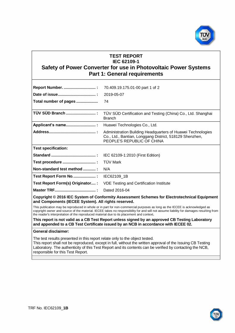
TRF No. IEC62109_1B TEST REPORT IEC 62109-1 Safety of Power Converter for use in Photovoltaic Power Systems Part 1: General requirements Report Number. ............................ : 70.409.19.175.01-00 part 1 of 2 Date of issue ................................. : 2019-05-07 Total number of pages ................... 74 TÜV SÜD Branch .......................... : TÜV SÜD Certification and Testing (China) Co., Ltd. Shanghai Branch Applicant’s name.......................... : Huawei Technologies Co., Ltd. Address......................................... : Administration Building Headquarters of Huawei Technologies Co., Ltd., Bantian, Longgang District, 518129 Shenzhen, PEOPLE'S REPUBLIC OF CHINA Test specification: Standard ....................................... : IEC 62109-1:2010 (First Edition) Test procedure ............................. : TÜV Mark Non-standard test method ........... : N/A Test Report Form No. ................... : IEC62109_1B Test Report Form(s) Originator.... : VDE Testing and Certification Institute Master TRF.................................... : Dated 2016-04 Copyright © 2016 IEC System of Conformity Assessment Schemes for Electrotechnical Equipment and Components (IECEE System). All rights reserved. This publication may be reproduced in whole or in part for non-commercial purposes as long as the IECEE is acknowledged as copyright owner and source of the material. IECEE takes no responsibility for and will not assume liability for damages resulting from the reader's interpretation of the reproduced material due to its placement and context. This report is not valid as a CB Test Report unless signed by an approved CB Testing Laboratory and appended to a CB Test Certificate issued by an NCB in accordance with IECEE 02. General disclaimer: The test results presented in this report relate only to the object tested. This report shall not be reproduced, except in full, without the written approval of the Issuing CB Testing Laboratory. The authenticity of this Test Report and its contents can be verified by contacting the NCB, responsible for this Test Report.
-
Upload
khangminh22 -
Category
Documents
-
view
0 -
download
0
Transcript of test report iec 62109-1 - EDİKLİ GES
TRF No. IEC62109_1B
TEST REPORT IEC 62109-1
Safety of Power Converter for use in Photovoltaic Power Systems Part 1: General requirements
Report Number. ............................ : 70.409.19.175.01-00 part 1 of 2
Date of issue ................................. : 2019-05-07
Total number of pages ................... 74
TÜV SÜD Branch .......................... : TÜV SÜD Certification and Testing (China) Co., Ltd. Shanghai Branch
Applicant’s name .......................... : Huawei Technologies Co., Ltd.
Address......................................... : Administration Building Headquarters of Huawei Technologies Co., Ltd., Bantian, Longgang District, 518129 Shenzhen, PEOPLE'S REPUBLIC OF CHINA
Test specification:
Standard ....................................... : IEC 62109-1:2010 (First Edition)
Test procedure ............................. : TÜV Mark
Non-standard test method ........... : N/A
Test Report Form No. ................... : IEC62109_1B
Test Report Form(s) Originator.... : VDE Testing and Certification Institute
Master TRF.................................... : Dated 2016-04
Copyright © 2016 IEC System of Conformity Assessment Schemes for Electrotechnical Equipment and Components (IECEE System). All rights reserved.
This publication may be reproduced in whole or in part for non-commercial purposes as long as the IECEE is acknowledged as
copyright owner and source of the material. IECEE takes no responsibility for and will not assume liability for damages resulting from the reader's interpretation of the reproduced material due to its placement and context.
This report is not valid as a CB Test Report unless signed by an approved CB Testing Laboratory and appended to a CB Test Certificate issued by an NCB in accordance with IECEE 02.
General disclaimer:
The test results presented in this report relate only to the object tested. This report shall not be reproduced, except in full, without the written approval of the Issuing CB Testing Laboratory. The authenticity of this Test Report and its contents can be verified by contacting the NCB, responsible for this Test Report.

Page 3 of 74
Report No. 70.409.19.175.01-00 part 1 of 2
TRF No. IEC62109_1B
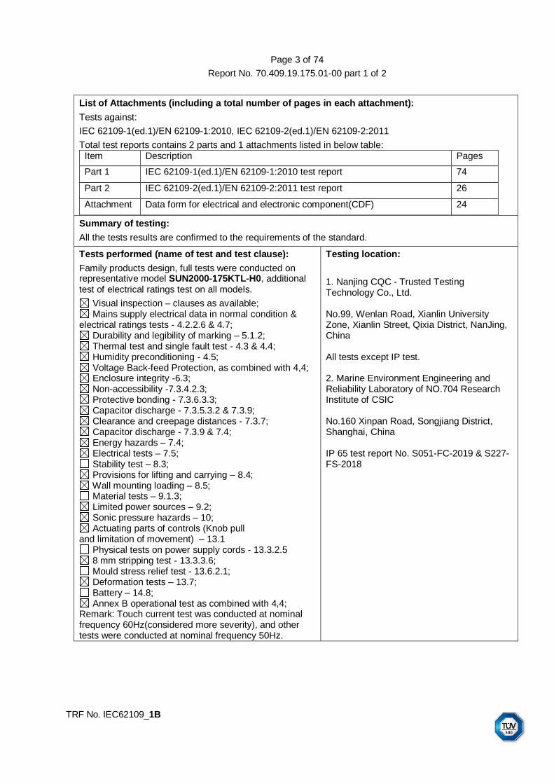
List of Attachments (including a total number of pages in each attachment):
Tests against:
IEC 62109-1(ed.1)/EN 62109-1:2010, IEC 62109-2(ed.1)/EN 62109-2:2011
Total test reports contains 2 parts and 1 attachments listed in below table: Item Description Pages
Part 1 IEC 62109-1(ed.1)/EN 62109-1:2010 test report 74
Part 2 IEC 62109-2(ed.1)/EN 62109-2:2011 test report 26
Attachment Data form for electrical and electronic component(CDF) 24
Summary of testing:
All the tests results are confirmed to the requirements of the standard.
Tests performed (name of test and test clause):
Family products design, full tests were conducted on representative model SUN2000-175KTL-H0, additional test of electrical ratings test on all models.
Visual inspection – clauses as available; Mains supply electrical data in normal condition &
electrical ratings tests - 4.2.2.6 & 4.7; Durability and legibility of marking – 5.1.2; Thermal test and single fault test - 4.3 & 4.4; Humidity preconditioning - 4.5; Voltage Back-feed Protection, as combined with 4,4; Enclosure integrity -6.3; Non-accessibility -7.3.4.2.3; Protective bonding - 7.3.6.3.3; Capacitor discharge - 7.3.5.3.2 & 7.3.9; Clearance and creepage distances - 7.3.7; Capacitor discharge - 7.3.9 & 7.4; Energy hazards – 7.4; Electrical tests – 7.5; Stability test – 8.3; Provisions for lifting and carrying – 8.4; Wall mounting loading – 8.5; Material tests – 9.1.3; Limited power sources – 9.2; Sonic pressure hazards – 10; Actuating parts of controls (Knob pull
and limitation of movement) – 13.1 Physical tests on power supply cords - 13.3.2.5 8 mm stripping test - 13.3.3.6; Mould stress relief test - 13.6.2.1; Deformation tests – 13.7; Battery – 14.8; Annex B operational test as combined with 4,4;
Remark: Touch current test was conducted at nominal frequency 60Hz(considered more severity), and other tests were conducted at nominal frequency 50Hz.
Testing location:
1. Nanjing CQC - Trusted Testing Technology Co., Ltd. No.99, Wenlan Road, Xianlin University Zone, Xianlin Street, Qixia District, NanJing, China All tests except IP test. 2. Marine Environment Engineering and Reliability Laboratory of NO.704 Research Institute of CSIC No.160 Xinpan Road, Songjiang District, Shanghai, China IP 65 test report No. S051-FC-2019 & S227-FS-2018

Page 4 of 74
Report No. 70.409.19.175.01-00 part 1 of 2
TRF No. IEC62109_1B
Summary of compliance with National Differences (List of countries addressed):
All tests were carried out according to IEC 62109-1(ed.1)/EN 62109-1:2010.
The text of IEC 62109-1(ed.1) was approved by CENELEC as a European Standard without any modification. Also compliance with EN 62109-1:2010, Annex ZA of EN 62109-1:2010 is recorded at the end of this report.
The product fulfils the requirements of IEC 62109-1(ed.1) / EN 62109-1:2010
Copy of marking plate:

Page 5 of 74
Report No. 70.409.19.175.01-00 part 1 of 2
TRF No. IEC62109_1B
Additional warning labels

Page 6 of 74
Report No. 70.409.19.175.01-00 part 1 of 2
TRF No. IEC62109_1B
Marking plate material: pressure-sensitive unprinted label stocks stamped into aluminum surface; Suitable for outdoor use with respect to exposure to Ultraviolet Light, Water Exposure and thermal transfer printed label stock applications, -60°C to 95°C
An additional PET film provided to cover label.

Page 7 of 74
Report No. 70.409.19.175.01-00 part 1 of 2
TRF No. IEC62109_1B
Test item particulars .............................................. :
Equipment mobility ................................................ : movable hand-held stationary fixed transportable for building-in
Connection to the mains ........................................ : pluggable equipment direct plug-in permanent connection for building-in
Environmental category ......................................... : outdoor indoor indoor unconditional conditional
Over voltage category Mains ................................. : OVC I OVC II OVC III OVC IV
Over voltage category PV ...................................... : OVC I OVC II OVC III OVC IV
Mains supply tolerance (%) .................................... : -90 / +110 %
Tested for power systems ..................................... : IT
Testing of phase-phase voltage (V) ....................... : 800V
Class of equipment ................................................ : Class I Class II Class III Not classified
Mass of equipment (kg) ......................................... : 84kg
Pollution degree ..................................................... : 3(external environment), 2(internal environment)
IP protection class ................................................. : IP65
............................................................................... :
Possible test case verdicts:
- test case does not apply to the test object .......... : N/A
- test object does meet the requirement ................ : P (Pass)
- test object was not evaluated for the requirement ............................................................ :
N/E
- test object does not meet the requirement .......... : F (Fail)
Testing ................................................................... :
Date of receipt of test item ..................................... : 2019-04-15
Date (s) of performance of tests ............................ : 2019-04-15 to 2019-04-30
Page 8 of 74
Report No. 70.409.19.175.01-00 part 1 of 2
TRF No. IEC62109_1B
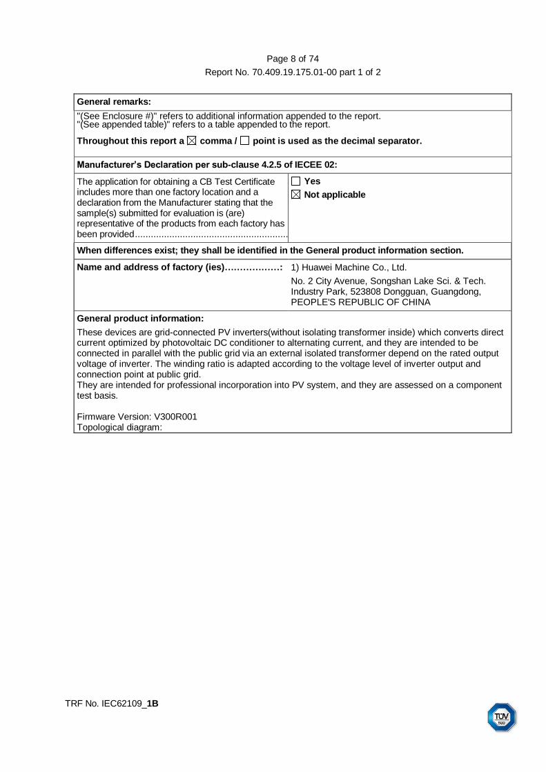
General remarks:
"(See Enclosure #)" refers to additional information appended to the report. "(See appended table)" refers to a table appended to the report. Throughout this report a comma / point is used as the decimal separator.
Manufacturer’s Declaration per sub-clause 4.2.5 of IECEE 02:
The application for obtaining a CB Test Certificate includes more than one factory location and a declaration from the Manufacturer stating that the sample(s) submitted for evaluation is (are) representative of the products from each factory has been provided ...........................................................:
Yes
Not applicable
When differences exist; they shall be identified in the General product information section.
Name and address of factory (ies)………………: 1) Huawei Machine Co., Ltd.
No. 2 City Avenue, Songshan Lake Sci. & Tech. Industry Park, 523808 Dongguan, Guangdong, PEOPLE'S REPUBLIC OF CHINA
General product information:
These devices are grid-connected PV inverters(without isolating transformer inside) which converts direct current optimized by photovoltaic DC conditioner to alternating current, and they are intended to be connected in parallel with the public grid via an external isolated transformer depend on the rated output voltage of inverter. The winding ratio is adapted according to the voltage level of inverter output and connection point at public grid. They are intended for professional incorporation into PV system, and they are assessed on a component test basis. Firmware Version: V300R001 Topological diagram:

Page 9 of 74
Report No. 70.409.19.175.01-00 part 1 of 2
TRF No. IEC62109_1B
The following documentations are retained on file: - Photograph; - Circuit diagrams; - PCB layout drawing; - PCB foil pattern assembly drawing; - Specification sheets for components; - Instruction manual. - Manufacturer’s work instruction and declaration for 100% routing test as required by IEC 62109-1(ed.1)/EN 62109-1:2010, IEC 62109-2(ed.1)/EN 62109-2:2011. For models differences, pls. see as in table below (exact from user manual directly for reference):
Technical specifications
SUN2000-175KTL-H0
SUN2000-185KTL-INH0
SUN2000-168KTL-H1
SUN2000-185KTL-H1
Input
Max. input voltage 1500 V 1500 V 1500 V 1500 V
Max. input current (per MPPT circuit)
26 A 26 A 26 A 26 A
Max. short-circuit current (per MPPT
circuit)
40 A 40 A 40 A 40 A

Page 10 of 74
Report No. 70.409.19.175.01-00 part 1 of 2
TRF No. IEC62109_1B
Max. backfeed current
0 A 0 A 0 A 0 A
Min. start-up voltage
550V 550V 550V 550V
MPP voltage range
500-1500Vdc 500-1500Vdc 500-1500Vdc 500-1500Vdc
MPP full load voltage range
880-1300Vdc 880-1300Vdc 880-1300Vdc 880-1300Vdc
Rated input voltage
1080V 1080V 1080V 1080V
Number of inputs 18 18 18 18
Number of MPPT circuits
9 9 9 9
Output
Rated output voltage
800V, 3W+PE 800V, 3W+PE 800V, 3W+PE 800V, 3W+PE
Rated Output Frequency
50Hz 50 Hz / 60 Hz 50 Hz / 60 Hz 50 Hz / 60 Hz
Rated Output Power
175kW 160kW 150kW 175kW
Max. Output Power
193kW 185kW 168kW 185kW
Max. Apparent power
193kVA 185kVA 168kVA 185kVA
Rated Output Current
126,3A 115,5
108,3 126,3
Max. Output Current Imax
140,7 134,9 122,5 134,9
Power factor 0,8 leading … 0,8 lagging
Max. total harmonic distortion
<3%
Protection
Input DC switch Supported Supported Supported Supported
Anti-islanding protection
Supported Supported Supported Supported
Output overcurrent protection
Supported Supported Supported Supported
Input reverse-connection protection
Supported Supported Supported Supported
Page 11 of 74
Report No. 70.409.19.175.01-00 part 1 of 2
TRF No. IEC62109_1B
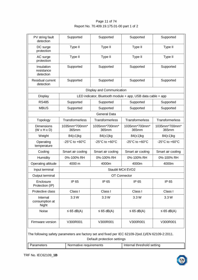
PV string fault detection
Supported Supported Supported Supported
DC surge protection
Type II Type II Type II Type II
AC surge protection
Type II Type II Type II Type II
Insulation resistance detection
Supported Supported Supported Supported
Residual current detection
Supported Supported Supported Supported
Display and Communication
Display LED indicator, Bluetooth module + app, USB data cable + app
RS485 Supported Supported Supported Supported
MBUS Supported Supported Supported Supported
General Data
Topology Transformerless Transformerless Transformerless Transformerless
Dimensions (W x H x D)
1035mm*700mm*365mm
1035mm*700mm*365mm
1035mm*700mm*365mm
1035mm*700mm*365mm
Weight 84(±1)kg 84(±1)kg 84(±1)kg 84(±1)kg
Operating temperature
-25°C to +60°C -25°C to +60°C -25°C to +60°C -25°C to +60°C
Cooling Smart air cooling Smart air cooling Smart air cooling Smart air cooling
Humidity 0%-100% RH 0%-100% RH 0%-100% RH 0%-100% RH
Operating altitude 4000 m 4000m 4000m 4000m
Input terminal Staubli MC4 EVO2
Output terminal OT Connector
Enclosure Protection (IP)
IP 65 IP 65 IP 65 IP 65
Protective class Class I Class I Class I Class I
Internal consumption at
Night
3.3 W 3.3 W 3.3 W 3.3 W
Noise ≤ 65 dB(A)
≤ 65 dB(A)
≤ 65 dB(A)
≤ 65 dB(A)
Firmware version V300R001 V300R001 V300R001 V300R001
The following safety parameters are factory set and fixed per IEC 62109-2(ed.1)/EN 62109-2:2011.
Default protection settings
Parameters Normative requirements Internal threshold setting

Page 12 of 74
Report No. 70.409.19.175.01-00 part 1 of 2
TRF No. IEC62109_1B
Maximum clearance time
Trip limit Maximum clearance time (factory setting)
Factory setting trip value
PV array Insulation resistance measurement before starting operation
- ≥1500V/30mA=50 kΩ
- 50 kΩ as default Adjustable range: 50 kΩ - 1500 kΩ
Continuous residual current monitoring(functional)
300 ms 10 mA/kVA 300 ms 10 mA RMS per kVA based on inverter ratings
Sudden changes in residual current(functional)
300 ms 30 mA 300 ms 30 mA
150 ms 60 mA 150 ms 60 mA
40 ms 150 mA 40 ms 150 mA
Alteration of the above settings or full setting range of the interface protection may cause a breach of the type-certificate marking.
Unauthorised access to factory safety parameters setting and software should be prohibited.
A reset to the factory safety parameters requires retesting and verification in conjunction with the end-use system.

Page 13 of 74
Report No. 70.409.19.175.01-00 part 1 of 2
IEC 62109-1
Clause Requirement – Test Result – Remark Verdict
TRF No. IEC62109_1B
4 GENERAL TESTING REQUIREMENTS P
4.1 General P
4.2 General conditions for testing P
4.2.1 Sequence of tests P
4.2.2 Reference test conditions P
4.2.2.1 Environmental conditions P
4.2.2.2 State of equipment P
4.2.2.3 Position of equipment These equipment were installed in accordance with the manufacturer’s instructions, in the configuration that results in the worst-case test conditions
P
4.2.2.4 Accessories Accessories and operator interchangeable parts available from or recommended by the manufacturer according to the installation manual required.
P
4.2.2.5 Covers and removable parts No covers or parts, which can be removed without using a tool.
N/A
4.2.2.6 Mains supply
a) Voltage:
b) Frequency:
c) Polarity:
d) Earthing:
e) Over-current Protection:
P
4.2.2.7 Supply ports other than the mains PV input P
4.2.2.7.1 Photovoltaic supply sources
a) Open circuit voltage:
b) Short-circuit current:
P
4.2.2.7.2 Battery inputs No battery P
4.2.2.8 Conditions of loading for output ports P
4.2.2.9 Earthing terminals P
4.2.2.10 Controls P
4.2.2.11 Available short circuit current P
4.3 Thermal testing (see appended table 4.3) P
4.3.1 General P
4.3.2 Maximum temperatures P
4.3.2.1 General P

Page 14 of 74
Report No. 70.409.19.175.01-00 part 1 of 2
IEC 62109-1
Clause Requirement – Test Result – Remark Verdict
TRF No. IEC62109_1B
4.3.2.2 Touch temperatures P
4.3.2.3 Temperature limits for mounting surfaces P
4.4 Testing in single fault condition (see appended table 4.4) P
4.4.1 General P
4.4.2 Test conditions and duration for testing under fault conditions
P
4.4.2.1 General P
4.4.2.2 Duration of tests P
4.4.3 Pass/fail criteria for testing under fault conditions P
4.4.3.1 Protection against shock hazard P
4.4.3.2 Protection against the spread of fire P
4.4.3.3 Protection against other hazards P
4.4.3.4 Protection against parts expulsion hazards P
4.4.4 Single fault conditions to be applied P
4.4.4.1 Component fault tests P
4.4.4.2 Equipment or parts for short-term or intermittent operation
Not for short-term or intermittent operation
N/A
4.4.4.3 Motors P
4.4.4.4 Transformer short circuit tests P
4.4.4.5 Output short circuit P
4.4.4.6 Backfeed current test for equipment with more than one source of supply
P
4.4.4.7 Output overload P
4.4.4.8 Cooling system failure P
4.4.4.9 Heating devices No heating device N/A
4.4.4.10 Safety interlock systems No safety interlock N/A
4.4.4.11 Reverse d.c. connections P
4.4.4.12 Voltage selector mismatch No voltage selector N/A
4.4.4.13 Mis-wiring with incorrect phase sequence or polarity P
4.4.4.14 Printed wiring board short-circuit test P
4.5 Humidity preconditioning (see appended table 7.5) P
4.5.1 General P
4.5.2 Conditions P
4.6 Backfeed voltage protection P
4.6.1 Backfeed tests under normal conditions P
4.6.2 Backfeed tests under single-fault conditions P

Page 15 of 74
Report No. 70.409.19.175.01-00 part 1 of 2
IEC 62109-1
Clause Requirement – Test Result – Remark Verdict
TRF No. IEC62109_1B
4.6.3 Compliance with backfeed tests P
4.7 Electrical ratings tests (see appended table 4.7) P
4.7.1 Input ratings P
4.7.1.1 Measurement requirements for DC input ports P
4.7.2 Output ratings P
5 MARKING AND DOCUMENTATION P
5.1 Marking P
5.1.1 General The marking label and warning label on external surface of side enclosure with rating label and warning substance, warning symbols, and installation indication or switch position provided at close up of external connection interface. Graphic symbols per Annex C or IEC 60417, refer to section “copy of marking plate”
P
Equipment shall bear markings as specified in 5.1 and 5.2
P
Graphic symbols may be used and shall be in accordance with Annex C or IEC 60417 as applicable.
The explanations are provided in the user manual.
P
Graphic symbols shall be explained in the documentation provided with the PCE.
P
5.1.2 Durability of markings P
Markings required by this clause to be located on the PCE shall remain clear and legible under conditions of NORMAL USE and resist the effects of cleaning agents specified by the manufacturer
Tested with lsopropyl alcohol for 30s
P
5.1.3 Identification refer to copy of marking plate P
The equipment shall, as a minimum, be permanently marked with:
P
a) the name or trade mark of the manufacturer or supplier
P
b) model number, name or other means to identify the equipment
P
c) a serial number, code or other marking allowing identification of manufacturing location and the manufacturing batch or date within a three month time period.
P

Page 16 of 74
Report No. 70.409.19.175.01-00 part 1 of 2
IEC 62109-1
Clause Requirement – Test Result – Remark Verdict
TRF No. IEC62109_1B
5.1.4 Equipment ratings Refer to IEC 62109-2(ed.1)/EN 62109-2:2011 test report
P
Unless otherwise specified in another part of IEC 62109, the following ratings, as applicable shall be marked on the equipment:
P
input voltage, type of voltage (a.c. or d.c.), frequency, and max. continuous current for each input
P
– output voltage, type of voltage (a.c. or d.c.), frequency, max. continuous current, and for a.c. outputs, either the power or power factor for each output
P
– the ingress protection (IP) rating as in 6.3 below P
5.1.5 Fuse identification P
Marking shall be located adjacent to each fuse or fuseholder, or on the fuseholder, or in another location provided that it is obvious to which fuse the marking applies, giving the fuse current rating and where fuses of different voltage rating value could be fitted, the fuse voltage rating.
P
Where fuses with special fusing characteristics such as time delay or breaking capacity are necessary, the type shall also be indicated
N/A
For fuses not located in operator access areas and for soldered-in fuses located in operator access areas, it is permitted to provide an unambiguous cross-reference (for example, F1, F2, etc.) to the servicing instructions which shall contain the relevant information.
P
5.1.6 Terminals, Connections, and Controls P
If necessary for safety, an indication shall be given of the purpose of Terminals, connectors, controls, and indicators, and their various positions, including any connections for coolant fluids such as water and drainage. The symbols in Annex C may be used, and where there is insufficient space, symbol 9 of Annex C may be used.
Relevant symbol, indicator or information is available.
P
Push-buttons and actuators of emergency stop devices, and indicator lamps used only to indicate a warning of danger or the need for urgent action shall be coloured red.
Indicator lamps used for dangerous failure
P
A multiple-voltage unit shall be marked to indicate the particular voltage for which it is set when shipped from the factory. The marking is allowed to be in the form of a paper tag or any other non-permanent material.
N/A

Page 17 of 74
Report No. 70.409.19.175.01-00 part 1 of 2
IEC 62109-1
Clause Requirement – Test Result – Remark Verdict
TRF No. IEC62109_1B
A unit with d.c. terminals shall be plainly marked indicating the polarity of the connections, with:
P
the sign “+” for positive and “-” for negative; or The “+” and “-” marking provided adjacent to the PV input terminal.
P
a pictorial representation illustrating the proper polarity where the correct polarity can be unambiguously determined from the representation
N/A
5.1.6.1 Protective Conductor Terminals symbol 7 of Annex C adjacent to earth terminal
P
The means of connection for the protective earthing conductor shall be marked with:
P
symbol 7 of Annex C; or P
the letters “PE”; or N/A
the colour coding green-yellow. N/A
5.1.7 Switches and circuit-breakers The components DC switch is integrated in inverter. Output overcurrent protection maybe provided by external circuit breaker specified in user manual in additional to the internal protection of inverter.
P
The on and off-positions of switches and circuits breakers shall be clearly marked. If a push-button switch is used as the power switch, symbols 10 and 16 of Annex C may be used to indicate the on-position, or symbols 11 and 17 to indicate the off-position, with the pair of symbols (10 and 16, or 11 and 17) close together.
DC switches integrated in PCE, On and Off position marking on PCE clearly with letter “ON” and “OFF”
P
5.1.8 Class ׀׀ Equipment Class I N/A
Equipment using Class ׀׀ protective means throughout shall be marked with symbol 12 of Annex C. Equipment which is only partially protected by DOUBLE INSULATION or REINFORCED INSULATION shall not bear symbol 12 of Table Annex C.
N/A
Where such equipment has provision for the connection of an earthing conductor for functional reasons (see 7.3.6.4) it shall be marked with symbol 6 of Annex C
N/A
5.1.9 Terminal boxes for External Connections The temperature observed on the terminals were not exceed the limited values specified.
P
Where required by note 1 of Table 2 as a result of high temperatures of terminals or parts in the wiring compartment, there shall be a marking, visible beside the terminal before connection, of either:
N/A

Page 18 of 74
Report No. 70.409.19.175.01-00 part 1 of 2
IEC 62109-1
Clause Requirement – Test Result – Remark Verdict
TRF No. IEC62109_1B
a) the minimum temperature rating and size of the cable to be connected to the TERMINALS; or
N/A
b) a marking to warn the installer to consult the installation instruction. Symbol 9 of Table D-1 is an acceptable marking
Symbol 9 of Table C
marked on label
P
5.2 Warning markings P
5.2.1 Visibility and legibility requirements for warning markings
P
Warning markings shall be legible, and shall have minimum dimensions as follows:
P
Printed symbols shall be at least 2,75 mm high P
Printed text characters shall be at least 1.5 mm high and shall contrast in colour with the background
P
Symbols or text that are moulded, stamped or engraved in a material shall have a character height of at least 2,0 mm, and if not contrasting in colour from the background, shall have a depth or raised height of at least 0,5 mm.
P
If it is necessary to refer to the instruction manual to preserve the protection afforded by the equipment, the equipment shall be marked with symbol 9 of Annex C
P
Symbol 9 of Annex C is not required to be used adjacent to symbols that are explained in the manual
explained in the manual P
5.2.2 Content for warning markings See warning marking and user manual
P
5.2.2.1 Ungrounded heat sinks and similar parts With grounded heat sink and similar metal parts
N/A
An ungrounded heat sink or other part that may be mistaken for a grounded part and involves a risk of electric shock in accordance with 7.3 shall be marked with symbol 13 of Annex C, or equivalent. The marking may be on or adjacent to the heat sink and shall be clearly visible when the PCE is disassembled to the extent that a risk of contact with the heat sink exists.
N/A
5.2.2.2 Hot Surfaces P
A part of the PCE that exceeds the temperature limits specified in 4.3.2 shall be marked with symbol 14 of Annex C or equivalent.
“hot surface” symbol used in warning marking
P
5.2.2.3 Coolant Air cooling N/A

Page 19 of 74
Report No. 70.409.19.175.01-00 part 1 of 2
IEC 62109-1
Clause Requirement – Test Result – Remark Verdict
TRF No. IEC62109_1B
A unit containing coolant that exceeds 70 °C shall be legibly marked externally where readily visible after installation with symbol 15 of Annex C. The documentation shall provide a warning regarding the risk of burns from hot coolant, and either:
N/A
a) statement that coolant system servicing is to be done only by SERVICE PERSONNEL, or
N/A
b) instructions for safe venting, draining, or otherwise working on the cooling system, if these operations can be performed without OPERATOR access to HAZARDS internal to the equipment
N/A
5.2.2.4 Stored energy P
Where required by 7.3.9.2 or 7.4.2 the PCE shall be marked with Symbol 21 of Annex C and the time to discharge capacitors to safe voltage and energy levels shall accompany the symbol.
Symbol used for warning on marking plate for installation, operation and maintenance.
P
5.2.2.5 Motor guarding No energy with power source removed for internal cooling fan
N/A
Where required by 8.2 a marking shall be provided where it is visible to service personnel before removal of a guard, warning of the hazard and giving instructions for safe servicing (for example disconnection of the source before removing the guard).
P
5.2.3 Sonic hazard markings and instructions Measured <<80dBA@1m, no hazard
N/A
If required by 10.2.1 a PCE shall: N/A
a) be marked to warn the operator of the sonic pressure hazard; or
N/A
b) be provided with installation instructions that specify how the installer can ensure that the sound pressure level from equipment at its point of use after installation, will not reach a value, which could cause a hazard. These instructions shall include the measured sound pressure level, and shall identify readily available and practicable protective materials or measures which may be used.
N/A
5.2.4 Equipment with multiple sources of supply PV and mains as sources of supply
P
A PCE with connections for multiple energy sources shall be marked with symbol 13 of Annex C and the manual shall contain the information required in 5.3.4.
Marked with symbol 13 of Annex C and explained in user manual.
P

Page 20 of 74
Report No. 70.409.19.175.01-00 part 1 of 2
IEC 62109-1
Clause Requirement – Test Result – Remark Verdict
TRF No. IEC62109_1B
The symbol shall be located on the outside of the unit or shall be prominently visible behind any cover giving access to hazardous parts.
Located outside of the unit P
5.2.5 Excessive touch current Max. measured >3,5mA r.m.s. Permanently connected wiring and a cross-section of the protective earthing conductor of at least S/2=25 mm2
required in user manual; additional second protective earthing terminal provided on enclosure as well
P
Where required by 7.3.6.3.7 the PCE shall be marked with symbol 15 of Annex C. See also 5.3.2 for information to be provided in the installation manual.
symbol 15 of Annex C marked information refer to user manual
P
5.3 Documentation P
5.3.1 General P
The documentation provided with the PCE shall provide the information needed for the safe operation, installation, and (where applicable) maintenance of the equipment. The documentation shall include the items required in 5.3.2 through 5.3.4, and the following:
All related information provided in the user’s manual.
P
a) explanations of equipment makings, including symbols used
P
b) location and function of terminals and controls P
c) all ratings or specifications that are necessary to safely install and operate the PCE, including the following environmental ratings along with an explanation of their meaning and any resulting installation requirements:
P
– ENVIRONMENTAL CATEGORY as per 6.1 Meet requirements for outdoor use
P
– WET LOCATIONS classification fort he intended external environment as per 6.1
Meet requirements for wet location use
P
– POLLUTION DEGREE classification for the intended external environment as per 6.2
3 P
– INGRESS PROTECTION rating as per 6.3 IP65 P
– Ambient temperature and relative humidity ratings
-25˚C...+60˚C Relative humidity:0…100%
P
– MAXIMUM altitude rating 4000m P

Page 21 of 74
Report No. 70.409.19.175.01-00 part 1 of 2
IEC 62109-1
Clause Requirement – Test Result – Remark Verdict
TRF No. IEC62109_1B
– OVERVOLTAGE CATEGORY assigned to each input and output port as per 7.3.7.1.2, accompanied by guidance regarding how to ensure that the installation complies with the required overvoltage categories;
PV: II Mains: III
P
d) a warning that when the photovoltaic array is exposed to light, it supplies a d.c. voltage to the PCE
Refer to user manual P
5.3.1.1 Language English P
Instructions related to safety shall be in a language that is acceptable in the country where the equipment is to be installed.
P
5.3.1.2 Format P
In general, the documentation must be provided in printed form and is to be delivered with the equipment.
Documentation provided in printed form and is to be delivered with the equipment
P
For equipment which requires the use of a computer for both installation and operation, documentation may be provided in electronic format without accompanying printed format.
N/A
5.3.2 Information related to installation P
The documentation shall include installation and where applicable, specific commissioning instructions and, if necessary for safety, warnings against hazards which could arise during installation or commissioning of the equipment. The information provided shall include:
As specified in user manual, refer to information related to installation
P
a) assembly, location, and mounting requirements:
P
b) ratings and means of connection to each source of supply and any requirements related to wiring and external controls, colour coding of leads, disconnection means, or overcurrent protection needed, including instructions that the installation position shall not prevent access to the disconnection means;
P
c) ratings and means of connection of any outputs from the PCE, and any requirements related to wiring and externals controls, colour coding of leads, or overcurrent protection needed;
P
d) explanation of the pin-out of connectors for external connections, unless the connector is used for a standard purpose (e.g. RS 232)
P
e) ventilation requirements; P
f) requirements for special services, for example cooling liquid;
P
Page 22 of 74
Report No. 70.409.19.175.01-00 part 1 of 2
IEC 62109-1
Clause Requirement – Test Result – Remark Verdict
TRF No. IEC62109_1B
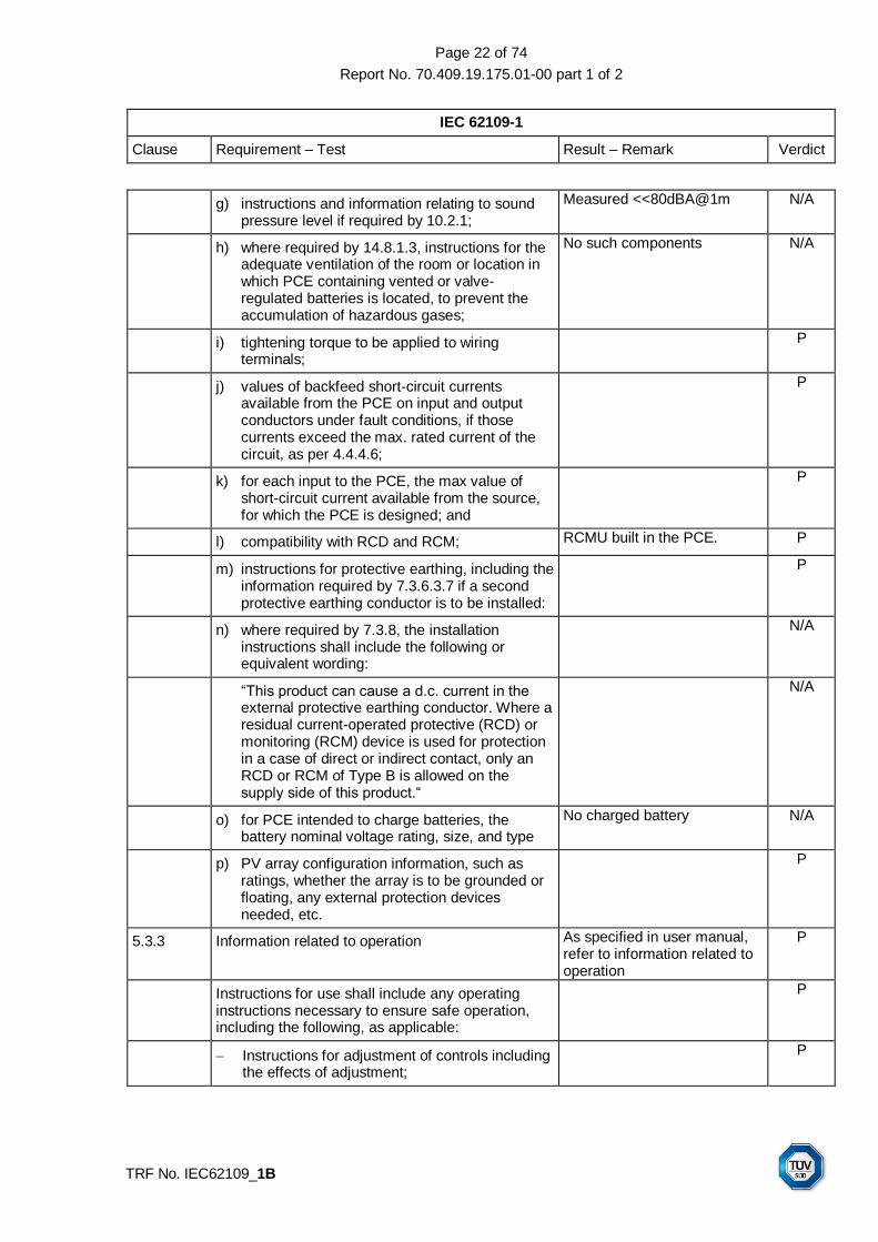
g) instructions and information relating to sound pressure level if required by 10.2.1;
Measured <<80dBA@1m N/A
h) where required by 14.8.1.3, instructions for the adequate ventilation of the room or location in which PCE containing vented or valve-regulated batteries is located, to prevent the accumulation of hazardous gases;
No such components N/A
i) tightening torque to be applied to wiring terminals;
P
j) values of backfeed short-circuit currents available from the PCE on input and output conductors under fault conditions, if those currents exceed the max. rated current of the circuit, as per 4.4.4.6;
P
k) for each input to the PCE, the max value of short-circuit current available from the source, for which the PCE is designed; and
P
l) compatibility with RCD and RCM; RCMU built in the PCE. P
m) instructions for protective earthing, including the information required by 7.3.6.3.7 if a second protective earthing conductor is to be installed:
P
n) where required by 7.3.8, the installation instructions shall include the following or equivalent wording:
N/A
“This product can cause a d.c. current in the external protective earthing conductor. Where a residual current-operated protective (RCD) or monitoring (RCM) device is used for protection in a case of direct or indirect contact, only an RCD or RCM of Type B is allowed on the supply side of this product.“
N/A
o) for PCE intended to charge batteries, the battery nominal voltage rating, size, and type
No charged battery N/A
p) PV array configuration information, such as ratings, whether the array is to be grounded or floating, any external protection devices needed, etc.
P
5.3.3 Information related to operation As specified in user manual, refer to information related to operation
P
Instructions for use shall include any operating instructions necessary to ensure safe operation, including the following, as applicable:
P
Instructions for adjustment of controls including the effects of adjustment;
P

Page 23 of 74
Report No. 70.409.19.175.01-00 part 1 of 2
IEC 62109-1
Clause Requirement – Test Result – Remark Verdict
TRF No. IEC62109_1B
Instructions for interconnection to accessories and other equipment, including indication of suitable accessories, detachable parts and any special materials;
P
Warnings regarding the risk of burns from surfaces permitted to exceed the temperature limits of 4.3.2 and required operator actions to reduce the risk; and
P
Instructions, that if the equipment is used in a manner not specified by the manufacturer, the protection provided by the equipment may be impaired.
P
5.3.4 Information related to maintenance Maintenance made only by professional service personal who is familiar with product
P
Maintenance instructions shall include the following:
P
Intervals and instructions for any preventive maintenance that is required to maintain safety (for example air filter replacement or periodic re-tightening of terminals);
P
Instructions for accessing operator access areas, if any are present, including a warning not to enter other areas of the equipment;
P
Part numbers and instructions for obtaining any required operator replaceable parts;
P
Instructions for safe cleaning (if recommended) P
Where there is more than one source of supply energizing the PCE, information shall be provided in the manual to indicate which disconnect device or devices are required to be operated in order to completely isolate the equipment.
P
5.3.4.1 Battery maintenance Without battery N/A
Where required by 14.8.5, the documentation shall include the applicable items from the following list of instructions regarding maintenance of batteries:
N/A
Servicing of batteries should be performed or supervised by personnel knowledgeable about batteries and the required precautions
N/A
When replacing batteries, replace with the same type and number of batteries or battery packs
N/A
General instructions regarding removal and installation of batteries
N/A

Page 24 of 74
Report No. 70.409.19.175.01-00 part 1 of 2
IEC 62109-1
Clause Requirement – Test Result – Remark Verdict
TRF No. IEC62109_1B
CAUTION: Do not dispose of batteries in a fire. The batteries may explode.
N/A
CAUTION: Do not open or damage batteries. Released electrolyte is harmful to the skin and eyes. It may be toxic.
N/A
CAUTION: A battery can present a risk of electrical shock and high short-circuit current. The following precautions should be observed when working on batteries:
N/A
a) Remove watches, rings, or other metal objects. N/A
b) Use tools with insulated handles. N/A
c) Wear rubber gloves and boots. N/A
d) Do not lay tools or metal parts on top of batteries
N/A
e) Disconnect charging source prior to connecting or disconnecting battery terminals
N/A
f) Determine if battery is inadvertently grounded. If inadvertently grounded, remove source from ground. Contact with any part of a grounded battery can result in electrical shock. The likelihood of such shock can be reduced if such grounds are removed during installation and maintenance (applicable to equipment and remote battery supplies not having a grounded supply circuit).
N/A
6 ENVIRONMENTAL REQUIREMENTS AND CONDITIONS P
The manufacturer shall rate the PCE for the following environmental conditions:
P
– ENVIRONMENTAL CATEGORY, as in 6.1 below
Meet requirements for outdoor use
P
– Suitability for WET LOCATIONS or not Meet requirements for wet location use
P
– POLLUTION DEGREE rating in 6.2 below PD 3 external, PD 2 internal P
– INGRESS PROTECTION (IP) rating, as in 6.3 below
IP65 P
– Ultraviolet (UV) exposure rating, as in 6.4 below Metal enclosure used except with plastic window, DC switch, DC connector, AC cable gland, communication coupler with polymeric material UV resistant.
P
– Ambient temperature and relative humidity ratings, as in 6.5 below
-25˚C...+60˚C Relative humidity:0…100%
P
6.1 Environmental categories and minimum environmental conditions P

Page 25 of 74
Report No. 70.409.19.175.01-00 part 1 of 2
IEC 62109-1
Clause Requirement – Test Result – Remark Verdict
TRF No. IEC62109_1B
6.1.1 Outdoor P
6.1.2 Indoor, unconditioned N/A
6.1.3 Indoor, conditioned N/A
6.2 Pollution degree PD 3 external, PD 2 internal P
6.3 Ingress Protection IP65 P
6.4 UV exposure Metal enclosure used except with plastic window, DC switch, DC connector, AC cable gland, communication coupler with polymeric material UV resistant.
P
6.5 Temperature and humidity -25˚C...+60˚C Relative humidity:0…100%
P
7 PROTECTION AGAINST ELECTRIC SHOCK AND ENERGY HAZARDS P
7.1 General P
7.2 Fault conditions See table 4.4.4 single fault tests
P
7.3 Protection against electric shock P
7.3.1 General P
7.3.2 Decisive voltage classification Accessible communication circuit: DVC A;
Power circuit and other circuits: DVC B, DVC C
P
7.3.2.1 Use of decisive voltage class (DVC) P
7.3.2.2 Limits of DVC (according table 6) P
7.3.2.3 Short-terms limits of accessible voltages under fault conditions
P
7.3.2.4 Requirements for protection (according table 7) See 7.3.7 Table: Clearance and creepage distance measurement
P
7.3.2.5 Connection to PELV and SELV circuits The PELV or SELV classification of the external circuit is not changed and the DVC classification of the external port of the PCE is not changed
P
7.3.2.6 Working voltage and DVC P
7.3.2.6.1 General P
7.3.2.6.2 AC working voltage (see Figure 2) AC Vmax: 800V considered for insulation with tolerance ±10%
P
7.3.2.6.3 DC working voltage (see Figure 3) DC Vmax: 1500V considered for insulation
P
7.3.2.6.4 Pulsating working voltage (see Figure 4) N/A

Page 26 of 74
Report No. 70.409.19.175.01-00 part 1 of 2
IEC 62109-1
Clause Requirement – Test Result – Remark Verdict
TRF No. IEC62109_1B
7.3.3 protective separation P
Protective separation shall be achieved by: P
double or reinforced insulation, or P
protective screening, i.e. by a conductive screen connected to earth by protective bonding in the PCE, or connected to the protective earth conductor itself, whereby the screen is separated from live parts by at least basic insulation, or
P
protective impedance comprising limitation of current per 7.3.5.3 and of discharged energy per 7.3.5.4, or
N/A
limitation of voltage according to 7.3.5.4. N/A
The protective separation shall be fully and effectively maintained under all conditions of intended use of the PCE
P
7.3.4 Protection against direct contact Protection against eclectic shock by means of earthed metal enclosure. Any access to touch live parts is impossible.
P
7.3.4.1 General P
Protection against direct contact is employed to prevent persons from touching live parts that do not meet the requirements of 7.3.5 and shall be provided by one or more of the measure given in 7.3.4.2 (enclosures and barriers) and 7.3.4.3 (insulation).
P
Open type sub-assemblies and devices do not require protective measures against direct contact but the instruction provided with the equipment must indicate that such measures must be provided in the end equipment or in the installation.
N/A
Product intended for installation in CLOSED ELECTRICAL OPERATING AREAS, (see 3.9) need not have protective measures against direct contact, except as required by 7.3.4.2.4.
N/A
7.3.4.2 Protection by means of enclosures and barriers Protection against eclectic shock by means of earthed metal enclosure.
P
The following requirements apply where protection against contact with live parts is provided by enclosures or barriers, not by insulation in accordance with 7.3.4.3.
P
7.3.4.2.1 General P

Page 27 of 74
Report No. 70.409.19.175.01-00 part 1 of 2
IEC 62109-1
Clause Requirement – Test Result – Remark Verdict
TRF No. IEC62109_1B
Parts of enclosures and barriers that provide protection in accordance with these requirements shall not be removable without the use of a tool (see 7.3.4.2.3).
P
Polymeric materials used to meet these requirements shall also meet the requirements of 13.6
Plastic panel for light indicator P
7.3.4.2.2 Access probe criteria IP65 P
Protection is considered to be achieved when the separation between the test probes and live parts, when tested as described below, is as follows:
P
a) decisive voltage classification A, (DVC A) - the probe may touch the live parts
Communication interface P
b) decisive voltage classification B, (DVC B) - the probe must not touch bare live parts
Not access P
c) decisive voltage classification C, (DVC C) – the probe must have adequate clearance to live parts, based on the clearance for Basic insulation using the recurring peak working voltage involved,
Not access P
7.3.4.2.3 Access probe tests P
Compliance with 7.3.4.2.1 is checked by all of the following:
P
a) Inspection; and P
b) Tests with the test finger (Figure D.1) and test pin (Figure D.2) of 0E, the results of which shall comply with the requirements of 7.3.4.2.1 a), b), and c) as applicable. Probe tests are performed on openings in the enclosures after removal of parts that can be detached or opened by an operator without the use of a tool, including fuseholders, and with operator access doors and covers open. It is permitted to leave lamps in place for this test. Connectors that can be separated by an operator without use of a tool, shall also be tested during and after disconnection. Any movable parts are to be put in the most unfavourable position.
IP65, without openings on enclosure, for mechanical enclosure test finger cannot access to live parts and approved external connecting device used.
P
The test finger and the test pin are applied as above, without appreciable force, in every possible position, except that floor-standing equipment having a mass exceeding 40 kg is not tilted.
P

Page 28 of 74
Report No. 70.409.19.175.01-00 part 1 of 2
IEC 62109-1
Clause Requirement – Test Result – Remark Verdict
TRF No. IEC62109_1B
Equipment intended for building-in or rack mounting, or for incorporation in larger equipment, is tested with access to the equipment limited according to the method of mounting detailed in the installation instructions.
Not intended for built-in or rack mounting.
N/A
c) Openings preventing the entry of the jointed test finger (Figure E-1 of 0E) during test b) above, are further tested by means of straight unjointed test finger (Figure E-3 of 0E), applied with a force of 30 N. If the unjointed finger enters, the test with the jointed finger is repeated except that the finger is applied using any necessary force up to 30 N.
P
d) In addition to a) – c) above, top surfaces of enclosure shall be tested with the IP3X probe of IEC 60529. The test probe shall not penetrate the top surface of the enclosure when probed from the vertical direction ±5 ° only.
No openings on top surface. N/A
7.3.4.2.4 Service access areas It is not allowed to remove the cover during installation and maintenance when PCE is energized.
N/A
7.3.4.3 Protection by means of insulation of live parts P
Where the requirements of 7.3.4.2 are not met, live parts shall be provided with insulation if:
P
– their working voltage is greater than the maximum limit of decisive voltage class A, or
P
– for a DVC A or B circuit, protective separation from adjacent circuit of DVC C is not provided (see note “‡“ under Table 7)
P
7.3.5 Protection in case of direct contact P
7.3.5.1 General P
Protection in case of direct contact is required to ensure that contact with live parts does not produce a shock hazard.
P
The protection against direct contact according to 7.3.4 is not required if the circuit contacted is separated from other circuits according to 7.3.2.3, and:
P
– is of decisive voltage class A and complies with 7.3.5.2, or
P
– is provided with protective impedance according to 7.3.5.3, or
N/A
– is limited in voltage according to 7.3.5.4 N/A

Page 29 of 74
Report No. 70.409.19.175.01-00 part 1 of 2
IEC 62109-1
Clause Requirement – Test Result – Remark Verdict
TRF No. IEC62109_1B
In addition to the measures as given in 7.3.5.2 to 7.3.5.4, it shall be ensured that in the event of error or polarity reversal of connectors no voltages that exceed DVC A can be connected into a circuit with protective separation. This applies for example to plug-in-sub-assemblies or other plug-in devices which can be plugged-in without the use of a tool (key) or which are accessible without the use of a tool.
P
Conformity is checked by visual inspection and trial insertion.
P
7.3.5.2 Protection using decisive voltage class A Communication interface P
7.3.5.3 Protection by means of protective impedance N/A
Circuits and conductive parts do not require protection against direct contact if any connection to circuits of DVC-B or DVC-C is through protective impedance, and the accessible circuit or part is otherwise provided with protective separation from circuits of DVC-B or DVC-C according 7.3.3.
N/A
7.3.5.3.1 Limitation of current through protective impedance N/A
The current available through protective impedance to earth and between simultaneously accessible parts, measured at the accessible live parts, shall not exceed a value of 3,5 mA a.c. or 10 mA d.c. under normal and single-fault conditions.
N/A
7.3.5.3.2 Limitation of discharging energy through protective impedance
N/A
The discharging energy available between simultaneously accessible parts protected by protective impedance shall not exceed the charging voltage and capacitance limits given in Table 9, which applies to both wet and dry locations, under normal and single fault conditions. Refer to figure 8.
N/A
7.3.5.4 Protection by means of limited voltages N/A
That portion of a circuit that has its voltage reduced to DVC-A by a voltage divider that complies with the following requirements, and that is otherwise provided with protective separation from circuits of DVC-B or DVC-C according to 7.3.3, does not require protection against direct contact.
N/A
The voltage divider shall be designed so that under normal and single fault conditions, including faults in the voltage division circuit, the voltage across the output of the voltage divider does not exceed the limit for DVC-A.
N/A
This type of protection shall not be used in case of protective class II or unearthed circuits, because it relies on protective earth being connected.
N/A

Page 30 of 74
Report No. 70.409.19.175.01-00 part 1 of 2
IEC 62109-1
Clause Requirement – Test Result – Remark Verdict
TRF No. IEC62109_1B
7.3.6 Protection against indirect contact See 7.3.7 Table: Clearance and creepage distance measurement
P
7.3.6.1 General P
Protection against indirect contact is required to prevent shock- hazardous current being accessible from conductive parts during an insulation failure. This protection shall comply with the requirements for protective class I (basic insulation plus protective earthing), class II (double or reinforced insulation) or class III (limitation of voltages)
P
That part of a PCE meets the requirements of 7.3.6.2 and 7.3.6.3 is defined as protective class I
P
That part of a PCE meets the requirements of 7.3.6.4 is defined as protective class II.
P
That part of PCE which meets the requirements of decisive voltage class A and in which no hazardous voltages are derived, is defined as protective class III. No shock hazard is present in such circuits.
P
Where protection against indirect contact is dependent on means provided during installation, the installation instructions shall provide details of the required means and shall indicate the associated hazards.
N/A
7.3.6.2 Insulation between live parts and accessible conductive parts
See 7.3.7 Table: Clearance and creepage distance measurement
P
Accessible conductive parts of equipment shall be separated from live parts by insulation meeting the requirements of Table 7 or by clearances as specified in 7.3.7.4 and creepages as specified in 7.3.7.5
P
7.3.6.3 Protective class I – Protective bonding and earthing P
7.3.6.3.1 General P
Equipment of protective class I shall be provided with protective earthing, and with protective bonding to ensure electrical contact between accessible conductive parts and the means of connection for the external protective earthing conductor, except bonding is not required for:
PE arrangement: external protective earthing is to be connected to terminal near AC terminal block, and an external second protective earthing conductor is bonded to metal case through locking washer, nut, isolating washer and UL approved ring terminal, refer to installation manual
P
a) accessible conductive parts that are protected by one of the measures in 7.3.5.2 to 7.3.5.4, or
P

Page 31 of 74
Report No. 70.409.19.175.01-00 part 1 of 2
IEC 62109-1
Clause Requirement – Test Result – Remark Verdict
TRF No. IEC62109_1B
b) accessible conductive parts are separated from live parts of DVC-B or -C using double or reinforced insulation.
P
7.3.6.3.2 Requirements for protective bonding P
Electrical contact with the means of connection of the external protective earthing conductor shall be achieved by one or more of the following means:
P
a) through direct metallic contact; As tightening with torque specified in user manual
P
b) through other conductive parts which are not removed when the PCE or sub-units are used as intended ;
N/A
c) through a dedicated protective bonding conductor;
P
d) through other metallic components of the PCE N/A
Where direct metallic contact is used and one or both of the parts involved is painted or coated, the paint or coating shall be removed in the area of contact, or reliably penetrated, to ensure metal to metal contact.
the paint removed in the area of contact
P
For moving or removable parts, hinges or sliding contacts designed and maintained to have a low resistance are examples of acceptable means if they comply with the requirements of 7.3.6.3.3.
N/A
Metal ducts of flexible or rigid construction and metallic sheaths shall not be used as protective bonding conductors, unless the device or material has been investigated as suitable for protective bonding purposes.
N/A
7.3.6.3.3 Rating of protective bonding P
Protective bonding shall withstand the highest thermal and dynamic stresses that can occur to the PCE item(s) concerned when they are subjected to a fault connecting live parts to accessible conductive parts.
The protective bonding shall remain effective for as long as a fault to the accessible conductive parts persists or until an upstream protective device removes power from the part.
P
Protective bonding shall meet following requirements:
N/A
a) For PCE with an overcurrent protective device rating of 16 A or less, the impedance of the protective bonding means shall not exceed 0,1 Ω during or at the end of the test below.
N/A

Page 32 of 74
Report No. 70.409.19.175.01-00 part 1 of 2
IEC 62109-1
Clause Requirement – Test Result – Remark Verdict
TRF No. IEC62109_1B
b) For PCE with an overcurrent protective device rating of more than 16 A, the voltage drop in the protective bonding test shall not exceed 2,5 V during or at the end of the test below.
N/A
As alternative to a) and b) the protective bonding may designed according to the requirements for the external protective earthing conductor in 7.3.6.3.5, in which case no testing is required.
P
The impedance of protective bonding means shall be checked by passing a test current through the bond for a period of time as specified below. The test current is based on the rating of the overcurrent protection for the equipment or part of the equipment under consideration, as follows:
N/A
a) For pluggable equipment type A, the overcurrent protective device is that provided external to the equipment (for example, in the building wiring, in the mains plug or in an equipment rack);
N/A
b) For pluggable equipment type B and fixed equipment, the maximum rating of the overcurrent protective device specified in the equipment installation instructions to be provided external to the equipment;
N/A
c) For a circuit or part of the equipment for which an overcurrent protective device is provided as part of the equipment, the rating of the provided overcurrent device.
N/A
Voltages are measured from the protective earthing terminal to all parts whose protective bonding means are being considered. The impedance of the protective earthing conductor is not included in the measurement. However, if the protective earthing conductor is supplied with the equipment, it is permitted to include the conductor in the test circuit but the measurement of the voltage drop is made only from the main protective earthing terminal to the accessible part required to be earthed.
N/A

Page 33 of 74
Report No. 70.409.19.175.01-00 part 1 of 2
IEC 62109-1
Clause Requirement – Test Result – Remark Verdict
TRF No. IEC62109_1B
On equipment where the protective earth connection to a subassembly or to a separate unit is part of a cable that also supplies power to that subassembly or unit, the resistance of the protective bonding conductor in that cable is not included in the protective bond impedance measurements for the subassembly or separate unit, as shown in Figure 11. However, this option is only permitted if the cab le is protected by a suitably rated protective device that takes into account the size of the conductor. Otherwise the impedance of the protective bonding conductor between the separate units is to be included, by measuring to the protective earthing terminal where the power source enters the first unit in the system, as shown in Figure 12.
N/A
7.3.6.3.3.1 Test current, duration, and acceptance criteria N/A
The test current, duration of the test and acceptance criteria are as follows:
N/A
a) For PCE with an overcurrent protective device rating of 16 A or less, the test current is 200% of the overcurrent protective device rating, but not less than 32 A, applied for 120s. The impedance of the protective bonding means during and at the end of the test shall not exceed 0,1 Ω.
N/A
b) For PCE with an overcurrent protective device rating of more than 16 A, the test current is 200% of the overcurrent protective device rating and the duration of the test is as shown in Table 10 below. The voltage drop in the protective bonding means, during and at the end of the test, shall not exceed 2,5 V.
N/A
c) During and after the test, there shall be no melting, loosening, or other damage that would impair the effectiveness of the protective bonding means.
N/A
The test current is derived from an a.c or d.c supply source, the output of which is not earthed.
N/A
As an alternative to Table 10, where the time-current characteristic of the overcurrent protective device that limits the fault current in the protective bonding means is known because the device is either provided in the equipment or fully specified in the installation instructions, the test duration may be based on that specific device’s time-current characteristic. The tests are conducted for a duration corresponding to the 200% current value on the time-current characteristic.
N/A

Page 34 of 74
Report No. 70.409.19.175.01-00 part 1 of 2
IEC 62109-1
Clause Requirement – Test Result – Remark Verdict
TRF No. IEC62109_1B
7.3.6.3.4 Protective bonding impedance (routine test) Manufacturer’s work instruction and declaration based on this clause
N/A
If the continuity of the protective bonding is achieved at any point by a single means only (for example a single conductor or single fastener), or if the PCE is assembled at the installation location, then the impedance of the protective bonding shall also be tested as a routine test.
The test shall be as in 7.3.6.3.3, except for the following:
N/A
the test current may be reduced to any convenient value greater than 10 A sufficient to allow measurement or calculation of the impedance of the protective bonding means:
N/A
the test duration may be reduced to no less than 2 s
N/A
For equipment subject to the type test in 7.3.6.3.3.1a), the impedance during the routine test shall not exceed 0,1Ω.
N/A
For equipment subject to the type test in 7.3.6.3.3.1b) the impedance during the routine test shall not exceed 2,5 V divided by the test current required by 7.3.6.3.3.1b).
N/A
7.3.6.3.5 External protective earthing conductor P
A protective earthing conductor shall be connected at all times when power is supplied to PCE of protective class I. Unless local wiring regulations state otherwise, the protective earthing conductor cross-sectional area shall be determined from Table 11 or by calculation according to IEC 60364-5-54.
required ≥25 mm2 (S/2), detail refer to user manual
P
If the external protective earthing conductor is routed through a plug and socket or similar means of disconnection, it shall not be possible to disconnect it unless power is simultaneously removed from the part to be protected.
N/A
The cross-sectional area of every external protective earthing conductor which does not form part of the supply cable or cable enclosure shall, in any case, be not less than:
P
2,5 mm² if mechanical protection is provided; N/A
4 mm² if mechanical protection is not provided. Related statement specified in
user manual.
P

Page 35 of 74
Report No. 70.409.19.175.01-00 part 1 of 2
IEC 62109-1
Clause Requirement – Test Result – Remark Verdict
TRF No. IEC62109_1B
For cord-connected equipment, provisions shall be made so that the external protective earthing conductor in the cord shall, in the case of failure of the strain-relief mechanism, be the last conductor to be interrupted.
P
7.3.6.3.6 Means of connection for the external protective earthing conductor
Connection means for main earthing conductor: separate terminal provided near the AC terminal block Connection means for second earthing conductor: terminal provided on enclosure through locking washer, nut, isolating washer and UL approved ring terminal
P
7.3.6.3.6.1 General P
The means of connection for the external protective earthing conductor shall be located near the terminals for the respective live conductors. The means of connections shall be corrosion-resistant and shall be suitable for the connection of cables according to 7.3.6.3.5.
The means of connection for the protective earthing conductor shall not be used as a part of the mechanical assembly of the equipment or for other connections.
A separate means of connection shall be provided for each external protective earthing conductor.
Connection and bonding points shall be so designed that their current-carrying capacity is not impaired by mechanical, chemical, or electrochemical influences. Where enclosures and/or conductors of aluminium or aluminium alloys are used, particular attention should be given to the problems of electrolytic corrosion.
P
The means of connection for the protective earthing conductor shall be permanently marked with:
P
symbol 7 of Annex C; or P
the colour coding green-yellow N/A
Marking shall not be done on easily changeable parts such as screws.
P
7.3.6.3.7 Touch current in case of failure of the protective earthing conductor
P
The requirements of this sub-clause shall be satisfied to maintain safety in case of damage to or disconnection of the protective earthing conductor.
P
For pluggable equipment type A, the touch current measured in accordance with 7.5.4 shall not exceed 3,5 mA a.c. or mA d.c.
Not a pluggable type A equipment
N/A

Page 36 of 74
Report No. 70.409.19.175.01-00 part 1 of 2
IEC 62109-1
Clause Requirement – Test Result – Remark Verdict
TRF No. IEC62109_1B
For all other PCE, one or more of the following measure shall be applied, unless the touch current measured in accordance with 7.5.4 using the test network of IEC 60990 test figure 4 shall not exceed 3,5 mA a.c. or 10 mA d.c.
Max. measured >3,5mA r.m.s. after IP65, thermal testing, single fault, and humidity preconditioning, See 7.3.6.3.7 Table
P
a) Permanently connected wiring, and: P
a cross-section of the protective earthing conductor of at least 10 mm² Cu or 16 mm² Al; or
P
automatic disconnection of the supply in case of discontinuity of the protective earthing conductor; or
N/A
provision of an additional terminal for a second protective earthing conductor of the same cross-sectional area as the original protective earthing conductor and installation instruction requiring a second protective earthing conductor to be installed or
A second protective earthing terminal provided on the enclosure.
P
b) Connection with an industrial connector according to IEC 60309 and a minimum protective earthing conductor cross-section of 2,5 mm² as part of a multi-conductor power cable. Adequate strain relief shall be provided.
N/A
In addition, the caution symbol 15 of Annex C shall be fixed to the product and the installation manual shall provide details of the protective earthing measures required in the installation as required in 5.3.2.
Symbol 15 used in warning marking
P
When it is intended and allowed to connect two or more PCEs in parallel using one common PE conductor, the above touch current requirements apply to the maximum number of the PCEs to be connected in parallel, unless one of the measures in a)
Not allowed N/A
or b) above is used. The maximum number of parallel PCEs is used in the testing and has to be stated in the installation manual.
N/A
7.3.6.4 Protective Class II – Double or Reinforced Insulation
Class I (protective class II part of LED cover, DC switch, DC connector, operator access communication port)
N/A
Equipment or parts of equipment designed for protective class II shall have insulation between live parts and accessible surfaces in accordance with 7.3.4.3. The following requirements also apply:
N/A

Page 37 of 74
Report No. 70.409.19.175.01-00 part 1 of 2
IEC 62109-1
Clause Requirement – Test Result – Remark Verdict
TRF No. IEC62109_1B
equipment designed to protective class II shall not have means of connection for the external protective earthing conductor. However this does not apply if the external protective earthing conductor is passed through the equipment to equipment series-connected beyond it. In the latter event, the external protective earthing conductor and its means for connection shall be insulated with basic insulation from the accessible surface of the equipment and from circuits that employ protective separation, extra-low voltage, protective impedance and limited discharging energy, according to 7.3.5. This basic insulation shall correspond to the rated voltage of the series-connected equipment;
N/A
metal-encased equipment of protective class II may have provision on its enclosure for the connection of an equipotential bonding conductor;
N/A
equipment of protective class II may have provision for the connection of an earthing conductor for functional reasons or for damping of overvoltages; it shall, however, be insulated as though it is a live part;
N/A
equipment employing protective class II shall be marked according to 5.1.8.
N/A
7.3.7 Insulation Including Clearance and Creepage Distance
See 7.3.7 Table: Clearance and creepage distance measurement
P
7.3.7.1 General P
This subclause gives minimum requirements for insulation, based on the principles of IEC 60664.
P
Manufacturing tolerances shall be taken into account during measurement of creepage, clearance, and insulation distance in the PCE.
P
Insulation shall be selected after consideration of the following influences:
P
pollution degree PD 3 external, PD 2 internal P
overvoltage category PV: II; Mains: III P
supply earthing system IT P
insulation voltage P
location of insulation P
type of insulation P

Page 38 of 74
Report No. 70.409.19.175.01-00 part 1 of 2
IEC 62109-1
Clause Requirement – Test Result – Remark Verdict
TRF No. IEC62109_1B
Compliance of insulation, creepage distances, and clearance distances, shall be verified by measurement or visual inspection, and the tests of 7.5.
P
7.3.7.1.3 Supply earthing systems P
Three basic types of earthing system are described in IEC 60364-1. They are:
P
TN system: has one point directly earthed, the accessible conductive parts of the installation being connected to that point by protective conductors. Three types of TN systems, TN-C, TN-S and TN-C-S, are defined according to the arrangement of the neutral and protective conductor.
P
TT system: has one point directly earthed, the accessible conductive parts of the installation being connected to earth electrodes electrically independent of the earth electrodes of the power system;
P
IT system: has all live parts isolated from earth or one point connected to earth through an impedance, the accessible conductive parts of the installation being earthed independently or collectively to the earthing system.
P
7.3.7.1.4 Insulation voltages P
Table 12 makes use of the circuit system voltage and overvoltage category to define the impulse withstands voltage and the temporary overvoltage.
P
7.3.7.2 Insulation between a circuit and its surroundings P
7.3.7.2.1 General 800 V(IT), OVC III (6000 V impulse voltage, 1800 Vrms temporary overvoltage) for the AC output terminal and 1500 V, OVC II (6000 V impulse voltage, no temporary overvoltage) for the PV input terminal
P
7.3.7.2.2 Circuits connected directly to the mains System voltage for mains is 800 Vrms according to table 12.
P
7.3.7.2.3 Circuits other than mains circuits System voltage for PV is 1500 Vd.c.
P
7.3.7.2.4 Insulation between circuits P
7.3.7.3 Functional insulating P
7.3.7.4 Clearance distances (see appended table 7.3.7) P
7.3.7.4.1 Determination P

Page 39 of 74
Report No. 70.409.19.175.01-00 part 1 of 2
IEC 62109-1
Clause Requirement – Test Result – Remark Verdict
TRF No. IEC62109_1B
7.3.7.4.2 Electric field homogeneity Inhomogeneous electric field is considered for PCE
N/A
7.3.7.4.3 Clearance to conductive enclosures P
7.3.7.5 Creepage distances (see appended table 7.3.7) P
7.3.7.5.1 General P
7.3.7.5.2 Voltage P
7.3.7.5.3 Materials Certified PWB used. Other material are considered IIIb The inside parts are considered pollution degree 2
P
7.3.7.6 Coating N/A
7.3.7.7 PWB spacings for functional insulating P
7.3.7.8 Solid insulating (see appended table 7.3.7) P
7.3.7.8.1 General P
7.3.7.8.2 Requirements for electrical withstand capability of solid insulation
P
7.3.7.8.2.1 Basic, supplemental, reinforced, and double insulation
P
7.3.7.8.2.2 Functional insulation P
7.3.7.8.3 Thin sheet or tape material P
7.3.7.8.3.1 General P
7.3.7.8.3.2 Material thickness not less than 0,2 mm P
7.3.7.8.3.3 Material thickness less than 0,2 mm P
7.3.7.8.3.4 Compliance P
7.3.7.8.4 Printed wiring boards For the inner layers of multi-layer PWBs, the insulation between adjacent tracks on the same layer treated as solid insulation, in which case it meet the requirements of 7.3.7.8
P
7.3.7.8.4.1 General P
7.3.7.8.4.2 Use of coating materials N/A
7.3.7.8.5 Wound components P
7.3.7.8.6 Potting materials For potting material used cover protective optocoupler, used as solid insulation
P
7.3.7.9 Insulation requirements above 30 kHz Evaluated according to Annex G
P
7.3.8 Residual Current-operated protective (RCD) or monitoring (RCM) device compatibility
RCMU integrated for PV side protection, refer to IEC 62109-2(ed.1)/EN 62109-2:2011 test report
P

Page 40 of 74
Report No. 70.409.19.175.01-00 part 1 of 2
IEC 62109-1
Clause Requirement – Test Result – Remark Verdict
TRF No. IEC62109_1B
RCD and RCM are used to provide protection against insulation faults in some domestic and industrial installations, additional to that provided by the installed equipment.
If an external RCD or residual current breaker is required, must follow with local regulation, type B should be used for main side.
P
7.3.9 Capacitor discharge P
7.3.9.1 Operator access area P
Equipment shall be so designed that there is no risk of electric shock in operator access areas from charge stored on capacitors after disconnection of the PCE.
Not access for operator from outside.
Symbol used for warning on marking plate for installation, operation and maintenance.
P
7.3.9.2 Service access areas P
Capacitors located behind panels that are removable for servicing, installation, or disconnection shall present no risk of electric shock or energy hazard from charge stored on capacitors after disconnection of the PCE.
For repairing and internal maintenance, only by professional service personal who is familiar with product.
Symbol used for warning on marking plate for installation, operation and maintenance.
P
7.4 Protection against energy hazards P
7.4.1 Determination of hazardous energy level P
A hazardous energy level is considered to exist if P
a) The voltage is 2 V or more, and power available after 60 s exceeds 240 VA.
Access to internal power circuit, tool required. No user serviceable parts inside the device per manufacturer’s manual. Operator access: communication interface circuit, external connecting device for PV generator and MAINs connection: approved installation coupler used or cable gland used
P
b) The stored energy in a capacitor is at a voltage. U of 2 V or more, and the stored energy. E, calculated from the following equation, exceeds 20J: E = 0,5 CU²
P
7.4.2 Operator Access Areas P

Page 41 of 74
Report No. 70.409.19.175.01-00 part 1 of 2
IEC 62109-1
Clause Requirement – Test Result – Remark Verdict
TRF No. IEC62109_1B
Equipment shall be so designed that there is no risk of energy hazard in operator access areas from accessible circuits.
Only access DVC A circuit(communication interface), no risk of energy hazard in operator access area from accessible circuits.
P
7.4.3 Services Access Areas For repairing and internal maintenance, only by professional service personal who is familiar with product.
Symbol used for warning on marking plate for installation, operation and maintenance.
<20J after 15 min inside
P
7.5 Electrical tests related to shock hazard (see appended table 7.5) P
7.5.1 Impulse voltage test (type test) P
7.5.2 Voltage test (dielectric strength test) P
7.5.2.1 Purpose of test P
7.5.2.2 Value and type of test voltage P
7.5.2.3 Humidity pre-conditioning P
7.5.2.4 Performing the voltage test P
7.5.2.5 Duration of the a.c. or d.c. voltage test P
7.5.2.6 Verification of the a.c. or d.c. voltage test P
7.5.3 Partial discharge test No double or reinforced solid insulation used. No voltage stress on the insulation is greater than 1 kV/mm.
(see appended table 7.5)
N/A
7.5.4 Touch current measurement (type test) P
The touch current shall be measured if required by 7.3.6.3.7 and shall not be greater than 3.5 mA a.c. or 10 mA d.c. or special measures of protection as given in 7.3.6.3.7 are required.
P
For type tests on PCE for which wet locations requirements apply according to 6.1, the humidity pre-conditioning of 4.5 shall be performed immediately prior to the touch current test.
P
7.5.5 Equipment with multiple sources of supply P
8 PROTECTION AGAINST MECHANICAL HAZARDS P
8.1 General P

Page 42 of 74
Report No. 70.409.19.175.01-00 part 1 of 2
IEC 62109-1
Clause Requirement – Test Result – Remark Verdict
TRF No. IEC62109_1B
Operation shall not lead to a mechanical HAZARD in NORMAL CONDITION or SINGLE FAULT CONDITION.
Edges, projections, corners, openings, guards, handles and the like, that are accessible to the operator shall be smooth and rounded so as not to cause injury during normal use of the equipment.
Edges, projections, corners, openings, guards, handles and the like, that are accessible to the OPERATOR are smooth and rounded.
P
Conformity is checked as specified in 8.2 to 8.6. P
8.2 Moving parts N/A
Moving parts shall not be able to crush, cut or pierce parts of the body of an OPERATOR likely to contact them, nor severely pinch the OPERATOR's skin. Hazardous moving parts of equipment, that is moving parts which have the potential to cause injury, shall be so arranged, enclosed or guarded as to provide adequate protection against the risk of personal injury.
No moving parts access from outside
N/A
8.2.1 Protection of service persons Power sources need to be removed when servicing and no moving part inside
N/A
Protection shall be provided such that unintentional contact with hazardous moving parts is unlikely during servicing operations. If a guard over a hazardous moving part may need to be removed for servicing, the marking of symbol 15 of Table D-1 shall be applied on or near the guard.
N/A
8.3 Stability N/A
Equipment and assemblies of equipment not secured to the building structure before operation shall be physically stable in NORMAL USE.
Wall mounting N/A
8.4 Provisions for lifting and carrying P
If carrying handles or grips are fitted to, or supplied with, the equipment, they shall be capable of withstanding a force of four times the weight of the equipment.
Weight: 84kg×4 for from zero
to full load in 5 s to 10 s, then maintained for 1 min, handles/grips not break loose from the equipment and not be any permanent distortion, cracking or other evidence of failure.
P
Equipment or parts having a mass of 18 kg or more shall be provided with a means for lifting and carrying or directions shall be given in the manufacturer's documentation.
P
8.5 Wall mounting P
Mounting brackets on equipment intended to be mounted on a wall or ceiling shall withstand a force of four times the weight of the equipment.
Weight: 84kg×4 for from zero
to full load in 5 s to 10 s, then maintained for 1 min, no damage to mounting brackets
P

Page 43 of 74
Report No. 70.409.19.175.01-00 part 1 of 2
IEC 62109-1
Clause Requirement – Test Result – Remark Verdict
TRF No. IEC62109_1B
8.6 Expelled parts N/A
Equipment shall contain or limit the energy of parts that could cause a HAZARD if expelled in the event of a fault.
No such parts N/A
9 PROTECTION AGAINST FIRE HAZARDS P
9.1 Resistance to fire P
This subclause specifies requirements intended to reduce the risk of ignition and the spread of flame, both within the equipment and to the outside, by the appropriate use of materials and components and by suitable construction.
P
9.1.1 Reducing the risk of ignition and spread of flame Method 1 used P
For equipment or a portion of equipment, there are two alternative methods of providing protection against ignition and spread of flame that could affect materials, wiring, wound components and electronic components such as integrated circuits, transistors, thyristors, diodes, resistors and capacitors.
P
9.1.2 Conditions for a fire enclosure P
A FIRE ENCLOSURE is required for equipment or parts of equipment for which Method 2 is not fully applied and complied with.
P
9.1.2.1 Parts requiring a fire enclosure P
Except where Method 2 is used, or as permitted in 9.1.2.2, the following are considered to have a risk of ignition and, therefore, require a FIRE ENCLOSURE:
P
– components in PRIMARY CIRCUITS P
– components in SECONDARY CIRCUITS supplied by power sources which exceed the limits for a LIMITED POWER SOURCE as specified in 9.2;
N/A
– components in SECONDARY CIRCUITS supplied by a LIMITED POWER SOURCE as specified in 9.2, but not mounted on a material of FLAMMABILITY CLASS V-1;
N/A
– components within a power supply unit or assembly having a limited power output complying with the criteria for a LIMITED POWER SOURCE as specified in 9.2, including overcurrent protective devices, limiting impedances, regulating networks and wiring, up to the point where the LIMITED POWER SOURCE output criteria are met;
N/A

Page 44 of 74
Report No. 70.409.19.175.01-00 part 1 of 2
IEC 62109-1
Clause Requirement – Test Result – Remark Verdict
TRF No. IEC62109_1B
– components having unenclosed arcing parts, such as open switch and relay contacts and commutators, in a circuit at HAZARDOUS VOLTAGE or at a HAZARDOUS ENERGY LEVEL; and
DC switch with open-contacts and plastic components of fire enclosure located more than 13 mm through air from parts that arc under normal conditions
P
– insulated wiring, except as permitted in 9.1.2.2. P
9.1.2.2 Parts not requiring a fire enclosure N/A
9.1.3 Materials requirements for protection against fire hazard
P
9.1.3.1 General P
ENCLOSURES, components and other parts shall be so constructed, or shall make use of such materials, that the propagation of fire is limited.
P
9.1.3.2 Materials for fire enclosures P
If an enclosure material is not classified as specified below, a test may be performed on the final enclosure or part of the enclosure, in which case the material shall additionally be subjected to periodic SAMPLE testing.
N/A
9.1.3.3 Materials for components and other parts outside fire enclosures
V-0 material used P
Except as otherwise noted below, materials for components and other parts (including MECHANICAL ENCLOSURES, ELECTRICAL ENCLOSURES and DECORATIVE PARTS); located outside FIRE ENCLOSURES, shall be of FLAMMABILITY CLASS HB.
Fire enclosure also as mechanical enclosure and electrical enclosure
P
9.1.3.4 Materials for components and other parts inside fire enclosures
All internal components are rated V-2 or better or mounded on PCB rated V-0.
P
9.1.3.5 Materials for air filter assemblies N/A
9.1.4 Openings in fire enclosures P
9.1.4.1 General P
For equipment that is intended to be used or installed in more than one orientation as specified in the product documentation, the following requirements apply in each orientation.
P
These requirements are in addition to those in the following sections:
P
– 7.3.4, Protection against direct contact; P
– 7.4, Protection against energy hazards; P
– 13.5, Openings in enclosures P
9.1.4.2 Side openings treated as bottom openings Without side openings in fire enclosure
P
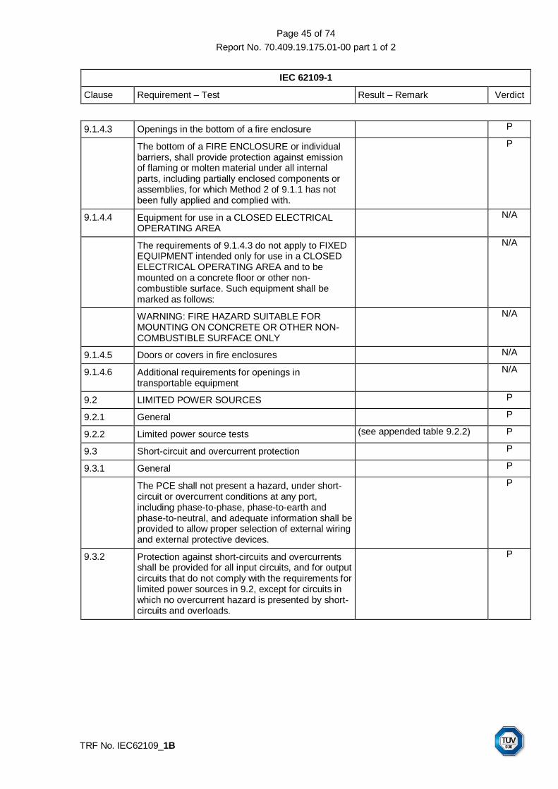
Page 45 of 74
Report No. 70.409.19.175.01-00 part 1 of 2
IEC 62109-1
Clause Requirement – Test Result – Remark Verdict
TRF No. IEC62109_1B
9.1.4.3 Openings in the bottom of a fire enclosure P
The bottom of a FIRE ENCLOSURE or individual barriers, shall provide protection against emission of flaming or molten material under all internal parts, including partially enclosed components or assemblies, for which Method 2 of 9.1.1 has not been fully applied and complied with.
P
9.1.4.4 Equipment for use in a CLOSED ELECTRICAL OPERATING AREA
N/A
The requirements of 9.1.4.3 do not apply to FIXED EQUIPMENT intended only for use in a CLOSED ELECTRICAL OPERATING AREA and to be mounted on a concrete floor or other non-combustible surface. Such equipment shall be marked as follows:
N/A
WARNING: FIRE HAZARD SUITABLE FOR MOUNTING ON CONCRETE OR OTHER NON-COMBUSTIBLE SURFACE ONLY
N/A
9.1.4.5 Doors or covers in fire enclosures N/A
9.1.4.6 Additional requirements for openings in transportable equipment
N/A
9.2 LIMITED POWER SOURCES P
9.2.1 General P
9.2.2 Limited power source tests (see appended table 9.2.2) P
9.3 Short-circuit and overcurrent protection P
9.3.1 General P
The PCE shall not present a hazard, under short-circuit or overcurrent conditions at any port, including phase-to-phase, phase-to-earth and phase-to-neutral, and adequate information shall be provided to allow proper selection of external wiring and external protective devices.
P
9.3.2 Protection against short-circuits and overcurrents shall be provided for all input circuits, and for output circuits that do not comply with the requirements for limited power sources in 9.2, except for circuits in which no overcurrent hazard is presented by short-circuits and overloads.
P
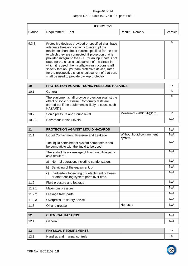
Page 46 of 74
Report No. 70.409.19.175.01-00 part 1 of 2
IEC 62109-1
Clause Requirement – Test Result – Remark Verdict
TRF No. IEC62109_1B
9.3.3 Protective devices provided or specified shall have adequate breaking capacity to interrupt the maximum short circuit current specified for the port to which they are connected. If protection that is provided integral to the PCE for an input port is not rated for the short-circuit current of the circuit in which it is used, the installation instructions shall specify that an upstream protective device, rated for the prospective short-circuit current of that port, shall be used to provide backup protection.
P
10 PROTECTION AGAINST SONIC PRESSURE HAZARDS P
10.1 General P
The equipment shall provide protection against the effect of sonic pressure. Conformity tests are carried out if the equipment is likely to cause such HAZARDS.
P
10.2 Sonic pressure and Sound level Measured <<80dBA@1m P
10.2.1 Hazardous Noise Levels N/A
11 PROTECTION AGAINST LIQUID HAZARDS N/A
11.1 Liquid Containment, Pressure and Leakage Without liquid containment system
N/A
The liquid containment system components shall be compatible with the liquid to be used.
N/A
There shall be no leakage of liquid onto live parts as a result of:
N/A
a) Normal operation, including condensation; N/A
b) Servicing of the equipment; or N/A
c) Inadvertent loosening or detachment of hoses or other cooling system parts over time.
N/A
11.2 Fluid pressure and leakage N/A
11.2.1 Maximum pressure N/A
11.2.2 Leakage from parts N/A
11.2.3 Overpressure safety device N/A
11.3 Oil and grease Not used N/A
12 CHEMICAL HAZARDS N/A
12.1 General N/A
13 PHYSICAL REQUIREMENTS P
13.1 Handles and manual controls P

Page 47 of 74
Report No. 70.409.19.175.01-00 part 1 of 2
IEC 62109-1
Clause Requirement – Test Result – Remark Verdict
TRF No. IEC62109_1B
Handles, knobs, grips, levers and the like shall be reliably fixed so that they will not work loose in normal use, if this might result in a hazard. Sealing compounds and the like, other than self-hardening resins, shall not be used to prevent loosening. If handles, knobs and the like are used to indicate the position of switches or similar components, it shall not be possible to fix them in a wrong position if this might result in hazard.
DC switch, PV connector and Communication connector on bottom and cable gland
P
13.1.1 Adjustable controls Without adjustable controls N/A
13.2 Securing of parts P
13.3 Provisions for external connections P
13.3.1 General P
13.3.2 Connection to an a.c. Mains supply Terminal block for AC cable connection with cable gland for tightening
P
13.3.2.1 General P
For safe and reliable connection to a MAINS supply, equipment shall be provided with one of the following:
P
– terminals or leads or a non-detachable power supply cord for permanent connection to the supply; or
P
– a non-detachable power supply cord for connection to the supply by means of a plug
N/A
– an appliance inlet for connection of a detachable power supply cord; or
N/A
– a mains plug that is part of direct plug-in equipment as in 13.3.8
N/A
13.3.2.2 Permanently connected equipment A set of terminals as specified in 13.3.3 for external connection of supply cords.
P
13.3.2.3 Appliance inlets N/A
13.3.2.4 Power supply cord Not provided together with power cord for connecting to AC terminals, the installer should follow user manual
N/A
13.3.2.5 Cord anchorages and strain relief N/A
For equipment with a non-detachable power supply cord, a cord anchorage shall be supplied such that:
N/A
– the connecting points of the cord conductors are relieved from strain; and
N/A
– the outer covering of the cord is protected from abrasion.
N/A
13.3.2.6 Protection against mechanical damage N/A

Page 48 of 74
Report No. 70.409.19.175.01-00 part 1 of 2
IEC 62109-1
Clause Requirement – Test Result – Remark Verdict
TRF No. IEC62109_1B
13.3.3 Wiring terminals for connection of external conductors
P
13.3.3.1 Wiring terminals P
13.3.3.2 Screw terminals P
13.3.3.3 Wiring terminal sizes P
13.3.3.4 Wiring terminal design P
13.3.3.5 Grouping of wiring terminals P
13.3.3.6 Stranded wire P
13.3.4 Supply wiring space P
13.3.5 Wire bending space for wires 10 mm² and greater P
13.3.6 Disconnection from supply sources Disconnect the unit from the MAINS by automatic disconnecting relays in all live conductor and PV supply by the DC integrated switches
P
13.3.7 Connectors, plugs and sockets Approved PV connector used P
13.3.8 Direct plug-in equipment N/A
13.4 Internal wiring and connections P
13.4.1 General P
13.4.2 Routing P
13.4.3 Colour coding Conductor having green-and-yellow insulation is used only for protective earthing and bonding connection
P
13.4.4 Splices and connections P
13.4.5 Interconnections between parts of the PCE N/A
13.5 Openings in enclosures P
13.5.1 Top and side openings P
Openings in the top and sides of ENCLOSURES shall be so located or constructed that it is unlikely that objects will enter the openings and create hazards by contacting bare conductive parts.
P
13.6 Polymeric Materials P
13.6.1 General UL approved material used. LED cover, DC switch, DC connector, communication port coupler, cable gland: V-0, suitable for outdoor use with respect to exposure to Ultraviolet Light, Water Exposure and Immersion in accordance with UL 746C
P

Page 49 of 74
Report No. 70.409.19.175.01-00 part 1 of 2
IEC 62109-1
Clause Requirement – Test Result – Remark Verdict
TRF No. IEC62109_1B
13.6.1.1 Thermal index or capability Thermal index of Polymeric Materials used higher than the maximum measured operating temperature in heating test
P
13.6.2 Polymers serving as enclosures or barriers preventing access to hazards
N/A
13.6.2.1 Stress relief test N/A
13.6.3 Polymers serving as solid insulation P
13.6.3.1 Resistance to arcing P
13.6.4 UV resistance P
Polymeric parts of an OUTDOOR ENCLOSURE required for compliance with this standard shall be sufficiently resistance to degradation by ultra-violet (UV) radiation
P
13.7 Mechanical resistance to deflection, impact, or drop P
13.7.1 General P
13.7.2 250-N deflection test for metal enclosures P
13.7.3 7-J impact test for polymeric enclosures LED cover P
13.7.4 Drop test N/A
13.8 Thickness requirements for metal enclosures P
13.8.1 General Conformity is checked by the test as specified in clause 13.7
P
13.8.2 Cast metal P
13.8.3 Sheet metal N/A
14 COMPONENTS P
14.1 General (see appended table 14) P
Where safety is involved, components shall be used in accordance with their specified RATINGS unless a specific exception is made. They shall conform to one of the following:
P
a) applicable safety requirements of a relevant IEC standard. Conformity with other requirements of the component standard is not required. If necessary for the application, components shall be subjected to the test of this standard, except that it is not necessary to carry out identical or equivalent tests already performed to check conformity with the component standard;
P

Page 50 of 74
Report No. 70.409.19.175.01-00 part 1 of 2
IEC 62109-1
Clause Requirement – Test Result – Remark Verdict
TRF No. IEC62109_1B
b) the requirements of this standard and, where necessary for the application, any additional applicable safety requirements of the relevant IEC component standard;
P
c) if there is no relevant IEC standard, the requirements of this standard;
P
d) applicable safety requirements of a non-IEC standard which are at least as high as those of the applicable IEC standard, provided that the component has been approved to the non-IEC standard by a recognized testing authority.
P
Components such as optocouplers, capacitors, transformers, and relays connected across basic, supplemental, reinforced, or double insulation shall comply with the requirements applicable for the grade of insulation being bridged, and if not previously certified to the applicable component safety standard shall be subjected to the voltage test of 7.5.2 as routine test.
P
14.2 Motor Over Temperature Protection N/A
Motors which, when stopped or prevented from starting (see 4.4.4.3), would present an electric shock HAZARD, a temperature HAZARD, or a fire HAZARD, shall be protected by an over temperature or thermal protection device meeting the requirements of 14.3.
N/A
14.3 Over temperature protection devices Power limited by temperature control in single fault condition or high temperature environment condition
P
14.4 Fuse holders Not replaced by operator N/A
14.5 MAINS voltage selecting devices N/A
14.6 Printed circuit boards P
Printed circuit boards shall be made of material with a flammability classification of V-1 of IEC 60707 or better.
PCB material approved by UL with UL94 V-0 rating
P
This requirement does not apply to thin-film flexible printed circuit boards that contain only circuits powered from limited power sources meeting the requirements of 9.2.
N/A
Conformity of the flammability RATING is checked by inspection of data on the materials. Alternatively, conformity is checked by performing the V-1 tests specified in IEC 60707 on three samples of the relevant parts.
P
14.7 Circuits or components used as transient overvoltage limiting devices P

Page 51 of 74
Report No. 70.409.19.175.01-00 part 1 of 2
IEC 62109-1
Clause Requirement – Test Result – Remark Verdict
TRF No. IEC62109_1B
If control of transient overvoltage is employed in the equipment, any overvoltage limiting component or circuit shall be tested with the applicable impulse withstand voltage of Table 7-10 using the test method from 7.5.1 except 10 positive and 10 negative impulses are to be applied and may be spaced up to 1 min apart.
P
14.8 Batteries N/A
Equipment containing batteries shall be designed to reduce the risk of fire, explosion and chemical leaks under normal conditions and after a single fault in the equipment including a fault in circuitry within the equipment battery pack.
N/A
14.8.1 Battery Enclosure Ventilation N/A
14.8.1.1 Ventilation requirements N/A
14.8.1.2 Ventilation testing N/A
14.8.1.3 Ventilation instructions N/A
14.8.2 Battery Mounting N/A
Compliance is verified by the application of the force to the battery's mounting surface. The test force is to be increased gradually so as to reach the required value in 5 to 10 s, and is to be maintained at that value for 1 min. A non-metallic rack or tray shall be tested at the highest normal condition operating temperature.
N/A
14.8.3 Electrolyte spillage N/A
Battery trays and cabinets shall have an electrolyte-resistant coating.
N/A
The ENCLOSURE or compartment housing a VENTED BATTERY shall be constructed so that spillage or leakage of the electrolyte from one battery will be contained within the ENCLOSURE and be prevented from:
N/A
a) reaching the PCE outer surfaces that can be contacted by the USER
N/A
b) contaminating adjacent electrical components or materials; and
N/A
c) bridging required electrical distances N/A
14.8.4 Battery Connections N/A
Reverse battery connection of the terminals shall be prevented if reverse connection could result in a hazard within the meaning of this Standard
N/A
14.8.5 Battery maintenance instructions N/A

Page 52 of 74
Report No. 70.409.19.175.01-00 part 1 of 2
IEC 62109-1
Clause Requirement – Test Result – Remark Verdict
TRF No. IEC62109_1B
The information and instructions listed in 5.3.4.1 shall be included in the operator manual for equipment in which battery maintenance is performed by the operator, or in the service manual if battery maintenance is to be performed by service personnel only.
N/A
14.8.6 Battery accessibility and maintainability N/A
Battery terminals and connectors shall be accessible for maintenance with the correct TOOLS. Batteries with liquid electrolyte, requiring maintained shall be so located that the battery cell caps are accessible for electrolyte tests and readjusting of electrolyte levels.
N/A
15 Software and firmware performing safety functions IEC 60730-1 Annex H considered
P
EN 62109-1:2010 P
Annex ZA Normative references to international publications with their corresponding European publications
Considered P
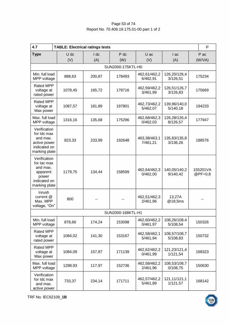
Page 53 of 74
Report No. 70.409.19.175.01-00 part 1 of 2
TRF No. IEC62109_1B
4.7 TABLE: Electrical ratings tests P
Type U dc
(V)
I dc
(A)
P dc
(W)
U ac
(V)
I ac
(A)
P ac
(W/VA)
SUN2000-175KTL-H0
Min. full load MPP voltage
888,63 200,87 178493 462,61/462,2
6/462,91 126,20/126,4
3/126,51 175234
Rated MPP voltage at
rated power 1078,45 165,72 178716
462,59/462,23/461,99
126,51/126,73/126,83
175669
Rated MPP voltage at Max power
1087,57 181,89 197801 462,73/462,2
5/462,07 139,96/140,0
5/140,18 194233
Max. full load MPP voltage
1316,16 135,68 175296 462,68/462,3
0/462,03 126,28/126,4
8/126,57 177947
Verification for Idc max and max.
active power indicated on
marking plate
823,33 233,99 192648 463,38/463,1
7/461,21 135,83/135,8
3/136,26 188576
Verification for Iac max and max. apparent
power indicated on
marking plate
1179,75 134,44 158599 462,64/462,3
0/462,00 140,05/140,2
9/140,42 155201VA @PF=0,8
Inrush current @ Max. MPP
voltage, “On”
800 -- -- 462,51/462,3
2/461,96 13,27A
@18,5ms --
SUN2000-168KTL-H1
Min. full load MPP voltage
878,66 174,24 153098 462,60/462,2
0/461,97 108,26/108,4
5/108,54 150326
Rated MPP voltage at
rated power 1084,02 141,30 153167
462,58/462,15/461,94
108,57/108,75/108,83
150732
Rated MPP voltage at Max power
1084,09 157,87 171139 462,62/462,2
0/461,99 121,23/121,4
1/121,54 168323
Max. full load MPP voltage
1298,93 117,97 152736 462,58/462,2
2/461,96 108,53/108,7
0/108,75 150630
Verification for Idc max and max.
active power
733,37 234,14 171711 462,57/462,2
5/461,89 121,11/121,1
1/121,57 168142

Page 54 of 74
Report No. 70.409.19.175.01-00 part 1 of 2
TRF No. IEC62109_1B
indicated on marking plate
Verification for Iac max and max. apparent
power indicated on
marking plate
1179,55 116,94 137916 462,66/462,2
2/462,05 122,02/122,2
0/122,31 135154VA @PF=0,8
Inrush current @ Max. MPP
voltage, “On”
800 -- -- 462,51/462,2
2/461,89 11,05A
@8,5ms --
SUN2000-185KTL-H1
Min. full load MPP voltage
881,89 202,76 178801 462,67/462,2
2/462,03 126,25/126,4
6/126,59 175327
Rated MPP voltage at
rated power 1079,02 165,12 178154
462,66/462,22/462,03
126,13/126,29/126,44
175122
Rated MPP voltage at Max power
1078,71 175,15 188923 462,73/462,2
5/462,07 133,66/133,9
0/134,11 185651
Max. full load MPP voltage
1298,65 138,28 179020 462,63/462,2
4/461,98 127,10/127,2
7/127,36 176408
Verification for Idc max and max.
active power indicated on
marking plate
807,36 234,00 188922 463,37/463,0
8/461,21 133,242/133,242/133,674
184973
Verification for Iac max and max. apparent
power indicated on
marking plate
1179,83 128,82 151981 462,65/462,3
0/462,01 134,34/134,5
6/134,68 148837VA @PF=0,8
Inrush current @ Max. MPP
voltage, “On”
800 -- -- 462,28/461,9
3/461,59 15,29A @16ms
--
SUN2000-185KTL-INH0
Min. full load MPP voltage
876,66 185,49 162602 462,62/462,2
1/461,97 114,91/115,2
5/115,16 159607
Rated MPP voltage at
rated power 1082,43 150,33 160063
462,62/462,21/461,98
115,31/115,49/115,51
160063

Page 55 of 74
Report No. 70.409.19.175.01-00 part 1 of 2
TRF No. IEC62109_1B
Rated MPP voltage at Max power
1082,27 174,57 188925 462,65/462,2
5/462,00 133,64/133,9
3/134,07 185642
Max. full load MPP voltage
1298,69 125,75 162794 462,63/462,2
1/461,99 115,57/115,8
8/115,86 160498
Verification for Idc max and max.
active power indicated on
marking plate
807,36 234 188922 463,37/463,0
8/461,21 133,242/133,242/133,674
184973
Verification for Iac max and max. apparent
power indicated on
marking plate
1179,69 128,95 152115 462,72/462,2
8/462,06 134,39/134,6
0/134,72 148896VA @PF=0,8
Inrush current @ Max. MPP
voltage, “On”
800 -- -- 462,60/462,2
1/461,98 10,1A@11,5
ms --
Supplementary information:
4.3 TABLE: heating temperature rise measurements (SUN2000-175KTL-H0) P
Test voltage(PV Input) .................................... : 8801 8802 13003 8804 --
Test voltage(AC Output) ................................. : 720 880 720 720 --
Test frequency(Hz) ......................................... : 50 50 50 50 --
Output power(kW) .......................................... : 171,1 177,2 140,2 168,3 --
Test duration(minutes).................................... : 410 415 425 420 --
maximum temperature T of part/at: T (°C) allowed Tmax (°C)
Ambient 40,0 40,0 40,0 40,0 --
Core of INV inductor 95,7 95,0 96,2 96,2 150,0
Coil of INV inductor 116,5 110,0 111,0 116,7 150,0
Core of Boost inductor 89,1 109,3 47,9 89,9 150,0
Coil of Boost inductor 94,9 116,7 47,8 95,1 150,0
INV IGBT module (Phase A) 86,9 87,2 76,9 88,1 130,0*
INV IGBT module (Phase B) 86,0 86,4 75,8 87,1 130,0*
INV IGBT module (Phase C) 86,4 87,3 76,6 86,4 130,0*
Boost IGBT(DEF) 77,5 81,3 60,1 78,9 130,0*
Boost IGBT(GHI) 70,7 74,2 58,1 71,1 130,0*
Boost inductor wire 77,6 81,1 62,1 77,5 105,0
INV inductor wire 88,0 84,2 78,3 86,6 105,0
X capacitor (C173) 77,2 77,4 67,6 76,5 105,0

Page 56 of 74
Report No. 70.409.19.175.01-00 part 1 of 2
TRF No. IEC62109_1B
Fly Cap.(C286) 79,8 82,3 67,0 79,2 105,0
Drive Optocoupler(Phase B) 82,4 80,9 73,7 81,8 110,0
Boost Current Hall(U47) 79,6 80,2 68,5 78,9 105,0
PV SPD(F304) 74,8 75,9 64,1 74,3 85,0
PV SPD(F604) 76,5 77,2 65,9 75,8 85,0
PV input Y capacitor(C608) 77,5 77,8 67,0 76,6 125,0
Relay(K9) 82,4 83,0 70,2 81,6 85,0
Relay(K1) 77,6 76,8 68,8 76,6 85,0
ISO relay(K8) 78,8 77,3 70,6 78,3 85,0
ISO relay(K4) 78,1 76,6 70,1 77,4 85,0
INV BUS Capacitor(C1427) 81,3 79,7 71,5 80,9 105,0
PCB 85,4 83,2 79,8 84,6 130,0
Hall(U10) 77,6 80,9 63,3 77,8 105,0
Hall(U28) 79,3 81,4 65,5 78,9 105,0
DC AUX IC(U23) 80,7 80,2 72,8 79,7 105,0
Coil of DC Aux Transformer T2 85,1 83,8 76,4 83,9 130,0
Core of DC Aux Transformer T2 84,1 83,0 75,9 82,9 130,0
AC AUX IC(U24) 83,4 82,4 75,2 82,3 105,0
Bobbin of DC Aux Transformer T2 79,8 78,2 71,7 78,5 130,0
Optocoupler(U40) 80,8 79,8 72,7 79,7 110,0
Optocoupler(U1101) 80,8 78,9 72,3 79,6 110,0
Optocoupler(U14) 92,8 87,4 85,0 91,3 110,0
MOS of AC Aux(Q42) 95,7 93,3 88,0 94,0 115,0
Bobbin of AC Aux Transformer T1 84,1 80,8 76,2 83,0 130,0
MOS of DC Aux(Q38) 84,0 83,6 76,5 83,2 115,0
Coil of AC Aux Transformer T1 88,3 84,4 80,6 87,3 130,0
Core of AC Aux Transformer T1 87,0 83,3 79,5 86,0 130,0
DC AUX Current Sampling Transformer(T8) 78,7 78,0 71,0 77,7 130,0
5v BUCK IC(U36) 83,7 82,7 74,8 82,5 125,0
3.3V BUCK IC(U35) 82,1 81,1 73,3 80,9 125,0
Optocoupler(U41) 81,9 80,8 73,1 80,8 110,0
7V BUCK IC(U54) 78,3 77,3 70,7 77,5 125,0
PWM IC(U61) 77,7 76,5 70,0 76,9 125,0
MOS for Grid relay(Q5) 77,9 76,7 70,4 77,0 115,0
Optocoupler of external fan(U20) 75,8 74,4 67,5 74,7 110,0
Optocoupler of CAN(U17) 80,9 78,5 72,7 79,7 110,0
DC Aux TVS(D174) 80,2 79,7 72,6 79,0 115,0
Optocoupler of 48V Dummy load(U45) 76,3 74,8 68,1 75,2 110,0
DC Aux drive transformer(T3) 75,2 74,1 67,2 74,3 130,0
AC Aux drive transformer(T5) 87,3 85,4 79,2 85,6 130,0
Optocoupler of external fan(U62) 75,8 74,4 67,4 74,6 110,0
AC Aux TVS(D104) 101,2 94,7 94,0 100,0 115,0

Page 57 of 74
Report No. 70.409.19.175.01-00 part 1 of 2
TRF No. IEC62109_1B
DSP1(U1500) 77,0 76,0 69,4 76,1 130,0*
DSP2(U5) 76,7 75,8 69,1 75,9 130,0*
AC X capacitor(C376) 77,3 75,8 70,4 76,7 105,0
AC Y capacitor(C502) 76,5 74,7 67,9 75,4 125,0
Grid relay(K10) 80,9 78,3 71,9 80,5 85,0
AC Aux sampling transformer(T10) 79,9 78,2 71,4 78,7 125,0
Inductor (L10) 104,4 95,0 87,4 102,6 125,0
X capacitor(C104) 71,8 72,1 62,3 71,1 125,0
Grid relay(K11) 80,6 78,1 71,7 80,4 85,0
INV Current Hall(U25) 80,4 78,5 71,6 79,6 85,0
BUS capacitor 76,4 75,4 75,2 75,2 105,0
Ambient of Internal Fan 72,9 71,7 65,2 72,1 85,0
EMI Chock(T11) 84,6 80,6 73,8 83,9 125,0
AC SPD(F2) 79,9 77,3 70,5 78,7 85,0
Ambient of Internal Fan 75,7 74,7 67,7 74,9 85,0
EMI chock(T11) 95,1 88,0 80,6 93,8 125,0
X capacitor(C478,C1708) 85,3 81,3 74,3 84,5 125,0
RCD Hall(U34) 79,4 77,2 70,3 78,4 105,0
Internal Fan 75,8 74,8 67,9 75,0 85,0
Mounting Surface 50,7 51,4 46,9 47,7 70,0
PV connector 68,4 68,8 59,5 68,0 90,0
Air outlet 60,5 62,2 53,8 62,4 --
AC terminal block 95,5 90,5 85,2 77,8 115,0
AC output power cord 79,5 78,4 76,2 75,7 105,0
Front cover 54,8 54,6 51,0 55,8 70,0
Ambient of DC switch 44,0 44,4 42,4 44,3 70,0
Output current Hall(U43) 83,7 82,0 75,6 82,8 115,0
PV internal wire 76,1 76,6 64,0 75,1 105,0
PV voltage Hall(U18) 84,0 82,4 76,1 83,2 105,0
DC switch 75,5 75,8 64,7 74,1 85,0
Supplementary information: 1. Lowest full load MPP voltage with rated power output @40°C (Wall mounting & without power derating)
2. Lowest full load MPP voltage with rated power output @40C (Wall mounting & without power derating)
3. Highest full load MPP voltage with rated power output @40C (Wall mounting & without power derating)
4. Lowest full load MPP voltage with rated power output @40C (Lie down & without power derating) 5. ‘*’ refer to PCB temperature limit value.
4.3 TABLE: heating temperature rise measurements (SUN2000-175KTL-H0) P
Test voltage(PV Input) .................................... : 8801 13002 13003 8804 --
Test voltage(AC Output) ................................. : 880 720 880 720 --
Test frequency(Hz) ......................................... : 50 50 50 50 --
Output power(kW) ........................................... : 177.3 139.5 179.0 152.3 --
Test duration(minutes) .................................... : 410 415 425 420 --

Page 58 of 74
Report No. 70.409.19.175.01-00 part 1 of 2
TRF No. IEC62109_1B
maximum temperature T of part/at: T (°C) allowed Tmax (°C)
Ambient 40,0 40,0 40,0 50,0 --
Core of INV inductor 95,3 96,1 94,3 93,0 150,0
Coil of INV inductor 110,3 111,0 109,8 109,8 150,0
Core of Boost inductor 110,5 48,9 50,4 87,6 150,0
Coil of Boost inductor 118,3 48,8 50,3 91,9 150,0
INV IGBT module (Phase A) 88,3 77,2 78,7 87,1 130,0*
INV IGBT module (Phase B) 87,4 76,0 77,9 86,2 130,0*
INV IGBT module (Phase C) 86,7 75,8 78,0 85,5 130,0*
Boost IGBT(DEF) 82,6 60,6 65,0 78,8 130,0*
Boost IGBT(GHI) 73,7 57,7 62,6 71,9 130,0*
Boost inductor wire 81,5 61,9 64,1 76,9 105,0
INV inductor wire 83,1 76,9 77,4 84,4 105,0
X capacitor (C173) 77,0 66,7 67,6 76,1 105,0
Fly Cap.(C286) 81,6 66,3 67,2 78,4 105,0
Drive Optocoupler(Phase B) 80,0 72,8 73,1 81,3 110,0
Boost Current Hall(U47) 79,5 67,6 68,7 78,4 105,0
PV SPD(F304) 75,9 62,6 63,8 74,1 85,0
PV SPD(F604) 76,7 64,7 65,8 75,4 85,0
PV input Y capacitor(C608) 77,2 65,9 67,0 76,2 125,0
Relay(K9) 82,4 69,7 70,8 81,0 85,0
Relay(K1) 75,9 67,7 68,0 76,2 85,0
ISO relay(K8) 76,9 69,9 70,3 77,9 85,0
ISO relay(K4) 76,0 69,1 69,4 77,0 85,0
INV BUS Capacitor(C1427) 79,4 70,8 71,2 80,1 105,0
PCB 82,3 78,7 74,3 83,2 130,0
Hall(U10) 81,4 62,7 64,6 77,3 105,0
Hall(U28) 81,4 64,9 66,7 78,2 105,0
DC AUX IC(U23) 79,3 71,6 71,8 79,6 105,0
Coil of DC Aux Transformer T2 82,8 74,9 74,8 83,4 130,0
Core of DC Aux Transformer T2 82,0 74,4 74,3 82,4 130,0
AC AUX IC(U24) 81,3 73,9 72,8 81,9 105,0
Bobbin of DC Aux Transformer T2 77,3 70,2 69,8 78,2 130,0
Optocoupler(U40) 78,8 71,3 71,4 79,4 110,0
Optocoupler(U1101) 77,8 70,8 70,4 78,9 110,0
Optocoupler(U14) 88,0 83,4 74,7 90,4 110,0
MOS of AC Aux(Q42) 92,8 86,0 76,0 93,3 115,0
Bobbin of AC Aux Transformer T1 80,8 74,9 70,7 82,2 130,0
MOS of DC Aux(Q38) 83,0 75,5 75,3 82,9 115,0
Coil of AC Aux Transformer T1 84,7 79,2 72,9 86,5 130,0
Core of AC Aux Transformer T1 83,6 78,1 72,1 85,2 130,0
DC AUX Current Sampling Transformer(T8) 76,9 69,6 69,8 77,4 130,0

Page 59 of 74
Report No. 70.409.19.175.01-00 part 1 of 2
TRF No. IEC62109_1B
5v BUCK IC(U36) 81,6 73,4 73,5 82,7 125,0
3.3V BUCK IC(U35) 80,0 72,0 72,0 81,0 125,0
Optocoupler(U41) 79,9 71,9 71,9 81,0 110,0
7V BUCK IC(U54) 76,6 69,7 69,8 77,3 125,0
PWM IC(U61) 75,8 69,1 68,8 76,6 125,0
MOS for Grid relay(Q5) 76,0 69,4 69,3 76,7 115,0
Optocoupler of external fan(U20) 73,5 66,3 66,3 74,7 110,0
Optocoupler of CAN(U17) 77,9 71,4 69,7 79,1 110,0
DC Aux TVS(D174) 78,5 71,1 71,1 78,8 115,0
Optocoupler of 48V Dummy load(U45) 74,0 66,9 66,6 75,1 110,0
DC Aux drive transformer(T3) 73,3 66,2 66,3 74,1 130,0
AC Aux drive transformer(T5) 84,5 77,5 72,5 85,3 130,0
Optocoupler of external fan(U62) 73,5 66,3 66,3 74,6 110,0
AC Aux TVS(D104) 96,1 92,6 77,6 98,5 115,0
DSP1(U1500) 75,2 68,4 68,3 75,9 130,0*
DSP2(U5) 75,0 68,1 68,2 75,7 130,0*
AC X capacitor(C376) 75,4 69,8 68,9 76,2 105,0
AC Y capacitor(C502) 73,6 66,8 67,2 74,9 125,0
Grid relay(K10) 78,1 71,4 71,7 79,4 85,0
AC Aux sampling transformer(T10) 77,2 70,0 69,7 78,1 125,0
Inductor(L10) 94,1 86,2 87,9 97,4 125,0
X capacitor(C104) 71,4 61,5 62,7 70,8 125,0
Grid relay(K11) 78,0 71,3 71,6 79,3 85,0
INV Current Hall(U25) 77,8 70,8 71,2 78,9 85,0
BUS capacitor 74,4 74,0 66,8 74,7 105,0
Ambient of Internal Fan 70,8 64,2 64,7 72,0 85,0
EMI Chock(T11) 80,1 73,0 73,9 82,0 125,0
AC SPD(F2) 76,3 69,2 69,8 77,7 85,0
Ambient of Internal Fan 74,0 66,6 66,7 74,6 85,0
EMI chock(T11) 87,4 79,7 81,3 90,1 125,0
X capacitor(C478,C1708) 80,6 73,3 74,3 82,4 125,0
RCD Hall(U34) 76,3 69,1 69,5 77,5 105,0
Internal Fan 73,9 66,8 67,5 74,9 85,0
Mounting Surface 48,1 44,0 45,8 50,7 70,0
PV connector 68,4 59,1 60,2 68,6 90,0
Air outlet 63,8 54,7 58,8 64,7 --
AC terminal block 75,4 70,8 76,7 87,8 115,0
AC output power cord 75,3 69,1 78,3 102,9 105,0
Front cover 55,4 51,1 51,3 58,1 70,0
Ambient of DC switch 45,0 42,5 42,9 48,8 70,0
Output current Hall(U43) 81,2 74,6 74,6 82,4 115,0
PV internal wire 75,8 63,1 64,9 74,6 105,0

Page 60 of 74
Report No. 70.409.19.175.01-00 part 1 of 2
TRF No. IEC62109_1B
PV voltage Hall(U18) 81,7 75,2 75,1 82,8 105,0
DC switch 74,4 63,3 64,8 73,5 85,0
Supplementary information: 1. Lowest full load MPP voltage with rated power output @40°C (Lie down & without power derating)
2. Highest full load MPP voltage with rated power output @40C (Lie down & without power derating)
3. Lowest full load MPP voltage with rated power output @50C (Lie down & with power derating)
4. Highest full load MPP voltage with rated power output @60C (power derating to thermal steady) 5. ‘*’ refer to PCB temperature limit value.
4.3 TABLE: heating temperature rise measurements (SUN2000-175KTL-H0) P
Test voltage(PV Input) .................................... : 13001 8802 13003 -- --
Test voltage(AC Output) ................................. : 880 720 880 -- --
Test frequency(Hz) ......................................... : 50 50 50 -- --
Output power(kW) ........................................... : 165,1 128,9 135,3 -- --
Test duration(minutes) .................................... : 410 415 425 -- --
maximum temperature T of part/at: T (°C) allowed Tmax (°C)
Ambient 50 60 60 -- --
Core of INV inductor 95,3 96,1 94,3 -- 150,0
Coil of INV inductor 110,3 111,0 109,8 -- 150,0
Core of Boost inductor 110,5 48,9 50,4 -- 150,0
Coil of Boost inductor 118,3 48,8 50,3 -- 150,0
INV IGBT module (Phase A) 88,3 77,2 78,7 -- 130,0*
INV IGBT module (Phase B) 87,4 76,0 77,9 -- 130,0*
INV IGBT module (Phase C) 86,7 75,8 78,0 -- 130,0*
Boost IGBT(DEF) 82,6 60,6 65,0 -- 130,0*
Boost IGBT(GHI) 73,7 57,7 62,6 -- 130,0*
Boost inductor wire 81,5 61,9 64,1 -- 105,0
INV inductor wire 83,1 76,9 77,4 -- 105,0
X capacitor (C173) 77,0 66,7 67,6 -- 105,0
Fly Cap.(C286) 81,6 66,3 67,2 -- 105,0
Drive Optocoupler(Phase B) 80,0 72,8 73,1 -- 110,0
Boost Current Hall(U47) 79,5 67,6 68,7 -- 105,0
PV SPD(F304) 75,9 62,6 63,8 -- 85,0
PV SPD(F604) 76,7 64,7 65,8 -- 85,0
PV input Y capacitor(C608) 77,2 65,9 67,0 -- 125,0
Relay(K9) 82,4 69,7 70,8 -- 85,0
Relay(K1) 75,9 67,7 68,0 -- 85,0
ISO relay(K8) 76,9 69,9 70,3 -- 85,0
ISO relay(K4) 76,0 69,1 69,4 -- 85,0
INV BUS Capacitor(C1427) 79,4 70,8 71,2 -- 105,0
PCB 82,3 78,7 74,3 -- 130,0
Hall(U10) 81,4 62,7 64,6 -- 105,0
Hall(U28) 81,4 64,9 66,7 -- 105,0
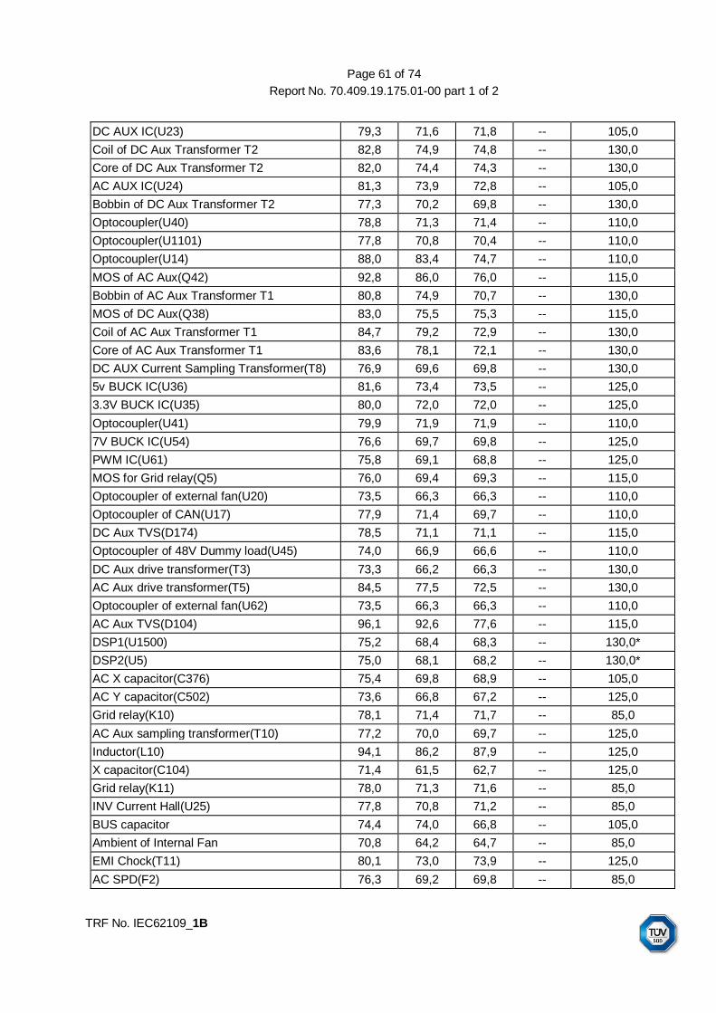
Page 61 of 74
Report No. 70.409.19.175.01-00 part 1 of 2
TRF No. IEC62109_1B
DC AUX IC(U23) 79,3 71,6 71,8 -- 105,0
Coil of DC Aux Transformer T2 82,8 74,9 74,8 -- 130,0
Core of DC Aux Transformer T2 82,0 74,4 74,3 -- 130,0
AC AUX IC(U24) 81,3 73,9 72,8 -- 105,0
Bobbin of DC Aux Transformer T2 77,3 70,2 69,8 -- 130,0
Optocoupler(U40) 78,8 71,3 71,4 -- 110,0
Optocoupler(U1101) 77,8 70,8 70,4 -- 110,0
Optocoupler(U14) 88,0 83,4 74,7 -- 110,0
MOS of AC Aux(Q42) 92,8 86,0 76,0 -- 115,0
Bobbin of AC Aux Transformer T1 80,8 74,9 70,7 -- 130,0
MOS of DC Aux(Q38) 83,0 75,5 75,3 -- 115,0
Coil of AC Aux Transformer T1 84,7 79,2 72,9 -- 130,0
Core of AC Aux Transformer T1 83,6 78,1 72,1 -- 130,0
DC AUX Current Sampling Transformer(T8) 76,9 69,6 69,8 -- 130,0
5v BUCK IC(U36) 81,6 73,4 73,5 -- 125,0
3.3V BUCK IC(U35) 80,0 72,0 72,0 -- 125,0
Optocoupler(U41) 79,9 71,9 71,9 -- 110,0
7V BUCK IC(U54) 76,6 69,7 69,8 -- 125,0
PWM IC(U61) 75,8 69,1 68,8 -- 125,0
MOS for Grid relay(Q5) 76,0 69,4 69,3 -- 115,0
Optocoupler of external fan(U20) 73,5 66,3 66,3 -- 110,0
Optocoupler of CAN(U17) 77,9 71,4 69,7 -- 110,0
DC Aux TVS(D174) 78,5 71,1 71,1 -- 115,0
Optocoupler of 48V Dummy load(U45) 74,0 66,9 66,6 -- 110,0
DC Aux drive transformer(T3) 73,3 66,2 66,3 -- 130,0
AC Aux drive transformer(T5) 84,5 77,5 72,5 -- 130,0
Optocoupler of external fan(U62) 73,5 66,3 66,3 -- 110,0
AC Aux TVS(D104) 96,1 92,6 77,6 -- 115,0
DSP1(U1500) 75,2 68,4 68,3 -- 130,0*
DSP2(U5) 75,0 68,1 68,2 -- 130,0*
AC X capacitor(C376) 75,4 69,8 68,9 -- 105,0
AC Y capacitor(C502) 73,6 66,8 67,2 -- 125,0
Grid relay(K10) 78,1 71,4 71,7 -- 85,0
AC Aux sampling transformer(T10) 77,2 70,0 69,7 -- 125,0
Inductor(L10) 94,1 86,2 87,9 -- 125,0
X capacitor(C104) 71,4 61,5 62,7 -- 125,0
Grid relay(K11) 78,0 71,3 71,6 -- 85,0
INV Current Hall(U25) 77,8 70,8 71,2 -- 85,0
BUS capacitor 74,4 74,0 66,8 -- 105,0
Ambient of Internal Fan 70,8 64,2 64,7 -- 85,0
EMI Chock(T11) 80,1 73,0 73,9 -- 125,0
AC SPD(F2) 76,3 69,2 69,8 -- 85,0

Page 62 of 74
Report No. 70.409.19.175.01-00 part 1 of 2
TRF No. IEC62109_1B
Ambient of Internal Fan 74,0 66,6 66,7 -- 85,0
EMI chock(T11) 87,4 79,7 81,3 -- 125,0
X capacitor(C478,C1708) 80,6 73,3 74,3 -- 125,0
RCD Hall(U34) 76,3 69,1 69,5 -- 105,0
Internal Fan 73,9 66,8 67,5 -- 85,0
Mounting Surface 48,1 44,0 45,8 -- 70,0
PV connector 68,4 59,1 60,2 -- 90,0
Air outlet 63,8 54,7 58,8 -- --
AC terminal block 75,4 70,8 76,7 -- 115,0
AC output power cord 75,3 69,1 78,3 -- 105,0
Front cover 55,4 51,1 51,3 -- 70,0
Ambient of DC switch 45,0 42,5 42,9 -- 70,0
Output current Hall(U43) 81,2 74,6 74,6 -- 115,0
PV internal wire 75,8 63,1 64,9 -- 105,0
PV voltage Hall(U18) 81,7 75,2 75,1 -- 105,0
DC switch 74,4 63,3 64,8 -- 85,0
Supplementary information: 1. Highest full load MPP voltage with rated power output @50°C (Lie down & with power derating)
2. Lowest full load MPP voltage with rated power output @60C (Lie down & with power derating)
3. Highest full load MPP voltage with rated power output @60C (Lie down & with power derating) 4. ‘*’ refer to PCB temperature limit value.
4.3 TABLE: heating temperature rise measurements (SUN2000-175KTL-H0) P
Test voltage(PV Input) .................................... : 8801 8802 8803 8804 -- --
Test voltage(AC Output) ................................. : 720 720 720 720 -- --
Test frequency(Hz) ......................................... : 50 50 50 50 -- --
Output power(kW) .......................................... : 131.2 168.5 24.1 124.3 -- --
Test duration(minutes) .................................... : 410 415 410 415 -- --
maximum temperature T of part/at: T (°C) allowed Tmax
(°C)
Ambient 40,0 40,0 40,0 40,0 -- --
Core of INV inductor 77,9 96,8 70,5 84,7 -- --
Coil of INV inductor 90,4 117,4 70,6 95,1 -- --
Core of Boost inductor 72,5 91,5 73,9 77,9 -- --
Coil of Boost inductor 74,0 97,0 73,4 79,7 -- --
INV IGBT module (Phase A) 73,8 87,9 95,9 95,6 -- --
INV IGBT module (Phase B) 73,2 87,0 95,4 93,2 -- --
INV IGBT module (Phase C) 73,1 87,0 90,2 77,9 -- --
Boost IGBT(DEF) 65,8 77,4 95,6 87,8 -- --
Boost IGBT(GHI) 62,0 71,7 84,9 66,9 -- --
Boost inductor wire 65,9 78,7 69,4 70,4 -- --
INV inductor wire 84,2 86,6 57,9 73,1 -- --
X capacitor (C173) 64,8 79,9 59,9 68,2 -- --

Page 63 of 74
Report No. 70.409.19.175.01-00 part 1 of 2
TRF No. IEC62109_1B
Fly Cap.(C286) 71,1 80,2 65,0 70,8 -- --
Drive Optocoupler(Phase B) 79,0 82,4 66,8 72,4 -- --
Boost Current Hall(U47) 71,0 79,9 64,6 70,2 -- --
PV SPD(F304) 59,6 75,7 58,6 65,9 -- --
PV SPD(F604) 61,3 77,4 58,8 67,3 -- --
PV input Y capacitor(C608) 61,5 77,3 59,0 67,6 -- --
Relay(K9) 75,6 81,9 68,7 73,8 -- --
Relay(K1) 71,6 77,3 61,0 67,6 -- --
ISO relay(K8) 76,6 78,5 60,6 69,2 -- --
ISO relay(K4) 74,0 77,8 59,4 68,4 -- --
INV BUS Capacitor(C1427) 76,3 83,2 64,8 71,9 -- --
PCB 70,4 90,9 64,3 73,0 -- --
Hall(U10) 62,3 78,7 62,2 68,3 -- --
Hall(U28) 64,5 79,7 63,6 69,8 -- --
DC AUX IC(U23) 78,4 80,2 62,7 70,8 -- --
Coil of DC Aux Transformer T2 75,4 85,6 64,0 73,9 -- --
Core of DC Aux Transformer T2 74,4 84,1 63,4 73,2 -- --
AC AUX IC(U24) 79,7 82,8 60,2 72,9 -- --
Bobbin of DC Aux Transformer T2 72,0 79,8 58,9 68,9 -- --
Optocoupler(U40) 73,4 80,6 61,3 70,5 -- --
Optocoupler(U1101) 73,7 81,7 56,8 69,1 -- --
Optocoupler(U14) 83,9 86,7 58,3 73,7 -- --
MOS of AC Aux(Q42) 89,7 94,9 59,2 81,7 -- --
Bobbin of AC Aux Transformer T1 78,7 83,2 56,1 71,6 -- --
MOS of DC Aux(Q38) 78,4 84,1 64,4 74,3 -- --
Coil of AC Aux Transformer T1 86,3 87,9 58,0 75,3 -- --
Core of AC Aux Transformer T1 81,9 86,1 56,9 74,3 -- --
DC AUX Current Sampling Transformer(T8) 72,5 78,8 58,8 68,7 -- --
5v BUCK IC(U36) 77,1 84,0 62,3 72,5 -- --
3.3V BUCK IC(U35) 76,5 82,3 61,4 71,1 -- --
Optocoupler(U41) 73,4 82,0 61,1 71,0 -- --
7V BUCK IC(U54) 68,8 78,8 58,9 68,7 -- --
PWM IC(U61) 70,0 77,9 57,4 67,5 -- --
MOS for Grid relay(Q5) 68,3 78,1 57,4 67,7 -- --
Optocoupler of external fan(U20) 64,6 78,2 54,6 65,7 -- --
Optocoupler of CAN(U17) 68,7 80,4 57,0 69,2 -- --
DC Aux TVS(D174) 73,8 80,1 60,5 70,0 -- --
Optocoupler of 48V Dummy load(U45) 66,8 78,0 55,0 66,1 -- --
DC Aux drive transformer(T3) 66,1 75,7 55,1 65,3 -- --
AC Aux drive transformer(T5) 78,9 87,6 57,7 75,0 -- --
Optocoupler of external fan(U62) 65,0 78,1 54,9 65,7 -- --
AC Aux TVS(D104) 98,5 97,3 58,2 84,6 -- --

Page 64 of 74
Report No. 70.409.19.175.01-00 part 1 of 2
TRF No. IEC62109_1B
DSP1(U1500) 68,0 77,1 57,2 67,2 -- --
DSP2(U5) 68,0 77,2 57,5 67,1 -- --
AC X capacitor(C376) 69,1 77,4 55,3 66,7 -- --
AC Y capacitor(C502) 70,2 75,2 54,2 65,6 -- --
Grid relay(K10) 74,5 80,8 56,3 69,4 -- --
AC Aux sampling transformer(T10) 71,6 81,4 56,3 68,8 -- --
Inductor (L10) 111,5 100,7 56,0 81,0 -- --
X capacitor(C104) 61,8 71,8 52,5 62,6 -- --
Grid relay(K11) 72,1 80,7 56,5 69,4 -- --
INV Current Hall(U25) 78,4 79,7 56,6 69,5 -- --
BUS capacitor 65,2 75,8 55,8 65,7 -- --
EMI Chock(T11) 82,1 82,8 55,0 71,0 -- --
AC SPD(F2) 71,4 81,4 54,6 67,7 -- --
Ambient of Internal Fan 58,6 76,0 55,6 65,7 -- --
EMI chock(T11) 92,4 92,5 55,4 76,4 -- --
X capacitor(C478,C1708) 76,4 86,0 55,1 71,1 -- --
RCD Hall(U34) 91,2 78,8 55,3 67,7 -- --
Internal Fan 65,9 74,9 55,4 66,2 -- --
Mounting Surface 44,9 46,3 39,4 44,6 -- 90
PV connector 60,0 67,8 51,4 60,6 -- 90
Air outlet 54,5 62,5 48,9 58,7 -- --
AC terminal block 74,0 83,5 45,5 73,0 -- 90
AC output power cord 76,0 82,4 45,2 69,5 -- --
Front cover 49,9 56,4 44,4 50,5 -- 90
Ambient of DC switch 41,7 41,8 38,6 41,0 -- --
Output current Hall(U43) 74,5 83,9 63,0 73,3 -- --
PV internal wire 63,7 76,7 52,6 65,2 -- --
PV voltage Hall(U18) 74,4 84,3 64,1 74,1 -- --
DC switch 63,0 74,2 53,4 64,5 -- 90
Supplementary information: 1. Left internal fan locked @40°C (Lie down) 2. Right internal fan locked @40°C (Lie down) 3. All external fan locked @40°C (Lie down) 4. An external fan locked @40°C (Lie down)
4.4 TABLE: fault condition tests P
ambient temperature (C) ...................................... : 25,0
No. component
No. fault
test voltage (V)
test time
fuse No.
fuse current
(A) result
Input fault

Page 65 of 74
Report No. 70.409.19.175.01-00 part 1 of 2
TRF No. IEC62109_1B
1 Input Reversed
1080Vdc/ 800Vac
10 min - - PV inverter could not start up. AC relays in open state. indicate String Reversed Fault. No components damage, no hazard.
2 Input SC 1080Vdc/ 800Vac
10 min - - PV inverter disconnected from grid immediately. No backfeed current observed to PV side. No output power feed into grid. No components damage, no hazard.
3 Input Over-voltage
1600Vdc/ 800Vac
10 min - - PV inverter disconnected from grid immediately, indicate high string input voltage fault. No components damage, no hazard.
Output fault
4 Output L1-L2
SC 1080Vdc/ 800Vac
10 min - - PV inverter disconnected from grid immediately. No components damage, no hazard.
5 Output L1-G
SC 1080Vdc/ 800Vac
10 min - - PV inverter disconnected from grid immediately. No components damage, no hazard.
6 Output L1/L2/L3
Mis-wiring
1080Vdc/ 800Vac
10 min - - PV inverter works normally. No components damage, no hazard.
7 Output L1 OC 1080Vdc/ 800Vac
10 min - - PV inverter works normally. No components damage, no hazard.
8 Output Over voltage
1080Vdc/ 900Vac
10 min - - PV inverter disconnected from grid immediately. No components damage, no hazard.
ISO detect circuit
9 Q4 C-E SC before start-up
1080Vdc/ 800Vac
10 min - - PV inverter can start up and work normally. No components damage, no hazard.
10 Q4 B-E SC before start-up
1080Vdc/ 800Vac
10 min - - PV inverter can start up and work normally. No components damage, no hazard.
11 C324 SC before start-up
1080Vdc/ 800Vac
10 min - - PV inverter cannot start up. No components damage, no hazard.
12 D46 B-E SC before start-up
1080Vdc/ 800Vac
10 min - - PV inverter can start up and work normally. No components damage, no hazard.
13 D45 B-E SC before start-up
1080Vdc/ 800Vac
10 min - - PV inverter can start up and work normally. No components damage, no hazard.
RCD detect circuit
14 C407 SC 1080Vdc/ 800Vac
10 min - - PV inverter work normally. No components damage, no hazard.
15 R1554 OC 1080Vdc/ 800Vac
10 min - - PV inverter work normally. No components damage, no hazard.
16 U34 Pin 2-3
SC before start-up
1080Vdc/ 800Vac
10 min - - PV inverter work normally. No components damage, no hazard.

Page 66 of 74
Report No. 70.409.19.175.01-00 part 1 of 2
TRF No. IEC62109_1B
17 U511 Pin 9-10
SC before start-up
1080Vdc/ 800Vac
10 min - - PV inverter cannot start up, indicate RCD sensor fault. No components damage, no hazard.
18 R1342 OC before start-up
1080Vdc/ 800Vac
10 min - - PV inverter cannot start up, indicate RCD sensor fault. No components damage, no hazard.
19 Q33 D-S SC before start-up
1080Vdc/ 800Vac
10 min - - PV inverter cannot start up, indicate RCD sensor fault. No components damage, no hazard.
20 R1318 OC before start-up
1080Vdc/ 800Vac
10 min - - PV inverter cannot start up, indicate RCD sensor fault. No components damage, no hazard.
Components single fault condition and Functional insulation on PWB short circuit test
21 1/4 bus capacitor C798
SC 1300Vdc/ 800Vac
10 min - - PV inverter disconnected from grid immediately. indicate BUS voltage unbalance. No components damage, no hazard.
22 1/2 bus capacitor
SC 1300Vdc/ 800Vac
10 min - - PV inverter disconnected from grid immediately. indicate BUS voltage unbalance. BUS capacitors break down, no hazard.
23 PV/DC current detector Vcc
disabled
1080Vdc/ 800Vac
10 min - - PV inverter disconnected from grid immediately. indicate PV sensor fault. No components damage, no hazard.
24 PV SPD F601 Pin 3-4
SC 1080Vdc/ 800Vac
10 min - - PV inverter disconnected from grid immediately. indicate SPD fault. No components damage, no hazard.
25 Boost IGBT U4 Pin C-E
SC 1080Vdc/ 800Vac
10 min - - PV inverter disconnected from grid immediately. U4 & bus capacitors break down, no hazard.
26 Boost IGBT U4 Pin 22-10
SC 1080Vdc/ 800Vac
10 min - - PV inverter disconnected from grid immediately. U4 break down, no hazard.
27 Boost IGBT U4 Pin 22-65
SC 1080Vdc/ 800Vac
10 min - - PV inverter disconnected from grid immediately. U4 break down, no hazard.
28 INV IGBT U1403 T1 Pin C-E
SC 1300Vdc/ 800Vac
10 min - - PV inverter disconnected from grid immediately. U1403 break down, indicate Bus overvoltage, no hazard.
29 INV IGBT U1403 T5 Pin C-E
SC 1300Vdc/ 800Vac
10 min - - PV inverter disconnected from grid immediately. U1403 break down, indicate Bus overvoltage, no hazard.
Aux power circuit
30 DC Aux transformer T2 Pin 1-2 Pin 5-6 Pin 7-8 Pin 9-10
SC 1300Vdc/ 800Vac
10 min - - PV inverter disconnected from grid immediately. No components damage, no hazard.
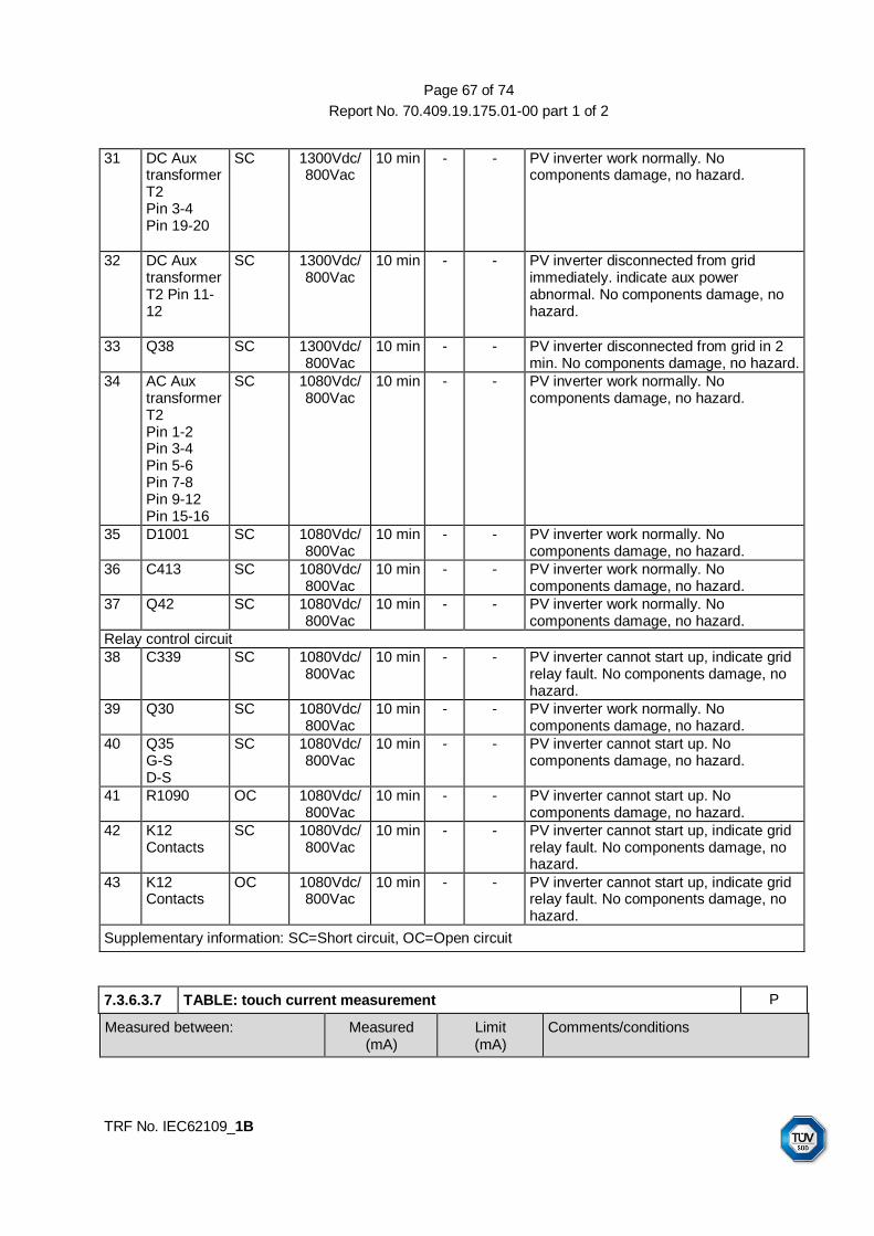
Page 67 of 74
Report No. 70.409.19.175.01-00 part 1 of 2
TRF No. IEC62109_1B
31 DC Aux transformer T2 Pin 3-4 Pin 19-20
SC 1300Vdc/ 800Vac
10 min - - PV inverter work normally. No components damage, no hazard.
32 DC Aux transformer T2 Pin 11-12
SC 1300Vdc/ 800Vac
10 min - - PV inverter disconnected from grid immediately. indicate aux power abnormal. No components damage, no hazard.
33 Q38 SC 1300Vdc/ 800Vac
10 min - - PV inverter disconnected from grid in 2 min. No components damage, no hazard.
34 AC Aux transformer T2 Pin 1-2 Pin 3-4 Pin 5-6 Pin 7-8 Pin 9-12 Pin 15-16
SC 1080Vdc/ 800Vac
10 min - - PV inverter work normally. No components damage, no hazard.
35 D1001 SC 1080Vdc/ 800Vac
10 min - - PV inverter work normally. No components damage, no hazard.
36 C413 SC 1080Vdc/ 800Vac
10 min - - PV inverter work normally. No components damage, no hazard.
37 Q42 SC 1080Vdc/ 800Vac
10 min - - PV inverter work normally. No components damage, no hazard.
Relay control circuit
38 C339 SC 1080Vdc/ 800Vac
10 min - - PV inverter cannot start up, indicate grid relay fault. No components damage, no hazard.
39 Q30 SC 1080Vdc/ 800Vac
10 min - - PV inverter work normally. No components damage, no hazard.
40 Q35 G-S D-S
SC 1080Vdc/ 800Vac
10 min - - PV inverter cannot start up. No components damage, no hazard.
41 R1090 OC 1080Vdc/ 800Vac
10 min - - PV inverter cannot start up. No components damage, no hazard.
42 K12 Contacts
SC 1080Vdc/ 800Vac
10 min - - PV inverter cannot start up, indicate grid relay fault. No components damage, no hazard.
43 K12 Contacts
OC 1080Vdc/ 800Vac
10 min - - PV inverter cannot start up, indicate grid relay fault. No components damage, no hazard.
Supplementary information: SC=Short circuit, OC=Open circuit
7.3.6.3.7 TABLE: touch current measurement P
Measured between: Measured (mA)
Limit (mA)
Comments/conditions

Page 68 of 74
Report No. 70.409.19.175.01-00 part 1 of 2
TRF No. IEC62109_1B
means of connection for the external protective earthing conductor and the external protective earthing conductor itself
14,0 3,5 Max. current recorded after clause 4.3, thermal testing and 4.5, single fault condition test, humidity pre-conditioning and IP65 test
supplementary information:
Note 1: For a PCE to be connected to an isolated system or impedance system, the neutral shall be connected through a resistance of 1 kΩ to the external protective earthing conductor, which shall be connected to each input phase in turn. The highest value will be taken as the definitive result.
Note 2: Permanently connected wiring and a cross-section of the protective earthing conductor of at least S/2=25 mm2 required in user manual. Additional second protective earthing terminal provided on enclosure as well.
7.3.7 TABLE: clearance and creepage distance measurements P
Insulation diagram

Page 69 of 74
Report No. 70.409.19.175.01-00 part 1 of 2
TRF No. IEC62109_1B
Isolation components and areas:
Area Insulation related information
Insulation area 1: Across power circuit(DC/AC) to earth(BI);
OVC System voltage(V)
Impulse voltage to
determine cl. (V)
Max. working voltage to
determine cr. (V)
PV II 1500 6000 1500
Mains III 462(rated voltage 800V,
IT system)
6000 880
Insulation area 2: Across drive, SIO/SOPs circuit, control circuit to earth(BI);
OVC System voltage(V)
Impulse voltage to
determine cl. (V)
Max. working voltage to
determine cr. (V)
PV II 1500 6000 1500
Mains III 462(rated voltage 800V,
IT system)
6000 880
Insulation area 3: Between PV different polarities (FI)
OVC System voltage(V)
Impulse voltage to
determine cl. (V)
Max. working voltage to
determine cr. (V)
PV I 1500 4000 1500
Mains II 462(rated voltage 800V,
IT system)
4000 -
Insulation area 4: Across contacts of relays (BI+SI)
OVC System voltage(V)
Impulse voltage to
determine cl. (V)
Max. working voltage to
determine cr. (V)
PV II 1500 6000 1500
Mains III 462(rated voltage 800V,
IT system)
6000 880
Insulation area 6: Across contacts of DC switch (RI)
OVC System voltage(V)
Impulse voltage to
determine cl. (V)
Max. working voltage to
determine cr. (V)
PV II 1500 8000 1500
Mains III 462(rated voltage 800V,
IT system)
8000 880
Insulation area 7: Between PV circuit and Drive,
OVC System voltage(V)
Impulse voltage to
determine cl. (V)
Max. working voltage to
determine cr. (V)

Page 70 of 74
Report No. 70.409.19.175.01-00 part 1 of 2
TRF No. IEC62109_1B
SIO/SOPs circuit, control circuit (FI)
PV I 1500 4000 1500
Mains II 462(rated voltage 800V,
IT system)
4000 -
Insulation area 8: Between drive, SIO/SOPs circuit, control circuit and communication RS485 port/USB (DI/RI)
OVC System voltage(V)
Impulse voltage to
determine cl. (V)
Max. working voltage to
determine cr. (V)
PV II 1500 8000 1500
Mains III 462(rated voltage 800V,
IT system)
8000 880
Insulation area 9: Between drive, SIO/SOPs circuit, control circuit and AC circuit after AC relay (FI)
OVC System voltage(V)
Impulse voltage to
determine cl. (V)
Max. working voltage to
determine cr. (V)
PV I 1500 4000 -
Mains II 462(rated voltage 800V,
IT system)
4000 880
Insulation area 10: Between AC live conductors and communication RS485 port/USB (RI)
OVC System voltage(V)
Impulse voltage to
determine cl. (V)
Max. working voltage to
determine cr. (V)
PV II 1500 8000 -
Mains III 462(rated voltage 800V,
IT system)
8000 880
Insulation area 11: Between internal live parts to LED cover (RI)
OVC System voltage(V)
Impulse voltage to
determine cl. (V)
Max. working voltage to
determine cr. (V)
PV II 1500 8000 -
Mains III 462(rated voltage 800V,
IT system)
8000 880
clearance cl and creepage distance dcr at / of:
Up (V)
U r.m.s. (V)
required cl (mm)
cl (mm)
required dcr (mm) dcr (mm)
Insulation area 1 and 2: Across power circuit(DC/AC)/ drive, SIO/SOPs circuit, control circuit to earth(BI);
Refer to above table
Refer to above table
7,1 ↓ PV side: PCB(inner): 7,1 PCB(outer) and
other insulator:15,0 Mains side: PCB: 7,1
other insulator:8,8
↓

Page 71 of 74
Report No. 70.409.19.175.01-00 part 1 of 2
TRF No. IEC62109_1B
- PV circuit to earthed metal enclosure and accessible surface (not on PCB)
↑ ↑ ↑ >8,0 ↑ >15,0
- Mains circuit to earthed metal enclosure and accessible surface (not on PCB)
↑ ↑ ↑ >8,0 ↑ >15,0
- shortest distance of PCB foil trace and on components on PCB (PV to earth)
↑ ↑ ↑ >15,2 ↑ >15,2
- shortest distance of PCB foil trace and on components on PCB (Mains to earth)
↑ ↑ ↑ >7,5 ↑ >7,5
- On boost inductor ↑ ↑ ↑ potting material
filled, verified by impulse
and dielectric strength
test
↑ potting material
filled, verified by
impulse and dielectric
strength test
- On conversion inductor
↑ ↑ ↑ potting material
filled, verified by impulse
and dielectric strength
test
↑ potting material
filled, verified by
impulse and dielectric
strength test
- IGBT module ↑ ↑ ↑ verified by impulse
and dielectric strength
test
↑ verified by impulse and
dielectric strength test
Insulation area 3: Between PV different polarities (FI)
Refer to above table
Refer to above table
3,9 ↓ 15,0 ↓
- on DC switch body ↑ ↑ ↑ >15,0 ↑ >15,0
Remark: DC switch approved by UL, outer cl. and cr. was checked and inner cl. and cr. was not checked
Insulation area 4: Across contacts of series connected relays (BI)
Refer to above table
Refer to above table
7,1 ↓ 15,0 ↓
- on AC relays ↑ ↑ ↑ cl.=3,6mm between each pair
↑ cr.>7,5mm between each pair

Page 72 of 74
Report No. 70.409.19.175.01-00 part 1 of 2
TRF No. IEC62109_1B
contacts Approved by third party
contacts Approved by third party
Insulation area 5: Across contacts of DC switch (BI)
Refer to above table
Refer to above table
7,1 ↓ 15,0 ↓
- on DC switch ↑ ↑ ↑ Approved by third party
↑ Approved by third party
Insulation area 6: Between AC live conductors (FI)
Refer to above table
Refer to above table
3,9 ↓ Mains side: PCB: 3,9
other insulator: 8,8
↓
- shortest distance across AC live conductors (Mains side, not on PCB)
↑ ↑ ↑ >20,0 ↑ >20,0
Insulation area 7: Between PV circuit and Drive, SIO/SOPs circuit, control circuit (FI)
Refer to above table
Refer to above table
3,9 ↓ PCB(inner): 7,1 PCB(outer) and Other insulator:
15,0
↓
Insulation area 9: Between drive, SIO/SOPs circuit, control circuit and AC circuit after AC relay (FI)
Refer to above table
Refer to above table
3,9 ↓ Mains side: PCB(inner): 3,9 PCB(outer): 4,4
other insulator: 8,8
↓
Remark: the insulation between PV circuit and AC circuit after AC relay shall be at least basic insulation and provided by insulation area 7 plus insulation area 9, and passed the impulse and hi-pot test of basic insulation requirements
Insulation area 8: Between drive, SIO/SOPs circuit, control circuit and communication RS485 port/USB (DI/RI)
Refer to above table
Refer to above table
10,4 ↓ PCB(inner): 10,4 PCB(outer) and other insulator:
30,0
↓
- shortest distance PCB foil trace and on components on PCB (control to SELV)
↑ ↑ ↑ 11,0 ↑ >30
Insulation area 10: Between AC live conductors and communication RS485 port/USB (RI)
Refer to above table
Refer to above table
10,4 ↓ Mains side: PCB(outer) and PCB(inner): 10,4 other insulator:
10,4
↓
- shortest distance PCB foil trace and on components on PCB (Mains to SELV)
↑ ↑ ↑ 11,0 ↑ >15,0

Page 73 of 74
Report No. 70.409.19.175.01-00 part 1 of 2
TRF No. IEC62109_1B
Insulation area 11: Between internal live parts to LED cover (RI)
Refer to above table
Refer to above table
10,4 ↓ PV side: PCB(inner): 10,4 PCB(outer) and other insulator:
30,0 Mains side:
PCB(inner): 10,4 PCB(outer) and other insulator:
10,4
↓
- internal live parts to LED cover
↑ ↑ ↑ >11,0 ↑ >30,0
Supplementary information:
1) Maximum operation altitude: 4000 m was taken into consideration, because requirements specified in IEC 62109-1:2010/EN 62109-1:2010 are only included for adjustment of clearance distances for higher elevations, but not for other factors related to elevation, such as thermal considerations.
2) Symbol ↑means to refer to cell above this arrow, symbol ↓means to refer to cell under this arrow.
3) For Cl. and Cr. in circuit of insulation above 30 kHz are found less severity of above table by evaluating according to Annex G, and harmonized to above table.
7.3.7 TABLE: distance through insulation measurement P
distance through insulation di at/of: U r.m.s.
(V) test voltage
(V) required di
(mm) di
(mm)
Insulation sheet between primary winding and secondary winding of isolating transformer T1(DI, three layers insulation sheet + triple insulated winding)
<DC1500 <AC800/462
DC 5110 -- --
Insulation sheet between primary winding and secondary winding of isolating transformer T2(DI, three layers insulation sheet + triple insulated winding)
<DC1500 <AC800/462
DC 5110 -- --
Potting material filling protection area of optocoupler(RI)
<DC1500 <AC800/462
DC 5110 0,2 >0,4
Epoxy resin used to fill inverter and boost inductor(BI)
<DC1500 <AC800/462
DC 2550 -- --
Insulation sheet cover inverter and boost inductor(BI)
<DC1500 <AC800/462
DC 2550 -- --
Insulation sheet between IGBT, MOSFET, DIODE body and heatsink(BI)
<DC1500 <AC800/462
DC 2550 -- --
Supplementary information: other components, such as optocoupler, power module are checked by certificates and specification.
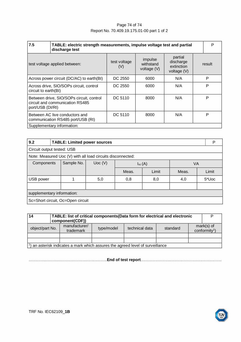
Page 74 of 74
Report No. 70.409.19.175.01-00 part 1 of 2
TRF No. IEC62109_1B
7.5 TABLE: electric strength measurements, impulse voltage test and partial discharge test
P
test voltage applied between: test voltage
(V)
impulse withstand
voltage (V)
partial discharge extinction
voltage (V)
result
Across power circuit (DC/AC) to earth(BI) DC 2550 6000 N/A P
Across drive, SIO/SOPs circuit, control circuit to earth(BI)
DC 2550 6000 N/A P
Between drive, SIO/SOPs circuit, control circuit and communication RS485 port/USB (DI/RI)
DC 5110 8000 N/A P
Between AC live conductors and communication RS485 port/USB (RI)
DC 5110 8000 N/A P
Supplementary information:
9.2 TABLE: Limited power sources P
Circuit output tested: USB
Note: Measured Uoc (V) with all load circuits disconnected:
Components Sample No. Uoc (V) Isc (A) VA
Meas. Limit Meas. Limit
USB power 1 5,0 0,8 8,0 4,0 5*Uoc
supplementary information:
Sc=Short circuit, Oc=Open circuit
14 TABLE: list of critical components(Data form for electrical and electronic component(CDF))
P
object/part No. manufacturer/
trademark type/model technical data standard
mark(s) of conformity1)
1) an asterisk indicates a mark which assures the agreed level of surveillance
………………………………………………….End of test report……………………………………………………