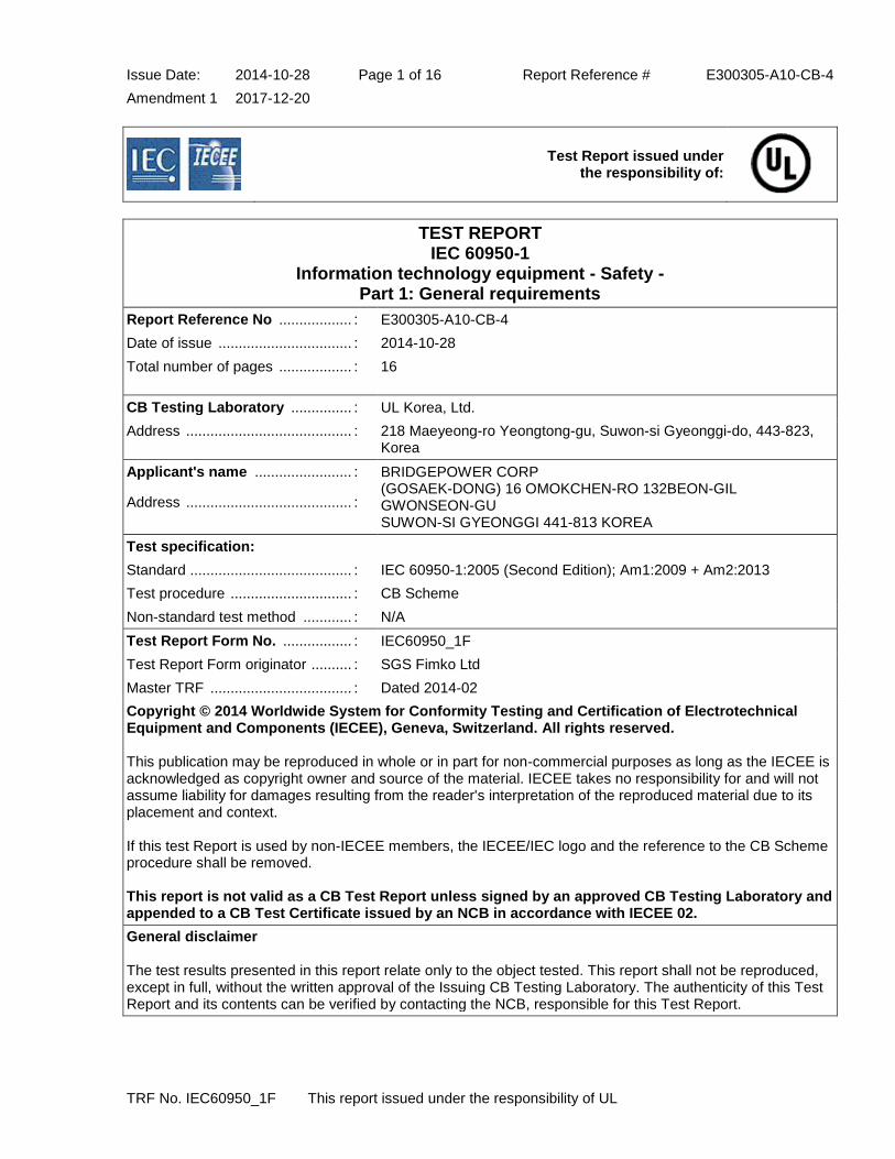
TEST REPORT IEC 60950-1 Information technology equipment
150
Issue Date: 2014-10-28 Page 1 of 16 Report Reference # E300305-A10-CB-4 Amendment 1 2017-12-20 TRF No. IEC60950_1F This report issued under the responsibility of UL Test Report issued under the responsibility of: TEST REPORT IEC 60950-1 Information technology equipment - Safety - Part 1: General requirements Report Reference No .................. : E300305-A10-CB-4 Date of issue ................................. : 2014-10-28 Total number of pages .................. : 16 CB Testing Laboratory ............... : UL Korea, Ltd. Address ......................................... : 218 Maeyeong-ro Yeongtong-gu, Suwon-si Gyeonggi-do, 443-823, Korea Applicant's name ........................ : Address ......................................... : BRIDGEPOWER CORP (GOSAEK-DONG) 16 OMOKCHEN-RO 132BEON-GIL GWONSEON-GU SUWON-SI GYEONGGI 441-813 KOREA Test specification: Standard ........................................ : IEC 60950-1:2005 (Second Edition); Am1:2009 + Am2:2013 Test procedure .............................. : CB Scheme Non-standard test method ............ : N/A Test Report Form No. ................. : IEC60950_1F Test Report Form originator .......... : SGS Fimko Ltd Master TRF ................................... : Dated 2014-02 Copyright © 2014 Worldwide System for Conformity Testing and Certification of Electrotechnical Equipment and Components (IECEE), Geneva, Switzerland. All rights reserved. This publication may be reproduced in whole or in part for non-commercial purposes as long as the IECEE is acknowledged as copyright owner and source of the material. IECEE takes no responsibility for and will not assume liability for damages resulting from the reader's interpretation of the reproduced material due to its placement and context. If this test Report is used by non-IECEE members, the IECEE/IEC logo and the reference to the CB Scheme procedure shall be removed. This report is not valid as a CB Test Report unless signed by an approved CB Testing Laboratory and appended to a CB Test Certificate issued by an NCB in accordance with IECEE 02. General disclaimer The test results presented in this report relate only to the object tested. This report shall not be reproduced, except in full, without the written approval of the Issuing CB Testing Laboratory. The authenticity of this Test Report and its contents can be verified by contacting the NCB, responsible for this Test Report.
-
Upload
khangminh22 -
Category
Documents
-
view
2 -
download
0
Transcript of TEST REPORT IEC 60950-1 Information technology equipment
Issue Date: 2014-10-28 Page 1 of 16 Report Reference # E300305-A10-CB-4
Amendment 1 2017-12-20
TRF No. IEC60950_1F This report issued under the responsibility of UL
Test Report issued under
the responsibility of:
TEST REPORT IEC 60950-1
Information technology equipment - Safety - Part 1: General requirements
Report Reference No .................. : E300305-A10-CB-4
Date of issue ................................. : 2014-10-28
Total number of pages .................. : 16
CB Testing Laboratory ............... : UL Korea, Ltd.
Address ......................................... : 218 Maeyeong-ro Yeongtong-gu, Suwon-si Gyeonggi-do, 443-823, Korea
Applicant's name ........................ :
Address ......................................... :
BRIDGEPOWER CORP (GOSAEK-DONG) 16 OMOKCHEN-RO 132BEON-GIL GWONSEON-GU SUWON-SI GYEONGGI 441-813 KOREA
Test specification:
Standard ........................................ : IEC 60950-1:2005 (Second Edition); Am1:2009 + Am2:2013
Test procedure .............................. : CB Scheme
Non-standard test method ............ : N/A
Test Report Form No. ................. : IEC60950_1F
Test Report Form originator .......... : SGS Fimko Ltd
Master TRF ................................... : Dated 2014-02
Copyright © 2014 Worldwide System for Conformity Testing and Certification of Electrotechnical Equipment and Components (IECEE), Geneva, Switzerland. All rights reserved. This publication may be reproduced in whole or in part for non-commercial purposes as long as the IECEE is acknowledged as copyright owner and source of the material. IECEE takes no responsibility for and will not assume liability for damages resulting from the reader's interpretation of the reproduced material due to its placement and context. If this test Report is used by non-IECEE members, the IECEE/IEC logo and the reference to the CB Scheme procedure shall be removed. This report is not valid as a CB Test Report unless signed by an approved CB Testing Laboratory and appended to a CB Test Certificate issued by an NCB in accordance with IECEE 02.
General disclaimer The test results presented in this report relate only to the object tested. This report shall not be reproduced, except in full, without the written approval of the Issuing CB Testing Laboratory. The authenticity of this Test Report and its contents can be verified by contacting the NCB, responsible for this Test Report.

Issue Date: 2014-10-28 Page 2 of 16 Report Reference # E300305-A10-CB-4
Amendment 1 2017-12-20
TRF No. IEC60950_1F This report issued under the responsibility of UL
Test item description .................. : Switching Power Supply
Trade Mark .................................... : BridgePower
Manufacturer ................................. : BRIDGEPOWER CORP (GOSAEK-DONG) 16 OMOKCHEN-RO 132BEON-GIL GWONSEON-GU SUWON-SI GYEONGGI 441-813 KOREA
Model/Type reference ................... : JPOE130A48******, JPOE130B48******, JPOE130C48******,PW180*A48*****, PW180*B48*****, PW180*C48*****, PUTP-130A-***, PUTP-130B-***, PUTP-130C-*** (Where * may be alphanumeric, "for marketing purpose and no impact safety related critical components and constructions")
Ratings .......................................... : Input Rating: 100-250 Vac, 50-60 Hz, 0.5 A Output Rating: 48 Vdc, 0.4 A or 48 Vdc, 0.35 A or 48 Vdc, 0.32 A

Issue Date: 2014-10-28 Page 3 of 16 Report Reference # E300305-A10-CB-4
Amendment 1 2017-12-20
TRF No. IEC60950_1F This report issued under the responsibility of UL
Testing procedure and testing location:
[x] CB Testing Laboratory
Testing location / address .............. : UL Korea, Ltd. 218 Maeyeong-ro Yeongtong-gu, Suwon-si Gyeonggi-do, 443-823, Korea
[ ] Associated CB Test Laboratory
Testing location / address .............. :
Tested by (name + signature) ........ : Jeremy Lim / Project handler
Approved by (name + signature) .... : Seungtae Kim / Reviewer
[ ] Testing Procedure: TMP/CTF Stage 1
Testing location / address .............. :
Tested by (name + signature) ........ :
Approved by (name + signature) .... :
[ ] Testing Procedure: WMT/CTF Stage 2
Testing location / address .............. :
Tested by (name + signature) ........ :
Witnessed by (name + signature) .. :
Approved by (name + signature) .... :
[ ] Testing Procedure: SMT/CTF Stage 3 or 4
Testing location / address .............. :
Tested by (name + signature) ........ :
Approved by (name + signature) .... :
Supervised by (name + signature) . :
[ ] Testing Procedure: RMT
Testing location / address .............. :
Tested by (name + signature) ........ :
Approved by (name + signature) .... :
Supervised by (name + signature) . :
List of Attachments
National Differences (0 pages)
Enclosures (3 pages)
Summary of Testing:
No tests were conducted
Summary of Compliance with National Differences:
Countries outside the CB Scheme membership may also accept this report.

Issue Date: 2014-10-28 Page 4 of 16 Report Reference # E300305-A10-CB-4
Amendment 1 2017-12-20
TRF No. IEC60950_1F This report issued under the responsibility of UL
List of countries addressed: AT, BE, BG, CH, CZ, DE, DK, ES, EU, FI, FR, GB, GR, HU, IE, IL, IT, JP, KR, NL, NO, PL, PT, RO, SE, SG, SI, SK, UA
The product fulfills the requirements of: N/A
Copy of Marking Plate - Refer to Enclosure titled Marking Plate for copy.

Issue Date: 2014-10-28 Page 5 of 16 Report Reference # E300305-A10-CB-4
Amendment 1 2017-12-20
TRF No. IEC60950_1F This report issued under the responsibility of UL
Test item particulars :
Equipment mobility ...............................................: movable
Connection to the mains ......................................: pluggable A
Operating condition ..............................................: continuous
Access location ....................................................: restricted access location
Over voltage category (OVC) ..............................: OVC II
Mains supply tolerance (%) or absolute mains supply values ...................................................................: +10%, -10%
Tested for IT power systems ...............................: Yes(for Norway only)
IT testing, phase-phase voltage (V) .....................: 230 Vac
Class of equipment ..............................................: Class I (earthed) or Class II (double insulated)
Considered current rating of protective device as part of the building installation (A) ...............................: 0.5
Pollution degree (PD) ...........................................: PD 2
IP protection class ................................................: IP X0
Altitude of operation (m) .......................................: Up to 2000m
Altitude of test laboratory (m) ...............................: N/A
Mass of equipment (kg) .......................................: 0.17
Possible test case verdicts:
- test case does not apply to the test object ........... : N / A
- test object does meet the requirement ................. : P(Pass)
- test object does not meet the requirement ........... : F(Fail)
Testing:
Date(s) of receipt of test item ...............................: N/A
Date(s) of Performance of tests ...........................: N/A
General remarks:
"(see Enclosure #)" refers to additional information appended to the report. "(see appended table)" refers to a table appended to the report. Throughout this report a point is used as the decimal separator.
Manufacturer's Declaration per Sub Clause 4.2.5 of IECEE 02: The application for obtaining a CB Test Certificate includes more than one factory and a declaration from the Manufacturer stating that the sample(s) submitted for evaluation is (are) representative of the products from each factory has been provided ...... When differences exist, they shall be identified in the General Product Information section.
Yes
Name and address of Factory(ies): WENDENG JEIL ELECTRONICS CO LTD DONG SHOU GUANGZHOU LU KAIFA-QU WENDENG-SHI SHANDONG CHINA BRIDGEPOWER CORP
Issue Date: 2014-10-28 Page 6 of 16 Report Reference # E300305-A10-CB-4
Amendment 1 2017-12-20
TRF No. IEC60950_1F This report issued under the responsibility of UL
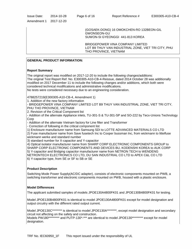
(GOSAEK-DONG) 16 OMOKCHEN-RO 132BEON-GIL GWONSEON-GU SUWON-SI GYEONGGI 441-813 KOREA BRIDGEPOWER VINA COMPANY LIMITED LOT B9 THUY VAN INDUSTRIAL ZONE, VIET TRI CITY, PHU THO PROVINCE, VIETNAM
GENERAL PRODUCT INFORMATION:
Report Summary
The original report was modified on 2017-12-20 to include the following changes/additions: The original Test Report Ref. No. E300305-A10-CB-4-Reissue, dated 2014 October 28 was additionally modified on 2017 December 11 to include the following changes and/or additions, which both were considered technical modifications and administrative modifications. No tests were considered necessary due to an engineering consideration. 4788257219(E300305-A10-CB-4, Amendment 1) 1. Addition of the new factory information - BRIDGEPOWER VINA COMPANY LIMITED LOT B9 THUY VAN INDUSTRIAL ZONE, VIET TRI CITY, PHU THO PROVINCE, VIETNAM 2. Revision of the Critical Component list - Addition of the alternate Appliance inlets, TU-301-S & TU-301-SP and SO-222 by Tecx-Unions Technology Corp - Addition of the alternate Vietnam factory for Line filter and Transformer - Correction of following in the critical component list 1) Enclosure manufacturer name from Samsung SDI to LOTTE ADVANCED MATERIALS CO LTD 2) Fuse manufacturer name from Save fusetech Inc to Cooper bussman Inc, from wickmann to littelfuse wickmann werke and standard number 3) standard number for X-capacitor and Y-capacitor 4) Optical isolator manufacturer name from SHARP CORP ELECTRONIC COMPONENTS GROUP to SHARP CORP ELECTRONIC COMPONENTS AND DEVICES BU, KODENSHI KOREA to AUK CORP 5) Y-capacitor and Bridging capacitor manufacturer name from NETRON TECH to WENDENG NETRONTECH ELECTRONICS CO LTD, DU SAN INDUSTRIAL CO LTD to APEX C&L CO LTD 6) Y-capacitor type, from SE or SF to SB or SE
Product Description
Switching Mode Power Supply(AC/DC adapter), consists of electronic components mounted on PWB, a switching transformer and electronic components mounted on PWB, housed with a plastic enclosure.
Model Differences
The applicant submitted samples of models JPOE130A4800FK01 and JPOE130B4800FK01 for testing. Model JPOE130B4800FK01 is identical to model JPOE130A4800FK01 except for model designation and output circuitry with the different rated output current. Model JPOE130C******** is identical to model JPOE130A********, except model designation and secondary circuit not affecting on the safety and construction. Models PW180********* and PUTP-130*-*** are identical to model JPOE130********* except for model designation.

Issue Date: 2014-10-28 Page 7 of 16 Report Reference # E300305-A10-CB-4
Amendment 1 2017-12-20
TRF No. IEC60950_1F This report issued under the responsibility of UL
Nomenclature JPOE130*(a)**(b)**(c)*(d)*(e)**(f) (a) means Design revision changes, may by A, B or C as rated output current, A or C - 0.4A or 0.35A, B - 0.32A or 0.35A; (b) means output voltage, 48; (c) means standards output cord options, may be 00 to 99; (d) means standards input cord options, may be F (Class I) or N (Class II); (e) means custom options, may be K or C; (f) means custom options, may be 00 to 99 or AA to ZZ. PW180*(a)*(b)**(c)**(d)*(e)**(f) (a) means custom options, may be K or C; (b) means design revision changes, may be A, B or C as rated output current, A or C - 0.4A or 0.35A, B - 0.32A or 0.35A; (c) means output voltage, 48; (d) means standards output cord options, may be 00 to 99; (e) means standards input cord options, may be F (Class I) or N (Class II); (f) means custom options, may be 00 to 99 or AA to ZZ. PUTP-130*(a)-**(b)*(c) (a) means design revision changes, may be A, B or C as rated output current, A or C - 0.4A or 0.35A, B - 0.32A or 0.35A; (b) means custom options, may be 00 to 99. (c) means standards input cord options, may be Blank (Class I) or N (Class II);
Additional Information
Max. Normal Load Condition: JPOE130A4800FK01 - 47.90 Vdc, 0.4 A; JPOE130B4800FK01 - 47.57 Vdc, 0.32 A or 46.9 Vdc, 0.35 A Before placing the products in the different countries, the manufacturer has to guarantee that: 1. Operating instructions and warnings are written in an accepted language of the certain country. 2. The equipment is in compliance with the national standards of the certain country. Amendment 1, 06CA55186 - Alternate rated output current; 0.35A Correction 1, 06CA55186 - Type error correction Amendment 2, 07CA04983 - Alternate Inlet, RF-180 by RongFeng Industrial Co. Ltd. for Class II equipment. Amendment 3, 07CA18853 - Model addition, JPOE130C**(b)**(c)*(d)*(e)**(f), PW180C*(b)**(c)**(d)*(e)**(f), PUTP-130C-**(b)*(c) with secondary circuit revision, JPOE130C**(b)**(c)*(d)*(e)**(f) is identical to JPOE130A**(b)**(c)*(d)*(e)**(f), except model designation and secondary circuit not affecting on the safety and construction. Reissued, E300305-A10-2, 08CA62248 - Applicant, Manufacturer, Factory name and address change due to movement, see Report cover page for new company name and address. - Delete Factory, Ault Korea Corp.

Issue Date: 2014-10-28 Page 8 of 16 Report Reference # E300305-A10-CB-4
Amendment 1 2017-12-20
TRF No. IEC60950_1F This report issued under the responsibility of UL
- Revision of Nomenclature. - Manufacturer change of Line filter(L1) and Transformer(T1) to BRIDGEPOWER CORP and Enclosure to Sabic Innovative Plastics in the appended table 1.5.1. - Addition of National deviation Correction 1, 09CA03570 - Correction of Nomenclature, (e) for model JPOE130 series and (a) for model PW180 series due to applicant's request. - Correction of sub. clause 1.5. - Correction of L1, T1 manufacturer in the appended table 1.5.1. Correction 2, 09CA14937 - Correction of Main Transformer (T1) type due to typo. Reissue, 10CA46694 1. Upgrade report from IEC 60950-1 1st edition to IEC 60950-1 2nd edition 2. No tests conducted under this investigation due to reissue of CB Test Report Ref.No. E300305-A10-CB-2 issued date 2008-12-12, E300305-A10-CB-2,Correction 1 issued 2009-01-15, E300305-A10-CB-2, Correction 2 issued 2009-03-26, CB Test Certificate Ref.No. DK-14726 issued data 2008-12-16 , DK-14727 issued data 2008-12-16 , DK-14726-M1 issued 2009-03-04 , DK-14727-M1 issued 2009-03-04. 3. Add manufacturer declaration. 4.For China, Japan and Australia differences, it is not listed in the CB bulletin 112A dated Dec. 2006 for IEC 60950-1, therefore the deviation of IEC 60950 3rd edition is used for China and Japan and the deviation of IEC 60950-1 1st edition used for Australia, see Enclosure, Miscellaneous. 5. Add trademark "BridgePower" Correction. SR9742118(E300305-A10-CB-3, Correction1) - Add humidity test time (48hours) in clause 2.9.2 due to missing. - Add "Also complied with humidity test" in table 5.2 supplementary information. 4786594328(E300305-A10-CB-4, Reissue) 1. Upgrade report from IEC 60950-1 2nd edition to IEC 60950-1 2nd edition Amendment 2 2. No tests conducted under this investigation due to reissue of CB Test Report Ref.No. E300305-A10-CB-3 issued date 2010-09-24, CB-20164 and CB-20163, CB Test Report Ref.No. E300305-A10-CB-3, Correction 1, DK-20164-M1-UL and DK-20163-M1-UL 3. Delete China Deviation 4. Revise Critical Component List - Change Manufacturer name from Cheil Industries to Samsung SDI 5. Change of applicant address from "964 GOSAEK-DONG GWONSEON-GU SUWON-SI GYEONGGI-DO 441-813 KOREA" to "(GOSAEK-DONG) 16 OMOKCHEN-RO 132BEON-GIL GWONSEON-GU SUWON-SI GYEONGGI 441-813 KOREA". 6. revised of MFR. and Factory address 4788257219(E300305-A10-CB-4, Amendment 1) 1. Addition of the new factory information - BRIDGEPOWER VINA COMPANY LIMITED LOT B9 THUY VAN INDUSTRIAL ZONE, VIET TRI CITY, PHU THO PROVINCE, VIETNAM 2. Revision of the Critical Component list - Addition of the alternate Appliance inlets, TU-301-S & TU-301-SP and SO-222 by Tecx-Unions Technology Corp - Addition of the alternate Vietnam factory for Line filter and Transformer - Correction of following in the critical component list 1) Enclosure manufacturer name from Samsung SDI to LOTTE ADVANCED MATERIALS CO LTD

Issue Date: 2014-10-28 Page 9 of 16 Report Reference # E300305-A10-CB-4
Amendment 1 2017-12-20
TRF No. IEC60950_1F This report issued under the responsibility of UL
2) Fuse manufacturer name from Save fusetech Inc to Cooper bussman Inc, from wickmann to littelfuse wickmann werke and standard number 3) standard number for X-capacitor and Y-capacitor 4) Optical isolator manufacturer name from SHARP CORP ELECTRONIC COMPONENTS GROUP to SHARP CORP ELECTRONIC COMPONENTS AND DEVICES BU, KODENSHI KOREA to AUK CORP 5) Y-capacitor and Bridging capacitor manufacturer name from NETRON TECH to WENDENG NETRONTECH ELECTRONICS CO LTD, DU SAN INDUSTRIAL CO LTD to APEX C&L CO LTD 6) Y-capacitor type, from SE or SF to SB or SE
Technical Considerations
The product was submitted and evaluated for use at the maximum ambient temperature (Tma) permitted by the manufacturer’s specification of: 30
The means of connection to the mains supply is: Pluggable A
The product is intended for use on the following power systems: TN, IT(for Norway only),
The equipment disconnect device is considered to be: Appliance inlet
The product was investigated to the following additional standards: EN 60950-1:2006 + A11:2009 + A1:2010 + A12:2011 + A2:2013 (which includes all European national differences, including those specified in this test report)., ,
The following circuit locations (with circuit/schematic designation) were investigated as a limited power source (LPS): all output
Abbreviations used in the report:
- normal condition ............................................ : N.C. - single fault condition ....................................... : S.F.C
- operational insulation ..................................... : OP - basic insulation .............................................. : BI
- basic insulation between parts of opposite polarity:
BOP
- supplementary insulation ............................... : SI
- double insulation ............................................ : DI - reinforced insulation ...................................... : RI
Indicate used abbreviations (if any)

Issue Date: 2014-10-28 Page 10 of 16 Report Reference # E300305-A10-CB-4
Amendment 1 2017-12-20
IEC 60950-1
Clause Requirement + Test Result - Remark Verdict
TRF No. IEC60950_1F This report issued under the responsibility of UL
5.1.6 Max. allowed touch current (mA) .............. : 0.25 mAr.m.s.(secondary output was not earthed, but separated from primary circuit by reinforced insulation)
-
D.1 Measuring instrument
Simpson meter 228 used.
Pass

Issue Date: 2014-10-28 Page 11 of 16 Report Reference # E300305-A10-CB-4
Amendment 1 2017-12-20
IEC 60950-1
Clause Requirement + Test Result - Remark Verdict
TRF No. IEC60950_1F This report issued under the responsibility of UL
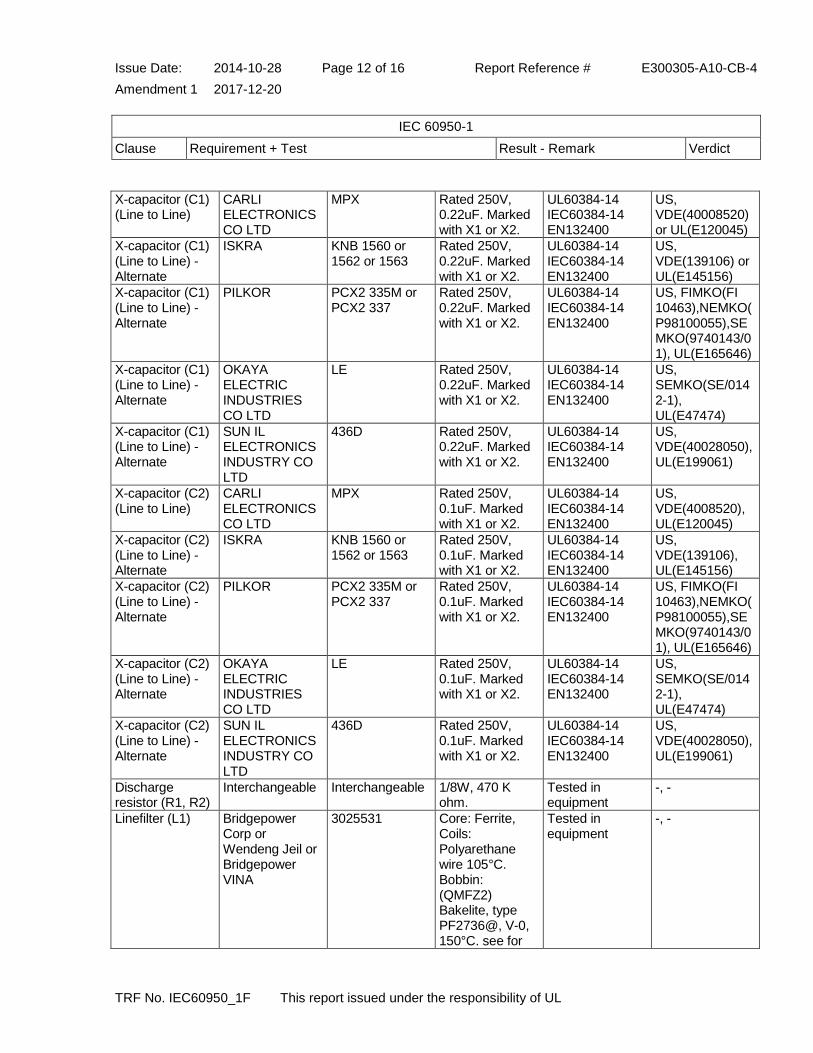
1.5.1 TABLE: list of critical components Pass
object/part or Description
manufacturer/ trademark
type/model technical data standard (Edition or year)
mark(s) of conformity
1)
Appliance Inlet (Class I)
Rong Feng Industrial Co., Ltd.
SS-120 Rated 15 A / 250 V.
UL498, EN60320-1
US, VDE(40028101) or UL(E102641)
Appliance Inlet-Class I - Alternate
Tecx-Unions Technology Corp
TU-301-S & TU-301-SP
Rated 250V, 15A minimum, Max 105°C
DEMKO (ENEC-00647-A1), ANSI/UL 498, ANSI/UL 60320-1, IEC/EN 60320-1
US, UL (E220004)
Appliance Inlet (Class II)
Rong Feng Industrial Co., Ltd.
RF-180 Rated 2.5 A / 250 V.
UL498, EN60320-1
US, VDE(40030168) or UL(E102641)
Appliance Inlet –Class II - Alternate
Tecx-Unions Technology Corp
SO-222 Rated 250V, 2.5A minimum, Max. 75°C
DEMKO (ENEC-00859), VDE(40043268), ANSI/UL 498, ANSI/UL 60320-1, IEC/EN 60320-1
US, UL (E220004)
Enclosure(Fire/Mech./Elec.)
Sabic Innovative Plastics
940(f1) Overall Sized approx. 95.0 by 54.0 by 32.0 mm. Min 2.0mm thickness, V-0, RTI 120°C. Composed of two pieces, secured together by ultrasonic welding.
UL94, UL746C US, UL(E45329)
Enclosure(Fire/Mech./Elec.) - Alternate
LOTTE ADVANCED MATERIALS CO LTD
HN-1064(+) Overall Sized approx. 95.0 by 54.0 by 32.0 mm. Min 2.0 mm thickness, V-0, RTI 80°C.
UL 94, UL746C US, UL(E115797)
Fuse (F1) Cooper bussman inc
SR-5 Rated 250V, T1.0AL
UL248-1, VDE0820, EN60127
US, VDE(122052) or VDE(40015513) or UL(E19180)
Fuse (F1) - Alternate
Littelfuse wickmann werke
(TR5) 382 Rated 250V, T1.0AL
UL248-1, VDE0820, EN60127
US, VDE(40018249) or VDE(126983), UL(E67006)
Thermistor (TH1) Interchangeable Interchangeable NTC, 5 ohm or 10 ohm at 25°C.
Tested in equipment
-, -
Issue Date: 2014-10-28 Page 12 of 16 Report Reference # E300305-A10-CB-4
Amendment 1 2017-12-20
IEC 60950-1
Clause Requirement + Test Result - Remark Verdict
TRF No. IEC60950_1F This report issued under the responsibility of UL
X-capacitor (C1) (Line to Line)
CARLI ELECTRONICS CO LTD
MPX Rated 250V, 0.22uF. Marked with X1 or X2.
UL60384-14 IEC60384-14 EN132400
US, VDE(40008520)or UL(E120045)
X-capacitor (C1) (Line to Line) - Alternate
ISKRA KNB 1560 or 1562 or 1563
Rated 250V, 0.22uF. Marked with X1 or X2.
UL60384-14 IEC60384-14 EN132400
US, VDE(139106) or UL(E145156)
X-capacitor (C1) (Line to Line) - Alternate
PILKOR PCX2 335M or PCX2 337
Rated 250V, 0.22uF. Marked with X1 or X2.
UL60384-14 IEC60384-14 EN132400
US, FIMKO(FI 10463),NEMKO(P98100055),SEMKO(9740143/01), UL(E165646)
X-capacitor (C1) (Line to Line) - Alternate
OKAYA ELECTRIC INDUSTRIES CO LTD
LE Rated 250V, 0.22uF. Marked with X1 or X2.
UL60384-14 IEC60384-14 EN132400
US, SEMKO(SE/0142-1), UL(E47474)
X-capacitor (C1) (Line to Line) - Alternate
SUN IL ELECTRONICS INDUSTRY CO LTD
436D Rated 250V, 0.22uF. Marked with X1 or X2.
UL60384-14 IEC60384-14 EN132400
US, VDE(40028050), UL(E199061)
X-capacitor (C2) (Line to Line)
CARLI ELECTRONICS CO LTD
MPX Rated 250V, 0.1uF. Marked with X1 or X2.
UL60384-14 IEC60384-14 EN132400
US, VDE(4008520), UL(E120045)
X-capacitor (C2) (Line to Line) - Alternate
ISKRA KNB 1560 or 1562 or 1563
Rated 250V, 0.1uF. Marked with X1 or X2.
UL60384-14 IEC60384-14 EN132400
US, VDE(139106), UL(E145156)
X-capacitor (C2) (Line to Line) - Alternate
PILKOR PCX2 335M or PCX2 337
Rated 250V, 0.1uF. Marked with X1 or X2.
UL60384-14 IEC60384-14 EN132400
US, FIMKO(FI 10463),NEMKO(P98100055),SEMKO(9740143/01), UL(E165646)
X-capacitor (C2) (Line to Line) - Alternate
OKAYA ELECTRIC INDUSTRIES CO LTD
LE Rated 250V, 0.1uF. Marked with X1 or X2.
UL60384-14 IEC60384-14 EN132400
US, SEMKO(SE/0142-1), UL(E47474)
X-capacitor (C2) (Line to Line) - Alternate
SUN IL ELECTRONICS INDUSTRY CO LTD
436D Rated 250V, 0.1uF. Marked with X1 or X2.
UL60384-14 IEC60384-14 EN132400
US, VDE(40028050), UL(E199061)
Discharge resistor (R1, R2)
Interchangeable Interchangeable 1/8W, 470 K ohm.
Tested in equipment
-, -
Linefilter (L1) Bridgepower Corp or Wendeng Jeil or Bridgepower VINA
3025531 Core: Ferrite, Coils: Polyarethane wire 105°C. Bobbin: (QMFZ2) Bakelite, type PF2736@, V-0, 150°C. see for
Tested in equipment
-, -

Issue Date: 2014-10-28 Page 13 of 16 Report Reference # E300305-A10-CB-4
Amendment 1 2017-12-20
IEC 60950-1
Clause Requirement + Test Result - Remark Verdict
TRF No. IEC60950_1F This report issued under the responsibility of UL
details.
Bridge diode (BD1)
Interchangeable Interchangeable Rated Min. 600 V, 0.8 A
Tested in equipment
-, -
Electrolytic Capacitor (C3)
Interchangeable Interchangeable 47 uF, 400 V, min. 85 degree.
Tested in equipment
-, -
Main Transformer(T1)
Bridgepower Corp or Wendeng Jeil or Bridgepower VINA
3025494 Class A insulation; Coils: Polyarethane wire 105°C. TIW Cosmolink, Type TIW-M 130°C. or TIW Furukawa TEX-E 130°C. Bobbin: (QMFZ2) Bakelite, type PF2736@, V-0, 150°C. see Enclosure for details.
Tested in equipment
-, -
Optical Isolator (U2)
Vishay Semiconductor gmbh
TCET1103G or TCET1103
Double protection optical isolator. Providing isolation voltage 5000 Vac
VDE0884, EN60950
US, BSI (7402),CQC(09001038077)
Optical isolator (U2) - Alternate
COSMO ELECTRONICS CORP
KP1010 Double protection optical isolator. Providing isolation voltage 5000 Vac
UL1577, VDE0884, EN60950
US, SEMKO(1016433),FIMKO(224986), UL(E169586)
Optical isolator (U2) - Alternate
SHARP CORP ELECTRONIC COMPONENTS AND DEVICES BU
PC123 Double protection optical isolator. Providing isolation voltage 5000 Vac
UL1577, VDE0884, EN60950
US, SEMKO( 9216212), NEMKO(135957), UL(E64380)
Optical isolator (U2) - Alternate
AUK CORP PC-17K Double protection optical isolator. Providing isolation voltage 5000 Vac.
UL1577, VDE0884, EN60950
US, Semko( 9805214/01-04), UL(E107486)
Y-Capacitor (C17, C18, C19, C20)
WENDENG NETRONTECH ELECTRONICS CO LTD
AA 250Vmin, 2200 pF. Marked with Y1 or Y2.
UL60384-14, IEC60384-14 EN132400
US, VDE(089754) or UL(E339029)
Y-Capacitor WENDENG AD 250Vmin, 2200 UL60384-14, US,

Issue Date: 2014-10-28 Page 14 of 16 Report Reference # E300305-A10-CB-4
Amendment 1 2017-12-20
IEC 60950-1
Clause Requirement + Test Result - Remark Verdict
TRF No. IEC60950_1F This report issued under the responsibility of UL
(C17, C18, C19, C20)_Alternate
NETRONTECH ELECTRONICS CO LTD
pF. Marked with Y1 or Y2.
IEC60384-14 EN132400
VDE(089753) or UL(E339029)
Y-Capacitor (C17, C18, C19, C20) - Alternate
APEX C&L CO LTD
NK 250Vmin, 2200 pF. Marked with Y1 or Y2.
UL60384-14, IEC60384-14 EN132400
US, FIMKO(FI 197620 A1),NEMKO(P97101988),SEMKO(0219069/01-04), UL(E107942)
Y-Capacitor (C17, C18, C19, C20) - Alternate
APEX C&L CO LTD
NU 250Vmin, 2200 pF. Marked with Y1 or Y2.
UL60384-14, IEC60384-14 EN132400
US, NEMKO(P97101989),FIMKO(FI 197621 A1),SEMKO(0219069/01-04), UL(E107942)
Y-Capacitor (C17, C18, C19, C20) - Alternate
DONGIL ELECTRONIC CO LTD
DA 250Vmin, 2200 pF. Marked with Y1 or Y2.
UL60384-14 IEC60384-14 EN132400
US, FIMKO(FI 10228),NEMKO(P98100372),SEMKO(9807214/01-02), UL(E128646)
Y-Capacitor (C17, C18, C19, C20) - Alternate
DONGIL ELECTRONIC CO LTD
DS 250Vmin, 2200 pF. Marked with Y1 or Y2.
UL60384-14 IEC60384-14 EN132400
US, FIMKO(FI 10228), UL(E128646)
Y-Capacitor (C17, C18, C19, C20) - Alternate
SAMWHA CAPACITOR
SD 250Vmin, 2200 pF. Marked with Y1 or Y2.
UL60384-14, IEC60384-14 EN132400
US, VDE(40015804), UL(E97754)
Y-Capacitor (C17, C18, C19, C20) - Alternate
SAMWHA CAPACITOR
SC 250Vmin, 2200 pF. Marked with Y1 or Y2.
UL60384-14, IEC60384-14 EN132400
US, VDE(40015805), UL(E97754)
Y-Capacitor (C17, C18, C19, C20) - Alternate
SUCCESS ELECTRONICS CO LTD
SB or SE 250Vmin, 2200 pF. Marked with Y1 or Y2.
UL60384-14 IEC60384-14 EN132400
US, VDE(40020001) or VDE(40020002), UL(E114280)
Bridging Capacitor (C20) (Class II only)
WENDENG NETRONTECH ELECTRONIC CO LTD
AD 250Vmin, 2200 pF. Marked with Y1.
UL60384-14, IEC60384-14 EN132400
US, VDE(089753), UL(E339029)
Bridging Capacitor (C20) (Class II only) - Alternate
APEX C&L CO LTD
NK 250Vmin, 2200 pF. Marked with Y1.
UL60384-14, IEC60384-14 EN132400
US, FIMKO(FI 197620 A1),NEMKO(P97101988),SEMKO(0219069/01-04), UL(E107942)
Bridging Capacitor (C20) (Class II only) -
DONGIL ELECTRONIC CO LTD
DA 250Vmin, 2200 pF. Marked with Y1.
UL60384-14 IEC60384-14 EN132400
US, FIMKO(FI 10228),NEMKO(P98100372),SE

Issue Date: 2014-10-28 Page 15 of 16 Report Reference # E300305-A10-CB-4
Amendment 1 2017-12-20
IEC 60950-1
Clause Requirement + Test Result - Remark Verdict
TRF No. IEC60950_1F This report issued under the responsibility of UL
Alternate MKO(9807214/01-02), UL(E128646)
Bridging Capacitor (C20) (Class II only) - Alternate
SAMWHA CAPACITOR
SD 250Vmin, 2200 pF. Marked with Y1.
UL60384-14, IEC60384-14 EN132400
US, VDE(40015804), UL(E97754)
Bridging Capacitor (C20) (Class II only) - Alternate
SUCCESS ELECTRONICS CO LTD
SE 250Vmin, 2200 pF. Marked with Y1.
UL60384-14 IEC60384-14 EN132400
US, VDE(40020002), UL(E114280)
PWB Interchangeable Interchangeable Min. V-1, min 105°C.
UL796 US, -
Bonding conductor (Class I only)
Interchangeable Interchangeable Mechanically clamped or secured on PWB from Appliance Inlet. Min 18 AWG, Green-and-Yellow Insulation.
UL758 US, -
Nameplate Label Interchangeable Interchangeable Suitable for use on surface of Polycarbonate (PC) with max. 60 °C surface temperature.
UL969 US, -
Bonding Glue Interchangeable Interchangeable Min. V-2, min. 100 °C for additional secureness of internal conductor.
UL94 US, -
Heatsink Interchangeable Interchangeable Basic insulated conductive part, wrapped by 3 turns polyester film tape, (OANZ2), rated 130 °C to separate from U1(pri.) and fixed by clip without mechanical stress. Overall size 50 by 20 by 2 mm thickness.
Tested in equipment
-, -
Extruded Insulating Tubing
Interchangeable Interchangeable Rated 600 V, 125 °C, VW-1.
UL224 US, -
Issue Date: 2014-10-28 Page 16 of 16 Report Reference # E300305-A10-CB-4
Amendment 1 2017-12-20
IEC 60950-1
Clause Requirement + Test Result - Remark Verdict
TRF No. IEC60950_1F This report issued under the responsibility of UL
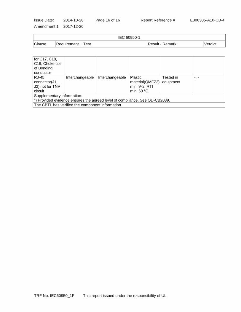
for C17, C18, C19, Choke coil of Bonding conductor
RJ-45 connector(J1, J2) not for TNV circuit
Interchangeable Interchangeable Plastic material(QMFZ2) min. V-2, RTI min. 60 °C.
Tested in equipment
-, -
Supplementary information: 1) Provided evidence ensures the agreed level of compliance. See OD-CB2039.
The CBTL has verified the component information.

Issue Date: 2014-10-28 Page 1 of 3 Report Reference # E300305-A10-CB-4
Amendment 1 2017-12-20 Enclosures
This report issued under the responsibility of UL
Enclosures
Type Supplement Id Description
Photographs 3-01 External view
Photographs 3-02 Internal view_JPOE130A4800FK01
Photographs 3-03 Internal view_JPOE130B4800FK01
Photographs 3-04 External view for Class II
Photographs 3-05 Internal view for Class II
Photographs 3-06 Internal view_JPOE130C4800FK01
Diagrams 4-01 Circuit_JPOE130A4800FK01
Diagrams 4-02 Circuit_JPOE130B4800FK01
Diagrams 4-03 Circuit_JPOE130A4800NK01
Diagrams 4-04 Circuit_JPOE130B4800NK01
Diagrams 4-05 Circuit_JPOE130C4800FK01
Schematics + PWB 5-01 PWB Layout_common
Schematics + PWB 5-02 PWB sub board for JPOE130B4800FK01
Schematics + PWB 5-03 PBW layout_JPOE130C
Miscellaneous 7-02 Linefilter_L1
Miscellaneous 7-03 Transformer_T1
Miscellaneous 7-05 National Differences - China and Japan and Australia
Miscellaneous 7-07 Manufacturer Declaration
Miscellaneous 7-08 Manufacturer Declaration
Miscellaneous 7-09 Manufacturer Declaration
Marking Plate 13-01 Marking Plate

Issue Date: 2014-10-28 Page 2 of 3 Report Reference # E300305-A10-CB-4
Amendment 1 2017-12-20 Enclosures
This report issued under the responsibility of UL
Misc ID 7-09
Issue Date: 2014-10-28 Page 3 of 3 Report Reference # E300305-A10-CB-4
Amendment 1 2017-12-20 Enclosures
This report issued under the responsibility of UL
Misc ID 7-09

���
������� �����
DK-41642-UL
��������������������������������������������������������������������� �!���
���������"#�����������������"����������"#������"��������������������������������!�"��
CB TEST CERTIFICATE CERTIFICAT D'ESSAI OC���$%&����$% �
�' �&( )*��'���%++,-
�./�.)$.$$��00���(�.++, &.)���/��.$��00�$%$�/.)$�%�
��"����1��������0.�23$�)*��4�/�2&(�)3���5�6��)3* ,�'�)0��)3*%�%'�)30 788�39�5�-��)** :���.
�./�.)$.$$��00���(�/.)%�.&�%�����/��.$��00�$%�.6� &.)�
��"����1��������0.�23$�)*��4�/�2&(�)3���5�6��)3* ,�'�)0��)3*%�%'�)30 788�39�5�-��)** :���.
�./�.)$.$$��00���(��.&���-��/��.$��00�$�,#%0 )�
����;When more than one factory, please report on page 2����;Lorsque il y plus d'une usine, veuillez utiliser la 2ème page
��"����1��������0.�23$�)*��4�/�2&(�)3���5�6��)3* ,�'�)0��)3*%�%'�)30 788�39�5�-��)** :���.�$$ � �).,�)���/.� �)�)+.*��
�.� )*0.)$+� )& +.,&(.�.&��� 0� &0<.,�%�0)�/ ).,�0��&.�.&�=� 0� >%�0+� )& +.,�0
�)+%��.� )*;�??3�@?<.&7@?34?!A7?�@��%�+%��.� )*;89<$&7?�8���89<$&7?�5@���89<$&7?�5��
��.$�/.�2� �.)-��.�>%�$��.6� >%��0 �,,��B 0���
� $*���'��
�-+����.)%�.&�%���#0��0� )*�.6��.��� �0%0�$�-+�$�+��*�.//�$%,.6��.�� ��$#�00. 0&�)0��%&��%�
��$�,��-+���������"��-+�
C����5?�89DDDDDD7C����5? 89DDDDDD7C����5?89DDDDDD7����3�5?�3DDD7����3�5? 3DDD7����3�5?3DDD7����.*��
�$$ � �)., )���/.� �)� �)�&�00.�-/.-.,0�6���+����$�)+.*�����0 )���/.� �)0&�/+,=/�)�. ��0�0 )=&�00. ��77+�%E�)�F��� )$ >%=00%�,.�G/�+.*�
,.00��$$ � �).,�)���/.� �)�)+.*��
�0./+,����(�+��$%&�'.0��0��$.)$��%)$��6� )&�)���/ �-' �(�)=&(.)� ,,�)$�&�+��$% �.=�=�00.-=��.=�=&�)0 $=�=&�)���/�H,.
��4?I@?3���$���7��4?I@?3���$���J./�7��4?I@?3���$���J./�
�00(�') )�(���0���+����������'( &(���/0+.�����( 0��� � &.���//� )$ >%=$.)0,��.++���$#�00. 0)%/=��$��=�=��)&�>% &�)0� �%�+.�� �$�&���� � &.�
�5??5?@3��?3 38 00%�$�)�?�83�?3�9
�( 0 ��0���� � &.�� 0 00%�$6-�(��.� �).,��� � &.� �) �$-���� � &.�$#�00. ��0�=�.6, +.�,#��*.) 0/�National de Certification
������7555�� )*0��)�$��4??4�7����(6���27���
���"�/2��7 ��%+E.)*@�":3�K@? .,,��%+7"�����:
���C��7�.�%)�%&( ��%0���'���. ) % ,$ )*4�7�3935�.�%)�%&( 7( -�$.32%7��2-��??3???@7C����
�����7K�)$��'� ���0��.$7����)��7���5 8�)�.� �7���"�
For full legal entity names see www.ul.com/ncbnames
".��;�?�83�?3�9
� *).�%��;
C.)3�� 2����*..�$
���7K�)$��'� ���0��.$7����)��7���5 8�)�.
ForooFoFoFoFooFooFoFoFooooFFFFoooFFFoFFoFFoFFooFo
C.)3�� 2����*......................................................................................�$�������������

���
������� �����
DK-41642-UL��$�,"��. ,0;C����5?�89DDDDDD7C����5? 89DDDDDD7C����5?89DDDDDD7����3�5?�3DDD7����3�5? 3DDD7����3�5?3DDD7�1�9?D�89DDDDD7�1�9?D 89DDDDD7�1�9?D89DDDDD�1(���D/.-6�.,+(.)%/�� &7L���/.�2�� )*+%�+�0�.)$)� /+.&�0.���-��,.��$&� � &.,&�/+�)�)�0.)$&�)0��%&� �)0L�
�.&��� �0;
1��"���C���������������""����!�������M!����:����3��1��"���3�!�7�!��"���( ).
�$$ � �).,�)���/.� �);�$$ � �).,,-�E.,%.��$����4?I@?3�;�??4����;�??I���;�?�?����;�?�����;�?�5J�.� �).," �����)&�00+�& � �$ )�(� ��0���+����
Additional information (if necessary)Information complémentaire (si nécessaire)
������7555�� )*0��)�$��4??4�7����(6���27���
���"�/2��7 ��%+E.)*@�":3�K@? .,,��%+7"�����:
���C��7�.�%)�%&( ��%0���'���. ) % ,$ )*4�7�3935�.�%)�%&( 7( -�$.32%7��2-��??3???@7C����
�����7K�)$��'� ���0��.$7����)��7���5 8�)�.� �7���"�
For full legal entity names see www.ul.com/ncbnames
� *).�%��;C.)3�� 2����*..�$
".��;�?�83�?3�9

���
������� �����
DK-41643-UL
��������������������������������������������������������������������� �!���
���������"#�����������������"����������"#������"��������������������������������!�"��
CB TEST CERTIFICATE CERTIFICAT D'ESSAI OC���$%&����$% �
�' �&( )*��'���%++,-
�./�.)$.$$��00���(�.++, &.)���/��.$��00�$%$�/.)$�%�
��"����1��������0.�23$�)*��4�/�2&(�)3���5�6��)3* ,�'�)0��)3*%�%'�)30 788�39�5�-��)** :���.
�./�.)$.$$��00���(�/.)%�.&�%�����/��.$��00�$%�.6� &.)�
��"����1��������0.�23$�)*��4�/�2&(�)3���5�6��)3* ,�'�)0��)3*%�%'�)30 788�39�5�-��)** :���.
�./�.)$.$$��00���(��.&���-��/��.$��00�$�,#%0 )�
����;When more than one factory, please report on page 2����;Lorsque il y plus d'une usine, veuillez utiliser la 2ème page
��"����1��������0.�23$�)*��4�/�2&(�)3���5�6��)3* ,�'�)0��)3*%�%'�)30 788�39�5�-��)** :���.�$$ � �).,�)���/.� �)�)+.*��
�.� )*0.)$+� )& +.,&(.�.&��� 0� &0<.,�%�0)�/ ).,�0��&.�.&�=� 0� >%�0+� )& +.,�0
�)+%��.� )*;�??3�@?<.&7@?34?!A7?�@��%�+%��.� )*;89<$&7?�8���89<$&7?�5@���89<$&7?�5��
��.$�/.�2� �.)-��.�>%�$��.6� >%��0 �,,��B 0���
� $*���'��
�-+����.)%�.&�%���#0��0� )*�.6��.��� �0%0�$�-+�$�+��*�.//�$%,.6��.�� ��$#�00. 0&�)0��%&��%�
��$�,��-+���������"��-+�
C����5?�89DDDDDD7C����5? 89DDDDDD7C����5?89DDDDDD7����3�5?�3DDD7����3�5? 3DDD7����3�5?3DDD7����.*��
�$$ � �)., )���/.� �)� �)�&�00.�-/.-.,0�6���+����$�)+.*�����0 )���/.� �)0&�/+,=/�)�. ��0�0 )=&�00. ��77+�%E�)�F��� )$ >%=00%�,.�G/�+.*�
,.00���$$ � �).,�)���/.� �)�)+.*��
�0./+,����(�+��$%&�'.0��0��$.)$��%)$��6� )&�)���/ �-' �(�)=&(.)� ,,�)$�&�+��$% �.=�=�00.-=��.=�=&�)0 $=�=&�)���/�H,.
��4?I@?3���$���7��4?I@?3���$���J./�7��4?I@?3���$���J./�
�00(�') )�(���0���+����������'( &(���/0+.�����( 0��� � &.���//� )$ >%=$.)0,��.++���$#�00. 0)%/=��$��=�=��)&�>% &�)0� �%�+.�� �$�&���� � &.�
�5??5?@3��?3 38 00%�$�)�?�83�?3�9
�( 0 ��0���� � &.�� 0 00%�$6-�(��.� �).,��� � &.� �) �$-���� � &.�$#�00. ��0�=�.6, +.�,#��*.) 0/�National de Certification
������7555�� )*0��)�$��4??4�7����(6���27���
���"�/2��7 ��%+E.)*@�":3�K@? .,,��%+7"�����:
���C��7�.�%)�%&( ��%0���'���. ) % ,$ )*4�7�3935�.�%)�%&( 7( -�$.32%7��2-��??3???@7C����
�����7K�)$��'� ���0��.$7����)��7���5 8�)�.� �7���"�
For full legal entity names see www.ul.com/ncbnames
".��;�?�83�?3�9
� *).�%��;
C.)3�� 2����*..�$
���7K�)$��'� ���0��.$7����)��7���5 8�)
F
C.)3�� 2����*****************************................................................... �$

Issue Date: 2014-10-28 Page 1 of 58 Report Reference # E300305-A10-CB-4
TRF No. IEC60950_1F This report issued under the responsibility of UL
Test Report issued under
the responsibility of:
TEST REPORT IEC 60950-1
Information technology equipment - Safety - Part 1: General requirements
Report Reference No .................. : E300305-A10-CB-4
Date of issue ................................. : 2014-10-28
Total number of pages .................. : 58
CB Testing Laboratory ............... : UL Korea, Ltd.
Address ......................................... : #808, Manhatan Building, 36-2 Yeouido-Dong, Yeongdeungpo-Gu, Seoul 150-749, Korea
Applicant's name ........................ :
Address ......................................... :
BRIDGEPOWER CORP (GOSAEK-DONG) 16 OMOKCHEN-RO 132BEON-GIL GWONSEON-GU SUWON-SI GYEONGGI 441-813 KOREA
Test specification:
Standard ........................................ : IEC 60950-1:2005 (Second Edition); Am1:2009 + Am2:2013
Test procedure .............................. : CB Scheme
Non-standard test method ............ : N/A
Test Report Form No. ................. : IEC60950_1F
Test Report Form originator .......... : SGS Fimko Ltd
Master TRF ................................... : Dated 2014-02
Copyright © 2014 Worldwide System for Conformity Testing and Certification of Electrotechnical Equipment and Components (IECEE), Geneva, Switzerland. All rights reserved. This publication may be reproduced in whole or in part for non-commercial purposes as long as the IECEE is acknowledged as copyright owner and source of the material. IECEE takes no responsibility for and will not assume liability for damages resulting from the reader's interpretation of the reproduced material due to its placement and context. If this test Report is used by non-IECEE members, the IECEE/IEC logo and the reference to the CB Scheme procedure shall be removed. This report is not valid as a CB Test Report unless signed by an approved CB Testing Laboratory and appended to a CB Test Certificate issued by an NCB in accordance with IECEE 02.
General disclaimer The test results presented in this report relate only to the object tested. This report shall not be reproduced, except in full, without the written approval of the Issuing CB Testing Laboratory. The authenticity of this Test Report and its contents can be verified by contacting the NCB, responsible for this Test Report.

Issue Date: 2014-10-28 Page 2 of 58 Report Reference # E300305-A10-CB-4
TRF No. IEC60950_1F This report issued under the responsibility of UL
Test item description .................. : Switching Power Supply
Trade Mark .................................... : BridgePower
Manufacturer ................................. : BRIDGEPOWER CORP (GOSAEK-DONG) 16 OMOKCHEN-RO 132BEON-GIL GWONSEON-GU SUWON-SI GYEONGGI 441-813 KOREA
Model/Type reference ................... : JPOE130A48******, JPOE130B48******, JPOE130C48******,PW180*A48*****, PW180*B48*****, PW180*C48*****, PUTP-130A-***, PUTP-130B-***, PUTP-130C-*** (Where * may be alphanumeric, "for marketing purpose and no impact safety related critical components and constructions")
Ratings .......................................... : Input Rating: 100-250 Vac, 50-60 Hz, 0.5 A Output Rating: 48 Vdc, 0.4 A or 48 Vdc, 0.35 A or 48 Vdc, 0.32 A
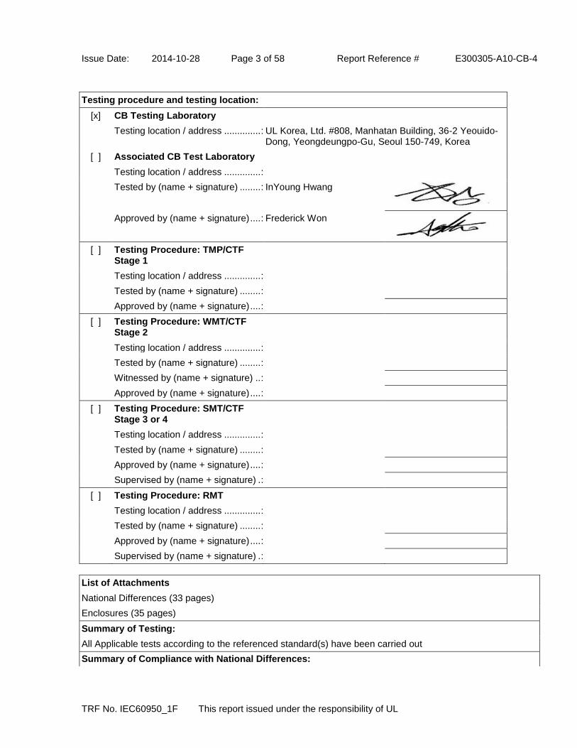
Issue Date: 2014-10-28 Page 3 of 58 Report Reference # E300305-A10-CB-4
TRF No. IEC60950_1F This report issued under the responsibility of UL
Testing procedure and testing location:
[x] CB Testing Laboratory
Testing location / address .............. : UL Korea, Ltd. #808, Manhatan Building, 36-2 Yeouido-Dong, Yeongdeungpo-Gu, Seoul 150-749, Korea
[ ] Associated CB Test Laboratory
Testing location / address .............. :
Tested by (name + signature) ........ : InYoung Hwang
Approved by (name + signature) .... : Frederick Won
[ ] Testing Procedure: TMP/CTF Stage 1
Testing location / address .............. :
Tested by (name + signature) ........ :
Approved by (name + signature) .... :
[ ] Testing Procedure: WMT/CTF Stage 2
Testing location / address .............. :
Tested by (name + signature) ........ :
Witnessed by (name + signature) .. :
Approved by (name + signature) .... :
[ ] Testing Procedure: SMT/CTF Stage 3 or 4
Testing location / address .............. :
Tested by (name + signature) ........ :
Approved by (name + signature) .... :
Supervised by (name + signature) . :
[ ] Testing Procedure: RMT
Testing location / address .............. :
Tested by (name + signature) ........ :
Approved by (name + signature) .... :
Supervised by (name + signature) . :
List of Attachments
National Differences (33 pages)
Enclosures (35 pages)
Summary of Testing:
All Applicable tests according to the referenced standard(s) have been carried out
Summary of Compliance with National Differences:

Issue Date: 2014-10-28 Page 4 of 58 Report Reference # E300305-A10-CB-4
TRF No. IEC60950_1F This report issued under the responsibility of UL
Countries outside the CB Scheme membership may also accept this report.
List of countries addressed: AT, BE, BG, CH, CZ, DE, DK, ES, EU, FI, FR, GB, GR, HU, IE, IL, IT, JP, KR, NL, NO, PL, PT, RO, SE, SG, SI, SK, UA
The product fulfills the requirements of: N/A
Copy of Marking Plate - Refer to Enclosure titled Marking Plate for copy.

Issue Date: 2014-10-28 Page 5 of 58 Report Reference # E300305-A10-CB-4
TRF No. IEC60950_1F This report issued under the responsibility of UL
Test item particulars :
Equipment mobility ...............................................: movable
Connection to the mains ......................................: pluggable A
Operating condition ..............................................: continuous
Access location ....................................................: restricted access location
Over voltage category (OVC) ..............................: OVC II
Mains supply tolerance (%) or absolute mains supply values ...................................................................: +10%, -10%
Tested for IT power systems ...............................: Yes(for Norway only)
IT testing, phase-phase voltage (V) .....................: 230 Vac
Class of equipment ..............................................: Class I (earthed) or Class II (double insulated)
Considered current rating of protective device as part of the building installation (A) ...............................: 0.5
Pollution degree (PD) ...........................................: PD 2
IP protection class ................................................: IP X0
Altitude of operation (m) .......................................: Up to 2000m
Altitude of test laboratory (m) ...............................: N/A
Mass of equipment (kg) .......................................: 0.17
Possible test case verdicts:
- test case does not apply to the test object ........... : N / A
- test object does meet the requirement ................. : P(Pass)
- test object does not meet the requirement ........... : F(Fail)
Testing:
Date(s) of receipt of test item ...............................: 2008-12-11
Date(s) of Performance of tests ...........................: 2008-12-11
General remarks:
"(see Enclosure #)" refers to additional information appended to the report. "(see appended table)" refers to a table appended to the report. Throughout this report a point is used as the decimal separator.
Manufacturer's Declaration per Sub Clause 4.2.5 of IECEE 02: The application for obtaining a CB Test Certificate includes more than one factory and a declaration from the Manufacturer stating that the sample(s) submitted for evaluation is (are) representative of the products from each factory has been provided ...... When differences exist, they shall be identified in the General Product Information section.
Yes
Name and address of Factory(ies): WENDENG JEIL ELECTRONICS CO LTD DONG SHOU GUANGZHOU LU KAIFA-QU WENDENG-SHI SHANDONG CHINA

Issue Date: 2014-10-28 Page 6 of 58 Report Reference # E300305-A10-CB-4
TRF No. IEC60950_1F This report issued under the responsibility of UL
BRIDGEPOWER CORP (GOSAEK-DONG) 16 OMOKCHEN-RO 132BEON-GIL GWONSEON-GU SUWON-SI GYEONGGI 441-813 KOREA
GENERAL PRODUCT INFORMATION:
Report Summary
All applicable tests according to the referenced standard(s) have been carried out.
Product Description
Switching Mode Power Supply(AC/DC adapter), consists of electronic components mounted on PWB, a switching transformer and electronic components mounted on PWB, housed with a plastic enclosure.
Model Differences
The applicant submitted samples of models JPOE130A4800FK01 and JPOE130B4800FK01 for testing. Model JPOE130B4800FK01 is identical to model JPOE130A4800FK01 except for model designation and output circuitry with the different rated output current. Model JPOE130C******** is identical to model JPOE130A********, except model designation and secondary circuit not affecting on the safety and construction. Models PW180********* and PUTP-130*-*** are identical to model JPOE130********* except for model designation. Nomenclature JPOE130*(a)**(b)**(c)*(d)*(e)**(f) (a) means Design revision changes, may by A, B or C as rated output current, A or C - 0.4A or 0.35A, B - 0.32A or 0.35A; (b) means output voltage, 48; (c) means standards output cord options, may be 00 to 99; (d) means standards input cord options, may be F (Class I) or N (Class II); (e) means custom options, may be K or C; (f) means custom options, may be 00 to 99 or AA to ZZ. PW180*(a)*(b)**(c)**(d)*(e)**(f) (a) means custom options, may be K or C; (b) means design revision changes, may be A, B or C as rated output current, A or C - 0.4A or 0.35A, B - 0.32A or 0.35A; (c) means output voltage, 48; (d) means standards output cord options, may be 00 to 99; (e) means standards input cord options, may be F (Class I) or N (Class II); (f) means custom options, may be 00 to 99 or AA to ZZ. PUTP-130*(a)-**(b)*(c) (a) means design revision changes, may be A, B or C as rated output current, A or C - 0.4A or 0.35A, B - 0.32A or 0.35A;
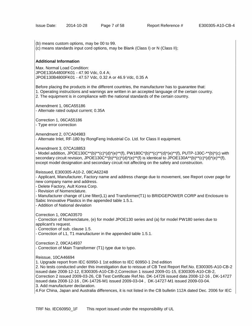
Issue Date: 2014-10-28 Page 7 of 58 Report Reference # E300305-A10-CB-4
TRF No. IEC60950_1F This report issued under the responsibility of UL
(b) means custom options, may be 00 to 99. (c) means standards input cord options, may be Blank (Class I) or N (Class II);
Additional Information
Max. Normal Load Condition: JPOE130A4800FK01 - 47.90 Vdc, 0.4 A; JPOE130B4800FK01 - 47.57 Vdc, 0.32 A or 46.9 Vdc, 0.35 A Before placing the products in the different countries, the manufacturer has to guarantee that: 1. Operating instructions and warnings are written in an accepted language of the certain country. 2. The equipment is in compliance with the national standards of the certain country. Amendment 1, 06CA55186 - Alternate rated output current; 0.35A Correction 1, 06CA55186 - Type error correction Amendment 2, 07CA04983 - Alternate Inlet, RF-180 by RongFeng Industrial Co. Ltd. for Class II equipment. Amendment 3, 07CA18853 - Model addition, JPOE130C**(b)**(c)*(d)*(e)**(f), PW180C*(b)**(c)**(d)*(e)**(f), PUTP-130C-**(b)*(c) with secondary circuit revision, JPOE130C**(b)**(c)*(d)*(e)**(f) is identical to JPOE130A**(b)**(c)*(d)*(e)**(f), except model designation and secondary circuit not affecting on the safety and construction. Reissued, E300305-A10-2, 08CA62248 - Applicant, Manufacturer, Factory name and address change due to movement, see Report cover page for new company name and address. - Delete Factory, Ault Korea Corp. - Revision of Nomenclature. - Manufacturer change of Line filter(L1) and Transformer(T1) to BRIDGEPOWER CORP and Enclosure to Sabic Innovative Plastics in the appended table 1.5.1. - Addition of National deviation Correction 1, 09CA03570 - Correction of Nomenclature, (e) for model JPOE130 series and (a) for model PW180 series due to applicant's request. - Correction of sub. clause 1.5. - Correction of L1, T1 manufacturer in the appended table 1.5.1. Correction 2, 09CA14937 - Correction of Main Transformer (T1) type due to typo. Reissue, 10CA46694 1. Upgrade report from IEC 60950-1 1st edition to IEC 60950-1 2nd edition 2. No tests conducted under this investigation due to reissue of CB Test Report Ref.No. E300305-A10-CB-2 issued date 2008-12-12, E300305-A10-CB-2,Correction 1 issued 2009-01-15, E300305-A10-CB-2, Correction 2 issued 2009-03-26, CB Test Certificate Ref.No. DK-14726 issued data 2008-12-16 , DK-14727 issued data 2008-12-16 , DK-14726-M1 issued 2009-03-04 , DK-14727-M1 issued 2009-03-04. 3. Add manufacturer declaration. 4.For China, Japan and Australia differences, it is not listed in the CB bulletin 112A dated Dec. 2006 for IEC

Issue Date: 2014-10-28 Page 8 of 58 Report Reference # E300305-A10-CB-4
TRF No. IEC60950_1F This report issued under the responsibility of UL
60950-1, therefore the deviation of IEC 60950 3rd edition is used for China and Japan and the deviation of IEC 60950-1 1st edition used for Australia, see Enclosure, Miscellaneous. 5. Add trademark "BridgePower" Correction. SR9742118(E300305-A10-CB-3, Correction1) - Add humidity test time (48hours) in clause 2.9.2 due to missing. - Add "Also complied with humidity test" in table 5.2 supplementary information. 4786594328(E300305-A10-CB-4, Reissue) 1. Upgrade report from IEC 60950-1 2nd edition to IEC 60950-1 2nd edition Amendment 2 2. No tests conducted under this investigation due to reissue of CB Test Report Ref.No. E300305-A10-CB-3 issued date 2010-09-24, CB-20164 and CB-20163, CB Test Report Ref.No. E300305-A10-CB-3, Correction 1, DK-20164-M1-UL and DK-20163-M1-UL 3. Delete China Deviation 4. Revise Critical Component List - Change Manufactuer name from Cheil Industries to Samsung SDI 5. Change of applicant address from "964 GOSAEK-DONG GWONSEON-GU SUWON-SI GYEONGGI-DO 441-813 KOREA" to "(GOSAEK-DONG) 16 OMOKCHEN-RO 132BEON-GIL GWONSEON-GU SUWON-SI GYEONGGI 441-813 KOREA". 6. revised of MFR. and Factory address
Technical Considerations
The product was submitted and evaluated for use at the maximum ambient temperature (Tma) permitted by the manufacturer’s specification of: 30
The means of connection to the mains supply is: Pluggable A
The product is intended for use on the following power systems: TN, IT(for Norway only),
The equipment disconnect device is considered to be: Appliance inlet
The product was investigated to the following additional standards: EN 60950-1:2006 + A11:2009 + A1:2010 + A12:2011 + A2:2013 (which includes all European national differences, including those specified in this test report)., ,
The following circuit locations (with circuit/schematic designation) were investigated as a limited power source (LPS): all output
Abbreviations used in the report:
- normal condition ............................................ : N.C. - single fault condition ....................................... : S.F.C
- operational insulation ..................................... : OP - basic insulation .............................................. : BI
- basic insulation between parts of opposite polarity:
BOP
- supplementary insulation ............................... : SI
- double insulation ............................................ : DI - reinforced insulation ...................................... : RI
Indicate used abbreviations (if any)

Issue Date: 2014-10-28 Page 9 of 58 Report Reference # E300305-A10-CB-4
IEC 60950-1
Clause Requirement + Test Result - Remark Verdict
TRF No. IEC60950_1F This report issued under the responsibility of UL
1 GENERAL Pass
1.5 Components Pass
1.5.1 General Pass
Comply with IEC 60950-1 or relevant component standard
Pass
1.5.2 Evaluation and testing of components Components certified to IEC harmonized standard and checked for correct application. Components, for which no relevant IEC-Standard exist, have been tested under the conditions occurring in the equipment, using applicable parts of IEC 60950. Components not certified are used in accordance with their ratings and they comply with applicable parts of IEC 60950-1 and the relevant component Standard.
Pass
1.5.3 Thermal controls N/A
1.5.4 Transformers (see Annex C) Pass
1.5.5 Interconnecting cables N/A
1.5.6 Capacitors bridging insulation Between lines; X1 or X2 capacitor according to IEC 60384-14;2005. Between primary and secondary: Y1 or Y2 capacitors according to IEC 60384-14:2005.
Pass
1.5.7 Resistors bridging insulation Two capacitors in series, each complying with IEC 60384-14:2005, subclass Y1 or Y2.
Pass
1.5.7.1 Resistors bridging functional, basic or supplementary insulation
Pass
1.5.7.2 Resistors bridging double or reinforced insulation between a.c. mains and other circuits
N/A
1.5.7.3 Resistors bridging double or reinforced insulation between a.c. mains and antenna or coaxial cable
N/A
1.5.8 Components in equipment for IT power systems Pass
1.5.9 Surge suppressors N/A
1.5.9.1 General N/A
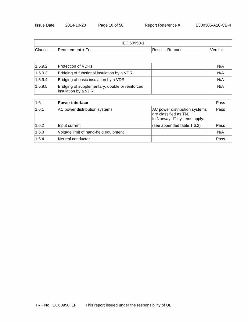
Issue Date: 2014-10-28 Page 10 of 58 Report Reference # E300305-A10-CB-4
IEC 60950-1
Clause Requirement + Test Result - Remark Verdict
TRF No. IEC60950_1F This report issued under the responsibility of UL
1.5.9.2 Protection of VDRs N/A
1.5.9.3 Bridging of functional insulation by a VDR N/A
1.5.9.4 Bridging of basic insulation by a VDR N/A
1.5.9.5 Bridging of supplementary, double or reinforced insulation by a VDR
N/A
1.6 Power interface Pass
1.6.1 AC power distribution systems AC power distribution systems are classified as TN. In Norway, IT systems apply.
Pass
1.6.2 Input current (see appended table 1.6.2) Pass
1.6.3 Voltage limit of hand-held equipment N/A
1.6.4 Neutral conductor Pass

Issue Date: 2014-10-28 Page 11 of 58 Report Reference # E300305-A10-CB-4
IEC 60950-1
Clause Requirement + Test Result - Remark Verdict
TRF No. IEC60950_1F This report issued under the responsibility of UL
1.7 Marking and instructions Pass
1.7.1 Power rating and identification markings Pass
1.7.1.1 Power rating mark Pass
Multiple mains supply connections ........................ : N/A
Rated voltage(s) or voltage range(s) (V) ............... : 100-250 Vac Pass
Symbol for nature of supply, for d.c. only .............. : N/A
Rated frequency or rated frequency range (Hz) .... : 50-60 Hz Pass
Rated current (mA or A) ........................................ : 0.5 A Pass
1.7.1.2 Identification markings Pass
Manufacturer's name or trademark or identification mark ....................................................................... :
Bridgepower Corp. or E300305 Pass
Model identification or type reference ................... : (see cover page) Pass
Symbol for Class II equipment only ....................... : for Class II equipment only Pass
Other markings and symbols ................................. : Additional symbols or marking does not give rise to misunderstanding.
Pass
1.7.1.3 Use of graphical symbols Pass
1.7.2 Safety instructions and marking Pass
1.7.2.1 General N/A
1.7.2.2 Disconnect devices Pass
1.7.2.3 Overcurrent protective device Pass
1.7.2.4 IT Power distribution systems Norway Only Pass
1.7.2.5 Operator access with a tool N/A
1.7.2.6 Ozone N/A
1.7.3 Short duty cycles Equipment is designed for continuous operation.
N/A
1.7.4 Supply voltage adjustment .................................... : Equipment is auto-ranging. N/A
Method and means of adjustment; reference to installation instructions .......................................... :
N/A
1.7.5 Power outlets on the equipment ............................ : No standard power outlets are provided.
N/A
1.7.6 Fuse identification (marking, special fusing characteristics, cross-reference) ........................... :
Marking adjacent to fuse on PCB as "T1A 250V"
Pass
1.7.7 Wiring terminals N/A
1.7.7.1 Protective earthing and bonding terminals ............ : N/A
1.7.7.2 Terminals for a.c. mains supply conductors N/A

Issue Date: 2014-10-28 Page 12 of 58 Report Reference # E300305-A10-CB-4
IEC 60950-1
Clause Requirement + Test Result - Remark Verdict
TRF No. IEC60950_1F This report issued under the responsibility of UL
1.7.7.3 Terminals for d.c. mains supply conductors N/A
1.7.8 Controls and indicators Not affecting safety. N/A
1.7.8.1 Identification, location and marking ....................... : N/A
1.7.8.2 Colours .................................................................. : N/A
1.7.8.3 Symbols according to IEC 60417 .......................... : N/A
1.7.8.4 Markings using figures ........................................... : N/A
1.7.9 Isolation of multiple power sources ....................... : N/A
1.7.10 Thermostats and other regulating devices ............ : N/A
1.7.11 Durability All markings provided on UL Recognized component labels suitable for surface they are applied upon.
Pass
1.7.12 Removable parts No removable part. N/A
1.7.13 Replaceable batteries ............................................ : No batteries provided. N/A
Language(s) .......................................................... : -
1.7.14 Equipment for restricted access locations ............. : The equipment is not intended for installation in a Restricted Access Area.
N/A

Issue Date: 2014-10-28 Page 13 of 58 Report Reference # E300305-A10-CB-4
IEC 60950-1
Clause Requirement + Test Result - Remark Verdict
TRF No. IEC60950_1F This report issued under the responsibility of UL
2 PROTECTION FROM HAZARDS Pass
2.1 Protection from electric shock and energy hazards Pass
2.1.1 Protection in operator access areas Pass
2.1.1.1 Access to energized parts Pass
Test by inspection .................................................. : No access with test finger and test pin to any parts with only basic insulation to ELV or hazardous voltage. Any hazardous parts accessible are unlikely.
Pass
Test with test finger (Figure 2A) ............................ : The test finger was unable to contact bare hazardous parts, basic insulation, or ELV circuits.
Pass
Test with test pin (Figure 2B)................................. : The test pin was unable to contact bare hazardous parts.
Pass
Test with test probe (Figure 2C) ............................ : No TNV present. N/A
2.1.1.2 Battery compartments N/A
2.1.1.3 Access to ELV wiring N/A
Working voltage (Vpeak or Vrms); minimum distance through insulation (mm) .......................... :
(see appended table 2.10.5) -
2.1.1.4 Access to hazardous voltage circuit wiring N/A
2.1.1.5 Energy hazards ..................................................... : No energy hazard in operator area.
Pass
2.1.1.6 Manual controls N/A
2.1.1.7 Discharge of capacitors in equipment Pass
Measured voltage (V); time-constant (s) ............... : Vo 374 Vpk, 37 % Vo 138 Vpk, Vtc 0 Vpk.
-
2.1.1.8 Energy hazards - d.c. mains supply N/A
a) Capacitor connected to the d.c. mains supply .. : N/A
b) Internal battery connected to the mains supply : N/A
2.1.1.9 Audio amplifiers ..................................................... : N/A
2.1.2 Protection in service access areas N/A
2.1.3 Protection in restricted access locations N/A

Issue Date: 2014-10-28 Page 14 of 58 Report Reference # E300305-A10-CB-4
IEC 60950-1
Clause Requirement + Test Result - Remark Verdict
TRF No. IEC60950_1F This report issued under the responsibility of UL
2.2 SELV circuits Pass
2.2.1 General requirements Pass
2.2.2 Voltages under normal conditions (V) ................... : All accessible voltages are less than 42.4 Vp or 60 V dc and are classified as SELV.
Pass
2.2.3 Voltages under fault conditions (V) ....................... : Under fault conditions voltages never exceed 71V peak and 120Vdc and do not exceed 42.4V peak or 60V dc for more than 0.2 sec.
Pass
2.2.4 Connection of SELV circuits to other circuits ........ : SELV circuits are only connected to other secondary circuits. SELV circuit and all interconnected circuits separated from primary by reinforced insulation. The SELV circuit does not exceed the SELV limits under normal and fault conditions.
Pass
2.3 TNV circuits N/A
2.3.1 Limits N/A
Type of TNV circuits .............................................. : - -
2.3.2 Separation from other circuits and from accessible parts
N/A
2.3.2.1 General requirements N/A
2.3.2.2 Protection by basic insulation N/A
2.3.2.3 Protection by earthing N/A
2.3.2.4 Protection by other constructions .......................... : N/A
2.3.3 Separation from hazardous voltages N/A
Insulation employed ............................................... : - -
2.3.4 Connection of TNV circuits to other circuits N/A
Insulation employed ............................................... : - -
2.3.5 Test for operating voltages generated externally N/A
Issue Date: 2014-10-28 Page 15 of 58 Report Reference # E300305-A10-CB-4
IEC 60950-1
Clause Requirement + Test Result - Remark Verdict
TRF No. IEC60950_1F This report issued under the responsibility of UL
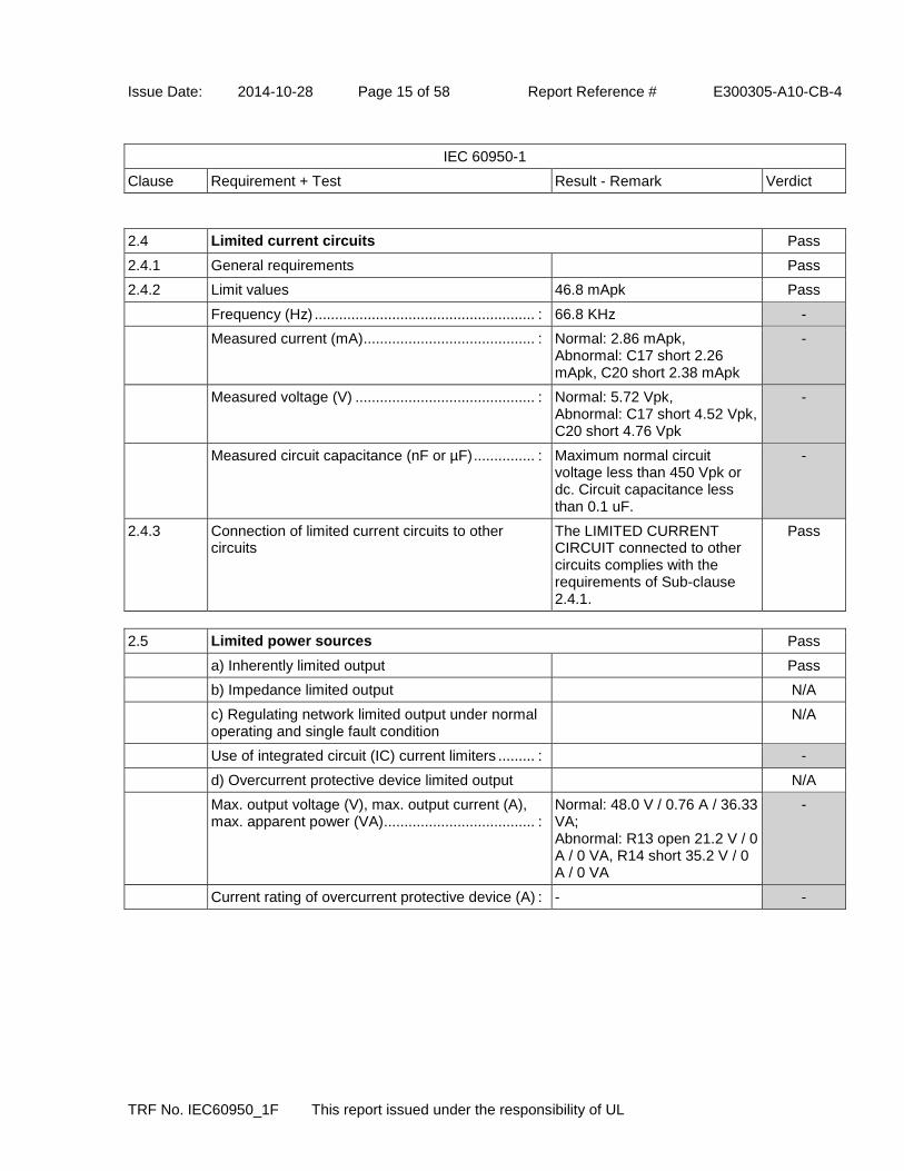
2.4 Limited current circuits Pass
2.4.1 General requirements Pass
2.4.2 Limit values 46.8 mApk Pass
Frequency (Hz) ...................................................... : 66.8 KHz -
Measured current (mA) .......................................... : Normal: 2.86 mApk, Abnormal: C17 short 2.26 mApk, C20 short 2.38 mApk
-
Measured voltage (V) ............................................ : Normal: 5.72 Vpk, Abnormal: C17 short 4.52 Vpk, C20 short 4.76 Vpk
-
Measured circuit capacitance (nF or µF) ............... : Maximum normal circuit voltage less than 450 Vpk or dc. Circuit capacitance less than 0.1 uF.
-
2.4.3 Connection of limited current circuits to other circuits
The LIMITED CURRENT CIRCUIT connected to other circuits complies with the requirements of Sub-clause 2.4.1.
Pass
2.5 Limited power sources Pass
a) Inherently limited output Pass
b) Impedance limited output N/A
c) Regulating network limited output under normal operating and single fault condition
N/A
Use of integrated circuit (IC) current limiters ......... : -
d) Overcurrent protective device limited output N/A
Max. output voltage (V), max. output current (A), max. apparent power (VA)..................................... :
Normal: 48.0 V / 0.76 A / 36.33 VA; Abnormal: R13 open 21.2 V / 0 A / 0 VA, R14 short 35.2 V / 0 A / 0 VA
-
Current rating of overcurrent protective device (A) : - -

Issue Date: 2014-10-28 Page 16 of 58 Report Reference # E300305-A10-CB-4
IEC 60950-1
Clause Requirement + Test Result - Remark Verdict
TRF No. IEC60950_1F This report issued under the responsibility of UL
2.6 Provisions for earthing and bonding Pass
2.6.1 Protective earthing for Class I equipment only Pass
2.6.2 Functional earthing N/A
Use of symbol for functional earthing .................... : N/A
2.6.3 Protective earthing and protective bonding conductors
Pass
2.6.3.1 General for Class I equipment only Pass
2.6.3.2 Size of protective earthing conductors Appliance Inlet used. N/A
Rated current (A), cross-sectional area (mm²), AWG ...................................................................... :
-
2.6.3.3 Size of protective bonding conductors Pass
Rated current (A), cross-sectional area (mm²), AWG ...................................................................... :
1.0 A, 0.75 mm2, 18 AWG -
Protective current rating (A), cross-sectional area (mm²), AWG........................................................... :
- -
2.6.3.4 Resistance of earthing conductors and their terminations; resistance (ohm), voltage drop (V), test current (A), duration (min) .............................. :
0.019 ohm, 0.82 Vdrop, 40 A, 2 minute
Pass
2.6.3.5 Colour of insulation ................................................ : Green and yellow Pass
2.6.4 Terminals Pass
2.6.4.1 General for Class I equipment only Pass
2.6.4.2 Protective earthing and bonding terminals Pass
Rated current (A), type, nominal thread diameter (mm) ...................................................................... :
Appliance Inlet used. -
2.6.4.3 Separation of the protective earthing conductor from protective bonding conductors
Unit employs an appliance inlet.
N/A
2.6.5 Integrity of protective earthing Pass
2.6.5.1 Interconnection of equipment N/A
2.6.5.2 Components in protective earthing conductors and protective bonding conductors
No switches or fuses in earthing conductors.
N/A
2.6.5.3 Disconnection of protective earth Disconnection of the protective earth at one assembly removes connection of HAZARDOUS VOLTAGES from the other assemblies at the same time.
Pass
2.6.5.4 Parts that can be removed by an operator It is not possible to disconnect earth without disconnecting mains.
Pass

Issue Date: 2014-10-28 Page 17 of 58 Report Reference # E300305-A10-CB-4
IEC 60950-1
Clause Requirement + Test Result - Remark Verdict
TRF No. IEC60950_1F This report issued under the responsibility of UL
2.6.5.5 Parts removed during servicing Connections to protective earthing cannot be removed unless hazardous voltage is removed from the part simultaneously.
Pass
2.6.5.6 Corrosion resistance N/A
2.6.5.7 Screws for protective bonding N/A
2.6.5.8 Reliance on telecommunication network or cable distribution system
N/A
2.7 Overcurrent and earth fault protection in primary circuits Pass
2.7.1 Basic requirements Pass
Instructions when protection relies on building installation
N/A
2.7.2 Faults not covered in 5.3.7 N/A
2.7.3 Short-circuit backup protection Pass
2.7.4 Number and location of protective devices ........... : One protective device in the "LIVE" phase.
Pass
2.7.5 Protection by several devices N/A
2.7.6 Warning to service personnel ................................ : N/A
2.8 Safety interlocks N/A
2.8.1 General principles N/A
2.8.2 Protection requirements N/A
2.8.3 Inadvertent reactivation N/A
2.8.4 Fail-safe operation N/A
Protection against extreme hazard N/A
2.8.5 Moving parts N/A
2.8.6 Overriding N/A
2.8.7 Switches, relays and their related circuits N/A
2.8.7.1 Separation distances for contact gaps and their related circuits (mm) .............................................. :
N/A
2.8.7.2 Overload test N/A
2.8.7.3 Endurance test N/A
2.8.7.4 Electric strength test N/A
2.8.8 Mechanical actuators N/A

Issue Date: 2014-10-28 Page 18 of 58 Report Reference # E300305-A10-CB-4
IEC 60950-1
Clause Requirement + Test Result - Remark Verdict
TRF No. IEC60950_1F This report issued under the responsibility of UL
2.9 Electrical insulation Pass
2.9.1 Properties of insulating materials Natural rubber, asbestos or hygroscopic material is not used.
Pass
2.9.2 Humidity conditioning Pass
Relative humidity (%), temperature (°C) ................ : 95%, 30degreeC, 48hours. (All of the transformer has passed the humidity test)
-
2.9.3 Grade of insulation Insulation materials comply with sub-clauses 2.10, 4.5.1 and 5.2.
Pass
2.9.4 Separation from hazardous voltages N/A
Method(s) used ...................................................... : -
Issue Date: 2014-10-28 Page 19 of 58 Report Reference # E300305-A10-CB-4
IEC 60950-1
Clause Requirement + Test Result - Remark Verdict
TRF No. IEC60950_1F This report issued under the responsibility of UL
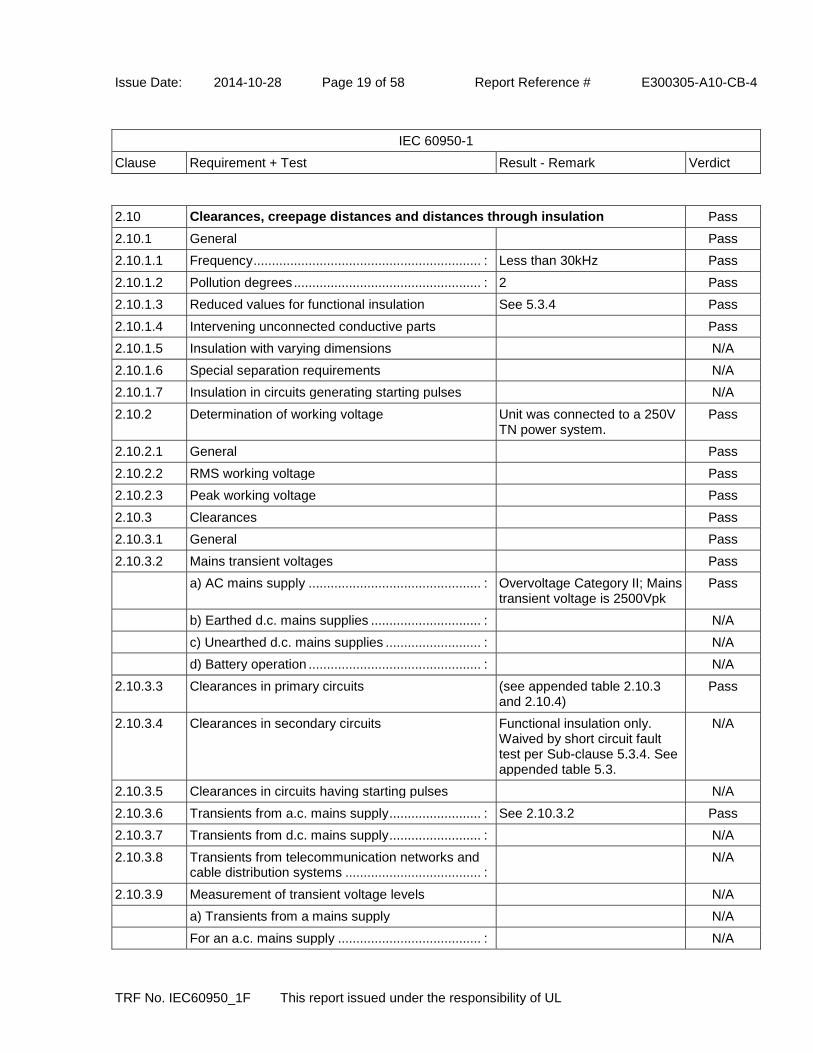
2.10 Clearances, creepage distances and distances through insulation Pass
2.10.1 General Pass
2.10.1.1 Frequency .............................................................. : Less than 30kHz Pass
2.10.1.2 Pollution degrees ................................................... : 2 Pass
2.10.1.3 Reduced values for functional insulation See 5.3.4 Pass
2.10.1.4 Intervening unconnected conductive parts Pass
2.10.1.5 Insulation with varying dimensions N/A
2.10.1.6 Special separation requirements N/A
2.10.1.7 Insulation in circuits generating starting pulses N/A
2.10.2 Determination of working voltage Unit was connected to a 250V TN power system.
Pass
2.10.2.1 General Pass
2.10.2.2 RMS working voltage Pass
2.10.2.3 Peak working voltage Pass
2.10.3 Clearances Pass
2.10.3.1 General Pass
2.10.3.2 Mains transient voltages Pass
a) AC mains supply ............................................... : Overvoltage Category II; Mains transient voltage is 2500Vpk
Pass
b) Earthed d.c. mains supplies .............................. : N/A
c) Unearthed d.c. mains supplies .......................... : N/A
d) Battery operation ............................................... : N/A
2.10.3.3 Clearances in primary circuits (see appended table 2.10.3 and 2.10.4)
Pass
2.10.3.4 Clearances in secondary circuits Functional insulation only. Waived by short circuit fault test per Sub-clause 5.3.4. See appended table 5.3.
N/A
2.10.3.5 Clearances in circuits having starting pulses N/A
2.10.3.6 Transients from a.c. mains supply ......................... : See 2.10.3.2 Pass
2.10.3.7 Transients from d.c. mains supply ......................... : N/A
2.10.3.8 Transients from telecommunication networks and cable distribution systems ..................................... :
N/A
2.10.3.9 Measurement of transient voltage levels N/A
a) Transients from a mains supply N/A
For an a.c. mains supply ....................................... : N/A

Issue Date: 2014-10-28 Page 20 of 58 Report Reference # E300305-A10-CB-4
IEC 60950-1
Clause Requirement + Test Result - Remark Verdict
TRF No. IEC60950_1F This report issued under the responsibility of UL
For a d.c. mains supply ......................................... : N/A
b) Transients from a telecommunication network N/A
2.10.4 Creepage distances (see appended table 2.10.3 and 2.10.4)
Pass
2.10.4.1 General Pass
2.10.4.2 Material group and comparative tracking index Pass
CTI tests ................................................................ : Material group IIIb; 100 <=CTI <175.
-
2.10.4.3 Minimum creepage distances See appended table 2.10.3 and 2.10.4
Pass
2.10.5 Solid insulation Approved optical isolator provided.
Pass
2.10.5.1 General Pass
2.10.5.2 Distances through insulation Pass
2.10.5.3 Insulating compound as solid insulation Certified optical isolator used. Pass
2.10.5.4 Semiconductor devices N/A
2.10.5.5 Cemented joints Certified optical isolator used(see appended table 1.5.1)
Pass
2.10.5.6 Thin sheet material - General Two layers used, each of which complies with the required electric strength test.
Pass
2.10.5.7 Separable thin sheet material Pass
Number of layers (pcs) .......................................... : 3 layers -
2.10.5.8 Non-separable thin sheet material N/A
2.10.5.9 Thin sheet material - standard test procedure N/A
Electric strength test .............................................. : -
2.10.5.10 Thin sheet material - alternative test procedure Pass
Electric strength test .............................................. : (see appended table 2.10.5) -
2.10.5.11 Insulation in wound components Pass
2.10.5.12 Wire in wound components Pass
Working voltage ..................................................... : Certified triple insulated wire used secondary of T1.
Pass
a) Basic insulation not under stress ...................... : N/A
b) Basic, supplementary, reinforced insulation...... : Supplementary or Reinforced Pass
c) Compliance with Annex U ................................. : Wiring meets the requirements of Annex U
Pass

Issue Date: 2014-10-28 Page 21 of 58 Report Reference # E300305-A10-CB-4
IEC 60950-1
Clause Requirement + Test Result - Remark Verdict
TRF No. IEC60950_1F This report issued under the responsibility of UL
Two wires in contact inside wound component; angle between 45° and 90° ................................... :
1 layer of insulation tape provided.
Pass
2.10.5.13 Wire with solvent-based enamel in wound components
N/A
Electric strength test .............................................. : -
Routine test N/A
2.10.5.14 Additional insulation in wound components N/A
Working voltage ..................................................... : N/A
- Basic insulation not under stress ........................ : N/A
- Supplementary, reinforced insulation .................. : N/A
2.10.6 Construction of printed boards N/A
2.10.6.1 Uncoated printed boards N/A
2.10.6.2 Coated printed boards N/A
2.10.6.3 Insulation between conductors on the same inner surface of a printed board
N/A
2.10.6.4 Insulation between conductors on different layers of a printed board
N/A
Distance through insulation N/A
Number of insulation layers (pcs) .......................... : N/A
2.10.7 Component external terminations N/A
2.10.8 Tests on coated printed boards and coated components
N/A
2.10.8.1 Sample preparation and preliminary inspection N/A
2.10.8.2 Thermal conditioning N/A
2.10.8.3 Electric strength test N/A
2.10.8.4 Abrasion resistance test N/A
2.10.9 Thermal cycling N/A
2.10.10 Test for Pollution Degree 1 environment and insulating compound
N/A
2.10.11 Tests for semiconductor devices and cemented joints
N/A
2.10.12 Enclosed and sealed parts N/A

Issue Date: 2014-10-28 Page 22 of 58 Report Reference # E300305-A10-CB-4
IEC 60950-1
Clause Requirement + Test Result - Remark Verdict
TRF No. IEC60950_1F This report issued under the responsibility of UL
3 WIRING, CONNECTIONS AND SUPPLY Pass
3.1 General Pass
3.1.1 Current rating and overcurrent protection Pass
3.1.2 Protection against mechanical damage Wires do not touch sharp edges and heat sinks which could damage the insulation and cause hazard.
Pass
3.1.3 Securing of internal wiring Pass
3.1.4 Insulation of conductors The insulation of the individual conductors are suitable for the application and the working voltage.
Pass
3.1.5 Beads and ceramic insulators N/A
3.1.6 Screws for electrical contact pressure N/A
3.1.7 Insulating materials in electrical connections N/A
3.1.8 Self-tapping and spaced thread screws N/A
3.1.9 Termination of conductors All conductors are reliably secured.
Pass
10 N pull test Pass
3.1.10 Sleeving on wiring N/A
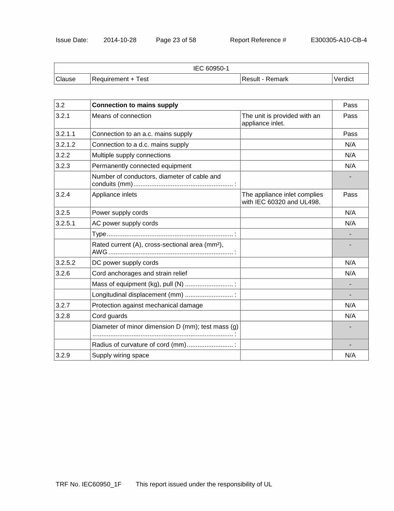
Issue Date: 2014-10-28 Page 23 of 58 Report Reference # E300305-A10-CB-4
IEC 60950-1
Clause Requirement + Test Result - Remark Verdict
TRF No. IEC60950_1F This report issued under the responsibility of UL
3.2 Connection to mains supply Pass
3.2.1 Means of connection The unit is provided with an appliance inlet.
Pass
3.2.1.1 Connection to an a.c. mains supply Pass
3.2.1.2 Connection to a d.c. mains supply N/A
3.2.2 Multiple supply connections N/A
3.2.3 Permanently connected equipment N/A
Number of conductors, diameter of cable and conduits (mm) ........................................................ :
-
3.2.4 Appliance inlets The appliance inlet complies with IEC 60320 and UL498.
Pass
3.2.5 Power supply cords N/A
3.2.5.1 AC power supply cords N/A
Type ....................................................................... : -
Rated current (A), cross-sectional area (mm²), AWG ...................................................................... :
-
3.2.5.2 DC power supply cords N/A
3.2.6 Cord anchorages and strain relief N/A
Mass of equipment (kg), pull (N) ........................... : -
Longitudinal displacement (mm) ........................... : -
3.2.7 Protection against mechanical damage N/A
3.2.8 Cord guards N/A
Diameter of minor dimension D (mm); test mass (g) ............................................................................... :
-
Radius of curvature of cord (mm) .......................... : -
3.2.9 Supply wiring space N/A

Issue Date: 2014-10-28 Page 24 of 58 Report Reference # E300305-A10-CB-4
IEC 60950-1
Clause Requirement + Test Result - Remark Verdict
TRF No. IEC60950_1F This report issued under the responsibility of UL
3.3 Wiring terminals for connection of external conductors N/A
3.3.1 Wiring terminals N/A
3.3.2 Connection of non-detachable power supply cords N/A
3.3.3 Screw terminals N/A
3.3.4 Conductor sizes to be connected N/A
Rated current (A), cord/cable type, cross-sectional area (mm²) ............................................................. :
-
3.3.5 Wiring terminal sizes N/A
Rated current (A), type and nominal thread diameter (mm) ....................................................... :
-
3.3.6 Wiring terminals design N/A
3.3.7 Grouping of wiring terminals N/A
3.3.8 Stranded wire N/A
3.4 Disconnection from the mains supply Pass
3.4.1 General requirement Pass
3.4.2 Disconnect devices The equipment is provided with an appliance coupler.
Pass
3.4.3 Permanently connected equipment N/A
3.4.4 Parts which remain energized No parts remain energized when the disconnect device is removed.
Pass
3.4.5 Switches in flexible cords N/A
3.4.6 Number of poles - single-phase and d.c. equipment Disconnect device disconnects all poles simultaneously.
Pass
3.4.7 Number of poles - three-phase equipment N/A
3.4.8 Switches as disconnect devices N/A
3.4.9 Plugs as disconnect devices N/A
3.4.10 Interconnected equipment N/A
3.4.11 Multiple power sources N/A

Issue Date: 2014-10-28 Page 25 of 58 Report Reference # E300305-A10-CB-4
IEC 60950-1
Clause Requirement + Test Result - Remark Verdict
TRF No. IEC60950_1F This report issued under the responsibility of UL
3.5 Interconnection of equipment Pass
3.5.1 General requirements Pass
3.5.2 Types of interconnection circuits ........................... : Interconnection circuits are SELV CIRCUITS.
Pass
3.5.3 ELV circuits as interconnection circuits N/A
3.5.4 Data ports for additional equipment N/A
4 PHYSICAL REQUIREMENTS Pass
4.1 Stability N/A
Angle of 10° N/A
Test force (N) ......................................................... : N/A
4.2 Mechanical strength Pass
4.2.1 General Pass
Rack-mounted equipment N/A
4.2.2 Steady force test, 10 N Pass
4.2.3 Steady force test, 30 N N/A
4.2.4 Steady force test, 250 N Pass
4.2.5 Impact test Pass
Fall test Pass
Swing test N/A
4.2.6 Drop test; height (mm) ........................................... : N/A
4.2.7 Stress relief test No indication of shrinkage or distortion on enclosures due to the stress relief test 80 degree C/7 h.
Pass
4.2.8 Cathode ray tubes N/A
Picture tube separately certified ............................ : N/A
4.2.9 High pressure lamps N/A
4.2.10 Wall or ceiling mounted equipment; force (N) ....... : N/A

Issue Date: 2014-10-28 Page 26 of 58 Report Reference # E300305-A10-CB-4
IEC 60950-1
Clause Requirement + Test Result - Remark Verdict
TRF No. IEC60950_1F This report issued under the responsibility of UL
4.3 Design and construction Pass
4.3.1 Edges and corners Pass
4.3.2 Handles and manual controls; force (N) ................ : N/A
4.3.3 Adjustable controls N/A
4.3.4 Securing of parts No loosening of parts impairing creepage distances or clearances over supplementary or reinforced insulation is likely to occur.
Pass
4.3.5 Connection by plugs and sockets The equipment does not have any interchangeable plugs/sockets.
N/A
4.3.6 Direct plug-in equipment N/A
Torque ................................................................... : N/A
Compliance with the relevant mains plug standard: N/A
4.3.7 Heating elements in earthed equipment N/A
4.3.8 Batteries N/A
- Overcharging of a rechargeable battery N/A
- Unintentional charging of a non-rechargeable battery
N/A
- Reverse charging of a rechargeable battery N/A
- Excessive discharging rate for any battery N/A
4.3.9 Oil and grease N/A
4.3.10 Dust, powders, liquids and gases N/A
4.3.11 Containers for liquids or gases N/A
4.3.12 Flammable liquids .................................................. : N/A
Quantity of liquid (l) ................................................ : N/A
Flash point (°C) ...................................................... : N/A
4.3.13 Radiation N/A
4.3.13.1 General N/A
4.3.13.2 Ionizing radiation N/A
Measured radiation (pA/kg) ................................... : -
Measured high-voltage (kV) .................................. : -
Measured focus voltage (kV) ................................. : -
CRT markings ........................................................ : -
4.3.13.3 Effect of ultraviolet (UV) radiation on materials N/A
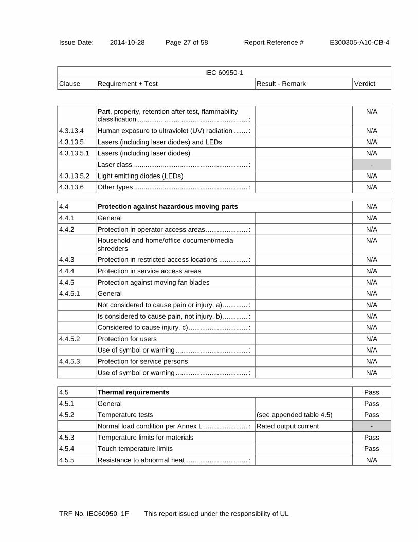
Issue Date: 2014-10-28 Page 27 of 58 Report Reference # E300305-A10-CB-4
IEC 60950-1
Clause Requirement + Test Result - Remark Verdict
TRF No. IEC60950_1F This report issued under the responsibility of UL
Part, property, retention after test, flammability classification .......................................................... :
N/A
4.3.13.4 Human exposure to ultraviolet (UV) radiation ....... : N/A
4.3.13.5 Lasers (including laser diodes) and LEDs N/A
4.3.13.5.1 Lasers (including laser diodes) N/A
Laser class ............................................................ : -
4.3.13.5.2 Light emitting diodes (LEDs) N/A
4.3.13.6 Other types ............................................................ : N/A
4.4 Protection against hazardous moving parts N/A
4.4.1 General N/A
4.4.2 Protection in operator access areas ...................... : N/A
Household and home/office document/media shredders
N/A
4.4.3 Protection in restricted access locations ............... : N/A
4.4.4 Protection in service access areas N/A
4.4.5 Protection against moving fan blades N/A
4.4.5.1 General N/A
Not considered to cause pain or injury. a) ............. : N/A
Is considered to cause pain, not injury. b) ............. : N/A
Considered to cause injury. c) ............................... : N/A
4.4.5.2 Protection for users N/A
Use of symbol or warning ...................................... : N/A
4.4.5.3 Protection for service persons N/A
Use of symbol or warning ...................................... : N/A
4.5 Thermal requirements Pass
4.5.1 General Pass
4.5.2 Temperature tests (see appended table 4.5) Pass
Normal load condition per Annex L ....................... : Rated output current -
4.5.3 Temperature limits for materials Pass
4.5.4 Touch temperature limits Pass
4.5.5 Resistance to abnormal heat ................................. : N/A

Issue Date: 2014-10-28 Page 28 of 58 Report Reference # E300305-A10-CB-4
IEC 60950-1
Clause Requirement + Test Result - Remark Verdict
TRF No. IEC60950_1F This report issued under the responsibility of UL
4.6 Openings in enclosures Pass
4.6.1 Top and side openings Pass
Dimensions (mm) .................................................. : No openings -
4.6.2 Bottoms of fire enclosures Pass
Construction of the bottom, dimensions (mm)....... : No openings or no risk of ignition and spread of flame by suitable construction.
-
4.6.3 Doors or covers in fire enclosures N/A
4.6.4 Openings in transportable equipment N/A
4.6.4.1 Constructional design measures N/A
Dimensions (mm) .................................................. : -
4.6.4.2 Evaluation measures for larger openings N/A
4.6.4.3 Use of metallized parts N/A
4.6.5 Adhesives for constructional purposes N/A
Conditioning temperature (°C), time (weeks) ........ : - -

Issue Date: 2014-10-28 Page 29 of 58 Report Reference # E300305-A10-CB-4
IEC 60950-1
Clause Requirement + Test Result - Remark Verdict
TRF No. IEC60950_1F This report issued under the responsibility of UL
4.7 Resistance to fire Pass
4.7.1 Reducing the risk of ignition and spread of flame Method 1 used. Pass
Method 1, selection and application of components wiring and materials
Pass
Method 2, application of all of simulated fault condition tests
N/A
4.7.2 Conditions for a fire enclosure Pass
4.7.2.1 Parts requiring a fire enclosure Pass
4.7.2.2 Parts not requiring a fire enclosure N/A
4.7.3 Materials Pass
4.7.3.1 General Pass
4.7.3.2 Materials for fire enclosures Equipment is movable with mass less than 18 kg. Fire enclosure material is V-1 minimum.
Pass
4.7.3.3 Materials for components and other parts outside fire enclosures
Fire enclosure covers all parts. N/A
4.7.3.4 Materials for components and other parts inside fire enclosures
Materials are minimum V-2 Pass
4.7.3.5 Materials for air filter assemblies N/A
4.7.3.6 Materials used in high-voltage components N/A
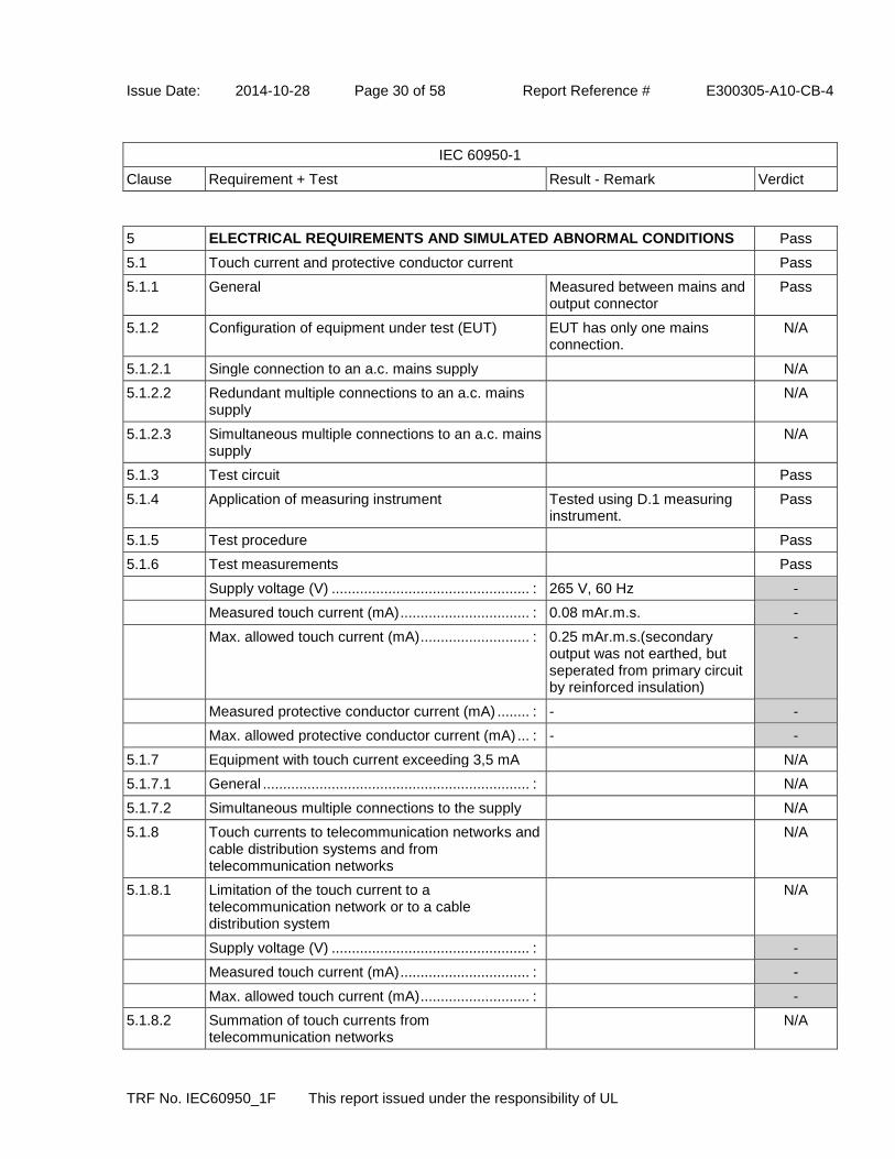
Issue Date: 2014-10-28 Page 30 of 58 Report Reference # E300305-A10-CB-4
IEC 60950-1
Clause Requirement + Test Result - Remark Verdict
TRF No. IEC60950_1F This report issued under the responsibility of UL
5 ELECTRICAL REQUIREMENTS AND SIMULATED ABNORMAL CONDITIONS Pass
5.1 Touch current and protective conductor current Pass
5.1.1 General Measured between mains and output connector
Pass
5.1.2 Configuration of equipment under test (EUT) EUT has only one mains connection.
N/A
5.1.2.1 Single connection to an a.c. mains supply N/A
5.1.2.2 Redundant multiple connections to an a.c. mains supply
N/A
5.1.2.3 Simultaneous multiple connections to an a.c. mains supply
N/A
5.1.3 Test circuit Pass
5.1.4 Application of measuring instrument Tested using D.1 measuring instrument.
Pass
5.1.5 Test procedure Pass
5.1.6 Test measurements Pass
Supply voltage (V) ................................................. : 265 V, 60 Hz -
Measured touch current (mA) ................................ : 0.08 mAr.m.s. -
Max. allowed touch current (mA) ........................... : 0.25 mAr.m.s.(secondary output was not earthed, but seperated from primary circuit by reinforced insulation)
-
Measured protective conductor current (mA) ........ : - -
Max. allowed protective conductor current (mA) ... : - -
5.1.7 Equipment with touch current exceeding 3,5 mA N/A
5.1.7.1 General .................................................................. : N/A
5.1.7.2 Simultaneous multiple connections to the supply N/A
5.1.8 Touch currents to telecommunication networks and cable distribution systems and from telecommunication networks
N/A
5.1.8.1 Limitation of the touch current to a telecommunication network or to a cable distribution system
N/A
Supply voltage (V) ................................................. : -
Measured touch current (mA) ................................ : -
Max. allowed touch current (mA) ........................... : -
5.1.8.2 Summation of touch currents from telecommunication networks
N/A

Issue Date: 2014-10-28 Page 31 of 58 Report Reference # E300305-A10-CB-4
IEC 60950-1
Clause Requirement + Test Result - Remark Verdict
TRF No. IEC60950_1F This report issued under the responsibility of UL
a) EUT with earthed telecommunication ports ...... : N/A
b) EUT whose telecommunication ports have no reference to protective earth
N/A
5.2 Electric strength Pass
5.2.1 General (see appended table 5.2) Pass
5.2.2 Test procedure Pass
5.3 Abnormal operating and fault conditions Pass
5.3.1 Protection against overload and abnormal operation
Pass
5.3.2 Motors N/A
5.3.3 Transformers (see appended Annex C) Pass
5.3.4 Functional insulation .............................................. : Functional insulation complies with the requirements (a), (b), or (c).
Pass
5.3.5 Electromechanical components N/A
5.3.6 Audio amplifiers in ITE ........................................... : N/A
5.3.7 Simulation of faults Pass
5.3.8 Unattended equipment N/A
5.3.9 Compliance criteria for abnormal operating and fault conditions
No fire, emission of molten metal or deformation was noted during the tests. Electric Strength tests performed after abnormal and fault tests.
Pass
5.3.9.1 During the tests Pass
5.3.9.2 After the tests Pass
6 CONNECTION TO TELECOMMUNICATION NETWORKS N/A
6.1 Protection of telecommunication network service persons, and users of other equipment connected to the network, from hazards in the equipment
N/A
6.1.1 Protection from hazardous voltages N/A
6.1.2 Separation of the telecommunication network from earth N/A
6.1.2.1 Requirements N/A
Supply voltage (V) ................................................. : -
Current in the test circuit (mA) ............................... : -
6.1.2.2 Exclusions.............................................................. : N/A

Issue Date: 2014-10-28 Page 32 of 58 Report Reference # E300305-A10-CB-4
IEC 60950-1
Clause Requirement + Test Result - Remark Verdict
TRF No. IEC60950_1F This report issued under the responsibility of UL
6.2 Protection of equipment users from overvoltages on telecommunication networks
N/A
6.2.1 Separation requirements N/A
6.2.2 Electric strength test procedure N/A
6.2.2.1 Impulse test N/A
6.2.2.2 Steady-state test N/A
6.2.2.3 Compliance criteria N/A
6.3 Protection of the telecommunication wiring system from overheating N/A
Max. output current (A) .......................................... : -
Current limiting method ......................................... : -
7 CONNECTION TO CABLE DISTRIBUTION SYSTEMS N/A
7.1 General N/A
7.2 Protection of cable distribution system service persons, and users of other equipment connected to the system, from hazardous voltages in the equipment
N/A
7.3 Protection of equipment users from overvoltages on the cable distribution system
N/A
7.4 Insulation between primary circuits and cable distribution systems
N/A
7.4.1 General N/A
7.4.2 Voltage surge test N/A
7.4.3 Impulse test N/A
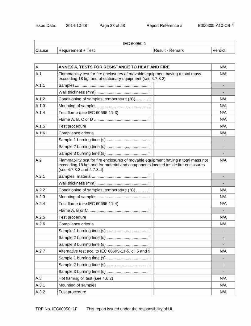
Issue Date: 2014-10-28 Page 33 of 58 Report Reference # E300305-A10-CB-4
IEC 60950-1
Clause Requirement + Test Result - Remark Verdict
TRF No. IEC60950_1F This report issued under the responsibility of UL
A ANNEX A, TESTS FOR RESISTANCE TO HEAT AND FIRE N/A
A.1 Flammability test for fire enclosures of movable equipment having a total mass exceeding 18 kg, and of stationary equipment (see 4.7.3.2)
N/A
A.1.1 Samples ................................................................. : -
Wall thickness (mm) .............................................. : -
A.1.2 Conditioning of samples; temperature (°C) ........... : N/A
A.1.3 Mounting of samples ............................................. : N/A
A.1.4 Test flame (see IEC 60695-11-3) N/A
Flame A, B, C or D ................................................ : N/A
A.1.5 Test procedure N/A
A.1.6 Compliance criteria N/A
Sample 1 burning time (s) ..................................... : -
Sample 2 burning time (s) ..................................... : -
Sample 3 burning time (s) ..................................... : -
A.2 Flammability test for fire enclosures of movable equipment having a total mass not exceeding 18 kg, and for material and components located inside fire enclosures (see 4.7.3.2 and 4.7.3.4)
N/A
A.2.1 Samples, material .................................................. : -
Wall thickness (mm) .............................................. : -
A.2.2 Conditioning of samples; temperature (°C) ........... : N/A
A.2.3 Mounting of samples ............................................. : N/A
A.2.4 Test flame (see IEC 60695-11-4) N/A
Flame A, B or C ..................................................... : -
A.2.5 Test procedure N/A
A.2.6 Compliance criteria N/A
Sample 1 burning time (s) ..................................... : -
Sample 2 burning time (s) ..................................... : -
Sample 3 burning time (s) ..................................... : -
A.2.7 Alternative test acc. to IEC 60695-11-5, cl. 5 and 9 N/A
Sample 1 burning time (s) ..................................... : -
Sample 2 burning time (s) ..................................... : -
Sample 3 burning time (s) ..................................... : -
A.3 Hot flaming oil test (see 4.6.2) N/A
A.3.1 Mounting of samples N/A
A.3.2 Test procedure N/A

Issue Date: 2014-10-28 Page 34 of 58 Report Reference # E300305-A10-CB-4
IEC 60950-1
Clause Requirement + Test Result - Remark Verdict
TRF No. IEC60950_1F This report issued under the responsibility of UL
A.3.3 Compliance criterion N/A
B ANNEX B, MOTOR TESTS UNDER ABNORMAL CONDITIONS (see 4.7.2.2 and 5.3.2)
N/A
B.1 General requirements N/A
Position .................................................................. : -
Manufacturer ......................................................... : -
Type ....................................................................... : -
Rated values .......................................................... : -
B.2 Test conditions N/A
B.3 Maximum temperatures N/A
B.4 Running overload test N/A
B.5 Locked-rotor overload test N/A
Test duration (days) ............................................... : -
Electric strength test: test voltage (V) .................... : -
B.6 Running overload test for d.c. motors in secondary circuits
N/A
B.6.1 General N/A
B.6.2 Test procedure N/A
B.6.3 Alternative test procedure N/A
B.6.4 Electric strength test; test voltage (V) .................... : N/A
B.7 Locked-rotor overload test for d.c. motors in secondary circuits
N/A
B.7.1 General N/A
B.7.2 Test procedure N/A
B.7.3 Alternative test procedure N/A
B.7.4 Electric strength test; test voltage (V) .................... : N/A
B.8 Test for motors with capacitors N/A
B.9 Test for three-phase motors N/A
B.10 Test for series motors N/A
Operating voltage (V) ............................................ : - -

Issue Date: 2014-10-28 Page 35 of 58 Report Reference # E300305-A10-CB-4
IEC 60950-1
Clause Requirement + Test Result - Remark Verdict
TRF No. IEC60950_1F This report issued under the responsibility of UL
C ANNEX C, TRANSFORMERS (see 1.5.4 and 5.3.3) Pass
Position .................................................................. : (see appended table 1.5.1) -
Manufacturer ......................................................... : (see appended table 1.5.1) -
Type ....................................................................... : (see appended table 1.5.1) -
Rated values .......................................................... : Class A -
Method of protection .............................................. : Inherently protection -
C.1 Overload test (see appended table 5.3) Pass
C.2 Insulation (see appended table 5.2) Pass
Protection from displacement of windings ............. : Triple insulated wire used and 2 mm margin tape provided on primary pin side.
Pass
D ANNEX D, MEASURING INSTRUMENTS FOR TOUCH-CURRENT TESTS (see 5.1.4)
Pass
D.1 Measuring instrument Simpson meter 228 uesd. Pass
D.2 Alternative measuring instrument N/A
E ANNEX E, TEMPERATURE RISE OF A WINDING (see 1.4.13) N/A
F ANNEX F, MEASUREMENT OF CLEARANCES AND CREEPAGE DISTANCES (see 2.10 and Annex G)
Pass

Issue Date: 2014-10-28 Page 36 of 58 Report Reference # E300305-A10-CB-4
IEC 60950-1
Clause Requirement + Test Result - Remark Verdict
TRF No. IEC60950_1F This report issued under the responsibility of UL
G ANNEX G, ALTERNATIVE METHOD FOR DETERMINING MINIMUM CLEARANCES
N/A
G.1 Clearances N/A
G.1.1 General N/A
G.1.2 Summary of the procedure for determining minimum clearances
N/A
G.2 Determination of mains transient voltage (V) N/A
G.2.1 AC mains supply .................................................... : N/A
G.2.2 Earthed d.c. mains supply ..................................... : N/A
G.2.3 Unearthed d.c. mains supply ................................. : N/A
G.2.4 Battery operation ................................................... : N/A
G.3 Determination of telecommunication network transient voltage (V) :
N/A
G.4 Determination of required withstand voltage (V) N/A
G.4.1 Mains transients and internal repetitive peaks ...... : N/A
G.4.2 Transients from telecommunication networks ....... : N/A
G.4.3 Combination of transients N/A
G.4.4 Transients from cable distribution systems N/A
G.5 Measurement of transient voltages (V) N/A
a) Transients from a mains supply N/A
For an a.c. mains supply N/A
For a d.c. mains supply N/A
b) Transients from a telecommunication network N/A
G.6 Determination of minimum clearances N/A
H ANNEX H, IONIZING RADIATION (see 4.3.13) N/A
J ANNEX J, TABLE OF ELECTROCHEMICAL POTENTIALS (see 2.6.5.6) N/A
Metal(s) used ......................................................... : -

Issue Date: 2014-10-28 Page 37 of 58 Report Reference # E300305-A10-CB-4
IEC 60950-1
Clause Requirement + Test Result - Remark Verdict
TRF No. IEC60950_1F This report issued under the responsibility of UL
K ANNEX K, THERMAL CONTROLS (see 1.5.3 and 5.3.8) N/A
K.1 Making and breaking capacity N/A
K.2 Thermostat reliability; operating voltage (V) .......... : N/A
K.3 Thermostat endurance test; operating voltage (V) : N/A
K.4 Temperature limiter endurance; operating voltage (V) .......................................................................... :
N/A
K.5 Thermal cut-out reliability N/A
K.6 Stability of operation N/A
L ANNEX L, NORMAL LOAD CONDITIONS FOR SOME TYPES OF ELECTRICAL BUSINESS EQUIPMENT (see 1.2.2.1 and 4.5.2)
Pass
L.1 Typewriters N/A
L.2 Adding machines and cash registers N/A
L.3 Erasers N/A
L.4 Pencil sharpeners N/A
L.5 Duplicators and copy machines N/A
L.6 Motor-operated files N/A
L.7 Other business equipment Rated output current Pass
M ANNEX M, CRITERIA FOR TELEPHONE RINGING SIGNALS (see 2.3.1) N/A
M.1 Introduction N/A
M.2 Method A N/A
M.3 Method B N/A
M.3.1 Ringing signal N/A
M.3.1.1 Frequency (Hz) ...................................................... : -
M.3.1.2 Voltage (V) ............................................................. : -
M.3.1.3 Cadence; time (s), voltage (V) ............................... : -
M.3.1.4 Single fault current (mA) ........................................ : -
M.3.2 Tripping device and monitoring voltage ................. : N/A
M.3.2.1 Conditions for use of a tripping device or a monitoring voltage
N/A
M.3.2.2 Tripping device N/A
M.3.2.3 Monitoring voltage (V) ........................................... : N/A
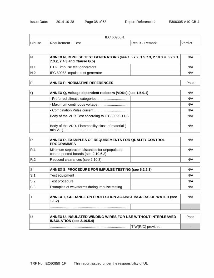
Issue Date: 2014-10-28 Page 38 of 58 Report Reference # E300305-A10-CB-4
IEC 60950-1
Clause Requirement + Test Result - Remark Verdict
TRF No. IEC60950_1F This report issued under the responsibility of UL
N ANNEX N, IMPULSE TEST GENERATORS (see 1.5.7.2, 1.5.7.3, 2.10.3.9, 6.2.2.1, 7.3.2, 7.4.3 and Clause G.5)
N/A
N.1 ITU-T impulse test generators N/A
N.2 IEC 60065 impulse test generator N/A
P ANNEX P, NORMATIVE REFERENCES Pass
Q ANNEX Q, Voltage dependent resistors (VDRs) (see 1.5.9.1) N/A
- Preferred climatic categories ............................... : N/A
- Maximum continuous voltage .............................. : N/A
- Combination Pulse current .................................. : N/A
Body of the VDR Test according to IEC60695-11-5 ............................................................................... :
N/A
Body of the VDR. Flammability class of material ( min V-1) ................................................................. :
N/A
R ANNEX R, EXAMPLES OF REQUIREMENTS FOR QUALITY CONTROL PROGRAMMES
N/A
R.1 Minimum separation distances for unpopulated coated printed boards (see 2.10.6.2)
N/A
R.2 Reduced clearances (see 2.10.3) N/A
S ANNEX S, PROCEDURE FOR IMPULSE TESTING (see 6.2.2.3) N/A
S.1 Test equipment N/A
S.2 Test procedure N/A
S.3 Examples of waveforms during impulse testing N/A
T ANNEX T, GUIDANCE ON PROTECTION AGAINST INGRESS OF WATER (see 1.1.2)
N/A
............................................................................... : -
U ANNEX U, INSULATED WINDING WIRES FOR USE WITHOUT INTERLEAVED INSULATION (see 2.10.5.4)
Pass
............................................................................... : TIW(R/C) provided. -

Issue Date: 2014-10-28 Page 39 of 58 Report Reference # E300305-A10-CB-4
IEC 60950-1
Clause Requirement + Test Result - Remark Verdict
TRF No. IEC60950_1F This report issued under the responsibility of UL
V ANNEX V, AC POWER DISTRIBUTION SYSTEMS (see 1.6.1) N/A
V.1 Introduction N/A
V.2 TN power distribution systems N/A
W ANNEX W, SUMMATION OF TOUCH CURRENTS N/A
W.1 Touch current from electronic circuits N/A
W.1.1 Floating circuits N/A
W.1.2 Earthed circuits N/A
W.2 Interconnection of several equipments N/A
W.2.1 Isolation N/A
W.2.2 Common return, isolated from earth N/A
W.2.3 Common return, connected to protective earth N/A
X ANNEX X, MAXIMUM HEATING EFFECT IN TRANSFORMER TESTS (see clause C.1)
N/A
X.1 Determination of maximum input current N/A
X.2 Overload test procedure N/A
Y ANNEX Y, ULTRAVIOLET LIGHT CONDITIONING TEST (see 4.3.13.3) N/A
Y.1 Test apparatus ....................................................... : N/A
Y.2 Mounting of test samples ....................................... : N/A
Y.3 Carbon-arc light-exposure apparatus .................... : N/A
Y.4 Xenon-arc light-exposure apparatus ..................... : N/A
Z ANNEX Z, OVERVOLTAGE CATEGORIES (see 2.10.3.2 and Clause G.2) Pass
AA ANNEX AA, MANDREL TEST (see 2.10.5.8) N/A
BB ANNEX BB, CHANGES IN THE SECOND EDITION Pass

Issue Date: 2014-10-28 Page 40 of 58 Report Reference # E300305-A10-CB-4
IEC 60950-1
Clause Requirement + Test Result - Remark Verdict
TRF No. IEC60950_1F This report issued under the responsibility of UL
CC ANNEX CC, EVALUATION OF INTEGRATED CIRCUIT (IC) CURRENT LIMITERS
N/A
CC.1 General N/A
CC.2 Test program 1 ...................................................... : N/A
CC.3 Test program 2 ...................................................... : N/A
CC.4 Test program 3 ...................................................... : N/A
CC.5 Compliance ............................................................ : N/A
DD ANNEX DD, REQUIREMENTS FOR THE MOUNTING MEANS OF RACK-MOUNTED EQUIPMENT
N/A
DD.1 General N/A
DD.2 Mechanical strength test, variable N ..................... : N/A
DD.3 Mechanical strength test, 250 N, including end stops ...................................................................... :
N/A
DD.4 Compliance ............................................................ : N/A
EE ANNEX EE, HOUSEHOLD AND HOME/OFFICE DOCUMENT/MEDIA SHREDDERS
N/A
EE.1 General N/A
EE.2 Markings and instructions N/A
Use of markings or symbols .................................. : N/A
Information of user instructions, maintenance and/or servicing instructions .................................. :
N/A
EE.3 Inadvertent reactivation test .................................. : N/A
EE.4 Disconnection of power to hazardous moving parts N/A
Use of markings or symbols .................................. : N/A
EE.5 Protection against hazardous moving parts .......... : N/A
Test with test finger (Figure 2A) N/A
Test with wedge probe (Figure EE1 and EE2) ...... : N/A
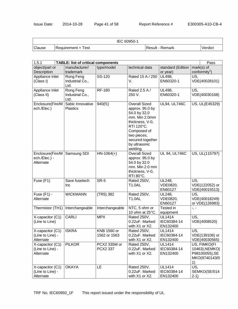
Issue Date: 2014-10-28 Page 41 of 58 Report Reference # E300305-A10-CB-4
IEC 60950-1
Clause Requirement + Test Result - Remark Verdict
TRF No. IEC60950_1F This report issued under the responsibility of UL
1.5.1 TABLE: list of critical components Pass
object/part or Description
manufacturer/ trademark
type/model technical data standard (Edition or year)
mark(s) of conformity
1)
Appliance Inlet (Class I)
Rong Feng Industrial Co., Ltd.
SS-120 Rated 15 A / 250 V.
UL498, EN60320-1
US, VDE(40028101)
Appliance Inlet (Class II)
Rong Feng Industrial Co., Ltd.
RF-180 Rated 2.5 A / 250 V.
UL498, EN60320-1
US, VDE(40030168)
Enclosure(Fire/Mech./Elec.)
Sabic Innovative Plastics
940(f1) Overall Sized approx. 95.0 by 54.0 by 32.0 mm. Min 2.0mm thickness, V-0, RTI 120°C. Composed of two pieces, secured together by ultrasonic welding.
UL94, UL746C US, UL(E45329)
Enclosure(Fire/Mech./Elec.) - Alternate
Samsung SDI HN-1064(+) Overall Sized approx. 95.0 by 54.0 by 32.0 mm. Min 2.0 mm thickness, V-0, RTI 80°C.
UL 94, UL746C US, UL(115797)
Fuse (F1) Save fusetech Inc
SR-5 Rated 250V, T1.0AL
UL248, VDE0820, EN60127
US, VDE(122052) or VDE(40015513)
Fuse (F1) - Alternate
WICKMANN (TR5) 382 Rated 250V, T1.0AL
UL248, VDE0820, EN60127
US, VDE(40018249) or VDE(126983)
Thermistor (TH1) Interchangeable Interchangeable NTC, 5 ohm or 10 ohm at 25°C.
Tested in equipment
-, -
X-capacitor (C1) (Line to Line)
CARLI MPX Rated 250V, 0.22uF. Marked with X1 or X2.
UL1414 IEC60384-14 EN132400
US, VDE(4008520)
X-capacitor (C1) (Line to Line) - Alternate
ISKRA KNB 1560 or 1562 or 1563
Rated 250V, 0.22uF. Marked with X1 or X2.
UL1414 IEC60384-14 EN132400
US, VDE(139106) or VDE(40030565)
X-capacitor (C1) (Line to Line) - Alternate
PILKOR PCX2 335M or PCX2 337
Rated 250V, 0.22uF. Marked with X1 or X2.
UL1414 IEC60384-14 EN132400
US, FIMKO(FI 10463),NEMKO(P98100055),SEMKO(9740143/01)
X-capacitor (C1) (Line to Line) - Alternate
OKAYA LE Rated 250V, 0.22uF. Marked with X1 or X2.
UL1414 IEC60384-14 EN132400
US, SEMKO(SE/0142-1)

Issue Date: 2014-10-28 Page 42 of 58 Report Reference # E300305-A10-CB-4
IEC 60950-1
Clause Requirement + Test Result - Remark Verdict
TRF No. IEC60950_1F This report issued under the responsibility of UL
X-capacitor (C1) (Line to Line) - Alternate
SUNIL 436D Rated 250V, 0.22uF. Marked with X1 or X2.
UL1414 IEC60384-14 EN132400
US, VDE(40028050)
X-capacitor (C2) (Line to Line)
CARLI MPX Rated 250V, 0.1uF. Marked with X1 or X2.
UL1414 IEC60384-14 EN132400
US, VDE(4008520)
X-capacitor (C2) (Line to Line) - Alternate
ISKRA KNB 1560 or 1562 or 1563
Rated 250V, 0.1uF. Marked with X1 or X2.
UL1414 IEC60384-14 EN132400
US, VDE(139106) or VDE(40030565)
X-capacitor (C2) (Line to Line) - Alternate
PILKOR PCX2 335M or PCX2 337
Rated 250V, 0.1uF. Marked with X1 or X2.
UL1414 IEC60384-14 EN132400
US, FIMKO(FI 10463),NEMKO(P98100055),SEMKO(9740143/01)
X-capacitor (C2) (Line to Line) - Alternate
OKAYA LE Rated 250V, 0.1uF. Marked with X1 or X2.
UL1414 IEC60384-14 EN132400
US, SEMKO(SE/0142-1)
X-capacitor (C2) (Line to Line) - Alternate
SUNIL 436D Rated 250V, 0.1uF. Marked with X1 or X2.
UL1414 IEC60384-14 EN132400
US, VDE(40028050)
Discharge resistor (R1, R2)
Interchangeable Interchangeable 1/8W, 470 K ohm.
Tested in equipment
-, -
Linefilter (L1) Bridgepower Corp or Wendeng Jeil
3025531 Core: Ferrite, Coils: Polyarethane wire 105°C. Bobbin: (QMFZ2) Bakelite, type PF2736@, V-0, 150°C. see for details.
Tested in equipment
-, -
Bridge diode (BD1)
Interchangeable Interchangeable Rated Min. 600 V, 0.8 A
Tested in equipment
-, -
Electrolytic Capacitor (C3)
Interchangeable Interchangeable 47 uF, 400 V, min. 85 degree.
Tested in equipment
-, -
Main Transformer(T1)
Bridgepower Corp or Wendeng Jeil
3025494 Class A insulation; Coils: Polyarethane wire 105°C. TIW Cosmolink, Type TIW-M 130°C. or TIW Furukawa TEX-E 130°C. Bobbin: (QMFZ2) Bakelite, type PF2736@, V-0,
Tested in equipment
-, -

Issue Date: 2014-10-28 Page 43 of 58 Report Reference # E300305-A10-CB-4
IEC 60950-1
Clause Requirement + Test Result - Remark Verdict
TRF No. IEC60950_1F This report issued under the responsibility of UL
150°C. see Enclosure for details.
Optical Isolator (U2)
Vishay Semiconductor
TCET1103G or TCET1103
Double protection optical isolator. Providing isolation voltage 5000 Vac
UL1577, VDE0884, EN60950
US, BSI (7402),CQC(09001038077)
Optical isolator (U2) - Alternate
COSMO ELECTRONICS CORP
KP1010 Double protection optical isolator. Providing isolation voltage 5000 Vac
UL1577, VDE0884, EN60950
US, SEMKO(1016433),FIMKO(224986)
Optical isolator (U2) - Alternate
SHARP CORP ELECTRONIC COMPONENTS GROUP
PC123 Double protection optical isolator. Providing isolation voltage 5000 Vac
UL1577, VDE0884, EN60950
US, SEMKO( 9216212), NEMKO(135957)
Optical isolator (U2) - Alternate
KODENSHI KOREA
PC-17K Double protection optical isolator. Providing isolation voltage 5000 Vac.
UL1577, VDE0884, EN60950
US, Semko( 9805214/01-04)
Y-Capacitor (C17, C18, C19, C20)
NETRON TECH AA 250Vmin, 2200 pF. Marked with Y1 or Y2.
UL1414, IEC60384-14 EN132400
US, VDE(089754)
Y-Capacitor (C17, C18, C19, C20)_Alternate
NETRON TECH AD 250Vmin, 2200 pF. Marked with Y1 or Y2.
UL1414, IEC60384-14 EN132400
US, VDE(089753)
Y-Capacitor (C17, C18, C19, C20) - Alternate
DU SAN INDUSTRIAL CO LTD
NK 250Vmin, 2200 pF. Marked with Y1 or Y2.
UL1414, IEC60384-14 EN132400
US, FIMKO(FI 197620 A1),NEMKO(P97101988),SEMKO(0219069/01-04)
Y-Capacitor (C17, C18, C19, C20) - Alternate
DU SAN INDUSTRIAL CO LTD
NU 250Vmin, 2200 pF. Marked with Y1 or Y2.
UL1414, IEC60384-14 EN132400
US, NEMKO(P97101989),FIMKO(FI 197621 A1),SEMKO(0219069/01-04)
Y-Capacitor (C17, C18, C19, C20) - Alternate
DONGIL DA 250Vmin, 2200 pF. Marked with Y1 or Y2.
UL1414 IEC60384-14 EN132400
US, FIMKO(FI 10228),NEMKO(P98100372),SEMKO(9807214/0
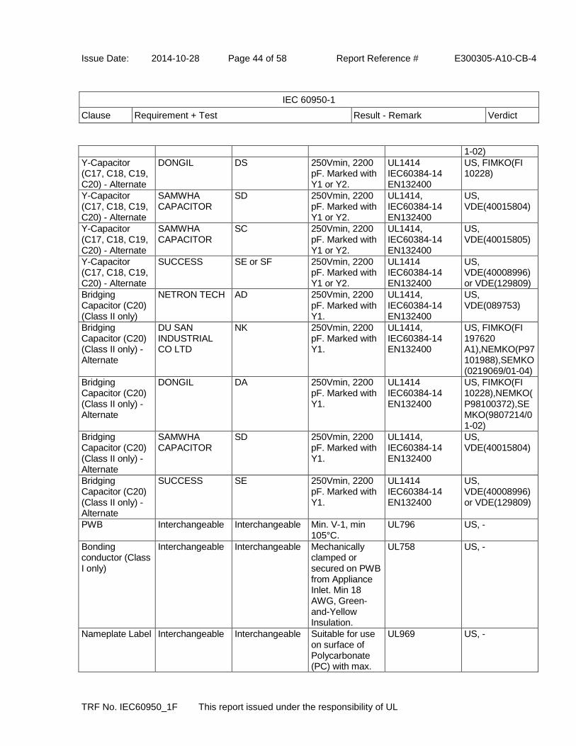
Issue Date: 2014-10-28 Page 44 of 58 Report Reference # E300305-A10-CB-4
IEC 60950-1
Clause Requirement + Test Result - Remark Verdict
TRF No. IEC60950_1F This report issued under the responsibility of UL
1-02)
Y-Capacitor (C17, C18, C19, C20) - Alternate
DONGIL DS 250Vmin, 2200 pF. Marked with Y1 or Y2.
UL1414 IEC60384-14 EN132400
US, FIMKO(FI 10228)
Y-Capacitor (C17, C18, C19, C20) - Alternate
SAMWHA CAPACITOR
SD 250Vmin, 2200 pF. Marked with Y1 or Y2.
UL1414, IEC60384-14 EN132400
US, VDE(40015804)
Y-Capacitor (C17, C18, C19, C20) - Alternate
SAMWHA CAPACITOR
SC 250Vmin, 2200 pF. Marked with Y1 or Y2.
UL1414, IEC60384-14 EN132400
US, VDE(40015805)
Y-Capacitor (C17, C18, C19, C20) - Alternate
SUCCESS SE or SF 250Vmin, 2200 pF. Marked with Y1 or Y2.
UL1414 IEC60384-14 EN132400
US, VDE(40008996) or VDE(129809)
Bridging Capacitor (C20) (Class II only)
NETRON TECH AD 250Vmin, 2200 pF. Marked with Y1.
UL1414, IEC60384-14 EN132400
US, VDE(089753)
Bridging Capacitor (C20) (Class II only) - Alternate
DU SAN INDUSTRIAL CO LTD
NK 250Vmin, 2200 pF. Marked with Y1.
UL1414, IEC60384-14 EN132400
US, FIMKO(FI 197620 A1),NEMKO(P97101988),SEMKO(0219069/01-04)
Bridging Capacitor (C20) (Class II only) - Alternate
DONGIL DA 250Vmin, 2200 pF. Marked with Y1.
UL1414 IEC60384-14 EN132400
US, FIMKO(FI 10228),NEMKO(P98100372),SEMKO(9807214/01-02)
Bridging Capacitor (C20) (Class II only) - Alternate
SAMWHA CAPACITOR
SD 250Vmin, 2200 pF. Marked with Y1.
UL1414, IEC60384-14 EN132400
US, VDE(40015804)
Bridging Capacitor (C20) (Class II only) - Alternate
SUCCESS SE 250Vmin, 2200 pF. Marked with Y1.
UL1414 IEC60384-14 EN132400
US, VDE(40008996) or VDE(129809)
PWB Interchangeable Interchangeable Min. V-1, min 105°C.
UL796 US, -
Bonding conductor (Class I only)
Interchangeable Interchangeable Mechanically clamped or secured on PWB from Appliance Inlet. Min 18 AWG, Green-and-Yellow Insulation.
UL758 US, -
Nameplate Label Interchangeable Interchangeable Suitable for use on surface of Polycarbonate (PC) with max.
UL969 US, -

Issue Date: 2014-10-28 Page 45 of 58 Report Reference # E300305-A10-CB-4
IEC 60950-1
Clause Requirement + Test Result - Remark Verdict
TRF No. IEC60950_1F This report issued under the responsibility of UL
60 °C surface temperature.
Bonding Glue Interchangeable Interchangeable Min. V-2, min. 100 °C for additional secureness of internal conductor.
UL94 US, -
Heatsink Interchangeable Interchangeable Basic insulated conductive part, wrapped by 3 turns polyester film tape, (OANZ2), rated 130 °C to separate from U1(pri.) and fixed by clip without mechanical stress. Overall size 50 by 20 by 2 mm thickness.
Tested in equipment
-, -
Extruded Insulating Tubing for C17, C18, C19, Choke coil of Bonding conductor
Interchangeable Interchangeable Rated 600 V, 125 °C, VW-1.
UL224 US, -
RJ-45 connector(J1, J2) not for TNV circuit
Interchangeable Interchangeable Plastic material(QMFZ2) min. V-2, RTI min. 60 °C.
Tested in equipment
-, -
Supplementary information: 1) Provided evidence ensures the agreed level of compliance. See OD-CB2039.
The CBTL has verified the component information.

Issue Date: 2014-10-28 Page 46 of 58 Report Reference # E300305-A10-CB-4
IEC 60950-1
Clause Requirement + Test Result - Remark Verdict
TRF No. IEC60950_1F This report issued under the responsibility of UL
1.5.1 TABLE: Opto Electronic Devices Pass
Manufacturer Vishay Semiconductor Cosmo Electronics Corp. Sharp Corp.
Type TCET1103G or TCET1103
KP1010 PC123
Separately tested BSI (7402),CQC(09001038077)
SEMKO(1016433),FIMKO(224986)
SEMKO( 9216212), NEMKO(135957)
Bridging insulation Reinforced Reinforced Reinforced
External creepage distance
6.0mm 6.5mm 7.0mm
Internal creepage distance
* * *
Distance through insulation
0.4mm 0.4mm 0.4mm
Tested under the following conditions
- - -
Input - - -
Output - - -
Manufacturer Kodenshi Korea
Type PC-17K
Separately Tested SEMKO(9805214/01-04)
Bridging Insulation Reinforced
Exter Creepage Distance 7.0mm
Inter Creepage Distance *
supplementary information:
*; Thermal Cycling Test Conducted

Issue Date: 2014-10-28 Page 47 of 58 Report Reference # E300305-A10-CB-4
IEC 60950-1
Clause Requirement + Test Result - Remark Verdict
TRF No. IEC60950_1F This report issued under the responsibility of UL
1.6.2 TABLE: Electrical data (in normal conditions) Pass
U (V) I (A) I rated (A) P (W) Fuse # I fuse (A) condition/status
Model: JPOE130A4800FK01
N/A N/A N/A N/A N/A N/A
90Vac 0.425 N/A 24.5 F1 0.425 Max. normal load at 50Hz
100Vac 0.392 0.5 24.1 F1 0.392 Max. normal load at 50Hz
250Vac 0.179 0.5 23.8 F1 0.179 Max. normal load at 50Hz
265Vac 0.169 N/A 23.8 F1 0.169 Max. normal load at 50Hz
90Vac 0.427 N/A 24.4 F1 0.427 Max. normal load at 60Hz
100Vac 0.392 0.5 24.1 F1 0.392 Max. normal load at 60Hz
250Vac 0.179 0.5 23.8 F1 0.179 Max. normal load at 60Hz
265Vac 0.169 N/A 23.8 F1 0.169 Max. normal load at 60Hz
Model: JPOE130B4800FK01
N/A N/A N/A N/A N/A N/A
90Vac 0.352 N/A 19.9 F1 0.352 Max. normal load at 50Hz
100Vac 0.319 0.5 19.6 F1 0.319 Max. normal load at 50Hz
250Vac 0.148 0.5 19.3 F1 0.148 Max. normal load at 50Hz
265Vac 0.141 N/A 19.4 F1 0.141 Max. normal load at 50Hz
90Vac 0.353 N/A 19.8 F1 0.353 Max. normal load at 60Hz
100Vac 0.319 0.5 19.6 F1 0.319 Max. normal load at 60Hz
250Vac 0.148 0.5 19.3 F1 0.148 Max. normal load at 60Hz
265Vac 0.141 N/A 19.4 F1 0.141 Max. normal load at 60Hz
Model: JPOE130B4800FK01(06CA55186)
N/A N/A N/A N/A N/A N/A
90Vac 0.405 N/A 22.3 F1 0.405 Max. normal load at 50Hz
100Vac 0.364 0.5 21.9 F1 0.364 Max. normal load at 50Hz
250Vac 0.188 0.5 21.2 F1 0.188 Max. normal load at 50Hz
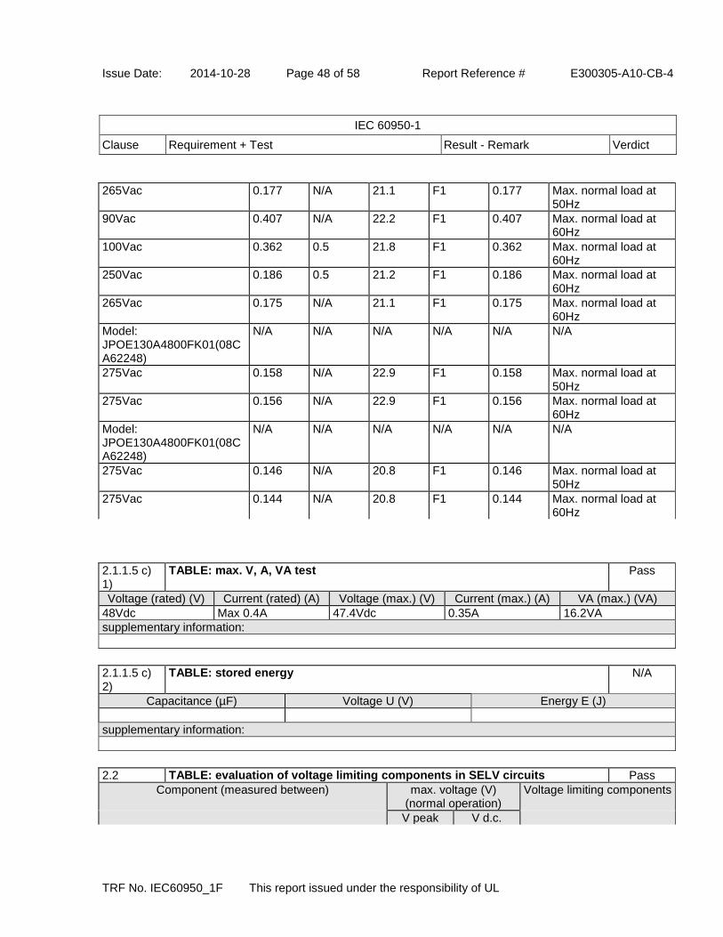
Issue Date: 2014-10-28 Page 48 of 58 Report Reference # E300305-A10-CB-4
IEC 60950-1
Clause Requirement + Test Result - Remark Verdict
TRF No. IEC60950_1F This report issued under the responsibility of UL
265Vac 0.177 N/A 21.1 F1 0.177 Max. normal load at 50Hz
90Vac 0.407 N/A 22.2 F1 0.407 Max. normal load at 60Hz
100Vac 0.362 0.5 21.8 F1 0.362 Max. normal load at 60Hz
250Vac 0.186 0.5 21.2 F1 0.186 Max. normal load at 60Hz
265Vac 0.175 N/A 21.1 F1 0.175 Max. normal load at 60Hz
Model: JPOE130A4800FK01(08CA62248)
N/A N/A N/A N/A N/A N/A
275Vac 0.158 N/A 22.9 F1 0.158 Max. normal load at 50Hz
275Vac 0.156 N/A 22.9 F1 0.156 Max. normal load at 60Hz
Model: JPOE130A4800FK01(08CA62248)
N/A N/A N/A N/A N/A N/A
275Vac 0.146 N/A 20.8 F1 0.146 Max. normal load at 50Hz
275Vac 0.144 N/A 20.8 F1 0.144 Max. normal load at 60Hz
2.1.1.5 c) 1)
TABLE: max. V, A, VA test Pass
Voltage (rated) (V) Current (rated) (A) Voltage (max.) (V) Current (max.) (A) VA (max.) (VA)
48Vdc Max 0.4A 47.4Vdc 0.35A 16.2VA
supplementary information:
2.1.1.5 c) 2)
TABLE: stored energy N/A
Capacitance (µF) Voltage U (V) Energy E (J)
supplementary information:
2.2 TABLE: evaluation of voltage limiting components in SELV circuits Pass
Component (measured between) max. voltage (V) (normal operation)
Voltage limiting components
V peak V d.c.
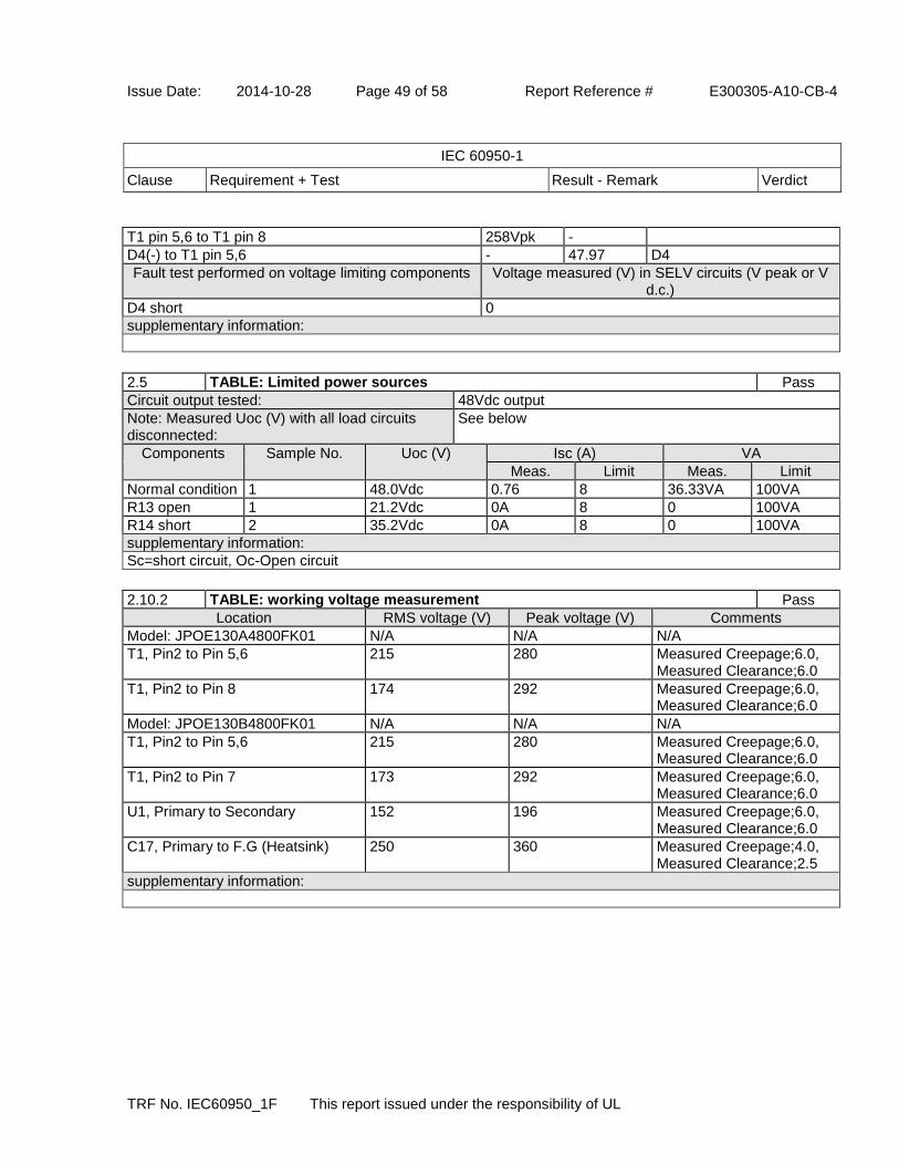
Issue Date: 2014-10-28 Page 49 of 58 Report Reference # E300305-A10-CB-4
IEC 60950-1
Clause Requirement + Test Result - Remark Verdict
TRF No. IEC60950_1F This report issued under the responsibility of UL
T1 pin 5,6 to T1 pin 8 258Vpk -
D4(-) to T1 pin 5,6 - 47.97 D4
Fault test performed on voltage limiting components Voltage measured (V) in SELV circuits (V peak or V d.c.)
D4 short 0
supplementary information:
2.5 TABLE: Limited power sources Pass
Circuit output tested: 48Vdc output
Note: Measured Uoc (V) with all load circuits disconnected:
See below
Components Sample No. Uoc (V) Isc (A) VA
Meas. Limit Meas. Limit
Normal condition 1 48.0Vdc 0.76 8 36.33VA 100VA
R13 open 1 21.2Vdc 0A 8 0 100VA
R14 short 2 35.2Vdc 0A 8 0 100VA
supplementary information:
Sc=short circuit, Oc-Open circuit
2.10.2 TABLE: working voltage measurement Pass
Location RMS voltage (V) Peak voltage (V) Comments
Model: JPOE130A4800FK01 N/A N/A N/A
T1, Pin2 to Pin 5,6 215 280 Measured Creepage;6.0, Measured Clearance;6.0
T1, Pin2 to Pin 8 174 292 Measured Creepage;6.0, Measured Clearance;6.0
Model: JPOE130B4800FK01 N/A N/A N/A
T1, Pin2 to Pin 5,6 215 280 Measured Creepage;6.0, Measured Clearance;6.0
T1, Pin2 to Pin 7 173 292 Measured Creepage;6.0, Measured Clearance;6.0
U1, Primary to Secondary 152 196 Measured Creepage;6.0, Measured Clearance;6.0
C17, Primary to F.G (Heatsink) 250 360 Measured Creepage;4.0, Measured Clearance;2.5
supplementary information:

Issue Date: 2014-10-28 Page 50 of 58 Report Reference # E300305-A10-CB-4
IEC 60950-1
Clause Requirement + Test Result - Remark Verdict
TRF No. IEC60950_1F This report issued under the responsibility of UL
2.10.3 and 2.10.4
TABLE: clearance and creepage distance measurements Pass
clearance cl and creepage distance dcr at/of:
Up (V) U r.m.s. (V)
required cl (mm)
cl (mm) required dcr (mm)
dcr (mm)
- - - - - - -
Functional:
Clearance (cl) and creepage distance (cr) at/of/between:
U peak (V) U r.m.s. (V)
Required cl (mm)
cl (mm) Required cr (mm)
cr (mm)
- - - - - - -
Basic/supplementary:
Clearance (cl) and creepage distance (cr) at/of/between:
U peak (V) U r.m.s. (V)
Required cl (mm)
cl (mm) Required cr (mm)
cr (mm)
Model: JPOE130B4800FK01
C17, Primary to F.G (Heatsink) 360 250 2.0 2.2 2.5 4.0
Reinforced:
Clearance (cl) and creepage distance (cr) at/of/between:
U peak (V) U r.m.s. (V)
Required cl (mm)
cl (mm) Required cr (mm)
cr (mm)
Model: JPOE130A4800FK01 - - - - - -
T1, Pin2 to Pin 5,6 280 215 4.0 6.0 5.0 6.0
T1, Pin2 to Pin 8 292 174 4.0 6.0 5.0 6.0
Model: JPOE130B4800FK01 - - - - - -
T1, Pin2 to Pin 5,6 280 215 4.0 6.0 5.0 6.0
T1, Pin2 to Pin 7 292 173 4.0 6.0 5.0 6.0
U1, Primary to Secondary 196 152 4.0 6.0 5.0 6.0
supplementary information:
The following terminal is connected to earth: Secondary GND.
2.10.5 TABLE: Distance through insulation measurements Pass
Distance through insulation (DTI) at/of: Upeak (V) Urms (V) Test voltage (V)
Required DTI (mm)
DTI (mm)
*Optical Isolator(U2) 196 Vpk 152Vrms 3000 Vac 0.4 0.4
**Transformer Bobbin(T1) 292 Vpk 215Vrms 3000 Vac 0.4 0.4
supplementary information:
* Certified by NCB(FIMKO or Equivalent) and UL ** Bobbin material: Phenolyc
4.3.8 TABLE: Batteries N/A
The tests of 4.3.8 are applicable only when appropriate battery data is not available
Is it possible to install the battery in a reverse polarity position?
Non-rechargeable batteries Rechargeable batteries
Discharging Unintentional charging
Charging Discharging Reversed charging
Meas. current
Manuf. specs.
Meas. current
Manuf. specs.
Meas. current
Manuf. specs.
Meas. curre
nt
Manuf.
specs.

Issue Date: 2014-10-28 Page 51 of 58 Report Reference # E300305-A10-CB-4
IEC 60950-1
Clause Requirement + Test Result - Remark Verdict
TRF No. IEC60950_1F This report issued under the responsibility of UL
Max. current during normal condition
Max. current during fault condition
Test results: Verdict
- Chemical leaks N/A
- Explosion of the battery N/A
- Emission of flame or expulsion of molten metal N/A
- Electric strength tests of equipment after completion of tests N/A
supplementary information:
4.3.8 TABLE: Batteries N/A
Battery category (lithium, NiMh, NiCad, lithium ion, etc.)
Manufacturer
Type / model
Voltage
Capacity (mAh)
Tested and Certified by (incl. Ref. No.)
Circuit protection diagram (Refer to indicated supplement of Enclosure - Miscellaneous)
MARKINGS AND INSTRUCTIONS (1.7.12, 1.7.15)
Location of replaceable battery
Language(s)
Close to the battery
In the servicing instructions
In the operating instructions
In the operating instructions
supplementary information:
Additional devices may be described in Enclosure - Miscellaneous
4.5 TABLE: thermal requirements Pass
Supply voltage (V): See below
---
Ambient Tmin (°C): N/A ---
Ambient Tmax (°C): See below
---
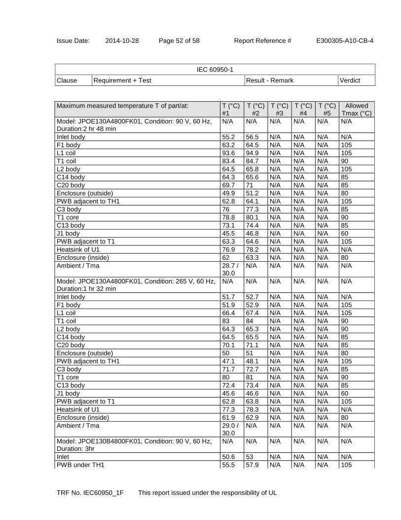
Issue Date: 2014-10-28 Page 52 of 58 Report Reference # E300305-A10-CB-4
IEC 60950-1
Clause Requirement + Test Result - Remark Verdict
TRF No. IEC60950_1F This report issued under the responsibility of UL
Maximum measured temperature T of part/at: T (°C) #1
T (°C) #2
T (°C) #3
T (°C) #4
T (°C) #5
Allowed Tmax (°C)
Model: JPOE130A4800FK01, Condition: 90 V, 60 Hz, Duration:2 hr 48 min
N/A N/A N/A N/A N/A N/A
Inlet body 55.2 56.5 N/A N/A N/A N/A
F1 body 63.2 64.5 N/A N/A N/A 105
L1 coil 93.6 94.9 N/A N/A N/A 105
T1 coil 83.4 84.7 N/A N/A N/A 90
L2 body 64.5 65.8 N/A N/A N/A 105
C14 body 64.3 65.6 N/A N/A N/A 85
C20 body 69.7 71 N/A N/A N/A 85
Enclosure (outside) 49.9 51.2 N/A N/A N/A 80
PWB adjacent to TH1 62.8 64.1 N/A N/A N/A 105
C3 body 76 77.3 N/A N/A N/A 85
T1 core 78.8 80.1 N/A N/A N/A 90
C13 body 73.1 74.4 N/A N/A N/A 85
J1 body 45.5 46.8 N/A N/A N/A 60
PWB adjacent to T1 63.3 64.6 N/A N/A N/A 105
Heatsink of U1 76.9 78.2 N/A N/A N/A N/A
Enclosure (inside) 62 63.3 N/A N/A N/A 80
Ambient / Tma 28.7 / 30.0
N/A N/A N/A N/A N/A
Model: JPOE130A4800FK01, Condition: 265 V, 60 Hz, Duration:1 hr 32 min
N/A N/A N/A N/A N/A N/A
Inlet body 51.7 52.7 N/A N/A N/A N/A
F1 body 51.9 52.9 N/A N/A N/A 105
L1 coil 66.4 67.4 N/A N/A N/A 105
T1 coil 83 84 N/A N/A N/A 90
L2 body 64.3 65.3 N/A N/A N/A 90
C14 body 64.5 65.5 N/A N/A N/A 85
C20 body 70.1 71.1 N/A N/A N/A 85
Enclosure (outside) 50 51 N/A N/A N/A 80
PWB adjacent to TH1 47.1 48.1 N/A N/A N/A 105
C3 body 71.7 72.7 N/A N/A N/A 85
T1 core 80 81 N/A N/A N/A 90
C13 body 72.4 73.4 N/A N/A N/A 85
J1 body 45.6 46.6 N/A N/A N/A 60
PWB adjacent to T1 62.8 63.8 N/A N/A N/A 105
Heatsink of U1 77.3 78.3 N/A N/A N/A N/A
Enclosure (inside) 61.9 62.9 N/A N/A N/A 80
Ambient / Tma 29.0 / 30.0
N/A N/A N/A N/A N/A
Model: JPOE130B4800FK01, Condition: 90 V, 60 Hz, Duration: 3hr
N/A N/A N/A N/A N/A N/A
Inlet 50.6 53 N/A N/A N/A N/A
PWB under TH1 55.5 57.9 N/A N/A N/A 105

Issue Date: 2014-10-28 Page 53 of 58 Report Reference # E300305-A10-CB-4
IEC 60950-1
Clause Requirement + Test Result - Remark Verdict
TRF No. IEC60950_1F This report issued under the responsibility of UL
F1 body 54.3 56.7 N/A N/A N/A 105
C3 body 68.2 70.6 N/A N/A N/A 85
L1 coil 77.7 80.1 N/A N/A N/A 105
C6 body 70.5 72.9 N/A N/A N/A 85
T1 coil 74.1 76.5 N/A N/A N/A 90
T1 core 72.6 75 N/A N/A N/A 90
L2 body 69 71.4 N/A N/A N/A 90
C13 body 73.1 75.5 N/A N/A N/A 85
C14 body 72.2 74.6 N/A N/A N/A 85
J1 body 45.3 47.7 N/A N/A N/A 60
PWB near T1 71 73.4 N/A N/A N/A 105
C20 body 67.3 69.7 N/A N/A N/A 85
Heatsink (U1) 69.1 71.5 N/A N/A N/A N/A
C2 body 74.1 76.5 N/A N/A N/A 85
U1 body 71.3 73.7 N/A N/A N/A 105
Enclosure (inside) 58.2 60.6 N/A N/A N/A 80
Enclosure (outside) 49.4 51.8 N/A N/A N/A 80
Ambient / Tma 27.6 / 30.0
N/A N/A N/A N/A
Model: JPOE130B4800FK01, Condition: 265 V, 60 Hz, Duration: 2hr 18min
N/A N/A N/A N/A N/A N/A
Inlet 50.6 52.9 N/A N/A N/A N/A
PWB under TH1 55.5 57.8 N/A N/A N/A 105
F1 body 54.3 56.6 N/A N/A N/A 105
C3 body 68.2 70.5 N/A N/A N/A 85
L1 coil 77.7 80 N/A N/A N/A 105
C6 body 70.5 72.8 N/A N/A N/A 85
T1 coil 74.1 76.4 N/A N/A N/A 90
T1 core 72.6 74.9 N/A N/A N/A 90
L2 body 69 71.3 N/A N/A N/A 90
C13 body 73.1 75.4 N/A N/A N/A 85
C14 body 72.2 74.5 N/A N/A N/A 85
J1 body 45.3 47.6 N/A N/A N/A 60
PWB near T1 71 73.3 N/A N/A N/A 105
C20 body 67.3 69.6 N/A N/A N/A 85
Heatsink (U1) 69.1 71.4 N/A N/A N/A N/A
C2 body 74.1 76.4 N/A N/A N/A 85
U1 body 71.3 73.6 N/A N/A N/A 105
Enclosure (inside) 58.2 60.5 N/A N/A N/A 80
Enclosure (outside) 49.4 51.7 N/A N/A N/A 80
Ambient / Tma 27.7 / 30.0
N/A N/A N/A N/A N/A
(06CA55186) Model: JPOE130B4800FK01, Condition: 90 V, 60 Hz, Duration: 4 hr
N/A N/A N/A N/A N/A
PWB under TH1 59.3 63.4 N/A N/A N/A 105
C3 body 70.3 74.4 N/A N/A N/A 85
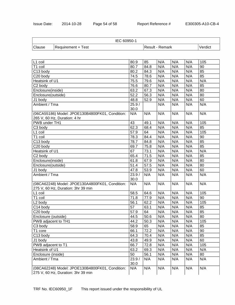
Issue Date: 2014-10-28 Page 54 of 58 Report Reference # E300305-A10-CB-4
IEC 60950-1
Clause Requirement + Test Result - Remark Verdict
TRF No. IEC60950_1F This report issued under the responsibility of UL
L1 coil 80.9 85 N/A N/A N/A 105
T1 coil 80.7 84.8 N/A N/A N/A 90
C13 body 80.2 84.3 N/A N/A N/A 85
C20 body 74.5 78.6 N/A N/A N/A 85
Heatsink of U1 75.5 79.6 N/A N/A N/A N/A
C2 body 76.6 80.7 N/A N/A N/A 85
Enclosure(inside) 63.2 67.3 N/A N/A N/A 80
Enclosure(outside) 52.2 56.3 N/A N/A N/A 80
J1 body 48.8 52.9 N/A N/A N/A 60
Ambient / Tma 25.9 / 30.0
N/A N/A N/A N/A
(06CA55186) Model: JPOE130B4800FK01, Condition: 265 V, 60 Hz, Duration: 4 hr
N/A N/A N/A N/A N/A N/A
PWB under TH1 43 49.1 N/A N/A N/A 105
C3 body 62.3 68.4 N/A N/A N/A 85
L1 coil 57.9 64 N/A N/A N/A 105
T1 coil 78.3 84.4 N/A N/A N/A 90
C13 body 78.7 84.8 N/A N/A N/A 85
C20 body 69.7 75.8 N/A N/A N/A 85
Heatsink of U1 67 73.1 N/A N/A N/A N/A
C2 body 65.4 71.5 N/A N/A N/A 85
Enclosure(inside) 61.8 67.9 N/A N/A N/A 80
Enclosure(outside) 51.4 57.5 N/A N/A N/A 80
J1 body 47.8 53.9 N/A N/A N/A 60
Ambient / Tma 23.9 / 30.0
N/A N/A N/A N/A N/A
(08CA62248) Model: JPOE130A4800FK01, Condition: 275 V, 60 Hz, Duration: 3hr 39 min
N/A N/A N/A N/A N/A N/A
L1 coil 58.5 64.6 N/A N/A N/A 105
T1 coil 71.8 77.9 N/A N/A N/A 90
L2 body 56.1 62.2 N/A N/A N/A 105
C14 body 57 63.1 N/A N/A N/A 85
C20 body 57.9 64 N/A N/A N/A 85
Enclosure (outside) 44.5 50.6 N/A N/A N/A 80
PWB adjacent to TH1 44.2 50.3 N/A N/A N/A 105
C3 body 58.9 65 N/A N/A N/A 85
T1 core 66.1 72.2 N/A N/A N/A 90
C13 body 64.3 70.4 N/A N/A N/A 85
J1 body 43.8 49.9 N/A N/A N/A 60
PWB adjacent to T1 66.7 72.8 N/A N/A N/A 105
Heatsink of U1 63.2 69.3 N/A N/A N/A N/A
Enclosure (inside) 50 56.1 N/A N/A N/A 80
Ambient / Tma 23.9 / 30.0
N/A N/A N/A N/A N/A
(08CA62248) Model: JPOE130B4800FK01, Condition: 275 V, 60 Hz, Duration: 3hr 39 min
N/A N/A N/A N/A N/A N/A

Issue Date: 2014-10-28 Page 55 of 58 Report Reference # E300305-A10-CB-4
IEC 60950-1
Clause Requirement + Test Result - Remark Verdict
TRF No. IEC60950_1F This report issued under the responsibility of UL
PWB under TH1 42.8 49.1 N/A N/A N/A 105
F1 body 46 52.3 N/A N/A N/A 105
C3 body 59.5 65.8 N/A N/A N/A 85
L1 coil 53.8 60.1 N/A N/A N/A 105
C6 body 64 70.3 N/A N/A N/A 85
T1 coil 73.4 79.7 N/A N/A N/A 90
T1 core 69.1 75.4 N/A N/A N/A 90
L2 body 68.3 74.6 N/A N/A N/A 90
C13 body 68.2 74.5 N/A N/A N/A 85
C14 body 67.7 74 N/A N/A N/A 85
J1 body 53.4 59.7 N/A N/A N/A 60
PWB near T1 68.8 75.1 N/A N/A N/A 105
C20 body 61.4 67.7 N/A N/A N/A 85
Heatsink (U1) 61.1 67.4 N/A N/A N/A N/A
C2 body 61.8 68.1 N/A N/A N/A 85
U1 body 66.1 72.4 N/A N/A N/A 105
Enclosure (inside) 53 59.3 N/A N/A N/A 80
Enclosure (outside) 44.5 50.8 N/A N/A N/A 80
Ambient / Tma 23.7 / 30.0
N/A N/A N/A N/A N/A
temperature T of winding: t1 (°C) R1 (Ohm)
t2 (°C) R2 (ohm)
T (°C) Allowed Tmax (°C)
Insulation class
- - - - - - - -
supplementary information:
T < (Tmax + Tamb - Tma), Tma: 30 degree C, T1: Class A Insulation.
4.5.5 TABLE: Ball pressure test of thermoplastic parts N/A
allowed impression diameter (mm) : ---
part test temperature (°C)
impression diameter (mm)
supplementary information:
4.7 TABLE: Resistance to fire Pass
Part Manufacturer of material
Type of material Thickness (mm)
Flammability class
Evidence
Enclosure Sabic Innovative Plastics
940(f1) Min. 2.0 V-0
Enclosure - alternate
Samsung SDI HN-1064+ Min. 2.0 V-0
supplementary information:
UL Recognized component used, see appended table 1.5.1.

Issue Date: 2014-10-28 Page 56 of 58 Report Reference # E300305-A10-CB-4
IEC 60950-1
Clause Requirement + Test Result - Remark Verdict
TRF No. IEC60950_1F This report issued under the responsibility of UL
5.1 TABLE: touch current measurement Pass
Measured between Measured (mA) Limit (mA) Comments/conditions
Secondary output 0.08mA 0.25mA 265Vac, 60Hz
supplementary information:
5.2 TABLE: Electric strength tests, impulse tests and voltage surge tests Pass
Test voltage applied between Voltage shape (AC, DC,
impulse, surge)
Test voltage (V)
Breakdown Yes / No
- - - -
Functional:
Test voltage applied between: Voltage shape (AC, DC,
impulse, surge)
Test voltage (V)
Breakdown Yes / No
- - - -
Basic/supplementary:
Test voltage applied between: Voltage shape (AC, DC,
impulse, surge)
Test voltage (V)
Breakdown Yes / No
Primary to Internal Heatsink AC 1,500 ac No
Pri. winding and Core of T1 AC 1,500 ac No
SELV winding and Core of T1 AC 1,500 ac No
Reinforced:
Test voltage applied between: Voltage shape (AC, DC,
impulse, surge)
Test voltage (V)
Breakdown Yes / No
Primary to Secondary AC 3,000 ac No
Primary to Enclosure (Metal Foil) AC 3,000 ac No
Primary to Secondary after Humidity Test AC 3,000 ac No
Primary to Enclosure (Metal Foil) after Humidity Test AC 3,000 ac No
One layer of Insulation Tape AC 3,000 ac No
One layer of insulation of T1 AC 3,000 ac No
Pri. winding and SELV winding of T1 AC 3,000 ac No
supplementary information:
Tests were conducted with all models. Also complied with humidity test.
5.3 TABLE: Fault conditions tests Pass
Ambient temperature (°C) see results ---
Power source for EUT: Manufacturer, model/type, output rating
JPOE130A4800FK01, JPOE130B4800FK01
---

Issue Date: 2014-10-28 Page 57 of 58 Report Reference # E300305-A10-CB-4
IEC 60950-1
Clause Requirement + Test Result - Remark Verdict
TRF No. IEC60950_1F This report issued under the responsibility of UL
Component No.
Fault Supply voltage
(V)
Test time
Fuse # Fuse current (A)
Observation
1, BD1(+) to (~)
Short 265V 1 sec F1 1 CD(F1, BD1), NC, NT, NB, Fuse type: SR-5 by save fuse
2, BD1(+) to (~)
Short 265V 1 sec F1 1 CD(F1, BD1), NC, NT, NB, Fuse type: 382 by Wickman
3, BD1(-) to (~)
Short 265V 1 sec F1 1 CD(F1, BD1), NC, NT, NB, Fuse type: SR-5 by save fuse
4, BD1(-) to (~)
Short 265V 1 sec F1 1 CD(F1, BD1), NC, NT, NB, Fuse type: 382 by Wickman
5, C3 Short 265V 1 sec F1 1 CD(F1, BD1), NC, NT, NB,. Fuse type: SR-5 by save fuse
6, C3 Short 265V 1 sec F1 1 CD(F1, BD1), NC, NT, NB, Fuse type: 382 by Wickman
7, U1 pin2 to pin4
Short 265V 1 sec F1 1 CD(F1, BD1, ZD2), NC, NT, NB, Fuse type: SR-5 by save fuse
8, U1 pin2 to pin4
Short 265V 1 sec F1 1 CD(F1, BD1, ZD2), NC, NT, NB, Fuse type: 382 by Wickman
9, D1(+) to (-) Short 265V 10 min
F1 1 IP FI max 0.162A, NC, NT, NB
10, C6(+) to (-)
Short 265V 10 min
F1 1 IP FI max 0.033A, NC, NT, NB
11, U2 pin3 to pin4
Short 265V 10 min
F1 1 IP FI max 0.033A, NC, NT, NB
12, C14(+) to (-)
Short 265V 10 min
F1 1 IP FI max 0.038, NC, NT, NB
13, U2 pin1 to pin2
Short 265V 10 min
F1 1 IP FI max 0.054A, NC, NT, NB
14, R13 Open 265V 10 min
F1 1 IP FI max 0.056A, NC, NT, NB
15, R14 Open 265V 10 min
F1 1 IP FI max 0.056A, NC, NT, NB
16, D4(K) to GND for JPOE130A4800FK01
Overload (T1)
265V 6 hr 15 min
F1 1 IP at output 1.0 A load Max. T1 coil: 105 degree C, Tamb. 28.4 degree C, NC, NT, NB
17, D4(K) to GND for JPOE130B4800FK01
Overload (T1)
265V 3 hr 3 min
F1 1 IP at output 0.325 A load Max. T1 coil: 78 degree C, Tamb. 28.4 degree C, NC, NT, NB
18, D4 for JPOE130A4800FK01
Short 250 V N/A F1 1 SELV Reliability Test, 0 Vpk between D4(K) to GND
19, D4 for JPOE130B4800FK01
Short 250 V N/A F1 1 SELV Reliability Test, 0 Vpk between D4(K) to GND

Issue Date: 2014-10-28 Page 58 of 58 Report Reference # E300305-A10-CB-4
IEC 60950-1
Clause Requirement + Test Result - Remark Verdict
TRF No. IEC60950_1F This report issued under the responsibility of UL
supplementary information:
Comments Key: IP - Internal protection operated, CT - Constant temperatures were obtained, TW - CD - Components damaged, NB - No indication of dielectric breakdown, YB - Dielectric breakdown, NC - Cheese cloth remained intact, YC - Cheesecloth charred or flamed, NT - Tissue paper remained intact, YT - Tissue paper charred or flamed, FI - Final Input Current, If not specified in component No., all tests were conducted with model JPOE130A4800FK01.
C.2 TABLE: transformers Pass
Loc. Tested insulation Working voltage peak / V (2.10.2)
Working voltage rms / V (2.10.2)
Required electric strength
(5.2)
Required clearance
/ mm (2.10.3)
Required creepage distance / mm
(2.10.4)
Required distance thr. insul. (2.10.5)
T1(JPOE130A4800FK01)
Reinforced 280 215 3000 4.0 5.0 0.4mm
T1(JPOE130B4800FK01)
Reinforced 292 215 3000 4.0 5.0 0.4mm
Loc. Tested insulation Test voltage /
V
Measured clearance
/ mm
Measured creepage dist. / mm
Measured distance thr. insul.
/ mm; number of layers
T1 Reinforced 3000 6.0 6.0 min. 1layer
Transformer type number Enclosure - Miscellaneous ID
3025494 7-03
supplementary information:
complied with humidity test

Issue Date: 2014-10-28 Page 1 of 33 Report Reference # E300305-A10-CB-4
This report issued under the responsibility of UL
Enclosure
National Differences
Austria** Belgium** Bulgaria**
Czech Republic** Denmark Finland France** Germany Greece**
Group Hungary**
Ireland Israel Italy** Japan Korea
Netherlands** Norway Poland**
Portugal** Romania** Singapore* Slovakia** Slovenia**
Spain Sweden
Switzerland Ukraine*
United Kingdom
* No National Differences Declared ** Only Group Differences

Issue Date: 2014-10-28 Page 2 of 33 Report Reference # E300305-A10-CB-4
IEC 60950-1:2005
SubClause Difference + Test Result - Remark Verdict
This report issued under the responsibility of UL
Denmark - Differences to IEC 60950-1:2005 (Second Edition); Am1:2009 + Am2:2013
1.2.4.1 In Denmark, certain types of Class I appliances (see sub-clause 3.2.1.1) may be provided with plug not establishing earthing continuity when inserted into Danish socket-outlets.
N/A
1.7.2.1 CLASS I PLUGGABLE EQUIPMENT TYPE A intended for connection to other equipment or a network shall, if safety relies on connection to protective earth or if surge suppressors are connected between the network terminals and accessible parts, have a marking stating that the equipment must be connected to an earthed mains socket-outlet. The marking text in the applicable countries shall be as follows: : “Apparatets stikprop skal tilsluttes en stikkontakt med jord, som giver forbindelse til stikproppens jord.”
N/A
1.7.5 In Denmark, socket-outlets for providing power to other equipment shall be in accordance with the Heavy Current Regulations, Section 107-2-D1, Standard Sheet DK 1-3a, DK 1-5a or DK 1-7a, when used on Class I equipment. For stationary equipment, the socket-outlet shall be in accordance with Standard Sheet DK 1-1b or DK 1-5a.
N/A
1.7.5 For CLASS II EQUIPMENT the socket outlet shall be in accordance with Standard Sheet DKA 1-4a. (Heavy Current Regulations, Section 107-2-D1)
Pass
3.2.1.1 Supply cord of single-phase equipment having a rated current not exceeding 13 A shall be provided with a plug according to the Heavy Current Regulations, Section 107-2-D1. CLASS I EQUIPMENT provided with socket-outlets with earth contact or which are intended to be used in locations where protection against indirect contact is required according to the wiring rules shall be provided with a plug in accordance with standard sheet DK 2-1a or DK 2-5a. If poly-phase equipment and single-phase equipment having a RATED CURRENT exceeding 13 A is provided with a supply cord with a plug, this plug shall be in accordance with the Heavy Current
N/A

Issue Date: 2014-10-28 Page 3 of 33 Report Reference # E300305-A10-CB-4
IEC 60950-1:2005
SubClause Difference + Test Result - Remark Verdict
This report issued under the responsibility of UL
Regulations, Section 107-2-D1 or EN 60309-2.

Issue Date: 2014-10-28 Page 4 of 33 Report Reference # E300305-A10-CB-4
IEC 60950-1:2005
SubClause Difference + Test Result - Remark Verdict
This report issued under the responsibility of UL
Finland - Differences to IEC 60950-1:2005 (Second Edition); Am1:2009 + Am2:2013
1.5.7.1 Resistors bridging BASIC INSULATION in CLASS I PLUGGABLE EQUIPMENT TYPE A must comply with the requirements in 1.5.7.1. In addition when a single resistor is used, the resistor must withstand the resistor test in 1.5.7.2.
N/A
1.5.9.4 The third dashed sentence is applicable only to equipment as defined in 6.1.2.2 of this annex.
N/A
1.7.2.1 CLASS I PLUGGABLE EQUIPMENT TYPE A intended for connection to other equipment or a network shall, if safety relies on connection to protective earth or if surge suppressors are connected between the network terminals and accessible parts, have a marking stating that the equipment must be connected to an earthed mains socket-outlet. The marking text shall be: "Laite on liitettävä suojakoskettimilla varustettuun pistorasiaan"
Operating instructions and warnings are written in an accepted language of the certain country.
N/A
2.3.2 Requirements according to this annex, 6.1.2.1 and 6.1.2.2 apply.
N/A
2.10.5.3 Requirements according to this annex, 6.1.2.1 and 6.1.2.2 apply.
N/A
5.1.7.1 Touch current measurement results exceeding 3,5 mA r.m.s are permitted only for the following equipment: - STATIONARY PLUGGABLE EQUIPMENT TYPE A that: (1) is intended to be used in a RESTRICTED ACCESS LOCATION where equipotential bonding has been applied, for example, in a telecommunication centre; and (2) has provision for a permanently connected PROTECTIVE EARTHING CONDUCTOR; and (3) is provided with instructions for the installation of that conductor by a SERVICE PERSON; - STATIONARY PLUGGABLE EQUIPMENT TYPE B - STATIONARY PERMANENTLY CONNECTED EQUIPMENT
N/A
6.1.2.1 Add the following text between the first and second paragraph of the compliance clause: If this insulation is solid, including insulation forming part of a component, it shall at least consist
N/A

Issue Date: 2014-10-28 Page 5 of 33 Report Reference # E300305-A10-CB-4
IEC 60950-1:2005
SubClause Difference + Test Result - Remark Verdict
This report issued under the responsibility of UL
of either - two layers of thin sheet material, each of which shall pass the electric strength test below, or - one layer having a distance through insulation of at least 0,4 mm, which shall pass the electric strength test below. Alternatively for components, there is no distance through insulation requirement for the insulation consisting of an insulating compound completely filling the casing, so that CLEARANCES and CREEPAGE DISTANCES do not exist, if the component passes the electric strength test in accordance with the compliance clause below and in addition - passes the tests and inspection criteria of 2.10.11 with an electric strength test of 1,5 kV multiplied by 1,6 (the electric strength test of 2.10.10 shall be performed using 1,5 kV), and - is subject to ROUTINE TESTING for electric strength during manufacturing, using a test voltage of 1,5 kV. It is permitted to bridge this insulation with an optocoupler complying with 2.10.5.4 b). It is permitted to bridge this insulation with a capacitor complying with EN 132400:1994 (EN 60384-14:2005), subclass Y2. A capacitor classified Y3 according to EN 132400 [EN 60384-14:2005], may bridge this insulation under the following conditions: - the insulation requirements are satisfied by having a capacitor classified Y3 as defined by EN 132400 [EN 60384-14], which in addition to the Y3 testing, is tested with an impulse test of 2,5 kV defined in EN 60950-1:2006, 6.2.2.1; - the additional testing shall be performed on all the test specimens as described in EN 132400 [EN 60384-14]; - the impulse test of 2,5 kV is to be performed before the endurance test in EN 132400 [EN 60384-14], in the sequence of tests as described in EN 132400 [EN 60384-14].
6.1.2.2 The exclusions are applicable for PERMANENTLY CONNECTED EQUIPMENT, PLUGGABLE EQUIPMENT TYPE B and equipment intended to
N/A

Issue Date: 2014-10-28 Page 6 of 33 Report Reference # E300305-A10-CB-4
IEC 60950-1:2005
SubClause Difference + Test Result - Remark Verdict
This report issued under the responsibility of UL
be used in a RESTRICTED ACCESS LOCATION where equipotential bonding has been applied, e.g. in a telecommunication center, and which has provision for a permanently connected PROTECTIVE EARTHING CONDUCTOR and is provided with instructions for the installation of that conductor by a SERVICE PERSON.
7.2 Requirements according to this annex 6.1.2.1 and 6.1.2.2 apply with the term TELECOMMUNICATION NETWORK in 6.1.2 being replaced by the term CABLE DISTRIBUTION SYSTEM.
N/A
Germany - Differences to IEC 60950-1:2005 (Second Edition); Am1:2009 + Am2:2013
1.7.2.1 If for the assurance of safety and health certain rules during use, amending or maintenance of a technical labour equipment or readymade consumer product are to be followed, a manual in German language has to be delivered when placing the product on the market. Of this requirement, rules for use even only by SERVICE PERSONS are not exempted.
N/A

Issue Date: 2014-10-28 Page 7 of 33 Report Reference # E300305-A10-CB-4
IEC 60950-1:2005
SubClause Difference + Test Result - Remark Verdict
This report issued under the responsibility of UL
Group - Differences to IEC 60950-1:2005 (Second Edition); Am1:2009 + Am2:2013
General Group Differences also includes the requirements in A11:2009 and A12:2011
Pass
1.3 A12:2011 - In EN 60950-1:2006/A12:2011 Delete the addition of 1.3.Z1 / EN 60950-1:2006 Delete the definition 1.2.3.Z1 / EN 60950-1:2006 /A1:2010
Pass
1.5.1 Add the following NOTE Z1: The use of certain substances in electrical and electronic equipment is restricted within the EU: see Directive 2002/95/EC
N/A
1.7.2.1 Delete NOTE Z1 and the addition for Portable Sound System Add the following Zx clauses and annex to the existing standard and amendments
N/A
2.7.1 Replace the subclause as follows: Basic requirements To protect against excessive current, short-circuits and earth faults in PRIMARY CIRCUITS, protective devices shall be included either as integral parts of the equipment or as parts of the building installation, subject to the following, a), b) and c): a) except as detailed in b) and c), protective devices necessary to comply with the requirements of 5.3 shall be included as parts of the equipment; b) for components in series with the mains input to the equipment such as the supply cord, appliance coupler, r.f.i. filter and switch, short-circuit and earth fault protection may be provided by protective devices in the building installation; c) it is permitted for PLUGGABLE EQUIPMENT TYPE B or PERMANENTLY CONNECTED EQUIPMENT, to rely on dedicated overcurrent and short-circuit protection in the building installation, provided that the means of protection, e.g. fuses or circuit breakers, is fully specified in the installation instructions. If reliance is placed on protection in the building installation, the installation instructions shall so state, except that for PLUGGABLE EQUIPMENT TYPE A the building installation shall be regarded as providing protection in accordance with the rating of the wall socket outlet.
Pass
2.7.2 Void N/A

Issue Date: 2014-10-28 Page 8 of 33 Report Reference # E300305-A10-CB-4
IEC 60950-1:2005
SubClause Difference + Test Result - Remark Verdict
This report issued under the responsibility of UL
3.2.3 Delete the NOTE and conduit sizes in parentheses in Table 3A
N/A
3.2.5.1 Add the following Note: NOTE Z1 The harmonised code designations corresponding to the IEC cord types are given in Annex ZD. In Table 3B, replace the first four lines by the following: Up to and including 6 0.75 a) Over 6 up to and including 10 0.75 b) 1.0 Over 10 up to and including 16 1.0 c) 1.5 In the conditions applicable to table 3B, delete the words "in some countries" in condition a). In Note 1, applicable Table 3B, to delete the second sentence.
N/A
3.3.4 In table 3D, delete the fourth line: conductor sizes for 10 to 13 A, and replace with the following: "Over 10 up to and including 16 1.5 to 2.5 1.5 to by 4" Delete the fifth line: conductor sizes for 13 to 16A.
N/A
4.3.13.6 Replace the existing NOTE by the following: NOTE Z1 Attention is drawn to 1999/519/EC: Council Recommendation on the limitation of exposure of the general public to electromagnetic fields 0 Hz to 300 GHz and 2006/25/EC: Directive on the minimum health and safety requirements regarding the exposure of workers to risks arising from physical agents (artificial optical radiation). Standards taking into account this Recommendation which demonstrate compliance with the applicable EU Directive are indicated in the OJEC.
N/A
H Replace the last paragraph of this annex by: At any point 10 cm from the surface of the OPERATOR ACCESS AREA, the dose rate shall not exceed 1 µSv/h (0,1 mR/h) (see NOTE). Account is taken of the background level. Replace the notes as follows: NOTE - These values appear in Directive 96/29/Euratom. Delete NOTE 2.
N/A
Zx Protection against excessive sound pressure from personal music players N/A

Issue Date: 2014-10-28 Page 9 of 33 Report Reference # E300305-A10-CB-4
IEC 60950-1:2005
SubClause Difference + Test Result - Remark Verdict
This report issued under the responsibility of UL
Zx.1 General - This sub-clause specifies requirements for protection against excessive sound pressure from personal music players that are closely coupled to the ear. It also specifies requirements for earphones and headphones intended for use with personal music players. A personal music player is a portable equipment for personal use, that: - is designed to allow the user to listen to recorded or broadcast sound or video; and - primarily uses headphones or earphones that can be worn in or on or around the ears; and - allows the user to walk around while in use. NOTE 1 Examples are hand-held or body-worn portable CD players, MP3 audio players, mobile phones with MP3 type features, PDA’s or similar equipment. A personal music player and earphones or headphones intended to be used with personal music players shall comply with the requirements of this sub-clause. The requirements in this sub-clause are valid for music or video mode only. The requirements do not apply: - while the personal music player is connected to an external amplifier; or - while the headphones or earphones are not used. NOTE 2 An external amplifier is an amplifier which is not part of the personal music player or the listening device, but which is intended to play the music as a standalone music player. The requirements do not apply to: - hearing aid equipment and professional equipment; NOTE 3 Professional equipment is equipment sold through special sales channels. All products sold through normal electronics stores are considered not to be professional equipment. - analogue personal music players (personal music players without any kind of digital processing of the sound signal) that are brought to the market before
N/A

Issue Date: 2014-10-28 Page 10 of 33 Report Reference # E300305-A10-CB-4
IEC 60950-1:2005
SubClause Difference + Test Result - Remark Verdict
This report issued under the responsibility of UL
the end of 2015. NOTE 4 This exemption has been allowed because this technology is falling out of use and it is expected that within a few years it will no longer exist. This exemption will not be extended to other technologies. For equipment which is clearly designed or intended for use by young children, the limits of EN 71-1 apply.
Zx.2 Equipment Requirements - No safety provision is required for equipment that complies with the following: - equipment provided as a package (personal music player with its listening device), where the acoustic output LAeq,T is ≤ 85 dBA measured while playing the fixed “programme simulation noise” as described in EN 50332-1; and - a personal music player provided with an analogue electrical output socket for a listening device, where the electrical output is ≤ 27 mV measured as described in EN 50332-2, while playing the fixed “programme simulation noise” as described in EN 50332-1. NOTE 1 Wherever the term acoustic output is used in this clause, the 30 s A-weighted equivalent sound pressure level LAeq,T is meant. See also Zx.5 and Annex Zx. All other equipment shall: a) protect the user from unintentional acoustic outputs exceeding those mentioned above; and b) have a standard acoustic output level not exceeding those mentioned above, and automatically return to an output level not exceeding those mentioned above when the power is switched off; and c) provide a means to actively inform the user of the increased sound pressure when the equipment is operated with an acoustic output exceeding those mentioned above. Any means used shall be acknowledged by the user before activating a mode of operation which allows for an acoustic output exceeding those mentioned above. The acknowledgement does not need to be repeated
N/A

Issue Date: 2014-10-28 Page 11 of 33 Report Reference # E300305-A10-CB-4
IEC 60950-1:2005
SubClause Difference + Test Result - Remark Verdict
This report issued under the responsibility of UL
more than once every 20 h of cumulative listening time; and NOTE 2 Examples of means include visual or audible signals. Action from the user is always required. NOTE 3 The 20 h listening time is the accumulative listening time, independent how often and how long the personal music player has been switched off. d) have a warning as specified in Zx.3; and e) not exceed the following: 1) equipment provided as a package (player with Its listening device), the acoustic output shall be ≤ 100 dBA measured while playing the fixed “programme simulation noise” described in EN 50332-1; and 2) a personal music player provided with an analogue electrical output socket for a listening device, the electrical output shall be ≤ 150 mV measured as described in EN 50332-2, while playing the fixed “programme simulation noise” described in EN 50332-1. For music where the average sound pressure (long term LAeq,T) measured over the duration of the song is lower than the average produced by the programme simulation noise, the warning does not need to be given as long as the average sound pressure of the song is below the basic limit of 85 dBA. In this case T becomes the duration of the song. NOTE 4 Classical music typically has an average sound pressure (long term LAeq,T) which is much lower than the average programme simulation noise. Therefore, if the player is capable to analyse the song and compare it with the programme simulation noise, the warning does not need to be given as long as the average sound pressure of the song is below the basic limit of 85 dBA. For example, if the player is set with the programme simulation noise to 85 dBA, but the average music level of the song is only 65 dBA, there is no need to give a warning or ask an acknowledgement as long as the average sound level of the song is not above the basic limit of 85 dBA.
Zx.3 Warning - The warning shall be placed on the N/A
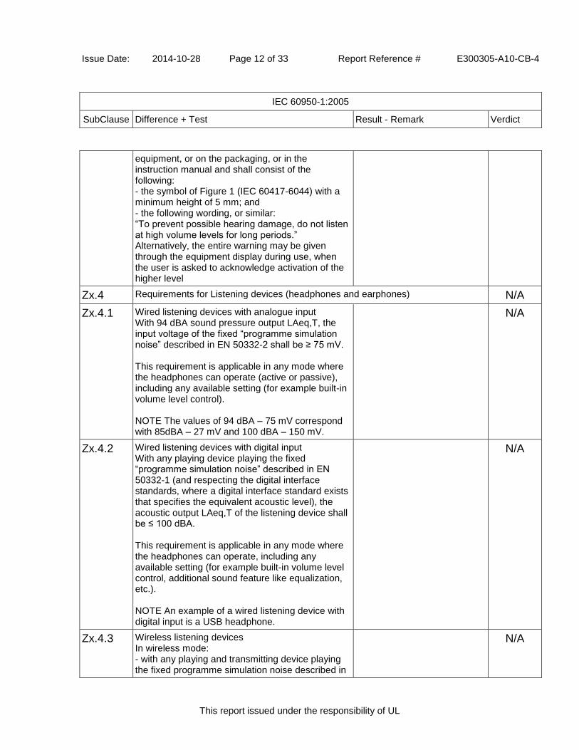
Issue Date: 2014-10-28 Page 12 of 33 Report Reference # E300305-A10-CB-4
IEC 60950-1:2005
SubClause Difference + Test Result - Remark Verdict
This report issued under the responsibility of UL
equipment, or on the packaging, or in the instruction manual and shall consist of the following: - the symbol of Figure 1 (IEC 60417-6044) with a minimum height of 5 mm; and - the following wording, or similar: “To prevent possible hearing damage, do not listen at high volume levels for long periods.” Alternatively, the entire warning may be given through the equipment display during use, when the user is asked to acknowledge activation of the higher level
Zx.4 Requirements for Listening devices (headphones and earphones) N/A
Zx.4.1 Wired listening devices with analogue input With 94 dBA sound pressure output LAeq,T, the input voltage of the fixed “programme simulation noise” described in EN 50332-2 shall be ≥ 75 mV. This requirement is applicable in any mode where the headphones can operate (active or passive), including any available setting (for example built-in volume level control). NOTE The values of 94 dBA – 75 mV correspond with 85dBA – 27 mV and 100 dBA – 150 mV.
N/A
Zx.4.2 Wired listening devices with digital input With any playing device playing the fixed “programme simulation noise” described in EN 50332-1 (and respecting the digital interface standards, where a digital interface standard exists that specifies the equivalent acoustic level), the acoustic output LAeq,T of the listening device shall be ≤ 100 dBA. This requirement is applicable in any mode where the headphones can operate, including any available setting (for example built-in volume level control, additional sound feature like equalization, etc.). NOTE An example of a wired listening device with digital input is a USB headphone.
N/A
Zx.4.3 Wireless listening devices In wireless mode: - with any playing and transmitting device playing the fixed programme simulation noise described in
N/A

Issue Date: 2014-10-28 Page 13 of 33 Report Reference # E300305-A10-CB-4
IEC 60950-1:2005
SubClause Difference + Test Result - Remark Verdict
This report issued under the responsibility of UL
EN 50332-1; and - respecting the wireless transmission standards, where an air interface standard exists that specifies the equivalent acoustic level; and - with volume and sound settings in the listening device (for example built-in volume level control, additional sound feature like equalization, etc.)set to the combination of positions that maximize the measured acoustic output for the abovementioned programme simulation noise, the acoustic output LAeq,T of the listening device shall be ≤ 100 dBA. NOTE An example of a wireless listening device is a Bluetooth headphone.
Zx.5 Measurement Methods Measurements shall be made in accordance with EN 50332-1 or EN 50332-2 as applicable. Unless stated otherwise, the time interval T shall be 30 s. NOTE Test method for wireless equipment provided without listening device should be defined.
N/A
Ireland - Differences to IEC 60950-1:2005 (Second Edition); Am1:2009 + Am2:2013
General Ireland has national differences declared for 60950-1:2005, Am 1:2009 (below).
N/A
3.2.1.1 Apparatus which is fitted with a flexible cable or cord and is designed to be connected to a mains socket conforming to I.S. 411 by means of that flexible cable or cord and plug, shall be fitted with a 13 A plug in accordance with Statutory Instrument 525:1997 - National Standards Authority of Ireland (section 28) (13 A Plugs and Conversion Adaptors for Domestic Use) Regulations 1997.
N/A
4.3.6 DIRECT PLUG-IN EQUIPMENT is known as plug similar devices. Such devices shall comply with Statutory Instrument 526:1997 - National Standards Authority of Ireland (Section 28) (Electrical plugs, plug similar devices and sockets for domestic use) Regulations, 1997.
N/A
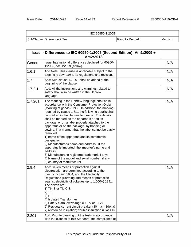
Issue Date: 2014-10-28 Page 14 of 33 Report Reference # E300305-A10-CB-4
IEC 60950-1:2005
SubClause Difference + Test Result - Remark Verdict
This report issued under the responsibility of UL
Israel - Differences to IEC 60950-1:2005 (Second Edition); Am1:2009 + Am2:2013
General Israel has national differences declared for 60950-1:2005, Am 1:2009 (below).
N/A
1.6.1 Add Note: This clause is applicable subject to the Electricity Law, 1954, its regulations and revisions.
N/A
1.7 Add: Sub-clause 1.7.201 shall be added at the beginning of the clause.
N/A
1.7.2.1 Add: All the instructions and warnings related to safety shall also be written in the Hebrew language.
N/A
1.7.201 The marking in the Hebrew language shall be in accordance with the Consumer Protection Order (Marking of goods), 1983. In addition, the marking required by clause 1.7.1, the following details shall be marked in the Hebrew language. The details shall be marked on the apparatus or on its package, or on a label properly attached to the apparatus or on the package, by bonding or sewing, in a manner that the label cannot be easily removed. 1) name of the apparatus and its commercial designation; 2) Manufacturer’s name and address. If the apparatus is imported, the importer’s name and address; 3) Manufacturer’s registered trademark,if any; 4) Name of the model and serial number, if any; 5) country of manufacturer
N/A
2.9.4 Add: Seven means of protection against electrocution are permitted according to the Electricity Law, 1954, and the Electricity Regulations (Earthing and means of protection against electricity of voltages up to 1,000V) 1991. The seven are 1) TN-S or TN-C-S 2) TT 3) IT 4) Isolated Transformer 5) Safety extra low voltage (SELV or ELV) 6) Residual current circuit breaker (30 ma = 1delta) 7) reinforced insulation; double insulation (Class II)
N/A
2.201 Add: Prior to carrying out the tests in accordance with the clauses of this Standard, the compliance of
N/A
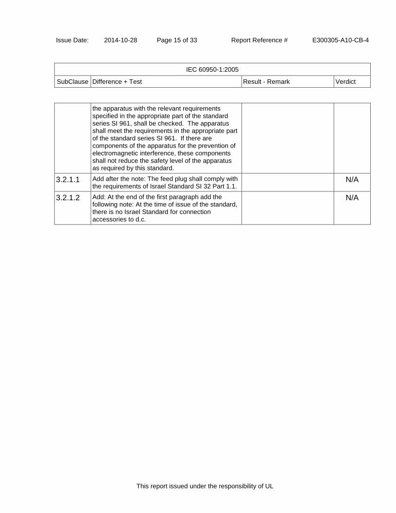
Issue Date: 2014-10-28 Page 15 of 33 Report Reference # E300305-A10-CB-4
IEC 60950-1:2005
SubClause Difference + Test Result - Remark Verdict
This report issued under the responsibility of UL
the apparatus with the relevant requirements specified in the appropriate part of the standard series SI 961, shall be checked. The apparatus shall meet the requirements in the appropriate part of the standard series SI 961. If there are components of the apparatus for the prevention of electromagnetic interference, these components shall not reduce the safety level of the apparatus as required by this standard.
3.2.1.1 Add after the note: The feed plug shall comply with the requirements of Israel Standard SI 32 Part 1.1.
N/A
3.2.1.2 Add: At the end of the first paragraph add the following note: At the time of issue of the standard, there is no Israel Standard for connection accessories to d.c.
N/A

Issue Date: 2014-10-28 Page 16 of 33 Report Reference # E300305-A10-CB-4
IEC 60950-1:2005
SubClause Difference + Test Result - Remark Verdict
This report issued under the responsibility of UL
Japan - Differences to IEC 60950-1:2005 (Second Edition); Am1:2009 + Am2:2013
General NCBs are issuing and recognizing to 60950-1:2005, Am 1:2009. Japan has declared differences to 60950-1:2001 (see below.)
N/A
1.2.4.1 Addition of the following note: Note: Even if the equipment is designed as Class I, the equipment is regarded as Class 0I equipment when 2-pin adaptor with earthing lead wire or cord set having 2-pin plug with earthing lead wire is provided or recommended.
N/A
1.2.4.3A Addition of new clause Class 0I Equipment: Equipment having attachment plug without earthing blade, where protection against electric shock is achieved by: - using BASIC INSULATION, and - providing externally an earth terminal or a lead wire for earthing in order to connect those conductive parts that might assume a HAZARDOUS VOLTAGES in the event of BASIC INSULATION fault to the PROTECTIVE EARTHING CONDUCTOR in the building wiring. NOTE – Class 0I equipment may have a part constructed with Double Insulation or Reinforced Insulation.
N/A
1.3.2 Add after the first paragraph: Note 1 Transportable or similar equipment that are relocated frequently for intended usage should not be designed as Class I or Class 0I equipment unless it is intended to be installed by service personnel. Note 2 Considering wiring circumstance in Japan, equipment intended to be installed where the provision for earthing connection is unlikely should not be designed as Class I or Class 0I equipment unless it is intended to be installed by service personnel.
N/A
1.5.1 Replace the first paragraph with: Where safety is involved, components shall comply either with the requirements of this standard, with the safety aspects of the relevant JIS component standard, or IEC component standards in case there is no applicable JIS component standard is available. However, a component that falls within
N/A

Issue Date: 2014-10-28 Page 17 of 33 Report Reference # E300305-A10-CB-4
IEC 60950-1:2005
SubClause Difference + Test Result - Remark Verdict
This report issued under the responsibility of UL
the scope of METI Ministerial ordinance No. 85 is properly used in accordance with its marked ratings, requirements of 1.5.4, 2.8.7 and 3.2.5 apply, and in addition, a cord connector of power supply cord set mating with appliance inlet complying with the standard sheet of IEC 60320-1, shall comply with relevant standard sheet of IEC 60320-1.
1.5.1 Replace note 1 with: Note 1 A JIS or an IEC component standard is considered relevant only if the component in question clearly falls within its scope.
N/A
1.5.2 Replace the first sentence in the first dashed paragraph with the following: A component that has been demonstrated to comply with a JIS component standard harmonized with the relevant IEC component standard, or where such JIS component standard is not available, a component that has been demonstrated to comply with the relevant IEC component standard shall be checked for correct application and use in accordance with its rating.
N/A
1.5.2 Add the following note after the first dashed paragraph: Note 1 See 1.7.5A when Type C.14 appliance coupler rated 10 A per IEC 60320-1 is used with an equipment rated not more than 125 V and rated more than 10 A.
N/A
1.5.2 Replace first sentence in the third dashed paragraph with the following: Where no relevant IEC component standard or JIS component standard harmonized with the relevant IEC component standard exists, or where components are used in circuits not in accordance with their specified rating, the components shall be tested under the conditions occurring in the equipment.
N/A
1.5.6 In this sub-clause, add “JIS C 5101-14:1998 or” before the reference number, IEC 60384-14:1993.
N/A
1.5.7.2 In this sub-clause, add “JIS C 5101-14:1998 or” before the reference number, IEC 60384-14:1993.
N/A
1.5.8 In the first paragraph, add “JIS C 5101-14:1998 or” before the reference number, IEC 60384-14:1993.
N/A
1.7.1 Replace fifth dashed paragraph with the following: N/A

Issue Date: 2014-10-28 Page 18 of 33 Report Reference # E300305-A10-CB-4
IEC 60950-1:2005
SubClause Difference + Test Result - Remark Verdict
This report issued under the responsibility of UL
manufacturer’s or responsible company’s name or trade-mark or identification mark
1.7.5 In the second paragraph, add “or JIS C 8303:2007” after the reference number, IEC/TR 60083:1997”.
N/A
1.7.5A Add the following new clause after 1.7.5: Appliance Coupler If appliance coupler according to IEC60320-1, C.14(rated current: 10A)is used in equipment whose rated voltage is less than 125V and rated current is over 10A, the following instruction or equivalent shall be described in the user instruction. “ Use only designated cord set attached in this equipment”
N/A
1.7.12 Replace first sentence with the following: Instructions and equipment marking related to safety shall be in Japanese.
N/A
1.7.17A Add the following new clause. after 1.7.17: Marking for CLASS 0I EQUIPMENT For CLASS 0I EQUIPMENT, the following instruction shall be marked on the visible place of the mains plug or the main body: “Provide an earthing connection” Moreover, for CLASS 0I EQUIPMENT, the following or equivalent instruction shall be indicated on the visible place of the main body or written in the operating instructions: “Provide an earthing connection before the mains plug is connected to the mains. And, when disconnecting the earthing connection, be sure to disconnect after pulling out the mains plug from the mains.”
N/A
2.1.1.1 In item b) of this sub-clause, replace “IEC 60083” with “JIS C 8303:2007 or Article 1 of the Ministerial Ordinance (No. 85:1962)”
N/A
2.6.3.2 Add the following after 1st paragraph: This also applies to the conductor of lead wire for protective earthing of CLASS 0I EQUIPMENT.
N/A
2.6.4.2 Replace 1st paragraph with the following: Equipment required to have protective earthing shall have a main protective earthing terminal.
N/A

Issue Date: 2014-10-28 Page 19 of 33 Report Reference # E300305-A10-CB-4
IEC 60950-1:2005
SubClause Difference + Test Result - Remark Verdict
This report issued under the responsibility of UL
For equipment with a DETACHABLE POWER SUPPLY CORD, the earthing terminal in the appliance inlet is regarded as the main protective earthing terminal except for CLASS 0I EQUIPMENT providing separate main protective earthing terminal other than appliance inlet.
2.6.5.4 Replace 1st sentence with the following: Protective earthing connections of CLASS I EQUIPMENT shall make earlier and break later than the supply connections in each of the following:
N/A
2.6.5.8A Add the following new clause. after 2.6.5.8A: Earthing of CLASS 0I EQUIPMENT Plugs with a lead wire for earthing shall not be used for equipment having a rated voltage exceeding 150V. For plugs with a lead wire for earthing, the lead wire shall not be earthed by a clip. CLASS 0I EQUIPMENT shall be provided with an earthing terminal or lead wire for earthing in the external location where easily visible.
N/A
2.10.3.1 In this sub-clause, replace IEC 60664-1 with JIS C 0664:2003.
N/A
2.10.3.2 In the second paragraph, replace IEC 60664-1 with JIS C 0664:2003.
N/A
3.2.3 Add the following after Table 3A: Table 3A applies when cables complying JIS C 3662 or JIS C 3663 are used. In case of other cables, cable entries shall be so designed that a conduit suitable for the cable used can be fitted.
N/A
3.2.5.1 Add the following to the last of first dashed paragraph. Or mains cords shall be of the sheathed type complying with Appendix 1 of Article 1 of the Ministerial Ordinance on stipulating technical requirements for the Electrical Appliance.
N/A
3.2.5.1 Add the following to the last of second dashed paragraph. Or mains cords shall be of the sheathed type complying with Appendix 1 of Article 1 of the Ministerial Ordinance on stipulating technical requirements for the Electrical Appliance.
N/A
3.2.5.1 Delete 1) in Table 3B. N/A

Issue Date: 2014-10-28 Page 20 of 33 Report Reference # E300305-A10-CB-4
IEC 60950-1:2005
SubClause Difference + Test Result - Remark Verdict
This report issued under the responsibility of UL
3.3.4 Add the following note to Table 3D: Note For cables other than those complying with JIS C 3662 or JIS C 3663, terminals shall be suitable for the size of the intended cables.
N/A
3.3.7 Add the following after the first sentence: This requirement is not applicable to the external earthing terminal of Class 0I equipment.
N/A
4.3.4 Add the following after the first sentence: This requirement also applies to those connections in Class 0I equipment, where CLEARANCE or CREEPAGE DISTANCES over BASIC INSULATION would be reduced to less than the values specified in 2.10.
N/A
4.3.13.5 Replace the first paragraph with the following: Except as permitted below, equipment shall be classified and labelled according to JIS C 6802:2005, and JIS C 6803:2006 or IEC 60825-2:2000, as applicable. Replace IEC 60825-1 in the second and the last paragraph with JIS C 6802:2005.
N/A
4.5 Add the following NOTE to Table 4B, 3): NOTE: In case no data for the material is available, Appendix 4, 1. (1). b. 3 of the Interpretation on the Ministerial Ordinance stipulating Technical Specifications for Electrical Appliances (Commerce and Distribution Policy Group No. 3:2008/06/19) may apply.
N/A
5.1.3 Add a note after the first paragraph as follows: Note – Attention should be drawn to that majority of three-phase power system in Japan is of delta connection, and therefore, in that case, test is conducted using the test circuit from IEC 60990, figure 13.
N/A
5.1.6 Replace Table 5A as shown in J60950-1. N/A
6 Replace IEC 60664-1 in NOTE 4 with JIS C 0664. N/A
7 Replace IEC 60664-1 in NOTE 3 with JIS C 0664:2003.
N/A
7.2 Add the following after the paragraph: However, the separation requirements and tests of 6.2.1 a), b) and c) do not apply to a CABLE DISTRIBUTION SYSTEM if all of the following
N/A

Issue Date: 2014-10-28 Page 21 of 33 Report Reference # E300305-A10-CB-4
IEC 60950-1:2005
SubClause Difference + Test Result - Remark Verdict
This report issued under the responsibility of UL
apply: − the circuit under consideration is a TNV-1 CIRCUIT; and – the common or earthed side of the circuit is connected to the screen of the coaxial cable and to all accessible parts and circuits (SELV, accessible metal parts and LIMITED CURRENT CIRCUITS, if any); and – the screen of the coaxial cable is intended to be connected to earth in the building installation.
JA Add new Annex JA: Document shredding machines shall also comply with the requirements of this annex except those of STATIONARY EQUIPMENT used by connecting directly to an AC MAINS SUPPLY of three-phase 200V or more.
N/A
JA.1 Add: Markings and instructions The symbol (JIS S 0101:2000, 6.2.4) (exclamation point in yellow triangle) and the following precautions for use shall be marked on readily visible part adjacent to document feed opening. The marking shall be clearly legible, permanent, and easily discernible; - that use by an infants/children may cause a hazard of injury etc.; - that a hand can be drawn into the mechanical section for shredding when touching the document-slot; - that clothing can be drawn into the mechanical section for shredding when touching the document-slot; - that hairs can be drawn into the mechanical section for shredding when touching the document-slot; - in case of equipment incorporating a commutator motor, that equipment may catch fire or explode by spraying of flammable gas.
N/A
JA.2 Add: Inadvertent Reactivation Any safety interlock that can be operated by means of the test finger, Figure JA.1, is considered to be likely to cause inadvertent reactivation of the hazard. Compliance is checked by inspection and, where necessary, by a test with the test finger, Figure JA.1
N/A

Issue Date: 2014-10-28 Page 22 of 33 Report Reference # E300305-A10-CB-4
IEC 60950-1:2005
SubClause Difference + Test Result - Remark Verdict
This report issued under the responsibility of UL
JA.3 Add: Disconnection from the mains supply: Document shredding machines shall incorporate an isolating switch complying with sub-clause 3.4.2 as the device disconnecting the power of hazardous moving parts. For this switch, two-position (single-use) switch or multi-position (multifunction) switch (e.g., slide switch) may be used.
N/A
JA.3 Add: If two-position switch, the positions for “ON” and “OFF” shall be indicated in accordance with sub-clause 1.7.8. If multi-position switch, the position for “OFF” shall be indicated in accordance with sub-clause 1.7.8 and other positions shall be indicated with proper terms or symbols. Compliance is checked by inspection
N/A
JA.4 Add: Protection against hazardous moving parts: Any warning shall not be used instead of the structure for preventing access to hazardous moving parts. Document shredding machines shall comply with the following requirements. Insert the test finger, Figure JA.1, into all openings in MECHANICAL ENCLOSURES without applying appreciable force. It shall not be possible to touch hazardous moving parts with the test finger. This consideration applies to all sides of MECHANICAL ENCLOSURES when the equipment is mounted as intended . Before testing with the test finger, remove the parts detachable without a tool. Insert the wedge-probe, Figure JA.2, into the document-slot. And, against all directions of openings, if straight-cutting type, a force of 45 N shall apply to the probe, and 90 N if cross-cutting type. In this case, the weight of the probe is to be factored into the overall applied force. Before testing with the wedge-probe, remove the parts detachable without a tool. It shall not be possible to touch any hazardous moving parts, including the shredding roller or the mechanical section for shedding, with the probe. Note 1 - The thickness of the probe varies linearly, with slope changes at the respective points shown in the table.
N/A

Issue Date: 2014-10-28 Page 23 of 33 Report Reference # E300305-A10-CB-4
IEC 60950-1:2005
SubClause Difference + Test Result - Remark Verdict
This report issued under the responsibility of UL
Note 2 –The allowable dimensional tolerance of the probe is +/- 0.127 mm.
W.1 Replace second and third sentence in the first paragraph with the following: This distinction between earthed and unearthed (floating) circuit is not the same as between CLASS I EQUIMENT, CLASS 0I EQUIPMENT and CLASS II EQUIPMENT. Floating circuits can exist in CLASS I EQUIPMENT or CLASS 0I EQUIPMENT and earthed circuits in CLASS II EQUIPMENT.
N/A
Korea - Differences to IEC 60950-1:2005 (Second Edition); Am1:2009 + Am2:2013
General Korea has national differences declared for 60950-1:2005, Am 1:2009 (below).
N/A
1.5.101 Plugs for the connection of the apparatus to the mains supply shall comply with the Korean requirement (KSC 8305)
Appliance inlet provided for models; a detachable power supply cord in compliance with national requirements will be provided by the local distributor.
N/A
8 EMC - The apparatus shall comply with the relevant CISPR standards
This test report covers safety evaluation only according to IEC60950-1; EMC testing to be covered by separate test report.
N/A

Issue Date: 2014-10-28 Page 24 of 33 Report Reference # E300305-A10-CB-4
IEC 60950-1:2005
SubClause Difference + Test Result - Remark Verdict
This report issued under the responsibility of UL
Norway - Differences to IEC 60950-1:2005 (Second Edition); Am1:2009 + Am2:2013
General Norway has national differences declared for 60950-1:2005, Am 1:2009 (below).
Pass
1.2.13.14 For requirements see 1.7.2.1 and 7.3. N/A
1.5.7.1 Resistors bridging BASIC INSULATION in CLASS I PLUGGABLE EQUIPMENT TYPE A must comply with the requirements in 1.5.7.2. In addition when a single resistor is used, the resistor must withstand the resistor test in 1.5.7.2.
N/A
1.5.8 Due to the IT power system used (see annex V, figure V.7), capacitors are required to be rated for the applicable line-to-line voltage (230 V).
Rated min. 250 Vac Pass
1.5.9.4 The third dashed sentence is applicable only to equipment as defined in 6.1.2.2 of this annex.
N/A
1.7.2.1 CLASS I PLUGGABLE EQUIPMENT TYPE A intended for connection to other equipment or a network shall, if safety relies on connection to protective earth or if surge suppressors are connected between the network terminals and accessible parts, have a marking stating that the equipment must be connected to an earthed mains socket-outlet. The marking text shall be: "Apparatet må tilkoples jordet stikkontakt"
Operating instructions and warnings are written in an accepted language of the certain country.
N/A
1.7.2.1 In Norway, the screen of the cable distribution system is normally not earthed at the entrance of the building and there is normally no equipotential bonding system within the building. Therefore the protective earthing of the building installation need to be isolated from the screen of a cable distribution system. It is however accepted to provide the insulation external to the equipment by an adapter or an interconnection cable with galvanic isolator, which may be provided by e.g. a retailer. The user manual shall then have the following or similar information in Norwegian and Swedish language respectively, depending on in what country the equipment is intended to be used in: "Equipment connected to the protective earthing of the building installation through the mains connection or through other equipment with a connection to protective earthing - and to a cable distribution system using coaxial cable, may in
N/A

Issue Date: 2014-10-28 Page 25 of 33 Report Reference # E300305-A10-CB-4
IEC 60950-1:2005
SubClause Difference + Test Result - Remark Verdict
This report issued under the responsibility of UL
some circumstances create a fire hazard. Connection to a cable distribution system has therefore to be provided through a device providing electrical isolation below a certain frequency range (galvanic isolator, see EN 60728-11)." NOTE: In Norway, due to regulation for installations of cable distribution systems, and in Sweden, a galvanic isolator shall provide electrical insulation below 5 MHz. The insulation shall withstand a dielectric strength of 1,5 kV r.m.s., 50 Hz or 60 Hz, for 1 min. Translation to Norwegian (the Swedish text will also be accepted in Norway): “Utstyr som er koplet til beskyttelsesjord via nettplugg og/eller via annet jordtilkoplet utstyr - og er tilkoplet et kabel-TV nett, kan forårsake brannfare. For å unngå dette skal det ved tilkopling av utstyret til kabel-TV nettet installeres en galvanisk isolator mellom utstyret og kabel-TV nettet."
2.2.4 Requirements according to this annex, 1.7.2.1, 6.1.2.1 and 6.1.2.2 apply.
N/A
2.3.2 Requirements according to this annex, 6.1.2.1 and 6.1.2.2 apply.
N/A
2.3.4 Requirements according to this annex, 1.7.2.1, 6.1.2.1 and 6.1.2.2 apply.
N/A
2.10.5.13 Requirements according to this annex, 6.1.2.1 and 6.1.2.2 apply.
N/A
5.1.7.1 TOUCH CURRENT measurement results exceeding 3,5 mA r.m.s are permitted only for the following equipment: - STATIONARY PLUGGABLE EQUIPMENT TYPE A that: (1) is intended to be used in a RESTRICTED ACCESS LOCATION where equipotential bonding has been applied, for example, in a telecommunication centre; and (2) has provision for a permanently connected PROTECTIVE EARTHING CONDUCTOR; and (3) is provided with instructions for the installation of that conductor by a SERVICE PERSON; - STATIONARY PLUGGABLE EQUIPMENT TYPE B - STATIONARY PERMANENTLY CONNECTED EQUIPMENT
N/A

Issue Date: 2014-10-28 Page 26 of 33 Report Reference # E300305-A10-CB-4
IEC 60950-1:2005
SubClause Difference + Test Result - Remark Verdict
This report issued under the responsibility of UL
6.1.2.1 Add the following text between the first and second paragraph of the compliance clause: If this insulation is solid, including insulation forming part of a component, it shall at least consist of either - two layers of thin sheet material, each of which shall pass the electric strength test below, or - one layer having a distance through insulation of at least 0,4 mm, which shall pass the electric strength test below. Alternatively for components, there is no distance through insulation requirement for the insulation consisting of an insulating compound completely filling the casing, so that CLEARANCES and CREEPAGE DISTANCES do not exist, if the component passes the electric strength test in accordance with the compliance clause below and in addition - passes the tests and inspection criteria of 2.10.11 with an electric strength test of 1,5 kV multiplied by 1,6 (the electric strength test of 2.10.10 shall be performed using 1,5 kV), and - is subject to ROUTINE TESTING for electric strength during manufacturing, using a test voltage of 1,5 kV. It is permitted to bridge this insulation with an optocoupler complying with 2.10.5.4 b). It is permitted to bridge this insulation with a capacitor complying with EN 132400:1994, subclass Y2. A capacitor classified Y3 according to EN 123400 [EN 60384-14:2005], may bridge this insulation under the following conditions: - the insulation requirements are satisfied by having a capacitor classified Y3 as defined by EN 132400 [EN 60384-14], which in addition to the Y3 testing, is tested with an impulse test of 2,5 kV defined in EN 60950-1:2006, 6.2.2.1; - the additional testing shall be performed on all the test specimens as described in EN 132400 [EN 60384-14]; - the impulse test of 2,5 kV is to be performed before the endurance test in EN 132400 [EN 60384-14], in the sequence of tests as described in EN 132400 [EN 60384-14.]
N/A

Issue Date: 2014-10-28 Page 27 of 33 Report Reference # E300305-A10-CB-4
IEC 60950-1:2005
SubClause Difference + Test Result - Remark Verdict
This report issued under the responsibility of UL
6.1.2.2 The exclusions are applicable for PERMANENTLY CONNECTED EQUIPMENT and PLUGGABLE EQUIPMENT TYPE B and equipment intended to be used in a RESTRICTED ACCESS LOCATION where equipotential bonding has been applied, e.g. in a telecommunication centre, and which has provision for a permanently connected PROTECTIVE EARTHING CONDUCTOR and is provided with instructions for the installation of that conductor by a SERVICE PERSON.
N/A
7.2 Requirements according to this annex, 6.1.2.1 and 6.1.2.2 apply with the term TELECOMMUNICATION NETWORK in 6.1.2 being replaced by the term CABLE DISTRIBUTION SYSTEM.
N/A
7.3 Refer to EN 60728-11:2005 for installation conditions
N/A
7.3 Requirements according to this annex 1.2.13.14 and 1.7.2.1 apply.
N/A
Spain - Differences to IEC 60950-1:2005 (Second Edition); Am1:2009 + Am2:2013
General Spain has national differences declared for 60950-1:2005, Am 1:2009 (below).
N/A
3.2.1.1 Supply cords of single-phase equipment having a rated current not exceeding 10A shall be provided with a plug according to UNE 20315:1994. Supply cords of single-phase equipment having a rated current not exceeding 2.5A shall be provided with a plug according to UNE-EN 50075:1993. CLASS 1 EQUIPMENT provided with socket-outlets with earth contacts or which are intended to be used in locations where protection against indirect contact is required according to the wiring rules, shall be provided with a plug in accordance with standard UNE 20315:1994. If poly-phase equipment is provided with a supply cord with a plug, this plug shall be in accordance with UNE-EN 60309-2.
N/A
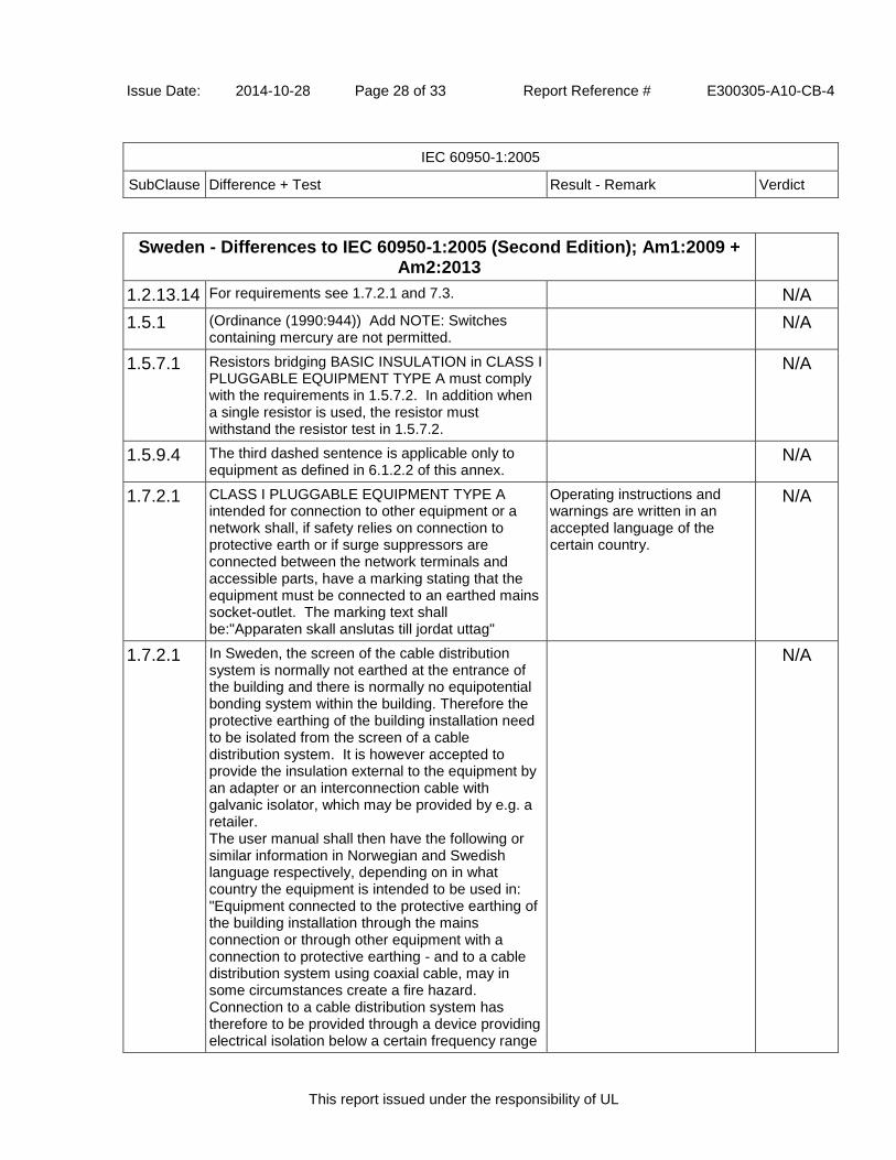
Issue Date: 2014-10-28 Page 28 of 33 Report Reference # E300305-A10-CB-4
IEC 60950-1:2005
SubClause Difference + Test Result - Remark Verdict
This report issued under the responsibility of UL
Sweden - Differences to IEC 60950-1:2005 (Second Edition); Am1:2009 + Am2:2013
1.2.13.14 For requirements see 1.7.2.1 and 7.3. N/A
1.5.1 (Ordinance (1990:944)) Add NOTE: Switches containing mercury are not permitted.
N/A
1.5.7.1 Resistors bridging BASIC INSULATION in CLASS I PLUGGABLE EQUIPMENT TYPE A must comply with the requirements in 1.5.7.2. In addition when a single resistor is used, the resistor must withstand the resistor test in 1.5.7.2.
N/A
1.5.9.4 The third dashed sentence is applicable only to equipment as defined in 6.1.2.2 of this annex.
N/A
1.7.2.1 CLASS I PLUGGABLE EQUIPMENT TYPE A intended for connection to other equipment or a network shall, if safety relies on connection to protective earth or if surge suppressors are connected between the network terminals and accessible parts, have a marking stating that the equipment must be connected to an earthed mains socket-outlet. The marking text shall be:"Apparaten skall anslutas till jordat uttag"
Operating instructions and warnings are written in an accepted language of the certain country.
N/A
1.7.2.1 In Sweden, the screen of the cable distribution system is normally not earthed at the entrance of the building and there is normally no equipotential bonding system within the building. Therefore the protective earthing of the building installation need to be isolated from the screen of a cable distribution system. It is however accepted to provide the insulation external to the equipment by an adapter or an interconnection cable with galvanic isolator, which may be provided by e.g. a retailer. The user manual shall then have the following or similar information in Norwegian and Swedish language respectively, depending on in what country the equipment is intended to be used in: "Equipment connected to the protective earthing of the building installation through the mains connection or through other equipment with a connection to protective earthing - and to a cable distribution system using coaxial cable, may in some circumstances create a fire hazard. Connection to a cable distribution system has therefore to be provided through a device providing electrical isolation below a certain frequency range
N/A

Issue Date: 2014-10-28 Page 29 of 33 Report Reference # E300305-A10-CB-4
IEC 60950-1:2005
SubClause Difference + Test Result - Remark Verdict
This report issued under the responsibility of UL
(galvanic isolator, see EN 60728-11)." NOTE: In Norway, due to regulation for installations of cable distribution systems, and in Sweden, a galvanic isolator shall provide electrical insulation below 5 MHz. The insulation shall withstand a dielectric strength of 1,5 kV r.m.s., 50 Hz or 60 Hz, for 1 min. Translation to Swedish: "Utrustning som är kopplad till skyddsjord via jordat vägguttag och/eller via annan utrustning och samtidigt är kopplad till kabel-TV nät kan i vissa fall medfõra risk fõr brand. Fõr att undvika detta skall vid anslutning av utrustningen till kabel-TV nät galvanisk isolator finnas mellan utrustningen och kabel-TV nätet."
2.3.2 Requirements according to this annex, 6.1.2.1 and 6.1.2.2 apply.
N/A
2.10.5.13 Requirements according to this annex, 6.1.2.1 and 6.1.2.2 apply.
N/A
5.1.7.1 TOUCH CURRENT measurement results exceeding 3,5 mA r.m.s are permitted only for the following equipment: STATIONARY PLUGGABLE EQUIPMENT TYPE A that: (1) is intended to be used in a RESTRICTED ACCESS LOCATION where equipotential bonding has been applied, for example, in a telecommunication centre; and (2) has provision for a permanently connected PROTECTIVE EARTHING CONDUCTOR; and (3) is provided with instructions for the installation of that conductor by a SERVICE PERSON; - STATIONARY PLUGGABLE TYPE B - STATIONARY PERMANENTLY CONNECTED EQUIPMENT
N/A
6.1.2.1 Add the following text between the first and second paragraph of the compliance clause: If this insulation is solid, including insulation forming part of a component, it shall at least consist of either - two layers of thin sheet material, each of which shall pass the electric strength test below, or - one layer having a distance through insulation of at least 0,4 mm, which shall pass the electric strength test below. Alternatively for components, there is no distance
N/A

Issue Date: 2014-10-28 Page 30 of 33 Report Reference # E300305-A10-CB-4
IEC 60950-1:2005
SubClause Difference + Test Result - Remark Verdict
This report issued under the responsibility of UL
through insulation requirement for the insulation consisting of an insulating compound completely filling the casing, so that CLEARANCES and CREEPAGE DISTANCES do not exist, if the component passes the electric strength test in accordance with the compliance clause below and in addition - passes the tests and inspection criteria of 2.10.11 with an electric strength test of 1,5 kV multiplied by 1,6 (the electric strength test of 2.10.10 shall be performed using 1,5 kV), and - is subject to ROUTINE TESTING for electric strength during manufacturing, using a test voltage of 1,5 kV. It is permitted to bridge this insulation with an optocoupler complying with 2.10.5.4 b). It is permitted to bridge this insulation with a capacitor complying with EN 132400:1994, subclass Y2. A capacitor classified Y3 according to EN 132400 [EN 60384-14:2005], may bridge this insulation under the following conditions: - the insulation requirements are satisfied by having a capacitor classified Y3 as defined by EN 132400 [EN 60384-14], which in addition to the Y3 testing, is tested with an impulse test of 2,5 kV defined in EN 60950-1:2006, 6.2.2.1; - the additional testing shall be performed on all the test specimens as described in EN 132400 [EN 60384-14]; - the impulse test of 2,5 kV is to be performed before the endurance test in EN 132400 [EN 60384-14], in the sequence of tests as described in EN 132400 [EN 60384-14.]
6.1.2.2 The exclusions are applicable for PERMANENTLY CONNECTED EQUIPMENT and PLUGGABLE EQUIPMENT TYPE B and equipment intended to be used in a RESTRICTED ACCESS LOCATION where equipotential bonding has been applied, e.g. in a telecommunication centre, and which has provision for a permanently connected PROTECTIVE EARTHING CONDUCTOR and is provided with instructions for the installation of that conductor by a SERVICE PERSON.
N/A
7.2 Requirements according to this annex, 6.1.2.1 and N/A

Issue Date: 2014-10-28 Page 31 of 33 Report Reference # E300305-A10-CB-4
IEC 60950-1:2005
SubClause Difference + Test Result - Remark Verdict
This report issued under the responsibility of UL
6.1.2.2 apply with the term TELECOMMUNICATION NETWORK in 6.1.2 being replaced by the term CABLE DISTRIBUTION SYSTEM.
7.3 Requirements according to this annex 1.2.13.14 and 1.7.2.1 apply.
N/A
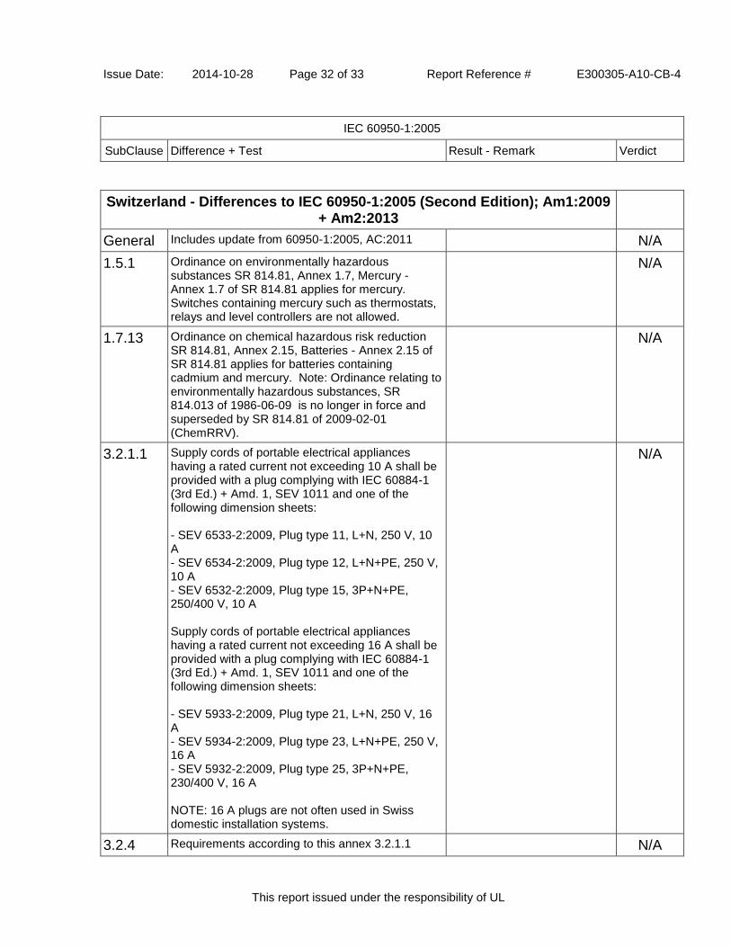
Issue Date: 2014-10-28 Page 32 of 33 Report Reference # E300305-A10-CB-4
IEC 60950-1:2005
SubClause Difference + Test Result - Remark Verdict
This report issued under the responsibility of UL
Switzerland - Differences to IEC 60950-1:2005 (Second Edition); Am1:2009 + Am2:2013
General Includes update from 60950-1:2005, AC:2011 N/A
1.5.1 Ordinance on environmentally hazardous substances SR 814.81, Annex 1.7, Mercury - Annex 1.7 of SR 814.81 applies for mercury. Switches containing mercury such as thermostats, relays and level controllers are not allowed.
N/A
1.7.13 Ordinance on chemical hazardous risk reduction SR 814.81, Annex 2.15, Batteries - Annex 2.15 of SR 814.81 applies for batteries containing cadmium and mercury. Note: Ordinance relating to environmentally hazardous substances, SR 814.013 of 1986-06-09 is no longer in force and superseded by SR 814.81 of 2009-02-01 (ChemRRV).
N/A
3.2.1.1 Supply cords of portable electrical appliances having a rated current not exceeding 10 A shall be provided with a plug complying with IEC 60884-1 (3rd Ed.) + Amd. 1, SEV 1011 and one of the following dimension sheets: - SEV 6533-2:2009, Plug type 11, L+N, 250 V, 10 A - SEV 6534-2:2009, Plug type 12, L+N+PE, 250 V, 10 A - SEV 6532-2:2009, Plug type 15, 3P+N+PE, 250/400 V, 10 A Supply cords of portable electrical appliances having a rated current not exceeding 16 A shall be provided with a plug complying with IEC 60884-1 (3rd Ed.) + Amd. 1, SEV 1011 and one of the following dimension sheets: - SEV 5933-2:2009, Plug type 21, L+N, 250 V, 16 A - SEV 5934-2:2009, Plug type 23, L+N+PE, 250 V, 16 A - SEV 5932-2:2009, Plug type 25, 3P+N+PE, 230/400 V, 16 A NOTE: 16 A plugs are not often used in Swiss domestic installation systems.
N/A
3.2.4 Requirements according to this annex 3.2.1.1 N/A

Issue Date: 2014-10-28 Page 33 of 33 Report Reference # E300305-A10-CB-4
IEC 60950-1:2005
SubClause Difference + Test Result - Remark Verdict
This report issued under the responsibility of UL
apply.

Issue Date: 2014-10-28 Page 34 of 33 Report Reference # E300305-A10-CB-4
IEC 60950-1:2005
SubClause Difference + Test Result - Remark Verdict
This report issued under the responsibility of UL
United Kingdom - Differences to IEC 60950-1:2005 (Second Edition); Am1:2009 + Am2:2013
2.6.3.3 The current rating of the circuit shall be taken as 13 A, not 16 A.
Considered. Pass
2.7.1 To protect against excessive currents and short-circuits in the PRIMARY CIRCUIT of DIRECT PLUG-IN EQUIPMENT, tests according to 5.3 shall be conducted, using an external protective device rated 30 A or 32 A. If these tests fail, suitable protective devices shall be included as integral parts of the DIRECT PLUG-IN EQUIPMENT, so that the requirements of 5.3 are met.
Pass
3.2.1.1 Apparatus which is fitted with a flexible cable or cord and is designed to be connected to a mains socket conforming to BS 1363 by means of that flexible cable or cord and plug, shall be fitted with a "standard plug" in accordance with Statutory Instrument 1786: 1994 - The Plugs and Sockets etc. (Safety) Regulations 1994, unless exempted by those regulations. NOTE: "Standard plug" is defined in SI 1786: 1994 and essentially means an approved plug conforming to BS 1363 or an approved conversion plug.
Appliance inlet provided for models; a detachable power supply cord in compliance with national requirements will be provided by the local distributor.
Pass
3.2.5.1 A power supply cord with conductor of 1.25 mm² is allowed for equipment with a rated current over 10A and up to and including 13A.
Appliance inlet provided for models; a detachable power supply cord in compliance with national requirements will be provided by the local distributor.
N/A
3.3.4 The range of conductor sizes of flexible cords to be accepted by terminals for equipment with a rated current of over 10 A up to and including 13 A is 1.25 mm² to 1.5 mm² nominal cross-sectional area.
N/A
4.3.6 The torque test is performed using a socket outlet complying with BS 1363 and the plug part of DIRECT PLUG-IN EQUIPMENT shall be assessed to BS 1363: Part 1, 12.1, 12.2, 12.3, 12.9, 12.11, 12.12, 12.16 and 12.17, except that the test of 12.17 is performed at not less than 125°C.
N/A
4.3.6 Where the metal earth pin is replaced by an Insulated Shutter Opening Device (ISOD), the requirements of clauses 22.2 and 23 also apply.
N/A

Issue Date: 2014-10-28 Page 1 of 35 Report Reference # E300305-A10-CB-4
Enclosures
This report issued under the responsibility of UL
Enclosures
Type Supplement Id Description
Photographs 3-01 External view
Photographs 3-02 Internal view_JPOE130A4800FK01
Photographs 3-03 Internal view_JPOE130B4800FK01
Photographs 3-04 External view for Class II
Photographs 3-05 Internal view for Class II
Photographs 3-06 Internal view_JPOE130C4800FK01
Diagrams 4-01 Circuit_JPOE130A4800FK01
Diagrams 4-02 Circuit_JPOE130B4800FK01
Diagrams 4-03 Circuit_JPOE130A4800NK01
Diagrams 4-04 Circuit_JPOE130B4800NK01
Diagrams 4-05 Circuit_JPOE130C4800FK01
Schematics + PWB 5-01 PWB Layout_common
Schematics + PWB 5-02 PWB sub board for JPOE130B4800FK01
Schematics + PWB 5-03 PBW layout_JPOE130C
Miscellaneous 7-02 Linefilter_L1
Miscellaneous 7-03 Transformer_T1
Miscellaneous 7-05 National Differences - China and Japan and Australia
Miscellaneous 7-07 Manufacturer Declaration
Miscellaneous 7-08 Manufacturer Declaration
Marking Plate 13-01 Marking Plate

Issue Date: 2014-10-28 Page 2 of 35 Report Reference # E300305-A10-CB-4
Enclosures
This report issued under the responsibility of UL
MarkingPlate ID 13-01

Issue Date: 2014-10-28 Page 3 of 35 Report Reference # E300305-A10-CB-4
Enclosures
This report issued under the responsibility of UL
MarkingPlate ID 13-01

Issue Date: 2014-10-28 Page 4 of 35 Report Reference # E300305-A10-CB-4
Enclosures
This report issued under the responsibility of UL
MarkingPlate ID 13-01

Issue Date: 2014-10-28 Page 5 of 35 Report Reference # E300305-A10-CB-4
Enclosures
This report issued under the responsibility of UL
MarkingPlate ID 13-01

Issue Date: 2014-10-28 Page 6 of 35 Report Reference # E300305-A10-CB-4
Enclosures
This report issued under the responsibility of UL
Photographs ID 3-01

Issue Date: 2014-10-28 Page 7 of 35 Report Reference # E300305-A10-CB-4
Enclosures
This report issued under the responsibility of UL
Photographs ID 3-02
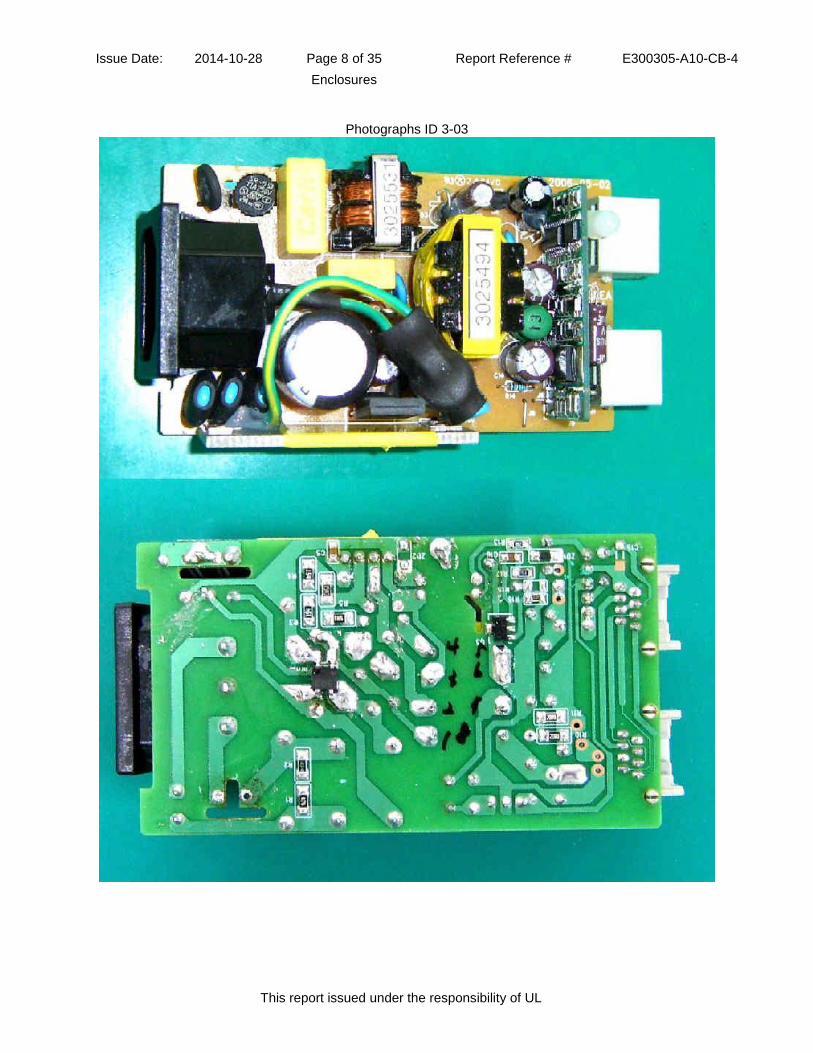
Issue Date: 2014-10-28 Page 8 of 35 Report Reference # E300305-A10-CB-4
Enclosures
This report issued under the responsibility of UL
Photographs ID 3-03
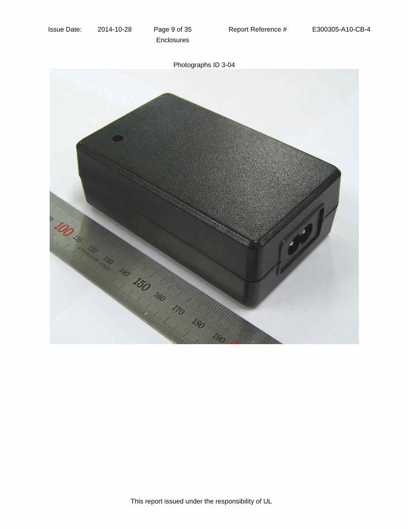
Issue Date: 2014-10-28 Page 9 of 35 Report Reference # E300305-A10-CB-4
Enclosures
This report issued under the responsibility of UL
Photographs ID 3-04

Issue Date: 2014-10-28 Page 10 of 35 Report Reference # E300305-A10-CB-4
Enclosures
This report issued under the responsibility of UL
Photographs ID 3-05
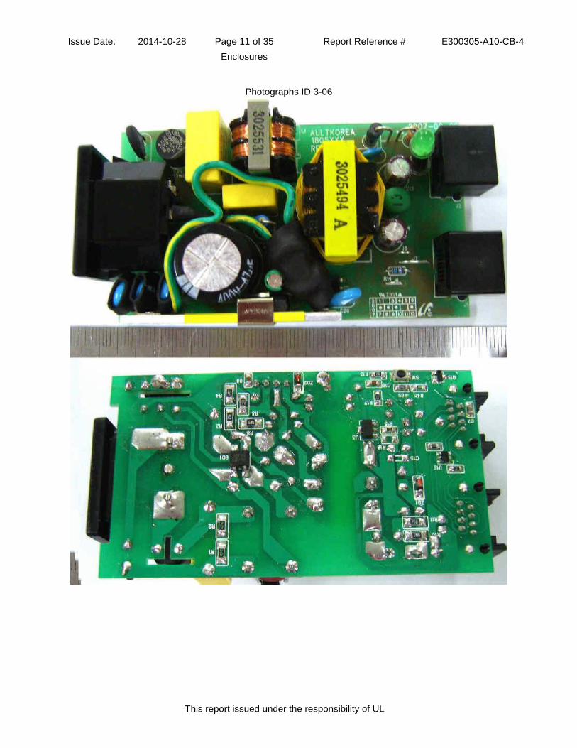
Issue Date: 2014-10-28 Page 11 of 35 Report Reference # E300305-A10-CB-4
Enclosures
This report issued under the responsibility of UL
Photographs ID 3-06
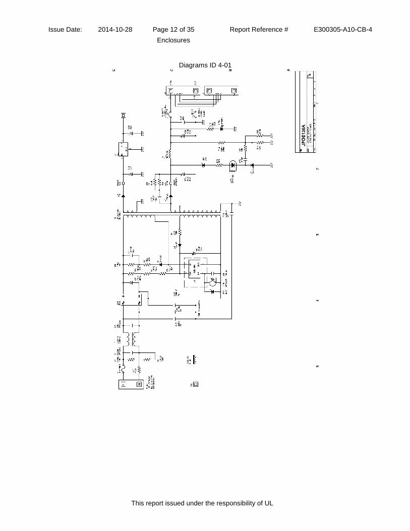
Issue Date: 2014-10-28 Page 12 of 35 Report Reference # E300305-A10-CB-4
Enclosures
This report issued under the responsibility of UL
Diagrams ID 4-01

Issue Date: 2014-10-28 Page 13 of 35 Report Reference # E300305-A10-CB-4
Enclosures
This report issued under the responsibility of UL
Diagrams ID 4-02
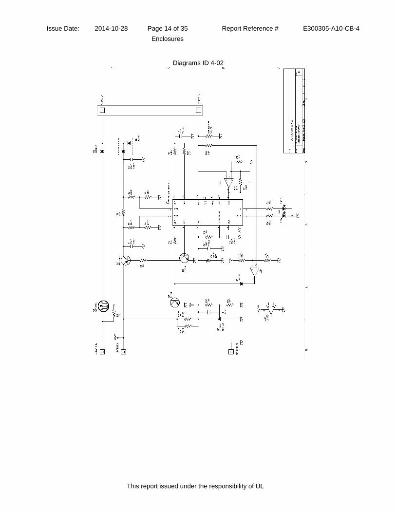
Issue Date: 2014-10-28 Page 14 of 35 Report Reference # E300305-A10-CB-4
Enclosures
This report issued under the responsibility of UL
Diagrams ID 4-02

Issue Date: 2014-10-28 Page 15 of 35 Report Reference # E300305-A10-CB-4
Enclosures
This report issued under the responsibility of UL
Diagrams ID 4-03

Issue Date: 2014-10-28 Page 16 of 35 Report Reference # E300305-A10-CB-4
Enclosures
This report issued under the responsibility of UL
Diagrams ID 4-04

Issue Date: 2014-10-28 Page 17 of 35 Report Reference # E300305-A10-CB-4
Enclosures
This report issued under the responsibility of UL
Diagrams ID 4-05

Issue Date: 2014-10-28 Page 18 of 35 Report Reference # E300305-A10-CB-4
Enclosures
This report issued under the responsibility of UL
Schematics ID 5-01

Issue Date: 2014-10-28 Page 19 of 35 Report Reference # E300305-A10-CB-4
Enclosures
This report issued under the responsibility of UL
Schematics ID 5-02

Issue Date: 2014-10-28 Page 20 of 35 Report Reference # E300305-A10-CB-4
Enclosures
This report issued under the responsibility of UL
Schematics ID 5-03
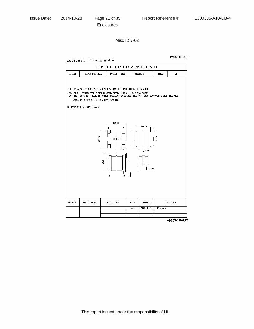
Issue Date: 2014-10-28 Page 21 of 35 Report Reference # E300305-A10-CB-4
Enclosures
This report issued under the responsibility of UL
Misc ID 7-02

Issue Date: 2014-10-28 Page 22 of 35 Report Reference # E300305-A10-CB-4
Enclosures
This report issued under the responsibility of UL
Misc ID 7-02
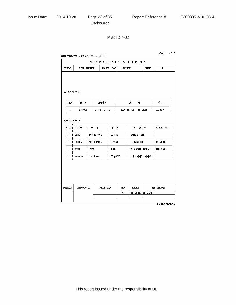
Issue Date: 2014-10-28 Page 23 of 35 Report Reference # E300305-A10-CB-4
Enclosures
This report issued under the responsibility of UL
Misc ID 7-02

Issue Date: 2014-10-28 Page 24 of 35 Report Reference # E300305-A10-CB-4
Enclosures
This report issued under the responsibility of UL
Misc ID 7-03
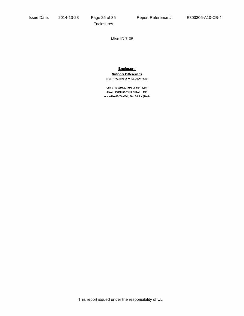
Issue Date: 2014-10-28 Page 25 of 35 Report Reference # E300305-A10-CB-4
Enclosures
This report issued under the responsibility of UL
Misc ID 7-05
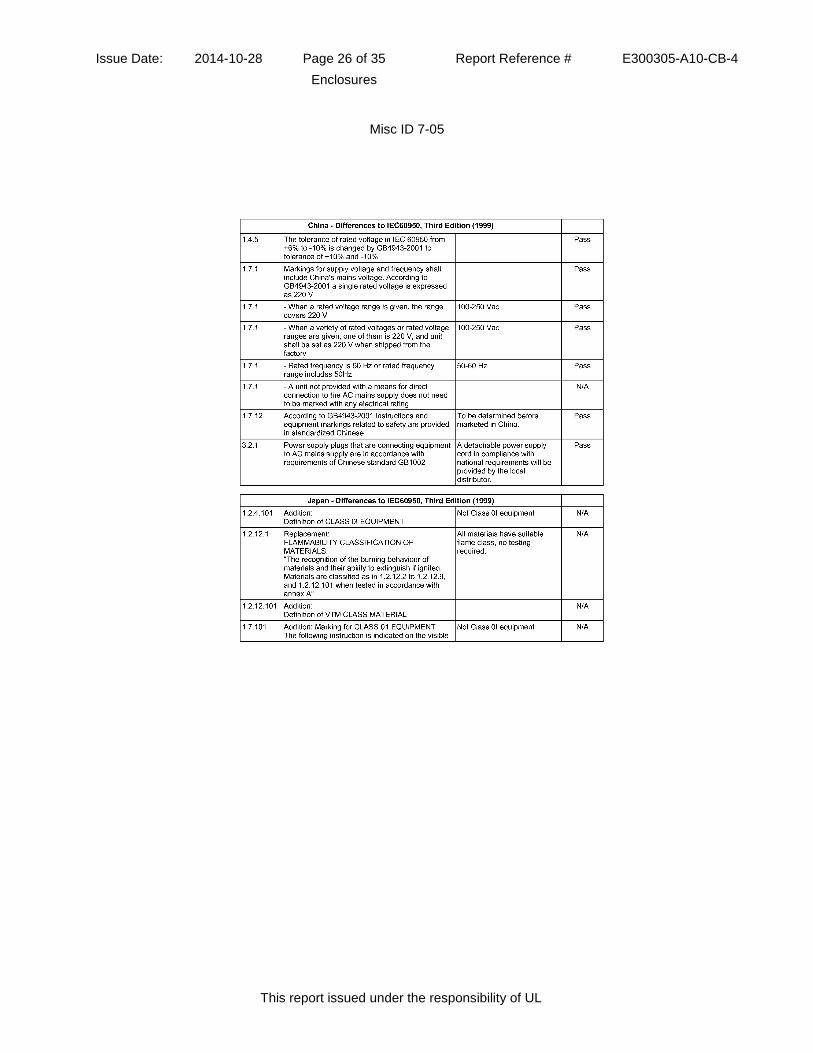
Issue Date: 2014-10-28 Page 26 of 35 Report Reference # E300305-A10-CB-4
Enclosures
This report issued under the responsibility of UL
Misc ID 7-05
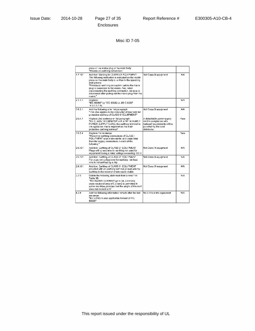
Issue Date: 2014-10-28 Page 27 of 35 Report Reference # E300305-A10-CB-4
Enclosures
This report issued under the responsibility of UL
Misc ID 7-05

Issue Date: 2014-10-28 Page 28 of 35 Report Reference # E300305-A10-CB-4
Enclosures
This report issued under the responsibility of UL
Misc ID 7-05
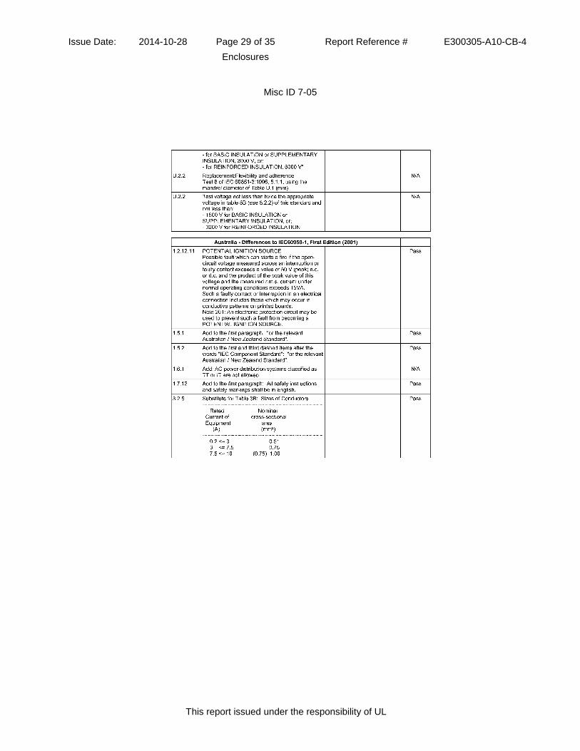
Issue Date: 2014-10-28 Page 29 of 35 Report Reference # E300305-A10-CB-4
Enclosures
This report issued under the responsibility of UL
Misc ID 7-05
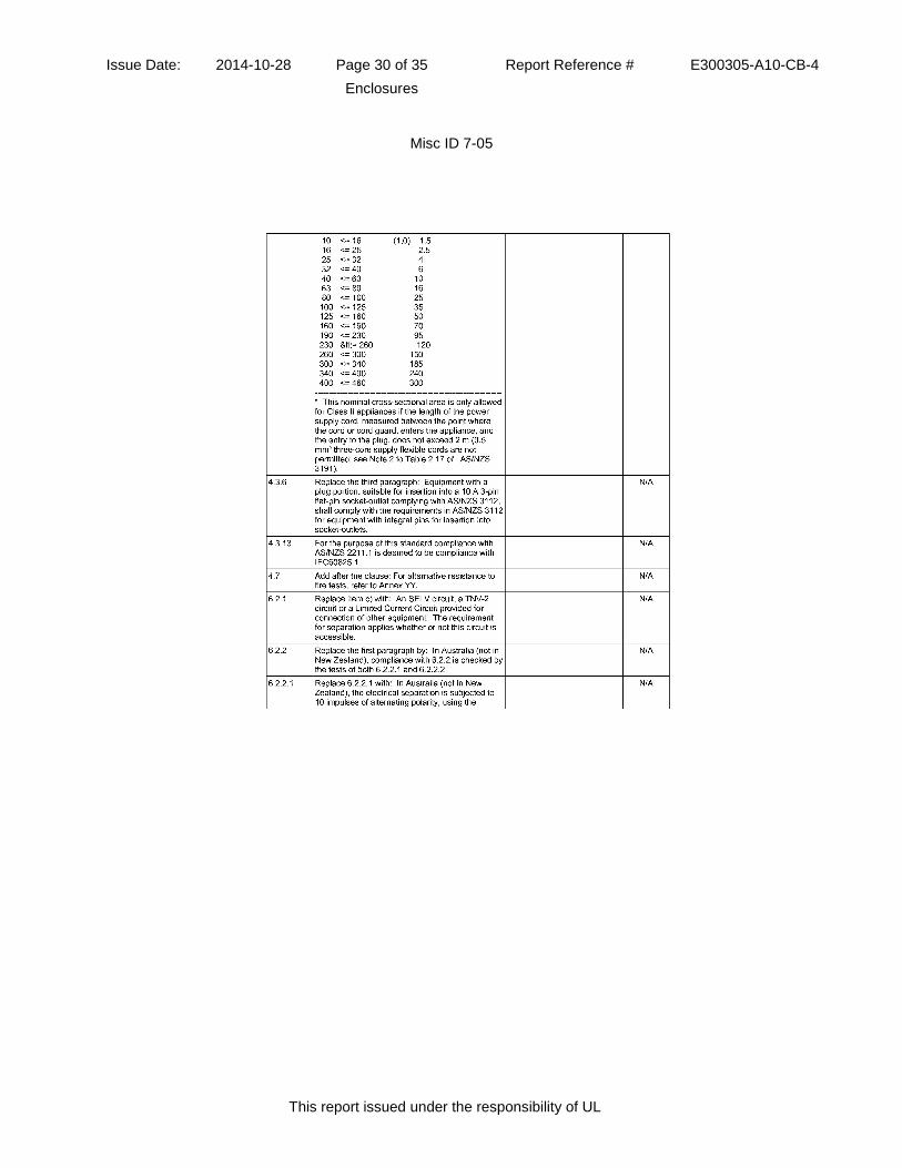
Issue Date: 2014-10-28 Page 30 of 35 Report Reference # E300305-A10-CB-4
Enclosures
This report issued under the responsibility of UL
Misc ID 7-05

Issue Date: 2014-10-28 Page 31 of 35 Report Reference # E300305-A10-CB-4
Enclosures
This report issued under the responsibility of UL
Misc ID 7-05

Issue Date: 2014-10-28 Page 32 of 35 Report Reference # E300305-A10-CB-4
Enclosures
This report issued under the responsibility of UL
Misc ID 7-07

Issue Date: 2014-10-28 Page 33 of 35 Report Reference # E300305-A10-CB-4
Enclosures
This report issued under the responsibility of UL
Misc ID 7-07
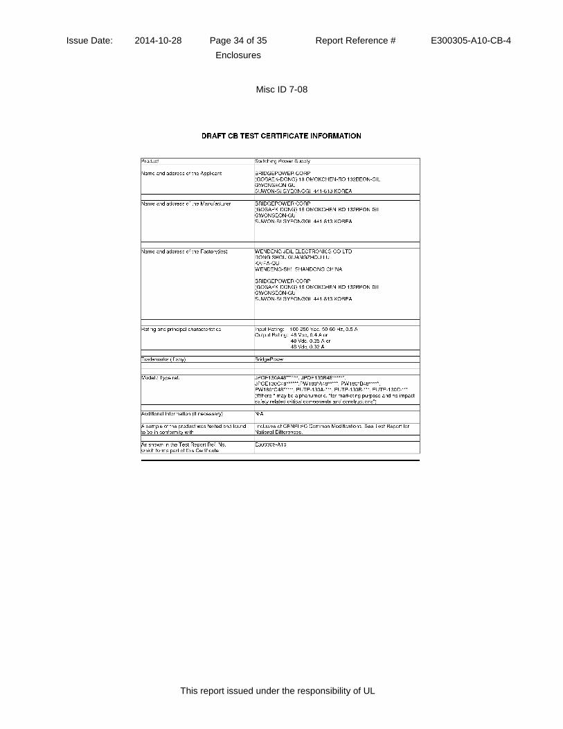
Issue Date: 2014-10-28 Page 34 of 35 Report Reference # E300305-A10-CB-4
Enclosures
This report issued under the responsibility of UL
Misc ID 7-08
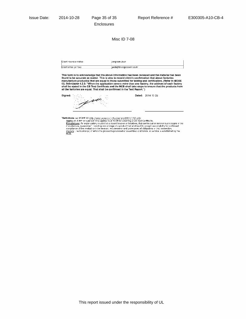
Issue Date: 2014-10-28 Page 35 of 35 Report Reference # E300305-A10-CB-4
Enclosures
This report issued under the responsibility of UL
Misc ID 7-08

���
������� �����
DK-41643-UL��$�,"��. ,0;C����5?�89DDDDDD7C����5? 89DDDDDD7C����5?89DDDDDD7����3�5?�3DDD7����3�5? 3DDD7����3�5?3DDD7�1�9?D�89DDDDD7�1�9?D 89DDDDD7�1�9?D89DDDDD�1(���D/.-6�.,+(.)%/�� &7L���/.�2�� )*+%�+�0�.)$)� /+.&�0.���-��,.��$&� � &.,&�/+�)�)�0.)$&�)0��%&� �)0L�
�.&��� �0;
1��"���C���������������""����!�������M!����:����3��1��"���3�!�7�!��"���( ).
�$$ � �).,�)���/.� �);�$$ � �).,,-�E.,%.��$����4?I@?3�;�??4����;�??I���;�?�?����;�?�����;�?�5J�.� �).," �����)&�00+�& � �$ )�(� ��0���+����
Additional information (if necessary)Information complémentaire (si nécessaire)
������7555�� )*0��)�$��4??4�7����(6���27���
���"�/2��7 ��%+E.)*@�":3�K@? .,,��%+7"�����:
���C��7�.�%)�%&( ��%0���'���. ) % ,$ )*4�7�3935�.�%)�%&( 7( -�$.32%7��2-��??3???@7C����
�����7K�)$��'� ���0��.$7����)��7���5 8�)�.� �7���"�
For full legal entity names see www.ul.com/ncbnames
� *).�%��;C.)3�� 2����*..�$
".��;�?�83�?3�9