test report iec 61558-2-16
126
-
Upload
khangminh22 -
Category
Documents
-
view
2 -
download
0
Transcript of test report iec 61558-2-16


TRF No. IEC61558_2_16C
Test Report issued under the responsibility of:
TEST REPORT IEC 61558-2-16
Safety of power transformers, power supplies, reactors and similar products for supply voltages up to 1100 V
Part 2: Particular requirements and tests for switch mode power supply units and transformers for switch mode power supply units
Report Number. .............................. : 50055232 001
Date of issue ................................... : Dec. 29, 2016
Total number of pages .................... 115
Name of Testing Laboratory preparing the Report ...................... :
TÜV Rheinland /CCIC (Ningbo) Co., Ltd. 3F, Building C13, R&D Park, No.32 , Lane 299 Guanghua Road,National Hi-Tech Zone, Ningbo, 315048, P. R. China
Applicant’s name ............................ : Wuxi Sans Electronic Co,.Ltd.
Address ........................................... : Industrial WuYi, DongGang Town, Wuxi, Jiangsu, P.R.China
Test specification:
Standard .......................................... : IEC 61558-2-16:2009 (First Edition) + A1:2013 used in conjunction with IEC 61558-1 (Second Edition) + A1:2009
Test procedure ............................... : CB Scheme
Non-standard test method ............. : N/A
Test Report Form No. ..................... : IEC61558_2_16C
Test Report Form(s) Originator..... : VDE Testing and Certification Institute
Master TRF ...................................... : Dated 2015-06
Copyright © 2015 IEC System of Conformity Assessment Schemes for Electrotechnical Equipment and Components (IECEE System). All rights reserved.
This publication may be reproduced in whole or in part for non-commercial purposes as long as the IECEE is acknowledged as copyright owner and source of the material. IECEE takes no responsibility for and will not assume liability for damages resulting from the reader's interpretation of the reproduced material due to its placement and context.
If this Test Report Form is used by non-IECEE members, the IECEE/IEC logo and the reference to the CB Scheme procedure shall be removed.
This report is not valid as a CB Test Report unless signed by an approved CB Testing Laboratory and appended to a CB Test Certificate issued by an NCB in accordance with IECEE 02.
General disclaimer:
The test results presented in this report relate only to the object tested. This report shall not be reproduced, except in full, without the written approval of the Issuing CB Testing Laboratory. The authenticity of this Test Report and its contents can be verified by contacting the NCB, responsible for this Test Report.


Page 3 of 115 Report No. 50055232 001
TRF No. IEC61558_2_16C
List of Attachments (including a total number of pages in each attachment):
Photo documentation (9 pages)
Summary of testing: Pass
Tests performed (name of test and test clause):
All applicable tests were performed. Details see appended clauses and tables.
The test samples are pre-production samples without serial numbers.
Testing location:
TÜV Rheinland /CCIC (Ningbo) Co., Ltd. 3F, Building C13, R&D Park, No.32 , Lane 299 Guanghua Road,National Hi-Tech Zone, Ningbo, 315048, P. R. China
Summary of compliance with National Differences:
EU Group Differences, EU Special National Conditions, AU.
Explanation of used code: AU=Australia
The product fulfils the requirements of IEC 61558-2-16:2009 (First Edition) + A1:2013 used in conjunction with IEC 61558-1 (Second Edition) + A1:2009 ; EN 61558-2-16:2009+A1 and EN 61558-1:2005+A1

Page 4 of 115 Report No. 50055232 001
TRF No. IEC61558_2_16C
Copy of marking plate:
Note: The artwork above may be only a draft. The use of certification marks on a product must be authorized by the respective NCBs that own these marks.

Page 5 of 115 Report No. 50055232 001
TRF No. IEC61558_2_16C
Test item particulars...................................................: AC/DC Power supply
Classification of installation and use.......................: Portable power supply
Supply Connection .....................................................: Appliance inlet
Possible test case verdicts:
- test case does not apply to the test object ........... : N/A
- test object does meet the requirement .................. : P (Pass)
- test object does not meet the requirement ........... : F (Fail)
Testing .......................................................................... :
Date of receipt of test item ........................................ : 2016-09-01
Date (s) of performance of tests ............................... : 2016-09-01 - 2016-12-28
General remarks:
"(See Enclosure #)" refers to additional information appended to the report. "(See appended table)" refers to a table appended to the report. Throughout this report a comma / point is used as the decimal separator.
Manufacturer’s Declaration per sub-clause 4.2.5 of IECEE 02:
The application for obtaining a CB Test Certificate includes more than one factory location and a declaration from the Manufacturer stating that the sample(s) submitted for evaluation is (are) representative of the products from each factory has been provided ............................................................... :
Yes
Not applicable
When differences exist; they shall be identified in the General product information section.
Name and address of factory (ies) .......................... : Wuxi Sans Electronic Co, .Ltd.
Industrial WuYi, DongGang Town, Wuxi, Jiangsu, P.R.China
General product information:
The equipment is switching mode power supplies intended for general use in the scope of this standard.
The equipment’s bottom enclosure is secured to top enclosure by ultrasonic.
The power supply cord was not provided together with the equipment. A suitable certified power supply cord set has to be evaluated when shipment.

Page 6 of 115 Report No. 50055232 001
IEC 61558-2-16
Clause Requirement + Test Result - Remark Verdict
TRF No. IEC61558_2_16C
8 MARKING AND OTHER INFORMATION P
8.1 Transformer marked with: P
a) rated supply voltage or voltage range (V) ......... : 100-240V P
b) rated output voltage (V) .................................... : See copy of marking plate P
c) rated output (VA, kVA or W) ............................. : N/A
d) rated output current (A) ..................................... : See copy of marking plate P
e) rated frequency (Hz) ......................................... : See copy of marking plate P
f) rated power factor (if not 1) ............................... : N/A
g) symbol AC for alternating current, or DC for direct current-output
See copy of marking plate P
h) symbol for electrical function (according to one or more part’s 2) in addition with the symbol for SMPS (IEC 61558-2-16:09)
For example:
P
i) manufacturer's name or trademark or name of the responsible vendor
See copy of marking plate P
j) model or type reference See copy of marking plate P
k) vector group according to IEC 60076 for three-phase transformer
N/A
l) symbol for Class II
P
m) symbol for Class III N/A
n) index IPXX if other than IP00 IP20 P
o) rated max. ambient temperature ta (if not 25 °C) ................................................................ :
N/A
p) rated minimum ambient temperature ta min, if <10° C and if a temperature sensitive device is used
N/A
q) short-time duty cycle: operating time Intermittent duty cycle: operating and resting time (e.g. 5min/30min)
N/A
r) for tw-marked transformers marked with the rated max. operating temperature, increased by multiples of 5 (e.g. tw 120; tw 125 )
N/A
s) transformers used with forced air cooling shall be marked with ”AF” in m/s
N/A
t) Information from the manufacturer to the purchaser (data sheet) :
N/A
– short-circuit voltage (% rated supply voltage) for stationary transformers > 1000 VA
N/A
– electrical function of the transformer N/A

Page 7 of 115 Report No. 50055232 001
IEC 61558-2-16
Clause Requirement + Test Result - Remark Verdict
TRF No. IEC61558_2_16C
8.2 Marking for transformers IP00 or for associated transformers: type and trademark, instruction sheets
N/A
8.3 Adjusted voltage easily and clearly discernible N/A
8.4 For each tapping or winding: rated output voltage and rated output
N/A
necessary connections clearly indicated N/A
8.5 For short-circuit proof transformers or non-inherently short-circuit proof transformers:
N/A
Rated current (A or mA) and symbol for time cur-rent characteristics of the fuses for non-inherently short-circuit proof transformer with incorporated fuses and non-short-circuit proof transformer ......... :
N/A
Manufacturer's model or type reference and rating of the device for non-inherently short-circuit proof transformers with incorporated replaceable protec-tive device (other than fuses)
N/A
Construction sheet for transformers with replaceable protective device (other than fuses) information with information about the replacement.
N/A
8.6 Terminals for neutral: "N" N/A
Terminal for protective earth marked with earthing symbol
N/A
Identification of input terminals: "PRI" N/A
Identification of output terminals: "SEC" N/A
Symbol for any point/terminal in connection with frame or core
N/A
8.7 Indication for correct connection P
8.8 Instruction sheet for type X, Y, Z attachments Output cord as Z attachment. P
8.9 Transformer for indoor use shall be marked with the relevant symbol.
P
8.10 Symbol for Class II construction not confused with maker's name or trademark.
P
Class II transformer with parts to be mounted – delivered with all parts for class II after mounting.
N/A
Symbol for class II transformer placed on the part which provides class II.
P
8.11 Correct symbols: P
Volts V P
Amperes A (mA) P
Volt amperes (or volt-amperes reactive for reactors) VA or (VAR) N/A

Page 8 of 115 Report No. 50055232 001
IEC 61558-2-16
Clause Requirement + Test Result - Remark Verdict
TRF No. IEC61558_2_16C
Watts W N/A
Hertz Hz P
Input N/A
Output N/A
Direct current P
Neutral N/A
Single-phase a.c. P
Three-phase a.c. N/A
Three-phase and neutral a.c. N/A
Power factor N/A
Class II construction
P
Class III construction N/A
Fuse-link P
Rated max. ambient temperature N/A
Frame or core terminal N/A
Protective earth N/A
IP number IP20 P
Earth (ground for functional earth) N/A
For indoor use only
P
tw5 YYY N/A
tw10 YYY N/A
twx YYY N/A
Additional Symbols (IEC 61558-2-16:09) P
SMPS incorporating a Fail-safe separating transformer
or
N/A
SMPS incorporating a Non-short-circuit-proof separating transformer
or
N/A
SMPS incorporating a Short-circuit-proof separating transformer (inherently or non-inherently) or
N/A
SMPS incorporating a Fail-safe isolating transformer or
N/A
SMPS incorporating a Non-short-circuit-proof isolating transformer
or
N/A

Page 9 of 115 Report No. 50055232 001
IEC 61558-2-16
Clause Requirement + Test Result - Remark Verdict
TRF No. IEC61558_2_16C
SMPS incorporating a Short-circuit-proof isolating transformer (inherently or non-inherently) or
N/A
SMPS incorporating a Fail-safe safety isolating transformer
N/A
SMPS incorporating a Non-short-circuit-proof safety isolating transformer
N/A
SMPS incorporating a Short-circuit-proof safety isolating transformer (inherently or non-inherently)
P
SMPS incorporating a Fail-safe auto-transformer or
N/A
SMPS incorporating a Non-short-circuit proof auto-transformer
or
N/A
SMPS incorporating a Short-circuit proof auto-transformer (inherently or non-inherently) or
N/A
SMPS (Switch mode power supply unit)
P
8.12 Figures, letters or other visual means for different positions of regulating devices and switches
N/A
OFF position indicated by figure 0 N/A
Greater output, input etc. indicated by higher figure N/A
8.13 Marking not on screws or other easily removable parts
P
Marking clearly discernible (transformer ready for use)
P
Marking for terminals clearly discernible if neces-sary after removal of the cover
N/A
Marking for terminals: no confusion between input and output
N/A
Marking for interchangeable protective devices po-sitioned adjacent to the base
N/A
Marking for interchangeable protective devices clearly discernible after removal of cover and pro-tective device
N/A
8.14 Special information for installation (in the catalogue, data sheet, or instruction sheet) if necessary:
P

Page 10 of 115 Report No. 50055232 001
IEC 61558-2-16
Clause Requirement + Test Result - Remark Verdict
TRF No. IEC61558_2_16C
For non-inherently short-circuit proof transformers with non-self-resetting or non-replaceable devices (weak-point, thermal link):
The device cannot be reset or replaced
N/A
For transformers generating a protective earth conductor current of 10 mA (see also cl. 18.5.2):
The installation shall be made according to the wiring rules.
N/A
For associated- and IP00-transformers:
At 10% over or under voltage in the supply voltage, the rated output of the transformer shall be selected accordingly.
N/A
For stationary transformers exceeding 1000 VA:
The short circuit voltage in % of the rated voltage
N/A
For all transformers the electrical function:
An information about the electrical function of the transformer (e.g. inherently short circuit proof safety isolating transformer)
P
For associated- and IP00-transformers:
The max. abnormal winding temperature
N/A
For tw-transformers:
The specific constant S is (e.g. S6 says S = 6000)
N/A
For transformers with more than one output winding, not for series or parallel connection
N/A
– an information in the instruction sheet: the transformer is not intended for series/parallel connection
N/A
For IP00-transformers the test of 27.2 is not performed. The result may be affected by the enclosure in the final application.
N/A
8.15 Marking durable and easily legible P
9 PROTECTION AGAINST ELECTRIC SHOCK P
9.1 Protection against contact with hazardous live parts P
9.1.1 A live part is not a hazardous live part if: P
– it is separated from the supply by double or reinforced insulation
P
– the requirements of 9.1.1.1 or 9.1.1.2 are fulfilled
P
9.1.1.1 The touch voltage is <35 V(peak) a.c. or < 60 Vd.c. Measured maximum output voltage: 54.6Vd.c.
P

Page 11 of 115 Report No. 50055232 001
IEC 61558-2-16
Clause Requirement + Test Result - Remark Verdict
TRF No. IEC61558_2_16C
9.1.1.2 If the touch voltage is > 35 V (peak)a.c. or > 60 V d.c., the following requirements shall be fulfilled:
N/A
The touch current shall not exceed: N/A
– for a.c. 0,7 mA (peak) N/A
– for d.c. 2,0 mA (see Annex J) N/A
In addition, when a capacitor is connected to live parts:
—
9.1.1.2.1 discharge: < 45 V and 15 kV) N/A
9.1.1.2.2 energy: < 350 mJ (voltage >15 kV) N/A
9.1.2 Transformers shall have an adequate protection against accessibility to hazardous live parts:
P
The enclosure of class I and class II transformers gives an adequate protection against accentual contact with hazardous live parts.
P
Class I transformers: accessible parts are separated from hazardous live parts by at least basic insulation.
N/A
Class II transformers: no accessibility to basic insulation, or conductive parts separated from hazardous live parts by basic insulation.
P
Hazardous live parts are not accessible after removal of detachable parts.
N/A
Hazardous live parts are not accessible after removal of detachable parts except for:
N/A
– lamps having caps larger B9 and E10 N/A
– type D fuse holder N/A
Lacquers, enamel, paper, cotton, oxide film on metal parts not used for protection against acci-dental contact with hazardous live parts:
P
Shafts, handles, operating levers, knops are not hazardous life parts.
N/A
Compliance is checked by inspection and by relevant tests according to IEC 60 529
P
Class II transformers and Class II parts of Class I construction are tested with the test pin (fig. 3)
P
Hazardous live parts shall not be touchable by test finger (fig. 2)
P
for Class II transformers: metal parts separated by basic insulation from hazardous live parts not touchable by test finger
P

Page 12 of 115 Report No. 50055232 001
IEC 61558-2-16
Clause Requirement + Test Result - Remark Verdict
TRF No. IEC61558_2_16C
hazardous live parts shall not be touchable with the test pin
P
9.1.3 Accessibility of non-hazardous live parts P
Non-hazardous live parts of the output circuit may be accessible if they are isolated from the input circuit by double or reinforced insulation and if the following conditions are fulfilled:
P
– The no load output voltage is < 35 V peak a.c. or < 60 V ripple free d.c., both poles are accessible
Max. No load voltage 54.19Vd.c.
P
– The no load output voltage is > 35 V peak a.c. or > 60 V ripple free d.c. and < 250 V a.c., only one pole may be accessible
N/A
9.2 Transformers with primary supply plug: 1 s after the interruption of the supply the voltage between the pins do not exceed 35 V (peak) a.c. or 60 V ripple free d.c.
Measured: 8V P
Transformers without a primary supply plug: 5 s after the interruption of the supply the voltage between the input terminals do not exceed 35 V (peak) a.c. or 60 V ripple free d.c.
N/A
The following tests are required : P
If the nominal capacitance is < 0,1 µF – no test is conducted.
Total 0.80uF N/A
– 10 times switch the supply source on and off, or use a special equipment for to switch off at the most unfavourable electrical angle
P
If the measured voltage is > 60 V ripple free d.c., the discharge must be < 45 µC.
N/A
10 CHANGE OF INPUT VOLTAGE SETTING P
Voltage setting not possible to change without a tool
N/A
Different rated supply voltages: N/A
– indication of voltage for which the transformer is set, is discernible on the transformer.
N/A
10.101 A wide range of the input (120 V a. c, to 240 V a.c voltage is allowed (IEC 61558-2-16:09):
P
– if the output voltages does not exceed the rated output voltage
P
– if the no-load voltage does not exceed the limits of output voltage deviation
P

Page 13 of 115 Report No. 50055232 001
IEC 61558-2-16
Clause Requirement + Test Result - Remark Verdict
TRF No. IEC61558_2_16C
11 OUTPUT VOLTAGE AND OUTPUT CURRENT UNDER LOAD P
11.1 Difference from rated value (without rectifier; with rectifier):
P
a) inherently short-circuit proof transformers with one rated output voltage for output voltage:
a.c. 10% ; d.c. 15%
N/A
b) inherently short-circuit proof transformers with one more than 1 rated output voltage for
highest output voltage: a.c. 10%; d.c. 15%
N/A
c) idem for other output voltages: a.c. 15%;
d.c. 20%
N/A
d) other transformers for output voltages:
a.c. 5%; d.c. 10%
(see appended table) P
12 NO-LOAD OUTPUT VOLTAGE (see supplementary requirements in Part 2) P
Remark: with rectifier measuring on both sides of the rectifier
The rectifier is not accessible N/A
12.101 The no load output voltage shall not exceed (IEC 61558-2-16:09):
P
– For SMPS incorporating separating or auto-transformers: 1000V a.c. or 1415 V ripple free d.c.
N/A
– For SMPS including isolating transformers: 500 V a.c. or 708 V ripple-free d.c.
N/A
– For SMPS including safety isolating transformers: 50 V a.c. or 120 V ripple-free d.c.
(see appended table) P
For independent transformers, this output voltage limitation applies even when output windings, not for interconnection, are connected in series
N/A
12.202 The difference between output voltage at no load and the output voltage measured in clause 11 does not exceed the values of table 101 (IEC 61558-2-16:2009), Rated output (VA) Rated value %
(see appended table) P
13 SHORT-CIRCUIT VOLTAGE N/A
Difference from marking for short-circuit voltage 20%
N/A
14 HEATING P

Page 14 of 115 Report No. 50055232 001
IEC 61558-2-16
Clause Requirement + Test Result - Remark Verdict
TRF No. IEC61558_2_16C
14.1 General requirements P
No excessive temperature in normal use P
Room temperature: rated ambient temperature ta + 5 °C
—
Type X, Y, Z attachments: 1 pull (5 N) to the con-nection windings
For output cord.
Upri (V): 1,1 times rated supply voltage loaded with rated impedance – for independent transformers
(see appended table) —
Upri (V): 1,1 times rated supply voltage: with I sec (A), measured with rated impedance and 1,0 times of the rated supply voltage for others than independent transformers
—
Type X, Y, Z attachments: 1 pull (5 N) to the con-nection windings
For output cord. P
Max. temperature windings ...................................... : P
– Class A: 100 °C N/A
– Class E: 115 °C N/A
– Class B: 120 °C (see appended table 14) P
– Class F: 140 °C N/A
– Class H: 165 °C N/A
– other classes N/A
Temperature of external enclosures of stationary transformers:
N/A
– metal: 70 °C N/A
– other material: 80 °C N/A
Temperature of external enclosure of stationary
transformer 85 °C (not touchable with the IEC test finger)
N/A
Temperature of external enclosures, handles, etc. of portable transformers:
P
– continuously held parts of metal: 55 °C N/A
– continuously held parts of other material:
75 °C
N/A
– not continuously held parts of metal: 60 °C N/A
– not continuously held parts of other material:
80 °C
(see appended table 14) P

Page 15 of 115 Report No. 50055232 001
IEC 61558-2-16
Clause Requirement + Test Result - Remark Verdict
TRF No. IEC61558_2_16C
Temperature of terminals for external conductors
70 °C
N/A
Temperature of terminals of switches 70 °C N/A
Temperature of internal and external wiring: (see appended table 14) P
– rubber: 65 °C N/A
– PVC: 70 °C P
Temperature of parts where safety can be affected: N/A
– rubber: 75 °C N/A
– phenol-formaldehyde: 105 °C N/A
– urea-formaldehyde: 85 °C N/A
– impregnated paper and fabric: 85 °C N/A
– impregnated wood: 85 °C N/A
– PVC, polystyrene and similar thermoplastic ma-
terial: 65 °C
N/A
– varnished cambric: 75 °C N/A
Temperature rise of supports 85 °C (see appended table 14) P
Temperature of printed boards: (see appended table 14) P
– bonded with phenol-formaldehyde: 105 °C N/A
– melamine-formaldehyde: 105 °C N/A
– phenol-furfural: 105 °C N/A
– polyester: 105 °C N/A
– bonded with epoxy: 140 °C N/A
Electric strength between input and output windings (18.3, 1 min); test voltage (V) .................................. :
4200V P
14.101 Winding temperature measured by thermocouples at the surface of the winding(IEC 61558-2-16:09)
P
– if the internal frequencies is > 1kHz P
– the values of Table 1 for windings temperatures are reduced by 10°C
P
14.2 Application of 14.1 or 14.3 according to the insulation system
P
14.2.1 Class of isolating system (classified materials according to IEC 60 085 and IEC 60 216)
Class B P

Page 16 of 115 Report No. 50055232 001
IEC 61558-2-16
Clause Requirement + Test Result - Remark Verdict
TRF No. IEC61558_2_16C
14.2.2 No classified material, or system but the measured temperature does not exceed the value of Class A
N/A
14.2.3 No classified material or system but the measured temperature exceeds the value for Class A, the live parts of the transformers are submitted to the test of 14.3
N/A
14.3 Accelerated ageing test for undeclared class of isolating system
N/A
Cycling test (10 cycles): N/A
– measuring of the no-load input current (mA) N/A
14.3.1 – heat run (temperature in table 2) N/A
14.3.2 – vibration test: 30 min; amplitude 0,35 mm; fre-quency range: 10 Hz, 55 Hz, 10 Hz
N/A
14.3.3 – moisture treatment (48 h, 17.2) N/A
14.3.4 Measurements and tests at the beginning and after each test:
N/A
– deviation of the no-load input current, 30%
N/A
– insulation resistance acc. cl.18.1 and 18.2 N/A
– electric strength, no breakdown (18.3); 2 min; test voltage 35% of specified value (table VI)
N/A
– Transformers (50 or 60 Hz version) are tested after the dielectric strength test as follows: under no load; duration: 5 min; Upri(V):1,2 times rated supply voltage; frequency (Hz): 2 times rated frequency
N/A
15 SHORT-CIRCUIT AND OVERLOAD PROTECTION P
15.1 General P
Tests direct after 14.1 at the same ta and without changing position.
(see appended table 15) P
Supply voltage between 0,9 times and 1,1 times of the rated supply voltage
(see appended table 15) —
Transformer with rectifier tests of 15.2 and 15.3 at the input and the output terminals of the rectifier.
N/A
Transformers with more than one output winding or tapping, all windings tested with normal load, the winding with the highest temperature is short circuited.
N/A
Wining protected inherently (15.2) N/A

Page 17 of 115 Report No. 50055232 001
IEC 61558-2-16
Clause Requirement + Test Result - Remark Verdict
TRF No. IEC61558_2_16C
– Max. temperature of winding protected
inherently (insulation class): 150 °C (A);
165 °C (E); 175 °C (B); 190 °C (F);
210 °C (H)
The equipment is non-inherently short-circuit proof transformer, see 15.3.
N/A
Winding protected by protective device: P
– Test according 15.3.2 - 15.3.3 – 15.3.4: max. temperature of winding during the time required or the time T given in table 4 (a) (insulation
class): 200 °C (A); 215 °C;(E); 225 °C
(B); 240 °C (F); 260 °C (H)
N/A
– Test according 15.3.1: max. temperature of winding during the first hour, peak value
(insulation class): 200 °C (A); 215°C (E);
225 °C (B); 240°C (F); 260 °C (H)
N/A
– Test according 15.3.1: max. temperature of winding after first hour, peak value (insulation
class): 175 °C (A); 190 °C (E); 200 °C
(B); 215 °C (F); 235 °C (H)
P
– Test according 15.3.1: max. temperature of winding after first hour, arithmetic mean
value (insulation class): 150
165 °C (E); 175 °C (B); 190 °C (F);
210 °C (H)
N/A
Max. temperature of external enclosures (accessi-
ble by test finger) 105 °C
(see appended table 15) P
Max. temperature of insulation of wiring (rubber and
PVC) 85 °C
(see appended table 15) P
Temperature rise of supports 105 °C (see appended table 15) P
15.2 For inherently short-circuit proof transformers and for transformers with rectifiers test by short circuit of the output winding at rated supply voltage x 1,1:
values in table 3
N/A
15.3 For non-inherently short-circuit proof transformers and for transformers with rectifiers: temperature
values in table 3
P
15.3.1 Output terminals short-circuited: protection device operates, test at 0,9 … 1,1 of the rated supply voltage
Protected by electronic circuit. P
15.3.2 If protected by a fuse accordance with either IEC 60 269-2 or IEC 60 269-3, or a technical equivalent fuse, the transformer is loaded as in ta-ble 4.
N/A

Page 18 of 115 Report No. 50055232 001
IEC 61558-2-16
Clause Requirement + Test Result - Remark Verdict
TRF No. IEC61558_2_16C
15.3.3 If protected by a fuse accordance with either
IEC 60 127 or ISO 8820, or a technical equivalent fuse, the transformer is loaded with the current as specified for the longest pre arcing time.
If protected by a miniature fuses in accordance to IEC 60127, 1,5 times of the rated fuse, until steady state condition (in addition)
N/A
15.3.4 If protected by a circuit-breaker according to IEC 60 898 the transformer is loaded with a current equal to 1,45 times the value of the circuit-breaker rated current
N/A
15.3.5 If other overload protection than a fuse (IEC 60 127) or a circuit-breaker (IEC 60 898) test with 0,95 times of operating current
(See appended table 15) P
If an internal week point is used, the test must be repeated with two new samples. The two additional samples works similar to the first sample.
Temperatures in the limit of table 3
N/A
15.4 For non-short-circuit proof transformers: values in table 3, tests as
indicated in 15.3
N/A
15.5 For fail-safe transformers: N/A
15.5.1 Three additional new specimens are used —
– Upri (V): 1,1 times rated supply voltage ........... : —
– Isec (A): 1,5 times rated output current ............ : —
– time until steady-state conditions t1 (h) ............ : —
– time until failure t2 (h): t1; 5 h ..................... : N/A
15.5.2 During the test: N/A
– no flames, molten material, etc. N/A
– temperature of enclosure 175 °C N/A
– temperature of plywood support 125 °C N/A
After the test: N/A
– electric strength (Cl. 18, 1 min, test voltage: 35% of specified value); no flashover or break- down for primary-to-secondary only for safety isolating, isolating and separating transformer and for primary-to-body for all kinds of transformer
N/A
– bare hazardous live parts not accessible by test finger through holes of enclosure
N/A

Page 19 of 115 Report No. 50055232 001
IEC 61558-2-16
Clause Requirement + Test Result - Remark Verdict
TRF No. IEC61558_2_16C
15.101 Electronic circuits of the SMPS fulfil the requirements of Annex H of part 1. After a fault: no electric shock, no fire hazard and no unintentional operation.
(Details see Annex H) P
16 MECHANICAL STRENGTH P
16.1 General P
After tests of 16.2, 16.3 and 16.4 P
– no damage P
– hazardous live parts not accessible by test pin according to 9.2
P
– no damage for insulating barriers P
– handles, levers, etc. have not moved on shafts No such parts N/A
16.2 Transformers (stationary and portable s. 16.1) Portable P
For stationary and portable transformers: 3 blows, impact energy 0,5 Nm
P
16.3 Portable transformers (except of plug in transformers)
P
For portable transformers: 100 falls, 25 mm P
16.4 Transformers with integrated pins (plug in transformers), the following tests are carried out:
N/A
a) plug-in transformers: tumbling barrel test:
50 x 250 g; 25 x 250 g
N/A
b) torque test of the plug pins with 0,4 Nm N/A
c) pull force according to table 5 for each pin N/A
17 PROTECTION AGAINST HARMFUL INGRESS OF WATER AND MOISTURE P
17.1 Degree of protection (IP code marked on the transformer)
IP20 P
Test according to 17.1.1 and for other IP ratings test according to IEC 60 529:
P
– stable operating temperature before starting the test for < IPX8
N/A
– transformer mounted and wired as in normal use
P
– fixed transformer mounted as in normal use by the tests according to 17.1.1 A to L
N/A
Page 20 of 115 Report No. 50055232 001
IEC 61558-2-16
Clause Requirement + Test Result - Remark Verdict
TRF No. IEC61558_2_16C
– portable transformers placed in the most unfa-vourable position and wired as in normal use
P
– glands tightened with a torque equal to two-thirds of 25.6
N/A
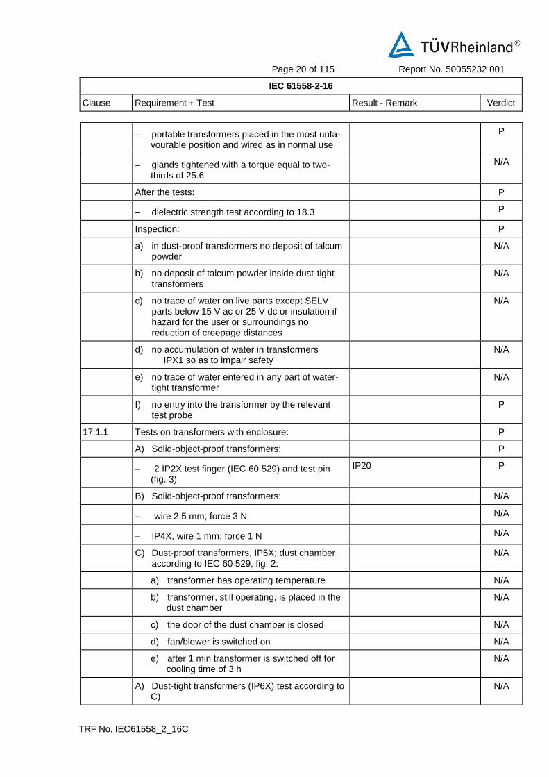
After the tests: P
– dielectric strength test according to 18.3 P
Inspection: P
a) in dust-proof transformers no deposit of talcum powder
N/A
b) no deposit of talcum powder inside dust-tight transformers
N/A
c) no trace of water on live parts except SELV parts below 15 V ac or 25 V dc or insulation if hazard for the user or surroundings no reduction of creepage distances
N/A
d) no accumulation of water in transformers IPX1 so as to impair safety
N/A
e) no trace of water entered in any part of water-tight transformer
N/A
f) no entry into the transformer by the relevant test probe
P
17.1.1 Tests on transformers with enclosure: P
A) Solid-object-proof transformers: P
– 2 IP2X test finger (IEC 60 529) and test pin (fig. 3)
IP20 P
B) Solid-object-proof transformers: N/A
– wire 2,5 mm; force 3 N N/A
– IP4X, wire 1 mm; force 1 N N/A
C) Dust-proof transformers, IP5X; dust chamber according to IEC 60 529, fig. 2:
N/A
a) transformer has operating temperature N/A
b) transformer, still operating, is placed in the dust chamber
N/A
c) the door of the dust chamber is closed N/A
d) fan/blower is switched on N/A
e) after 1 min transformer is switched off for cooling time of 3 h
N/A
A) Dust-tight transformers (IP6X) test according to C)
N/A

Page 21 of 115 Report No. 50055232 001
IEC 61558-2-16
Clause Requirement + Test Result - Remark Verdict
TRF No. IEC61558_2_16C
B) Drip-proof transformers (IPX1) test according to fig. 3 of IEC 60 529 for 10 min
N/A
C) Rain-proof transformers (IPX2) test according to fig. 3 of IEC 60 529 for 10 min in operation, any angle up to 15°
N/A
D) Spray proofed transformers (IPX3) test according to fig. 4 of IEC 60 529 for 10 min in operation and 10 min switched off , time for complete oscillation (2 x 120°) is 4 sec.
N/A
E) Splash-proof transformers (IPX4) test according to fig. 4 of IEC 60 529 (see F) for 10 min in operation and 10 min switched off
(the tube shall oscillate 360
N/A
F) Jet-proof transformer (IPX5) test according to fig. 6 of IEC 60 529 (nozzle 6,3mm)
N/A
G) Powerful Jet-proof transformer (IPX6) test according to fig. 6 of IEC 60 529 (nozzle 12 mm)
N/A
H) Watertight transformers (IPX7) N/A
I) Pressure watertight transformers (IPX8) N/A
17.2 After moisture test (48 IP20, 168 h for other transformers):
48h P
– insulation resistance and electric strength (Cl. 18)
P
18 INSULATION RESISTANCE AND ELECTRIC STRENGTH P
18.2 Insulation resistance between: P
– live parts and body for basic insulation 2 MΩ N/A
– live parts and body for reinforced insulation
7 MΩ
Between primary and enclosure: 100MΩ
P
– input circuits and output circuits for basic
insulation 2 MΩ
N/A
– input circuits and output circuits for double or
reinforced insulation 5 MΩ
Between input and output:
100 MΩ
T2 primary to secondary:
100 MΩ
core to secondary:
100 MΩ
P
– each input circuit and all other input circuits
connected together 2 MΩ
N/A

Page 22 of 115 Report No. 50055232 001
IEC 61558-2-16
Clause Requirement + Test Result - Remark Verdict
TRF No. IEC61558_2_16C
– each output circuit and all other output circuits
connected together 2 MΩ
N/A
– hazardous live parts and metal parts with basic
insulation (Class II transformers) 2 MΩ
N/A
– body and metal parts with basic insulation
(Class II transformers) 5 MΩ
N/A
– metal foil in contact with inner and outer sur-
faces of enclosures 2 MΩ
N/A
18.3 Electric strength test (1 min): no flashover or break-down:
P
1) basic insulation between input circuits and out-put circuits; working voltage (V); test voltage (V) :
N/A
2) double or reinforced insulation between input circuits and output circuits; working voltage (V); test voltage (V) .................................................. :
Between input and output: 4200V
T2 primary to secondary: 4200V
P
3) basic or supplementary insulation between: P
a) live parts of different polarity; working voltage (V); test voltage (V) ........................ :
Between L/N after fuse open-circuit: 2100V
P
b) live parts and the body if intended to be connected to protective earth ..................... :
N/A
c) inlet bushings and cord guards and an-chorages ..................................................... :
N/A
d) live parts and an intermediate conductive part .............................................................. :
N/A
e) intermediate conductive parts and body ..... : N/A
4) Reinforced insulation between the body and live parts; working voltage (V); test voltage (V) :
Between primary and enclosure 4200V
P
5) Functional insulation for windings intended to be connected in series or parallel (test voltage = working voltage + 500 V) (IEC 61558-2-16:09)
N/A
18.4 Does not apply (IEC 61558-2-16:09) -
18.101 Impulse test according Table F5 of IEC 60664-1 with 1,2/50 µs (IEC 61558-2-16)
4923Vpeak applied P
– After the test of 18.3, 10 impulses of each polarity between input and output terminals
P
– During the tests no breakdown of the insulation between turns of a winding, between input and output circuits, or between windings and any conductive core
P

Page 23 of 115 Report No. 50055232 001
IEC 61558-2-16
Clause Requirement + Test Result - Remark Verdict
TRF No. IEC61558_2_16C
18.102 (A1)
Partial discharge tests according to IEC 60664-1 , if the working voltage is > 750 V peak
N/A
Partial discharge is < 10 pC at time P2
See Fig. 19.101
N/A
18.5 Touch current and protective earth current P
18.5.1 Touch current P
Touch current measured after the clause 14 test (hot) for class I and class II transformers (class II transformers with metal foil at the plastic surface). The test circuit according figure 8. Measuring network according Figure J1 (Annex J). If the frequency is >30kHz, measuring across the 500 Ohm resistor of J1 (burn effects).
P
Measurement of the touch current with switch p of picture 8 in both positions and in combination with switches e and n. The measured values are less than the required values of table 8b.
P
– switches n and e in on position 0.148mA max. between output to L/N
0.088mA max. between enclosure to L/N
P
– switch n: off and switch e: on 0.148mA max. between output to L/N
0.088mA max. between enclosure to L/N
P
– switch n: on and switch e: off 0.148mA max. between output to L/N
0.088mA max. between enclosure to L/N
P
18.5.2 Protective earth conductor current N/A
The transformer is connected as in clause 14
Impedance of the ammeter < 0,5 Ohm, connected between earth terminal of the transformer and protective earth conductor
N/A
The measured values are less than the required values of table 8b.
N/A
19 CONSTRUCTION P
19.1 Separation of input and output circuits P
19.1.1 SMPS incorporating auto-transformers (IEC 61558-2-16:2009)
N/A

Page 24 of 115 Report No. 50055232 001
IEC 61558-2-16
Clause Requirement + Test Result - Remark Verdict
TRF No. IEC61558_2_16C
19.1.1.1 For plug connected auto-transformers with rated in-put voltage > rated output voltage the potential to earth shall not exceed the rated output voltage. (IEC 61558-2-16:2009)
N/A
19.1.1.2 SMPS with polarised input and output plug and socket-outlet system: an instruction is given with the information, that the transformer shall not be used with non-polarised plug and socket outlet system. (IEC 61558-2-16:2009)
N/A
19.1.1.3 A polarity detecting device only energises the output in the case: output potential to earth < rated output voltage, also with reversed input plug. (IEC 61558-2-16:2009)
N/A
– The contact separation of the device is > 3mm N/A
– A current to earth does not exceed 0,75 mA. N/A
– All tests are repeated under fault conditions of H.2.3 of annex H of part 1. The potential to earth does not exceed the max output voltage for more than 5 s.
N/A
19.1.2 SMPS incorporating separating transformers (IEC 61558-2-16:09)
N/A
19.1.2.1 Input and output circuits electrically separated. (IEC 61558-2-16:09)
N/A
19.1.2.2 The insulation between input and output winding(s) consist of basic insulation (IEC 61558-2-16:09)
N/A
Class I SMPS N/A
– Insulation between input windings and body consist of basic insulation
N/A
– Insulation between output windings and body consist of basic insulation
N/A
Class II SMPS (IEC 61558-2-16:2009) N/A
– Insulation between input windings and body consist of double or reinforced insulation
N/A
– Insulation between output windings and body consist of double or reinforced insulation
N/A
19.1.2.3 The insulation between input windings and intermediate conductive parts and the output windings and intermediate part consist of basic insulation (IEC 61558-2-16:09)
N/A
For class I SMPS the insulation between input and output windings via the intermediate conductive parts consist of basic insulation (IEC 61558-2-16:2009)
N/A

Page 25 of 115 Report No. 50055232 001
IEC 61558-2-16
Clause Requirement + Test Result - Remark Verdict
TRF No. IEC61558_2_16C
For class II SMPS the insulation between input winding and the body and between the output windings and the body via the intermediate conductive parts consist of double or reinforced insulation. (IEC 61558-2-16:2009)
N/A
19.1.2.4 Parts of output circuits may be connected to protective earth (IEC 61558-2-16:09)
N/A
19.1.2.5 No direct contact between output circuits and the body, unless: (IEC 61558-2-16:2009)
N/A
– Allowed for associated transformers by the equipment standard
N/A
– Clause 19.8 of part 1 is fulfilled N/A
19.1.3 SMPS incorporating isolating transformers and safety isolating transformers (IEC 61558-2-16:09)
P
19.1.3.1 Input and output circuits electrically separated (IEC 61558-2-16:09)
P
No possibility of any connection between these cir-cuits
P
19.1.3.2 The insulation between input and output winding(s) consist of double or reinforced insulation (exception see 19.1.3.4) (IEC 61558-2-16:09)
P
Class I SMPS not intended for connection to the mains by a plug:
—
– Insulation between input windings and body connected to earth consist of basic insulation rated to the input voltage
N/A
– Insulation between output windings and body, connected to earth consist of basic insulation rated for the output voltage
N/A
Class I SMPS intended for connection to the mains by a plug (EN 61558-2-16:09):
N/A
– Insulation between input windings and body connected to earth consist of basic insulation rated to the working voltage
N/A
– Insulation between output windings and body, connected to earth consist of supplementary insulation rated for the working voltage
N/A
Class II SMPS (IEC 61558-2-16:2009) P
– Insulation between input windings and body consist of double or reinforced insulation rated to the input voltage
P

Page 26 of 115 Report No. 50055232 001
IEC 61558-2-16
Clause Requirement + Test Result - Remark Verdict
TRF No. IEC61558_2_16C
– Insulation between output windings and body consist of double or reinforced insulation, rated to the output voltage
P
19.1.3.3 SMPS with intermediate conductive parts not connected to the body (between input/output) (EN 61558-2-16:09):
N/A
19.1.3.3.1 For class I and class II SMPS the insulation between input and output windings, via intermediate conductive parts, consist of double or reinforced insulation, rated to the working voltage (EN 61558-2-16:09).
P
– For class II SMPS the insulation between input winding and the body and between the output windings and the body via the intermediate conductive parts consist of double or reinforced insulation. (rated to the input voltage, for SELV circuits only basic insulation to the body)
N/A
– For transformers, different from independent, the insulation between input and output windings, via intermediate conductive parts, consist of double or reinforced insulation, rated to the working voltage.
P
19.1.3.3.2 Class I transformers with earthed core, and not allowed for class II equipment (EN 61558-2-16:09)
N/A
– Insulation from the input to the earthed core: basic insulation rated for the input voltage
N/A
– Insulation from the output voltage to the earthed core: basic insulation rated for the output voltage
N/A
19.1.3.3.3 Insulation between : input to intermediate conductive parts and output and intermediate parts consist of at least basic insulation (EN 61558-2-16:09)
P
– If the insulation from input or output to the intermediate metal part is less than basic insulation, the part is considered to be connected to input or output.
N/A
19.1.3.4 For class I SMPS, with protective screen, not connected to the mains by a plug the following conditions comply (EN 61558-2-16:09):
Class II SMPS N/A
– The insulation between input winding and protective screen consist of basic insulation (rated input voltage)
N/A

Page 27 of 115 Report No. 50055232 001
IEC 61558-2-16
Clause Requirement + Test Result - Remark Verdict
TRF No. IEC61558_2_16C
– The insulation between output winding and protective screen consist of basic insulation (rated output voltage)
N/A
– The protective screen consist of metal foil or a wire wound screen extending the full width of the windings and has no gaps or holes
N/A
– Where the protective screen does not cover the entire width of the input winding, additional insulation to ensure double insulation in this area, is used.
N/A
– If the screen is made by a foil, the turns are isolated, overlap at least 3 mm
N/A
– The cross-section of the screen and the lead out wire is at least corresponding to the rated current of the overload device
N/A
– The lead out wire is soldered or fixed to the protective screen.
N/A
Protective screening is not allowed for SMPS with plug connection to the mains (EN 61558-2-16:09)
N/A
19.1.3.5 No connection between output circuit and protective earth, except of associated transformers (allowed by equipment standard) or 19.8 is fulfilled (EN 61558-2-16:09).
N/A
19.1.3.6 No connection between output circuit and body, except of associated transformers (allowed by equipment standard) (EN 61558-2-16:09)
P
19.1.3.7 The distance between input and output terminals 25 mm
N/A
19.1.3.8 Portable SMPS having an rated output < 630 VA (EN 61558-2-16:09)
P
19.1.3.9 No connection between output circuit and body except of associated transformers (allowed by equipment standard) (EN 61558-2-16:09)
P
19.1.3.10 Protective screening is not allowed for SMPS with plug connection to the mains (EN 61558-2-16:09)
N/A
19.2 Fiercely burning material not used P
Unimpregnated cotton, silk, paper and fibrous ma-terial not used as insulation
P
Wax-impregnated, etc. not used P
19.3 Portable transformer: short-circuit proof or fail-safe P
19.4 Class II transformers: contact between accessible metal parts and conduits or metal sheaths of supply wiring impossible
N/A

Page 28 of 115 Report No. 50055232 001
IEC 61558-2-16
Clause Requirement + Test Result - Remark Verdict
TRF No. IEC61558_2_16C
19.5 Class II transformers: part of supplementary or re-inforced insulation, during reassembly after routine servicing not omitted
P
19.6 Class I and II transformers: creepage distances and clearances over supplementary or reinforced insu-lation if wire, screw, nut, etc. become loose or fall
50% specified values (Cl. 26)
P
19.7 Conductive parts connected to accessible metal parts by resistors or capacitors shall be separated from hazardous live parts by double or reinforced insulation
See 19.8. P
19.8 Resistors or capacitors connected between hazardous live parts and the body (accessible metal parts) consist of:
P
– components according to IEC 60 065, 14.1 or capacitor Y1 according to IEC 60 384-14
Approved Y capacitors used. P
– at least two separate components CY6&CY7 bridged in series. P
– if one component is short-circuited or opened, values specified in Cl. 9 shall not be exceeded
P
– if the working voltage is < 250 V, one Y1 capacitor according 60384-14 is allowed
P
19.9 Insulation material input/output and supplementary insulation of rubber resistant to ageing
No such material N/A
(Cl. 26)
N/A
19.10 Protection against accidental contact by insulating coating:
No such material N/A
a) ageing test (section I, IEC 60 068-2-2), test Ba: 168 h; 70
N/A
b) impact test (spring-operated impact hammer according to IEC 60 068-2-63; 0,5 ± 0,05 J)
N/A
c) scratch test (hardened steel pin) electric strength test according to Cl. 18
N/A
19.11 Handles, levers, knobs, etc.: No such parts N/A
– insulating material N/A
– supplementary insulation covering N/A
– separated from shafts or fixing by supplemen-tary insulation
N/A
19.12 Windings construction P
19.12.1 Undue displacement in all types of transformers not allowed:
P

Page 29 of 115 Report No. 50055232 001
IEC 61558-2-16
Clause Requirement + Test Result - Remark Verdict
TRF No. IEC61558_2_16C
– of input or output windings or turns thereof Fixed by bobbin and insulation tape
P
– of internal wiring or wires for external connection
Fixed by bobbin and insulation tape
P
– of parts of windings or of internal wiring in case of rupture or loosening
Fixed by bobbin and insulation tape
P
19.12.2 Serrated tape: N/A
– distance through insulation according to table 13
N/A
– one additional layer of serrated tape, and N/A
– one additional layer without serration N/A
– in case of cheekless bobbins the end turns of each layer shall be prevented from being displaced
N/A
19.12.3 (A1)
Insulated windings wires providing basic, supplementary or reinforced insulation, meet the following requirements:
P
– Multi-layer extruded or spirally wrapped insulation, passed the tests of annex K
P
– Basic insulation: two wrapped or one extruded wire
N/A
– Supplementary insulation: two layers, wrapped or extruded
N/A
– Reinforced insulation: three layers wrapped or extruded
Approved triple insulated wire used
P
Spirally wrapped insulation: N/A
– creepage distances between wrapped layers > cl. 26 _ P1 values
N/A
– path between wrapped layers sealed, the test voltage of K2 is multiplied with 1,35
N/A
– test 26.2.3 – Test A, passed for wrapped layers N/A
– the finished component pass the electric strength test according to cl. 18.3
N/A
a) Insulated winding wire used for basic or supplementary insulation in a wound part:
N/A
– comply with annex K N/A
– two layers for supplementary insulation N/A

Page 30 of 115 Report No. 50055232 001
IEC 61558-2-16
Clause Requirement + Test Result - Remark Verdict
TRF No. IEC61558_2_16C
– one layer for basic insulation N/A
– one layer for mechanical separation between the insulated wires of primary and secondary. This layer fulfils the requirement of basic insulation.
N/A
b) Insulated winding wire used for reinforced insulation in a wound part:
Approved triple insulated wire used
P
– comply with annex K P
– three layers P
– relevant dielectric strength test of 18.3 P
Where the insulated winding wire is wound: P
– upon metal or ferrite cores N/A
– upon enamelled wire Additional 2 layers tape between windings
P
– under enamelled wire P
– one layer for mechanical separation between the insulated wires and the core or the enamelled wires is required. This layer fulfils the requirement of basic insulation.
P
– both windings shall not touch each other and also not the core.
Additional insulation tube used P
100 % routine test of Annex K3 of part 1 is fulfilled P
no creepage distances and clearances for insulated winding wirers
-
for TIW wires values of box 2) c) of table 13, table C.1 and table D.1 of part 1 and of clause 26.106 are not required
-
FIW Transformers which use FIW wire No FIW used. N/A
19.12.101 (A1)
Max. class F for transformers which use FIW-wire N/A
19.12.102 (A1)
FIW wires comply with IEC 60851-5, Ed.4.1; IEC 60317-0-7 and IEC 60317-56, Ed.1.
N/A
– other nominal diameter as mentioned in table 19.101 can be calculated with the formula after table 19.111
N/A
FIW wire used for basic or supplementary insulation for transformers according 19.1.2 (separating-transformers) of IEC 61558-2-16:
N/A

Page 31 of 115 Report No. 50055232 001
IEC 61558-2-16
Clause Requirement + Test Result - Remark Verdict
TRF No. IEC61558_2_16C
– the test voltage of table 8a – part 1, based on the working voltage of basic or supplementary insulation, comply with the min. voltage strength of table 19.111
N/A
– one layer for mechanical separation is located between the insulated wires of primary and secondary. This layer fulfil the requirement of basic insulation
N/A
– between FIW and enamelled wire, no requirements of creepage distances and clearances
N/A
– no touch of FIW and enamelled wires (grad 1, or grad 2 …)
N/A
FIW wire used for double or reinforced insulation for transformers according 19.1.3 (isolating and safety isolating transformers) of IEC 61558-2-16 (PRI and SEC basic insulated FIW-wire):
N/A
– the test voltage of table 8a – part 1, based on the working voltage of basic or supplementary insulation, comply with the min. voltage strength of table 19.111
N/A
– for primary and secondary winding FIW-wire for basic insulation is used
N/A
– one layer for mechanical separation is located between the insulated wires of primary and secondary. This layer fulfil the requirement of basic insulation
N/A
– no touch between the basic insulated PRI and SEC FIW-wires
N/A
– between PRI- and SEC-FIW wires, no requirements of creepage distances and clearances
N/A
Alternative construction used for reinforced insulation (reinforced insulated FIW wire and enamelled wire)
N/A
– the test voltage of table 8a – part 1, based on the working voltage reinforced insulation, comply with the min. voltage strength of table 19.111
N/A
– one layer for mechanical separation is located between the reinforced insulated FIW wire and the enamelled wire. This layer fulfil the requirement of basic insulation
N/A

Page 32 of 115 Report No. 50055232 001
IEC 61558-2-16
Clause Requirement + Test Result - Remark Verdict
TRF No. IEC61558_2_16C
– no touch between the FIW wire and the enamelled wire
N/A
– between the reinforced FIW wire and any other parts, no requirements of creepage distances and clearances exist
N/A
Alternative construction with FIW wires, basic or supplementary insulated for transformers with double or reinforced insulation according to 19.1.3 (basic/supplementary insulated FIW wire + enamelled wire + creepage distance and clearances for basic insulation)
N/A
– the test voltage of table 8a – part 1, based on the working voltage of basic or supplementary insulation, comply with the min. voltage strength of table 19.111
N/A
– PRI or SEC basic insulated FIW wire and to the other winding (enamelled wire) requirements of supplementary insulation
N/A
– creepage distances and clearances between the basic insulated FIW wire and the enamelled wire for basic or supplementary insulation are required.
N/A
Where the FIW wire is wound N/A
– upon metal or ferrite cores N/A
– one layer for mechanical separation between the insulated wires and the core or the enamelled wires is required. This layer fulfils the requirement of basic insulation.
N/A
– both windings shall not touch each other and also not the core.
N/A
19.13 Handles, operating levers and the like shall be fixed N/A
19.14 Protection against electric shock: covers securely fixed, 2 independent fixing means, one with tool
P
19.15 Transformer with pins for fixed socket-outlets: no strain on socket-outlet
N/A
Additional torque 0,25 Nm N/A
19.16 Protection index for portable transformers: P
200 VA IP20 and instructions for use <200VA, IP20, for indoor use only.
P
> 200 VA 2,5 kVA IPX4 (single-phase) N/A
> 200 VA 6,3 kVA IPX4 (polyphase) N/A

Page 33 of 115 Report No. 50055232 001
IEC 61558-2-16
Clause Requirement + Test Result - Remark Verdict
TRF No. IEC61558_2_16C
> 2,5 VA (single-phase) IP21 N/A
> 6,3 VA (polyphase) IP21 N/A
19.17 Transformers IPX1 - IPX6 totally enclosed, except
for drain hole (diameter 5 mm or 20 mm² with
width 3 mm); drain hole not required for trans-former completely filled with insulating materials
N/A
19.18 Transformers IPX1 with a moulded, if any N/A
19.19 Class I transformers with a non-detachable flexible cable or cord with earth conductor and a plug with earth contact
N/A
19.20 Live parts of SELV and PELV-circuits: separation not less than PRI/SEC of a safety isolating trans-former
No other circuits than SELV on secondary side.
P
– SELV output circuits separated by double or reinforced insulation from all other than SELV or PELV circuits
N/A
– SELV output circuits separated by basic insulation from other SELV or PELV circuits
N/A
19.20.1 SELV circuits and parts not connected to protective earth, to live parts, or protective conductors forming part of other circuits
P
Nominal voltage (V) > 25 V a.c. or 60 V d.c., the re-quired insulation fulfils the high voltage test ac-cording to table 8 a
N/A
19.20.2 PELV-circuits double or reinforced insulation is necessary
N/A
19.21 FELV-circuits: protection against contact fulfils the min. test voltage required for the primary circuit
N/A
19.22 Class II transformers shall not be provided with means for protective earth
P
For fixed transformers an earth conductor with dou-ble or reinforced insulation to accessible metal parts is allowed
N/A
19.23 Class III transformers shall not be provided with means for protective earth
N/A
20 COMPONENTS P
Components such as switches, plugs, fuses, lamp holders, flexible cables and cords, comply with relevant IEC standard
(see appended table 20) P
Components inside the transformer pass all tests of this standard together with the transformer tests
P

Page 34 of 115 Report No. 50055232 001
IEC 61558-2-16
Clause Requirement + Test Result - Remark Verdict
TRF No. IEC61558_2_16C
Testing of components separately to the transformer according the relevant standard:
N/A
– Ratings of the component in line with the transformer ratings, including inrush current. Component test according the component standard, based on the component marking (rating).
N/A
– Components without markings tested under transformer conditions including inrush current.
N/A
– If no IEC standard exists, the component is tested under transformer conditions.
N/A
20.1 Appliance couplers for main supply shall comply with:
Approved appliance inlet used.
P
– IEC 60 320 for IPX0 P
– IEC 60 309 for other N/A
20.2 Automatic controls shall comply with IEC 60 730-1 N/A
20.3 Thermal-links comply with IEC 60691 N/A
20.4 Switches shall comply with annex F N/A
Disconnection from the supply: N/A
– by a switch, disconnecting all poles of the supply (full disconnection under the relevant overvoltage category
N/A
– or a flexible supply cable and cord with plug N/A
– or an instruction sheet: disconnection by all-poles switches incorporated in fixed wiring
N/A
20.5 Socket-outlets of the output circuit shall be such that there is no unsafe compatibility to plugs complying with input circuit.
P
Plugs and socket-outlets for SELV systems with both a rated current = 3A and a rated voltage =24 V shall comply with following:
P
SELV plug and socket-outlets shall comply with IEC 60 884-2-4 and IEC 60 906-3
N/A
– It is not possible for plugs to enter socket-outlets of other standardised voltage system
P
– Socket outlets do not accommodate plugs of other standardised voltage systems
P
– Socket outlets do not have a protective earth contact
P

Page 35 of 115 Report No. 50055232 001
IEC 61558-2-16
Clause Requirement + Test Result - Remark Verdict
TRF No. IEC61558_2_16C
PELV plug and socket-outlets shall comply with fol-lowing:
N/A
– It is not possible for plugs to enter socket-outlets of other standardised voltage system
N/A
– Socket outlets do not accommodate plugs of other standardised voltage systems
N/A
– Socket outlets do not have a protective earth contact
N/A
FELV plug and socket-outlets shall comply with fol-lowing:
N/A
– It is not possible for plugs to enter socket-outlets of other standardised voltage system
N/A
– Socket outlets do not accommodate plugs of other standardised voltage systems
N/A
20.6 Thermal cut-outs, overload releases etc. have ade-quate breaking capacity
P
– Thermal cut outs fulfil the relevant requirements of 20.7 and 20.8
N/A
– Thermal links fulfil the relevant requirements of 20.8
N/A
– The breaking capacity is in accordance with the relevant fuse standard
Approved current fuse used. P
20.6.1 For Fuses According IEC 60127 and IEC 60269, the fuse current does not exceed 1,1 times of the rated value
P
20.7 Thermal cut outs shall meet the requirements of 20.7.1.1 and 20.7.2, or 20.7.1.2 and 20.7.2.
N/A
20.7.1 Requirements according to IEC 60730-1 N/A
20.7.1.1 Thermal cut-out tested as component shall comply with IEC 60 730-1
N/A
20.7.1.2 Thermal cut-out tested as a part of the transformer N/A
a) Thermal cut outs type 1 or type 2 (IEC 60730-1)
N/A
b) Thermal cut outs fulfil the requirements of micro-interruption (type 1C or 2 C) or micro-disconnection, (type 1B or 2B) (see IEC 60730-1)
N/A
c) Thermal cut outs with manual rest have a trip free mechanism (type 1E and 2E) (see IEC 60730-1)
N/A

Page 36 of 115 Report No. 50055232 001
IEC 61558-2-16
Clause Requirement + Test Result - Remark Verdict
TRF No. IEC61558_2_16C
d) The number of cycles of automatic action shall be:
N/A
– 3000 cycles for self-resetting thermal cut-outs
N/A
– 300 cycles for non-self-resetting thermal cut-outs resetting by hand
N/A
– 300 cycles for non-self-resetting thermal cut-outs resetting disconnecting
N/A
– 30 cycles for non-self-resetting thermal cut-outs which are only resettable by a tool
N/A
e) Thermal cut outs fulfil the electrical stress according IEC 60730-1, 6.14.2
N/A
f) Characteristic of thermal cut-outs: N/A
– ratings according IEC 60730-1, cl. 5 N/A
– classification according to: N/A
1) nature of supply to IEC 60730-1, cl. 6.1 N/A
2) type of load controlled to IEC 60730-1, cl. 6.2 N/A
3) degree of protection IPX0 to IEC 60730-1, cl. 6.5.1
N/A
4) degree of protection IP0X to IEC 60730-1, cl. 6.5.2
N/A
5) pollution degree to IEC 60730-1, cl. 6.5.3 N/A
6) comparative tracking index to IEC 60730-1, cl. 6.13
N/A
7) max. ambient temperature to IEC 60730-1, cl. 6.7
N/A
20.7.1.2 Thermal cut-out tested as a part of the transformer, test with 3 samples:
N/A
– at least micro-interruption or micro-disconnection (IEC 60730-1)
N/A
– 300 h aged at ta (transformer) + 10°C N/A
– subjected to a number of cycles for automatic operating according 20.7.1.1
N/A
During the test no sustaining arcing shall occur, during and after the test no damage at the thermal cut out and the transformer in the sense of this standard
N/A
20.7.2 Thermal cut-outs shall have adequate breaking capacity
N/A

Page 37 of 115 Report No. 50055232 001
IEC 61558-2-16
Clause Requirement + Test Result - Remark Verdict
TRF No. IEC61558_2_16C
20.7.2.1 The output of the transformer with a non-self-resetting thermal cut out is short circuited at a supply voltage 1, 1 of rated supply voltage. After opening of the cut off, the supply voltage is switched of, until the transformer is cooling down.
N/A
– 3 cycles at 25° C for transformers without ta min
N/A
– 3 cycles at ta min for transformers with ta min N/A
– after the 3 cycles short circuit of the output at 1,1 of rated supply voltage for 48 h.
N/A
During the tests no sustaining arcing shall occur After the test: withstand the test of clause 18, show no damage in sense of this standard, and be operational.
N/A
20.7.2.2 The output of the transformer with a self-resetting thermal cut out is short circuited at a supply voltage 1, 1 of rated supply voltage.
N/A
– 48 h at 25° C for transformers without ta min N/A
– 24 h at ta and 24 h at ta min for transformers with ta min
N/A
During the tests no sustaining arcing shall occur After the test: withstand the test of clause 18, show no damage in sense of this standard, and be operational.
N/A
20.7.3 Test of a PTC resistor: N/A
5 cycles: transformer short-circuited for 48 h by 1,1 times of the input voltage and max. ta
N/A
5 cycles: transformer short-circuited for 48 h by 0,9 times of the input voltage and min. ta (if de-clared)
N/A
After the test: withstand the test of clause 18, show no damage in sense of this standard, and be operational.
N/A
20.8 Thermal links shall be tested in one of the following two ways.
N/A
20.8.1 Thermal-links shall comply with IEC 60 691 as a separate component.
N/A
– electrical conditions to IEC 60691, cl. 6.1 N/A
– thermal conditions to IEC 60691, cl. 6.2 N/A
– ratings to IEC 60691, cl. 8 b N/A

Page 38 of 115 Report No. 50055232 001
IEC 61558-2-16
Clause Requirement + Test Result - Remark Verdict
TRF No. IEC61558_2_16C
– suitability of sealing components, impregnating fluids or cleaning solvents IEC 60691, cl. 8 c
N/A
20.8.2 Thermal-links tested as a part of the transformer: N/A
– ageing test 300 h by 35 + 10 N/A
– After transformer fault condition the thermal link operate without sustaining arcing
N/A
– after opening the thermal-link shall have an in-sulation resistance of at least 0,2
N/A
– 3 cycles for replaceable thermal-links N/A
– 3 new specimens for not replaceable thermal-links
N/A
20.9 Self-resetting devices not used if mechanical, elec-trical, etc. hazards
N/A
20.10 Thermal cut-outs which can be reset by soldering operation are not allowed
N/A
20.11 Overload protection devices do not operate during test (20 times switched on and off, at no load); Upri (V): 1,1 times rated supply voltage.
P
21 INTERNAL WIRING P
21.1 Internal wiring and electrical connections protected or enclosed
P
Wire-ways smooth and free from sharp edges P
21.2 Openings in sheet metal: edges rounded (radius 1,5 mm) or bushings of insulating material
N/A
21.3 Bare conductors: distances adequately maintained P
21.4 When external wires are connected to terminal, in-ternal wiring shall not work loose
N/A
21.5 Insulation of heat-resistant and non-hygroscopic material for insulated conductors subject to tem-perature rise > limiting values given in 14.1
N/A
22 SUPPLY CONNECTION AND EXTERNAL FLEXIBLE CABLES AND CORDS P
22.1 All cables, flexible cords etc. shall have appropriate current and voltage ratings
Inlet provided. No detachable cord supplied.
P
22.2 Input and output wiring inlet and outlet openings for external wiring: separate entries without damage to protective covering of cable or cord
P

Page 39 of 115 Report No. 50055232 001
IEC 61558-2-16
Clause Requirement + Test Result - Remark Verdict
TRF No. IEC61558_2_16C
Input and output wiring inlet and outlet openings for flexible cables or cords: insulating material or bushing of insulating material
P
Bushings for external wiring: reliably fixed, not of rubber unless part of cord guard
P
22.3 Fixed transformer: N/A
– possible to connect after fixing N/A
– inside space for wires allow easy introduction and connection of conductors
N/A
– fitting of cover without damage to conductors N/A
– contact between insulation of external supply wires and live parts of different polarity not al-lowed
N/A
22.4 Length of power supply cord for portable transform-ers between 2 m and 4 m; without 0,5 mm
2
Power cord not provided. N/A
22.5 Power supply cords for transformers IPX0 and transformers ”for indoor use only” > IPX0:
N/A
– for transformers with a mass < 3 kg: 60227 IEC52 ( H03VV-..) (60245 IEC 53)
N/A
– for transformers with a mass > 3 kg: 60227 IEC53 (H05VV-..) or 60245 IEC 53
N/A
Power supply cords for transformers for outdoor use: > IPX0: 60245 IEC57 (H05RN-..)
N/A
22.6 Power supply cords for single-phase portable
transformers with input current 16A:
N/A
– cord set fitted with an appliance coupler in ac-cordance with IEC 60320
N/A
22.7 Nominal cross-sectional area (mm²); input current (A) at rated output not less than shown in table 9
N/A
22.8 Class I transformer with power supply flexible cable: green/yellow core connected to earth terminal
N/A
Plug for single-phase transformer with input current 16 A according to IEC 60 083,
IEC 60 906-1 or IEC 60 309
N/A
22.9 Type X, Y or Z attachments: see relevant part 2 P
22.9.1 For type Z attachment: moulding enclosure and power supply cable do not affect insulation of cable
Output cord P
22.9.2 Inlet openings or inlet bushing: without risk of dam-age to protective covering of power supply cord
N/A

Page 40 of 115 Report No. 50055232 001
IEC 61558-2-16
Clause Requirement + Test Result - Remark Verdict
TRF No. IEC61558_2_16C
Insulation between conductor and enclosure: N/A
– for Class I transformer: insulation of conductor plus separate basic insulation
N/A
– for Class II transformer: insulation of conductor plus double or reinforced insulation
N/A
22.9.3 Inlet bushings: N/A
– no damage to power supply cord N/A
– reliably fixed N/A
– not removable without tool N/A
– not integral with power supply cord (for type X attachment)
N/A
– not of natural rubber except for Class I trans-former with type X, Y and Z attachments
N/A
22.9.4 For portable transformers which are moved while operating:
N/A
– cord guards, if any, of insulating material and fixed
N/A
Compliance is tested by the oscillating test accord-ing to fig. 7:
N/A
– loaded force during the test according to fig. 7 N/A
– 10 N for a cross-sectional area > 0,75 N/A
– 5 N for a cross-sectional area 0,75 N/A
After the test according to fig. 7: N/A
– no short-circuit between the conductors N/A
– no breakage of more than 10% of stands of any conductor
N/A
– no separation of the conductor from the terminal
N/A
– no loosening of any cord guards N/A
– no damage of the cord or cord guard N/A
– no broken strands piercing the insulation and not becoming accessible
N/A
22.9.5 Cord anchorages for type X attachment: N/A
– glands in portable transformers not used unless possibility for clamping all types and sizes of cable
N/A
Page 41 of 115 Report No. 50055232 001
IEC 61558-2-16
Clause Requirement + Test Result - Remark Verdict
TRF No. IEC61558_2_16C
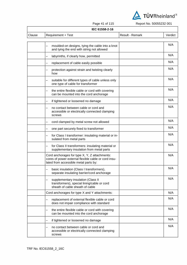
– moulded-on designs, tying the cable into a knot and tying the end with string not allowed
N/A
– labyrinths, if clearly how, permitted N/A
– replacement of cable easily possible N/A
– protection against strain and twisting clearly how
N/A
– suitable for different types of cable unless only one type of cable for transformer
N/A
– the entire flexible cable or cord with covering can be mounted into the cord anchorage
N/A
– if tightened or loosened no damage N/A
– no contact between cable or cord and accessible or electrically connected clamping screws
N/A
– cord clamped by metal screw not allowed N/A
– one part securely fixed to transformer N/A
– for Class I transformer: insulating material or in-sulated from metal parts
N/A
– for Class II transformers: insulating material or supplementary insulation from metal parts
N/A
Cord anchorages for type X, Y, Z attachments: cores of power external flexible cable or cord insu-lated from accessible metal parts by:
N/A
– basic insulation (Class I transformers), separate insulating barrier/cord anchorage
N/A
– supplementary insulation (Class II transformers), special lining/cable or cord sheath of cable sheath of cable
N/A
Cord anchorages for type X and Y attachments: N/A
– replacement of external flexible cable or cord does not impair compliance with standard
N/A
– the entire flexible cable or cord with covering can be mounted into the cord anchorage
N/A
– if tightened or loosened no damage N/A
– no contact between cable or cord and accessible or electrically connected clamping screws
N/A
Page 42 of 115 Report No. 50055232 001
IEC 61558-2-16
Clause Requirement + Test Result - Remark Verdict
TRF No. IEC61558_2_16C
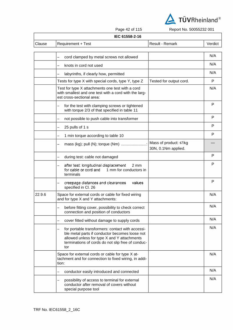
– cord clamped by metal screws not allowed N/A
– knots in cord not used N/A
– labyrinths, if clearly how, permitted N/A
Tests for type X with special cords, type Y, type Z Tested for output cord. P
Test for type X attachments one test with a cord with smallest and one test with a cord with the larg-est cross-sectional area:
N/A
– for the test with clamping screws or tightened with torque 2/3 of that specified in table 11
P
– not possible to push cable into transformer P
– 25 pulls of 1 s P
– 1 min torque according to table 10 P
– mass (kg); pull (N); torque (Nm) ....................... : Mass of product: ≤1kg
30N, 0.1Nm applied.
—
– during test: cable not damaged P
– 2 mm 1 mm for conductors in
terminals
P
– specified in Cl. 26
P
22.9.6 Space for external cords or cable for fixed wiring and for type X and Y attachments:
N/A
– before fitting cover, possibility to check correct connection and position of conductors
N/A
– cover fitted without damage to supply cords N/A
– for portable transformers: contact with accessi-ble metal parts if conductor becomes loose not allowed unless for type X and Y attachments terminations of cords do not slip free of conduc-tor
N/A
Space for external cords or cable for type X at-tachment and for connection to fixed wiring, in addi-tion:
N/A
– conductor easily introduced and connected N/A
– possibility of access to terminal for external conductor after removal of covers without special purpose tool
N/A
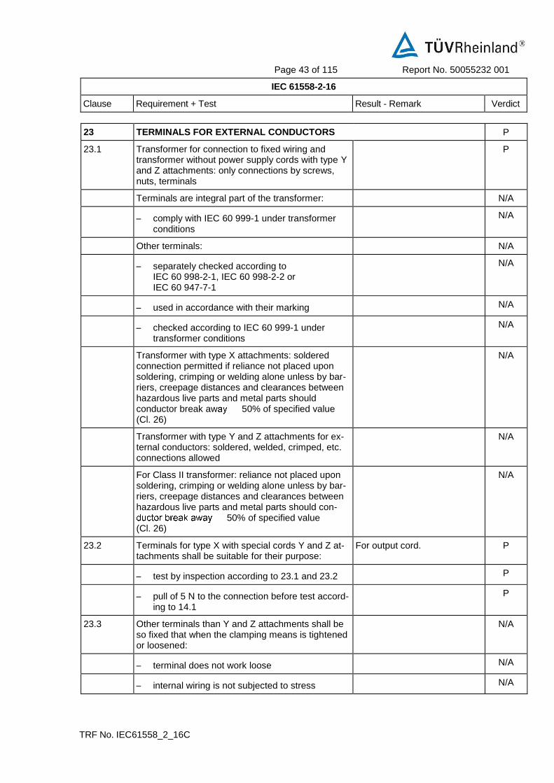
Page 43 of 115 Report No. 50055232 001
IEC 61558-2-16
Clause Requirement + Test Result - Remark Verdict
TRF No. IEC61558_2_16C
23 TERMINALS FOR EXTERNAL CONDUCTORS P
23.1 Transformer for connection to fixed wiring and transformer without power supply cords with type Y and Z attachments: only connections by screws, nuts, terminals
P
Terminals are integral part of the transformer: N/A
– comply with IEC 60 999-1 under transformer conditions
N/A
Other terminals: N/A
– separately checked according to IEC 60 998-2-1, IEC 60 998-2-2 or IEC 60 947-7-1
N/A
– used in accordance with their marking N/A
– checked according to IEC 60 999-1 under transformer conditions
N/A
Transformer with type X attachments: soldered connection permitted if reliance not placed upon soldering, crimping or welding alone unless by bar-riers, creepage distances and clearances between hazardous live parts and metal parts should conductor break aw 50% of specified value (Cl. 26)
N/A
Transformer with type Y and Z attachments for ex-ternal conductors: soldered, welded, crimped, etc. connections allowed
N/A
For Class II transformer: reliance not placed upon soldering, crimping or welding alone unless by bar-riers, creepage distances and clearances between hazardous live parts and metal parts should con-
50% of specified value (Cl. 26)
N/A
23.2 Terminals for type X with special cords Y and Z at-tachments shall be suitable for their purpose:
For output cord. P
– test by inspection according to 23.1 and 23.2 P
– pull of 5 N to the connection before test accord-ing to 14.1
P
23.3 Other terminals than Y and Z attachments shall be so fixed that when the clamping means is tightened or loosened:
N/A
– terminal does not work loose N/A
– internal wiring is not subjected to stress N/A

Page 44 of 115 Report No. 50055232 001
IEC 61558-2-16
Clause Requirement + Test Result - Remark Verdict
TRF No. IEC61558_2_16C
– creepage distances and clearance are not re-duced below the values specified in Cl. 26
N/A
23.4 Other terminals than Y and Z attachments shall be so designed that:
N/A
– they clamp the conductor between metallic sur-faces with sufficient contact pressure
N/A
– without damage to the conductor N/A
– test by inspection according to 23.3 and 23.4 N/A
– 10 times fastening and loosening a conductor with the largest cross-sectional area with 2/3 of the torque specified in Cl. 25
N/A
23.5 Terminals for fixed wiring and for type X: located near their associated terminals of different polarities and the earth terminal if any
N/A
23.6 Terminal blocks not accessible without the aid of a tool
N/A
23.7 Transformer with type X attachments: stranded conductor test (8 mm removed):
N/A
– Class I transformers: no connection between live parts and accessible metal parts
N/A
– free wire of earth terminal: no touching of live parts
N/A
– Class II transformers: no connection between live parts and accessible metal parts, no con-nection between live parts and metal parts separated from accessible metal parts by supplementary insulation
N/A
23.8 Terminals for a current > 25 A: N/A
– pressure plate, or N/A
– two clamping screws N/A
23.9 When terminal, other than protective earth con-ductor, screws loosened as far as possible, no contact:
N/A
– between terminal screws and accessible metal parts
N/A
– between terminal screws and inaccessible metal parts for Class II transformers
N/A
24 PROVISION FOR PROTECTIVE EARTHING P

Page 45 of 115 Report No. 50055232 001
IEC 61558-2-16
Clause Requirement + Test Result - Remark Verdict
TRF No. IEC61558_2_16C
24.1 Class I transformers: accessible conductive parts connected to earth terminal
N/A
Class II transformers: no provision for earth P
24.2 Protective earth terminal for connection to fixed wiring and for type X attachment transformers: comply with Cl. 23, adequately locked, not possible to loosen without a tool
N/A
24.3 No risk of corrosion from contact between metal of earth terminal and other terminal
N/A
In case of earth terminal body of Al, no risk of cor-rosion from contact between Cu and Al
N/A
Body of earth terminal or screws/nuts of brass or other metal resistant to corrosion
N/A
24.4 Resistance of connection between earth terminal 0,1 A or
1,5 rated input current at 1 min
N/A
24.5 Class I transformers with external flexible cables or cords:
N/A
– current-carrying conductors becoming touch before the earth conductor
N/A
25 SCREWS AND CONNECTIONS N/A
25.1 Screwed connections withstand mechanical stresses
No screw N/A
Screws transmitting contact pressure or likely to be tightened by the user or having a diameter < 2,8 mm, shall screw into metal
N/A
Screws not of metal which is soft or liable to creep (Zn, Al)
N/A
Screws of insulating material: not used for electrical connection
N/A
Screws not of insulating material if their replace-ment by metal screws can impair supplementary or reinforced insulation
N/A
Screws to be removed (replacement etc. of power supply cord) not of insulating material if their re-placement by metal screws can impair basic insula-tion
N/A
No damage after torque test: diameter (mm); torque (Nm); ten times
N/A
No damage after torque test: diameter (mm); torque (Nm); five times
N/A

Page 46 of 115 Report No. 50055232 001
IEC 61558-2-16
Clause Requirement + Test Result - Remark Verdict
TRF No. IEC61558_2_16C
25.2 Screws in engagement with thread of insulating material:
N/A
– length of engagement 3 mm + 1/2 screw di-ameter or 8 mm
N/A
– correct introduction into screw hole N/A
25.3 Electrical connections: contact pressure not trans-mitted through insulating material
N/A
25.4 In case of use of thread-forming (sheet metal) screws for connection of current-carrying parts: clamping and locking means provided
N/A
Thread-cutting (self-tapping) screws used for the connection of current-carrying parts allowed if they generate a full form machine screw thread and if not operated by the user
N/A
Thread-cutting screws and thread-forming screws used for earth continuity allowed if at least 2 screws for each connection are used and it is not neces-sary to disturb the connection in normal use
N/A
25.5 Screws for current-carrying mechanical connections locked against loosening
N/A
Rivets for current-carrying connections subject to torsion locked against loosening
N/A
25.6 Test of screwed glands with a torque according table 12. After the test no damage at the transformer and the gland.
N/A
26 CREEPAGE DISTANCES AND CLEARANCES P
26.1 See 26.101 P
26.2 Creepage distances (cr) and clearances (cr) See cl.26.101 P
26.2.1 Windings covered with adhesive tape N/A
– the values of pollution degree 1 are fulfilled N/A
– all isolating material are classified acc. to IEC 60085 and IEC 60216
N/A
– test A of 26.2.3 is fulfilled N/A
26.2.2 Uncemented insulating parts pollution degree P2 or P3
P
– all isolating material are classified acc. to IEC 60085 and IEC 60216
P
– values of pollution degree 1 are not applicable P
26.2.3 Cemented insulating parts N/A

Page 47 of 115 Report No. 50055232 001
IEC 61558-2-16
Clause Requirement + Test Result - Remark Verdict
TRF No. IEC61558_2_16C
– all isolating materials are classified acc. to IEC 60085 and IEC 60216
N/A
– values of distance through insulation (dti) are fulfilled
N/A
– creepage distances and clearances are not required
N/A
– test A of this sub clause is fulfilled N/A
Test A N/A
– thermal class N/A
– working voltage N/A
– Test with three specially specimens, with uninsulated wires, without impregnation or potting
N/A
Two of the three specimens are subjected to: N/A
– the relevant humidity treatment according to 17.2 (48 h)
N/A
– the relevant dielectric strength test of 18.3 multiplied with factor 1,35
N/A
– One of the three specimens is subjected to the relevant dielectric strength test of 18.3 multiplied by the factor 1,35 immediately at the end of the last cycle with high temperature
N/A
Impulse dielectric test according to 4.1.1.2.1 of IEC 60 664-1 (1,2 / 50 – see Annex R of IEC 61558-1
N/A
26.2.4 Enclosed parts, by impregnation or potting N/A
26.2.4.1 – The requirements of reduced values as stated for pollution degree 1 (P1) are fulfilled
N/A
– all isolating materials are classified acc. to IEC 60085 and IEC 60216
N/A
Test B N/A
– thermal class N/A
– working voltage N/A
– Test with three specially specimens, potted or impregnated. The dielectric strength test is applied directly to the joint.
N/A
Two of the three specimens are subjected to: N/A

Page 48 of 115 Report No. 50055232 001
IEC 61558-2-16
Clause Requirement + Test Result - Remark Verdict
TRF No. IEC61558_2_16C
– the relevant humidity treatment according to 17.2 (48 h)
N/A
– the relevant dielectric strength test of 18.3 multiplied with factor 1,25
N/A
– One of the three specimens is subjected to the relevant dielectric strength test of 18.3 multiplied by the factor 1,25 immediately at the end of the last cycle with high temperature
N/A
The three spacemen pass the Impulse dielectric test according to 4.1.1.2.1 of IEC 60 664-1 (1,2 / 50 – see Annex R of IEC 61558-1
N/A
26.2.4.2 – The requirements of distance through insulation (dti) are fulfilled. (P1 values are not required)
N/A
– all isolating materials are classified acc. to IEC 60085 and IEC 60216
N/A
Test C N/A
– thermal class N/A
– working voltage N/A
– Test with three specimens, potted or impregnated. (finished components)
N/A
– Neither cracks, nor voids in the insulating compounds
N/A
Two of the three specimens are subjected to: N/A
– the relevant humidity treatment according to 17.2 (48 h)
N/A
– the relevant dielectric strength test of 18.3 multiplied with factor 1,35
N/A
– One of the three specimens is subjected to the relevant dielectric strength test of 18.3 multiplied by the factor 1,35 immediately at the end of the last cycle with high temperature
N/A
The three spacemen pass the Impulse dielectric test according to 4.1.1.2.1 of IEC 60 664-1 (1,2 / 50 – see Annex R of IEC 61558-1
N/A
26.3 Distance through insulation P
For double or reinforced insulation, the required values of Tables 13, C1, and D1 – boxes 2b, 2c and 7 are fulfilled
Dti of enclosure is min.2.5mm (required: ≥1.0mm)
P

Page 49 of 115 Report No. 50055232 001
IEC 61558-2-16
Clause Requirement + Test Result - Remark Verdict
TRF No. IEC61558_2_16C
The insulation fulfil the material classification according IEC 60085 or 60216 or the test of 14.3
P
26.3.1 Reduced values of the thickness of insulation for supplementary or reinforced insulation are allowed if the following conditions are fulfilled:
P
– the isolating materials are classified acc. to IEC 60085 and IEC 60216
N/A
– the test of 14.3 is fulfilled N/A
– If both requirements are fulfilled, the required values for solid insulation can be multiplied by 0,4
N/A
– Minimum thickness of reinforced insulation >0,2 mm
N/A
– Minimum thickness of supplementary insulation >0,1 mm
N/A
26.3.2 Insulation in thin sheet form P
– If the layers are non-separable (glued together):
N/A
– The requirement of 3 layers is fulfilled N/A
– The mandrel test according 26.3.3 is fulfilled with 150 N
N/A
– The required values for d.t.i. of Tables 13, C.1 and D.1 – marked by index ”e” is fulfilled.
N/A
– If the layers are separated: N/A
– The requirement of 2 layers is fulfilled N/A
– If serrated tape is used, 1 additional layer (serrated) and one additional layer without serration is required
N/A
– The mandrel test according 26.3.3 is fulfilled on each layer with 50 N
N/A
– The required values for d.t.i. of Tables 13, C.1 and D.1 – marked by index ”e” is fulfilled.
N/A
– If the layers are separated (alternative: P
– The requirement of 3 layers is fulfilled Three layers of insulation tape on T1 core considered as supplementary insulation.
P

Page 50 of 115 Report No. 50055232 001
IEC 61558-2-16
Clause Requirement + Test Result - Remark Verdict
TRF No. IEC61558_2_16C
– If serrated tape is used, 1 additional layer (serrated) and one additional layer without serration is required
N/A
– The mandrel test according 26.3.3 is fulfilled on 2/3 of the layers with 100 N
P
– The required values for d.t.i. of Tables 13, C.1 and D.1 – marked by index ”e” is fulfilled.
P
Test according to 14.3 and if the isolating materials are classified acc. to IEC 60085 and IEC 60216 no distances through insulation are required for insulation in thin sheet form
N/A
The figures within square brackets in box 2 and 7 of table 13 (C.1/D.1) are used for insulation in thin sheet form as follows:
P
– rated output > 100 VA values in square brackets apply
P
– 25 VA 100 VA 2/3 of the value in square brackets apply
N/A
– rated output 25 VA 1/3 of the value in square brackets apply
N/A
26.3.3 Mandrel test of insulation in thin sheet form (specimen of 70 mm width are necessary):
P
– If the layers are non-separable – at least 3 layers glued together fulfil the test:
N/A
– pull force of 150 N N/A
– high voltage test of 5,0 kV or the test voltage of 18.3 multiplied by 1,25 whatever is the greater. No flashover, no breakdown.
N/A
– If the layers are separable and 2/3 of at least 3 layers fulfil the test.
3 layers P
– pull force of 100 N P
– high voltage test of 5,0 kV or the test voltage of 18.3 multiplied by 1,25 whatever is the greater. No flashover, no breakdowns.
P
– If the layers are separable 1 of at least 2 layers fulfil the test:
N/A
– pull force of 50 N N/A
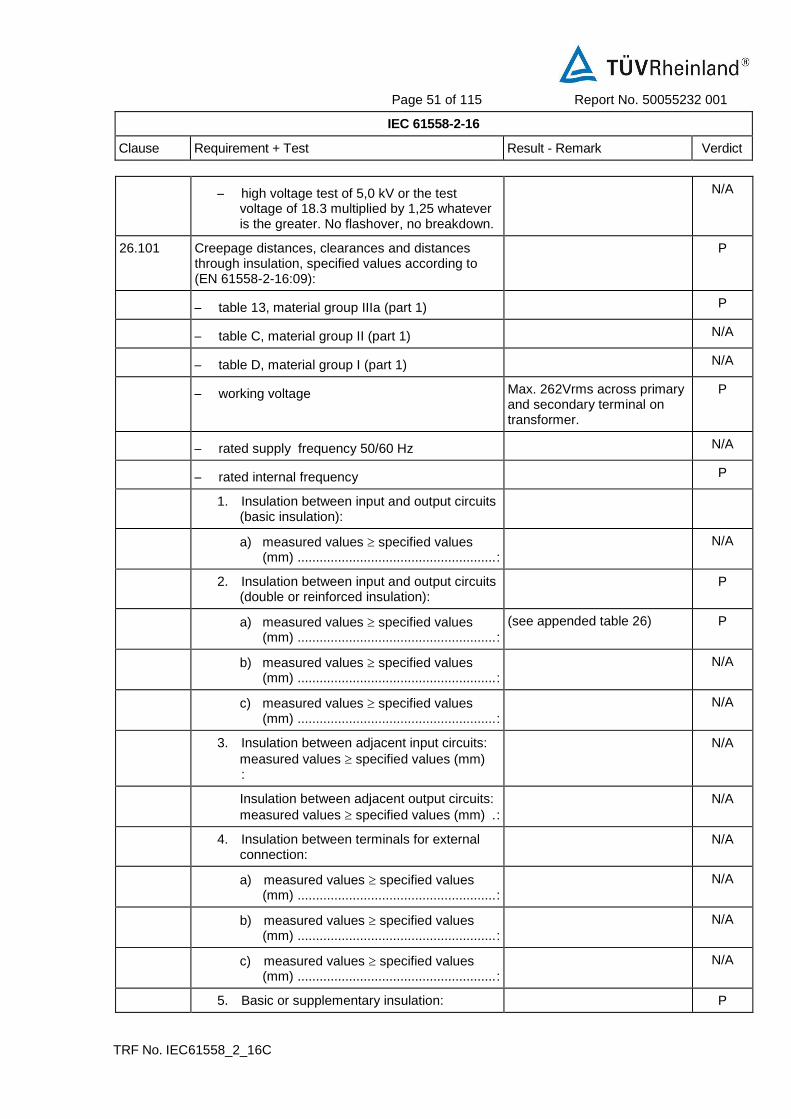
Page 51 of 115 Report No. 50055232 001
IEC 61558-2-16
Clause Requirement + Test Result - Remark Verdict
TRF No. IEC61558_2_16C
– high voltage test of 5,0 kV or the test voltage of 18.3 multiplied by 1,25 whatever is the greater. No flashover, no breakdown.
N/A
26.101 Creepage distances, clearances and distances through insulation, specified values according to (EN 61558-2-16:09):
P
– table 13, material group IIIa (part 1) P
– table C, material group II (part 1) N/A
– table D, material group I (part 1) N/A
– working voltage Max. 262Vrms across primary and secondary terminal on transformer.
P
– rated supply frequency 50/60 Hz N/A
– rated internal frequency P
1. Insulation between input and output circuits (basic insulation):
a) measured values specified values (mm) ...................................................... :
N/A
2. Insulation between input and output circuits (double or reinforced insulation):
P
a) measured values specified values (mm) ...................................................... :
(see appended table 26) P
b) measured values specified values (mm) ...................................................... :
N/A
c) measured values specified values (mm) ...................................................... :
N/A
3. Insulation between adjacent input circuits:
measured values specified values (mm) :
N/A
Insulation between adjacent output circuits:
measured values specified values (mm) . :
N/A
4. Insulation between terminals for external connection:
N/A
a) measured values specified values (mm) ...................................................... :
N/A
b) measured values specified values (mm) ...................................................... :
N/A
c) measured values specified values (mm) ...................................................... :
N/A
5. Basic or supplementary insulation: P

Page 52 of 115 Report No. 50055232 001
IEC 61558-2-16
Clause Requirement + Test Result - Remark Verdict
TRF No. IEC61558_2_16C
a) measured values specified values (mm) ...................................................... :
(see appended table 26) P
b) measured values specified values (mm) ...................................................... :
N/A
c) measured values specified values (mm) ...................................................... :
N/A
d) measured values specified values (mm) ...................................................... :
(see appended table 26) P
e) measured values specified values (mm) ...................................................... :
N/A
6. Reinforced or double insulation: measured ecified values (mm) ................. :
(see appended table 26) P
7. Distance through insulation: P
a) measured values specified values (mm) ...................................................... :
N/A
b) measured values specified values (mm) ...................................................... :
see appended table 26) P
c) measured values specified values (mm) ...................................................... :
see appended table 26) P
26.102 Values of IEC 61558-2-16 applicable for frequency up to 3 MHz (EN 61558-2-16:09)
P
For frequency above 3 MHz clause 7 of IEC 60664-4 is applicable (high frequency testing)
N/A
26.103 Clearance (EN 61558-2-16:09) P
a) Clearance for frequency > 30 kHz according figure 101 two determinations are necessary:
P
– determination based on peak working voltage according Table 104 :
P
Peak working voltage 415Vpeak P
Basic insulation: required / measured N/A
Double or reinforced insulation: required / measured value
N/A
– and alternative if applicable for approximately homogeneous field according to Table 102
N/A
Peak working voltage N/A
Basic insulation: required / measured N/A
Double or reinforced insulation: required / measured value
N/A

Page 53 of 115 Report No. 50055232 001
IEC 61558-2-16
Clause Requirement + Test Result - Remark Verdict
TRF No. IEC61558_2_16C
– determination based on measured r.m.s. working voltage according Tables 13, C1 and D1 (see clause 26.101)
See 26.101 P
The minimum clearance is the greater of the two values.
See 26.101 P
b) Clearance for frequency < 30 kHz according figure 101 two determinations are necessary:
N/A
– determination based on peak working voltage with recurring peak voltages according Table 103 :
N/A
– determination based on measured r.m.s. working voltage according Tables 13, C1 and D1 (see clause 26.101)
N/A
The minimum clearance is the greater of the two values.
N/A
26.104 The working voltages of Table 102, 103 and 104 are peak voltages including µsec peaks EN 61558-2-16:09)
N/A
The working voltage according to Table 13 of part 1 are r.m.s. voltages
N/A
26.105 Creepage distances N/A
Two determinations of creepage distances are necessary (see Figure 102)
N/A
– determination based on measured peak working voltage according Tables 105 to 110
N/A
Peak working voltage N/A
Pollution degree N/A
Basic or supplementary insulation: required / measured
N/A
Double or reinforced insulation: required / measured value
N/A
– determination based on measured r.m.s. working voltage according Tables 13, C1 and D1 (see clause 26.101)
N/A
If the values based on table 105 to 110 are lower than the relevant values in Tables 13, C.1 or D.1, the higher values shall be applicable
N/A
26.106 Distance through insulation (EN 61558-2-16:09) N/A
Instead of partial discharge with high frequency voltage the test of the distance and the calculation of the electric field is applicable under the following conditions:
N/A

Page 54 of 115 Report No. 50055232 001
IEC 61558-2-16
Clause Requirement + Test Result - Remark Verdict
TRF No. IEC61558_2_16C
– the max. frequency is < 10 MHz N/A
– the field strength approximately comply with Figure 103
N/A
– no voids or gaps are present in between the solid insulation
N/A
For thick layers d1 > 0,75 the peak value of the field strength is < 2 kV/mm
N/A
For thin layers d2 < 30 µm the peak value of the field strength is < 10 kV/mm
N/A
For d1 > d > d2 equation (1) is used for calculation the field strength
N/A
26.107 (A1)
For transformers with FIW wires the following test is required
N/A
– 10 cycles are required N/A
– 68 h test at max heating temperature + 10°C or test at max. allowed winding temperature based on the insulation class (required in table 1) + 10°C
N/A
– 1 h at 25° C N/A
– 2 h at 0° C N/A
– 1 h at 25° C – (next cycle start again with 68 h max winding temp + 10)
N/A
– during the 10 cycles test 2 x working voltage is connected between PRI and SEC
N/A
– after 10 cycle test 2 transformers are subjected to the 17.2 test for 48 h and direct after the 48 h the dielectric strength test of 18.3 (100 % test voltage) is done
N/A
– after the 10 cycle test the third sample is tested at the end of the last cycle in the hot position with the dielectric strength test of 18.3 (100 % test voltage)
N/A
– the partial discharge test according to 18.101 is done after the cycling test and after the high voltage test, if the peak working voltage is >750 V
N/A
27 RESISTANCE TO HEAT, FIRE AND TRACKING P
27.1 Resistance to heat P
All insulating parts are resistant to heat P

Page 55 of 115 Report No. 50055232 001
IEC 61558-2-16
Clause Requirement + Test Result - Remark Verdict
TRF No. IEC61558_2_16C
For parts of rubber, which passed the test of 19.9, no additional test is required.
N/A
The tests are not required for cables and small connectors with a rated current < 3 A, a rated voltage < 24 V a.c. or 60 V d.c. and a power < 72 W
N/A
27.1.1 External accessible parts P
The Ball-pressure test -: diameter of impression < 2 mm; heating cabinet temperature (° C) at 70 ° C or the temperature T of 14.1 (T + 15) - is fulfilled.
Enclosure material: 88° C
Impression:1.1mm
P
27.1.2 Internal parts P
For insulating material retaining current carrying parts in position , the ball-pressure test -: diameter of impression < 2 mm; heating cabinet temperature (° C) at 125 ° C or the temperature T of 14.1 (T + 15) - is fulfilled
PCB: 125° C; 0.8mm
L1 Bobbin: 125° C; 1.1mm
T3 bobbin: 125° C; 1.0mm
T2 bobbin: 125° C; 1.1mm
Output connector: 125° C; 1.2mm
P
27.2 Resistance to abnormal heat under fault conditions N/A
27.3 Resistance to fire P
All isolating parts of the transformer shall be resistant to ignition and spread of fire. The test according to IEC 60696-2-10 is required
P
27.3.1 External accessible parts (glow wire tests) P
– 650° C for enclosures Enclosure P
– 650 ° C for parts retaining current carrying parts in position and terminals for external conductors Current < 0,2 A
N/A
– 750° C for parts retaining current carrying parts in position and terminals for external conductors with fixed wiring. Current > 0,2 A
N/A
– 850° C for parts retaining current carrying parts in position and terminals for external conductors with non-fixed wiring. Current > 0,2 A
Output connector P
27.3.2 Internal parts P
– 550 °C for internal insulating material – not retaining current carrying parts in position
N/A
– 650 °C for coil formers (bobbins) T3 Bobbin
T2 bobbin
L1 Bobbin
P

Page 56 of 115 Report No. 50055232 001
IEC 61558-2-16
Clause Requirement + Test Result - Remark Verdict
TRF No. IEC61558_2_16C
– 650 °C for parts retaining current carrying parts in position and terminals for external conductors. Current < 0,2 A
N/A
– 750 °C for parts retaining current carrying parts in position and terminals for external conductors with fixed wiring. Current > 0,2 A
N/A
– 850 °C for parts retaining current carrying parts in position and terminals for external conductors with non-fixed wiring. Current > 0,2 A
PCB
Output connector
P
27.4 For IP other than IPX0:If insulating parts retaining current carrying parts in position and under P3 conditions, the material resistance to tracking is at least material of group IIIa
N/A
Test (175 V): no flashover or breakdown before 50 drops
N/A
28 RESISTANCE TO RUSTING P
Ferrous parts protected against rusting P
E ANNEX E , GLOW WIRE TEST P
The test is required according to IEC 60695-2-10 and IEC 60695-2-11 with the following additions:
P
E.1 Clause 6, ”Severities” of IEC 6095-2-11, apply with the temperature stated in 27.3 of IEC 61558-1
P
E2 Clause 8, ”Conditioning”, of IEC 60695-2-11 apply, preconditioning is required
P
E3 Clause 10, ”Test Procedure”, of IEC 60695-2-11apply, The tip of the glow wire is applied to the flat side of the surface.
P
F ANNEX F, REQUIREMENTS FOR MANUALLY OPERATED SWITCHES WHICH ARE PARTS OF THE TRANSFORMER
N/A
F.2 Manually operated mechanical switches, tested as separate component, shall comply with IEC 61058 under the conditions of F2.
N/A
F.§ Manually operated mechanical switches tested as part of the transformer shall comply with the conditions specified under F.3
N/A

Page 57 of 115 Report No. 50055232 001
IEC 61558-2-16
Clause Requirement + Test Result - Remark Verdict
TRF No. IEC61558_2_16C
H ANNEX H, ELECTRONIC CIRCUITS (IEC 61558-1)
P
H1 General notes on tests (addition to clause 5) P
H.2 SHORT-CIRCUIT AND OVERLOAD PROTECTION (ADDITION TO CLAUSE 15) P
H.2.1 Circuits designed and applied so that fault condi-tions do not render the appliance unsafe
P
During and after each test: P
– temperatures do not exceed values specified in table 3 of Cl. 15.1
P
– transformer complies with conditions specified in sub-clause 15.1
P
If a conductor of a pcb becomes open circuited, the transformer is considered to have withstood the particular test, provided that all six conditions as specified are met
N/A
H.2.2 Fault conditions a) to f) of sub-clause H.2.3 are not tested if the following conditions are met:
N/A
– electronic circuit is a low-power circuit as speci-fied
N/A
– safety of the appliance as specified does not rely on correct functioning of the electronic circuit
N/A
H.2.3 Fault conditions tested as specified when relevant: P
a) short-circuit of creepage distances and clear-ances, if less than specified in Cl. 26
See only test of c) to e) N/A
b) open circuit at the terminals of any component P
c) short-circuit of capacitors, unless they comply with IEC 60 384-14
P
d) short-circuit of any two terminals of an electronic component as specified
P
e) any failure of an integrated circuit as specified P
f) low-power circuit: low-power points are con-nected to the supply source
N/A
Cl. 15 is repeated with a simulated fault as indicated in a) to e), if the transformer incorporates an electronic circuit to ensure compliance with Cl. 15
Unit shut down for all fault
condition test. See appended
table H.2.3
N/A
Fault condition e) is applied for encapsulated and similar components
N/A

Page 58 of 115 Report No. 50055232 001
IEC 61558-2-16
Clause Requirement + Test Result - Remark Verdict
TRF No. IEC61558_2_16C
PTC's and NTC's are not short-circuited if they are used as specified
N/A
H.2.4 If for a fuse-link complying with IEC 60 127-3 rated fuse current I1 is used, current I2 is measured as specified:
P
– if I2 < 2,1 x I1 test of 15.8 is repeated with fuse-link short-circuited
N/A
– if I2 > 2,75 x I1, no other tests are necessary P
If I2 > 2,1 x I1 and I2 < 2,75 x I1 test of 15.8 is re-peated as specified
N/A
For fuses other than those complying with IEC 60 127-3, the test is carried out as specified 15.3.2 to 15.3.5
N/A
H.3 CREEPAGE DISTANCES, CLEARANCES AND DISTANCES THROUGH INSULATION
P
H.3.1 For live parts separated by basic insulation smaller cr and cl as in 26 are allowed, if H2 is fulfilled.
For secondary circuits and parts protected by fuse.
P
In optocouplers no requirements of cr and cl Approved optocoupler used P
For coatings annex W applies. Smaller distances as required in IEC 60664-3, clause 4 are applicable,
N/A
For potted transformers cycling tests acc, 26.2. are applicable
N/A
H.3.2 The ma. surface temperature of optocouplers is 50 K
P
K (A1) ANNEX K, INSULATED WINDING WIRES FOR USE AS MULTIPLE LAYER INSULATION
P
K.1 Wire construction: P
insulated winding wire for basic or supplementary insulation (see 19.12.3)
N/A
insulated winding wire for reinforced insulation (see 19.12.3)
VDE approved triple insulated wire
P
splid circular winding wires and stranded winding wires with 0,05 to 5 mm diameter
P
spirally wrapped insulation – overlapping N/A
K.2 Type tests N/A

Page 59 of 115 Report No. 50055232 001
IEC 61558-2-16
Clause Requirement + Test Result - Remark Verdict
TRF No. IEC61558_2_16C
K.2.1 General
Tests between ambient temperature between 15° C and 35° C and at an humidity between 45% and 75 %
N/A
K.2.2 Electric strength test N/A
K.2.2.1 Solid circular winding wires and stranded winding wires
N/A
Test samples prepared according to clause 4.4.1 of IEC 60851-5:2008 (twisted pair)
N/A
Dielectric strength test: 6 kV for reinforced insulation
N/A
Dielectric strength test: 3 kV for basic or supplementary insulation
N/A
K.2.2.2 Square or rectangular wires . N/A
Test samples prepared according to clause 4.7.1 of IEC 60851-5:2008
N/A
Dielectric strength test: 5,5 kV for reinforced insulation
N/A
Dielectric strength test: 2,75 kV for basic or supplementary insulation
N/A
K.2.3 Flexibility and adherence N/A
Claus 5.1 in Test 8 of IEC 60851-3:2009 shall be used
N/A
Test samples prepared according to clause 5.1.1.4 of IEC 60851-3:2009
N/A
Dielectric strength test: 5,5 kV for reinforced insulation
N/A
Dielectric strength test: 2,75 kV for basic or supplementary insulation
N/A
Mandrel diameter according table K.1 N/A
The tension to the wire during winding on mandrel is 118 N/mm² (118 MPa)
N/A
K.2.4 Heat shock N/A
Test samples prepared according to 3.1.1 (in Test 9) of IEC 60851-6:1996
N/A
high voltage test immediately after this test N/A
Dielectric strength test: 5,5 kV for reinforced insulation
N/A
Dielectric strength test: 2,75 kV for basic or supplementary insulation
N/A

Page 60 of 115 Report No. 50055232 001
IEC 61558-2-16
Clause Requirement + Test Result - Remark Verdict
TRF No. IEC61558_2_16C
K.2.5 Retention of dielectric strength after bending
( test as specified under test 13 of 4.6.1 c) of IEC 60 851-5)
N/A
N/A
high voltage test immediately after this test
Dielectric strength test: 5,5 kV for reinforced insulation
Dielectric strength test: 2,75 kV for basic or supplementary insulation
N/A
K.3.1 General
Tests as subjected in K.3.2 and K.3.3
N/A
K.3.2 Routine test N/A
Dielectric strength test: 4,2 kV for reinforced insulation
N/A
Dielectric strength test: 2,1 kV for basic or supplementary insulation
N/A
K.3.3 Sampling test N/A
K.3.3.1 Solid circular winding wires and stranded winding wires
N/A
Test with a twisted pair, prepared according clause 4.4.1 of IEC 60851-5:2008
N/A
Dielectric strength test: 6 kV for reinforced insulation
N/A
Dielectric strength test: 3 kV for basic or supplementary insulation
N/A
K.3.3.2 Square rectangular wire N/A
Samples prepared according to clause 4.7.1 of IEC 60851-5:2008
N/A
Dielectric strength test: 5,5 kV for reinforced insulation
N/A
Dielectric strength test: 3 kV for basic or supplementary insulation
N/A
U ANNEX U – INFORMATIVE – OPTIONAL TW – MARKING FOR TRANSFORMERS N/A
The tests of Annex U are based on constant S = 4500. Other constants are possible, if the test of U.5.2 is done with positive result.
N/A
U1 General notes and tests N/A
8 transformers of one type are necessary for the test. Tests according U5.
N/A

Page 61 of 115 Report No. 50055232 001
IEC 61558-2-16
Clause Requirement + Test Result - Remark Verdict
TRF No. IEC61558_2_16C
U.2 Heating (addition to clause 14) N/A
14.4 Thermal endurance test N/A
Test according U5 and measurements according 11.1
N/A
Transformers tested as an integral part of the equipment (option), assigned with tw
N/A
The thermal conditions are so adjusted, that the duration of test is as indicated by the manufacturer.
N/A
If no indications are given, the test period is 30 days
N/A
After the test, when the transformers have returned to room temperature, they fulfil the following requirements:
N/A
a) The output voltage has not changed from the measured value at the beginning by more than allowed value of clause 11.1
N/A
b) The insulation resistance between input and output winding and between windings and body is, measured with 500 V d.c. , not less than 1 MOhm
N/A
c) The transformer fulfil the dielectric strength test with 35% of the values in Clause 18, Table 8.a.
N/A
The test result is positive, is min. 6 of the 7 samples have passed the test.
N/A
The test result is negative, if 2 or more samples fail the test
N/A
If the result is negative, the test can be repeated with 7 new samples
N/A
U.3 Short circuit and overload protection (addition to clause 15)
N/A
At short circuit and overload tests the winding temperature if less than the required value of table U.1
N/A
U.5 General requirements and information about thermal endurance test on windings
N/A
U.5.1 Thermal endurance test N/A
Transformers tested at rated output N/A
Loads outside of the oven N/A
7 transformers are placed in the oven N/A
The temperature of the hottest winding of each of the 7 transformers is-together with the oven temperature, at the applicable temperature of table U.2
N/A

Page 62 of 115 Report No. 50055232 001
IEC 61558-2-16
Clause Requirement + Test Result - Remark Verdict
TRF No. IEC61558_2_16C
After 4 hours measuring of the actual winding temperatures. Regulation of the oven temperature if necessary
N/A
After 24 hours again measuring of the winding temperature. The temperatures of the 7 samples are very near to the required temperature of the values of table U.2. The test time of the coldest winding is not longer than twice the theoretical test time based on table U.2
N/A
U.5.2 The use of constant S other than 4500 in tw tests N/A
U.5.2.1 Procedure a) N/A
The manufacturer prepares test results with a minimum of samples of 30.
N/A
T and log L are calculated from the dates N/A
The diagram according to Figure U.2 will be founded.
N/A
U.5.2.3 Procedure b) N/A
The testing authority shall test 14 new transformers N/A
Test 1, based on clause U.5.1 but at the calculated test room temperature for 10 days. The test is continued until all transformer fail.
N/A
Calculation of the mean life L2 at temperature T2
according to U4 N/A
Test 2, based on clause U.5.1 but at a calculated room temperature T2 (for 120 days).The test time with T2 exceeds L2.
N/A
If all transformers fail before L2, the result is negative.
N/A

Page 63 of 115 Report No. 50055232 001
IEC 61558-2-16
Clause Requirement + Test Result - Remark Verdict
TRF No. IEC61558_2_16C
V ANNEX V, SYMBOLS TO BE USED FOR THERMAL CUT-OUTS N/A
V.2.1.1 Restored by manual operation
IEC 489/98
N/A
V.2.1.2 Restored by disconnection of the supply
IEC 490/98
N/A
V.2.1.3 Thermal link
IEC 491/98
N/A
V.2.2 Self-resetting thermal cut-out
IEC 492/98
N/A

Page 64 of 115 Report No. 50055232 001
IEC 61558-2-16
Clause Requirement + Test Result - Remark Verdict
TRF No. IEC61558_2_16C
11 and 12 TABLE: OUTPUT VOLTAGE AND OUTPUT CURRENT UNDER LOAD; NO-LOAD OUTPUT VOLTAGE
P
Clause 11 12
type/rated output/
rated voltage
(V)
sec. voltage
(V)
delta Usec (%)
Usec V no-load output
delta Usec no-load output %
further information
54.6V/3A 54.6 54.60 0 54.19 0.75% 100V/47Hz
54.6V/3A 54.6 54.60 0 54.19 0.75% 100V/63Hz
54.6V/3A 54.6 54.60 0 54.19 0.75% 240V/47Hz
54.6V/3A 54.6 54.60 0 54.19 0.75% 240V/63Hz
Limits: -- -- 10 -- 15 --
14 TABLE: heating P
Supply voltage (V) ........................... : 90V/63Hz 264V/47Hz --
Maximum measured temperature T of part/at::
T (°C) Required T(°C)
Inlet 57.5 42.5 70
CY1 71.4 50.3 125
CY5 74.8 53.5 125
CX1 98.7 60.4 100
CX2 81.8 53.9 100
VRP1 64.0 48.9 85
CX0 70.4 50.8 120
L1 92.8 59.4 120
LF1 92.8 55.5 120
LF2 113.1 66.3 120
T1 winding 98.5 66.0 120
T1 bobbin 100.7 68.1 120
C23 90.9 71.9 105
T3 winding 98.1 82.7 120
T3 bobbin 99.5 81.6 120
T2 Primary winding 97.2 87.7 110
T2 secondary winding 98.8 89.3 110
T2 bobbin 98.7 86.0 110
CY8 60.6 64.3 125
CY7 97.4 86.1 125
U4 74.9 75.0 100
U5 78.5 77.4 100

Page 65 of 115 Report No. 50055232 001
IEC 61558-2-16
Clause Requirement + Test Result - Remark Verdict
TRF No. IEC61558_2_16C
Ls5 69.5 72.5 120
PCB under BD1 118.4 72.8 130
PCB under Q15 116.5 74.4 130
PCB under T2 97.7 82.0 130
PCB under Ds2 99.5 67.5 130
Output wire (Internal) 57.9 67.9 70
Enclosure inside near T1 66.0 52.9 --
Enclosure outside near T1 63.4 51.8 80
Enclosure inside near L1 72.9 49.6 --
Enclosure inside near L1 66.6 46.6 80
Support 75.4 54.2 85
Input wire 30.1 28.8 --
Ambient 25.0 24.4 --
Max Ambient 25.0 24.4 --
Supplementary information: The heating test performed at unit continuous operation.
15 TABLE: short-circuit and overload protection P
ambient temperature (°C) ..................................... : 25 —
at 1,1 or 0,9 times rated voltage (V) ..................... : See below —
Measured temperature of part/at: T(°C) Allowed Tmax (°C)
Output overload test:
Test voltage 90 V ac, 63Hz 264 V ac, 47Hz --
1. T2 primary winding 105.7 91.7 175
2. T2 secondary winding 105.1 93.3 175
3. Output wire 61.8 71.1 85
4. Enclosure outside near BD1 67.6 53.1 105
5. Enclosure outside above L1 78.5 48.0 105
6. Enclosure outside under T2 71.8 51.0 105
7. Support 31.4 29.0 105
8. Ambient temperature during test 24.6 24.6 --
Maximum Ambient temperature 25 25 --
Output short-circuit test:
Test voltage 90 V ac, 63Hz 264 V ac, 47Hz --
1. T2 primary winding 37.4 175
2. T2 secondary winding 38.0 175

Page 66 of 115 Report No. 50055232 001
IEC 61558-2-16
Clause Requirement + Test Result - Remark Verdict
TRF No. IEC61558_2_16C
3. Output wire 30.9 85
4. Enclosure outside near BD1 28.2 105
5. Enclosure outside above L1 28.5 105
6. Enclosure outside under T2 31.2 105
7. Support 32.2 105
8. Ambient temperature during test 23.0 --
Maximum Ambient temperature 25 --
18.2 TABLE: insulation resistance measurements P
Insulation resistance R between: R (MΩ) Required R (MΩ)
Between mains poles (primary fuse disconnected) 100 2
Between primary and enclosure 100 7
Between input and output 100 5
Between primary and secondary of T1 100 5
Between core and secondary of T1 100 5
Supplementary information:

Page 67 of 115 Report No. 50055232 001
IEC 61558-2-16
Clause Requirement + Test Result - Remark Verdict
TRF No. IEC61558_2_16C
20 TABLE: Critical components information P
Object/part No. Manufacturer/ trademark
Type/model Technical data Standard (Edition / year)
Mark(s) of conformity
1)
Appliance Inlet Rong Feng
Industrial Co.,
Ltd.
RF-180 2.5A, 250Vac, 70°C IEC/EN 60320-1 VDE
(40030168)
Fuse
(F1)
Dong guan
Better
Electronic
Technology
Co., Ltd.
932 T5A, 250Vac IEC/EN60127-1
IEC/EN60127-3
VDE
(40033369)
Alternative Sunny East
Enterprise Co.
Ltd.
TSP T5A, 250Vac IEC/EN60127-1
IEC/EN60127-3
VDE
(40027173)
Varistor
(VRP1)
Shantou High-
New
Technology
Dev. Zone
Songtian
Enterprise Co.,
Ltd.
10D471K Min.300Vac,
385Vdc,85°C
IEC/EN 61051-1
IEC/EN 61051-2
IEC/EN 61051-2-
2
VDE
(40023049)
X-Capacitor
(CX1)
Tenta Electric
Industrial Co.,
Ltd.
MEX 0.33uF, 275Vac,
40/100/21
IEC/EN 60384-14 VDE
(119119)
Alternative Farad
Electronics Co.,
Ltd.
PXK 0.33uF, 275Vac,
40/110/56
IEC/EN 60384-14 VDE
(40030152)
Alternative
Shenzhen
Weidy Industrial
Development
Co.,Ltd
MKP 0.33uF, 310Vac
40/110/56
IEC/EN 60384-14 VDE
(40041066)
X-Capacitor
(CX2)
Tenta Electric
Industrial Co.,
Ltd.
MEX 0.47uF, 275Vac,
40/100/21
IEC/EN 60384-14 VDE
(119119)
Alternative Farad
Electronics Co.,
Ltd.
PXK 0.47uF, 275Vac,
40/110/56
IEC/EN 60384-14 VDE
(40030152)
Alternative Shenzhen
Weidy Industrial
Development
Co.,Ltd
MKP 0.47uF, 310Vac
40/110/56
IEC/EN 60384-14 VDE
(40041066)
Y-Capacitor
(CY1,CY2)
Success
Electronics Co.,
Ltd.
SE 2200pF, 250Vac,
40/125/56, Y1
IEC/EN 60384-14 VDE
(40020002)

Page 68 of 115 Report No. 50055232 001
IEC 61558-2-16
Clause Requirement + Test Result - Remark Verdict
TRF No. IEC61558_2_16C
Alternative Kunshan Micro
Capacitors
Electronic Co.,
Ltd.
E-Series 2200pF, 250Vac,
25/125/21, Y1 type
IEC/EN 60384-14 VDE
(40016537)
Alternative Yinan Don’s
Electronic
Components
Co., Ltd.
CT81 2200pF, 250Vac,
25/125/21, Y1 type
IEC/EN 60384-14 VDE
(135256)
Alternative
Hsuan Tai
Electronic Co.,
Ltd.
CY 2200pF, 400Vac,
40/125/21, Y1 type
IEC/EN 60384-14 VDE
(40008912)
Alternative Anshan Kei Fat
Electronic
Ceramic
Technical Co.,
Ltd.
CT7 2200pF, 250Vac,
25/125/21, Y1 type
IEC/EN 60384-14 VDE
(40011817)
Y-Capacitor
(CY4,CY5)
Success
Electronics Co.,
Ltd.
SE 1000pF, 250Vac,
40/125/56, Y1 type
IEC/EN 60384-14 VDE
(40020002)
Alternative Kunshan Micro
Capacitors
Electronic Co.,
Ltd.
E-Series 1000pF, 250Vac,
25/125/21, Y1 type
IEC/EN 60384-14 VDE
(40016537)
Alternative Yinan Don’s
Electronic
Components
Co., Ltd.
CT81 1000pF, 250Vac,
25/125/21, Y1 type
IEC/EN 60384-14 VDE
(135256)
Alternative
Hsuan Tai
Electronic Co.,
Ltd.
CY 1000pF, 400Vac,
40/125/21, Y1 type
IEC/EN 60384-14 VDE
(40008912)
Alternative Anshan Kei Fat
Electronic
Ceramic
Technical Co.,
Ltd.
CT7 1000pF, 250Vac,
25/125/21, Y1 type
IEC/EN 60384-14 VDE
(40011817)
Y-Capacitor
(CY6,CY7,
CY8)
Success
Electronics Co.,
Ltd.
SE 4700pF, 250Vac,
40/125/56, Y1 type
IEC/EN 60384-14 VDE
(40020002)
Alternative Kunshan Micro
Capacitors
Electronic Co.,
Ltd.
E-Series 4700pF, 250Vac,
25/125/21, Y1 type
IEC/EN 60384-14 VDE
(40016537)
Alternative Yinan Don’s
Electronic
Components
Co., Ltd.
CT81 4700pF, 250Vac,
25/125/21, Y1 type
IEC/EN 60384-14 VDE
(135256)

Page 69 of 115 Report No. 50055232 001
IEC 61558-2-16
Clause Requirement + Test Result - Remark Verdict
TRF No. IEC61558_2_16C
Alternative Hsuan Tai
Electronic Co.,
Ltd.
CY 4700pF, 400Vac,
40/125/21, Y1 type
IEC/EN 60384-14 VDE
(40008912)
Alternative Anshan Kei Fat
Electronic
Ceramic
Technical Co.,
Ltd.
CT7 4700pF, 250Vac,
25/125/21, Y1 type
IEC/EN 60384-14 VDE
(40011817)
Photo coupler
(U3,U4,U5)
China
Resources
Semiconductor
(ShenZhen) Ltd.
PC817C Int. Cr : 7.62 mm,
Ext. Cr : 7.62 mm,
Dti : 0.4 mm, T110
IEC/EN 60747-5-
5
VDE
(40042139)
Alternative
Lite-On
Technology
Corporation
LTV-817 Int. Cr : 7 mm,
Ext. Cr : 7 mm, Dti :
0.4 mm, T115
IEC/EN 60747-5-
5
VDE
(40015248)
Line choke
(CX0)
BORUN
Electronics
Factory
T10*4*5-01 130°C IEC/EN 61558-1
IEC/EN 61558-2-
16
Tested with
appliance
Line choke
(L1)
HUAIAN YAOLING ELECTRONIC CO.,LTD
L-22*10*6.5-
240uH
130°C IEC/EN 61558-1
IEC/EN 61558-2-
16
Tested with
appliance
Line choke
(Ls5)
HUAIAN
YAOLING
ELECTRONIC
CO.,LTD
L-18*10*6-10uH 130°C IEC/EN 61558-1
IEC/EN 61558-2-
16
Tested with
appliance
Line choke
(LF1,LF2)
HUAIAN
YAOLING
ELECTRONIC
CO.,LTD
L-18*10*7-
10mH
130°C IEC/EN 61558-1
IEC/EN 61558-2-
16
Tested with
appliance
Line choke
(T1)
HUAIAN
YAOLING
ELECTRONIC
CO.,LTD
SSL300V67-
PFC
130°C IEC/EN 61558-1
IEC/EN 61558-2-
16
Tested with
appliance
Line choke
(T3)
HUAIAN
YAOLING
ELECTRONIC
CO.,LTD
SSL-67LS 130°C IEC/EN 61558-1
IEC/EN 61558-2-
16
Tested with
appliance

Page 70 of 115 Report No. 50055232 001
IEC 61558-2-16
Clause Requirement + Test Result - Remark Verdict
TRF No. IEC61558_2_16C
Transformer
(T2)
HUAIAN
YAOLING
ELECTRONIC
CO.,LTD
SSB300V54.6-
3T
Class B
N1(3-2):
Φ:0.1*30*16Ts;
N3(2-1):
Φ:0.1*30*16Ts;
N4(5-4):
Φ:0.3*4Ts. ;
N2(9-10):
Φ:0.1*80*9Ts;
N2 (11-12) :
Φ:0.1*80*9Ts;
N5(7-8):
Φ:0.3*3Ts;
N6(P1-P2):
Φ:0.3*4Ts
IEC/EN 61558-1
IEC/EN 61558-2-
16
Tested with
appliance
-Bobbin CHANG CHUN
PLASTICS CO
LTD
T375J Phenolic, V-0,
150°C, min.
Thickness: 0.5mm
IEC/EN 61558-1
IEC/EN 61558-2-
16
UL
(E59481)
+Tested with
appliance
-Magnet wire WUXI JUFENG
COMPOUND
LINE CO LTD
xUEWN* 130°C IEC/EN 61558-1
IEC/EN 61558-2-
16
UL
(E206882)
+Tested with
appliance
-Magnet wire DONG GUAN
YIDA
INDUSTRIAL
CO LTD
2UEW 130°C IEC/EN 61558-1
IEC/EN 61558-2-
16
UL
(E344055)
+Tested with
appliance
-Triple insulated
wire
Dah Jin
Technology
Co., Ltd.
TLW-B 130°C IEC/EN 60950-1
IEC/EN 61558-1
IEC/EN 61558-2-
16
VDE (40008834) +Tested with appliance
-Tube FLUO TECH
INDUSTRIES
CO LTD
TFL 200°C, IEC/EN 61558-1
IEC/EN 61558-2-
16
UL
(E175982)
+Tested with
appliance
-Barrier Tape
JINGJIANG
YAHUA
PRESSURE
SENSITIVE
GLUE CO LTD
WF 130°C IEC/EN 61558-1
IEC/EN 61558-2-
16
UL
(E165111)
+Tested with
appliance
-Insulation tape XINYU
SHENGDAFEN
G ELECTRIC
MATERIAL CO
LTD
SDF-312 130°C IEC/EN 61558-1
IEC/EN 61558-2-
16
UL
(E317896)
+Tested with
appliance

Page 71 of 115 Report No. 50055232 001
IEC 61558-2-16
Clause Requirement + Test Result - Remark Verdict
TRF No. IEC61558_2_16C
-Margin tape JINGJIANG
YAHUA
PRESSURE
SENSITIVE
GLUE CO LTD
WF 130°C IEC/EN 61558-1
IEC/EN 61558-2-16
UL
(E165111)
+Tested with
appliance
PCB CHANGZHOU SHUANGJIN ELECTRONIC CO LTD
CCEM-1 V-0, 130°C IEC/EN 61558-1
IEC/EN 61558-2-16
UL (E190089) +Tested with appliance
Alternative CHANGZHOU ZIYIN ELECTRONIC CIRCUIT CO LTD
CY-10 V-0, 130°C IEC/EN 61558-1
IEC/EN 61558-2-16
UL (E148151) +Tested with appliance
Enclosure SABIC
INNOVATIVE
PLASTICS
JAPAN L L C
C2950 V-0, 75°C
Min 2.5 thickness
IEC/EN 61558-1
IEC/EN 61558-2-
16
UL
(E207780) +
Tested with
appliance
Output cord Shangyu Jintao
Electron Co.,Ltd
H03VV-F 2X0.75mm2 EN 50525-2-11 VDE
(40013419)
Alternative Shangyu Jintao
Electron Co.,Ltd
H03VVH2-F 2X0.75mm2 EN 50525-2-11 VDE
(40013419)
Alternative Shenzhen
Dongju
Wire&Cable
Co.,Ltd
H03VV-F 2X0.75mm2 EN 50525-2-11 VDE
(129988)
Alternative Shenzhen Bao
Hing Electric
Wire
& Cable
Manufacture
Co. Ltd.
H03VV-F 2X0.75mm2 EN 50525-2-11 VDE
(131689)
Supplementary information: 1)
Provided evidence ensures the agreed level of compliance. See OD-CB2039

Page 72 of 115 Report No. 50055232 001
IEC 61558-2-16
Clause Requirement + Test Result - Remark Verdict
TRF No. IEC61558_2_16C
26 Table: working voltage measurement P
Location RMS voltage (V) Peak voltage (V) Comments
Transformer: T2
From (Pri.) To (Sec.) RMS voltage (V) ("DC" coupling)
Peak voltage (V) ("AC + DC")
Comments
T2 Pin 1 Pin 7 1.63 3.33 At max. Rated load.
T2 Pin 2 Pin 7 142 332 At max. Rated load.
T2 Pin 3 Pin 7 220 258 At max. Rated load.
T2 Pin 4 Pin 7 1.11 1.3 At max. Rated load.
T2 Pin 5 Pin 7 0.941 1.15 At max. Rated load.
T2 Pin 1 Pin 8 0.782 1.84 At max. Rated load.
T2 Pin 2 Pin 8 128 308 At max. Rated load.
T2 Pin 3 Pin 8 197 408 At max. Rated load.
T2 Pin 4 Pin 8 122 226 At max. Rated load.
T2 Pin 5 Pin 8 119 202 At max. Rated load.
T2 Pin 1 Pin 9 126 338 At max. Rated load.
T2 Pin 2 Pin 9 163 172 At max. Rated load.
T2 Pin 3 Pin 9 262 336 At max. Rated load.
T2 Pin 4 Pin 9 122 221 At max. Rated load.
T2 Pin 5 Pin 9 1.67 1.74 At max. Rated load.
T2 Pin 1 Pin 10 138 172 At max. Rated load.
T2 Pin 2 Pin 10 111 266 At max. Rated load.
T2 Pin 3 Pin 10 152 358 At max. Rated load.
T2 Pin 4 Pin 10 146 242 At max. Rated load.
T2 Pin 5 Pin 10 133 256 At max. Rated load.
T2 Pin 1 Pin 11 111 260 At max. Rated load.
T2 Pin 2 Pin 11 126 318 At max. Rated load.
T2 Pin 3 Pin 11 198 398 At max. Rated load.
T2 Pin 4 Pin 11 123 230 At max. Rated load.
T2 Pin 5 Pin 11 119 206 At max. Rated load.
T2 Pin 1 Pin 12 118 282 At max. Rated load.
T2 Pin 2 Pin 12 135 368 At max. Rated load.
T2 Pin 3 Pin 12 202 415 At max. Rated load.
T2 Pin 4 Pin 12 112 222 At max. Rated load.
T2 Pin 5 Pin 12 119 192 At max. Rated load.
T2 Pin 1 Pin P1 74 204 At max. Rated load.
T2 Pin 2 Pin P1 101 266 At max. Rated load.

Page 73 of 115 Report No. 50055232 001
IEC 61558-2-16
Clause Requirement + Test Result - Remark Verdict
TRF No. IEC61558_2_16C
26 TABLE: clearance and creepage distance measurements P
Clearance (cl) and creepage distance (cr) at/of/between:
U r.m.s. (V)
Required cl (mm)
cl (mm)
Required dcr (mm)
dcr (mm)
L and N before F1 (BI) on PCB trace
250 2.5 2.8 2.6 2.8
Two ends of F1 (BI) on PCB trace
250 2.5 2.8 2.6 2.8
Primary components to user accessible parts (enclosure outside) (RI)
250 4.7 6.8 5.0 6.8
Primary components to secondary components (RI)
Top side
262 4.9 See below 5.3 See below
CY8 rimary to secondary 262 4.9 8.4 5.3 8.4
U4 Primary pin to C111 262 4.9 7.6 5.3 7.6
U4/U3 Primary to secondary 262 4.9 7.8 5.3 7.8
U3 Primary pin to Secondary PCB board to
262 4.9 7.3 5.3 >7.3
SRQ1 trace to secondary heat-sink
262 4.9 7.6 5.3 7.6
T2 primary trace to secondary trace
262 4.9 8.5 5.3 8.5
T2 floating core to secondary trace (BI)
262 2.7 6.8 2.7 6.8
T2 Pin 3 Pin P1 184 362 At max. Rated load.
T2 Pin 4 Pin P1 171 272 At max. Rated load.
T2 Pin 5 Pin P1 169 252 At max. Rated load.
T2 Pin 1 Pin P2 70 192 At max. Rated load.
T2 Pin 2 Pin P2 120 282 At max. Rated load.
T2 Pin 3 Pin P2 205 388 At max. Rated load.
T2 Pin 4 Pin P2 169 248 At max. Rated load.
T2 Pin 5 Pin P2 170 266 At max. Rated load.
CY8 Primary Secondary 12.1 22.4 At max. Rated load.
CY6 Primary CY7 Secondary 119 210 At max. Rated load.
U4 Pin 1 Pin3 80.5 176 At max. Rated load.
U4 Pin 1 Pin3 80.5 176 At max. Rated load.
U4 Pin 2 Pin4 80.5 176 At max. Rated load.
U4 Pin 2 Pin4 80.5 176 At max. Rated load.
Remark: attach the measured oscilloscope chart

Page 74 of 115 Report No. 50055232 001
IEC 61558-2-16
Clause Requirement + Test Result - Remark Verdict
TRF No. IEC61558_2_16C
Primary traces to secondary traces (RI)
Bottom side
250 4.9 See below 5.3 See below
CY8 primary to secondary trace 262 4.9 8.2 5.3 8.2
U4/U3 primary to secondary 262 4.9 7.6 5.3 7.6
T2 primary to secondary 262 4.9 9.2 5.3 9.2
Heat-sink primary to secondary 262 4.9 9.6 5.3 9.6
CY6 Primary primary to secondary pin
262 2.7 6.2 2.7 6.2
CY7 Primary primary to secondary pin
262 2.7 7.5 2.7 7.5
C28B trace to CY6/CY7 floating pin
262 2.7 9.6 2.7 9.6
Note(s):
1. BI: Basic Insulation, SI: Supplementary Insulation, RI: Reinforced Insulation.
2. Core of transformer T1 considered as primary part.
3. 3 layers of insulation tape wrapped around core of transformer.
4. 3 layers of insulation tape wrapped around Secondary PCB board (near U3 side).
5. Insulation sheet added betwwen transformer T2 and Secondary PCB board.
6. Internal wires soldered to PCB are additionally glued.
7. The required values are found for intermediate values of working voltages by interpolation.
- Working voltage is 250V, BI or SI: cl. = 2.5mm, cr. = 2.6mm; RI: cl. = 4.7mm, cr. = 5.0mm
- Working voltage is 262V, BI or SI: cl. = 2.7mm, cr. = 2.7mm; RI: cl. = 4.9mm, cr. = 5.3mm
26 Safety isolation transformer P
Construction details:
Transformer part name: T2
Manufacturer: See component list table
Type: See component list table
Effective voltage rms 262V
Required clearance for reinforced insulation (from table 13 by interpolation)
4.9mm
Required creepage distance for reinforced insulation (from table 13 by interpolation)
5.3mm
Measured min. creepage distance
Location inside (mm) outside (mm)
Primary to secondary 6.0 14.1
Primary to core 3.0 7.0

Page 75 of 115 Report No. 50055232 001
IEC 61558-2-16
Clause Requirement + Test Result - Remark Verdict
TRF No. IEC61558_2_16C
Secondary to core 3.0 7.1
Measured min. clearances
Location inside (mm) outside (mm)
Primary to secondary 6.0 14.1
Primary to core 3.0 7.0
Secondary to core 3.0 7.1
Construction:
1 6
SSB300V54.6-3T
1 6
玛拉胶带
铜皮
注:线包外层屏蔽铜皮,需用玛拉胶带反包,铜皮上
、下两边各折3mm胶带贴于铜皮上。如左图所示
铜皮
玛拉胶带
磁芯顶端、底端4个角需要用玛拉胶带反包,反
折高度为5mm,如上图所示
玛拉胶带
BARRIER TAPE
挡墙
挡墙
挡墙
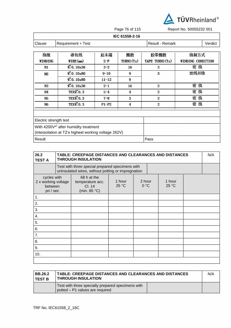
Page 76 of 115 Report No. 50055232 001
IEC 61558-2-16
Clause Requirement + Test Result - Remark Verdict
TRF No. IEC61558_2_16C
Electric strength test
With 4200V*) after humidity treatment
(interpolation at T2’s highest working voltage 262V)
Result Pass
26.2
TEST A
TABLE: CREEPAGE DISTANCES AND CLEARANCES AND DISTANCES THROUGH INSULATION
N/A
Test with three special prepared specimens with uninsulated wires, without potting or impregnation
cycles with 2 x working voltage
between pri / sec
68 h at the temperature acc.
Cl. 14 (min. 85 °C)
1 hour 25 °C
2 hour 0 °C
1 hour 25 °C
1.
2.
3.
4.
5.
6.
7.
8.
9.
10.
BB.26.2
TEST B
TABLE: CREEPAGE DISTANCES AND CLEARANCES AND DISTANCES THROUGH INSULATION
N/A
Test with three specially prepared specimens with potted – P1 values are required

Page 77 of 115 Report No. 50055232 001
IEC 61558-2-16
Clause Requirement + Test Result - Remark Verdict
TRF No. IEC61558_2_16C
cycles with 2 x working voltage
between pri / sec
68 h at the temperature acc.
Cl. 14 (min. 85 °C)
1 hour 25 °C
2 hour 0 °C
1 hour 25 °C
1.
2.
3.
4.
5.
6.
7.
8.
9.
10.

Page 78 of 115 Report No. 50055232 001
IEC 61558-2-16
Clause Requirement + Test Result - Remark Verdict
TRF No. IEC61558_2_16C
26.2
TEST C
TABLE: CREEPAGE DISTANCES AND CLEARANCES AND DISTANCES THROUGH INSULATION
N/A
Test with three specially prepared specimens with potting (only dti is required)
cycles with 2 x working voltage
between pri / sec
68 h at the temperature acc.
Cl. 14 (min. 85 °C)
1 hour 25 °C
2 hour 0 °C
1 hour 25 °C
1.
2.
3.
4.
5.
6.
7.
8.
9.
10.
26.107
61558-2-16/A1
TABLE: CREEPAGE DISTANCES AND CLEARANCES AND DISTANCES THROUGH INSULATION
N/A
Test for transformers, use FIW-wire
cycles with 2 x working voltage
between pri / sec
68 h at the temperature acc.
Cl. 14 (min. 85 °C)
1 hour 25 °C
2 hour 0 °C
1 hour 25 °C
1.
2.
3.
4.
5.
6.
7.
8.
9.
10.

Page 79 of 115 Report No. 50055232 001
IEC 61558-2-16
Clause Requirement + Test Result - Remark Verdict
TRF No. IEC61558_2_16C
H.2.3 TABLE: Fault conditions tested as specified when relevant: P
Ambient temperature ( C) ................................... : 25 C if no other specified
Applied input voltage (V) ...................................... : See below
Component No.
Fault Supply voltage (V)
Test time Fuse # Fuse current (A)
Observation
Output o-l 264 4h45min F1 0.782 Overloaded up to 3.3A fold-back. No damage, no hazards.
Output s-c 264 30min F1 0.048 Unit shutdown. No damage, no hazards.
Output o-l 90 4h22min F1 2.197 Overloaded up to 3.3A fold-back. No damage, no hazards.
Output s-c 90 3h38 F1 0.056 Unit shutdown. No damage, no hazards.
Transformer pin 7-8
s-c 264 10min F1 0.087 Fuse opened immediately, no damage, no hazards.
Transformer pin 9-10
s-c 264 10min F1 0.087 Unit shutdown. No damage, no hazards.
LF1 s-c 264 1s F1 0 Fuse opened immediately, no damage, no hazards.
BD1 s-c 264 1s F1 0 Fuse opened immediately, no damage, no hazards.
C23 s-c 264 1s F1 0 Fuse opened immediately, no damage, no hazards.
Q1 D - G s-c 264 10min F1 0.688 Output normal. No damage, no hazards.
Q1 D - S s-c 264 10min F1 0.688 Output normal. No damage, no hazards.
U4 pin 1 - 2
s-c 264 10min F1 0.692 Output normal. No damage, no hazards.
U4 pin 3 - 4
s-c 264 10min F1 0.692 Output normal. No damage, no hazards.
U4 pin 3 o-c 264 10min F1 0.692 Output normal. No damage, no hazards.
U3 pin 1 - 2
s-c 264 10min F1 0.080 Unit shutdown. No damage, no hazards.
U3 pin 3 - 4
s-c 264 10min F1 0.086 Unit shutdown. No damage, no hazards.
U3 pin 3 o-c 264 10min F1 0.086 Unit shutdown. No damage, no hazards.
Ds2 s-c 264 10min F1 0.086 Input 1.35W. No damage, no hazards.

Page 80 of 115 Report No. 50055232 001
IEC 61558-2-16
Clause Requirement + Test Result - Remark Verdict
TRF No. IEC61558_2_16C
Cs14 s-c 264 10min F1 0.060 Unit shutdown. No damage, no hazards.
U1 pin3-8 s-c 264 10min F1 0.087 Unit shutdown. No damage, no hazards.
U1 pin1-8 s-c 264 10min F1 0.089 Unit shutdown. No damage, no hazards.
U1 pin11-8 s-c 264 10min F1 0.694 Output normal. No damage, no hazards.
U2 pin14-4 s-c 264 10min F1 0.090 Unit shutdown. No damage, no hazards.
U2 pin15-4 s-c 264 10min F1 0.086 Unit shutdown. No damage, no hazards.
U2 pin7-4 s-c 264 10min F1 0.086 Unit shutdown. No damage, no hazards.
Supplementary information: The unit passed 4200V hi-pot test between primary and accessible output
connector after single fault test above.
1. In fault column, s-c=short-circuited, o-c=open-circuited, o-l=over-loaded.

Page 81 of 115 Report No. 50055232 001
IEC 61558-2-16
Clause Requirement + Test Result - Remark Verdict
TRF No. IEC61558_2_16C
Annex U U.5.1 THERMAL ENDURANCE TEST
Type ref.
Rated PRI-Voltage
Rated SEC-Voltage
Material of Winding
Material of bobbin
Material of resin
Material of potting
Material of foil
Components removed for test
tw
S
Objective test duration (days)
Theoretical test temperature
Sample 1 2 3 4 5 6 7
Winding PRI SEC PRI SEC PRI SEC PRI SEC PRI SEC PRI SEC PRI SEC
Start – Rk
After 4 h – Rw
After 4 h – winding temperature
After 4 h - oven temperature
After 24 h – Rw
After 24 h – winding temperature
After 24 h - oven temperature
Final test period (days)
Output voltage (11.1) under load
Insulating resistance
High voltage test

Page 82 of 115 Report No. 50055232 001
IEC 61558-2-16
Clause Requirement + Test Result - Remark Verdict
TRF No. IEC61558_2_16C
(35% of the values in Table 8.a
Annex U U.5.2 The use of another constant S other than 4500 in tw tests Test1:10 days
Type ref.
Rated PRI-Voltage
Rated SEC-Voltage
Material of Winding
Material of bobbin
Material of resin
Material of potting
Material of foil
Components removed for test
tw
S
Objective test duration (days)
Theoretical test temperature
Sample 1 2 3 4 5 6 7
Winding PRI SEC PRI SEC PRI SEC PRI SEC PRI SEC PRI SEC PRI SEC
Start – Rk
After 4 h – Rw
After 4 h – winding temperature
After 4 h - oven temperature
After 24 h – Rw
After 24 h – winding temperature
After 24 h - oven temperature
Final test period (days)
Output voltage (11.1) under load
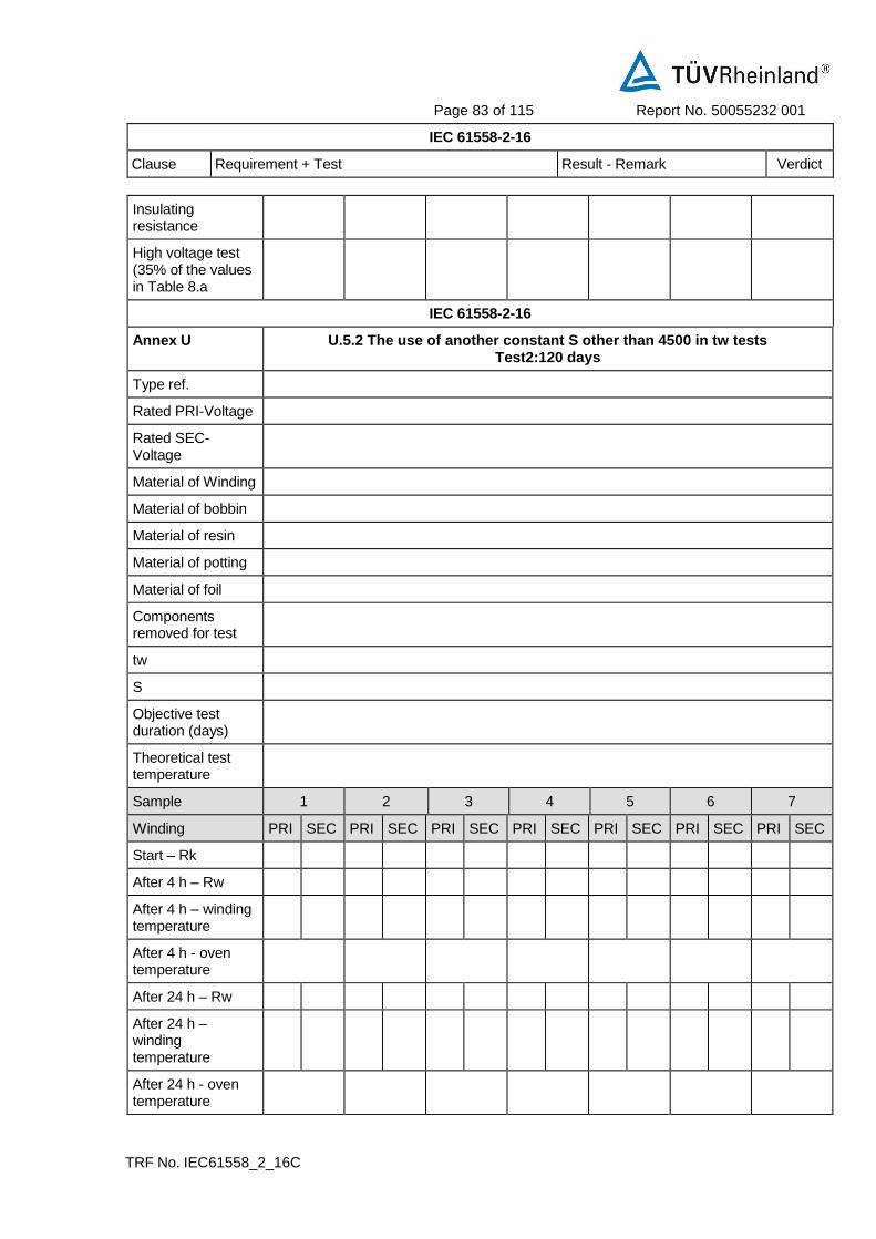
Page 83 of 115 Report No. 50055232 001
IEC 61558-2-16
Clause Requirement + Test Result - Remark Verdict
TRF No. IEC61558_2_16C
Insulating resistance
High voltage test (35% of the values in Table 8.a
IEC 61558-2-16
Annex U U.5.2 The use of another constant S other than 4500 in tw tests Test2:120 days
Type ref.
Rated PRI-Voltage
Rated SEC-Voltage
Material of Winding
Material of bobbin
Material of resin
Material of potting
Material of foil
Components removed for test
tw
S
Objective test duration (days)
Theoretical test temperature
Sample 1 2 3 4 5 6 7
Winding PRI SEC PRI SEC PRI SEC PRI SEC PRI SEC PRI SEC PRI SEC
Start – Rk
After 4 h – Rw
After 4 h – winding temperature
After 4 h - oven temperature
After 24 h – Rw
After 24 h – winding temperature
After 24 h - oven temperature

Page 84 of 115 Report No. 50055232 001
IEC 61558-2-16
Clause Requirement + Test Result - Remark Verdict
TRF No. IEC61558_2_16C
Final test period (days)
Output voltage (11.1) under load
Insulating resistance
High voltage test (35% of the values in Table 8.a
AA Annex AA N/A
Partial discharge (PD) test N/A
N/A
BB Annex BB N/A
Particular requirements for associated transformers for switch mode power supplies with internal frequencies > 500 Hz
See separate test report-form for these Annex. N/A
BB.8 MARKING AND OTHER INFORMATION N/A
BB.8.2 Marking for transformers IP00 or for associated transformers: type and trademark, instruction sheets
N/A
BB.8.11 Correct symbols: N/A
Volts V N/A
Amperes A (mA) N/A
Volt amperes (or volt-amperes reactive for reactors)
VA or (VAR) N/A
Watts W N/A
Hertz Hz N/A
Input PRI N/A
Output SEC N/A
Direct current d.c. (DC) or N/A
Neutral N N/A
Single-phase a.c. N/A
Three-phase a.c. 3 N/A
Three-phase and neutral a.c. 3N N/A
Power factor cos N/A
Class II construction
N/A

Page 85 of 115 Report No. 50055232 001
IEC 61558-2-16
Clause Requirement + Test Result - Remark Verdict
TRF No. IEC61558_2_16C
Class III construction
N/A
Fuse-link N/A
Rated max. ambient temperature ta N/A
Frame or core terminal
N/A
Protective earth
N/A
IP number IPXX N/A
Earth (ground for functional earth)
N/A
For indoor use only
N/A
tw5 YYY N/A
tw10 YYY N/A
twx YYY N/A
Additional Symbols (IEC 61558-2-16:09) N/A
SMPS incorporating a Fail-safe separating transformer or
N/A
Additional Symbols (IEC 61558-2-16:09) N/A
SMPS incorporating a Non-short-circuit-proof separating transformer
or
N/A
SMPS incorporating a Short-circuit-proof separating transformer (inherently or non-inherently)
or
N/A
SMPS incorporating a Fail-safe isolating transformer or
N/A
SMPS incorporating a Non-short-circuit-proof isolating transformer
or
N/A
SMPS incorporating a Short-circuit-proof isolating transformer (inherently or non-inherently) or
N/A
SMPS incorporating a Fail-safe safety isolating transformer
N/A
SMPS incorporating a Non-short-circuit-proof safety isolating transformer
N/A
SMPS incorporating a Short-circuit-proof safety isolating transformer (inherently or non-inherently)
N/A
SMPS (Switch mode power supply unit)
N/A

Page 86 of 115 Report No. 50055232 001
IEC 61558-2-16
Clause Requirement + Test Result - Remark Verdict
TRF No. IEC61558_2_16C
BB.9 PROTECTION AGAINST ELECTRIC SHOCK N/A
BB.10 CHANGE OF INPUT VOLTAGE SETTING N/A
BB.11 OUTPUT VOLTAGE AND OUTPUT CURRENT UNDER LOAD N/A
BB.12 NO-LOAD OUTPUT VOLTAGE (see supplementary requirements in Part 2) N/A
BB.13 SHORT-CIRCUIT VOLTAGE N/A
BB.14 HEATING N/A
BB.14.2 Application of 14.1 or 14.3 according to the insulation system
N/A
BB.14.2.1 Class of isolating system (classified materials according to IEC 60 085 and IEC 60 216)
N/A
BB.14.2.2 No classified material, or system but the measured temperature does not exceed the value of Class A
N/A
BB.14.2.3 No classified material or system but the measured temperature exceeds the value for Class A, the live parts of the transformers are submitted to the test of 14.3
N/A
BB.14.3 Accelerated ageing test for undeclared class of isolating system
N/A
Cycling test (10 cycles): N/A
– measuring of the no-load input current (mA) N/A
BB.14.3.1 – heat run (temperature in table 2) N/A
BB.14.3.2 – vibration test: 30 min; amplitude 0,35 mm; frequency range: 10 Hz, 55 Hz, 10 Hz
N/A
BB.14.3.3 – moisture treatment (48 h, 17.2) N/A
BB.14.3.4 Measurements and tests at the beginning and after each test:
N/A
– deviation of the no-load input current, measured at the beginning of the test is
30%
N/A
– insulation resistance acc. cl.18.1 and 18.2 N/A

Page 87 of 115 Report No. 50055232 001
IEC 61558-2-16
Clause Requirement + Test Result - Remark Verdict
TRF No. IEC61558_2_16C
– electric strength, no breakdown (18.3); 2 min; test voltage 35% of specified value (table VI)
N/A
– Transformers (50 or 60 Hz version) are tested after the dielectric strength test as follows: under no load; duration: 5 min; Upri(V):1,2 times rated supply voltage; frequency (Hz): 2 times rated frequency
N/A
BB.15 SHORT-CIRCUIT AND OVERLOAD PROTECTION N/A
BB.16 MECHANICAL STRENGTH N/A
BB.17 PROTECTION AGAINST HARMFUL INGRESS OF WATER AND MOISTURE N/A
BB.18 INSULATION RESISTANCE AND ELECTRIC STRENGTH N/A
BB.18.2 Insulation resistance between: N/A
– live parts and body for basic insulation 2
N/A
– live parts and body for reinforced insulation 7
N/A
– input circuits and output circuits for basic 2
N/A
– input circuits and output circuits for double or reinforced insulation 5
N/A
– each input circuit and all other input circuits 2
N/A
– each output circuit and all other output 2
N/A
– hazardous live parts and metal parts with basic insulation (Class II transformers)
2
N/A
– body and metal parts with basic insulation (Class 5
N/A
– metal foil in contact with inner and outer sur- 2
N/A
BB.18.3 Electric strength test (1 min): no flashover or breakdown:
N/A
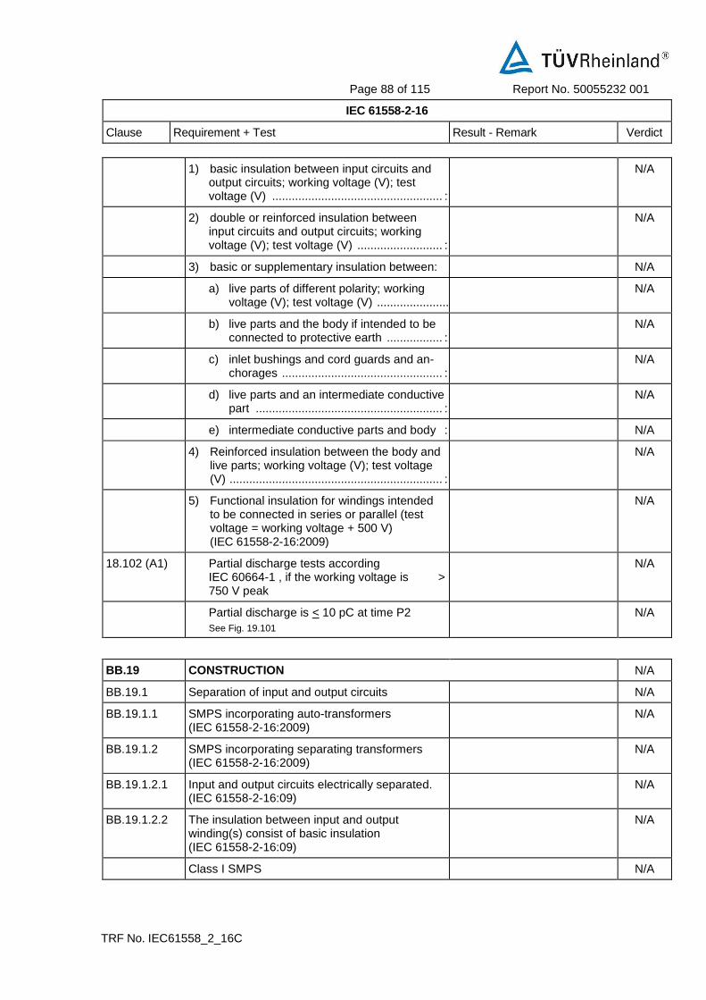
Page 88 of 115 Report No. 50055232 001
IEC 61558-2-16
Clause Requirement + Test Result - Remark Verdict
TRF No. IEC61558_2_16C
1) basic insulation between input circuits and output circuits; working voltage (V); test voltage (V) .................................................... :
N/A
2) double or reinforced insulation between input circuits and output circuits; working voltage (V); test voltage (V) .......................... :
N/A
3) basic or supplementary insulation between: N/A
a) live parts of different polarity; working voltage (V); test voltage (V) ........................ :
N/A
b) live parts and the body if intended to be connected to protective earth ................. :
N/A
c) inlet bushings and cord guards and an-chorages ................................................. :
N/A
d) live parts and an intermediate conductive part ......................................................... :
N/A
e) intermediate conductive parts and body : N/A
4) Reinforced insulation between the body and live parts; working voltage (V); test voltage (V) ................................................................. :
N/A
5) Functional insulation for windings intended to be connected in series or parallel (test voltage = working voltage + 500 V) (IEC 61558-2-16:2009)
N/A
18.102 (A1) Partial discharge tests according IEC 60664-1 , if the working voltage is > 750 V peak
N/A
Partial discharge is < 10 pC at time P2
See Fig. 19.101
N/A
BB.19 CONSTRUCTION N/A
BB.19.1 Separation of input and output circuits N/A
BB.19.1.1 SMPS incorporating auto-transformers (IEC 61558-2-16:2009)
N/A
BB.19.1.2 SMPS incorporating separating transformers (IEC 61558-2-16:2009)
N/A
BB.19.1.2.1 Input and output circuits electrically separated. (IEC 61558-2-16:09)
N/A
BB.19.1.2.2 The insulation between input and output winding(s) consist of basic insulation (IEC 61558-2-16:09)
N/A
Class I SMPS N/A

Page 89 of 115 Report No. 50055232 001
IEC 61558-2-16
Clause Requirement + Test Result - Remark Verdict
TRF No. IEC61558_2_16C
– Insulation between input windings and body consist of basic insulation
N/A
– Insulation between output windings and body consist of basic insulation
N/A
Class II SMPS (IEC 61558-2-16:09) N/A
– Insulation between input windings and body consist of double or reinforced insulation
N/A
– Insulation between output windings and body consist of double or reinforced insulation
N/A
BB.19.1.2.3 The insulation between input windings and intermediate conductive parts and the output windings and intermediate part consist of basic insulation (IEC 61558-2-16:09)
N/A
For class I SMPS the insulation between input and output windings via the intermediate conductive parts consist of basic insulation (IEC 61558-2-16:09)
N/A
For class II SMPS the insulation between input winding and the body and between the output windings and the body via the intermediate conductive parts consist of double or reinforced insulation (IEC 61558-2-16:09)
N/A
BB.19.1.2.4 Parts of output circuits may be connected to protective earth (IEC 61558-2-16:09)
N/A
BB.19.1.2.5 No direct contact between output circuits and the body, unless: (IEC 61558-2-16:2009)
N/A
– Allowed for associated transformers by the equipment standard
N/A
– Clause 19.8 of part 1 is fulfilled N/A
BB.19.1.3 SMPS incorporating isolating transformers and safety isolating transformers (IEC 61558-2-16:09)
N/A
BB.19.1.3.1 Input and output circuits electrically separated (IEC 61558-2-16:09)
N/A
No possibility of any connection between these circuits
N/A
BB.19.1.3.2 The insulation between input and output winding(s) consist of double or reinforced insulation (exception see 19.1.3.4) (IEC 61558-2-16:09)
N/A
Class I SMPS not intended for connection to the mains by a plug:
—

Page 90 of 115 Report No. 50055232 001
IEC 61558-2-16
Clause Requirement + Test Result - Remark Verdict
TRF No. IEC61558_2_16C
– Insulation between input windings and body connected to earth consist of basic insulation rated to the input voltage
N/A
– Insulation between output windings and body, connected to earth consist of basic insulation rated for the output voltage
N/A
Class I SMPS intended for connection to the mains by a plug (EN 61558-2-16:09):
N/A
– Insulation between input windings and body connected to earth consist of basic insulation rated to the working voltage
N/A
– Insulation between output windings and body, connected to earth consist of supplementary insulation rated for the working voltage
N/A
N/A
Class II SMPS (IEC 61558-2-16:09) N/A
– Insulation between input windings and body consist of double or reinforced insulation rated to the input voltage
N/A
– Insulation between output windings and body consist of double or reinforced insulation, rated to the output voltage
N/A
BB.19.1.3.3 SMPS with intermediate conductive parts not connected to the body (between input/output) (EN 61558-2-16:09):
N/A
19.1.3.3.1 For class I and class II SMPS the insulation between input and output windings, via intermediate conductive parts, consist of double or reinforced insulation, rated to the working voltage (EN 61558-2-16:09)
N/A
– For class II SMPS the insulation between input winding and the body and between the output windings and the body via the intermediate conductive parts consist of double or reinforced insulation. (rated to the input voltage, for SELV circuits only basic insulation to the body))
N/A
– For transformers, different from independent, the insulation between input and output windings, via intermediate conductive parts, consist of double or reinforced insulation, rated to the working voltage.
N/A

Page 91 of 115 Report No. 50055232 001
IEC 61558-2-16
Clause Requirement + Test Result - Remark Verdict
TRF No. IEC61558_2_16C
BB.19.1.3.3.2 Class I transformers with earthed core, and not allowed for class II equipment (EN 61558-2-16:09)
N/A
– Insulation from the input to the earthed core: basic insulation rated for the input voltage
N/A
– Insulation from the output voltage to the earthed core: basic insulation rated for the output voltage
N/A
BB.19.1.3.3.3 Insulation between : input to intermediate conductive parts and output and intermediate parts consist of at least basic insulation (EN 61558-2-16:09)
N/A
– If the insulation from input or output to the intermediate metal part is less than basic insulation, the part is considered to be connected to input or output.
N/A
BB.19.1.3.4 For class I SMPS, with protective screen, not connected to the mains by a plug the following conditions comply (EN 61558-2-16:09):
N/A
– The insulation between input winding and protective screen consist of basic insulation (rated input voltage)
N/A
– The insulation between output winding and protective screen consist of basic insulation (rated output voltage)
N/A
– The protective screen consist of metal foil or a wire wound screen extending the full width of the windings and has no gaps or holes
N/A
– Where the protective screen does not cover the entire width of the input winding, additional insulation to ensure double insulation in this area, is used.
N/A
– If the screen is made by a foil, the turns are isolated, overlap at least 3 mm
N/A
– The cross-section of the screen and the lead out wire is at least corresponding to the rated current of the overload device
N/A
– The lead our wire is soldered or fixed to the protective screen.
N/A
Protective screening is not allowed for SMPS with plug connection to the mains (EN 61558-2-16:09)
N/A

Page 92 of 115 Report No. 50055232 001
IEC 61558-2-16
Clause Requirement + Test Result - Remark Verdict
TRF No. IEC61558_2_16C
BB.19.1.3.5 No connection between output circuit and protective earth, except of associated transformers (allowed by equipment standard) or 19.8 is fulfilled (EN 61558-2-16:09)
N/A
BB.19.1.3.6 No connection between output circuit and body, except of associated transformers (allowed by equipment standard) (EN 61558-2-16:09)
N/A
BB.19.1.3.7 The distance between input and output terminals f 25 mm
N/A
BB.19.1.3.8 Portable SMPS having an rated output < 630 VA (EN 61558-2-16:09)
N/A
BB.19.1.3.9 No connection between output circuit, and body except of associated transformers (allowed by equipment standard) (EN 61558-2-16:09)
N/A
BB.19.1.3.10 Protective screening is not allowed for SMPS with plug connection to the mains (EN 61558-2-16:09)
N/A
BB.19.11 Handles, levers, knobs, etc.: N/A
– insulating material N/A
– supplementary insulation covering N/A
– separated from shafts or fixing by supplementary insulation
N/A
BB.19.12 Windings construction N/A
BB.19.12.1 Undue displacement in all types of transformers not allowed:
N/A
– of input or output windings or turns thereof N/A
– of internal wiring or wires for external connection
N/A
– of parts of windings or of internal wiring in case of rupture or loosening
N/A
BB.19.12.2 Serrated tape: N/A
– distance through insulation according to table 13
N/A
– one additional layer of serrated tape, and N/A
– one additional layer without serration N/A
– in case of cheek less bobbins the end turns of each layer shall be prevented from being displaced
N/A
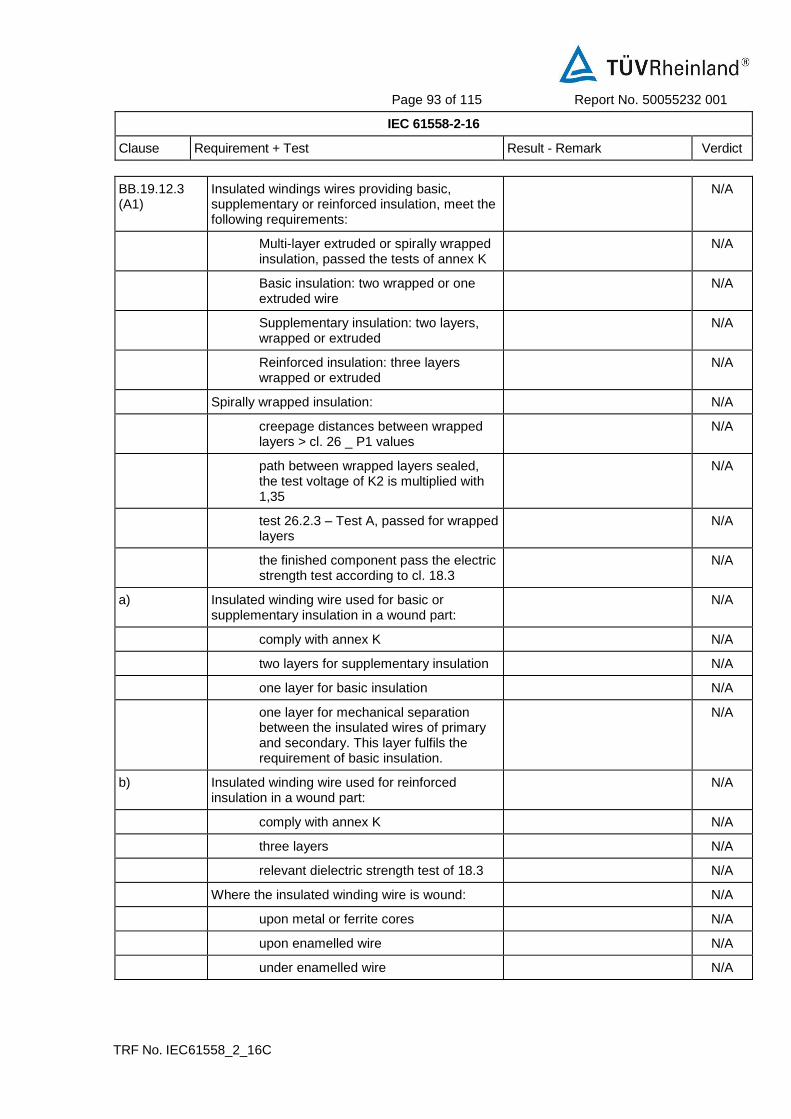
Page 93 of 115 Report No. 50055232 001
IEC 61558-2-16
Clause Requirement + Test Result - Remark Verdict
TRF No. IEC61558_2_16C
BB.19.12.3 (A1)
Insulated windings wires providing basic, supplementary or reinforced insulation, meet the following requirements:
N/A
Multi-layer extruded or spirally wrapped insulation, passed the tests of annex K
N/A
Basic insulation: two wrapped or one extruded wire
N/A
Supplementary insulation: two layers, wrapped or extruded
N/A
Reinforced insulation: three layers wrapped or extruded
N/A
Spirally wrapped insulation: N/A
creepage distances between wrapped layers > cl. 26 _ P1 values
N/A
path between wrapped layers sealed, the test voltage of K2 is multiplied with 1,35
N/A
test 26.2.3 – Test A, passed for wrapped layers
N/A
the finished component pass the electric strength test according to cl. 18.3
N/A
a) Insulated winding wire used for basic or supplementary insulation in a wound part:
N/A
comply with annex K N/A
two layers for supplementary insulation N/A
one layer for basic insulation N/A
one layer for mechanical separation between the insulated wires of primary and secondary. This layer fulfils the requirement of basic insulation.
N/A
b) Insulated winding wire used for reinforced insulation in a wound part:
N/A
comply with annex K N/A
three layers N/A
relevant dielectric strength test of 18.3 N/A
Where the insulated winding wire is wound: N/A
upon metal or ferrite cores N/A
upon enamelled wire N/A
under enamelled wire N/A

Page 94 of 115 Report No. 50055232 001
IEC 61558-2-16
Clause Requirement + Test Result - Remark Verdict
TRF No. IEC61558_2_16C
one layer for mechanical separation between the insulated wires and the core or the enamelled wires is required. This layer fulfils the requirement of basic insulation.
N/A
both windings shall not touch each other and also not the core.
N/A
100 % routine test of Annex K3 of part 1 is fulfilled
N/A
no creepage distances and clearances for insulated winding wirers
N/A
for TIW wires values of box 2) c) of table 13, table C.1 and table D.1 of part 1 and of clause 26.106 are not required
N/A
FIW Transformers which use FIW wire N/A
BB 19.12.101 (A1)
Max. class F for transformers which use FIW-wire
N/A
BB 19.12.102 (A1)
FIW wires comply with IEC 60851-5, Ed.4.1; IEC 60317-0-7 and IEC 60317-56, Ed.1.
N/A
other nominal diameter as mentioned in table 19.101 can be calculated with the formula after table 19.111
N/A
FIW wire used for basic or supplementary insulation for transformers according 19.1.2 (separating-transformers) of IEC 61558-2-16:
N/A
the test voltage of table 8a – part 1, based on the working voltage of basic or supplementary insulation, comply with the min. voltage strength of table 19.111
N/A
one layer for mechanical separation is located between the insulated wires of primary and secondary. This layer fulfil the requirement of basic insulation
N/A
between FIW and enamelled wire, no requirements of creepage distances and clearances
N/A
no touch of FIW and enamelled wires (grad 1, or grad 2 …)
N/A
FIW wire used for double or reinforced insulation for transformers according 19.1.3 (isolating and safety isolating transformers) of IEC 61558-2-16 (PRI and SEC basic insulated FIW-wire):
N/A

Page 95 of 115 Report No. 50055232 001
IEC 61558-2-16
Clause Requirement + Test Result - Remark Verdict
TRF No. IEC61558_2_16C
the test voltage of table 8a – part 1, based on the working voltage of basic or supplementary insulation, comply with the min. voltage strength of table 19.111
N/A
for primary and secondary winding FIW-wire for basic insulation is used
N/A
one layer for mechanical separation is located between the insulated wires of primary and secondary. This layer fulfil the requirement of basic insulation
N/A
no touch between the basic insulated PRI and SEC FIW-wires
N/A
between PRI- and SEC-FIW wires, no requirements of creepage distances and clearances
N/A
Alternative construction used for reinforced insulation (reinforced insulated FIW wire and enamelled wire)
N/A
the test voltage of table 8a – part 1, based on the working voltage reinforced insulation, comply with the min. voltage strength of table 19.111
N/A
one layer for mechanical separation is located between the reinforced insulated FIW wire and the enamelled wire. This layer fulfil the requirement of basic insulation
N/A
no touch between the FIW wire and the enamelled wire
N/A
between the reinforced FIW wire and any other parts, no requirements of creepage distances and clearances exist
N/A
Alternative construction with FIW wires, basic or supplementary insulated for transformers with double or reinforced insulation according to 19.1.3 (basic/supplementary insulated FIW wire + enamelled wire + creepage distance and clearances for basic insulation)
N/A
the test voltage of table 8a – part 1, based on the working voltage of basic or supplementary insulation, comply with the min. voltage strength of table 19.111
N/A
PRI or SEC basic insulated FIW wire and to the other winding (enamelled wire) requirements of supplementary insulation
N/A

Page 96 of 115 Report No. 50055232 001
IEC 61558-2-16
Clause Requirement + Test Result - Remark Verdict
TRF No. IEC61558_2_16C
creepage distances and clearances between the basic insulated FIW wire and the enamelled wire for basic or supplementary insulation are required.
N/A
Where the FIW wire is wound N/A
upon metal or ferrite cores N/A
one layer for mechanical separation between the insulated wires and the core or the enamelled wires is required. This layer fulfils the requirement of basic insulation.
N/A
both windings shall not touch each other and also not the core.
N/A
BB.20 COMPONENTS N/A
BB.21 INTERNAL WIRING N/A
BB.22 SUPPLY CONNECTION AND EXTERNAL FLEXIBLE CABLES AND CORDS N/A
BB.23 TERMINALS FOR EXTERNAL CONDUCTORS N/A
BB.24 PROVISION FOR PROTECTIVE EARTHING N/A
BB.25 SCREWS AND CONNECTIONS N/A
BB.26 CREEPAGE DISTANCES AND CLEARANCES N/A
BB.26.1 See 26.101 N/A
BB.26.2 Creepage distances (cr) and clearances (cr) N/A
BB.26.2.1 Windings covered with adhesive tape N/A
– the values of pollution degree 1 are fulfilled N/A
– all isolating material are classified acc. to IEC 60085 and IEC 60216
N/A
– test A of 26.2.3 is fulfilled N/A
BB.26.2.2 Uncemented insulating parts pollution degree P2 or P3
N/A
– all isolating material are classified acc. to IEC 60085 and IEC 60216
N/A

Page 97 of 115 Report No. 50055232 001
IEC 61558-2-16
Clause Requirement + Test Result - Remark Verdict
TRF No. IEC61558_2_16C
– values of pollution degree 1 are not applicable
N/A
BB.26.2.3 Cemented insulating parts N/A
– all isolating materials are classified acc. to IEC 60085 and IEC 60216
N/A
– values of distance through insulation (dti) are fulfilled
N/A
– creepage distances and clearances are not required
N/A
– test A of this sub clause is fulfilled N/A
Test A N/A
– thermal class N/A
– working voltage N/A
– Test with three specially specimens, with uninsulated wires, without impregnation or potting
N/A
Two of the three specimens are subjected to: N/A
– the relevant humidity treatment according to 17.2 (48 h)
N/A
– the relevant dielectric strength test of 18.3 multiplied with factor 1,35
N/A
– One of the three specimens is subjected to the relevant dielectric strength test of 18.3 multiplied by the factor 1,35 immediately at the end of the last cycle with high temperature
N/A
Impulse dielectric test according to 4.1.1.2.1 of IEC 60 664-1 (1,2 / 50 – see Annex R of IEC 61558-1
N/A
BB.26.2.4 Enclosed parts, by impregnation or potting N/A
BB.26.2.4.1 – The requirements of reduced values as stated for pollution degree 1 (P1) are fulfilled
N/A
– all isolating materials are classified acc. to IEC 60085 and IEC 60216
N/A
Test B N/A
– thermal class N/A
– working voltage N/A

Page 98 of 115 Report No. 50055232 001
IEC 61558-2-16
Clause Requirement + Test Result - Remark Verdict
TRF No. IEC61558_2_16C
– Test with three specially specimens, potted or impregnated. The dielectric strength test is applied directly to the joint.
N/A
Two of the three specimens are subjected to: N/A
– the relevant humidity treatment according to 17.2 (48 h)
N/A
– the relevant dielectric strength test of 18.3 multiplied with factor 1,25
N/A
– One of the three specimens is subjected to the relevant dielectric strength test of 18.3 multiplied by the factor 1,25 immediately at the end of the last cycle with high temperature
N/A
The three spacemen pass the Impulse dielectric test according to 4.1.1.2.1 of IEC 60 664-1 (1,2 / 50 – see Annex R of IEC 61558-1
N/A
BB.26.2.4.2 – The requirements of distance through insulation (dti) are fulfilled. (P1 values are not required)
N/A
– all isolating materials are classified acc. to IEC 60085 and IEC 60216
N/A
Test C N/A
– thermal class N/A
– working voltage N/A
– Test with three specimens, potted or impregnated. (finished components)
(see appended table) N/A
– Neither cracks, nor voids in the insulating compounds
N/A
Two of the three specimens are subjected to: N/A
– the relevant humidity treatment according to 17.2 (48 h)
N/A
– the relevant dielectric strength test of 18.3 multiplied with factor 1,35
N/A
– One of the three specimens is subjected to the relevant dielectric strength test of 18.3 multiplied by the factor 1,35 immediately at the end of the last cycle with high temperature
N/A

Page 99 of 115 Report No. 50055232 001
IEC 61558-2-16
Clause Requirement + Test Result - Remark Verdict
TRF No. IEC61558_2_16C
The three spacemen pass the Impulse dielectric test according to 4.1.1.2.1 of IEC 60 664-1 (1,2 / 50 – see Annex R of IEC 61558-1
N/A
BB.26.3 Distance through insulation N/A
For double or reinforced insulation, the required values of Tables 13, C1, and D1 – boxes 2b, 2c and 7 are fulfilled
N/A
The insulation fulfil the material classification according IEC 60085 or 60216 or the test of 14.3
N/A
BB.26.3.1 Reduced values of the thickness of insulation for supplementary or reinforced insulation are allowed if the following conditions are fulfilled:
N/A
– the isolating materials are classified acc. to IEC 60085 and IEC 60216
N/A
– the test of 14.3 is fulfilled N/A
– If both requirements are fulfilled, the required values for solid insulation can be multiplied by 0,4
N/A
– Minimum thickness of reinforced insulation >0,2 mm
N/A
– Minimum thickness of supplementary insulation >0,1 mm
N/A
BB.26.3.2 Insulation in thin sheet form N/A
– If the layers are non-separable (glued together):
N/A
– The requirement of 3 layers is fulfilled N/A
– The mandrel test according 26.3.3 is fulfilled with 150 N
N/A
– The required values for d.t.i. of Tables 13, C.1 and D.1 – marked by index ”e” is fulfilled.
N/A
– If the layers are separated: N/A
– The requirement of 2 layers is fulfilled N/A
– If serrated tape is used, 1 additional layer (serrated) and one additional layer without serration is required
N/A
– The mandrel test according 26.3.3 is fulfilled on each layer with 50 N
N/A

Page 100 of 115 Report No. 50055232 001
IEC 61558-2-16
Clause Requirement + Test Result - Remark Verdict
TRF No. IEC61558_2_16C
– The required values for d.t.i. of Tables 13, C.1 and D.1 – marked by index ”e” is fulfilled.
N/A
– If the layers are separated (alternative: N/A
The requirement of 3 layers is fulfilled
N/A
– If serrated tape is used, 1 additional layer (serrated) and one additional layer without serration is required
N/A
– The mandrel test according 26.3.3 is fulfilled on 2/3 of the layers with 100 N
N/A
– The required values for d.t.i. of Tables 13, C.1 and D.1 – marked by index ”e” is fulfilled.
N/A
Test according to 14.3 and if the isolating materials are classified acc. to IEC 60085 and IEC 60216 no distances through insulation are required for insulation in thin sheet form
N/A
The figures within square brackets in box 2 and 7 of table 13 (C.1/D.1) are used for insulation in thin sheet form as follows:
N/A
– rated output > 100 VA values in square brackets apply
N/A
– 25 VA 100 VA 2/3 of the value in square brackets apply
N/A
– rated output 25 VA 1/3 of the value in square brackets apply
N/A
BB.26.3.3 Mandrel test of insulation in thin sheet form (specimen of 70 mm width are necessary):
N/A
– If the layers are non-separable – at least 3 layers glued together fulfil the test:
N/A
– pull force of 150 N N/A
– high voltage test of 5,0 kV or the test voltage of 18.3 multiplied by 1,25 whatever is the greater. No flashover, no breakdown.
N/A
– If the layers are separable and 2/3 of at least 3 layers fulfil the test.
N/A
– pull force of 100 N N/A

Page 101 of 115 Report No. 50055232 001
IEC 61558-2-16
Clause Requirement + Test Result - Remark Verdict
TRF No. IEC61558_2_16C
– high voltage test of 5,0 kV or the test voltage of 18.3 multiplied by 1,25 whatever is the greater. No flashover, no breakdowns.
N/A
– If the layers are separable 1 of at least 2 layers fulfil the test:
N/A
– pull force of 50 N N/A
– high voltage test of 5,0 kV or the test voltage of 18.3 multiplied by 1,25 whatever is the greater. No flashover, no breakdown.
N/A
BB.26.101 Creepage distances, clearances and distances through insulation, specified values according to (EN 61558-2-16:09):
N/A
– table 13, material group IIIa (part 1) N/A
– table C, material group II (part 1) N/A
– table D, material group I (part 1) N/A
– working voltage N/A
– rated supply frequency 50/60 Hz N/A
– rated internal frequency N/A
1. Insulation between input and output circuits (basic insulation):
N/A
a) measured value(mm) ................................................. :
N/A
2. Insulation between input and output circuits (double or reinforced insulation):
N/A
a) (mm) ................................................. :
N/A
b) (mm) ................................................. :
N/A
c) s (mm) ................................................. :
N/A
3. Insulation between adjacent input circuits:
(mm) ....................................................... :
N/A
Insulation between adjacent output
values (mm) ............................................ :
N/A

Page 102 of 115 Report No. 50055232 001
IEC 61558-2-16
Clause Requirement + Test Result - Remark Verdict
TRF No. IEC61558_2_16C
4. Insulation between terminals for external connection:
N/A
a) (mm) ................................................. :
N/A
b) (mm) ................................................. :
N/A
c) (mm) ................................................. :
N/A
5. Basic or supplementary insulation: N/A
a) (mm) ................................................. :
N/A
b) mea(mm) ................................................. :
N/A
c) (mm) ................................................. :
N/A
d) (mm) ................................................. :
N/A
e) (mm) ................................................. :
N/A
6. Reinforced or double insulation: d values
(mm) ....................................................... :
N/A
7. Distance through insulation: N/A
a) (mm) ................................................. :
N/A
b) (mm) ................................................. :
N/A
c) (mm) ................................................. :
N/A
BB.26.102 Values of IEC 61558-2-16 applicable for frequency up to 3 MHz (EN 61558-2-16:09)
N/A
For frequency above 3 MHz clause 7 of IEC 60664-4 is applicable (high frequency testing)
N/A
BB.26.103 Clearance (EN 61558-2-16:09) N/A
a.) Clearance for frequency > 30 kHz according figure 101 two determinations are necessary:
N/A
– determination based on peak working voltage according Table 104 :
N/A
Peak working voltage N/A
Basic insulation: required / measured N/A

Page 103 of 115 Report No. 50055232 001
IEC 61558-2-16
Clause Requirement + Test Result - Remark Verdict
TRF No. IEC61558_2_16C
Double or reinforced insulation: required / measured value
N/A
– and alternative if applicable for approximately homogeneous field according to Table 102
N/A
Peak working voltage N/A
Basic insulation: required / measured N/A
Double or reinforced insulation: required / measured value
N/A
– determination based on measured r.m.s. working voltage according Tables 13, C1 and D1 (see clause 26.101)
N/A
The minimum clearance is the greater of the two values.
N/A
b.) Clearance for frequency < 30 kHz according figure 101 two determinations are necessary:
N/A
– determination based on peak working voltage with recurring peak voltages according Table 103 :
N/A
– determination based on measured r.m.s. working voltage according Tables 13, C1 and D1 (see clause 26.101)
N/A
The minimum clearance is the greater of the two values.
N/A
BB.26.104 The working voltages of Table 102, 103 and 104 are peak voltages including µsec peaks EN 61558-2-16:09)
N/A
The working voltage according to Table 13 of part 1 are r.m.s. voltages
N/A
BB.26.105 Creepage distances N/A
Two determinations of creepage distances are necessary (see Figure 102)
N/A
– determination based on measured peak working voltage according Tables 105 to 110
N/A
Peak working voltage N/A
Pollution degree N/A
Basic or supplementary insulation: required / measured
N/A
Double or reinforced insulation: required / measured value
N/A

Page 104 of 115 Report No. 50055232 001
IEC 61558-2-16
Clause Requirement + Test Result - Remark Verdict
TRF No. IEC61558_2_16C
– determination based on measured r.m.s. working voltage according Tables 13, C1 and D1 (see clause 26.101)
N/A
If the values based on table 105 to 110 are lower than the relevant values in Tables 13, C.1 or D.1, the higher values shall be applicable
N/A
BB.26.106 Distance through insulation (EN 61558-2-16:09) N/A
Instead of partial discharge with high frequency voltage the test of the distance and the calculation of the electric field is applicable under the following conditions:
N/A
– the max. frequency is < 10 MHz N/A
– the field strength approximately comply with Figure 103
N/A
– no voids or gaps are present in between the solid insulation
N/A
For thick layers d1 > 0,75 the peak value of the field strength is < 2 kV/mm
N/A
For thin layers d2 < 30 µm the peak value of the field strength is < 10 kV/mm
N/A
For d1 > d > d2 equation (1) is used for calculation the field strength
N/A
BB.26.107 (A1)
For transformers with FIW wires the following test is required
N/A
– 10 cycles are required N/A
– 68 h test at max heating temperature + 10°C or test at max. allowed winding temperature based on the insulation class (required in table 1) + 10°C
N/A
– 1 h at 25° C N/A
– 2 h at 0° C N/A
– 1 h at 25° C – (next cycle start again with 68 h max winding temp + 10)
N/A
– during the 10 cycles test 2 x working voltage is connected between PRI and SEC
N/A
– after 10 cycle test 2 transformers are subjected to the 17.2 test for 48 h and direct after the 48 h the dielectric strength test of 18.3 (100 % test voltage) is done
N/A

Page 105 of 115 Report No. 50055232 001
IEC 61558-2-16
Clause Requirement + Test Result - Remark Verdict
TRF No. IEC61558_2_16C
– after the 10 cycle test the third sample is tested at the end of the last cycle in the hot position with the dielectric strength test of 18.3 (100 % test voltage)
N/A
– the partial discharge test according to 18.101 is done after the cycling test and after the high voltage test, if the peak working voltage is >750 V
N/A
BB.27 RESISTANCE TO HEAT, FIRE AND TRACKING N/A
IEC 61558-2-16 Annex BB
Clause Requirement + Test Result - Remark Verdict
BB.E ANNEX E , GLOW WIRE TEST N/A
The test is required according to IEC 60695-2-10 and IEC 60695-2-11 with the following additions:
N/A
BB.E.1 Clause 6, ”Severities” of IEC 6095-2-11, apply with the temperature stated in 27.3 of IEC 61558-1
N/A
BB.E2 Clause 8, ”Conditioning”, of IEC 60695-2-11 apply, preconditioning is required
N/A
BB.E3 Clause 10, ”Test Procedure”, of IEC 60695-2-11apply, The tip of the glow wire is applied to the flat side of the surface.
N/A
BB.F ANNEX F, REQUIREMENTS FOR MANUALLY OPERATED SWITCHES WHICH ARE PARTS OF THE TRANSFORMER
N/A
BB.H ANNEX H, ELECTRONIC CIRCUITS (IEC 61558-1)
N/A
BB.K
61558-2-16/A1
ANNEX K, INSULATED WINDING WIRES FOR USE AS MULTIPLE LAYER INSULATION
N/A
BB.K.1 Wire construction: N/A
– insulated winding wire for basic or supplementary insulation (see 19.12.3)
N/A
– insulated winding wire for reinforced insulation (see 19.12.3)
N/A
– splid circular winding wires and stranded winding wires with 0,05 to 5 mm diameter
N/A

Page 106 of 115 Report No. 50055232 001
IEC 61558-2-16
Clause Requirement + Test Result - Remark Verdict
TRF No. IEC61558_2_16C
– spirally wrapped insulation - overlapping N/A
BB.K.2 Type tests N/A
BB.K.2.1 General
Tests between ambient temperature between 15° C and 35° C and at an humidity between 45% and 75 %
N/A
BB K.2.2 Electric strength test N/A
BB K.2.2.1 Solid circular winding wires and stranded winding wires
N/A
Test samples prepared according to clause 4.4.1 of IEC 60851-5:2008 (twisted pair)
N/A
Dielectric strength test: 6 kV for reinforced insulation
N/A
Dielectric strength test: 3 kV for basic or supplementary insulation
N/A
BB K.2.2.2 Square or rectangular wires . N/A
Test samples prepared according to clause 4.7.1 of IEC 60851-5:2008
N/A
Dielectric strength test: 5,5 kV for reinforced insulation
N/A
Dielectric strength test: 2,75 kV for basic or supplementary insulation
N/A
BB K.2.3 Flexibility and adherence N/A
Claus 5.1 in Test 8 of IEC 60851-3:2009 shall be used
N/A
Test samples prepared according to clause 5.1.1.4 of IEC 60851-3:2009
N/A
Dielectric strength test: 5,5 kV for reinforced insulation
N/A
Dielectric strength test: 2,75 kV for basic or supplementary insulation
N/A
Mandrel diameter according table K.1 N/A
The tension to the wire during winding on mandrel is 118 N/mm² (118 MPa)
N/A
BB.K.2.4 Heat shock N/A
Test samples prepared according to 3.1.1 (in Test 9) of IEC 60851-6:1996
N/A
– high voltage test immediately after this test N/A
– Dielectric strength test: 5,5 kV for reinforced insulation
N/A

Page 107 of 115 Report No. 50055232 001
IEC 61558-2-16
Clause Requirement + Test Result - Remark Verdict
TRF No. IEC61558_2_16C
– Dielectric strength test: 2,75 kV for basic or supplementary insulation
N/A
BB.K.2.5 Retention of dielectric strength after bending
( test as specified under test 13 of 4.6.1 c) of IEC 60 851-5)
N/A
– high voltage test immediately after this test
– Dielectric strength test: 5,5 kV for reinforced insulation
– Dielectric strength test: 2,75 kV for basic or supplementary insulation
N/A
BB.K.3 Testing during manufacturing N/A
BB.K.3.1 General
Tests as subjected in K.3.2 and K.3.3
N/A
BB K.3.2 Routine test N/A
– Dielectric strength test: 4,2 kV for reinforced insulation
N/A
– Dielectric strength test: 2,1 kV for basic or supplementary insulation
N/A
BB K.3.3 Sampling test N/A
BB K.3.3.1 Solid circular winding wires and stranded winding wires
N/A
Test with a twisted pair, prepared according clause 4.4.1 of IEC 60851-5:2008
N/A
– Dielectric strength test: 6 kV for reinforced insulation
N/A
– Dielectric strength test: 3 kV for basic or supplementary insulation
N/A
BB K.3.3.2 Square rectangular wire N/A
Samples prepared according to clause 4.7.1 of IEC 60851-5:2008
N/A
– Dielectric strength test: 5,5 kV for reinforced insulation
N/A
– Dielectric strength test: 3 kV for basic or supplementary insulation
N/A
BB.U ANNEX U – INFORMATIVE – OPTIONAL TW – MARKING FOR TRANSFORMERS N/A
V ANNEX V, SYMBOLS TO BE USED FOR THERMAL CUT-OUTS N/A

Page 108 of 115 Report No. 50055232 001
IEC 61558-2-16
Clause Requirement + Test Result - Remark Verdict
TRF No. IEC61558_2_16C
BB.26.2
TEST A
TABLE: CREEPAGE DISTANCES AND CLEARANCES AND DISTANCES THROUGH INSULATION
N/A
Test with three special prepared specimens with uninsulated wires, without potting or impregnation
cycles with 2 x working voltage
between pri / sec
68 h at the temperature acc.
Cl. 14 (min. 85 °C)
1 hour 25 °C
2 hour 0 °C
1 hour 25 °C
1.
2.
3.
4.
5.
6.
7.
8.
9.
10.
BB.26.2
TEST B
TABLE: CREEPAGE DISTANCES AND CLEARANCES AND DISTANCES THROUGH INSULATION
N/A
Test with three specially prepared specimens with potted – P1 values are required
cycles with 2 x working voltage
between pri / sec
68 h at the temperature acc.
Cl. 14 (min. 85 °C)
1 hour 25 °C
2 hour 0 °C
1 hour 25 °C
1.
2.
3.
4.
5.
6.
7.
8.
9.
10.

Page 109 of 115 Report No. 50055232 001
IEC 61558-2-16
Clause Requirement + Test Result - Remark Verdict
TRF No. IEC61558_2_16C
BB.26.2
TEST B
TABLE: CREEPAGE DISTANCES AND CLEARANCES AND DISTANCES THROUGH INSULATION
N/A
Test with three specially prepared specimens with potted – P1 values are required
cycles with 2 x working voltage
between pri / sec
68 h at the temperature acc.
Cl. 14 (min. 85 °C)
1 hour 25 °C
2 hour 0 °C
1 hour 25 °C
BB.26.2
TEST C
TABLE: CREEPAGE DISTANCES AND CLEARANCES AND DISTANCES THROUGH INSULATION
N/A
Test with three specially prepared specimens with potting (only dti is required)
cycles with 2 x working voltage
between pri / sec
68 h at the temperature acc.
Cl. 14 (min. 85 °C)
1 hour 25 °C
2 hour 0 °C
1 hour 25 °C
1.
2.
3.
4.
5.
6.
7.
8.
9.
10.
BB.26.107
61558-2-16/A1
TABLE: CREEPAGE DISTANCES AND CLEARANCES AND DISTANCES THROUGH INSULATION
N/A
Test for transformers, use FIW-wire
cycles with 2 x working voltage
between pri / sec
68 h at the temperature acc.
Cl. 14 (min. 85 °C)
1 hour 25 °C
2 hour 0 °C
1 hour 25 °C

Page 110 of 115 Report No. 50055232 001
IEC 61558-2-16
Clause Requirement + Test Result - Remark Verdict
TRF No. IEC61558_2_16C
BB.26.107
61558-2-16/A1
TABLE: CREEPAGE DISTANCES AND CLEARANCES AND DISTANCES THROUGH INSULATION
N/A
Test for transformers, use FIW-wire
cycles with 2 x working voltage
between pri / sec
68 h at the temperature acc.
Cl. 14 (min. 85 °C)
1 hour 25 °C
2 hour 0 °C
1 hour 25 °C
1.
2.
3.
4.
5.
6.
7.
8.
9.
10.
BB 18.2 TABLE: Dielectric Strength N/A
Test voltage applied between: Test potential applied (V)
Breakdown / flashover (Yes/No)
Supplementary information:
BB 18.3 TABLE: insulation resistance measurements N/A
Insulation resistance R between: R (MΩ) Required R (MΩ)
Supplementary information:
BB 26 TABLE: Clearance And Creepage Distance Measurements N/A
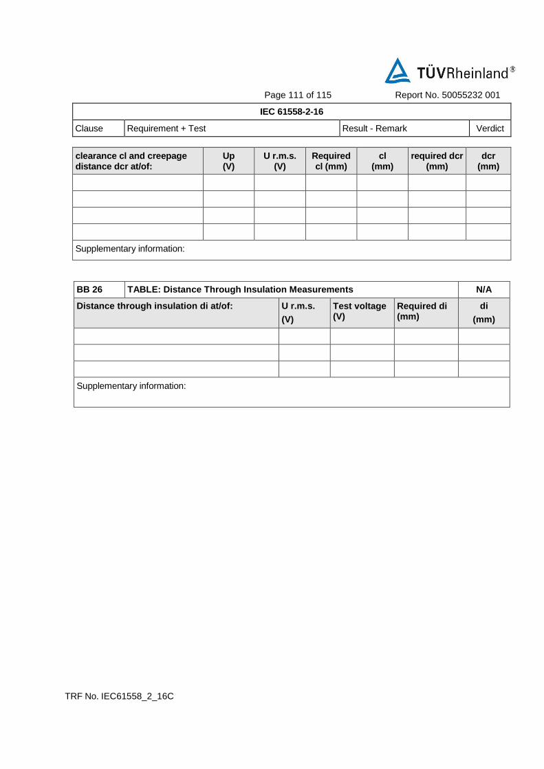
Page 111 of 115 Report No. 50055232 001
IEC 61558-2-16
Clause Requirement + Test Result - Remark Verdict
TRF No. IEC61558_2_16C
clearance cl and creepage distance dcr at/of:
Up (V)
U r.m.s. (V)
Required cl (mm)
cl (mm)
required dcr (mm)
dcr (mm)
Supplementary information:
BB 26 TABLE: Distance Through Insulation Measurements N/A
Distance through insulation di at/of: U r.m.s.
(V)
Test voltage (V)
Required di (mm)
di
(mm)
Supplementary information:

Page 112 of 115 Report No. 50055232 001
IEC 61558-2-16
Clause Requirement + Test Result - Remark Verdict
TRF No. IEC61558_2_16C
APPENDIX Variations to IEC 61558-1 Ed 2.1 for application in Australia and New Zealand P
EXPLANATION FOR ABBREVIATIONS
P=Pass, F=Fail, N/A=Not applicable. Placed in the column to the right.
5.5 Replace the text with the following variation: 5.5 For a.c., test voltages are of substantially sinusoidal wave form, and, if not
otherwise specified, have a frequency of 50 Hz.
47-63Hz P
8.1 After Item a) insert the following variation:
− The marking of rated voltage or rated voltage range of single-phase transformers shall cover 240V for Australia and 230 V for New Zealand and, for polyphase transformers, 415 V for Australia and 400 V for New Zealand.
100-240Vac P
Table 1 Insert the following entry:
Insulated pins of transformers with pins for insertion into socket-outlets 70°C
P
16.4 After item a) insert the following variation:
Items b) and c), Table 5, and the last four paragraphs of the test specification are not applicable.
N/A
19.15 Replace the test specification with the following variation:
Compliance is checked by inserting the transformer, as in normal use into a socket-outlet capable of accepting a 10 A plug complying with Figure 2.1(a) of AS/NZS 3112. The socket-outlet has a horizontal pivot at a distance of 8 mm behind the engagement face of the socket-outlet and in the plane of the lower intersection of the centre lines of the contact apertures.
N/A
19.16 Replace the text with the following variation:
19.16 VOID
P

Page 113 of 115 Report No. 50055232 001
IEC 61558-2-16
Clause Requirement + Test Result - Remark Verdict
TRF No. IEC61558_2_16C
19.201 After 19.23 insert the following variation:
19.201 Transformers having integral pins for insertion into socket outlets shall comply with the appropriate requirements of AS/NZS 3112.
Compliance is checked as specified in Appendix J of AS/NZS 3112
NOTE 1 Clause J.2.2.3 (Internal connections for plug portions) of AS/NZS 3112 is covered by clause
19.6 and clause 21 of this standard
NOTE 2 Clause J.2.2.6.2 (High voltage test) of AS/NZS 3112, except for the test of the insulation of the insulated pins, is covered by clause 18 of this standard. NOTE 3 Clause J.2.2.6.4 (Temperature rise test) of AS/NZS 3112 is covered by clause 14 of this standard NOTE 4 Clause J.2.2.6.7 (Equipment with integral pins intended to be supported by the contacts of a
socket-outlet) of AS/NZS 3112 is covered by clause 19.15 of this standard
N/A
20 Replace the first and third paragraphs with the following variations: Components shall comply with the safety requirements specified in the relevant IEC or Australian/New Zealand Standards as far as they reasonably apply. Compliance with the IEC or Australian/New Zealand Standards for the relevant
Component does not necessarily ensure compliance with the requirements of this Standard.
P
20.5 Insert in the second paragraph in the requirement, before IEC 60906-3 the following variation: Annex E in AS/NZS 3112 or
P
22.4 Replace the text with the following variation: 22.4 VOID
N/A
22.6 Replace in the requirement, “16” with the following variation: “10”.
N/A

Page 114 of 115 Report No. 50055232 001
IEC 61558-2-16
Clause Requirement + Test Result - Remark Verdict
TRF No. IEC61558_2_16C
22.8 Replace the second paragraph in the requirement, with the following variation: Power supply cords of portable transformers shall be fitted with an appropriately rated plug complying with AS/NZS 3112 or AS/NZS 3123 or IEC 60309
N/A
APPENDIX Amendment 1 to AS/NZS61558.2.16:2010 P
-- AUSTRALIAN NATIONAL VARIATIONS --
-- There are no national variations to this Part 2 other than those listed in Annex ZZ to AS/NZS 61558.1.
P
-- NEW ZEALAND NATIONAL VARIATIONS --
-- There are no national variations to this Part 2 other than those listed in Annex ZZ to AS/NZS 61558.1.
P
National Differences
Clause Requirement + Test Result – Remark Verdict
APPENDIX Amendment 2 to AS/NZS61558.2.16:2010 P
General Throughout the standard including the cover pages replace the text: Safety of Power Transformers, Power Supplies, Reactors and similar products for supply voltages up to 1 100 V – By: Safety of transformers, reactors, power supply units and similar products for voltages up to 1 100 V – Where ever it occurs. Throughout the standard including the cover pages replace the text: requirements for switch mode power supply units and transformers for switch mode power supply units By: requirements and tests for switch mode power supply units and transformers for switch mode power supply units Where ever it occurs.
P
APPENDIX Amendment 3 to AS/NZS61558.2.16:2010 P

Page 115 of 115 Report No. 50055232 001
IEC 61558-2-16
Clause Requirement + Test Result - Remark Verdict
TRF No. IEC61558_2_16C
National Differences
Clause Requirement + Test Result – Remark Verdict
General Under the list of interests represented on Committee EL-002 Replace Australian Retailers Association with National Retailers Association (Australia) Replace Ministry of Economic Development, New Zealand with WorkSafe New Zealand Add Testing Interests New Zealand Delete Energy Networks Australia
P

P H O T O D O C U M E N T A T I O N
50055232 001
for
AC/DC Power Supply
SSLC180V54.6
Wuxi Sans Electronic Co,. Ltd.
This documentation consists of 8 pages (excluding this cover page)

Photo Documentation
Report Number: 50055232 001
Model: SSLC180V54.6
Page 1 of 8
Top view Rating label location
Bottom view

Photo Documentation
Report Number: 50055232 001
Model: SSLC180V54.6
Page 2 of 8
Input view
Output view

Photo Documentation
Report Number: 50055232 001
Model: SSLC180V54.6
Page 3 of 8
Internal view
PCB board view

Photo Documentation
Report Number: 50055232 001
Model: SSLC180V54.6
Page 4 of 8
PCB board view
Transformer Top view

Photo Documentation
Report Number: 50055232 001
Model: SSLC180V54.6
Page 5 of 8
Transformer Bottom view
Transformer Internal view

Photo Documentation
Report Number: 50055232 001
Model: SSLC180V54.6
Page 6 of 8
Transformer Internal view
Transformer Internal view

Photo Documentation
Report Number: 50055232 001
Model: SSLC180V54.6
Page 7 of 8
Transformer Internal view
Transformer Internal view Triple insulated wire (PRI)

Photo Documentation
Report Number: 50055232 001
Model: SSLC180V54.6
Page 8 of 8
Transformer Internal view