IEC 62109-1 - Ecori Energia Solar
131
Copyright Bureau Veritas Consumer Products Services Germany GmbH This report shall not be reproduced in part or in full without the written approval of the issuing testing laboratory. TEST REPORT IEC 62109-1 Safety of power converters for use in photovoltaic power system - Part 1: General requirements Report reference number .............. : 14TH0476-IEC62109-1_8 Date of issue .......................... 2020-08-14 Total number of pages ........... : 165 Testing laboratory name ............... : Bureau Veritas Consumer Products Services Germany GmbH Address .............................................: Businesspark A96 86842 Türkheim Germany Applicant s name ........................... : SolarEdge Technologies Ltd. Address .............................................: 1 HaMada Street, Herzliya 4673335, Israel Test specification Standard ...........................................: IEC 62109-1:2010, EN 62109-1:2010, DIN EN 62109-1:2011 Test procedure ............................... : Certificate of compliance Test report form number. ..................: IEC 62109-1:2010, EN 62109-1:2010, DIN EN 62109-1:2011 Master TRF .......................................: Bureau Veritas Consumer Products Services Germany GmbH Test item description......................: Grid-tied photovoltaic inverter Trademark ........................................: Model / Type .....................................: SE20.1K, SE25K, SE27.6K, SE33.3K Ratings ............................................ : SE20.1K SE25K SE27.6K SE33.3K Input DC voltage range [V]................: 680 1000 680 1000 750 1000 750 1000 Input DC current [A] ..........................: 30,45 37 40 40 Output AC voltage [V] .......................: 220 230 230 277 Grid frequency [Hz] ..........................: 50 / 60 50 / 60 50 / 60 50 / 60 Output AC current [A]........................: 30,45 38 40 40 Output power [VA].............................: 20100 25000 27600 33300 Information: At no point the DC+ (or DC-) to GND voltage exceeds 50% of the DC input rating range. The DC input range describes the potential between the DC poles (DC+ to DC-), however the maximum potential between the DC poles (DC+ and DC-) to GND is less than 50% of the specified range during normal and ground fault conditions.
-
Upload
khangminh22 -
Category
Documents
-
view
2 -
download
0
Transcript of IEC 62109-1 - Ecori Energia Solar

Copyright Bureau Veritas Consumer Products Services Germany GmbH This report shall not be reproduced in part or in full without the written approval of the issuing testing laboratory.
TEST REPORT
IEC 62109-1 Safety of power converters for use in photovoltaic power system -
Part 1: General requirements
Report reference number .............. : 14TH0476-IEC62109-1_8
Date of issue .......................... 2020-08-14
Total number of pages ........... : 165
Testing laboratory name ............... : Bureau Veritas Consumer Products Services Germany GmbH
Address .............................................: Businesspark A96 86842 Türkheim Germany
Applicant s name ........................... : SolarEdge Technologies Ltd.
Address .............................................: 1 HaMada Street, Herzliya 4673335, Israel
Test specification
Standard ...........................................: IEC 62109-1:2010, EN 62109-1:2010, DIN EN 62109-1:2011
Test procedure ............................... : Certificate of compliance
Test report form number. ..................: IEC 62109-1:2010, EN 62109-1:2010, DIN EN 62109-1:2011
Master TRF .......................................: Bureau Veritas Consumer Products Services Germany GmbH
Test item description ......................: Grid-tied photovoltaic inverter
Trademark ........................................:
Model / Type .....................................: SE20.1K, SE25K, SE27.6K, SE33.3K
Ratings ............................................ : SE20.1K SE25K SE27.6K SE33.3K
Input DC voltage range [V] ................: 680 1000 680 1000 750 1000 750 1000
Input DC current [A] ..........................: 30,45 37 40 40
Output AC voltage [V] .......................: 220 230 230 277
Grid frequency [Hz] ..........................: 50 / 60 50 / 60 50 / 60 50 / 60
Output AC current [A]........................: 30,45 38 40 40
Output power [VA] .............................: 20100 25000 27600 33300
Information: At no point the DC+ (or DC-) to GND voltage exceeds 50% of the DC input rating range. The DC input range describes the potential between the DC poles (DC+ to DC-), however the maximum potential between the DC poles (DC+ and DC-) to GND is less than 50% of the specified range during normal and ground fault conditions.

Page 2 of 165 Report No.: 14TH0476-IEC62109-1_8
Copyright Bureau Veritas Consumer Products Services Germany GmbH
This report shall not be reproduced in part or in full without the written approval of the issuing testing laboratory.
Testing Location ............................ : Bureau Veritas Consumer Products Services Germany GmbH
Address .............................................: Businesspark A96, 86842 Türkheim, Germany
Tested by (name and signature) ........................:
Stefan Gerstmeyr
Approved by (name and signature) ........................:
Domenik Koll
..................... : Flextronics International Kft.
Factory address ............................... : Posta ut 63
8900 Zalaegerszeg
Hungary, part of EU
..................... : Celestica SRL
Factory address ............................... : 88 Soseaua Borsului
417075 Bors, Bihor County
Romania, part of EU
..................... : Jabil Circuit (Guangzhou) Ltd.
Factory address ............................... : No. 128, Jun Cheng Road,East section
Guangzhou Economic and Technological, Development District
510530 Guangzhou, Guangdong Province, Luogang, China
Document History
Date Internal reference Modification / Change / Status Revision
2015-07-24 DK Initial report was written 0
2015-09-24 DK Updated manufacturer addresses. 1
2016-05-24 DK Updated critical components list 2
2016-09-26 DK Updated report for use with GSM modules. Additional description at general product information section added.
3
2017-09-06 DK Updated critical component list, manufacturer address updated
4
2017-11-10 DK New display board D1186 attached 5 2018-03-20 DK Updated critical component list due to additional plastic
part at case 7J Test for polymeric enclosures
6
2018-09-17 SG Updated PCBs D1163 / D1160 Updated Digital Board D1288 Updated creepage & clearance measurements
7
2020-08-04 SG Additional model SE20.1K added to the report Additional accessory added to the report
8
Supplementary information:

Page 3 of 165 Report No.: 14TH0476-IEC62109-1_8
Copyright Bureau Veritas Consumer Products Services Germany GmbH
This report shall not be reproduced in part or in full without the written approval of the issuing testing laboratory.
Test item particulars
Classification of installation and use ............................ : operator access area
Equipment mobility ...................................................... : movable hand-held stationary fixed transportable for building-in
Connection to the mains .............................................. : pluggable equipment direct plug-in permanent/lockable connection for building-in
Connection to PV ......................................................... : pluggable equipment direct plug-in permanent/lockable connection for building-in
Enviromental category ................................................. : outdoor indoor indoor unconditional conditional
Over voltage category Mains ....................................... : OVC I OVC II OVC III OVC IV
Over voltage category PV ............................................ : OVC I OVC II OVC III OVC IV
Operating condition ...................................................... : Continuous Short-time
Mains supply tolerance (%) .......................................... : According to the specification:
operating range:
- SE20.1K: 220Vac +/- voltage range: 184-264,5V
- SE25K: 230Vac +/- voltage range: 184-264,5V
- SE27,6K: 230Vac +/- voltage range: 184-264,5V
- SE33,3K: 277Vac +/-voltage range: 244-305V
Tested for IT power systems ...................................... : Yes
IT testing, phase-phase voltage (V) ............................ : 400
Class of equipment ..................................................... : Class I Class II Class III Not classified
Mass of equipment (kg) ............................................... : 45
Pollution degree............................................................ : ext. 2, int. 3
Protection against ingress of water ............................. : IP65 according to IEC 60529
Possible test case verdicts
- test case does not apply to the test object ................. : N/A
- test object does meet the requirement ....................... : P (Pass)
- test object does not meet the requirement ................. : F (Fail)
Testing
Date of receipt of test item ............................................ : 2015-02-24
Date (s) of performance of tests ................................... : 2015-02-24 to 2015-04-30; 2020-07-19 to 2020-07-21

Page 4 of 165 Report No.: 14TH0476-IEC62109-1_8
Copyright Bureau Veritas Consumer Products Services Germany GmbH
This report shall not be reproduced in part or in full without the written approval of the issuing testing laboratory.
General remarks
The test results presented in this report relate only to the object tested. This report shall not be reproduced in part or in full without the written approval of the issuing testing laboratory. "(see Enclosure #)" refers to additional information appended to the report. "(see appended table)" refers to a table appended to the report. Throughout this report a comma / point is used as the decimal separator.
This report consists of the following documents and/or enclosures
1. Test Report
2. IP test report Annex No. 1
3. Pictures of the unit Annex No. 2
4. Schematics, layouts, transformer data Annex No. 3
5. Test equipment list Annex No. 4

Page 5 of 165 Report No.: 14TH0476-IEC62109-1_8
Copyright Bureau Veritas Consumer Products Services Germany GmbH
This report shall not be reproduced in part or in full without the written approval of the issuing testing laboratory.
Copy of marking plate
The artwork below may be only a draft. The use of certification marks on a product must be authorized by the respective NCBs that own these marks.

Page 6 of 165 Report No.: 14TH0476-IEC62109-1_8
Copyright Bureau Veritas Consumer Products Services Germany GmbH
This report shall not be reproduced in part or in full without the written approval of the issuing testing laboratory.
Copy of warning marks

Page 7 of 165 Report No.: 14TH0476-IEC62109-1_8
Copyright Bureau Veritas Consumer Products Services Germany GmbH
This report shall not be reproduced in part or in full without the written approval of the issuing testing laboratory.
Enclosure and user interface:

Page 8 of 165 Report No.: 14TH0476-IEC62109-1_8
Copyright Bureau Veritas Consumer Products Services Germany GmbH
This report shall not be reproduced in part or in full without the written approval of the issuing testing laboratory.
General product information:
The maximum ambient temperature is specified as 60°C Dimension of EUT: 540 by 315 by 260 mm.
The Solar converter converts DC voltage into AC voltage.
The input and output are protected by Varistors to Earth. The unit is providing EMC filtering at the output toward mains. The unit does not provide galvanic separation from input to output (transformer). The output is switched off redundant by the high power switching bridge and a two relays. This assures that the opening of the output circuit will also operate in case of one error. The DC input range described the potential between the DC poles, DC+ to DC-, but the DC+ to GND is less than 50% of the specified range.
The product was tested on
Hardware: Power board is D1041 / D1160 Relay board is D1043 / D1163 Digital board is D1026 / D1288 Display board is D1044 / D1186
Accessories (optional): LTE CAT1 board is D1493
Software: Main DSP software version is 1.130 Aux DSP software version is 2.19
All tests were performed on EUT SE27.6K. Tests of the EUT SE27.6K not applicable for the other models of the series were performed on the concerned model(s) and a statement is given at the relevant test.
Additional hardware accessories
The inverters may be delivered pre-installed with one of the following communication kits, which have been pre-certified.
- SE1000-CDMA2005-S1 Cellular CDMA Kit
- SE1000-GSEG-20E or SE1000-GSM02 Cellular GSM Kit
- SE1000-RS485-IF RS485 Expansion Kit
- SE1000-WIFI01 SolarEdge WiFi Module Kit
- SE1000-ZBGW-K5 SolarEdge ZigBee Module Kit
These communication kits do not adversely affect the compliance of the inverters covered in this report.

Page 9 of 165 Report No.: 14TH0476-IEC62109-1_8
Copyright Bureau Veritas Consumer Products Services Germany GmbH
This report shall not be reproduced in part or in full without the written approval of the issuing testing laboratory.
Description of the electrical circuit:
Both PV input connectors are wired in parallel and EMC filtered by X/Y capacitors and inductors, in addition the input is protected against transient over-voltages by Varistor VR101 and VR102 in series to the surge arrestor SA101. The energy is stored in the two banks (according to bridge topology) of electrolytic capacitors: C779-C782, upper bank, C783-C786, lower bank PWM modulated by the three level bridge formed by IGBT modules: IGBT700, IGBT730 and IGBT760. This output signal is filtered by LCL filter formed by:
- L200, C211 and L211 for L1
- L201, C212 and L212 for L2
- L203, C213 and L213 for L3
The capacitor discharge is controlled by IGBT140 for the upper bank and IGBT 120 for the lower bank which shorts the resistors R130, R131 and R132, R133 respectively between V_DC+ and V_DC-.
Due to the transformerless technology of the inverter, there are two power relays in series to the power bridge in order to ensure the safe disconnection of the system also in the case of a single fault. In addition there is a RCD, Type B implemented. The inverters output is EMC filtered and also protected by Varistor VR252 in series to a surge arrestor SA250 to earth.
The Digital board realizes the redundancy of the safety functionality of the unit.
There are two residual current. Both can disable the power bridge and open the relays in case of fault.
The voltage is one time measured directly on the PWM filter and one time on the AC output after the relays.
The isolation measurement before start-up is monitored only by one DSP since its redundancy is guaranteed by the RCD. Residual currents are detected by the current sensor U601, driven by U600. The output signals I_rcd and I_rchardware shutdown to guarantee its fail-safety.
The dc-injection (signal DC_Current_measurement) is active compensated, in case of fault there is a disconnection if the dc-injection exceeds certain limits.
Before every start-up the safety functions are verified, including test of the relays. The unit monitors the grid voltage for at least 30s before it connects to the grid.

Page 10 of 165 Report No.: 14TH0476-IEC62109-1_8
Copyright Bureau Veritas Consumer Products Services Germany GmbH
This report shall not be reproduced in part or in full without the written approval of the issuing testing laboratory.
Block diagram of the utility interactive inverter:
Page 11 of 165 Report No.: 14TH0476-IEC62109-1_8
Copyright Bureau Veritas Consumer Products Services Germany GmbH
This report shall not be reproduced in part or in full without the written approval of the issuing testing laboratory.
Information for Production testing to be done by the manufacturer:
Factory Tests:
The equipment at the conclusion of manufacture, before shipment, is subject to the following production line testing:
(Warning: The factory test(s) specified may present a hazard of injury to personnel and/or property and should only be performed by persons knowledgeable of such hazards and under conditions designed to minimize the possibility of injury.)
1. Production-line Dielectric Voltage-Withstand Test (Cl 7.5.2.2): The equipment at the conclusion of manufacture, before shipment, shall withstand for one sec, without breakdown, the application of following test voltages. AC to Earth: 1500Vac AC to SELV: 1500Vac DC to Earth: 1500Vac DC to SELV: 1500Vac
2. Productive bonding impedance (routine test). Ref Cl. 7.3.6.3.4 Test current: 10A for 2s.

Page 12 of 165 Report No.: 14TH0476-IEC62109-1_8
Copyright Bureau Veritas Consumer Products Services Germany GmbH
This report shall not be reproduced in part or in full without the written approval of the issuing testing laboratory.
Summary of testing:
The EUT was tested to the standard IEC 62109-1:2010, EN 62109-1:2011, DIN EN 62109-1:2011.
1. All tests were performed on EUT SE Jupiter 27.5kW. Tests of the EUT SE Jupiter 27.5kW not applicable for the model SE Jupiter 33.3kW or SE25K were performed on the concerned model and a statement is given at the relevant test.
2. The EUT Jupiter 27.5kW and Jupiter 33.3kW was tested on a 63 A (IEC) branch circuit. The safety of the unit relies on the branch circuit of building installation. If used on a branch circuit greater than this, additional testing may be necessary. The unit is approved for TN, TT and IT mains connections.
3. Input (DC) to output (AC) (DVC-C circuits) is separated by functional insulation (transformerless inverter) and provide functional insulation between the circuits itself. Input (DC) and output (AC) (DVC-C circuits) to earth is separated by basic insulation. The user interface (DVC-A circuits) (Ethernet, RS485) is separated by reinforced insulation to input (DC) and output (AC) and provide functional insulation between the circuits itself and between the circuits to earth.
4. The EUT provides wiring terminals within the enclosure for the DC input and the AC output.
5. The EUT is rated class I and shall be properly bonded to the main protective earthing terminal in the final installation.
6. The magnetic device TX1001 has an electrical basic insulation system designated Class B respectively, TX1051 has an electrical basic insulation system designated Class B respectively, the T601 has an electrical basic insulation system designated Class B respectively.
7. The EUT has been evaluated for use in a Pollution Degree II (reduction from pollution degree 3 to 2 because of enclosure IP65; clause 6.2, table 5) environment and a maximum altitude of 2000m. The unit is specified for outdoor and indoor (unconditioned) use.
8. The enclosure fulfils the requirements of an electrical, mechanical and fire enclosure.
9. The EUT was evaluated for a maximum ambient of 60°C. The temperature test was performed without forced air cooling.
10. Marking: The unit provides the following markings:
Marking according Table C.1 Symbols, drawing 9, refer to the operating manual
Marking according Table C.1 Symbols, drawing 13, risk of electrical shock
Marking according Table C.1 Symbols, drawing 21, displaying the high voltage and the time for the voltage decrease to 60V dc.

Page 13 of 165 Report No.: 14TH0476-IEC62109-1_8
IEC 62109-1
Clause Requirement + Test Verdict
Copyright Bureau Veritas Consumer Products Services Germany GmbH
This report must not be reproduced in part or in full without the written approval of the issuing testing laboratory.
4 General testing requirements P
4.1 General Compliance with this standard was verified by investigation of the EUT and the respective documentation and testing according to the applicable requirements of this standard.
P
4.2 General conditions for testing P
4.2.1 Sequence of tests In the course of testing, the EUT was inspected regarding creation of possible hazards in the meaning of this standard.
P
4.2.2 Reference test conditions P
4.2.2.1 Environmental conditions Tests were performed within the environmental limits of 15 - 40°C ambient temperature, 5 -75% humidity and 75 106kPa air pressure. No frost, dew, percolating water, rain and solar radiation was present.
P
4.2.2.2 State of equipment Each test was performed on a representative EUT which was assembled within the specified unfavourable conditions of the manufacturer.
P
4.2.2.3 Position of equipment The EUT was installed in accordance with the manufacturer specified most unfavourable instructions.
P
4.2.2.4 Accessories No accessories present in the meaning of this clause.
N/A
4.2.2.5 Covers and removable parts No covers and removable parts present which can be removed without using a tool.
N/A
4.2.2.6 Mains supply Tests were carried out, where applicable, with the most unfavourable conditions where the outcome was considered to be significant.
P
4.2.2.7 Supply ports other than the mains Tests were carried out, where applicable, with the most unfavourable conditions where the outcome was considered to be significant.
P

Page 14 of 165 Report No.: 14TH0476-IEC62109-1_8
IEC 62109-1
Clause Requirement + Test Verdict
Copyright Bureau Veritas Consumer Products Services Germany GmbH
This report must not be reproduced in part or in full without the written approval of the issuing testing laboratory.
4.2.2.7.1 Photovoltaic supply sources Supply sources were chosen in regard to the max. values of the PV source in the end use, specified by the limits which are stated on the type label. For fault condition tests the PV source was limited to 1,5 times of the maximum rated input current.
P
4.2.2.7.2 Battery inputs The EUT is not intended to be supplied from battery banks.
N/A
4.2.2.8 Conditions of loading for output ports Output ports were loaded to the most unfavourable condition.
P
4.2.2.9 Earthing terminals Protective earth was connected. Functional earthing terminals do not exist.
P
4.2.2.10 Controls No user adjustable control provided. Only service personal is permitted to open the unit. The DC switch for PV connection or disconnection
P
4.2.2.11 Available short circuit current Adequate sources were used during testing.
P
4.3 Thermal testing P
4.3.1 General See following subchapters. P
4.3.2 Maximum temperatures Components and parts meet their specified temperature limits.
P
4.3.2.1 General P
4.3.2.2 Touch temperatures (see appended table) P
4.3.2.3 Temperature limits for mounting surfaces (see appended table) P
4.4 Testing in single fault condition P
4.4.1 General The EUT and its technical documentation were reviewed and applicable single faults were performed.
P
4.4.2 Test conditions and duration for testing under fault conditions
P
4.4.2.1 General Considered. P
4.4.2.2 Duration of tests P
The equipment shall be operated until further change as a result of the applied fault is unlikely
Considered. P

Page 15 of 165 Report No.: 14TH0476-IEC62109-1_8
IEC 62109-1
Clause Requirement + Test Verdict
Copyright Bureau Veritas Consumer Products Services Germany GmbH
This report must not be reproduced in part or in full without the written approval of the issuing testing laboratory.
If a non-resettable, manual, or automatically resetting protective device or circuit operates
P
automatic reset devices or circuits: N/A
manual reset devices or circuits: N/A
non-resettable devices or circuits: P
4.4.3 Pass/fail criteria for testing under fault conditions P
4.4.3.1 Protection against shock hazard P
a) by making measurements, compliance is checked by the test of 7.5.2 (without humidity preconditioning) for basic insulation
Dielectric strength test was performed after fault condition testing.
(see appended table)
P
b) by performing a dielectric strength test as per 7.5.2 (without humidity preconditioning) in the following cases:
Dielectric strength test was performed after fault condition testing.
P
i) on reinforced or double Insulation, using the test level for basic insulation, and
(see appended table) P
ii) on basic insulation in protective class I equipment, using the test level for basic insulation,
(see appended table) P
c) by inspection to ensure a fuse connected between the protective earthing terminal and the protective earthing conductor in the test setup has not opened;
The fuse did not open while testing.
P
d) by inspection of the enclosure to ensure that no damage
(see appended table) P
4.4.3.2 Protection against the spread of fire P
There shall be no emission of molten metal, burning insulation, or flaming or glowing particles from the fire enclosure
No emission of molten metal, burning insulation, or flaming or glowing particles from the fire enclosure was determined during the tests.
P
4.4.3.3 Protection against other hazards Considered. P
4.4.3.4 Protection against parts expulsion hazards The enclosure provides adequate rigidity. No hazard occurred and is expected.
P
4.4.4 Single fault conditions to be applied P
4.4.4.1 Component fault tests Applicable faults were considered by reference of the EUT and the technical documentation.
P
The following faults are simulated: P
a) Short circuit or open circuit of relevant components.
(see appended table) P

Page 16 of 165 Report No.: 14TH0476-IEC62109-1_8
IEC 62109-1
Clause Requirement + Test Verdict
Copyright Bureau Veritas Consumer Products Services Germany GmbH
This report must not be reproduced in part or in full without the written approval of the issuing testing laboratory.
b) Short circuit or open circuit of any components or insulation where failure could adversely affect supplementary insulation or reinforced insulation.
(see appended table) P
c) In addition, where required by Method 2 of 9.1.1, components that could result in a fire hazard are to be overloaded unless they comply with the requirements of 9.1.3.
Method 1 was applied.
Refer also to clause 9.1.1.
N/A
4.4.4.2 Equipment or parts for short-term or intermittent operation
No such parts present. N/A
4.4.4.3 Motors Fan motors provided. (see appended table)
P
4.4.4.4 Transformer short circuit tests (see appended table) P
4.4.4.5 Output short circuit P
the highest of the RMS current values measured or calculated over a time period as follows:
(see appended table) P
a) for AC signals, 3 cycles of the nominal AC frequency for the port under consideration
An internal software limit for the output current is provided which causes an immediate shut down.
P
b) for all signals, the duration of the short circuit from the time the short circuit is applied
N/A
c) for short circuit tests that result in a continuous non-zero value, the steady-state RMS value
N/A
4.4.4.6 Backfeed current test for equipment with more than one source of supply
Only one source of supply is intended.
N/A
In addition to the requirements of 4.4.3, the short-circuit currents are to be recorded and if they exceed the maximum rated current for the port
N/A
4.4.4.7 Output overload P
If overcurrent protection is provided by a current-sensitive device or circuit
N/A
For equipment in which the output voltage is designed to collapse when a specified overload current is reached
(see appended table) P
4.4.4.8 Cooling system failure P
a) air-intakes shall be blocked or partially blocked; (see appended table) P
b) cooling fans shall be stopped or disconnected, one at a time;
(see appended table) P
c) cooling by circulation of water or other coolant shall be stopped or partially restricted.
No coolant is provided. N/A
4.4.4.9 Heating devices No heating devices provided. N/A
Page 17 of 165 Report No.: 14TH0476-IEC62109-1_8
IEC 62109-1
Clause Requirement + Test Verdict
Copyright Bureau Veritas Consumer Products Services Germany GmbH
This report must not be reproduced in part or in full without the written approval of the issuing testing laboratory.
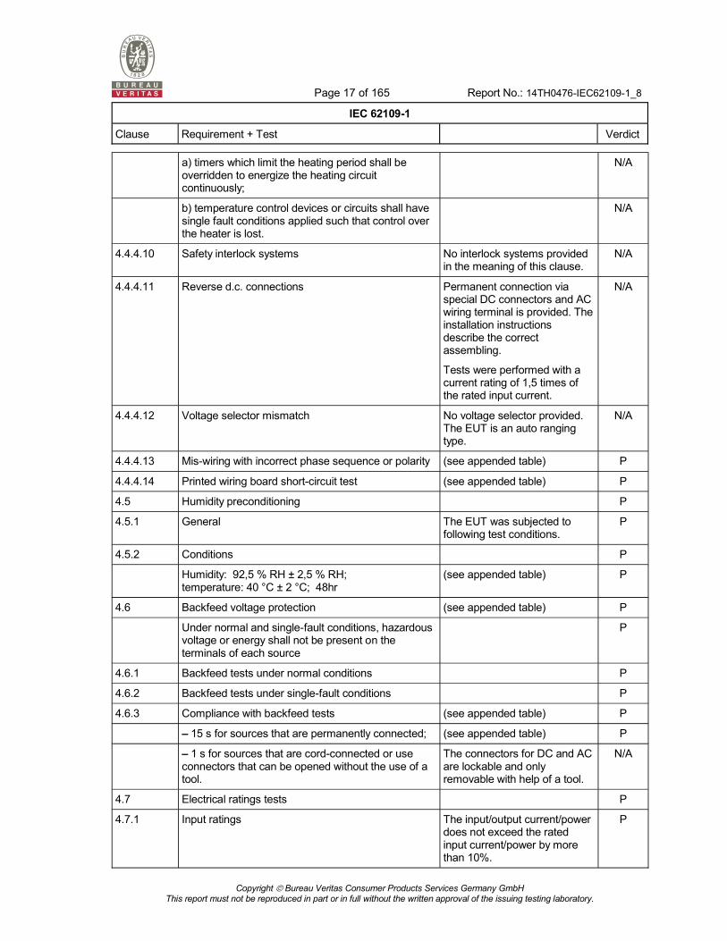
a) timers which limit the heating period shall be overridden to energize the heating circuit continuously;
N/A
b) temperature control devices or circuits shall have single fault conditions applied such that control over the heater is lost.
N/A
4.4.4.10 Safety interlock systems No interlock systems provided in the meaning of this clause.
N/A
4.4.4.11 Reverse d.c. connections Permanent connection via special DC connectors and AC wiring terminal is provided. The installation instructions describe the correct assembling.
Tests were performed with a current rating of 1,5 times of the rated input current.
N/A
4.4.4.12 Voltage selector mismatch No voltage selector provided. The EUT is an auto ranging type.
N/A
4.4.4.13 Mis-wiring with incorrect phase sequence or polarity (see appended table) P
4.4.4.14 Printed wiring board short-circuit test (see appended table) P
4.5 Humidity preconditioning P
4.5.1 General The EUT was subjected to following test conditions.
P
4.5.2 Conditions P
Humidity: 92,5 % RH ± 2,5 % RH; temperature: 40 °C ± 2 °C; 48hr
(see appended table) P
4.6 Backfeed voltage protection (see appended table) P
Under normal and single-fault conditions, hazardous voltage or energy shall not be present on the terminals of each source
P
4.6.1 Backfeed tests under normal conditions P
4.6.2 Backfeed tests under single-fault conditions P
4.6.3 Compliance with backfeed tests (see appended table) P
15 s for sources that are permanently connected; (see appended table) P
1 s for sources that are cord-connected or use connectors that can be opened without the use of a tool.
The connectors for DC and AC are lockable and only removable with help of a tool.
N/A
4.7 Electrical ratings tests P
4.7.1 Input ratings The input/output current/power does not exceed the rated input current/power by more than 10%.
P

Page 18 of 165 Report No.: 14TH0476-IEC62109-1_8
IEC 62109-1
Clause Requirement + Test Verdict
Copyright Bureau Veritas Consumer Products Services Germany GmbH
This report must not be reproduced in part or in full without the written approval of the issuing testing laboratory.
4.7.1.1 Measurement requirements for DC input ports (see appended table) P
4.7.2 Output ratings (see appended table) P
5 Marking and documentation P
5.1 Marking P
5.1.1 General P
Except for marking of internal parts, these markings shall be visible from the exterior after installation, or be visible after removing a cover or opening a door without the aid of a tool
Present. The type label is located on the outer surface of the enclosure.
P
For rack- or panel-mounted equipment, markings are permitted to be on a surface
No rack or panel mounted equipment.
N/A
Graphic symbols may be used and shall be in accordance with Annex C or IEC 60417 as applicable
Considered. P
5.1.2 Durability of markings P
The markings are rubbed quickly by hand, without undue pressure, for 30 s with a cloth soaked with the specified cleaning agent
P
The markings shall be clearly legible after the above treatment, and adhesive labels shall not have worked loose or become curled at the edges.
P
5.1.3 Identification P
a) the name or trade mark of the manufacturer or supplier;
P
b) a model number, name or other means to identify the equipment,
P
c) a serial number, code or other marking allowing identification of manufacturing location and the manufacturing batch or date within a three month time period.
P
5.1.4 Equipment ratings P
input voltage, type of voltage (a.c. or d.c.), frequency, and maximum continuous current for each input;
P
output voltage, type of voltage (a.c. or d.c.), frequency, maximum continuous current, and for a.c. outputs, either the power or power factor for each output;
P
the ingress protection (IP) rating as in 6.3 below. P
5.1.5 Fuse identification N/A

Page 19 of 165 Report No.: 14TH0476-IEC62109-1_8
IEC 62109-1
Clause Requirement + Test Verdict
Copyright Bureau Veritas Consumer Products Services Germany GmbH
This report must not be reproduced in part or in full without the written approval of the issuing testing laboratory.
Marking shall be located adjacent to each fuse or fuseholder, or on the fuseholder, or in another location provided
N/A
For fuses not located in operator access areas and for soldered-in fuses located in operator access areas
N/A
5.1.6 Terminals, connections and controls P
If necessary for safety, an indication shall be given of the purpose of terminals, connectors, controls, and indicators, and their various positions
P
The symbols in Annex C may be used, and where there is insufficient space, symbol 9 of Annex C may be used
P
A multiple-voltage unit shall be marked to indicate the particular voltage
N/A
A unit with d.c. terminals shall be plainly marked indicating the polarity of the connections, with:
P
P
a pictorial representation illustrating the proper polarity where the correct polarity can be unambiguously determined from the representation.
N/A
5.1.6.1 Protective conductor terminals P
symbol 7 of Annex C; or P
the letters "PE"; or N/A
the color coding green-yellow. N/A
5.1.7 Switches and circuit-breakers P
The on and off-positions of switches and circuit breakers shall be clearly marked
P
5.1.8 Class II equipment N/A
Equipment using Class II protective means throughout shall be marked with symbol 12 of Annex C.
N/A
Where such equipment has provision for the connection of an earthing conductor for functional reasons (see 7.3.6.4) it shall be marked with symbol 6 of Annex C.
N/A
5.1.9 Terminal boxes for external connections N/A
a) the minimum temperature rating and size of the cable to be connected to the terminals; or
N/A
b) a marking to warn the installer to consult the installation instructions. Symbol 9 of Annex C is an acceptable marking.
N/A
5.2 Warning markings P
Page 20 of 165 Report No.: 14TH0476-IEC62109-1_8
IEC 62109-1
Clause Requirement + Test Verdict
Copyright Bureau Veritas Consumer Products Services Germany GmbH
This report must not be reproduced in part or in full without the written approval of the issuing testing laboratory.
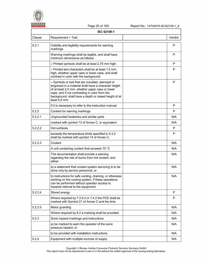
5.2.1 Visibility and legibility requirements for warning markings
P
Warning markings shall be legible, and shall have minimum dimensions as follows:
P
Printed symbols shall be at least 2,75 mm high. P
Printed text characters shall be at least 1,5 mm high, whether upper case or lower case, and shall contrast in color with the background.
P
Symbols or text that are moulded, stamped or engraved in a material shall have a character height of at least 2,0 mm, whether upper case or lower case, and if not contrasting in color from the background, shall have a depth or raised height of at least 0,5 mm.
P
If it is necessary to refer to the instruction manual P
5.2.2 Content for warning markings P
5.2.2.1 Ungrounded heatsinks and similar parts N/A
marked with symbol 13 of Annex C, or equivalent N/A
5.2.2.2 Hot surfaces P
exceeds the temperature limits specified in 4.3.2 shall be marked with symbol 14 of Annex C.
P
5.2.2.3 Coolant N/A
A unit containing coolant that exceeds 70 °C N/A
The documentation shall provide a warning regarding the risk of burns from hot coolant, and either:
N/A
a) a statement that coolant system servicing is to be done only by service personnel, or
N/A
b) instructions for safe venting, draining, or otherwise working on the cooling system, if these operations can be performed without operator access to hazards internal to the equipment
N/A
5.2.2.4 Stored energy P
Where required by 7.3.9.2 or 7.4.2 the PCE shall be marked with Symbol 21 of Annex C and the time
P
5.2.2.5 Motor guarding N/A
Where required by 8.2 a marking shall be provided N/A
5.2.3 Sonic hazard markings and instructions N/A
a) be marked to warn the operator of the sonic pressure hazard; or
N/A
b) be provided with installation instructions N/A
5.2.4 Equipment with multiple sources of supply N/A

Page 21 of 165 Report No.: 14TH0476-IEC62109-1_8
IEC 62109-1
Clause Requirement + Test Verdict
Copyright Bureau Veritas Consumer Products Services Germany GmbH
This report must not be reproduced in part or in full without the written approval of the issuing testing laboratory.
shall be marked with symbol 13 of Annex C and the manual shall contain the information required in 5.3.4.
N/A
5.2.5 Excessive touch current N/A
shall be marked with symbol 15 of Annex C. See also 5.3.2 for information to be provided in the installation manual.
N/A
5.3 Documentation P
5.3.1 General P
a) explanations of equipment markings, including symbols used;
P
b) location and function of terminals and controls; P
c) all ratings or specifications that are necessary to safely install and operate the PCE, including the following:
P
Environmental category as per 6.1 P
Wet locations classification as per 6.1 P
Pollution degree classification for the intended external environment as per 6.2
P
Ingress protection rating as per 6.3 P
Ambient temperature and relative humidity ratings P
Maximum altitude rating P
Overvoltage category assigned to each input and output port as per 7.3.7.1.2, accompanied by guidance regarding how to ensure that the installation complies with the required overvoltage categories;
P
d) a warning that when the photovoltaic array is exposed to light, it supplies a d.c. voltage to the PCE
P
5.3.1.1 Language P
acceptable in the country where the equipment is to be installed
Responsibility of the manufacturer.
P
5.3.1.2 Format P
In general, the documentation shall be provided in printed form and is to be delivered with the equipment
P
For equipment which requires the use of a computer for both installation and operation
N/A
5.3.2 Information related to installation P
a) assembly, location, and mounting requirements; P

Page 22 of 165 Report No.: 14TH0476-IEC62109-1_8
IEC 62109-1
Clause Requirement + Test Verdict
Copyright Bureau Veritas Consumer Products Services Germany GmbH
This report must not be reproduced in part or in full without the written approval of the issuing testing laboratory.
b) ratings and means of connection to each source of supply and any requirements related to wiring and external controls, color coding of leads, disconnection means, or overcurrent protection needed, including instructions that the installation position shall not prevent access to the disconnection means;
P
c) ratings and means of connection of any outputs from the PCE, and any requirements related to wiring and external controls, color coding of leads, or overcurrent protection needed;
P
d) explanation of the pin-out of connectors for external connections, unless the connector is used for a standard purpose (e.g. RS 232);
P
e) ventilation requirements; P
f) requirements for special services, for example cooling liquid;
N/A
g) instructions and information relating to sound pressure level if required by 10.2.1;
N/A
h) where required by 14.8.1.3, instructions for the adequate ventilation of the room or location in which PCE containing vented or valve-regulated batteries is located, to prevent the accumulation of hazardous gases;
N/A
i) tightening torque to be applied to wiring terminals; N/A
j) values of backfeed short-circuit currents available from the PCE on input and output conductors under fault conditions, if those currents exceed the max. rated current of the circuit, as per 4.4.4.6;
N/A
k) for each input to the PCE, the maximum value of short-circuit current available from the source, for which the PCE is designed; and
P
l) compatibility with RCD and RCM; P
m) instructions for protective earthing of the PCE, including the information required by 7.3.6.3.7 if a second protective earthing conductor is to be installed;
P
n) where required by 7.3.8, the installation instructions shall include the following or equivalent wording:
component. Where a residual current operated protective (RCD) or monitoring (RCM) device is used for protection in case of direct or indirect contact, only an RCD or RCM of Type B is allowed on the
N/A
o) for PCE intended to charge batteries, the battery nominal voltage rating, size, and type;
N/A

Page 23 of 165 Report No.: 14TH0476-IEC62109-1_8
IEC 62109-1
Clause Requirement + Test Verdict
Copyright Bureau Veritas Consumer Products Services Germany GmbH
This report must not be reproduced in part or in full without the written approval of the issuing testing laboratory.
p) PV array configuration information, such as ratings, whether the array is to be grounded or floating, any external protection devices needed, etc.
P
5.3.3 Information related to operation P
instructions for adjustment of controls including the effects of adjustment;
P
instructions for interconnection to accessories and other equipment, including indication of suitable accessories, detachable parts and any special materials;
P
warnings regarding the risk of burns from surfaces permitted to exceed the temperature limits of 4.3.2 and required operator actions to reduce the risk; and
P
instructions that if the equipment is used in a manner not specified by the manufacturer, the protection provided by the equipment may be impaired.
P
5.3.4 Information related to maintenance P
intervals and instructions for any preventive maintenance that is required to maintain safety (for example air filter replacement or periodic re-tightening of terminals);
N/A
instructions for accessing operator access areas, if any are present, including a warning not to enter other areas of the equipment;
P
part numbers and instructions for obtaining any required operator replaceable parts;
N/A
instructions for safe cleaning (if recommended); N/A
where there is more than one source of supply energizing the PCE, information shall be provided in the manual to indicate which disconnect device or devices are required to be operated in order to completely isolate the equipment.
P
5.3.4.1 Battery maintenance N/A
Servicing of batteries should be performed or supervised by personnel knowledgeable about batteries and the required precautions.
N/A
When replacing batteries, replace with the same type and number of batteries or battery packs.
N/A
General instructions regarding removal and installation of batteries.
N/A
CAUTION: Do not dispose of batteries in a fire. The batteries may explode.
N/A

Page 24 of 165 Report No.: 14TH0476-IEC62109-1_8
IEC 62109-1
Clause Requirement + Test Verdict
Copyright Bureau Veritas Consumer Products Services Germany GmbH
This report must not be reproduced in part or in full without the written approval of the issuing testing laboratory.
CAUTION: Do not open or damage batteries. Released electrolyte is harmful to the skin and eyes. It may be toxic.
N/A
CAUTION: A battery can present a risk of electrical shock and high short-circuit current. The following precautions should be observed when working on batteries:
a) Remove watches, rings, or other metal objects. b) Use tools with insulated handles. c) Wear rubber gloves and boots. d) Do not lay tools or metal parts on top of batteries. e) Disconnect charging source prior to connecting or
disconnecting battery terminals.
f) Determine if battery is inadvertently grounded.
N/A
6 Environmental requirements and conditions P
The manufacturer shall rate the PCE for the following environmental conditions:
P
6.1 Environmental categories and minimum environmental conditions
P
6.1.1 Outdoor The EUT is also intended for outdoor use where it is protected from direct sun and direct rain.
P
6.1.2 Indoor, unconditioned Outdoor use is the most unfavourable condition.
P
6.1.3 Indoor, conditioned Outdoor use is the most unfavourable condition.
P
6.2 Pollution degree Pollution degree 2 was specified instead of PD3.
The EUT provide an IP65 enclosure and the pollution degree was reduced by table 5.
P
6.3 Ingress protection P
shall comply with Table 4 and shall be verified in accordance with IEC 60529.
The manufacturer specifies IP65 according to IEC 60529.
The test report was reviewed and accepted.
P
6.4 UV exposure P
6.5 Temperature and humidity The maximum ambient temperature was specified to -20°C to +50°C with derating starting at 45°C.
Humidity 0-95% (conditioned and unconditioned).
P

Page 25 of 165 Report No.: 14TH0476-IEC62109-1_8
IEC 62109-1
Clause Requirement + Test Verdict
Copyright Bureau Veritas Consumer Products Services Germany GmbH
This report must not be reproduced in part or in full without the written approval of the issuing testing laboratory.
7 Protection against electric shock and energy hazards P
7.1 General Considered. P
7.2 Fault conditions Considered. Refer also to clause 4.4.
P
7.3 Protection against electric shock P
7.3.1 General The decisive voltage class was determined for the minimum required level of protection.
(see appended table)
Protection against electric shock is ensured by protection against direct contact via means of the enclosure (refer also to clause 7.3.4.2) and by protection against indirect contact via protective class 1, basic insulation and protective bonding (refer also to clause 7.3.6.3).
P
7.3.2 Decisive voltage classification P
7.3.2.1 Use of decisive voltage class (DVC) P
the working voltage limits of Table 6, and Refer to 7.3.2.2. P
the applicable protective measures of 7.3.2.4. Refer to 7.3.2.4. P
7.3.2.2 Limits of DVC The working voltage within the power circuits exceeds the limits for DVC A and B. DVC C according to table 6 was used for PV input circuits and AC output circuits. The user interface was considered to meet the requirements of SELV circuits which were specified for DVC A.
(see appended test table)
P
7.3.2.3 Short-term limits of accessible voltages under fault conditions
P

Page 26 of 165 Report No.: 14TH0476-IEC62109-1_8
IEC 62109-1
Clause Requirement + Test Verdict
Copyright Bureau Veritas Consumer Products Services Germany GmbH
This report must not be reproduced in part or in full without the written approval of the issuing testing laboratory.
7.3.2.4 Requirements for protection Insulation between AC and PE: basic insulation
Insulation between PV and PE: basic insulation
Insulation between AC and PV: functional insulation
Insulation between AC and SELV circuits: reinforced insulation
Insulation between PV and SELV circuits: reinforced insulation
P
Protection shall be provided that ensures that no single fault
P
Accessible earthed conductive parts shall be separated from DVC-B and DVC-C circuits by at least basic insulation.
P
7.3.2.5 Connection to PELV and SELV circuits The internal SELV circuits meet the requirements of SELV circuits. The connection to these circuits to other circuits in the end use application shall be considered in the final installation. A statement that only SELV circuits shall be connected to these circuits is given in the installation instructions.
P
the PELV or SELV classification of the external circuit is not changed, and
Part of the investigation of the final installation.
N/A
the DVC classification of the external port of the PCE is not changed.
Part of the investigation of the final installation.
N/A
7.3.2.6 Working voltage and DVC P
7.3.2.6.1 General Worst case combinations were considered.
P
7.3.2.6.2 AC working voltage (see Figure 2) (see appended table) P
The DVC is that of the lowest voltage row of Table 6 for which both of the following conditions are satisfied.
- UAC ACL
- UACP ACPL
Considered. For specification of DVC refer to clause 7.3.2.4.
P
7.3.2.6.3 DC working voltage (see Figure 3) (see appended table) P

Page 27 of 165 Report No.: 14TH0476-IEC62109-1_8
IEC 62109-1
Clause Requirement + Test Verdict
Copyright Bureau Veritas Consumer Products Services Germany GmbH
This report must not be reproduced in part or in full without the written approval of the issuing testing laboratory.
The DVC is that of the lowest voltage row of Table 6 for which both of the following conditions are satisfied.
- UDC DCL
- UDCP DCL
Considered. For specification of DVC refer to clause 7.3.2.4.
P
7.3.2.6.4 Pulsating working voltage (see Figure 4) P
The DVC is that of the lowest voltage row of Table 6 for which both of the following conditions are satisfied.
- UAC/UACL + UDC/UDCL
- UACP/UACPL + UDC/(1,17 × UDCL
Considered. For specification of DVC refer to clause 7.3.2.4.
P
7.3.3 Protective separation P
- double or reinforced insulation, or Reinforced insulation was used for protective separation.
P
- protective screening, or Protective screening was not used.
N/A
- protective impedance comprising limitation of current per 7.3.5.3.1 and of discharged energy per 7.3.5.3.2, or
N/A
- limitation of voltage according to 7.3.5.4. Voltage limitation was not used.
N/A
7.3.4 Protection against direct contact P
7.3.4.1 General Protection against direct contact to DVC C circuits is ensured by the enclosure.
P
Open type sub-assemblies and devices do not require protective measures against direct contact
The whole EUT has an enclosure.
N/A
the instructions provided with the equipment shall indicate that such measures must be provided in the end equipment or in the installation.
No instructions required. N/A
7.3.4.2 Protection by means of enclosures and barriers P
7.3.4.2.1 General All life parts are provided within the enclosure. The enclosure was tested according to clause 7.3.4.2.2.
P
Parts of enclosures and barriers that provide protection in accordance with these requirements shall not be removable without the use of a tool
The enclosure cannot be opened or removed without help of a tool to get access to hazardous life parts.
P
7.3.4.2.2 Access probe criteria P

Page 28 of 165 Report No.: 14TH0476-IEC62109-1_8
IEC 62109-1
Clause Requirement + Test Verdict
Copyright Bureau Veritas Consumer Products Services Germany GmbH
This report must not be reproduced in part or in full without the written approval of the issuing testing laboratory.
a) decisive voltage classification A, (DVC A) - the probe may touch the live parts;
User interfaces for interconnection in the final installation are provided which could be touched. These interfaces are supplied by SELV circuits which were considered to represent DVC A circuits. For the DVC A circuits clause 7.3.5 was applied.
P
b) decisive voltage classification B, (DVC B) - the probe shall have adequate clearance to live parts, based on the clearance for functional insulation
No circuit within the EUT was considered to be a DVC B circuit.
N/A
c) decisive voltage classification C, (DVC C) - the probe shall have adequate clearance to live parts, based on the clearance for basic insulation
All hazardous life parts and circuits which were specified for DVC C are not accessible. Tests according to clause 7.3.4.2.3 were performed.
P
7.3.4.2.3 Access probe tests P
a) Inspection; and Considered. P
b) Tests with the test finger (Figure D.1) and test pin (Figure D.2) of Annex D, the results of which shall comply with the requirements of 7.3.4.2.1 a), b), and c) as applicable.
Considered. P
The floor-standing equipment having a mass exceeding 40 kg is not tilted.
Considered. P
Equipment intended for building-in or rack mounting, or for incorporation in larger equipment,
The EUT is not a built-in or rack mounted equipment.
N/A
c) Openings preventing the entry of the jointed test finger (Figure D.1 of Annex D) during test b) above, are further tested by means of a straight unjointed test finger (Figure D.3 of Annex D), applied with a force of 30 N.
(see appended table) P
If the unjointed finger enters, the test with the jointed finger is repeated
No further test was necessary. N/A
d) In addition to a) to c) above, top surfaces of enclosures shall be tested with the IP3X probe of IEC 60529.
IP65 protection according IEC60529.
P
7.3.4.2.4 Service access areas N/A
live parts of DVC B or C that may be unintentionally touched when making adjustments shall be protected against contact by the finger probe of Figure D.1 of Annex D.
The EUT will be fully disconnected during installation/maintenance.
N/A
7.3.4.3 Protection by means of insulation of live parts All hazardous parts are protected by the enclosure. See clause 7.3.4.2.
N/A
Where the requirements of 7.3.4.2 are not met, live parts shall be provided with insulation if:
N/A

Page 29 of 165 Report No.: 14TH0476-IEC62109-1_8
IEC 62109-1
Clause Requirement + Test Verdict
Copyright Bureau Veritas Consumer Products Services Germany GmbH
This report must not be reproduced in part or in full without the written approval of the issuing testing laboratory.
their working voltage is greater than the maximum limit of decisive voltage class A, or
N/A
for a DVC A or B circuit, protective separation from adjacent circuits of DVC C is not provided (see note 2) under Table 7).
N/A
Any conductive part, which is not separated from DVC-B or DVC-C parts by at least basic insulation
N/A
As an alternative to solid or liquid insulation, a clearance according to 7.3.7.4, shown by LB and LR in Figure 5, may be provided.
N/A
Three cases are considered: N/A
Case a) Accessible parts are conductive and are connected to earth by protective bonding.
N/A
Cases b) and c) Accessible parts are non-conductive (case b)) or conductive but not connected to earth by protective bonding (case c)).
N/A
7.3.5 Protection in case of direct contact P
7.3.5.1 General For accessible circuits DVC-A is used.
P
it shall be ensured that in the event of error or polarity reversal of connectors no voltages that exceed DVC-A are present on circuits that are not protected against direct contact.
P
7.3.5.2 Protection using decisive voltage class A P
if the circuit has protective separation from circuits of DVC-B or DVC-C in accordance with 7.3.3.
Reinforced insulation between DVC-C and DVC-A was used.
P
7.3.5.3 Protection by means of protective impedance N/A
if any connection to circuits of DVC-B or DVC-C is through protective impedance, and the accessible circuit or part is otherwise provided with protective separation from circuits of DVC-B or DVC-C according to 7.3.3.
N/A
7.3.5.3.1 Limitation of current through protective impedance P
The current available through protective impedance to earth and between simultaneously accessible parts, measured at the accessible live parts, shall not exceed a value of 3,5 mA a.c. or 10 mA d.c. under normal and single-fault conditions.
(see appended table) P
7.3.5.3.2 Limitation of discharging energy through protective impedance
P
The discharging energy available between simultaneously accessible parts protected by protective impedance shall not exceed the charging voltage and capacitance limits given in Table 9,
(see appended table) P
7.3.5.4 Protection by means of limited voltages N/A

Page 30 of 165 Report No.: 14TH0476-IEC62109-1_8
IEC 62109-1
Clause Requirement + Test Verdict
Copyright Bureau Veritas Consumer Products Services Germany GmbH
This report must not be reproduced in part or in full without the written approval of the issuing testing laboratory.
That portion of a circuit that has its voltage reduced to DVC-A by a voltage divider
N/A
This type of protection shall not be used in case of protective class II or unearthed circuits
N/A
7.3.6 Protection against indirect contact P
7.3.6.1 General Protection is given by class I equipment with protective earth connection and protective bonding which is separated from hazardous parts and circuits by basic insulation.
Refer also to clause 7.3.6.3.
P
This protection shall comply with the requirements for protective class I (basic insulation plus protective earthing), protective class II (double or reinforced insulation) or protective class III (limitation of voltages).
Protection class I. P
7.3.6.2 Insulation between live parts and accessible conductive parts
Protection is ensured by adequate clearance and creepage distances according clauses 7.3.7.4 and 7.3.7.5.
P
7.3.6.3 Protective class I - Protective bonding and earthing P
7.3.6.3.1 General The EUT provide a AC wiring terminal for connection of the external PE conductor. All other accessible conductive parts are reliable bonded to protective earth.
P
except bonding is not required for: Exception not used. N/A
a) accessible conductive parts that are protected by one of the measures in 7.3.5.2 to 7.3.5.4, or
N/A
b) accessible conductive parts that are separated from live parts of DVC-B or -C using double or reinforced insulation.
Exception not used. N/A
7.3.6.3.2 Requirements for protective bonding Protective bonding of accessible conductive parts is achieved either via screw connection or through dedicated protective bonding conductors.
P
a) through direct metallic contact; P
b) through other conductive parts which are not removed when the PCE or sub-units are used as intended;
N/A
c) through dedicated protective bonding conductors; P
d) through other metallic components of the PCE. P

Page 31 of 165 Report No.: 14TH0476-IEC62109-1_8
IEC 62109-1
Clause Requirement + Test Verdict
Copyright Bureau Veritas Consumer Products Services Germany GmbH
This report must not be reproduced in part or in full without the written approval of the issuing testing laboratory.
For moving or removable parts, hinges or sliding contacts designed and maintained to have a low resistance
No such connections used. N/A
Metal ducts of flexible or rigid construction and metallic sheaths shall not be used as protective bonding conductors, unless the device or material has been investigated as suitable for protective bonding purposes.
No such connections used. N/A
7.3.6.3.3 Rating of protective bonding P
Protective bonding shall withstand the highest thermal and dynamic stresses
The protective bonding conductors have suitable cross sectional areas with an adequate current carrying capacity.
P
Protective bonding shall meet following requirements:
P
a) For PCE with an overcurrent protective device rating of 16 A or less, the impedance of the protective bonding means shall not exceed 0,1 during or at the end of the test below.
N/A
b) For PCE with an overcurrent protective device rating of more than 16 A, the voltage drop in the protective bonding test shall not exceed 2,5 V during or at the end of the test below.
(see appended table) P
As alternative to a) and b) the protective bonding may designed according to the requirements for the external protective earthing conductor in 7.3.6.3.5
Alternative method not used. N/A
The impedance of protective bonding means shall be checked by passing a test current through the bond for a period of time as specified below.
P
a) for pluggable equipment type A, the overcurrent protective device is that provided external to the equipment.
The EUT is permanently connected.
N/A
b) for pluggable equipment type B and fixed equipment, the maximum rating of the overcurrent protective device specified in the equipment installation instructions to be provided external to the equipment;
(see appended table) P
c) for a circuit or part of the equipment for which an overcurrent protective device is provided as part of the equipment, the rating of the provided overcurrent device.
Overcurrent protective device of the AC output side is not integral part of the EUT.
N/A
7.3.6.3.3.1 Test current, duration, and acceptance criteria P
a) For PCE with an overcurrent protective device rating of 16 A or less
N/A
b) For PCE with an overcurrent protective device rating of more than 16 A
(see appended table) P

Page 32 of 165 Report No.: 14TH0476-IEC62109-1_8
IEC 62109-1
Clause Requirement + Test Verdict
Copyright Bureau Veritas Consumer Products Services Germany GmbH
This report must not be reproduced in part or in full without the written approval of the issuing testing laboratory.
c) During and after the test, there shall be no melting, loosening, or other damage
(see appended table) P
As an alternative to Table 10, where the time-current characteristic of the overcurrent protective device that limits the fault current in the protective bonding means is known
Alternative method not used. N/A
7.3.6.3.4 Protective bonding impedance (routine test) P
the test current may be reduced to any convenient value greater than 10 A sufficient to allow measurement or calculation of the impedance of the protective bonding means;
See summary of testing. P
the test duration may be reduced to no less than 2 s.
See summary of testing. P
For equipment subject to the type test in 7.3.6.3.3.1a), the impedance during the routine test
The type test was performed according to clause 7.3.6.3.3.1b.
N/A
For equipment subject to the type test in 7.3.6.3.3.1b) the impedance during the routine test shall not exceed 2,5 V divided by the test current required by 7.3.6.3.3.1b).
See information for production testing.
P
7.3.6.3.5 External protective earthing conductor P
A protective earthing conductor shall be connected at all times when power is supplied to PCE of protective class I.
The EUT is intended for permanent connection to the AC mains. The installation instructions describe the proper installation and connection of the supply circuits. If connected to the mains, the protective earthing conductor is also connected. The disconnecting device to separate the EUT from the AC mains is not part of the EUT and shall be considered in the final installation.
P
Unless local wiring regulations state otherwise, the protective earthing conductor cross-sectional area shall be determined from Table 11 or by calculation according to IEC 60364-5-54.
The external protective earthing conductor is not part of the EUT. The protective earthing conductor will be at least the size of the input power conductors but min 10mm². This is sufficiently described in the installation instructions.
P

Page 33 of 165 Report No.: 14TH0476-IEC62109-1_8
IEC 62109-1
Clause Requirement + Test Verdict
Copyright Bureau Veritas Consumer Products Services Germany GmbH
This report must not be reproduced in part or in full without the written approval of the issuing testing laboratory.
If the external protective earthing conductor is routed through a plug and socket, or similar means of disconnection
Within the EUT no devices are present in which the protective earthing conductor will be routed through by installation. The earthing conductor is not part of the EUT. This shall be considered in the final installation.
P
The cross-sectional area of every protective earthing conductor which does not form part of the supply cable or cable enclosure shall, in any case, be not less than:
N/A
2,5 mm2 if mechanical protection is provided; N/A
4 mm2 if mechanical protection is not provided. N/A
For cord-connected equipment, provisions shall be made so that the protective earthing conductor in the cord shall, in the case of failure of the strain-relief mechanism, be the last conductor to be interrupted.
No strain-relief required. wiring terminal is used.
N/A
7.3.6.3.6 Means of connection for the external protective earthing conductor
P
7.3.6.3.6.1 General A wiring terminal is provided for permanent connection of the mains supply conductors. The protective earth part of the AC terminal for connection to the external earthing conductor.
P
The means of connection for the external protective earthing conductor shall be located near the terminals
Protective earth is located adjacent to the AC conductors.
P
The means of connection shall be corrosion resistant and shall be suitable for the connection of cables
Approved wiring terminal used. safety
P
The means of connection for the protective earthing conductor shall not be used as a part of the mechanical assembly
Present. Connector used. P
A separate means of connection shall be provided for each external protective earthing conductor.
Only one connector provided and required.
N/A
Connection and bonding points shall be so designed that their current-carrying capacity is not impaired by mechanical, chemical, or electrochemical influences.
The connection materials of protective earthing and bonding were investigated and were deemed to be not impaired by electrochemical influences.
P
The means of connection for the protective earthing conductor shall be permanently marked with:
P

Page 34 of 165 Report No.: 14TH0476-IEC62109-1_8
IEC 62109-1
Clause Requirement + Test Verdict
Copyright Bureau Veritas Consumer Products Services Germany GmbH
This report must not be reproduced in part or in full without the written approval of the issuing testing laboratory.
symbol 7 of Annex C; or Symbol 7 is provided as a marking adjacent to the AC connector and on the AC connector itself where the external protective earthing is connected.
P
the color coding green-yellow. N/A
7.3.6.3.7 Touch current in case of failure of the protective earthing conductor
P
For pluggable equipment type A , the touch current measured in accordance with 7.5.4 shall not exceed 3,5 mA a.c. or 10 mA d.c.
The EUT is not an equipment with type A connection.
N/A
For all other PCE, one or more of the following measures shall be applied, unless the touch current measured in accordance with 7.5.4 does not exceed 3,5 mA a.c. or 10 mA d.c.
The measured touch current does exceed 3,5mA. Additional precautions have been taken.
(see appended table)
P
a) Permanently connected wiring, N/A
a cross-section of the protective earthing conductor of at least 10 mm2 if copper, or 16 mm2 if aluminum; or
N/A
automatic disconnection of the supply in case of discontinuity of the protective earthing conductor; or
P
provision of an additional terminal for a second protective earthing conductor of the same cross-sectional area as the original protective earthing conductor and installation instructions requiring a second protective earthing conductor to be installed. or
P
b) Connection with an industrial connector according to IEC 60309 and a minimum protective earthing conductor cross-section of 2,5 mm2 as part of a multi-conductor power cable. Adequate strain relief shall be provided.
P
In addition, the caution symbol 15 of Annex C shall be fixed to the product and the installation manual shall provide
P
When it is intended and allowed to connect two or more PCEs in parallel using one common protective earthing conductor,
N/A
unless one of the measures in a) or b) above is used.
N/A
The maximum number of parallel PCEs is used in the testing and has to be stated in the installation manual.
N/A
7.3.6.4 Protective class II - Double or reinforced insulation The EUT is a class I equipment.
N/A

Page 35 of 165 Report No.: 14TH0476-IEC62109-1_8
IEC 62109-1
Clause Requirement + Test Verdict
Copyright Bureau Veritas Consumer Products Services Germany GmbH
This report must not be reproduced in part or in full without the written approval of the issuing testing laboratory.
Equipment or parts of equipment designed for protective class II shall have insulation between live parts and accessible surfaces in accordance with 7.3.4.3.
N/A
The following requirements also apply: N/A
equipment designed to protective class II shall not have means of connection for the external protective earthing conductor.
N/A
metal-encased equipment of protective class II may have provision on its enclosure for the connection of an equipotential bonding conductor;
N/A
equipment of protective class II may have provision for the connection of an earthing conductor for functional reasons or for the damping of overvoltages; it shall, however, be insulated as though it is a live part;
N/A
equipment employing protective class II shall be marked according to 5.1.8.
N/A
7.3.7 Insulation including clearance and creepage distances
P
7.3.7.1 General Considered. P
7.3.7.1.1 Pollution degree According to clause 5.2, PD 2 was assumed to be used due to the enclosure meets the requirements of clause 6.2, table 5.
P
7.3.7.1.2 Overvoltage category and Impulse withstand voltage rating
P
The concept of overvoltage categories is applied to each separate circuit in the PCE, including mains circuits, PV circuits, and other circuits, whether connected to or isolated from the mains and PV circuits, as follows:
P
a) For equipment or circuits energized from the mains, four categories are considered:
OVC III was assumed to be used. (4000V)
P
category IV applies to equipment permanently connected at the origin of an installation (upstream of the main distribution board).
N/A
category III applies to fixed equipment downstream of, and including, the main distribution board.
P
category II applies to equipment not permanently connected to the installation.
N/A
category I applies to equipment connected to a circuit where measures have been taken to reduce transient overvoltages to a low level.
N/A

Page 36 of 165 Report No.: 14TH0476-IEC62109-1_8
IEC 62109-1
Clause Requirement + Test Verdict
Copyright Bureau Veritas Consumer Products Services Germany GmbH
This report must not be reproduced in part or in full without the written approval of the issuing testing laboratory.
b) For PV circuits in general OVC II (4311V) P
c) For PCE with galvanic isolation The EUT does not provide galvanic isolation between the PV and main circuits.
N/A
The magnitude of impulses from the mains circuit on the PV circuit
N/A
The rating to be used on the PV circuit is the higher of the value in b) and the value calculated above.
N/A
The magnitude of impulses from the PV circuit on the mains circuit
N/A
The rating to be used on the mains circuit is the higher of the value in a) and the value calculated above.
N/A
d) For PCE not providing galvanic isolation between the mains and PV circuits
The EUT does not provide galvanic isolation between the PV and the main circuits. The higher of the impulse withstand voltages were applied.
OVC II (4311V)
P
e) For other circuits the impulse withstand voltage rating:
No other circuits provided. N/A
for circuits connected to the mains without galvanic isolation
N/A
for circuits connected to the PV circuit without
N/A
where isolation is provided by means of isolation transformers, optocouplers, or similar galvanic isolation devices, between a considered circuit and an adjacent mains or PV circuit
N/A
f) The overvoltage categories determined as above apply from circuits to earth.
For functional insulation between circuits of the same OVC was reduced by one value.
P
g) Application of means to reduce impulse voltages Reduced values were not considered.
N/A
7.3.7.1.3 Supply earthing systems P
Three basic types of earthing system are described in IEC 60364-1. They are:
TN, TT or IT system provided in the final installation.
P
TN system: P
TT system: P
IT system: P
7.3.7.1.4 Insulation voltages Considered. P
7.3.7.2 Insulation between a circuit and its surroundings P

Page 37 of 165 Report No.: 14TH0476-IEC62109-1_8
IEC 62109-1
Clause Requirement + Test Verdict
Copyright Bureau Veritas Consumer Products Services Germany GmbH
This report must not be reproduced in part or in full without the written approval of the issuing testing laboratory.
7.3.7.2.1 General P
For creepage distances, the r.m.s. value of the working voltage is used.
(see appended table) P
7.3.7.2.2 Circuits connected directly to the mains For circuits directly connected to the mains the working voltage was used.
P
7.3.7.2.3 Circuits other than mains circuits P
Clearances and solid insulation between circuits other than the mains and their surroundings
For PV circuits the maximum rated PV open circuit voltage was used.
P
7.3.7.2.4 Insulation between circuits Considered. P
7.3.7.3 Functional insulation Functional insulation was verified by fault condition tests (short).
P
7.3.7.4 Clearance distances P
7.3.7.4.1 Determination (see appended table) P
Clearances for use in altitudes above 2 000 m shall be calculated with a correction factor according to Table A.2 of IEC 60664-1
The EUT is not intended to be used above 2000m altitude.
N/A
7.3.7.4.2 Electric field homogeneity An inhomogeneous electric field is considered to be used for the determination of separations. Therefore table 13 was applied.
P
7.3.7.4.3 Clearance to conductive enclosures Deformation tests were performed. Because of the rigidity of the enclosure no distances got reduced.
P
7.3.7.5 Creepage distances P
7.3.7.5.1 General Considered.
(see appended table)
P
7.3.7.5.2 Voltage (see appended table) P
7.3.7.5.3 Materials (see appended table) P
CTI CTI IIIb was assumed to be used for other materials as the PCBs.
P
7.3.7.6 Coating Coating is not provided. N/A

Page 38 of 165 Report No.: 14TH0476-IEC62109-1_8
IEC 62109-1
Clause Requirement + Test Verdict
Copyright Bureau Veritas Consumer Products Services Germany GmbH
This report must not be reproduced in part or in full without the written approval of the issuing testing laboratory.
7.3.7.7 PWB spacings for functional insulation Functional insulation was verified by performing short circuit tests according to 4.4.4.14.
For the material and its specifications for the PCB refer
P
the PWB has flammability rating of V-0 (see IEC 60695-11-10)
P
the PWB base material has a minimum CTI of 175
Re
P
the equipment complies with the PWB short-circuit test (see 4.4.4.14).
Refer to clause 4.4.4.14. P
7.3.7.8 Solid insulation P
7.3.7.8.1 General Considered.
(see appended table)
P
7.3.7.8.2 Requirements for electrical withstand capability of solid insulation
Already approved materials used for insulations.
P
7.3.7.8.2.1 Basic, supplemental, reinforced, and double insulation
P
Solid insulation shall withstand the applicable impulse withstand voltage test (7.5.1) and the a.c. or d.c. voltage test (7.5.2)
(see appended table) P
7.3.7.8.2.2 Functional insulation Refer to clause 7.3.7.3. P
7.3.7.8.3 Thin sheet or tape material P
7.3.7.8.3.1 General Only approved materials were used. See list of critical components.
P
Insulation consisting of thin (less than 0,7 mm) sheet or tape materials is permitted
P
Where more than one layer of insulation is used, there is no requirement for all layers to be of the same material.
P
7.3.7.8.3.2 Material thickness not less than 0,2 mm P
Basic or supplementary insulation Considered. P
Double insulation N/A
Reinforced insulation N/A
7.3.7.8.3.3 Material thickness less than 0,2 mm P
Basic or supplementary insulation Considered. P
Double insulation Considered. P
Reinforced insulation Considered. P

Page 39 of 165 Report No.: 14TH0476-IEC62109-1_8
IEC 62109-1
Clause Requirement + Test Verdict
Copyright Bureau Veritas Consumer Products Services Germany GmbH
This report must not be reproduced in part or in full without the written approval of the issuing testing laboratory.
7.3.7.8.3.4 Compliance P
Compliance is checked by the tests described in 7.5.1 to 7.5.3
Refer to clause 7.5.1 and 7.5.3. P
7.3.7.8.4 Printed wiring boards (PWBs) P
7.3.7.8.4.1 General P
Insulation between conductor layers in double-sided single-layer PWBs, multi-layer PWBs and metal core PWBs
Considered. P
For the inner layers of multi-layer PWBs, the insulation between adjacent tracks on the same layer shall be treated as:
Considered. P
a creepage distance for pollution degree 1 and a clearance as in air
N/A
as solid insulation Considered. P
7.3.7.8.4.2 Use of coating materials Coating materials not provided. N/A
Type 1 protection N/A
Type 2 protection N/A
7.3.7.8.5 Wound components Wound components meet the requirements of 7.3.7.8.1 and 7.3.7.8.2 and were tested according the dielectric strength test according to clause 3.5.2.
The transformers shall be tested to a routine dielectric strength test. This shall be verified by the manufacturer.
P
7.3.7.8.6 Potting materials Considered. P
7.3.7.9 Insulation requirements above 30 kHz Considered.
The distances required in Annex G are below the distances required for clearances according table 13.
P
7.3.8 Residual Current Detection (RCD) or Monitoring (RCM) device compatibility
The unit is compatible with a RCD type A.
P
Pluggable type A PCE shall be designed so that, under normal and single-fault conditions, any resulting d.c. component in the residual current does not exceed the d.c. current withstand requirements in IEC 60755 and IEC 62020 for RCD and RCM of type A.
N/A

Page 40 of 165 Report No.: 14TH0476-IEC62109-1_8
IEC 62109-1
Clause Requirement + Test Verdict
Copyright Bureau Veritas Consumer Products Services Germany GmbH
This report must not be reproduced in part or in full without the written approval of the issuing testing laboratory.
PCE that is pluggable type B or fixed equipment, may have a d.c. residual current component present in excess of the d.c. current withstand requirements in IEC 60755 and IEC 62020 for RCD and RCM of type A, if the information required by 5.3.2 item l) is provided in the installation instructions.
The unit is no able to create a residual current, which cannot be tolerated by an RCD type A.
N/A
7.3.9 Protection against shock hazard due to stored energy
P
7.3.9.1 Operator access area On the AC side the connection to mains is provided by permanent connection which is permitted to be installed by service personal only.
P
In the case of plugs, connectors, or similar devices that can be disconnected without the use of a tool
The EUT is intended to be installed in an operator access location. But the EUT dos not provide means for connection to the EUT to get in direct contact to hazardous voltages. Special DC and AC connectors are provided which can only be removed by help of a tool.
P
7.3.9.2 Service access areas P
Capacitors within a PCE shall be discharged to a voltage less than DVC A (see 7.3.2.2), or an energy level below the limits specified in 7.3.5.3.2, within 10 s after the removal of power from the PCE.
The EUT is not intended for operator access. The voltage and power do not discharge within 10s in the unit due to the DC link capacitors. A statement is placed on the outside of the enclosure. Adequate warning statements are provided in the installation instructions.
P
For energy storage devices (such as batteries or ultracapacitors) the intended function of which is to maintain charge even with the PCE off and disconnected from external sources
No hazardous charge present for the intended function.
N/A
7.4 Protection against energy hazards P
7.4.1 Determination of hazardous energy level P
A hazardous energy level is considered to exist if: P
a) the voltage is 2 V or more, and power available after 60 s exceeds 240 VA. Or
(see appended table) P
b) the stored energy in a capacitor is at a voltage, U of 2 V or more, and the stored energy, E, calculated from the following equation, exceeds 20 J:
N/A
7.4.2 Operator access areas P

Page 41 of 165 Report No.: 14TH0476-IEC62109-1_8
IEC 62109-1
Clause Requirement + Test Verdict
Copyright Bureau Veritas Consumer Products Services Germany GmbH
This report must not be reproduced in part or in full without the written approval of the issuing testing laboratory.
Equipment shall be so designed that there is no risk of energy hazard in operator access areas from accessible circuits.
Operator accessible parts of the EUT are the enclosure and the user interface. These circuits provide non-hazardous energy levels.
P
7.4.3 Service access areas P
Energy storage devices within a PCE shall be discharged to an energy level less than 20 J, as in 7.4.1, within 10 s after the removal of power from the PCE.
The voltage and power do not discharge in 10s within the unit. A statement is placed on the outside of the enclosure. Adequate warning statements are provided in the installation instructions.
P
For energy storage devices (such as batteries or ultracapacitors), The warning symbol 21 of Annex C shall be placed.
Unintentional contact to bare parts in not likely to occur.
P
7.5 Electrical tests related to shock hazard P
7.5.1 Impulse voltage test (type test) Test was applied wherever it was required by this standard.
P
The impulse voltage test is performed with a voltage having a 1,2
(see appended table) P
7.5.2 Voltage test (dielectric strength test) (type test and routine test)
P
7.5.2.1 Purpose of test Considered.
Routine test are in the responsibility of the manufacturer.
P
7.5.2.2 Value and type of test voltage (see appended table) P
7.5.2.3 Humidity pre-conditioning Considered. P
7.5.2.4 Performing the voltage test (see appended table) P
7.5.2.5 Duration of the a.c. or d.c. voltage test P
The duration of the test shall be at least 60 s for the type test and 1 s for the routine test.
Considered. P
7.5.2.6 Verification of the a.c. or d.c. voltage test (see appended table) P
7.5.3 Partial discharge test (type test or sample test) The working voltage across any reinforced solid insulation does not exceed the limit of 700V and the voltage stress on the insulation is not greater than 1kV per mm. Refer to clause 7.3.2.6.
P
7.5.4 Touch current measurement (type test) P
The touch current shall be measured if required by 7.3.6.3.7 and shall not be greater than 3,5 mA a.c. or 10 mA d.c.
(see appended table). P

Page 42 of 165 Report No.: 14TH0476-IEC62109-1_8
IEC 62109-1
Clause Requirement + Test Verdict
Copyright Bureau Veritas Consumer Products Services Germany GmbH
This report must not be reproduced in part or in full without the written approval of the issuing testing laboratory.
or special measures of protection as given in 7.3.6.3.7 are required.
No additional measures required.
N/A
7.5.5 Equipment with multiple sources of supply N/A
8 Protection against mechanical hazards P
8.1 General Edges, corners and the like are smooth and rounded. No hazard is expected.
P
8.2 Moving parts Moving parts are the cooling fans outside the enclosure. These devices are covered by a fan protection grid and are not accessible in normal operation. The operator/user is not permitted to perform maintenance. If trained service personal perform maintenance the previously the EUT have to be switched off at both AC and DC side. Therefore no hazard is expected.
P
8.2.1 Protection of service persons For service purposes the EUT will be disconnected. No hazard is expected from moving parts.
P
8.3 Stability The EUT is intended to be fixed.
N/A
a) Equipment other than hand-held equipment N/A
b) Equipment which has both a height of 1 m or more and a mass of 25 kg or more, and all floor-standing equipment, has a force applied at its top, or at a height of 2 m if the equipment has a height of more than 2 m.
N/A
c) Floor-standing equipment has a force of 800 N applied downwards
N/A
1) all horizontal working surfaces; N/A
2) other surfaces providing an obvious ledge and which are not more than 1 m abovefloor level.
N/A
8.4 Provisions for lifting and carrying P
If more than one handle or grip is fitted, the force is distributed between the handles or grips in the same proportion as in normal use.
Mounting means are provided for lifting and carrying which have an adequate rigidity. See also manual.
P
8.5 Wall mounting Adequate provisions are provided. The correct mounting is stated the installation instructions.
P

Page 43 of 165 Report No.: 14TH0476-IEC62109-1_8
IEC 62109-1
Clause Requirement + Test Verdict
Copyright Bureau Veritas Consumer Products Services Germany GmbH
This report must not be reproduced in part or in full without the written approval of the issuing testing laboratory.
8.6 Expelled parts The event of expelled parts is not likely to occur due to the rigidity of the enclosure. No hazard is expected in normal operation.
N/A
9 Protection against fire hazards P
9.1 Resistance to fire The EUT provides a metal enclosure which contains all necessary parts and circuits requiring a fire enclosure.
P
9.1.1 Reducing the risk of ignition and spread of flame All relevant components and materials which affect safety are sufficiently flammability retardant. Refer also to the
P
Method 1 Selection and application of components, wiring and materials
Method 1 was used. Possible faults were simulated.
(see appended table)
P
Method 2 Application of all of the simulated fault tests in 4.4.4.1 a), b), and c).
Method 1 was used. N/A
9.1.2 Conditions for a fire enclosure P
9.1.2.1 Parts requiring a fire enclosure P
Except where Method 2 is used, or as permitted in 9.1.2.2, the following require a fire enclosure:
Fire enclosure is provided. P
components in mains circuits; P
components in secondary circuits supplied by power sources which exceed the limits for a limited power source as specified in 9.2;
No secondary circuits which exceed the limits present.
N/A
components in secondary circuits supplied by a limited power source as specified in 9.2, but not mounted on material of flammability class V-1;
PCBs have minimum V-1
P
components within a power supply unit or assembly having a limited power output complying with the criteria for a limited power source as specified in 9.2;
N/A
components having unenclosed arcing parts, such as open switch and relay contacts and commutators, in a circuit at hazardous voltage or at a hazardous energy level; and
P
insulated wiring, except as permitted in 9.1.2.2. P
9.1.2.2 Parts not requiring a fire enclosure The EUT requires a fire enclosure.
N/A
The following do not require a fire enclosure: N/A

Page 44 of 165 Report No.: 14TH0476-IEC62109-1_8
IEC 62109-1
Clause Requirement + Test Verdict
Copyright Bureau Veritas Consumer Products Services Germany GmbH
This report must not be reproduced in part or in full without the written approval of the issuing testing laboratory.
wiring and cables insulated with PVC, TFE, PTFE, FEP, neoprene or polyimide;
N/A
plugs and connectors forming part of a power supply cord or interconnecting cable;
N/A
components, including connectors, meeting the requirements of 9.1.3.2, which fill an opening in a fire enclosure;
N/A
connectors in secondary circuits supplied by power sources which are limited to a maximum of 15 VA under normal operating conditions and after a single fault in the equipment;
N/A
connectors in secondary circuits supplied by a limited power source as specified in 9.2,
N/A
other components in secondary circuits: N/A
supplied by a limited power source as specified in 9.2, and mounted on materials of flammability class C.1;
N/A
supplied by internal or external power sources which are limited to a maximum of 15 VA under normal operating conditions and after a single fault in the equipment and mounted on material of flammability class HB;
N/A
complying with Method 2 of 9.1.1. N/A
9.1.3 Materials requirements for protection against fire hazard
P
9.1.3.1 General
P
Materials of flammability classes VTM-0, VTM-1 and VTM-2 are considered to be equivalent to materials of FLAMMABILITY classes V-0, V-1 and V-2
P
Where material of flammability class HB or flammability class HBF, is required, material passing the glow-wire test at 550 °C according to IEC 60695-2-11
P
Where it is not practical to protect components against overheating under fault conditions
P
Polymeric materials that serve as the outer enclosure and have surface area greater than 1 m2 or a single dimension larger than 2 m
P
9.1.3.2 Materials for fire enclosures
P
The material of a fire enclosure, in the thinnest significant wall thickness used, shall be classified as flammability class 5VB according to IEC 60695-11-20 or shall pass the 5VB test in the end product.
The enclosure is made of metal.
N/A

Page 45 of 165 Report No.: 14TH0476-IEC62109-1_8
IEC 62109-1
Clause Requirement + Test Verdict
Copyright Bureau Veritas Consumer Products Services Germany GmbH
This report must not be reproduced in part or in full without the written approval of the issuing testing laboratory.
a) the sample shall not release either flaming drops or particles capable of igniting the surgical cotton, and
N/A
b) the sample shall not continue to burn for more than 1 min after the fifth application of the test flame, and
N/A
c) there shall be no openings greater than 25 mm after the test.
N/A
Materials for components that fill an opening in a fire enclosure shall:
P
be of at least V-1 class material and no larger than 100 mm in any dimension; or
P
be of at least V-2 class material and either P
no larger than 25 mm in any dimension, or P
no larger than 100 mm in any dimension and located at least 100 mm from any part that is a source of fire hazard, or
P
be of at least V-2 class material and there is a barrier or device(s) that forms a barrier made of a V-10 class material between the part and a source of fire hazard, or
P
comply with a relevant IEC component standard P
Plastic materials of a fire enclosure shall be located more than 13 mm through air from parts
No arcing can occur. N/A
Plastic materials of a fire enclosure located less than 13 mm through air from non-arcing parts
P
Metals, ceramic materials and glass shall be considered to comply without test.
P
9.1.3.3 Materials for components and other parts inside fire enclosures
P
Inside fire enclosures, materials for components and other parts, shall comply with one of the following:
P
be of flammability class V-2 or flammability class HF-2; or
P
meet the flammability requirements of a relevant IEC component standard
P
The above requirement does not apply to any of the following:
P
electrical components which do not present a fire hazard under abnormal operating conditions
P
materials and components within an enclosure of 0,06 m3 or less
P
one or more layers of thin insulating material P

Page 46 of 165 Report No.: 14TH0476-IEC62109-1_8
IEC 62109-1
Clause Requirement + Test Verdict
Copyright Bureau Veritas Consumer Products Services Germany GmbH
This report must not be reproduced in part or in full without the written approval of the issuing testing laboratory.
electronic components P
wiring, cables and connectors insulated with PVC, TFE, PTFE, FEP, neoprene or polyimide
P
individual clamps (not including helical wraps or other continuous forms), lacing tape, twine and cable ties used with wiring harnesses;
P
the following parts, provided that they are separated from electrical parts by at least 13 mm of air or by a solid barrier of material of flammability class V-1:
P
other small parts which would contribute negligible fuel to a fire
P
tubing for air or any fluid systems, containers for powders or liquids and foamed plastic parts, provided that they are of flammability class HB.
P
9.1.3.4 Materials for air filter assemblies No air filter assemblies present.
N/A
Air filter assemblies shall be constructed of materials of flammability class V-2, or flammability class HF-2.
N/A
This requirement does not apply to the following constructions:
N/A
air filter assemblies in air circulating systems N/A
air filter assemblies located inside or outside a fire enclosure
N/A
air filter frames constructed of materials of flammability class HB
N/A
air filter assemblies located externally to the fire enclosure
N/A
9.1.4 Openings in fire enclosures P
9.1.4.1 General P
9.1.4.2 Side openings treated as bottom openings P
Where a portion of the side of a fire enclosure falls within the area traced out by the 5° angle in Figure 14
P
9.1.4.3 Openings in the bottom of a fire enclosure P
The location and size of the bottom or barrier shall cover area D in Figure 14
P
The following constructions are considered to satisfy the requirement without test:
P
- no opening in the bottom of a fire enclosure; P
- openings in the bottom of any size under an internal barrier, screen or the like
P

Page 47 of 165 Report No.: 14TH0476-IEC62109-1_8
IEC 62109-1
Clause Requirement + Test Verdict
Copyright Bureau Veritas Consumer Products Services Germany GmbH
This report must not be reproduced in part or in full without the written approval of the issuing testing laboratory.
- openings in the bottom, each not larger than 40 mm2
P
- baffle plate construction P
- metal bottoms of fire enclosures P
- metal bottom screens having a mesh P
9.1.4.4 Equipment for use in a closed electrical operating area
The EUT is not intended for use in such an area.
N/A
9.1.4.5 Doors or covers in fire enclosures No door or cover provided which allow access to an operator access location.
N/A
the door or cover shall be provided with a safety interlock; or
N/A
a door or cover, intended to be routinely opened by the user, shall comply with both of the following conditions:
N/A
it shall not be removable from other parts of the fire enclosure by the user; and
N/A
it shall be provided with a means to keep it closed during normal operation.
N/A
9.1.4.6 Additional requirements for openings in transportable equipment
The EUT is not transportable. It will be fixed in normal use.
N/A
The following measures provide acceptable protection:
N/A
providing openings that do not exceed 1 mm in width regardless of length; or
N/A
providing a screen having a mesh with nominal openings not greater than 2 mm between center lines and constructed with a thread or wire diameter of not less than 0,45 mm; or
N/A
providing internal barriers. N/A
Additionally, where metallized parts of a plastic barrier or enclosure
N/A
access by a foreign metallic object; or N/A
there shall be a barrier between the bare conductive parts and the enclosure; or
N/A
fault testing shall be carried out N/A
9.2 Limited power sources P
9.2.1 General The user interface provides limited power source.
P
A limited power source shall comply with one of the following:
P
the output is inherently limited in conformity with Table 22; or
N/A

Page 48 of 165 Report No.: 14TH0476-IEC62109-1_8
IEC 62109-1
Clause Requirement + Test Verdict
Copyright Bureau Veritas Consumer Products Services Germany GmbH
This report must not be reproduced in part or in full without the written approval of the issuing testing laboratory.
an impedance limits the output in conformity with Table 22.
N/A
an overcurrent protective device is used and the output is limited in conformity with Table 23; or
N/A
a regulating network limits the output in conformity with Table 22, both under normal operating conditions and after any single fault; or
(see appended table) P
a regulating network limits the output in conformity with Table 22 under normal operating conditions, and one of the above protective means is used in addition to limit the output under single fault conditions.
N/A
9.2.2 Limited power source tests (see appended table) P
9.3 Short-circuit and overcurrent protection An external protective device is required. Refer also to
beginning of the report.
P
9.3.1 General P
9.3.2 Number and location of overcurrent protective devices
The installation instructions state the required types of overcurrent protection for the DC input and the AC output. The overcurrent protective devices are part of the final installation.
P
If a protective device interrupts a neutral conductor Considered in the installation. N/A
Where a protective device or related set of devices require manual replacement or resetting and interrupt more than one conductor
Considered in the installation. N/A
For pluggable equipment type B or fixed equipment, and for PV circuits
The type and characteristic of the external overcurrent protection is sufficiently described in the installation instructions.
P
For pluggable equipment type A The EUT is not pluggable type A.
N/A
9.3.3 Short-circuit co-ordination (backup protection) The type and characteristic of the external overcurrent protection device is described in the installation instructions.
P
10 Protection against sonic pressure hazards P

Page 49 of 165 Report No.: 14TH0476-IEC62109-1_8
IEC 62109-1
Clause Requirement + Test Verdict
Copyright Bureau Veritas Consumer Products Services Germany GmbH
This report must not be reproduced in part or in full without the written approval of the issuing testing laboratory.
10.1 General Measurements regarding sonic pressure were performed and the EUT was considered to be not hazardous.
P
10.2 Sonic pressure and sound level Considered. P
10.2.1 Hazardous noise levels P
If the measured sound pressure exceeds 80 dBA
measurement distance of 1 m
P
11 Protection against liquid hazards N/A
11.1 Liquid containment, pressure and leakage No liquid containment system present as integral part of the EUT.
N/A
There shall be no leakage of liquid onto live parts as a result of:
N/A
a) Normal operation, including condensation; N/A
b) Servicing of the equipment; or N/A
c) Inadvertent loosening or detachment of hoses or other cooling system parts over time
N/A
11.2 Fluid pressure and leakage N/A
11.2.1 Maximum pressure N/A
11.2.2 Leakage from parts N/A
11.2.3 Overpressure safety device N/A
The over pressure safety device shall: N/A
a) be connected as close as possible to the liquid-containing parts of the system
N/A
b) be installed so as to provide easy access for inspection, maintenance and repair;
N/A
c) only be adjustable via the use of a tool; N/A
d) have its discharge opening so located and directed that the released material is not directed towards any person;
N/A
e) have its discharge opening so located and directed that operation of the device will not deposit liquid on parts that may cause a hazard;
N/A
f) have adequate discharge capacity; N/A
g) have no shut-off valve between it and the parts that it is intended to protect.
N/A
11.3 Oil and grease IP65 enclosure. The internal parts and circuits are not exposed to oil or grease.
N/A

Page 50 of 165 Report No.: 14TH0476-IEC62109-1_8
IEC 62109-1
Clause Requirement + Test Verdict
Copyright Bureau Veritas Consumer Products Services Germany GmbH
This report must not be reproduced in part or in full without the written approval of the issuing testing laboratory.
12 Chemical hazards N/A
12.1 General N/A
13 Physical requirements P
13.1 Handles and manual controls P
Handles, knobs, grips, levers and the like shall be reliably fixed so that they will not work loose in normal use
All such means are properly fixed to the EUT. Loosening is not possible.
P
If the shape of these parts is such that an axial pull is unlikely to be applied in normal use, the force is:
N/A
15 N for the operating means of electrical components; and
N/A
20 N in other cases. N/A
If the shape is such that an axial pull is likely to be applied, the force is:
N/A
30 N for the operating means of electrical components; and
N/A
50 N in other cases. As worst case condition 50N was applied.
P
13.1.1 Adjustable controls No adjustable controls present which could arise in hazard in case of incorrect setting.
N/A
13.2 Securing of parts All parts are well secured. Screws engage at least two complete threads.
P
13.3 Provisions for external connections P
13.3.1 General Considered. P
13.3.2 Connection to an a.c. mains supply P
13.3.2.1 General A special lockable industrial connector is provided.
P
13.3.2.2 Permanently connected equipment The EUT does not provide a permanent connection in the meaning of this clause.
N/A
Permanently connected equipment shall be provided with
N/A
Permanently connected equipment having a set of terminals or leads
N/A
Conduit and cable entries and knock-outs for supply connections
N/A
13.3.2.3 Appliance inlets A special lockable industrial connector is provided.
N/A

Page 51 of 165 Report No.: 14TH0476-IEC62109-1_8
IEC 62109-1
Clause Requirement + Test Verdict
Copyright Bureau Veritas Consumer Products Services Germany GmbH
This report must not be reproduced in part or in full without the written approval of the issuing testing laboratory.
13.3.2.4 Power supply cords Power supply cord is not part of the EUT.
N/A
if rubber insulated N/A
if PVC insulated N/A
include, for equipment required to have protective earthing
N/A
have conductors with cross-sectional areas N/A
13.3.2.5 Cord anchorages and strain relief No cord anchorage or strain relief required.
N/A
Pull (N) N/A
13.3.2.6 Protection against mechanical damage No sharp points or cutting edges are present.
P
13.3.3 Wiring terminals for connection of external conductors
No wiring terminals used for connection.
N/A
13.3.3.1 Wiring terminals N/A
13.3.3.2 Screw terminals N/A
13.3.3.3 Wiring terminal sizes N/A
13.3.3.4 Wiring terminal design N/A
13.3.3.5 Grouping of wiring terminals N/A
13.3.3.6 Stranded wire N/A
13.3.4 Supply wiring space No non-detachable power supply cord is used.
N/A
13.3.5 Wire bending space for wires 10 mm2 and greater No wiring terminal is used. N/A
13.3.6 Disconnection from supply sources Disconnection device on the PV-circuit side is the PV switch inside the EUT.
Disconnection device on the AC side is not part of the EUT. This shall be considered in the final installation.
A statement is given in the installation instructions.
P
13.3.7 Connectors, plugs and sockets The EUT provide means for special connection. Misconnection is not likely to occur.
N/A
13.3.8 Direct plug-in equipment The EUT is not a direct plug-in equipment.
N/A
The additional torque which has to be applied to the socket-outlet shall not exceed 0,25 N·m.
N/A
13.4 Internal wiring and connections P

Page 52 of 165 Report No.: 14TH0476-IEC62109-1_8
IEC 62109-1
Clause Requirement + Test Verdict
Copyright Bureau Veritas Consumer Products Services Germany GmbH
This report must not be reproduced in part or in full without the written approval of the issuing testing laboratory.
13.4.1 General P
13.4.2 Routing The wires are routed away from sharp edges, moving parts, screw threads and the like. No damaging is expected in normal use.
P
If a metal clamp is used for conductors having thermoplastic insulation less than 0,8 mm thick
N/A
13.4.3 Color coding The colors green or yellow or both are not used for wires other than protective bonding conductors.
P
13.4.4 Splices and connections P
A soldered joint, other than a component on a PWB All connections are proper arranged and secured.
P
When stranded internal wiring is connected to a wire-binding screw
All connections are proper arranged and secured.
P
When screw terminal connections are used All connections are proper arranged and secured.
P
The end of a stranded conductor All connections are proper arranged and secured.
P
13.4.5 Interconnections between parts of the PCE P
Cable assemblies and flexible cords provided for interconnection between sections of equipment or between units of a system
No parts inside which can be removed without help of a tool. The interconnecting cables are in such way provided that physical damage can be excluded.
P
13.5 Openings in enclosures The EUT is specified to be used in only one orientation.
P
13.5.1 Top and side openings P
Dimension IP65 enclosure. It is unlikely that objects will enter the enclosure.
P
13.6 Polymeric materials P
13.6.1 General N/A
13.6.1.1 Thermal index or capability N/A
13.6.2 Polymers serving as enclosures or barriers preventing access to hazards
P
13.6.2.1 Stress relief test N/A
13.6.3 Polymers serving as solid insulation N/A
13.6.3.1 Resistance to arcing N/A
13.6.4 UV resistance N/A

Page 53 of 165 Report No.: 14TH0476-IEC62109-1_8
IEC 62109-1
Clause Requirement + Test Verdict
Copyright Bureau Veritas Consumer Products Services Germany GmbH
This report must not be reproduced in part or in full without the written approval of the issuing testing laboratory.
13.7 Mechanical resistance to deflection, impact, or drop P
13.7.1 General The EUT provide a metal enclosure which adequate rigidity.
P
13.7.2 250 N deflection test for metal enclosures P
13.7.3 7 J impact test for polymeric enclosures One part of the enclosure can be a plastic part. Therefore a test was performed.
P
13.7.4 Drop test The EUT is fixed in the final installation.
N/A
13.8 Thickness requirements for metal enclosures N/A
13.8.1 General The enclosure complies with clause 13.7.
N/A
13.8.2 Cast metal N/A
13.8.3 Sheet metal N/A
14 Components P
14.1 General compo
P
14.2 Motor overtemperature protection The motors of the fans were tested according clause 4.4.4.3. No hazard occurred.
(see appended test table)
P
14.3 Overtemperature protection devices No overtemperature protection device is provided in the sense of this clause.
N/A
The number of operations is as follows: N/A
a) Self-resetting overtemperature protection devices are caused to operate 200 times.
N/A
b) Non-self-resetting overtemperature protection devices, except thermal fuses, are reset after each operation and thus caused to operate 10 times.
N/A
c) Non-resetting overtemperature protective devices are caused to operate once.
N/A
14.4 Fuse holders The whole EUT is not intended to be opened by an operator.
N/A
14.5 Mains voltage selecting devices No mains voltage selecting device present.
N/A
14.6 Printed circuit boards PCBs meet the required flammable requirements.
P

Page 54 of 165 Report No.: 14TH0476-IEC62109-1_8
IEC 62109-1
Clause Requirement + Test Verdict
Copyright Bureau Veritas Consumer Products Services Germany GmbH
This report must not be reproduced in part or in full without the written approval of the issuing testing laboratory.
14.7 Circuits or components used as transient overvoltage limiting devices
OVCs were specified for the conditions in which the EUT is located. No components are present to reduce the transients and the level of overvoltage categories.
N/A
14.8 Batteries No battery provided. N/A
14.8.1 Battery enclosure ventilation N/A
14.8.1.1 Ventilation requirements N/A
14.8.1.2 Ventilation testing N/A
During and at the conclusion of the test, the maximum hydrogen gas concentration shall not be more than 2 % by volume at periods of 2, 4, 6, and 7 h during the test.
N/A
14.8.1.3 Ventilation instructions N/A
14.8.2 Battery mounting N/A
a) Metallic racks and trays N/A
b) The materials used for nonmetallic racks and trays or for a polymeric enclosure or compartment housing a non-sealed or valve-regulated battery
N/A
The battery mounting means N/A
A metallic battery rack or tray intended to support one or more storage batteries
N/A
14.8.3 Electrolyte spillage N/A
14.8.4 Battery connections N/A
14.8.5 Battery maintenance instructions N/A
14.8.6 Battery accessibility and maintainability N/A
15 Software and firmware performing safety functions P

Page 55 of 165 Report No.: 14TH0476-IEC62109-1_8
IEC 62109-1
Clause Requirement + Test Verdict
Copyright Bureau Veritas Consumer Products Services Germany GmbH
This report must not be reproduced in part or in full without the written approval of the issuing testing laboratory.
Annex A Measurement of clearances and creepage distances (normative) P
Annex B Programmable equipment (normative) P
B.1 Software or firmware that performs safety critical functions (normative)
The safety relevant software parts were tested via hardware fault tests.
(see appended table)
P
B.2 Evaluation of controls employing software P
B.2.1 Risk analysis P
Annex C Symbols to be used in equipment markings (normative) P
Annex D Test probes for determining access (informative) P
Annex E RCDs (informative) P
E.1 Selection of RCD type in AC circuits Considered. P
Annex F Altitude correction for clearances (informative) N/A
Annex G Clearance and creepage distance determination for frequencies greater than 30 kHz (informative)
P
G.1 Clearances The values affect not the calculated distances of clause 7.3.7.
P
G.2 Creepage distances The values affect not the calculated distances of clause 7.3.7.
P
Annex H Measuring instrument for touch current measurements (see 7.5.4) (informative)
P
H.1 Measuring instrument H.1 Measuring instrument was used for measurement.
P
H.2 Alternative measuring instrument N/A
Annex I Examples of protection, insulation, and overvoltage category requirements for PCE (informative)
P
I.1 Numerical example Considered. P
I.2 Illustrative examples Considered. P

Page 56 of 165 Report No.: 14TH0476-IEC62109-1_8
IEC 62109-1
Clause Requirement + Test Verdict
Copyright Bureau Veritas Consumer Products Services Germany GmbH
This report must not be reproduced in part or in full without the written approval of the issuing testing laboratory.
Annex J Ultraviolet light conditioning test (see 13.6.4) (normative) N/A
J.1 General Test was not used for evaluation throughout this report.
N/A
J.2 Mounting of test samples N/A
J.3 Carbon-arc light-exposure apparatus N/A
J.4 Xenon-arc light-exposure apparatus N/A

Page 57 of 165 Report No.: 14TH0476-IEC62109-1_8
IEC 62109-1
Clause Requirement + Test Verdict
Copyright Bureau Veritas Consumer Products Services Germany GmbH
This report must not be reproduced in part or in full without the written approval of the issuing testing laboratory.
4.2.2.6
4.7
TABLE: mains supply electrical data in normal condition
TABLE: Electrical Rating Tests (in normal conditions)
P
Input voltage
[V d.c.]
Input current
[A d.c.]
Input power
[kW d.c.]
Output voltage
[V a.c.]
Output current
[A a.c.]
Output power
[kW a.c.]
SE27.6K
754 37,8 28,6 3 x 230 3 x 40 27,6
950 30,1 28,6 3 x 230 3 x 40 27,6
754 30,3 23,1 3 x 184 3 x 39,4 21,75
754 37,8 28,6 3 x 230 3 x 40,0 27,6
754 35,6 26,9 3 x 276 3 x 26,24 21,73
SE20.1K
715 28,55 20,47 3 x 220 90,05 20,02
815 25,10 20,52 3 x 220 90,11 20,03
950 21,57 20,56 3 x 220 90,17 20,05
815 25,06 20,43 3 x 253 79,20 20,05
815 20,27 16,53 3 x 176 91,00 16,05
480 24,80 11,94 3 x 127 90,68 11,54
Supplementary information:
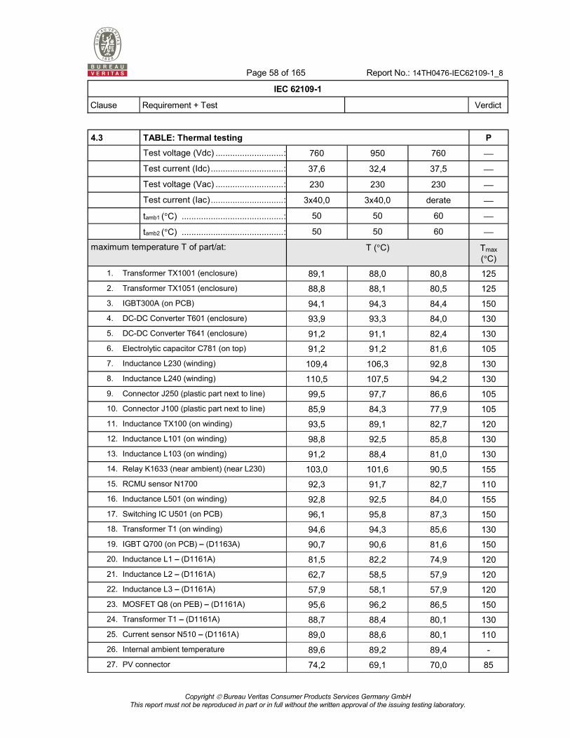
Page 58 of 165 Report No.: 14TH0476-IEC62109-1_8
IEC 62109-1
Clause Requirement + Test Verdict
Copyright Bureau Veritas Consumer Products Services Germany GmbH
This report must not be reproduced in part or in full without the written approval of the issuing testing laboratory.
4.3 TABLE: Thermal testing P
Test voltage (Vdc) ............................ : 760 950 760
Test current (Idc) .............................. : 37,6 32,4 37,5
Test voltage (Vac) ............................ : 230 230 230
Test current (Iac) .............................. : 3x40,0 3x40,0 derate
tamb1 ( C) .......................................... : 50 50 60
tamb2 ( C) .......................................... : 50 50 60
maximum temperature T of part/at: T ( C) Tmax ( C)
1. Transformer TX1001 (enclosure) 89,1 88,0 80,8 125
2. Transformer TX1051 (enclosure) 88,8 88,1 80,5 125
3. IGBT300A (on PCB) 94,1 94,3 84,4 150
4. DC-DC Converter T601 (enclosure) 93,9 93,3 84,0 130
5. DC-DC Converter T641 (enclosure) 91,2 91,1 82,4 130
6. Electrolytic capacitor C781 (on top) 91,2 91,2 81,6 105
7. Inductance L230 (winding) 109,4 106,3 92,8 130
8. Inductance L240 (winding) 110,5 107,5 94,2 130
9. Connector J250 (plastic part next to line) 99,5 97,7 86,6 105
10. Connector J100 (plastic part next to line) 85,9 84,3 77,9 105
11. Inductance TX100 (on winding) 93,5 89,1 82,7 120
12. Inductance L101 (on winding) 98,8 92,5 85,8 130
13. Inductance L103 (on winding) 91,2 88,4 81,0 130
14. Relay K1633 (near ambient) (near L230) 103,0 101,6 90,5 155
15. RCMU sensor N1700 92,3 91,7 82,7 110
16. Inductance L501 (on winding) 92,8 92,5 84,0 155
17. Switching IC U501 (on PCB) 96,1 95,8 87,3 150
18. Transformer T1 (on winding) 94,6 94,3 85,6 130
19. IGBT Q700 (on PCB) (D1163A) 90,7 90,6 81,6 150
20. Inductance L1 (D1161A) 81,5 82,2 74,9 120
21. Inductance L2 (D1161A) 62,7 58,5 57,9 120
22. Inductance L3 (D1161A) 57,9 58,1 57,9 120
23. MOSFET Q8 (on PEB) (D1161A) 95,6 96,2 86,5 150
24. Transformer T1 (D1161A) 88,7 88,4 80,1 130
25. Current sensor N510 (D1161A) 89,0 88,6 80,1 110
26. Internal ambient temperature 89,6 89,2 89,4 -
27. PV connector 74,2 69,1 70,0 85

Page 59 of 165 Report No.: 14TH0476-IEC62109-1_8
IEC 62109-1
Clause Requirement + Test Verdict
Copyright Bureau Veritas Consumer Products Services Germany GmbH
This report must not be reproduced in part or in full without the written approval of the issuing testing laboratory.
28. Strain relief AC 69,2 69,3 64,2 80
29. Temperature near display 67,6 67,3 61,7 130
30. Temperature heat sink hotspot 87,6 89,0 79,1 90
Supplementary information:
Comment:
The above temperatures are recorded at tamb1. The values measured are subtracted with tamb1 and tamb2 (°C) added. Therefore above measured temperatures are the absolute temperatures in °C at maximum ambient.
The printed circuit board is rated 130 °C.

Page 60 of 165 Report No.: 14TH0476-IEC62109-1_8
IEC 62109-1
Clause Requirement + Test Verdict
Copyright Bureau Veritas Consumer Products Services Germany GmbH
This report must not be reproduced in part or in full without the written approval of the issuing testing laboratory.
4.4.2, 4.4.4, 9.3
TABLE: Fault Condition Tests P
Ambient temperature ( C) ...................................25
Power source for EUT: Manufacturer, model/type, output rating .....................................
see appended table
Component No.
Fault Test voltage (V)
Test time
fuse No. (AC)
Current
Result
DC AC DC AC
4.4.4.1 Component fault tests
IGBT
IGBT300A
PIN 16 to PIN 8 short
950V
30A
230V
3x40A
10min Ext.
63
950V
0A
0V
0A
External circuit breaker opened immediately.
No hazard. Unit defect.
IGBT
IGBT300A
PIN 8 to PIN 13 short
950V
30A
230V
3x40A
10min Ext.
63
950V
0A
0V
0A
External circuit breaker opened immediately.
No hazard. Unit defect.
Electrolytic capacitor
C780
Short 800V
36A
230V
3x40A
10min Ext.
63
800V
36A
230V
3x40A
No effect on function,
No hazard, No defect,
No fire
Relay
K1629
Molten contacts
850V
0A
230V
0A
10min Ext.
63
850V
0A
230V
0A
G1 AC
to the grid, No hazard, No defect, no fire
Relay
K1632
Molten contacts
850V
0A
230V
0A
10min Ext.
63
850V
0A
230V
0A
to the grid, No hazard, No defect, no fire
Relay
K1633
Molten contacts
850V
0A
230V
0A
10min Ext.
63
850V
0A
230V
0A
to the grid, No hazard, No defect, no fire
Diode
D501
PIN 1 to PIN 4 short
850V
36A
230V
3x40A
10min Ext.
63
850V
0A
230V
0A
Unit switched off immediately, Fuse F501 operates, No hazard, no fire
Diode
D508
short 850V
36A
230V
3x40A
10min Ext.
63
850V
0A
230V
0A
Unit switched off immediately, Display defect, No hazard, no fire
IGBT
Q700
(D1163)
short 950V
30A
230V
3x40A
10min Ext.
63
950V
0A
0V
0A
External circuit breaker opened immediately.
No hazard. Unit defect.

Page 61 of 165 Report No.: 14TH0476-IEC62109-1_8
IEC 62109-1
Clause Requirement + Test Verdict
Copyright Bureau Veritas Consumer Products Services Germany GmbH
This report must not be reproduced in part or in full without the written approval of the issuing testing laboratory.
Component No.
Fault Test voltage (V)
Test time
fuse No. (AC)
Current
Result
DC AC DC AC
a.c. current measurement
N500
deactivated 850V
3,90A
230V
3 x 4,30A
10min Ext.
63
850V
0A
230V
0A
to the grid, No hazard, No defect, no fire
4.4.4.3 Motors
Fan Blocked during operation
850V
3,90A
230V
3 x 4,30A
10min Ext.
63
850V
0A
230V
0A
Inverter disconnects after reaching the maximum internal temperature. Error 46. No hazard, no defect
Fan Blocked before start
850V
3,90A
230V
3 x 4,30A
10min Ext.
63
850V
0A
230V
0A
Inverter disconnects after reaching the maximum internal temperature. Error 46. No hazard, no defect
4.4.4.4 Transformer short circuit tests
Transformer
T1001
Winding Lp short
700V 225V 5min Ext.
63
3,66A 6A No effect on function. Unit works normally. No excessive temperature range, no hazard, no defect.
Transformer
T1001
Winding Ls short
700V 225V 5min Ext.
63
3,66A 6A No effect on function. Unit works normally. No excessive temperature range, no hazard, no defect.
Transformer
TX1051
Winding Lp short
700V 225V 5min Ext.
63
3,66A 6A No effect on function. Unit works normally. No excessive temperature range, no hazard, no defect.
Transformer
TX1051
Winding Ls short
700V 225V 5min Ext.
63
3,66A 6A No effect on function. Unit works normally. No excessive temperature range, no hazard, no defect.
Transformer
T601
PIN 1 to PIN 2 short
850V
36A
230V
3x40A
10min Ext.
63
850V
0A
230V
0A
Unit switched off immediately. No restart. No hazard, no fire
Transformer
T601
PIN 6 to PIN 7 short
850V
36A
230V
3x40A
10min Ext.
63
850V
0A
230V
0A
Unit switched off immediately. No restart. No hazard, no fire
Transformer
T1
PIN 1 to PIN 3 short
750V
3,9A
230V
3x4,3A
10min
Ext.
63
750V
3,9A
230V
3x4,3A
No effect on function, No hazard, No fire, No defect

Page 62 of 165 Report No.: 14TH0476-IEC62109-1_8
IEC 62109-1
Clause Requirement + Test Verdict
Copyright Bureau Veritas Consumer Products Services Germany GmbH
This report must not be reproduced in part or in full without the written approval of the issuing testing laboratory.
Component No.
Fault Test voltage (V)
Test time
fuse No. (AC)
Current
Result
DC AC DC AC
Transformer
T1
PIN 5 to PIN 4 short
750V
3,9A
230V
3x4,3A
10min
Ext.
63
750V
3,9A
230V
3x4,3A
No effect on function, No hazard, No fire, No defect
Transformer
T1
PIN 7 to PIN 10 short
750V
3,9A
230V
3x4,3A
10min
Ext.
63
750V
3,9A
230V
3x4,3A
No effect on function, No hazard, No fire, No defect
Transformer
T1
(D1163)
PIN 11 to PIN 12 short
750V
3,9A
230V
3x4,3A
10min
Ext.
63
750V
3,9A
230V
3x4,3A
No effect on function, No hazard, No fire, No defect
Transformer
T1
(D1163)
PIN 9 to PIN 10 short
750V
3,9A
230V
3x4,3A
10min
Ext 63A
750V
3,9A
230V
3x4,3A
No effect on function, No hazard, No fire, No defect
Transformer
T1
(D1163)
PIN 7 to PIN 8 short
750V
3,9A
230V
3x4,3A
10min
Ext 63A
750V
3,9A
230V
3x4,3A
No effect on function, No hazard, No fire, No defect
Transformer
T1
(D1163)
PIN 1 to PIN 3 short
750V
3,9A
230V
3x4,3A
10min
Ext 63A
750V
3,9A
230V
3x4,3A
No effect on function, No hazard, No fire, No defect
4.4.4.5 Output short circuit
L1 to L2 short 850V
36A
230V
3x40A
10min Ext.
63
850V
0A
0V
0A
Isc= 9,63 A rms / 60 ms
External circuit breaker opened immediately. Unit shut down immediately.
No hazard. No defect.
L2 to L3 short 850V
36A
230V
3x40A
10min Ext.
63
850V
0A
0V
0A
Isc= 9,18 A rms / 60 ms
External circuit breaker opened immediately. Unit shut down immediately.
No hazard. No defect.
L1 to L3 short 850V
36A
230V
3x40A
10min Ext.
63
850V
0A
0V
0A
Isc= 10,23 A rms / 60 ms
External circuit breaker opened immediately. Unit shut down immediately.
No hazard. No defect.
4.4.4.7 Output overload
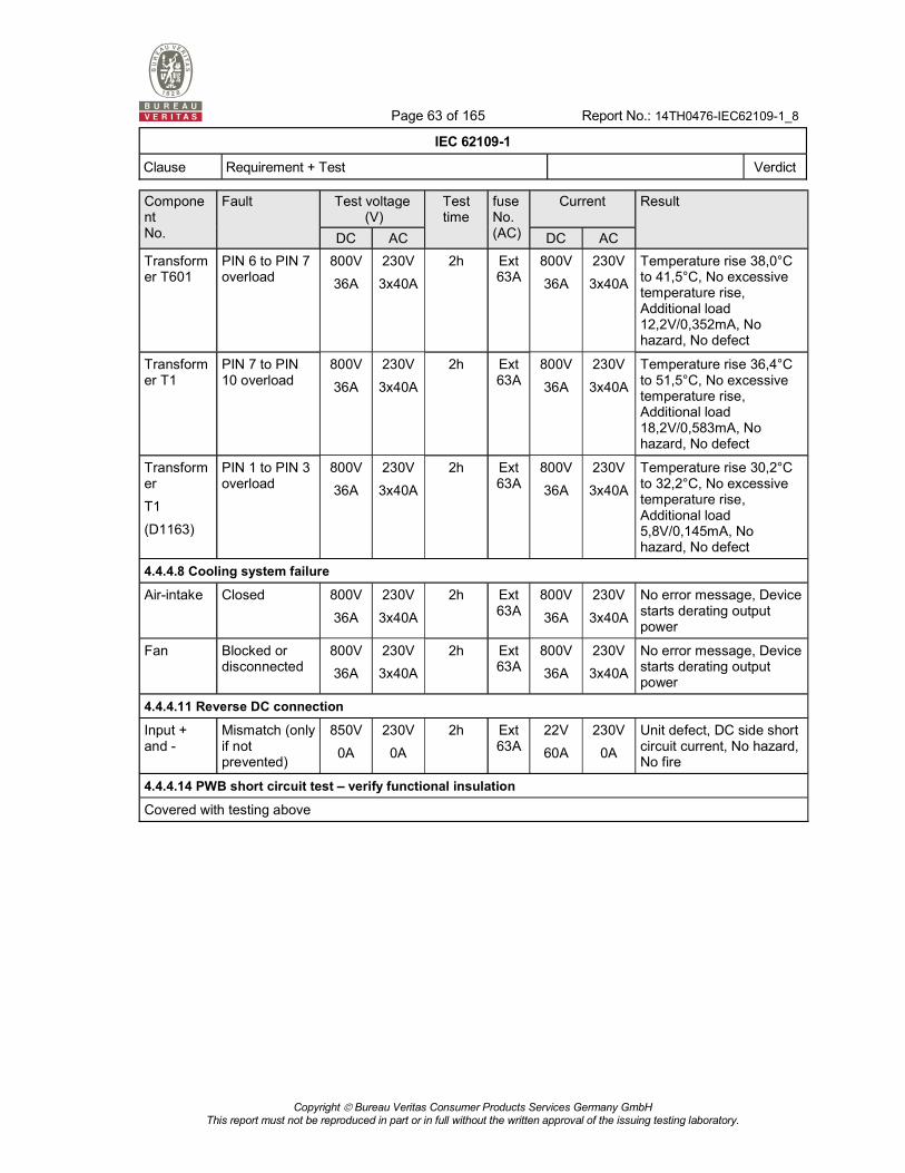
Page 63 of 165 Report No.: 14TH0476-IEC62109-1_8
IEC 62109-1
Clause Requirement + Test Verdict
Copyright Bureau Veritas Consumer Products Services Germany GmbH
This report must not be reproduced in part or in full without the written approval of the issuing testing laboratory.
Component No.
Fault Test voltage (V)
Test time
fuse No. (AC)
Current
Result
DC AC DC AC
Transformer T601
PIN 6 to PIN 7 overload
800V
36A
230V
3x40A
2h Ext 63A
800V
36A
230V
3x40A
Temperature rise 38,0°C to 41,5°C, No excessive temperature rise, Additional load 12,2V/0,352mA, No hazard, No defect
Transformer T1
PIN 7 to PIN 10 overload
800V
36A
230V
3x40A
2h Ext 63A
800V
36A
230V
3x40A
Temperature rise 36,4°C to 51,5°C, No excessive temperature rise, Additional load 18,2V/0,583mA, No hazard, No defect
Transformer
T1
(D1163)
PIN 1 to PIN 3 overload
800V
36A
230V
3x40A
2h Ext 63A
800V
36A
230V
3x40A
Temperature rise 30,2°C to 32,2°C, No excessive temperature rise, Additional load 5,8V/0,145mA, No hazard, No defect
4.4.4.8 Cooling system failure
Air-intake Closed 800V
36A
230V
3x40A
2h Ext 63A
800V
36A
230V
3x40A
No error message, Device starts derating output power
Fan Blocked or disconnected
800V
36A
230V
3x40A
2h Ext 63A
800V
36A
230V
3x40A
No error message, Device starts derating output power
4.4.4.11 Reverse DC connection
Input + and -
Mismatch (only if not prevented)
850V
0A
230V
0A
2h Ext 63A
22V
60A
230V
0A
Unit defect, DC side short circuit current, No hazard, No fire
4.4.4.14 PWB short circuit test verify functional insulation
Covered with testing above

Page 64 of 165 Report No.: 14TH0476-IEC62109-1_8
IEC 62109-1
Clause Requirement + Test Verdict
Copyright Bureau Veritas Consumer Products Services Germany GmbH
This report must not be reproduced in part or in full without the written approval of the issuing testing laboratory.
7.3.2 TABLE: Decisive voltage class (DVC)
TABLE: DVC and Working Voltage Measurement Tests
P
Location rms voltage peak voltage (V) Classification
T1 (reinforced)
PIN 1 to PE 197 352 C
PIN 3 to PE 195 344 C
PIN 5 to PE 196 -344 C
PIN 6 to PE 196 -344 C
PIN 7 to PE 4,38 -9,4 A
PIN 8 to PE 0,6 -0,67 A
PIN 9 to PE 0,6 -0,66 A
PIN 10 to PE 0,6 -0,66 A
PIN 11 to PE 0,3 0,34 A
PIN 12 to PE 0,3 0,34 A
PIN 13 to PE 1,01 -1,12 A
PIN 1 to PIN 3 0,32 -0,37 A
PIN 1 to PIN 5 391 -400 C
PIN 1 to PIN 6 390 -400 C
PIN 1 to PIN 7 195 -344 C
PIN 1 to PIN 8 195 -348 C
PIN 1 to PIN 9 195 -347 C
PIN 1 to PIN 11 195 -348 C
PIN 1 to PIN 12 195 -344 C
PIN 1 to PIN 13 195 -344 C
Comment:
Test condition: Input 1000Vdc, Output 277Vac

Page 65 of 165 Report No.: 14TH0476-IEC62109-1_8
IEC 62109-1
Clause Requirement + Test Verdict
Copyright Bureau Veritas Consumer Products Services Germany GmbH
This report must not be reproduced in part or in full without the written approval of the issuing testing laboratory.
Location rms voltage peak voltage (V) Classification
TX1001 (reinforced)
PIN 1 to PIN 8 445,89 -530 C
PIN 1 to PIN 5 474,69 -560 C
PIN 4 to PIN 8 449,84 -560 C
PIN 4 to PIN 5 445,52 -530 C
Comment:
Test condition: Input 1000Vdc, Output 230Vac
Location rms voltage peak voltage (V) Classification
TX1051 (reinforced)
PIN 1 to PIN 8 444,13 -510 C
PIN 1 to PIN 5 446,71 -560 C
PIN 4 to PIN 8 445,9 -530 C
PIN 4 to PIN 5 445,73 -540 C
Comment:
Test condition: Input 1000Vdc, Output 230Vac
Location rms voltage peak voltage (V) Classification
T601 (reinforced)
PIN 1 to PE 3,98 4,08 A
PIN 2 to PE 3,89 4 A
PIN 3 to PE 1,04 -1,12 A
PIN 4 to PE 0,46 -0,77 A
PIN 1 to PIN 6 0,18 -509 C
PIN 1 to PIN 7 0,18 -512 C
PIN 1 to PIN 9 0,19 -528 C
PIN 1 to PIN 10 0,19 -528 C
Comment:
Test condition: Input 1000Vdc, Output 230Vac

Page 66 of 165 Report No.: 14TH0476-IEC62109-1_8
IEC 62109-1
Clause Requirement + Test Verdict
Copyright Bureau Veritas Consumer Products Services Germany GmbH
This report must not be reproduced in part or in full without the written approval of the issuing testing laboratory.
Location rms voltage peak voltage (V) Classification
T1 (reinforced)
PIN 1 to PE 193,38 344 C
PIN 3 to PE 193,07 336 C
PIN 4 to PE 188,76 -328 C
PIN 5 to PE 188,87 334 C
PIN 1 to PIN 7 193,57 344 C
PIN 1 to PIN 10 193,35 344 C
Comment:
Test condition: Input 1000Vdc, Output 230Vac
Location rms voltage peak voltage (V) Classification
T1 (reinforced) D1163 board
PIN 7 to PE 5,02 -5,04 A
PIN 8 to PE 378,05 -472 C
PIN 9 to PE 362,87 456 C
PIN 10 to PE 362,91 456 C
PIN 11 to PE 380,52 472 C
PIN 12 to PE 378,34 470 C
PIN 11 to PIN 7 381,53 472 C
PIN 11 to PIN 10 381,05 472 C
Comment:
Test condition: Input 1000Vdc, Output 230Vac

Page 67 of 165 Report No.: 14TH0476-IEC62109-1_8
IEC 62109-1
Clause Requirement + Test Verdict
Copyright Bureau Veritas Consumer Products Services Germany GmbH
This report must not be reproduced in part or in full without the written approval of the issuing testing laboratory.
7.3.5.2 TABLE: Protection using decisive voltage class A P
Transformer Designation Location Maximum Voltage
(Vpk/dc) Voltage Limiting
Component
TR 1 Pin 7 to 10 51,7 V / 20,34 V --
- Diode D508 PIN 2 to T1 PIN 9 -16,2 V/ 12,43 V D508
TR 1 (D1163A) Pin 7 to 10 -120 V /5,39 V --
- Diode D11 PIN 2 to T1 PIN 9 -15,5 / 11,24 V D11
Supplementary information:

Page 68 of 165 Report No.: 14TH0476-IEC62109-1_8
IEC 62109-1
Clause Requirement + Test Verdict
Copyright Bureau Veritas Consumer Products Services Germany GmbH
This report must not be reproduced in part or in full without the written approval of the issuing testing laboratory.
7.3.5.3.1, 7.3.6.3.6, 7.5.4
Limitation of current through protective impedance
TABLE: Touch Current Test
P
From To Measured voltage Calculated current
D1160
V_AC_L1 V_OUT_L1_INTR 276Vrms 64µArms
VDC+ VDC+_INTR 1000Vdc 239µA
D1163
V_ISO V_ISO_INTR 1000Vdc 2,24mAdc
V_F_L1 V_F_L1_INTR 276Vrms 64µArms
Supplementary information:

Page 69 of 165 Report No.: 14TH0476-IEC62109-1_8
IEC 62109-1
Clause Requirement + Test Verdict
Copyright Bureau Veritas Consumer Products Services Germany GmbH
This report must not be reproduced in part or in full without the written approval of the issuing testing laboratory.
7.3.5.3.2, 7.3.9
TABLE: Discharge Test P
Measurement location Initial Voltage
(Vpk)
Time to delay to 60V or limit of 7.3.5.4
(s) Inverter status
DC + to DC - 980 48,3 Feeding power to grid
990 43,2 Stand by
L to N -500 1,7 Feeding power to grid
-350 1,9 Stand by
-350 0,3 Nightmode
Supplementary information:

Page 70 of 165 Report No.: 14TH0476-IEC62109-1_8
IEC 62109-1
Clause Requirement + Test Verdict
Copyright Bureau Veritas Consumer Products Services Germany GmbH
This report must not be reproduced in part or in full without the written approval of the issuing testing laboratory.
7.3.6 TABLE: Ground Continue Test P
Location Test current
(A)
Time
(min)
Voltage
(V)
Resistance calculated
(m )
PE-terminal to enclosure cover 126 8 0,787 6,25
PE-terminal to enclosure heatsink 126 8 0,756 6,00
PE-terminal to enclosure side 126 8 0,795 6,31
Supplementary information:

Page 71 of 165 Report No.: 14TH0476-IEC62109-1_8
IEC 62109-1
Clause Requirement + Test Verdict
Copyright Bureau Veritas Consumer Products Services Germany GmbH
This report must not be reproduced in part or in full without the written approval of the issuing testing laboratory.
7.3.7 TABLE: Clearance And Creepage Distance Measurements P
clearance cl and creepage distance dcr at/of:
Impuls withstand voltage
(V)
Mains circuit temporary
overvoltage
(V peak)
U r.m.s.
(V)
U peak
(V)
required cl
(mm)
cl
(mm)
required
cr (mm)
dcr
(mm)
Board D1160EA
Mains to PE (basic) OVCIII
230 V a.c.
4464 2120 277 392 3,6 3,6 3,6* 3,6
PV to PE (basic)
1000 V d.c.
4464 N/A 500 500 3,6 3,6 3,6* 3,6
Mains to SELV (reinforced)
6464 2120 277 392 6,1 6,1 6,1* 6,1
PV to SELV (reinforced)
6464 2120 277 392 6,1 6,1 6,1* 6,1
Board D1163FA
Mains to PE (basic) OVCIII
230 V a.c.
4464 2120 277 392 3,6 5,5 3,6* 5,5
PV to PE (basic)
1000 V d.c.
4464 N/A 500 500 3,6 5,5 3,6* 5,5
Mains to SELV (reinforced)
6464 2120 277 392 6,1 6,1 6,1* 6,1
PV to SELV (reinforced)
6464 2120 277 392 6,1 6,1 6,1* 6,1
Supplementary information:

Page 72 of 165 Report No.: 14TH0476-IEC62109-1_8
IEC 62109-1
Clause Requirement + Test Verdict
Copyright Bureau Veritas Consumer Products Services Germany GmbH
This report must not be reproduced in part or in full without the written approval of the issuing testing laboratory.
Block diagram:
Supplementary information:
TR1

Page 73 of 165 Report No.: 14TH0476-IEC62109-1_8
IEC 62109-1
Clause Requirement + Test Verdict
Copyright Bureau Veritas Consumer Products Services Germany GmbH
This report must not be reproduced in part or in full without the written approval of the issuing testing laboratory.
D1160EA top

Page 74 of 165 Report No.: 14TH0476-IEC62109-1_8
IEC 62109-1
Clause Requirement + Test Verdict
Copyright Bureau Veritas Consumer Products Services Germany GmbH
This report must not be reproduced in part or in full without the written approval of the issuing testing laboratory.
D1160EA bottom
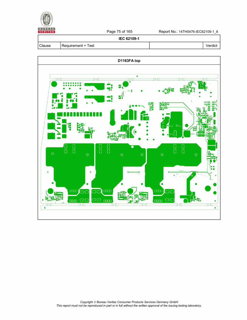
Page 75 of 165 Report No.: 14TH0476-IEC62109-1_8
IEC 62109-1
Clause Requirement + Test Verdict
Copyright Bureau Veritas Consumer Products Services Germany GmbH
This report must not be reproduced in part or in full without the written approval of the issuing testing laboratory.
D1163FA top

Page 76 of 165 Report No.: 14TH0476-IEC62109-1_8
IEC 62109-1
Clause Requirement + Test Verdict
Copyright Bureau Veritas Consumer Products Services Germany GmbH
This report must not be reproduced in part or in full without the written approval of the issuing testing laboratory.
D1163FA bottom

Page 77 of 165 Report No.: 14TH0476-IEC62109-1_8
IEC 62109-1
Clause Requirement + Test Verdict
Copyright Bureau Veritas Consumer Products Services Germany GmbH
This report must not be reproduced in part or in full without the written approval of the issuing testing laboratory.
7.5.1 TABLE: Impulse Voltage Tests P
Test voltage applied between: Test potential applied (V)
Breakdown / flashover (Yes/No)
DC to PE 4464 No
AC to PE 4464 No
AC to user 6464 No
DC to user 6464 No
Supplementary information:

Page 78 of 165 Report No.: 14TH0476-IEC62109-1_8
IEC 62109-1
Clause Requirement + Test Verdict
Copyright Bureau Veritas Consumer Products Services Germany GmbH
This report must not be reproduced in part or in full without the written approval of the issuing testing laboratory.
7.5.2 TABLE: Dielectric Strength Tests P
Test voltage applied between: Test potential applied (V)
Breakdown / flashover (Yes/No)
SE33.3K
DC to PE 1500Vac / 2120Vdc No
AC to PE 1500Vac / 2120Vdc No
AC to user 3000Vac / 4240Vdc No
DC to user 3000Vac / 4240Vdc No
SE20.1K
DC to PE 1500Vac / 2120Vdc No
AC to PE 1500Vac / 2120Vdc No
AC to user 3000Vac / 4240Vdc No
DC to user 3000Vac / 4240Vdc No
Supplementary information:

Page 79 of 165 Report No.: 14TH0476-IEC62109-1_8
IEC 62109-1
Clause Requirement + Test Verdict
Copyright Bureau Veritas Consumer Products Services Germany GmbH
This report must not be reproduced in part or in full without the written approval of the issuing testing laboratory.
7.5.4 TABLE: Touch current measurement P
The unit was connected to 276 Vac, 720 Vdc and 50Hz. The outputs were loaded to the rated value. The current measuring circuit according to Figure 4 of IEC 60990 was taken.
Star mains equipment
Parts tested Measured voltage
(V) Calculated
current (mA) Comments
Common point Enclosure 1,95 3,91 Normal condition
Common point Enclosure 1,96 3,90 L1 and L2 swapped
Common point Enclosure 1,72 3,44 L1 disconnected
Common point Enclosure 1,81 3,61 L2 disconnected
Common point Enclosure 1,70 3,36 L3 disconnected
Comments:
* Unit did not start to operate without PE connected. Measurements were performed at stand-by condition.

Page 114 of 165 Report No.: 14TH0476-IEC62109-1_8
Copyright Bureau Veritas Consumer Products Services Germany GmbH
This report must not be reproduced in part or in full without the written approval of the issuing testing laboratory.
Annex No. 1
IP Test Report

Page 115 of 165 Report No.: 14TH0476-IEC62109-1_8
Copyright Bureau Veritas Consumer Products Services Germany GmbH
This report must not be reproduced in part or in full without the written approval of the issuing testing laboratory.

Page 116 of 165 Report No.: 14TH0476-IEC62109-1_8
Copyright Bureau Veritas Consumer Products Services Germany GmbH
This report must not be reproduced in part or in full without the written approval of the issuing testing laboratory.

Page 117 of 165 Report No.: 14TH0476-IEC62109-1_8
Copyright Bureau Veritas Consumer Products Services Germany GmbH
This report must not be reproduced in part or in full without the written approval of the issuing testing laboratory.

Page 118 of 165 Report No.: 14TH0476-IEC62109-1_8
Copyright Bureau Veritas Consumer Products Services Germany GmbH
This report must not be reproduced in part or in full without the written approval of the issuing testing laboratory.

Page 119 of 165 Report No.: 14TH0476-IEC62109-1_8
Copyright Bureau Veritas Consumer Products Services Germany GmbH
This report must not be reproduced in part or in full without the written approval of the issuing testing laboratory.

Page 120 of 165 Report No.: 14TH0476-IEC62109-1_8
Copyright Bureau Veritas Consumer Products Services Germany GmbH
This report must not be reproduced in part or in full without the written approval of the issuing testing laboratory.

Page 121 of 165 Report No.: 14TH0476-IEC62109-1_8
Copyright Bureau Veritas Consumer Products Services Germany GmbH
This report must not be reproduced in part or in full without the written approval of the issuing testing laboratory.

Page 122 of 165 Report No.: 14TH0476-IEC62109-1_8
Copyright Bureau Veritas Consumer Products Services Germany GmbH
This report must not be reproduced in part or in full without the written approval of the issuing testing laboratory.

Page 123 of 165 Report No.: 14TH0476-IEC62109-1_8
Copyright Bureau Veritas Consumer Products Services Germany GmbH
This report must not be reproduced in part or in full without the written approval of the issuing testing laboratory.

Page 124 of 165 Report No.: 14TH0476-IEC62109-1_8
Copyright Bureau Veritas Consumer Products Services Germany GmbH
This report must not be reproduced in part or in full without the written approval of the issuing testing laboratory.

Page 125 of 165 Report No.: 14TH0476-IEC62109-1_8
Copyright Bureau Veritas Consumer Products Services Germany GmbH
This report must not be reproduced in part or in full without the written approval of the issuing testing laboratory.

Page 126 of 165 Report No.: 14TH0476-IEC62109-1_8
Copyright Bureau Veritas Consumer Products Services Germany GmbH
This report must not be reproduced in part or in full without the written approval of the issuing testing laboratory.
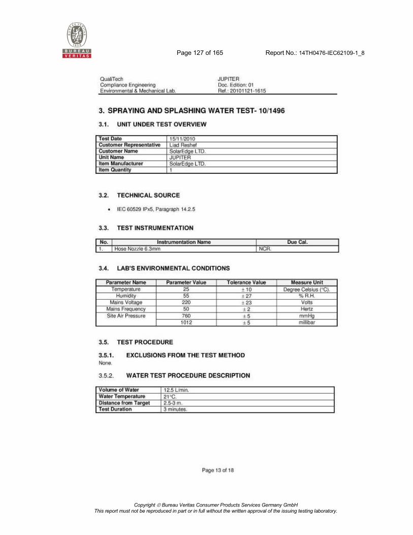
Page 127 of 165 Report No.: 14TH0476-IEC62109-1_8
Copyright Bureau Veritas Consumer Products Services Germany GmbH
This report must not be reproduced in part or in full without the written approval of the issuing testing laboratory.

Page 128 of 165 Report No.: 14TH0476-IEC62109-1_8
Copyright Bureau Veritas Consumer Products Services Germany GmbH
This report must not be reproduced in part or in full without the written approval of the issuing testing laboratory.

Page 129 of 165 Report No.: 14TH0476-IEC62109-1_8
Copyright Bureau Veritas Consumer Products Services Germany GmbH
This report must not be reproduced in part or in full without the written approval of the issuing testing laboratory.
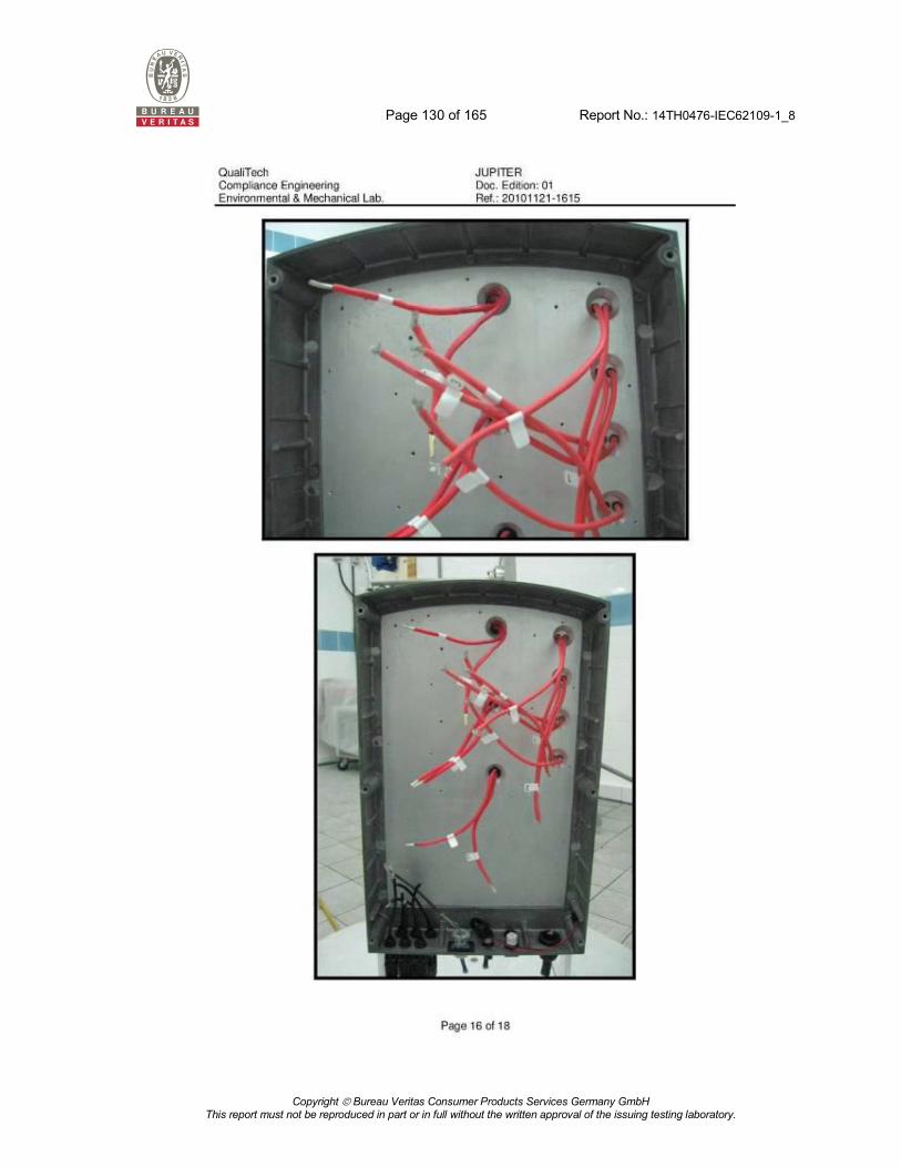
Page 130 of 165 Report No.: 14TH0476-IEC62109-1_8
Copyright Bureau Veritas Consumer Products Services Germany GmbH
This report must not be reproduced in part or in full without the written approval of the issuing testing laboratory.

Page 131 of 165 Report No.: 14TH0476-IEC62109-1_8
Copyright Bureau Veritas Consumer Products Services Germany GmbH
This report must not be reproduced in part or in full without the written approval of the issuing testing laboratory.
Page 132 of 165 Report No.: 14TH0476-IEC62109-1_8
Copyright Bureau Veritas Consumer Products Services Germany GmbH
This report must not be reproduced in part or in full without the written approval of the issuing testing laboratory.

Page 133 of 165 Report No.: 14TH0476-IEC62109-1_8
Copyright Bureau Veritas Consumer Products Services Germany GmbH
This report must not be reproduced in part or in full without the written approval of the issuing testing laboratory.
Annex No. 2
Pictures of the unit
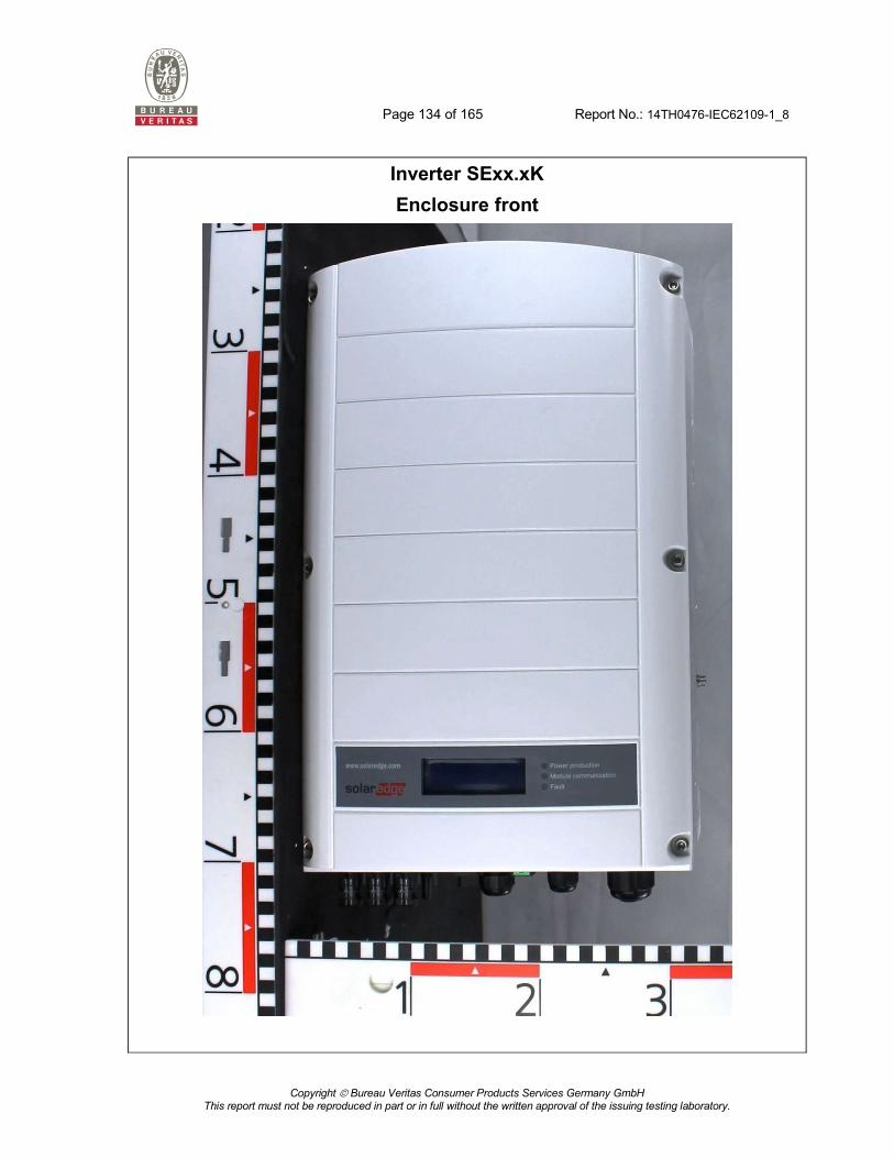
Page 134 of 165 Report No.: 14TH0476-IEC62109-1_8
Copyright Bureau Veritas Consumer Products Services Germany GmbH
This report must not be reproduced in part or in full without the written approval of the issuing testing laboratory.
Inverter SExx.xK
Enclosure front

Page 135 of 165 Report No.: 14TH0476-IEC62109-1_8
Copyright Bureau Veritas Consumer Products Services Germany GmbH
This report must not be reproduced in part or in full without the written approval of the issuing testing laboratory.
Enclosure bottom
(connectors)

Page 136 of 165 Report No.: 14TH0476-IEC62109-1_8
Copyright Bureau Veritas Consumer Products Services Germany GmbH
This report must not be reproduced in part or in full without the written approval of the issuing testing laboratory.
Enclosure top side

Page 137 of 165 Report No.: 14TH0476-IEC62109-1_8
Copyright Bureau Veritas Consumer Products Services Germany GmbH
This report must not be reproduced in part or in full without the written approval of the issuing testing laboratory.
Enclosure left side
Enclosure right side

Page 138 of 165 Report No.: 14TH0476-IEC62109-1_8
Copyright Bureau Veritas Consumer Products Services Germany GmbH
This report must not be reproduced in part or in full without the written approval of the issuing testing laboratory.
Enclosure back

Page 139 of 165 Report No.: 14TH0476-IEC62109-1_8
Copyright Bureau Veritas Consumer Products Services Germany GmbH
This report must not be reproduced in part or in full without the written approval of the issuing testing laboratory.
Enclosure open

Page 140 of 165 Report No.: 14TH0476-IEC62109-1_8
Copyright Bureau Veritas Consumer Products Services Germany GmbH
This report must not be reproduced in part or in full without the written approval of the issuing testing laboratory.
Earth connection
Earth connection PCB:
M3 machine thread screw
flat washer
spring lock washer
enclosure
thread bolt
PCB

Page 141 of 165 Report No.: 14TH0476-IEC62109-1_8
Copyright Bureau Veritas Consumer Products Services Germany GmbH
This report must not be reproduced in part or in full without the written approval of the issuing testing laboratory.
Fan wire run

Page 142 of 165 Report No.: 14TH0476-IEC62109-1_8
Copyright Bureau Veritas Consumer Products Services Germany GmbH
This report must not be reproduced in part or in full without the written approval of the issuing testing laboratory.

Page 143 of 165 Report No.: 14TH0476-IEC62109-1_8
Copyright Bureau Veritas Consumer Products Services Germany GmbH
This report must not be reproduced in part or in full without the written approval of the issuing testing laboratory.
LTE CAT1 board

Page 144 of 165 Report No.: 14TH0476-IEC62109-1_8
Copyright Bureau Veritas Consumer Products Services Germany GmbH
This report must not be reproduced in part or in full without the written approval of the issuing testing laboratory.
Annex No. 3
Schematics, layouts and transformer drawings

Page 145 of 165 Report No.: 14TH0476-IEC62109-1_8
Copyright Bureau Veritas Consumer Products Services Germany GmbH
This report must not be reproduced in part or in full without the written approval of the issuing testing laboratory.
Schematic D1160A

Page 146 of 165 Report No.: 14TH0476-IEC62109-1_8
Copyright Bureau Veritas Consumer Products Services Germany GmbH
This report must not be reproduced in part or in full without the written approval of the issuing testing laboratory.

Page 147 of 165 Report No.: 14TH0476-IEC62109-1_8
Copyright Bureau Veritas Consumer Products Services Germany GmbH
This report must not be reproduced in part or in full without the written approval of the issuing testing laboratory.

Page 148 of 165 Report No.: 14TH0476-IEC62109-1_8
Copyright Bureau Veritas Consumer Products Services Germany GmbH
This report must not be reproduced in part or in full without the written approval of the issuing testing laboratory.

Page 149 of 165 Report No.: 14TH0476-IEC62109-1_8
Copyright Bureau Veritas Consumer Products Services Germany GmbH
This report must not be reproduced in part or in full without the written approval of the issuing testing laboratory.

Page 150 of 165 Report No.: 14TH0476-IEC62109-1_8
Copyright Bureau Veritas Consumer Products Services Germany GmbH
This report must not be reproduced in part or in full without the written approval of the issuing testing laboratory.

Page 151 of 165 Report No.: 14TH0476-IEC62109-1_8
Copyright Bureau Veritas Consumer Products Services Germany GmbH
This report must not be reproduced in part or in full without the written approval of the issuing testing laboratory.

Page 152 of 165 Report No.: 14TH0476-IEC62109-1_8
Copyright Bureau Veritas Consumer Products Services Germany GmbH
This report must not be reproduced in part or in full without the written approval of the issuing testing laboratory.

Page 153 of 165 Report No.: 14TH0476-IEC62109-1_8
Copyright Bureau Veritas Consumer Products Services Germany GmbH
This report must not be reproduced in part or in full without the written approval of the issuing testing laboratory.
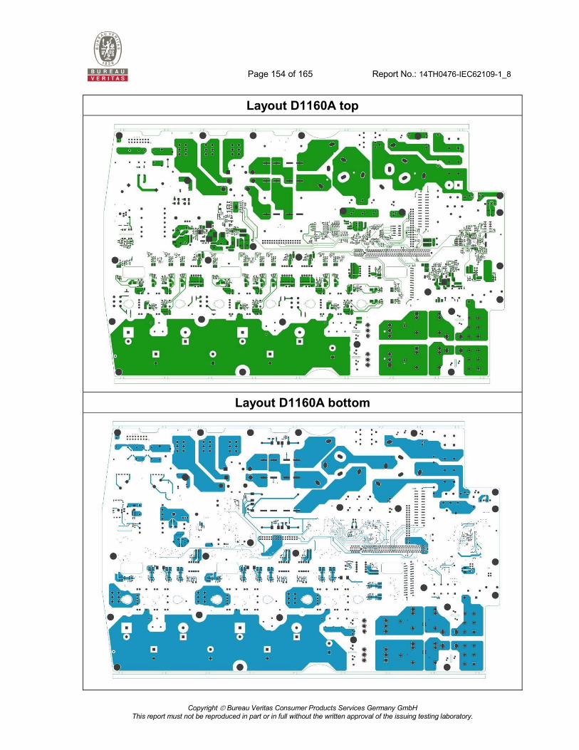
Page 154 of 165 Report No.: 14TH0476-IEC62109-1_8
Copyright Bureau Veritas Consumer Products Services Germany GmbH
This report must not be reproduced in part or in full without the written approval of the issuing testing laboratory.
Layout D1160A top
Layout D1160A bottom

Page 155 of 165 Report No.: 14TH0476-IEC62109-1_8
Copyright Bureau Veritas Consumer Products Services Germany GmbH
This report must not be reproduced in part or in full without the written approval of the issuing testing laboratory.
Schematic D1163A
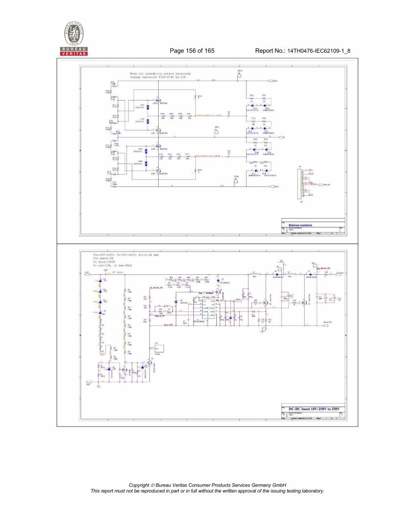
Page 156 of 165 Report No.: 14TH0476-IEC62109-1_8
Copyright Bureau Veritas Consumer Products Services Germany GmbH
This report must not be reproduced in part or in full without the written approval of the issuing testing laboratory.

Page 157 of 165 Report No.: 14TH0476-IEC62109-1_8
Copyright Bureau Veritas Consumer Products Services Germany GmbH
This report must not be reproduced in part or in full without the written approval of the issuing testing laboratory.

Page 158 of 165 Report No.: 14TH0476-IEC62109-1_8
Copyright Bureau Veritas Consumer Products Services Germany GmbH
This report must not be reproduced in part or in full without the written approval of the issuing testing laboratory.

Page 159 of 165 Report No.: 14TH0476-IEC62109-1_8
Copyright Bureau Veritas Consumer Products Services Germany GmbH
This report must not be reproduced in part or in full without the written approval of the issuing testing laboratory.

Page 160 of 165 Report No.: 14TH0476-IEC62109-1_8
Copyright Bureau Veritas Consumer Products Services Germany GmbH
This report must not be reproduced in part or in full without the written approval of the issuing testing laboratory.
Layout D1163A top
Layout D1163A bottom

Page 161 of 165 Report No.: 14TH0476-IEC62109-1_8
Copyright Bureau Veritas Consumer Products Services Germany GmbH
This report must not be reproduced in part or in full without the written approval of the issuing testing laboratory.
Transformer datasheet (SELV)

Page 162 of 165 Report No.: 14TH0476-IEC62109-1_8
Copyright Bureau Veritas Consumer Products Services Germany GmbH
This report must not be reproduced in part or in full without the written approval of the issuing testing laboratory.

Page 163 of 165 Report No.: 14TH0476-IEC62109-1_8
Copyright Bureau Veritas Consumer Products Services Germany GmbH
This report must not be reproduced in part or in full without the written approval of the issuing testing laboratory.

Page 164 of 165 Report No.: 14TH0476-IEC62109-1_8
Copyright Bureau Veritas Consumer Products Services Germany GmbH
This report must not be reproduced in part or in full without the written approval of the issuing testing laboratory.
Annex No. 4
Test Equipment list

Page 165 of 165 Report No.: 14TH0476-IEC62109-1_8
Copyright Bureau Veritas Consumer Products Services Germany GmbH
This report must not be reproduced in part or in full without the written approval of the issuing testing laboratory.
Measurement period: 2015-02-24 to 2015-04-30
Equipment Internal
No. Manufacturer Type Serial No. Last Calibration
Electronic Source 120 ET Euro-Test LAB/SM315 01.39.3155 Aug. 09 DC Power Supply 362 PCE A12KW E00126287 -- DC Power Supply 363 PCE A12KW E00126314 -- DC Power Supply 364 PCE A12KW E00126318 -- Leakage current meter 812 Kikusui TOS3200 NK003303 Jun. 14 DC- source 870 Regatron Model T.C.P. 0941CC133 DC- source 871 Regatron Model T.C.P. 0941CC134 Electronic Rack/Current Transducer Powersupply 905 SIGNALTEC MCTS 37-006-0074 Current Transducer 907 Danfysik Ultrstab 867 10076239 Sep. 14 Current Transducer 908 Danfysik Ultrstab 867 10076242 Sep. 14 Current Transducer 909 Danfysik Ultrstab 867 10076223 Sep. 14 Oscilloscope 943 Yokogawa DLM2000 91K53064 Mrz. 13 Dewetron Multi Channel Data Acquisition System 991 Dewetron
DEWE-2600 with voltage and current modules 28100161 Aug. 13
3 phase transformer 1006 Ruhstrat TIDMT 50kVA 41312 Differential probe 1050 TESTEC SI-9002 118138 Sep. 14
DC- source 1057 Regatron Model T.C.P. 32.1000.400.PV.HMI 1239CC621
Hygro- /Thermo- /Barometer 1073 Greisinger GFTB 100 90258040 Feb. 15
Climatic chamber 1084
WEISS Umwelttechnik GmbH WK3-1600/70-H/S 59226130830010 Apr. 14
Measurement period: 2020-07-19 to 2020-07-21
Equipment Internal
No. Manufacturer Type Serial No. Last Calibration
Hygro- /Thermo- /Barometer
1073 Greisinger GFTB 100 90258040 Mar-20
Spitzenberger & Spies Test System for PV-Inverter
1091 Spitzenberger & Spies
PVS 127500 / EMC D 75000/PAS / PRU 12750 / Mobile box / RLC 3500/2.5
A5191 00 / A5192 00 / A5193 00 / A5194 00 / A5195 00
N/A
Dewetron Multi Channel Data Acquisition System
1092 Dewetron DEWE-800 / DEWE-30-16 with Voltage an Current Modules
12130573, 56121690
Jan-20
Dielectric Tester (HV-Tester)
730 SPS electronic HA 2201G 9011904 May-20