Test Benches
35
Jim Duckworth, WPI Test Benches - Module 8 1 Test Benches Module 8
-
Upload
khangminh22 -
Category
Documents
-
view
0 -
download
0
Transcript of Test Benches

Jim Duckworth, WPI Test Benches - Module 81
Test Benches
Module 8

Overview
Jim Duckworth, WPI Test Benches - Module 82
• We have concentrated on VHDL for synthesis• Can also use VHDL as a test language• Very important to conduct comprehensive verification on
your design • To simulate your design you need to produce an additional
ENTITY and ARCHITECTURE design.– Usually referred to as a TEST BENCH
• Not hardware, just additional VHDL!
Test Bench
Jim Duckworth, WPI Test Benches - Module 83
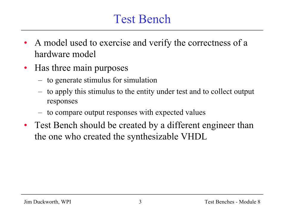
• A model used to exercise and verify the correctness of a hardware model
• Has three main purposes– to generate stimulus for simulation– to apply this stimulus to the entity under test and to collect output
responses– to compare output responses with expected values
• Test Bench should be created by a different engineer than the one who created the synthesizable VHDL

Test Bench
Jim Duckworth, WPI Test Benches - Module 84
Entity to betested
ApplyStimulus
VerifyResponses
Test Bench Overview
Jim Duckworth, WPI Test Benches - Module 85
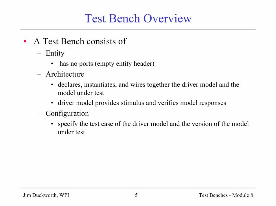
• A Test Bench consists of– Entity
• has no ports (empty entity header)– Architecture
• declares, instantiates, and wires together the driver model and the model under test
• driver model provides stimulus and verifies model responses– Configuration
• specify the test case of the driver model and the version of the model under test

Test Bench - general structure
Jim Duckworth, WPI Test Benches - Module 86
ENTITY test_bench ISEND test_bench;
ARCHITECTURE tb1 OF test_bench IStest_component declarationinternal signal declarations
BEGINUUT: test_component instantiation
signals to generate stimulus
assert statements to verify repsonsesEND tb1;
test_component
inainbinc
out1

Test Bench - alternative structure
Jim Duckworth, WPI Test Benches - Module 87
Component:driver_model
Component:model_under_test
inainb
inc
out1
ENTITY test_bench ISEND test_bench;

Test Bench - template
Jim Duckworth, WPI Test Benches - Module 88
ENTITY test_bench ISEND test_bench;
ARCHITECTURE test-fixture OF test_bench IS
COMPONENT driver_modelEND COMPONENT;
COMPONENT model_under_testEND COMPONENT;
SIGNAL -- wires to connect together
BEGIN-- component instantiations
END test_fixture;

VHDL for Test Generation
Jim Duckworth, WPI Test Benches - Module 89
• We need to look at new VHDL constructs to support our test bench design
• Modeling Time• Generating Waveforms• The Assert Statement• NOTE: The following examples are for testing – NOT for
synthesis

Modeling Time (not for synthesis)
Jim Duckworth, WPI Test Benches - Module 810
• Example: 2 input AND gate
c <= a AND b;
• c changes value immediately after a change on the inputs a or b

Adding Propagation Delays
Jim Duckworth, WPI Test Benches - Module 811
ARCHITECTURE behav OF and_gate_model IS
BEGIN
PROCESS(a, b)
BEGIN
c <= a AND b; -- instantaneous change
-- adding "AFTER" to add delay
c <= a AND b AFTER 10 ns; -- same tphl and tplh
-- If we need different propagation delays:
IF a = '1' AND b = '1' THEN
c <= '1' AFTER 9 ns -- tplh
ELSE
c <= '0' AFTER 10 ns -- tphl
END IF;

Adding Propagation Delays (cont’d)
Jim Duckworth, WPI Test Benches - Module 812
• This is called the Inertial Delay Model (default)• Models delays of most switching circuits• If input pulse is shorter than the time expression (switching
time of circuit) then no change occurs on the output.

Transport Delay Model (only for modeling)
Jim Duckworth, WPI Test Benches - Module 813
• Transport delay is an optional delay model for signal assignment.
• Any pulse is transmitted, no matter how short its duration.IF a = '1' AND b = '1' THEN
c <= TRANSPORT '1' AFTER 9 ns -- tplh
ELSE
c <= TRANSPORT '0' AFTER 10 ns -- tphl
END IF;

Generating Arbitrary Waveforms
Jim Duckworth, WPI Test Benches - Module 814
• It is possible to assign multiple values to a signal
a <=‘0’, ‘1’ AFTER 8 ns, ‘0’ AFTER 13 ns, ‘1’ AFTER 50 ns;
• When this signal assignment is executed (at time T) it causes four events to be scheduled for signal a– ‘0’ at T – ‘1’ at T + 8– ‘0’ at T + 13– ‘1’ at T + 50
T+8T T+13 T+50

Waveform Examples – creating clocks
Jim Duckworth, WPI Test Benches - Module 815
ARCHITECTURE testbench OF example IS
SIGNAL clk : std_logic := ‘0’; -- initialize signals
BEGIN
clk <= NOT clk AFTER 10 ns;
-- creates periodic waveform on signal clk
-- with a period of 20ns
10 20 30 40 50

Waveform Examples – more clocks
Jim Duckworth, WPI Test Benches - Module 816
PROCESS -- Note: no sensitivity list
BEGIN
clk <= ‘0’;
WAIT FOR 20 ns;
clk <= ‘1’;
WAIT FOR 12 ns;
END PROCESS;
– OR
BEGIN
clk <= ‘1’ AFTER 20 ns WHEN clk = ‘0’ ELSE
‘0’ AFTER 12 ns;
20 32 52 64 84 96

Waveform Examples – more clocks
Jim Duckworth, WPI Test Benches - Module 817
• Example of two-phase clock
SIGNAL clk1, clk2 : std_logic := ‘0’;
two_phase: PROCESS
BEGIN
clk1 <= ‘0’, ‘1’ AFTER 5 ns, ‘0’ AFTER 20 ns;
clk2 <= ‘0’, ‘1’ AFTER 10 ns, ‘0’ AFTER 30 ns;
WAIT FOR 35 ns;
END PROCESS two_phase;
5 10 15 20 25 30 35 40 45 50 55 60
one period

Assert Statement
Jim Duckworth, WPI Test Benches - Module 818
• How do we check outputs?• Assert statement is used to report information• Assert statement checks a Boolean expression
– if true, the statement does nothing– if false, the report string is output
• optional severity level to output string– note– warning– error– failure (will stop simulator)

Test Bench Example
Jim Duckworth, WPI Test Benches - Module 819
LIBRARY ieee;
USE ieee.std_logic_1164.ALL;
ENTITY test_bench IS
END test_bench;
ARCHITECTURE test_fixture OF test_bench IS
COMPONENT and2
PORT (a, b : IN std_logic;
c : OUT std_logic);
END COMPONENT;
-- configuration statement – may be required by simulator
-- FOR ALL: and2 USE ENTITY work.and2;
SIGNAL ina, inb, out1 : std_logic; -- local signal declarations

Test Bench Example (cont’d)
Jim Duckworth, WPI Test Benches - Module 820
BEGIN
-- make copy of AND2 component to test
UUT: and2 PORT MAP (ina, inb, out1);
-- create stimulus patterns
ina <= '0', '1' AFTER 50 ns, '0' AFTER 80 ns;
inb <= '0', '1' AFTER 30 ns, '0' AFTER 120 ns;
-- check system responses
PROCESS
BEGIN
WAIT FOR 60 ns;
ASSERT (out1 = '1') -- if false issues report string
REPORT "Output of AND gate incorrect at 60 ns"
SEVERITY NOTE;
END PROCESS;
END test_fixture;

Simulator outputs
Jim Duckworth, WPI Test Benches - Module 824
• #Loading work.and2_test_bench_vhd_tb(behavior)
• #Loading work.and2(behavioral)
• #**Note: Output of AND gate incorrect at 60 ns
• # Time: 60ns Iteration:0 Instance: /and2_test_bench_vhd_tb

WAIT statements – provide timing control
Jim Duckworth, WPI Test Benches - Module 825
• Three basic forms - causes process to suspend– WAIT FOR time expression
• WAIT FOR 20 ns;– WAIT UNTIL Boolean expression
• WAIT UNTIL sum > 100;– WAIT ON sensitivity list
• WAIT ON a, b, c; -- waits for an event to occur on signal a, b, or c
• Variations:– each time event on a signal occurs the expression is evaluated
• WAIT UNTIL sum > 100 FOR 500 ns;• WAIT ON clk FOR 17 ms;

Test Bench Example - shift register
Jim Duckworth, WPI Test Benches - Module 826
• LS194 component (shift register) under test• Start with synthesizable VHDL description
-- example of a 4-bit shift register
-- LS194 4-bit bidirectional universal shift register
LIBRARY ieee;
USE ieee.std_logic_1164.ALL;
ENTITY LS194 IS
PORT(clk, n_clr, s0, s1, sr_ser, sl_ser : IN std_logic;
abcd : IN std_logic_vector(3 DOWNTO 0);
q : OUT std_logic_vector(3 DOWNTO 0));
END LS194;

LS194 Component (cont’d)
Jim Duckworth, WPI Test Benches - Module 827
ARCHITECTURE behav OF LS194 IS
SIGNAL temp : std_logic_vector(3 DOWNTO 0);
BEGIN
PROCESS(clk, n_clr)
BEGIN
If n_clr = '0' THEN -- asynchronous clear
temp <= "0000";
ELSIF clk'EVENT AND clk = '1' THEN
IF s0 = '1' AND s1 = '1' THEN -- synch load
temp <= abcd;
ELSIF s0 = '1' AND s1 = '0' THEN -- shift right
temp <= sr_ser & temp(3 DOWNTO 1);
ELSIF s0 = '0' AND s1 = '1' THEN -- shift left;
temp <= temp(2 DOWNTO 0) & sl_ser;
ELSE -- inhibit mode
temp <= temp;
END IF;
END IF;
END PROCESS;
q <= temp;
END behav;

LS194 – Synthesizable VHDL
Jim Duckworth, WPI Test Benches - Module 828

LS194 - Schematic
Jim Duckworth, WPI Test Benches - Module 829

Test Bench for shift register
Jim Duckworth, WPI Test Benches - Module 830
-- example of test_bench to test operation of '194 shift register
LIBRARY ieee;
USE ieee.std_logic_1164.ALL;
ENTITY test_bench IS
END test_bench;
ARCHITECTURE test_fixture OF test_bench IS
COMPONENT ls194
PORT(clk, n_clr, s0, s1, sr_ser, sl_ser : IN std_logic;
abcd : IN std_logic_vector(3 DOWNTO 0);
q : OUT std_logic_vector(3 DOWNTO 0));
END COMPONENT;
FOR all: ls194 USE ENTITY work.ls194; -- configuration
-- define internal signals for connecting ls194 to driver
SIGNAL clk, s0, s1, n_clr, sr_ser, sl_ser : std_logic := '0';
SIGNAL abcd, q : std_logic_vector(3 DOWNTO 0);

Test Bench (cont’d)
Jim Duckworth, WPI Test Benches - Module 831
BEGIN
-- instantiate ls194 shift register component
shift_reg:
ls194 PORT MAP(clk, n_clr, s0, s1, sr_ser, sl_ser, abcd, q);
clk <= NOT clk AFTER 50 ns; -- create system clock
PROCESS
BEGIN
WAIT FOR 10 ns;
ASSERT q = "0000"
REPORT "ERROR: clear failed"
SEVERITY error;
WAIT FOR 20 ns;
n_clr <= '1';

Test Bench (cont’d)
Jim Duckworth, WPI Test Benches - Module 832
-- check synchronous load
s0 <= '1';
s1 <= '1';
abcd <= "0010";
WAIT UNTIl clk = '0'; -- first falling edge
ASSERT q = "0010"
REPORT "ERROR: load failed"
SEVERITY error;
-- now check shift left
s0 <= '0';
WAIT UNTIL clk = '0'; -- next falling clock edge
ASSERT q = "0011"
REPORT "ERROR: shift left failed"
SEVERITY error;

Test Bench (cont’d)
Jim Duckworth, WPI Test Benches - Module 833
FOR i IN 0 TO 2 LOOP -- three more shift lefts
IF i = 1 THEN
sl_ser <= '1';
ELSE
sl_ser <= '0';
END IF;
WAIT UNTIL clk = '0';
END LOOP;
ASSERT q = "1010"
REPORT "ERROR: serial shift left failed"
SEVERITY error;
WAIT; -- suspend
END PROCESS;
END test_fixture;

Test Bench File
Jim Duckworth, WPI Test Benches - Module 834

Test Bench Simulation
Jim Duckworth, WPI Test Benches - Module 835
• #**Error: ERROR: shift left failed
• # Time: 200 ns Iteration: 0 Instance /ls194_ls194_tb_vhd_tb
• #**Error: ERROR: serial shift left failed
• # Time: 500 ns Iteration: 0 Instance /ls194_ls194_tb_vhd_tb

New Test Bench Design
Jim Duckworth, WPI Test Benches - Module 836
-- creating a separate driver for the test bench
LIBRARY ieee;
USE ieee.std_logic_1164.ALL;
ENTITY ls194_driver IS
PORT(clk : BUFFER std_logic := '0'; -- notice buffer
n_clr, s0, s1, sr_ser, sl_ser : OUT std_logic := '0';
abcd : OUT std_logic_vector(3 DOWNTO 0);
q : IN std_logic_vector(3 DOWNTO 0));
END ls194_driver;
ARCHITECTURE behav OF ls194_driver IS
BEGIN
clk <= NOT clk AFTER 50 ns; -- create system clock
PROCESS
BEGIN
WAIT FOR 10 ns;
ASSERT q = "0000"

New Test Bench
Jim Duckworth, WPI Test Benches - Module 837
ENTITY test_bench2 ISEND test_bench2;
ARCHITECTURE test_fixture OF test_bench2 ISCOMPONENT ls194
PORT(clk, n_clr, s0, s1, sr_ser, sl_ser : IN std_logic;abcd : IN std_logic_vector(3 DOWNTO 0);q : OUT std_logic_vector(3 DOWNTO 0));
END COMPONENT;
COMPONENT ls194_driverPORT(clk : BUFFER std_logic;
n_clr, s0, s1, sr_ser, sl_ser : OUT std_logic;abcd : OUT std_logic_vector(3 DOWNTO 0);q : IN std_logic_vector(3 DOWNTO 0));
END COMPONENT;
FOR all: ls194 USE ENTITY work.ls194; -- configurationFOR all: ls194_driver USE ENTITY work.ls194_driver;
-- define internal signals for connecting ls194 to driverSIGNAL clk, s0, s1, n_clr, sr_ser, sl_ser : std_logic;SIGNAL abcd, q : std_logic_vector(3 DOWNTO 0);
BEGIN-- instantiate ls194 shift register componentshift_reg: ls194 PORT MAP(clk, n_clr, s0, s1, sr_ser, sl_ser, abcd, q);driver: ls194_driver PORT MAP(clk, n_clr, s0, s1, sr_ser, sl_ser, abcd, q);
END test_fixture;

New Test Bench Structure
Jim Duckworth, WPI Test Benches - Module 838
Component:LS194_driver
Component:LS194
clkS0, s1
abcd
q
ENTITY test_bench ISEND test_bench;