TEPEx CATALOGUE 2014.pdf - Ex-Baltic
108
-
Upload
khangminh22 -
Category
Documents
-
view
1 -
download
0
Transcript of TEPEx CATALOGUE 2014.pdf - Ex-Baltic


TEP Ex is a regional leader in manufacturing of explosion-protected electrical equipment. Through continuous development of new products and mar-kets, modernization of technology and investment in company employees and organization, we con-tinue the tradition of more than 60 years of experi-ence in the field.
Long-term company policy relies on our people and delivery of innovative products from our own devel-opment teams. Aiming for excellence is for us one of the most important corporate values.
Our products are intended for use in potentially ex-plosive atmospheres of gases, vapors and dust in
industries such as refineries, offshore installations, petro-chemical industry, chemical industry, pharmaceutical in-dustry, food processing, shipbuilding and underground min-ing.
The production program includes Ex light fittings, Ex instal-lation material and accessories, Ex control units, Ex signal devices, Ex terminals, Ex distribution cabinets up to 630 V and 500 A.
In accordance with national regulative, all of our products and systems for quality assurance are certified by an authorized certification institution in the Republic of Croatia – The Ex Agency. At European level, the certification was carried out according to the ATEX Directive 94/9/EC by an authorized certification notified body CESI and Ex Agency. The production process is conducted according to high standards of ISO 9001 (Quality Assurance System) and ISO 14001 (Environmental Management System), ensur-ing high quality products with constant care for environ-ment.
Based on our long history in producing supreme quality explosion protected electrical equipment, we are ready to deal with every demand or specific requirement of our cus-tomers.
If you would need any additional information regarding our products or our company, we will be glad to answer your questions, with the professional approach from our Com-munication team.
About us

0403.24 Zone 1, 2 II 2G IM2 Ex ed I/IIC T2,T3 1.1
PLFM Zone 1, 2, 21, 22 II 2GD Ex de IIC T3-T6 Gb Ex tb IIIC Db 1.2
PLFS-T Zone 1, 2, 21, 22 II 2GD Ex de IIC T3-T6 1.3
PLFS LED 50 Zone 1, 2, 21, 22 II 2GD Ex de IIC T6 Gb Ex tb IIIC T80°C Db 1.6
PLFL Zone 1, 2, 21, 22 II 2GD Ex de IIC T3-T4 Gb Ex tb IIIC Db 1.4
RLF Zone 1, 2, 21, 22 II 2GD Ex de IIC T3/T4 1.5
PSF Zone 1, 2, 21, 22 II 2GD Ex de mb IIC T4 Gb Ex tb IIIC Db 2.1
PSF E Zone 1, 2, 21, 22 II 2GD Ex de mb IIC T4 Gb Ex tb IIIC Db 2.5
FLX Zone 1, 2, 21, 22 II 2GD Ex d IIC T5-T6 2.2
FLXE LED Zone 1, 2, 21, 22 II 2GD Ex d IIC T6 Gb Ex tb IIIC Db 2.3
SIF Zone 1, 2, 21, 22 II 2GD Ex d e mb IIC T4 Gb Ex tb IIIC Db 2.4
Ex FLUORESCENT LIGHT FITTINGS, EMERGENCY LIGHT FITTING
SKX Zone 1, 2, 21, 22 II 2GD Ex e.. IIC T6 Gb Ex tb IIIC Db 3.1
GGCD Zone 1, 2 II 2G Ex e d mb [ib] IIC T5 Gb 3.2
R3004/500V/IV I M2 I M2 Ex de I 3.3
RK 01 Zone 1, 2, 21, 22 II 2G Ex e II T6 Ex ia/ib IIC T6 4.1
JBX Zone 1, 2, 21, 22 II 2GD Ex d IIC Gb Ex tb IIIC Db 4.6
SKX Zone 1, 2, 21, 22 II 2GD Ex e IIC T6 4.2
SKX AISI316 Zone 1, 2, 21, 22 II 2GD Ex e ia/ib IIC Gb Ex tb IIIC Db 4.3
SKX 604016 Zone 1, 2, 21, 22 II 2GD Ex e IIC T6 Gb Ex tb IIIC T80 Db 4.5
R3002-R3006 Zone 1, 2, 21, 22 II 2GD IM2 Ex de I/IIC T6 Gb Mb Ex tb IIIC Db
4.4
ADP Zone 1, 2, 21, 22 II 2GD Ex de IIC T6 5.1
RSM Zone 1, 2 II 2G IM2 Ex d I/IIC Gb Mb 5.2
SMP Zone 1, 2 II 2G Ex e mb IIC T4 Gb 5.3
Cable glands Zone 1, 2, 21, 22 II 2GD Ex e , Ex d 5.4
Torchlights Zone 1, 2 II 1G Ex ia IIC T4 Ga 5.5
SMK 4 Zone 1, 2 II 2G Ex e mb IIC T6 Gb 5.6
Ex PENDANT LIGHT FITTINGS, FLOODLIGHTS
Ex CONTROL UNITS, GROUNDING DEVICE, INSULATION MONITORING
Ex JUNCTION BOX, TERMINAL BOXES, BUSBAR ENCLOSURE, DISTRIBUTION CABINETS
OTHER Ex PRODUCTS / multiwire bushing / el.ballsat / cable glands / torchlights / magnetic switch /
Contents
GUIDE FOR EXPLOSION PROTECTION
List of light sources for TEPEx luminires

GUIDE FOR EXPLOSION PROTECTION
Categories / Protection levers / Zones
PRIMARY Preventing the
formation of an explosive atmosphere
SECONDARY Avoidance of the
ignition of an explosive atmosphere
TERTIARY Mitigation of the effects
of an explosion to an acceptable extent
If the danger of explosion cannot be completely or only partly avoided by measures of preventing the formation of an hazardous explosive atmosphere, then measures must be taken that avoid the ignition of the explosive atmosphere.
Integrated explosion protection
AREAS CATEGORIES EPL ZONES EXPLOSIVE ATMOSPHERE
Mining - I M1 Ma
/ >1,5% CH4
M2 Mb <1,5% CH4
Other than mines - II
1G, 1D Ga, Da 0, 20 Continuosly, long term ог frequently
3G, 2D Gb, Db 1, 21 Likely to occur
3G, 3D Gc, Dc 2, 22 Not likely to occur, short period
EPL - Equipment Protection Level G - Gas D - Dust
a - very high protection level b - very high protection level c - extended protection level
450C
300C
200C
135C
100C
85C
T1 T2 T3 T4 T5 T6 Temp. Class
I methane
IIA
ammonium, ethane,
propane, benzene, methanol
ethyl n-butanol,
n-butyl alcohol
benzine, kerosene , n-hexane, diesel fuel
etileter, acetilaldehid,
benzaldehyde, dibutileter, diheksileter
- -
IIB LPG mix ethylene hydrogen sulphide etileter, dietileter - -
IIC hydrogen acetylene - - - carbon disulphide
Gas G
rou
ps
Maxim
um
Su
rface
Tem
pera
ture
Dust Groups
IIIA Combustible flyings
IIIB Non-conductive dust
IIIC Conductive dust
Dust Flash point [C]
layer cloud
Minimum ignition energy (cloud)
[mJ]
Lower Explosion Limit (cloud) [g/m
3]
Celluloze 270 480 80 55
Sugar 400 370 30 45
Strach 380 400 25 25
Wheat 220 500 60 65
Sawdust 260 470 40 35
Aluminium powder 490-700 550-800 15-160 40-140
Zinc 540 690 960 460
Asphalt 550 510 40 35

Types of protection for explosive atmosphere of flammable gases, vapours, mists or dusts EN/IEC 60079-0
Type of protection Standard Concept Symbol Category EPL
Flameproof EN/IEC 60079-1 d M2, 2G
M1, 1G, 3G (*) Mb, Gb
Ma,Ga, Gc (*)
Increased safety EN/IEC 60079-7 e M2, 2G 3G (*)
Mb, Gb Gc (*)
Pressurized EN/IEC 60079-2 px, py, pz M2, 2G, 3G 2D, 3D (*)
Mb, Gb, Gc Db, Dc (*)
Intrinsic safety EN/IEC 60079-11 ia, ib, ic M1, M2, 1G, 2G, 3G
1D, 2D, 3D Ma, Mb, Ga, Gb, Gc
Da, Db, Dc
Type of protection “n” EN/IEC 60079-15 nA nC nR
3G Gc
Powder filling EN/IEC 60079-5 q M2, 2G Mb, Gb
Oil - immersion EN/IEC 60079-6 o M2, 2G Mb, Gb
Encapsulation EN/IEC 60079-18 m M1, M2, 1G, 2G, 3G
1D, 2D, 3D Ma, Mb, Ga, Gb,Gc
Da, Db, Dc
Protection by enclosures
EN/IEC 60079-31 t 1D, 2D, 3D Da, Db, Dc
Type of protection for non-electrical equipment EN 13463-1 / prIEC 80079-36 (**)
Flow restricting EN 13463-2 fr 3G, 3D /
Flameproof EN 13463-3 d M2, 2G /
Constructional safety EN 13463-5
prIEC 80079-37 (**) c
M2, 1G, 2G, 3G 1D, 2D, 3D
Mb, Ga, Gb, Gc Da, Db, Dc
Control of ignition sources
EN 13463-6 prIEC 80079-37 (**)
b M2, 1G, 2G, 3G
1D, 2D, 3D Mb, Ga, Gb, Gc
Da, Db, Dc
Liquid immersion EN 13463-8
prIEC 80079-37 (**) k
M1, M2, 1G, 2G, 3G 1D, 2D, 3D
Ma, Mb, Ga, Gb, Gc Da, Db, Dc
Pressurized EN/IEC 60079-2 p M2, 2G, 2D
3G, 3D /
Type of protection
(*) Extension of scope in the next edition of standard (**) Standard is in preparation
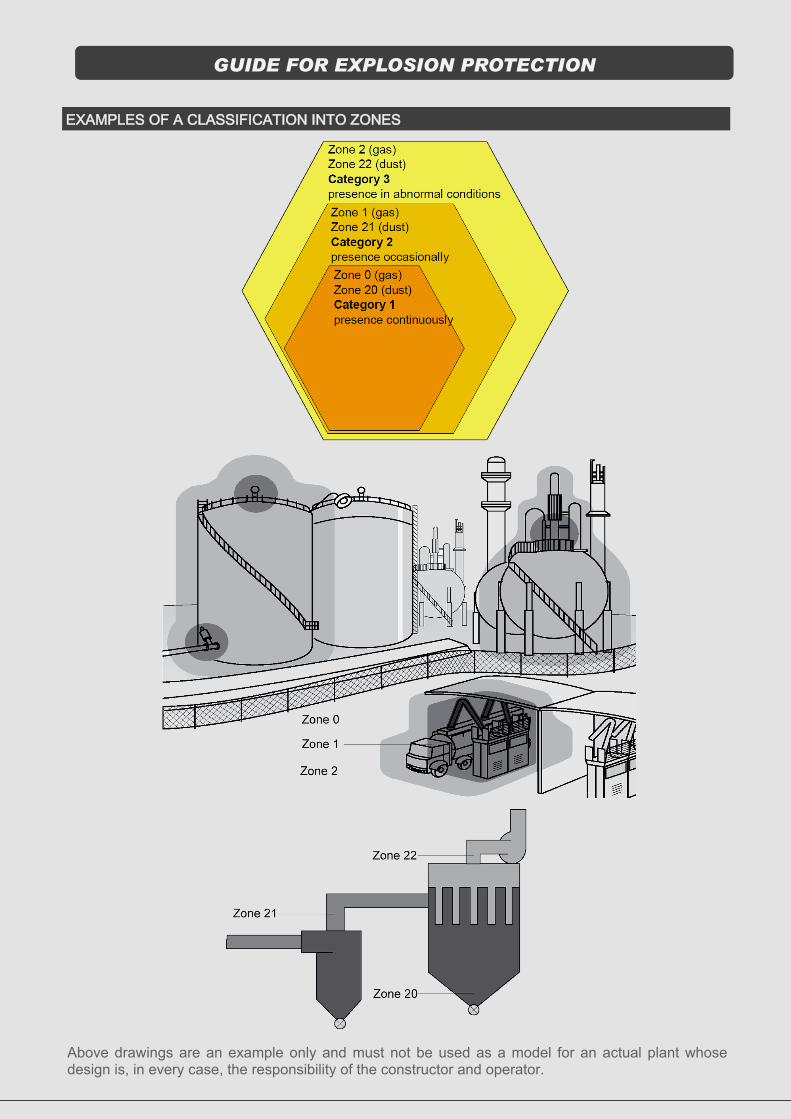
EXAMPLES OF A CLASSIFICATION INTO ZONES
GUIDE FOR EXPLOSION PROTECTION
Above drawings are an example only and must not be used as a model for an actual plant whose design is, in every case, the responsibility of the constructor and operator.

GGCD 01/K1 230V 50Hz 50mA
CESI 11 ATEX 041 MA ....... DATE ......
HR - 10090 Zagreb
II 2G Ex d e [ib] mb IIC T5 Gb IP66
0722
WARNING - DO NOT OPEN WHEN ENERGIZED
ATEX - equipment marking
3
1
2
4
5
6
7
8
9
10
No. Description
1 Manufacturer’s name and address
Product identification 2
3 Technical data
Apparatus category 4
Marking of explosion protection 5
6 Warning markings
7 Conformity symbol , EU symbol
8 Notified body (ExNB)
9 Standard ambient temperature (-20 ÷ +40C), unless stated on label
10 Certificate number and product number


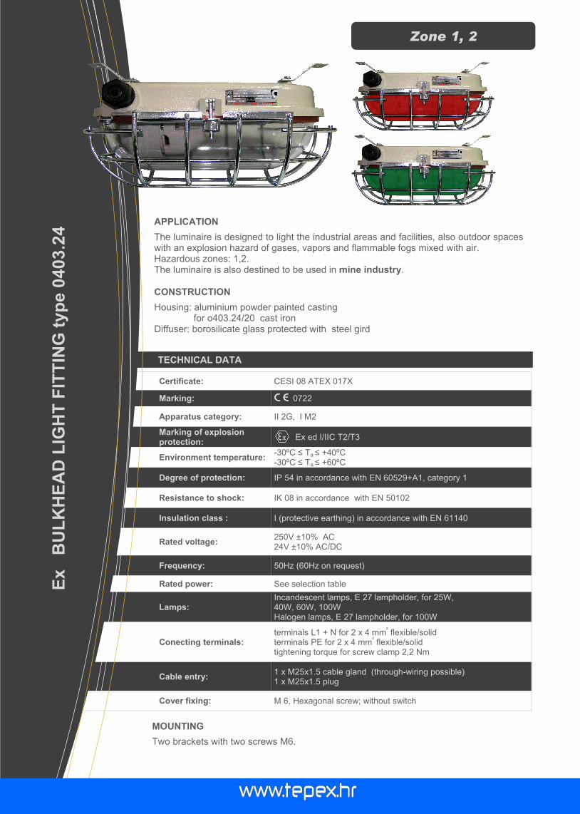
TECHNICAL DATA
Certificate: CESI 08 ATEX 017X
Marking: 0722
Apparatus category: II 2G, I M2
Marking of explosion protection:
Ex ed I/IIC T2/T3
Environment temperature: -30ºC ≤ Ta ≤ +40ºC -30ºC ≤ Ta ≤ +60ºC
Degree of protection: IP 54 in accordance with EN 60529+A1, category 1
Resistance to shock: IK 08 in accordance with EN 50102
Insulation class : I (protective earthing) in accordance with EN 61140
Rated voltage: 250V ±10% AC 24V ±10% AC/DC
Frequency: 50Hz (60Hz on request)
Rated power: See selection table
Lamps: Incandescent lamps, E 27 lampholder, for 25W, 40W, 60W, 100W Halogen lamps, E 27 lampholder, for 100W
Conecting terminals: terminals L1 + N for 2 x 4 mm
² flexible/solid
terminals PE for 2 x 4 mm² flexible/solid
tightening torque for screw clamp 2,2 Nm
Cable entry: 1 x M25x1.5 cable gland (through-wiring possible) 1 x M25x1.5 plug
Cover fixing: M 6, Hexagonal screw; without switch
APPLICATION
The luminaire is designed to light the industrial areas and facilities, also outdoor spaces with an explosion hazard of gases, vapors and flammable fogs mixed with air. Hazardous zones: 1,2. The luminaire is also destined to be used in mine industry.
Ex
B
UL
KH
EA
D L
IGH
T F
ITT
ING
typ
e 0
403.2
4
Zone 1, 2
CONSTRUCTION
Housing: aluminium powder painted casting for o403.24/20 cast iron Diffuser: borosilicate glass protected with steel gird
MOUNTING
Two brackets with two screws M6.

MODEL CODE
MODEL CODE APPARATUS CATEGORY
EXPLOSION PROTECTION
RATED VOLTAGE
LAMPS (E27) WEIGHT LUMINUS FLUX
[lm]
0403.24/10 II 2G Ex ed IIC
T2,T3 24 V DC 230 V AC
100W max. EN60064 60W max. DIN 49810 Bl.4
3,8 kg 1500 800
0403.24/11,12 (red or green glass)
II 2G Ex ed IIC T3 230 V AC 60W max. DIN 49810 Bl.4 40W max. DIN 49810 Bl.4
3,8 kg 800 450
0403.24/20 I M2 Ex ed I 230 V AC 100W max. EN60064 6,0 kg 1500
POLAR CURVE
Rated luminous flux: 1160lm (100W), 580lm (60W) Efficiency in operation: approx. 60%
355
319
O9
193
190
DIMENSION DRAWING (all dimensions in mm)
Spare parts 0403.24 : 1. Lampholder E27 2. Gasket 0403.24 3. Protective glass 0403.24
Accessories 0403.24 : 4. Lightbulb 100W, 60W, 40W / 230V, 110V, 24V – IEC 60064 Lightbulb 60W, 40W / 230V – DIN 49810 Bl.4 5. II 2G Exe II cable gland M25 with gasket, type SPU25 6. I M2 Exe I trumpet-shaped cable gland, set 7. II 2G Exe II plug M25 with gasket, type SPC25 8. I M2 Exe I plug M25, set
3
2
5,6 7,8
1
4
ATEX 0722
SPARE PARTS AND ACCESSORIES

TECHNICAL DATA
Certificate: Ex Agency
Marking: 2465
Apparatus category: II 2GD
Marking of explosion protection:
Ex de IIC T3-T6 Gb Ex tb IIIC T80ºC-195ºC Db
Environment temperature: -30ºC ≤ Ta ≤ +40ºC
Degree of protection: IP 66 in accordance with EN 60529+A1, category 1
Resistance to shock: IK 08 in accordance with EN 50102
Insulation class : I (protective earthing) in accordance with EN 61140
Rated voltage: See selection table
Frequency: 50Hz (60Hz on request)
Rated power: See selection table
Cable entries: two entries M20
Connecting terminals: L, N, PE; max. 2 x 2,5 mm
2 solid, flexible
terminal for external -PA connection; max 2x6 mm2
tightening torque for screw clamp 2,2 Nm
Cable gland and plug: one Ex d plug and one Ex de adapter, type ADP 03/23,
for cable v 6-15 mm
Weight: 3,5 kg
APPLICATION
The luminaire is designed to light the industrial areas and facilities, also outdoor spaces with an explosion hazard of gases, vapors and flammable fogs mixed with air. Hazardous zones: 1,2, 21, 22.
Ex P
EN
DA
NT
LIG
HT
FIT
TIN
G t
yp
e P
LF
M
Zone 1, 2, 21, 22
CONSTRUCTION
Housing: aluminium powder painted casting Diffuser: borosilicate glass Accessories: protected galvanized steel gird (INOX on request), assembly kit for wall,
pipe and ceiling mounting
MOUNTING
Pendant, on pipe, wall, ceiling

MODEL CODE
POLAR CURVE, DIMENSION DRAWING (all dimensions in mm)
SPARE PARTS AND ACCESSORIES
ATEX 2465
MODEL CODE
WATTAGE LAMP TYPE
NOMINAL VOLTAGE
LUMINOUS FLUX [lm]
LAMP HOLDER
TEMPERATURE CLASS (gas)
T0 MAX (dust)
Ta=40°C Ta=40°C
PLFM 023 23 W
(30 W) TC-TSE
110 V 1500
E27
T6 80°C 230 V 2300
PLFM 100 100 W A, 110 V 1500
T4 130°C QT 230 V 1700
PLFM 150 150W A 110 V 2200
T3 195°C QT 230 V 2400
SKETCH DESCRIPTION CODE SKETCH DESCRIPTION CODE
Replacement glass PLFM
PLFM 10-120
Ex e cable gland M25
SPU 25
Wire guard PLFM PLFM 10-130
Ex e plug M25, SPC 25
Gasket PLFM PLFM 10-140
Light bulb Acording to type
table
Lampholder with internal reflector
PLFM 10-150
PLFM fixing bracket for tube R
1 1/2“ , 1”, 1/2” PLFM 20-120
Autotransformer
PLFM PLFM 10-160
PLFS-T mounting bracket (ceiling
mounting) PLFM 20-130
Junction box ADP 23 PLFM 20-110
PLFS-T mounting bracket (wall mounting)
PLFM 20-140
345
175
320

TECHNICAL DATA
Certificate: CESI 06 ATEX 052
Marking: 0722
Apparatus category: II 2GD
Marking of explosion protection:
Ex de IIC T3-T6 tD A21 IP66 T80ºC-130ºC
Environment temperature: -20ºC ≤ Ta ≤ +40ºC / +50ºC - according to selection table
Degree of protection: IP 66/67 in accordance with EN 60529+A1, category 1
Resistance to shock: IK 08 in accordance with EN 50102
Insulation class : I (protective earthing) in accordance with EN 61140
Rated voltage: 230 V (-10% / +6%) (other voltage on request) 12 V AC/DC, 24 V AC/DC, 110 V AC, 230 V AC-lamp type PLFS-T/FLASH
Frequency: 50Hz (60Hz on request)
Rated power: according to table
Cable entries: two entries Exe M25x1,5 according EN 60423
Connecting terminals:
L1, L2, L3, N; max. 2 x 2,5 mm2 solid, flexible terminal for protective earthing conductor connection -PE; max 2x6mm2 terminal for external -PA connection; max 2x6mm2 tightening torque for screw clamp 1,2 Nm
Cable gland and plug: II 2GD Exe M25 IP66 tightening torque for gland screw 2,5 Nm, tightening torque for gland or plug 3,5 Nm
Cover fixing: M 6, Hexagonal screw; without switch
Weight: 7,0 kg
APPLICATION
The luminaire is designed to light the industrial areas and facilities, also outdoor spaces with an explosion hazard of gases, vapors and flammable fogs mixed with air. Hazardous zones: 1,2, 21, 22.
Ex P
EN
DA
NT
LIG
HT
FIT
TIN
G t
yp
e P
LF
S-T
Zone 1, 2, 21, 22
CONSTRUCTION
Housing: aluminium powder painted casting Diffuser: borosilicate glass Accessories: protected galvanized steel gird, assembly kit for wall, pipe and ceiling
mounting
MOUNTING
Pendant, on pipe, wall, ceiling mounting
Allow inclination ±45 of vertical mounting

MODEL CODE
POLAR CURVE, DIMENSION DRAWING [mm]
SPARE PARTS AND ACCESSORIES
ATEX 0722
MODEL CODE WATTAGE LAMP TYPE
LAMP HOLDER
TEMPERATURE CLASS (gas)
T0 MAX (dust) LUMINOUS FLUX [lm]
Ta=40°C Ta=50°C Ta=40°C
PLFS-T/200
max. 200 W A
E27
T4
T4
130°C
2500
max. 230 W QT T3 4200
max. 160 W LME T4 3150
max. 30 W TC-TSE T6 - 80°C 2300
PLFS-T/125 125 W HME
T4
-
130°C
6700
110 W HSE-I - 9500
PLFS-T/100 100 W HSE - 9000
HIE - 8400
PLFS-T/70 70 W HSE
T5 T4 95°C 5800
HIE 5500
PLFS-T/150 150 W HIE T4 - 130°C 12500
PLFS-T/FLASH
15 W / 11 J (in total)
XENON - T6 - 80°C -
With external reflector Without external reflector
SKETCH DESCRIPTION CODE SKETCH DESCRIPTION CODE
Replacement glass PLFS-T
PLFS-T 10-120
Ex e cable gland M25
SPU 25
Wire guard PLFS-T PLFS-T 10-130
Ex e plug M25, SPC 25
Base plate with lamp holder, ballast
PLFS-T 10-140
Light bulb Acording to type
table
PLSF-T cover Exe set
PLFS-T 10-150 PLFS-T fixing
bracket for tube R 1 1/2“
PLFS-T 20-120
PLFS-T externar reflector, wide
PLFS-T 20-100 PLFS-T mounting bracket (ceiling and
wall mounting) PLFS-T 20-130
PLFS-T external reflector, narow
PLFS-T 20-110

Certificate: ATEX
Marking: 2465
Apparatus category: II 2G II 2D
Marking of explosion protection:
Ex de IIC T6 Gb Ex tb IIIC T80ºC Db
Environment tempera-ture:
-40ºC ≤ Ta ≤ +50ºC
Degree of protection: IP 66
Resistance to shock: IK 08
Insulation class : I (protective earthing) in accordance with EN 61140
LED driver: With OVP, OCP, OTP protection An autonomous activation after recovery
Rated voltage: 90 - 305 V AC 127 - 431 V DC
Frequency: 50/60 Hz
Rated power: 50W
Power factor: cos φ > 0,96
Nominal luminous flux: 5000 lm, at tamb=25 C
Average lifetime : 70 000 hours
Cable entrys: 2 x M25x1.5 - ISO 25
Connecting terminals: L1, L2, L3, N; max. 2 x 2,5 mm
2 solid, flexible
PE terminal ; max 2x6mm2 External PA terminal -PA; max 2x6mm
2
Cable glands and plugs: 1x cable gland ISO 25 (for cable 6-15mm) 1x plug ISO 25
Waight: 7,0 kg
TECHNICAL DATA
APPLICATION
The luminaire is designed to light the industrial areas and facilities, also outdoor spaces with an explosion hazard of gases, vapors and flammable fogs mixed with air. Hazardous zones: 1,2, 21, 22. Product is compliant with ATEX, LV, EMC, RoHS Directive EU.
Ex P
EN
DA
NT
LIG
HT
FIT
TIN
G t
yp
e P
LF
S L
ED
50
Zone 1, 2, 21, 22
CONSTRUCTION
Housing: aluminum powder painted casting Diffuser: borosilicate glass Accessories: protected galvanized steel gird, assembly kit for wall, pipe and ceiling
mounting Gasket: silicon LED components: LED-Bridgelux, LED-BJB, LED driver-MW, TI-Amasan

MOUNTING
Pendant, on pipe, wall, ceiling mounting
MODEL CODE
POLAR CURVE DIMENSION [mm]
SPARE PARTS AND ACCESSORIES
ATEX
SKETCH DESCRIPTION CODE SKETCH DESCRIPTION CODE
Replacement glass
PLFS LED
PLFS LED 10-120
Ex e cable gland M25
SPU 25
Wire guard PLFS LED
PLFS LED 10-130
Ex e plug M25, SPC 25
Cover Exe PLFS
PLFS 10-150 PLFS-T fixing
bracket for tube R 1 1/2“
PLFS 20-120
External reflector PLFS
PLFS 20-100 PLFS-T mounting bracket (ceiling and
wall mounting) PLFS 20-130
TYPE WATTAGE LUMINOUS FLUX
[lm] tamb=25C AMBIENT TEMP.
CRI The color
rendering index
CCT (Correlated color temperature) [K]
80 4500 PLFS LED 50 50 W 5000 -40C ÷ 50C
WARNING - DO NOT OPEN WHEN ENERGIZED
P - AZ -
HR - 10090 ZAGREB
II 2G Ex de IIC T6 Gb -20°ta +50°C
II 2D Ex tb IIIC T80°C Db IP 66
PLFS-T/LED HREx ATEX T 13.099
90-305 VAC, 127-431 VDC 50 W max.
xxx
-40 +50 2465

TECHNICAL DATA
Certificate: ATEX
Marking: 2465
Apparatus category: II 2GD
Marking of explosion protection:
Ex de IIC T3-T4 Gb Ex tb IIIC T140ºC-150ºC Db
Environment temperature: -40ºC ≤ Ta ≤ +50ºC - according to selection table
Degree of protection: IP 66 in accordance with EN 60529+A1, category 1
Resistance to shock: IK 08 in accordance with EN 50102
Insulation class : I (protective earthing) in accordance with EN 61140
Rated voltage: 230 V (-10% / +6%) (other voltage on request)
Frequency: 50Hz (60Hz on request)
Rated power: See selection table
Power factor: cos = 0,95 , compensated
Cable entries: Two entries M20, with one Ex d plug and one Ex de adapter, type
ADP 03/23, for cable v 6-15 mm
Connecting terminals: L, N, PE; max. 2 x 2,5 mm
2 solid, flexible, terminal for external -PA
connection; max 2x6mm2 , tightening torque for screw clamp 2,2 Nm
Cable gland and plug: II 2GD Exe M25 IP66 tightening torque for gland screw 2,5 Nm, tightening torque for gland or plug 3,5 Nm
Weight: 27 kg
APPLICATION
The luminaire is designed to light the industrial areas and facilities, also outdoor spaces with an explosion hazard of gases, vapors and flammable fogs mixed with air. Hazardous zones: 1,2, 21, 22.
Ex P
EN
DA
NT
LIG
HT
FIT
TIN
G t
yp
e P
LF
L
Zone 1, 2, 21, 22
CONSTRUCTION
Housing: aluminium powder painted casting Diffuser: borosilicate glass Accessories: protected galvanized steel gird, assembly kit for wall, pipe and ceiling
mounting
MOUNTING
Pendant, on pipe, wall, ceiling mounting
Allow inclination ±45 of vertical mounting

MODEL CODE
POLAR CURVE, DIMENSION DRAWING [mm]
SPARE PARTS AND ACCESSORIES
ATEX 2465
MODEL CODE WATTAGE LAMP TYPE
LUMINOUS FLUX [lm]
LAMP HOLDER
TEMPERATURE CLASS (gas)
T0 MAX (dust)
Ta=40°C Ta=50°C Ta=40°C
PLFL/250 HIE, HSE, HSE Twinarc
250 W
HIE 20000
E40
T4 140°C
T3
HSE 28000
HSE Tw 32000
PLFL/250 HME
HME 20000
PLFL/250 LME
LME 5500
PLFL/500 A,QT
500 W A 8400
- 150°C QT 10250
With external reflector
Without external reflector
SKETCH DESCRIPTION CODE SKETCH DESCRIPTION CODE
Replacement glass PLFL
PLFL 10-120 Gasket set PLFL PLFL 10-160
Wire guard PLFS-T PLFL 10-130
Ex d plug M20, SPC Exd 20
Base plate with lamp holder, ballast
PLFL 10-140
Light bulb Acording to type table
Junction box ADP 23 PLFS-T 10-150 PLFL fixing
bracket for tube R 1 1/2“
PLFL 20-120
PLFL externar reflector
PLFL 20-100 PLFL mounting
bracket (ceiling and
wall mounting) PLFL 20-130
E40 -40 +50
365
50
290
12,5
180
540
285
180
365
50
290
12,5
180
540
285180
535
210
365
50
290
12,5
180
540
285
180

TECHNICAL DATA
Certificate: CESI 09 ATEX 001
Marking: 0722
Apparatus category: II 2GD
Marking of explosion protection:
Ex de IIC T4-T3 or Ex d IIC T4-T3 tD A21 IP66 T10ºC-150ºC
Environment temperature: -20ºC ≤ Ta ≤ +40ºC - according to selection table
Degree of protection: IP 66 in accordance with EN 60529+A1, category 1
Resistance to shock: IK 08 in accordance with EN 50102
Insulation class : I (protective earthing) in accordance with EN 61140
Rated voltage: RLF/... HIT,HST,HME,QT -230/240 V (-10% / +6%) / 50 Hz RLF/... QL -230 V (200-277 V) - 50/60 Hz ili (190-264 V) - DC
Frequency: 50Hz (60Hz on request)
Rated power: See selection table
Power factor: RLF/... HIT,HST,HME,QT - cos > 0,9 ind. RLF/... QL - λ > 0,92 THD < 10 %
Cable entries:
RLF/... HIT,HST,HME,QT - three entries M20, with two Ex d plug and one Ex de adapter,
type ADP 03/23, for cable ¯6-15 mm RLF/... QL - two entries M25 into Ex e junction box with one Ex e cable gland ,
type SPU 25, for cable v 6-15 mm and one Ex e plug, type SPC 25
Connecting terminals:
RLF/... HIT,HST,HME,QT -clamps in Ex de adapter for connection L1, L2, N, PE, 2,5mm2 max. / clamp - solid, stranded; tightening torque for clamp screw 1,2 Nm;
Weight: See selection table
APPLICATION
The floodlight is designed to light the industrial areas and facilities, also outdoor spaces with an explosion hazard of gases, vapors and flammable fogs mixed with air. Hazardous zones: 1,2, 21, 22.
Ex F
LO
OD
LIG
HT
ty
pe R
LF
Zone 1, 2, 21, 22
CONSTRUCTION
Housing: aluminium powder painted casting Diffuser: borosilicate tube glass Accessories: protected galvanized steel gird, assembly kit for wall, pipe and ceiling
mounting
MOUNTING
Pendant, on pipe, wall, ceiling mounting Wall or ceiling mounting is possible with RLF carrier and M12 screws. Also, it is possible to fixate luminaire to 2'' pipe or other round surface with U-Bolts.

MODEL CODE
POLAR CURVE, DIMENSION DRAWING [mm]
ATEX 0722
MODEL CODE WATTAGE LAMP TYPE
LUMINOUS FLUX [lm]
LAMP HOLDER
TEMPERATURE CLASS (gas)
T0 MAX (dust) WEIGHT
Ta=40°C Ta=40°C
RLF/250 HIT
250 W
HIE 20000
E40
T4 130°C 25 kg RLF/250 HST HST 33200
RLF/250 HME HME 13000
RLF/400 HIT
400 W
HIE 34000
T3 190°C 27 kg RLF/400 HST HST 56500
RLF/400 HME HME 22000
RLF/500 QT 500 W QT 6300
22 kg RLF/85 QL 85 W QL
6300 T4 130°C QL
RLF/165 QL 165 W 12000
Wide beam reflector
E40 -20 +40
Narrow beam reflector
RLF/.... RLF/..QL
QL 165 W

SPARE PARTS AND ACCESSORIES
Zone 1, 2, 21, 22
If it is not ordered differently, floodlight RLF/ ... HIT,HST,HME,QT presume floodlight with RLF carrier, one Ex de adapter ADP 03/32 and two Ex d plugs, without light source and mounting accessories. Manufacturer will deliver spare parts and accessories on buyer request.
Accessories RLF ... : 4. set bed plate RLF/ ... HIT, HST 5. set bed plate RLF/ ... HME 6. gaskets RLF/..., set 7. adapter Ex ed, type ADP 03/23 8. plug Ex d M20
Spare parts RLF ...: 1. Light source, according to table 2. Screws for mounting M12 x 40 ISO 4017 A4-80, set 3. Bolts in „U“ shape M12 - A64/NW50 DIN 3570 A4, set
32
6 1 6
4,5 6
2 1
3
Spare parts RLF QL : 1. junction box gasket Ex e type MMK 13 2. gland Ex e type SPU 25, M25 with gasket and nut 3. plug Ex e type SPC 25, M25 with gasket and nut
If it is not ordered differently, floodlight RLF/... QL presume floodlight with RLF QL carrier, one Ex e junction box MMK 13 with Ex e connecting terminals, Ex e M25 cable gland, Ex e M25 plug, and Philips QL Induction Lighting System, without mounting accessories. Manufacturer will deliver spare parts and accessories on buyer request.

ATEX 0722 E40
-20 +40


TECHNICAL DATA
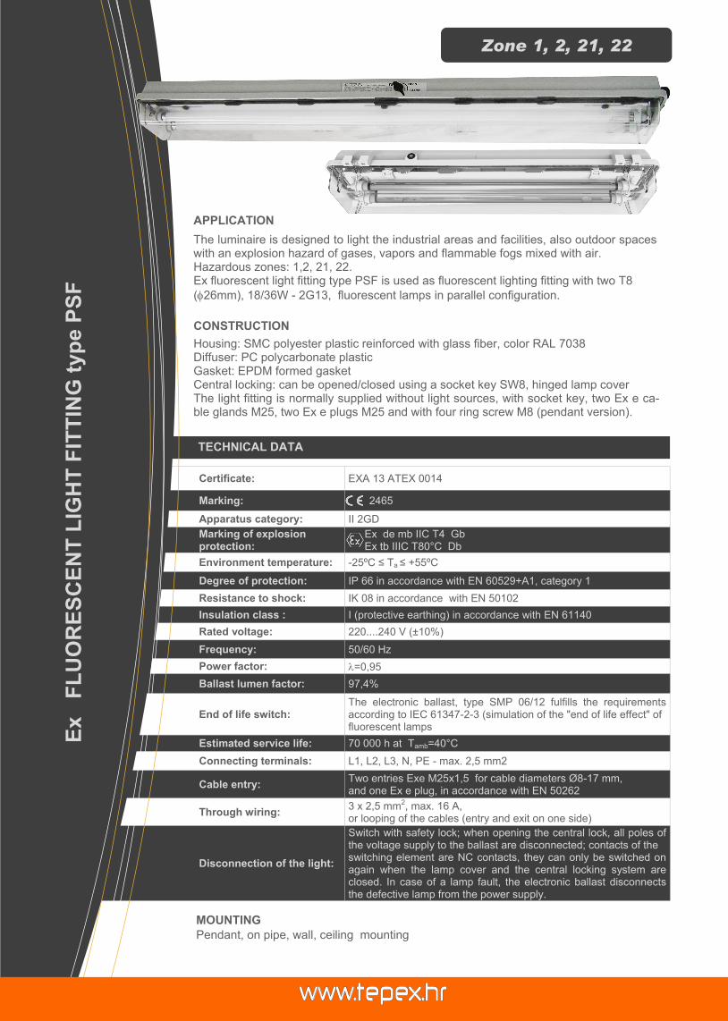
Certificate: EXA 13 ATEX 0014
Marking: 2465
Apparatus category: II 2GD
Marking of explosion protection:
Ex de mb IIC T4 Gb Ex tb IIIC T80°C Db
Environment temperature: -25ºC ≤ Ta ≤ +55ºC
Degree of protection: IP 66 in accordance with EN 60529+A1, category 1
Resistance to shock: IK 08 in accordance with EN 50102
Insulation class : I (protective earthing) in accordance with EN 61140
Rated voltage: 220....240 V (±10%)
Frequency: 50/60 Hz
Power factor: =0,95
Ballast lumen factor: 97,4%
End of life switch: The electronic ballast, type SMP 06/12 fulfills the requirements according to IEC 61347-2-3 (simulation of the "end of life effect" of fluorescent lamps
Estimated service life: 70 000 h at Tamb=40°C
Connecting terminals: L1, L2, L3, N, PE - max. 2,5 mm2
Cable entry: Two entries Exe M25x1,5 for cable diameters Ø8-17 mm, and one Ex e plug, in accordance with EN 50262
Through wiring: 3 x 2,5 mm
2, max. 16 A,
or looping of the cables (entry and exit on one side)
Disconnection of the light:
Switch with safety lock; when opening the central lock, all poles of the voltage supply to the ballast are disconnected; contacts of the switching element are NC contacts, they can only be switched on again when the lamp cover and the central locking system are closed. In case of a lamp fault, the electronic ballast disconnects the defective lamp from the power supply.
APPLICATION
The luminaire is designed to light the industrial areas and facilities, also outdoor spaces with an explosion hazard of gases, vapors and flammable fogs mixed with air. Hazardous zones: 1,2, 21, 22. Ex fluorescent light fitting type PSF is used as fluorescent lighting fitting with two T8
(26mm), 18/36W - 2G13, fluorescent lamps in parallel configuration.
Ex F
LU
OR
ES
CE
NT
LIG
HT
FIT
TIN
G t
yp
e P
SF
Zone 1, 2, 21, 22
CONSTRUCTION
Housing: SMC polyester plastic reinforced with glass fiber, color RAL 7038 Diffuser: PC polycarbonate plastic Gasket: EPDM formed gasket Central locking: can be opened/closed using a socket key SW8, hinged lamp cover The light fitting is normally supplied without light sources, with socket key, two Ex e ca-ble glands M25, two Ex e plugs M25 and with four ring screw M8 (pendant version).
MOUNTING
Pendant, on pipe, wall, ceiling mounting

MODEL CODE
POLAR CURVE
DIMENSION DRAWING (all dimensions in mm)
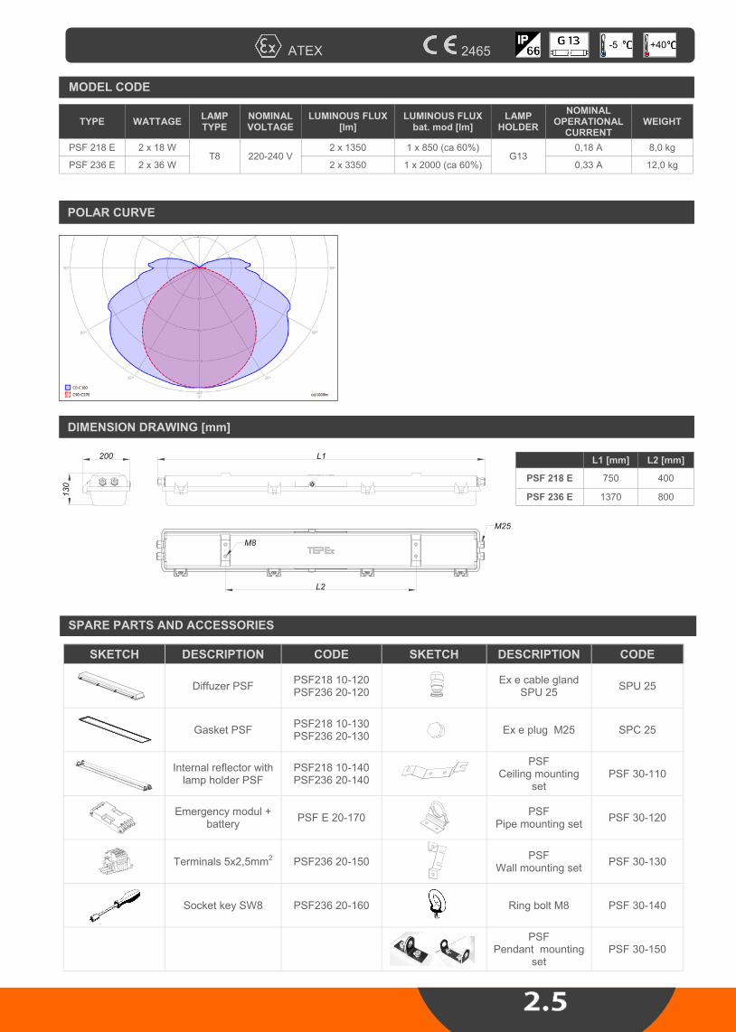
ATEX 2465
MODEL CODE
WATTAGE LAMP TYPE
NOMINAL VOLTAGE
LUMINOUS FLUX [lm]
LAMP HOLDER
NOMINAL OPERATIONAL
CURRENT WEIGHT
PSF 218 2x18 W T8 220 - 240 V
2 x 1350 G13
0,18 A 7,5 kg
PSF 236 2x36 W 2 x 3350 0,33 A 10 kg
SPARE PARTS AND ACCESSORIES
SKETCH DESCRIPTION CODE SKETCH DESCRIPTION CODE
Diffuzer PSF PSF218 10-120 PSF236 20-120
Ex e cable gland
SPU 25 SPU 25
Gasket PSF PSF218 10-130 PSF236 20-130
Ex e plug M25 SPC 25
Internal reflector with
lamp holder PSF
PSF218 10-140 PSF236 20-140
PSF
Ceiling mounting set
PSF 30-110
El. ballast SMP
06/12 SMP 06/12
PSF Pipe mounting set
PSF 30-120
Terminals 5x2,5mm2 PSF236 20-150
PSF Wall mounting set
PSF 30-130
Socket key SW8 PSF236 20-160 Ring bolt M8 PSF 30-140
PSF
Pendant mounting set
PSF 30-150
200
130
L1
L2
M8
M25
L1 [mm] L2 [mm]
PSF 218 750 400
PSF 236 1370 800
-25 +55

TECHNICAL DATA
Certificate: HREx
Marking: 2465
Apparatus category: II 2GD
Explosion protection: Ex d e mb IIC T4 Gb Ex tb IIIC T80°C Db
Environment temperature: -5ºC ≤ Ta ≤ +40ºC
Degree of protection: IP 66
Resistance to shock: IK 08
Insulation class: I (procreative earthling) in accordance to EN 61140
Rated voltage: 220....240 V (±10%)
Frequency: 50/60 Hz
Power factor: =0,95
Ballast lumen factor BLF: 97,4%
Battery: Nominal autonomy:
Ni-Cd 6V/4Ah (7Ah) PSF 236 E ............... 2h
Estimated service life: 70 000 h at Tamb=40°C
Terminals: L1, L2, L3, N, PE - max. 2,5 mm2
Cable entries: 2 x cable glands Ex e M25x1,5, for cable Ø8-17 mm, 2 x plugs Ex e
Disconnection of the light:
Switch with safety lock; when opening the central lock, all poles of the voltage supply to the ballast are disconnected; contacts of the switching element are NC contacts, they can only be switched on again when the lamp cover and the central locking system are closed. In case of a lamp fault, the electronic ballast disconnects the defective lamp from the power supply.
Piktogram: 300x150mm
DESCRIPTION
The luminaire is designed to light the industrial areas and facilities, also outdoor spaces with an explosion hazard of gases, vapors and flammable fogs mixed with air. Hazardous zones: 1,2, 21, 22. Ex fluorescent light fitting type PSF 236 E is used as emergency light fitting with >1,5h autonomy.
Ex
EX
PL
OS
ION
PR
OT
EC
TE
D E
ME
RG
EN
CY
FL
UO
RE
SC
EN
T L
IGH
T F
ITT
ING
ty
pe
PS
F …
E
Zone 1, 2, 21, 22
MOUNTING
Pendant, on pipe, wall, ceiling mounting
CONSTRUCTION
Housing: SMC polyester plastic reinforced with glass fiber, color RAL 7038 Diffuser: PC polycarbonate plastic Gasket: EPDM formed gasket Central locking: can be opened/closed using a socket key SW8, hinged lamp cover The light fitting is normally supplied without light sources, with socket key, two Ex e ca-ble glands M25, two Ex e plugs M25 and with four ring screw M8 (pendant version).
MODEL CODE
POLAR CURVE
DIMENSION DRAWING [mm]
ATEX 2465
TYPE WATTAGE LAMP TYPE
NOMINAL VOLTAGE
LUMINOUS FLUX [lm]
LUMINOUS FLUX bat. mod [lm]
LAMP HOLDER
NOMINAL OPERATIONAL
CURRENT WEIGHT
PSF 218 E 2 x 18 W T8
2 x 1350 1 x 850 (ca 60%) G13
0,18 A 8,0 kg 220-240 V
PSF 236 E 2 x 36 W 2 x 3350 1 x 2000 (ca 60%) 0,33 A 12,0 kg
200
130
L1
L2
M8
M25
-5 +40
SPARE PARTS AND ACCESSORIES
SKETCH DESCRIPTION CODE SKETCH DESCRIPTION CODE
Diffuzer PSF PSF218 10-120 PSF236 20-120
Ex e cable gland
SPU 25 SPU 25
Gasket PSF PSF218 10-130 PSF236 20-130
Ex e plug M25 SPC 25
Internal reflector with
lamp holder PSF
PSF218 10-140 PSF236 20-140
PSF
Ceiling mounting set
PSF 30-110
Emergency modul +
battery PSF E 20-170
PSF Pipe mounting set
PSF 30-120
Terminals 5x2,5mm2 PSF236 20-150
PSF Wall mounting set
PSF 30-130
Socket key SW8 PSF236 20-160 Ring bolt M8 PSF 30-140
PSF
Pendant mounting set
PSF 30-150
L1 [mm] L2 [mm]
PSF 218 E 750 400
PSF 236 E 1370 800

TECHNICAL DATA
Certificate: HREx, ATEX
Marking: 0722
Apparatus category: II 2GD
Marking of explosion protection:
Ex de IIC T5/T6 Ex d IIC T5/T6 tD A21 T90°C/T80°C
Environment temperature: -20ºC ≤ Ta ≤ +50ºC
Degree of protection: IP 66 in accordance with EN 60529+A1, category 1
Resistance to shock: IK 08 in accordance with EN 50102
Insulation class : I (protective earthing) in accordance with EN 61140
Rated voltage: 100 V ÷ 280 V AC/DC
Frequency: 0-60 Hz
Rated power: See selection table
Power factor: =0,99
Connecting terminals: L1, L2, L3, N, PE - max. 2,5 mm
2
PE for outside earthing max. 2 x 6 mm2
Cable entry:
2 x M20, according to EN 60079-1, ISO 965-1, ISO 965-3 or 2 x 3/4"NPT, according to ANSI/ASME B1.20.1 or 2 x M20, with one Ex d plugs and one adapter type ADP 03/24,
for cable 6-15 mm
Through wiring: With two Ex de adapter ADP 03/24 - 4 x 2,5 mm2, max. 16 A,
Energy classification EEI: A2
Electromagnetic compatibility:
in conformity with the EC Directive 89/CE and harmonized stand-ards: EN 55015, EN 61547, EN 61000-3-2, EN 61000
APPLICATION
The luminaire is designed to light the industrial areas and facilities, also outdoor spaces with an explosion hazard of gases, vapors and flammable fogs mixed with air. Hazardous zones: 1,2, 21, 22. Ex fluorescent light fitting type FLX is used as fluorescent lighting fitting with two TC-TSE fluorescent compact lamps 18W,24W,36W, 40W, 55W with 2G11 lampholder.
Ex
FL
UO
RE
SC
EN
T L
IGH
T F
ITT
ING
typ
e F
LX
Zone 1, 2, 21, 22
CONSTRUCTION
Housing: corrosion resistant grey polyurethanes painted aluminium color RAL 7000 Diffuser: borosilicate glass tube Gasket: silicon The light fitting is normally supplied with two light sources, two entries M20 and wall/sealing mounting set.
MOUNTING
Pendant, on pipe, wall, ceiling mounting Operates in any position.

SPARE PARTS AND ACCESSORIES
MODEL CODE
POLAR CURVE DIMENSION DRAWING (all dimensions in mm)
ATEX 0722
MODEL CODE
WATTAGE LAMP TYPE
NOMINAL VOLTAGE
LUMINOUS FLUX [lm]
LAMP HOLDER
A B WEIGHT
FLX 218 2x18 W
TC-TSE 100-280 V
2 x 1200
2G11
330 215 3,3 kg
FLX 224 2x24 W 2 x 1800 425 310 3,8 kg
FLX 236 2x36 W 2 x 2900 520 405 5,8 kg
FLX 240 2x40 W 2 x 3600 645
8,0 kg 530
FLX 255 2x55 W 2 x 4700 8,4 kg
SKETCH DESCRIPTION CODE SKETCH DESCRIPTION CODE
Cover gasket FLX FLX 10-120 Ex d cable gland
SPU 20 SPU 20
Base plate FLX/... FLX 10-130 Ex d plug M20 SPC 20
Protective grid FLX
set FLX 20-140
FLX Wall / ceiling mounting set
FLX 20-170
External reflector
FLX FLX 20-150
FLX Pipe mounting set
FLX 20-180
Junction box ADP 23 FLX 10-160
-20 +40
12
B
12
15
13
177
140 80 A

TECHNICAL DATA
Certificate: ATEX
Marking: 2465
Apparatus category: II 2GD
Marking of explosion protection:
Ex d IIC T6 Gb Ex tb IIIC T80°C Db
Environment temperature: -20ºC ≤ Ta ≤ +50ºC
Degree of protection: IP 66 in accordance with EN 60529+A1, category 1
Resistance to shock: IK 08 in accordance with EN 50102
Insulation class : I (protective earthing) in accordance with EN 61140
Rated voltage: Acoording to „MODEL CODE“
Frequency: 50-60 Hz
Rated power: 2x 1.2W
Lumen output: network grid power supplay / battery power supplay : 200 lm
Connecting terminals: L1, L2, L3, N, PE - max. 2,5 mm
2
PE for outside earthing max. 2 x 6 mm2
Rated autonomy: > 3 hours
Battery: Ni-MH 3,6V/2.2Ah, build in light fitting, microprocessor controlled charging, discharging and control of battery
Recharging time: 24 hours ( 20 hours >90% rated autonomy)
Cable entry:
2 x M20, according to EN 60079-1, ISO 965-1, ISO 965-3 or 2 x 3/4"NPT, according to ANSI/ASME B1.20.1 or 2 x M20, with one Ex d plugs and one adapter type ADP 03/24,
for cable 6-15 mm
Through wiring: With two Ex de adapter ADP 03/24 - 4 x 2,5 mm2, max. 16 A,
Energy classification EEI: A2
Electromagnetic compatibility:
in conformity with the EC Directive 2004/108CE
APPLICATION
The luminaire is designed to light the industrial areas and facilities, also outdoor spaces with an explosion hazard of gases, vapors and flammable fogs mixed with air. Hazardous zones: 1,2, 21, 22. Ex light fitting type FLXE 118 LED is used as emergency LED light fitting with >3h au-tonomy.
Ex E
ME
RG
EN
CY
LIG
HT
FIT
TIN
G t
yp
e F
LX
E 1
18
LE
D
Zone 1, 2, 21, 22
CONSTRUCTION
Housing: corrosion resistant grey polyurethanes painted aluminium, color RAL 7000 Diffuser: borosilicate glass tube Gasket: Silicon The light fitting is normally supplied with two LED sources, two entries M20 and wall/sealing mounting set. TEST button for testing the emergency light function.
MOUNTING
Pendant, on pipe, wall, ceiling mounting Operates in any position.

SPARE PARTS AND ACCESSORIES
MODEL CODE
DIMENSION DRAWING (all dimensions in mm) ISOCANDELA CURVE [l/cd]
ATEX 2465
SKETCH DESCRIPTION CODE SKETCH DESCRIPTION CODE
Cover gasket FLXE FLXE10-120 Ex d cable gland
SPU 20 SPU 20
Base plate FLXE/... FLXE10-130 Ex d plug M20 SPC 20
Protective grid FLXE
set FLXE20-140
FLXE Wall / ceiling mounting set
FLXE20-170
External reflector
FLXE FLXE20-150
FLXE Pipe mounting set
FLXE20-180
Junction box ADP 24 ADP10-160
-20 +40
180±0,5
160±0,512240±1 220±1
O13
330
The lamp can operate with two types of con-nection: a) Maintained (Dauerschaltung) The light fitting can be used for general and orientation lighting with mains power supply via L' (installation switch). In case of voltage drop or an interruption in the mains power sup-ply L, the light fitting will continue to operate in battery-powered mode, regardless of the sta-tus of installation switch L' (ON/OFF). b) Non maintained (Bereitschaftschaltung) In case of voltage drop or an interruption in the mains power supply L, the light fitting will oper-ate only in battery-powered mode. In both types of the connection in the presence of continuous phase L, it is possible to verify the correctness of the emergency system by turning on the switch in the TEST circuit.

TECHNICAL DATA
Certificate: ATEX
Marking: 2465
Apparatus category: II 2GD
Marking of explosion protection:
Ex d e mb IIC T4 Gb Ex tb IIIC T80°C Db
Environment temperature: -30ºC ≤ Ta ≤ +50ºC
Degree of protection: IP 66 in accordance with EN 60529+A1, category 1
Resistance to shock: IK 08 in accordance with EN 50102
Insulation class : I (protective earthing) in accordance with EN 61140
Rated voltage: 220....240 V (±10%)
Frequency: 50/60 Hz
Power factor: =0,95
Ballast lumen factor: 97,4%
End of life switch: The electronic ballast, type SMP 06/12 fulfills the requirements according to IEC 61347-2-3 (simulation of the "end of life effect" of fluorescent lamps
Estimated service life: 70 000 h at Tamb=40°C
Connecting terminals: L1, L2, L3, N, PE - max. 4 mm2
Cable entry: Two entries Exe M25x1,5 for cable diameters Ø8-17 mm, and one Ex e plug, in accordance with EN 50262
Through wiring: 5x terminals 4x4 mm
2, max. 16 A,
or looping of the cables (entry and exit on one side)
Disconnection of the light:
Switch with safety lock; when opening the central lock, all poles of the voltage supply to the ballast are disconnected; contacts of the switching element are NC contacts, they can only be switched on again when the lamp cover are closed. In case of a lamp fault, the electronic ballast disconnects the defective lamp from the power supply.
APPLICATION
The luminaire is designed to light the industrial areas and facilities, also outdoor spaces with an explosion hazard of gases, vapors and flammable fogs mixed with air. Hazardous zones: 1,2, 21, 22. Ex fluorescent light fitting type SIF is used as fluorescent lighting fitting with two/four T8 fluorescent lamps in parallel configuration.
Ex F
LU
OR
ES
CE
NT
LIG
HT
FIT
TIN
G t
yp
e S
IF ...
Zone 1, 2, 21, 22
CONSTRUCTION
Housing: powder-coated sheet steel , color RAL 9000 Diffuser: flat borosilicate glass with a high thermal and mechanical stability Gasket: EPDM formed gasket All-pole are disconnected via NC switch when glass cover is opened. The light fitting is normally supplied without light sources, two Ex e cable glands M25, one Ex e plug M25 and with two ring screw M8 (pendant version).
MOUNTING
Pendant, wall/ceiling mounting, recessed

SPARE PARTS AND ACCESSORIES
MODEL CODE
POLAR CURVE Recessed light fitting
DIMENSION DRAWING (all dimensions in mm)
ATEX 2465
MODEL CODE
WATTAGE LAMP TYPE
NOMINAL VOLTAGE
LUMINOUS FLUX [lm]
LAMP HOLDER
NOMINAL OPERATIONAL
CURRENT WEIGHT
SIF 236 2x36 W T8 220 - 240 V
2 x 3350 G13
0,18 A 26 kg
SIF 436 4x36 W 4 x 3350 0,33 A 28 kg
SKETCH DESCRIPTION CODE SKETCH DESCRIPTION CODE
Gasket SIF SIF 10-130 Ex e cable gland
SPU 25 SPU 25
El. ballast SMP
06/12 SMP 06/12 Ex e plug M25 SPC 25
Ring bolt M8 -
-25 +55


TECHNICAL DATA
Certificate: CESI 13 ATEX 017X
Marking: 0722
Apparatus category: II 2G II 2D
Marking of explosion protection:
Ex e d mb ia/ib IIC Gb Ex tb IIIC T80ºC Db
Environment temperature: -20 ºC ≤ Ta ≤ +50 ºC
Degree of protection: IP 66
Resistance to shock: IK 08
Insulation class: I (protective earthing) in accordance with EN 61140
Rated insulation voltage Ui: 690 V AC (type with mantle terminals type SL Ui=400V AC)
Rated current Ith: Up to 16 A
PE terminals (inside of the enclosure):
max. 2x4 mm2+2x2,5 mm2 , 3x4 mm2 , 2x6 mm2
Cover fixing: 4xM5 cheese head screw, stainless steel A2
Color: black, RAL 9005
MOUNTING
With screw kit through the housing holes 6 mm at the peaks the rectangle:
SKX 12: 75 x 50 mm SKX 13: 75 x 100 mm SKX 14: 75 x 150 mm SKX 15/15H: 125 x 150 mm
APPLICATION
Explosion protected control units type SKX 12 – SKX 15, alone or in various combina-tions of merged set (combination) are intended for the control, distribution and signaling in the power circles on places with presence of explosive mixtures of gases, vapor and dust with air, in hazardous areas 1, 2, 21, 22.
Ex C
ON
TR
OL
UN
ITS
typ
e S
KX
12, S
KX
13, S
KX
14,
SK
X 1
5
Zone 1, 2, 21, 22
CONSTRUCTION
Enclosure: polyester plastic reinforced with glass fiber, color - black Cover: with integrated Thermoplastic elastomer gasket, closes with four M5 stainless steel screws. Due to the four available sizes and the modular design, the devices can be used for almost every application. Built-in components, actuators and indicator components can be mounted in or on Ex e enclosures or combination of merged enclosures. Possible combinations and schedules built-in components, actuators and indicator components is determined by the certification documentation. Control units usually aren't wired.

SPARE PARTS AND ACCESSORIES
BUILD-IN COMPONENTS
ATEX 0722 +50
1. Enclosure and cover SKX .. 2. Cable gland 3. Cover gasket SKX .. 4. Build-in components 5. Actuators and indicators 6. Terminal PE
Description, type Schema Overview
Control switch SMS 03/.
II 2G I M2 Ex de I/IIC Gb Mb
Rated voltage: 630 V AC
Rated current: 16 A
Terminals: 2,5 mm2
SMS 03/2
SMS 03/1
Type Shema
0 90° I
2 A
1 A
I 90° II
2 A
4 A1 A
2 B
1 B 4 B
2 C
1 C 4 C
I 45° II
2 A
4 A1 A
2 B
1 B 4 B
I II
2 A
4 A1 A
2 B
1 B 4 B
2 C
1 C 4 C
0 90° I
2 A
1 A
3 A
4 A
2 B
1 B
3 B
4 B
0
90°
III
2 A
1 B
3 A
4 B
45°0
45° 45°0
I II
0 90° I
2 A
1 A
2 B
1 B
3 B
4 B
I 90° II
2 A
4 A1 A
2 B
1 B 4 B
I 90° II
2 A 2 B
1 B4 B
I 90° II
2 A
4 A1 A
I 45° II
2 A
4 A1 A45°
0
045° II
2 A
1 A45°
t
3 A
4 A
0 90° I
2 A
4 A1 A
2 A
SMS 03/3
SMS 03/4
SMS 03/5
SMS 03/6
SMS 03/7
SMS 03/8
SMS 03/9
SMS 03/10
SMS 03/11
SMS 03/12
SMS 03/13

BUILD-IN COMPONENTS
Description, type Schema Overview
Control switch GHG 23.
II 2GD Ex de IIC
Rated voltage: 690 V AC
Rated current : 10 A
Terminals: 2,5 mm2
Pushbutton PBT/.
II 2G I M2 Ex de I/IIC Gb Mb
Rated voltage: 630V AC
Rated current: 16A
Terminals: 2,5 mm2
Zone 1, 2, 21, 22

BUILD-IN COMPONENTS
Description, type Schema Overview
Signal lamp SLP
II 2G I M2 Ex de I/IIC Gb Mb
Rated voltage: 12-250 V AC/DC
Max. current: 20-8 mA
Terminals: 2,5 mm2
Potentionmeter PBT/POT
II 2G I M2 Ex de I/IIC Gb Mb
Rated voltage: 315 V AC/DC
Rated power: 1W
Scale: 0-100% / 270
Tolerance: ±20%
Characteristic: linear
Terminals: 2,5 mm2
Resistance R:
1,0 k
2,2 k
4,7 k
10 k
470 k
Measuring instruments AM 72, VM 72
II 2GD Ex e ib IIC
Measuring range:
AM: n/1 A, 0-20 mA, 0-25 A direct 4-20 mA VM: n/1A, 6-415V, 6-660 V
Scale: according to customer
demand
Terminals: 1,5 - 4 mm2
-
Mantle terminals SL5 , SL8
II 2G I M2 Ex de I/IIC Gb Mb
Rated voltage: 400 V
Rated current: 16 A AC
Terminals: 4 mm2
Max. No. of wire under one clamp: 2x4mm
2 + 2x2,5mm
2, 3x4mm2
-
Terminals TH 35-7.5
II 2GD Ex e II
5 terminals 4mm2
2 terminals 16mm2
Rated voltage: 690 V AC
Rated current: 16 A
-
N/PE busbar (only for SKX 15)
II 2G I M2 Ex de I/IIC Gb Mb
11x max. 2x4mm2
-
ATEX 0722 +50

ACTUATORS AND INDICATORS
Description, type Mounting Overview
Switch actuator SMO 17/.
II 2G II 2D I M2 Ex e I/IIC Gb Mb
Ex t IIIC Db
Front element of measuring instruments SAM 72
II 2G II 2D I M2 Ex e I/IIC Gb Mb
Ex t IIIC Db
Puschbitton actuator SPO 01/.
II 2G II 2D I M2 Ex e I/IIC Gb Mb
Ex t IIIC Db
Front element of signal lamp SPO 02/.
II 2G II 2D I M2 Ex e I/IIC Gb Mb
Ex t IIIC Db
Key-operated pushbutton actuator
GHG 410 1904 R0012
II 2GD Ex e II IP66
I0 I II I 0 II
I
0
III
II
I II III
1 2
3
4
1 2
3
45
1 2
3
456
1 2
3
SMO 17/1 SMO 17/2 SMO 17/3 SMO 17/4
SMO 17/5 SMO 17/6 SMO 17/7 SMO 17/8 SMO 17/9
Type SPO 01/.
SPO 01/01 0
SPO 01/02 I
SPO 01/03 II
SPO 01/04 RED
SPO 01/05 GREEN
SPO 01/06 WHITE
SPO 01/07 START
SPO 01/08 STOP
SPO 01/09 ON
SPO 01/10 OFF
Type SPO 02/.
SPO 02/01 RED
SPO 02/02 GREEN
SPO 02/03 YELLOW
SPO 02/04 TRANSPARENT
Zone 1, 2, 21, 22

Description, type Mounting Overview
Mushroom-head pushbutton actuator
GHG 418 815 ..R ..(EMERGENCY-STOP)
II 2GD
Ex e II IP66
Key-operated mushroom-head pushbutton actuator GHG 418 815 ..R..
(EMERGENCY-STOP)
II 2GD Ex e II IP66
Potentiometer acuator GHG 410 1944 R0010
II 2GD
Ex e II IP66
Cable gland SPU ISO 16 - ISO 40
II 2G II 2D
Ex e I/IIC Gb Ex t IIIC Db
Cable gland for armourd cable SPU A
ISO 16 - ISO 40
II 2G II 2D Ex e I/IIC Gb Ex t IIIC Db
Plug SPC .. ISO 16 - ISO M40
II 2G II 2D
Ex e I/IIC Gb Ex t IIIC Db
Connection part SKX
ACTUATORS AND INDICATORS
ATEX 0722 +50

Enclosure type SKX 12
A
B
C
D
Max. No. of cable glands
side
cable gland
M16 M20 M25
A-C 2 2 1
B-D 1 1 1
Max. No. of cable glands
side
cable gland
M16 M20 M25
A-C 2 2 1
B-D 4 3 2
Enclosure type SKX 13
A
B
C
D
Zone 1, 2, 21, 22

Enclosure type SKX 14
Max. No. of cable glands
side
cable gland
M16 M20 M25 M32
A-C 2 2 1 1
B-D 6 4 3 2
Enclosure type SKX 15
Max. No. of cable glands
side
cable gland
M16 M20 M25 M32 M40
A-C 4 3 2 2 1
B-D 6 4 3 2 2
side
cable gland
M16 M20 M25 M32 M40
A-C 4 3 2 2 1
B-D 5 3 3 - -
* with built-in N/PE busbar
A
B
C
D
A
B
C
D
ATEX 0722 +50

SKX 12/ ..
Type Build-in components and actuator / indicator Overview
SKX 12/1 Signal lamp SLP - red SPO 02/1
- cable gland SPU 25
SKX 12/2 Signal lamp SLP - green SPO 02/2
- cable gland SPU 25
SKX 12/3 Signal lamp SLP - white SPO 02/4
- cable gland SPU 25 -
SKX 12/21 Control switch SMS 03/1 - switch actuator SMO 17/1
- cable gland SPU 25
SKX 12/22 Serial switch SMS 03/8 - switch actuator SMO 17/5
- cable gland SPU 25 0 - I - II - III
SKX 12/23 Control switch SMS 03/6 - switch actuator SMO 17/2
- cable gland SPU 25
SKX 12/31 Pushbutton PBT 01 - Key-operated mushroom-head pushbutton
actuator GHG 410 1906 R0005 - cable gland SPU 25 -
SKX 12/32 Pushbutton PBT 01 - pushbutton actuator SPO 01/1
- cable gland SPU 25
SKX 12/33 Pushbutton PBT 01 - pushbutton actuator SPO 01/2
- cable gland SPU 25
SKX 12/34 Pushbutton PBT 01 - Mushroom-head pushbutton actuator
GHG 410 1905 R0005 - cable gland SPU 25 -
SKX 12/35 Pushbutton PBT 01 - Mushroom-head pushbutton actuator
GHG 410 1906 R0005 with protector - 2x cable gland SPU 20
-
SKX 12/36 Pushbutton PBT 011
- Key-operated pushbutton GHG 410 1906 R0005 - 2x cable gland SPU 20
-
SKX 12/37 Potentiometer GHG 4101901 R0193 - GHG 410 1944 R0010
- cable gland SPU 25 -
I
STANDARD PRODUCTS OF CONTROL UNITS
0
Zone 1, 2, 21, 22

SKX 13/ ..
Type Build-in components and actuator / indicator Overview
SKX 13/1 2x pushbutton PBT 01 - SPO 01/1 - SPO 01/2
- cable gland SPU 25
SKX 13/11 Pushbutton PBT 01 - SPO 01/1 - Signal lamp SLP
- Front element of signal lamp SPO 02/2 - cable gland SPU 25
SKX 13/21 Mantle terminals SL8 - 6x cable gland SPU 25 -
SKX 13/71 Switch GHG 23. ...R.... (Ex 23 4 024)
- switch actuator SMO 17/2 - cable gland SPU 25
-
SKX 13/72 Switch GHG 23. ...R.... (Ex 23 8 067)
- switch actuator SMO 17/1 - cable gland SPU 25
-
SKX 13/10 Switch SMS 03/1 - switch actuator SMO 17/1
- cable gland SPU 25
SKX 13/20 SMS 03/4 - SMO 17/2 - SPU 25
SKX 13/30 SMS 03/5 - SMO 17/2 - SPU 25
SKX 13/40 SMS 03/6 - SMO 17/2 - SPU 25
SKX 13/60 SMS 03/3 - SMO 17/3 - SPU 25
SKX 13/70 SMS 03/2 - SMO 17/1 - SPU 25
SKX 13/80 SMS 03/7 - SMO 17/1 - SPU 25
SKX 13/100 SMS 03/8 - SMO 17/5 - SPU 25
SKX 13/110 SMS 03/9 - SMO 17/1 - SPU 25
SKX 13/120 SMS 03/11 - SMO 17/2 - SPU 25
ATEX 0722 +50

SKX 14/ ..
Type Build-in components and actuator / indicator Overview
SKX 14/1 2x pushbutton PBT 01 - SPO 01/1 - SPO 01/2 -
Signal lamp SLP - SPO 02/2 - cable gland SPU 25
SKX 14/11 3x pushbutton PBT 01
- pushbutton actuator SPO 01/1 - SPO 01/2 - SPO 01/3 - cable gland SPU 25
SKX 14/21 Mantle terminals SL 8 - 8x cable gland SPU 25 -
SKX 14/22
3x signal lamp SLP front element of signal lamp
SPO 02/1 - SPO 02/2 - SPO 02/3 - cable gland SPU 25
SKX 14/31
3x pushbutton PBT 01 - pushbutton actuator SPO 01/1 - SPO 01/2
Mushroom-head pushbutton actuator GHG 410 1906 R0005
- cable gland SPU 25
-
Zone 1, 2, 21, 22

SKX 15/ ..
Type Build-in components and actuator / indicator Overview
SKX 15/1 2x pushbutton PBT 01 - SPO 01/1 - SPO 01/2
- 2x signal lamp SLP - 02/1 - SPO 02/2 - 2x cable gland SPU 25
SKX 15/11-11
2x pushbutton PBT 01 - pushbutton actuator SPO 01/1 - SPO 01/2
- ammeter AM 72 100/1A - 2x cable gland SPU 25
- - - SKX 15/11-12 2xPBT 01 - SPO 01/1 - SPO 01/2 - AM 72 50/1 A - 2xSPU 25
SKX 15/11-21 2xPBT 01 - SPO 01/1 - SPO 01/2 - AM 72 100/5 A - 2xSPU 25
SKX 15/11-22 2xPBT 01 - SPO 01/1 - SPO 01/2 - AM 72 50/1 A - 2xSPU 25
SKX 15/21-11
Switch GHG 23. .R.. - switch actuator SMO 17/1 - ammeter AM 72 100/1 A
- 2x uvodnica SPU 25
- - -
SKX 15/21-12
Switch GHG 23. ...R… - switch actuator SMO 17/1 - ammeter AM 72 100/1 A
- 2x uvodnicaSPU 25
SKX 15/21-21
Switch GHG 23. ...R.... - Switch actuator SMO 17/1 - ammeter AM 72 100/5 A
- 2x uvodnica SPU 25
SKX 15/21-22
Switch GHG 23. ...R.... - switch actuator SMO 17/1 - ammeter AM 72 50/5 A - 2x cable gland SPU 25
SKX 15/34 4x pushbutton PBT/1 - 2xSPO 01/1 - 2xSPO 01/2
- 2x cable gland SPU 25 -
SKX 15/41 Switch SMS 03/1
- 2x terminal EURO E16-25 - 2x cable gland SPU 25
-
SKX 15/50 Switch SMS 03/12 - SMO 17/2
- cable gland SPU 25 -
SKX 15/90 Switch SMS 03/10 - SMO 17/3
- cable gland SPU 25 -
SKX 15/51 Switch SMS 03/9 - SMO 17/1
- 2x pushbutton PBT/1 - SPO 01/1 - SPO01/2 - 2x cable gland SPU 25
-
SKX 15/61 Switch GHG 23. ...R.... (Ex 23 4 024) - SMO 17/2
- 5x terminal EURO E4 - cable gland SPU 25
-
SKX 15/62 Switch GHG 23. ...R.... (Ex 23 8 067) - SMO 17/1
- 5x terminal EURO E4 - cable gland SPU 25
-
SKX 15/65 4x mantle terminals SL5 - 8x cable gland SPU 25
-
ATEX 0722 +50
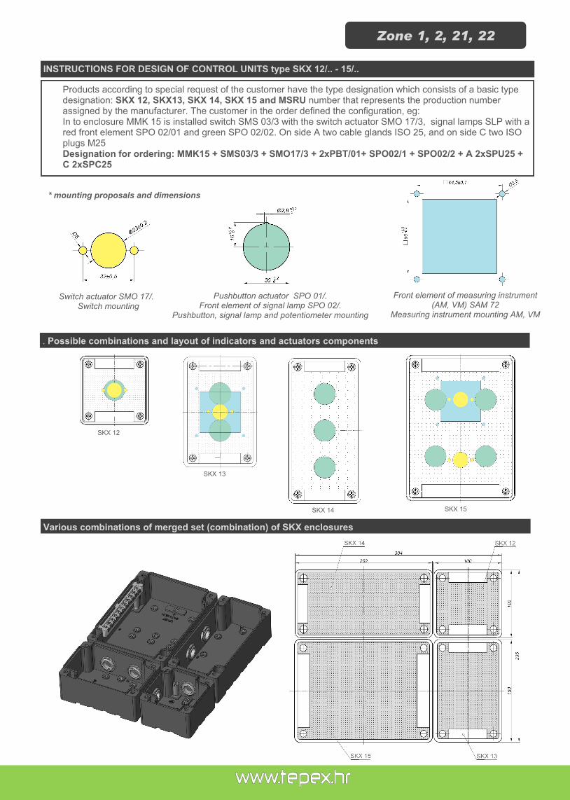
Products according to special request of the customer have the type designation which consists of a basic type designation: SKX 12, SKX13, SKX 14, SKX 15 and MSRU number that represents the production number assigned by the manufacturer. The customer in the order defined the configuration, eg: In to enclosure MMK 15 is installed switch SMS 03/3 with the switch actuator SMO 17/3, signal lamps SLP with a red front element SPO 02/01 and green SPO 02/02. On side A two cable glands ISO 25, and on side C two ISO plugs M25 Designation for ordering: MMK15 + SMS03/3 + SMO17/3 + 2xPBT/01+ SPO02/1 + SPO02/2 + A 2xSPU25 + C 2xSPC25
INSTRUCTIONS FOR DESIGN OF CONTROL UNITS type SKX 12/.. - 15/..
. Possible combinations and layout of indicators and actuators components
* mounting proposals and dimensions
Various combinations of merged set (combination) of SKX enclosures
SKX 12
SKX 13
SKX 14 SKX 15
Switch actuator SMO 17/. Switch mounting
Pushbutton actuator SPO 01/. Front element of signal lamp SPO 02/.
Pushbutton, signal lamp and potentiometer mounting
Front element of measuring instrument (AM, VM) SAM 72
Measuring instrument mounting AM, VM
Zone 1, 2, 21, 22

ATEX 0722 +50

TECHNICAL DATA
Certificate: ATEX
Marking: 0722
Apparatus category: II 2GD
Marking of explosion protection:
Ex edm ia/ib IIC Gb Ex tb IIIC T80ºC Db
Environment temperature: -20 ºC ≤ Ta ≤ +50 ºC
Degree of protection: IP 66
Resistance to shock: IK 08
Insulation class: I (protective earthing) in accordance with EN 61140
Rated insulation voltage Ui: Up to 690 V AC
Rated current Ith: Up to 80 A
PE terminals (inside of the enclosure):
max. 2x4 mm2+2x2,5 mm2 , 3x4 mm2 , 2x6 mm2
Cover fixing: 6 x M6 cheese head screw, stainless steel A2
Color:: black, RAL 9005
MOUNTING
With screw kit through the housing holes 7 mm at the peaks the rectangle:
SKX 16: 235 x 200 mm SKX 18: 380 x 200 mm SKX 20: 580 x 200 mm
APPLICATION
Explosion protected control units type SKX 16 – SKX 20, alone or in various combina-tions of merged set (combination) are intended for the control, distribution and signaling in the power circles on places with presence of explosive mixtures of gases, vapor and dust with air, in hazardous areas 1, 2, 21, 22
Ex
CO
NT
RO
L U
NIT
S t
yp
e S
KX
16
, S
KX
18, S
KX
20
CONSTRUCTION
Enclosure: SMC polyester plastic reinforced with glass fiber, color - black Cover: SMC with integrated thermoplastic elastomer gasket, closes with four/six M6 stainless steel screws. Due to the three available sizes and the modular design, the devices can be used for almost every application. Built-in components, actuators and indicator components can be mounted in or on Ex e enclosures or combination of merged enclosures. Possible combinations and schedules built-in components, actuators and indicator components is determined by the certification documentation. Control units usually aren't wired.
Zone 1, 2, 21, 22

SPARE PARTS AND ACCESSORIES
BUILD-IN COMPONENTS
1. Enclosure and cover SKX .. 2. Cable glands and plugs 3. Build-in components 4. Actuators and indicators
Description, type Schema Overview
Control switch SMS 03/.
II 2G I M2 Ex de I/IIC Gb Mb
Rated voltage: 630 V AC
Rated current: 16 A
Terminals: 2,5 mm2
1
2
3
4
ATEX 0722 +50
SMS 03/2
SMS 03/1
Type Shema
0 90° I
2 A
1 A
I 90° II
2 A
4 A1 A
2 B
1 B 4 B
2 C
1 C 4 C
I 45° II
2 A
4 A1 A
2 B
1 B 4 B
I II
2 A
4 A1 A
2 B
1 B 4 B
2 C
1 C 4 C
0 90° I
2 A
1 A
3 A
4 A
2 B
1 B
3 B
4 B
0
90°
III
2 A
1 B
3 A
4 B
45°0
45° 45°0
I II
0 90° I
2 A
1 A
2 B
1 B
3 B
4 B
I 90° II
2 A
4 A1 A
2 B
1 B 4 B
I 90° II
2 A 2 B
1 B4 B
I 90° II
2 A
4 A1 A
I 45° II
2 A
4 A1 A45°
0
045° II
2 A
1 A45°
t
3 A
4 A
0 90° I
2 A
4 A1 A
2 A
SMS 03/3
SMS 03/4
SMS 03/5
SMS 03/6
SMS 03/7
SMS 03/8
SMS 03/9
SMS 03/10
SMS 03/11
SMS 03/12
SMS 03/13

BUILD-IN COMPONENTS
Description, type Schema Overview
Control switch GHG 23.
II 2GD Ex de IIC
Rated voltage: 690 V AC
Rated current : 10 A
Terminals: 2,5 mm2
Main curent switch GHG 260
II 2GD Ex de IIC
Rated voltage: 690 V AC
Rated current : 40 - 80 A
Terminals: 16 - 25 mm2
Zone 1, 2, 21, 22

BUILD-IN COMPONENTS
Description, type Schema Overview
Pushbutton PBT/. II 2G I M2 Ex de I/IIC Gb Mb
Rated voltage: 630V AC
Rated current: 16A
Terminals: 2,5 mm2
Signal lamp SLP
II 2G I M2 Ex de I/IIC Gb Mb
Rated voltage: 12-250 V AC/DC
Max. current: 20-8 mA
Terminals: 2,5 mm2
Potentionmeter PBT/POT
II 2G I M2 Ex de I/IIC Gb Mb
Rated voltage: 315 V AC/DC
Rated power: 1W
Scale: 0-100% / 270
Tolerance: ±20%
Characteristic: linear
Terminals: 2,5 mm2
Resistance R:
1,0 k
2,2 k
4,7 k
10 k
470 k
Measuring instruments AM 72, VM 72
II 2GD Ex e ib IIC
Measuring range:
AM: n/1 A, 0-20 mA, 0-25 A direct 4-20 mA VM: n/1A, 6-415V, 6-660 V
Scale: according to customer
demand
Terminals: 1,5 - 4 mm2
-
Mantle terminals SL5 , SL8
II 2G I M2 Ex de I/IIC Gb Mb
Rated voltage: 400 V
Rated current: 16 A AC
Terminals: 4 mm2
Max. No. of wire under one clamp: 2x4mm
2 + 2x2,5mm
2, 3x4mm2
-
Terminals TH 35-7.5
II 2GD Ex e II
Up to 70 mm2
Rated voltage: 690 V AC
Rated current: up to 80 A
-
ATEX 0722 +50

ACTUATORS AND INDICATORS
Description, type Mounting Overview
Switch actuator SMO 17/.
II 2G II 2D I M2 Ex e I/IIC Gb Mb
Ex t IIIC Db
Switch actuator GHG 260 1006
II 2GD Ex e II
Front element of measuring instruments SAM 72
II 2G II 2D I M2 Ex e I/IIC Gb Mb
Ex t IIIC Db
Puschbitton actuator SPO 01/.
II 2G II 2D I M2 Ex e I/IIC Gb Mb
Ex t IIIC Db
Front element of signal lamp SPO 02/.
II 2G II 2D I M2 Ex e I/IIC Gb Mb
Ex t IIIC Db
Key-operated pushbutton actuator
GHG 410 1904 R0012
II 2GD Ex e II IP66
I0 I II I 0 II
I
0
III
II
I II III
1 2
3
4
1 2
3
45
1 2
3
456
1 2
3
SMO 17/1 SMO 17/2 SMO 17/3 SMO 17/4
SMO 17/5 SMO 17/6 SMO 17/7 SMO 17/8 SMO 17/9
Type SPO 01/.
SPO 01/01 0
SPO 01/02 I
SPO 01/03 II
SPO 01/04 RED
SPO 01/05 GREEN
SPO 01/06 WHITE
SPO 01/07 START
SPO 01/08 STOP
SPO 01/09 ON
SPO 01/10 OFF
Type SPO 02/.
SPO 02/01 RED
SPO 02/02 GREEN
SPO 02/03 YELLOW
SPO 02/04 TRANSPARENT
Ø13
Ø87,5
60°Ø5x6
Zone 1, 2, 21, 22

Description, type Mounting Overview
Mushroom-head pushbutton actuator
GHG 418 815 ..R ..(EMERGENCY-STOP)
II 2GD
Ex e II IP66
Key-operated mushroom-head pushbutton actuator GHG 418 815 ..R..
(EMERGENCY-STOP)
II 2GD Ex e II IP66
Potentiometer acuator GHG 410 1944 R0010
II 2GD
Ex e II IP66
Cable gland SPU ISO 16 - ISO 40
II 2G II 2D
Ex e I/IIC Gb Ex t IIIC Db
Cable gland for armourd cable SPU A
ISO 16 - ISO 40
II 2G II 2D Ex e I/IIC Gb Ex t IIIC Db
Plug SPC .. ISO 16 - ISO M40
II 2G II 2D
Ex e I/IIC Gb Ex t IIIC Db
Main fuse NH0 300XX, NH0, 301XX
II 2GD Ex de IIC
-
ACTUATORS AND INDICATORS
ATEX 0722 +50

Enclosure type SKX 16
255
250
120
162
Side Cable
gland M20 M25 M32 M40 M50 M63
B-D 9 9 5 3 3 2
A-C 7 5 3 3 - -
Enclosure type SKX 18
250
120
400
162
Side Cable
gland M20 M25 M32 M40 M50 M63
B-D 15 15 9 6 5 4
A-C 7 5 3 3 - -
Zone 1, 2, 21, 22

Enclosure type SKX 20
Side Cable
gland M20 M25 M32 M40 M50 M63
B-D 22 22 12 8 6 6
A-C 7 5 3 3 - -
600
250
120 162
ATEX 0722 +50

In and on Ex e enclosure or combination of multiple enclosures, interconnected by bushing, are mounted " Ex e d m ia/ib" and Ex e built-in components, actuator and indicators. There are no limitation in orientation of encosure/combination of multiple enclosures, (longer side of enclosure is mounted horizontally or vertically) and the manner of which the mounting is set to the surface. In horizontal orientation of enclosure, built-in components and actuator and indicators are mounted in maximum two rows. In vertical orientation of enclosure , built-in components and actuator and indicators are mounted in maximum:
SKX 16 - 2 rows SKX 18 - 3 rows SKX 20 - 5 rows
The actual nuber of mounted rows depends on the device configuration. Circuit breaker 3p/4p Ith = 40 A, 80 A with its matching actuatuator or block NH 00 main fuse always occupies two hole rows, Actuator and indicators – circuit breaker which are not connected with the actuaror, always occupie one and a half row. In one row there can be maximaly be: SKX 16 - 6 pols, horizontal and vertical orientation of the enclosure, SKX 18 - 12 pols vertical, 8 pols horizontal orientation of the enclosure, SKX 20 - 18 pols vertical, 12 pols horizontal orientation of the enclosure.
INSTRUCTIONS FOR DESIGN OF LOW VOLTAGE SWITCHGEAR AND CONTROL GEAR ASSEMBLYES type SKX 16/.., SKX 18/.., SKX 20/..
We design systems to suit your requirements on the basis of the data you supply us with:
the required minimum type of protection
as appropriate, details of the hazardous atmosphere for which the equipment must be suitable
single line or wiring diagram
schematic for control systems
operating, auxiliary and control voltages
frequency
power and current ratings of connected loads
quantities and types of components required, e.g. contactors, switches, circuit-breakers, fuses, thermal relays, instruments, terminals etc
quantity and types of cables
number and size of conductors
quantity and location of entries (from top, bottom, side, centre)
environmetal conditions
method of installation
Zone 1, 2, 21, 22

Various combinations of merged set (combination) of SKX enclosures K
80
400
600
255
2,3
2,3
1260
250 250
2,3
110
110
110
110
110
110
80
502
±0.5
A
B
C
DD
DB
B
CC A
A
SK
X 1
6
SK
X 1
8
SK
X 2
0
SK
X 1
6S
KX
20
SK
X 1
8
ATEX 0722 +50

TECHNICAL DATA
Certificate: CESI 11 ATEX 041
Marking: 0722
Apparatus category: II 2G
Marking of explosion protection:
Ex d e [ib] mb IIC T5 Gb
Environment temperature: -20 ºC ≤ Ta ≤ +50 ºC
Degree of protection: IP 66
Resistance to shock: IK 08
Insulation class: I (protective earthing) in accordance with EN 61140
Rated voltage: 230V ± 10%
Rated current: 50 mA
Frequency: 50Hz
Output circuit: 2 alternating contacts Un=250 V AC, In=8 A / 230 V,
4 A at cos=0.4
Push button START: Starting the system, control the time about 10s
Signal lamps:
Red: blinking inside control time (10 sec - MOD2), contacts NO are open, contacts NC are closed, continuous oper-ation (MOD1 and MOD 2), contacts NO are open, contacts NC are closed Green: continuous operation (MOD1 and MOD 2), contacts NO are closed, contacts NC are open
Cable entries: 3 x M25 - power supply, two output circuit 4 x M25 - 2x connection clamp , 2x wire to equipotential busbar or grounding
Weight: 6 kg (without clamp and cable) weight of clamps with 10 m cable ca. 2,5 kg
MOUNTING
APPLICATION
Explosion protected grounding and grounding control device type GGCD-01/.. together with clamp make ac-tive grounding system for static grounding and perma-nent monitoring earthling, in areas endangered by flam-mable and explosive mixtures of gases and air, fumes of flammable liquids and air, or various combinations be-tween the two, in danger zones 1,2 in accordance with related standards EN 60079-10 Explosion protected grounding and grounding control device type GGCD-01/.., intended for the permanent removal of electrostatic charge that may occur during filling or emptying tanks (road tracks, railcar tanks, bar-rels). The system provides the conditions for starting the production process only if the insured continuity control loop earthling resistance and jaw of clamp for grounding.
Ex G
RO
UN
DIN
G A
ND
GR
OU
ND
ING
CO
NT
RO
L D
EV
ICE
Typ
e G
GC
D-0
1/..
Zone 1, 2
CONSTRUCTION
Enclosure: polyester plastic reinforced with glass fiber, color - black Cover: with integrated Thermoplastic elastomer gasket, closes with four M6 stainless steel screws.
295O8
200

MODEL CODE DIMENSION
ATEX 0722 +50
TYPE DESCRIPTION:
GGCD-01/K1 Type with one a clamp K1 with 10m spiral cable
GGCD-01/K2 Type with two clamps K1 with 2x10m spiral cable
Principle of work for GGCD-01/..
280
255 190
ACCESSORIES:
1. Cable reel - 20m with plugs for connection to GGCD 2. Metal cable glands for armourd cable Ex e II 3. Dislocated monitoring system
Dislocated monitoring system
Dislocated monitoring system type
GGCD 01/PC CONTROL:
modules GGCD 01/M1 placed in the device
Central unit (outside of the hazardous area)
Windows compatible applications (map with all installed GGCD devices, status, sound signal in case of failure
indication on the device
response device
Clamps are not connected
bright red light disabled transport
Clamps are short-circuited with the earthing construction (for example, the iron fence)
bright red light
disabled transport
Tank is connected via the device GGCD-01
bright green light
transport allowed
Tank is connected via the device GGCD-01 but cable to the grounding or busbar is broken
bright red light
disabled transport
Tank is connected via the device GGCD-01 + successively ground through, for example, "loading arm"
bright green light
transport allowed

Certificate: ATEX
Apparatus category: I M2
Marking of explosion protection: Ex de I
Degree of protection: IP 66
Service temperature: -20oC ÷ +40
oC
POWER SUPPLY
Rated voltage Un: 1000V AC -20% ÷ +10% / 50Hz
Rated power (without external loads): cca 15W
MEASURING CIRCUIT
Rated voltage Un: 0-1000V AC
Frequency: 10-1000 Hz
ALARM adjustable: 5-100 k (10-200 /V at 500V)
PRE-ALARM adjustable (state of reduced insulation)
10 k5 M(20-10k/V)
OUTPUT CONTACTS
External signaling for state of reduced insulation: 3 x NO
External signaling for ground fault: 3 x NO
Auxiliary contacts for managing with switching device:
1 x NO/NC 1 x NO/NC
Connection terminal: 0,5 ÷ 4 mm2
Color: yellow, RAL1016
Dimension: 470 x 345 x 790 mm
Weight: 100 kg
Enclosure material: - Ex d enclosure - Ex e enclosure
steel 12 mm steel 2.5 mm
TECHNICAL DATA
Ex IN
SU
LA
TIO
N M
ON
ITO
R D
EV
ICE
ty
pe
R3002/1
000 V
/IV
I M2
APPLICATION
Explosion protected insulation monitor are used for early detection of insulation faults in applications where unscheduled downtimes of machinery would have serious conse-quences. They are used in earthed systems for reasons of efficiency and protection against fire and accidents. Ex insulation monitor has been certified for use in mines.
Un=230V In=16A AC15 - 1500VA

INSULATION MONITOR DEVICE
DIMENSION [mm]
+40 -20
CABLE GLAND Pg 21 (15-22mm)
kMETAR
RESET
TEST
Plug Pg 21
CORRECT STATE
REDUCED INSULATION
FAILURE
SWITCH
SIGNALIZATION:
GREEN work (correct state)
TRANSPARENT Reduced insulation (pre-alarm)
RED Ground fault (alarm)
k METAR analog measuring instrument
Outdoor light: lamp 42V, 50Hz (other voltages available on request)
External sound: trumpet 42V, 50Hz (other voltages available on request)
ATEX 2465


TECHNICAL DATA
Certificate: CESI 10 ATEX 040
Marking: 0722
Apparatus category: II 2G II 2D
Marking of explosion protection:
Ex e II T6 Ex ia/ib IIC T6
Ex tD A21 T80C
Environment temperature:
-20ºC ≤ Ta ≤ +40ºC or +50ºC -40ºC ≤ Ta ≤ +50ºC, with specially designed cable glands -40ºC ≤ Ta ≤ +70ºC, for Ex i, with specially designed cable glands
Degree of protection: IP 66
Resistance to shock: IK 08
Insulation class: I (protective earthing) in accordance with EN 61140
Rated voltage: 630 V
Maximum voltage for Ex i: 60 V
Nominal cross-section: 4 mm
2 RK01/514, RK01/514 Exi, RK01/544,RK01/744
6 mm2 RK01/516
Terminal rated current:
Cable current load capacity:
1.5 mm2 - 16 A
2.5 mm2 - 20 A
4 mm2 - 25 A
6 mm2 - 32 A
Cable entries, cable glands and screw plugs:
Cable entries in accordance with EN 60423 Cable glands in accordance with EN 50262
6 x M25 for cable 6-15 mm (13-19 mm available on request)
6 x M32 for cable 12-21 mm (17-25 mm available on request)
4 x M25 for cable 6-15 mm (13-19 mm available on request)
4 x M32 for cable 12-21 mm (17-25 mm available on request)
External earthing terminal: 2x6 mm2 max., cable lug 6-6, DIN 46234 (on type RK01/544-E)
Weight: 0,55 kg 0,80 kg with internal metal plate
MOUNTING
With two screws through the housing holes 6 mm at the peaks the rectangle: 100 x 75 mm
Ex J
UN
CT
ION
BO
X t
yp
e R
K 0
1/.
..
Zone 1, 2, 21, 22
CONSTRUCTION
Enclosure: PA glass fibre reinforced polyamide, color - black Cover: PA glass fibre reinforced polyamide with integrated thermoplastic elastomer gas-ket, closes with four M5 stainless steel screws.
APPLICATION
Explosion protected junction box RK 01/… are used for carrying and distributing elec-trical power in hazardous areas intended for use in explosive gas and dust atmos-phere in danger Zones 1, 2, 21, 22. The junction box RK 01/… are fitted with pillar (mantle) terminals or terminal blocks for cable up to 6mm
2. For cable with ar-
moured cable there are junction boxes available with internal metal plate and ex-ternal earthing terminal.
RK01/744,RK01/544 RK01/544E
Ta40°C 22 A
Ta50°C 18 A
RK01/514 Ta40°C 20 A
Ta50°C 16 A
RK01/516 Ta40°C 25 A
Ta50°C 20 A

MODEL CODE
ATEX 0722 +50
DIMENSIONS
TYPE DESIGN CABLE
GLANDS
NUMBER OF TERMINALS
- TERMINAL CROSS SECTION
(nominal)
MAX. CAPACITY PER
TERMINAL
RK 01/514
cable glands 4xM25
for cable
6-15mm, 2xM25
screw plug
5 - 1 x 4mm2
(L1, L2, L3, N, PE)
1x0,5....4mm2
2x0,5....2,5mm2
RK01/514 Ex i
5 - 1 x 4mm
2
(Blue 1-5)
RK 01/516 5 - 1 x 6mm
2
(L1, L2, L3, N, PE) 1x1,5....6mm
2
2x1,5....4mm2
RK 01/544
cable glands 6xM25
for cable
6-15mm
5 - 4 x 4mm2
4x4mm2
6x2,5mm2
1x4mm2 + 2x2,5mm
2+
+3x1,5mm2
1x4mm2 + 5x1,5mm
2
2x4mm2 + 3x2,5mm
2
RK 01/744 7 - 4 x 4mm2
RK 01/544-E
2 x M32 cable glands for ar-moured cable Øv23-32mm
4 x M25 cable glands for ar-moured cable Øv17-23mm
5 - 4x 6mm2
Other configuration available on request
115
115
180
185
43
O6
75
100
64
II 2D Ex A21 IP66 T80°CII 2G Ex e II T6
WARNINGDO NOT OPEN WHEN ENERGIZED
HR - 10090 Zagreb 0722
RK/054 Ui=690V CESI 09 ATEX ...
P- AZ-

TECHNICAL DATA
Certificate: EXA 13 ATEX 0003U
Marking: 2465
Apparatus category: II 2G II 2D
Marking of explosion protection:
Ex d IIC Gb Ex tb IIIC Db
Environment temperature: -20ºC ≤ Ta ≤ +60ºC
Service temperature: -20ºC ≤ Ta ≤ +80ºC
Degree of protection: IP 66
Insulation class : I (protective earthing) in accordance with EN 60947
External earthing terminal: max. 2 x 6 mm2
Color: Gray, RAL 7001
Weight: 1,0 kg
DIMENSION MODEL CODE
Ex JU
NC
TIO
N B
OX
typ
e J
BX
01
Zone 1, 2, 21, 22
CONSTRUCTION
Enclosure: corrosion resistant grey polyurethanes painted aluminium color RAL 7000 Gasket: Silicon
APPLICATION
Explosion proof terminal box type JBX 01 is empty Ex d enclosure (component) in which are installed industry-standard performance equipment (low voltage switching devices, electrical appliances) . It has been certified for use in hazardous area due to the presence of flammable and explo-sive gases, vapors and dusts in Zones 1, 2, 21, 22.
TYPE No. of entries/side Entries
JBX 01/11 2 / B-D
M20x1,5 - ISO 261 JBX 01/12 3 / B-C-D
JBX 01/13 4 / A-B-C-D
JBX 01/31 2 / B-D 3/4” - NPT -
ANSI ASME B1.20.1 JBX 01/32 3 / B-C-D
JBX 01/33 4 / A-B-C-D
JBX 01/41 2 / B-D 1/2” - NPT -
ANSI ASME B1.20.1 JBX 01/42 3 / B-C-D
JBX 01/43 4 / A-B-C-D
118
87
87
7
98

ATEX 2465 +60

TECHNICAL DATA
Certificate: ATEX
Marking: 2465
Apparatus category: II 2G II 2D
Marking of explosion protection:
Ex e II T6, Ex e ia IIC T6, Ex ia IIC T6 tD A21 T80ºC
Environment temperature: -20ºC ≤ Ta ≤ +50ºC
Degree of protection: IP 66
Resistance to shock: IK 07
Insulation class: I (protective earthing) in accordance with EN 61140
Rated voltage: Up to 750 V AC
Rated current: In accordance with table
Surface resistance: < 109
Rated cross-section: max. nominal cross-section 300 mm2
N/PE rails inside the Enclosure:
2 pcs, 11 terminals 2x4mm2 max.
Weight (without cable glands):
SKX 12/E ..... 0.5kg SKX 13/E ..... 0,7kg SKX 14/E ..... 1.0kg SKX 15/E ..... 1.0 - 1,5kg SKX 16/E ..... 3,5kg SKX 18/E ..... 4,5kg SKX 20/E ..... 7,0kg
MOUNTING
With two/four screws through the housing holes 6 mm at the peaks the rectangle: SKX 12: 75 x 50 mm SKX 13: 75 x 100 mm SKX 14: 75 x 150 mm SKX 15: 125 x 150 mm
SKX 16: 235 x 200 mm SKX 18: 380 x 200 mm SKX 20: 580 x 200 mm
Ex T
ER
MIN
AL
BO
X t
yp
e S
KX
12/E
- 2
0/E
Zone 1, 2, 21, 22
CONSTRUCTION
Enclosure: SMC glass fibre reinforced polyamide, color - black Cover: SMC glass fibre reinforced polyamide with integrated thermoplastic elastomer gasket, closes with four M5/M6 stainless steel screws.
APPLICATION
The terminal boxes are intended for the distribution of electrical energy, e.g. light cir-cuits, heating circuits, control circuits, intrinsically safe circuits on places with presence of explosive mixtures of gases, vapor and dust with air, in hazardous areas 1, 2, 21, 22. Enclosure of glass fibre-reinforced polyester resin can be supplied in 7 sizes with vari-ous heights and they are suitable for fixed mounting. The terminal boxes are fitted to order with terminals and cable glands. For armored cables all terminal boxes are availa-ble with internal metal plate and cable glands for armored cables.
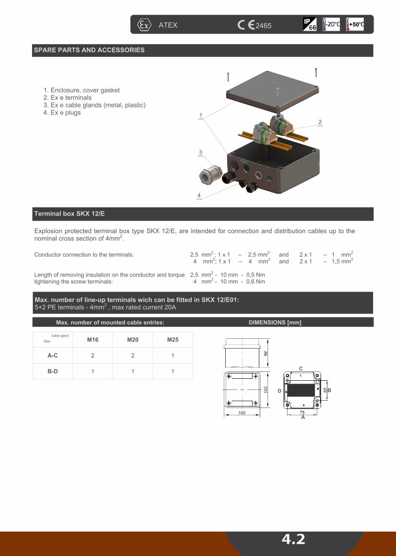
ATEX 2465 +50
Terminal box SKX 12/E
SPARE PARTS AND ACCESSORIES
1. Enclosure, cover gasket 2. Ex e terminals 3. Ex e cable glands (metal, plastic) 4. Ex e plugs
1
3
2
4
Explosion protected terminal box type SKX 12/E, are intended for connection and distribution cables up to the nominal cross section of 4mm
2.
Conductor connection to the terminals: 2,5 mm2 ; 1 x 1 – 2,5 mm
2 and
2 x 1 – 1 mm
2
4 mm2; 1 x 1 – 4 mm
2 and
2 x 1 – 1,5 mm
2
Length of removing insulation on the conductor and torque tightening the screw terminals:
2,5 mm2 - 10 mm - 0,5 Nm
4 mm2 - 10 mm - 0,6 Nm
Max. number of line-up terminals wich can be fitted in SKX 12/E01: 5+2 PE terminals - 4mm
2 , max rated current 20A
Max. number of mounted cable entries: DIMENSIONS [mm]
Side
Cable gland
M16 M20 M25
A-C 2 2 1
B-D 1 1 1
A
B
C
D

Terminal box SKX 13/E
Explosion protected terminal box type SKX 13/E, are intended for connection and distribution cables up to the nominal cross section of 6mm
2.
Conductor connection to the terminals: 2,5 mm2 ; 1 x 1 – 2,5 mm
2 and
2 x 1 – 1 mm
2
4 mm2; 1 x 1 – 4 mm
2 and
2 x 1 – 1,5 mm
2
6 mm2; 1 x 1 – 6 mm
2 and
2 x 1 – 2,5 mm
2
Length of removing insulation on the conductor and torque tightening the screw terminals:
2,5 mm2 - 10 mm - 0,5 Nm
4 mm2 - 10 mm - 0,6 Nm
6 mm2 - 12 mm - 1,2 Nm
Max. number of line-up terminals wich can be fitted in SKX 13/E: SKX 13/E01 - 8+2 PE terminals - 4mm
2 , max rated current 20A
SKX 13/E02 - 8+2 PE terminals - 6mm2 , max rated current 25A
Max. number of mounted cable entries: DIMENSIONS [mm]
Side
Cable gland
M16 M20 M25
A-C 2 2 1
B-D 4 3 2
A
B
C
D
Terminal box SKX 14/E
Explosion protected terminal box type SKX 14/E, are intended for connection and distribution cables up to the nominal cross section of 6mm
2.
Conductor connection to the terminals: 2,5 mm2 ; 1 x 1 – 2,5 mm
2 and
2 x 1 – 1 mm
2
4 mm2; 1 x 1 – 4 mm
2 and
2 x 1 – 1,5 mm
2
6 mm2; 1 x 1 – 6 mm
2 and
2 x 1 – 2,5 mm
2
Length of removing insulation on the conductor and torque tightening the screw terminals:
2,5 mm2 - 10 mm - 0,5 Nm
4 mm2 - 10 mm - 0,6 Nm
6 mm2 - 12 mm - 1,2 Nm
Max. number of line-up terminals wich can be fitted in SKX 13/E: SKX 14/E01 - 16+4 PE terminals - 4mm
2 , max rated current 20A
SKX 14/E02 - 16+4 PE terminals - 6mm2 , max rated current 25A
Max. number of mounted cable entries: DIMENSIONS [mm]
Side
Cable gland
M16 M20 M25 M32
A-C 2 2 1 1
B-D 6 4 3 2
A
B
C
D
Zone 1, 2, 21, 22

Terminal box SKX 15/E
Max. number of mounted cable entries: DIMENSIONS [mm]
Explosion protected terminal box type SKX 15/E, are intended for connection and distribution cables up to the nominal cross section of 25mm
2.
Conductor connection to the terminals: 2,5 mm2 ; 1 x 1 – 2,5 mm
2 and
2 x 1 – 1 mm
2
4 mm2; 1 x 1 – 4 mm
2 and
2 x 1 – 1,5 mm
2
6 mm2; 1 x 1 – 6 mm
2 and
2 x 1 – 2,5 mm
2
10 mm2; 1 x 1,5 – 10 mm
2 and
2 x 1,5 – 4, mm
2
16 mm2; 1 x 1,5 – 16 mm
2 and
2 x 1,5 – 4 mm
2
25 mm2; 1 x 1,5 – 25 mm
2 and
2 x 1,5 – 4 mm
2
Length of removing insulation on the conductor and torque tightening the screw terminals:
2,5 mm2 - 10 mm - 0,5 Nm
4 mm2 - 10 mm - 0,6 Nm
6 mm2 - 12 mm - 1,2 Nm
10 mm2 - 12 mm - 2,0 Nm
16 mm2 - 14 mm - 3,0 Nm
25 mm2 - 14 mm - 3,0 Nm
Terminal fittings, number of conductors which can be fitted depending on
conductor cross-section and continues current
Max. current
[A]
CROSS SECTION [mm2]
Rated cross section of conductors - rated cross section of terminals
2,5 4 6 10 16 25
6 142
10 51 80 Allowed combinations
16 23 32 48
20 20 30 50
25 16 26 42
35 12 19 29
50 8 12 Unallowable combinations
63 6
Max. number of terminals
depending of the
enclosure size
28 + rails 2x24 PE
24 + rails 2x24 PE 20 15 10 10
Side Cable gland
M16 M20 M25 M32 M40
A-C 4 3 2 2 1
B-D 6 4 3 2 2
Side Cable gland
M16 M20 M25 M32 M40
A-C 4 3 2 2 1
B-D 5 3 3 - -
*with N/PE rails
A
B
C
D
ATEX 2465 +50

Terminal box SKX 16/E
Explosion protected terminal box type SKX 16/E, are intended for connection and distribution cables up to the nominal cross section of 35mm
2.
Conductor connection to the terminals: 2,5 mm2 ; 1 x 1 – 2,5 mm
2 and
2 x 1 – 1 mm
2
4 mm2; 1 x 1 – 4 mm
2 and
2 x 1 – 1,5 mm
2
6 mm2; 1 x 1 – 6 mm
2 and
2 x 1 – 2,5 mm
2
10 mm2; 1 x 1,5 – 10 mm
2 and
2 x 1,5 – 4, mm
2
16 mm2; 1 x 1,5 – 16 mm
2 and
2 x 1,5 – 4 mm
2
25 mm2; 1 x 1,5 – 25 mm
2 and
2 x 1,5 – 4 mm
2
35 mm2; 1 x 2,5 – 35 mm
2 and
2 x 2,5 – 6 mm
2
Length of removing insulation on the conductor and torque tightening the screw terminals:
2,5 mm2 - 10 mm - 0,5 Nm
4 mm2 - 10 mm - 0,6 Nm
6 mm2 - 12 mm - 1,2 Nm
10 mm2 - 12 mm - 2,0 Nm
16 mm2 - 14 mm - 3,0 Nm
25 mm2 - 14 mm - 3,0 Nm
35 mm2 - 17 mm - 5,0 Nm
Terminal fittings, number of conductors which can be fitted depending on
conductor cross-section and continues current
Max. current
[A]
CROSS SECTION [mm2]
Rated cross section of conductors - rated cross section of terminals
2,5 4 6 10 16 25 35
6
10 96 Allowed combinations
16 32 96
20 32 96
25 32 96
35 32
50 Unallowable combinations 32
63 16 24 24
80 8 8
Max. number of terminals
depending of the
enclosure size
80 66 57 44 16 16 12
double row assembly single row assembly
Max. number of mounted cable entries: DIMENSIONS [mm]
Side Cable
gland M20 M25 M32 M40 M50 M63
B-D 9 9 5 3 3 2
A-C 7 5 3 3 - -
255
250
120
162
235
200
Zone 1, 2, 21, 22

Terminal box SKX 18/E
Max. number of mounted cable entries: DIMENSIONS [mm]
Terminal fittings, number of conductors which can be fitted depending on
conductor cross-section and continues current
Explosion protected terminal box type SKX 18/E, are intended for connection and distribution cables up to the nominal cross section of 70mm
2.
Conductor connection to the terminals: 35 mm2; 1 x 2,5 –35 mm
2 and
2 x 2,5 – 6 mm
2
50 70
Length of removing insulation on the conductor and torque tightening the screw terminals:
35 mm2 - 17 mm - 5,0 Nm
50 70
Max. current
[A]
CROSS SECTION [mm2]
Rated cross section of conductors - rated cross section of terminals
2,5 4 6 10 16 25 35 50 70
6 264
10 96 244 Allowed combinations
16 32 96 148
20 32 96 148
25 32 96
35 32 64
50 Unallowable combinations 32 36 36
63 16 24 24 36 36
80 8 8 24 24
100 8 8
Max. number of terminals
depending of the
enclosure size
128 106 92 70 52 25 25 12 8
double row assembly single row assembly
Side Cable
gland M20 M25 M32 M40 M50 M63
B-D 15 15 9 6 5 4
A-C 7 5 3 3 - -
250
120
400
162
380
200
ATEX 2465 +50

Terminal box SKX 20/E
Terminal fittings, number of conductors which can be fitted depending on
conductor cross-section and continues current
Max. number of mounted cable entries: DIMENSIONS [mm]
Explosion protected terminal box type SKX 20/E, are intended for connection and distribution cables up to the nom-inal cross section of 70mm
2.
Max. current
[A]
CROSS SECTION [mm2]
Rated cross section of conductors - rated cross section of terminals
2,5 4 6 10 16 25 35 50 70
6 264
10 96 244 Allowed combinations
16 32 96 148
20 32 96 148
25 32 96
35 32 64
50 Unallowable combinations 32 36 36
63 16 24 24 36 36
80 8 8 24 24
100 8 8
Max. number of terminals
depending of the
enclosure size
128 106 92 70 52 25 25 12 8
double row assembly single row assembly
Side Cable
gland M20 M25 M32 M40 M50 M63
B-D 22 22 12 8 6 6
A-C 7 5 3 3 - -
600
250
120 162
580
200
Zone 1, 2, 21, 22

ATEX 2465 +50

TECHNICAL DATA
Certificate: HREx T 11.009U
Marking: E1/08
Apparatus category: II 2G II 2D
Marking of explosion protection:
Ex e IIC, Ex ia/ib IIC Gb, Ex tb IIIC Db
Service temperature: -40ºC ≤ Tservice ≤ +80ºC
Degree of protection: IP 66
Resistance to shock: IK 10
Insulation class: I (protective earthing), internal and external PE terminal 6 mm2
Cable entries: according to specification
MODEL CODE Ex S
TA
INL
ES
S S
TE
EL
BO
X
- A
ISI 316
Zone 1, 2, 21, 22
CONSTRUCTION
Enclosure: Stainless steel AISI 316, 1.5mm Gasket: EPDM formed gasket
APPLICATION
Ex stainless steel terminal boxes are certified for use in industry areas made hazardous by flammable gases, vapors, liquids and dust in the zones 1, 2, 21, 22.
MMK .. .. .. / ..
model code
dimension, e.g 200x200x120 [mm] → MMK 202012
type of configuration
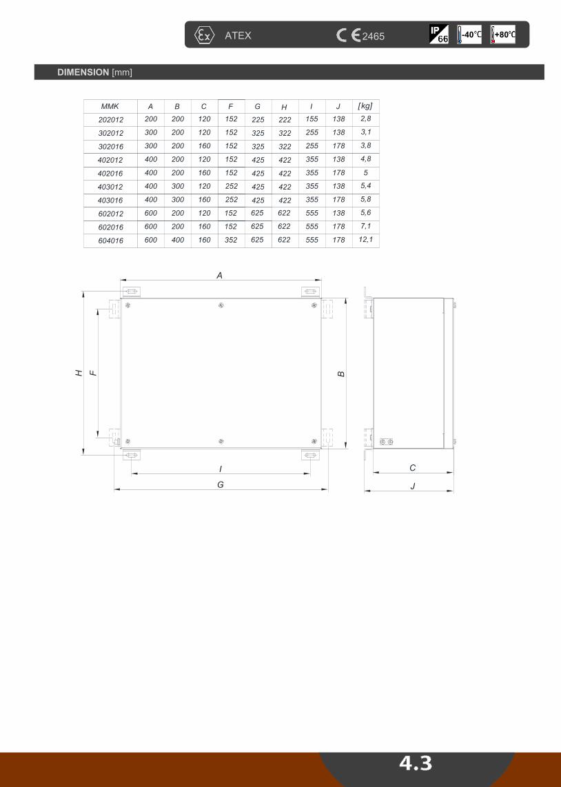
ATEX 2465 +80 -40
J
A
FH
I
G
B
C
A
200
300
B
200
200
GF
202012
302012
MMK
600 200602016
300 200302016
400 200402012
400 200402016
400 300403012
400 300403016
600 200602012
600 400604016
H
222
322
622
322
422
422
422
422
622
622
IC
120
120
160
160
120
160
120
160
120
160
152
152
152
152
152
152
252
252
152
352
225
325
625
325
425
425
425
425
625
625
155
255
555
255
355
355
355
355
555
555
J
138
138
178
178
138
178
138
178
138
178
[kg]
2,8
3,1
7,1
3,8
4,8
5
5,4
5,8
5,6
12,1
DIMENSION [mm]

TECHNICAL DATA
Certificate: HREx T 13.001
Marking: 2465
Apparatus category: II 2G II 2D
Marking of explosion protection:
Ex e IIC T6 Gb Ex tb IIIC T80°C Db
Environment temperature: -20ºC ÷ +50ºC
Degree of protection: IP 66
Resistance to shock: IK 10
Nominal voltage Un: 690 V AC ±10%
Cable entries: according to specification
MODEL CODE
Ex B
US
BA
R E
NC
LO
SU
RE
typ
e S
KX
604016
-./...
IN
OX
AIS
I 316
L
Zone 1, 2, 21, 22
CONSTRUCTION
Enclosure: Stainless steel AISI 316L, 1.5mm Gasket: EPDM formed gasket
APPLICATION
Busbar enclosure type SKX 604016-./... Is intended for conection and junction cables cross section from 35 mm2 up to 150 mm2. The busbar enclosure consists of the board with the tripolar busbar and busbar for the grounding which have been built in the AISI 316L enclosure (dimension 600x400x160 mm).
SKX 604016- . / ...
type and design of enclosure
number of cable entries
number and size of terminals
Terminal Cross section tamb -20°C do +40°C tamb -20°C do +50°C
185 mm2
150 mm2 300 A 250 A
120 mm2 250 A 200 A
120 mm2
95 mm2 200 A 160 A
70 mm2 150 A 125 A
50 mm2 125 A 100 A
35 mm2 100 A 80 A
Table of maximum currents:
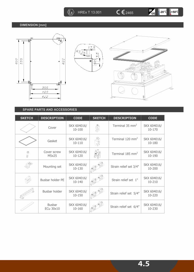
HREx T 13.001 2465 +50 -20
DIMENSION [mm]
SPARE PARTS AND ACCESSORIES
SKETCH DESCRIPTION CODE SKETCH DESCRIPTION CODE
Cover SKX 604016/
10-100
Terminal 35 mm2
SKX 604016/ 10-170
Gasket SKX 604016/
10-110
Terminal 120 mm2
SKX 604016/ 10-180
Cover screw
M5x25 SKX 604016/
10-120 Terminal 185 mm2
SKX 604016/ 10-190
Mounting set SKX 604016/
10-130 Strain relief set 3/4"
SKX 604016/ 10-200
Busbar holder PE SKX 604016/
10-140 Strain relief set 1"
SKX 604016/ 10-210
Busbar holder
SKX 604016/
10-150 Strain relief set 5/4"
SKX 604016/ 10-220
Busbar
ECu 30x10 SKX 604016/
10-160 Strain relief set 6/4"
SKX 604016/ 10-230

Ex d
D
IST
RIB
UT
ION
CA
BIN
ET
S t
yp
e R
3002,
R300
4
Ex e
BU
SB
AR
CA
BIN
ET
typ
e R
30
03,
R3005,
R300
6
Zone 1, 2, 21, 22
APPLICATION
The „flameproof“ Ex d distribution cabinets type R3002 and R3004 can be used in Zone 1, 2, 21,22. They are used for:
Electrical motor drivers
Lighting control
Electric power distributing and control
Electric power measuring and control
Technological process control A distribution cabinets type R3002 and R3004 is made of steel with Exd flameproof protection type. Closing of the cabinet is of threaded type and is protected against open-ing by lock switch, so that it can be opened only when it is not under voltage. The units is protected against corrosion by its painting inside and outside. Ex d steel enclosures (type R3002 and R3004) and Ex e sheet steel enclosures (type R3003, R3005, R3006) can be used as single enclosures and combinations. The dimensions of the enclosures are so designed that they can be combined into a large modular unit. A large number of components, such as contactors, switches, in-struments and PLCs can be built into these enclosures. Naturally, customer-supplied equipment can also be incorporated into the layout. The equipment layout is designed by us to customer's requirements. Cable entry is either direct (cable glands or conduit entries) or indirect via an Ex e enclosures type R3003, R3005, R3006. The "flameproof" type protection 'Ex d' is based on the principle that electrical compo-nents which may cause sparks or arcing in normal operation (switches, contactors etc.) are in an enclosure constructed so that it will contain an explosion of flammable gas or vapor and will not permit ignition of a surrounding explosive atmosphere. Further, the temperature of the outside surface of the enclosures must not exceed the prescribed temperature limit for the appropriate temperature class. That means, the heat loss from the components fitted must not exceed a specified value.
Enclosure in sheet steel
5 basic enclosure sizes
Enclosures can be combined
(modular system)
Available as empty enclosures
or as completely fitted and
wired control and distribution
units
Cable entries available:
Direct : cable glands,
Indirect : via Ex e enclosure
multiwire bushing,
conductor insulator
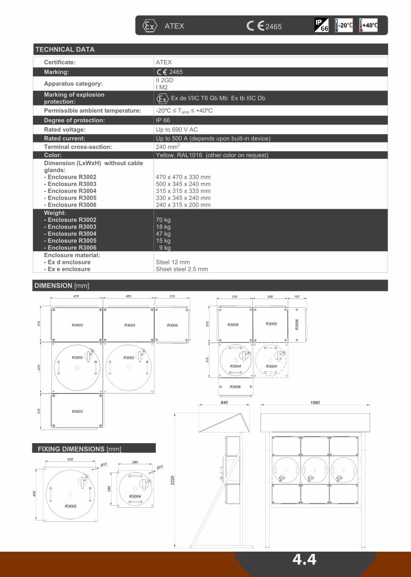
TECHNICAL DATA
Certificate: ATEX
Marking: 2465
Apparatus category: II 2GD I M2
Marking of explosion protection:
Ex de I/IIC T6 Gb Mb Ex tb IIIC Db
Permissible ambient temperature: -20ºC ≤ Tamb ≤ +40ºC
Degree of protection: IP 66
Rated voltage: Up to 690 V AC
Rated current: Up to 500 A (depends upon built-in device)
Terminal cross-section: 240 mm2
Color: Yellow, RAL1016 (other color on request)
Dimension (LxWxH) without cable glands: - Enclosure R3002 - Enclosure R3003 - Enclosure R3004 - Enclosure R3005 - Enclosure R3006
470 x 470 x 330 mm 500 x 345 x 240 mm 315 x 315 x 333 mm 330 x 345 x 240 mm 240 x 315 x 200 mm
Weight: - Enclosure R3002 - Enclosure R3003 - Enclosure R3004 - Enclosure R3005 - Enclosure R3006
70 kg 18 kg 47 kg 15 kg 9 kg
Enclosure material: - Ex d enclosure - Ex e enclosure
Steel 12 mm Sheet steel 2.5 mm
DIMENSION [mm]
ATEX 2465 +40 -20
R3002
R3003
R3003 R3003 R3005
R3002
R3006
R3004
R3005R3005
R3006
R3004
470
315
470
315
315
455 315 315 300 157
315
2220
840 1880
FIXING DIMENSIONS [mm]
R3002R3004
435
435
280
290
O12
O12
R3002R3004
435
435
280
290
O12
O12

SPARE PARTS
Ex e sheet steel enclosures (type R3003, R3005, R3006)
Seals for flanges
Seals for covers
Conductor insulator
Multiwire bushings
Cable glands
Actuatos and indicator elements
Built-in components
TYPE OF INSTALLATION
A) temporary B) wall-mounted C) free-standing With or without protection canopy
Data required for the layout of control and distribution boards
We design systems to suit your requirements on the basis of the data you supply us with:
the required minimum type of protection
as appropriate, details of the hazardous atmosphere for which the equipment must be suitable
single line or wiring diagram
schematic for control systems
operating, auxiliary and control voltages
frequency
power and current ratings of connected loads
quantities and types of components required, e.g. contactors, switches, circuit-breakers, fuses, thermal relays,
instruments, terminals etc
quantity and types of cables
number and size of conductors
quantity and location of entries (from top, bottom, side, centre)
environmetal conditions
method of installation
C) Direct on line start of tree phase motor D) Light fittings control panel
Zone 1, 2, 21, 22

Examples of wiring diagram for distribution cabinets
31
-Q11
5
42 6
M
3
L1 L2 L3
97 95
98 96
Pe
U V W
-F1
31
-Q12
5
42 6
-F2
42 6
SPOJ ZA DIRKTNO POKRETANJE TROFAZNOG
MOTORA I DVA SMJERA VRTNJE
31
-Q11
5
42 6
M
3
L1 L2 L3
97 95
98 96
Pe
-F1
31
-Q15
5
42 6
31
-Q13
5
42 6
31 5 13
14
21
22
U1
V1
W1
V2
W2
U2
-F2
42 6
I
42 6
I I
-Q1
SPOJ ZA POKRETANJE TROFAZNOG MOTORA U
SPOJU ZVIJEZDA - TROKUT
A) Direct on line start of tree phase motor; B) STAR-DELTA switching of three phase motor two directions of rotation
31
-Q11
5
42 6
M
3
L1 L2 L3
97 95
98 96
Pe
U V W
-F1
-F2
42 6
SPOJ ZA DIRKTNO POKRETANJE
TROFAZNOG MOTORA
C) Direct on line start of tree phase motor D) Light fittings control panel
EXIT
ATEX 2465 +40 -20


TECHNICAL DATA
Certificate: CESI 09 ATEX 068U
Marking: 0722
Apparatus category: II 2G II 2D
Marking of explosion protection:
Ex de IIC Ex tD A21 IP66
Service temperature: -20 ºC ≤ Tservice ≤ +60 ºC
Degree of protection: IP 66
Rated voltage Ue: 400 V AC
Rated current Ie: 16 A
Connection terminal : L1, L2, L3, N, PE , 2 x max.2,5 mm2
Adapter wiring: 2 / 3 / 4 x 1,5 mm2 RADOX 155
Adapter thread: M 20x1,5-6g according to ISO 965-1, ISO 965-3 G 1/2 according to ISO 228-1 1/2" NPT according to ANSI/ASME B1.20.1
Cable gland: For cable 6-15 mm
Dimension: 52x85mm
MODEL CODE
APPLICATION
Explosion proof adapter ADP2. is used for electrical connection between Exd enclosure and Exe adapter terminal without usage of the special Exd cable glands. It is used as component with enclosure in haz-ardous areas zone 1, 2, 21, 22.
Ex A
DA
PT
ER
typ
e A
DP
fo
r ca
ble
co
nn
ecti
on
Zone 1, 2, 21, 22
Ex d side
Ex e side
CONSTRUCTION
Bushing with outer thread (M20, NPT 1/2", BSP 1/2") and cemented wiring makes enclosure of adapter on which cable terminal is mounted. The space with cable terminal is sealed in adapter enclosure. Cable gland M25, type SPU 25 is mounted on adapter enclosure.
TYPE WIRING WIRE LENGHT
(Ex d side)
ADP 22 2x1.5mm2 ;black, black
200 mm ADP 23 3x1.5mm2 ; brown, blue, yellow-green
ADP 24 4x1.5mm2 ; black, brown, blue, yellow-green
Other configurations available on request

OVERVIEW OF APPLICATIONS
ATEX 0722 +60

TECHNICAL DATA
Certificate: CESI 09 ATEX 068U
Marking: 0722
Apparatus category: I M2 II 2G
Marking of explosion protection:
Ex d I Mb Ex d IIC Gb
Service temperature: -20 ºC ≤ Tservice ≤ +95 ºC
Rated insulation voltage Ue:
1000 V AC
Rated current Ie: Determined by technical data of device
Wire: - rated cross-section 1,5 - 35 mm2 - type RADOX 155 or BETAtherm 155 IEC 60228 class 5
MODEL CODE
TYPE
NUMBER AND CROSS-SECTION OF
WIRES
SIZE OF THREAD/THREAD LENGTH
(mm)
KEY SIZE AF/ BUSHING
LENGTH (mm)
WIRE LENGTH (THREAD
SIDE) (mm)
TOTAL WIRE LENGTH (mm)
RSM 04 6x1,5mm2
M25x1,5 - 6g / 14,5 OK30 / 30 150 330
RSM 05 8x1,5mm2
M25x1,5 - 6g / 14,5 OK30 / 30 150 330
RSM 07 6x4mm2
M33x1,5 - 6g / 14,5 OK36 / 30 300 530
RSM 08 6x6mm2
M33x1,5 - 6g / 14,5 OK36 / 30 300 530
RSM 10 6x10mm2
M36x1,5 - 6g / 14,5 OK41 / 30 300 530
RSM 11 6x16mm2
M36x1,5 - 6g / 14,5 OK41 / 30 300 530
RSM 13 6x25mm2
M42x1,5 - 6g / 14,5 OK46 / 30 200 430
RSM 14 6x35mm2
M42x1,5 - 6g / 14,5 OK46 / 30 200 430
APPLICATION
Explosion proof multiwire bushing RSM/.. is Exd component used for electrical con-nection between Exd enclosures or between Exd enclosure and Exe terminal box. The bushing is described by the model code depending on the thread size, number and cross section of the wires. It is used as component with enclosure in mining and hazardous area due to the presence of flammable and explosive gases, vapors or mists in Zones 1 and 2.
Ex M
ULT
IWIR
W B
US
HIN
G t
yp
e R
SM
Zone 1, 2
Other configurations available on request

ATEX 0722 +95

TECHNICAL DATA
Certificate: ATEX
Marking: 2465
Apparatus category: II 2G
Marking of explosion protection:
Ex e mb IIC T4 Gb
Ambient temperature: -25 ºC ≤ Tamb≤ +70 ºC
Degree of protection: IP 20
Rated voltage: 220-240 V ±10%
Frequency: 50-60 Hz
Insulation class: I (protective earthing), PE terminal
Lamps type: Fluo lamps T8 1-2 x 18/36/58W, in paralel configuration
Power factor: ~0.95
BLF - Ballast lumen factor:
~ 97 %
Estimated service life: 100 000 hours at Tamb=65°C 60 000 hours at Tamb=70°C
Connection terminal: 1,0-2.5mm2 solid, stranded, flexible
Weight: SMP 06 - 1,2 kg SMP 07 - 0,8 kg
With overcurrent, overvoltage and overtemperature protection
MODEL CODE
APPLICATION
The new SMP 06 and SMP 07 are electronic ballast for explosion proof applications. It has been certified for use in hazardous area due to the presence of flammable and explosive gases and vapors in Zones 1 and 2 in accord-ance with EN 60079-10. The SMP ballast meets all requirements of EN 60079-0:2009, EN 60079-7:2007, EN 60079-18:2009 and related industrial standards.
Ex E
LE
CT
RO
NIC
BA
LL
AS
T f
or
T8
flu
ore
sce
nt
lam
ps
Zone 1, 2
TYPE LAMP TYPE Dimension A Dimension B
SMP 06/11 1 x 18/36W T8 230 220
SMP 06/12 2 x 18/36W T8 230 220
SMP 06/13 1 x 58W T8 250 240
SMP 06/14 2 x 58W T8 250 240
SMP 07/11 1 x 18/36W T8 218 195
SMP 07/12 2 x 18/36W T8 218 195
CONSTRUCTION
SMP 06 enclosure: aluminium profile SMP 07 enclosure: plastic PA6

ATEX 2465 +70
230
O5,5
LN
PE
HR - 10090 Zagreb
SMP 06/1. 220-240V 50-60Hz
II 2 G Ex e mb IIC T4 -25°C < Ta < +70°C HREx T 10.006U
=0,96 EEI=A2
E-01/08
. x 18 / 36W T81)
1)
40
90
220B
A
DIMENSION
WIRING DIAGRAM
SMP 07
SMP 06

PLASTIC Ex e CABLE GLANDS
Apparatus category: II 2GD
Marking of explosion protection:
Ex e
Ambient temperature: -35 ºC ≤ Tamb≤ +95 ºC
Degree of protection: IP 68
Material: Polyamide/neopren
MODEL CODE
Ex C
AB
LE
GL
AN
DS
Zone 1, 2, 21, 22
THREADS CLAMPING
RANGE RAL 5012 RAL 9005 H (mm) E (mm) L (mm)
M12 4,0 - 6,0 F7431200E F8031200E 15 15 39
M16 6,0 - 10,0 F7431600E F8031600E 22 15 44
M20 7,0 - 12,0 F7432050E F8032050E 24 15 45
M25 10,0 - 18,0 F7432500E F8032500E 33 15 53
M25 6,00 - 15,0 33 15 53 SPU 25 B SPU 25
M32 17,0 - 24,0 42 15 57 F7433200E F8033200E
M40 17,0 - 31,0 53 16 68 F7434000E F8034000E
M50 24,5 - 37,0 50 16 71 F7435000E F8035000E
M63 34,0 - 47,0 70 16 72 F7436300E F8036300E

ATEX 2465 +95 -40
METAL Ex d/e CABLE GLANDS (double sealing, for armoured cable) type 4F
Apparatus category: II 2GD
Marking of explosion protection: Ex d/e
Ambient temperature: -40 ºC ≤ Tamb≤ +95 ºC
Degree of protection: IP 68
Material: Brass nickel plated
MODEL CODE
THREADS CLAMPING
RANGE H (mm) E (mm) CODE
M16 7,0 - 12,0 20 16 4114169
M20 9,0 - 16,0 24 16 4114219
M20 13,0 - 21,0 28 16 4114229
M25 13,0 - 21,0 30 16 4114279
M25 17,0 - 27,5 36 16 4114279
M32 22,0 - 34,0 44 16 4114339
M40 28,0 - 41,0 50 16 4114419
M50 34,0 - 48,0 64 16 4114519
M63 39,0 - 54,0 70 16 4114639
M63 48,0 - 65,0 80 16 4114649
M75 55,0 - 74,0 90 18 4114769
E

TECHNICAL DATA type DF104
Certificate: ATEX
Marking: 0539
Apparatus category: II 1G
Marking of explosion protection:
II 1G Ex ia IIC T4 Ga
Ambient temperature: -20 ºC ≤ T≤ +40 ºC
Degree of protection: IP 68
Luminous flux: 43 lm
Length of light beam: 32 m
Battery: 3x C battery
Autonomy: app 70 sati
Weight: 190 g (without battery)
Dimension: 220x60x85 mm
APPLICATION
Explosion protected torchlights type DF104 and DF1013 , are designed for inspection and maintenance work in industrial areas and facilities, also outdoor spaces with an ex-plosion hazard of gases, vapors mixed with air. Hazardous zones: 1,2.
Ex T
OR
CH
LIG
HT
S ty
pe
DF
104,
DF
1013
Zone 1, 2
12 Ø5 LEDs Push Button Clamp Two Ways Position Clip

ATEx +40 68
TECHNICAL DATA type DF1013
0539
Certificate: ATEX
Marking: 0539
Apparatus category: II 1G
Marking of explosion protection:
II 1G Ex ia IIC T4 Ga
Ambient temperature: -20 ºC ≤ T≤ +40 ºC
Degree of protection: IP 68
Luminous flux: 60 lm (Osram 1W LED)
Length of light beam: 130 m
Battery: 4x AA battery
Autonomy: app. 14 hours
Weight: 100 g (without battery)
Dimension: 175x45x45 mm
Lamp Push Button Waterproof Useful

Certificate: ATEX
Marking: 2465
Apparatus category: II 2G
Marking of explosion protection: Ex e mb IIC T6 Gb
Degree of protection: IP 54
Ambient temperature: -20oC ÷ +60
oC
Contact: 1NO / SPST (normally open)
Power: 20 VA max. at 100-265V AC 10 VA max.
Rated voltage Un: 265 V AC rms max. / 200 V DC max.
Rated current: 1 A AC/DC 1,5 A DC max.
Switching current: 0,35 A AC max. / 0,5 A DC max.
Mechanical life: 5 x 10⁶ typical
Cable gland: Pg 11 for cable diameter 4,0 - 10,5 mm
Connection terminal: 2x 1÷2,5 mm2
Weight: 105 kg
TECHNICAL DATA
Activation distances and hysteresis
Ex M
AG
NE
TIC
SW
ITC
H ty
pe S
MK
4
Zone 1, 2
APPLICATION
Explosion protected magnetic swich type SMK4 is used as the executive element in signaling, control and measuring devices. It has been certified for use in hazardous area due to the presence of flammable and explosive gases and vapors in Zones 1, 2.
UPOZORENJE
NE
OT
VA
RA
J P
OD
NA
PO
NO
M
WARNING
DO
NO
T O
PE
N W
HE
N
EN
ER
GIZ
ED
100
UPOZORENJE
NE
OT
VA
RA
J P
OD
NA
PO
NO
M
WARNING
DO
NO
T O
PE
N W
HE
N
EN
ER
GIZ
ED
100
CONSTRUCTION
Enclosure: SMC plastic enclosure color RAL 7000 Gasket: Silicon

DIMENSION
+40 -20 ATEX 2465
-20°C < Ta < +60°C MA . . . .
SMK4 20 VA max. 25 AZ IP54
HR-10090 Zagreb
II 2G Ex e mb IIC T6 Gb EXA 13 ATEX .... (1)
265 V AC / 200 V DC 1 A / 0,35 A AC/DC
2465
40
60
O4,8
34
40
WARNING
DO NOT OPEN WHEN ENERGIZED 29
64
3
64
55
12,5
12
Switch
Magnet

List of light sources for TEPEx luminaires


Availability, design and specifi cations are subject to change without notice. All rights reserved.
Printed in the Republic of Croatia, November 2013, TEPEx d.o.o.

Prilaz dr.F.Tuđmana 6, 49210 ZABOK, CROATIA
Tel: +385 49 222 900, +385 49 426 451
Fax: +385 49 426 450
@: [email protected] [email protected]
Web: www.tepex.hr