
Temperature Control using Fuzzy Logic
10
International Journal of Instrumentation and Control Systems (IJICS) Vol.4, No.1, January 2014 DOI : 10.5121/ijics.2014.4101 1 Temperature Control using Fuzzy Logic P. Singhala 1 , D. N. Shah 2 , B. Patel 3 1,2,3 Department of instrumentation and control, Sarvajanik College of Engineering and Technology Surat, Gujarat, INDIA Abstract The aim of the temperature control is to heat the system up todelimitated temperature, afterwardhold it at that temperature in insured manner. Fuzzy Logic Controller (FLC) is best way in which this type of precision control can be accomplished by controller. During past twenty yearssignificant amount of research using fuzzy logichas done in this field of control of non-linear dynamical system. Here we have developed temperature control system using fuzzy logic. Control theory techniques are the root from which convention controllers are deducted. The desired response of the output can be guaranteed by the feedback controller. Keywords Fuzzy logic, Fuzzy Logic Controller (FLC) and temperature control system. 1. Introduction Low cost temperature control using fuzzy logic system block diagram shown in the fig. in this system set point of the temperature is given by the operator using 4X4 keypad. LM35 temperature sensor sense the current temperature. Analog to digital converter convert analog value into digital value and give to the Fuzzy controller. Fig: 1 Temperature control system Controller calculates error between set point value and current value and consider as Input function of fuzzy logic. By fuzzification process controller calculate it membership. After in rule base and inference system output membership value calculated. Defuzzification process calculates actual value of PWM for heater and fan which is output of the temperature control system.
-
Upload
independent -
Category
Documents
-
view
4 -
download
0
Transcript of Temperature Control using Fuzzy Logic

International Journal of Instrumentation and Control Systems (IJICS) Vol.4, No.1, January 2014
DOI : 10.5121/ijics.2014.4101 1
Temperature Control using Fuzzy Logic
P. Singhala1, D. N. Shah2, B. Patel3
1,2,3Department of instrumentation and control, Sarvajanik College of Engineering andTechnology Surat, Gujarat, INDIA
Abstract
The aim of the temperature control is to heat the system up todelimitated temperature, afterwardhold it atthat temperature in insured manner. Fuzzy Logic Controller (FLC) is best way in which this type ofprecision control can be accomplished by controller. During past twenty yearssignificant amount ofresearch using fuzzy logichas done in this field of control of non-linear dynamical system. Here we havedeveloped temperature control system using fuzzy logic. Control theory techniques are the root from whichconvention controllers are deducted. The desired response of the output can be guaranteed by the feedbackcontroller.
Keywords
Fuzzy logic, Fuzzy Logic Controller (FLC) and temperature control system.
1. Introduction
Low cost temperature control using fuzzy logic system block diagram shown in the fig. in thissystem set point of the temperature is given by the operator using 4X4 keypad. LM35 temperaturesensor sense the current temperature. Analog to digital converter convert analog value into digitalvalue and give to the Fuzzy controller.
Fig: 1 Temperature control system
Controller calculates error between set point value and current value and consider as Inputfunction of fuzzy logic. By fuzzification process controller calculate it membership. After in rulebase and inference system output membership value calculated. Defuzzification processcalculates actual value of PWM for heater and fan which is output of the temperature controlsystem.

International Journal of Instrumentation and Control Systems (IJICS) Vol.4, No.1, January 2014
2
Fig 2: Block diagram of temperature control system
The process comprises of a heater, fan and a temperature sensor. The amount of current passingthrough the coil decides the temperature of the thin metal plate. Temperature detection of thismetal plate can be done by dedicated temperature sensors. A fan is placed near to the heatingmechanism. Amount of power delivered to both heater and fan can be controlled by passing acommand through serial port via microcontroller. Now, microcontroller generate PWM (PulseWidth Modulation) signal for the MOSFET to deliver desired amount of power to fan and heater.It could thus be used as a small plant readily available for various experimentation and studypurpose.
2. Working Principle
Temperature control system shown in below figure is works on the basic principle of fuzzylogic.The fundamentals of fuzzy logic elaborated by LotfiA.Zedeh, a professor at the Universityof California at Berkley.He presented fuzzy logic not as a control methodology, but as a methodof processing data by allowing partial set membership instead of non membership. Until 70’s dueto insufficient small computer capability the method of settheory was not applied to controlsystem.
Nonlinear mapping of an input data set to a scalar output data is known as fuzzy logic system. Afuzzy logic system consists of four main parts:
• Fuzzifier• Rules• inference engine• defuzzifier.
These components and the general architecture of a fuzzy logic system are shown in Figure 3.
Fig 3: Fuzzy logic system

International Journal of Instrumentation and Control Systems (IJICS) Vol.4, No.1, January 2014
3
In order to exemplify the usage of a fuzzy logic system, consider a temperature control systemcontrolled by a fuzzy logic controller. The temperature of the room can be adjusted by details likecurrent temperature of the room and the target value by defined system. The comparison betweenthe room temperature and the target temperature can be compared by fuzzy engine at certainperiod of time and produces a command of heating or cooling.
Fig 4: A simple fuzzy logic system to control room temperature
Fuzzy logic algorithm:
Fuzzy logic algorithm1 Define linguistic variables and terms2 Construct the membership function3 Construct rule base4 Convert crisp data to fuzzy values using the
membership function5 Evaluate rule in the rule base6 Combine the result of each rule7 Convert output data to non fuzzy values
Table 1: Fuzzy logic algorithmFuzzy set
Before understand fuzzy set little terminology is necessary to understand.Set:Objects having one or more similar characteristics can be collectedand classified into set.Member: objects belonging to a set call member of the set.
In fuzzy set member have their membership grade associated with it. For example set of HOTtemperature is decide between 60< TEMP< 80. If temperature is 60 degree then we say it is notbelong to HOT set but in fuzzy logic it is belong to set but having membership grade 0. Similarlyif temperature is 62 and 78 then it belong to fuzzy set with membership grade 0.10 and 0.90respectively i.e. First member is not more likely belong to HOT set but 78 temperature is mostlikely belong to the set HOT.
Membership Functions
Implementation of membership function is vital in thefuzzification and defuzzification steps of aFLS, to evaluate the non-fuzzy input values to fuzzy linguistic terms and vice-versa. Amembership function is implemented to measure the linguistic term. For instance, membershipfunctions for the linguistic terms of temperature variable are plotted. The staggering feature of
International Journal of Instrumentation and Control Systems (IJICS) Vol.4, No.1, January 2014
4
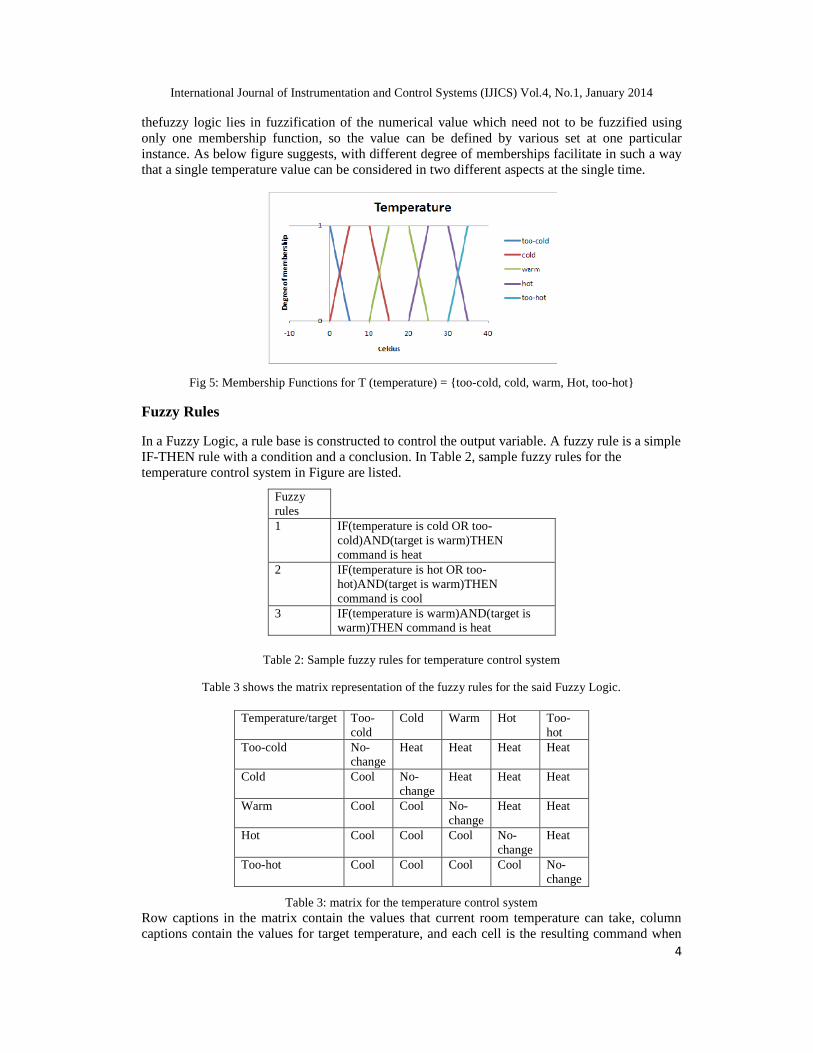
thefuzzy logic lies in fuzzification of the numerical value which need not to be fuzzified usingonly one membership function, so the value can be defined by various set at one particularinstance. As below figure suggests, with different degree of memberships facilitate in such a waythat a single temperature value can be considered in two different aspects at the single time.
Fig 5: Membership Functions for T (temperature) = {too-cold, cold, warm, Hot, too-hot}
Fuzzy Rules
In a Fuzzy Logic, a rule base is constructed to control the output variable. A fuzzy rule is a simpleIF-THEN rule with a condition and a conclusion. In Table 2, sample fuzzy rules for thetemperature control system in Figure are listed.
Fuzzyrules1 IF(temperature is cold OR too-
cold)AND(target is warm)THENcommand is heat
2 IF(temperature is hot OR too-hot)AND(target is warm)THENcommand is cool
3 IF(temperature is warm)AND(target iswarm)THEN command is heat
Table 2: Sample fuzzy rules for temperature control system
Table 3 shows the matrix representation of the fuzzy rules for the said Fuzzy Logic.
Temperature/target Too-cold
Cold Warm Hot Too-hot
Too-cold No-change
Heat Heat Heat Heat
Cold Cool No-change
Heat Heat Heat
Warm Cool Cool No-change
Heat Heat
Hot Cool Cool Cool No-change
Heat
Too-hot Cool Cool Cool Cool No-change
Table 3: matrix for the temperature control systemRow captions in the matrix contain the values that current room temperature can take, columncaptions contain the values for target temperature, and each cell is the resulting command when

International Journal of Instrumentation and Control Systems (IJICS) Vol.4, No.1, January 2014
5
the input variables take the values in that row and column. For instance, the cell (4, 5) in thematrix can be read as follows: If temperature is warm and target is hot then command is heat.Fuzzification: Fuzzification is the process of making crisp quantity fuzzy. In real world,hardware such as digital voltmeter generates crisp data, but these data are subject to experimentalerror [8].
Defuzzification: The procedure of producing a quantitativeoutcome in fuzzy logic, given fuzzysets and corresponding membership degrees can be described as term “Defuzzification”. It isbasicallyrequired in fuzzy control arrangements. These arrangements will contain large number ofrules which willconvert a number of variables into a fuzzy result and eventually the convertedvariables called resultsareexpressed in terms of membership in fuzzy sets. To understand this,rules contrived to determine how much pressure to enforce might result in "Decrease Pressure(13%), Maintain Pressure (33%) and Increase Pressure (70%)". Defuzzification is rendering themembership degrees of the fuzzy sets into a particularconclusion in other words, real value [9].
3. Implementation of fuzzy logic
Fuzzification of Input
In the fuzzification process, a real scalar value changes into a fuzzy value. Arrangements ofFuzzy variables ensurethat real values get translated into fuzzy values. After translating those realvalues into fuzzy values, the possible outcome is called “linguistic terms”. The input linguisticvariables for Fuzzy Logic Temperature Controller (FLTC) suggest two things. First it showslinguistically the difference between the set point and second it also express the measured andcalculated signals from a temperature sensor. Input to FLTC is Error= (Set point-Temperaturesensed). For fuzzified input, two functions including trapezoidal and triangular are used.Todetermine the range of fuzzy variables according to the crisp inputs is the primary requirement forproper running of the fuzzier program.Temperature difference which was sensed previously, isrestricted to positive value. The following fuzzy sets are used: NEG =negative, SNEG=smallnegative, ZERO= zero, SPOZ=small positive, POZ= positive. Table suggests the Membershipfunction for input linguistic variable. Membership function for input linguistic variable.
No. Crisp Input Range ( Error = Set Point – Current Temperature ) Fuzzy Variable Name1 -15 to -50 NEG2 0 to +30 SNEG3 -15 to +15 ZERO4 0 to +30 SPOZ5 +15 to +50 POZ
Table 4: Input linguistic variables
To include the linguistic variable negative (Neg) to a microcontroller, transformation of thepictorial representation into substantive code is needed.
Fuzzy Membership Functions for Outputs
The output linguistic variables express linguistically the applied values to the FLTC actuators fortemperature control. Present study considered typically one output variable, which is a PWMWave for fan and Heater. In this case it is essential to attribute fuzzy memberships toyieldvariable, which has to be identical to the input variable. The fuzzy sets used for PWM Waveare as follows: Z = zero, L = large, M = medium, H = high, VH = very high.

International Journal of Instrumentation and Control Systems (IJICS) Vol.4, No.1, January 2014
6
No
Fuzzy variablerange output Corresponding Fuzzy variable
name
1 165.75 to 255 65% to 100% VH2 127 to 204 50% to 80% H3 165.75 to 89.25 65% To 35% M
4 127 to 51 50% to 20% L5 89.25 to 0 35% to 0% Z
Table 5: Output linguistic variables
Rule block
Once the current values of the input variables are fuzzified, the fuzzy controllercontinues with thephase of “making decisions,” or deciding what actions to take to bring the temperature to its set-point value. For the action to be initiated the measures are minimal time as well as minimaltemperature. The restraintpolicy of a Fuzzy Control System is comprisedby the rule blocks.
In the rules ‘IF’ part depicts the situation, for which the rules are projected. The following'THEN' part delineates the reaction of the fuzzy system in this state. The control policy of heateris structurally formulated according to fuzzy rules. For example, rule 1 “If error is NEG thenfiring angle is Z”.
No
Fuzzy variablerange output Corresponding Fuzzy variable
name
1 165.75 to 255 65% to 100% VH2 127 to 204 50% to 80% H3 165.75 to 89.25 65% To 35% M
4 127 to 51 50% to 20% L5 89.25 to 0 35% to 0% Z
Table 6: Fuzzy rules
Defuzzification
The outcome of defuzzification has to be in a numeric formso that it defines the PWM Wave ofthe MOSFET which is used toforce the fan and heater. Out of the number of ways to executedefuzzification; in thegiven scenario, weighted average defuzzificationis the best technique toobtain the crisp output. It can be further described by following equation (1).= ∑ ( )× ( )∑ ( ) ….. (1)
P[i] = Theextremum value of ith output membership function.W[i] =The weight associated with ith rule.The fuzzy variable can be converted into crisp output using C code fragment. One example ofthat is given below.
{

International Journal of Instrumentation and Control Systems (IJICS) Vol.4, No.1, January 2014
7
= (( ∗ ) ( ∗ ) ( ∗ ) ( ∗ ) ( ∗ ) ( ∗ ) ( ∗ ))( ) ;
PWM=z;}
The degree of each membership function which was computed in the previous step offuzzificationis encountered by the subprogram called “Defuzzify”and this after certain process itreturns defuzzified output.This defuzzify output is employed to restraint the pulse widthmodulation wave of MOSFET.
4. Pulse width modulation technique
The temperature System has a Heater coil and a Fan. The heater assembly consists of an ironplate placed at a distance from a nichrome coil. When current passes throughthe coil it getsheated and in turn raises the temperature of the iron plate. We are interested to alter the heatgenerated by thecoil and also the speed at which the fan is operated. The amount of power whichis to be delivered to fan and heater can be assured by several methods. We are using the PWMtechnique.
Modulation of the square wave which is in duty cycle is done by Pulse Width Modulation action.
Duty cycle = TON / TWhere;
TON : ON time of the waveT : Total time period of wave Power delivered to the load is proportional to T-ON time of thesignalThis is used to control the current flowing through the heating element and also speed of the fan.
Fig 6: Pulse width modulation
An 80% duty cycle indicates that the fan is ON 80% of the time and OFF 20% of the time. Therelation between the speed of the fan and the value of the applied pulse width modulation dutycycle is in direct proportion. In other words, a high duty cycle will produce high speeds and a lowduty cycle will produce low speeds.

International Journal of Instrumentation and Control Systems (IJICS) Vol.4, No.1, January 2014
8
5. Outcome of temperature control using fuzzy logic
Fig 7: Overall view of system
The Temperature in the case study is as follow:
Set temperature: 45˙ C
Current temperature: 46˙ C
Fig 8: LCD display
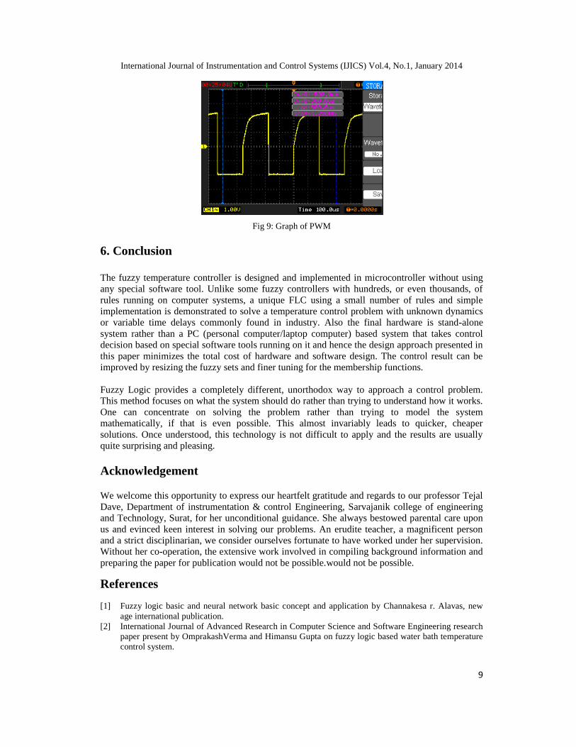
Error = SP – CV = 45 - 46 = -1Rule base Follow: Rule-2(SNEG) and Rule-3(ZERO)Therefore Fuzzilization value f2=0.04
f3=0.933Defuzzilization value Z * = 130.95The Duty Cycle of FAN speed = 51%The Duty Cycle of HEATING COIL current = 49%
International Journal of Instrumentation and Control Systems (IJICS) Vol.4, No.1, January 2014
9
Fig 9: Graph of PWM
6. Conclusion
The fuzzy temperature controller is designed and implemented in microcontroller without usingany special software tool. Unlike some fuzzy controllers with hundreds, or even thousands, ofrules running on computer systems, a unique FLC using a small number of rules and simpleimplementation is demonstrated to solve a temperature control problem with unknown dynamicsor variable time delays commonly found in industry. Also the final hardware is stand-alonesystem rather than a PC (personal computer/laptop computer) based system that takes controldecision based on special software tools running on it and hence the design approach presented inthis paper minimizes the total cost of hardware and software design. The control result can beimproved by resizing the fuzzy sets and finer tuning for the membership functions.
Fuzzy Logic provides a completely different, unorthodox way to approach a control problem.This method focuses on what the system should do rather than trying to understand how it works.One can concentrate on solving the problem rather than trying to model the systemmathematically, if that is even possible. This almost invariably leads to quicker, cheapersolutions. Once understood, this technology is not difficult to apply and the results are usuallyquite surprising and pleasing.
Acknowledgement
We welcome this opportunity to express our heartfelt gratitude and regards to our professor TejalDave, Department of instrumentation & control Engineering, Sarvajanik college of engineeringand Technology, Surat, for her unconditional guidance. She always bestowed parental care uponus and evinced keen interest in solving our problems. An erudite teacher, a magnificent personand a strict disciplinarian, we consider ourselves fortunate to have worked under her supervision.Without her co-operation, the extensive work involved in compiling background information andpreparing the paper for publication would not be possible.would not be possible.
References
[1] Fuzzy logic basic and neural network basic concept and application by Channakesa r. Alavas, newage international publication.
[2] International Journal of Advanced Research in Computer Science and Software Engineering researchpaper present by OmprakashVerma and Himansu Gupta on fuzzy logic based water bath temperaturecontrol system.

International Journal of Instrumentation and Control Systems (IJICS) Vol.4, No.1, January 2014
10
[3] Mendel Fuzzy logic systems for engineering: a tutorial. Proceedings of the IEEE, 83(3):345{377, Mar1995.
[4] The 8051 microcontroller and embedded systems using assembly and C by Muhammad Ali Mazidi,Janice GillispieMazidi, RolinD. Mckinlay. Second edition, P.PEARRSON publication ISBN 978-81 -317 -1026-5.
[5] Control Application using fuzzy logic: Design of fuzzy temperature controller by R.M. Anguilar, V.Munoz and V. Callero university of La Laguna Spair.
[6] Implementation of the fuzzy temperature control using microprosessor by M.D.Hananane,Department of Electronics, Kolhapur.
[7] http://en.wikipedia.org/wiki/Fuzzy_logic[8] http://www.ti.com/lit/ds/symlink/lm35.pdf[9] Proceedings of 2007 ICIAS International Conference on Intelligent and Advanced Systems, pp.209-
214.Kleanthis N., Costas N., and Christos S., 2006.“A comparison of classical, neural and fuzzycontrol for an underwater vehicle”.
[10] Proceedings of 7th WSEAS international conference on Neural Networks, pp.61-66. Cox E.,1998.The fuzzy systems handbook, Second Edition, Academic press limited London.
[11] Driankow D. Hellendoorn H. and Reinfrank M., 1996.An Introduction to Fuzzy Control, NarosaPublishing House, New Delhi.
[12] Burgos O.T., Hizon, J.R.E. and Sison L.G., 2004. “Comparison of classical and fuzzy control inactive mass damping of a flexible structure using acceleration feedback”, procedingof TENCON-2004 IEEE Conference, Vol. 4, pp.645-648.
[13] HuaYun Yu, DaBin Zhang, 2010. “Design of Fuzzy Logic Controllers Based on Evolvable HardwarePlatform”, 4th International Conference on Genetic and Evolutionary Computing (ICGEC), pp.864-867.
[14] Control Application Using Fuzzy Logic: Design of a Fuzzy Temperature Controller; R.M. Aguilar, V.Muñoz and Y. Callero; University of La Laguna; Spain.
[15] A Stable Self-Tuning Fuzzy Logic Control System for Industrial Temperature Regulation;ZhiqiangGao, Thomas A. Trautzsch and James G. Dawson; Department of Electrical Engineering;Cleveland State University; Cleveland, Ohio 44115.
[16] http://en.wikipedia.org/wiki/Defuzzificatio[17] I nternational journal of engineering, science & technology vol. 3, no. 4, 2011, pp 276-283.
Authors
PiyushSinghalareceived B.E. degree in Instrumentation and Control Engineering fromthe Gujarat Technological University, India. He is right now working in a PreciseConchem Private Ltd. His area of interest covers Process Control as well as PLC andSCADA.
Dhrumil Shah received B.E. degree in Instrumentation and Control Engineering from theGujarat Technological University, India. His research field covers basic concepts relatedto fuzzy logic and its application.
Bhavikkumar Patel has received B.E. degree in Instrumentation and Control Engineeringfrom Gujarat Technological University, India. He also seeks some of his interests incontrol system designing and automation.