Tele-presence in populated exhibitions through web-operated mobile robots
18
Autonomous Robots 15, 299–316, 2003 c 2003 Kluwer Academic Publishers. Manufactured in The Netherlands. Tele-Presence in Populated Exhibitions Through Web-Operated Mobile Robots WOLFRAM BURGARD Computer Science Department, University of Freiburg, Germany [email protected] PANOS TRAHANIAS Foundation for Research and Technology—Hellas (FORTH) and University of Crete, Greece DIRK H ¨ AHNEL Computer Science Department, University of Freiburg, Germany MARK MOORS AND DIRK SCHULZ Department of Computer Science, University of Bonn, Germany HARIS BALTZAKIS Foundation for Research and Technology—Hellas (FORTH) and University of Crete, Greece ANTONIS ARGYROS Foundation for Research and Technology—Hellas (FORTH), Greece Abstract. This paper presents techniques that facilitate mobile robots to be deployed as interactive agents in populated environments such as museum exhibitions or trade shows. The mobile robots can be tele-operated over the Internet and, this way, provide remote access to distant users. Throughout this paper we describe several key techniques that have been developed in this context. To support safe and reliable robot navigation, techniques for environment mapping, robot localization, obstacle detection and people-tracking have been developed. To support the interaction of both web and on-site visitors with the robot and its environment, appropriate software and hardware interfaces have been employed. By using advanced navigation capabilities and appropriate authoring tools, the time required for installing a robotic tour-guide in a museum or a trade fair has been drastically reduced. The developed robotic systems have been thoroughly tested and validated in the real-world conditions offered in the premises of various sites. Such demonstrations ascertain the functionality of the employed techniques, establish the reliability of the complete systems, and provide useful evidence regarding the acceptance of tele-operated robotic tour-guides by the broader public. Keywords: web-operated robots, tele-presence in exhibitions, navigation competences, remote visualization 1. Introduction Mobile robotic technology and its application in var- ious sectors is currently an area of high interest. Re- search in this field promises advanced developments and novelties in many aspects. Over the last decade, a variety of service robots were developed that are de- signed to operate in populated environments. Example
-
Upload
independent -
Category
Documents
-
view
4 -
download
0
Transcript of Tele-presence in populated exhibitions through web-operated mobile robots
Autonomous Robots 15, 299–316, 2003c© 2003 Kluwer Academic Publishers. Manufactured in The Netherlands.
Tele-Presence in Populated Exhibitions Through Web-OperatedMobile Robots
WOLFRAM BURGARDComputer Science Department, University of Freiburg, Germany
PANOS TRAHANIASFoundation for Research and Technology—Hellas (FORTH) and University of Crete, Greece
DIRK HAHNELComputer Science Department, University of Freiburg, Germany
MARK MOORS AND DIRK SCHULZDepartment of Computer Science, University of Bonn, Germany
HARIS BALTZAKISFoundation for Research and Technology—Hellas (FORTH) and University of Crete, Greece
ANTONIS ARGYROSFoundation for Research and Technology—Hellas (FORTH), Greece
Abstract. This paper presents techniques that facilitate mobile robots to be deployed as interactive agents inpopulated environments such as museum exhibitions or trade shows. The mobile robots can be tele-operated overthe Internet and, this way, provide remote access to distant users. Throughout this paper we describe several keytechniques that have been developed in this context. To support safe and reliable robot navigation, techniques forenvironment mapping, robot localization, obstacle detection and people-tracking have been developed. To supportthe interaction of both web and on-site visitors with the robot and its environment, appropriate software and hardwareinterfaces have been employed. By using advanced navigation capabilities and appropriate authoring tools, the timerequired for installing a robotic tour-guide in a museum or a trade fair has been drastically reduced. The developedrobotic systems have been thoroughly tested and validated in the real-world conditions offered in the premises ofvarious sites. Such demonstrations ascertain the functionality of the employed techniques, establish the reliabilityof the complete systems, and provide useful evidence regarding the acceptance of tele-operated robotic tour-guidesby the broader public.
Keywords: web-operated robots, tele-presence in exhibitions, navigation competences, remote visualization
1. Introduction
Mobile robotic technology and its application in var-ious sectors is currently an area of high interest. Re-
search in this field promises advanced developmentsand novelties in many aspects. Over the last decade, avariety of service robots were developed that are de-signed to operate in populated environments. Example
300 Burgard et al.
cases are robots that are deployed in hospitals (Kingand Weiman, 1990), museums (Burgard et al., 1999;Nourbakhsh et al., 1999; Thrun et al., 2000), trade-fairs (Rodriguez-Losada et al., 2002), office buildings(Asoh et al., 1997; Simmons et al., 1997; Arras andVestli, 1998), and department stores (Endres et al.,1998). In these environments the mobile robots per-form various services, e.g., deliver, educate, entertainor assist people. Moreover, robots may offer alternativeways for interactive tele-presence in exhibition spaces,a topic that we informally term “robots in exhibitions.”
The deployment of robotic systems able to operate inpopulated environments is heavily based on advancesin a number of enabling technologies that facilitate safe,reliable and effective operation of mobile robots and theexecution of assigned tasks. The set of enabling tech-nologies needed to pursue a specific application variesaccording to the tasks implied by the application as wellas the environment in which the robot(s) operate. Still,there exists a set of generic technologies that are essen-tial to most of the applications. Examples are technolo-gies that give rise to standard navigation competences,such as mapping, localization, path planning and obsta-cle avoidance (Castellanos et al., 1999; Lu and Milios,1997; Gutmann and Konolige, 1999; Thrun, 2001).
In this paper, we describe a number of techniquesthat cover various aspects of robots that are deployedin populated environments and hence have to inter-act with people therein. Among them are techniquesfor mapping large environments, an obstacle-avoidancetechnique that relies on laser-vision fusion to detect ob-jects that are invisible to the laser scanner, a method fortracking people with a moving mobile robot, and an ap-proach to filter out range measurements coming frommoving persons in the process of map construction. Wealso describe new aspects of the user interfaces, suchas a speech interface for on-site users and a flexibleweb-interface with enhanced visualization capabilitiesfor remote users.
For robots operated over the web, video streamingand enhanced visualizations may be used for improvingthe user’s perception of the environment. Furthermore,robots physically interacting with people may employenhanced interaction interfaces like speech recognitionor text-to-speech synthesis. A variety of Web-basedtele-operation interfaces for robots has been developedover the last years. Three of the earlier systems are theMercury Project, the “Telerobot on the Web,” and theTele-Garden (Goldberg et al., 1995, 2002; Taylor andTrevelyan, 1995). These systems allow people to per-
form simple tasks with a robot arm via the Web. Sincethe manipulators operate in prepared workspaces with-out any unforeseen obstacles, all movement commandsissued by a Web user can be carried out in a determin-istic manner. Additionally, it suffices to provide stillimages from a camera mounted on the robot arm aftera requested movement task has been completed. Themobile robotic platforms Xavier, Rhino and Minerva(Simmons et al., 1997; Burgard et al., 1999; Thrun et al.,2000) can also be operated over the Web. Their inter-faces relied on client-pull and server-push techniquesto provide visual feedback of the robot’s movements;this includes images taken by the robot as well as ajava-animated map indicating the robot’s current posi-tion. However, these interfaces do not include any tech-niques to reflect changes of the environment. 3D graph-ics visualizations for Internet-based robot control havealready been suggested by Hirukawa et al. (2002). Theirinterface allows Web users to carry out manipulationtasks with a mobile robot, by controlling a 3D graphicssimulation of the robot contained in the Web browser.The robots described in this paper use video streamsto convey visual information to the user. Additionally,they provide online visualizations in a virtual 3D envi-ronment. This allows the users to choose arbitrary view-points and leads to significant reductions of the requiredcommunication bandwidth. Furthermore, our interfaceprovides accurate visualization of the persons in thevicinity of the robot which makes the navigation behav-ior of the robot easier to understand for remote users.
In this work we deal with robots that operate inexhibition spaces, serving at the same time web- aswell as on-site visitors. This endeavor has evolved asa pure research and development activity in the in-volved laboratories, as well as in the formal frame-work of two European Commission funded projects,namely TOURBOT1 and WebFAIR.2 TOURBOT dealtwith the development of an interactive tour-guide robotable to provide individual access to museums’ exhibitsover the Internet. The successful course of TOUR-BOT and the vision to introduce corresponding ser-vices to the more demanding case of trade fairs, resultedin launching WebFAIR. Additionally, WebFAIR intro-duces tele-conferencing between the remote user andon-site attendants and employs a multi-robot platform,facilitating thus simultaneous robot control by multipleusers. In this paper, we also report on the demonstrationevents that took place in the framework of TOURBOTand argue on the drastic reduction of the system set-uptime that was achieved.
Tele-Presence in Populated Exhibitions 301
2. Mapping
In order to navigate safely and reliably, mobile robotsmust be able to create suitable representations of theenvironment. Maps are also necessary for human-robotinteraction since they allow users to direct the robotto places in the environment. Our current system usestwo different mapping techniques. The first approachis an incremental technique for simultaneous localiza-tion and mapping that is highly efficient and uses gridmaps to deal with environments of arbitrary shape butlacks the capability of global optimization especiallywhen larger cycles have to be closed. The second ap-proach relies on line-features and corner-points. It usesa combination of a discrete (Hidden Markov) modeland a continuous (Kalman-filter) model (Baltzakis andTrahanias, 2002) and applies the EM-algorithm to learnglobally consistent maps. Both methods offer verypromising alternatives, each one with its own merits. Inenvironments with no clearly defined structure (walls,corridors, corners, etc.), the former method is more ad-equate, at the price of slightly decreased loop-closingcapabilities. When the environment structure becomesevident, the latter method can be employed, to rendermore robust loop closing. Both mapping approachesare described in the remainder of this section.
2.1. Incremental Mapping Using Grid Maps
This first mapping technique uses occupancy grid maps(Moravec and Elfes, 1985) and realizes an incrementalmapping scheme that has been previously employedwith great success (Thrun et al., 2000; Gutmann andKonolige, 1999). Mathematically, we calculate a se-quence of robot poses l1, l2, . . . and correspondingmaps by maximizing the marginal likelihood of the t-thpose and map relative to the (t − 1)-th pose and map:
l t = argmaxlt
{p(st | lt , m(l t−1, st−1))
· p(lt | ut−1, l t−1)} (1)
The term p(st | lt , m(l t−1, st−1)) is the probability ofthe most recent measurement st given the pose lt
and the map m(l t−1, st−1) constructed so far. Theterm p(lt | ut−1, l t−1) represents the probability that therobot is at location lt provided that the robot was previ-ously at position l t−1 and has carried out (or measured)the motion ut−1. The resulting pose l t is then used togenerate a new map m via the standard incrementalmap-updating function presented in Moravec and Elfes
(1985):
m(l t , st ) = argmaxm
p(m | l t , st ) (2)
The overall approach can be summarized as follows.At any point t −1 in time the robot is given an estimateof its pose l t−1 and a map m(l t−1, st−1). After the robotmoved further on and after taking a new measurementst , the robot determines the most likely new pose l t . Itdoes this by trading off the consistency of the measure-ment with the map (first term on the right-hand sidein (1)) and the consistency of the new pose with thecontrol action and the previous pose (second term onthe right-hand side in (1)). The map is then extended bythe new measurement st , using the pose l t as the poseat which this measurement was taken.
Our algorithm to 2D scan matching is an extension ofthe approach presented in Thrun et al. (2000). To aligna scan relative to the map constructed so far, we com-pute an occupancy grid map m(l t−1, st−1) (Moravecand Elfes, 1985; Thrun et al., 2000) out of the sen-sor scans obtained so far. Additionally to previous ap-proaches, we integrate over small Gaussian errors in therobot pose when computing the maps. This increasesthe smoothness of the map and of the likelihood func-tion to be optimized and, thus, facilitates range registra-tion. To maximize the likelihood of a scan with respectto this map, we apply a hill climbing strategy.
2.2. Feature-Based Mapping
In the case of structured environments, localization ac-curacy can be increased by constructing and employingfeature based maps of the environment. Our feature-based mapping algorithm utilizes line segments andcorner points which are extracted out of laser rangemeasurements. We apply a variant of the Iterative-End-Point-Fit algorithm (Michael and Quint, 1994) to clus-ter the end-points of a range scan into sets of collinearpoints. Corner points are then computed at the inter-sections of directly adjacent line segments (Baltzakisand Trahanias, 2002). Data association (feature match-ing) during mapping is performed based on a dynamicprogramming string-search algorithm (Baltzakis andTrahanias, 2002). This algorithm exploits informa-tion contained in the spatial ordering of the features.Simultaneously, the dynamic programming implemen-tation furnishes it with computational efficiency.
Existing approaches to simultaneous mapping andlocalization usually store all map features and the
302 Burgard et al.
pose of the robot in a single complex random variable(Smith et al., 1990). This approach is computation-ally demanding since its space and time complexitygrows quadratically in the number of features (Freseand Hirzinger, 2001). In contrast, our approach treatsmap features as parameters of the dynamical systemaccording to which the robot’s state evolves. There-fore, the problem is reformulated as to simultaneouslydetermine the state and the parameters of a dynamicalsystem; that is, a learning problem, that is solved viaa variant of the EM-algorithm (Dempster et al., 1977;Burgard et al., 1999; Thrun et al., 2000).
In the mapping context, the E-step is responsiblefor calculating the state of the robot at each point t intime. Since the approach described here is an off-linemapping technique, all past and future observations areavailable and can be used to estimate the state at timet . The problem of estimating variables given both pastand future observations is denoted as “smoothing.”A very popular method for performing smoothingis the Raugh-Tung-Striebel smoother (Rauch et al.,1965). This algorithm consists of two steps. The firststep (forward step) is the Extended Kalman Filter(EKF) forward recursions. For each time instant t , itestimates the mean µxt and covariance �xt using anEKF. The second step is a backward recursion. It startswith the final measurement and recursively estimatesmaximum a-posteriori estimates for the previous statesµxt and �xt as:
�xt = �xt + S[�xt+1 − �x−
t+1
]ST (3)
µxt = µxt + S[µxt+1 − µx−
t+1
](4)
where
S = �xt F Tx �−1
x−t+1
. (5)
Here Fx denotes the Jacobian of the transitionfunction F with respect to µxt .
To detect and close loops during mapping, our al-gorithm relies on the global localization capabilitiesof a hybrid method based on a switching state-spacemodel (Baltzakis and Trahanias, 2002). This approachapplies multiple Kalman trackers assigned to multi-ple hypotheses about the robot’s state. It handles theprobabilistic relations among these hypotheses usingdiscrete Markovian dynamics. Hypotheses are dynam-ically generated by matching corner points extractedfrom measurements with corner points contained inthe map. Hypotheses that cannot be verified by obser-
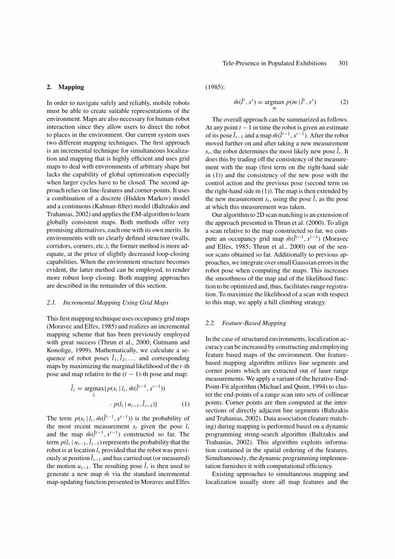
Figure 1. Flow-gram of the iterative mapping algorithm.
vations or sequences of observations become less likelyand usually disappear quickly.
Our algorithm (see Fig. 1) iterates the E- and theM-step until the overall process has converged or untila certain number of iterations has been carried out. Ourcurrent system always starts with a single hypothesisabout the state of the system. Whenever a corner pointappears in the robot’s measurements, new hypotheseswill be created at corresponding positions. On theother hand, hypotheses that cannot be confirmed fora sequence of measurements typically vanish. Theresulting map always corresponds to the most likelyhypothesis.
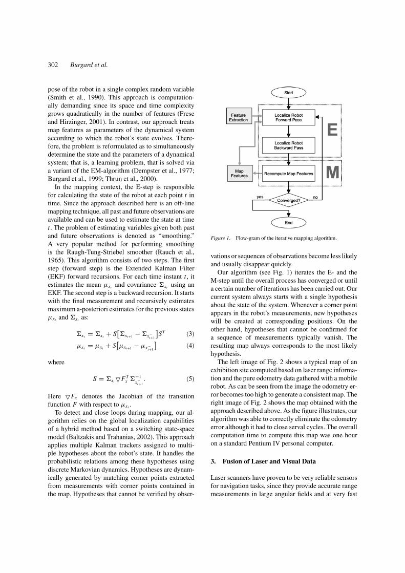
The left image of Fig. 2 shows a typical map of anexhibition site computed based on laser range informa-tion and the pure odometry data gathered with a mobilerobot. As can be seen from the image the odometry er-ror becomes too high to generate a consistent map. Theright image of Fig. 2 shows the map obtained with theapproach described above. As the figure illustrates, ouralgorithm was able to correctly eliminate the odometryerror although it had to close serval cycles. The overallcomputation time to compute this map was one houron a standard Pentium IV personal computer.
3. Fusion of Laser and Visual Data
Laser scanners have proven to be very reliable sensorsfor navigation tasks, since they provide accurate rangemeasurements in large angular fields and at very fast
Tele-Presence in Populated Exhibitions 303
Figure 2. Line feature maps of an exhibition site: Original data (left image) and map generated by our algorithm (right image).
rates. However, laser range scans are 2D representa-tions of a 3D world. Thus, the underlying assumptionis that laser profiles accurately model the shape of theenvironment also along the vertical dimension whichis invisible to the laser. Although this assumption isjustified in many indoor environments, various objectssuch as chairs, tables, and shelves usually have a geom-etry that is not uniform over their height. Accordingly,not all aspects of such objects are visible in laser-rangescans. The capability to correctly identify objects in thevicinity of the robot, however, is particularly importantfor robots in real-world environments such as exhibi-tions, since it is a basic precondition for the safety ofthe robot and the exhibits.
One potential solution to this problem could be to ex-ploit 3D laser scanners, which unfortunately are veryexpensive. The alternative solution is to utilize addi-tional sources of information, such as vision, to in-fer 3D information. Our system exactly follows thisapproach. It uses the 2D structure acquired with thelaser-range scanner and, based on this, it computes a2 1
2 D representation by introducing vertical planar wallsfor the obstacles in the 2D map. We then exploit camerainformation to (a) validate the correctness of the con-structed model and (b) qualitatively and quantitativelycharacterize inconsistencies between laser and visualdata wherever such inconsistencies are detected.
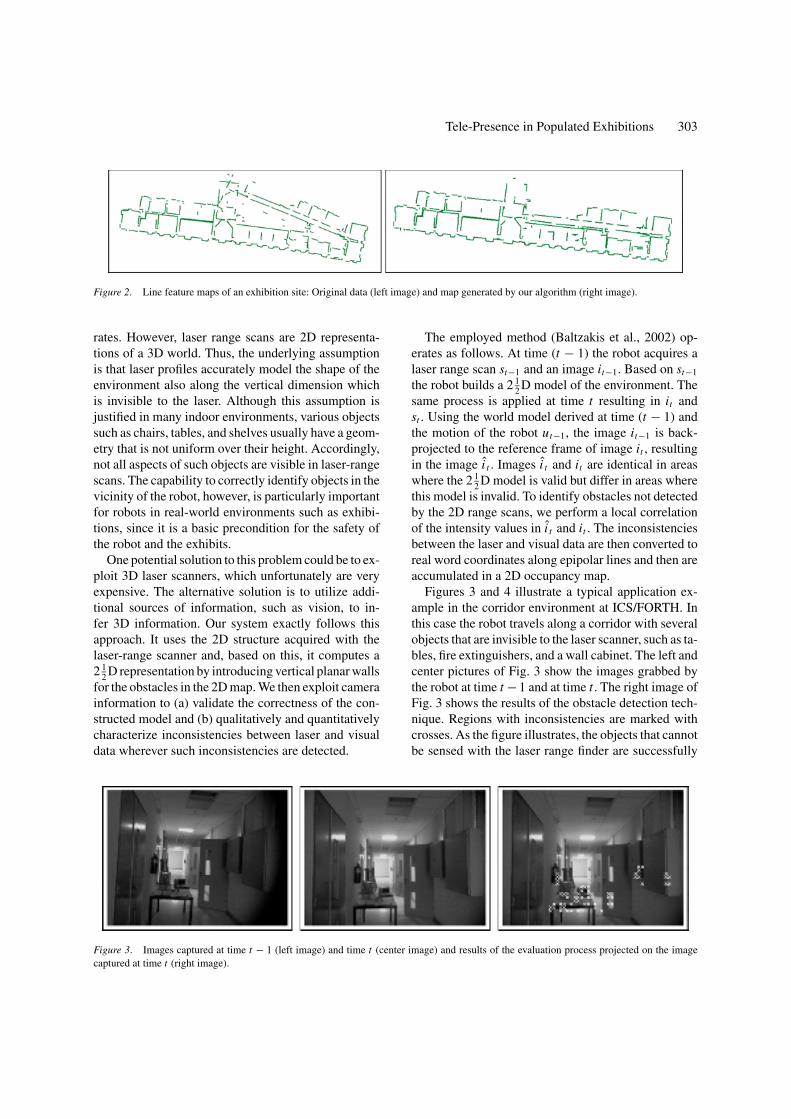
Figure 3. Images captured at time t − 1 (left image) and time t (center image) and results of the evaluation process projected on the imagecaptured at time t (right image).
The employed method (Baltzakis et al., 2002) op-erates as follows. At time (t − 1) the robot acquires alaser range scan st−1 and an image it−1. Based on st−1
the robot builds a 2 12 D model of the environment. The
same process is applied at time t resulting in it andst . Using the world model derived at time (t − 1) andthe motion of the robot ut−1, the image it−1 is back-projected to the reference frame of image it , resultingin the image i t . Images i t and it are identical in areaswhere the 2 1
2 D model is valid but differ in areas wherethis model is invalid. To identify obstacles not detectedby the 2D range scans, we perform a local correlationof the intensity values in i t and it . The inconsistenciesbetween the laser and visual data are then converted toreal word coordinates along epipolar lines and then areaccumulated in a 2D occupancy map.
Figures 3 and 4 illustrate a typical application ex-ample in the corridor environment at ICS/FORTH. Inthis case the robot travels along a corridor with severalobjects that are invisible to the laser scanner, such as ta-bles, fire extinguishers, and a wall cabinet. The left andcenter pictures of Fig. 3 show the images grabbed bythe robot at time t − 1 and at time t . The right image ofFig. 3 shows the results of the obstacle detection tech-nique. Regions with inconsistencies are marked withcrosses. As the figure illustrates, the objects that cannotbe sensed with the laser range finder are successfully
304 Burgard et al.
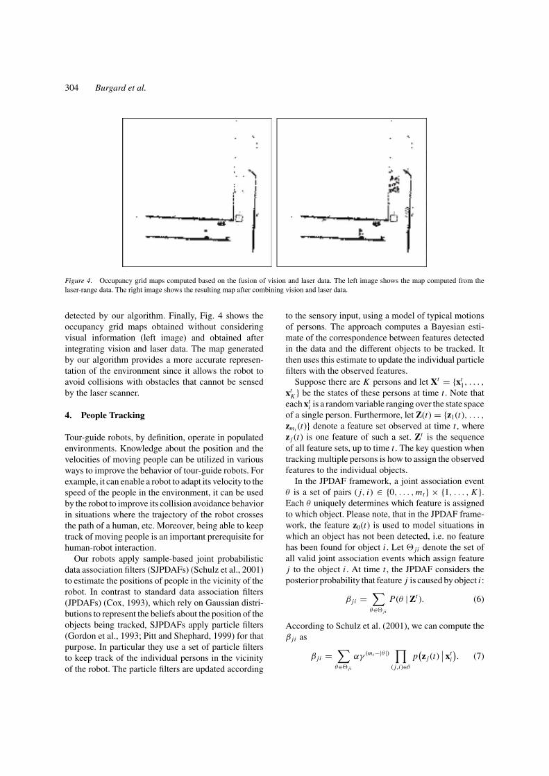
Figure 4. Occupancy grid maps computed based on the fusion of vision and laser data. The left image shows the map computed from thelaser-range data. The right image shows the resulting map after combining vision and laser data.
detected by our algorithm. Finally, Fig. 4 shows theoccupancy grid maps obtained without consideringvisual information (left image) and obtained afterintegrating vision and laser data. The map generatedby our algorithm provides a more accurate represen-tation of the environment since it allows the robot toavoid collisions with obstacles that cannot be sensedby the laser scanner.
4. People Tracking
Tour-guide robots, by definition, operate in populatedenvironments. Knowledge about the position and thevelocities of moving people can be utilized in variousways to improve the behavior of tour-guide robots. Forexample, it can enable a robot to adapt its velocity to thespeed of the people in the environment, it can be usedby the robot to improve its collision avoidance behaviorin situations where the trajectory of the robot crossesthe path of a human, etc. Moreover, being able to keeptrack of moving people is an important prerequisite forhuman-robot interaction.
Our robots apply sample-based joint probabilisticdata association filters (SJPDAFs) (Schulz et al., 2001)to estimate the positions of people in the vicinity of therobot. In contrast to standard data association filters(JPDAFs) (Cox, 1993), which rely on Gaussian distri-butions to represent the beliefs about the position of theobjects being tracked, SJPDAFs apply particle filters(Gordon et al., 1993; Pitt and Shephard, 1999) for thatpurpose. In particular they use a set of particle filtersto keep track of the individual persons in the vicinityof the robot. The particle filters are updated according
to the sensory input, using a model of typical motionsof persons. The approach computes a Bayesian esti-mate of the correspondence between features detectedin the data and the different objects to be tracked. Itthen uses this estimate to update the individual particlefilters with the observed features.
Suppose there are K persons and let Xt = {xt1, . . . ,
xtK } be the states of these persons at time t . Note that
each xti is a random variable ranging over the state space
of a single person. Furthermore, let Z(t) = {z1(t), . . . ,zmt (t)} denote a feature set observed at time t , wherez j (t) is one feature of such a set. Zt is the sequenceof all feature sets, up to time t . The key question whentracking multiple persons is how to assign the observedfeatures to the individual objects.
In the JPDAF framework, a joint association eventθ is a set of pairs ( j, i) ∈ {0, . . . , mt } × {1, . . . , K }.Each θ uniquely determines which feature is assignedto which object. Please note, that in the JPDAF frame-work, the feature z0(t) is used to model situations inwhich an object has not been detected, i.e. no featurehas been found for object i . Let � j i denote the set ofall valid joint association events which assign featurej to the object i . At time t , the JPDAF considers theposterior probability that feature j is caused by object i :
β j i =∑
θ∈� j i
P(θ | Zt ). (6)
According to Schulz et al. (2001), we can compute theβ j i as
β j i =∑
θ∈� j i
αγ (mt −|θ |) ∏
( j,i)∈θ
p(z j (t)
∣∣ xti
). (7)
Tele-Presence in Populated Exhibitions 305
It remains to describe how the beliefs p(xti ) about the
states of the individual objects are represented and up-dated. In our approach (Schulz et al., 2001), we usesample-based representations of the individual beliefs.The key idea is to represent the density p(xt
i | Zt ) bya set St
i of N weighted, random samples or particlesst
i,n(n = 1 . . . N ). A sample set constitutes a discreteapproximation of a probability distribution. Each sam-ple is a tuple (xt
i,n, wti,n) consisting of state xt
i,n and animportance factor wt
i,n . The prediction step is realizedby drawing samples from the set computed in the pre-vious iteration and by updating their state according tothe prediction model p(xt
i | xt−1i , �t). In the correction
step, a feature set Z(t) is integrated into the samples ob-tained in the prediction step. Thereby we consider theassignment probabilities β j i . In the sample-based vari-ant, these quantities are obtained by integrating overall samples:
p(z j (t)
∣∣ xti
) = 1
N
N∑
n=1
p(z j (t)
∣∣ xti,n
). (8)
Given the assignment probabilities we may thencompute the weights of the samples
wti,n = α
mt∑
j=0
β j i p(z j (t)
∣∣ xti,n
), (9)
where α is a normalizer ensuring that the weights sumup to one over all samples. Finally, we obtain N newsamples from the current samples by bootstrap resam-pling. For this purpose we select every sample xt
i,n withprobability wt
i,n .In our system we apply the SJPDAF to estimate the
trajectories of persons in range scans. Since the laserrange scanners mounted on our platforms are at a heightof approximately 40 cm, the beams are reflected by
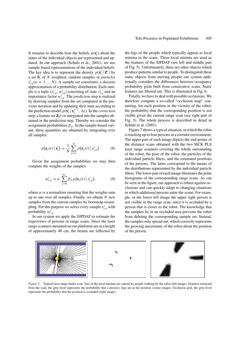
Figure 5. Typical laser range finder scan. Two of the local minima are caused by people walking by the robot (left image). Features extractedfrom the scan, the grey-level represents the probability that a person’s legs are at the position (center image). Occlusion grid, the grey-levelrepresents the probability that the position is occluded (right image).
the legs of the people which typically appear as localminima in the scans. These local minima are used asthe features of the SJPDAF (see left and middle partof Fig. 5). Unfortunately, there are other objects whichproduce patterns similar to people. To distinguish thesestatic objects from moving people our system addi-tionally considers the differences between occupancyprobability grids built from consecutive scans. Staticfeatures are filtered out. This is illustrated in Fig. 6.
Finally, we have to deal with possible occlusions. Wetherefore compute a so-called “occlusion map” con-taining, for each position in the vicinity of the robot,the probability that the corresponding position is notvisible given the current range scan (see right part ofFig. 5). The whole process is described in detail inSchulz et al. (2001).
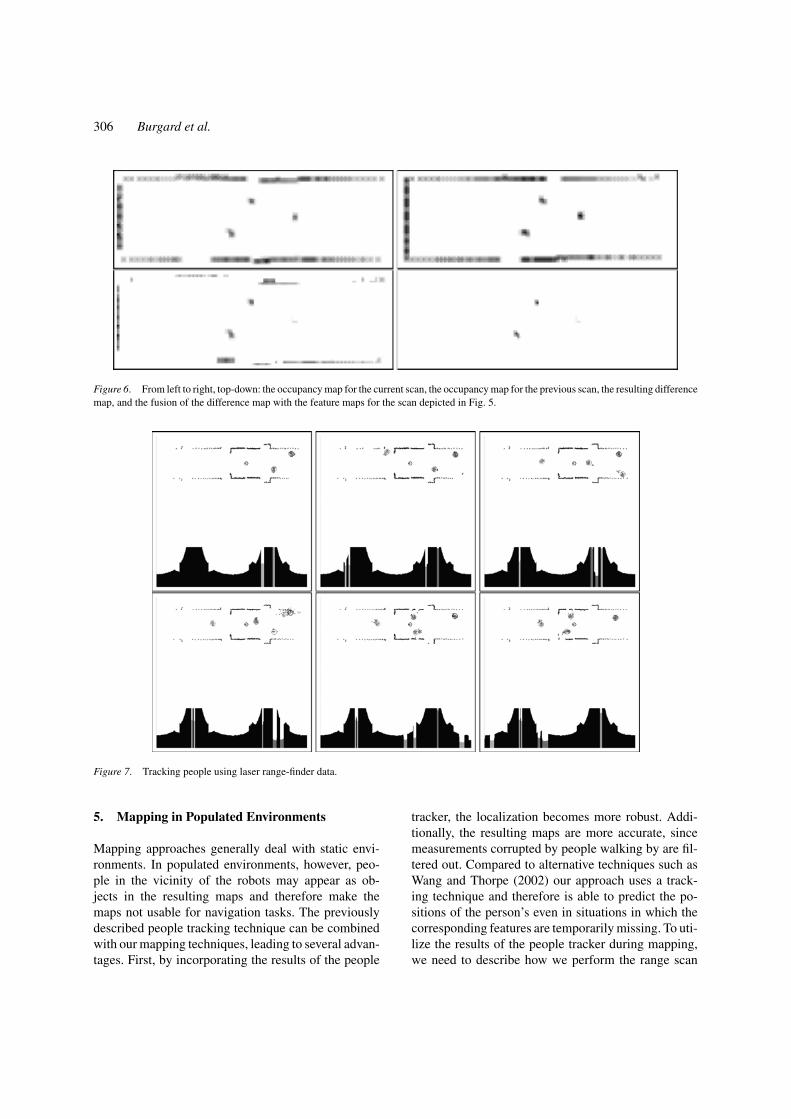
Figure 7 shows a typical situation, in which the robotis tracking up to four persons in a corridor environment.The upper part of each image depicts the end-points ofthe distance scans obtained with the two SICK PLSlaser range scanners covering the whole surroundingof the robot, the pose of the robot, the particles of theindividual particle filters, and the estimated positionsof the persons. The latter correspond to the means ofthe distributions represented by the individual particlefilters. The lower part of each image illustrates the polarhistograms of the corresponding range scans. As canbe seen in the figure, our approach is robust against oc-clusions and can quickly adapt to changing situationsin which additional persons enter the scene. For exam-ple, in the lower left image the upper right person isnot visible in the range scan, since it is occluded by aperson that is closer to the robot. The knowledge thatthe samples lie in an occluded area prevents the robotfrom deleting the corresponding sample set. Instead,the samples only spread out, which correctly representsthe growing uncertainty of the robot about the positionof the person.
306 Burgard et al.
Figure 6. From left to right, top-down: the occupancy map for the current scan, the occupancy map for the previous scan, the resulting differencemap, and the fusion of the difference map with the feature maps for the scan depicted in Fig. 5.
Figure 7. Tracking people using laser range-finder data.
5. Mapping in Populated Environments
Mapping approaches generally deal with static envi-ronments. In populated environments, however, peo-ple in the vicinity of the robots may appear as ob-jects in the resulting maps and therefore make themaps not usable for navigation tasks. The previouslydescribed people tracking technique can be combinedwith our mapping techniques, leading to several advan-tages. First, by incorporating the results of the people
tracker, the localization becomes more robust. Addi-tionally, the resulting maps are more accurate, sincemeasurements corrupted by people walking by are fil-tered out. Compared to alternative techniques such asWang and Thorpe (2002) our approach uses a track-ing technique and therefore is able to predict the po-sitions of the person’s even in situations in which thecorresponding features are temporarily missing. To uti-lize the results of the people tracker during mapping,we need to describe how we perform the range scan
Tele-Presence in Populated Exhibitions 307
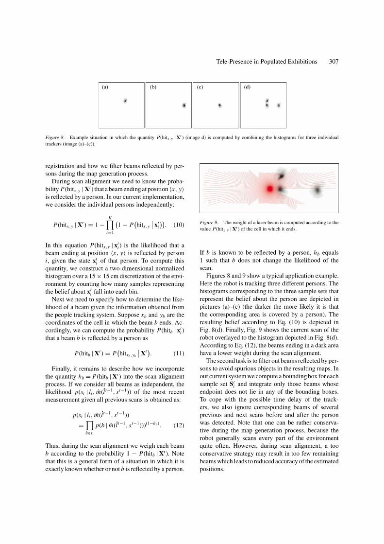
Figure 8. Example situation in which the quantity P(hitx,y | Xt ) (image d) is computed by combining the histograms for three individualtrackers (image (a)–(c)).
registration and how we filter beams reflected by per-sons during the map generation process.
During scan alignment we need to know the proba-bility P(hitx,y | Xt ) that a beam ending at position 〈x, y〉is reflected by a person. In our current implementation,we consider the individual persons independently:
P(hitx,y | Xt ) = 1 −K∏
i=1
(1 − P
(hitx,y
∣∣ xti
)). (10)
In this equation P(hitx,y | xti ) is the likelihood that a
beam ending at position 〈x, y〉 is reflected by personi , given the state xt
i of that person. To compute thisquantity, we construct a two-dimensional normalizedhistogram over a 15 × 15 cm discretization of the envi-ronment by counting how many samples representingthe belief about xt
i fall into each bin.Next we need to specify how to determine the like-
lihood of a beam given the information obtained fromthe people tracking system. Suppose xb and yb are thecoordinates of the cell in which the beam b ends. Ac-cordingly, we can compute the probability P(hitb | xt
i )that a beam b is reflected by a person as
P(hitb | Xt ) = P(hitxb,yb
∣∣ Xt). (11)
Finally, it remains to describe how we incorporatethe quantity hb = P(hitb | Xt ) into the scan alignmentprocess. If we consider all beams as independent, thelikelihood p(st | lt , m(l t−1, st−1)) of the most recentmeasurement given all previous scans is obtained as:
p(st | lt , m(l t−1, st−1))
=∏
b∈st
p(b | m(l t−1, st−1)))(1−hb). (12)
Thus, during the scan alignment we weigh each beamb according to the probability 1 − P(hitb | Xt ). Notethat this is a general form of a situation in which it isexactly known whether or not b is reflected by a person.
Figure 9. The weight of a laser beam is computed according to thevalue P(hitx,y | Xt ) of the cell in which it ends.
If b is known to be reflected by a person, hb equals1 such that b does not change the likelihood of thescan.
Figures 8 and 9 show a typical application example.Here the robot is tracking three different persons. Thehistograms corresponding to the three sample sets thatrepresent the belief about the person are depicted inpictures (a)–(c) (the darker the more likely it is thatthe corresponding area is covered by a person). Theresulting belief according to Eq. (10) is depicted inFig. 8(d). Finally, Fig. 9 shows the current scan of therobot overlayed to the histogram depicted in Fig. 8(d).According to Eq. (12), the beams ending in a dark areahave a lower weight during the scan alignment.
The second task is to filter out beams reflected by per-sons to avoid spurious objects in the resulting maps. Inour current system we compute a bounding box for eachsample set St
i and integrate only those beams whoseendpoint does not lie in any of the bounding boxes.To cope with the possible time delay of the track-ers, we also ignore corresponding beams of severalprevious and next scans before and after the personwas detected. Note that one can be rather conserva-tive during the map generation process, because therobot generally scans every part of the environmentquite often. However, during scan alignment, a tooconservative strategy may result in too few remainingbeams which leads to reduced accuracy of the estimatedpositions.
308 Burgard et al.
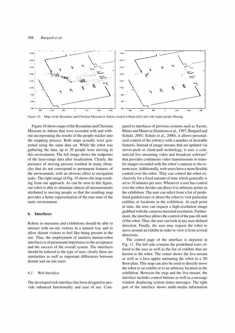
Figure 10. Maps of the Byzantine and Christian Museum in Athens created without (left) and with (right) people filtering.
Figure 10 shows maps of the Byzantine and ChristianMuseum in Athens that were recorded with and with-out incorporating the results of the people-tracker intothe mapping process. Both maps actually were gen-erated using the same data set. While the robot wasgathering the data, up to 20 people were moving inthis environment. The left image shows the endpointsof the laser-range data after localization. Clearly, thepresence of moving persons resulted in many obsta-cles that do not correspond to permanent features ofthe environment, with an obvious effect to navigationtasks. The right image of Fig. 10 shows the map result-ing from our approach. As can be seen in this figure,our robot is able to eliminate almost all measurementsattributed to moving people so that the resulting mapprovides a better representation of the true state of thestatic environment.
6. Interfaces
Robots in museums and exhibitions should be able tointeract with on-site visitors in a natural way and toallow distant visitors to feel like being present in thesite. Thus, the employment of intuitive human-robotinterfaces is of paramount importance to the acceptanceand the success of the overall system. The interfacesshould be tailored to the type of user; clearly there aresimilarities as well as important differences betweendistant and on-site users.
6.1. Web Interface
The developed web-interface has been designed to pro-vide enhanced functionality and ease of use. Com-
pared to interfaces of previous systems such as Xavier,Rhino and Minerva (Simmons et al., 1997; Burgard andSchulz, 2001; Schulz et al., 2000), it allows personal-ized control of the robot(s) with a number of desirablefeatures. Instead of image streams that are updated viaserver-push or client-pull technology, it uses a com-mercial live streaming video and broadcast software3
that provides continuous video transmissions to trans-fer images recorded with the robot’s cameras to the re-mote user. Additionally, web-users have a more flexiblecontrol over the robot. They can control the robot ex-clusively for a fixed amount of time which generally isset to 10 minutes per user. Whenever a user has controlover the robot, he/she can direct it to arbitrary points inthe exhibition. The user can select from a list of prede-fined guided tours or direct the robot to visit particularexhibits or locations in the exhibition. At each pointin time, the user can request a high-resolution imagegrabbed with the cameras maximal resolution. Further-more, the interface allows the control of the pan-tilt unitof the robot. Thus, the user can look at any user-defineddirection. Finally, the user may request the robot tomove around an exhibit in order to view it from severaldirections.
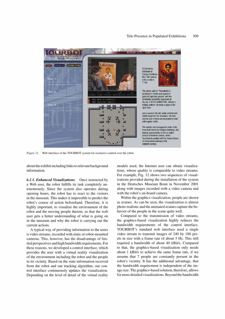
The control page of the interface is depicted inFig. 11. The left side contains the predefined tours of-fered to the user as well as the list of exhibits that areknown to the robot. The center shows the live-streamas well as a Java applet animating the robot in a 2Dfloor-plan. This map can also be used to directly movethe robot to an exhibit or to an arbitrary location in theexhibition. Between the map and the live-stream, theinterface includes control buttons as well as a messagewindow displaying system status messages. The rightpart of the interface shows multi-media information
Tele-Presence in Populated Exhibitions 309
Figure 11. Web interface of the TOURBOT system for exclusive control over the robot.
about the exhibit including links to relevant backgroundinformation.
6.1.1. Enhanced Visualizations. Once instructed bya Web user, the robot fulfills its task completely au-tonomously. Since the system also operates duringopening hours, the robot has to react to the visitorsin the museum. This makes it impossible to predict therobot’s course of action beforehand. Therefore, it ishighly important, to visualize the environment of therobot and the moving people therein, so that the webuser gets a better understanding of what is going onin the museum and why the robot is carrying out thecurrent actions.
A typical way of providing information to the usersis video streams, recorded with static or robot-mountedcameras. This, however, has the disadvantage of lim-ited perspectives and high bandwidth requirements. Forthese reasons, we developed a control interface, whichprovides the user with a virtual reality visualizationof the environment including the robot and the peoplein its vicinity. Based on the state information receivedfrom the robot and our tracking algorithm, our con-trol interface continuously updates the visualization.Depending on the level of detail of the virtual reality
models used, the Internet user can obtain visualiza-tions, whose quality is comparable to video streams.For example, Fig. 12 shows two sequences of visual-izations provided during the installation of the systemin the Deutsches Museum Bonn in November 2001along with images recorded with a video camera andwith the robot’s on-board camera.
Within the graphics visualization, people are shownas avatars. As can be seen, the visualization is almostphoto-realistic and the animated avatars capture the be-havior of the people in the scene quite well.
Compared to the transmission of video streams,the graphics-based visualization highly reduces thebandwidth requirements of the control interface.TOURBOT’s standard web interface used a singlevideo stream to transmit images of 240 by 180 pix-els in size with a frame rate of about 5 Hz. This stillrequired a bandwidth of about 40 kBit/s. Comparedto that, the graphics-based visualization only needsabout 1 kBit/s to achieve the same frame rate, if weassume that 7 people are constantly present in therobot’s vicinity. It has the additional advantage, thatthe bandwidth requirement is independent of the im-age size. The graphics-based solution, therefore, allowsfor more detailed visualizations. Beyond the bandwidth

310 Burgard et al.
Figure 12. The enhanced 3D visualization allows arbitrary view-points. The left sequence shows the real and the virtual view through therobot’s cameras. The right images show the robot guiding three people through the museum and a bird’s eye view of the scene.
savings, the graphics-based visualization offers an in-creased flexibility to the Internet user. Virtual camerascan be placed anywhere and the viewpoints can evenbe changed at run-time, as illustrated in the right im-age sequence of Fig. 12. Our current prototype imple-ments these ideas. It uses Open Inventor models of therobot and of the environment for the 3D rendering. Onstart-up, the control interface connects to the robot viaTCP/IP and after downloading the model, the visual-ization component receives state information from therobot and starts rendering the scene accordingly.
6.2. On-Board Interface
Besides the web interface that is used by remote users,the robots have several means for communicating andinteracting with the on-site visitors. A reduced versionof the web interface is also displayed in a touch screenappropriately mounted at the rear side of the robot.Through this touch screen, the on site visitors may in-struct the robot to guide them to specific exhibits. Oneof the main differences between the web and the on-board interface is that video streams and enhanced visu-
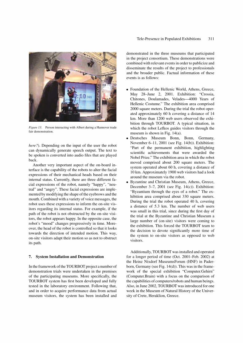
alizations are not provided, since they are not actuallyrequired by the on-site visitors. Instead, the on-boardinterface makes extensive use of synthetic speech. Toenhance the communication with users in the museum,the robots are equipped with a speaker-independentspeech interface. We employ a commercially availablespeech system4 that detects simple phrases. The inputof the user is processed and the parsed phrase is used togenerate corresponding actions. To improve the recog-nition rate, the software allows the definition of con-texts, i.e., sets of phrases that are relevant in certainsituations. Depending on user input or depending onthe task that is currently carried out, the system can dy-namically switch between the different contexts. Thecurrent system includes 20 different phrases, that canbe used to request information about the robot, the exhi-bition site, or even the time and the weather. In severalinstallations in populated environments we figured outthat the overall recognition rate is approximately 90%.Figure 13 shows a scene in which a person interactswith the robot Albert during the Hannover trade fair in2001. Here the person asked several questions about therobot and requested information about the time (whoare you?, where are you from? what are you doing
Tele-Presence in Populated Exhibitions 311
Figure 13. Person interacting with Albert during a Hannover tradefair demonstration.
here?). Depending on the input of the user the robotcan dynamically generate speech output. The text tobe spoken is converted into audio files that are playedback.
Another very important aspect of the on-board in-terface is the capability of the robots to alter the facialexpressions of their mechanical heads based on theirinternal status. Currently, there are three different fa-cial expressions of the robot, namely “happy”, “neu-tral” and “angry”. These facial expressions are imple-mented by modifying the shape of the eyebrows and themouth. Combined with a variety of voice messages, therobot uses these expressions to inform the on-site vis-itors regarding its internal status. For example, if thepath of the robot is not obstructed by the on-site visi-tors, the robot appears happy. In the opposite case, therobot’s “mood” changes progressively in time. More-over, the head of the robot is controlled so that it lookstowards the direction of intended motion. This way,on-site visitors adapt their motion so as not to obstructits path.
7. System Installation and Demonstration
In the framework of the TOURBOT project a number ofdemonstration trials were undertaken in the premisesof the participating museums. More specifically, theTOURBOT system has first been developed and fullytested in the laboratory environment. Following that,and in order to acquire performance data from actualmuseum visitors, the system has been installed and
demonstrated in the three museums that participatedin the project consortium. These demonstrations werecombined with relevant events in order to publicize anddisseminate the results of the project to professionalsand the broader public. Factual information of theseevents is as follows:
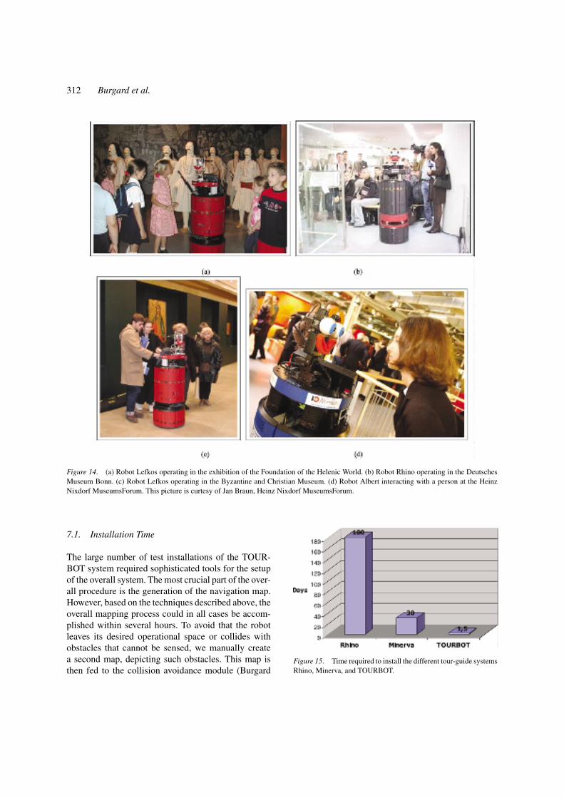
• Foundation of the Hellenic World, Athens, Greece,May 28–June 2, 2001. Exhibition: “Crossia,Chitones, Doulamades, Velades—4000 Years ofHellenic Costume.” The exhibition area comprised2000 square meters. During the trial the robot oper-ated approximately 60 h covering a distance of 14km. More than 1200 web users observed the exhi-bition through TOURBOT. A typical situation, inwhich the robot Lefkos guides visitors through themuseum is shown in Fig. 14(a).
• Deutsches Museum Bonn, Bonn, Germany,November 6–11, 2001 (see Fig. 14(b)). Exhibition:“Part of the permanent exhibition, highlightingscientific achievements that were awarded theNobel Prize.” The exhibition area in which the robotmoved comprised about 200 square meters. Thesystem operated about 60 h, covering a distance of10 km. Approximately 1900 web visitors had a lookaround the museum via the robot.
• Byzantine and Christian Museum, Athens, Greece,December 3–7, 2001 (see Fig. 14(c)). Exhibition:“Byzantium through the eyes of a robot.” The ex-hibition area comprised about 330 square meters.During the trial the robot operated 40 h, coveringa distance of 5.3 km. The number of web userswas small in this trial, since during the first day ofthe trial at the Byzantine and Christian Museum alarge number of (on-site) visitors were coming tothe exhibition. This forced the TOURBOT team tothe decision to devote significantly more time ofthe system to on-site visitors as opposed to webvisitors.
Additionally, TOURBOT was installed and operatedfor a longer period of time (Oct. 2001–Feb. 2002) atthe Heinz Nixdorf MuseumsForum (HNF) in Pader-born, Germany (see Fig. 14(d)). This was in the frame-work of the special exhibition “Computer.Gehirn”(Computer.Brain) with a focus on the comparison ofthe capabilities of computers/robots and human beings.Also, in June 2002, TOURBOT was introduced for oneweek in the Museum of Natural History of the Univer-sity of Crete, Heraklion, Greece.
312 Burgard et al.
Figure 14. (a) Robot Lefkos operating in the exhibition of the Foundation of the Helenic World. (b) Robot Rhino operating in the DeutschesMuseum Bonn. (c) Robot Lefkos operating in the Byzantine and Christian Museum. (d) Robot Albert interacting with a person at the HeinzNixdorf MuseumsForum. This picture is curtesy of Jan Braun, Heinz Nixdorf MuseumsForum.
7.1. Installation Time
The large number of test installations of the TOUR-BOT system required sophisticated tools for the setupof the overall system. The most crucial part of the over-all procedure is the generation of the navigation map.However, based on the techniques described above, theoverall mapping process could in all cases be accom-plished within several hours. To avoid that the robotleaves its desired operational space or collides withobstacles that cannot be sensed, we manually createa second map, depicting such obstacles. This map isthen fed to the collision avoidance module (Burgard
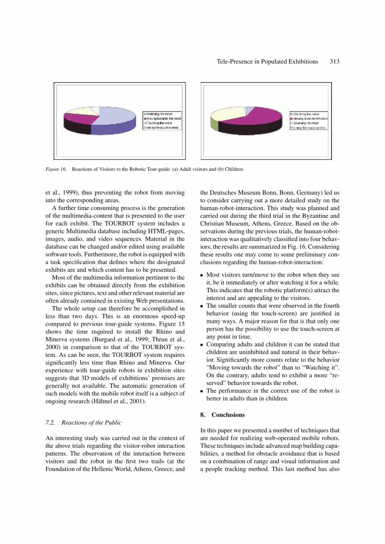
Figure 15. Time required to install the different tour-guide systemsRhino, Minerva, and TOURBOT.
Tele-Presence in Populated Exhibitions 313
Figure 16. Reactions of Visitors to the Robotic Tour-guide. (a) Adult visitors and (b) Children.
et al., 1999), thus preventing the robot from movinginto the corresponding areas.
A further time consuming process is the generationof the multimedia-content that is presented to the userfor each exhibit. The TOURBOT system includes ageneric Multimedia database including HTML-pages,images, audio, and video sequences. Material in thedatabase can be changed and/or edited using availablesoftware tools. Furthermore, the robot is equipped witha task specification that defines where the designatedexhibits are and which content has to be presented.
Most of the multimedia information pertinent to theexhibits can be obtained directly from the exhibitionsites, since pictures, text and other relevant material areoften already contained in existing Web presentations.
The whole setup can therefore be accomplished inless than two days. This is an enormous speed-upcompared to previous tour-guide systems. Figure 15shows the time required to install the Rhino andMinerva systems (Burgard et al., 1999; Thrun et al.,2000) in comparison to that of the TOURBOT sys-tem. As can be seen, the TOURBOT system requiressignificantly less time than Rhino and Minerva. Ourexperience with tour-guide robots in exhibition sitessuggests that 3D models of exhibitions’ premises aregenerally not available. The automatic generation ofsuch models with the mobile robot itself is a subject ofongoing research (Hahnel et al., 2001).
7.2. Reactions of the Public
An interesting study was carried out in the context ofthe above trials regarding the visitor-robot interactionpatterns. The observation of the interaction betweenvisitors and the robot in the first two trails (at theFoundation of the Hellenic World, Athens, Greece, and
the Deutsches Museum Bonn, Bonn, Germany) led usto consider carrying out a more detailed study on thehuman-robot-interaction. This study was planned andcarried out during the third trial in the Byzantine andChristian Museum, Athens, Greece. Based on the ob-servations during the previous trials, the human-robot-interaction was qualitatively classified into four behav-iors; the results are summarized in Fig. 16. Consideringthese results one may come to some preliminary con-clusions regarding the human-robot-interaction:
• Most visitors turn/move to the robot when they seeit, be it immediately or after watching it for a while.This indicates that the robotic platform(s) attract theinterest and are appealing to the visitors.
• The smaller counts that were observed in the fourthbehavior (using the touch-screen) are justified inmany ways. A major reason for that is that only oneperson has the possibility to use the touch-screen atany point in time.
• Comparing adults and children it can be stated thatchildren are uninhibited and natural in their behav-ior. Significantly more counts relate to the behavior“Moving towards the robot” than to “Watching it”.On the contrary, adults tend to exhibit a more “re-served” behavior towards the robot.
• The performance in the correct use of the robot isbetter in adults than in children.
8. Conclusions
In this paper we presented a number of techniques thatare needed for realizing web-operated mobile robots.These techniques include advanced map building capa-bilities, a method for obstacle avoidance that is basedon a combination of range and visual information anda people tracking method. This last method has also
314 Burgard et al.
been used to provide enhanced visualizations over theInternet. In addition to video streams our systems pro-vides high-resolution virtual reality visualizations thatalso include the people in the vicinity of the robot. Thisincreases the flexibility of the interface and simultane-ously allows a user to understand the navigation actionsof the robot.
The techniques described in this paper have beensuccessfully deployed within the EU-funded projectsTOURBOT and WebFAIR which aim at the develop-ment of interactive tour-guide robots, able to serve web-as well as on-site visitors. Technical developments inthe framework of these projects have resulted in robustand reliable systems that have been demonstrated andvalidated in real-world conditions. Equally important,the system set-up time has been drastically reduced,facilitating its porting in new environments.
Our current research extends the navigation capa-bilities of the robotic systems by addressing obstacleavoidance in the cases of objects that are not visibleby the laser scanner (Baltzakis et al., 2002), 3D map-ping (Hahnel et al., 2001), mapping in dynamic envi-ronments (Hahnel et al., 2002), predictive navigation(Foka and Trahanias, 2002), and multi-robot coordina-tion (Fox et al., 2000). Moreover, in the context of theabove projects additional issues are addressed. Theyconsider (a) how to adapt this technology in order to fitthe long-term operational needs of an exhibition site,(b) how to evaluate the robotic system in terms of itsimpact to the main function and objectives of the ex-hibition site (financial impact, accessibility, marketingand promotion, impact on visitor demographic, etc.),and (c) how to evaluate the content and educationaladded value to museum and exhibition visitors, and (d)how to generate a feedback to the technology devel-opers in order to achieve technological improvementsand to further adapt to the needs of the users.
Acknowledgments
This work has partly been supported by the by theIST Programme of Commission of the European Com-munities under contract numbers IST-1999-12643 andIST-2000-29456. The authors furthermore would liketo thank the members of the IST-project TOURBOTfor helpful comments and fruitful discussions.
Notes
1. http://www.ics.forth.gr/tourbot/.2. http://www.ics.forth.gr/webfair/.
3. http://www.webcam32.com/.4. http://www.novotech-gmbh.de/.
References
Arras, K.O. and Vestli, S.J. 1998. Hybrid, high-precision localisationfor the mail distributing mobile robot system MOPS. In Proc. ofthe IEEE International Conference on Robotics & Automation(ICRA).
Asoh, H., Hayamizu, S., Hara, I., Motomura, Y., Akaho, S., andMatsui, T. 1997. Socially embedded learning of office-conversantrobot jijo-2. In Proceedings of IJCAI-97, IJCAI, Inc.
Baltzakis, H., Argyros, A., and Trahanias, P. 2002. Fusion of rangeand visual data for the extraction of scene structure information.In Intl. Conf. on Pattern Recognition (ICPR).
Baltzakis, H. and Trahanias, P. 2002. Hybrid mobile robot local-ization using switching state-space models. In Proc. of the IEEEInternational Conference on Robotics & Automation (ICRA).
Baltzakis, H. and Trahanias, P. 2002. An iterative approach forbuilding feature maps in cyclic environments. In Proc. of theIEEE/RSJ International Conference on Intelligent Robots and Sys-tems (IROS).
Burgard, W., Cremers, A.B., Fox, D., Hahnel, D., Lakemeyer, G.,Schulz, D., Steiner, W., and Thrun, S. 1999. Experiences withan interactive museum tour-guide robot. Artificial Intelligence,114:(1/2).
Burgard, W., Fox, D., Jans, H., Matenar, C., and Thrun, S. 1999.Sonar-based mapping with mobile robots using EM. In Proc. ofthe International Conference on Machine Learning (ICML).
Burgard, W. and Schulz, D. 2001. Robust visualization for web-based control of mobile robots. In Robots on the Web: PhysicalInteraction Through the Internet, K. Goldberg and R. Siegwart(Eds.), MIT-Press.
Castellanos, J.A., Montiel, J.M.M., Neira, J., and Tardos, J.D. 1999.The SPmap: A probabilistic framework for simultaneous local-ization and map building. In IEEE Transactions on Robotics andAutomation, 15(5):948–953.
Cox, I.J. 1993. A review of statistical data association techniquesfor motion correspondence. International Journal of ComputerVision, 10(1):53–66.
Dempster, A., Laird, N., and Rubin, D. 1977. Maximum likelihoodfrom incomplete data via the EM algorithm. J. R. Statist. Soc. B,39:185–197.
Endres, H., Feiten, W., and Lawitzky, G. 1998. Field test of a navi-gation system: Autonomous cleaning in supermarkets. In Proc. ofthe IEEE International Conference on Robotics & Automation(ICRA).
Foka, A. and Trahanias, P. 2002. Predictive autonomous robot nav-igation. In Proc. of the IEEE/RSJ International Conference onIntelligent Robots and Systems (IROS).
Fox, D., Burgard, W., Kruppa, H., and Thrun, S. 2000. A probabilisticapproach to collaborative multi-robot localization. AutonomousRobots, 8(3).
Frese, U. and Hirzinger, G. 2001. Simultaneous localization andmapping—a discussion. IJCAI01 Workshop Reasoning with Un-certainty in Robotics, Seatle, Washington, USA.
Goldberg, K., Gentner, S., Sutter, C., Wiegley, J., and Farzin, B.2002. The mercury project: A feasibility study for online robots. InBeyond Webcams: An Introduction to Online Robots, K. Goldbergand R. Siegwart (Eds.), MIT Press.
Tele-Presence in Populated Exhibitions 315
Goldberg, K., Santarromana, J., Bekey, G., Gentner, S., Morris, R.,Wiegley, J., and Berger, E. 1995. The telegarden. In Proc. of ACMSIGGRAPH.
Gordon, N.J., Salmond, D.J., and Smith, A.F.M. 1993. A novel ap-proach to nonlinear/non-Gaussian Bayesian state estimation. IEEProceedings F, 140(2):107–113.
Gutmann, J.-S. and Konolige, K. 1999. Incremental mapping of largecyclic environments. In Proc. of the IEEE Int. Symp. on Compu-tational Intelligence in Robotics and Automation (CIRA).
Hahnel, D., Burgard, W., and Thrun, S. 2001. Learning compact3d models of indoor and outdoor environments with a mobilerobot. In Fourth European Workshop on Advanced Mobile Robots(EUROBOT’01).
Hahnel, D., Schulz, D., and Burgard, W. 2002. Map building with mo-bile robots in populated environments. In Proc. of the IEEE/RSJ In-ternational Conference on Intelligent Robots and Systems (IROS).
Hirukawa, H., Hara, I., and Hori, T. 2002. Online robots. In BeyondWebcams: An Introduction to Online Robots, K. Goldberg and R.Siegwart (Eds.), MIT Press:
King, S. and Weiman, C. 1990. Helpmate autonomous mobile robotnavigation system. In Proc. of the SPIE Conference on MobileRobots, pp. 190–198.
Lu, F. and Milios, E. 1997. Globally consistent range scan alignmentfor environment mapping. Autonomous Robots, 4:333–349.
Michael, T.S. and Quint, T. 1994. Sphere of influence graphs ingeneral metric spaces. Mathematical and Computer Modelling,29:45–53.
Moravec, H.P. and Elfes, A.E. 1985. High resolution maps fromwide angle sonar. In Proc. of the IEEE International Conferenceon Robotics & Automation (ICRA), pp. 116–121.
Nourbakhsh, I., Bobenage, J., Grange, S., Lutz, R., Meyer, R., andSoto, A. 1999. An affective mobile educator with a full-time job.Artificial Intelligence, 114:(1/2).
Pitt, M.K. and Shephard, N. 1999. Filtering via simulation: Auxiliaryparticle filters. Journal of the American Statistical Association,94:446.
Rauch, H., Tung, F., and Striebel, C. 1965. Maximum likelihoodestimates of linear dynamic systems. American Institute of Aero-nautics and Astronautics Journal, 3(8):1445–1450.
Rodriguez-Losada, D., Matia, F., Galan, R., and Jimenez, A. 2002.Blacky, an interactive mobile robot at a trade fair. In Proc. ofthe IEEE International Conference on Robotics & Automation(ICRA).
Schulz, D., Burgard, W., Fox, D., and Cremers, A.B. 2001. Track-ing multiple moving objects with a mobile robot. In Proc. of theIEEE Conference on Computer Vision and Pattern Recognition(CVPR).
Schulz, D., Burgard, W., Fox, D., Thrun, S., and Cremers, A.B. 2000.Web interfaces for mobile robots in public places. IEEE-Magazineon Robotics and Automation.
Simmons, R., Goodwin, R., Haigh, K., Koenig, S., and O’Sullivan,J. 1997. A layered architecture for office delivery robots. InProc. of the First International Conference on Autonomous Agents(Agents).
Smith, R., Self, M., and Cheeseman, P., 1990. Estimating uncertainspatial relationships in robotics. In Autonomous Robot Vehicles,I.J. Cox and G.T. Wilfong (Eds.), Springer-Verlag, pp. 167–193.
Taylor, K. and Trevelyan, J. 1995. A telerobot on the World WideWeb. In Proceedings of the 1995 National Conference of the Aus-tralian Robot Association.
Thrun, S. 2001. A probabilistic online mapping algorithm for teamsof mobile robots. Journal of Robotics Research, 20(5):335–363.
Thrun, S. Beetz, M., Bennewitz, M., Burgard, W., Cremers, A.B.,Dellaert, F., Fox, D., Hahnel, D., Rosenberg, C., Roy, N., Schulte,J., and Schulz, D. 2000. Probabilistic algorithms and the interactivemuseum tour-guide robot Minerva. Journal of Robotics Research,19:11.
Thrun, S., Burgard, W., and Fox, D. 2000. A real-time algorithmfor mobile robot mapping with applications to multi-robot and3D mapping. In Proc. of the IEEE International Conference onRobotics & Automation (ICRA).
Wang, C.-C. and Thorpe, C. 2002. Simultaneous localization andmapping with detection and tracking of moving objects. In Proc. ofthe IEEE International Conference on Robotics & Automation(ICRA).
Wolfram Burgard studied Computer Science at the University ofDortmund and received his PhD from the University of Bonn in 1991.Currently, he is associate Professor at the Department of ComputerScience at the University of Freiburg where he is head of the Lab forAutonomous Intelligent Systems. He is also affiliated to the Centerof Automated Learning and Discovery at the Carnegie Mellon Uni-versity. His fields of interest lie in robotics and artificial intelligence.
Panos Trahanias is a Professor with the Department of ComputerScience, University of Crete, Greece and the Institute of Com-puter Science, Foundation for Research and Technology—Hellas(FORTH), Greece. He received his Ph.D. in Computer Sciencefrom the National Technical University of Athens, Greece, in 1988.He has been a Research Associate at the Institute of Informaticsand Telecommunications, National Centre for Scientific Research“Demokritos”, Athens, Greece. From 1991 to 1993 he was with theDepartment of Electrical and Computer Engineering, University ofToronto, Canada, as a Research Associate. His research interests arein computer vision, vision-based robot navigation, telematics appli-cations and virtual & augmented reality applications.
316 Burgard et al.
Dirk Hahnel studied Computer Science at the University of Bonn.Currently he is a Ph.D. student at the Department of Computer Sci-ence at the University of Freiburg. His areas of interest lie in mobilerobot navigation and especially in the learning of two-dimensionaland three-dimensional maps.
Mark Moors received the diploma degree in computer science fromthe University of Bonn in 2000. Currently he is a Ph.D. student atthe Institute for Computer Science at the University of Bonn. Hisfocus of research lies in multi-robot systems, especially in the areasof planning, tracking and exploration.
Dirk Schulz is a research associate in the Computer Science and En-gineering department at the University of Washington. He received
his Ph.D. in computer science from the University of Bonn in 2002.His main research interests are in the field of mobile robotics, proba-bilistic state estimation, object tracking, and Web-controlled mobilerobots.
Haris Baltzakis received the B.Eng. degree in electrical engineeringfrom Democtritus University of Thrace, Xanthi, Greece, in 1997,and the M.Sc. degree in computer science from University of Crete,Heraklion, Greece in 1999. He is currently a Ph.D. student at theDepartment of Computer Science, University of Crete, Greece. Hisresearch interests include computer vision and autonomous robotnavigation.
Antonis Argyros received his Ph.D. from the Department of Com-puter Science, University of Crete, Greece. He has been a postdoc-toral fellow at the Royal Institute of Technology in Stockholm, Swe-den. Since 1999 he is a research scientist at the Institute of ComputerScience (ICS) of the Foundation for Research and Technology—Hellas (FORTH) in Heraklion, Crete, Greece. Dr. Argyros has alsoserved as a visiting assistant professor at the Computer Science De-partment of the University of Crete. His current research interestsinclude computer vision, robotics and vision-based robot navigation.