Technical Specification - Moree Plains Shire Council
254
Technical Specification Boggabilla Amenities Moree Plains Shire Council Sep-18 (Our Reference: 28989 -Technical Specification_A.docx) NATSPEC October 2017
-
Upload
khangminh22 -
Category
Documents
-
view
2 -
download
0
Transcript of Technical Specification - Moree Plains Shire Council

Technical
Specification Boggabilla Amenities
Moree Plains Shire Council
Sep-18 (Our Reference: 28989 -Technical Specification_A.docx)
NATSPEC October 2017
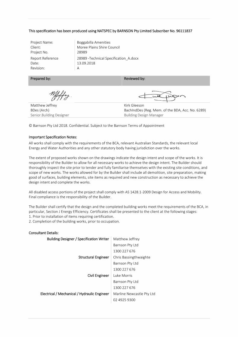
This specification has been produced using NATSPEC by BARNSON Pty Limited Subscriber No. 96111837
Project Name: Boggabilla Amenities Client: Moree Plains Shire Council Project No. 28989
Report Reference 28989 -Technical Specification_A.docx Date: 13.09.2018 Revision: A
Prepared by:
Reviewed by:
Matthew Jeffrey BDes (Arch) Senior.Building Designer
Kirk Gleeson BachIndDes (Reg. Mem. of the BDA, Acc. No. 6289) Building Design Manager
© Barnson Pty Ltd 2018. Confidential. Subject to the Barnson Terms of Appointment
Important Specification Notes:
All works shall comply with the requirements of the BCA, relevant Australian Standards, the relevant local Energy and Water Authorities and any other statutory body having jurisdiction over the works. The extent of proposed works shown on the drawings indicate the design intent and scope of the works. It is responsibility of the Builder to allow for all necessary works to achieve the design intent. The Builder should thoroughly inspect the site prior to tender and fully familiarise themselves with the existing site conditions, and scope of new works. The works allowed for by the Builder shall include all demolition, site preparation, making good of surfaces, building elements, site items as required and new construction as necessary to achieve the design intent and complete the works. All disabled access portions of the project shall comply with AS 1428.1-2009 Design for Access and Mobility. Final compliance is the responsibility of the Builder. The Builder shall certify that the design and the completed building works meet the requirements of the BCA, in particular, Section J Energy Efficiency. Certificates shall be presented to the client at the following stages: 1. Prior to installation of items requiring certification. 2. Completion of the building works, prior to occupation.
Consultant Details:
Building Designer / Specification Writer Matthew Jeffrey
Barnson Pty Ltd
1300 227 676
Structural Engineer Chris Bassingthwaighte
Barnson Pty Ltd
1300 227 676
Civil Engineer Luke Morris
Barnson Pty Ltd
1300 227 676
Electrical / Mechanical / Hydraulic Engineer Marline Newcastle Pty Ltd
02 4925 9300
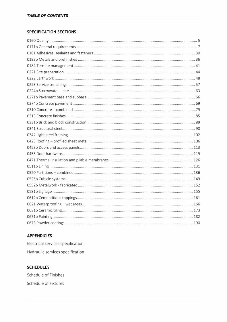
TABLE OF CONTENTS
SPECIFICATION SECTIONS
0160 Quality ............................................................................................................................................ 5
0171b General requirements .................................................................................................................. 7
0181 Adhesives, sealants and fasteners ................................................................................................ 30
0183b Metals and prefinishes ............................................................................................................... 36
0184 Termite management ................................................................................................................... 41
0221 Site preparation ............................................................................................................................ 44
0222 Earthwork ..................................................................................................................................... 48
0223 Service trenching .......................................................................................................................... 57
0224b Stormwater – site ....................................................................................................................... 63
0271b Pavement base and subbase ...................................................................................................... 66
0274b Concrete pavement .................................................................................................................... 69
0310 Concrete – combined ................................................................................................................... 79
0315 Concrete finishes .......................................................................................................................... 85
0331b Brick and block construction ....................................................................................................... 89
0341 Structural steel.............................................................................................................................. 98
0342 Light steel framing ...................................................................................................................... 102
0423 Roofing – profiled sheet metal ................................................................................................... 106
0453b Doors and access panels ........................................................................................................... 113
0455 Door hardware ............................................................................................................................ 119
0471 Thermal insulation and pliable membranes ............................................................................... 126
0511b Lining ........................................................................................................................................ 131
0520 Partitions – combined ................................................................................................................. 136
0525b Cubicle systems ........................................................................................................................ 149
0552b Metalwork - fabricated ............................................................................................................. 152
0581b Signage ..................................................................................................................................... 155
0612b Cementitious toppings .............................................................................................................. 161
0621 Waterproofing – wet areas ......................................................................................................... 166
0631b Ceramic tiling ............................................................................................................................ 173
0671b Painting ..................................................................................................................................... 182
0673 Powder coatings ......................................................................................................................... 190
APPENDICIES
Electrical services specification
Hydraulic services specification
SCHEDULES
Schedule of Finishes
Schedule of Fixtures

28989 -Technical Specification_A.docx © NATSPEC (Oct 17) 4 13/09/2018
THIS PAGE IS INTENTIONALLY BLANK

0160 Quality
22498-Technical Specification-Rev a Revision a 13/09/2018 Page 5 of 193
0160 QUALITY
1 GENERAL
1.1 RESPONSIBILITIES
General Requirement: Provide a project Quality Management System, as documented.
1.2 CROSS REFERENCES
General Requirement: Conform to the following worksections:
- 0171 General Requirements.
1.3 STANDARDS
General Standard: To AS/NZS ISO 9001.
1.4 INTERPRETATION
Definitions General: For the purposes of this worksection the definitions given in AS/NZS ISO 9000 and the following apply:
- Quality package: A designated part of the works, which may include the whole works, for which an individual quality system is required.
- Service: After sales service, repairs and maintenance.Access for maintenance: Includes access for maintenance, inspection, measurement, operation, adjustment, repair, replacement and other maintenance related tasks.
1.5 SUBMISSIONS
Quality Plan Quality package: Submit a Quality Plan for each quality package, at least 10 working days before work on that package commences. Keep on site a copy of each approved quality plan.
Authority approvals General: Provide project Quality Management System documents to the following authority:
- The Principal’s Representative.
2 PROJECT QUALITY MANAGEMENT SYSTEM REQUIREMENTS
2.1 DOCUMENTATION REQUIREMENTS
Quality plan Standard: Conform to the recommendations of AS/NZS ISO 10005. Include inspection and test plans.
Documented procedures Review: Provide evidence of revision(s) (including dates), approval and status of each procedure.
Register: Maintain a register of documented procedures including the title, identifier and revision status.

0160 Quality
22498-Technical Specification-Rev a Revision a 13/09/2018 Page 6 of 193
2.2 AUDITING
General Audit plan: Conform to the recommendations of AS/NZS ISO 19011 clauses 6.4 and 6.5.
Initial systems audit: Carry out before date of site possession.
External audits Nominated auditor: National Association of Testing Authorities (NATA).
2.3 CORRECTIVE ACTION
General Review: Provide procedure to review the various control methods to minimise nonconformance. Record amendments to the project Quality Management System resulting from corrective action.
Nonconforming works: Include in the Quality Plan the procedure for reporting any nonconforming works to the contract administrator and any corrective action requests.
0171b General requirements
22498-Technical Specification-Rev a Revision a 13/09/2018 Page 7 of 193
0171B GENERAL REQUIREMENTS
1 GENERAL
1.1 RESPONSIBILITIES
Compliance The contractor is responsible for compliance with the Building Code of Australia and all relevant Statutory Requirements whether stated or implied and will also be responsible for providing all certification required by Council, Statutory Authorities or the law as well as those noted in, and in accordance with, the Contract.
Structural Certification The contractor must engage a qualified structural engineer to certify the constructed structural works and ensure their compliance with the design documents.
General Noise levels: Install systems within the limits of the contract design and documented equipment performance and as documented in the Noise level schedule.
Performance Structural: If required, provide structures, installations and components as follows:
- Fixed accessways: To AS 1657.
- Structural design actions: To the AS/NZS 1170 series.
Importance level to AS/NZS 1170.0: 4.
1.2 DESIGN
Design development General: The works include development of the design beyond that documented, as required.
Design by contractor: If the contractor provides design, use only appropriately qualified persons and conform to all statutory requirements.
Conflict with the documents: If it is believed that a conflict exists between statutory requirements and the documents, notify the contract administrator immediately and provide a recommendation to resolve the conflict.
1.3 PRECEDENCE
General Order of precedence:
- The requirements of other worksections of the specification override conflicting requirements of this worksection.
- The requirements of worksections override conflicting requirements of their referenced documents. The requirements of the referenced documents are minimum requirements.
1.4 REFERENCED DOCUMENTS
General Contractual relationships: Responsibilities and duties of the principal, contractor and contract administrator are not altered by requirements in the documents referenced in this specification.
Current editions: Use referenced documents which are the editions, with amendments, current 3 months before the closing date for tenders, except where other editions or amendments are required by statutory authorities.

0171b General requirements
22498-Technical Specification-Rev a Revision a 13/09/2018 Page 8 of 193
1.5 INTERPRETATION
Documentation conventions Imperative mood and streamlined language: The words shall or shall be are implied where a colon is used following a keyword or within a sentence or sentence fragment.
Subject of sentences and phrases: Specification requirements are to be performed by the contractor, unless stated otherwise.
Abbreviations General: For the purposes of this specification the following abbreviations apply:
- AS: Australian Standard.
- BCA: National Construction Code Series Volume One: Building Code of Australia Class 2 to 9 Buildings and Volume Two: Building Code of Australia Class 1 and Class 10 Buildings.
- EN: European Norm (European Standard).
- GRP: Glass Reinforced Plastic.
- IP: Ingress protection.
- NATA: National Association of Testing Authorities.
- NCC: National Construction Code.
- NZS: New Zealand Standard.
- PCA: National Construction Code Series Volume 3: Plumbing Code of Australia.
- PVC: Polyvinyl Chloride.
- PVC-U: Unplasticised Polyvinyl Chloride. Also known as UPVC.
- SDS: Safety data sheets.
- VOC: Volatile Organic Compound.
- WHS: Work Health and Safety.
Definitions General: For the purposes of this specification, the following definitions apply:
- Access for maintenance: Includes access for maintenance, inspection, measurement, operation, adjustment, repair, replacement and other maintenance related tasks.
- Accessible, readily: Readily accessible, easily accessible, easy access and similar terms mean capable of being reached quickly and without climbing over or removing obstructions, mounting upon a chair, or using a movable ladder, and in any case not more than 2.0 m above the ground, floor or platform.
- Attendance: Attendance, provide attendance and similar expressions mean give assistance for examination and testing.
- Contract administrator: Has the same meaning as architect or superintendent and is the person appointed by the owner or principal under the contract.
- Contractor: Has the same meaning as builder and is the person or organisation bound to carry out and complete the work under the contract.
- Default: Specified value, product or installation method which is to be provided unless otherwise documented.
- Design life: The period of time for which it is assumed, in the design, that an asset will be able to perform its intended purpose with only anticipated maintenance but no major repair or replacement being necessary.
- Documented: Documented, as documented and similar terms mean contained in the contract documents.

0171b General requirements
22498-Technical Specification-Rev a Revision a 13/09/2018 Page 9 of 193
- Economic life: The period of time from the acquisition of an asset to the time when the asset, while still physically capable of fulfilling its function and with only anticipated maintenance, ceases to be the lowest cost alternative for satisfying that function.
- Electricity distributor: Any person or organisation that provides electricity from an electricity distribution system to one or more electrical installations. Includes distributor, supply authority, network operator, local network service provider, electricity retailer or electricity entity, as may be appropriate in the relevant jurisdiction.
- Fire hazard properties: Terminology to BCA A2.4.
- Geotechnical site investigation: The process of evaluating the geotechnical characteristics of the site in the context of existing or proposed construction.
- Give notice: Give notice, submit, advise, inform and similar expressions mean give notice (submit, advise, inform) in writing to the contract administrator.
- High level interface: Systems transfer information in a digital format using an open system interface.
- Hot-dip galvanized: Zinc coated to AS/NZS 4680 after fabrication with coating thickness and mass to AS/NZS 4680 Table 1.
- Ingress protection: IP, IP code, IP rating and similar expression have the same meaning as IP Code in AS 60529.
- Joints:
. Construction joint: A joint with continuous reinforcement provided to suit construction sequence.
. Contraction joint: An opening control joint with a bond breaking coating separating the joint surfaces to allow independent and controlled contraction of different parts or components, induced by shrinkage, temperature changes or other causes. It may include unbound dowels to assist vertical deflection control.
. Control joint: An unreinforced joint between or within discrete elements of construction which allows for relative movement of the elements.
. Expansion joint: A closing control joint with the joint surfaces separated by a compressible filler to allow axial movement due to thermal expansion or contraction with changes in temperature or creep. It may include unbound dowels to assist vertical deflection control.
. Sealant joint: A joint filled with a flexible synthetic compound which adheres to surfaces within the joint to prevent the passage of dust, moisture and gases.
. Structural control joint: A control joint (contraction, expansion and isolation) in structural elements when used with applied material and finishes.
. Substrate joint: A joint in the substrate which includes construction joints and joints between different materials.
. Weakened plane joint: A contraction joint created by forming a groove, extending at least one quarter the depth of the section, either by using a grooving tool, by sawing, or by inserting a premoulded strip.
- Local (government) authority: A body established for the purposes of local government by or under a law applying in a state or territory.
- Low level interface: Systems transfer information via terminals and voltage free contacts.
- Manufacturer’s recommendations: Recommendations, instructions, requirements, specifications (and similar expressions) provided in written or other form by the manufacturer and/or supplier relating to the suitability, use, installation, storage and/or handling of a product.
- Metallic-coated: Steel coated with zinc or aluminium-zinc alloy as follows:

0171b General requirements
22498-Technical Specification-Rev a Revision a 13/09/2018 Page 10 of 193
. Metallic-coated steel sheet: To AS 1397. Metal thicknesses specified are based metal thicknesses.
. Ferrous open sections zinc coated an in-line process: To AS/NZS 4791.
. Ferrous hollow sections zinc coated by a continuous or specialised process: To AS/NZS 4792.
- Network Utility Operator: The entity undertaking the piped distribution of drinking water or natural gas for supply or is the operator of a sewerage system or external stormwater drainage system.
- Obtain: Obtain, seek and similar expressions mean obtain (seek) in writing from the contract administrator.
- Pipe: Includes pipe and tube.
- Practical completion or defects free completion: The requirements for these stages of completion are defined in the relevant building contract for the project.
- Principal: Principal has the same meaning as owner, client and proprietor and is the party to whom the contractor is legally bound to construct the works.
- Professional engineer: As defined by the BCA.
- Proprietary: Identifiable by naming the manufacturer, supplier, installer, trade name, brand name, catalogue or reference number.
- Prototype: A full size mock-up of components, systems or elements to demonstrate or test construction methods, junctions and finishes, and to define the level of quality.
- Provide: Provide and similar expressions mean supply and install and include development of the design beyond that documented.
- Record drawings: Record drawings has the same meaning as as-installed drawings, as-built drawings and work-as-executed drawings.
- Referenced documents: Standards and other documents whose requirements are included in this specification by reference.
- Registered testing authority:
. An organisation registered by the National Association of Testing Authorities (NATA) to test in the relevant field; or
. An organisation outside of Australia registered by an authority recognised by NATA through a mutual recognition agreement; or
. An organisation recognised as being a Registered Testing Authority under legislation at the time the test was undertaken.
- Required: Required by the contract documents, the local council or statutory authorities.
- If required: A conditional specification term for work which may be shown in the documents or is a legislative requirement.
- Sample: A physical example that illustrates workmanship, materials or equipment, and establishes standards by which the work will be judged. It includes samples, prototypes and sample panels.
- Statutory authority: A public sector entity created by legislation, that is, a specific law of the Commonwealth, State or Territory.
- Supply: Supply, furnish and similar expressions mean supply only.
- Tests – completion: Tests carried out on completed installations or systems and fully resolved before the date for practical completion, to demonstrate that the installation or system, including components, controls and equipment, operates correctly, safely and efficiently, and meets performance and other requirements. The superintendent may direct that completion tests be carried out after the date for practical completion.
- Tests – pre-completion: Tests carried out before completion tests, including:
. Production: Tests carried out on a purchased item, before delivery to the site.

0171b General requirements
22498-Technical Specification-Rev a Revision a 13/09/2018 Page 11 of 193
. Progressive: Tests carried out during installation to demonstrate performance in conformance with this specification.
. Site: Tests carried out on site.
. Type: Tests carried out on an item identical with a production item, before delivery to the site.
- Tolerance: The permitted difference between the upper limit and the lower limit of dimension, value or quantity.
- Verification: Provision of evidence or proof that a performance requirement has been met or a default exists.
1.6 CONTRACT DOCUMENTS
Services diagrammatic layouts General: Layouts of service lines, plant and equipment shown on the drawings are diagrammatic only, except where figured dimensions are provided or calculable.
Before commencing work:
- Obtain measurements and other necessary information.
- Coordinate the design and installation in conjunction with all trades.
Levels General: Spot levels take precedence over contour lines and ground profile lines.
Drawings and manuals for existing services Warranty: No warranty is given as to the completeness or accuracy of drawings and/or manuals of existing services.
1.7 SUBMISSIONS
Requirement General: Submit the following:
- Authority approvals: Notes of meetings with authorities whose requirements apply to the work and evidence that notices, fees and permits have been sought and paid, that authority connections are complete and that statutory approvals by the authorities whose requirements apply to the work have been received.
- Building penetrations: Details of the methods to maintain the required structural, fire and other properties to EXECUTION, BUILDING PENETRATIONS.
- Certification: Certification of conformance to documented requirements, including certification that the plant and equipment submitted meets all requirements of the contract documents and that each installation is operating correctly.
- Design documentation: Design data and certification of proposed work, if required and as documented.
- Electronic facility and asset management information: For the whole of the work to EXECUTION, ELECTRONIC FACILITY AND ASSET MANAGEMENT INFORMATION.
- Execution details: Execution programs, schedules and details of proposed methods and equipment. For building services include the following:
. Embedded services: Proposed method for embedding services in concrete walls or floors or chasing into concrete or masonry walls.
. Fixing of services: Typical details of locations, types and methods of fixing services to the building structure.
. Inaccessible services: If services will be enclosed and not accessible after completion, submit proposals for location of service runs and fittings.

0171b General requirements
22498-Technical Specification-Rev a Revision a 13/09/2018 Page 12 of 193
- Marking and labelling: Samples and schedules of proposed marking and labels to EXECUTION, MARKING AND LABELLING.
- Operation and maintenance manuals: For the whole of the work to EXECUTION, OPERATION AND MAINTENANCE MANUALS.
- Products: Products and materials data, including manufacturer’s technical specifications and drawing, evidence of conformance to product certification schemes, performance and rating tables and installation and maintenance recommendations.
- Prototypes: Prototypes of components, systems or elements.
- Records: As-built documents, photographs, system diagrams, schedules and logbooks to EXECUTION, RECORD DRAWINGS.
- Samples: Representative of proposed products and materials and including proposals to incorporate samples into the works, if any to EXECUTION, SAMPLES.
- Shop drawings: To EXECUTION, SHOP DRAWINGS.
- Substitutions: To PRODUCTS, GENERAL, Substitutions.
- Tests:
. Inspection and testing plan consistent with the construction program including details of test stages and procedures.
. Certificates for type tests.
. Fire hazard properties: Evidence of conformance of proposed proprietary products to documented requirements for fire hazard properties.
. Test reports for testing performed under the contract to EXECUTION, TESTING.
- Warranties: To EXECUTION, WARRANTIES.
Contractor review: Before submissions, review each submission item and check for coordination with other work of the contract and conformance to contract documents.
Submission times Default timing: Make submissions at least 5 working days before ordering products or starting installation of the respective portion of the works.
Proposed products schedules: If major products are not specified as proprietary items, submit a schedule of those proposed for use within 3 weeks of site possession.
Identification Requirement: Identify the project, contractor, subcontractor or supplier, manufacturer, applicable product, model number and options, as appropriate and include relevant contract document references. Include service connection requirements and product certification.
Non-conformance: Identify proposals that do not conform with project requirements, and characteristics which may be detrimental to successful performance of the completed work.
Errors Requirement: If a submission contains errors, make a new or amended submission as appropriate, indicating changes made since the previous submission.
Electronic submissions Electronic copies file format: Cad files in AutoCAD .dwg format using an agreed layering and drawing convention and pdf.
Transmission medium: email or web download site
Hard copy submissions Hard copy quantity:

0171b General requirements
22498-Technical Specification-Rev a Revision a 13/09/2018 Page 13 of 193
− Loose documents larger than A3: One transparency on heavyweight plastic film the same size as the standard contract drawings.
− Loose documents up to and including A3: One Copy
Standard contract drawing size: A1
1.8 INSPECTION
Notice Concealment: If notice of inspection is required for parts of the works that are to be concealed, advise when the inspection can be made before concealment.
Tests: Give notice of the time and place of documented tests.
Minimum notice: As documented in the Notices schedule.
Light levels Requirements: To AS/NZS 1680.2.4.
Attendance General: Provide attendance for documented inspections and tests.
2 PRODUCTS
2.1 GENERAL
Manufacturers’ or suppliers’ recommendations General: Provide and select, if no selection is given, transport, deliver, store, handle, protect, finish, adjust and prepare for use the manufactured items in conformance with the recommendations of the manufacturer or supplier.
Proprietary items/systems/assemblies: Assemble, install or fix to substrate in conformance with the recommendations of the manufacturer or supplier.
Project modifications: Advise of activities that supplement, or are contrary to the recommendations of the manufacturers or supplier.
Sealed containers General: If materials or products are supplied by the manufacturer in closed or sealed containers or packages, bring the materials or products to point of use in the original containers or packages.
Sources policy General: A preference for Australian or New Zealand goods.
Prohibited materials General: Do not provide the following:
- Materials, exceeding the limits of those listed, in the Safe Work Australia Hazardous Chemical Information System (HCIS).
- Materials that use chlorofluorocarbon (CFC) or hydro chlorofluorocarbon (HCFC) in the manufacturing process.
Substitutions Identified proprietary items: Identification of a proprietary item does not necessarily imply exclusive preference for the identified item, but indicates the necessary properties of the item.
Alternatives: If alternatives to the documented products, methods or systems are proposed, submit sufficient information to permit evaluation of the proposed alternatives, including the following:
- Evidence that the performance is equal to or greater than that specified.
- Evidence of conformity to a cited standard.

0171b General requirements
22498-Technical Specification-Rev a Revision a 13/09/2018 Page 14 of 193
- Samples.
- Essential technical information, in English.
- Reasons for the proposed substitutions.
- Statement of the extent of revisions to the contract documents.
- Statement of the extent of revisions to the construction program.
- Statement of cost implications including costs outside the contract.
- Statement of consequent alterations to other parts of the works.
Availability: If the documented products or systems are unavailable within the time constraints of the construction program, submit evidence.
Criteria: If the substitution is for any reason other than unavailability, submit evidence that the substitution:
- Is of net enhanced value to the principal.
- Is consistent with the contract documents and is as effective as the identified item, detail or method.
2.2 MATERIALS AND COMPONENTS
Consistency General: For each material or product use the same manufacturer or source and provide consistent type, size, quality and appearance.
Corrosion resistance General: Conform to the following atmospheric corrosivity category as defined in AS 4312 and the AS/NZS 2312 series.
Galvanizing Severe conditions: Galvanize mild steel components (including fasteners) to AS/NZS 1214 or AS/NZS 4680 as appropriate, if:
- Exposed to weather.
- Embedded in masonry.
- Exposed to or in air spaces behind the external leaf of masonry walls.
- In contact with chemically treated timber, other than copper chrome arsenate (CCA).
3 EXECUTION
3.1 SAMPLES
General Incorporation of samples: Only incorporate samples in the works which have been endorsed for inclusion. Do not incorporate other samples.
Retention of samples: Keep endorsed samples in good condition on site, until the date of practical completion.
Unincorporated samples: Remove on completion.
3.2 SHOP DRAWINGS
General Documentation: Include dimensioned drawings showing details of the fabrication and installation of structural elements, building components, services and equipment, including relationship to building structure and other services, cable type and size, and marking details.

0171b General requirements
22498-Technical Specification-Rev a Revision a 13/09/2018 Page 15 of 193
Diagrammatic layouts: Coordinate work shown diagrammatically in the contract documents, and prepare dimensioned set-out drawings.
Record drawings: Amend all documented shop drawings to include changes made during the progress of the work and up to the end of the defects liability period.
Services coordination: Coordinate with other building and service elements. Show adjusted positions on the shop drawings.
Space requirements: Check space and access for maintenance requirements of equipment and services indicated diagrammatically in the contract documents.
Building work drawings for building services: On dimensioned drawings show all:
- Access doors and panels.
- Conduits to be cast in slabs.
- Holding down bolts and other anchorage and/or fixings required complete with loads to be imposed on the structure during installation and operation.
- Openings, penetrations and block-outs.
- Sleeves.
- Plinths, kerbs and bases.
- Required external openings.
3.3 OFF-SITE DISPOSAL
Removal of material General: Dispose of building waste material off site to the requirements of the relevant authorities.
3.4 WALL CHASING
Holes and chases General: If holes and chases are required in masonry walls, make sure structural integrity of the wall is maintained. Do not chase walls nominated as fire-resistance or acoustic rated.
Parallel chases or recesses on opposite faces of a wall: Not closer than 600 mm to each other.
Chasing in blockwork: Only in core-filled hollow blocks or in solid blocks which are not designated as structural.
Concrete blockwork chasing table
Block thickness (mm) Maximum depth of chase (mm)
190 35
140 25
90 20
3.5 FIXING
General Suitability: If equipment is not suitable for fixing to non-structural building elements, fix directly to structure and trim around penetrations in non-structural elements.
Fasteners General: Use proprietary fasteners capable of transmitting the loads imposed, and sufficient for the rigidity of the assembly.

0171b General requirements
22498-Technical Specification-Rev a Revision a 13/09/2018 Page 16 of 193
3.6 SERVICES CONNECTIONS
Connections General: Connect to network distributor services or service points. Excavate to locate and expose connection points. Reinstate the surfaces and facilities that have been disturbed.
Network distributors’ requirements General: If the network distributor elects to perform or supply part of the works, make the necessary arrangements. Install equipment supplied, but not installed, by the authorities.
3.7 SERVICES INSTALLATION
General Fixing: If non-structural building elements are not suitable for fixing services to, fix directly to structure and trim around holes or penetrations in non-structural elements.
Installation: Install equipment and services plumb, fix securely and organise reticulated services neatly. Allow for movement in both structure and services.
Concealment: Unless otherwise documented, conceal all cables, ducts, trays and pipes except where installed in plant spaces, ceiling spaces and riser cupboards. If possible, do not locate on external walls.
Lifting: Provide heavy items of equipment with permanent fixtures for lifting as recommended by the manufacturer.
Suspended ground floors: Keep all parts of services under suspended ground floors at least 150 mm clear of the ground surface. Make sure services do not impede access.
Arrangement: Arrange services so that services running together are parallel with each other and with adjacent building elements.
Dissimilar metals General: Join dissimilar metals with fittings of electrolytically compatible material.
Temporary capping Pipe ends: During construction protect open ends of pipe with metal or plastic covers or caps.
Piping General: Install piping in straight lines at uniform grades without sags. Arrange to prevent air locks. Provide sufficient unions, flanges and isolating valves to allow removal of piping and fittings for maintenance or replacement of plant.
Spacing: Provide at least 25 mm clear between pipes and between pipes and building elements, additional to insulation.
Changes of direction: Provide long radius elbows or bends and sets where practicable, and swept branch connections. Provide elbows or short radius bends where pipes are led up or along walls and then through to fixtures. Do not provide mitred fittings.
Vibration: Arrange and support piping so that it remains free from vibration whilst permitting necessary movements. Minimise the number of joints.
Embedded pipes: Do not embed pipes that operate under pressure in concrete or surfacing material.
Valve groupings: If possible, locate valves in groups.
Pressure testing precautions: Isolate items not rated for the test pressure. Restrain pipes and equipment to prevent movement during pressure testing.
Differential movement General: If the geotechnical site investigation report predicts differential movements between buildings and the ground in which pipes or conduits are buried, provide control joints in the pipes or conduits, as follows:

0171b General requirements
22498-Technical Specification-Rev a Revision a 13/09/2018 Page 17 of 193
- Arrangement: Arrange pipes and conduits to minimise the number of control joints.
- Magnitude: Accommodate the predicted movements.
3.8 BUILDING PENETRATIONS
Penetrations Requirement: Maintain the required structural, fire and other properties when penetrating or fixing to the following:
- Structural building elements including external walls, fire walls, fire doors and access panels, other tested and rated assemblies or elements, floor slabs and beams.
- Membrane elements including damp-proof courses, waterproofing membranes and roof coverings. If penetrating membranes, provide a waterproof seal between the membrane and the penetrating component.
Sealing Fire-resisting building elements: Seal penetrations with a system conforming to AS 4072.1.
Non fire-resisting building elements: Seal penetrations around conduits and sleeves. Seal around cables within sleeves. If the building element is acoustically rated, maintain the rating.
Sleeves General: If piping or conduit penetrates building elements, provide metal or PVC-U sleeves formed from pipe sections as follows:
- Movement: Arrange to permit normal pipe or conduit movement.
- Diameter (for non fire-resisting building elements): Sufficient to provide an annular space around the pipe or pipe insulation of at least 12 mm.
- Prime paint ferrous surfaces.
- Terminations:
. If cover plates are fitted: Flush with the finished building surface.
. In fire-resisting and acoustic rated building elements: 50 mm beyond finished building surface.
. In floors draining to floor wastes: 50 mm above finished floor.
. Elsewhere: 5 mm beyond finished building surface.
. Termite management: To AS 3660.1.
- Thickness:
. Metal: 1 mm or greater.
. PVC-U: 3 mm or greater.
Sleeves for cables: For penetrations of cables not enclosed in conduit through ground floor slabs, beams and external walls provide sleeves formed from PVC-U pipe sections.
3.9 CONCRETE PLINTHS
Construction General: Provide concrete plinths as documented and under all equipment located on concrete floor slabs as follows:
- Height: 75 mm or greater, as documented.
- Concrete: Grade N20.
- Finish: Steel float flush with the surround.
- Reinforcement: Single layer of F62 fabric.
- Surround: Provide galvanized steel surround at least 75 mm high and 1.6 mm thick. Fix to the floor with masonry anchors. Fill with concrete.

0171b General requirements
22498-Technical Specification-Rev a Revision a 13/09/2018 Page 18 of 193
3.10 SUPPORT AND STRUCTURE
General Requirement: Provide incidental supports and structures to suit the services.
3.11 PIPE SUPPORTS
Support systems General: Provide proprietary support systems of metallic-coated steel construction.
Vertical pipes: Provide anchors and guides to maintain long pipes in position, and supports to balance the mass of the pipe and its contents.
Saddles: Do not provide saddle type supports for pipes greater than DN 25.
Dissimilar metals: If pipe and support materials are dissimilar, provide industrial grade electrically non-conductive material securely bonded to the pipe to separate them. Provide fixings of electrolytically compatible material.
Uninsulated pipes: Clamp piping supports directly to pipes.
Insulated pipes:
- Spacers: Provide spacers at least as thick as the insulation between piping supports and pipes. Extend either side of the support by at least 20 mm.
- Spacer material: Rigid insulation material of sufficient strength to support the piping and suitable for the temperature application.
Support spacing Cold and heated water pipes: To AS/NZS 3500.1 Table 5.6.4. Provide additional brackets, clips or hangers to prevent pipe movement caused by water pressure effects.
Sanitary plumbing: To AS/NZS 3500.2 Table 10.2.1.
Fuel gas: To AS/NZS 5601.1 Table 5.5.
Other pipes: To AS/NZS 3500.1 Table 5.6.4.
Hanger size table
Nominal pipe size (DN) Minimum hanger diameter for single hangers (mm)
50 maximum 9.5
65 to 90 12.7
100 to 125 15.8
150 to 200 19.0
3.12 PLANT AND EQUIPMENT
General Location: Locate so that failure of plant and equipment (including leaks) does not create a hazard for the building occupants and causes a minimum or no damage to the building, its finishes and contents including water sensitive equipment or finishes.
Safe tray and an overflow pipe: Provide to each tank, hot water heater and storage vessel.
3.13 ACCESS FOR MAINTENANCE
General Requirement: Provide access for maintenance of plant and equipment.
Standards: Conform to the relevant requirements of AS 1470, AS 1657, AS/NZS 1892.1, AS 2865 and AS/NZS 3666.1.

0171b General requirements
22498-Technical Specification-Rev a Revision a 13/09/2018 Page 19 of 193
Work Health and Safety: Conform to the requirements of the applicable Work Health and Safety regulations.
Protection from injury: Protect personnel from injury caused by contact with objects including those that are sharp, hot or protrude at low level.
Plant room flooring surfaces: R10 Slip resistance classification to AS 4586.
Trip hazards: Do not run small services including drains and conduits across floors where they may be a trip hazard.
Manufacturer's standard equipment: Modify manufacturer’s standard equipment when necessary to provide the plant access documented.
Clearances Minimum clearances for access: Conform to the following:
- ≥ 2100 mm clear vertically above horizontal floors, ground and platforms.
- Preferably ≥ 750 m clear, but in no case less than 600 mm horizontally between equipment or between equipment and building features including walls.
- If tools are required to operate, adjust or remove equipment, provide sufficient space so that the tools can be used in their normal manner and without requiring the user to employ undue or awkward force.
- If equipment components are hinged or removable, allow the space recommended by the manufacturer.
- Within plant items: Conform to the preceding requirements, and in no case less than the clearances recommended in BS 8313.
Elevated services other than in occupied areas Access classifications:
- Access class A: Readily accessible. Provide clear and immediate access to and around plant items. If plant or equipment is located more than 2.0 m above the ground, floor or platform, provide a platform with handrails accessible by a stair, all to AS 1657.
- Access class B: If the plant item requiring access is located more than 2.0 m above the ground, floor or platform, provide a platform with handrails accessible by a non-vertical ladder, all to AS 1657.
- Access class C: Locate plant so that temporary means of access conforming to Work health and Safety regulations can be provided.
Temporary means of access: Make sure there is adequate provision in place which is safe and effective.
Areas in which access is restricted to authorised maintenance personnel: Provide access as follows:
- Instruments, gauges and indicators (including warning and indicating lights) requiring inspection at any frequency: Readily accessible.
- Access required monthly or more frequently: Access class A.
- Access required between monthly and six monthly: Access class A or B.
- Access required less frequently than six monthly: Access class A, B or C.
Other areas: Provide access as follows:
- Locate to minimise inconvenience and disruption to building occupants or damage to the building structure or finishes.
- In suspended ceilings, locate items of equipment that require inspection and/or maintenance above tiled parts. If not possible, provide access panels where located above set plaster or other inaccessible ceilings. Arrange services and plant locations to reduce the number of access panels. Coordinate with other trades to use common access panels where feasible.

0171b General requirements
22498-Technical Specification-Rev a Revision a 13/09/2018 Page 20 of 193
- Do not locate equipment requiring access above partitions.
- Instruments, gauges and other items requiring inspection at any frequency: Readily accessible.
- Labelling: If equipment is concealed in ceilings, provide marking to MARKING AND LABELLING, Equipment concealed in ceilings.
Facilities for equipment removal and replacement Requirement: Provide facilities to permit removal from the building and replacement of plant and equipment, including space large enough to accommodate it and any required lifting and/or transportation equipment. Arrange plant so that large and/or heavy items can be moved with the minimum of changes of direction.
Removal of components: Allow sufficient space for removal and replacement of equipment components including air filters, tubes of shell and tube heat exchangers, removable heat exchanger bundles, coils and fan shafts. Provide access panels or doors large enough to permit the safe removal and replacement of components within air handling units.
Facilities for access Equipment behind hinged doors: Provide doors opening at least 150°.
Equipment behind removable panels: Provide panels with quick release fasteners or captive metal thread screws.
Removable panels: Provide handles to permit easy and safe removal and replacement.
Insulated plant and services: If insulation must be removed to access plant and services provide access for maintenance, arranged so it can be repeatedly removed and replaced without damage.
Piping Requirement: Conform to the following:
- Provide access and clearance at fittings which require maintenance, inspection or servicing, including control valves and joints intended to permit pipe removal.
- Arrange piping so that it does not interfere with the removal or servicing of associated equipment or valves or block access or ventilation openings.
- Preferably run piping, conduits, cable trays and ducts at high level and drop vertically to equipment.
Electrical and controls Electrical equipment: Provide clearances and access space to AS/NZS 3000.
Switchboards and electrical control equipment: Locate near the main entrance to plant space. Arrange plant so that, to the greatest extent possible, switchboards are visible from the plant being operated.
Control panels: Locate near and visible from the plant controlled.
3.14 VIBRATION SUPPRESSION
General Requirement: Minimise the transmission of vibration from rotating or reciprocating equipment to other building elements.
Standard Rotating and reciprocating machinery noise and vibration: Vibration severity in Zone A to ISO 20816-1 and ISO 10816-3.
Speeds General: If no maximum speed is prescribed do not exceed 1500 r/min for direct driven equipment.

0171b General requirements
22498-Technical Specification-Rev a Revision a 13/09/2018 Page 21 of 193
Connections General: Provide flexible connections to rotating machinery and assemblies containing rotating machinery. Isolate pipes by incorporating sufficient flexibility into the pipework or by use of proprietary flexible pipe connections installed so that no stress is placed on pipes due to end reaction.
Inertia bases General: If necessary to achieve the required level of vibration isolation, provide inertia bases having appropriate mass and conforming as follows:
- Construction: Steel or steel-framed reinforced concrete. Position foundation bolts for equipment before pouring concrete.
- Supports: Support on vibration isolation mountings using height saving support brackets.
Vibration isolation mountings General: Except for external equipment that is not connected to the structure of any building, support rotating or reciprocating equipment on mountings as follows:
- For static deflections < 15 mm: Single or double deflection neoprene in-shear mountings incorporating steel top and base plates and a tapped hole for bolting to equipment.
- For static deflections ≥ 15 mm: Spring mountings.
Selection: Provide mountings selected to achieve 95% isolation efficiency at the normal operating speeds of the equipment.
Installation: Set and adjust vibration isolation mounting supports to give clearance for free movement of the supports.
Spring mountings: Provide freestanding laterally stable springs as follows:
- Clearances: ≥ 12 mm between springs and other members such as bolts and housing.
- High frequency isolation: 5 mm neoprene acoustic isolation pads between baseplate and support.
- Levelling: Provide bolts and lock nuts.
- Minimum travel to solid: ≥ 150% of the designated minimum static deflection.
- Ratio of mean coil diameter to compressed length at the designated minimum static deflection: ≥ 0.8:1.
- Snubbing: Snub the springs to prevent bounce at start-up.
- Vertical resilient limit stops: To prevent spring extension when unloaded, to serve as blocking during erection and which remain out of contact during normal operation.
3.15 FINISHES TO BUILDING SERVICES
General Requirement: If exposed to view (including in plant rooms), paint building services and equipment.
Surfaces painted or finished off-site: Conform to 0183 Metals and prefinishes.
Exceptions: Do not paint chromium or nickel plating, anodised aluminium, GRP, stainless steel, non-metallic flexible materials and normally lubricated machined surfaces. Surfaces with finishes applied off-site need not be re-painted on-site provided the corrosion resistance of the finish is not less than that of the respective finish documented.
Standard: Conform to the recommendations of AS/NZS 2311 Sections 3, 6 and 7 or AS/NZS 2312.1 Sections 6, 7 and 8, as applicable.
Painting systems New unpainted interior surfaces: To AS/NZS 2311 Table 5.1.
New unpainted exterior surfaces: To AS/NZS 2311 Table 5.2.

0171b General requirements
22498-Technical Specification-Rev a Revision a 13/09/2018 Page 22 of 193
Paint application Coats: Apply the first coat immediately after substrate preparation and before contamination of the substrate can occur. Make sure each coat of paint or clear finish is uniform in colour, gloss, thickness and texture and free of runs, sags, blisters or other discontinuities.
Combinations: Do not combine paints from different manufacturers in a paint system.
Protection: Remove fixtures before starting to paint and refix in position undamaged when painting is complete.
Underground metal piping Corrosion protection: Provide corrosion protection for the following:
- Underground ferrous piping.
- Underground non-ferrous metal piping in corrosive environments.
Protection methods: Select from the following:
- Cathodic protection: Sacrificial anodes or impressed current. Incorporate a facility for periodic testing. Conform to the recommendations of AS 2832.1.
- Continuous wrapping using proprietary petroleum taping material.
- Impermeable flexible plastic coating.
- Sealed polyethylene sleeve.
Low VOC emitting paints Paint types: To the recommendations of AS/NZS 2311 Table 4.2.
3.16 MARKING AND LABELLING
General Requirement: Mark and label services and equipment for identification purposes as follows:
- Locations exposed to weather: Provide durable materials.
- Pipes, conduits and ducts: To AS 1345 throughout its length, including in concealed spaces.
- Cables: Label to indicate the origin and destination of the cable.
Consistency: Label and mark equipment using a consistent scheme across all services elements of the project.
Label samples and schedules Submission timing: Before marking or labelling.
Schedule: For each item or type of item include the following:
- A description of the item or type of item for identification.
- The proposed text for marking or labelling.
- The proposed location of the marking and labelling.
Electrical accessories Circuit identification: Label isolating switches and outlets to identify circuit origin.
Operable devices Requirement: Mark to identify the following:
- Controls.
- Indicators, gauges, meters.
- Isolating switches.
Equipment concealed in ceilings Location: Provide a label on the ceiling, indicating the location of each concealed item requiring access for routine inspection, maintenance and/or operation. In tiled ceilings, locate the label on the

0171b General requirements
22498-Technical Specification-Rev a Revision a 13/09/2018 Page 23 of 193
ceiling grid closest to the item access point. In flush ceilings, locate adjacent to closest access panel. Items to be labelled include but are not limited to:
- Fan coil units and terminal equipment (e.g. VAV terminals).
- Fire and smoke dampers.
- Isolating valves not directly connected to items otherwise labelled.
- Motorised dampers.
- Wall mounted equipment in occupied areas: Provide labels on wall mounted items in occupied areas including the following:
. Services control switches.
. Temperature and humidity sensors.
Points lists Automatic control points: Provide plasticised, fade-free points lists for each automatic control panel. Store in a pocket on the door of the panel. Lists to include terminal numbers, point addresses, short and long descriptors.
Pressure vessels General: Mount manufacturer’s certificates in glazed frames on a wall next to the vessel.
Valves and pumps General: Label to associate pumps with their starters and valves. Screw fix labels to body or attach label to valve handwheels with a key ring.
Underground services Survey: Accurately record the routes of underground cables and pipes before backfilling. Include on the record drawings.
Records: Provide digital photographic records of underground cable and pipe routes before backfilling. Include in operation and maintenance manual.
Location marking: Accurately mark the location of underground cables and pipes with route markers consisting of a marker plate set flush in a concrete base, engraved to show the direction of the line and the name of the service.
Markers: Place markers at ground level at each joint, route junction, change of direction, termination and building entry point and in straight runs at intervals of not more than 100 m.
Marker bases: 200 mm diameter x 200 mm deep, minimum concrete.
Direction marking: Show the direction of the cable and pipe run by means of direction arrows on the marker plate. Indicate distance to the next marker.
Plates: Brass, aluminium or stainless steel with black filled engraved lettering, minimum size 75 x 75 x 1 mm thick.
Plate fixing: Waterproof adhesive and 4 brass or stainless steel countersunk screws.
Marker height: Set the marker plate flush with paved surfaces, and 25 mm above other surfaces.
Marker tape: Where electric bricks or covers are not provided over underground wiring, provide a 150 mm wide yellow or orange marker tape bearing the words WARNING – electric cable buried below, laid in the trench 150 mm below ground level.
Labels and notices Materials: Select from the following:
- Cast metal.
- For indoor applications only, engraved two-colour laminated plastic.
- Proprietary pre-printed self-adhesive flexible plastic labels with machine printed black lettering.
- Stainless steel or brass minimum 1 mm thick with black filled engraved lettering.
0171b General requirements
22498-Technical Specification-Rev a Revision a 13/09/2018 Page 24 of 193
Emergency functions: To AS 1319.
Colours: Generally to AS 1345 as appropriate, otherwise black lettering on white background except as follows:
- Danger, warning labels: White lettering on red background.
- Main switch and caution labels: Red lettering on white background.
Edges: If labels exceed 1.5 mm thickness, radius or bevel the edges.
Labelling text and marking: To correspond to terminology and identifying number of the respective item as shown on the record drawings and documents and in operating and maintenance manuals.
Lettering heights:
- Danger, warning and caution notices: Minimum 10 mm for main heading, minimum 5 mm for remainder.
- Equipment labels within cabinets: Minimum 3.5 mm.
- Equipment nameplates: Minimum 40 mm.
- Identifying labels on outside of cabinets: Minimum 5 mm.
- Isolating switches: Minimum 5 mm.
- Switchboards, main assembly designation: Minimum 25 mm.
- Switchboards, outgoing functional units: Minimum 8 mm.
- Switchboards, sub assembly designations: Minimum 15 mm.
- Valves: Minimum 20 mm.
- Self-adhesive flexible plastic labels:
. Labels less than 2000 mm above floor: 3 mm on 6 mm wide tape.
. Labels minimum 2000 mm above floor: 8 mm on 12 mm wide tape.
. Other locations: Minimum 3 mm.
Label locations: Locate labels so that they are easily seen and are either attached to, below or next to the item being marked.
Fixing: Fix labels securely using screws, rivets, proprietary self-adhesive labels or double-sided adhesive tape and as follows:
- If labels are mounted in extruded aluminium sections, use rivets or countersunk screws to fix the extrusions.
- Use aluminium or monel rivets for aluminium labels.
Vapour barriers: Do not penetrate vapour barriers.
3.17 SOFTWARE
General Requirement: Provide the software required for the operation and management of building services systems and equipment.
3.18 WARRANTIES
General Requirement: If a warranty is documented, name the principal as warrantee. Register with manufacturers as necessary. Retain copies delivered with components and equipment.
Warranty period: Start warranty periods at acceptance of installation.
Approval of installer: If installation is not by manufacturer, and product warranty is conditional on the manufacturer’s approval of the installer, submit the manufacturer’s written approval of the installing firm.

0171b General requirements
22498-Technical Specification-Rev a Revision a 13/09/2018 Page 25 of 193
3.19 RECORD DRAWINGS
General Requirement: Show the following:
- Installed locations of building elements, services, plant and equipment.
- Off-the-grid dimensions and depth if applicable.
- Any provisions for the future.
Recording, format and submission Progress recording: Keep one set of drawings on site at all times, expressly for the purpose of marking changes made during the progress of the works.
Drawing layout: Use the same borders and title block as the contract drawings.
Quantity and format: Conform to SUBMISSIONS.
Endorsement: Sign and date all record drawings.
Accuracy: If errors in, or omissions from, the record drawings are found, amend the drawings and re-issue in the quantity and format documented for SUBMISSIONS.
Date for submission: Not later than 2 weeks after the date for practical completion.
Services record drawings General: To General and Recording, format and submission and the following:
- Extensions and/or changes to existing: If a drawing shows extensions and/or alterations to existing installations, include sufficient of the existing installation to make the drawing comprehensible without reference to drawings of the original installation.
- Detention: If on-site detention tanks or pondage are provided, include the volume required on the drawing and the permitted flow rate to the connected system.
- Domestic cold water or fire mains: Show the pressure available at the initial connection point and the pressure available at the most disadvantaged location on each major section of the works.
- Stormwater: If storm water pipes are shown, include the pipe size and pipe grade together with the maximum acceptable flow and the actual design flow.
Diagrams: Provide diagrammatic drawings of each system including the following:
- Controls.
- Piping including all valves and valve identification tags.
- Principal items of equipment.
- Single line wiring diagrams.
- Acoustic and thermal insulation.
- Access provisions and space allowances.
- Fixings.
- Fixtures.
- Switchgear and control gear assembly circuit schedules including electrical service characteristics, controls and communications.
- Charts of valve tag numbers, with location and function of each valve, keyed to flow and control diagrams.
Subsurface services: Record information on underground or submerged services to the documented quality level, conforming to AS 5488.

0171b General requirements
22498-Technical Specification-Rev a Revision a 13/09/2018 Page 26 of 193
3.20 OPERATION AND MAINTENANCE MANUALS
General Authors and compilers: Personnel experienced in the maintenance and operation of equipment and systems installed, and with editorial ability.
Referenced documents: If referenced documents or technical worksections require that manuals be submitted, include corresponding material in the operation and maintenance manuals.
Subdivision: By installation or system, depending on project size.
Contents Requirement: Include the following:
- Table of contents: For each volume. Title to match cover.
- Directory: Names, addresses, email addresses and telephone and facsimile numbers of principal consultant, subconsultants, contractor, subcontractors and names of responsible parties.
- Record drawings: Complete set of record drawings, full size.
- Drawings and technical data: As necessary for the efficient operation and maintenance of the installation. Include:
. Switchgear and control gear assembly circuit schedules including electrical service characteristics, controls and communications.
. Charts of valve tag numbers, with location and function of each valve, keyed to flow and control diagrams.
- Installation description: General description of the installation.
- Systems descriptions and performance: Technical description of the systems installed and mode of operation, presented in a clear and concise format readily understandable by the principal’s staff. Identify function, normal operating characteristics, and limiting conditions.
- Systems performance: Technical description of the mode of operation of the systems installed.
- Baseline data: To AS 1851, AS/NZS 1668.1 and AS 1670.1.
- Documentation to AS 1851 including the schedule of essential functionality and performance requirements.
- Digital photographic records to Underground services.
- Equipment descriptions:
. Name, address, email address and telephone and facsimile numbers of the manufacturer and supplier of items of equipment installed, together with catalogue list numbers.
. Schedules (system by system) of equipment, stating locations, duties, performance figures and dates of manufacture. Provide a unique code number cross-referenced to the record and diagrammatic drawings and schedules, including spare parts schedule, for each item of equipment installed. Equipment schedules in tabular form including the equipment designation used on the drawings, manufacturer’s name and contact details, equipment name plate data, function of item, associated system and capacity data.
. Manufacturers’ technical literature for equipment installed, assembled specifically for the project, excluding irrelevant matter. Mark each product data sheet to clearly identify specific products and component parts used in the installation, and data applicable to the installation.
. Supplements to product data to illustrate relations of component parts. Include typed text as necessary.
- Certificates:
. Certificates from authorities.
. Copies of manufacturers’ warranties.

0171b General requirements
22498-Technical Specification-Rev a Revision a 13/09/2018 Page 27 of 193
. Product certification.
. Test certificates for each service installation and all equipment.
. Test reports
. Test, balancing and commissioning reports.
. Control system testing and commissioning results.
- 7 day record of all trends at commissioning.
- Operation procedures:
. Manufacturers’ technical literature as appropriate.
. Safe starting up, running-in, operating and shutting down procedures for systems installed. Include logical step-by-step sequence of instructions for each procedure.
. Control sequences and flow diagrams for systems installed.
. Legend for colour-codes services.
. Schedules of fixed and variable equipment settings established during commissioning and maintenance.
. Procedures for seasonal changeovers.
. If the installation includes cooling towers, a water efficiency management plan.
- Maintenance procedures:
. Detailed recommendations for periodic maintenance and procedures, including schedule of maintenance work including frequency and manufacturers’ recommended tests.
. Manufacturer’s technical literature as appropriate. Register with manufacturer as necessary. Retain copies delivered with equipment.
. Safe trouble-shooting, disassembly, repair and reassembly, cleaning, alignment and adjustment, balancing and checking procedures. Provide logical step-by-step sequence of instructions for each procedure.
. Schedule of spares recommended to be held on site, being those items subject to wear or deterioration and which may involve the principal in extended deliveries when replacements are required. Include complete nomenclature and model numbers, and local sources of supply.
. Schedule of normal consumable items, local sources of supply ,and expected replacement intervals up to a running time of 40 000 hours. Include lubrication schedules for equipment.
. Schedules for recording recommissioning data so that changes in the system over time can be identified.
. Instructions for use of tools and testing equipment.
. Emergency procedures, including telephone numbers for emergency services, and procedures for fault finding.
. Safety data sheets (SDS).
. Instructions and schedules conforming to AS 1851, AS/NZS 3666.2, AS/NZS 3666.3 and AS/NZS 3666.4.
- Maintenance records:
. Prototype service records conforming to AS 1851 prepared to include project specific details.
. Prototype periodic maintenance records and report to AS/NZS 3666.2, AS/NZS 3666.3 and AS/NZS 3666.4 as appropriate, prepared to include project specific details.
. For hard copies: In binders which match the manuals, loose leaf log book pages designed for recording completion activities including operational and maintenance procedures, materials used, test results, comments for future maintenance actions and notes covering the condition of

0171b General requirements
22498-Technical Specification-Rev a Revision a 13/09/2018 Page 28 of 193
the installation. Include completed log book pages recording the operational and maintenance activities performed up to the time of practical completion.
. Number of pages: The greater of 100 pages or enough pages for the maintenance period and a further 12 months.
- Emergency information: For each type of emergency, including fire, flood, gas leak, water leak, power failure, water failure, system or sub system failure, chemical release or spill, include the following:
. Emergency instructions.
. Emergency procedures including:
* Instructions for stopping or isolating.
* Shutdown procedures and sequences.
* Instructions for actions outside the property.
* Special operating instructions relevant to the emergency.
* Contact details relevant to the emergency.
Emergency information manual Form of emergency information: Provide one of the following:
- An index and coloured tabs identifying emergency information for each type of emergency within the Operation and maintenance manual.
- A separate Emergency manual containing copies of emergency information from the main Operation and maintenance manual.
Format – electronic copies Scope: Provide the same material as documented for hardcopy in electronic format.
Quantity and format: Conform to SUBMISSIONS , Electronic submissions.
Printing: Except for drawings required in the RECORD DRAWINGS clause provide material that can be legibly printed on A4 size paper.
Format – hard copy General: A4 size loose leaf, in commercial quality, 4 ring binders with hard covers, each indexed, divided and titled. Include the following features:
- Cover: Identify each binder with typed or printed title OPERATION AND MAINTENANCE MANUAL, to spine. Identify title of project, volume number, volume subject matter, and date of issue.
- Dividers: Durable divider for each separate element, with typed description of system and major equipment components. Clearly print short titles under laminated plastic tabs.
- Drawings: Fold drawings to A4 size with title visible, insert in plastic sleeves (one per drawing) and accommodate them in the binders.
- Pagination: Number pages.
- Ring size: 50 mm maximum, with compressor bars.
- Text: Manufacturers’ printed data, including associated diagrams, or typewritten, single-sided on bond paper, in clear concise English.
Number of copies: 3.
Date for submission Draft submission: The earlier of the following:
- 4 weeks before the date for practical completion.
- Commencement of training on services equipment.
Final submission: Within 2 weeks after practical completion.
0171b General requirements
22498-Technical Specification-Rev a Revision a 13/09/2018 Page 29 of 193
3.21 ELECTRONIC FACILITY AND ASSET MANAGEMENT INFORMATION
3.22 CLEANING
Final cleaning General: Before the date for practical completion, clean throughout, including all exterior and interior surfaces except those totally and permanently concealed from view.
Labels: Remove all labels not required for maintenance.
3.23 PERIODIC MAINTENANCE OF SERVICES
General Requirement: During the maintenance period, carry out periodic inspections and maintenance work as recommended by manufacturers of supplied equipment, and promptly rectify faults.
Emergencies: Attend emergency calls promptly.
Annual maintenance: Carry out recommended annual maintenance procedures before the end of the maintenance period.
Maintenance period: The greater of the defects liability period and the period documented in the Maintenance requirements schedule.
Maintenance program General: Submit details of maintenance procedures and program, relating to installed plant and equipment, 6 weeks before the date for practical completion. Indicate dates of service visits. State contact telephone numbers of service operators and describe arrangements for emergency calls.
Maintenance records General: Record in binders provided with the Operation and maintenance manuals.
Referenced documents: If referenced documents or technical worksections require that log books or records be submitted, include this material in the maintenance records.
Certificates: Include test and approval certificates.
Service visits: Record comments on the functioning of the systems, work carried out, items requiring corrective action, adjustments made and name of service operator. On completion of the visit, obtain the signature of the principal's designated representative on the record of the work undertaken.
Site control General: Report to the principal’s designated representative on arriving at and before leaving the site.
3.24 POST-CONSTRUCTION MANDATORY INSPECTIONS AND MAINTENANCE
General Requirement: For the duration of the defects liability period, provide inspections and maintenance of safety measures required by the following:
- AS 1851.
- Other statutory requirements applicable to the work.
Records: Provide mandatory records.
Certification: Certify that mandatory inspections and maintenance have been carried out and that the respective items conform to statutory requirements.
Annual inspection: Perform an annual inspection and maintenance immediately before the end of the defects liability period.
0181 Adhesives, sealants and fasteners
22498-Technical Specification-Rev a Revision a 13/09/2018 Page 30 of 193
0181 ADHESIVES, SEALANTS AND FASTENERS
1 GENERAL
1.1 RESPONSIBILITIES
General Requirement: Provide adhesives, sealants and fasteners, as documented.
Performance Requirements: Conform to the following:
- Fitness for purpose: Capable of transmitting imposed loads, sufficient to maintain the rigidity of the assembly, or integrity of the joint.
- Finished surface: That will not cause discolouration.
- Compatibility: Compatible with the products to which they are applied.
- Sealant replacement: Capable of safe removal without compromising the application of the replacement sealant for future refurbishment.
- Movement: If an adhered or sealed joint is subject to movement, select a system certified to accommodate the projected movement under the conditions of service.
- Fasteners: Suitable for the particular use, capable of transmitting imposed loads and maintaining the rigidity of the assembly.
1.2 PRECEDENCE
General Order of precedence:
- The requirements of other worksections of the specification override conflicting requirements of this worksection.
- The requirements of worksections override conflicting requirements of their referenced documents. The requirements of the referenced documents are minimum requirements.
1.3 CROSS REFERENCES
General Requirement: Conform to the following:
- 0171 General requirements.
1.4 SUBMISSIONS
Samples Visible joint sealants: Submit colour samples.
Products and materials Sealants: Submit technical data sheets.
Tests Compatibility testing: Submit adhesion and compatibility testing data demonstrating that adhesive, sealant or fastener is compatible with materials to be fixed and is suitable for the project conditions.
Warranties Manufacturer’s warranty: Submit the manufacturer’s published product warranties.

0181 Adhesives, sealants and fasteners
22498-Technical Specification-Rev a Revision a 13/09/2018 Page 31 of 193
1.5 INSPECTION
Notice Inspection: Give notice so that inspection may be made of prepared joints and penetrations for each sealant application included in the Installed sealant tests schedule.
2 PRODUCTS
2.1 ADHESIVES
Standards Mastic adhesive: To AS 2329.
Polymer emulsion adhesive for timber: To AS 2754.2, not inferior to Type 3.
High strength adhesive tape General description: A foam of cross linked polyethylene or closed cell acrylic coated both sides with a high performance acrylic adhesive system, encased in release liners of paper or polyester.
Product classification: Select tape to suit substrate as follows:
- Firm high strength foam tapes: For high energy surfaces including most bare metals such as stainless steel and aluminium.
- Conformable high strength foam: For the following:
. Medium energy surfaces including many plastics and paints, and bare metals.
. Lower energy surfaces including many plastics, most paints and powder coatings, and bare metals.
Thickness: Select the tape to make sure a mismatch between surfaces does not exceed half the tape thickness under the applied lamination pressure.
2.2 SEALANTS
Standards General: To ISO 11600.
External masonry joints General: Provide sealant and bond breaking materials which are non-staining to masonry. Do not use bituminous materials with absorbent masonry units.
Bond breaking backing:
- Bond breaking materials: Non-adhesive to sealant, or faced with a non-adhering material.
- Foamed materials: Closed-cell or impregnated, not water-absorbing.
Fire-resisting control joints General: Provide sealant materials that maintain the nominated fire-resistance level (FRL).
- Fire-stopping: To AS 4072.1.
Lightweight building element joints Joints subject to rapid changes of movement: Provide sealants that accommodate the movement of the contact materials.
Floor control joints General: Provide trafficable sealants.
Bond breaking backing:
- Bond breaking materials: Non-adhesive to sealant, or faced with a non-adhering material.
- Foamed materials: Closed-cell or impregnated, not water-absorbing.

0181 Adhesives, sealants and fasteners
22498-Technical Specification-Rev a Revision a 13/09/2018 Page 32 of 193
2.3 FASTENERS
General Masonry anchors: Proprietary expansion or bonded type anchors conforming to SELECTIONS, ANCHORS.
Plain washers: To AS 1237.1.
- Provide washers to the heads and nuts of bolts, and the nuts of coach bolts.
Plugs: Proprietary purpose-made plastic.
Stainless steel fasteners: To ASTM A240/A240M.
Steel nails: To AS 2334.
- Length: At least 2.5 times the thickness of the member being secured, and at least 4 times the thickness if the member is plywood or building board less than 10 mm thick.
Unified hexagon bolts, screws and nuts: To AS/NZS 2465.
Fasteners in CCA treated timber: Epoxy coated or stainless steel.
Bolts Coach bolts: To AS/NZS 1390.
Hexagon bolts Grades A and B: To AS 1110.1.
Hexagon bolts Grade C: To AS 1111.1.
Corrosion resistance Atmospheric corrosivity category: To 0171 General requirements.
Steel products: Conform to the Corrosion resistance table or provide proprietary products with metallic and/or organic coatings of equivalent corrosion-resistance.
Corrosion resistance table
Atmospheric corrosivity category to AS 4312
Threaded fasteners and anchors Powder actuated fasteners
Material Minimum local metallic coating thickness (µm)
Material
C1 and C2 Electroplated zinc or Hot-dip galvanized
30 Stainless steel 316
C3 Hot-dip galvanized 50 Stainless steel 316
C4 and T Stainless steel 316 - Stainless steel 316
Finishes Electroplating:
- Metric thread: To AS 1897.
- Imperial thread: To AS 4397.
Galvanizing:
- Threaded fasteners: To AS/NZS 1214.
- Other fasteners: To AS/NZS 4680.
Mild steel fasteners: Galvanize if:
- Embedded in masonry.
- In external timbers.
- In contact with chemically treated timber other than CCA treated timber.
Epoxy coated: CCA treated timber.

0181 Adhesives, sealants and fasteners
22498-Technical Specification-Rev a Revision a 13/09/2018 Page 33 of 193
Nuts Hexagon chamfered thin nuts Grades A and B: To AS 1112.4.
Hexagon nuts Grade C: To AS 1112.3.
Hexagon nuts Style 1 Grades A and B: To AS 1112.1.
Hexagon nuts Style 2 Grades A and B: To AS 1112.2.
Screws Coach screws: To AS/NZS 1393.
Hexagon screws Grades A and B: To AS 1110.2.
Hexagon screws Grade C: To AS 1111.2.
Hexagon socket screws: To AS 1420.
Self-drilling screws: To AS 3566.1.
Self-tapping screws:
- Crossed recessed countersunk (flat – common head style): To AS/NZS 4407.
- Crossed recessed pan: To AS/NZS 4406.
- Crossed recessed raised countersunk (oval): To AS/NZS 4408.
- Hexagon: To AS/NZS 4402.
- Hexagon flange: To AS/NZS 4410.
- Hexagon washer: To AS/NZS 4409.
- Slotted countersunk (flat – common head style): To AS/NZS 4404.
- Slotted pan: To AS/NZS 4403.
- Slotted raised countersunk (oval – common head style): To AS/NZS 4405.
Blind rivets Description: Expanding end type with snap mandrel.
Type: Closed end for external application, open end for internal application.
End material:
- Aluminium base alloy for metallic-coated or prepainted steel.
- Stainless steel for stainless steel sheet.
- Copper for copper sheet.
Size:
- For sheet metal to sheet metal: 3 mm.
- For sheet metal to supports, brackets and rolled steel angles: 4.8 mm.
3 EXECUTION
3.1 ADHESIVES
General Requirement: Install to the manufacturer’s recommendations.
Preparation Substrates: Conform to the following:
- Remove any deposit or finish which may impair adhesion.
- If framed or discontinuous, provide support members in full lengths without splicing.
- If solid or continuous, remove excessive projections.
- If previously painted, remove cracked or flaking paint and lightly sand the surface.

0181 Adhesives, sealants and fasteners
22498-Technical Specification-Rev a Revision a 13/09/2018 Page 34 of 193
Contact adhesive Precautions: Do not use contact adhesive if:
- A substrate is polystyrene foam.
- A PVC substrate may allow plasticiser migration.
- The adhesive solvent can discolour the finished surface.
- Dispersal of the adhesive solvent is impaired.
Two-way method: Immediately after application, press firmly to transfer adhesive and then pull both surfaces apart. Allow to tack off and then reposition and press firmly together. Tap areas in contact with a hammer and padded block.
One-way method: Immediately after application, bring substrates together and maintain maximum surface contact for 24 hours by clamps, nails or screws as appropriate. If highly stressed, employ permanent mechanical fasteners.
High strength adhesive tape Preparation:
- Non-porous surfaces: Clean with surface cleaning solvents such as isopropyl alcohol/water, wash down and allow to dry.
- Porous surfaces: Prime the surface with a contact adhesive compatible with the tape adhesive system.
Application to copper, brass, plasticised vinyl and hydrophilic surfaces such as glass and ceramics in a high humidity environment: Conform to manufacturer's recommendations.
Applied lamination pressure: Make sure the tape experiences 100 kPa.
Application temperature: Generally above 10°C and to the manufacturer's recommendations.
Completion: Do not apply loads to the assembly for 72 hours at 21°C.
3.2 JOINT SEALING
General Requirement: Install to the manufacturer’s recommendations.
Joint preparation Cleaning: Cut flush joint surface protrusions and rectify if required. Mechanically clean joint surfaces free of any deposit or finish which may impair adhesion of the sealant. Immediately before sealant application, remove loose particles from the joint, using oil-free compressed air.
Bond breaking: Install bond breaking backing material.
Taping: Protect the surface on each side of the joint using 50 mm wide masking tape or equivalent means. On completion of sealant application, remove the tape and remove any stains or marks from adjacent surfaces.
Primer: Apply the recommended primer to the surfaces in contact with sealant materials.
Sealant joint proportions General weatherproofing joints (width:depth):
- 1:1 for joint widths less than 12 mm.
- 2:1 for joint widths greater than 12 mm.
Sealant application General: Apply the sealant to dry joint surfaces using a pneumatic applicator gun. Make sure the sealant completely fills the joint to the required depth, provides good contact with the full depth of the sides of the joint and traps no air in the joint. Do not apply the sealant outside the recommended working time for the material or the primer.

0181 Adhesives, sealants and fasteners
22498-Technical Specification-Rev a Revision a 13/09/2018 Page 35 of 193
Weather conditions Two pack polyurethanes: Do not apply the sealant if ambient conditions are outside the following:
- Temperature: Less than 5°C or greater than 40°C.
- Humidity: To the manufacturer’s recommendations.
Joint finish General: Force the sealant into the joint and finish with a smooth, slightly concave surface using a tool designed for the purpose.
Excess sealant: Remove from adjoining surfaces using cleaning material nominated by the sealant manufacturer.
Protection General: Protect the joint from inclement weather during the setting or curing period of the material.
Rectification General: Cut out and remove damaged portion of joint sealant and reinstall so repaired area is indistinguishable from undamaged portion.
3.3 FASTENERS
General Requirement: Install to the manufacturer’s recommendations.
Fastening to wood and steel Timber substrates: To AS 1720.1 Section 4.
Self drilling screws: To AS 3566.1 for timber and steel substrates.
Masonry anchors Installation: To the manufacturer’s recommendations.
4 SELECTIONS
To be in accordance with the requirements of this specification and the design drawings.

0183b Metals and prefinishes
22498-Technical Specification-Rev a Revision a 13/09/2018 Page 36 of 193
0183B METALS AND PREFINISHES
1 GENERAL
1.1 RESPONSIBILITIES
General Requirements: Provide metal and prefinishes, as documented.
Performance Requirement: Provide metals in sections of strength and stiffness suited to their required function, finish and method of fabrication.
1.2 PRECEDENCE
General Order of precedence:
- The requirements of other worksections of the specification override conflicting requirements of this worksection.
- The requirements of worksections override conflicting requirements of their referenced documents. The requirements of the referenced documents are minimum requirements.
1.3 CROSS REFERENCES
General Requirement: Conform to the following:
- 0171 General requirements.
1.4 SUBMISSIONS
Samples General: Submit samples of the following:
- Anodising: One sample of every colour and finishing option.
2 PRODUCTS
2.1 METALS
Aluminium and aluminium alloys Drawn pipe: To AS/NZS 1867.
Drawn rod, bar and strip: To AS/NZS 1865.
Extrusions: To AS/NZS 1866.
Plate and sheets: To AS/NZS 1734.
Coated steel Electrogalvanized (zinc) coating on ferrous hollow and open sections: To AS 4750.
Metallic-coated: Steel coated with zinc or aluminium-zinc alloy as follows:
- Ferrous open sections by an in-line process: To AS/NZS 4791.
- Ferrous hollow sections by a continuous or specialised process: To AS/NZS 4792.
- Metallic-coated steel sheet: To AS 1397. Metal thicknesses specified are base metal thicknesses.
Steel wire: To AS/NZS 4534.

0183b Metals and prefinishes
22498-Technical Specification-Rev a Revision a 13/09/2018 Page 37 of 193
Copper and copper alloys Casting: To AS 1565.
Plate, sheet and strip: To AS 1566.
Rods, bars and sections: To AS/NZS 1567.
Composition and designations: To AS 2738.
Stainless steel Bars: To ASTM A276/A276M.
Plate, sheet and strip: To ASTM A240/A240M.
Welded pipe (plumbing applications): To AS 1769.
Welded pipe (round, square, rectangular): To ASTM A554.
Steel Sheet: To AS/NZS 1595.
Structural bars and sections: To AS/NZS 3679.1.
Structural hollow section: AS/NZS 1163.
Steel for prefinishes Cold rolled bar: To AS 1443 – Bright.
Cold rolled sheet: To AS/NZS 1595.
- Designation: CA2S-E.
3 EXECUTION
3.1 GENERAL
Metal separation Incompatible sheet metals: Prevent direct contact between incompatible metals. Provide separation by one of the following:
- Apply an anti-corrosion low moisture transmission coating such as alkyd zinc phosphate primer or aluminium pigmented bituminous paint to contact surfaces.
- Insert a concealed, non-metallic separation layer such as polyethylene film, adhesive tape, neoprene, nylon or bituminous felt.
Incompatible fixings: Do not use.
Incompatible service pipes: Install lagging or grommets. Do not use absorbent, fibrous or paper products.
Brazing General: Make sure brazed joints have sufficient lap to provide a mechanically sound joint.
Butt joints: Do not use butt jointing for joints subject to load. If butt joints are used, do not rely on the filler metal fillet only.
Filler metal: To AS/NZS 1167.1.
Finishing Visible joints: Finish visible joints made by welding, brazing or soldering using methods appropriate to the class of work (including grinding or buffing) before further treatment such as painting, galvanizing or electroplating. Make sure self-finished metals are without surface colour variations after jointing.
Preparation General: Before applying decorative or protective prefinishes to metal components, complete welding, cutting, drilling and other fabrication, and prepare the surface using a suitable method.

0183b Metals and prefinishes
22498-Technical Specification-Rev a Revision a 13/09/2018 Page 38 of 193
Standard: To AS 1627 series.
Priming steel surfaces: If site painting is documented to otherwise uncoated mild steel or similar surfaces, prime as follows:
- After fabrication and before delivery to the works.
- After installation, repair damaged priming and complete the coverage to unprimed surfaces.
Welding Aluminium: To AS 1665.
Stainless steel: To AS/NZS 1554.6.
Steel: To AS/NZS 1554.1.
3.2 STAINLESS STEEL FINISHES
General Requirement: Provide a surface finish to match the approved sample.
Pre-assembly Bead blasted finish: Provide a uniform non-directional low reflective surface by bead blasting. Do not use sand, iron or carbon steel shot. Blast both sides of austenitic stainless steel to equalise induced stress.
Post-assembly pre-treatment Heat discolouration: Remove by pickling.
Welds: Grind excess material, brush, and polish to match the pre-assembly finish.
Post-assembly finish Electropolish finish for external installations: Provide an electro-chemical process to stainless steel type 316.
Brushed electropolish finish: Conform to the following:
- Pre-assembly finish: No. 4 brushed finish.
- Post-assembly finish: Provide an electro-chemical processed finish to achieve a No. 7 to No. 8 brushed finish.
Mirror electropolish finish:
- Pre-assembly finish: Mill finish 2B or mirror polished finish.
- Post-assembly finish: Provide an electro-chemical processed finish to achieve a No. 8 mirror like finish.
Completion Cleaning: Clean and rinse to an acid free condition and allow to dry. Do not use carbon steel abrasives or materials containing chloride.
Protection: Secure packaging or strippable plastic sheet.
Electroplated coatings Chromium on metals: To AS 1192.
- Service condition number: At least 2.
Nickel on metals: To AS 1192.
- Service condition number: At least 2.
Zinc on iron or steel: To AS 1789.
3.3 NON-FERROUS FINISHING
Mechanical finishes Bright finished copper alloy surfaces: For indoor applications, apply a clear lacquer protecting coating.

0183b Metals and prefinishes
22498-Technical Specification-Rev a Revision a 13/09/2018 Page 39 of 193
3.4 ANODISING
General Standard: To AS 1231.
Thickness grade: To AS 1231 Table H1.
3.5 METAL SPRAYING
Metal spray Standard: To ISO 2063.
Minimum thicknesses:
- Indoor applications: 125 μm.
- Outdoor applications: 175 μm.
Process: Electric arc.
Seal coat: Cover the metal spray finish with two coats of vinyl seal to a total dry film thickness of 80 μm.
3.6 PREPAINTING
Air-drying enamel Application: Spray or brush.
Finish: Full gloss.
General use:
- Primer: Two-pack epoxy primer to AS/NZS 3750.13.
- Top coats: 2 coats to AS 3730.6.
Oil resistant use:
- Primer: Two-pack epoxy primer to AS/NZS 3750.13.
- Top coats: 2 coats to AS/NZS 3750.22.
Equipment paint system Description: Brush or spray application using paint as follows:
- Full gloss enamel finish coats, oil and petrol resistant: To AS/NZS 3750.22, two coats.
- Prime coat to metal surfaces generally: To AS/NZS 3750.19 or AS/NZS 3750.20.
- Prime coat to zinc-coated steel: To AS 3730.15 or AS/NZS 3750.16.
- Undercoat: To AS/NZS 3750.21.
Prepainted metal products Standard: To AS/NZS 2728.
Product type as noted in AS/NZS 2728: Not lower than the type appropriate to the atmospheric corrosivity category.
Stoving enamel Application: Spray or dip.
Two-pack liquid coating Application: Spray.
Finish: Full gloss.
Primer: Two pack epoxy primer to AS/NZS 3750.13.
Topcoat:
- Internal use: Proprietary polyurethane or epoxy acrylic system.
- External use: Proprietary polyurethane system.

0183b Metals and prefinishes
22498-Technical Specification-Rev a Revision a 13/09/2018 Page 40 of 193
3.7 COMPLETION
Damage Damaged prefinishes: Remove and replace items, including damage caused by unauthorised site cutting or drilling.
Repair Metallic-coated sheet: If repair is required to metallic-coated sheet or electrogalvanizing on inline galvanized steel products, clean the affected area and apply a two-pack organic primer to AS/NZS 3750.9.

0184 Termite management
22498-Technical Specification-Rev a Revision a 13/09/2018 Page 41 of 193
0184 TERMITE MANAGEMENT
1 GENERAL
1.1 RESPONSIBILITIES
General Requirement: Provide termite management systems, as documented.
Performance Objective: To achieve building protection.
1.2 CROSS REFERENCES
General Requirement: Conform to the following:
- 0171 General requirements.
1.3 STANDARD
General Termite management systems: To AS 3660.1.
1.4 SUBMISSIONS
Certification Certificate of installation: Submit certificate to AS 3660.1 Appendix A3.
Operation and maintenance manuals Maintenance regime: For systems requiring post construction monitoring, provide a maintenance manual with the details of the following:
- Inspection frequency.
- Instructions for inspection of termite activity and treatment effectiveness.
- Contact details of installers and manufacturer’s authorised supplier of replacement parts/components.
- Reapplication requirements.
Products and materials Product data: Submit manufacturer’s data for each product/material of the following:
- Construction details, material description and dimensions of individual components.
- Treatments and application procedures.
Type tests: Submit results, as follows:
- Termite management systems to AS 3660.3.
Tests Woven stainless steel management systems: Provide certification that stainless steel type 725 has been used to the manufacturer’s recommendation.
Site tests: Submit test results, as follows:
- Chemical termite management systems: Not to be used.
Warranties Management system warranty: Submit the manufacturer’s warranty.

0184 Termite management
22498-Technical Specification-Rev a Revision a 13/09/2018 Page 42 of 193
1.5 NON-CHEMICAL MANAGEMENT SYSTEMS
Concrete slab Standard: To AS 3660.1 Section 4.
Services penetration management system type: Proprietary PVC-U pipe shields.
Woven stainless steel mesh Standard: To AS 3660.1 Section 6.
Grade: 725 stainless steel.
Graded stone particles Standard: To AS 3660.1 Section 7.
1.6 CHEMICAL SOIL MANAGEMENT SYSTEMS
Not to be used.
1.7 INSPECTION
Notice Inspection: Give notice so that inspection may be made of the following:
- Completed earthworks or substrate preparation before system application/installation.
- The completed termite management system.
2 EXECUTION
2.1 PHYSICAL SYSTEMS
Concrete slab Standard: To AS 3660.1 Section 4.
Termite cap and strip shields Standard: To AS 3660.1 Section 5.
Woven stainless steel mesh Standard: To AS 3660.1 Section 6.
Granular materials Standard: To AS 3660.1 Section 6.
2.2 COMPLETION
Termite management system notice General: Permanently fix a durable notice in a prominent location to BCA B1.4(i)(ii) or BCA 3.1.3.4.
Waste materials Progressive cleaning: Make sure no waste materials which could attract termites remain on the site.
Completion inspection Report: At the end of the defects liability period, inspect the termite management systems and submit a report on their efficacy and status.
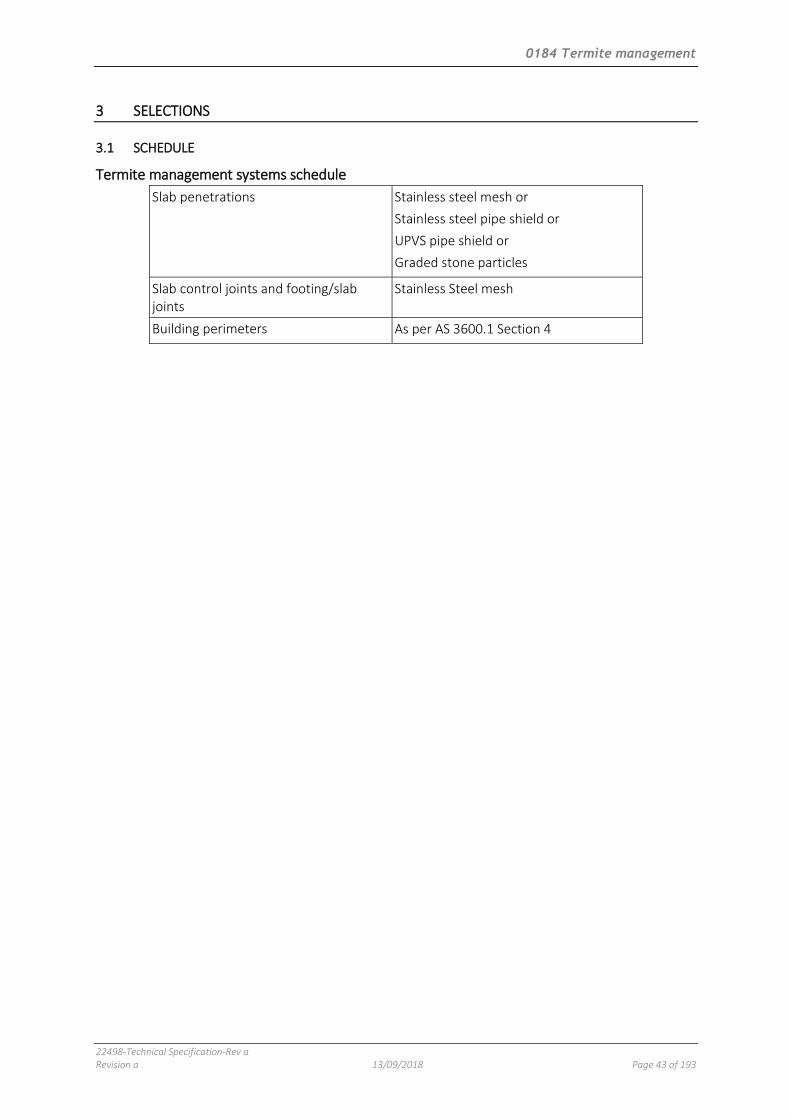
0184 Termite management
22498-Technical Specification-Rev a Revision a 13/09/2018 Page 43 of 193
3 SELECTIONS
3.1 SCHEDULE
Termite management systems schedule
Slab penetrations Stainless steel mesh or
Stainless steel pipe shield or
UPVS pipe shield or
Graded stone particles
Slab control joints and footing/slab joints
Stainless Steel mesh
Building perimeters As per AS 3600.1 Section 4

0221 Site preparation
22498-Technical Specification-Rev a Revision a 13/09/2018 Page 44 of 193
0221 SITE PREPARATION
1 GENERAL
1.1 RESPONSIBILITIES
General Requirement: Provide site preparation, as documented.
Incidental works Generally: Undertake the following:
- Reinstatement: Reinstate undeveloped ground surfaces to the condition existing at the commencement of the contract.
- Minor trimming: As required to complete the works, as documented.
1.2 CROSS REFERENCES
General Requirement: Conform to the following:
- 0171 General requirements.
1.3 INTERPRETATION
Definitions General: For the purposes of this worksection the following definitions apply:
- Authorities: Any authority or agency covering statutory requirements relating to the project, including clearances for work in that particular area.
- Clearances: A formal certificate, approval or condition issued by an authority to allow work to be carried out in a particular area.
- Network Utility Operator: The entity undertaking the piped distribution of drinking water or natural gas for supply or is the operator of a sewerage system or external stormwater drainage system.
1.4 SUBMISSIONS
Execution details Requirement: Submit details of methods and equipment proposed for the following:
- Clearing and grubbing.
- Tree removal and transplanting.
1.5 INSPECTION
Notice Inspection: Give notice so that inspection may be made of the following:
- Enclosures around trees to be retained.
- Trees to be removed.

0221 Site preparation
22498-Technical Specification-Rev a Revision a 13/09/2018 Page 45 of 193
2 EXECUTION
2.1 COMMUNITY LIAISON
Notification General: Notify residents about construction activities which will affect access to, or disrupt the use of, their properties.
Notice: Minimum 5 working days, unless the work is of an urgent nature with safety implications.
Notification content:
- The nature of the work.
- The reason for it being undertaken.
- The expected duration.
- Changes to traffic arrangements and property access.
- The 24-hour contact number of the representative responsible.
2.2 EXISTING SERVICES
General Requirement: Before commencing earthworks, locate and mark existing underground services in the areas which will be affected by the earthworks operations including clearing, excavating and trenching.
Utility services: Contact DIAL BEFORE YOU DIG to identify location of underground utility services pipes and cables.
Excavation: Do not machine excavate within 1 m of existing underground services.
Existing service lines: If required, divert services detected during excavation to new routes, clear of the building, and reconnect to the Network Utility Operator’s requirements.
2.3 SITE CLEARING
Extent Requirement: Clear only areas to be occupied by works such as structures, paving, excavation, regrading and landscaping or other areas designated to be cleared.
Contractor’s site areas: If not included within the areas documented above, clear generally only to the extent necessary for the performance of the works.
Clearing and grubbing Clearing: Remove everything on or above the site surface, including rubbish, scrap, grass, vegetable matter and organic debris, scrub, trees, timber, stumps, boulders and rubble.
Grubbing: Grub out stumps and roots over 75 mm diameter to a minimum depth of 500 mm below subgrade under buildings, embankments or paving, or 300 mm below finished surface in unpaved areas. Backfill holes remaining after grubbing with sand material to prevent ponding of water. Compact the material to the relative density of the existing adjacent ground material.
Redundant/decommissioned works: Remove works, including slabs, foundations, pavings, drains and access chambers covers found on the surface.
Batters Temporary protection: Where change in level between crest and toe is more than 1.5 m, protect from erosion with geofabric, a hessian and tar or heavy duty black polythene sheet waterproof cover. Seal joints and securely fix down at crest and toe.

0221 Site preparation
22498-Technical Specification-Rev a Revision a 13/09/2018 Page 46 of 193
Surplus material Topsoil and excavated material: Continually remove unwanted stripped soil and other material from the site as the work proceeds, including any material dropped on footpaths or roadways.
2.4 STORMWATER AND SEDIMENT CONTROL
General Erosion and sediment control measures: To 0172 Environmental management.
Waterways and drains Waterways: Temporarily divert, as necessary, ditches, field drains and other waterways affected by excavation and reinstate on completion.
Stormwater drains: Divert drains detected during excavation to new routes, clear of the building, and reconnect to the Network Utility Operator’s requirements.
2.5 EXISTING WORKS TO BE RETAINED
Marking Requirement: Mark out works with 1 m high 50 x 50 mm timber stakes with yellow plastic tapes attached to prevent accidental damage.
2.6 TREES TO BE REMOVED
Designation Marking: Mark trees and shrubs to be removed 1000 mm above ground level.
Extent: To be identified on site specific documentation (not part of standard documents).
2.7 TREE PROTECTION
General Warning signs: Display in a prominent position at each entrance to the site, warning that trees and plantings are to be protected during the contract. Remove on completion.
Lettering: Road sign type sans serif letters, 100 mm high to AS 4970 Appendix C.
Protection measures: Provide before commencement of earthworks.
Trees to be retained Extent: All trees NOT marked for removal.
Tree protection Tree protection zone (TPZ): To AS 4970 Section 3.
Tree protective measures: To AS 4970 Section 4.
Monitoring and certification: To AS 4970 Section 5.
Work near trees Harmful materials: Conform to the following:
- Keep the area within the dripline free of sheds and paths, construction material and debris.
- Do not place bulk materials and harmful materials under or near trees.
- Do not place spoil from excavations against tree trunks.
- Prevent wind-blown materials such as cement from harming trees and plants.
Damage: Prevent damage to tree bark. Do not attach stays, guys and the like to trees.
Work under trees: Do not remove topsoil from, or add topsoil to, the area within the dripline of the trees.
Excavation: If excavation is required near trees to be retained, give notice. Minimise period of excavation under tree canopies.

0221 Site preparation
22498-Technical Specification-Rev a Revision a 13/09/2018 Page 47 of 193
Hand methods: Use hand methods to locate, expose and cleanly remove the roots on the line of excavation. If it is necessary to excavate within the drip line, use hand methods so that root systems are intact and undamaged.
Roots: Do not cut tree roots exceeding 50 mm diameter. Where it is necessary to cut tree roots, use cutting methods that do not excessively disturb the remaining root system. Immediately after cutting, water the tree and apply a liquid rooting hormone to stimulate the growth of new roots.
Backfilling: Backfill excavations around tree roots. Place the backfill in layers of 300 mm maximum depth and compacted to a dry density similar to that of the original or surrounding soil. Do not backfill around tree trunks to a height greater than 200 mm above the original ground surface. Immediately after backfilling, thoroughly water the root zone surrounding the tree.
Backfill material:
- Mix proportions (topsoil:well-rotted composts) by volume: 3:1.
- Neutral pH value.
- Free from weed growth and harmful materials.
Compacted ground: Do not compact the ground or use skid-steel vehicles under the tree dripline. If compaction occurs, give notice.
Compaction protection: Protect areas adjacent the tree dripline. Submit proposals for an elevated platform to suit the proposed earthworks machinery.
Watering: Water trees as necessary, including where roots are exposed at ambient temperature more than 35°C.
Mulching: Spread 100 mm thick organic mulch to the whole of the area covered by the drip line of all protected trees.
2.8 COMPLETION
Clean up Progressive cleaning: Keep the work included in the contract clean and tidy as it proceeds and regularly remove from the site waste and surplus material arising from execution of the work, including any work performed during the defects liability period or the plant establishment period.
Removal of plant: Within 10 working days of the date of practical completion, remove temporary works, construction plant, buildings, workshops and equipment which does not form part of the works, except what is required for work during the defects liability period or the plant establishment period. Remove these on completion.
Waste disposal: To 0172 Environmental management.
Vermin management Requirement: Employ an approved firm of pest exterminators and provide a certificate from the firm stating that the completed works is free of vermin.

0222 Earthwork
22498-Technical Specification-Rev a Revision a 13/09/2018 Page 48 of 193
0222 EARTHWORK
1 GENERAL
1.1 RESPONSIBILITIES
General Requirement: Provide earthworks to the dimensions and tolerances, as documented.
1.2 CROSS REFERENCES
General Requirement: Conform to the following:
- 0171 General requirements.
1.3 STANDARDS
General Earthworks: Conform to the recommendations of those parts of AS 3798 which are referenced in this worksection.
1.4 INTERPRETATION
Abbreviations General: For the purposes of this worksection the following abbreviations apply:
- GITA: Geotechnical inspection and testing authority.
- GTA: Geotechnical testing authority.
Definitions General: For the purposes of this worksection the definitions given in AS 3798 and the following apply:
- Description and classification of soils: To AS 1726.
- Site classification: To BCA 3.2.4.
- Bad ground: Ground unsuitable for the work, including fill liable to subsidence, ground containing cavities, faults or fissures, ground contaminated by harmful substances and ground which is, or becomes, soft, wet or unstable.
- Base: One or more layers of material, forming the uppermost structural element of a pavement and on which the surfacing may be placed.
- Discrepancy: A difference between contract information about the site and conditions encountered on the site, including but not limited to discrepancies concerning the following:
. The nature or quantity of the material to be excavated or placed.
. Existing site level.
. Services or other obstruction beneath the site surface.
- Rock: Monolithic material with volume greater than 0.3 m3 which cannot be removed until broken up by rippers or percussion tools.
- Site topsoil: Soil excavated from the site which contains organic matter, supports plant life, conforms generally to the fine-to-medium texture classification to AS 4419 (loam, silt, clay loam) and is free from:
. Stones more than 25 mm diameter.
. Clay lumps more than 75 mm diameter.

0222 Earthwork
22498-Technical Specification-Rev a Revision a 13/09/2018 Page 49 of 193
. Weeds and tree roots.
. Sticks and rubbish.
. Material toxic to plants.
- Subbase: Material laid on the subgrade below the base either for the purpose of making up additional pavement thickness required, to prevent intrusion of the subgrade into the base, or to provide a working platform.
- Subgrade: The trimmed or prepared portion of the formation on which the pavement, footing or slab is constructed. Generally taken to relate to the upper line of the formation.
- Zone of influence: A foundation zone bounded by planes extending downward and outward from the bottom edge of a footing, slab or pavement and defining the extent of foundation material having influence on the stability or support of the footings, slab or pavement.
1.5 TOLERANCES
General Finish: Finish the surface to the required level, grade and shape within the following tolerances:
- Under building slabs and load bearing elements: + 0, - 25 mm.
- Pavement subgrades: + 0, - 40 mm.
- Batters: No steeper than the slope shown on the drawings. Make sure flatter slopes do not impact on boundaries or required clearances to buildings, pavements or landscaping.
- Other ground surfaces: ± 50 mm, provided the area remains free draining and matches adjacent construction where required. Provide smoothness as normally produced by a scraper blade.
1.6 SUBMISSIONS
Design Calculations: Submit calculations by a professional engineer to show that proposed excavations and temporary supports, including where applicable supports for adjacent structures, will be stable and safe.
Execution details Report: Submit a time based schedule noting the methods and equipment proposed for the earthworks, including the following:
- Dewatering and groundwater control and disposal of surface water.
- Excavation methods, stages, clearances, batters and temporary supports.
- Stockpiles and borrow pits.
- Placing and compaction methods and stages.
Geotechnical site investigations: Provide a geotechnical report supporting the procedures proposed for excavation.
Disposal location: Submit the locations and evidence of compliance with the relevant authorities for the disposal of material required to be removed from site.
Temporary shoring: Submit a proposal for any temporary shoring or underpinning required including the progressive removal.
Proof rolling: Submit method and equipment for proof rolling.
Certified records of measurement: Submit a certified copy of the agreed records of measurement.
Construction records: Submit the following to AS 3798 clause 3.4 and Appendix B:
- Geotechnical site visit record; and
- Earthworks summary report or daily geotechnical reports.

0222 Earthwork
22498-Technical Specification-Rev a Revision a 13/09/2018 Page 50 of 193
Materials Imported fill: Submit certification or test results by a GTA registered laboratory which establish the compliance of imported fill with the contract including the source.
Tests Compaction: Submit certification and/or test results in conformance with the specified level of responsibility to AS 3798.
1.7 INSPECTION
Notice Inspection: Give notice so that inspection may be made of the following:
- Items to be measured as listed in RECORDS OF MEASUREMENT.
- Areas to be cleared and/or stripped of topsoil.
- Areas stripped of topsoil.
- Excavation completed to contract levels or founding material.
- Proof roll subgrade before placing fill.
- Filling completed to contract levels.
- Stockpiled topsoil before spreading.
2 PRODUCTS
2.1 FILL MATERIALS
General Suitable material: To AS 3798 clause 4.4 including inorganic, non-perishable material suitably graded and capable of compaction to the documented density.
Unsuitable materials: Do not use unsuitable material for fill in conformance with AS 3798 clause 4.3.
Sulfur content: Do not provide filling with sulfur content exceeding 0.5% within 500 mm of cement bound elements (for example concrete structures or masonry) unless such elements are protected by impermeable membranes or equivalent means.
Re-use of excavated material: Only re-use suitable material in conformance with AS 3798 clause 4.4.
Stockpiles: Segregate the earth and rock material and stockpile, for re-use in backfilling operations.
Locations: Do not stockpile excavated material against tree trunks, buildings, fences or obstruct the free flow of water along gutters where stockpiling is permitted along the line of the trench excavation.
Disposal: If stockpiling is not permitted under the contract, dispose of excavated material off-site to AS 3798 clause 6.1.8.
2.2 BORROW OR IMPORTED FILL
General Borrow or imported material: Only when no suitable excavated material is available.
- Suitable material: To AS 3798 clause 4.4.
Material complying with the following: Consult the geotechnical and engineer for specific or additional requirements applicable to the site.

0222 Earthwork
22498-Technical Specification-Rev a Revision a 13/09/2018 Page 51 of 193
3 EXECUTION
3.1 SITE PREPARATION
Erosion and sedimentation control Drainage, erosion and sedimentation control: To 0172 Environmental management.
3.2 GEOTECHNICAL
As found site conditions General: If the following are encountered, give notice immediately and obtain instructions before carrying out any further work in the affected area:
- Bad ground.
- Discrepancies.
- Rock.
- Springs, seepages.
- Topsoil > 100 mm deep.
Inspection and testing Inspection and testing: Conform to the following:
- Level 1 GITA required to AS 3798 clause 8.2.
- Level 2 GTA required to AS 3798 clause 8.3.
3.3 RECORDS OF MEASUREMENT
Excavation and backfilling Agreed quantities: If a schedule of rates applies, provisional quantities are specified, or there are variations to the contract levels or dimensions of excavations, do not commence backfilling or place permanent works in the excavation until the following have been agreed and recorded:
- Depths of excavations related to the datum.
- Final plan dimensions of excavations.
- Quantities of excavations in rock.
Method of measurement: By registered surveyor unless otherwise agreed.
Rock Level and class: If rock is measured for payment purposes, whether as extra over excavation of material other than rock or for adjustment of provisional measurements, do not remove the rock until the commencing levels and the classes of rock have been determined.
3.4 REMOVAL OF TOPSOIL
General Extent: Areas of cut or fill and areas occupied by structures, pavements and embankments.
Maximum depth: 200 mm.
Topsoil stockpiles General: Stockpile site topsoil intended for re-use and imported topsoil where necessary.
Stockpile heights: Establish stockpiles to maximum height of 1.5 m.
Mark: Identify stockpiles of different soil types.
Vegetation: Do not burn off or remove plant growth which may occur during storage.
Protection: Provide the following:
- Drainage and erosion protection.

0222 Earthwork
22498-Technical Specification-Rev a Revision a 13/09/2018 Page 52 of 193
- Do not allow traffic on stockpiles.
- If a stockpile is to remain for more than four weeks, sow with temporary grass.
- Protect the topsoil stockpiles from contamination by other excavated material, weeds and building debris.
Remove: Remove topsoil that is unsuitable for re-use from the site to AS 3798 clause 6.1.8.
3.5 EXCAVATION
Extent Site surface: Excavate over the site to give correct levels and profiles as the basis for structures, pavements, filling and landscaping. Make allowance for compaction, settlement or heaving.
Footings: Excavate for footings, pits, wells and shafts, to the required sizes and depths. Confirm that the foundation conditions meet the design bearing capacity.
Rock General: Do not use explosives.
Existing footings Requirement: If excavation is required within the zone of influence of an existing footing, use methods including (temporary) shoring or underpinning that maintain the support of the footing and make sure that the structure and finishes supported by the footing are not damaged.
Existing services Location: Before commencing earthworks, locate and mark existing underground services in the areas which will be affected by the earthworks operations including clearing, excavating and trenching.
Utility services: Contact DIAL BEFORE YOU DIG to identify location of underground utility services pipes and cables.
Excavation: Do not excavate by machine within 1 m of existing underground services.
Proof rolling Extent: Proof roll excavations for pavements, filling and non-spanning slabs on ground to determine the presence of any bad ground.
Proof rolling method and equipment: To AS 3798 clause 5.5.
Outcome: If excessive settlement, rebound or heaving is encountered, provide test pits or trenching to determine the extent of bad ground.
Disposal of excess excavated material General: Remove excess excavated material from site not required or unsuitable for fill.
Standard: To AS 3798 clause 6.1.8.
3.6 SUBGRADES AFFECTED BY MOISTURE
General Requirement: If the subgrade is unable to support construction equipment, or it is not possible to compact the overlying pavement only because of a high moisture content, perform one or more of the following:
- Allow the subgrade to dry until it will support equipment and allow compaction.
- Scarify the subgrade to a depth of 150 mm, work as necessary to accelerate drying, and recompact when the moisture content is satisfactory.
- Excavate the wet material and remove to spoil, and backfill excavated areas.

0222 Earthwork
22498-Technical Specification-Rev a Revision a 13/09/2018 Page 53 of 193
3.7 BEARING SURFACES
General Requirement: Provide even plane bearing surfaces for loadbearing elements including footings. Step to accommodate level changes. Make the steps to the appropriate courses if supporting masonry.
Deterioration General: If the bearing surface deteriorates because of water or other cause, excavate further to a sound surface before placing the loadbearing element.
3.8 REINSTATEMENT OF EXCAVATION
General Fill adjacent structures and trenches: To AS 3798 clause 6.2.6.
Zone of influence: Within the zone of influence of footings, beams, or other structural elements, use concrete of strength equal to the structural element, minimum 15 MPa. Make sure that remedial concrete does not create differential bearing conditions.
Below slabs or pavements: Provide selected fill compacted to the specified density.
Cut subgrades: Where the over excavation is less than 100 mm, do not backfill. Rectify by increasing the thickness of the layer above.
Rock depressions and subsoil drains: Backfill rock depressions and over excavation of subsoil drains using coarse subsoil filter.
3.9 SUPPORTING EXCAVATIONS
Removal of supports General: Remove temporary supports progressively as backfilling proceeds.
Voids General: Guard against the formation of voids outside sheeting or sheet piling if used. Fill and compact voids to a dry density similar to that of the surrounding material.
3.10 ADJACENT STRUCTURES
Temporary supports General: Provide supports to adjacent structures where necessary, sufficient to prevent damage arising from the works.
Lateral supports: Provide lateral support using shoring.
Vertical supports: Provide vertical support where necessary using piling or underpinning or both.
Permanent supports General: If permanent supports for adjacent structures are necessary and are not described, give notice and obtain instructions.
Encroachments General: If encroachments from adjacent structures are encountered and are not shown on the drawings, give notice and obtain instructions.
Zone of influence Angle from horizontal: Typical angles are 30° for granular material, 45° for stiff clay.
3.11 ROCK BOLTING
General Requirement: Provide proprietary high strength steel bars or tubes anchored into holes drilled in the rock and tensioned against plates bearing on the rock face to provide temporary or permanent
0222 Earthwork
22498-Technical Specification-Rev a Revision a 13/09/2018 Page 54 of 193
support for the rock face. Schedule the installation to conform to systematic bolting or calculated relief, as documented.
Standard: To AS 4678.
Protection General: Protect permanent rock bolts by grouting the drilled hole with cement grout after tensioning the rock bolt. Protect the bearing plate and the exposed portion of rock bolt and anchorage with a protective coating or by embedment in concrete.
3.12 GEOTEXTILE
General Material: UV stabilised polymeric fabric formed from a plastic yarn composed of at least 85% by weight.
Identification and marking: To AS 3705.
Preparation: Trim the ground to a smooth surface free from cavities and projecting rocks.
Placing: Lay the fabric flat, but not stretched tight, and secure it with anchor pins. Overlap joints 300 mm minimum.
3.13 PREPARATION FOR FILLING
Preparation Stripping: Prepare the ground surface before placing fill (including topsoil fill), ground slabs or load bearing elements to AS 3798 clause 6.1.5. Remove materials which will inhibit or prevent satisfactory placement of fill layers, loose material, debris and organic matter.
Foundation preparation: To AS 3798 clause 6.1.7.
Compaction: Compact the ground exposed after stripping or excavation to the minimum relative compaction in AS 3798 Table 5.1.
Scarify method: Loosen exposed excavation by scarifying to a minimum or 150 mm, moisture condition and compact to AS 3798 Section 5.
Impact roller and impact compaction: Use an approved method.
Slope preparation: If fill is placed on a surface steeper than 4:1 (horizontal:vertical), bench the surface to form a key for the fill. As each layer of fill is placed, cut the existing ground surface progressively to form a series of horizontal steps more than 1 m in width and more than 100 mm deep. Recompact the excavated material as part of the filling. Shape to provide free drainage.
Under earth mounds General: Cultivate the ground to a depth of 200 mm before mound formation.
Under slabs, paving and embankments Compact the ground: To AS 3798 Table 5.1. If necessary, loosen the ground to a depth of more than 200 mm and adjust the moisture content before compaction to a density consistent with subsequent filling.
Rock ledges General: Remove overhanging rock ledges.
3.14 PLACING FILL
General Layers: Place fill in near-horizontal layers of uniform thickness, deposited systematically across the fill area.
Extent: Place and compact fill to the designated dimensions, levels, grades, and cross sections so that the surface is always self-draining.

0222 Earthwork
22498-Technical Specification-Rev a Revision a 13/09/2018 Page 55 of 193
Edges: At junctions of fill and existing surfaces, do not feather the edges.
Mix: Place fill in a uniform mixture.
Previous fill: Before placing subsequent fill layers, make sure that previously accepted layers still conform to requirements, including moisture content.
Protection: Protect the works from damage due to compaction operations. Where necessary, limit the size of compaction equipment or compact by hand. Commence compacting each layer at the structure and proceed away from it.
Protective covering: Do not disturb or damage the protective covering of membranes during backfilling.
Placing at structures General: Place and compact fill in layers simultaneously on both sides of structures, culverts and pipelines to avoid differential loading. Carefully place first layers of fill over the top of structures.
Concrete: Do not place fill against concrete retaining walls until the concrete has been in place for 28 days unless the structure is supported by struts.
3.15 PLACING TOPSOIL
Stockpiled topsoil Cultivation: Rip to a depth of 100 mm or to the depth of rippable subgrade if less. Cultivate around services and tree roots by hand. Trim to allow for the required topsoil depth.
Herbicide: Apply before placing topsoil.
Placing: Spread and grade evenly.
Disposal of excess topsoil On-site: Dispose of surplus topsoil remaining on site by spreading evenly over the areas already placed.
Off-site: Remove excess topsoil from the site and dispose of legally.
Compaction: Lightly compact topsoil so that the finished surface is smooth, free from lumps of soil, at the required level, ready for cultivation and planting.
Edges: Finish topsoil flush with abutting kerbs, mowing strips and paved surfaces. Feather edges into adjoining undisturbed ground.
3.16 FILL MOISTURE CONTROL
General Moisture content: Adjust the moisture content of fill during compaction within the range of 85 to 115% of the optimum moisture content determined by AS 1289.5.1.1 or AS 1289.5.2.1, as appropriate, to achieve the required density.
3.17 COMPACTION REQUIREMENTS FOR FILL AND SUBGRADE
Density General: Compact the subgrade and each layer of fill to the required depth and density, as a systematic and construction operation. Shape surface to provide drainage and prevent ponding.
Excavated and stripped ground surface: After excavation and/or stripping, compact these surfaces to a minimum depth of 150 mm.
Maximum rock and lump size in layer after compaction: To AS 3798 clause 6.2.2.
Fill batter faces: Either compact separately, or overfill and cut back. Form roughened surfaces to the faces.
Minimum relative compaction: To AS 3798 Table 5.1.

0222 Earthwork
22498-Technical Specification-Rev a Revision a 13/09/2018 Page 56 of 193
Compaction control tests Compaction control tests: To AS 1289.5.4.1 or AS 1289.5.7.1.
Compaction control test frequency Standard: To AS 3798 Table 8.1.
Confined operations: 1 test per 2 layers per 50 m2.
3.18 COMPLETION
Grading External areas: Grade to give falls away from buildings, minimum 1:100.
Subfloor areas: Grade the ground surface under suspended floors to drain ground or surface water away from buildings without ponding.
Temporary works Tree enclosures: Remove temporary tree enclosures at completion.
Tree marking: Remove temporary marks and tags at completion.
Temporary supports: Remove temporary supports to adjacent structures at completion.
Site restoration Requirement: Where variation of existing ground surfaces is not required as part of the works, restore surfaces to the condition existing at the commencement of the contract.
0223 Service trenching
22498-Technical Specification-Rev a Revision a 13/09/2018 Page 57 of 193
0223 SERVICE TRENCHING
1 GENERAL
1.1 RESPONSIBILITIES
General Requirement: Provide trenching for underground services, as documented.
Design Steel shoring and trench lining systems: To AS 4744.1.
Hydraulic shoring and trench lining equipment: To AS 5047.
1.2 CROSS REFERENCES
General Requirement: Conform to the following:
- 0171 General requirements.
- 0222 Earthwork.
1.3 STANDARDS
General Earthworks: To AS 3798.
1.4 INTERPRETATION
Abbreviations General: For the purposes of this worksection the following abbreviations apply:
- CBR value: California Bearing Ratio value.
1.5 TOLERANCES
General Earthworks: To TOLERANCES in 0222 Earthwork.
1.6 SUBMISSIONS
Execution details Excavation method: Submit details of proposed equipment and method of excavation, including the following:
- Service location and type: A plan of the trench works showing the location and type of service.
- Open excavation: Proposed duration.
- Shuttering and/or bracing of trench sides: If required for safety and stability, provide proposals.
- Geotechnical data: Geotechnical report supporting the procedures proposed for trenching and/or boring.
- Boring: Proposals for the following:
. Limits on length.
. Existence of other services and method of protection.
. Pressure grouting to voids.
. The effect of pressure grouting on other services, ground heave and proposals for minimising such effects.

0223 Service trenching
22498-Technical Specification-Rev a Revision a 13/09/2018 Page 58 of 193
. Access to properties outside the site.
. Council permits.
. Service interruptions including a plan for minimising unintended interruptions.
- Hazards: Identify WHS hazards that may be encountered with deep trenches including toxic gases and liquids.
Off-site disposal location: Submit details of the proposed disposal locations and evidence of conformance with the relevant authorities for the disposal of material required to be removed from the site.
1.7 INSPECTION
Notice Inspection: Give notice so that inspection may be made at the following stages:
- Service trenches excavated before laying the service.
- Services laid in trenches and ready for backfilling.
2 PRODUCTS
2.1 FILL MATERIALS
General Requirement: Provide fill materials including borrow or imported fill to FILL MATERIALS and BORROW OR IMPORTED FILL in 0222 Earthwork.
3 EXECUTION
3.1 EXISTING SERVICES
Location Requirement: Before commencing service trenching, locate and mark existing underground services in the areas which will be affected by the service trenching operations.
Utility services: Contact DIAL BEFORE YOU DIG to identify location of underground utility services pipes and cables.
Excavation General: Do not excavate by machine within 1 m of existing underground services.
3.2 EXISTING SURFACES
Concrete and asphalt pavements Method: Sawcut trench set out lines for the full depths of the bound pavement layers except where the set out line is located along expansion joints.
Removal of concrete and asphalt: Break out concrete or asphalt pavement material between the trench set out lines, remove and dispose of off-site.
Segmental paving units Removal: Take up segmental paving units both full and cut by hand, between the trench set out lines, and neatly stack on wooden pallets.
Concrete edging: Break out, remove and dispose of off-site.
Concrete subbase: If present, sawcut along the trench set-out lines.
Grass Removal method: Neatly cut grass turf between trench set-out lines into 300 mm squares.

0223 Service trenching
22498-Technical Specification-Rev a Revision a 13/09/2018 Page 59 of 193
Grass suitable for re-use: Take up and store the turf and water during the storage period, otherwise remove and dispose of it off-site.
Small plants, shrubs and trees Small plants required for re-planting: Take up and store. Wrap the rootball in a hessian or plastic bag with drain holes and water during the storage period.
Unsuitable vegetation: Remove and dispose of off-site.
3.3 EXCAVATING
Site preparation As found site conditions: To GEOTECHNICAL in 0222 Earthwork.
Records of measurement: If records of measurement are required, to RECORDS OF MEASUREMENT in 0222 Earthwork.
Remove topsoil: To REMOVAL OF TOPSOIL in 0222 Earthwork.
Excavation General: Excavate for underground services in conformance with the following:
- To required lines and levels, with uniform grades.
- Straight between access chambers, inspection points and junctions.
- With stable sides.
- Width tolerance: ± 50 mm, unless constrained by adjacent structures.
- Excavation: To EXCAVATION and ADJACENT STRUCTURES in 0222 Earthwork.
Trench widths General: Keep trench widths to the minimum, consistent with the laying and bedding of the relevant service and construction of access chambers and pits.
Trench depths General: As required by the relevant service and its bedding method.
Adjacent to footings: If excavation is necessary below the zone of influence of the underside of adjacent footings, give notice, and provide support for the footings as instructed.
Obstructions General: Clear trenches of sharp projections. Cut back roots encountered in trenches to at least 600 mm clear of services. Remove other obstructions including stumps and boulders which may interfere with services or bedding.
Tree protection: To AS 4970.
Dewatering General: Keep trenches free of water. Place bedding material, services and backfilling on firm ground, free of surface water.
Pumping: Provide pump-out from adjacent sumps or install well points.
Adjacent subsidence: Provide recharge points to isolate the dewatering zone.
Excess excavation General: If trench excavation exceeds the correct depth, reinstate to the correct depth and bearing value using compacted bedding material or sand stabilised with 1 part of cement to 20 parts of sand by volume.
Stockpiles Excavated material for backfill: If required, segregate the earth and rock material and stockpile, for re-use in backfilling operations.

0223 Service trenching
22498-Technical Specification-Rev a Revision a 13/09/2018 Page 60 of 193
Locations: Do not stockpile excavated material against tree trunks, buildings, fences or obstruct the free flow of water along gutters where stockpiling is permitted along the line of the trench excavation.
Disposal: If stockpiling is not permitted, dispose of excavated material off-site.
Unsuitable material Disposal: Remove unsuitable material from the bottom of the trench or at foundation level and dispose of off-site. Replace with backfill material to FILL MATERIALS to 0222 Earthwork.
Boring Subcontractor: If under road boring is required instead of trenches, engage a suitably qualified subcontractor to do the work.
3.4 TRENCH BACKFILL
General Place fill: To PLACING FILL in 0222 Earthwork.
Timing: Backfill service trenches as soon as possible after laying and bedding the service, if possible on the same working day.
Marking services: Underground marking tape to AS/NZS 2648.1.
Bedding, haunch, side and overlay zones Installation and material: To the particular utility authority or utility service requirements. Secure pipes against floatation.
Overlay zone thickness: Maximum 300 mm immediately over the utility service.
Topsoil areas: Complete the backfilling with at least 100 mm of topsoil.
Material in reactive clay areas: In sites classified M, M-D, H1, H1-D, H2, H2-D, E or E-D to AS 2870, re-use excavated site material at a moisture content within ± 1% of that of the adjoining in situ clay.
Selected material zone Extent: The section of trench within the zone, if applicable.
Backfill material: Selected material free from stones larger than 100 mm maximum dimension and the fraction passing a 19 mm Australian Standard sieve to have a 4 day soaked CBR value, in conformance with AS 1289.6.1.2, and not less than that of the adjacent selected material zone.
Trees Backfill at trees: Backfill minimum 300 mm thick, around tree roots with a topsoil mixture. Place and compact in layers of 150 mm minimum depth to a dry density equal to that of the surrounding soil.
Do not place backfill: Above the original ground surface around tree trunks or over the root zone.
Watering: Thoroughly water immediately after backfilling the tree root zone.
Compaction Control moisture within backfill: To FILL MOISTURE CONTROL in 0222 Earthwork.
Layers: Compact all material in layers not exceeding 150 mm compacted thickness. Compact each layer to the required relative compaction before starting the next layer.
Compaction: To COMPACTION REQUIREMENTS FOR FILL AND SUBGRADE in 0222 Earthwork and AS 3798 Section 5.
Frequency of testing: To AS 3798 clause 8.7.
Precautions: If compacting adjacent to utility services, use compaction methods which do not cause damage or misalignment.

0223 Service trenching
22498-Technical Specification-Rev a Revision a 13/09/2018 Page 61 of 193
Density tests Testing authority: Carry out density tests of pipe bedding and backfilling by a registered testing authority.
Test methods: Conform to the following
- Compaction control tests: To AS 1289.5.4.1 or AS 1289.5.7.1.
- Field dry density: AS 1289.5.3.2 or AS 1289.5.3.5.
- Standard maximum dry density: AS 1289.5.1.1.
- Dry density ratio: AS 1289.5.4.1.
- Density index: AS 1289.5.6.1.
3.5 SURFACE RESTORATION
Subbase and base Material: Crushed rock, DGS20 or DGB20 material configured in layers and depths to match existing and adjacent work.
Supply and installation: To 0271 Pavement base and subbase.
Compaction: Uniformly compact each layer of the subbase and base courses over the full area and depth within the trench to a relative compaction of 100% when tested in conformance with AS 1289.5.4.1.
Compaction test frequency: Minimum 1/every second layer/50 m² of restoration surface area.
Pathways and paved areas generally Restoration materials: Consistent with the surface existing before commencement of the works.
Subbase: 150 mm crushed stone DGB20 compacted to 100% relative compaction in conformance with AS 1289.5.4.1.
Lippage at patches: Match the surface level at any point along the patch’s edge with the adjoining footpath surface within ± 5 mm.
Concrete surfaces Construction: Conform to the following:
- Prime coat the cut edges of the existing surfaces with cement slurry. Lay and compact concrete so that the edges are flush and the centre is cambered 10 mm above the adjoining existing surfaces.
- Material: 25 MPa concrete.
- Surface finish and pattern: Match existing adjoining work.
- Minimum thickness: 75 mm or the adjacent pavement thickness, whichever is thicker.
- Reinforcement and dowels: If required, provide steel reinforcement with dowels into the adjacent concrete.
- Expansion joints: 15 mm thick preformed jointing material of bituminous fibreboard placed where new concrete abuts existing concrete and in line with joints in existing concrete.
- Control joints:
. Form control joints strictly in line with the control joints in existing concrete.
. Around electricity supply poles: Terminate the concrete paving 200 mm from the pole and fill the resulting space with cold mix asphalt.
Curing: Cure by keeping continuously wet for 7 days.
Asphalt footpaths Materials and installation: To 0272 Asphaltic concrete or 0273 Sprayed bituminous surfacing, as appropriate.
Thickness: Match the adjoining footpath.

0223 Service trenching
22498-Technical Specification-Rev a Revision a 13/09/2018 Page 62 of 193
Finish: Compact to a smooth even surface.
Segmental paving units Materials and installation: To 0276 Paving – sand bed or 0275 Paving – mortar and adhesive bed as appropriate and as follows:
- Laying: Re-lay to match the pattern and surface levels of the existing paving.
- Damaged paving units unsuitable for relaying: Replace paving units with new units of the same material, type, size and colour as the existing.
Landscaped areas In topsoil areas: Complete the backfilling with topsoil for at least the top 100 mm.
Lawn: Re-lay stockpiled turf. If existing turf is no longer viable, re-sow the lawn over the trench and other disturbed areas.
Planted areas: Overfill to allow for settlement.

0224b Stormwater – site
22498-Technical Specification-Rev a Revision a 13/09/2018 Page 63 of 193
0224B STORMWATER – SITE
1 GENERAL
1.1 RESPONSIBILITIES
General
1.2 CROSS REFERENCES
General Requirement: Conform to the following worksection(s):
- 0171 General requirements.
- 0222 Earthwork.
1.3 STANDARDS
Stormwater drainage Standard: To AS/NZS 3500.3.
1.4 INTERPRETATION
Definitions General: For the purposes of this worksection the following definition applies:
- Pipe surround: Includes pipe overlay, pipe side support, side zone and haunch zone.
1.5 INSPECTION
Notice Inspection: Give notice so that inspection may be made at the following stages:
- Excavated surfaces prior to placing bedding material.
- Concealed or underground services prior to being covered.
- Pipe joints before covering.
- Placing of cast in situ concrete.
- Upon completion.
2 PRODUCTS
2.1 MATERIALS
Joints Solvent cement and priming fluid: To AS/NZS 3879.
Type of pipes and fittings Fibre reinforced cement (FRC): To AS 4139 and the following:
- ≤ 450 mm diameter: Rubber ring joints to AS 4139.
- > 450 mm diameter: With a purpose machined internal spigot and socketsystem within the pipe wall.
Glass-reinforced polyester (GRP): To AS 3571.1.
Cast iron access chamber covers and frames: To AS 1830 or AS 1831, as appropriate.
Polyvinyl chloride (PVC): To AS/NZS 1254, AS/NZS 1260 or AS 1273, as appropriate.
Polyethylene (PE): To AS/NZS 4129, AS/NZS 4130, ISO 8770 or AS/NZS 2033, as appropriate.

0224b Stormwater – site
22498-Technical Specification-Rev a Revision a 13/09/2018 Page 64 of 193
Precast concrete: To AS/NZS 4058.
Rubber ring joints/elastomeric seals: To AS 1646.
Plastic pipe for subsoil drainage: To AS 2439.1.
Vitrified clay or ceramic: To AS 1741.
Bedding material Bed and haunch zones: Provide granular material graded to AS 1141 series.
Conformance: Conform to the Bedding material.
Bedding material grading table
Sieve size (mm) Weight passing %
Bed and haunch Side zones
75.0 - 100
19.0 100 -
9.5 - 50-100
2.36 50-100 30-100
0.60 20-90 15-50
0.30 10-60 -
0.15 0-25 -
0.075 0-10 0-25
Filter material General: Provide filter materials consisting of natural clean washed sands and gravels and screened crushed rock conforming to AS/NZS 3500.3 clause 2.13.1.
2.2 GEOTEXTILES
Subsoil drainage Filter: Conform to AS/NZS 3500.3 clause 2.13.2.
2.3 PREFABRICATED PITS
General Requirement: Provide precast or prefabricated pits in conformance with AS/NZS 3500.3 clauses 2.12.8 and 7.5.
Metal access covers and grates Standard: To AS 3996.
3 EXECUTION
3.1 SUBSOIL DRAINS
Jointing General: At junctions of subsoil pipes, provide tees, couplings or adaptors to AS 2439.1.
Geotextiles Marking: To AS 3705.
3.2 COMPLETION
Cleaning General: Clean and flush the whole installation.

0224b Stormwater – site
22498-Technical Specification-Rev a Revision a 13/09/2018 Page 65 of 193
4 SELECTIONS
To be in accordance with the requirements of this specification and the design drawings.

0271b Pavement base and subbase
22498-Technical Specification-Rev a Revision a 13/09/2018 Page 66 of 193
0271B PAVEMENT BASE AND SUBBASE
1 GENERAL
1.1 RESPONSIBILITIES
General Requirement: Provide base and subbase courses as documented.
1.2 CROSS REFERENCES
General Requirement: Conform to the following:
- 0171 General requirements.
1.3 INTERPRETATION
Definitions General: For the purposes of this worksection, the following definitions apply:
- Base: Layer(s) of material, forming the uppermost structural element of a pavement and on which the surfacing may be placed.
- Flexible pavement: A pavement which obtains its load-spreading properties from intergranular pressure, mechanical interlock and cohesion between the particles of the pavement material.
- Subbase: Material laid on the subgrade (or selected material), below the base, either for the purpose of making up additional pavement thickness, to prevent intrusion of the subgrade into the base, or to provide a working platform.
1.4 SUBMISSIONS
Products and materials Source of material: Submit the supplier name, material type (crushed rock, natural gravel, recycled concrete aggregate) and source quarry or recycling site.
1.5 INSPECTION
Notice Inspection: Give notice so that inspection may be made of the following:
- Prepared subgrade.
- Proof rolling of subbase before spreading of base.
- Proof rolling of base before sealing.
2 PRODUCTS
2.1 BASE AND SUBBASE MATERIAL
Granular material Requirement: Provide unbound granular materials, including blends of two or more different materials, which when compacted develop structural stability and are uniform in grading and physical characteristics.
Crushed rock and recycled material class Requirement: Provide crushed rock and recycled material as documented, from the following classes:

0271b Pavement base and subbase
22498-Technical Specification-Rev a Revision a 13/09/2018 Page 67 of 193
- Class 1: Pavement base material (with a minimum plasticity index) for unbound pavements requiring a very high standard of surface preparation for a sprayed sealed or thin asphalt surfacing.
- Class 2: Pavement base material (with no minimum plasticity index) for unbound pavements which may not require a very high standard of surface preparation.
- Class 3: Not applicable.
- Class 4: Subbase material for unbound flexible pavements.
3 EXECUTION
3.1 SUBGRADE PREPARATION
General Requirement: Prepare the subgrade in conformance with 0222 Earthwork.
3.2 PLACING BASE AND SUBBASE
General Weak surfaces: Do not place material on a surface that is weakened by moisture and is unable to support, without damage, the construction plant required to perform the works.
Spreading: Spread material in uniform layers without segregation.
Moisture content: Maintain wet mixed materials at the required moisture content before and during spreading. Add water to dry mixed materials through fine sprays to the entire surface of the layer after spreading, to bring the material to the required moisture content.
Compacted layer thickness: 200 mm maximum and 100 mm minimum. Provide layers of equal thickness in multilayer courses.
Joints General: Plan spreading and delivery to minimise the number of joints. Offset joints in successive layers by a minimum of 300mm.
Start of shift: Remix last 2m of previous days' work for continuity of compaction.
Final trimming General: Trim and grade the base course to produce a tight even surface with no loose stones or slurry of fines.
3.3 TOLERANCES
Surface level General: Provide a finished surface level which is free draining and evenly graded between level points.
Subbase: + 10 mm, - 25 mm.
Base: + 10 mm, - 5 mm.
Base abutting gutters: ± 5 mm from the level of the lip of the gutter, minus the design thickness of the wearing course.
Surface deviation Base: ≤ 5 mm from a 3 m straightedge laid on the surface.
3.4 BASE AND SUBBASE COMPACTION
General Construction operation: Compact each layer of fill to the required depth and density, as a systematic construction operation.

0271b Pavement base and subbase
22498-Technical Specification-Rev a Revision a 13/09/2018 Page 68 of 193
Unstable areas: If unstable areas develop during rolling or are identified by proof rolling, open up, dry back and recompact, to the requirements of this worksection. If dry back is not possible, remove for the full depth of layer, dispose of and replace with fresh material.
Minimum relative compaction table
Item description Minimum dry density ratio (modified compaction) to AS 1289.5.2.1
Subbase 95%
Base 98%
Compaction requirements General: Apply uniform compactive effort, over the whole area to be compacted, until the required density is achieved or until failure is acknowledged. If failure is acknowledged, conform to Rectification.
Equipment: Use rollers appropriate to the materials and compaction requirements documented.
Moisture content General: During spreading and compaction, maintain material moisture content within the range of -2% to +1% from the optimum moisture content (modified compaction).
Spraying: Use water spraying equipment to distribute water uniformly, in controlled quantities, over uniform lane widths.
Dry back: Allow materials to dry to 60 to 80% of the optimum moisture content before applying the seal or wearing course.
Rectification General: If a section of the pavement material fails to meet the required density or moisture content after compaction, remove the non-conforming material, dispose of off-site or rectify for re-use, replace with fresh material, and re-compact.
Level corrections General: Rectify incorrect levels as follows:
- High areas: If the area can be rectified by further trimming to produce a uniform, hard surface by cutting without filling, trim so that the rectified area conforms to TOLERANCES.
- Low areas and high areas not rectifiable by further trimming: Remove layers to a minimum depth of 75 mm, lightly tyne and replace with new material and recompact.
3.5 TESTING
Site tests Compaction control tests: To AS 1289.5.4.1 and AS 1289.5.4.2.
Frequency of compaction control tests: Not less than the following (whichever requires the most tests):
- 1 test per layer per 100 lineal metres for two-lane roads.
- 1 test per layer per 2000m2 for carparks.
- 3 tests per layer.
- 3 tests per visit.
0274b Concrete pavement
22498-Technical Specification-Rev a Revision a 13/09/2018 Page 69 of 193
0274B CONCRETE PAVEMENT
1 GENERAL
1.1 RESPONSIBILITIES
General Requirement: Provide concrete pavement as documented.
Performance Requirement: Provide finished surfaces conforming to the following:
- Free draining and evenly graded between level points.
- Even and smooth riding.
Conformance: Conform to the local authority requirements for levels, grades and the minimum details of thickness, reinforcement and concrete strength for pavements within the kerb-and-gutter property boundaries.
1.2 CROSS REFERENCES
General Requirement: Conform to the following:
- 0171 General requirements.
- 0222 Earthwork.
- 0310 Concrete – combined.
1.3 STANDARDS
Concrete Specification and supply: To AS 1379.
Materials and construction: To AS 3600.
1.4 INTERPRETATION
Definitions General: For the purposes of this worksection the following definitions apply.
- Absolute level tolerance: Maximum deviation from design levels.
- Ambient temperature: The air temperature at the time of mixing and placing of concrete.
- Average ambient temperature: Average value of the daily maximum and minimum ambient temperatures over the relevant period at a site.
- Concrete class – normal: Concrete which is specified primarily by a standard compressive strength grade and otherwise in conformance with AS 1379 clause 1.5.3.
- Concrete class – special: Concrete which is specified to have certain properties or characteristics different from, or additional to, those of normal-class concrete and otherwise in conformance with AS 1379 clause 1.5.4.
- Green concrete: Concrete which has set but not appreciably hardened.
- Relative level tolerance: Maximum deviation from a 3m straightedge laid on the surface.
- Weather – cold: Ambient shade temperature less than 10°C.
- Weather – hot: Ambient shade temperature greater than 30°C.

0274b Concrete pavement
22498-Technical Specification-Rev a Revision a 13/09/2018 Page 70 of 193
1.5 TOLERANCES
General Edges abutting gutters: Within ± 5mm of the level of the actual gutter edge.
Rigid pavement surface:
- Absolute tolerance: +10mm, - 0mm.
- Relative tolerance: ±5mm.
Joint locations in plan (rigid pavement): ±15mm.
1.6 SUBMISSIONS
Products Aggregates: Nominate the source for all aggregates proposed.
Reinforcement: Submit the manufacturer’s certificate of compliance with AS/NZS 4671, or submit test certificates from an independent testing authority.
Liquid curing compounds: Submit certified test results, including the application rate and the efficiency index to AS 3799 Appendix B.
Curing by covering: Submit details of the proposed covering material.
Repair materials: Submit proposals for epoxy resin/grout and elastomeric sealant.
Concrete: Submit the concrete supply delivery dockets.
Subcontractors: Submit names and contact details of proposed pre-mixed concrete suppliers, and alternative source of supply in the event of breakdown of pre-mixed or site mixed supply.
Trial mix design report: Six weeks before commencing production, submit a report for each mix design containing the information required in AS 1012.2, the individual and combined aggregate particle size distribution, and the records and reports for the tests.
1.7 INSPECTION
Notice Inspection: Give notice so that inspection may be made of the following:
- Base or subgrade before covering.
- Membrane or film underlay installed on the base or subgrade.
- Concrete formwork, reinforcement and dowels in position.
- Commencement of concrete placing.
- Completion of concrete placing.
- Evaluation of surface finish.
2 PRODUCTS
2.1 REINFORCEMENT
Steel reinforcement Standard: To AS/NZS 4671.
Identification: Supply reinforcement with readily identifiable grade and origin.
Surface condition: Free of loose mill scale, rust, oil, grease, mud or other material which may reduce the bond between the reinforcement and concrete.
Accessories Bar chairs: Use plastic tipped wire bar chairs to AS/NZS 2425.
Tie wire: Galvanized annealed steel 1.25mm diameter minimum.

0274b Concrete pavement
22498-Technical Specification-Rev a Revision a 13/09/2018 Page 71 of 193
Dowels General: Provide each dowel in one piece, straight, cut accurately to length with ends square and free from burrs.
Standard: To AS/NZS 4671.
Grade: 250R steel bars 450mm long.
Tie bars Type: Deformed bar, 12mm diameter, grade 500N, 1m long.
2.2 AGGREGATE
Characteristics Standards: AS 2758.1.
Quality: Provide at least 40% by mass of the total aggregates in the concrete mix of quartz sand aggregate having a nominal size of less than 5 mm and containing at least 70% quartz by mass.
Durability: All constituent, fraction of constituent or aggregates to conform to AS 1141.22 and the following:
- Wet strength not less than 80kN.
- 10% Fines Wet/Dry Variation not to exceed 35%.
Recycled concrete aggregate (RCA): Use coarse aggregates from demolition concrete or RCA.
Blending: If blending coarse RCA with natural aggregates, make sure substitution rates are below 30%.
2.3 CEMENT
General Standard: To AS 3972.
Transport: Cement in watertight packaging and protect from moisture until used. Do not use caked or lumpy cement.
- Age: Less than 6 months old.
- Storage: Store cement bags under cover and above ground.
2.4 FLY ASH
General Standard: To AS 3582.1.
Fly ash quantity: Nil to 70 kg/m3
Minimum binder content (fly ash plus cement): 300 to 330 kg/m3.
2.5 WATER
General Standard: Chloride ion to AS 3583.13 and sulphate ion to AS 1289.4.2.1.
Quality: Water used in the production of concrete to be potable, free from materials harmful to concrete or reinforcement, and be neither salty nor brackish.
Limits: Not containing more than:
- 600 parts per million of chloride ion, determined to AS 3583.13.
- 400 parts per million of sulphate ion, determined to AS 1289.4.2.1.
2.6 ADMIXTURES
General Standard: Chemical admixtures to AS 1478.1.

0274b Concrete pavement
22498-Technical Specification-Rev a Revision a 13/09/2018 Page 72 of 193
Quality: Provide admixtures free from calcium chloride, calcium formate, or triethanolamine or any other accelerator. Do not use admixtures or combinations of admixtures without prior written approval.
Dosage: Vary the dosage of chemical admixture to account for air temperature and setting time in conformance with the manufacturer’s recommendations.
2.7 CURING COMPOUNDS
General Curing compounds: To AS 3799 and AS 1160, Type 2, white pigmented or containing aluminium reflective pigments.
Sheet material covering: To ASTM C171, white opaque or clear polyethylene film, or white burlap-polyethylene sheet, or equivalent material.
2.8 OTHER MATERIALS
Tactile ground surface indicators Standard: To AS/NZS 1428.4.1.
3 EXECUTION
3.1 SUBGRADE
Preparation Conformance: Prepare subgrade in conformance with the 0222 Earthwork worksection.
Extent: Prepare a uniform subgrade for the full pavement formation, extending at least to the back of kerbs.
Reinstatement: Make sure of uniformity for backfilling of any utility trenches.
3.2 SUBBASE
Width Subbase width: Extend the subbase at its full depth to at least the back of kerbs or other edge stops before their installation.
No integral kerbs: Extend granular unbound subbase at least 300 mm beyond each side of the carriageway.
Unbound subbase materials and installation: Conform to 0271 Pavement base and subbase.
Bound subbase materials and installation: Conform to 0271 Pavement base and subbase.
Tolerance and friction reduction Tolerance: Subbase finished surface level, +0mm to - 10mm.
Friction reduction: Provide 200μm thick polyethylene sheeting with 200mm taped minimum laps and/or a 20mm thick layer of sand (silt and clay material less than 5%) directly beneath the concrete pavement.
3.3 CONCRETE MIX
Standard Concrete mix and supply: To AS 3600 Section 17 and AS 1379.
Properties Workability: Slump values to conform to the following:
- Fixed form paving with manual operated vibration: 50 to 60mm.
- Drying shrinkage: Maximum 450µε after 21 days of air drying.

0274b Concrete pavement
22498-Technical Specification-Rev a Revision a 13/09/2018 Page 73 of 193
Elapsed time delivery General: Make sure that the elapsed time between the wetting of the mix and the discharge of the mix at the site is in conformance with the Elapsed delivery time table. Do not discharge at ambient temperature below 10°C or above 32°C.
Elapsed delivery time table
Concrete temperature at time of discharge (°C) Maximum elapsed time (hours)
10 – 24 2.00
24 – 27 1.50
27 – 30 1.00
30 – 32 0.75
Site mixed supply Emergencies: If mixing by hand is carried out, provide details.
Plant: Mix concrete in a plant located on the construction site.
Pre-mixed supply Addition of water: Do not add water.
Transport: Make sure the mode of transport prevents segregation, loss of material and contamination of the environment, and does not adversely affect placing or compaction.
Concrete delivery docket: For each batch, submit a docket listing the information required by AS 1379 clause 1.7.3, and the following information:
- Any binders or additives.
- Method of placement and climate conditions during pour.
- Name of concrete delivery supervisor.
- The concrete element or part of the works for which the concrete was ordered, and where it was placed.
3.4 TESTING
Standards Sampling, identification, testing and recording: To the AS 1012 series.
Specimens: Sample the concrete on-site, at the point of discharge from the agitator.
Type and frequency: To AS 1379.
Testing authority: Concrete supplier or NATA registered laboratory.
Concrete testing methods Slump: Test at least one sample from each batch before placing concrete from that batch in the work.
- Standard: To AS 1012.3.1.
- Maximum slump variation: ± 10mm.
Compressive strength: Test to AS 1012.8.1.
Drying shrinkage: Test to AS 1012.8.4 and AS 1012.13.
Flexural strength: To AS 1012.8.2 and AS 1012.11.
Acceptance criterion: The average strength of any set of 3 consecutive project samples must be equal to or greater than the specified minimum value.

0274b Concrete pavement
22498-Technical Specification-Rev a Revision a 13/09/2018 Page 74 of 193
Project assessment sampling frequency table
Number of batches for each type and grade of concrete per day
Minimum number of samples
1 1
2-5 2
6-10 3
11-20 4
each additional 10 1 additional
3.5 INSTALLATION
Junctions with existing pavements Trimming: Where the pavement is to be joined to an existing pavement, remove a strip of the existing pavement at least 300mm wide for its full depth and trim the edge vertically before placing new pavement material.
Existing sealed pavement: Trim the seal to a neat edge.
Fixed formwork Description:
- Steel forms.
- Seasoned, dressed timber planks, free of warps, bends or kinks, with the full width of their top edges covered with steel angle sections finishing flush with the form face.
Depth: Equal to the edge thickness of the slab and in one piece.
Tolerances on position:
- Absolute level tolerance: ± 5mm.
- Relative level tolerance: ± 5mm.
- Horizontal tolerance: ± 10mm (maximum departure of face from a plane surface).
- Verticality: 3mm departure from vertical.
Staking: Stake forms in position using at least 3 steel stakes per form, not more than 1.5m apart. Lock joints between form sections to prevent movement.
Release agent: Before placing reinforcement, apply a release agent compatible with the contact surfaces, to the interior of the formwork, except where the concrete is to receive an applied finish for which there is no compatible release agent. Clean the reinforcement to remove all traces of release agent.
Re-use: Clean and recoat the forms each time before placing concrete.
Keyways: Form the keyways of keyed construction joints using steel form strips accurately located at the mid-depth of the slab and securely fastened flush against the formwork face.
Reinforcement Tolerances in fabrication and fixing: To AS 3600.
Locate reinforcement: Place reinforcement in the top half of the pavement.
Minimum cover to reinforcement: 30mm.
Splicing mesh: Overlap a minimum of 2 crosswires.
Supports: Provide proprietary concrete, metal or plastic supports to AS/NZS 2425 and as follows:
- To withstand construction and traffic loads and maintain the concrete cover, as documented.

0274b Concrete pavement
22498-Technical Specification-Rev a Revision a 13/09/2018 Page 75 of 193
- With a protective coating if they are ferrous metal extending to the surface of the concrete, or are used with galvanized or zinc-coated reinforcement.
- Minimum spacing:
. Bars: ≤ 60diameters.
. Fabric: ≤ 800mm.
- Supports over membranes: Prevent damage to waterproofing membranes or vapour barriers. If appropriate, place a metal or plastic plate under each support.
- Projecting reinforcement: If starter or other bars project beyond reinforcement mats or cages, through formwork or from cast concrete, provide a plastic protective cap to each bar until it is incorporated into subsequent work.
- Tying: Secure the reinforcement against displacement by tying at intersections with either wire ties, or clips. Bend the ends of wire ties away from nearby faces of forms so that the ties do not project into the concrete cover.
- Mats: For bar reinforcement in the form of a mat, secure each bar at alternate intersections.
Cores, fixings and embedded items Position: Fix cores and embedded items to prevent movement during concrete placing. In locating cores, fixings and embedded items, reposition but do not cut reinforcement, and maintain cover to reinforcement.
Isolation: Isolate embedded items so that water cannot track to concrete providing minimum cover to reinforcement.
3.6 CONCRETE PLACING AND COMPACTION
Concrete placing General: Place concrete uniformly over the width of the slab or lane and so that the face is generally vertical and normal to the direction of placing. Hand spread concrete using shovels, not rakes.
Remove: Any water ponding on the ground.
Placing sequence: Commence from one corner (usually the lowest point) and proceed continuously out from that point.
Weather: Do not place concrete in temperatures above 30°C or below 10°C without adequate precautions.
Compaction Thickness 100mm or less: Compact by placing screeding and finishing processes. If required use a hand-held vibrating screed at the surface. Do not use immersion vibrators.
Thickness more than 100mm and downturns: Use an immersion vibrator.
Placing records General: Keep on site and make available for inspection a log book recording each placement of concrete, including the following:
- Date of concrete placement.
- Delivery dockets noting the specified grade and source of concrete.
- Slump measurements to AS 1012.3.1.
- The portion of work.
- Volume placed.
Rain General: During placement and before setting, do not expose concrete to rain.
Protection: Protect surface from damage by covering until hardened.

0274b Concrete pavement
22498-Technical Specification-Rev a Revision a 13/09/2018 Page 76 of 193
3.7 CONCRETE PRIMARY FINISH
General Finishing: Do not commence finishing until all bleed water has evaporated from the surface.
Commence: Immediately after placement and spreading and compaction of the plastic concrete, start finishing operations to achieve the documented finish.
Unformed surfaces General: Strike off, screed and level slab surfaces to finished levels, to the tolerance class and finish documented in the Unformed surface finishes schedule.
Formed surfaces Damage: Do not damage concrete works through premature removal of formwork.
Curing: If forms are stripped when concrete is at an age less than the minimum curing period, commence curing exposed faces as soon as the stripping is completed.
Surface repairs Repair method: If required, submit proposals.
3.8 CONCRETE CURING
General Curing: Commence curing as soon as possible after finishing and extend for a minimum period of 3 days.
End of curing period: Prevent rapid drying out at the end of the curing period.
Protection: Maintain at a reasonably constant temperature with minimum moisture loss, during the curing period.
Curing methods Covering sheet method: Immediately after finishing operations, cover concrete using damp hessian or cotton mats overlapped at least 150mm and anchored against displacement by wind or other interference. Keep the mats continuously damp until covered by the covering sheet material. Repair tears immediately.
Moist curing method: Immediately after finishing operations and when the concrete has set sufficiently not to be damaged by the curing process, keep the concrete surface continuously damp by ponding or spraying constantly with water, fog, or mist, using suitable spraying equipment. Continue wetting for the curing period.
Self-levelling toppings: To AS 3799, if also used for curing.
Coloured concrete: Do not cure with plastic sheeting, damp sand or wet hessian. Use only chemical curing compounds compatible with the sealer or a sealer to the manufacturer's recommendations.
Curing compound Application: Provide a uniform continuous flexible coating to AS 3799, without visible breaks or pinholes. Make sure coating remains unbroken at least for the required curing period after application. Respray defective areas within 30 minutes. Respray within 3 hours after heavy rain.
3.9 JOINTS
General Requirement Construct expansion, contraction and construction joints straight and plumb. Make transverse joints normal to longitudinal joints. Extend transverse expansion and contraction joints continuously from edge to edge of the pavement through interconnected slabs.
Joint layout: Install joints as documented.

0274b Concrete pavement
22498-Technical Specification-Rev a Revision a 13/09/2018 Page 77 of 193
Contraction joints Installation: Construct transverse and longitudinal contraction joints by early power sawing or by placing an insert in the fresh concrete.
Construction joints Installation: Place header board on the subbase or subgrade at right angles to the pavement centre line.
- Planned location: Terminate each day’s placing operation at a transverse construction joint located to coincide with a planned contraction or expansion joint.
- Unplanned joints: If placement is interrupted for 30 minutes or longer, form a tied transverse construction joint within the middle third of the distance between planned joints but no closer than 1.5m to the nearest planned joint. If necessary remove placed concrete back to the required location.
Expansion joints Requirement: Provide formed full depth joints around structures and features which project through, into or against the pavement, and elsewhere as required.
Dowelled expansion joints: Cap dowels at one end with a compressible material.
Preparing joints Stripping time: At least 12 hours.
Clean: Immediately before installation of the sealer, make sure the joint space is dry, clean and free from loose material. Remove laitance, curing compound and protrusions of hardened concrete from the sides and upper edges of the joint.
Joint sealing Sealant type: Provide silicone sealant in conformance with the manufacturer's recommendations.
Backing rod: Compressible closed cell polyethylene foam with a bond breaking surface.
3.10 SURFACE SEALERS
General Application: Apply surface sealer after the curing period and when concrete has dried to allow the sealer to penetrate into the concrete surface.
Curing sealer compound: If using the sealer as a curing compound, apply directly after finishing.
Concrete finishes Conform to: Finishes in the 0310 Concrete – combined worksection.
Surface repairs Repair method: If required, submit proposals
3.11 COMPLETION
Completion tests Slip resistance of completed installation: To AS 4663.
Protection General: Keep traffic, including construction plant, off the pavement entirely during curing. Permit access only to necessary construction plant vehicles which conform to the predetermined load limits appropriate to the use of the concrete.
Cleaning Excavated material: Remove from site.

0274b Concrete pavement
22498-Technical Specification-Rev a Revision a 13/09/2018 Page 78 of 193
4 SELECTIONS
To be in accordance with the requirements of this specification and the design drawings.

0310 Concrete – combined
22498-Technical Specification-Rev a Revision a 13/09/2018 Page 79 of 193
0310 CONCRETE – COMBINED
1 GENERAL
1.1 RESPONSIBILITIES
General Requirement: Provide cast concrete, as documented and as follows:
- Conforming to the design details and performance criteria.
- Satisfying quality and inspection requirements.
- Compatible with documented finishes.
Design Formwork: The design of formwork, other than profiled steel sheeting composite formwork, is the contractor’s responsibility. Allow for dimensional changes, deflections and cambers resulting from the following:
- Imposed actions.
- Concrete shrinkage and creep.
- Temperature changes.
- The application of prestressing forces (if any).
Structural design: To AS 3600.
1.2 CROSS REFERENCES
General Requirement: Conform to the following worksection(s):
- 0171 General requirements.
1.3 STANDARDS
General Formwork design and construction, formed surfaces: To AS 3610 and AS 3610.1.
Plywood formwork: To AS 6669.
Profiled steel sheeting, including shear connectors: To AS 2327.1.
Specification and supply of concrete: To AS 1379.
Reinforced concrete construction: To AS 3600.
Residential ground slabs and footings: To AS 2870.
Post-tensioning: To AS 3600.
Concrete structures for retaining liquids: To AS 3735.
Strand, bar and wire: To AS/NZS 4672.1.
1.4 INTERPRETATION
Definitions General: For the purposes of this worksection the following definitions apply:
- Ambient temperature: The air temperature at the time of mixing and placing of concrete.
- Anti-burst reinforcement: Reinforcement cage surrounding anchorages to control the tensile bursting stresses.

0310 Concrete – combined
22498-Technical Specification-Rev a Revision a 13/09/2018 Page 80 of 193
- Average ambient temperature: Average value of the daily maximum and minimum ambient temperatures over the relevant period at a site.
- Batch: A quantity of concrete containing a fixed quantity of ingredients and produced in a discrete operation.
- Concrete class:
. Normal: Concrete which is specified primarily by a standard compressive strength grade and otherwise conforming to AS 1379 clause 1.5.3.
. Special: Concrete which is specified to have certain properties or characteristics different from, or additional to, those of normal-class concrete and otherwise conforming to AS 1379 clause 1.5.4.
- Early age strength: A mean compressive strength at 7 days exceeding the values shown in AS 1379 Table 1.2.
- Formwork:
. Jump formwork: Incrementally moved formwork.
. Lost formwork: Sacrificial formwork left in place.
. Slip formwork: Continuously slipped or moving formwork.
. Table forms: Prefabricated and re-usable formwork systems for slabs and beams.
- Green concrete: Concrete which has set but not appreciably hardened.
- Production assessment: An assessment procedure for concrete specified by strength grade, carried out by the supplier on concrete produced by a specific supplying plant and based on the statistical assessment of standard compressive strength tests on concrete.
- Project assessment: An assessment procedure for concrete specified by strength grade, specified at the customer’s option, which provides additional test data for the statistical assessment of concrete supplied to a specific project.
- Sample: A physical example that illustrates workmanship, materials or equipment, and establishes standards by which the work will be judged. It includes samples, prototypes and sample panels.
- Specimen: A portion of a sample which is submitted for testing.
- Weather:
. Cold: Ambient shade temperature less than 10°C.
. Hot: Ambient shade temperature greater than 30°C.
1.5 TOLERANCES
Formwork Plumb of elements > 8 m high: 1:1000.
Plumb of elements ≤ 8 m high: To AS 3610.1.
Position: Construct formwork so that finished concrete conforms to AS 3600 clause 17.5 and as documented in the Formwork dimensional deviation schedule.
Reinforcement Fabrication and fixing: To AS 3600 clause 17.2.
Reinforcement and tendon position: To AS 3600 clause 17.5.3.
Finishes Formed surfaces quality of surface finish: To AS 3610.1 Table 3.3.2.
Unformed surfaces flatness: To the Flatness tolerance class table, using a straightedge placed anywhere on the surface in any direction, for the documented class of finish.

0310 Concrete – combined
22498-Technical Specification-Rev a Revision a 13/09/2018 Page 81 of 193
Flatness tolerance class table
Class Measurement Maximum deviation (mm)
A 2 m straightedge 4
B 3 m straightedge 6
C 600 mm straightedge 6
1.6 SUBMISSIONS
Execution details Pre-mixed supply delivery dockets: For each batch, submit a docket listing the information required by AS 1379.
Materials Product conformity: Submit current assessments of conformity, as appropriate, as follows:
- Certificate of conformity by a JAS-ANZ accredited third party.
- Report by a NATA accredited laboratory describing tests and giving results which demonstrate that the product conforms.
Concrete mixes: Submit details, for each grade and type of concrete including any proposed use of special-purpose cement types.
Tests - Concrete compressive strength test results to AS 1012.9.
1.7 INSPECTION
Notice Inspection: Give notice so that inspection may be made of the following:
- Base or subgrade before covering.
- Membrane or film underlay installed on the base or subgrade.
- Completed formwork and reinforcement, tendons, cores, fixings and embedded items fixed in place.
2 PRODUCTS
2.1 MATERIALS
General Stockpile: If uniform, consistent colour is documented , stockpile sand, cement and aggregates.
Aggregates Standard: To AS 2758.1.
Cement Standard: To AS 3972.
Water Standard: To AS 1379 clause 2.4.
Polymeric film underlay Vapour barriers and damp-proofing membranes: To AS 2870 clause 5.3.3.
Chemical admixtures Standard: To AS 1478.1.

0310 Concrete – combined
22498-Technical Specification-Rev a Revision a 13/09/2018 Page 82 of 193
Curing compounds Curing compounds: To AS 3799.
2.2 CONCRETE
Properties Concrete mix and supply: Conform to the following:
- Normal-class: To AS 1379 clause 1.5.3.
2.3 TESTING
General Test authority: Concrete supplier or NATA registered laboratory.
Reports and records of test results: To the relevant parts of the AS 1012 series. Keep results on site.
Assessment process of test results Standard: To AS 1379.
Method of assessment: Project assessment.
Sampling Method of sampling: AS 1012.1.
Sampling locations: To AS 1012.1 and the following:
- Slump tests: On site, at the point of discharge from the agitator.
- Compressive strength tests: Spread the site sampling evenly throughout the pour.
Frequency of sampling: To AS 1379 Sections 5 and 6 and the following:
- Slump tests: Take at least one sample from each batch.
- Compressive strength tests: To the Project assessment strength grade sampling table.
Project assessment strength grade sampling table
Number of batches for each type and grade of concrete per day
Minimum number of samples: Columns and load bearing wall elements/batch
Minimum number of samples: Other elements/day
1 1 1
2-5 1 2
6-10 1 3
11-20 1 4
each additional 10 1 1 additional
Making and curing of specimens General: To AS 1012.8.1 and AS 1012.8.2.
Test methods General : To the relevant parts of the AS 1012 series.
Drying shrinkage at 56 days: To AS 1012.13.
Embedded pressure pipes General: Complete leak tests before embedding pipes.
2.4 FORMWORK
Plywood formwork Material: Plywood sheeting to AS 6669.

0310 Concrete – combined
22498-Technical Specification-Rev a Revision a 13/09/2018 Page 83 of 193
Tolerances: To AS 3610.1 Section 3.
2.5 REINFORCEMENT
Fibre reinforcement Standard: To CIA CPN35.
Steel reinforcement Standard: To AS/NZS 4671.
Protective coating Standard: To AS 3600 clause 17.2.1.2.
Galvanizing: To AS/NZS 4680.
Tie wire General: Annealed steel 1.25 mm diameter (minimum).
External and corrosive applications: Galvanized.
2.6 MISCELLANEOUS
Surface hardeners, sealants and protectors Supply: If documented, provide proprietary products conforming to the manufacturer’s recommendations.
Slip resistance treatment Slip resistance classification: To AS 4586.
3 EXECUTION
3.1 POLYMERIC FILM UNDERLAY
Installation Standard: To AS 2870 clause 5.3.3.
3.2 REINFORCEMENT
Cover Concrete cover generally: To AS 3600 clause 4.10.
3.3 CONCRETE
Pre-mixed supply Addition of water: To AS 1379 clause 4.2.3.
3.4 CORES, FIXINGS AND EMBEDDED ITEMS
Tolerances General: Maximum deviation from correct positions:
- Anchor bolt groups for structural steel: To AS 4100.
3.5 COMPLETION
Formwork removal Stripping:
- General: To AS 3600 where it is more stringent than AS 3610.1.
- Vertical formwork: To AS 3610.1 Appendix B Table B1.

0310 Concrete – combined
22498-Technical Specification-Rev a Revision a 13/09/2018 Page 84 of 193
Protection General: Protect the concrete from damage due to construction loads, physical and thermal shocks, and excessive vibrations, particularly during the curing period.
Surface protection: Protect finished concrete surfaces and applied finishes from damage.
4 SELECTIONS
To be in accordance with the design drawings and the requirements of this specification.
0315 Concrete finishes
22498-Technical Specification-Rev a Revision a 13/09/2018 Page 85 of 193
0315 CONCRETE FINISHES
1 GENERAL
1.1 RESPONSIBILITIES
General Requirement: Provide finishes to formed and unformed concrete surfaces, as documented.
Performance Requirement: Compatible with documented finishes.
1.2 CROSS REFERENCES
General Requirement: Conform to the following:
- 0171 General requirements.
1.3 STANDARDS
General Formed surfaces: To AS 3610.1.
Slip resistance Classification: To AS 4586.
1.4 INTERPRETATION
Definitions General: For the purposes of this worksection the following definition applies:
- Green concrete: Concrete which has set but not appreciably hardened.
1.5 TOLERANCES
Formed surfaces Quality of the surface finish: To AS 3610.1 Table 3.3.2.
Unformed surfaces Unformed surfaces flatness: To the Flatness tolerance class table, using a straightedge placed anywhere on the surface in any direction, for the documented class of finish.
Flatness tolerance class table
Class Measurement Maximum deviation (mm)
A 2 m straightedge 4
B 3 m straightedge 6
C 600 mm straightedge 6
1.6 SUBMISSIONS
Prototypes Test panels: Provide test panels to AS 3610.1 and as documented in the Test panels schedule.
Manufacture: Cast the panels using the formwork, concrete, compaction equipment, form release agents, curing and formwork removal methods which are to be used in the final work.

0315 Concrete finishes
22498-Technical Specification-Rev a Revision a 13/09/2018 Page 86 of 193
Storage: Once accepted, maintain the panels on site undamaged and protected from the weather, as reference prototypes for evaluation of completed work.
Surface treatment: Do not proceed with the related work until the acceptable range of surface treatments has been determined.
Tests Site tests: Submit test results, as follows:
- Slip resistance test of completed installations.
1.7 INSPECTION
Notice Inspection: Give notice so that inspection may be made of the following:
- Evaluation of the off-form finishes.
- Evaluation of surface finish.
2 PRODUCTS
3 MATERIALS
Surface modifiers Hardeners, sealants and protectors: If documented, proprietary products conforming to the manufacturer’s recommendations.
Slip resistance treatment: If documented, proprietary products conforming to manufacturer's recommendations.
4 EXECUTION
4.1 SURFACE MODIFIERS
General Application: Apply to clean surfaces to the manufacturer’s recommendations.
4.2 FORMED SURFACES
General Surface finish: Provide formed concrete finishes as documented in the Formed surface finishes schedule.
Damage: Do not damage concrete works through premature removal of formwork.
Curing General: If formwork is stripped before the minimum curing period for the concrete has elapsed, continue curing the exposed faces as soon as the stripping is completed.
Evaluation of formed surfaces General: If evaluation of formed surface tolerance or colour is required, complete the evaluation before surface treatment.
Surface repairs Method: If surface repairs are required, submit proposals.
Finishing methods Details: If soffits of concrete elements or faces of concrete columns are to have a finish other than an off-form finish, provide finishes as documented.
Blasted finishes:

0315 Concrete finishes
22498-Technical Specification-Rev a Revision a 13/09/2018 Page 87 of 193
- Abrasive: Blast the cured surface using hard, sharp graded abrasive particles until the coarse aggregate is in uniform relief.
- Light abrasive: Blast the cured surface using hard, sharp graded abrasive particles to provide a uniform matt finish without exposing the coarse aggregate.
Bush hammered finish: Remove the minimum matrix using bush hammering to expose the coarse aggregate, recessing the matrix no deeper than half the aggregate size, to give a uniform texture.
Exposed aggregate finish: Remove the vertical face formwork while the concrete is green. Wet the surface and scrub with stiff fibre or wire brushes, flushing continuously with clean water, until the aggregate is uniformly exposed. Do not use acid etching. Rinse the surface with water.
Floated finishes:
- Sand floated finish: Remove the vertical face formwork while the concrete is green. Wet the surface and rub using a wood float. Rub fine sand into the surface until a uniform colour and texture are produced.
- Grout floated finish: Remove the vertical face formwork while the concrete is green. Dampen the surface and spread a slurry, using hessian pads or sponge rubber floats. Remove surplus slurry and work until a uniform colour and texture are produced.
Smooth rubbed finish: Remove the vertical face formwork while the concrete is green. Wet the surface and rub using a carborundum or similar abrasive brick until a uniform colour and texture are produced.
4.3 UNFORMED SURFACES
General Surface finish: As documented in the Unformed surface finishes schedule.
Finished levels: Strike off, screed and level slab surfaces to finished levels and to the flatness tolerance class documented.
Surface repairs Method: If surface repairs are required, submit proposals.
Finishing methods – primary finish Machine float finish:
- After levelling, consolidate the surface using a machine float.
- Cut and fill and refloat immediately to a uniform, smooth, granular texture.
- Hand float in locations inaccessible to the machine float.
Steel trowel finish: After machine floating finish, as follows:
- Use power or hand steel trowels to produce a smooth surface relatively free from defects.
- When the surface has hardened sufficiently, re-trowel to produce the final consolidated finish free of trowel marks and uniform in texture and appearance.
Burnished finish: Continue steel trowelling until the concrete surface attains a polished or glossy finish, uniform in texture and appearance, and free of trowel marks and defects.
Wood float finish: After machine floating, use wood or plastic hand floats to produce the final consolidated finish free of float marks and uniform in texture and appearance.
Broom finish: After machine floating and steel trowelling use a broom or hessian belt drawn across the surface to produce a coarse even-textured transverse-scored surface.
Scored or scratch finish: After screeding, use a stiff brush or rake drawn across the surface before final set, to produce a coarse scored texture.
Sponge finish: After machine floating and steel trowelling, use a damp sponge to wipe the surface to produce an even textured sand finish.

0315 Concrete finishes
22498-Technical Specification-Rev a Revision a 13/09/2018 Page 88 of 193
Exposed aggregate finish: After floating and when concrete has stiffened, wet the surface and scrub with stiff fibre or wire brushes, flushing continuously with clean water, until the aggregate is uniformly exposed. Rinse the surface with water.
Finishing methods – supplementary finish Abrasive blast: After steel trowelling, abrasive blast the cured surface to provide texture or to form patterns without exposing the coarse aggregate, using hard, sharp graded abrasive particles.
Coloured applied finish: After machine floating, apply a proprietary liquid or dry shake material to the manufacturer’s recommendations and trowel to achieve the required appearance.
Stamped and coloured faux paved or cobblestone finish: Provide a proprietary finishing system.
Polished finish: After steel trowelling, grind the cured surface of the concrete.
4.4 TESTING
Completion tests Slip resistance of completed installation: To AS 4663.
5 SELECTIONS
To be in accordance with the requirements of this specification and the design drawings.

0331b Brick and block construction
22498-Technical Specification-Rev a Revision a 13/09/2018 Page 89 of 193
0331B BRICK AND BLOCK CONSTRUCTION
1 GENERAL
1.1 RESPONSIBILITIES
General Requirement: Provide brick and block construction, as documented.
1.2 CROSS REFERENCES
General Requirement: Conform to the following:
- 0171 General requirements.
1.3 STANDARDS
General Materials and construction: To AS 3700.
1.4 TOLERANCES
General Requirement: To AS 3700 Table 12.1.
1.5 INSPECTION
Notice Inspection: Give notice so that inspection may be made of the following:
- Set-out.
- Unit type, colour and texture.
- Bottoms of cavities, after cleaning out.
- Bottoms of core holes, before grouting.
- Reinforcement type and diameter.
- Positioning of reinforcing before grouting.
- Control joints, ready for insertion of joint filler.
- Damp-proof courses, in position.
- Flashings, in position.
- Lintels, in position.
- Structural steelwork, including bolts and shelf angles, in position.
2 PRODUCTS
2.1 DURABILITY
General Exposure locations: To AS 3700 clause 5.4.
2.2 MATERIALS
Brick and block units Selections: As documented in the Brick and block construction schedule.
Standard: To AS/NZS 4455.1 and AS/NZS 4455.3.
Salt attack resistance grade: To AS 3700 Table 5.1.
0331b Brick and block construction
22498-Technical Specification-Rev a Revision a 13/09/2018 Page 90 of 193
Minimum age of clay bricks: 7 days.
Mortar materials Mortar class: To AS 3700 Table 5.1.
Cement: To AS 3972.
White cement: With ≤ 1% iron salts content.
Lime: To AS 1672.1.
Sand: Fine aggregate with a low clay content and free from efflorescing salts, selected for colour and grading.
Water: Clean and free from any deleterious matter.
Admixtures: To AS 3700 clause 11.4.2.4.
Pigment: To BS EN 12878, and as follows:
- Integral pigment mix proportion: ≤ 10% by weight of cement.
Masonry cement mortar mix proportions table (cement:lime:sand), by volume
Mortar class to AS 3700
Clay Concrete Calcium silicate Water thickener
M3 1:0:4 1:0:4 n/a Yes
M4 1:0:3 n/a n/a Yes
Cement (GP/GB) mortar mix proportions table (cement: lime:sand), by volume
Mortar class to AS 3700
Clay Concrete Calcium silicate Water thickener
M2 1:2:9 n/a n/a No
M3 1:1:6 1:1:6 n/a Optional
M3 1:0:5 1:0:5 1:0:5 Yes
M4 1:0.5:4.5 1:0.5:4.5 n/a Optional
M4 1:0:4 1:0:4 1:0:4 Yes
M4 1:0-0.25:3 1:0-0.25:3 n/a Optional
Grout Standard: To AS 3700 clause 11.7.
Minimum characteristic compressive strength: 12 MPa.
2.3 BUILT-IN COMPONENTS
General Durability class of built-in components: To AS 3700 Table 5.1.
Steel lintels Angles and flats: To AS/NZS 3679.1.
Cold formed proprietary lintels: Designed to AS/NZS 4600.
Corrosion protection: To AS/NZS 2699.3.
Galvanizing: Do not cut after galvanizing.
Reinforcement Standard: To AS/NZS 4671.
Corrosion protection: To AS 3700 clause 5.9.
Minimum cover: To AS 3700 Table 5.1.
Wall ties Standard: To AS/NZS 2699.1.
Corrosion protection: To AS/NZS 2699.1.

0331b Brick and block construction
22498-Technical Specification-Rev a Revision a 13/09/2018 Page 91 of 193
Connectors and accessories Standard: To AS/NZS 2699.2.
Corrosion protection: To AS/NZS 2699.2.
Flashings and damp-proof courses Standard: To AS/NZS 2904.
Slip joints Standard: To AS 3700 clause 4.13.
3 EXECUTION
3.1 GENERAL
Mortar mixing General: Measure volumes accurately to the documented proportions. Machine mix for at least six minutes.
Protection from contamination General: Protect masonry materials and components from ground moisture and contamination.
Bond Type: Stretcher bond.
Building in Embedded items: Build in wall ties and accessories as the construction proceeds. If it is not practicable to obtain the required embedment wholly in the mortar joint in hollow masonry units, fill appropriate cores with grout or mortar.
Steel door frames: Fill the backs of jambs and heads solid with mortar as the work proceeds.
Clearance for timber frame shrinkage General: In timber frame brick veneer construction, leave clearances between window frames and brick sill and between roof frames and the brick veneer as follows:
- Additional clearance: To accommodate additional shrinkage of unseasoned floor timbers.
- Single storey frames and ground floor windows (not for slab on ground): 10 mm.
- Two storey frames and upper floor windows: 20 mm.
Construction at different rates or times Monolithic structural action: If two or more adjoining sections of masonry, including intersecting walls, are constructed at different rates or times, rake back or tie the intersections between those sections so that monolithic structural action is obtained in the completed work.
Joining to existing General: Provide a control joint where joining to existing structures. Do not tooth new masonry into existing work unless approved by a professional engineer.
Mortar joints Solid and cored units: Lay on a full bed of mortar. Fill perpends solid. Cut mortar flush.
Face-shell bedded hollow units: Fill perpends solid. Cut mortar flush.
Finish: Conform to the following:
- Externally: Tool to give a dense water-shedding finish.
- Internally: If wall is to be plastered, do not rake more than 10 mm to give a key.
- Thickness: 10 mm.
Cutting: Set out masonry with joints of uniform width and minimum cutting of masonry units.
Monolithic structural action Header units: Except in stretcher bond facework, provide brick and block header units, to AS 3700 clause 4.11.2.
Spacing: 600 mm maximum.
Location: Provide header units in the following locations:
- At engaged piers.

0331b Brick and block construction
22498-Technical Specification-Rev a Revision a 13/09/2018 Page 92 of 193
- At engagement of diaphragms with the leaves in diaphragm walls.
- At intersections of flanges with shear walls.
- At intersections with supporting walls and buttresses.
- Between leaves in solid masonry construction.
Rate of construction General: Regulate the rate of construction to eliminate joint deformation, slumping or instability.
Rods Set-out: Construct masonry to the following rods:
- 75 mm high units: 7 courses to 600 mm.
- 90 mm high units: 6 courses to 600 mm.
- 190 mm high units: 3 courses to 600 mm.
Protection General: Cover the top surface of brickwork and blockwork to prevent the entry of rainwater and contaminants.
Single leaf and solid walls: Moisture protection to AS 3700 clause 4.7.4.
Temporary support General: If the final stability of the masonry is dependent on construction of (structural) elements after the brickwork and blockwork is completed, provide proposals for temporary support or bracing.
3.2 FACEWORK
Cleaning General: Clean progressively as the work proceeds to remove mortar smears, stains and discolouration. Do not erode joints if using pressure spraying.
Acid solution: Do not use.
Colour mixing Distribution: In facework, distribute the colour range of units evenly to prevent colour concentrations and banding.
Below ground Facework: Commence face brickwork at least 1 full course for blockwork, or 2 full courses for brickwork, below adjacent finished surface level.
Double face walls Selection: Select face units for uniform width and double-face qualities.
Preferred face: Before starting, obtain approval of the preferred wall face, and favour that face should a compromise be unavoidable.
Perpends General: If other than vertically aligned perpends in alternate courses are proposed, provide details.
Sills and thresholds General: Solidly bed sills and thresholds and lay them with the top surfaces draining away from the building.
Minimum size of cut unit: Three quarters full width.
3.3 SUBFLOOR WORK
Access openings General: In internal walls, leave door width openings beneath doorways to give access to underfloor areas.
Air vent locations General: Provide air vents to give adequate cross ventilation to the space under suspended ground floors.
Cavity walls: Provide matching vents in the internal leaves located as near as practicable to the vents in the external leaves.
Location: Below damp-proof course to internal and external walls.
Air vent types Blockwork: Select from the following:

0331b Brick and block construction
22498-Technical Specification-Rev a Revision a 13/09/2018 Page 93 of 193
- Concrete framed: Bronze wire mesh in concrete frame, 390 x 190 mm.
- Vent blocks: Purpose-made vent blocks.
Brickwork: Select from the following:
- Concrete framed: Bronze wire mesh in concrete frames, 470 x 160 mm.
- Cut brick: 2 cut bricks laid vertically and evenly spaced in a 230 mm wide x 2 course high opening, backed with bronze wire mesh built in.
- Terracotta: Perforated, 230 x 160 mm.
Underpinning Requirement: Install underpinning , without causing damage to the building.
Grouting: Pack dry mix M4 mortar between underpinning and existing structure at the completion of each panel of underpinning.
3.4 CAVITY WORK
Cavity clearance General: Keep cavities clear at all times.
Cavity fill General: Fill the cavity with mortar to 1 course above adjacent finished (ground) level. Fall the top surface towards the outer leaf.
Cavity width General: Construct minimum cavity widths in conformance with the following:
- Masonry walls: 50 mm.
- Masonry veneer walls: 40 mm between the masonry leaf and the load bearing frame and 25 mm minimum between the masonry leaf and sheet bracing.
Openings Care: Do not close the cavity at the jambs of external openings.
Wall ties, connectors and accessories Protection: Install to prevent water passing across the cavity.
3.5 DAMP-PROOF COURSES
Location General: Locate damp-proof courses as follows:
- Timber floors: In the first course below the level of the underside of ground floor timbers in internal walls and inner leaves of cavity walls.
- Cavity walls built off slabs on ground: In the bottom course of the outer leaf, continuous horizontally across the cavity and up the inner face bedded in mortar, turned 30 mm into the inner leaf 1 course above.
- Masonry veneer construction: In the bottom course of the outer leaf, continuous horizontally across the cavity. Fasten to the inner frame 75 mm above floor level.
- Walls adjoining infill floor slabs on membranes: In the course above the underside of the slab in internal walls and inner leaves of cavity walls. Project 40 mm and dress down over the membrane turned up against the wall.
Height: Not less than:
- 150 mm above the adjacent finished ground level.
- 75 mm above the finished paved or concrete area.
- 50 mm above the finished paved or concreted area and protected from the direct effect of the weather.
Installation General: Lay in long lengths. Lap full width at angles and intersections and at least 150 mm at joints. Step as necessary, but not exceeding 2 courses per step for brickwork and 1 course per step for blockwork. Sandwich damp-proof courses between mortar.

0331b Brick and block construction
22498-Technical Specification-Rev a Revision a 13/09/2018 Page 94 of 193
Junctions: Preserve continuity of damp-proofing at junctions of damp-proof courses and waterproof membranes.
Lap sealing: Seal with a bituminous adhesive and sealing compound.
3.6 FLASHINGS
Location General: Locate flashings as follows:
- Floors: Full width of outer leaf immediately above slab or shelf angle, continuous across cavity and up the inner face bedded in mortar, turned 30 mm into the inner leaf 2 courses above for brick and 1 course above for block. If the slab supports the outer skin and is not rebated, bed the flashing in a suitable sealant.
- Under sills: 30 mm into the outer leaf bed joint 1 course below the sill, extending up across the cavity and under the sill in the inner leaf or the frame for masonry veneer. Extend at least 150 mm beyond the reveals or each side of the opening.
- Over lintels to openings: Full width of outer leaf immediately above the lintel, continuous across cavity, turned 30 mm into the inner leaf 2 courses above for brick and 1 course above for block or turned up against the inner frame and fasten to it. Extend at least 150 mm beyond the lintels.
- At abutments with structural frames or supports: Vertical flash in the cavity using 150 mm wide material, wedged and grouted into a groove in the frame opposite the cavity.
- At jambs: Vertically flash jamb, extending 75 mm into the cavity, interleaved with the sill and head flashing at each end. Fix to jambs.
- At roof abutments with cavity walls: Cavity flash immediately above the roof and over-flash the roof apron flashing.
Installation General: Sandwich flashings between mortar except where on lintels or shelf angles. Bed flashings, sills and copings in one operation to maximise adhesion.
Laps: If required, lap full width at angles and intersections and at least 150 mm at joints. Step as necessary, but not exceeding 2 courses per step for brickwork and 1 course per step for blockwork.
Lap sealing: Seal with a bituminous adhesive and sealing compound.
Pointing: Point up joints around flashings, filling voids.
Weepholes Requirement: Locate weepholes to external leaves of cavity walls in the course immediately above flashings, and cavity fill, and at the bottoms of unfilled cavities.
Form: Open perpends.
Maximum spacing: 1200 mm.
3.7 WALL TIES
Location General: Space wall ties in conformance with AS 3700 clause 4.10 or AS 4773.2, as appropriate, and at the following locations:
- Not more than 600 mm in each direction.
- Adjacent to vertical lateral supports.
- Adjacent to control joints.
- Around openings.
Installation Fixing of masonry veneer ties:
- To timber frames: Screw fix to outer face of timber frames with fixings to AS 3566.1.
- To concrete: Masonry anchors.
- To steel frames: Screw fix to outer face of steel studs with fixings to AS 3566.1.

0331b Brick and block construction
22498-Technical Specification-Rev a Revision a 13/09/2018 Page 95 of 193
3.8 CONTROL JOINTS
General Location and spacing: Provide contraction joints, expansion joints or articulation joints to AS 3700 clause 4.8.
Control joint filling Filler material: Provide compatible sealant and bond breaking backing materials which are non-staining to brickwork and blockwork. Do not use bituminous materials with absorbent masonry units.
- Bond breaking materials: Non-adhesive to sealant, or faced with a non-adhering material.
- Foamed materials: Closed-cell or impregnated, not water-absorbing.
Installation: Clean the joints thoroughly and insert an easily compressible backing material before sealing.
Sealant depth: Fill the joints with a gun-applied flexible sealant for a depth of at least two-thirds the joint width.
Fire-resistance rated control joints General: If a control joint occurs in an element of construction required to have a fire-resistance rating, construct the control joint with fire-stopping materials which maintain the fire-resistance level of the element.
Fire-stopping: To AS 4072.1.
3.9 BRICKWORK AND BLOCKWORK DUCT RISERS
General Location: Build a one-piece corrosion resistant metal tray to the masonry duct risers at roof level.
Installation General: Cut an opening for the riser. Turn tray edges up 25 mm around the opening 13 mm clear of the walls. Externally turn the tray up 100 mm under the stepped flashing and down 100 mm over the apron flashing. Lap and solder joints.
Weepholes General: Provide 2 weepholes through the masonry duct riser walls on opposite sides immediately above the tray.
3.10 BRICKWORK BED JOINT REINFORCEMENT
Location General: Locate as follows:
- In 2 bed joints below and above head and sill flashings to openings.
- In 2 bed joints below and above openings.
- In third bed joint above bottom of wall.
- In second bed joint below top of wall.
Maximum vertical intervals: 500 mm.
Installation General: Lap 450 mm at splices. Fold and bend at corners so that the longitudinal wires are continuous. Stop 50 mm short of control joints. Extend 450 mm beyond each side of openings.
Reinforcement Material: Galvanized welded wire mesh.
Width: Equal to the width of the leaf, less 15 mm cover from each exposed surface of the mortar joint.
3.11 REINFORCED AND GROUTED BLOCKWORK
Cleaning core holes General: Provide purpose-made cleanout blocks or machine cut a cleaning hole at the base of each grouted core.
Location: Locate on the side of the wall which is to be rendered or otherwise concealed.
Cleaning: Rod cores to dislodge mortar fins protruding from the blocks and mortar droppings from reinforcement. Remove through the clean-out blocks.
0331b Brick and block construction
22498-Technical Specification-Rev a Revision a 13/09/2018 Page 96 of 193
Grouting Commencement: Do not commence until grout spaces have been cleaned out and the mortar joints have attained sufficient strength to resist blow-outs.
Height of lift: Limit the height of individual lifts in any pour to make sure that the grout can be thoroughly compacted to fill all voids.
Compaction: Compact by vibration or by rodding.
Topping up: On the completion of the last lift, top up the grout after 10 min to 30 min, and vibrate or rod to mix with the previous pour.
3.12 LINTELS
Location General: Install one lintel to each wall leaf as documented in the Lintel schedule.
Installation General: Do not cut on site. Keep lintels 10 mm clear of heads of frames.
Steel lintels: Pack mortar between any vertical component and supported masonry units. For angles, install the long leg vertical.
Minimum bearing each end:
- Span ≤ 1000 mm: 100 mm.
- Span > 1000 mm ≤ 3000 mm: 150 mm.
- Span > 3000 mm: To structural drawings.
Propping: Provide temporary props to lintels to prevent deflection or rotation.
- Minimum propping period: 7 days.
3.13 CONNECTORS AND ACCESSORIES
Slip joints General: Install slip joints to top of all unreinforced masonry walls supporting concrete slabs and other concrete elements.
Protection: Keep the slip joints in place and protect from displacement.
Flexible masonry ties General: Install stabilising ties at control joints and abutting structural elements, including columns, beams and slab soffits.
Locations and details: To structural drawings.
3.14 ARCHES
Arch voussoirs General: Cut units using a masonry saw.
Shapes and dimensions General: Form arches using solid or cored (not hollow) masonry units.
3.15 BAGGING
Preparation General: Cut joints flush before bagging.
Dry bagging Application: Apply laying mortar to the surface using a hessian bag or similar. Flush up irregularities, but leave a minimum amount of mortar on the surface.
Textured bagging Application: Apply laying mortar to the surface using a sponge float. Flush up irregularities, but leave approximately 2 mm of mortar on the surface. When initial set is reached, texture using a hand bristle brush.

0331b Brick and block construction
22498-Technical Specification-Rev a Revision a 13/09/2018 Page 97 of 193
4 SELECTIONS
To be in accordance with the requirements of this specification and the design drawings.
0341 Structural steel
22498-Technical Specification-Rev a Revision a 13/09/2018 Page 98 of 193
0341 STRUCTURAL STEEL
1 GENERAL
1.1 RESPONSIBILITIES
General Requirement: Provide structural steelwork, as documented and provide for the fixing of adjoining building elements that are to be connected to or supported on the structural steel.
1.2 CROSS REFERENCES
General Requirement: Conform to the following worksection(s):
- 0171 General requirements.
- 0344b Steel – hot-dip galvanized coatings.
1.3 STANDARDS
General Materials, construction, fabrication and erection: To AS 4100.
Cold-formed steel: To AS/NZS 4600.
1.4 INTERPRETATION
Abbreviations General: For the purposes of this worksection the following abbreviations apply:
- AESS: Architecturally Exposed Structural Steel.
- ILAC: International Laboratory Accreditation Cooperation.
1.5 SUBMISSIONS
Records Drawings: Supply as-built structural and shop drawings.
Shop drawings General: Submit shop drawings to a scale that best describes the detail, showing the following:
- Each assembly, component and connection.
- Fabrication, surface treatment, transport and erection.
Specific requirements: Include the following information:
- Marking plans.
- Identification.
- Steel type and grade.
- Dimensions of items.
- Required camber, where applicable.
- Fabrication methods including, where applicable, hot or cold forming and post weld heat treatment.
- Location, type and size of welds and/or bolts and bolt holes.
- Weld categories and bolting categories.

0341 Structural steel
22498-Technical Specification-Rev a Revision a 13/09/2018 Page 99 of 193
- Orientation of members.
- Surface preparation methods and coating system if shop applied.
- Best practice details in relation to application of protective coatings.
- Breather holes for hollow sections (with seal plates) being hot-dip galvanized.
- Procedures necessary for shop and site assembly, and erection.
- Location of and preparation for site welds.
- Temporary works such as lifting lugs, support points, temporary cleats and bracing which are required for transport and erection of the structural steelwork, and the procedure for final removal.
- Required fixings for adjoining building elements.
Substitution: If alternative sections or connections are proposed, submit details.
Purlins and girts: If it is proposed to support anything other than cladding on or from purlins and girts, submit details.
Splices: If variations to documented splice locations or additional splices are proposed, submit details.
Tests Type tests: Submit results, as follows:
- Steel properties: Evidence that the steel used in the work conforms to the cited material standards.
1.6 INSPECTION
Notice – on-site Inspection: Give notice so that inspection may be made of the following:
- Steelwork and column bases erected on site, before grouting, encasing, site painting or cladding.
- Tensioning of bolts in categories 8.8/TB and 8.8/TF.
- Reinforcement and formwork in place before any encasement.
- Completed grouting, encasement.
2 PRODUCTS
2.1 STEEL TYPE AND GRADE
Steel members and sections steel grade table
Type of steel Minimum grade
Universal beams and columns, parallel flange channels, large angles to AS/NZS 3679.1
300
Flat, small angles, taper flange beams and columns to AS/NZS 3679.1
250
Welded sections to AS/NZS 3679.2 300
Hot rolled plates, floor plates and slabs to AS/NZS 3678
250
Hollow sections to AS/NZS 1163: Circular sections less than 165 mm nominal outside diameter
C250
Hollow sections to AS/NZS 1163: Sections other than the above
C350
Cold formed purlins and girts to AS 1397 G450 Z350 or Z450
0341 Structural steel
22498-Technical Specification-Rev a Revision a 13/09/2018 Page 100 of 193
Steel certification Acceptable evidence: Certified mill test reports, or test certificates issued by the mill in conformance with AS/NZS 1163 clause 13.2.2 for cold formed hollow sections, AS/NZS 3679.1 clause 11.2.2 for hot rolled bars or sections or AS/NZS 3679.2 clause 10.2.3 for welded I sections.
Alternative: Have the steel tested by an independent NATA or ILAC accredited testing authority for compliance with the chemical composition and mechanical test requirements of the cited material standard.
2.2 BOLTS
Bolts, nuts and washers Finish: Hot-dip galvanized, corrosion-free, and in serviceable condition.
3 EXECUTION
3.1 FABRICATION AND ERECTION
General Requirement: Shop detail and fabricate members so that they can be properly erected.
Substitution: Detail substitution of members proposed.
Beam camber General: If beam members have a natural camber within the straightness tolerance, fabricate and erect them with the camber up.
Straightening Requirement: If correcting distorted members, conform to the submitted procedures and avoid damage.
Site work General: Other than work shown on the shop drawings as site work, do not fabricate, modify or weld structural steel on site.
Identification marks General: Provide marks or other means of identifying each member compatible with the finish, for the setting out, location, erection and connection of the steelwork in conformance with the marking plans.
High strength bolting: If the work includes more than one bolting category, mark high-strength structural bolted connections with a 75 mm wide flash of colour, clear of holes.
Cold formed members: Clearly mark material thickness.
Monorail beams: Identify and mark rated capacity in conformance with AS 1418.18 clause 5.12.6.
Tolerances Measurement: Check tolerances by measurement after fabrication and application of corrosion protection.
Conformance: To AS 4100 clause 14.4.
3.2 WELDING
General Standard: To AS/NZS 1554.1.
3.3 BOLTING
General Standards: To AS 1110.1, AS 1111.1 and AS/NZS 1252.

0341 Structural steel
22498-Technical Specification-Rev a Revision a 13/09/2018 Page 101 of 193
Anchor bolts General: Provide each anchor bolt with 2 nuts and 2 oversize washers with sufficient thread to permit the levelling nut and washer to be set below the base plate.
Galvanizing: Galvanize all components.
Hexagonal bolts: To AS 1111.1.
Hexagonal nuts: To AS 1112.3.
Plain washers: To AS 1237.1.
Set-out: Set out bolt groups using templates and subject to survey check.
3.4 ARCHITECTURALLY EXPOSED STRUCTURAL STEEL
General Requirement: Provide AESS as documented in the AESS schedule.
Standard: Conform to the requirements of ASI/SCNZ AESS E - AESS Sample specification.
Fabrication Requirement: Conform to the requirements of ASI AESS F - AESS Code of practice.
Welds: Make intermittent welds appear continuous, either with additional welding, caulking or filler.
Corners and edges: Grind smooth sharp, marred, or roughened corners and edges.
Rough surfaces: Deburr and ground smooth.
3.5 SURFACE PREPARATION AND TREATMENT
General Requirement: Conform to the 0344b Steel – hot-dip galvanized coatings worksection as appropriate.
AESS surface preparation: Class 2 blast and to the requirements of ASI AESS F - AESS Code of practice.
3.6 ERECTION
General Standard: To AS 3828.
Execution: Make sure that every part of the structure has sufficient design capacity and is stable
3.7 REPAIRS
General Requirement: Repair finishes to restore the full integrity of each phase and each coating.
3.8 COMPLETION
Tolerances Conformance: After erection is complete confirm conformance with AS 4100 clause 15.3.
Temporary connections General: Remove temporary cleats on completion and restore the surface.
4 SELECTIONS
To be in accordance with the requirements of this specification and the design drawings.
0342 Light steel framing
22498-Technical Specification-Rev a Revision a 13/09/2018 Page 102 of 193
0342 LIGHT STEEL FRAMING
1 GENERAL
1.1 RESPONSIBILITIES
General Requirement: Provide light steel floor, wall, roof and truss framing, as documented.
Performance Requirements:
- Suitable for having flooring, linings, cladding and roofing fixed to it.
- In conformance with the documented performance criteria.
- Independently designed and documented.
- Independently certified by a professional engineer for the design and the erected framing.
1.2 CROSS REFERENCES
General Requirement: Conform to the following:
- 0171 General requirements.
1.3 STANDARDS
General Design, materials and protection: To AS/NZS 4600.
Residential and low-rise steel framing: To NASH-1 (National Association of Steel Housing) and NASH-2.
1.4 INTERPRETATION
Definitions General: For the purposes of this worksection the definitions given in the NASH-1 and NASH-2 Standards apply.
1.5 TOLERANCES
General Manufacturing, assembly and installation tolerances: To NASH-1 Appendix D and NASH-2 Appendix A.
1.6 SUBMISSIONS
Design documentation General: Where the structural drawings define performance criteria, submit independent design, documentation and certification from a professional engineer including certification for the erected work.
Reactions: Submit the location and magnitude of reactions that are to be accommodated by the support structure.
Floor and wall frame member sizes: Submit a schedule of proposed member sizes, certified as meeting stated project, and AS/NZS 4600 requirements for span, spacings and loadings.
Shop drawings General: Submit shop drawings, to a scale that best describes the detail, certified by a professional engineer stating that the design has been carried out to AS/NZS 4600 or NASH-1 and NASH-2, requirements for the documented configurations and loadings. Include the following:

0342 Light steel framing
22498-Technical Specification-Rev a Revision a 13/09/2018 Page 103 of 193
- Prefabricated roof trusses:
. Plan: Truss layout.
. Elevations: Arrangement of members, allowing for the accommodation of in-roof services, and the size and section type of each member.
. Method of assembly and connection details.
. Holding down and bracing: Details demonstrating capability to resist lateral and uplift forces.
- Prefabricated wall frames:
. Plan: Wall layout.
. Elevation: Arrangement of members, and size and section type of each member.
. Method of assembly, connection, holding down and bracing.
Drawing format: 2D and 3D CAD drawings.
1.7 INSPECTION
Notice Inspection: Give notice so that inspection may be made of the following:
- Steel framing erected on site before lining or cladding.
2 PRODUCTS
2.1 GENERAL
Storage and handling Requirement: Transport all components to site and store if required in a manner so as not to damage or distort the components.
2.2 COMPONENTS
Cold-formed steel framing General: Cold-form sections from steel, metallic-coated to AS 1397.
Corrosion protection: To BCA 3.4.2.2.
Framing members Cold-formed steel framing for proprietary systems: To NASH-1 and NASH-2.
3 EXECUTION
3.1 GENERAL
Fabrication Length: Cut members accurately to length so that they fit firmly against abutting members.
Service holes: Form holes by drilling or punching.
Bushes: Provide plastic bushes or grommets to site cut holes.
Swarf: Immediately remove swarf and other debris from cold-formed steel framing.
Fastening Type: Select from the following:
- Bolting.
- Self-drilling, self-tapping screws.
- Blind rivets.
- Proprietary clinching system.

0342 Light steel framing
22498-Technical Specification-Rev a Revision a 13/09/2018 Page 104 of 193
- Structural adhesives.
- Welding. On-site welded connections are not permitted.
Welding Burning: Avoid procedures that result in greater than localised burning of the sheets or framing members.
Prefabricated frames General: Protect frames from damage or distortion during erection.
Metal separation General: Install lagging to separate non-ferrous service pipes and accessories from the framing.
Unseasoned or CCA treated timber General: Do not fix in contact with framing without fully painting the timber and/or the steel.
Earthing Permanent earthing: Required.
Temporary earthing: Provide temporary earthing during erection until the permanent earthing is installed.
Protection General: Restore coatings which have been damaged by welding or other causes. Thoroughly clean affected areas back to base metal and coat with a zinc rich organic primer.
Grommets: Provide grommets to isolate piping and wiring from cold-formed steel framing.
3.2 WALL FRAMING
Wall studs General: Provide studs in single lengths without splices. Place a stud under each structural load point from the roof or ceiling (except at openings). Provide multiple studs at points of concentrated load.
Maximum stud spacing: 600 mm.
Heads to openings Requirement: Provide lintels appropriate to load and span.
Additional support General: Provide additional support in the form of noggings, trimmers and studs for support and fixing of lining, cladding, hardware, accessories, fixtures and fittings.
Vermin barriers Brick veneer barrier: Close nail 10 mm steel wire mesh to the underside of the bottom plate of external stud walls, extending across the cavity for building into brickwork.
Damp-proof course Requirement: Provide damp-proof courses under the bottom plate of stud walls built off slabs or masonry dwarf walls, as follows:
- External walls (not masonry veneer): Turn up a minimum of 75 mm on the inside and tack to studs. Project 10 mm beyond the external slab edge or dwarf wall and turn down at 45°.
- Walls of bathrooms, shower rooms and laundries: Turn up a minimum of 150 mm on the wet side and tack to studs.
Installation: Lay in long lengths. Lap full width at angles and intersections and at least 150 mm at joints.
Junctions: Preserve continuity of damp-proofing at junctions of damp-proof courses, sarking and waterproof membranes.

0342 Light steel framing
22498-Technical Specification-Rev a Revision a 13/09/2018 Page 105 of 193
Flashings Location: Provide flashings to external openings sufficient to prevent the entry of moisture. Form trays at the ends of sill flashings.
Masonry veneer construction: Extend across cavities and build into brickwork.
3.3 ROOF TRIM
Fascia, valley gutter and barge boards Requirement: Supply and fix fascia, valley gutter and barge boards in conformance with the manufacturer’s requirements.
3.4 COMPLETION
Cleaning General: On completion of framing remove debris from any gaps between members and make sure void between bottom chord of roof trusses and top of any non-supporting internal wall is clear.
4 SELECTIONS
To be in accordance with the requirements of this specification and the design drawings.

0423 Roofing – profiled sheet metal
22498-Technical Specification-Rev a Revision a 13/09/2018 Page 106 of 193
0423 ROOFING – PROFILED SHEET METAL
1 GENERAL
1.1 RESPONSIBILITIES
General Requirement: Provide a profiled sheet metal roofing system and associated work, as documented and which satisfies the project performance requirements
1.2 PERFORMANCE
Roof access Type: Normal Roof Maintenance
1.3 CROSS REFERENCES
General Requirement: Conform to the following worksection(s):
- 0171 General requirements.
1.4 SUBMISSIONS
Samples Requirement: Submit samples of the following:
- Custom profiled flashings and cappings.
- Sheet metal finishes showing the range of variation available.
- Sealants.
- Trims and accessories with a colour finish.
Warranties Roofing materials: Submit the manufacturer's product warranties.
1.5 INSPECTION
Notice Inspection: Give notice so that inspection may be made of the following:
- Roof supports.
- The parts of the roofing, sarking, vapour barrier, insulation and roof plumbing installation before covering up or concealing.
2 PRODUCTS
2.1 GENERAL
Storage and handling Storage: Store metal roofing materials, as follows:
- Away from uncured concrete and masonry, on a level base, and not in contact with other materials that cause staining, denting or other surface damage.
Handling: Handle metal roofing materials as follows:
- Use gloves when handling precoated metal roofing material.

0423 Roofing – profiled sheet metal
22498-Technical Specification-Rev a Revision a 13/09/2018 Page 107 of 193
- Use soft soled shoes when fixing or working on roofs.
- Protect edges and surfaces from damage. Do not drag sheets across each other or over other materials.
2.2 COMPONENTS
Fasteners Finish: Prefinished exposed fasteners with an oven baked polymer coating to match the roofing material.
Fastenings to timber battens: Provide fastenings long enough to penetrate the thickness of the batten without piercing the underside.
Profiled fillers Type: Purpose-made closed cell polyethylene foam profiled to match the roofing profile.
Location: Provide profiled fillers under flashings to the following:
- Ridges.
- Eaves.
- Lapped joints in roof sheeting.
Safety mesh Standard: To AS/NZS 4389.
Location All roofs over building.
Requirement Permanently fix safety mesh to all roofs.
Safety mesh must be permanently fixed over the entire area to be roofed (includes
eaves). Safety mesh must remain in place after completion of building.
Standards General: To AS/NZS 4389
Code of Practice: Must be in accordance with WorkCover’s – Code of practice for Safe Work of Roofs
- Part 1 Commercial and Industrial buildings Cl. 3.2 Safety mesh
- Other available methods as an alternative to safety mesh must not be used.
Insulation spacer Product: to suit the required insulation thickness.
2.3 SHEET METAL ROOFING
Standards Design and materials: To AS 1562.1.
Stainless steel: To ASTM A240/A240M.
Proprietary steel roofing Product brand: LYSAGHT steel roofing.
Profile: Custom Orb
Product material type: Colourbond steel
Thickness, Base Metal Thickness (BMT) (mm): 0.7
Colour: Refer to Schedule of Finishes.

0423 Roofing – profiled sheet metal
22498-Technical Specification-Rev a Revision a 13/09/2018 Page 108 of 193
2.4 ROOF PLUMBING
General Description: Sloped Description: Flashings, cappings, gutters, rainheads, outlets, downpipes and accessories necessary to complete the roofing system.
Flashing and capping: Notched to match profile of roof sheeting.
Matching fascia/barge capping: If the selected eaves gutter is a proprietary high front pattern forming part of a combined system of gutter, fascia and barge, provide matching proprietary fascias and barge cappings to roof verges and edges.
Standards Roof drainage: To AS/NZS 3500.3.
Metal rainwater goods: To AS/NZS 2179.1.
Flashings and cappings: To AS/NZS 2904.
3 EXECUTION
3.1 INSTALLATION
Protection General: Keep the roofing and rainwater system free of debris and loose material during construction construction, and leave them clean and unobstructed on completion. Repair damage to the roofing and rainwater system.
Touch up: If it is necessary to touch up minor damage to prepainted metal roofing, do not overspray onto undamaged surfaces.
Thermal movement Requirement: Allow for thermal movement in the roof installation and the structure, including movement in joints and fastenings.
Pan type sheets Removal: Install sheets so that individual sheets can be removed without damage.
Metal separation Requirement: Prevent direct contact between incompatible metals, and between green hardwood or chemically treated timber and aluminium or coated steel, by one of the following methods:
- Applying an anti-corrosion, low moisture transmission coating to contact surfaces.
- Inserting a separation layer.
Tolerances Requirement: To AS 1562.1 clause 4.2.
3.2 SHEET METAL ROOFING
Roof sheet installation Accessories: Provide accessories with the same finish as roofing sheets to complete the roofing installation.
3.3 BUILDING ELEMENTS
Ridges and eaves Sheet ends: Treat as follows:
- Project sheets 50 mm into gutters.
- Close off ribs at bottom of sheets using mechanical means or with purpose-made fillers or end caps.

0423 Roofing – profiled sheet metal
22498-Technical Specification-Rev a Revision a 13/09/2018 Page 109 of 193
- Turn pans of sheets up at tops and down into gutters by mechanical means.
- Pre-cut notched eaves flashing and birdproofing if required.
- Close off ridges with purpose-made ridge fillers of closed cell polyethylene foam.
Ridge and barge Capping: Finish off along ridge and verge lines with purpose-made ridge capping or barge rolls.
End laps General: If end laps are unavoidable, and the sheet profile is not suitable for interlocking or contact end laps, construct a stepped type lap.
3.4 ROOF PLUMBING
Jointing sheet metal rainwater goods Butt joints: Make joints over a backing strip of the same material.
Soldered joints: Do not solder aluminium or aluminium/zinc-coated steel.
Sealing: Seal fasteners and mechanically fastened joints. Fill the holes of blind rivets with silicone sealant.
Jointing system: Aluminium blind rivets.
Flashings Installation: Flash roof junctions, upstands, abutments and projections through the roof. Preform to required shapes if possible. Notch, scribe, flute or dress down as necessary to follow the profile of adjacent surfaces. Mitre angles and lap joints 150 mm in running lengths. Provide matching expansion joints at 6 m maximum intervals.
Upstands: Flash projections above or through the roof with two part flashings, consisting of a base flashing and a cover flashing, with at least 100 mm vertical overlap. Provide for independent movement between the roof and the projection.
Large penetrations in low pitch roofs: Extend the base flashing over the roofing ribs to the ridge to prevent ponding behind the penetrating element.
Wall abutments: Where a roof abuts a wall, provide flashing as follows:
- In masonry walls, planked cladding or concrete: Step in courses to the roof slope. Interleave with damp proof course, if any.
- Raking in masonry: Build into the full width of the outer leaf. Turn up within cavity, slope inward across the cavity and fix to or build into the inner leaf at least 75 mm above the roofing line.
- Raking in concrete: Turn 25 mm into joints or grooves, wedge at 200 mm centres with compatible material and point up.
Fixing to pipes: Solder or seal with neutral cured silicone rubber and secure with either of the following:
- Clamping ring.
- Proprietary flexible clamping shoe with attached metal surround flashing.
Gutters Gutter and sump support: Provide framing and lining to support valley gutters, box gutters and sumps. Line the whole area under the gutters and sumps.
Box gutter: Prefabricate box gutters to the required section and shape. Form stop ends, downpipe nozzles, bends and returns. Dress downpipe nozzles into outlets. Provide overflows to prevent back-flooding.
- Hail guards: Install grating over the whole of the profile.
Expansion joints: Provide expansion joints in guttering longer than 30m.

0423 Roofing – profiled sheet metal
22498-Technical Specification-Rev a Revision a 13/09/2018 Page 110 of 193
Minimum slope of eaves gutters: 1:200.
Eave gutters: Half round gutter with beaded front edge and supported on half round brackets at stop ends and max. 1200 mm intermediate centres. Provide fabricated angles at external corners to suit half round gutter and finished to match gutters.
Brackets to be Stramit heavy duty type A4 colour matched to gutters.
Bolt brackets to gutter purlins with two M6 galv. bolts.
Leaf guards: Material shall have a flammability index 5
Leaf screen location: All gutter outlets.
External downpipes General: Prefabricate downpipes to the required section and shape where possible. Connect heads to gutter outlets and, if applicable, connect feet to rainwater drains.
Access cover: Provide a removable watertight access cover at the foot of each downpipe stack.
Downpipe support: Provide supports and fixings for downpipes.
Downpipe schedule
Item Material and Finish
Shape Thickness and grade
Jointing method
Sheetmetal downpipes
Colorbond Circular 0.55 BMT Rivet and silicon seal
3.5 ROOF ACCESS SAFETY SYSTEMS WALKWAY
Provision for safe working on roofs General: Provide a proprietary anchorage points system to AS/NZS 1891.4 and in accordance with WorkCover’s Code of Practice for Safe Work on Roofs (Part 1 Commercial and Industrial Buildings) for the attachment of individual fall arrest devices/restraints. Anchorage points are also to be provided to prevent “pendulum effect” in corners of buildings.
Installation: A “competent person” (AS/NZS 1891.4-1.4.1) must install all anchorage points at appropriate intervals and in the most suitable position to make safe access to all areas of the roof and sufficient distance from the roof end to prevent a “pendulum effect”.
Anchorage System: The complete height protection system including all installed anchorage points must be certified by an “engineer” that it is in full compliance with WorkCover requirements load rating of 22kn (minimum).
Building Structure: Prior to the installation of the height protection system an “engineer” (AS/NZS 1891.4-1.4.2) must certify the building structure and that the elements including connections supporting the height protection system can safely carry the loads.
Flashing: Where the anchorage points penetrate the roof, provide a proprietary flexible roof flashing especially designed to fit narrow diameter penetrations.
Compatibility: All metal fittings must be non-corrosive and compatible or is isolated by inert elements between dissimilar metals.
Ladder Fixing Points Generally: Provide an integral system of safe access by ladder for a single and 2 storey building for provision for future roof maintenance. The complete system is to be in accordance with WorkCover requirements.
Location: Ladder fixing points are to be located in a safe position to minimise visual impact.
Locate the fixing points so they are unobtrusive as possible and avoid installing them on the face of a major visual building element.
Number: One ladder fixing point/s per roof at a location that is safely accessible with a ladder.
0423 Roofing – profiled sheet metal
22498-Technical Specification-Rev a Revision a 13/09/2018 Page 111 of 193
Materials: Construct the ladder fixing points out of non corrosive steel complete with all washer gaskets necessary to prevent roof leakage and corrosion. All metals and metal finishes and must be compatible with each other.
Access: Provide a safe system of access from the ladder fixing point to the main anchorage system. This anchorage system must provide safe access to all parts of the roof.
Certification (mandatory) Certification: The complete height protection system including all associated building works and anchorage points must be certified by an “engineer” that it is in full compliance with the specification.
The certification must clearly identify that each anchor and its support structure where it is attached complies with WorkCover requirements load rating of 22kn (minimum).
One copy of the certification must be handed to the Person with full authority/Principal.
- Independent Testing Authority
- Provide a copy of a NATA registered Testing Authorities report of the ultimate load testing of the roof harness anchor.
- Specification Reference: Preliminaries - Independent Testing Authority.
- One copy of the test report must be handed to the Person with full authority/Principal.
Equipment Data and Maintenance Records Provide a log for Equipment Data and Maintenance Records to AS/NZS1891.4. Hand the log to the Person with full authority/Principal.
Layout Plan Provide a professionally drawn scaled layout plan for the roof anchorage and ladder fixing points, on a
A2 (minimum) sheet, laminated, timber frame and wall mounted adjacent the enquires counter.
3.6 TESTING
Site tests Internal downpipes: Test each stack hydrostatically in stages, each test to run over two storeys high for two hours. Remedy defects and retest if necessary.
3.7 COMPLETION
Reinstatement Extent: Repair or replace damage to the roofing and rainwater system. If the work cannot be repaired satisfactorily, replace the whole area affected.
Touch up: If it is necessary to touch up minor damage to prepainted metal roofing, do not overspray onto undamaged surfaces.
Cleaning Roofing and rainwater drainage system: Remove debris, metal swarf, solder, sealants and unused materials.
Exposed metal surfaces: Clean surfaces of substances that interfere with uniform weathering or oxidisation.
Roof plumbing: Clean out spoutings, gutters and rainwater pipes after completion of roof installation.
Maintenance manual On completion: Submit a manual of recommendations from the roofing manufacturer or supplier for the maintenance of the roofing system including, frequency of inspection and recommended methods of access, inspection, cleaning, repair and replacement.
0423 Roofing – profiled sheet metal
22498-Technical Specification-Rev a Revision a 13/09/2018 Page 112 of 193
Warranties Requirement: Cover materials and workmanship in the terms of the warranty in the form of interlocking warranties from the supplier and installer.
- Form: Against failure of materials and execution under normal environment and use conditions.
- Period: As offered by the supplier/manufacturer.
4 SELECTIONS
To be in accordance with the requirements of this specification and the design drawings.

0453b Doors and access panels
22498-Technical Specification-Rev a Revision a 13/09/2018 Page 113 of 193
0453B DOORS AND ACCESS PANELS
1 GENERAL
1.1 RESPONSIBILITIES
General Requirement: Provide doors, frames, doorsets, security screen doors and fire-resisting doorsets, as documented.
1.2 CROSS REFERENCES
General Requirement: Conform to the following:
- 0171 General requirements.
- 0455 Door hardware.
- Colour and Finishes Schedule
1.3 INTERPRETATION
Definitions General: For the purposes of this worksection the following definitions apply:
- Balanced construction: Flush door construction where the facings on one side of the core are nominally equal in thickness, grain direction, properties and arrangement to those on the other side of the core, such that uniformly distributed changes in moisture content will not cause warpage.
- Cellular core door: Timber hollow core doors with cellulose mesh grid or honeycomb core encased by timber rails and stiles.
- Door frame: Includes jamb linings.
- Doorset: An assembly comprising a door or doors and supporting frame, guides and tracks including the hardware and accessories necessary for operation.
. Fire-resisting doorset: A doorset which retains its integrity, provides insulation and limits, if required, the transmittance of radiation in a fire.
. Smoke-doorset: A doorset which restricts the passage of smoke.
- Flush door: A door leaf with two plane faces which entirely cover and conceal its structure. It includes doors with intermediate rail, cellular, blockboard, medium density fibreboard (MDF) and particleboard cores.
. Solid core door: A flush door with a solid core continuous between stiles and rails or edge strips and fully bonded to the faces.
. Hollow core door: Flush door leaf with air spaces between the two outer facings, constructed with either a cellular core or skeleton core.
- Joinery door: A door leaf with either stiles and rails, or stiles, rails and muntins, framed together. A joinery door may also incorporate glazing bars.
. Louvred door: A joinery door with framed openings filled in with louvre blades.
. Panelled door: A joinery door with framed openings filled in with panels including glass.

0453b Doors and access panels
22498-Technical Specification-Rev a Revision a 13/09/2018 Page 114 of 193
1.4 SUBMISSIONS
Products and materials Type tests: Submit results, as follows:
- Fire-resisting and smoke doorsets: To AS 1905.1 and BCA Spec C3.4.
- Weighted sound reduction index (Rw): To AS/NZS ISO 717.1.
Samples General: Submit 2 samples as follows:
- Colour range from prefinished production material (e.g. anodised or organic coated extrusions and sheet). Following the colour selection, submit 5 sets of samples showing the colour range.
- Door manufacturer’s standard hardware items.
- Finishes to prepared surfaces.
- Joints using proposed techniques.
1.5 INSPECTION
Notice Inspection: Give notice so that inspection may be made of the following:
- Door frames in place before building in to masonry.
- Door frames installed before fixing trim.
2 PRODUCTS
2.1 FRAMES
Aluminium frames General: Assembled from aluminium sections, including accessories such as buffers, pile strips, strike plates, fixing ties or brackets and cavity flashing, with provision for fixing documented hardware.
Threshold: If the frame includes a threshold member, provide a self-draining section with anti-skid surface.
Steel frames General: Continuously welded from metallic-coated steel sheet sections, including accessories such as buffers, strike plates, spreaders, mortar guards, switch boxes, fixing ties or brackets, and cavity flashing with provision for fixing documented hardware and electronic security assemblies, and prefinished with a protective coating.
Base metal thickness:
- General: Minimum 1.1 mm.
- Fire-resisting doorsets: Minimum 1.5 mm.
- Security doorsets: Minimum 1.6 mm.
Metallic-coating class to AS 1397 interior: ZF100.
Metallic-coating class to AS 1397 exterior: Z275
Finish: Grind the welds smooth, cold galvanize the welded joints and shop prime.
Hardware and accessories: Provide 4 mm backplates and lugs for fixing hardware including hinges and closers. Screw fix the hinges into tapped holes in the backplates.

0453b Doors and access panels
22498-Technical Specification-Rev a Revision a 13/09/2018 Page 115 of 193
2.2 DOORS
General Doors: Proprietary products manufactured for interior or exterior applications and for the finish required.
Materials Standards: Conform to the following:
- Decorative laminated sheets: To AS/NZS 2924.1.
- Wet processed fibreboard (including hardboard): To AS/NZS 1859.4.
- Dry processed fibreboard (including medium density fibreboard): To AS/NZS 1859.2.
- Particleboard: To AS/NZS 1859.1.
- Plywood and blockboard for interior use: To AS/NZS 2270.
- Plywood and blockboard for exterior use: To AS/NZS 2271.
- Seasoned cypress pine: To AS 1810.
- Timber – hardwood: To AS 2796.1.
- Timber – softwood: To AS 4785.1.
Certification Panel doors: Provide panels branded under the authority of a recognised certification scheme to 0185 Timber products, finishes and treatment, as applicable to the product. Locate the brand on faces or edges which will be concealed in the works.
Joinery doors General: Provide joinery doors, as documented.
Flush doors General: Provide flush doors of balanced construction.
Cellular core and intermediate rail core flush doors:
- Provide a subframe of 25 mm minimum width timber around openings for louvres and glazing.
- Provide additional material to take hardware, fastenings and grooves.
Solid core: Solid flush doors as follows:
- Flush door with blockboard: Core plate of timber strips laid edge to edge, fully bonded to each other and to facings each side of no less than two sheets of timber veneer.
- Flush doors with particleboard: Core plate of particleboard fully bonded to facings each side of no less than two sheets of timber veneer.
Medium density fibreboard doors: Single thickness of moisture resistant general purpose medium density fibreboard with the same surface finish to both sides, for internal use.
Smoke doors: Solid core not less than 35 mm thick.
Construction Adhesives:
- Internal: To AS/NZS 2270.
- External: To AS/NZS 2271.
Door thickness:
- General: 35 mm.
- External doors and doors over 900 mm wide: 40 mm.
Cut-outs: If openings are required in flush doors (e.g. for louvres or glazing), do not make cut-outs closer than the width of the stiles at the edges of the doors.

0453b Doors and access panels
22498-Technical Specification-Rev a Revision a 13/09/2018 Page 116 of 193
Edge strips: Minimum thickness 10 mm. Increase overall thickness to greater than 15 mm to accommodate the full depth of the rebate in rebated doors. Apply to the external edges of door after the facings are bonded to the door framing/core and finish flush with outside surface of the facings.
Edge strip location: Fix all round.
Louvre grilles: Construct by inserting the louvre blades into a louvre frame, and fix the frame into the door.
Double doors Square edged doors: Bevel as necessary to prevent binding between the leaves.
Rebated meeting stiles: If not double acting doors, provide rebated meeting stiles or fix equivalent metal T stop to one leaf. Form rebates to suit standard rebated hardware.
Tolerance Squareness: The difference between the lengths of diagonals of a door: Maximum 3 mm.
Twist: The difference between perpendicular measurements taken from diagonal corners: Maximum 3 mm.
Door panel nominal size (mm):
- Height: ± 2.
- Width: + 2, - 0.
Flush doors schedule
Door Code Generally External
Door type: Solid core Solid core
Door thickness (mm): 40 45
Adhesive bond type: C A
Core material: Blockboard Blockboard
Facing: Veneer Quality B Waterproof ply
Edge strips: Required all around Required all around
Finish: Paint Paint
2.3 AIR RELIEF DOOR GRILLES
Location Refer to Mechanical documents.
Assembly Fit extruded aluminium telescopic louvres with chevron grille to frame, concealed screw fix into blockboard core.
Frame size: 32 mm aluminium flange.
Free Area: 70%.
Finish Clear anodised.
2.4 DOORSETS
Fire-resisting doorsets Standard: To AS 1905.1 and BCA Spec C3.4.
2.5 ANCILLARY MATERIALS
Trims Timber: Solid timber at least 19 mm thick, mitred at corners.

0453b Doors and access panels
22498-Technical Specification-Rev a Revision a 13/09/2018 Page 117 of 193
Extruded gaskets and seals General: As documented in the Door seal schedule.
Materials: Non-cellular (solid) elastopressive seals as follows:
- Flexible polyvinyl chloride (PVC): To BS 2571, 100% solids with high consistency, ultraviolet stabilised.
- Rubber products (neoprene, ethylene propylene diene monomer (EPDM) or silicone rubber): To BS 4255-1.
Flashings General: Corrosion resistant, compatible with the other materials in the installation, and coated with a non-staining compound where necessary.
Standard: To AS/NZS 2904.
Jointing materials General: Compatible with each other and with the contact surfaces and non-staining to finished surfaces. Do not provide bituminous materials on absorbent surfaces.
Nylon brush seals General: Dense nylon bristles locked into galvanized steel strips and fixed in a groove in the edge of the door or in purpose-made anodised aluminium holders fixed to the door with double sided PVC foam tape.
Pile weather strips General: Polypropylene or equivalent pile and backing, low friction silicone treated, ultraviolet stabilised.
Standard: To AAMA 701/702.
Weather bars General: Provide a weather bar under hinged external doors, locate under the centres of closed doors.
Type: Raven weather seal RP31 at base of door with threshold plate RP98.
3 EXECUTION
3.1 FRAMES
General Frames: Install the frames as follows:
- Plumb, level, straight and true.
- Fixed or anchored to the building structure.
- Isolated from any building loads, including loads caused by structural deflection or shortening.
Frame fixing Brackets: Metallic-coated steel:
- Width: Minimum 25 mm.
- Thickness: Minimum 1.5 mm.
Depth of fixing for building into masonry:
- Brackets: Minimum 200 mm.
- Expansion anchors: Minimum 50 mm.
- Plugs: Minimum 50 mm.
- Rods: Minimum 60 mm.

0453b Doors and access panels
22498-Technical Specification-Rev a Revision a 13/09/2018 Page 118 of 193
Jamb fixing centres: Maximum 600 mm.
Joints General: Make accurately fitted joints where fasteners, pins, screws, adhesives and pressure indentations are not visible on exposed surfaces.
Aluminium frames Building into masonry: Screw galvanized steel brackets twice to jambs and build in.
Fixing to masonry openings: Build in seasoned timber plugs to masonry joints or use proprietary expansion anchors and screw twice through jambs at each fixing.
Fixing to stud frame openings: Screw once to studs at each fixing.
Steel frames Building into masonry: Attach galvanized steel rods to jambs, build in and grout up.
Fixing to masonry openings: Build in hairpin anchors and install locking bars, or use proprietary expansion anchors and screw twice through jambs at each fixing.
Fixing to stud frame openings: Attach galvanized steel brackets to jambs and screw twice to studs at each fixing.
Finishing Trim: Provide mouldings, architraves, reveal linings, and other internal trim using materials and finishes matching the door frames to make neat and clean junctions between the frame and the adjoining building surfaces.
Seals General: Provide the fixings, rebates, grooves, and clearances required for installation and operation of the seals. Allow seals unwound from coils to settle before use.
Weatherproofing Flashings and weatherings: Install flashings, weather bars, drips, storm moulds, caulking and pointing to prevent water from penetrating the building between the door frame and the building structure under the prevailing service conditions, including normal structural movement of the building.
3.2 DOORS
Priming General: Prime timber door leaves on top and bottom edges before installation.
3.3 DOORSETS
Security screen doorsets Standard: To AS 5040.
3.4 COMPLETION
Operation General: Make sure moving parts operate freely and smoothly, without binding or sticking, at correct tensions or operating forces and that they are lubricated where appropriate.
Protection Temporary coating: On or before the date for practical completion, or before joining up to other surfaces, remove all traces of temporary coatings used as a means of protection.
4 SELECTIONS
To be in accordance with the requirements of this specification, the design drawings and the Door and Window Schedule.

0455 Door hardware
22498-Technical Specification-Rev a Revision a 13/09/2018 Page 119 of 193
0455 DOOR HARDWARE
1 GENERAL
1.1 RESPONSIBILITIES
General Requirement: Provide door hardware, as documented.
Handing: Before supply, verify on site, the correct handing of hardware items.
Hardware specified generically: Provide hardware of sufficient strength and quality to perform its function, appropriate to the intended conditions of use, suitable for use with associated hardware, and fabricated with fixed parts firmly joined.
Operation: Make sure working parts are accurately fitted to smooth close bearings, without binding or sticking, free from rattle or excessive play, lubricated where appropriate.
Supply Delivery: Deliver door hardware items, ready for installation, in individual complete sets for each door, as follows:
- Clearly labelled to show the intended location.
- In a separate dust and moisture proof package.
- Including the necessary templates, fixings and fixing instructions.
Replacement items Door hardware: Match items being replaced with existing unless documented otherwise. Upgrade
hinges as necessary to conform to Hinges table A and Hinges table B.
1.2 CROSS REFERENCES
General Requirement: Conform to the following:
- 0171 General requirements.
- 0453b Doors and access panels.
1.3 INTERPRETATION
Abbreviations General: For the purposes of this worksection, the abbreviations given in AS 4145.1 Appendix D apply.
Definitions General: For the purposes of this worksection, the general definitions given in AS 4145.1 Section 2 apply.
Lock function: For the purposes of this worksection, the general definitions given in AS 4145.1 Appendix E apply.
1.4 SUBMISSIONS
Door-by-door schedule General: Submit a door-by-door hardware schedule.
Information sources: This worksection and the contract drawings.
Execution details Re-use of recovered hardware: Submit a proposal describing the standard of cleaning, repair and testing of recovered items and the location where each is to be reused.

0455 Door hardware
22498-Technical Specification-Rev a Revision a 13/09/2018 Page 120 of 193
Keys Key codes: Submit the lock manufacturer’s record of the key coding system showing each lock type, number and type of key supplied, key number for re-ordering, and name of supplier.
Keys: For locks keyed to differ and locks keyed alike, verify quantities against key records, and deliver to the contract administrator at practical completion.
Key control system:
- New works: Submit details of the proprietary key control security system proposed by the lock manufacturer for locks required to accept a group key (master, grandmaster).
- Alterations and additions: Submit details to extend the existing key control security system for locks required to accept a group key.
Operation and maintenance manuals Automatic door operators: Submit the installer’s proposal for continuing maintenance after completion on an annual renewal basis.
Manual: Submit the manufacturer’s published recommendations for use, care and maintenance of the hardware provided.
Record documents Door hardware schedule: Submit an amended schedule, prepared by the door hardware supplier, showing changes to the contract door hardware schedule caused as follows:
- By the approval of a hardware sample.
- By the acceptance of an equivalent to a specified proprietary item.
- By a contract variation to a door hardware requirement.
Samples Generic items: Submit samples of hardware items offered as meeting the description of items not specified as proprietary items.
Reconditioned items: Submit samples of hardware items offered as meeting the standard of cleaning, repair and testing of recovered items.
Warranties Requirement: Submit the following:
- Hardware: Manufacturer’s published product warranties.
- Automatic door operators.
2 PRODUCTS
2.1 GENERAL
Supply Delivery: Deliver door hardware items, ready for installation, in individual complete sets for each door, as follows:
- Clearly labelled to show the intended location.
- In a separate dust and moisture proof package.
- Including the necessary templates, accessories fixings and fixing instructions.
Hardware specified generically: Hardware of the required strength and quality to perform its function, appropriate to the intended conditions of use, suitable for use with associated hardware, and fabricated with fixed parts firmly joined.

0455 Door hardware
22498-Technical Specification-Rev a Revision a 13/09/2018 Page 121 of 193
Replacement items Door hardware: Match items being replaced with the existing, unless documented otherwise. Upgrade hinges as necessary to conform to Hinges for timber doors table and Hinges for aluminium doors table.
2.2 LOCKS AND LATCHES
Standard General: To AS 4145.2.
Padlocks Standard: To AS 4145.4.
Lock and latch classification Rating systems: To AS 4145.1 Section 3.
Performance requirements: To AS 4145.2 Section 3.
2.3 HINGES
Butt hinge materials Timber doors in timber or steel frames:
Material: stainless steel.
Aluminium framed doors in aluminium frames:
Material: stainless steel.
Doors fitted with closers: Provide low friction ball bearing hinges.
Fire-resisting doors: To AS 1905.1.
Power transfer hinges: Do not load and install with other compatible hinges.
Lift-off doors: If toilet cubicles require lift-off doors, provide lift-off hinges and allow for door panel with sufficient clearance at the head allow door removal.
Timber solid core doors Number of hinges: Determine the number of hinges required based on the nominated door leaf size and weight only. For other door leaf sizes or for doors with applied finishes, use the weight of the door to determine the number of hinges required. For a door leaf over 80 kg, use pivot hinges.
Size of hinges: Determine the size of the hinge based on the door leaf thickness:
- 35 to 43 mm thick door: 100 x 75 mm butt hinges with a minimum thickness of 2.5 mm.
- 44 to 55 mm thick door: 100 x 100 mm butt hinges with a minimum thickness of 2.5 mm.
- > 55 mm thick door: To the door by door hardware schedule.
Hinge pin: Supply fixed pins to hinges of doors opening out or designated as a security doors. For all other doors, provide loose pins.
Wide throw: If necessary, use wide throw hinges to achieve the required door swings in the presence of obstacles such as nibs, deep reveals and architraves.
Hinges for timber doors table
Nominal door leaf size (L x W x T) (mm)
Door leaf weight (kg) Number of hinges
2040 x 400 x 35 ≤ 19 2
2040 x 600 x 35 ≤ 29 2
2040 x 720 x 35 ≤ 35 3
2040 x 820 x 35 ≤ 39 3
2040 x 920 x 35 ≤ 44 3

0455 Door hardware
22498-Technical Specification-Rev a Revision a 13/09/2018 Page 122 of 193
Nominal door leaf size (L x W x T) (mm)
Door leaf weight (kg) Number of hinges
2040 x 1020 x 35 ≤ 49 4
2040 x 720 x 40 ≤ 37 3
2040 x 820 x 40 ≤ 42 3
2040 x 920 x 40 ≤ 48 3
2040 x 1020 x 40 ≤ 52 4
2040 x 720 x 50 ≤ 45 3
2040 x 820 x 50 ≤ 50 3
2040 x 920 x 50 ≤ 57 3
2040 x 1020 x 50 ≤ 68 4
2400 x 720 x 40 ≤ 50 4
2400 x 820 x 40 ≤ 52 4
2400 x 920 x 40 ≤ 55 4
2400 x 1020 x 40 ≤ 60 4
2400 x 1220 x 50 ≤ 72 5
2040 x 920 x 70 ≤ 88 Pivot hinges
Length (L) is the dimension along the knuckles, not including hinge tips, if any, and width (W) is the dimension across both hinge leaves when opened flat.
Aluminium doors Application: Aluminium hinges for aluminium doors, or for doors of other materials in aluminium frames of a weight of 40 kg or less.
Hinges for aluminium doors table
Nominal hinge size (L x W x T) (mm)
Door leaf weight (kg) Knuckles (minimum) Screws/hinge leaf (minimum)
100 x 70 x 3 ≤ 30 3 3
100 x 80 x 3.5 ≤ 50 5 4
130 x 50 x 3.4 ≤ 75 Interfold 3
Length (L) is the dimension along the knuckles, not including hinge tips, if any, and width (W) is the dimension across both hinge leaves when opened flat.
2.4 DOOR HANGING SYSTEMS
General Requirement: Provide sliding door tracks and guides as documented in the Door hardware selection schedule.
2.5 ANCILLARIES
Bolts General: Barrel bolts, flush bolts and tower bolts with keepers, including lock plates, staples, ferrules or floor sockets.

0455 Door hardware
22498-Technical Specification-Rev a Revision a 13/09/2018 Page 123 of 193
Mortar guards General: For steel door frame installations, provide mortar guards designed to allow the full extension of the lock tongue or similar devices and the correct operation of the locking mechanism.
Rebated doors General: For mortice locks or latches to rebated doors, provide purpose-made rebated pattern items.
Strike plates General: Use strike plates supplied with the locks or latches. Do not provide universal strike plates.
2.6 ELECTRONIC CONTROL DEVICES
General Requirement: Electric strikes, electric locks, drop bolts and/or similar devices to suit door construction and hardware.
Electromagnetic hold-open devices: To AS 1905.1 and AS 1670.1.
Fail-safe: Connect door control devices in a fail-safe mode to permit egress in the event of power failure.
Fail-secure: Connect door control devices in a fail-secure mode to prevent egress in the event of power failure.
Authorised products: Equipment listed in the ActivFire Register of Fire Protection Equipment.
Glass doors: Tumbler, drop bolts or magnetic holders.
Double leaf doors (solid frame): Electric strike or lock on the fixed leaf, connected to the door frame by concealed flexible wiring.
Activation Activation device: Keypads, card readers or other activation devices located next to entry points.
External: Weatherproof (IP56) hoods or housings for external units.
Mounting height: 900 to 1100 mm from floor level and not less than 500 mm from internal corners.
2.7 KEYING
Keying requirements Requirement: Provide door hardware and keys as documented in the Key codes schedule.
Temporary construction keys and cylinders Requirement: Provide one of the following:
- Loan cylinder: Install for construction locks and replace at practical completion.
- Construction keyed master key cylinder: Keep up-to-date records of keys issued including recipient’s name, company and contact details, date issued and date returned.
Delivery of keys Great grandmaster, grandmaster and master keys: Arrange for the manufacturer or supplier to deliver direct to the principal.
For locks keyed to differ and locks keyed alike: Check the quantity against key records, and deliver keys to the contract administrator at practical completion.
Group keying Keying system: To the Key codes schedule.
Existing system extension: Obtain the details of existing group or master key systems of the system to be extended.
Future extensions: Provide master and grandmaster group keying systems capable of accommodating future extensions.

0455 Door hardware
22498-Technical Specification-Rev a Revision a 13/09/2018 Page 124 of 193
Proprietary keying control security system: Provide for cylinder or pin-tumbler locks that accept a group key (e.g. master key, maison key).
Stamping: Stamp keys and lock cylinders to show the key codes and/or door number as scheduled.
Identification Labelling: Supply each key with a purpose-made plastic or stamped metal label legibly marked to identify the key, attached to the key by a metal ring.
Key material Lever locks: Malleable cast iron or mild steel.
Pin tumbler locks: Nickel alloy, not brass.
Number of keys table
Key code Key type Minimum number of keys
GGMK Great grandmaster keys 2
GMK Grandmaster keys 2
MK Master keys 2 per code group
KD Locks keyed to differ 2 per lock
KA Locks keyed alike:
- 2 locks in code group 4
- 3 to 10 locks in code group 6
- 11 to 40 locks in code group 10
- 41 and over locks in code group
1 per 4 locks or part thereof
3 EXECUTION
3.1 INSTALLATION
General Handing: Before supply, verify on site, the correct handing of hardware items.
Operation: Make sure working parts are accurately fitted to smooth close bearings, without binding or sticking, free from rattle or excessive play, lubricated where appropriate.
Proprietary products: To manufacturer’s recommendations.
Mounting height
Locks Cylinders: Fix vertically and with consistent key alignment.
Door stops Fixing: Fix on the floor, skirting or wall, as appropriate, to prevent the door or door furniture striking the wall or other surface.
Fasteners Materials: Provide materials compatible with the item being fixed, and of sufficient strength, size and quality to perform their function.
- Concealed fixings: Provide a corrosion resistant finish to concealed fixings.
- Exposed fixings: Match exposed fixings to the material being fixed.

0455 Door hardware
22498-Technical Specification-Rev a Revision a 13/09/2018 Page 125 of 193
Security: Locate exposed fixings to lock furniture on the inside faces of external doors and on the inside faces of internal doors to lockable rooms.
Support: Provide appropriate back support (for example lock stiles, blocking, wall noggings and backing plates) for hardware fixings.
- Hollow metal sections: Provide backing plates drilled and tapped for screw fixing, or provide rivet nuts with machine thread screws. Do not use self-tapping screws or blind rivets.
Floor springs General: Form a recess in the floor slab for the floor spring box, securely fix and grout the box in place so that the cover plate is flush with the finished floor.
Hinges Metal frames: Fix hinges using metal thread screws.
Timber doorsets: Install butt hinges in housings equal in depth to the thickness of the hinge leaf (except for hinges designed for mounting without housing), and fix with countersunk screws.
3.2 COMPLETION
Adjustment General: Leave the hardware properly adjusted with working parts in working order, and clean, undamaged, properly adjusted, and lubricated where appropriate.
Automatic door operators: Maintain and adjust the system throughout the defects liability period.
Keys Contractor’s keys: Immediately before practical completion, replace or reset cylinders to which the contractor has had key access during construction to exclude the contractor’s keys.
Warranties Automatic door operators warranty (or interlocking warranties): By the supplier and installer for the system and its installation, for a period of at least twelve months from the date of practical completion.
3.3 KICKPLATES
Location: Refer Hardware Schedule
Material: 1.2 thick stainless steel SSS finish
Height: Kickplates 150 mm
Width: Full door width less depth of rebates on closing side.
Fixing: Countersunk screw fix at 150 mm maximum centers.
4 SELECTIONS
To be in accordance with the requirements of this specification, the design drawings, and the Door and Hardware Schedules.

0471 Thermal insulation and pliable membranes
22498-Technical Specification-Rev a Revision a 13/09/2018 Page 126 of 193
0471 THERMAL INSULATION AND PLIABLE MEMBRANES
1 GENERAL
1.1 RESPONSIBILITIES
General Requirement: Provide thermal insulation and pliable membrane systems, as documented.
Performance Requirements:
- Complete for their function.
- Conforming to the detail and location drawings.
- Firmly fixed in position.
1.2 CROSS REFERENCES
General Requirement: Conform to the following:
- 0171 General requirements.
1.3 INTERPRETATION
Definitions General: For the purposes of this worksection the following definitions apply:
- FBS-1 (fibre-bio-soluble) mineral wool: Insulation composed of bio-soluble glass or rock fibres.
- Fibre batts: Flexible insulation supplied as factory cut pieces and composed of mineral wool (glass and rock fibre) or polyester fibre.
- Fire hazard properties: Terminology to BCA A2.4.
- Pliable building membrane: To AS/NZS 4200.1 and equivalent to sarking-type materials as defined in the BCA.
- Thermal insulation terminology: To AS/NZS 4859.1.
- Vapour permeable (breathable) membrane: A flexible membrane material, normally used for secondary waterproofing that allows for the transmission of water vapour.
1.4 SUBMISSIONS
Certification Requirement: Submit evidence of conformance to PRODUCTS, INSULATION AND PLIABLE MEMBRANE, Insulation.
Certification provider: An organisation accredited by the Joint Accreditation System of Australia and New Zealand (JAS-ANZ).
Fire hazard properties General: Submit evidence of conformance to PRODUCTS, GENERAL, Fire hazard properties.
Products and materials Thermal insulation properties: Submit evidence of conformance to AS/NZS 4859.1.
Warranties Manufacturer's published product warranties: Submit on completion.

0471 Thermal insulation and pliable membranes
22498-Technical Specification-Rev a Revision a 13/09/2018 Page 127 of 193
1.5 INSPECTION
Notice Inspection: Give notice so that inspection may be made of the pliable membrane and insulation before they are covered up or concealed.
2 PRODUCTS
2.1 GENERAL
Fire hazard properties Insulation fire hazard indices: Conform to the following for all materials, tested to AS/NZS 1530.3:
- Spread-of-Flame Index: ≤ 9.
- Smoke-Developed Index: ≤ 8 if Spread-of-Flame Index > 5.
Materials with reflective facing: Test to AS/NZS 1530.3 and the recommendations of Appendix A6.
Pliable membranes Flammability Index tested to AS 1530.2: ≤ 5.
Marking Identification: Marked to show the following:
- Manufacturer’s identification.
- Product brand name.
- Product type.
- Quantity.
- Product reference code and batch number.
- Date of manufacture.
2.2 INSULATION AND PLIABLE MEMBRANE MATERIALS
Insulation Cellulosic fibre (loose fill): To AS/NZS 4859.1 Section 5.
Mineral wool blankets and cut pieces: To AS/NZS 4859.1 Section 8.
Polyester: To AS/NZS 4859.1 Section 7.
Polyisocyanurate (rigid cellular RC/PIR): To AS 1366.2.
Polystyrene (extruded rigid cellular RC/PS-E): To AS 1366.4.
Polystyrene (moulded rigid cellular RC/PS-M): To AS 1366.3.
Polyurethane (rigid cellular RC/PUR): To AS 1366.1.
Polyurethane (sprayed): To AS 1366.1 Table 2.
Wet processed fibreboard (including softboard): To AS/NZS 1859.4.
Wool: To AS/NZS 4859.1 Section 6.
Reflective thermal insulation: To AS/NZS 4859.1 Section 9.
Pliable membranes Standard: To AS/NZS 4200.1.
Vapour barrier:
- Vapour control classification: Class 1.
Sarking membrane (other than walls and gables):
- Water control classification: Water barrier.
Vapour permeable (breathable) membrane: Minimum Class 4.

0471 Thermal insulation and pliable membranes
22498-Technical Specification-Rev a Revision a 13/09/2018 Page 128 of 193
Fasteners and supports General: Metallic-coated steel.
Mesh support to roof insulation Metallic-coated steel wire netting: To AS 2423 Section 4.
- Size: 45 mm mesh x 1 mm diameter.
Welded safety mesh: To AS/NZS 4389.
3 EXECUTION
3.1 GENERAL
Bulk insulation Requirement: To AS 3999 and BCA J1.2.
Requirement: Firmly butt together fibre blankets or batts, with no gaps except as follows:
- Access openings and vents: Do not obstruct.
- Light fittings: To AS/NZS 3000 clause 4.5.
- Electrical cables: To AS 3999 clause 2.6.
Glass Wool and Rock Wool insulation: Conform to the ICANZ Industry code of practice for the safe use of glass wool and rock wool insulation.
Marking: Deliver mineral wool products to site in packaging labelled FBS-1 BIO-SOLUBLE INSULATION.
Pliable membrane Installation: To AS 4200.2 and BCA J1.2 or BCA 3.12.1.1, as appropriate.
3.2 FLOORS
Below concrete slab on ground Product type: Rigid cellular extruded sheets.
Preparation: Sand blinding or working slab.
Laying pattern: Stretcher bond, with edges tightly butted.
Damp proof membrane: Lay over insulation.
Joints: Apply reinforced foil tape to all joints.
3.3 WALLS
Framed wall thermal break strips Product type: Proprietary item.
Application: To steel framing with lightweight external cladding.
R-Value: ≥ 0.2.
Screw fixing: Button head screws at 1 m centres.
Adhesive fixing: Wallboard adhesive walnuts at 1 m centres.
Framed walls – bulk insulation Product type: Fibre batts.
Installation: Friction fit between framing members. If other support is not provided, staple nylon twine to the framing and stretch tight.
Vapour permeable (breathable) membrane Application: Provide a vapour permeable membrane behind external facing material which does not provide permanent weatherproofing or which may be subject to condensation forming on the internal face, including the following:

0471 Thermal insulation and pliable membranes
22498-Technical Specification-Rev a Revision a 13/09/2018 Page 129 of 193
- Boards fixed vertically or diagonally.
- Boards or planks fixed in exposed locations where wind driven rain can penetrate the joints.
- Unpainted or unsealed cladding.
- Masonry veneer.
Installation: Run the vapour permeable membrane horizontally on the outer face of external wall framing, over the flashing, from the bottom plate up. Pull taut over the framing and fix to framing members. Seal across the wall cavity at the top.
Horizontal laps: At least 150 mm wide, lapped to make sure water is shed to the outer face of the membrane.
End or vertical overlaps laps: At least 150 mm wide made over framing.
Openings: Run the vapour permeable membrane over the openings and leave covered until windows and doors are installed. Cut the membrane on a 45° diagonal from each corner of the opening, fold the flaps inside and fix to the inside frame of the opening. If the membrane is used to provide a continuous air tight layer, seal all joints with pressure sensitive adhesive tape.
Fixing: Install as follows:
- Timber frames: Metallic-coated clouts, 20 mm long 6 to 8 mm staples or punched multi-point metallic-coated steel brads.
- Steel or aluminium frames: Hex head screws, with either 20 mm diameter washers or through hardboard strips.
- Plywood: Alternatives:
. Metallic-coated clouts, 20 mm long 6 to 8 mm staples or punched multi-point metallic-coated steel brads at minimum 300 mm centres.
. Water based contact adhesive with a 50% adhesive cover.
3.4 ROOFS
General Location: The whole of the roof area including skylight shaft walls, except the following:
- Eaves, overhangs, skylights, vents and openings.
- Roofs to outbuildings, garages, and semi-enclosed spaces such as verandahs, porches and carports.
Mesh support to roof insulation Locations: Provide support to the following:
- Sarking, vapour barrier or reflective thermal insulation membranes laid over roof framing members which are spaced at more than 900 mm centres.
- Blanket type thermal insulation laid over roof framing members as sound insulation to metal roofing.
Wire safety mesh: Lay over the roof framing allowing only natural mesh sag between members to suit the application. Staple to timber frame, wire to steel frame.
Installing welded safety mesh: To AS/NZS 4389.
Pliable membranes Sarking membrane:
- Location: Provide sarking under tile and shingle roofing.
Vapour barrier:
- Installation: Lay over the roof framing with sufficient sag to allow the bulk insulation to achieve its full thickness. Overlap all edges 150 mm and seal all joints with pressure sensitive adhesive tape.
0471 Thermal insulation and pliable membranes
22498-Technical Specification-Rev a Revision a 13/09/2018 Page 130 of 193
Metal roofs – bulk insulation Product: Fibre blankets or batts.
Installation:
- Batts: Fit tightly between framing members.
- Blanket for sound insulation: Install over the roof framing, reflective thermal insulation (if any), and mesh support, so that the blanket is in continuous contact with the underside of the metal roofing sheets.
- Combined blanket and reflective insulation: Lay facing reflective insulation face downwards over safety mesh.
Ceiling insulation – bulk insulation Product type:
- Framed ceilings: Fibre batts.
- Suspended ceiling: Fibre blanket.
Application: Over ceiling lining.
Installation:
- Batts: Fit tightly between framing members.
- Blankets: Butt joint and lay over ceiling panels or lining.
3.5 COMPLETION
Warranties Insulation and pliable membranes: Submit the manufacturer’s published product warranties.
4 SELECTIONS
To be in accordance with the requirements of this specification, the design drawings, and the Section J Report.

0511b Lining
22498-Technical Specification-Rev a Revision a 13/09/2018 Page 131 of 193
0511B LINING
1 GENERAL
1.1 RESPONSIBILITIES
General Requirement: Provide internal lining systems, as documented.
Performance Requirement: Provide lining system with a surface that is:
- Resistant to impacts expected in use.
- Resistant to moisture encountered under expected environmental conditions.
- Free of irregularities.
- A suitable substrate for the nominated final finish.
1.2 CROSS REFERENCES
General Requirement: Conform to the following:
- 0171 General requirements.
1.3 INTERPRETATION
Definitions General: For the purposes of this worksection the definitions given in AS/NZS 4491 and the following apply:
- Fibre cement sheet linings: Treated cellulose fibre in a matrix of cement and sand autoclaved sheet, sealed on one side.
1.4 TOLERANCES
Permitted deviations Gypsum lining: To AS/NZS 2589 clause 4.2.2.
Other lining: 4 mm from a 1.8 m straightedge.
Substrates Requirement: Plumb, level, in true alignment and to the lining manufacturer’s recommendations.
Timber, steel framing and battened masonry: To AS/NZS 2589 clause 4.2.
1.5 SUBMISSIONS
Fire hazard properties Requirement: Submit evidence of conformance to PRODUCTS, GENERAL, Fire hazard properties.
Warranties Lining materials: Submit the manufacturer's published product warranties.
1.6 INSPECTION
Notice Inspection: Give notice so that inspection may be made of the following:
- Substrate or framing before installation of linings.
- Finished surface of installation before applying:
0511b Lining
22498-Technical Specification-Rev a Revision a 13/09/2018 Page 132 of 193
. Sealer.
. Finish coatings or decorative papers.
2 PRODUCTS
2.1 GENERAL
Fire hazard properties Group number: To BCA Spec C1.10 and AS 5637.1.
Storage and handling Requirement: Dry and undamaged lining stacked in pallets horizontally on a smooth, level surface. Prevent distortion or moisture ingress.
Timber or fibreboard panels: Store off the ground in a well-ventilated area.
Handling: Do not drag sheets across each other or across other materials. Protect edges, corners and surface from damage.
Marking Identification: Marked to show the following:
- Manufacturer’s identification.
- Product brand name.
- Product type.
- Quantity.
- Product reference code and batch number.
- Date of manufacture.
Certification Timber based products: Label panels under the authority of a recognised certification scheme to 0185 Timber products, finishes and treatment, as applicable to the product. Locate the label on faces or edges which will be concealed in the works.
2.2 PLASTERBOARD
General Standard: To AS/NZS 2588.
2.3 FIBRE CEMENT
General Standard: To AS/NZS 2908.2.
Wall and ceiling linings: Type B category 2.
Minimum thickness: 4.5 mm.
2.4 ADHESIVES, SEALANTS AND FASTENERS
Adhesives For wallboards: Gunnable synthetic rubber/resin based mastic contact adhesive formulated for bonding flooring and wallboards to a variety of substrates.
Sealants Fire-resistance rated sealant: Non-hardening sealant, compatible with the materials to be sealed and having a fire-resistance rating equal to that of the building element it seals.
Acoustic sealant: Non-hardening sealant compatible with the materials to be sealed.

0511b Lining
22498-Technical Specification-Rev a Revision a 13/09/2018 Page 133 of 193
Fasteners Steel nails: Hot-dip galvanized.
3 EXECUTION
3.1 CONSTRUCTION GENERALLY
Conditions Commencement: Do not commence lining work until the building or installation area is enclosed and weathertight, and all wet trades have been completed.
Substrates or framing General: Before fixing linings, check and adjust the alignment of substrates or framing, if necessary.
Battens General: Fix at each crossing with structural framing members, to solid walls or ceiling support. Provide wall plugs in solid substrates.
Ceiling linings General: Do not install until the timber roof structure is fully loaded for at least 14 days.
Accessories and trim General: Provide accessories and trim as necessary to complete the installation.
Adhesives General: Provide adhesive types appropriate for the purpose, and apply them so they transmit the loads imposed without causing discolouration of the finished surfaces.
Fire-resisting and acoustic installations Sealing: Apply sealant to the manufacturer’s recommendations and as follows:
- Around services pipes and penetrations.
- Electrical outlets and recessed lights: Line back and sides of fixture with plasterboard and seal around fixture junction with sealant.
- Around perimeter of lining panels: Provide continuous runs of sealant.
3.2 PLASTERBOARD LINING
Installation Gypsum plasterboard and fibre reinforced gypsum lining: To AS/NZS 2589.
Level of finish and jointing: To AS/NZS 2589 clause 3.1.
Supports General: Install timber battens or proprietary cold-formed galvanized steel furring channels as follows:
- Where framing member spacing exceed the recommended spacing.
- Where direct fixing of plasterboard is not possible, due to the arrangement or alignment of the framing or substrate.
- Where the lining is the substrate for tiled finishes.
- If required for penetrations for services, including mechanical grilles and lighting fixtures.
- If required to support fixtures.
Multiple sheet layers Application: Fire-resistance rated and acoustic rated walls.
Joints: Fill and flush up all joints and fasteners in each layer and caulk up perimeters and penetrations before installing following layers. Stagger all sheet joints by minimum 200 mm.

0511b Lining
22498-Technical Specification-Rev a Revision a 13/09/2018 Page 134 of 193
Joints Flush joints: Provide recessed edge sheets and finish flush using perforated paper reinforcing tape.
Butt joints: Make joints over framing members or provide back blocking.
External corner joints: Make joints over metallic-coated steel corner beads.
Dry joints: Provide square edged sheet and finish with a PVC-U joining section.
Control joints: Provide purpose-made metallic-coated control joint beads at not more than 12 m centres in walls and ceilings and to coincide with structural control joints.
Wet areas: Install additional supports, flashings, trim and sealants as required.
Joints in tiled areas: Do not apply a topping coat after bedding perforated paper tape in bedding compound.
3.3 FIBRE CEMENT LINING
Installation Joints and layout: Run sheets across the framing members. In flush jointed applications, stagger end joints in a brick pattern and locate them on framing members, away from the corners of large openings. Provide supports at edges and joints.
Supports General: Install timber battens or proprietary cold-formed galvanized steel furring channels as follows:
- Where framing member spacing exceed the recommended spacing.
- Where direct fixing of fibre cement is not possible, due to the arrangement or alignment of the framing or substrate.
- Where the lining is the substrate for tiled finishes.
- If required for penetrations for services, including mechanical grilles and lighting fixtures.
- If required to support fixtures.
Fixing Timber framed construction: Nail only or combine with adhesive.
Steel framed construction: Screw only or combine with adhesive.
Wall framing: Conform to the following:
- Do not fix to top and bottom plates or noggings.
- In tiled areas: Provide an extra row of noggings immediately above wall-to-floor flashings. Fix sheet at 150 mm centres to each stud and around the perimeter of the sheet.
Masonry wall construction: Conform to the following:
- Direct fixing: Adhesive fix to the masonry except where lining forms a substrate for tiled finish.
- Furring channels: Fix using screw and/or adhesive.
Ceilings: Fix using screw and/or adhesive to ceiling furring members. Do not fix sheets directly to the bottom chords of trusses.
- Ceiling battens: Fix at 600 mm maximum centres.
Wet areas: Do not use adhesive fixing alone.
Multiple sheet layers Application: Fire-resistance rated and acoustic rated walls.
Joints: Fill and flush up all joints and fasteners in each layer and caulk up perimeters and penetrations before installing following layers. Stagger all sheet joints by minimum 200 mm.

0511b Lining
22498-Technical Specification-Rev a Revision a 13/09/2018 Page 135 of 193
Joints Joint width:
- Butt joints: 1 to 2 mm.
- Expressed joints: 10 mm maximum.
Joint backing for expressed joints: Black self-adhesive polyurethane tape.
Flush joints: Provide recessed edge sheets and finish flush using perforated paper reinforcing tape.
External corner joints: Make joints over metallic-coated steel corner beads.
Dry joints: Provide square edged sheet and finish with a PVC-U joining section.
Control joints: Provide control joints to coincide with structural control joints and as follows:
- Walls: ≤ 7.2 m centres.
- Ceilings: To divide into bays not larger than 10.8 x 7.2 m.
- Soffit linings: To divide into bays not larger than 4.2 x 4.2 m or 5.6 x 3.6 m.
- Control joint beads: Purpose-made metallic-coated.
- Support: Provide framing parallel to the joint on each side. Do not fix the lining to abutting building surfaces.
Wet areas: Provide additional supports, flashings, trim and sealants as required.
Joints in tiled areas: Bed perforated paper tape in bedding compound. Do not apply a topping coat.
- Control joints: Not more than 4.2 m centres and space to suit joints required in tiling.
- Internal corners: Reinforce with metallic-coated steel angles. In corners subject to continuous moisture, flash over the angle and under the sheeting with continuous bitumen coated aluminium flashing.
3.4 TRIM AND ACCESSORIES
General Requirement: Provide trim such as beads, mouldings and stops to make neat junctions between lining components, finishes and adjacent surfaces.
Proprietary items: Provide complete with installation accessories.
Timber and MDF trim: Fix using full length so that trim is secure and without movement. Where nail or screw fixings are used, make sure fastener finishes sufficiently below face of trim so that stopping piece finishes flush with the face.
3.5 COMPLETION
General Damaged or marked lining and components: Replace.
Exposed surfaces: Touch up shop applied finishes and restore damaged or marked areas.
Timber panels: If appearance is not uniform, replace panels.
Cleaning: Clean completed surfaces to remove irregularities and leave panels smooth and clean, to the manufacturer’s recommendations. If required, sand with fine paper to remove irregularities and refinish panel surface.
- Debris and unused material: Remove from site.
Warranties Requirement: At practical completion, submit warranties against defective materials and installation.
4 SELECTIONS
To be in accordance with the requirements of this specification and the design drawings.
0520 Partitions – combined
22498-Technical Specification-Rev a Revision a 13/09/2018 Page 136 of 193
0520 PARTITIONS – COMBINED
1 GENERAL
1.1 RESPONSIBILITIES
General Requirement: Provide demountable partitions systems, as documented.
Performance Strength and stability: To remain stable, and without rattle and signs of deflection or permanent deformation under normal conditions of use, including the slamming of doors.
Imposed loads: To support imposed dead loads, seismic loads, wind loads, including designated eccentric loads and not to deflect in excess of the following, where H is the height of the partition:
- The lesser of H/240 or 30 mm for partitions subjected to wind loads and lined with flexible material.
- The lesser of H/360 or 20 mm for partitions subjected to wind loads and lined with brittle materials.
- H/500 for eccentric loads.
1.2 CROSS REFERENCES
General Requirement: Conform to the following:
- 0171 General requirements.
1.3 INTERPRETATION
Definitions General: For the purposes of this worksection the following definitions apply:
- Partition - fully demountable: A partition system in which any component may be demounted without damage, using only small hand tools, and subsequently reassembled without cutting, trimming or refinishing.
- Partition - glazed: A partition system consisting of a suite of exposed sections forming door and window frames, ceiling channels, sills, glazing and accessories; and generally intended for use in conjunction with framed and lined partition systems.
- Partition - semi demountable: A partition system in which the major components are designed to be removed and reused but panels or linings, which are likely to be damage during removal, are not.
1.4 TOLERANCES
Demountable partitions Deviation (from true grid lines and planes): 1:1000 to a maximum of 3 mm.
Misalignment (of adjoining surfaces at panel junctions): 1 mm.
Panel thickness: ± 0.5 mm.
Length and width: 0.1% of the dimension or 0.5 mm, whichever is the greater.
Flatness, twist, winding and bow: 1 mm deviation from a 2.4 m straightedge placed in any position.
Maximum deviation of edges from the intended true line: ± 1 mm.
Framed and lined partitions Finished framing: To AS/NZS 2589 clause 4.2.2.

0520 Partitions – combined
22498-Technical Specification-Rev a Revision a 13/09/2018 Page 137 of 193
1.5 SUBMISSIONS
Certification Requirement: Submit a certificate from an independent testing authority showing that the partition systems conform to the specified weighted sound reduction index (Rw).
Fire hazard properties Requirement: Submit evidence of conformance to PRODUCTS, GENERAL, Fire hazard properties.
Operation and maintenance manuals Requirement: Submit on completion.
Products and materials Manufacturer's data: Submit manufacturer’s standard product literature for each partition type.
Type tests: Submit results as follows:
- Fire-resistance level.
- Impact resistance, glazed partitions.
- Impact resistance, lightweight partitions.
- Pressure resistance.
- Weighted sound reduction index (Rw): To AS/NZS ISO 717.1.
Prototypes General: Erect a prototype of each partition type, including at least one example of each component in the system.
Samples Demountable partitions: For each partition type, submit samples of the following:
- Each panel type in the selected finish and colour, at least 300 x 300 mm.
- Each type of cover strip, door frame, ceiling channel, bead and other exposed components of the partition suite, in the selected finish and colour, at least 100 mm long.
- Each type of timber veneer, showing the limits of the range of variation in colour, grain pattern, and other visible characteristics, at least 300 x 300 mm.
- Each type of glass, at least 100 x 100 mm.
- Floor and ceiling fixings and adjustments.
- Suite of electrical devices and cover plates if provided as part of a proprietary system.
- Skirting, skirting duct, and skirting duct stop ends, returns and removable covers, at least 100 mm long.
Glazing materials: Submit samples of glazing materials, each at least 200 x 200 mm, showing specified visual properties and the range of variation, if any, for each of the following types of glass or glazing plastics:
- Tinted or coloured glass or glazing plastics.
- Surface modified or surface coated glass.
- Patterned or obscured glass or glazing plastics.
- Ceramic-coated glass.
- Mirror glass.
Glazing framing systems: Submit samples of the following:
- Prefinished production extrusions showing the limits of the range of variation in the selected finish, at least 100 mm long.
- Joints made by proposed techniques.

0520 Partitions – combined
22498-Technical Specification-Rev a Revision a 13/09/2018 Page 138 of 193
- Skirting, skirting duct, and skirting duct stop ends, returns and removable covers, at least 100 mm long.
Shop drawings General: Submit shop drawings of each partition type, showing the following details and associated information where applicable:
- Plans, sections and elevations of the installation.
- Full size sections of members and details of partition intersections and terminations.
- Dimensions, clearances, tolerances, and provision for expansion.
- Junctions and trim to adjoining construction.
- Doors (note if supplied by others) and frames, including door seals and door stops coordinated with documented door thicknesses.
- Coordination with documented door hardware.
- Glass types, thicknesses and glazing methods.
- Methods of fixing partitions.
- Details of acoustic treatments to joints.
- Method of providing reticulation of services, access to services, and service outlets.
- Performance data of components and assemblies.
- Specification of materials and finishes.
Subcontractors General: Submit name and contact details of proposed manufacturers and installers.
Substrate acceptance: Submit evidence of the installer’s acceptance of the wall, floor and ceiling substrate before starting installation.
Tests Site tests: Submit results, as follows:
- Airborne sound insulation rating of completed installation.
Warranties General: Submit on completion.
1.6 INSPECTION
Notice Inspection: Give notice so that inspection may be made of the following:
- Set-out before installation.
- Partition framing before installation of linings and finishes.
- Completion of a prototype.
- Openings prepared to receive internal windows.
- Framed and lined partitions ready to receive the framed and glazed component.
- Completion of installation.
2 PRODUCTS
2.1 GENERAL
Fire hazard properties Group number: To BCA Spec C1.10 and AS 5637.1.

0520 Partitions – combined
22498-Technical Specification-Rev a Revision a 13/09/2018 Page 139 of 193
Fire-resistance of building elements Fire-resistance level: To AS 1530.4.
Tests Impact resistance, glazed partitions: To withstand impact without permanent deformation, damage, failure of fastenings.
- Test method: Use the apparatus and procedure of the shot-bag test of AS/NZS 2208, Appendix D.
Impact resistance, lightweight partitions: To withstand impact without permanent deformation, damage, failure of fastenings.
- Test method: Use the apparatus and procedure of the sand-bag test of ASTM E695.
Pressure resistance: To withstand a uniformly distributed load normal to the plane of the partition without permanent deformation or damage or excessive deflection:
- Test method: ASTM E72.
2.2 DEMOUNTABLE PARTITIONS
General Requirement: Provide proprietary non-load-bearing demountable partitioning comprising solid and glazed panels, doors and door frames, and accessories to form a complete and finished partition system, and as documented in the Demountable partition construction schedule.
Aluminium extrusions Standard: To AS/NZS 1866.
Sealant General: Provide sealants of types appropriate to the purpose for acoustic ratings and fire-resistance levels, and compatible with partition materials and building substrate.
2.3 FRAMED AND LINED PARTITIONS
Light steel framing General: Proprietary framing system of metallic-coated folded steel strip lipped studs and channel section top and bottom tracks and noggings.
Sections and members: To AS/NZS 4600.
Timber framing Gauging: Provide gauged timbers in studs, noggings and plates for double faced walls.
Timber species or group: Radiata pine.
Seasoning: Required.
Stress grade: F5 to AS/NZS 1748.1.
Plasterboard Standard: To AS/NZS 2588.
Fibre cement Standard: To AS/NZS 2908.2.
Wall and ceiling linings: Type B category 2.
Minimum thickness: 4.5 mm.
Accessories General: Provide accessories necessary to complete the installation including the following:
- Corner beads.
- Stop beads.
- Shadowline.

0520 Partitions – combined
22498-Technical Specification-Rev a Revision a 13/09/2018 Page 140 of 193
- Control joints.
- Sheet metal and MDF partition end caps.
Adhesives General: Provide adhesives of types appropriate to their purpose and substrates, applied to transmit the loads imposed without causing discolouration of finished surfaces.
Sealants General: Provide sealants of types appropriate to their purpose for acoustic ratings and fire-resistance levels, and compatible with partition materials and building substrate.
2.4 GLAZED PARTITIONS
General System: Provide proprietary non-load bearing glazed partition suite comprising main frames, door frames, sills, ceiling channels and other extrusions as accessories to form a complete and finished system, and as documented in the Framed and glazed partition construction schedule.
Frames Aluminium extrusions: To AS/NZS 1866.
Sealants General: Provide sealants of types appropriate to the purpose for acoustic ratings and compatible with partition materials and building substrate.
Tests Weighted sound reduction index (Rw) type-tests for proprietary double glazed systems: Interpolation between test results for similar systems is acceptable, subject to the following conditions:
- Dimensional (thickness or width) differences do not exceed a ratio of 1:1.5.
- Each tested system differs from the proposed system by not more than one variable from the following elements:
. Cavity: Width dimension.
. Cavity reveal: Acoustic absorption treatment.
. First panel: Glass type, glass thickness.
. Mounting: Type, seal type.
. Second panel: Glass type, glass thickness.
2.5 GLASS
Standards Glass type and thickness: To AS 1288, where no glass type or thickness is documented.
Materials and installation: To AS 1288.
Quality requirements for cut-to-size and processed glass: To AS/NZS 4667.
Terminology for work on glass: To AS/NZS 4668.
Glass and glazing plastics Glass: Free from defects which detract from appearance or interfere with performance under normal conditions of use.
Glazing plastics: Free from surface abrasions, and warranted by the manufacturer for 10 years against yellowing or other colour change, loss of strength and impact resistance, and general deterioration.
Heat soaking Requirement: All toughened and heat strengthened glass products.
Standard: To EN 14179-1.

0520 Partitions – combined
22498-Technical Specification-Rev a Revision a 13/09/2018 Page 141 of 193
Safety glazing materials Standard: To AS/NZS 2208.
Certification: Required.
Certification provider: An organisation accredited by the Joint Accreditation System of Australia and New Zealand (JAS-ANZ).
Type: Grade A to AS 1288.
Ceramic-coated glass General: Heat strengthened or toughened glass with a coloured ceramic coating fused to and made an integral part of the surface.
Opacified glass General: Glass with an opacifier permanently bonded to the inner face.
Unacceptable blemishes in heat-treated flat glass (including tinted and coated glass) Standard: To ASTM C1048.
Glass identification Safety glazing materials: Identify each piece or panel, to AS 1288.
Noise reducing glazed assemblies: Label each panel with a legible non-permanent mark, stating and certifying the Rw rating, and identifying the testing authority. Remove when directed.
2.6 GLAZING MATERIALS
General Glazing materials (including putty, glazing compounds, sealants, gaskets, glazing tapes, spacing strips, spacing tapes, spacers, setting blocks and compression wedges): Appropriate for the conditions of application and the required performance.
Glazing tapes Standards: To AAMA 800, Products coded 804.3, 806.3 or 807.3, as applicable.
Jointing materials General: Provide recommended jointing and pointing materials which are compatible with each other and with the contact surfaces and non-staining to finished surfaces. Do not provide bituminous materials on absorbent surfaces.
Priming Compatibility: Apply the recommended primer to the surfaces in contact with sealant materials.
Extruded gaskets and seals Material: Non cellular (solid) elastopressive seals as follows:
- Rubber products (neoprene, ethylene propylene diene monomer (EPDM) or silicone rubber): To BS 4255-1.
- Flexible polyvinyl chloride (PVC): To BS 2571, E type compounds, colour fastness Grade B.
2.7 ALUMINIUM FRAME FINISHES
Anodised Thickness: 20 microns.
2.8 PLENUM BAFFLES
Application Requirement: Provide plenum baffles to maintain fire-resistance and acoustic performance documented for the partitions.
0520 Partitions – combined
22498-Technical Specification-Rev a Revision a 13/09/2018 Page 142 of 193
Types Impregnated vinyl: Lead impregnated vinyl sheeting hung as a curtain from the slab soffit.
Plasterboard: Plasterboard sheets bonded together (if more than one layer).
Bulk insulation: Layers of bulk insulation batts compressed between the top of the partition and the slab soffit.
3 EXECUTION
3.1 PREPARATION
Substrate General: Prepare the substrate to receive the partitions. On carpet, fix bottom tracks over polyethylene film. Protect carpet from pulling of threads when drilling or installing fasteners.
Protection General: Protect existing work from damage during the installation and rectify any damage. Provide temporary coverings if required.
Pre-conditioning General: Acclimatise wood based system components in the in-service conditions for a minimum period of two weeks before assembly.
Set-out General: Set out the partition grid on the centreline of framing members, and to coincide with the ceiling grid and other major building grid, as applicable.
3.2 DEMOUNTABLE PARTITIONS
Partition erection General: Install demountable partitions in conformance with manufacturer’s recommendations and as follows:
- Plumb, level, on correct alignments, and firmly fixed.
- Supported by fixing the top plate to the ceiling structure or slab soffit, or stabilised by lapping and fastening intersecting or butting plates together.
- With partition panels firmly butted to one another and to adjacent construction.
Fixing Concealed fixings: For demountable items provide fixings capable of being repeatedly removed and replaced without damage to finishes.
Fixing to masonry: Provide masonry anchors of expansion or chemical grout type. Do not use explosive-driven fastenings.
Fixing to suspended ceilings: Provide top support to the partition without damage to the ceiling components.
Splicing General: Splice plates at ends to maintain continuity and alignment.
Sound properties General: Preserve the sound reduction properties of partitions by sealing flanking sound transmission paths during installation, including junctions between partition panels and between panels and other building surfaces, air gaps around doorsets, recesses, such as pelmets and blind boxes, and at cut-outs for services. Avoid cut-outs back-to-back or next to each other.

0520 Partitions – combined
22498-Technical Specification-Rev a Revision a 13/09/2018 Page 143 of 193
Sealing methods: Use appropriate sealing methods, including purpose-made solid profiled inserts, durable resilient gaskets or closed cell foam strips. Provide solid resilient materials in preference to foamed or fluid applied materials whenever possible.
Building movements General: Provide clearances or deflection heads so that partitions are not damaged by structural building movements including long term slab deflection. If fire-resistance or acoustic properties are specified, provide a resilient foam or mastic seal having properties equal to those required for the partition.
Control joints General: At control joints, provide proprietary nested or tongue and groove panel joints to accommodate expansion and contraction without separation or loss of acoustic performance. Do not bridge control joints with continuous partition system components.
Service access General: Conceal reticulation of associated building services, either within cavities in the partition structure or within ducted skirtings supplied as part of the partition system, or both. Provide removable or demountable components of the partition system for access to services concealed within partition cavities.
3.3 FRAMED AND LINED PARTITIONS
Partition erection General: Install partitions plumb, level, on their correct alignment, and firmly fixed.
Building movements: Provide clearances or deflection heads so that partitions are not damaged by structural building movements including long term slab deflection. If fire-resistance or acoustic properties are required, provide a resilient foam or mastic seal having properties equal to those required for the partition.
Structural floor control joints General: Do not run or fix partitions framing across control joints.
Acoustic rated partitions General: Isolate the frames from floors, ceilings and vertical abutments with beads of non-hardening sealant compatible with the materials to be sealed.
Trim Requirement: Provide trim such as beads, mouldings, stops and skirtings to make neat junctions between lining components, finishes and adjacent surfaces.
3.4 LIGHT STEEL FRAMES
Tracks General: Conform to the following:
- Fix bottom tracks to floor substrate.
- Fix top wall tracks to suspended ceiling grid or as documented.
- Fix deflection head tracks to the structural soffit above.
Fixing to masonry: Provide masonry anchors of expansion or chemical grout type. Do not use explosive-driven fastenings.
Track fixing: Fix top and bottom tracks at 600 mm maximum centres generally, and 100 mm from ends. Splice plates at ends to maintain continuity and alignment.
Stud framing General: Provide studs in single lengths without splices. Rotate intermediate studs into tracks for friction fixing. Screw fix jamb studs, corner studs and wall intersection studs to tracks.

0520 Partitions – combined
22498-Technical Specification-Rev a Revision a 13/09/2018 Page 144 of 193
Fixing: Fix noggings at 1350 mm maximum centres vertically and as required for skirtings and wet area lining. Make sure that faces of noggings and studs are accurately aligned.
Lintels: Install a stiffened top plate lintel for spans of 1800 mm or greater.
Curved partitions Stud spacing: Conform to the sheeting manufacturer’s recommendations for curved partitions.
Jambs General: Install boxed double studs at jambs and heads to all openings.
Additional frame support General: Provide frame support for fixing the following:
- Floor mounted fixed joinery units and furniture.
- All wet area fittings and fixtures.
- All grab rails and handrails.
Timber nogging: Provide 240 x 40 mm timber nogging with proprietary stud fixing brackets for wall hung sanitary fittings.
Stud stiffening: Provide stud stiffening to support wall hung joinery units with:
- Full height close fitting timber inserts.
- Boxed steel lipped studs.
Stud service holes General: Use factory pre-cut flared holes, or provide site cut holes punched or drilled on the centreline of the member and fit proprietary plastic bushes or grommets. Splice additional stiffening to studs if site cut service holes exceed 1/3 the depth of the member.
Metal separation General: Isolate non-ferrous service pipes and accessories from the metal framing.
Earthing Permanent earthing: Required.
Temporary earthing: Provide temporary earthing during erection until the permanent earthing is installed.
Cavity walls General: If bridging is nominated, follow the manufacturer’s recommendations.
Staggered stud framed walls General: Provide studs staggered at 300 mm centres set in oversized top and bottom plates so that each face has stud fixings at 600 mm centres.
3.5 TIMBER FRAMES
Moisture content General: Do not commence construction of wall framing unless the moisture content of the timber has been tested to AS/NZS 1080.1 and values obtained as follows:
- Air conditioned buildings: 8 to 10%.
- Intermittently heated buildings: 10 to 12.5%.
- Unheated buildings: 12 to 15%.
Framing General: Construct wall frames to AS 1684.4 Section 6, as appropriate for internal walls.
Double faced walls: Provide gauged timbers in studs, noggings and plates.

0520 Partitions – combined
22498-Technical Specification-Rev a Revision a 13/09/2018 Page 145 of 193
3.6 AUTOCLAVED AERATED CONCRETE (AAC) PANELS
Support framing General: Install deflection head track and base angle to building structure, with mechanical fasteners at maximum 600 mm centres.
Cutting General: Cut panels as required for recommended clearance between top of panel and structural soffit, and where panels abut columns and adjacent construction. Protect exposed reinforcing at cut edges with anti-corrosion agent to manufacturer’s recommendations.
AAC panel installation General: Install panels to AS 5146.3 and manufacturer’s recommendations and as follows:
- Install panels a minimum of 35 mm into the deflection head track.
- Secure into the base angle.
- Progressively apply panel adhesive to vertical joints between adjacent panels.
- Fit panels snugly together to fully bed adhesive.
Control joints General: Provide minimum 10 mm wide control joints as follows:
- Spaced at maximum 6 m centres in continuous partition runs.
- Where AAC panels abut adjacent building elements.
Sealant Locations: Provide fire-resisting and acoustic sealant as documented and as follows:
- At both sides of deflection head at junction with structural soffit.
- At all control joints.
- At services penetrations.
3.7 PLASTERBOARD LINING
Installation Gypsum plasterboard and fibre reinforced gypsum lining: To AS/NZS 2589.
Multiple sheet layers Application: Fire-resisting and acoustic rated partitions.
Joints: Fill and flush up all joints and fixings in each layer and caulk up perimeters and penetrations before commencing succeeding layers. Stagger all sheet joints by minimum 200 mm.
Joints and joint treatment General: Install joint accessories as documented, in conformance with manufacturer’s recommendations. Install plumb, level and true to line.
Flush joints: Provide recessed edge sheets and finish flush, using joint reinforcing tape bedded in joint compound.
Butt joints: Make joints over framing members or otherwise provide back blocking.
External corner joints: Provide purpose fabricated perforated metallic-coated steel corner beads, bedded in joint compound.
Ceiling junctions: Install purpose fabricated perforated metallic-coated steel shadowline to top of partition.
Sheet metal partition end caps: Provide purpose fabricated perforated metallic-coated steel end caps, sized for partition thickness and bedded in joint compound.
MDF end caps: Provide recessed edge sheets and finish flush using joint reinforcing tape and joint compound.

0520 Partitions – combined
22498-Technical Specification-Rev a Revision a 13/09/2018 Page 146 of 193
Dry joints: Provide square edged sheet and finish with a PVC-U joining section.
Control joints: Provide purpose-made perforated metallic-coated control joint beads at not more than 12 m centres in partitions and to coincide with structural control joints. Bed in joint compound.
Wet areas: Provide additional supports, flashings, trim and sealants as required.
Joints in tiled areas: Bed reinforcing tape in joint compound. Do not apply a topping coat.
3.8 FIBRE CEMENT LINING
Installation General: Install as follows:
- Run sheets across the framing members.
- In flush jointed applications, stagger end joints in a brick pattern and locate them on framing members, away from the corners of large openings.
- Provide supports at edges and joints.
- Do not fix to top and bottom plates or noggings.
Timber framing: Nail only or combined with adhesive.
Steel framing: Screw only or combined with adhesive.
Tiled and wet areas: Provide an extra row of noggings immediately above wall-to-floor flashings. Fix sheet at 150 mm centres to each stud and around the perimeter of the sheet. Do not use adhesive fixing alone.
Multiple sheet layers Application: Fire-resisting and acoustic rated partitions.
Joints: Fill and flush up all joints and fixings in each layer and caulk up perimeters and penetrations before commencing succeeding layers. Stagger all sheet joints by minimum 200 mm.
Joints and joint treatment General: Install joint accessories as documented, in conformance with manufacturer’s recommendations. Install plumb, level and true to line.
Flush joints: Provide recessed edge sheets and finish flush using joint reinforcing tape bedded in joint compound.
External corner joints: Provide purpose fabricated perforated metallic corner beads, bedded in joint compound.
Ceiling junctions: Install purpose fabricated perforated metallic coated steel shadowline to top of partition.
Sheet metal partition end caps: Provide purpose fabricated perforated metallic-coated steel end caps, sized for partition thickness and bedded in joint compound.
MDF end caps: Provide recessed edge sheets and finish flush using joint reinforcing tape and joint compound.
Dry joints: Provide square edged sheet and finish with a PVC-U joining section.
Control joints: Provide control joints to coincide with structural control joints and as follows:
- Walls: ≤ 7.2 m centres.
- Control joint beads: Purpose-made metallic-coated.
- Support: Provide framing parallel to the joint on each side. Do not fix the lining to abutting building surfaces.
Wet areas: Provide additional supports, flashings, trim and sealants as required.
Joints in tiled areas: Bed reinforcing tape in joint compound. Do not apply a topping coat.
- Control joints: At maximum 4.2 m centres and spaced to suit joints required in tiling.

0520 Partitions – combined
22498-Technical Specification-Rev a Revision a 13/09/2018 Page 147 of 193
- Internal corners: Reinforce with metallic-coated steel angles. In corners subject to continuous moisture, flash over the angle and under the sheeting with continuous bitumen coated aluminium flashing.
3.9 GLAZED PARTITION SYSTEMS
General Requirement: Conform to manufacturer’s recommendations and assembly details.
Frame erection Frames: Install main frames, sills, ceiling channels, door and window frames and other framing members as follows:
- Plumb, level, square, straight and true.
- Fixed or anchored to the building structure.
- Isolated from any building loads, including loads caused by structural deflection or shortening.
- Joints tightly fitted and neatly aligned.
- Door and window openings accurately sized.
- Use concealed fixings.
Sealant Acoustic sealant: If documented or if required to maintain rated acoustic performance, bed sill and ceiling channels in acoustic sealant.
Glass processing Processing: Perform required processes on glass, including cutting, obscuring, silvering and bending. Form necessary holes, including for fixings, hardware, equipment, access openings and speaking holes. Process exposed glass edges to a finish not inferior to ground arrised.
Framed glazing Assembly: Provide proprietary glazing beads and resilient (PVC, butyl or similar) glazing tapes, gaskets and inserts, to hold the glass firmly without distortion and to withstand the specified loadings.
Frameless glazing Assembly: Join the vertical edges of adjacent glass panels with a silicone jointing compound.
Support: For frameless installations not fixed directly to the building structure, provide adequate connection of the top and bottom glazing channels or bead to resist lateral loads.
3.10 PLENUM BAFFLES
Baffles General: Install plenum baffles tightly butted to building structure, service ducts, pipes and conduits and to the top of the partition or the top of the suspended ceiling directly above the line of the partition. Seal joints, penetrations and intersections and maintain the required acoustic performance.
Fire-resisting partitions General: If a suspended ceiling of equivalent fire-resistance is not provided, either extend the partitions to the underside of the structural soffit, or provide plenum baffles of equivalent fire-resistance level.
Acoustic rated partitions General: If a suspended ceiling of equivalent sound insulation rating is not provided, either extend the partitions to the underside of the structural soffit, or provide acoustic plenum baffles. The ceiling and baffle to provide a combined rating equivalent to the partition rating.
0520 Partitions – combined
22498-Technical Specification-Rev a Revision a 13/09/2018 Page 148 of 193
3.11 COMPLETION
Cleaning General: Remove protective coverings, replace damaged glass and leave the work clean, polished, free from defects, and in good condition.
Rectification General: Correct any defects to joints, remove any excess joint compound, and leave the partition installation complete, clean and ready for the application of finishes.
Operation and maintenance manual Requirement: Provide a manual that includes the following:
- Full product information for each partition system, including product designations, components list, colours and finishes, and accessories.
- Information on all glass, including type, thickness, and details of any colouration or treatment affecting the physical appearance of the installation.
- Information on all doors and hardware supplied as part of the partition system, including door type, size, finishes, and hardware details.
- Maintenance recommendations.
- Copies of type-tests and compliance certificates for fire, acoustic or other system performance requirements.
- Detailed instructions for demounting and re-erecting each demountable partition system without damage and to maintain acoustic and fire-resisting properties. Include information on the relocation of inbuilt services.
Paint General: Within 14 days of the date of practical completion, provide touch-up paint for each demountable partition colour used, including application instructions.
Warranties Requirement: Warrant against defective materials and installation.
4 SELECTIONS
To be in accordance with the requirements of this specification and the design drawings.

0525b Cubicle systems
22498-Technical Specification-Rev a Revision a 13/09/2018 Page 149 of 193
0525B CUBICLE SYSTEMS
1 GENERAL
1.1 RESPONSIBILITIES
General Requirement: Provide cubicles, as documented.
1.2 CROSS REFERENCES
General Requirement: Conform to the following:
- 0171 General requirements.
1.3 TOLERANCES
General Deviation (from true grid lines and planes): 1:1000 to a maximum of 3 mm.
Misalignment (of adjoining surfaces at panel junctions): 1 mm.
Panel thickness: ± 0.5 mm.
Length and width: 0.1% of the dimension or 0.5 mm, whichever is the greater.
Flatness, twist, winding and bow: 1 mm deviation from a 2.4 m straightedge placed in any position.
Maximum deviation of edges from the intended true line: ± 1 mm.
1.4 SUBMISSIONS
Samples General: Submit samples as follows:
- Each selected panel and door finish, at least 300 x 300 mm, with associated selected edge strips and trims.
- All hardware and metal components in the selected finish.
Shop drawings General: Submit shop drawings to a scale that best describes the detail, showing the following:
- Overall layout and dimensions.
- Materials, thicknesses and finishes of elements including doors, divisions, fronts, pedestals and top rail.
- Assembly hardware.
- Door hardware type and location.
- Relationship of assembly to adjacent building elements.
Subcontractors General: Submit name and contact details of proposed manufacturers and installers.
Tests Type tests: Submit results as follows:
- Graffiti removal: Removal of spray paint and permanent markers from the nominated surface.
Warranties Cubicle system assemblies: Submit the manufacturer’s published product warranties.

0525b Cubicle systems
22498-Technical Specification-Rev a Revision a 13/09/2018 Page 150 of 193
1.5 INSPECTION
Notice Inspection: Give notice so that inspection may be made of the following:
- Set-out before installation.
- Completion of installation.
2 PRODUCTS
2.1 GENERAL
Marking Identification: Marked to show the following:
- Manufacturer’s identification.
- Product brand name.
- Product type.
- Quantity.
- Product reference code and batch number.
- Date of manufacture.
2.2 PRODUCT SYSTEMS
High pressure decorative laminate (HPDL) and panels and doors Material: Compact high pressure decorative laminate panels with an integral surface finish and edges sealed by the manufacturer.
Edge: Factory prefinished square cut, ground smooth and arrised, and oiled by the manufacturer.
Compressed fibre cement panels Material: Factory prefinished compressed cellulose cement sheets with square stone cut edges ground smooth and arrised.
Standard: To AS/NZS 2908.2.
Panel finish: Factory applied two pack polyurethane.
2.3 ACCESSORIES
Suspension beam General: For suspended systems, provide a suspension beam consisting of a galvanized mild steel channel, located immediately above the ceiling framing along the line of the partition fronts. Build the ends into masonry structure or provide end fixings to the structure, as necessary, to transfer the load. Drill the bottom flange of the channel for the partition fixing bolts.
Hardware Fixing hardware: Bolts, dowels, brackets, standards, cappings and stabilising bars supplied to complete the cubicle assembly.
Door furniture: As documented in the Cubicle schedule.
3 EXECUTION
3.1 PANELS
Acclimatisation General: Condition wood-based product components in the anticipated environment for two weeks before assembly.

0525b Cubicle systems
22498-Technical Specification-Rev a Revision a 13/09/2018 Page 151 of 193
Manufactured cubicle system installation Assembly: Attach divisions and nibs to walls and fronts with purpose-made proprietary fixings. Cut nibs and divisions that abut walls, as required, so that assembly is plumb. Seal edges as recommended by the manufacturer.
Floor mounted/overhead braced type: Fix fronts to the floor with proprietary fittings and at the top to a metal channel headrail, supplied as part of the system. Run headrail across the fronts and fix to the walls at each end. Form the channel into a box section over doorways by snapping in a mating channel insert.
Heads of openings: Fix stabilising head channels by screwing to the top of the partitions. Provide an infill strip to the channel across the opening.
Ceiling hung type: Hang the fronts from a suspension beam with attachments incorporating a means of height adjustment, supplied as part of the system.
Freestanding type: Fix fronts to the floor with proprietary fittings.
3.2 ACCESSORIES
Shower seats Fixing: Fix to structural elements using one of the following methods:
- Anodised aluminium channel to exposed edge, secured to walls at each end.
- Product assembly detail.
- Proprietary wall bracket.
4 SELECTIONS
4.1 SCHEDULES
Cubicle schedule
Property Code
Manufactured cubicle systems Floor mounted/overhead braced
Manufacturer Waterloo Contemporary
Product name Compact laminate
Headrail Anodised aluminium
Front support Aluminium floor fixture
Finish: Type Compact laminate
Finish: Colour Refer to Colour and Finishes Schedule
Hardware
Indicator bolts 1 x Avanti indicator lock with combined bumper
Hinges 3 x Avanti concealed hinges
Coat hook/door stop 1 x Avanti indicator concealed coat hook/door bumper with combined bumper
Fixings Stainless Steel
Warranty 7 years

0552b Metalwork - fabricated
22498-Technical Specification-Rev a Revision a 13/09/2018 Page 152 of 193
0552B METALWORK - FABRICATED
1 GENERAL
1.1 RESPONSIBILITIES
General Requirement: Provide metal fixtures, as documented.
Performance Requirements:
- Undamaged, plumb, level and straight or as documented.
- Free of surface defects or distortions or as documented.
1.2 CROSS REFERENCES
General Requirement: Conform to the following:
- 0171 General requirements.
1.3 STANDARDS
General Access for maintenance: To AS 1657.
Tactile indicators: To AS/NZS 1428.4.1.
1.4 TOLERANCES
General Requirement: ± 2 mm from design dimensions.
1.5 SUBMISSIONS
Operation and maintenance manuals General: Submit manufacturer’s published recommendations for service use.
Products and materials Proprietary items: Submit the manufacturer’s product data standard drawings and details showing:
- Methods of construction.
- Assembly and fixing, with dimensions and tolerances.
Stainless steel: For each batch of stainless steel supplied to the works, submit the certificate of conformance or test certificate to the applicable standard, as documented.
Stainless steel welding: Before fabrication commences, submit evidence of qualification of the welding procedure by testing to AS/NZS 1554.6 clause 4.7 or evidence of prequalification to AS/NZS 1554.6 clause 4.12.
1.6 INSPECTION
Notice Inspection: Give notice so that inspection may be made of the following:
- Arrival of materials on site or in workshop.
- Shop fabricated or assembled items ready for delivery to the site.
- Commencement of shop or site welding.

0552b Metalwork - fabricated
22498-Technical Specification-Rev a Revision a 13/09/2018 Page 153 of 193
- Site erected assemblies on completion of erection, before covering up by cladding and encasing.
- Steel surfaces prepared for, and immediately before, site applied finishes.
Surfaces requiring inspection Welded components, steel castings and corroded metal surfaces: Visual inspections to AS 3978.
2 PRODUCTS
2.1 GENERAL
Storage and handling Requirement: Store and handle fabricated metalwork, as follows:
- Deliver to site in unbroken wrapping or packing.
- Store on a level base, away from uncured concrete and masonry and areas of wet plaster.
- Do not store in contact with other materials that may cause staining, denting or other surface damage.
- Use gloves when handling precoated finishes.
- Keep storage time to minimum by delivering items only when required for installation.
Marking General: Provide suitable and sufficient marks or other means for identifying each member of site-erected assemblies, and for their correct setting out, location, erection and connection. Mark bolted connections to show the bolting category. Do not mark stainless steel by notching.
2.2 MATERIALS
Metals and components Performance: Provide metals and components in quantity, lengths and cross-sections of strength and stiffness suited to their required function, finish, fabrication and method of installation.
Fasteners Performance: Provide non-galvanic corrosion fasteners.
Materials: Provide fasteners in materials of structural and mechanical strengths and corrosion resistance at least equal to that of the lowest resistant metal in the connection.
To copper and copper alloys: Copper or copper-alloy fixing devices only.
To aluminium and aluminium alloys: Aluminium alloy or non-magnetic stainless steel fixing devices only.
To stainless steel: Appropriate stainless steel materials only.
3 EXECUTION
3.1 CONSTRUCTION GENERALLY
Aluminium structures Standard: To AS/NZS 1664.1 or AS/NZS 1664.2.
Metals Performance: Provide metals capable of transmitting the loads imposed and sufficient for the required performance and behaviour of the assembly without causing deflection or distortion of finished surfaces.
Incompatible metals: Separate using concealed layers of suitable materials in appropriate thicknesses.
0552b Metalwork - fabricated
22498-Technical Specification-Rev a Revision a 13/09/2018 Page 154 of 193
Fabrication Workshop: Fabricate and pre-assemble items in the workshop wherever practicable.
Edges and surfaces: Keep clean, neat and free from burrs and indentations. Remove sharp edges without excessive radiusing.
Tube bends: Form bends in tube without deforming the cross section and the material thickness.
Colour finished work: Match colours of sheets, extrusions and heads of fasteners.
Thermal movement: Accommodate thermal movement in joints and fastenings.
Joints General: Fit joints to an accuracy appropriate to the class of work. Finish visible joints made by cutting, drilling, welding, brazing or soldering using grinding, buffing or other methods appropriate to the class of work, before further treatment.
Self-finished metals: Free of surface colour variations, after jointing.
Joints: Fit accurately to a fine hairline or as documented.
Splicing General: Provide structural members in single lengths.
3.2 WELDING AND BRAZING
Welding Quality: Provide finished welds which are free of surface and internal cracks, welding slag, and porosity.
Site welds: Avoid site welding wherever possible. If required, locate site welds in positions for down hand welding.
Butt weld quality level: Not inferior to the appropriate level recommended in AS/NZS 1554.1 Section 6, AS/NZS 1554.6 Section 6 or AS 1665 Appendix A, as appropriate.
Brazing General: Make sure brazed joints have sufficient lap to provide a mechanically sound joint.
Butt joints: Do not use butt joints for joints subject to load. If butt joints are used, do not rely on the filler material only.
3.3 STAINLESS STEEL FABRICATION
Welding stainless steel Certification of welders: To AS 1796.
Riveting General: Use only to join stainless steel sheet or strip less than 1 mm thick. Drill (not punch) the rivet hole, and drive the rivet cold. On completion, clean and passivate the riveted assembly.
Soldering General: Do not solder stainless steel.
3.4 COMPLETION
Cleaning Temporary coatings: On or before completion of the works, or before joining up to other surfaces, remove all traces of coatings used as temporary protection.
4 SELECTIONS
Refer to Schedule of Fixtures & Fittings for Selections

0581b Signage
22498-Technical Specification-Rev a Revision a 13/09/2018 Page 155 of 193
0581B SIGNAGE
1 GENERAL
1.1 RESPONSIBILITIES
General Requirement: Provide signage systems, as documented.
Performance Requirement: Provide signage as follows:
- Appropriately secured.
- Located within a clear line of vision.
- To contrast with the background.
- With clean, well defined edges or arrises, and free from blemishes.
1.2 CROSS REFERENCES
General Requirement: Conform to the following:
- 0171 General requirements.
1.3 STANDARDS
Signs Safety signs - design and use: To AS 1319.
Signs and graphics for disability access: AS 1428.1 and AS 1428.2.
1.4 INTERPRETATION
Definitions General: For the purposes of this worksection the following definitions apply:
- House signage: Internal and external project specific signs.
- Statutory signage: Signs prescribed by the BCA and statutory authorities.
- Variable room identification systems: Changeable plate systems incorporating fixed room numbers and removable name strips.
1.5 INSPECTION
Notice Inspection: Give notice so that inspection may be made of the following:
- Graphics items delivered to site before installation.
- Building locations or substrates prepared to receive graphics items before they are installed.
1.6 SUBMISSIONS
Samples Materials: Submit samples showing each colour and finish of exposed graphics materials and accessories. If there is a range of colours and/or textures for a particular item, submit samples showing the extremes and mean of the range.

0581b Signage
22498-Technical Specification-Rev a Revision a 13/09/2018 Page 156 of 193
2 PRODUCTS
2.1 MATERIALS
Materials standards Aluminium:
- Plate for engraving: Alloy and temper designation 6063-0.
- For casting: To AS 1874.
Stainless steel: Surface finish designation 4 (general purpose polished).
Plastics:
- PVC-U sheet: Semi-rigid sheet.
- Rigid cellular polystyrene: To AS 1366.3, class VH for cut-out shapes.
Photoluminescent exit signs: To BCA E4.8(b).
3 EXECUTION
3.1 WORKMANSHIP
Production General: Form signage and graphic items accurately with clean, well defined edges or arises, free from blemishes.
Engraving to two layer plastic laminate: Engrave lettering to expose the lower laminate.
Engraved and filled: Lettering precision cut and filled colouring material. Clean faces of all filling material.
Casting: Produce shapes free of pits, scale, blow holes or other defects, hand or machine finished if necessary.
Laser cut lettering: Individual vinyl letters with self-adhesive backing.
Printed lettering: Lettering and graphic images screen/digitally printed on:
- Film with self-adhesive backing.
- Acrylic sheet.
- Aluminium plate.
- Stainless steel plate.
Large format digital printing: Lettering and graphic images screen printed film with self-adhesive backing.
Signwriting: Lettering and graphic images hand painted direct to the background by a tradesman with recognised qualifications and demonstrated experience.
Fabricated: Three dimensional, formed as follows:
- Laser cutting from solid material and hand finished as necessary.
- Moulding: Individual plastic hollow three dimensional characters and shapes formed by:
. Injection moulding.
. Vacuum forming.
- Built-up individual shapes by fabricating the faces and edges from separate pieces neatly and securely joined.
Installation General: Install signage and graphic items level and plumb, securely mounted, with concealed theft-resistant fixings.

0581b Signage
22498-Technical Specification-Rev a Revision a 13/09/2018 Page 157 of 193
Self-adhesive signs: Fix free of bubbles and creases.
4 SELECTIONS
4.1 GRAPHIC DOOR SYMBOLS
International symbols Design and use: Generally to AS 2342.1; safety signs to AS 1319.
Type A pictogram in reverse cut computer vinyl, the back of clear 3 mm acrylic face. Colour background silver.
Colour to be in accordance with international standards.
Symbols “Male toilet“ symbol
“Female toilet” symbol
“Access toilet” symbol
“Ambulant toilet” symbol.
Size 150 x 150 mm.
Mounting height: 1500mm above FFL.
Location To room doors.
4.2 CENTRE IDENTIFICATION SIGN
Location Refer to Drawings.
Description Cut out aluminium lettering, upper case.
Wording and lettering height Wording example:
MOREE FIRE CONTROL CENTRE – 150 mm
Confirm wording with RFS prior to installation.
Type face Arial Narrow, upper case.
Character spacing: As indicated on Drawings.
Fixing Secret fixing to external walls to preferred subcontractor’s instructions.
4.3 CREST - METAL
Location As indicated on the drawings. Confirm location and signage with RFS prior to fabrication.
Description A painted sheet metal sign of RFS logo & wording on white background screw and adhesive fixed over metal wall cladding.
Size 1200 mm high.

0581b Signage
22498-Technical Specification-Rev a Revision a 13/09/2018 Page 158 of 193
Logo Refer RFS colour image in Appendix.
4.4 OBSCURE FILM STRIP WITH RFS CREST
Location To internal face of glazed windows and doors – refer to Door and Window schedule drawing A10.
Size As detailed on drawings.
Description An applied film sign of RFS logo adhesive fixed to manufacturer’s recommendations. Confirm signage and location with RFS prior to fabrication.
4.5 BRAILLE AND TACTILE SIGNS
Location Access WCs and all Training rooms.
Description As required by:
- BCA Clause D3.6.
- AS 1428.1
Material Engraved aluminium.
4.6 STATUTORY SIGNS
Termite protection
Position In or near meter box or similar
Message Indicate: - The method of protection
- The date of installation
- The life expectancy of a chemical barrier as listed on the appropriate authority's pesticides register label
- The installer’s recommendation for inspections
Sign type Laminated page(s)
Compliance BCA 3.1.3.4, BCA B1.4(i)(ii) AS 3660.1 Appendix A
Braille and tactile exit signage-buildings required to be accessible
Position To BCA Spec D3.6 for every door in BCA E4.5
Message Exit (and) Level (followed by the floor level number)
Letter height (minimum) BCA Spec D3.6
Sign type
Compliance BCA E4.5, BCA D3.6 and BCA Spec D3.6

0581b Signage
22498-Technical Specification-Rev a Revision a 13/09/2018 Page 159 of 193
Fire hose reel location sign
Position Above or adjacent the FHR if located in a recess or obscure location
Message To AS 2441 Figure 10.1
Letter height (minimum) 16 mm
Sign type Adhesive backed vinyl
Compliance AS 2441
Portable fire extinguishers – location signs
Position As nominated in AS 2444 clause 3.2 at every installed extinguisher nominated BCA Table E1.6
Message Prescribed graphic
Letter height (minimum) 16 mm
Sign type Computer generated adhesive backed vinyl graphic
Compliance BCA E1.6 AS 2444 clause 3.3 Fire Brigade
Fire blankets
Position As nominated in AS 2444 clause 6.4 at every blanket location
Message Prescribed graphic
Letter height (minimum)
Sign type Computer generated adhesive backed vinyl graphic
Compliance BCA E1.6 AS 2444 clauses 6.3, 6.4 and Fig 6.1 Fire Brigade
Regulatory carpark signs: Disabled persons parking facilities
Position Designated car space
Message Graphic nominated AS/NZS 2890.1 clause 3.1 figure 3.1
Sign type Pavement marking paint.
Compliance AS/NZS 2890.6 clause 3.1
Unisex accessible sanitary facilities
Position To BCA Spec D3.6
Message - Braille and tactile signage incorporating the international symbol of access.
- Indicate suitability for left or right handed use.
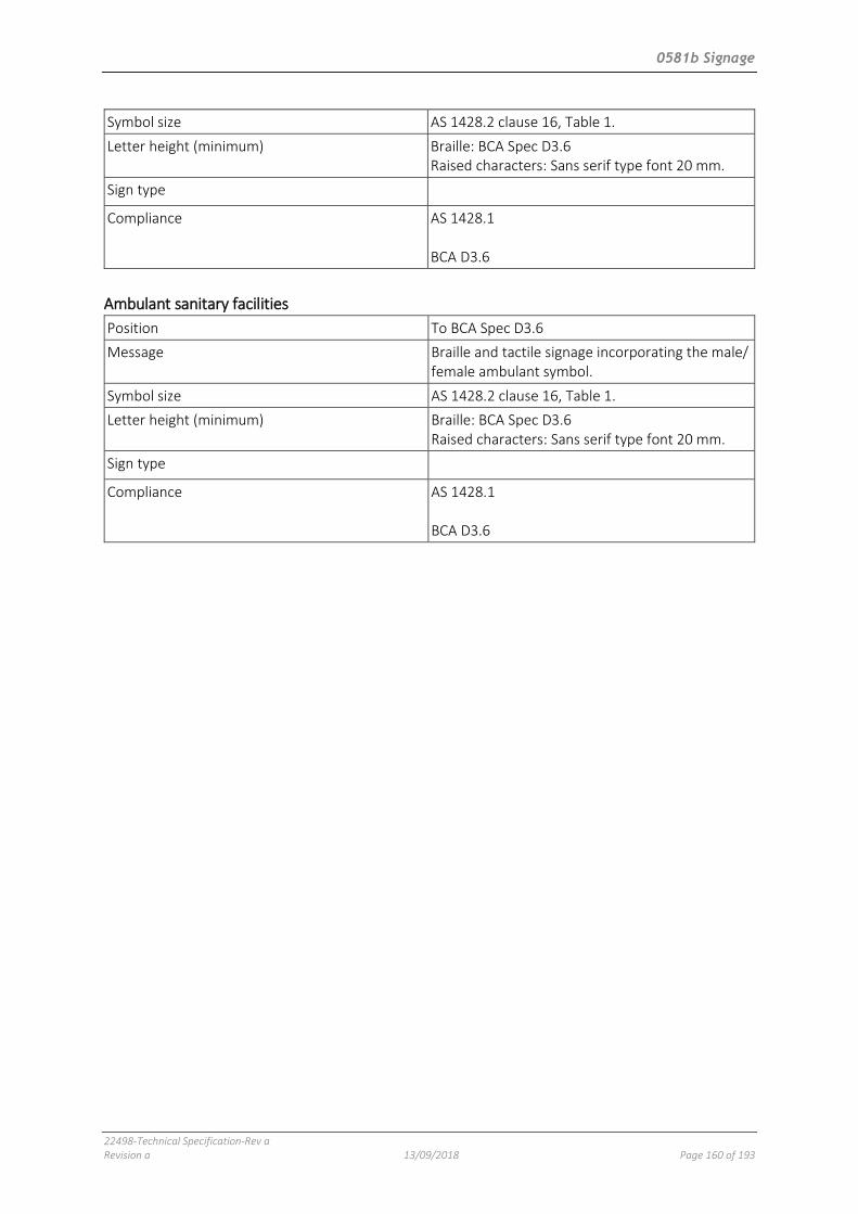
0581b Signage
22498-Technical Specification-Rev a Revision a 13/09/2018 Page 160 of 193
Symbol size AS 1428.2 clause 16, Table 1.
Letter height (minimum) Braille: BCA Spec D3.6 Raised characters: Sans serif type font 20 mm.
Sign type
Compliance AS 1428.1 BCA D3.6
Ambulant sanitary facilities
Position To BCA Spec D3.6
Message Braille and tactile signage incorporating the male/ female ambulant symbol.
Symbol size AS 1428.2 clause 16, Table 1.
Letter height (minimum) Braille: BCA Spec D3.6 Raised characters: Sans serif type font 20 mm.
Sign type
Compliance AS 1428.1 BCA D3.6

0612b Cementitious toppings
22498-Technical Specification-Rev a Revision a 13/09/2018 Page 161 of 193
0612B CEMENTITIOUS TOPPINGS
1 GENERAL
1.1 RESPONSIBILITIES
General Requirement: Provide cementitious toppings, as documented.
Performance Requirements:
- If floating, without edge curl.
- If bonded, without drummy areas.
- Without obvious shrinkage cracks.
1.2 CROSS REFERENCES
General Requirement: Conform to the following:
- 0171 General requirements.
- 0631 Ceramic tiling
1.3 INTERPRETATION
Definitions General: For the purposes of this worksection the following definitions apply:
- Concrete class:
o Normal: Concrete which is specified primarily by a standard compressive strength grade and otherwise in conformance with AS 1379 clause 1.5.3.
- Substrate: The surface to which a material or product is applied.
- Topping: Mixture of binders, aggregate and water applied to substrates in a plastic state and dried and cured to a hard surface.
- Topping function:
o Levelling: Topping placed to receive applied floor finishes.
o Wearing: Topping placed to act as the finished floor.
- Topping method:
o Bonded or post applied: Topping which is bonded to a hardened substrate from which laitance has been removed and to which a bonding agent has been applied.
o Monolithic or wet applied: Topping placed on a plastic substrate so that a chemical bond is created between the substrate and the topping.
1.4 STANDARDS
Slip resistance Classification: To AS 4586.
1.5 TOLERANCES
General Thickness: Deviation from the documented thickness:
- Thickness < 15 mm: ± 2 mm.
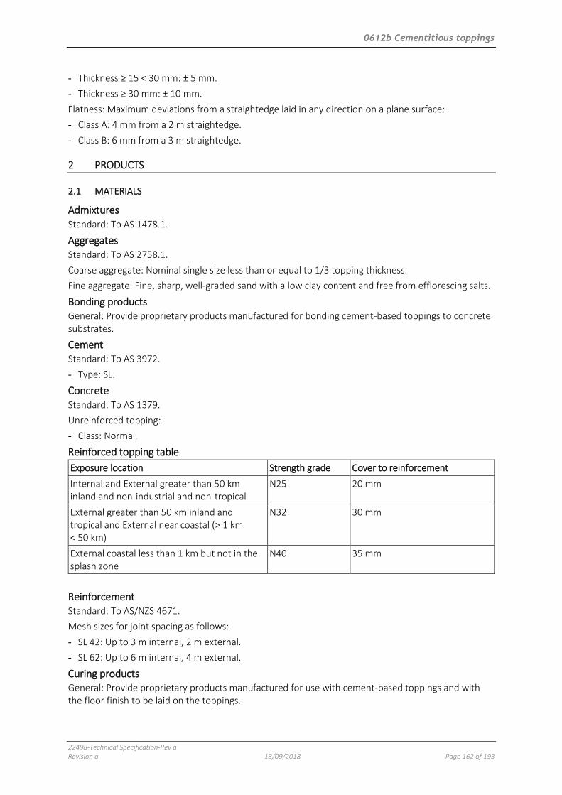
0612b Cementitious toppings
22498-Technical Specification-Rev a Revision a 13/09/2018 Page 162 of 193
- Thickness ≥ 15 < 30 mm: ± 5 mm.
- Thickness ≥ 30 mm: ± 10 mm.
Flatness: Maximum deviations from a straightedge laid in any direction on a plane surface:
- Class A: 4 mm from a 2 m straightedge.
- Class B: 6 mm from a 3 m straightedge.
2 PRODUCTS
2.1 MATERIALS
Admixtures Standard: To AS 1478.1.
Aggregates Standard: To AS 2758.1.
Coarse aggregate: Nominal single size less than or equal to 1/3 topping thickness.
Fine aggregate: Fine, sharp, well-graded sand with a low clay content and free from efflorescing salts.
Bonding products General: Provide proprietary products manufactured for bonding cement-based toppings to concrete substrates.
Cement Standard: To AS 3972.
- Type: SL.
Concrete Standard: To AS 1379.
Unreinforced topping:
- Class: Normal.
Reinforced topping table
Exposure location Strength grade Cover to reinforcement
Internal and External greater than 50 km inland and non-industrial and non-tropical
N25 20 mm
External greater than 50 km inland and tropical and External near coastal (> 1 km < 50 km)
N32 30 mm
External coastal less than 1 km but not in the splash zone
N40 35 mm
Reinforcement Standard: To AS/NZS 4671.
Mesh sizes for joint spacing as follows:
- SL 42: Up to 3 m internal, 2 m external.
- SL 62: Up to 6 m internal, 4 m external.
Curing products General: Provide proprietary products manufactured for use with cement-based toppings and with the floor finish to be laid on the toppings.

0612b Cementitious toppings
22498-Technical Specification-Rev a Revision a 13/09/2018 Page 163 of 193
Mixes General: Provide toppings as follows or select mix proportions to the Mix proportion table:
- Air entrainment: ≤ 3%.
- Nominal coarse aggregate size: ≤ 0.3 x topping thickness.
- Slump: 80 mm.
- Standard strength grade: N25.
Water quantity: The minimum necessary to achieve full compaction and prevent excessive water being brought to the surface during compaction.
Mix proportion table
Mix type Thickness (mm) Upper and lower limits of proportions by weight
Cement Fine aggregate Coarse aggregate
Bonded – cement and sand
35 1 1
3 4.5
0 0
Bonded – fine concrete 40 1 1
3 3
1 2
Floating – fine concrete 100 1 1
3 3
1 2
Granolithic Floors: 25 Skirtings: 13 1 2 1, of 2 mm - 3 mm
Separated – fine concrete
70 1 1
3 3
1 2
Water General: Clean and free from any deleterious matter.
3 EXECUTION
3.1 PREPARATION
Substrates General: Provide substrates as follows:
- Clean and free from any deposit which may impair adhesion of monolithic or bonded toppings.
- Remove excessive projections and voids and fill hollows with a mix not stronger than the substrate or weaker than the topping.
- Roughen hardened concrete by scabbling or the like to remove 2 mm of the laitance and expose the aggregate.
Bonded toppings General: Before laying topping wash the substrate with water and provide a bonding product, or treat as follows:
- Keep wet for 2 hours or more.
- Remove surplus water and brush on neat cement or a clean slurry of cement and water.
- Place the topping while the slurry is wet.
3.2 APPLICATION
Laying General: Spread the mix and compact. Strike off, consolidate and level surfaces to finished levels.
Monolithic toppings: Lay while concrete subfloor is plastic and the surface water is no longer visible.

0612b Cementitious toppings
22498-Technical Specification-Rev a Revision a 13/09/2018 Page 164 of 193
Toppings over 50 mm thick:
- Lay in two layers of equal thickness.
- Place a layer of reinforcement between the layers of toppings. Lap reinforcement 200 mm and tie. Do not create four way laps.
3.3 SURFACE FINISHES
Finishing methods – primary finish Machine float finish:
- After levelling, consolidate the surface using a machine float.
- Cut and fill and refloat immediately to a uniform, smooth, granular texture.
- Hand float in locations inaccessible to the machine float.
Steel trowel finish: After machine floating finish as follows:
- Produce a smooth surface relatively free from defects using power tools.
- When the surface has hardened sufficiently, use steel hand trowels to produce the final consolidated finish free of trowel marks and uniform in texture and appearance.
Scored or scratch finish: After screeding, give the surface a coarse scored texture using a stiff brush or rake drawn across the surface before final set.
Surface finishes General: Provide surface finishes as documented in the Cementitious toppings construction schedule.
Slip-resistant treatment Surface treatment: Apply silicon carbide granules after floating and before the topping surface has set, and trowel into the surface so that the granules remain exposed.
Application rate: 1 kg/m2 evenly distributed.
Slip-resistant treatment to stair treads Slip resistance treatment: Form two grooves and fill with a silicon carbide two-part resin.
Dimensions: 10 mm deep, 15 mm wide, length width of tread less 100 mm.
Position:
- First groove: Centre 35 mm from tread nose.
- Second groove: Centre 60 mm from step nose.
Surface treatment General: Apply the surface treatment after floating and before the topping surface has set.
Temperature General: Make sure that the temperature of mixes, substrates and reinforcement are not less than 5ºC or greater than 35ºC at the time of application.
Severe temperature: If the ambient shade temperature is greater than 38°C, do not mix topping.
3.4 CONTROL OF MOVEMENT
General Requirement: Provide control joints as follows and as documented in the Control joints schedule:
- Location:
. Over structural control joints.
. To divide complex room plans into rectangles.
. Around the perimeter of the floor.
. At junctions between different substrates.

0612b Cementitious toppings
22498-Technical Specification-Rev a Revision a 13/09/2018 Page 165 of 193
. To divide large topping-finished areas into bays.
. At abutments with the building structural frame and over supporting walls or beams where flexing of the substrate is anticipated.
- Depth of joint: Right through to the substrate.
- Depth of elastomeric sealant: One half the joint width, or 6 mm, whichever is the greater.
Control joints to divide topping into bays: Provide joints using one of the following methods:
- Form in situ using square edge steel forms and trowelling a 3 mm radius to edges.
- Form a groove, extending at least one quarter the depth of the section, either by using a grooving tool, by sawing, or by inserting a premoulded strip.
- Install a control joint product.
3.5 JOINT ACCESSORIES
Weather bars General: Provide a corrosion-resistant metal weather bar under hinged external doors. Locate under the centres of closed doors.
Floor finish dividers General: Finish cementitious toppings at junctions with differing floor finishes with a corrosion resistant metal dividing strip suitably fixed to the substrate, with top edge flush to the finished floor. If changes of floor finish occur at doorways make the junction directly below the centre of the closed door.
3.6 COMPLETION
Curing General: Prevent premature or uneven drying out and protect from the sun and wind.
Curing: Use a curing product or, as soon as toppings have set sufficiently, keep them moist by covering with polyethylene film for seven days.
Joint sealant General: If required, seal joints as follows:
- Formed joints: ≤ 25 mm deep with filler and bond-breaker.
- Sawn joints: Full depth of cut.
Protection General: Protect finished work from damage during building operations.
4 SELECTIONS
Cementitious topping to be applied to wet area floors to achieve falls to floor wastes.

0621 Waterproofing – wet areas
22498-Technical Specification-Rev a Revision a 13/09/2018 Page 166 of 193
0621 WATERPROOFING – WET AREAS
1 GENERAL
1.1 RESPONSIBILITIES
General Requirement: Provide wet area waterproofing systems as documented.
Performance Requirements:
- Grade to floor wastes, to dispose of water without ponding.
- Prevent moisture entering the substrate or adjacent areas.
1.2 CROSS REFERENCES
General Requirement: Conform to the following:
- 0171 General requirements.
- 0631 Ceramic tiling
1.3 STANDARDS
Waterproofing wet areas Standard: To AS 3740.
1.4 INTERPRETATION
Definitions General: For the purposes of this worksection the definitions given in AS 3740 and the following apply:
- Bond breaker: A system preventing a membrane bonding to the substrate, bedding or lining.
- Membranes (waterproof): Impervious barriers to liquid water which may be:
. Installed below floor finishes.
. Installed behind the wall sheeting or render and termed External.
. Installed to the face of the wall sheeting or render and termed Internal.
. Applied in liquid or gel form and air cured to form a seamless film.
. Applied in sheet form with joints lapped and sealed.
- Substrate: The surface to which a material or product is applied.
- Waterproof (WP): The property of a material that does not allow moisture to penetrate through it.
- Waterproofing systems: Combinations of membranes, flashings, drainage and accessories which form waterproof barriers and which may be:
. Bonded to substrates.
- Water resistant (WR): The property of material that restricts moisture movement and will not degrade under conditions of moisture.
- Wet area: An area within a building supplied with a floor waste.

0621 Waterproofing – wet areas
22498-Technical Specification-Rev a Revision a 13/09/2018 Page 167 of 193
1.5 SUBMISSIONS
Products and materials Documentation: Submit copies of product manufacturer's:
- Product technical data sheets.
- Safety data sheets (SDS).
- Type tests certificates verifying conformance to AS/NZS 4858.
Records Placing records: Photographically record the application of membranes and information as follows:
- Date.
- Portion of work.
- Substrate preparation.
- Protection provided from traffic.
Warranties Requirement: Submit warranties to COMPLETION, Warranties.
1.6 INSPECTION
Notice Inspection: Give notice so that inspection may be made of the following:
- Substrate preparation completed.
- Secondary layers preparation completed.
- Before membranes are covered up or concealed.
- After flood testing, if applicable.
2 PRODUCTS
2.1 GENERAL
Storage and handling Store and handle to the manufacturer's recommendations and as follows:
- Protect materials from damage.
Marking Identification: Marked to show the following:
- Manufacturer’s identification.
- Product brand name.
- Product type.
- Quantity.
- Product reference code and batch number.
- Date of manufacture.
- Material composition and characteristics such as volatility, flash point, light fastness, colour and pattern.
2.2 MEMBRANES
Standards Standard: To AS/NZS 4858.

0621 Waterproofing – wet areas
22498-Technical Specification-Rev a Revision a 13/09/2018 Page 168 of 193
Membrane systems Requirement: Provide a proprietary membrane systems suitable for the intended internal wet area waterproofing.
2.3 ACCESSORIES
Water stop angles Material: Rigid, corrosion resistant angles compatible with the waterproof membrane system.
Bond breakers Requirement: Compatible with the extensibility class of the membrane to be used.
Material: Purpose made bond breaker tapes and closed cell foam backing rods or fillets of sealant.
Flashings Requirement: Flexible waterproof flashings compatible with the waterproof membrane system.
Liquid membrane reinforcement Requirement: Flexible fabric compatible with the waterproof membrane system.
Sealants Requirement: Waterproof, flexible, mould-resistant and compatible with host materials.
Adhesives Requirement: Waterproof and compatible with host materials.
3 EXECUTION
3.1 PREPARATION
Substrates General: Make sure substrates are as follows:
- Clean and free of any deposit or finish which may impair adhesion of membranes.
- If walls are plastered, remove loose sand.
- If walls or floors are framed or discontinuous, support members are in full lengths without splicing.
- If floors are solid or continuous:
. Excessive projections are removed.
. Voids and hollows greater than 10 mm with abrupt edges are filled with a cement:sand mix not stronger than the substrate nor weaker than the bedding.
. Depressions less than 10 mm are filled with a latex modified cementitious product with feathering eliminated by scabbling the edges.
. Cracks in substrates wider than 1.5 mm are filled with a filler compatible with the membrane system.
Concrete substrates: Cure for more than 28 days.
External corners: Round or arris edges.
Moisture content Requirement: Verify that the moisture content of the substrate is compatible with the water vapour transmission rate of the membrane system by testing to AS 1884 Appendix A.
Falls Membrane directly under the floor finish: Make sure the fall in the substrate conforms to the fall documented for the finish.
Sheet substrate fastening Requirement: Fasten or adequately fix to the supporting structure.

0621 Waterproofing – wet areas
22498-Technical Specification-Rev a Revision a 13/09/2018 Page 169 of 193
Control joints Finishes: Align control joints in finishes and bedding with control joints or changes in materials in the substrate.
Water stop angles Requirement: Provide water stop angles at door thresholds and shower enclosures to support the waterproof membrane at junctions between waterproofed and non-waterproofed areas.
Sizing: Size the vertical leg of the water stop angle to conform to the requirements of AS 3740.
Corners: Cut the horizontal leg and bend the vertical leg at corners instead of forming vertical joints between separate lengths of angle.
Fixing: Fix water stop angles to the substrate with compatible sealant or adhesive and corrosion-resistant countersunk or wafer head screws.
Priming Compatibility: If required, prime the substrates with compatible primer for adhesion of the membrane system.
Bond breakers Requirement: After the priming of surfaces, provide bond breakers at all wall/floor, hob/wall junctions and at control joints where the membrane is bonded to the substrate.
Sealant fillet bond breakers:
- Application: Form a triangular fillet or cove of sealant to internal corners within the period recommended by the membrane manufacturer after the application of the primer.
- Widths: 5 mm x 5 mm to vertical corners. 6 mm x 6 mm to 9 mm x 9 mm to horizontal corners.
Backing rod bond breakers: Retain in position with continuous length of tape pressed firmly in place against the surfaces on each side of the rod.
3.2 APPLICATION
Protection Damage: Protect membrane from damage during installation and for the period after installation until the membrane achieves its service characteristics that resist damage.
Extent of waterproofing Waterproof or water resistant surfaces: To the requirements of BCA F1.7 for Class 2, 3 and 4 buildings, or BCA 3.8.1.2 for Class 1 buildings.
Sheet membrane joints Bituminous sheet membranes:
- Side laps at least 75 mm.
- End laps at least 100 mm.
Synthetic rubber membranes:
- Factory-vulcanized laps at least 40 mm.
- Field side laps at least 50 mm for side laps.
- Field end-laps at least 100 mm for end laps.
PVC membranes:
- Factory welded laps at least 30 mm.
- Field–welded laps at least 75 mm.
Vertical membrane terminations Upstands: At least 150 mm above the finished tile level of the floor or 25 mm above the maximum retained water level, whichever is the greater.
0621 Waterproofing – wet areas
22498-Technical Specification-Rev a Revision a 13/09/2018 Page 170 of 193
Anchoring: Secure sheet membranes along the top edge.
Edge protection: Protect edges of the membrane.
Flashings Junctions between waterproof surfaces: Provide a bond breaker at internal corners behind flashings.
Junctions between waterproof surfaces and other surfaces: Provide a bead of sealant at the following junctions:
- Waterproof and water-resistant surfaces.
- Water-resistant and water-resistant surfaces.
- Water-resistant and non water-resistant surfaces.
Perimeter flashings: Provide continuous flashings to the full perimeter of waterproof areas at wall/floor junctions and to water stop angles.
Vertical flashings: Provide vertical corner flashings continuous across wall/wall junctions to at least 1800 mm above finished floor level.
Vertical liquid applied flashings:
- Return legs at least 40 mm on each wall.
- Overlap the vertical termination of the floor waterproofing membrane at least 20 mm.
Vertical sheet flashings:
- Return legs at least 50 mm on each wall.
- Overlap shower tray upstands at least 50 mm.
- Do not penetrate flashing with wall lining fasteners.
Reinforcement: At coves, corners and wall/floor junctions with gaps greater than 3 mm reinforce liquid applied membranes with reinforcement fabric tape recommended by the membrane manufacturer. Fold the tape in half lengthways and imbed it in the first flashing coat of membrane with one half of the tape on each side of the corner or joint. Apply a second coat of liquid membrane to seal the fabric.
Door jambs and architraves Requirement: If the bottom of doorjambs and architraves do not finish above the floor tiling, waterproof their surfaces below tile level to provide a continuous seal between the perimeter flashing to the wall/floor junction and the water stop angle.
Drainage connections Floor wastes: Provide floor wastes of sufficient height to accommodate the thickness of floor finishes and bedding at the outlet position. Position drainage flange to drain at membrane level. Turn membrane down 50 mm minimum into the floor waste drainage flanges, and adhere to form a waterproof connection.
Floor wastes in shower trays: Provide drainage of the tile bed and a waterproof connection between the tray and the drain.
Preformed drainage channels:
- With continuous drainage flanges: Provide a continuous waterproof connection between the membrane and the channel.
- Without drainage flanges: Provide continuous waterproofing under the channel and terminate the membrane at a floor waste with a recessed drainage flange.
Unenclosed showers Requirement: Extend membrane at least 1500 mm into the room from the shower rose outlet, on the walls and floor.

0621 Waterproofing – wet areas
22498-Technical Specification-Rev a Revision a 13/09/2018 Page 171 of 193
Taps and spouts Requirement: Waterproof penetrations for taps and spouts with proprietary flange systems or a sealant.
Provision for servicing: Install taps in a manner that allows tap washers or ceramic discs to be serviced without damaging the waterproofing seal.
Recessed soap holders Construction: Support all faces of the recess and line with the same sheet material as the adjacent wall. Fall base of recess towards the shower area. Flash all junctions and waterproof all surfaces.
Curing of liquid applied systems General: To the manufacturer's instructions.
Curing: Allow membrane to fully cure before tiling.
Overlaying finishes on membranes Requirement: Protect waterproof membranes with compatible water-resistant surface materials that do not cause damage to the membrane.
Suitable materials: Conform to AS 3740.
Bonded or partially bonded systems: If the topping or bedding mortar is required to be bonded to the membrane, provide sufficient control joints in the topping or bedding mortar to reduce the movement over the membrane.
3.3 TESTING
Flood test Application: Perform a flood test before the installation of surface finishes.
Moisture content measurement method: Conform to AS 1884 Appendix A.
Set-up:
- Measure the wall/floor junction of adjacent spaces and the floor soffit below for dryness.
- Record the result for each area.
- Dam the doorway(s) and seal floor wastes and drainage outlets to allow 50 mm water level.
- Fill space with clean water and leave overnight.
Evaluation:
- Make a visual inspection of the wall/floor junction of adjacent spaces and of the floor soffit below for obvious water or moisture.
- Test the same areas for dryness and compare the results to the measurements taken before flooding.
Compliance:
- Evidence of water from the visual test: Failure.
- No visual evidence of water: Proceed with moisture measurements.
- Test results indicating an increase in moisture before and after flooding: Failure.
Records:
- Submit records of all flood tests.
3.4 COMPLETION
Protection General: Keep traffic off membrane surfaces until bonding has set or for 24 hours after laying, whichever period is the longer.
Reinstatement: Repair or replace faulty or damaged work.

0621 Waterproofing – wet areas
22498-Technical Specification-Rev a Revision a 13/09/2018 Page 172 of 193
Warranties Requirement: Cover materials and workmanship in the terms of the warranty in the form of interlocking warranties from the supplier and the applicator.
- Form: Against failure of materials and execution under normal environment and use conditions.
- Period: As offered by the supplier.
4 SELECTIONS
4.1 SYSTEMS
Liquid applied membrane systems schedule
Seamless wet area membrane
Proprietary system “Duro Mastic P15” under-tile modified acrylic urethane waterproofing membrane by Durotech (T: 02 9603 1177)
Location To all tiled floors in wet areas and also to tiled walls and tiled splashbacks.
0631b Ceramic tiling
22498-Technical Specification-Rev a Revision a 13/09/2018 Page 173 of 193
0631B CERAMIC TILING
1 GENERAL
1.1 RESPONSIBILITIES
General Requirement: Provide tiling systems to walls, floors and other substrates as documented.
Performance Requirements:
- Consistent in colour and finish.
- Firmly bonded to substrates for the expected life of the installation.
- Set out with joints accurately aligned in both directions and wall tiling joints level and plumb.
- Direct all water flowing from supply points to drainage outlets without leakage to the substrate or adjacent areas.
1.2 CROSS REFERENCES
General Requirement: Conform to the following:
- 0171 General requirements.
- 0621 Waterproofing – wet areas.
- Schedule of Finishes.
1.3 STANDARDS
Tiling General: Conform to the documented recommendations of those parts of AS 3958.1 which are referenced in this worksection.
Slip resistance Classification: To AS 4586.
1.4 INTERPRETATION
Definitions General: For the purposes of this worksection the following definitions apply:
- Adhesives:
o Cementitious (C): Adhesives in which the binders are hydraulic, e.g. Portland cement, with aggregates and organic additives.
o Dispersion (D): Adhesives in which the binders are in the form of aqueous polymer dispersion with mineral fillers and organic additives.
o Reaction resin (R): Adhesives in which in the binders are synthetic resins with mineral fillers and organic additives. The curing occurs by chemical reaction.
- Bedding: Mixtures of materials which are applied to substrates in a plastic state and which dry, cure and adhere tiles to substrates.
o Adhesive bedding: Tiling adhered by adhesives.
o Mortar bedding: Tiling adhered in a cementitious mortar bed.
- Lippage: Height deviation between adjacent tiles.
0631b Ceramic tiling
22498-Technical Specification-Rev a Revision a 13/09/2018 Page 174 of 193
- Stepping: The relative surface level of adjacent paving elements within the expanse of the main pavement.
- Substrate: The surface to which a material or product is applied.
- Tiles: Thin slabs made from clays and/or other inorganic raw materials used generally as coverings for floors and walls and adhered to continuous supporting substrates.
o Cementitious: Cement based pre-finished tiles.
- Underlay: A non-structural layer of sheet material or an in situ levelling material on the subfloor to provide a smooth level surface.
- Wet area: An area within a building supplied with a floor waste.
1.5 TOLERANCES
Completed tiling Requirement: To the recommendations of AS 3958.1 clause 5.4.6.
1.6 SUBMISSIONS
Product and materials Type tests: Submit results, as follows:
- Slip resistance of tiles.
Samples General: Submit labelled samples of tiles, including fittings, accessories, grout and sealants, illustrating the range of variation in colour and finish.
Sample panels: Prepare a sample panel of each type of tiling system as follows:
- Size: > 2 m2.
- Include samples of junction details and trim.
- Preserve the panel until related work is complete.
Tests Site tests: Submit results, as follows:
- Slip resistance of completed installation.
- Impact sound insulation.
1.7 INSPECTION
Notice Inspection: Give notice so that inspection may be made of the following:
- Substrate immediately before tiling.
- Trial set-outs before execution.
- Control joints before sealing and grouting.
- Grout and sealant colours before application.
2 PRODUCTS
2.1 GENERAL
Marking Identification: Marked to show the following:
- Manufacturer’s identification.
- Product brand name.

0631b Ceramic tiling
22498-Technical Specification-Rev a Revision a 13/09/2018 Page 175 of 193
- Product type.
- Quantity.
- Product reference code and batch number.
- Date of manufacture.
2.2 TILES AND ACCESSORIES
Tiles Standard: To AS ISO 13006.
Tactile ground surface indicators: To AS/NZS 1428.4.1.
Coves, nosings and skirtings: Provide matching stop-end and internal and external angle tiles moulded for that purpose.
Exposed edges: Purpose-made border tiles with the exposed edge (whether round, square or cushion) glazed to match the tile face. If such tiles are not available, mitre tiles on external corners.
Accessories General: Provide tile accessories which match the composition, colour and finish of the surrounding tiles.
2.3 ADHESIVES
General Standard: To AS ISO 13007.1.
Type General: Provide adhesives compatible with the materials and surfaces to be adhered, and as documented in the Wall tiling schedule and the Floor tiling schedule.
Prohibited uses: Do not provide the following combinations:
- Cement-based adhesives on wood, metal, painted or glazed surfaces, gypsum-based plaster.
- Organic solvent-based adhesives on painted surfaces.
- Organic PVC-based adhesives and organic natural rubber latex adhesives in damp or wet conditions.
- PVA (polyvinyl acetate) based adhesives in wet areas or externally.
2.4 MORTAR
Materials Cement type to AS 3972: GP.
- White cement: Iron salts content not more than 1%.
- Off-white cement: Iron salts content not more than 2.5%.
Lime: To AS 1672.1.
Sand: Fine aggregate with a low clay content selected for grading, sharp and free from efflorescing salts.
Measurement of volume: Measure binders and sand by volume using buckets or boxes. Do not allow sand to bulk by absorption of water.
Bedding mortar Mix proportion (cement:sand), by volume: Select proportions from the range 1:3 to 1:4 for satisfactory adhesion. Provide minimum water.
Terracotta tiles: Use proprietary polymer modified mortar.
Mixing: To AS 3958.1 clause 2.15.

0631b Ceramic tiling
22498-Technical Specification-Rev a Revision a 13/09/2018 Page 176 of 193
Water General: Clean and free from any deleterious matter.
2.5 GROUT
Type Cement based proprietary grout: Mix with water. Fine sand may be added as a filler in wider joints.
Terracotta tiles: Use proprietary polymer modified grout.
General purpose cement based grout: Mix with fine sand. Provide minimum water consistent with workability.
Mix proportions (cement:sand), by volume:
- For joints < 3 mm: 1:2.
- For joints ≥ 3 mm: 1:3.
Pigments Pigments for coloured grout: Provide colourfast fillers compatible with the grout material. For cement-based grouts, provide lime-proof natural or synthetic metallic oxides compatible with cement.
2.6 CONTROL JOINTS
Control joint materials General: As documented in the Control joint schedule.
Control joint strip: A proprietary control joint consisting of a neoprene core sandwiched between metal plates with lugs or ribs for mechanical keying. Set flush with the finished surface.
Proprietary slide plate divider strip: An arrangement of interlocking metal plates grouted into pockets formed in the concrete joint edges.
Sealant: One-part self-levelling non-hardening mould resistant, silicone or polyurethane sealant applied over a backing rod. Finish flush with the finished surface.
- Floors: Trafficable, shore hardness greater than 35.
Backing rod: Compressible closed cell polyethylene foam with a bond-breaking surface.
3 EXECUTION
3.1 SUBSTRATES
Drying and shrinkage General: Before tiling, allow at least the following times to elapse (for initial drying out and shrinkage) for these substrates:
- Concrete slabs: 42 days.
- Concrete blockwork: 28 days.
- Toppings on slabs and rendering on brick or blockwork: A further 21 days.
- Rendering on swimming pool shell: A further 21 days minimum.
3.2 PREPARATION
Standard Preparation: To AS 3958.1 Section 4.
Ambient temperature General: If the ambient temperature is less than 5°C or greater than 35°C, do not lay tiles.

0631b Ceramic tiling
22498-Technical Specification-Rev a Revision a 13/09/2018 Page 177 of 193
Substrates without wet area membranes General: Conform to the following:
- Clean off of any deposit or finish which may impair adhesion or location of tiles.
- If framed or discontinuous, support members are in full lengths without splicing.
- If solid or continuous:
. Remove excessive projections.
. Fill voids and hollows greater than 10 mm with abrupt edges with a cement:sand mix not stronger than the substrate or weaker than the bedding.
. Fill depressions less than 10 mm with a latex modified cementitious product and eliminate feathering by scabbling the edges.
Absorbent substrates: If suction is excessive, control it by dampening but avoid over-wetting and do not apply mortar bedding to substrates showing surface moisture.
Dense concrete: If not sufficiently rough to provide a mechanical key, roughen by scabbling or the like to remove 3 mm of the surface and expose the aggregate; then apply a bonding treatment.
Substrates with wet area membranes General: Make sure substrates are as follows:
- Clean and free of any deposit or finish which may impair adhesion or location of tiles.
- Compatible with all components of the floor system.
3.3 FIXING UNDERLAY
Installation Requirement: Lay in staggered (brick) pattern, perpendicular to the direction of the subfloor, with joins in the underlay not coinciding with joints in the subfloor. Fix with fasteners and fastener spacing to the manufacturers recommendations.
3.4 TILING GENERALLY
Cutting and laying Cutting: Cut tiles neatly to fit around fixtures and fittings and at margins where necessary. Drill holes without damaging tile faces. Cut recesses for fittings such as soap holders. Rub edges smooth without chipping.
Laying: Return tiles into sills, reveals and openings. Butt up to returns, frames, fittings, and other finishes. Strike and point up beds where exposed. Remove tile spacers before grouting.
Variations General: Distribute variations in hue, colour, or pattern uniformly, by mixing tiles or tile batches before laying.
Protection Floor tiles: Keep traffic off floor tiles until the bedding has set and attained its working strength.
Cleaning: Keep the work clean as it proceeds and protect finished work from damage.
Bath ventilation General: Ventilate the space below fully enclosed baths with at least 2 vermin proof ventilating tiles.
3.5 SETTING OUT
Tile joints Joint widths: Set out tiles to give uniform joint widths within the following limits:
- Floors:
. Dry pressed tiles: 3 mm.
0631b Ceramic tiling
22498-Technical Specification-Rev a Revision a 13/09/2018 Page 178 of 193
. Extruded tiles: 6 mm.
. Vitrified: 3 to 5 mm.
. Quarry tiles: 6 to 12 mm.
. Chemical resistant epoxy jointed tiling: 5 to 6 mm.
- Large and/or irregular floor tiles: 6 to 12 mm.
- Mounted mosaics: To match mounting pattern.
- Walls:
. Dry pressed tile: 1.5 mm.
. Extruded tile: 6 mm.
Joint alignment: Set out tiling with joints accurately aligned in both directions and wall tiling joints level and plumb.
Joint position: Set out tiles from the centre of the floor or wall to be tiled.
Margins General: Provide whole or purpose-made tiles at margins where practicable, otherwise, set out to give equal margins of cut tiles. If margins less than half a tile width are unavoidable, locate the cut tiles where they are least conspicuous.
Fixtures General: If possible position tiles so that holes for fixtures and other penetrations occur at the intersection of horizontal and vertical joints or on the centre lines of tiles. Continue tiling fully behind fixtures which are not built in to the tiling surface. Before tiling make sure that fixtures interrupting the tile surfaces are accurately positioned in their designed or optimum locations relative to the tile layout.
3.6 FALLS AND LEVELS
Grading General: Grade floor tiling to even and correct falls to floor wastes and elsewhere as required. Make level junctions with walls. Where falls are not required, lay level.
Fall, general: 1:100 minimum.
Fall, in shower areas: 1:60 minimum.
Change of finish: Maintain finished floor level across changes of floor finish including carpet.
3.7 BEDDING
Standard Cement mortar: To AS 3958.1 clause 5.5.
Adhesive: To AS 3958.1 clause 5.6.
Preparation of tiles Adhesive bedding: Fix tiles dry; do not soak.
Mortar bedding: Soak porous tiles in water for half an hour and then drain until the surface water has disappeared.
Terracotta tiles: Use pre-sealed tiles or apply a breathable sealer and lay dry. If a final sealed finish is selected, use a compatible laying sealer.
Bedding General: Use bedding methods and materials which are appropriate to the tile, the substrate, the conditions of service, and which leave the tile firmly and solidly bedded in the bedding material and adhered to the substrate. Form falls integral with the substrate.

0631b Ceramic tiling
22498-Technical Specification-Rev a Revision a 13/09/2018 Page 179 of 193
Thin adhesive beds General: Provide only if the substrate deviation is less than 3 mm, tested with a 3 m straightedge. Cover the entire tile back with adhesive when the tile is bedded.
Thickness: 1.5 to 3 mm.
Thick adhesive beds General: Provide on substrates with deviations up to 6 mm, tested with a 3 m straightedge, and with tiles having deep keys or frogs.
Nominal thickness: 6 mm.
Adhesive bedding application General: Apply adhesive by notched trowel to walls and floors and direct to tiles if required, to provide evenly distributed coverage after laying as follows:
- Domestic internal walls: > 65%.
- Domestic internal floors: > 80%.
- Other wall and floors: > 90%.
- Wet areas and bench tops: 100%.
Pattern of distribution of adhesive: To the recommendations of AS 3958.1 clause 5.6.4.3. Verify by examining one tile in ten as work proceeds.
Wall tile spacers: Do not use spacer types that inhibit the distribution of adhesive.
Curing: Allow the adhesive to cure for the period nominated by the manufacturer before grouting or allowing foot traffic.
Mortar beds For floor tiles: Either lightly dust the screeded bed surface with dry cement and trowel level until the cement is damp, or spread a thin slurry of neat cement, or cement-based thin bed adhesive, on to the tile back. Do not use mortar after initial set has occurred.
- Nominal thickness: 20 to 40 mm.
Thick reinforced beds: Place mortar bed in two layers, and incorporate the mesh reinforcement in the first layer.
3.8 CONTROL OF MOVEMENT
General Requirement: Provide control joints carried through the tile and the bedding to the recommendations of AS 3958.1 clause 5.4.5 and as follows:
- Floor location:
. Over structural control joints.
. To divide complex room plans into rectangles.
. Around the perimeter of the floor.
. At junctions between different substrates.
. To divide large tiled areas into bays.
. At abutments with the building structural frame and over supporting walls or beams where flexing of the substrate is anticipated.
- Wall location:
. Over structural control joints.
. At junctions with different substrate materials when the tiling is continuous.
. At vertical corners in shower compartments.
- Depth of joint: Right through to the substrate.

0631b Ceramic tiling
22498-Technical Specification-Rev a Revision a 13/09/2018 Page 180 of 193
- Sealant width: 6 to 25 mm.
- Depth of elastomeric sealant: One half the joint width, or 6 mm, whichever is the greater.
3.9 GROUTED AND SEALANT JOINTS
Grouted joints General: Commence grouting as soon as practicable after bedding has set. Clean out joints as necessary before grouting.
Face grouting: Fill the joints solid and tool flush. Clean off surplus grout. Wash down when the grout has set. When grout is dry, polish the tiled surface with grout film remover and a clean cloth.
Edges of tiles: Grout exposed edge joints.
Epoxy grouted joints: Make sure tile edge surfaces are free of extraneous matter such as cement films or wax, before grouting.
Sealant joints General: Provide joints filled with sealant and finished flush with the tile surface as follows:
- Where tiling is cut around sanitary fixtures.
- At internal corners of walls in showers.
- Around fixtures interrupting the tile surface, for example pipes, brackets, bolts and nibs.
- At junctions with elements such as window and door frames and built-in cupboards.
Material: Anti-fungal modified silicone.
Width: 5 mm.
Depth: Equal to the tile thickness.
3.10 JOINT ACCESSORIES
Floor finish dividers General: Finish tiled floors at junctions with differing floor finishes with a corrosion-resistant metal dividing strip fixed to the substrate using mechanical fixings, with top edge flush with the finished floor. If changes of floor finish occur at doorways, make the junction directly below the closed door. Grout up underneath to provide continuous support.
Type: Ribbed brass strip, 2 mm thick.
Stepping: Less than 5 mm.
Adjustments Requirement: Check that the height of the floor finish divider is sufficient for the topping and tile thickness. Adjust as required with a matching flat bar adhesive fixed to the divider angle.
3.11 TESTING
Completion tests Slip resistance of completed installation: To AS 4663.
3.12 COMPLETION
Spare tiles General: Supply spare matching tiles and accessories of each type for future replacement purposes. Store the spare materials on site.
Quantity: At least 1% of the quantity installed.
Cleaning General: Clean tiled surfaces using an appropriate tile cleaning agent, and polish.

0631b Ceramic tiling
22498-Technical Specification-Rev a Revision a 13/09/2018 Page 181 of 193
Operation and maintenance manuals General: Submit a manual describing care and maintenance of the tiling, including procedures for maintaining the slip-resistance classification stating the expected life of the slip-resistance classification.
4 SELECTIONS
4.1 SCHEDULES
Wall tiling schedule
Property Ceramic Wall Tiles
Tile: Type Glazed Tile as per Schedule of Finishes
Tile: Size (mm) 100mm x 100mm
Tile: Colour Refer to Schedule of Finishes
Tile: Edge Square
Adhesive bedding: Type Adhesive
Adhesive bedding: Thickness Thin Bed
Tile pattern Stack bond on horizontal
Grout: Type Cement
Grout: Colour Match tiles

0671b Painting
22498-Technical Specification-Rev a Revision a 13/09/2018 Page 182 of 193
0671B PAINTING
1 GENERAL
1.1 RESPONSIBILITIES
General Requirement: Provide coating systems to substrates, as documented.
Performance Requirement: Provide coating systems as follows:
- Consistent in colour, gloss level, texture and dry film thickness.
- Free of runs, sags, blisters, or other discontinuities.
- Paint systems which are fully opaque or at the documented level of opacity.
- Clear finishes at the level of transparency consistent with the product.
- Fully adhered.
- Resistant to environmental degradation within the manufacturer’s stated life span.
1.2 CROSS REFERENCES
General Requirement: Conform to the following:
- 0171 General requirements.
1.3 STANDARDS
Painting General: To the recommendations of those parts of AS/NZS 2311 referenced in this worksection.
1.4 INTERPRETATION
Definitions - General: For the purposes of this worksection the definitions in AS/NZS 2310 and the following
apply:
- Adhesion: The sum total of forces of attachment between a dry film and its substrate.
- Gloss unit: Numerical value for the amount of specular reflection relative to that of a standard surface under the same geometric conditions.
- Levels of gloss finish: When the specular direction is 60 degrees, a surface with the following specular gloss reading are defined as follows:
o Full gloss finish between 50 and 85 gloss units.
o Semi-gloss between 20 and 50 gloss units.
o Low gloss between 5 and 20 gloss units (also known as low sheen).
1.5 SUBMISSIONS
Samples Clear finish coatings: Submit samples of timber or timber veneer matching those to be used in the works as follows:
- Requirement: Label for identification and prepare, putty, stain, seal and coat in conformance with the documented system.
- Size: Large enough to be cut into 4 segments.

0671b Painting
22498-Technical Specification-Rev a Revision a 13/09/2018 Page 183 of 193
Opaque coatings: Submit labelled samples of each coating system, on representative substrates, showing surface preparation, colour, gloss level, texture, and physical properties.
Paint General: Submit the following at least 3 weeks before the paint is required:
- Paint brand name and product range quality statement.
- Safety data sheets (SDS) showing the health and safety precautions to be taken during application.
- The published recommendations for maintenance.
1.6 INSPECTION
Notice Inspection: Give notice so that inspection may be made of the following:
- Painting stages:
. Completion of surface preparation.
. After application of final coat.
- Clear finishing stages:
. Before surface preparation of timber.
. Completion of surface preparation.
. After application of final coat.
2 PRODUCTS
2.1 GENERAL
Storage and handling General: Store materials not in use in tightly covered containers in well-ventilated areas with temperatures maintained at the manufacturer’s recommendations.
2.2 MARKING
Identification General: Deliver materials to the site in the manufacturer’s original sealed containers or packaging, legibly marked to show the following:
- Manufacturer’s identification.
- Product brand name.
- Product type.
- Quantity.
- Product reference code and batch number.
- Date of manufacture.
- Material composition and characteristics such as volatility, flash point, light fastness, colour and pattern. Provide technical data sheets if not shown on labels.
- Handling and installation instructions.
- Safety data sheets.
2.3 PAINTING MATERIALS
Standards Paint types: To AS/NZS 2311 Table 4.2 and the following:
- Metal primer for steel, lead and chromate free: To AS 3730.21 and AS/NZS 3750.19.

0671b Painting
22498-Technical Specification-Rev a Revision a 13/09/2018 Page 184 of 193
- Metal primer, latex: To AS 3730.15.
- Metal primer for metallic-coated surfaces, solvent-borne: To AS 3730.21.
- Zinc-rich organic binder/primer for steel: To AS/NZS 3750.9.
Combinations General: Do not combine paints from different manufacturers in a paint system.
Clear timber finish systems: Provide only the combinations of putty, stain and sealer recommended by the manufacturer of the topcoats.
Putty and fillers Material: To the recommendations of the paint system manufacturer, suitable for the substrate and compatible with the primer.
Tinting General: Provide only products which are colour tinted by the manufacturer or supplier.
Toxic ingredients General: To the Poisons Standard June 2017 (including SUSMP 17) Part 2 Section 7.
3 EXECUTION
3.1 PREPARATION
Order of work Other trades: Before painting, complete the work of other trades as far as practicable within the area to be painted, except for the installation of fittings, floor sanding and laying flooring materials.
Clear finishes: Complete clear timber finishes before commencing opaque paint finishes in the same area.
Protection General: Before painting, clean the area and protect it from dust contamination. Use drop sheets and masking agents to protect surfaces, including finished surfaces and adjacent finishes, during painting.
Fixtures and furniture: Remove door furniture, switch plates, light fittings and other fixtures before painting, and conform to the following:
- Labelling and storage: Attach labels or mark fixtures using a non-permanent method, identifying location and refixing instructions, if required. Store and protect against damage.
Difficult to remove fixtures: Where removal is impractical or difficult, apply surface protection before substrate preparation and painting.
Wet paint warning Notices: Place in a conspicuous location and do not remove until the paint is dry.
Substrate preparation – generally General: Prepare substrates to receive the painting systems to the paint manufacturer’s recommendations.
Cleaning: Clean down the substrate surface. Do not cause damage to the substrate or the surroundings.
Filling: Fill cracks and holes with fillers, sealants, putties or grouting cements as appropriate for the finishing system and substrate, and sand smooth.
- Clear finish: Provide filler tinted to match the substrate.
Clear timber finish systems: Prepare the surface so that its attributes will show through the clear finish without blemishes, using methods including the following:
- Removal of bruises.

0671b Painting
22498-Technical Specification-Rev a Revision a 13/09/2018 Page 185 of 193
- Removal of discolourations, including staining by oil, grease and nailheads.
- Bleaching where necessary to match the timber colour sample.
- Puttying.
- Fine sanding, with the last abrasive no coarser than 220 grit, so that there are no scratches across the grain.
Treated surfaces: If surfaces have been treated with preservatives or fire retardants, make sure coating is compatible with the treatment and does not adversely affect its performance.
Unpainted surfaces Standard: To AS/NZS 2311 Section 3.
3.2 PAINTING
Light levels General: ≥ 400 lux.
Substrate moisture content Requirement: Use a moisture meter to demonstrate that the moisture content of the substrate is at or below the recommended maximum level for the type of paint and the substrate material.
Paint application Standard: To AS/NZS 2311 Section 6.
Timing: Apply the first coat immediately after substrate preparation and before contamination of the substrate can occur. Apply subsequent coats after the manufacturer’s recommended drying period has elapsed.
Painting conditions General: Unless the paint is recommended for such conditions, do not paint under the following conditions:
- Dusty conditions.
- Relative humidity: > 85%.
- Surface temperature: < 10°C or > 35°C.
Priming before fixing General: Apply one coat of wood primer, and 2 coats to end grain, to the back of the following before fixing in position:
- External fascia boards.
- Timber door and window frames.
- Bottoms of external doors.
- Associated trims and glazing beads.
- Timber board cladding.
Spraying General: If the paint application is by spraying, use conventional or airless equipment which conforms to the following:
- Satisfactorily atomises paint being applied.
- Does not require paint to be thinned beyond the maximum amount recommended by the manufacturer.
- Does not introduce oil, water or other contaminants into the applied paint.
Paint with known health hazards: Provide personal protection, masking, ventilating and screening facilities to AS/NZS 4114.1 and AS/NZS 4114.2.

0671b Painting
22498-Technical Specification-Rev a Revision a 13/09/2018 Page 186 of 193
Sanding Clear finishes: Sand the sealer using abrasives no coarser than 320 grit without cutting through the colour. Take special care with round surfaces and edges.
Repair Requirement: Clean off marks, paint spots and stains progressively and restore damaged surfaces to their original condition.
Maintenance painting: To AS/NZS 2311 Section 8.
Repair of galvanizing Cleaning: For galvanized surfaces which have been subsequently welded, power tool grind to remove all surface contaminants, including rust and weld splatter. Prime affected area immediately after cleaning.
Primer: Type 2 organic zinc-rich coating for the protection of steel to AS/NZS 3750.9.
Tinting General: Tint each coat of an opaque coating system so that each has a noticeably different tint from the preceding coat, except for top coats in systems with more than one top coat.
Services General: Paint all new services and equipment, including those in plant rooms, if not embedded, except chromium, anodised aluminium, GRP, PVC-U, stainless steel, non-metallic flexible materials and normally lubricated machined surfaces.
Proprietary items: Repaint only if damaged.
Windows Operation: Make sure opening windows function correctly before and after painting.
Doors Drying: Maintain door leaf in the open position during drying. Do not allow door hardware or accessories to damage the door finish during the drying process.
3.3 COMPLETION
General Protection and masking: Remove masking and protection coverings before paint has dried.
Cleaning: On completion of painting, remove splatters by washing, scraping or other methods which do not scratch or damage adjacent finished surfaces.
Reinstatement: Repair, replace or refinish any damage, including works of other trades. Touch up new damaged decorative paintwork or misses only with the paint batch used in the original application.
Removed fixtures: Refix undamaged fixture in the original location, make sure they are properly fitted and in proper working order.
Disposal of paint and waste materials. Requirement: Conform to requirements of the local government authority.
4 SPECIALISED COATING SYSTEMS
4.1 EXTERIOR ACRYLIC TEXTURE FINISH
Description: A three (3) coat, roll on, high performance, high build 100% acrylic coating system.
Proprietary item: Dulux AcraTex 950 Roll On 00 over compressed fibre cement sheet.
Substrate: Compressed fibre cement wall cladding.
Substrate preparation: In accordance with manufacturer’s printed instructions.

0671b Painting
22498-Technical Specification-Rev a Revision a 13/09/2018 Page 187 of 193
Coating system: Refer PAINT SYSTEMS SCHEDULE.
Warranty: Materials and workmanship – 7 years.
5 PAINT SYSTEMS
5.1 PAINT SYSTEM DESCRIPTION
Final coat: If a paint or clear finish system is referred to only by its final coat (for example by the manufacturer’s brand name, or the generic name) provide in addition to the final coat, the appropriate stains, primers, sealers and undercoats, suitable for the substrate and compatible with the finish coat and each other.
No system description given: If a surface is to be painted but no system is nominated select the system from AS 2311 Section 5, using System 1 where a choice is offered.
5.2 NUMBER OF COATS
Unless specified as one coat or two coat systems, each paint system consists of at least 3 coats.
Provide additional coats if necessary to:
- prepare porous or reactive substrates with prime or seal coats consistent with the manufacturer’s recommendations;
- achieve the total film thickness or texture; or
- achieve a satisfactory opacity.
5.3 TINTING
Tint each coat of an opaque coating system so that each has a noticeably different tint from the preceding coat, except for top coats in systems with more than one top coat.
5.4 PAINT SYSTEMS SCHEDULE
General: These schedules specify, for each of the paint systems listed in the Painting schedules, and for each substrate to which those systems are applied in the project,
- the number and order of coats; and
- the paint type for each coat.
- Proprietary Items: Refer to the following Paint Manufacturers Schedule.
Codes: Codes are APAS Specification Code.
Semi gloss latex (acrylic): Interior
Substrate, Walls 1st Coat 2nd Coat 3rd Coat
Fibre cement, Plasterboard (paper faced).
*Dulux Acrylic Sealer Undercoat OR *Taubmans Ultraprep Undercoat OR *Pascol Easy - Prep Undercoat
*Dulux Wash & Wear Semi Gloss Acrylic. *Taubmans Living Proof Satin. *Pascol Semi Gloss Acrylic
*Dulux Wash & Wear Semi Gloss Acrylic. *Taubmans Living Proof Satin. *Pascol Semi Gloss Acrylic
Timber, Medium density fibreboard.
*Dulux Exterior Acrylic Primer OR *Taubmans Ultraprep Wood Primer
*Dulux Wash & Wear Semi Gloss Acrylic. *Taubmans Living Proof Satin (Acrylic).
*Dulux Wash & Wear Semi Gloss Acrylic. *Taubmans Living Proof Satin (Acrylic).

0671b Painting
22498-Technical Specification-Rev a Revision a 13/09/2018 Page 188 of 193
OR *Pascol Acrylic primer / Undercoat
*Pascol Semi Gloss Acrylic
*Pascol Semi Gloss Acrylic
Matt latex (acrylic): Interior
Substrate, Ceilings 1st Coat 2nd Coat 3rd Coat
Fibre cement, Plasterboard (paper faced).
*Dulux Acrylic Sealer Undercoat
*Dulux Wash & Wear Flat Acrylic.
*Dulux Wash & Wear Flat Acrylic.
Full gloss, Solvent borne: Interior
Substrate 1st Coat 2nd Coat 3rd Coat
Timber doors and trim.
*Dulux oil based undercoat OR *Taubmans All Purpose Undercoat OR *Pascol All Purpose Undercoat
*Dulux Super Enamel High Gloss *Taubmans Ultra Gloss Enamel *Pascol High Gloss Enamel
* Dulux Super Enamel High Gloss * Taubmans Ultra Gloss Enamel * Pascol High Gloss Enamel
Steel door frames, Galvanised and Zincalume/ Organic or inorganic zinc primed metal, non-structural.
*Dulux Galvanised Iron Primer OR *Taubman’s Ultraprep Undercoat OR Pascol Easy Prep
*Dulux Super Enamel High Gloss *Taubmans Ultra Gloss Enamel *Pascol High Gloss Enamel
*Dulux Super Enamel High Gloss *Taubmans Ultra Gloss Enamel *Pascol High Gloss Enamel
Full gloss, Solvent borne: Exterior
Substrate 1st Coat 2nd Coat 3rd Coat
Iron and steel. *Dulux All Metal Primer x 2 coats OR *Taubmans Rust Stop Metal Primer x 2 coats OR *Pascol All Metal Primer x 2 coats OR *Bristol Stop Rust Red Oxide Primer x 2 coats
*Dulux Hi Gloss *Taubmans Ultra Gloss Enamel *Pascol High Gloss Enamel *Bristol Supreme High Gloss Enamel
*Dulux Hi Gloss *Taubmans Ultra Gloss Enamel *Pascol High Gloss Enamel *Bristol Supreme High Gloss Enamel
Zinc coated steel, Organic or inorganic zinc primed metal, nonstructural.
*Dulux Galvanised Iron Primer OR *Taubmans Ultraprep Galvanised Iron Primer OR
*Dulux Hi Gloss *Taubmans Ultra Gloss Enamel *Pascol High Gloss Enamel
*Dulux Hi Gloss *Taubmans Ultra Gloss Enamel *Pascol High Gloss Enamel

0671b Painting
22498-Technical Specification-Rev a Revision a 13/09/2018 Page 189 of 193
*Pascol Galvanised Iron Primer
Low gloss latex (acrylic): Exterior
Substrate 1st Coat 2nd Coat 3rd Coat
Compressed fibre cement soffit linings (ExoTec)
*Dulux Weathershield Low Sheen Acrylic OR *Taubmans All Weather Low Sheen OR *Pascol Sunscreen Low Sheen OR *Bristol Weathertough Low Sheen
*Dulux Weathershield Low Sheen Acrylic OR * Taubmans All Weather Low Sheen OR *Pascol Sunscreen Low Sheen OR *Bristol Weathertough Low Sheen
5.5 COMPLETION
General Protection and masking: Remove masking and protection coverings before paint has dried.
Cleaning: On completion of painting, remove splatters by washing, scraping or other methods which do not scratch or damage adjacent finished surfaces.
Reinstatement: Repair, replace or refinish any damage, including works of other trades. Touch up new damaged decorative paintwork or misses only with the paint batch used in the original application.
Removed fixtures: Refix in original location, make sure they are properly fitted and in proper working order.
Disposal of paint and waste materials. Requirement: Conform to requirements of the local government authority.
6 SELECTIONS
Prepare substrates and apply paint systems as specified here and to colours as shown in Colour and finishes schedule.
0673 Powder coatings
22498-Technical Specification-Rev a Revision a 13/09/2018 Page 190 of 193
0673 POWDER COATINGS
1 GENERAL
1.1 RESPONSIBILITIES
General Requirement: Provide powder coating systems to substrates, as documented.
1.2 CROSS REFERENCES
General Requirement: Conform to the following worksection(s):
- General requirements.
1.3 STANDARDS
Substrates Application to aluminium and aluminium alloy substrates for architectural applications: To AS 3715.
Application to metal substrates other than aluminium for architectural applications: To AS 4506.
1.4 INTERPRETATION
Definitions General: For the purposes of this worksection the following definitions apply:
- Powder coating: The process of applying a thermoset powder coat to a substrate.
. Thermoset powder coat: A mixture of finely ground particles of pigment and resin sprayed on to the substrate. The charged powder particles adhere to the electrically grounded surfaces until heated and fused into a smooth coating in a curing oven.
. Thermoset polyester powder coat: Uses an enhanced polyester resin.
. Thermoset fluoropolymer coat: Factory applied spray coatings on aluminium products, includes PVF2 (polyvinyl fluoride) and PTFE (poly tetra fluoro ethylene) coatings.
- Substrate: The surface to which a material or product is applied.
1.5 SUBMISSIONS
Manufacturer’s documents General: Submit the selected manufacturer’s details at least 3 weeks before the material is required for fabrication, as follows:
- Recommended coating system for the nominated service condition.
- Brand name.
- Storage and handling recommendations.
- Maintenance recommendations.
Warranties General: Submit the coating manufacturer’s warranties as documented.
2 EXECUTION
2.1 PREPARATION
Substrate pre-treatment and application Power coating to aluminium: To AS 3715 Appendix G.
Power coating to metals, other than aluminium: To AS 4506 Appendix I.

0673 Powder coatings
22498-Technical Specification-Rev a Revision a 13/09/2018 Page 191 of 193
2.2 CLEANING
Architectural aluminium applications Completed assembly: Clean to AS 3715 Appendix C.
3 SELECTIONS
To be in accordance with the requirements of this specification and the design drawings.

0673 Powder coatings
22498-Technical Specification-Rev a Revision a 13/09/2018 Page 192 of 193
APPENDICES

ELECTRICAL SERVICES SPECIFICATION
for
Boggabilla Sports Field Amenities BOGGABILLA NSW 2409
Project No: MN10456
Client:
Moree Plains Shire Council
Architect: Barnson Pty Ltd
Prepared By: Keld Hoyer
Marline Newcastle Pty Ltd

MN10456 Boggabilla Sports Field Amenities Revision Date: 20 August 2018 Revision 1: Tender Issue Page 2 of 17
Report Details
Copyright © All rights reserved. No part of this document may be reproduced, published, transmitted or adapted in any form or by any means without the written permission of Marline Newcastle Pty Ltd.
Disclaimer The information contained in this document is provided for the sole use of the recipient and no reliance should be placed on the information by any other person. In the event that the information is disclosed or furnished to any other person, Marline Newcastle Pty Ltd accepts no liability for any loss or damage incurred by that person whatsoever as a result of using the information.
Revision No. Description: Date: Engineer: Verified:
1 Tender Issue 20 August 2018 S Ryan K Hoyer

MN10456 Boggabilla Sports Field Amenities Revision Date: 20 August 2018 Revision 1: Tender Issue Page 3 of 17
ELECTRICAL SERVICES ELECTRICAL SERVICES 3 1 GENERAL ELECTRICAL REQUIREMENTS 4 1.1 GENERAL .................................................................................................................................................... 4 1.2 INSPECTION ............................................................................................................................................... 5 1.3 INSTALLATION TESTING AND COMMISSIONING .................................................................................... 5 1.4 CONTRACTOR'S SUBMISSIONS ............................................................................................................... 5 1.5 CONSTRUCTION GENERALLY.................................................................................................................. 6 1.6 FINAL LOCATION & UNIFORMITY ............................................................................................................. 6 1.7 POWER, METERING, RETICULATION AND PROTECTION ..................................................................... 6
2 SWITCHBOARDS ....................................................................................................................................... 7
2.1 GENERAL .................................................................................................................................................... 7 2.2 DESIGN ....................................................................................................................................................... 7 2.3 CUSTOM-BUILT SWITCHBOARDS ............................................................................................................ 7 2.4 CONDUCTORS FOR CUSTOM-BUILT SWITCHBOARDS ......................................................................... 7 2.5 SWITCHGEAR FOR CUSTOM-BUILT SWITCHBOARDS .......................................................................... 8 2.6 CONTROLGEAR FOR CUSTOM-BUILT SWITCHBOARDS ....................................................................... 9 2.7 SURGE DIVERTERS ................................................................................................................................... 9 2.8 LABELS ..................................................................................................................................................... 10 2.9 CIRCUIT SCHEDULE ................................................................................................................................ 10
3 WIRING AND ACCESSORIES .................................................................................................................. 10
3.1 CONTRACTOR'S SUBMISSIONS ............................................................................................................. 10 3.2 WIRING SYSTEM INSTALLATION ........................................................................................................... 10 3.3 POWER CABLE SELECTION ................................................................................................................... 11 3.4 CONDUITS ................................................................................................................................................ 11 3.5 POWER OUTLETS .................................................................................................................................... 11
4 LUMINAIRES ............................................................................................................................................ 12
4.1 GENERAL .................................................................................................................................................. 12 4.2 INTERNAL LIGHTING ............................................................................................................................... 12 4.3 QUALITY ................................................................................................................................................... 12 4.4 LUMINAIRES ............................................................................................................................................. 12 4.5 ACCESSORIES AND CONTROL EQUIPMENT ........................................................................................ 13 4.6 LAMPS ....................................................................................................................................................... 14 4.7 INSTALLATION ......................................................................................................................................... 14 4.8 WORKSHOP DRAWINGS ......................................................................................................................... 15 4.9 EARTH RESISTANCE OF FOOTINGS ..................................................................................................... 15
5 INSTALLATION CERTIFICATION ............................................................................................................ 16
6 TENDER PRICE BREAKDOWN FOR ELECTRICAL SERVICES ............................................................ 17

MN10456 Boggabilla Sports Field Amenities Revision Date: 20 August 2018 Revision 1: Tender Issue Page 4 of 17
1 GENERAL ELECTRICAL REQUIREMENTS
1.1 GENERAL
Scope of Work
This electrical sub-contract consists of, but is not necessarily limited to the supply, installation
and commissioning of the following:
- All work to be staged to suit the client and builder works, notify the client prior to
tendering and during construction where completion of works cannot be achieved as
per staging dates.
- Make all necessary applications, arrangements and submissions with supply authority
to achieve the new layout. Submit all necessary maximum demand calculations as
necessary. Notify management of commissioning date and progress to enable staging
/ shut down works.
- Expand existing MSB to achieve new layout. Submit staging plan, MSB work, access,
reinstatement and interruption works to client for approval during the tendering process.
- It is the contractors responsibility to ensure the switch board will fit into the area
provided. Notify the builder immediately where changes are required.
- Provide new cable to achieve new layout. Provide new conduits for future
- Provide new switchboards to achieve new layout. Submit staging plan, MSB work,
access, reinstatement and interruption works to client for approval during the tendering
process.
- Provide new sub- mains to achieve new layout.
- Re-labelling of existing distribution boards throughout to comply with new works,
- Provide all necessary demolition works to achieve new layout. Disconnect and make
safe of redundant existing electrical equipment and cabling necessary for new works.
Ensure that the shut-down period is kept to a minimum and is carried out in accordance
with the agreed times.
- Earthing systems
- Provide power to outlets, equipment, appliances as detailed.
- Provide power to hydraulic services, switchboard and appliances.
- Provide external lighting.
- Provision of temporary power and lighting
- Wiring of equipment supplied by others
- Operation and maintenance manual
- Twelve months’ preventative maintenance
- Twelve months’ defects liability period.
- Testing and commissioning of installation.
- Maintenance and warranty service during the warranty period.
The installation should provide flexibility and ability to accommodate changes and expansion
of facilities over the life of the building.
Items of equipment of a common type are to be from the same manufacturer.
Pay all fees lawfully imposed by relevant Electricity Supply or Telecommunications Authorities
in provision of supply and services.
The specified works is shown on the following drawings and forms part of the works:
E-01 LEGEND, NOTES & DRAWING SCHEDULE
E-02 SITE RETICULATION
E-03 POWER & LIGHTING LAYOUTS
Standard
Building Code of Australia
AS 3000, AS 1670, AS 2220, AS 2293, AS3003

MN10456 Boggabilla Sports Field Amenities Revision Date: 20 August 2018 Revision 1: Tender Issue Page 5 of 17
NSW Service and Installation Rules
Essential Energy Service Rules
Australian Communications Authority
Any other authority having jurisdiction over this installation
Operating environment
Provide an electrical system and elements which are suitable for the ambient service
conditions and operating environment with components and equipment suitable for the
system application.
Electromagnetic compatibility
Electrical and electronic apparatus: To AS/NZS 4251.1 and AS/NZS 4252.1.
1.2 INSPECTION
Notice
Give sufficient notice so that inspection may be made at the following stages:
- Trench excavation/ reticulation before installing cables.
- Underground and concealed conduits before concealment.
- Concealed cabling prior to covering.
- Switchboard terminations, prior to installing escutcheon plates.
- Required tests.
1.3 INSTALLATION TESTING AND COMMISSIONING
Provide manuals for all systems showing all technical details of the system, maintenance,
operational procedures and as-installed drawings.
Provide 12 months maintenance for the following:
Emergency and Exit Lighting: To AS 2293.2
Fire Detection and Alarms: To AS 1851.8
Maintain an on site record of maintenance visits.
Test certificates
Provide copies of test certificates for all tests.
Number of copies of test certificates: > 2
Tests schedule > AS PER AUSGRID & AS/NZS 3000 - 2007
Balancing of load
Balance the load at practical completion.
1.4 CONTRACTOR'S SUBMISSIONS
Product data
Submit manufacturer's published product data, including
- Technical specifications;
- Recommendations for installation.
Shop drawings
Submit shop drawings showing dimensions of equipment, location, circuit identification and
labelling details for the following:
- switchboards
- cabling system
Work-as-executed drawings
Prior to practical completion submit work-as-executed drawings in both electronic (pdf) and
hard copies showing the "as installed" location of electrical cables, services and equipment
including the depth of underground cables, in relation to permanent site features and other
underground services.

MN10456 Boggabilla Sports Field Amenities Revision Date: 20 August 2018 Revision 1: Tender Issue Page 6 of 17
4 hard copies and electronic (pdf) submit electronic copy to marline for review and approval.
Locate laminated copy of site plan and single line in MSB
Operating and maintenance manuals
4 hard copies and electronic (pdf) submit electronic copy to marline for review and approval.
1.5 CONSTRUCTION GENERALLY
System integration
Interconnect the elements so that the system performs its required functions.
Wiring
Conceal wiring runs, except within plant room. Where cable ladders are to be used.
Concealed wiring: Easily rewireable, without damage to finishes or materials.
Building penetrations
Proprietary system: > To approval
Limitations: Unless prior approval has been given do not penetrate
- Structural members including external walls, fire walls, floor slabs and beams; or
- Membrane elements including damp-proof courses, waterproofing membranes and
roof coverings.
Membranes: Where approval is given to penetrate membranes, provide a waterproof seal
between the element and the penetrating pipe, conduit or cable.
Fire rated elements: Seal the penetration using a system conforming to AS 4072.1.
Non fire rated elements: Seal penetrations around conduits and sleeves with a weak
sand/cement mix or other approved material. Seal the space between cables within sleeves
with a pliable waterproof compound. If the building element is acoustic rated, maintain the
rating by packing the penetration with a suitable insulation.
Concrete building elements: Obtain approval for the location of sleeves or core holes.
Service penetrations in fire/smoke walls shall comply with BCA clause C2.5.
Labelling
General: Provide laminated flexible labels to outlets, switches, operable control devices and
indicators.
Wiring: Identify the origin of wiring by means of legible indelible marking.
1.6 FINAL LOCATION & UNIFORMITY
The locations shown on drawings for all equipment, fittings and accessories are approximate
only. Final locations shall be determined on site to comply with site requirements, relevant
Standards and Codes of Practice and to suit architectural layouts.
The tenderer/contractor shall allow for movement of up to 5m prior to installation without extra
cost.
1.7 POWER, METERING, RETICULATION AND PROTECTION
Provide all necessary cabling as required.
Provide RCD protection as per AS 3000 requirements. Standards to AS 3190 and AS 3175.
RCDs are to be an approved type combined overload and circuit breaker having a rated
tripping current of 30 mA and complying with AS 3190.
Reduced size neutral conductors in any wiring system is not permitted.
Maintain separation between telecommunications and power cabling in accordance with AS
3084.
Provide surge protection on all power cables entering the building and on all subcircuits
supplying communications, security equipment as shown on drawings.
Outlets to have in-built plug-in insert type labelling for circuit identification and colour coded as
to function.

MN10456 Boggabilla Sports Field Amenities Revision Date: 20 August 2018 Revision 1: Tender Issue Page 7 of 17
2 SWITCHBOARDS
2.1 GENERAL
Interpretation
Throughout this section the term "switchboards" refers to low voltage switchgear and control
gear assemblies.
Approved manufacturers
The switchboards shall be provided by an approved switchboard manufacturer. & alterations
to switchboard are also to be provided by an approved switchboard manufacturer.
2.2 DESIGN
Standard
To AS 3439.3 or AS 3439.1, as required.
Circuit protection
Provide circuit protection by means of automatic circuit breakers.
Conductors
Busbars: Provide busbar circuits within the switchboard, extending from the termination of the
incoming functional unit to the line side of protective equipment for outgoing functional units.
Cable interconnections: Do not use to link adjacent circuit breakers where proprietary multi
pole busbar assemblies are readily available.
Fault levels
The values given are prospective symmetrical r.m.s. values of the short-circuit current at the
switchboard input terminals. Provide conductors and equipment suitable for a rated
prospective short-circuit withstand current.
Degrees of protection
To AS 1939.
Minimum degrees:
- General: IP41.
- In plant rooms: IP42.
- Switchboards for outdoor use: IP54W.
Spare facilities
Provide minimum 20% spare pole capacity.
Switchboard schedule
As per drawings
2.3 CUSTOM-BUILT SWITCHBOARDS
Definition
Switchboards purpose-built to the requirements of the contract documents.
2.4 CONDUCTORS FOR CUSTOM-BUILT SWITCHBOARDS
Busbars
Materials: Hard drawn, high conductivity electrolyte tough pitch copper.
Phase sequence: For main busbars and connections to switching devices, red, white and blue
from left to right and from top to bottom, when viewed from the front of the switchboard.
Current carrying capacity: Provide busbars of current rating required or, if not stated, based
on the frame size of all outgoing functional units and the load diversity factors given in
AS 3439.1.
Busbar links: Provide removable links for current transformers.

MN10456 Boggabilla Sports Field Amenities Revision Date: 20 August 2018 Revision 1: Tender Issue Page 8 of 17
Jointing: Make busbar joints with high tensile steel bolts, washers and nuts, locked in position
with lock nuts or locking tabs. Do not use tapped holes and studs for jointing current carrying
sections.
Busbar insulation: Active and neutral busbars: Select from the following:
- Polyethylene: Minimum 0.4 mm thick with dielectric strength in accordance with
AS 3000 of 2 kV r.m.s. for 1 minute. Apply by a fluidised bed process in which the
material is directly cured onto the bars.
- Fully encapsulated busbars or close fitting busbar insulation mouldings: Not less than
1 mm thick.
- Heat shrink material: Use only on rounded edge busbars.
Wiring
Cable type: Provide PVC insulated copper cables to AS 3147 and rated to AS 3008.1.
Control and indication circuits: Provide conductors of not less than 1 mm2 with 32/0.2
stranding sized to suit the current carrying capacity of the particular circuit.
Terminations
Motor control centres: For connections up to and including 16 mm2 provide DIN rail mounted,
spring loaded, tunnel type terminal blocks. For connections to circuits above 16 mm2 provide
stud type terminals not less than 5 mm diameter sized to continuously carry the load. Fit
insulated sleeve ferrules to flexible cables terminated in tunnel terminals.
Identification: Identify each cable at both ends with neat ring type ferrules.
2.5 SWITCHGEAR FOR CUSTOM-BUILT SWITCHBOARDS
Moulded case and miniature circuit breakers
Standards:
- To AS 3858 for fault capacities of 10 kA or more.
- To AS 3111 for miniature overcurrent circuit breakers up to 125 A current rating and
less than 10 kA fault capacity.
Type: Automatic trip.
Adjustable current settings: Make provision for sealing of the trip current adjustment control,
to prevent tampering, if adjustable with the covers in position. Where the adjustment control is
concealed behind the cover or escutcheon, no sealing facility is required. Provide a label
mounted on or adjacent to the circuit breaker indicating the rated current and trip current
setting.
Trip setting: Set all adjustable short circuit trip settings to the "low" position.
Trip units: Connect circuit breakers with interchangeable trip units so that the trip units are not
"live" when the circuit breaker contacts are open.
Clip tray chassis: For miniature overcurrent circuit breakers provide clip tray assemblies,
capable of accepting the installation of single, double, or triple circuit breakers, and related
busbars. Provide moulded clip-on pole fillers for all unused portions of the chassis.
Switch-isolator and fuse-switch units
Standards: To AS 3947.3 and AS 3133
Utilisation category: For circuits comprising essentially motor or other highly inductive loads,
not less than AC-23. For other circuits, not less than AC-22.
Locking: Provide a facility to lock the unit in the OFF position.
Fuse-switch units: Ensure fuse links are isolated when the switch contacts are open.
Fuses
Provide fuses which discriminate with other protective equipment.
Let-through energy and peak current cut-off: Suitable for the protected equipment.
Standard: To AS 2005 Parts 10, 20, 21.1, 21.2, and 29.

MN10456 Boggabilla Sports Field Amenities Revision Date: 20 August 2018 Revision 1: Tender Issue Page 9 of 17
Type: Use enclosed, high rupturing capacity (HRC) type, except that unenclosed fuses may
be used as fault current limiters.
Unenclosed fuses: Provide barriers to prevent inadvertent electrical contact between phases
by a foreign metallic straight object, on both sides of each fuse link. Where necessary for safe
removal and insertion of the fuse carrier, provide extraction handles.
Residual current devices
Standard: To AS 3190.
Tripping:
- Maximum tripping time: Type II, to AS 3190 and AS 3000.
2.6 CONTROLGEAR FOR CUSTOM-BUILT SWITCHBOARDS
Contactors
Standard: To AS 3947.4.1 for a.c. contactors.
Type: Block type, air break.
Rated duty: Intermittent; 1 or 3 operating cycles per hour.
Minimum size: 16 A for 3 phase at 415 V a.c. at utilization category AC-3. 16 A for single
phase at 240 V a.c.
Mechanical durability: 10 x 106 no-load operating cycles.
Utilization category: Not less than AC-3.
Contacts life: 1 million operations at utilization category AC-3.
Short circuit protection: Type "1".
Auxiliary contacts: Provide auxiliary contacts with minimum one normally open and one
normally closed separate contact with rating of 4 A at 240 V a.c.
Alternating current motor starters
Standard: To AS 3947.4.1.
Selection: Provide DOL motor starters except where limitations on starting currents preclude
their use.
Rated values: Not less than:
- Rated operational current: The full load current of the load controlled.
- Rated duty: Intermittent; 1, 3 or 12 operating cycles per hour.
- Mechanical durability: 0.3 x 10⁶ no-load operating cycles.
- Utilization category: AC-3.
Motor protection
Single phase motor protection: If required by AS 3000 and if mounted in the switchboard,
provide a manual reset overload device.
Three phase motor protection: Provide thermal overload protection relays for each motor.
Thermal overload protection relays:
- Standards: To AS 3947.5.1.
- Construction: For three phase operation, provide triple pole relays with differential trip
bar operation for single phase protection, and with ambient temperature compensation.
In addition provide the following:
One set of normally open and normally closed auxiliary contacts with minimum operational
current of 4 A at 240 V a.c.
Thermal overload connections directly to the contactor using proprietary links.
Manual reset.
2.7 SURGE DIVERTERS
Provide surge protection, one protection device per circuit as shown on drawings.
Protection is to be installed within the switchboard from which each protected circuit
originates. Provide an identifying label for the protection devices and locate on cover of

MN10456 Boggabilla Sports Field Amenities Revision Date: 20 August 2018 Revision 1: Tender Issue Page 10 of 17
switchboard in front of sections where devices are located. Individually number each
protection device and provide schedule to identify each device to its associated protected
circuit.
Provide label on front cover with explanation of LED status indication and procedure to be
followed when the LED indicates protection is no longer effective. Mount these devices such
that the status indicators are readily visible without the need to remove any cover panels.
Type
- Connection type: Series
- Voltage: 120-275VAC & 120-300VDC
- Current rating: 20A
- Cut off frequency (-3dB at full load): <1KHz
- Attenuation (at full load): >60dB @ 1MHz
- Clamping Voltage (A-N)/(N-E): 470Vrms/650Vrms
- Response time: <5nS
- Maximum surge current (8/20nS): 25KA x 2
- Peak let-through voltage (3KA A-N): 800V
- Energy absorption (8/20uS A-N)/8/20uS N-E): 550J/400J
- LED Status indication; and
- DIN rail mounting
2.8 LABELS
Marking
For each switchboard, include labels for switchboard designation, functional units, control
switches, circuit designations and ratings, fuses, warning notices, switchboard manufacturer's
name and source of electrical supply for other than main switchboards. Identify separate
sections of enclosures.
Fixing
Screw fix or rivet each label adjacent to the relevant item of equipment.
Material
Two colour laminated plastic, or photo anodised rigid aluminium.
2.9 CIRCUIT SCHEDULE
General
Provide a schedule holder and typed circuit schedule and install adjacent to the switchboard.
3 WIRING AND ACCESSORIES
3.1 CONTRACTOR'S SUBMISSIONS
Power cable ratings
If cable sizes are not given, submit calculations of current ratings and voltage drop, to
AS 3008.1.
3.2 WIRING SYSTEM INSTALLATION
General
Lighting system to general spaces shall be reticulated using normal practice of cable tray or
ladder, within concealed ceiling spaces with plug socket droppers to luminaires. Where there
are no concealed ceiling spaces, reticulation shall be by exposed cable tray or ladder in
accordance with Australian Standards.

MN10456 Boggabilla Sports Field Amenities Revision Date: 20 August 2018 Revision 1: Tender Issue Page 11 of 17
Power cabling shall be as far as possible run on tray or ladder systems or within duct system
cast into concrete. The use of PVC conduit shall be limited and wherever possible elastomeric
or XLPE insulated cables shall be used. Any cables run in any air plenum, including
concealed ceiling spaces used for this purpose shall be constructed of halogen free materials
and limit developed smoke in the event of fire.
Installation methods
Rendered brick partition: Use flush wall boxes and chase conduits into wall.
Face brick partition: Use flush wall boxes and conceal conduits in brickwork.
Face brick external cavity wall: Use flush wall boxes and run conduits in cavity, tied against
inner brick surface.
Stud partition: Use flush wall boxes and run conduits in cavity.
Fire Walls: Use recessed fire rated wall boxes (Clipsal type)
Support cabling run in accessible ceiling areas above and clear of ceiling fabric and
suspension systems by means of cable trays. Cabling supports must not interfere with
removal and/or replacement of ceiling tiles or access into an accessible ceiling space.
Straight-through joints
Unless unavoidable due to length or difficult installation conditions, run cables for their entire
route length without intermediate straight-through joints.
Details of joints: > To be submitted for approval
Cable joints
Locate joints in accessible locations.
3.3 POWER CABLE SELECTION
Cable
Use multi-stranded copper cable, or MIMS.
Minimum size: 2.5 mm2 for lighting circuits and 2.5 mm2 for power circuits.
MIMS cables: 1 kV/1 kV class bare cable.
PVC insulated cables: Use XLPE insulated.
3.4 CONDUITS
Installation
If exposed to view, install conduits in parallel runs with right angle changes of direction.
Inspection fittings
Use accessible type.
Non-metallic conduits and fittings
To AS/NZS 2053, as appropriate.
Corrugated conduit: In slabs, use high compression corrugated conduit and restrain at regular
intervals to achieve a nominally straight run.
3.5 POWER OUTLETS
a) The building should allow for wiring access, cable and conduit supports in the form of
cable trays in accessible ceiling spaces for wiring system. The cable trays are to be
sized to carry the fit out cabling and not cause cable capacity derating that results in
subcircuit cabling larger than 2.5mm2.
b) Outlets to have in-built plug-in insert type labelling for circuit identification and colour
coded as to function.

MN10456 Boggabilla Sports Field Amenities Revision Date: 20 August 2018 Revision 1: Tender Issue Page 12 of 17
4 LUMINAIRES
4.1 GENERAL
STANDARDS
Standards
Luminaires: To AS 3137.
INTERPRETATIONS
Definitions
Proprietary luminaires: Luminaires available as a catalogue item.
Custom-built luminaires: Luminaires manufactured to order.
DESIGN
Performance of custom-built luminaires
Select, design and use reflectors, accessories and control equipment to the lamp
manufacturer's recommendations and which allow the lamps to achieve the performance
given in the lamp manufacturer's published data sheets.
4.2 INTERNAL LIGHTING
Compliance with AS 1680 “Code of Practice for interior lighting and Visual Environment”.
The luminaires shall have a downward light output ratio (DLOR) above 0.75. The luminaires
shall use T5 (16mm dia.) triphosphor linear fluorescent lamps with electronic dimmable
ballasts. The luminaire photometric performance shall be verified with the submission of a
report from a NATA approved lighting laboratory. The photometric performance test report
shall be provided with the proposal.
4.3 QUALITY
INSPECTION
Notice
Give notice so that inspection of custom-built luminaires may be made when the first batch of
each type is ready for delivery to site.
SAMPLES
Prototypes
Submit prototypes of each type of custom-built luminaire.
4.4 LUMINAIRES
COMPLETE
Lamps
Provide luminaires complete with lamps and accessories.
PROPRIETARY LUMINAIRES
Modifications
Carry out to the original manufacturer's standards.
FLUORESCENT
Recessed
Reflectors: 8 cell parabolic.
Diffusers: K12 prismatic.

MN10456 Boggabilla Sports Field Amenities Revision Date: 20 August 2018 Revision 1: Tender Issue Page 13 of 17
Surface mounted
Diffusers: K12 prismatic wrap-around.
4.5 ACCESSORIES AND CONTROL EQUIPMENT
BALLASTS
Electronic fluorescent lamp ballasts
Standards: To AS 3963 and AS 3134.
Refer to requirements for automatic dimming controls.
Power factor: > 0.9.
Current total harmonic distortion: < 15%.
Number of ballasts: Provide separate ballasts for each lamp.
Reactive fluorescent lamp ballasts
Standard: To AS 2643.
Connections: Provide quick-connect terminals or wiring, suitable for the operating temperature
close to the ballast.
Number of ballasts: Provide separate electronic ballasts for each lamp.
Maximum ballast losses at operating temperature table
Ballast grade - switch start type
Lamp size (W) Standard (W) Low loss (W)
18 9 5
36 9 5.5
58 12 7.5
CAPACITORS AND FILTERS
Power factor correction
General: Correct each luminaire to a minimum power factor of 0.9 lagging.
Capacitors: To AS 2644.
Fuses
Type: 25 mm long, 6 mm diameter cartridge.
Fuses table
Lamp Fuse
Fluorescent, 1 or 2 lamps 2 A
Discharge, 50 - 250 W 5 A
Discharge, 400 - 1000 W 10 A
Integral fuses
Provide integral fuses for high intensity discharge (HID) lamp ballasts.
FLUORESCENT LAMP STARTERS
Standard
To AS 4111.
Starter switches
Provide starter switches which are compatible with the lamp and controlgear.
OTHER CONTROLGEAR
ELV transformers
General: For extra-low voltage tungsten halogen lamps provide
one transformer per lamp with power rating matching the lamp; or

MN10456 Boggabilla Sports Field Amenities Revision Date: 20 August 2018 Revision 1: Tender Issue Page 14 of 17
common transformers which maintain constant secondary voltage irrespective of load and
maintain primary/supply mains fluctuation within normal limits.
Transformer regulation: 5%.
Regulation
Output voltage: Not in excess of the nominal rated lamp voltage at a load of 75% of nominal
transformer rating.
4.6 LAMPS
GENERAL
Standards
Fluorescent: To AS 1201.
FLUORESCENT
General
Cathodes: Low resistance.
Bi-pin caps: Standard.
Lamps: 26 mm diameter, correlated colour temperature (CCT) 4100 K.
All lamps in patient areas to be colour corrected
4.7 INSTALLATION
GENERAL
General
Mount luminaires on proprietary supports using battens, trims, noggings, roses and packing
material, as necessary.
Surface mounted luminaires
General: Fit packing pieces to level luminaires and prevent distortion of luminaire bodies. Use
packing strips to align end to end luminaires.
Fixing: Use 2 fixings at each end of fluorescent luminaires. A single fixing at each end in
conjunction with 1.6 mm backing plates may be used for narrow luminaires.
Recessed luminaires
Connect recessed troffer fluorescent luminaires to a plug socket outlet.
Test the operation of alarm sectors and panel functions, including open and short circuit tests.
Demonstrate that the system functions under mains fail condition.
Demonstrate operation of the battery and charger including a full discharge/recharge over the
designated time.
MAINTENANCE
General
Standard: To AS 2201.1.
Breakdown call outs: Attend on site within 24 hours of notification. Rectify faults, and replace
faulty materials and equipment.
Frequency of routine visits: 3 monthly.
Maintenance period performance monitoring
Monitor: Access control system.
Investigate: Causes of alarms.
Report: < 2 days.
False alarms
Notification of false alarms: On the first working day after a false alarm, submit notification of
the circumstances surrounding the false alarm and action necessary to prevent similar
occurrences.

MN10456 Boggabilla Sports Field Amenities Revision Date: 20 August 2018 Revision 1: Tender Issue Page 15 of 17
Alterations due to false alarms: Carry out alterations necessary to eliminate false alarms due
to technical faults, selection, siting or aiming of devices; or environmental conditions evident
at the time of installation.
All lighting earthing system bonds, clamps, pits and electrodes shall be proprietary and design
for the purposes for which they are used.
4.8 WORKSHOP DRAWINGS
Prior to commencing the installation of the network, submit for approval workshop drawings
showing the proposed method of installation of the roof network detailing, in particular, the
method of fixing the conductor and the method of bonding to each of the metal objects on the
roof. Do not proceed with the work until approval of these drawings has been obtained.
4.9 EARTH RESISTANCE OF FOOTINGS
Measure the earthing resistance of all nominated footings. Carry out the measurement
generally as specified in AS 1768. Supply all equipment and instruments necessary to carry
out the measurements.
Submit copies of measurement for approval.
Include copies in the Maintenance Manuals.

MN10456 Boggabilla Sports Field Amenities Revision Date: 20 August 2018 Revision 1: Tender Issue Page 16 of 17
5 INSTALLATION CERTIFICATION
INSTALLATION CERTIFICATION (System Installer)
PROJECT: Boggabilla Sports Field Amenities
SYSTEM: Electrical Services
THIS IS TO CERTIFY that the (nominate system or component) has been installed by me in
accordance with the approved design drawings, specifications and relevant standard/s as
nominated below:
Design Drawings:
E-01 LEGEND, NOTES & DRAWING SCHEDULE
E-02 SITE RETICULATION
E-03 POWER & LIGHTING LAYOUTS
Electrical Specification
Design & Installation Standard:
General Lighting AS1680.1, AS1680.2.1, AS1680.2.2, AS1680.2.3
Wiring Rules AS/NZS 3000 – 2007
Obtrusive Lighting AS 4282
External Lighting AS 1158
The exception/s to the above is/are as follows:-
The reason/s for such exception/s is/are as follows:-
Name:
Company:
Address:
Position:
Signature
DATE:

MN10456 Boggabilla Sports Field Amenities Revision Date: 20 August 2018 Revision 1: Tender Issue Page 17 of 17
6 TENDER PRICE BREAKDOWN FOR ELECTRICAL SERVICES
Provide a tender estimate breakdown as part of the overall tender price. The breakdown is to include the
following:
WORK DESCRIPTION TENDER
PRICE
Arrangements with supply authority, $
Redirection of existing services $
Temporary power supplies and lighting $
MSB works $
Modifications to existing retained lighting $
Sub-mains general $
Distribution Boards general $
Excavation / reticulation $
External Lighting $
Power outlets $
Power to hydraulic services $
Drafting and Engineering $
Demolition $
Hoisting and Lifting $
Site Labour $
Commissioning $
Maintenance During Warranty Period $
Manuals and As-Built Drawings $
Other $
Subtotal $
GST $
TOTAL $
Signed
Name
Company
Date

HYDRAULIC SERVICES
SPECIFICATION
for
Boggabilla Sports Field Amenities
BOGGABILLA NSW 2409
Project No:
MN10456
Client:
Moree Plains Shire Council
Architect:
Barnson Pty Ltd
Prepared By:
Brendan Maher
Marline Newcastle Pty Ltd
MN10456 Boggabilla Sports Field Amenities Revision Date: 20 August 2018 Revision 1: Tender Issue Page 2 of 28
Report Details
Copyright © All rights reserved. No part of this document may be reproduced, published, transmitted or adapted in any
form or by any means without the written permission of Marline Newcastle Pty Ltd.
Disclaimer The information contained in this document is provided for the sole use of the recipient and no reliance should
be placed on the information by any other person. In the event that the information is disclosed or furnished
to any other person, Marline Newcastle Pty Ltd accepts no liability for any loss or damage incurred by that
person whatsoever as a result of using the information.
Revision No. Description: Date: Engineer: Verified:
1 Tender Issue 20 August 2018 B Maher B Maher

MN10456 Boggabilla Sports Field Amenities Revision Date: 20 August 2018 Revision 1: Tender Issue Page 3 of 28
HYDRAULIC SERVICES HYDRAULIC SERVICES 3
1 GENERAL HYDRAULIC REQUIREMENTS ............................................................................................... 4
GENERAL .................................................................................................................................................... 4 QUALITY ..................................................................................................................................................... 5 MATERIALS AND COMPONENTS ............................................................................................................. 5 EXECUTION ................................................................................................................................................ 6 COMPLETION ........................................................................................................................................... 11
2 FRESHWATER.......................................................................................................................................... 14
GENERAL .................................................................................................................................................. 14 QUALITY ................................................................................................................................................... 14 MATERIALS AND COMPONENTS ........................................................................................................... 15 PUMPS ...................................................................................................................................................... 16 EXECUTION .............................................................................................................................................. 17 WATER HEATING SYSTEMS ................................................................................................................... 19 COMPLETION ........................................................................................................................................... 21
3 WASTEWATER ......................................................................................................................................... 21
GENERAL .................................................................................................................................................. 21 QUALITY ................................................................................................................................................... 21 MATERIALS AND COMPONENTS ........................................................................................................... 22 EXECUTION .............................................................................................................................................. 22
4 SANITARY FIXTURES AND TAPWARE .................................................................................................. 23
GENERAL .................................................................................................................................................. 23 SANITARY FIXTURES AND TAPWARE SCHEDULE ............................................................................... 23
5 STORMWATER ......................................................................................................................................... 23
GENERAL .................................................................................................................................................. 23 PRODUCTS ............................................................................................................................................... 24 EXECUTION .............................................................................................................................................. 24
6 TENDER PRICE BREAKDOWN FOR HYDRAULIC SERVICES.............................................................. 28

MN10456 Boggabilla Sports Field Amenities Revision Date: 20 August 2018 Revision 1: Tender Issue Page 4 of 28
1 GENERAL HYDRAULIC REQUIREMENTS
GENERAL
1.1.1 GENERAL
Precedence
Requirements of individual technical sections of the specification override conflicting
requirements in this section.
1.1.2 REFERENCED DOCUMENTS
Current editions
Use referenced documents which are editions, with amendments, current 3 months before the
closing date for tenders, except where other editions or amendments are required by statutory
authorities.
Contractual relationships
Responsibilities and duties of the principal, contractor and contract administrator are not
altered by requirements in referenced documents.
General standards
Microbial control: To AS/NZS 3666.1.
Water supply: To AS 3500.1.2.
Plumbing and drainage: To AS/NZS 3500.2.2.
1.1.3 INTERPRETATION
General
Unless the context otherwise requires, the following definitions apply:
Supply: "Supply", "furnish" and similar expressions mean "supply only".
Provide: "Provide" and similar expressions mean "supply and install".
Approved: "Approved", "reviewed", "directed", "rejected", "endorsed" and similar expressions
mean "approved (reviewed, directed, rejected, endorsed) in writing by the contract
administrator".
Give notice: "Give notice", "submit", "advise", "inform" and similar expressions mean "give
notice (submit, advise, inform) in writing to the contract administrator".
Obtain: "Obtain", "seek" and similar expressions mean "obtain (seek) in writing from the
contract administrator".
Proprietary: "Proprietary" mean identifiable by naming manufacturer, supplier, installer, trade
name, brand name, catalogue or reference number.
Samples: Includes samples, prototypes and sample panels.
Technical
Zinc-coated steel: Includes zinc-coated steel, zinc/iron alloy-coated steel, and aluminium/zinc-
coated steel.
Pipe: Includes pipe and tube.
Tests
Except where otherwise defined in referenced documents, the following definitions apply:
Pre-completion tests: Tests carried out before completion tests.
Type tests: Tests carried out on an item identical with a production item, before delivery to the
site.
Production tests: Tests carried out on the purchased equipment, before delivery to the site.
Site tests: Tests carried out on site.
Completion tests: Acceptance tests and final tests.

MN10456 Boggabilla Sports Field Amenities Revision Date: 20 August 2018 Revision 1: Tender Issue Page 5 of 28
Acceptance tests: Tests carried out on completed installations or systems and, except for final
tests, before the date for practical completion, to demonstrate that the installation or system,
including components, controls and equipment, operates correctly, safely and efficiently, and
meets performance and other requirements.
Final tests: Acceptance tests carried out before completion of the maintenance period.
Maintenance period
Co-extensive with the defects liability period.
1.1.4 CONTRACT DOCUMENTS
General
Diagrammatic layouts: Layouts of service lines, plant and equipment shown on the drawings
are diagrammatic only, except where figured dimensions are provided or calculable. Before
commencing work, obtain measurements and other necessary information.
Levels: Spot levels take precedence over contour lines and ground profile lines.
QUALITY
1.2.1 INSPECTION
General
All inspections shall be to the relevant authorities requirements.
Notice
Witness points: If notice of inspection is to be given in respect of parts of the works, advise if
and when those parts are to be concealed.
Hold points: If notice of inspection is to be given in respect of parts of the works, do not conceal
those parts without approval.
Concealed services: Give notice so that inspection may be made of services to be concealed.
Design
Variation documents: If it is proposed to change the installation from that shown on the contract
documents, or if changes are required by statutory authorities, submit variation documents
showing the proposed changes.
Authorities
Correspondence: Submit copies of correspondence and notes of meetings with authorities.
Authorities' approvals: Submit documents showing approval of the authorities whose
requirements apply to the work.
Materials and components
Product data: For proprietary equipment, submit the manufacturer's product data including
Technical specifications and drawings;
Type test reports;
Performance and rating tables; and
Recommendations for installation and maintenance.
MATERIALS AND COMPONENTS
1.3.1 GENERAL
Proprietary items
Implication: Identification of a proprietary item does not necessarily imply exclusive preference
for the item so identified, but indicates the necessary properties of the item.

MN10456 Boggabilla Sports Field Amenities Revision Date: 20 August 2018 Revision 1: Tender Issue Page 6 of 28
Alternatives: If alternatives are proposed, submit proposed alternatives and include samples,
available technical information, reasons for proposed substitutions and cost. If necessary,
provide an English translation. State if provision of proposed alternatives will necessitate
alteration to other parts of the works and advise consequent costs.
Manufacturers' or suppliers' recommendations
General: Select, if no selection is given, and transport, deliver, store, handle, protect, finish,
adjust, prepare for use, and provide manufactured items in accordance with the current written
recommendations and instructions of the manufacturer or supplier.
Instructions: Submit the recommendations and instructions, and advise of conflicts with other
requirements.
Project modifications: Advise of activities that supplement, or are contrary to, manufacturer's or
suppliers' written recommendations and instructions.
Product certification: If products must comply with product certification schemes, provide them
in accordance with the certification requirements.
Sealed containers
If materials or products are supplied by the manufacturer in closed or sealed containers or
packages, bring the materials or products to point of use in the original containers or packages.
Consistency
For the whole quantity of each material or product use the same manufacturer or source and
provide consistent type, size, quality and appearance.
EXECUTION
1.4.1 INSTALLATION
General
General: Install equipment and services plumb, fix securely and organise reticulated services
neatly. Allow for movement in both structure and services.
Arrangement: Arrange services so that services running together are parallel with each other
and with adjacent building elements. Under suspended ground floors, keep services at least
150 mm clear above ground surface, additional to insulation, and ensure access is not
impeded.
Lifting: Provide permanent fixtures attached to the equipment, for lifting heavy items of
equipment, as recommended by the manufacturer.
1.4.2 SERVICES CONNECTIONS
Statutory authorities' requirements
If the authorities elect to perform or supply part of the works, make the necessary
arrangements. Install equipment supplied, but not installed, by the authorities.
Fees
If fees are required by the authority to carry out the necessary work. Pay all fees required.
Connections
Connect to statutory authorities' services or service points. Excavate to locate and expose
connection points. On completion reinstate the surfaces and facilities which have been
disturbed.
1.4.3 SYSTEM INTEGRATION
General
Interconnect system elements so that the installations perform their designated functions.

MN10456 Boggabilla Sports Field Amenities Revision Date: 20 August 2018 Revision 1: Tender Issue Page 7 of 28
1.4.4 BUILDING PENETRATIONS
Piping sleeves
General: Provide metal or UPVC sleeves formed from pipe sections, for piping penetrations
through building elements.
Sleeve diameter (for non fire-rated building elements): Sufficient to provide an annular space
around the pipe or pipe insulation of at least 12 mm.
Minimum sleeve thickness:
Metal: 1 mm.
UPVC: 3 mm.
Sleeve terminations:
If cover plates are fitted: Flush with the finished building surface.
In floors draining to floor wastes: 50 mm above finished floor.
In fire-rated and acoustic-rated building elements: 50 mm beyond finished building surface.
Elsewhere: 5 mm beyond finished building surface.
Finish: Prime paint ferrous surfaces.
Fire rated building elements
Seal penetrations with a system conforming to AS 4072.1.
Non-fire rated building elements
Seal penetrations around conduits and sleeves. Seal around cables within sleeves. If the
building element is acoustic rated, maintain the rating.
Limitations
General: Do not penetrate or fix to the following without approval:
Structural building elements including external walls, fire walls, floor slabs and beams.
Membrane elements including damp-proof courses, waterproofing membranes and roof
coverings.
Membranes: If approval is given to penetrate membranes, provide a waterproof seal between
the membrane and the penetrating component.
1.4.5 FIXING
General
If equipment and services are not suitable for fixing to non-structural building elements, fix
directly to structure and trim around holes or penetrations in non-structural elements.
1.4.6 UNDERGROUND METAL PIPING
Corrosion protection
General: Provide corrosion protection for
underground ferrous piping; and
underground non-ferrous metal piping in corrosive areas.
Protection methods: Select from the following:
Impermeable flexible plastic coating.
Sealed polyethylene sleeve.
Continuous wrapping using proprietary petroleum taping material.
Cathodic protection: Sacrificial anodes or impressed current. Incorporate a facility for periodic
testing.
Standard: Comply with the recommendations of AS 2832.1.

MN10456 Boggabilla Sports Field Amenities Revision Date: 20 August 2018 Revision 1: Tender Issue Page 8 of 28
1.4.7 FINISHES
Piping
General: Finish exposed piping, including fittings and supports, as follows:
In internal locations: Chrome plate copper piping to AS 1192 service condition 2, bright.
Externally paint
In concealed but necessary spaces (including cupboards and non-habitable enclosed spaces):
Leave unpainted
Valves: Finish valves to match connected piping.
1.4.8 PIPING
Cleaning
General: Before installation, remove loose scale, burrs, fins and obstructions.
Protection: During construction, prevent the entry of foreign matter into the piping system by
temporarily sealing the open ends of pipes and valves with purpose-made covers of pressed
steel or rigid plastic.
Installation
General: Install piping in straight lines at uniform grades with no sags. Arrange to prevent air
locks. Provide sufficient unions, flanges and isolating valves to allow removal of piping and
fittings for maintenance or replacement of plant.
Arrangement: Arrange and support piping so that it remains free from vibrations whilst
permitting necessary movements. Minimise the number of joints.
Spacing: Provide at least 25 mm clear between pipes and between pipes and building
elements, additional to insulation.
Dissimilar metals: Join dissimilar metals with fittings of electrolytically compatible material.
Accessibility
Provide access and clearance at fittings which require maintenance or servicing, including
control valves and joints intended to permit pipe removal. Arrange piping so that it does not
interfere with the removal or servicing of associated equipment or valves or block access or
ventilation openings.
Embedded piping
Expansion and contraction: Sheath or sleeve metal piping chased into masonry or encased in
concrete so that expansion or contraction can take place without damage to the pipe or to the
material or surface finish of the surrounding element.
Cover plates
If piping emerges from exposed building surfaces, provide cover plates of non-ferrous metal,
finished to match the pipe, or of stainless steel, close fitting and firmly fixed in place.
Cover plate sizes table
Nominal pipe size, DN Cover plate diameter
< 20 65mm
20, 50< 100mm
> 50 50mm larger than pipe
Support system
General: Provide proprietary support systems of galvanised or zinc-coated steel construction.
Vertical pipes: Provide anchors and guides to maintain long pipes in position, and supports to
balance the mass of the pipe and its contents.

MN10456 Boggabilla Sports Field Amenities Revision Date: 20 August 2018 Revision 1: Tender Issue Page 9 of 28
1.4.9 NOISE AND VIBRATION SUPPRESSION
Minimise the transmission of vibration and noise from rotating or reciprocating equipment to other
building elements.
Except for external equipment which is not connected to the structure of any building, support
rotating or reciprocating equipment on mountings as follows:
- For static deflections <15mm: Single or double deflection neoprene in-shear mountings
incorporating steel top and base plates and a tapped hole for bolting to equipment.
- For static deflections >15mm: spring mountings.
Select mountings to achieve 95% isolation efficiency at the normal operating speeds of the
equipment.
Spring mountings shall be free-standing laterally stable springs with at least 12mm clearance
between springs and other members such as bolts and housing:
- Ratio of mean coil diameter to compressed length at the designated minimum static
deflection: >0.8:1
- Minimum travel to solid of at least 150% of the designated minimum static deflection.
- Levelling bolts and lock nuts
- 5mm neoprene acoustic isolation pads between baseplate and support
- Vertical resilient limit stops: To prevent spring extension when unloaded, to serve as
blocking during erection and which remain out of contact during normal operating.
- Snubbing: Snub the springs to prevent bounce at start-up.
Set and adjust vibration isolation mounting supports to give adequate clearance for free
movement of the supports.
Provide inertia bases with mass at least that of the equipment supported.
Steel or steel-framed reinforced concrete. Position foundation bolts for equipment before pouring
concrete.
Support on vibration isolation mountings using height saving support brackets.
Internal noise levels from hydraulics plant inside the development should not exceed the levels
given below. Unless stated otherwise, the noise level criteria should not be exceeded with the
plant operating under all normal operating conditions. Provide treatment to achieve the specified
noise criteria.
Table 2 – Noise Criteria for Level 1 Commercial Buildings
SPACE/ACTIVITY TYPE NOISE LEVEL 1eq RW
Carparks 55
Lobbies 45
Retail Spaces 45
Office Spaces 40
Gymnasium 45
Pool 50
Toilet 40
External noise levels emitted by noise producing hydraulics plant such as booster pumps, etc at
all property boundaries and nearby buildings on adjacent properties shall meet the requirements
of:

MN10456 Boggabilla Sports Field Amenities Revision Date: 20 August 2018 Revision 1: Tender Issue Page 10 of 28
- Local Council
- Environment Protection Authority
- Any other relevant statutory authority.
Noise from the hydraulics system should be minimised by:
- Limiting pipe velocities in water systems to not more than 1.5m/s
- Laying out pipes to minimise the number of changes in direction and installing pipes so
that the effective cross sectional area of the pipe is maintained at pipe bends and
junctions.
- Selecting valves and fittings that minimise the generation of noise.
- Installing pressure reducing stations as required to eliminate excessive pressure at the
terminal valves.
- Controlling structure-borne noise (i.e. plant and pipe vibration transmitted into the building
structure) with the use of plant isolation mounts, resilient sleeves, etc.
- Provision of water hammer arrestors in reticulation piping to dishwashers and washing
machines.
The Sub-Contractor shall minimise the transmission of vibration to the building structure to ensure
the noise and vibration criteria are achieved by:
- Statically and dynamically balancing rotating plant and equipment. Out of balance should
not exceed 0.03mm kg/kg of rotating element after installation. Where specified, provide
balancing test certificates.
- Providing isolation mounts or hangers for vibrating plant and equipment.
- Providing inertia blocks where required to limit the vibration amplitude.
- Isolating piping, electrical conduit, etc subject to vibration from the building structure.
- Providing flexible connections where piping is connected to vibrating plant and
machinery.
Submit a schedule of isolation mounts indicating make, model, rated load and static deflection,
actual load and static deflection, unloaded height, fully loaded height.
Waste pipes over habitable rooms or noise sensitive areas shall be lagged with a layer of 8kg/m2
loaded vinyl having an outer aluminium foil backing, separated from the pipe with a layer of 25mm
thick open cell foam. Overlap all joints in the loaded vinyl by minimum of 50mm and tape airtight
with aluminium tape.
1.4.10 MARKING
General
General: Mark equipment, piping and valves, to provide a ready means of identification.
Piping: To AS 1345, as applicable.
Labels
Type: Select from the following:
For indoor applications only, engraved two-colour laminated plastic.
Engraved and black filled lettering on stainless steel or brass, minimum thickness 1 mm.
Cast metal.
Label edges: If labels exceed 1.5 mm thickness, radius or bevel the edges.
Minimum lettering heights
Equipment nameplates: 40 mm.
Valve and pump identification: 20 mm.

MN10456 Boggabilla Sports Field Amenities Revision Date: 20 August 2018 Revision 1: Tender Issue Page 11 of 28
Warning notices: 7 mm.
Automatic controls and electrical equipment: 5 mm.
Other: 3 mm.
Location
General: Locate labels so that they are easily seen and are either attached to, below or next to
the item being marked.
Exposed locations: Provide durable materials.
Fixing
General: Mechanical fixing. Do not penetrate vapour barriers.
Valves and pumps: Screw fix to body or attach by key ring to valve handwheels.
Contents
General: Match terminology of record drawings.
Valves and pumps: Correlate pumps to starters and valves.
Piping
Identify throughout its length, including in concealed spaces.
COMPLETION
1.5.1 GENERAL
Contractor's submissions
Within 2 weeks after practical completion, submit 3 copies of designated documents.
Warranties
General: Name the principal as warrantee. Register with manufacturers as necessary. Retain
copies delivered with components and equipment.
Commencement: Commence warranty periods at practical completion or at acceptance of
installation, if acceptance is not concurrent with practical completion.
Approval of installer: If installation is not by manufacturer, and product warranty is conditional
on the manufacturer's approval of the installer, submit the manufacturer's written approval of
the installing firm.
1.5.2 RECORD DRAWINGS
General
Submit record drawings. Show the “as installed” locations of building elements, plant and
equipment. Show off-the-grid dimensions where applicable.
Services
Show dimensions, types and location of equipment and piping in relation to permanent site
features and other underground services. Include relationship to building structure and other
services, and changes made during commissioning and the maintenance period. Include
diagrammatic drawings of each system showing piping, and principal items of equipment.
Format
Use the same borders and title block as the contract drawings. Drawings to be AutoCAD
format.
1.5.3 OPERATION AND MAINTENANCE MANUALS
General
General: Submit operation and maintenance manuals for installations.

MN10456 Boggabilla Sports Field Amenities Revision Date: 20 August 2018 Revision 1: Tender Issue Page 12 of 28
Authors and compilers: Personnel experienced in the maintenance and operation of equipment
and systems installed, and with editorial ability.
Subdivision: By installation or system, depending on project size.
Referenced documents: If referenced documents or technical sections require that manuals be
submitted, include corresponding material in the operation and maintenance manuals.
Format
A4 size loose leaf, in commercial quality, 4 ring binders with hard covers, each indexed, divided
and titled. Include the following features:
Pagination: Number pages consecutively.
Cover: Identify each binder with typed or printed title "OPERATION AND MAINTENANCE
MANUAL", to spine. Identify title of project, volume number, volume subject matter, and date
of issue.
Ring size: 50 mm maximum, with compressor bars.
Text: Manufacturers' printed data, including associated diagrams, or typewritten, single-sided
on bond paper, in clear concise English.
Dividers: Durable divider for each separate element, with typed description of system and
major equipment components. Clearly print short titles under laminated plastic tabs.
Drawings: Fold drawings to A4 size and accommodate them in the binders so that they may be
unfolded without being detached from the rings. Provide with reinforced punched binder tabs.
Contents - services
Include the following in addition to Contents - general:-
Installation description: General description of the installation.
Systems descriptions: Technical description of the systems installed, written to ensure that
the principal's staff fully understand the scope and facilities provided. Identify function, normal
operating characteristics, and limiting conditions.
Systems performance: Technical description of the mode of operation of the systems
installed.
Equipment descriptions:
Operation procedures:
- Supplements to product data to illustrate relations of component parts. Include typed
text as necessary.
- Manufacturers' technical literature for equipment installed, assembled specifically for
the project, excluding irrelevant matter. Mark each product data sheet to clearly identify
specific products and component parts used in the installation, and data applicable to
the installation.
- Safe starting up, running-in, operating and shutting down procedures for systems
installed. Include logical step-by-step sequence of instructions for each procedure.
- Control sequences and flow diagrams for systems installed.
- Legend for colour-coded services.
- Schedules of fixed and variable equipment settings established during commissioning
and maintenance.
- Procedures for seasonal changeovers.
Maintenance procedures:

MN10456 Boggabilla Sports Field Amenities Revision Date: 20 August 2018 Revision 1: Tender Issue Page 13 of 28
- Schedule of normal consumable items, local sources of supply, and expected
replacement intervals up to a running time of 40,000 hours. Include lubricant and
lubrication schedules for equipment.
- Schedule of normal consumable items, local sources of supply, and expected
replacement intervals up to a running time of 40,000 hours. Include lubricant and
lubrication schedules for equipment.
- Instructions for use of tools and testing equipment.
- Emergency procedures, including telephone numbers for emergency services, and
procedures for fault finding.
Certificates:
- Copies of test certificates for the installation and equipment used in the installation.
- Test reports.
Drawings: Charts of valve tag numbers, with location and function of each valve, keyed to
flow and control diagrams.
Timing and quantity
Final copies: Submit 3 sets of final volumes within 2 weeks after practical completion.
Incorporate feedback from review and from training of principal's staff, including preparation
and insertion of additional data.
1.5.4 TRAINING
General
Operation and maintenance manuals: Use items and procedures listed in the final draft
operation and maintenance manuals as the basis for instruction. Review contents with the
principal's staff in detail.
Format: Conduct training at agreed time, at system or equipment location.
Operation
Immediately after practical completion, explain and demonstrate to the principal's staff the
purpose, function and operation of the installations.
Maintenance
Immediately after practical completion, explain and demonstrate to the principal's staff the
purpose, function and maintenance of the installations.
1.5.5 COMMISSIONING
Reports
Submit reports indicating observations and results of tests and compliance or non-compliance
with requirements.
Notice
Give sufficient notice for inspection to be made of the commissioning of the installation.
1.5.6 COMPLETION TESTS
General
Carry out acceptance tests and final tests.
Sound pressure level measurements
Internal: To AS 2107.
External: To AS 1055.1.
Hydraulic site tests

MN10456 Boggabilla Sports Field Amenities Revision Date: 20 August 2018 Revision 1: Tender Issue Page 14 of 28
Preparation for pressure testing: Securely anchor pipes and fittings in position to prevent
movement during tests. Leave pipe joints exposed to enable observation during tests.
Disconnect equipment which is not designed to carry the test pressure.
1.5.7 MAINTENANCE
General
General: During the maintenance period, carry out periodic inspections and maintenance work
as recommended by manufacturers of supplied equipment, and promptly rectify faults.
Emergencies: Attend emergency calls promptly.
Site control
Report to the principal's designated representative on arriving at and before leaving the site.
Maintenance records
General: Submit, in binders which match the manuals, loose leaf log book pages designed for
recording completion activities including operational and maintenance procedures, materials
used, test results, comments for future maintenance actions and notes covering the condition
of the installation. Include completed log book pages recording the operational and
maintenance activities performed up to the time of practical completion.
Number of pages: The greater of 100 pages or enough pages for the maintenance period and
a further 12 months.
Certificates: Include test and approval certificates.
Service visits: Record comments on the functioning of the systems, work carried out, items
requiring corrective action, adjustments made and name of service operator. Obtain the
signature of the principal's designated representative.
Referenced documents: If referenced documents or technical sections require that log books
or records be submitted, include this material in the maintenance records.
Certification: On satisfactory completion of the installation, submit certificates stating that each
installation is operating correctly.
End of Defects Liability Period
Prior to the end of the defects liability period undertake all yearly maintenance procedures and
provide an Annual Fire Safety Statement to the client.
2 FRESHWATER
GENERAL
2.1.1 CROSS REFERENCES
General
Refer to the General requirements worksection.
2.1.2 STANDARDS
Water supply
General: To AS/NZS 3500.1.2.
Hot water supply
General: To AS/NZS 3500.4.2.
QUALITY
2.2.1 INSPECTION
Witness points

MN10456 Boggabilla Sports Field Amenities Revision Date: 20 August 2018 Revision 1: Tender Issue Page 15 of 28
Give sufficient notice so that inspection may be made at the following stages if required by
regulative authority:
Excavated surfaces.
Concealed or underground services.
2.2.2 PRE-COMPLETION TESTS
Production tests
Water heating system storage containers: Factory test uninsulated vessels at not less than 1.25
x the maximum working pressure of the system. Maintain the test pressure for 24 hours without
loss.
Site tests
Test system for leaks, including pipe joints, valve seats, tap washers and strainers. Repair as
necessary, replace if damaged, and retest.
MATERIALS AND COMPONENTS
2.3.1 AUTHORISED PRODUCTS
Standard
To SAA MP52, unless otherwise required by the statutory authority.
2.3.2 THERMOSTATIC MIXING VALVES
Type
General: Water temperature regulated by a single hand control, and capable of delivering water
at the temperature of either of the supply systems and at any temperature in between, and
suitable for controlling single or multiple outlets, as appropriate.
Controls: Incorporate the following:
A temperature sensitive automatic control which maintains temperature at the pre-selected
setting and rapidly shuts down the flow if either supply system fails, or if the normal discharge
water temperature is exceeded.
Hot water flush facility.
2.3.3 PRESSURE CONTROL VALVES
Type
Provide reduction valves, pressure limiting valves, or ratio valves, which produce the necessary
reduction in pressure.
2.3.4 LINE STRAINERS
Description
Type: Low resistance, Y-form bronze bodied type, with screen of dezincification resistant brass,
corrosion-resistant stainless steel, or monel.
Screen perforations: 0.8 mm maximum.
2.3.5 PRESSURE GAUGES
General
Provide gauges with full scale reading in kPa, a minimum nominal diameter of 63 mm and
capable of reading pressures at least 25% higher than the maximum static pressure of the
system.
Standard
Bourdon tube gauges: To AS 1349.
Accuracy grade: Industrial.

MN10456 Boggabilla Sports Field Amenities Revision Date: 20 August 2018 Revision 1: Tender Issue Page 16 of 28
Installation
Comply with the recommendations of AS 1349 Appendix B. Locate at inlet and outlet sides of
cold water pumps. Isolate from pump vibration and provide complete with gauge cock on inlet.
PUMPS
2.4.1 WATER SUPPLY PUMPS
General
Provide self-priming pump and motor units operated by automatic controls. Factory assemble
the pump and motor on a common base plate with mounting pads.
Noise and vibration
Minimise noise and vibration, using anti-vibration mountings.
2.4.2 PRESSURE BOOSTER SYSTEM
Single pressure booster system
Provide a pump, motor and pressure vessel package with in-built controls to maintain the
pressure at the pump discharge between the maximum and operating pressures. Factory
assemble on a steel base.
Dual pressure booster system
General: Provide a dual system consisting of 2 pump and motor sets, each serving its own
pressure vessel and operated by an interconnected automatic control mechanism. Factory
assemble the units on steel frames mounted on steel base plates.
Coupling: Connect suction and discharge pipe with flexible pipe of maximum pressure rating 2
x the system design pressure.
Pressure vessels: Diaphragm pressure tanks of fabricated steel construction, epoxy coated on
metal surfaces in contact with water. Precharge the tanks with air.
Control mechanisms: Provide a device which alternates the pumps after each cycle of
operation, starts the idle pump if the other fails, and activates an audible alarm and a flashing
warning light to indicate a failure.
Control panel: Mount the control panel on the wall inside the room in which the system is
installed, next to the door.
Alarm bells: Mount on an external wall. Provide bells which can be muted.
Warning lights: Mount on the control panel, to indicate the following:
Pump no.1 failure.
Pump no.2 failure.
Mains pressure low.
Power on.
Selector: Provide manual/automatic pump selector for on/off control of the pumps.
Cut-out circuit: Provide an over-riding automatic cut-out circuit with manual restart which
operates when suction pressure falls below the stated limit.
Isolating switches: Provide an isolating switch next to each pump motor.
Overload: Provide necessary thermal overload protection.
Meters: Provide an hours-run meter to each motor.
2.4.3 HOT WATER CIRCULATING PUMPS
General
General: Provide an in-line circulator pump and motor with bronze housing and stainless steel
or corrosion-resistant interior fittings.

MN10456 Boggabilla Sports Field Amenities Revision Date: 20 August 2018 Revision 1: Tender Issue Page 17 of 28
Standard: To BS EN 1151.
After hours control: Provide time clock.
Noise and vibration
Minimise noise and vibration, using anti-vibration mountings.
EXECUTION
2.5.1 MAINS CONNECTION
General
Connect the cold water supply system to the statutory authority's main through a stop valve
and meter.
2.5.2 RETICULATION
Copper Press-Fit Fittings
Connection with press-fit fitting made of copper or gunmetal. Inspection of un-pressed fittings
utilises a positive leak path for the whole range 2.2kPa to 300kPa when a dry pressure test is
performed and 100kPa to 650kPa with a wet pressure test. This warranted safety function is
facilitated by a channel in the metallic body of the fitting. After pressing, the connection is
permanent and inseparable. The seal is made of EPDM, with performance characteristics
allowing use in solar applications. The fitting body has a cylindrical pipe guide in front of the
seal. Fittings carry Watermark Approval.
Cold water system
Provide the cold water supply system, installed from the meter to the draw-off points or
connections to other services.
Cold water piping system schedule
Pipeline location Material Nominal size Jointing method
All Copper All Silver Brazed
Hot water system
Provide the hot water system, installed from the cold water connection points to the draw-off
points or connections to other services.
Hot water piping system schedule
Pipeline location Material Nominal size Jointing method
All Copper All Silver Brazed
2.5.3 FITTINGS AND ACCESSORIES
General
Provide the fittings necessary for the proper functioning of the water supply system, including
taps, valves, backflow prevention devices, pressure and temperature control devices, strainers,
gauges and automatic controls and alarms.
Tap and valve heads
Vandalproof heads: If available, provide vandalproof or anti-tampering devices for the
designated types.

MN10456 Boggabilla Sports Field Amenities Revision Date: 20 August 2018 Revision 1: Tender Issue Page 18 of 28
Plastic heads and handles: Provide break-resistant fittings of a compact nature, to prevent
fracture and exposure of jagged or rough edges.
Metal heads and handles: Provide brass fittings or suitably bush to prevent electrolysis and
growth.
Tap positions
Locate hot tap to the left of, or above, the cold tap.
Valve spindles
If practicable, install in a vertical position.
Isolating valves schedule
Location Function Description
All Isolation Ball valves
2.5.4 PIPING
Material identification marking
Pipes with grade or class identification markings: Install so that the markings are visible for
inspection.
Finishes
General: Finish exposed piping, including fittings and supports, as follows:
Internal locations: Chrome plate copper piping to AS 1192 service condition 2, bright.
Externally: Paint.
In concealed but accessible spaces (including cupboards and non-habitable enclosed
spaces): Leave copper and plastic unpainted except for identification marking.
Valves: Finish valves to match connected piping.
2.5.5 PIPING INSULATION
General
General: For insulated piping, completely cover the pipe with insulation fitted tightly to the pipe
surface and secured with wires, straps, adhesive, adhesive tape or other appropriate means. If
insulation is installed in sections, butt the joints closely together without gaps. Over connection
unions and couplers, install the insulation so that it is readily removable.
Fittings: Provide insulation of thermal resistance equivalent to the piping insulation.
Metal sheathing
Location: Insulated piping in plantrooms, external locations and where exposed to view.
General: Cover piping with metal sheathing sprung over the insulation in one piece with laps at
least 30 mm wide, and fastened with self-tapping screws or snap head rivets at 150 mm
maximum centres. Preform the sheathing to match the shape of the insulated pipe and fittings.
Position laps to avoid water penetration. In external locations weatherproof the joints and fixings
using a non-setting mastic.
Material: 0.5 mm thick zinc-coated steel sheet.
Surface preparation
Clean the surfaces to remove scale, rust, grease and dirt and prepare surfaces to suit the
insulation. Restore surface coatings, which have been damaged or affected by welding.
Testing

MN10456 Boggabilla Sports Field Amenities Revision Date: 20 August 2018 Revision 1: Tender Issue Page 19 of 28
Do not install insulation until the piping has been tested.
Insulation schedule
Pipelines location Material Thickness (mm) Outer jacket
In-wall Thermotec polytube 6 mm None
In ceiling Thermotec 4 Zero 20 mm None
2.5.6 PIPE SUPPORTS
Insulated pipe
General: Provide supports formed to fit around the insulation.
Protection: For pipes DN 25 either
protect the insulation at the support point with metal sheathing; or
replace the insulation at the support point with a shaped wooden spacer block. Butt the
insulation up to the wooden block and seal with silicone compound. Clad the block and
insulation in 0.5 mm zinc-coated steel sheet extending 100 mm each side of the support.
2.5.7 VALVE BOXES
General
Provide cast-iron valve boxes with removable covers for access to underground gate valves.
Provide cast-iron sluice valve covers for access to sluice valves.
Installation
Set beneath each box a shaft formed of UPVC pipe to give clear access to the valve wheel or
spindle. Set top flush with pavement surface, or 15 mm above unpaved surfaces, and encase
in formed concrete box 150 mm thick, with top surface trowelled smooth.
2.5.8 PITS
General
Install below-ground water meters, stop valves and control valves, in concrete access pits with
removable pit covers.
Construction
Internal dimensions: To give 300 mm clear space all around the fittings in the pit.
Concrete: Grade N20 to AS 1379, 100 mm thick, reinforced with F82 fabric.
Pit covers: To AS 3996.
Installation
Grade floor to a point on one side and drain to the stormwater drainage system. Carry the pit
walls up to 50 mm above finished ground level. Cast in the pit cover frame flush with the top.
Trowel the top smooth.
2.5.9 MARKING
Notice plate
Provide a notice plate containing condensed emergency instructions, legibly printed or
engraved on durable material resistant to defacement, at least 3 mm thick or mounted on board
at least 3 mm thick, permanently fixed in a convenient position at the control valves.
WATER HEATING SYSTEMS
2.6.1 PROPRIETARY WATER HEATERS
Tariff

MN10456 Boggabilla Sports Field Amenities Revision Date: 20 August 2018 Revision 1: Tender Issue Page 20 of 28
Install so that the heating system qualifies for the tariff concession or subsidy offered by the
statutory authority.
Unitary electric storage heaters
Location Store Room – refer to drawings
Water heater type Rheem 613315 (2 off)
Heat storage volume 630
Rated hot water delivery 630
Maximum water supply pressure (kPa) 850
Minimum working water pressure (kPa) 250
2.6.2 STORAGE CONTAINERS
General
General: Provide a cylindrical vessel consisting of shell, insulation and outer casing, with cold
water feed, connected to the heating unit by the primary flow and return circuit, and provided
with connections, fittings and controls necessary for its proper functioning.
Orientation
Vertical mounting.
Shell material
Copper alloy: To AS 1566 designation C65500.
Stainless steel: To ASTM A240/A240M Grade 316L.
Nickel alloy: To AS 1566 designation C75700.
Jointing
Weld by the inert gas shielded arc process using filler rods of the parent metal. Use suitable
passivation methods on welds in stainless steel.
Insulation
Cover external surfaces with semi-rigid mineral wool or fibreglass batts of minimum thermal
resistance rating R 1.2.
Casing
Sheath insulated surfaces with 0.8 mm zinc-coated steel sheet, or 1 mm aluminium sheet,
lapped to shed water. Fix at 75 mm centres with solid sealed end aluminium rivets.
Fittings
Include the following:
DN 25 drain with valve and hose connection for draining the container.
Cold water connection 100 mm above bottom, fitted with inlet spreader.
Flow and return connection.
150 mm mercury-in-steel type thermometer. Mount in an easily readable position. Install in a
fitted pocket and mount on a threaded chromium plated brass hexagon socket so that the
sensing stem extends for its full length into the vessel.
Pressure gauge, 150 mm Bourdon type, mounted in an easily readable position.
Pipe connections
Pipe < DN 50: Screwed sockets with unions.
Pipe ≥ DN 50: Flanged, extended 50 mm clear of the insulation casing.
Flanges:

MN10456 Boggabilla Sports Field Amenities Revision Date: 20 August 2018 Revision 1: Tender Issue Page 21 of 28
Standard: To AS 2129.
To copper alloy shells: Brass, with copper alloy bolts to AS 1566 designation 655.
To stainless steel shells: The same material as the shell.
Cathodic protection
Provide an anode inside the vessel in a readily removable location within reach of a personnel
access opening.
Personnel access
Provide a bolted flanged cover fitted with a gasket, or a cover fitted with a gasket and clamping
bar.
Mounting
General: Mount the vessel on a fabricated mild steel cradle or base ring.
Cradle: Insert 1.5 mm fibreglass woven tape between vessel and cradle.
Base ring: Provide the same material as the vessel for the portion of the ring in contact with the
vessel.
COMPLETION
2.7.1 GENERAL
Pressure booster system
Test the system on completion.
Charging
On completion of installation, commissioning, testing and disinfection, fill the system with water,
turn on control and isolating valves and the energy supply and leave the water supply system
in full operational condition.
3 WASTEWATER
GENERAL
3.1.1 CROSS REFERENCES
General
Refer to the General requirements worksection.
3.1.2 STANDARD
Sanitary plumbing and sanitary drainage
General: To AS/NZS 3500.2.2.
QUALITY
3.2.1 INSPECTION
Witness points
Give sufficient notice so that inspection may be made at the following stages if required by
regulative authority:
Excavated surfaces.
Concealed or underground services.
3.2.2 SUBMISSIONS
Shop drawings
Submit drawings and schedules showing the layout and details of the system, including

MN10456 Boggabilla Sports Field Amenities Revision Date: 20 August 2018 Revision 1: Tender Issue Page 22 of 28
location, type, grade and finish of piping, fittings and pipe supports; and
location, type and other relevant details of sanitary ware.
MATERIALS AND COMPONENTS
3.3.1 AUTHORISED PRODUCTS
Standard
To SAA MP52, unless otherwise required by the statutory authority.
3.3.2 SANITARY FIXTURES AND TAPWARE
Refer to Sanitary Fixtures and Tapware Section.
EXECUTION
3.4.1 SANITARY PLUMBING
Vent pipes
Staying to roof: If fixings for stays penetrate the roof covering, seal the penetrations and make
watertight.
Terminations: Provide vent cowls of the same material as the vent pipe.
Sanitary plumbing piping schedule
Location Pipe material Nominal size Grade or class Jointing method
All UPVC As per drawings DWV Solvent Cement
Pipe support schedule
Location Type Maximum spacing
(mm)
Fixing method
All Abbey or Unistrut 1000 Mechanical
Traps
Type: S or P
Material: UPVC in enclosed locations, chrome plated brass in exposed locations.
Dimensions (mm): 40 and 50
3.4.2 SANITARY DRAINAGE
Trade wastes
Dispose of trade waste through high density polyethylene pipelines laid, bedded and jointed as
necessary. Provide necessary sumps or interceptors.
Pipeline identification
Lay detectable plastic warning tape, 300 mm above buried piping, for the full length of the
piping.
Sanitary drainage piping schedule
Location Pipe material and
nominal size
Grade or class Jointing method Bedding material
All UPVC Solvent Cement Granular

MN10456 Boggabilla Sports Field Amenities Revision Date: 20 August 2018 Revision 1: Tender Issue Page 23 of 28
3.4.3 PIPING
Finishes
General: Finish exposed piping, including fittings and supports, as follows:
In internal locations: Chrome plate copper piping to AS 1192 service condition 2, bright.
Externally, and steel piping and iron fittings internally: Paint.
In concealed but accessible spaces (including cupboards and non-habitable enclosed
spaces): Leave copper and plastic unpainted except for identification marking. Prime steel
piping and iron fittings.
Valves: Finish valves to match connected piping.
3.4.4 DISCHARGE FROM AIR HANDLING SYSTEMS
Trays, sumps and drainage
Standard: To AS/NZS 3666.1.
4 SANITARY FIXTURES AND TAPWARE
GENERAL
Supply, install and commission all sanitary fixtures, fittings and tapware connected to the
hydraulic services.
Allow to take deliver, store as necessary and install. Provide all fixings, necessary cutting,
securing of brackets to walls, levelling and connection to various services required for
satisfactory operation.
Fix and support fixtures strictly to the manufacturers recommendations.
All exposed brackets shall be white enamelled.
All exposed connections shall be chrome plated unless specified.
Supply and install the following or equivalent fixtures, fittings and tapware.
Provide the accessories necessary for correct installation.
Accessories shall include but not be limited to those scheduled below for specific locations or
fixtures.
SANITARY FIXTURES AND TAPWARE SCHEDULE
Refer to Architect’s schedule.
5 STORMWATER
GENERAL
5.1.1 CROSS REFERENCES
General
Refer to the General requirements worksection.
5.1.2 INTERPRETATION
Definitions
General: For the purposes of this worksection the definitions given below apply.
Pipe surround: Includes pipe overlay, pipe side support, side zone and haunch zone.

MN10456 Boggabilla Sports Field Amenities Revision Date: 20 August 2018 Revision 1: Tender Issue Page 24 of 28
5.1.3 STANDARDS
Stormwater drainage
Standard: To AS/NZS 3500.3.
5.1.4 INSPECTION
Notice
Inspection: Give sufficient notice so that inspection may be made at the following stages:
Excavated surfaces.
Concealed or underground services.
5.1.5 SUBMISSIONS
Samples
General: Submit samples of the following:
Each type of imported pipe bedding material.
Each type of filter material.
PRODUCTS
5.2.1 MATERIALS
Channel drain, grating and sumps
General: Provide proprietary PVC-U channel drain complete with friction fit grating sections.
Provide matching sumps.
Surface drains – half round pipe
General: Provide surface drains lined with half round pipe, including bedding and jointing.
Conform to the Lined surface drain schedule.
Surface drains – grated trenches
General: Provide precast or cast in situ concrete lined trenches with bitumen coated cast-iron
or galvanized steel gratings.
EXECUTION
5.3.1 TOLERANCES
General
General: Conform to the Pipeline tolerances table. These tolerances are conditional on falls
to outlets being maintained and no part of a pipeline being at less than the designated gradient.
Pipeline tolerances table
Permissible angular deviation
from alignment
Permissible displacement
from alignment
Horizontal 1 in 300 15 mm
Vertical 1 in 500 5 mm
5.3.2 STORMWATER DRAINS
Location
General: Provide stormwater drains to connect downpipes, surface drains, subsoil drains and
drainage pits to the outlet point or point of connection. Make sure that location of piping will not
interfere with other services and building elements not yet installed or built. Subject to the
preceding and documented layouts, follow the most direct route with the least number of
changes in direction.

MN10456 Boggabilla Sports Field Amenities Revision Date: 20 August 2018 Revision 1: Tender Issue Page 25 of 28
Downpipe connections: Turn up branch pipelines with bends to meet the downpipe, finishing
50 mm (nominal) above finished ground or pavement level. Seal joints between downpipes and
drains.
Laying
General: Lay in straight lines between changes in direction or grade with sockets pointing up
hill. If other pipes are adjacent, set each pipe true to line and complete each joint before laying
the next pipe. If work is not continuous cap open ends to prevent entry of foreign matter.
Identification
General: Lay a detectable strip or plastic tape in the trench after pipe laying, testing and initial
backfilling.
Pipe underlay
General: Bed piping on a continuous underlay of bedding material, at least 75 mm thick after
compaction. Grade the underlay evenly to the gradient of the pipeline.
Chases: If necessary, form chases to prevent projections such as sockets and flanges from
bearing on the trench bottom or underlay.
Pipe surrounds
General: Place the material in the pipe surround in layers ≤ 200 mm loose thickness, and
compact without damaging or displacing the piping.
Anchor blocks
General: If necessary to restrain lateral and axial movement of the stormwater pipes provide
reinforced concrete anchor blocks at junctions and changes of grade or direction.
Encasement
General: Conform to the Stormwater pipeline schedule.
Location: Encase the pipeline in concrete at least 150 mm above and below the pipe, and
150 mm each side or the width of the trench, whichever is the greater.
Concrete: Grade N20 to AS 1379.
Thermal movement
General: Arrange piping to accommodate thermal expansion. Provide proprietary expansion
joints in copper and plastic pipes where pipe flexibility does not allow movement. Make sure
that movement does not strain branch connections.
5.3.3 SUBSOIL DRAINS
General
General: Provide subsoil drains to intercept groundwater seepage and prevent water build-up
behind walls and under floors and pavements. Connect subsoil drains to surface drains or to
the stormwater drainage system as applicable.
Piping: Conform to the Subsoil pipeline schedule.
Trench width: ≥ 450 mm.
Pipe depth: Provide the following minimum clear depths, measured to the crown of the pipe,
where the pipe passes below the following elements:
100 mm below formation level of the pavement, kerb or channel.
100 mm below the average gradient of the bottom of footings.
450 mm below the finished surface of unpaved ground.
Jointing
General: At junctions of subsoil pipes provide tees, couplings or adaptors to AS 2439.1.

MN10456 Boggabilla Sports Field Amenities Revision Date: 20 August 2018 Revision 1: Tender Issue Page 26 of 28
Pipe underlay
General: Grade the trench floor evenly to the gradient of the pipeline. If the trench floor is rock,
correct any irregularities with compacted bedding material. Bed piping on a continuous underlay
of bedding material, at least 75 mm thick after compaction. Lay the pipe with one line of
perforations at the bottom.
Chases: If necessary, form chases to prevent projections such as sockets and flanges from
bearing on the trench bottom or underlay.
Pipe surrounds
General: Place the material in the pipe surround in layers ≤ 200 mm loose thickness, and
compact without damaging or displacing the piping.
Depth of overlay:
To the underside of the bases of overlying structures such as pavements, slabs and
channels.
To within 150 mm of the finished surface of unpaved or landscaped areas.
Geotextiles
General: Provide polymeric fabric formed from plastic yarn composed of at least 85% by weight
propylene, ethylene amide or vinyledenechloride and containing stabilisers or inhibitors which
provide resistance to deterioration due to ultraviolet light.
Marking: To AS 3705.
Protection: Provide heavy duty protective covering. Store clear of the ground and out of direct
sunlight. During installation do not expose the filter fabric to sunlight for more than 14 days.
Filter socks
General: Provide polyester permeable socks capable of retaining particles of 0.25 mm size.
Securely fit or join the sock at each joint.
PITS
Finish to exposed surfaces
General: Provide a smooth, seamless finish, using steel trowelled render or concrete cast in
steel forms.
Corners: Cove or splay internal corners.
Metal access covers and grates
Standard: To AS 3996.
Cover levels: Top of cover or grate, including frame:
In paved areas: Flush with the paving surface.
In landscaped areas: 25 mm above finished surface.
Gratings taking surface water runoff: Locate to receive runoff without ponding.
5.3.4 TESTING
Pre-completion tests
General: Before backfilling or concealing, carry out the following tests:
- Downpipes within buildings: Air or water pressure test to AS/NZS 3500.3 Section 10.
- Site stormwater drains and main internal drains: Air or water pressure test to
AS/NZS 3500.3 Section 10.
- Rising mains from pumped discharge: Water pressure test to AS/NZS 3500.3 Section
10.
Leaks: If leaks are found, rectify and re-test.

MN10456 Boggabilla Sports Field Amenities Revision Date: 20 August 2018 Revision 1: Tender Issue Page 27 of 28
5.3.5 COMPLETION
Cleaning
General: Clean and flush the whole installation.

MN10456 Boggabilla Sports Field Amenities Revision Date: 20 August 2018 Revision 1: Tender Issue Page 28 of 28
6 TENDER PRICE BREAKDOWN FOR HYDRAULIC SERVICES
Provide a tender estimate breakdown as part of the overall tender price. The breakdown is to
include the following:
WORK DESCRIPTION TENDER
PRICE
Hot Water Plant $
Sewer $
Water $
Fixtures and Fittings $
Commissioning $
Maintenance During Warranty Period $
Manuals & As-Built Drawings $
Other $
$
$
$
$
$
Subtotal $
GST $
TOTAL $
Signed
Name
Company
Date

0673 Powder coatings
22498-Technical Specification-Rev a Revision a 13/09/2018 Page 193 of 193
SCHEDULES

Schedule of
Finishes Boggabilla Amenities
Moree Plains Shire Council
Jun-18
(Our Reference: 28989 - Shedule of Finishes_Rev A.docx)

Project Name: Proposed Boggabilla Amenities Client: Moree Plains Shire Council Project No. 28989
Report Reference 28989 - Schedule of Finishes_A.docx Date: 14.06.2018 Revision: A
Prepared by:
Reviewed by:
Matthew Jeffrey BDes (Arch) Senior.Building Designer
Kirk Gleeson BachIndDes (Reg. Mem. of the BDA, Acc. No. 6289) Building Design Manager
© Barnson Pty Ltd 2018. Confidential. Subject to the Barnson Terms of Appointment

Reference: 28989 - Shedule of Finishes_Rev A.docx 3 14/06/2018
1.0 GENERAL NOTES
All work and materials shall be in accordance with the Building Code of Australia, the relevant
Australian Standards, and the local council’s requirements. Any discrepancy or ambiguity shall be
referred to the Architect for written direction.
Supply all materials, labour, equipment and services necessary to perform the work shown on the
drawings and/or referred to in the Specification. Materials and workmanship shall be in
accordance with appropriate S.A.A. Code and Specifications. Any ambiguities shall be referred to
the Architect for written direction.
All materials and workmanship shall be of the best possible description of their various kinds, the
word 'best' as applied in this specification is to mean that in the Architect's opinion there is no
superior material of its kind available on the market and that there is no better workmanship. Any
material fully described under one trade and referred to by name only in another trade shall be
of similar quality. No materials or workmanship shall be omitted which are either implied in the
plans and specifications or which are necessary for the proper construction and completion of
the work.
The Contractor is to provide sample panels (minimum size 1sqm) of all applied internal and
external finishes unless otherwise advised by the Architect. Where such samples are approved
they may be incorporated into the works. The Contractor is to provide the Architect with 48hrs
notice when inspections are required.
All products and materials to be incorporated into the Works shall be used or installed strictly in
accordance with the manufacturer’s directions. All manufactured items and materials to be
supplied and installed in accordance with manufacturers instructions so as not to void warranties.
1.1 Tiling
Tiles generally sealed to supplier’s recommendation.
Generally grey grout throughout flooring & white grout throughout wall tiling, or colour to best
match tiles unless otherwise noted.
Builder to confirm grout colour based on tile colour with architect prior to construction.
Absolute minimum grout lines. Builder to lay tiles out before fixing and remove any discoloured
tiles.
Square chrome metal tiling angle to top edge & external corners of exposed tiles.
Reference: 28989 - Shedule of Finishes_Rev A.docx 4 14/06/2018
1.2 Painting
Refer to Technical Specification & manufacturers requirements for surface preparation, pre-
treatment, paint storage, number of coats and application.
Provide undercoat primer to suit base.
Confirm extent and locations of paint colours and types with Architect.

Reference: 28989 - Shedule of Finishes_Rev A.docx 5 14/06/2018
2.0 EXTERNAL FINISHES
Refer to Working Drawings for location and extent of materials.
Roof
TAG ELEMENT FINISH COLOUR DESCRIPTION
RS1 Metal roof sheeting Colorbond Pale Eucalypt Lysaght – Custom Orb 0.48bmt
Corrugated Roofing
RC/BC Trims, flashings &
barge rolls
Colorbond Pale Eucalypt Bluescope Steel
EG Roof guttering,
brackets & leaf
guards
Colorbond Pale Eucalypt Lysaght – Flatback Gutter
DP Downpipes Colorbond Pale Eucalypt Bluescope Steel Circular
Downpipe
- External Ceilings Dulux –
Professional
Exterior Matt
Casper White
Quarter – 11W
Cemintel Soffitline flush jointed
fibre cement sheeting
Wall Cladding
TAG ELEMENT FINISH COLOUR DESCRIPTION
FB Split Face Block Boral Almond Designer Block Series
Split face block
Breeze Blocks Austral Pewter Austral masonry breeze block
Diamond Breeze code: 15-936
Steelwork & Miscellaneous Items
ELEMENT FINISH COLOUR DESCRIPTION
Fascia Colorbond Pale Eucalypt Bluescope Steel
Batten Gate
(to services)
Powdercoated Pale Eucalypt Dulux powder coated

Reference: 28989 - Shedule of Finishes_Rev A.docx 6 14/06/2018
Rainwater Tanks Colorbond Pale Eucalypt Bluescope Steel Custom Orb
profile
Doors
ELEMENT FINISH COLOUR DESCRIPTION
Steel door frames Powder coated Woodland Grey Dulux powder coated
Door leaf Dulux -
Aquanamel
Pale Eucalypt Semi Gloss
Floor Finishes
ELEMENT FINISH COLOUR DESCRIPTION
Pathways Broom Finish - Natural concrete with suitable clear
finish sealer

Reference: 28989 - Shedule of Finishes_Rev A.docx 7 14/06/2018
3.0 INTERNAL FINISHES
Refer to Working Drawings for location and extent of materials. All colours and finishes to be
confirmed with architect prior to construction or application
Accessible Toilet/ Changeroom 1 & 2/ Officials
TAG ELEMENT FINISH COLOUR DESCRIPTION
CONC. Concrete Broom Finish Natural Natural Concrete with suitable
clear finish sealer.
SKT Skirting Tiles Glennon Tiles Bauhaus Cove
GT06603
100x100mm unglazed matt cove
skirting tile - lightly speckled
match grout colour to tiles
WCT Wall Tiles
(Shower
Recess)
Glennon Tiles Bauhaus
GT06013
100x100mm unglazed matt wall
& floor tile - lightly speckled
match grout colour to tiles
PT Ceiling Paint ‘Dulux - Wash &
Wear’ Kitchen &
Bathroom Ceiling
Flat
Casper White
Quarter – 11W
Matt
PT2 Wall Paint Dulux - Wash &
Wear +Plus Kitchen
& Bathroom
Casper White
Quarter – 11W
Low Sheen
Female & Male Toilet/ Medical/ MSB/ Services/ Storage
TAG ELEMENT FINISH COLOUR DESCRIPTION
CONC. Concrete Broom Finish Natural Natural Concrete with suitable
clear finish sealer.
SKT Skirting Tiles Glennon Tiles Bauhaus Cove
GT06603
100x100mm unglazed matt cove
skirting tile - lightly speckled
match grout colour to tiles
PT Ceiling Paint ‘Dulux - Wash &
Wear’ Kitchen &
Bathroom Ceiling
Flat
Casper White
Quarter – 11W
Matt

Reference: 28989 - Shedule of Finishes_Rev A.docx 8 14/06/2018
PT2 Wall Paint Dulux - Wash &
Wear +Plus Kitchen
& Bathroom
Casper White
Quarter – 11W
Low Sheen

Schedule of
Fixtures, Fittings &
Equipment Boggabilla Amenities
Moree Plains Shire Council
Aug-18
(Our Reference: 28989 - Shedule of Fixtures_Rev A.docx)

Project Name:Project Name:Project Name:Project Name: Proposed Boggabilla Amenities
Client:Client:Client:Client: Moree Shire Plains Council
Project No.Project No.Project No.Project No. 28989
Report ReferenceReport ReferenceReport ReferenceReport Reference 28989-Schedule of Fixtures_Rev A.docx
Date:Date:Date:Date: 27.08.2018
Revision:Revision:Revision:Revision: A
Prepared by:Prepared by:Prepared by:Prepared by:
Reviewed by:Reviewed by:Reviewed by:Reviewed by:
Matthew Jeffrey
BDes (Arch)
Senior.Senior.Senior.Senior.Building DesignBuilding DesignBuilding DesignBuilding Designerererer
Kirk Gleeson
BachIndDes (Reg. Mem. of the BDA, Acc. No. 6289)
Building Design ManagerBuilding Design ManagerBuilding Design ManagerBuilding Design Manager
© Barnson Pty Ltd 2018. Confidential. Subject to the Barnson Terms of Appointment

Reference: 28989 - Shedule of Fixtures_Rev A.docx 3 27/08/2018
1.0 GENERAL NOTES
All work and materials shall be in accordance with the Building Code of Australia, the relevant
Australian Standards, and the local council’s requirements. Any discrepancy or ambiguity shall be
referred to the Architect for written direction.
Supply all materials, labour, equipment and services necessary to perform the work shown on the
drawings and/or referred to in the Specification. Materials and workmanship shall be in
accordance with appropriate S.A.A. Code and Specifications. Any ambiguities shall be referred to
the Architect for written direction.
All materials and workmanship shall be of the best possible description of their various kinds, the
word 'best' as applied in this specification is to mean that in the Architect's opinion there is no
superior material of its kind available on the market and that there is no better workmanship. Any
material fully described under one trade and referred to by name only in another trade shall be
of similar quality. No materials or workmanship shall be omitted which are either implied in the
plans and specifications or which are necessary for the proper construction and completion of
the work.
All products and materials to be incorporated into the Works shall be used or installed strictly in
accordance with the manufacturer’s directions. All manufactured items and materials to be
supplied and installed in accordance with manufacturers instructions so as not to void warranties.
Grandeur Hand Basin

Reference: 28989 - Shedule of Fixtures_Rev A.docx 4 27/08/2018
2.0 WET AREA FIXTURES
Refer to Working Drawings for location and extent of materials.
Female Toilets
TAGTAGTAGTAG ITEMITEMITEMITEM Q’TYQ’TYQ’TYQ’TY MANUFACTURER REFERENCE
WC1 Toilet 3 Britex S/S Centurion Toilet Suite with
integral dual flush cistern and Black
Toilet Seat
WC2 Ambulant Toilet 1 Britex S/S Centurion Ambulant Toilet Suite
with integral dual flush cistern and
Black Toilet Seat
WB1 Basin 3 Britex S/S Round Wall Mounted Hand Basin
TW1 Tapware 3 Britex TW-9101- Hob Mounted Eco Timed
Flow Tap - Cold
CH Coat Hook 1 Britex BTX-10-034- S/S Robe Hook
(Ambulant cubicle)
TPD Toilet Roll Holder 4 Britex BTX-06-060- S/S Contour Double Roll
Toilet Paper Dispenser
FW Floor Waste 1 Galvin Engineering S/S Floor Drain Grate or approved
equivalent
GR1 Grab Rail 2 Britex BTR-01-058 S.S. 90°- Ambulant Grab
Rail
Toilet Partitions Laminex FAOB – Foot Assembly Overhead
Brace with Laminex Multipurpose
Compact Laminate
Colour: New Graphite

Reference: 28989 - Shedule of Fixtures_Rev A.docx 5 27/08/2018
Male Toilet
TAGTAGTAGTAG ITEMITEMITEMITEM Q’TYQ’TYQ’TYQ’TY MANUFACTURERMANUFACTURERMANUFACTURERMANUFACTURER REFERENCEREFERENCEREFERENCEREFERENCE
WC1 Toilet 1 Britex S/S Centurion Toilet Suite with
integral dual flush cistern and Black
Toilet Seat
WC2 Ambulant Toilet 1 Britex S/S Centurion Ambulant Toilet Suite
with integral dual flush cistern and
Black Toilet Seat
UR1 Trough Unirnal 1 Britex S/S Sanistep urinal -1700mm long
WB1 Basin 3 Britex S/S Round Wall Mounted Hand Basin
TW1 Tapware 3 Britex TW-9101- Hob Mounted Eco Timed
Flow Tap - Cold
CH Coat Hook 1 Britex BTX-10-034- S/S Robe Hook
(Ambulant cubicle)
TPD Toilet Roll Holder 2 Britex BTX-06-060- S/S Contour Double Roll
Toilet Paper Dispenser
FW Floor Waste 1 Galvin Engineering S/S Floor Drain Grate or approved
equivalent
GR1 Grab Rail 2 Britex BTR-01-058 S.S. 90°- Ambulant Grab
Rail
Toilet Partitions Laminex FAOB – Foot Assembly Overhead
Brace with Laminex Multipurpose
Compact Laminate
Colour: New Graphite
Change Rooms (quantities shown for each room)
TAGTAGTAGTAG ITEMITEMITEMITEM Q’TYQ’TYQ’TYQ’TY MANUFACTURERMANUFACTURERMANUFACTURERMANUFACTURER REFERENCEREFERENCEREFERENCEREFERENCE
WC1 Toilet 2 Britex S/S Centurion Toilet Suite with
integral dual flush cistern and Black
Toilet Seat

Reference: 28989 - Shedule of Fixtures_Rev A.docx 6 27/08/2018
TAGTAGTAGTAG ITEMITEMITEMITEM Q’TYQ’TYQ’TYQ’TY MANUFACTURERMANUFACTURERMANUFACTURERMANUFACTURER REFERENCEREFERENCEREFERENCEREFERENCE
WB1 Basin 2 Britex S/S Round Wall Mounted Hand Basin
MIR1 Mirror 2 Britex S/S security stainless steel mirror
TW1 Tapware 2 Britex TW-9101- Hob Mounted Eco Timed
Flow Tap - Cold
TW2 Shower Tapware 3 Britex TW-SET-06 – Vandal Resistant
Shower Set
TPD Toilet Roll Holder 2 Britex BTX-06-054- S/S Contour Double Roll
Toilet Paper Dispenser
CH Coat Hook 18 Britex BTX-10-034- S/S Robe Hook
(1 per shower cubicle & 15
throughout changeroom)
FW Floor Waste 4 Galvin Engineering S/S Floor Drain Grate or approved
equivalent
Toilet Partitions Laminex FAOB – Foot Assembly Overhead
Brace with Laminex Multipurpose
Compact Laminate
Colour: New Graphite
Bench Modwood Modwood 137x23 slats with 20mm
gap
Colour: Blackbean (Brushed)
Officials
TAGTAGTAGTAG ITEMITEMITEMITEM Q’TYQ’TYQ’TYQ’TY MANUFACTURERMANUFACTURERMANUFACTURERMANUFACTURER REFERENCEREFERENCEREFERENCEREFERENCE
WC1 Toilet 1 Britex S/S Centurion Toilet Suite with
integral dual flush cistern and Black
Toilet Seat
WB1 Basin 1 Britex S/S Round Wall Mounted Hand Basin
MIR1 Mirror 1 Britex S/S security stainless steel mirror

Reference: 28989 - Shedule of Fixtures_Rev A.docx 7 27/08/2018
TW1 Tapware 1 Britex TW-9101- Hob Mounted Eco Timed
Flow Tap - Cold
TW2 Shower Tapware 1 Britex TW-SET-06 – Vandal Resistant
Shower Set
TPD Toilet Roll Holder 1 Britex BTX-06-054- S/S Contour Double Roll
Toilet Paper Dispenser
CH Coat Hook 3 Britex BTX-10-034- S/S Robe Hook
(1 in shower & 2 in change room)
FW Floor Waste 2 Galvin Engineering S/S Floor Drain Grate or approved
equivalent
Toilet Partitions Laminex FAOB – Foot Assembly Overhead
Brace with Laminex Multipurpose
Compact Laminate
Colour: New Graphite
Bench Modwood Modwood 137x23 slats with 20mm
gap
Colour: Blackbean (Brushed)
Accessible Toilet
TAGTAGTAGTAG ITEMITEMITEMITEM Q’TYQ’TYQ’TYQ’TY MANUFACTURER REFERENCE
WC3 Toilet 1 Britex S/S Centurion Disabled Toilet suite
with integral dual flush cistern and
white Seat
WB2 Basin 1 Britex S/S Disabled Hand Basin
TW3 Tapware 1 Britex TW-MIX-L- Hob Mounted Eco Timed
Flow Tap - Cold
TW4 Shower Tapware 1 Britex adjustable height hand held shower
set with grab rail BRT-01-062

Reference: 28989 - Shedule of Fixtures_Rev A.docx 8 27/08/2018
TAGTAGTAGTAG ITEMITEMITEMITEM Q’TYQ’TYQ’TYQ’TY MANUFACTURER REFERENCE
SH Shelf 1 Britex S/S Shelf
BTX-10-010 (300mm) mounted 900
above FFL.
MIR1 Mirror 2 Britex S/S security stainless steel mirror
SD Soap Dispenser 1 JD Macdonald ‘Surface mounted vertical soap
dispenser 0347
(bottom of dispenser to be 900mm
above FFL)
HD Hand Dryer `1 JD Macdonald ‘Turbo Slim’ satin S/S
model 10-0199-2-93
CH Coat Hook 4 Britex BTX-10-034- S/S Robe Hook
TPD Toilet Roll Holder 1 Britex BTX-06-060- S/S Contour Double Roll
Toilet Paper Dispenser
FW Floor Waste 1 Galvin Engineering S/S Floor Drain Grate or approved
equivalent
GR2 Grab Rail 1 Britex 90deg. extension with 300mm
combination rail with S/S backrest
BTX-BRC-R90-VR
GR3 Grab Rail 1 Britex S/S offset flush mount shower grab
rail
BTR-01-022: S.S. T Offset Flush
Mount Shower Grab Rail LHS
ST Shower Seat 1 JD Macdonald ‘folding disabled phenolic shower
seat’’
Model 8203-M-AU
CT Change Table 1 RBA ‘Koala Kare’ S/S horizontal baby
change table KB110-SSWM