technical instructions - NHTSA
86
1 TECHNICAL INSTRUCTIONS FOR CUSTOMER SUPPORT PROGRAM ZKA * * * * * * * * * * * * * * * * * * * * * * * * * * * * * CERTAIN 2011 THROUGH 2015 MODEL YEAR TACOMA * * * * * * * * * * * * * * * * * * * * * * * * * * * * * COVERAGE FOR VEHICLE FRAME CORROSION PERFORATION The repair quality of covered vehicles is extremely important to Toyota. All dealership technicians performing this CSP are required to successfully complete the most current version of the E-Learning course “Safety Recall and Service Campaign Essentials”. To ensure that all vehicles have the repair performed correctly; technicians performing this repair are required to currently hold at least one of the following certification levels: • Certified Technician (any specialty) • Expert Technician (any specialty) • Master Technician • Master Diagnostic Technician Final repair must be signed off and validated by a MDT, Shop Foreman or Service Manager using the Frame Replacement Inspection Form. It is the dealership’s responsibility to select technicians with the above certification level or greater to perform this CSP repair. Carefully review your resources, the technician skill level, and ability before assigning technicians to this repair. It is important to consider technician days off and vacation schedules to ensure there are properly trained technicians available to perform this repair at all times.
-
Upload
khangminh22 -
Category
Documents
-
view
1 -
download
0
Transcript of technical instructions - NHTSA

1
TECHNICAL INSTRUCTIONS
FOR
CUSTOMER SUPPORT PROGRAM ZKA
* * * * * * * * * * * * * * * * * * * * * * * * * * * * *
CERTAIN 2011 THROUGH 2015 MODEL YEAR TACOMA
* * * * * * * * * * * * * * * * * * * * * * * * * * * * *
COVERAGE FOR VEHICLE FRAME CORROSION PERFORATION
The repair quality of covered vehicles is extremely important to Toyota. All dealership technicians performing this CSP are required to successfully complete the most current version of the E-Learning course “Safety Recall and Service Campaign Essentials”. To ensure that all vehicles have the repair performed correctly; technicians performing this repair are required to currently hold at least one of the following certification levels:
• Certified Technician (any specialty)
• Expert Technician (any specialty)
• Master Technician
• Master Diagnostic Technician
Final repair must be signed off and validated by a MDT, Shop Foreman or Service Manager using the Frame Replacement Inspection Form.
It is the dealership’s responsibility to select technicians with the above certification level or greater to perform this CSP repair. Carefully review your resources, the technician skill level, and ability before assigning technicians to this repair. It is important to consider technician days off and vacation schedules to ensure there are properly trained technicians available to perform this repair at all times.

2
OPERATION FLOWCHART
Covered
Yes
Campaign completed, return the vehicle
to the customer
Verify Vehicle Eligibility1. Confirm vehicle VIN matches the R.O.
2. Check the TIS Vehicle Inquiry System
Not Covered No further action required
Perform pre-hoist inspection
Perform Frame Inspection utilizing the Inspection application
Was perforation 10mm or larger found in the locations identified in Green below?
Inspection Application submits report for FTS approval
Was approval received from the FTS?
Order parts and complete frame replacement
No further action required at this time.
No
Yes
No further action requiredNo
Frame Rail SealNOT FOUND
Inspect for Frame Rail Seal
Frame Rail SealALREADY INSTALLED
No further action required
Cold Climate States Include - CT, DE, IL, IN, KY, MA, MD, ME, MI, MN, NH, NJ, NY, OH, PA, RI, VA, VT, WI, WV and District of Columbia
Background
Toyota has received a number of reports regarding vehicle frame corrosion perforation on certain 2011-2017 model year Tacoma vehicles. These reports have indicated that these vehicles, when operated in specific cold climate areas (Cold Climate States1) with high road salt usage, or exposed to other environmental factors, may exhibit more-than-normal corrosion to the vehicle’s frame.

3
PREPARATION
A. TOOLS & EQUIPMENT
• A/C service equipment
• Alignment rack
• Brake bleeder
• Engine hanger
1GR-FE Engine
12281-31060 – Engine hanger No. 1 (Qty: 1)
12282-31040 – Engine hanger No. 2 (Qty: 1)
90119-08A87 – Bolt (Qty: 4)
2TR-FE Engine
12281-75050 – Engine hanger (Qty: 2)
91672-81025 – Bolt (Qty: 2)
• Engine hoist (Qty: 2) or Hydraulic mini crane (Qty 2)
• Engine sling (Qty: 2)
• Protective eyewear
• Protective gloves
• Ratcheting tie down strap (2 in X 27 ft, minimum work load capacity: 3,000 lbs)
• Special Service Tools (SST)
09325-40010 – Transmission oil plug (Transmission A340E)
09610-20012 – Pitman arm puller (2WD)
09628-62011 – Ball joint puller (4WD, Pre-Runner)
09520-32040 – A component of SST 09520-24010, Differential side gear shaft puller
09520-01010 – Drive shaft remover attachment
09628-00011 – Ball joint puller
09922-10010-01 – Variable open wrench
• Standard hand tools
• Techstream
• Torque wrench
• Torx® T55H socket
• Socket wrench 35mm
• Hexagon wrench 8, 10
• Deep socket wrench 10, 12, 14, 17, 19mm
• Union Nut Wrench 10mm
• Weights
B. SUPPLIES
• Toyota Genuine ATF WS or DEXRON® lll (DEXRON® ll) – As needed
• Hypoid gear oil API GL-5 SAE 75W-90 – 1.5 liter (4WD Only)
• R134a refrigerant – As needed
• Toyota DOT 3 brake fluid – 3 pints
• Toyota long life coolant – 2 gallons
• Paint Marker
• MP Grease

4
THE PARTS SHOWN BELOW WERE INCLUDED IN ZH6 2005-2010MY FRAME REPLACEMENT PARTS BUT WILL NOT BE INCLUDED IN ZKA 2011-2015
• When removing the reusable parts, be careful to NOT damage and make them non-reusable.
Judge if the following parts are reusable or not on the actual vehicle, and order the part individually as needed.
5
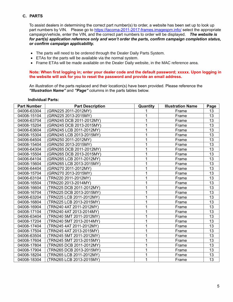
C. PARTS
To assist dealers in determining the correct part number(s) to order, a website has been set up to look up part numbers by VIN. Please go to https://tacoma-2011-2017-frames.imagespm.info/ select the appropriate campaign/vehicle, enter the VIN, and the correct part numbers to order will be displayed. The website is for part(s) application reference only and won’t order the parts, confirm campaign completion status, or confirm campaign applicability.
• The parts will need to be ordered through the Dealer Daily Parts System.
• ETAs for the parts will be available via the normal system.
• Frame ETAs will be made available on the Dealer Daily website, in the MAC reference area.
Note: When first logging in; enter your dealer code and the default password; xxxxx. Upon logging in the website will ask for you to reset the password and provide an email address.
An illustration of the parts replaced and their location(s) have been provided. Please reference the “Illustration Name” and ”Page” columns in the parts tables below.
Individual Parts:
Part Number Part Description Quantity Illustration Name Page
04006-63304 (GRN225 2011-2012MY) 1 Frame 13
04008-15104 (GRN225 2013-2015MY) 1 Frame 13
04006-63704 (GRN245 DCB 2011-2012MY) 1 Frame 13
04008-15204 (GRN245 DCB 2013-2015MY) 1 Frame 13
04006-63604 (GRN245 LCB 2011-2012MY) 1 Frame 13
04008-15304 (GRN245 LCB 2013-2015MY) 1 Frame 13
04006-64504 (GRN250 2011-2012MY) 1 Frame 13
04008-15404 (GRN250 2013-2015MY) 1 Frame 13
04006-64304 (GRN265 DCB 2011-2012MY) 1 Frame 13
04008-15504 (GRN265 DCB 2013-2015MY) 1 Frame 13
04006-64104 (GRN265 LCB 2011-2012MY) 1 Frame 13
04008-15604 (GRN265 LCB 2013-2015MY) 1 Frame 13
04006-64404 (GRN270 2011-2012MY) 1 Frame 13
04008-15704 (GRN270 2013-2015MY) 1 Frame 13
04006-63104 (TRN220 2011-2012MY) 1 Frame 13
04008-16504 (TRN220 2013-2014MY) 1 Frame 13
04008-16604 (TRN225 DCB 2011-2012MY) 1 Frame 13
04008-16704 (TRN225 DCB 2013-2015MY) 1 Frame 13
04006-63204 (TRN225 LCB 2011-2012MY) 1 Frame 13
04008-16804 (TRN225 LCB 2013-2015MY) 1 Frame 13
04008-16904 (TRN240 4AT 2011-2012MY) 1 Frame 13
04008-17104 (TRN240 4AT 2013-2014MY) 1 Frame 13
04006-63404 (TRN240 5MT 2011-2012MY) 1 Frame 13
04008-17204 (TRN240 5MT 2013-2014MY) 1 Frame 13
04008-17404 (TRN245 4AT 2011-2012MY) 1 Frame 13
04008-17504 (TRN245 4AT 2013-2015MY) 1 Frame 13
04006-63504 (TRN245 5MT 2011-2012MY) 1 Frame 13
04008-17604 (TRN245 5MT 2013-2015MY) 1 Frame 13
04008-17804 (TRN265 DCB 2011-2012MY) 1 Frame 13
04008-17904 (TRN265 DCB 2013-2015MY) 1 Frame 13
04008-18204 (TRN265 LCB 2011-2012MY) 1 Frame 13
04008-18304 (TRN265 LCB 2013-2015MY) 1 Frame 13

6
Individual Parts (Continued): Part Number Part Description Quantity Illustration Name Page
43425-04040 Ring, Shaft Snap (For Front Drive Inner Shaft Outer) 2 Front Suspension 15 47313-04210 Tube, Front Brake, No.3 1 Brake Tubes 17,18,20
47313-04241 Tube, Front Brake, No.3 1 Brake Tubes 17,18,20 47315-04180 Tube, Front Brake, No.5 1 Brake Tubes 17,18,20
47315-04191 Tube, Front Brake, No.5 1 Brake Tubes 17,18,20 47323-04180 Tube, Rear Brake, No.3 1 Brake Tubes 17,18,20
47323-04191 Tube, Rear Brake, No.3 1 Brake Tubes 17,18,20 47324-04140 Tube, Rear Brake, No.4 1 Brake Tubes 17,18,20
47324-04151 Tube, Rear Brake, No.4 1 Brake Tubes 17,18,20 47325-04190 Tube, Rear Brake, No.5 1 Brake Tubes 17
47325-04191 Tube, Rear Brake, No.5 1 Brake Tubes 17 47325-04200 Tube, Rear Brake, No.5 1 Brake Tubes 18-21
47325-04201 Tube, Rear Brake, No.5 1 Brake Tubes 18-21 47325-04210 Tube, Rear Brake, No.5 1 Brake Tubes 20
47325-04211 Tube, Rear Brake, No.5 1 Brake Tubes 20 47326-04160 Tube, Rear Brake, No.6 1 Brake Tubes 17
47326-04161 Tube, Rear Brake, No.6 1 Brake Tubes 17 47326-04170 Tube, Rear Brake, No.6 1 Brake Tubes 18-21
47326-04171 Tube, Rear Brake, No.6 1 Brake Tubes 18-21 47326-04180 Tube, Rear Brake, No.6 1 Brake Tubes 20
47326-04181 Tube, Rear Brake, No.6 1 Brake Tubes 20 48068-04030 Arm Sub-Assy, Front Suspension, Lower No.1 RH 1 Front Suspension 14
48068-04040 Arm Sub-Assy, Front Suspension, Lower No.1 RH 1 Front Suspension 15 48069-04030 Arm Sub-Assy, Front Suspension, Lower No.1 LH 1 Front Suspension 14
48069-04040 Arm Sub-Assy, Front Suspension, Lower No.1 LH 1 Front Suspension 15 48304-04090 Bumper, Front Spring, LH 1 Front Suspension 14
48304-04090 Bumper, Front Spring, RH 1 Front Suspension 14 48304-AD010 Bumper, Front Spring, LH 1 Front Suspension 14
48304-AD010 Bumper, Front Spring, RH 1 Front Suspension 14 51900-35410 Carrier Assy, Spare Wheel 1 Spare Tire Carrier 13
51900-35420 Carrier Assy, Spare Wheel 1 Spare Tire Carrier 13 82711-16830 Clamp (For Rear Differential Lock) 1 Wire Harness Brackets 23
82715-04160 Bracket (For 2TR-FE 4WD Front Differential Wire) 1 Wire Harness Brackets 23 82715-04200 Bracket (For 2TR-FE A/F Sensor Wiring) 1 Wire Harness Brackets 23
82715-04200 Bracket (For Frame Wire No.2) 1 Wire Harness Brackets 23 82715-04220 Bracket (For Frame Wire) 1 Wire Harness Brackets 23
82715-04230 Bracket (For Frame Wire) 1 Wire Harness Brackets 23 82715-04240 Bracket (For Frame Wire No.2) 1 Wire Harness Brackets 23
82715-04290 Bracket (For Frame Wire No.2) 1 Wire Harness Brackets 23 82715-04290 Bracket (For 2TR-FE A/F Sensor Wiring) 1 Wire Harness Brackets 23
82715-04350 Bracket (For Frame Wire No.2) 1 Wire Harness Brackets 23 82715-3D680 Bracket (For 1GR-FE 4WD Front Differential Wire) 1 Wire Harness Brackets 23
82715-04250 Bracket (For Rear Differential Lock) 1 Wire Harness Brackets 23 82715-04260 Bracket (For Rear Differential Lock) 1 Wire Harness Brackets 23
90105-A0064 Bolt (For Skid Control Sensor) 1 ABS 23 90105-A0066 Bolt (For Rear Differential Lock) 2 Wire Harness Brackets 23
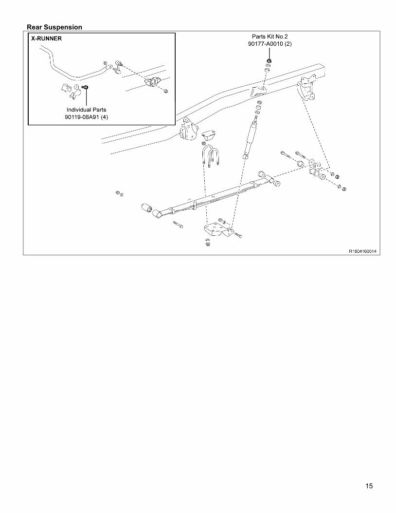
90119-08A91 Bolt (For Rear Stabilizer Bracket Cover) 4 Rear Suspension 16 90119-A0141 Bolt (For Front Differential Wire Bracket) 1 Wire Harness Brackets 23
90119-A0148 Bolt (For W/ Frame Wire No.2) 2 Wire Harness Brackets 23 90119-A0151 Bolt (For Heat Insulator of Propeller Shaft) 2 Propeller Shaft 25
90119-A0161 Bolt (For Front Stabilizer Bracket) 4 Front Suspension 14 90119-A0169 Bolt (For Brake Tube) 9 Brake Tubes 17-20,22
90119-A0169 Bolt (For 1GR-FE W/O Frame Wire No.2) 2 Wire Harness Brackets 23 90119-A0169 Bolt (For 2TR-FE W/O Frame Wire No.2) 4 Wire Harness Brackets 23
90119-A0169 Bolt (For W/ Frame Wire No.2) 6 Wire Harness Brackets 23 90119-A0193 Bolt (For Front Hook, No.1 W/ Fuel Tank Protector) 2 Under Cover 13
90178-A0001 Nut (For 4WD, Pre-Runner Front Suspension Camber Adjust Cam) 2 Front Suspension 15 90178-A0013 Nut (For 2WD Front Suspension Camber Adjust Cam) 4 Front Suspension 14
90179-08241 Nut (For Fuel Tank Protector) 4 Fuel Tank 22 90240-08054 Pin, W/ Hole (For Transmission Control Rod) 1 Shift Lever 26
90468-14033 Clip (For Transmission Control Rod) 1 Shift Lever 26 90469-A0004 Clamp, Brake Tube, No.11 (For Regular Cab) 2 Brake Tubes 17
90469-A0004 Clamp, Brake Tube, No.11 (For Access Cab) 3 Brake Tubes 18,19 90469-A0004 Clamp, Brake Tube, No.11 (For Double Cab) 4 Brake Tubes 20,21

7
Parts Kits:
Part Number Part Description Quantity
04008-07235 Parts Kit No.1 – Common Replacement Kit D 1
The kit listed above includes the following parts:
Part Number Part Description Qty Illustration Name Page
90910-03001 Bolt (For Front Engine Mount) 4 Engine Mounting 24
91671-80814 Bolt (For Rear Engine Mount) 4 Engine Mounting 24
94151-21001 Nut (For Front Engine Mount) 4 Engine Mounting 24
90412-10289 Way (For Front Brake Tube) 2 Brake Tubes 17-21
77285-35760 Clamp, Fuel Tube, No.1 1 Fuel Tubes 22
Part Number Part Description Quantity
04008-22104 Parts Kit No.2 – Common Replacement Kit E 1
The kit listed above includes the following parts:
Part Number Part Description Qty Illustration Name Page
90069-08019 Packing (For Radiator Drain Cock) 1 Radiator 26
90080-11555 Bolt (For Steering Intermediate Shaft) 2 Power Steering 24
90412-10276 Way, 2 (For Rear Brake Tube) 1 Brake Tubes 17-21
90949-A1006 Clamp, Brake Tube, No.10 3 Brake Tubes 17-21
90468-A0007 Clip (For Brake Tube) 4 Brake Tubes 17-22
90171-A0005 Nut, Castle (For Front Lower Ball Joint RH) 1 Front Suspension 14,15
90171-A0005 Nut, Castle (For Front Lower Ball Joint LH) 1 Front Suspension 14,15
90080-17215 Nut (For Front Suspension Support) 6 Front Suspension 14,15
90177-A0010 Nut (For Rear Shock Absorber) 2 Rear Suspension 16
90119-A0169 Bolt (For Spare Tire Carrier) 4 Spare Tire Carrier 13
51719-04010 Holder, Body Support Bracket 2 Cab Mounting 13
90178-A0044 Nut (For Front Bumper Extension) 6 Front Bumper 26
90119-A0192 Bolt (For Rear Bumper) 6 Rear Bumper 26
90119-A0249 Bolt (For Fuel Tank Band) 2 Fuel Tank 22
90210-A0002 O Ring (For Discharge Hose Sub-Assy) 1 Air Conditioning 26
90210-A0004 O Ring (For Suction Hose Sub-Assy) 1 Air Conditioning 26
Part Number Part Description Quantity
04006-46104 Parts Kit No.3 – JPN Source Parts Kit 4 (4WD) 1
The kit listed above includes the following parts:
Part Number Part Description Qty Illustration Name Page
12157-10010 Gasket, Front Differential Filler Plug 1 Front Differential 24
90430-24003 Gasket, Front Differential Drain Plug 1 Front Differential 24
90311-47027 Seal, Oil (For Differential Side Gear Shaft) 1 Front Differential 24
90311-47026 Seal, Oil (For Differential Side Gear Shaft) 1 Front Differential 24
43514-28010 Cap, Front Axle Hub Grease, RH 1 Front Suspension 15
43514-28010 Cap, Front Axle Hub Grease, LH 1 Front Suspension 15
95381-04045 Cotter Pin (For Front Drive Shaft) 2 Front Suspension 15

8
Parts Kits (Continued):
Part Number Part Description Quantity
04001-71404 Parts Kit No.4 – JPN Source Parts Kit 2 (2WD) 1
The kit listed above includes the following parts:
Part Number Part Description Qty Illustration Name Page
95381-03025 Cotter Pin (For Tie Rod End) 2 Power Steering 24
48190-25010 Cam, Front Suspension Camber Adjust, No.1 RH 2 Front Suspension 14
48190-25010 Cam, Front Suspension Camber Adjust, No.1 LH 2 Front Suspension 14
48198-25010 Cam, Front Suspension Camber Adjust, No.2 RH 2 Front Suspension 14
48198-25010 Cam, Front Suspension Camber Adjust, No.2 LH 2 Front Suspension 14
95381-03230 Cotter Pin (For Front Suspension Lower Arm) 2 Front Suspension 14
Part Number Part Description Quantity
04001-71504 Parts Kit No.5 – JPN Source Parts Kit 3 (4WD and Pre-Runner) 1
The kit listed above includes the following parts:
Part Number Part Description Qty Illustration Name Page
95381-03225 Cotter Pin (For Tie Rod End) 2 Power Steering 24
48190-60020 Cam, Front Suspension Camber Adjust, No.1 RH 1 Front Suspension 15
48190-60020 Cam, Front Suspension Camber Adjust, No.1 LH 1 Front Suspension 15
48198-60011 Cam, Front Suspension Camber Adjust, No.2 RH 1 Front Suspension 15
48198-60011 Cam, Front Suspension Camber Adjust, No.2 LH 1 Front Suspension 15
48409-60020 Cam Sub-Assy, Front Suspension Toe Adjust 2 Front Suspension 15
48452-35020 Plate, Front Suspension Toe Adjust, No.2 2 Front Suspension 15
95381-03230 Cotter Pin (For Front Suspension Lower Arm) 2 Front Suspension 15
Part Number Part Description Quantity
04008-22304 Parts Kit No.6 – USA Source Parts Kit 5 (1GR) 1
The kit listed above includes the following parts:
Part Number Part Description Qty Illustration Name Page
17176-0P030 Gasket, Air Surge Tank to Intake Manifold 1 1GR-FE Exhaust
System 25
17451-0D020 Gasket, Exhaust Pipe 1 1GR-FE Exhaust
System 25
90080-10291 Bolt (For Exhaust Pipe) 2 1GR-FE Exhaust
System 25
90080-11180 Bolt (For Exhaust Pipe Stopper Bracket) 2 1GR-FE Exhaust
System 25
Part Number Part Description Quantity
04008-22504 Parts Kit No.7 – USA Source Parts Kit 7 (2TR) 1
The kit listed above includes the following parts:
Part Number Part Description Qty Illustration Name Page
90080-43033 Gasket (Exhaust Pipe) 1 2TR-FE Exhaust
System 25
90080-10064 Bolt (Exhaust Pipe) 2 2TR-FE Exhaust
System 25
90177-A0004 Nut (Exhaust Pipe) 2 2TR-FE Exhaust
System 25

9
Parts Kits (Continued):
Part Number Part Description Quantity
04001-71804 Parts Kit No.8 – USA Source Parts Kit 3 (Except For X-Runner) 1
The kit listed above includes the following parts:
Part Number Part Description Qty Illustration Name Page
90119-A0166 Bolt (For Front Suspension Toe Adjust Cam) 2 Front Suspension 15
48304-04100 Bumper, Front Spring, LH 1 Front Suspension 15
48304-04100 Bumper, Front Spring, RH 1 Front Suspension 15
90119-A0192 Bolt (For Hook No.1) 2 Under Cover 13
90080-11373 Bolt (For Engine Under Cover Sub-Assy No.1) 4 Under Cover 13
90080-11373 Bolt (For Engine Under Cover Sub-Assy No.2) 4 Under Cover 13
90189-A0002 Clip (For Left Rear Wheel Well Liner) 8 Rear Wheel House Liner
26
90189-A0002 Clip (For Quarter Panel Wheel Opening Moulding) 2 Moulding 27
75395-35070 Clip (For Quarter Panel Wheel Opening Moulding) 3 Moulding 27
75396-35020 Clip (For Quarter Panel Wheel Opening Moulding) 7 Moulding 27
Part Number Part Description Quantity
04001-71904 Parts Kit No.9 – USA Source Parts Kit 4 (X-Runner) 1
The kit listed above includes the following parts:
Part Number Part Description Qty Illustration Name Page
90189-A0002 Clip (For Left Rear Wheel Well Liner) 6 Rear Wheel House Liner
26
75395-04010 Clip (For Rocker Panel Moulding) 4 Moulding 27
75396-04010 Clip (For Rocker Panel Moulding) 14 Moulding 27
75395-35070 Clip (For Body Rocker Panel Moulding) 2 Moulding 27
75395-35070 Clip (For Back Door Moulding) 2 Moulding 27
75396-35020 Clip (For Body Rocker Panel Moulding) 1 Moulding 27
75396-35020 Clip (For Back Door Moulding) 1 Moulding 27
90189-A0002 Clip (For Body Rocker Panel Moulding) 1 Moulding 27
90189-A0002 Clip (For Back Door Moulding) 1 Moulding 27
Part Number Part Description Quantity
04001-72204 Parts Kit No.10 – Brake Tube Kit 2 (GRN245 with Off Road Package 2011MY) 1
The kit listed above includes the following parts:
Part Number Part Description Qty Illustration Name Page
47313-04200 Tube, Front Brake, No.3 1 Brake Tubes 19,21
47315-04170 Tube, Front Brake, No.5 1 Brake Tubes 19,21
47323-04170 Tube, Rear Brake, No.3 1 Brake Tubes 19,21
47324-04130 Tube, Rear Brake, No.4 1 Brake Tubes 19,21

10
Parts Kits (Continued):
Part Number Part Description Quantity
04008-22704 Prats Kit No.11 – Brake Tube Kit 5
(GRN245 with Off Road or TRD Package 2012-2015MY) 1
The kit listed above includes the following parts:
Part Number Part Description Qty Illustration Name Page
47313-04231 Tube, Front Brake, No.3 1 Brake Tubes 19,21
47315-04171 Tube, Front Brake, No.5 1 Brake Tubes 19,21
47323-04171 Tube, Rear Brake, No.3 1 Brake Tubes 19,21
47324-04131 Tube, Rear Brake, No.4 1 Brake Tubes 19,21
Part Number Part Description Quantity
04008-22904 Parts Kit No.12 – Brake Tube Kit 10 (2WD 2011MY) 1
The kit listed above includes the following parts:
Part Number Part Description Qty Illustration Name Page
47314-04140 Tube, Front Brake, No.4 1 Brake Tubes 17,18,20
47316-04140 Tube, Front Brake, No.6 1 Brake Tubes 17,18,20
Part Number Part Description Quantity
04008-23104 Parts Kit No.13 – Brake Tube Kit 6 (2WD 2012-2015MY) 1
The kit listed above includes the following parts:
Part Number Part Description Qty Illustration Name Page
47314-04141 Tube, Front Brake, No.4 1 Brake Tubes 17,18,20
47316-04141 Tube, Front Brake, No.6 1 Brake Tubes 17,18,20
Part Number Part Description Quantity
04008-23204 Parts Kit No.14 – Brake Tube Kit 11 (4WD and Pre-Runner 2011MY) 1
The kit listed above includes the following parts:
Part Number Part Description Qty Illustration Name Page
47314-04150 Tube, Front Brake, No.4 1 Brake Tubes 17-21
47316-04150 Tube, Front Brake, No.6 1 Brake Tubes 17-21
90119-A0169 Bolt (For Brake Tube) 7 Brake Tubes 17-22
Part Number Part Description Quantity
04008-23304 Parts Kit No.15 – Brake Tube Kit 7 (4WD and Pre-Runner 2012-2015MY) 1
The kit listed above includes the following parts:
Part Number Part Description Qty Illustration Name Page
47314-04151 Tube, Front Brake, No.4 1 Brake Tubes 17-21
47316-04151 Tube, Front Brake, No.6 1 Brake Tubes 17-21
90119-A0169 Bolt (For Brake Tube) 7 Brake Tubes 17-22
11
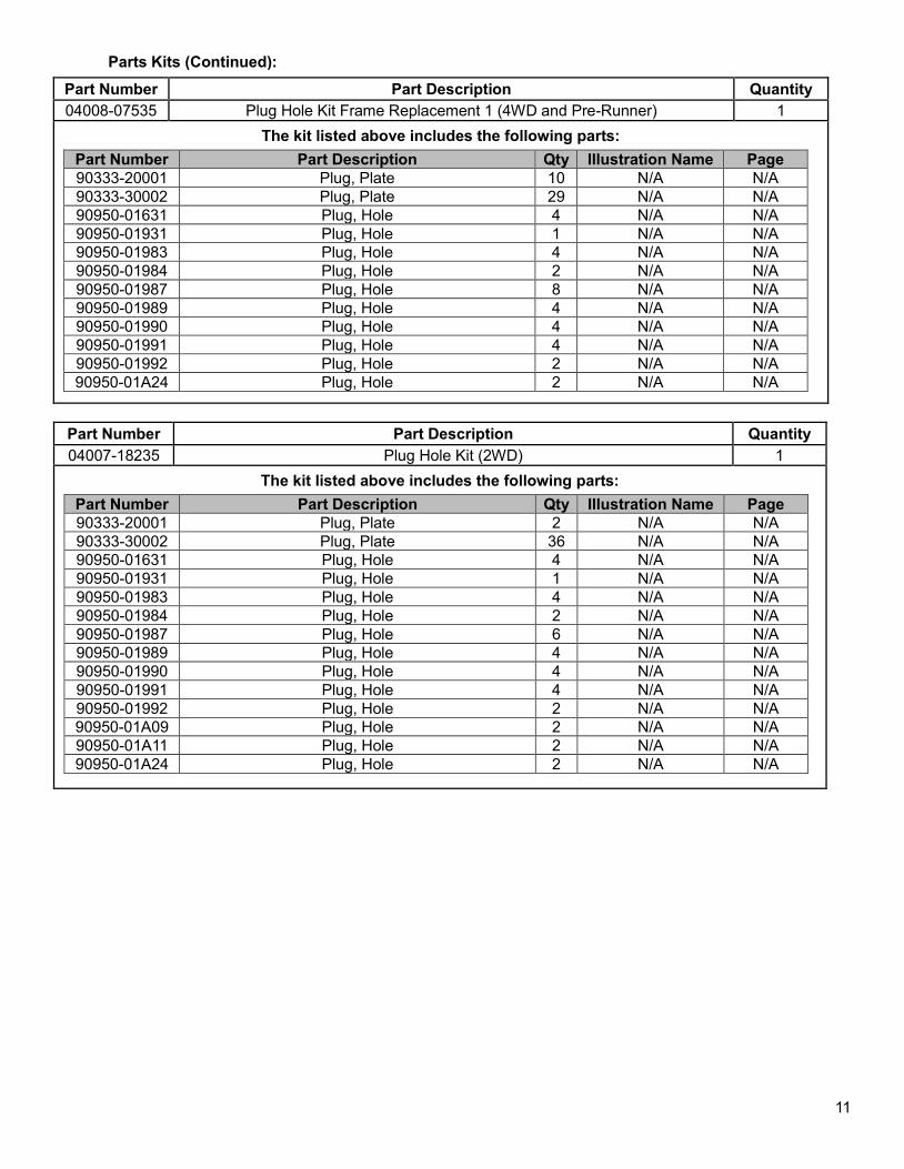
Parts Kits (Continued):
Part Number Part Description Quantity
04008-07535 Plug Hole Kit Frame Replacement 1 (4WD and Pre-Runner) 1
The kit listed above includes the following parts:
Part Number Part Description Qty Illustration Name Page
90333-20001 Plug, Plate 10 N/A N/A
90333-30002 Plug, Plate 29 N/A N/A
90950-01631 Plug, Hole 4 N/A N/A
90950-01931 Plug, Hole 1 N/A N/A
90950-01983 Plug, Hole 4 N/A N/A
90950-01984 Plug, Hole 2 N/A N/A
90950-01987 Plug, Hole 8 N/A N/A
90950-01989 Plug, Hole 4 N/A N/A
90950-01990 Plug, Hole 4 N/A N/A
90950-01991 Plug, Hole 4 N/A N/A
90950-01992 Plug, Hole 2 N/A N/A
90950-01A24 Plug, Hole 2 N/A N/A
Part Number Part Description Quantity
04007-18235 Plug Hole Kit (2WD) 1
The kit listed above includes the following parts:
Part Number Part Description Qty Illustration Name Page
90333-20001 Plug, Plate 2 N/A N/A
90333-30002 Plug, Plate 36 N/A N/A
90950-01631 Plug, Hole 4 N/A N/A
90950-01931 Plug, Hole 1 N/A N/A
90950-01983 Plug, Hole 4 N/A N/A
90950-01984 Plug, Hole 2 N/A N/A
90950-01987 Plug, Hole 6 N/A N/A
90950-01989 Plug, Hole 4 N/A N/A
90950-01990 Plug, Hole 4 N/A N/A
90950-01991 Plug, Hole 4 N/A N/A
90950-01992 Plug, Hole 2 N/A N/A
90950-01A09 Plug, Hole 2 N/A N/A
90950-01A11 Plug, Hole 2 N/A N/A
90950-01A24 Plug, Hole 2 N/A N/A

12
D. PARTS ILLUSTRATION Frame
Cab Mounting
Under Cover Spare Tire Carrier

13
Front Suspension

14
Front Suspension Continued…
15
Rear Suspension

16
Brake Tubes
17
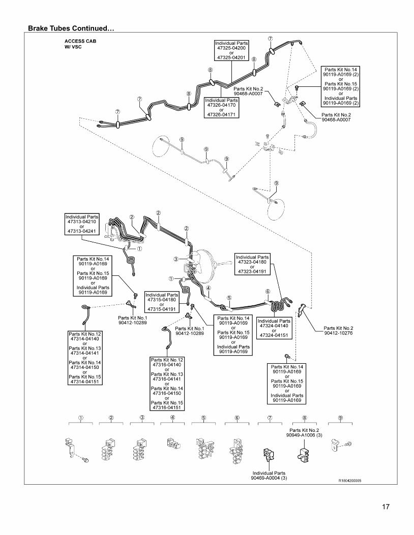
Brake Tubes Continued…

18
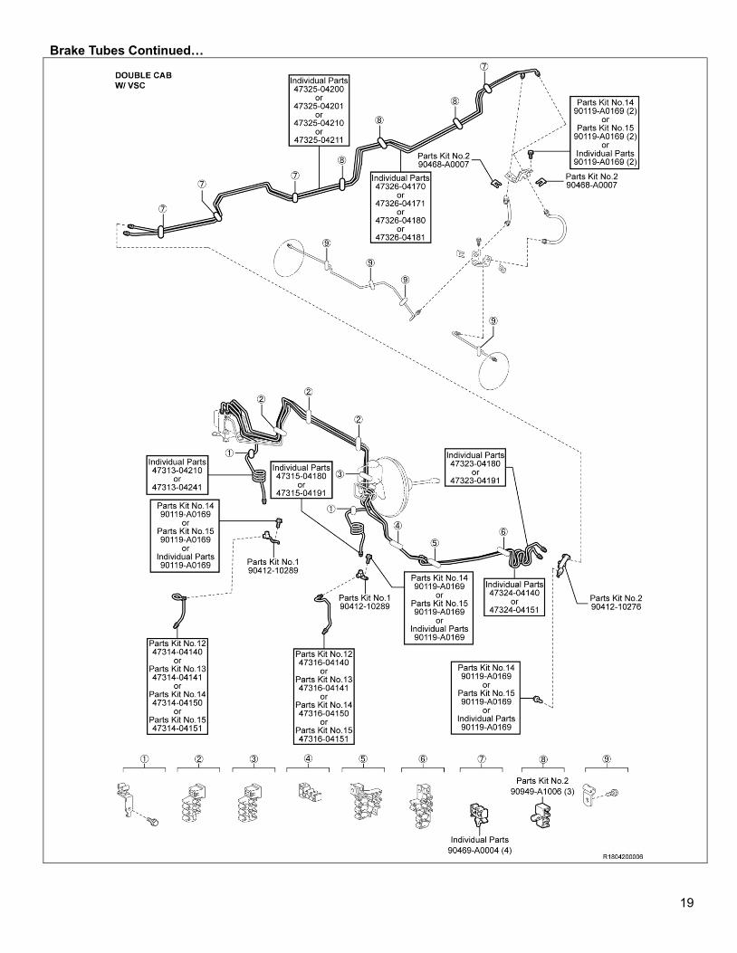
Brake Tubes Continued…
19
Brake Tubes Continued…

20
Brake Tubes Continued…

21
Brake Tubes Continued…
Fuel Tank
Fuel Tubes

22
ABS
Wire Harness Brackets

23
Power Steering
Front Differential Engine Mounting

24
Propeller Shaft
1GR-FE Exhaust System
2TR-FE Exhaust System

25
Shift Lever Radiator
Air Conditioning Front Bumper
Rear Bumper Rear Wheel House Liner

26
Moulding Moulding Continued…
Moulding Continued…

27
FRAME INSPECTION
PERFORM INITIAL PRE-HOIST INSPECTION 1. INSPECT THE FRAME FOR EXCESSIVE FRAME CORROSION THAT COULD AFFECT THE STRUCTURAL
INTEGRITY OF THE FRAME
FRAME INSPECTION
All frame inspection must be performed using the frame inspection application on TIS. Ensure you inspect the frame and properly document the inspection. Failure to perform this will result in denial of the claim.
1. INSPECT FOR FRAME RAIL SEAL a. Inspect if the frame already has a frame rail seal installed as shown in the image below
No further action required. Campaign is complete
YES NO
Is the frame rail seal already installed?
Proceed to the next step in the frame inspection

28
2. ACCESS INSPECTION APPLICATION a. Run the VIN in TIS and click on the Warranty Tab. b. Click on the “Frame Inspection” link on TIS.
3. LOG INTO THE INSPECTION APPLICATION a. Reenter your TIS password

29
4. ENTER VEHICLE INFORMATION a. Enter the vehicle mileage. b. Select the state from the drop down menu that the vehicle is registered.
Note: Do NOT select the state the dealership is located.
c. Select NO CRC Previously Applied: Select Frame Button
5. INSPECT THE FRAME SECTIONS a. Inspect the frame in the colored areas below and use the application to document the results of the
inspection.
Tacoma 11 to 17
b. Select Section A
Note: The frame inspection application must be completed in alphabetical order.

30
c. Inspect the frame section and inspect all surfaces of the frame rail and crossmember. Select the photo that best represents the frame condition. If perforation of 10mm or larger is identified select “Perforation of the Frame”.
Note: You must click the bubble next to the image to select the condition.
d. If you selected Perforation of the Frame, the application will request more information about the size of perforation(s) and location.
e. The section with perforation will split into 2 sub-sections to further identify the perforation location. f. Select the size of the perforation in each sub-section. g. Upload a photo for each area containing perforation and describe the location in the comments
section.
Note:
• Include the R.O in the image of at least one of the perforation holes.
• If both sub-sections have perforation, it will require two pictures to be uploaded.
• If perforation was accidentally selected, use the back button to reset section.
h. Select Next to move onto the next section.

31
Each image attached has a size limit of 3 MB and all images cannot exceed 15 MB total. If 3MB is uploaded the system will display the error shown below. User using Chrome browser may receive intermittent errors when uploading several high-quality images, IE is recommended.
i. Once all sections have been completed, select the Submit button.
Note: When completed it will be indicated by all sections being grayed out and the submit button will appear.
32
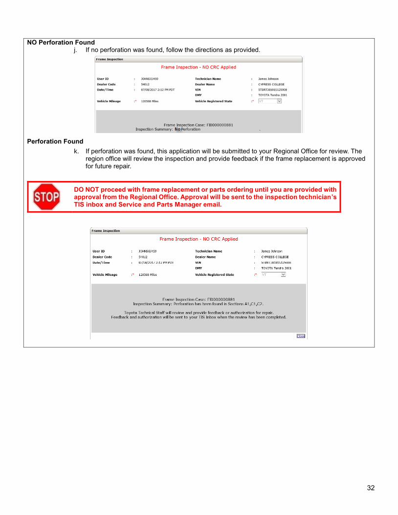
NO Perforation Found j. If no perforation was found, follow the directions as provided.
Perforation Found
k. If perforation was found, this application will be submitted to your Regional Office for review. The region office will review the inspection and provide feedback if the frame replacement is approved for future repair.
DO NOT proceed with frame replacement or parts ordering until you are provided with approval from the Regional Office. Approval will be sent to the inspection technician’s TIS inbox and Service and Parts Manager email.
33
FRAME REPLACEMENT WORK PROCEDURE
A. PERFORM PRELIMINARY VEHICLE INSPECTION
1. Perform health check and record any preexisting DTCs 2. Test drive the vehicle and inspect the following vehicle functions/current operating conditions prior to vehicle
repair.
• 4WD System (4WD Only)
• Interior Lights
• Exterior Lights
• HVAC System
• Audio System
• Power Windows
• Power Door Locks
• All Gauges, Indicators and Warning Lights
• Etc.
3. Documents the current vehicle operating condition on the Frame Replacement Inspection Sheet.
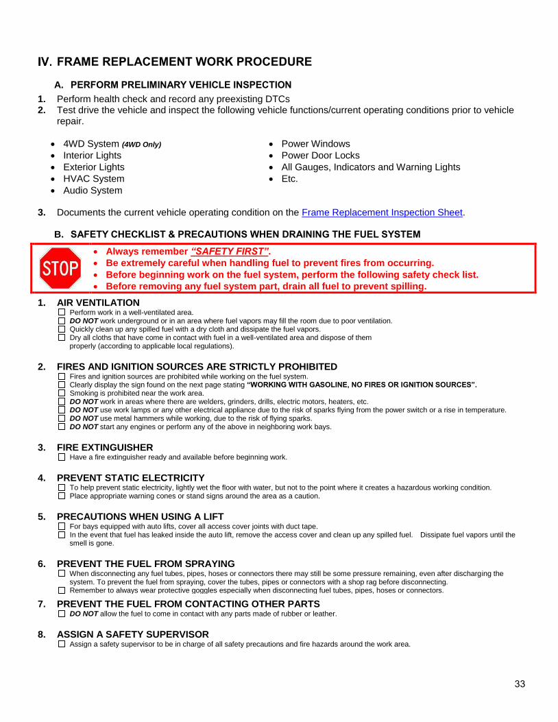
B. SAFETY CHECKLIST & PRECAUTIONS WHEN DRAINING THE FUEL SYSTEM
• Always remember “SAFETY FIRST”.
• Be extremely careful when handling fuel to prevent fires from occurring.
• Before beginning work on the fuel system, perform the following safety check list.
• Before removing any fuel system part, drain all fuel to prevent spilling.
1. AIR VENTILATION Perform work in a well-ventilated area. DO NOT work underground or in an area where fuel vapors may fill the room due to poor ventilation. Quickly clean up any spilled fuel with a dry cloth and dissipate the fuel vapors. Dry all cloths that have come in contact with fuel in a well-ventilated area and dispose of them properly (according to applicable local regulations).
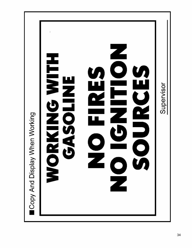
2. FIRES AND IGNITION SOURCES ARE STRICTLY PROHIBITED
Fires and ignition sources are prohibited while working on the fuel system. Clearly display the sign found on the next page stating “WORKING WITH GASOLINE, NO FIRES OR IGNITION SOURCES”. Smoking is prohibited near the work area. DO NOT work in areas where there are welders, grinders, drills, electric motors, heaters, etc. DO NOT use work lamps or any other electrical appliance due to the risk of sparks flying from the power switch or a rise in temperature. DO NOT use metal hammers while working, due to the risk of flying sparks. DO NOT start any engines or perform any of the above in neighboring work bays.
3. FIRE EXTINGUISHER
Have a fire extinguisher ready and available before beginning work.
4. PREVENT STATIC ELECTRICITY
To help prevent static electricity, lightly wet the floor with water, but not to the point where it creates a hazardous working condition. Place appropriate warning cones or stand signs around the area as a caution.
5. PRECAUTIONS WHEN USING A LIFT
For bays equipped with auto lifts, cover all access cover joints with duct tape. In the event that fuel has leaked inside the auto lift, remove the access cover and clean up any spilled fuel. Dissipate fuel vapors until the smell is gone.
6. PREVENT THE FUEL FROM SPRAYING
When disconnecting any fuel tubes, pipes, hoses or connectors there may still be some pressure remaining, even after discharging the system. To prevent the fuel from spraying, cover the tubes, pipes or connectors with a shop rag before disconnecting.
Remember to always wear protective goggles especially when disconnecting fuel tubes, pipes, hoses or connectors.
7. PREVENT THE FUEL FROM CONTACTING OTHER PARTS DO NOT allow the fuel to come in contact with any parts made of rubber or leather.
8. ASSIGN A SAFETY SUPERVISOR
Assign a safety supervisor to be in charge of all safety precautions and fire hazards around the work area.
34

35

36
C. DISCHARGE THE FUEL SYSTEM PRESSURE
• DO NOT disconnect any part of the fuel system until you have discharged the fuel system pressure.
• Even after discharging the fuel system pressure, place a piece of cloth around the tubes, pipe, hoses and connectors as you separate them to reduce the risk of fuel spraying on yourself, in the engine compartment and onto other parts.
• For additional repair information, please reference the appropriate repair manual in TIS for the vehicle you are working on.
1. CHECK FOR DTCs
2. RECORD THE RADIO STATION PRESETS
3. DISCONNECT THE NEGATIVE (-) BATTERY TERMINAL
NOTE: Wait 90 seconds after the negative (-) terminal cable is disconnected from the battery before proceeding. Doing so will prevent the SRS from being deployed (i.e. airbag, seat belt pretensioner, etc.).
4. DISCHARGE THE FUEL SYSTEM PRESSURE Remove the upper relay block cover. Remove the circuit opening relay. Connect the negative (-) battery terminal. Start the engine. Turn the ignition switch to ON after the engine stops.
NOTE: DTC P0171 (system too lean) may be present.
Crank the engine again, and check that the engine stops. Remove the fuel tank cap, and discharge the pressure in
the fuel tank completely. Disconnect the negative (-) battery terminal.
Reinstall the circuit opening relay. Reinstall the upper relay block cover.
NOTE: Reinstall the No.1 upper relay block cover to not let foreign objects enter.

37
D. REMOVE THE BED ASSY
• If the frame is perforated, ONLY raise the vehicle high enough to remove the tires.
• For added safety and support place jack stands under the front and rear portions of the frame.
• DO NOT work directly underneath the vehicle when performing bed assy removal.
• The actual vehicle specs, equipment and parts required may differ than what is shown. Please use the correct specifications and parts for the model you are working on.
• For additional repair information, please reference the appropriate repair manual found on TIS for the vehicle you are working on.
1. CENTER THE VEHICLE BETWEEN THE LIFT ARMS Verify the vehicle is aligned with the center point of the lift to prevent interference and damage to the frame
and/or lift.
2. REMOVE THE FOLLOWING PARTS
• Rear Tail/Combination Light LH/RH
• Rear Bumper Assy
• Rear Mudguard LH/RH (If Equipped)
• Side Step Assy LH/RH (If Equipped)
• Rocker Panel Molding LH/RH (If Equipped)
• Body Rocker Panel Molding Assy LH (If Equipped)
• Outside LH Back Door Molding Sub-Assy (If Equipped)
• Quarter Panel Wheel Opening Molding LH (If Equipped)
• Left Rear Wheel Well Liner
• Power Outlet Socket Assy (If Equipped)
When removing the parts, be careful not to damage them and surrounding components.
3. DISCONNECT THE FRAME WIRE HARNESS
Disconnect the clamps, connectors and the frame wire harness from the bed assy.
NOTE:
• The number of connectors may differ depending on the vehicle specification.
• Be careful not to damage the wire harness clamps when removing them.
4. DISCONNECT THE FUEL INLET PIPE SUB-ASSY
Remove the bolt and disconnect the fuel inlet pipe sub-assy.
5. REMOVE THE BED ASSY
Using a Torx® T55H Socket, remove the 6 Torx ® bolts from the bed assy.
NOTE:
• Use 4 or more people to remove the bed assy from the frame.
• Evenly support the bed assy when removing it.
• Be careful not to damage the filler tubes when removing the bed.
• Protect the front side of the bed assy to not damage the cab assy.

38
E. REMOVE THE CAB BODY ASSY
• If the frame is perforated, ONLY raise the vehicle high enough to remove the tires.
• For added safety and support place jack stands under the front and rear portions of the frame.
• DO NOT work directly underneath vehicle when performing cab assy removal, unless noted.
• The actual vehicle specs, equipment and parts required may differ than what is shown. Please use the correct specs and parts for the model you are working on.
• For additional repair information, please reference the appropriate repair manual in TIS for the vehicle you are working on.
1. REMOVE THE ENGINE UNDER COVERS
NOTE: Use precaution when performing this step, as you will need to work underneath the vehicle.
2. EVACUATE THE REFRIGERANT FROM THE AIR CONDITIONING SYSTEM
3. DRAIN THE FOLLOWING FLUIDS
• Coolant
• Brake Fluid
• Clutch Fluid (1GR-FE Manual Trans Only)
• Front Differential Fluid (4WD Only) NOTE: DO NOT remove the radiator cap while the radiator and engine are hot, doing so may cause the coolant to spray out causing potential injuries.
4. REMOVE THE FOLLOWING BODY COMPONENTS
• Radiator Grille
• Front Bumper Filler LH/RH (Except 2011MY)
• Front Fender Mudguard LH/RH
• Front Bumper Assy
• Front Bumper Reinforcement
• Front No.2 Bumper Extension Sub-assy LH/RH
5. REMOVE THE FOLLOWING INTERIOR COMPONENTS
• Front Door Scuff Plate LH/RH
• Front Floor Footrest
• Cowl Side Trim Board LH/RH
6. REMOVE THE INSTRUMENT PANEL BOX
7. DISCONNECT THE FRAME WIRE HARNESS
Disconnect the 5 clamps. Disconnect the connector(s).
NOTE: The number of connectors may differ depending on the model.
Remove the frame wire harness grommet from the cab
assy. Pull out the frame wire harness from the vehicle cab assy.

39
8. DISCONNECT THE NO.2 FRAME WIRE HARNESS (IF EQUIPPED)
For Frame Connecting Type:
Remove the 2 bolts and cover.
Disconnect the 2 connectors and clamp.
For Floor Connecting Type:
Remove all 4 passenger side seat rail bolts. Tilt the passenger side seat backwards. Turn back the floor carpet.
Remove the bolt and wiring harness protector.
Disconnect the 2 connectors. Remove the No.2 frame wire harness grommet from the
cab assy. Pull out the No.2 frame wire harness from the cab assy.
9. REMOVE THE GLOVE BOX AND LOWER INSTRUMENT PANEL FINISH PANEL Remove the glove box. Remove the bolt and the lower instrument panel finish
panel. Disconnect the radio setting condenser connector. (If Equipped)
10. DISCONNECT THE ENGINE WIRE HARNESS
Disconnect each connector and clamp from the ECM and remove the engine wire harness. NOTE: The number of connectors may differ depending on the model.

40
11. REMOVE THE FOLLOWING PARTS
• Rear Console Box (for Separate Seat Type)
• Front Console Box (Manual Trans Only)
• Voltage Inverter Assy (If Equipped)
• Manual Transmission Shift Lever (Manual Trans Only)
12. DISCONNECT THE PARKING BRAKE CABLES
For Separate Seat Type:
Remove the 2 clips. Disconnect the 2 parking brake cables.
For Bench Seat Type:
Turn back the floor carpet. Remove the 3 bolts and the parking brake cable joint
protector.
Remove the 2 clips. Disconnect the 2 parking brake cables.
13. REMOVE THE FOLLOWING PARTS
• V-Bank Cover (1GR-FE Only)
• Air Cleaner Hose and Air Cleaner Assy (2TR-FE Only)
• Air Cleaner Assy (1GR-FE Only)
14. DISCONNECT THE NO.2 ENGINE WIRE HARNESS Remove the nut and disconnect the (+) positive battery
cable. Remove the bolt and disconnect the ground wire. Disconnect the 2 clamps.
Remove the upper relay block cover. Disconnect the 3 connectors.
Remove the nut and disconnect the fuse box wire harness. Reinstall the upper relay block cover.

41
LH Side
RH Side
15. DISCONNECT THE FRONT SKID CONTROL SENSOR WIRE HARNESS Disconnect the harness clamp and front skid control sensor
connector. Repeat the procedure on the opposite side.
RH Side
16. DISCONNECT THE NO.2 FRAME WIRE HARNESS (IF EQUIPPED) Disconnect the harness clamp and connector.
17. DISCONNECT THE FRONT DIFFERENTIAL BREATHER TUBES (4WD ONLY) Disconnect the front differential breather tubes.
NOTE: There may be 2 front differential breather tubes depending on the vehicle model.
18. DISCONNECT THE FUEL PIPES AND VAPOR FEED HOSE Remove the 2 fuel pipe clamps. Disconnect the No. 1 and No. 2 fuel pipe. Remove the clip and disconnect the fuel vapor feed hose.
NOTE: Put a shop towel under the fuel pipe to catch any spilled fuel.
19. DISCONNECT THE VACUUM HOSE
Disconnect the vacuum hose.

42
20. DISCONNECT THE RADIATOR HOSES AND AUTO TRANS COOLING LINES (Auto Trans Only) Disconnect the inlet and outlet radiator hoses from engine. Disconnect the inlet and outlet auto transmission cooling lines from the radiator
Be careful not to damage the radiator hoses.
21. REMOVE THE FOLLOWING PARTS
• Radiator Support to Frame Seal
• Fan Shroud
• Radiator Assy
22. DISCONNECT THE NO.1 HOSE
2TR-FE Only (Shown): Disconnect the No.1 hose from the air pump assy. Remove the bolt and disconnect the ground wire.
2012-2015MY (1GR-FE Only): Disconnect the No.1 hose from the air pump assy.
23. DISCONNECT THE POWER STEERING PUMP OIL RESERVOIR ASSY (1GR-FE ONLY)
Disconnect power steering pump oil reservoir assy.
24. DISCONNECT THE GROUND WIRE (1GR-FE ONLY)
Remove the bolt and disconnect the clamp and the ground wire.
25. DISCONNECT THE ENGINE WIRE HARNESS
Disconnect the clamp. Remove the engine wire harness container from the cowl
panel.
26. DISCONNECT THE WATER / HEATER HOSES, ENGINE SIDE
LH Side
RH Side
27. REMOVE THE FRONT FENDER APRON SEALS
4WD, Pre-Runner Only (Shown):
Remove the 20 clips and 4 front fender apron seals.
2WD Only:
Remove the 22 clips and 4 front fender apron seals.

43
28. DISCONNECT THE AIR CONDITIONING DISCHARGE AND SUCTION HOSES FROM THE COMPRESSOR
29. DISCONNECT THE SUCTION HOSE BRACKET
LH Side
RH Side
30. DISCONNECT THE FRONT BRAKE TUBES Disconnect the front brake tube. Repeat the procedure on the opposite side.
31. DISCONNECT THE STEERING SLIDING YOKE
NOTE: Use precaution when performing this step, as you will need to work underneath the vehicle.
Make sure the front wheels are in a straight-ahead position and the steering wheel is centered.
Using the seat belt, hold the steering wheel in position as shown in the illustration, to prevent damage to the spiral cable.
Place match marks on the steering sliding yoke and No.2 intermediate shaft.
Loosen bolt (A) and remove bolt (B). Disconnect the steering sliding yoke from the No.2
intermediate shaft. NOTE: If the steering sliding yoke is stuck, tap it from below with a brass hammer to disconnect it.
32. DISCONNECT THE SHIFT CABLE (AUTO TRANS ONLY)
Cable Type (Shown): Remove the clip. Remove the nut and disconnect the shift cable.
Rod Type:
Remove the pin and clip, disconnect the shift cable. NOTE: Use precaution when performing this step, as you will need to work underneath the vehicle.

44
33. DISCONNECT THE CLUTCH RELEASE CYLINDER ASSY (2TR –FE MANUAL TRANS ONLY) Remove the bolt and disconnect the clutch hose. Remove the 2 bolts and disconnect the clutch release
cylinder. NOTE: Use precaution when performing this step, as you will need to work underneath the vehicle.
34. DISCONNECT THE NO.1 CLUTCH HOSE (1GR-FE MANUAL TRANS ONLY)
Disconnect the clutch release cylinder tube from the clutch
hose. Remove the clip and disconnect the clutch hose.
35. DISCONNECT THE NO.2 FUEL HOSE Remove the clip and disconnect the No.2 fuel hose.
NOTE: Use precaution when performing this step, as you will need to work underneath the vehicle.
36. DISCONNECT THE FUEL TANK TUBES Remove the fuel pipe clamp. Disconnect the 2 fuel tank tubes.
NOTE: Use precaution when performing this step, as you will need to work underneath the vehicle.
37. DISCONNECT THE REAR BRAKE TUBES Disconnect the 2 rear brake tubes.
NOTE: Use precaution when performing this step, as you will need to work underneath the vehicle.
38. DISCONNECT THE PARKING BRAKE CABLES
NOTE: Use precaution when performing this step, as you will need to work underneath the vehicle.
39. REMOVE THE FOLLOWING PARTS (ACCESS CAB ONLY)
• Floor Board No.1/No.2
• Seat Floor Box
• Rear Floor Side Service Hole Cover LH/RH)
• Rear Lower Console Box
• Rear Seat Cushion Assy
• No.1 w/ Box Speaker Assy (If Equipped)

45
40. REMOVE THE CAB BODY ASSY USING AN ABOVE GROUND LIFT
Remove the 4 hole plugs. Remove the 6 nuts, 6 washers and 6 bolts. Set the lift arms under the cab body assy so they DO NOT interfere with the frame or cab mounts. Check that all wire harnesses, hoses, cables and the steering shaft are disconnected. Mark the location of the tires so it will be easier to install the cab onto the new frame.
Lift the cab assy up slowly, making sure it does not interfere with anything while being raised. Raise the cab assy high enough so that the top of the engine clears the lowest point of the cab assy. Pull the frame assy out from under the vehicle.
Lower the cab assy all the way down and leave it on the lift. Reinstall the 6 bolts, they will be used as guides during cab assy reinstallation.
NOTE:
• Center the cab assy weight on the lift arms so that it does not slant/tilt to one side.
• Raise the cab assy slightly off the frame and verify that it is held securely by the lift arms.
• The center of gravity of the cab body may become nose heavy depending on placement of the lift arm which could cause the cab to fall when lifted. To prevent this, use weights to establish a balance and secure the cab body to the lift arm using ratchet tie down belts.
• DO NOT work directly underneath the vehicle when pulling the frame assy out from under.
F. DISASSEMBLE THE FRAME
1. PLACE THE FRAME ON A LIFT
Place the frame on the lift, and secure it with a ratcheting tie down strap. This will prevent the frame from tilting or falling off as parts are removed.
• Ratcheting Tie Downs: Qty 1 (Length: 2 in X 27 ft and Min. Work Load Capacity: 3,000 lbs)
2. DISCONNECT THE FRONT PROPELLER SHAFT ASSY (4WD ONLY) Remove the 4 nuts from transfer case side of the front
propeller shaft assy.
3. REMOVE THE FOLLOWING PARTS
• Wheels
• Rear Propeller Shaft Assy
• Propeller Shaft Heat Insulator (If Equipped)
• Exhaust Pipe Stopper Bracket (If Equipped)
• Insert SST 09325-40010 into trans after the Rear Prop Shaft is removed to prevent oil leakage (2WD Only)

46
NOTE: Place match marks on the front (if equipped) and rear propeller shafts prior to removal.
4. REMOVE THE EXHAUST SYSTEM (1GR-FE ONLY) Remove the 2 bolts and 2 springs. Disconnect the 4 exhaust pipe supports from the frame and
remove the center exhaust pipe assy. Remove the exhaust pipe gasket.
Disconnect the 2 exhaust pipe supports from the frame.
5. REMOVE THE EXHAUST SYSTEM (2TR-FE ONLY)
Remove the 2 bolts and 2 nuts. Disconnect the 4 exhaust pipe supports from the frame and remove the center exhaust pipe assy. Remove the exhaust pipe gasket. Disconnect the 2 oxygen sensor wire harness clamps. Disconnect the exhaust pipe support from the frame.
6. REMOVE THE FOLLOWING PARTS
• No.2 Fuel Tank Protector (If Equipped)
• No.1 Fuel Tank Protector Assy (If Equipped)
• Fuel Tank Straps
• V-belt
• Fuel Tank
• Charcoal Canister Assy
7. REMOVE AND SET ASIDE THE POWER STEERING VANE PUMP Disconnect the connector. Disconnect the clamp. (1GR-FE Only) Remove the bolt and disconnect the ground wire. (1GR-FE Only) Remove the 2 bolts and the power steering vane pump.
NOTE:
• DO NOT disconnect the power steering vane pump hoses or tubes.
• Keep the power steering pump reservoir upright to prevent the fluid from leaking out.
8. REMOVE THE FOLLOWING PARTS
• Intake Air Surge Tank (1GR-FE Only) • Intake Air Connector (2TR-FE Only)

47
9. DISCONNECT THE OIL COOLER TUBE (AUTO TRANS ONLY)
Remove the bolts and disconnect the oil cooler tube.
LH Side
RH Side (4WD Only)
RH Side (2TR-FE Only)
10. REMOVE THE ENGINE AND TRANSMISSION ASSY
Remove the bolt and disconnect the ground wire. (LH Side) Disconnect the connector and clamp. (4WD Only) Disconnect the clamp. (2TR-FE Only) Disconnect and remove the necessary items/parts to
prepare the engine and transmission assy for removal. Install the engine hanger.
For 1GR-FE: 12281-31060 = No.1 Engine Hanger 12282-31040 = No.2 Engine Hanger 90119-08A87 = 4 Bolts For 2TR-FE: 12281-75050 = 2 Engine Hangers 91672-81025 = 2 Bolts
Remove the engine and transmission assy. NOTE:
• Hang up the front exhaust pipe with string to avoid applying pressure at the joint part. (2TR-FE only)
• ALWAYS use 2 engine hoists/cranes to lift it.
• DO NOT use 1 engine hoist/crane to lift the engine & transmission assy, as the unbalanced weight may lead to an accident or injury.
• ONLY use engine hoists/cranes that can properly support the weight of the engine and transmission assy.
• Carefully adjust the 2 engine hoists/cranes used so that the engine and transmission assy is properly balanced.

48
Be careful not to damage exhaust system while removing the engine and trans mission assy.
11. REMOVE THE FRONT PROPELLER SHAFT ASSY (4WD ONLY)
12. DISCONNECT THE FRONT SKID CONTROL SENSOR WIRE HARNESS (2WD ONLY)
2011MY RH Side:
Remove the bolt, disconnect the clamp and skid control sensor wire harness.
Except 2011MY RH Side:
Remove the 2 bolts and skid control sensor wire harness.
Repeat the procedure on the opposite side.
13. DISCONNECT THE FRONT SKID CONTROL SENSOR WIRE HARNESS (4WD, PRE-RUNNER ONLY)
Remove the bolt and disconnect the skid control sensor
wire harness.
Repeat the procedure on the opposite side.
14. DISCONNECT THE FRONT BRAKE HOSE (2WD ONLY)
Disconnect the front brake tube from the brake hose.
Remove the 2 bolts and disconnect the front brake hose and flexible hose bracket.
Repeat the procedure on the opposite side.
15. DISCONNECT THE FRONT BRAKE HOSE (4WD, PRE-RUNNER ONLY) Disconnect the front brake tube from the brake hose.
Remove the bolt and disconnect the front brake hose and flexible hose bracket.
Repeat the procedure on the opposite side.
16. REMOVE THE FOLLOWING PARTS
• Front Axle Hub Grease Cap (4WD Only)
• Front Axle Shaft Nut (4WD Only)
• Tie Rod End*
• Front Stabilizer Link Assy
• Lower Ball Joint Attachment**

49
* SST 09610-20012 (2WD), SST 09628-62011 (4WD, Pre-Runner) disconnect the tie rod end. **SST 09628-00011
17. REMOVE THE FRONT SUSPENSION UPPER ARM AND STEERING KNUCKLE ASSY (2WD ONLY) Remove the 2 bolts, 2 nuts, 2 washers and front
suspension upper arm w/ steering knuckle. Repeat the procedure on the opposite side.
18. REMOVE THE FRONT SUSPENSION UPPER ARM AND STEERING KNUCKLE ASSY (4WD, PRE-RUNNER ONLY) Remove the bolt, nut, 2 washers and front suspension
upper arm w/ steering knuckle. Repeat the procedure on the opposite side.
NOTE: If the drive shaft is difficult to disconnect, tap the drive shaft loose with a plastic hammer.
19. REMOVE THE FOLLOWING PARTS
• Front Drive Shaft Assy (4WD Only) *
• Front Suspension Member Brace Sub-Assy
• Front Stabilizer Bar
• Front Shock Absorber Assy
• Power Steering Link Assy w/ Pump
• Front Differential Carrier (4WD Only)
*SST 09520-24010 (09520-32040),09520-01010
NOTE:
• When removing the power steering link with the pump, have one person support the power steering link and the other support the pump and keep it upright to avoid fluid leakage.
• If the drive shaft is difficult to remove tap it with a plastic hammer.
• Be careful not to damage the dust cover and oil seal.
20. DISCONNECT THE PARKING BRAKE CABLES Remove the 6 bolts and parking brake cables.
21. REMOVE THE FRAME WIRE HARNESS
Remove the bolt and disconnect the ground wire (If Equipped).
Disconnect the clamps and remove the frame wire harness. NOTE:
• The number of wire harness clamps will differ depending on the vehicle specification.
• Take care not to damage or break the wire harness clamps during removal.

50
22. REMOVE THE NO.2 FRAME WIRE HARNESS (IF EQUIPPED)
Disconnect the clamps and remove the frame wire harness. NOTE:
• The number of wire harness clamps will differ depending on the vehicle specification.
• Take care not to damage or break the wire harness clamps during removal.
23. REMOVE THE NO.2 FLEXIBLE HOSE BRACKET
Disconnect the No.5 rear brake tube. Disconnect the No.6 rear brake tube. Remove the 2 clips and disconnect the 2 brake hoses. Remove the 2 bolts and No.2 flexible hose bracket.
24. REMOVE THE FOLLOWING PARTS
• Spare Tire Carrier Assy (2012-2015MY)
• No.1 Rear Spring Bumper (2WD Only)
• Rear Stabilizer Bar (If Equipped)
25. REMOVE THE LEAF SPRINGS AND SHOCK ABSORBER ASSY
For this campaign, the leaf springs will not be replaced. However, if eligible, replace leaf springs under E02. If the vehicle is not eligible for E02, or already had E02 performed, there is no need to separate the rear differential from the leaf springs, remove the leaf springs and rear diff as an assembly.
26. REMOVE THE SKID CONTROL SENSOR WIRE BRACKET (W/ REAR DIFFERENTIAL LOCK ONLY)
Remove the bolt. Cut the clamp (A) using nippers. Disconnect the 2 clamps and 2 connectors to remove the 2
brackets. Remove the clamp (A) from the bracket.
27. REMOVE THE NO.2 CHARCOAL CANISTER PIPE
Disconnect the clamps and remove the No.2 charcoal canister pipe.

51
28. REMOVE THE FRAME AUXILIARY CROSSMEMBER EXTENSIONS (IF EQUIPPED)
Remove the 2 bolts and frame auxiliary crossmember
extensions.
29. REMOVE THE HOOK
Remove the 2 bolts and hook.
30. REMOVE THE REAR ENGINE MOUNTING REINFORCES (1GR-FE ONLY)
Remove the 2 bolts and 2 rear engine mounting reinforces.
31. REMOVE THE PARKING BRAKE CABLE HEAT INSULATOR (IF EQUIPPED)
Remove the 2 bolts and parking brake cable heat insulator.
32. REMOVE THE NO.1 RECEIVER HITCH ATTACHMENT REINFORCEMENT (IF EQUIPPED)
Remove the 2 bolts and No.1 receiver hitch attachment
reinforcement.
33. REMOVE THE CAB MOUNTS
34. REMOVE THE FRAME FROM THE LIFT Remove the ratcheting tie down strap and the frame from the lift.

52
G. PLUG HOLES IN REPLACEMENT FRAME (see Appendix)
1. PLACE THE NEW FRAME ON THE LIFT Place the NEW frame on the lift, and secure it with a ratcheting tie down strap.
• Ratcheting Tie Downs: Qty 1 (Length: 2 in X 27 ft and Min. Work Load Capacity: 3,000 lbs)
Install all plugs. Use the picture found in appendix to reference the plug installation. NOTE:
• You may have to remove certain stickers to install optional equipment.
• You may not install all the plugs in plug kit.
• Make sure all the plugs are flush with the frame.
• Make sure the surface of the frame is clean before you apply stickers.
53
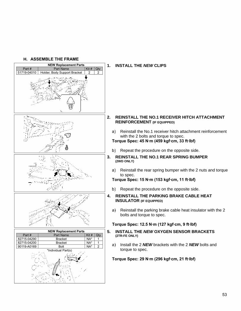
H. ASSEMBLE THE FRAME
NEW Replacement Parts
Part # Part Name Kit # Qty
51719-04010 Holder, Body Support Bracket 2 2
1. INSTALL THE NEW CLIPS
2. REINSTALL THE NO.1 RECEIVER HITCH ATTACHMENT REINFORCEMENT (IF EQUIPPED)
Reinstall the No.1 receiver hitch attachment reinforcement
with the 2 bolts and torque to spec. Torque Spec: 45 N∙m (459 kgf∙cm, 33 ft∙lbf)
Repeat the procedure on the opposite side.
3. REINSTALL THE NO.1 REAR SPRING BUMPER (2WD ONLY)
Reinstall the rear spring bumper with the 2 nuts and torque
to spec. Torque Spec: 15 N∙m (153 kgf∙cm, 11 ft∙lbf)
Repeat the procedure on the opposite side.
4. REINSTALL THE PARKING BRAKE CABLE HEAT INSULATOR (IF EQUIPPED)
Reinstall the parking brake cable heat insulator with the 2
bolts and torque to spec.
Torque Spec: 12.5 N∙m (127 kgf∙cm, 9 ft∙lbf)
NEW Replacement Parts
Part # Part Name Kit # Qty
82715-04290 Bracket NA* 1
82715-04200 Bracket NA* 1
90119-A0169 Bolt NA* 2
*Individual Part(s)
5. INSTALL THE NEW OXYGEN SENSOR BRACKETS (2TR-FE ONLY)
Install the 2 NEW brackets with the 2 NEW bolts and
torque to spec.
Torque Spec: 29 N∙m (296 kgf∙cm, 21 ft∙lbf)

54
6. REINSTALL THE REAR ENGINE MOUNTING REINFORCES (1GR-FE ONLY)
Reinstall the rear engine mounting reinforces with the 2
bolts and torque to spec.
Torque Spec: 31 N∙m (316 kgf∙cm, 23 ft∙lbf)
NEW Replacement Parts
Part # Part Name Kit # Qty
90119-A0192 Bolt 8 2
90119-A0193 Bolt NA* 2
*Individual Part(s)
7. REINSTALL THE HOOK
Reinstall the hook with the 2 NEW bolts and torque to spec.
Torque Spec: 70 N∙m (714 kgf∙cm, 52 ft∙lbf)
8. REINSTALL THE FRAME AUXILIARY CROSSMEMBER EXTENSION (IF EQUIPPED)
Reinstall the 2 frame auxiliary crossmember extensions
with the 2 bolts and torque to spec.
Torque Spec: 45 N∙m (459 kgf∙cm, 33 ft∙lbf)
9. REINSTALL THE CAB MOUNTS
Reinstall cab mounts No.1 Reinstall cab mounts No.2 and No.3 with the 8 bolts and
torque to spec.
Torque Spec: 61 N∙m (622 kgf∙cm, 45 ft∙lbf)
10. INSTALL THE NEW FRONT SUSPENSION LOWER ARM (2WD ONLY)
Install the NEW front suspension lower arm with the 2 NEW nuts, 2 NEW No.1 camber adjust cams and 2 NEW No.2 camber adjust cams, then torque to spec.
Torque Spec: 210 N∙m (2141 kgf∙cm, 155 ft∙lbf)
Repeat the procedure on the opposite side.

55
NEW Replacement Parts
Part # Part Name Kit # Qty
48069-04030 Arm Sub-Assy, Front
Suspension, Lower No.1, LH NA* 1
48068-04030 Arm Sub-Assy, Front
Suspension, Lower No.1, RH NA* 1
48190-25010 Cam, Front Suspension
Camber Adjust, No.1 LH/RH 4 4
48198-25010 Cam, Front Suspension
Camber Adjust, No.2 LH/RH 4 4
90178-A0013 Nut NA* 4
*Individual Part(s)
2WD Only
11. INSTALL THE NEW FRONT SUSPENSION LOWER ARM (4WD, PRE-RUNNER ONLY) Install the NEW front suspension lower arm with the NEW bolt, NEW nut, NEW toe adjust cam, NEW No.2
toe adjust cam, NEW No.1 camber adjust cam and NEW No.2 camber adjust cam, then torque to spec. Torque Spec: 135 N∙m (1377 kgf∙cm, 100 ft∙lbf)
Repeat the procedure on the opposite side.
4WD, Pre-Runner Only
NEW Replacement Parts
Part # Part Name Kit # Qty
48069-04040 Arm Sub-Assy, Front
Suspension, Lower No.1, LH NA* 1
48068-04040 Arm Sub-Assy, Front
Suspension, Lower No.1, RH NA* 1
48190-60020 Cam, Front Suspension
Camber Adjust, No.1 LH/RH 5 2
48198-60011 Cam, Front Suspension
Camber Adjust, No.2 LH/RH 5 2
48409-60020 Cam, Sub-Assy, Front Suspension Toe Adjust
5 2
48452-35020 Plate, Front Suspension Toe
Adjust, No.2 5 2
90119-A0166 Bolt 8 2
90178-A0001 Nut NA* 2
*Individual Part(s)
NEW Replacement Parts (2WD Only)
Part # Part Name Kit # Qty
48304-AD010 Bumper, Front Spring, LH/RH**
NA* 2
48304-04090 NA* 2
*Individual Part(s) **Only 1 part used, part number varies by vehicle type.
NEW Replacement Parts (4WD, Pre-Runner Only)
Part # Part Name Kit # Qty
48304-04100 Bumper, Front Spring, LH/RH 8 2
12. INSTALL THE NEW FRONT SPRING BUMPER
Using the SST 09922-10010-01, install the NEW front spring bumpers and torque to spec.
Torque Spec: 31 N∙m (316 kgf∙cm, 23 ft∙lbf)
Repeat the procedure on the opposite side.
13. INSTALL THE NEW REAR BRAKE TUBES
Install the NEW rear brake tubes with the NEW clamp(s).

56
NEW Replacement Parts
Part # Part Name Kit # Qty
47325-***** Tube, Rear Brake, No.5 NA* 1
47326-***** Tube, Rear Brake, No.6 NA* 1
90469-A0004 Clamp, Brake Tube, No.11**
NA* 2 or 3 or 4
NA*
NA*
90949-A1006 Clamp, Brake Tube, No.10 2 3
*Individual Part(s) ** Only 1 part used, part number varies by vehicle type.
14. REINSTALL THE NO. 2 CHARCOAL CANISTER PIPE
Reinstall the fuel return and main tube support. Reinstall the No.2 charcoal canister pipe.
NEW Replacement Parts
Part # Part Name Kit # Qty
90119-A0169 Bolt 2 4
51900-35410 Carrier Assy, Spare Wheel**
NA* 1
51900-35420 NA* 1
*Individual Part(s) ** Only 1 part used, part number varies by vehicle type.
15. INSTALL THE NEW SPARE TIRE CARRIER ASSY (2011MY ONLY)
Install the NEW spare tire carrier assy with the 4 NEW
bolts and torque to spec.
Torque Spec: 20 N∙m (204 kgf∙cm, 15 ft∙lbf)
16. REINSTALL THE SPARE TIRE CARRIER ASSY (2012-2015MY ONLY)
Reinstall the spare tire carrier assy with the 4 NEW bolts and torque to spec.
Torque Spec: 20 N∙m (204 kgf∙cm, 15 ft∙lbf)
NEW Replacement Parts
Part # Part Name Kit # Qty
82715-04250 Bracket NA* 1
82715-04260 Bracket NA* 1
82711-16830 Clamp NA* 1
90105-A0066 Bolt NA* 1
*Individual Part(s)
17. INSTALL THE NEW SKID CONTROL SENSOR WIRE BRACKET (W/ REAR DIFFERENTIAL LOCK ONLY)
Install the NEW clamp (A). Install the 2 NEW brackets with the 2 clamps and 2
connectors. Install the NEW bolt.
Torque Spec: 12.5 N∙m (127 kgf∙cm, 9 ft∙lbf)
NEW Replacement Parts
Part # Part Name Kit # Qty
90177-A0010 Nut 2 2
*Individual Part(s)
18. REINSTALL THE LEAF SPRINGS AND SHOCK ABSORBER ASSY
Reinstall the leaf springs with the 4 bolts, 4 washers and 4
nuts, then torque to spec.
Torque Spec: 120 N∙m (1224 kgf∙cm, 89 ft∙lbf)
Reinstall the shock absorber assy with the 2 NEW nuts, 2 retainers and 2 cushions, then torque to spec.
Torque Spec: 20 N∙m (204 kgf∙cm, 15 ft∙lbf)

57
NEW Replacement Parts
Part # Part Name Kit # Qty
90119-08A91 Bolt NA* 4
*Individual Part(s)
19. REINSTALL THE REAR STABILIZER BAR (IF EQUIPPED)
Reinstall the rear stabilizer bar with the 2 brackets and 4 NEW bolts, then torque to spec.
Torque Spec: 30 N∙m (306 kgf∙cm, 22 ft∙lbf)
Reconnect the 2 stabilizer bar links with the 4 nuts, then torque to spec.
Torque Spec: 65 N∙m (663 kgf∙cm, 48 ft∙lbf)
NEW Replacement Parts
Part # Part Name Kit # Qty
90468-A0007 Clip 2 2
90119-A0169 Bolt
14 or 15 or
NA*
2
*Individual Part(s)
20. REINSTALL THE NO.2 FLEXIBLE HOSE BRACKET
Reinstall the No.2 flexible hose bracket with the 2 NEW bolts.
Reconnect the 2 brake hoses with the 2 NEW clips. Connect the No.5 and No.6 rear brake tubes, then torque
to spec.
Torque Spec: Flexible hose bracket - 29 N∙m (296 kgf∙cm, 21 ft∙lbf) Rear brake tube - 15.2 N∙m (155 kgf∙cm, 11 ft∙lbf)
NEW Replacement Parts
Part # Part Name Kit # Qty
82715-04200 Bracket NA* 1
82715-04290 Bracket NA* 1
82715-04240 Bracket NA* 1
82715-04350 Bracket NA* 1
90119-A0169 Bolt NA* 4
*Individual Part(s)
21. INSTALL THE NEW NO.2 FRAME WIRE HARNESS BRACKETS (IF EQUIPPED)
Install the NEW bracket (A) with the NEW bolt and torque
to spec. (Except 2TR-FE) Torque Spec: 29 N∙m (296 kgf∙cm, 21 ft∙lbf)
Install the NEW bracket (B) with the NEW bolt and torque to spec. (Except 2TR-FE)
Torque Spec: 29 N∙m (296 kgf∙cm, 21 ft∙lbf)
For Floor Connecting Type:
Install the NEW bracket with the NEW bolt and torque to spec.
Torque Spec: 29 N∙m (296 kgf∙cm, 21 ft∙lbf)
For Frame Connecting Type: Install the NEW bracket with the 2 NEW bolts and torque to
spec. Torque Spec: 29 N∙m (296 kgf∙cm, 21 ft∙lbf)
Rear Side (Floor Connecting Type)
Rear Side (Frame Connecting Type)
22. REINSTALL THE NO.2 FRAME WIRE HARNESS (IF EQUIPPED) Reconnect the clamps to install the No.2 frame wire
harness.
NOTE: The number of wire harness clamps will differ depending on the vehicle spec.
NEW Replacement Parts
Part # Part Name Kit # Qty
82715-04220 Bracket NA* 1
23. INSTALL THE NEW HARNESS BRACKETS

58
82715-04230 Bracket NA* 1
90119-A0169 Bolt NA* 2
*Individual Part(s)
Install the 2 NEW brackets with the 2 NEW bolts and torque to spec.
Torque Spec: 14 N∙m (143 kgf∙cm, 10 ft∙lbf)
Front Side Rear Side
24. REINSTALL THE FRAME WIRE HARNESS
Reconnect the clamps to install the frame wire harness. Reconnect the ground wire with the bolt and torque to spec
(If Equipped).
Torque Spec: 14 N∙m (143 kgf∙cm, 10 ft∙lbf)
NOTE: The number of wire harness clamps will differ depending on the vehicle spec.
Access Cab Parking Brake Cable Routing
25. RECONNECT THE PARKING BRAKE CABLES
Reinstall the 2 parking brake cables with the 6 bolts, then torque to spec.
Torque Spec: 12.5 N∙m (127 kgf∙cm, 9 ft∙lbf)

59
NEW Replacement Parts
Part # Part Name Kit # Qty
82715-04160 Bracket**
NA* 1
82715-3D680 NA* 1
90119-A0141 Bolt NA* 1
*Individual Part(s) ** Only 1 part used, part number varies by vehicle type.
26. REINSTALL THE FRONT DIFFERENTIAL CARRIER (4WD ONLY)
Apply adhesive to the serration bolt. Reinstall the front differential carrier with the 2 bolts, 4
stoppers and 3 nuts, then torque to spec.
Torque Spec: Except TMMTX Made Bolt - 137.3 N∙m (1400 kgf∙cm, 101 ft∙lbf) Nut - 87.2 N∙m (889 kgf∙cm, 64 ft∙lbf)
Torque Spec: TMMTX Made Bolt - 128.5 N∙m (1310 kgf∙cm, 95 ft∙lbf) Nut - 81.5 N∙m (831 kgf∙cm, 60 ft∙lbf)
Disconnect the connector from the bracket. Remove the bolt and bracket. Install the NEW bracket with the NEW bolt and torque to
spec. Torque Spec: 14 N∙m (143 kgf∙cm, 10 ft.∙lbf)
2TR-FE
1GR-FE
27. REINSTALL THE POWER STEERING LINK ASSY W/ POWER STEERING VANE PUMP
Reinstall the power steering link assy w/ power steering vane pump with the bolts and nuts, then torque to spec.
Torque Spec: 2TR-FE 4WD Bolt A - 95 N∙m (969 kgf∙cm, 70 ft∙lbf) Bolt B - 28 N∙m (286 kgf∙cm, 21 ft∙lbf)
Torque Spec: Except 2TR-FE 4WD Bolt A - 92 N∙m (938 kgf∙cm, 68 ft∙lbf) Bolt B - 28 N∙m (286 kgf∙cm, 21 ft∙lbf)
NOTE:
• When reinstalling the power steering link with the pump, have one person support the power steering link and the other support the pump.
• Keep the power steering pump reservoir upright to prevent the fluid from leaking out.
28. RECONNECT THE FRONT DIFFERENTIAL BREATHER TUBE (4WD ONLY)
Reconnect the front differential breather tube with the bolt and 2 clamps, then torque to spec.
Torque Spec: 12.7 N∙m (130 kgf∙cm, 9 ft∙lbf)

60
NEW Replacement Parts
Part # Part Name Kit # Qty
90080-17215 Nut 2 6
29. REINSTALL THE FRONT SHOCK ABSORBER ASSY
Install the 3 NEW nuts (A) and torque to spec. Reinstall the front shock absorber assy with the bolt and
nut (B), then torque to spec.
Torque Spec: Nut A - 64 N∙m (653 kgf∙cm, 47 ft∙lbf) Nut B - 83 N∙m (846 kgf∙cm, 61 ft∙lbf)
Repeat the procedure on the opposite side.
NEW Replacement Parts (2WD Only)
Part # Part Name Kit # Qty
90119-A0161 Bolt NA* 4
*Individual Part(s)
30. REINSTALL THE FRONT STABILIZER BAR
Reinstall the stabilizer bar with 2 brackets and 4 NEW bolts, then torque to spec. (2WD Only)
Reinstall the stabilizer bar with 2 brackets and 4 bolts, then torque to spec. (4WD, Pre-Runner Only).
Torque Spec: 2WD - 21 N∙m (214 kgf∙cm, 15 ft∙lbf) 4WD, Pre-Runner - 40 N∙m (408 kgf∙cm, 30 ft∙lbf)
2WD Only
4WD, Pre-Runner Only
31. REINSTALL THE FRONT SUSPENSION MEMBER BRACE SUB-ASSY
Reinstall the suspension member brace sub-assy with 8
bolts (2WD Only) or 7 bolts (4WD, Pre-Runner Only), then torque to spec.
Torque Spec: 45 N∙m (459 kgf∙cm, 33 ft∙lbf)
NEW Replacement Parts
Part # Part Name Kit # Qty
90311-47026 Seal, Oil (For Differential Side Gear Shaft)
3 1
90311-47027 3 1
43425-04040 Ring, Shaft Snap (For Front
Drive Inner Shaft Outer) NA* 2
*Individual Part(s)
32. REINSTALL THE FRONT DRIVE SHAFT ASSY (4WD ONLY)
Remove the type T oil seal. Install the NEW type T oil seal. Install a NEW snap ring. Reinstall the front drive shaft assy. Repeat the procedure on the opposite side.
NOTE: Be careful not to damage the dust cover and oil seal.

61
33. REINSTALL THE FRONT SUSPENSION UPPER ARM AND STEERING KNUCKLE ASSY (2WD ONLY)
Reinstall the front suspension upper arm w/ steering knuckle with the 2 bolts, 2 nuts and 2 washers, then torque to spec.
Torque Spec: Bolt - 82 N∙m (836 kgf∙cm, 60 ft∙lbf)
Repeat the procedure on the opposite side.
34. REINSTALL THE FRONT SUSPENSION UPPER ARM AND STEERING KNUCKLE ASSY (4WD, PRE-RUNNER ONLY)
Reinstall the front suspension upper arm w/ steering knuckle with the bolt, nut and 2 washers, then torque to spec.
Torque Spec: Nut - 115 N∙m (1173 kgf∙cm, 85 ft∙lbf)
Repeat the procedure on the opposite side.
NEW Replacement Parts
Lower Ball Joint Attachment
Part # Part Name Kit # Qty
90171-A0005 Nut, Castle (For Front Lower
Ball Joint LH/RH) 2 2
95381-03230 Cotter Pin 4 or 5
2
Tie Rod End
Part # Part Name Kit # Qty
95381-03025 Cotter Pin**
4 2
95381-03225 5 2
** Only 1 part used, part number varies by vehicle type.
35. REINSTALL THE FOLLOWING PARTS
• Lower Ball Joint Attachment
Reinstall the lower ball joint attachment with the NEW nut and 2 bolts, then torque to spec.
Install the NEW cotter pin.
Repeat the procedure on the opposite side.
Torque Spec: Nut - 140 N∙m (1428 kgf∙cm, 103 ft.∙lbf) Bolt - 160 N∙m (1632 kgf∙cm, 118 ft∙lbf)
• Front Stabilizer Link Assy (2WD Only)
Reinstall the front stabilizer link assy with 2 retainers, 2 cushions and nut, torque to spec.
Torque Spec: 19 N∙m (194 kgf∙cm, 14 ft∙lbf)
Reinstall the nut, then torque to spec.
Torque Spec: 69 N∙m (704 kgf∙cm, 51 ft∙lbf)
Repeat the procedure on the opposite side.
• Front Stabilizer Link Assy (4WD, Pre-Runner Only)
Reinstall the front stabilizer link assy with the 2 nuts, torque to spec.
Torque Spec: 70 N∙m (714 kgf∙cm, 52 ft∙lbf)
Repeat the procedure on the opposite side.
• Tie Rod End
Reinstall the tie rod end with the nut and torque to spec.
Torque Spec: 2WD - 49 N∙m (500 kgf∙cm, 36 ft∙lbf) 4WD, Pre-Runner - 91 N∙m (928 kgf∙cm, 67 ft∙lbf)
Install the NEW cotter pin.
Repeat the procedure on the opposite side.
• Front Axle Shaft Nut (4WD Only)
Temporarily reinstall the front axle shaft nut.
Nut will be tightened when the vehicle is completed.
Repeat the procedure on the opposite side.

62
NEW Replacement Parts
Part # Part Name Kit # Qty
47314-04140 Tube, Front Brake, No.4**
12 1
47314-04141 13 1
47316-04140 Tube, Front Brake, No.6**
12 1
47316-04141 13 1
90412-10289 Way (For Front Brake Tube) 1 2
90119-A0169 Bolt NA* 2
*Individual Part(s) ** Only 1 part used, part number varies by vehicle type.
36. INSTALL THE NEW FRONT BRAKE TUBE AND NEW WAY (2WD ONLY)
Temporarily install the NEW front brake tube and NEW way.
Install the NEW bolt to the NEW way and torque to spec. Torque Spec: 32 N∙m (326 kgf∙cm, 24 ft∙lbf)
Repeat the procedure on the opposite side.
NEW Replacement Parts
Part # Part Name Kit # Qty
47314-04150 Tube, Front Brake, No.4**
14 1
47314-04151 15 1
47316-04150 Tube, Front Brake, No.6**
14 1
47316-04151 15 1
90412-10289 Way (For Front Brake Tube) 1 2
90119-A0169 Bolt 14 or 15
2
**Only 1 part used, part number varies by vehicle type.
37. INSTALL THE NEW FRONT BRAKE TUBE AND
NEW WAY (4WD, PRE-RUNNER ONLY)
Temporarily install the NEW front brake tube and NEW way.
Install the NEW bolt to the NEW way and torque to spec.
Torque Spec: 32 N∙m (326 kgf∙cm, 24 ft∙lbf)
Repeat the procedure on the opposite side.
NEW Replacement Parts
Part # Part Name Kit # Qty
90119-A0169 Bolt NA* 4
90468-A0007 Clip 2 2
*Individual Part(s)
38. RECONNECT THE FRONT BRAKE HOSE (2WD ONLY)
Reinstall the flexible hose bracket with the NEW bolt and torque to spec.
Torque Spec: 32 N∙m (326 kgf∙cm, 24 ft∙lbf)
Reconnect the front brake hose with a NEW clip. Reconnect the front brake tube and torque to spec.
Torque Spec: 15.2 N∙m (155 kgf∙cm, 11 ft∙lbf)
Reinstall the NEW bolt and torque to spec. Torque Spec: 32 N∙m (326 kgf∙cm, 24 ft∙lbf)
Repeat the procedure on the opposite side.
NEW Replacement Parts
Part # Part Name Kit # Qty
90119-A0169 Bolt 14 or 15
2
90468-A0007 Clip 2 2
39. RECONNECT THE FRONT BRAKE HOSE (4WD, PRE-RUNNER ONLY)
Reinstall the flexible hose bracket with the NEW bolt and torque to spec.
Torque Spec: 32 N∙m (326 kgf∙cm, 24 ft∙lbf)
Reconnect the front brake hose with a NEW clip. Reconnect the front brake tube and torque to spec.
Torque Spec: 15.2 N∙m (155 kgf∙cm, 11 ft∙lbf)
Repeat the procedure on the opposite side.

63
NEW Replacement Parts
Part # Part Name Kit # Qty
90105-A0064 Bolt NA* 1
*Individual Part(s)
40. RECONNECT THE FRONT SKID CONTROL SENSOR WIRE HARNESS (2WD ONLY)
2011MY RH Side: Remove the clamp from the front skid control sensor wire
harness. Install the NEW bolt (A) and torque to spec.
Torque Spec: 12.5 N∙m (127 kgf∙cm, 9 ft∙lbf)
Reconnect the front skid control sensor wire harness with bolt and torque to spec.
Torque Spec: 12.5 N∙m (127 kgf∙cm, 9 ft∙lbf)
Except 2011MY RH Side:
Reconnect the front skid control sensor wire harness with the 2 bolts.
Torque Spec: 12.5 N∙m (127 kgf∙cm, 9 ft∙lbf)
Repeat the procedure on the opposite side.
41. RECONNECT THE FRONT SKID CONTROL SENSOR WIRE HARNESS (4WD, PRE-RUNNER ONLY)
Reconnect the front skid control sensor wire harness with bolt and torque to spec.
Torque Spec: 12.5 N∙m (127 kgf∙cm, 9 ft∙lbf)
Repeat the procedure on the opposite side.
42. REINSTALL THE WHEELS
43. REINSTALL THE FRONT PROPELLER SHAFT ASSY (4WD ONLY)
Referencing the matchmarks, reinstall the propeller shaft
assy to the front differential. Reinstall the 4 bolts, 4 washer and 4 nuts, them torque to
spec. Torque Spec: 88.2 N∙m (899 kgf∙cm, 65 ft∙lbf)
44. REINSTALL THE ENGINE AND TRANSMISSION ASSY Reinstall engine and transmission assy.
NOTE:
• Hang up the front exhaust pipe with string to avoid applying pressure at the joint part. (2TR-FE only)
• Use 2 engine hoists/cranes to lift engine & trans assy.
• DO NOT use 1 engine hoist/crane to lift the engine & trans assy, the unbalanced weight may lead to an accident or injury.
• ONLY use engine hoists/cranes that can properly support the weight of the engine & trans.
• Carefully adjust the 2 engine hoists/cranes used so that the engine & trans assy is balanced.

64
NEW Replacement Parts
Part # Part Name Kit # Qty
90910-03001 Bolt 1 4
94151-21001 Nut 1 4
LH Side
RH Side
Attach the engine mounts with the 4 NEW bolts and 4 NEW nuts, then torque to spec.
2011MY: Torque Spec: 38 N∙m (387 kgf∙cm, 28 ft∙lbf)
2012-2015MY: Torque Spec: 40 N∙m (408 kgf∙cm, 30 ft∙lbf)
NEW Replacement Parts
Part # Part Name Kit # Qty
91671-80814 Bolt 1 4
Attach the transmission mount with 4 NEW bolts and torque to spec.
2011MY: Torque Spec: 18.5 N∙m (189 kgf∙cm, 14 ft∙lbf)
2012-2015MY: Torque Spec: 30 N∙m (306 kgf∙cm, 22 ft∙lbf)
Remove the bolt(s) and the engine hangers. Reinstall the items/parts that were removed during the
engine and transmission assy removal.
LH Side
RH Side (4WD Only)
RH Side (2TR-FE Only)
Reinstall the bolt and reconnect the ground wire. (LH Side)
Torque Spec: 12.5 N∙m (127 kgf∙cm, 9 ft∙lbf)
Reconnect the connector and clamp. (4WD Only)
Reconnect the clamp. (2TR-FE Only)
65
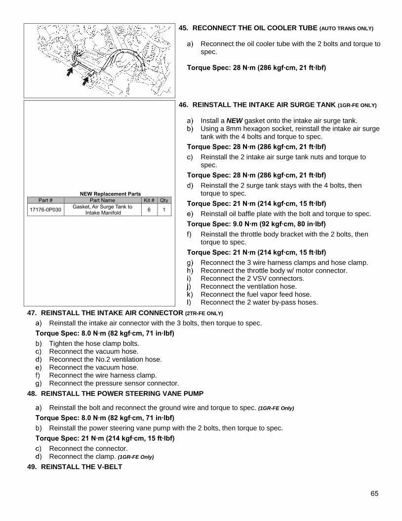
45. RECONNECT THE OIL COOLER TUBE (AUTO TRANS ONLY) Reconnect the oil cooler tube with the 2 bolts and torque to
spec.
Torque Spec: 28 N∙m (286 kgf∙cm, 21 ft∙lbf)
NEW Replacement Parts
Part # Part Name Kit # Qty
17176-0P030 Gasket, Air Surge Tank to
Intake Manifold 6 1
46. REINSTALL THE INTAKE AIR SURGE TANK (1GR-FE ONLY)
Install a NEW gasket onto the intake air surge tank. Using a 8mm hexagon socket, reinstall the intake air surge
tank with the 4 bolts and torque to spec.
Torque Spec: 28 N∙m (286 kgf∙cm, 21 ft∙lbf)
Reinstall the 2 intake air surge tank nuts and torque to spec.
Torque Spec: 28 N∙m (286 kgf∙cm, 21 ft∙lbf)
Reinstall the 2 surge tank stays with the 4 bolts, then torque to spec.
Torque Spec: 21 N∙m (214 kgf∙cm, 15 ft∙lbf)
Reinstall oil baffle plate with the bolt and torque to spec.
Torque Spec: 9.0 N∙m (92 kgf∙cm, 80 in∙lbf)
Reinstall the throttle body bracket with the 2 bolts, then torque to spec.
Torque Spec: 21 N∙m (214 kgf∙cm, 15 ft∙lbf)
Reconnect the 3 wire harness clamps and hose clamp. Reconnect the throttle body w/ motor connector.
Reconnect the 2 VSV connectors. Reconnect the ventilation hose. Reconnect the fuel vapor feed hose. Reconnect the 2 water by-pass hoses.
47. REINSTALL THE INTAKE AIR CONNECTOR (2TR-FE ONLY)
Reinstall the intake air connector with the 3 bolts, then torque to spec.
Torque Spec: 8.0 N∙m (82 kgf∙cm, 71 in∙lbf)
Tighten the hose clamp bolts. Reconnect the vacuum hose. Reconnect the No.2 ventilation hose. Reconnect the vacuum hose.
Reconnect the wire harness clamp. Reconnect the pressure sensor connector.
48. REINSTALL THE POWER STEERING VANE PUMP
Reinstall the bolt and reconnect the ground wire and torque to spec. (1GR-FE Only)
Torque Spec: 8.0 N∙m (82 kgf∙cm, 71 in∙lbf)
Reinstall the power steering vane pump with the 2 bolts, then torque to spec.
Torque Spec: 21 N∙m (214 kgf∙cm, 15 ft∙lbf)
Reconnect the connector. Reconnect the clamp. (1GR-FE Only)
49. REINSTALL THE V-BELT

66
50. REINSTALL THE FUEL TANK STRAPS
Reinstall the fuel tank straps with the 2 pins and 2 clips.
NEW Replacement Parts
Part # Part Name Kit # Qty
90119-A0249 Bolt 2 2
51. REINSTALL THE FUEL TANK
Reinstall the fuel tank with the 2 NEW bolts and torque to spec.
Torque Spec: 62 N∙m (632 kgf∙cm, 46 ft∙lbf)
Reconnect the connector.
52. REINSTALL THE NO.2 FUEL TANK PROTECTOR (IF EQUIPPED)
NEW Replacement Parts
Part # Part Name Kit # Qty
90179-08241 Nut NA* 4
*Individual Part(s)
53. REINSTALL THE NO.1 FUEL TANK PROTECTOR ASSY (IF EQUIPPED)
Reinstall the No.1 fuel tank protector assy with the 4 NEW
nuts and torque to spec.
Torque Spec: 20 N∙m (204 kgf∙cm, 15 ft∙lbf)
NEW Replacement Parts
Part # Part Name Kit # Qty
77285-35760 Clamp. Fuel Tube, No.1 1 1
90105-A0066 Bolt NA* 1
*Individual Part(s)
54. REINSTALL THE CHARCOAL CANISTER ASSY Reinstall the charcoal canister assy with the bolt and 3
nuts, then torque to spec. Torque Spec: 20 N∙m (204 kgf∙cm, 15 ft∙lbf)
Reconnect the fuel tank vent hose. Reconnect the fuel hose. Reconnect the main tube support and reconnect the filter
hose. Reconnect the connector.
w/ Rear Differential Lock: Install the NEW bolt and connect the skid control sensor wire bracket and torque to spec.
w/o Rear Differential Lock: Install the bolt and reconnect the skid control sensor wire bracket and torque to spec.
Torque Spec: 12.5 N∙m (127 kgf∙cm, 9 ft∙lbf)
Install the NEW clamp.
NEW Replacement Parts
Part # Part Name Kit # Qty
17451-0D020 Gasket, Exhaust Pipe 6 1
55. REINSTALL THE EXHAUST SYSTEM (1GR-FE ONLY)
Reconnect the 2 exhaust pipe supports to the frame. Install the NEW exhaust pipe gasket.

67
NEW Replacement Parts
Part # Part Name Kit # Qty
90080-10291 Bolt 6 2
Reconnect the 4 exhaust pipe supports to the frame and reinstall the center exhaust pipe assy.
Install the 2 NEW bolts and 2 springs, then torque to spec.
Torque Spec: 43 N∙m (438 kgf∙cm, 32 ft∙lbf)
56. REINSTALL THE EXHAUST SYSTEM (2TR-FE ONLY)
NEW Replacement Parts
Part # Part Name Kit # Qty
90080-43033 Gasket 7 1
90080-10064 Bolt 7 2
90177-A0004 Nut 7 2
Reconnect the exhaust pipe support to the frame. Reconnect the 2 oxygen sensor wire harness clamps.
Install the NEW exhaust pipe gasket. Reconnect the 4 exhaust pipe supports to the frame and
reinstall the center exhaust pipe assy. Install the 2 NEW bolts and 2 NEW nuts then torque to
spec.
Torque Spec: 48 N∙m (489 kgf∙cm, 35 ft∙lbf)
NEW Replacement Parts
Part # Part Name Kit # Qty
90080-11180 Bolt 6 2
57. REINSTALL THE EXHAUST PIPE STOPPER BRACKET (IF EQUIPPED)
Reinstall the exhaust pipe stopper bracket with the 2 NEW bolts and torque to spec.
Torque Spec: 19 N∙m (194 kgf∙cm, 14 ft∙lbf)
NEW Replacement Parts
Part # Part Name Kit # Qty
90119-A0151 Bolt NA* 2
*Individual Part(s)
58. REINSTALL THE PROPELLER SHAFT HEAT INSULATOR (IF EQUIPPED)
Reinstall the propeller shaft heat insulator with the 2 NEW
bolts and torque to spec.
Torque Spec: 15.7 N∙m (160 kgf∙cm, 12 ft∙lbf)

68
59. REINSTALL THE REAR PROPELLER SHAFT ASSY
Remove the SST. (2WD Only) Referencing the matchmarks, reinstall the rear propeller
shaft assy to the transmission / transfer case. Reinstall the 4 washers and 4 nuts, then torque to spec.
(4WD Only)
Torque Spec: 88.2 N∙m (899 kgf∙cm, 65 ft∙lbf)
Reinstall the center support bearing to the frame as shown in the illustration with 2 washers and 2 bolts, then torque to spec. (3-Joint Type Only)
Torque Spec: 36.2 N∙m (369 kgf∙cm, 27 ft∙lbf)
Referencing the matchmarks, reinstall the rear propeller shaft assy to the rear differential with 4 bolts, 4 washers and 4 nuts, then torque to spec.
Torque Spec: 88.2 N∙m (899 kgf∙cm, 65 ft∙lbf)
60. RECONNECT THE FRONT PROPELLER SHAFT ASSY (4WD ONLY)
Referencing the matchmarks, reconnect the front propeller shaft assy to the transfer case and the front differential with 4 bolts, 4 washers and 4 nuts, then torque to spec.
Torque Spec: 88.2 N∙m (899 kgf∙cm, 65 ft∙lbf)
61. REMOVE THE FRAME FROM THE LIFT Remove the ratcheting tie down strap from the frame. Lower the frame to the ground.

69
I. REINSTALL THE CAB BODY ASSY
Before lowering the cab assembly ensure that you install the NEW brakelines onto the bulk head.
NEW Replacement Parts
Part # Part Name Kit # Qty
47313-04200
Tube, Front Brake, No.3**
10 1
47313-04231 11 1
47313-04210 NA* 1
47313-04241 NA* 1
47315-04170
Tube, Front Brake, No.5**
10 1
47315-04171 11 1
47315-04180 NA* 1
47315-04191 NA* 1
47323-04170
Tube, Rear Brake, No.3**
10 1
47323-04171 11 1
47323-04180 NA* 1
4732304191 NA* 1
47324-04130
Tube, Rear Brake, No.4**
10 1
47324-04131 11 1
47324-04140 NA* 1
47324-04151 NA* 1
*Individual Part(s) **Only 1 part used, part number varies by vehicle type.
1. INSTALL THE NEW ENGINE COMPARTMENT BRAKE TUBES
Install the NEW No.3 and NEW No.5 front brake tubes. Install the NEW No.3 and NEW No.4 rear brake tubes. Torque all brake tubes to spec.
Torque Spec: Flare Nut (M10) - 15.2 N∙m (155 kgf∙cm, 11 ft∙lbf) Flare Nut (M12) - 19.5 N∙m (199 kgf∙cm, 14 ft∙lbf)
2. REINSTALL THE CAB BODY ASSY
Raise the cab assy high enough so that the top of the engine clears the lowest point of the cab. Push the frame under the cab assy and line the tires up with the alignment marks. Lower the cab assy slowly, making sure it does not interfere with anything. Adjust the vehicle’s frame as needed to align the cab mounts with the cab assy bolts. Once the cab assy is set on the mounts, secure it to the frame with 6 bolts, 6 nuts, 6 washers and torque to
spec.
Torque Spec: No.1 - 37.5 N∙m (382 kgf∙cm, 28 ft∙lbf) No.2, No.3 - 45 N∙m (459 kgf∙cm, 33 ft∙lbf)
Reinstall the 4 hole plugs.
NOTE:
• DO NOT work directly underneath the vehicle when pushing the frame under the cab assy.
• Slowly lower the cab assy making sure the wire harness, steering shaft & hoses don’t interfere.
• With 2 to 3 people checking for interference, slowly lower the cab body assembly to the frame.

70
3. RECONNECT THE PARKING BRAKE CABLE
NEW Replacement Parts
Part # Part Name Kit # Qty
90412-10276 Way, 2 (For Rear Brake Tube) 2 1
90119-A0169 Bolt
14 or 15 or
NA*
1
*Individual Part(s)
4. CONNECT THE REAR BRAKE TUBES Temporarily install the NEW 2 way with the NEW bolt. Temporarily install the 4 rear brake tubes. Torque the bolt to spec.
Torque Spec: 32 N∙m (326 kgf∙cm, 24 ft∙lbf)
Torque the 4 rear brake tubes to spec.
Torque Spec: 15.2 N∙m (155 kgf∙cm, 11 ft∙lbf)
5. RECONNECT THE FUEL TANK TUBES
Reconnect the 2 fuel tank tubes. Reinstall the fuel pipe clamp.
NOTE:
• Align the connector with the pipe, and push into the connector until the connector makes a "click" sound. If the connection is tight, apply a little amount of fresh engine oil on the tip of the pipe.
• Ensure the pipe and the connector are securely connected by pulling them.
6. RECONNECT THE NO.2 FUEL HOSE
Reconnect the No.2 fuel hose with the clip.
NEW Replacement Parts (Rod Type)
Part # Part Name Kit # Qty
90468-14033 Clip NA* 1
90240-08054 Pin, W/ Hole (For Transmission
Control Rod) NA* 1
*Individual Part(s)
7. RECONNECT THE SHIFT CABLE (AUTO TRANS ONLY)
Cable Type (Shown): Reconnect the shift cable with the nut and torque to spec.
Torque Spec: 14 N∙m (143 kgf∙cm, 10 ft∙lbf)
Install the clip.
Rod Type: Reconnect the shift cable with the NEW pin and NEW clip.

71
8. RECONNECT THE CLUTCH RELEASE CYLINDER ASSY (2TR-FE MANUAL TRANS ONLY)
Reconnect the clutch release cylinder with the 2 bolts and
torque to spec.
Torque Spec: 11.8 N∙m (120 kgf∙cm, 9 ft∙lbf)
Reconnect the clutch hose with the bolt and torque to spec.
Torque Spec: 37 N∙m (377 kgf∙cm, 27 ft∙lbf)
9. RECONNECT THE NO.1 CLUTCH HOSE (1GR-FE MANUAL TRANS ONLY)
Reconnect the No.1 clutch hose with the clip. Reconnect the clutch release cylinder tube to the clutch
hose.
Torque Spec: 15.2 N∙m (155 kgf∙cm, 11 ft∙lbf)
NEW Replacement Parts
Part # Part Name Kit # Qty
90080-11555 Bolt 2 2
10. RECONNECT THE STEERING SLIDING YOKE
Make sure the front wheels are in a straight-ahead position and the steering wheel is centered.
Referencing the match marks, reconnect the steering sliding yoke to the No.2 intermediate shaft with the NEW bolt (B).
Remove bolt (A) and install the NEW bolt (A). Torque all bolts to spec.
Torque Spec: 35 N∙m (357 kgf∙cm, 26 ft∙lbf)
Disconnect the seat belt that is holding the steering wheel.
LH Side
RH Side
11. RECONNECT THE FRONT SKID CONTROL SENSOR WIRE HARNESS
Reconnect the harness clamp and front skid control sensor
connector. Repeat the procedure on the opposite side.
RH Side
12. RECONNECT THE NO.2 FRAME WIRE HARNESS (IF EQUIPPED)
Reconnect the harness clamp and connector.

72
LH Side
RH Side
13. CONNECT THE FRONT BRAKE TUBES
Connect the front brake tube and torque to spec.
Torque Spec: 15.2 N∙m (155 kgf∙cm, 11 ft∙lbf)
Repeat the procedure on the opposite side.
NEW Replacement Parts
Part # Part Name Kit # Qty
90210-A0002 O Ring 2 1
90210-A0004 O Ring 2 1
14. RECONNECT THE AIR CONDITIONING DISCHARGE AND SUCTION HOSES TO THE COMPRESSOR
Install a NEW o-ring to the A/C discharge and suction hoses.
Reconnect the A/C discharge and suction hoses to the compressor, then torque to spec.
Torque Spec: 19 N∙m (194 kgf∙cm, 14 ft∙lbf)
15. RECONNECT THE SUCTION HOSE BRACKET
Reconnect the suction hose bracket with the bolt and torque to spec.
Torque Spec: 7.5 N∙m (76 kgf∙cm, 66 in∙lbf)
LH Side
RH Side
16. REINSTALL THE FRONT FENDER APRON SEALS
4WD, Pre-Runner Only (Shown): Reinstall the 4 front fender apron seals with the 20 clips.
2WD Only:
Reinstall the 4 front fender apron seals with the 22 clips.
17. RECONNECT THE WATER / HEATER HOSES, ENGINE SIDE

73
18. RECONNECT THE ENGINE WIRE HARNES Reinstall the engine wire harness container to the cowl
panel. Reconnect the clamp.
19. RECONNECT THE NO.1 HOSE
2TR-FE Only (Shown): Reconnect the ground wire with the bolt.
Torque Spec: 8.0 N∙m (82 kgf∙cm, 71 in∙lbf)
Reconnect the No.1 hose to the air pump assy.
2012-2015MY (1GR-FE Only):
Reconnect the No.1 hose to the air pump assy.
20. RECONNECT THE POWER STEERING PUMP OIL RESERVOIR ASSY (1GR-FE ONLY)
Reconnect the power steering pump oil reservoir assy.
21. RECONNECT THE GROUND WIRE (1GR-FE ONLY)
Reconnect the ground wire with the bolt.
Torque Spec: 8.0 N∙m (82 kgf∙cm, 71 in∙lbf)
Reconnect the clamp.
NEW Replacement Parts
Part # Part Name Kit # Qty
90069-08019 Packing (For Radiator Drain
Cock) 2 1
22. REINSTALL THE FAN SHROUD
23. REINSTALL THE RADIATOR ASSY
Install the NEW o-ring to the drain plug. Tighten the radiator drain plug. Reinstall the radiator with 4 bolts and torque to spec.
Torque Spec: 18 N∙m (184 kgf∙cm, 13 ft∙lbf)
Reinstall the automatic transmission cooler lines (Auto Trans
Only). Reinstall the fan shroud with the 2 bolts.
Torque Spec: 5.0 N∙m (51 kgf∙cm, 44 in∙lbf)
24. RECONNECT THE RADIATOR HOSES
25. REINSTALL THE RADIATOR SUPPORT TO FRAME SEAL
26. RECONNECT THE VACUUM HOSE Reconnect the vacuum hose.

74
27. RECONNECT THE FUEL PIPES Reconnect the No.1 and No.2 fuel pipe.
NOTE:
• Align the connector with the pipe, and push into the connector until the connector makes a "click" sound. If the connection is tight, apply a little amount of fresh engine oil on the tip of the pipe.
• Ensure the pipe and the connector are securely connected by pulling them.
Reinstall the 2 fuel pipe clamps.
28. RECONNECT THE FUEL VAPOR FEED HOSE
29. RECONNECT THE FRONT DIFFERENTIAL BREATHER TUBES (4WD ONLY)
Reconnect the front differential breather tubes.
NOTE: There may be 2 different breather tubes depending on the vehicle spec.
30. RECONNECT THE NO.2 ENGINE WIRE HARNESS
Remove the upper relay block cover. Reconnect the 3 connectors. Reconnect fuse box wire harness with the nut and torque
to spec.
Torque Spec: 11 N∙m (112 kgf∙cm, 8 ft∙lbf)
Reinstall the No.1 upper relay block cover.
Reconnect the No.2 engine wire harness with the 2 clamps.
Reconnect the (+) positive battery cable with the nut and torque to spec.
Torque Spec: 7.6 N∙m (77 kgf∙cm, 67 in∙lbf)
Reconnect the ground wire with the bolt and torque to spec.
Torque Spec: 8.0 N∙m (82 kgf∙cm, 71 in∙lbf)
31. REINSTALL THE FOLLOWING PARTS
• Air Cleaner Assy (1GR-FE Only)
Torque Spec: 8.0 N∙m (82 kgf∙cm, 71 in∙lbf)
• Air Cleaner Hose and Air Cleaner Assy (2TR-FE Only)
Torque Spec: 12 N∙m (122 kgf∙cm, 9 ft∙lbf)
• V-Bank Cover (1GR-FE Only)
Torque Spec: 7.5 N∙m (76 kgf∙cm, 66 in∙lbf)
32. REINSTALL THE FOLLOWING PARTS (ACCESS CAB ONLY)
• Rear Floor Side Service Hole Cover LH/RH
• Seat Floor Box
• Floor Board No.1/No.2
• No.1 w/ Box Speaker Assy (If Equipped)
• Rear Seat Cushion Assy
• Rear Lower Console Box

75
33. RECONNECT THE PARKING BRAKE CABLES
For Separate Seat Type: Reconnect the 2 parking brake cables. Reinstall the 2 clips.
For Bench Seat Type: Reconnect the 2 parking brake cables. Reinstall the 2 clips.
Reinstall the parking brake cable joint protector with the 3 bolts and torque to spec.
Torque Spec: 12.5 N∙m (127 kgf∙cm, 9 ft∙lbf)
Turn back the floor carpet.
34. REINSTALL THE FOLLOWING PARTS
• Manual Transmission Shift Lever (Manual Trans Only)
• Voltage Inverter Assy (If Equipped)
• Front Console Box(Manual Trans Only)
• Rear Console Box (for Separate Seat Type)
35. RECONNECT THE ENGINE WIRE HARNESS
Reconnect each connector and clamp to the ECM and engine wire harness. NOTE: The number of connectors may differ depending on the model.
36. REINSTALL THE GLOVE BOX AND THE LOWER INSTRUMENT PANEL FINISH PANEL
Reconnect the radio setting condenser connector
(If Equipped). Reinstall the lower instrument panel finish panel with the
bolt. Reinstall the glove box.
37. RECONNECT THE NO.2 FRAME WIRE HARNESS (IF EQUIPPED)
For Frame Connecting Type:
Reconnect the 2 connectors and clamp.
NEW Replacement Parts
Part # Part Name Kit #
Qty
90119-A0148 Bolt NA* 2
*Individual Part(s)
Reinstall the wiring harness protector cover with the 2 NEW bolts and torque to spec.
Torque Spec: 8.0 N∙m (82 kgf∙cm, 71 in∙lbf)

76
For Floor Connecting Type:
Insert the No.2 frame wire harness into the cab assy. Reinstall the No.2 frame wire harness grommet to the cab
assy. Reconnect the 2 connectors.
Reinstall the wiring harness protector with the bolt and torque to spec.
Torque Spec: 8.0 N∙m (82 kgf∙cm, 71 ft∙lbf)
Turn back the floor carpet. Reinstall the passenger side seat with the 4 bolts and
torque to spec. Torque Spec: 37 N∙m (377 kgf∙cm, 27 ft∙lbf)
38. RECONNECT THE FRAME WIRE HARNESS
Insert the frame wire harness into the cab assy. Reinstall the frame wire harness grommet to the cab assy. Reconnect the connector(s). Reconnect the 5 clamps.
NOTE: The number of connectors may differ depending on the model.
39. REINSTALL THE FOLLOWING INTERIOR COMPONENTS
• Instrument Panel Box
• Cowl Side Trim Board LH/RH
• Front Floor Footrest
• Front Door Scuff Plate LH/RH

77
NEW Replacement Parts
Front No.2 Bumper Extension Sub-Assy LH/RH
Part # Part Name Kit # Qty
90178-A0044 Nut 2 6
40. REINSTALL THE FOLLOWING BODY COMPONENTS
• Front No.2 Bumper Extension Sub-assy LH/RH
Reinstall the front No.2 bumper extension with 6 NEW nuts and torque to spec.
Torque Spec: 58 N∙m (591 kgf∙cm, 43 ft∙lbf)
• Front Bumper Reinforcement
Reinstall the front bumper reinforcement with 6 nuts and torque to spec.
Torque Spec: 58 N∙m (591 kgf∙cm, 43 ft∙lbf)
• Front Bumper Assy (2011MY):
Reinstall the front bumper assy with the 6 screws and 9 clips.
• Front Bumper Assy (2012-2015MY):
Reinstall the front bumper assy with the 2 bolts, 6 screws and 5 clips.
• Front Fender Mudguard LH/RH
• Front Bumper Filler LH/RH (Except 2011MY)
• Radiator Grille
J. REINSTALL THE BED ASSY
1. REINSTALL THE BED ASSY Using a Torx® T55H Socket, reinstall the bed assy Torx ®
bolts and torque to spec. Torque Spec: 60 N∙m (612 kgf∙cm, 44 ft∙lbf)
NOTE:
• Use 4 or more people to lift the bed assy.
• Evenly support the bed assy when reinstalling it.
• Be careful not to damage or hit the fuel inlet pipe when reinstalling the bed assy.
• Protect the front side of the bed assy to not damage the cab assy.
2. REINSTALL THE FUEL INLET PIPE SUB-ASSY
Reinstall the fuel inlet pipe sub-assy with the bolt and torque to spec.
Torque Spec: 20 N∙m (204 kgf∙cm, 15 ft∙lbf)
3. RECONNECT THE FRAME WIRE HARNESS Reconnect the clamps to the bed assy.
NOTE:
• The number of connectors will differ depending on the vehicle spec.
• Use new clamps if the original ones are damaged.

78
NEW Replacement Parts
Left Rear Wheel Well Liner
Part # Part Name Kit # Qty
90189-A0002 Clip**
8 8
90189-A0002 9 6
**Only 1 part used, part number varies by vehicle type.
Quarter Panel Wheel Opening Moulding
Part # Part Name Kit # Qty
90189-A0002 Clip 8 2
75395-35070 Clip 8 3
75396-35020 Clip 8 7
Body Rocker Panel Moulding Assy LH
Part # Part Name Kit # Qty
75395-35070 Clip 9 2
75396-35020 Clip 9 1
90189-A0002 Clip 9 1
Outside LH Back Door Moulding Sub-Assy
Part # Part Name Kit # Qty
75395-35070 Clip 9 2
75396-35020 Clip 9 1
90189-A0002 Clip 9 1
Rocker Panel Moulding LH/RH
Part # Part Name Kit # Qty
75395-04010 Clip 9 4
75396-04010 Clip 9 14
Rear Bumper Assy
Part # Part Name Kit # Qty
90119-A0192 Bolt 2 6
4. REINSTALL THE FOLLOWING PARTS
• Power Outlet Socket Assy (If Equipped)
• Left Rear Wheel Well Liner
• Quarter Panel Wheel Opening Moulding LH (If Equipped)
• Body Rocker Panel Moulding Assy LH (If Equipped)
• Outside LH Back Door Moulding Sub-Assy (If Equipped)
• Side Step Assy LH/RH (If Equipped)
• Rocker Panel Moulding LH/RH (If Equipped)
• Rear Mudguard LH/RH (If Equipped)
• Rear Bumper Assy
Reinstall the rear bumper assy with the 10 NEW bolts and torque to spec. (Trailer Hitch Equipped Vehicles
Only) Reinstall the rear bumper assy with the 6 NEW
bolts and torque to spec.
Torque Spec: 90 N∙m (918 kgf∙cm, 66 ft∙lbf)
• Rear Tail/Combination Light LH/RH

79
K. FINAL ASSEMBLY
1. RECONNECT THE NEGATIVE (-) BATTERY TERMINAL
NEW Replacement Parts
Front Differential
art # Part Name Kit # Qty
12157-10010 Gasket, Front Differential Filler
Plug 3 1
90430-24003 Gasket, Front Differential Drain
Plug 3 1
2. REFILL THE FOLLOWING FLUIDS
• Brake Fluid
Remove the brake tubes from the master cylinder.
Refill with Toyota Dot 3 Brake Fluid.
Bleed the master cylinder.
Reinstall the brake tubes to the master cylinder and torque to spec.
Torque: 19.5 N*m (199 kgf*cm, 14 ft.*lbf)
Refill with Toyota Dot 3 Brake Fluid.
Bleed the brake system at each wheel and torque the bleeder screws to spec.
Torque Spec: 10.8 N∙m (110 kgf∙cm, 8 ft∙lbf)
• Clutch Fluid (1GR-FE Manual Trans Only)
Refill with Toyota Dot 3 Brake Fluid.
Bleed the clutch system and torque the bleeder screws to spec.
Torque Spec: 10.8 N∙m (110 kgf∙cm, 8 ft∙lbf) NOTE: 2TR-FE Manual Trans uses master cylinder reservoir for clutch.
• Coolant
Refill with Toyota Long Life Coolant.
Bleed the cooling system.
• Front Differential Fluid (4WD Only)
Install the NEW drain plug washer and torque to spec.
Torque Spec: 64.7 N·m (660 kgf·cm, 48 ft·lbf)
Refill with Hypoid Gear Oil API GL-5 75W-90.
Install the NEW filler plug washer and torque to spec.
Torque Spec: 39.2 N·m (400 kgf·cm, 29 ft·lbf)
3. START THE VEHICLE AND INSPECT THE FOLLOWING FOR LEAKS
• Fuel System
Start the engine and let it run for 5 seconds, then stop the engine and inspect for leaks. If there are no leaks, restart the engine and re-inspect.
• Cooling System
• Brake System
• Clutch System (1GR-FE Manual Trans Only)
• Front Differential System
4. RECHARGE THE A/C SYSTEM AND CHECK FOR PROPER OPERATION AND REFRIGERANT LEAKS
5. CHECK THE OPERATION OF THE FOLLOWING SYSTEMS AND ADJUST AS NEEDED
Make sure to follow the procedure outlined in the appropriate repair manual for the vehicle you are working on when checking, and if needed, adjusting the operation of the systems listed below. This is an important step, and must be performed thoroughly to ensure proper operation of these systems.
• Parking Brake Travel
• Shift Control Lever (Automatic Trans Only)
• Clutch Pedal (Manual Trans Only)
6. CHECK ALL FLUID LEVELS AND ADJUST AS NEEDED

80
NEW Replacement Parts
Part # Part Name Kit # Qty
95381-04045 Cotter Pin 3 2
43514-28010 Cap, front Axle Hub Grease,
LH/RH 3 2
7. TORQUE THE FRONT AXLE NUT (4WD ONLY)
Remove the front wheels. Torque the front axle nut to spec.
Torque Spec: 235 N∙m (2396 kgf∙cm, 173 ft∙lb)
Reinstall the lock cap with the NEW cotter pin.
NOTE: If the holes for the cotter pin are not aligned, tighten the axle nut further, up to 60°.
Install the NEW grease cap. Repeat the procedure on the opposite side.
Reinstall the front wheels and torque to spec.
Torque Spec: 113 N∙m (1152 kgf∙cm, 83 ft∙lbf)
8. PERFORM A WHEEL ALIGNMENT
9. CHECK THE HEADLIGHT AIM AND ADJUST AS NEEDED
NEW Replacement Parts
Part # Part Name Kit # Qty
90080-11373 Bolt 8 4
90080-11373 Bolt 8 4
10. REINSTALL THE ENGINE UNDER COVERS
Reinstall the engine under cover with 8 NEW bolts and torque to spec.
Torque Spec: 30 N∙m (306 kgf∙cm, 22 ft∙lbf)
11. CHECK FOR DTC’S AND REPAIR AS NEEDED
12. PERFORM INITIALIZATION
13. FINAL INSPECTION Check the operation of the following systems:
• 4WD System (4WD Only)
• Interior Lights
• Exterior Lights
• HVAC System
• Audio System
• Power Windows
• Power Door Locks
• All Gauges, Indicators and Warning Lights
• Etc.
14. TEST DRIVE THE VEHICLE AND DOCUMENT FINAL REPAIR STATUS Test drive the vehicle and perform final repair sign off with the Frame Replacement Inspection Sheet. This
must be performed and signed off by an MDT, Shop Foreman or Service Manager and retained with Final R.O.

81
APPENDIX As required by Federal Regulations, please make sure all recalled parts (original parts) removed from the vehicle are disposed of in a manner in which they will not be reused. Adequate time has been provided in the repair time to cut up and dispose of the perforated frame.

82

83

84

85

86