Background Symptoms - NHTSA
20
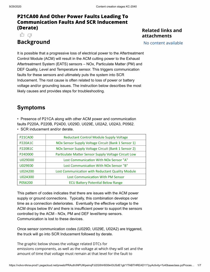
9/29/2020 Content creation stages KC-2040 https://volvo-trkna-prod1.pegacloud.net/prweb/PRAuth/iNPUIKpeinqPJi2G0hH930k43USdE1gb*/!TABTHREAD11?pyActivity=%40baseclass.pzProces… 1/7 P21CA00 And Other Power Faults Leading To Communication Faults And SCR Inducement (Derate) Background It is possible that a progressive loss of electrical power to the Aftertreatment Control Module (ACM) will result in the ACM cutting power to the Exhaust Aftertreatment System (EATS) sensors – NOx, Particulate Matter (PM) and DEF Quality, Level and Temperature sensor. This triggers communication faults for these sensors and ultimately puts the system into SCR Inducement. The root cause is often related to loss of power or battery voltage and/or grounding issues. The instruction below describes the most likely causes and provides steps for troubleshooting. Symptoms • Presence of P21CA along with other ACM power and communication faults P220A, P220B, P24D0, U029D, U029E, U02A2, U02A3, P0562. • SCR inducement and/or derate. P21CA00 Reductant Control Module Supply Voltage P220A1C NOx Sensor Supply Voltage Circuit (Bank 1 Sensor 1) P220B1C NOx Sensor Supply Voltage Circuit (Bank 1 Sensor 2) P24D000 Parculate Maer Sensor Supply Voltage Circuit Low U029D00 Lost Communicaon With NOx Sensor "A" U029E00 Lost Communicaon With NOx Sensor "B" U02A200 Lost Communicaon with Reductant Quality Module U02A300 Lost Communicaon With PM Sensor P056200 ECU Baery Potenal Below Range This pattern of codes indicates that there are issues with the ACM power supply or ground connections. Typically, this combination develops over time as a connection deteriorates. Eventually the effective voltage to the ACM drops below 8V and there is insufficient power to support the sensors controlled by the ACM - NOx, PM and DEF level/temp sensors. Communication is lost to these devices. Once sensor communication codes (U029D, U029E, U02A2) are triggered, the truck will go into SCR Inducement followed by derate. The graphic below shows the voltage related DTCs for emissions components, as well as the voltage at which they will set and the amount of time that voltage must remain at that level for the fault to Related links and attachments No content available
-
Upload
khangminh22 -
Category
Documents
-
view
6 -
download
0
Transcript of Background Symptoms - NHTSA
9/29/2020 Content creation stages KC-2040
https://volvo-trkna-prod1.pegacloud.net/prweb/PRAuth/iNPUIKpeinqPJi2G0hH930k43USdE1gb*/!TABTHREAD11?pyActivity=%40baseclass.pzProces… 1/7
P21CA00 And Other Power Faults Leading ToCommunication Faults And SCR Inducement(Derate)
Background It is possible that a progressive loss of electrical power to the AftertreatmentControl Module (ACM) will result in the ACM cutting power to the ExhaustAftertreatment System (EATS) sensors – NOx, Particulate Matter (PM) andDEF Quality, Level and Temperature sensor. This triggers communicationfaults for these sensors and ultimately puts the system into SCRInducement. The root cause is often related to loss of power or batteryvoltage and/or grounding issues. The instruction below describes the mostlikely causes and provides steps for troubleshooting.
Symptoms • Presence of P21CA along with other ACM power and communicationfaults P220A, P220B, P24D0, U029D, U029E, U02A2, U02A3, P0562. • SCR inducement and/or derate.
P21CA00 Reductant Control Module Supply VoltageP220A1C NOx Sensor Supply Voltage Circuit (Bank 1 Sensor 1)P220B1C NOx Sensor Supply Voltage Circuit (Bank 1 Sensor 2)P24D000 Par�culate Ma�er Sensor Supply Voltage Circuit LowU029D00 Lost Communica�on With NOx Sensor "A"U029E00 Lost Communica�on With NOx Sensor "B"U02A200 Lost Communica�on with Reductant Quality ModuleU02A300 Lost Communica�on With PM SensorP056200 ECU Ba�ery Poten�al Below Range
This pattern of codes indicates that there are issues with the ACM powersupply or ground connections. Typically, this combination develops overtime as a connection deteriorates. Eventually the effective voltage to theACM drops below 8V and there is insufficient power to support the sensorscontrolled by the ACM - NOx, PM and DEF level/temp sensors. Communication is lost to these devices. Once sensor communication codes (U029D, U029E, U02A2) are triggered,the truck will go into SCR Inducement followed by derate. The graphic below shows the voltage related DTCs foremissions components, as well as the voltage at which they will set and theamount of time that voltage must remain at that level for the fault to
Related links andattachmentsNo content available

9/29/2020 Content creation stages KC-2040
https://volvo-trkna-prod1.pegacloud.net/prweb/PRAuth/iNPUIKpeinqPJi2G0hH930k43USdE1gb*/!TABTHREAD11?pyActivity=%40baseclass.pzProces… 2/7
log. This graphic is for informational purposes only and should not beused for diagnosis.
Diagnosis And Repair
IMPORTANTPresence of any combinations of P24D0, P21CA, P0562,generally does NOT indicate the ACM is 'bad' or a PMsensor is 'bad'.
Required Tools
Part Number Description Quantity9998699 Break-Out Box 19990014 62-Pin ACM Connector Harness 1
88890074 (or equivalent) Multimeter 1
Initial Checks This combination of faults is frequently caused by a loose orfaulty connection on battery power or ground (but not fully disconnected - iffully disconnected, DTCs U116F and U010E would also be present). • Check that ALL the ACM power and ground connections are securelytightened.
- Ensure battery nuts are tightened to 15 lb-ft (20 Nm).
9/29/2020 Content creation stages KC-2040
https://volvo-trkna-prod1.pegacloud.net/prweb/PRAuth/iNPUIKpeinqPJi2G0hH930k43USdE1gb*/!TABTHREAD11?pyActivity=%40baseclass.pzProces… 3/7
- Ensure multiple ring terminals on a common stud are fanned out andlying flat against each other. - Ensure ring terminals and other contact points are clean and freefrom any terminal protectant coating or wax.
• If there is no evidence of loose battery connections: Continue to thechecks below.
Other items to check 1. Check the battery condition as follows:
1.1. Check the complete battery pack voltage.
1.1.1. Start the truck. 1.1.2. Run the engine at fast idle (1000 RPM) for 1 minute. 1.1.3. Turn the truck off, then return the key to the ON position. 1.1.4. Check voltage with all of the batteries still connected toone another.
• All battery positive terminals are connected together bybusbars or cables, and all battery negative terminals areconnected together.
1.1.5. Make a note of the voltage and evaluate results:
• For a fully charged system, in good condition, thevoltage should be 12.4 - 12.6V for standard floodedlead-acid batteries, or 12.6 - 12.8V for AGM-typebatteries. • Low battery voltage is indicative of an inadequatecharging system
- Potential causes include corroded cables, dirtyconnections and/or weak or defective batteries.
1.2. Check individual battery condition.
1.2.1. Disconnect the busbars and cables. 1.2.2. Inspect and clean all interconnecting terminals. Ensurethere is no corrosion.

9/29/2020 Content creation stages KC-2040
https://volvo-trkna-prod1.pegacloud.net/prweb/PRAuth/iNPUIKpeinqPJi2G0hH930k43USdE1gb*/!TABTHREAD11?pyActivity=%40baseclass.pzProces… 4/7
1.2.3. Check each battery voltage and perform a load test oneach battery individually. 1.2.4. Evaluate results:
• If one battery's voltage is significantly lower thanthe others, or lower than the measurement from Step1.1.5, OR fails a load test: The battery may be bad orthere may be a connection issue such as excessivecorrosion on the busbar or terminal, inhibiting propercharging.
1.2.5. Replace or clean any corroded part as needed. 1.2.6. Reconnect the busbars and/or cables.
1.3. Check the battery pack voltage while charging system isactive.
1.3.1. Start the truck. 1.3.2. Run the engine at fast idle (1000 RPM) for 1 minute. 1.3.3. With the engine still running, recheck battery voltage:
• Voltage should rise to 13.5-14.5V rapidly. • If the voltage is less than 13V: Run then engine for anadditional minute and recheck, as the batteries may havebeen deeply discharged.
1.3.4. Evaluate results:
• If the voltage remains less than 13V: There is anissue with the alternator or the alternator belt. • If the alternator belt is in good condition, there is anissue with the alternator.
For the following 2 checks, use the ACM ring terminal at theframe rail as a reference. NOTE: Ensure clean contact is made to the meter probes.
2. With key on, engine off, verify battery power feed to ACM pins 53, 57, and60 is the same as same as battery voltage (Vbat).

9/29/2020 Content creation stages KC-2040
https://volvo-trkna-prod1.pegacloud.net/prweb/PRAuth/iNPUIKpeinqPJi2G0hH930k43USdE1gb*/!TABTHREAD11?pyActivity=%40baseclass.pzProces… 5/7
3. Verify that ACM pin 3 also sees Vbat (this is the ignition voltage pin).If the ACM is not seeing Vbat there is an issue in the power supply path frombattery power to ACM (check in-line fuse, wiring, etc.). 4. Verify voltage at the ACM grounds pins 55, 58, and 61, relative to thebattery negative is <0.5V with ignition on.
• If the difference is greater than 0.5V: there may be an issue withelevated resistance on the ground path (corrosion on the ringterminal; corroded, damaged, or loose pins; etc.).
5. Verify that ACM pin 49 shows a constant voltage close to Vbat relative tothe ground ring terminal as follows:
• If pin 49 shows 9-11V: This is a sign of reduced voltage. Therecould be something causing an intermittent voltage drop.
- Examples include corrosion on the ground path, chafed wire,water intrusion, etc.
• If pin 49 shows <5 V: There is a definite voltage drop belownormal–see potential causes above.
For the following checks, individual sensors will triggercommunication faults when they are disconnected from the EATSharness. These steps are necessary for diagnosis and the faults may becleared afterward. If pin 49 voltage is still dropping below expected voltage: Work through the following steps one sensor at a time in the followingorder:
• PM Sensor• DEF Quality (level and temperature) Sensor• Inlet NOx Sensor• Outlet NOx Sensor
• For each sensor:
1. Cycle the key off.2. Allow the system to fully power down for 1 minute. 3. Unplug the sensor and cycle power back on.
• If the voltage at pin 49 recovers to Vbat: There is an issuewith the sensor being checked. • If the voltage reading remains unchanged: Anothercomponent is the culprit. Reconnect the sensor being checked

9/29/2020 Content creation stages KC-2040
https://volvo-trkna-prod1.pegacloud.net/prweb/PRAuth/iNPUIKpeinqPJi2G0hH930k43USdE1gb*/!TABTHREAD11?pyActivity=%40baseclass.pzProces… 6/7
and proceed to the next sensor
• If a sensor is found to be faulty:
- Check for the presence of corrosion or contamination in the sensorconnector.- Corrosion can also appear on the mating harness connector and thisshould be addressed to ensure integrity of connection.
• For any trucks that show PM sensor issues: Verify that the exhaustpipe contamination fix is implemented.
- See FSB 284-069 Exhaust Particulate Sensor, Repair (2017Vehicles). This applies to vehicles manufactured between 1/1/2017and 11/15/2017.
○ FSB 284-069 can be found under the Service tab of Impact.○ Search for "284-069" (Without quotes) under the AdditionalSearch Values section. Make sure 'Titles' is selected from thedropdown menu.
• If sensors are NOT found to be the problem and pin 49 voltage is stilldropping below expected voltage: 1. Cycle the key off. Allow the system to fully power down for 1 minute. 2. Disconnect the DPF/EATS harness.
- If voltage is restored from this exercise: Then the issue is in theharness. - If voltage remains the same: Repeat for the jumper harness to theDEF Quality Sensor and pump.
3. Inspect the harness found to be causing voltage drop..
- Harness issues such as water intrusion, damaged harness, etc. cancause short circuits, and affect voltage.
Tags
P21CA00 P220A1C P220B1C P24D000
U029D00 U029E00 U02A200 U02A300
P056200 P21CA 00 P220A 1C U02A3 00
a
9/29/2020 Content creation stages KC-2040
https://volvo-trkna-prod1.pegacloud.net/prweb/PRAuth/iNPUIKpeinqPJi2G0hH930k43USdE1gb*/!TABTHREAD11?pyActivity=%40baseclass.pzProces… 7/7
P056200 P21CA-00 P220A-1C U02A3-00
P0562-00 ACM POWER EATS DATALINK
P220B-1C P24D0-00 U029D-00 U029E-00
U02A2-00
Feedback
Give feedback to help improve the content of this article

Printed by:BRADLEY PICKENS
Service
Chassis ID Path284/Bulletins/Information//FSB 284-069, Exhaust Particulate Sensor, Repair (2017 Vehicles)
Model Identity145526930
Publish date ID/Operation7/16/2020
1 / 13
Copyright to this documentation belongs to the Volvo Group. No reproduction, copying, change, amendment or other similar disposal is entitled without prior written consent bythe Volvo Group
The information contained herein is current at the time of its original distribution, but is subject to change. The reader is advised that printed copies are uncontrolled.
IMPACT 4.07.80 9/29/2020

FSB 284-069, Exhaust Particulate Sensor, Repair (2017 Vehicles)
(July 2020)
Some trucks built between 1/1/2017 and 11/15/2017 may experience a Particulate Matter (PM) Sensor fault that can result in the MIL lamp illuminating. These faults may be P24DA, “PM Sensor Exhaust Sample Error,” or P24D1, “PM Sensor Regen Incomplete.” These faults may be caused by contamination of the PM sensor. In order to reduce the likelihood of sensor contamination, new exhaust pipe parts are being made available that contain an internal water management feature along with an integrated drain that will prevent contamination of the sensor. If either of these two faults occur, follow the instructions outlined in this bulletin to clean the exhaust pipes and install a new exhaust pipe with the new contamination prevention measures.
Required Parts – All Years
Inspect and replace the v-band clamp as needed
A new gasket will be needed when disconnecting the SCR exit.
Note: No gasket needed for vertical SCR.
Part Description Part NumberSCR Gasket 21095726
V-band Clamp 21021850Particulate Matter Sensor 23320447
Note: Customer adaptations can change required parts. Check for adaptations before ordering parts. (For example, under-slung exhaust)
Repair Procedure
Determine which Flex Pipe and Clamp the truck currently has installed on it. If the truck you are repairing has the Flex Pipe and Clamp shown in scenario 1, you will need to order the improved Flex Pipe (P/N 21142254) and Clamp (P/N 25172497). If the truck you are repairing has the Flex Pipe and Clamp shown in scenario 2, this truck already has the improved parts and ordering a new Flex Pipe and Clamp is NOT required.
Scenario 1
This style Flex Pipe and Clamp will no longer work with the upper adjacent connecting pipe. The below parts in scenario 2 are required to perform this FSB.
2 / 13
Copyright to this documentation belongs to the Volvo Group. No reproduction, copying, change, amendment or other similar disposal is entitled without prior written consent bythe Volvo Group
The information contained herein is current at the time of its original distribution, but is subject to change. The reader is advised that printed copies are uncontrolled.
IMPACT 4.07.80 9/29/2020

Follow the repair below that is applicable for your configuration.
Scenario 2
This style Flex Pipe and Clamp only needs the upper adjacent pipe replaced. Reuse the existing Flex Pipe and Clamp, or order as needed.
Flex Pipe – 21142254
Clamp – 25172497
3 / 13
Copyright to this documentation belongs to the Volvo Group. No reproduction, copying, change, amendment or other similar disposal is entitled without prior written consent bythe Volvo Group
The information contained herein is current at the time of its original distribution, but is subject to change. The reader is advised that printed copies are uncontrolled.
IMPACT 4.07.80 9/29/2020

Follow the repair below that is applicable for your configuration.
Table of Contents
Model Cab Type Exhaust Configuration
Repair Number
VNL Day Cab Single Outlet RightSide Outboard
1
VHD Axle Fwd Day Cab Single Outlet RightSide Outboard
2
VNM, VHD Axle Bwd
Day Cab Single Outlet RightSide Outboard
3
VHD Axle Bwd Day Cab Dual Outlet 4VHD Axle Fwd Day Cab Dual Outlet 4VNM, VHD, VNL
Sleeper Cabs
Single OutletRight Side
5
4 / 13
Copyright to this documentation belongs to the Volvo Group. No reproduction, copying, change, amendment or other similar disposal is entitled without prior written consent bythe Volvo Group
The information contained herein is current at the time of its original distribution, but is subject to change. The reader is advised that printed copies are uncontrolled.
IMPACT 4.07.80 9/29/2020

OutboardDual Outlet
VNM, VHD, VNL
Sleeper Cabs
Single OutletRight Side OutboardDual Outlet
6
Repair 1
ModelCab Type
Exhaust Configuration
Pipe 1(Stack)
Pipe 2(SCR Elbow)
Flex Pipe Clamp
VNL Day Cab
Single Outlet Right Side Outboard
238731232218198120442244Clamp 25172497 x 2
Repair 2
5 / 13
Copyright to this documentation belongs to the Volvo Group. No reproduction, copying, change, amendment or other similar disposal is entitled without prior written consent bythe Volvo Group
The information contained herein is current at the time of its original distribution, but is subject to change. The reader is advised that printed copies are uncontrolled.
IMPACT 4.07.80 9/29/2020

Model Cab Type
Exhaust Configuration Pipe 1
VNM/VHD
Day Cab
Single Outlet Right Side Inboard
23630037
Repair 3
6 / 13
Copyright to this documentation belongs to the Volvo Group. No reproduction, copying, change, amendment or other similar disposal is entitled without prior written consent bythe Volvo Group
The information contained herein is current at the time of its original distribution, but is subject to change. The reader is advised that printed copies are uncontrolled.
IMPACT 4.07.80 9/29/2020

Model Cab Type Exhaust Configuration
Pipe 1
VNM/VHD
430/630 Sleeper
Single Outlet Right Side Inboard
(Not Bright) 23154798
Caution
(Bright) 23154799
Repair 4
7 / 13
Copyright to this documentation belongs to the Volvo Group. No reproduction, copying, change, amendment or other similar disposal is entitled without prior written consent bythe Volvo Group
The information contained herein is current at the time of its original distribution, but is subject to change. The reader is advised that printed copies are uncontrolled.
IMPACT 4.07.80 9/29/2020

Model Cab Type
Exhaust Configuration
Pipe 1
VHD Axle Bwd
Day Cab Dual Outlet 23155774
VHD Axle Fd Day Cab Dual Outlet 23155785
Repair 5
8 / 13
Copyright to this documentation belongs to the Volvo Group. No reproduction, copying, change, amendment or other similar disposal is entitled without prior written consent bythe Volvo Group
The information contained herein is current at the time of its original distribution, but is subject to change. The reader is advised that printed copies are uncontrolled.
IMPACT 4.07.80 9/29/2020

ModelCab Type
Exhaust Configuration Pipe 1
VNMVHDVNL
Sleeper Cabs
Single Outlet Right Side Outboard
(Not Bright) 23154798(Bright) 23154799
Repair 6
9 / 13
Copyright to this documentation belongs to the Volvo Group. No reproduction, copying, change, amendment or other similar disposal is entitled without prior written consent bythe Volvo Group
The information contained herein is current at the time of its original distribution, but is subject to change. The reader is advised that printed copies are uncontrolled.
IMPACT 4.07.80 9/29/2020
1.
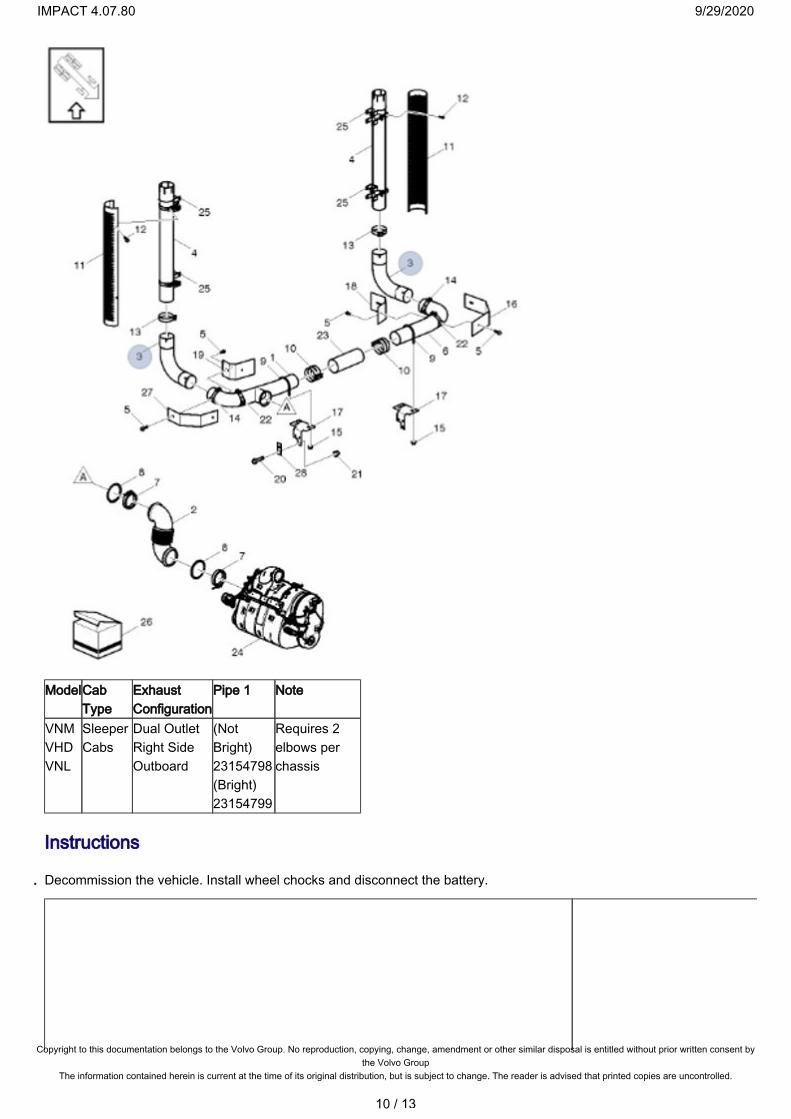
ModelCab Type
Exhaust Configuration
Pipe 1 Note
VNMVHDVNL
Sleeper Cabs
Dual OutletRight Side Outboard
(Not Bright) 23154798(Bright) 23154799
Requires 2 elbows per chassis
Instructions
Decommission the vehicle. Install wheel chocks and disconnect the battery.
10 / 13
Copyright to this documentation belongs to the Volvo Group. No reproduction, copying, change, amendment or other similar disposal is entitled without prior written consent bythe Volvo Group
The information contained herein is current at the time of its original distribution, but is subject to change. The reader is advised that printed copies are uncontrolled.
IMPACT 4.07.80 9/29/2020

1.
2. 3. 4. 5. 6. 7. 8. 9.
10.
11.
12. 13. 14.
15.
Remove the PM sensor and module.Remove all exhaust pipes up to the SCR outlet pipe.Pressure wash the inside of each pipe that will be reused.Reassemble the exhaust system using the new parts referenced in the table above.Mark the SCR outlet pipe 1.5" from the end also mark the new pipe (not flex) 1.5" from its inlet.Slip the flex pipe as for over the SCR outlet pipe as possible.Install the new exhaust pipe.Using a new clamp assemble the new exhaust pipe to the new flex pipe using the 1.5" mark to get the correct amount of overlap.Slide the assembly into place using the 1.5" mark on the SCR outlet as a reference point and to ensure the correct amout of overlap, once in both pipes are in place use clamps to secure.
Note: Correct installation is achieved when the flex pipe is in a "relaxed" state, there should be no compression or expansion visible on oposing sides of the pipe after installed.
Install the new PM sensor and module.
Note: Do not use any lubricant of any kind on the PM sensor threads.
Note: Align the tab on the sensor with the slot.
Torque the sensor to 35 +/- 5 Nm (26+/- 4 Ft lb)Install the sensor module.Torque the nuts toM6: 10 +/- 5 Nm (88 +/- 3 in lb)M8: 24 +/- 4 Nm (17.1 +/- 3 ft lb)
11 / 13
Copyright to this documentation belongs to the Volvo Group. No reproduction, copying, change, amendment or other similar disposal is entitled without prior written consent bythe Volvo Group
The information contained herein is current at the time of its original distribution, but is subject to change. The reader is advised that printed copies are uncontrolled.
IMPACT 4.07.80 9/29/2020

15.
16.
17. 18.
Install the wire ties and clamps.
Note: Use high temperature cable ties.
Connect the battery.
Clear any DTC codes.Remove the wheel chocks.
12 / 13
Copyright to this documentation belongs to the Volvo Group. No reproduction, copying, change, amendment or other similar disposal is entitled without prior written consent bythe Volvo Group
The information contained herein is current at the time of its original distribution, but is subject to change. The reader is advised that printed copies are uncontrolled.
IMPACT 4.07.80 9/29/2020

18.
Reimbursement
This repair may be eligible for reimbursement if a product failure was experienced within time and mileage limits of the applicable Warranty coverage. Reimbursement is obtained via the normal claim handling process.
UCHPReimbursement
Claim Type (used only when uploading from the Dealer Bus. Sys.)
W
Labor CodePrimary Labor Code (Exhaust Particulate Sensor, Repair)
2846-16-09-02See table for times.
Causal Part 22946032
Labor Times Reference – 2017 Vehicles
Model Cab Type Exhaust Configuration
Pipe 1
VNLVNMVHD
Day Cab Single Outlet Right Side Outboard
1.5
VHD Day Cab Dual Outlet 2.9VNMVHDVNL
Sleeper Cabs
Single Outlet Right Side OutboardDual Outlet
3.5
13 / 13
Copyright to this documentation belongs to the Volvo Group. No reproduction, copying, change, amendment or other similar disposal is entitled without prior written consent bythe Volvo Group
The information contained herein is current at the time of its original distribution, but is subject to change. The reader is advised that printed copies are uncontrolled.
IMPACT 4.07.80 9/29/2020