
TECHNICAL BID - Mahindra World City
594
TECHNICAL BID For Design, Supply, Construction, Erection, Commissioning and Operating of (Phase I) 3000 M 3 /Day Capacity Sewage Treatment Plant based on advanced Sequential Batch Reactor Technology At Mahindra World City (Jaipur) Limited, Jaipur at Domestic Tariff Area, Mahindra World City (Jaipur) Limited, Jaipur MWCJL/HR/INFRA/DTA PH/III/STP/2013-14/T-33 Project Site: Engineering Consultant: Mahindra World City (Jaipur) Limited 411, Neelkant Towers 1 Bhawani Singh Road-Scheme, Jaipur, Rajasthan - 302 001, India Tel: +91 141 3003455, 3003495-98 Mahindra Consulting Engineers Ltd. Mahindra Towers, Ground Floor No.17/18, Pattullous Road, Chennai – 600 002 Tel: 044-28542325/26 Fax: 044-28542324
-
Upload
khangminh22 -
Category
Documents
-
view
0 -
download
0
Transcript of TECHNICAL BID - Mahindra World City

TECHNICAL BID
For
Design, Supply, Construction, Erection, Commissioning and Operating of (Phase I) 3000 M3/Day Capacity Sewage Treatment Plant based on advanced Sequential Batch Reactor Technology At
Mahindra World City (Jaipur) Limited, Jaipur
at
Domestic Tariff Area, Mahindra World City (Jaipur) Limited, Jaipur
MWCJL/HR/INFRA/DTA PH/III/STP/2013-14/T-33
Project Site: Engineering Consultant:
Mahindra World City (Jaipur) Limited 411, Neelkant Towers 1 Bhawani Singh Road-Scheme, Jaipur, Rajasthan - 302 001, India Tel: +91 141 3003455, 3003495-98
Mahindra Consulting Engineers Ltd. Mahindra Towers, Ground Floor No.17/18, Pattullous Road, Chennai – 600 002 Tel: 044-28542325/26 Fax: 044-28542324

Tender Document for Setting up of Sewage Treatment Plant (Phase I) at MWCJL, Jaipur
Page 1 of 549
Tender Document
For the Design, Supply, Construction, Erection, Commissioning and Operating of (Phase I) 3000 m3/day capacity Sewage Treatment Plant based on advanced Sequential Batch
Reactor Technology at Mahindra World City (Jaipur) Limited, Jaipur
MWCJL/HR/INFRA/DTA PH/III/STP/2013-14/T-33
Earnest Money Deposit : Rs.9,00,000/- (Rupees Nine Lakhs Only) in the form of Demand Draft or Bank Guarantee from a nationalized or scheduled bank.
Security deposit
:
5% of Contract amount in the form of Bank Guarantee from a Scheduled/ Nationalized Bank, to be made within seven days from the date of receipt of work order.
Performance Guarantee
: 5% of Contract amount in the form of Bank Guarantee from a Scheduled/ Nationalized Bank, to be made within seven days from the date of receipt of work order and before executing the Agreement for the work.
Time of completion : 6 months Issued to
Issued on
HEAD (Infrastructure & Development) Mahindra World City (Jaipur) Limited,
411, Neelkant Towers 1 Bhawani Singh Road, C-Scheme, Jaipur,Rajasthan - 302 001, India.
Tel : +91 141 3003455, 3003495-98

Tender Document for Setting up of Sewage Treatment Plant (Phase I) at MWCJL, Jaipur
Page 2 of 549
CONTENTS
Section Description Page Numbers
From To Technical Bid
Tender Notice 3 4 Bid Synopsis 5 7
Section 1 Prequalification Document 8 20 Section 2 Notice Inviting Tender 21 38 Section 3 Bid Data Sheet 39 41 Section 4 General Conditions of Contract 42 61 Section 5 Special Conditions of Contract 62 72
Section 5.1 General Requirements 73 81 Section 5.2 Materials and Workmanship 82 92 Section 5.3 General Civil Specifications 93 346 Section 5.4 General Mechanical Specifications 347 349 Section 5.5 General Electrical Specifications 350 375 Section 5.6 Scope of works 376 379 Section 5.7 Design Criteria 380 386 Section 5.8 Specific Requirements of processing units 387 398 Section 5.9 Specific requirements of Mechanical Equipments 399 406
Section 5.10 Specific requirements of Electrical & Instrumentation works
407 487
Section 5.11 Guarantee 488 490 Section 5.12 Inspection and testing at Manufacturer’s Works 491 494 Section 5.13 Erection, Testing and Commissioning 495 504
Section 6 Annexures 505 532 Section 7 Technical Schedules 533 547 Section 8 Tender Drawings 548 549
Price Bid

Tender Document for Setting up of Sewage Treatment Plant (Phase I) at MWCJL, Jaipur
Page 3 of 549
Tender Notice – Sewage Treatment Plant Mahindra World City (Jaipur) Limited (MWCJL), Jaipur, invites sealed tenders in Two Cover System (Technical Bid and Price Bid) in the prescribed form from reputed contractors for the following work.
MWCJL/HR/INFRA/DTA PH/III/STP/2013-14/T-33
Name of work Period of
completion Earnest money deposit
For The Design, Supply, Construction, Erection, Commissioning and Operating of (Phase I) 3000 M3/Day Capacity Sewage Treatment Plant based on Advanced Sequential Batch Reactor technology At Mahindra World City (Jaipur) Limited Jaipur Limited, Jaipur.
6 months
Rs.9,00,000/- (Rupees Nine Lakhs Only) as in the form of
Demand Draft or Bank Guarantee from a
Nationalized/Scheduled Bank
Eligibility Condition 1. The tenderer should have designed, constructed, commissioned and operated at least one
STP/ETP working on advanced sequential batch reactor technology of minimum 3000m3/day capacity as main contractor, which is in operation for a minimum period of one year during the last three financial years. Necessary certificate from the client showing satisfactory performance of the contract, salient features of the plant and satisfactory performance during the operation and maintenance period shall be furnished.
2. The contractor should have successfully completed at least one work of similar nature of
value not less than Rs.500 lakhs, as a single contract during the last three years ending the last day of the month previous to the one in which applications are invited.
3. The average annual turnover shall not be less than Rs.1000 Lakhs during the three
financial years viz. 2009-10, 2010-11 and 2011-12. 4. The contractor should possess latest solvency certificate from a nationalized/scheduled
bank for an amount not less than Rs.250 Lakhs. 5. The contractor should possess required construction equipment, machinery and staff for
execution of the work. 6. In case if the contractor does not have the patent for the technology, then the contractor
can tie up with the technology provider and to this effect the contractor should have

Tender Document for Setting up of Sewage Treatment Plant (Phase I) at MWCJL, Jaipur
Page 4 of 549
entered Memorandum of Understanding (MoU) with the technology provider and the same need to be provided along with technical bid. Technology Provider should attend all the meetings convened by MWCJL without fail during the execution of work.
7. The contractor should not have incurred any loss in the last three financial years.
Issue of tender documents : From 21.03.2013 to 28.03.2013 (During office hours)
Date of Pre-bid meeting : 11 AM on 28-03-2013 Last date of receipt of tender documents : 3 PM on 04-04-2013 Date of opening of Technical Bids : 3.30 PM on 04-04-2013 Date of opening of price bid : Will be intimated later.
8. The tender documents can be obtained from the office of Mahindra World City (Jaipur)
Limited, Jaipur, at the address below, on payment of Rs.3000/- (Rupees Three Thousand only) (cost of tender documents plus VAT @4.04%) in cash or demand draft in favour of the Mahindra World City (Jaipur) Limited payable at Jaipur on all working days between 10 am and 5 pm. The tender documents will not be sent by post. Tender Documents can be downloaded from MWCJL website http://www.mahindraworldcity.com/Docs/Tenders/Jaipur MWCJL reserves the right to pre-qualify the tenders as per the standards fixed by MWCJL, and to reject all or accept any tender without assigning any reason. Contractors who had earlier been awarded works by MWCJL or any of its subsidiary company and not satisfactorily completed within the approved time frame are not eligible to prequalify.
9. After evaluation of the pre-qualification documents, the qualified tenders will be informed
the date of opening of the price bid. Jaipur, 21.03.2013
Sd/-
HEAD (Infrastructure & Development) Mahindra World City (Jaipur) Limited,
411, Neelkant Towers 1 Bhawani Singh Road,C-Scheme, Jaipur,Rajasthan - 302 001, India.
Tel : +91 141 3003455, 3003495-98

Tender Document for Setting up of Sewage Treatment Plant (Phase I) at MWCJL, Jaipur
Page 5 of 549
Bid Synopsis
1 Tender Number : MWCJL/HR/INFRA/DTA PH/III/STP/2013-14/T-33
2 Name & address of Client : HEAD (Infrastructure & Development)
Mahindra World City (Jaipur) Limited
411, Neelkant Towers
1 Bhawani Singh Road, C-Scheme, Jaipur, Rajasthan - 302 001, India.
Tel : +91 141 3003455, 3003495-98
3 Name of Project : Sewage Treatment Plant (Phase - I), Mahindra World City
(Jaipur) Limited.
4 Place of work : Mahindra World City (Jaipur) Limited
Neelkant Towers Bhawani Singh Road, C-Scheme,
Jaipur, Rajasthan
5 Scope of work : Design, Supply, Construction, Erection, Commissioning And
Operating Of (Phase I) 3000 M3/Day Capacity Sewage
Treatment Plant based on Advanced Sequential Batch
Reactor Technology At Mahindra World City (Jaipur) Limited, Jaipur
6 Type of Tender : Lump Sum Contract (Two Cover system)
7 Schedule of rates applicable : Latest Rajasthan PWD Schedule of rates (RPWD )
8 Completion Period : 6 Calendar Months
9 Cost of Tender Document : Rs. 3000 (Rupees Three Thousand Only) + Vat (4.04%) for
Direct Purchase
No Fee if it is Downloaded from Website
10 Date of sale of Tender
Documents
: 21-03-2013 to 28-03-2013
11 Tender document issuing
authority
HEAD (Infrastructure & Development)
Mahindra World City (Jaipur) Limited
411, Neelkant Towers
1 Bhawani Singh Road, C-Scheme, Jaipur, Rajasthan - 302 001, India.
Tel : +91 141 3003455, 3003495-98
12 Place, Date & Time of Pre-
bid Meeting
: Mahindra World City (Jaipur) Limited
411, Neelkant Towers
1 Bhawani Singh Road, C-Scheme,
Jaipur, Rajasthan - 28-03-2013 (11.00 AM)
Tender Document for Setting up of Sewage Treatment Plant (Phase I) at MWCJL, Jaipur
Page 6 of 549
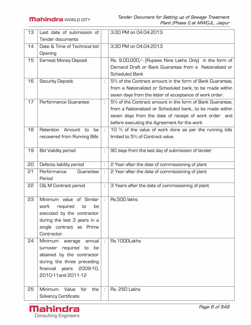
13 Last date of submission of
Tender documents
3.00 PM on 04.04.2013
14 Date & Time of Technical bid
Opening
3.30 PM on 04.04.2013
15 Earnest Money Deposit Rs. 9,00,000/- (Rupees Nine Lakhs Only) in the form of Demand Draft or Bank Guarantee from a Nationalized or
Scheduled Bank
16 Security Deposit : 5% of the Contract amount in the form of Bank Guarantee,
from a Nationalized or Scheduled bank, to be made within
seven days from the letter of acceptance of work order.
17 Performance Guarantee : 5% of the Contract amount in the form of Bank Guarantee, from a Nationalized or Scheduled bank,. to be made within
seven days from the date of receipt of work order and
before executing the Agreement for the work
18 Retention Amount to be
recovered from Running Bills
: 10 % of the value of work done as per the running bills
limited to 5% of Contract value.
19 Bid Validity period : 90 days from the last day of submission of tender
20 Defects liability period : 2 Year after the date of commissioning of plant
21 Performance Guarantee
Period
: 2 Year after the date of commissioning of plant
22 O& M Contract period : 3 Years after the date of commissioning of plant
23 Minimum value of Similar
work required to be
executed by the contractor
during the last 3 years in a
single contract as Prime Contractor.
: Rs.500 lakhs
24 Minimum average annual
turnover required to be
attained by the contractor
during the three preceding
financial years 2009-10, 2010-11and 2011-12
: Rs.1000Lakhs
25 Minimum Value for the
Solvency Certificate
: Rs. 250 Lakhs

Tender Document for Setting up of Sewage Treatment Plant (Phase I) at MWCJL, Jaipur
Page 7 of 549
26 Contractor should not have
incurred any loss in the last
three financial years
: Audited balance sheet and P&L statement of last three
financial years to be submitted
27 Interval of interim Bills Once a month or for a minimum payment of 10% of Contract amount
Sd/-
HEAD (Infrastructure & Development) Mahindra World City (Jaipur) Limited,
411, Neelkant Towers 1 Bhawani Singh Road, C-Scheme,
Jaipur, Rajasthan - 302 001,

Tender Document for Setting up of Sewage Treatment Plant (Phase I) at MWCJL, Jaipur
Page 8 of 549
SECTION – 01 PREQUALIFICATION DOCUMENT

Tender Document for Setting up of Sewage Treatment Plant (Phase I) at MWCJL, Jaipur
Page 9 of 549
Tender Declaration Form
(To be typed in the letter head of the tenderer duly signed and sealed) From: -------------- To: HEAD (Infrastructure & Development) Mahindra World City (Jaipur) Limited, 411, Neelkant Towers 1 Bhawani Singh Road, C-Scheme, Jaipur, Rajasthan - 302 001 Sir, Sub.: Design, Supply, Fabrication, Construction, Erection and commissioning of Sewage
Treatment Plant based on Advanced Sequential Batch Reactor Technology (Phase I) of 3000 cum/day Capacity at Jaipur.
Ref.: Your Tender Notification No: MWCJL/HR/INFRA/DTA PH/III/STP/2013-14/T-33 Having examined carefully the specifications together with the condition of contract, schedules, drawings and the accompaniments, I / We hereby offer to carry out the works described in the scope of work as per the specification, drawings, relevant code provisions, site requirements etc., at the quoted amount entered by me/us in the accompanying price bid. All documents to be furnished for pre-qualification are enclosed in the bid. I / We further agree to complete the whole work in six months from the date of agreement. An amount of Rs.9,00000/-(Rupees Nine Lakhs only) is enclosed in the form of ………………………………………………………………………………………………..as Earnest Money Deposit (EMD). After the tender is accepted, in case, if I / We fail to execute the agreement as stipulated in the tender conditions or to commence the execution of the works as per the work order; I / We agree that the MWCJL shall, without prejudice to any other right or remedy be at liberty to forfeit the said earnest money absolutely.

Tender Document for Setting up of Sewage Treatment Plant (Phase I) at MWCJL, Jaipur
Page 10 of 549
We also authorize MWCJL or its authorized representatives to verify the credentials with appropriate authorities to satisfy themselves for our pre-qualification. We hereby confirm that the technology provider shall accompany us for all the meetings convened by MWCJL during execution of the works. Thanking you, Yours faithfully, Date: Signature of Bidder Place:

Tender Document for Setting up of Sewage Treatment Plant (Phase I) at MWCJL, Jaipur
Page 11 of 549
General Information of the Firm
(Form –A)
A. 1. Name of the bidder firm / company :
2. Permanent address of the bidder :
3. Present postal address of the bidder :
4. Telephone numbers :
Office :
Residence :
Mobile numbers :
5.Telex / Fax :
B. Nature of company (strike out whichever is not
applicable) proprietary firm /partnership firm / private ltd/ public ltd.
:
C. Date of incorporation :
D. Details of proprietor partners / directors (as the
case may be)
:
Note: Attach copies of registration of firm/ company/ with details proprietor/Directors.
Signature of Bidder

Tender Document for Setting up of Sewage Treatment Plant (Phase I) at MWCJL, Jaipur
Page 12 of 549
Details of similar work carried out by the Bidder
(Form –B)
(Similar work of value not less than Rs.500 lakhs, as a single contract during the last three years ending the last day of the month previous to the one in which applications are invited).
(CERTIFICATE TO BE ATTACHED)
Sl. No.
Name of Project
Client Reference
Value of Work
Time of completion
Date of
award
Date of completion
Percentage of
participation
* Attach certified copies of work order and satisfactory completion certificates in respect of
quality, time and satisfactions of client as documentary proof
Signature of Bidder

Tender Document for Setting up of Sewage Treatment Plant (Phase I) at MWCJL, Jaipur
Page 13 of 549
Data Sheet in respect of the selected similar work (Form –C)
1. Name of Scheme 2. Capacity of the scheme 3. Name and address of client for whom the work was
carried out
4. Client’s full address and contact Phone No. 5. Number and date of letter of ordering the work 6. PAC of the contract 7. Time stipulated for completion 8. Actual date of commencement of work 9. Actual date of commissioning
10. Final date of defect liability period 11. Details of units (Write number, size, capacity etc.) No. of units Dimension
a. Receiving Chamber b. Primary treatment – Grit chamber c. Fine screen, coarse screen d. Stilling Chamber e. SBR basin f. Diffuser g. Blower and PLC h Sludge sump i. Sludge drying system (Specify the type) j. Details of territory unit if any
12. Influent characteristics 13. Sewage characteristics
a. Agreed b. Achieved
14. Number and date of certificate issued by client (attach photocopy for reference)
15. Address of Engineer - In - Charge if any 16. General write up about the scheme
Note: 1. Selected schemes should be supported with documentary evidence 2. Only schemes taken up and completed from 2009 to 2012 are to be included 3. Only schemes, which were designed and constructed by the tenderer as prime contractor are
to be mentioned. Works carried out as sub-contractors or as schedule contractors based on client’s own design are not eligible to be included.
4. Completion certificate and performance certificate. Signature of Bidder

Tender Document for Setting up of Sewage Treatment Plant (Phase I) at MWCJL, Jaipur
Page 14 of 549
Details of other major Works carried out by the bidder
(Form –D)
(Details of major work done other than said earlier by the contractor on his own during the last
three financial years, 09-10, 10-11, 11-12)
Sl. No.
Name of Project
Client Reference
Value of Work
Time of completion
Date of
award
Date of completion
Percentage of
participation
(Attach certified copies of work order and satisfactory completion certificates for each work as documentary proof)
Signature of Bidder

Tender Document for Setting up of Sewage Treatment Plant (Phase I) at MWCJL, Jaipur
Page 15 of 549
Details of Projects in hand
(Form –E)
Sl. No.
Name of Project
Client Reference
Value of Work
Time of completion
Date of award
Date of completion
Percentage of
participation
(Attach certified copies of work order for each work as documentary proof)
Signature of Bidder

Tender Document for Setting up of Sewage Treatment Plant (Phase I) at MWCJL, Jaipur
Page 16 of 549
Details of staff available for the proposed work
(Form –F)
Sl. No.
Description of Staff Qualification Experience Nature of
experience
Note: - MWCJL may insist to engage the listed number of staff with the above-specified qualification and experience. Enclose detailed bio-data for each personnel. (Attach additional sheets if required). MWCJL may also insist to engage additional staff with better qualifications over and above those listed.
Signature of Bidder

Tender Document for Setting up of Sewage Treatment Plant (Phase I) at MWCJL, Jaipur
Page 17 of 549
Details of Machines available for the proposed work
(Form –G)
Sl. No. Description of Machinery Number Remarks
Note: MWCJL will insist to bring the listed number of machines for the execution of the work (Attach additional sheets if required). MWCJL may also insist to bring additional machinery over and above those listed above for the execution of the work.
Signature of Bidder

Tender Document for Setting up of Sewage Treatment Plant (Phase I) at MWCJL, Jaipur
Page 18 of 549
Proposed Manpower details for Operation and Maintenance
(Form –H)
Sl. No.
Name of the Person
Proposed Designation
Qualification Experience
Duration of assignment during O&M
Period
Note: - Operation and maintenance of the entire treatment plant for a period of three year by deputing required manpower as indicated in the scope of service including flow monitoring, analysis of raw and treated waste water and other operating parameters; maintaining and displaying the records through log books, colour charts, monitoring of connected activities, Laboratory analysis etc. complete as per item G of Price schedule.
Signature of Bidder

Tender Document for Setting up of Sewage Treatment Plant (Phase I) at MWCJL, Jaipur
Page 19 of 549
Details of Financial Stability of the Contactor/Firm (Form –I)
1. The Annual Turn Over of the Contractor / Firm for the last three years. (The average
annual turnover of the bidder shall not be less than Rs.1000 lakhs during the last three financial years 2009-2010, 2010-2011, 2011-2012). (Attach copies of audited accounts).
2. The following parameters may be furnished as per the audited financial statements duly
certified by an independent certified auditor for the last three accounting years.
Sl. No. Particulars of parameters 2009-10 2010-11 2011-12
1. Authorized Capital
2. Subscribed Capital
3. Paid-up Capital
4. Reserves (Other than revaluation reserve)
5. Net worth
6. Gross Fixed Assets
7. Net Fixed Assets
8. Current Assets
9. Current Liabilities
10. Profit before depreciation, interest and taxes
11. Profit Before taxes
12. Profit After taxes
3. Turn over for the last three financial years :
(All statements should be supported by documentary proof) 4. The contractor should not have incurred any loss during the previous three financial years
(Attach details of profit and loss statement as documentary proof) 5. The contractor should possess latest solvency certificate for Rs.250 Lakhs issued from a
Nationalized /Scheduled Bank.
Signature of Bidder

Tender Document for Setting up of Sewage Treatment Plant (Phase I) at MWCJL, Jaipur
Page 20 of 549
Notes:
1. Each pages of this pre-qualification document shall be signed by person/ persons on behalf of the organization having necessary authorization/ Power of attorney to do so.
2. The pre-qualification bid containing false and / or inadequate information are liable to
rejection.
3. The pre-qualification Document without sufficient documentary proof for the data are liable for rejection
4. I/We here by certify that the details given above are correct to the best of my / our
knowledge. I/We have no objection for MWCJL in contacting our clients / Bankers for reference.
Place: Signature: Date: …………………2013 Name of Bidder:

Tender Document for Setting up of Sewage Treatment Plant (Phase I) at MWCJL, Jaipur
Page 21 of 549
SECTION – 02 NOTICE INVITING TENDER

Tender Document for Setting up of Sewage Treatment Plant (Phase I) at MWCJL, Jaipur
Page 22 of 549
2. Notice Inviting Tender 2.1 Invitation
Sealed tenders on lump sum basis are hereby invited for and on behalf of MWCJL (Mahindra World City (Jaipur) Limited Jaipur Limited) by its HEAD (Infrastructure & Development) (Owner) from contractors having experience of “Design, Supply, Construction, Erection, Commissioning and Operating of (Phase I) 3000 M3/Day Capacity Sewage Treatment Plant based on Advanced Sequential Batch Reactor At Mahindra World City (Jaipur) Limited, Jaipur”. The scope of work, tender drawings, specifications and commercial conditions of the contract are appended. The last date of receipt of tender is 28-03-2013 and the tender has to be submitted on or before 3.00 PM on 04-04-2013.
2.2 General Information
The general information on the project may be found under Bid synopsis of this tender. The information given is only indicative. The tenderers are required to visit the site and familiarize themselves with the site condition, nature of substrata and ongoing works, availability of construction materials, labour and all other data required etc. before quoting. The tenderers should also visit the Park to have awareness about the existing Sewage generated. The drawings, conditions of contract, scope of work and the specifications may be carefully studied before they quote their rates. No claims for extra compensation over and above the quoted rates, on the ground that the tenderers have misjudged site conditions, nature of substrata, tender conditions or any other reason for any item of tender will be entertained by the owner.
2.3 Purchase of Tender Document
The tender documents can be obtained from the office of the MWCJL, MWCJL Mahindra World City (Jaipur) Limited Jaipur, 411, Neelkant Towers, 1 Bhawani Singh Road C-Scheme, Jaipur, Rajasthan - 302 001, Tel: +91 141 3003455, 3003495-98 on payment of Rs.3000/-(Rupees Three Thousand Only) (Cost of tender documents plus 4.04% VAT) in cash or Demand Draft payable to Mahindra World City (Jaipur) Limited. If the tender documents are to be sent by post, additional amount of Rs.100/- shall be paid along with the cost of tender documents, on any working day during office hours. The amount so paid for the tender document is not refundable. No fee is applicable if the tender documents are downloaded from web site http://www.mahindraworldcity.com/Docs/Tenders/Jaipur. The processed tender documents duly signed and completed in all respects along with all desired documents shall be forwarded to the office of Mahindra World City (Jaipur) Limited, Jaipur,411, Neelkant Towers,1 Bhawani Singh Road, C-Scheme, Jaipur, Rajasthan - 302 001,Tel : +91

Tender Document for Setting up of Sewage Treatment Plant (Phase I) at MWCJL, Jaipur
Page 23 of 549
141 3003455, 3003495-98 so as to reach on or before 3.00PM on 04-04-2013. Any tender received after the due date and time will be rejected.
2.4 Criteria for Pre-Qualification to open the price bid and award work
2.4.1 The tenderer should have designed, constructed, commissioned and operated at least one
STP/STP working on advanced sequential batch reactor process of minimum 3000m3/day capacity as main contractor, which is in operation for a minimum period of one year during the last three financial years. Necessary certificate from the client showing satisfactory performance of the contract, salient features of the plant and satisfactory performance during the operation and maintenance period shall be furnished.
2.4.2 The Contractor should have successfully completed at least one work of similar nature of
value not less than Rs.500 lakhs, as a single contract during the last three years ending the last day of the month previous to the one in which applications are invited.
2.4.3 The average annual turnover shall not be less than Rs.1000 Lakhs during the three
financial years viz. 2009-10, 2010-11 and 2011-12.
2.4.4 The Contractor should possess latest solvency certificate from a nationalized/ scheduled bank for an amount not less than Rs.250 Lakhs.
2.4.5 The Contractor should possess required construction equipment, machinery and staff for
execution of the work.
2.4.6 The Contractor should not have incurred any loss in the last three financial years.
2.4.7 The Contractor should have adequate professional staff in the organization for design 2.4.8 In case if the contractor does not have the patent for the technology, then the contractor
can tie up with the technology provider and to this effect the contractor should have entered Memorandum of Understanding (MoU) with the technology provider and the same need to be provided along with technical bid. Technology Provider should attend all the meetings convened by MWCJL without fail during the execution of work.
2.5 Earnest Money Deposit (EMD)
EMD shall be Rs.9,00,000/- (Rupees Nine Lakhs only), in the form of Demand draft or Bank Guarantee from a Scheduled / Nationalized Bank taken in favour of the Mahindra World City (Jaipur) Limited, payable at Jaipur. If the mode of payment is Bank Guarantee, it should cover the period of validity of tender plus 30 days.

Tender Document for Setting up of Sewage Treatment Plant (Phase I) at MWCJL, Jaipur
Page 24 of 549
EMD of the unsuccessful bidder will be refunded without any interest on finalization of the contract with successful bidder or on the expiry of the validity period of tender plus 30 days whichever is earlier. EMD deposited with the client will be forfeited /encashed under the following circumstances.
1. If the bidder withdraws his bid during the period of validity specified. 2. If the successful bidder fails within the time limit to sign the contract agreement or
fails to furnish the required security deposit.
EMD of the successful bidder shall be refunded on execution of the agreement. 2.6 Submission
2.6.1 Tenderers will submit their bids in two sealed covers Cover A - will contain the
Technical bid, Necessary supporting documents and EMD and Cover B - will contain the price bid. Technical Bid will be submitted in duplicate (one original and one photocopy of the original) and the bids marked Original and Duplicate. In case of any discrepancy in the data furnished between original and copy, the Original document shall stand. These covers shall be sealed and superscribed as “TECHNICAL BIDS / PRICE BIDS” respectively. Both these bids will be sealed in a single cover sealed envelope superscribed with the words TENDER No. MWCJL/HR/INFRA/DTA PH/III/STP/2013-14/T-33 for the work “Supply, Erection and commissioning of Sewage Treatment Plant based on Advanced Sequential Batch Reactor technology (Phase I) at Mahindra World City (Jaipur) Limited, Jaipur”.
Contractors shall address and submit their bids to:
HEAD (Infrastructure & Development) Mahindra World City (Jaipur) Limited 411, Neelkant Towers 1 Bhawani Singh Road, C-Scheme, Jaipur, Rajasthan - 302 001, India. Tel: +91 141 3003455, 3003495-98.
2.6.1 The Technical bid shall contain the following details (IN DUPLICATE):
1. Earnest Money Deposit as specified in original.
2. Letter accompanying the tender with any technical suggestions other than those stipulated in the tender, if found necessary. However conditional tenders will not be considered.

Tender Document for Setting up of Sewage Treatment Plant (Phase I) at MWCJL, Jaipur
Page 25 of 549
3. Techno commercial bid including vendor lists, BOQ without price details and other relevant data.
4. A preliminary agreement duly executed on non-judicial stamp paper of value not less than Rs.100/- as per Pro-forma attached as Annexure-II.
5. Structure of the organization - provide certificate of incorporation / memorandum and articles of association/partnership deed, details of registered office, corporate office, experience reference etc. as per Form–A of Pre-qualification document.
6. Names, designation and contact details of the contact persons and partners in the firm/ Director of the Company.
7. Declaration for confirming that the technology Provider shall attend all the meetings convened by MWCJL without fail during the execution of work.
8. Tender declaration form duly typed in their letter head, duly signed with seal.
9. Copy of power of attorney in favor of the authorized signatory of tenderer.
10. Audited balance sheets for last three years certified by the charted account
11. List of works executed and in hand as shown in Form–D and Form–E of Pre-qualification document with details of works for which pre-qualification criteria is relied upon as in the Notice Inviting Tender.
12. List of similar work, completed and commissioned with technical details and clients references with contact numbers as per the Form-B and Form-C of Pre-qualification document.
13. Details of design capability.
14. Solvency certificate duly certified by a Nationalized bank/Schedule bank.
15. The details of sub-contractors proposed (including Electrical and Mechanical works) with their financial and work experience details supported by documents if applicable.
16. The information furnished shall very clearly demonstrate and establish the qualifications for eligibility to tender.
17. The hydraulic basic designs and drawings of the scheme proposed and other salient features of the proposal.

Tender Document for Setting up of Sewage Treatment Plant (Phase I) at MWCJL, Jaipur
Page 26 of 549
18. Memorandum of Understanding (MoU) between the technology provider and the bidder
19. Contractors design, layout, hydraulic flow diagrams, dimensioned drawings of each component, foundations proposed material proposed, finishes inside as plastering, flooring etc., detailed specification of doors and windows including make.
20. Detailed specification and make of mechanical and electrical components including capacity, number of units etc.
21. It should also contain the technical bid issued to the contractor duly signed and stamped on each page by the tenderer himself.
2.6.2 The Price Bid shall contain the following details:
The Price bid shall contain the bid documents in original and complete in all respects with schedule and BOQ rate duly filled up. Tenders not submitted in the prescribed format shall be summarily rejected. All the pages shall be stamped with necessary seal and signed by the tenderer.
If the tender is made by an individual it shall be signed with his full name and his complete address. If it is made by a partnership firm it shall be signed by a partner of the firm who shall give the name and address of each of the other partners of the firm and attach a copy of “Power of Attorney” with the tender authorizing him to sign on behalf of the other partners. If the tenders are made by a private / public company, it shall be signed by a person on behalf of the company having necessary power of attorney to do so.
2.7 Opening
2.7.1 Tenders will be opened in the presence of tenderers or their authorized representatives
who are present at 3.30 PM on 04.04.2013 in the office of Mahindra World City (Jaipur) Limited, Jaipur. Only the Technical bid will be opened at that time. The covers containing the Price bid will be sealed and kept under the safe custody of MWCJL. The Price bid will be opened only after the evaluation of the credentials of the tenderer and the technical bid completely in all respects. The Price bid of such tenderers who fulfill the qualification criteria and whose technical proposal are acceptable to MWCJL shall be opened after giving due intimation to such tenderers in advance. The price bids of those bidders who fail to meet the minimum qualification criteria shall be recorded without opening.

Tender Document for Setting up of Sewage Treatment Plant (Phase I) at MWCJL, Jaipur
Page 27 of 549
a) Clarification of Bids
To assist in the examination, evaluation and comparison of Bids, the owner may, at his discretion, seek clarifications/additional details and the response shall be in writing or by cable, but no change in the price or substance of the Bid shall be sought offered, or permitted except as required to confirm the correction of arithmetic errors discovered by the Owner in the evaluation of the Bids in accordance with Clause 2.7.1(C).
Subject to sub-clause mentioned above, no Bidder shall contact the Owner on any matter relating to its bid from the time of the bid opening to the time the contract is awarded. If the client requires any clarifications, the bidder shall furnish the same. Any effort by the Bidder to influence the Owner in the Owner’s bid evaluation, bid comparison or contract award decisions may result in the rejection of the Bidder’s bid.
b) Examination of Bids and Determination of Responsiveness Prior to the detailed
evaluation of Bids, the Owner will determine whether each bid
i. meets the eligibility criteria defined already; ii. has been properly signed; iii. is accompanied by the required securities and; iv. is accompanied with the basic designs and drawings of the scheme proposed
and other salient feature of the proposal. v. is accompanied with the data sheet duly filled and signed as per Form-C of the
pre-qualification document. vi. is substantially responsive to the requirements of the biding documents as per
the pre-qualification document.
A substantially responsive Bid is one which conforms to all the terms, conditions, and specifications of the Bidding documents, without material deviation or reservation. A material deviation or reservation is one
i. which affects in any substantial way the scope, quality, or performance of the works; ii. which limits in any substantial way, inconsistent with the Bidding documents, the
Owner’s rights or the Bidder’s obligation under the contract or iii. whose rectification would affect unfairly the competitive position of other Bidders
presenting substantially responsive Bids
If a Bid is not substantially responsive, it will be rejected by the Owner, and may not subsequently be made responsive by correction or withdrawal of the nonconforming deviation or reservation

Tender Document for Setting up of Sewage Treatment Plant (Phase I) at MWCJL, Jaipur
Page 28 of 549
c) Correction of Errors
Bids determined to be substantially responsive will be checked by the Owner for any arithmetic errors. Errors will be corrected by the Owner as follows:
i. Where there is a discrepancy between the unit rates quoted in figures and in
words, the rates quoted in words only will be considered. ii. Where there is a discrepancy between the unit rate and the line taken, total,
resulting from multiplying the unit rate by the quantity, the unit rate as quoted will govern.
The amount stated in the Bid will be adjusted by the Owner in accordance with the above procedure for the correction of errors and, with concurrence of the Bidder, shall be considered as binding upon the Bidder. If the Bidder does not accept the corrected amount, the Bid will be rejected, and the Bid security will be forfeited.
2.7.2 After the public opening of the tenders, the information relating to the examination,
clarification, evaluation and comparison of tenders and recommendations concerning the award of contract shall not be disclosed to the tenderer and other persons not officially concerned with such process.
2.7.3 Subject to MWCJL’s right to accept any tender and reject any or all tenders: the owner will
award the contract to the tenderer whose bid has been determined to be substantially responsive to the tender documents and who has offered the lowest Evaluated Tender Price. However MWCJL should be satisfied of the capability and resources of the tenderer to carry out the contract effectively.
2.7.4 Before the expiry of the period of validity of the Tender the MWCJL will notify the
successful tenderer in writing by registered letter that his tender has been accepted. This letter (hereinafter referred as letter of acceptance) shall name the sum which MWCJL will pay to the contractor in consideration of the work by the contractor as specified by the contract (hereinafter called the contract price). This letter of acceptance will constitute the formation of a contract between MWCJL and the tenderer.
2.7.5 Date of starting of work will be considered as ten days from the date of work order or
within seven days from the date of receipt of work order whichever is earlier. Before commencing the work, the tenderer shall make a security deposit as give in Clause 2.10 of this notice and furnish the same for the proper fulfillment of the contract and shall execute an agreement for the work in required non-judicial stamp paper. The validity of Bank Guarantee for security deposit shall be up to the period of completion of work plus an additional period of three months.

Tender Document for Setting up of Sewage Treatment Plant (Phase I) at MWCJL, Jaipur
Page 29 of 549
2.7.6 If the tenderer fails to execute the agreement as stated above within the specified period, the Earnest Money Deposit shall be forfeited to the MWCJL and fresh tenders shall be called for or the matter otherwise disposed of. If as a result of such measures due to the default of the tenderer to pay the required deposit, execute the agreement or take possession of the work site, any loss to MWCJL results, the same will be recovered from the tenderer by deducting from any amount due to him from other works or by revenue recovery as arrears of land revenue or by any other suitable course of action including legal proceedings.
2.7.7 Tenders not properly filled up, mutilated with incorrect calculations or generally not
complying with the conditions of tender are susceptible to be rejected. 2.8 Pre-bid Meeting
2.8.1 A Pre-bid meeting will be held at 11AM on 28.03.2013 at office of the MWCJL, Jaipur for
any clarification on the bid. 2.9 Acceptance of Tender 2.9.1 The acceptance of a tender rests with the Authorized Representative of the MWCJL who
does not bind himself to accept the lowest tender and reserves to himself the authority to reject any or all the tenders received without assigning any reason whatsoever.
2.9.2 The authorized representative of the MWCJL reserves the right of accepting the whole or
part of any of the tenders received and the tenderer shall be bound to perform the same at the rates quoted.
2.10 Security Deposit 2.10.1 The successful bidder on receipt of the letter of intimation/ work order will deposit an
amount equal to 5% of the quoted amount as Security Deport in the form of Bank Guarantee from a Scheduled / Nationalized Bank and execute the contract agreement within seven days from the date of the letter of acceptance. The EMD furnished by him shall be refunded on execution of the agreement.
The validity of Bank Guarantee for security deposit shall be up to the period of completion
of work / the extended period of completion of work with an additional claim period of three months.
The Security Deposit will be refunded to the Contractor on commissioning of the work as
certified by the Engineer – In – Charge or as decided by MWCJL.

Tender Document for Setting up of Sewage Treatment Plant (Phase I) at MWCJL, Jaipur
Page 30 of 549
2.10.2 In case of unbalanced bids, an additional bank guarantee has to be submitted as per standard PWD norms.
2.11 Performance Guarantee 2.11.1 The successful bidder shall submit a performance guarantee in the form of Bank
Guarantee from a Scheduled/ Nationalized Bank before executing the contract agreement for an amount equal to 5% of the Contract value (in addition to the Security Deposit)
2.11.2 This Bank Guarantee shall be valid for a period of additional 24 (Twenty four) months
performance guarantee period plus 3 months claim period) from the date of completion of work / the extended period of completion of work.
2.11.3 If the plant do not work satisfactorily, the Contractor should make good the same, as
otherwise the Performance Guarantee will be enchased by MWCJL to rectify the defects in the plant.
2.11.4 The Performance Guarantee will be released and refunded to the Contractor after
ensuring satisfactory performance of the plant and after the completion of defect liability period as certified by the Engineer – In – Charge or as decided by MWCJL.
2.12 Retention Amount
Retention Money at the rate of 10% of the value of work done as per the running bills shall be deducted from each running bill until the total amount of each running bill aggregate to 5% of the Contract Value. This amount of money will be withheld for rectifying the defects if any, in the work so executed with in the defect liability period of 24 months or as specified after the commissioning of the plant, unless such defects are rectified by the Contractor himself. On request from the Contractor, after virtual completion of the work, 50% of the total retention money shall be refunded against the Bank Guarantee from a Scheduled / Nationalized Bank having validity upto three months after the defect liability period. This retention money shall be refunded on satisfactory completion of the defect liability period as certified by the Engineer – In – Charge or as decided by MWCJL. In case, if any defects are remaining to be rectified even after the defect liability period, the retention money will be retained until the defects are rectified by the contactor. This money will be returned to the Contractor after the defect liability period only on rectification of the defects. In case, the Contractor is not attending to the defects after the defect liability period, these works will be undertaken by MWCJL after issuing a notice to the Contractor and the cost

Tender Document for Setting up of Sewage Treatment Plant (Phase I) at MWCJL, Jaipur
Page 31 of 549
thereof will be deducted from the retention money and the balance if any returned to the Contractor.
2.13 Interests
2.13.1 All the deposits of EMD, security deposit, performance guarantee and retention money will
not bear any interest whatsoever. 2.14 Statutory Payments / Deductions
2.14.1 Income tax will be deducted from each of the running bills at the rate prevailing at the time
of payment. 2.14.2 All statutory payment in connection with the employment of the workmen for this work will
be borne by the Contractor. The Contractor is the owner of all the workers engaged for this work and should therefore take all required registrations and pay the necessary premium correctly to labour welfare funds constituted by the Union Government and Government of Rajasthan from time to time. Remittance to labour welfare fund shall be deducted from the bill.
2.14.3 All statutory deductions shall be made from the amount eligible to the contractor in each
part bill at current rates. The deduction towards the work contract tax will be made for Mechanical works/ Civil works as per rules in force. The rate of deduction towards work contract tax shall be revised based on the Government revisions from time to time. Any tax omitted to be deducted in any part bill shall be deducted in the subsequent bills / final bill.
2.15 Period of Validity
Tender shall remain valid for acceptance for a period of 90 days from last date of submission of tenders.
If the bidder withdraws his tender before the said period or makes any modifications in the terms and conditions of the tender, then the owner has the liberty to forfeit the EMD.
2.16 Inspection of Site
2.16.1 Every tenderer shall inspect the site of the proposed work and acquaint himself with the
site conditions, substrata, approaches, availability of raw materials, geological and weather conditions etc., before quoting his rates. He must also go through all the specifications and other tender documents. Any further clarifications in the documents will be given in the pre bid meeting.

Tender Document for Setting up of Sewage Treatment Plant (Phase I) at MWCJL, Jaipur
Page 32 of 549
2.17 Scope of Work
MWCJL propose to construct a 3000 cum/day capacity Sewage Treatment Plant (STP) based on advanced sequential batch reactor principle for the project as shown in the master plan (Drawing No: 002 of M/s Mahindra Consulting Engineers Limited, Chennai, Engineering Consultant for the work) and the tender now invited is for the design, supply, construction, erection and commissioning of 1st phase having a capacity of3000 cum/day. The tenderer should generally follow the layout proposed on the master plan and see that the Phase-I works are taken up in such a way that no hindrances are taken place for the subsequent units in the later phases. In case if, the tenderer intent to follow a modified proposal from the master plan, he shall furnish the revised layout design for the total capacity of 3000 cum/day in the phased manner and furnish the detailed design for the phase-I with a capacity of 3000 cum/day.
2.17.1 The scope of the tender covers
a. Revised Layout design of STP for a total capacity of 3000 cum/day. b. Design, Supply, Fabrication, Construction, Erection, and commissioning of STP
(Phase-I) with a capacity of 3000 cum/day. c. All the civil works and structural steel fabrication for the STP (Phase-I) as per the
layout, hydraulic profile, individual unit drawings and detailed description provided in the tender.
d. Complete inter connecting piping between units including supply of all materials like CI, HDPE, GI pipes, fittings, valves, flanges, gaskets, nuts & bolts and necessary materials required for pipe supports and associated civil works for STP(Phase-I).
e. Design supply, erection and commissioning of all equipment required for the STP (Phase-I) as per the individual equipment specifications given in the tender document. The scope also includes all necessary civil works, foundations etc. complete including the commissioning of all equipment.
f. All the electrical & Instrumentation works including supply, erection & commissioning of MCC panel, PLC control panel, Field Instruments, Transformers, DG sets, with suitable for outgoing feeder, automatic power factor controlling panel and power factor improving capacitors, local push buttons stations, etc as per standard. The scope also includes all necessary civil works like construction of foundation for panels, cable trenches, cable supports, yard lighting poles, earth pits, fencing around the transformer yard, lighting fixtures and required number of sockets in indoor areas in and around the building as required.
g. To check with layout, Construction of interconnecting roads, pathways and landscaping within the STP areas as mentioned in layout drawings.
h. All temporary sheds, MCC room, security room, toilet etc. required for storage of materials and for Contractor’s supervisor personnel at site.
i. Supply Laboratory equipment & glassware as per the list attached.

Tender Document for Setting up of Sewage Treatment Plant (Phase I) at MWCJL, Jaipur
Page 33 of 549
j. Supply of essential tools & equipment for minor repairs and maintenance of the plant and other consumables for three years.
k. Commissioning of STP (Phase-I) and conducting Guarantee Trial Runs. l. Supply of As-Built Drawings. m. Supply of spares required for the operation of the Plant (Phase-I) for three years. n. Operation and maintenance of the plant (Phase-I) for three years after
commissioning of the plant
2.17.2 The scope of work including commissioning and submission of as built drawings in six copies in hard and also in soft copy.
2.17.3 It is to be expressly understood that all works connected for its proper and satisfactory
functioning as a whole unit have to be included by the tenderers in their lump sum amount even such works are not described in B.O.Q. or elsewhere.
2.17.4 It is the responsibility of the contractor to provide specific drawings and documents
pertaining to the plant to get approval/ clearance from Pollution Control Board (PCB) and Electrical Inspectorate.
2.17.5 It is the responsibility of the contractor to provide specific drawings and documents
pertaining to the plant for obtaining power supply from RSEB/ other agencies. 2.18 Interpreting Specifications
In interpreting specification, the following order of decreasing importance shall be followed.
1. Specification mentioned in schedule 2. Technical specification 3. Special conditions of contract 4. General conditions of contract 5. Drawings 6. B.I.S codes 7. Manual on sewerage and sewage treatment published by CPHEEO, Govt. of India.
2.18.1 Matters not covered by the specifications given in the contract as a whole shall be covered
by the relevant Indian Standard Codes and Central Public Health Engineering Organization Manual and its subsequent amendments. If such codes on a particular subject have not been framed, the decision of the Engineer - In - Charge/MWCJL shall be final.
2.19 Lump Sum Contract
2.19.1 The overall lump sum price accepted and specified in the agreement shall not be varied on
any account whatsoever. The lump sum price will be deemed to have included in the cost of

Tender Document for Setting up of Sewage Treatment Plant (Phase I) at MWCJL, Jaipur
Page 34 of 549
all materials, labour, hire charges for all machinery, cost of fuel, power, all leads and lifts, taxes levies, royalties, over heads, contingencies, profits etc. and the quoted price is all inclusive. No alterations shall be made by the tenderer in the Notice inviting Tender Instructions to the contractors. Contract form, conditions of the contract, special conditions, drawings and specifications and if any such alterations are made or any additional conditions attached, the tender is liable to be rejected.
2.19.2 The contract prices are fixed and not subject to revision or price adjustment for any
reasons. 2.20 Execution of Work 2.20.1 Immediately on the receipt of work order and within a fort night period the contractor
should submit detailed programme of work in three copies to MWCJL, who shall arrange to scrutinize them through the Engineer - In - Charge and suggest modifications or suggestions, if any. The contractor is bound to include such modifications and suggestion in the programme of work and submit six copies of such revised drawings to MWCJL for final approval. Based on the modified design/drawings they will also prepare detailed working drawings including bar bending schedule, mix design, erection details, etc., in eight copies to MWCJL for approval. MWCJL, if satisfied with the revision shall approve the drawings and shall return one copy to the contractor for their record. The work at site shall be carried out strictly in compliance to the approvals so issued.
2.20.2 The contractor shall submit detailed data sheets for the bought out or manufactured items
such as pipes, specials, valves, blowers, diffusers, screens, rubber rings, pumps, starters, panel boards, PLC, water meters etc., furnishing all technical particulars from the manufacturers for approval of MWCJL before they are ordered. The data sheet and type of inspection for these materials are to be got agreed from MWCJL before they are ordered by the contractor.
2.20.3 The work shall be carried out under the direction and supervision of the Engineer In Charge
or their representatives at site. On acceptance of the tender, the contractor shall intimate in writing the name of his accredited representative who would be supervising the construction and would be responsible for carrying out of the work. The Contractor should engage only Graduate Engineers who are sufficiently experienced at the site as Site in Charge. Any communication or instructions issued to him by MWCJL or its Engineer - In - Charge regarding the work shall be binding on the contractors as if they were issued to them direct. Commissioning of the project shall be done as described in the tender document. The contractor shall replace/rectify any defects/burst etc., occurring during commissioning period and such costs are included in the lump sum rate quoted by them and no payment will be made for such items of work.

Tender Document for Setting up of Sewage Treatment Plant (Phase I) at MWCJL, Jaipur
Page 35 of 549
2.20.4 The Engineers decision with regard to the quality of the material and workmanship will be final and binding. Any material rejected thus shall be immediately removed by the contractor and replaced by materials as per specifications and standards including the standards prescribed by the BIS.
2.21 Defects Liability Period
2.21.1 The defects liability period is twenty four calendar months from the date of successful
commissioning of the Plant. After the issue of completion certificates, any defect developed within “Defect Liability Period” of Twenty four months will have to be rectified by the contractor at their own cost and in case the defects are not rectified by the contractor, Engineer - In - Charge/MWCJL or their representative shall get the work done at the risk and cost of the contractor.
2.22 Delays in Commencement
2.22.1 The contractor shall not be entitled to any compensation for any loss suffered by him on account of delays in commencing or executing the work, whatever the cause for such delays may be including delays in procuring Government Controlled or other materials.
2.23 Occupation in Part
2.23.1 If the MWCJL wants to occupy areas in part the contractor shall complete the work of
these areas in conjunction With MWCJL and hand over the same to the MWCJL without affecting any of the clauses of contract agreement.
2.24 Quality of materials used for the work 2.24.1 The contractor should inspect the source of materials, their quality, quantity and availability.
All materials must strictly comply with the relevant B.I.S. specifications AND APPROVED BY THE MWCJL/Engineer - In - Charge.
2.25 Other work at site
2.25.1 The contractor must co-operate and co-ordinate with other contractors involved in other
works at the site. The contractor should also note that they shall have to clear the site of vegetation, debris etc. before the commencement of the work and that no extra payment is permissible on this account.
2.26 Period of completion 2.26.1 Time is the essence of this contract the overall construction period shall be six months.
Date of starting of work will be considered as ten days from the date of work order or

Tender Document for Setting up of Sewage Treatment Plant (Phase I) at MWCJL, Jaipur
Page 36 of 549
within seven days from the date of receipt of work order whichever is earlier. The contractor shall submit within a fort night from the date of issue of work order, bar chart and PERT for the execution of the work and a programme for procurement of material and deployment of labour and other procurement of mechanical works for completing the project as per schedule.
2.27 Liquidated damages
2.27.1 If the Contractor fails to complete the work within the specified period of completion or
within any extended time allowed, as given in the relevant clause, the Contractor shall pay the owner as penalty an amount equivalent to 0.5% (point five percentage) of the value of unfinished portion of work (as per original agreement and supplementary agreements) for every week of delay subject to a maximum of 10% (ten percentage) of the contract value of the work. Such amounts may be deducted by the owner from any amount due or that may become due to the Contractor.
2.27.2 This amount of penalty so levied on the Contractor will not be refunded, unless and otherwise the Project Implementation Committee so decides.
2.27.3 The penalty for delay in completion of work shall not exceed 10% of the total contract value at any point of time.
2.28 Contractor’s store and site office
2.28.1 Suitable area for construction of temporary sheds for storing his tools and plants, materials at site office and cement godown should be found out and maintained by the contractor. These structures will be provided by the contractor at his own expense and he will be solely responsible for guarding his property with requisite insurance against theft, fire, etc., The contractor will also have to dismantle the sheds and vacate the land of all debris, etc., at his own expense after completion of work, The contractor shall make his own arrangements for stacking pipes and for conveyance to site of work. The contact rates for shall include such charges and no separate payment will be made.
2.29 Measurement and payment
2.29.1 Wherever mode of measurement is specified, the measurement will be taken at site as
per the latest BIS code of practice for measurement 2.29.2 The contractor or his representative shall accompany the Engineer - In - Charge/MWCJL
or their representative in taking measurements and shall agree to the measurements taken on spot All necessary arrangements, equipments, tools, plants, instruments, meter gauges shall be supplied by the contractor at his own cost The contractor shall then present his bill based upon the agreed and recorded measurements and as per the

Tender Document for Setting up of Sewage Treatment Plant (Phase I) at MWCJL, Jaipur
Page 37 of 549
directions of the Engineer - In - Charge. If the contractor fails to accompany the Engineer - In - Charge/MWCJL representatives for measurements, then he shall be bound by the measurements taken by the Engineer - In - Charge / MWCJL or their representative.
2.29.3 Payment Clause
10% as mobilization advance against submission of Bank Guarantee (B.G) valid up to period of commissioning of the plant
Civil & Piping
i) 5% on approval of structural drawings, piping layout and P&I drawings by Engineer -
In - Charge/ MWCJL along with bill of quantities after deducting 20% of the total bill value against mobilization advance paid.
ii) 80% value of civil and piping works will be released progressively based on the measurements certified by the Engineer - In - Charge &MWCJL after deducting 20% of the total bill value/ remaining portion of the mobilization advance against mobilization advance paid.
iii) 10% on completion of trial run and commissioning iv) 5% as retention money on completion of defects liability period
Mechanical & Electrical
i) 5% of value on approval of general arrangement drawings and vendor‘s equipment
drawings by the Engineer - In - Charge/ MWCJL after deducting 20% of the total bill value against mobilization advance paid.
ii) 55% of the value on the receipt of material in good condition at site after deducting 20% of the total bill value/ remaining portion of the mobilization advance against mobilization advance paid.
v) 15% of value on completion of erection of the plant. iii) 20% of value on completion of trial run and commissioning of the plant iv) 5% as retention money on completion of defects liability period
Operation and Maintenance:
Payment towards operation and maintenance works will be given on equated monthly basis with effect from the date of virtual completion.
2.29.4 Payment towards all interim bills will be made by the MWCJL within 40 days of
presentation of the bill by the contractor based on accepted measurements.

Tender Document for Setting up of Sewage Treatment Plant (Phase I) at MWCJL, Jaipur
Page 38 of 549
2.30 Water, Electricity
2.30.1 The contractor shall make his own arrangement for water and electricity required for the work. The MWCJL/ Engineer - In - Charge take no responsibility for the supply of either electricity or water during the construction period.
2.31 Consumables required for Operation and Maintenance
2.31.1 All the consumables required for the operation of the plant including electricity charges,
during the three years operation and maintenance period will be met by MWCJL. 2.32 Declaration
2.32.1 I/We hereby declare that I/We have read and understood the above instructions and the
terms and conditions mentioned above are binding on me/ US. Place:
Signature of the Tenderer
Date:

Tender Document for Setting up of Sewage Treatment Plant (Phase I) at MWCJL, Jaipur
Page 39 of 549
SECTION – 3.0 BID DATA SHEET

Tender Document for Setting up of Sewage Treatment Plant (Phase I) at MWCJL, Jaipur
Page 40 of 549
3. Bid Data Sheet
The following specific data shall complement, supplement, or amend the provisions in the Instructions to Bidders. Whenever there is a conflict, the provisions herein shall prevail over those in Instruction to Bidders.
Introduction 1. Name of Project: Advanced Sequential Batch Reactor Sewage Treatment Plant (Phase-
I) for MWCJL Mahindra World City (Jaipur) limited, Jaipur. 2. Name of Contract:
1) Design, Supply, Construction, Erection & Commissioning of Sewage Treatment Plant based on Advanced Sequential Batch Reactor (Phase I)having a capacity of 3000 Cum / Day
2) Operation & maintenance of the Plant for 3 years on completion of successful commissioning
3. Name of Owner: Mahindra World City (Jaipur) limited, Jaipur 4. Owner’s address, telephone and facsimile numbers where bids are to be
submitted: HEAD (Infrastructure & Development) MWCJL, MWCJL House, 411, Neelkant Towers 1 Bhawani Singh Road, C-Scheme, Jaipur, Rajasthan - 302 001 Tel : +91 141 3003455, 3003495-98
5. Pre- qualification requirements: 1. The tenderer should have designed, constructed, commissioned and operated at
least one STP/ETP working on advanced sequential batch reactor technology or its modification of minimum 3000m3/day capacity as main contractor, which is in operation for a minimum period of one year during the last three financial years. Necessary certificate from the client showing satisfactory performance of the contract, salient features of the plant and satisfactory performance during the operation and maintenance period shall be furnished.
2. The Contractor should have successfully completed at least one work of similar nature of value not less than Rs.500 lakhs, as a single contract during the last three years ending the last day of the month previous to the one in which applications are invited.
3. The average annual turnover shall not be less than Rs.1000 Lakhs during the three financial years viz. 2009-10, 2010-11 and 2011-12.
4. The Contractor should possess latest solvency certificate from a nationalized / scheduled bank for an amount not less than Rs.250Lakhs.
5. The Contractor should possess required construction equipment, machinery and

Tender Document for Setting up of Sewage Treatment Plant (Phase I) at MWCJL, Jaipur
Page 41 of 549
staff for execution of the work. 6. The Contractor should not have incurred any loss in the last three financial years. 7. The Contractor should have adequate professional staff in the organization for
design. 8. In case if the contractor does not have the patent for the technology, then the
contractor can tie up with the technology provider and to this effect the contractor should have entered Memorandum of Understanding (MoU) with the technology provider and the same need to be provided along with technical bid. Technology Provider should attend all the meetings convened by MWCJL without fail during the execution of work
6. Bid validity period : 90 days from the last date of submission of tender 7. Period of completion of works : 6 months 8. Date and Time of Pre-bid Meeting : 28-03-2013, 11.00 AM 9. Last date & time of submission of bid : 04-04-2013, 3.00 PM
10. List of enclosures with the bid: (a) Technical Schedules duly filled in (b) Price Schedules duly filled in (c) Construction Schedule. (d) Fund allocation statement / schedule. (e) Organisation chart with CVs of key personnel to be deployed at site. (f) List of Plant - Equipment to be deployed at site. (g) Drawings / Documents the contractor proposes in support of his design. (h) General Information of the Firm (Contractor) with copies of Company Balance Sheets of
last three years. (i)
List of similar jobs i.e. Construction of Sewage Treatment Plant carried out during last seven years, jobs in hand along with details such as client & Engineer - In - Charge’ address, project name, description of scope, value of contract, year of completion, etc. The Bidder shall submit the completion certificates from the Client to substantiate his claims.
(j) Earnest Money Deposit (k) Memorandum of Understanding (MOU) with the technology provider
HEAD (Infrastructure & Development) Mahindra World City (Jaipur) Limited,
411, Neelkant Towers 1 Bhawani Singh Road,C-Scheme, Jaipur,Rajasthan - 302 001, India.
Tel : +91 141 3003455, 3003495-98

Tender Document for Setting up of Sewage Treatment Plant (Phase I) at MWCJL, Jaipur
Page 42 of 549
SECTION – 4.0 GENERAL CONDITIONS OF CONTRACT

Tender Document for Setting up of Sewage Treatment Plant (Phase I) at MWCJL, Jaipur
Page 43 of 549
4. General Conditions of Contract 4.1 Definition of Terms
These contract documents as herein defined where the context so admits, the following words and expressions will have the following meanings:
a. The “Owner”/ “Client”/ “Employer” means Mahindra World City (Jaipur) Limited, HEAD
(Infrastructure & Development), Mahindra World City (Jaipur) Limited, 411, Neelkant Towers,1 Bhawani Singh Road, C-Scheme, Jaipur, Rajasthan - 302 001, India their successors or assigns.
b. The Engineer - In - Charge means HEAD (Infrastructure & Development), Mahindra
World City (Jaipur) Limited, 411, Neelkant Towers,1 Bhawani Singh Road, C-Scheme, Jaipur, Rajasthan - 302 001,India
c. The ‘Engineer-in-Charge’/ ‘Engineer’/ ‘Project Manager’ shall mean the Site Manager,
the person designated as such by the Owner and shall include those who are expressly authorised by the Owner to act for and on its behalf for completion of this contract.
d. The ‘Work’ shall mean the works to be executed in accordance with the contract or
part thereof as the case may be and shall include extra, additional, altered or substituted works as required for purpose of the contract.
e. The ‘Site’ means the areas on which the permanent works are to be executed or
carried out and any other places provided by the Owner for purpose of the contract. f. ‘The Contractor’ means the person or the persons, firm or company whose tender has
been accepted by the Owner and includes the Contractor’s legal representative or his successors and permitted assignee.
g. The ‘Contract Document’ means collectively the Tender Document, Designs, Drawings,
Specifications, agreed variations, if any & any such other documents constituting the tender and acceptance thereof.
h. The ‘Construction Equipment’ means all tools / tackles, machinery and equipment of
whatsoever nature for the use or for the execution, completion, operation or maintenance of the work unless intended to form part of the permanent work.
i. The ‘Sub-Contractor’ means any person or firm or company (other than the
Contractor) to whom any part of the work has been entrusted by the Contractor, with the prior written consent of the Engineer-in-Charge and the legal representatives, successors and permitted assignee of such person, firm or company.

Tender Document for Setting up of Sewage Treatment Plant (Phase I) at MWCJL, Jaipur
Page 44 of 549
j. The ‘Contract’ shall mean the Agreement and subsequent additions / revisions between the Owner and the Contractor for the execution of the works including all contract documents therein.
k. Estimated contract value/ Total contract value shall mean the amount referred to in the agreement.
l. Final Contract value shall mean the amount of the final bill as certified by the Engineer-In-Charge.
m. The `Specification’ shall mean the various technical specifications attached and referred to in the tender documents. It shall also include the latest editions, versions, including all addenda/ corrigenda or relevant Indian Standard Specifications published before entering into contract.
n. The ‘Drawings’ shall include maps, plans and tracings or prints thereof with modifications approved in writing by the Engineer-in-Charge and such other drawings as may, from time to time, be furnished or approved in writing by the Engineer-in-Charge / Project Manager.
o. The ‘Tender’/ ‘Bid’ means the ‘tender’/ ‘bid’ submitted by the Contractor for acceptance by the Owner.
p. The ‘Completion Certificate’ shall mean the certificate to be issued by the Engineer-in-Charge when the works have been completed in all respects to his entire satisfaction.
q. The ‘Final Certificate’ in relation to a work means the certificate issued by the Engineer-in-Charge after the period of defects liability is over.
r. The ‘Period of Liability’ in relation to a work means the specified period from the date of issue of completion certificate up to the date of issue of final certificate during which the Contractor stands responsible for rectifying all defects that may appear in the works.
4.2 Co-ordination of Work
The Engineer-in-Charge shall co-ordinate the works of various agencies engaged at site to ensure minimum disruption of work carried out by different agencies. It must be the responsibility of the Contractor to plan and execute the work strictly in accordance with site instructions to avoid hindrance to the work being executed by all other agencies.

Tender Document for Setting up of Sewage Treatment Plant (Phase I) at MWCJL, Jaipur
Page 45 of 549
4.3 Interpretation of Contract Document 4.3.1 Except if and to the extent otherwise provided by the contract , the provisions of the
general conditions of contract and special conditions shall prevail over those of any other documents forming the contract are to be taken as mutually explanatory and should there be any discrepancy, in-consistency, error or omission in the contract, the matter may be referred to Engineer-in-Charge who shall give his decision and issue to the Contractor instructions directing in what manner the work is to be carried out. The decision of the Engineer-in-Charge shall be final and conclusive and the Contractor shall carry out work in accordance with this decision.
4.3.2 Works shown upon the drawing but not mentioned in the specifications or described in
the specifications without being shown on the drawings shall nevertheless be held to be included in the same manner as if they had been specifically shown upon the drawings and described in the specifications.
4.4 Materials and Workmanship
The materials, design and workmanship shall satisfy the latest revisions of relevant Indian Standards, the job specifications contained herein and codes referred to. Where the job specifications stipulate requirements in addition to those contained in the standard codes and specifications, these additional requirements shall also be satisfied. In case, relevant Indian standards are not available, it shall satisfy the equivalent British or American standards.
4.5 Contractor to obtain his own information 4.5.1 The Contractor infixing his rates shall for all purposes whosoever is deemed to have
himself independently obtained all necessary information for the purposes of preparing this tender. The correctness of the details given in the tender document to help the Contractor to submit the tender is not guaranteed.
4.5.2 The Contractor shall be deemed to have examined the Contract Documents, to have
generally obtained his own information in all matters whatsoever that might affect the carrying out the works at the scheduled rates and to have satisfied himself to the sufficiency of his offer. Any error in description of quantities or omissions therefore shall not vitiate the contract or release the Contractor from executing the work comprised in the contract according to drawings and specifications at the scheduled rates. He is deemed to have known the scope, nature and labour involved etc, and as to his involvement for all work he has to complete in accordance with the contract documents whatever be the defects, omissions or errors that might have remained inadvertently in the tender documents and deemed to have visited surroundings, to have fully satisfied himself to the nature of all existing structures, if any and also as to the nature and

Tender Document for Setting up of Sewage Treatment Plant (Phase I) at MWCJL, Jaipur
Page 46 of 549
conditions of the railways, roads, bridges and culverts, all the means of transport and communications, whether by land, water or air and as to possible interruptions thereto and the access to and egress from the site, to have made enquiries, examined and satisfied himself as to the sites for obtaining sand, stones, bricks and other materials, the sites for disposal of surplus materials, the available accommodation as to whatever required, depots and such other buildings as may be necessary for executing and satisfactorily completing the works, to have made local independent enquiries as to the sub-soil, water and variations thereof, storms, prevailing winds, climatic conditions, all other similar matters that may affect these works. He is deemed to have acquainted himself as to his liability for payment of Government taxes, Customs duty, other charges and other statutory rules and regulations governing work at site and employment of labour in the vicinity.
4.5.3 Any neglect or failure on the part of the Contractor in obtaining necessary and reliable
information upon the foregoing or any other matters affecting the contract shall not relieve him from any risks or liabilities or the entire responsibility of completion of the works at the scheduled rates and time in strict accordance with the contract documents.
4.5.4 No verbal agreement or inference from conversation with any officer or employee of the
Owner either before or after the execution of the contract agreement shall in any way affect or modify any of the terms of obligations herein contained.
4.6 Time of Performance
The work covered by this contract shall be commenced immediately after the receipt of the letter of acceptance of tender and be completed in stages on or before the date mentioned in the time schedule of completion of work.
4.7 Force Majeure
Any delays in or failure of the performance of either party hereto shall not constitute default hereunder or give rise to claims for damages, if any, to the extent such delays or failure of performance is caused by occurrences such as Acts of God or the public enemy, expropriation or confiscation of facilities by government authorities, compliance with any order or request of any government authorities, acts of war, rebellion or sabotage or fires, floods, explosions, riots or illegal strikes. The Contractor shall keep records of the circumstances referred to above and bring these to the notice of Engineer-in-Charge in writing immediately on such occurrences.
4.8 Penalty on Delay of Completion of Work
If the Contractor fails to complete the work within the specified period of completion or within any extended time allowed, as given in the relevant clause, the Contractor shall pay

Tender Document for Setting up of Sewage Treatment Plant (Phase I) at MWCJL, Jaipur
Page 47 of 549
the owner as penalty an amount equivalent to 0.5% (point five percentage) of the value of unfinished portion of work (as per original agreement and supplementary agreements) for every week of delay subject to a maximum of 10% (ten percentage) of the contract value of the work. Such amounts may be deducted by the owner from any amount due or that may become due to the Contractor. This amount of penalty so levied on the Contractor will not be refunded, unless and otherwise the Project Implementation Committee so decides.
The penalty for delay in completion of work shall not exceed 10% of the total contract value at any point of time.
4.9 Sub-Letting of Work 4.9.1 Sub – Letting
No part of the contract nor any share of interest thereof shall in any manner or degree be transferred, assigned , sublet by the Contractor directly or indirectly to any firm or corporation whatsoever except as provided for in the succeeding sub-clause without the consent in writing of the Owner.
4.9.2 Sub - Contracts for Works, etc.
For execution of any part of the work at site the Owner may give his written consent / approval for sub-contracting such part of the work for which the main Contractor desires to enter into provided the main Contractor submits such individual sub-contract to the Engineer-in-Charge before being finalised for his approval.
4.9.3 Contractor’s Liability Not Limited by Sub-Contractors
Notwithstanding any subletting with such approval as aforesaid and notwithstanding that the Engineer-in-Charge shall have received copies of any sub-contracts, the Contractor shall be and shall remain solely responsible for the quality and proper and expeditious execution of the works and the performance of all the conditions of the contract in all respects and in such subletting or sub-contracting had not taken place and as if such work has been done directly by the Contractor.
4.9.4 Owner May Terminate Sub-Contracts.
If any sub-Contractor engaged upon the works at the site executes any work which in the opinion of the Engineer-in-Charge is not in accordance with the contract documents, the Owner may write notice to the Contractor asking him to terminate such sub-contract and the Contractor upon the receipt of such notice shall terminate such sub-contract

Tender Document for Setting up of Sewage Treatment Plant (Phase I) at MWCJL, Jaipur
Page 48 of 549
and the latter shall forthwith leave the works, failing which the Owner shall have the right to remove such sub-Contractors from the site as deemed fit by them.
4.9.5 No Remedy for Action under This Clause:
No action taken by the Owner under this Clause shall relieve the Contractor of any of his liabilities under the contract or give rise to any right to compensation, extension of time or otherwise.
4.10 Right of Owner to Determine/Terminate Contract 4.10.1 Owner shall, at any time, be entitled to determine and terminate the contract, if in the
opinion of the Owner the cessation of the work becomes necessary for any cause whatsoever, in which case the cost of approved materials at the site as verified and approved by Engineer-in-Charge and of the value of the work done to date by the Contractor shall be paid for in full at the rates specified in the contract. A notice in writing from the Owner to the Contractor of such determination and termination and the reason, thereof shall be conclusive proof of the fact that the contract has been so determined and terminated by the Owner.
4.10.2 Should the contract be determined under sub-clause (i) of this clause and the Contractor
claims payments of compensation for expenditure incurred by him in the expectation of completing the whole of the work, the Owner shall consider and admit such claim as are deemed fair and reasonable and are supported by vouchers to the satisfaction of the Engineer-in-Charge. The Owner’s decision on the necessity and propriety of any such expenditure shall be final and conclusive and binding on the Contractor.
4.11 Drawings, Designs Etc., Property of Owner 4.11.1 All drawings, blue prints, tracings, reproducible, models, plans, specification and copies
thereof, furnished by the Owner as well as drawings, tracings, reproducible, plans, specifications, design calculation, etc., prepared by the Contractor for the purposes of execution of works covered in or connected with the contract shall be the property of the Owner and shall not be used for any other work but are to be delivered to the Owner on completion of the contract.
4.11.2 Where so desired by Engineer-in-Charge, the Contractor agrees to respect the secrecy of
any document, drawing, etc., issued to him for the execution of the contract, and restricts access to such documents, drawings, etc. to the maximum and further the Contractor agrees to maintain an individual SECRECY having access to such documents, drawings, etc. In any event the Contractor shall not issue drawings and documents to any other agency or individual without the written approval of Engineer-in-Charge.

Tender Document for Setting up of Sewage Treatment Plant (Phase I) at MWCJL, Jaipur
Page 49 of 549
4.12 Non Waiver of Defaults
Any failure by the Owner or Contractor at any time, or from time to time to enforce or require the strict keeping and performance of any of the terms or conditions of this agreement, or to exercise a right hereunder, shall not constitute a waiver of such terms, conditions, or rights, and shall not affect or impair the same or the right of the Owner or Contractor, as the case may be, at any time to avail themselves of the same.
4.13 Execution of Works 4.13.1 All the works shall be executed in strict conformity with the provisions of the contract
documents and with such explanatory detailed drawings, specifications and instructions as may be furnished from time to time to the Contractor by the Engineer-in-Charge whether mentioned in the contract or not. The Contractor shall be responsible for ensuring that the works throughout are executed in the most substantial, proper and workmanlike manner, with the quality of material and workmanship in strict accordance with the specifications and to the entire satisfaction of the Engineer-in-Charge.
4.13.2 Wherever it is mentioned in the specifications that the Contractor shall perform certain
work or provide certain facilities/ materials, it is understood that the Contractor shall do so at his cost.
4.13.3 The materials, design and workmanship shall satisfy the latest revisions of relevant Indian
standards and any other as specified, the job specifications contained herein and codes referred to, where the job specifications stipulate requirements in addition to those contained in the standards & codes and specifications, these additional requirements shall also be satisfied. In case relevant Indian standards are not available it shall satisfy the equivalent British or American standards.
4.14 Work in Monsoon and Dewatering 4.14.1 The completion of the work may entail working in the monsoon also. The Contractor must
maintain a minimum labour force as may be required for the job and plan and execute the construction and erection according to the prescribed schedule. No extra rate will be considered for such work in monsoon.
4.14.2 During the monsoon and other period it shall be the responsibility of the Contractor to
keep the construction work site free from water logging at his own cost. 4.15 Work on Holidays & After Dusk Time
Under unavoidable circumstance or as per requirements of specific site conditions if it becomes necessary to carry out work on holidays or after dusk time the Contractor will

Tender Document for Setting up of Sewage Treatment Plant (Phase I) at MWCJL, Jaipur
Page 50 of 549
approach the Engineer-in-Charge or his representative normally two days in advance and obtain necessary permission in writing. The Contractor shall make all the necessary arrangements for work to proceed in workmanlike manner solely at his risk and cost, during the aforesaid circumstance.
4.16 General Conditions for Construction and Erection Work
The Contractor shall submit to the Owner reports at regular intervals regarding the state and progress of work. The details and perform of the report will mutually be agreed after the award of contract.
4.17 Drawings to Be Supplied By the Owner 4.17.1 Where drawings are attached with tender, these shall be for the general guidance of the
Contractor to enable him to visualize the types of work contemplated and scope of work involved. The Contractor will be deemed to have studied the drawings and acquainted himself about the work involved.
4.17.2 Copies in good and readable condition of all detailed working drawings relating to the works
shall be kept at the Contractor’s office on the site and shall be made available to the Engineer-in-Charge at any time during the contract. The drawings and other documents issued by the Owner shall be returned to the Owner on completion of the works.
4.18 Drawings to Be Supplied By the Contractor
Where approval of drawings before manufacture/ construction/ fabrication has been specified, it shall be Contractor’s responsibility to have these drawings prepared as per the directions of Engineer-in-Charge and get them approved before proceeding with manufacture/ construction/ fabrication as the case may be. Any changes that may have become necessary in these drawings during the execution of the work shall have to be carried out by the Contractor to the satisfaction of Engineer-in-Charge, at no extra cost. Contractor shall prepare and get approval from the Engineer-in-Charge on the drawings well in advance so as not to hinder the progress of work as the case may be.
4.19 Setting out Works
The Engineer-in-charge shall furnish the Contractor with only the four corners of the work site and a level bench mark and the Contractor shall set out the works and shall provide an efficient staff for the purpose and shall be solely responsible for the accuracy of such setting out.

Tender Document for Setting up of Sewage Treatment Plant (Phase I) at MWCJL, Jaipur
Page 51 of 549
4.20 Responsibility for Level and Alignment
The Contractor shall be entirely and exclusively responsible for the horizontal and vertical alignment, the levels and the correctness of every part of work and shall rectify any errors or imperfections herein. Such rectifications shall be carried out by the Contractor, at his own cost, when instructions are issued to that effect by the Engineer-in-Charge.
4.21 Materials to Be Supplied By the Contractor 4.21.1 The Contractor shall procure and provide the whole of the materials required for the
construction including tools, tackles, construction plant and equipment for the completion and maintenance of the work and shall make his own arrangement for procuring such materials and for the transport/ storage thereof. The Owner will insist on the procurement of all materials conforming to I.S. or relevant standard and from reputed suppliers. Samples where applicable shall be got approved from the Engineer-in-Charge. All equipment makers to be got approved prior to procurement.
4.21.2 All materials procured should meet the specifications given in the tender document. The
Engineer-in-Charge may, at his discretion, ask for samples and test certificates for any batch of any materials procured. Before procuring, the Contractor should get the approval of Engineer-in-Charge for any material to be used for the works.
4.21.3 Manufacturer’s certificates shall be submitted for all materials supplied by the Contractor.
If, however, in the opinion of the Engineer-in Charge any tests are required to be conducted on the material supplied by the Contractor, these will be arranged by the Contractor promptly at the laboratories recommended by the OWNER at the cost of the Contractor.
4.22 Discrepancies between Instructions
Should any discrepancy occur between the various instructions furnished to the Contractor, his agents or staff or any doubt arises as to the meaning of any such instructions or should there be any misunderstanding between the Contractor’s staff and the Engineer-in-Charge’s staff, the Contractor shall refer the matter immediately in writing to the Engineer-in-Charge whose decision thereon shall be final and conclusive and no claim for losses alleged to have been caused by such discrepancies between instructions doubts or misunderstanding shall in any event be admissible.
4.23 Abnormal Rates
The Contractor is expected to quote rate for each item after careful analysis of cost involved for the performance of the completed item considering all specifications and conditions of contract. This will avoid loss of profit or gain in case of curtailment or change

Tender Document for Setting up of Sewage Treatment Plant (Phase I) at MWCJL, Jaipur
Page 52 of 549
of specification of any item. In case it is noticed that the rates quoted by the tender for any item are unusually high or unusually low it will be sufficient cause for the rejection of the tender unless the Owner is convinced about the reasonableness of the rates on scrutiny of the analysis for such rates to be furnished by the tender on demand.
4.24 Inspection of Works 4.24.1 The Engineer-in-Charge will have full power and authority to inspect the works at any time
wherever in progress, either in the site or at the Contractor’s premises/workshops wherever situated, premises/ workshops of any person, firm or corporation where materials are being made or are to be supplied, and the Contractor shall afford or procure for the Engineer-in-Charge every facility and assistance to carry out such inspection. The Contractor shall at all time during the usual working hours and at all other times at which reasonable notice of the intention of the Engineer-in-Charge or his representative to visit the works shall have been given to the Contractor, the Contractor, either himself be present to receive orders and instructions or have a responsible agent duly accredited in writing be present for the purpose . Orders given to the Contractor’s agent shall be considered to have the same force as if they have been given to the Contractor himself. The Contractor shall give not less than seven days’ notice in writing to the Engineer-in-Charge before covering up or otherwise placing beyond reach of inspection and measurement any work in order that the same work may be inspected and measured. In the event of breach of above the same shall be uncovered at Contractor’s expense for carrying out such measurement or inspection.
4.24.2 No material shall be despatched from the Contractor’s works before obtaining the approval in writing of the Engineer-in-Charge. The Contractor is to provide at all times, during the progress of the work and the maintenance period, proper means of access with ladders, gangways and scaffoldings, etc., and the necessary attendance to move and adopt as directed for inspection or measurement recording etc. of the works by the Engineer-in-Charge.
4.25 Assistance to the Engineer-In-Charge
The Contractor shall make available to the Engineer-in-Charge free of cost all necessary instructions and assistance in checking of setting out of works and in checking of any works made by the Contractor for the purpose of setting out and taking measurements of work.
4.26 Tests for Quality of Works
All workmanship shall be of the best respective kinds described in the contract documents and in accordance with the instructions of the Engineer-in-Charge and shall be subjected from time to time to such tests at Contractor’s cost as the Engineer-in-Charge may direct

Tender Document for Setting up of Sewage Treatment Plant (Phase I) at MWCJL, Jaipur
Page 53 of 549
at the place of manufacture of fabrication, or on the site, or at all or any such places. The Contractor shall provide assistance, instructions, labour and materials as are normally required for examining, measuring and testing any workmanship as may be required and selected by the Engineer-in-Charge.
4.27 Samples
The Contractor shall furnish to the Engineer-in-Charge for approval when required or if required by the specifications, adequate samples of all materials and finished goods to be used in the work. Such samples shall be submitted before the work is commenced and in ample time to permit test and examinations thereof. All materials furnished and applied in actual work shall be fully equal to the approved samples.
4.28 Action and Compensation In Case of Bad Work
If it shall appear to the Engineer-in-Charge that any work has been executed with unsound, imperfect or unskilled workmanship or with materials of any inferior quality or that any materials or articles approved by the Contractor for the execution of the work are unsound or of a quality inferior to that contracted for, or otherwise not in accordance with the contract, the Contractor shall on demand in writing from the Engineer-in-Charge or his authorised representative specifying the work materials or articles complained of, notwithstanding that the same may have been inadvertently passed, certified and paid for , forthwith rectify or remove and reconstruct the work to specified standards and provide other proper and suitable materials or articles at his own charge and cost, and in the event of failure to do so within a period to be specified by the Engineer-in-Charge in his demand aforesaid, the Contractor shall be liable to pay compensation at the rate of 0.5% (point five percentage)of the value of unfinished portion of work, for every week of delay, limited to a maximum of 10% (ten Percentage) of the Contract value of the work, while his failure to do so continues , and in the case of any such failure the Engineer-in-Charge may on expiry of notice period rectify or remove and re-execute the work or remove and replace with others, the materials or articles complained of as the case may be, at the risk and expense in all respects of the Contractor. The decision of the Engineer-in-Charge as to any question arising under this clause shall be final and conclusive.
4.29 Period of Liability 4.29.1 The Contractor shall guarantee the installation/ work for a period of twelve months from
the date of issue of completion certificate. Any damage or defect that may arise or lie undiscovered at the time of issue of completion certificates, connected in any way with the equipment or materials supplied by him or his sub-Contractors, or in the workmanship shall be rectified or replaced by the Contractor at his own expense as deemed necessary by the Engineer-in-Charge or in default, the Engineer-in-charge may

Tender Document for Setting up of Sewage Treatment Plant (Phase I) at MWCJL, Jaipur
Page 54 of 549
cause the same to be made good by the other Contractor and deduct expenses from any sums that may be then, or at any time thereafter become due to the Contractor.
4.29.2 The work will not be considered as complete and taken over by the Owner until all the
temporary works, constructed by Contractor are removed and work site cleaned to the satisfaction of the Engineer-in-Charge.
4.29.2.1 Care of Works
From the commencement to completion of the works, the Contractor shall take full responsibility for the care for all works including all temporary works and in case any damage, loss or injury shall happen to the works or to any part thereof or to any temporary works from any cause whatsoever, shall at his own cost repair and make good the same so that at completion the work shall be in good order and in conformity in every respect with requirements of the contract and the Engineer-in-Charge’s instructions.
4.30 Schedule of Costs and Payments 4.30.1 Contractor’s Remuneration
The price to be paid by the Owner to Contractor for the whole of the work to be done and the performance for all the obligations undertaken by the Contractor under the contract documents shall be ascertained by the application of the respective schedule of costs, (the inclusive nature of which is more particularly defined by way of application but not of limitation, with the succeeding sub-clauses of this clause) and payment to be made accordingly for the work actually executed and approved by the Engineer-in-Charge. The sum as ascertained shall (excepting only as and to the extent expressly provided herein) constitute the sole and inclusive remuneration of the Contractor under the contract and no further other payment whatsoever shall be or become due or payable to the Contractor under the contract.
4.30.2 Rates to be Inclusive
The prices/ rates quoted by the Contractor shall remain firm till the issue of final certificate and shall not be subject to escalation. Schedule of costs, items shall be deemed to include and cover all costs, expenses and liabilities of every description and all risks of every kind to be taken in description and all risks of every kind to be taken in executing, completing and handing over the work to the Owner by the Contractor. The Contractor shall be deemed to have known the nature, scope, magnitude and the extent of the works and materials required though the contract document may not fully and precisely furnish them. He shall make such provisions in the rates as he may consider necessary to cover the cost of such items of work and materials as may be reasonable and necessary to complete the works. The opinion of the Engineer-in-Charge as to the items of work shall

Tender Document for Setting up of Sewage Treatment Plant (Phase I) at MWCJL, Jaipur
Page 55 of 549
be final and binding on the Contractor although the same may not be shown on or described specifically in contract documents.
4.30.3 Rates to Cover Constructional Plant, Materials, Labour, Etc.
Without in any way limiting the provisions of the preceding sub-clause the item rates shall be deemed to include and cover the cost of all constructional plant, temporary work (except as provided for herein), pumps, materials, labour, insurance, fuel, stores and appliances to be supplied by the Contractor and other matters in connection with each item in the item rates and the execution of the works or any portion thereof furnished, completed in every respect and maintained as shown or described in the contract documents, or may be ordered in writing during the continuance of the contract.
4.30.4 Rates to Cover Royalties, Rents and Claims
The rates shall be deemed to include and cover the cost if any of all royalties and fees for the articles and processes, protected by letters, patent or otherwise incorporated in or used in connection with the works, also all royalties, rents and other payments in connection with obtaining materials, or whatsoever kind for the works and shall include an indemnity to the Owner which the Contractor hereby gives against all actions, proceedings, claims, damages, costs and expenses arising from the incorporation in or use of the works of any such articles, processes or materials. Octroi or other municipal or local board charges if levied on materials, equipment or machineries to be brought to site for use on work shall be borne by the Contractor.
4.30.5 To cover Taxes and Duties
No exemption or deduction of customs duty, excise duties, sales tax, any port dues, transport charges, stamp duties or State Government or local body or Municipal taxes or duties, taxes or charges (from or of any other body), whatsoever, will be granted or obtained. All of the said expenses shall be deemed to be included in and covered by the item rates. The Contractor shall also obtain and pay for all permits or other privileges necessary to complete the work.
4.30.6 Rates to Cover Risks of Delay
The item rates shall be deemed to include and cover the risk of all possibilities of delay and interference with the Contractor’s conduct of work which occur from any cause including orders if the Owner in the exercise of his powers and on account of extension of time granted due to various reasons and for all other possible or probable causes of delay.

Tender Document for Setting up of Sewage Treatment Plant (Phase I) at MWCJL, Jaipur
Page 56 of 549
4.30.7 Rates cannot be altered
For work under unit rate basis, no alteration will be allowed in the schedule of rates by reason of works or of any part of them being modified, altered, extended, diminished or omitted. The item rates are all inclusive rates which have been fixed by the Contractor and agreed to by the Owner and cannot be altered. For lump-sum contracts, the payment will be made according to the work actually carried out, for which purpose an item-wise schedule of rates shall be furnished, suitable for evaluating the value of work done and preparing running account bills.
4.30.8 No Escalation to be considered.
The rates quoted shall be firm throughout the period of contract including the extended period. There will not be any payment towards escalation in the cost of materials or labour or any other inputs, or hike in the taxes payable by the Contractor. No escalation on any ground will be accepted, once the bids are opened by MWCJL.
4.30.9 Rates for Extra Items/ Deviated Items
i. Any item of work that does not find a place in the schedule of quantities, in the original tender or in the accepted tender or contract as has been directed by the Engineer - In - Charge/ “MWCJL” to execute is deemed as an extra item of work. All such works that are necessary to be carried out under the direction of the Engineer - In - Charge/ MWCJL shall be carried out by Contractor. No such variation will violate the contract. Change records shall be used to regulate extra items.
ii. Extra items of work thus carried out by the contractor will be paid at the rates worked out by the Engineer - In - Charge/MWCJL in the following manner.
iii. In the case of all extra items whether additional, altered or substituted, if accepted rates for identical items are available in the contract, such rates shall be applicable.
iv. In the case of extra items whether altered or substituted, for which similar items exist in the contract, the rates shall be derived from the original item by appropriate adjustments of cost of affected components, on the basis of provisions of standard data book and schedule of rates of Rajasthan PWD (Civil & Electrical) –Latest. An allowance of 10% of rate worked out will be added towards contractor’s profit overhead and establishment charges taken together. The percentage excess or reduction of the contract rate for the original item with reference to the estimated rate shall then be applied in deriving the rates for such items.
v. In the case of extra items, whether additional, altered or substituted, for which rate can be only partly derived from similar items in the contract, PWD data and schedule of rates and partly from market rates, the rates will be worked out as follows:
o The contractor immediately after the execution of work shall communicate to the Engineer of MWCJL and Engineer - In - Charge, the rate claimed for the

Tender Document for Setting up of Sewage Treatment Plant (Phase I) at MWCJL, Jaipur
Page 57 of 549
item with supporting documents as regards the prevailing market rates. The Engineer - In - Charge shall examine these records and work out the rate in the following manner:
o As regards the first part involving items in the PWD data and schedule of rates, the rate will be worked out as given in (iv) above. As regards the second part involving market rates, the rate will be worked out as given in (vi) below.
vi. In the case of extra items, whether additional altered or substituted, for which the
rates cannot be derived from similar items of work in the contract or from the PWD data and schedule of rates, the rates shall be worked out fully on the basis of prevailing market rates (giving due consideration to the analysis of the rate furnished by the Contractor with supporting documents). The contractor immediately after execution of work as mentioned in (i) above shall communicate to the Engineer of MWCJL/ Engineer - In - Charge, the rate which he proposes to claim for the item, supported by analysis of the rate claimed and the Engineer - In - Charge shall determine the rate on the basis of the market rate giving due consideration to the rate claimed by the Contractor and forward the same to MWCJL. In case the requirement of labour for such item is available in the PWD Data Book, this shall be taken as the basis for working out rate. If this is not available, observed data during actual execution of work will be taken as the basis. An allowance of 10% will be added towards contractor’s overhead profit and establishment charges taken together. The percentage excess or reduction of the contract rate over the estimate rate shall not be applied in this case.
vii. While working out the rate analysis for extra item whether derived, substituted, additional, etc. the cost for transportation, transit insurance, all types of taxes and duties, octroi etc. at actual shall be included.
4.31 Procedure of Measurement/Billing of Work In Progress
All measurements shall be in metric system as specified by IS: Code of practice unless otherwise specified, All the works in progress will be jointly measured by the representative of the Engineer-in-Charge and the Contractor’s authorised agents progressively in accordance with the stipulations of IS:1200, such measurements will get recorded in the measurement book by the Contractor or his authorised representative and signed in token of acceptance by the Engineer-in-Charge or his authorised representative.
For the purpose of taking joint measurements, the Contractor’s representative shall be bound to be present whenever required by the Engineer-in-Charge. If, however, he abstains for reasons whatsoever, the measurements will be taken by the Engineer-In-Charge or his representative ex-parte and this will be deemed to be correct and binding on the Contractor.

Tender Document for Setting up of Sewage Treatment Plant (Phase I) at MWCJL, Jaipur
Page 58 of 549
4.32 Running Account Payment to Be Regarded As Advances
All running account payments shall be regarded as payment by way of advance against the final payment only and not as payments for work actually done and completed and shall not preclude the requiring of bad, unsound and imperfect or unskilled work to be removed or taken away and reconstructed or re-erected or be considered as an admission of the due performance of the contract or any part thereof, in this respect, or of the accruing of any claim to the Contractor, nor shall it conclude, determine or affect in any of them as to the final settlement and the adjustments of the accounts or otherwise, in any other way vary or affect the contract. The Contractor shall submit the final bill within one month of the date of physical completion of the work, otherwise the Engineer-In-Charge’s certificate of the measurement and of the total amount payable for the work accordingly shall be final and binding on all parties.
The contractor shall present not more than one bill per month except in case of final bill which can be earlier.
The total amount of each running bill should not be less than the 10% of the accepted contract value.
From each running bill 10% shall be deducted towards retention money subject to a maximum of 5% of Contract value and this amount will be retained till the completion of defects liability period.
4.33 Completion Certificate
Within one month of completion of the work in all respect, the Contractor shall be furnished with a certificate by the Engineer-in-Charge of such completion, but no certificate shall be given nor shall the work be deemed to have been executed until all scaffolding, surplus materials, debris, set concrete and rubbish is cleaned off the site completely, nor until the work shall have been measured by the Engineer-In-Charge whose measurements shall be binding and conclusive. The work with measurements will not be considered complete and taken over by the Owner until all the temporary works constructed are removed and the work site cleaned to the satisfaction of the Engineer-In-Charge.
If the Contractor shall fail to comply with the requirements of this clause on or before the date fixed for the completion of the work, the Engineer-in-Charge may at the expense of the Contractor remove such scaffoldings, surplus materials and rubbish and dispose of the same as he think fit and clean off such dirt as aforesaid except for any sum actually realised by the sale thereof.

Tender Document for Setting up of Sewage Treatment Plant (Phase I) at MWCJL, Jaipur
Page 59 of 549
4.34 Final Decision and Final Certificate
Upon expiry of the period of liability subject to the Engineer-in-Charge being satisfied that the works have been duly rectified by the Contractor during monsoon or such period as herein before provided and that the Contractor has in all respect duly made up any subsidence and performed all his obligations, under the contract, the Engineer-in-Charge shall (without prejudice to the rights of the Owner to retain the provisions of relevant clause hereof) give a certificate herein referred to as the final certificate to that effect and the Contractor shall not be considered to have fulfilled the whole of his obligations under the contract until Final Certificate shall have been given by the Engineer-in-Charge notwithstanding any previews entry upon the work and taking possession, working or using of the same or any part thereof by the Owner.
4.35 Certificate and Payments on Evidence of Completion
Except the final certificate, no other certificate or payments against a certificate or on general account shall be taken to be an admission by the Owner of the due performance of the contract or any part thereof, of occupancy, or validity of any claim by the Contractor.
4.36 Taxes, Duties, Octroi & Provident Fund Compensations etc.
The Contractor agrees to and does hereby accept full and exclusive liability for the payment of any and all taxes, duties, octroi, etc., now or hereafter imposed, increased, modified from time to time in respect of works and materials and all contributions and taxes for unemployment compensation, insurance and old age pensions or annuities and statutory requirements for provident fund compensations of the Contractor’s employees now or hereafter imposed by any Central and State Governmental Authorities which are imposed with respect to or covered by the wages, salaries or other compensations paid to the persons employed by the Contractor and the Contractor shall be responsible for the compliance with all obligations and restrictions imposed by the Labour Laws or any other law affecting employer-employee relationship and the Contractor further agrees to comply and to secure the compliance of all sub-Contractors, with all applicable Centre, State, Municipal and Local laws and regulations and requirements of any Central, State or Local Government Agency or Authority, Contractor further agrees to defend, indemnify and hold harmless the Owner from any liability or penalty which may be imposed by the Central, State or Local Authorities by reason of any violation by Contractor of Authorities by reason of any violation by Contractor or sub-Contractor of such laws, regulations or requirements and also from all claims, suits or proceedings that may be brought against the Owner arising under, growing out of, or by reason of the work provided for by this contract by third parties, or by Central or State Government Authorities or any administrative sub-division thereof.

Tender Document for Setting up of Sewage Treatment Plant (Phase I) at MWCJL, Jaipur
Page 60 of 549
4.37 Insurance
The Contractor shall at his own expense carry out and maintain insurance with a reputable insurance company in accordance with various government acts like Employee’s State Insurance Act and Workman’s Compensation Act and contractor’s all risk policy beneficial to the Owner. etc. to the satisfaction of the Owner and indemnify and keep the Owner indemnified against all actions, claims, proceedings, suits that may be made or filed by Contractors, their employees, other heirs and legal representatives and against any claims, actions, proceedings, suits filed by the government, both state or central, in this regards for any breach of current rules, regulations etc. by the Contractor.
4.38 Damage to Property Contractor shall be responsible for making good to the satisfaction of the Owner any
loss of or any damage to all structures and properties belonging to the Owner or being executed or procured or being procured by the Owner or of other agencies within the premises of all the works of the Owner, if such loss or damage is due to fault and / or negligence or willful acts or omissions of the Contractor, his employees, agents, representative or sub-Contractor.
4.39 Precedence Order In Case Of Variances/Discrepancies: 4.39.1 For smooth progress of work, the order of priorities as mentioned herein below should be
followed in interpreting the true intent of the contract so far as price implications are concerned.
4.39.2 Special Conditions shall prevail upon General Conditions for commercial matters whereas for technical matters Site Instructions issued from time to time shall prevail upon Drawings, BOQ, and Specifications and finally IS & other statutory stipulations in that descending order.
4.40 Abandoning the Work by Contractor
If the Contractor has abandoned the Contract without any lawful reason, or has suspended the progress of the works for fourteen days, or has failed to start the works after receiving from the Engineer in Charge notice to proceed, the Employer may, notwithstanding any previous waiver, after giving seven days’ notice in writing to the Contractor, determine the Contract, but without thereby affecting the Powers of the Engineer in Charge or the obligations and liabilities of the Contractor, the whole of which shall continue in force as fully as if the Contract had not been so determined, and as if the works subsequently executed had been executed by or on behalf of the Contractor. And further, the Employer by his agents or servants may enter upon and take possession of the works and all plant, tools, scaffoldings, sheds, machinery steam and other power utensils and materials lying upon the premises or the adjoining lands or roads, and use the same

Tender Document for Setting up of Sewage Treatment Plant (Phase I) at MWCJL, Jaipur
Page 61 of 549
as his own property or may employ the same by of his own servants and workmen in carrying on and completing the works or by employing any other Contractor or other person or persons to complete the works, and the Contractor shall not in any way interrupt or do any act, matter or thing to prevent on hinder such other Contractor or other person or persons employed for completing and finishing or using the materials and plant for the works. When the works shall be completed or as soon thereafter as convenient the Engineer in Charge shall give a notice in writing to the Contractor to remove his surplus materials and plant, and should the contractor fail to do so within a period of fourteen days after receipt thereof by him, the Employer may sell the same by public auction, and give credit to the Contractor for the net amount realised. The Engineer in Charge shall thereafter ascertain and certify in writing (if anything) shall be due or payable to or by the Employer, for the value of the said plant and materials so taken possession of by the Employer and the expense or loss which the Employer shall have been put to in procuring the works to be completed and the amount, if any, owing to the Contractor and the amount which shall be so certified shall thereupon be paid by the Employer to the Contractor or by the Contractor to the Employer, as the case may be, and the Certificate of the EIC shall be final and conclusive between the parties.
4.41 Back charging the contractor
Extra cost and expenses incurred for completing the balance work or carrying out the rectification of any work as mentioned above through another agency or agencies including its own department, shall be debited to contractor’s account and shall be recovered from any money due or that may become due to the contractor without prejudice to any other remedy that may be available to the “MWCJL” in law. If there is any savings in cost due to re arrangement or supplementing through other agencies the original contractor will not have any claim on this.
4.42 Addressing of dispute
Being a lumpsum turnkey contract no claims will be entertained. Any dispute or difference any time arisen between the parties hereto as to the construction, meaning, content or effect of this agreement, or any clause or item contained therein, or the rights and liabilities of the parties hereunder which cannot be settled by the parties shall not be referred to any arbitrator and shall be only resolved through court of law and the courts in Jaipur District will have the jurisdiction to decide the issue.
HEAD (Infrastructure & Development), Mahindra World City (Jaipur) Limited,
411, Neelkant Towers, 1 Bhawani Singh Road,C-Scheme,
Jaipur,Rajasthan - 302 001,

Tender Document for Setting up of Sewage Treatment Plant (Phase I) at MWCJL, Jaipur
Page 62 of 549
SECTION – 5.0 SPECIAL CONDITIONS OF CONTRACT

Tender Document for Setting up of Sewage Treatment Plant (Phase I) at MWCJL, Jaipur
Page 63 of 549
5. Special Conditions of Contract 5.1 Security Deposits
The successful bidder on receipt of the letter of intimation/ work order will deposit an amount equal to 5% of the quoted amount as Security deport in the form of Bank Guarantee from a Scheduled/ Nationalized Bank and execute the contract agreement within seven days from the date of the letter of acceptance. The EMD furnished by him shall be refunded on execution of the agreement.
The validity of Bank Guarantee for security deposit shall be up to the period of completion of work/ the extended period of completion of work with an additional claim period of three months.
5.2 Refund of Security Deposits
The Security Deposit will be refunded to the Contractor on virtual completion of the work as certified by the Engineer – In – Charge or as decided by MWCJL.
5.3 Terms of Payment
10% as mobilization advance against submission of Bank Guarantee (B.G) valid up to period of commissioning of the plant
Civil & Piping
i) 5% on approval of structural drawings, piping layout and P&I drawings by Engineer -
In - Charge/ MWCJL along with bill of quantities after deducting 20% of the total bill value against mobilization advance paid.
ii) 80% value of civil and piping works will be released progressively based on the measurements certified by the Engineer - In - Charge &MWCJL after deducting 20% of the total bill value/ remaining portion of the mobilization advance against mobilization advance paid.
iii) 10% on completion of trial run and commissioning iv) 5% as retention money on completion of defects liability period
Mechanical & Electrical
i) 5% of value on approval of general arrangement drawings and vendor‘s equipment drawings by the Engineer - In - Charge/ MWCJL after deducting 20% of the total bill value against mobilization advance paid.

Tender Document for Setting up of Sewage Treatment Plant (Phase I) at MWCJL, Jaipur
Page 64 of 549
ii) 55% of the value on the receipt of material in good condition at site after deducting 20% of the total bill value/ remaining portion of the mobilization advance against mobilization advance paid.
iii) 15% of value on completion of erection of the plant. iv) 20% of value on completion of trial run and commissioning of the plant v) 5% as retention money on completion of defects liability period
Operation and Maintenance:
Payment towards operation and maintenance works will be given on equated monthly basis with effect from the date of virtual completion.
5.4 Retention Money
Retention Money at the rate of 10% of the value of work done as per the running bills shall be deducted from each running bill until the total amount of each running bill aggregate to 5% of the Contract Value. This amount of money will be withheld for rectifying the defects if any, in the work so executed with in the defect liability period of 24 months or as specified after the virtual completion of work, unless such defects are rectified by the Contractor himself. On request from the Contractor, after virtual completion of the work, 50% of the total retention money shall be refunded against the Bank Guarantee from a Scheduled/ Nationalized Bank having validity upto three months after the defect liability period. This retention money shall be refunded on satisfactory completion of the defect liability period as certified by the Engineer – In – Charge or as decided by MWCJL. In case, if any defects are remaining to be rectified even after the defect liability period, the retention money will be retained until the defects are rectified by the contactor. This money will be returned to the Contractor after the defect liability period only on rectification of the defects. In case, the Contractor is not attending to the defects after the defect liability period, these works will be undertaken by MWCJL after issuing a notice to the Contractor and the cost thereof will be deducted from the retention money and the balance if any returned to the Contractor.
5.5 Interests All the deposits of EMD, security deposits and retention money will not bear any interest whatsoever.

Tender Document for Setting up of Sewage Treatment Plant (Phase I) at MWCJL, Jaipur
Page 65 of 549
5.6 Levies & Taxes
No additional payments towards levies & taxes or any statutory payments to the government or local or statutory authorities shall be made by the owner. The rate quoted shall be deemed to include all levies & taxes, which may come in force till the successful completion of the project.
5.7 Escalation
It should be explicitly understood by the Contractor that the rates payable to the Contractor are fixed and are not liable for consideration of any escalation towards any increase in prices of building materials and labour or otherwise etc., during complete execution period of works.
5.8 Time of Completion
The entire work shall be completed within the period stated in the contract. The completion period is inclusive of monsoons, Sundays, holidays (Public/Festival) period and no extension of time shall be granted on this account. During inclement weather, the Contractor shall suspend concreting for such time as the Owner/ Engineer-In-Charge may direct and shall protect from possible damages to all works which are in progress at that time.
5.8.1 The Contractor shall complete the works as per the priorities laid down by the Owner
during the currency of the contract.
5.8.2 The BIDDER shall submit along with the Bid a Schedule of Tools, Tackles & Equipment in working condition that he proposes to maintain at site at any stage during the Contract period to maintain the stipulated progress. Also, the Contractor should bring to site any additional machinery as suggested by Engineer-in-Charge for completing the work in stipulated time.
5.8.3 If the Contractor fails to complete the work within the specified time, he shall be liable to pay fine for delay to the Owner.
5.8.4 It shall be clearly understood that the Owner will not entertain any claim from the Contractor for any idle time compensation for any reasons whatsoever.
5.8.5 Extension of time of completion: Should the amount of extra or additional work of any kind whatsoever which may occur, be such as fairly to justify the contractors request for extension of time for the completion of the work the Engineer - In - Charge shall determine the amount of such extension and with the approval of the “MWCJL” shall intimate the Contractor in writing provided that the

Tender Document for Setting up of Sewage Treatment Plant (Phase I) at MWCJL, Jaipur
Page 66 of 549
Engineer - In - Charge are not bound to take into account any extra or additional work or other special circumstances unless the contractor has within 28 days, after such work has been commenced or such circumstances have arisen, submit to the Engineer - In - Charge full and detailed particulars of any request for the extension of time to which they may consider to be justified.
5.8.6 Extension of completion time due to unavoidable causalities:
If in the opinion of the Engineer - In - Charge the progress of the work has at any time been delayed by an un avoidable causalities, etc. beyond the control of the Contractor then the time of completion of the work may be extended for such reasonable time as the Engineer - In - Charge may decide with the approval of MWCJL and this will be indicated in writing.
5.9 Penalty for Delay
If the Contractor fails to complete the work within the specified period of completion or within any extended time allowed, as given in the relevant clause, the Contractor shall pay the owner as penalty an amount equivalent to 0.5% (point five percentage) of the value of unfinished portion of work (as per original agreement and supplementary agreements) for every week of delay subject to a maximum of 10% (ten percentage) of the contract value of the work. Such amounts may be deducted by the owner from any amount due or that may become due to the Contractor. This amount of penalty so levied on the Contractor will not be refunded, unless and otherwise the Project Implementation Committee so decides. The penalty for delay in completion of work shall not exceed 10% of the total contract value at any point of time.
5.10 Defects Liability Period
The Contractor warrants that the works or any part thereof shall be free from defects in the design, engineering, materials and workmanship of the Plant and Equipment supplied and of the work executed.
5.10.1 The Defects Liability Period shall be for a period of twenty four calendar (24) months from
the date of issue of completion certificate.
5.10.2 If during the Defects Liability Period any defect should be found in the design, engineering, materials and workmanship of the Plant and Equipment supplied or of the work executed by the Contractor, the Contractor shall promptly, in consultation and agreement with the Owner regarding appropriate methods to be adopted for remedying of the defects, and at

Tender Document for Setting up of Sewage Treatment Plant (Phase I) at MWCJL, Jaipur
Page 67 of 549
its cost, repair, replace or otherwise make good (as the Contractor shall, at its discretion, determine) such defect as well as any damage to the Facilities caused by such defect.
5.10.3 In addition, the Contractor shall also provide an extended warranty for any such
component of the works.
5.11 Watch & Ward The Contractor shall provide his own watch and ward service for security of his materials, plant and equipment.
5.12 Contractor’s Site Office
5.12.1 Space for the Contractor’s site office, godown, workshop and assembly yard will be
allocated by the Owner, as close to the job site as possible and given free of charge to the Contractor. The Contractor shall construct at his cost all the above mentioned temporary structures for his use as per standards and specifications to be approved by the Owner. The Contractor shall obtain all statutory permissions for his temporary establishment and shall pay all necessary statutory fees, taxes, etc. The Contractor shall dismantle these temporary establishments and clear the site at his cost after the completion of work.
5.13 Other Contractors at Site
5.13.1 Apart from the work under this Contract, other works connected with the proposed
project will be simultaneously going on either departmentally or through other agencies. Each Contractor or Agency shall co-operate with all the others to the fullest extent and shall allow to each other, every facility and co-operation for execution of their works simultaneously and satisfactorily, during the erection of machinery or execution of any other related works. The Contractor will have to work only at places as directed by the Owner/ Engineer. He may sometimes have to suspend his work partially or totally in the interest of the whole project. In such cases and at such times, he will be informed from time to time and directed by the Owner/Engineer when to work. He may also be required to dismantle/ shift his construction plant and equipment so as to cause minimum obstructions and inconvenience for erection of machinery and/or any other construction operations. In such cases he shall not be given any compensation on account of reduction or stoppage of labour force or dismantling/shifting of his construction plant and equipment, etc. It shall however be seen that the Contractor is not put to unnecessary inconvenience.
5.14 Contract Labour
5.14.1 Contractor shall comply with Contract Labour (Regulation and Abolishment) Act. The
Contractor shall keep the Owner advised of any labour disputes arising on this Contract.

Tender Document for Setting up of Sewage Treatment Plant (Phase I) at MWCJL, Jaipur
Page 68 of 549
5.15 Objects of Value
All objects of value or antiquity found on site during excavation or otherwise shall remain the property of the Owner, and any such finding shall immediately be reported to the Owner.
5.16 Work At Night
If the Owner gives permission for night work if requested by the Contractor, such night work shall not entitle the Contractor to any increase in rates. Where night work is in progress, any excavated areas shall be barricaded and shall be provided with red lights and shall take all such other necessary precautions etc. and also all other work areas shall be well lighted to prevent accidental falls, etc.
5.17 Suspension of Works
Should work be suspended by reason of rain, strike, lockouts or any other cause, the Contractor shall take all precautions necessary for the protection of works and at his own expense shall make good, to the Owner’s satisfaction, any damage arising from any of these causes.
5.18 Design & Engineering
5.18.1 Specifications and Drawings
The Contractor shall execute the basic and detailed design and the engineering work in compliance with the provisions of the Contract, or where not so specified as per acceptable international standards, and in accordance with good engineering practice. The Contractor shall be responsible for any discrepancies, errors or omissions in the specifications, drawings and other technical documents that he has prepared, whether such specifications, drawings and other documents have been approved by the Project Manager or not, provided that such discrepancies, errors or omissions are not because of inaccurate information furnished in writing to the Contractor by or on behalf of the Owner.
5.18.2 Codes and Standards
Wherever references are made in the Contract to codes and standards in accordance with which the Contract shall be executed, the edition or the revised version of such codes and standards current at the date twenty-eight (28) days prior to date of bid submission shall apply unless otherwise specified. During Contract execution, any changes in such codes and standards shall be applied after approval by the Owner.

Tender Document for Setting up of Sewage Treatment Plant (Phase I) at MWCJL, Jaipur
Page 69 of 549
5.18.3 Approval / Review of Technical Documents The Contractor shall prepare (or cause its subcontractors to prepare) and furnish to the Project Manager the documents & drawings for approval or review, in accordance with the requirements of the contract. Any part of the works covered by or related to the documents to be approved by the Project Manager shall be executed only after the Project Manger’s approval thereof. The Project Manager shall not disapprove any documents, except on the grounds that the document does not comply with some specified provision of the Contract or that it is contrary to good engineering practice. If the Project Manager disapproves the documents, the Contractor shall modify the document and resubmit it for the Project Manager’s approval. If the Project Manager approves the document subject to modification(s), the Contractor shall make the required modification (s), whereupon the document shall be deemed to have been approved. The Project Manager’s approval, with or without modification of the document furnished by the Contractor, shall not relieve the Contractor of any responsibility or liability imposed upon it by any provisions of the Contract. The Contractor shall not depart from any approved document unless the Contractor has first submitted to the Project Manager an amended document and obtained the Project Manager’s approval thereof.
5.19 Procurement
5.19.1 Plant and Equipment The Contractor shall manufacture or procure and transport all the Plant and Equipment in an expeditious and orderly manner to the Site.
5.19.2 Transportation
The Contractor shall at its own risk and expense transport all the Plant and Equipment and the Contractor’s Equipment to the site by the mode of transport that the Contractor judges most suitable under all the circumstances. Loading, unloading and shifting of equipment shall be at Contractor’s expenses. Unless otherwise provided in the Contract, the Contractor shall be entitled to select any safe mode of transport operated by any person to carry the Plant and Equipment and the Contractor’s Equipment.

Tender Document for Setting up of Sewage Treatment Plant (Phase I) at MWCJL, Jaipur
Page 70 of 549
Upon despatch of each shipment of the Plant and Equipment and the Contractor’s Equipment, the Contractor shall notify the Owner by telex, cable or facsimile of the description of the Plant and Equipment and of the Contractor’s Equipment, the point and means of dispatch, and the estimated time of arrival at the site. The Contractor shall furnish the Owner with relevant shipping documents to be agreed upon between the parties. The Contractor shall be responsible for obtaining, if necessary, approvals from the authorities for transportation of the Plant and Equipment and the Contractor’s Equipment to the Site. The Owner shall use its best endeavours in a timely and expeditious manner to assist the Contractor in obtaining such approvals, if requested by the Contractor. The Contractor shall indemnify and hold harmless the owner from and against any claim for damage to roads, bridges or any other traffic facilities that may be caused by the transport of the Plant and Equipment and the Contractor’s Equipment to the Site.
5.19.3 Customs Clearance
The Contractor shall, at its own expense, handle all imported Plant and Equipment and Contractor’s Equipment at the point (s) of import and shall handle any formalities for customs clearance, provided that if applicable laws or regulations require any application or act to be made by or in the name of the owner, the owner shall take all necessary steps to comply with such laws or regulations.
5.20 Installation
5.20.1 Bench Mark
The Contractor shall be responsible for the true and proper setting-out of all the facilities required for plant installation with respect to the bench marks, reference marks and lines provided to it in writing by or on behalf of the Owner. If, at any time during the progress of installation of plant any error shall appear in the position, level or alignment of the works, the Contractor shall forthwith notify the Project Manager of such error and, at its own expense, immediately rectify such error to the reasonable satisfaction of the Project Manager.
5.20.2 Contractor’s Supervision The Contractor shall give or provide all necessary superintendence during the installation of the plant and the senior staff shall be constantly on the Site to provide full time superintendence of the installation. The Contractor shall provide and employ only technical personnel who are skilled and having sound experience in their respective areas and supervisory staff who are competent to adequately supervise the work at hand.

Tender Document for Setting up of Sewage Treatment Plant (Phase I) at MWCJL, Jaipur
Page 71 of 549
5.21 Test and Inspection
5.21.1 The Contractor shall at its own expense carry out at the place of manufacture and/or on the Site all such tests and/or inspections of the Plant and Equipment and any part of the works as specified in the Contract.
5.21.2 The Owner / Project Manager or their designated representatives shall be entitled to attend the aforesaid test and/or inspection.
5.21.3 After ensuring that the respective plant/equipment are ready in all respects and
preparations for carrying out the tests/or inspections are underway the Contractor shall give a reasonable advance notice for the suitable date, place and time thereof to the Project Manager. The Contractor shall obtain from any relevant third party or manufacturer any necessary permission or consent to enable the Employer and the Project Manager (or their designated representatives) to attend the test and/or inspection. In no case it should so happen that after reaching the destination of the inspection/or test, the equipment is not ready in all respects for carrying out the tests.
5.21.4 The Contractor shall provide the Project Manager with a certified report of the results of any such test and/or inspection.
5.21.5 If the Owner or Project Manager (or their designated representative) fails to attend the test and/or inspection, or if it is agreed between the parties that such person shall not do so, then the Contractor may proceed with the test and/or inspection in the absence of such persons, and may provide the Project Manager with a certified report of the results thereof.
5.21.6 If any Plant and Equipment fails to pass any test and/or inspection, the Contractor shall either rectify or replace such Plant and Equipment and shall repeat the test and/or inspection upon giving a notice.
5.21.7 The Contractor shall afford the Owner and the Project Manager, at the Contractor’s expense, access at any reasonable time to any place where the Plant and Equipment are being manufactured or are being installed, in order to inspect the progress and the manner of manufacture or installation, provided that the Project Manager shall give the Contractor a reasonable prior notice.
5.21.8 The Contractor agrees that neither the execution of a test and/or inspection of Plant and Equipment or any part of the facilities, nor the attendance by the Owner or the Project Manager, nor the issue of any test certificate shall release the Contractor from any other responsibilities under the Contract.

Tender Document for Setting up of Sewage Treatment Plant (Phase I) at MWCJL, Jaipur
Page 72 of 549
5.21.9 No part of the works or foundations shall be covered up on the Site without the Contractor carrying out any test and/or inspection required under the Contract. The Contractor shall give a reasonable notice to the Project Manager whenever any such parts of the works or foundations are ready or about to be ready for test and/or inspection; such test and/or inspection and notice thereof shall be subject to the requirements of the Contract.
5.21.10 The Contractor at his cost shall uncover any part of the works or foundations, or shall
make openings in or through the same as the Project Manager may from time to time require at the site, and shall reinstate and make good such part or parts.
5.22 Commissioning
5.22.1 Commissioning of the works or any part thereof shall be commenced by the Contractor
immediately after completion of installation.
5.23 Patent Indemnity
The Contractor shall indemnify and hold harmless the owner and its employees and officers from and against any and all suits, actions or administrative proceedings, claims, demands, losses, damages, costs and expenses of whatsoever nature, including attorney’s fees and expenses, which the Employer may suffer as a result of any infringement or alleged infringement of any patent, utility model, registered design, trademark, copyright or other intellectual property right registered or otherwise existing at the date of Contract by reason of the installation of the Facilities by the Contractor or the use of the Facilities.
5.24 Power and Water
Contractor has to make his own arrangement for Power and water for construction purpose. However, MWCJL may provide water if available and shall recover the cost towards it as per the prevailing rates.
5.25 Minimum Safety Rules
The Contractor shall abide by all relevant safety codes and will be responsible for the safety of all activities on the site
HEAD (Infrastructure & Development) Mahindra World City (Jaipur) Limited,
411, Neelkant Towers 1 Bhawani Singh Road, C-Scheme,
Jaipur, Rajasthan - 302 001

Tender Document for Setting up of Sewage Treatment Plant (Phase I) at MWCJL, Jaipur
Page 73 of 549
SECTION – 5.1 GENERAL REQUIREMENTS

Tender Document for Setting up of Sewage Treatment Plant (Phase I) at MWCJL, Jaipur
Page 74 of 549

Tender Document for Setting up of Sewage Treatment Plant (Phase I) at MWCJL, Jaipur
Page 75 of 549
5.1 General Requirements
5.1.1 Owner’s Drawings: 5.1.1.1 The drawings listed in the Tender Document are the Owner’s drawings and are provided
by the Owner as illustrative of the Specification.
5.1.1.2 All data and information furnished in the drawings by the Owner is given in good faith but the Owner does not accept the responsibility for the completeness and accuracy thereof. The same shall be developed by the Contractor and got approved from the Owner before execution of the same.
5.1.2 Drawing Sheet Format: 5.1.2.1 All drawings provided by the Contractor shall be on standard size sheets, in the form of
black or blue lines on a white background and shall show the following particulars in a title block located in the lower right hand corner, in addition to the name of Contractor and equipment manufacturer, date, scale, drawing number, revision number (RO for drawings submitted initially, R1, R2. etc. for drawings submitted subsequently) and project title .A blank space of 90 mm x 100 mm shall be provided for the Owner’s approval stamp and provision shall be made for details of revisions to be recorded.
5.1.2.2 All drawings submitted by the Bidder / Contractor shall use the English language and
preferably SI units. All drawings shall be clearly and fully cross referenced to the other drawings as relevant.
5.1.2.3 The contractor shall submit minimum 3 hard copies of all approved drawings /
documents along with a copy in tracing cloth and also in the form of soft copy preferably in C.D
5.1.2.4 Photographs/ video clippings taken at regular intervals while work is in progress shall
also to be submitted by the contractor 5.1.3 Bidder/ Contract Drawings: 5.1.3.1 Drawings submitted by the Bidder with his Bid shall be listed in the Bid Document. Such
drawings shall show all the essential items of the Plant offered together with sufficient details to enable the general arrangement of the Plant to be determined.
5.1.3.2 The outline dimensional drawings submitted by the Contractor shall include the following, in addition to overall dimension:

Tender Document for Setting up of Sewage Treatment Plant (Phase I) at MWCJL, Jaipur
Page 76 of 549
(a) Parameters of equipment (b) Load details (c) Support details (d) Foundation pocket details
5.1.4 Submission and Approval Drawings: 5.1.4.1 The following shall be the procedure for submission and approval of drawings:
(a) The Contractor shall submit adequate copies of the drawings to the Owner. All the drawings are to be signed by the Contractor or his authorised representatives.
(b) The Owner will arrange to review the drawings and, if found fit for approval will return one (1) copy to the Contractor, duly approved.
(c) In case the drawings/ documents are not fit for approval but worth for review, the Owner will arrange to mark the comments on the drawings and return one (1) copy to the Contractor. In such case, the Contractor shall resubmit the revised drawings within two weeks and the same shall be repeated till the drawings are finally approved.
(d) If the submitted drawings/ documents is not worth for review, the Contractor will be informed accordingly.
(e) After tests on completion, the Contractor shall submit, within 15 days of the conclusion of the tests, diallers/ tracings of the “As-built Drawings” to the Owner.
5.1.4.2 When the drawings are received by the Owner after revision by the Contractor, he will
only arrange to review the revision made and hence the Contractor shall carefully identify all the revised details / dimensions and also describe the revision in the revision block.
5.1.4.3 No drawings, with corrections made after taking the prints will be accepted. 5.1.4.4 Approval of drawings by the Owner shall not relieve the Contractor of his responsibility in
terms of Contract.
5.1.5 Operation and Maintenance Manuals: 5.1.5.1 The operation and maintenance manuals shall be arranged to provide separate volumes
for each principal section of the Works and they shall relate to a “As-built” conditions and shall include all necessary drawings and diagrams for a proper understanding of the Works.
5.1.5.2 The operation and maintenance manual shall be approved in draft form initially prior to
commencement of erection by the Owner and shall cover all items of the Works. For this purpose, three draft copies shall be submitted to the Owner. A mere collection of manufacturers’ descriptive leaflets will not be acceptable in satisfaction of this Clause.

Tender Document for Setting up of Sewage Treatment Plant (Phase I) at MWCJL, Jaipur
Page 77 of 549
The operation and maintenance manual shall comprise both operating instructions and maintenance instructions.
5.1.5.3 The manuals shall include, but not be limited to the following information:
(a) Descriptive overview of the whole of the Works. (b) Descriptions of all systems installed, including mechanical, electrical,
instrumentation, control systems with relevant design and operating parameters. (c) Descriptions of all equipment supplied including manufacturer’s leaflets, which
shall be scheduled for easy reference. (d) Schedules and manufacturer’s catalogues for all equipment supplied, giving
duties, electrical load, etc. (e) Average / Estimated life of all equipment. (f) Schedules of all equipment suppliers (and their local agents) including names,
addresses, telephone, fax and e-mail numbers. (g) Start-up, operation and shutdown instruction for all parts of the Works. These
shall include step-by-step directions on setting the Plant to work listing all adjustments and settings necessary for the current functioning of the Plant.
(h) Instructions on monitoring of Plant performance and sample log sheets for each Plant item, to be filled by operators on a routine basis.
(i) “Dos” and “Don’ts” in Plant operation. Operator’s attention shall be drawn to all operations considered to be dangerous to operators or likely to cause damage to the Plant.
(j) Procedures to deal with breakdown and emergencies. (k) Safety requirements. (l) Checking, testing and replacement procedures to be carried out on all Plant
items on a daily, weekly and monthly basis or at longer intervals to ensure trouble free operation. Full maintenance instructions for all equipment including planned maintenance schedules or charts giving daily, weekly, monthly, quarterly, half yearly annually and overall instructions, together with recommended lubricants and spares. These shall also include details of routine maintenance work that will be within the competence of the normal maintenance staff and notification of maintenance work that will have to be done by the manufacturer, his agent or other specialist operator.
(m) Fault locations and remedy charts to facilitate tracing the cause of malfunctions or breakdown and correcting faults.
(n) Complete list of recommended lubricants and lubrications charts. (o) A “Spares Schedule”, which shall consist of a complete list of item wise spares for
all Plant items with ordering references and part numbers. (p) A complete list of manufacturer’s instructions for operation and maintenance of
all bought out equipment. The list shall be tabulated in alphabetical order, giving the name of supplier/ manufacturer, identification of the Plant item, giving the

Tender Document for Setting up of Sewage Treatment Plant (Phase I) at MWCJL, Jaipur
Page 78 of 549
model number and the literature provided including instruction leaflets and drawing numbers.
(q) Step by step procedure for the dismantling, repair and re-assembly of all items of equipment.
(r) Part-list and drawings or exploded diagrams for each item of Plant with construction particulars, materials of construction, mating components, clearances and tolerances, maximum wear permitted before replacements are to be done, etc.
(s) Record drawings of all systems installed, including general arrangements, conduit and wiring trunking systems, wiring diagrams, control schematics and valve charts etc., to a reduced scale.
(t) Certified suppliers’ drawings of all equipment supplied, which shall be scheduled for easy reference.
(u) Site test reports for all mechanical, electrical and instrumentation systems. Site test process reports for proving tests, commissioning reports, and supplier’s test certificates.
(v) Copies of performance curves.
5.1.5.4 Each volume shall be durable and permanently bound within a stiff binder of a design to be approved by the Owner. They shall permit the subsequent incorporation of revisions to be necessary during the Defect Liability Period.
5.1.6 Protection and Packing for Transportation: 5.1.6.1 Before any Plant is dispatched from manufacturer’s works, it shall be properly prepared
and packed and the Contractor shall give the Owner at least fourteen (14) days’ notice that these preparations are to commence.
5.1.6.2 Prior to dispatch, the Plant shall be adequately protected by painting or by other
approved means for the whole period of transit, storage and erection, against corrosion and incidental damage, including the effects of vermin, sunlight, rain, high temperatures and humid atmosphere. The Contractor shall be responsible for the Plant being so packed and/ or protected as to ensure that it reached the Site intact and undamaged. The Plant shall be packed to withstand rough handling in transit and all packages shall be suitable for storage including possible delays in transit.
5.1.6.3 The Contractor shall be deemed to have included in the schedule of prices for all
materials and packing cases necessary for the safe package, conveyance and delivery and storage of the Plant with all protective and preservation measures.
5.1.6.4 Cases containing rubber rings, bolts and other small items shall not normally weigh more
than 50 kg, gross per case. No one package or bundle shall contain items of Plant

Tender Document for Setting up of Sewage Treatment Plant (Phase I) at MWCJL, Jaipur
Page 79 of 549
intended for incorporation in more than one section of the Works. All items of Plant shall be clearly marked for identification against the packing list.
5.1.6.5 Eye bolts, lifting hooks and brackets shall be provided for lifting the boxes, crates and
packages. Every crate or package shall contain a packing list in a waterproof envelope. A duplicate copy of the packing list shall be sent by post to the Owner at site. Consignments imported by ocean freight shall be packed and preserved as stipulated above.
5.1.6.6 All crates, packages, etc. shall be clearly marked with a waterproof material to show the weight and where the slings should be attached, and shall also have an indelible identification mark relating them to the packing lists. Packing cases shall be non-returnable. Contractor shall have to clear the site including packing material.
5.1.6.7 Electrical equipment shall be enclosed in sealed air tight package with hygroscopic
material, before being placed in packing cases on shock absorbent materials and secured by means of battens.
5.1.7 Delivery, Unloading and Storing at Site: 5.1.7.1 The Contractor shall be responsible for checking all materials delivered to site and shall
keep the Owner’s Representative fully informed of the state of deliveries. The Contractor shall carry out, at his cost, all instructions of Owner for proper unloading, preservation, maintenance, storage and security of materials delivered to site until he fulfils all his obligations under the Contract.
5.1.7.2 The Contractor shall erect and maintain on the site any temporary storage facility as
required and approved by the Owner. If built up shed or area is provided by the Owner depending upon availability, the Contractor shall have to pay rent as finalised by the Owner.
5.1.7.3 Multiple handling and movement of materials during storage and retrieval shall be
avoided.
5.1.8 Spare Parts: 5.1.8.1 Spares during pre-commissioning trials, commissioning tests/ maintenance, guarantee
etc. shall be provided by the Contractor. The spares also include the consumables such as bulbs, fuses, wires, lubricating oil, gaskets, packing seals etc. The necessary spares shall be brought by the Contractor prior to the pre-commissioning test so as to avoid the downtime of equipment due to non-availability of them. All the spares have to be provided as required, by Contractor free of cost.

Tender Document for Setting up of Sewage Treatment Plant (Phase I) at MWCJL, Jaipur
Page 80 of 549
5.1.8.2 All spare parts shall be new, unused and strictly interchangeable with the parts for which they are intended to be replacements and shall be treated and packed for long storage under the climatic conditions prevailing at the site. Each spare part shall be clearly marked or labelled on the outside of its packing with its description, number and purpose. When more than one spare is packed in a single case or other container, a general description of its contents shall be shown on the outside of such case or container and a detailed list enclosed. All cases, containers and other packages shall be marked and numbered in an approved manner for the purpose of identification. Spares shall be delivered to site after the completion of erection but before start of commissioning of Plant along with technical leaflets and details. Spare parts shall be indicated in the assembly drawing showing clearly the part numbers.
5.1.8.3 All cases, containers or other packages are liable to be opened for such examination as
the Owner may require and packing shall be designed to facilitate opening and thereafter repacking. In the event of the some specific spares offered in the Contract being withdrawn from manufacture owing to changes in design of equipment or similar reasons viz., model being obsolete etc., the Contractor shall inform the Owner before such withdrawal, so that the Owner can take timely alternative steps.
5.1.9 Tools: 5.1.9.1 Tools shall be delivered to site just prior to Tests on Completion. 5.1.9.2 The specified tools shall not be used for the erection of the Plant being supplied and
except that the Owner may call upon the Contractor to demonstrate their use or effectiveness, they must be handed over to the Employer in a completely new and unused condition. Should the Contractor require any such tools at site for erection, he shall provide his own.
5.1.9.3 The test equipment shall include special purpose items essential to the testing or
recalibration of related items of Facilities. 5.1.10 Works to be kept clear of Water: 5.1.10.1 The Contractor shall keep the Works well drained until the Owner certifies that the whole
of the Works is substantially complete and shall ensure that so far as is practicable, work is carried out in the dry condition. Excavated areas shall be kept well drained and free from standing water.
5.1.10.2 Notwithstanding any approval by the Owner of the Contractor’s arrangements for the
exclusion of water, the Contractor shall be responsible for the sufficiency thereof and for keeping the Works safe at all times, particularly during any floods and for making good at his own expense any damage to the Works, including any that may be attributable to

Tender Document for Setting up of Sewage Treatment Plant (Phase I) at MWCJL, Jaipur
Page 81 of 549
floods. Any loss of production or additional costs of any kind that may result from floods shall be at the Contractor’s own risk.
5.1.11 Assistance for the Engineer’s Staff: 5.1.11.1 The Contractor shall provide all necessary assistance to the Owner and his staff in
carrying out their duties of checking the setting out, inspecting and measuring the Works. The Contractor shall provide staff men, office attendants and labourers, as may be needed, from time to time by the Owner.
5.1.11.2 The Contractor shall provide for the Owner and his staff such protective clothing, safety
helmets and rubber boots of suitable sizes, hand lamps and the like, as may reasonably be required by them. These articles shall remain the property of the Contractor. No separate payment shall be made on this account.

Tender Document for Setting up of Sewage Treatment Plant (Phase I) at MWCJL, Jaipur
Page 82 of 549
SECTION – 5.2 MATERIALS AND WORKMANSHIP

Tender Document for Setting up of Sewage Treatment Plant (Phase I) at MWCJL, Jaipur
Page 83 of 549
5.2 Materials and Workmanship
5.2.1 Introduction This part of the Specification sets out the general standards of materials to be supplied
and the workmanship required to be ensured by the Contractor. All components parts of the Works shall, unless otherwise specified, comply with the provisions of this part or be subject to the approval of the Owner. Particular attention shall be paid to a neat orderly well-arranged installation carried out in a methodical competent manner.
5.2.2 Reference Specifications and Standards 5.2.2.1 The Contractor may propose at no extra cost to the Owner, the use of any relevant
authoritative internationally recognized Reference Standard, including Indian Standard (IS).
5.2.2.2 All details, materials and equipment supplied and workmanship performed shall comply
with these Standards. If Bidder offers equipment to other Standards, the equipment / material should be equal or superior to those specified and full details of the difference shall be supplied.
5.2.3 Materials - General 5.2.3.1 All materials incorporated in the Works shall be the most suitable for the duty concerned
and shall be new and of reputed make/approved quality, free from imperfections and selected for long life and minimum maintenance. Nondestructive tests, if called for in the Specification, shall be carried out. All submerged moving parts of the Plant, or shafts and spindles, etc. of the submerged moving parts or the faces etc. in contact with them shall be of corrosion resistant materials. All parts in direct contact with various chemicals, shall be completely resistant to corrosion, or abrasion by these chemicals, and shall maintain their properties without ageing due to the passage of time, exposure to light or any other cause.
5.2.4 Workmanship - General 5.2.4.1 Workmanship and general finish shall be of first class quality and in accordance with best
workshop practice. 5.2.4.2 All similar items of the Plant and their component parts shall be completely
interchangeable. Spare parts shall be manufactured from the same materials as the originals and shall fit all similar items. Machining fits on renewable parts shall be accurate and to specified tolerances so that replacements can be readily installed. All equipment shall operate without excessive vibration and with minimum noise. All revolving

Tender Document for Setting up of Sewage Treatment Plant (Phase I) at MWCJL, Jaipur
Page 84 of 549
parts shall be truly balanced both statically and dynamically so that when running at normal speeds at any load unto the maximum there shall be no vibration due to lack of balance.
5.2.4.3 All parts, which can be worn or damaged by dust, shall be totally enclosed in dust proof
housings. All materials incorporated in the Works shall be the most suitable for the duty concerned, free from imperfections and selected for long life and minimum maintenance. The Contractor shall supply all necessary accessories required for satisfactory and safe operation of the Plant unless it is specifically excluded from his scope. Suitable provision by means of eyebolts or other means are to be provided to facilitate handling of all items that are too heavy or bulky for lifting and carrying by two men.
5.2.4.4 If, after installation, the operation or use of the materials or equipment furnished by the Contractor proves to be unsatisfactory, the Owner shall have the right to operate or use such materials or equipment until correction of defects, errors or omissions, by repair or by partial or complete replacement, can be made without interfering with the Plant operations.
5.2.5 Welding 5.2.5.1 Welding shall comply with the latest revision of the ASME Sec. – IX and other relevant
codes. 5.2.5.2 Welders shall be qualified in accordance with the requirement of the appropriate section
of ASME Sec. – IX. The Owner shall have the right to call for further qualifications from time to time from any welder who in the opinion of the Engineer does not produce weld in accordance with the qualifications. Each welder shall be assigned a number and letter. Each welding shall clearly be identified as to its welder marking the welder's Code adjacent to the welds. A record chart shall be maintained for each welder showing the procedures for which he has qualified, the date of such qualification, the type of defects produced and their frequency. The Owner shall disqualify the welder whose Work requires disproportionate repairs.
5.2.5.3 Welding procedure specifications (WPS) has to be qualified by a reputed metallurgical
lab by the contractor in the presence of the Engineer. The welding procedure shall be qualified as per ASME Sec. – IX.
5.2.5.4 Inspection and quality of surveillance shall not be limited to the examination of finished
welds. The techniques employed shall be based on methods which are known to produce good results and which have been verified at Site by actual demonstration.
5.2.5.5 Haphazard striking of the electrodes for establishing an arc shall not be permitted. The
arc shall be struck either on the joint or on a starting tag; the starting tag shall be of the

Tender Document for Setting up of Sewage Treatment Plant (Phase I) at MWCJL, Jaipur
Page 85 of 549
same material or a material compatible with the base metal being welded. In case of any inadvertent strike on place other than the welding, the area affected shall be ground flushed and examined by liquid penetration method.
5.2.5.6 Generally, a stringer bead technique shall be used with a slight oscillation if necessary to
avoid slag and to minimize the number of beads needed to fill should exceed 3 times the wire diameter. Vertical welds shall be made in upward direction. For all pipes above 300 mm dia., two (2) welders working simultaneously along both sides of the pipe shall do welding wherever possible.
5.2.5.7 The root pass shall have less than 1.5 mm internal reinforcement. 5.2.5.8 Final welds shall be suitable for appropriate fabrication of the non-destructive
examination of the weld. If grinding is necessary, the weld shall be blended into the parent metal without gouging or thinning of the parent metal in any way. Uneven and excessive grinding may be a cause for rejection. Fillet weld shall preferably be convex and free from undercutting and overlap at the toe of weld. Convexity and concavity shall not exceed 1.5 mm. The leg lengths shall not exceed the specified size by more than 1.5 mm.
5.2.5.9 Qualified welders in accordance with the design details and material specifications shall
also do all attachments such as lugs, brackets and other non-pressure parts. Temporary attachments shall be removed in a manner that will not damage the parent metal. Area of temporary attachments shall be dressed smooth and examined by ultrasonic or liquid penetration methods.
5.2.5.10 All weld repairs shall be carried out using the approved welding procedures and welders.
Re-welded areas shall be re-examined by the methods specified for the original welds and the Owner’s Representative shall duly qualify repair procedures.
5.2.6 Pre-heating and Post-heating Treatment
Pre-heating and post heating treatment shall conform to the relevant applicable Codes. Pre-heating not exceeding 121 deg. C for all carbon steel construction above 25 mm thickness would be mandatory. Such pre-heating would be maintained during flame cutting, flame or arc gouging, welding and repairs and may be done by gas heating by gas torches/gas rings with neutral flame. The temperature shall be checked by temperature indicating crayons. However, such pre-heating will not be necessary for welds less than 6 mm size.
5.2.7 Electrodes 5.2.7.1 All electrodes shall be stored in their original sealed containers under dry conditions.
Electrodes shall remain identified until consumed. All electrodes shall be dried before

Tender Document for Setting up of Sewage Treatment Plant (Phase I) at MWCJL, Jaipur
Page 86 of 549
use. Drying ovens shall be provided in Work areas for drying purposes. Electrodes withdrawn from oven shall be promptly used and excess unused electrodes shall be promptly returned to oven.
5.2.7.2 It shall be ensured that only 7010 electrode are used for root welding of pipes which is
to be cleared by D.P. Testing and capping shall be done by 7018 electrodes. All structural steel, tanks and pressure vessels shall be welded by using 7018 electrodes only.
5.2.8 Examination/NDT/Radiography The various stages of examination and types shall be as stipulated in the respective
fabrication Codes subject to the Owner's approval. 5.2.9 Stainless Steel Welding 5.2.9.1 All welding consumable such as electrodes, filler wires, argon gas for shielding and
purging shall be of high quality and the proposed brand shall be furnished for approval of the Owner. Weld deposits shall have similar or higher physical properties and similar chemical composition to the members joined.
5.2.9.2 All electrodes shall be purchased in sealed containers only and stored in their packing
intact. The packets opened shall be consumed as early as possible. The electrodes removed from the containers shall be kept in holding ovens at temperatures recommended by electrode manufacturer. Special care shall be taken in avoiding mixing of electrodes in the oven. The electrodes and filling wires shall be free from rust, oil, grease, earth and other foreign matter.
5.2.9.3 Argon gas with purity 99.5% shall be used for shielding and purging. The purity of gas
shall be certified by the gas manufacturers.
5.2.9.4 Non- destructive examination of the welds shall be carried out to ensure quality of weld. 5.2.9.5 The electric current for welding shall be direct current, straight polarity (electrode
negative). The welding current shall be kept minimum possible to ensure minimum heat affected zone in the parent material. Other side of the weld joint shall be periodically flushed with argon gas.
5.2.10 Castings 5.2.10.1 Cast iron shall be of standard gray close-grained quality. The structure of the castings
shall be homogeneous and free from non-metallic inclusions and other injurious defects.

Tender Document for Setting up of Sewage Treatment Plant (Phase I) at MWCJL, Jaipur
Page 87 of 549
All surfaces of castings which are not machined shall be smooth and shall be carefully fettled to remove all foundry irregularities.
5.2.10.2 Minor defects in depth not exceeding 12.5 percent of total metal thickness and which
will not ultimately affect the strength and serviceability of the casting may be repaired by approved welding techniques. The Owner shall be notified of large defects and no repair welding of such defects shall be carried out without prior approval of the Owner. If the removal of metal for repair should reduce the stress resisting cross section of the casting by more than 25 percent, or to such extent that the computed stress in the remaining metal exceeds the allowable stress by more than 25 percent, then casting shall be rejected. Test coupons cast simultaneously with the main castings shall be identified to check physical, chemical analysis of casting. Major defects on casting are not acceptable. Castings repaired by welding for minor defects shall be stress-relieved after such welding. Non-destructive tests as directed by the Owner will be required for any casting containing defects whose extent cannot otherwise be judged, or to determine where repair welds have been properly made.
5.2.11 Forging 5.2.11.1 All major stress-bearing forging shall be made to a Standard Specification. Forging shall
be subjected to magnetic particle testing or dye penetration test at the areas of fillets and change in section. The testing shall be conducted after rough machining (10 microns). Any defect which will not machine out during the final machining, will be gouged out fully, inspected by dye penetration or magnetic particle inspection to ensure that the defect is fully removed and repaired using an approved repair procedure. Any indication, which proves to penetrate deeper than 2.5% of the finished thickness of the component, shall be reported to the Owner giving the details like location, length, width and depth. For the magnetic particle inspection the choice of wet or dry particles shall be at the Contractor's discretion.
5.2.11.2 All forging shall be de-magnetized after test and shall be heat treated for the relief of
residual stresses. 5.2.12 Design Life 5.2.12.1 The Works as a whole shall be new, of sound workmanship, robustly designed for a long
reliable operating life and shall be capable of 24 hours per day continuous operation for prolonged period in the climatic and working conditions prevailing at the Site, and with the minimum of maintenance. Particular attention shall be given to temperature changes, the stability of paint finish for high temperatures, the rating of engines, electrical machinery, thermal overload services, cooling systems and the choice of lubricants for possible high and prolonged operating temperatures. The Contractor shall be called upon to demonstrate this for any component part either by service records, or

Tender Document for Setting up of Sewage Treatment Plant (Phase I) at MWCJL, Jaipur
Page 88 of 549
evidence of similar equipment already installed elsewhere or relevant type tests. Routine maintenance and repair shall as far as possible not require the services of highly skilled personnel. All equipment covered by this specification shall be designed to provide a minimum design service life of 20 years.
5.2.12.2 The plant shall be designed to provide easy access to and replacement of components
parts which are subject to wear, without the need to replace whole units. No parts in contact with water shall have a life from new to replacement or repair of less than five years. Where major dismantling is unavoidable to replace a part, the life of such part shall not be less than ten years.
5.2.12.3 Design features shall include the protection of Plant against damage caused by vermin,
dirt, dust and dampness and to reduce risk of fire. Plant shall operate without undue vibration, and parts shall be designed to withstand the maximum stresses under the most severe condition of normal service. Materials shall have a high resistance to change in their properties due to the passage of time, exposure to light, temperature and any other cause which may have a detrimental effect upon the performance of life of the Works.
5.2.12.4 Plant located outside lockable areas/building shall have additional features to prevent unauthorized operation.
5.2.13 Lubrication 5.2.13.1 A complete schedule of recommended oils and other lubricants shall be furnished by the
Contractor. The number of different types of lubricants shall be kept to a minimum. The schedule and the name of the supplier of the lubricants shall be submitted to the Owner.
5.2.13.2 Contractor shall indicate indigenously available equivalent lubricants, with complete
specification, to enable the Owner to arrange for regular supply. 5.2.13.3 Where lubrication is effected by means of grease, preference shall be given to a
pressure system which does not require frequent adjustment or recharging. Frequent, for this purpose, means more than once in a month and grease systems having shorter periods between greasing should be avoided. Where necessary for accessibility grease nipples shall be placed at the end of the extension piping, and, when a number of such points can be grouped conveniently, the nipples shall be brought to a battery plate mounted in a convenient position. All grease nipples shall be of the same size and type for every part of the Plant. Arrangements shall be provided to prevent bearings being overfilled with either grease or oil.
5.2.13.4 Wherever more than one special greasing is required, a grease gun for each special type
shall be supplied and permanently labeled.

Tender Document for Setting up of Sewage Treatment Plant (Phase I) at MWCJL, Jaipur
Page 89 of 549
5.2.13.5 Oil containers shall be supplied complete with oil level indicators of the sight glass type, or where this is not practicable, with dipsticks. The indicators shall show the level at all temperatures likely to be experienced in service. The levels shall be clearly visible in the sight glass type from the normal access floor to the particular item of Plant and they shall be easily dismantled for cleaning. All sight glasses shall be firmly held and enclosed in metal protection in such manner that they cannot be accidentally dislodged.
5.2.13.6 All lubrication systems shall be designed so as not to cause a fire or pollution hazard and
particular care shall be taken to prevent leakage of lubricants and to avoid leaking lubricants coming into contact with any electrical equipment, heated surfaces or any other potential source of fire.
5.2.14 Name Plate 5.2.14.1 Each item of the Plant shall have permanently attached to it in a conspicuous position, a
nameplate and rating plate. Upon these shall be engraved or stamped, the manufacturer's name, type and serial number of Plant, details of the loading any duty at which the item of Plant has been designed to operate, and such diagrams as may be required by the Owner. All indicating and operating devices shall have securely attached to them or marked upon them designations as to their function and proper manner of use.
5.2.14.2 Name plates, rating plates and labels shall be of a non-flame propagating materials,
either non-hygroscopic or transparent plastic with engraved lettering of a contrasting colour. Fixing shall be by means of non-corrosive screws; drive rivets or adhesives shall not be used.
5.2.14.3 Warning labels shall be provided where necessary to warn of dangerous circumstances
or substances. Inscriptions or graphic symbols shall be black on a yellow background. 5.2.14.4 Instruction labels shall be provided where safety procedures such as wearing of
protective clothing are essential to protect personnel from hazardous or potentially hazardous conditions. These labels shall have inscriptions or graphic symbols in white on a blue background.
5.2.15 Nuts, Bolts, Studs and Washers 5.2.15.1 Nuts, bolts, studs and washers for incorporation in the Plant shall conform to the
requirements of the appropriate standard. Nuts and bolts shall be of the best quality of specified grade, machined on the shank and under the head and nut. Bolts shall be of one piece construction and shall be of sufficient length so that only one thread shall show through the nut in the fully tightened condition.

Tender Document for Setting up of Sewage Treatment Plant (Phase I) at MWCJL, Jaipur
Page 90 of 549
5.2.15.2 Fitted bolts shall be a light driving fit in the reamed holes they occupy, shall have the screwed portion of such a diameter that it will not be damaged in driving and shall be marked in a conspicuous position to ensure correct assembly at Site.
5.2.15.3 Washers, locking devices and anti-vibration arrangements shall be provided where
necessary. Jointing hardware for the entire Plant shall be provided with sufficient spares to cater for site losses.
5.2.15.4 Where bolts pass through structural members taper washers shall be fitted, where
necessary, to ensure that no bending stress is caused in the bolt. Where there is a risk of corrosion, bolts, nuts and studs shall be designed so that the maximum stress does not exceed half the yield stress of the material under any conditions. All bolts, nuts and washers which are subject to frequent adjustment or removal in the course of maintenance and repair shall be made of nickel-bearing stainless steel.
5.2.15.5 The Contractor shall supply all holding down, alignment and leveling bolts complete with
anchorage, nuts, washers and packaging required to attach the Plant to its foundations, and all bed plates, frames and other structural parts necessary to spread the loads transmitted by the Plant to concrete foundations without exceeding the design stresses.
5.2.15.6 All nuts, bolts and washers located underwater and other extremely corrosive
environment shall be of SS 316. Carbon steel nuts, bolts, studs and washer wherever used shall be galvanized to ensure corrosion resistance.
5.2.16 Allowance for Wastage 5.2.16.1 The Contractor shall supply reasonable excess quantities to cover wastages of those
consumable which will be normally subject to waste during erection, commissioning and setting to Work.
5.2.17 Painting - General 5.2.17.1 The Contractor shall be responsible for the cleaning, preparation for painting and priming
or otherwise protecting, as specified, all parts of the plant at the place of manufacture prior to packing.
5.2.17.2 Parts may be cleaned but surface defects may not be filled in before testing at the
manufacturer's works. Parts subject to hydraulic test shall be tested before any surface treatment. After test, all surfaces shall be thoroughly cleaned and dried out, if necessary by washing with an approved dewatering fluid prior to surface treatment. Except where the specification provides to the contrary all painting materials shall be applied in strict accordance with the paint manufacturer's instructions.

Tender Document for Setting up of Sewage Treatment Plant (Phase I) at MWCJL, Jaipur
Page 91 of 549
5.2.17.3 All protective coatings shall be suitable for use in warm humid climates. All primers, under coats and finishes shall be applied by brush or airless spray, except where otherwise specified. Consecutive coats shall be in distinct but appropriate shades. All paints shall be supplied from the store to the painters, ready for application, and addition of thinners or any other material shall be prohibited.
5.2.18 Painting at Place of Manufacture Steel and cast iron parts shall be sand blasted to near white cleaning before painting.
Edges, sharp curves etc. shall be ground to a curve before sand blasting. A primer coat of required dry film thickness shall be provided. In addition, the parts are to be provided with adequate number of coats to the specified dry film thickness.
5.2.19 Painting at Site 5.2.19.1 Immediately on arrival at the site, all items of Plant shall be examined for damage to the
paint coat applied at the manufacturer's works, and any damaged portions shall be cleaned down to the bare metal, all rust removed and the paint coat made good with similar paint.
5.2.19.2 Before final painting is commenced, the Contractor shall submit for the approval of
Owner's Representative, full details of the paints he proposes to use together with colour charts for the gloss finishes. After erection, such items which are not finish painted shall be done so and, items that have been finish painted at the manufacturer's works shall be touched up for any damaged paint work.
5.2.19.3 The dry paint film thickness shall be measured by Electrometer or other instruments
approved by the Owner. In order to obtain the dry film thickness specified, the Contractors shall ensure that the coverage rate given by the paint manufacturer will enable the thickness to be obtained. Painted fabricated steel work which is to be stored prior to erection shall be kept clear of the ground and shall be laid out or stacked in an orderly manner that will ensure that no water or dirt can accumulate on the surface. Suitable packaging shall be laid between the stacked materials. Where cover is provided, it shall be ventilated.
5.2.20 Noise and Vibration 5.2.20.1 The Contractor shall provide a quiet installation. All items of Plant and equipment shall
be carefully chosen with a view to minimizing sound levels. 5.2.20.2 The Contractor shall provide and fix all material for the prevention of transmission of
noise and vibration through the structure. Wherever required, the Plant shall be mounted on resilient mountings, in such a manner that the Plant foundations are isolated
Tender Document for Setting up of Sewage Treatment Plant (Phase I) at MWCJL, Jaipur
Page 92 of 549
from the floor or structure. In addition, all rotating Plant shall be statically and dynamically balanced. Mechanical vibration shall be eliminated by the use of anti-vibration mountings and flexible connections to ensure an isolation efficiency of 95% from the building structure.
5.2.21 Galvanizing 5.2.21.1 Wherever galvanizing has been specified the hot dip process shall be used. The
galvanized coating shall be of uniform thickness. Weight of zinc coatings for various applications shall not be less than those indicated below:
(a) Fabricated steel
Thickness less than 2 mm but not less than 1.2 mm 340 gms/sq.m Thickness 2 mm and above 460 gms/sq.m
(b) Fasteners
Up to nominal size M10 270 gms/sq.m Over M10 300 gms/sq.m
5.2.21.2 Galvanizing shall be carried out after all drilling, punching, cutting, bending and welding
operations have been carried out. Burrs shall be removed before galvanizing. Any site modification of galvanized parts should be covered well by zinc rich primer and aluminum paint.
5.2.22 Supports for Pipe work & Valves All necessary supports, saddles, sling, fixing bolts and foundation bolts shall be supplied to
support the pipe work. Valve and other facilities mounted in the pipe work shall be supported independent of the pipes to which they connect.

Tender Document for Setting up of Sewage Treatment Plant (Phase I) at MWCJL, Jaipur
Page 93 of 549
SECTION – 5.3 GENERAL CIVIL SPECIFICATIONS

Tender Document for Setting up of Sewage Treatment Plant (Phase I) at MWCJL, Jaipur
Page 94 of 549
Table of Contents
S. No. Sub-
Section Title
1. C1 Earthwork in Grading, Excavation and Backfilling.
2. C2 Technical specifications for Properties, Storage and Handling of
Common Building Materials.
3. C3 Technical specifications for Cast-In-Situ Concrete & Allied Works.
4. C4 Technical specifications for Masonry & Allied Works.
5. C5 Technical specifications for Plastering & Allied Works.
6. C6 Technical specifications for Flooring and Other Allied Works.
7. C7 Technical specifications for Roof Water Proofing Insulation and
Allied Works.
8. C8 Technical specifications for Painting, White Washing etc.
9. C9 Technical specifications for Fabrication and Erection of Structural
Steel Works, Annexure - A Inspection, Testing and Quality Check
List along with Addendum.
10. C10 Technical specifications for Glass and Glazing.
11. C11 Technical specifications for MS Doors, Windows, Ventilators and
Louvers.
12. C12 Technical specifications for Rolling Steel Shutters / Grills.
13. C17 Technical specifications for Sanitary Sewers and Manholes.
14. WS1 Technical specifications for Laying of pipes and fittings / specials.
15. WS2 Technical specifications for Laying and Jointing of Cast Iron Pipes
and Fittings (cast iron).

Tender Document for Setting up of Sewage Treatment Plant (Phase I) at MWCJL, Jaipur
Page 95 of 549
5.3 GENERAL CIVIL SPECIFICATIONS SUB-SECTION - C1
TECHNICAL SPECIFICATION FOR EXCAVATION AND FILLING

Tender Document for Setting up of Sewage Treatment Plant (Phase I) at MWCJL, Jaipur
Page 96 of 549
Section - C1
Technical specification for Excavation and filling 1. Scope 1.1 This section of the specification covers the technical requirements for excavation and filling
in & around structures, buildings, pipes, foundations, trenches, pits, drains, channels, cable ducts, underground facilities & similar works. It also covers filling areas and plinths with selected materials, conveyance and disposal of surplus spoils and/or stacking them properly as directed by the Engineer.
1.2 The Contractor shall be fully responsible for proper setting out of works, profiling in
excavation, stacking, etc., taking adequate safety measures etc. The Contractor shall carry out all works meant within the intent of this specification even if not explicitly mentioned herein. All work shall be executed to the satisfaction of the Engineer.
1.3 Existing trees, shrubs, any other plants, pole lines, fences, signs, monuments, buildings,
pipelines, drains, sewers, or other surface or subsurface systems/drains/facilities within or adjacent to the works being carried out which are not to be disturbed, shall be protected from damage by the Contractor. The Contractor shall provide and install suitable safeguards approved by the Engineer for this purpose.
1.4 During excavation, the Contractor shall take all necessary precautions against soil erosion,
water & environmental pollution and where required to undertake additional works to achieve this objective. Before start of operations, the Contractor shall submit to the Engineer for approval, his work plan and the procedure he intends to follow for disposal of waste materials etc. and the schedule for carrying out temporary and permanent control works. However, the approval of the Engineer to such plans and procedures shall not absolve the Contractor of his responsibility for safe and sound work.
2. General Requirements 2.1 The Contractor shall make his own surveying arrangements for locating the coordinates
and positions of all work and establishing the reduced levels (RL’s) at these locations based on two reference grid lines and one bench mark which will be furnished by the Owner. The Contractor has to provide at site all the required survey instruments, along with qualified surveyors, to the satisfaction of the Engineer so that the work can be carried out accurately and according to the specification and drawings.
2.2 The Contractor shall furnish all skilled and unskilled labour, plant, tools, tackle, equipment,
men, materials required for complete execution of the work in accordance with the drawings and as described herein and/or as directed by the Engineer.

Tender Document for Setting up of Sewage Treatment Plant (Phase I) at MWCJL, Jaipur
Page 97 of 549
2.3 The Contractor shall control the grade in the vicinity of all excavations so that the surface of the ground will be properly sloped or dyked to prevent surface water from running into the excavated areas during construction.
2.4 All materials obtained from excavation shall remain owner’s property. All salvaged
materials of archeological importance or of value (in the opinion of the Engineer) shall be segregated from the other materials and both stacked separately and in regular manner at locations indicated by the Engineer.
2.5 Excavation shall include removal of trees including roots & organic remains, vegetation,
grass, bushes, shrubs, plants, poles, fences, etc. that are in the area to be excavated as well as beyond the excavation line so as to ensure safety of the excavated side slopes, and of men and equipment operating in the area. Before start of excavation work, joint measurements of ground level shall be taken after cleaning all grass, vegetation, etc.
2.6 Excavation shall include the removal of all materials required to execute the work properly
and shall be made with sufficient clearance as decided by the Engineer to permit the placing and setting of forms, inspection and completion of all works to the satisfaction of the Engineer for which the excavation was done.
2.7 Wherever reference is made to ‘drawings’ in this specification it shall mean the latest
issue of the approved drawings. 3. Codes and Standards 3.1 All standards, specifications, acts, and codes of practice referred to herein shall be the
latest editions including all applicable official amendments and revisions. 3.2 In case of conflict between this specification and those (IS standards, codes etc.) referred
to herein (in para 3.3) the former shall prevail.
3.3 Some of the relevant Indian standards, Acts and Codes are referred to here below:
IS:383 Specification for coarse and fine aggregates from natural sources for concrete.
IS:2720 (Part-II, IV to VIII, Methods of tests for soils - determination of water
XIV, XXVII to XXIX, XL) XXI, XXIII, XXIV content etc.
IS:3764: Safety code for excavation work IS:4081: Safety code for blasting and related drilling operations

Tender Document for Setting up of Sewage Treatment Plant (Phase I) at MWCJL, Jaipur
Page 98 of 549
IS:4701: Code of Practice for earth work on canals IS:9758: Guide lines for Dewatering during construction. IS:10379: Code of practice for field control of moisture and
compaction of soils for embankment and sub-grade. Indian Explosives Act 1940: as undated.
4. Excavation 4.1 Excavation in all types of soils, soft and disintegrated rock (ordinary rock), and hard rock
shall be done upto the required level. Excavation shall also include breaking of existing concrete RCC, Masonry work, tar and bitumen surfaces, and paving works etc. In case blasting is required the same shall be subject to the approval of Engineer. Sides and bottoms of excavation shall be cut sharp and true to line and level. Undercutting shall not be permitted. When machines are used for excavation, the last 300 mm before reaching the required level shall be excavated manually or by such equipment that soil at the required final level will be left in its natural condition. Suitability of strata (at the bottom of excavations) for laying the foundation thereon shall be determined by the Engineer.
4.2 Excavation for foundations shall be to the bottom of lean concrete and as shown on
drawings or as directed by the Engineer. The bottom of all excavations shall be trimmed to required levels and when excavation is carried below such levels, by error, it shall be brought back to specified level by filling with concrete of nominal mix 1:3:6/1:4:8 (cement: coarse sand : 20mm down aggregates) as directed by the Engineer.
4.3 The Contractor shall ascertain for himself the nature of materials to be excavated and the
difficulties, if any, likely to be encountered in executing this work. Cofferdams, Sheeting, shoring, bracing, maintaining suitable slopes, draining etc. shall be provided and installed by the Contractor, to the satisfaction of the Engineer.
4.4 All excavation for installation of underground facilities, such as piping, sewer lines, drain
lines, etc. shall be open cuts. For deep and huge excavations and in other excavations, if required by the Engineer, the Contractor shall submit for Engineer’s approval (as already mentioned under clause 1.4) an “Excavation scheme” showing the methodology to be adopted for excavation in order to maintain the stability of side slopes, means for ensuring safety of existing facilities nearby, dewatering as required etc. However, the Contractor shall be fully responsible for the scheme irrespective of any approvals granted. Benching shall be provided for deeper excavation wherever required.
4.5 When excavation requires bracing, sheeting or shoring etc., the Contractor shall submit
drawings to the Engineer, showing arrangements and details of proposed installation. The

Tender Document for Setting up of Sewage Treatment Plant (Phase I) at MWCJL, Jaipur
Page 99 of 549
Contractor shall also furnish all supporting calculations as called for and shall not proceed until he has received written approval from the Engineer. However, the responsibility for adequacy of such bracing, sheeting, shoring etc. will rest with the Contractor, irrespective of any approval of the Engineer. All precautions shall be taken while excavations near existing structures are to be carried out till the backfilling is completed.
4.6 The Contractor shall have to constantly pump out any water collected in excavated pits
and other areas due to rain water, ground water, springs etc. and maintain dry working conditions at all times until the excavation, placement of reinforcement, shuttering, concreting, backfilling is completed. The Contractor shall remove all slush/muck from the excavated areas to keep the work area dry. Sludge pumps, if required, shall be employed by the Contractor for this purpose.
4.7 The Contractor shall remove all materials arising from excavations from the vicinity of the
work either for direct filling, stacking and subsequent filling or for ultimate disposal as directed by the Engineer. In no case shall the excavated soil be stacked within a distance of 1.5m from the edge of excavation or one third the depth of excavation whichever is more. Material to be used for filling shall be kept separately as directed by the Engineer.
5. Filling 5.1 Materials
a) Materials to be used for filling purposes shall be stone, sand or other inorganic materials and they shall be clean and free from shingle, salts, organic, large roots and excessive amount of sod. lumps, concrete or any other foreign substances which could harm or impair the strength of the substructure in any manner. All clods shall be suitably broken to small pieces. When the materials is mostly rock boulders, these shall be broken into pieces not larger than 150mm size. Sand used for filling shall be clean, medium grained and free from impurities. Fines less than 5 microns shall not be more than 20%. In any case, the materials to be used for filling purposes shall have the prior written approval of the Engineer.
b) If excavated materials are to be used for filling, then the Contractor shall select the
materials from the stockpile, load and transport this material and execute the filling. This shall include excavation of earth which may become hard due to laying in stack yard for a long period of time.
c) In case the materials have to be brought from pits/quarries, then it shall be the Contractor’s responsibility for identification of such quarry areas, obtaining approval for their use from concerned authorities, excavation/quarrying, loading and carriage of such material, unloading and filling at specified locations. The Contractor shall pay any fees, royalties etc. that may have to be paid for utilisation of borrow areas.

Tender Document for Setting up of Sewage Treatment Plant (Phase I) at MWCJL, Jaipur
Page 100 of 549
5.2 Filling Procedure
i) After completion of foundation, footings, walls and other construction below the elevation of the final grades, and prior to filling, all temporary shoring, timber, etc. shall be sequentially removed and the excavation cleaned of all trash, debris and perishable materials. Filling shall begin only with the written approval of the Engineer. Also, areas identified for filling shall be cleared of all soft pockets, vegetation, bushes, slush etc. In case of plinth and similar filling the ground shall be dressed and consolidated by ramming and light rolling.
ii) Fill materials shall not be dropped directly upon or against any structure or facility
where there is danger of displacement or damage. Filling shall be started after the concrete/masonry has fully set and shall be carried out in such manner so as not to cause any undue lateral thrust on any part of the structure.
iii) All space between foundation (concrete or masonry) and the sides of excavation shall
be filled to the original surface after making allowance for settlement. Fill shall be placed in horizontal layers not exceeding 200mm loose thickness. Each layer shall be watered and compacted with proper moisture content and with such equipment as may be required to obtain a compaction/density as specified. Trucks or heavy equipment for depositing or compacting fill shall not be used within 1.5 metres of building walls, piers or other facilities which may be damaged by their weight or operations. The methods of compaction shall be subject to the approval of the Engineer. Pushing of earth for filling shall not be adopted under any circumstances.
iv) Fill adjacent to pipes shall be free of stones, concrete, etc. and shall be hand placed and compacted uniformly on both sides of the pipe and where practicable upto a minimum depth of 300mm over the top of pipes. While tamping around the pipes, care should be taken to avoid unequal pressure.
v) Filling shall be accurately finished to line, slope, cross section and grade as shown on the drawings. Finished surface shall be free of irregularities and depressions and shall be within 20mm of the specified level.
vi) Where filling with stone from excavated materials is required, as per design and functional requirements, it shall be from broken pieces of boulders. At first a 75mm thick cushion of selected earth shall be laid over which the 200mm thick graded stones shall be laid in loose layers of 200mm and then the interstices filled with properly graded fine materials consisting of selected earth brought from borrow areas. Each layer shall be watered and compacted to the required density as per design and functional requirements before the next layer is laid. However, no cushion shall be required where filling is over non-rocky surface.

Tender Document for Setting up of Sewage Treatment Plant (Phase I) at MWCJL, Jaipur
Page 101 of 549
vii) Where clean stone fill is required as per design and functional requirements it shall consist of clean selected stone metal of 40mm nominal size. It shall be laid in layers not exceeding 150mm (loose) and lightly tamped before the next layer is laid. No compaction shall be required for this type of stone filling.
5.3 Compaction
a) Where compaction of 90% Standard Proctor Density is called for, such compaction shall be by mechanical means but the contractor may be permitted to adopt manual means only if the Engineer finds that the desired compaction is achievable in the field.
b) Where compaction to 95% Standard Proctor Density is called for, it shall be by
mechanical means only. Where access is possible, compaction shall be 12 tonne rollers smooth wheeled, sheep foot or wobly wheeled and directed by the Engineer. A smaller weight roller may be permitted by the Engineer in special cases, but in any case not less than 10 passes of the roller will be accepted for each layer. Each layer shall be wetted or the material dried by aeration to a moisture content of 3-5% above the Optimum Moisture Content to be determined by Contractor. Each layer shall be watered, rammed and compacted to the density as specified in the Schedule of Quantities.
c) For compacting each sand layer, water shall be sprayed over it to flood it and it shall be kept flooded for 24 hours to ensure maximum compaction. Vibro-compactors shall also be used if necessary to obtain the required degree of compaction. Any temporary works required to contain sand under flooded condition shall also be undertaken. The surface of the consolidated sand shall be dressed to required levels or slope.
d) After the compacted fill has reached the desired level, the surface shall be flooded with water for 24 hours, allowed to dry and then rammed and consolidated to avoid any settlement, at a later date. The compacted surface shall be properly shaped, trimmed and consolidated to an even gradient or level. All soft spots shall be excavated, filled and consolidated.
e) The degree of compaction of compacted fill in place will be subject to tests in accordance with relevant Indian Standards as desired by the Engineer. As the work progress, the Contractor shall provide the necessary facilities to make such tests. If any test indicates that the compaction achieved is less than the required as per design and functional requirements degree of compaction, the Engineer may require all fill placed subsequent to the last successfully test to be removed and recompacted by the Contractor. Compaction procedure shall be amended as necessary to obtain satisfactory results.

Tender Document for Setting up of Sewage Treatment Plant (Phase I) at MWCJL, Jaipur
Page 102 of 549
f) When semi-compacted fill is required as per design and functional requirements by the Engineer, the Contractor shall fill up such areas with available earth from stock piles or borrow pits or directly from excavation without special compaction except that obtained by moving trucks, etc.
6. Sampling Testing and Quality Control 6.1 General
a) The Contractor shall carry out all sampling and testing in accordance with the relevant Indian Standards and/or International Standards and shall conduct such tests as are called for by the Engineer. Where no specific testing procedure is mentioned, the tests shall be carried out as per the prevalent accepted engineering practice to the directions of the Engineer. Tests shall be done in the field and at a laboratory approved by the Engineer and the Contractor shall submit to the Engineer, the test results in triplicate within three days after completion of a test. The Engineer may, at his discretion, waive some of the stipulations given below, for small and unimportant operations.
b) Work found unsuitable for acceptance shall be removed and replaced by the Contractor. The work shall be redone as per specification requirement and to the satisfaction of the Engineer.
c) Only as a very special case and that too in non-critical areas, the Engineer may accept
filling work which is marginally unacceptable as per the criteria laid down. For such accepted work, payment shall be made at a reduced rate prorata to the compaction obtained against that stipulated.
6.2 Quality Assurance Programme
The Contractor shall submit and finalise a detailed field Quality Assurance Programme within 30 days from the date of award of the Contract according to the requirements of the specification. This shall include setting up of a testing laboratory, arrangement of testing apparatus/ equipment, deployment of qualified/experienced manpower, preparation of format for record, Field Quality Plan, etc. on finalised field quality plan, the owner shall identify customer hold prints beyond which work shall not proceed without written approval from the Engineer.
6.3 Frequency of sampling and testing including the methods for conducting the tests are
given in Table-1. The testing frequencies set forth are the desirable minimum and the Engineer shall have the full authority to carry out or call for tests as frequently as he may deem necessary to satisfy himself that the materials and works comply with the appropriate specifications.

Tender Document for Setting up of Sewage Treatment Plant (Phase I) at MWCJL, Jaipur
Page 103 of 549
6.4 Acceptance Criteria
Following Acceptance Criteria shall be followed.
a) All individual samples collected and tested should pass without any deviation when only one set of sample is tested.
b) For re-test of any sample two additional samples shall be collected and tested, and both should pass without any deviation.
c) Where a large number of samples are tested for a particular test than 9 samples out
of every 10 consecutive samples tested shall meet the specification requirement.
d) Tolerance on finished levels for important filling areas at approved intervals shall be + 20 mm. However, for an unimportant area, tolerance upto + 57 mm shall be acceptable at the discretion of the Engineer. However, these tolerances shall be applicable for localised areas only.
Table - 1
Frequency of Sampling and Testing Sl. No.
Nature of Test/ Characteristics
Methods of Test No. of Samples & Frequency of Test
Remarks
1. Suitability of Fill Materials (a) Grain Size Analysis IS:2720 (Part-IV) One in every 2000
Cu.m. for each type and each source of fill material subject
to a minimum of two samples
Test for sand
(b) Liquid limit and Plastic Limit
IS:2720 (Part-V) Test for soil
(c) Shrinkage Limit IS:2720 (Part-VI) One in every 5000 cu.m. for each type and each source of
fill materials.
The frequency of Test shall be
increased depending on
type of soil
(d) Free sweel Index IS:2720 (Part-XL)
(e) Chemical Analysis IS:2720 (i) Organic matter Part XXII One in every 5000
cu.m. for each type and each source of
fill materials.
Test for sand and soil.
(ii) Calcium carbonate
Part XXIII

Tender Document for Setting up of Sewage Treatment Plant (Phase I) at MWCJL, Jaipur
Page 104 of 549
Sl. No.
Nature of Test/ Characteristics
Methods of Test No. of Samples & Frequency of Test
Remarks
(iii) pH Part XXVI (iv) Total soluble
sulphate Part XXVII
II. Standard Proctor Test IS:2720 (Part VII) One in every 2000 cu.m. for each type and each source of
fill materials
Test for soil for determining
optimum moisture
content, Dry Density etc.
III. Moisture content of Fill before compaction.
IS:2720 (Part II) -do- Test for soil
IV.
Degree of compaction of Fill (a) Dry density by core cutter method
Or
Dry density in place by sand displacement
method
IS:2720 (Part XXIX) IS:2720 (Part XXVIII)
(i) For foundation filling, one for every ten foundations for each compacted layer. However, each layer for location of important and heavily loaded foundations resting on fill shall be tested. (ii) For area filling one for every 1000 sq.m. area for each compacted layer.
Test for soil
(b) Relative density Index IS:2720 (Part XIV) -do- (i) & (ii) Test for sand (c) Dry Density by
proctor needle penetration Standard Practice Random checks to
be carried out for each compacted
layer in addition to tests mentioned
under IV (a) above.
Test for soil

Tender Document for Setting up of Sewage Treatment Plant (Phase I) at MWCJL, Jaipur
Page 105 of 549
SECTION - C2 TECHNICAL SPECIFICATION FOR PROPERTIES, STORAGE
AND HANDLING OF COMMON BUILDING MATERIALS

Tender Document for Setting up of Sewage Treatment Plant (Phase I) at MWCJL, Jaipur
Page 106 of 549
Section - C2 Technical Specification for Properties, Storage and Handling of Common
Building Materials 1 Scope 1.1 The scope of this section of the specification is to specify the properties, storage and
handling of common building materials namely, coarse aggregates, cement, water, sand masonry units, reinforcement and structural steel.
1.2 Properties of the materials in general have been discussed. Specific requirements of the
materials have been stipulated separately under specification for relevant items of work. 2 General Requirements 2.1 The work shall include, providing of all necessary plants and equipment, providing adequate
engineering supervision and technical personnel, skilled and unskilled labour etc. as required to carry out the entire work as directed by the Engineer to his complete satisfaction.
2.2 All materials proposed for use in the work shall conform to the requirements laid down in
this section, and also subject to the approval of the Engineer. After specific materials have been accepted, the source of supply of such materials shall not be changed without prior approval of the Engineer.
Approval of any material by the Engineer shall not relieve the Contractor of his
responsibility, for the requisite quality and performance of the material used. 2.3 Any material considered to be sub-standard, or not upto satisfaction of the Engineer, shall
not be used by the Contractor and shall be removed from the site immediately. 2.4 Representative samples shall be procured by the Contractor and submitted to the
Engineer, for approval before bulk procurement. The representative samples shall be retained by the Engineer for future comparison and reference.
3 Codes and Standards 3.1 In the event that state, city or other local governmental bodies have requirements more
stringent than those set forth in this specification, the former shall govern. 3.2 All applicable standards, acts, specifications, codes of practice, hand books, referred to
herein shall be the latest editions, including all official amendments and revisions. In case

Tender Document for Setting up of Sewage Treatment Plant (Phase I) at MWCJL, Jaipur
Page 107 of 549
of discrepancy between this specification and those referred to herein, this specification shall govern.
Any special materials used, but not covered here, shall conform to relevant Indian
Standards, if any, or as specified by the Engineer for any special purpose. 3.3 Some of the applicable Indian Standards, Codes are referred to here below:
IS:226 Specification for structural steel (standard quality). IS:269 Specification for ordinary Portland cement, 33 grade. IS:383 Specification for coarse and fine aggregates from natural sources
for concrete. IS: 432 (Parts 1&2) Specification for mild steel and medium tensile steel bars and
hard-drawn steel wires for concrete reinforcement. IS:455 Specification for Portland slag cement. IS:712 Specification for building limes. IS:1077 Specification for common burnt clay building bricks. IS:1127 Recommendations for dimensions and workmanship of natural
building stones for masonry work. IS:1129 Recommendation for dressing of natural building stones. IS:1489 Specification for Portland pozzolana cement : (Part-I) Fly ash based. (Part-II) Calcined clay based. IS:1542 Specification for sand for plaster. IS:1566 Specification hard-drawn steel wire fabric for concrete
reinforcement. IS:1597 Code of Practice for construction of Stone masonry, rubble stone
masonry.

Tender Document for Setting up of Sewage Treatment Plant (Phase I) at MWCJL, Jaipur
Page 108 of 549
IS:1786 Specification for high strength deformed bars for concrete reinforcement.
IS:2062 Specification for structural steel (fusion welding quality). IS:2116 Specification for sand for masonry mortars. IS:2386 (Part I to VIII) Testing of aggregates for concrete. IS:3495 (Part-I to IV) Methods of test of burnt clay building bricks. IS:4031 Methods of physical tests for hydraulic cement. IS:4032 Methods of chemical analysis of hydraulic cement. IS:4082 Recommendations on stacking and storage of construction
materials at site. IS:7969 Safety code for handling and storage of building materials. IS:8112 High strength ordinary port land cement. IS:8500 Medium and high strength structural steel. IS:12269 53 grade ordinary port land cement. IS:12330 Sulphate resisting Portland cement. IS:12600 Portland cement, low heat. IS:12894 Fly Ash Lime Bricks - specification. 4 Bricks 4.1 Burnt clay bricks, for general masonry work, shall conform to IS: 1077 and for face brick
work, shall conform to IS: 2691. Fly ash lime bricks shall conform to IS:12894. 4.2 Bricks for general masonry work shall be table moulded/machine made, well burnt without
being vitrified, of uniform size, shape, having sharp edges and cherry red colour. These shall be free from cracks, flaws or nodules of free lime and shall emit clear ringing sound (metallic sound) when struck. These shall not show any signs of efflorescence either when dry or subsequent to soaking in water. Fractured surface shall show uniform texture free from girts, lumps, holes etc.

Tender Document for Setting up of Sewage Treatment Plant (Phase I) at MWCJL, Jaipur
Page 109 of 549
4.3 Unless otherwise specified, minimum compressive strength shall correspond to class designation 75 as per IS:107 with a minimum crushing strength of 75 kg/sq.cm. for general masonry work. However, for non-load bearing walls, bricks pavements, etc. bricks of class designation 50 shall only be used, wherever specified or shown on the drawings. Water absorption after 24 hours immersion shall not exceed 20% by weight for common bricks and 15% for face bricks.
4.4 On the basis of finish and dimensional tolerance, the bricks shall be classified as sub class
A and B. Dimensional tolerance shall not exceed 3% and 8% of the size, of common bricks for sub-class A & B respectively and 3% for face bricks. All bricks shall have rectangular faces and sharp straight edges. Maximum permissible chippage for the face bricks shall be 6mm at the edges and 10mm for corners. The face bricks shall show no efflorescence after soaking in water and drying in the shade.
4.5 The size of the bricks used shall be either modular size as per IS:1077 or locally available
conventional size as approved by the Engineer. 4.6 Each brick shall have the manufacturer’s identification mark clearly marked on the frog.
The colour and texture of face bricks shall be limited to the range of samples submitted. Any brick not found upto the satisfaction of the Engineer shall be removed immediately from site by the Contractor.
5 Stones 5.1 All stones shall be from approved quarries. These shall be hard, tough, durable, compact
grained, uniform the texture and colour and free from decay, flaws, veins, cracks and sand holes. The surface of a freshly broken stone shall be bright, clean and sharp and hall show uniformity of texture, without loose grains and free from any dull, chalky or earthy appearance. Stone with round surface shall not be used.
5.2 Stones showing mottled colours shall not be used for face work. A stone shall not absorb
more than 5% of its weight of water after 24 hours immersion. The type of stone shall be as specified or shown on drawings and/or as instructed by the Engineer. Stones used for masonry work shall conform to IS:1597 (part-I) No soft stone shall be used for masonry or for filling purpose.
5.3 Any stone not found upto the satisfaction of Engineer shall be removed immediately from
site by the Contractor. 6 Concrete Blocks 6.1 Hollow cement concrete blocks shall conform to IS:2185. The blocks shall be uniform and
of regular shape and size and shall meet the specified strength. Only full size blocks shall

Tender Document for Setting up of Sewage Treatment Plant (Phase I) at MWCJL, Jaipur
Page 110 of 549
be used except when approved by Engineer for making up wall length at specific locations. The blocks shall be properly cured and shall have such texture that plaster will adhere to them. Owner issue cement shall not be used for making concrete blocks, unless otherwise specified.
7 Lime 3.1 Lime shall be stone lime and it shall conform to IS:712. Hydrated lime shall be mixed with
water to form a putty. This shall be stored with reasonable care to prevent evaporation of water for atleast 24 hours before use. Quick lime shall be slaked with enough water to make a cream and then stored with reasonable care to prevent evaporation of water for atleast seven days before use. Type of lime to be used for different purposes such as concreting, plastering, white washing etc. shall be according to the satisfaction made hereunder :
Class-A Eminently hydraulic lime used for structural purposes. Class-B Semi-hydraulic lime used for masonry mortars, lime concrete and plaster
undercoat. Class-C Fatline used for finishing coat in plastering, white washing, composite
mortars, etc. and with addition of pozzolanic materials for masonry mortar. Class-D Magnesium/dolomitic lime used for finishing coat in plastering,
whitewashing, etc. Class-E Kankar lime used for masonry mortar. Class-F Siliceous dolomitic lime used for undercoat and finshing coat of plaster. 8 Cement 8.1 Cement shall be ordinary Portland cement, 33 grade conforming to IS:269. The Engineer
may permit the use of Portland pozzolana cement conforming to IS:1489 or Portland slag cement conforming to IS:455. However, OPC, PPC and PSC should never be mixed. High grade (strength, ordinary cement conforming to IS: 8112 and IS:12269 shall be used only for producing very high grade of concrete. The Contractor shall satisfy himself at the time of taking delivery that the quality, quantity and freshness of cement are upto the specified standards. No complaint later regarding the quality of cement supplied by the Owner shall be entertained.
8.2 If at any time, the Engineer considers that the cement being used by the Contractor is not
upto the specification, he may suspend the work and send the samples of the cement to a

Tender Document for Setting up of Sewage Treatment Plant (Phase I) at MWCJL, Jaipur
Page 111 of 549
testing laboratory for standard tests. The Contractor shall also have no claim for such suspension of work. Changing of type of cement within the same structure shall not be permitted without the prior approval of the Engineer.
9 Water 9.1 Water used for cement concrete, mortar, plaster, grout, curing, washing of coarse
aggregate, soaking of bricks, etc. shall be clean and free from injurious amount of oil, acids, alkalis, organic matters or other harmful substances in such amounts that may impair the strength or durability of the structure. Potable water shall generally be considered satisfactory for all masonry and concrete works, including curing. The Contractor shall carry out necessary tests in advance to prove the suitability of the water proposed to be used. As a guide, the following concentrations represent the maximum permissible values:
a) To neutralize 200 ml sample of water, it should not require more than 2ml of 0.1
normal NaOH. b) To neutralize 200 ml sample of water, it should not require more than 10 ml of 0.1
normal HCL. c) Percentage of solids shall not exceed the following:
i) Organic .......................................0.02 ii) Inorganic......................................0.30 iii) Sulphates.....................................0.05 iv) Chlorides......................................0.10 v) Suspended matter.........................0.20
10 Aggregates 10.1 Aggregates mean both coarse and fine inert materials used in the preparation of concrete.
Aggregates shall consist of natural sands, crushed stone and gravel from a source known to produce satisfactory aggregate for concrete and shall be chemically inert, hard, strong, durable against weathering, of limited porosity and free from such quantities of deleterious materials as may cause corrosion of reinforcement or may impair the strength and/or durability of the concrete. Total percentage of all deleterious materials, including coal, lignite, clay lumps, materials finer than 75 microns, soft fragments and shale but excluding mica shall not exceed 5%. However, for crushed fine aggregate, total percentage of coal and lignite and clay lumps, shall be limited to 2%. Both coarse and fine aggregates shall conform to IS:383 for concrete, shotcreting etc. unless otherwise mentioned.
10.2 Sample of aggregates for mix design and determination of their suitability shall be sent to
the laboratory well in advance in scheduled placing of concrete. Sampling, testing, and

Tender Document for Setting up of Sewage Treatment Plant (Phase I) at MWCJL, Jaipur
Page 112 of 549
interpretation of test results shall be subject to the approval of the Engineer. Aggregates shall be properly graded.
11 Sand 11.1 Sand shall be hard, durable, clean and free from adherent coatings of organic matter and
shall not contain clay balls or pellets. The sand shall be free from impurities such as iron pyrites, alkalies, salts, coal, mica, shale, or other laminated materials, in such forms or quantities as to affect adversely the hardening, strength, durability or appearance on mortar, plaster, etc. or to cause corrosion of any metal in contact with such mortar, plaster etc. In no case, the cumulative percentage of Impurities in sand shall be more than 5% by weight. All sand shall be properly graded. Unless otherwise directed by the Engineer, sand for masonry mortars shall conform to IS: 2116 and sand for plaster shall conform to IS: 1542. Sand, when used as fine aggregate, in concrete, shall conform to IS:383. For filling, medium grained sand (having fines less than 75 microns not exceeding 20%) shall be used.
12 Reinforcement Steel, Structural Steel (including embedded steel) and Wire Mesh 12.1 All steel for reinforcement shall be clean and free from loose mill scales, dust, loose rust,
oil, grease, paint or other harmful matters which may affect its bond with concrete. Mild steel and medium tensile steel bars and hard drawn steel wire for concrete reinforcement shall conform to grade-1 of IS: 432 (Part-1). High strength deformed steel bars shall conform to grade Fe 415 of IS: 1786. All steel bars shall be of tested quality. Actual grade and type steel, to be used, shall be as specified or shown on drawings.
12.2 Structural steel (including embedded steel) shall be straight, sound, free from twists, cracks, flaws, laminations and all other defects. Structural steel shall be of tested quality conforming to IS:226, IS:2062 or IS:8500. These shall be free from lamination defects. Grade and type of steel to be used shall be as specified.
12.3 Hard drawn steel wire fabric shall conform to IS:1566. Wire fabric shall be electrically
cross welded. 13 Storage and Handling of Materials 13.1 Generally, all materials shall be stacked and stored by the Contractor as described in
IS:4082 unless otherwise mentioned and in a manner affording convenient access for identification and inspection at all times. The storage area and arrangements shall be subject to the approval of the Engineer. Any material rendered unserviceable during the Contractor’s custody, shall be replaced or repaired by the Contractor as determined by the Engineer.

Tender Document for Setting up of Sewage Treatment Plant (Phase I) at MWCJL, Jaipur
Page 113 of 549
13.2 All materials shall be so stored as to prevent deterioration or intrusion of foreign matter and to ensure the preservation of their quality and fitness for the work. Any material which has deteriorated or has been damaged or is otherwise considered defective by the Engineer, shall not be used and shall be removed and the cost thereof, shall be realised from the Contractor’s dues. The Contractor shall maintain up-to-date accounts of receipts, issue and balance (stock wise) of all materials.
13.3 Bricks shall not be dumped at site. These shall be stacked on dry firm ground in regular
tiers even as they are unloaded to minimize breakage and defacement of bricks. Bricks of different class, selected for various categories of use in the work, shall be stacked separately. Each stack shall contain equal number of bricks, preferably not more than 3000.
13.4 Dressed stone for all facing, paving etc. shall be stored with special care to avoid
defacement of faces and edges or damp and rust stains. 13.5 Lime shall be stored in weather-proof sheds. Lime which has been damaged by rain,
moisture or air slaking, shall not be used. If the lime is supplied as hydrated lime, it shall be stored in the same manner as cement.
13.6 Cement
a) Consignments of cement shall be stored as received and shall be consumed in the order of their delivery. Cement held in storage for more than ninety days shall invariably be tested, and only if test results are satisfactory, the Engineer may consider permitting its use.
b) Different consignments of different types of cement, i.e. OPC, PPC, PSC shall be stacked separately with clear identifiable stack number.
c) The cement shall be stored in dry, leak proof and weather proof are closed sheds. Storage under tarpaulins shall not be permitted. The cement bags shall be stored well away from the walls and insulated from the floor, using planks etc. to avoid contact with moisture. The cement shall be stacked in easily countable stacks and in a place of easy access so as to facilitate proper inspection and removal on a first in first out basis. Not more than 15 bags shall be stacked in any tier to prevent lumping up under pressure. However, in stacks more than 8 bags high, the cement bags shall be arranged alternately lengthwise and crosswise so as to tie the stacks together and minimize the danger of toppling over. The cement bags shall be gently kept to avoid leakage of cement from the bags. Substandard or partially set cement shall be immediately removed from the site as soon as it is detected.
d) The Contractor shall make his own arrangements for the storage of adequate quantity of cement. Cement in bulk may be stored in bins or silos which will provide adequate protection against dampness, contamination, etc. The bins or silos, shall be cleaned periodically.

Tender Document for Setting up of Sewage Treatment Plant (Phase I) at MWCJL, Jaipur
Page 114 of 549
13.7 Coarse and Fine Aggregates/Sand
a) Coarse and fine aggregates shall be stacked separately. Contamination with foreign materials and earth during storage and while heaping the materials shall be avoided. Coarse aggregates shall be stacked in layers not exceeding 120 cm in height such that corning and segregation do not occur. Each layer shall cover the entire area of the stock pile before succeeding layers are placed. Segregated aggregates from stock-pile shall be rejected.
b) Aggregates shall be stored on brick soling or an equivalent platform so that they do not come in contact with dirt, clay, grass or any other injurious substance, at any stage. For lifting aggregates from stock piles, rakers shall be used. Aggregates of different sizes shall be kept in separate and easily measurable stacks. If so desired by the Engineer, aggregates from different source shall be stacked separately with proper care to prevent intermixing.
13.8 Reinforcement and Structural Steel (including steel required for embedment)
a) Reinforcement and structural steel (including steel required for embedment) shall be stored consignment wise and size wise, off the ground by atleast 150mm and protected by the suitable cover, or as desired by the Engineer. The steel shall be protected from rusting, oil grease and distortions. The reinforcing steel shall be coated with cement wash before stacking to prevent scale and rust, in areas having accelerating corrosion effect like marine atmosphere. The stacks shall be easily measurable. Steel needed for immediate use only shall be removed from storage. Fabricated steel shall be carefully stored to prevent damage, distortion, corrosion and deterioration.
b) Reinforcement shall be stored according to the diameter, grade and length in such a place as to permit easy approach for inspection and identification.
c) The area shall be such that water does not accumulate and reinforcement does not get distorted or corroded. It shall not be stacked directly over ground or near any harmful materials. It shall be cleaned of excessive rust before use.
d) Steel plates of different specifications shall be stacked separately. Steel of IS:2062 and IS:8500 quality shall be given a grade wise, distinctive identification mark. Passage and space between the stacks shall be sufficient for rigging operations.
14 Testing
14.1 All materials provided by the Contractor shall be tested for conformity of the specification and the test results shall be submitted to the Engineer for acceptance. In addition to above, the Contractor shall carry out the relevant tests at site as specified under different items of work.

Tender Document for Setting up of Sewage Treatment Plant (Phase I) at MWCJL, Jaipur
Page 115 of 549
SECTION C-3 TECHNICAL SPECIFICATION FOR
CAST-IN-SITU CONCRETE AND ALLIED WORKS

Tender Document for Setting up of Sewage Treatment Plant (Phase I) at MWCJL, Jaipur
Page 116 of 549
Section C-3 Technical Specification for cast-in-situ concrete and allied works
Section - 1 Common Requirement
1. Scope 1.1 The work shall include providing of materials, all necessary plant and equipment, providing
adequate engineering supervision and technical personnel, skilled and unskilled labour, etc. as required to carry out the entire work as indicated on the drawings and/or described herein subsequently and/or as directed by the Engineer.
1.2 The Contractor shall carry out all works meant within the intent of this specification even if
not explicitly mentioned herein. All works shall be executed to the satisfaction of the Engineer.
1.3 This specification is divided into 13 sections. The section-1 deals with common
requirements and the other 12 sections deal with specifications for 12 different items/activities. The stipulations contained in Section-1, ‘Common Requirements’ shall form a part of the specifications of 12 different items/activities described in section 2 to 13.
All these eight sections are as follows:
Section - 1 Common requirements Section - 2 Cast-in-Situ Concrete Section - 3 Reinforcement Section - 4 Formwork and staging Section - 5 Embedded parts Section - 6 Foundation bolt assembly Section - 7 Shotcreting Section - 8 Grouting Section - 9 Encasement of steel structures/elements Section - 10 Joints in Concrete Section - 11 Water proofing/damp proofing of underground concrete structures. Section - 12 Dismantling/Demolishing works-RCC and PCC. Section - 13 Cement Additives/Admixtures in concrete. Section - 10 Joints in Concrete Section - 11 Water proofing/damp proofing of underground concrete structures. Section - 12 Dismantling/Demolishing works-RCC and PCC. Section - 13 Cement Additives/Admixtures in concrete.

Tender Document for Setting up of Sewage Treatment Plant (Phase I) at MWCJL, Jaipur
Page 117 of 549
2. General 2.1 Any approval, instructions, permission, checking, review, etc. whatsoever by the Engineer,
shall not relieve the Contractor of his responsibility and obligation regarding adequacy, correctness, completeness, safety strength, quality, workmanship, etc.
2.2 The Contractor shall make his own surveying arrangements for locating the coordinates
and positions of all work and establishing the reduced levels (RLs) at these locations, based on two reference grid lines and one bench mark, which will be furnished by the Owner. The Contractor has to provide at site, faction of the Engineer so that the work can be carried out accurately and according to the specifications and drawings.
3. Codes and Standards 3.1 All applicable standards, specifications, etc. and codes of practice shall generally be the
latest editions, including all applicable official amendments and revisions. A complete set of all these documents shall generally be available at site, with the Contractor.
3.2 All work shall be carried out as per the stipulations contained in various sections of these
specifications and the latest Indian Standards, Acts, Codes and best practices. 3.3 In case of conflict between the stipulations contained in various sections of these
specifications and stipulations of Indian Standards, Codes, etc. the requirements of stipulations contained in various sections of these specifications, shall prevail over that of Indian Standards, Codes, etc.
3.4 Some of the applicable Indian Standards, Codes, etc. are referred to here below: IS:73 Specification for paving bitumen IS:2062 Specification for structural steel IS:269 Specification for Ordinary Portland cement, 33 grade. IS:280 Specification of mild steel wire for general engineering purposes
IS:383 Specification for coarse and fine aggregates from natural sources for concrete.
IS:432 Specification for mild steel and medium tensile steel (parts I & II) bars and hard drawn steel wire for concrete reinforcement. IS:455 Specification for Portland slag cement

Tender Document for Setting up of Sewage Treatment Plant (Phase I) at MWCJL, Jaipur
Page 118 of 549
IS:456 Code of practice for plain and reinforced concrete. IS:457 Code of general construction of plain & reinforced concrete for dams & other massive structures. IS:516 Method of test for strength of concrete IS:650 Specification for standard sand for testing of cement IS:702 Specification for industrial bitumen IS:816 Code of practice for use of metal arc welding for general construction in mild steel. IS:1199 Method of sampling and analysis of concrete IS:1200 Method of measurement of building and civil engineering works. (Part-II, V, VIII, XVIII) IS:1367 Technical supply conditions for threaded steel fasteners. IS:1489 Specification for Portland-pozzolana cement (Part-I) Fly ash based (Part-II) Calcined clay based IS:1566 Specification for Hard-drawn steel wire fabric for concrete reinforcement. IS:1609 Code of practice for laying damp proof treatment using bitumen felts. IS:1786 Specification for high strength deformed steel bars and wires for concrete reinforcement
IS:1791 General requirements for batch type concrete mixers. IS:1838(Part 1) Specification for preformed fillers for expansion joints in (concrete pavements and structures (non extruding and resilient type) IS:2204 Code of practice for construction of reinforced concrete shell roof. IS:2210 Criteria for the design of reinforced concrete shell structures and folded plates.

Tender Document for Setting up of Sewage Treatment Plant (Phase I) at MWCJL, Jaipur
Page 119 of 549
IS:2386 (Parts I to VIII) Methods of test of aggregates for concrete. IS:2438 Specification for roller pan mixer IS:2502 Code of practice for bending and fixing of bars for concrete reinforcement. IS:2505 General requirements for concrete vibrators, immersion type. IS:2506 General requirements for concrete vibrators, screed board type. IS:2514 Specification for concrete vibrating tables. IS:2571 Code of practice for laying in-situ cement-concrete flooring. IS:2645 Specification for Integral cement water proofing compounds.
IS:2722 Specification for portable swing weigh batchers for concrete. (Single and double bucket type) IS:2750 Specification for Steel scaffoldings IS:2751 Code of practice for welding of mild steel plain and deformed bars for reinforced concrete structures. IS:3025 Methods of sampling and test waste water. IS:3067 Code of practice for general design details and preparatory work for damp proofing & water proofing of buildings. IS:3150 Specification for hexagonal wire netting for general purposes. IS:3366 Specification for Pan vibrators. IS:3370 (Part I to IV) Code of practice for concrete structures for the storage of liquids. IS:3384 Specification for bitumen primer for use in water proofing & damp proofing. IS:3414 Code of practice for design and installation of joints in buildings. IS:3550 Methods of test for routine control for water used in industry.

Tender Document for Setting up of Sewage Treatment Plant (Phase I) at MWCJL, Jaipur
Page 120 of 549
IS:3558 Code of practice for use of immersion vibrators for consolidating concrete. IS:3696 (Part I & II) Safety code for scaffolds and ladders IS:4014 (Parts I & II) Code of practice for steel tubular scaffolding IS:4031 Methods for physical tests for hydraulic cement. IS:4130 Safety Code for demolition of buildings. IS:4326 Code of practice for earthquake resistant design and construction of buildings. IS:4461 Code of practice for joints in surface hydro-electric power stations. IS:4656 Specification for form vibrators for concrete. IS:4925 Specification for batching and mixing plant. IS:4990 Specification for plywood for concrete shuttering work. IS:4995 Criteria for design of reinforced concrete bins for the storage of granular (Parts I & II) and powdery materials. IS:5121 Safety code for piling and other deep foundations. IS:5256 Code or practice for sealing joints in concrete lining on canals. IS:5525 Recommendations for detailing of reinforcement in reinforced concrete work. IS:5624 Specification for foundation bolts. IS:6461 Glossary of terms relating to cement concrete. IS:6494 Code of practice for water proofing of underground water reservoirs and swimming pools. IS:6509 Code of practice for installation of joints in concrete pavements. IS:7193 Specification for glass fiber base coal-tar pitch and bitumen felts. IS:7293 Safety code for working with construction machinery.

Tender Document for Setting up of Sewage Treatment Plant (Phase I) at MWCJL, Jaipur
Page 121 of 549
IS:7861(Parts I&II) Code of practice for extreme weather concreting IS:9012 Recommended practice for Shotcreting. IS:9103 Specification for admixtures for concrete. IS:9417 Recommendations for welding cold-worked steel bars for reinforced concrete construction. IS:9595 Recommendations for metal-arc welding of carbon and carbon manganese steels. IS:10262 Recommended guidelines for concrete mix design. IS:11384 Code of practice for composite construction in structural steel and concrete. IS:12118 Specification for two-parts poly sulphide. IS:12200 Code of practice for provision of water stops at transverse contraction joints in masonry and concrete dams. IS:12269 53 Grade ordinary Portland cement. IS:12600 Portland cement, low heat. SP:23 Handbook of concrete mixes SP:24 Explanatory Handbook on IS:456-1978 SP:34 Handbook on concrete reinforcement and detailing. 4. Sampling, Testing and Quality Assurance 4.1 Facilities required for sampling materials, concrete, reinforcement, formwork, etc. in the
field and in the laboratory shall be provided by the Contractor. The Contractor shall carry out all sampling and testing in accordance with the relevant Indian Standards and/or International Standards and this specification. Where no specific testing procedure is mentioned, the tests shall be carried out as per the prevalent accepted engineering practice to the directions of the Engineer. Tests shall be done in the field in the presence of the Engineer or his authorized representative and at a laboratory, approved by the Engineer, and the Contractor shall submit to the Engineer the test results in triplicate within three days after completion of any test.

Tender Document for Setting up of Sewage Treatment Plant (Phase I) at MWCJL, Jaipur
Page 122 of 549
4.2 The Contractor shall maintain records of all inspection and testing, which shall be made available to the Engineer. The Engineer at his discretion, may waive some of the stipulations for small and unimportant concreting operations and other works.
4.3 Work found unsuitable for acceptance shall be removed and replaced by the Contractor.
The work shall be redone as per specification requirements and to the satisfaction of the Engineer at no extra cost to the Owner.
4.4 Quality Assurance Programme
a) The Contractor shall submit and finalize a detailed field Quality Assurance Programme within 30 days from the date of award of the contract, before commencement of work at site, according to the requirements of the specification. This shall include setting up of a testing laboratory, arrangement of testing apparatus/equipment, deployment of qualified/experienced manpower, preparation of format for record, field quality plan, etc. On finalized field quality plan, the Owner shall identify, customer hold points, beyond which work shall not proceed without written approval from the Engineer. The testing apparatus/equipment installed in the field laboratory shall be calibrated/corrected by the authorized persons as frequently as possible to give accurate testing results.
b) Frequency of sampling and testing, etc. and Acceptance Criteria are given in respective
sections. However, the testing frequencies set forth are the desirable minimum and the Engineer shall have the full authority to carry out or call for tests as frequently as he may deem necessary to satisfy himself that the materials and works comply with the appropriate specifications.
Section - 2 Cast-In-Situ Concrete 5. Scope 5.1 This section of the specification deals with plain or reinforced cement concrete for general
use and in structures and covers the requirements for concrete, materials, their properties, storage, handling, grading, mix design, strength and quality, pouring at all levels, testing, casting, protecting, curing, finishing, etc.
6. General requirements: 6.1 The provision of IS:456 shall be followed as general guidance, along with all other relevant
Indian Standards, unless otherwise specifically mentioned.
6.2 Before starting a concrete pour, the Contractor shall obtain the approval of the Engineer on a ‘Pour Card’ maintained for this purpose. He shall obtain complete instructions about

Tender Document for Setting up of Sewage Treatment Plant (Phase I) at MWCJL, Jaipur
Page 123 of 549
the materials and proportions, water cement ratio, etc. to be used, slump/workability, number of test cubes/samples to be taken, type of finishing to done, any admixture to be added, any limitation on size of pour and location for interruption of a pour in case of premature stopping of pour, etc.
6.3 The mixers and weigh-batchers, shall be maintained in clean and serviceable condition.
Accuracy of all equipment shall be periodically checked. All concrete shall be mixed in mechanically operated batch mixers complying with IS:1791 and these shall be of approved make, with suitable provision for correctly controlling the water delivered to the drum. Weigh batchers shall conform to IS:2722 and shall be capable of controlling the weights to within one percent of the desired value.
6.4 The Contractor’s procedures for casting massive concrete sections (as noted on the
drawings or as identified by the Engineer) shall take account of the release of the heat of hydration, drying shrinkage behaviour. The procedures shall be such that cracking or loss of strength of the concrete from these effects is prevented. At least one week before commencing the construction of any massive concrete section, the Contractor shall submit, for approval of the Engineer, detailed proposals for placing the concrete together with supporting calculations to demonstrate the suitability of the methods.
7. Materials
7.1 In general, all the materials used in the manufacture of concrete shall be in accordance
with the Technical Specification for Properties, Storage and Handling of Common Building Materials, (vide module C2) which shall be deemed to form a part of this specification.
7.2 The Engineer shall have the right to inspect the sources of materials, method of procurement and storage of materials, method of procurement and storage of materials, quality control procedures, etc.
7.3 Cement
The cement used shall be the Ordinary Portland cement conforming to IS:269 or Portland Pozzolana cement conforming to IS:1489 or Portland slag cement conforming to IS:455 or any other type of cement, specified in IS:456 with the prior approval of the Engineer. However, any special type of cement such as High strength cement or sulphate resisting cement, may be used under special circumstances.
7.4 Aggregates
1. For reinforced concrete work, aggregates conforming to IS:383 & IS:2386 having a maximum size of 20 mm shall be used. For certain reinforced concrete works, aggregates having a maximum size other than 20 mm size shall also be used as called

Tender Document for Setting up of Sewage Treatment Plant (Phase I) at MWCJL, Jaipur
Page 124 of 549
for in the drawings. However, for lean concrete provided as mud mat below structural concrete, maximum size upto 40 mm shall be used.
2. Aggregates (coarse or fine) with a specific gravity below 2.6 shall not be used without
special permission of the Engineer. Machine-made sand will be acceptable provided the constituent (rock/gravel) is sound, hard, dense and is acceptable to the Engineer. Sand, natural gravel and crushed rock shall be prepared for use by such screening or washing, or both, as necessary to remove all objectionable foreign matter.
3. Type of aggregates: Petrographic examination shall be carried out to ascertain the
structure and rock type of aggregate including presence of strained quartz and other reactive minerals. Moreover, in case the coarse aggregate sample is of composite nature, the proportions (by weight) of different rock types in the composite sample and petrographic evaluation of each rock should also be ascertained. While determining different rock type is in the composite sample, special emphasis should be given on identification of known reactive rocks like chalcedony, opal etc. and procedure laid down in IS:2430 for sampling of aggregates may be followed. The sample should not contain weathered rock and reduced to required quantity by quartering and coning.
The results of petrographic test, shall be submitted to the Engineer. The Engineer shall review the results on consultation with some specialist agencies, if required, to determine potential activity of the aggregate (siliceous minerals) which may lead to reaction of silica in aggregate with the alkalis of cement. In additional, potential of some aggregate like lime stone to residual expansion due to repeated temperature cycle is also to be reviewed. Further, the Contractor shall submit the results of Alkali aggregates reactivity carried out as per IS:2386 (Pt. VII).
In case of any apprehension about the properties of the aggregate, the Engineer shall ask the Contractor to send samples of coarse and fine aggregate to any of the established research laboratory including National Council for, Cement and Building Materials (NCB), Ballabgarh for further testing. However, the Owner shall fix the agency and bear the cost of such testing.
In case, it is established from the tests that the aggregates contain reactive silica which would react with alkalis of the cement, the Contractor shall be asked to change the source of supply of the aggregate and take additional measures as suggested. In case aggregates indicate residual expansion, under repeated temperature cycle test, the material shall not be used for concreting of equipment foundations which are likely to be subjected under repeated temperature cycle. The Contractor shall use different type of aggregate as approved by the Engineer.

Tender Document for Setting up of Sewage Treatment Plant (Phase I) at MWCJL, Jaipur
Page 125 of 549
7.5 Admixtures Admixtures in concrete for promoting workability, improving strength, entraining air for
similar purposes may be used only after the written permission from the Engineer is obtained. These shall be free from injurious amount of chloride, etc. Addition of admixtures should not reduce the specified strength or durability of concrete and should not have detrimental effect on reinforcement. The admixtures shall conform to IS:9103 and shall be of proven make and from a reputed manufacturer. Calcium chloride as accelerating admixture is not permitted to be used other than in mass concrete works. The Contractor shall produce latest test results carried out at approved Government Test Houses for the approval of the Engineer, before use. Details of admixtures have been covered under Section - 13.
8. Water 8.1 Water used for mixing and curing shall be clean and free from injurious amounts of oils,
acids, alkalis, sugar, organic materials or other substances that may be deleterious to concrete or steel. Potable water is generally considered satisfactory for mixing concrete. The maximum permissible values of impurities shall be as given in clause no. 4.3 of IS:456-1978.
8.2 In case of doubt regarding development of strength, the suitability of water for making
concrete shall be ascertained by the compressive strength and initial setting time tests specified in IS:456.
8.3 Average 28 days compressive strength of atleast three 150 mm concrete cubes
prepared with water proposed to be used shall not be less than 90% of the average strength of three similar concrete cubes prepared with distilled water. The cubes shall be prepared, cured and tested in accordance with IS:456.
8.4 The initial setting time of a concrete test block made with the appropriate cement and the
water proposed to be used shall not be less than 30 minutes and shall not differ by + 30 minutes from the initial setting time of control test block prepared with the same cement and distilled water. The test shall be carried out as per IS:4031.
8.5 Where concrete, made from water, proposed to be used does not satisfy the above
requirements and/or contains an excess of acid, alkali, sugar, salt or other deleterious, substances, then the Engineer may refuse to permit its use. Sea water shall not be used for curing besides mixing in concrete.

Tender Document for Setting up of Sewage Treatment Plant (Phase I) at MWCJL, Jaipur
Page 126 of 549
9. Grades of Concrete All concrete shall be “design mix concrete” as defined in IS:456, unless an nominal mix
concrete such as 1:2:4, 1:3:6, 1:4:8 of 1:5:10 proportion is specified. The proportion referred to is by weight (mass). The grades for ‘design mix’ concrete shall be designated M-15, M-20, etc. as specified in IS:456.
9.1 Nominal Mix Concrete
a) Nominal mix concrete shall be used only for plain Cement concrete works and where shown on drawings or specifically allowed by the Engineer. Such concrete shall not require preparation of trial mixes and all such concrete shall be mixed in a mechanical mixer. Proportions for nominal mix concrete shall be according to Table-3 of IS:456-1978. In addition, standard proportion by volume shall be used wherever specified.
b) In proportioning concrete, the cement shall be measured by (mass) weight. The
quantities of fine and coarse aggregates may be determined by volume (for corresponding weight) but preferably by weight. If fine aggregates are moist, the amount of surface water shall be determined. Also an allowance shall be made for bulking in case of volume batching, in accordance with IS:2386 (Part-III). Allowance shall also be made for surface water present in the aggregates, when computing the water requirement. All the above data shall be maintained properly, to the satisfaction of the Engineer.
c) The recommended maximum water cement ratios are specified in Table 1.
Table - 1 Recommended water - cement ratio
Nominal Mix Concrete Quantity of water per 50 kg. of cement
(max.) 1:5:10 60 litres 1:4:8 45 litres 1:3:6 34 litres 1:2:4 32 litres
d) Nominal mix concrete 1:5:10 shall correspond to grade M5, 1:4:8 shall correspond to
grade M7.5, 1:3:6 to grade M10 and 1:2:4 to grade M15 of IS:456.
e) If Nominal mix concrete made in accordance with specified proportions does not yield the specified strength of the corresponding grade and fails to satisfy the requirements of “acceptance criteria for concrete” as specified in IS:456. Such concrete shall be treated in the following manner:

Tender Document for Setting up of Sewage Treatment Plant (Phase I) at MWCJL, Jaipur
Page 127 of 549
i) In case the Engineer is satisfied that lower strength of concrete is attributed to material and workmanship of the Contractor, then such concrete shall be replaced by concrete of specified strength. The Engineer may, however, also accept such lower strength concrete but such lower strength concrete shall be classified as belonging to the appropriate lower grade proportion.
ii) In case the Engineer is satisfied that lower strength of concrete is not
attributable to the Contractor, he may direct in writing to increase the cement content to obtain specified strength. Such extra cement shall also be considered for reconciliation purposes. The use of richer mix shall be continued until the Engineer instructs otherwise.
f) Nominal mix proportion shall not be classified as higher grade proportion either on the
ground that the test strengths are higher than the minimum specified or in the case where the Engineer directs use of additional cement over the quantity specified for the particular mix proportion to achieve the minimum specified strength.
9.2 Design Mix Concrete
a) Design Mix Concrete shall be used on all concrete works, except where specified otherwise or specially permitted by the Engineer. The mix shall be designed for all grades of concrete (except those specified under Nominal Mix Concrete) such as to obtain for works cubes, the required workability and the characteristic strength not less than the appropriate values given in Table 2. Using Standard Deviation specified in IS:10262 corresponding to good quality control, the Minimum value of target strength of design mix of various grades of concrete shall be as per Table 2.
However, the Engineer may allow to change the target strength values based on adequate numbers of works test results.
Table - 2
Grades of Concrete Compressive strength of a 15 cm cube at 28 days (N/Sq.mm)
Grade Designation of
Concrete
Preliminary test strength (target strength of trial mix)
Characteristic strength on works cubes
M 15 20.8 15 M 20 27.6 20 M 30 33.7 25 M 30 39.9 30 M 35 45.4 35

Tender Document for Setting up of Sewage Treatment Plant (Phase I) at MWCJL, Jaipur
Page 128 of 549
b) In proportioning concrete, the quantity of both cement and aggregates shall be determined by mass. However, only in some exceptional cases including concreting in some isolated areas, the Engineer may allow the quantity of aggregates to be determined by an equivalent volume basis after the relationship between weight and volume is well established by trials and the same shall be verified frequently. Water shall be either measured by volume in calibrated tanks or weighed. All measuring equipment at site shall be maintained in a clean and serviceable condition, and their accuracy shall be periodically checked.
c) To keep the water-cement ratio to the designed value, allowance shall be made for the
moisture contents in both fine and coarse aggregates and determination of the same in accordance with IS:2386 Part (III) shall be made as frequently as directed by the Engineer.
In some of the structures, water-cement ratio shall be restricted even below 0.45. To increase the workability, plasticizer may have to be used in such cases. Trial mix shall be carried out accordingly.
d) With the permission of the Engineer, for any of the above mentioned grades of
concrete, if the water quantity has to be increased, proportionately cement quantity shall also be increased, to keep the ratio of water to cement same as adopted in Preliminary tests for the corresponding grade of concrete. The extra cement required on account of this shall also be considered for reconciliation purposes.
9.3 Mix Design
a) IS: 10262 shall be followed as general guidance for mix design. Preliminary tests/trial mix, as specified or as required by the Engineer, shall be carried out sufficiently ahead of the actual commencement of the work with different grades of concrete made from representative samples of aggregates and cement expected to be used on the works. These tests are to be conducted to arrive at the grading of aggregates, water cement ratio, workability and the quantity of cement required to give Preliminary (target) compressive strengths as specified in Table-2.
b) Minimum cement contents, from durability consideration, or different exposures and
sulphate attack shall be as given in Table-19 and 20 of IS:456. In case, higher value is obtained from trial mix from strength consideration, same shall be considered.
c) At least four trial mixes are to be made and minimum. Six test cubes taken for each
trial mix noting the slump for each type of mix. The cubes shall then be properly cured and three cubes for each mix shall be tested in a laboratory (approved by the Engineer) at 7 days and others at 28 days and others at 28 days for obtaining the compressive strength. The test reports shall be submitted to the Engineer. The design mix

Tender Document for Setting up of Sewage Treatment Plant (Phase I) at MWCJL, Jaipur
Page 129 of 549
particulars shall indicate, with the help of graphs and curves etc. the extent of variation in the grading of aggregates which can be allowed. While designing mixes, over wet mixes shall be avoided. For chimney, natural draft cooling tower, etc. where assessment of early strength is required, the concrete cubes shall also be tested for early age strength at 1 day and 3 days for establishing the values.
d) The Contractor shall submit the test reports of mix design to the Engineer for his view,
indicating design criteria, analysis and proportioning of materials, etc. On the basis of the above test reports, a mix proportion by mass and the water cement ratio shall be determined by the Contractor such that concrete prepared with this mix yield the desired characteristic strength and shall have suitable workability. The mix design to be adopted on the works shall be subject to the approval of the Engineer. The proportions, once decided for different grades of concrete, shall be adhered to, during all concreting operations as long as the quality of the materials does not change. If, however, at any time, the quality of materials being used has changed from those for Preliminary mix design, or there is a change either in the required strength of concrete, or water cement ratio or workability, the Contractor shall have to make similar trial mixes and Preliminary tests to ascertain the revised mix proportions and water cement ratio to be used for obtaining the desired strength and consistency.
e) In the situations, like casting of piles, where the compaction of concrete is not possible
by vibration, the method of compacting concrete cubes of Preliminary/ trial mixes and work tests shall be in the same manner as the method of compacting concrete at site is proposed.
9.4 Workability of Concrete
a) The workability of concrete shall be checked at frequent intervals. The workability of
concrete measured in accordance with IS:1199 for every sample taken for testing shall be recorded with the corresponding cube test result.
b) The degree of workability necessary to allow the concrete to be well compacted and to be worked into the corners of formwork and round the reinforcement to give the required surface finish shall depend on the type and nature of the structure and shall be based on experience and tests. The suggested ranges of values of workability for concrete for some placing conditions, measured in accordance with IS:1199 as stipulated under clause No. 6.0 of IS:456, are given below in Table-3, for guidance only. In addition, in some special cases like casting of pile, very high degree of workability (upto 180 mm slumps) shall be used.

Tender Document for Setting up of Sewage Treatment Plant (Phase I) at MWCJL, Jaipur
Page 130 of 549
Table - 3 Limits of Workability
Placing Degree of
Workability Value of workability
Concreting of shallow sections with vibration factor Concreting of lightly reinforced section with vibration Concreting of lightly reinforced section without vibration, or heavily reinforced sections with vibration Concreting of heavily reinforced sections without vibration
Very Low
Low
Medium
High
20-10 seconds, Vee-bee time or 0.75-0.80 compacting. 10-5 seconds, Vee-bee time or0.80-0.85 compacting factor. 5-2 seconds, Vee-bee time or 0.85-0.92 compacting factor or 25-75mm, slump for 20 mm aggregate (for smaller aggregate the values will be lower). Above 0.92 compacting factor or 75-125 mm slump for 20 mm aggregate (for smaller aggregate the values will be lower)
Note: Notwithstanding the values given above, the slump to be maintained for work in progress shall be as per directions of the Engineer.
9.5 Mixing of Concrete
a) Concrete shall be mixed in a mechanical mixer conforming to IS:1791. However, mixing shall preferably be done at a single central batching plant, conforming to IS:4925, situated within the area allocated for the Contractor’s particular use as shown on the drawing or as directed by the Engineer. The plant shall have a mechanically operated mixer of an approved size and type, capable of ensuring a uniform distribution of the materials throughout the mass and the mass is uniform in colour and consistency.
b) Water shall not be added into the drum of the mixer, until all the cement and
aggregates constituting the batch are already in the drum and dry mixed for atleast one minute and are uniformly distributed. Water shall then be added and mixing of each batch shall be continued until there is a uniform distribution of the materials and the mass but in no case shall mixing be done for less than two minutes and for atleast 40 revolutions after all the water and materials are in the drum. When absorbent aggregates are used or when the mix is very dry, the mixing time shall be extended as directed by the Engineer. Mixers shall not be loaded above their rated capacity as this prevents thorough mixing.

Tender Document for Setting up of Sewage Treatment Plant (Phase I) at MWCJL, Jaipur
Page 131 of 549
c) The entire contents of the drum shall be discharged before the ingredients for the next batch are fed into the drum. No partly set or remixed or excessively wet concrete shall be used and it shall be immediately removed from site. Each time if the work stops for more than 30 minutes, the mixer shall be thoroughly cleaned and when the next mixing commences, the first batch shall have 10% additional cement.
d) In exceptional circumstances and/or work in remote areas, hand mixing may be
allowed by the Engineer, subject to adding 10% extra cement which shall be considered for reconciliation purposes. The mixing shall be carried out on watertight platform and mixing shall be continued till a uniform colour and consistency of the mix is achieved.
9.6 Concrete Conveying
a) Concrete shall be handled and conveyed as rapidly as practicable, from the place of mixing to the place of final laying, by approved means, before the initial setting of the cement starts. Concrete shall be conveyed in such a way that there is no segregation or loss of any of the ingredients and maintaining the required workability. If segregation does occur during transport, the concrete shall be remixed.
During very hot or cold weather, if directed by the Engineer, concrete shall be transported in deep containers which will reduce the rate of water loss by evaporation in hot weather and heat loss in cold weather, at no extra cost to the Owner.
b) Conveying equipment for concrete shall be mortar tight, well maintained and thoroughly
cleaned before commencement of concrete mixing. Such equipment shall be kept free from set concrete. Chutes shall not be used for transport of concrete without the written permission of the Engineer. The chute in case permitted to be used shall be of such size and design as to ensure practically continuous flow. Slope of the chute shall be so adjusted that the concrete flow without the use of an excessive quantity of water and without segregation of its ingredients. The delivery end of the chute shall be as close as possible to the point of deposit.
c) Concrete may be conveyed and places by mechanically operated equipment, e.g. pumps
or pneumatic placers only with the written permission of the Engineer, who shall also review the entire scheme for which comprehensive details shall be furnished by the Contractor.
9.7 Concrete Placing
a) Concrete shall be placed and compacted in its final position before the cement reaches the initial set and normally concrete shall be compacted in its final position within minutes of leaving the mixer.

Tender Document for Setting up of Sewage Treatment Plant (Phase I) at MWCJL, Jaipur
Page 132 of 549
b) Where direct placement is not possible, the Contractor shall provide suitable arrangements such as chutes, tremie, elephant trunks, etc. to confine the movement of concrete as directed by the Engineer. Concrete shall not be dropped from a height or handled in a manner which may cause segregation.
c) If concrete is placed by pumping, the consistency shall be the minimum necessary for
such conveyance of concrete. Before commencement of regular pumping, the pipeline shall be lubricated by cement mortar (1:2), and once pumping commences, stoppages shall be avoided.
d) Concrete shall not be placed in foundations on soft areas or where there is standing
water or debris. Such soft areas shall be removed and filled with 1:4:8/1:3:6 nominal mix concrete, as directed by the Engineer.
e) For rock surfaces, it shall be ensured that the rock is not unsound. On sloping rock
faces, rough steps or benches shall be formed and concrete shall not be placed on a sloping rock surface. Prior to pouring concrete, the rock surface shall be cleaned with a high pressure water and air jet and kept wet for three hours. Also, before placing concrete, water shall be removed from depressions, the rock surface shall be dried and a 10 mm thick cement sand mortar (1:6) layer shall be placed and worked into all crevices, cracks, depression, etc.
f) The placing of concrete shall be a continuous operation with no interruption in excess
of 30 minutes between the placing of continuous portions of concrete. Concrete shall be placed in continuous horizontal layers of 150 mm or higher thickness as directed by the Engineer and thoroughly compacted before placing next layer. The thickness of each layer shall be such that it will be deposited before the previous layer has stiffened. When placing concrete through reinforcing steel, care shall be taken to prevent segregation of the coarse aggregates.
g) Approval by the Engineer of any of the materials and/or work as required herein shall
not relieve the Contractor of his obligation to produce finished concrete in accordance with the drawings and specifications. Slots, openings, holes, pockets, etc. shall be provided in the concrete as directed by the Engineer.
h) Slabs, beams and similar members shall normally be poured in one operation. In
special circumstances, with the approval of the Engineer, these can be poured in horizontal layers, but it must be ensured that the under layer is not already hardened. Bleeding of under layer, if any, shall be effectively removed. Moulding, throating, drip course, etc. shall be poured as shown on the drawings or as desired by the Engineer.
i) After the concrete has been placed, it shall be spaded and thoroughly compacted by
approved mechanical vibrators to a maximum subsidence without segregation and

Tender Document for Setting up of Sewage Treatment Plant (Phase I) at MWCJL, Jaipur
Page 133 of 549
thoroughly worked around reinforcement or other embedded fixtures into the correct form and shape. Hand tamping in some cases may be allowed subject to the approval of the Engineer. Care must be taken to ensure that the inserts, fixtures, reinforcement and formwork are not displaced or disturbed during placing of concrete.
j) Whenever vibration has to be applied externally, the design of formwork and the
disposition of vibrators shall receive special consideration to ensure efficient compaction and to avoid surface blemishes. Surface vibrators and form attached vibrator shall not be permitted under normal conditions. Their use shall require written approval of the Engineer.
k) Vibrators shall penetrate both the layer poured and the under layer to ensure good
bond homogeneity and to prevent the formation of cold joints. Immersion vibrators shall not be allowed to come in contact with steel reinforcement after start of initial set. Also, they shall not be allowed to come in contact with forms or finished surfaces.
l) Immersion vibrators shall have a ‘no load’ frequency, amplitude and acceleration as per
IS:2505 depending upon the size of the vibrator. Immersion vibrators shall be operated by experienced men. These vibrators shall be immersed not more than 450 mm apart and withdrawn when air bubbles cease to come to the surface. Such vibrators shall in no case be used to push concrete inside the forms and vibrators shall be withdrawn slowly.
m) No concrete shall be placed in wet weather or on a water covered surface. If there has
been any signs of washing of cement or sand, the concrete shall be entirely removed immediately. Suitable precautions shall be taken in advance to guard against possible rains before leaving the fresh concrete unattended.
n) Mass concrete shall be poured in lifts not exceeding 1.0 m in height unless otherwise
indicated on drawings or as directed by the Engineer. Horizontal lift shall not be more than 150 cm in thickness, according to provision of IS:457.
o) Formwork and reinforcement shall be approved in writing by the Engineer before
concrete is placed. Concrete shall be placed only after all preparations for casting have been approved by the Engineer and approval given to proceed with the casting in writing on pour card to be maintained by the Contractor for this purpose and to be submitted along with the Contractor’s bills.
p) Concrete, when deposited, shall have a temperature of not less than 5 degrees
Centigrade and not more than 40 degree Centigrade. When depositing concrete in very hot weather, precautions shall be taken so that the temperature of wet concrete does not exceed 40 degrees Centigrade while placing. This shall be achieved by stacking aggregates under the shade and keeping them moist, starting curing before

Tender Document for Setting up of Sewage Treatment Plant (Phase I) at MWCJL, Jaipur
Page 134 of 549
concrete dries out, etc. However, before mixing / placing concrete, when the above temperature conditions vary on either side, approval of the Engineer shall be obtained for the method of execution.
9.8 Protection and Curing of Concrete
a) Newly place concrete shall be protected by approved means from rain, sun and wind. Concrete placed below ground level, shall be protected from falling earth, during and after placing. Concrete placed in ground containing any deleterious substances, shall be kept free from contact with such ground or with water draining from such ground, during placing of concrete and for a period of atleast three days or as otherwise instructed by the Engineer.
b) The ground water around newly poured concrete shall be kept down to an approved
level by pumping or other approved means of drainage. Adequate steps shall be taken to prevent floatation or flooding. Steps, as approved by the Engineer, shall be taken to protect immature concrete from damage by debris, excessive loading, vibration, abrasion, mixing with earth or other deleterious materials, etc. that may impair the strength and durability of the concrete.
c) As soon as the concrete had hardened sufficiently for the surface not to be marked, it
shall be kept in a damp or wet condition by ponding or by covering with a layer of sacking, canvas, hessian or similar materials and kept continuously wet for atleast seven days after final setting. This period may be extended, at the discretion of the Engineer, upto fourteen days. Curing of horizontal surfaces exposed to drying winds shall begin immediately after the concrete has hardened. Concrete slabs and floors shall be cured for the periods mentioned above by flooding with water of minimuM 30mm depth.
d) Approved curing compounds may be used in lieu of moist curing with the permission of
the Engineer. However, such permission may be granted only in specific cases. Such compounds shall be applied to all exposed surfaces of the concrete, as soon as possible after the concrete has set.
e) Quantity of water applied shall be such as to prevent erosion of freshly placed concrete.
9.9 Construction Joints
a) When work has to be interrupted, the concrete shall be rebated and/or keyed at the joint to such shape and size as may be required by the Engineer or as shown on the drawings. All vertical construction joints shall be made with stop boards, which are rigidly fixed and slotted to allow for the passage of the reinforcing steel. In the case of

Tender Document for Setting up of Sewage Treatment Plant (Phase I) at MWCJL, Jaipur
Page 135 of 549
water retaining structures, basements, tunnels, etc. water stop of approved material shall be provided, if so specified on the drawings or as directed by the Engineer.
b) Construction joints shall be located as shown or described on the drawings. Where it
is not described, the joints shall be in accordance with the following guidelines.
i) In a column, the joints shall be formed about 75 mm below the lowest soffit of the beams framing into it, including haunches, if any. In flat slab construction, the joint shall be 75 mm below the soffit of the column capital.
ii) Concrete in a beam shall be placed throughout without a joint. If unavoidable,
the joint shall be vertical and within the middle-third of the span. When a beam intersects a girder, the joints in the girder shall be given an offset equal to a distance twice the width of the beam and additional reinforcement provided for shear. The joints shall be vertical throughout the full thickness of the concrete member with suitable shear key wherever shown on the drawing.
iii) A joint in a suspended floor slab shall be vertical at one quarter points of the
span and at right angle of the principal reinforcement.
iv) Construction joints in equipment foundations shall not be provided without specific concurrence of the Engineer.
v) Vertical construction joints in water retaining structures shall not be permitted
unless shown on the drawings.
However, if the Contractor desires any adjustments in the location of construction joints (to suit site conditions) from those shown on drawings or from those explained above, he shall obtain prior approval from the Engineer.
c) Before fresh concrete is placed, the cement skin of the partially hardened concrete
which was poured earlier shall be thoroughly removed and the surface made rough and aggregate exposed, by wire brushing, hacking, water jetting, air jetting or any other method as directed by the Engineer. The rough surface shall be thoroughly wetted for about 1/2 hour and shall be dried and coated with 10 to 15 mm thick layer of 1:1 freshly mixed cement and sand slurry. Special care shall be taken to see that the first layer of concrete placed after a construction joint is thoroughly rammed against the existing layer.
d) In forming a joint, concrete shall not be allowed to slope away to a thin edge. The
locations of construction joints shall be planned by the contractor well in advance of pouring and they will have to be approved by the Engineer. The Contractor’s

Tender Document for Setting up of Sewage Treatment Plant (Phase I) at MWCJL, Jaipur
Page 136 of 549
proposals shall include atleast the location of construction joints, the sequence of pouring, formwork details and their stripping times.
e) Where the concrete has not fully hardened, all laitance shall be removed by scrubbing
the wet surface with wire or bristle brushes. Care being taken to avoid dislodgement of particles of aggregates. The surface shall be thoroughly wetted and all free water removed. The surface shall then be coated with neat cement slurry. On this surface, a layer of concrete not exceeding 150 mm in thickness shall first be placed shall be well rammed against old work, particular attention being to corners and close spots. Work, thereafter, shall proceed in the normal way.
f) For multiple lift work, a suitable gap shall be maintained between setting of the earlier
placed concrete and the commencement of concrete pour. After depositing concrete in columns, piers or walked time gap of minimum 4 hours, preferably 24 hours shall be maintained before depositing concrete in beams, girders or slabs, supported there in order to avoid cracking due to settlement.
9.10 Work in Extreme Weather Conditions During hot weather (atmospheric temperature above 40 degree centigrade) of cold
weather (atmospheric temp at 5 degree centigrade and below) the concreting shall be done as per the procedures and precautions set out in IS:7868 (parts I and II).
9.11 Cleaning and Finishing of Concrete
a) All concrete surfaces shall have an even and clean finish free from honeycombs, air bubbles, fins or other blemishes unmarred, reasonable smooth. The formwork joint marks on concrete work exposed to view shall be rubbed with carborandum stone and defects patched up with paste of cement sand mortar (a:2) and cured. The finish shall be made to the satisfaction of the Engineer. Concrete surfaces to be subsequently plastered or where brick work is to be built against them, shall be adequately hacked as soon as the form is stripped off so that proper bond can develop.
b) Immediately after removal of forms, the concrete shall be inspected and defective
areas as pointed out by the Engineer shall be removed partially or entirely as directed. Holes, left by form bolts, etc. shall be filled-up and made good with cement sand mortar of approved mix. All superficial defects such as honeycombing, rough patches, etc. shall be similarly made good. If the defective area is at a vulnerable location, e.g. at the ends of beams & columns etc. then it may be necessary to cut out the member completely or in part and reconstruct as directed by the Engineer. If epoxies have to be used, the same shall be subject to the approval of the Engineer. Poured concrete affected by faulty formwork shall be removed totally and replaced. If so directed, the Contractor shall have to resort to grouting/shotcreting.

Tender Document for Setting up of Sewage Treatment Plant (Phase I) at MWCJL, Jaipur
Page 137 of 549
c) A smooth finish shall be obtained with the use of forms having smooth and even surfaces and edges. Panels and form linings shall be of uniform size and be as large as practicable and installed with closed joints. Upon removal of forms, the joint marks shall be smoothened off and all blemishes, projections etc. removed leaving the surfaces reasonably smooth and unmarred.
d) Where integral cement concrete finish is called for, the surface shall be compacted
and then floated and treated with a straight edge and any high and low spots eliminated. The work shall be carried out as per IS:2571.
10. Sampling, Testing and Quality Assurance including Construction Tolerances
10.1 General
a) Concrete cubes for works tests shall be cured under laboratory conditions, except when in the opinion of the Engineer, extreme weather conditions prevail at which time, these may require curing under job conditions.
b) b) For the purposes of statistical analysis, any substandard cube result, which in the
opinion of the Engineer, is due to improper sampling, moulding or testing shall be discarded and a dummy result shall be substituted. The value of a dummy result shall be equivalent to the average value of the cubes from the same grade of concrete tested immediately before and after the discarded result. The number of such substandard cubes shall not exceed 5%.
c) If the ‘strength’ of the laboratory controlled cubes, for any portion of the concrete work,
falls below the compressive strength specified, the Engineer shall have the right to order a change in the proportions or the water content for the remaining portion of the surface.
d) If the ‘strength’ of the works cured test cubes falls below the specified strength, the
Engineer shall have the right to require provisions for temperature and moisture control during the period of curing as necessary to secure the required strength, and may require retest in accordance with the standard method of securing, preparing and testing specimens from hardened concrete for compressive and flexural strengths, or load tests to be made on the portion of the building so affected. All such tests shall be made at the Contractor’s expense.
e) Unacceptable concrete work shall be dismantled by the Contractor and replaced by
fresh work, meeting the specification requirements. In the course of dismantling, if any damage is done to the embedded items or adjacent structures, the same shall be made good, by the Contractor, to the satisfaction of the Engineer, at no extra cost to the Owner.

Tender Document for Setting up of Sewage Treatment Plant (Phase I) at MWCJL, Jaipur
Page 138 of 549
f) Only as a very special case and that too in non-critical areas, the Engineer may accept concrete work which is marginally unacceptable as per the criteria laid down in IS:456. For such accepted work, payment shall be made at a reduced rate prorate to the concrete cube strength obtained, against that stipulated.
g) Before placing concrete, the inside of forms shall be checked to ensure that they are
clean and thoroughly wetted or adequately treated. so as to prevent absorption of water from the concrete.
h) Ultrasonic tests on the foundations of major equipment to ascertain the quality and
grade of concreting shall be carried out. The Owner shall arrange for the specialised agency for conducting the test at his cost. The Contractor shall provide all the necessary facilities and arrangement for conducting the test at site in terms of access, scaffolding etc. In case of any defects, the Contractor shall rectify the same as directed by the Engineer.
i) Rebound hammer test shall be carried out for ascertaining the quality of concrete
work, as directed by the Engineer. j) Test shall be conducted for the water tightness of the liquid retaining structures as per
IS:3370 and IS:6494. The details and sequence of tests shall be as given hereunder:
i) All arrangements, including supply of water for testing purposes, shall be kept ready when the tank is nearing completion.
ii) Water supply to the tank shall be in stages of 300 to 450 mm height in order to check the water tightness of the tank and location of leakage of various levels.
iii) The permissible drop in level in 24 hours shall be 6 mm in case of covered reservoir/tank and 12 mm in the case of open reservoir/tank.
iv) The leakage points shall be marked and separately treated after dewatering. v) The reservoir/tank shall be retested for water tightness after rectification.
For basement type structures like cable vault, track-hopper, tunnel, neutralising pit, etc. the Contractor shall examine the water tightness against ingress of sub-soil water.
Frequency of sampling and testing including the methods of conducting the tests shall be as given in Annexure - A.
10.2 Sampling of Concrete Samples from fresh concrete shall be taken according to IS:1199 and tested as per
IS:516.

Tender Document for Setting up of Sewage Treatment Plant (Phase I) at MWCJL, Jaipur
Page 139 of 549
a) Normally only compressive test shall be performed but the Engineer may require other tests to be performed in accordance with IS:516.
b) i) Trial Mixes:
Atleast four trial mixes shall be made with; min. 6 test cubes for each mix.
ii) Works Tests:
The min. frequency of sampling of concrete of each grade shall be according to clause 14.2.2 of IS:456-1978. However, after getting continuous satisfactory results and in the case of voluminous concrete works, the Engineer, may at his discretion reduce the frequency of sampling as follows.
For each grade of concrete, and for each 8 hours (shift) of work or part thereof, atleast one sample consisting of six specimens shall be taken from each 150 cu.m. of concrete or part thereof, 3 specimens shall be tested at 7 days and remaining 3 shall be tested at 28 days. However, in all cases, the 28 days compressive strength shall alone be the criterion for acceptance or rejection.
c) To control the consistency of concrete from every mixing, slump tests and compaction
factor tests in accordance with IS:1199 shall be carried out by the Contractor every two hours or as directed by the Engineer. Slumps corresponding to the test specimens shall be recorded for reference.
d) The strength of sample shall be the average of the strength of three specimens. The
individual variation should not be more than ± 15% of the average.
10.3 Unless otherwise specified, the tolerance in construction shall be as follows:
Description of Item/ Structural element Permissible Deviation in mm The dimensions of concrete as cast when compared with those on the drawings shall be within the tolerance given below: Faces of concrete in foundations and structural members against which backfill is placed.
+ 25 - 10
Location of footing (for RCC framed structures only).
+ 25 - 25
Eccentricity of footing 2% of footing width of direction of misplacement but limiting to 50mm.
Top surface of slabs and of concrete to receive base plates to be grouted.
+ 5 - 5
Alignment of beams, lintels, columns, walls, slabs + 5 - 5

Tender Document for Setting up of Sewage Treatment Plant (Phase I) at MWCJL, Jaipur
Page 140 of 549
Description of Item/ Structural element Permissible Deviation in mm and similar structural elements. Deviation from specified dimensions of cross-sections of columns and beams.
+ 12 - 6
Alignment of holding down bolts without sleeves. + 1.5 - 1.5 Alignment of holding down bolts with sleeves. + 5 - 5 Level of holding down bolt assemblies. + 10 - 10 Embedded parts (in any direction). + 5 - 5 Centres of packets or holes with greatest lateral dimension not exceeding 150 mm.
+ 10 - 10
Variation in steps: Riser + 1.5 - 1.5 Tread + 3.0 - 3.0 Plumb 3mm for every metre subject to a
maximum of 10mm. 10.4 Acceptance Criteria The acceptance criteria of concrete shall be in accordance with clause no.15 of IS:456-
1978. However, in exceptional circumstances, the Engineer may, at his discretion, accept a concrete of lower strength than that specified at reduced rates. The concrete shall be deemed to comply with the strength requirements if:
a) Every sample has a test strength not less than the characteristic value or b) The strength of one or more samples, though less than the characteristic value, in
each case is not less than the greater of :
i) The characteristic strength minus 1.35 times the Standard Deviation and ii) 0.80 times the characteristic strength; average strength of all the samples, is
not less than the characteristic strength + [ 1.65 - 1.65/ square root of (No. of samples)] times the standard deviation.
10.5 Load Test
If any work is found unacceptable whereupon the Engineer requires its removal and
reconstruction, the Contractor may request that it should be load tested in accordance with the provision of clause no. 16.50 of IS:456-1978 as given below:
a) The test load shall be 125 percent of the maximum superimposed load for which the
structure or element was designed. This load shall not be applied earlier than 28 days after the effective hardening of concrete. This test load shall be maintained for 24

Tender Document for Setting up of Sewage Treatment Plant (Phase I) at MWCJL, Jaipur
Page 141 of 549
hours and during the entire duration of the test, struts, strong enough to take the whole superimposed, dead and other loads shall be placed in position, leaving a small gap under the members.
b) The maximum deflection shall be measured after the test load is in position for 24
hours. Thereafter, the test load shall be removed. c) If 24 hours after the removal of the load, the structure does not show a recovery of
atleast 75 percent of the maximum deflection, registered as in (b) above, the test shall be repeated after a lapse of 72 hours. The structure shall be considered to have failed to pass the test if the recovery after the second test is not atleast 80 percent of the maximum deflection during the second test.
d) If the maximum deflection in mm, shown during 24 hours under load, is less than 40 l
sq / D, where I is the effective span in metres and D is overall depth of the section in mm, it is not necessary for the recovery to be measured and the recovery position of the above mentioned clause 10.5 (c) will not apply.
Section 3 - Reinforcement 11. Scope 11.1 This section of the specification deals with reinforcement for all reinforced concrete works
and covers the requirement of materials, their properties, storage, handling, furnishing of bar bending schedules and the cleaning, bending, binding and placing of reinforcement with suitable cover blocks. This shall also include the supply of reinforcement, wherever required.
12. General Requirements 12.1 The Contractor shall prepare and furnish to the Engineer, bar bending schedules for all
RCC works for his review and approval. No work shall commence without the approval of bar bending schedule by the Engineer, in writing.
12.2 The Contractor shall have to obtain prior written approval from the Engineer, if he desires
any adjustments in diameter or spacing of reinforcement. However, the Contractor shall modify the bar bending schedule, when a particular type and size of reinforcement would not be available, with the approval of the Engineer.

Tender Document for Setting up of Sewage Treatment Plant (Phase I) at MWCJL, Jaipur
Page 142 of 549
13. Materials 13.1 All steel for reinforced concrete works shall be in accordance with Technical Specification
for Properties, Storage and Handling of common Building Materials, (vide module C2) which shall be deemed to form the part of this Specification.
13.2 All bars shall be thoroughly cleaned before being fabricated. Pitted and defective bars shall
not be used. 14. Bending and Placing 14.1 Bending
a) Reinforcing bars supplied bent or in coils, shall be straightened before these are cut to size. Straightening of bars shall be done in cold and without damaging the bars. This is to be considered as a part of reinforcement bending and fabrication work.
b) Unless otherwise specified, reinforcing steel shall be bent in accordance with
procedure specified in IS:2502 and/or as approved by the Engineer. Bends and shapes shall comply strictly with the dimensions shown on the approved bar bending schedules and they shall be rechecked by the Contractor before bending and he shall be entirely responsible for their correctness. Bars correctly bent, shall only be used. Unless specified otherwise or directed by the Engineer, the detailing of reinforcement shall be in accordance with IS:5525 and SP:34.
c) No reinforcement shall be bent, when in position in the work without approval of the
Engineer, whether or not it is partially embedded in concrete. Where the reinforcement bars are bent aside, at construction taken to ensure that, at no time, the radius of the bend is less than 4 times the bar diameters for plain mild steel or 6 times the bar diameters for deformed bars. Care shall also be taken while bending back bars, to ensure that the concrete around the bar is not damaged.
d) Welding of bars to obtain continually shall not be allowed, particularly for cold twisted
bars, unless specifically approved by the Engineer. If welding is approved, the work shall be carried out as per IS:2751 and IS:9417, according to the best practice and as directed by the Engineer.
14.2 Placing in Position
b) All reinforcement shall be accurately fixed and maintained in position as shown on the drawings by such approved means as steel chairs, and/or concrete spacer blocks as per IS:2502. Bars intended to be in contact at crossing points by two numbers annealed steel wire of 0.9 mm to 1.6 mm size conforming to IS:280 in such a manner

Tender Document for Setting up of Sewage Treatment Plant (Phase I) at MWCJL, Jaipur
Page 143 of 549
that they do not slip over each at the time of fixing & concreting. The tying of bars shall be in criss cross manner.
c) Binders shall tightly embrace the bars with which these are intended to be in contact
and shall be securely held. The vertical distance between successive layers of bars shall be maintained by provision of spacer bars. These shall be so spaced that the main bars do not sag perceptively between adjacent spacers.
Bundled bars shall be provided wherever shown on the drawing to facilitate concreting. Location of laps and development lengths shall be as indicated on the drawings.
d) The placing of reinforcement shall be completed well in advance of concrete pouring.
Just prior to concrete pouring, the reinforcement shall be checked by the Engineer, for accuracy of placement and cleanliness. Necessary corrections, as directed by the Engineer shall be carried out. Care shall be taken to ensure that projecting ends of ties and other embedded metal do not encroach into the concrete cover. Where concrete blocks are used for ensuring the cover and positioning of reinforcement, these shall be made of mortar 1:2 (1 cement: 2 sand) by volume and cured for atleast seven days. The sizes and locations of the concrete blocks shall be approved by the Engineer. The 28 days crushing strength of cover blocks shall be atleast equal to the specified strength of concrete in which the blocks will be embedded.
e) Laps and anchorage length of reinforcing bars shall be in accordance with IS:456,
unless otherwise specified. If the bars in a lap are not of the same diameter, the smaller diameter will guide the lap length. Laps shall be staggered as far as practicable and as directed by the Engineer and not more than 50% of bars shall be lapped at a particular section. Mechanical connections, for splicing reinforcement bars in congested locations may be used by the Contractor, only if approved by the Engineer. Reinforcement bars shall not be lapped unless the length required exceeds the maximum available lengths of bars at site.
15. Cover to reinforcement
a) Unless shown otherwise on the drawings, minimum clear concrete cover for reinforcement (exclusive of plaster or other finishes) shall be as follows:-
‐ At each end of a reinforcing bar, not less than 25 mm, nor less than twice the bar diameter.
‐ For a longitudinal reinforcing bar in a column, 40 mm or bar diameter whichever is more. 25 mm cover may be adopted for columns of minimum dimension 200 mm or under and with longitudinal reinforcement diameter not exceeding 12 mm.
‐ For longitudinal reinforcing bars in a beam, not less than 25 mm or less than the bar diameter.

Tender Document for Setting up of Sewage Treatment Plant (Phase I) at MWCJL, Jaipur
Page 144 of 549
‐ For reinforcement in slabs and walls; not exposed to weather or ground not less than 15 mm nor less than the bar diameter.
‐ For bottom reinforcement in footings: 75 mm, if concrete is laid against the ground or 40 mm if laid on a layer of lean concrete.
‐ For retaining walls, grade beams, top and sides of footings and similar surfaces exposed to weather or ground; 50 mm for bars larger than 16 mm and 40 mm for bars upto 16 mm.
‐ For concrete members exposed to the action of harmful chemicals, acids, alkalies, atmosphere, sulphurous smoke, sea water etc., the cover shall be as shown on the drawings.
‐ For liquid retaining structures; 40 mm or diameter of main bars, whichever is larger. This shall be increased to 50 mm in case of sea water or corrosive environment.
b) Clean distance between reinforcing bars shall be in accordance with IS:456 or as shown on drawings.
16. Sampling, Testing and Quality Assurance 16.1 General Sample bent bars shall be checked to ensure that they conform to the bar bending
schedules. Reinforcement in position shall be checked for proper positioning, and rigidity, cover, spacing of bars, placement of chairs and spacers, etc. Also it shall be checked that all bars at crossings are properly tied.
16.2 Tolerance Tolerance in construction, unless otherwise specified or as approved by the Engineer shall
be as follows:
Description of item/Structural element Permissible Deviation in mm (Max.) Placing of reinforcement For effective depth 200 mm or less +10 -5For effective depth more than 200 mm +15 -10Cover to reinforcement - -5Cutting of reinforcement When minimum length specified +75 -When maximum length specified - -50When maximum or minimum length not specified +75 -25
16.3 Frequency of sampling and testing of reinforcement work shall be as given in Annexure-A.

Tender Document for Setting up of Sewage Treatment Plant (Phase I) at MWCJL, Jaipur
Page 145 of 549
Section 4 - Formwork and Staging
17. Scope 17.1 This section of the specification deals with the requirements for the supply, erection,
dismantling of formwork and staging required for cast-in-situ concrete works including for making pockets/block outs.
18. General Conditions 18.1 The Contractor shall supply, fabricate, erect and dismantle (after use) all staging that is
required for all activities covered under the specifications. He shall prepare the scheme and submit along with the supporting calculations for approval of the Engineer.
19. Materials 19.1 Formwork shall compose of steel, best quality wood or non-absorbent type plywood.
Timber shall be free from significant knots and shall be of medium grain as far as possible and hard woods shall be used as caps and wedges under or over posts. Timber shall be well seasoned, free from sap, shakes, worm holes, warps or other surface defects and shall have smooth finish.
19.2 Staging, unless specified otherwise, shall generally be of mild steel tubes, steel beams and
channels etc. or strong sal ballies 150 mm in diameter or above. Bamboos, small diameter ballies etc., shall not be used unless approved by the Engineer in specific cases.
20. Classification of Formwork
a) Ordinary
This shall be used in places where ordinary surface finish is required and shall compose of steel and/or approved good quality seasoned wood. Plywood shuttering can also be used by the Contractor.
b) Plywood
This shall be used in exposed surfaces as shown on drawings or as directed by the
Engineer where a specially good finish is required. Such surfaces shall be formed using approved brand of heavy quality water resistant plywood to produce a perfectly leveled, uniform and smooth surface. Reuse of such forms may be permitted only after inspection and approval by the Engineer, for each such reuse.

Tender Document for Setting up of Sewage Treatment Plant (Phase I) at MWCJL, Jaipur
Page 146 of 549
c) Formwork for shell roofs
For this item, the detailed design of formwork shall be submitted by the Contractor to the Engineer, well in advance, for his approval. Units of shell forms may be used repeatedly but prior approval shall be required for each repetition. Extra care shall be taken to keep correct levels and profiles.
21. Quality of Formwork and Staging 21.1 Formwork shall consist of all materials required for forming the boxing to pour concrete,
including steel/wood/plywood forms, ties, anchors, hangers, inserts, etc. Formwork shall be so constructed that vertical and horizontal adjustments can be made as required. The design and engineering of formwork including staging as well as its erection and dismantling shall be the responsibility of the Contractor.
21.2 The staging shall be true and rigid and thoroughly braced in both directions as well as
cross braced, strutted and propped such that it will not deform unduly under weight of concrete and other loads due to men, equipment, etc. Vertical member or props should not be supported on an unpropped lower suspended floor or beam unless it is ensured by the Contractor that the lower floor or beam can safely carry the loads. No propping shall take place until the Engineer’s approval has been given to the Contractor’s scheme submitted along with supporting calculations.
21.3 The forms and staging shall be sufficiently strong to carry without under deformation, the
dead weight of the concrete as a liquid as well as anticipated working loads. Where the concrete is vibrated, the formwork shall be strong enough to withstand the effects of vibration, without appreciable deflection, bulging, distortion or loosening of its components. The joints in the formwork shall be sufficiently tight to prevent any leakage of mortar. The formwork shall be such as to ensure a smooth uniform surface free from honeycombs, air bubbles, bulges, fins and other blemishes. Any blemish or defect found on the surface of the concrete must be brought to the notice of the Engineer immediately and rectified as directed by him.
21.4 To achieve the desired rigidity, ample studs, braces, bolts, spacer blocks, wires, clamps,
ties, straps, shores, etc. Shall be used to hold the form in proper position without undue distortion. These shall be approved by the Engineer but they must in no way impair the strength of concrete or leave stains or marks on the finished surface. Where there are chances of these fixtures being embedded, only mild steel or concrete of adequate strength shall be used. Bolts passing completely through liquid and or earth retaining walls/slabs, basement walls etc. For the purpose of securing and aligning the formwork, shall not be permitted.

Tender Document for Setting up of Sewage Treatment Plant (Phase I) at MWCJL, Jaipur
Page 147 of 549
21.5 For exposed interior and exterior concrete surfaces of beams and columns, plywood or other approved forms thoroughly cleaned and tied together with approved corrosion resistant devices shall be used. Rigid care shall be exercised ensuring that all column forms are plumb and true and thoroughly cross braced to keep them so.
21.6 Bevelled strips 25x25 mm shall be provided to form angles and in corners of columns and
beam boxes for chamfering of corners if shown on drawings or directed by the Engineer. Temporary openings for cleaning, inspection and for pouring concrete shall be provided at the base of vertical forms and at other places, where these are necessary and as may be directed by the Engineer. The temporary openings shall be so formed that they can be conveniently closed rigidly when required and must not leave any mark on the concrete.
21.7 If it is so desired by the Engineer, the Contractor shall prepare, before commencement of
the actual work, designs and drawings for formwork and staging and get them approved by the Engineer. Formwork shall be so designed and positioned that it can be removed without damage to concrete.
21.8 The Contractor shall maintain necessary camber in centering for all floor slabs and beams
in all spanning directions, so as to offset the deflection and assume correct shape. The camber shall have the crown of not less than 8 mm for every 5 metres span unless otherwise shown on the drawings. For cantilever, camber at free end shall be 1 in 100.
21.9 The Contractor shall provide the shuttering for complete stretch of work upto expansion
joints for the structures like shell, folded plate etc. and/or as directed by the Engineer. 22. Cleaning and Treatment of Forms 22.1 All forms shall be thoroughly cleaned of old concrete, wood shavings, saw dust, dirt and
dust sticking to them before these are fixed in position. All rubbish, loose concrete, chippings, shavings, saw dust etc. shall be scrupulously removed from the interior of the forms before concrete is poured. Wire brushes, brooms, compressed air jet and/or water jet etc. shall be kept handy for cleaning, if directed by the Engineer.
22.2 Before formwork is placed in position, the form surfaces that will be in contact with
concrete shall be treated with approved non-staining oil or composition which is insoluble in water and not injurious to concrete. Care shall be taken that the oil or composition does not come in contact with reinforcing steel or stain the concrete surfaces. Burnt oil shall not be allowed to be used specially where the concrete surface will require finishing and/or plaster.

Tender Document for Setting up of Sewage Treatment Plant (Phase I) at MWCJL, Jaipur
Page 148 of 549
23. Removal of Forms 23.1 The Contractor shall begin the removal of formwork only after the approval of the Engineer.
He shall place on record the dates on which the concrete is placed in different parts of the work and the dates of the removal of formwork there from. This record shall be checked and countersigned by the Engineer. The Contractor shall be responsible for the safe removal of formwork but the Engineer may delay the time of removal if he considers it necessary. Any work showing signs of damage through premature removal of formwork, shall be entirely removed and reconstructed by the Contractor at no extra cost to the Owner.
23.2 The formwork shall be so designed and erected that the forms for slabs and the sides of beams, columns and walls may be removed first, leaving the beam bottoms and their supports in position. Repropping of beams shall not be done except with the approval of the Engineer. Formwork for columns and walls at each stage of concreting shall be erected only upto the particular lift of construction. Wedges, spacer bolts, clamps or other suitable means shall be provided to allow accurate adjustment of the formwork and to allow it to be removed gradually without jerking the concrete.
23.3 Forms of various types of structural components shall, under normal circumstances, not
be removed before the minimum periods specified in Cl. 10.3 of IS:456-1978, which shall also be subject to the approval of the Engineer. However, in any case formwork shall not be struck until the concrete has reached strength, atleast twice that of the stress to which the concrete may be subjected to at the time of removal of forms.
In normal circumstances and where ordinary Portland cement is used, forms may
generally be removed after the expiry of the following periods, according to clause no. 10.3 of IS:456-1978. i) Walls, columns and vertical 1 to 2 days faces of all structural members as directed by the Engineer.
ii) Slabs (Props left under) 3 days iii) Beam soffits (props left under) 7 days iv) Removal of props under slabs
Spanning upto 4.5 m 7 days Spanning upto 4.5 m 14 days

Tender Document for Setting up of Sewage Treatment Plant (Phase I) at MWCJL, Jaipur
Page 149 of 549
v) Removal of props under Beams Spanning upto 6 m 14 days Spanning over 6 m 21 days vi) Cantilever Slabs 14 days
23.4 The number of props left under, their sizes and disposition shall be such as to be able to
safely carry the full dead load of the slab, beam or arch as the case may be together with any live load likely to occur during curing or further construction.
23.5 Where the shape of the element is such that the formwork has reentrant angles, the
formwork shall be removed as soon as possible after the concrete has set, to avoid shrinkage cracking occuring due to the restraint imposed.
23.6 In case of cantilever slabs, the removal of forms shall begin from the outer edge and
proceed towards the support, where as in the case of slabs supported on two/four sides, the removal of forms shall begin from centre to supports.
23.7 The formwork shall be so made as to produce a finished concrete, true to shape, lines,
plumb and to dimensions as shown on the drawings. The Engineer may call for finished work at any time to set standards of workmanship. Once approved, these will become the accepted Sample.
23.8 In case PPC/PSC is used instead of OPC, the removal of shuttering/support shall be after
50% more time from that being applied for OPC, unless otherwise permitted by the
Engineer. For concrete temperature above 40 °C, stripping time shall be increased. 23.9 In case of special structures, such as shells, folded plates, etc., the sequence of removal of
forms shall be as per drawings or as directed by the Engineer. 24. Reuse of Forms Before reuse, all forms shall be thoroughly scraped, cleaned, all nails and adhering
substances removed, holes and leaks satisfactorily plugged, joints examined and where necessary repaired and inside surfaces treated as specified herein before. Formwork shall not be used/re-used, if declared unfit or unserviceable by the Engineer.

Tender Document for Setting up of Sewage Treatment Plant (Phase I) at MWCJL, Jaipur
Page 150 of 549
25. Testing and quality assurance (including dimension tolerance) 25.1 General Staging shall be checked for its soundness as a whole and for adequacy of the joints and
its foundations. All joints shall be either vertical or horizontal and shall be such as to avoid loss of liquid through the formwork.
25.2 Dimensional Tolerance for Formwork
Levels and heights ± 6 mm
Plumb 3mm for every metre subject to a maximum of 10mm
Unevenness of any surfaces ± 3 mm
Length or breadth ± 12 mm
Diagonals ± 15 mm In case of inclined surfaces like track hopper wall, folded plates etc., the deviation in the
alignment of inclined surfaces, shall not exceed 3 mm with reference to the theoretical alignment, for a length of 1000 mm measured vertically, subject to a maximum of 10 mm.
In addition to above, requirement of clause no. 11.3 shall be complied with, which shall be
the final acceptance criteria of concrete work. 25.3 Frequency of sampling and testing of work, shall be as given in Annexure-A.
Section 5 - Embedded Parts
26. Scope 26.1 This section of specification deals with the supply, fabrication (where called for) and/or
erection of embedded steel parts and PVC pipes. 27. General Requirements 27.1 Embedded steel parts shall be furnished by the Owner for transportation & erection by the
Contractor or supplied, fabricated and erected by the Contractor as stipulated. If supplied by the Owner, these parts shall be furnished anywhere within the project area and the Contractor shall transport the same to the work site.

Tender Document for Setting up of Sewage Treatment Plant (Phase I) at MWCJL, Jaipur
Page 151 of 549
27.2 a) Embedded steel parts supplied, fabricated and erected by the Contractor shall include items such as, but not limited to, foundation grillages, anchor bolts, pipe sleeves, equipment mounting plates, steel pieces properly welded with necessary lugs as shown on the drawings, auxiliary framing for equipment supports, pesty plugs for door and window frames, dowel bars for concrete work, miscellaneous frames, etc.
b) Embedded steel parts supplied, fabricated/erected by the Contractor shall also include
items such as, but not limited to plate inserts, edge protection angles, rolled sections with or without properly welded lugs.
c) Coldwork deformed steel bars shall not be used for lugs. 28. Materials 28.1 The materials shall be in accordance with the relevant clauses of Technical Specification
for ‘Properties, Storage and Handling of Common Building Materials (vide module C2), which shall be deemed to form a part of this specification. Mild steel pipes shall conform to IS:1161. Unless otherwise specified, medium class pipes shall be provided/
PVC pipes shall conform to IS:4985. Minimum pressure rating shall be 2 Kgf/cm2. 29. Fabrication, Erection etc. 29.1 The Contractor shall fabricate, transport to site and erect accurately in position all
embedded steel parts either by welding, bolting or any other means as approved by the Engineer. Exposed surfaces of embedded parts other than holding down bolts, unless otherwise stated, are to be painted with two coats of approved anticorrosive paint (as per IS:2074) and/or bituminous paint as directed. The threads of holding down bolts shall be greased and protected with waterproof tape.
29.2 During erection, the Contractor shall provide necessary strong temporary bracings and
supports to ensure proper installation of the embedded parts which shall be erected at the true locations as shown on the drawings and these shall be in plumb and level (unless otherwise shown on drawings). The Contractor shall furnish the Engineer with fabrication and assembly drawings prepared for embedded steel parts showing the erection procedure, for major items, wherever necessary.
29.3 Fabrication & erection shall be carried out as per IS:800. Welding rods & site /field
welding shall conform to IS:816 and IS:9595. IS:7634 (part-III) shall be followed for PVC pipe works.

Tender Document for Setting up of Sewage Treatment Plant (Phase I) at MWCJL, Jaipur
Page 152 of 549
Section 6 - Foundation Bolt Assembly 30. Scope 30.1 This section of the specification deals with the requirements of supply, fabrication and
erection of foundation bolt assembly etc.
31. General Requirements 31.1 Supply, fabrication, erection and installation of Foundation bolt assembly shall comprise of
foundations bolts, stiffener plates, washers, nuts, lock nuts, pipe sleeves etc. 32. Materials 32.1 Foundation bolts shall generally conform to IS:5624. Mild steel bars used for the
fabrication of bolt assembly shall conform to grade-I of IS:432, IS:226, IS:2062 or any other material including high carbon/high tensile steel as specified.
32.2 Hexagonal nuts and lock nuts shall conform to IS:1363 & IS:1364 upto M 36 dia and
IS:3138 and M 42 to M 150 dia. 32.3 Flat plain washers shall be of mild steel and punched/machined type conforming to
IS:5369. 32.4 Steel pipe sleeves shall conform, to Medium class of IS:1161. 33. Fabrication, Erection, etc.
33.1 The fabrication and erection of bolt assemblies shall include threading, cutting, grinding,
drilling, welding, etc., complete. All bolts, bolts assemblies, etc. shall be fabricated by the Contractor to the correct dimensions and shapes as shown on drawings, supplied by the Engineer. The bolts shall have coarse pitch screw thread in the diameter range, 8 to 64
and 6 mm pitch screw for diameter > 64 mm as per IS: 4218. 33.2 For fabrication of any particular size of bolt indicated on the drawing, the diameter of the
threaded portion of the bolt shall be considered as the diameter of the bolt. 33.3 Every bolt shall be provided with steel washer, under the nut. The washer shall be flat and
min. outside circle have a diameter 2.50 times that of the bolt and of suitable thickness. All nuts shall be of steel with well formed hexagonal heads unless specified otherwise, forged from solid metal and shall be dipped in hot boiled linseed oil as soon as these are made. The nuts shall fit good on the bolts.

Tender Document for Setting up of Sewage Treatment Plant (Phase I) at MWCJL, Jaipur
Page 153 of 549
33.4 During erection, the Contractor shall provide necessary template, temporary bracings, supports, etc. to ensure proper positioning of the assemblies and holding them firmly until they are cast/grouted and the grouted has set. All materials shall be erected in plump and in level (unless otherwise specified) and at true locations as shown on the drawings. Threads shall be protected by using PVC taps.
33.5 Fabrication & erection shall be carried out as per IS:800. Welding shall conform to IS:816
and 9595.
Section 7 - Shotcreting
34. Scope 34.1 This section of the specification deals with the requirements of furnishing and placement of
shotcreting. 35. General Requirements 35.1 Generally, shotcreting shall be done in accordance with IS:9012. 35.2 Reinforcement for shotcreting shall be as detailed below, unless specified otherwise.
a) Reinforcement in one direction consisting of 6 mm M.S. bars at 750 mm c/c shall be connected to the lugs of fastening of the wire fabric. This shall be used in case of 50 mm or above thick shotcreting.
b) Wire fabric conforming to IS:1566 shall be used as reinforcement and shall consist of
wire, 3 mm diameter, spaced 50 mm both ways and shall be electrically cross welded. Wire fabric shall be securely tied to 6 mm bars for 50 mm (min) thickness. Adjacent sheet of wire fabric shall be lapped at least 100 mm tied.
c) Clear cover to reinforcement mesh shall not be less than 15 mm.
35.3 This work shall be executed only by experienced operators, approved by the Engineer.
35.4 Minimum thickness shotcreting shall be 50 mm. for abrasion resistant and 25 mm for
ordinary surface protection work. 36. Materials 36.1 Generally, the materials shall be in accordance with the relevant clauses of Technical
Specification for properties. Storage and Handling of common Building Material, which shall be deemed to form a part of this Specification.

Tender Document for Setting up of Sewage Treatment Plant (Phase I) at MWCJL, Jaipur
Page 154 of 549
a) Fine aggregates shall consist of natural sand or crushed stone from a known source and shall be strong, hard, coarse, sharp chemically inert, clean and free from any coating. It shall be free from clay, coal or coal residue, organic or any other impurities that may impair the strength or durability of the concrete and shall conform to IS:383.
b) Fine aggregate (sand) shall be well graded and particles shall range in size within the following limits. The Engineer, may approve the use of any other grading as per the requirements of IS:9012.
IS Sieve Designation Percentage passing by Weight
10 mm 100 4.75 mm 90 - 100 2.36 mm 60 - 95 1.18 mm 45 - 80
600 microns 35 - 60 300 microns 8 - 30 150 microns 0 - 10
c) The fineness modules shall be preferably between 2.5 & 3.3. Any other value can be
used, with prior approval of the Engineer.
36.2 Water shall be clean & free deleterious matter and shall have same properties, stipulated for use in concrete work.
36.3 Set accelerating and water proofing shotcreting admixtures of approved make shall be
used wherever required. 37. Application 37.1 After the placement of reinforcement and/or welded mesh and not more than six hours
prior to the application of shotcrete, the surface shall be thoroughly cleaned of all loose material and dirt. The Contractor shall properly prepare the surfaces, reinforcement and/or welded mesh to receive the shotcrete. Cleaned surfaces shall be wetted not more than one hour prior to shotcreting.
37.2 The mix as placed on surface shall one part cement to three parts approved sand by
volume. Cement and sand shall be dry mixed; no water shall be added after mixing and before using in the gun. The quantity of water when added shall be only that which is sufficient to hydrate the cement. For average atmospheric conditions, the water cement ratio for shotcrete in place shall be between 0.35 and 0.5. Suitable admixture shall be used wherever required.

Tender Document for Setting up of Sewage Treatment Plant (Phase I) at MWCJL, Jaipur
Page 155 of 549
37.2 A uniform pressure of not less than 2.5 kgf/cm2 at the nozzle shall be maintained. Necessary adjustments shall be made to ensure this pressure, taking into account the length of hose and height of the place to be shotcreted.
37.3 The application shall proceed in an upward direction. Beams, stiffener and intermediate
walls, if any, shall be wrapped with wire fabric and completely covered with shotcreting. All rebound shall be removed from the area of application as the work progresses and such rebound material shall not be reused.
38. Curing As soon as the freshly shotcreted surface shows the first dry patches, a fine spray of
water shall be applied to keep it moist. After the surface has hardened, it shall be kept continuously moist for minimum seven days. If there is extreme heat, especially when accompanied by hot winds, the shotcreted surface, immediately upon completion, shall be covered with burlap of similar covering, which must be kept continuously moist for 14 days after shotcreting. The temperature of the lining shall not be permitted to exceed 38 Degrees Centigrade during placing and curing.
Section 8 - Grouting
39. Scope 39.1 This section of the specification deals with the requirements of furnishing and placement of
grout in blockouts and foundation bolt holes and underpinning of base plates. In case special type of grouting is required for the machine base plate, the contractor shall submit the details of the same and get it approved from the Engineer.
40. General Requirements 40.1 The space between the top surface of the foundation and the underside of the base plate
shall be filled with appropriate grout. 40.2 Crushing strength of grout shall be one grade higher than the foundation concrete.
Minimum crushing strength shall be 25N/sq.mm. unless otherwise specified. 40.3 The contact area between the grout and base plate shall not be less than 80%. 41. Materials 41.1 Cement shall be Ordinary Portland Cement slag cement or Pozzolana Portland Cement
conforming to IS:269, 455 and 1489 respectively.

Tender Document for Setting up of Sewage Treatment Plant (Phase I) at MWCJL, Jaipur
Page 156 of 549
41.2 Sand shall be clean and well graded conforming to IS 383. For flowable grout, sand conforming to zone-4 grade shall be used. Coarse aggregate wherever used shall also conform to IS:383.
41.3 Clean potable water as recommended for concrete mix shall be used. 41.4 Admixtures
a) Non-shrink admixtures of approved make shall be used. b) Plasticiser conforming to IS:9103 shall be used to increase the workability,
wherever required. 42. Mixing and Placing 42.1 Type of Mix
a) There shall generally be following three types grout mix:: i) Ready mixed non-shrink cementitious grout ii) Cement-Sand Grout: The proportion of cement to sand shall generally be 1:2,
unless otherwise specified. iii) Cement Aggregate Grout: The approximate proportions of cement, sand and
coarse aggregate shall be 1:1:25:2, with a maximum size of aggregate as 10 mm. This mix shall generally be used for grout thickness above 40 mm for dry pack application.
42.2 Mixing Depending upon the case of placement and method of application, there shall be following
three grout consistencies.
a) Fluid Mix: Water-cement ratio shall be 0.6 (max.) may be added to increase workability,
wherever required. This grout mix shall be suitable for application with low pressure grouting equipment or self flowing and suitable for grouting of pockets/blockouts, etc.
b) Plastic Mix: Water-Cement ratio shall be about 0.5. This grout mix shall be suitable for
application with trowel or rod. c) Stiff Mix:: Water-cement ratio shall generally be 0.4. This grout mix shall be suitable for dry-
pack application. The consistency should allow pressurising into firm hard ball without cracking.

Tender Document for Setting up of Sewage Treatment Plant (Phase I) at MWCJL, Jaipur
Page 157 of 549
42.3 Placing The blockouts, bolts holes etc. which have to be grouted, shall be cleaned thoroughly by use
of compressed air just prior to taking up the grouting operations. 42.4 Cement, sand, aggregate, and non-shrink admixture of approved quality and proven make
shall be first blended thoroughly in the required proportion as per manufacturer’s specifications. Grout shall then be prepared by mixing this admixture with water. Any grout which has been mixed for a period longer than half an hour shall not be used on the work.
42.5 Immediately after preparation, a grout of suitable mix shall be poured into the blockouts,
pockets and bolt holes either from the sides or through the holes provided for this purpose in the base plate, by using special equipment for pressure grouting. It shall be ensured by rodding and by tapping of bolts that the blockout is completely filled without leaving any voids. The pouring shall cease as soon as each hole is filled and any excess grout found on the surface of the concrete foundation shall be completely removed and the surface dried.
42.6 The space between the top surface of the foundation concrete and the underside of the
baseplate shall be filled with appropriate grout type. Grouting, once commenced, shall be done continuously. Grout shall be worked from one end to the other (to prevent air entrapment) and until the grout oozes out through the grout holes provided in the base plates.
42.7 In case of stiff mix, the space between the top surface of foundation concrete and the
underside of the base plate shall be dry packed by firmly pressing or ramming into place against fixed supports.
42.8 When it is clear that the centre of base has been properly filled, the grout outside the base
plate shall be briefly rammed to ensure compaction below the edges. Shims provided for the alignment of plant bases shall be positioned at the edges of the base to permit subsequent removal which shall take place not less than 7 days after the grouting has been executed. The resulting cavities shall be made good with the same grade of grout as has been used for grouting under the rest of the base plate.
42.9 Curing The work shall be cured for a period of atleast 7 days commencing 24 hours after the
completion of the grouting. The curing shall be done by covering the surfaces with wet gunny bags and flooding.

Tender Document for Setting up of Sewage Treatment Plant (Phase I) at MWCJL, Jaipur
Page 158 of 549
Section 9 - Encasement of Steel Structures / Elements 43. Scope 43.1 This section of specification deals with the requirement for encasement of steel work in
concrete with necessary formwork, placing, finishing and curing, complete as per drawings and specifications.
44. General Requirements 44.1 All concrete work, reinforcement, formwork & staging work shall be done as per
stipulations of section 2, 3 and 4 of this specification. 44.2 The reinforcement to be provided for encasement of steel elements shall be mild steel
bars or in the form of wire netting. Such reinforcement shall be kept 20 mm away from the steel member and held securely to it.
44.3 The minimum grade of concrete to be used for encasing shall be M-20 unless specified.
The aggregate to be used in concrete shall be 12.5 mm maximum size unless specified otherwise. In case of box type steel sections, encasement shall be done with cement, sand mortar (1:4) with thickness of 50mm over 0.9 mm size wire netting conforming to IS:3150, or as shown on the drawings.
44.4 In the case of encasement of beams with concrete, if the gap between the edge of the
shuttering and flange is hardly sufficient for placing the concrete, the workability of the concrete shall be increased suitably by increasing the water-cement ratio.
44.5 Minimum cover for concrete encasement shall be 50 mm 45. Materials 45.1 The materials shall be in accordance with the relevant clauses of Technical Specification for
Properties, Storage and handling of common Building Materials which shall be deemed to form the part of this specification.
46. Wire Netting Hexagonal wire netting shall be 0.9 mm dia and 19 mm aperture size, conforming to
IS:3150.

Tender Document for Setting up of Sewage Treatment Plant (Phase I) at MWCJL, Jaipur
Page 159 of 549
Section 10 - Joints in Concrete 47. Scope 47.1 This section of the specification deals with the requirement of furnishing and installing of
joints including joint filler materials, water bars, resilient pads type vibration damping material in an around the side of concrete works, etc.
48. General Requirements 48.1 Details of joints shall be as approved by Engineer or as per approved drawings. Where
necessary or / and specified, joints shall be made water tight by use of water stops. 49. Classification of Joints 49.1 From the point of view of utility, the joints as provided may be classified as below:
a) Construction Joints
Construction joints are produced by placing fresh concrete against surface of hardened concrete. Construction joints are generally, but not necessarily, vertical or horizontal. Requirements of construction joints shall be as per clause specified elsewhere.
b) Contraction Joints
These are provided to eliminate tensile stresses due to shrinkage and are commonly
used where temperature variations are small and where there is no likelihood of expansion, such as spaces below water and earth levels and unexposed to atmosphere. At contraction joints, the reinforcement is discontinued and bond is not allowed to develop between the joint faces, thereby introducing a structural discontinuity. A contraction joint also serves as a construction joint so far as break in the pouring of concrete is concerned.
c) Expansion Joints
These are provided either to completely eliminate or to significantly reduce
comprehensive stresses in concrete that would otherwise result from thermal expansion and might crush, buckle or crack, part of the structure. Expansion joints serve the purpose of contraction and also construction joints.

Tender Document for Setting up of Sewage Treatment Plant (Phase I) at MWCJL, Jaipur
Page 160 of 549
d) Control Joints
At places where cracking is inevitable, places of weakness are introduced by the provision of control joints so that the cracking takes place along these joints instead of allowing it to develop in a haphazard manner.
e) Separation Joints
The places where the expansion of the structure is not expected but they are required
to be kept structurally separate so that stresses, vibrations, etc. are not transferred, a separation joint should be provided. Like expansion joint, a gap is provided in separation joint also, but this is not expected to be used by the expansion of members. In case, no gap is required, the separation joint can be obtained by using an approved alkathene sheet stuck on the surface against which concrete shall be placed.
f) Settlement Joints
Structures, which are likely to settle with respect to the adjacent structures, shall be
separated by a settlement joint so that the adverse effects of differential settlement are obviated. It is like an expansion joint but with a different sealing arrangement.
50. Materials 50.1 Joint Filler
a) Bitumen Board :
The bitumen impregnated fibre board; a preformed material shall be used as joint filler which shall fill space between the concrete surfaces at the joints. The minimum thickness of board shall be 12 mm and the material shall conform to IS:1838.
b) Expanded Polystyrene:
The expanded polystyrene slab shall be of fire retarding grade (type-2) conforming to IS:
4671. Density of material shall not be less than 25 kg/cu.m. 50.2 Water Stops
a) Water stops shall be provided at the joints as a continuous diaphragm to contain the filler material and/or to exclude passage of water or any other material into or out of the structure.

Tender Document for Setting up of Sewage Treatment Plant (Phase I) at MWCJL, Jaipur
Page 161 of 549
b) The water stops shall be either metallic like Copper, or non-metallic like P.V.C. the material is to be procured from reputed manufacturers having proven records of satisfactory supply of Water Stops of similar make and shape of other jobs. Only PVC water stop shall be used, unless, otherwise, specifically approved by the Engineer.
c) Non-metallic Water Stop :
These will be normally in PVC and can be of shape having any combination of the
following features:
i) Plain ii) Central Bulb iii) Dumb-bell or flattened ends iv) Ribbed and Corrugated Wings v) V-shaped vi) Kicker type (Externally placed)
Water bars shall generally meet the stipulations of IS:12200. The minimum thickness
of PVC Water Stops shall be 5 mm and the minimum width 3000 mm, unless otherwise specified in the schedule of items. However, for some non-critical areas 150 mm wide and 5 mm thick water stop can be used. The actual size and the shape will be as shown on drawings and/or as directed by the Engineer. The material should be of good quality Polyvinyl Chloride, highly resistant to tearing, abrasion and corrosion as well as to chemicals likely to come in contact with during use. The performance requirements shall generally be as follows:
Sp. Gr : 1.3 to 1.4 Shore Hardness : 60A to 80A Tensile Strength : 116kgf / cm2 min. Max.safe continuous temp. : 70 degree C. Ultimate Elongation : Not less than 300% Tear Resistance : 45kgf / cm2 min. Stiffness in flexure : 25kgf / cm2 min. Accelerated extraction

Tender Document for Setting up of Sewage Treatment Plant (Phase I) at MWCJL, Jaipur
Page 162 of 549
i) Tensile strength : 110kgf / cm2 ii) Ultimate elongation : 250% iii) Water absorption in 7 days : 5% (max.)
Effect of Alkali : 7 days a) Weight increase : 0.25% max. b) Weight decrease : 0.10% max. c) Hardness change : + 5 % Effect of Alkali : 28 days a) Weight increase : 0.40% max. b) Weight decrease : 0.30% max. c) Dimension change : + 1%
50.3 Sealing Compound
a) Bitumen Sealing Compound:
The bitumen sealing compound shall be from approved manufacturer and shall conform to the requirements of IS:1834. For joints in concrete lining on canals/reservoirs, sealing compound conforming to IS: 5256 shall be used.
b) Polysulphide Sealing Compound:
This shall be two-part polysulphide sealant and shall be from approved manufacturer, conforming to IS:12118. Materials shall consist of polysulphide polymer and a curing agent. Gun grade material shall be used unless otherwise specified. The application of the sealant shall be strictly followed as per manufacturer’s guidelines.
50.4 Metal Cover Strips Metal cover strips shall be made from aluminium or mild steel sections as shown on
drawings. The min. thickness of aluminium strips shall be 3 mm and that of mild steel 6 mm. Aluminium alloy strip shall be corrosion resistant grade 31000 as per IS:737. Mild Steel shall conform to IS:226 or IS:2062.
50.5 Resilient Pads
i) The vibration damping material shall be resilient rubber pads made up of natural or synthetic rubber and shall have the following physical properties

Tender Document for Setting up of Sewage Treatment Plant (Phase I) at MWCJL, Jaipur
Page 163 of 549
a) Shore ‘A’ durometer hardness : 50 (+) / (-) 5 b) Min. elongation : 450% c) Ultimate min. tensile strength : 145 kg/sq.cm d) Rubber pads shall not absorb more than 10% of weight of water in a 7 days
test. ii) The minimum thickness of the resilient pads shall be 12 mm.
51. Installation 51.1 Bitumen Board / Expand Polystryrene The bitumen impregnated fibre board may be secured to vertical concrete by nails in the
first placed concrete. The joint filler shall be coated on both faces with coal-tar pitch conforming to IS:216 or bitumen grade conforming to IS:73 or IS:702.
51.2 i) Water stops shall not have any longitudinal joints and shall be procured and installed in
largest practicable lengths having a minimum number of transverse joints. The jointing procedure shall be as per the manufacturer’s recommendations and shall be reviewed and approved by the Engineer. Suitable field splicing kit including heater shall be used for this purpose. The edges shall be neatly crimped and bent to ensure proper bond with the concrete.
ii) As Non-metallic Water Stops can be easily handled in very large lengths unlike metal strips, transverse joints will be allowed only under unavoidable circumstances and with the specific approval of the Engineer. The method of forming these joints, laps etc. shall be as specified by the Manufacturer and/or approved by the Engineer, taking particular care to match the centre and the edges accurately.
iii) Particular care shall be taken for the correct positioning of the waterstops to prevent any faulty installation which may result in joint leakage.
Adequate provisions shall be made to support the water stops during the progress of work and to ensure their proper embedment in the concrete. The symmetrical halves of the water stops shall be equally divided between the concrete pours adjacent to the joints.
Max. density and imperviousness of the concrete shall be ensured by thoroughly working in the vicinity of joints. However, particular care should be exercised in use of vibrators in the proximity of joints to avoid dislodging of the water stops. iv) Splices
Splices in the continuity of intersections of runs of water stops shall be jointed as per manufacturer’s stipulations depending on the type of water stops used. In case of a cross

Tender Document for Setting up of Sewage Treatment Plant (Phase I) at MWCJL, Jaipur
Page 164 of 549
section, overlapping must not be done but, instead factory made cross joint should be used. It is essential that the material is not damaged during the splicing operation and that the continuity of the entire water stops across the section be maintained.
v) Inspection All water stops installations shall be subject to inspection and approval by the Engineer, before concreting operations, encasing water stops, are performed.
51.3 Sealing Compound
When directed, the gap in joints shall be thoroughly cleaned and sealing compound laid as per manufacturer’s specification and approved drawings. Primer shall be applied wherever required. For reservoir/canal lining, procedure as stipulated under clause 9.0 of IS:5256-1969 shall be followed.
51.4 Metal Cover Strips The metal cover strips shall be pinned (using stainless steel) at one end and slotted at the
other end. Exposed surface of mild steel shall be painted with two coats of approved anti-corrosive paint (as per IS:2074) and/or bituminous paint. Welding of aluminium shall be in accordance with IS:2812.
52. Resilient pads: The resilient pads shall be installed around the foundation or at other locations as shown
on the drawings. The pads shall be installed in position by sticking the same to the foundations by using approved glue.
Section - 11 waterproofing/ damp proofing of underground concrete
structures 53. Scope 53.1 This section of specification deals with the retirements of all works for completing
waterproofing/damp proofing of underground concrete structure. This shall include water retaining and basement type structures.
54. General Requirements 54.1 As a general guidance, the provisions of IS: 6494 shall be followed unless otherwise
mentioned.

Tender Document for Setting up of Sewage Treatment Plant (Phase I) at MWCJL, Jaipur
Page 165 of 549
The Contractor shall do the proper concreting so that concrete is water tight in itself without any waterproofing treatment. The waterproofing treatment shall be provided in exceptional cases, as additional precaution, as shown on the drawings or directed by the Engineer.
54.2 The work of waterproofing / damp proofing of underground concrete structures by course
of bitumen felt, blown bitumen or any other operations shall be entrusted by the Contractor to one of the well known expert agencies approved by the Engineer.
54.3 Actual type of waterproofing treatment to be provided for particular structure, shall be as
shown on the drawings or directed by the Engineer. 55. Bitumen Felt Treatment 55.1 Materials
a) The materials shall be in accordance with the relevant clauses of Technical specification for properties, Storage and Handling of Common building materials
b) The bitumen felt shall conform to IS: 1322 and the workmanship to IS : 1609 and IS :
3067. The bitumen felt shall be hessain based. Bitumen primer shall conform to IS: 3384. The bonding materials shall consist of blown type bitumen conforming to IS: 702 or residual bitumen conforming to IS: 73 or a mixture of the two, to withstand local conditions of prevailing temperature gradient of surface. The contractor shall satisfy the Engineer that the bonding materials proposed to be used are suitable for the particular job.
55.2 Installation
a) Waterproofing / Damp proofing for horizontal surfaces, unless specified otherwise with two layers of felt on which subsequently concrete shall be placed, shall be provided with the following treatments :
i) A minimum of 12mm thick plaster 1:4 (1 cement : 4 sand) with waterproofing
admixture / additives over PCC ii) One coat of bitumen primer @ 0.4 kg/sq.m min. iii) One layer of hot applied bitumen @ 1.5kg/sq.m. min. iv) One layer of self finished felt (type - 3, grade II as per IS : 1322). v) One layer of hot applied bitumen @ 1.5 kg/sq.m min. vi) One layer of self finished felt (type - 3, grade - II as per IS : 1322). vii) One layer of hot applied bitumen @ 1.5 kg/sq.m min. viii) A minimum of 12mm thick plaster 1:4 (1 cement: 4 sand).

Tender Document for Setting up of Sewage Treatment Plant (Phase I) at MWCJL, Jaipur
Page 166 of 549
b) Water proofing / Damp proofing for other surfaces (including vertical) unless specified otherwise, with two layers of felt shall be provided with following treatments :
i) One coat of bitumen primer @ 0.4 kg/sq.m min. ii) One layer of hot applied bitumen @ 1.5 kg/sq.m min. iii) One layer of self finished felt (type - 3, grade - II as per IS : 1322). iv) One layer of hot applied bitumen @ 1.5 kg/sq.m min. v) One layer of self finished felt (type - 3, grade II as per IS : 1322). vi) One layer of hot applied bitumen @ 1.5 kg/sq.m min.vii) A minimuM 30mm
thick plaster 1:4 (1 cement: 4 stand). vii) Half brick masonry work in cement mortar 1:4 (1 cement: 4 sand) using
bricks of class designation 75, unless otherwise specified. 56. Miscellaneous Treatment 56.1 Plastering Treatment
After the side walls are constructed and allowed to undergo the specified curing, the surface of the walls and the flooring should be made rough with a hacking tool, washed clean with water and wire brushed so as to remove all the loose material, and a waterproof cement plaster 1:3 mix, with suitable proportion of an integral waterproofing compound shall be applied in two coats, the first coat being 12mm thick and the next 10mm thick. The second coat shall be applied after allowing a time interval of at least 24 hrs for the first coat to harden. Hexagonal galvanised netting of 0.90mm dia, 19 mm aperture size shall be used in the plastering. The netting shall be fixed with the help of MS Screws, fixed with the help of fibrous plugs provided before application of first layer of plaster.
56.2 Hot Applied Bitumen Treatment
The external concrete of plastered surface shall be carefully cleaned, cured and allowed to dry for some time before the application of a coat of hot bitumen of the industrial grade 85/25 conforming to IS : 702 against ground water seepage. Rate of application of bitumen shall not be less than 1.7 kg/sq.m and it should be heated to about 120 C before application. Anti-stripping compound shall be added. Anti-stripping and adhesion improving agent shall be 100% mixable in bitumen. The stripping and adhesion improving agent shall be 100% mixable in bitumen. The stripping value tested as per IS : 6241 should be nil when recommended quantity of anti-stripping compound is mixed. Nominal mix proportion of the compound shall be 1 percent by weight of bitumen. However, actual mix proportion shall be as per manufacturer's recommendation.

Tender Document for Setting up of Sewage Treatment Plant (Phase I) at MWCJL, Jaipur
Page 167 of 549
56.3 Polymer Modified Cementitious Coating Treatment
a) Materials
i) Modified liquid polymer blend shall be a dispersion containing 100% acrylic based polymer solids.
ii) Portland cement based dry powder iii) Clean, fine specially prepared quartz sand approximately 0.6 mm size.
b) Mixing
The liquid polymer shall be stirred well and cement base powder shall then be added slowly to make a slurry mix. For preparation of brush topping mix, quartz sand shall be added slowly and mixed well till a homogenous mixture is obtained. The mix shall be used within half an hour of the preparation. Addition of quartz sand may not be necessary, in case dry power contains the same.
c) Properties of the Coating
i) It must adhere to the wet surface ii) It should develop adequate bond strength with the concrete surface, not less
than 2 N / sq.m iii) Co-efficient of permeability shall be about 5 x 10 cms. iv) Water absorption after continuous soaking shall not be more than 1%. v) The materials shall be permeable under water vapour. vi) The material shall be resistant to acids and alkalies present in the soil and
underground water with normal pH value between 4 and 14. vii) The co-efficient of thermal expansion of the material shall be close to that of
concrete.
d) Application
The concrete surface shall be cleaned and made free from grease, oils or loosely adhered particles. The surface shall be damp without any free water.
i) For Slurry mix : a minimum of 2 coats shall be applied on the surface. The first coat being applied when the surface is still damp and left to harden for 4 to 6 hours. After 4 to 6 hours of the application of second coat, it shall be finished by rubbing down with a soft dry sponge. The coverage shall not be less than 1.1kg/sq.m in the 2 coats. A lap of 75mm shall be provided at the joints.
The coating shall be air dried for 4 to 6 hours and, thereafter, cured for 7 days after the application of last coat.

Tender Document for Setting up of Sewage Treatment Plant (Phase I) at MWCJL, Jaipur
Page 168 of 549
ii) For Brush Toping Mix : This shall be applied in two coats. A primary coat of slurry
mix can also be first applied on the surface as first coat. After the coating has dried up, a coat of brush toping mix shall be applied over it with a push broom or any other similar brush. It shall be left in broom finished condition. The nominal thickness shall be 1.5mm and minimum thickness shall be 1.0mm. A lap of 75mm shall be provided at the joints. It shall be ensured that no pinhole exists and rebrushing shall be done to cover the pinholes if any.
The coating shall be air dried for 4 to 6 hours and thereafter cured for 7 days after application of last coat.
57. Chemical Injection Treatment
Wherever shown on the drawing or directed by the Engineer, min 12mm dia (N.B.) threaded nozzle of suitable length, shall be provided over the surface ad along the construction joint line in a grid pattern at a spacing not exceeding 1.5m c/c before concreting operation. Adequate precaution shall be taken to keep the nozzles plugged at both ends to prevent them from getting closed by concrete.
For fixing of any nozzle in set concrete suitable size hole shall be drilled, preferably by using repercussive hammer drill electrically operated, in grid pattern and grouting nozzle shall be fixed in these holes. After the nozzles are fully set, neat cement slurry admixed with water soluble non-shrink polymer/monomer based chemical shall be injected through the network of nozzles with low pressure grout pumps at a pressure of about 2.0 kg/sq.cm. Water cement ratio of the slurry shall not be more than 1:2. The resultant solution shall not have viscosity greater than 1:2 centipoises. Plasticizing agent shall be added wherever required. The grouting shall be started at very low pressure and increased gradually to a required pressure. The grouting shall continue till the hole refuses to take any further grout, even at an increased pressure. Applied pressure shall not be more than the designed strength of the concrete. After completion of grouting operation, the nozzles shall be sealed properly to the satisfaction of the Engineer.

Tender Document for Setting up of Sewage Treatment Plant (Phase I) at MWCJL, Jaipur
Page 169 of 549
Section 12 - Dismantling / Demolishing Work - RCC and PCC 58. Scope 58.1 This section of specification deals with the requirements of dismantling / demolishing RCC
and / or PCC work 59. General Requirements 59.1 The dismantling implies, carefully taking up or down and removing without damage, this
shall consist of dismantling one or more parts of a structure. This includes chipping work, making holes/ opening etc in concrete members according to the required shape, size and profile at all elevations.
59.2 The term demolition implies, taking up or down or breaking up of a structure / member in
part or full as specified or shown on drawings or as directed by the Engineer 59.3 In a structure / member, both dismantling and demolishing work may be involved. In such
case, the portion of work treated as demolishing shall be as shown on the drawing or as decided by the Engineer
59.4 All materials obtained from the demolition/dismantling work, shall be the property of the
owner, unless otherwise specified. 59.5 All serviceable materials obtained, shall be separated out and stacked properly upto a lead
of 500 metres or shall be returned to NTPC stores and all unserviceable materials, rubbish etc shall be disposed off as directed by the Engineer upto a lead of 2 kms.
59.6 The dismantling / demolishing operations shall be carried out in proper sequence so that
the serviceable material can be salvaged, without being damaged during the process of work.
59.7 Necessary propping, shoring and under pinning shall be provided for the safety of the
adjoining work or property which is to be left intact, before dismantling / demolishing work 60. Safety 60.1 All demolition work shall be carried out in conformity with the local safety regulations,
extreme caution being exercised to avoid damage to the work and the equipment, which are to be left intact. Necessary precautions shall be taken to keep the dust nuisance down. Safety requirements in IS:4130 shall also be followed.

Tender Document for Setting up of Sewage Treatment Plant (Phase I) at MWCJL, Jaipur
Page 170 of 549
60.2 As and where necessary, the dismantled / demolished materials shall be lowered to the ground and not thrown and then properly stacked as directed by the Engineer. Wherever required, temporary enclosures shall be erected to minimise the dust or moisture infiltration.
Section 13 - Cement Additives / Admixtures in Concrete 61. Scope 61.1 This section of specification deals with the requirements of furnishing, placing and mixing
cement additives / admixtures, in all kinds of cement concrete, (plain or reinforced) for all kinds of structures at all levels.
62. General Requirements 62.1 The Contractor shall furnish all labour and equipment to place and mix waterproofing
cement additive and cement plasticizer in concrete of any grade and cement mortar. Thereafter he shall carry out the work as specified earlier in relevant clauses of this specification for concrete and hence complete the work as indicated on the drawing and as per the specification listed hereunder.
62.2 Waterproofing additive and other types of admixtures shall be as far as possible, free from
aggressive chemical like chloride, sulphide etc., which can cause corrosion of steel reinforcement in RCC.
62.3 The Contractor shall have the services of the manufacturer's supervisor, at no extra cost
to the owner, to supervise the work, if directed by the Engineer.
62.4 Admixtures in concrete for promoting workability, improving strength, entraining air or for similar purposes may be used only after the written permission from the Engineer, is obtained. Addition to admixtures shall not reduce the specified strength or durability of concrete in any case. The admixtures shall conform to IS:9103 and shall be of proven make and from a reputed manufacturer. Calcium chloride shall not be permitted to be used other than in mass (plain) concrete works.
63. Materials 63.1 Waterproof cement additive shall conform to IS: 2645 and shall be of proven make and
from a reputed manufacturer. 63.2 Admixtures in concrete shall conform to IS : 9103 and shall be of proven make and from a
reputed manufacturer. In addition, for plasticizer cum waterproofing compound materials shall meet the permeability requirements as per IS : 2645. Similarly, for plasticizer cum

Tender Document for Setting up of Sewage Treatment Plant (Phase I) at MWCJL, Jaipur
Page 171 of 549
retardar admixture material shall satisfy the setting time requirements of retarder and other properties of plasticizer as per IS : 9103.
64. Mixing
64.1 Admixtures/ waterproofing additive shall be used at the rate specified by the
manufacturer or as indicated on the drawings and shall be mixed with water, as required by the Engineer.
64.2 Samples of concrete in which admixture and / or waterproofing cement additive is added
shall be tested for water proofness, workability, compressive strength, water absorption, density, setting time, etc., the results shall conform to relevant IS specifications.
Annexure -“A”
Table - 4 Frequency of Sampling and Testing
Sl. No.
Nature of Test/ Characteristics
Method of Test
No. Of samples & Frequency of Test
Remarks
1. COARSE AGGREGATES
a) Particle size and shape IS:2386 (Pt.1) One per 100 cu.m.
or part thereof or change of source whichever is earliest
Result to be as per the requirement of design mix, subject to variations within the limits specified in relevant Indian Standards.
b) Moisture content IS:2386 (Pt.3) Once for each stack
of 100 cu.m. or part thereof except during monsoon when this has to be done every day before starting of the work.
Accordingly water content of the concrete shall be adjusted.
c) Specific gravity,
density, voids, absorption.
IS:2386 (Pt.3) Once in 12 weeks or change of source whichever is earlier.
These tests shall be carried out while establishing design mix and results to be intimated.

Tender Document for Setting up of Sewage Treatment Plant (Phase I) at MWCJL, Jaipur
Page 172 of 549
Sl. No.
Nature of Test/ Characteristics
Method of Test
No. Of samples & Frequency of Test
Remarks
d) Mechanical properties,
crushing value, abrasion value and impact value.
IS:2386 (Pt.4) Once per source Acceptance norms shall be as per IS:383
e) Soundness IS:2386 (Pt.5) Once per source Acceptance norms shall be as per IS:383.
f) Reaction with alkali. IS:2386 (Pt.7) Once per source These tests shall be carried out while establishing design mix and result to be intimated. Acceptance shall be as per IS:2386 (Pt.7) and Clause 8.4C of this specification.
g) Flakiness and petro-
graphic examinations IS:2386 This is to be done
once and should be repeated in case the source is changed.
These tests shall be carried out while establishing design mix and results to be intimated.
h) Deleterious materials IS:2386 (Pt.2) Once per source Results should be within
the limit as specified in relevant Indian Standards and in this Specification.
II FINE
AGGREGATES/SAND
a) Particle size and shape.
IS:2386 (Pt.1) One per 100 cu.m. or part thereof or change of source, whichever is earlier.
Should be as per the requirement of design mix, subject to variation within the limit as specified in relevant IS Codes.
b) Specific gravity, density, voids, adsorption and bulking.
IS:2386 (Pt.3) Once in 12 weeks or change of source whichever is earlier.
These tests will be carried out while establishing design mix and results to be intimated.

Tender Document for Setting up of Sewage Treatment Plant (Phase I) at MWCJL, Jaipur
Page 173 of 549
Sl. No.
Nature of Test/ Characteristics
Method of Test
No. Of samples & Frequency of Test
Remarks
c) Bulkage, moisture content (Routine test)
IS:2386 (Pt.3) To be done every day before start of work.
Volume of sand and weight of water shall be adjusted as per bulkage and moisture content.
d) Silt, clay deleterious materials, organic impurities.
IS:2386 (Pt.2) Once per source and to be repeated, if source is changed.
Volume of sand and weight of water shall be adjusted as per bulkage and moisture content.
e) Soundness and
Petrographic examination.
IS:2386 (Pt.5&8)
Once per source. Acceptance norms shall be as per IS:383.
f) Mortar making
properties. IS:2386 (Pt.6) -do- Acceptance norms shall
be as per IS:383. g) Reaction with alkali. IS:2386 (Pt.7) Once per source Acceptance norms shall
be as per IS:383 and IS:2386 (Pt.7).
III CEMENT a) Setting time IS:4031 One sample of each
received from stores.
Acceptance norms shall be as per relevant Indian Standard
b) Compressive Strength IS:4031 -do- -do- IV WATER Harmful substances,
pH value, initial setting time, compressive strength.
IS:3025, IS:4031 &
IS:516
Once a month for each source
Acceptance norms shall be as per Cl.4.3 of IS:456-1978.
V. CONCRETE a) Workability (Slump and
compaction factor) IS:1199 One sample every
two hours from every mixing plant.
Acceptance value shall be as per Cl. 6.1 of IS:456-1978.
b) Crushing Strength IS:516 i) As per Cl.14.2.2 of
Acceptance criteria shall be as per Cl.15 of IS:456-

Tender Document for Setting up of Sewage Treatment Plant (Phase I) at MWCJL, Jaipur
Page 174 of 549
Sl. No.
Nature of Test/ Characteristics
Method of Test
No. Of samples & Frequency of Test
Remarks
IS:456-1978 for initial period
1978.
ii)One sample of six cubes per 150cu.m. or part thereof for mass concrete for Subsequent period.
A minimum of 3 (Part-7) specimens shall be tested for 28 days strength.
c) Water-cement ratio IS:119 At random at the
time of batching According to mix design
d) Cement Content IS:1199 -do- -do- e) Finished dimensions Physical
measurement All structures Acceptance as per
Specification VI. FORM WORK
a) Staging (Durability strength & soundness of staging, joints, adequacy of its foundation and specific level)
Visual Each member Any staging intended for use shall be approved by the Engineer for its durability and strength
After erection of staging, nominated representatives of Engineer shall check the soundness of the staging as a whole, its joints, adequacy of its foundation and the specific levels.
b) Shuttering i) Materials Visual Random Formwork materials shall
be strictly as per specifications and

Tender Document for Setting up of Sewage Treatment Plant (Phase I) at MWCJL, Jaipur
Page 175 of 549
Sl. No.
Nature of Test/ Characteristics
Method of Test
No. Of samples & Frequency of Test
Remarks
approved of the Engineer. Materials for formwork shall be unwrapped, thoroughly clean and without broken or damaged edges either due to repetitive use or otherwise. Oiling of for m work before concreting shall be resorted to.
ii) Joints Visual Random Joints shall be leak proof
to avoid loss of liquid iii) Dimensions and
plumb Physical
measurement Each member and before every lift.
Tolerance as per Specification
VII REINFORCEMENT a) Placement Visual each The bar bending schedule
with the necessary hooks, laps, covers, spacers and chairs shall be 100% checked for all concreting works before start of the work.
b) Cutting tolerance Physical
measurement Random Tolerance shall be as per
specification.

Tender Document for Setting up of Sewage Treatment Plant (Phase I) at MWCJL, Jaipur
Page 176 of 549
Section 14 - Slab On Grade 65. Scope 65.1 This section of specification deals with carrying out the work of “slab on grade”. In all
medium duty industrial floors. 66. General Requirements 66.1 The contractor shall furnish all material/ labour and equipment. The specifications covered
under section C-3, sub section 1 to 13 fore cast in situ concrete and allied works shall generally be applicable unless otherwise specified here under.
66.2 The work includes right from preparation of subgrade to completing and curing slab on
grade in all respects to the satisfaction of the Engineer. 67. Materials
(a) Materials for filling shall be crushed stone dust, sand or other inorganic materials and they shall be clean and free from shingle, salts, organic matters, roots and excessive amount of sod, concrete or any other foreign substances which could harm or impair the strength of the substructure in any manner.
(b) Stones for Granular sub base shall be broken stones to gauge not exceeding 63 mm
and shall be free from dust, organic matters etc. (c) Maximum size of 40 mm stone aggregate shall be used for concrete. (d) Cement shall be ordinary Portland Cement conforming to IS:269,Grade 43 (e) Admixtures in concrete for improving workability, strength etc may be used only after
the written permission from the Engineer. (f) Water shall be clean, free from injurious matters. Potable water is generally
considered satisfactory. (g) Reinforcing steel bars shall conform to grade 1 of IS:432 (part 1) (h) Polysulphide sealant shall conform to IS 12118 Gun Grade. (i) Concrete curing compound shall be CONCURE WB of M/s. Fosroc Chemicals (India)
Ltd., or equivalent. 68. Laying of Slab on Grade
i) Uneven (but fairly level) sub grade shall be dressed, levelled by necessary Excavation/ Scraping / Filling, watered, rolled by 10T roller and consolidated to desired level.

Tender Document for Setting up of Sewage Treatment Plant (Phase I) at MWCJL, Jaipur
Page 177 of 549
ii) On consolidated subgrade, two layers of granular sub base each of 75 mm thickness shall be laid Total consolidated thickness of sub base shall be 150 mm. Refer specification No.C-1.6.0 - Granular Sub Base (Hard core)
iii) On consolidated sub base water proof paper shall be placed with minimum 150mm overlaps on all sides.
iv) Concrete grade M20, 150 mm thick shall be poured in strips as per drawing and as directed by the Engineer.
The strips shall be prepared by placing formwork in straight line and level. Each strip
may be of size 4 metre wide x 20 metre long Alternate strips shall be cast by leaving 24 hours interval in between.
Form work shall be strong enough to hold the screed vibrator. The concrete shall be vibrated by screed vibrator / surface vibrator and when it
becomes touch dry it shall be machine trowelled to smooth uniform level surface. Ramp surfaces shall then be “BROOM FINISHED”.
Under no circumstances dry cement or cement slurry shall be separately spread on concrete at any time.
Special care shall be taken to pour and vibrate the concrete along the form work to avoid any segregation of aggregate and honey combing.
v) 24 hours after concreting, the form work shall be removed and immediately the
grooves of size 10mm x 50mm as shown on the drawing shall be cut in concrete at an interval of about 4.0 metres or as shown on the drawing. The grooves shall be cleaned and concrete surface shall then be sprayed by water based concrete curing compound as specified. The grooves shall be filled up by poly sulphide sealant after fourteen days.
vi) Dowels shall be provided along transverse and longitudinal construction joints as shown on the drawing.
vii) Any expansion / contraction joints in slab on grade shall be provided at locations and as per the details indicated on the drawing.
69. Acceptance criteria: All finished surface shall be smooth, uniform and at desired line and level within a
tolerance of ± 3.0 mm. It shall be free from cracks and warping.

Tender Document for Setting up of Sewage Treatment Plant (Phase I) at MWCJL, Jaipur
Page 178 of 549
SECTION - C 04 TECHNICAL SPECIFICATIONS FOR MASONRY AND
ALLIED WORKS

Tender Document for Setting up of Sewage Treatment Plant (Phase I) at MWCJL, Jaipur
Page 179 of 549
Section - C 04 Technical Specifications for Masonry and Allied Works
1. Scope This section of the specification covers furnishing, installation including handling,
transportation, batching, mixing, laying, scaffolding, centering, shuttering, finishing, curing, protection and repairing till handing over of brick masonry and allied works including DPC, plinth protection and dismantling.
2. General Requirements 2.1 The Contractor shall furnish all skilled and unskilled labour, plant, equipment, scaffolding,
materials, etc. required for complete execution of the work in accordance with the drawings and as described herein and/or as directed by the Engineer.
2.2 All workmanship shall be in accordance with the latest standards and best possible
practice. Masonry work shall be true to line & level as shown on drawings. All such masonry shall be tightly built against structural members and bonded with dowels, anchors, inserts, etc, as shown on the drawings.
2.3 The Contractor shall carry out all works for settling out the building lines, locating the co-
ordinates and establishing the reduced levels (RL’s) on the basis of reference grid lines and bench mark, which shall be furnished by the Owner, at one or more locations.
2.4 Any approval, instructions, permission, checking, review, etc. whatsoever by the Engineer
shall not relieve the Contractor of his responsibility and obligation regarding adequacy, correctness, completeness, safety, strength, quality, workmanship, etc.
3. Codes and Standards 3.1 All applicable standards, acts and codes of practice referred to shall be the latest editions
including all applicable official amendments and revisions. A complete set of all these documents shall generally be available at site, with the Contractor.
3.2 In case of conflict between this specification and those (IS Standards, Codes etc.) referred
to in clause 3.3, the former shall prevail.
3.3 Some of the applicable Indian Standards, Codes, etc. are referred to here below:

Tender Document for Setting up of Sewage Treatment Plant (Phase I) at MWCJL, Jaipur
Page 180 of 549
IS:1127 Recommendations for Dimensions and Workmanship of Natural Building Stones for Masonry Work.
IS:1597 Code of practice for construction of Stone Masonry. IS:1905 Code of Practice for Structural Safety of Buildings - Masonry walls. IS:2116 Specification for sand for masonry mortars. IS:2185 Specification for Hollow cement concrete blocks IS:2212 Code of Practice for Brickwork. IS:30000 Code of Practice for preparation and use of masonry mortar. IS:2572 Code of Practice for construction of Hollow concrete block masonry IS:3414 Design and installation of joints in buildings. IS:3696 Safety code for scaffolds and ladders. IS:4130 Safety code during demolition of buildings. IS:4326 Code of practice for earthquake resistant design and construction of
buildings IS:12894 Fly ash lime bricks specifications. SP:20 Explanatory hand book on masonry code. 4. Brick Masonry
4.1 Materials Properties of common building materials for the construction of brick masonry, viz. burnt
clay bricks, sand lime and cement shall be in accordance with the technical specification for ‘Properties, Storage and Handling of Common Building Materials’ (vide Mode C2). Besides clay bricks, other type of bricks like, fly ash-lime bricks cured by autoclave process shall also be used, whenever specified, or shown on the drawing.

Tender Document for Setting up of Sewage Treatment Plant (Phase I) at MWCJL, Jaipur
Page 181 of 549
4.2 Mortar IS:30000 shall be followed as general guidance for preparation and use of mortar. Only
cement-sand mortar shall be used. Lime shall be added for composite mortar with specific approval of the Engineer.
Unless otherwise specified, mortar for brickwork having one or more brick thickness shall
be 1 part cement and 6 parts sand by volume. Mortar for half-brick thick walls shall be 1 part cement and 4 parts sand by volume. Richer mix proportion shall be used, whenever specified or as per design requirement. Mortar shall meet the compressive strength requirement as per IS:30000 and IS:1905.
Sand shall conform to IS:2116. Grading of sand when tested as per IS:2386 shall be as
specified in Table -1.
Table 1 Grading of sand for use in masonry mortars
IS Sieve Designation IS:460 (Part-I)
Percentage Passing by Mass
Method of Test
4.75mm 100 IS:2386 (Part-I) 2.36mm 90 to 100 1.18mm 70 to 100
600 micron 40 to 100 300 micron 5 to 70 150 micron 0 to 15
Sand, whose grading falls outside the specified limits due to excess or deficiency of coarse
or fine particles, may be processed to comply with the standard by screening through a suitably sized sieve and/or blending with required quantities of suitable sizes of sand particles. Based on test results and in the light of practical experience with the use of local materials, deviation in grading of sand given in Table-1 may be considered by the Engineer. The various sizes of particles of which the sand is composed, shall be uniformly distributed throughout the mass. The required grading may often be obtained by screening and/or by blending together either natural sands or crushed stone screenings, which are by themselves of unsuitable grading.
Cement and sand shall be thoroughly mixed dry in a mechanical mixer and water shall then
be added to obtain a mortar of the consistency of a stiff paste, care being taken to add just sufficient water for the purpose. Water shall be clean and free from injurious amount of deleterious matter such as oil, acid alkali, salt and vegetable growth. Hand mixing may be allowed by the Engineer on clean approved platform in special cases only. Mortar shall be used as soon as possible after mixing, before it begins to set and preferably within 30 minutes after water is added to the dry mixture. Mortar unused for more than 30 minutes

Tender Document for Setting up of Sewage Treatment Plant (Phase I) at MWCJL, Jaipur
Page 182 of 549
shall generally be rejected and removed from site of work. However, the Engineer may allow the use of mortar upto 2 hours.
Surplus mortar droppings while laying masonry, if received on a surface from dirt, may be
mixed with fresh mortar if permitted by the Engineer, where direct for addition of extra cement and this shall be implemented.
4.3 Laying IS:2212 shall be followed as general guidance for construction of brick masonry Vat/tank
of suitable size shall be provided by the Contractor for soaking of bricks. Bricks shall be soaked in water before use for a period generally not less than 6 hours so that the water just penetrates the whole depth of the bricks. Bricks shall be laid in by hand and not thrown inside the tank. Bricks shall be taken out sufficiently in advance so that these are skin dray at the time of laying.
Bricks shall be laid in English Bond unless otherwise specified. Half or cut bricks shall not
be used except where necessary to complete the bond. Closers in such cases shall be cut to the required size and used near the ends of the walls, next to quoin headers.
Bricks shall be laid generally with frogs upwards. A layer of mortar shall be spread on the
full width and over a suitable length of the lower course. Each brick shall be properly bedded and set home (in position) by gently tapping with the trowel handle or with a wooden mallet. Its inside face shall be buttered with mortar before the next brick is laid and pressed against it. On completion of a course, all vertical joints shall be fully filled from the top with mortar. The thickness of joints shall be kept uniform and shall not exceed 10 mm. Bricks shall be so laid that all joints are full of mortar.
All face joints shall be raked to a minimum depth of 15 mm by raking tools during the
progress of brickwork, when the mortar is still green, so as to provide proper key for the plaster or pointing to be done. When plastering or pointing is not required to be done, the joints shall be struck flush and finished at the time of laying.
Brickwork in walls shall be taken up truly plumb. All courses shall normally be laid truly
horizontal unless indicated to be laid on slope and all vertical joints shall be truly vertical. Vertical joints in alternate courses shall come directly one over the other. Brick wall shall be construed with atleast one plain face with proper alignment.
All connected brickwork shall be carried up simultaneously and no portion of work shall be
left more than one metre below the rest of the work. Where this is not possible, in the opinion of the Engineer, the work shall be raked back according to bond (and not toothed) at an angle not steeper than 45 deg. The work done per day should not be more than one metre height

Tender Document for Setting up of Sewage Treatment Plant (Phase I) at MWCJL, Jaipur
Page 183 of 549
All iron fixtures, pipes, water outlets, holdfasts for doors and windows, etc. which are required to be built into the brickwork shall be embedded in their correct position in mortar or cement concrete as the work proceeds as per directions of the Engineer.
All brickwork shall be built tightly against columns, floor slabs or other structural parts and
around door and window frames with proper distance to permit caulked joint. Where drawings indicate that structural steel columns and spandrel beams are to be partly or wholly covered with brickwork, the bricks shall be laid closely against all flanges and webs with all spaces between the steel and brickwork filled solid with mortar not less than 10mm in thickness.
The top courses of all plinth, parapet, steps and top wall below CRC shall be laid with brick
on edge (other than modular size bricks) unless otherwise specified. Care shall be taken that the bricks forming the top courses and ends of walls are properly radiated and keyed into position as shown on the drawings.
Scaffolding shall be strong enough to withstand all the dead, live and impact loads which
are likely to come upon it. It shall also be so designed as to ensure the safety of the workmen using them.
For all brick masonry except for exposed brickwork, single scaffolding shall be permitted. In
such cases, the inner end of the horizontal scaffolding pole shall rest in a hole provided only in header course for the purpose. Only one header for each pose shall be left out. Such holes for scaffolding shall, however, not be allowed in pillars/columns less than one metre in width. The holes left in masonry works for scaffolding purposes shall be filled and made good before plastering.
In case of joining old brickwork with new brick work, the old work shall be toothed to the full
width of the new wall and to the dept of quarter of a brick in alternate courses. It shall be cleaned of all dust, loose mortar, etc., and thoroughly wetted before starting new brick work. Thickness of each course of new work shall be made equal to the thickness of the corresponding course of the old work by adjusting thickness of horizontal mortar joints.
The face of the brickwork shall be cleaned on the same day on which brickwork is laid and
all mortar dropping removed promptly. Template (bed-block) of plain or reinforced cement concrete shall generally be provided to
support ends of RCC beams. Top surface of the wall shall be suitably treated as per direction of the Engineer so as to minimise the friction to movement of the concrete slab over the bearing.
Brickwork shall be protected from rain by suitable covering when the mortar is green.
Masonry work shall be cured by keeping it constantly moist on all faces for a minimum

Tender Document for Setting up of Sewage Treatment Plant (Phase I) at MWCJL, Jaipur
Page 184 of 549
period of seven days. Brickwork carried out during the day shall be suitably marked indicating the date on which the work is done so as to keep a watch on the curing period.
4.4 Half brick masonry The work shall be done in the same manner, as mentioned in 4.03 except that all course
shall be laid with stretchers. In cases where reinforcement is considered necessary from structural consideration, 2 nos. 8 mm dia bars shall be provided generally at every 4th layer of bricks or as specified on the drawings. Before laying reinforcement, it shall be cleaned of rust and loose flakes with a wire brush. They shall be securely anchored at their ends where the partitions bond. Half the mortar thickness for the bedding joint shall be laid first and then 8mm dia bars laid straight out near each face of the brickwork maintaining a side cover of 12mm mortar. Subsequently the other half of the mortar thickness shall be laid covering the reinforcement fully.
4.5 Exposed brickwork Exposed brickwork i.e brickwork is superstructure which is not covered by plaster shall be
as shown on the drawings and shall be done by specially skilled masons. All courses shall be laid truly horizontal and all vertical joints shall be truly vertical. Vertical joints in alternate courses shall come directly one over the other. Thickness of brick courses shall be kept uniform and for this purpose wooden straight edge with graduations indicating thickness of each course including joint shall be used. The height of window sills, bottom of lintels and other such important points in the height of the wall shall be marked on the graduated straight edge. Masons must check workmanship frequently with plumb, spirit level, rule and string.
For all exposed brick work, double scaffolding having two sets of vertical supports shall be
provided. The supports shall be sound and strong, tied together with horizontal pieces over which scaffolding planks shall be fixed.
If face bricks are specified on the drawings, the brickwork shall be in composite work with
face bricks on the exposed face and balance in standard bricks, but maintaining the bond fully. Where face bricks are not specified, bricks for the exposed face shall be specially selected from available stack of bricks. All exposed brickwork on completion of work shall be rubbed down, washed clean and pointed as specified. Where face bricks are used, carborundum stone shall be used for rubbing down.
4.6 Reinforcing Anchorage For external walls, the anchorage in the form of flats or rods from spandrel beams and
columns and any other anchoring and reinforcement as shown on the drawing shall be adequately embedded in the masonry.

Tender Document for Setting up of Sewage Treatment Plant (Phase I) at MWCJL, Jaipur
Page 185 of 549
5. Hollow concrete block masonry 5.1 Hollow Concrete Blocks
a) All hollow concrete blocks shall have a density not less than 1500 kg/cu.m and shall conform to Grade A (7.0) of IS:2185 (Part-I) in all respects and shall be used for the purpose of load bearing walls, curtain walls and partition walls.
The hollow concrete blocks shall be of the following sizes :
IS Size Design Nominal Size mm Actual Size mm
L B H L B H Size A 400 300 200 390 300 190 Size B 400 200 200 390 200 190 Size C 400 100 200 390 100 190
Hollow concrete Block, unless otherwise specifically indicated, shall generally refer to
Size B. Half size block thick masonry shall refer to Size C. Size other than above may be required, if so desired by the Engineer. The usual
requirements of specials for use in corners, joints and half size blocks shall be supplied as required. Maximum variation in the dimensions of the hollow concrete blocks shall not be more than +/-3.0 mm for height and breadth and not more that +/-5mm for length. The volume of the cavity shall not be more than 50% of the gross volume of block. The shell thickness of blocks shall not be more than 50% of the gross volume of block. The shell thickness of blocks shall not be less than 40 mm for size A&B and 20mm for size C. The total width of cavity in any block as laid in the wall shall be a maximum of 65 percent of the total breadth of the block.
b) Materials of Hollow Concrete Blocks
The cement used in the manufacture of blocks shall conform to IS:269, IS:455 and
IS:1489. The aggregates used in the manufacture of blocks shall be clean and free from deleterious matter and shall conform to the requirements of IS:383. All aggregates shall pass through IS Sieve 12.5 mm and not more than 10 percent shall pass through a 300 micron sieve. In addition, at least 15 percent shall be retained on IS Sieve 10 mm and 40 percent on IS Sieve 4.75 mm.
The water shall be clean and free from all deleterious materials and conform to the
requirements of IS:456. Admixtures, with no adverse effect on durability and properties of the block at the time of construction or in future, may be used, if so approved by the Engineer.

Tender Document for Setting up of Sewage Treatment Plant (Phase I) at MWCJL, Jaipur
Page 186 of 549
c) Surface Texture and Finish
Surface texture of the blocks, except when a profiled face is desired, shall be such as to provide a satisfactory bond with the plaster. Where specified on the drawings, blocks with profiled faces shall be used.
d) Manufacture
The manufacture shall be by mechanical process, unless permitted otherwise by the
Engineer. There must be strict quality control procedure starting from the ingredients to the finished blocks, ready for supply. Manufacturer’s marks and batch references shall be marked on the blocks. No block shall be supplied to the user till fully cured, and samples tested and quality clearances obtained.
5.2 Laying IS:2572 shall be followed as general guidance for construction of Hollow Concrete block
masonry. The Hollow Concrete Blocks shall be stacked on the ground preferably on paved surface or planks and then covered with tarpaulins to keep them dry. Stacks shall be delivered batchwise all damaged blocks shall be sorted out at the time of stacking. Hollow Concrete Blocks shall be used only after shrinkage has taken place. The moisture content must not exceed the limit specified in IS: 2185. The blocks shall not be wetted before and during placement. Unless otherwise specified composite mortar (1 cement: 1 lime: 10 sand) shall be used for type A&B. For type C, the mix proportion shall be 1:1:8.
Two types of mortar bedding are used, full mortar bedding and the face shall mortar
bedding. In full mortar bedding, the unit webs as well as face shells are bedded in mortar. In face shell mortar bedding, only the face shell ends of the blocks are mortared. Normally, full mortar bedding shall be used, however, face shell bedding may be provided for walls carrying light loads. It will be preferable to butter both the blocks already laid and the block to be laid to ensure well filled head joints. Regardless of the method used to apply mortar to vertical edges, each block is brought over its final position and pushed downward into the mortar bed and sideways against the previously laid block so that the mortar oozes out of the head and bed joints on both sides of the face shell. In any case, mortar shall not be spread too far ahead of the actual laying of units as it will tend to stiffen and loose its plasticity. For installing close units, all edges of the opening and all vertical edges of the close unit shall be buttered before carefully lowering the unit into place. If any mortar falls out leaving an open joint, the close unit shall be removed and placed again after application of fresh mortar. Close unit locations shall be staggered.
Where hexagonal wire netting is specified to be used between courses, it shall be ensured
that the netting does not remain exposed anywhere.

Tender Document for Setting up of Sewage Treatment Plant (Phase I) at MWCJL, Jaipur
Page 187 of 549
All mortar joints shall be of uniform thickness all through. For exposed block work, the joints shall be struck flush, cleaned and finished immediately. Where pointing or plastering is to be provided, the joints shall be raked to minimum 10mm depth using raking tools while the mortar is still green to provide bond for plaster or pointing.
Requirements for curing as stated for brick masonry shall apply for hollow concrete block
masonry as well. 5.3 Reinforced brick/hollow concrete block masonry Where shown on drawings, the masonry shall be strengthened by providing RCC bands
(members) or reinforcement at suitable intervals along the height of the masonry. These members shall be in the form of horizontal (Tansom) and/or vertical (mullion) members. Vertical steel reinforcement at corners and junctions of wall shall also be provided, wherever specified.
The band shall be made of reinforced concrete of grade M15 unless otherwise specified. It
shall be to the full width of the wall and not less than 75mm in depth and shall be reinforced as shown on drawings.
Where steel reinforcing bars are provided, the bars shall be embedded in cement sand
mortar not leaner than 1:4 unless otherwise specified. The thickness of joints containing steel bars shall be increased, so as to have a minimum mortar cover of 6 mm around the bar. Area of steel provided shall be as specified on the drawings. Vertical steel reinforcing bars at corners and junctions of walls, where specified, shall be embedded as shown on the drawings, in cement-sand mortar not leaner than 1:4 unless otherwise specified.
6. Stone Masonry 6.1 Rubble stone masonry which is commonly used in stone work has been covered under this
specification. Details of construction for Random Stone Masonry (uncoursed) and Coursed Rubble Masonry (first and second sorts) are given in the following clauses. IS:1597 shall be followed as general guidance for construction of stone masonry.
6.2 Stone The stone shall be of the type specified, such as granite, sand stone, quartzite and /or
best locally available stone which shall be subject to approval of the Engineer. It shall be obtained only from an approved quarry. Colour of the stone shall be as shown on the drawings or approved by the Engineer. It shall be hard, sound, durable and free from decay, weathering. It shall also be free from defects like cavities, cracks, sand holdes, flaws, veins, patches of soft and loose materials, etc. Stones with round surface shall not be more than

Tender Document for Setting up of Sewage Treatment Plant (Phase I) at MWCJL, Jaipur
Page 188 of 549
5 percent when tested in accordance with IS:1124. The minimum crushing strength of stone shall be 200 kg/sq cm unless otherwise specified.
6.3 Size of Stone Normally, stones used should be small enough to be lifted and placed by hand. the length of
stone, shall not exceed three times the height and the breadth on base shall not be greater than three fourth of the thickness of wall not more than 15 cm. The height of stone may be upto 30 cm.
6.4 Mortar Unless otherwise specified, mortar for stone masonry shall be 1 part of and 6 parts sand
by volume. Properties, preparation and use of mortar shall be same as specified for brick masonry work vide, clause no. 4.2)
6.5 Dressing of Stone The dressing of stone shall be as specified below for individual types of masonry work and it
shall also conform to the general requirements for stone covered in IS:1129.
a) For Random Rubble Stone Masonry, stone shall be hammered the face, the sides and the beds to enable it to come into close with the neighbouring stone. the bushing on the face shall be than 4 cm on an exposed face, and 1 cm on a face, to
b) For coursed Rubble Masonry (First sort) Face stones, shall dressed on all beds, and joints, so as to give them approx. angular shape.
6.6 Laying
a) Random Rubble Masonry
All stones shall be wetted before use. The wall shall be carried up truly plumb or to the specified batter. Every stone shall be carefully fitted to the adjacent stones, so as to form neat and close joints. Stones may be brought to level courses at plinth, window sills and roof level. Levelling up shall be done with concrete comprising of one part of mortar (used for the masonry) and two parts of graded stone aggregate of 20 mm nominal size. The bond shall be obtained by fitting in closely, the adjacent stones and by using bond stones.
Face stones shall extend and bond well into the backing. These shall be arranged to
break joints as much as possible, and to avoid long vertical lines of joints, the hearting or interior filling of the wall shall consist of rubble stones which may be of any shape but shall not pass through a circular ring of 15 cm inner diameter. Thickness of these

Tender Document for Setting up of Sewage Treatment Plant (Phase I) at MWCJL, Jaipur
Page 189 of 549
stones in any direction shall not be less than 10 cm. These shall be carefully laid, hammered down with a wooden mallet into the position and solidly bedded in mortar. Clips and spells of stone shall be used where necessary to avoid thick mortar beds or joints and at the same time ensuring that no hollow spaces are left anywhere in the masonry. The hearting shall be laid nearly level with facing and backing except that at about one metre intervals, vertical ‘plumb’ projecting about 15 cm to 20 cm shall be firmly embedded to form a bond between successive courses. The chips shall not be used below the hearting stone to bring these upto the level of face-stones. The use of chips shall be restricted to the fillings of interstices between the adjacent stones in hearting and these shall not exceed 20% of the quantity of stone masonry. The masonry in a structure shall be carried regularly. Where the masonry of one part has to be delayed, the work shall be raked back at an angle not steeper than 45 deg. Toothing in masonry shall not be permitted.
Bond or through stones running right through the thickness of walls shall be provided
in walls upto 60 cm thick and in case of walls above 60 cm thickness, a set of two or more bond stones overlapping each other by atleast 15 cm shall be provided in a line from back to back.
In case of highly absorbent type of stones (porous lime stone and sand stone etc.) the
bond stone shall extend about two third into the wall. Through stones in such cases may give rise to damp penetration and therefore, for all thickness of such walls, a set of two or more bond stones overlapping each other by atleast 15 cm shall be provided.
Where bond stones of suitable length are not available, cement concrete block of mix
1:3:6 (with 20mm nominal size graded stone aggregate) shall be used. Atleast one bond stone or a set of bond stones shall be provided for every 0.5 sq m of the wall surface. All bond stones in stone masonry shall be marked suitably as directed by the Engineer.
The quoins shall be selected stones, neatly dressed with the hammer or chisel to form
the required angle, and laid header and stretcher in the alternate layers. Volume of these stones shall not be less than 0.03 cu m.
Stones shall be so laid that all joints are fully packed with mortar and chips. Face joints
shall not be more that 20mm think. When plastering or pointing is not required to be done, the joints shall be struck flush and finished at the time of laying. Otherwise the joints shall be raked to a minimum depth of 20 mm by raking tool during the progress of work, when the mortar is still green.
Single scaffolding having one set of vertical support shall be allowed. Masonry work
shall be kept constantly moist on all faces for a minimum period of seven days. Green work shall be protected from damage, mortar dropping and rain during construction.

Tender Document for Setting up of Sewage Treatment Plant (Phase I) at MWCJL, Jaipur
Page 190 of 549
b) Coursed Rubble Masonry (First Sort)
All stones shall be wetted before use. The walls shall be built up truly plumb or to specified batter. All courses shall be laid truly horizontal and all vertical joints shall be truly vertical. The height of each course shall not be less than 150 mm nor more than 300 mm. Every stone shall be carefully fitted to the adjacent stones, so as to form neat and close joints. Face stones shall be laid in alternate header and stretcher fashion. No face stone shall be less in breadth than its height and at least one third of the stones shall tail into the work for length not less than twice their height. These shall be so arranged as to break joints by 7 atleast 75 mm. Each face stone shall be of the same height in any given course. The bond shall be obtained by fitting in closely the adjacent stones and by using bond stones.
Stones shall be laid with grains horizontal so that the load is transmitted along the
direction of the maximum crushing strength.
The hearting or the interior filling of the wall shall consist of stones carefully laid on their proper beds in mortar; chips and spalls of stone being used where necessary to avoid thick beds or joints of mortar and at the same time ensuring that no hollow spaces are left anywhere in the masonry. The chips shall not be used below the hearting stone to bring these upto the level of face stones. The use of chips shall be restricted to the filling of interstices between the adjacent stones in hearting and these shall not exceed 10% of the total volume of stone masonry. All bed joints shall be horizontal and all side joints vertical. All joints shall be fully packed with mortar. Face joints shall not be more than 10 mm thick. When plastering or pointing is not required to be done, the joints shall be struck flush and finished at the time of laying. Otherwise, the joints shall be raked to a minimum depth of 20mm by raking took during the progress of work, when the mortar is still green.
Stone may be brought to level courses at plinth, window sills and roof level. Levelling up
at plinth level, window sills and roof level shall be done with concrete comprising of one part of the mortar (use for the masonry) and two parts of graded stone aggregate of 20mm nominal size.
The masonry in a structure shall be raised up uniformly and regularly but where breaks
are unavoidable, the work shall be raked back at angle not steeper than 45 deg. Toothing shall not be allowed. Masonry on any day should not be raised by more than 1 metre in height.
Bond or through stones running right through the thickness of walls shall be provided
in walls upto 600 mm thick and in case of walls above 600 mm thickness, a set of two or more bond stones overlapping each other by atleast 150mm shall be provided in a line from face to back.

Tender Document for Setting up of Sewage Treatment Plant (Phase I) at MWCJL, Jaipur
Page 191 of 549
In case of highly absorbent types of stones (porous limestone and sand stone etc.) the bond stone shall extend about two-third into the wall. Through stones in such cases may give rise to damp penetration. Therefore, for all the thickness of such walls, a set of two or more bond stones overlapping each other by atleast 150mm shall be provided.
Where bond stones of suitable lengths are not available, cement concrete blocks of
1;3:6 mix (1cement : 3 sand : 6 graded stone aggregate 20mm nominal size) shall be used.
A bond stone or a set of bond stones shall be inserted 1.5 to 1.8 metres apart, in
every course. All bond stones shall be suitably marked during construction for subsequent verification and shall be staggered in subsequent layers. The quoins shall be of selected stones, neatly dressed with the hammer or chisel to form the required angle. These shall be of the same height in which these occur. These shall be atleast 450 mm long and shall be laid stretchers and headers alternately. These shall be laid square on the beds, which shall be rough chisel dressed to a depth of atleast 100 mm. In case of exposed work, these stones shall have a minimuM 30mm wide chisel drafts at four edges, all the edges being in the same plane. Single scaffolding having one set of vertical support shall be allowed. The supports shall be sound and strong, tied together by horizontal scaffolding member may rest in a hole provided in the masonry. Such holes, however, shall not be allowed in pillars under one metre in width. The holes left in masonry work for supporting scaffolding shall be filled and made good with cement concrete 1:3:6 (1 cement : 3 sand : 6 stone aggregate 20 mm nominal size)
Masonry work shall be kept constantly moist on all faces for a minimum period of seven
days. Green work shall be protected from rain by suitable covering. The work shall also be suitably protected from damage, mortar dropping and rain during construction.
c) Coursed Rubble Masonry (second sort)
Laying of this type of masonry shall be in the same manner as First Sort masonry
described above except for the following:
The use of chips for filling of interstices of adjacent stones in hearting shall not exceed 15% of the total volume of stone masonry, and stone in each course need not be of the same height, but more than two stones shall not be used in the height of a course. Face joints shall not be more than 20mm thick.
7. Mouldings and Cornices The relevant clauses of the specifications described under 4.0 & 6.0 shall also apply. The
bricks or stones shall be cut and dressed to the required shape as shown on architectural

Tender Document for Setting up of Sewage Treatment Plant (Phase I) at MWCJL, Jaipur
Page 192 of 549
drawings. If no subsequent finish is envisaged, these shall be rubbed to correct profile with carborundum stone.
8. Plinth Protection Plinth of buildings shall be protected with brick on edge paving of minimum 750mm width
unless otherwise shown on the drawings. the treatment shall consist of laying bricks conforming to class 50 (min.) of IS:1077 in cement mortar 1:6 (1 cement : 6 sand) over a 75 mm thick bed of dry graded brick aggregate, 40mm nominal size, grouted with sand. the top shall be finished with 1:2 cement mortar pointing (1 cement : 6 sand). Plinth protection shall be laid with a minimum outward slope of 1 in 50. The brick aggregate shall be well graded, broken from well burnt or slightly overburnt and dense brick bats. It shall be homogeneous in texture, roughly cubical in shape, clean and free from dirt or any other foreign matter.
The ground shall first be prepared to the required, slope around and building. The high
portions of the ground should be cut down, hollows and depressions filled upto the required level from the excavated earth and rammed so as to give uniform outward slope. The bed shall be watered and rammed and heavy iron square rammers. Surplus earth, if any, shall be disposed off beyond a lead of 50 m or as directed by the Engineer.
Over this, 75mm thick bed of dry brick aggregate of 40mm nominal size, shall be laid with
a minimum outward slope of 1 in 50. aggregates shall be carefully laid and packed, bigger sized being placed at the bottom. The brick aggregates shall be consolidated dry with heavy iron rammers.
The aggregates shall then be grouted evenly with sand at the rate of 0.06 cubic metre per
square metre area, adequately watered to ensure filling of voids by sand and again rammed with heavy iron rammers. The finished surface shall give uniform appearance. after the subgrade has been compacted thoroughly, brick flooring with bricks of specified strength in cement mortar 1:6 (1 cement : 6 sand) shall be laid. The soaking of bricks shall be done as mentioned under clause 4.03 above. The bricks shall be laid on edge in Diagonal / herring Bone Bond or other pattern as specified or as directed by the Engineer. Bricks shall be laid on 12mm thick mortar bed and each brick shall be properly bedded and set home by gentle tapping with handle of trowel or wooden mallet. Its inside face shall be buttered with mortar before the next brick is laid and pressed against it. On completion of the portion of flooring, the vertical joints shall be fully filled from the top with mortar. The surface shall present a true plain surface with the required slope.
The point shall be done in cement mortar 1:2 (1 cement: 2 sand). The mortar shall be
pressed into the joints and shall be finished off flush and level with the edges of the bricks so as to give a smooth appearance. The edges shall be neatly trimmed with a trowel and a straight edge. The mortar shall not spread over surface of the masonry.

Tender Document for Setting up of Sewage Treatment Plant (Phase I) at MWCJL, Jaipur
Page 193 of 549
Brick flooring and pointing shall be kept wet for a minimum period of seven days. These shall be protected from rain by suitable covering when the mortar is green.
9. Damp Proof Course (DPC) All walls in a building shall be provided with a damp proof course generally immediately
below the underside of the ground floor or as shown on the drawings. This shall run without break throughout the length of the wall, even under door or other openings.
Damp proof course shall be 50 mm thick (unless, otherwise specified) consisting of
cement concrete in proportion 1:1.5:3 (1 cement: 1.5 sand: 3 graded stone aggregate 10mm nominal size) mixed with water proofing cement additive as approved by the Engineer. The additive shall be used in proportion recommended by the manufacturer.
The surface of masonry work shall be levelled and prepared before laying the cement
concrete. Edges of DPC shall be straight and even. the side shuttering shall consist of wooden forms and shall be strong and properly fixed so that it does not get disturbed during compaction and mortar does not leak through. The concrete mix shall be of workable consistency and shall be tamped thoroughly to make a dense mass. When the side shutterings are removed the surface should be smooth without any honeycombing. The top surface shall be double chequered and cured by ponding for atleast 7 days. The cement concrete shall be allowed to dry for atleast 24 hours after curing and hot bitumen of grade 85/25 conforming to IS:702 at the rate of 1.7 kg/sq metre shall be applied over the dried up surface of cement concrete after being properly cleaned with brushes and finally with a cloth soaked in kerosene oil. The bitumen shall be applied uniformly so that no blank spaces are left anywhere.
10. Dismantling and Demolition 10.1 The term ‘Dismantling’ implies carefully removing without damage (up or down). This shall
consist of dismantling one or more part of the building as specified or shown on the drawings.
10.2 The term ‘Demolition’ implies breaking up. This shall consist of demolishing whole or part of
work including all relevant items as specified or shown on the drawings.
10.3 General Requirements
(a) All materials obtained from dismantling or demolition shall be the property of the Owner, unless otherwise specified and shall be kept in safe custody until handed over at owner’s stores or to the Engineer. Demolition shall be carried out in the shape and profile shown on the drawings or as directed by the Engineer.

Tender Document for Setting up of Sewage Treatment Plant (Phase I) at MWCJL, Jaipur
Page 194 of 549
(b) The dismantling or demolition shall always be planned before hand and shall be done in reverse order of the one in which the structure was constructed. the scheme shall be got approved from the Engineer before starting the work.
10.4 Precautions
(a) Necessary propping, shoring and under pinning shall be provided for the safety of the adjoining work or property before dismantling or demolition is taken up and the work shall be carried out in such a way that no damage is caused to the adjoining work or property. Wherever specified, temporary enclosures or partitions shall also be provided.
(b) All demolition work shall be carried out in conformance with the local safety regulations,
ensuring the safety of men and materials.
(c) Necessary precautions shall be taken to keep down the dust nuisance.
(d) All materials which are likely to be damaged during the operation shall be carefully removed first.
(e) Dismantling shall be done in a systematic manner. The dismantled articles shall be
passed by hand, where necessary, lowered to the ground (and not thrown) and then properly stacked as directed by the Engineer.
(f) Where fixing is done by nails, screws, bolts, rivets, etc. dismantling shall be done by
taking out the fixing with proper tools and not be tearing or ripping off.
(g) All serviceable materials obtained shall be separated out and stacked properly as directed by the Engineer, upto a lead of 500m or handed over at Owner’s stores. All unserviceable materials, rubbish etc. shall be disposed off, as directed by the Engineer upto a lead of 2 kms.
11. Sampling Testing and Quality Control 11.1 General
(a) The Contractor shall carry out all sampling and testing in accordance with the relevant Indian Standards and/or International Standards and shall conduct such tests as are called for by the Engineer. Where no specific testing procedure is mentioned, the tests shall be carried out as per the prevalent accepted engineering practice to the directions of the Engineer. Tests shall be done in the field and at a laboratory approved by the Engineer and the Contractor shall submit to the Engineer, the test results in triplicate within three days after completion of a test. The Engineer may at his

Tender Document for Setting up of Sewage Treatment Plant (Phase I) at MWCJL, Jaipur
Page 195 of 549
discretion, waive off some of the stipulations given below, for small and unimportant operations.
(b) Material / work found unsuitable for acceptance shall be removed and replaced by the
Contractor. The works shall be redone as per specification requirements and to the satisfaction of the Engineer.
11.2 Quality Assurance Programme The Contractor shall submit and finalise a detailed field Quality Assurance Programme
within 30 days from the date of award of the Contract according to the requirements of the specification. This shall include setting up of a testing laboratory, arrangement of testing apparatus/ equipment, deployment of qualified/ experienced manpower, preparation of format for record, field quality plan etc. On finalised field quality plan, the Owner shall identify, customer hold points beyond which work shall not proceed without written approval from the Engineer.
11.3 Frequency of sampling and testing including the methods for conducting the tests are
given in Table-2. The testing shall be done at site. The testing frequencies set forth are the desirable minimum and the Engineer shall have the full authority to carry out or all for tests as frequently as he may deem necessary to satisfy himself that the materials and works comply with the appropriate specifications. Some of the type tests and performance tests which are not included in the table shall be carried out at the manufacturers premises or at an independent Government approved laboratory.
11.4 All masonry shall be built true and plumb within the tolerances prescribed as below. Care
shall be taken to keep the perpends properly aligned.
a) Deviation in vertically in total height of any wall of a building more than one storey in height shall not exceed +/- 12.5 mm.
b) Deviation from vertical within a storey shall not exceed +/- 6mm per 3 m height. c) Deviation from the position shown on the plan of any brickwork more than one storey in
height shall not exceed 12.5 mm. d) Relative displacement between load bearing walls in adjacent storeys intended to be in
a vertical alignment shall not exceed 6 mm. e) Deviation of bed joint from horizontal in any length upto 12 m shall not exceed 6 mm,
and in any length over 12 m it shall not exceed 12.5 mm total. f) Deviation from the specified thickness of bed-joints, cross joints or perpends shall not
exceed +/- 3 mm.

Tender Document for Setting up of Sewage Treatment Plant (Phase I) at MWCJL, Jaipur
Page 196 of 549
Table - 2 Frequency of Sampling and Testing
Sl. No.
Type of material/
work
Nature of Test/ characteristics
of test
Method of Test
No. of Samples and
frequency
Remarks/ Acceptance norms
1. 2. 3. 4. 5. 6.
1. Burnt clay bricks
a) Dimensions Clause No.5.2.1 of IS:1077
Max. 8% deviation for non-modular bricks. For modular bricks as per clause no.5.2 of IS:1077. For face bricks as per IS:2691.
b)Compressive
strength IS:3495 (Part-1)
As specified
c)Water absorption
IS:3495 (Part-2)
A set of 20 bricks (min.) for each lot of 50,000 or part thereof for all tests (a to c)
Max. 20%. However, 15% for face bricks only.
d) Efflorescence IS:3495
(Part-3) Moderate.
However for face brick nil.
e) War page IS:3495 For face brick 2.5
mm (max.)
II. Stone a) Type of stone by petrographic examination
IS:1123 One set of stones of each type and from each source.
As specified.
b) Shape and size
Physical measurement
Random As specified
c) Crushing IS:1121 One set of As specified

Tender Document for Setting up of Sewage Treatment Plant (Phase I) at MWCJL, Jaipur
Page 197 of 549
Sl. No.
Type of material/
work
Nature of Test/ characteristics
of test
Method of Test
No. of Samples and
frequency
Remarks/ Acceptance norms
1. 2. 3. 4. 5. 6. strength (Part-I) stones of each
type and from each source.
d) Water
absorption IS:1124 One set of
stones of each type and from each source.
As specified
e) Durability IS:1126 One set of
stones of each type and from each source.
As specified
III. Hollow
Concrete blocks
a) Dimensions Appendix-A of IS:2185 (Part-I)
Clause No.3 of IS:2185 (Part-I)
b) Block
Density Appendix-B of IS:2185 (Part-I)
A set of 20 blocks for 5000 or part thereof as per clause no. 10 of IS:2185 (Part-I) for all tests (a to f)
Not less than 1500 kg/cu.m.
c)Compressive strength
Appendix-C of IS:2185 (Part-I)
As specified
d) Water
absorption Appendix-D of IS:2185 (Part-I)
Not more than 5% by mass
e) Drying
shrinkage Appendix-E of IS:2185 (Part-I)
Not more than 0.1%

Tender Document for Setting up of Sewage Treatment Plant (Phase I) at MWCJL, Jaipur
Page 198 of 549
Sl. No.
Type of material/
work
Nature of Test/ characteristics
of test
Method of Test
No. of Samples and
frequency
Remarks/ Acceptance norms
1. 2. 3. 4. 5. 6. f) Moisture
movement Appendix-F of IS:2185 (Part-I)
Not more than 0.09%
IV. Sand a) General
quality Visual One set of
samples from each source of material per 100 cu.m. or part thereof.
As specified
b) Deleterious
material IS:2386 (Parts-I & 2)
One set of samples from each source of material per 100 cu.m. or part thereof.
Clause 3.3 of IS:2116
c) Grading Sieve analysis
as per IS:2386 (Part-I)
One set of samples from each source of material per 100 cu.m. or part thereof.
Table-1 of IS:2116
V. Cement a) Setting time IS:4031 One set of sample for each lot of material received
No separate testing is required in case cement is tested for preparation of concrete mix
b)Compressive
strength IS:4031 One set of
sample for each lot of material received
No separate testing is required in case cement is tested for preparation of concrete mix

Tender Document for Setting up of Sewage Treatment Plant (Phase I) at MWCJL, Jaipur
Page 199 of 549
Sl. No.
Type of material/
work
Nature of Test/ characteristics
of test
Method of Test
No. of Samples and
frequency
Remarks/ Acceptance norms
1. 2. 3. 4. 5. 6. VI. Water a) Harmful
substances, pH value
IS:3025 Once a month for each source
No separate testing is required in case water is tested for concrete mix
b) Initial
setting time IS:4031 Once a month
for each source No separate testing is required in case water is tested for concrete mix
c)Compressive
strength IS:516 Once a month
for each source No separate testing is required in case water is tested for concrete mix
VII. Mortar a)Compressive
strength Appendix-A of
IS:30000 One sample (consisting of min 3 specimens)
Table-1 of IS:30000
b) Consistency Appendix-B of
IS:30000 One sample for each type of mix
Clause 7.2 of IS:30000
c) Water
Retentivity Appendix-C of
IS:30000 One sample for each type of mix
Clause 7.3 of IS:30000
VIII. Masonry
construction a) Workmanship Visual &
Physical measurement
All work As per specification and Cl. No.11.0 of IS:2212 for brickwork
b) Verticality
and alignment Physical measurement
All work As per specification and Cl.No.6.3.4 of IS:1905

Tender Document for Setting up of Sewage Treatment Plant (Phase I) at MWCJL, Jaipur
Page 200 of 549
SECTION - C5 TECHNICAL SPECIFICATION FOR PLASTERING AND
ALLIED WORKS

Tender Document for Setting up of Sewage Treatment Plant (Phase I) at MWCJL, Jaipur
Page 201 of 549
Section - C5 Technical Specification for Plastering and Allied Works
1. Scope
1.1 This part of the specification covers the requirements for plastering and allied works for all
types of masonry and concrete surfaces.
2. General Requirements 2.1 The Contractor shall furnish all skilled and unskilled labour, plant, equipment, scaffolding,
materials, etc. required for complete execution of the work in accordance with the drawings and as described herein and/or as directed by the Engineer.
2.2 The Contractor shall follow all safety requirements/rules during execution of the work. 2.3 I.S:1661 shall be followed as a general guidance for plastering work.
3. Codes and Standards 3.1 All applicable standards, acts and codes of practice referred to shall be the latest editions
including all applicable official amendments and revisions. A complete set of all these documents shall generally be available at Site with the Contractor.
3.2 In case of any conflict between this specification and those (IS Standards, Codes etc.)
referred to in clause 3.3, the former shall prevail. 3.3 Some of the applicable Indian Standards, Codes, etc. are referred to here below:
IS:383 Coarse and fine aggregates from natural sources for concrete.
IS:712 Building limes. IS:1542 Specification for sand for plaster IS:1635 Code of practice for field slaking of Building lime and preparation of putty
IS:30000 Code of practice for preparation and use of masonry mortar. IS:2333 Plaster-of-paris IS:2402 Code of practice for external rendered finishes

Tender Document for Setting up of Sewage Treatment Plant (Phase I) at MWCJL, Jaipur
Page 202 of 549
IS:2547 Gypsum building plaster IS:3150 Hexagonal wire netting for general purpose 4. Materials
4.1 Materials namely, cement, sand, water, Coarse aggregate, shall be in accordance with
Technical Specifications for properties, storage and handling of common building materials.
4.2 Lime for preparation of putty or neeru for punning work shall be according to class B& C of
IS:712. 4.3 For rough cast plaster, coarse aggregate of size 6 to 12 mm shall be used in the finishing
coat. Coarse aggregate shall be as per IS:383. 4.4 Gypsum, for use in plaster-of-paris punning work shall be according to IS:2333. 4.5 For lath plastering, galvanised hexagonal wire netting with wire 0.9mm dia and 12.5 mm
mesh conforming to IS:3150 shall be used.
5. Mortar
5.1 Unless otherwise specified cement-sand mortar shall be used. Cement mortar shall be prepared by mixing cement and sand in specified proportions by volume. Sand shall be measured on the basis of its dry volume using gauge boxes. Suitable allowance in quantity shall be made to cater for the bulkage. Cement shall preferably be measured by weight. For the purpose of determining the corresponding volume, one cubic metre of cement shall be taken to weigh 1440 Kg.
5.2 The mixing of mortars shall be done in mechanical mixer. However depending on nature,
magnitude and location of the work, the Engineer may relax the condition of use of mechanical mixer and allow hand mixing.
Cement and sand in the specified proportions shall be fed into the mixer and mixed dry
thoroughly in the mixer. Water shall then be added gradually and the wet mixing continued for atleast 3 minutes. Hand mixing shall be carried out on a clean, water tight platform. Only that quantity of mortar, which can be used within 30 minutes of its mixing shall generally be prepared at a time. Care shall be taken, not to add more water than that which shall bring the mortar to the consistency of a stiff paste. IS:30000 and IS:1661 shall be referred for ascertaining the quantity of water.

Tender Document for Setting up of Sewage Treatment Plant (Phase I) at MWCJL, Jaipur
Page 203 of 549
In case of cement mortar, the mortar that has stiffened because of evaporation of water from the mortar may be retempered under special circumstances, with the approval of the Engineer, by adding water as frequently as needed to restore the requirements of consistency but this retempering shall be permitted only upto one hour from the time of addition of cement.
Cement mortar shall be used as soon as possible after mixing and before it begins to set,
preferably within half an hour from the time water is added to cement during mixing and in any case within one hour thereof.
Sweep mortar shall not be used. 6. Plastering 6.1 Mix proportion and plaster thickness The mix proportion and thickness of plaster for various surfaces shall be as specified or
shown in the drawings. Unless otherwise specified the following shall be adopted.
i) Ceiling plaster minimum 6mm thick cement mortar (1:4) ii) Plaster on external/ 18mm thick, cement mortar* (1:6)
rough face of masonry work or concrete surface
iii) Plaster on plain face 12mm thick, cement mortar* (1:6) of masonry work or concrete surface. *In case of special application like water proofing surface, base course of decorative finish
etc., richer mix proportion not leaner than 1:4 shall be used. 6.2 Preparation of Surface The surface shall be cleaned of all dust, loose mortar droppings, traces of algae,
efflorescence and other foreign matter by water or by brushing. Smooth surfaces shall be roughened by wire brushing, if it is not hard and by hecking when it is hard. In case of concrete surface, if a chemical retarder has been applied to the framework, the surface shall be roughened by wire brushing and all the resulting dust and loose particles cleaned off and care shall be taken that none of the retarders is left on the surface.
Trimming of projections, wherever necessary shall be done to achieve an even surface.
Ranking of joints in case of brickwork where necessary shall be done. The masonry shall be allowed to dry out for sufficient period before plastering.

Tender Document for Setting up of Sewage Treatment Plant (Phase I) at MWCJL, Jaipur
Page 204 of 549
For ceiling plaster, the concrete surface shall be pock marked with a pointed tool to ensure a proper key for the plaster.
The wall shall be dampened evenly and not soaked before application of plaster. If the
surface becomes dry in spots, such areas shall be moistened again. 6.3 Sequence of plastering operations For external plaster, the plastering operations shall be started from the top and carried
downwards. To ensure even thickness and a true surface, plaster about 15 x 15 cm shall be first applied horizontally and vertically, at not more than 2m intervals over the entire surface to serve as gauges. The surfaces of those gauged areas shall be truly in the plane of the finished plastered surface. For internal plaster, the plastering operations may be started wherever the building frame and cladding work are ready, the temporary supports of the ceiling resting on the wall have been removed.
The first undercoat shall then be applied to ceilings. After the ceiling plaster is completed
and scaffolding for the same removed, the first undercoat on walls shall then be applied. After a suitable time interval as detailed under application of plaster, the second coat
(finishing coat) shall be applied, first to the ceiling and then to the walls. Where corners and edges have to be rounded off, such rounding off shall be completed
along with the finishing coat to prevent any joint marks. 6.4 Application of Plaster 6.4.1 Wall/vertical surface plaster Unless otherwise stated, the plastering above 12mm thick shall be carried out in two
coats only.
i) The backing or first coat The backing coat shall be 10 to 12 mm thick and carried to the full length of the all or to
natural breaking points like doors and windows. Before the rendering coat hardens, it shall be roughened to provide mechanical key for the second coat.
Masonry walls on which plaster is to be applied directly, shall be properly set and cured
with the joints raked to a depth of at least 10 mm. The rendering coat shall be troweled hard and tight, forcing it into surface depressions to obtain a permanent bond.

Tender Document for Setting up of Sewage Treatment Plant (Phase I) at MWCJL, Jaipur
Page 205 of 549
On smooth concrete walls, the surface shall be roughened and the rendering coat shall be dashed on to ensure adequate bond. The dashing of the rendering coat shall be done using a strong whipping motion at right angles to the face of the wall, or it may be applied with a plaster machine or cement gun.
ii) Finishing Coat
Before starting to apply the finishing coat, the surface of the backing coat shall be
dampened evenly. The final plastered surface shall be cured and kept continuously damp for minimum 7 days.
6.4.2 Ceiling Plaster Stage scaffolding shall be provided for ceiling plaster. This shall be independent of the
walls. Projecting burrs of mortar formed due to gaps at the joints is shuttering shall be removed.
The surface shall be scrubbed clean with wire brushes. In addition, the concrete surfaces shall be pock marked with a pointed tool at a spacing of not more than 50 mm centres, the pocks being made not less than 3 mm deep, to ensure a proper key for the plaster. The mortar shall be washed off and all surface cleaned of all oil, grease, etc. and well wetted before the plaster is applied.
Ceiling plaster shall not be commenced until the slab above has been furnished and
centering has been removed. The average thickness of plaster shall not be less than 6 mm. The minimum thickness over any portion of the surface shall not be less than 5 mm.
The Surface shall be cured atleast twice a day for a minimum period of seven days. 6.4.3 Grooves in Plaster Where specified in drawings, rectangular grooves 12 to 20 mm wide and 8 to 10 mm
deep shall be provided in external plaster by means of timber battens or metal strips, fixed on plaster when plaster is still green. Battens or strips shall be carefully removed after initial set of plaster and broken edges and corners made good. All grooves shall be uniform in width and depth and shall be truly plumb and correctly aligned.
6.4.4 Drip Course Drip course wherever indicated in the drawings shall be provided at the time of plastering
to prevent travelling of water drops from the projections. Unless otherwise, specified, projected strip form drip course shall be provided.

Tender Document for Setting up of Sewage Treatment Plant (Phase I) at MWCJL, Jaipur
Page 206 of 549
6.4.5 Metal Lathing The lathing shall be tightly stretched with the long way of the mesh across the supports
before nailing. This shall be secured with 25 mm galvanised steel staples or nails at 200 mm centres, if the studding is of wood and with 0.90 mm iron tying wire, if the studding is of steel. Edges of lathing shall be lapped not less than 25 mm at the sides and ends and wired together with galvanised wire of diameter not less than 1.25 mm, every 100 mm between supports.
Before plastering, the surface of metal lathing shall be brushed over with thin cement
slurry or given a protective coat of bitumen oil paint. 6.4.5.1 Plastering to lathing It shall be carried out in two coats. Mortars for the first coat shall be of stiff consistency
and applied as evenly as possible to give a uniform good cover to the lathing. It shall be allowed to dry until all shrinkage movement has ceased before the second coat is applied. Too much pressure shall not be used in applying plaster to lathing to guard against its deflection.
6.4.6 Rough Cast Finish The plaster base over which the rough cast finish is to be applied shall be done in general
as per clause no. 6.4 under sub head "Application of Plaster". It shall be ensured that the base surface which is to receive rough cast mixture is in plastic
state. Coarse aggregate of size 6 to 12 mm shall be used in the finishing coat. The grading and size shall vary according to the texture required.
The rough cast mix shall be wetted and shall be dashed on the plaster base in plastic state
by hand scoop so that the mix gets well pitched into the plaster base. The mix shall again be dashed over the vacant spaces, if any, so that the finished surface represents a homogeneous surface of sand mixed with grovel. The surface shall be cured for a minimum period of 7 days.
6.5 Punning Work 6.5.1 Lime punning or Neeru finish 6.5.1.1 Materials Lime putty: It shall be obtained by slaking lime with fresh water and sifting it. The slaking
shall be done in accordance with IS: 1635.

Tender Document for Setting up of Sewage Treatment Plant (Phase I) at MWCJL, Jaipur
Page 207 of 549
Neeru: It shall be obtained by mixing lime putty and sand in equal proportion and chopped jute @ 4 Kg. per cu.m. of mortar. The mixture shall be properly ground to a fine paste between two stones.
6.5.1.2 Application of punning Lime punning consists in finishing the interior with a thin coat (3 mm) of fat lime putty
mixed with an equal amount of sand. Before actual use, putty shall be matured for 2 to 3 days.
The mortar for punning shall be applied in 3 mm thick layer just after the undercoat has
hardened. It shall be finished to a smooth surface by means of a plaster's trowel. The curing shall be started as soon as the punning has hardened but in any case not
earlier than 24 hours after the punning has been completed. The punning shall be kept wet for a period of seven days.
6.5.2 Plaster of paris punning The plaster of paris (gypsum Anhydrous) conforming to IS: 2547 shall be used for plaster
of paris punning. The plaster of paris shall be mixed with water to a workable consistency and shall be applied on the plastered surface and finished to a smooth surface by steel float. The finished surface shall be smooth and true to plane, slopes or curves as required. The nominal thickness of the punning shall be 2 mm.
6.5.3 Neat Cement punning The plastered surface over which neat cement punning is to be done, shall be uniformly
treated over its entire area with a paste of neat cement and rubbed smooth, so that the whole surface is covered with neat cement coating. The quantity of cement applied shall be 1 kg. per sq. metre. Smooth finishing shall be completed with a float immediately and in no case later than half an hour of adding water to the cement.
6.6 Trueness of plastering system The finished plastered surface shall not show any deviation more than 4 mm when
checked with a straight edge of 2 metre length placed against the surface. 6.7 Thickness of plaster The thickness of the plaster shall be measured exclusive of the thickness of key i.e.,
grooves or open joints in brickwork. The average thickness of plaster shall not be less than the specified thickness. The minimum thickness over any portion of the surface shall not

Tender Document for Setting up of Sewage Treatment Plant (Phase I) at MWCJL, Jaipur
Page 208 of 549
be less than the specified thickness by more than 3 mm for plaster thickness above 12 mm and 1 mm for ceiling plaster. Extra thickness required in dubbing behind rounding of the corners at junctions of wall or in plastering of masonry cornices etc. shall be ignored.
6.8 Inspection and testing
a) The plastered surface shall be checked for following defects and the remedial measures for the same shall be adopted as per IS: 1661.
i) Blistering ii) Bound failure or loss of adhesion iii) Cracking iv) Crazing v) Efflorescence vi) Grinning vii) Irregularity of surface texture viii) Popping or blowing ix) Recurrent surface dampness x) Softness or chalkiness
b) Trueness of the plaster shall be checked as per clause no.6.6
c) Thickness of the plaster shall be checked as per clause no.6.7
7. Pointing 7.1 The materials, preparation of mortar etc. shall be same as specified for cement plaster
works. The mix proportion shall not be leaner than 1:3, unless otherwise specified. For all exposed brickwork or stone masonry work, self supporting double scaffolding, having two sets of vertical supports shall be provided so as to avoid openings in the wall.
7.2 Preparation of surface The joints shall be raked out properly to such a depth that the minimum depth of the new
mortar measured from either the sunk surfaces of the finished pointing or from the edge of the brick shall not be less than 10 mm. Dust and loose mortar shall be brushed out. Efflorescence, if any shall be removed by brushing and scraping. The surface shall then be thoroughly washed with water, cleaned and kept wet before commencement of pointing.
7.3 Application of mortar and Finishing The mortar shall be pressed into the raked out joints, with a pointing trowel, either flush,
sunk or raked, according to the type of pointing required. The mortar shall not spread over

Tender Document for Setting up of Sewage Treatment Plant (Phase I) at MWCJL, Jaipur
Page 209 of 549
the corner, edges or surface of the masonry. The pointing shall then be finished with the proper tool according to the type of pointing required.
7.4 Type of Pointing 7.4.1 Ruled pointing Unless otherwise specified ruled pointing shall be adopted for all exposed brick/block
masonry work. However, for rubble masonry works, recessed pointing shall be adopted. The mortar shall be pressed into the raked out joints and shall be finished off flush and
then while the mortar is still green, a groove of shape and size as shown in drawings shall be formed by running a forming tool straight along the centre line of joints. This operation shall be continued till a smooth and hard surface is obtained. The vertical joints shall also be finished in a similar way. The vertical joints shall make true right angles at their junctions with the horizontal lines and shall not project beyond the same. For recessed pointing in rubble masonry recess shall be provided along the centre line of the joint profile.
7.4.2 Flush pointing The mortar shall be pressed into the joints and shall be finished off flush and level with the
edges of the brick, tiles or stones so as to give a smooth appearance. The edges shall be neatly trimmed with a trowel and straight edge. Unless otherwise specified, flush pointing shall be adopted for drains and brick on edge paving.
7.4.3 Raised and cut pointing Raised and cut pointing shall project from the wall facing with its edges cut parallel so as to
have a uniformly raised band about 6 mm raised and width 10 mm or more as directed. The superfluous mortar shall be cut off from the edges of the lines and the surface of the masonry shall also be cleaned off all mortar. Unless otherwise specified, raised and cut pointing shall be adopted for stone masonry pointing, and shall be provided along the Centre line of the joint profile.
7.5 Curing The pointing shall be kept wet for 7 days.

Tender Document for Setting up of Sewage Treatment Plant (Phase I) at MWCJL, Jaipur
Page 210 of 549
SECTION - C6 TECHNICAL SPECIFICATION FOR FLOORING
AND OTHER ALLIED WORKS

Tender Document for Setting up of Sewage Treatment Plant (Phase I) at MWCJL, Jaipur
Page 211 of 549
Section - C6 Technical specification for flooring and other allied works
1. Scope This specification cover the supplying, installation, finishing, curing, testing, protecting,
maintaining until handling over of various types of floor finishes and allied items of works as listed below :
1.1. In situ finishes: 1.1.1 Integral finishes to concrete base. 1.1.2 Terrazzo finish. 1.1.3 Metallic hardener like “Ironite” finish. 1.2. Tile finishes 1.2.1 Terrazzo tile 1.2.2 Glazed tile 1.2.3 Rubber Based Vinyl Tiles 1.3 Base The base to receive the finish is covered under other relevant specifications. 1.4 Sequence The commencement, scheduling and sequence of the finishing works shall be planned in
details and must be specifically approved by the Engineer, keeping in view the activities of other agencies working in the area. However, the Contractor shall remain fully responsible for all normal precautions and vigilance to prevent and damage whatsoever till handling over to the Owner.
2. Installation 2.1 Special Materials Materials required for individual finishing items are specified under respective items. In
general, all such materials shall be in accordance with the relevant IS Codes (Latest

Tender Document for Setting up of Sewage Treatment Plant (Phase I) at MWCJL, Jaipur
Page 212 of 549
edition) where applicable. In all cases these materials shall be of the best indigenous quality unless specified otherwise.
The materials for finishing items must be procured from well-reputed specialised
manufactures and on the basis of approval of samples by the Engineer. The materials shall be ordered, procured and stored well in advance to avoid possible delays to the construction programme.
2.2 Workmanship Workers specially experienced in particular items of finishing work shall carry out the work.
Where such workers are not readily available, experienced supervisors recommended by the manufacturer shall be engaged with the prior permission of the Engineer. In particular cases, Engineer may desire the installation of finishing items by the manufacturer. This arrangement shall be made by the Contractor.
2.3. Preparation of the Base Surface The surface to be treated shall be thoroughly examined by the contractor. Any rectification
necessary shall be brought to the notice of the Engineer and his approval shall be obtained regarding the method and extent of such rectification required. For all types of flooring, skirting, dado and similar locations, the base to receive the finish shall be adequately roughened by chipping, raking of joints and thoroughly cleaning of all dirts, grease etc., using water hard brushes and detergent as required, unless otherwise directed by the manufacturer of any special finishing materials, or specifically indicated in this specification under the individual item. To prevent absorption of water from any wet finishing treatment, the base shall be thoroughly soaked with water and all excess water mopped up. However, the surface shall be dry where adhesive are used for fixing the finishes. The actual finishing work shall not commence until the Engineer has approved the surface.
2.4. In-Situ-Finishes 2.4.1 Integral Finishing to Concrete Base While the surface of the concrete laid in accordance with the specification for ‘’Cement
Concrete’’ has been fully compacted and levelled but the concrete is still green, a thick slurry made with neat cement shall be applied evenly and worked in with iron floats. When the slurry starts to set, it shall be pressed with iron floats, to achieve a firm, compact and smooth surface without any trowel marks or undulations. The finish shall be as thin as possible by using 2.2 kg. of cement per sq.m. of area. The surface shall not be subjected to any loads or abrasion for at least 21 days after laying.

Tender Document for Setting up of Sewage Treatment Plant (Phase I) at MWCJL, Jaipur
Page 213 of 549
When desired by the Engineer, the surface while still ‘green’ shall be intended by pressing strings. The markings shall be of even depth, in straight lines and the panels shall be of uniform and symmetrical patterns.
2.4.2 Terrazzo Finish: In-Situ It shall consist of an underbed and a topping laid over an already laid and matured concrete
base.
(a) Thickness Unless otherwise specified, the total thickness of the finish shall be a minimum of 40
mm for horizontal surfaces and 25 mm for vertical surfaces of which the topping shall be not less than 10 mm. The topping shall be of uniform thickness but the underbed shall vary in thickness as necessary to provide any slopes. The finished vertical surface shall project 6 mm from the adjacent plaster or other finishes. The surface receiving the finish shall be cut back as necessary to accommodate the specified thickness. All junctions between vertical and horizontal surfaces shall be rounded neatly to a uniform radius of 25 mm.
(b) Mix
i) Underbed
The underbed for floors and similar horizontal surfaces shall consist of a mix of 1
part cement, 1 part sand and 3 parts sand by volume. The sand shall be coarse. The stone chips shall be 10 mm down well graded. Only sufficient water shall be added to provide a mortar of workable consistency.
ii) Topping
The mix for the topping shall be composed of cement, colour pigment, marble dust
and marble chips. The proportions of the ingredients shall be such as to produce the terrazzo of the colour, texture and pattern approved by the Engineer. The cement shall be white or grey or a mixture of the two in which the pigment shall be added to achieve the desired colour. To 3 parts of these mixture, 1 part marble powder by volume shall be added and thoroughly mixed dry to 1 part of this mix, 1 to 1.5 parts of marble chips by volume shall be added and thoroughly mixed dry again.
The pigment must be stable and non-fading. It must be very finely ground. The
marble powder shall l be from white marble and shall be finer than I.S. Sieve No. 30.

Tender Document for Setting up of Sewage Treatment Plant (Phase I) at MWCJL, Jaipur
Page 214 of 549
The size of marble chips may be between 1 mm to 20 mm but at least 5 mm smaller than the topping thickness.
Sufficient quantity to cover each visible area shall be prepared in on lot to ensure
uniform colour. Water to make it just workable shall be added to a batch immediately before it is laid. The size of batch shall be such that it can be laid before it starts setting.
(c) Laying
The underbed shall be laid in panels. The panels shall not the more than 5 sq.m. in
area of which no side shall be more than 2.5 m long. For locations exposed to the sun, the maximum ate of a panel shall be 2.0 sq.m. The panels shall be laid in alternate bays or chequered board pattern. No panel shall be in contact with any other already laid until the later has contracted to the full extent.
Dividing strips made of aluminium 40 mm wide and 2 mm thick (min) shall be used for
forming the panels. The strips shall exactly match the total depth of underbed plus topping.
After laying, the underbed shall be levelled, compacted and brought to proper grade
with a screed or float. The topping shall be laid after about 24 hours while the underbed is still ‘green’ but firm enough to receive the topping. Slurry of the mixture of cement and pigment already made shall be spread evenly and brushed injust before laying and topping. The topping shall be rolled for horizontal areas and thrown and pressed for vertical areas of extract all superfluous cement and water and to achieve a compact dense mass fully bonded with the underbed. The surface of the topping shall be trowelled over, pressed and brought to a smooth dense surface showing at least 75% exposure of marble chips in an even pattern of distribution over the area covered.
(d) Curing
The surface shall be left for curing for 12 to 18 hours and then cured by allowing water
to stand on the surface or by covering with wet sack for four days.
(e) Grinding and Polishing When the surface has sufficiently hardened it shall be watered and ground evenly with
rapid cutting coarse grade (No. 60) grit blocks till the marble chips are exposed and the surface is smooth. Then the surface shall be thoroughly washed and cleaned. A grout already prepared from a mixture of cement and pigment shall be applied to fill up all pinholes. This surface shall be cured for 7 days by keeping it moist and then ground with fine grit block (No. 120). It shall again be cleaned with water, the grout reapplied

Tender Document for Setting up of Sewage Treatment Plant (Phase I) at MWCJL, Jaipur
Page 215 of 549
to fill up any more pinholes that might have appeared and allowed be cured again for 5 days. Finally the surface shall be ground a third time with very fine grid blocks (No. 320) to achieve a smooth surface free from pinholes. Where a grinding machine cannot be used, hand grinding may be allowed where the first rubbing shall be with carborundum stone of coarse grade No. 60, the second rubbing with medium grade NO. 80 and the final rubbing and polishing with fine grade (No. 120). The surface shall be cleaned with water, dried and covered with oil free clean saw dust if directed by the Engineer. The final polishing shall be postponed if desired by the Engineer and shall be taken up just before handing over to the Owner.
Just before handing over to the owner, the surface shall be dusted with oxalic acid at
the rate of 0.33 gm per sq.m., water sprinkled on to it and finished by buffing with felt or hessian mops. The floor shall be cleaned with soft moist rag and dried, if desired by the Engineer, wax polish shall be applied. However, all excess waxpolish has to be wiped off and the surface left glossy but not slippery.
2.4.3 Metallic Hardener Like ‘’Ironite’’ Finish It shall consist of an underbed and a topping (incorporating iron particles) laid over an
already laid and matured concrete base.
(a) Thickness Unless otherwise specified the total thickness of the finish shall be minimum of 52 mm
for horizontal surfaces of which topping shall not be less than 12 mm. The topping shall be of uniform thickness, but the underbed shall vary in thickness to provide and slopes. Vertical surfaces shall project 6 mm from adjacent plaster or other finishes. The surface receiving the finish shall be cut back as necessary to accommodate the specified thickness.
(b) Material
The hardening compound shall be uniformly graded iron particles, free from non-
ferrous metal impurities, oil, grease, sand, soluble alkaline compounds or other injurious materials. When desired by the Engineer, actual samples shall be tested for impurities.
(c) Mix
i) The underbed for floors and similar horizontal surfaces and for vertical surfaces
shall be prepared in accordance with Clause 2.04.02 (b). ii) The Proportion of the metallic hardener shall be as specified or as indicated by
the manufacturer. However, in absence of any such direction 1 part metallic

Tender Document for Setting up of Sewage Treatment Plant (Phase I) at MWCJL, Jaipur
Page 216 of 549
hardener shall be mixed dry with 4 parts cement, by weight. To this mixture 6 mm nominal size stone chips shall be added in proportion of 1 part cement (mixed with hardener) to 2 parts of stone chips by volume and uniformly mixed. A minimum quantity of water shall be added to make it workable.
(d) Laying
The concrete floor shall be laid in panels of 1m x 1m or as directed by the Engineer.
Alternate panels shall be laid on the same day followed by the other group of alternate panels the next day. The edges of the panels shall be supported either by wooden strips or flat angle iron pieces fixed securely in position. The underbed shall be laid to the required grade. The forms, if any, shall remain sufficiently projecting to take the topping. The surface of the underbed shall be roughened by wire brush as soon as possible.
The junction of floor and walls, floors and dado or skirting shall be rounded off as
directed. The Wooden strips or flat iron pieces shall be removed from their places before the
succeeding alternate layers are laid. The topping shall be laid while the concrete underbed is still ‘very green’ about 3 hours
after laying of the later. The topping shall be of uniform thickness and even dense surface without trowel marks, pinholes, etc. The topping layer shall be pressed firmly, worked vigorously and quickly to secure full bond with the underbed. Immediately after the initial setting starts, the surface shall be finished smooth with a steel trowel.
The finished floor shall be cured for 7 days by keeping it wet. 2.5. Tile Finishes These shall included tiles, stone slabs and similar manufactured or natural items over an
already, laid and matured base of concrete or masonry by means of an underbed or an adhesive layer.
2.5.1 Terrazzo Tiles This tiles finish shall consist of precast terrazzo tiles laid over an underbed.
(a) Thickness
The total thickness including the underbed shall be a minimum of 40 mm for floors and 30 mm for walls unless otherwise specified.

Tender Document for Setting up of Sewage Treatment Plant (Phase I) at MWCJL, Jaipur
Page 217 of 549
The skirting, dado and similar vertical surfaces shall project 6 mm uniformly from the adjacent plaster or other wall finishes. The surface receiving the finish shall be cut back as necessary to accommodate the specified thickness.
(b) Tiles
The tiles shall be composed of an underbed and topping. The topping shall be of
uniform thickness not less than 10 mm. The total thickness including the topping shall be as specified but not less than 20 mm. The underbed shall be composed of 1 part ordinary grey cement and 3 parts of stone ships by weight, mixed with water.
(c) Topping
The tiles for the topping shall be as specified under Clause 2.04.02 (b). The tiles shall be cured at the shop for at least 14 days before delivery to the site. First
grinding shall be given to the tiles in the shop before delivery. Tiles shall be packed properly to prevent damage during transit and storage. The tiles must be stored carefully to prevent staining by damp, rust, oil, grease or other chemicals.
Tiles made in each batch shall be kept and used separately so that the colour of each
area of the floor shall be uniform. The manufacturer of the tiles shall also supply the grout mix containing cement and pigment in the exact proportions as used in finishing the tiles. The containers for the grout mix shall be suitably marked to ensure that they can be related to the particular type and batch of tiles.
(d) Mix-Underbed
The underbed for floors and similar horizontal surfaces shall be 1 part lime putty; 1
part surkhi; 2 parts coarse sand by weight mixed with sufficient water to form a stiff workable mass. For skirting and dados and all vertical surfaces it shall be about 10 mm thick and composed of 1 part cement and 3 parts sand by weight.
(e) Laying
The underbed mortar shall be evenly spread and brought to the appropriate grade and
consolidated to a smooth surface. The surface shall be roughened for better bond with the tiles. While the underbed is still fairly moist but firm, cement shall be hand dusted over it or cement slurry applied. The tiles shall immediately be placed in position and firmly pressed by wooden mallet on to the underbed so that the tile surface achieves the desired level. The tiles shall be soaked in water for about 10 minutes just before laying. The joints between tiles shall be as narrow as possible and not more than 1.5 mm wide.

Tender Document for Setting up of Sewage Treatment Plant (Phase I) at MWCJL, Jaipur
Page 218 of 549
Special care shall be taken to check the level, the surface and the lines of the joints frequently so that these are perfect. When tiles are required to be cut to match the dimensions, they shall be sawn and edges rubbed smooth. The location of cut tiles shall be planned in advance and approved by the Engineer. At the junction of horizontal surface with vertical surfaces the tiles on the former shall enter at least 12 mm under the later. After fixing, the floor shall be kept moist sand allowed to mature undisturbed for 7 days. Heavy traffic shall not be allowed. If desired, diving strips as specified under Clause 2.04.02 (c) may be used for dividing the work into suitable panels. (f) Grinding and Polishing
The procedure shall be the same as specified in Clause 2.04.02 (e) but grinding shall not commence until 14 days have elapsed after laying of tiles.
2.5.2 Glazed Tiles
This finish shall be composed of glazed, earthen, coarse tiles with an underbed laid over a concrete or masonry base.
(a) Thickness The total thickness shall be between 20 mm and 25 mm including the underbed. The tile finish on vertical surface shall project 6 mm uniformly from the adjacent plaster or other wall finishes. The surfaces receiving the finish shall be cut as necessity to accommodate the specified thickness. (b) Tiles Glazed
The tiles shall be earthenware, covered with glazed, white or coloured, plain or with designs, of this size approved by the Engineer and 6 mm thick. The tolerance shall be +/-1.5 mm for length and breadth and +/-0.5 mm for thickness. Specials like internal and external angles, beads, covers, cornices, corner pieces etc., shall match. The top surface of the tiles shall be glazed with an unfading stable gloss finish as desired by the Engineer. The tiles shall be flat and to shape. The colour shall be uniform and a fractured section shall be fine grained in texture, dense and homogenous. The tiles shall be strong and free

Tender Document for Setting up of Sewage Treatment Plant (Phase I) at MWCJL, Jaipur
Page 219 of 549
from flaws like cracks, chips craze, spacks, crawlings etc., and other imperfections. The edges and the underside of the tiles shall be completely free from glaze and the underside shall have ribs or identations for better anchorage with the fixing mortar.
The coloured tiles, when supplied, shall preferably come from on batch to avoid difference in colour.
(c) Mix-Underbed
This mix for the underbed shall consist of 1 part cement and 3 parts coarse sand by weight mixed with sufficient water or any other mix if specified.
(d) Laying
The under and tiling shall be laid as specified in Clause 2.05.01 (e).
(e) Finishing
The joints shall be cleaned and flush pointed with white cement and cured for 7 days by keeping it wet. The surface shall be cleaned with soap or suitable detergent, washed fully and wiped with soft cloth to prevent scratching immediately before handing over to the Owner.
2.5.3 PVC Tiles and Rolls as per IS-3462-1986
This covers PVC based vinyl Tiles and Rolls set with adhesive on to a concrete or masonry base. An underbed may be required to secure a desirable surface and grade.
Tiles
Unless otherwise mentioned the tiles shall be squares of approved dimensions. The tolerance of dimensions shall be +/-1.5 mm.
The tiles should be clandered laminated solid resilient unbreakable and flexible PVC Vinyl tiles in sizes of 305 mm x 305 mm x 3 mm thick. This shall have properties of a high wear resistance and resilience, designed to withstand high traffic and abrasion. All edges shall be cut true and square. The colour shall be non-fading and uniform in appearance, insoluble in water and resistant to alkalies cleaning agents and usual floor polishes. Rubber based adhesive to be used for fixing tiles shall be Dunlop S-758 or Fevicol SR-998 or equivalent or a recommended by the manufacture. The adhesive shall have a short drying time and long life. Each container shall show the shelf life, date of manufacture and over age container shall be immediately removed from the site.

Tender Document for Setting up of Sewage Treatment Plant (Phase I) at MWCJL, Jaipur
Page 220 of 549
Rolls It should be clandered laminated solid resilient unbreakable and flexible PVC Vinyl Flooring of size 1.5 mtrs. (Width) x 20 mtrs (Length) x 3 mm thick with inherent characteristics of wear resistance, dimensional stability, elegance etc.
Each packet of tile or roll shall be legibly and indelibly marked with the manufacturer’s trade mark, thickness, size batch number and date of manufacture.
Tiles shall be delivered securely packed and store in clean, dry, well ventilated places. Joint Welding This can be provided where ever the PVC Rolls are installed in order to avoid dust accumulation leakage of water and prevention from wear and tear in joints. In this, a PVC cord is put into the joint after making groves with machine and is welded with hot thermo welding machine.
(a) Mix Underbed
The underbed, where required to make up the specified thickness or to achieve the required grade of the right type of surface shall be composed of 1 part cement, 2 parts sand and 4 parts stone chips mixed with just sufficient water to make the mix workable.
(b) Laying
The tiles shall be stored in the room to be tiled for atleast 24 hours to bring them to the same temperature as the room. In air conditioning spaces, the air conditioned space, the tiles shall be stored in the room to be tiled for at least 24 air conditioning shall be fully operational before the tiling is laid. The surface to receive this finish shall be firm, even textured but not too smooth, without undulations and other deficiencies. If an underbed is laid, the same shall be cured for at least 7 days by keeping it moist and then is shall be fully dried. The surface shall be thoroughly cleaned. All loose dust particles shall be removed. Oil and grease, if any shall be removed completely by the use of detergent. The adhesive shall be applied uniformly to the fully dry surface in the desired thickness. The adhesive shall also be applied to the backs and edges of the tiles and surface shall be allowed to dry. The tiles shall then be placed neatly on the surface exactly to the approved pattern and set with a suitable tool. If the edges tend to curl up, weights are to be applied to keep the edges down. Special care shall be taken to avoid the formation of air pockets

Tender Document for Setting up of Sewage Treatment Plant (Phase I) at MWCJL, Jaipur
Page 221 of 549
under the tiles. The joints shall be very fine. Any adhesive squeezed out through the joints shall be removed immediately.
(c) Finishing
Any adhesive marks on the surface shall be removed by wiping with a soft cloth soaked in solvent. The surface shall be cleaned with soft soap dried and then polished with approved type of polish just before handling over to the Owner.
2.6. Ground Floor with Earth Subgrade
For ground floors having an earthen subgrade, the floor finish shall consist of the following:
1. Compacted Earth
i) 150 mm thick dry rubble soling on rammed earth. Rubble shall be hand packed as directed by the Engineer. This shall be laid closely in position on the subgrade. All interstices between the stones shall be wedged in with smaller stones of suitable size well driven to ensure tight packing and complete filling of the interstices. The filling shall be carried out simultaneously with the placing in position of the rubble stone and shall not lag behind. The small interstices shall be filled with hard clean sand well watered and rammed.
ii) 100 mm thick sand cushion. iii) PVC sub-base 75 mm thick, 1:4:8 mix. iv) Floor finish with underbed as specified elsewhere.
3. Acceptance Criteria The finish shall be checked specially for :
(a) Level, slope, plumb as the case may be (The surface of the finish shall be smooth and within +/-5 mm of the specified level or position. Local irregularities shall be within +/-3 mm when measured against a 3 metre straight edge. Abrupt changes of alignment shall not exceed 2 mm).
(b) Pattern and symmetry (c) Alignment of joints, dividing strips, etc. (d) Color, texture (e) Surface finish (f) Thickness of joints (g) Details of edges, junctions, etc. (h) Performance (i) Precautions specified for durability
Tender Document for Setting up of Sewage Treatment Plant (Phase I) at MWCJL, Jaipur
Page 222 of 549
4. External Wall Treatment 4.1 Madrasi Danna, Vineratex, Granotex, etc.
Madrasi Danna, Vineratex, or Granotex finishes, where indicated shall be applied with materials as manufactured by the approved agencies. Stone finish, unless otherwise specifically mentioned, shall be used. Samples of materials shall be submitted to the Engineer to approval before the bulk purchase is made. The contractor shall prepare test panels 1m x 1m in size and obtain approval from the Engineer before commencing actual application of each type of finish. The thickness of the finish shall not be less than 3 mm. All surfaces to be finished shall be smooth and level and shall be thoroughly cleaned to remove any grease, dirt or loose particles and shall be free from surface water. Extremely porous surfaces shall be pre-sealed with a thin coat of suitable primer. Previously painted surfaces shall be prepared by scrapping off all loose paints, washing with a suitable detergent and rinsing thoroughly with clean water. The finish shall be applied strictly in accordance with the manufacturer’s instructions. After application, the Contractor shall protect the surfaces against rain & sun until complete hardness of the finish is achieved without any extra cost to the Owner. This type of work shall be carried out by specialized agencies only.
5. I.S. Codes Some of the important applicable Indian Codes for this section are listed below. Latest
editions of these codes shall be follows:
IS : 777 - Glazed earthenware tiles IS : 1237 - Cement concrete flooring tiles IS : 1433 - Code of practice for laying and finishing of cement concrete flooring tiles. IS : 2114 - Code of practice for laying in situ terrazzo floor and finishes.

Tender Document for Setting up of Sewage Treatment Plant (Phase I) at MWCJL, Jaipur
Page 223 of 549
SECTION - C7 TECHNICAL SPECIFICATION FOR ROOF WATERPROOFING
INSULATION AND ALLIED WORKS

Tender Document for Setting up of Sewage Treatment Plant (Phase I) at MWCJL, Jaipur
Page 224 of 549
Section - C7 Technical specification for roof Waterproofing insulation and allied works
1. Scope
This specification covers furnishing, installing, finishing, curing, testing, protecting,
maintaining till handing over of roof waterproofing, thermal insulation and allied works for buildings.
2. General Requirements 2.1. The Contractor shall furnish all skilled and unskilled labour, plant, equipment, scaffolding,
materials etc., required for complete execution of the work in accordance with the drawings and as described herein and / or as directed by the Engineer.
2.2. The Contractor shall follow all safety requirements / rules during execution of the work.
2.3. The Contractor should have adequate experience in execution of such works. Alternatively,
he should engage specialised agency for executing the work after obtaining approval from the Engineer.
3. Codes and Standards
3.1 All applicable standards, acts and codes of practice referred to shall be the latest editions
including all applicable official amendments and revisions. A complete set of all these documents shall generally be available at site, with the Contractor.
3.2 In case of any conflict between this specification and those (IS Standards, Codes etc.)
referred to in clause 3.3, the former shall prevail.
3.3 Some of the applicable Indian Standards, Codes, etc are referred to here below:
IS : 702 Specification for industrial bitumen IS : 1203 Methods of testing tar and bitumen IS : 1237 Specification for cement concrete flooring tiles IS : 1322 Specification for bitumen felts for water proofing and damp proofing IS : 1346 Code of practice for water proofing of roofs with bitumen felts

Tender Document for Setting up of Sewage Treatment Plant (Phase I) at MWCJL, Jaipur
Page 225 of 549
IS : 1580 Specification for bituminous compound for waterproofing and caulking purposes IS : 3067 Code of practice for general design details and preparatory work for damp- proofing and water proofing of buildings IS : 3384 Specification for bitumen primer for use in water proofing and damp- proofing IS : 5916 Safety code for construction involving use of hot bituminous materials IS : 6598 Specification for cellular concrete for thermal insulation
4. Materials
4.1 Bitumen felt for waterproofing treatment shall be Hessian base self - finished felts of specified type and grade conforming to IS : 1322
4.2 Bitumen primer shall conform to IS : 3384 4.3 The bonding material between the felt and the roof surface and between the successive
felts shall be industrial blown type bitumen of specified grade (s) conforming to IS : 702 4.4 Cellular concrete (foam concrete) for insulation of roof shall be cast - in - situ of specified
type conforming to IS : 6598 4.5 Materials for cement mortar under bedding and cement sand plaster over cellular
concrete shall be as specified for plastering and allied works 4.6 Materials for cement concrete under bedding work shall be as specified for concrete and
allied works
5. Layers of Treatments
Various layers of treatment required for roof waterproofing and insulation work shall be as given below However different layers which are to be actually provided for various areas shall be as shown in the drawings and directed by the Engineer.
a) Grading underbed b) Insulation (Cellular concrete) c) Cement plaster and d) Waterproofing treatment

Tender Document for Setting up of Sewage Treatment Plant (Phase I) at MWCJL, Jaipur
Page 226 of 549
6. Grading Underbed
5.1 The underbed shall be laid to provide an ultimate run-off gradient not less than 1 in 100 or as specified in the drawing and as directed by the Engineer. Upto an average thickness of 25mm the underbed shall usually be composed of cement and sand plaster. For higher thickness the underbed shall be made with cement concrete. However actual thickness and other details shall be as per approved drawings Well defined cracks other than hair cracks in the roof structure shall be cut to 'V' section, cleaned and filled up flush with cement - sand slurry or with cold applied bituminous caulking compound conforming to IS : 1580. The roof surface shall be cured prior to the application of underbed.
The surface of roof and that part of the parapet, gutters, drain mouths etc., over which the underbed is to be applied shall be roughened and thoroughly cleaned of all foreign matter namely fungus, moss and dust, with wire brushing and dusting. Oil patches if any shall be removed with detergent. The surface shall be soaked with water and all excess water removed just before laying of the underbed. The underbed shall not be laid under direct sunlight and shall be kept in shade immediately after laying, so as to avoid quick loss of water from the mix and separation from the roof surface. The underbed shall be cured under water twice a day for at least 7 days. The underbed shall be finished to receive the waterproofing treatment directly or insulation as the case may be.
7.1. Cement Mortar Underbed
The grading plaster shall have an average thickness of 25mm. It shall consist of cement and sand in the ration of 1:4 by volume. The sand and cement shall be thoroughly mixed dry before water is added. Each batch of mix shall be consumed before the initial set starts. The plaster shall be laid to proper grade in continuous operation and fully compacted. The surface shall be even and reasonably smooth. For detailed specification of plastering work Section -C5 shall be followed.
7.1. Cement Concrete Underbed
The concrete shall be used where the underbed is more than 25mm (average) thick. It shall consist of cement concrete 1:2:4 mix by volume (1 cement: 2 sand: 4 graded stone aggregate. 12.5 mm down stone nominal size). The aggregate shall be thoroughly mixed dry and minimum quantity of water shall be added to make the mix workable.

Tender Document for Setting up of Sewage Treatment Plant (Phase I) at MWCJL, Jaipur
Page 227 of 549
The mix shall be laid to proper grade in continuous operation and full consolidated. The surface shall be even and smooth. For detailed specification of concrete work Section C3 shall be followed.
7. Insulation
7.1 Insulation shall consist of cast-in-situ cellular concrete conforming to IS : 6598.
The cellular concrete of thickness 40 mm (minimum) shall be laid over the grading underbed over precast/cast-in-situ RCC roofs. The cellular concrete shall be laid directly over the surface of the roof without separate under bedding and the slope be provided by cellular concrete, wherever shown in the drawings and / or as directed by the Engineer.
7.2 Cellular Concrete
It shall consist of cast - in - situ light weight concrete formed by producing gas or air bubbles in cement slurry or a cement - sand slurry. The cement slurry or cement - sand slurry. The material shall be cured under natural conditions i.e., under ambient pressure and temperature by water. The material shall have a density of 320 kg/cu.m. crushing strength of minimum 2.5 kg/sq.m. value of thermal conductivity of maximum 0.7 mW/cm deg at 50 degree Centigrade mean temperature i.e., Type A. Before start of the laying of the cellular concrete, samples shall be prepared at site got tested. The approval of the Engineer shall necessarily be obtained. Cellular concrete laid shall be sufficiently strong to take the usual workloads and standard loads expected on the roof. Any damaged portion shall be removed and replaced forthwith. While laying the cellular concrete, samples from each batch of the mix shall be kept for test, if so desired by the Engineer. The approval of the Engineer shall be taken before laying the layer of cement plaster over the cellular concrete.
8. Cement Plaster
After laying the insulation (cellular concrete), the surface shall be regarded with cement plaster and made ready as required to receive the waterproofing treatment. The top surface of insulation shall be finished, with 12mm (minimum) thick, or as specified in the item 1:4 cement - sand plaster by volume to get an even and smooth surface. The sand and cement shall be thoroughly mixed dry before water is added to it. Each batch of the mix shall be consumed before the initial set starts. It shall be cured twice a day for at

Tender Document for Setting up of Sewage Treatment Plant (Phase I) at MWCJL, Jaipur
Page 228 of 549
least seven days before laying the waterproofing course. For detailed specification of plastering work MODULE / shall be followed.
9. Waterproofing Treatment
9.1 Preparatory work
IS : 3067 shall be followed as a general guidance for preparatory work.
Waterproofing treatment shall be carried out into the drain pipe or outlets by at least 100mm. The waterproofing treatment laid on the surface shall overlap the upper age of the waterproofing treatment in the drain outlets by at least 100mm. Drain outlets shall be suitably placed with respect to the roof gradient to ensure rapid drainage and prevent local accumulation of water on the roof surface. Masonry drain mouths shall be widened two and a half times the diameter of the drain and rounded with cement mortar. Forecast iron outlets a groove shall be cut all round to tuck the treatment. When a pipe passes through a roof on which waterproofing treatment is to be laid, a cement concrete angle - fillet shall be built round it and the waterproofing treatment taken over the fillet. In case of parapet walls above 450mm in height, for tucking in the waterproofing treatment a horizontal groove at a minimum height of 150mm above roof level shall be left in the vertical face at the time of construction. This groove shall be 75mm wide and 65mm deep. The horizontal face of the groove shall be shaped with cement mortar 1:4. In case of low parapets, where the height does not exceed 450mm, no groove shall be provided and the waterproofing treatment shall be carried right over the top. In the case of existing RCC and stone walls, cutting the chase for tucking in the waterproofing treatment is not recommended. At the junction between the roof and the vertical face of the parapet wall, a fillet 75mm (min) in radius shall be constructed. At the drain mouths, the fillet shall be suitably cut back and rounded off for easy application of the waterproofing treatment and easy flow of water. Outlets at every low dividing wall, about less than 300mm in height, shall be cut open to full depth and the bottom and sides shall be rendered smooth and corners rounded off for easy application of waterproofing treatment.

Tender Document for Setting up of Sewage Treatment Plant (Phase I) at MWCJL, Jaipur
Page 229 of 549
9.2 The surface to be coated with bitumen primer shall be cleaned with wire brushes and cotton or gunny cloth. All loose materials shall be removed and surface shall be further cleaned with a piece of cloth lightly soaked in kerosene oil. The surface shall be painted when it is completely dry. Bitumen primer (priming coat) shall be used prior to the application of the first mopping coat of hot molten bitumen to promote the bonding of the bitumen with the surface. The bitumen primer shall be liquid bitumen of low viscosity which shall penetrate into the prepared surface upon application. It shall be free from water and it shall conform to IS : 3384. It shall preferably be made from the same grade of bitumen as used in bonding. The bitumen primer shall be brushed over the surfaces and allowed to dry. Generally, a quantity of 0.27 litres per sq.m. (minimum) is recommended.
9.3 The bonding material between the felt and the roof surface and between the successive
felts shall be industrial blown type bitumen of Grade 85/25 or 90/15 conforming to IS : 702 to withstand local conditions of prevailing temperature and gradient of roof surface. For top dressing bitumen used shall be industrial blown type of allowable penetration not more than 40 when tested in accordance with IS : 1203.
For vertical surface upto 1 meter height blown type bitumen of grade 85/25 or 90/15 and above 1 metre height grade 115/25 shall be used.
9.4 Bitumen Tar Felt of Type 3, Grade 1 conforming to IS : 1322 shall be used for roof
waterproofing and the treatment shall be done as per IS : 1346.
The Contractor shall state the source from where he proposes to procure the materials. The Contractor shall satisfy the Engineer that the bonding material proposed to be used is suitable for the particular job. Test certificates for the bonding material shall also be submitted and samples, if desired by the Engineer shall be provided for confirmatory tests. Sample of the self - finished felt shall be submitted in advance to the Engineer along with test certificates for his review. Samples of stone grit shall be submitted if instructed by the Engineer. The stone grit shall be 6mm and down size and shall be devoid of fine sand. Test certificates shall be furnished with each batch of bulk supply for Engineer's approval.
9.5 Course of treatment
The waterproofing treatment shall consist of a seven course treatment. Each layer of bonding materials, self - finished bitumen felt or stone grit is counted as one course.
Brief description of various courses of treatment shall be as follows: Heavy treatment - seven courses for severe conditions:

Tender Document for Setting up of Sewage Treatment Plant (Phase I) at MWCJL, Jaipur
Page 230 of 549
1 Primer conforming to IS : 3384 at the rate of 0.27 litre / sq.m minimum 2 Hot applied bitumen at the rate of 1.2 kg/sq.m minimum 3 Hessian - base self finished felt, Type - 3, Grade 1 4 Hot applied bitumen at the rate of 1.2 kg/sq.m minimum 5 Hessian - base self finished felt, Type 3, Grade 1 6 Hot applied bitumen at the rate of 1.2 kg/sq.m, minimum and 7 Grit, devoid of fine sand, at the rate of 0.006 cu.m/sq.m
9.6 Surface finish
9.6.1 When the roof surface is subjected to foot traffic or used as a working area, a cement
mortar (1:4) shall be applied over the top most layer of roofing treatment. Over this, a layer of cement concrete flooring tiles conforming to IS : 1237 shall be provided in place of stone grit and cement painted. The tiles shall be laid as per IS : 1443. Alternatively, a screening of proportion of 1:4 of cement and sand 45mm thick can be laid over the roof treatment wherever shown in the drawing and marked off into square of 600mm made with expansion joints provided at a distance of 3 metre which shall be properly caulked with bituminous sealing compound conforming to grade A of IS : 1834.
9.7 Waterproofing treatment shall be carefully carried out from the time the surface is
prepared to receive the felt to the finishing of the treated surface. Special attention and strict supervision shall be necessarily paid to overlapping of joints in felts, treatment around drainage openings in the roof and treatment of the parapet walls. The sticking of the felt to the roof by means of hot bitumen also requires skill. In order to achieve this, the waterproofing treatment shall be laid by a specialist firm with long experience in this particular line. The surface to receive the waterproofing treatment must be cleaned of all foreign matter, namely fungus, moss, dust etc by wire brushing and dusting and dried satisfactorily and the approval of the Engineer taken before starting the work. If any existing top course shall be completely removed and all damaged felts or other defects repaired. The Engineer may instruct the Contractor to lay part of the stipulated course at the first instant to be followed later on with the balance courses. This interim finish shall be done with a course of hot applied bitumen. While doing the balance, hot bitumen shall be applied again to start with after repair of all damages to the already laid courses.
The bitumen bonding material of specified grade shall be prepared by heating to the correct working temperature specified by the manufacturer and maintained at that temperature. It shall then be conveyed to the point of work in a bucket or pouring can, poured and spread on the surface in a uniform continuous coating at the specified rate. For very large roofs, use of a spray machine is recommended to secure even spreading. The surface shall be carefully examined for gaps or pin holes, which on location shall be carefully filled up with the bitumen. Bitumen shall be applied carefully so that the exposed faces are not disfigured by splashing or spattering the bitumen all over.

Tender Document for Setting up of Sewage Treatment Plant (Phase I) at MWCJL, Jaipur
Page 231 of 549
The coat of bitumen shall be continued at least 15cm along the vertical surfaces joining the roof. In case of parapet walls, it shall be continued upto the drip course. The self finished felt shall be cut to the required lengths, brushed clean of dusting material and laid out flat on the roof and allowed to soften, to eliminate curls and subsequent stretching. The felt shall normally be laid in lengths at right angles to the direction of run-off gradient, commencing at the lowest level and working upto the crest so that the over-laps of the adjacent layers of felt shall offer minimum obstruction to the flow off of water. The felt shall not be laid in single piece of very long lengths as they are likely to shrink. Six to eight metres are suitable lengths. Each length of felt prepared for laying as described above shall be laid in position and rolled up for a distance of half its length. The hot bonding material heated to correct working temperature as specified by the manufacturer, shall be poured on to the roof across the full width of the rolled felt as the latter is steadily unrolled and pressed down. The excess bonding material which squeezes out at the ends shall be removed as the laying proceeds. The pouring shall be so regulated that the correct weight of bonding, material per unit area is spread uniformly over the. When the first half of the strip of felt has been bonded to the roof, the other half shall be rolled up and then unrolled on to the hot bonding material in the same way. Subsequently strips shall also be laid in the same manner. Each strip shall overlap the preceeding one by at least 75mm at the sides of strip of felt and at least 100mm at the ends. All overlaps shall be firmly bonded with hot bitumen. Streaks and trailings of bitumen near edges of laps shall be levelled by heating the overlaps with a blow lamp and levelling down unevenness.
In a seven course treatment the fourth and sixth layers of bonding material and the fifth layer of self-finished felt shall be laid in the manner already described, taking care that the joints are staggered with those in the layer beneath it i.e., third layer. The sixth layer shall be carried out after the flashing is done.
Immediately after application of top layer of bitumen stone grit shall be evenly spread and levelled over the surface when the bitumen is still hot.
After completion, the surface shall be cleaned taking care that loose gravels, felt cuttings, etc. do not find their way into rain down corners.
The surface level shall be such as to allow quick draining of rains without leaving any pool anywhere. The finishing course shall be fully secured and shall have an even density. There shall not be any bubble formation or crushed or squeezed insulation or underbed.
For heat reflecting surface or for aesthetic reasons bitumen based aluminium paints or coloured bituminous emulsions may be used as directed by the Engineer.

Tender Document for Setting up of Sewage Treatment Plant (Phase I) at MWCJL, Jaipur
Page 232 of 549
9.8 Flashing Felt shall be laid as flashings in widths wherever junctions of vertical and horizontal structures (i.e., roof surface and parapet wall or any other vertical structure) occur with minimum overlap of 100mm. The lower layer of flashing felt in seven course treatment shall overlap the roof waterproofing by not less than 200mm while upper layer shall overlap the roofing felt by 100mm. On the vertical and sloping faces last course of flashing should not be of stone grit or pea-sized gravel, but it shall be replaced by providing two coats of bituminous paint at the minimum rate of 0.1 litres/sq.m per coat or a single coat of bituminous emulsion at the rate of 0.5 litre/sq.m may be applied. The lower edge of flashing shall overlap the felt laid on flat portion of the roof and the upper edge of the flashing shall be tucked into the horizontal groove 75mm thick wide 65mm deep, provided at a minimum height of 150mm from top of the roof surface. The flashing treatment shall be firmly held in place in the grooves with wooden wedges at intervals and the grooves shall be filled with cement mortar 1:4 (1 cement : 4 coarse sand) or cement concrete 1:2:4 (1 cement : 2 coarse sand : 4 graded stone aggregate 6 mm nominal size) and surface of flashing. After the top flashing felt layer has been laid, the penultimate layer of bonding material shall be applied over the roofing felt and horizontal overlaps and vertical and sloping surfaces of flashing at the specified rate. Then grit or gravel shall be spread uniformly over the hot bonding material on the horizontal surface and pressed into it with a wooden roller. Where waterproofing treatment is required to be isolated from the roof structure, bitumen saturated felt shall be spread over the roof surface and tucked into the flashing grooves. To keep these felts free from the structure, no bonding material shall be used below these felts.
9.9 Fillets
All along the junction of the roof surfaces and vertical walls cement mortar (1:4) fillet shall be provided. The fillets shall be 150mm x 150mm in size unless otherwise shown on drawing or instructed by the Engineer. The shape of the fillet shall slightly be concave. Cast-in-situ cement concrete (1:2:4 with 12.5mm down aggregate) or cement mortar 1:4 shall be used to provide fillet.
9.10 Expansion joints
Expansion joints shall be designed to suit the requirements of each roof. Expansion joint coverings shall be of bitumen felt. In this case, a minimum of two layers of bitumen felt,

Tender Document for Setting up of Sewage Treatment Plant (Phase I) at MWCJL, Jaipur
Page 233 of 549
Type 2, Grade 2 as specified in IS: 1322 shall be used with top dressing gravel or other suitable finish.
10 Acceptance Criteria
The surface level such be such as to allow quick draining of rains without leaving any pool anywhere. The finishing course shall be fully secured and shall have an even density. There shall not be any bubble formation or crushed or squeezed insulation or underbed.
11 Guarantee
The Contractor shall give a guarantee in writing for all works executed under this specification supplemented by a separate and unilateral guarantee from the specialised agency for the roof waterproofing treatment work. The Contractor shall give a guarantee for materials and workmanship and satisfactorily functioning of the waterproofing treatment for a period of (6) six years from the date of completion of work or the date of handing over the site to the Engineer whichever is later. The specialist agency/Contractor shall endorse the guarantee, beyond the defect liability period as indicated, in favour of the Owner. The Contractor shall replace/rectify defects, if any, observed in the waterproofing treatment to the satisfaction of the Engineer.

Tender Document for Setting up of Sewage Treatment Plant (Phase I) at MWCJL, Jaipur
Page 234 of 549
SECTION - C 8 TECHNICAL SPECIFICATION FOR PAINTING, WHITE
WASHING ETC

Tender Document for Setting up of Sewage Treatment Plant (Phase I) at MWCJL, Jaipur
Page 235 of 549
Section - C 8 Technical Specification for Painting, White Washing etc.
1.0 Scope This specification covers painting, white washing, etc. of both interior and exterior surfaces
of masonry, concrete, plastering, plaster of Paris, rain water down comers, floor and roof drains, waste and service water pipes and other items, as directed by the Engineer.
If the surface to be finished cannot be put in a suitable condition for painting by customary
preparatory method, the Contractor shall notify the Engineer in writing and assume responsibility for any rectification and unsatisfactory finishing that might result.
Before commencing painting, the Contractor shall obtain the approval of the Engineer in
writing regarding the scheduling of work to minimise damage, disfiguration or staining by other trades. He shall also undertake necessary precautions to prevent damage, disfiguration or staining of other trades or other installations.
2.0 Materials 2.1 Materials shall be the highest grade products of well known approved manufacturers and
shall be delivered to the site in original sealed containers, bearing brand name, manufacturer’s name and colour shade, with labels intact and seals unbroken. All materials shall be subject to inspection and approval by the Engineer. It is desired that materials of one manufacturer only shall be used as far as possible and paint of one shade be obtained from the same manufacturing batch. All paints shall be subjected to analysis from random samples taken at site from the painter’s bucket, if so desired by the Engineer.
All primer coats shall be compatible to the material of the surface to be finished as well as
to the finishing coats to be applied. All unspecified materials shall be of the highest quality available and shall conform to the
latest IS standards. All such materials shall be made by reputable recognised manufacturers and shall be approved by the Engineer.
All colours shall be as per the painting schedule and tinting and matching shall be done to
the satisfaction of the Engineer. In such cases, where samples are required, they shall be executed in advance with the specified materials for the approval of the Engineer.
2.2 Synthetic Enamel Paint Shall be made from synthetic resins and drying oil with rutile titanium dioxide and other
selected pigments to give a smooth, hard, durable and glossy finish to all exterior and

Tender Document for Setting up of Sewage Treatment Plant (Phase I) at MWCJL, Jaipur
Page 236 of 549
interior surfaces. White and pastel shades shall resist yellowing and darkening with ageing, The paint shall conform to IS:2932 and IS:2933.
2.3 Waterproof Cement Paint Shall be made from best quality white cement and lime resistant colours with accelerators,
waterproofing agents and fungicides. The paint shall conform to IS:5410. 2.4 Dry Distemper Dry distemper of required colour conforming to IS:427 an of approved brand and
manufacturer shall be used. The primer where used shall be cement primer or distemper primer. These shall be of same manufacturer as that of distemper.
2.5 White Washing White washing shall be done from pure shell lime or fat lime, or a mixture of both as
instructed by the Engineer and shall conform to IS:712 (latest edition) Samples of lime shall be submitted to the Engineer for approval and lime as per the approved samples shall be brought to site in an unslaked condition. After slaking, it shall be allowed to remain in a tank of water for two days and then stirred up with a pole, until it attains the consistency of thin cream. 100 grams of gum to 6 litres of white wash water and a little quantity of indigo or synthetic ultramarine blue shall be added to the lime.
2.6 Colour Wash Shall be done with mineral colours not affected by lime added to white wash. No colour
wash shall be done until a sample of the colour wash to the required tint or shade has been approved by the Engineer. The colour shall be of even tint or shade over the whole surface. If it is blotchy or otherwise badly applied, it shall be redone by the Contractor at his own cost.
2.7 Acrylic Emulsion Paint Shall be water based acrylic copolymer emulsion with rutile titanium dioxide and other
selected pigment and fungicide. It shall exhibit excellent adhesion to plaster and cement surface and shall resist deterioration by alkali salts. The paint film shall allow the moisture in wall to escape without pelling or blistering the paint. After it is dried, the paint should be able to withstand washing with mild soap and water without any deterioration in colour or without showing flaking, blistering or peeling.

Tender Document for Setting up of Sewage Treatment Plant (Phase I) at MWCJL, Jaipur
Page 237 of 549
2.8 Oil Bound Distemper Oil bound distemper (IS:428-1969) of approved brand and manufacture shall be used. The
primer where used be cement primer or distemper primer. These Shall be of same manufacturer as that of distemper. The distemper shall be diluted with prescribed thinner in a manner recommended by the manufacturer. Only sufficient quality of distemper required for a day’s work shall be prepared.
2.9 Chemical Resistant Paint Chemical resistant paint as per IS:157 of approved brand and manufacture shall be used.
Primer coat to be used shall be as per manufacturer’s specifications. 2.10 Fire Resistant Paint Fire resisting paint (silicate type) shall be as per IS:162 and of approved brand and
manufacture. Primer to be used shall be as per manufacturer’s specifications. 2.11 Oil Resistant Paint Oil resistant paint shall be as per IS:161 and of approved brand and manufacturer. Primer
coat shall be as per manufacturer’s specifications. 3.0 Storage The Contractor shall arrange for safe and proper storage of all materials and tools. Paints
shall be kept covered at all times and mixing shall be done in suitable containers. All necessary precautions shall be taken by the Contractor to prevent fire.
4.0 Preparation of Surface Before starting the work, the Contractor shall obtain the approval of the Engineer
regarding the soundness and readiness of the surface to be painted on. 4.1 Masonry, Concrete and Plastered Surface The surface shall be free from all oil, grease, efflorescence, mildew, loose paint or other
foreign and loose materials. Masonry cracks shall be cleaned out and patch filled with mortar similar to the original surface and uniformly textured. Where this type of resurfacing may lead to the finishing paint being different in shade from the original surfaces, the resurfaced area shall be treated with a minimum of one coat of cement primer and should be continued to the surrounding area for a distance of atleast 100mm.

Tender Document for Setting up of Sewage Treatment Plant (Phase I) at MWCJL, Jaipur
Page 238 of 549
Surfaces with mildew or efflorescence shall be treated as below:
a. Mildew
All mildewed surfaces shall be treated with an approved fungicide such as ammonical wash consisting of 7 gm. of copper carbonate dissolved in 80 ml liquor and diluted to 1 liter with water or 2.5 percent magnesium silica fluoride solution and allowed to dry thoroughly before paint is applied.
b. Efflorescence:
All efflorescence shall be removed by scrubbing the affected surface with a solution of mariatic acid and in water (1:6 to 1:8) and then washed fully with clear water and allowed to dry thoroughly.
4.2 Metal All metal surfaces shall be absolutely clean, dry and free from wax, grease and soap films.
All steel and iron surfaces in addition shall be free from rust. All galvanised iron surfaces shall be pretreated with a compatible primer according to the manufacturer’s direction. Any abrasion in shop coat shall be touched up with the same quality of paint as the original coat.
5.0 Application 5.1 General The method of application shall be as recommended by the manufacturer. In case of
selection of a special shade and colour (not available in standard shades) the Contractor shall prepare test panels in different shades of minimum size 1 metre square as instructed by the Engineer and obtain his approval prior to applications of the finishing paints.
Proper tools and implements shall be used. Scaffolding if used shall be independent of the
surface to be painted to avoid shade differences of the freshly repaired anchor holes. Painting shall be done by skilled labour in a workman like manner. All materials shall be evenly applied, so as to be free of sags, runs, crawls or other defects. All coats shall be of proper consistency. In case of application by brush, no brush marks shall be visible. The brushes shall be clean and in good condition before application of the paint.
All priming undercoats for painting shall be applied by brush only. Roller and spray
equipment, etc., shall not be used.

Tender Document for Setting up of Sewage Treatment Plant (Phase I) at MWCJL, Jaipur
Page 239 of 549
No work shall be done under conditions that are unsuitable for the production of good results. No painting shall be done when plastering is in progress or is drying. Paint which seals the surfaces to moisture shall be applied only after the moisture on and below the surface has dried out.
All coats shall be thoroughly dry before being sand papered or before the succeeding coat
is applied. Coats of painting as specified are intended to cover surfaces perfectly. In case the surface is not covered properly by applying the specified number of coats, further coats shall be applied by the Contractor when so directed by the Engineer.
All primers and under coats shall be tinted to approximate the colour of the finishing coats.
Finished coats shall be of exact colour and shade as approved samples and all finish shall be uniform in colour and texture. All parts of mouldings and ornaments shall be left clean and true to finish.
5.2 Synthetic enamel Paint Shall be applied on properly primed surface. Subsequent coat shall not be applied till the
previous coat is dry. The previous coat shall be lightly sand papered for better adhesion of subsequent coats.
5.3 Waterproof Cement Paint Surface to be coated with cement paint shall be washed and brushed down. As soon as
the moisture has disappeared, the surface shall be given one coat of paint. Care shall be taken so that the paint does not dry out too rapidly. After 4 to 6 hours, the water shall be sprinkled over the surface to assist curing and prevent cracking. After the first, coat has dried (24 to 48 hours), the second coat shall be applied.
In a similar manner the finished surface shall be kept moist by occasional sprinkling with
water for seven days after painting. 5.4 Dry Distemper New plastered surface shall be allowed to dry for atleast two months. New lime or lime
plastered surface shall be washed with a solution of 1 part of vinegar to 12 parts water or 1:50 sulphuric acid solution and left for 24 hours after which the wall shall be thoroughly washed with clean water. For cement plastered surface, the surface shall be washed with a solution of 100 gms of zinc sulphate to 1 litre of water and then allowed to dry.
Dry distempering shall be done as per manufacturer’s instruction. In applying the
distempers, the brush should first be applied horizontally and immediately crossed off

Tender Document for Setting up of Sewage Treatment Plant (Phase I) at MWCJL, Jaipur
Page 240 of 549
perpendicularly. Brushing shall not be continued too long as otherwise brush marks may result.
5.5 White Washing The surface where white washing is to be applied shall be cleaned of all loose material and
dirt. All holes and irregularities of the surfaces shall be filled up with lime putty and shall be allowed to dry out before application of the lime solution.
One coat of white wash shall consist of one stroke from top downwards, another from
bottom upwards over the first stroke and another from left to right and right to left before the vertical stroke dries out. A second coat shall be applied and similarly a third coat shall be applied whenever the Engineer feels that more than two coats are required and the Contractor shall do so without any extra cost to the Owner. No brush marks shall show on the finished surface.
5.6 Colour Wash For new work, the priming coat shall be of white wash with lime or with whiting. Two or
more coats shall then be applied on the entire surface till it represents a smooth and uniform finish. The finished dry surface shall not be powdery and shall not readily come off on hand when rubbed. Indigo or synthetic ultramarine blue shall, however, not be added.
5.7 Acrylic Emulsion Paint Lime gauged cement plastered surfaces shall not be painted for at least one month after
plastering. All sample patch shall be painted to check alkali reaction if so desired by the Engineer. Painting shall be strictly as per manufacturer’s specification.
5.8 Oil Bound Distemper Any unevenness in surface shall be made good by applying putty. The patched surface shall
be allowed to dry thoroughly before the coat of distemper is applied. One coat of distemper properly diluted with thinner as specified by the manufacturer shall be applied by brush in horizontal strokes followed immediately by vertical ones which together will constitute one coat. Two or more coats of distemper as found necessary shall be applied to obtain even shade.
5.9 Chemical Resistant, Fire Resistant and Oil Resistant Paints In general, method of application of these paints shall be strictly as per manufacturer’s
specification.

Tender Document for Setting up of Sewage Treatment Plant (Phase I) at MWCJL, Jaipur
Page 241 of 549
6.0 Painting of Iron Work 6.1 Paint to use for various items of work shall be of best quality and shall be obtained ready
mixed in sealed containers from approved manufacturer. The Contractor shall obtain the Engineer’s approval for the make and colour of the paint he proposes to use.
6.2 All surfaces shall be thoroughly cleaned of all dirt, loose particles and rust and approved
prior to application of paint. Workmanship shall conform to IS:1477 (Part I & II) 6.3 Specified number of coats shall be applied and atleast 24 hours shall elapse between the
application of successive coats. No painting shall be carried out on exterior work in wet weather or on surfaces which are not entirely dry.
6.4 Painting rate shall include all necessary scaffolding, cradles and plant. 7.0 Protection Furniture and other movable objects, equipments, fittings and accessories shall be moved,
protected and replaced upon completion of the painting work. All stationary items of equipments shall be well covered so that no paint can fall on them. Work finished by other agencies shall be well protected. All protection shall be as per instruction of the Engineer.
8.0 Cleaning Up The Contractor shall upon completion of painting etc. remove all marks and make good
surfaces, where paint has spilled, splashed or splattered, including all equipments, fixtures, glass furniture, fittings, etc. to the satisfaction of the Engineer.
9.0 Acceptance Criteria 9.1 All painted surfaces shall be uniform and pleasing the appearance. 9. 2 The colour, texture etc. shall match exactly with approved samples. 9.3 All stains, splashes and splatters of paint shall be removed from surrounding surfaces. 10.0 Painting of structural steel / miscellaneous steel 10.1 Scope The specification covers painting of the structural / miscellaneous steel supplied and
erected either by other agencies or by the Contractor for work under the scope of this contract. One shop coat of red oxide zinc chromate primer including necessary touching

Tender Document for Setting up of Sewage Treatment Plant (Phase I) at MWCJL, Jaipur
Page 242 of 549
up has already been completed by the concerned agency. One coat of red oxide zinc chromate primer followed by a coat of undercoating and two or more finishing coats of synthetic enamel paint as described hereunder are only required to be provided under the item for painting structural / miscellaneous steel.
10.2 Type of Structures to be painted Painting shall be done on all exposed surfaces (including undersides wherever exposed) of
various structural steel members like columns, trusses, beams, roof girders, oil tanks, trestles, bracings, crane girders, chequered plates, gratings, brackets, base plates etc. in the plant as directed by the Engineer. It should be clearly noted that all structures are already erected/placed in position or are under erection, hence the quoted rate by Contractor shall account for all aspects involved in painting keeping in view the heights, available access to members etc. It is advised that the Contractor should visit the site and get himself acquainted with the nature of work completely including the extent and type of scaffoldings etc, required, before quoting his rate.
10. 3 Material Paint shall be synthetic enamel paint conforming to IS:2932 of approved colour and brand. 10.4 Painting 10.4.1 In general, painting work shall be in accordance with IS:1477 (Part I & II). 10.4.2 Surface of steel work to be painted shall be thoroughly cleaned of all grease, oil dirt, rust,
foreign matter like cement splashings, etc. by suitable solvent and mild rubbing with abrasive paper / hand scrapping to the full satisfaction of the Engineer. Clearing with solvents / scraping shall be limited to the affected areas only.
10.4.3 In cases where the existing primer is removed while cleaning the surface as detailed in
12.4.2, damaged portions shall be provided with a coat of wash or etching primer on suitable chemical pretreatment solutions and another coat of red oxide Zinc chromate primer. The payment for red oxide primer will be made as per relevant item of Schedule of items.
10.4.4 After the surface is prepared in a manner described above, the primer coat shall be dry
cut without scratching or in any way damaging the primer coats and clean the surfaces from dust.
Over this dry surface apply an optimum coat of undercoating (synthetic enamel paint) by
brush or spray with minimum brush marks. Allow the film to dry hard, wet rub, cutting

Tender Document for Setting up of Sewage Treatment Plant (Phase I) at MWCJL, Jaipur
Page 243 of 549
down to a smooth finish (ensuring that at no place the undercoat is completely removed) Allow the water to evaporate.
10.4.6 The total dry film thickness of each coat shall be not less than 25 microns. 10.4.7 The paint shall be applied by brushing / spraying. Spraying shall be adopted with prior
approval of Engineer generally on large surface areas. Paints shall be stirred frequently to keep the pigment in suspension. Paint shall be ready mixed in original sealed containers as packed by the paint manufacturers and no thinners shall be permitted. No painting shall be done in frosty/ foggy / rainy weather or when humidity is high enough to cause condensation on the surface to be painted. Paint shall not be applied when the temperature of the surface to be painted is 5 deg or lower.
10.4.8 Contractor shall provide and use sufficient number of drop clothes, covers, tarpaulins and
other screens to protect adjacent surfaces and shall remove all splatter and stains from such surfaces. The contractor shall also protect his own work.
10.4.9 Any and all damage to adjacent work or any part of the premises due to painting
carelessness or accidental performance of the Contractor shall be repaired or made good at the Contractor’s expense.
10.4.10Painting shall be discontinued when exposed to rain and dust storm and shall not
commence until the surfaces are perfectly dry and clean. Wherever practicable. Surfaces shall be painted when in shade or when temperature is falling.
10.5 Cleaning up The Contractor upon completion of painting etc. shall remove all marks and make surfaces
good, where paint has been spilled, splashed or splattered, including all equipment, fixtures, glass, furniture, fittings, etc. to the satisfaction of the Engineer.
10.6 Acceptance Criteria
a. All painted surfaces shall be uniform and pleasing in appearance. b. The colour, texture, etc. shall match exactly with the approved samples. c. All stains, splashes and splatters of paints shall be removed from surrounding
surfaces.

Tender Document for Setting up of Sewage Treatment Plant (Phase I) at MWCJL, Jaipur
Page 244 of 549
SECTION - C9 TECHNICAL SPECIFICATION FOR FABRICATION AND
ERECTION OF STRUCTURAL STEEL WORKS

Tender Document for Setting up of Sewage Treatment Plant (Phase I) at MWCJL, Jaipur
Page 245 of 549
Section - C9 Technical Specification for Fabrication and erection of structural steel works
1 Scope 1.1 This section of specification deals with the technical specifications needed for the
fabrication and erection of Structural Steel Works coming under the scope of this contract. All connections shall be of welded type unless specifically approved by the Engineer otherwise.
1.2 The specification cover providing, fabrication, erection, alignment etc. Complete including
preparation of fabrication drawings of structural steel work involving rolled sections, pipes and built up sections fabricated out of plates, rolled section and or combination of plates and rolled sections in columns, beams, gantry girders, roof trusses, portals, purlins, space frames, shear connector, monorails, galleries, wall beams, brackets, stub columns bracings, trestles, base plates, chequered plate floorings, gratings with binders, walk way platform, ladders, stairs complete with stringers, treads, landings, hand rails posts, erection bolts and nuts, permanent bolts and nuts, dismantling, modification and re-erection of fabricated/erected steel, etc. including all sampling and testing as given in Annexure-A for the areas of work as specified above.
2 General Requirements 2.1 The Contractor shall furnish all structural steel material, labour, plant, equipment,
consumables, scaffolding, tools, tackles, materials and everything that is required for complete executions of the work on schedule in accordance with the drawings and as described herein and/or as directed by the Engineer.
2.2 Reference points and bench marks The Contractor shall make his own arrangements for locating the coordinates and
positions of all work and reduced level (RL) at these locations based on two reference grid lines and one bench mark which shall be furnished by the Owner. The Contractor has to provide at site all the required survey instruments to the satisfaction of the Engineer so that the work can be carried out accurately according to the specifications and drawings.
2.3 Safe working The Contractor shall strictly follow, at all stages of fabrication, transportation and erection
of steel structures, the stipulations contained in the Indian Standard Safety Code for erection of Structural steel work IS:7205 and the provisions of the safety rules as specified in the General conditions of the contract for ensuring safety of men and

Tender Document for Setting up of Sewage Treatment Plant (Phase I) at MWCJL, Jaipur
Page 246 of 549
materials. This shall include proper approach and working platform during erection of the structures.
2.4 Drawings 2.4.1 The fabrication drawings are to be prepared and furnished by the Contractor. These shall
be based on the design drawings. These drawings shall indicate complete details of fabrication and erection including all splicing details, lacing details, weld sizes of lengths, detailing of all joints, and bill of materials in the proforma approved by the Engineer, and all other customary details in accordance with standard structural engineering practice whether or not given by the Owner. He shall furnish along with the fabrication drawings, necessary calculations regarding design of joints viz. Size and length of welds, dia and number of bolts, and calculations justifying other fabrication details as well as design of erection and fabrication splices in accordance with IS:800 and other relevant standards. He shall also furnish scheme of erection.
2.4.2 The fabrication drawings shall indicate identification (erection) marks for purposes of
despatch and erection etc. 2.4.3 In addition, the total quantity as well as abstract of quantities be indicated in the fabrication
drawings. The Contractor shall prepare a consolidated schedule of permanent bolts and nuts, showing the length, size, weight and numbers required for each fabricated member.
2.4.4 Three copies of the detailed fabrication drawings including bolts and nuts schedule shall be
submitted by the Contractor for approval in the first instance along with Bill of materials showing the description of members, their erection marks, quantity, etc. (Proforma to be approved by the Engineer). In case the approval accorded to the fabrication drawings is subject to any modifications, additions, and alterations, the Contractor shall submit two sets of the revised drawings for final approval after incorporating these changes.
2.4.5 In case the drawings are approved as submitted, he shall submit thirteen additional prints
of such approved fabrication drawings. In addition, the Contractor shall also be required to furnish one reproducible copy of final fabrication drawings (as actually fabricated).
2.4.6 The design drawings may require revision either before or after the preparation and
approval of fabrication drawings. Such revision shall be duly incorporated in the fabrication drawings and nothing extra shall be payable on this account for preparation/revision of fabrication drawings. The Contractor is expected to make his own assumptions regarding the quantum of such revisions involving preparation/revision of fabrication drawings, while quoting.
2.4.7 The fabrication work shall start only after the approval to the fabrication drawings is
accorded by the Engineer.

Tender Document for Setting up of Sewage Treatment Plant (Phase I) at MWCJL, Jaipur
Page 247 of 549
2.4.8 Such approval shall, however, not relieve the Contractor of his responsibility for the safety of the structure, good connections, erectability, etc.
2.5 Samples Samples for checking the quality of materials procured by the Contractor and
workmanship in the execution of the works may be called for at any time by the Engineer. In case such samples are found to be of sub standard/unacceptable quality, the Contractor shall immediately discontinue use of such materials and workmanship and get fresh samples approved by the Engineer. Nothing shall affect the liberty of the Engineer to reject whole or portions of structures where such defective materials and workmanship has already been used before detection.
2.6 Test at works 2.6.1 The Contractor shall arrange for all materials procured by him to be tested as and when
required and in the presence of the representative of Engineer. 2.6.2 For structural steel test samples shall be cut out of the materials from the locations
indicated by the Engineer and samples shall be prepared in accordance with the requirements of Indian Standards Specifications for conducting such tests. For each set of tests three samples shall be taken for tensile strength test and bend test. One set of tests will include test of three individual specimens of samples.
2.7 Fabrication shop at project site Fabrication shop of the Contractor at project site shall have all facilities required for
carrying out the work. The Contractor shall get the details of the shop approved by the Engineer.
3 Applicable Standard and Codes 3.1 Except where otherwise specified herein or authorised by the engineer, all items of work
shall conform to the requirements of relevant latest Indian standards. Any item of work, for which there is no Indian Standard available, shall conform to the latest British standard (B.S.) The item of work shall be best of its kind and subject to approval of the Engineer. In case of conflict between this specification and those referred to in the standard, the former shall prevail.
3.2 List of certain important codes and standards applicable to this work is given below.
However the applicable standards and codes shall be as per but not limited to the list given below.

Tender Document for Setting up of Sewage Treatment Plant (Phase I) at MWCJL, Jaipur
Page 248 of 549
3.2.1 Materials IS : 808 Rolled steel, Beam, Channel and Angle Sections IS : 2062 Structural Steel (Fusion Welding Quality) IS : 1363 Hexagon head Bolts, Screws and nuts of production grade C. IS : 1364 Hexagon head Bolts, Screws, and Nuts of production grade A & B. IS : 1367 Technical supply conditions for Threaded fasteners. IS : 1161 Specification of steel Tubes for Structural purposes. IS : 2016 Specification for plain washers. IS : 814 Specification for covered Electrodes for Metal Arc Welding for weld steel. IS : 1852 Specification for Rolling and Cutting Tolerances for Hot rolled steel products. IS :2074 Ready mixed paints, Red Oxide Zinc chromate primer. IS : 3502 Specifications for chequered plate. IS : 383 Specification for coarse and fine aggregates from natural sources for concrete. IS : 1566 Specification for hard-drawn steel wire fabric for concrete reinforcement. IS : 3757 Specification for high strength structural bolts. 3.2.2 Codes of Practice
IS : 800 Code of practice for Construction in steel. IS : 816 Code of practice for use of Metal Arc Welding for General Construction. IS : 9595 Code of procedure of Manual Metal Arc Welding of Mild Steel. IS : 817 Code of practice for Training and Testing of Metal Arc Welders

Tender Document for Setting up of Sewage Treatment Plant (Phase I) at MWCJL, Jaipur
Page 249 of 549
IS : 1811 Qualifying tests for Metal Arc Welders (engaged in welding structures other than pipes). IS : 1182 Recommended practice for Radiographic examination of Fusion-welded butt joints in plates. IS : 1477 Code of practice for painting of Ferrous Metal in Buildings and Allied Finishes. IS : 3696 Safety code of scaffolds and ladders. IS : 7293 Safety code for working with construction machinery. IS : 7205 Indian Standard safety code for erection of Structural Steel. IS : 7215 Tolerances for fabrication steel structures. IS : 12843 Tolerance for erection of structural steel. IS : 4353 Recommendation for submerged arc welding of mild steel and low alloy steels. SP : 6 ISI Hand book for Structural Engineers. (Part 1 to 7)
3.2.3 Standards for Testing
IS: 1608 Method of Tensile Testing of Steel products other than sheets, strip, wire and tube. IS : 1599 Method of Bend Tests for Steel products other than sheets, strip, wire and tube. IS : 228 Methods of chemical Analysis of pig iron, cast iron and plain carbon and alloy steel IS : 2595 Code of practice for Radio graphic testing. IS : 1182 Recommended practice for Radiographic Examination of fusion welded butt joints in steel plates. IS : 3664 Code of practice for Ultrasonic Testing by pulse echo method.

Tender Document for Setting up of Sewage Treatment Plant (Phase I) at MWCJL, Jaipur
Page 250 of 549
IS : 3613 Acceptance tests for wire flux combination for submerged Arch Welding. IS : 3658 Code of practice for Liquid penetrant Flow Detection. IS : 5334 Code of practice for Magnetic Particle Flaw Detection of Welds.
4 Materials 4.1 Structural steel rolled sections and plates shall conform to specified grade of IS:2062.
However rolled sections and plates upto 20 mm conforming to IS:226 may be used in place of grade-A of IS:2062. Pipes used in Handrails, embedments etc. Shall conform to IS:1161. Chequered plate shall conform to IS:3502. High strength steel shall conform to IS:8500 of specified grade. All other materials shall be as per the list of standards codes given above or mentioned elsewhere in the relevant sections.
4.2 All steel sections and plates shall be straight, sound, free from twists, cracks, flaws,
laminations, rough, jagged and imperfect edges and other defects. 4.3 In case any defect like laminations is noticed in the steel sections and plates during
fabrication and erection, the same shall be brought to the notice of the Engineer. These sections and plates shall be rejected unless specifically approved for acceptance by the Engineer.
5 Fabrication 5.1 The fabrication and erection of works shall be carried out generally in accordance with
IS:800 as well as the stipulations contained in these specification. All materials shall be completely fabricated at his own shop or at the shop established by him at project site and finished with proper connection materials for ready assembly in the field. Check list format, inspection certificate for fabrication, erection, alignment and protocol for handling over of structural steel shall be submitted by the Contractor in the form as agreed to by the Engineer. Fabrication work shall be taken up based on the approved fabrication drawings.
5.2 Cutting Plans Fabrication work shall be taken up based on the fabrication drawings duly approved by the
Engineer - In - Charge. The Contractor shall prepare necessary cutting plans before commencement of fabrication for all fabrication drawings.

Tender Document for Setting up of Sewage Treatment Plant (Phase I) at MWCJL, Jaipur
Page 251 of 549
5.3 Straightening All steel material shall be straight and free from bends or twists. If the sections are
distorted or twisted during transit, storage, etc. They shall be straightened and/or flattened by straightening machine at ambient temperature, though minor kinks or bends may be corrected by limited heating under careful supervision.
5.4 Bending The bending of plates and sections to specially required shapes shall be done either on
appropriate machine or by angle smithy and black smithy processes. 5.5 Cutting Cutting may be effected by shearing, cropping, sawing or by gas cutting by mechanically
controlled torch. Gas cutting by hand may only be used when specifically authorised in writing by the Engineer. The edges of all plates shall be perfectly straight and uniform throughout. Shearing, cropping and gas cutting shall be clean, square and free from distortion and burrs, and should the Engineer find it necessary the edges shall be ground afterwards by the Contractor.
5.6 Grinding 5.6.1 All the edges cut by flame shall be ground before they are welded. Ends of all bearing
stiffeners shall be ground to fit tightly at both top and bottom. The maximum permissible gap between the bearing stiffeners and the flanges shall not be more than 0.2 mm locally.
5.6.2 In case of gantry girders, the bottom of the knife-edge support shall be accurately ground
to provide effective bearing on the column bracket with a clearance not exceeding 0.2 mm locally at any place. The top surface of the column bracket shall also be ground similarly. The column splices and butt joints of struts and compression members shall be accurately ground and closely butted over the whole section with tolerance not exceeding 0.2 mm locally at any place. Notwithstanding the above, full load shall be transferred through welds.
5.6.3 The ends of shafts together with attached gussests, angles, channels, etc. After welding
together shall be accurately ground so that the parts connected, butt over the entire surface of contact. Care shall be taken to see that these connecting angles or channels are fixed with such accuracy that they are not reduced in thickness by grinding by more than 1 mm.
5.6.4 The slab bases shall be similarly ground over the bearing surface and shall have effective
contact with the end of the shaft. The bearing face which is to be grouted direct to a

Tender Document for Setting up of Sewage Treatment Plant (Phase I) at MWCJL, Jaipur
Page 252 of 549
foundation need not be ground if such face is true and parallel to the upper face. To facilitate grouting and escape of air, holes shall be provided wherever necessary in column bases.
5.7 Clearances The erection clearance for cleated ends of members connecting steel to steel shall not be
greater than 2 mm at each end unless specifically approved by the Engineer. 5.8 Holes 5.8.1 Holes through more than one thickness of material for members, such as compound
stanchion and girders, flanges, shall where possible, be drilled after the members are assembled and tightly clamped or bolted together. Sub-punching may be permitted before assembly, provided the holes are punched 3 mm less in diameter than the required size and reamed after assembly to the full size. Punching shall not be adopted where the thickness of metal exceeds 16 mm.
5.8.2 When holes are being drilled in one operation through two or more separable parts, those
parts, when so specified by the Engineer, shall be separated after drilling and burrs removed.
5.8.3 Holes in connecting angles and plates, other than splices, also in roof members and light
framing, may be punched full size through material not over 12 mm thick, except where required for close tolerance.
5.8.4 Matching holes for rivets and blacks bolts shall register with each other so that a gauge of
1.5 mm or 2.0 mm (as the case may be, depending on whether the diameter of the bolt is less than or more than 25 mm) less in diameter than the diameter of the hole will pass freely through the assembled members in a direction at right angles to such members. Finished holes shall not be more than 1.5 or 2.0 mm (as the case may be) larger in diameter than the diameter of the black bolt passing through them unless otherwise specified by the Engineer.
5.8.5 Holes for bolts shall not be formed by a gas cutting process, except in special cases with
specific permission of the Engineer. Wherever a horizontal member is likely to collect water, suitable holes for drainage shall be provided.
5.9 Notches The ends of all joints, beams and girders shall be cut truly square unless required
otherwise and joist flanges shall be neatly cut away or notched where necessary, the notches being kept as small as possible.

Tender Document for Setting up of Sewage Treatment Plant (Phase I) at MWCJL, Jaipur
Page 253 of 549
5.10 Assembly 5.10.1 The component parts shall be assembled in such a manner that they are neither twisted
nor otherwise damaged and shall be so prepared that the specified chamber, if any, is provided. In order to minimise distortion in a member the component parts shall be positioned by using clamps, clips, dogs, jigs and other suitable means and fasteners (bolts and welds) shall be placed in a balanced pattern. If the individual components are to be bolted, parallel and tapered drifts shall be used to align the parts so that the bolts can be accurately positioned.
5.10.2 Items like roof trusses, galleries, plate girders etc. shall be trial assembled keeping in view
the actual site conditions, prior to despatch to site for erection so that they can be conveniently preassembled before erection or conveniently preassembled during erection. Necessary match marks shall be made on these components before disassembly in the shop and despatching.
5.10.3 For columns which are fabricated in two or more parts, controlled assembly shall be
carried out in the fabrication yard before despatch to the erection site. 5.11 Bolting 5.11.1 Every bolt shall be provided with a washer under the nut so that no part of the threaded
portion of the bolt is within the thickness of the parts bolted together. 5.11.2 Flat washers shall be circular of a diameter 2.5 times that of bolt and of suitable thickness.
Where bolt heads/nuts bear upon the beveled surfaces they shall be provided with the square tapered washers of suitable thickness to afford a seating square with the axis of the bolt.
5.11.3 All bolts and nuts shall be of steel, with well-formed hexagonal heads unless specified
otherwise, forged from the solid and shall be dipped in hot boiled linseed oil as soon as they are made. The nuts shall be good fit on the bolts and two clear threads shall show through the nut when it has been finally tightened up.
5.11.4 Notwithstanding anything to the contrary contained in IS:1363, IS:1364, and IS:1367, the unthreaded length of the bolt shall be equal to total thickness of metal being bolted together plus 2 mm. The threaded length shall be equal to at least the diameter of bolts plus 6 mm.
6 Welding 6.1 The works shall be done as per approved fabrication drawing which would clearly indicate
various details of joints to be welded, type of weld, length and size of weld, whether shop or site weld. Symbols for welding on fabrication drawings shall be according to IS:813.

Tender Document for Setting up of Sewage Treatment Plant (Phase I) at MWCJL, Jaipur
Page 254 of 549
Efforts shall be made to reduce site welding so as to avoid improper welding due to constructional difficulties.
6.2 Welding of Structural Steel Work 6.2.1 Welding of Structural Steel shall be done by an electric arc process. The procedure to be
followed, materials, plant and equipment to be used, testing and inspection procedures to be applied shall be subject to the approval of the Engineer and shall conform generally to relevant acceptable standards viz. IS:816, IS:9595, IS:814, IS:4354 and Indian Standard Hand Book for metal arc welding, and other standard codes of practice internationally accepted.
6.2.2 Submerged-Arc-Welding/MIG (using Carbon dioxide) welding process employing semi-
automatic welding machine and fully automatic welding machine (of approved make) shall be used for welding all butt joints and longitudinal fillet welds (connecting flange with web) respectively for fabrication of columns, framing beams & crane gantry girders, unless manual arc welding is specifically approved by the Engineer. Necessary jigs & fixtures and rotation of structures shall be so arranged that vertically down-hand position of welding becomes possible.
6.2.3 ‘Open-Arc-Welding’ process employing coated electrodes shall be employed for fabrication
of other welded connections not covered under 6.02.02 and field welding. 6.2.4 Wherever welding is done for assembling the components of structures, the job shall be
so positioned that downhand welding is possible. In cases where positioning of job is not possible other manual welding positions could be resorted to.
6.2.5 Any structural joint shall be welded only by those welders who are qualified for all welding
procedures and positions required in such joint that is welded. The entire weld of any structure joint shall be made by one welder.
6.2.6 Each welder shall be assigned an identification mark and such mark shall be marked on the
structure adjacent to the weld on completion of any structural welded joint. 6.2.7 The Contractor shall maintain records of all the welders identification marks, the joints
welded by each welder, the welding procedure adopted, welding machine employed, pre and post heating done and any non destructive test done and stress relieving heat treatment performance on such joints. All such records for entire welding operation shall be accessible to the Engineer for scrutiny and such record shall be countersigned by Engineer for welding work accomplished in the preceding months as token of acceptance. But such acceptance shall not relieve the Contractor of his responsibility regarding adequacy & safety of welding operation.

Tender Document for Setting up of Sewage Treatment Plant (Phase I) at MWCJL, Jaipur
Page 255 of 549
6.3 Edge Preparation for Welding Proper edge preparation shall be made for jointing of materials before welding. Suitable
edge preparation shall be done for all processes of welding except for square-butt welds. Type of edge preparation shall depend on the thickness of parent materials that are to be joined. The edge forms shall be chosen to suit the design, technology and production conditions and shall be subject to the approval of the Engineer. The edge form of weldments shall be prepared either by machines or by automatic gas cutting with surface roughness of the welding area not exceeding Rs.50/- All edges cut by flame shall be ground before they are welded.
6.4 Electrodes 6.4.1 The electrodes used for welding shall be of suitable type and size depending upon
specifications of the parent materials, the method of welding, the position of welding and quality of welds desired e.g. normal penetration welds or deep penetration welds. However, only low Hydrogen electrodes shall be used for plates thickness above 40 mm for IS:2062 steel and for all thickness of high strength steel conforming to IS:8500.
6.4.2 All low hydrogen electrodes shall be baked and stored before use as per manufacturers
recommendation. The electrodes shall be rebaked at 250°C - 300°C for one hour and later on cooled in the same oven to 100°C. It shall be transferred to an holding oven maintained at 60°C - 70°C. The electrodes shall be drawn from this oven for use. Rutile type electrodes shall not be kept in the same oven.
6.4.3 Where coated electrodes are used they shall meet the requirements of IS:814 and
relevant ASME-SEC IX and IIC. Coating shall be heavy to withstand normal conditions of handling and storage. They shall be free from all defects which would interfere with performance of electrodes.
6.4.4 Only those electrodes which give radiographic quality welds shall be used for welds which
are subjected to radiographic testing. 6.4.5 Where bare electrodes are used these shall correspond to specification of the parent
material. The type of flux-wire combination for submerged arc welding shall conform to the requirements of IS:3613. The electrodes shall be stored properly and the flux shall be baked before use in an oven in accordance with the manufacturer’s requirements as stipulated.
6.4.6 Specific approval of the Engineer shall be taken by the Contractor for the various
electrodes proposed to be used on the work before any welding is started.

Tender Document for Setting up of Sewage Treatment Plant (Phase I) at MWCJL, Jaipur
Page 256 of 549
6.5 Preheating inter-pass temperature and post weld heat treatment 6.5.1 Mild steel plates conforming to IS:2062 and thicker than 20 mm, may require preheating
of the parent plate prior to welding as mentioned in Table-1. For high strength steel conforming to IS:8500 the minimum preheat temperature shall be as specified in Table -1. However, higher preheat temperature may be required as per approved welding procedure and same shall be followed. In welding materials of unequal thickness, the thicker part shall be taken for this purpose.
6.5.2 Base metal shall be preheated, not withstanding provisions of IS:9595 to the temperature
given in Table - 1 prior to welding or tack welding. When base metal not otherwise required to be preheated is at a temperature below 0 deg. C it shall be preheated to at least 20 deg.C, prior to tack welding or welding. Preheating shall bring the surface of the base metal to the specified preheat temperature and this temperature shall be maintained as minimum interpass temperature while welding is in progress.
Table - 1
Minimum Preheat Interpass Temperature for Welding Welding used
Thickness of thicker part at point of welding
Other than low hydrogen
electrode IS:2062
steel
IS:8500 steel
Low hydrogen electrodes/ or
submerged arc welding IS:2062 steel
IS:8500 Steel
1 2 3 4 5 Upto 20 mm including None welding by
this None None
Over 20 mm including 66ºC electrode not allowed
20ºC 66ºC
Over 40 mm to 63 mm including
not allowed - 66ºC 110ºC
Over 63 mm not allowed - 110ºC 150ºC 6.5.3 Preheating may be applied by external flame which is non-carbonising like LPG, by electric
resistance or electric induction process such that uniform heating of the surface extending upto a distance of four times the thickness of the plate on either side of the welded joint is obtained.
6.5.4 Thermo-chalk, thermo-couple or other approved methods shall be used for measuring the
plate temperature.

Tender Document for Setting up of Sewage Treatment Plant (Phase I) at MWCJL, Jaipur
Page 257 of 549
6.5.5 All butt welds with plater thicker than 50 mm require post weld heat treatment as per procedure given in AWS D-1.1. Post heating shall be done upto 600 deg c and rate of application shall be 200 deg C per hour. The post heat temperature shall be maintained for 60 minutes per 2.5 cm thickness. For maintaining slow and uniform cooling, asbestos pads shall be used for covering the heated areas. The Contractor shall submit and finalise post weld heat treatment procedure at the time of finalisation of quality plans.
6.6 Sequence of Welding 6.6.1 The sequence of welding shall be carefully chosen to ensure that the components
assembled by welding are free from distortion and large residual stresses are not developed. The distortion should be effectively controlled either by a counter effect or by a counter distortion. The direction of welding should be away from the point of restraint and towards the point of maximum freedom.
6.6.2 Each case shall be carefully studied before finally following a particular sequence of
welding. 6.6.3 Butt weld in flange plates and/or web plates shall be completed before the flanges and
webs are welded together. 6.6.4 The beam and column stiffeners shall preferably be welded to the webs before the web
and flanges are assembled unless the web and flanges to the beam or column are assembled by automatic welding process.
6.6.5 Approval of welding sequence and procedure shall not relieve the Contractor of the
responsibility for the correct welding and for minimising the distortion in the finished structure which in no case shall exceed that laid down in Indian Standards.
6.6.6 All welds shall be finished full and made with correct number of runs, the welds being kept
free from slag and other inclusions, all adhering slag being removed from exposed faces immediately after such run.
6.6.7 Current shall be appropriate for the type of electrode used. To ensure complete fusion,
the welding procedure should go proper and rate of arc advancement should not be so rapid as to leave the edges unmelted.
6.6.8 Puddling shall be sufficient to enable the gases to escape from the molten metal before it
solidifies. 6.6.9 Non-uniform and heating and cooling should be avoided to ensure that excessive stresses
are not locked up resulting ultimately in cracks.

Tender Document for Setting up of Sewage Treatment Plant (Phase I) at MWCJL, Jaipur
Page 258 of 549
6.6.10 The welding shrinkage shall be minimised by adopting the correct welding procedure and method. In long and slender members extra length should be provided, at the time of fabrication, for shrinkage.
6.6.11 The ends of butt welds shall have full throat thickness. This shall be obtained on all main
butt welds by the use of runoff and run on pieces adequately secured on either side of main plates. Additional metal remaining after the removal of extension pieces shall be removed by grinding or by other approved means and the ends and surface of the welds shall be smoothly finished.
6.6.12 The fusion faces shall be carefully aligned. Angle shrinkage shall be controlled by
presetting. Correct gap and alignment shall be maintained during the welding operation. 6.6.13 All main but welds shall have complete penetration and except where it is impracticable
they shall be welded from both sides, back surface of the weld being gauged out clean before first run of the weld is given from the back. However, partial penetration butt weld shall be permitted, when specifically shown in the fabrication drawings.
6.6.14 Intermittent welds shall not be permitted without the approval of the Engineer. These shall
be permitted only when specifically approved in the fabrication drawings. 6.7 Testing of welders All the welders to be employed for the job shall have to qualify the appropriate tests laid
down in IS:817 and IS:1181. If the welder fails in these tests, two further set of tests shall be undertaken and the welder to qualify must pass both these sets of tests.
The Engineer also reserves the right to have any welder retested at any time. All the
necessary arrangements required for the testing of welders are to be provided by the Contractor.
6.8 Inspection of welds 6.8.1 Visual Inspection 100 percent of the welds shall be inspected visually for external defects. Dimensions of
welds shall be checked. The lengths and size of weld shall be as per approved fabrication drawings. It may be slightly oversized but should not be undersized. The profile of weld is affected by the position of the joint but it should be uniform. The welds should have regular height and width of beads. The height and spacing of ripples shall be uniform. The joints in the weld run shall as far as possible be smooth and should not show any humps or craters in the weld surface. Welds shall be free from unfilled craters on the surface, under-cuts, slags on the surface and visible cracks. Such inspection shall be done after cleaning the

Tender Document for Setting up of Sewage Treatment Plant (Phase I) at MWCJL, Jaipur
Page 259 of 549
weld surface with steel wire brushes and chisel to remove the spatter metal, scales, slag etc. If external defects mentioned above are noticed, there is every possibility of internal defects and further radiographic/ultrasonic examination shall be undertaken as per Indian Standards. Weld gauges shall be used to measure the size of the welds.
6.8.2 Mechanical testing Test plates shall be incorporated on either side of 10% of main butt welds & the weld shall
be continuous over the test plate. The test plate shall be cut from extensions of the main plates and shall be fixed so that metal lies in the same direction as that of the main plate. Test plates shall be prepared and tested in accordance with the accepted Standards, in the presence of the Engineer or his authorised representative. All testing equipment and facilities for carrying out these tests shall be provided by the Contractor. Should any of these tests fail, further radiographic examination of the welds in question on the main members, shall be undertaken by the Engineer in accordance with clause 6.08.03. These tests for the test plates and radiographic examination are additional to those contemplated under routine inspection and testing. The Contractor shall carry out these additional radiographic tests as per normal testing procedure.
6.8.3 Non-destructive and special testing In addition to the normal supervision and testing procedure, radiographic/ultrasonic or
other non-destructive examination shall be carried out, as stipulated in the Fabrication/Erection checklist on butt or fillet welded joints and/or on test specimens, as per Annexure-A. All test of welds shall be carried out by the Contractor at his own cost as per Annexure-A. However, for checking the quality of weld, the Owner shall carry out additional tests at his own cost. The Contractor shall provide necessary supporting facilities free of cost, as may be required by the Engineer, including cordoning of radiation zone while Radiography testing is in progress. Prepared etched section of the welds may be required for examination. The Contractor shall, at his own cost, provide these prepared sections.
The case of failure of any of the tests, the cost of re-test of that portion of the test shall be
recovered from the Contractor. Rectification of such components shall also be carried out by the Contractor at his own cost.
6.8.4 Rectification of defective welding work wherever defects like improper penetration,
extensive presence of blow holes, undercuts, cracking, slag inclusion, etc. are noticed by visual inspection/other tests, the welds, in such location shall be removed by gouging process. The joints shall be prepared again by cleaning the burrs and residual matters with wire bushes and grinding, if necessary, and rewelded. The gouging shall as far as possible be done using gouging electrodes. Flame gouging shall be resorted to only in special cases with specific permission of the Engineer.

Tender Document for Setting up of Sewage Treatment Plant (Phase I) at MWCJL, Jaipur
Page 260 of 549
7 Acceptance of welded structures 7.1 The acceptance of the welded work shall depend upon current dimensions and alignment,
absence of distortion in the structure, satisfactory results from the inspection and testing of the joints and the test specimens as per quality check list and upon general workmanship being good meeting the tolerance requirements given in the quality check list as per Annexure-A.
8 Erection procedure 8.1 Erection Marks 8.1.1 The erectability of the structures shall be checked by the Contractor before
commencement of the fabrication work to avoid future modification. Before any steel work leaves the Contractor’s fabrication site, it shall be suitably marked in
accordance with the approved fabrication drawings and according to an approved marking plan.
8.1.2 The erection marks assigned to various components of the structural steel work, excepting
secondary beams, shall also contain an erection sequence number indicating the sequence in which the various components are to be erected.
8.1.3 Erection marks shall be clearly painted on the work item, each piece being marked in at
least two places. Each piece shall also have its weight marked thereon. In order to help identification, each erection piece, i.e. erection mark item, shall bear its items erection mark and erection sequence number. Erection marks shall be painted on the structures, during the process of fabrication to facilitate their identification during inspection. Where a number of components are identical and bear the same erection mark, these components shall be further identified by assigning numerals in addition to the common erection mark.
8.1.4 The centre lines of all column, elevations and girder bearings shall be marked on the
sections with the utmost care to ensure proper alignment and assembly of the pieces at site.
8.2 Erection 8.2.1 The Contractor shall submit for approval of the Engineer his Erection Scheme for the
erection of all types of structures. Erection shall commence only after approval of the Contractor’s proposed erection scheme.

Tender Document for Setting up of Sewage Treatment Plant (Phase I) at MWCJL, Jaipur
Page 261 of 549
8.2.2 The erection scheme shall give full details of the method of handling, transport, hoisting and erection including false work/staging, temporary bracing, guying temporary strengthening etc. It will also give the complete details of the quantity and capacity of the various items of erection equipment that will be used. Any modifications to the erection scheme as directed by the engineer for various reasons or due to the interference with the work of other agencies shall be incorporated by the Contractor.
8.2.3 The Contractor shall examine the site conditions and transportation clearances before
deciding whether columns are to be fabricated and erected in one piece or more than one piece. Erection of structures is to be carried out preferably with a crane and in case this is not possible, only the upper portion of the columns can be erected with a derrick. Further, the erection of columns and portals etc. shall be carried out in one single piece as far as practicable. No column shall be fabricated and erected in more than 3 pieces. Proper splicing shall be provided at the erection joints indicated in fabrication drawings. When erection joints are provided in columns, their location shall generally be just above a floor level.
8.2.4 The structural steel shall as far as practicable be erected frame wise. Thereafter, the
frames shall be progressively aligned and all erection welding completed. The secondary beams shall thereafter be erected, aligned and welded completely as per the approved schedule of work. Touch up painting in these areas shall be completed and as soon as a particular portion of the structure/floor is completed in all respects, it shall be handed over to other Contractors for carrying out other civil works as well as mechanical/electrical erection works. Conveyor galleries shall generally be erected as a completely fabricated box, i.e. the bottom chord and bracings, top chord and bracings, side vertical posts and bracings, end portals and roof-trusses shall be completely welded prior to erection. The inside sheeting runners and roof sheeting purlins may be erected individually.
8.3 Protection against Damage in Transit 8.3.1 All steel work shall be efficiently and sufficiently protected against damage in transit to site
from any cause whatsoever. All projecting plates or bars and ends of members at joints shall be stiffened, all straight bars and plates shall be bundled, all screwed ends and machined surfaces shall be suitably packed and all bolts, nuts, washers and small loose parts shall be packed separately in cases so as to prevent damage or distortion during transit. Should there be any distortion of fabricated members the Contractor shall immediately report the matter to the Engineer. Distorted steel received from stores or distorted during transport from stores to the fabrication yard shall not be used in fabrication unless the distortions are minor which in the opinion of the Engineer can be removed by acceptable methods.

Tender Document for Setting up of Sewage Treatment Plant (Phase I) at MWCJL, Jaipur
Page 262 of 549
These distortions shall be rectified by the Contractor by cold-bending. If heating is necessary to rectify the defects, the details of the procedure shall be intimated to the Engineer whose approval shall be taken before such rectification. The temperature of teat treatment shall not exceed the limits beyond which the original properties of the steel are likely to be impaired.
8.3.2 If in the opinion of the Engineer the steel has been unduly bent in transit from the project
stores to the fabrication yard or during handling by the Contractor which cannot be rectified in the opinion of the Engineer, such steel shall be counted as wastage and the cost of such steel shall be recovered from the Contractor as per the provisions of the Contract.
8.4 Stability of Structures The Contractor shall be responsible for the stability of the structure at all stages of its
erection at site and shall take all necessary measures by the additions of temporary bracings and guying to ensure adequate resistance to wind and also to loads due to erection equipment and their operations. Guying and bracing shall be done in such a way that it does not interfere with the movement or working of other agencies working in the area. For the purpose of guying, the Contractor shall not use other structures in the vicinity which are likely to be damaged by the guy.
8.4.2 Setting Column Bases Column bases shall be set so that the column load is uniformly transmitted to the
foundation. The Contractor shall carefully check the location and layout of anchor bolts embedded in foundations constructed to ensure that the structures can be properly erected as shown on the drawings.
8.4.3 The Contractor shall be responsible for the correct alignment and levelling of all steel work
on site to ensure that the columns are in plumb. The permissible erection tolerances for the structural members are given in Table ‘A’ given at the end of this specification.
8.4.4 Before erection of columns on their foundations, the top surface of base concrete shall be
thoroughly cleaned with wire brushes and by chipping to remove all laitance and loose material. The Contractor shall also be responsible to provide all packing and shim, plates. No steel structure shall be erected on their foundation unless such foundations have been certified fit for erection of steel by the Engineer. Adequate number of air release holes and inspection holes shall be provided in the base plate. The grouting/under pinning of base plate and chipping of foundation to desired level are also in scope of Contractor.

Tender Document for Setting up of Sewage Treatment Plant (Phase I) at MWCJL, Jaipur
Page 263 of 549
8.5 Painting 8.5.1 After inspection and issue of test and acceptance certificate, all steel surfaces shall be
painted or otherwise treated. Except where encased in concrete, all steel work shall be given one coat of approved metal protection as may be specified, applied evenly and thoroughly and well worked into the joints and other open spaces.
Materials
i) The touch-up primers and paints shall consist of Red oxide Zinc Chromate conforming to the requirements of IS:2074 with a pigment to be specified by the Owner. However, the Contractor may have to use other type of primer wherever specified.
ii) The contents of paint drums shall be thoroughly mixed so that no material remains at the bottom before the paint is used and the paint shall be stirred at regular intervals while being applied.
iii) The primers should not be diluted or thinned except as hereinafter specifically provided. Where the paint has thickened due to loss of Solvent by evaporation in partially used tins it may be brought to consistency for application, in consultation with the manufacturer who shall give necessary information particularly with regard to appropriate viscosity.
iv) Material shall be of best quality available and procured directly from approved manufacturers. Samples shall be submitted to the Owner or approval before procurement.
8.5.2 Preparation of Surface
i) The surface preparation shall be done in accordance with IS:1477 (Part I) Code of Practice for Finishing of Ferrous Metals in Buildings: Painting and Allied Finishes: Part I (Operation and Workmanship).
ii) The surface shall be cleaned and degreased in accordance with one or more of the methods given in Clause 6.1 of IS:1477 (Part I).
iii) The surface shall be derusted and de-scaled either mechanically or chemically by one or more of the methods given in Clause 6.2 of OS:1477 (Part I) to the satisfaction of the Owner. However flame cleaning, sand, blasting, and shot blasting are excluded from the scope of contractor.
iv) While cleaning with power wire-brush, care shall be taken not to do it excessively, since mill scale easily gets burnished to a smooth even surface to which paints does not adhere, and this will be detrimental to the performance of paint. All accessible weld flux and splatter shall be removed by power tools.

Tender Document for Setting up of Sewage Treatment Plant (Phase I) at MWCJL, Jaipur
Page 264 of 549
8.5.3 Application of Priming Coat, Touch-up Paint
i) Primers are generally applied by brushing. In areas which are difficult to reach either by brushing or spraying, daubers, mops or both may be used by dipping the same in paints and pulling or pushing them through the narrow spaces unless otherwise specified one coat of primer of 25 micron thickness shall be applied in shop.
ii) During the painting, the air temperature shall be well above the dew point and not less than 4 C and relative humidity not greater than 80%. The time of painting shall be such that moisture does not condense on the structure before or during painting or until the painting is dry.
iii) Primer coats shall be applied without any time lag after the pre-cleaning or pretreatment and care shall be taken to ensure that paint is not applied to damp surface (in early morning, under humid conditions dew etc.)
iv) Surfaces of fabricated steel where shop priming coat has been removed or damaged during transit or defaced during welding including site welded locations shall be cleaned and applied with touch up primer coat of paint.
8.5.4 Shop Connections
i) Surfaces to be permanently in contact shall receive a priming coat immediately prior to being jointed together at the works except where jointed by welding.
ii) Galvanised steel shall not be prepared or painted at site. 8.5.5 Machined, sliding or rocking surfaces of casting blocks, slabs or pins shall be coated with a
mixture of white lead and tallow after the work has been inspected and approved by the Owner. Molybdenum disulphate (grease) will be used in rider pin connections.
8.5.6 Surfaces not in contact, but inaccessible after shop assembly shall receive two coats of
shop paints, positively of different colours or such material to prove use of two coats before assembly. This does not apply to the interior of sealed hollow sections.
8.5.7 Shop contact surfaces shall be cleaned by effective means before assembly, but not
painted. 8.5.8 In the case of surface to be welded, the steel shall not be painted or metal coated within
minimum 50 mm distances of any edges to be welded, if the paint specified or the metal coasting would be harmful to welders or impair the quality of the welds. Welds and adjacent parent metal shall not be painted prior to deslaggings, inspection and acceptance.

Tender Document for Setting up of Sewage Treatment Plant (Phase I) at MWCJL, Jaipur
Page 265 of 549
8.5.9 Site Preparation of Contract Surface
i) The paint, on all contact surfaces, which was applied in the fabrication shop shall be carefully removed and a fresh coat of priming paint shall be applied to all surfaces in permanent contact, and the surfaces shall be brought together while the paint is still wet.
ii) The Contractor shall provide and use sufficient number of drop cloths, covers,
tarpaulin and other screens to protect adjacent surfaces and shall remove all spatter and stains from such surfaces. The Contractor shall also protect his own work.
iii) The Contractor shall provide and use sufficient number of drop cloths, covers,
tarpaulin and other screens to protect adjacent surfaces and shall remove all spatter and stains from such surfaces. The Contractor shall also protect his own work.
iv) Painting shall be discontinued during rain and dust-storm and shall not commence
until the surfaces are perfectly dry and clean. Wherever practicable, surfaces shall be painted when in shade or when the temperature is failing.
v) Welds and adjacent metal shall not be painted or touched up prior to deslagging
inspection and approval.
vi) Parts of the steel structures to be encased in concrete shall not be painted.
vii) One coat of primer and touch-up paint shall be applied except for the item which shall be not dip galvanised.
9 Steel grading 9.1 All grating units shall be rectangular in pattern and welded grating assembly. The size and
the spacing of the bearing bars and cross bars shall be as approved in detailed drawings. The detail fabrication drawings for gratings shall be prepared by contractor on the basic of approved design for grating.
9.2 The gratings shall be made up in panel units designed to coincide with the span of the
structural steel framing as indicated in the drawings or as directed by the Engineer. The size of each panel shall be as approved by Engineer.
9.3 The grating unit shall be accurately fabricated and finished, free from wraps, twists or any
defects that would impair their strength, serviceability and appearance.

Tender Document for Setting up of Sewage Treatment Plant (Phase I) at MWCJL, Jaipur
Page 266 of 549
9.4 Grating work shall include cut outs and clearance opening for all columns, pipes, ducts, conduits or any other installation penetrating through the grating work. Such cut outs and clearances shall be treated as follows.
9.5 The gratings shall be notched, trimmed and neatly finished around flanges and webs of the
columns, moment connections, cap plates and such other components of the steel structures encountered during the placement of the gratings. In all such cases, the trimming shall be done to follow the profile of the components encountered. After trimming, the binding strip shall be provided on the grating to suit the profile so obtained.
9.6 Opening in gratings for pipes or ducts that are 150 mm in size or diameter or larger shall
be provided with steel bar toe plates of not less than 5 mm thickness and appropriate width, set flush with the bottom of the bearing bars.
9.7 Penetrations in gratings that are more than 50 mm but less than 150 mm in size or
diameter shall be welded with plates of size shown in the detailed drawings set flush with the bottom of the grating panel.
9.8 Unless otherwise indicated on the drawings, grating units to all penetrations shall be made
up in split section, accurately fitted and neatly finished to provide for proper assembly and erection at the job site.
9.9 Grating units shall be provided with all necessary clips, bolts, nuts and lock washers
required for proper assembly and rigid installation and fastening to abutting units and supporting structural steel framing members.
9.10 All fabricated grating section and accessories shall be primed and finish painted in the
shop prior to erection at site. Painting shall consist of two coats of red lead primer and two coat of black enamel finish.
9.11 Prior to painting all surfaces shall be cleaned free from rust, millscale, grease, oil, or any
other foreign matter that might affect the adherence of the paint by sand blasting. While the primer shall be applied by spray guns or by brushes, the final coat of finished paint shall necessarily be applied by means of spray guns only.
9.12 The applied coatings shall be uniform, free from voids and streaks, drilled or punched holes
shall be touched up prior to erection or assembly. 9.13 Maximum deviation in linear dimension from the approved dimension shall exceed 12 mm.

Tender Document for Setting up of Sewage Treatment Plant (Phase I) at MWCJL, Jaipur
Page 267 of 549
10 Stairs, Railings and Ladders 10.1 All stairs and intermediate landings shall be constructed to size dimensions and design, as
indicated on the detailed drawings. Such stairway shall be fabricated as a complete unit which shall include struts, hangers, posts, cross bracings, cleats and accessories, as required for connection to structural steel framing and concrete.
10.2 Stair treads shall be furnished complete with punched and slotted carrier plates attached
ready to bolt to stair stringers. Treads shall be provided with antislip nosing using chequered plate and set flush with the stair treads.
10.3 Pipe handrails, as specified in detailed drawings shall be assembled with flush type fittings
and welded joints, ground and polished smooth. Railings shall be provided with all necessary fittings posts brackets, bolts, plates and similar accessories as shown on the approved drawings and as required for proper installation.
10.4 Hand rails shall be of standard weight black steel pipes of flush welded construction,
ground smooth using 32 mm nominal bore medium class pipes with double rail about 1 metre above platform level and pipe posts spread not more than 1.5 metres apart.
10.5 Smooth uniform curves and bends are to be provided at stair returns and also wherever
specified/required. The open ends of all pipe posts shall be plugged and welded. A minimum radius of 3 times the pipe diameter shall be provided at all points of direction changes in the hand rails.
10.6 Vertical ladders shall be as called for on the approved drawings. The ladders shall be
provided with support arms formed of bent steel plate or clip angles. Where shown on the drawings the ladders shall have loose neck supports, designed to form hand grabs and end brackets for fastening to abutting construction. Maximum deviation in the linear dimensions of railings, stairs and ladders, from the approved dimensions, shall not exceed 12 mm.
11 Chequered Plate 11.1 Chequered plates shall be fixed to supporting members by welding as specified in relevant
drawings or as directed by the engineer. The edges shall be made smooth and no burrs or jagged ends shall be left. While splicing care should be taken so that there is continuity in pattern between the two portions. Care should also be taken to avoid distortion of the plate while welding of stiffening angles/vertical stiffening ribs. Surfaces shall be provided with primer paint as per Clause No.8.5.

Tender Document for Setting up of Sewage Treatment Plant (Phase I) at MWCJL, Jaipur
Page 268 of 549
12 Ash Storage Silo/Intermediate Hopper 12.1 Shape of the silo/intermediate hopper shall be circular in plan. Bottom hopper portion
shall be of conical shape and/or flat bottom type as specified in mechanical section. 12.2 For general requirements, fabrication and construction details, including design criteria,
IS:9178 (Pt.I, II & III) shall be followed as general guidance. 12.3 Side walls shall be made of mild steel plates having horizontal and vertical stiffeners at
regular interval as per the design requirements. Stiffeners shall be provided on the external face. Joints between the walls inside the silos should be continuously welded to ensure complete sealing. However, for the stiffeners provided on the outer shell, intermittent welding may be adopted.
12.4 Bending of plates and rolled sections to the required shape for fabrication shall be done by
plate bending machine or cold bending process without resorting to heating, hammering, angle smithy and black smithy process.
12.5 Poking hole and 10 mm thick striking plate shall be provided to facilitate ash flow. Poking
holes shall have circular m.s. pipe and cover cap as shown in the drawing. 12.6 Lining To cater for corrosion, abrasion or smoothness lining shall be provided in sloping/conical
portion as specified in mechanical section. Lining shall generally be in the form of stainless steel sheet of 3 mm thickness of grade SS 316 or 10 mm thick alloy C.I. liners of 300-350 BHN (min.).
12.7 Intermediate/Buffer and Storage Silos Hoppers The hoppers shall be conical in shape with valley angle as 55 degrees and the details of
hopper specifications are covered elsewhere in this specifications. 13 Sampling, Testing and Quality Control 13.1 General
a) The Contractor shall carry out all sampling and testing in accordance with the relevant Indian Standards and/or International Standards andshall conduct such tests as called for by the Engineer. Where no specific testing procedure is mentioned, the tests shall be carried out as per the prevalent accepted engineering practice to the directions of the Engineer. Tests shall be done in the field and at a laboratory approved by the Engineer and the Contractor shall submit to the Engineer, the test results in triplicate

Tender Document for Setting up of Sewage Treatment Plant (Phase I) at MWCJL, Jaipur
Page 269 of 549
within three days after completion of a test. The Engineer may, at his discretion, waive off some of the stipulations given for small and unimportant operations.
b) Material/work found unsuitable for acceptance, shall be removed and replaced by the
Contractor. The work shall be redone as per specification requirements and to the satisfaction of the Engineer.
c) Radiography and ultrasonic testing of welds shall be carried out by specialist agency
only. In case, the Contractor does not have the required expertise, he shall engage specialist agency for this purpose.
13.2 An indicative programme of Inspection and testing for raw materials, welds and
dimensional tolerances for fabrication & erection of steel structures are given in Annexure-A. The Contractor shall draw-up a comprehensive programme for executing the works based on this indicative programme.

Tender Document for Setting up of Sewage Treatment Plant (Phase I) at MWCJL, Jaipur
Page 270 of 549
ANNEXURE - A Inspection, Testing and Quality Check List
A.0 Inspection & Testing The Contractor shall carry out a comprehensive inspection and testing programme of
inspection / testing on the basis of details given below. The testing of all the materials supplied by the Contractor shall be carried out by him. This is however, not intended to form a comprehensive programme as it is the Contractor’s responsibility to draw-up and carry out such a programme duly approved by the Engineer. Such approval shall not relieve the Contractor of the responsibility about the correctness and adequacy of workmanship, materials etc.
A.1.1 Raw Material Inspection A.1.1.1 Steel
i) Conformity with Specifications
a) The conformity of the materials with the specification and the availability of the relevant Test Certificates shall be checked. Carbon equivalent value shall also be made available.
b) Plates above 25 mm thickness shall be subjected to ultrasonic test as per ASTM A435 or equivalent to check the presence of lamination.
ii) Physical Conditions:
a) Steel shall not be pitted and should be free from scales and rust. b) If the rolled sections and plates are bent or distorted, bend or distortion shall
normally be removed by cold treatment etc. c) Straightening under hot stage shall be resorted only under specific permission
from the Engineer. d) If any rolling defects, viz. lamination, cracks etc. are discovered in the steel during
the processing, it is to be rejected.
iii) Storage
a) Steel plates of different specifications shall be stacked separately. b) Steel of IS:2062 (different grades) and IS:8500 quality shall be given distinctive
identification mark. c) Rolled sections shall be stacked profile-wise separately.

Tender Document for Setting up of Sewage Treatment Plant (Phase I) at MWCJL, Jaipur
Page 271 of 549
d) Steel sections shall be stacked over spacers supported on posts of about 50 cm. height above ground. Passages and space between the stacks shall be sufficient for rigging operations.
A.1.1.2 Electrodes
i) Electrodes for all welding shall be procured as envisaged in the welding procedure sheet predetermined before actual welding operation starts/
ii) Electrodes shall be properly stored dry as required by the IS Code or by the manufacturer.
iii) Electrodes shall bear the ISI or equivalent Certification mark. iv) The approval for all the consumables for welding shall be specifically obtained
beforehand. A.1.1.3 Nuts, Bolts etc.
i) The quality of these shall be as per relevant IS Codes. ii) They shall be stored properly according to grade, diameter and length. However,
special bolts like HSFG shall be stored separately as per the relevant clause. iii) Bolts of well known manufacturers are acceptable with manufacturer’s test
certificates. However, in case the Contractor is not able to produce the test certificate, the bolts can be accepted only after satisfactory cold bend and flattening tests. For the purpose of these tests, the inspecting officer should select at random 3 specimens each for cold bend and flattening tests. For the purpose of these tests, the inspecting officer should select at random 3 specimens each for cold bend and flattening tests out of each consignment of 1000 Nos. or less and instruct the Contractor to carry out the tests in his presence. Cost of testing shall be borne by the Contractor.
A.1.1.4 Paints/Primers
i) The relevant IS or equivalent mark on sealed tins shall be checked. ii) A few tins shall be opened at random to check the condition of the paint. Paint from old
stock and showing signs of solidification shall not be accepted. A.1.1.5 Cement
i) The quality of cement shall conform to relevant IS code.
ii) Cement is to be stored in a place of easy access for proper inspection and identification. It should be placed in a weather tight building, so that dampness and loss due to other causes is minimum.

Tender Document for Setting up of Sewage Treatment Plant (Phase I) at MWCJL, Jaipur
Page 272 of 549
A.1.2 Welding Procedure Qualification
Welding procedure shall be established as per ASME Section IX or equivalent Indian Standards. Welding procedure, specifications shall be submitted by the Contractor for review and approval of the Owner. Typical welding procedure data sheet is given in Proforma A.P-1.
A.1.3 Welders Qualification Test
Welders qualification test shall be as per ASTM Section IX or equivalent Indian Standards. A.1.4 Inspection for Tack Assembly Set up :
i) Bevel ii) Gap iii) Off-setting iv) Shrinkage allowance v) Fitment Sequence vi) Principal overall size
A.1.5 Preheating:
Temperature control by Thermochalk or suitable equivalent method. A.1.6 Inspection of Main Welds of Principal Components for Columns, Crane Girders, Framing
beams, Trusses, etc.
I) Fillet Welds for :
i) Check size ii) Macrotech examination of Production Test coupons for Main Fillet weld. iii) 100% Visual examination iv) 100% Dye penetration test/magnetic particle test - Major welds (including welds
subjected to tension) like web to flange connection, splice plates, moment/shear connection.
v) 10% All other areas.
II) Butt Welds :
a) Columns, Beams etc. i) 100% Visual examination ii) 100% Dye penetration test after back gouging shall be carried out. Final weld
shall also be tested.

Tender Document for Setting up of Sewage Treatment Plant (Phase I) at MWCJL, Jaipur
Page 273 of 549
iii) Mechanical testing of production test coupons - Minimum one joint per column/built up beam and crane grinder etc. The Engineer may reduce the frequency of this test, after getting consistently satisfactory results for initial 10 tests.
iv) 100% Radiography test on tension zone (bottom flange of the girder) welds and
10% spot Radiography on compression zone for minimum 300 mm length (top flange of the girder) welds of crane girder shall be carried out. Where Radiography test is not possible, ultrasonic test shall be carried out after grinding the surface wherever required with prior approval of the Engineer.
v) All other butt welds and full penetration welds shall be subjected to 10% spot
Radiographic test and for the balance ultrasonic test. Wherever Radiography is not possible, ultrasonic testing shall be carried out with prior approval of the Engineer.
b) Dry Ash Silo :
i) Dye penetration test after back gouging and for all finished welds. ii) 10% spot Radiography test on fabrication shop butt welds and 10% spot
Radiography test on site erected butt joints shall be carried out where access is available.
c) In case of failure of any weld in spot radiography the percentage for retesting shall be doubled at that particular location.
A.1.7 Final Inspection
i) Dimensional check as per fabrication check list detailed elsewhere. ii) Marking for holes for fitments or connection and hole sizes. iii) Erection mark iv) Painting
a) Dressing and surface preparation.
b) Final painting including dry film thickness (DFT) by using Elcometer or any other
approved method. In addition, the rate of application (coverage) as per manufacturer’s recommendation shall be checked.
A.1.8 Inspection during Fabrication and Erection
a) All structural components/members shall be checked for dimensional tolerance during fabrication and erection.

Tender Document for Setting up of Sewage Treatment Plant (Phase I) at MWCJL, Jaipur
Page 274 of 549
b) Tolerance on dimensions for fabrication of structures shall be according to IS:7215 and check list given under table A-1 to A-5. In case of any conflict between the provisions of IS:7215 and those mentioned under the table, the stipulation of the latter shall govern.
c) Tolerance on dimensions for erection of steel structures shall be according to IS:12843. Relevant portion of the same is given under Table A-6 for ready reference.
A.1.9 Welding Tests on welds and weld Defects A.1.9.1 Mechanical testing of welds (Destructive tests): Butt welds having one or more of the
following defects are not acceptable.
i) Bend Test : No crack on root/face on being bent through 180 degree with mandrel of 41 where t is the thickness of plate.
ii) Tensile Test : Weld strength not less than parent metal’s strength.
A.1.9.2 Radiographic Examination Sections of welds that are shown by Radiography to have any of the following type of
imperfections shall be judged unacceptable:
1) Any type of crack or zone of incomplete fusion or penetration.
2) Any elongated slag inclusion which has length greater than :
i) 6mm for t upto 20 mm ii) 8mm for t from 20 mm to 32 mm iii) ‘t’ = thickness of weld
3) Any group of slag inclusion in line that have an aggregate length greater than ‘t’ in a
length of 12t, except when distance between the successive imperfections exceed 6L where ‘L’ is length of longest imperfection in group.
4) Rounded indications in excess of that specified by the acceptance standard given in
Appendix 4 of ASME section VIII Div. 1. A.1.9.3 Ultrasonic Examination The welded joints will be tested by suitable combination of Angle and Normal beam probe
techniques to ensure scanning of the entire cross-section of weldments.

Tender Document for Setting up of Sewage Treatment Plant (Phase I) at MWCJL, Jaipur
Page 275 of 549
Acceptance Standard
All indications which produce a response greater than 20% of the reference level shall be investigated to the extent that operator can determine the shape, identify and location of all such reflectors and evaluate them in terms of the acceptance standards given in (a) and (b) below:
a) Discontinuities are unacceptable if the amplitude exceeds the reference level and
discontinuities have lengths which exceed.
i) 6 mm for‘t’ upto 20 mm inclusive
ii) 8 mm for‘t’ from 20 mm to 50 mm inclusive
iii) 20 mm for‘t’ over 50 mm Where‘t’ is thickness of weld being examined. If a weld joins two members having
different thickness at the weld,‘t’ is thinner of these two thickness.
b) Where discontinuities are interpreted to be cracks, lack of fusion, or incomplete penetration, they are unacceptable regardless of discontinuities or signal amplitude.
A.1.9.4 Visual Examination:
Following defects are not allowed :
1. Unsatisfactory appearance 2. Incomplete weld 3. Molten metal flow 4. Pits 5. Surface crack, lack of penetration 6. Insufficient length 7. Surface defects exceeding 5% of weld seam area
A.1.9.5 Dye Penetration Test:
All surfaces to be examined shall be free of:
a) Relevant linear indications
b) Four or more rounded defects in a line separated by 1.5mm or less (edge to edge) except where the specification for the material establishes different requirements for acceptance so far as defects are concerned.
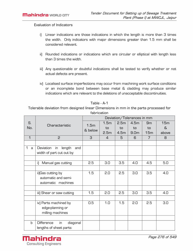
Tender Document for Setting up of Sewage Treatment Plant (Phase I) at MWCJL, Jaipur
Page 276 of 549
Evaluation of Indicators
i) Linear indications are those indications in which the length is more than 3 times the width. Only indicators with major dimensions greater than 1.5 mm shall be considered relevant.
ii) Rounded indications or indications which are circular or elliptical with length less
than 3 times the width. iii) Any questionable or doubtful indications shall be tested to verify whether or not
actual defects are present. iv) Localised surface imperfections may occur from machining work surface conditions
or an incomplete bond between base metal & cladding may produce similar indications which are relevant to the deletions of unacceptable discontinuities.
Table - A-1
Tolerable deviation from designed linear Dimensions in mm in the parts processed for fabrication
S. No.
Characteristic
Deviation/Tolerances in mm
1.5m & below
1.5m to
2.5m
2.5m to
4.5m
4.5m to
9.0m
9m to
15m
15m &
above 1 2 3 4 5 6 7 8
1 a Deviation in length and
width of part cut out by:
i) Manual gas cutting 2.5 3.0 3.5 4.0 4.5 5.0 ii)Gas cutting by
automatic and semi- automatic machines
1.5 2.0 2.5 3.0 3.5 4.0
iii) Shear or saw cutting 1.5 2.0 2.5 3.0 3.5 4.0 iv) Parts machined by
edge-planning or milling machines
0.5 1.0 1.5 2.0 2.5 3.0
b Difference in diagonal
lengths of sheet parts:

Tender Document for Setting up of Sewage Treatment Plant (Phase I) at MWCJL, Jaipur
Page 277 of 549
S. No.
Characteristic
Deviation/Tolerances in mm
1.5m & below
1.5m to
2.5m
2.5m to
4.5m
4.5m to
9.0m
9m to
15m
15m &
above 1 2 3 4 5 6 7 8
i) For butt welding 4.0 4.0 4.0 5.0 6.0 6.0 ii) For lap welding 5.0 5.0 5.0 8.0 10.0 10.0 c Deviation in distances
between hole centres, formed as per:
i) Marking of extreme
ones 2.0 2.0 2.5 3.0 3.5 4.0
ii) marking of adjacent
ones 1.5 1.5 1.5 1.5 1.5 1.5
2 Deviation in the dimensions
of structural despatch members after finishing:
a When assembled upon
assembly benches as per marking.
3.0 4.0 5.0 7.0 10.0 15.0
b When assembled in the jig
and other devices fastening with fixtures.
2.0 2.0 3.0 5.0 7.0 10.0
c Dimensions (length and
breadth) between milled surface (after finishing)
0.5 1.0 1.5 2.0 2.5 3.0
3 Distance between groups
of erection holes (in finished members):
a Formed during machining 3.0 4.0 5.0 7.0 10.0 15.0

Tender Document for Setting up of Sewage Treatment Plant (Phase I) at MWCJL, Jaipur
Page 278 of 549
S. No.
Characteristic
Deviation/Tolerances in mm
1.5m & below
1.5m to
2.5m
2.5m to
4.5m
4.5m to
9.0m
9m to
15m
15m &
above 1 2 3 4 5 6 7 8
of separate parts installed when assembling as per marking.
b Formed during machining
of parts, installed when assembling with the help of fixtures.
2.0 2.0 3.0 5.0 7.0 10.0
c Drilled with the help of
templates in finished members.
0.5 1.0 1.5 2.0 2.5 4.0
Fabrication Check List
Table-A.2 Tolerable deviations of fabricated members from designed geometrical shape
Sl. No. Characteristic Deviation/Tolerance Remarks
1. Curvature of assembly Parts a) Gap between a sheet and a steel
rule face over 1 m length 1.5 mm
b) Gap between a taut string and
vertex face of an angle flange or web of channel and joist.
0.001 L, but not greater than 10 mm.
L-length of member
2. Deviation of edge line steel sheet parts
from theoretical profile:
a) During butt and toe welding 2 mm b) During lap welding 5 mm 3. Deviation of radius of the bend:

Tender Document for Setting up of Sewage Treatment Plant (Phase I) at MWCJL, Jaipur
Page 279 of 549
Sl. No. Characteristic Deviation/Tolerance Remarks a) Clearance between template and
the surface of rolled sheet flange or face of cold bend profile.
2 mm Template length
(1.5m along the curve)
b) -do- for hot bend profile 3 mm -do c) Ellipticity (difference of
diameters) in space sheet structures. 0.005D D-diameter of
circumference
d) -do- in erection joints 0.003D -do- 4. Deformation of dispatch members: a) Inclination of flanges with the web:
i) at junction 0.005b b-width of flange ii) at other places 0.01b -do- b) Transverse bending of flanges: i) at junction with members 0.005b b-width of flange
ii) at other places 0.01b -do- c) Warping of the web 0.003h h-depth of the
member d) Sag of member L/750 but not more
than 15 mm L-length of the
member 5. Other deviations: a) Shifting of axes of riveting/
bolting lines for lattice structures from theoretical eccentricity.
3.0 mm
b) Inclination of the milled surface from designed position.
1/1500

Tender Document for Setting up of Sewage Treatment Plant (Phase I) at MWCJL, Jaipur
Page 280 of 549
Fabrication Check List
Table - A.3 Acceptance Deviations in as fabricated steel structures
S. No. Characteristic Deviation/ Tolerance
1. COLUMNS a) Deviation in length ‘L’ measured distance from bottom surface of the column footings, to the group of holes for ‘trusses’, fasteners, collar beams, purlins and other elements to be connected to column. When L is under 10 m ± 10 mm When L is over 10 m ± 15 mm b) Deviation in distance ‘L’ from bottom surface of the column footing to the top of crane bracket. When L is under 10 m ± 5 mm When L is over 10 m ± 10 mm c) Deviation in distance from bearing surface of the bracket to the first fastener of the element to be connected to column. ± 1 mm d) Deviation in distance between any group of holes for connection of bracings to columns. ± 2 mm e) Sag of column element 1/1000 of length (curvature) element but not more than 15 mm.

Tender Document for Setting up of Sewage Treatment Plant (Phase I) at MWCJL, Jaipur
Page 281 of 549
f) Difference in web depth of column i) At splice joint ± 2 mm ii) At any other location ± 10 mm g) Deviation in distance from supporting surface of milled end of the despatched element of column to the clear or heating plate or column to the cleat or seating plate for fastening of collar beams, purlins, girders etc. (Fish plates, brackets). ± 3 mm 2. TRUSSES a) Deviation in span ‘L’ of the truss between end erection holes in gussets of supporting units or between external planes of supporting gussets or angles when trusses are resting on brackets or supports: When L is under 25 m ± 7 mm When L is over 25 m 1/2500 but not more
than 10 mm b) Deviation in distance between the centres of holes or webs of angles for fastening bracing, purlins, monitors, etc. ± 3 mm c) Deviation in distance between the first row of erection holes and the more than 15 mm. d) Distance between holes for fasteners to top and bottom chords of trusses on supports. ± 3 mm

Tender Document for Setting up of Sewage Treatment Plant (Phase I) at MWCJL, Jaipur
Page 282 of 549
e) Sag of separate elements between 1/1500 of length of element
node points. but not more than 10 mm. 3. BEAMS a) Deviation in span L of beams between bend erection holes, outer surfaces of end plates: When L is under 25 m ± 10 mm When L is over 25 m ± 1/2500 length but not
more than 15 mm b) Deviation in the height of beam as measured from the bearing surface to the top of upper flange. ± 3 mm c) Deviation in distance between the group of holes for fastening of purlins, monitors, bracings, bracing grids etc. ± 3 mm d) Sag (curvature) of the girder 1/1000 length but not despatch member more than 15 mm 4. ELEMENTS OF FRAMEWORK BRACINGS, PURLINS ETC. a) Deviation in distance between end erection holes, determining the span of element. ± 3 mm b) Sag of despatch members 1/1000 length but not more than 15 mm c) Deviation in distance between the groups of
erection holes of the element ± 3 mm
d) Gratings, Stair, Railings, ladders, etc. ± 12 mm 5. SHOP ASSEMBLY ( BEFORE DESPATCH FOR ERECTION) a) Columns weighing more than 20 T i) Every first and further every tenth set of

Tender Document for Setting up of Sewage Treatment Plant (Phase I) at MWCJL, Jaipur
Page 283 of 549
b) Roof trusses of 30 m or more span identical structure to be put for control assembly. c) Crane girders with span more than 18 m d) Bunkers i) Number of erection
bolts shall be atleast 30% of the total No. of holes.
Fabrication Check List
Table - A.4 Acceptable Deviation in Holes or Bolts
S. No.
Characteristic Deviation Tolerance No. of deviation
in each group
1. a) Deviation of dia of holes for rivet and bolts: Upto 16 mm ± 1 mm No limit
Over 16 mm ± 1.5 mm
b) Deviation of dia of turned and fitted bolts: Nominal dia of bolts Upper limit: and holes + 0.125 mm Lower limit: 0.00 No limit 2. Ovalness (difference between the greatest and lesser dia) Upto 16 mm hole dia + 1 mm No limit Upto 16 mm hole dia + 1.5 mm 3. Deformity in size greater Not permitted than 1.5 mm and cracks in the edge of holes. 4. Misalignment of holes in separate plates in the joints: i) Upto 1 mm Upto 50% ii) From 1 to 1.5 mm Upto 10%
Note: in holes shall be removed, the depth and width of countersunk hole shall not deviate from the standard by more than 1.5 mm.

Tender Document for Setting up of Sewage Treatment Plant (Phase I) at MWCJL, Jaipur
Page 284 of 549
Fabrication Check List Table - A.5
Permissible Fabrication Deviation of Structural Steel
S. No.
Type of structures and constructions
Name of Deviations Value of Deviation
(Tolerance)
1. Column Assembly fits a) Base plate and column 0.1 mm b) Frame Joints 2.0 mm c) Web and flange 1.5 mm d) Web & stiffeners 1.5 mm e) Flange & stiffeners 1.5 mm Intermediate stiffeners & Bearing stiffeners f) Cap plate & column 0.1 mm g) Crane girder seat 0.1 mm h) Beam brackets 2.0 mm
2. Beams (c), (d), (e) of S.No. 1 1.5 mm above
3. Crane Girders (c), (d), (e) of S.No. 1 0.1 mm above and knife edge supports
4. Silos & Hoppers a) Ring beam and wall 1.5 mm b) Stiffeners and walls 1.5 mm c) Stiffeners and ring beams 1.5 mm d) Deflection of straight section
of compression cord from the plane of truss, collar beam or girder.
1/1500 of span but nore more than 10mm
5. Purlin Deviation in distance between purlins.
5 mm

Tender Document for Setting up of Sewage Treatment Plant (Phase I) at MWCJL, Jaipur
Page 285 of 549
Erection Check List Table - A.6
Maximum Permissible Tolerances in Steel Structures
S. No. Description Tolerance 1. Erected steel columns: i) Deviation of column axis at foundation top level with respect to true axis: a) in longitudinal direction ± 5 mm b) in lateral direction ± 5 mm ii) Deviation in the level of bearing ± 5 mm surface of columns at foundation
top with respect to true level
iii) Out of plumbness (verticality) of column axis from true vertical axis as measured at column top: a) For columns without any special requirements: 1) upto and including 30 m height ± H or ± 25 mm 1000 whichever is less 2) over 30 m height ± H or ± 35 mm 1200 whichever is less b) For column with special requirements like cranes or such similar requirements: 1) upto and including 30 m height ± H or ± 25 mm 1000 whichever is less 2) over 30 m height ± H or ± 25 mm 1500 whichever is less

Tender Document for Setting up of Sewage Treatment Plant (Phase I) at MWCJL, Jaipur
Page 286 of 549
S. No. Description Tolerance iv) Deviation in straightness in longitudinal and transverse of column at any point along ± H or ± 10 mm the height. 1500 whichever is less v) Difference in the erected positions of adjacent pairs of columns along length or across width of building prior to connecting trusses/beams with respect to true distance. ± 5 mm vi) Deviation in any bearing or seating level with respect to true level. ± 5 mm vii) Deviation in difference in bearing levels of a member on adjacent pair of columns both across and along the building. ± 5 mm
NOTES:
1. Tolerance specified under iii(a) and iii(b) should be read in conjunction with iv and v.
2. ‘H’ is the column height in mm.
Table - A.6 (Contd.) S. No. Description Tolerance 2. Erected Steel Trusses I) Shift, at the centre of span of top chord member with respect to vertical plane passing through the centre of bottom chord. ± 1 of height of 250 truss in mm at centre of span or ± 15 mm whichever is less.

Tender Document for Setting up of Sewage Treatment Plant (Phase I) at MWCJL, Jaipur
Page 287 of 549
S. No. Description Tolerance ii) Lateral shift of top chord of truss at the centre of span from the vertical plane passing through the centre of supports of the truss. ± 1 of span of 1500 truss in mm or ± 10 mm whichever is less. iii) Lateral shift in location of truss from its true axis in plan. ± 10 mm iv) Lateral shift in location of purlin from true position. ± 5 mm v) Deviation of difference of bearing levels of trusses from the true difference. ± 1 of span of 1200 truss in mm or ± 20 mm whichever is less. 3. Erected Crane Girder and Rails i) Shift in the centre line of crane rail with respect to centre line of web crane girder. ±(Web thk in mm) + 2 mm 2 ii) Shift in plan of alignment of crane rail with respect to true axis of crane rail at any point. ± 5 mm iii) Deviation in crane track gauge with respect to the gauge: a) For track gauge upto and including 15 mm ± 5 mm b) For track gauge more than

Tender Document for Setting up of Sewage Treatment Plant (Phase I) at MWCJL, Jaipur
Page 288 of 549
S. No. Description Tolerance 15 mm ± (5 + 0.25(S-15)) mm subject to a maximum of ± 10 mm, where S in meters is true track gauge. iv) Deviation in the crane rail level at any point from true level ± 10 mm v) Difference in levels between crane track rails at: a) Supports of crane girders 15 mm b) Mid span of crane girders 20 mm vi) Relative shift of crane rail surface at a joint plan and elevation. 2 mm subject to grinding of surfaces for smooth transition.

Tender Document for Setting up of Sewage Treatment Plant (Phase I) at MWCJL, Jaipur
Page 289 of 549
Proforma - A.P.1
Typical Welding Procedure Data Sheet
Contractor...........................................................Address...................................................... Quality of weld....................................................Specification.............................................. Material Specification...........................................Thickness.......................................Batch/ Cast No........................................................Joint preparation(Fig)........................................ Gap............................................................Location of Specimens......................................... Whether condition..................................................Type of Day.................................... Wind break used............................................................................................................................... Electrode Group No.................................Make..................Specimen.................................... Pre and Post Heating............................................................................................................... Welding position.................................................................................................................... Size of reinforcement................................................Whether removed.................................. Welding Sequence.................................................................................................................. Backing strip used............................................Type................................................ Welding process.............................................................................................................................. Current conditions Polarity..................................................................................................... Size of electrode..................................................................................................................... Amperage and Voltage............................................................................................................ Number of Electrodes used per run........................................................................................

Tender Document for Setting up of Sewage Treatment Plant (Phase I) at MWCJL, Jaipur
Page 290 of 549
Cleaning method..................................................................................................................... Remarks............................................................................................................................ Welding Engineer Owner Signature (Inspecting Authority) For and behalf of Contractor Date:___________________

Tender Document for Setting up of Sewage Treatment Plant (Phase I) at MWCJL, Jaipur
Page 291 of 549
SECTION - C10 TECHNICAL SPECIFICATION FOR GLASS AND GLAZING

Tender Document for Setting up of Sewage Treatment Plant (Phase I) at MWCJL, Jaipur
Page 292 of 549
Section - C10 Technical specification for glass and glazing
1. Scope
The work in general shall consist of supplying and fixing all glass and glazing including all clips, putty, mastic cement, etc. wherever required.
2. Installation 2.1 General
The Contractor shall supply and install all glass and glazing as required for various doors, windows, sashes, ventilators and fixed louvers, miscellaneous glazing and partitions, as approved by the Owner, having very high optical clarity, brighter appearance, uniform thickness, consistent product quality manufactured out of molten glass coming out of the furnace floats on molten tin, thus being formed into float glass. The glass shall be delivered to site in containers with the maker's name, guarantee, type of glass and thickness, or weight of glass attached to the outside of the containers. Glass cut to size shall be straight and free from chips, spalls or any other damage on any cut edge.
2.2 Materials
(a) Clear glass shall be flat drawn sheet glass and shall be atleast 4 mm thick conforming to IS:2835. Sheet glass for doors shall be minimum 5.5 mm thick.
(b) Wired glass shall be thick rolled glass with centrally embedded 24G wire mesh of Georgian type. This may be of clear or coloured glass as shown in drawings and shall conform to IS:5437.
(c) Composite double glazing shall be made of double glazing of two 6 mm thick sheet glass either both sheets of tinted glass or one glass tinted & other plain or both sheets of plain sheet glass. Both the glasses shall be separated by an air gap of 12 mm. The trapped air shall be kept dry by means of suitable desiccant. The sealing shall be under strict quality control. The composite glazing shall be procured as finished product from reputed manufactures. Toughen glass conforming to IS:2553 shall be used.
(d) Obscure glass shall have a cast surface on one side. (e) Coloured and figured glass shall be as per the approved sample. (f) In general, the putty shall conform to IS:410 latest edition and be of best quality from
an approved manufacturer. It shall be brought to site in the manufacturer's original packing. Quick setting putty shall be used for windows and sashes except when glare reducing glass is used where it shall be of non-setting type.
(g) Neoprene gaskets with snap-fit glazing shall be fixed as per manufacturer's instructions and shall fit firmly against the glass to give a leak proof installation.

Tender Document for Setting up of Sewage Treatment Plant (Phase I) at MWCJL, Jaipur
Page 293 of 549
2.3 Glazing, Setting and Finish All glazing clips, bolts, nuts, putty, mastic, cement, etc., shall be supplied by the Contractor. All glass shall be thoroughly cleaned before placing in position. Each glass pane shall be held in place by special glazing clips of an approved type. Four glazing clips shall be provided per glass pane, except for large panes where six or more clips shall be used as instructed by the Engineer. All holes that may be necessary for holding the clips, glazing beads and all other attachments shall be drilled by the Contractor. Glass panes shall be set without springing, and shall be bedded in putty and back puttied, except where mouldings or gaskets are specified. Putty, mastic cement etc., shall be smoothly finished to a true even line. Obscure and figured glass shall be set with smooth side out. After completion of glazing work, the Contractor shall remove all dirt, stains, putty, etc., clean the glass panes and leave the work in perfectly acceptable condition. All broken, cracked or damaged glass shall be replaced by new at the Contractor's own cost.
3. Acceptance Criteria
(a) All installations shall be free from cracked, broken or damaged glass. Edges of large panes of thicker glass and heat absorbing glass shall be inspected carefully for chipped, cracked or unground edges.
(b) Glazing shall be carefully done to avoid direct contact with metal frames. (c) All glass shall be embedded in mastic or fixed by neoprene gaskets to give a leak-proof
installation. (d) At completion the panes shall be free from dirt, stains, excess putty, etc., to the
complete satisfaction of the Engineer.
4. IS Codes
Some of the important applicable Indian Codes for this section are listed below. Latest editions of these codes shall be followed:
IS:3548 Code of Practice for glazing in building. IS:1083 Code of practice for fixing and glazing metal doors, windows and ventilators. IS:419 Putty for use on window frames.

Tender Document for Setting up of Sewage Treatment Plant (Phase I) at MWCJL, Jaipur
Page 294 of 549
SECTION - C11 TECHNICAL SPECIFICATION FOR MS DOORS, WINDOWS,
VENTILATORS, LOUVERS, ETC

Tender Document for Setting up of Sewage Treatment Plant (Phase I) at MWCJL, Jaipur
Page 295 of 549
Section - C11 Technical specification for ms doors, windows, ventilators, louvers, etc
1 Scope
The work in general shall consist of supplying, erecting and installing of all MS doors, windows, ventilators, louvres, glazed partitions etc. as required with all materials, complete excluding supply of glass and glazing. Supplying and/or fixing of all door and window accessories and hardware is also included in the scope.
2 Installation 2.1 Materials
Steel sections used for fabrication of doors, windows, etc. shall be standard rolled steel sections specified in IS:1038 and IS:1361. Mild Steel sheets for frames, shutters, louver blades, etc. shall be of the gauge mentioned in this specification. Hardwares and fixtures of the best quality from approved manufacturers only shall be used. The Bidder shall specifically state the particular manufacturer’s materials, he proposes to use. All hardware and fixtures shall be able to withstand repeated use. Door closers shall conform to IS:3564 latest edition and shall be suitable for doors weighing 61-80 kg unless otherwise stated. Each closer shall be guaranteed against manufacturing defect for one year and any defect found within this period shall be rectified or the closer replaced free of charge. Concealed doors closers shall be either floor mounted or transform mounted suitable for installation with metal doors. They shall conform to the performance requirements and endurance test stated in Appendix A of IS 3564 (latest edition). Aluminium sections for fabrication of doors, windows, partitions etc. shall be extruded section conforming to IS:1948 and 1949 or as manufactured by Indian Aluminium Company Ltd. or approved equivalent. The alloy used shall conform to IS designation HE-9-WP of IS:733. Heavy duty double acting floor springs where specified shall conform to IS:6315, shall be suitable for door shutters weighing upto 125 kg. shall be hydraulically regulated, shall be constructed of cast brass casting cover and shoe, gun metal piston player and all other parts of mild steel. The Contractor shall submit samples of each type of hardware to the Engineer. The approved samples shall be retained by the Engineer for comparison of the bulk supply. The samples shall be returned to the Contractor towards the end for incorporation in the job.

Tender Document for Setting up of Sewage Treatment Plant (Phase I) at MWCJL, Jaipur
Page 296 of 549
The mastic for caulking shall be of best quality from a manufacturer approved by the Engineer. In general the mastic for fixing of metal frames shall be as per IS:1081 latest edition and/or as approved by the Engineer.
2.2 Fabrication 2.2.1 Steel Doors, Windows, Ventilators, Louvers, etc.
(a) Door Frames :
Frames shall be fabricated from 16 G sheets. They shall be mortised, reinforced, drilled and tapped for hinges, lock and bolt strikes. Where necessary, frames shall be reinforced for door closers. Welded construction with mitred corners shall be used. Rubber door silencers shall be furnished and for the striking jamb, Loose ‘T’ masonry anchors shall be provided. Frames shall finish flush with the floor and adjustable floor anchors shall be supplied. Frames shall be brought to site with the floor ties/weather bars installed in place.
(b) Double Plate Flush Door Shutter
Door shutters shall be 45 mm thick completely flush design and shall comprise of two outer sheets of 18G steel sheets rigidly connected and reinforced inside with continuous vertical 20 G stiffeners, spot welded in position at not more than 150mm centres. Both edges of doors shall be joined and reinforced to full height by steel channels placed immediately inside and welded to the door faces. The tops and bottoms of doors shall be reinforced horizontally by steel channels running to the full width of the door. Doors shall have proper level on lock stiles and rails to operate without bending and shall be reinforced at the corners to prevent sagging or twisting. Pairs of double doors shall have meeting stile edges bevelled or rebated. Wherever required the doors shall be sound deadened by filling the inside voids with mineral wool or other suitable approved materials.
Door shall be mortised, reinforced, drilled and tapped in the shop for hinges, locks and bolts. They shall also be reinforced for closers, push plates and other surface hardware where necessary.
Any drilling and tapping required on the surface shall be done at site. Wherever required provision shall be made for fixing glazing, vision panels, louvers, etc. Glazing mouldings shall be of 18 g steel as directed by the Engineer. Louvre blades shall be V or Z shaped and made out of 16 G sheets.

Tender Document for Setting up of Sewage Treatment Plant (Phase I) at MWCJL, Jaipur
Page 297 of 549
(c) Single Sheet Door Shutters
Single sheet doors shall be made from best quality 18 G mild steel sheets and shall present a flush surface on the outside. The inside shall be stiffened with a semitubular edge and central stiffening rail which shall support the lock and other furniture. The frames shall be made from best quality 16 G mild steel sheets.
Wherever required provision for fixing glass panels, louvers, etc. shall be made.
Fabrication shall be as specified in 2.02.01 (b) “Double Flush Door Shutters”.
(d) Sliding Doors
Sliding doors shall be either double plate or single plate construction as required and made out of 18 gauge steel sheets with adequate stiffeners.
The Contractor shall specify the weight of the door in his shop drawing and submit the manufacturer’s catalogue of the sliding gear he proposes to use. The Contractor shall make provisions where necessary for openings in the door for monorail beams. Doors shall close positively to exclude rain water from seeping in. Sliding doors shall withstand specified wind loads without buckling or jamming. The door shall slide freely under all ambient conditions.
(e) Steel Windows, Sashes, Ventilators, etc.
These shall conform in all respects to IS:1038 and IS:1361 latest editions. The details as called for in the above codes shall be applicable for coupling mullions, transoms, weather bars, pivot arrangements for ventilators, etc.
All welds shall be flush butt welded to form a solid fused joint, so that all frames are square and flat.
Where composite unit openings are envisaged the individual windows units shall be joined together with requisite transom and mullions. All windows shall be outside glazed fixed with putty or metal glazing beads. Where aluminium glazing beads are specified they shall be extruded aluminium channel 9.5 mm x 9.5 mm x 1.6 mm (Indal section No.2209) aluminium beads shall be given one coat of zinc chromate primer before fixing to windows.
2.2.2 Welding
The joints for steel doors, windows, ventilators, etc. shall be electrically flash butt welded joint at all corners and junctions to form a solid fuses right angle joint.

Tender Document for Setting up of Sewage Treatment Plant (Phase I) at MWCJL, Jaipur
Page 298 of 549
2.2.3 Fabrication of Aluminium Doors, Windows, Frames, Etc.
Extruded sections shall have a minimum 3 mm wall thickness. All sections shall be approved by the Engineer before fabrication is taken up. Doors, windows, frames, mullions, transformers etc. shall be anodized in bath of sulphuric acid to provide a clear coating of minimum 10 micro-meter. The anodized materials shall then be sealed by immersing in boiling water for 15 minutes. A protective transparent coating shall be applied to the sections before shipment from the factory.
Fabrication drawings shall be submitted by the contractor which shall also include the weights of the materials used and got approved from the Engineer.
2.3 Shop Coat of Paint
The shop paint for steel doors, windows, etc. shall be best red oxide, zinc chromate primer paint from approved manufacturer conforming to IS:2074, latest edition. All surfaces shall be thoroughly cleaned of rust, grease, loose mill scales, etc. and given one coat of shop paint. Portions like mullions transoms, etc. which will be inaccessible after assembly of units shall be given an extra coat of paint before assembly.
2.4 Handling and Storage of Fabricated Material
All metal doors, windows, etc. shall be packed and crated properly before despatch to ensure that there will be no damage to the fabricated materials. Loading into wagons and trucks shall be done with all care to ensure safe arrival of materials at site in an undamaged condition. All metal doors, windows, etc. shall be stored under cover and handled in a way to preventdamage or distortion. Special care shall be taken to prevent staining of aluminium products by rust, motor etc.
2.5 Assembly and Erection at Site
In general the fixing of steel doors, windows, ventilators, louvres, etc. shall conform to IS:1081 latest edition. The Contractor shall assemble and install all steel doors, windows, sashes, fixed metal louvres, etc. including transoms and mullions for composite units in respective places keeping proper lines and levels, and in an approved workman like manner to give a trouble free and leak proof installation. If required by the Engineer, the installation shall be carried out under the supervision of the manufacturer’s staff.
After installation of steel doors, windows, etc., all abrasions to the shop-coat of paint shall be retouched and made good with the same quality of paint.
All coupling mullions, transoms, frames, etc. in contact with adjacent steel and other members shall be well bedded in mastic. The Contractor shall bring to site the mastic

Tender Document for Setting up of Sewage Treatment Plant (Phase I) at MWCJL, Jaipur
Page 299 of 549
cement in original sealed containers of the manufacturer and shall apply it as per the manufacturer’s instructions.
Floor, shutters, partitions, hardware fixtures, etc. shall be fixed only after the major equipment has been installed in the rooms.
Wherever required, nylon cords of approved quality shall be supplied along with pivoted sashes. These shall be adequate length to terminate one metre from the floor. Loose ends of cords shall have a metal or plastic pull as approved by the Engineer.
3 Acceptance Criteria 3.1 For Fabricated Items
(a) Overall dimensions shall be within ± 0.5mm of the size. (b) Mullions, transoms, etc. shall be in one length and permissible deviations from
straightness shall be limited to plus minus 0.5 mm from the axis of the member. (c) Door and window shutters shall operate without jamming. The clearance at head and
jamb for door shutters shall not exceed 1.5mm. For double leafs the gap at the meeting stiles shall not be more than 1.5mm.
(d) Door leafs shall be undercut wherever required. (e) Doors, windows, frames, etc. shall be on a true plane, free from warp or buckles. (f) All welds shall be dressed flush on exposed and contact surfaces.
(g) Correctness of hardware and smoothness of operation of all shop installed hardware
and fixture.
(h) Provisions for hardware and fixtures to be installed at site.
(i) Glazing beads shall be cut with mitred corners.
(j) Shop coats shall be properly applied.
(k) Exposed aluminium surface shall be free from scratches, stains and discolouration. Anodized surfaces shall present a uniform and pleasing look.
3.2 For Installed Items
(a) Installation shall be at the correct location, elevation and in general on a true vertical plane.

Tender Document for Setting up of Sewage Treatment Plant (Phase I) at MWCJL, Jaipur
Page 300 of 549
(b) All frames of external walls shall be mastic caulked to prevent leakage through the joint between frames and masonry.
(c) All openable sections shall operate smoothly without jamming.
(d) Locks, fasteners, etc. shall engaged positively. Keys shall be non-interchangeable.
(e) Cutting to concrete or masonry shall be made good and all abrasions to shop paint
shall be touched up with a paint of the same quality as the shop paint.
(f) Aluminium doors, windows etc. shall be free scratches, stains or discolouration.
(g) It shall be the responsibility of the contractor to see that the material is protected from mortar, paint, plaster, terrazzo framing members to the satisfaction of the Engineer before handing over to the Owner.
4 Information to be submitted Before starting fabrication of any metal doors, windows, etc. the Contractor shall submit
detailed fabrication drawings to the Engineer for approval. The fabrications shall be started only after approval of the drawings.
5 IS Codes
The important IS Codes to be followed are listed below: IS:1083 Steel doors, windows and ventilators. IS:1361 Steel windows for industrial buildings. IS:1451 Steel door frames.

Tender Document for Setting up of Sewage Treatment Plant (Phase I) at MWCJL, Jaipur
Page 301 of 549
SECTION - C12 TECHNICAL SPECIFICATION FOR ROLLING STEEL
SHUTTERS/GRILLS

Tender Document for Setting up of Sewage Treatment Plant (Phase I) at MWCJL, Jaipur
Page 302 of 549
Section - C12 Technical specification for rolling steel shutters/grills
1. Scope This specification covers the design, supply of materials, fabrication, delivery and erection
of rolling shutters grills with motor drives and/or manual operation during all accessories as hereinafter specified. All electrical work shall be in strict accordance with the latest Indian Electricity Rules.
2. Installation 2.1 Components
a) States for rolling shutters shall be made from tested bright, cold rolled, annealed M.S. strips, not less than 0.9 mm thick for shutters upto 3.5 m wide and not less than 1.24 mm thick for shutters 3.5 m wide and above, machine rolled at 75 mm rolling centres, interlocking with each other. The profile will be such as to prevent excessive deflection under specified wind load.
b) Rolling grills shall be constructed out of 6 mm dia. rods at 35 mm centres running
horizontally flexibly connected with vertical links spa ed not more than 200 mm centres. Alternatively, rolling grills shall be made from perforated slats of approved design, reinforced with 6 mm dia rods.
c) End locks shall be heavy type M.C.I./C.I. and shall be provided at each end of alternate
slats.
d) Bottom bars shall be finished with two angles not less than 6 mm thick for external shutters. When shown on drawings, a flexible weather strip shall be applied to make tight contact with the floor.
e) Guide shall be of such depth as to retain the shutter under a wind pressure of 150
kg/sq.m. The minimum thickness of guide shall be 126.
f) Shafts shall be of steel pipes of sufficient size to carry the torsional load with a maximum deflection of 1/360th of span. Grease packed ball bearings or bushings shall be provided for smooth trouble, free operation.
g) Hoods shall be formed of not less than 20 gauge steel, suitably reinforced to prevent sag.

Tender Document for Setting up of Sewage Treatment Plant (Phase I) at MWCJL, Jaipur
Page 303 of 549
h) Locks shall be side belt and hasp or cylinder lock operable from one or both sides. Provision for to securing hand chain with pad-lock, provision for removable handle for hand cranks etc. shall be made as desired by the Engineer.
i) Power unit shall be suitable for 3 phase, 50 cycle, 400 volt A.C. Power supply and shall
be either floor or wall mounted unit. The motors shall be of sufficient capacity to move the shutter in either direction at a speed of 0.3 metres per second. In addition to the gear motor, each standard power unit shall include a magnetic brake, reversing starter with built-in overload protection, a geared limit switch and one push button station located inside the building unless otherwise stated.
It is desirable that the button bar or motor operated doors shall be provided with a sensitive edge, electrically connected to stop the travel of the door on meeting an obstruction.
j) Operating chains shall be of tested quality, heavily galvanized and with all ends rounded
to assure smooth operation and hand protection.
k) Reduction gears shall be of high strength grey cast iron, machine moulded from machine cut patterns.
2.2 Manually Operated Shutters/Grills Manually operated shutters shall be easily operable by one person. The speed of operation
shall be about 0.3 metres per second. In general, manually operated shutters shall be push-pull type for opening upto 9 sq. metre
in area. Larger shutters shall be either chain and gear operated or crank and gear operated. The crank handle shall be removable. All shutters shall be lockable from one or both sides as desired by the Engineer.
2.3 Power Operated Shutters/Grill These shall be operable from a push button station conveniently located beside the door or
as shown on drawings. One emergency hand chain-crankoperation shall also be provided for use in case of failure of the electrical system.
2.4 Shop Coat Shutters shall be painted with one coat of red lead or zinc chromate primer. Where
specified, doors shall be galvanised and subsequently painted with one coat of zinc chromate for adhesion of field coat.

Tender Document for Setting up of Sewage Treatment Plant (Phase I) at MWCJL, Jaipur
Page 304 of 549
3. Acceptance Criteria 3.1 Shop Inspection After completion the manufacture of different components of the rolling shutter, an
arrangement for shop inspection by the Engineer shall be made to check the conformity with approved shop drawings.
3.2 Field Inspection After installing the shutters, the Contractor shall test the performance of the shutter in
the presence of the Engineer. The doors shall be smoothly operable under all ambient conditions. All control and locking devices shall give fault- free performance.
3.3 Guarantee The Contractor shall give one year’s guarantee for the successful operation of the
shutters. 4. IS Codes IS:6248 Metal rolling shutters and rolling grills.

Tender Document for Setting up of Sewage Treatment Plant (Phase I) at MWCJL, Jaipur
Page 305 of 549
SECTION C - 17 TECHNICAL SPECIFICATION FOR SANITARY SEWERS &
MANHOLES

Tender Document for Setting up of Sewage Treatment Plant (Phase I) at MWCJL, Jaipur
Page 306 of 549
Section C - 17 Technical specification for sanitary sewers & manholes
1.0 Scope 1.1 The work shall include providing of materials, all necessary plant and equipment, providing
adequate engineering supervision and technical personnel, skilled and unskilled labour, etc. as required to carry out the entire work as indicated on the drawings and/or described herein subsequently and/or as directed by the Engineer.
1.2 The Contractor shall carry out all works meant within the intent of this specification even if
not explicitly mentioned herein. All works shall be executed to the satisfaction of the Engineer.
1.3 This specification is divided into 6 sections, section C-17 deals with sanitary sewers and
manholes and the other sections deal with specifications for 5 different items / activities. Stipulations contained in sections, C-1, C-2, C-3, C-4, C-5 and C- 17 shall form part of specifications for sanitary sewers and manholes.
All these six sections are as follows:- Section C-1 Technical specification for Excavation and Filling Section C-2 Technical specification for Properties, Storage and Handling of
Common Building Materials. Section C-3 Technical specification for Cast in situ concrete and Allied works. Sub section: 1 - Common requirement 2 - Cast in situ concrete and Allied works 3 - Reinforcement 4 - Formwork and staging Section C-4 Technical specification for Masonry and Allied works Section C-5 Technical specification for plastering and Allied works
Section C-17 Technical specification for Sanitary Sewers and Manholes Layout and Details of Bore Logs.

Tender Document for Setting up of Sewage Treatment Plant (Phase I) at MWCJL, Jaipur
Page 307 of 549
2.0 General Requirements 2.1 Any approval, instructions, permission, checking, review, etc. whatsoever by the Engineer,
shall not relieve the Contractor of his responsibility and obligation regarding adequacy, correctness, completeness, safety, strength, quality, workmanship, etc.
2.2 The Contractor shall make his own surveying arrangements for locating the coordinates
and positions of all work and establishing the reduced levels (RLs) at these locations, based on two reference grid lines and one bench mark which will be furnished by the Owner. The Contractor has to provide at Site, all the required survey instruments, along with qualified surveyors, to the satisfaction of the Engineer so that the work can be carried out accurately and according to the specifications and drawings.
3.0 Codes and Standards 3.1 All applicable standards, specifications, etc. and codes of practice shall generally be the
latest editions, including all applicable official amendments and revisions. A complete set of all these documents shall generally be available at site, with the Contractor.
3.2. All work shall be carried out as per the stipulations contained in various sections of these
specifications and the latest Indian Standards, Act, Codes and best practices. 3.3. In case of conflict between the stipulations contained in various sections of these
specifications and stipulations of Indian Standards, Codes, etc. the requirements of stipulations contained in various sections of these specifications shall prevail over that of Indian Standards, Codes, etc.
3.4. Some of the applicable Indian Standards, Codes etc. are referred to herein below IS:651 - Glazed stoneware pipes and fittings IS:458 - Precast concrete pipes IS:1726 - Manhole covers & frames IS:5455 - C.I. Rungs IS:458 - Vent Shafts IS:4127 - Code of practice for laying of glazed stoneware pipes IS:783 - Code of practice for laying of Concrete pipes

Tender Document for Setting up of Sewage Treatment Plant (Phase I) at MWCJL, Jaipur
Page 308 of 549
IS:4111 - Code of practice for ancillary structures in sewerage system (part1) (manholes)
4.0 Sewers: 4.1.1. Glazed Stoneware pipes shall conform to IS:651 4.1.2. Concrete pipes shall conform to IS:458 4.1.3. Manhole covers and frames shall conform to IS:1726 4.1.4. Cast iron rungs shall conform to IS:5455 5.0. Laying of Sewers 5.1. Excavation for sewers 5.1.1. The whole of the excavation will be classified under two heads only, viz :
(a) General excavation to include excavation in road surfaces of every description together with their foundations, clay, loose sand stone, murum, boulders, sand, lime cement masonary and all other materials of whatever description not requiring to be blasted.
(b) Rock excavation to comprise excavation in rock big boulders more than 0.25 cubic
metre in volume very hard sand stone or littoral concrete, requiring to be blasted by an explosive or burst out in small pieces by Iron wedges or Chisels.
5.1.2. Class of Excavation to be determined In case of any question arising as to the class of excavation, the Engineer shall determine
under which category, and to what extent any particular excavation shall be classed and this decision will be binding to the contractor.
5.1.3. Trial Holes Trial holes of such sizes and depths and in such positions as may be necessary or be
directed by the Engineer shall be dug and subsequently made good as may be ordered by and to the satisfaction of the Engineer.
Sufficient trial holes must be dug to accurately locate and determine the positions of
services like water mains, Electricity Cables, Culverts and obstructions in advance of the main excavation.

Tender Document for Setting up of Sewage Treatment Plant (Phase I) at MWCJL, Jaipur
Page 309 of 549
In all cases the trial holes are to be excavated in accordance with the specification for excavation, refilling and reinstatement etc.
5.1.4. Widths of Excavation for different diameter of pipes The width at bottom of trenches for different diameters of pipes for excavation of trenches
will be as follows: (Widths of excavation for sections without shoring shall be obtained by deducting 0.1 m from those given in the Table).
Statement showing the proposed widths for Excavation of trenches in sewerage works
Sizes of pipe
Excavation in Ordinary soil Excavation in rock wherever it is
met with
Shoring in one stage upto 3M Above 3 M & Depth
upto 5 M depth
Shoring in two stages more than 5
M depth
Shoring in one
Stage upto 5 M depth
Shoring in two stages
more than 5 M depth
(1) (2a) (2b) (2c) (3a) (3b) 150mm 250mm 300mm 350mm 400mm 450mm 500mm 600mm
0.8 M 0.9 M
0.9 M 1.0 M
0.9 M 1.0 M
1.3 M 1.5 M
1.40 M 1.60 M
1.50 M 1.70 M
1.50 M 1.70 M
1.60 M 1.80 M
....
1.4 M upto 5 M } 1.0 M below 5 M }
1.4 M upto 5 M } 1.0 M below 5 M }
1.8 M upto 5 M } 1.5 M below 5 M }
1.90 M upto 5 M } 1.60 M below 5 M }
2.0 M upto 5 M } 1.70 M below 5 M }
2.0 M upto 5 M } 1.70 M below 5 M }
2.10 M upto 5 M } 1.80 M below 5 M }
0.8 M
0.9 M
0.9 M
1.3 M
1.40 M
1.50 M
1.50 M
1.60 M
...
1.0 M
1.0 M
1.50 M
1.60 M
1.70 M
1.70 M
1.80 M
700mm
1.70 M 1.90 M
2.20 M upto 5 M } 1.90 M below 5 M }
1.70 M
1.90 M

Tender Document for Setting up of Sewage Treatment Plant (Phase I) at MWCJL, Jaipur
Page 310 of 549
Sizes of pipe
Excavation in Ordinary soil Excavation in rock wherever it is
met with
Shoring in one stage upto 3M Above 3 M & Depth
upto 5 M depth
Shoring in two stages more than 5
M depth
Shoring in one
Stage upto 5 M depth
Shoring in two stages
more than 5 M depth
(1) (2a) (2b) (2c) (3a) (3b) 800mm
900mm
1000m
1100m
1200m
1400m
1600m
1800 m
2.00 M 2.30 M
2.10 M 2.40 M
2.20 M 2.50 M
2.30 M 2.60 M
2.40 M 2.70 M
2.70 M 3.00 M
2.90 M 3.20 M
3.10 M 3.40 M
2.60 M upto 5 M } 2.30 M below 5M }
2.70 M upto 5 M } 2.40 M below 5M }
2.80 M upto 5 M }2.50 M below 5 M }
2.90 M upto 5 M } 2.60 M below 5 M }
3.0 M upto 5 M } 2.70 M below 5 M }
3.40 M upto 5 M }3.00 M below 5 M }
3.50 M upto 5 M } 3.20 M below 5 M }
3.70 M upto 5 M } 3.40 M below 5 M }
2.00 M
2.10 M
2.20 M
2.30 M
2.40 M
2.70 M
2.90 M
3.10 M
2.30 M
2.40 M
2.50 M
2.60 M
2.70 M
3.00 M
3.20 M
3.40 M Note: Widths for trenches less than those mentioned in the above table shall not be permitted. The size of excavation for manhole will be taken as follows:-
size of manhole
Depth of Manhole upto invert level in meter
Size of excavation without drop arrangement
Size of excavation with drop
arrangement
1.2 m x 0.75 m
upto 1.50 m
2.50 m x 2.05 m

Tender Document for Setting up of Sewage Treatment Plant (Phase I) at MWCJL, Jaipur
Page 311 of 549
size of manhole
Depth of Manhole upto invert level in meter
Size of excavation without drop arrangement
Size of excavation with drop
arrangement 1.2 m x dia
1.35 m dia
1.35 m dia
1.50 m dia
1.50 m dia
greater than 1.5 m to 2.70 m
greater than
2.70 m to 3.30 m
greater than 3.30 m to 4.50 m
greater than
4.50 m to 6.00 m
greater than 6.00 m to 7.00 m
2.50 m x 2.50 m
2.55 m x 2.55 m
2.75 m x 2.75 m
3.10 m x 3.10 m
3.30 m x 3.30 m
3.00 m x 2.50 m
3.05 m x 2.55 m
3.25 m x 2.75 m
3.60 m x 3.10 m
3.80 m x 3.30 m
Note: Size of excavation shall not be less than those mentioned in the above table.
5.1.5. Depth of Excavation of Trenches The depths for the trenches will be from the surface to the bed of the pipes and in case
when a layer of concrete and/or precast blocks are required to be placed below the pipe line, the depth will be upto the bottom of the concrete and/or of the Block below the underside of the pipe line.
The depth of excavation for manhole shall be from the surface of the existing ground level
to the bottom of foundation. 5.1.6. Grip for collar Joints Where a collar occurs a grip is to be cut in the bottom of the trench or concrete bed to a
depth of at least 75 mm below the bed of the pipes so that the pipe may have a fair bearing on its shaft and not rest upon its collar. Such grip shall be of sufficient size in every respect to admit the hand, all around the collar in order to make the joint, and the grip shall be maintained clear until the joint has been passed by the Engineer.
5.1.7. Trenches in Rocky ground The trenches in stony or rocky ground are to be excavated all along to the full depth such
that the bottom of the excavation shall not be higher at any point than the bottom of the concrete bedding layer below the sewer pipe.

Tender Document for Setting up of Sewage Treatment Plant (Phase I) at MWCJL, Jaipur
Page 312 of 549
5.1.8. When any portion of the excavation has been carried down to the necessary depth, the Contractor shall obtain permission from the Engineer before commencing the laying of Pipes or concrete or the construction of masonry.
5.2. Alignment 5.2.1. Sight Rails: 5.2.1.1.The sight rails (about 25 cm wide and 40 mm thick) are to be screwed with the top-edge
against the level marks. The centre line of the pipe sewer or the drain will be marked on the rail and this mark will denote also the meeting point of the centre lines of any converging drains or pipe sewers. A line drawn from the top-edge of the next rail will be vertically parallel with the bed of the sewer or drain at any intermediate point may be easily determined by letting down the selected boning staff until the teehead comes in the line of sight from rail to rail.
5.2.1.2.The posts and rails are to be perfectly square and planed smooth on all sides and edges.
The rails are to be painted white on both sides, and the teeheads and cross piece of the boning staves are to be painted black.
If the pipes or drains covering to a manhole come in at various levels there must be a rail
fixed for every different level. When a rail comes within 0.60 m of the surface of the ground a higher sight-rail must be fixed for use with the rail over the next point.
The posts and rails must in no case be removed until the trench is excavated the drains
are constructed and the pipes are laid and permission given to proceed with the filling in. 5.2.2. Boning Staves: Boning staves shall be prepared by the Contractors about 75 mm by 50 mm of various
lengths, each length being of a certain number of meter and with a fixed teehead and fixed intermediate cross piece, each about 300 mm long. The top edge of the cross piece must be fixed at a distance below the top edge of this teehead, equal to as the case may be, the outside diameter of the pipe or the thickness of the concrete bed to be laid. The boning staff must be marked on both sides to indicate its full length. According to the circumstances of each case, a suitable length of boning staff will be determined upon, and the reduced level of the bed of the pipe or bottom of concrete of drain at each sight-rail added to the selected length of boning staff, will be marked by a horizontal line on both posts, or on walls or fences to which the sight-rail is to be fixed.
5.3. Bedding in Soft Grounds 5.3.1. a) When the work of constructing the sewers has to be carried out in soft underground
strata, such as puddle etc. or in a reclaimed land, a good foundation shall be provided for

Tender Document for Setting up of Sewage Treatment Plant (Phase I) at MWCJL, Jaipur
Page 313 of 549
the pipes and manholes. For the former excavation in the trench shall be taken 75 mm deeper than what is ordinarily required and for this depth the whole of the trench shall be covered over with M 150 concrete slab of the required width, reinforced with B.R.C. fabric No.9 or any other fabric approved by the Engineer. The foundation concrete of the manholes shall similarly be reinformed with same fabric, spread to cover the whole area of the foundation.
b) The fabric shall be suitably cut to the requirement and securely joined together with
adequate laps which should not be less than 200 mm. The fabric in the line and manholes must also be securely jointed together. The rates in both the cases shall be held to include all lapping, jointing and also any probable wastage.
5.3.2. Encasing / Bedding / Haunching etc. The pipes shall be provided with encasement / bedding / Haunching etc. as specified in
drawings. 5.4. Laying of pipes: 5.4.1. Handling Pipes: At every point of loading or unloading, pipes or castings must be handled by approved lifting
tackle. Unloading by rolling down planks or any other form of inclined ramp will not be allowed unless the written consent of the Engineer to the method proposed has been obtained. Pipes are to be carefully stacked on site with timber packings under and between the pipes.
5.4.2. Placing in Trenches:
a) The pipes are to be laid up the gradients beginning at the lower end. No pipe is to be laid until the trench has been excavated to its required depth for a distance of 2.0 M. in front of the pipe to be laid. (This distance may vary as directed by the Engineer)
All the pipes are to be laid perfectly true, both in line and on gradient. The pipes in a
trench shall be all laid and fitted previous to the jointing being commenced. b) Properly fitted temporary wooden stopper shall be provided and constantly used to
close the ends of all incomplete pipe lines. The stoppers are only to be removed when pipes are being laid and jointed.

Tender Document for Setting up of Sewage Treatment Plant (Phase I) at MWCJL, Jaipur
Page 314 of 549
5.5. Jointing of Pipes 5.5.1. Jointing of Glazed Stoneware Pipes Types of Joints - The stoneware pipes shall be cement jointed or provided with bituminous
joints as approved by the Engineer. Materials for Cement Joints - The materials shall consist of the following:
a) Spun yarn or tarred gaskets b) Cement and c) Sand
Jointing procedure for Cement Joints - The procedure as laid in the next four paragraphs shall be followed.
Caulking of yarn or gasket - In each joint, spun yarn soaked in neat cement slurry or tarred
gasket shall be passedround the joint and inserted in it by means of a caulking tool. More spun yarn or gasket shall be added if necessary and shall be well caulked. Yarn or gasket so rammed shall not occupy more than one fourth of the depth of socket.
Caulking of cement mortar - Cement mortar (1:1) (One part of cement to one part of
sand) shall be slightly moistened and carefully inserted by hand into the remaining space of the joint after caulking of yarn or gasket. The mortar shall then be caulked into the joint with a caulking tool. More cement mortar shall be added until the space of joint has been completely filled with tightly caulked mortar. The joint shall then be finished off neatly outside the socket at an angle of 45 degrees.
Curing - The cement mortar joints shall be cured at least for seven days before testing. The approximate quantity of cement and spun yarn required for each joint for certain
common sizes of pipes are given below for guidance:
Nominal Dia of pipe Cement Spun Yarn mm kg kg 100 1 0.25 150 1.5 0.35 200 2 0.70 250 2.5 0.80 300 3.25 1.10 350 4.5 1.25 400 5.5 1.50

Tender Document for Setting up of Sewage Treatment Plant (Phase I) at MWCJL, Jaipur
Page 315 of 549
Materials and Jointing Procedure for Bituminous Joints - The materials shall consist of a composition of asphalt and sand in the ratio of 1:7. Asphalt and sand shall be boiled together and filled into the socket in a molten state with the aid of special moulds. Jointing with Cast Iron Pipes - Where any cast iron soil pipe, waste pipe, ventilating pipe or trap is connected with a stoneware pipe or drain connecting with a sewer, the joint shall be made with cement joints. Jointing with Concrete pipes - The procedure shall be the same as described for cement joints but the socket or the spigot shall be thoroughly wetted before the joints are made.
5.5.2. Jointing of R.C. Pipes with Collar Joints The R.C. Pipes shall be carefully laid in position over the concrete bedding or over the firm
ground at the required level and their abutting faces shall be coated with hot bitumen in liquid condition by means of a brush. The wedge-shaped groove in the end of the pipe shall then be filled with a sufficient quantity of a special bitumenous plastic compound. The collar then shall be slipped over the end of the pipe and the next pipe butted well against the plastic ring by suitable appliance approved by the Engineer so as to thoroughly compress the plastic compound into the grooves, care being taken that the concentricity of the pipes and the levels are not disturbed during this operation.
The collar shall then be placed symmetrically over the end of the two pipes and the space
between the inside of the collar and the outside of the pipe filled with a 1:1 mixture of cement and sand tampered with just sufficient water to have a consistency of the semi-dry condition well packed and thoroughly rammed with caulking tools. The joints shall be finished off with a fillet sloping at 45 Deg. to the size of the pipe and finished joints will be protected and cured for atleast four days or as directed.
Any plastic solution or cement mortar that may have been squeezed into the inside of the
pipe shall be removed so as to leave the pipe perfectly clean 5.5.3. Water tightness of Joints / Works 5.5.3.1 The drains, manholes and all joints of pipes must be made thoroughly sound and water
tight, and any joint which may be proved to be leaky at any time during the progress of the works or during the contractors subsequent period of maintenance shall be immediately made sound by the contractors at their own expenses.
The contractors, when required by the Engineer shall at their own cost prove all works to
be water tight by filling it with water to such height as the Engineer may determine. Any additional precautionary measures of appliances that may be found necessary to ensure the water tightness of the manholes, flush tanks, disc plugs in junctions and the joints of

Tender Document for Setting up of Sewage Treatment Plant (Phase I) at MWCJL, Jaipur
Page 316 of 549
pipes shall be adopted by the Contractor without extra charge, the responsibility of making them completely water tight resting upon the Contractors.
5.5.3.2.Immediately after the test with the double disc or Cylinder as mentioned in Clause
No.5.5.5. has been completed and any defect thereby disclosed have been made good the Contractor shall prove the joints of the stretch of underground pipes whether of stoneware, cast iron or RC pipes, to be water tight by filling in pipes with water before back filling the trench to the level of 1.50 M above the top of the highest pipe in the stretch and holding the water up for the period of one hour or such further time as the Engineer may direct. The apparatus used for the purposes of testing shall be approved by the Engineer. The contractor if required by the Engineer shall pump the excavation dry and keep it so during the period of testing. No test applied to part of a stretch of pipes shall be considered conclusive nor shall it be deemed to obviate the necessity of an application of the test to the whole of stretch when completed. The loss of water over a period of 30 mins. should be measured by adding water from a measuring vessel at regular 10 mins. intervals and noting the quantity required to maintain the original water level. For the purposes of the test the average quantity added should not exceed 1 lt/hour/100 linear meters /10 mm of nominal internal dia (0.2 gallons / hr / 100 linear ft/inch of nominal internal diameter).
Any leakage including excessive sweating which causes a drop in the test water level will be
visible and the defective part of the work should be removed and made good. The manholes when they have been raised above the subsoil water, water level expected in
the monsoon shall similarly be tested for water tightness as for the pipelines. The procedure for this shall be as follows:
The mouths of all pipes entering the manhole shall be suitably plugged with brick,
masonary or wooden any other type of plug. The manhole under test shall then be filled with water upto the general subsoil water level and observed for a period of 1 hr.. If the level does not drop by more than 50mm in 1 hr. it shall be assumed that the manhole is water tight. During the period of the test the outside trench shall be kept free from any accumulation of subsoil water in case of a drop of more than 50 mm in the water level the Contractor shall locate the places from where the leakage is taking place and take steps to stop the leakage. For the work of laying jointing and testing of GSW pipes and RCC pipes the payment will be made on running metre basis but 10% amount will be with held till the satisfactory Hydraulic Test will be given.
5.5.4. Inspection of the Joints After the joints of any pipes in underground work have thoroughly set, the Engineer (or any
person whom he may appoint) may inspect the joints and if he has any doubt as to their soundness he may require the Contractors to put open and clean away the cement or lead

Tender Document for Setting up of Sewage Treatment Plant (Phase I) at MWCJL, Jaipur
Page 317 of 549
at their expense provided that unless some defect be found, they shall not be required to open more than one joint in 20 M of pipe though if the defect be found the Engineer may direct them to open as many joints as may be deemed necessary.
5.5.5. Cleansing of the pipes As soon as a stretch of pipes whether of stoneware or cast iron or RC Pipes has been laid
complete from manhole to manhole the Contractor shall run through the pipes both backwards & forwards a double disc/solid/closed cylinder 75mm less in dia. than the internal dia. of the pipes. The open ends of the other pipes in the manhole shall be closed as directed by the Engineer to prevent entry of mud or silt etc. If as a result of the removal of any obstruction the Engineer considers that damages may have been caused to the pipes lines, he shall be entitled to order the length to be retested at the expenses of the Contractor. Should such retest prove unsatisfactory the Contractor shall at his own expense amend the work & carry out such further tests as are required by the Engineer. It shall also be ascertained by the Contractors that each stretch from manhole is absolutely clear & without any obstruction by means of visual examination of the interior of the pipe line suitably enlightened by projected sunlight or mirror and lamp or smooth ball or otherwise as directed by the Engineer.
5.5.6. Fracture of Pipes
a) In the event of pipes being fractured after being apparently properly laid whether due to imperfect loads having been formed or the material for refilling having been improperly selected or to any other causes the Contractor in every instances will be held responsible and will be called upon the replace such defective pipes at his own cost, if such defect appears before the expiration of the period of maintenance.
b) Any pipe or length of pipes found to be defective shall be immediately removed and replaced at the Contractor’s expense and leaking joints shall be remade, the inspections and tests shall then be repeated as often as necessary until the whole line under inspection or test is accepted by the Engineer.
5.5.7. All works to be clear, clean and perfect The Contractors shall after completion or whenever required by the Engineer, prove all
pipes and fittings to be clear and perfect, and for this purpose shall, at their own expense and in the presence of the Engineer or his appointees, provide suitable instruments and appliances and pass them through the pipes shall if required, throw in water and show that it passes freely through every portion of the work. Brick, mortar and rubbish shall not be allowed to fall into the manholes of sewer lines while fixing or if allowed, shall be removed by the Contractors at their own expenses.

Tender Document for Setting up of Sewage Treatment Plant (Phase I) at MWCJL, Jaipur
Page 318 of 549
5.6. Manholes 5.6.1. Depth of manholes: The manholes on the sewers shall be constructed in the form and of the dimensions
shown on the drg. The depth of the manholes shall be measured from the top of cover to the invert level of the manhole.
The manholes shall be constructed at places shown on the drawings or wherever directed
by the Engineer. Typ. designs for these manholes are shown on the drg. but the actual dimensions shall in each case be determined by the Engineer as the circumstances may require.
5.6.2. Construction of brick masonry manholes: The walls of the manholes shall be built in brick work in cement mortar and walls and the
cap is plastered both from inside and outside with cement plaster 1:3. In case of conical manholes, the walls shall be brought up and 15 cm thick concrete cap of M 150 trunkated conical shape as shown in the drawing and shall be cast in situ and shall be covered over with a cast iron frame and cover or a cast iron plate as may in each case be required by the Engineer. Whenever rectangular manholes are to be constructed the brick walls shall be brought up and shall cover over with a reinforced cement concrete slab with an opening in the position as directed by the Engineer.
5.6.3. Drop arrangement The drop arrangements in manholes will include as per drawing providing and fixing the
required length of pipe embedded in the brick masonary of the manhole, the bends, double tees including cutting the ends if required and filleting with extra brick work below the bend and plugging the open mouths of the double Tee junctions wherever directed to make them water tight. It will also include providing and fixing pipe including cutting, jointing, filleting, etc. all complete and brick masonary encasement all round including curing, finishing smooth the exposed surface with c.m. 1:3 20 mm thick.
5.6.4. Floors and half channel pipes The floors shall consist of cement concrete. Concrete or R.C. half channel pipes of the
required size and curves shall be laid and bedded in cement on the concrete base to the same line and fall as sewers unless otherwise directed. Both sides of the channel pipes shall be benched up in a concrete and rendered in cement mortar 20 mm thick and formed to a slope of not less than 1 in 12 to the channel.

Tender Document for Setting up of Sewage Treatment Plant (Phase I) at MWCJL, Jaipur
Page 319 of 549
5.6.5. Steps Where the depth of the invert exceeds 0.80 M below the surface of the ground, cast iron
steps weighing not less than 5.44 kg and of approved pattern shall be built at every four courses or 40 cm. intervals in manhole with such additional hand irons as may be necessary for safety. The first step shall be provided at 0.6 M below the Road surface or top of Manhole cover.
5.6.6. Pipe entering and leaving manholes Whenever a pipe enters or leaves manholes, bricks on edge shall be laid around the upper
half of the pipe so as to form an arch all around the pipe, there shall be joint of cement mortar 13 mm thick between it and the bricks or cement concrete. The ends of all pipes shall be properly built in and neatly finished off with cement mortar. The pipe projections are to be cut so that the ends are flush with plastered surface.
5.6.7. Frames and Covers Cast iron frames are to be provided by the Contractor and bedded in cement mortar on
the brick work or cement concrete with splayed fillet all around and in such position that the top may be 13 mm above the original surface of the road. The covers are to be placed in position and the whole left neat and dry.
Covers to be provided by the Contractor shall be of cast iron (heavy duty), circular pattern.
They shall be coated with bituminous paint. 5.7. Vent Shafts Vent shafts are to be provided and fixtures by the Contractor as shown in the drawing and
as directed by the Engineer in concrete. They shall be connected to the manhole, the connection consisting of R.C. NP2 pipe 150 mm in diameter surrounded by 150 mm thick concrete of M 100 strength. The installation for the vent shaft shall include excavation , concrete foundation, bend head piece, connecting R.C. Pipe, the R.C. shaft all necessary fittings and fixtures etc. as also the erecting scaffolding cutting through cornices, roofs and making good the same etc.
R.C. vent shafts when required shall be provided of approved make as per drawing. It shall
have a flue chamber, connecting pipe line, basic block of M 100 concrete and the shaft will be tapering with slits on all sides at the top.

Tender Document for Setting up of Sewage Treatment Plant (Phase I) at MWCJL, Jaipur
Page 320 of 549
6.0. Testing and Acceptance 6.1. Inspection before installation All pipes, fittings are fixtures shall be inspected before delivery at the site to see whether
they confirm to accepted standards. The pipes shall again be inspected before laying by sounding to disclose cracks. All defective items shall be clearly marked and removed from the site.

Tender Document for Setting up of Sewage Treatment Plant (Phase I) at MWCJL, Jaipur
Page 321 of 549
SUB-SECTION -WS-1 TECHNICAL SPECIFICATIONS FOR LAYING OF PIPES AND
FITTINGS/ SPECIALS

Tender Document for Setting up of Sewage Treatment Plant (Phase I) at MWCJL, Jaipur
Page 322 of 549
Sub-Section -WS-1 Technical specifications for laying of pipes and fittings / specials
1 Scope
The work shall include providing of materials, all necessary plant and equipment, providing adequate engineering supervision and technical personnel, skilled and unskilled labour, etc. as required to carry out the entire work as indicated on the drawings and/or described herein subsequently and/or as directed by the Engineer. The Contractor shall carry out all works meant within the intent of this specification even if not explicitly mentioned herein. All works shall be executed to the satisfaction of the Engineer. This specification is divided into 5 sections, sections C-l,C-2, C-3, C-4 & C-5 deal with specifications for 5 different items / activities for civil construction items which will be met with during laying of the pipe lines. Data Sheet -A shall form part of specific requirements as regards trench width to be considered for payment of excavation, hydrostatic test pressure at work site, leakage test pressure at work site and bedding. All these five sections are as follows:-
Section C-l Technical specification for Excavation and Filling.
Section C-2 Technical specification for Properties, Storage and Handling of
common Building Materials
Section C-3 Technical specification for Cast in situ concrete and Allied works Sub section:
1- Common requirement 2- Cast in situ concrete and Allied works. 3- Reinforcement 4- Form work and staging
Section C-4 Technical specification for Masonry and Allied works. Section C-5 Technical specification for plastering and Allied works Data Sheet-A Refer Clause No. 7.7 of this specification
The two parts (i.e. Specifications from C-l to C-5 as mentioned above and Data Sheet -A) are complementary and are to be read together for a correct interpretation of the provisions of this specification. Where requirements of the two sections conflict, those of Data Sheet - A shall govern.

Tender Document for Setting up of Sewage Treatment Plant (Phase I) at MWCJL, Jaipur
Page 323 of 549
2 Applicable Codes The laying of pipes and fittings/specials shall comply with all currently applicable statutes, regulations, standards and codes. In particular, the following standards, unless otherwise specified herein, shall be referred. In all cases, the latest revision of the standards/codes shall be referred to. If requirements of this specification conflicts with the requirements of the standards/codes, this specification shall govern. Any approval, instructions, permissions, checking, review, etc. whatsoever by the Engineer, shall not relieve the Contractor of his responsibility and obligation regarding adequacy, correctness, completeness, timely completion, safety, strength, quality & workmanship etc. The Contractor shall make his own surveying arrangements for locating the coordinates and positions of all work and establish the reduced levels (RLs) at these locations, based on two reference grid lines and one bench mark which will be furnished by the Owner. If need be the owner reserves the right to have the Contractor re-verify the coordinates at no cost to Owner. The Contractor has to provide at site, all the required survey instruments, along with qualified surveyors, to the satisfaction of the Engineer so that the work can be carried out accurately and according to the specifications and drawings.
2.1 Codes of Practice
All applicable standards, specifications, etc. and codes of practice shall be the latest editions, including all applicable official amendments and revisions. A complete set of all these documents shall generally be available at site, with the Contractor. All work shall be carried out as per the stipulations contained in various sections of these specifications and the latest Indian Standards, Act, Codes and best practices. In case of conflict between the stipulations contained in various sections of these specifications and stipulations of Indian Standard Codes, etc. the requirements of stipulations contained in various sections of these specifications shall prevail over that of Indian Standards, Codes, etc. Contractor is responsible to notify owner in writing well in advance of such conflicts prior to execution of the work. Some of the applicable Indian Standards, Codes are referred to herein below:
(a) IS.783 - Code of practice for laying of concrete pipes (b) I.S. 3114 - Code of practice for laying of cast iron pipes (c) I.S. 3764 - Excavation work - code of safety (d) I.S. 5822 - Code of practice for laying of electrically welded steel pipes for water
supply (e) I.S. 6530 - Code of practice for laying of asbestos cement pressure pipes

Tender Document for Setting up of Sewage Treatment Plant (Phase I) at MWCJL, Jaipur
Page 324 of 549
(f) I.S. 1726 - Specifications for Cast Iron Manhole covers & frames (g) I.S. 5455 - Specifications for C.I. steps for manholes. (h) I.S.4111(Part -1) - Code of practice for ancillary structures in sewerage system
(manholes) 3 Carting & Handling
Pipes and fittings/specials shall be transported to all the work sites at places along the alignment of pipe line as directed by Owner/Engineer. Contractor shall be responsible for the safety of pipes and fittings/specials in transit, loading/unloading storage etc. Every care shall be exercised in handling pipes and fittings/specials to avoid possible damage. While unloading, the pipes and fittings/specials shall not be dropped down from the truck on to any hard surfaces. They should be unloaded on timber skids with steadying ropes or by any other approved means. Padding shall be provided between coated pipes, fittings/specials and timber skids to avoid damage to the coating. Suitable gaps between pipes/stacks of pipe should be left at intervals in order to permit free access from one side to the other. In case of spigot & socket pipes care should be taken regarding orientation of pipes while unloading. As far as possible pipes shall be unloaded on one side of the trench only. The pipes shall be checked for any visible damage (such as broken edges, cracking & spalling of pipe etc.) while unloading and shall be sorted out for replacement. Any pipe which shows any damage to preclude it from being used shall be discarded. Dragging of pipes and fittings/specials along concrete and similar pavement with hard surfaces shall be prohibited.
4 STORAGE 4.1 Each stack of pipes shall contain only pipes of same class and size, with consignment or
batch number marked on it with particulars of suppliers wherever possible. Storage shall be done on firm level and clean ground and wedges shall be provided at the bottom layer to keep the stack stable. The stack shall be in pyramid shape or the pipes laid lengthwise and crosswise in alternate layers. The pyramid stack shall be made for smaller diameter pipes for conserving space in storing them. The height of the stack shall not exceed 1.5 m. Also necessary security arrangements should be provided to avoid these till the pipes are finally used.
4.2 Fittings/specials shall be stacked under cover and separated from pipes and with suitable
security measures. 4.3 Rubber rings shall be stored in a clean & cool store away from windows, boiler, electrical
equipment and petrol, oils or other chemicals. Particularly in the field where the rubber rings are being used it is desirable that they do not be left out on the ground in the sun or overnight under heavy frost or snow conditions.

Tender Document for Setting up of Sewage Treatment Plant (Phase I) at MWCJL, Jaipur
Page 325 of 549
5 Laying 5.1 General
The Contractor shall visit the site before tendering and get himself acquainted with site conditions and the regulations regarding the laying of pipes in congested areas, heavy traffic areas etc. The successful bidder shall take the necessary permission and clearance of all the local authorities like department of roads, traffic, water supply and drainage, electricity" board, telephone company etc. wherever necessary. Road reinstatement shall not be included in backfilling unless specified. General lighting for worksite, warning lights, sign boards, fencing & barricading etc. shall be provided by Contractor at his own cost.
5.2 Excavation 5.2.1 Before excavating the trench the alignment of pipeline shall be approved by
Owner/Engineer. The excavation of trenches and pits for manholes/chambers shall be carried out in accordance with the specifications contained herein below and shall be done in such a manner that IT DOES NOT GET FAR AHEAD OF THE LAYING OPERATION as approved by Owner/Engineer.
After excavation of trenches, pipes shall not be lowered in position unless the dimensions of trenches and bedding work at the bottom of the trenches are-approved and measured by Engineer / Owner. Pipes and fittings shall be carefully lowered in the trenches. Special arrangements such as cranes, tripods with chain pulley block etc. for lowering the pipes and fittings shall be made by Contractor at his own cost. In no case pipes shall be dropped. Slings of canvas or equally NON ABRASIVE MATERIAL of suitable width and strength or special attachment to fit the ends of pipes and fittings shall be used to lift and lower the coated pipes and fittings. The pipes and fittings shall be inspected for defects and, be struck with light hammer preferably while in suspended position to detect presence of any cracks. If doubt persists, further confirmation shall be done by pouring a little Paraffin on the inside of the pipe at the suspected spot and after doing vigilant investigation whether the Paraffin is leaking on to the external side of the pipe or not then only the non leaking pipe should be considered fit for use. Pipes and fittings damaged during lowering or aligning shall be replaced by contractor at no extra cost.
5.2.2 To protect the persons from injury and to avoid any damage to property, adequate
barricades, construction signs, red lanterns and guards, as required for smooth functioning of work and to avoid any minor or major accidents, shall be placed and maintained during the progress of the construction work and until it is safe for the traffic

Tender Document for Setting up of Sewage Treatment Plant (Phase I) at MWCJL, Jaipur
Page 326 of 549
to use the roadways. The relevant Indian Standards and the rules and regulations of local authorities in regard to safety provisions shall be observed.
5.2.3 Suitable fencing/barricades shall be provided along the sides of trenches and pits. The
posts of fencing shall be of timber securely fixed in the ground not more than 3 m apart and they shall not be less than 75 mm. in diameter or less than 1.2 m. above the surface of the ground. There shall be two rails, one near the top of the posts and the other about 450 mm. above the ground and each shall be from 50 mm. to 70 mm. in diameter and sufficiently long to run from post to post to which they shall be bound with strong rope. The method of projecting rails beyond the posts and tying them together where they meet will not be allowed on any account. All along the edges of the excavated trenches a bund of earth about 1.2 m. high shall be formed where required by Owner/Engineer (but due care shall be taken while stacking the excavated stuff to cause least inconvenience for day to day site activities) for further protection. The above work shall not be paid for separately and the Contractor shaft takes into account the costs of such works and quote accordingly. Total quantity of water required for entire work including for testing- pipes and fittings at work site shall be arranged by Contractor at his own cost. Dragging of pipes and fittings along concrete and similar pavements with hard surfaces shall be prohibited.
5.2.4 The road metal and also the rubble packing obtained out of road surface excavations etc.
shall first be stripped off for the whole width and entire length of the trench/pit and separately deposited in such place or places as may be determined by Owner/Engineer. In case of the metal packing or "Khandkies" not being so deposited or being mixed up with excavated materials and not available for backfilling and making good the excavation, the cost of the new metal, packing or "Khandkies" required shall be charged to the Contractor.
5.2.5 The portions of trenches in stony or rocky ground are to be excavated all along to the
entire length and for the full depth such that the bottom of the excavation shall not be higher at any point than the bottom of the concrete' bedding layer below the sewer pipe.
During excavation, large stones and rubble shall be separated and removed from the excavated soil and stacked separately. The material from excavation shall be deposited on either side of the trench leaving adequate clear distance from the edges of the trench and pit or as may be necessary to prevent the sides of the trench/pit to "cave-in" or at such a distance and in such a manner as to avoid covering fire hydrants, sluice valves, manhole covers etc., and so as to avoid abutting the wall or structure or causing inconvenience to the public and other service, organization or otherwise as Owner/ Engineer may direct.
5.2.6 Contractor also shall take into account while quoting his rates for possible additional
excavations for trial pits of such sizes and depths that may be required to be undertaken by him as per the instructions of Owner/Engineer for determining the locations of various

Tender Document for Setting up of Sewage Treatment Plant (Phase I) at MWCJL, Jaipur
Page 327 of 549
existing underground service line such as water pipes, drains, sewers, gas pipe lines, electric and telephone cable etc. which may be met with. Contractor should also as per the instructions of Owner/Engineer backfill and thoroughly compact all such additional excavations and make the area as original after the purpose of locating is served. No additional payment will be considered by the Owner on this account.
During the pendency of the contract the Contractor should take all due precautions for proper maintenance and protection against damage of all such service lines if met with during excavation, by means of shoring, strutting, planking over, padding- or otherwise as Owner / Engineer may direct. Also all precautions shall be taken during excavation and laying operations to guard against possible damage to any existing structures. In case if any such damages have occurred then those shall be made good either by Contractor or by other agency, as Engineer / Owner may decide and wholly in either case at the expense of Contractor.
5.2.7 If the work for which the excavation has been made is not completed by the expected date
of the setting of monsoon or the setting in of rain whichever is earlier, or before the day fixed by Owner/Engineer for filling in any excavation on account of any festival or special occasion, contractor shall backfill such excavation and consolidate the filling at his own expenses as directed by Engineer/Owner and shall re-excavate when required at his own cost.
Engineer/Owner may order portions of shoring to be left in the trenches at such places, where it is found absolutely necessary to do so as to avoid any damage which may be caused (because of pulling out shoring from the- excavated trench/pit) to buildings, cables, gas mains, water mains, sewers etc. in close proximity of the excavation. Contractor shall be paid at the negotiated rate for the shoring left in the trenches / pit if directed by Engineer / Owner. Contractor shall not claim, for any reasons whatsoever for the shoring which may have been left in position by him at his own discretion. Contractor shall not be paid for shoring left in the portions of the rakers, struts, or other timber cut off and not permanently left in the work.
5.2.8 Utmost care shall be taken to see that the width of the trench at the top of pipe is not
more than that as specified. In case additional width is required it shall be provided only in the top portion from the ground level upto 300 mm. above the crown of pipe. If any extra width is provided in the area below this portion because of mistake on part of the Contractor, Contractor shall have to provide remedial measures in the form of lime concrete or rubble masonry or otherwise at the discussion and to the satisfaction of Owner / Engineer. Contractor shall not be paid any additional for extra excavation as well as for the resulting remedial measures adopted to make up for the additionally done excavation. If rock is met with, it shall be removed to 15 cm. below the bottom of pipes and fittings / specials and the space resulting shall be refilled with granular materials and properly consolidated. No compensation will be paid to the Contractor on this account and

Tender Document for Setting up of Sewage Treatment Plant (Phase I) at MWCJL, Jaipur
Page 328 of 549
financial implications for the same should be included by the Contractor in his rates. Bottom of trenches / pits shall be saturated with water and well rammed wherever Owner / Engineer may consider it necessary to do so.
5.2.9 Wherever a socket or collar of pipe or fitting / special is to be accommodated a strip
sufficient enough for this purpose is to be cut in the bottom of the trench or concrete bed to a depth of at least 75 mm. below the bed of the pipe so that the pipe may have a fair bearing on its shaft and does not rest upon its socket. Such strip shall be of sufficient size in every respect to admit the free movements of hand holding necessary tools of the skilled worker, all around the socket in order to make the joint completely water tight and the strip shall be maintained clear until the joint has been approved by Owner / Engineer.
All the pipes are to be laid perfectly true both in alignment and to the gradient specified.
5.2.10 When welding is to be carried out with the pipes and specials in the trench, additional excavation of not more than 60 cm. in depth and 90 cm. in length shall be made at joints in order to facilitate welding. The excess volume of this excavation should be brought to the acceptable level by making good with necessary fill material as directed by Owner / Engineer. The charges on this account should be included in his rates by the Contractor.
5.2.11 The excess excavated material shall be carried away from site of works to a place up to a
distance as directed by Owner / Engineer. This shall be done immediately so as not to cause any inconvenience to the public or traffic. If the instructions from Engineer are not implemented within seven- days from the date pf instructions to cart the materials and to clear the site, the same shall be 'carried out by Owner/Engineer at the risk and cost of the Contractor and any claim or dispute shall not be entertained in this respect.
5.3 Dewatering 5.3.1 During the excavation, if subsoil water or water mixed with- day/slush- is met with
Contractor shall have to provide necessary equipment and labourers for dewatering the trenches/pits by bailing out water or clay/slush; if pumping out subsoil water is found to be necessary, Contractor shall provide pumps in sufficient numbers/type for the same. In both the above cases the excavation shall be done to the required level and the pipes shall be laid to proper alignment and gradient. Contractor shall also make foolproof necessary arrangement for the disposal of drained water to nearby storm water drain or in a pit if allowed by Owner/Engineer. In no case the water shall be allowed to- spread indiscriminately over the adjoining area. Before discharging this water into public sewer/drain, Contractor shall take necessary permission from all the local authorities before implementing the draining arrangements.

Tender Document for Setting up of Sewage Treatment Plant (Phase I) at MWCJL, Jaipur
Page 329 of 549
5.4 special foundation in poor quality soil 5.4.1 Where the bottom of the trench at subgrade is found to consist of material which is
unstable to such a degree that in the opinion of Owner/Engineer, it cannot be removed and replaced with an approved material thoroughly compacted in place to support the pipe properly, a suitable foundation for the pipes, consisting of piling, timbers or other materials, in accordance with relevant drawings and as instructed and approved by Owner/Engineer shall be constructed.
5.4.2 When the work of constructing the pipe lines has to be carried out in soft underground
strata, such as puddle etc. or in a reclaimed land, a good foundation shall be provided for the pipes and manholes. For the former, excavation in the trench shall be taken 75 mm. deeper than what is ordinarily required and for this depth the whole of the trench shall be covered over with M-150 bed concrete of the required width, reinforced with B.R.C. fabric No.9 or any other fabric- approved-by the Engineer.
5.4.3 The fabric shall be suitably cut to the requirement and securely joined together with
adequate laps which should not be less than 200 mm. The fabric in the pipe line must also be securely jointed together. The rates in both the cases shall be held to include all lapping, jointing and also any probable wastage.
5.5 Wooden shoring 5.5.1 Contractor shall suitably design polling boards, walling and struts to meet different soil
conditions that might be encountered in excavating trenches/pits. The horizontal and vertical spacing of struts shall, be such that not only the sides of trenches shall be prevented from collapse but also easy lowering of pipe in trenches shall be ensured without creating undue obstructions for the excavation of the work. Any inconvenience and/or delay that might be caused in lowering pipes in trenches as a result of adopting improper spacing of struts by Contractor shall be his sole responsibility. No part of shoring shall at any time be removed by Contractor without obtaining permission from Owner/Engineer. While taking out shoring planks the hollows of any form must simultaneously be filled in with soft earth well watered & rammed with rammers.
5.5.2 5.5.2 Owner/Engineer may order portions of shoring to be left in the trenches/pits at
such places, where it is found absolutely necessary to do so as to avoid any damage which may be caused to the adjacent buildings, cables, gas-mains, water mains, sewers etc. in close proximity of the excavation, by pulling out the shoring from the excavations. Contractor shall not claim, on any reason, whatsoever for the shoring which may have been left in by him at his own discretion.

Tender Document for Setting up of Sewage Treatment Plant (Phase I) at MWCJL, Jaipur
Page 330 of 549
5.6 Steel plate shoring 5.6.1 Where the subsoil conditions are expected to be of a soft and unstable character in
trench/pit excavation the normal method of timbering may prove insufficient to avoid subsidence of the adjoining road surfaces and other services. In such circumstances contractor will be required to use steel trench sheeting or sheet piling adequately supported by timber struts, walling etc., as per the instructions, manner and method directed by Owner/Engineer. Contractor shall supply, pitch drive and subsequently remove trench sheeting or piling in accordance with other items of the specification.
5.7 Boning staves and side rails 5.7.1 In laying the pipes and fittings/specials the centre for each pipe line shall be marked by a
peg. Contractor shall dig holes for and set up two posts (about 100 mm. x 100 mm. x 1800 mm.) at each junction of pipe lines at nearly equal distance from the peg and at sufficient distances there from to be well clear of all intended excavation, so arranged that a side rail when fixed at a certain level against the post shall cross the centre line of the manhole / chamber or pipe lines. The side rail shall not in any case be more than 30 m apart, intermediate rails shall be put up if directed by Owner / Engineer.
5.7.2 Boning staves of 75 mm. x 50 mm size shall be prepared by Contractor in various lengths,
each length being of a certain whole number of metres and with a fixed tee-head and fixed intermediate cross pieces, each about 300 mm. long. The top-edge of the cross piece must be fixed below the top-edge of this tee-head at a distance equal to the outside diameter of the pipe or the thickness of the concrete bed to be laid as the case may be. The top of cross pieces shall indicate different levels such as excavation for pipe line, top of concrete bed, top of pipe etc. as the case may be.
5.7.3 The side rail of size 250 mm. x 40,mm. shall be screwed with the top edge resting
against the level marks. The centre line of the pipe shall be marked on the rail and this mark shall denote also the meeting point of the centre lines of any converging pipes. A line drawn from the top edge of one rail to the top edge of the next rail shall be vertically parallel with the bed of the pipe and the depth of the bed of pipe at any intermediate point may be determined by letting down the selected boning staff until the tee head comes in the line of the sight from rail to rail.
5.7.4 The post and rails shall be perfectly square and planed smooth on all sides and edges. The
rails shall be painted white on both sides, and the tee heads and cross piece of the boning staves shall be painted black.
5.7.5 For the pipes converging to a manhole / chamber at various levels, there shall be a rail
fixed for every different level. When a rail comes within 0.60 M. of the surface of the ground, a higher sight rail shall be fixed for use with the rail over the next point.

Tender Document for Setting up of Sewage Treatment Plant (Phase I) at MWCJL, Jaipur
Page 331 of 549
5.7.6 The posts and rails shall be in no case be removed until the trench is excavated, the pipes are laid and Owner / Engineer gives permission to proceed with the backfilling.
5.8 Encasing / being / hunching etc. 5.8.1 The pipes shall be provided with encasement / bedding / hunching etc. as specified in
drawings. 5.9 Laying of pipes and fittings / specials 5.9.1 All precautions shall be taken during excavation and laying operations to guard against
possible damage to any existing structure / pipe line of water, gas, sewage etc. and excavation to proceed in accordance with the stipulations of Clause No. 5.2.1 of this specifications.
5.9.2 All the pipes are to be laid perfectly true both in alignment and to gradient specified In case
of spigot and socket pipe the socket end of the pipe shall face upstream EXCEPT WHEN THE PIPE LINE RUNS UPHILL IN WHICH CASE THE SOCKET ENDS SHOULD FACE THE UPGRADE. The laying of pipes shall always proceed upgrade of a slope. After placing a pipe in the trench, the spigot end shall be centered in the socket and the pipe forced home and aligned to required gradient. The pipes shall be secured in place with approved backfill material tamped under it except at the socket. Pipes and fittings / specials which do not allow a sufficient and uniform space for joints shall be removed and replaced with pipes and fittings/ specials of proper dimensions to ensure such uniform space: Precaution shall be taken to prevent dirt from entering the jointing space. At times when pipe laying is not in progress, the open ends of pipe shall be closed by a watertight plug or other means approved by Owner / Engineer. During the period that the plug is on, the contractor shall take proper precautions against flotation of the pipe owing to entry of water into the trench: Wherever it is necessary to deflect pipe from a straight line, either in the vertical or horizontal plane, to avoid obstructions or where long radius curves are permitted, the deflection allowed at joints shall not exceed 21 /2°. In the case of pipes, with joint to be made with loose collars, the collars shall be slipped on before the next pipe is laid. The pipes shall be laid such that the marking on pipes appears at the top of the pipes.
5.9.3 The cutting of pipe for inserting valves, fittings or closure pieces /specials shall be done in
a neat and workmanlike manner without damage to the pipe so as to leave a smooth end at right angles to the axis of the pipe. For this purpose, pipe cutting machine shall be used and skilled labourers only should be allowed to achieve this task.
5.10 Thrust blocks 5.10.1 Thrust blocks shall be provided as directed by Owner / Engineer to counteract hydraulic
thrust, at places wherever directed and as per relevant drawing.

Tender Document for Setting up of Sewage Treatment Plant (Phase I) at MWCJL, Jaipur
Page 332 of 549
5.10.2 Where the hydraulic thrust is in an upward direction, anchor blocks as per the relevant drawing shall be provided to which the pipes shall be secured with steel straps.
5.11 Jointing of pipes 5.11.1 Jointing for pipes and fittings / specials shall be done in accordance with: the relevant
specifications depending on type of pipes being used. (Please refer Clause No.2.1 of these specifications)
5.12 Testing and commissioning 5.12.1 Testing and commissioning of pipes shall be done in accordance with the relevant
specifications. 5.13 Backfilling 5.13.1 Trenches shall be backfilled with approved selected excavated material only after the
successful testing of the pipe line. The tamping around the pipe shall be done by hand or other hand operated mechanical means. The water content of the soil shall be as near the optimum moisture content as possible. Filling of the trench shall be carried out simultaneously on both sides of the pipe in such a manner that the level of filling rises gradually and unequal pressure does not occur on the pipe. Back filling shall be done in layers not exceeding 30 cm. Each layer shall be consolidated by watering, ramming, care being taken not to damage to the pipe line. In case of mild steel pipes / specials, the spiders provided during assembly and welding shall be retained until the trench is refilled and consolidated. Where timbers are placed under the pipe line to aid alignment, these timbers shall be removed before backfilling.
5.14 Reinstatement of road / footpath 5.14.1 Reinstatement of road / footpath shall be done as per requirements of local authorities
and the relevant specifications after the completion of work. 5.15 Clearing of site 5.15.1 All surplus materials, and all tools and temporary structures shall be removed from the
site as directed by Owner / Engineer and the construction site left clean to the satisfaction of Owner/Engineer.
6.0 Measurement 6.1 The measurements for excavation in trenches shall be done in following manner and will be
paid accordingly.

Tender Document for Setting up of Sewage Treatment Plant (Phase I) at MWCJL, Jaipur
Page 333 of 549
(i) Length (L) As per the actual length of pipe and fittings / specials laid at work site. (ii) Width (B) O.D. + 600 mm. only where O.D. is the outside dia. of pipes in mm. (iii) Depth (D) Average depth of trench from ground level to invert of pipe and fittings.
6.2 Excavation of asphalt road and reinstatement of road shall be measured on per square
metre basis and the length and width at top of trench shall be considered same as those mentioned for excavation of trench.
The rate for this item should be inclusive of all excess excavated material to be transported from site of work to a place upto a maximum distance of 5 km. as directed by Engineer / Owner immediately after his instructions so as not to cause any inconvenience to the public or traffic.
6.3 In case the excavation is done in wet condition either by bailing out water or by resorting to
pumping, the respective items shall be paid according to the items in schedule of quantities and rates. The measurement for these items shall be made as per the units for relevant item(s) in schedule of quantities and rates. However, Engineer will decide on site the mode of dewatering and his decision shall be final and binding on Contractor.
6.4 Shoring (open/ close) if to be paid separately shall be measured on the square metre
basis of the actual area of trenches shored. 6.5 The measurement for removal of excess excavated material upto a specified distance shall
be as per the relevant item(s) in the Schedule of Quantities and Rates and shall be measured on cubic metre basis. In case of soil 30% deduction shall be done to take account for voids where as it will be 40% in case of rubble.
6.6 Measurement for pipes and fittings / specials shall be in accordance with the relevant clause(s) of specification for particular type of pipes.
7.0 Notes 7.1 Fencing provided along the sides of trenches and pits shall not be paid for separately and
Contractor shall take into account the costs of such works and quote accordingly. 7.2 In case of the road metal packing or dressed stones not being deposited as specified or
being mixed up with excavated materials and not available for the reinstatement of road / pavement, the cost of the new metal packing or dressed stones required shall be charged to Contractor by Owner / Engineer.
7.3 Service lines if damaged during excavation shall be made good either by Contractor or by
other agency as Owner / Engineer may decide and wholly in either case at the expense of Contractor.

Tender Document for Setting up of Sewage Treatment Plant (Phase I) at MWCJL, Jaipur
Page 334 of 549
7.4 Contractor shall not be paid any additional compensation for excess excavation over what is specified as well as for any remedial measures that are specified.
7.5 The excess excavated material shall be carried away from site of works as specified, failing
which in view of public safety and traffic convenience Owner / Engineer may carry out the work by any other agency at Contractor's risk and cost.
7.6 Portion of shoring left in the excavated trenches or pits shall be measured and paid
separately, if instructed by Owner / Engineer to do so. 8.0 Data Sheet – A
8.1 Hydrostatic Test Pressure at Work Site
30 m.
8.2 Leakage Test Pressure at Work Site
30 m.
8.3 Bedding
As per drawing
8.4 Width of trench
O.D. + 600 mm. only where O.D is the outside dia. of pipes in mm
Tender Document for Setting up of Sewage Treatment Plant (Phase I) at MWCJL, Jaipur
Page 335 of 549
SUB-SECTION -WS-2 TECHNICAL SPECIFICATIONS FOR LAYING OF JOINTING
OF CAST IRON PIPES AND FITTINGS (CAST IRON)

Tender Document for Setting up of Sewage Treatment Plant (Phase I) at MWCJL, Jaipur
Page 336 of 549
Sub-Section -WS-2 Technical specifications for laying of jointing of cast iron pipes and fittings (cast iron)
1.0 Scope
This specification covers the requirements for collecting from stores/warehouses as suggested by the Owner, transporting to work sites, laying, jointing and field testing of cast iron pipes and fittings for the water distribution and transmission Network.
2.0 APPLICABLE CODES
Various operations such as transporting to work sites, lowering in trenches, laying, jointing and field testing of cast iron pipes and fittings shall comply with all currently applicable standards. In particular, the following standards, unless otherwise specified herein, shall be referred. In all cases, the latest revision of the standards shall be referred to. If requirements of this specification conflict with the requirements of the standards, this specification shall govern.
a) Cast Iron Pipes -LA Class-IS :: 1536 b) Specials (Tees, crosses, bends etc.) - IS :: 1538 c) Property connections & Fittings - IS:: 1239 (Part I & II) d) Laying of C.I. pipes -IS:: 3114 e) Sluice Valves - IS :: 780 and IS :: 2906 f) Butterfly Valves (Double flanged long body) - BS :: 5155 / IS:: 13095 g) Kinetic Double Air Valves with isolating sluice valve - IVC make h) Fire Hydrants-IS :: 908 i) Rubber Gasket for Flanged Connection - IS :: 638 j) Ferrules - IS :: 2692 k) Specification for rubber sealing rings for gas mains, water mains and sewers.
IS::5382 l) Scour valve including C.I. L.A class drain pipe of dia. equivalent to that of Scour valve
and 6 m. length IS:780 & IS:2906 3.0 Carting and handling 4.0 Storage 5.0 Laying
For Clauses No.3.0 i.e. Carting and Handling, 4.0 i.e. Storage and 5.0 i.e. Laying - please refer Sub-Section WS-1 for "Technical Specifications for Laying of Pipes and Fittings / Specials" which are common for this item also.

Tender Document for Setting up of Sewage Treatment Plant (Phase I) at MWCJL, Jaipur
Page 337 of 549
6.0 Valves 6.1 General
i. Valves shall be as per internationally recognized standards. Flanges shall be machined on faces and edges and conform to ISO 7005, IS 6392 or BS 4504.
ii. Valves shall be double flanged type and the face shall be parallel to each other and
flange face should be at right angles to the valve centerline. Back side of valve flanges shall be machined or spot faced for proper seating of the head and nut.
iii. Valve buried or installed in underground chamber, where access to a hand wheel would
be impractical shall be operated by means of extension spindle and / or keys.
iv. Valve of diameter 450 mm. and above shall be provided with lifting eyes and shall have detachable bolted covers for inspection, cleaning and servicing.
v. Valve shall be suitable for frequent operation as well as operation after long periods of
idleness in either open or closed position.
vi. The valve stem, thrust washers, screws, nuts and all other components exposed to the water shall be of a corrosion resistant grade of stainless steel.
vii. Valves shall be free from sharp projections.
6.2 Butterfly Valves
(a) Butterfly valve shall be as per IS 13095 / BS 5155. Valve shall suitable for mounting in any position.
(b) The valve seat shall be secured to the valve body. When the valve is fully closed, a seal
shall seat firmly so as to prevent leakage. The seat surfaces shall be machined smooth to provide a long life for the seal.
(c) The valve seal shall be replaceable and securely clamped to the edge of the disc by stainless steel seal retention members, or equivalent so as to prevent leakage and to hold the seal securely during operation. The seal retention member shall be securely clamped with stainless steel fasteners. All fasteners shall be set flush so as to offer the least resistance possible to the flow-through the valve.
(d) Valve shall be suitable for throttling purpose.

Tender Document for Setting up of Sewage Treatment Plant (Phase I) at MWCJL, Jaipur
Page 338 of 549
(e) All valve spindles and hand wheels shall be positioned to give good access for operational personnel.
(f) Valve of diameter 450 mm. and above shall be provided with enclosed gear
arrangement for ease of operation. The operation gear shall be such that they can be opened and closed by one man against an unbalanced head 15% in excess of the maximum specified rating. Valve and any gearing shall be such as to permit manual operation in a reasonable time and not exceed a required rim pull of 400 N.
(g) All hand wheels shall be arranged to turn in a clockwise direction to close the valve, the
direction of rotation for opening and closing being indicated on the hand wheels 6.3 Sluice Valves
(a) Sluice valve shall conform to IS 780 and IS 2906 or relevant internationally recognized standards.
(b) They shall be of rising or non-rising spindle type depending on application. The valve
shall be furnished with a bushing arrangement for replacement of packing without leakage. They shall also have renewable channel and shoe linings. The gap between the shoe and channel shall be limited to 1.5 mm.
(c) The gate face rings shall be screwed into the gate or alternatively securely pegged over
the full circumference.
(d) Valves of 450 mm. and above shall be provided with thrust bearing arrangement for ease of operation.
(e) Valves of diameter 450 mm. and above shall be provided with enclosed gear
arrangement for ease of operation. The operation gear of all valves shall be such that they can be opened and closed by one man against an unbalanced head 15% in excess of the maximum specified rating. Valve and any gearing shall be such as to permit manual operation in a reasonable time and not exceed a required rim pull of 400 N.
(f) AJ1 valves, spindles and hand wheels shall be positioned to give good access for
operational personnel.
(g) All hand wheels shall be arranged to turn in a clockwise direction to close the valve, the direction to close the valve, the direction of rotation for opening and closing being indicated on the hand wheels.

Tender Document for Setting up of Sewage Treatment Plant (Phase I) at MWCJL, Jaipur
Page 339 of 549
6.4 Non-Return Valve
(a) The valve shall be suitable for mounting on a horizontal pipeline and flow direction shall be clearly embossed on the valve body.
(b) The valves shall possess high speed closing characteristics and be designed for
minimum slam condition when closing.
(c) In case of multi door swing type check valve, the non-slam characteristic shall be achieved by providing suitable combination of door and hydraulic passages without any external damping arrangements or passages. The angle of sealing and door weight shall be designed to provide the most efficient working with least restriction to flow.
(d) Valve of diameter greater than 450 mm. shall be provided, in addition to others, feet
and jacking screws. Hinge pins / shaft shall preferably be square in section to ensure positive location of flaps and provide for secure fixing.
6.5 Air Valves
(a) The valve shall be capable of exhausting air form pipe work automatically when being filled. The air being released at a sufficiently high rate to prevent the restriction of the inflow rate. . Similarly the valve shall be capable of ventilating pipe work automatically when being emptied, the air inflow rate being sufficiently high to prevent the development of a vacuum in the pipelines. The valve shall also automatically release air accumulating in pipe work during normal working conditions.
(b) Air valve shall be of the double orifice type with a large orifice for ventilation or exhaust
of the pipeline and smaller orifice for automatic release of air under normal working pressure.
(c) Air valve shall be designed to prevent premature closure prior to all air having been discharged from the line. The orifice shall be positively sealed in the closed position but the float (ball) shall only be raised by the liquid and not by a mixture of air and liquid spray. The seating shall be designed to prevent the floats sticking after long periods in the closed position.
6.6 Pressure Relief Valves
(a) Pressure relief valves shall be capable of relieving pressure in the system to prevent the system being pressurized in excess of a preset maximum allowable pressure. The valves shall be drop tight under normal operating conditions.

Tender Document for Setting up of Sewage Treatment Plant (Phase I) at MWCJL, Jaipur
Page 340 of 549
(b) The valve operation shall be achieved by the interaction of the inlet pressure and an intermediate pressure produced by a pilot valve or relay system acting on the upper side of the main valves.
(c) The pilot valve or relay system shall be actuated by a diaphragm connected to the inlet
pressure on its underside and a constant pressure on its upper side derived either from weight or from a spring.
7.0 Jointing 7.1 Tyton Joints
The rubber rings shall be stored in a cool dark, dry and dust free environment. The storage location shall not be exposed to direct sunlight or any heat radiating appliances. The rings shall not be allowed to come in contact with any fuels and shall be stored free of tension.
Rubber rings shall be clearly labeled in bundles to indicate the type of ring, the size .of pipe which they are to be used, the manufacturer's name or trademark and the month and the year of the manufacture. The rings shall comply with IS:5382 regarding their material finish, tolerance in dimensions and physical requirements. Rubber ring bundles from every lot shall carry with them manufacturer's test certificate showing the results of following tests:
[a] Hardness [b] Tensile Strength [c] Compression test [d] Oil immersion test [e] Water absorption test [f] Stretch test and visual examination
The test procedures, the scale of sampling and the criteria for acceptance shall be as per IS:5382 and lS:3400. The rubber rings shall be such that they shall not show any signs of deterioration for any reasons during the contract period plus the defects liability period. Entire expenses associated with correcting defects in this regard including replacement of rubber rings shall be fully borne by the Contractor. In jointing cast iron spigot and socket pipes and fittings with tyton flexible joints, the Contractor shall take into account the manufacturer's recommendations as to the methods and equipment to be used in assembling the joints, in particular the contractor shall ensure that the spigot end of the pipe to be jointed is smooth and has been properly

Tender Document for Setting up of Sewage Treatment Plant (Phase I) at MWCJL, Jaipur
Page 341 of 549
chamfered, that the rubber ring as per IS::5382 is correctly positioned in the socket and that the two pipes are accurately in line, before the joint is made. The rubber rings and any recommended lubricant shall be procured only through the reputed pipe supplier or as directed by the Engineer.
7.2 Flanged Joints
In case of flanged joints, the jointing material used between flanges of pipes and fittings shall be compressed fibre board or rubber conforming to IS:638 of thickness between 1.5 mm. to 3 mm. The fibre board shall be impregnated with chemically neutral mineral oil and shall have a smooth and hard surface. Its weight per sq.m. shall be not less than 112 g./mm. thickness. Each bolt shall be tightened a little at a time taking care not to tighten the bolt which is located immediately adjacent to the tightened bolt and the bolt which is located diametrically opposite each other should alternatively be tightened.
The practice of fully tightening the bolts one after another shall not be allowed. The bolts shall be of mild steel unless otherwise specified.
7.3 Lead Caulking Joint
The jointing shall be done with molten lead and spun yarn. Pig lead shall be of uniform quality, clean and free from any impurities and any foreign materials. It shall be of uniform softness capable of being easily caulked or driven. It shall conform to IS::782. Spun yarn shall be of clean hemp and of good quality. It shall conform to IS: :65S7. The quantity of lead and spun yarn to be used for jointing of different diameters of C.I. pipes and fittings shall be as per Table 1 of IS::3114.
Lead shall be heated in a melting pot kept in easy reach of the joint to be poured so that the molten metal will not be chilled in being carried from the melting pot to the joint and shall be brought to a proper temperature so that when stirred it will show a rapid change of colour. Before pouring, all scum shall be removed. Each joint shall be made with one continuous pour filling in the entire joint space with solid lead. Spongy or imperfectly filled joints shall thoroughly cleaned by heating/burning till all the contents of the imperfectly tilled lead in the joint are cleared. After clearing the joint it should be re-poured as per the original procedure. The joint runner shall fit snugly against the face of the socket and a bund of clay should be made on outside of the pipe to form a pouring lip to provide for filling the joint flush with the face and to the top of the socket. The jointing is done by first caulking in spun yarn, then filling the remainder of the joint space by running in molten lead, taking care that no dross enters the joint, and then

Tender Document for Setting up of Sewage Treatment Plant (Phase I) at MWCJL, Jaipur
Page 342 of 549
thoroughly caulking the lead. The spun yarn shall be used to centre the spigot in the socket and to prevent the flow of molten lead into the bore of the pipe.
After the lead has been run into the joint the lead shall be thoroughly caulked. Caulking of joints shall be done after a convenient length of the pipes shall been laid and leaded. The leading ring shall first be removed and any lead outside the socket shall be removed with a flat chisel and then the joint caulked around three times with caulking tools of increasing thickness and hammer of 2 kg weight. Lead run joints shall be preferably finished 3 mm. behind the socket face. The joints shall not be covered till the pipe line has been tested under specified hydrostatic test pressure, though the rest of the pipe line should be covered up to prevent expansion and contraction due to variation in temperature.
7.3.1 Proposed Jointing of C.T. Pipes
It is proposed to use spigot and socket pipes with rubber ring tyton joints and flanged joints for valves and other appurtenances. The pipeline shall be laid such that the socket ends should face the upstream on level ground. When the line runs uphill the socket end should face the upgrade. Whenever valve or hydrant connection is to be made socket and flanged specials or T specials as shown in the drawings shall be used. In case of rubber ring joints, the groove and the socket shall be thoroughly cleaned before inserting the rubber gasket. While inserting the gasket, it shall be made sure that it takes the proper direction and that it is correctly seated in the groove. After cleaning dirt or foreign materials from the plain end, lubricant shall be applied in accordance with the pipe manufacturer's recommendations. The plain end of the pipe shall be pushed into the socket of the pipe and while pushing, the pipe shall be kept straight. If any deflections are to be made in the alignment, it may be made after the joint is assembled.
For joints between pipe and valve, socket and flanged specials shall be used. The gasket used between flanges of valves and pipe shall be compressed fibre board or natural / synthetic rubber (IS::63S) of thickness between 1.5 to 3.0 mm. The fibre board shall be impregnated with chemically neutral mineral oil and shall have a smooth and hard surface. Its weight per square meter shall be not less than 112 g/mm thickness. Each bolt should be tightened a little at a time taking care to tighten diametrically opposite bolts alternatively. The practice of fully tightening the bolts one after another is highly undesirable.
7.3.2 Property Connections
A property connection should consist of following parts

Tender Document for Setting up of Sewage Treatment Plant (Phase I) at MWCJL, Jaipur
Page 343 of 549
(i) Brass ferrule (ii) Communication pipes with couplings, bends, elbows, union etc. ( Length as per drawings) (iii) Cap at the end of the communication pipe near the plot boundary.
The plot owner is expected to construct and connect the remaining portion of property connections at plot boundary. The desired arrangement of property connection is shown in Drawing No.15-A-101.
7.3.3 Connection at Main
Boring on water main should be done on top of main to reduce possible entry of silt into pipe and subsequently damaging of meters. A manual drilling and tapping machine should be used for this purpose. A bore shall be drilled and tapped on CI main and a ferrule shall be screwed directly into the bore. Upto 38 mm size of property connections, ferrules shall be used where as for higher size property connections, T connection shall be given. Ferrule shall be of gunmetal or brass as per IS:: 2692. The ferrule should be so set in the main that the communication pipe leads off in line with the main before curving round right handed into its proper course as show in Drawing No. 15-A-I01 . G I. Pipes to be used as property connections shall confirm to IS:: 1239. Class C. the pipe should be provided, external protection of bitumen coating with hession cloth wrapped over it. It should be provided with PVC sheathing wherever they are exposed such as in case of drain crossings.
The specials to be used at crossing of pipelines, T joints, 90 deg. bends and valve joints are shown in the Drawing No. 15-A-101.
7.4 Testing
After the pipes and specials are laid, jointed and the trench partially back filled except at the joints the stretch of pipe line as directed by Engineer shall be subjected to pressure test and leakage test. Where any section of the rising main is provided with concrete thrust blocks or anchorages, the pressure test shall not be made until atleast five days have elapsed after the concrete was cast. If rapid hardening cement has been used in these blocks or anchorages, the test shall not be made until atleast two days have elapsed after concreting.
Each section of pipe line shall be slowly filled with water and all air shall be expelled from the pipe by tapping at points of highest elevation before the test is made and plugs inserted after the test have been completed. Specified pressure as per Data Sheet A, based on the elevation of the lowest point of the line or section under test and corrected to the elevation of the test gauge, shall be applied by means of a pump connected to the pipe as directed by Engineer. The duration of test shall not be less than 5 minutes. Where the

Tender Document for Setting up of Sewage Treatment Plant (Phase I) at MWCJL, Jaipur
Page 344 of 549
field test pressure is less than two-third the work test pressure, the period of test should be increased to atleast 24 hours. If a drop in pressure occurs, the quantity of water added in order to re-establish the test pressure should be carefully measured. This should not exceed 0.1 litre/mm, dia. per km. of pipe line length per day for each 30 m. head of pressure applied. The exposed joints shall be carefully examined and all such joints showing visible leaks shall be rectified until it becomes fully water tight. Any cracked or defective pipes and fittings as a consequence of this pressure test shall be removed from site and replaced by acceptable quality of pipes by Contractor and the test shall be repeated to the satisfaction of Engineer/Owner.
After the satisfactory completion of pressure test, the section of pipeline shall be subjected to leakage test at a pressure as specified in Data Sheet A. The duration of test shall be 2 hrs. No pipe installation shall be accepted until the leakage is less than the number of CUM./hr. as determined by the formula;
qL = ND √p
3.3 where,
q L = the allowable leakage in CUM./hr. N = number of joints in the length of the pipeline D = diameter in mm. and p = the average test pressure during the leakage test in kg./sq.cm.
Should any test of pipe laid disclose leakage greater than that specified above the defective joints shall be repaired by Contractor at no extra cost to the Engineer until the leakage is within the specified allowance.
Necessary equipment and water used for testing shall be arranged by Contractor at his own cost. Damage during testing shall be Contractor's responsibility and shall be rectified by him at no extra cost to the Engineer/Owner. Water used for testing shall be drained out from the pipe to safe location and should not be released in the excavated trenches.
After the tests mentioned above are completed to the satisfaction of Engineer/Owner, the backfilling of trenches shall be done as per specification.
7.5 Disinfection Of Water Mains
The mains intended for potable water supplies should be disinfected before commissioning them for use.
After pressure testing the main, it should be flushed with water with sufficient velocity to remove all dirt and other foreign materials. When this process has been completed the

Tender Document for Setting up of Sewage Treatment Plant (Phase I) at MWCJL, Jaipur
Page 345 of 549
process of disinfection (using liquid chlorine, sodium or calcium hydrochloride) can proceed by one of the following methods.
7.6 Continuous Feed
In this method, water from the distribution system or other approved source and the chlorine are fed at a concentration of atleast 20 to 50 mg./litre. A properly adjusted hydrochloride solution injected into the main with a hydro chlorinator, or liquid chlorine injected into the main through a solution feed chlorinator and booster pump shall be used. The residual chlorine should be checked at intervals to ensure that the proper level is maintained. Chlorine application should continue until the entire main is filled. The water should remain in the main for a minimum of 24 hours, during which time all valves, hydrants, etc. along the main should be operated to ensure their proper disinfection. Following the 24 hours period not less than 10 mg./l. residual chlorine should remain in the main.
7.7 Slug Method
In this method a continuous flow of water is fed with .a constant dose of chlorine but with rates proportioned to give a chlorine concentration of atleast 300 mg./l. The chlorine is applied continuously for a period of time to provide a column of chlorinated water that will contact all interior surface of the main for a period of atleast three hours. As the slug passes tees, crosses etc., valves must be properly operated to ensure their disinfection. This method shall be used principally for large diameter mains.
Regardless of the method used, it is necessary to make certain that back flow of the strong chlorine solution into the supplying line does not occur. The' chlorinated water should be flushed to waste until the remaining water has a chlorine residual approximating to 0.2 tng./l. that throughout the rest of the system bacteriological tests should be taken and if the result fails to meet minimum standards, the disinfecting procedure must be repeated and the results again tested before placing the main in service.
8.0 MEASUREMENT
The measurement for pipe laying shall be on running metres of net length along the centre line of pipe as laid including specials. The length of pipes shall not include the portion of spigots within the sockets of fittings and pipes.
The rate for providing and laying of C.I. pipes shall be deemed to include the extra excavation required for ordinary bedding of pipes as per IS: 783 and also for sockets or flanges if any and cost of jointing material.

Tender Document for Setting up of Sewage Treatment Plant (Phase I) at MWCJL, Jaipur
Page 346 of 549
8.1 Procedure of Measurements i. Length (L): As per the actual length of pipe and fittings / specials laid at work site. ii. Trench Width (B): For payment of excavation, the width of trench shall be considered
as O. D. + 600 mm. only where O.D. is the outside diameter of the pipe in mm. iii. Depth (D): Average depth of trench from ground level to invert of pipe and fittings.
9.0 Data Sheet - A 9.1 Hydrostatic Test Pressure at Work Site
30 m 9.2 Leakage Test Pressure at Work Site
30 m. 9.3 Bedding
As per drawing 10.0 Notes 10.1 Fencing provided along the sides of trenches and pits shall not be paid for separately and
Contractor shall take into account the costs of such works and quote accordingly. 10.2 In case of the road metal packing or dressed stones not being deposited as specified or
being mixed up with excavated materials and not available for the reinstatement of road / pavement, the cost of the new metal packing or dressed stones required shall be charged to Contractor by Owner / Engineer.
10.3 Service lines if damaged during excavation shall be made good either by Contractor or by other agency as Owner / Engineer may decide and wholly in either case at the expense of Contractor.
10.4 Contractor shall not be paid any additional compensation for excess excavation over what
is specified as well as for any remedial measures that are specified. 10.5 The excess excavated material shall be carried away from site of works as specified, failing
which in view of public safety and traffic convenience Owner / Engineer may carry out the work by any other agency at Contractor's risk and cost.
10.6 Portion of shoring left in the excavated trenches or pits shall be measured and paid
separately, if instructed by Owner / Engineer to do so.

Tender Document for Setting up of Sewage Treatment Plant (Phase I) at MWCJL, Jaipur
Page 347 of 549
SECTION – 5.4 GENERAL MECHANICAL SPECIFICATIONS
GENERAL

Tender Document for Setting up of Sewage Treatment Plant (Phase I) at MWCJL, Jaipur
Page 348 of 549
General Mechanical Specifications 1. End Suction Pumps: 1.1 End suction pumps shall be horizontally mounted complete with drive motor on a common
base plate. The pump / drive coupling shall be of the spacer type to facilitate removal of the pump rotating element and bearing housing without dismantling the pump casing, adjoining pipe work or drive motor.
1.2 The bed plate shall be of substantial fabricated steel construction with floor fixing bolt holes
ready drilled. All holding down bolts etc. shall be supplied with the units. 1.3 Impellers shall be provided with means to prevent abrasive matter reaching the glands and
with fully shrouded impellers, to prevent the trapping of matter between the impeller vanes and the casing.
1.4 The speed of any pump shall not exceed 1,500 rpm. 1.5 Glands may be fitted with suitable mechanical seals or conventional soft packing. The
gland arrangement shall be designed for ease of adjustment or removal of the seal or packing material. Shafts shall be sleeved around the area of the gland when soft pack glands are used.
1.6 Flushing facilities shall be provided for mechanical seals or packed glands, where pump
fluid may be contaminated with abrasive material. Where soft packed glands are used, means shall be provided for collection of the gland leakage water, which shall be piped into the drainage system through adequately sized ports.
1.7 Lubrication arrangements shall be so designed that there is no contamination of the pumped fluid.
1.8 The pumps and associated pipe work shall be, wherever possible, arranged so that air can
be completely expelled during priming. Where this is not possible, facilities shall be provided for the removal of the trapped air. Adequate facilities shall be provided for drainage of the pumps for inspection purposes.
1.9 Tapping shall be provided at both the suction and discharge flanges for pressure gauge
equipment. 2. Submersible Pumps: 2.1 Submersible pumps shall be of the totally submersible centrifugal or mixed flow type
capable of operating below a 15m. Head of water. The pumping unit shall be suitable for

Tender Document for Setting up of Sewage Treatment Plant (Phase I) at MWCJL, Jaipur
Page 349 of 549
continuous operation, designed to meet the desired performance and capable of handling the pumped medium without undue wear and tear.
2.2 The motor shall be direct coupled to its pump and rated for continuous full load operation
above or under water. 2.2 The insulation rating of the motor shall be Class F rated, but at full load the temperature
rise shall restrict to temperature limits of Class B insulation. Supply rated output at deviations of up to + 10% of the rated voltage and + 3% frequency. The motor shall be to IP68 BS 5490.
2.3 The cable termination shall be water tight and provided with a cable sleeve and strain
relief. 2.4 The motor shall have ball type bearings permanently greased and maintenance free. 2.5 The pump and motor shall be separated by two mechanical face seals. The lower seal
shall rotate in the water medium and the upper seal shall rotate in an oil bath medium. 2.6 The pump shall have a non-overloading performance characteristic and its efficiency shall
be high at the duty point and remain at a reasonably high level over the duty range of the pumping system.
2.7 Rotating assemblies of pumps shall be statically and dynamically balanced. 2.9 The pump wear rings shall be easily replaceable. 3. Induction Motor: 3.1 Design Requirements: The motors shall generally conform to IS: 325 or relevant, equivalent internationally
approved standards. Additionally the specific requirements mentioned in the following clauses shall also be met.
3.2 Performance and Characteristics:
(a) Motors shall be capable of giving rated output without reduction in the expected life span when operated continuously under the following supply conditions :
(i) Variation in supply voltage + 10%
(ii) Variation in supply frequency + 5% (iii) Combined voltage and frequency variation + 10%
Tender Document for Setting up of Sewage Treatment Plant (Phase I) at MWCJL, Jaipur
Page 350 of 549
(b) Motors shall be suitable for full voltage direct-on-line starting.
(c) The power rating of the motor shall be the larger of the following:
(i) 115% of the power input to the pump at duty point. (ii) Maximum power input while operating within maximum and minimum
system resistance. 3.3 Insulations:
(a) Any joints in the motor insulation such as at coil connections or between slot and winding sections, shall have strength equivalent to that of slot sections of the coil. The insulation shall be given tropical and fungicidal treatment for successful operation of the motor in hot, humid and tropical climate. The motors shall be provided with class F insulation with temperature rise limited to that of class B insulation.
(b) Motors shall be given power house treatment. This comprises an additional treatment
to the winding over and above the normal specified treatment. After the coils are placed in slots and all connections have been made, the entire motor assembly shall be impregnated by completely submerging in suitable insulating compound or varnish followed by proper baking. At least three such submersions and baking shall be applied to the assembly.
3.4 Constructions Features:
(a) The motor construction shall be suitable for easy disassembly and reassembly. The enclosure shall be sturdy and shall permit easy removal of any part of the motor for inspection and repair.
(b) Motors weighing more than 25 kg. shall be provided with eyebolts, lugs or other means to facilitate safe lifting.
(c) The rotor barsshall not be insulated in the slot portion between the iron core
laminations for squirrel cage motors. 3.5 Terminal Box:
(a) Terminal boxes shall be of weather proof construction designed for outdoor service. To eliminate entry to dust and water, gaskets of neoprene or approved equivalent shall be provided at cover joints and between box and motor frame. It shall be suitable for bottom entry of cables. It shall be capable of being turned through 360 degrees in steps of 90 degrees.

Tender Document for Setting up of Sewage Treatment Plant (Phase I) at MWCJL, Jaipur
Page 351 of 549
(b) The terminals shall be of the stud type with necessary plain washers, spring washers and check-nuts. They shall be designed for the current carrying capacity and shall ensure ample phase to phase and phase to ground clearances. Suitable cable glands and cable lugs shall be supplied to match specified cables.
3.6 Accessories:
Two independent earthing points shall be provided on opposite sides of the motor, for bolted connections. These earthing points shall be in addition to earthing stud provided in the terminal box.
3.7 H.V. Motors:
(a) Motors shall be capable of starting and accelerating the load with the applicable method of starting, without exceeding acceptable winding temperatures, when the supply voltage is 80% of the rated voltage.
(b) Motors shall be capable of satisfactory operation at full load at a supply voltage of 80%
of the rated voltage for 5 minutes, commencing from hot condition.
(d) The locked rotor withstand time under hot conditions at 110% rated voltage shall be more than starting time at minimum permissible voltage by at least two seconds or 15% of the accelerating time whichever is greater. The locked rotor current of motors shall not exceed 600% of full load current of motors which is inclusive of 20% tolerance.
(d) Motors when started with the drive imposing its full starting torque under the specified supply voltage variations shall be capable of withstanding atleast two successive starts from cold condition and one start from hot condition without injurious heating of windings. The motors shall also be suitable for three equally spread starts per hour under the above referred supply conditions.
(e) The three phases shall be segregated by metal barriers within both line and neutral
terminal box.
(f) The earthing pads shall be of non-corrodible metal, welded / brazed at two locations on opposite sides. The pad size shall be 75 x 65 x 25 mm. with two holes drilled at 40 mm. centers, tapped and provided with suitable bolts and washers for connecting the earthing strip.
(g) At least six resistance type temperature detectors for the stator winding each having
D.C. resistance of 100 ohms at 0 degrees Celsius, embedded in the stator winding at locations where highest temperatures may be expected, shall be provided. The material of the RTD’s shall be platinum.

Tender Document for Setting up of Sewage Treatment Plant (Phase I) at MWCJL, Jaipur
Page 352 of 549
(h) Motors shall have space heaters suitable for 240 V single phase 50 Hz AC supply. These shall be placed in easily accessible position in the lower part of motor frame. Provision shall be made to measure temperature of bearing by inserting hand held temperature measuring device.
(i) Motors shall have drain plugs so located that they will drain water, resulting from
condensation or other causes from all pockets in the motor casing. 3.8 L.V. Motors:
(a) Motors shall be suitable of starting and accelerating the load with the applicable method of starting, without exceeding acceptable winding temperatures, when the supply voltage is 85% of the rated motor voltage.
(b) The locked rotor current of the motor shall not exceed 600% of full load current
(subject to tolerance as per the applicable standard).
(c) Motors shall be designed to withstand 120% of rated speed for two minutes without any mechanical damage, in either direction of rotation.
(d) Stator leads shall be brought to the terminal box as insulated cable through a suitable barrier and terminated in clamp type terminals.
4. Valves: 4.1 General:
(a) Valves shall be as per internationally recognised standards. Flanges shall be machined onfaces and edges and conform to ISO 7005, IS 6392 or BS 4504.
(b) Valves shall be double flanged type and the face shall be parallel to each other and
flange face should be at right angles to the valve centreline. Back side of valve flanges shall be machined or spot faced for proper seating of the head and nut.
(c) Valve buried or installed in underground chamber, where access to a hand wheel would
be impractical shall be operated by means of extension spindle and / or keys. (d) Valve of diameter 450 mm. and above shall be provided with lifting eyes and shall have
detachable bolted covers for inspection, cleaning and servicing. (e) Valve shall be suitable for frequent operation as well as operation after long periods of
idleness in either open or closed position.

Tender Document for Setting up of Sewage Treatment Plant (Phase I) at MWCJL, Jaipur
Page 353 of 549
(f) The valve stem, thrust washers, screws, nuts and all other components exposed to the water shall be of a corrosion resistant grade of stainless steel.
(g) Valves shall be free from sharp projections.
4.2 Butterfly Valve:
(a) Butterfly valve shall be as per IS 13095 / BS 5155. Valve shall suitable for mounting in any position.
The valve seat shall be secured to the valve body. When the valve is fully closed, a seal shall seat firmly so as to prevent leakage. The seat surfaces shall be machined smooth to provide a long life for the seal.
(c) The valve seal shall be replaceable and securely clamped to the edge of the disc by
stainless steel seal retention members, or equivalent so as to prevent leakage and to hold the seal securely during operation. The seal retention member shall be securely clamped with stainless steel fasteners. All fasteners shall be set flush so as to offer the least resistance possible to the flow through the valve.
(d) Valve shall be suitable for throttling purpose.
(e) All valve spindles and hand wheels shall be positioned to give good access for
operational personnel.
(f) Valve of diameter 450 mm. and above shall be provided with enclosed gear arrangement for ease of operation. The operation gear shall be such that they can be opened and closed by one man against an unbalanced head 15% in excess of the maximum specified rating. Valve and any gearing shall be such as to permit manual operation in a reasonable time and not exceed a required rim pull of 400 N.
(g) All hand wheels shall be arranged to turn in a clockwise direction to close the valve, the
direction of rotation for opening and closing being indicated on the hand wheels. 4.3 Sluice Valves:
(a) Sluice valve shall conform to IS 780 and IS 2906 or relevant internationally recognised standards.
(b) They shall be of risingor non-rising spindle type depending on application. The valve
shall be furnished with a bushing arrangement for replacement of packing without leakage. They shall also have renewable channel and shoe linings. The gap between the shoe and channel shall be limited to 1.5 mm.

Tender Document for Setting up of Sewage Treatment Plant (Phase I) at MWCJL, Jaipur
Page 354 of 549
(c) The gate face rings shall be screwed into the gate or alternatively securely pegged over the full circumference.
(d) Valves of 450 mm. and above shall be provided with thrust bearing arrangement for
ease of operation.
(e) Valves of diameter 450 mm. and above shall be provided with enclosed gear arrangement for ease of operation. The operation gear of all valves shall be such that they can be opened and closed by one man against an unbalanced head 15% in excess of the maximum specified rating. Valve and any gearing shall be such as to permit manual operation in a reasonable time and not exceed a required rim pull of 400 N.
(f) All valves, spindles and hand wheels shall be positioned to give good access for
operational personnel.
(g) All hand wheels shall be arranged to turn in a clockwise direction to close the valve, the direction to close the valve, the direction of rotation for opening and closing being indicated on the hand wheels.
4.4 Non-Return Valve:
(a) The valve shall be suitable for mounting on a horizontal pipeline and flow direction shall be clearly embossed on the valve body.
(b) The valves shall possess high speed closing characteristics and be designed for
minimum slam condition when closing. (c) In case of multi-door swing type check valve, the non-slam characteristic shall be
achieved by providing suitable combination of door and hydraulic passages without any external damping arrangements or passages. The angle of sealing and door weight shall be designed to provide the most efficient working with least restriction to flow.
(d) Valve of diameter greater than 450 mm. shall be provided, in addition to others, feet
and jacking screws. Hinge pins / shaft shall preferably be square in section to ensure positive location of flaps and provide for secure fixing.
4.5 Air Valve:
(a) The valve shall be capable of exhausting air form pipe work automatically when being filled. The air shall be released at a sufficiently high rate to prevent the restriction of the inflow rate. Similarly the valve shall be capable of ventilating pipe work automatically when being emptied, the air inflow rate being sufficiently high to prevent the

Tender Document for Setting up of Sewage Treatment Plant (Phase I) at MWCJL, Jaipur
Page 355 of 549
development of a vacuum in the pipelines. The valve shall also automatically release air accumulating in pipe work during normal working conditions.
(b) Air valve shall be of the double orifice type with a large orifice for ventilation or exhaust
of the pipeline and smaller orifice for automatic release of air under normal working pressure.
(c) Air valve shall be designed to prevent premature closure prior to all air having been
discharged from the line. The orifice shall be positively sealed in the closed position but the float (ball) shall only be raised by the liquid and not by a mixture of air and liquid spray. The seating shall be designed to prevent the floats sticking after long periods in the closed position.
4.6 Pressure Relief Valve:
(a) Pressure relief valves shall be capable of relieving pressure in the system to prevent the system being pressurised in excess of a pre-set maximum allowable pressure. The valves shall be drop tight under normal operating conditions.
(b) The valve operation shall be achieved by the interaction of the inlet pressure and an
intermediate pressure produced by a pilot valve or relay system acting on the upper side of the main valves.
(c) The pilot valve or relay system shall be actuated by a diaphragm connected to the inlet
pressure on its underside and a constant pressure on its upper side derived either from weight or from a spring.
5. Electric Actuator:
(a) All local controls shall be protected by a lockable cover.
(b) Each actuator shall be adequately sized to suit the application and be continuously rated to suit the modulating control required. The gearbox shall be oil or grease filled, and capable of installation in any position. All operating spindles, gears and headstocks shall be provided with adequate points for lubrication.
(c) The actuator shall be capable of producing not less than 1.1/2 times the required
valve torque and shall be suitable for at least 15 minutes continuous operation. (d) The actuator starters shall be integrally housed with the actuator in robustly
constructed and totally enclosed weatherproof housing. The motor starter shall be capable of starting the motor under the most severe conditions.

Tender Document for Setting up of Sewage Treatment Plant (Phase I) at MWCJL, Jaipur
Page 356 of 549
(e) The starter housing shall be fitted with contacts and terminals for power supply, remote control and remote positional indication, and shall also be fitted with internal heaters so as to provide protection against damage due to condensation. Heaters shall be suitable for single phase operation. The heaters shall be switched “ON” when the starters are “OFF” and shall be switched “OFF” when the starters are “ON”.
(f) Each starter shall be equipped as follows:
(i) 2 Nos. Three phase magnetically operated line contactors with no-volt release and electrical and mechanical interlock.
(ii) 1 No. Three phase terminal cut-out device. (iii) 1 No. Control circuit transformer fully protected by fuses on primary and
secondary circuit. (iv) 1 No. Set of “Open”, “Close” and “Stop” buttons. (v) 1 No. Local - Off-remote switch with padlocking facilities. (vi) 1 No. Set of torque and limit switches for “Open” and “Close” positions. (vii) Valve position indicator and hand wheel for manual operation. (viii) Reduction gear unit.
(g) Gearbox shall have a life of 1,00,000 hours, and be selected in accordance with AGMA
recommendation. 6. Pipe work: 6.1 All pipes, fittings, bolts, nuts, jointing materials and appurtenances for piping required for
execution of the Works shall be manufactured and erected in accordance with the erection plans, specifications and directives of the Engineer. All pipe work and fittings shall be to a class in excess of the maximum pressure attained in service including any surge pressure.
6.2 The pipe work installation shall be so arranged to offer ease of dismantling and removal of
pumps or other major items of equipment. Flanged adapter shall be included in the suction and delivery pipe work of all pumps as well as on delivery header for easy dismantling, and provision shall be made for a flexible joint arrangement to building structures. All loose flanges shall be secured to fixed flanges by suitable tie-bolts. All pipe work shall be adequately supported with purpose-made fittings. When passing through walls, pipe work shall incorporate a puddle flange or other suitable sealing device. Flange adapters and unions shall be supplied and fitted in pipe work runs, wherever necessary, to permit the simple disconnection of flanges, valves and equipment. The final outlet connection of the pipe work shall match the connecting point of the transmission main.
6.3 Flanged joints shall be made with minimum 3 mm thick full face, fabric reinforced rubber
gaskets, pierced to take the bolts, and the face of all flanges shall be machined to give a

Tender Document for Setting up of Sewage Treatment Plant (Phase I) at MWCJL, Jaipur
Page 357 of 549
true angle of 90o to the centre line of the pipe or fittings. All necessary supports, saddles, slings, fixing bolts and foundation bolts shall be supplied to support the pipe work and its associated equipment in an approved manner. Valves, meters and other devices mounted in the pipe work shall be supported independently of the pipes to which they are connected.
6.3 The jointing work and materials necessary to fix and connect the pipes, including adequate
and efficient pipe support shall be included in the Contract. The Contractor shall be responsible for ensuring that the internal surface of all pipe work is thoroughly clean before and during erection and before commissioning. Cleaning shall include removal of all dirt, rust, scale and welding slag due to site welding. Before despatch from the manufacturer’s works, the ends of the pipes, branch pipes, etc., shall be suitably capped and covered to prevent any accumulation of dirt or damage. This protection shall not be removed until immediately prior to connecting adjacent pipes, valves or pumps. All small bore pipes shall be blown through with compressed air before connection is made to instruments and other equipment. No point of passage of pipes through floors or walls shall be used as a point of support, except with the approval of the Engineer.
6.4 Material of steel pipes and fittings shall conform to IS:1239 and IS:3589. Fabrication and
testing shall be in accordance with IS:3589 for pipes and IS:6392 for flanges 6.5 All underground steel pipes shall be corrosion protected using 2 coats of coal tar primer
and 2 coats of each 2 mm thick coal tar based material conforming to IS 10221 & AWWA 203
6.6 All cast iron pipes shall be of Class B conforming to IS 1536 and fitting and specials shall
conform to IS 1538
6.7 All HDPE pipes and fittings shall be UV resistant. The pipe fittings used shall be either injection moulded / Factory fabricated.

Tender Document for Setting up of Sewage Treatment Plant (Phase I) at MWCJL, Jaipur
Page 358 of 549
SECTION – 5.5 GENERAL ELECTRICAL SPECIFICATIONS

Tender Document for Setting up of Sewage Treatment Plant (Phase I) at MWCJL, Jaipur
Page 359 of 549
Section 5.5 - General Electrical Specifications
1. Introduction
This specification covers the design, manufacture, assembly, testing, and manufacturing works, packing, transporting to site including, storage at site, erection, testing and commissioning of all electrical equipments including all accessories for efficient and trouble free operations for Sewerage treatment plant
A. MV Panel / Motor Control Centre 2. Scope
This specification covers the requirements of design, manufacture, testing and supply of 415V, 3 phase, 4 wire MV Panel / Motor Control Centres (MCCs)
2.1 Electrical System
o System Voltage : 415V, 3 phases, 4 W
o Control Voltage : 110V, 1 phase derived from 415V/110V control transformer
o Voltage Variation : + 6%
o Frequency : 50 Hz. + 3%
o Neutral Earthing : Solidly earthed
3. Standards
The Motor Control Centres conform to the requirements of the latest Indian Standard Specifications including but not limited to the following:
IS 8623 : Low voltage switchgear and control gear Assemblies IS 5578 : Marking of insulated conductors IS 11353 : Uniform system of marking & identification of Conductors and apparatus IS 2705 : Current Transformers IS 5082 : Material data for aluminium busbars IS 1248 : Direct acting electrical indicating instruments IS 722 : AC Electricity Meters

Tender Document for Setting up of Sewage Treatment Plant (Phase I) at MWCJL, Jaipur
Page 360 of 549
IS 9224 : Fuses with high breaking capacity IS 13947 : Low voltage switchgear & control gear 4. Construction of MV Panel / MCC 4.1 The Panel shall be totally enclosed, single front, non-draw out type, compartmentalised with
multitier compartments, free standing, dust and vermin proof floor mounting type. The panels shall be fabricated from 1.6 mm / 2mm thick CRCA sheet steel. Stiffeners shall be used where necessary. These shall be provided with fabricated base frame channel of 100mm height at the bottom. The base frame channel shall have adequate provision for grouting the panels on foundation. The angle/ channels used in the construction of MCC shall be fabricated from 14 gauge sheet steel. All doors shall be fabricated from 16 gauge sheet steel.
4.2 The construction of the panel shall conform to a degree of protection equivalent to IP-54
per IS-2147 latest edition. All doors, removable covers, gland plates, etc. shall be provided gasket all round with neoprene gaskets. Lifting facility shall be of enclosed design, with readily accessible terminals for making connections to extension for both sides.
4.3 The panels shall be modular in construction with all equipment associated with a particular
feeder housed in a compartment enclosed on all sides with sheet metal. The panels shall be divided into following distinct
Sections:
o a completely enclosed busbar compartment running horizontally at the top. o completely metal enclosed busbar compartments for vertical busbars. o individual feeder modules in multi-tier modular formation. o vertical cable alleys with removable gland plates at the bottom.
4.4 The feeder compartment doors shall be of lift-off type with concealed hinges on one side
and insulated quick opening type plastic knobs on the other side which will ensure tight closing of the door, making the compartment effectively dustproof also the Bottom most feeder shall be minimum 300 mm above the floor
The compartment doors shall be so interlocked that it shall not be possible to open the
doors unless the respective isolating switch is in ‘OFF’ position. However, provision shall be made to bypass this interlock.
4.5 The external cable entries to the panels shall be from the bottom. The 3 phase and neutral terminals for the cable connections to each feeder shall be staggered and shall be shrouded. Between two adjacent feeder terminals, barriers shall be provided to avoid accidental contacts with live terminals. The barriers shall be of non-inflammable material.

Tender Document for Setting up of Sewage Treatment Plant (Phase I) at MWCJL, Jaipur
Page 361 of 549
Wherever inter-panel wiring is taken through cut-outs on the barriers, neoprene rubber grommets shall be provided.
4.6 All auxiliary devices for control, indication, measurement and protection such as push buttons, control & selector switches, indicating lamps, ammeters, voltmeters, KWH meter, protective relays shall be mounted on the front side of the respective compartment only.
4.7 The size and layout of each compartment of panels shall be such as to enable easy maintenance of the equipment mounted therein. The compartment size shall be standardised to provide uniformity.
4.8 Connections from the vertical busbars to the isolators of the feeders shall be through aluminium busbars or PVC insulated copper conductor cables. The incoming terminals of the isolators shall be shrouded to avoid accidental contact with live terminals.
5. Equipment Specification
5.1 Main Busbars
5.1.1 The busbars shall be air insulated and made of high conductivity, high strength aluminium conductor. The busbars shall be braced and supported with non-hygroscopic SMC / DMC insulating supports to provide a through fault withstand capacity of 50KA for 1 sec. The neutral as well as the earth bus shall also be capable of withstanding the above fault level. Busbar supports shall have anti-tracking arrangement. With liberal clearances and creepage distance shall be provided for the busbar system to minimise the possibility of faults. High tensile bolts and spring washers shall be provided at all busbar joints. The busbars shall be provided with colour coded heat shrinkable PVC sleeves and busbar joints shall be provided with press-fit FRP moulds.
5.1.2 The cross-section of the bus bars and risers for various ratings shall be such that the maximum operating temperature shall be limited to 85 degree C. for the specified site conditions. Connections from the busbars to functional circuits shall be arranged and supported so as to withstand without any damage or deformation the thermal and dynamic stresses developed during short-circuit. The main phase busbars shall have continuous current rating as shown on drawings for the entire length of the busbars and the neutral bus shall have a continuous rating of at least 50% of the phase busbars. Risers (vertical busbars) shall have a continuous current rating at least 125% of combined feeder ratings of the particular vertical section.

Tender Document for Setting up of Sewage Treatment Plant (Phase I) at MWCJL, Jaipur
Page 362 of 549
B. LOW VOLTAGE SWITCH GEARS 1.0 Scope This specification covers the requirements of design, manufacture, assembly, inspection,
testing and delivery at site of Low Voltage Switch Boards etc....complete with all accessories for the STP system
2.0 Site Conditions
For details refer site layout. 3.0 Electrical System For details refer SLD. 4.0 Standards 4.1 The Low Voltage Switch Boards shall conform to the requirements of the latest Indian
Standard Specifications including but not limited to the following:
IS 13947 Low Voltage Switchgear and Control gear. (Part I to V) IS 3427 Metal enclosed switchgear and control gear
IS 10118 Code of practice for selection, installation and maintenance of switchgear & control gear IS 3703 Low voltage fuses IS 11353 Guide for Uniform System of marking and identification of conductors and
apparatus IS 2705 Current Transformers
5.0 Construction 5.1 The panels shall be sheet steel enclosed on all sides and shall be dust and vermin-proof,
providing a degree of protection equivalent to IP 54. The sheet steel used shall be minimum 2 mm CRCA.
5.2 The switchgear shall be of metal enclosed, modular type suitable for indoor floor mounting
and shall have following features.
(a) Height shall not exceed 2400 mm. (b) Normal operating height shall not exceed 1800 mm. (c) Shall be double / single front execution and fixed or draw out type as per specific
requirement.

Tender Document for Setting up of Sewage Treatment Plant (Phase I) at MWCJL, Jaipur
Page 363 of 549
(d) Shall have designation labels both on front and rear sides (e) Shall be provided with proper neoprene/rubber gaskets for removable covers,
doors, between panels and all round the perimeter of adjacent panels. (f) Shall have extensibility on both sides. (g) The switchgear shall have eye- bolts, 2 Nos. per shipping section for lifting of the
switchgear. (h) If rear covers are removable type hinged rear covers with door locking
arrangement shall be provided instead of covers removable completely by bolts. (i) The door locking arrangement shall be provided by means of operating handle /
knob which will lock the door by 90 Deg. rotation of the handle / knob. 5.3 Switchgear shall be divided into distinct vertical sections each comprising of:
(a) A completely enclosed bus-bar compartment running horizontally (b) Enclosed vertical bus-bars serving all modules in vertical section (c) A separate horizontal enclosure for all auxiliary power and control buses, if
required. (d) Vertical cable alley of min. 300 mm. wide covering entire height.
5.4 Main and Auxiliary Buses:
(a) Switchgear bus bars shall be of uniform cross section throughout the length and made of high conductivity, electrolytic aluminum conductor.
(b) Bus-bars shall be of adequate size to meet continuous and short time rating as per specific requirement.
(c) Bus-bars shall be fully insulated by colour coded PVC heat shrinkable sleeves, for main bus-bars and colour coded PVC tapes for droppers.
(d) Bus-bars shall be adequately supported to withstand stresses developed due to short circuits. Supports shall be of glass reinforced phenolic material or cast resin.
(e) Bus-bar joints shall be provided with contact grease at the joints shall be complete with tensile steel bolts and Belleville washers and nuts.
(f) Provide separate power bus, neutral bus and earth bus. (g) Neutral Bus shall have same cross section as that of phase.
(h) Sufficient Louvers with steel grills shall be provided, if required, to maintain the
temperature rise within limits. 5.5 Earthing
(a) An earthing bus of size 50 x 6 mm Tinned copper shall be extended throughout the length of the panels at the top / bottom, as appropriate.
(b) Earth Bus shall be bolted / welded to the framework of each unit and each breaker earthing bus.

Tender Document for Setting up of Sewage Treatment Plant (Phase I) at MWCJL, Jaipur
Page 364 of 549
(c) All non -current carrying metal work of the panel shall be effectively bonded to earth bus.
(d) Hinged doors shall be earthed through flexible earthing braids. (e) Positive earthing of circuit breaker shall be maintained in both – Test and Service
Position.
5.6 The panels shall be provided with hinged doors for access to components. Doors shall be gasket all around with neoprene gaskets.
5.7 All accessible live connections shall be shrouded and it shall be possible to change
individual fuses, switches, from the front of board / panel without danger of contact with live connections.
5.8 The panels shall require no rear access for maintenance. However, for single front panels
if not specified clearly as back to wall, cable termination shall be at rear. 5.9 Operating devices shall be incorporated only in the front of switchgear. 5.10 Each shipping section shall have metal sheets at both ends. 5.11 Cable alley, if required, shall be provided with suitable hinged doors. 5.12 Rear of single front switchgear shall be provided with removable panels with captive
screws. 5.13 All doors shall be with concealed type hinges and captive screws. 5.14 Each vertical section shall be equipped with a space heater controlled by thermostat. 5.15 Each switchgear cubicle shall be provided with interior lighting with a 20 W fluorescent
tube with on/off switch. 5.16 Industrial type, Metal clad socket outlet with DP MCB, shall be provided in the interior of
each cubicle. 5.17 All identical equipment and corresponding parts be fully interchangeable without any
modifications. 5.18 The floor mounted Distribution Boards, with switch fuse disconnector units shall be
compartmentalized with hinged door to each unit. Interlock shall be provided so as to prevent opening of the door, when the switch is ON and to prevent closing of the switch, when the door is not fully closed. However, defeat interlock features shall also be provided,

Tender Document for Setting up of Sewage Treatment Plant (Phase I) at MWCJL, Jaipur
Page 365 of 549
for the purpose of examination/maintenance. The switch shall be provided with padlocking facility in OFF position.
5.19 Motor Starter Modules shall have the following minimum features.
i) All starters for motors up to 7.5 kW (10 HP) shall be Direct-ON-Line (DOL) type and starter for motors above 7.5 kW (10 HP) shall be ‘Star Delta’ type, unless otherwise specified.
ii) All motor starters up to 7.5 kW shall be provided with ammeters of suitable range to
read the live current of any one phase only. Motor starters above 7.5 kW shall be provided with Ammeter & Ammeter Selector Switch, to read the live current of all the three phases.
Ammeter shall be suitable to read current 0-I-61 i.e. Ammeter shall be provided with compressed scale, where I is rated current of motor.
iii) All starter modules shall have ON & OFF push buttons on the door. The colour of the
Push buttons shall be red for ON and green for OFF, unless otherwise specified.
iv) Contactors for all motors shall be rated for Class AC3 duty, in accordance with the latest edition of IS 13947, Part-IV.
v) Operating coils of all contactors shall be suitable for operation on 230 V, 1 phase, 50
Hz supply, unless otherwise specified.
vi) Contactors shall not drop out at 70 – 100% of coil rated voltage.
vii) Contactors shall be provided with at least two pairs of NO & NC auxiliary contacts.
viii) Contactors shall be provided with a three element, positive acting, ambient temperature compensated, time lagged, hand reset type of thermal overload relay with single phase prevention feature and adjustable settings. Relays shall be directly connected or CT operated. Overload relay and reset push button shall be independent of the “Start” and “Stop” push buttons.
ix) All Starter Modules shall have ON, OFF and Trip Indication on the Door, as follows;
unless otherwise specified.
Red − Motor ON
Green − Motor OFF
Amber − Motor Trip

Tender Document for Setting up of Sewage Treatment Plant (Phase I) at MWCJL, Jaipur
Page 366 of 549
6.0 Specifications of Components 6.1 Moulded Case Circuit Breakers (MCCB)
(a) Moulded case Circuit Breakers (MCCB) shall be three pole, quick make, quick break, trip free, thermal magnetic trip elements, with provision for padlocking in each position. The MCCB shall be suitable for adapting accessories, such as under voltage trip coil, shunt trip coil, etc.
(b) The input and output terminals of the MCCB unit shall be extended and separated
so that aluminum cables of given sizes can be easily terminated in the panel.
(c) The MCCB shall be mounted in such a way that the operating knob is projected out of the panel door cut-out, so that the MCCB ON/OFF operation is possible while the door is in close position.
(d) MCCB shall have the breaking capacity, equal to system fault level, as per specific
requirement. 6.2 Switch Disconnector and Fuses
(a) 415 Volts air-break switches shall be of the load break, fault make, group operated type. For use on 3-phase systems, the switches shall be triple pole type with a link for neutral. For use on single phase system and D-C systems, the switches shall be of the two pole type.
(b) Switches shall be of the heavy duty, quick make and quick break type. Switches
contacts shall be silver plated and contact springs shall be of stainless steel. Switch handles shall have provision for locking in both fully open and fully closed positions. Mechanical ON-OFF indication shall be provided on the switches.
(c) Switches for controlling motor circuits shall be of the load break, fault make type,
and shall be capable of breaking locked rotor current of the associated motor.
(d) 415 V switches and fuses shall be provided with the following interlocks so that:
(ii) The fuses are not accessible, unless the switch is in fully open condition. (iii) It is possible to close the switch when the fuse cover is open. However it
shall be possible for an authorised person to override the interlock and operate the switch.

Tender Document for Setting up of Sewage Treatment Plant (Phase I) at MWCJL, Jaipur
Page 367 of 549
(a) All fuses shall be of the HRC cartridge type, mounted in plug-in type of fuse bases. Fuses shall be provided with visible indicators to show that they have operated.
(b) Earthing and neutral lines in main supply circuits shall be of solid silver plated copper and be of the bolted pattern.
(c) Fuses and links functionally associated with the same circuit, shall be mounted side by side.
6.3 Indicating Meters, Lamps
(a) The meters shall be moving iron type, flush mounted, of scaled size as per specific requirement and shall have provision for zero adjustment outside the cover.
(b) Accuracy class of the meters shall be 1.0, unless otherwise specified.
(c) Indicating Lamps shall be of LED cluster type.
(d) All Energy meters shall be Draw out type, alternatively it shall have the facility, for
online testing, calibration & measurement. 6.4 Thermal Overload Relays/ Bimetallic Relays (BMR)
(a) Bimetallic relays (BMR) shall be three element, positive acting, ambient temperature compensated, time lagged.
(b) BMR shall be either directly connected or CT operated (c) BMR shall be hand reset type unless otherwise specified in specific requirement. (d) BMR shall have built in single phase preventing feature. (e) Test button, for checking the trip circuit shall be provided.
6.5 Current Transformers
(a) Current transformers of appropriate ratio, class of accuracy and burden shall be provided.
(b) The secondary windings of current transformers shall be earthed at one point through removable and accessible links with provision for attaching test links.
(c) Current transformers shall be rated to withstand the thermal and magnetic stresses resulting from through fault currents equal to system fault level.
(d) The CT shall be epoxy resin insulated / taped type. (e) CT shall be suitable for 1.2 times rated current continuously. (f) Identification labels shall be fitted, in such a fashion that the label is visible even in
the installed condition. Label shall describe minimum CT Ratio, rating output, serial number & type.

Tender Document for Setting up of Sewage Treatment Plant (Phase I) at MWCJL, Jaipur
Page 368 of 549
6.6 Contactors
(a) Contactors shall be of Air Break Single Throw Electromagnetic type. (b) Operating coils of contactors shall be suitable for operation on a 230V, 1 phase,
50 Hz supply, unless otherwise specified in specific requirement. (c) Contactors shall not drop out at voltages between 70% - 100% of coil rated
voltage. (d) Contactors shall be provided, with atleast two pairs of NO & NC auxiliary contacts. (e) Coil voltage tag, shall be provided, for easy identification of coil voltage even in the
insulated condition. (f) Rating, technical data, terminal markings, coil data shall be clearly visible from front.
7.0 Internal Wiring 7.1 The panels shall be supplied completely wired, ready for the external connections at the
terminal blocks. Wiring shall be carried out with 1100/650V grade PVC insulated, stranded copper conductor of adequate size.
7.2 Minimum size of conductor for power circuits shall be of 4 sq. mm copper 7.3 All CT wiring shall be with PVC cables having at least 2.5 sq. mm. copper conductor. 7.4 Remaining control circuit shall be with PVC cables having minimum 1.5 sq. mm copper
wires. 7.5 Disconnecting Links (for measurement), shall be provided in all CT Secondary Circuits. 7.6 Barriers and shrouds shall be provided to permit safe working at the terminals of one
circuit without accidentally touching of another line circuit. 7.7 Wiring shall be neatly bunched, adequately supported and properly routed through PVC
channels. 7.8 Wires shall be identified by ferules which shall be as per approved control wiring diagram. 7.9 Terminal blocks used shall be clip on, finger proof, screw type, made up of unbreakable
material. 8.0 Painting 8.1 Sheet metal work of the panels shall undergo a thorough surface treatment comprising
rust removal, degreasing, pickling and phosphating prior to painting. The pretreated

Tender Document for Setting up of Sewage Treatment Plant (Phase I) at MWCJL, Jaipur
Page 369 of 549
boards shall be painted with two coats of suitable primer and epoxy powder coated with Siemens grey shade.
9.0 Name Plate 9.1 A nameplate shall be provided for each panel. 9.2 The nameplates shall be rear engraved Perspex with white letters on black background. 9.3 Individual circuit identification nameplates shall be provided for each Miniature Circuit
Breaker (MCB) / switch fuse unit. 9.4 All equipment mounted inside shall be labelled with Dymo type stickers (self adhesive). 10.0 Hardware 10.1 All hardware used shall be zinc passivated. 11.0 Inspection and Testing 11.1 Representatives of the Owner shall have free access to vendor’s works to inspect, expedite
and witness shop tests. Any materials or work found to be defective or which does not meet the requirements of the specification shall be rejected and replaced at supplier’s cost.
11.2 Tests shall be carried out on the boards as per the relevant Indian Standard Specifications
and the test report shall be submitted to the Owner. 11.3 Following tests shall be carried out by the vendor on each board that shall be witnessed by
the Representative(s) of the Owner.
(a) Verification of wiring (continuity test) as per approved wiring diagrams. (b) Mechanical operation test. (c) Insulation test on busbars, power and control wiring circuits with 1000V megger. (d) High voltage test at 2500V for 1 minute.
12.0 Data / Drawings / Documents
The vendor shall submit the following data / information / drawings / documents at the inquiry / order execution stages as indicated below:

Tender Document for Setting up of Sewage Treatment Plant (Phase I) at MWCJL, Jaipur
Page 370 of 549
12.1 At inquiry stage
(a) Descriptive literature of the various equipment offered with catalogues, if any. (b) Schematic wiring drawings. (c) Make of various equipment and associated components / accessories. (d) Where applicable, preliminary schematic of the equipment / system offered in the
tender. (e) Brief write-up on control scheme and features.
12.2 At Order Stage – Refer Specific Requirements in Section 5 10 12.3 At Final Order execution Stage The following shall be submitted after inspection but before dispatch of the equipment.
(a) “As Built” drawings (4 sets + 1 set of film reproducible) (b) Routine and type test certificates (including all bought out components) (8 sets) (c) Detailed Operation and Maintenance manuals (4 sets) (d) Detailed erection, testing and commissioning manuals (4 sets)
13.0 Guarantee 13.1 The panels shall be guaranteed for trouble free operation for a period of 12 months from
date of commissioning or 18 months from the date of arrival at site whichever is earlier. The supplier shall rectify free of cost any defects discovered during this period.
C. POWER / CONTROL CABLES 1.0 Scope 1.1 This specification covers the requirements of design, manufacture, inspection, testing and
supply of power and control cables. 2.0 Site Conditions 2.1 Ambient Temperature 50 Deg C 2.2 Altitude above MSL Less than 1000 Meters 2.3 Relative Humidity 89% - 96% max 68% - 90% min 2.4 Atmosphere Polluted

Tender Document for Setting up of Sewage Treatment Plant (Phase I) at MWCJL, Jaipur
Page 371 of 549
3.0 Electrical System 3.1 Nominal Voltage 433 V + 10% 3.2 Frequency 50 Hz. + 3% 3.3 No. of phases 3 phase, 4 W 3.4 Fault level 50 KA, 1 sec. 3.5 Neutral Earthing Solidly Earthed 4.0 Standards 4.1 The Power & Control Cables shall comply with the requirements of the following Indian
Standard Specifications.
IS 1554 (Part I) PVC Cables for voltage up to and including 1100 volts. IS 8130 Conductors for insulated electric cables. IS 7098 Cross linked polyethylene insulated PVC sheathed cables. IS 5831 PVC insulation and sheath of electric cables. IS 3975 Mild steel wires, strips and tapes for armouring of cables.
5.0 General Construction The cables shall be suitable for laying in trays, trenches, ducts, conduits and for buried
underground installation with uncontrolled backfill and possibility of flooding by water. These shall have following constructional features.
5.1 All power and control cables for use on low voltage system shall be heavy duty type,
1100V grade with aluminium/ copper conductor, XLPE insulated, inner extended PVC sheathed, armoured and overall PVC sheathed as detailed below:
5.2 The construction of the conductors shall be SOLID for aluminium conductor cables upto
10 mm sq. and for copper conductor cables upto 2.5 mm sq. For cables above 10 mm sq. and for copper cables above 2.5 mm sq. the conductor shall be STRANDED. Conductors of nominal cross sectional area less than 25 sq. mm shall be circular only. Conductors of nominal cross section area 25 sq. mm and above may be circular or sector shaped.
5.3 The core insulation shall be with cross-linked polyethylene unfilled insulating compound. It
shall be free from voids and shall withstand all mechanical and thermal stresses under steady state and transient operating conditions.

Tender Document for Setting up of Sewage Treatment Plant (Phase I) at MWCJL, Jaipur
Page 372 of 549
5.4 The inner sheath shall be applied over the laid-up cores by extrusion and shall be of PVC conforming to the requirements of type ST1 PVC compound per IS 5831. The extruded inner sheath shall be of uniform thickness of size not less than 0.5mm upto 16 sq. mm 0.8 mm from 25 sq. mm upt o 120 sq. mm and 1.0 mm above 120 sq. mm conductor size.
5.5 For multi-core cables, the armouring shall be by single round galvanised steel wires where
the calculated diameter below armouring does not exceed 13 mm and galvanised steel strips where this dimension is greater than 13 mm. Requirement and methods of tests for armour material and uniformity of galvanisation shall be as per IS 3975 and IS 2633.
5.6 The outer sheath for the cables shall be applied by extrusion and shall be of PVC
compound and conforming to the requirements of type ST 1 compound per IS 5831. To protect the cables against rodent and termite attack, suitable chemicals shall be added into the PVC compound of the outer sheath.
5.7 The dimensions of the insulation, armour and outer sheath materials shall be governed by
appropriate IS. 6.0 Inspection & Testing 6.1 Representative of the Owner shall have free access to vendor’s works to inspect, expedite
and witness shop tests. Any materials or works found to be defective or which does not meet the requirements of this specification will be rejected and shall be replaced at Vendor’s cost.
6.2 All routine tests shall be carried out on the cables as per relevant Indian Standard
Specifications and will be witnessed by the Owner. 6.3 Routine test certificates as well as Type test certificates for the type tests carried out on
identical cables shall be furnished to the Owner for reference and records. 7.0 Data & Information 7.1 Vendor shall furnish with the bid full constructional data along with ratings and other
parameters of the cables. Deviations, if any, shall be brought out clearly in the bid. 8.0 Packing 8.1 The cables shall be supplied in standard drum lengths duly wound on steel cable drums. 8.2 Vendor shall ensure that the bending radii of cables are not less than 12 times their
overall diameters when wound on drums. Both ends of the cables shall be sealed.

Tender Document for Setting up of Sewage Treatment Plant (Phase I) at MWCJL, Jaipur
Page 373 of 549
8.3 Following information shall be printed on the flange of each cable drum:
a) Type b) Size c) Voltage grade d) Length in meters e) ISI Mark f) Gross weight g) Direction of rolling
D. LIGHTING AND POWER POINT 1.0 Wiring 1.1 Wiring shall be as per industrial norms using G.I. conduit and PVC insulated copper
conductor wires or copper conductor armoured cables. 1.5 sq. mm copper wire/cable shall be used for lighting points, 2.5 sq. mm copper wires/cables shall be used for 20 Amps single phase points and 4 sq. mm. copper cable/wire shall be used for 3 phase power points.
1.2 Cables/conduits shall be properly clamped on wall, ceiling / trusses by means of G.I.
spacers and saddles at 300/500 mm intervals respectively. 2.0 MCB DB 2.1 MCB DB shall be used for distribution of circuit for lighting and power point. 2.2 The MCB DB shall be double door type and duly painted with powder coated finish. 2.3 Wherever possible, MCB DB shall be manufactured by MCB manufacturer only. 2.4 MCB shall be used to control light and power point. 2.5 All MCB shall be rated for 10KA short circuit current for 1 sec. 3.0 Power Points 3.1 Single Phase 20 amps power points shall be provided using 20 amps, 3 pin, metal clad
socket out let and 20 amps single pole MCB enclosed in sheet steel enclosure with powder coated finish.
3.2 Three Phase, 32 amps power points shall be provided using 32 amps, 5 pin metal clad
socket and 32 amps TP MCB in sheet steel enclosure with powder coated finish.

Tender Document for Setting up of Sewage Treatment Plant (Phase I) at MWCJL, Jaipur
Page 374 of 549
3.3 Adequate no. of single phase power points and one no. 3 phase power point shall be provided in each building.
4.0 Lighting 4.1 Lighting system shall be provided for 200 lux illumination level in indoor area. 4.2 Industrial type fluorescent fixtures with reflector or metal halide high bay fixture shall be
provided depending on mounting height available in indoor area. 4.3 HPSV street lighting fixtures mounted on street lighting GI, poles/wall mounting bracket
shall be provided for outdoor area illumination. The lux level shall be 20. 4.4 All outdoor lighting fixtures shall be weather proof type. 4.5 Additional task lights shall be provided near outdoor equipment, wherever required. 5.0 Push button stations 5.1 Push button stations shall be provided for remote operation wherever required. 5.2 The enclosures of the local control station shall be of 2 mm. thick steel epoxy painted. 5.3 Outdoor type push buttons shall be completely weather,dust and vermin proof and shall be
provided with canopy. Degree of protection shall be IP:55 5.4 Metal parts shall be given tropicalising treatment as pre standards and painted with one
coat of epoxy primer and two coats of light gray epoxy paint. 5.5 Push button contacts shall be designed for extra robust both mechanical and electrical
operation. High quality material shall be used in their construction to ensure mechanical life exceeding 10 million switching operations. The contact shall be of silver alloy of 10A continuous current rating.
E. EARTHING AND LIGHTENING PROTECTION 1.0 General
All non live metal parts of the electrical system equipment shall be earthed with suitable size earth conductors 2 distinct earthing shall be provided for all 3 phase equipment. Earthing shall be in conformation with IS 3043 and lightning protection shall be in confirmation with IS:2309/1969

Tender Document for Setting up of Sewage Treatment Plant (Phase I) at MWCJL, Jaipur
Page 375 of 549
2.0 Earth station
A. Pipe Electrode Earthing
40mm dia GI Pipe 2.5/3.0 m long with tapered bottom and 12mm dia holes at 75mmc/c on all sides for bottom 2.0 m with top watering arrangement.
B. Plate Electrode
600x600x6mm GI plates with 25mm dia watering pipe with funnel buried at a depth of 2.5 m forms earth electrode. Earthing strip is directly brought to chamber/disconnecting link in protective pipe.
C. Masonry Chamber
Brick masonry chamber of size 300x300x300mm with cast iron cover and frame with top at ground level are provided for watering arrangement.
D. Artificial soil treatment
In case of rockery soil or hard murram, soil resistance is very high, for getting proper earth continuity,alternate layers of charcoal and salt are provided through out height of electrode with overall 300mm cover
The earth resistance shall not exceed 2.0 ohms in any case.
E. Lightening Protection
25x3mm GI strips shall be laid on all parapet walls with 5 spikes brass /Copper lightening arrestors fixed at topmost points. These protection conductors shall be brought down on vertical upto test and disconnecting link of 32x6mm at 1mtr from GL. Beyond this link 25x6mm GI strip shall be run upto earth station. Earth station shall be 600x600x6mm GI plate earthing.

Tender Document for Setting up of Sewage Treatment Plant (Phase I) at MWCJL, Jaipur
Page 376 of 549
SECTION – 5.6
SCOPE OF WORKS

Tender Document for Setting up of Sewage Treatment Plant (Phase I) at MWCJL, Jaipur
Page 377 of 549
Section 5.6 - Scope of works 1.0 General
MWCJL propose to construct on 3000 cum/day capacity STP based on Advanced Sequential Batch Reactor principle as shown in the master plan (Drg No: 002) and the tender now invited in for the construction of 1st phase having a capacity of 3000cum/day. The tenderer should generally follow the layout proposed on the master plan and see that the PHASE –I works are taken up in such a way that no hindrance are taken place for the subsequent units in the later phases.
The Scope of Work shall consist of Design, Supply, Fabrication, Construction & Erection of Sewage Treatment Plant – Phase I, and commissioning the same to give treated wastewater quality that is specified in the section on Guarantee. The Contractor shall also operate the plant for three years after successful commissioning of the plant.
The scope shall include providing labour, supervision, permanent material and equipment, consumable materials, construction equipment, tools, temporary facilities ware housing, insurance, taxes and duties, inspection & testing and all other things necessary to complete the works in accordance with Contract Document for Construction of Sewage Treatment Plant (STP)
Sl.No.
Description
Phase 1 Phase 2 Phase 3 Phase 4
Unit
Civ
il W
orks
Mec
hani
cal,
Elec
tric
al a
nd
inst
rum
enta
tion
Civ
il W
orks
Mec
hani
cal,
Elec
tric
al a
nd
inst
rum
enta
tion
Civ
il W
orks
Mec
hani
cal,
Elec
tric
al a
nd
inst
rum
enta
tion
Civ
il W
orks
Mec
hani
cal,
Elec
tric
al a
nd
inst
rum
enta
tion
1 Raw sewage pumping station
3.00 1.50 0.00 1.50 2.00 2.00 MLD
2 Primary treatment
3.00 3.00 0.00 0.00 2.00 2.00 MLD
3 Secondary treatment
1.50 1.50 1.50 1.50 2.00 2.00 MLD
4 Chlorination 3.00 3.00 0.00 0.00 2.00 2.00 MLD
5 Sludge sump 3.00 1.50 0.00 1.50 2.00 2.00 MLD
6 Sludge drying bed
1.50 1.50 MLD
7 Sludge handling system
3.00 3.00 2.00 2.00

Tender Document for Setting up of Sewage Treatment Plant (Phase I) at MWCJL, Jaipur
Page 378 of 549
2.0 Description of Works 2.1 Topographical and Geotechnical Survey including Subsoil Investigation for Water Table and
Safe Allowable Bearing Capacity. Subsoil Investigation shall be carried out by the Contractor through a reputed and specialist firm approved by Executive Engineer for confirmation of Geotechnical data
2.2 To prepare overall layout including all the phases (phase 1-4) 2.3 To furnish layout design of the Sewage Treatment Plant for the total capacity of 3000
cum/day and to Supply, Fabrication, Construction, Erection, and commissioning of Sewage Treatment Plant – Phase I with a capacity of 3000 cum/day.
2.4 Site Development including but not be limited to the following works:
a) Cutting of unwanted Tress, Plants, Bushes and Shrubs etc. and removing the same
form Site. b) Demolishing the existing Structures and removing the debris from Site. c) Shifting of Pipe Lines, Cables and Poles etc. if required. d) Levelling and grading to improve the aesthetics and to facilitate the vehicular
movement.
2.5 All the civil works and structural steel fabrication for the STP as per the layout, hydraulic profile, individual unit drawings and detailed description provided in the tender.
2.6 Complete inter connecting piping between units including supply of all materials like CI,
HDPE, GI pipes, fittings, valves, flanges, gaskets, nuts & bolts and necessary materials required for pipe supports and associated civil works for STP.
2.7 Design supply, erection and commissioning of all equipment required for the STP as per the individual equipment specifications given in the tender document. The scope also includes all necessary civil works, foundations etc. complete including the commissioning of all equipment.
2.8 All electrical works including supply, erection & commissioning of MCC panel, with suitable
capacity of outgoing feeder, automatic power factor controlling panel and power factor improving capacitors, local bush button stations, etc. as per standards. The scope also includes all necessary civil works like construction of foundation for panels, cable trenches, cable supports, yard lighting poles, earth pits, fencing around the transformer yard, lighting fixtures and required number of sockets in indoor areas in and around the building as required.

Tender Document for Setting up of Sewage Treatment Plant (Phase I) at MWCJL, Jaipur
Page 379 of 549
2.9 To check with layout, Construction of interconnecting roads, pathways and landscaping within the STP areas as mentioned in layout drawings.
2.10 All temporary sheds, SBR Air Blower cum MCC & Control Building, office, laboratory, security room, toilet etc. required for storage of materials and for Contractor’s supervisor personnel at site including suitable plinth protection.
2.11 Other Ancillary Structures including Roads & Pathways, Plant Drains & Storm Water Drains, Boundary Walls etc
2.12 Supply Laboratory equipment & glassware as per the list attached.
2.13 Supply of essential tools & equipment for minor repairs and maintenance of the plant.
2.14 Commissioning of STP and conducting Guarantee Trial Runs.
2.15 Supply of As-Built Drawings.
2.16 Supply of spares required for the operation of the Treatment Plant for three years. 3.0 Operation & Maintenance of Treatment Plant
The contractor has to operate and maintain treatment system provided by him for a period of three years. Required manpower as Engineers, Operators, Laboratory Analyst and other Supporting Staff has to be provided by the Contractor. Power &Water required for the operation shall be provided by MWCJL free of cost. However, contractor has to install necessary meters for recording the consumption. Other consumable items viz. lubricating oil, Grease, Chemicals, etc. has to be procured by the Contractor for which the cost shall be included and shown separately in the O&M price. After completion of O&M period the contractor should handover the STP as new condition to the OWNER. The Contractor shall give the details of manpower in the Technical Schedule and the cost towards the service in the Price Schedule.

Tender Document for Setting up of Sewage Treatment Plant (Phase I) at MWCJL, Jaipur
Page 380 of 549
SECTION – 5.7
DESIGN CRITERIA

Tender Document for Setting up of Sewage Treatment Plant (Phase I) at MWCJL, Jaipur
Page 381 of 549
Section 5.7 - Design Criteria The wastewater from the entire Processing area will be collected into the proposed Sewage Treatment Plant (STP) to treat it to the desired quality specified in the Tender. The STP will be implemented in phases. In Phase–I, it is proposed to provide the treatment units for the flow of 3000 Cum./Day and other infrastructure facilities for the smooth operation of the treatment plant. The primary purpose of this section is to provide basic data such as raw wastewater quantity and quality and the design criteria for the STP. 1.0 Quantity and Quality
Wastewater Quantity
The quantity of wastewater considered for design of various treatment units is 3000cum/day.
2.0 Quality of Wastewater / Treatment Plant
Sr. No
Parameters Unit Raw sewage Tertiary Treated
Sewage
1 PH - 6.0 – 8.5 6.0 – 8.0
2 Suspended Solids Mg/l 250 – 300 Less than 10
3 Biochemical Oxygen
Demand
Mg/l 250 - 350 Less than 10
4 Chemical Oxygen Demand Mg/l 400 - 600 Less than 100
5 Oil & Grease Mg/l <50 Less than 5
6 Total Residual chlorine Mg/l Less than 1
7 Ammonical Nitrogen (as
N)
Mg/l Less than 1
8 Total Kjeldahl Nitrogen (as
N)
Mg/l 45 Nil
9 Sulphate (as S) Mg/l Less than 2
10 Nitrate Nitrogen Mg/l Less than 10
11 Total Phosphorus Mg/l Less than 1
12 Fecal Coliform MPN/100 ml 1 x 10⁶ ≤ 100 13 Total Coliform MPN/100 ml 1 x 10⁷ ≤ 100

Tender Document for Setting up of Sewage Treatment Plant (Phase I) at MWCJL, Jaipur
Page 382 of 549
3.0 Design Basis
The design criteria for the treatment plant are presented below. The design criteria are based on the information available on various Indian Equipment and based on CPHEEO manual, applicable Indian standards.
Sl. No Design Parameters Capacity
1 Average Flow: Present 1.50 MLD 2 Average Flow: Ultimate 3.00 MLD 3 Peak Factor 2.50 4 Peak Flow: Present 3.75 MLD 5 Peak Flow: Ultimate 7.50 MLD
4.0 P & I Diagram
The P & I diagram is presented in MACE–P842–DTA–STPR–004 5.0 Treatment Plant
The proposed plant will be designed for the treatment of wastewater having characteristic mentioned above to the requirements.
Raw Sewage Pumping Station
Receiving Chamber Coarse Screen Channels Raw Sewage Sump & Pump House
Primary Treatment unit
Stilling Chamber Fine Screen Channels Manual Grit Channel Secondary Treatment unit
SBR Basin Final disinfection & Disposal Sludge drying bed
6.0 Proposed Treatment Scheme: 6.1 Receiving of Raw Sewage:
Raw Sewage will be received by deep gravity outfall sewer, which will discharge the raw sewage into a Receiving Chamber from where it will be taken into downstream Coarse Screens. The function of the Receiving Chamber is to reduce the incoming velocity. It shall

Tender Document for Setting up of Sewage Treatment Plant (Phase I) at MWCJL, Jaipur
Page 383 of 549
be of adequate size to meet the requirements of workability inside it. It shall be water tight to prevent seepage of the sewage outside.
Average Flow : 3.00 MLD Peak Factor : 2.50 Peak Flow : 7.50 MLD Number of Units : 1 No. Hydraulic Retention Time : 30 Sec min. at Peak Flow
6.2 Coarse Screening:
Coarse Screen Channels shall be provided upstream of Wet Well for removal of floating and oversized material coming with the sewage. Coarse Screens should be capable to screen out most of the medium & large floating and oversized material such as plastic rags, debris, weeds, paper, cloth, rags etc. which could clog the impellers of Raw Sewage Transfer Pumps. It shall be Rake type inclined Bar Screen and shall have sturdy design to take care of all sorts of materials envisaged in the gravity sewer.
Average Flow : 3.00 MLD Peak Factor : 2.50 Peak Flow : 7.50 MLD Number of Units : 1 Mechanical (Working) + 1 Manual (Stand by) each of 100% of Peak Flow
capacity. Approach Velocity at Average Flow : 0.30 m/s Velocity through Screen at Average Flow : 0.60 m/s max. Velocity through Screen at Peak Flow : 1.20 m/s max. Wheel Barrow : 1 No. min.
6.3 Raw Sewage Pumping Station:
Sewage after coarse screening shall enter into Raw Sewage Sump (Wet Well). The capacity of the Wet Well should be kept such that adequate hydraulic retention time is available during average and peak flow conditions. The effective liquid volume shall be provided below the invert level of the incoming sewer after leaving provision for freeboard. The capacity of the Wet Well shall be so kept that with any combination of inflow and pumping, the operating cycle for any Pump will not be less than 5 minutes. Suitable combination of submersible Pumps shall be provided in the Wet Well to cater the pumping requirements at average and peak flow conditions. Based on incoming flow conditions, adequate numbers of pumps shall operate automatically to cater the pumping requirements.

Tender Document for Setting up of Sewage Treatment Plant (Phase I) at MWCJL, Jaipur
Page 384 of 549
Pumping Station shall have a Pump House for installing electrical panels required for Coarse Screens and Pumps. Suitable arrangement shall be provided for lifting of Pumps. The pumped flow from the Pumping Station shall be taken to the elevated Head Works of the Plant.
Average Flow : 3.00 MLD Peak Factor : 2.50 Peak Flow : 7.50 MLD Hydraulic Retention Time : 5 minutes minimum at Peak Flow
6.4 Flow Measurement:
Online Flow measurement shall be done by installing an ultrasonic Flow Measurement Device on the common discharge header of Raw Sewage Transfer Pumps.
6.5 Inlet Chamber:
Raw Sewage from Sewage Pumping Station shall be received into the Inlet Chamber from where it will be taken into downstream Fine Screen Channels. The function of the Inlet Chamber is to reduce the incoming velocity. It shall be of adequate size to meet the requirements of workability inside it. It shall be water tight to prevent seepage of the sewage outside.
Average Flow : 3.00 MLD Peak Factor : 2.50 Peak Flow : 7.50 MLD Number of Units : 1 No. Hydraulic Retention Time : 30 Sec min. at Peak Flow Free Board : 0.50 m min.
6.6 Fine Screening:
Fine Screens Channels shall be provided upstream of Grit Removal Units. Fine Screens should be capable to screen out most of the small floating materials above 6 mm size. It shall be of Mat type. The screenings shall be dropped on the Conveyor Belt installed at the top of the Fine Screens Channels. The screening material as collected will drop automatically into wheel Barrows for its disposal.
Average Flow : 3.00 MLD Peak Factor : 2.50 Peak Flow : 7.50 MLD Number of Units : 1 Mechanical (Working) + 1 Manual

Tender Document for Setting up of Sewage Treatment Plant (Phase I) at MWCJL, Jaipur
Page 385 of 549
(Stand by) each of 100% of Peak Flow capacity.
Approach Velocity at Average Flow : 0.30 m/s Velocity through Screen at Average Flow : 0.60 m/s max. Velocity through Screen at Peak Flow : 1.20 m/s max. Free Board : 0.30 m min.
Wheel Barrow : 1 No. min.
6.7 De-gritting: Screened Sewage will gravitate to Manual Grit Channels for removal of grit and small inorganic particulate matter of specific gravity above 2.65 and particle size above 150 microns. The Manual Grit Channel shall be of RCC construction and rectangular in size. The grit separated shall be properly collected and be transferred for disposal. The de-gritted sewage shall flow through open channels from the Manual Grit Channel and confluence into a single channel of suitable width.
Average Flow : 3.00 MLD Peak Factor : 2.50 Peak Flow : 7.50 MLD No. of Units : 1 Working + 1 Standby of 100% of Peak Flow
capacity each Type : Manual Size of grit particle : 0.15 mm Specific gravity of grit : 2.65 Surface Overflow Rate : 960 m3/m2/day maximum Free Board : 0.30 m min.
Side Water Depth : 0.90 m min 6.8 Sequential Batch Reactor (SBR) Units:
Primarily treated sewage shall be fed into the Sequential Batch Reactor (SBR) Units for biological treatment to remove BOD, COD, Suspended Solids, Nitrogen and Phosphorous.
Sequential Batch Reactor (SBR) shall work in Cyclic / Batch mode in single step. It shall perform Biological Organic Removal, Nitrification, De-nitrification and Biological Phosphorous Removal and shall be capable of simultaneous sludge stabilization. The oxygen required shall be supplied through Fine Bubble Diffused Aeration System with auto control of oxygen level in the Basins. The system shall have a SVI < 120 for higher settling rates and shall be designed in such a way that growth of filamentous bacteria is restricted. The complete operation including Filling of Sewage, Aeration, Sludge Recirculation, Decanting and Wasting of Excess Sludge shall be controlled by PLC. Treated effluent from

Tender Document for Setting up of Sewage Treatment Plant (Phase I) at MWCJL, Jaipur
Page 386 of 549
Sequential Batch Reactor (SBR) Units shall be collected in Chlorination Tank for its disinfection.
Average Flow : 1.50 MLD Peak Factor : 2.50 Peak Flow : 3.75 MLD
6.9 Chlorination Units:
Treated sewage from Sequential Batch Reactor (SBR) Units shall be collected in a Chlorination Tank where disinfectant will be added at suitable dosing rate for disinfection. Baffle walls shall be provided in the Tank to facilitate hydraulic mixing of treated sewage. Adequate reaction time shall be provided to ensure proper disinfection of treated sewage.
Chlorinated effluent from Chlorination Tank shall be discharged into the treated wastewater tank by RCC Channel / RCC Pipe through gravity.
Design Flow : Average Flow or Decant Flow whichever is more Number of Units : 1 No. Hydraulic Retention Time : 30 Minutes min. (excluding Outlet Channel after Weir) Free Board : 0.30 m min.
6.10 Treated Waste water sump:
Average Flow : 1.50 MLD Peak Factor : 2.50 Peak Flow : 3.75 MLD Number of Units : 1 No. Hydraulic Retention Time : 4.8 hours at Peak Flow Free Board : 0.30 m Min
6.11 Sludge Sump:
Capacity : As required for Ultimate Average Flow of 3.00 MLD Number of Units : 1 No. Hydraulic Retention Time : 8 hrs. min. of average daily sludge production Free Board : 0.50 m min.

Tender Document for Setting up of Sewage Treatment Plant (Phase I) at MWCJL, Jaipur
Page 387 of 549
SECTION – 5.8 SPECIFIC REQUIREMENTS OF PROCESS UNITS

Tender Document for Setting up of Sewage Treatment Plant (Phase I) at MWCJL, Jaipur
Page 388 of 549
Section 5.8 - Specific Requirements of Process Units A. Details of Civil Works: 1. Sewage Treatment Plant (STP): 1.1 Introduction
The various units required for the proposed Sewage Treatment Plant (STP) shall be generally as per the layout shown in the drawing No: MACE–P843–SEZ–STPR–001 the description and type of treatment required is given in the following section. The sizes of various units given are for general guidelines & the size indicating in the specific requirements of process units are indicative only and the minimum required by the client, however the tenderer at his liberty to increase sizes so as to assure the guaranteed performance of the plant and to deliver the required output without compromising the facility of additional units.
1.2 Treatment Units 1.2.1 Raw Sewage Pumping Station:
Raw Sewage Pumping Station comprising Receiving Chamber, Coarse Screen Channels and Raw Sewage Sump (Wet Well) shall be designed for Ultimate Peak Flow.
1.2.2 Receiving Chamber
Deep gravity outfall sewer shall discharge the raw sewage into a Receiving Chamber from where it shall be taken into downstream Coarse Screens. The function of the Receiving Chamber is to reduce the incoming velocity. It is proposed to construct inlet pipe with receiving chamber in RCC M 30 grade concrete reinforced cement concrete and as per IS 3370 before letting the wastewater into the Coarse Screen Channel-Mechanical and Coarse Screen Channel-Manual. The Receiving chambers will be of size 1600 x 1000 x 1500 SWD. The contractor has to provide necessary Pipes, fittings and values as per the design. RCC Platform / Walkway, minimum 1.00 m wide with Hand Railing as per specifications shall be provided. RCC Staircase, minimum 1.00 m wide with Hand Railing as per specifications shall be provided for access from Finished Ground Level to the top of the Unit & to the Operating Platform / Walkway. The floor of the inlet channel shall be provided with 40 mm. thick IPS flooring in 1:2:4 with water proofing compound. All the internal surfaces shall be finished with 20 mm. thick smooth cement plaster in C:M 1:3 with waterproofing compound and all the external

Tender Document for Setting up of Sewage Treatment Plant (Phase I) at MWCJL, Jaipur
Page 389 of 549
surfaces with 20 mm. thick sand faced cement plaster in C:M 1:5 and painted with cement paint in two coats of approved make and shade.
All other accessories, whether specified or not, but required for completion of Contract shall form the part of contactors Scope.
1.2.3 Coarse Screen Channel-Mechanical/ Coarse Screen Channel-Manual
Adequate Nos. of Mechanical (working) along with Manual (standby) Coarse Screens shall be provided upstream of Wet Well for removal of floating and oversized material coming with the sewage. The Coarse Screens shall screen out most of the medium & large floating and oversized material such as plastic rags, debris, weeds, paper, cloth, rags etc which could clog the waste water pump impellers. The Coarse Screens shall be inclined Bar Screen of stainless steel flats and shall be of sturdy design to take care of all sorts of materials envisaged in the gravity sewer. The screenings shall be dropped on a Conveyor provided above the top of the Screen Channels. The screening material as collected will drop automatically into a wheelbarrow for its disposal. It is proposed to construct size of Coarse Screen Channel-Mechanical 5000 x 400 x 400 SWD and Coarse Screen Channel-Manual 5000 x 400 x 400 SWD. The entire construction shall be in M30 grade reinforced cement concrete and as per IS 3370.The contractor has to provide the contractor has to provide necessary Pipes, fittings and values as per the design. The floor of the Coarse Screen Channel shall be provided with 40 mm. thick IPS flooring in 1:2:4 with water proofing compound. All the internal surfaces shall be finished with 20 mm. thick smooth cement plaster in C:M 1:3with waterproofing compound and all the external surfaces with 20 mm. thick sand faced cement plaster in C:M 1:5 and painted with cement paint in two coats of approved make and shade. RCC Platform / Walkway, minimum 1.00 m wide with Hand Railing as per specifications shall be provided. RCC Staircase, minimum 1.00 m wide with Hand Railing as per specifications shall be provided for access from Finished Ground Level to the top of the Unit & to the Operating Platform / Walkway. All other accessories, whether specified or not, but required for completion of Contract shall form the part of contactors Scope
Necessary pipe inserts, guide rail for pumps, handrail, foundation bolts etc. shall be provided as required.
1.2.4 Raw Sewage Sump:
Screened sewage after Coarse Screening shall enter into Wet Well of the Pumping Station. The capacity of the Wet Well is such that adequate detention time is available

Tender Document for Setting up of Sewage Treatment Plant (Phase I) at MWCJL, Jaipur
Page 390 of 549
during average and peak flow conditions. The effective liquid volume shall be provided below the invert level of the incoming sewer after leaving provision for freeboard. Also an additional depression shall be provided to ensure adequate submergence of Pumps. Pumping Station shall have a Room adequate for installing Electrical Panels. Suitable arrangement shall be provided for lifting of Pumps. It is proposed to construct 1 no. Raw sewage sump in RCC (Grade M-30 Construction) of size 5000 m. Dia x 1500 SWD.
It shall be covered from sides to protect it from the natural elements. Ventilation shall be as per NBC norms specified in the Civil Construction Manual. It shall be suitably designed to avail of natural lighting and ventilation. All the internal surfaces shall be finished with 20 mm. thick smooth cement plaster in C:M 1:3 with water proofing compound and all the external surfaces with 20 mm. thick sand faced cement plaster in C:M 1:5 and painted with cement paint in two coats of approved make and shade. All other accessories, whether specified or not, but required for completion of Contract shall form the part of contactors Scope. Necessary pipe inserts, guide rail for pumps, handrail, foundation bolts etc. shall be provided as required.
1.3 Primary Treatment Unit
Primary Treatment Units comprising Inlet Chamber, Fine Screen Channels and Grit Chambers shall be designed for Ultimate Peak Flow.
1.3.1 Stilling Chamber
Raw sewage shall be taken into a Stilling Chamber from where it shall be taken into downstream Fine Screens. The function of the Receiving Chamber is to reduce the incoming velocity. It is proposed to construct inlet channel with stilling chamber and screening facility in RCC M 30 grade concrete before letting the wastewater into the Fine Screens. The stilling will be of size 1600 x 1100 x 1500mm SWD. The contractor has to provide necessary Pipes, fittings and values as per the design. The floor of the inlet channel shall be provided with 40 mm. thick IPS flooring in 1:2:4 with water proofing compound. All the internal surfaces shall be finished with 20 mm. thick smooth cement plaster in C:M 1:3with waterproofing compound and all the external surfaces with 20 mm. thick sand faced cement plaster in C:M 1:5 and painted with cement paint in two coats of approved make and shade.

Tender Document for Setting up of Sewage Treatment Plant (Phase I) at MWCJL, Jaipur
Page 391 of 549
RCC Platform / Walkway, minimum 1.00 m wide with Hand Railing as per specifications shall be provided. RCC Staircase, minimum 1.00 m wide with Hand Railing as per specifications shall be provided for access from Finished Ground Level to the top of the Unit & to the Operating Platform / Walkway.
All other accessories, whether specified or not, but required for completion of Contract shall form the part of contactors Scope. Necessary pipe inserts, guide rail for pumps, handrail, foundation bolts etc. shall be provided as required.
1.3.2 Fine Screen Channels
It is proposed to construct 1No. of Mechanical along with 1 No. Manual (standby) Fine Screens shall be provided upstream of treatment units for fine screening of sewage. The Fine Screens shall screen out most of the floating and oversized material more than 6mm size such as plastic debris, weeds, paper, cloth, rags etc which could foul the downstream treatment units. The Fine Screens shall be inclined Bar Screen of stainless steel flats. The screenings shall be dropped on a Conveyor provided above the top of the screen channel. The screening material as collected will drop automatically into a wheelbarrow for its disposal. The size of the fine screen channels (Mechanical) & (Manual) 6500 x 400 x 400 mm SWD. RCC Platform/Walkway, minimum 1.00 m wide with Hand Railing as per specifications shall be provided. RCC Staircase, minimum 1.00 m wide with Hand Railing as per specifications shall be provided for access from Finished Ground Level to the top of the Unit & to the Operating Platform/Walkway. All other accessories, whether specified or not, but required for completion of Contract shall form the part of contactors Scope. Necessary pipe inserts, guide rail for pumps, handrail, foundation bolts etc. shall be provided as required.
1.3.3 Grit Channel
Screened Sewage will gravitate to Manual Grit Channel for removal of grit and small inorganic Particulate matter of specific gravity above 2.65 and particle size above 150 microns. The Manual Grit Channel shall be of RCC construction and rectangular in size 5300 x 1500 x 1000mm SWD. The entire construction shall be in M30 grade reinforced cement concrete and as per IS 3370. The grit separated shall be properly collected and be transferred for disposal. The de gritted sewage shall flow through open channels from the Manual Grit Channel and confluence into a single channel of suitable width.

Tender Document for Setting up of Sewage Treatment Plant (Phase I) at MWCJL, Jaipur
Page 392 of 549
RCC Platform / Walkway, minimum 1.00 m wide with Hand Railing as per specifications shall be provided. RCC Staircase, minimum 1.00 m wide with Hand Railing as per specifications shall be provided for access from Finished Ground Level to the top of the Unit & to the Operating Platform / Walkway. All the internal surfaces shall be finished with 20 mm. thick smooth cement plaster in C:.M 1:3 with water proofing compound and all the external surfaces with 20 mm. thick sand faced cement plaster in C:M 1:5 and painted with cement paint in two coats of approved make and shade. Flooring to be finished with 40 mm. thick IPS in 1:2:4. All other accessories, whether specified or not, but required for completion of Contract shall form the part of contactors Scope. Necessary pipe inserts, guide rail for submersible pumps, handrail, foundation bolts etc. shall be provided as required.
1.4 SBR Basin
It is proposed to construct two nos SBR Basin of 14100 x 7100 x 5000mm SWD. Primary treated sewage shall be fed into the Cyclic Activated Sludge Process/SBR Process Basins for biological treatment to remove BOD, COD and Suspended Solids. The entire construction shall be in M30 grade reinforced cement concrete and as per IS 3370. RCC Platform / Walkway, minimum 1.20 m wide with Hand Railing as per specifications shall be provided. RCC Staircase, minimum 1.20 m wide with Hand Railing as per specifications shall be provided for access from Finished Ground Level to the top of the Unit & to the Operating Platform/Walkway. Plinth protection along periphery shall be provided as per technical specifications. System is proposed to operated in a batch reactor mode. This eliminates all the inefficiencies of the Continuous processes. A batch reactor is a perfect reactor, which ensures 100% treatment. Two modules are provided to ensure continuous treatment. The complete process takes place in a single reactor, within which all biological treatment steps take place sequentially. The complete biological operation is divided into cycles. Each cycle is of 3 – 5 hrs duration, during which all treatment steps take place. The floor of the tank shall have a nominal slope towards the drain sump and shall be provided with 40 mm. thick IPS flooring in 1:2:4 with waterproofing compound. All the internal surfaces shall be finished with 20mm. thick smooth cement plaster in C:M 1:3 with waterproofing compound and all the external surfaces with 20 mm. thick sand faced

Tender Document for Setting up of Sewage Treatment Plant (Phase I) at MWCJL, Jaipur
Page 393 of 549
cement plaster in C:M 1:5 and painted with cement paint in two coats of approved make and shade. All other accessories, whether specified or not, but required for completion of Contract shall form the part of contactors Scope Necessary pipe inserts, guide rail for pumps, handrail, foundation bolts etc. shall be provided as required.
1.5 Chlorination System
Treated sewage from SBR Basins shall be taken to Chlorination Tank by RCC Channel / RCC Pipe. Gas Chlorine shall be added at suitable dosing rate for disinfection. Baffle Walls shall be provided in the Tank to facilitate hydraulic mixing of treated sewage. The entire construction shall be in M30 grade reinforced cement concrete and as per IS 3370. It is proposed to construct Chlorination tank of 8500 x 5000 x 1500mm SWD. Treated sewage from SBR basins will be collected in a Chlorination Tank where disinfectant will be added for disinfection at suitable dosing rate. Baffle walls shall be provided in the tank to facilitate hydraulic mixing of treated sewage. Adequate reaction time shall be considered for while selecting the chlorination tank volume to ensure proper disinfection of treated sewage. Treated Sewage after Chlorine Contact tank shall be reused for various non potable purposes such as flushing, gardening, bulk washing, cooling, etc. All the internal surfaces shall be finished with 20 mm. thick smooth cement plaster in C:M 1:3 with water proofing compound and all the external surfaces with 20 mm. thick sand faced cement plaster in C:M 1:5 and painted with cement paint in two coats of approved make and shade. All other accessories, whether specified or not, but required for completion of Contract shall form the part of contactors Scope Necessary pipe inserts, guide rail for pumps, handrail, foundation bolts etc. shall be provided as required.
1.6 Sludge Sump and dewatered sludge sump
It is proposed to construct 1 no. Sludge sump of 3000 x 2000 x 2000 mm SWD and Dewatered sludge sump of 1500 x 1500 x 2000 mm SWD in RCC Grade M-20 Construction with free board of 0.3 m. All the internal surfaces shall be finished with 20 mm. thick smooth cement plaster in C:M 1:3 with water proofing compound and all the external surfaces with 20 mm. thick sand faced cement plaster in C:M 1:5 and painted

Tender Document for Setting up of Sewage Treatment Plant (Phase I) at MWCJL, Jaipur
Page 394 of 549
with cement paint in two coats of approved make and shade. 40 mm. thick IPS in 1:2:4 shall be provided on the floor of the tank.
Necessary pipe inserts, guide rail for pumps, handrail, foundation bolts etc. shall be provided as required.
1.7 Sludge Drying Beds
It is proposed to construct 7 nos. sludge drying beds of 5000 x 1000 x 500 mm size each for dewatering the waste sludge from the biological system. The sludge drying beds shall be of masonry wall (Brick/Rubble) with PCC under drain slab and channel with pre cast grating, necessary stone and sand media, complete with feed channel, RCC splash tray. In the feed channel, Teak wood gates have to be provided at the inlet of individual bed with necessary fixing arrangement to isolate the beds. The floor of the beds shall be finished with 40 thick IPS. The top of the walls shall be provided with 150 thick PCC coping For rubble masonry walls the joints shall be flush pointed with 1:3 C:M and the haunch between the side walls and the floor shall be finished with 75 thick Vata (rounded corner). For brick walls, the external exposed surfaces shall be plastered with 20 mm. thick sand faced plaster in C:M 1:5 and painted with cement paint in two coats of approved make and shade. And all internal surfaces shall be plastered with 20 mm. thick smooth cement plaster in C:M 1:3 with waterproofing compound. The individual beds shall be provided with High and Low Level chambers connected to under drain channel to collect percolated water from the filter media. An overflow channel interconnecting all the beds with nominal slope towards the Low Level chamber also has to be provided to prevent overflow from the media. The depth of media to be provided in the bed from bottom to top is given in the data sheet.
Item Size mm Depth of Layer mm
Broken Stone 100 –150 150 Metal 75 150 Metal 30 100 Metal 20 100 Sand Coarse 150
1.8 Treated Waste Water Tank
It is proposed to construct 1 no. treated waste water sump of 13.0 m x 13.0 m x 4.5m (LD) in RCC Grade M-20 Construction with free board of 0.3 m. All the internal surfaces
Tender Document for Setting up of Sewage Treatment Plant (Phase I) at MWCJL, Jaipur
Page 395 of 549
shall be finished with 20 mm. thick smooth cement plaster in C:M 1:3 with water proofing compound and all the external surfaces with 20 mm. thick sand faced cement plaster in C:M 1:5 and painted with cement paint in two coats of approved make and shade. 40 mm. thick IPS in 1:2:4 shall be provided on the floor of the tank. Overflow shall be connected to nearest drain through RCC channel / pipe. Necessary pipe inserts, guide rail for pumps, handrail, foundation bolts etc. shall be provided as required.
1.9 Buildings
It is proposed to construct following structures to facilitate the operation and maintenance of the treatment plant. The structures with minimum suggested area are given below.
i) DG Platform – 8000 x 5000 mm – 1No ii) SBR air blower/ MCC Room and Control Building - 15000 x 8000 x 10000 mm high
(G + 1) with partition walls to house MCC panel and other machineries. iii) Office cum Laboratory building – 6000 x 6000 x 10000 mm high (G+1) with
necessary partitions iv) Security Room – 3000 x 3000 x 4000 mm high v) Toilet – 9.0 sq. m with all internal structures. vi) Raw sewage pump house – 5000 mm Dia x 4500 mm high.
Note: Bidder has to verify and confirm the area of the buildings as per his equipment
layout.
The buildings are proposed to be constructed with RCC Grade M-30 framed structure with spread footings, columns, plinth beams, necessary floor beams, staircase, etc. with top slab, grade slab at ground level in M-15 on PCC 1:3:6 bedding. Brick masonry for external walls 230 mm. thick will be in C:M1:6 and internal partition walls 115 mm. thick in C:M 1:4 with RCC patli at mid height for full width of wall in 1:2:4 concrete and 2 Nos. 8 mm. dia. Tor steel reinforcement bars. All the buildings will have 20 mm. thick sand faced cement plaster in two coats in C:M 1:4 externally and 12 mm. Thick smooth neeru finished plaster in C:M 1:5 internally. The buildings will have slopping terrace with India Water Proofing Treatment and chajjas will also have suitable water proofing treatment. (All the water proofing treatment shall have a guarantee of 10 years) The buildings will be painted with three coats of white / colour wash internally and two coats of cement based paint externally. The building shall have necessary rolling shutters, PVC doors, aluminium windows, aluminium ventilators, not less than 20% area. Rain water drain pipes of PVC of not less than 110 mm OD, ramps. The flooring for office & laboratory shall be of polished first class ceramic tiles and all other floorings shall be of I.P.S.

Tender Document for Setting up of Sewage Treatment Plant (Phase I) at MWCJL, Jaipur
Page 396 of 549
The building (ii) & (iii) shall be provided with 1000 litres capacity overhead HDPE tanks with necessary foundations. The sanitary block shall have 2 nos. WC, 2 nos urinals and 2 no’s wash basins. The laboratory section of the building shall be provided with working platform made up of with acid / alkali resistant tiling, stainless steel sink with necessary water tapping to facilitate analysis of water samples.
1.10 Miscellaneous Civil Works:
• Pump pads
The pump pads will be of the size required for installing the pumps of required capacity as indicated in the specifications for equipment.
• Filter Pads
Filter pads will be of the size required for installing the filters of required capacity as indicated in the specifications for equipment. The filters shall be located at a convenient place.
• Roads
3.5m. wide asphalt road within the STP area shall be provided. The preparation should include 230 thick rubble soling, 150 thick Compacted WBM with 40 to 80mmsize metal, 50mm thick bituminous macadam and 40 thick asphalted concrete with 80-100 grade bitumen @ 5% by weight and finally 15 mm thick seal coat with 80-100 grade bitumen @ 6% by weight.
• Pathways
1 m wide pathway to approach the individual treatment units from the internal road shall be provided and will have 100 mm. thick PCC 1:3:6 with slight camber towards edges.
• Drain
Adequate Storm Water Drainage shall be provided adjacent to the Internal Roads considering local rainfall intensity with 100% runoff. It shall be in RCC Class NP 3 pipe of min 600 mm dia. with necessary Chambers at appropriate locations. These Chambers shall be covered with CI Gratings. This Storm Water Drainage shall be connected to the nearby Storm Water Drain or Channel of project area.

Tender Document for Setting up of Sewage Treatment Plant (Phase I) at MWCJL, Jaipur
Page 397 of 549
• Plinth Protection (Apron concrete) around Structures.
All the structures shall be provided with 750 mm. wide plinth protection (apron concrete) at ground level around the periphery with PCC 1:3:6 - 100 mm. thick at the junction with walls and 75 mm. thick at the other end with broom finish with cement slurry topping and 150 mm. thick well compacted rubble soling below.
• Pre-Cast Concrete Blocks
Required numbers of pre-cast concrete blocks in M 30concrete have to be provided at the required locations.
• Entrance gate and Chain link Fencing
Required numbers entrance gate and chain link fencing including pole at a distance of 3m center to center around the STP area should be designed provided by the contactor.
B. DETAILS OF PIPING WORK 2. General
The piping work covered under this contract includes the pipe line from the Receiving chamber to STP and the interconnecting piping between the various treatment units. From the Terminal manhole, the STP Contractor responsible for laying the sewer line shall connect the pipe to the insert pipe provided at the inlet of the Receiving Chamber. The description given is for guidelines and the Contractor has to design the sizes of all individual pipes and prepare a detailed piping layout and P&I drawing.
2.1 Interconnecting pipe connections
The Contractor has to design the sizes of all individual pipes between the process units and prepare a detailed piping layout and P&I drawing. All interconnecting pipes required to meet the operational requirements are to be provided by the contractor.
2.2 Service Water Connections
HDPE holding tanks of 500 litres capacity are provided on the top of the buildings (ii) and (iii) to supply water and to sanitary block. The contractor has to provide 40 dia. GI pipelines from the main tapping point located near the boundary of the STP area up to these tanks. The pipeline shall be provided with water meter and isolation valve, pipe fitting, specials etc. From the overhead tanks internal plumbing works with necessary fitting sand valves to supply water to various user points have to be provided by the Contractor.

Tender Document for Setting up of Sewage Treatment Plant (Phase I) at MWCJL, Jaipur
Page 398 of 549
2.3 Sanitary water Connection
The water used in the toilet block shall be taken to the receiving chamber. Necessary chambers, GSW pipes, fittings etc. also shall be provided.
Notes
• All the CI pipes below the ground level shall be of Class B, all vertical lines shall be flanges and screw. socket and spigot type (Tyron joints with rubber rings) and above ground shall be flange-type (Class B)
• GI pipes and fittings shall be heavy grade and valves below 80 shall be of bronze construction
• All the buried pipes shall be laid minimum 1 m below the ground level and shall be provided with adequate bedding.
• For valves below ground adequate size valve chambers of brick masonry construction with precast R.C.C / M. S chequered plate cover has to be provided
• Vertical sections of piping shall be provided with duct-foot bends.
• Frictional loss in the pipe line shall not exceed 5m for 1000 m length of pipe.
Material for all HDPE pipes and fitting shall conform to IS: 4984 and the material grade shall be of PE 80. The pipes and fittings shall be minimum Class PN-6 or shall be one class above the maximum line pressure.

Tender Document for Setting up of Sewage Treatment Plant (Phase I) at MWCJL, Jaipur
Page 399 of 549
SECTION – 5.9 SPECIFIC REQUIREMENTS OF MECHANICAL

Tender Document for Setting up of Sewage Treatment Plant (Phase I) at MWCJL, Jaipur
Page 400 of 549
Section 5.9 - Specific requirements of mechanical 3 The Raw Sewage Pump Specification
The Pumps shall be submersible sewage Pumps with centrifugal, non-clog type design. The speed of pump shall not be more than 1500 rpm. The impeller should be of a non-clog design with smooth passage and solid handling capability of 100 mm size. The Pumps will have automatic coupling arrangement at discharge end, a guide pipe and a chain for easy removal and lowering of Pumps. The Pumps shall run smooth without undue noise and vibration. Vibration shall be limited as per BS 4675 Part I. The motor shall be squirrel cage type, suitable for three phase supply continuous duty with class ‘F’ insulation. Motor shall have integral cable parts and the cable entries shall be sealed. Complete rotor shall be balanced dynamically.
S. No Description Specification
1 Capacity and No. of Pumps
80 m3/hr @ 15MWC (3 Nos.: 2W + 1S) (To be confirmed by the bidder)
2 Type of Pumps Submersible type non-clog design 3 Liquid Raw Sewage 4 Specific gravity 1.05 5 Solid Passage Size 100 mm max. 6 Insulation Class F 7 Protection IP 68 8 Efficiency more than 70% 9 Installation Fixed.
10 Casing Cast Iron IS 210 Gr. FG 260 1 Impeller Cast Iron IS 210 Gr. FG 260
12 Shaft AISI 410 13 Cable gland Cast Iron IS 210 Gr. FG 260 14 Motor Body Cast Iron IS 210 Gr. FG 260 15 Seal cover Cast Iron IS 210 Gr. FG 260 16 Automatic Coupling CI 17 Duck foot bend CI 18 Guide Pipe SS 304 19 Lifting chain SS 304 20 Fasteners MS with GI Coating
4 Mechanical & Manual Coarse Screen Channels:
The clear opening shall be 20 mm for Mechanical Coarse Screen and 20 mm for Manual Coarse Screen. The Mechanical and Manual Screens shall be made of SS 304 flats.

Tender Document for Setting up of Sewage Treatment Plant (Phase I) at MWCJL, Jaipur
Page 401 of 549
Manually operated CI/Al Sluice Gates shall be provided at the upstream to regulate the flow.
Number of Units : 1 Mechanical (Working) + 1 Manual (Stand by) each of 100% of Peak Flow capacity. Wheel Barrow : 1 No. min.
5 Mechanical & Manual Fine Screen Channels:
The clear opening shall be 6 mm for Mechanical Fine Screen and 10 mm for Manual Fine Screen. The Mechanical and Manual Screens shall be made of SS 304 flat. Manually operated CI/Al Sluice Gates shall be provided at the upstream and downstream ends to regulate the flow.
Number of Units : 1 Mechanical (Working) + 1 Manual (Stand by) each of 100% of
Peak Flow capacity. Wheel Barrow : 1 No. min.
6 Manual Grit Channels:
Manually operated CI/Al Sluice Gates shall be provided at the upstream and downstream ends to regulate the flow.
No. of Units : 1 Working + 1 Standby of 100% of Peak Flow capacity each Type : Manual Size of grit particle : 0.15 mm
7 Air Blower:
S. no Description Specification
1 Capacity and Quantity 450 Nm3/hr (3 Nos.: 2W + 1S) (To be confirmed by the bidder)
2 Type of Blower Twin Lobe , Rotary 3 Speed 1500rpm Material
4 Casing EN-GJL-200, cast iron
5 Rotor C45 N, Drop forged steel
6 Base plate With vibration isolators
7 Electrical/mechanical relief valve
Yes

Tender Document for Setting up of Sewage Treatment Plant (Phase I) at MWCJL, Jaipur
Page 402 of 549
8 Decanter Device
• The Decanting Device shall be Moving Weir Arm Device of SS 304 with top mounted Gear Box, Electric Drive, Scum Guard, Downcomers, Collection Pipe, Bearings. The following type of decanter assemblies are not acceptable:
Rope Driven Decanters. Floating Decanters. GRP Products. Valve Arrangement.
• The maximum design travel rate shall be 60 mm/min with proven hydraulic discharge capacity of the decanter proportional to the selected Basin area.
• There should be maximum one (1) Decanter per Basin.
• The hydraulic design based on design flow rate as given above shall not exceed flow speed of 1.30 m/s.
• Flexible rubber hose kind of decanter sealing is not acceptable.
• Each Decanter shall be inclusive of local control boxes with manual operation selection and function buttons and communication to main PLC by DH485 or Ethernet.
9 Diffuser
S. no Description Specification
1 Type of Diffuser Coarse Bubble Diffuser 2 Air Flow Rate per Diffuser 7 m3/hr (To be confirmed by the bidder) 3 No of Diffusers As per Design Calculation
10 Return Activated Sludge (RAS) Pumps:
Capacity and Head : 20 m3/hr @ 5MWC ( To be confirmed by the bidder) Type : Submersible / Horizontal Centrifugal Liquid : Biological Sludge of 0.8 – 1% solids consistency Solid Size : 40 mm (Maximum) Efficiency : more than 50% Quantity : 1 No. per Basin + 1 No. Store Standby
11 Surplus Activated Sludge (SAS) Pumps:
Capacity and Head : 5 m3/hr @ 5MWC ( To be confirmed by the bidder) Type : Submersible / Horizontal Centrifugal Liquid : Biological Sludge of 0.8 – 1% solids consistency Solid Size : 40 mm (Maximum) Efficiency : more than 50% Quantity : 1 No. per Basin + 1 No. Store Standby

Tender Document for Setting up of Sewage Treatment Plant (Phase I) at MWCJL, Jaipur
Page 403 of 549
12 Sludge Transfer (Centrifuge Feed) Pumps:
Sludge Transfer (Centrifuge Feed) Pumps shall be of positive displacement type Screw Pumps suitable for handling biological sludge of 0.8 – 3% solids consistency.
Capacity : As required for Present Average Flow of 1.50 MLD Type : Positive Displacement Type Screw Pump Liquid : Biological Sludge of 0.8 – 1% Solids Consistency Efficiency : more than 30% Quantity : 2 Nos. (1 Working + 1 Standby) at Present 1 No. (1
Working) in future
13 Chlorine dosing pump
Chlorine dosage pump rating : 0 – 20 LPH (To be confirmed by the bidder) Type : Plunger / diaphragm
14 Hoist for lifting the pumps
2 Nos. of 5 MT manual chain pulley block with 300 MM ISMB rail shall be provided to lift the raw sewage pumps and air blower.
15 Common Items
3.1 Sluice Valves
Manufacturing Standard : IS 780 / IS 2906 Type : Rising Guides : With renewable shoe and channel arrangement. Operation : Hand wheel - It shall be possible to operate the valves with
one person. Stuffing Box : With back seat bush Direction of Rotation : Clockwise for closing Rating : 10 bar Material of Construction : Body - CI IS 210 Gr FG 200
Tender Document for Setting up of Sewage Treatment Plant (Phase I) at MWCJL, Jaipur
Page 404 of 549
Gate - CI IS 210 Gr FG 200 Spindle - SS BS 970 Gr 431 S29 Seat rings - SS BS 970 Gr 304 S11 Shoe & channel lining - Bronze IS 318 Gr LTB2 Back seat bush - Bronze IS 318 Gr LTB2
3.2 Non Return Valves
Mounting : Horizontal Type : Swing type Design : With non slam characteristics without external counter weights. Rating : 10 bar Material of Construction : Body - CS IS 210 Gr FG 200 Doors - CI IS 210 Gr FG 200 Body rings - SS BS 970 Gr 304 S11 Hinge pin - SS BS 970 Gr 431 S29
3.3 Butterfly Valves
Duty : Pumping Plants and Water Treatment Plant Manufacturing Standard : IS 13095 / BS 5155 Type : Long body or short body pattern (Wafer design not
acceptable). Design : Double eccentric Rating : 10 bar Material of Construction : Body - CI IS 210 Gr FG 200 Disc - CI IS 210 Gr FG 200 Shaft - SS BS 970 Gr 931 S29 Body seat ring - SS BS 970 Gr 304 S11 Disc seal ring - EPDM
16 Specified Spares
Item Number/Lot
a) Bearing for each motor 1 Set b) Bearings for each Pump 1 Set c) Gland Packing for Pumps 1 Set

Tender Document for Setting up of Sewage Treatment Plant (Phase I) at MWCJL, Jaipur
Page 405 of 549
d) Consumables such as bulbs, wires, fuses, gaskets packing seal etc.
for two year operation of the plant
17 Specified Tools
Item Number
a) Pipe wrench 2 set b) Hammer 5 lbs and 10 lbs 1 set c) Spanner Set 2 set d) Ring spanner Set 2 set e) Insulated Plier 2 set f) Screw Drivers 2 set g) Grease gun 1 set h) Bearing Puller and Coupling Puller 1 set i) Adjustable Screw 2 set j) Rough File 2 set k) Line Tester 1 set l) Measuring Tape 30 metres 2 set
m) Vibration and noise level measurement instrument 1 set n) Split Level 1 set
18 Laboratory Glass wares / Equipment
Parameters to be analyzed - pH, Suspended Solids, Sludge Volume Index (SVI) Dissolved Oxygen, BOD
S. No Item Capacity/Size Nos.
A Equipment 1
pH Meter 0-14 pH range and 0.01
resolution 1
2 Turbidity Meter 0.1 mg accuracy 1 3 BOD analyzer 25 x 40 cm 1 4 COD analyzer 45cm x 45 cm x 45cm 1 5 Vacuum Pump 300 Lt 1 6 Hot air oven 1 7 Electronic Balance (Digital) 1 B Glass wares 1 Beakers 1000 ml,
250 ml,100 ml 2 6 each

Tender Document for Setting up of Sewage Treatment Plant (Phase I) at MWCJL, Jaipur
Page 406 of 549
S. No Item Capacity/Size Nos. 2 Conical Flasks 250 ml 6 3 Measuring Cylinders 1000 ml
100 ml, 50 ml 2 4 each
4 Blow pipettes 20 ml, 10 ml, 5 ml 3 each 5 Graduated Pipettes 10 ml, 5 ml 3 each 6 Burettes with PVC stoppers 50 ml 3 7 BOD Bottles 300 ml 20 8 Funnels 50 mm, 75 mm 2 each
9 Gooch Crucibles G1/G2/G3 30 ml 4 each 10 Vacuum Flasks 2000 ml 2 11 Imhoff Cone ( for SVI ) 1000 ml 1 12 Reagent Bottles 250 ml, 100 ml
The Contractor has to supply any other glass wares apart from those mentioned above required for routine monitoring of the treatment plant. Necessary furniture like working tables, chairs, storage cabinets for chemicals, books etc, have to be provided by the Contractor.
All the glass ware shall be of Corning/Borosil make. All laboratory equipments and tools shall be ISI marked items.
Note: After completion of the three year operation & maintenance period the equipment
as indicated above shall be handed over to the Client in good operational condition. Also the inventory of glass wares in good condition as mentioned above shall be maintained.

Tender Document for Setting up of Sewage Treatment Plant (Phase I) at MWCJL, Jaipur
Page 407 of 549
SECTION – 5.10 SPECIFIC REQUIREMENTS OF ELECTRICAL &
INSTRUMENTATION WORKS

Tender Document for Setting up of Sewage Treatment Plant (Phase I) at MWCJL, Jaipur
Page 408 of 549
SPECIFICATION FOR M.V PANEL / MOTOR CONTROL CENTRES 1 Scope
This specification covers the requirements of design, manufacture, testing and supply of 415V, 3 phase, 4 wire MV Panel / Motor Control Centres (MCCs)
2 Electrical System
o System Voltage: 415V, 3 phases, 4 W o Control Voltage: 110V, 1 phase derived from 415V/110V control
transformer o Voltage Variation : + 6% o Frequency : 50 Hz. + 3% o Neutral Earthing : Solidly earthed
3 Construction of MV panel / MCC 3.1 The Panel shall be totally enclosed, single front, non-draw out type, compartmentalised with
multitier compartments, free standing, dust and vermin proof floor mounting type. The
panels shall be fabricated from 1.6 mm / 2mm thick CRCA sheet steel. Stiffeners shall be
used where necessary. These shall be provided with fabricated base frame channel of 100mm height at the bottom. The base frame channel shall have adequate provision for
grouting the panels on foundation. The angle/ channels used in the construction of MCC
shall be fabricated from 14 gauge sheet steel. All doors shall be fabricated from 16 gauge
sheet steel.
3.2 The construction of the panel shall conform to a degree of protection equivalent to IP-54
per IS-2147 latest edition. All doors, removable covers, gland plates, etc. shall be provided gasket all round with neoprene gaskets. Lifting facility shall be of enclosed design, with
readily accessible terminals for making connections to extension for both sides.
3.3 The panels shall be modular in construction with all equipment associated with a particular
feeder housed in a compartment enclosed on all sides with sheet metal. The panels shall
be divided into following distinct sections:
− a completely enclosed busbar compartment running horizontally at the top.
− completely metal enclosed busbar compartments for vertical busbars.
− individual feeder modules in multi-tier modular formation.
− vertical cable alleys with removable gland plates at the bottom.

Tender Document for Setting up of Sewage Treatment Plant (Phase I) at MWCJL, Jaipur
Page 409 of 549
3.4 The feeder compartment doors shall be of lift-off type with concealed hinges on one side
and insulated quick opening type plastic knobs on the other side which will ensure tight
closing of the door, making the compartment effectively dustproof also the Bottom most feeder shall be minimum 300 mm above the floor
The compartment doors shall be so interlocked that it shall not be possible to open the doors unless the respective isolating switch is in ‘OFF’ position. However, provision shall be made to bypass this interlock.
3.5 The external cable entries to the panels shall be from the bottom. The 3 phase and neutral
terminals for the cable connections to each feeder shall be staggered and shall be
shrouded. Between two adjacent feeder terminals, barriers shall be provided to avoid
accidental contacts with live terminals. The barriers shall be of non-inflammable material.
Wherever inter-panel wiring is taken through cut-outs on the barriers, neoprene rubber grommets shall be provided.
3.6 All auxiliary devices for control, indication, measurement and protection such as push
buttons, control & selector switches, indicating lamps, ammeters, voltmeters, KWH meter,
protective relays shall be mounted on the front side of the respective compartment only.
3.7 The size and layout of each compartment of panels shall be such as to enable easy
maintenance of the equipment mounted therein. The compartment size shall be
standardised to provide uniformity.
3.8 Connections from the vertical busbars to the isolators of the feeders shall be through aluminium busbars or PVC insulated copper conductor cables. The incoming terminals of
the isolators shall be shrouded to avoid accidental contact with live terminals.
4 Motor Control Centre (MCC) – Particular Requirements 4.1 The MCC shall feed power to all loads of the STP including buildings, indoor and outdoor
lighting, instrument power requirements etc.
4.2 Motors upto and including 10 HP shall be provided with direct-on-line (DOL) starters and
motors above 10 HP shall be provided with Star-Delta starters. For motors upto 10 HP CT
shall be provided in the centre phase complete with ammeter. For motors above 10 HP CT
shall be provided in all three phases complete with ammeter and ammeter selector switch.
4.3 Each DOL starter feeder shall be complete with the following components (minimum)

Tender Document for Setting up of Sewage Treatment Plant (Phase I) at MWCJL, Jaipur
Page 410 of 549
o 1 Nos. MPCB o 1 No. Air-break contactor of suitable rating with coil rated for 110 V AC and
provided with 2 NO + 2 NC auxiliary contacts. Suitable for minimum AC 3 duty application.
o 1 No. 6 A auxiliary contactor with 4 NO + 4 NC contacts, suitable for minimum AC 3 duty application.
o 1 No. Bimetallic overload relay (BMR) with built in single phasing prevention relay (SPPR).
o 1 No. RED indicating lamp (for Motor “ON” indication). o 1 No. GREEN indicating (for Motor “OFF” indication). o 1 No. AMBER indicating (for Motor “TRIP” indication). o 1 No. Start Push Button. o 1 No. Stop Push Button. o 1 No. BMR reset Push Button. o 1 No. Auto-Manual-Off selector switch. o 1/3Nos Class 1.0, 7.5 VA Current Transformer along with 96 x 96 mm. ammeter
and ammeter selector switch (as applicable) o Set of Power and Control terminals. o Set of Hardwired & soft signals for PLC operations
4.4 Each star-delta starter feeder shall be complete with the following components (min.):
o 1 No. MPCB o 1 No. Air-break contactor of suitable rating with coil rated for 110 V AC and with 2
NO + 2 NC auxiliary contacts. o 1 No. Timer 0-30 seconds. o 1 No. BMR with SPPR. o 1 No. RED indicating lamp (for Motor “ON” indication). o 1 No. GREEN indicating (for Motor “OFF” indication). o 1 No. AMBER indicating (for Motor “TRIP” indication). o 1 No. Auto-Manual selector switch. o 1 No. Auto-Manual-Off selector switch. o 3 Nos. Class 1.0, 7.5 VA Current Transformer along with 96 x 96 mm. ammeter
and ammeter selector switch. o Set of Power and Control terminals. o Set of Hardwired & soft signals for PLC operations
4.5 Local/Remote selector switch shall be provided in MCC/switchgear. Local start/stop is
envisaged from the local push button/MCC. The remote operation shall be through STP
PLC panel.

Tender Document for Setting up of Sewage Treatment Plant (Phase I) at MWCJL, Jaipur
Page 411 of 549
4.6 All the MCC panel Incoming feeder and the outgoing feeders shall be monitored and
controlled via STP PLC panel. Necessary hardwired & soft signals IO shall be furnished by
the Bidder.
4.7 Control supply voltage for the starter feeders (DOL and Star-Delta) will be 110 V AC. For
this purpose 2 Nos. control transformers (415 V / 110 V) shall be provided in the MCC.
The control transformer primary and secondary sides shall be provided with fuses on both
phases and neutral. The Contractor based on actual VA requirements of the MCC and
considering 20% spare capacity shall decide the rating of the control transformer. One transformer shall be standby with change over facility.
4.8 The 110 V control supply shall be wired through the 4th pole of the 4 pole isolators
provided in each starter feeder. Additionally a control fuse (4A) and neutral link shall also
be provided in the control circuit of each starter feeders.
4.9 The quantities of DOL and star-delta starters shall be based on the number of motors of
each rating in the STP. In addition to the starter feeders actually required for feeding
power to the drives of STP and Chemical House, 20% spare feeders of each rating
(subject to a minimum of 1 No.) shall be provided in the MCC by Contractor.
4.10 Power to instruments shall be fed through the MCC using 2000 VA (min.) 415 / 110 V
Instrument Transformer. For this purpose one instrument transformer feeder complete
with transformer, and fuses on both the primary and secondary sides shall be provided.
Taking into account the load requirements of the instruments and providing 20% spare
capacity for future use, if a higher rating of Instrument Transformer is required, then the same shall be provided by Contractor.
4.11 Depending on inductive load to be fed from the MCC the Contractor shall size the
requirement of power factor improvement capacitor for improving the power factor
improvement capacitor for improving the power factor to 0.95 lag. Contractor shall provide necessary switch fuse feeders for this purpose in the MCC.
4.12 The incomer feeder to the MCC shall be rated for the total load of the MCC considering
the load of 20% of the spare feeders provided therein. The incomer shall be provided with
the following:
o 1 No. 415 V, 4P MCCB o 3 Nos. Class 1.0, 15 VA current transformers. o 1 No. Ammeter with ammeter selector switch. o 1 No. Voltmeter with voltmeter selector switch and control fuses.

Tender Document for Setting up of Sewage Treatment Plant (Phase I) at MWCJL, Jaipur
Page 412 of 549
o 1 No. KWH meter with max. Demand Indicator. o 1 No. Power Factor Meter. o Nos. R,Y,B, indicating lamps with series resistors and control fuses.
4.13 Local Control Station
Local control stations shall be provided near each motor in the field for start and stop operation of the motors.
5 Equipment Specification
5.1 Main Busbars
The busbars shall be air insulated and made of high conductivity, high strength aluminium conductor. The busbars shall be braced and supported with non-hygroscopic SMC / DMC insulating supports to provide a through fault withstand capacity of 50KA for 1 sec. The neutral as well as the earth bus shall also be capable of withstanding the above fault level. Busbar supports shall have anti-tracking arrangement. With liberal clearances and creepage distance shall be provided for the busbar system to minimise the possibility of faults. High tensile bolts and spring washers shall be provided at all busbar joints. The busbars shall be provided with colour coded heat shrinkable PVC sleeves and busbar joints shall be provided with press-fit FRP moulds. The cross-section of the bus bars and risers for various ratings shall be such that the maximum operating temperature shall be limited to 85 degree C. for the specified site conditions. Connections from the busbars to functional circuits shall be arranged and supported so as to withstand without any damage or deformation the thermal and dynamic stresses developed during short-circuit. The main phase busbars shall have continuous current rating as shown on drawings for the entire length of the busbars and the neutral bus shall have a continuous rating of at least 50% of the phase busbars. Risers (vertical busbars) shall have a continuous current rating at least 125% of combined feeder ratings of the particular vertical section.
5.2 Moulded Case Circuit Breaker (MCCB)
5.2.1 MCCB shall be suitable for manual operation with rotary handles. Breaking capacity of 50
KA 5.2.2 Auxiliary contact of 2 NO / 2 NC shall be provided for the PLC communication. Under
voltage coil, shall be provided in the incoming MCCB.

Tender Document for Setting up of Sewage Treatment Plant (Phase I) at MWCJL, Jaipur
Page 413 of 549
5.2.3 MCCB’s shall be front mounted type with standard mounting accessory like phase barriers, padlick support, spreader links for high rating MCCB,s shall provided as required.
5.3 Miniature Circuit Breakers
5.3.1 These shall be hand operated type. The miniature circuit breaker shall incorporate
thermal overload and magnetic short circuit tripping devices. These shall have short circuit withstand capacity of 10 KA.
5.3.2 Provide positive ‘ON’ locking devices for miniature circuit breakers supplying power to
corridor lights, night lights and other circuits requiring continuous supply. 5.3.3 Provide flush type latch and lock on the hinged doors with two sets of keys. All keys shall
be identical. 5.3.4 Provide a neatly typed directory on each panel, listing the locations of devices and
equipment served by each circuit, mounted on the inside of the front cover in a frame with hard transparent shield.
5.4 Contactor Type Motor Starters
5.4.1 These shall be electromagnetic air-break type rated for continuous duty suitable for AC3 utilisation category per IS 13947. The control supply for the motor starter circuit shall be obtained from respective feeder module.
5.4.2 The contactor shall have minimum 2 NO + 2 NC auxiliary contacts. It shall be complete with single phase, two winding type control transformer with 110V secondary voltage and sized to suit control circuit load plus 20% spare and installed within the contactor enclosure. One leg of the secondary winding shall be grounded and other leg to be provided with MCB control. Primary winding of transformer shall be provided with MCB.
5.4.3 The contactor shall be complete with three element, positive acting, ambient temperature compensated, time lagged thermal overload relay with adjustable setting and hand-reset feature. The thermal overload relay shall have built-in single phasing protection feature.
5.5 Indicating /Integrating Meters
5.5.1 All meters shall be flush mounting type suitable for AC application. These instruments shall
be digital panel meters with LCD display.

Tender Document for Setting up of Sewage Treatment Plant (Phase I) at MWCJL, Jaipur
Page 414 of 549
5.6 Control Switches
Control and instrument selector switches shall be rotary type provided with escutcheon plates clearly marked to show operating position and suitable for semi-flush mounting with only the switch joint plate and operating handle projecting out. The connection shall be from the back.
5.7 Space heater
Each vertical panel shall be provided with space heater to prevent moisture condensation and maintain cubicle temperature 5 degree C above the ambient. The space heaters shall be located suitably and shall be controlled through thermostats with suitable setting and a manually operated switch-fuse unit.
5.8 Indicating lamps
These shall be of LED type complete with series resistors. The lamps shall have red, green, amber, Blue and white caps as applicable made out of temperature resistant prismatic glass. The lamp holders and caps shall be guaranteed for continuous operation of lamps without any damage.
5.9 Control Wiring
All control wiring shall be carried out with 1100 V grade single core cables conforming to IS-694 having stranded copper conductors of min 2.5 sq. mm section.
Wiring shall be identified by numbered ferrules at each end. The ferrules shall be firmly located on each wire so as to prevent free movement.
5.10 Cable terminations
Terminals for power cables shall be stud type only and shall be complete with phase barriers and terminal shrouds. Control terminals can be clamp type.
5.11 Earthing
Earth bus of adequate size of Aluminium flat shall be provided at the bottom extending through the entire length. It shall be bolted to each vertical section of the Panel. It shall be provided with suitable terminals at both ends connecting it to earth grid.

Tender Document for Setting up of Sewage Treatment Plant (Phase I) at MWCJL, Jaipur
Page 415 of 549
5.12 Nameplate
Each feeder of the MV PANEL / MCC shall be provided with a nameplate engraved with its designation. The nameplates shall be rear engraved perspex with white letters on black background. Caution nameplates shall be with black letters on red background.
6. Painting & Finishing 6.1 Sheet metal work of the panels shall undergo a thorough surface treatment comprising
rust removal, degreasing, pickling and phosphatising prior to painting.
6.2 The pre-treated panels shall be powder coated with two coats of suitable primer and
finished with two coats of Power coated of approved shade.
7. Inspection and Testing 7.1 Representative of the Owner shall have free access to vendor’s works to inspect, expedite
and witness shop tests. Any materials or works found to be defective or which does not
meet the requirements of this specification will be rejected and shall be replaced at
supplier’s cost. Purchaser reserves the right to carryout stage wise inspection.
7.2 All routine tests shall be carried out on MV PANEL / MCC as per relevant Indian Standard
Specifications which include the following:
a. verification of wiring as per approved wiring diagrams b. mechanical operation tests c. insulation tests d. electrical control, interlock and sequential operation as per approved schematic
wiring diagrams. e. high voltage test at 2500V for 1 minute.
8. Data sheet for M.V panel / motor control centre
o Type : Indoor, Single front, Free standing, Cubical panel o System Voltage : 415 V AC, 3 phase 4 wire, o System frequency : 50 Hz ±3 % o Base Frame : Required o Main Bus Bar : Electrolytic grade Aluminium o Painting : Powder Coats of approved shade o Statuary requirement : All Panel Should be approved by CPRI o Earth Bus : Aluminium

Tender Document for Setting up of Sewage Treatment Plant (Phase I) at MWCJL, Jaipur
Page 416 of 549
o Control wiring : 2.5 Sq.mm, 1100 V grade PVC Copper wire o Cable Entry : Top Entry o Enclosure Protection : IP 54 o Insulation Supports : SMC / DMC o Indicating Lamp : Clustered LED Type o Indicating Instruments : Digital LCD display o Communications : All the required hardwired & soft signals shall be connected to
the STP PLC system
9. Technical specification for Automatic Power Factor Correction Panel (APFC) 9.1 Scope
This specification covers the requirements of design, manufacture, assembly, inspection, testing and delivery at site, installation of Automatic Power Factor Correction Panel (APFC)
9.2 Codes and Standards
The design, manufacture and performance of power capacitors and accessories shall conform to the requirements of the latest Indian Standard Specifications including but not limited to the following:-
IS 2147 : Degree of Protection provided by enclosure for low voltage switchgear IS 13703 : HRC cartridge fuse link upto 650Volts IS 13947 : Specification for low voltage switchgear and Control gear
IS 2705 : Specification for current transformers IS 8623 : Specification for factory built assemblies of Switchgear and control gear
(upto 1000 volts) IS 5578 : Guide for marking of insulated conductors IS 13925 : Specification for shunt capacitor for power system IS 4064 : Heavy duty airbreak switches and complete units of airbreak switches &
fuses. IS 375 : Marking and arrangement for switchgear, fuse main connection and
auxiliary wiring. IS 3427 : Metal enclosed switchgear and control gear. 9.3 Construction & Component Specification 9.3.1 Capacitor bank shall be suitable for operation on 440 volts 3 phase, 4 wire, 50 Hz. i.e.
solidly earthed A.C. supply system.

Tender Document for Setting up of Sewage Treatment Plant (Phase I) at MWCJL, Jaipur
Page 417 of 549
9.3.2 The capacitor bank shall be complete with the required capacitor units with the supporting post insulators, sheet steel cubicle, bus bars, connecting strips, foundation channels, fuses, corrosion proof rating plate, etc.
9.3.3 The capacitor bank may comprise suitable number of single phase self cooled hermetically
sealed units in series parallel combination to achieve required KVAR rating. However, failure of one unit shall not create an over voltage on other units connected in parallel to avoid failure of parallel units.
9.3.4 Each capacitor unit/bank shall be provided with directly connected continuously rated, low
loss discharge device to reduce voltage to 50 volts within one minute.
9.3.5 Each capacitor unit shall continuously operate at the following overload conditions separately.
a) Over voltage up to 10% of the rated RMS voltage. b) Over current up to 15% of the rated current. c) Maximum reactive output up to 30% over the rated reactive output.
9.3.6 Capacitor bank shall be of “APP” power capacitor type. 9.3.7 The capacitors shall be in accordance with IS: 13925. 9.3.8 The capacitor bank shall be suitable for mounting in each compartment of APFC panel. 9.3.9 Capacitor Banks shall be internally wired from individual outgoing capacitor feeder’s and
from power control capacitor panel through suitably rated insulated copper wires with 7 to 8 turns coil to limit the starting inrush current.
9.4 Capacitor Control Panel 9.4.1 The control panel shall be indoor, cubicle type, floor mounted, dust and vermin proof, fixed
type, single front, self standing, totally enclosed type. 9.4.2 Cubicle shall comprise rigid structural frame enclosed by 14 SWG cold rolled sheet steel,
Structural frame work with MS base frame channel of 100 x 50 mm with foundation bolts etc. shall be provided at the bottom to mount control panel directly on concrete floor base.
9.4.3 All doors, removable covers shall be gasketed all around preferably with neoprene gaskets. 9.4.4 The control panel shall be complete with the following:

Tender Document for Setting up of Sewage Treatment Plant (Phase I) at MWCJL, Jaipur
Page 418 of 549
a) Removable cable gland plate, b) 650 V grade terminal blocks. c) Earth bus bar, of adequate size.
9.4.5 All internal control wiring inside the cubicle shall be carried out with 2.5 sq.mm
1100 V grade, PVC insulated flexible copper wires duly ferruled at either end. The power wiring of 63 A and above shall be carried out with PVC insulated copper busbar.
9.4.6 Separate name plate shall be provided for relay, instruments, switch, indicating lamp, etc.
Name plate shall be made of PVC acrylic sheet, Anodised Aluminium rear engraved with white letter in black background.
9.4.7 Painting shall include emulsion cleaning, pickling with dilute acid, washing and rinsing by
water, phosphatising and oven drying. One (1) coat of stoving type zinc chromate primer and two (2) coats of epoxy power coating of approved shade shall be applied.
9.4.8 Automatic Power Factor Correction Relay with 14 steps shall be provided. 9.4.9 Control panel shall consist of MCCB, power contactors shall be suitable for capacitor
switching, timer, Auto/manual selector switch, indicating lamps, etc. 9.4.10 The busbars, shall be of electrolytic grade aluminum and shall be provided with heat
shrinkable PVC tapes and colour coded. 9.4.11 All panel door, where equipments are mounted, shall be bonded with earth bars. 9.4.12 Schematic wiring shall be designed in such a way that once a capacitor bank is switched
“OFF”, it shall not be possible to switch “ON” the same capacitor bank, until its terminal voltage drops down to less than 50 volts.
9.4.13 Busbar and cable alley shall be shrouded by barrier plates to avoid inadvertent contact
with line parts when the compartment door is opened. 9.4.14 The Busbars shall be supported on epoxy cast resin insulators. 9.4.15 Tapping points of busbar shall be treated against oxidation. 9.4.16 Identification markings/labels shall be provided on busbars and tappings. 9.4.17 “Caution live Busbars” name plate shall be provided on barriers & covers of busbar
enclosure.

Tender Document for Setting up of Sewage Treatment Plant (Phase I) at MWCJL, Jaipur
Page 419 of 549
9.4.18 Cable alleys shall be provided with hinged doors. The busbar alley door shall be bolted & which can be opened with special keys by authorised persons.
9.4.19 All MCCB shall be provided with mechanical pad locking in off position.
9.4.20 Removable gland plate shall be provided at bottom.
9.4.21 Indicating lamps of multi cluster LED type shall be provided on each capacitor feeder door. Capacitors ‘ON’ & ‘OFF’ indications shall be provided.
9.4.22 One No. each start & stop push button shall be provided on each capacitor feeder for manual operation.
9.4.23 One (1) Auto-manual selector switch with timer shall be provided for operation in the incomer feeder.
9.4.24 The control wiring shall be provided with ferrule numbers and terminal block shall be numbered for ease in connection.
9.4.25 Panels shall be provided with space heater for panel heating operating on 230V AC controlled by thermostat toggle switch & fuse.
9.4.26 Phase indication lamps, emergency trip pushbutton and space heater shall be provided on the incomer feeder.
9.5 Moulded Case Circuit Breakers
Moulded case circuit breakers shall be triple pole and neutral link suitable for capacitor duty.
9.6 Contactors 9.6.1 The air break contactors shall be triple pole type with 2 Nos. + 2 NC auxiliary contacts or
as required. The auxiliary contacts shall be wired to the terminals, as per control schematic diagram.
9.6.2 The making and breaking capacities of contactor shall be suitable for capacitor duty. 9.6.3 Contactor coil shall operate satisfactorily between 85% - 110% and drop out preferably
at less than 70%. 9.6.4 The contactor ratings shall be as follows:

Tender Document for Setting up of Sewage Treatment Plant (Phase I) at MWCJL, Jaipur
Page 420 of 549
5 KVAR - 12A 10 KVAR - 25A 25 KVAR - 65A 50 KVAR - 110A
9.7 Current Transformer
The CTS shall be of cast resin type & shall be capable of withstanding the rated fault current of the system for one second. The secondary terminal of the CTS shall be brought out to ‘Test Link’ block.
9.8 Indicating and Recording Instruments
96 sq.mm. Ammeter shall be of class 1.5 accuracy as per IS 1248. 9.9 Push Buttons
o ‘START’ push button shall have standard recess knob. o ‘STOP’ push button shall be of palm push type, mushroom head, having stay-put feature. o Colour of the push button for normal applications.
STOP - RED START - GREEN All Others - BLACK
9.10 Wiring 9.10.1 The control wiring shall be carried out with copper conductors of minimum 2.5 sq.mm.
cross section. Control circuits shall be provided with HRC Fuses. 9.10.2 All control wiring shall be carried out through common wire ways. These shall not cross
busbar chamber. All control wiring shall be easily accessible for maintenance. 9.10.3 Power & control wiring shall be carried out with PVC insulated flexible copper conductor of
1100V grade having adequate current carrying capacity. 9.10.4 Each control wire shall be identified at both ends with wire designation by means of
unbreakable ferrule in accordance with IS - 375. 9.11 Earth Busbar
The APFC Relay Panel shall be provided with adequate size of an earth bus bar of Aluminium running through the entire length of the panel.

Tender Document for Setting up of Sewage Treatment Plant (Phase I) at MWCJL, Jaipur
Page 421 of 549
9.12 Tests 9.12.1 Routine tests shall be carried out on assembled capacitors and control panel as per
relevant IS Standards.
9.12.2 Type tests reports for similar capacitor units shall be submitted. 9.13 Data Sheet for Automatic Power Factor Correction Panel
o Type : Indoor, single front, cubical panel o System Voltage : 440 V AC, 3 phase 4 wire, o System frequency : 50 Hz ±3 % o Short circuit withstanding: 35 kA for 1 Sec. o Busbar : Electrolytic grade Aluminium o Bus Bar Support : SMC / DMC o Control Supply : 230 V AC o Cable entry : Bottom/Top entry o Earth bus : Adequate size of Aluminium conductor o Capacitor : Cylindrical Power capacitor with APP o APFC Relay : Suitable up to 14 steps with auto / manual Selection o Base Frame : Required o Power Contactors : Adequate capacity of power contactor o Painting : Powder coating
10. Technical Specification for 1.1KV XLPE Cables 10.1 Scope
This specification covers the requirements of design, manufacture, inspection, testing and supply at site of 1.1KV grade XLPE power and control cables.
10.2 Electrical System
o Nominal Voltage : 415V + 6% o Frequency : 50 Hz. + 3% o No. of phases : 3 phase, 4 W
10.3 Standards
The 1.1KV grade Power & Control Cables conform to the requirements of the latest Indian Standard Specifications including but not limited to the following:

Tender Document for Setting up of Sewage Treatment Plant (Phase I) at MWCJL, Jaipur
Page 422 of 549
IS 7098 : Cross-linked polyethylene insulated PVC sheathed cables
IS 3975 : Mild steel wires, strips and tapes for armouring of cables
IS 10418: 1982 : Drums for electric cables. IS 10810 : Methods of test for cables IS 1554 (Part I) : PVC Cables for voltage up to and including 1100
volts. IS 8130 : Conductors for insulated electric cables IS 5831 : PVC insulation and sheath of electric cables IS 3975 : Mild steel wires, strips and tapes for armouring of
cables
10.4 General Construction The cables shall be suitable for laying in trays, trenches, ducts, conduits and buried
underground installation with uncontrolled backfill and possibility of flooding by water. These shall have following constructional features.
10.4.1 All power and control cables for use on low voltage system shall be heavy duty type, 1100V
grade with aluminium / copper conductor, XLPE insulated, PVC inner sheathed, armoured and overall PVC sheathed as detailed below:
10.4.2 The construction of the conductors shall be SOLID for aluminium conductor cables up to
10 mm sq. and for copper conductor cables up to 2.5 mm sq. For cables above 10 mm sq. and for copper cables above 2.5 mm sq. the conductor shall be STRANDED. Conductors of nominal cross sectional area less than 10 sq.mm shall be circular only. Conductors of nominal cross section area 16 sq.mm and above may be circular or sector shaped.
10.4.3 The core insulation shall be with XLPE applied over the conductor by extrusion and shall
conform to the IS 7098. Control cables having 6 cores and above shall be identified with prominent and indelible arabic numerals on the outer surface of the insulation. Colour of the numbers shall be white with a spacing of maximum 500 mm between two consecutive numbers.
10.4.4 The inner sheath shall be applied over the laid-up cores by extrusion and shall be of PVC
conforming to the requirements of type ST2 PVC compound per IS 5831. The extruded inner sheath shall be of uniform thickness of size not less than 0.5 mm up to 16 sq.mm, 0.8 mm from 25 sq.mm upto 120 sq.mm and 1.0 mm above 120 sq.mm conductor size. Taped inner sheath shall also be acceptable.

Tender Document for Setting up of Sewage Treatment Plant (Phase I) at MWCJL, Jaipur
Page 423 of 549
10.4.5 For multi core cables, the armouring shall be by single round galvanised steel wires where the calculated diameter below armouring does not exceed 13 mm and galvanised steel strips where this dimension is greater than 13 mm. Requirement and methods of tests for armour material and uniformity of galvanisation shall be as per IS 3975 and IS 2611.
10.4.6 The outer sheath for the cables shall be applied by extrusion and shall be of PVC compound
and conforming to the requirements of type ST 2 compound per IS 5831. To protect the cables against rodent and termite attack, suitable chemicals shall be added into the PVC compound of the outer sheath.
10.4.7 The dimensions of the insulation, armour and outer sheath materials shall be governed by
values given in IS 1554 (Part I). 10.5 Inspection & Testing 10.5.1 Representative of the Owner shall have free access to vendor’s works to inspect, expedite
and witness shop tests. Any materials or works found to be defective or which does not meet the requirements of this specification will be rejected and shall be replaced at Vendor’s cost.
10.5.2 All routine tests shall be carried out on the cables as per relevant Indian Standard Specifications and will be witnessed by the Owner.
10.5.3 Routine test certificates as well as Type test certificates for the type tests carried out on identical cables shall be furnished to the Owner for reference and records.
10.6 Data & Information
Vendor shall furnish with the bid full constructional data along with ratings and other parameters of the cables. Deviations, if any, shall be brought out clearly in the bid.
10.7 Packing 10.7.1 The cables shall be supplied in standard drum lengths duly wound on non-returnable
wooden drums.
10.7.2 Vendor shall ensure that the bending radii of cables are not less than 12 times their overall diameters when wound on drums. Both ends of the cables shall be sealed.
10.7.3 Following information shall be printed on the flange of each cable drum.

Tender Document for Setting up of Sewage Treatment Plant (Phase I) at MWCJL, Jaipur
Page 424 of 549
a) Type b) Size c) Voltage grade d) Length in meters e) ISI Mark f) Gross weight g) Direction of rolling
11. Technical Specification for 11 KV XLPE Cables
11.1 Scope
This specification covers the requirements of design, manufacture, inspection, testing and supply of 11KV XLPE Armoured aluminium Cables.
11.2 Electrical System
o Nominal Voltage : 11 KV + 6% o Frequency : 50 Hz. + 3% o No. of phases : 3 phases, 3 W
11.3 Standards The Cables shall comply with conform to the latest editions of the following Indian Standard
Specifications.
IS 7098 (Part II) : Cross-linked polyethylene insulated PVC sheathed cables for working voltages from 1.1KV up to and including 11 KV.
IS 3975 : Mild steel wires, strips and tapes for armouring of cables.
IS 10418: 1982 : Drums for electric cables. IS 10810 : Methods of test for cables. IS 1554 (Part I) : PVC Cables for voltage up to and including 1100 volts. IS 8130 : Conductors for insulated electric cables. IS 5831 : PVC insulation and sheath of electric cables. IS 3975 : Mild steel wires, strips and tapes for armouring of
cables 11.4 General Construction The XLPE cables shall be suitable for laying in trays, trenches, ducts, conduits and buried
underground installation with uncontrolled backfill and possibility of flooding by water. These shall have following constructional features.

Tender Document for Setting up of Sewage Treatment Plant (Phase I) at MWCJL, Jaipur
Page 425 of 549
11.4.1 Cables for 11 KV systems shall be with Aluminium Conductor, XLPE insulated, screened, sheathed, armoured and overall PVC sheathed as detailed below:
11.4.2 The construction of the conductors shall be stranded and compacted circular for all
cables. 11.4.3 All cables rated 11KV shall be provided with conductor shielding, insulation shielding /
screening. The conductors shall be provided with non-metallic extruded semi-conducting shielding.
11.4.4 The core insulation shall be with cross-linked polyethylene unfilled insulating compound. It
shall be free from voids and shall withstand all mechanical and thermal stresses under steady state and transient operating conditions.
11.4.5 The insulation shielding shall consist of non-metallic extruded semi-conducting compound
in combination with a non-magnetic metallic screening of copper. The insulation screen shall be strippable without application of heat.
11.4.6 The conductor screen, XLPE insulation and insulation screen shall all be extruded in one
operation by ‘Tripple Extrusion’ process to ensure perfect bonding between the layers. The core identification shall be with coloured strips or by printed numerals.
11.4.7 The inner sheath shall be applied over the laid up cores by extrusion and shall conform to
the requirements of Type ST2 compound of IS : 5831. The extruded inner sheath shall be of uniform thickness of size not less than 0.7 mm for all sizes of cables
11.4.8 The armouring shall be by galvanised steel strips type. 11.4.9 The outer sheath for the cables shall be applied by extrusion over the armouring and
shall be of PVC compound conforming to the requirements of Type ST2 compound of IS 5831. To protect the cable against rodent and termite attack, suitable chemicals shall be added into the PVC compound of outer sheath.
11.4.10 The dimensions of the insulation, armour and outer sheathing materials shall be
governed by values given in Tables 1, 3 and 4 of IS 7098 Part - II 11.5 Packing 11.5.1 The cables shall be supplied in standard drum lengths duly wound on non-returnable
wooden / Steel drums.
11.5.2 Vendor shall ensure that the bending radius of cables are not less than 12 times their overall diameters when wound on drums. Both ends of the cables shall be sealed.

Tender Document for Setting up of Sewage Treatment Plant (Phase I) at MWCJL, Jaipur
Page 426 of 549
11.5.3 Following information shall be printed on the flange of each cable drum
a) Type b) Size c) Voltage grade d) Length in meters e) ISI mark
i. Gross weight ii. Direction of rolling
12. Specification for Power / Lighting Distribution Boards
12.1 Scope
This specification covers the requirements of design, manufacture, assembly, inspection, testing and delivery at site of Power/ Lighting Distribution Boards/ Panels.
12.2 Standards
The Power / Lighting Distribution Boards shall conform to the requirements of the latest Indian Standard Specifications including but not limited to the following:
IS 13947 : Low Voltage Switchgear and Control gear IS 11353 : Guide for Uniform System of marking and identification of
conductors and apparatus IS 2705 : Current Transformers IS 8623 : Low voltage switchgear and control gear assemblies IS 4237 : General requirements for switchgear And Control gear for
voltages not exceeding 1000V IS 13032 : Miniature, Airbreak circuit breakers for voltages not
exceeding 1000V IS 13947 : Switches, disconnectors, air break Switch (Part 3)
disconnectors and fuse combination units. IS 13703 : LV Fuses for voltages not exceeding 1000 V ac or 1500 V
dc Part 1 General requirements

Tender Document for Setting up of Sewage Treatment Plant (Phase I) at MWCJL, Jaipur
Page 427 of 549
IS 1248 : Direct acting electrical instruments IS 722 : AC Electricity Meters 12.3 Construction & Component Specification 12.3.1 Power/ Lighting Distribution Boards 12.3.1.1 The boards shall be sheet steel enclosed on all sides and shall be dust and vermin
proof, providing a degree of protection equivalent to IP 54. The sheet steel used shall be 14/16 Gauge CRCA.
12.3.1.2 The distribution boards shall be provided with hinged doors for access to components.
Doors shall be provided with gasket all around with neoprene gaskets. 12.3.1.3 The Power Distribution Boards (PDBs) / Lighting DB, shall be suitable for wall
mounting. Cable entries to these boards for incoming as well as outgoing cables shall be from the Top
12.3.1.4 The busbars of Power Distribution Boards (PDBs) / Lighting DB shall be of electrical
grade Copper of adequate size. These shall be supported on SMC/ DMC/ Epoxy non-hygroscopic supports at suitable intervals to withstand the thermal and dynamic stresses developed due to short circuit current of 10KA for Power DBs & Lighting DB.
12.3.1.5 Internal Earth bus of adequate size of copper flat shall be provided extending through
the entire length of the boards
i. Earth leakage circuit breakers (ELCBs)
The ELCBs shall be designed to operate within 30 milliseconds to provide effective protection against electrocution risks and fires caused by earth leakage faults of 30 mA and above. All parts of the switching mechanism shall be of non-corroding self lubricating material thus providing consistent and trouble free services. These shall have short circuit withstand capacity of 10 KA.
ii. Miniature Circuit Breakers
These shall be hand operated type. The miniature circuit breaker shall incorporate thermal overload and magnetic short circuit tripping devices. These shall have short circuit withstand capacity of 10 KA.
12.3.1.6 Provide positive ‘ON’ locking devices for miniature circuit breakers supplying power to
corridor lights, night lights and other circuits requiring continuous supply.

Tender Document for Setting up of Sewage Treatment Plant (Phase I) at MWCJL, Jaipur
Page 428 of 549
12.3.1.7 Provide a neatly typed directory on each panel, listing the locations of devices and equipment served by each circuit, mounted on the inside of the front cover in a frame with hard transparent shield.
12.4 Internal Wiring
The boards/ panels shall be supplied completely wired, ready for the external connections at the terminal blocks. Wiring shall be carried out with 1100V grade PVC insulated, stranded copper conductor of adequate size (min. 2.5 mm sq.) Identification ferrules shall be provided to correspond with wiring diagrams. All wiring shall be terminated on terminal block. Terminals of Power Distribution Boards / Lighting DB shall covered terminals.
12.5 Painting
Sheet metal work of the Boards / Panels shall undergo a thorough surface treatment comprising rust removal, degreasing, pickling and phosphating prior to painting. The pre-treated boards/ panels shall be painted / Powder coated with two coats of suitable primer and finished with two coats of Power coated of approved shade as per IS-5.
13. Specification for Cable Carrier System and Accessories 13.1 Scope
This specification covers the requirements of design, manufacture, assembly, inspection, testing and delivery at site of cable carrier system with accessories.
13.2 Standards
The Cable carrier system with accessories shall conform to the requirements of the latest Indian Standard Specifications including but not limited to the following:
IS 513 : Cold rolled low carbon steel and strips IS 1079 : Hot rolled carbon steel and strips. IS 2629 : Recommended practice for hot dip galvanizing . IS 2611 : Methods for testing uniformity of coating of Zinc coated articles IS 1367 : Technical supply conditions for threaded steel fasteners. IS 1663 : Method for tensile testing of steel sheet & strip of thickness 0.5
mm to 3 mm

Tender Document for Setting up of Sewage Treatment Plant (Phase I) at MWCJL, Jaipur
Page 429 of 549
13.3 Construction 13.3.1 Cable carries, fittings and accessories
13.3.1.1 Cable carries, fittings and accessories shall be fabricated out of rolled Mild Sheet
sheets free from flaws such as laminations, rolling marks, pitting etc. conforming relevant codes.
13.3.1.2 Minimum thickness of Mild Steel sheets used for fabrication of cable carries and
fittings shall be 2mm. The thickness of side coupler plates shall be minimum 3 mm. These shall be hot dip galvanized with 80micron thickness minimum
13.3.1.3 All accessories like bends, reducers, tees, crosses coupler plates, etc., shall be pre fabricated, these shall not be fabricated at site.
13.3.1.4 Structural supports shall be made out of Mild steel with hot dip galvanised of adequate size and load carrying capacity.
13.3.1.5 Structural supports shall be located appropriately and the distance between any two supports shall not be more than 1500 mm.
13.3.1.6 In RCC trenches, the cable carries shall be of cantilever construction and erected with anchor fasteners / insert plate with adequate load carrying capacity. Fittings like bends, reducers, tees, crosses, etc. accessories like side coupler plates etc. and hardware GI bolts, nuts, springs, washers as may be required shall be treated as part of the supply item.
13.3.1.7 In masonry brick work the cable carrier support shall be grouted adequately with appropriate supports using cement mortar.
13.3.1.8 In vertical sections the cable carries shall be of ladder perforated construction with one or multi tiers complete with matching fittings like bends, reducers, tees, crosses etc., accessories like side coupler plat etc. and hardware GI bolts, nuts, springs, washers, etc. as may be required.
13.3.1.9 Each size and type of cable tray / ladder of 2.5 metre length and uniformly loaded @ 76 kg. per metre shall n have deflection at the mid span exceeding 7 mm.
13.4 Support System for Cable Carries
The support system shall be fabricated from standard structural steel members. The cable carries and support system shall be hot dip galvanised

Tender Document for Setting up of Sewage Treatment Plant (Phase I) at MWCJL, Jaipur
Page 430 of 549
13.5 Galvanising
Galvanising of steel components and accessories shall conform to relevant code The galvanising shall be uniform, clean, smooth, continuous and free from spots. Should the galvanizing of the samples be found defective, the entire batch steel shall have to be re-galvanised at contractor's cost after pickling. The amount of zinc deposit over threaded portion of bolts, nuts, screws a washers shall be as per relevant codes. The removal of extra zinc on threaded portion of components shall be carefully done to ensure that the threads have the required zinc coating on them.
14. Technical Specifications for Street Lighting 14.1 Scope
The scope of work under this tender document covers design, manufacture, testing at works, transportation, delivery at site, storage, erection, testing and commissioning of the entire lighting system, including swaged steel tubular pole, light fittings, cables, timer, earthing system. Detailed technical specification for the design, supply of equipment / materials and construction of various items for the electrical system are covered separately in this tender document. The contractor shall carry out the works in accordance with the general terms and conditions, the special terms & tender document.
14.2 Electrical System Particulars
o Nominal system voltage : 415 V ± 6 % o Rated frequency : 50 Hz ± 3 % o Short circuit rated : 50 KA / 1 Sec. o Neutral Earthing : Solidly Earthed.
14.3 Standards
The Street light conform to the requirements of the latest Indian Standard Specifications including but not limited to the following:
IS 732 : Code of Practice for Electrical Wiring Installations.
IS 3043 : Code of Practice for Earthing. IS 5216 : Guide for Safely Procedures and practices in Electrical Work.

Tender Document for Setting up of Sewage Treatment Plant (Phase I) at MWCJL, Jaipur
Page 431 of 549
IS 1255 : Code of Practice for Installation & Maintenance of Power Cables upto and including 11 KV Ratings.
IS 2713 : Specification for Steel Pole 14.4 Description of Street Lighting Poles 14.4.1 Street lighting poles shall be swaged steel tubular poles meeting the requirements of IS:
2713 and as per the dimensions specified and suitable for mounting outdoor street light fixtures.
14.4.2 The material used for poles shall be MS. tubes confirming to IS: 1239. The tubes selected
shall be as nearby circular as possible and free from harmful surface defects. The ends shall be cut, dressed up and get ready for swaging. The depth of swaging shall be maintained as per standard applicable to outer diameter of the pole.
14.4.3 The dimensions of the poles shall be as close as possible to the design / drawing enclosed
and shall not exceed acceptable tolerances of:
(a) 1.0 percent for outer diameter. (b) Thickness shall not fall more than 10% of the thickness specified. (c) The tolerance on the length of any section shall be 40 mm and on the overall
length by 25 mm. (d) The height of single pole shall not fall below the calculated value by more than 7.5
percent. (e) The finished pole shall not be out of straightness by more than 1/600 of its
length. 14.4.4 The pole after manufacture shall be thoroughly cleaned both inside and outside and the
exterior portion is to be painted with Anti corrosive chemical resistant paint as per IS: 157 of approved brand and manufacture shall be used. Yellow primer coat to be used shall be as per manufacturer’s specifications.
14.4.5 Standard earthing arrangement with a junction box is to be provided in each pole at a height of 500 mm above planting depth.
14.4.6 Steel base plate of size 300 x 300 x 6 mm shall be welded to the bottom of pole.
14.4.7 The poles shall be complete with canopy arrangement to suit single / double cross arm bracket to mount the fixture, as the case may be. The canopies are to be fabricated out of mild steel tubes and to be supplied as separate attachments to facilitate transportation and installation with ease.

Tender Document for Setting up of Sewage Treatment Plant (Phase I) at MWCJL, Jaipur
Page 432 of 549
14.4.8 The pole shall be provided with a SMC junction box for looping cable of appropriate size and type for supply cable looping in and out. The size of the junction box shall be adequate for easy termination of the cable. For specific poles at junction, where more than one outgoing cables going on different routes are involved, the junction box sizes shall be adequate to accommodate that many number of cable termination.
14.4.9 In addition, the junction box shall be provided with locking device and key. One 10 amps
double pole MCB shall be provided per fixture in the junction box for fixture control along with connectors for looping in and out. The junction boxes shall be suitable for outdoor installation and weather proof type.
14.4.10 Clamping arrangement for mounting junction box, control gear box etc. and entry and exit
for flexible cable from junction box to fixture shall be provided at suitable locations. 14.4.11 Flood light mounting poles shall be provided with suitable mounting arrangement in place
of cross arm bracket, which are normally used for street lighting fixtures. 14.4.12 The poles shall be erected on road as indicated on the proposed section of roads
indicating its width and relative position of street lighting poles. The cross arm bracket shall be mounted perpendicular to the length of the road and junction box on rear side of the pole. All the poles shall be absolutely straight and in perfect plumb. These poles shall be aligned properly along the edge of the road and with other poles.
14.4.13 The poles shall be erected with concrete foundation below the ground level and 300 mm
coping above ground level. While erection, the poles shall be erected in such a way that the length of poles underground, shall be at least 1/5th the length of the pole above ground level.
14.4.14 G.I. Pipe sleeves 2 nos. of adequate length and size shall be provided for each cable
during erection of the poles. 14.4.15 If required by the owner, the following random sample tests shall be performed to
ensure quality of the poles.
(a) Tensile test as per IS: 2713. (b) Chemical analysis of the material to ensure sulphur and phosphorous content
within limit of 0.06 percent each as per IS: 228. (c) Deflection test to ensure that temporary deflection due to applied load shall not
exceed limit of 157.5 mm. (d) Permanent set test to ensure that the permanent set, after application and
release of specified load, measured from zero position, does not exceed 13 mm.

Tender Document for Setting up of Sewage Treatment Plant (Phase I) at MWCJL, Jaipur
Page 433 of 549
(e) Drop test on swaged poles to ensure that poles do not show signs of telescoping or loosening of joints, if dropped vertically with butt end (bottom end) downwards from a height of 2 M on to a hard wood block 150 mm thick laid on a concrete foundation.
14.4.16 Street light fittings shall be suitable for 70 W HPSV tubular lamp (SON-T), comprising of
single piece die cast aluminium alloy LM6 housing with pot optics reflector, finished in stove enamelled tone. Fitted with high transparency clear acrylic cover, held in position by 4 Nos. stainless steel toggles and covering lamp compartment as well as control gear compartment. The control gear compartment shall be wired with copper would ballast, power factor improvement capacitor and mains connector. The total housing shall be weather proof and shall prevent entry of insects. A pair of purity anodised aluminium side reflector shall be mounted inside the lamp compartment for high photometry efficiency.
14.4.17 The cable entry to the fixture shall be protected by rubber grommetted inlet against ingress of water. Suitable type of connector shall be provided inside the control gear compartment for incoming wire termination.
14.4.18 The construction of the fixture shall be such that lamp replacement shall be easily possible by releasing toggles and opening acrylic cover which is hinged to one end. The mounting arrangement shall be suitable for mounting fixture firmly on G.I. pipe having maximum 65 mm O.D. The fixture shall be weather proof and suitable for outdoor installation.
14.4.19 Protection class shall be least IP:43 for control gear as well as lamp compartment. The luminaries shall be BJMSD 70 SV (SONT) or Equivalent make.
14.4.20 The fixture shall be provided with electrochemically brightened and anodised aluminium reflector for higher optical efficiency.
14.4.21 The construction of the luminaries shall be such, that replacement of lamp or other maintenance can be easily completed.
14.4.22 3 Nos. cable entries and lugs for mounting the box shall be provided on the box.
14.4.23 The earthing system shall consist of earth electrodes, earthing conductors, connected to each other to form a close loop. Earthing shall be carried out as per IS:3043.
14.4.24 All earthing stations individually shall be provided with disconnect facility to check their earth resistance periodically.

Tender Document for Setting up of Sewage Treatment Plant (Phase I) at MWCJL, Jaipur
Page 434 of 549
14.4.25 The steel armoured of the cable also shall be connected to the earthing system by means of cable gland.
14.4.26 The fixture shall be connected to earth by means of one extra core of the 3 core PVC insulated copper wire from junction box to fixture.
14.4.27 All hardware used for earthing installation shall be hot dip galvanised.
14.4.28 Obtaining statutory approvals, for the drawings & installation, Liaison with local authorities needed if any.
Civil Works: All civil works associated with street lighting work are included in the scope of electrical contractor. This includes excavation in all types of soils, soft / Hard rock, reinstatement, making good the surfaces to match original, removal of surplus earth, PCC, foundation of poles, 1:2:4 concrete / masonry works plastering work etc., all inclusive
15. Earthing and Lightening Protection 15.1 General
All non live metal parts of the electrical system equipment shall be earthed with adequate size earth conductors 2 distinct earthing shall be provided for all 3 phase equipment. Earthing shall be in conformation with IS 3043 and lightning protection shall be in confirmation with IS:2309/1969
15.2 Earth Station
o Pipe Electrode Earthing
Earth electrode shall be of minimum 40mm dia class “B” GI Pipe 3.0 m long with tapered bottom and 12mm dia holes at 75mmc/c on all sides for bottom 2.0 m with top watering arrangement.
o Plate Electrode
600x600x6mm GI plates with 25mm dia watering pipe with funnel buried at a depth of 2.5 m forms earth electrode. Earthing strip is directly brought to chamber/disconnecting link in protective pipe.
Tender Document for Setting up of Sewage Treatment Plant (Phase I) at MWCJL, Jaipur
Page 435 of 549
Earth electrode shall be back filled with alternate layers of charcoal and salt are provided through out height of electrode with overall 300mm cover
15.3 Masonry Chamber
Brick masonry chamber of size 450x450x450mm with heavy duty cast iron cover and frame with top at ground level are provided for watering arrangement.
15.4 Artificial Soil Treatment
In case of rockery soil or hard moorum, soil resistance is very high, for getting proper earth continuity, Artificial soil treatment shall provided to achieve the required level of lower resistance as per IS. The earth resistance shall not exceed 1.0 ohms in any case. Accordingly the earth pits to be increased to match this value.
15.5 Lightening Protection
25x3mm GI strips shall be laid on all parapet walls with 5 spikes Copper lightening arrestors fixed at topmost points. This protection down conductors shall be 50 x 6 mm GI flat brought down on vertical upto test and disconnecting link of 50x6mm at 1mtr from GL. Beyond this link 25x6mm GI strip shall be run upto earth station. Earth station shall be 600x600x6mm GI plate earthing.
16. Specification for 11 KV / 433 Distribution Transformer 16.1 Scope
This specification covers the requirements of design, manufacture, assembly, inspection, testing and delivery at site, installation of Power / distribution transformer.
16.2 Standards
The Distribution Transformer shall conform to the requirements of the latest Indian standard Specifications including but not limited to the following:-
IS : 10561 : Application guide for power transformer IS : 2026 : Power Transformer IS : 3639 : Fittings and Accessories IS : 1180 : Auxiliary Transformer IS : 335 : New insulating oil for transformers IS : 6600 : Loading of Oil immersed transformer

Tender Document for Setting up of Sewage Treatment Plant (Phase I) at MWCJL, Jaipur
Page 436 of 549
IS : 2071 : Method of impulse voltage testing IS : 2099 : Bushings for > 1000 V, AC IS : 7421 : Bushings for < 1000 V, AC IS : 12063 : Degrees of protection provided by enclosures of electrical equipment
IS : 3637 : Gas operated relays IS : 1271 : Thermal evaluation and classification of electrical insulation
IS : 2147 : Degree of protection provided by enclosure for low voltage switch gear and control gear
IS : 13956 : Testing of transformers IS : 8468 : On-load tap changers IS : 3043 : Code of practice for earthing
16.3 Design consideration
The design and the operational features of the transformer and accessories shall be in accordance with the latest standards and practice. The transformer operation shall have safe operation under situation of sudden variation of loads and voltage variation as may be required.
16.4 Construction & Component Specification
The transformer core shall be made out of high grade, non-ageing, grain oriented cold rolled silicon steel of low hysterisis loss and high permeability. The core structure shall be securely grounded to prevent electrostatic potential. Adequate eye bolts for lifting the limbs coil assembly. Core and coil shall withstand shocks during the transport, installation & service. Adequate provision shall be made to prevent the movement of the core and windings. Transformer oil tank shall be of welded construction and fabricated from boiler steel plates of adequate thickness. The welded procedure and performance shall be in line with ASME BPV-IX. Jacking pads shall be provided at convenient location on the transformer tank to allow the jacking of the completely filled transformer. One set lifting hooks shall be provided, for complete transformer. Adequate space shall be provided at the bottom of the tank for settlements of sediments. Conservator tank shall have adequate capacity to accommodate oil preservation system and volumetric expansion of the total cold oil volume in the transformer and radiator for a
change in temperature from minimum ambient air temperature of 5°C to 120°C

Tender Document for Setting up of Sewage Treatment Plant (Phase I) at MWCJL, Jaipur
Page 437 of 549
Transformer shall have explosion vent, Oil temperature indicator, winding temperature indicator, High speed on load tap changing gear with + 5 % to -15 % in steps of 1.25 % (16 steps) shall be provided and mounted on the transformer. On load tap changer shall have mechanical position indicator, operation counter, and mechanical stopper to prevent over cranking. OLTC shall be provided with RTCC panel consisting of tap position indicator, cubical lighting, thermostatically controlled space heater, Auto / Manual selector switch, raise / Lower selector switch, Auto tap changing controller complete with voltage sensing relay, over load protection for tap changer motor, Oil temperature indicator shall be 6 “ dial type with scale range of 5° C to 120° C, one NO contact for alarm and one NO contact for trip with independent adjustable contacts. Oil level indicator shall be mounted on conservator equipped with one NO contact for minimum level alarm, one NO contact for maximum level alarm. Indicator shall be visible from the ground level. Winding shall be of electrolytic grade copper free from scales and burns and fully insulated. Adequate insulating spacers shall be provided to ensure the free circulation of the oil to reduce the hot spot of the winding. Insulating materials of the transformer shall be as per IS 1271 latest edition, wood insulation shall be of well seasoned and treated may be used. Two earthing terminals shall be provided for transformer body earthing with adequate size at the bottom of the tank. Marshalling box shall be dust proof, Vermin proof, and weather proof. Protective devices of the transformer and CT’s shall be wired with XPLE insulated armoured cables up to the marshalling box. Terminals connectors shall be of Elmax / equivalent. The marshalling box shall have removable gland plate. Transformers shall be supplied with first filling of oil and 10 % extra in non returnable drums. The oil shall confirm to IS – 335. All accessories and transformer enclosure shall be sand blasted to obtain clean surface free from scale, grease and rust.
Tender Document for Setting up of Sewage Treatment Plant (Phase I) at MWCJL, Jaipur
Page 438 of 549
The accessories and transformer enclosure shall be given a phosphate coating followed by two coats of Epoxy primer and two coats of Epoxy power coating of approved shade. The total loss shall not exceed the value in guaranteed technical particulars. For the purpose of comparing tenders, the losses will be capitalized by adding to the transformer price a sum which shall be a. Iron loss : Rs. 69,000/KW b. Copper loss : Rs. 59,000/ KW If the measured losses both No load & Load losses exceed the guaranteed by more than one percent ( 1 % ) compensation shall be deducted from the unit price in accordance with the cost/ KW given above. Type test certificate shall be submitted for similar type of transformer and accessories.
16.5 Data Sheet for 11 KV / 0.433 KV Transformer o Type of Transformer : Out door o Number of phases : 3
o Frequency : 50 Hz, ± 3 % o Type of Cooling : ONAN o Type of oil : Mineral oil o Type of winding : Double wounded - copper o Rated Voltage o HT Winding : 11 KV o LT Winding : 0.433 KV o Method of earthing o HT Winding : Nil o LT Winding : Solid earthing o Rated Insulation level o One minute power frequency o withstand voltage : 22 KV rms o Switching impulse withstand : 70 KV rms o test o Vector group : DYn 11 o Radiators : Detachable with shut off valve o Tap changer type & Range : On load tap changer, + 5 % to -15 % in steps of 1.25 %
(16 steps) o Terminal arrangement o HT Side : Cable box to suit suitable o Size XLPE Aluminium o Cable

Tender Document for Setting up of Sewage Treatment Plant (Phase I) at MWCJL, Jaipur
Page 439 of 549
o LT side : Bare bushing for flexible o Connection through flange mounted on tank
For bus duct o Dielectric tests o Impulse – HV / LV : o Power Frequency HV / LV :
o Temperature rise in oil : 45° C (over ambient )
o Temperature rise in winding : 55° C (over ambient) o Type of winding : Double wound copper o Auxiliary supply voltage for : 240 V AC alarm & trip o Marshalling Box : Oil & winding temperature Alarm and Trip
17. Diesel Generator
17.1 Scope
This specification covers the requirements of Design, Manufacture, Testing, Transportation, Supply, of Erection Testing and Commissioning of Diesel Generator with accessories for the STP.
17.2 Standards
The Diesel Generator shall conform to the requirements of the latest Indian Standard Specifications including but not limited to the following:-
IS : 2147 : Degree of protection provided by enclosure for Low voltage
switch gear and control gear
IS : 4722 : Rotating Electrical Machines IS : 3043 : Code of practice for earthing
IS 8623 : Low voltage switchgear and control gear Assemblies IS 5578 : Marking of insulated conductors
IS 11353 : Uniform system of marking & identification of conductors and apparatus
IS 2705 : Current Transformers

Tender Document for Setting up of Sewage Treatment Plant (Phase I) at MWCJL, Jaipur
Page 440 of 549
IS 5082 : Material data for aluminium busbars IS 1248 : Direct acting electrical indicating instruments IS 9224 : Fuses with high breaking capacity IS 13947 : Low voltage switchgear & control gear IS 13364 : Specification for ac generators driven by reciprocating Part 2 internal combustion engine Rated above 20 kVA and
upto 1250 kVA 17.3 Design consideration
The design and the operational features of the Diesel Generator and accessories shall be in accordance with the latest standards and practice. The Generator operation shall have safe operation under situation of sudden variation of loads and voltage variation as may be required. The generator shall be designed for Standby power rating suitable for intermediate running
18. Construction & Component Specification 18.1 Diesel Engine 18.1.1 The diesel engines shall be approved make, suitable for STAND-BY POWER, direct
injection, four stroke, multi cylinder, water cooled through base mounted radiator, turbo charged, water cooled type operating, acoustic enclosure and capable of developing requisite BHP rating to drive the Alternator
18.1.2 The engine shall be designed to operate at 50° C ambient temperature without any de-rating factor
18.1.3 The engine and the governing system shall conform to class-A1 governing as per BS 5514 and shall be suitable for STAND-BY POWER generating application. The unit shall be suitable for operation on High Speed Diesel Oil without any modifications.
18.1.4 The governing system of the engine shall be of the microprocessor based electronic type suitable to control frequency variation within +/-4% for a sudden load change up to 70% The governor shall ensure that the speed of the set is regulated within 1% of the nominal speed under normal operating conditions

Tender Document for Setting up of Sewage Treatment Plant (Phase I) at MWCJL, Jaipur
Page 441 of 549
18.1.5 The engine shall be electric start and shall be suitable for battery assisted manual/auto starting. The design shall ensure that the starter will be automatically released when the engine picks up speed beyond 60% of the rated speed.
18.1.6 All moving parts of the engine and other associated equipment shall be provided with guards to prevent accidental contact. The guard shall be designed to facilitate easy removal and reinstallation
18.1.7 The engine fitments shall include but not be limited to the following :-
i. Flexible coupling and flywheel with guard ii. Air inlet system with Dry type air filter with clogged condition indicator and
turbo charger. iii. Fuel system complete with Fuel Pump, flexible hoses, primary and secondary
fuel filters with service indicator and manual priming pump. iv. Exhaust system with dry manifold and residential silencer. Exhaust piping shall
be done as per Local pollution control norms v. Lube oil system with gear type oil pump, oil cooler, filter and crank case
breather. vi. Cooling system with engine coolant belt, fan, guard, radiator and low
coolant level switch. vii. 24V D.C. Starter and battery charging alternator with auto cut off. viii. Acoustic enclosure suitable for out door operation
18.2 Acoustic Enclosure
18.2.1 The acoustic enclosure shall be of free standing, floor mounting type integral with the DG
set.
18.2.2 The enclosure shall be provided with rugged heavy-duty structural steel base frame with chequered plate flooring on which the DG set is to be mounted. The enclosure shall be prefabricated factory-built and modular in construction.
18.2.3 The enclosure shall consist of acoustically treated panels housed in rugged steel frames, which shall be bolted together to from the body of the enclosure.
18.2.4 Hinged doors shall be provided, on either side, which shall also be acoustically treated, thereby providing easy access to the DG set while minimizing the operating space requirements.
18.2.5 The construction of the acoustic enclosure shall be such that with both the acoustic doors open on the either side, full access is available to the engine and alternator.

Tender Document for Setting up of Sewage Treatment Plant (Phase I) at MWCJL, Jaipur
Page 442 of 549
18.2.6 Fresh air inlet into the system a parallel baffle air inlet silencer shall be provided. Additionally, to augment the fresh air inlet requirements, a forced air ventilation duct with associated silencer shall be provided above the alternator.
18.2.7 For hot air discharge, an acoustic discharge plenum shall be provided in front of the engine radiator, for discharge of hot air into the surroundings through a parallel baffle air outlet silencer. The enclosure shall have suitable openings in the roof module for exhaust piping.
18.2.8 The acoustic panels shall be filled with a special grade high-density mineral wool retained on the inside by perforated GI sheets specially designed for optimum sound attenuation.
18.2.9 The outer surface of the Acoustic Panels shall be fabricated of performed 16SWG corrugated CRCA sheet steel.
18.2.10 All structural members such as angles / channels used in the construction of the enclosure frame.
18.2.11 All materials used for Acoustic Enclosure shall be fire resistant / fire retardant grade.
18.2.12 The sheet steel treatment shall consist of degreasing, de-rusting and phosphating followed by two coats of zinc chromate primer, followed by two coats of Zinpholite surface for superior corrosion resistance and two coats of finish paint.
18.2.13 For effective Acoustic sealing, necessary gasketing material shall be provided.
18.2.14 All hardware and fittings used shall be passivated with zinc.
18.2.15 With the above Enclosure, the sound pressure levels when measured at a distance of 1 meter outside the Acoustic Enclosure shall be around 75 dB (A) under free field conditions confirming to the state Pollution control Board regulation.
18.2.16 The above noise level is defined with all background ambient noise levels from any other source being less than 75 db (A) so as not to influence this noise level.
18.2.17 The section of the exhaust piping within the acoustic enclosure from the engine exhaust manifold onwards upto and including the Residential silencer, must be adequately cladded with thermal insulation to limit surface temperature as also reduce noise level to less than 75 db (A).
18.2.18 It shall be ensured that at least 1000mm (min.) clear space is available all around the Acoustic Enclosure to ensure free air flow for the Genset as required and to facilitate accessibility for generator operation and routine maintenance.

Tender Document for Setting up of Sewage Treatment Plant (Phase I) at MWCJL, Jaipur
Page 443 of 549
18.2.19 The enclosure shall be provided with suction fans to ensure that the adequate cooling and combustion air is made available to the engine and the temperature within the enclosure is limited to 5 deg. C above ambient.
18.2.20 The fan shall be designed with sufficient static to draw the requisite quality of air from the duct provided for this purpose. Calculations shall be furnished to prove the adequacy of the ventilation system offered. The suction fans shall start automatically when the temperature in the enclosure reaches 40 0C and shall continue to run for 5 to 10 minutes after the load is disconnected. A temperature controller shall be provided for this purpose housed in sheet steel enclosure.
18.2.21 Two light points controlled by a switch complete with 36W fluorescent Luminaries and lamps shall be provided. Provision shall also be made for fixing a heat detector inside the acoustic enclosure which will be connected to the central fire alarm panel.
18.2.22 Necessary openings shall be made for the entry of power cable and control cables, fuel piping, exhaust piping, air inlet pipe etc.
18.2.23 With the installation of the acoustic enclosure, there shall not be any de-rating of the DG set. The maximum temperature of oil and water shall not exceed the limits prescribed by the manufacturer of the engine. The DG set shall give rated output continuously.
18.2.24 The ventilation system shall be designed to provide an adequate air volume whenever the DG set is in operation.
18.2.25 The ventilation fan shall be of the axial flow type designed to handle the static pressure estimated based on the inlet air duct size and length.
19 Instrument / Control Panel shall have the Equipments / Instruments but not limited
to the following
a) Auto Start / Stop control b) MCCB / ACB for power control c) MCB for Control wiring d) Lube oil pressure e) Coolant temperature. f) Low Coolant Level g) High Coolant Temperature h) Programmable KW level relay i) Over Speed j) Engine start / stop key switch. k) D.C Voltage. l) Engine RPM.

Tender Document for Setting up of Sewage Treatment Plant (Phase I) at MWCJL, Jaipur
Page 444 of 549
m) Operating Hours Meter n) Over / Under Voltage o) Over Current p) Safety cutouts for low lube oil pressure high coolant temperature, over speed,
emergency stop, low coolant level and fail to start q) Indications for the above safety cutouts r) Alternator Voltage and Amperage of all 3 phases s) Excitation Voltage and Amps. t) Voltage adjustment potentiometer u) Wiring harness using temperature resistant insulation and flexible copper
conductor wires. The wiring should be clamped at regular intervals and terminated using lugs.
v) Stainless steel flexible for engine exhaust. w) Stop solenoid. x) Panel illuminating lights y) Emergency stop z) Communication port with RS 485 / Equivalent port to communicate to SCADA
system (supplied by others) to monitor critical and essential system data. 20 Accessories
The following accessories shall be supplied with the DG set
Common base frame for the Engine and Alternator Anti-vibration mounts of reputed make in requisite quantity Residential silencers Protective guards for all rotating parts 18 SWG galvanized sheet steel trays beneath the engine, day tank and over flow
collection tank to collect the oil leakage
20.1 Batteries
20.1.1 The batteries shall be of heavy duty, high performance and rated for continuous duty. 20.1.2 Each battery shall be rated 12V. The number and AH capacity shall be selected to suit
the engine requirements. 20.1.3 Battery shall be suitable for six successive starting attempts each of 10 seconds
duration with a gap of 5 seconds between successive starts. 20.1.4 The battery shall be supplied complete with electrolyte and accessories. The accessories
shall include battery stand, battery leads with terminal ends, acrylic top cover and inter battery connectors. First charging of the batteries shall be included.

Tender Document for Setting up of Sewage Treatment Plant (Phase I) at MWCJL, Jaipur
Page 445 of 549
20.2 Alternator 20.2.1 Approved make, 1500 RPM, 415V, 3 Phase, neutral, 50c/s, of adequate KVA, 0.8PF,
star connected, horizontal foot mounted, double bearing, self excited, self regulated, brush-less, screen protected drip proof, continuous duty suitable for Stan by power alternator with Class "H" insulation in IP-23, acoustic enclosure incorporating the following.
20.2.2 Continuous damper winding fitted on each pole. 20.2.3 PMG Pilot exciter or separate excitation winding.
20.2.4 Thermister for Hot spot detection with control unit for mounting in the control panel. 20.2.5 3 phase sensing AVR incorporating engine load relief features and +/- 0.5% voltage
regulation and capable of operating at lagging P.F range of 0.1 to 1.0 if the integrated controller is not offered.
20.2.6 Terminal box with separately mounted adopter box having bus bars and flexible wiring
between Alternator terminals and adopter box drawn in PVC covered metallic flexible conduit. The adopter box shall be suitable for terminating adequate size of Three phase 3 ½ core XLPE armoured Aluminium cable
20.2.7 The Alternator shall further meet the following specification. 20.2.8 The alternator shall conform to IS 4722 / BS standards. 20.2.9 The alternator shall be suitable for 20% over speed for two minutes. 20.2.10 The alternator terminal voltage for any load variation should be maintained within +/-2%. 20.2.11 The transient and steady state frequency variation should be limited to +/-4% for sudden
load variation upto 70%. The generator TVD for sudden load variation of 100% shall not be more than 15%.
20.2.12 Both ends of each phase winding shall be brought to the terminal box. 20.2.13 The alternator shall be capable of carrying 50% overload for a duration of one minute 20.2.14 The alternator shall withstand a 3phase short circuit at the terminals for a period of 3
seconds

Tender Document for Setting up of Sewage Treatment Plant (Phase I) at MWCJL, Jaipur
Page 446 of 549
20.2.15 The total harmonic distortion shall not exceed 3% and the design shall permit up to 30% unbalance between phases while in operation
20.2.16 The efficiency shall not be less than 95% in the normal operating range of 50% to 100%
loading 21 Emissions 21.1 The exhaust gas composition shall be regulated as per the new norms declared by the
state Pollution Control Board / Central Pollution Control Board and Ministry of Environment, Government of India.
21.2 Type test certificate shall be submitted for similar type of Diesel Generator and
accessories.
22 Painting & Finishing 22.1 Outer enclosure Sheet metal work of the Alternator shall undergo a thorough surface
treatment comprising rust removal, degreasing, pickling and phosphatising prior to painting.
22.2 The pre-treated body shall be powder coated with two coats of suitable primer and finished
with two coats of epoxy power coated of approved shade. 23 Erection
23.1 Leveling and grouting of machinery, if required
23.2 Contractor shall check the civil works where the Plant is to be installed sufficiently in
advance, for their conformity to the approved drawing for installing the Plant with respect to lines, levels and accuracies of positions embedment, anchorage pockets, cut-outs etc. He shall record all measurements and deviations in prescribed control formats. He shall proceed with the works with the engineer’s consent to such preparatory inspection of works.
23.3 Contractor shall mark precisely the centrelines and datum reference on the civil works,
where the Plant is to be installed with reference to bench marks, using indelible means of marking.
23.4 Contractor shall undertake the inspection of all components to be erected sufficiently in
advance to check their soundness and conformity to drawings and the inspection records shall be signed by the Engineer as approval for undertaking the installation of the

Tender Document for Setting up of Sewage Treatment Plant (Phase I) at MWCJL, Jaipur
Page 447 of 549
components. Any damage, shortfalls etc. shall be made good to the satisfaction of the Engineer.
23.5 All grout for equipment shall be carried out using non-shrinkable continuous grout
materials with suitable frame work of at least 12 mm thickness. Surfaces to receive the grout shall be hacked and roughened and laitance shall be removed by wire brushing or blast of air. Concrete surface shall be blown off by compressed air before commencing grouting.
23.6 Grouting shall be done in one continuous operation from one side such that grout flows in a
single wave until grout reaches all confined spaces with no air pockets and air form all confined spaces IS expelled A hydro static head of 150 mm shall be maintained during grouting operations. All grouting shall be carried out In the presence of the Engineer's Representative All lines and levels shall be checked up after grout IS set. Block outs shall be closed using cement concrete of the same grade as that of the parent structure.
24 General Preparations before Completion of the Plant 24.1 The following documents should be completed in accordance with the Contract schedule
before completion of erection. The Employer and the Contractor shall preserve and control these documents in a safe and appropriate place on Site in order that both the parties, personnel can make use of them at any time.
(a) Technical Documents (b) Operation and Maintenance manual (c) Design documents including the Contractor's design data, drawings and
Specifications. (d) Tools and test equipment list (e) Spare parts list. (f) Lubricant list (g) Procedures
• Mechanical testing procedure
• Electrical testing procedure
• Instrumentation testing procedure
• Detailed Pre commissioning and Commissioning procedure
• Detailed Performance Test procedure.
24.2 Manpower
24.2.1 Required manpower shall be provided as agreed between the Contractor and the Employer in a Manpower Mobilization Plan, which shall include the number and

Tender Document for Setting up of Sewage Treatment Plant (Phase I) at MWCJL, Jaipur
Page 448 of 549
qualifications of the operator and maintenance personnel to be furnished by the Employer for the Plant.
24.3 Completion of Erection
24.3.1 The completion of. Plant under erection by the Contractor shall be deemed to occur, if all
the units of the Plant are structurally and mechanically complete and will include among other such responsibilities the following:
a) Plant in the Scope of the Contract has been erected, installed and grouted as per
specifications b) Installation checks are completed and approved by the Engineer c) The erected Plants are totally ready for commissioning checks.
24.4 At the stage of completion of erection, the Contractor shall ensure that all the physical, aesthetic and workmanship aspects are totally complete and the Plant is fit and sound to undergo tests on completion.
24.5 Upon achieving the completion as described above, the Contractor shall notify the Engineer
by a written notice intimating completion of erection and notify the Engineer for inspection. The Engineer / Engineer's Representative shall proceed with the inspection of such units within 14 days of such a notice
a) The Engineer shall certify completion when there are no defaults in the Works or
b) The Engineer shall inform the Contractor list of deficiencies for rectification
hereinafter referred as Punch list and the Contractor shall complete the rectification work within a jointly agreed period before tests are completed and obtain the Engineer's acceptance or approval of the same before proceeding with the test on completion.
c) The Engineer may inform the Contractor that the works are accepted with the
'Punch' list items which do not hamper operability, safety or maintainability) and allow the Contractors to proceed with the pre- commissioning checks followed by tests on completion, when the Contractor under-takes to complete outstanding works within an agreed time during defects liability period Taking over shall be based on rectification of all deficiencies as advised by Punch lists
24.6 The erection period indicated by the contractor would be deemed to cover all the activities
up to Completion as stipulated in previous paragraphs, notice of completion by the Contractor, inspection by the Engineer for Completion, and Contractor rectification of all deficiencies as noticed by the deficiency/Punch list, and acceptance by the engineer of such rectification’s, prior to Tests on Completion.

Tender Document for Setting up of Sewage Treatment Plant (Phase I) at MWCJL, Jaipur
Page 449 of 549
24.7 Minor defects, which in the opinion of Engineer, which do not hamper operability and maintainability, will not be taken into account for deciding Mechanical Completion. Such defects shall be rectified concurrent to commissioning checks before Tests on Completion. However, the Engineer's decision in this regard is final.
24.8 The commissioning period as notified by the contractor shall be deemed to occur beyond
the date of Completion and shall include all periods of pre commissioning, trials and Tests on completion.
24.9 It is in the Contractor's interest to offer the section/units/systems, progressively' under
identified milestones within overall erection period, duly completed for rectification of any deficiencies pointed out by the Engineer and to achieve Mechanical Completion before undertaking the tests on Completion within the specified erection period. The Engineer also reserves the right to withhold the cost as estimated to be equivalent to the rectification of deficiencies pointed out to the Contractor until such a time such deficiencies are rectified to the "satisfaction of the Engineer "
24.10 In addition to the progressive supervision and inspection by Employer, the Contractor shall
offer for inspection to Engineer, the completely erected plant/part of plant on which tests are to be carried out After such inspection by: Engineer, each equipment / sub-system shall be tested by the Contractor in accordance with the applicable standards in the presence of Engineer.
25 Drawings and Documents 25.1 Supplier shall submit the Civil foundation details including the reinforcement sizing, for
preparation of the required foundations.
25.2 Recommended Power and control cable size, for the electrical works.
25.3 Supplier shall provide all drawings and documents of adequate copies as required for obtaining approval for the state / Central government authority / statuary approvals.
25.4 Assistance required for obtaining approval shall be provided by the supplier to full fill the
statuary approvals.

Tender Document for Setting up of Sewage Treatment Plant (Phase I) at MWCJL, Jaipur
Page 450 of 549
26 Data Sheet for Diesel Generator
26.1 Diesel Engine Rated engine capacity in KVA :
Maximum time required to start the engine from cold and to bring up to the rated speed. : Aspiration : Turbo Charged after cooled
26.2 Alternator
a. IS Standards : IS 4722 b. Type and enclosure : c. Rating at its terminals : d. Maximum rated KW of motor that can be
started ‘DOL' when generator is on NO Load : at 50% Load : at 85% Load :
e. Largest motor that can be started (with FCMA / Star Delta Starter) on NO Load : at 50% Load : at 85% Load :
f. Voltage regulation : ± 1 % g. Ingressive Protection : IP 23 or better h. Type and class of insulation for windings. : Class H i. Wave form Distortion : Less than 1.5% j. Harmonic Factor : Better than 2 % k. Communications : All the required hardwired & soft signals shall be connected to
the STP PLC system

Tender Document for Setting up of Sewage Treatment Plant (Phase I) at MWCJL, Jaipur
Page 451 of 549
27 Installation, Testing and Commissioning – Electrical Equipment
27.1 Equipment Installation, Testing and Commissioning
27.1.1 Installation of Equipment
a) In accordance with the specific installation instructions, as shown in the Contractor’s drawings or as directed by the Owner, the Contractor shall unload, erect, install, wire, test and place into commercial use of all electrical equipment included in the contract. Equipment shall be installed in a neat, workmanlike manner so that it is level, plumb, square and properly aligned and oriented.
b) The Contractor shall furnish all supervision, labour, tools, equipment, rigging materials
and incidental materials such as bolts, wedges, anchors, concrete inserts etc. required to completely install, test and adjust the equipment.
c) Drawings, instructions and recommendations shall be correctly followed in handling,
settling, testing and commissioning of all equipment and care shall be exercised in handling to avoid distortion to stationary structures, the marring of finish, or damaging of delicate instruments or other electrical parts.
d) The Contractor shall erect and commission the equipment as per the instructions of
the Owner and shall extend all co-operation to him.
e) In case of any doubt/misunderstanding as to correct interpretation of drawings or instructions, necessary clarification shall be obtained from the Owner. The Contractor shall be held responsible for any damage to the equipment consequent to not following instructions correctly.
f) The Contractor shall move all equipment into the respective buildings through regular
doors or floors openings provided specifically for the equipment. The Contractor shall make his own arrangement for lifting of equipment.
g) Where assemblies are supplied in more than one section, the Contractor shall make all
necessary mechanical and electrical connections between sections including the connections between busbars /wires. The Contractor shall also carry out the adjustments/alignments necessary for proper operation of the circuit breakers. All insulators and bushings shall be protected against damage during installation. Insulators or business chipped, cracked or damaged due to negligence or carelessness shall be replaced by the Contractor at his own expenses.
h) The Contractor shall take utmost care in handling instruments, relays and other
delicate mechanisms. Wherever the instruments or relays are supplied separately, they

Tender Document for Setting up of Sewage Treatment Plant (Phase I) at MWCJL, Jaipur
Page 452 of 549
shall be mounted only after the associated control panels have been erected and aligned. The blocking material/mechanism employed for the safe transit of the instruments and relays shall be removed after ensuring that the panels have been completely installed and no further movement of the same would be necessary.
Any damage to relays and instruments shall be immediately reported to the Owner.
i) Care shall be taken during handling on insulating oil to prevent ingress of moisture or
foreign matter. In the testing, circulation, filtering, or otherwise handling of oil, rubber hose shall not be used. Circulation and filtering of oil, the heating of oil by regulated short-circuit current during drying runs and sampling and testing of oil shall be in accordance with the latest Code of Practice IS:10028 (Part II) shall be carried out.
j) Inspection, storage, installation, testing and commissioning of transformers shall be in
accordance with the latest Indian Standard Code of Practice IS:10028. All commissioning tests as applicable, vide Appendix B of IS:10028 (Part II) shall be carried out.
k) Switchgear, relay and control panels shall be installed in accordance with the latest
Indian Standard Code of Practice IS:10118. The switchgear panels shall be installed on finished surface or concrete or steel sills. The Contractor shall be required to install and align any channel sills which form part of the foundations. Tape or compound shall be applied where called for. The base of outdoor type units shall be sealed in approved manner to prevent ingress of moisture.
l) After installation of all power and control wiring, the Contractor shall perform operating
tests on all switchgear and panels to verify the proper operation of switchgear/panels and the correctness of the interconnections between various items of equipment. This shall be done by applying normal AC or DC voltage to the circuits and operating the equipment. Megger tests for insulation, polarity installation tests shall be carried out by the Contractor who shall also make all necessary for proper functioning of the equipment.
m) Installation and testing of the battery and battery chargers shall be done in strict
compliance with the applicable standards. Each cell shall be inspected for breakage and condition of cover seals as soon as received at site. The battery shall be set up on racks as soon as possible after receipt, utilising lifting devices. The cells shall not be lifted by terminals. Contact surface of the battery terminals and inter cell connectors shall be cleaned, coated with protective grease and assembled. Each connection shall be properly tightened. Each cell shall be tested with an hydrometer and thermometer and the results logged. A freshening charge, if required, shall be added. When handed over to the Owner, the battery shall be fully charged and the electrolyte shall be at the full level of the specified specific gravity.

Tender Document for Setting up of Sewage Treatment Plant (Phase I) at MWCJL, Jaipur
Page 453 of 549
l) Equipment furnished with finished coats of paint shall be touched up by the Contractor if their surface is spoiled or marred while handling.
m) Foundation work and grouting-in of fixing bolts or channels for all transformer,
switchgear, motors and control panels will be carried out by the Contractor.
27.2 Installation Work for Earthing and Lightning Protection System
a) The Contractor shall install copper/steel conductors, braids, etc. required for the system and individual equipment earthing. All work such as cutting, bending, supporting, painting/coating, drilling, brazing/soldering/welding, clamping, bolting and connecting onto structures, equipment frames, terminals, rails or other devices shall be in the Contractor’s scope of work. All incidental hardware and consumables such as fixing cleats/clamps, anchor fasteners, lugs, bolts, nuts, washing, bituminous.
b) The quantities, sizes, materials of earthing conductors and electrodes to be installed as
per requirement. Routes of the conductors and locations of electrodes shall be as shown on the project drawings.
c) The work of embedment of earthing conductor in RCC floors/walls along with provision
of earth plate inserts/pads/earth risers shall be done by the Civil Contractor when the floors are cast or during construction of walls. However, when required to do so in those areas where flooring will be done after the Contractor is at site, the Contractor shall co-ordinate with Civil Contractor and shall install the earthing conductors before the commencement of the concrete work. In such cases, the Contractor’s scope of installation shall include laying the conductors in position with 50 mm concrete cover, making welded connections to inserts / pad / risers above the floor near the equipment. The embedded conductors shall be connected to reinforcing rods wherever necessary.
d) If the tap connections (earthing leads) from the floor embedded main earthing grid to
the equipment are more than 500 mm long then the same shall be embedded in floor by the Contractor where required, together with associated civil work such as excavation/chasing, concreting and surfacing, if not already done by the civil Contractor. The concrete cover over the conductor shall not be less than 50 mm.
e) Installation of earth conductors in outdoor areas, buried in ground, shall include
excavation of earth upto 600 mm deep 450 mm wide, laying of conductors at 600 mm depth, brazing/welding as required, of main grid conductor joints as well as risers of length 500 mm above ground at required locations and then backfiring material to be placed over buried conductor shall be free from stones and other harmful mixtures. Backfill shall be placed in layers of 150 mm, uniformly spread along the ditch and tampered utilising pneumatic tampers or other approved means. If the excavated soil is

Tender Document for Setting up of Sewage Treatment Plant (Phase I) at MWCJL, Jaipur
Page 454 of 549
found unsuitable for backfilling, the Contractor shall arrange for suitable material from outside.
f) Installation of earth connection leads to equipment and risers on steel structures /
walls shall include laying the conductors, welding / cleating at specified intervals, welding/brazing to the main earth grid risers, bolting at equipment terminals and coating welded/brazed joints by bitumen paint. Galvanised conductors shall be touched up with zinc rich paint where holes are drilled at site for bolting to equipment/structure.
g) Electrodes shall be installed (a) directly in earth, or (b) in constructed earth pits and
connected to main buried earth grid, as per standard practice. The scope of work shall include excavation, construction of the earth pits including all materials required for construction of earth pits, placing the rod and fixing test links on those pipe/rod/plate electrodes in test pits and connecting to main earth conductors.
h) Installation of lightning conductors on the roofs of buildings shall include laying,
anchoring, fastening and cleating of horizontal conductors, grouting of vertical rods wherever necessary, laying fastening /cleating / welding of the down comers on the walls / columns of the building and connection to the test links to be provided above ground level.
i) Installation of the test links shall include mounting of the same at specified height on
wall/column by suitable brackets and connections of the test link to the earth electrode. j) Whenever main earthing conductor crosses cable trenches, they shall be buried below
the trench floor. k) Suitable earth risers shall be provided above finished floor / ground level. If the
equipment is not available at the time of laying of the main earth conductors, the minimum length of such riser inside the building shall be 200 mm and outdoors shall be 500 mm above ground level. The risers to be provided will be marked in project drawings.
l) Earth leads and risers between equipment earthing terminal and the earthing grid shall
follow as direct and short a path as possible. m) Wherever earthing conductors passes through walls galvanised iron sleeves shall be
provided for the passage of earthing conductor. The pipe ends shall be sealed by the Contractor by suitable water proof compound.

Tender Document for Setting up of Sewage Treatment Plant (Phase I) at MWCJL, Jaipur
Page 455 of 549
27.3 Earthing Connections
a) All connections in the main earth conductors buried in earth/concrete and connection between main earthing conductor and earth leads shall be of welded type.
b) Connection between earth leads and earthing terminal provided on the equipment shall
be bolted type. c) All bimetallic connections shall be treated with suitable compound to prevent moisture
ingression. d) Metallic conduits and pipes shall be connected to the earthing system. e) Lightning protection system down conductors shall not be connected to other earthing
conductors above ground level. Also no intermediate earthing connection shall be made to lightning arrestor and transformer earthing leads which shall be directly connected to plate electrode.
27.4 Earth Electrodes
a) Electrodes shall as far practicable, be embedded below permanent moisture level. b) Test pits with concrete covers shall be provided for periodic testing of earth resistance.
The details of test pits shall generally be as per IS 3043. Installation of plate electrodes in test pits shall be suitable for watering. The necessary materials required for installation work shall also include civil work such as excavation and connection to main earth grid.
c) Earth pits shall be treated with salt and charcoal. d) Soil, salt and charcoal placed around the electrode shall be finely graded, free from
stones and other harmful mixtures. Backfill shall be placed in layers of 250 mm thick uniformly spread and compacted. If excavated soil is found unsuitable for backfilling, the Contractor shall arrange for a suitable soil from outside.
27.5 Lightning Protection System
a) The lightning protection of air termination rods and/or horizontal air termination conductors shall be fixed in such a way that they remain in their installed position even during severe weather conditions. The necessary accessories such as cleats, clamps, welding materials, bolts and nuts shall be supplied by the Contractor.

Tender Document for Setting up of Sewage Treatment Plant (Phase I) at MWCJL, Jaipur
Page 456 of 549
b) Air termination system shall be connected to earthing system by down conductors. The down conductors shall follow a direct path to earth. There shall not be any sharp bends, turns and kinks in the down conductors.
c) All joints in the down conductors shall be of welded type. All metallic structures within 2
metres of down conductors shall be bonded to lightening protection system. d) Every down conductor shall be provided with a ‘test link’ at about 1000 mm above
ground level housed in a suitable G.I. enclosure made of adequate thickness steel sheet and hot-dip galvanised. The test joint shall be directly connected to the earthing system electrode.
e) The lightning protection system shall not be in direct contact with underground metallic service ducts, cables, cable conduits and metal enclosures of electrical equipment. However, all metal projections, railings, vents, tanks, etc. above the roof shall be bonded together to form a part of roof grid.
27.6 Installation of Cable Racks and Trays
a) Lines and grade for trays may be measured from building steel and finished floor elevations. Changes in line or grade, or the addition of offsets by means of cutting standard tray sections and inserting additional tray fittings to match with the existing arrangement shall be considered as a normal part of the work.
b) Where embedded steel inserts in concrete floors/walls for welding the supports for
cable racks/trays are not available, Contractor shall provide suitable anchor fasteners at no extra cost.
c) Cable shall be clamped to the cable trays at regular intervals. d) Flexible metallic conduits shall be used for termination of connection to equipment such
as motors, limit switches and other apparatus.
27.7 Installation of Cables
a) The Contractor shall install, test and commission the cables specified in the specification in accordance with drawings and instructions issued by the Owner’s representative. Cables shall be laid directly buried in earth, on cable racks, in built-up trenches, on cable trays and supports, in conduits and ducts or bare on walls, ceiling etc. as per drawings. Contractor’s scope of work includes unloading, laying, fixing, jointing, bending and termination of the cables. The Contractor shall also supply the necessary materials and equipment required for jointing and termination of the cables.

Tender Document for Setting up of Sewage Treatment Plant (Phase I) at MWCJL, Jaipur
Page 457 of 549
b) All apparatus, connections and cable work shall be designed and arranged to minimise risk of fire and any damage which might be caused in the event of fire. Wherever cables pass through floor or wall openings or other partitions, suitable bushes of an approved type shall be supplied and put into position by the Contractor.
c) Standard cable grips and reels shall be utilised for cable pulling. If unduly difficult pulling
occurs, the Contractor shall check the pull required and suspend pulling until further procedure has been approved by the Owner. The maximum pull tension shall not exceed the recommended value for the cable measured by the tension dynamometer. In general, any lubricant that does not injure the overall covering and does not set up undesirable conditions of electrostatic stress or electrostatic charge may be used to assist in the pulling of insulated cables in conduits and ducts.
d) After pulling the cable, the Contractor shall record cable identification with date pulled
neatly with waterproof ink in linen tags. Identification tags shall be attached securely to each end of cable with non-corrosive wire. The said wire must be non-ferrous material on single conductor power cable. Tags shall further be attached at intervals on long runs of cables on cable trays and in pull boxes. Cables and joint markers and RCC warning covers shall be provided wherever required.
e) All cables shall be allocated a unique number which shall be fixed at each end of the
cable also at every 30 mtrs. intervals, using corrosion resistant label. Cable of different categories shall be tagged with the following subscripts and three digit number.
- HV power HV-P _____ - LV power P _____ - -Control C _____ - Instrumentation I ______ - Protection PR_____ - Telecommunication T_______
f) Sharp bending and kinking of cables shall be avoided. The bending radii for various types
of cables shall not be less than those specified below:
11 KV XLPE multi core armoured cables: 15 times the overall dia of the cable 1100 V PVC insulated armoured cables: 12 times the overall dia of the cable If shorter radius appears necessary, no bend shall be made until clearance and
instructions have been received from the Owner.
g) Power, control and instrumentation cables shall be laid in separate cable racks / trays.

Tender Document for Setting up of Sewage Treatment Plant (Phase I) at MWCJL, Jaipur
Page 458 of 549
h) Where groups of HV, LV and control cables are to be laid along the same route, suitable barriers to segregate them physically shall be provided.
i) Cables of different categories shall be installed so as to maintain satisfactory clearances
for safety and in order to reduce the possibility of electrical interference. The following table gives the distances in mm that shall be maintained between the different categories of cable.
Cable Category HV PowerLV
PowerC&I
ProtectionTelecommunication
HV Power NA 300 600 900 LV Power 300 NA 300 600
C&I Protection 600 300 NA 300 Telecommunication 600 300 300 NA
j) Where cables cross roads and water, oil, gas or sewage pipes, the cables shall be laid in
reinforced spun concrete or steel pipes. For road crossings the pipe for the cables shall be buried at not less than one metre depth.
k) Cables laid in ground shall be laid on a 50 mm riddled earth bed. The cables shall then
be covered on top and at their sides with riddled earth of depth of about 150 mm. This is then gently filled up to a depth of about 100 mm above the top of uppermost cable to provide bedding for the protective cable covers which are placed centrally over the cables. The protective cable covers for LV cables may be of earthenware and for HV cables of reinforced concrete. The RCC covers shall have one hole at each end, to tie them to each other with GI wires to prevent displacement. The trench is then backfilled with the excavated soil and well rammed in successive layer of not more than 300 mm depth, with the trenches being watered to improve consolidation wherever necessary. To allow for subsidence, it is advisable to allow a crown of earth not less than 50 mm in the centre and tapering towards the sides of the trench.
l) In each cable run some extra length shall be kept at a suitable point to enable one or two
straight through joints to be made, should the cable develop a fault at a latter date. m) Cables on cable racks, on cable trays and conduits shall be formed to avoid bearing
against edges of trays, racks, conduits or their supports upon entering or leaving trays, racks or conduits. Cables shall be racked or laid directly into cantilevered cable trays where practicable, but in some cases it may be necessary that cables are pulled or threaded into trays. To facilitate visual tracing, cables in tray shall be laid only in single layers and unnecessary crossing of cables shall be avoided. Cables on trays shall finally be clamped in an approved manner.

Tender Document for Setting up of Sewage Treatment Plant (Phase I) at MWCJL, Jaipur
Page 459 of 549
n) Cable splices will not be permitted except where permitted by the Owner. Splices shall be made by Contractor for each type of wire or cable in accordance with the instructions issued by cable manufacturer’s and the Owner. Before splicing, insulated cables shall have conductor insulation stepped and bound or pencilled for recommended distance back from splices to provide a long leakage path. After splicing, insulation equal to that on the spliced conductors shall be applied at each splice.
o) Jointing of cables shall be in accordance with relevant Indian Standard Code of Practice.
Materials and tools required for cable jointing work, including cold setting bituminous compound shall be supplied by the Contractor. Cables shall be firmly clamped on either side of a straight through joint at a distance of not more than 300 mm away from the joints. Identification tags shall be provided at each joint at all cable terminations.
p) At cable terminal points where the conductor and cable insulation will be terminated,
termination shall be made in neat, workmanlike and approved manner by men specialised in this class of work.
q) Control cable termination shall be made in accordance with wiring diagrams, using
colour codes established by the Owner for the various control circuit, by code marked wiring diagram.
r) When control cables are to be fanned out and cabled together with cord, the
Contractor shall make connections to terminal blocks, and test the equipment for proper operation before cables are corded together. If there is any question as to the proper connection, the Contractor shall make a temporary connection with sufficient length of cables so that the cable can be switched to another terminal without splicing. After correct connections are established through operating the equipment, cables shall be cut to their correct lengths, connected to terminals in the specified manner, and corded together where necessary to hold them in place in a workmanlike manner.
s) Cable seals shall be examined to ascertain if they are intact and that cable ends are not
damaged. If the seals are found to be broken the cable ends shall not be jointed until after due examination and testing by the Owner. Before jointing is commenced, insulation resistance of both sections of cables to be jointed shall be checked by megger.
t) After installation and alignment of motors, the Contractor shall complete the conduit
installation, including a section of flexible conduit between motor terminal box and trench/tray. The Contractor shall install and connect the power, control and heater supply cables as per equipment manufacturer’s drawings, if any.
u) For directly buried underground cables, Contractor shall install galvanised cast iron
cable markers over ground, at all bends, loops, joints, crossing points and at every 30

Tender Document for Setting up of Sewage Treatment Plant (Phase I) at MWCJL, Jaipur
Page 460 of 549
meters interval on straight runs. The cable markers shall be anchored in the ground to a depth of minimum 500 mm. The cable markers for L.T. cables & HT cables shall be distinctly different in shape and marked as L.T. Cables and HT Cables as the case may be by 30 mm size letters.
27.8 Lighting System Installation
This covers the requirements of installation of the following:-
a) Lighting fixtures complete with lamps and accessories b) Main Lighting distribution board c) Lighting panels d) Receptacles and lighting control switches e) Point wiring f) Street lighting poles and flood light towers g) Multi core cables for street and boundary lighting h) Maintaining equipment/materials during storage and being responsible for the
equipment/material until they are handed over to the Owner. i) Installation, testing and commissioning shall be carried out in accordance with the
drawings and as stipulated in this specification.
27.9 Applicable Standards
Electrical wiring installations : IS:732 (system voltage exceeding 1100 V) Code of practice for interior illumination (Part-1) : IS:3646 Code of practice for street lighting installation : IS:1944 Code of practice for industrial lighting : IS:6666 Code of practice for fire safety of building : IS:1646 Boxes for enclosure of electrical accessories : IS:5111 Guide for safety procedures and practices in : IS:5216 electrical work 27.10 Lighting Fixtures
a) The installation of lighting fixtures shall be based on the mounting arrangement shown in the drawings enclosed. Installation shall include all materials required to mount the

Tender Document for Setting up of Sewage Treatment Plant (Phase I) at MWCJL, Jaipur
Page 461 of 549
fixtures in the manner as shown in the drawings. Installation of lighting fixtures shall include installation of control gear box wherever applicable.
b) Installation of receptacles and switches shall be carried out suitably as per the lighting
layout drawings prepared by Contractor and approved by Owner. Switch shall be mounted in flush with the front cover plate. Supply and installation of necessary hardware shall be included in the scope for installation of receptacles/switches.
c) Lighting distribution boards shall be installed at the location indicated in the layout
drawings prepared by Contractor and approved by Owner. Installation rates quoted for installation of lighting distribution boards shall include supply and installation of base channels, foundation bolts, etc.
d) Outdoor lighting distribution boards shall be installed on a concrete plinth. The top of
plinth shall be 100 mm (min.) above the ground level. Construction of concrete plinth shall be included in the installation of outdoor lighting distribution board. Installation cost of lighting distribution board shall include installation of earthing conductor from LDB to the nearest earthing grid.
27.11 Point Wiring 27.11.1 Supply and Installation of Conduit Point Wiring
a) The point wiring shall include supply of necessary materials for the conduit wiring such as galvanised rigid steel conduit, galvanised M.S. fixing saddles with spacer plates, nylon/fibre plugs, galvanised M.S. fixing screws, 12 SWG galvanised steel earthing wire, PVC insulated copper conductor wires, control switches and pulling, termination of the earthing/PVC insulated wires as required, installation of control switches, drilling holes in brick walls/RCC roof slabs for taking the wiring conduits and refinishing any other works/material necessary for making point wiring complete in all respects.
b) Wires used for conduit point wiring of lighting fixtures/ceiling fans and receptacles
shall be 1100 V grade, PVC insulated, single core, Multi strands copper conductor wires of sizes not less than 1.5 sq.mm and 2.5 sq.mm respectively. Wires shall conform to IS:694 and shall bear the ISI mark.
c) Bidder shall take into consideration necessary galvanised MS fixing clamps when the
wiring conduits are to be supported from steel roof truss/structural members. 27.11.2 Point wiring shall also include/hold good for the following:
a) Supply and installation of lighting control switches and switchboxes complete with fixing accessories.

Tender Document for Setting up of Sewage Treatment Plant (Phase I) at MWCJL, Jaipur
Page 462 of 549
b) Drilling holes in brick/RCC wall and roof for taking cable or conduit, sealing and refinishing with cement plaster.
c) Testing, commissioning and handing over the lighting system in commercial working condition.
27.11.3 Outdoor Lighting (Street and Flood Lighting)
The following shall be deemed to be included as part of the installation work for outdoor lighting point wiring.
a) Installation of multicore/single core cables between LDB and junction box mounted on
street light pole/flood lighting tower, from junction box to metal enclosed control gear box.
b) Supply and installation of crimping type cable lugs, double compression type cable
glands at each junction box and fixture, termination and testing and commissioning of cables.
c) Contractor’s scope shall also include excavation and preparation for buried cables.
Supply and installation of route markers, supply and installation of HDPE pipes for road crossing shall also be included.
d) Supply and installation of necessary cleating arrangement for cabling on flood light
poles. e) Contractor shall provide necessary foundation for erecting street light pole/flood light
tower and install the same. Contractor shall prepare foundation drawings with necessary details to Owner for approval.
f) Contractor shall plan and cut the cables in such a way that there is no wastage and no
cable jointing is required in any run. However, should any joint become necessary, the same shall be provided by the Contractor and joint marker shall also be provided at no extra cost.
g) Earthing of street light pole/flood light tower, lighting fixtures, control gear boxes,
junction boxes, etc. are also included in the scope of installation. Contractor shall earth street light pole/flood light poles and junction box with 25 x 3 mm G.S. flat tap off from the 25 x 3 mm M.S. flat earthing grid along the street lighting included in the scope. The Contractor shall interconnect earthing grid to plant main earthing grid at first and last pole of each feeder circuit and at one intermediate pole.

Tender Document for Setting up of Sewage Treatment Plant (Phase I) at MWCJL, Jaipur
Page 463 of 549
27.11.4 Installation of Lighting Poles and Towers for Outdoor Lighting (Street and Flood Lighting)
a) Work includes supply and installation of street light poles and flood light towers
including associated junction boxes with fuses, links and terminals for junction boxes and junction boxes near each flood light fixtures.
b) All street light poles and towers shall be painted with two coats of red oxide oil primer
followed by two coats of aluminium alkyd paint.
27.11.5 Installation of Lighting Distribution Board, Lighting Panels (AC & DC), 240 V, AC 1-Phase Distribution Boards
a) Installation of above items shall include necessary foundation channels, bolts/nuts,
etc. for grouting lighting distribution boards, iron brackets/grouting brackets, bolts/nuts for wall/column mounted panels and associated civil works.
27.12 Point Wiring
27.12.1 Wiring
a) Wiring shall be carried out strictly as per project drawings and technical specification. All exposed conduit wiring shall have provision for easy inspection. Exposed wiring when run along wall shall be as near the ceiling as possible. Where cable wiring is specified cable shall be cleated on to the wall as close to the ceiling as possible. In all types of wiring due consideration shall be given for neatness and appearance.
b) Wherever DC emergency lighting is provided, emergency lighting wires shall run in a
separate conduit. Colour of the wires used shall be as follows; white for positive, black for negative.
c) Wherever lighting system has three phase distribution, separate conduits shall be
used for different phases. For easy identification of phases and neutral wires, the following colour wires shall be used. (i) R - Phase - Red (ii) Y - Phase - Yellow (iii) B - Phase - Blue (iv) Neutral - Black
d) There shall be a circuit breaker or a linked switch on each live conductor of supply mains at the point of entry. The wiring throughout the installation shall be such that there is no break in neutral wire in the form of switch or fuse unit.

Tender Document for Setting up of Sewage Treatment Plant (Phase I) at MWCJL, Jaipur
Page 464 of 549
e) Conductors not arranged for connection to the same system or supply different
phases of the same supply, shall be kept apart throughout their entire run.
f) Receptacles and lighting fittings in general shall be fed from different circuits. Five amps receptacles for toilet or small rooms can be fed from the lighting circuit with proper isolating arrangement.
g) Each final sub-circuit from a lighting panel shall be controlled by a single pole switch
connected to the live conductor. h) For long conduit wiring runs, inspection/pull boxes shall be provided at intervals not
exceeding 10 m. Such facilities shall also be provided at conduit bends.
27.12.2 5General Practices
a) All receptacles and switches to be installed in offices and control rooms shall be flush mounted within the wall and those in other areas shall be wall or column mounted.
b) Ceiling roses shall not embody fuse terminals as an integral part. For voltages
exceeding 250 volts, a ceiling rose or any similar attachment shall not be used. c) A socket outlet shall not embody fuse terminals as an integral part of it. The switch
controlling the socket outlet shall be on the live side of the line.
d) All exposed metal parts of the plug, when the plug is in complete engagement with the socket outlet, shall be in effective electrical connection with the earthing pin.
27.12.3 5Earthing
a) Exposed conduits and fittings shall be earthed by 1.5 / 2.5 sq.mm PVC insulated wire inside the conduit shall be used for earthing
b) Conduits shall be earthed at the ends adjacent to switch boards at which they
originate or otherwise at the earth clip, clamp or gland, in effective electrical contact with the conduit.
c) For outdoor lighting poles the earthing conductor shall be terminated upto the junction box on the pole and 2.5 Sq.mm PVC multi strands copper wire shall be taken up to the pole fitting.

Tender Document for Setting up of Sewage Treatment Plant (Phase I) at MWCJL, Jaipur
Page 465 of 549
27.12.4 Commissioning
All checks and tests shall be as per the Manufacturer’s drawing manuals, relevant codes of installation and commissioning check lists as given below :-
a) Among other commissioning tests, the following shall be carried out at site after
completion of installation. Contractor shall ensure to use calibrated test equipment having valid calibration test certificates from standard laboratories traceable to National Standards/ International Standards. All tests to be carried out in the presence of Owner.
i. For Transformers
Dielectric strength of transformer oil. Operation of all protective equipment, voltage/turns ratio at all taps, winding resistance at all taps, vector group test, phase sequence test, buchholz relay operation (alarm and trip), OLTC control indicating and alarm circuits, lightning arrestor installation, test the bushing oil for dielectric strength.
ii. For Switchgear Power frequency high voltage test, operation tests.
iii. For Relays Check internal wiring, relay settings. Satisfactory operation over their whole operating range by secondary injection. Check the minimum pick up voltage of D.C. coils, megger all terminals to body and AC to DC terminals.
iv. Relay and Control Panel
v. Switch development, check on relays, check on metres, functional checking of all
control circuit, e.g. closing, tripping, control, interlock, supervision, and alarm circuits including proper functioning of the component equipment.
vi. Circuit breakers
Manual operation of breakers, power closing/opening operation manually and electrically, breaker closing and tripping time, trip free and anti pumping operation, control wiring for correctness of connections, continuity and IR value,

Tender Document for Setting up of Sewage Treatment Plant (Phase I) at MWCJL, Jaipur
Page 466 of 549
electrical and mechanical interlocks, all functional checks on CTS, checks on spring charging motor.
vii. Battery Special gravity test, cell voltage check, capacity test as per IS, Initial charging cycle.
viii. Battery charger & D.C. Distribution Board Functional check of auxiliary devices such as alarms, indicating etc., measurement of voltage regulate
ix. Voltage transformers
Polarity test, ratio test on all cores, oil level and leakages, ‘Insulation resistance test’, earthing connection.
x. Current Transformer
Megger between windings and winding terminal to body, polarity test, capacitance and tan delta test.
xi. Cables
• All new cables shall be megger tested before terminating/jointing. After terminating/jointing is completed of all L.V. (i.e. 1100V) cable shall be megger tested by 1000V megger. All H.T. Cables (i.e. 11 KV) shall be megger tested by 2500 V motor operated megger.
• Cable core shall be tested for
- Continuity - Absence of cross phasing - Insulation resistance to earth - Insulation resistance between conductors
xii. Earthing and Lightning Protection System
The Contractor shall ensure the continuity of all conductors and joints. The Owner may ask for earth continuity tests earth resistance measurements and other tests which in his opinion are necessary to prove that the system is in

Tender Document for Setting up of Sewage Treatment Plant (Phase I) at MWCJL, Jaipur
Page 467 of 549
accordance with design, specification, code of practice and electricity rules. Earth resistance value should be not greater than one (1) ohm,
xiii. Lighting System Before putting complete system into service, commissioning tests stipulated in
applicable standards and code of practice shall be carried out by the Contractor in the presence of the Owner covering all lighting system equipment.
xiv. The Contractor shall carry out insulation resistance tests by megger of following rating:
• Control circuits upto 220 V 500 V megger
• Power circuits upto 1.1 KV 1000 V megger
27.13 Safety Procedure and Practice 27.13.1 Following safety procedure and practice should be provided by electrical Contractor in
switchgear room/sub-station as per latest edition of I.S. 5216.
a) Rubber matting (i) In front of 11 KV switchgear. (ii) In front of 415 V switchgear and other panel in switchgear room.
b) Shock treatment charts
(i) One chart near 11 KV switchgear room (ii) One chart near 415 V switchgear room
c) Caution/Danger Board
(i) 11 KV switchgear : (ii) 11 KV capacitor panel : (iii) 415 V switchgear : (iv) Transformer near H.T. cable box : (v) All power Distribution Board :

Tender Document for Setting up of Sewage Treatment Plant (Phase I) at MWCJL, Jaipur
Page 468 of 549
d) Fire Safety
The requirement of hand appliance in switchgear room, electrical equipment room shall be provided as per Clause 4.0 of Fire Protection Manual by Regional Traffic Committee, 10th edition 1988.
e) Contractor’s Licence The Contractor shall obtain the necessary Licence/Authorisation form the Licensing
Board of the locality/State for carrying out the installation work. The persons deputed by the Contractor’s firm should also hold valid permits issued/recognised by the Licensing Board of the locality/State in which the works is to be done. The electrical installation work shall be carried out by licensed electricians only and approved by appropriate authorities. It is the responsibility of Contractor to get approval of complete system from the appropriate authority.
28 Control & Instrumentation 28.1 Introduction
The work shall include all Instrumentation & control system related works & services to be performed by CONTRACTOR for engineering, procurement, construction and start-up at 2x1.5 MLD sewerage treatment plant
28.2 Codes and Standards
The applicable project specifications, project standard drawings, Design general specifications and any amendments for instrumentation are to be accordance with these below documents. In subject to vary of these mentioned documents shall be proposed by the contractor for the approval of Client/Consultant
1.0 TEMPERATURE MEASUREMENT 1.1 Performance test code- Temperature Measurement ASME PTC 19.3-1974
1.2 Temperature Measurement-Thermocouples ANSI MC 96.1-1982
1.3 Temperature Measurement-Guide to Electrical resistance thermometry
IS 2806
1.4 Specification for Industrial platinum resistance thermometer sensor
IS 2845
1.5 RTD Design Code DIN 43760
2.0 PRESSURE MEASUREMENT

Tender Document for Setting up of Sewage Treatment Plant (Phase I) at MWCJL, Jaipur
Page 469 of 549
2.1 Pressure measurement instrument and apparatus ANSI/ASME PTC 19.2
2.2 Specification for Pressure & Vacuum gauges IS 3624
3.0 FLOW MEASUREMENT 3.1 FLOW MEASUREMENT ASME PTC 19.5
4.0 ENCLOSURES 4.1 Industrial control and system enclosure NEMA-ICS-6-1993
4.2 Degree of protection provided by enclosures IP Code IEC 60529
5.0 INSTALLATION PRACTICE IN HAZARDOUS AREA 5.1 Classification of Hazardous area NFPA-70
6.0 INSTRUMENT TUBING 6.1 Forged Fittings, Socket welding, threading ANSI/ASME B16.11
7.0 INSTRUMENT END CONNECTIONS 7.1 Pipe Thread General Purpose ANSI/ASME B1.20.1
7.2 Pipe Flange and Flanged Fittings ASME B16.5
8.0 CABLES 8.1 PVC insulated electrical cables for working up to and
including 1100V IS1554
8.2 PVC Insulated and sheath of electrical cables IS15831
8.3 Mild Steel Wires, Formed wires and tapes for armouring of cables
IS3975
9.0 SURGE PROTECTION
9.1 Standard Surge with stand Capability test for relays and relay Systems associated with electrical power apparatus
ANSI C 37.90.1-200X
Where: IEEE - Institute of Electrical and Electronics Engineers ISA – International Society for Automation NEMA – National Electrical Manufactures association ANSI- American National Standard Institute ASME-American Society of Mechanical engineers IS-Indian Standards IEC- International electro technical commission
28.3 Scope of Work The scope of work shall include the Procurement, Installation, Testing & commissioning of all field instrumentation, of PLC based Control and monitoring systems, back-up hardwired

Tender Document for Setting up of Sewage Treatment Plant (Phase I) at MWCJL, Jaipur
Page 470 of 549
control panel, all field instruments and sensors, all junctions boxes etc.. All erection hardware, spares, consumables, tools and tackles and testing instruments for Sewarge Treatment plant Water Intake system
The scope shall include complete cabling works, including supply and installation of cable tray erection hardware and all necessary accessories between any two equipment systems in the scope of the contractor including field instruments to junction box and to PLC system Field instruments scope of supply shall be as per approved P&ID and other relevant project documents. The contractor shall ensure the PROJECT requirements are fulfilled as per the client modifications and satisfactory to the design documents and drawings. Contractor shall be responsible for installation of all instruments as per installation drawings provided for this project of all other items like cables, cable glands, tubings, pipes and fittings, insulation materials, cable trays, conduit, identification tags, structural materials required for instrument support and tray etc... Submission of all as built-drawings/documents O&M manuals, and training of EMPLOYERS personnel shall be in the scope of the contractor.
28.4 Operation and Control Philosophy
The operation, monitoring and control of STP Plant shall be performed from an exclusive PLC based control system provided with redundancy in communications & power supplies. The PLC based software shall be of latest software applications. The suitable flow transmitters shall be provided in the inlet & outlet of the 2x1.5 MLD otherwise, wherever the application suits for flow measurements shall be provided by the contractor. Suitable pressure gauges shall be provided in the discharge side of the all the pumps. The level measuring shall be provided with redundancy having one level transmitter & one level switch or redundant transmitters, wherever the function requires like raw sewage sump & Pump house, Mechanical fine screen channel, SBR check basin, Sludge sump, Dewatering polymer dosing system etc....Analysers like Dissolved oxygen shall be provided in the SBR basin Contractor shall propose and finalize all field instruments & PLC control system requirements during bidding stage. Contractor shall identify corresponding Input & output signals and revise P&ID based on final requirement this shall be in contractor scope for terms of IO count and material supply etc. The PROJECT operation shall be of automated system as per the approved design documents and drawings with override facilities for manual operations.

Tender Document for Setting up of Sewage Treatment Plant (Phase I) at MWCJL, Jaipur
Page 471 of 549
28.5 Controls Implemented in PLCs
The control system offered shall be state-of-art PLC based technology with redundancy provided for processor, communication modules and power supplies and non-redundant IO modules with latest software applications
28.6 Control System Hardware 28.6.1 Functional Features
The functional features of the control system shall include, but not limited to, the following:
Sl. No. Feature a Scan time for digital and pulse inputs not greater than 250 msec. b Scan time for all analog inputs not greater than 500 msec. c Execution time not greater than 120 msec. d Maximum system loading of 60% under worst loading conditions. e Overall accuracy of signal measurement shall be 0.5%. f Independent measurement circuits for each measurement. g Failure of one logic shall not result in failure of the other logics. h Extensive self diagnostic and power supply failure alarms.
The control system shall have the following self-diagnostic and monitoring features as a minimum:
o Alarm generation of sub sequent system failures, low battery, fuse failure alarm
etc.... o Monitoring of power supply and communication systems o Power supply isolation for ground detection without physical removal. o Individual signal isolation for ground detection without field wiring removal. o LEDs for fault indication on each type IO modules o Electrical MFM, TVM & Microprocessor relay shall be connected to PLC through
modbus o Fail-safe operation by freezing final control element position and changing to manual
mode with alarm. 28.6.2 Hardware Design Features
The control system hardware shall be designed with the following features as a minimum:

Tender Document for Setting up of Sewage Treatment Plant (Phase I) at MWCJL, Jaipur
Page 472 of 549
Description Galvanic Isolation card for signals Input & output power supply
Required
Power supply to transmitters from the internal power pack
24VDC
Online card replacement capabilities Required
Inrush Current Limiting Required
Filters for noise rejection Required
Self Diagnostic Tests
Input Diagnostics Required
Configuration diagnostics Required
Memory Diagnostics Required
System Hardware Check Required
Output Diagnostics Required
External Hardware Check Required
Power System Diagnostics Required
Alarm Indication in TFT when any self Diagnostic Test Fails Required
o Non volatile memory for storing programs, standard software to perform logic
functions, data acquisition and diagnostic features. o Redundant internal power packs rated for 110% of maximum load requirements and
powered from two (2) independent sources. The power packs shall generate all necessary system level voltages. Buses shall be formed at the power pack output for each voltage level.
28.6.3 Controller Features & Functions
o Minimum 32 bit processor with floating point capability. o Synchronization of real time for all systems from operator station o Data acquisition from all input signals. o Processor Speed shall be 133MHZ or higher o Validation of all inputs and outputs. o Performing logical, Boolean, open loop and closed loop operations on inputs. o Executing self diagnostic and communications monitoring routines. o Monitoring of ADC / DAC performance and alarming for analog inputs. o Redundant communications with I/O modules and MMI equipment. o The controller to IO communication speed shall be 10MBPS or higher o Battery back-up of not less than 360 hrs. o Volatile memory to store dynamic plant data, control programs and self diagnostic
routines.

Tender Document for Setting up of Sewage Treatment Plant (Phase I) at MWCJL, Jaipur
Page 473 of 549
28.6.4 Input and Output System
DESCRIPTION GENERAL Signal Isolation Optical / Galvanic
Individual Fuse for each point Required Maximum Allowable Distance between I/O Rack and Processor
Contractor to furnish
Power System Redundancy Required
I/O Rack to Process Link Required
Module Failure Indication in Module and PLC Required LED Indication and Alarm in PLC for individual Channel Failure or Fuse Blowing out in a Module
Required
Analog Input Module
No. of Inputs / Module Contractor to furnish
Type of Inputs 4-20 mA DC
Power Supply to Field Transmitter Required
Burn out Protection Required
Accuracy ± 0.1% or better
Analog Output Module
No. of Inputs / Module Contractor to furnish
Type of Inputs 4-20mA, DC
Accuracy ± 0.1% or better
Digital Input Module
No. of Inputs / Module Contractor to furnish
Type of Inputs Pot Free Contacts
Type of Isolation Contractor to furnish
LED Status Indication for each input Required
Interrogation Voltage (Generation by System) 24V DC
Digital Output Module
A. No. of Output per Module Contractor to furnish
Type of Outputs Contractor to furnish
Output Rating Contractor to furnish
D. Type of Isolation Contractor to furnish
LED Status Indication for each input / Output Required
Turn On Time No. of Interposting Relays required with 2 No. + 2 NC Contacts Rated to 5A, 230 V AC
Required (shall be provided in the relay panel)
SUBSYSTEM COMMUNICATION
Interfaces required Serial Link Through redundant

Tender Document for Setting up of Sewage Treatment Plant (Phase I) at MWCJL, Jaipur
Page 474 of 549
DESCRIPTION RS232 / RS485 port with modbus Gateway
Memory required to support the interface Contractor to furnish
Protocol Supported Modbus RTU
Modems Contractor to furnish
Power Supply 230 V AC
Cables for Power Supply Required
Cable for Communication Required 28.6.5 I/O Assignment Philosophy
o I/O modules shall be assigned in such a way in an identical manner for e.g. Raw sewage sump transfer pump 1W + 1S shall be grouped in such a manner with their respective instruments wired in different modules 1W in rack 1 & 1S in rack 2 and so on
o Inputs and outputs shall not be combined in a single module. o 10% of each type of I/O module shall be mounted and wired up to the cabinet TBs
as hot spares. o 10% of channels in each I/O module shall be allotted as spare channels.
28.6.6 Control System Software
o The Real Time Operating System offered with the control system shall be proven,
able to support all equipment/peripherals of the system and support software development, logic modifications and offline simulation without affecting real-time system performance.
o The data acquisition, processing and alarm monitoring/reporting software shall perform real time processing
o Process data including engineering unit conversions and alarm/event time stamping.
o The control software resident in the controllers shall perform mathematical function routines/algorithms and other logic functions for modulating and sequential control loops. The control logics shall be generated using logic function blocks and ladder diagrams and shall not require programming knowledge of any machine language.
o Utility applications for report and display generation, data base management, file handling, communication, online system back up, online diagnostics, graphic screen editing, online debugging, alarm management, log generation, test and maintenance programs, antivirus, OPC server/EMPLOYER, human machine interface software etc. shall also be a part of the Contractor scope.

Tender Document for Setting up of Sewage Treatment Plant (Phase I) at MWCJL, Jaipur
Page 475 of 549
o Contractor shall supply licensed copies of RTOS, engineering and all other utility application software.
28.6.7 Communication Data Bus / Network
o The PLC-based control system shall communicate with its HMI over a suitable redundant communication data bus/network.
o Communication Speed B/w Control to operating station shall be 10MBPS or higher o Bus loading shall be allowed to maximum of 60% o All necessary cables, network interface modules, switches and other devices shall be
provided such that redundancy of the network is ensured. In the event of failure of the primary network, the secondary network shall be capable of handling complete data traffic under worst loading conditions.
o The network and its components shall have monitoring and diagnostic capabilities for troubleshooting.
28.6.8 Human Machine Interface (HMI)
The HMI for the PLC-based control systems offered shall include the following, as a minimum:
S. No. Item Description Quantity
PLC System for Sewage Treatment Plant* 1 Operator-cum-engineering workstation with desk
mounted 22” LCD/TFT monitors, keyboard, mouse, Inbuilt Speakers and other accessories.
One (1) Nos.
2 A4 colour Laser Printer One (1) No. 3 Network switches, routers, cables and other
accessories One (1) Set
4 Control Desk for mounting workstation, printers network components and other accessories
One (1) No.
5 Operator Chairs and other furniture One (1) Set
o The PC-based workstations shall have a 22” TFT monitor, QWERTY keyboard and optical mouse/track ball facility. The monitor shall be provided with anti-reflection feature and suitable for desktop mounting. The workstation shall be provided with a DVD read / write drive. Speakers (in-built or external) shall be provided in the workstations for audible annunciation of alarms with distinct tones based on alarm priority. The volume shall be adequate to make the annunciation audible over ambient control room noise.
o The control desk shall be a free standing, ergonomically and aesthetically designed structure for locating the workstation and other peripherals.

Tender Document for Setting up of Sewage Treatment Plant (Phase I) at MWCJL, Jaipur
Page 476 of 549
28.6.9 HMI Functions
The operator-cum-engineering station shall be configured for the following functions:
o Display of plant/equipment/process graphics and mimics with individual point data. o Alarms notification using ‘soft’ alarm windows in OS and display with chronological
summaries for process alarms, bad input points, system diagnostics and faults etc. o Operator actions for auto/manual selection, local/remote selection, open loop and
closed loop controls, alarm acknowledge actions etc. o Trend plot and X-Y plot features. o Generation of logs and reports. o Equipment operation history. o Control logic modifications. o Offline logic simulation. o Modifications to plant/equipment graphic screens and mimics.
28.6.10 Back up Control Panel
o A hardwired back up panel shall be provided for manual operation of the STP system, complete with flow indicators, level indicators etc...Shall be decided on detail engineering stage, complete with annunciator’s local pushbuttons etc...
o The signals shall be designate from PLC to hardwired control panels, the operator shall have full control over the STP system, in prior sequence Hardwired back up panel is operated by the operator
o Housing of the backup panel shall be with a 2mm CRCA steel sheet construction o Panel shall have rear double doors o Cable entry shall be from the bottom side o Panel shall isolating system, electronic shield earthing buses, eye bolts and lifiting
hooks, 100mm thick black base frame o Interior surface of the panel shall confirm to RAL-9002 o Exterior surface of the panel shall confirm to RAL-7035 o The panel shall be provided with accessories space heaters with thermostat, panel
lamp with door switch auxiliary power socket, document holder, door latch and name plates
28.7 Field Instruments 28.7.1 Pressure Transmitter
• The transmitter shall be smart microprocessor based, 2-wire indicating type LCD display with accuracy +/-0.01% of span or better
• Provision for external zero and span adjustment, self diagnostics and temperature compensation

Tender Document for Setting up of Sewage Treatment Plant (Phase I) at MWCJL, Jaipur
Page 477 of 549
• Transmitter shall be 24V DC powered with a 4-20mA DC output signal and superimposed digital HART signal
• Turndown ratio shall be 100:1 generally and 50:1 for very low pressure applications. Housing shall be aluminium with polyurethane confirming to IP65 or equivalent degree of protection.
28.7.2 Pressure Gauge
• Direct reading pipe mounted gauges with aluminium body with dial size of 150mm
• Sensing element and Movement mechanism shall be of made of SS316 & SS304 Bourdon tube for high pressure application and diaphragm/bellow for low pressure applications
• Accuracy shall be +/-1% of span
• IP 67 or equivalent degree of protection
• Over-range protection shall be 1.3 times above the maximum pressure
• Process connection shall be ½” NPT(M)
28.7.3 Ultrasonic Flow meter
• The transmitter shall be smart microprocessor based, 4-wire clamp on flow meter indicating type LCD display with accuracy +/-0.5% of span
• The flow meter shall be powered from 240V AC UPS supply. The transmitter shall provide a 4-20mA DC output signal.
• The flow totalizing, history & recording with printer shall be performed in PLC
28.7.4 Electromagnetic Flow meter
• Full bore electromagnetic type flow meter with an integral top mounted indicating transmitter shall be provided for measuring the flow
• The smart transmitter shall be HART and compatible shall have an accuracy of 0.5% and repeatability of 0.1% of the flow output
• The casing shall be made of corrosive resistance aluminium alloy confirming to IP67 or equivalent degree of protection and flow tube and extension pipe shall be of SS 304 construction with fluorocarbon, PTFE or elastomer lining
• The flow meter shall be powered from 240VAC UPS supply. The transmitter shall provide a 4-20mA DC output
• Load impedance shall be 500 Ohms(Min)
• The flow totalizing, history & recording with printer shall be performed in PLC

Tender Document for Setting up of Sewage Treatment Plant (Phase I) at MWCJL, Jaipur
Page 478 of 549
28.7.5 Ultrasonic Level Transmitter
• The transmitter shall be smart microprocessor based, 2-wire indicating type LCD display with accuracy +/-0.2% of span
• Provision for external zero and span adjustment, self diagnostics and temperature compensation
• Transmitter shall be 24V DC powered with a 4-20mA DC output signal and superimposed digital HART signal
• Housing shall be aluminium material painted with suitable weather proof confirming to IP65 or equivalent.
28.7.6 Radar Type Level Transmitter
• The transmitter shall be smart microprocessor based, 2-wire indicating type LCD display with accuracy +/-0.3% of span
• The sensor shall be non contact with the fluid
• Provision for external zero and span adjustment, self diagnostics and temperature compensation
• Transmitter shall be 24V DC powered with a 4-20mA DC output signal and superimposed digital HART signal
• Housing shall be aluminium material painted with suitable weather proof confirming to IP65 or equivalent.
28.7.7 Level Switches
• Capacitance probe type level switches shall be mounted in the Dewatering polymer dosing system. It shall function as single point or two point level switch with adjustable time delay and probe failure alarm
• The enclosure shall be cast aluminium, polyurethane painted and IP67 rating. The control operations shall be potentiometer to set Level alarm; Time delay and DIP for switch setting
• The level switch shall have LED indications for level alarm and probe failure.
• The probe shall have a temperature rating of -25 Deg to +80 Deg C with cable entries of ½ NPT (F) and sensitivity shall be +/-0.5% of probe output.
• The electrode shall be of rigid PTFE construction.
• The capacitance type level switch shall be powered from 240 V AC UPS supply.
28.7.8 Temperature Transmitter (RTD)
• Sensing element shall be provided as RTD PT-100 with three wire type duplex sensors

Tender Document for Setting up of Sewage Treatment Plant (Phase I) at MWCJL, Jaipur
Page 479 of 549
• The element connection shall be ½” BSP(M)
• IP65 or equivalent protection shall be used with die-cast aluminium material
28.7.9 Float Limit Switch
• The float material shall be of SS or equivalent
• Accuracy of +/-1% of FSD
• Switch contacts shall be 2NO+2NC
• Protection Housing shall be Die cast aluminium material with IP68 or equivalent
28.7.10 Temperature Gauge
• Gauge housing material shall confirm to die-cast aluminium
• Accuracy shall be +/-1%
• Overange protection shall be 1.3 times the full scale
• IP65 or equivalent degree of protection shall be provided with dial size of 150mm
28.7.11 Dissolved Oxygen Analyser
• The transmitter shall be smart microprocessor based, 2-wire indicating type LCD display with accuracy +/-0.25
• Provision for external zero and span adjustment, self diagnostics
• Sensing type shall be Amperometric sensor
• Transmitter shall be 24V DC powered with a 4-20mA DC output signal and superimposed digital HART signal
• Housing shall be aluminium material painted or vendor standard with suitable weather proof confirming to IP65 or equivalent.
28.7.12 Chlorine Analyser
• The transmitter shall be smart microprocessor based, 2-wire indicating type LCD display with accuracy +/-0.25
• The chlorine analyzer concentration range shall be of 0 to 5 ppm by volume and maximum response time of 30s for 80% of range to 10 PPm
• Provision for external zero and span adjustment, self diagnostics
• Sensing type shall be Amperometric sensor
• Transmitter shall be 24V DC powered with a 4-20mA DC output signal and superimposed digital HART signal
• Housing shall be aluminium material painted or vendor standard with suitable weather proof confirming to IP65 or equivalent.

Tender Document for Setting up of Sewage Treatment Plant (Phase I) at MWCJL, Jaipur
Page 480 of 549
Note: The contractor shall add/delete other than these above specified instruments during detail engineering stage if required in line with the PID as per process requirements subjected to prior approval by Client/Consultant.
For Further Details kindly refer the attached P&ID drawings
28.8 Cabinets and Enclosures
• The PLC cabinets located inside air conditioned control rooms shall be IP22 rated, totally enclosed, free standing type with a2mm(min). CRCA steel sheet construction.
• The cabinets shall have full height front and rear double leaf doors with louvers and filters, suitable gland plates for bottom cable entry, isolated system and electronic shield earthing buses, eye bolts and lifting hooks, 100mm thick black base frame and 15mm anti-vibration pad.
• The panel surfaces shall be painted with appropriate colour and adequate paint film thickness. The colour for exterior and interior surfaces shall confirm to the following shades
• Two coats of finishing synthetic enamel paint shall be applied, each coat followed by stoving. The final finished thickness of the paint film on steel shall not be less than 100 microns and shall not be more than 150 microns
• The cabinets shall be provided with accessories namely, space heater with thermostat panel lamp with door switch, auxiliary power socket, cooling fan, document holder, door latch and name plates. The cabinets shall be designed for a grounded installation on the building structure
28.9 Junction Boxes
• Junction boxes shall be of galvanized steel construction confirming to IP65 or equivalent degree of protection and suitable for wall or column mounting. It shall have single lockable door with gasket opening sideways with common keys.
• JBs shall be designed for bottom entry with removable gland plates
• The JBs shall have provision for additional 10% to add.
• Accessories shall include metal tags, clamps, fixtures, bolts, nuts, gasket, lock & key etc...
28.10 Cables
Supply, laying and termination of all instrumentation, signal, and special cables shall be in the scope of the Bidder. As a general philosophy, individual pair shielded & overall shield twisted pair copper cables shall be used for analog signals while only overall shielded cables shall be used for digital signals. Sleeve type printed ferrules indicating terminal

Tender Document for Setting up of Sewage Treatment Plant (Phase I) at MWCJL, Jaipur
Page 481 of 549
numbers at both end terminations shall be provided. Cross ferruling philosophy shall be adopted.
28.11 Instrumentation Cables
Instrumentation cables shall be 600V AC grade, stranded high conductivity annealed, tinned copper, twisted pair (with min. 20 twists per meter) extruded PVC insulated with overall and / or individual screening, extruded PVC inner sheathed, galvanized steel wire armoured, extruded outer sheathed with FRLS PVC compound. The conductor size shall be minimum 1 sq.mm.
Triplet cables similar to instrumentation cables may be used for RTDs. Instrumentation cables carrying digital signals shall have overall screening along with drain wire and analogue signal carrying cables shall have individual pair screening and overall screening along with pair drain wires and overall drain wire. Shields shall have 25% overlap and 100% coverage. Shield thickness shall be 0.06 mm (min.) and tinned copper drain wire of 0.8mm ND.
28.12 Earthing
• Separate Instrument earth shall be provided for the control system equipment located in the control room and elsewhere in the field. The Instrument earth risers shall be exclusive and separate from the main plant equipment earthing. The control system equipment shall be earthed at two separate points. Earthing cable and other accessories required for instrument earthing shall be contractor scope.
• System or panel earthing shall be provided for earthing control system cabinets, panels, desks and other electronic equipment chassis. The system earthing points shall not be the same as those for instrument earthing. Earthing cable, flats and other accessories required for system earthing shall be in contractor scope.
28.13 Power Supply
• Redundant 415V, 3 phase AC feeders shall be envisaged as the power source for the PLC cabinets and other control system components of the STP system.
• 100% redundant Uninterruptible Power Supply with adequate rating of continuous duty with minimum ½ hour backup shall be provided. The incoming power supply shall be redundant for UPS.

Tender Document for Setting up of Sewage Treatment Plant (Phase I) at MWCJL, Jaipur
Page 482 of 549
28.14 Drive Control Philosophy 28.14.1 Motorized Operated Valves (Open/Close types)
• The actuator shall accept command signals (24V DC) for the drive `Open’ and `Close’ operation from the PLC system
Ready for Start Actuator run feedback Trip indication Remote selection Open limit switch Close Limit switch Open torque switch Close torque switch Open command Close command
28.14.2 VFD Starter Panel
• The MCC shall accept command signals (24V DC) for VFD `Start’ and `Stop’ Operations from PLC and generate the following feedback signals (Potential free contacts)
Drive Current Feedback Drive Speed Feedback Speed Reference(Set Point) Remote mode Selected Drive Healthy Drive Run/Stop Indication Drive Fault Start command Stop command Current indication
28.14.3 LT Motor Starter Panel
• The MCC shall accept command signals (24V DC) for motor `Start’ and `Stop’ Operations from PLC and generate the following feedback signals (Potential free contacts)
Remote selected

Tender Document for Setting up of Sewage Treatment Plant (Phase I) at MWCJL, Jaipur
Page 483 of 549
Run/stop indications Trip Indication Feeder healthy Circuit breaker spring charged Feeder DC supply fail Start command Stop command Current indication
Local emergency stop push button stations shall be provided for all drives. The stop push button contacts shall be wired directly to the MCC for protection purpose
28.15 Erection & Commissioning Services
• The contractor shall be responsible for the erection, testing and commissioning of all equipment covered in this package
• The contractor shall operate and maintain all C&I system in his scope till completion of the entire job or until it is accepted and taken over by the customer whichever is earlier
• The laying and termination of all cables, single pair, multi pair, triad cables and power cables with cable glands, lugs, junction boxes, cable jointing kits and auxiliaries required shall be full filled by contractor
• Perforated GI cable trays for control and instrumentation cables with all necessary hardware’s shall be in contractor scope
28.16 Erection, Field Calibration, Testing and Commissioning
• The contractor shall erect, calibrate, test and commission all instrumentation and PLC system supplied under this contract to the complete satisfaction of the EMPLOYER/ Consultant. The scope shall include the following:
All necessary co-ordination with other contractors at site for erection, calibration,
testing and commissioning of instruments and accessories. Furnishing all approved test certificates, calibration certificates and traceability
certificates for calibration, testing and commissioning of C&I equipment as applicable.
28.17 Installation Requirements
• Contractor shall be fully responsible for installation of all C&I works
• Contractor shall ensure all the instruments & PLC control system is FAT approved in prior to the installation works of any item

Tender Document for Setting up of Sewage Treatment Plant (Phase I) at MWCJL, Jaipur
Page 484 of 549
• All instrument installations shall comply with approved drawings. The exact routing of tubes shall be decided at site during erection by the contractor depending upon the location of measurement tap points. Size and location of field junction boxes shall be as per the Drawings approved.
• The contractor shall get prior approval of the EMPLOYER/ Consultant before any installation work starts. If any work is carried out by the contractor before prior approval from EMPLOYER / Consultant and modification is sought by EMPLOYER / Consultant later, then the work will be redone by the Bidder without any cost / material implications to the EMPLOYER / Consultant.
• All panels, cabinets supplied by the contractor shall be welded or bolted to floor channels as per the drawings
• Supply of local supports / mounting brackets, local instrument enclosures and racks with necessary fixtures for all the equipment supplied shall be in contractor scope
28.18 Field Calibration and Testing Requirements
• The contractor shall set up his own instrument laboratory at site for calibration of various instruments. The calibration equipment shall cover the complete necessary range with a desired accuracy of not less than +/-0.1%. All calibration equipment shall be certified by the National Physical Laboratory (NPL) or Institute of Design of Electrical Measuring Instruments (IDEMI) for the complete duration of the Contract.
• The contractor shall follow standard procedures for calibration of various instruments and as instructed by the EMPLOYER/CONSULTANT including any requirements of field calibration. Proper documentation in this regard shall be maintained and handed over to the EMPLOYER.
• For all electrical valve actuators, functioning, setting and performance of limit switches/torque switches at various positions shall be checked before and after installation of the actuators.
• The C&I system availability shall not be less that 99.7% and shall be demonstrated by an analysis during system design and by test after actual installation in plant. Supply of performance test instrumentation is included in the Contractor scope.
28.19 Commissioning Requirements
• Once the instrument is taken in service, the contractor shall physically inspect the various joints and pipes for any leakage and repair any defects along with the EMPLOYER/Consultant
• Manufacturer's instructions shall be thoroughly understood and followed before commissioning each instrument.
• After delivery of the any Panels & instruments, the contractor shall locate all the equipment in its final position, check all the Loop checking, power wiring, grounding and interconnection cables, all in accordance with manufacturer's recommendations and

Tender Document for Setting up of Sewage Treatment Plant (Phase I) at MWCJL, Jaipur
Page 485 of 549
drawings. The contractor shall perform initialization of system power, field loading of system configuration/software and data base, demonstration of PLC system functionality to verify conformance with manufacturer's instructions and specifications, fine tuning implementation of any configuration changes as required and providing general trouble shooting and final solutions to application and/or instrument problems.
• Any deviation subject to the drawings shall be prior notified and corrected by the contractor
28.20 Erection and Maintenance Tools
• All special maintenance and erection tools and tackles for C&I like cable puller, terminal connectors & test/simulation jig as required for the system is in Contractor’s scope.
• If in the opinion of EMPLOYER / Consultant, the tools and tackles etc. provided by contractor are not adequate; the contractor shall suitably augment the same as directed by EMPLOYER/Consultant.
28.21 Training
• The personnel to be trained shall be as follows:
• Two (2) System Engineers
• For 2 weeks on maintenance aspects of the PLCs Control system UPS and other systems offered
• Two (2) Instrument Engineer
• For 2 weeks on maintenance testing & operation of aspects of the field instruments, and other field activities in the package
• The Contractor’s personnel at site shall continuously and intensively instruct and train adequate number of the EMPLOYER's operating and maintenance personnel during erection and commissioning of the equipment to enable them take over the complete operation and maintenance of the equipment after commissioning.
28.22 Testing & Inspection 28.22.1 Factory Acceptance Test (Pre-FAT & FAT)
• The control system being offered shall be fully tested and inspected at the manufacturer’s works. The tests shall be witnessed by the EMPLOYER/ EMPLOYER’s Engineer. The contractor shall prepare and submit detailed test procedures and test sheets for the EMPLOYER/ EMPLOYER’s Engineer approval. The Bidder shall provide

Tender Document for Setting up of Sewage Treatment Plant (Phase I) at MWCJL, Jaipur
Page 486 of 549
all supervision, specialized personnel and material to fully accomplish the testing at the manufacturer’s works and at the EMPLOYER’s site. Punch lists shall be prepared during the course of testing and all issues, non-conformities and resolutions brought out shall be addressed and resolved.
• After each system configuration and in-house testing and prior to shipment of the system. Vendor will perform a factory acceptance test (FAT) each system, which will be witnessed by desired client personal. The purpose of the FAT is to demonstrate the system conformance with the approved documents/drawings.
• Detailed test schedules, including at least the tests listed below, shall be submitted for the Company’s approval one month before the testing. The contractor shall have a technician and test equipment available full time during testing.
• Prior to commencement of FAT, the procedure established shall be as per the approved FAT procedure submitted by the contractor to EMPLOYER/Consultant
28.22.2 Site Acceptance Test (SAT)
• Site Acceptance Tests (SAT) are to be carried out by the contractor after erection. After the site acceptance test & commissioning of the system, the contractor service engineers shall be positioned at site till the commissioned system stabilizes completely at no extra cost. The contractor representative shall be made available at site for the period during commissioning, site acceptance, and stabilization. Contractor shall carry out this activity without any cost and time implications to the EMPLOYER.
• Prior to commencement of SAT the EMPLOYER/Consultant representatives are to agree on the SAT format and methodology for accepting the system. After completion of the SAT both EMPLOYER/Consultant and contractor are to be issued with copies of completed SAT documentation
28.22.3 Final Acceptance Test
• The control system offered shall be accepted when the equipment is complete in every detail including spares and documentation as per the documentation schedule and the contractor/EMPLOYER’s site resident engineers are satisfied that the equipment has meet the requirement of this specification. The contractor shall perform testing and inspection of all instrumentation and control system equipment supplied under this contract as per the P&ID and relevant drawings to the complete satisfaction of the EMPLOYER / Consultant. The responsibility of work shall also include but not limited to the following:

Tender Document for Setting up of Sewage Treatment Plant (Phase I) at MWCJL, Jaipur
Page 487 of 549
All necessary co-ordination with other Contractors at site for testing and inspection of Instruments and accessories.
Making available all necessary test equipment with approved test certificates, calibration certificates and traceability certificates as applicable.
28.23 Guarantee Tests
• The contractor shall conduct integrated test, inspection and checking of the system offered at manufacturer’s works and pre-commissioning tests at site as detailed in the specification. The contractor shall prove the guarantee of the system and equipment supplied by him. All the necessary Instruments, control systems shall be as per the EMPLOYEER/Consultant approved vendors List.
28.24 As Built Documents
• On successful completion of the instruments & control system the contractor shall prepare “As Built Drawings/ Report for the entire system.
• All documentation shall be handed over in the formats required by the Client/Consultant

Tender Document for Setting up of Sewage Treatment Plant (Phase I) at MWCJL, Jaipur
Page 488 of 549
SECTION – 5.11
GUARANTEE

Tender Document for Setting up of Sewage Treatment Plant (Phase I) at MWCJL, Jaipur
Page 489 of 549
1. General
The guarantee is applicable for the performance of individual process equipment as well as overall performance of the Sewage Treatment Plant.
In case of any contradiction given in this section with respect to those mentioned elsewhere in this document the below mentioned clauses shall prevail.
2. Manufacturer’s Guarantees
The manufacturer’s guarantee for design, workmanship and performance for all bought out items shall be made available to the owner and shall be valid at least for the entire defects liability period.
In the event of failure of any particular equipment which fails more than three times during the guarantee period as mentioned in clause below, the contractor shall replace at his own cost that equipment. Manufacturer’s / Contractor’s guarantee, for such replaced equipment shall also be made available to the Owner and should be kept at least for one year from the date of last replacement.
3. Performance Guarantee for Sewage Treatment Plant
The Contractor shall give guarantee for a period of two years from the date of successful commissioning of the treatment plant against design, defective materials, workmanship and performance. The contractor shall give guaranteed treated waste water quality as indicated in Table – A. Any defects found in the workmanship, materials or performance of the unit shall be made good by the Contractor at his own expense within the time specified by Engineer-In-Charge.
Table A : Guaranteed Quality of Treated Wastewater from STP
Sr. No Parameters Unit Tertiary Treated Sewage
1 PH - 6.0 – 8.0 2 Suspended Solids Mg/l Less than 10 3 Biochemical Oxygen Demand Mg/l Less than 10 4 Chemical Oxygen Demand Mg/l Less than 100 5 Oil & Grease Mg/l Less than 5 6 Total Residual chlorine Mg/l Less than 1 7 Ammonical Nitrogen (as N) Mg/l Less than 1 8 Total Kjeldahl Nitrogen (as N) Mg/l Nil 9 Sulphate (as S) Mg/l Less than 2

Tender Document for Setting up of Sewage Treatment Plant (Phase I) at MWCJL, Jaipur
Page 490 of 549
Table A : Guaranteed Quality of Treated Wastewater from STP
Sr. No Parameters Unit Tertiary Treated Sewage
10 Nitrate Nitrogen Mg/l Less than 10 11 Total Phosphorus Mg/l Less than 1 12 Fecal Coliform MPN/100 ml ≤ 100 13 Total Coliform MPN/100 ml ≤ 100
In case the quality of treated Sewage from STP varies from what is required, the Contractor shall rectify the plant at no extra cost so as to achieve the requisite performance guarantee and satisfy commissioning of the plant to the Engineer-In-Charge. In case the Contractor fails to achieve any of the aforesaid guarantees he will be penalized by an amount up to 10% (ten percent) of the total contract value. For this purpose any money due to the Contractor shall be forfeited and adjusted against such penalty.
4. Equipment Guarantee
The Contractor shall guarantee for the period of one year from the date of successful commissioning of the treatment plant against defective performance of all equipment / instruments / mechanical or electrical parts under Contractor’s scope of supply. Any defects found either in materials or workmanship shall be made good by the Contractor at his own expense within the time specified by the Engineer-In-Charge.
5. Testing and Trial Run
The contractor shall have to dry test each process equipment used for the plant for about 48 hours continuous running to the full satisfaction of the Engineer-In-Charge. After satisfactory testing of the individual equipment, the Contractor shall run the whole plant at no extra cost to the owner for at least 30 days as directed by the Engineer-In-Charge and ensure the treated Sewage quality.
Necessary instruments, gauges, supervisory personnel etc. shall be furnished / provided by the Contractor free of cost for conducting the trial runs.
6. Commissioning and Handing Over
During trial runs as described above, the Contractor shall satisfy the Engineer-In-Charge in all respects regarding the satisfactory quality of materials, equipment and workmanship used in the plant and quality of treated Sewage. Only after satisfying himself, regarding the above points, the Engineer-In-Charge will issue the completion certificate and take over the plant and such date of taking over shall be deemed as date of commissioning. The Defects Liability Period described above will start from this date.

Tender Document for Setting up of Sewage Treatment Plant (Phase I) at MWCJL, Jaipur
Page 491 of 549
SECTION – 5.12 INSPECTION AND TESTING AT
MANUFACTURER’SWORKS

Tender Document for Setting up of Sewage Treatment Plant (Phase I) at MWCJL, Jaipur
Page 492 of 549
1.1 All inspection and testing shall be carried out in accordance with the Specification and in absence of Specification relevant Indian Standard or internationally approved equivalent standard. After award of contract, Bidder shall furnish QA plan which will be mutually discussed with the Owner and finalized QA plan shall include test, and incoming supply of raw materials and bought out items, stage inspections and tests on finished products at manufacturer's works / appropriate testing station. QA plan shall clearly indicate tests which are intended to be witnessed by the Bidder alone and those by both Bidder and Owner.
1.2 The Contractor shall carry out wherever practical, at the place of manufacture tests of the
Plant / Equipment. 1.3 The Owner shall be entitled to attend the aforesaid inspection and / or tests by his own
duly authorized and designated representatives. 1.4 The Owner and his duly authorized representative shall have access to the Contractor's
premises at all suitable times to inspect and examine the material and workmanship of the mechanical and electrical plant and equipment during its manufacture there. If part of the plant and equipment is being manufactured on other premises, the Contractor shall obtain permission for the Owner or his duly authorized representative, to inspect as if the plant and equipment was manufactured on the Contractors own premises. Testing (including testing for chemical analysis and physical properties) shall be carried out by the Contractor and certificates submitted to the Owner who will have the right to witness or inspect the above mentioned inspection / testing at any stage desired by him. Where inspection or testing is to be carried out at a subcontractor's works, a representative of the Contractor shall be present.
1.5 The procedure for the testing and inspection to be carried out during or following the
manufacture of the materials to ensure the quality and workmanship of the materials and to further ensure that they conform to the Contract is whatever place they are specified shall be as described below.
(b) The Contractor shall give the Owner at least 21 clear days’ notice in writing of the date
and the place at which any plant or equipment will be ready for inspection/testing as provided in the Contract. The Owner or his duly authorized representative shall thereupon at his discretion notify the Contractor of his intention either to release such part of the plant and equipment upon receipt of works test certificates or of his intention to inspect. The Owner shall then give notice in writing to the Contractor, and attend at the place so named the said plant and equipment which will be ready for inspection and/or testing. As and when any plant shall have passed the tests referred to in this section, the Owner shall issue to the Contractor a notification to that effect.

Tender Document for Setting up of Sewage Treatment Plant (Phase I) at MWCJL, Jaipur
Page 493 of 549
(c) The Contractor shall forward to the Owner duly certified copies of the test certificates and characteristics performance curves for all equipment.
(d) If the Owner fails to attend the inspection and/or test, or if it is agreed between the
parties that the Owner shall not do so, then the Contractor may proceed with the inspection and/or test in the absence of the Owner and provide the Owner with a certified report of the results thereof as per (b) above.
(e) If any materials or any part of the works fails to pass any inspection / test, the
Contractor shall either rectify or replace such materials or part of the works and shall repeat the inspection and/or test upon giving a notice as per (a) above. Any fault or shortcoming found during any inspection or test shall be rectified to the satisfaction of the Owner before proceeding with further inspection.
(f) Where the plant and equipment is a composite unit of several individual pieces
manufactured in different places, it shall be assembled and tested as one complete working unit, at the maker's works or at site as mutually agreed by the Owner and Contractor.
(g) Neither the execution of an inspection test of materials or any part of the works, nor
the attendance by the Owner, nor the issue of any test certificate pursuant to (c) above shall release the Contractor from any other responsibilities under the Contract.
(h) The test equipment, meters, instruments etc., used for testing shall be calibrated at
recognized test laboratories at regular intervals and valid certificates shall be made available to the Owner's at the time of testing. The calibrating instrument used as standards shall be traceable to National/International standards. Calibration certificates or test instruments shall be produced from a recognized Laboratory for the Owner's consent in advance of testing and if necessary instruments shall be recalibrated or substituted before the commencement of the test.
(i) Items of plant or control systems not covered by standards shall be tested in
accordance with the details and program agreed between the Owner and Contractor.
(j) Tests shall also be carried out such that due consideration is given to the Site conditions under which the equipment is required to function. The test certificates shall give all details of such tests.
(k) The Contractor shall establish and submit a detailed procedure for the Inspection of materials or any part of the works to the Owner for approval within the date indicated in the Programme Details. The detailed procedure shall indicate or specify, without limitation, the following:

Tender Document for Setting up of Sewage Treatment Plant (Phase I) at MWCJL, Jaipur
Page 494 of 549
i) Applicable code, standard and regulations ii) Fabrication sequence flow chart indicating tests and inspection points iii) Detailed tests and inspection method, indicating tests and inspection points iv) Acceptance criteria v) Test report forms and required code certificates and data records vi) Method of sampling, if any sampling test to be conducted vii) Contractor's or Owner's witness points.
(l) The Contractor shall not pack for shipment any part of the Plant until he has obtained
from the Owner or his authorized representative his written approval to the release of such part for shipment after any tests required by the Contract have been completed to the Owner's satisfaction.

Tender Document for Setting up of Sewage Treatment Plant (Phase I) at MWCJL, Jaipur
Page 495 of 549
SECTION – 5.13 ERECTION, TESTING AND COMMISSIONING

Tender Document for Setting up of Sewage Treatment Plant (Phase I) at MWCJL, Jaipur
Page 496 of 549
1. Erection - General 1.1 The Contractor's staff shall include adequate and competent erection Engineer with
proven, suitable, previous experience on similar contracts to supervise the erection of the Works and sufficient skilled, semi-skilled and unskilled labour to ensure completion of Works in time. The Contractor shall not remove any representative, erector or skilled labour from the Site without prior approval of the Owner.
1.2 The Contractor shall ensure that no installation or erection work shall commence until full
and unconditionally approved working drawings, signed and stamped by the Owner are available at Site.
1.3 The Contractor's erection staff shall arrive on the Site on dates to be agreed by the Owner.
Before they proceed to the Site, however, the Contractor shall first satisfy himself, as necessary, that sufficient plant of his (or his sub-contractor's) supply has arrived on Site so that there will be no delay on this account.
1.4 One erection engineer who shall be required to be the Contractor's representative shall be
conversant with the erection and commissioning of the complete Works. Should there be more than one erector, one shall be in charge and the Contractor shall inform the Owner in writing which erector is designated as his representative and is in charge. Erection engineer is to report to Project Manager.
1.5 The Contractor shall be responsible for setting up and erecting the plant to the line and
levels of reference and of the positions, levels dimensions and alignment, appliances and labour in connection therewith. The checking of setting out of any line or level by the Owner shall not in any way relieve the Contractor of his responsibility for the correctness thereof.
1.6 Erection of Plant shall be phased in such a manner so as not to obstruct the work being
done by other contractors or operating staff who may be present at the time. Before commencing any erection work, the Contractor shall check the dimension of structures where the various items of Plants are to be installed and shall bring any deviations from the required position, lines or dimensions to the notice of the Owner. Plant shall be erected in a neat and workmanlike manner on the foundations and at the locations shown on the approved drawings. Unless otherwise directed by the Owner, the Contractor shall adhere strictly to the aforesaid approved drawings. If any damage is caused by the Contractor during the course of erection to new or existing Plant or buildings or any part thereof, the Contractor shall, at no additional cost to the Owner, make good, repair or replace the damage, promptly and effectively as directed by the Owner and to the Owner's satisfaction.
1.7 The Contractor shall align all equipment and holding down bolts and shall inform the Owner
before proceeding with grouting-in the items concerned. The Contractor shall ensure that

Tender Document for Setting up of Sewage Treatment Plant (Phase I) at MWCJL, Jaipur
Page 497 of 549
all equipment is securely held and remains in correct alignment before, during and after grouting-in.
1.8 The approval by the Owner of the Contractor's proposals for rigging and hoisting any items
of the Plant into final positions shall not relieve the Contractor from his responsibility for damage to completed structures, parts or members thereof or other installed equipment. He shall at his own cost make good, repair or replace any damaged or injured items, whether structural, electrical, architectural, or of any other description, promptly and effectively to the satisfaction of the Owner.
1.9 No Plants or other loads shall be moved across the floors of structures without first
covering the floors with timber of sufficient size so that applied loads will be transferred to floor beams and girders of steel or concrete. If it is required to reduce bending stresses and deflection, the beams and girders shall be provided with temporary supports. Any movement of Plant and other loads over the floor structures shall be subjected to the prior approval of the Owner.
1.10 During erection of the Plant, the Owner will inspect the installation from time to time in the
presence of the Contractor's Site representative to establish conformity with the requirements of the Specification. Any deviations and deficiencies found or evidence of unsatisfactory workmanship shall be corrected as instructed by the Owner.
2. Leveling and Grouting of Machinery 2.1 Contractor shall check the civil works, where the Plant is to be installed sufficiently in
advance, for their conformity to the approved drawings for installing the Plant with respect to lines, levels and accuracies of positions embedment, anchorage pockets, cutouts etc. He shall record all measurements and deviations in prescribed control formats. He shall proceed with the work, with the Owner's consent to such preparatory inspection of works.
2.2 Contractor shall mark precisely the center lines and datum reference on the civil works,
where the Plant is to be installed with reference to bench marks, using indelible means of marking.
2.3 He shall undertake sufficiently in advance chipping of any unevenness of concrete on
foundations, anchor bolt pockets, cutouts etc., to achieve uniform level of reference for erection. All concrete surfaces receiving grout shall be hacked as required to ensure better bonding with grouting.
2.4 Contractor shall undertake the inspection of all components to be erected sufficiently in
advance to check their soundness and conformity to drawings and the inspection records shall be signed by the Owner as approval for undertaking the installation of the

Tender Document for Setting up of Sewage Treatment Plant (Phase I) at MWCJL, Jaipur
Page 498 of 549
components. Any damage, shortfalls etc. shall be made good to the satisfaction of the Owner.
2.5 All grout for equipment shall be carried out using non-shrinkable continuous grout
materials with suitable framework of at least 12 mm thickness. Surfaces to receive the grout shall be hacked and roughened and laitance shall be removed by wire brushing or blast of air. Concrete surface shall be blown off by compressed air before commencing grouting. Grouting shall be done in one continuous operation from one side such that grout flows in a single wave until grout reaches all confined spaces with no air pockets and air from all confined spaces is expelled. A hydrostatic head of 150 mm shall be maintained during grouting operations. All grouting shall be carried out in the presence of the Owner. All lines and levels shall be checked up after grout is set. Block outs shall be closed using cement concrete of the same grade as that of the parent structure.
3. Records, Procedures and Reports 3.1 The Contractor shall maintain records pertaining to the quality of installation/erection
work and inspection, testing, compliance with all technical requirements in respect of all his works as described in the previous paragraphs. The reporting formats shall be in the approved formats. The Contractor shall submit such records to the Owner after the completion of any particular work before submitting the bill of supply/progress of work. Such report shall comprise shop inspection reports, shop testing reports, material test reports, based on which dispatch clearances are provided, all the quality control reports of welding, erection and alignment records.
3.2 All the above mentioned records shall be submitted in the final form duly countersigned by
the Owner attesting conformity to specifications and his approval of installation, and duly incorporating all the additions, alterations, and information as required by the Owner, on the basis of preliminary reports giving the progress of the work. Such records notwithstanding, any records submitted earlier with bill of supply/progress etc., shall be duly bound and submitted to the Owner in six copies by the Contractor on his notification of the mechanical completion of erection.
4. General Preparations before Completion of the Plant 4.1 The following documents should be completed in accordance with the Contract schedule
before completion of erection. The Owner and the Contractor shall preserve and control these documents in a safe and appropriate place on Site in order that both parties personnel can make use of them at any time.

Tender Document for Setting up of Sewage Treatment Plant (Phase I) at MWCJL, Jaipur
Page 499 of 549
(a) Technical Documents
(I) Operation and Maintenance manual (II) Design documents including the Contractor's design data, drawings and
Specifications. (III) Tools and test equipment list (IV) Spare parts list (V) Lubricant list
(b) Procedures
i) Mechanical testing procedure ii) Electrical testing procedure iii) Instrumentation testing procedure iv) Detailed Pre-commissioning and Commissioning procedure v) Detailed Performance Test procedure
5. Completion of Erection 5.1 The completion of Plant under erection by the Contractor shall be deemed to occur, if all
the units of the Plant are structurally and mechanically complete and will include among other such responsibilities the following:
(a) Plant in the Scope of the Contract has been erected, installed and grouted as
per specifications. (b) Installation checks are completed and approved by the Owner (c) The erected plants are totally ready for commissioning checks.
5.2 At the stage of completion of erection, the Contractor shall ensure that all the physical,
aesthetic and workmanship aspects are totally complete and the Plant is fit and sound to undergo tests on completion and subsequent pre-commissioning checks.
5.3 Upon achieving the completion as described above, the Contractor shall notify the Owner
by a written notice intimating completion of erection and notify the Owner for inspection. The Owner shall proceed with the inspection of such units within 14 days of such a notice.
(a) The Owner shall certify completion when there are no defaults in the Works or (b) The Owner shall inform the Contractor list of deficiencies for rectification
hereinafter referred as Punch list and the Contractor shall complete the rectification work within a jointly agreed period before pre-commissioning activities and obtain the Owner's acceptance or approval of the same before proceeding with the same.

Tender Document for Setting up of Sewage Treatment Plant (Phase I) at MWCJL, Jaipur
Page 500 of 549
(c) The Owner may inform the Contractor that the works are accepted with the 'Punch' list (items which do not hamper operability safety or maintainability) and allow the Contractors to proceed with the pre-commissioning checks when the Contractor undertakes to complete such outstanding works within an agreed time during defects liability period. Taking over shall be based on rectification of all deficiencies as advised by Punch lists.
5.4 The erection period indicated by the Contractor would be deemed to cover all the activities
up to Completion as stipulated in previous paragraphs, notice of completion by the Contractor, inspection by the Owner for Completion, and Contractor rectification of all deficiencies as noticed by the deficiency/Punch list, and acceptance by the Owner of such rectifications, prior to Tests on Completion.
5.5 Minor defects, which in the opinion of the Owner which do not hamper operability and
maintainability will not be taken into account for deciding Mechanical Completion. Such defects shall be rectified concurrent to commissioning checks before Tests on Completion. However, the Owner's decision in this regard is final.
5.6 The commissioning period as notified by the Contractor shall be deemed to occur beyond
the date of Completion and shall include all periods of pre-commissioning, trials and Tests on completion.
5.7 It is in the Contractor's interest to offer the section/units/systems, progressively under
the identified milestones within overall erection period, duly completed for rectification of any deficiencies pointed out by the Owner and to achieve Mechanical Completion before undertaking the tests on Completion within the specified erection period. The Owner also reserves the right to withhold the cost is estimated to be equivalent to the rectification of deficiencies pointed out to the Contractor until such a time such deficiencies are rectified to the satisfaction of the Owner.
6. Pre-commissioning 6.1 After the Completion of erection, Pre-commissioning activities listed below shall be carried
out to make the Plant ready for Commissioning. 6.2 Upon completion of erection of each piece of equipment, facility or discrete part of the
plant, mechanical checks and tests shall be carried out according to the Contractor's checklist. The mechanical checks and tests shall be to establish that:
(a) The Plant is erected in accordance with the Contractor's construction drawings, pipe
work drawings, instrument diagrams, etc. issued for the Plant.

Tender Document for Setting up of Sewage Treatment Plant (Phase I) at MWCJL, Jaipur
Page 501 of 549
(b) The materials are installed and mechanically function in accordance with the Contract and
(c) Applicable codes as listed in the Contract are followed for materials and workmanship. 6.3 Items such as painting, thermal insulation and final clean-up which do not materially affect
the operation or safety of the Plant will be excluded. All these items shall be listed and completed after the Pre-commissioning or Commissioning at the discretion of the Contractor, but before acceptance.
6.4 The Contractor shall prepare and maintain at Site test forms and records that shall
include:
(a) Description of type of test or check (b) Date and time of test or check (c) Identification of equipment and facilities (d) Test pressure, test data and results, including remarks, if any (e) Signature of the Contractor's personnel attesting to data recorded, if any.
The Contractor’s construction forces thereof shall carry out checks, tests and recording.
6.5 Wherever the Owner's witness or attesting of the check or test is required, the Owner's
personnel shall attend such check and test. For this purpose, the Contractor shall keep the Owner informed of a day-to-day test plan schedule. The test plan schedule may be revised from time to time to reflect the actual progress of the work and test.
6.6 Any items found incomplete or requiring repair or adjustment shall be marked as such on
the test records and then reported by the Contractor to the Owner and the Contractor's personnel in charge of the relevant construction area.
6.7 Checking procedures shall be repeated until all the items on the checklist are cleared 6.8 A complete set of test records shall be handed over to the Owner on completion. 6.9 The tests on the different Mechanical and Electrical equipment shall include but not limited
to: (a) Pumps, Piping and Valves
i) 1.5 times the shut off Pressure or twice the working pressure whichever is
higher to test the soundness of the joints. Provision of the necessary pumps, gauges, blank flanges, tapping etc. for carrying out these tests shall be included in the Contract.

Tender Document for Setting up of Sewage Treatment Plant (Phase I) at MWCJL, Jaipur
Page 502 of 549
ii) Leakage tests shall be carried out on all erected pipe work, pumps and valves immediately after erection and where possible before being built in.
iii) Operating tests shall be conducted on valves iv) The pump set shall be tested for performance. The vibration and noise levels
shall be checked to be within the specified limits.
(b) Pump motors
Condition of winding insulation be tested and insulation values shall be restored to required level by suitable heating arrangements locally.
(c) LV Switch board (part of USS) / Power Distribution Boards
(i) Checking of all internal wiring for correctness as per supplier’s drawings. (ii) Insulation resistance test. (iii) CT Polarity Test / PT Ratio Test. (iv) Operational check of instruments and testing of relays by primary /
secondary injection. (v) Phase sequence test. (vi) Functional simulation test. (vii) Local & Remote Operation.
(d) Power and Control Cables
(i) All cores of cables shall be tested individually for continuity and insulation
resistance with earth/sheath/armour as well as between the cores, before as well as after installation.
(ii) Pressure test as per relevant IS will be carried out on all 11 kV cables together with joints.
(e) Distribution Boards / Switch Socket Outlets
(i) Checking of wiring as per drawing. (ii) Insulation resistance. (iii) Functional test.
(f) Tests for Earthing System
(i) The resistance of each earth pit shall be measured and recorded. (ii) The resistance of the complete earthing system shall be less than 1.0 ohm or
values specified by the local Electrical Inspector whichever is less. (iii) Earthing continuity tests shall be carried out for all the equipment.

Tender Document for Setting up of Sewage Treatment Plant (Phase I) at MWCJL, Jaipur
Page 503 of 549
7. Commissioning 7.1 After the completion of Pre-commissioning activities the final checks and preparations
necessary for start-up of the plant shall be carried out. The Contractor shall submit to the Owner a written Notice of Mechanical Completion that shall include:
(a) Identity of a part of the Plant considered mechanically complete (b) A copy of relevant completed test reports (c) The date on which the completion of the tests was achieved (d) Check list and (e) A request for issuance of a Mechanical Completion Certificate in respect of that
part. 7.2 Within fourteen (14) days from the date of receipt of the Contractor's written Notice, the
Owner shall:
(a) In the case of acceptance, issue a Mechanical Completion Certificate (b) In the case of Objection, submit a rejection Statement setting forth remaining items
to be completed or defects of deficiencies to be corrected before Mechanical Completion status can be accepted. When the Owner rejects the Contractor's Notice the Contractor shall take any necessary action to complete or correct the items marked and give the Owner a second Notice of Mechanical Completion.
7.3 After the issuance by the Owner of a Mechanical Completion Certificate, Commissioning
activities listed below shall be carried out to enable the start-up and operation of the Plant Procedures are described as below:
(a) Commissioning Procedure shall be carried out in a methodical sequence as follows
(i) Warming up (ii) Start-up (iii) Initial running (iv) Operability adjustment (v) Stable operation (vi) Final adjustment
(b) At all stages of commissioning sequence, the Plant shall be operated at optimum Plant conditions. To ensure this, the Contractor may make minor adjustment to the conditions indicated in the Operation and Maintenance Manual as necessary.
(c) The Contractor shall check the operating conditions of the Plant by constantly monitoring operating data.
(d) The Contractor shall specify for each discrete part of the Plant the operational data to be recorded and the manner in which the data is to be taken.

Tender Document for Setting up of Sewage Treatment Plant (Phase I) at MWCJL, Jaipur
Page 504 of 549
(e) All the operating data shall be recorded by the Owner on the forms to be mutually agreed. The Owner shall make a copy of the operating log and analytical data from initial operation through to the completion of Performance Test available to the Contractor for evaluation.
8. Performance Test 8.1 After the final operation of the Plant, a Performance Test shall be carried out to
demonstrate the Contractor's Performance Guarantee. 8.2 Prior to conducting Performance Test, the Contractor shall furnish the detailed
Performance Test Procedure in the format as per Annexure – XI for approval. 8.3 Performance Test shall be carried out by the Contractor's personnel according to the
instructions set forth in the Contractor's Operation and Maintenance Manual and under the supervision of Owner's operating personnel.
8.4 Operating and analytical data recorded during Performance Test shall be taken down by
the Owner and made available to the Contractor for evaluation. 9. Acceptance 9.1 Acceptance will occur in any of the three following possible ways:
(a) Fulfillment of Guarantees When Performance Test has been successfully completed and the Performance
Guarantees are met. (b) Deemed Acceptance
When Performance Test has not been completed or has not been carried out for reasons not attributable to the Contractor within the specified date or other mutually agreed period.
(c) Payment of Liquidated Damages When the Contractor has paid the liquidated damages.
HEAD (Infrastructure & Development) Mahindra World City (Jaipur) Limited
411, Neelkant Towers 1 Bhawani Singh Road, C-Scheme, Jaipur, Rajasthan - 302 001, India.
Tel: +91 141 3003455, 3003495-98.

Tender Document for Setting up of Sewage Treatment Plant (Phase I) at MWCJL, Jaipur
Page 505 of 549
SECTION – 6.0 ANNEXURES
Tender Document for Setting up of Sewage Treatment Plant (Phase I) at MWCJL, Jaipur
Page 506 of 549
Annexure I PROFORMA OF PRELIMINARY AGREEMENT
(To be executed on stamp paper of value Rs.100/- and submitted along with tender)
Preliminary agreement entered into on this…. day of … between M/S Mahindra World City (Jaipur) Limited, Jaipur (hereinafter called MWCJL on One Part and …… (name and address of the Contractor) (Hereinafter called the Contractor) on the Other Part for the execution of the agreement as well as the constructing 3000Cu.m. / day Sewage Treatment Plant for MWCJL Jaipur, Rajasthan on lump sum turnkey basis dated……….... and whereas as the notice inviting tenders it is stated as follows. Before commencing the work of within 15 days of the date when the acceptance of tender has been intimated to him, the tenderer shall deposit an additional sum as security deposit for the proper fulfillment of the same and he shall execute an agreement for the work in the schedule form of agreement. If he fails to do this or fail to maintain a specified rate of progress, the earnest money deposit shall be forfeited to MWCJL and fresh tenders shall be called for or the matter otherwise disposed. If as a result of such measures due to the default of the tenderer to pay the requisite deposit sign contracts to take possession of the work any loss to the MWCJL results, the same will be recovered from him as arrears of revenue but should it be a saving to MWCJL the original contractor shall have no claim whatever to the difference. Recoveries to this or any other account will be made from the sum that may be due to contractor on this or any other contracts or under the Revenue Recover Act or otherwise as the MWCJL made decide. Now therefore these present witness and it is mutually agreed as follows:- 1. The terms and condition for the said contract having been stipulated in the said tender form to
which the contractor has agreed, a copy of which is appended, and which forms part of this agreement, it is agreed that the terms and conditions stipulated there in shall bind the parties to this agreement, except to the extent to which they are abrogated or altered by express terms and conditions herein, agreed to and in which respect the express provisions herein shall supersede those of the said tender form.
2. The Contractor hereby agrees and under take to perform and fulfill all the operation and
obligations connected with the constructing 3000Cu.m. / day Sewage Treatment Plant for MWCJL, Jaipur, Rajasthan, on lumpsum turnkey basis.
3. If the Contractor does not come forward to execute the original agreement after the said work
is awarded and letter of acceptance issued in his favour or commits breach of any of the conditions of the contract as stipulated in the Notice Inviting Tenders as quoted above within the period stipulated, MWCJL may rearrange the works otherwise or get it done otherwise at the risk and cost of the contractor and the loss so sustained by MWCJL can be realizing from the contractor under the Revenue Recovery Act as if arrears of land revenue as assessed, quantified and fixed by an adjudicating authority consisting of MWCJL or any other officer or

Tender Document for Setting up of Sewage Treatment Plant (Phase I) at MWCJL, Jaipur
Page 507 of 549
officers authorized by MWCJL taking into consideration the prevailing rates and after giving due notice to the Contractor. The decision taken by such authorized officer or officers shall be final and conclusive and shall be binding on the contractor.
4. The contractor further agrees that any amount found due to MWCJL under or by virtue of this
agreement shall be recoverable from the Contractor from his E.M.D. and his properties, movable and immovable as arrears of land revenue under the provision of the Revenue Recovery Act for the time being in force or in any other manner as MWCJL may deem in this regard.
In witness where of…. HEAD (Infrastructure & Development), Mahindra World City (Jaipur) Limited (MWCJL) and the Contractor, have set their hands on the day and year first above written, signed by Sri…………………………………., HEAD (Infrastructure & Development), MWCJL. In the presence of witness 1. ……………………… 2. ………………………
Signed and delivered by Shri. ……………………Contractor, in the presence of witness: 1. ……………………… 2. ………………………

Tender Document for Setting up of Sewage Treatment Plant (Phase I) at MWCJL, Jaipur
Page 508 of 549
ANNEXURE – II ARTICLES OF AGREEMENT
ARTICLES OF AGREEMENT made this the ….. at Jaipur BETWEEN THE Mahindra World City (Jaipur) Limited, a body corporate duly constituted under the Rajasthan Industrial Infrastructure Development Act, 1993, having its principal office at MWCJL 411, Neelkanth Towers, 1 Bhawani Singh Marg, C-Scheme, Jaipur – 302021, represented by its HEAD ( Infrastructure & Development ) (hereinafter called MWCJL, which expression shall, unless repugnant to the context, be deemed to include its successors and permitted assigns) of the ONE PART AND …… (hereinafter referred to as the Contractor, which expression shall, unless repugnant to the context, be deemed to include its successors and permitted assigns) of the OTHER PART. Whereas the “MWCJL” is desirous of constructing 3000 Cu.m. / day Sewage Treatment plant for MWCJL 411, Neelkanth Towers, 1 Bhawani Singh Marg, C-Scheme, Jaipur – 302021, Rajasthan, on lumpsum turnkey basis. And whereas the Contractor has agreed to execute upon and subject to the conditions set forth herein and to the conditions set forth in the special conditions, technical specifications & in the schedule of quantities and conditions of contract (all of which are collectively hereinafter to as the said conditions and forming part and parcel of this articles of agreement) the work shown upon the said drawings and/or described in the said specifications and included in the said schedule of quantities at the respective rates therein set forth amounting to the sum as therein arrived at or such other sum as shall become payable thereunder (hereinafter referred to as the said contract amount). NOW IT IS HEREBY AGREED AS FOLLOWS: 1. In consideration of the said contract amount to be paid at the time and in the manner agreed
upon, the contractor shall upon and subject to the conditions of the contract execute and complete the work shown upon the approved drawings and described in the said specifications and the schedule at the agreed rates.
2. The “MWCJL” shall pay the contract amount or such other sum that may become payable at
times and in the manner hereinafter specified in the said conditions. 3. The term “Engineer - In - Charge” (in the said conditions) shall mean MWCJL. In the event of
their ceasing to be the “ENGINEER - IN - CHARGE”, for the purpose of this contracts such other person or persons as shall be nominated for that purpose by the “MWCJL”, shall be “ENGINEER - IN - CHARGE” provided always that no person or persons subsequently appointed to be the “ENGINEER - IN - CHARGE” under this contract shall be entitled to disregard or over rule any previous decisions expressed in writing by the “ENGINEER - IN - CHARGE” for the time being.

Tender Document for Setting up of Sewage Treatment Plant (Phase I) at MWCJL, Jaipur
Page 509 of 549
4. The said conditions and appendix thereto shall be read and construed as forming part of this agreement and the parties hereto shall respectively abide by and submit themselves to the said conditions and perform the agreement on their part respectively in the said conditions.
5. The plans, agreement and documents mentioned herein above shall form the basis of this
contract. 6. The Contract being a fixed lump sum contract, the work in respect of the entire works to be
paid for according to the payment terms agreed upon and the rates contained in the schedule and as provided in the detailed BOQ.
7. The “MWCJL” reserves to themselves the right of altering the drawings and nature of the
work by adding or omitting any items of work form the contract or having portions of the same carried out without prejudice to this contract.
8. The time shall be considered as of the essence of this Agreement and the Contractor do
hereby agree to commence the work within seven days from the date of receipt of letter of acceptance and immediately after handing over of site as provided for in the said conditions and to complete the entire works within the specified period subject nevertheless to the provisions for extension of time. The Contractor will also be bound to adhere to the schedule agreed upon based on the bar chart of the contractor with regard to completion of the intermediate stages for completion of the work, subject to provisions for extension of time. The Contractor will be liable for payment of liquidated damages as laid down in the relevant clauses of the Notice Inviting Tender.
9. It is specifically understood that the Contractor shall not be eligible for or entitled to claim any
amount except to the extent allowed or due under the terms of this contract. 10. The contractor shall indemnify and keep indemnified the “MWCJL” against all losses and
claims for injuries and damages to any person or property whatsoever which may arise out of, or in consequence of the construction or maintenance of the work and against all claims, demands, proceedings, damages, cost, charges, expenses whatsoever in respect thereof in relation thereto.
11. All disputes arising out of or in any way connected with this agreement shall be deemed to have arisen in Rajasthan and only courts in Jaipur shall have jurisdiction to determine the same.

Tender Document for Setting up of Sewage Treatment Plant (Phase I) at MWCJL, Jaipur
Page 510 of 549
12. The several parts of this contract have been read by us and fully understood by us. AS WITNESS OUT HANDS CONTRACTOR … DAY OF …. 2013 Signed by the Contractor : In the presence of Address : Occupation : Signed by “MWCJL” : In the presence of Address : Occupation

Tender Document for Setting up of Sewage Treatment Plant (Phase I) at MWCJL, Jaipur
Page 511 of 549
ANNEXURE – III FORM OF BANK GUARANTEE FOR EARNEST MONEY DEPOSIT ISSUED BY THE BANK
(Stamp Paper should be purchased in the name of the Bank)* In Consideration of the HEAD ( Infrastructure & Development ) of Mahindra World City (Jaipur) Limited (hereafter called “MWCJL”) having demanded from Shri. … (here hereafter called “Contractor”) the production of a Bank Guarantee for Rs. …. (Rupees… Only) as Earnest Money deposit for the due fulfillment by the Contractor of the terms and conditions in Clause 1-10 of Notice inviting tender for the work of “…..” we, … (indicate the name of Bank) (hereinafter referred to as “Bank”) at the request of the contractor do hereby undertake to pay to the MWCJL an amount not exceeding Rs…………. (Rupees. ………………………………………………Only) on demand by MWCJL. 1. We …. do hereby undertake to pay (indicate the name of Bank) The amounts due and
payable under this guarantee without any demure, merely on a demand from the MWCJL stating that the amount claimed is required to meet the recoveries due or likely to be due from the said contractor(s). Any such demand made on the bank shall be conclusive as regards the amount due and payable by the Bank under this Guarantee. However, our liability under this guarantee shall be restricted to an amount not exceeding.
2. We undertake to pay to the MWCJL any money so demanded not withstanding any dispute
or disputes raised by the contractor (s) in any suit or proceeding pending before any court or Tribunal relating thereto, our liability under this present being absolute and unequivocal. The payments so made by us under this bond shall be a valid discharge of our liability for payment thereunder and the contractor(s) shall have no claim against us for making such payment.
3. We …………………………….... (indicate the name of Bank) further agree that the guarantee herein
contained shall remain in full force and effect during the period that would be taking for the performance of the said agreement and that it shall continue to be enforceable till all the dues of the MWCJL under or by virtue of the said agreement have been fully paid and its claims satisfied or discharged or till the HEAD ( Infrastructure & Development ) on behalf of the MWCJL certified that the terms and conditions of the said agreement have been fully and property carried out by the said contractor (s) and accordingly discharges this guarantee.
We ……………………………..… (indicate the name of Bank) further agree with the Mahindra World City (Jaipur) Limited that the MWCJL shall have the fullest liberty without our consent and without affecting in any manner our obligations hereunder to vary any of the terms and conditions of the said contractor (s) from time to time or to postpone for any time or from time to time any of the powers exercisable by the MWCJL against the said contractor (s) and to forbear or enforce any of the terms and conditions relating to the said agreement and we shall not be relieved from our liability by reason of any such variation, or extension being granted to the said contractor (s) or for any forbearance, act or omission on the part of the MWCJL or any indulgence by the MWCJL to

Tender Document for Setting up of Sewage Treatment Plant (Phase I) at MWCJL, Jaipur
Page 512 of 549
the said contractor (s) or by any such manner or thing whatsoever which under the law relating to sureties would, but for this provision, have effect of so relieving us. 4. This guarantee will not be discharged due to the change in the constitution of the Bank or
the Contractors. 5. We ……………………………….. (indicate the name of Bank) lastly undertake not to revoke this
guarantee except with the previous consent of the MWCJL in writing. 6. This guarantee shall be valid upto …….......…. unless extended on demand by the MWCJL.
Notwithstanding anything mentioned above, our liability against this guarantee is restricted to Rs………… (Rupees……….……………………… Only) and unless a claim in writing is lodged with us within one month of the date of expiry or the extended date of expiry of this guarantee, all our liabilities under this guarantee shall stand discharged.
Dated the … day of…. 2013.
(indicate the name of the Bank) Seal and Signature of the authorized signatories of the Bank.
* “Stamp paper to be purchased in the name of the Bank”, should not appear in the final typed
proforma

Tender Document for Setting up of Sewage Treatment Plant (Phase I) at MWCJL, Jaipur
Page 513 of 549
ANNEXURE – IV BANK GUARANTEE FORMAT FOR SECURITY DEPOSIT
(Stamp Paper should be purchased in the name of the Bank)* Mahindra World City (Jaipur) Limited 411, Neelkant Towers 1 Bhawani Singh Road, C-Scheme, Jaipur, Rajasthan - 302 001, India. Tel: +91 141 3003455, 3003495-98. Dear Sirs, Guarantee No. Amount of Guarantee Guarantee cover from Last Date for lodgment of claim This deed of guarantee executed by the--------------, constituted under the having its Central Office at-------------- (hereinafter referred to as “the Bank”) in favour of Mahindra World City (Jaipur) Limited (herein after referred to as “the beneficiary”) for an amount not exceeding at the request of -------------- (hereinafter referred to as the Contractor). This guarantee is issued subject to the condition that the liability of the Bank under this Guarantee is limited to a maximum of Rs.-------- and the guarantee shall remain in full force upto --------- (date of expiry) and cannot be invoked otherwise than by a written demand or claim under this guarantee served on the Bank on or before the -------- (last date of claim). SUBJECT TO AS AFORESAID In consideration of the HEAD (Infrastructure & Development) of Mahindra World City (Jaipur) Limited (hereinafter called “MWCJL”) having demanded from--------------------- having its registered Office at ---------------- (hereinafter called “Contractor”) the production of a Bank Guarantee for Rs.-------------- as security for the due fulfillment by the Contractor of terms and conditions in the agreement for the work of “Design Construction & Commissioning of Sewage Treatment Plant of 3000 Cu.M. / day Capacity” at Jaipur We, --------- (herein after referred to as “Bank”) at the request of the Contractor to hereby undertake to pay to the MWCJL an amount not exceeding ---------- on demand by MWCJL.

Tender Document for Setting up of Sewage Treatment Plant (Phase I) at MWCJL, Jaipur
Page 514 of 549
We, ………………………………… do hereby undertake to pay the amount due and payable under this guarantee without and demur, merely on demand from the MWCJL stating that the amount claimed is required to meet the recoveries due or likely to be due from the said Contractor. Any such demand made on the bank shall be conclusive as regards the amount due and payable by the Bank under this guarantee. However, our liability under this guarantee shall be restricted to an amount not exceeding Rs. We,…………………………………undertake to pay to the MWCJL any money so demanded not withstanding any dispute or disputes raised by the contractor in any suit or proceeding pending before any court or tribunal relating thereto, our liability under this present being absolute and unequivocal. The payment so made by us under this bond shall be a valid discharge of our liability for payment thereunder and the contractor shall have no claim against us for making such payment. We,………………………………… further agree that the guarantee here in contained shall remain in full force and effect during the period that would be taking for the performance of the said agreement and that it shall continue to be enforceable till all the dues of the MWCJL under or by virtue of the said agreement have been fully paid and its claims satisfied or discharged or till the HEAD (Infrastructure & Development) on behalf of the MWCJL certifies that the terms and conditions of the said agreement have been fully and properly carried out by the said contractor and accordingly discharges this guarantee. We,…………………………………further agree with the Mahindra World City (Jaipur) Limited that the
MWCJL shall have the fullest liberty without our consent and without affecting in any manner our obligations here under to vary any of the terms and conditions of the said contract from time to time or to postpone for any time or from time to time any of the powers exercisable by the MWCJL against the said contractor and to forbear or enforce any of the terms and conditions relating to the said agreement and we shall not be relieved from our liability by reason of any such variation, or extension being granted to the said contractor or for any forbearance, act or omission on the part of the MWCJL or any indulgence by the MWCJL to the said contractor or by any such manner or thing whatsoever which under the law relating to sureties would, but for this provision, have effect of so relieving us.
This guarantee will not be discharged due to the change in the constitution of the Bank or the Contractor. We,…………………………………lastly undertake not to revoke this guarantee except with the previous consent of the MWCJL in writing. This guarantee shall be valid upto …………….. unless extended on demand by the MWCJL. Notwithstanding what has been stated above, our liability under this guarantee is restricted to Rs. ……………………………….. Our guarantee shall remain inforce until …………….unless a demand or claim

Tender Document for Setting up of Sewage Treatment Plant (Phase I) at MWCJL, Jaipur
Page 515 of 549
under this guarantee is made on us in writing on or before …………….all our rights under this guarantee shall be forfeited and we shall be released and discharged from all liabilities under this guarantee thereafter. Dated the … day of…. 2013.
(indicate the name of the Bank) Seal and Signature of the authorized signatories of the Bank.
* “Stamp paper to be purchased in the name of the Bank”, should not appear in the final typed
proforma

Tender Document for Setting up of Sewage Treatment Plant (Phase I) at MWCJL, Jaipur
Page 516 of 549
AFFIDAVIT (To be taken by the Contractor on a non-judicial stamp paper before a Notary)
I/We have submitted Bank Guarantee to the Managing Director, Mahindra World City (Jaipur) Limited as Security Deposit for the due fulfillment by me/us of the terms and conditions and the Notice inviting tender for the work of “Design, Supply, Fabrication, Construction, Erection and commissioning of Sewage Treatment Plant (Phase I), of 3000 cum/day Capacity at Jaipur”. This Bank Guarantee expires on …………….. I / We undertake to keep the validity of the Bank Guarantee intact by getting it extended from time to time at my / our own initiatives upto the recorded data of completion of the work or as directed by the Managing Director, MWCJL. I / We also indemnify the MWCJL against any losses arising out of non-encashment of the Bank Guarantee, if any.
Name and address of the Contractor
Place: Date:

Tender Document for Setting up of Sewage Treatment Plant (Phase I) at MWCJL, Jaipur
Page 517 of 549
ANNEXURE – V Performance Bank Guarantee (Unconditional)
(Stamp Paper should be purchased in the name of the Bank)* M/s. Mahindra World City (Jaipur) Limited, 411, Neelkanth Towers, Bhawani Singh Marg, C-Scheme, Jaipur - 302021.
This Deed of guarantee (hereinafter referred to as “Guarantee”) made on this date ...................... by Bank Canara Bank, 74-Janpath, New Delhi 110001, a scheduled bank with its head office at 112, J C Road, Bangalore – 560 002 (hereinafter referred to as the “Bank”) of the first part in favour of M/s. Mahindra World City (Jaipur) Limited, a company incorporated under Companies Act, 1956 and having its office at 411,Neelkanth Towers, Bhawani Singh Marg, C-Scheme, Jaipur - 302021. (hereinafter referred to as “MWCJ” which expression shall, unless repugnant to the meaning and context here to, include its affiliates, successors and assigns) of the other part. WHEREAS:
A. M/s. Mahindra World City (Jaipur) Limited is developing a special economic zone at Jaipur called “Mahindra World City, Jaipur” (hereinafter referred to as “DTA”);
B. On the assurance of M/s ----------------------------------------------------------------- ) having its office at --------------------------------------------------------------------------- (hereinafter referred to “Contractor”) that they are having the necessary infrastructure and capacity to undertake construction of --------------------------------- at Mahindra World City Jaipur (Rajasthan) Electrical package at the DTA to the quality, specifications and time frame as per the terms and conditions stipulated by MWCJ, MWCJ and Contractor have entered into a contract ref: MWCJL/DTA/____________________ dated ------------------th day July 2013 (hereinafter referred to as “Contract” which expression shall include any agreed amendments or modifications thereto) to execute the work within the SEZ in accordance with the terms and conditions of such Contract;
C. Contractor has, by its acceptance to enter into the Contract with MWCJ has agreed to furnish a bank guarantee to MWCJ to ensure timely and satisfactory performance and completion of the work as per terms of the Contract;
D. The Bank has, at the request of the Contractor, agreed to grant in favour of MWCJ, a guarantee to secure performance by Contractor of its obligations under the said works contract.
NOW THIS GUARANTEE WITNESSES AS FOLLOWS:
1. The Bank hereby unconditionally, unequivocally and irrevocably guarantee to MWCJ and agrees and undertakes that if in the sole and unfettered opinion of MWCJ, Contractor has failed to perform its obligations under the said Contract and any amendments or

Tender Document for Setting up of Sewage Treatment Plant (Phase I) at MWCJL, Jaipur
Page 518 of 549
modifications thereto, the Bank shall upon demand of MWCJ forthwith pay to MWCJ, without demur, contestation or dispute, without reference to Contractor, the amount set forth in certificate by MWCJ as the amount of loss / claim / damage / cost / expense arising or likely to arise out of breach or non fulfilment of the said Contract. Any such certificate or demand by MWCJ on the Bank, shall be conclusive as regards the amount due and payable by the Bank to MWCJ under this Guarantee, notwithstanding any dispute between Contractor and MWCJ as to the liability for or quantum of loss / damage / claim / costs / expenses and notwithstanding any notice by Contractor to the Bank withhold or not to pay any amount to MWCJ against this Guarantee either before or after invoking of this Guarantee by MWCJ Provided always the total liability of the Bank hereunder shall be limited to Rs. ------------------------------------
2. This Guarantee of the Bank shall be effective immediately from the date hereof and shall be
in force for till a certificate is issued by MWCJ to the Bank in accordance with Clause 4 of this Guarantee or the claim expiry date of this guarantee i.e. --------------------- whichever is earlier. If a demand issue served, before the claim expiry date, this Guarantee shall continue in full force and effect --------------------------------------- in respect of the amount so demanded until the obligation of the Bank in respect hereof is finally determined and the payment made to MWCJ.
3. The Bank agrees that MWCJ has the fullest liberty, without affecting in any manner the
Bank’s obligations hereunder, to vary any of the terms and conditions of the said Contract, to extend the time of performance by the Contractor from time to time and to forbear from enforcing any of the terms of the said Contract without any notice to or the consent of the Bank and the Bank shall not be released from its liability under this Guarantee by reason of any such variation or extension or forbearance being granted to Contractor. The Bank agrees that MWCJ has no obligation whatsoever to exercise its rights against collateral, if any, of Contractor but may immediately call on this Guarantee.
4. This Guarantee herein contained shall remain in valid and effect till MWCJ certify that the
terms and conditions of the said Contract have been fully and properly carried out and that the Contractor has fulfilled all its obligations under the Contract and that MWCJ has no claim against the Contractor on any account against the said Contract or the expiry date whichever is earlier.
5. Only neglect or forbearance, on the part of MWCJ, in the enforcement of the payment of any money, the payment whereof is intended to be hereby secured or the giving of the time for the payment hereto shall in no way relieve the Bank of their liability under this Guarantee.
6. The Bank shall not revoke this Guarantee during its currency except with the previous consent in writing of MWCJ.

Tender Document for Setting up of Sewage Treatment Plant (Phase I) at MWCJL, Jaipur
Page 519 of 549
7. Any notice or communication under this Guarantee shall be in writing and shall be served on the Bank at its address first hereinbefore mentioned and to MWCJ at its address first hereinbefore mentioned. Either party may notify to the other in writing any change in such address for service of notice upon it. The notices shall be served personally against acknowledgement or by Registered Post
8. This Guarantee shall not be affected by any change in the constitution of the Bank or of
Contractor or of MWCJ.
9. This Guarantee shall be governed by the applicable laws of India.
10. The expression “The Bank” and “the Contractor” hereinbefore used shall include their respective successors and permitted assigns.
Notwithstanding anything contained herein above in the Bank Guarantee.
1- Our liability under this Bank Guarantee shall not exceed -------------------------------------------------This Bank Guarantee shall be valid up to -----------------------------
2- We shall be liable to pay any amount under this Bank Guarantee or part thereof only and only if we received (if your serve upon us) a written claim or demand under this Guarantee up to -----------------------------------------------------------------.
SIGNATURE AND SEAL OF THE GUARANTOR Name of Bank : Address : Date : * “Stamp paper to be purchased in the name of the Bank”, should not appear in the final typed
proforma.

Tender Document for Setting up of Sewage Treatment Plant (Phase I) at MWCJL, Jaipur
Page 520 of 549
ANNEXURE - VI ADVANCE BANK GUARANTEE
Bank Guarantee Bond (RE : Mobilization Advance)
M/s. Mahindra World City (Jaipur) Limited, 411, Neelkanth Towers, Bhawani Singh Marg, C-Scheme, Jaipur - 302021. This Bond (hereinafter referred to as “Guarantee”) made this (date).................. by -----------------------------------, a scheduled bank with its head office at -------------------------------------------------------- (hereinafter referred to as the “Guarantor”) of the first part in favour of M/s. Mahindra World City (Jaipur) Limited, a company incorporated under Companies Act, 1956 and having its office at 411, Neelkanth Towers, Bhawani Singh Marg, C-Scheme, Jaipur - 302021. (hereinafter referred to as “MWCJ” which expression shall, unless repugnant to the meaning and context here to, include its affiliates, successors and assigns) of the other part. WHEREAS: A. M/s. Mahindra World City (Jaipur) Limited is developing a special economic zone at Jaipur
called “Mahindra World City, Jaipur” (hereinafter referred to as “DTA”); B. On the assurance of M/s Bharat ............................................................................................... (hereinafter
referred to “Contractor”) that they are having the necessary infrastructure and capacity to undertake construction of Construction of STP at Mahindra World City Jaipur (Rajasthan) package at the DTA to the quality, specifications and time frame as per the terms and conditions stipulated by MWCJ, MWCJ and Contractor have entered into a contract Ref. No. __________________ dated __________ (hereinafter referred to as “Contract” which expression shall include any agreed amendments or modifications thereto) to execute the work Electrical Work (work specification) within the DTA in accordance with the terms and conditions of such Contract;
C. And whereas MWCJ has agreed to pay the said Contractor a sum of
Rs.................................................. as Mobilisation Advance as per terms and conditions of the above said Contract, that the said Contractor shall submit in favour of the MWCJ and an unconditional and irrevocable Bank Guarantee for an equal amount valid till completion period i.e ........................
D. The said Contractor has agreed to refund to the Company the balance un-recovered sum in
the event of the said Contract Agreement being terminated or coming to as end for whatsoever reason,

Tender Document for Setting up of Sewage Treatment Plant (Phase I) at MWCJL, Jaipur
Page 521 of 549
E. We the Guarantor, at the request of the Contractor, agreed to Guarantee in favour of MWCJ, a guarantee to advance payment made by MWCJ to the Contractor.
NOW THIS GUARANTEE WITNESSES AS FOLLOWS:
1. The Bank hereby unconditionally, unequivocally and irrevocably guarantee to MWCJ and agrees and undertakes that if in the sole and unfettered opinion of MWCJ, Contractor has failed to pay the amount equivalent to ..................................................................... given as advance by MWCJto the Contractor (hereinafter referred to as “Advance”) within the time stipulated in the Contract, the Bank shall upon demand of MWCJ forthwith pay to MWCJ without demur, contestation or dispute, without reference to Contractor, amount equivalent to Advance. Any such certificate or demand by MWCJ on the Bank, shall be conclusive as regards the amount due and payable by the Bank to MWCJ under this Guarantee, notwithstanding any dispute between Contractor and MWCJ as to the liability for or quantum of loss / damage / claim / costs / expenses and notwithstanding any notice by Contractor to the Bank withhold or not to pay any amount to MWCJ against this Guarantee either before or after invoking of this Guarantee by MWCJ Provided always the total liability of the Bank hereunder shall be limited to Rs. ..................................................
2. This Guarantee of the Bank shall be effective immediately from the date hereof of receipt
of advance payment in the A/c of........................................................... maintained with us and shall be in force for till a certificate is issued by MWCJ to the Bank in accordance with Clause 5 of this Guarantee unless a claim or demand in writing is served upon the Bank by MWCJ. If a demand is so served, this Guarantee shall continue in full force and effect (notwithstanding the expiration date) in respect of the amount so demanded until the obligation of the Bank in respect hereof is finally determined and the payment made to MWCJ.
3. The Bank agrees that MWCJ has the fullest liberty, without affecting in any manner the
Bank’s obligations hereunder, to vary any of the terms and conditions of the said Contract, to extend the time of performance by the Contractor from time to time and to forbear from enforcing any of the terms of the said Contract without any notice to or the consent of the Bank and the Bank shall not be released from its liability under this Guarantee by reason of any such variation or extension or forbearance being granted to Contractor. The Bank agrees that MWCJ has no obligation whatsoever to exercise its rights against collateral, if any, of Contractor but may immediately call on this Guarantee.
4. The Bank agrees that MWCJ has the fullest liberty, without affecting in any manner the
Bank’s obligation hereunder, to assign this guarantee in favour of any MWCJ affiliate company in India without the consent of but with prior intimation to, the Bank, and the Bank shall not be released from its liability under this Guarantee by reason of any such assignment. The Bank shall forthwith, on receipt of such intimation; undertake necessary

Tender Document for Setting up of Sewage Treatment Plant (Phase I) at MWCJL, Jaipur
Page 522 of 549
endorsements or amendments hereto to incorporate the assignment in favour of such MWCJ affiliate assignee.
5. This Guarantee herein contained shall remain in force and effect till MWCJ certify that the
Contractor has dully paid the Advance back to MWCJ. The Bank shall be released of its liabilities and obligations under this Guarantee only after such a certificate as aforesaid are issued by MWCJ to the Bank.
i) The Bank shall not revoke this Guarantee during its currency except with the
previous consent in writing of MWCJ.
ii) Only neglect or forbearance, on the part of MWCJ, in the enforcement of the payment of any money, the payment whereof is intended to be hereby secured or the giving of the time for the payment hereto shall in no way relieve the Bank of their liability under this Guarantee.
However, this guarantee shall in any case will cease to be in effect after and any demand under this guarantee should reach us on or before the said date.
6. Any notice or communication under this Guarantee shall be in writing and shall be served on the Bank at its address first hereinbefore mentioned and to MWCJ at its address first hereinbefore mentioned. Either party may notify to the other in writing any change in such address for service of notice upon it. The notices shall be served personally against acknowledgement or by Registered Post / Fax / Telex.
7. The Bank hereby agrees that their liability hereunder shall not be discharged or released
or altered or impaired in any manner by any change in the constitution structure or our Bank or by merger or amalgamation by our Bank with any other Bank, Company, Corporation or Body.
8. The Bank hereby agrees that their liability hereunder shall not be discharged or released
or altered or impaired in any manner by any change in the constitution structure or powers of the said, Contractor or of the MWCJ.
9. This Guarantee shall be governed by the applicable laws of India.
10. The expression “The Bank” and the Contractor hereinbefore used shall include their
respective successors and permitted assigns. Notwithstanding anything contained herein We the .................................................. hereby irrevocably and unconditionally undertake to pay to MWCJ, by Banker’s Cheque / Demand Draft favouring Mahindra World City (Jaipur) Ltd., payable at Jaipur on First Demand without protest or demur or proof or condition any and all

Tender Document for Setting up of Sewage Treatment Plant (Phase I) at MWCJL, Jaipur
Page 523 of 549
amount demanded by your Company in writing, with reference to the guarantee and that the liability of the ......................, under this guarantee is restricted to................................................................... Unless a claim in writing is presented to us during the validity period of this Guarantee and / or during a further grace period of ............................................................. thereafter upon expiry of the said validity,
a) Our liability under this Bank Guarantee shall not exceed..............................................
b) This Bank Guarantee shall be valid upto ......................... and
c) We are liable to pay the guaranteed amount or any part thereof under this Bank
Guarantee only and only if you serve upon us a written claim or demand on or before ..................................
IN WITNESS WHEREOF................................................. FOR AND ON BEHALF OF THE BANK HAS SIGNED THIS GUARANTEE ON THE DAY AND THE YEAR FIRST ABOVE WRITTEN. ( ) WITNESSES:

Tender Document for Setting up of Sewage Treatment Plant (Phase I) at MWCJL, Jaipur
Page 524 of 549
ANNEXURE - VII PROFORMA OF BANK GUARANTEE FOR RETENTION PAYMENT
Bank Guarantee No.: Date: 1. In consideration of M/s. Mahindra World City (Jaipur) Limited., at 4th Floor, 411, Neelkanth
Towers, Bhawani Singh Road, C-Scheme, Jaipur (hereinafter referred to as “Owner”) having agreed to exempt M/s………………… (hereinafter referred to as the Contractor ) from deduction of 5 % of the Contract Value as Retention Money as stated in …………………………., dated …………………………. under the terms and conditions of M/s. Mahindra World City (Jaipur) Limited., made between M/s. Mahindra World City (Jaipur) Limited., and M/s………………………….., for Supply & Installation of modular workstation (hereinafter referred to as the Contract) on production of Bank Guarantee for Rs………………. for the due fulfillment by the Contractor of the terms and conditions contained in the said contract and to ensure rectification of defects identified in the Defects Liability Period by the Contractor, We, ………………………. (hereinafter referred to as the “Bank”) hereby guarantee the payment to the Employer an amount not exceeding Rs. …………………against any loss or damage caused to or suffered, would be caused to or suffered by the Employer by reason of any breach by the said Contractor of any of the terms and conditions contained in the said Contract.
2. We, ………………. , do hereby unconditionally and irrevocably undertake to pay to the Employer to the extent of ……………………………………………….without any demur merely on a demand from the Employer stating that the amount claimed is due by way of loss or damage caused to or suffered or would be caused to or suffered by the Employer by reason of breach by the Contractor of any of the terms and conditions contained in the said Contract. Any such demand made on the bank shall be conclusive as regards to the amount due payable by the bank under this guarantee. However, our liability under this guarantee shall be restricted to an amount not exceeding Rs. ……………………………………………………
3. Our liability under this present guarantee is absolute and unequivocal and we undertake to pay to the Employer the amount so demanded without seeking the consent of the Contractor and not withstanding the Contractor raising any dispute and / or disputes or filing any suit or proceeding before any court or tribunal authority. The payment so made by us under this guarantee shall be a valid discharge of our liability for payment hereunder and the Contractor shall have no claim against us for making such payment.
4. Notwithstanding anything to the contrary, Employer’s decision as to whether the Contractor
has made any default or defaults and the amounts to which Employer is entitled by reason therefore shall be binding on us and we shall not be entitled to ask the Employer to establish the claims under the guarantee but will pay the same on demand without objection.
5. We, ……………………………………. , further agree that the guarantee herein contained shall remain in
full force and effect during the period that would be taken for the performance of the said

Tender Document for Setting up of Sewage Treatment Plant (Phase I) at MWCJL, Jaipur
Page 525 of 549
Contract and that it shall continue to be enforceable till all the dues of the Employer under or by virtue of the said contract have been fully paid and its claims satisfied or discharged and till the Employer certifies that the terms and conditions of the said Contract have been fully and properly carried out by the said Contractor and accordingly discharges this guarantee. Unless a demand or claim under this guarantee is made on us in writing on or before .we shall be discharged from all liability under this guarantee thereafter.
6. This guarantee shall not be revocable by us except with the written consent of the Employer
and shall continue to be enforceable till …………………………………… Should it be necessary to extend this guarantee beyond the said date, we undertake to extend the validity of this guarantee for such further period as may be required by the Employer, subject to the Employer giving in writing to Contractor the request for extension, and such extension shall be given before the expiry of the guarantee failing which the amount covered under this guarantee shall forthwith become payable to the Employer, not withstanding that the contract is continuing and / or the Employer has or has not terminated the contract or preferred any claim against the contractor.
7. We, ………………………………………, further agree with the Employer that the Employer shall have the
fullest liberty without our consent and without affecting in any manner our obligations hereunder to vary any of the of the terms and conditions said contract or to extend time of performance by the said Contractor from time to time or to postpone for any time or from time to time exercise any of the powers exercisable by the Employer against the said Contractor and to forbear or enforce any of the terms and conditions relating to the said Contract and we shall not be relieved from our liability by reason of any such variation, or extension being granted to the said Contractor or any indulgence by Employer to the said Contract or by any such matter or thing whatsoever which under the law relating to sureties, would but for this provision, have effect of so relieving us.
8. This Guarantee shall not in anyway be affected due to change in our constitution or by your
taking or varying or giving up any securities from the Contractor or any other person, firm or Employer on its behalf or by change in the constitution, winding up, dissolution, insolvency or death as the case may be of the Contractor.
9. In order to give full effect to the Guarantee herein contained you shall be entitled to act as if
we are your principal debtors in respect of all your claims against the Contractor hereby guaranteed by us as aforesaid and we hereby expressly waive all our right of suretyship and other rights if any which are in any way inconsistent with the above or any other provisions of this guarantee.
10. We, ……………………………………….., also undertake not to revoke this guarantee during its currency
except with the previous consent of the Employer in writing.

Tender Document for Setting up of Sewage Treatment Plant (Phase I) at MWCJL, Jaipur
Page 526 of 549
11. We agree that the Employer shall be entitled to enforce this Guarantee against us as a Principal Debtor, without proceeding against the Contractor and notwithstanding any security or other guarantee the Employer may have in relation to the Contractor’s liabilities.
12. Our obligations under this Guarantee shall be continuing obligations and shall not be
satisfied, discharged or affected by any intermediate or on-account payment. 13. Any enforcement or failure to enforce by the Employer of any other such security or
guarantee, shall in no way relieve us from our obligations under this Guarantee.
Notwithstanding anything contained herein above: i) Our liability under this guarantee shall not exceed Rs
……………………………………………………………………….This Bank Guarantee shall be valid upto ……………….
ii) We are liable to pay the guaranteed amount or any part thereof under this Bank Guarantee only and only if you serve upon us a written claim or demand on or before …………………………..

Tender Document for Setting up of Sewage Treatment Plant (Phase I) at MWCJL, Jaipur
Page 527 of 549
ANNEXURE - VIII
SUGGESTED LIST OF MANUFACTURERS
Sr. No. Equipments Makes A Mechanical
1 Mechanical Fine Screen
Jash Johnson Huber
2 Manual Fine Screen
Shivpad Voltas
3 Grit Mechanism
Hindustan Dorr-Oliver Shivpad Triveni Voltas
4 Air Blowers
Everest Transmission Swam Pneumatics AerZen Robuschi Blowers
5 Fine Bubble Membrane Diffusers & Pipe Grid
EDI OTT Reheau Polymer
6A Pumps: Submersible / Horizontal Centrifugal
ABS Aqua Flygt Grundfos Homa Kishore KSB Jyothi Kirloskar Mather&Platt
6B Pumps: Screw
Alpha Helical Hydro Prokav Netzsch Ramo Roto
6C Pumps: Metering
Milton Roy Prominent Shapotools Sandur Grundfoss

Tender Document for Setting up of Sewage Treatment Plant (Phase I) at MWCJL, Jaipur
Page 528 of 549
Sr. No. Equipments Makes
7 Chlorination System
Chloro Control Industrial Devices Metito Pennwalt
8 Solid Bowl Centrifuge
Alfa Laval Hiller Humboldt Pennwalt
9 Agitators Fibre&Fibre Remi Standard Engineers
10 Chain Pulley Block / Electric Hoist
Indef Hercules Hoists Ltd. W.H. Brady & Co. Ltd.
11 Pipes
MS Pipes
Jindal Lloyds Surya Roshni Tata Zenith
SS Pipes Jindal Prakash Remi
DI Pipes Jindal Electro Steel Casting LancoKalahasti
HDPE Pipes Reliance Duraline Hasti
UPVC Pipes Astral, Georg Fischer 12 Valves
Knife Gate Valves
BDK IVC Jash Vaas KSB Ltd. Kirloskar Brothers Ltd Indian Valve International
Non Return Valves / Butterfly Valves
BDK Crane Intervalve

Tender Document for Setting up of Sewage Treatment Plant (Phase I) at MWCJL, Jaipur
Page 529 of 549
Sr. No. Equipments Makes KSB Ltd. Kirloskar Brothers Ltd Indian Valve International
Ball Valves / Needle Valves
Audco BDK Intervalve KSB Ltd. Kirloskar Brothers Ltd Indian Valve International Fouress Engineering Ltd
Sl. No. Particulars Make
B Electrical & Instrumentation
1 Power Transformer
2 Oil filled Transformer CGL / VOLTAMP / Kirlosker
3 Dry Type Transformer VOLTAMP / CGL
4 Motors
5 A.C. L.T. Motor Crompton Greaves / Siemens / Bharat BIJLEE /
ABB
7 D.C. Motor Kirlosker / Crompton Greaves
8 Switchgear Panel
9 H.T. Switchgear ABB / Siemens /
10 L.T. Switchgear MCC L&T / Siemens / Schneider Electric India Ltd. /
ABB
11 D.C. distribution Board/ MLDB
/ SLDB / Lighting Panels
MK Engineers / Siemens/ Legrand
12 CT, PT Pragati / Kappa I Power Gear
13 Indoor Isolator Driescher Panicker / A bond strand Pvt. Ltd.
14 Local control panel / Local push
button Station
Control & schematics / intrelec / Popular
switchgear / MK Engineers
15 Cables Polycab/ Universal Cables / KEI Industries Limited
16 Instrumentation Cables Paramount Cables / Cords Cables Industries Ltd. /
Delton Cables
17 UPS Emerson Network Power Pvt. Ltd. / DB Power
Electronics / Siemens Ltd.
18 Lighting Fittings Philips / Bajaj / Crompton / Wipro
19 Lighting Transformer Voltamp / Truvolt / Trans0 India / Indcoil /

Tender Document for Setting up of Sewage Treatment Plant (Phase I) at MWCJL, Jaipur
Page 530 of 549
Sl. No. Particulars Make
Indushree
22 VFD Panel Siemens / L&T / ABB / Gujarat Hirel / Rockwell
Automation
23 Battery & Charger
24 Lead-Acid Battery AMCO / EXIDE / AMARA RAJA
25 Battery Charger CHHABI / AMARA RAJA / HBL
26 Miscellaneous Items
27 Contactor & Oil Relay Siemens I L&T I BCH
28 Timbers Siemens / L&T / BCH
29 Control switches / Selector
switches
Areva / Kaycee / Siemens / L&T / Teknic
30 Push Buttons / Lamps Siemens / L&T / Bch / Kaycee
31 Terminal Blocks ELMAX / TOSHA / ESSEN / EE / Connectwell / WAGO
32 MCB Schneider / ABB/ Siemens/ Legrand
33 Hooters Kheraj / Tullu / Waves Electronics
34 Plug & Sockets BCH / Shakti Electricals / Cyclo Electric / Kaypee
Electrical
35 Earthing Materials R.K. Smelting / Industrial Perforation / India
Electricals Syndicate
36 H.T. termination and Jointing kits 3M / Raychem / Densons
37 Cable Trays R.K. Smelting Enterprise / Industrial Perforation /
Indiana Cable Trays / Technofab
40 Level Indicator Bradbury Instrument / EIP Bulk Controls / Sapcon
/ Levecon
45 Protective Relays ABB / Schneider / Siemens /
46 Interposing Relays AREVA / L & T / OMRON / JYOTI
47 Electrical Panel Meter (Ammeter, Voltmeter)
Automatic Electric / Meco / Rishab Instruments / IMP
48 Transducers Siemens / ABB / MECO / Automatic Electric Ltd.
/ Southern Transducers (L & T)
49 Outdoor Insolator With Earth
Switch
ABB I ELPRO I OBLUM / Driescher Panlckker I
Hwelm Industries / PEI / Sterling Isolator
50 Lightning Arrestor CGL I ELPRO I OBLUM / WS Insulators
51 Capacitors CGL I Madhav I Meher I Universal Cables
52 Insulators Jayshree /Modern I WS Insulators I Allied Ceramic
53 Motors Contactors BhartiaCurtler Hammer

Tender Document for Setting up of Sewage Treatment Plant (Phase I) at MWCJL, Jaipur
Page 531 of 549
Sl. No. Particulars Make
L&T
Siemens
55 Relays
ABB
Schneider L&T
56 Switch / Fuses GE
L&T
Siemens
57 Instrument & Meters Universal Electrics Ltd.
Automatic Electric Ltd. Meco Instruments (P Ltd.
Industrial Motors (P) Ltd.
Endress& Hauser
Forbes Marshall Polymetron
59 Local Push Buttons and
Indication Lamps
Bhartiya Cutler Hammer
L&T Siemens
Vaishnov
62 Ceiling Fans Bajaj
Crompton
Orient Usha
63 Lighting Fixtures Bajaj
Crompton
Philips
Wipro
64 Exhaust Fan Bajaj
Crompton GE
67 Diesel Generators Cater Pillar
Cummins India
Kirloskar
Instrumentation
68 Pressure Gauge: Bourdon Tube
/ Sealed Diaphragm Type
H. Guru, Gluck, Waree, Pricol, General Instruments
69 Level Switch: Float Type Levcon, Nivo Control, P&F, SBEM
70 Level Transmitter: Ultrasonic Emerson

Tender Document for Setting up of Sewage Treatment Plant (Phase I) at MWCJL, Jaipur
Page 532 of 549
Sl. No. Particulars Make
Type E&H
Forbes Marshall
Honeywell
71 Flow Meter: Electromagnetic / Ultrasonic Type
EmersonE&H
Forbes Marshall
Honeywell
72 DO Meter Roemount
E&H Forbes Marshall
Hach
Honeywell
73 Actuator Auma
L&T
Rotork
74 Variable Frequency Drive ABBMitsubishi
Siemens
75 PLC Allen Bradley
Messung
Mitsubishi Schneider
Siemens
76 Personal Computer Apple
Dell
HP
Lenovo
77 SCADA System GE FanucRockwell
Tata Honeywell
Vijeo Citect
Mandatory Spares - Electrical & Instrumentation Works
** The mandatory spares shall be 10% of Total equipment quantity supplied by the contractor and the same shall be finalized on discussion with the Bidder
Note: For any other makes other than suggested in the list, the contractor shall take approval from the Client during Tender negotiations


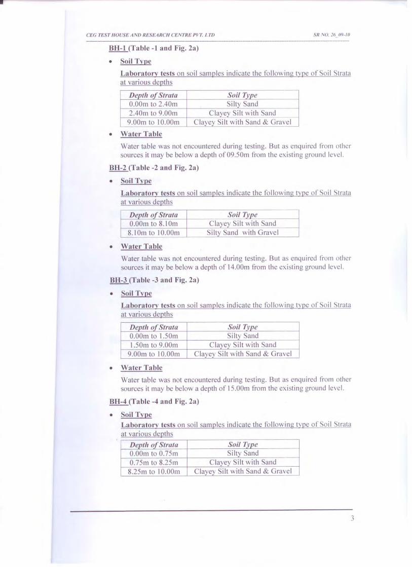


Tender Document for Setting up of Sewage Treatment Plant (Phase I) at MWCJL, Jaipur
Page 533 of 549
SECTION – 7.0 TECHNICAL SCHEDULES

Tender Document for Setting up of Sewage Treatment Plant (Phase I) at MWCJL, Jaipur
Page 534 of 549
Technical Schedules Following Technical Schedules are to be filled in by the Bidders and furnished along with the Bid. 1. Submersible pump sets
Description Submersible pump for raw sewage pump
a) Make b) Type c) Efficiency % d) Motor Rating, KW e) Make of motor f) Weight of pumps,
Kg
2. Horizontal Centrifugal pumpsets / Submersible pumpsets
Description Surplus Activated
Sludge Return Activated Sludge
Pumps a) Make b) Type c) Efficiency % d) Motor Rating, KW e) Make of motor f) Weight of pumps,
Kg
3. Screw pumps
Description For sludge feed to sludge drying
bed / centrifuge a) Make b) Type c) Efficiency % d) Motor Rating, KW e) Make of motor f) Weight of pumps, Kg

Tender Document for Setting up of Sewage Treatment Plant (Phase I) at MWCJL, Jaipur
Page 535 of 549
3. Blower a) Make Blower
Motor
b) Type e) Motor rating KW f) Speed of Blower g) Speed of Motor h) Type of Hood arrangement 4. Diffuser a) Make b) Type e) Membrane f) Transfer Efficiency g) MOC of grid support
5 Decanter a) Make b) Type e) Motor rating KW f) Speed of Decanter g) Speed of Motor
6. Pipes a) Make b) Rating
7. Diaphragm Pressure Guages
a) Make b) Type c) Range
8. Sluice Valves
a) Make

Tender Document for Setting up of Sewage Treatment Plant (Phase I) at MWCJL, Jaipur
Page 536 of 549
b) Size c) Type d) Rating
9. Butterfly Valve a) Make b) Size c) Type d) Rating
10. Non - Return Valves a) Make b) Size c) Type d) Rating
11 415 V Switch Gear 11.1
General
a)
Manufactured by
b)
Dimensions:
c)
Manufacturer’s type designation
d)
Dimensions: (Width x depth x height)
mm x mm x mm
i) Incoming breaker cubicle
ii) Complete panel
d)
Draw out space required in front mm
e)
Window type alarm annunciation as per the Specification
i) Make of alarm annunciation
ii) No. of annunciation windows

Tender Document for Setting up of Sewage Treatment Plant (Phase I) at MWCJL, Jaipur
Page 537 of 549
9.2
Air circuit Breakers
a)
Manufactured by
b)
Manufacturer’s type designation
c)
Rated Current when installed within cubicles A
d)
Maximum temperature rise over the reference ambient 45° when carrying continuous current under site condition
°C
e)
Method of closing:
i) Normal
ii) Emergency
f)
Normal voltage of closing coil V
g)
Normal voltage of tripping coil V
h)
Power required to operate closing coil at normal voltage
i)
Power required to operate tripping coil at normal voltage
W
j)
Spring charging motor details
i. rated voltage
ii. rated output
iii. class of insulation
iv. spring charging time
9.3
Bus Bars
a)
Material and Bus bar cross-section mm x mm

Tender Document for Setting up of Sewage Treatment Plant (Phase I) at MWCJL, Jaipur
Page 538 of 549
b)
Continuous current rating Amps
c)
Temperature rise over the specified ambient temperature 45°C
°C
9.4
Isolating Switches
a)
Make
b)
Type
c)
No. of pole
d)
Rated voltage Volts
e)
Rated continuous current kA (Peak)
f)
Rated making current kA (rms)
g)
Rated breaking current kA (rms)
h)
Short time rating kA (rms)
9.5
Fuses
a)
Make
b)
Type
c)
Rated voltage V
d)
Rated current Amps
9.6
Motor Contactors
a)
Make
b)
Type
c) No. of poles

Tender Document for Setting up of Sewage Treatment Plant (Phase I) at MWCJL, Jaipur
Page 539 of 549
d)
Ampere capacity of contactor A
e)
Rated voltage for main contacts V
f)
Rated voltage of coil V
g)
Rated voltage of auxiliary contacts V
9.7
Current Transformer
a)
Make
b)
Type designation
c)
Class of insulation
9.8
Voltage Transformers
a)
Make
b)
Type designation
c)
Class of insulation
9.9
Voltmeter
a)
Make
b)
Type
c)
Accuracy class
9.10
Ammeter
a)
Make
b)
Type

Tender Document for Setting up of Sewage Treatment Plant (Phase I) at MWCJL, Jaipur
Page 540 of 549
c)
Accuracy class
9.11
Power Factor Meter
a) Make b) Type c) Accuracy class 9.12
Motor Protection Relay
a)
Make
b)
Type designation
c)
Description pamphlet number (to be enclosed with tender)
9.13
Under voltage Relay
a)
Make
b)
Type
c)
Descriptive pamphlet number (to be enclosed with the tender)
9.14
Push Buttons
a)
Make
b)
Type designation
c)
Of contacts:
i. Normally open ii. Normally closed iii. Contact rating at 240 AC
A
9.15
Indicating Lamps
a)
Make

Tender Document for Setting up of Sewage Treatment Plant (Phase I) at MWCJL, Jaipur
Page 541 of 549
b)
Type
9.16
Control / Selector Switches
a)
Make
b)
Type designation
c)
Voltage grade V
d)
Current ratings:
i. Make and carry
A
ii. Break
A
9.17
Wiring
a)
Voltage grade V
b)
Insulation
c)
Conductor material
d)
Size of conductor mm²
e)
Colour code used
f)
Type of terminals
g)
Size of terminals
9.18
Lighting D.E
a)
Make
b)
Thickness of sheet steel mm
c)
Minimum clearances

Tender Document for Setting up of Sewage Treatment Plant (Phase I) at MWCJL, Jaipur
Page 542 of 549
i. between phases
mm
ii. phase to nearest earthed
mm
d)
Degree of protection as per IS 13947
e)
Breaking capacity of MCB provided on lighting DB
kA
10
Power Capacitors
10.1
Capacitor Bank
a)
Make
b)
Type
c)
Temperature rise over the specified ambient temperature
°C
d) i) Hot spot temperature at rated current
°C
ii) Maximum operating temperature
°C
e)
Capacity of battery (Micro Farads)
f)
Rated line current Amps
g)
Maximum permissible overload current Amps
h)
Capacitor losses
i) For complete battery
Watts
ii) For individuals units
Watts
i)
Electrical clearance in the bank
i) Phase to phase
mm
ii) Phase to earth
mm

Tender Document for Setting up of Sewage Treatment Plant (Phase I) at MWCJL, Jaipur
Page 543 of 549
10.2
Unit Capacitors
a)
Rated Voltage Volts
b)
Rated Output KVAR
c)
Maximum over voltage the unit capacitor is capable of withstanding continuously
%
d)
Insulation strength to earth
e)
No. of capacitor elements per capacitor
f) i) Type of active ii) Thickness iii) Alternating nominal r.m.s voltage stress on
the dielectric paper Volts / mm
g)
Type of impregnant used
10.2
Capacitor fuses
a)
Rating of the fuse element
i) Current A ii) Voltage V b)
Strength of the fuse elements in Amp² sec at which it melts
Amp²sec
c)
Material of the fuse element
11 PUSH BUTTON STATIONS
(a) Manufactured by
(b) Enclosure thickness mm
(c) No. of contacts a) Normally open b) Normally closed c) Contact rating at 240 V.A.C.

Tender Document for Setting up of Sewage Treatment Plant (Phase I) at MWCJL, Jaipur
Page 544 of 549
12 CABLES 12.1 11kV XLPE INSULATED UNEARTHED GRADE POWER CABLES
a) Manufactured by
b) Permissble voltage, frequency and for combined voltage and frequency variation
c) Continuous current rating
with cable laid in air under specified ambient temperature for specified maximum conductor temperature Amps.
d) Derating factors for the following shall be indicated
i. Variation in ambient
Temperature in steps of5° C
ii. Grouping of cables in covered trenches on cable racks
a) Short circuit capacity
i. Current and duration kA/Sec
ii. Maximum conductor °C
temperature
b) Loss tangent at normal frequency
c) Conductor:
i. Composition ii. Cross section mm²

Tender Document for Setting up of Sewage Treatment Plant (Phase I) at MWCJL, Jaipur
Page 545 of 549
a) Type of conductor screening
b) Insulation:
i. Composition ii. Thickness mm
a) Type of insulation screening
b) Inner sheath:
i. Material ii. Calculated diameter over mm
the stranded cores a) Outer sheath
i. Material ii. Thickness mm
a) Armour
i. Type of armour ii. Nominal diameter of cable mm
over inner sheath iii. Armour thickness / wire mm
diameter
a) Overall diameter of the cable mm
b) Recommended minimum bending mm radius
c) Safe pulling force when pulled
by using pulling eye
d) Standard length of cable on each drum

Tender Document for Setting up of Sewage Treatment Plant (Phase I) at MWCJL, Jaipur
Page 546 of 549
13 LIGHTING FITTINGS & MISCELLANEOUS ITEMS 13.1 LIGHTING FITTINGS
a. Manufactures
b. Nominal working voltage V
c. Maximum permissible supply % voltage variation for satisfactory operation
d. Power factor at normal working
voltage and frequency
e. Power loss per ballast at W nominal working voltage and frequency
f. Insulation class of ballast winding
g. Average ballast winding °C
temperature
h. Capacitor case temperature °C 13.2 EMERGENCY (INSTALITE) LIGHTS
a) Manufacturer
b) Rated Voltage V
c) Light output duration W

Tender Document for Setting up of Sewage Treatment Plant (Phase I) at MWCJL, Jaipur
Page 547 of 549
14 PAINTING AND GALVANISING 14.1 PAINTING
a) Address where the bidder is likely to carry out work
b) Whether facility for 7
Tank process available Yes / No
Note: 1. Only the manufacturer mentioned in this section will be accepted. 2. For all remaining bought out / ordered items the contractor has to submit detailed
data sheets, sketches / Fabrication drawings together with detailed data sheet and get it approved before such items are ordered.
HEAD (Infrastructure & Development) Mahindra World City (Jaipur) Limited
411, Neelkant Towers 1 Bhawani Singh Road, C-Scheme, Jaipur, Rajasthan - 302 001, India.
Tel:+911413003455,3003495-98.

Tender Document for Setting up of Sewage Treatment Plant (Phase I) at MWCJL, Jaipur
Page 548 of 549
SECTION – 8.0 Tender Drawings

Tender Document for Setting up of Sewage Treatment Plant (Phase I) at MWCJL, Jaipur
Page 549 of 549
List of Tender Drawings
Sl. No. Drawing No. Title
1 MACE–P842–DTA–STPR–001 Sewerage network layout with STP location
2 MACE–P842–DTA–STPR–002 STP for Processing Zone
3 MACE–P842– DTA–STPR–003 Plant layout
4 MACE–P842– DTA–STPR–004 P & I Diagram for 2×1.5MLD -STP
5 MACE–P842– DTA–STPR–005 Hydraulic Flow Diagram
6 MACE–P842– DTA–STPR–006 Single line diagram for 2×1.5 MLD -STP
7 MACE–P842– DTA–STPR–007 System Configuration for 2×1.5MLD
HEAD (Infrastructure & Development) Mahindra World City (Jaipur) Limited
411, Neelkant Towers 1 Bhawani Singh Road, C-Scheme, Jaipur, Rajasthan - 302 001, India.
Tel:+911413003455,3003495-98.


PRICE BID
FOR
DESIGN, SUPPLY, CONSTRUCTION, ERECTION, COMMISSIONING AND OPERATING OF (PHASE I) 3000 M3/DAY CAPACITY SEWAGE TREATMENT PLANT BASED ON ADVANCED
SEQUENTIAL BATCH REACTOR TECHNOLOGY AT MAHINDRA WORLD CITY (JAIPUR) LIMITED, JAIPUR
AT
DTA Zone, MAHINDRA WORLD CITY (JAIPUR) LIMITED, JAIPUR
MWCJL/HR/INFRA/DTA PH III/STP/2013-14/T-33
Project Site: Engineering Consultant
Mahindra World City (Jaipur) Limited Mahindra Consulting EngineersLtd. 411, Neelkant Towers Mahindra Towers, Ground Floor 1 Bhawani Singh Road-Scheme, No.17/18, Pattullous Road, Jaipur, Rajasthan - 302 001, India. Chennai – 600 002 Tel: +91 141 3003455, 3003495-98 Tel: 044-28542325/26

TABLE OF CONTENTS
S. No. Description Page No.
1. Preamble to Price Schedules 3
2. Summary of Price Schedules 4
3. Price Schedule for Civil Works 5
4. Price Schedule for Mechanical Works 6
5. Price Schedule for Piping Works 7
6. Price Schedule for Electrical & instrumentation Works 7
7. Price Schedule for Laboratory Items 10
8. Price Schedule for Spares for three years 10
9. Price Schedule for Operation & Maintenance 10

PREAMBLE TO PRICE SCHEDULES
1. Prices shall be quoted on the basis of the specified scope of works.
2. The Price Schedules do not give a full description of the work to be performed under each
item and the Bidder shall be deemed to have read the Technical Specifications, other
Bidding Documents and Drawings to ascertain the full scope of work included in each item
while filling in the prices. The entered rates and prices shall be deemed to include for the full scope as aforesaid, including overheads and profits.
3. In the Price Schedule, where there are errors between the total of the amounts given
under the column for Price Breakdown and the amount given under the Total Price, the
former shall prevail and the latter will be corrected accordingly. Similarly, any discrepancy in the total bid price and that of the Summary of Price Schedules (price indicated in a
Schedule indicating the total of that section); the total bid price shall be corrected to reflect
the actual summary of the Price Schedules
4. Items left blank, if any, in the Schedules will be deemed to have been included in other items. The grand summary and the total for each Schedule shall be deemed to be the
respective total price for executing the works and sections thereof in complete
accordance with the Contract, whether or not each individual item has been priced.

SUMMARY OF PRICE SCHEDULE
A. Total of Civil Works : Rs.
B. Total of Mechanical Works : Rs.
C. Total of Piping Works : Rs.
D. Total of Electrical & Instrumentation
Works : Rs.
E. Total of Laboratory Items : Rs.
F. Total of Spares for three years : Rs.
G. Total of Operation & Maintenance : Rs.
GRAND TOTAL : Rs.
(Amount in words)

A. Price Schedule for Civil Works:
S. No. Description Qty. Unit Rate Amount (Rs.)1. Receiving Chamber 1 No 2. Coarse Screen Channel-Mechanical 1 No 3. Coarse screen channel-Manual 1 No. 4. Raw Sewage Sump 1 No.
5. Stilling Chamber 1 No.
6. Fine Screen Channel-Mechanical 1 No.
7. Fine Screen Channel-Manual 1 No.
8 Grit Channel 2 Nos.
9. SBR Basin 2 Nos
10 Chlorination Tank 1 No
11 Sludge Sump 1 No
12 MCC Room including trenches for cables, G.I. pipe sleeves, Plinth Protection etc. complete.
1 No.
13 Security Room with all necessary structures. 1 No. 14 Toilet room with WC, Urinals, overhead storage
tank, Plinth Protection etc. complete. 1 No.
15 Foundation pads for pumps, Blowers MCC, etc. complete.
1 Lot
16 Internal roads, Drain, pathway and landscaping as per the layout.
1 Lot
17 Gate and Fencing 1 Lot 18 Any other additional items required 1 Lot
TOTAL OF CIVIL WORKS Notes: -
1. Cost should be inclusive of excavation, backfilling and spreading of earth as required within
the STP area.
2. Cost should be inclusive of disposal of surplus excavated material beyond the STP battery
limit, but within the estate area as per client’s suggestion.

B. Price Schedule for Mechanical Works:
S. No Description Qty Unit Rate Amount
1 Mechanical Coarse Screen 1 No
2 Manual Coarse Screen 1 No
3 Raw Sewage Transfer Pumps 3 Nos
4 Mechanical Fine Screen 1 No
5 Manual Fine Screen 1 No
6 Belt Conveyor for Screenings 1 No
7 Air Blowers with Acoustic Enclosures 3 Nos
8 Motors for above 3 Nos
9 Return Activated Sludge Pumps with
Motors 3 Nos
10 Surplus Activated Sludge Pumps with
Motors 3 Nos
11 Decanters 2 Nos
12
Core components of Decanters, comprising
Variable Frequency Drives, Electric Motors with
Gearbox, Lifting Mechanisms, Float Switches,
Magnetic Switches etc. complete
2 Sets
13 Diffusers 1 Lot
14 Air Pipe Grid for Diffusers with Pipe
Supports, Hardware, Adhesives etc. complete 1 Lot
15 Mechanical Hoist for Air Blowers and raw sewage
pump. 2 No
16 Chlorine Dosing System including Dosing Pump, Interconnecting Piping, Safety Equipments & other
Accessories
1 No
17 Sludge Transfer (Centrifuge Feed) Pumps shall be
of positive displacement type Screw Pumps
18 Service Water Pumps with Motors 2 Nos
19 Piping 1 Lot
20 Valves/Sluice Gates 1 Lot
21 Structural Steel 1 Lot
22 Additional instrumentation including Pressure
gauges, flow meters etc as required 1 Lot
23 Specified Tools 1 Lot

S. No Description Qty Unit Rate Amount
24 Specified Spare Parts 1 Lot
25 Any other additional items as required 1 Lot
Total of Mechanical works
C. Price Schedule for Piping Works:
S. No. Description Qty. Unit Rate Amount (Rs.)1. All interconnecting piping between various
process units including valves, fittings, NRVs, pressure gauge, etc. complete.
1 Lot
2. All plumbing work within battery limits, including water meter, valves, fittings etc. complete.
1 Lot
3. Drainage line from sanitary block to Receiving Chamber
1 Lot
4. Any other additional items as required 1 Lot Total of Piping Works
Note: -
1. The cost of piping should be inclusive of preparation of pipe trenches, back filling, pipe supports, etc.
D. Price Schedule for Electrical & Instrumentation Works:
S. No. Description Qty. Unit Rate Amount (Rs.)1 Supply, Erection, Testing, and Commissioning
of 11 kV DP structure system including metering cubical, yard fencing, including all civil works as required complying to state electricity board norms.
1 Lot
2 Supply, Erection, Testing, and Commissioning of 11 kV / 433 V DYn11 outdoor transformer with OLTC of adequate capacity including inter connecting HV, LT & control cabling, cable termination, equipment earthing including yard fencing, including all civil works as required. Including obtaining the entire STP electrical systems approval
1 Lot

S. No. Description Qty. Unit Rate Amount (Rs.)from CEIG / Local electricity board.
2 Supply, Erection, Testing, and Commissioning of 433 V DG set with acoustic enclosure suitable for outdoor operation including all accessories exhaust system, foundation, fuelling system, interconnecting power and control cables etc., all inclusive.
1 Lot
3 Design, Supply, Erection, Testing and Commissioning of MV panel includingIncoming ACB’s, for transformer & DG set and outgoing MCCB’s, Hardwired, meteringwith communication port, indication lamps etc. complete for suitable operation with PLC system
1 Lot
4
Design, Supply, Erection, Testing and Commissioning of LT power panel (MCC panel) including Variable Speed Drive, DOL starters, metering, indication lamps etc. complete. Hardwired, metering with communication port, indication lamps etc., complete for suitable operation with PLC system
1
Lot
5 Supply, Erection, Testing, and Commissioning of copper /Al. cable for control ,power and Instrumentation cables, cable tray & accessories inclusive of termination of cables laid underground/ wall/ cable trays asrequired
1
Lot
6
Design, Supply, Erection, Testing, and Commissioning of APFC Capacitor panel ofrequired KVAR.
1 No.
7
Design, Supply, Testing, Erection and Commissioning of earthing system with GI wires, GI strips for LT panels & motors, as required as per specification, including earth pits (GI plate / Pipe) for DP structure, Transformer, MV panel, DG set, MCC panel,
1
Lot
Design, Supply, Erection, Testing and

S. No. Description Qty. Unit Rate Amount (Rs.)8 Commissioning of light fixtures, Exhaust fans,
ceiling fans and 5A, 15A power points, 32A TPN welding sockets where ever required, including wiring with copper wires/ cables and structural steel for supports with MCB’s and MCB distribution board.
1 Lot
9
Design, Supply, Erection and Commissioning of outdoor light wall mounted fixtures aroundSTP area including wall brackets and necessary hardwires and cabling.
1 Lot
10 Design, Supply, Erection and Commissioning of Street light poles including fixtures around STP area including wall brackets and necessary hardwires and cabling.
1 Lot
11 Any other additional items as required. Total for Electrical Works
Instrumentation Works
1 All field instruments, analyzer, Junction boxes, cables & erection hardwares
1 Lot
2 Design, engineering, manufacture, supply of Programmable Logic Controller (P.L.C) with
SCADA, memory module, digital Input modules, digital Output modules, power supply module I/O expansion racks, I/ O
cables, screwed power terminals, AC&DC terminals tube light Door switch etc., It shall be mounted inside the Panel and software
development for P.L.C Complete with all hardware, software& peripherals, control
desk furniture with accessories needed for erection & commissioning.
1 Lot
3 UPS with Lead acid batteries 1 Lot 4 Any other additional items as required
E. Laboratory Items:
S. No Description Quantity Unit Rate Amount
1 pH Meter 1 No.
2 Turbidity Meter 1 No.

3 BOD analyzer 1 No
4 COD analyzer 1 No
5 Vacuum Pump 1 No
6 Glass ware 1 LS.
7 Hot air oven 1 No.
8 Electronic Balance (Digital) 1 No.
9 Any other items if necessary 1 lot
Total for Laboratory Equipments
F. Spares for 3 years:
S. No. Description Qty. Unit Rate Amount (Rs.)
1. Spares for 3 years after completion of
defect liability period
1 Lot
G. Price Schedule for Operation & Maintenance:
S. No. Description Qty. Unit Rate Amount (Rs.)
I. Operation and maintenance of the entire
treatment plant for a period of three year
by deputing required manpower as indicated in the scope of service including
flow monitoring, analysis of raw and treated
waste water and other operating
parameters; maintaining and displaying the
records through log books, colour charts
including monitoring & Laboratory analysisetc. complete.
1. First year 1 Year
2. Second year 1 Year
3. Third year 1 Year
Total for Operation & Maintenance