Technical Assistance in the Drafting of the Transportation Plan for the City of Tena Napo Province,...
117
Technical Assistance in the Drafting of the Transportation Plan for the City of Tena Napo Province, Republic of Ecuador July, 2012 University of of Wisconsin – Green Bay Dr. Marcelo Cruz Dr. Adam Parrillo Shane Marquardt Kelly Mech Stephanie Hummel University of Wisconsin – Milwaukee Matthew Leser Anthony Stein Aalborg University, Denmark Thomas Reinwald Sorensen
Transcript of Technical Assistance in the Drafting of the Transportation Plan for the City of Tena Napo Province,...
Technical Assistance
in the Drafting of the
Transportation Plan
for the City of Tena
Napo Province, Republic of Ecuador July, 2012
University of of Wisconsin – Green Bay Dr. Marcelo Cruz Dr. Adam Parrillo Shane Marquardt
Kelly Mech Stephanie Hummel
University of Wisconsin – Milwaukee Matthew Leser Anthony Stein
Aalborg University, Denmark Thomas Reinwald Sorensen

1
Design Guidelines for the Street Plan for the city of Tena, Napo Province
INTRODUCTION These design guidelines are an applicable tool for planning and design of the streets in the city of Tena and provide viable transportation options for all citizens of Tena. This tool is intended to create "complete streets" – i.e. streets that provide capacity and mobility for motorists, as well as being safer and more comfortable for pedestrians, bicyclists, and neighbors who share the streets. The document is organized to assist the technical team within the Department of Planning of Tena and is divided into the following sections: Chapter 1: Redefining the streets of Tena………………………………………………...…2 Chapter 2: Designing streets for several users…………………………………………….11 Chapter 3: Applying the guidelines………………………………………………………….36 Chapter 4: Segments…………………………………………………………………………43 Chapter 5: Intersections………………………………………………………………………64 Appendix A: Street classification and rationale……………………………………………78 Appendix B: Veloway network and central Tena pedestrian area...……………………103 Appendix C: Design of signage, bus shelters, and public art……………...……………112 How are these guidelines applied? These are applied through a variety of processes, including investment projects, regional development planning, and land use planning. To date, this includes the following:
New or re-constructed streets The urban landscape and conversion of street projects Reconstructed intersections Sidewalk projects
These projects reflect Tena’s approach to the design and construction of streets that improve safety and livability of neighborhood, promote transportation options, and create lasting value. The guidelines are being applied during the area planning process. This area planning process includes plans to apply the guidelines to appropriate street classifications, street intervals and street cross sections based on planned land uses.
2
1. REDEFINING THE STREETS OF TENA The urban street design guidelines described in this document present a comprehensive approach to designing new and modified streets within designated within Tena’s sphere of influence. The Guidelines allow for the provision of better streets throughout Tena – streets that reflect the best aspects of the streets built in the past, and will provide greater capacity while maintaining safe and comfortable travel for motorists, pedestrians, bicyclists and public transit riders. Why do we need new urban street design guidelines? Tena’s streets come to symbolize the growing pains that can accompany growth and prosperity, including increased congestion in some portions of the city and streets that have become increasingly hostile to anyone but motorists. Therefore, these urban design guidelines have been developed in response to two basic issues:
Tena needs to better plan for continued growth and development The citizenship deserves and wants better streets.
Growth and Its Consequences Tena is growing rapidly, which is expected to continue into the future with an additional 45,000 people projected to be living here over the next 15 years. This population increase means additional employees working here and additional students studying here, many of whom will be commuters from other towns within the canton. The ability to accommodate this growth using the same development and transportation approaches as were used during previous decades is questionable at best. Moreover, the ability to accommodate growth while encouraging sustainable development that improves the quality of life is even less likely. Quality of life is the key concern to Tena’s continued economic development. The Design Guidelines are intended to help the City accommodate growth in several ways. They support a variety of City policies, including districts, activity nodes and corridors, and edges within a growth framework and also support the recently approved Territorial Development Plan, which describes the transportation-related policies and programs needed to help Tena maintain its many advantages as it continues to grow. The Guidelines will help achieve the emerging vision for Tena (Figure 1.1) by supporting the goal of more compact and focused growth, and by offering more transportation choices. These are complementary intentions because compact development facilitates the provision of transportation choices and, in turn, providing transportation choices makes compact development more livable and viable. “Transportation choices” are created both by providing more connections (more route choices for all travelers) and by building streets that are easier to use by more types of travelers (by people who want to walk, ride transit, or ride bicycles). Generally, more
3
connections and better provision for all modes will help increase the transportation system’s capacity, further making growth more sustainable. Figure 1.1: Emerging vision for Tena
Providing transportation choices also helps address an important environmental consequence of growth – poor air quality. In Tena, like many cities, the primary air quality problem is ozone, created when nitrogen oxides and volatile organic compounds combine in sunlight and stagnant air. In the canton of Tena, nitrogen oxides are emitted mostly by motor vehicles; therefore, the sheer number of cars and the miles they travel have a great impact on air quality. In addition to the individual health effects of poor air quality, there are also significant health care costs, which can further impact the city’s ability to sustain development. Air quality, therefore, is an important component of both quality of life and continued economic development. Disconnected street layouts reduce the network’s ability to handle traffic because it concentrates all traffic on to a few streets. It also makes it more difficult for people to walk or bicycle between land uses due to the lack of direct or shorter routes. One way to affect air quality is by reducing three interrelated aspects of motor vehicle use; (1) the vehicle miles traveled (VMT) and the (2) number and (3) duration of engine starts. VMT refers to the total number of daily miles traveled by motor vehicles within or through a geographic area. It is virtually impossible to reduce total VMT in a growing city, but it is possible to reduce VMT per capita so that each additional person doesn’t increase VMT by the current average per capita. We can help do this by offering viable transportation choices for people as they travel between land uses, an important goal of these Urban Street Design Guidelines. The Urban Design Guidelines will also help Tena plan for growth by better matching the transportation network to the land uses that lie along that network. Better integration of land uses and transportation, through context based design, will ensure that mutually reinforcing decisions are made and that the ability to take advantage of more transportation choices is enhanced.
To be an urban community of choice for living, working and leisure More compact and focused growth Protection of environmentally sensitive areas Expanded travel choices Mix of uses and integration work, live, shop, and play Viable and sustainable economy Maintenance of livable neighborhoods Revitalization and infill of older areas Variety of housing options and costs High quality urban design Nurturing the infrastructure needed to support development Empowered citizenry that is informed and engaged
4
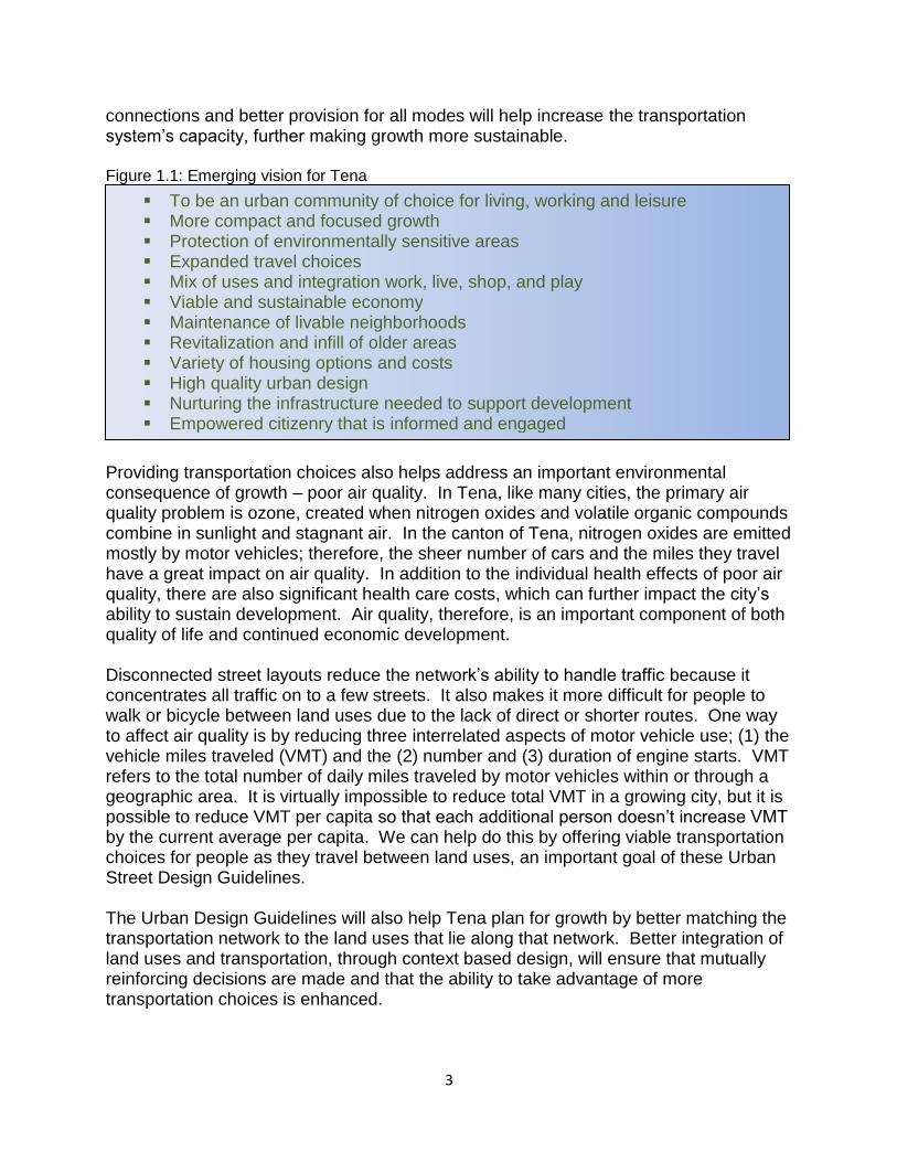
Better Streets Building streets to provide more choices will help Tena meet the challenges of growth, but it also means that we will be building better streets overall – the types of streets that Tenajences desire. By our observation in the field and by listening to stakeholders in the development of the guidelines, we have identified “most favorite” and “least favorite” streets in Tena. The “most favorite” streets tend to be located in the older, central neighborhoods of Tena; streets that include contrasting and contradictory streetscape. Certain streets have a tree canopy and pedestrian amenities and other streets are treeless concrete streetscapes built for the dominance of the automobile, but contain abundant and dynamic activity (Figure 1.2). Figure 1.2: Most favorite streets examples
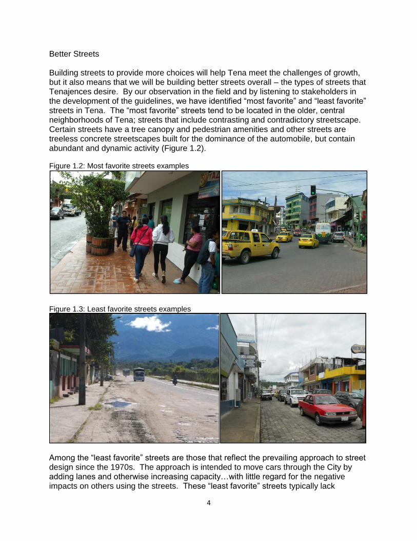
Figure 1.3: Least favorite streets examples
Among the “least favorite” streets are those that reflect the prevailing approach to street design since the 1970s. The approach is intended to move cars through the City by adding lanes and otherwise increasing capacity…with little regard for the negative impacts on others using the streets. These “least favorite” streets typically lack
5
pedestrian amenities; driveways, parking lots, and utility poles are more abundant than trees; and they often possess of wide expanses of pavement for moving traffic (Figure 1.3). Even accounting for the different design and orientation of the land uses along the streets, motorists are clearly the dominant “users” of the least favorite streets. A more inclusive streetscape would include the needs of non-motorists that would want:
aesthetically pleasing (including street trees), and comfortable and safe for pedestrians and cyclists (specifi c design treatments
and speed reduction) What Are the Guidelines Trying to Achieve? Providing the best possible streets to accommodate growth, provide transportation choices, and help keep Tena livable requires a different approach to and philosophy of planning and designing streets. Cities are seeing the need to plan for and design “complete” streets (streets that better serve all users) rather than focusing only on one set of users. The Urban Street Design Guidelines are essentially Tena’s “complete street” guidelines with the goal of making the streets more democratic and strengthening citizenry among Tenajences. Planners have become very good at designing auto-oriented streets, which has had unintended but predictable consequences. We are now getting better at providing design elements such as sidewalks, planting strips, and bike lanes on thoroughfares. However, we do not have a consistent, clear method to decide which types of streets to build and where to build them. The Guidelines will help us to get better at designing complete streets for all users. To accomplish this, the University of Wisconsin team developed these Guidelines based on the following principles:
Streets are a critical component of public space. Streets play a major role in establishing the image of a community; therefore,
they affect the health, vitality, quality of life, and economic welfare of a city. Streets provide the critical framework for current and future development. The locations and types of streets will affect the land development pattern, as
well as how much development can be supported by the street network. The design of a street is only one aspect of its effectiveness. How the street fits
within the surrounding transportation network and supports adjacent land uses will also be important to its effectiveness.
Tena’s streets will be designed to provide mobility and support livability and economic development goals.
The safety, convenience, and comfort of motorists, cyclists, pedestrians, transit users, and members of the surrounding community will be considered when planning and designing Tena’s streets.
6
Streets should be designed to encourage Tenajences to make trips by means other than cars, thereby positively impacting congestion, air quality, and the health of our citizens.
Planning and designing streets must be a collaborative process, because it is necessary that decisions about the street be made with a variety of interests and perspectives represented.
Based on these principles, the recommendations contained within The Guidelines reflect the following basic goals:
1. Support economic development and quality of life – by providing more transportation capacity, while creating more overall user-friendly streets.
2. Provide more and safer transportation choices – by creating a better connected network (route choices) and building streets for a variety of users (mode choices).
3. Better integrate land use and transportation – by avoiding “mismatches” between land uses and streets and by creating the right combination of land uses and streets to facilitate planned growth.
The New Street Types In creating an Urban Street Network to meet the goals described above, Tena’s streets will be classified according to the following four street types:
Main Streets (main arterial streets) Avenues ( secondary connector streets) Parkways (circumventing beltways) Local Streets (collector streets)
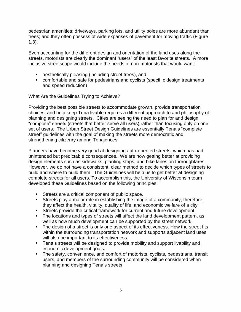
Figure 1.4: Street classification continuum
These street types fall along a continuum (Figure 1.4), with the Main Street being the most pedestrian-oriented street type and the Parkway being the most auto oriented street type. Pedestrian and auto refer both to the design of the street itself and to the
7
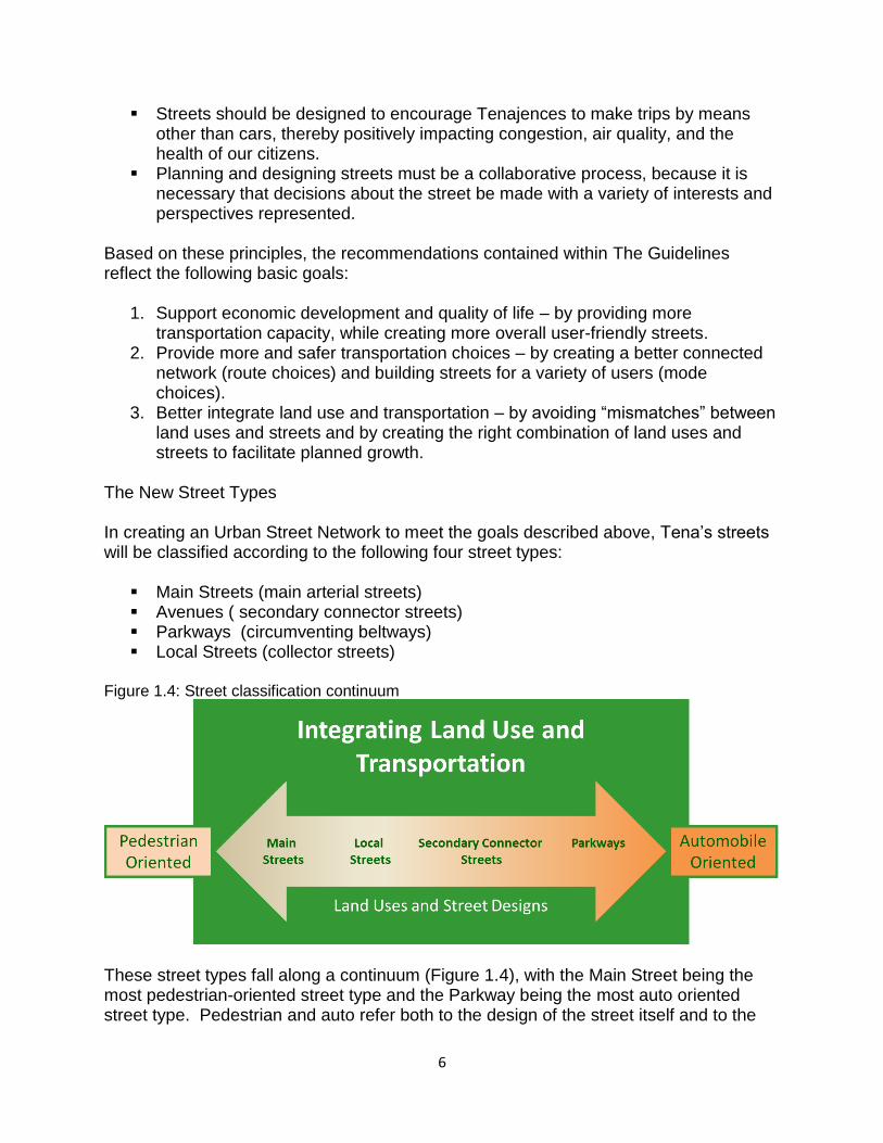
characteristics of the land uses located along the street. Even though each street type emphasizes different mixes of modes, all of these streets will be designed with all potential travelers and stakeholders in mind. By creating a variety of street types, the street network can better provide appropriate choices for those travelers and stakeholders, including Tena’s current and future residents, commuters, and visitors. Once a street (or segment of a street) is classified as a certain type, the street design should reflect that classification and future land use decisions along the street should also reflect that classification. Street design decisions and land use decisions should be mutually reinforcing to create effective synergy between streets and land uses. Main Streets are “destination streets” as they provide access to and function as centers of civic, social, and commercial activity. They are designed to provide the highest level of comfort, security, and access for pedestrians. Development along Main Streets is dense and focused toward the pedestrian whereas land uses on Main Streets are typically mixed and are generators and attractors of pedestrian activity. Because of their specialized function and context, Main Streets represent a relatively small portion of Tena’s overall street network. An example is provided in Figure 1.5. Figure 1.5: Main Street example
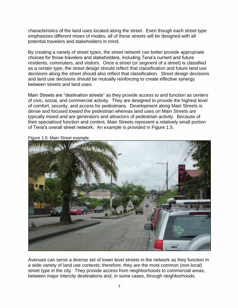
Avenues can serve a diverse set of lower level streets in the network as they function in a wide variety of land use contexts; therefore, they are the most common (non-local) street type in the city. They provide access from neighborhoods to commercial areas, between major intercity destinations and, in some cases, through neighborhoods.
8
Avenues serve an important function in providing transportation choices, therefore, maintaining vehicular movement is a higher priority than with a Main Street, but pedestrians and cyclists are still accommodated in the design. In fact, the higher speeds and traffic volumes increase the need for safe pedestrian and bicycle treatments, such as providing adequate buffers from the traffic. An existing example is provided in Figure 1.6. Figure 1.6: Avenue example
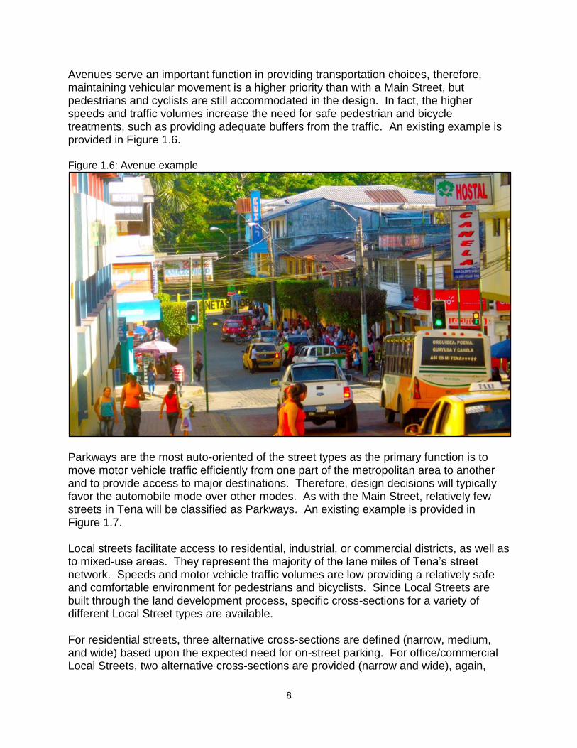
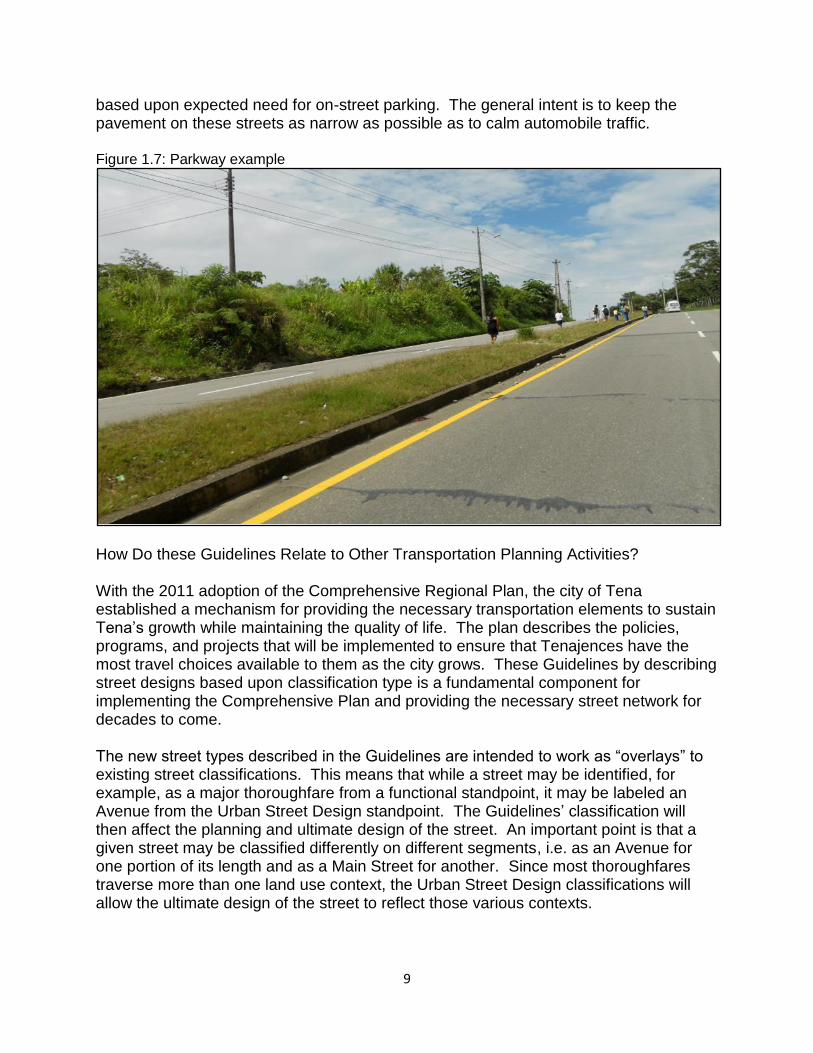
Parkways are the most auto-oriented of the street types as the primary function is to move motor vehicle traffic efficiently from one part of the metropolitan area to another and to provide access to major destinations. Therefore, design decisions will typically favor the automobile mode over other modes. As with the Main Street, relatively few streets in Tena will be classified as Parkways. An existing example is provided in Figure 1.7. Local streets facilitate access to residential, industrial, or commercial districts, as well as to mixed-use areas. They represent the majority of the lane miles of Tena’s street network. Speeds and motor vehicle traffic volumes are low providing a relatively safe and comfortable environment for pedestrians and bicyclists. Since Local Streets are built through the land development process, specific cross-sections for a variety of different Local Street types are available. For residential streets, three alternative cross-sections are defined (narrow, medium, and wide) based upon the expected need for on-street parking. For office/commercial Local Streets, two alternative cross-sections are provided (narrow and wide), again,
9
based upon expected need for on-street parking. The general intent is to keep the pavement on these streets as narrow as possible as to calm automobile traffic. Figure 1.7: Parkway example
How Do these Guidelines Relate to Other Transportation Planning Activities? With the 2011 adoption of the Comprehensive Regional Plan, the city of Tena established a mechanism for providing the necessary transportation elements to sustain Tena’s growth while maintaining the quality of life. The plan describes the policies, programs, and projects that will be implemented to ensure that Tenajences have the most travel choices available to them as the city grows. These Guidelines by describing street designs based upon classification type is a fundamental component for implementing the Comprehensive Plan and providing the necessary street network for decades to come. The new street types described in the Guidelines are intended to work as “overlays” to existing street classifications. This means that while a street may be identified, for example, as a major thoroughfare from a functional standpoint, it may be labeled an Avenue from the Urban Street Design standpoint. The Guidelines’ classification will then affect the planning and ultimate design of the street. An important point is that a given street may be classified differently on different segments, i.e. as an Avenue for one portion of its length and as a Main Street for another. Since most thoroughfares traverse more than one land use context, the Urban Street Design classifications will allow the ultimate design of the street to reflect those various contexts.
10
The use of this “overlay” approach will likely need to be refined somewhat, as Tena moves away from its traditional thoroughfare planning process. The Guidelines attempt to better reflect multi-modal and context-based design that has produced a new type of plan that replaces the Thoroughfare Plan – the Comprehensive Transportation Plan (CTP). The Guidelines classification system should work in tandem with the CTP, with the major difference being that the street function is anticipated by the city. By having a set of street types that better reflect and complement a variety of land use contexts, Tenajences and visitors can expect to find viable transportation choices as they travel through the City, something that has become increasingly difficult in recent years. Further, by defining and implementing street designs to meet the intent of the different street types, we have the best chance of meeting the multiple and sometimes conflicting objectives of the different users of our streets. It is the intent that Tena’s Guidelines will, over time, result in a well-connected network of “complete” streets that function well for all users and that complement and preserve the communities and neighborhoods they connect. Content of the Guidelines The following chapters are intended to provide a comprehensive treatment of Tena’s approach to street design. Each chapter provides a separate, standalone piece of information pertaining to street design, but each chapter also relates to the others. In this fashion, the Guidelines provide both the “big picture” of developing Tena’s desired street network and the detailed guidelines necessary to design individual street segments and intersections. The remaining chapters include: Chapter 2: Designing Streets for Multiple Users.
This chapter presents a thorough treatment of the need for and approaches to evaluating the tradeoffs among competing users and uses of the street right-of-way.
Chapter 3: Applying the Guidelines. This chapter defines the recommended approach to applying the Guidelines,
particularly in the case of non-local streets. Chapter 4: Segments.
This chapter contains detailed information (text and diagrams) describing how to design the portions of the streets between the intersections.
Chapter 5: Intersections.
This chapter contains detailed information (text and diagrams) describing how to design various types of intersections.
Appendices A-C.
These provide additional details about the application of the new approaches outlined in the Guidelines.
11
Items to be Developed Although the current document includes comprehensive coverage of planning and designing Tena’s street network, there are some additional related items that must be developed over the coming months and treated as supplements to the Urban Street Design Guidelines. Some of these are items that will require additional stakeholder comment or will be treated as part of the implementation of the Transportation Action Plan or the adopted Urban Street Design Guidelines. These additional items include:
a section on designing “special” street types, such as green streets, alleys, cul-de-sac, one-way streets, and private streets;
more details on “connector” streets, including development of a connector map; and
a section describing access control, including driveway designs. 2. Designing Streets for Multiple Users The Urban Street Design Guidelines are intended to ensure the best aspects of Tena’s transportation network are re-created as the city and its street network continue to grow and evolve. This means that the various street design elements (described in Chapter 4 and 5) must be applied in the right combinations and in the appropriate places. Additionally, the process of planning and designing streets must also be sensitive to both the land use context and to the needs of the various users of a street. This chapter provides information about the different potential travelers and their expectations of the street. Chapter 3 provides a template for the implementation of the Guidelines in order that any tradeoffs are taken into equal consideration for all stakeholders. Assessing Tradeoffs: Who Is Using The Street? The first step towards designing streets that provide viable transportation options is to understand the different expectations of what constitutes a “good” street, depending on who is using the street. It is possible that a street design solution that works well for motorists may or may not work as well for pedestrians or bicyclists. This is one reason why many cities are concerned with providing “complete streets,” or streets that effectively serve the needs of all travelers of the street. However, even if every “ideal” design element meets the expectations of all travelers of a street, the resulting street may not satisfy the needs of the people who live or work along it. These different stakeholders – pedestrians, bicyclists, transit users, motorists, and neighbors – and their expectations for a street can complicate the design process, which is one reason why Tena has developed these guidelines. Prior to the 1990’s, street design was treated as a relatively straightforward task, with a pre-set menu of (often auto-oriented) cross-sections for streets with pre-defined functional classifications. That approach has been changing in many cities for a variety of reasons. One reason is that as right-of-way becomes constrained as cities grow and
12
develop, the standard cross-sections are less likely to fit within the available right-of-way, especially for retrofit projects. Another reason is that there is increasing concern about providing facilities that can be used by people other than motorists. In these cases, designing the street has become a more analytical process – one that considers the various user perspectives and surrounding land usages, in addition to the street function. The Guidelines are intended to ensure a process that clearly, consistently, and comprehensively considers the needs of the various users of the street. All streets should be evaluated in terms of how they affect:
pedestrians (including transit users) bicyclists transit operators motorists people living, working, or otherwise using the adjacent land uses
Each of these groups has expectations of how a given street should function, and, therefore, how it should be designed. The following examples describe various street users’ perspectives and how they might be addressed in the design process. What Do Motorists Want From Streets? When a motorist expresses a concern or makes a request related to streets, it often stems from congestion or safety concerns. For example, motorists might expect streets to be widened and signalized intersections to be coordinated to expedite their own travel times. They may also ask that the number of stop-controlled intersections on local streets be reduced, so that they can maintain free traffic flow through neighborhoods. This motorist interest for the provision of “safe and efficient” travel through design features has also been the primary concern of highway designers. To meet motorists’ expectations for safe and efficient travel, perfect conditions for the street network would include:
minimal traffic delays, minimal conflicts (affecting both delay and safety), and consistently designed facilities
For the most part, however, urban streets cannot provide this combination of conditions except perhaps on parkways or access-controlled roadways. Even then, travel delay and potential for conflicts with other vehicles will vary by the time of day. Furthermore, consistent road design is not only difficult to provide in urban contexts, but probably not desirable for other reasons (one being it contradicts the concept of context-sensitive design).
13
Although providing all of the favorable conditions for motorists described above is difficult, there are ways to achieve some of the motorists’ preferences, either through construction or operational changes. These approaches include:
adding through or turn lanes to increase capacity, which can help to reduce delay, at least temporarily;
making operational changes, such as providing more green signal time to streets with higher traffic volumes, reducing the wait time at signalized intersections for motorists on the higher volume street while increasing wait time for motorists entering from the lower volume street;
constructing grade-separated intersections and roundabouts, in place of signal or stop-controlled intersections, increasing capacity while limiting delay; and
using bus pullouts to separate stopping transit vehicles from the travel lane in order to help reduce delay.
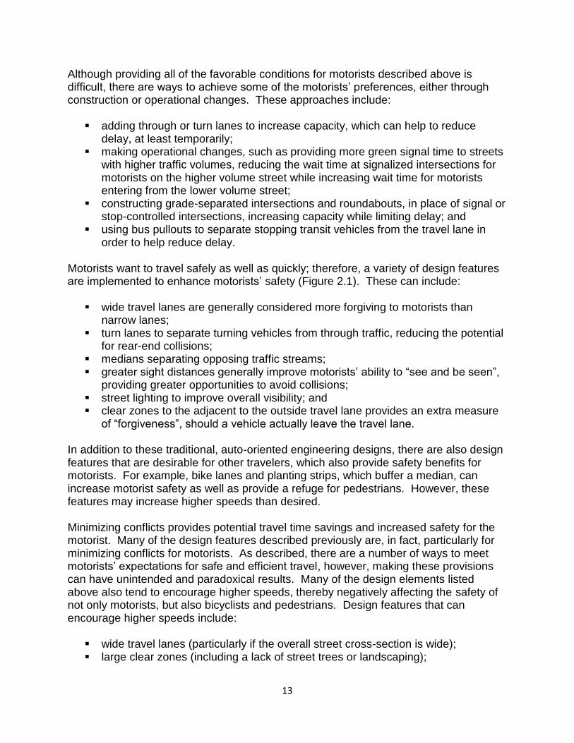
Motorists want to travel safely as well as quickly; therefore, a variety of design features are implemented to enhance motorists’ safety (Figure 2.1). These can include:
wide travel lanes are generally considered more forgiving to motorists than narrow lanes;
turn lanes to separate turning vehicles from through traffic, reducing the potential for rear-end collisions;
medians separating opposing traffic streams; greater sight distances generally improve motorists’ ability to “see and be seen”,
providing greater opportunities to avoid collisions; street lighting to improve overall visibility; and clear zones to the adjacent to the outside travel lane provides an extra measure
of “forgiveness”, should a vehicle actually leave the travel lane. In addition to these traditional, auto-oriented engineering designs, there are also design features that are desirable for other travelers, which also provide safety benefits for motorists. For example, bike lanes and planting strips, which buffer a median, can increase motorist safety as well as provide a refuge for pedestrians. However, these features may increase higher speeds than desired. Minimizing conflicts provides potential travel time savings and increased safety for the motorist. Many of the design features described previously are, in fact, particularly for minimizing conflicts for motorists. As described, there are a number of ways to meet motorists’ expectations for safe and efficient travel, however, making these provisions can have unintended and paradoxical results. Many of the design elements listed above also tend to encourage higher speeds, thereby negatively affecting the safety of not only motorists, but also bicyclists and pedestrians. Design features that can encourage higher speeds include:
wide travel lanes (particularly if the overall street cross-section is wide); large clear zones (including a lack of street trees or landscaping);
14
medians; large or wide curb radii at intersections and driveways; and straight, flat sections of streets with long blocks and widely spaced intersections.
Figure 2.1: Example of motorist oriented design features
Besides the safety paradox, the “need for speed” usually translates into rapid acceleration and deceleration between intersections. While this behavior often has minimal impact on overall travel time, it does have significant impacts on pedestrians, bicyclists, and others using the street. These types of interrelationships and tradeoffs are typical of the design process and need to be considered when attempting to address motorists’ expectations, particularly if that involves physical changes to streets and intersections. What Do Pedestrians Want From Streets? A traditional approach to street design might define pedestrian needs of a street as simply (1) a sidewalk and (2) the ability to safely cross the street. These are, indeed, crucial to creating a safe walking environment. However, pedestrians expect and need more than just “walking space” to feel safe and comfortable, and the Guidelines consider several factors that are important to pedestrians. If we are to support and encourage walking as an attractive and viable mode of travel, our street designs must reflect that pedestrians additionally value features that:
help shorten walking distances, separate or buffer pedestrians from moving traffic, create an aesthetically pleasing streetscape and amenities, protect pedestrians from the elements, and
15
allow them to walk as safely as possible. Additionally, some special pedestrian populations will have other specific concerns, and their needs must also be considered. For example, safe crossings for blind pedestrians may require a different set of design features than those for the general population. Any individual design elements can accommodate any one of the general categories of pedestrian expectations; however, effectively encouraging more pedestrian travel typically requires a combination of several different design elements since the pedestrian is interacting with the overall walking environment. For example, the combination of safe crossings, security lighting, and wide sidewalks may not encourage walking if people feel they have a viable destination. For walking trips other than for pure recreation, this means that a walkable environment includes a mix of land uses in close enough proximity to walk comfortably between them. People are much more likely to walk to a given destination if walking distance, actual and/or perceptual, is minimized. In business or mixed commercial districts, for example, the typical acceptable walking distances may be longer than in districts with widely spaced industrial land use contexts since people are more likely to have stores, windows, and ground-floor features to look at while they’re walking. Conversely, walking through areas with a lack of visual stimulation can make the distance traveled seem longer. Providing the right types of land uses and design characteristics, therefore, can positively influence perceived distance, and creating direct connections between land uses can also minimize the distance traveled. Design elements that create better connections include:
short blocks with marked intersections, and continuous walkway systems that connect door fronts with transit stops or other
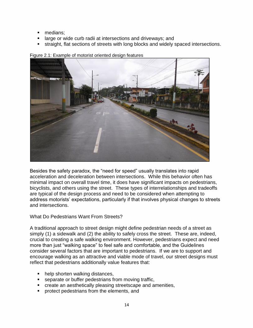
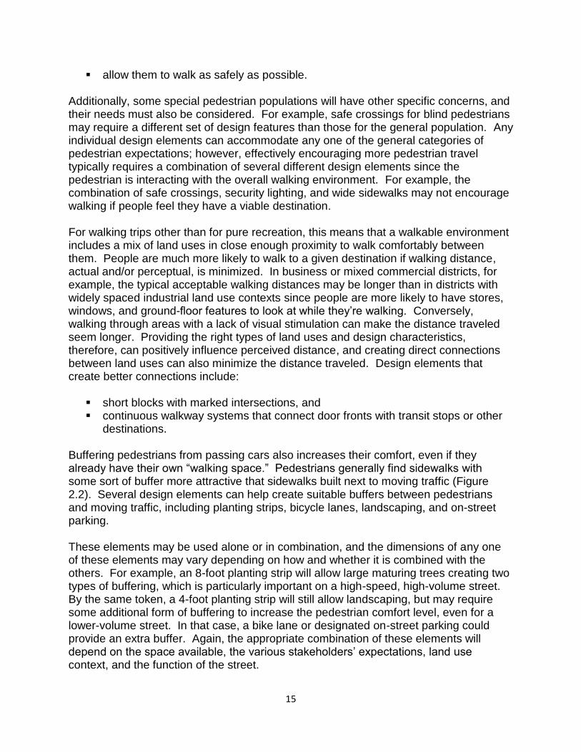
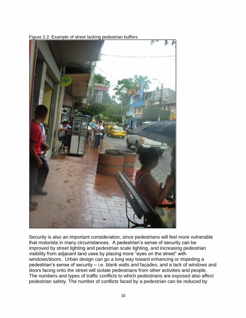
destinations. Buffering pedestrians from passing cars also increases their comfort, even if they already have their own “walking space.” Pedestrians generally find sidewalks with some sort of buffer more attractive that sidewalks built next to moving traffic (Figure 2.2). Several design elements can help create suitable buffers between pedestrians and moving traffic, including planting strips, bicycle lanes, landscaping, and on-street parking. These elements may be used alone or in combination, and the dimensions of any one of these elements may vary depending on how and whether it is combined with the others. For example, an 8-foot planting strip will allow large maturing trees creating two types of buffering, which is particularly important on a high-speed, high-volume street. By the same token, a 4-foot planting strip will still allow landscaping, but may require some additional form of buffering to increase the pedestrian comfort level, even for a lower-volume street. In that case, a bike lane or designated on-street parking could provide an extra buffer. Again, the appropriate combination of these elements will depend on the space available, the various stakeholders’ expectations, land use context, and the function of the street.
16
Figure 2.2: Example of street lacking pedestrian buffers
Security is also an important consideration, since pedestrians will feel more vulnerable that motorists in many circumstances. A pedestrian’s sense of security can be improved by street lighting and pedestrian scale lighting, and increasing pedestrian visibility from adjacent land uses by placing more ”eyes on the street” with windows/doors. Urban design can go a long way toward enhancing or impeding a pedestrian’s sense of security – i.e. blank walls and façades, and a lack of windows and doors facing onto the street will isolate pedestrians from other activities and people. The numbers and types of traffic conflicts to which pedestrians are exposed also affect pedestrian safety. The number of conflicts faced by a pedestrian can be reduced by
17
managing driveway access to minimize and control the locations of turning cars, and providing median or corner pedestrian refuge islands, which help to break up a crossing into more easily manageable parts. These design elements basically allow a pedestrian to focus on the various traffic movements one at a time. The overall distance (or time) over which the pedestrian must deal with potential conflicts can be minimized by:
reducing the number of travel lanes, providing curb extensions, designing smaller/tighter curb radii, and providing sufficient signal timing in order that pedestrians avoid feeling “trapped”
in an intersection. In a less obvious fashion, a robust street network with many connections can facilitate implementing the pedestrian-friendly design elements described above. Conflicts between pedestrians and vehicles are not limited to motor vehicles, but also with bicycles. Cyclists traveling the wrong way in mixed traffic or on the sidewalk are particularly dangerous because they are traveling faster than pedestrians while being less visible and audible (bicycles are not as noisy as motor vehicles). That is why bike lanes serve an important function for pedestrians that goes beyond the role of providing extra buffering described earlier. Aesthetics can also have a major impact on enhancing pedestrian comfort. Streetscape elements that impact aesthetics include:
pedestrian scale lighting, benches, trash receptacles, landscaping, urban design treatments for adjacent development, and walking surface texture.
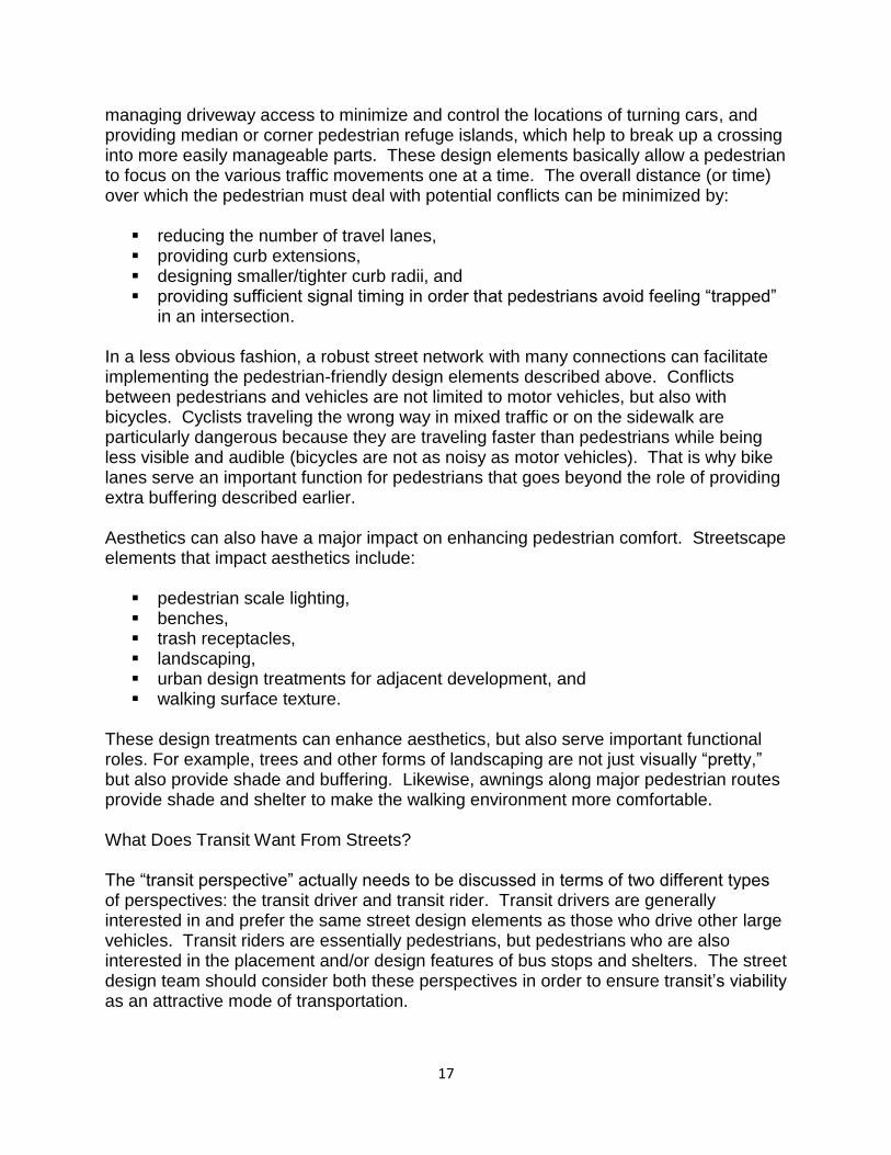
These design treatments can enhance aesthetics, but also serve important functional roles. For example, trees and other forms of landscaping are not just visually “pretty,” but also provide shade and buffering. Likewise, awnings along major pedestrian routes provide shade and shelter to make the walking environment more comfortable. What Does Transit Want From Streets? The “transit perspective” actually needs to be discussed in terms of two different types of perspectives: the transit driver and transit rider. Transit drivers are generally interested in and prefer the same street design elements as those who drive other large vehicles. Transit riders are essentially pedestrians, but pedestrians who are also interested in the placement and/or design features of bus stops and shelters. The street design team should consider both these perspectives in order to ensure transit’s viability as an attractive mode of transportation.
18
Transit drivers have expectations specific to their need to operate very large vehicles along very busy streets. Transit drivers basically want (1) adequate space to operate and maneuver their vehicles, (2) minimal conflicts with other travelers and with features along the sides of the street, and (3) minimal delays, in order to maintain the route schedule. Design elements that help provide the space for buses to operate include:
wide travel lanes, wide corner turning radii, street signs, utility poles, and on-street parking located to maximize clearance for
side mirrors, adequate merging distances.
Transit drivers also want to reduce the potential for conflict between transit vehicles and other travelers. In addition to minimizing driver fatigue, reducing such conflicts can help minimize schedule delays, which harm transit operations and performance. Conflicts can be minimized by:
selecting safe locations for bus stops, and providing signal priority for transit vehicles.
Just as delay will affect transit operations, so can the ability to provide more route coverage and travel efficiency. Coverage and efficiency are impacted by the extent of the street network. Short blocks providing multiple route options can increase pedestrians’ access to transit as well as transit’s access to a greater number of land uses (and potential riders). Transit riders have the same types of interests as other pedestrians with some additional specific expectations. Transit riders also want:
accessible bus stops, easy connections, and personal comfort and security while waiting for the bus.
Generally speaking, accessibility comes from having well-located transit stops on a well-connected network. The spacing of bus stops and their locations relative to pedestrian-oriented or clustered land uses will affect peoples’ ability and/or willingness to use transit. Transit stops should be located so that walking distances are not excessive. In addition, those land uses located near transit stops should be designed with entrances and sidewalks connecting buildings directly to the stop or to the nearest public sidewalk. Accessibility is further improved by having a dense, well-connected network for pedestrians. Such a network can be achieved by including short blocks on the street network or bike-pedestrian pathways. Either way, the connections should include paved surfaces. Closely related to their need for accessibility, transit riders also want to be able to transition between modes as easily as possible. Intermodal accessibility is provided through a comprehensive pedestrian sidewalk network with easy street crossings,
19
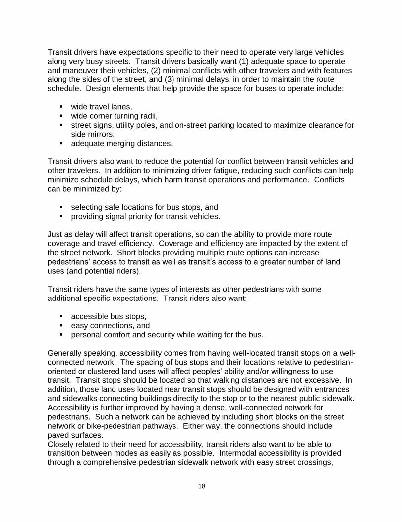
transit stops located in close proximity to bike/pedestrian trails, and bike racks at stations and bus stops. Unlike most other pedestrians, transit riders must occasionally be stationary. At transit stops, transit riders will be concerned about their own comfort and personal security (Figure 2.3). Riders’ security concerns may be more pronounced that those of other pedestrians, as transit riders may perceive that they are more vulnerable while waiting for transit vehicles. Perceived or actual security can be enhanced by a variety of design features, including:
street and pedestrian-scale lighting, transit stop located near complementary land uses and other people, and increased visibility through urban design (i.e. windows and doorways that face
onto the street). Figure 2.3: Existing transit stop in Tena lacking important design features
As with other users of the street, some design elements can have both positive and (unintended) negative consequences for transit operators and riders. For example, the lifespan of transit vehicles can be lengthened by minimizing vertical grade variations along curb lanes at cross streets and drainage grate areas, and by providing smooth, well-maintained street surfaces. Conversely, the wider lanes and curb radii that provide more maneuvering space for transit vehicles can create less comfortable streets for transit riders. Bus pullouts may reduce delays to motorists who would otherwise have to wait behind the stopped bus, but may cause delays for transit riders, as the driver has to wait to merge back into the travel lane. Essentially, there are a myriad of tradeoffs inherent in many of the decisions that must be made as part of the street design process-what-and what works well for one type of traveler may or may not work well for another.
20
What Do Bicyclists Want From Streets? Different types of bicyclists have different perspectives or expectations related to their trips. Those expectations will vary according to the type of cyclist (experienced vs. casual) and the type of trip (transportation vs. recreational). Experienced cyclists typically feel more comfortable traveling in the traffic lanes than do casual cyclists – casual cyclists will often avoid mixing with traffic and will feel more secure riding in separate, dedicated bike lanes. Cyclists who are commuting to work prefer to take the shortest most direct route to their destination, while recreational cyclists are more likely to take less direct routes. Generally, however, all types of cyclists want:
a well-connected network of bicycling facilities, safe travel routes, and direct travel routes, particularly when bicycling for purposes other than strictly
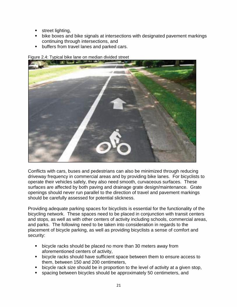
exercise or recreation A dedicated bicycle network that connects neighborhoods, employment centers, schools, parks and other activity centers must be developed for bicycling to become a viable transportation mode for Tenajences. That bicycle network should include direct routes, multiple route options, and dedicated cycling space. Direct routes can be provided through both a continuous network of local streets and through bike lanes on Tena’s higher-volume streets while short blocks help to create the dense network necessary for direct and lower-volume routes. Signed bike routes and other wayfinding treatments can make it easier for casual cyclists to travel on the local street network for short trips that would otherwise be made by car. Dedicated space for bicyclists is one way to create a good bicycle network on higher speed, high volume streets. On these streets, bike lanes are necessary for cyclists’ safety and comfort. Ideally, dedicated bike lanes are raised at a height of 10-15 centimeters, and separated from through traffic (as depicted in Figure 2.4). The width of the bike lane is very important:
the minimum width for a designated bike lane is 4 feet of usable asphalt surface, with preference for 5 feet when possible;
where the bike lane is next to parked cars or on steep, uphill grades, 6 feet may be necessary since the cyclist may need room to avoid opening car doors or to pedal uphill (due to “wobbling”).
In cases where space is insufficient for an official bike lane, edge stripping should be used to keep motor vehicles within ten feet of the center line or adjacent travel lane. Cyclists also need to be visible to motorized traffic. There are a variety of design elements to help improve bicyclists’ safety, including:
designated bike lanes, pavement markings,
21
street lighting, bike boxes and bike signals at intersections with designated pavement markings
continuing through intersections, and buffers from travel lanes and parked cars.
Figure 2.4: Typical bike lane on median divided street
Conflicts with cars, buses and pedestrians can also be minimized through reducing driveway frequency in commercial areas and by providing bike lanes. For bicyclists to operate their vehicles safely, they also need smooth, curvaceous surfaces. These surfaces are affected by both paving and drainage grate design/maintenance. Grate openings should never run parallel to the direction of travel and pavement markings should be carefully assessed for potential slickness. Providing adequate parking spaces for bicyclists is essential for the functionality of the bicycling network. These spaces need to be placed in conjunction with transit centers and stops, as well as with other centers of activity including schools, commercial areas, and parks. The following need to be taken into consideration in regards to the placement of bicycle parking, as well as providing bicyclists a sense of comfort and security:
bicycle racks should be placed no more than 30 meters away from aforementioned centers of activity,
bicycle racks should have sufficient space between them to ensure access to them, between 150 and 200 centimeters,
bicycle rack size should be in proportion to the level of activity at a given stop, spacing between bicycles should be approximately 50 centimeters, and
22
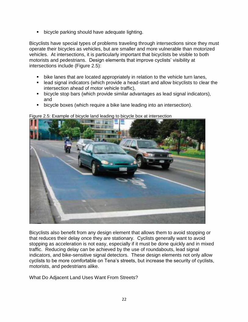
bicycle parking should have adequate lighting. Bicyclists have special types of problems traveling through intersections since they must operate their bicycles as vehicles, but are smaller and more vulnerable than motorized vehicles. At intersections, it is particularly important that bicyclists be visible to both motorists and pedestrians. Design elements that improve cyclists’ visibility at intersections include (Figure 2.5):
bike lanes that are located appropriately in relation to the vehicle turn lanes, lead signal indicators (which provide a head-start and allow bicyclists to clear the
intersection ahead of motor vehicle traffic), bicycle stop bars (which provide similar advantages as lead signal indicators),
and bicycle boxes (which require a bike lane leading into an intersection).
Figure 2.5: Example of bicycle land leading to bicycle box at intersection
Bicyclists also benefit from any design element that allows them to avoid stopping or that reduces their delay once they are stationary. Cyclists generally want to avoid stopping as acceleration is not easy, especially if it must be done quickly and in mixed traffic. Reducing delay can be achieved by the use of roundabouts, lead signal indicators, and bike-sensitive signal detectors. These design elements not only allow cyclists to be more comfortable on Tena’s streets, but increase the security of cyclists, motorists, and pedestrians alike. What Do Adjacent Land Uses Want From Streets?
23
Thus far, the discussion has focused on those who travel along streets, but these are not the only stakeholders who have an interest in streets. Other people who have an interest in the design of streets include residents, building owners, property managers, employees, and other occupants along a street or in adjacent neighborhoods. These types of stakeholders often consider themselves most impacted by designs or design changes intended to meet the needs of other stakeholders, particularly those of motorists. These “stationary” stakeholders’ perspectives are an important consideration during the design process. People who occupy neighboring land uses may have different perspectives on street design, depending on whether these are residential or commercial land uses. Either way, these stakeholders will share an interest in feeling safe and secure, to have access to their property, and to enjoy an aesthetically pleasing environment. Therefore, they will likely see the following design elements as beneficial:
lighting safe and contained travel ways, driveways (for access to their properties), and trees and landscaping
These stakeholders will typically not want to lose portions of their property (street frontage), so minimizing the overall right-of-way width may be seen as beneficial to most of these stakeholders as well. Owners, inhabitants, or managers of residential, institutional, commercial, or any pedestrian-oriented properties typically are very concerned about safety, which sometimes include lower traffic volumes. Types of street design elements that can help achieve this include:
traffic calming devices, low design speeds, safe and convenient pedestrian crossings, and reduced street widths.
In residential and institutional zones, reducing the noise from motor vehicles may also be important. Some forms of traffic calming that can help achieve this may be to provide more separation between dwellings and the travel lanes. Owners or operators of commercial uses (particularly those that are lower-density and less pedestrian oriented) will want automobile access and visibility. Therefore, these stakeholders may:
oppose access controls (that limit driveways), oppose medians, but want turn lanes, and want median breaks allowing access to their properties.
24
In addition to automobile access, owners or operators of higher-density commercial uses are also interested in good access to pedestrian traffic as well as transit riders. To achieve this, good site design will typically include:
operating front doors and windows, direct sidewalks to the street, sidewalks between buildings, and sidewalks to parking areas.
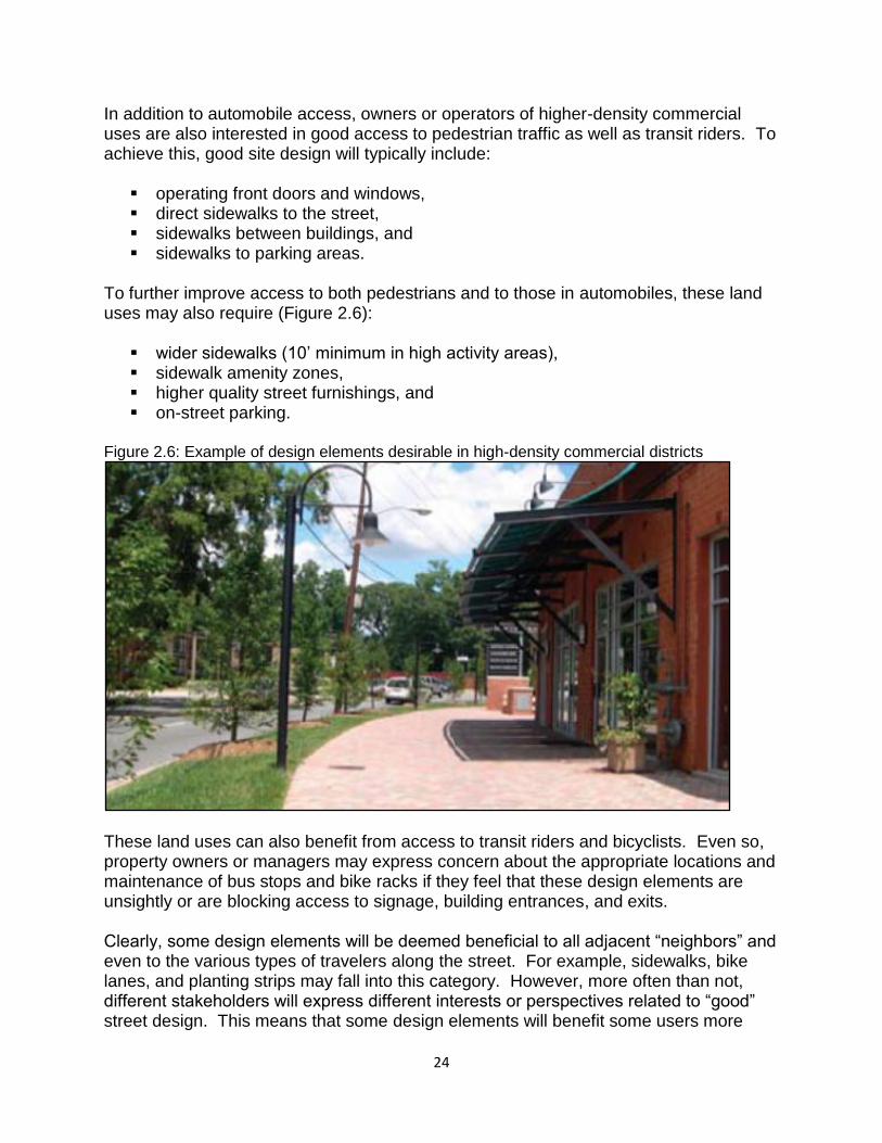
To further improve access to both pedestrians and to those in automobiles, these land uses may also require (Figure 2.6):
wider sidewalks (10’ minimum in high activity areas), sidewalk amenity zones, higher quality street furnishings, and on-street parking.
Figure 2.6: Example of design elements desirable in high-density commercial districts
These land uses can also benefit from access to transit riders and bicyclists. Even so, property owners or managers may express concern about the appropriate locations and maintenance of bus stops and bike racks if they feel that these design elements are unsightly or are blocking access to signage, building entrances, and exits. Clearly, some design elements will be deemed beneficial to all adjacent “neighbors” and even to the various types of travelers along the street. For example, sidewalks, bike lanes, and planting strips may fall into this category. However, more often than not, different stakeholders will express different interests or perspectives related to “good” street design. This means that some design elements will benefit some users more

25
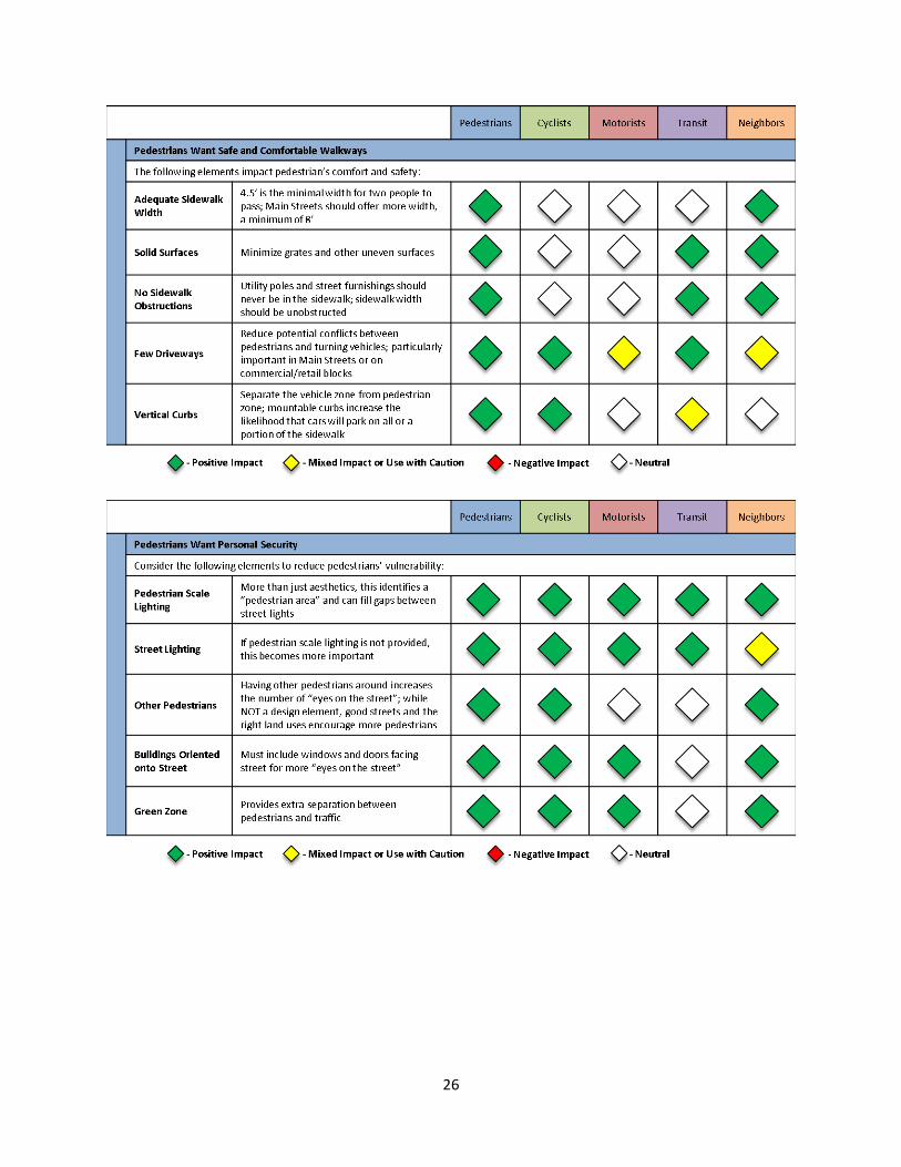
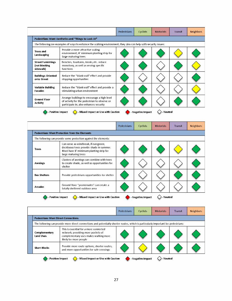
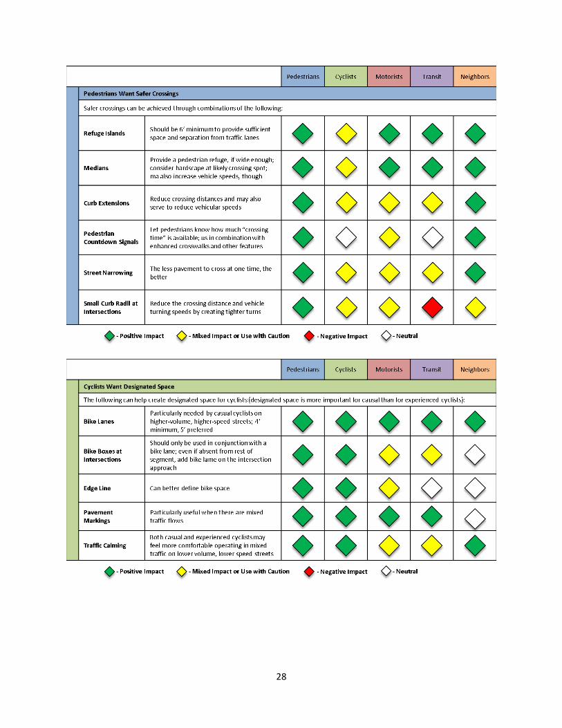
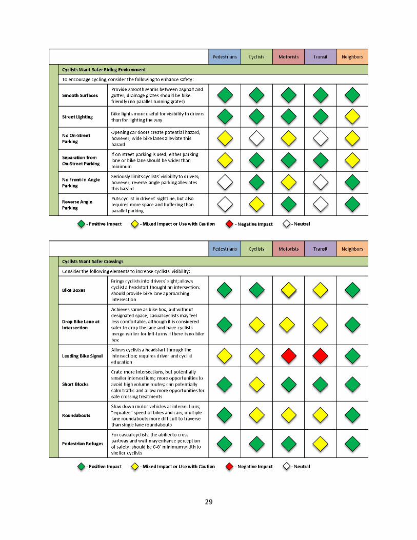
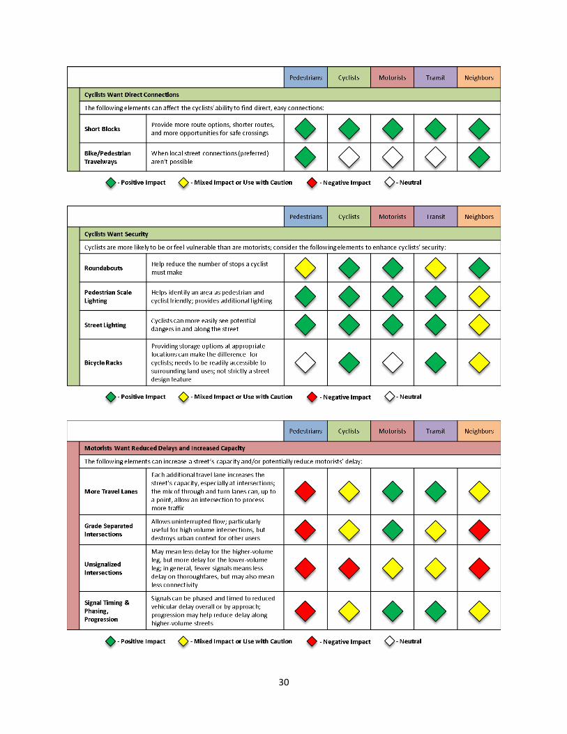
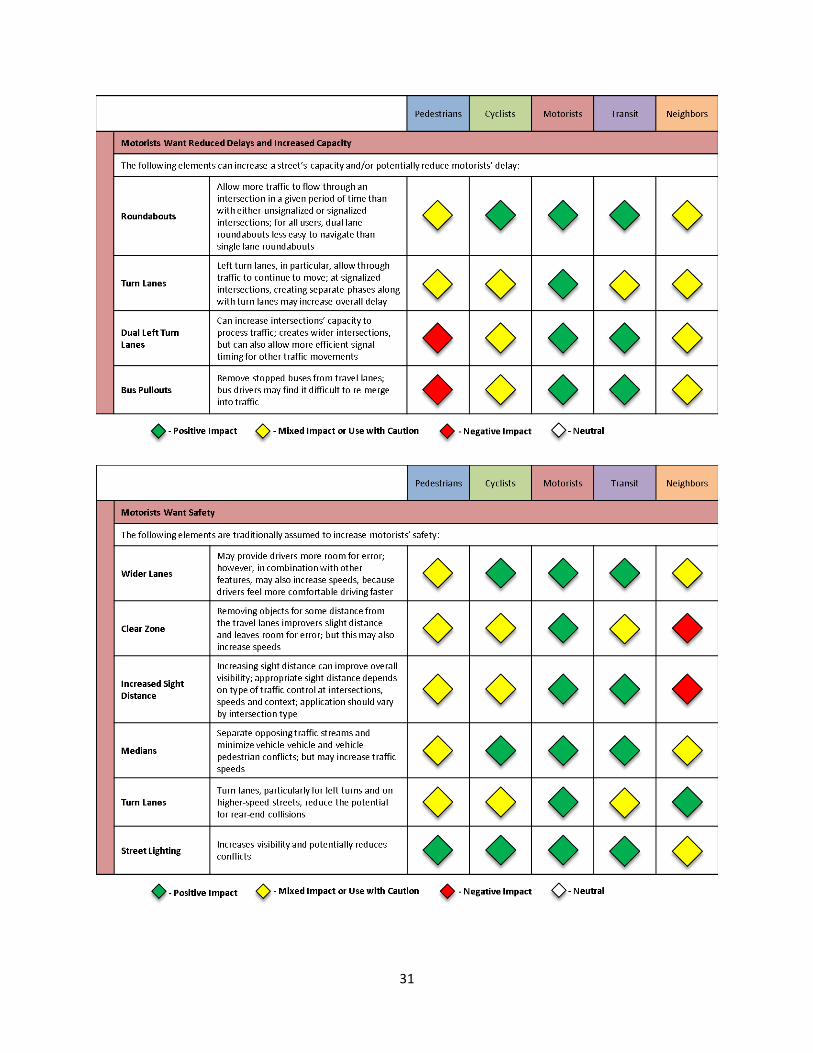
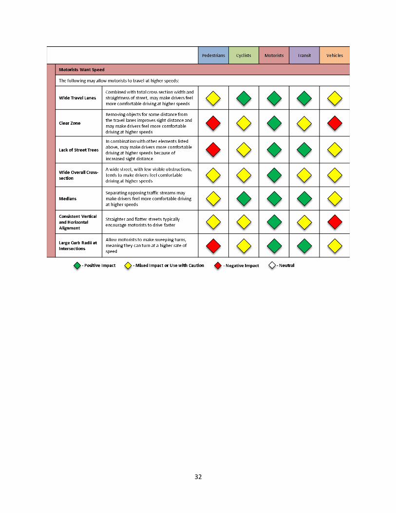
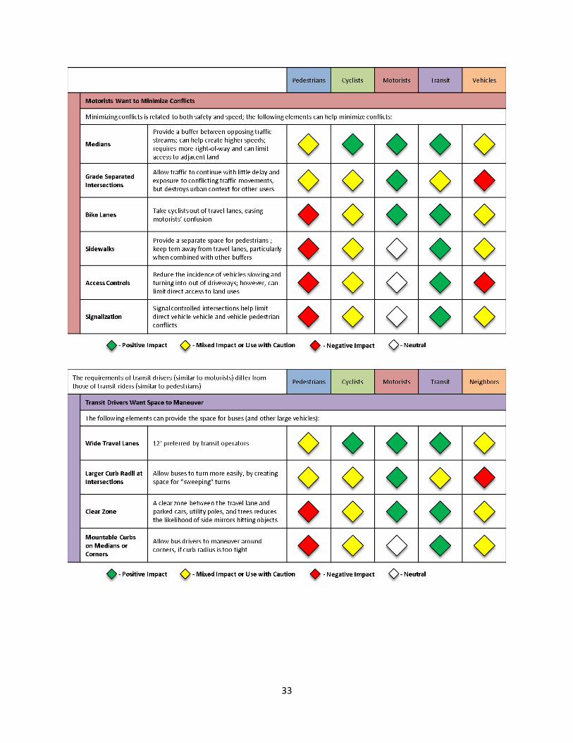
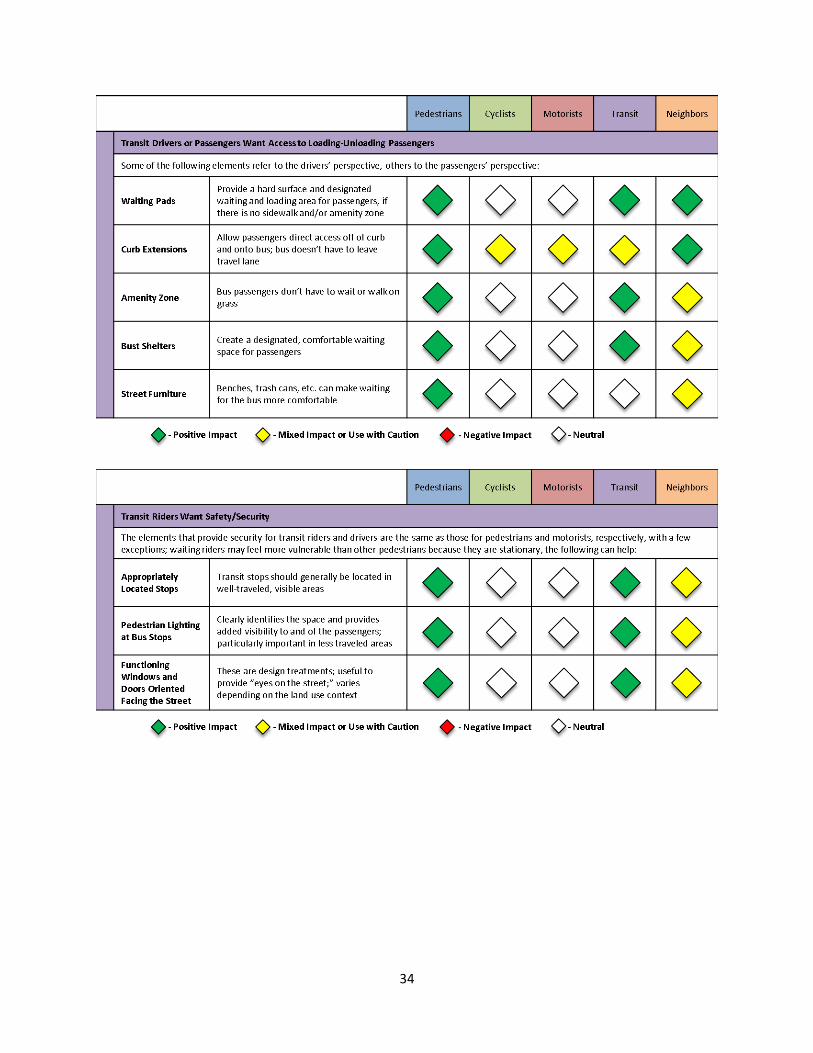
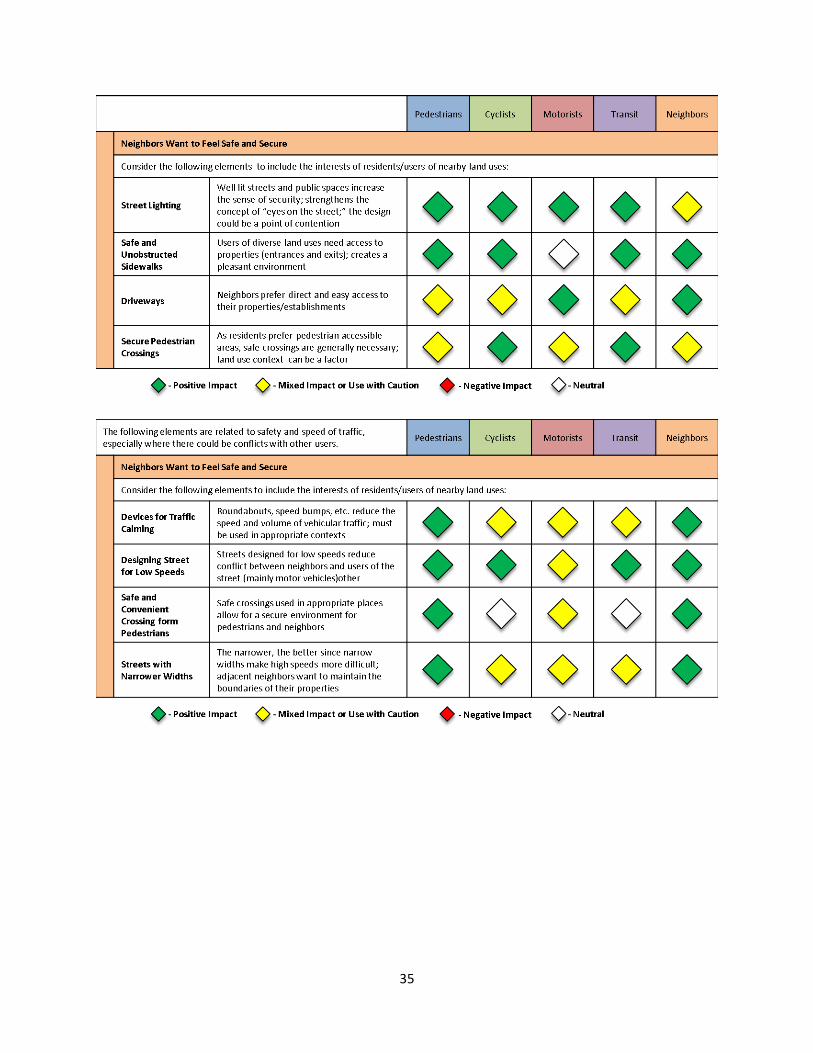
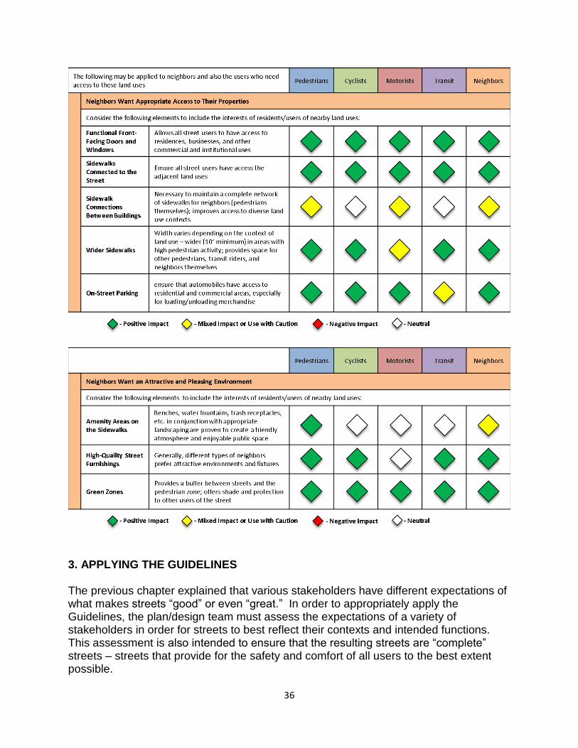
than others, and that some design elements that benefit one user group may actually work to the detriment of other user groups. This, along with the likelihood of right-of-way constraints, heightens the need to thoroughly assess tradeoffs between different perspectives during the design process. Chapter 3 describes a process for planning and designing streets that incorporates an assessment of those tradeoffs. The matrix shown in Figure 2.7 offers additional visual guidance for assessing tradeoffs among street design elements by stakeholder preferences. The matrix shows which design elements may enhance certain stakeholders’ experiences, and relates these elements to other stakeholders’ expectations. The matrix is not intended to be a comprehensive treatment of all aspects of street design and the tradeoffs inherent in them. Rather, it offers examples that a design team can consider to solve a variety of design issues in constrained environments. The design team should use this matrix to help document their discussions of the decisions made during Step 6 of the design process described in Chapter 3. For intersection projects, the design team should follow the guidelines described in Chapter 5 and Appendices A and B for assessing level-of-service (LOS) for pedestrians and cyclists for different intersection types. Note that the matrix treats “transit” from the transit drivers’ perspective, since riders share the same expectations discussed for other pedestrians. Figure 2.7: Stakeholder street design matrices
26
27
28
29
30
31
32
33
34
35
36
3. APPLYING THE GUIDELINES The previous chapter explained that various stakeholders have different expectations of what makes streets “good” or even “great.” In order to appropriately apply the Guidelines, the plan/design team must assess the expectations of a variety of stakeholders in order for streets to best reflect their contexts and intended functions. This assessment is also intended to ensure that the resulting streets are “complete” streets – streets that provide for the safety and comfort of all users to the best extent possible.
37
The purpose of this chapter is to explain how the perspectives of all stakeholders interested in or affected by existing or future streets will be incorporated into a new process for planning and designing streets in Tena’s sphere of influence. The new process described in this chapter consolidates traditional city planning, urban design, and transportation planning activities into a sequence of fact finding and decision-making steps. The application of the new process for planning and designing streets is intended to support the creation of “more streets for more people.” This overriding goal of the Guidelines will require achieving the following changes:
1. ensuring that the perspectives of all stakeholders interested or affected by streets are seriously considered during the planning and design process for existing or future streets;
2. defining a clear sequence of activities to be undertaken by staff, consultants and stakeholders;
3. remembering that this will be a process that is much more geared toward what we want to happen in the future than just accepting what happened in the past or exists now;
4. verifying that the inevitable tradeoffs affecting objectives, benefits, costs, and impacts are well documented so that the recommendations made by staff , consultants or stakeholders are based on understanding the direct effects on specific modes of travel and/or land use intentions; and
5. always striving to create not only more streets, but also more complete streets that are good for all modes of travel, and even some great streets that are remarkable because of the very effective and favorable ways that the adjacent land uses and transportation functions of those streets support each other.
The process described in this chapter provides a great deal of flexibility to those involved in the decision-making process, so that the resulting streets are appropriately based on the existing and proposed land use and transportation contexts. This flexibility is intended to foster creative solutions by ensuring that land use planners, engineers, transportation planners and others work together to think through the implications of alternative street designs. The six-step process, shown in Figure 3.1 and described below, will primarily be applied to planning and designing the “non-local” street types – Main Streets, Avenues, and Parkways. In some cases, public projects that retrofit existing Local Streets may require the use of the six-step process and, when area plans are being prepared, both nonlocal and Local Streets will need to be specified. The area planning process provides one of the best opportunities to integrate the planned land use and transportation characteristics on an area-wide basis, and the six-step process gives the framework for that integration. Even in the case of area plans, though, the level of specification will vary between nonlocal and Local Streets. Assuming that there is enough information available about future land use and
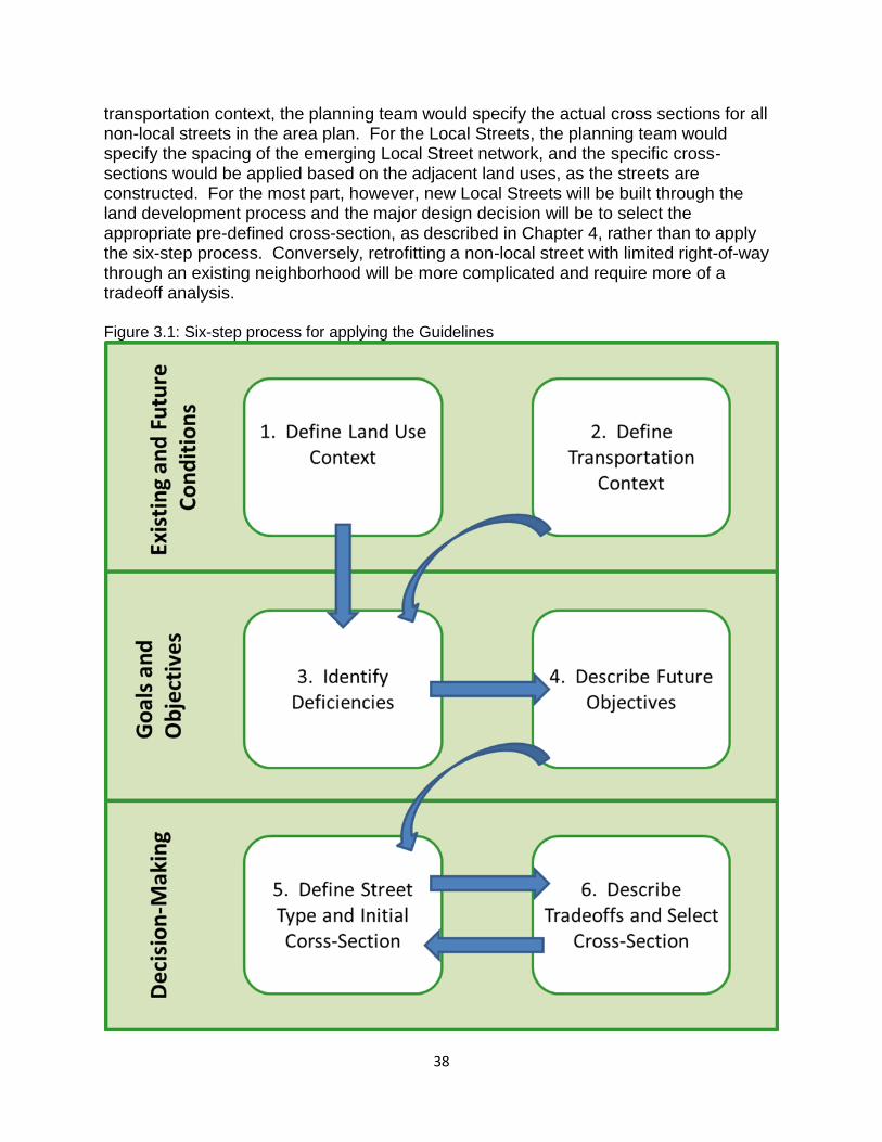
38
transportation context, the planning team would specify the actual cross sections for all non-local streets in the area plan. For the Local Streets, the planning team would specify the spacing of the emerging Local Street network, and the specific cross-sections would be applied based on the adjacent land uses, as the streets are constructed. For the most part, however, new Local Streets will be built through the land development process and the major design decision will be to select the appropriate pre-defined cross-section, as described in Chapter 4, rather than to apply the six-step process. Conversely, retrofitting a non-local street with limited right-of-way through an existing neighborhood will be more complicated and require more of a tradeoff analysis. Figure 3.1: Six-step process for applying the Guidelines
39
Applying the Guidelines: The Six Steps The remainder of this chapter defines a six-step process for developing the most appropriate design for streets in a variety of contexts. The following three assumptions are built into the six-step process:
1. The process will involve a variety of stakeholders. The number of stakeholders and discussions will vary, depending on the magnitude and consequences of the street(s) to be designed.
2. The resulting street will be as “complete” a street as possible, in order to meet the multimodal objectives defined in the Transportation Action Plan.
3. The steps in the decision-making process will be well-documented. The documentation will clearly describe the major tradeoff s made among competing design elements, how those were discussed and weighed against each other, and the preliminary and final outcomes. Thorough documentation will ensure that all stakeholders’ perspectives are adequately considered in the final design.
Figure 3.1 shows the assessment steps to be included in applying the Guidelines. Each of the six steps is defined in more detail in the remainder of the chapter. It is important to note that the steps described below can be applied either to a single street or to a collection of streets in an area (such as when an area plan is being developed). In either case, the first four steps should take an area-wide approach to gathering and assessing the information required for each step since street segments do not exist or function in isolation from the surrounding street network and land uses. Step 1: Define the Existing and Future Land Use and Urban Design Context The classification and ultimate design of any street should reflect both the existing and expected future land use contexts. These existing and future contexts should be considered from the broadest area-wide perspective down to the details of the immediately adjacent land uses. A street is likely to be classified and/or designed differently if it is in an area slated for higher density development, such as a transit station area versus in a neighborhood of single family houses where very limited development changes are anticipated. The following questions regarding the intensity and arrangement of existing and future land uses in the area surrounding the street to be designed should be addressed by the plan/design team:
What does the area look like today? What are current land use mixtures and densities? What are the typical building types, their scale, setbacks, urban design
characteristics, relation to street, any special amenities, etc.? Are there any particular development pressures on the area (the nature of this
may vary according to whether the area is a “greenfield” versus an infill area and this type of information is particularly important in the absence of an area plan)?
40
o What, if anything, can be gleaned from permit data, for example, about the nature of the emerging land use context?
What are the “functions” and the general circulation framework of the neighborhood and adjacent areas?
Is there a detailed plan for the area? o If so, what does the adopted detailed plan envision for the future of the
area? o Does the plan make specific recommendations regarding densities,
setbacks, urban design, etc.? Are there any other adopted development policies for the area?
o If so, what do those policies imply for the area? Step 2: Define the Existing and Future Transportation Context The transportation assessment should consider both the existing and expected future conditions of the transportation network adjacent to or affecting the street to be designed. The recommended design should reflect the entire transportation context (function, multimodal features, and form) rather than that related strictly to capacity on a given segment. The following questions regarding existing and future transportation conditions should be addressed by the plan/design team:
What is the character of the existing street? How does the street currently relate to the adjacent land uses?
How does the street currently function? What are the daily and hourly traffic volumes? Operating and posted speeds? What is the level-of-service (LOS) for pedestrians? Cyclists? Motorists?
What are the current design features, including number of lanes, sidewalk availability, bicycle facilities, traffic control features, street trees, etc.?
What, if any, transit services are provided? Where are the transit stops? What is the relationship between the street segment being analyzed and the
surrounding network (streets, sidewalks, transit, and bicycle connections)? Are there any programmed or planned transportation projects in the area that
would affect the street segment? Are there any other adopted transportation policies that would affect the
classification of the street segment? Step 3: Identify Deficiencies Once the existing and future land use and transportation contexts are clearly defined and understood from an area wide perspective, the plan/design team should be able to identify and describe any deficiencies that could/should be addressed by the new or modified street. This step should consider all modes and the relationship between the transportation and the land use contexts. From the information provided in the first two steps, “deficiencies” might include, but are not limited to:
Gaps in the bicycle or pedestrian network near or along the street segment;
41
Gaps in the bicycle or pedestrian network in the area (which may increase the need for facilities on the segment, because of the lack of alternative routes);
Insufficient pedestrian or bicycle facilities (i.e. in poor repair, poorly lighted, or not well buffered from traffic);
Gaps in the overall street network (this includes the amount of connectivity in the area, as well as any obvious capacity issues on other segments in the area);
Inconsistencies between the amount or type of transit service provided along the street segment and the types of facilities and/or land uses adjacent to the street;
Inconsistencies between the existing land uses and the features of the existing or planned street network.
Step 4: Describe Future Objectives This step synthesizes the information from the previous steps into defined objectives for the street project. The objectives could be derived from the plans and/or policies for the area around the street, as well as from the previously identified list of deficiencies. The objectives will form the basis for the street classification and design. In addition to the general intent of providing complete streets, the following issues should be considered in defining the specific objectives:
What existing policies might or should influence the specific objectives for the street?
What conditions are expected to stay the same (or more importantly, what conditions should stay the same)?
Would the community and the stakeholders like the street and the neighborhood to stay the same or to change?
Why and how would the community and the stakeholders like the street and the neighborhood to change?
Given this, what conditions are likely to change as a result of classifying the street (exactly how will the street classification and design support the stakeholders’ expectations)?
Step 5: Recommend Street Classification and Test Initial Cross-Section At this point, the plan/design team recommends the appropriate Guideline street typology (or typologies, if several streets are being analyzed) based on the previous steps. The rationale behind the classification should be documented. This step should also include a recommendation for any necessary adjustments to the land use plan/policy and/or transportation plan for that area. Since the street type and the ultimate design are defined, in part, according to the land use context, subsequent land use decisions should reflect and support the agreed-upon street type and design. The initial cross-section should be defined based on the recommended street typology, keeping in mind that some typologies allow more than one option. Once the preferred option is identified, the ideal cross-section will typically include the design features with their preferred dimensions specified for that street type. The initial
42
cross-section should then be tested against the land use and transportation contexts and the defined objectives for the street project. At this point, any constraints to the provision of the initial preferred cross-section should also be identified including:
Lack of right-of way, Existing structures, Existing trees or other environmental features, Topography, and Location and number of driveways.
This step should clearly identify which constraints may prohibit the use or require refinement of the initially defined cross-section. Step 6: Describe Tradeoff s and Select Cross-Section If the initial “preferred” cross-section can be applied, then this step is easy; the initial cross-section is the recommended cross-section. In many cases, though, the initial cross-section will need to be refined to better address the land use and transportation objectives, given the constraints identified in Step 5. Sometimes, the technical team will develop more than one alternative design, and in that case, these multiple alternatives should be presented to the stakeholders. Any refinements to the initial cross section (or alternatives) should result from a thoughtful consideration of tradeoffs among competing uses of the existing or future public right-of-way. The tradeoffs should be related to the requirements of each group of stakeholders and the variety of design elements that can best accommodate those requirements. The matrix at the end of Chapter 2 provides a listing of the general expectations of various stakeholders about streets and the elements that might achieve those expectations. At the least, the requirements and elements listed in that matrix should be considered in any tradeoff discussion, though that list should not be considered comprehensive. The specific method of evaluating the tradeoffs is left open to the plan/design team as long as the method/discussion/analysis is documented. All perspectives should receive equal consideration and accountability in the plan/design process. Proper documentation will also generate information useful for future street design projects that might have similar characteristics, objectives, or constraints. Once the tradeoffs are evaluated, the team should be able to develop a refined cross-section and suggested design treatments. The culmination of all of the previous steps, including any additional stakeholder comments, should provide sufficient rationale to select the design alternative that best matches the context and future expectations for the street project. Final Comments on the Six Steps The steps outlined in this chapter suggest that there is a linear process leading to an ideal solution. Realistically, in some instances the process may not follow the exact
43
sequence described above. Some information may not be available or even be applicable for some conditions. The intent, though, is to ensure that the existing and future contexts are given adequate consideration, that any related plans are modified to reflect the outcome, and that all perspectives are given equal consideration in the process. The same approach described here for large-scale street projects can be applied to smaller-scale or short-term projects or processes. In those cases, an “abbreviated” version of the six steps can be used to reach decisions that will necessarily involve a shorter timeframe or fewer stakeholders, but for which it is still important to consider all perspectives and document any necessary tradeoffs. The intent is to apply this thought process to the design of our emerging complete street network, whether through the full six-step process or through the abbreviated version. 4. SEGMENTS The previous chapters of this document have focused on the need for, objectives of, and methods for applying Tena’s new Urban Street Design Guidelines. This chapter contains the detailed guidelines for the street segments or blocks – the portions of the street between intersections (Chapter 5 provides guidelines for the intersections). The following sections describe the design elements (with preferred dimensions) that should be included for each of the street types. Each of the detailed descriptions included in this chapter is intended to accomplish the overall objective of providing safe, functional, multi-modal streets that serve varied users. This chapter does not provide specific information about designing the transitions between different street types. These transitions will most likely occur at intersections, which are described in detail in the next chapter. The reader should refer to both chapters when designing a segment or an intersection that transitions between street types. Sections 4.1-4.3 describe the guidelines for segments on non-local streets (Main Streets, Avenues, and Parkways). The information in these sections is detailed, but not entirely prescriptive. The design team should use this detailed information about dimensions in conjunction with the design method and trade-off analyses outlined in Chapter 3. Many of the design element dimensions described in this chapter refer to evaluating trade-offs in a “constrained” environment. Design teams should take care to consider what constitutes a “constraint.” For example, when a streetscape is being designed with existing buildings, those buildings might constitute a constraint. However, when a street is built “from scratch” or when new buildings are being constructed along an existing street, these buildings would not typically be considered a constraint. In those cases, the preferred dimensions should generally be provided or the design team should justify why they are not.
44
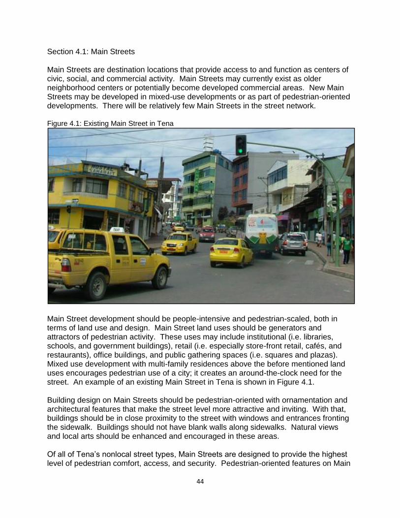
Section 4.1: Main Streets Main Streets are destination locations that provide access to and function as centers of civic, social, and commercial activity. Main Streets may currently exist as older neighborhood centers or potentially become developed commercial areas. New Main Streets may be developed in mixed-use developments or as part of pedestrian-oriented developments. There will be relatively few Main Streets in the street network. Figure 4.1: Existing Main Street in Tena
Main Street development should be people-intensive and pedestrian-scaled, both in terms of land use and design. Main Street land uses should be generators and attractors of pedestrian activity. These uses may include institutional (i.e. libraries, schools, and government buildings), retail (i.e. especially store-front retail, cafés, and restaurants), office buildings, and public gathering spaces (i.e. squares and plazas). Mixed use development with multi-family residences above the before mentioned land uses encourages pedestrian use of a city; it creates an around-the-clock need for the street. An example of an existing Main Street in Tena is shown in Figure 4.1. Building design on Main Streets should be pedestrian-oriented with ornamentation and architectural features that make the street level more attractive and inviting. With that, buildings should be in close proximity to the street with windows and entrances fronting the sidewalk. Buildings should not have blank walls along sidewalks. Natural views and local arts should be enhanced and encouraged in these areas. Of all of Tena’s nonlocal street types, Main Streets are designed to provide the highest level of pedestrian comfort, access, and security. Pedestrian-oriented features on Main
45
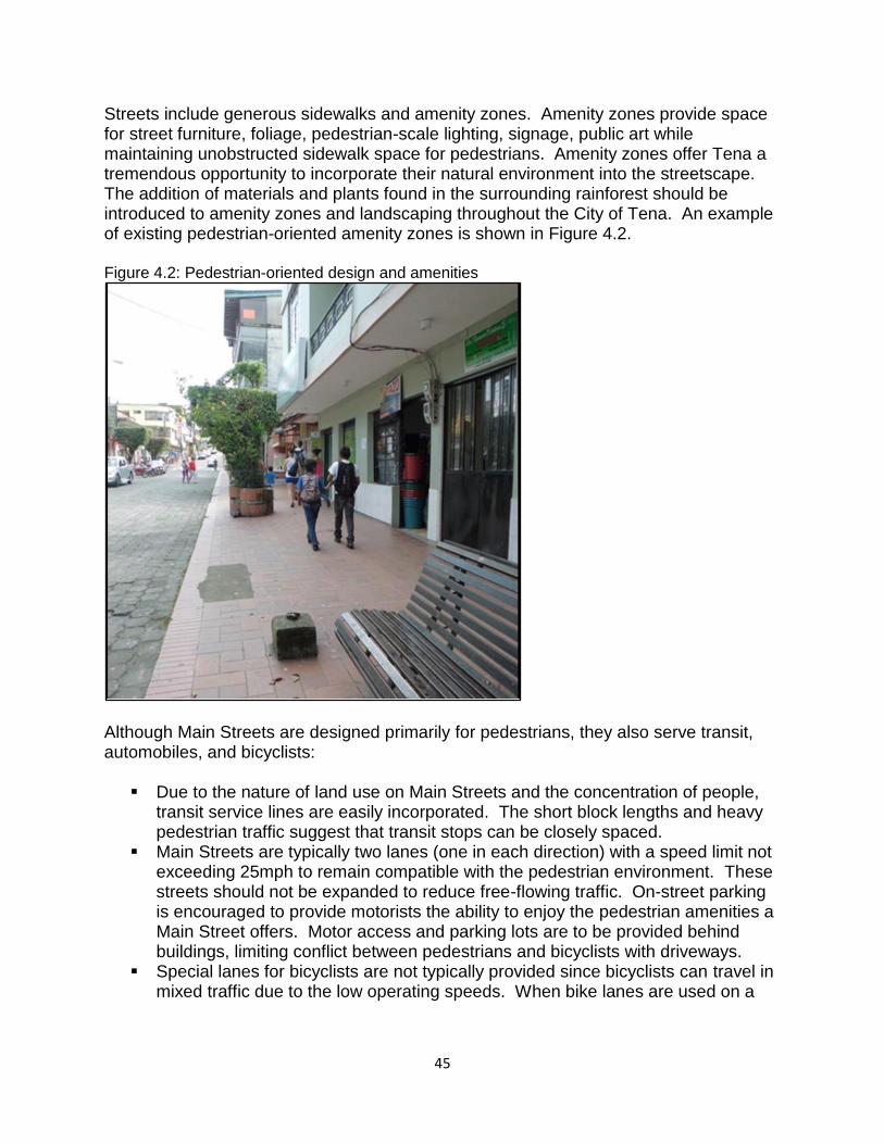
Streets include generous sidewalks and amenity zones. Amenity zones provide space for street furniture, foliage, pedestrian-scale lighting, signage, public art while maintaining unobstructed sidewalk space for pedestrians. Amenity zones offer Tena a tremendous opportunity to incorporate their natural environment into the streetscape. The addition of materials and plants found in the surrounding rainforest should be introduced to amenity zones and landscaping throughout the City of Tena. An example of existing pedestrian-oriented amenity zones is shown in Figure 4.2. Figure 4.2: Pedestrian-oriented design and amenities
Although Main Streets are designed primarily for pedestrians, they also serve transit, automobiles, and bicyclists:
Due to the nature of land use on Main Streets and the concentration of people, transit service lines are easily incorporated. The short block lengths and heavy pedestrian traffic suggest that transit stops can be closely spaced.
Main Streets are typically two lanes (one in each direction) with a speed limit not exceeding 25mph to remain compatible with the pedestrian environment. These streets should not be expanded to reduce free-flowing traffic. On-street parking is encouraged to provide motorists the ability to enjoy the pedestrian amenities a Main Street offers. Motor access and parking lots are to be provided behind buildings, limiting conflict between pedestrians and bicyclists with driveways.
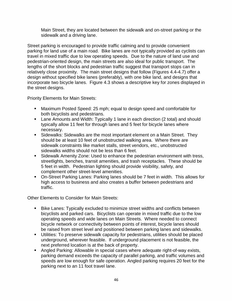
Special lanes for bicyclists are not typically provided since bicyclists can travel in mixed traffic due to the low operating speeds. When bike lanes are used on a
46
Main Street, they are located between the sidewalk and on-street parking or the sidewalk and a driving lane.
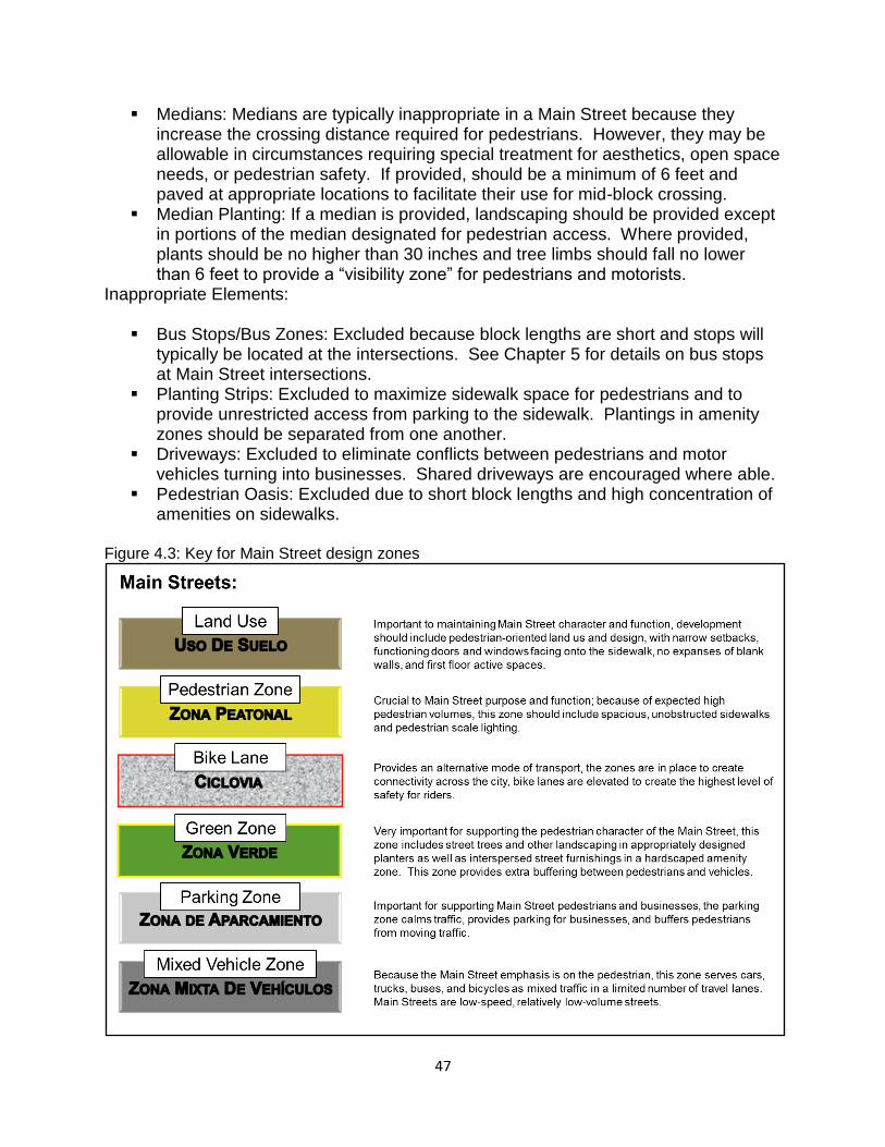
Street parking is encouraged to provide traffic calming and to provide convenient parking for land use of a main road. Bike lanes are not typically provided as cyclists can travel in mixed traffic due to low operating speeds. Due to the nature of land use and pedestrian-oriented design, the main streets are also ideal for public transport. The lengths of the short blocks and pedestrian traffic suggest that transport stops can in relatively close proximity. The main street designs that follow (Figures 4.4-4.7) offer a design without specified bike lanes (preferably), with one bike land, and designs that incorporate two bicycle lanes. Figure 4.3 shows a descriptive key for zones displayed in the street designs. Priority Elements for Main Streets:
Maximum Posted Speed: 25 mph; equal to design speed and comfortable for both bicyclists and pedestrians.
Lane Amounts and Width: Typically 1 lane in each direction (2 total) and should typically allow 11 feet for through lanes and 5 feet for bicycle lanes where necessary.
Sidewalks: Sidewalks are the most important element on a Main Street. They should be at least 10 feet of unobstructed walking area. Where there are sidewalk constraints like market stalls, street vendors, etc., unobstructed sidewalks widths should not be less than 6 feet.
Sidewalk Amenity Zone: Used to enhance the pedestrian environment with tress, streetlights, benches, transit amenities, and trash receptacles. These should be 5 feet in width. Pedestrian lighting should provide visibility, safety, and complement other street-level amenities.
On-Street Parking Lanes: Parking lanes should be 7 feet in width. This allows for high access to business and also creates a buffer between pedestrians and traffic.
Other Elements to Consider for Main Streets:
Bike Lanes: Typically excluded to minimize street widths and conflicts between bicyclists and parked cars. Bicyclists can operate in mixed traffic due to the low operating speeds and wide lanes on Main Streets. Where needed to connect bicycle network or connectivity between points of interest, bicycle lanes should be raised from street level and positioned between parking lanes and sidewalks.
Utilities: To preserve sidewalk capacity for pedestrians, utilities should be placed underground, wherever feasible. If underground placement is not feasible, the next preferred location is at the back of property.
Angled Parking: Allowable in special cases where adequate right-of-way exists, parking demand exceeds the capacity of parallel parking, and traffic volumes and speeds are low enough for safe operation. Angled parking requires 20 feet for the parking next to an 11 foot travel lane.
47
Medians: Medians are typically inappropriate in a Main Street because they increase the crossing distance required for pedestrians. However, they may be allowable in circumstances requiring special treatment for aesthetics, open space needs, or pedestrian safety. If provided, should be a minimum of 6 feet and paved at appropriate locations to facilitate their use for mid-block crossing.
Median Planting: If a median is provided, landscaping should be provided except in portions of the median designated for pedestrian access. Where provided, plants should be no higher than 30 inches and tree limbs should fall no lower than 6 feet to provide a “visibility zone” for pedestrians and motorists.
Inappropriate Elements:
Bus Stops/Bus Zones: Excluded because block lengths are short and stops will typically be located at the intersections. See Chapter 5 for details on bus stops at Main Street intersections.
Planting Strips: Excluded to maximize sidewalk space for pedestrians and to provide unrestricted access from parking to the sidewalk. Plantings in amenity zones should be separated from one another.
Driveways: Excluded to eliminate conflicts between pedestrians and motor vehicles turning into businesses. Shared driveways are encouraged where able.
Pedestrian Oasis: Excluded due to short block lengths and high concentration of amenities on sidewalks.
Figure 4.3: Key for Main Street design zones
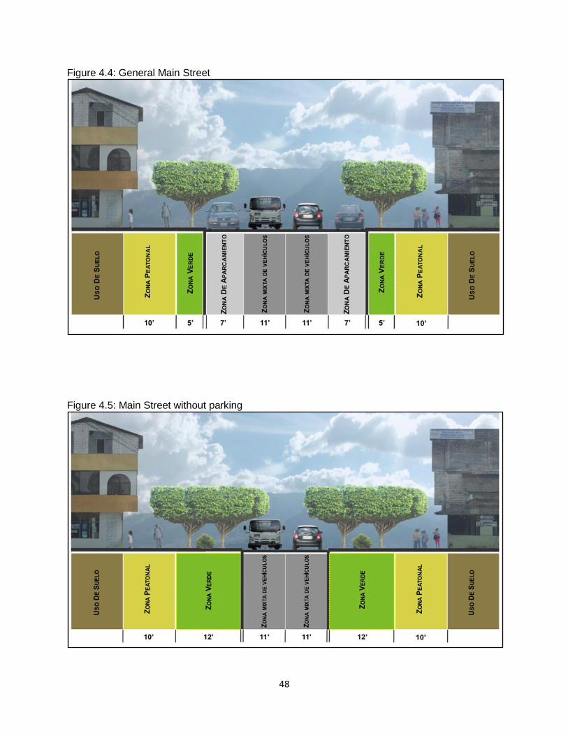
48
Figure 4.4: General Main Street
Figure 4.5: Main Street without parking
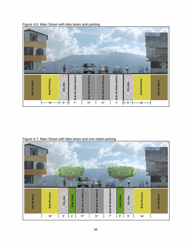
49
Figure 4.6: Main Street with bike lanes and parking
Figure 4.7: Main Street with bike lanes and one-sided parking
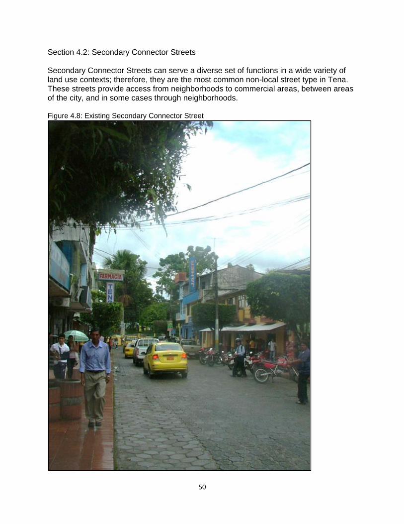
50
Section 4.2: Secondary Connector Streets Secondary Connector Streets can serve a diverse set of functions in a wide variety of land use contexts; therefore, they are the most common non-local street type in Tena. These streets provide access from neighborhoods to commercial areas, between areas of the city, and in some cases through neighborhoods. Figure 4.8: Existing Secondary Connector Street
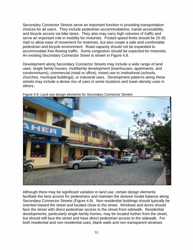
51
Secondary Connector Streets serve an important function in providing transportation choices for all users. They include pedestrian accommodations, transit accessibility, and bicycle access via bike lanes. They also may carry high volumes of traffic and serve an important role in mobility for motorists. Posted speed limits should be 25-35 mph to allow ease of movement for motorists, but also create a safe and comfortable pedestrian and bicycle environment. Road capacity should not be expanded to accommodate free-flowing traffic. Some congestion should be expected for motorists. An existing Secondary Connector Street is shown in Figure 4.8. Development along Secondary Connector Streets may include a wide range of land uses: single family houses, multifamily development (townhouses, apartments, and condominiums), commercial (retail or office), mixed use to institutional (schools, churches, municipal buildings), or industrial uses. Development patterns along these streets may include a dense mix of uses in some locations and lower-density uses in others. Figure 4.9: Land use design elements for Secondary Connector Streets
Although there may be significant variation in land use, certain design elements facilitate the best access for pedestrians and maintain the desired modal balance along Secondary Connector Streets (Figure 4.9). Non-residential buildings should typically be oriented toward the street and located close to the street. Windows and doors should face the street with direct pedestrian access to the street-front sidewalk. Residential developments, particularly single-family homes, may be located further from the street, but should still face the street and have direct pedestrian access to the sidewalk. For both residential and non-residential uses, blank walls and non-transparent windows
52
should be avoided to help provide for pedestrian comfort, security, and points of interest. Since Secondary Connector Streets serve many functions and contexts, there are a number of alternative cross-sections (Figures 4.11-4.17). Block lengths should be limited to 600 feet to provide frequent locations for safe pedestrian crossings, as well as frequent and convenient connections to adjacent neighborhoods. Signalized intersections are specially designed for pedestrian crossings. Common elements included in all Secondary Connector Street cross-sections are sidewalks with green zones/amenity zones or bike lanes along both sides of the street; a descriptive key for these zones is provided in Figure 4.10). Secondary Connector Streets have three sub-classifications: Narrow, Medium, and Wide. All of these classifications should have sidewalks, green zones or amenity zones, two lanes for traffic (one in each direction), and a bicycle lane where needed for bike network continuity.
Narrow classified streets typically have low density land uses. These could be residential, mixed use, or commercial. Narrow roads should not have on-street parking;
Medium classified streets are typically commercial-based land use with mixed use developments. If space is available, on-street parking and amenity zones for pedestrians should be provided;
Wide classified streets typically have commercial and industrial land uses. On-street parking is necessary for these streets. Amenity or green zones should be provided wherever space is available.
Priority Elements:
Posted Speed: 25-30 mph preferred with 35 mph allowable. This is higher than Main Street speeds, but lower than Parkway speeds. This reflects the desire to provide safe and comfortable speeds for all modes.
Design Speed: 30-40 mph. The design speed should be slightly higher than the posted speed, but not so high as to encourage speeding.
Number of Through Lanes: 1 in each direction, 2 total. Blocks without on-street parking could have a third lane for turning.
Lane Width: Should typically provide 9 foot lanes for a Narrow classification, 11 foot lanes for Medium and Wide classification. Bike lanes should typically be between 4 and 5 feet. On-street parking lanes should be 7 feet.
Bicycle Accommodations: Bicycle lanes are desirable on Secondary Connector Streets to allow cyclists higher mobility and to continue a bicycle network. Bicycle lanes should be a minimum of 4 feet wide in the absence of on-street parking. Where on-street parking exists, the bicycle lane should be 5 feet wide to allow additional clear space between cyclists and opening car doors.
53
Sidewalks: Minimum 4.5 to 5 feet wide unobstructed sidewalks should be provided. A sidewalk amenity zone should typically be provided whenever space is available.
•Planting Strips: Green zones or amenity zones are preferred on Secondary Connector Streets. With limited space on these roadways, any amount of green space or amenity space there is available should be used. If sidewalks have extra space after providing unobstructed pedestrian space, small pockets of greenery should be added to the sidewalk space. Segments where bicycle lanes are needed on Secondary Connector Streets will likely remove the green zones or amenity zones.
Lighting: Street and pedestrian lighting is to be provided. Ideally, these fixtures should be located away from trees to maximize lighting.
Other Elements to Consider:
On-Street Parking: Desirable in areas with front-facing development, especially retail development. Lane widths should be 7 feet. On-street parking should be on Wide and Medium classified streets where possible but should be limited on Narrow classified streets.
Driveways: Secondary Connector Streets will typically have driveways to adjacent properties, however; driveways raise the potential for conflict between pedestrians and turning vehicles. Therefore, in commercial or other areas with high pedestrian activity expected, efforts should be made to minimize the number of driveways and to maximize the distance between them. For example, in these types of pedestrian-oriented areas, access should be from a side street rather than the Secondary Connector Street. Shared driveways are also encouraged.
Utilities: To preserve sidewalk capacity for pedestrians, maintain a clear zone, and allow larger trees and other aesthetic treatments, utilities should be placed underground wherever possible.
Traffic Calming: Many of the ideal elements on Secondary Connector Streets will provide a measure of traffic calming (i.e. on-street parking, short block lengths, closer signal spacing), however; some forms of traffic calming, such as street-side landscaping treatments, are allowable if necessary to maintain desired speeds.
Inappropriate Elements:
Shoulder: Inappropriate in an urban setting
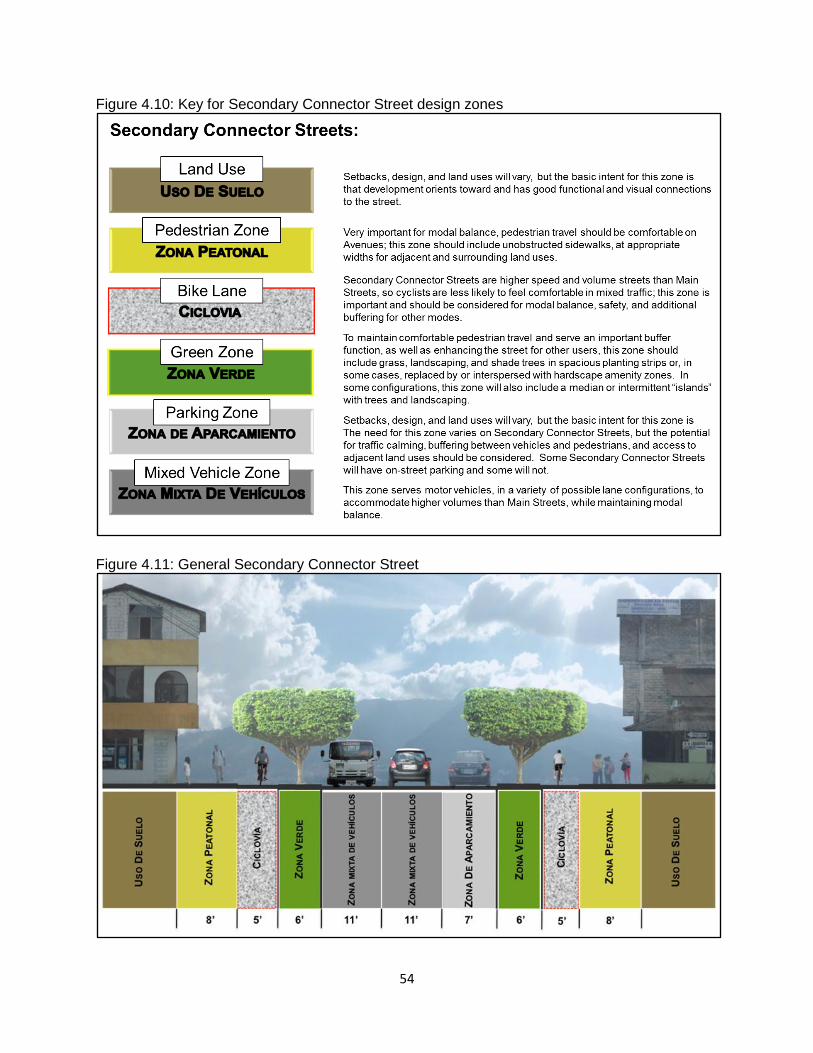
54
Figure 4.10: Key for Secondary Connector Street design zones
Figure 4.11: General Secondary Connector Street
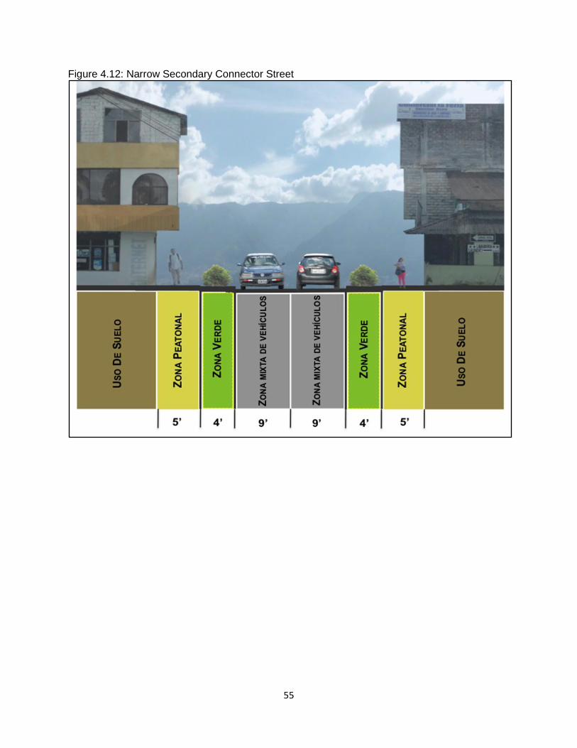
55
Figure 4.12: Narrow Secondary Connector Street
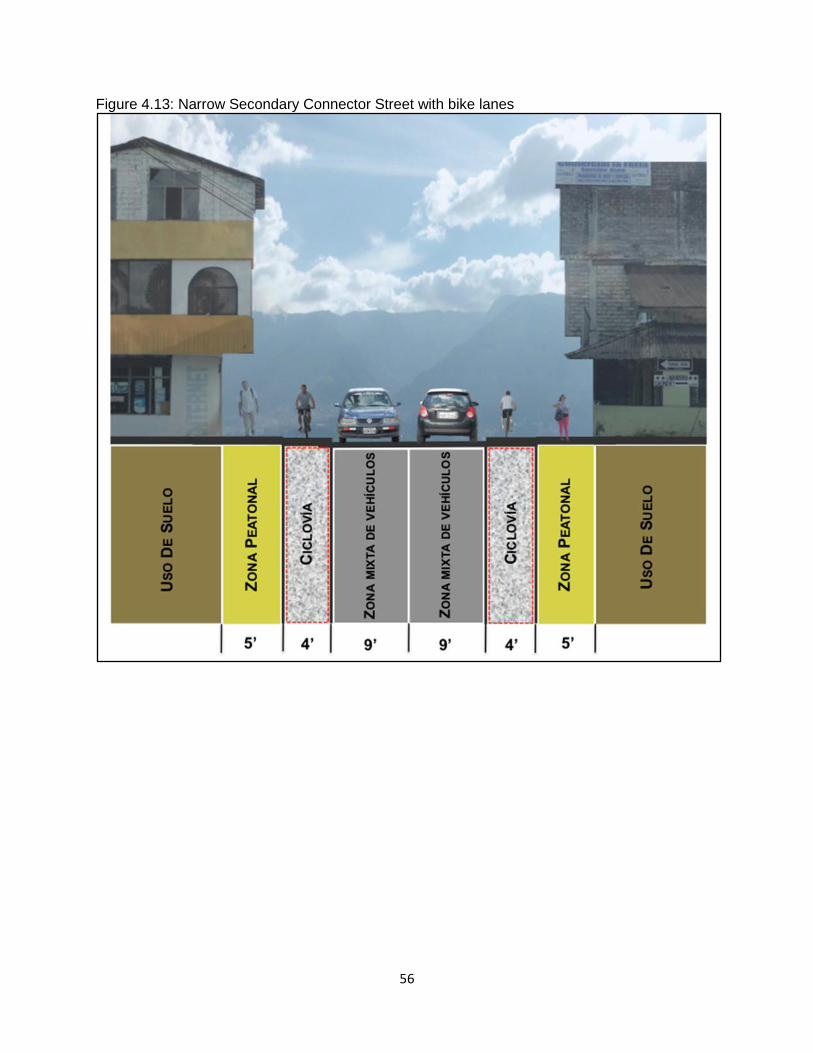
56
Figure 4.13: Narrow Secondary Connector Street with bike lanes
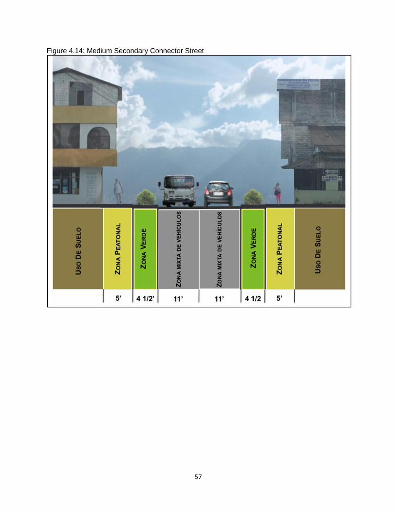
57
Figure 4.14: Medium Secondary Connector Street
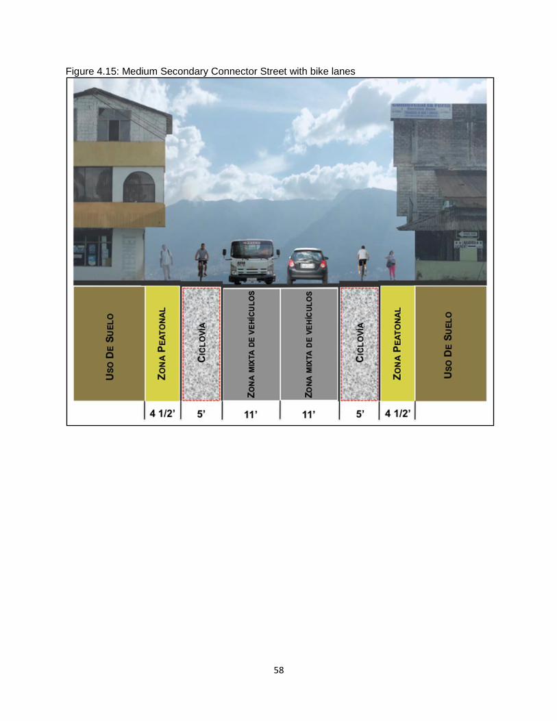
58
Figure 4.15: Medium Secondary Connector Street with bike lanes
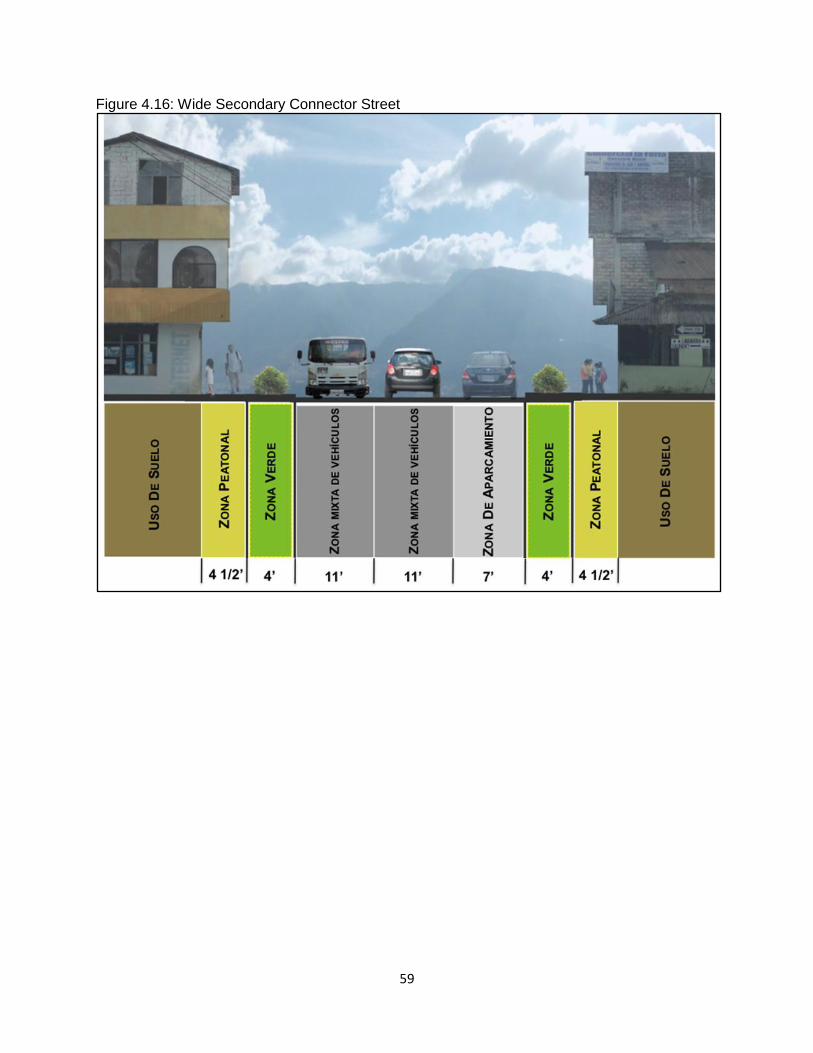
59
Figure 4.16: Wide Secondary Connector Street
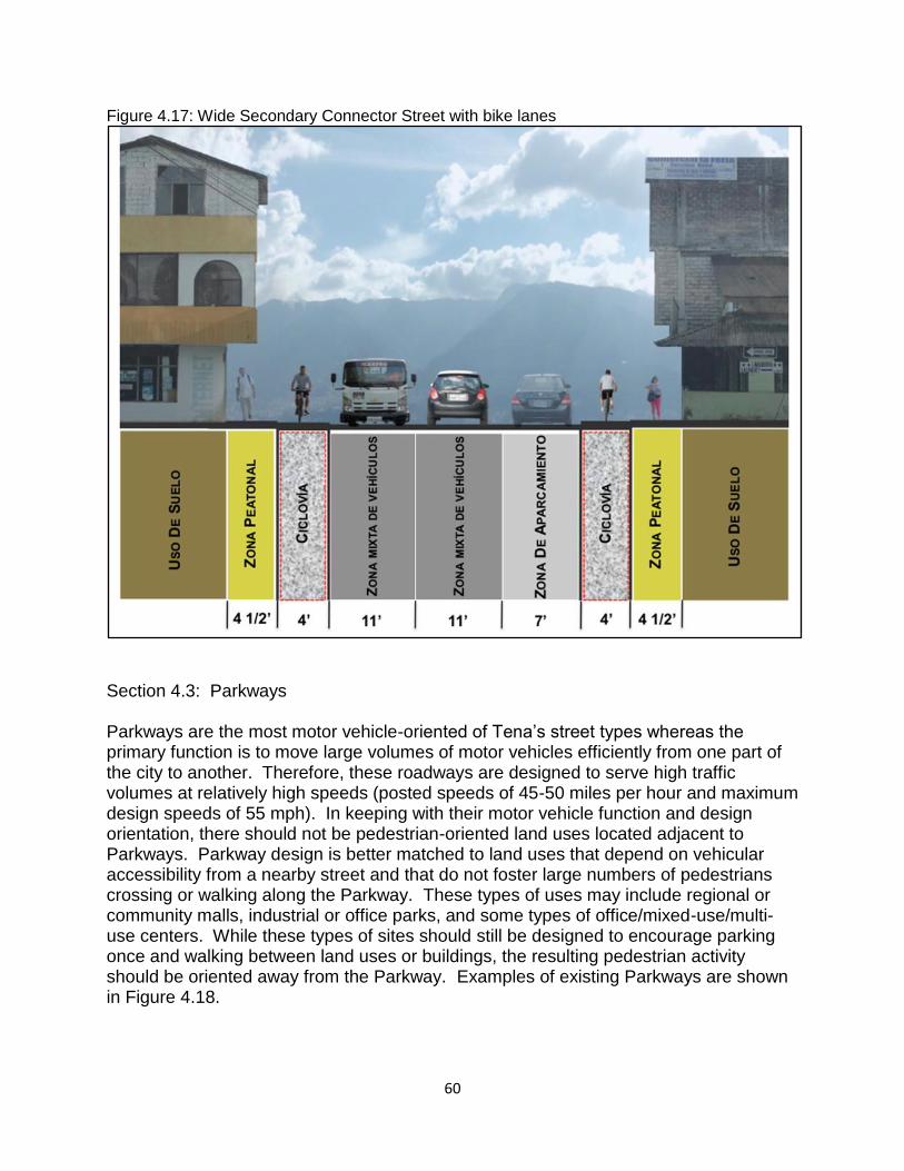
60
Figure 4.17: Wide Secondary Connector Street with bike lanes
Section 4.3: Parkways Parkways are the most motor vehicle-oriented of Tena’s street types whereas the primary function is to move large volumes of motor vehicles efficiently from one part of the city to another. Therefore, these roadways are designed to serve high traffic volumes at relatively high speeds (posted speeds of 45-50 miles per hour and maximum design speeds of 55 mph). In keeping with their motor vehicle function and design orientation, there should not be pedestrian-oriented land uses located adjacent to Parkways. Parkway design is better matched to land uses that depend on vehicular accessibility from a nearby street and that do not foster large numbers of pedestrians crossing or walking along the Parkway. These types of uses may include regional or community malls, industrial or office parks, and some types of office/mixed-use/multi-use centers. While these types of sites should still be designed to encourage parking once and walking between land uses or buildings, the resulting pedestrian activity should be oriented away from the Parkway. Examples of existing Parkways are shown in Figure 4.18.
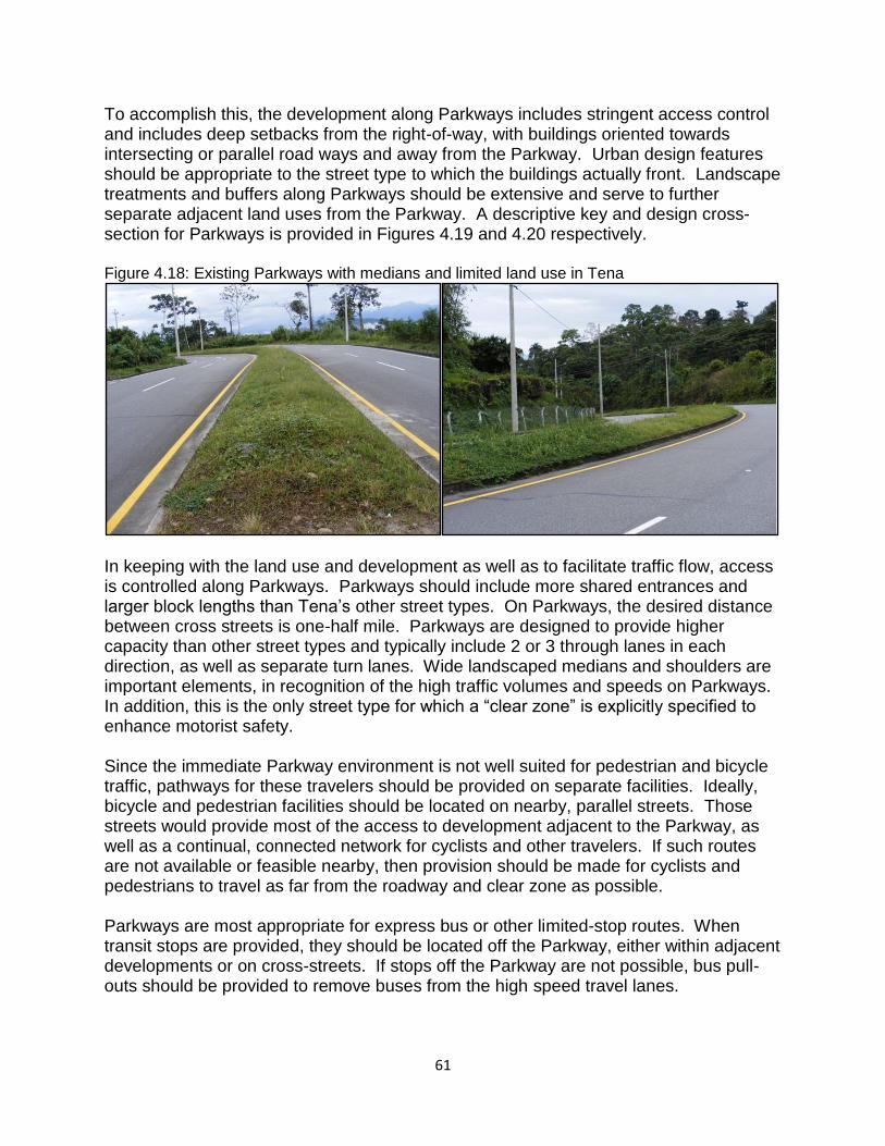
61
To accomplish this, the development along Parkways includes stringent access control and includes deep setbacks from the right-of-way, with buildings oriented towards intersecting or parallel road ways and away from the Parkway. Urban design features should be appropriate to the street type to which the buildings actually front. Landscape treatments and buffers along Parkways should be extensive and serve to further separate adjacent land uses from the Parkway. A descriptive key and design cross-section for Parkways is provided in Figures 4.19 and 4.20 respectively. Figure 4.18: Existing Parkways with medians and limited land use in Tena
In keeping with the land use and development as well as to facilitate traffic flow, access is controlled along Parkways. Parkways should include more shared entrances and larger block lengths than Tena’s other street types. On Parkways, the desired distance between cross streets is one-half mile. Parkways are designed to provide higher capacity than other street types and typically include 2 or 3 through lanes in each direction, as well as separate turn lanes. Wide landscaped medians and shoulders are important elements, in recognition of the high traffic volumes and speeds on Parkways. In addition, this is the only street type for which a “clear zone” is explicitly specified to enhance motorist safety. Since the immediate Parkway environment is not well suited for pedestrian and bicycle traffic, pathways for these travelers should be provided on separate facilities. Ideally, bicycle and pedestrian facilities should be located on nearby, parallel streets. Those streets would provide most of the access to development adjacent to the Parkway, as well as a continual, connected network for cyclists and other travelers. If such routes are not available or feasible nearby, then provision should be made for cyclists and pedestrians to travel as far from the roadway and clear zone as possible. Parkways are most appropriate for express bus or other limited-stop routes. When transit stops are provided, they should be located off the Parkway, either within adjacent developments or on cross-streets. If stops off the Parkway are not possible, bus pull-outs should be provided to remove buses from the high speed travel lanes.
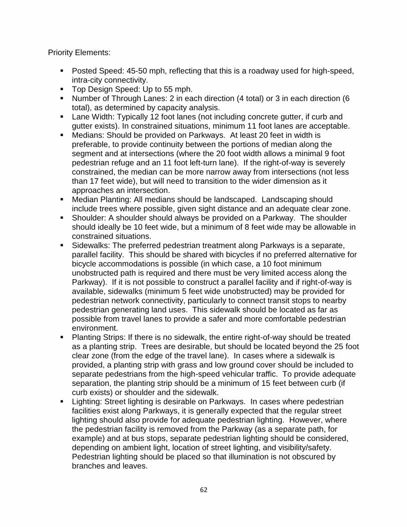
62
Priority Elements:
Posted Speed: 45-50 mph, reflecting that this is a roadway used for high-speed, intra-city connectivity.
Top Design Speed: Up to 55 mph. Number of Through Lanes: 2 in each direction (4 total) or 3 in each direction (6
total), as determined by capacity analysis. Lane Width: Typically 12 foot lanes (not including concrete gutter, if curb and
gutter exists). In constrained situations, minimum 11 foot lanes are acceptable. Medians: Should be provided on Parkways. At least 20 feet in width is
preferable, to provide continuity between the portions of median along the segment and at intersections (where the 20 foot width allows a minimal 9 foot pedestrian refuge and an 11 foot left-turn lane). If the right-of-way is severely constrained, the median can be more narrow away from intersections (not less than 17 feet wide), but will need to transition to the wider dimension as it approaches an intersection.
Median Planting: All medians should be landscaped. Landscaping should include trees where possible, given sight distance and an adequate clear zone.
Shoulder: A shoulder should always be provided on a Parkway. The shoulder should ideally be 10 feet wide, but a minimum of 8 feet wide may be allowable in constrained situations.
Sidewalks: The preferred pedestrian treatment along Parkways is a separate, parallel facility. This should be shared with bicycles if no preferred alternative for bicycle accommodations is possible (in which case, a 10 foot minimum unobstructed path is required and there must be very limited access along the Parkway). If it is not possible to construct a parallel facility and if right-of-way is available, sidewalks (minimum 5 feet wide unobstructed) may be provided for pedestrian network connectivity, particularly to connect transit stops to nearby pedestrian generating land uses. This sidewalk should be located as far as possible from travel lanes to provide a safer and more comfortable pedestrian environment.
Planting Strips: If there is no sidewalk, the entire right-of-way should be treated as a planting strip. Trees are desirable, but should be located beyond the 25 foot clear zone (from the edge of the travel lane). In cases where a sidewalk is provided, a planting strip with grass and low ground cover should be included to separate pedestrians from the high-speed vehicular traffic. To provide adequate separation, the planting strip should be a minimum of 15 feet between curb (if curb exists) or shoulder and the sidewalk.
Lighting: Street lighting is desirable on Parkways. In cases where pedestrian facilities exist along Parkways, it is generally expected that the regular street lighting should also provide for adequate pedestrian lighting. However, where the pedestrian facility is removed from the Parkway (as a separate path, for example) and at bus stops, separate pedestrian lighting should be considered, depending on ambient light, location of street lighting, and visibility/safety. Pedestrian lighting should be placed so that illumination is not obscured by branches and leaves.
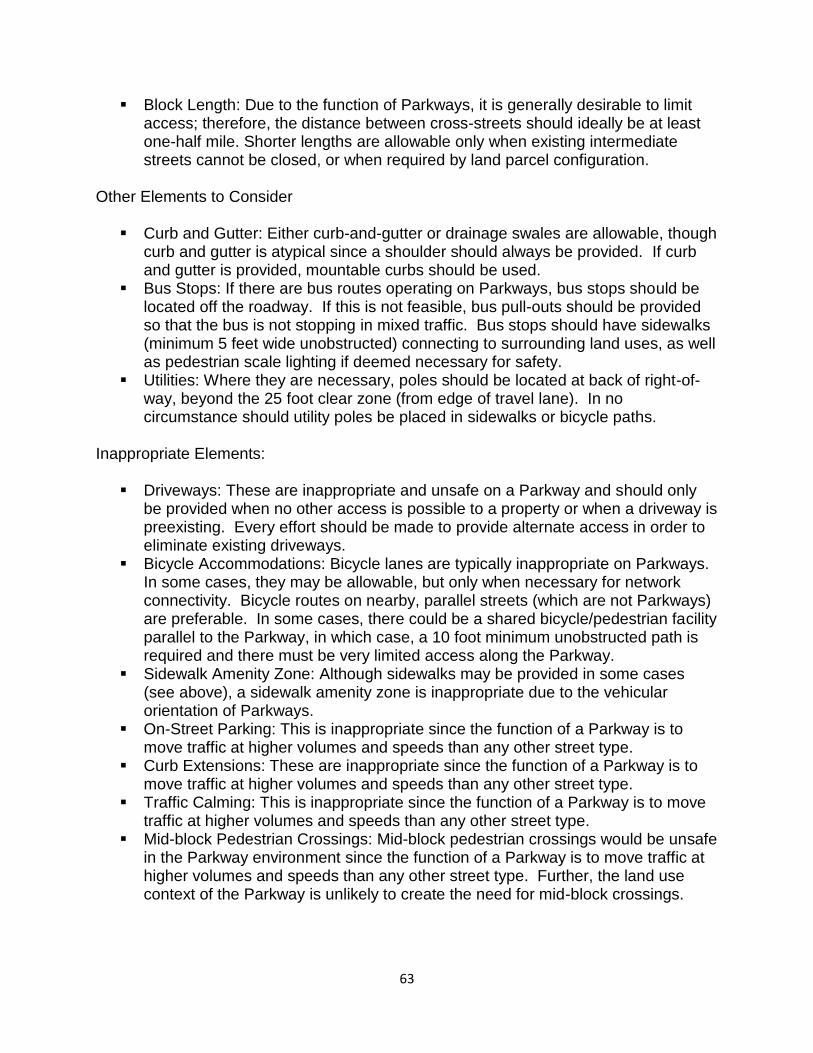
63
Block Length: Due to the function of Parkways, it is generally desirable to limit access; therefore, the distance between cross-streets should ideally be at least one-half mile. Shorter lengths are allowable only when existing intermediate streets cannot be closed, or when required by land parcel configuration.
Other Elements to Consider
Curb and Gutter: Either curb-and-gutter or drainage swales are allowable, though curb and gutter is atypical since a shoulder should always be provided. If curb and gutter is provided, mountable curbs should be used.
Bus Stops: If there are bus routes operating on Parkways, bus stops should be located off the roadway. If this is not feasible, bus pull-outs should be provided so that the bus is not stopping in mixed traffic. Bus stops should have sidewalks (minimum 5 feet wide unobstructed) connecting to surrounding land uses, as well as pedestrian scale lighting if deemed necessary for safety.
Utilities: Where they are necessary, poles should be located at back of right-of-way, beyond the 25 foot clear zone (from edge of travel lane). In no circumstance should utility poles be placed in sidewalks or bicycle paths.
Inappropriate Elements:
Driveways: These are inappropriate and unsafe on a Parkway and should only be provided when no other access is possible to a property or when a driveway is preexisting. Every effort should be made to provide alternate access in order to eliminate existing driveways.
Bicycle Accommodations: Bicycle lanes are typically inappropriate on Parkways. In some cases, they may be allowable, but only when necessary for network connectivity. Bicycle routes on nearby, parallel streets (which are not Parkways) are preferable. In some cases, there could be a shared bicycle/pedestrian facility parallel to the Parkway, in which case, a 10 foot minimum unobstructed path is required and there must be very limited access along the Parkway.
Sidewalk Amenity Zone: Although sidewalks may be provided in some cases (see above), a sidewalk amenity zone is inappropriate due to the vehicular orientation of Parkways.
On-Street Parking: This is inappropriate since the function of a Parkway is to move traffic at higher volumes and speeds than any other street type.
Curb Extensions: These are inappropriate since the function of a Parkway is to move traffic at higher volumes and speeds than any other street type.
Traffic Calming: This is inappropriate since the function of a Parkway is to move traffic at higher volumes and speeds than any other street type.
Mid-block Pedestrian Crossings: Mid-block pedestrian crossings would be unsafe in the Parkway environment since the function of a Parkway is to move traffic at higher volumes and speeds than any other street type. Further, the land use context of the Parkway is unlikely to create the need for mid-block crossings.
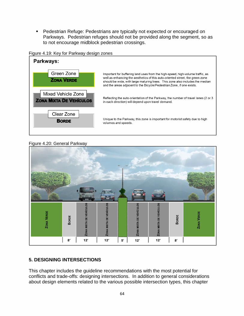
64
Pedestrian Refuge: Pedestrians are typically not expected or encouraged on Parkways. Pedestrian refuges should not be provided along the segment, so as to not encourage midblock pedestrian crossings.
Figure 4.19: Key for Parkway design zones
Figure 4.20: General Parkway
5. DESIGNING INTERSECTIONS This chapter includes the guideline recommendations with the most potential for conflicts and trade-offs: designing intersections. In addition to general considerations about design elements related to the various possible intersection types, this chapter
65
also describes Tena’s new approach to evaluating the level-of-service (LOS) at intersections for motorists, pedestrians, and bicyclists. The University of Wisconsin Team has developed the following methodology to evaluate important design features that affect pedestrians and cyclists crossing intersections. Known as the level of service (LOS), this methodology identifies and evaluates the features according to their influence on the comfort and safety of pedestrians and cyclists. Key features are identified and classified: crossing distance, space allocation on the road (i.e. crosswalks, bike lanes), the corner radius dimension and characteristics of traffic signals. This methodology can be used as a diagnostic tool to evaluate and improve the levels of comfort and safety for pedestrians and cyclists by modifying the design and operational characteristics of the intersections. The results can be compared to LOS traffic intersection and is weighed according to user priorities. This methodology is intended to be used to select the design and operational features that can help achieve the desired levels of service for pedestrians and cyclists. Designing street segments often involves trade-offs, particularly when retrofitting streets without ample right-of-way. Designing intersections is even more complicated for the following reasons:
There are a large number of possible intersection types due to the many combinations of street types. Furthermore, each intersection will potentially vary from the “ideal” or “preferred” design, particularly when the requirements of specific land use contexts are also considered.
Intersections are where the transitions between different street types are most likely to occur. These transitions can be problematic as they present potential conflicts between those elements that might support one street type over another.
Vehicular traffic delays occur most often at intersections so engineers typically attempt to reduce travel delays by increasing capacity at intersections; however, intersections are also where pedestrians and cyclists are expected to cross the street. Therefore, conflicts are created because capacity increases for motorists often lead to lower LOS for other travelers. Simply put each additional turn lane or through lane makes crossing that intersection by foot or bicycle more difficult and is also more likely to directly affect the adjacent land uses through loss of right-of-way. This means that working through design trade-offs is more difficult and potentially more important for intersections than for street segments.
Given the importance of intersections for congestion relief, pedestrian crossings, and commercial interests, these locations are also often where mismatches between transportation and land uses occur.
All of the above issues combine to make intersection design the most likely point of contention between traffic engineers, land use planners, urban designers, the traveling public, and those people who live and work near an intersection. The information
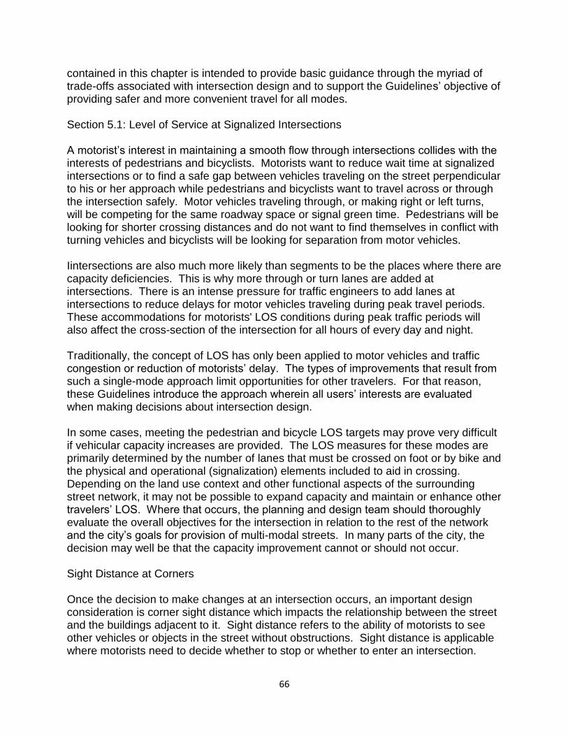
66
contained in this chapter is intended to provide basic guidance through the myriad of trade-offs associated with intersection design and to support the Guidelines’ objective of providing safer and more convenient travel for all modes. Section 5.1: Level of Service at Signalized Intersections A motorist’s interest in maintaining a smooth flow through intersections collides with the interests of pedestrians and bicyclists. Motorists want to reduce wait time at signalized intersections or to find a safe gap between vehicles traveling on the street perpendicular to his or her approach while pedestrians and bicyclists want to travel across or through the intersection safely. Motor vehicles traveling through, or making right or left turns, will be competing for the same roadway space or signal green time. Pedestrians will be looking for shorter crossing distances and do not want to find themselves in conflict with turning vehicles and bicyclists will be looking for separation from motor vehicles. Iintersections are also much more likely than segments to be the places where there are capacity deficiencies. This is why more through or turn lanes are added at intersections. There is an intense pressure for traffic engineers to add lanes at intersections to reduce delays for motor vehicles traveling during peak travel periods. These accommodations for motorists' LOS conditions during peak traffic periods will also affect the cross-section of the intersection for all hours of every day and night. Traditionally, the concept of LOS has only been applied to motor vehicles and traffic congestion or reduction of motorists’ delay. The types of improvements that result from such a single-mode approach limit opportunities for other travelers. For that reason, these Guidelines introduce the approach wherein all users’ interests are evaluated when making decisions about intersection design. In some cases, meeting the pedestrian and bicycle LOS targets may prove very difficult if vehicular capacity increases are provided. The LOS measures for these modes are primarily determined by the number of lanes that must be crossed on foot or by bike and the physical and operational (signalization) elements included to aid in crossing. Depending on the land use context and other functional aspects of the surrounding street network, it may not be possible to expand capacity and maintain or enhance other travelers’ LOS. Where that occurs, the planning and design team should thoroughly evaluate the overall objectives for the intersection in relation to the rest of the network and the city’s goals for provision of multi-modal streets. In many parts of the city, the decision may well be that the capacity improvement cannot or should not occur. Sight Distance at Corners Once the decision to make changes at an intersection occurs, an important design consideration is corner sight distance which impacts the relationship between the street and the buildings adjacent to it. Sight distance refers to the ability of motorists to see other vehicles or objects in the street without obstructions. Sight distance is applicable where motorists need to decide whether to stop or whether to enter an intersection.
67
These Guidelines have some objectives that will change the way that Tena’s current sight distance recommendations are applied. In general, Tena’s Sight Distance Policy will be applied to all intersections, although there are some instances that will call for using the policy with the greatest possible flexibility. For example, in a very urban or pedestrian-oriented context, there may be a conflict between sight triangles (the space available for drivers to see each other as they approach an intersection) and the desire to have buildings situated close to the street or even directly behind the sidewalk (Figure 5.1). Even with the wider sidewalks and amenity zones found in these areas, meeting the requirement of a strictly applied sight triangle for an adjacent intersection may not be possible or desirable. Likewise, the requirements for departure sight triangles along streets (when pulling out of side streets or driveways), if applied strictly, may conflict with the desire to provide bus shelters, street furnishings, or enough street trees of sufficient size to create a canopy.
Figure 5.1. Sight distance triangles in urban locations; potentially conflicting objectives?
Conversely, on streets designed for other contexts, where higher speeds and land uses with deeper setbacks are found, a stricter application of the sight distance recommendations is required. In those cases, the traditional viewpoint of maintaining adequate “room for error” by motorists is necessary for maintaining safety. This is a worthwhile objective and intended outcome for all streets and intersections defined within these Guidelines. In summary, corner sight distance must be applied carefully to avoid unintended and potentially negative consequences. As with many of the recommendations contained within these Guidelines, those designing a street should make an effort to best match the design outcome to the surrounding context.
68
Traffic Signal Timing As described earlier in this chapter, designing the physical elements of an intersection to satisfy multiple objectives related to motorists, pedestrians, and cyclists can be challenging. Likewise, there are many tradeoff s to consider when timing traffic signals, because people traveling through one location and using different modes essentially “compete” for green signal time. Specific signal timing is an important and complex component of meeting the multi-modal objectives of these Guidelines. Why is signal timing so complex? The following illustrates some of the difficulties of satisfying everyone who is impacted by signal timing at an intersection:
Not surprisingly, most motorists do not like to be stopped by traffic signals. Once they do stop, they typically want to move again as soon as possible.
Traffic signal timing traditionally heavily favors (provides more “green time” to) the higher-volume street over the lower-volume street – sometimes creating noticeably higher delays for motorists waiting on the lower-volume street. Motorists on the higher-volume street are less likely to be stopped at any given side street, but motorists on the lower-volume street oft en feel that their wait is excessive.
In addition to “fairly” allocating green time between competing motorists, it is also important to provide enough green time for safe pedestrian crossings – which can have the unintended consequence of increasing overall cycle lengths at the intersection. However, it is important to provide for pedestrians, particularly in pedestrian-oriented areas, and even where it might be more difficult, such as at very large or high-traffic-volume intersections, have a difficult time traversing the intersection.
Like motorists, pedestrians also do not like to wait a long time to cross an intersection and, when the wait is perceived as being “too long”, are more likely than motorists to cross against the signal.
Signalized intersections do not function solely as discrete locations – they are increasingly operated as part of a group of signals and, therefore, signal timing (and “green time” allocation) at any given intersection is typically not considered independent of other, nearby intersections. Signal cycle length tradeoff decisions will help meet those objectives, in part through the following assumptions:
In general, shorter cycle lengths and wait times are desirable, particularly when this can also accommodate pedestrian crossings.
Signal timing decisions will consider the types of streets that intersect (the intersection “context”), in addition to the nearby (potentially synchronized) intersections that might be affected.
Signal timing decisions will not always heavily favor the higher-volume streets or flows, although every attempt will be made to maintain satisfactory throughput.
69
The objective of minimizing vehicular delay and/or maximizing vehicular throughput is a higher priority for Boulevards and Parkways than for Main Streets or Avenues.
Signalized Intersection Characteristics Relative to the Pedestrian LOS The main impediments to the comfort and safety for pedestrians crossing at signalized intersections are the crossing distance and conflicts with turning vehicles. Volumes and speeds of vehicles are also factors but are tempered by the presence or non-presence of the traffic signal and/or physical characteristics of the intersection. For example, tight bend radii can slow the speed of vehicle turning right and conflicts created by vehicle turning left or right can be eliminated or reduced with phase signals; these are design factors affecting the comfort and safety between pedestrians and vehicles. So, although volumes and speeds are not addressed explicitly, they are implicitly treated in this methodology. This approach for assessing pedestrian LOS, therefore, identifies the key elements or characteristics of intersections that increase or decrease the comfort and safety, and then weigh them relative to each other. For example:
Crossing Distance: As mentioned above, the crossing distance is the main obstacle for pedestrians traveling through the intersections and therefore receives the highest weight in this methodology. The less distance you have to walk across the street, the easier and more comfortable is the perception of the crossing.
Phase signal and duration: This is the most intricate of design parameters and the second largest in terms of weight. It is classified according to the type and level of information provided to the pedestrian crossing and if the signal phases minimize, eliminate or exacerbate conflicts between pedestrians and turning vehicles (Figure 5.2).
Corner radius: Corner radii are classified according to their effect on the speed of vehicles turning right and any increase walking distance for pedestrians. The smaller the radius, the slower the speed of turn and the less distance to walk. The maximum radii of 20 feet are preferable, while the large radii (over 40 feet) are considered harmful. In addition, changes in the angle of turn also reduce speeds and increase motorist visibility thereby increasing pedestrian safety (Figure 5.3).
Signalized Intersection Characteristics Relative to the Cyclist LOS For simplicity, no distinction is made between the corner radius and its effect on the speed of turning vehicles to a single lane or multiple lanes. Furthermore, the effect of the angle of intersection at vehicle speeds for a given radius is not directly incorporated. The main obstacles to the comfort and safety of cyclists are slightly different from those for pedestrians. Characteristics of traffic signals and potential conflicts with turning vehicles are important issues, but the crossing distance is less important and is surpassed by the desire of physical space separated from car traffic. Since the space used by cyclists is shared with motor vehicles, traffic speed is also a significant factor.
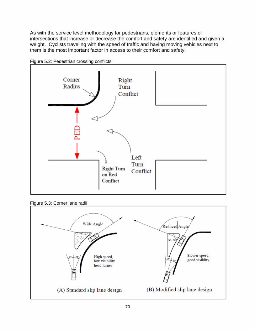
70
As with the service level methodology for pedestrians, elements or features of intersections that increase or decrease the comfort and safety are identified and given a weight. Cyclists traveling with the speed of traffic and having moving vehicles next to them is the most important factor in access to their comfort and safety. Figure 5.2: Pedestrian crossing conflicts
Figure 5.3: Corner lane radii
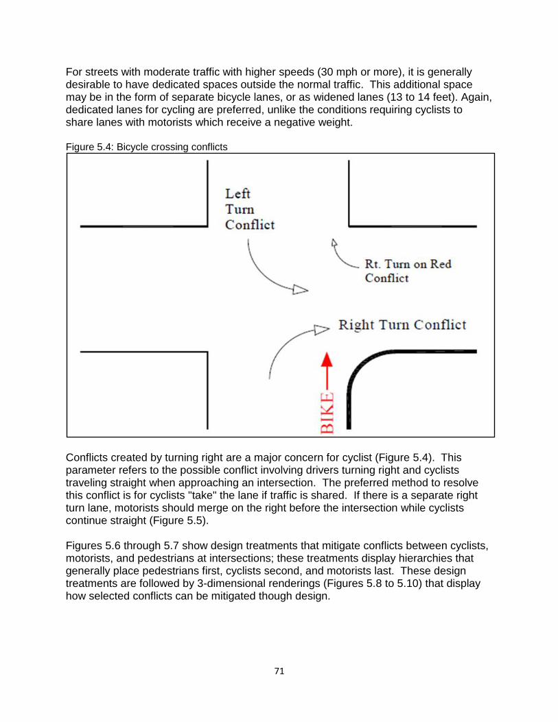
71
For streets with moderate traffic with higher speeds (30 mph or more), it is generally desirable to have dedicated spaces outside the normal traffic. This additional space may be in the form of separate bicycle lanes, or as widened lanes (13 to 14 feet). Again, dedicated lanes for cycling are preferred, unlike the conditions requiring cyclists to share lanes with motorists which receive a negative weight. Figure 5.4: Bicycle crossing conflicts
Conflicts created by turning right are a major concern for cyclist (Figure 5.4). This parameter refers to the possible conflict involving drivers turning right and cyclists traveling straight when approaching an intersection. The preferred method to resolve this conflict is for cyclists "take" the lane if traffic is shared. If there is a separate right turn lane, motorists should merge on the right before the intersection while cyclists continue straight (Figure 5.5). Figures 5.6 through 5.7 show design treatments that mitigate conflicts between cyclists, motorists, and pedestrians at intersections; these treatments display hierarchies that generally place pedestrians first, cyclists second, and motorists last. These design treatments are followed by 3-dimensional renderings (Figures 5.8 to 5.10) that display how selected conflicts can be mitigated though design.
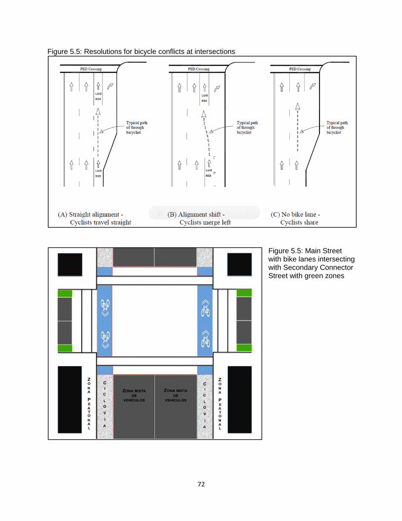
72
Figure 5.5: Resolutions for bicycle conflicts at intersections
Figure 5.5: Main Street with bike lanes intersecting with Secondary Connector Street with green zones
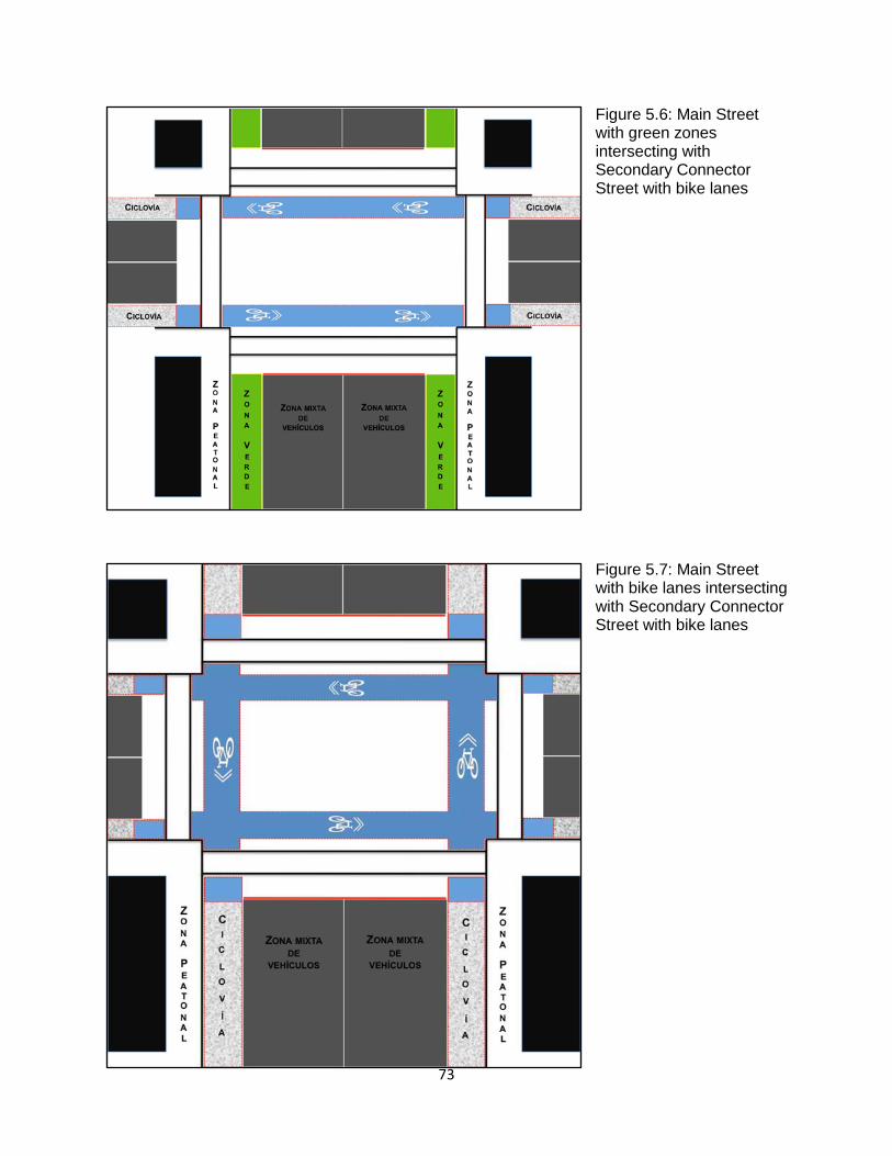
73
Figure 5.6: Main Street with green zones intersecting with Secondary Connector Street with bike lanes
Figure 5.7: Main Street with bike lanes intersecting with Secondary Connector Street with bike lanes
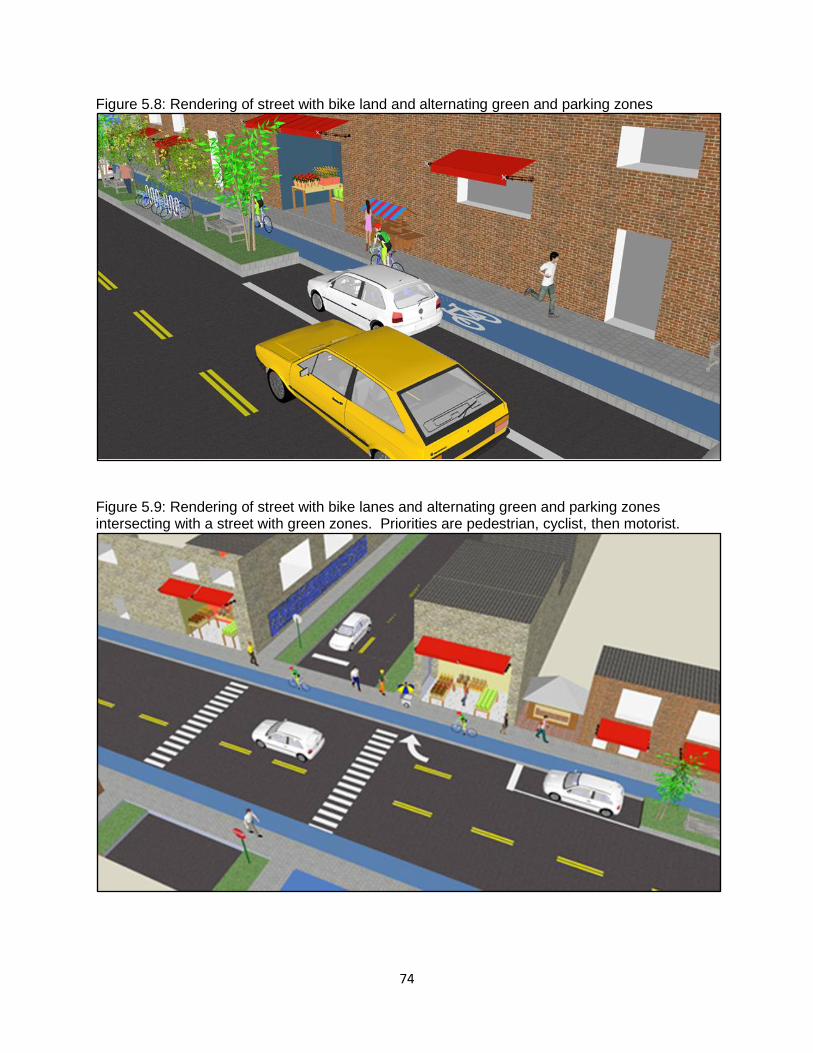
74
Figure 5.8: Rendering of street with bike land and alternating green and parking zones
Figure 5.9: Rendering of street with bike lanes and alternating green and parking zones intersecting with a street with green zones. Priorities are pedestrian, cyclist, then motorist.
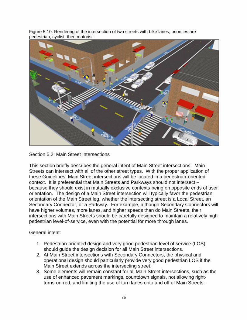
75
Figure 5.10: Rendering of the intersection of two streets with bike lanes; priorities are pedestrian, cyclist, then motorist.
Section 5.2: Main Street Intersections This section briefly describes the general intent of Main Street intersections. Main Streets can intersect with all of the other street types. With the proper application of these Guidelines, Main Street intersections will be located in a pedestrian-oriented context. It is preferential that Main Streets and Parkways should not intersect – because they should exist in mutually exclusive contexts being on opposite ends of user orientation. The design of a Main Street intersection will typically favor the pedestrian orientation of the Main Street leg, whether the intersecting street is a Local Street, an Secondary Connector, or a Parkway. For example, although Secondary Connectors will have higher volumes, more lanes, and higher speeds than do Main Streets, their intersections with Main Streets should be carefully designed to maintain a relatively high pedestrian level-of-service, even with the potential for more through lanes. General intent:
1. Pedestrian-oriented design and very good pedestrian level of service (LOS) should guide the design decision for all Main Street intersections.
2. At Main Street intersections with Secondary Connectors, the physical and operational design should particularly provide very good pedestrian LOS if the Main Street extends across the intersecting street.
3. Some elements will remain constant for all Main Street intersections, such as the use of enhanced pavement markings, countdown signals, not allowing right-turns-on-red, and limiting the use of turn lanes onto and off of Main Streets.
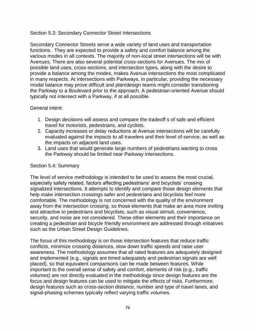
76
Section 5.3: Secondary Connector Street Intersections Secondary Connector Streets serve a wide variety of land uses and transportation functions. They are expected to provide a safety and comfort balance among the various modes in all contexts. The majority of non-local street intersections will be with Avenues. There are also several potential cross-sections for Avenues. The mix of possible land uses, cross-sections, and intersection types, along with the desire to provide a balance among the modes, makes Avenue intersections the most complicated in many respects. At intersections with Parkways, in particular, providing the necessary modal balance may prove difficult and plan/design teams might consider transitioning the Parkway to a Boulevard prior to the approach. A pedestrian-oriented Avenue should typically not intersect with a Parkway, if at all possible. General intent:
1. Design decisions will assess and compare the tradeoff s of safe and efficient travel for motorists, pedestrians, and cyclists.
2. Capacity increases or delay reductions at Avenue intersections will be carefully evaluated against the impacts to all travelers and their level of-service, as well as the impacts on adjacent land uses.
3. Land uses that would generate large numbers of pedestrians wanting to cross the Parkway should be limited near Parkway intersections.
Section 5.4: Summary The level of service methodology is intended to be used to assess the most crucial, especially safety related, factors affecting pedestrians’ and bicyclists’ crossing signalized intersections. It attempts to identify and compare those design elements that help make intersection crossings safer and pedestrians and bicyclists feel more comfortable. The methodology is not concerned with the quality of the environment away from the intersection crossing, so those elements that make an area more inviting and attractive to pedestrians and bicyclists, such as visual stimuli, convenience, security, and noise are not considered. These other elements and their importance on creating a pedestrian and bicycle friendly environment are addressed through initiatives such as the Urban Street Design Guidelines. The focus of this methodology is on those intersection features that reduce traffic conflicts, minimize crossing distances, slow down traffic speeds and raise user awareness. The methodology assumes that all rated features are adequately designed and implemented (e.g., signals are timed adequately and pedestrian signals are well placed), so that equivalent comparisons can be made between features. While important to the overall sense of safety and comfort, elements of risk (e.g., traffic volumes) are not directly evaluated in the methodology since design features are the focus and design features can be used to mitigate the effects of risks. Furthermore, design features such as cross-section distance, number and type of travel lanes, and signal-phasing schemes typically reflect varying traffic volumes.

77
This level of service methodology is expected to be applied in conjunction with the traditional level of service methodology for motor vehicles. The importance or relative weight given to each level of service (for motor vehicles, bicyclists or pedestrians) is expected to vary by intersection, depending on the planned function and context of each intersection.
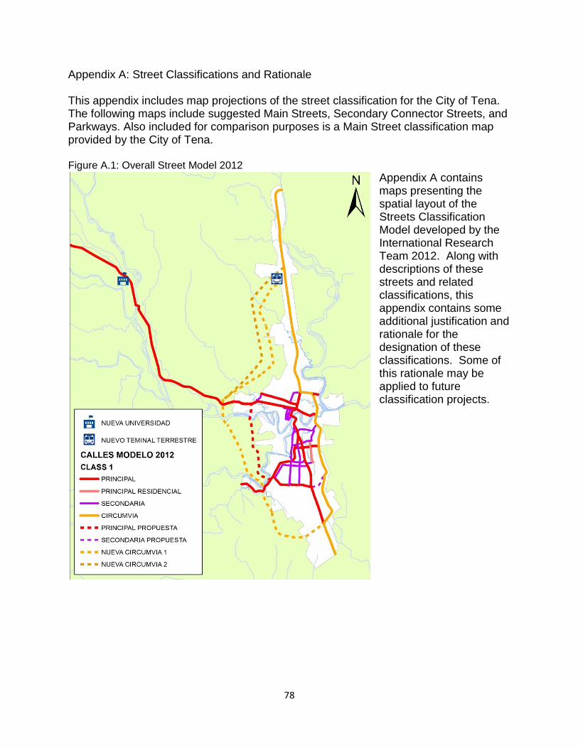
78
Appendix A: Street Classifications and Rationale This appendix includes map projections of the street classification for the City of Tena. The following maps include suggested Main Streets, Secondary Connector Streets, and Parkways. Also included for comparison purposes is a Main Street classification map provided by the City of Tena. Figure A.1: Overall Street Model 2012
Appendix A contains maps presenting the spatial layout of the Streets Classification Model developed by the International Research Team 2012. Along with descriptions of these streets and related classifications, this appendix contains some additional justification and rationale for the designation of these classifications. Some of this rationale may be applied to future classification projects.
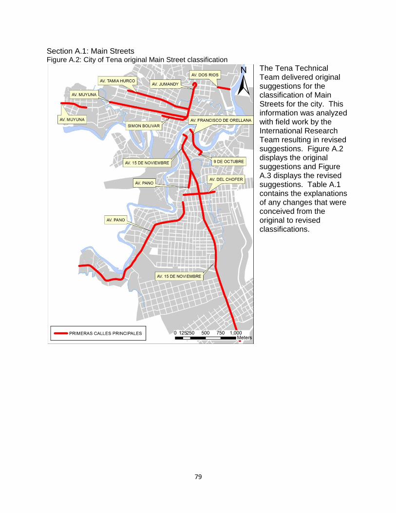
79
Section A.1: Main Streets Figure A.2: City of Tena original Main Street classification
The Tena Technical Team delivered original suggestions for the classification of Main Streets for the city. This information was analyzed with field work by the International Research Team resulting in revised suggestions. Figure A.2 displays the original suggestions and Figure A.3 displays the revised suggestions. Table A.1 contains the explanations of any changes that were conceived from the original to revised classifications.
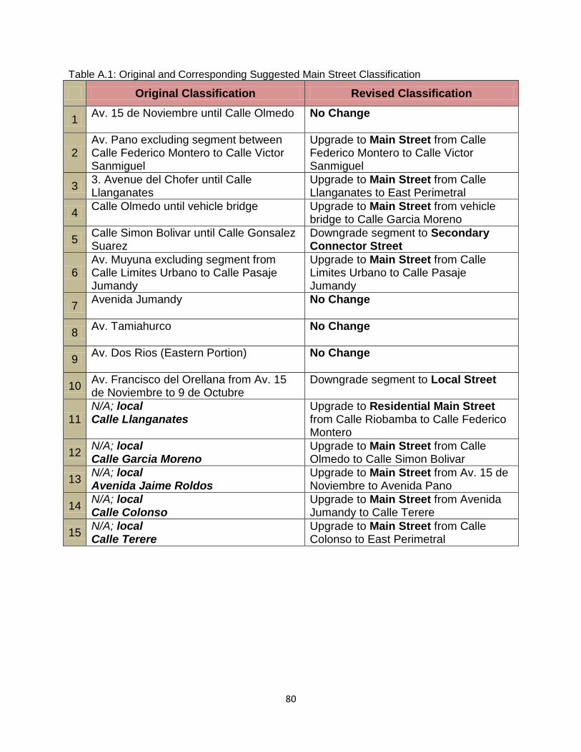
80
Table A.1: Original and Corresponding Suggested Main Street Classification
Original Classification Revised Classification
1 Av. 15 de Noviembre until Calle Olmedo
No Change
2 Av. Pano excluding segment between Calle Federico Montero to Calle Victor Sanmiguel
Upgrade to Main Street from Calle Federico Montero to Calle Victor Sanmiguel
3 3. Avenue del Chofer until Calle Llanganates
Upgrade to Main Street from Calle Llanganates to East Perimetral
4 Calle Olmedo until vehicle bridge
Upgrade to Main Street from vehicle bridge to Calle Garcia Moreno
5 Calle Simon Bolivar until Calle Gonsalez Suarez
Downgrade segment to Secondary Connector Street
6 Av. Muyuna excluding segment from Calle Limites Urbano to Calle Pasaje Jumandy
Upgrade to Main Street from Calle Limites Urbano to Calle Pasaje Jumandy
7 Avenida Jumandy
No Change
8 Av. Tamiahurco No Change
9 Av. Dos Rios (Eastern Portion)
No Change
10 Av. Francisco del Orellana from Av. 15 de Noviembre to 9 de Octubre
Downgrade segment to Local Street
11 N/A; local Calle Llanganates
Upgrade to Residential Main Street from Calle Riobamba to Calle Federico Montero
12 N/A; local Calle Garcia Moreno
Upgrade to Main Street from Calle Olmedo to Calle Simon Bolivar
13 N/A; local Avenida Jaime Roldos
Upgrade to Main Street from Av. 15 de Noviembre to Avenida Pano
14 N/A; local Calle Colonso
Upgrade to Main Street from Avenida Jumandy to Calle Terere
15 N/A; local Calle Terere
Upgrade to Main Street from Calle Colonso to East Perimetral
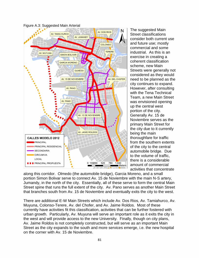
81
Figure A.3: Suggested Main Arterial
The suggested Main Street classifications consider both current use and future use; mostly commercial and some industrial. As this is an exercise in creating a coherent classification scheme, new Main Streets were generally not considered as they would need to be planned as the city continues to expand. However, after consulting with the Tena Technical Team, a new Main Street was envisioned opening up the central west portion of the city. Generally Av. 15 de Noviembre serves as the primary Main Street for the city due to it currently being the main thoroughfare for traffic from the southern extents of the city to the central automobile bridge. Due to the volume of traffic, there is a considerable amount of commercial activities that concentrate
along this corridor. Olmedo (the automobile bridge), Garcia Moreno, and a small portion Simon Bolivar serve to connect Av. 15 de Noviembre with the main N-S artery, Jumandy, in the north of the city. Essentially, all of these serve to form the central Main Street spine that runs the full extent of the city. Av. Pano serves as another Main Street that branches south from Av. 15 de Noviembre and eventually exits the city to the west. There are additional E-W Main Streets which include Av. Dos Rios, Av. Tamiahurco, Av. Muyuna, Colonso-Terere, Av. del Chofer, and Av. Jaime Roldos. Most of these currently have activities fit this classification, activities that can be further fostered with urban growth. Particularly, Av. Muyuna will serve an important role as it exits the city in the west and will provide access to the new University. Finally, though on city plans, Av. Jaime Roldos is not completely constructed, but will serve as an important Main Street as the city expands to the south and more services emerge, i.e. the new hospital on the corner with Av. 15 de Noviembre.
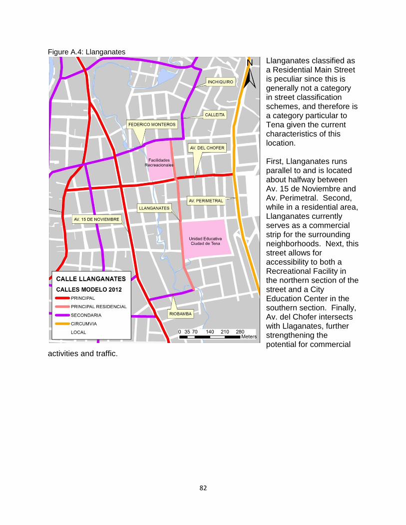
82
Figure A.4: Llanganates
Llanganates classified as a Residential Main Street is peculiar since this is generally not a category in street classification schemes, and therefore is a category particular to Tena given the current characteristics of this location. First, Llanganates runs parallel to and is located about halfway between Av. 15 de Noviembre and Av. Perimetral. Second, while in a residential area, Llanganates currently serves as a commercial strip for the surrounding neighborhoods. Next, this street allows for accessibility to both a Recreational Facility in the northern section of the street and a City Education Center in the southern section. Finally, Av. del Chofer intersects with Llaganates, further strengthening the potential for commercial
activities and traffic.
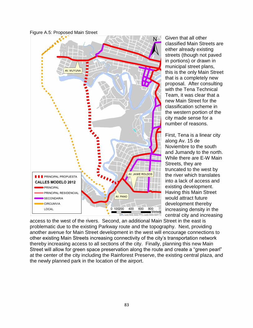
83
Figure A.5: Proposed Main Street
Given that all other classified Main Streets are either already existing streets (though not paved in portions) or drawn in municipal street plans, this is the only Main Street that is a completely new proposal. After consulting with the Tena Technical Team, it was clear that a new Main Street for the classification scheme in the western portion of the city made sense for a number of reasons. First, Tena is a linear city along Av. 15 de Noviembre to the south and Jumandy to the north. While there are E-W Main Streets, they are truncated to the west by the river which translates into a lack of access and existing development. Having this Main Street would attract future development thereby increasing density in the central city and increasing
access to the west of the rivers. Second, an additional Main Street in the east is problematic due to the existing Parkway route and the topography. Next, providing another avenue for Main Street development in the west will encourage connections to other existing Main Streets increasing connectivity of the city’s transportation network thereby increasing access to all sections of the city. Finally, planning this new Main Street will allow for green space preservation along the route and create a “green pearl” at the center of the city including the Rainforest Preserve, the existing central plaza, and the newly planned park in the location of the airport.
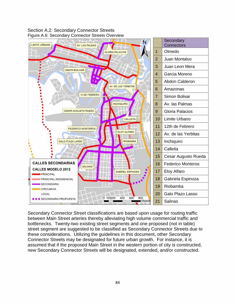
84
Section A.2: Secondary Connector Streets Figure A.6: Secondary Connector Streets Overview
Secondary Connectors
1 Olmedo
2 Juan Montalvo
3 Juan Leon Mera
4 Garcia Moreno
5 Abdon Calderon
6 Amazonas
7 Simon Bolivar
8 Av. las Palmas
9 Gloria Palacios
10 Limite Urbano
11 12th de Febrero
12 Av. de las Yerbitas
13 Inchiquiro
14 Calleita
15 Cesar Augusto Rueda
16 Federico Monteros
17 Eloy Alfaro
18 Gabriela Espinoza
19 Riobamba
20 Galo Plazo Lasso
21 Salinas
Secondary Connector Street classifications are based upon usage for routing traffic between Main Street arteries thereby alleviating high volume commercial traffic and bottlenecks. Twenty-two existing street segments and one proposed (not in table) street segment are suggested to be classified as Secondary Connector Streets due to these considerations. Utilizing the guidelines in this document, other Secondary Connector Streets may be designated for future urban growth. For instance, it is assumed that if the proposed Main Street in the western portion of city is constructed, new Secondary Connector Streets will be designated, extended, and/or constructed.
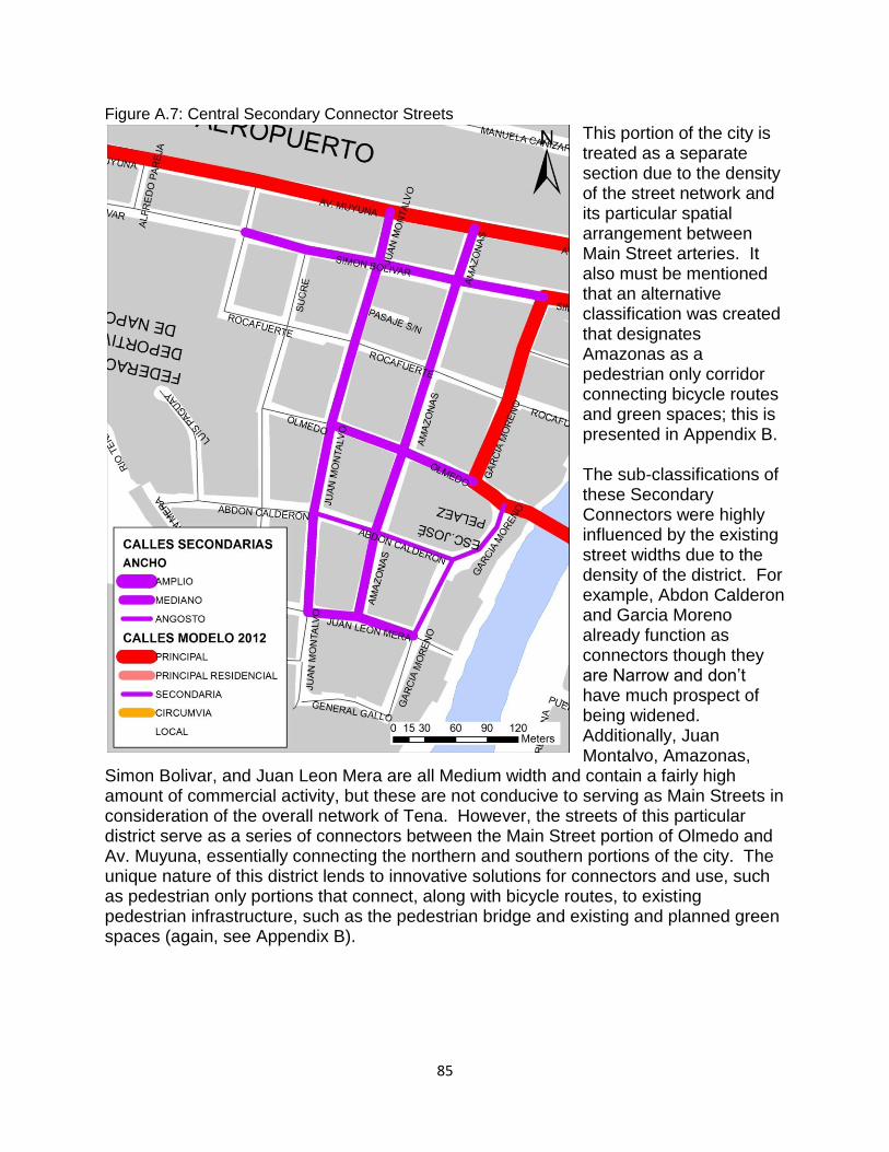
85
Figure A.7: Central Secondary Connector Streets
This portion of the city is treated as a separate section due to the density of the street network and its particular spatial arrangement between Main Street arteries. It also must be mentioned that an alternative classification was created that designates Amazonas as a pedestrian only corridor connecting bicycle routes and green spaces; this is presented in Appendix B. The sub-classifications of these Secondary Connectors were highly influenced by the existing street widths due to the density of the district. For example, Abdon Calderon and Garcia Moreno already function as connectors though they are Narrow and don’t have much prospect of being widened. Additionally, Juan Montalvo, Amazonas,
Simon Bolivar, and Juan Leon Mera are all Medium width and contain a fairly high amount of commercial activity, but these are not conducive to serving as Main Streets in consideration of the overall network of Tena. However, the streets of this particular district serve as a series of connectors between the Main Street portion of Olmedo and Av. Muyuna, essentially connecting the northern and southern portions of the city. The unique nature of this district lends to innovative solutions for connectors and use, such as pedestrian only portions that connect, along with bicycle routes, to existing pedestrian infrastructure, such as the pedestrian bridge and existing and planned green spaces (again, see Appendix B).
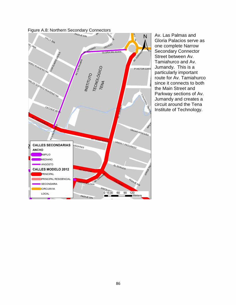
86
Figure A.8: Northern Secondary Connectors
Av. Las Palmas and Gloria Palacios serve as one complete Narrow Secondary Connector Street between Av. Tamiahurco and Av. Jumandy. This is a particularly important route for Av. Tamiahurco since it connects to both the Main Street and Parkway sections of Av. Jumandy and creates a circuit around the Tena Institute of Technology.
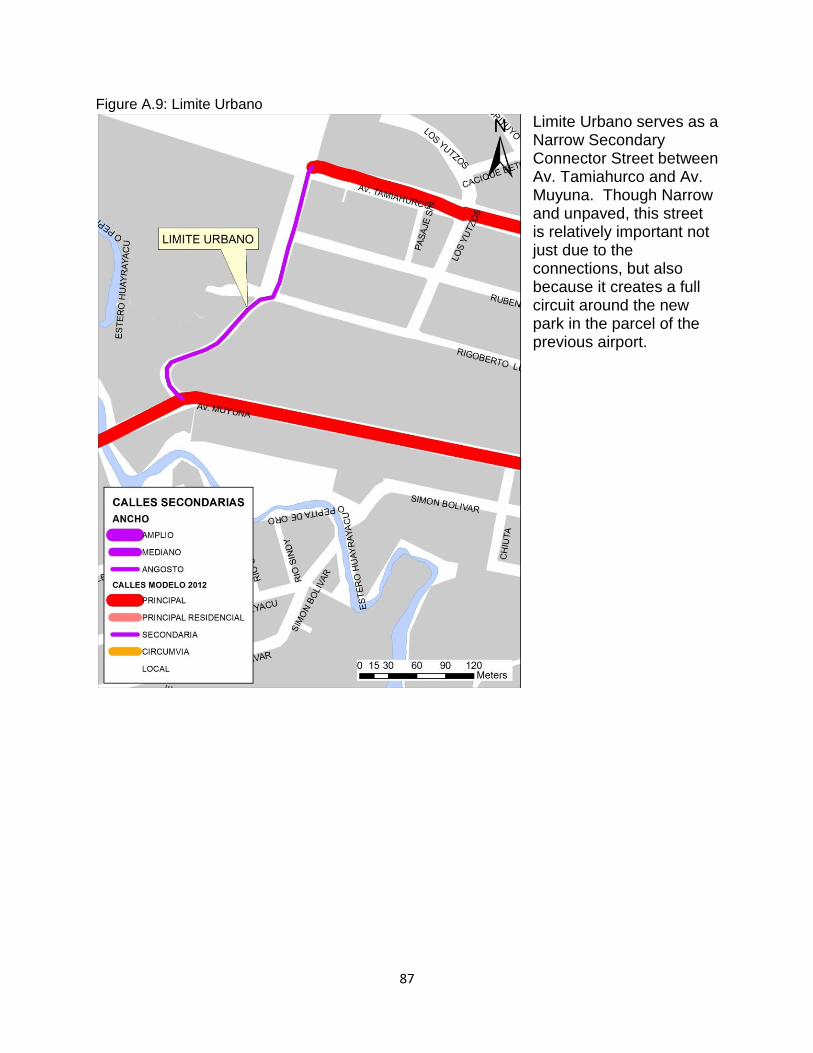
87
Figure A.9: Limite Urbano
Limite Urbano serves as a Narrow Secondary Connector Street between Av. Tamiahurco and Av. Muyuna. Though Narrow and unpaved, this street is relatively important not just due to the connections, but also because it creates a full circuit around the new park in the parcel of the previous airport.
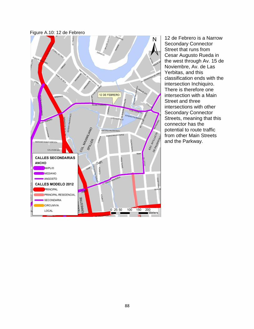
88
Figure A.10: 12 de Febrero
12 de Febrero is a Narrow Secondary Connector Street that runs from Cesar Augusto Rueda in the west through Av. 15 de Noviembre, Av. de Las Yerbitas, and this classification ends with the intersection Inchiquiro. There is therefore one intersection with a Main Street and three intersections with other Secondary Connector Streets, meaning that this connector has the potential to route traffic from other Main Streets and the Parkway.
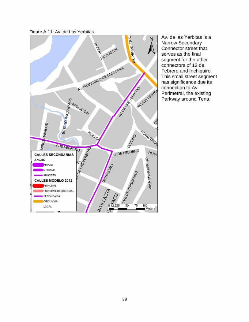
89
Figure A.11: Av. de Las Yerbitas
Av. de las Yerbitas is a Narrow Secondary Connector street that serves as the final segment for the other connectors of 12 de Febrero and Inchiquiro. This small street segment has significance due its connection to Av. Perimetral, the existing Parkway around Tena.
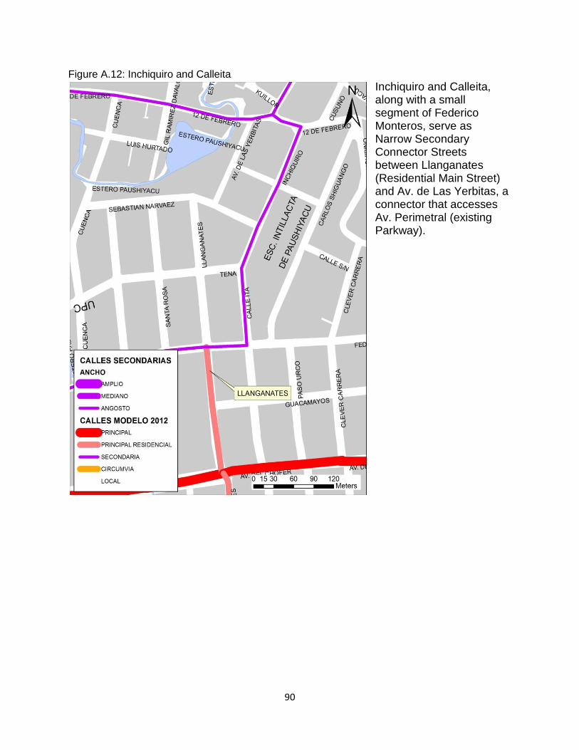
90
Figure A.12: Inchiquiro and Calleita
Inchiquiro and Calleita, along with a small segment of Federico Monteros, serve as Narrow Secondary Connector Streets between Llanganates (Residential Main Street) and Av. de Las Yerbitas, a connector that accesses Av. Perimetral (existing Parkway).
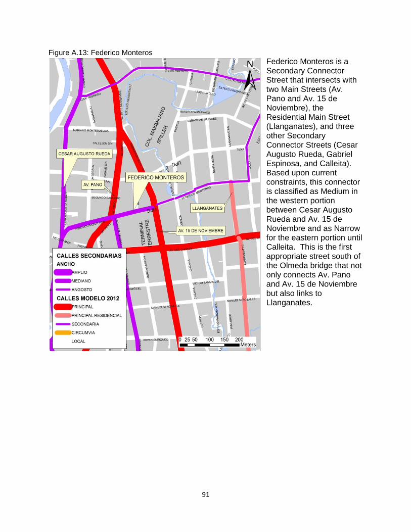
91
Figure A.13: Federico Monteros
Federico Monteros is a Secondary Connector Street that intersects with two Main Streets (Av. Pano and Av. 15 de Noviembre), the Residential Main Street (Llanganates), and three other Secondary Connector Streets (Cesar Augusto Rueda, Gabriel Espinosa, and Calleita). Based upon current constraints, this connector is classified as Medium in the western portion between Cesar Augusto Rueda and Av. 15 de Noviembre and as Narrow for the eastern portion until Calleita. This is the first appropriate street south of the Olmeda bridge that not only connects Av. Pano and Av. 15 de Noviembre but also links to Llanganates.
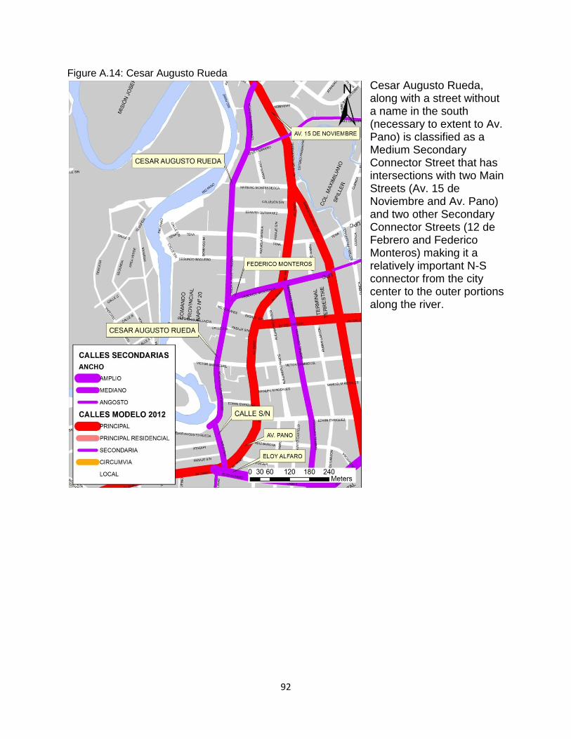
92
Figure A.14: Cesar Augusto Rueda
Cesar Augusto Rueda, along with a street without a name in the south (necessary to extent to Av. Pano) is classified as a Medium Secondary Connector Street that has intersections with two Main Streets (Av. 15 de Noviembre and Av. Pano) and two other Secondary Connector Streets (12 de Febrero and Federico Monteros) making it a relatively important N-S connector from the city center to the outer portions along the river.
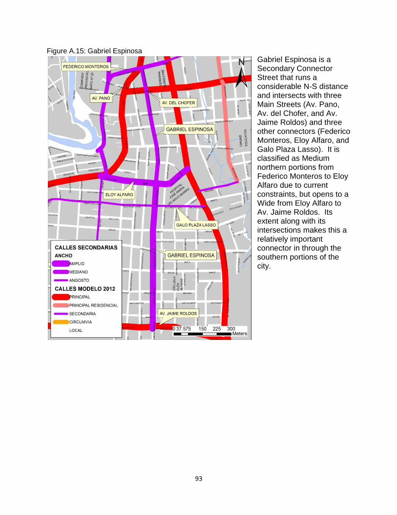
93
Figure A.15: Gabriel Espinosa
Gabriel Espinosa is a Secondary Connector Street that runs a considerable N-S distance and intersects with three Main Streets (Av. Pano, Av. del Chofer, and Av. Jaime Roldos) and three other connectors (Federico Monteros, Eloy Alfaro, and Galo Plaza Lasso). It is classified as Medium northern portions from Federico Monteros to Eloy Alfaro due to current constraints, but opens to a Wide from Eloy Alfaro to Av. Jaime Roldos. Its extent along with its intersections makes this a relatively important connector in through the southern portions of the city.
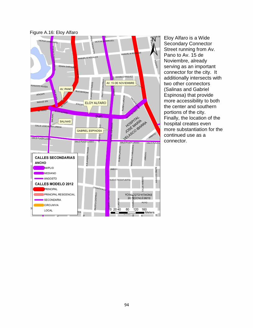
94
Figure A.16: Eloy Alfaro
Eloy Alfaro is a Wide Secondary Connector Street running from Av. Pano to Av. 15 de Noviembre, already serving as an important connector for the city. It additionally intersects with two other connectors (Salinas and Gabriel Espinosa) that provide more accessibility to both the center and southern portions of the city. Finally, the location of the hospital creates even more substantiation for the continued use as a connector.
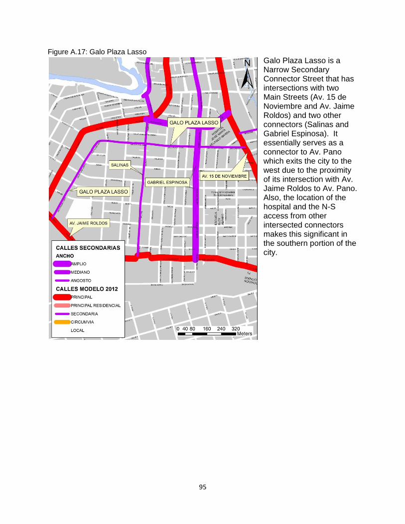
95
Figure A.17: Galo Plaza Lasso
Galo Plaza Lasso is a Narrow Secondary Connector Street that has intersections with two Main Streets (Av. 15 de Noviembre and Av. Jaime Roldos) and two other connectors (Salinas and Gabriel Espinosa). It essentially serves as a connector to Av. Pano which exits the city to the west due to the proximity of its intersection with Av. Jaime Roldos to Av. Pano. Also, the location of the hospital and the N-S access from other intersected connectors makes this significant in the southern portion of the city.
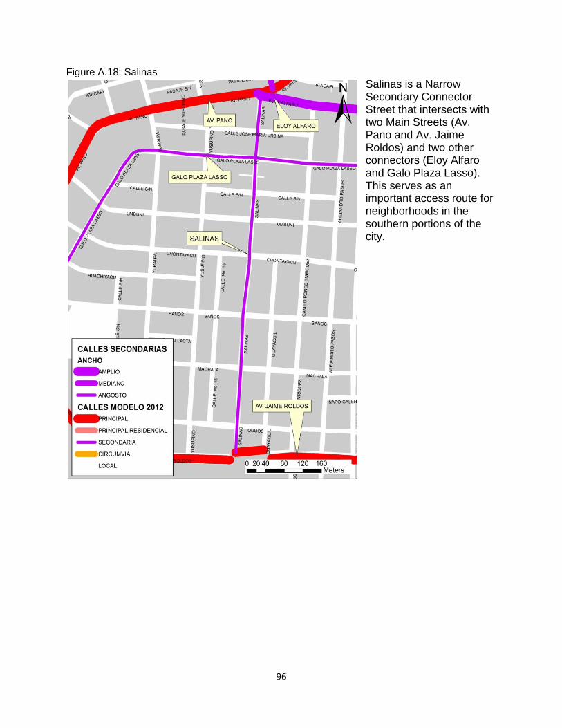
96
Figure A.18: Salinas
Salinas is a Narrow Secondary Connector Street that intersects with two Main Streets (Av. Pano and Av. Jaime Roldos) and two other connectors (Eloy Alfaro and Galo Plaza Lasso). This serves as an important access route for neighborhoods in the southern portions of the city.
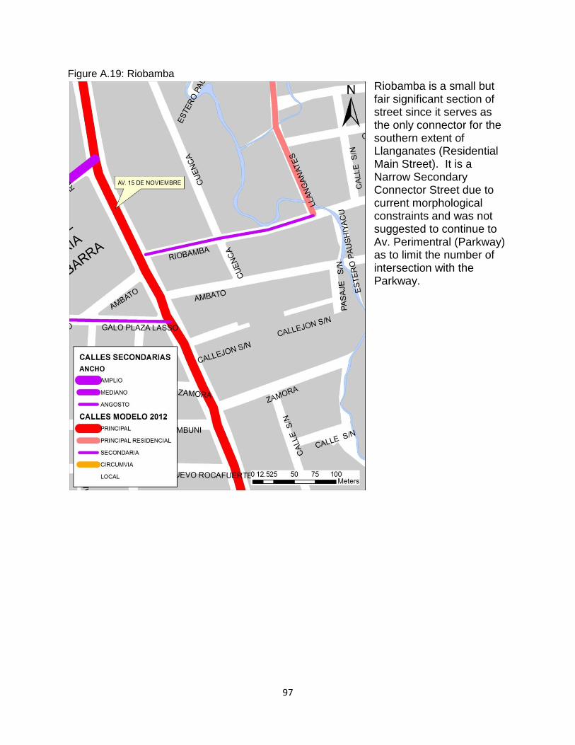
97
Figure A.19: Riobamba
Riobamba is a small but fair significant section of street since it serves as the only connector for the southern extent of Llanganates (Residential Main Street). It is a Narrow Secondary Connector Street due to current morphological constraints and was not suggested to continue to Av. Perimentral (Parkway) as to limit the number of intersection with the Parkway.
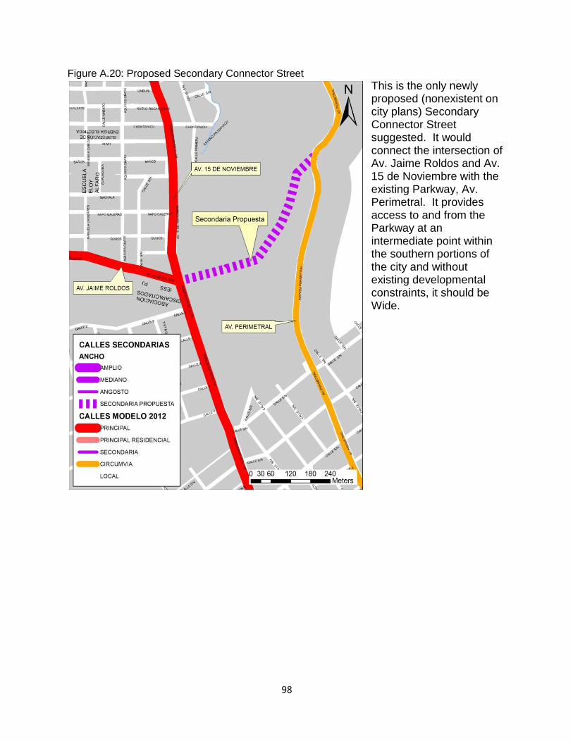
98
Figure A.20: Proposed Secondary Connector Street
This is the only newly proposed (nonexistent on city plans) Secondary Connector Street suggested. It would connect the intersection of Av. Jaime Roldos and Av. 15 de Noviembre with the existing Parkway, Av. Perimetral. It provides access to and from the Parkway at an intermediate point within the southern portions of the city and without existing developmental constraints, it should be Wide.
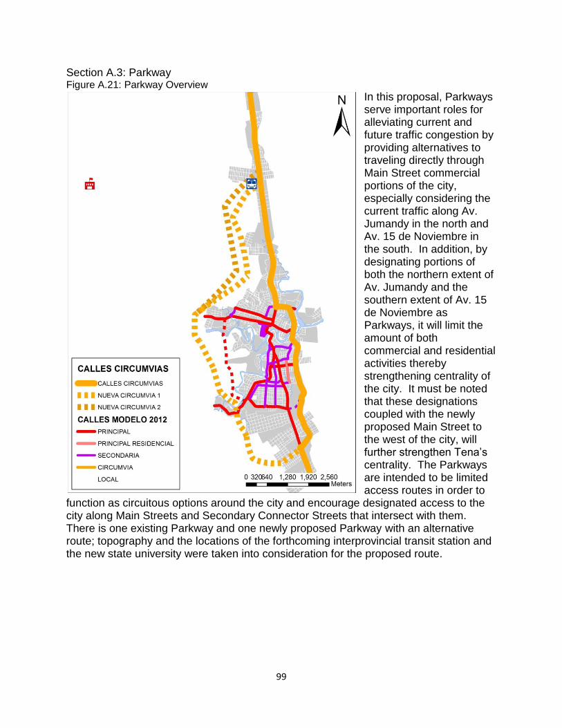
99
Section A.3: Parkway Figure A.21: Parkway Overview
In this proposal, Parkways serve important roles for alleviating current and future traffic congestion by providing alternatives to traveling directly through Main Street commercial portions of the city, especially considering the current traffic along Av. Jumandy in the north and Av. 15 de Noviembre in the south. In addition, by designating portions of both the northern extent of Av. Jumandy and the southern extent of Av. 15 de Noviembre as Parkways, it will limit the amount of both commercial and residential activities thereby strengthening centrality of the city. It must be noted that these designations coupled with the newly proposed Main Street to the west of the city, will further strengthen Tena’s centrality. The Parkways are intended to be limited access routes in order to
function as circuitous options around the city and encourage designated access to the city along Main Streets and Secondary Connector Streets that intersect with them. There is one existing Parkway and one newly proposed Parkway with an alternative route; topography and the locations of the forthcoming interprovincial transit station and the new state university were taken into consideration for the proposed route.
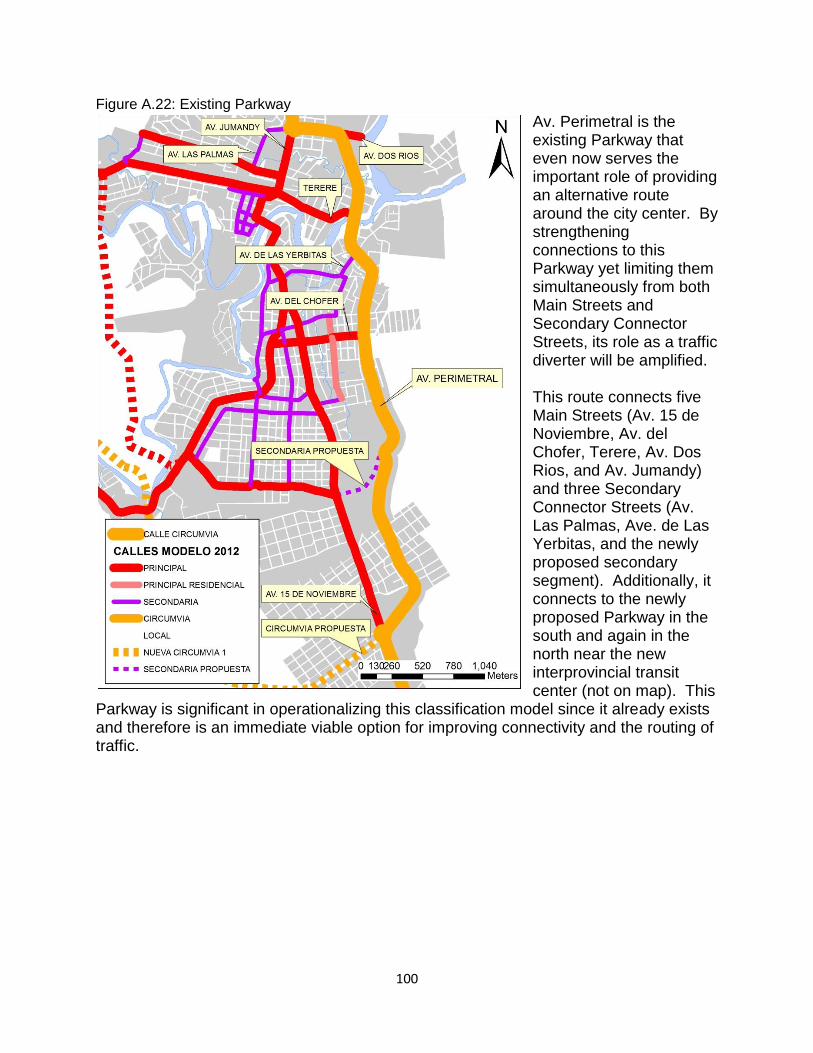
100
Figure A.22: Existing Parkway
Av. Perimetral is the existing Parkway that even now serves the important role of providing an alternative route around the city center. By strengthening connections to this Parkway yet limiting them simultaneously from both Main Streets and Secondary Connector Streets, its role as a traffic diverter will be amplified. This route connects five Main Streets (Av. 15 de Noviembre, Av. del Chofer, Terere, Av. Dos Rios, and Av. Jumandy) and three Secondary Connector Streets (Av. Las Palmas, Ave. de Las Yerbitas, and the newly proposed secondary segment). Additionally, it connects to the newly proposed Parkway in the south and again in the north near the new interprovincial transit center (not on map). This
Parkway is significant in operationalizing this classification model since it already exists and therefore is an immediate viable option for improving connectivity and the routing of traffic.
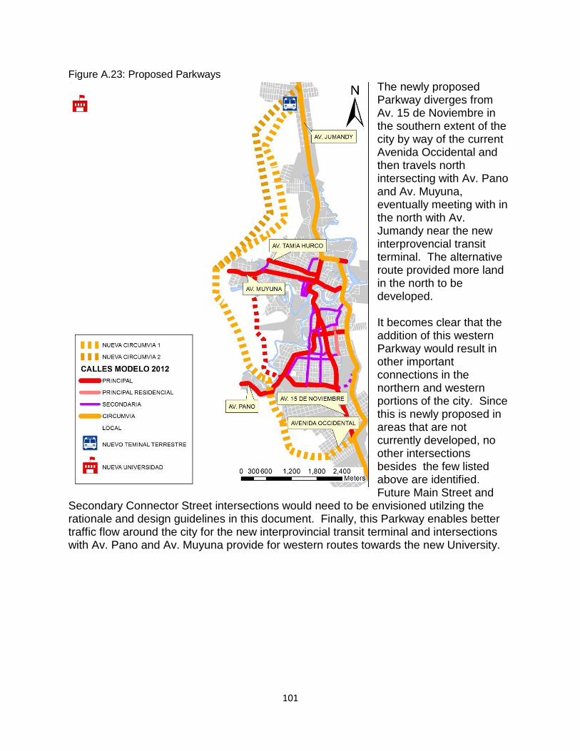
101
Figure A.23: Proposed Parkways
The newly proposed Parkway diverges from Av. 15 de Noviembre in the southern extent of the city by way of the current Avenida Occidental and then travels north intersecting with Av. Pano and Av. Muyuna, eventually meeting with in the north with Av. Jumandy near the new interprovencial transit terminal. The alternative route provided more land in the north to be developed. It becomes clear that the addition of this western Parkway would result in other important connections in the northern and western portions of the city. Since this is newly proposed in areas that are not currently developed, no other intersections besides the few listed above are identified. Future Main Street and
Secondary Connector Street intersections would need to be envisioned utilzing the rationale and design guidelines in this document. Finally, this Parkway enables better traffic flow around the city for the new interprovincial transit terminal and intersections with Av. Pano and Av. Muyuna provide for western routes towards the new University.
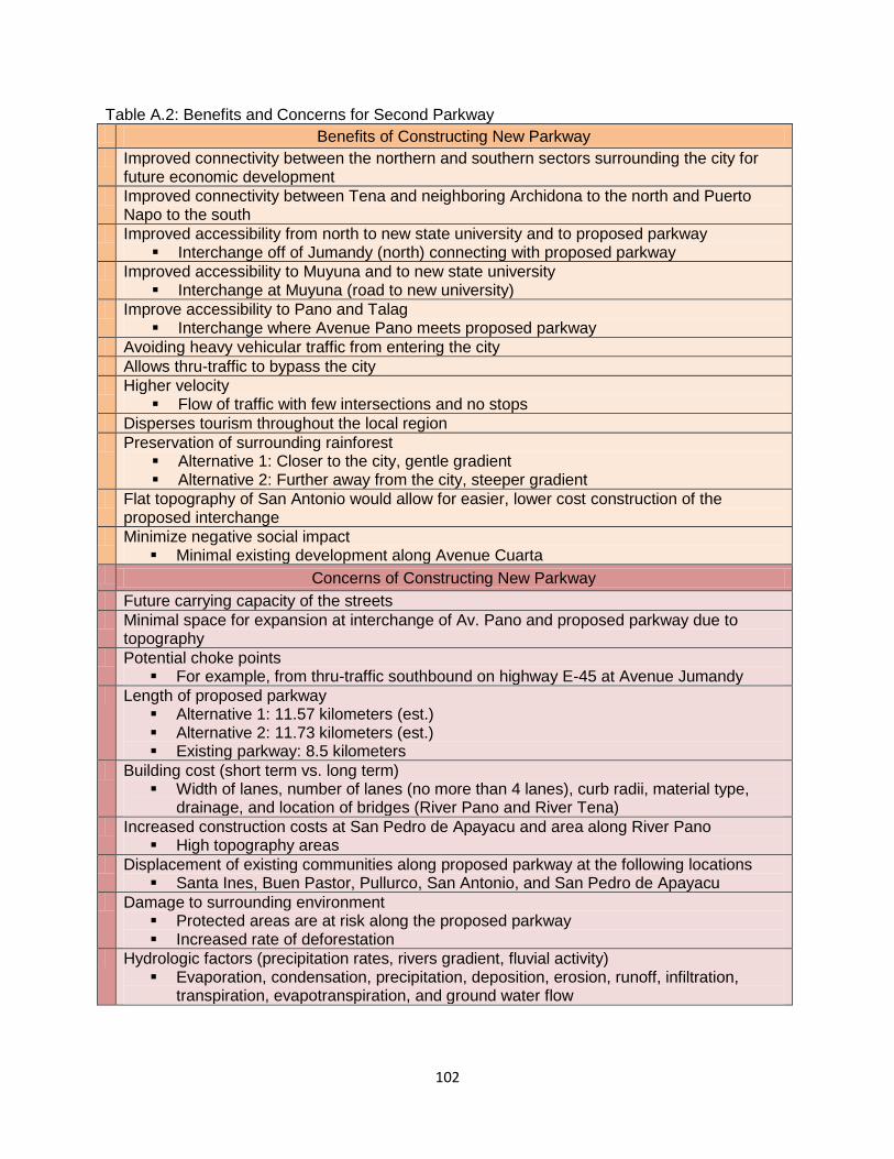
102
Table A.2: Benefits and Concerns for Second Parkway
Benefits of Constructing New Parkway
Improved connectivity between the northern and southern sectors surrounding the city for future economic development
Improved connectivity between Tena and neighboring Archidona to the north and Puerto Napo to the south
Improved accessibility from north to new state university and to proposed parkway Interchange off of Jumandy (north) connecting with proposed parkway
Improved accessibility to Muyuna and to new state university Interchange at Muyuna (road to new university)
Improve accessibility to Pano and Talag Interchange where Avenue Pano meets proposed parkway
Avoiding heavy vehicular traffic from entering the city
Allows thru-traffic to bypass the city
Higher velocity Flow of traffic with few intersections and no stops
Disperses tourism throughout the local region
Preservation of surrounding rainforest Alternative 1: Closer to the city, gentle gradient Alternative 2: Further away from the city, steeper gradient
Flat topography of San Antonio would allow for easier, lower cost construction of the proposed interchange
Minimize negative social impact Minimal existing development along Avenue Cuarta
Concerns of Constructing New Parkway
Future carrying capacity of the streets
Minimal space for expansion at interchange of Av. Pano and proposed parkway due to topography
Potential choke points For example, from thru-traffic southbound on highway E-45 at Avenue Jumandy
Length of proposed parkway Alternative 1: 11.57 kilometers (est.) Alternative 2: 11.73 kilometers (est.) Existing parkway: 8.5 kilometers
Building cost (short term vs. long term) Width of lanes, number of lanes (no more than 4 lanes), curb radii, material type,
drainage, and location of bridges (River Pano and River Tena)
Increased construction costs at San Pedro de Apayacu and area along River Pano High topography areas
Displacement of existing communities along proposed parkway at the following locations Santa Ines, Buen Pastor, Pullurco, San Antonio, and San Pedro de Apayacu
Damage to surrounding environment Protected areas are at risk along the proposed parkway Increased rate of deforestation
Hydrologic factors (precipitation rates, rivers gradient, fluvial activity) Evaporation, condensation, precipitation, deposition, erosion, runoff, infiltration,
transpiration, evapotranspiration, and ground water flow
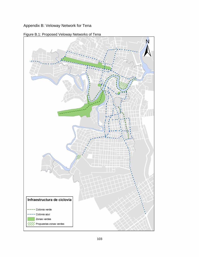
103
Appendix B: Veloway Network for Tena Figure B.1: Proposed Veloway Networks of Tena
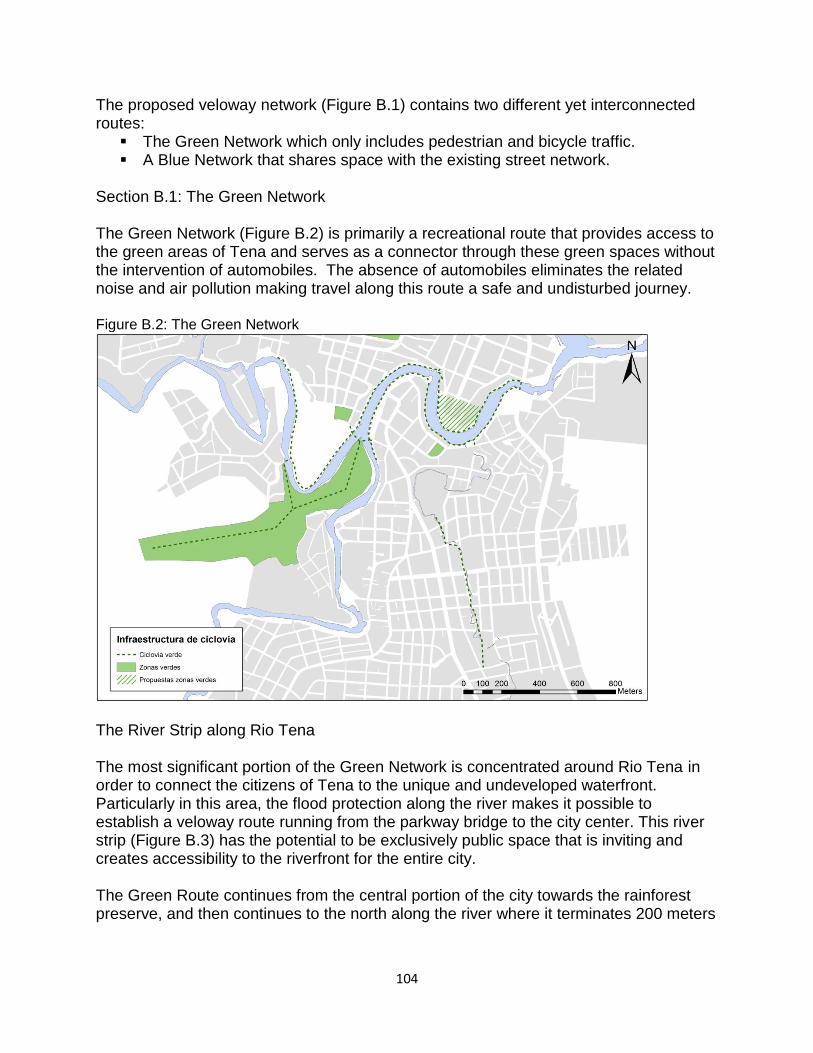
104
The proposed veloway network (Figure B.1) contains two different yet interconnected routes:
The Green Network which only includes pedestrian and bicycle traffic. A Blue Network that shares space with the existing street network.
Section B.1: The Green Network The Green Network (Figure B.2) is primarily a recreational route that provides access to the green areas of Tena and serves as a connector through these green spaces without the intervention of automobiles. The absence of automobiles eliminates the related noise and air pollution making travel along this route a safe and undisturbed journey. Figure B.2: The Green Network
The River Strip along Rio Tena The most significant portion of the Green Network is concentrated around Rio Tena in order to connect the citizens of Tena to the unique and undeveloped waterfront. Particularly in this area, the flood protection along the river makes it possible to establish a veloway route running from the parkway bridge to the city center. This river strip (Figure B.3) has the potential to be exclusively public space that is inviting and creates accessibility to the riverfront for the entire city. The Green Route continues from the central portion of the city towards the rainforest preserve, and then continues to the north along the river where it terminates 200 meters
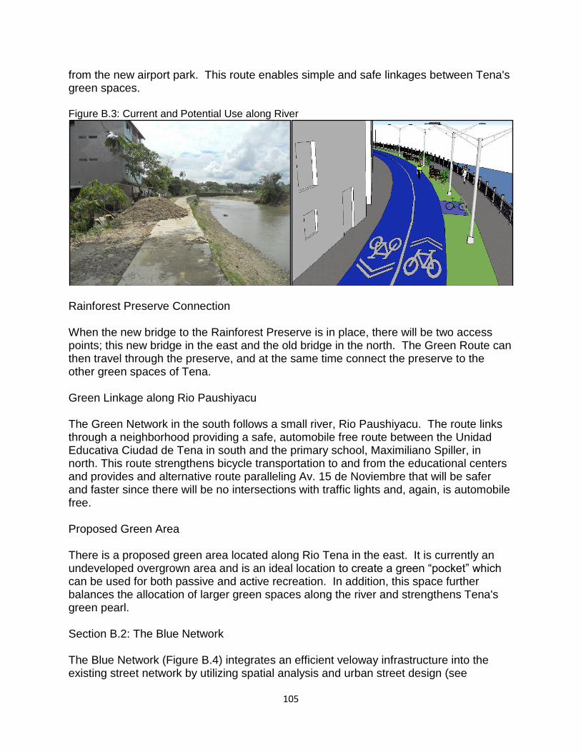
105
from the new airport park. This route enables simple and safe linkages between Tena's green spaces. Figure B.3: Current and Potential Use along River
Rainforest Preserve Connection When the new bridge to the Rainforest Preserve is in place, there will be two access points; this new bridge in the east and the old bridge in the north. The Green Route can then travel through the preserve, and at the same time connect the preserve to the other green spaces of Tena. Green Linkage along Rio Paushiyacu The Green Network in the south follows a small river, Rio Paushiyacu. The route links through a neighborhood providing a safe, automobile free route between the Unidad Educativa Ciudad de Tena in south and the primary school, Maximiliano Spiller, in north. This route strengthens bicycle transportation to and from the educational centers and provides and alternative route paralleling Av. 15 de Noviembre that will be safer and faster since there will be no intersections with traffic lights and, again, is automobile free. Proposed Green Area There is a proposed green area located along Rio Tena in the east. It is currently an undeveloped overgrown area and is an ideal location to create a green “pocket” which can be used for both passive and active recreation. In addition, this space further balances the allocation of larger green spaces along the river and strengthens Tena's green pearl. Section B.2: The Blue Network The Blue Network (Figure B.4) integrates an efficient veloway infrastructure into the existing street network by utilizing spatial analysis and urban street design (see
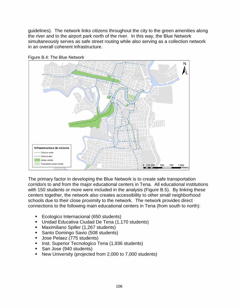
106
guidelines). The network links citizens throughout the city to the green amenities along the river and to the airport park north of the river. In this way, the Blue Network simultaneously serves as safe street routing while also serving as a collection network in an overall coherent infrastructure. Figure B.4: The Blue Network
The primary factor in developing the Blue Network is to create safe transportation corridors to and from the major educational centers in Tena. All educational institutions with 150 students or more were included in the analysis (Figure B.5). By linking these centers together, the network also creates accessibility to other small neighborhood schools due to their close proximity to the network. The network provides direct connections to the following main educational centers in Tena (from south to north):
Ecologico Internacional (650 students) Unidad Educativa Ciudad De Tena (1,170 students) Maximiliano Spiller (1,267 students) Santo Domingo Savio (508 students) Jose Pelaez (775 students) Inst. Superior Tecnologico Tena (1,936 students) San Jose (940 students) New University (projected from 2,000 to 7,000 students)
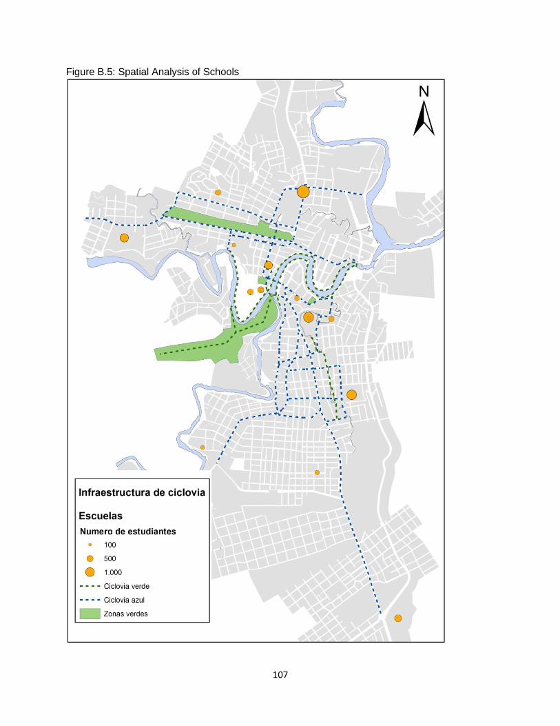
107
Figure B.5: Spatial Analysis of Schools
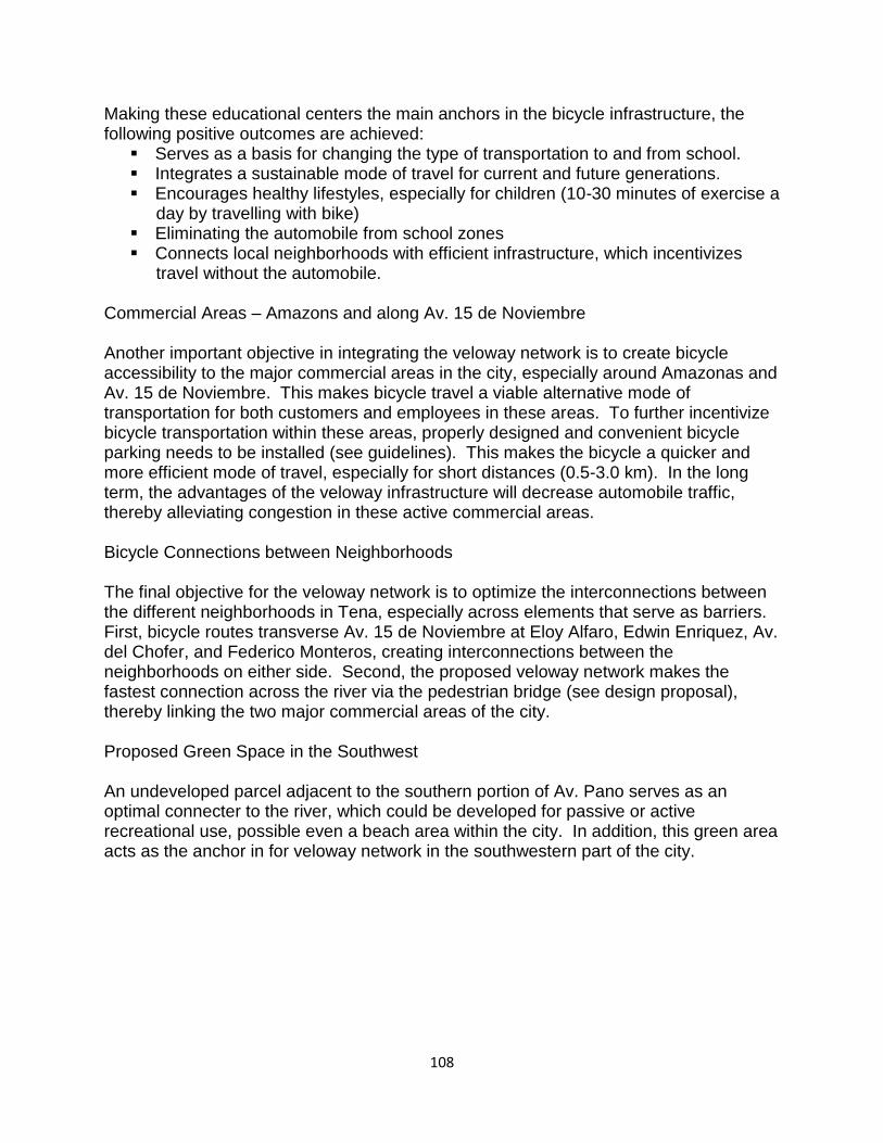
108
Making these educational centers the main anchors in the bicycle infrastructure, the following positive outcomes are achieved:
Serves as a basis for changing the type of transportation to and from school. Integrates a sustainable mode of travel for current and future generations. Encourages healthy lifestyles, especially for children (10-30 minutes of exercise a
day by travelling with bike) Eliminating the automobile from school zones Connects local neighborhoods with efficient infrastructure, which incentivizes
travel without the automobile. Commercial Areas – Amazons and along Av. 15 de Noviembre Another important objective in integrating the veloway network is to create bicycle accessibility to the major commercial areas in the city, especially around Amazonas and Av. 15 de Noviembre. This makes bicycle travel a viable alternative mode of transportation for both customers and employees in these areas. To further incentivize bicycle transportation within these areas, properly designed and convenient bicycle parking needs to be installed (see guidelines). This makes the bicycle a quicker and more efficient mode of travel, especially for short distances (0.5-3.0 km). In the long term, the advantages of the veloway infrastructure will decrease automobile traffic, thereby alleviating congestion in these active commercial areas. Bicycle Connections between Neighborhoods The final objective for the veloway network is to optimize the interconnections between the different neighborhoods in Tena, especially across elements that serve as barriers. First, bicycle routes transverse Av. 15 de Noviembre at Eloy Alfaro, Edwin Enriquez, Av. del Chofer, and Federico Monteros, creating interconnections between the neighborhoods on either side. Second, the proposed veloway network makes the fastest connection across the river via the pedestrian bridge (see design proposal), thereby linking the two major commercial areas of the city. Proposed Green Space in the Southwest An undeveloped parcel adjacent to the southern portion of Av. Pano serves as an optimal connecter to the river, which could be developed for passive or active recreational use, possible even a beach area within the city. In addition, this green area acts as the anchor in for veloway network in the southwestern part of the city.
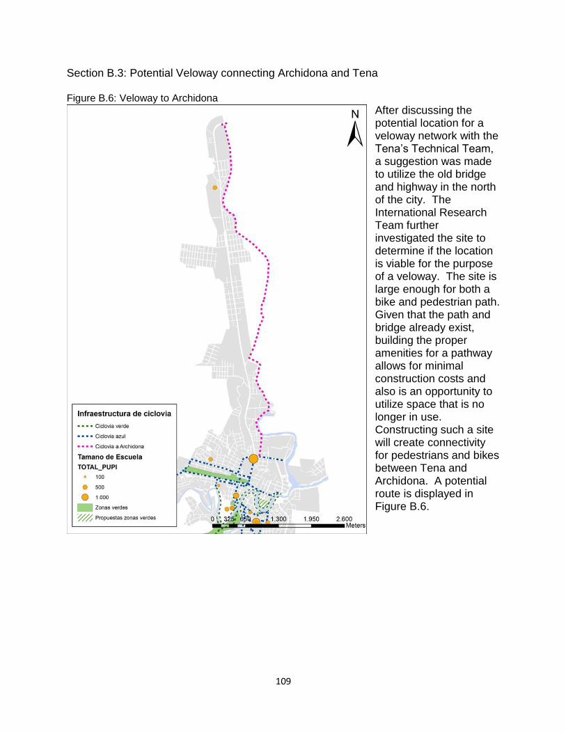
109
Section B.3: Potential Veloway connecting Archidona and Tena Figure B.6: Veloway to Archidona
After discussing the potential location for a veloway network with the Tena’s Technical Team, a suggestion was made to utilize the old bridge and highway in the north of the city. The International Research Team further investigated the site to determine if the location is viable for the purpose of a veloway. The site is large enough for both a bike and pedestrian path. Given that the path and bridge already exist, building the proper amenities for a pathway allows for minimal construction costs and also is an opportunity to utilize space that is no longer in use. Constructing such a site will create connectivity for pedestrians and bikes between Tena and Archidona. A potential route is displayed in Figure B.6.
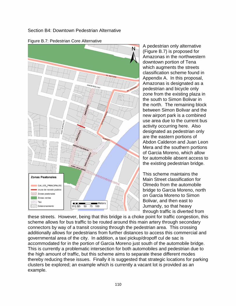
110
Section B4: Downtown Pedestrian Alternative Figure B.7: Pedestrian Core Alternative
A pedestrian only alternative (Figure B.7) is proposed for Amazonas in the northwestern downtown portion of Tena which augments the streets classification scheme found in Appendix A. In this proposal, Amazonas is designated as a pedestrian and bicycle only zone from the existing plaza in the south to Simon Bolivar in the north. The remaining block between Simon Bolivar and the new airport park is a combined use area due to the current bus activity occurring here. Also designated as pedestrian only are the eastern portions of Abdon Calderon and Juan Leon Mera and the southern portions of Garcia Moreno, which allow for automobile absent access to the existing pedestrian bridge. This scheme maintains the Main Street classification for Olmedo from the automobile bridge to Garcia Moreno, north on Garcia Moreno to Simon Bolivar, and then east to Jumandy, so that heavy through traffic is diverted from
these streets. However, being that this bridge is a choke point for traffic congestion, this scheme allows for bus traffic to be routed around this main artery through secondary connectors by way of a transit crossing through the pedestrian area. This crossing additionally allows for pedestrians from further distances to access this commercial and governmental area of the city. In addition, a taxi pickup/dropoff cul de sac is accommodated for in the portion of Garcia Moreno just south of the automobile bridge. This is currently a problematic intersection for both automobiles and pedestrian due to the high amount of traffic, but this scheme aims to separate these different modes thereby reducing these issues. Finally it is suggested that strategic locations for parking clusters be explored; an example which is currently a vacant lot is provided as an example.
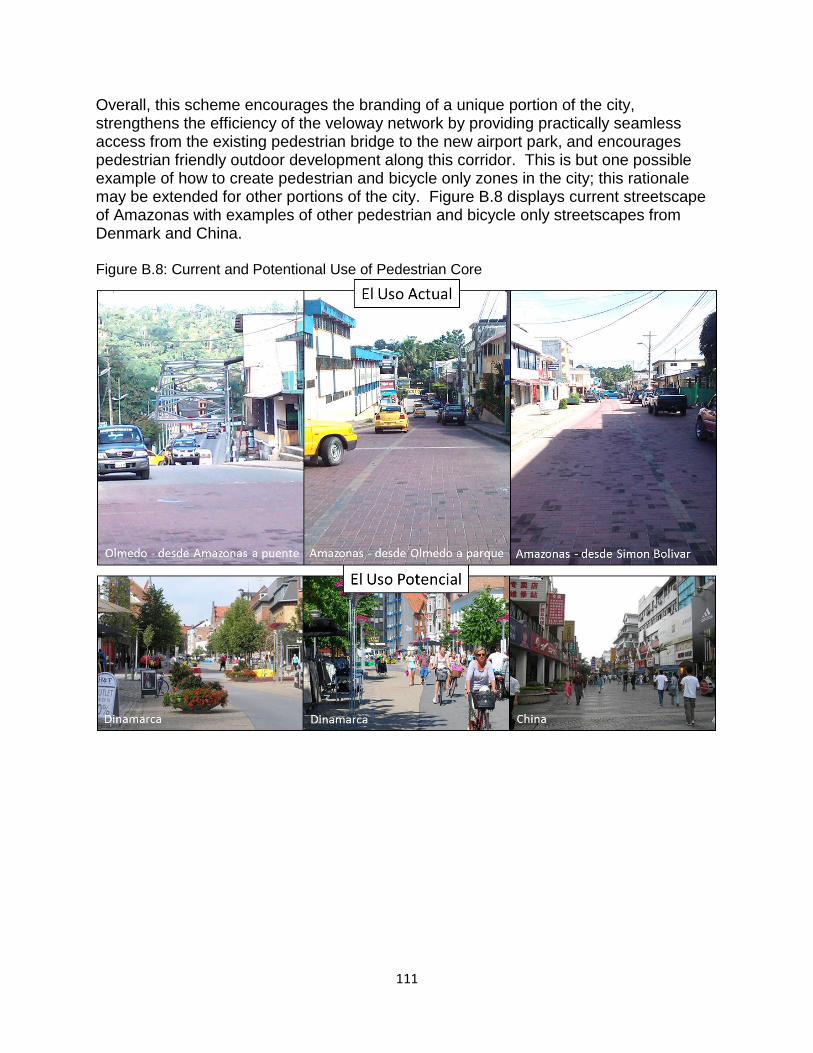
111
Overall, this scheme encourages the branding of a unique portion of the city, strengthens the efficiency of the veloway network by providing practically seamless access from the existing pedestrian bridge to the new airport park, and encourages pedestrian friendly outdoor development along this corridor. This is but one possible example of how to create pedestrian and bicycle only zones in the city; this rationale may be extended for other portions of the city. Figure B.8 displays current streetscape of Amazonas with examples of other pedestrian and bicycle only streetscapes from Denmark and China. Figure B.8: Current and Potentional Use of Pedestrian Core
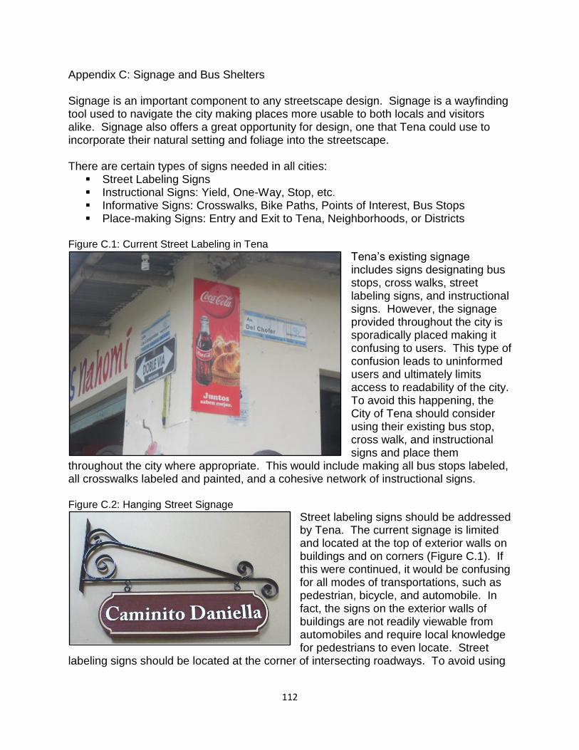
112
Appendix C: Signage and Bus Shelters Signage is an important component to any streetscape design. Signage is a wayfinding tool used to navigate the city making places more usable to both locals and visitors alike. Signage also offers a great opportunity for design, one that Tena could use to incorporate their natural setting and foliage into the streetscape. There are certain types of signs needed in all cities:
Street Labeling Signs Instructional Signs: Yield, One-Way, Stop, etc. Informative Signs: Crosswalks, Bike Paths, Points of Interest, Bus Stops Place-making Signs: Entry and Exit to Tena, Neighborhoods, or Districts
Figure C.1: Current Street Labeling in Tena
Tena’s existing signage includes signs designating bus stops, cross walks, street labeling signs, and instructional signs. However, the signage provided throughout the city is sporadically placed making it confusing to users. This type of confusion leads to uninformed users and ultimately limits access to readability of the city. To avoid this happening, the City of Tena should consider using their existing bus stop, cross walk, and instructional signs and place them
throughout the city where appropriate. This would include making all bus stops labeled, all crosswalks labeled and painted, and a cohesive network of instructional signs. Figure C.2: Hanging Street Signage
Street labeling signs should be addressed by Tena. The current signage is limited and located at the top of exterior walls on buildings and on corners (Figure C.1). If this were continued, it would be confusing for all modes of transportations, such as pedestrian, bicycle, and automobile. In fact, the signs on the exterior walls of buildings are not readily viewable from automobiles and require local knowledge for pedestrians to even locate. Street
labeling signs should be located at the corner of intersecting roadways. To avoid using
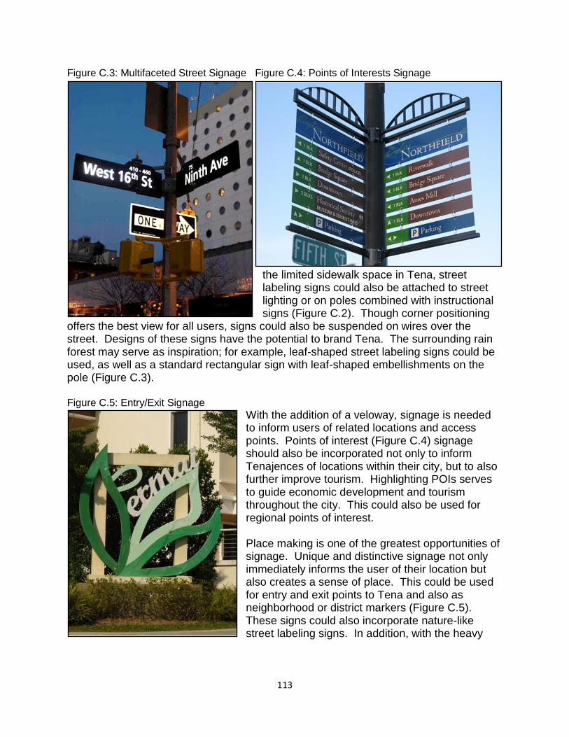
113
Figure C.3: Multifaceted Street Signage Figure C.4: Points of Interests Signage
the limited sidewalk space in Tena, street labeling signs could also be attached to street lighting or on poles combined with instructional signs (Figure C.2). Though corner positioning
offers the best view for all users, signs could also be suspended on wires over the street. Designs of these signs have the potential to brand Tena. The surrounding rain forest may serve as inspiration; for example, leaf-shaped street labeling signs could be used, as well as a standard rectangular sign with leaf-shaped embellishments on the pole (Figure C.3). Figure C.5: Entry/Exit Signage
With the addition of a veloway, signage is needed to inform users of related locations and access points. Points of interest (Figure C.4) signage should also be incorporated not only to inform Tenajences of locations within their city, but to also further improve tourism. Highlighting POIs serves to guide economic development and tourism throughout the city. This could also be used for regional points of interest. Place making is one of the greatest opportunities of signage. Unique and distinctive signage not only immediately informs the user of their location but also creates a sense of place. This could be used for entry and exit points to Tena and also as neighborhood or district markers (Figure C.5). These signs could also incorporate nature-like street labeling signs. In addition, with the heavy
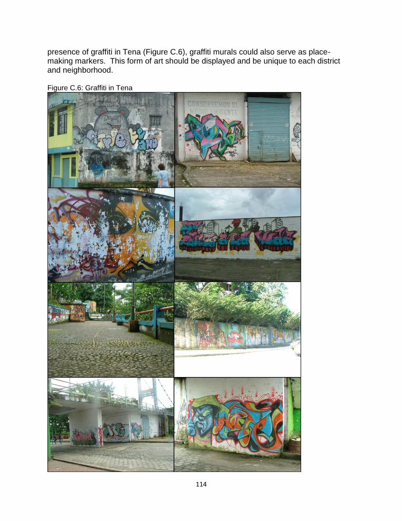
114
presence of graffiti in Tena (Figure C.6), graffiti murals could also serve as place-making markers. This form of art should be displayed and be unique to each district and neighborhood. Figure C.6: Graffiti in Tena
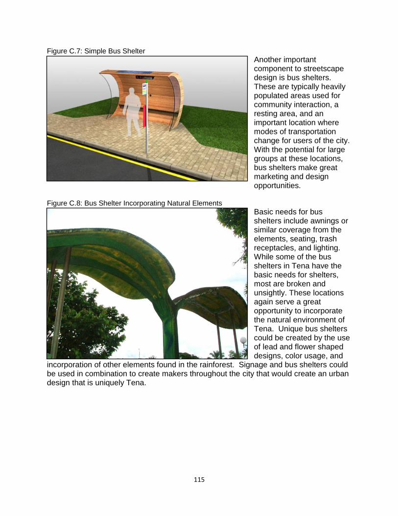
115
Figure C.7: Simple Bus Shelter
Another important component to streetscape design is bus shelters. These are typically heavily populated areas used for community interaction, a resting area, and an important location where modes of transportation change for users of the city. With the potential for large groups at these locations, bus shelters make great marketing and design opportunities.
Figure C.8: Bus Shelter Incorporating Natural Elements
Basic needs for bus shelters include awnings or similar coverage from the elements, seating, trash receptacles, and lighting. While some of the bus shelters in Tena have the basic needs for shelters, most are broken and unsightly. These locations again serve a great opportunity to incorporate the natural environment of Tena. Unique bus shelters could be created by the use of lead and flower shaped designs, color usage, and
incorporation of other elements found in the rainforest. Signage and bus shelters could be used in combination to create makers throughout the city that would create an urban design that is uniquely Tena.