Teach Yourself Electricity and Electronics - University of ...
748
-
Upload
khangminh22 -
Category
Documents
-
view
0 -
download
0
Transcript of Teach Yourself Electricity and Electronics - University of ...


Teach YourselfElectricity and
Electronics

This page intentionally left blank

Teach YourselfElectricity and
ElectronicsThird Edition
Stan Gibilisco
McGraw-HillNew York Chicago San Francisco Lisbon London Madrid
Mexico City Milan New Delhi San Juan SeoulSingapore Sydney Toronto

Copy r i g h t 2002, 1997, 1993 by The McGra w - H i l l Com p a n i e s , Inc. All right s reser v e d . Manuf a c t u r e d in the Unite d State s of Am eri c a . Excep t as perm i t t e d under the Unite d State s Copy r i g h t Act of 1976, no part of this publi c a t i o n m a y be repro d u c e d or distr i b u t e d in any form or by any m eans , or store d in a databa s e or retri e v a l sy ste m , witho u t the prior writt e n perm i s s i o n of the publi s h e r . 0-07 - 1 3 8 9 3 9 - 3 The m a teri a l in this eBook also appear s in the print versi o n of this title : 0-07- 1 3 7 7 3 0 - 1 . A l l tradem a r k s are tradem a r k s of their respec t i v e owne r s . Rathe r than put a tradem a r k sy m bo l after every occurr e n c e of a tradem a r k e d nam e , we use nam es in an edito r i a l fashi o n only , and to the benef i t of the trad e m a r k owne r , with no inten t i o n of infri n g e m e n t of the trade m a r k . Where such desig n a t i o n s appea r in this book, they have been print e d with initi a l caps. M c G r a w - H i l l eBooks are availa b l e at specia l quanti t y discou n t s to use as prem iu m s and sales prom ot i o n s , or for use in corpo r a t e train i n g progr a m s . For m o re inform a t i o n , pleas e conta c t Georg e Hoare , Speci a l Sales , at georg e _ h o a r e @ m c g r a w - h i l l . c o m or (212 ) 904- 4 0 6 9 . T E R M S OF USE This is a copy ri g h t e d work and The McGra w - H i l l Co m p an i e s , Inc. ("McGr a w - H i l l " ) and its licens o r s reser v e all right s in and to the work. Use of this work is subje c t to these term s . Excep t as perm i t t e d under the Copy r i g h t Act of 1976 and the right to store and re tri e v e one copy of the work, y ou m a y not decom p i l e , disass e m b l e , revers e engine e r , reprod u c e , m odify , creat e deriv a t i v e works based upon, trans m i t , distr i b u t e , disse m i n a t e , sell, publi s h or subli c e n s e the work or an y part of it witho u t McGra w - H i l l s prior conse n t . You m a y use the work for y our own nonco m m e r c i a l and pers o n a l use; any other use of the work is stric t l y prohi b i t e d . Your right to use the work m a y be term i n a t e d if y ou fail to com p l y with these term s . T H E WORK IS PROVIDE D "AS IS." McGRAW - H I L L AND ITS LICENSO R S MAKE NO GUARANT E E S OR WARRANT I E S AS TO THE ACCURAC Y , ADEQUAC Y OR COMPLET E N E S S OF OR RESULTS TO BE OBTAINE D FROM USING THE WORK, INCLUDI N G ANY INFORMATION THAT CAN BE ACCESSED THROUGH THE WORK VIA HYPERLINK OR OTHERW I S E , AND EXPRES S L Y DISCLA I M ANY WARRAN T Y , EXPRES S OR IMPLIE D , INCLUDI N G BUT NOT LIMITED TO IMPLIED WARRANT I E S OF MERCHAN T A B I L I T Y OR FITNESS FOR A PARTICU L A R PURPOS E . McGraw - H i l l and its licen s o r s do not warra n t or guara n t e e that the funct i o n s conta i n e d in the work will m eet y our requi r e m e n t s or that its opera t i o n will be unint e r r u p t e d or error free. Neith e r McGra w - H i l l nor its licen s o r s shall be liabl e to y ou or any on e else for any inaccu r a c y , error or om issi o n , regard l e s s of cause, in the work or for any dam a g e s resul t i n g there f r o m . McGra w - H i l l has no respo n s i b i l i t y for the conte n t of any infor m a t i o n acces s e d throu g h the work. Under no circum s t a n c e s shall McGraw - H i l l and/or its licens o r s be liabl e for any indir e c t , incid e n t a l , speci a l , punit i v e , conse q u e n t i a l or sim il a r dam a g e s that resul t fro m the use of or inabi l i t y to use the work, even if any of them has been advis e d of the possi b i l i t y of su ch dam a g e s . This lim it a t i o n of liabi l i t y shall apply to any claim or cause whatsoe v e r whet he r such claim or cause arises in contra c t , tort or otherw i s e . D O I : 10.1 0 3 6 / 0 0 7 1 3 8 9 3 9 3

To Tony, Tim, and Samuelfrom Uncle Stan
v

This page intentionally left blank

Contents
Preface xix
Part 1 Direct current
1 Basic physical concepts 3Atoms 3
Protons, neutrons, and the atomic number 4
Isotopes and atomic weights 4
Electrons 5
Ions 5
Compounds 9
Molecules 10
Conductors 11Insulators 11
Resistors 13
Semiconductors 14
Current 15
Static electricity 15
Electromotive force 16
Nonelectrical energy 18
Quiz 19
2 Electrical units 23The volt 23
Current flow 24
The ampere 26
Resistance and the ohm 26
Conductance and the siemens 28
vii

Power and the watt 29
Energy and the watt hour 31
Other energy units 33
ac Waves and the hertz 34
Rectification and fluctuating direct current 35
Safety considerations in electrical work 37
Magnetism 38
Magnetic units 39
Quiz 40
3 Measuring devices 44Electromagnetic deflection 44
Electrostatic deflection 46
Thermal heating 47
Ammeters 48
Voltmeters 49
Ohmmeters 51
Multimeters 53
FET and vacuum-tube voltmeters 54
Wattmeters 54
Watt-hour meters 55
Digital readout meters 56
Frequency counters 57
Other specialized meter types 57
Quiz 60
4 Basic dc circuits 65Schematic symbols 65
Schematic diagrams 67
Wiring diagrams 68
Voltage/current/resistance circuit 68
Ohm’s Law 69
Current calculations 69
Voltage calculations 71
Resistance calculations 71
Power calculations 72
Resistances in series 73
Resistances in parallel 74
Division of power 75
Resistances in series-parallel 75
Resistive loads in general 77
Quiz 77
5 Direct-current circuit analysis 82Current through series resistances 82
Voltages across series resistances 83
viii Contents

Voltage across parallel resistances 85
Currents through parallel resistances 86
Power distribution in series circuits 88
Power distribution in parallel circuits 88
Kirchhoff’s first law 89
Kirchhoff’s second law 91
Voltage divider networks 92
Quiz 95
6 Resistors 99Purpose of the resistor 99
The carbon-composition resistor 102
The wirewound resistor 103
Film type resistors 104
Integrated-circuit resistors 104
The potentiometer 105
The decibel 107
The rheostat 109
Resistor values 110
Tolerance 110
Power rating 110
Temperature compensation 111
The color code 112
Quiz 114
7 Cells and batteries 118Kinetic and potential energy 118
Electrochemical energy 118
Primary and secondary cells 119
The Weston standard cell 120
Storage capacity 120
Common dime-store cells and batteries 122
Miniature cells and batteries 124
Lead-acid cells and batteries 125
Nickel-cadmium cells and batteries 125
Photovoltaic cells and batteries 127
How large a battery? 128
Quiz 130
8 Magnetism 134The geomagnetic field 134
Magnetic force 135
Electric charge in motion 136
Flux lines 136
Magnetic polarity 137
Dipoles and monopoles 139
Contents ix
Magnetic field strength 139
Permeability 142
Retentivity 142
Permanent magnets 143
The solenoid 144
The dc motor 145
Magnetic data storage 146
Quiz 149
Test: Part 1 153
Part 2 Alternating current
9 Alternating current basics 165Definition of alternating current 165
Period and frequency 165
The sine wave 167
The square wave 167
Sawtooth waves 167
Complex and irregular waveforms 169
Frequency spectrum 170
Little bits of a cycle 172
Phase difference 173
Amplitude of alternating current 173
Superimposed direct current 175
The ac generator 176
Why ac? 178
Quiz 178
10 Inductance 183The property of inductance 183
Practical inductors 184
The unit of inductance 185
Inductors in series 185
Inductors in parallel 186
Interaction among inductors 187
Effects of mutual inductance 188
Air-core coils 189
Powdered-iron and ferrite cores 190
Permeability tuning 190
Toroids 190
Pot cores 192
Filter chokes 192
Inductors at audio frequency 193
Inductors at radio frequency 193
Transmission-line inductors 193
x Contents

Unwanted inductances 195
Quiz 195
11 Capacitance 199The property of capacitance 199
Practical capacitors 201
The unit of capacitance 201
Capacitors in series 202
Capacitors in parallel 203
Dielectric materials 204
Paper capacitors 204
Mica capacitors 205
Ceramic capacitors 205
Plastic-film capacitors 206
Electrolytic capcitors 206
Tantalum capacitors 206
Semiconductor capacitors 207
Variable capacitors 207
Tolerance 209
Temperature coefficient 210
Interelectrode capacitance 210
Quiz 211
12 Phase 215Instantaneous voltage and current 215
Rate of change 216
Sine waves as circular motion 217
Degrees of phase 218
Radians of phase 221
Phase coincidence 221
Phase opposition 222
Leading phase 222
Lagging phase 224
Vector diagrams of phase relationships 225
Quiz 226
13 Inductive reactance 231Coils and direct current 231
Coils and alternating current 232
Reactance and frequency 233
Points in the RL plane 234
Vectors in the RL plane 235
Current lags voltage 237
Inductance and resistance 238
How much lag? 240
Quiz 243
Contents xi

14 Capacitive reactance 247Capacitors and direct current 247
Capacitors and alternating current 248
Reactance and frequency 249
Points in the RC plane 251
Vectors in the RC plane 253
Current leads voltage 254
How much lead? 256
Quiz 259
15 Impedance and admittance 264Imaginary numbers 264
Complex numbers 265
The complex number plane 266
The RX plane 269
Vector representation of impedance 270
Absolute-value impedance 272
Characteristic impedance 272
Conductance 275
Susceptance 275
Admittance 276
The GB plane 277
Vector representation of admittance 279
Why all these different expressions? 279
Quiz 280
16 RLC circuit analysis 284Complex impedances in series 284
Series RLC circuits 288
Complex admittances in parallel 289
Parallel GLC circuits 292
Converting from admittance to impedance 294
Putting it all together 294
Reducing complicated RLC circuits 295
Ohm’s law for ac circuits 298
Quiz 301
17 Power and resonance in ac circuits 305What is power? 305
True power doesn’t travel 307
Reactance does not consume power 308
True power, VA power and reactive power 309
Power factor 310
Calculation of power factor 310
How much of the power is true? 313
xii Contents

Power transmission 315
Series resonance 318
Parallel resonance 319
Calculating resonant frequency 319
Resonant devices 321
Quiz 323
18 Transformers and impedance matching 327Principle of the transformer 327
Turns ratio 328
Transformer cores 329
Transformer geometry 330
The autotransformer 333
Power transformers 334
Audio-frequency transformers 336
Isolation transformers 336
Impedance-transfer ratio 338
Radio-frequency transformers 339
What about reactance? 341
Quiz 342
Test: Part 2 346
Part 3 Basic electronics
19 Introduction to semiconductors 359The semiconductor revolution 359
Semiconductor materials 360
Doping 362
Majority and minority charge carriers 362
Electron flow 362
Hole flow 363
Behavior of a P-N junction 363
How the junction works 364
Junction capacitance 366
Avalanche effect 366
Quiz 367
20 Some uses of diodes 370Rectification 370
Detection 371
Frequency multiplication 372
Mixing 373
Switching 374
Voltage regulation 374
Amplitude limiting 374
Contents xiii

Frequency control 376
Oscillation and amplification 377
Energy emission 377
Photosensitive diodes 378
Quiz 380
21 Power supplies 383Parts of a power supply 383
The power transformer 384
The diode 385
The half-wave rectifier 386
The full-wave, center-tap rectifier 387
The bridge rectifier 387
The voltage doubler 389
The filter 390
Voltage regulation 392
Surge current 393
Transient suppression 394
Fuses and breakers 394
Personal safety 395
Quiz 396
22 The bipolar transistor 400NPN versus PNP 400
NPN biasing 402
PNP biasing 404
Biasing for current amplification 404
Static current amplification 405
Dynamic current amplification 406
Overdrive 406
Gain versus frequency 407
Common-emitter circuit 408
Common-base circuit 409
Common-collector circuit 410
Quiz 411
23 The field-effect transistor 416Principle of the JFET 416
N-channel versus P-channel 417
Depletion and pinchoff 418
JFET biasing 419
Voltage amplification 420
Drain current versus drain voltage 421
Transconductance 422
The MOSFET 422
xiv Contents

Depletion mode versus enhancement mode 425
Common-source circuit 425
Common-gate circuit 426
Common-drain circuit 427
A note about notation 429
Quiz 429
24 Amplifiers 433The decibel 433
Basic bipolar amplifier circuit 437
Basic FET amplifier circuit 438
The class-A amplifier 439
The class-AB amplifier 440
The class-B amplifier 441
The class-C amplifier 442
PA efficiency 443
Drive and overdrive 445
Audio amplification 446
Coupling methods 447
Radio-frequency amplification 450
Quiz 453
25 Oscillators 457Uses of oscillators 457
Positive feedback 458
Concept of the oscillator 458
The Armstrong oscillator 459
The Hartley circuit 459
The Colpitts circuit 461
The Clapp circuit 461
Stability 463
Crystal-controlled oscillators 464
The voltage-controlled oscillator 465
The PLL frequency synthesizer 466
Diode oscillators 467
Audio waveforms 467
Audio oscillators 468
IC oscillators 469
Quiz 469
26 Data transmission 474The carrier wave 474
The Morse code 475
Frequency-shift keying 475
Amplitude modulation for voice 478
Single sideband 480
Contents xv

Frequency and phase modulation 482
Pulse modulation 485
Analog-to-digital conversion 487
Image transmission 487
The electromagnetic field 490
Transmission media 493
Quiz 495
27 Data reception 499Radio wave propagation 499
Receiver specifications 502
Definition of detection 504
Detection of AM signals 504
Detection of CW signals 505
Detection of FSK signals 506
Detection of SSB signals 506
Detection of FM signals 506
Detection of PM signals 508
Digital-to-analog conversion 509
Digital signal processing 510
The principle of signal mixing 511
The product detector 512
The superheterodyne 515
A modulated-light receiver 517
Quiz 517
28 Integrated circuits and data storage media 521Boxes and cans 521
Advantages of IC technology 522
Limitations of IC technology 523
Linear versus digital 524
Types of linear ICs 524
Bipolar digital ICs 527
MOS digital ICs 527
Component density 529
IC memory 530
Magnetic media 532
Compact disks 535
Quiz 535
29 Electron tubes 539Vacuum versus gas-filled 539
The diode tube 540
The triode 541
Extra grids 542
Some tubes are obsolete 544
xvi Contents
Radio-frquency power amplifiers 544
Cathode-ray tubes 546
Video camera tubes 547
Traveling-wave tubes 549
Quiz 551
30 Basic digital principles 555Numbering systems 555
Logic signals 557
Basic logic operations 559
Symbols for logic gates 561
Complex logic operators 561
Working with truth tables 562
Boolean algebra 564
The flip-flop 564
The counter 566
The register 567
The digital revolution 568
Quiz 568
Test: Part 3 572
Part 4 Advanced electronics and related technology
31 Acoustics, audio, and high fidelity 583Acoustics 583
Loudness and phase 585
Technical considerations 587
Basic components 589
Other components 591
Specialized systems 596
Recorded media 597
Electromagnetic interference 601
Quiz 602
32 Wireless and personal communications systems 606Cellular communications 606
Satellite systems 608
Acoustic transducers 612
Radio-frequency transducers 613
Infrared transducers 614
Wireless local area networks 615
Wireless security systems 616
Hobby radio 617
Noise 619
Quiz 620
Contents xvii

33 Computers and the Internet 624The microprocessor and CPU 624
Bytes, kilobytes, megabytes, and gigabytes 626
The hard drive 626
Other forms of mass storage 628
Random-access memory 629
The display 631
The printer 633
The modem 635
The Internet 636
Quiz 640
34 Robotics and artificial intelligence 644Asimov’s three laws 644
Robot generations 645
Independent or dependent? 646
Robot arms 648
Robotic hearing and vision 652
Robotic navigation 657
Telepresence 661
The mind of the machine 663
Quiz 665
Test: Part 4 669
Final exam 679
Appendices
A Answers to quiz, test, and exam questions 697
B Schematic symbols 707
Suggested additional reference 713
Index 715
xviii Contents
!"# #$ !

PrefaceThis book is for people who want to learn basic electricity, electronics, and com-
munications concepts without taking a formal course. It can also serve as a class-room text. This third edition contains new material covering acoustics, audio,high-fidelity, robotics, and artificial intelligence.
I recommend you start at the beginning of this book and go straight through.There are hundreds of quiz and test questions to fortify your knowledge and helpyou check your progress as you work your way along.
There is a short multiple-choice quiz at the end of every chapter. You may (andshould) refer to the chapter texts when taking these quizzes. When you think you’reready, take the quiz, write down your answers, and then give your list of answers toa friend. Have the friend tell you your score, but not which questions you got wrong.The answers are listed in the back of the book. Stick with a chapter until you getmost of the answers correct. Because you’re allowed to look at the text duringquizzes, the questions are written so that you really have to think before you writedown an answer. Some are rather difficult, but there are no trick questions.
This book is divided into four major sections: Direct Current, Alternating Cur-rent, Basic Electronics, and Advanced Electronics and Related Technology. At theend of each section is a multiple-choice test. Take these tests when you’re done withthe respective sections and have taken all the chapter quizzes. Don’t look back at thetext when taking these tests. A satisfactory score is 37 answers correct. Again, an-swers are in the back of the book.
There is a final exam at the end of the book. The questions are practical, mostlynonmathematical, and somewhat easier than those in the quizzes. The final examcontains questions drawn from all the chapters. Take this exam when you have fin-ished all four sections, all four section tests, and all of the chapter quizzes. A satis-factory score is at least 75 percent correct answers.
With the section tests and final exam, as with the quizzes, have a friend tell youyour score without letting you know which questions you missed. That way, you willnot subconsciously memorize the answers. You might want to take a test two or
xix !
"# #$ !

three times. When you have gotten a score that makes you happy, you can check tosee where your knowledge is strong and where it can use some bolstering.
It is not necessary to have a mathematical or scientific background to use thisdo-it-yourself course. Junior-high-school algebra, geometry, and physical sciencewill suffice. I’ve tried to gradually introduce standard symbols and notations so it willbe evident what they mean as you go. By the time you get near the end of this book,assuming you’ve followed it all along, you should be familiar with most of the symbolsused in schematic diagrams.
I recommend that you complete one chapter a week. An hour daily ought to bemore than enough time for this. That way, in less than nine months, you’ll completethe course. You can then use this book, with its comprehensive index, as a perma-nent reference.
Suggestions for future editions are welcome.
Stan Gibilisco
xx Preface

1PART
Direct Current

This page intentionally left blank

1CHAPTER
Basic physical conceptsIT IS IMPORTANT TO UNDERSTAND SOME SIMPLE, GENERAL PHYSICS PRINCIPLESin order to have a full grasp of electricity and electronics. It is not necessary to knowhigh-level mathematics.
In science, you can talk about qualitative things or about quantitative things, the“what” versus the “how much.” For now, you need only be concerned about the “what.”The “how much” will come later.
AtomsAll matter is made up of countless tiny particles whizzing around. These particles areextremely dense; matter is mostly empty space. Matter seems continuous because theparticles are so small, and they move incredibly fast.
Even people of ancient times suspected that matter is made of invisible particles.They deduced this from observing things like water, rocks, and metals. These sub-stances are much different from each other. But any given material—copper, for example—is the same wherever it is found. Even without doing any complicated experiments, early physicists felt that substances could only have these consistent behaviors if they were made of unique types, or arrangements, of particles. It took centuries before people knew just how this complicated business works. And even today,there are certain things that scientists don’t really know. For example, is there a smallestpossible material particle?
There were some scientists who refused to believe the atomic theory, even aroundthe year of 1900. Today, practically everyone accepts the theory. It explains the behaviorof matter better than any other scheme.
Eventually, scientists identified 92 different kinds of fundamental substances in nature, and called them elements. Later, a few more elements were artificially made.
3 !
"# #$ !
Each element has its own unique type of particle, known as its atom. Atoms of differ-ent elements are always different.
The slightest change in an atom can make a tremendous difference in its behavior.You can live by breathing pure oxygen, but you can’t live off of pure nitrogen. Oxygenwill cause metal to corrode, but nitrogen will not. Wood will burn furiously in an atmos-phere of pure oxygen, but will not even ignite in pure nitrogen. Yet both are gases atroom temperature and pressure; both are colorless, both are odorless, and both are justabout of equal weight. These substances are so different because oxygen has eight pro-
tons, while nitrogen has only seven.There are many other examples in nature where a tiny change in atomic structure
makes a major difference in the way a substance behaves.
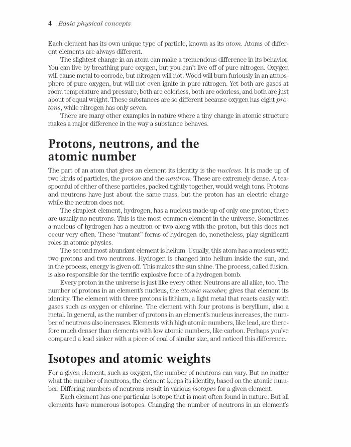
Protons, neutrons, and the atomic numberThe part of an atom that gives an element its identity is the nucleus. It is made up oftwo kinds of particles, the proton and the neutron. These are extremely dense. A tea-spoonful of either of these particles, packed tightly together, would weigh tons. Protonsand neutrons have just about the same mass, but the proton has an electric chargewhile the neutron does not.
The simplest element, hydrogen, has a nucleus made up of only one proton; thereare usually no neutrons. This is the most common element in the universe. Sometimesa nucleus of hydrogen has a neutron or two along with the proton, but this does not occur very often. These “mutant” forms of hydrogen do, nonetheless, play significantroles in atomic physics.
The second most abundant element is helium. Usually, this atom has a nucleus withtwo protons and two neutrons. Hydrogen is changed into helium inside the sun, and in the process, energy is given off. This makes the sun shine. The process, called fusion,is also responsible for the terrific explosive force of a hydrogen bomb.
Every proton in the universe is just like every other. Neutrons are all alike, too. Thenumber of protons in an element’s nucleus, the atomic number, gives that element itsidentity. The element with three protons is lithium, a light metal that reacts easily withgases such as oxygen or chlorine. The element with four protons is beryllium, also ametal. In general, as the number of protons in an element’s nucleus increases, the num-ber of neutrons also increases. Elements with high atomic numbers, like lead, are there-fore much denser than elements with low atomic numbers, like carbon. Perhaps you’vecompared a lead sinker with a piece of coal of similar size, and noticed this difference.
Isotopes and atomic weightsFor a given element, such as oxygen, the number of neutrons can vary. But no matterwhat the number of neutrons, the element keeps its identity, based on the atomic num-ber. Differing numbers of neutrons result in various isotopes for a given element.
Each element has one particular isotope that is most often found in nature. But allelements have numerous isotopes. Changing the number of neutrons in an element’s
4 Basic physical concepts

nucleus results in a difference in the weight, and also a difference in the density, of theelement. Thus, hydrogen containing a neutron or two in the nucleus, along with the pro-ton, is called heavy hydrogen.
The atomic weight of an element is approximately equal to the sum of the num-ber of protons and the number of neutrons in the nucleus. Common carbon has anatomic weight of about 12, and is called carbon 12 or C12. But sometimes it has an atomic weight of about 14, and is known as carbon 14 or C14.
Table 1-1 lists all the known elements in alphabetical order, with atomic numbers inone column, and atomic weights of the most common isotopes in another column. Thestandard abbreviations are also shown.
ElectronsSurrounding the nucleus of an atom are particles having opposite electric chargefrom the protons. These are the electrons. Physicists arbitrarily call the electrons’charge negative, and the protons’ charge positive. An electron has exactly the samecharge quantity as a proton, but with opposite polarity. The charge on a single elec-tron or proton is the smallest possible electric charge. All charges, no matter howgreat, are multiples of this unit charge.
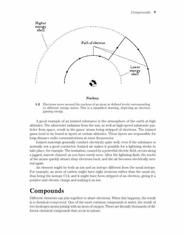
One of the earliest ideas about the atom pictured the electrons embedded in the nu-cleus, like raisins in a cake. Later, the electrons were seen as orbiting the nucleus, mak-ing the atom like a miniature solar system with the electrons as the planets (Fig. 1-1).Still later, this view was modified further. Today, the electrons are seen as so fast-moving, with patterns so complex, that it is not even possible to pinpoint them at anygiven instant of time. All that can be done is to say that an electron will just as likely beinside a certain sphere as outside. These spheres are known as electron shells. Theircenters correspond to the position of the atomic nucleus. The farther away from the nucleus the shell, the more energy the electron has (Fig. 1-2).
Electrons can move rather easily from one atom to another in some materials. Inother substances, it is difficult to get electrons to move. But in any case, it is far easierto move electrons than it is to move protons. Electricity almost always results, in someway, from the motion of electrons in a material.
Electrons are much lighter than protons or neutrons. In fact, compared to the nu-cleus of an atom, the electrons weigh practically nothing.
Generally, the number of electrons in an atom is the same as the number of protons.The negative charges therefore exactly cancel out the positive ones, and the atom is electrically neutral. But under some conditions, there can be an excess or shortage of electrons. High levels of radiant energy, extreme heat, or the presence of an electric field(discussed later) can “knock” or “throw” electrons loose from atoms, upsetting the balance.
IonsIf an atom has more or less electrons than neutrons, that atom acquires an electricalcharge. A shortage of electrons results in positive charge; an excess of electrons gives anegative charge. The element’s identity remains the same, no matter how great the ex-cess or shortage of electrons. In the extreme case, all the electrons might be removed
Ions 5

6 Basic physical concepts
Table 1-1. Atomic numbers and weights.
Element name Abbreviation Atomic number Atomic weight*
Actinium Ac 89 227Aluminum Al 13 27Americium** Am 95 243Antimony Sb 51 121Argon Ar 18 40Arsenic As 33 75Astatine At 85 210Barium Ba 56 138Berkelium** Bk 97 247Beryllium Be 4 9Bismuth Bi 83 209Boron B 5 11Bromine Br 35 79Cadmium Cd 48 114Calcium Ca 20 40Californium** Cf 98 251Carbon C 6 12Cerium Ce 58 140Cesium Cs 55 133Chlorine Cl 17 35Chromium Cr 24 52Cobalt Co 27 59Copper Cu 29 63Curium** Cm 96 247Dysprosium Dy 66 164Einsteinium** Es 99 254Erbium Er 68 166Europium Eu 63 153Fermium Fm 100 257Fluorine F 9 19Francium Fr 87 223Gadolinium Gd 64 158Gallium Ga 31 69Germanium Ge 32 74Gold Au 79 197Hafnium Hf 72 180Helium He 2 4Holmium Ho 67 165Hydrogen H 1 1Indium In 49 115Iodine I 53 127Iridium Ir 77 193Iron Fe 26 56Krypton Kr 36 84Lanthanum La 57 139Lawrencium** Lr or Lw 103 257

Ions 7
Table 1-1. Continued
Element name Abbreviation Atomic number Atomic weight*
Lead Pb 82 208Lithium Li 3 7Lutetium Lu 71 175Magnesium Mg 12 24Manganese Mn 25 55Mendelevium** Md 101 256Mercury Hg 80 202Molybdenum Mo 42 98Neodymium Nd 60 142Neon Ne 10 20Neptunium** Np 93 237Nickel Ni 28 58Niobium Nb 41 93Nitrogen N 7 14Nobelium** No 102 254Osmium Os 76 192Oxygen O 8 16Palladium Pd 46 108Phosphorus P 15 31Platinum Pt 78 195Plutonium** Pu 94 242Polonium Po 84 209Potassium K 19 39Praseodymium Pr 59 141Promethium Pm 61 145Protactinium Pa 91 231Radium Ra 88 226Radon Rn 86 222Rhenium Re 75 187Rhodium Rh 45 103Rubidium Rb 37 85Ruthenium Ru 44 102Samarium Sm 62 152Scandium Sc 21 45Selenium Se 34 80Silicon Si 14 28Silver Ag 47 107Sodium Na 11 23Strontium Sr 38 88Sulfur S 16 32Tantalum Ta 73 181Technetium Tc 43 99Tellurium Te 52 130Terbium Tb 65 159Thallium Tl 81 205Thorium Th 90 232Thulium Tm 69 169

from an atom, leaving only the nucleus. However it would still represent the same element as it would if it had all its electrons.
A charged atom is called an ion. When a substance contains many ions, the mater-ial is said to be ionized.
8 Basic physical concepts
Table 1-1. Continued
Element name Abbreviation Atomic number Atomic weight*
Tin Sn 50 120Titanium Ti 22 48Tungsten W 74 184Unnilhexium** Unh 106 —Unnilpentium** Unp 105 —Unnilquadium** Unq 104 —Uranium U 92 238Vanadium V 23 51Xenon Xe 54 132Ytterbium Yb 70 174Yttrium Y 39 89Zinc Zn 30 64Zirconium Zr 40 90
*Most common isotope. The sum of the number of protons and the number of neutrons in the nucleus. Most elementshave other isotopes with different atomic weights.
**These elements (atomic numbers 93 or larger) are not found in nature, but are human-made.
1-1 An early model of the atom, developed about theyear 1900, renderedelectrons like planets andthe nucleus like the sun in aminiature solar system.Electric charge attractionkept the electrons fromflying away.
A good example of an ionized substance is the atmosphere of the earth at highaltitudes. The ultraviolet radiation from the sun, as well as high-speed subatomic par-ticles from space, result in the gases’ atoms being stripped of electrons. The ionizedgases tend to be found in layers at certain altitudes. These layers are responsible forlong-distance radio communications at some frequencies.
Ionized materials generally conduct electricity quite well, even if the substance isnormally not a good conductor. Ionized air makes it possible for a lightning stroke totake place, for example. The ionization, caused by a powerful electric field, occurs alonga jagged, narrow channel, as you have surely seen. After the lightning flash, the nucleiof the atoms quickly attract stray electrons back, and the air becomes electrically neu-tral again.
An element might be both an ion and an isotope different from the usual isotope.For example, an atom of carbon might have eight neutrons rather than the usual six,thus being the isotope C14, and it might have been stripped of an electron, giving it apositive unit electric charge and making it an ion.
CompoundsDifferent elements can join together to share electrons. When this happens, the resultis a chemical compound. One of the most common compounds is water, the result oftwo hydrogen atoms joining with an atom of oxygen. There are literally thousands of dif-ferent chemical compounds that occur in nature.
Compounds 9
1-2 Electrons move around the nucleus of an atom at defined levels corresponding to different energy states. This is a simplified drawing, depicting an electrongaining energy.

A compound is different than a simple mixture of elements. If hydrogen and oxy-gen are mixed, the result is a colorless, odorless gas, just like either element is a gasseparately. A spark, however, will cause the molecules to join together; this will liber-ate energy in the form of light and heat. Under the right conditions, there will be a vi-olent explosion, because the two elements join eagerly. Water is chemically illustratedin Fig. 1-3.
10 Basic physical concepts
Compounds often, but not always, appear greatly different from any of the ele-ments that make them up. At room temperature and pressure, both hydrogen and oxy-gen are gases. But water under the same conditions is a liquid. If it gets a few tens ofdegrees colder, water turns solid at standard pressure. If it gets hot enough, water be-comes a gas, odorless and colorless, just like hydrogen or oxygen.
Another common example of a compound is rust. This forms when iron joins withoxygen. While iron is a dull gray solid and oxygen is a gas, rust is a maroon-red orbrownish powder, completely unlike either of the elements from which it is formed.
MoleculesWhen atoms of elements join together to form a compound, the resulting particles
are molecules. Figure 1-3 is an example of a molecule of water, consisting of threeatoms put together.
The natural form of an element is also known as its molecule. Oxygen tends to occurin pairs most of the time in the earth’s atmosphere. Thus, an oxygen molecule is some-times denoted by the symbol O2. The “O” represents oxygen, and the subscript 2 indi-cates that there are two atoms per molecule. The water molecule is symbolized H2O,because there are two atoms of hydrogen and one atom of oxygen in each molecule.
1-3 Simplified diagram of a water molecule.

Sometimes oxygen atoms are by themselves; then we denote the molecule simply as O.Sometimes there are three atoms of oxygen grouped together. This is the gas calledozone, that has received much attention lately in environmental news. It is written O3.
All matter, whether it is solid, liquid, or gas, is made of molecules. These particlesare always moving. The speed with which they move depends on the temperature. Thehotter the temperature, the more rapidly the molecules move around. In a solid, themolecules are interlocked in a sort of rigid pattern, although they vibrate continuously(Fig. 1-4A). In a liquid, they slither and slide around (Fig. 1-4B). In a gas, they are lit-erally whizzing all over the place, bumping into each other and into solids and liquidsadjacent to the gas (Fig. 1-4C).
ConductorsIn some materials, electrons move easily from atom to atom. In others, the electronsmove with difficulty. And in some materials, it is almost impossible to get them to move.An electrical conductor is a substance in which the electrons are mobile.
The best conductor at room temperature is pure elemental silver. Copper and alu-minum are also excellent electrical conductors. Iron, steel, and various other metals arefair to good conductors of electricity.
In most electrical circuits and systems, copper or aluminum wire is used. Silver isimpractical because of its high cost.
Some liquids are good electrical conductors. Mercury is one example. Salt water isa fair conductor.
Gases are, in general, poor conductors of electricity. This is because the atoms ormolecules are usually too far apart to allow a free exchange of electrons. But if a gas be-comes ionized, it is a fair conductor of electricity.
Electrons in a conductor do not move in a steady stream, like molecules of waterthrough a garden hose. Instead, they are passed from one atom to another right next toit (Fig. 1-5). This happens to countless atoms all the time. As a result, literally trillionsof electrons pass a given point each second in a typical electrical circuit.
You might imagine a long line of people, each one constantly passing a ball to theneighbor on the right. If there are plenty of balls all along the line, and if everyone keepspassing balls along as they come, the result will be a steady stream of balls moving alongthe line. This represents a good conductor.
If the people become tired or lazy, and do not feel much like passing the balls along,the rate of flow will decrease. The conductor is no longer very good.
InsulatorsIf the people refuse to pass balls along the line in the previous example, the line repre-sents an electrical insulator. Such substances prevent electrical currents from flowing,except possibly in very small amounts.
Most gases are good electrical insulators. Glass, dry wood, paper, and plastics areother examples. Pure water is a good electrical insulator, although it conducts somecurrent with even the slightest impurity. Metal oxides can be good insulators, eventhough the metal in pure form is a good conductor.
Insulators 11

12 Basic physical concepts
1-4 At A, simplified renditionof molecules in a solid; atB, in a liquid; at C, in agas. The molecules don’tshrink in the gas. Theyare shown smallerbecause of the muchlarger spaces betweenthem.

Electrical insulators can be forced to carry current. Ionization can take place; whenelectrons are stripped away from their atoms, they have no choice but to move along.Sometimes an insulating material gets charred, or melts down, or gets perforated by aspark. Then its insulating properties are lost, and some electrons flow.
An insulating material is sometimes called a dielectric. This term arises from thefact that it keeps electrical charges apart, preventing the flow of electrons that wouldequalize a charge difference between two places. Excellent insulating materials can beused to advantage in certain electrical components such as capacitors, where it is im-portant that electrons not flow.
Porcelain or glass can be used in electrical systems to keep short circuits from oc-curring. These devices, called insulators, come in various shapes and sizes for differentapplications. You can see them on high-voltage utility poles and towers. They hold thewire up without running the risk of a short circuit with the tower or a slow dischargethrough a wet wooden pole.
ResistorsSome substances, such as carbon, conduct electricity fairly well but not really well. Theconductivity can be changed by adding impurities like clay to a carbon paste, or by wind-ing a thin wire into a coil. Electrical components made in this way are called resistors. Theyare important in electronic circuits because they allow for the control of current flow.
Resistors can be manufactured to have exact characteristics. Imagine telling eachperson in the line that they must pass a certain number of balls per minute. This is anal-ogous to creating a resistor with a certain value of electrical resistance.
The better a resistor conducts, the lower its resistance; the worse it conducts, thehigher the resistance.
Resistors 13
1-5 In a conductor, electrons are passed from atom to atom.

Electrical resistance is measured in units called ohms. The higher the value inohms, the greater the resistance, and the more difficult it becomes for current to flow.For wires, the resistance is sometimes specified in terms of ohms per foot or ohms per
kilometer. In an electrical system, it is usually desirable to have as low a resistance, orohmic value, as possible. This is because resistance converts electrical energy into heat.Thick wires and high voltages reduce this resistance loss in long-distance electricallines. This is why such gigantic towers, with dangerous voltages, are necessary in largeutility systems.
SemiconductorsIn a semiconductor, electrons flow, but not as well as they do in a conductor. You mightimagine the people in the line being lazy and not too eager to pass the balls along. Somesemiconductors carry electrons almost as well as good electrical conductors like copperor aluminum; others are almost as bad as insulating materials. The people might be justa little sluggish, or they might be almost asleep.
Semiconductors are not exactly the same as resistors. In a semiconductor, the ma-terial is treated so that it has very special properties.
The semiconductors include certain substances, such as silicon, selenium, or gal-lium, that have been “doped” by the addition of impurities like indium or antimony.Perhaps you have heard of such things as gallium arsenide, metal oxides, or silicon
rectifiers. Electrical conduction in these materials is always a result of the motion of electrons. However, this can be a quite peculiar movement, and sometimes engi-neers speak of the movement of holes rather than electrons. A hole is a shortage of anelectron—you might think of it as a positive ion—and it moves along in a direction opposite to the flow of electrons (Fig. 1-6).
14 Basic physical concepts
1-6 Holes move in the opposite direction from electrons in a semiconducting material.

When most of the charge carriers are electrons, the semiconductor is calledN-type, because electrons are negatively charged. When most of the charge carriers areholes, the semiconducting material is known as P-type because holes have a positiveelectric charge. But P-type material does pass some electrons, and N-type material car-ries some holes. In a semiconductor, the more abundant type of charge carrier is calledthe majority carrier. The less abundant kind is known as the minority carrier.
Semiconductors are used in diodes, transistors, and integrated circuits in almostlimitless variety. These substances are what make it possible for you to have a computerin a briefcase. That notebook computer, if it used vacuum tubes, would occupy a sky-scraper, because it has billions of electronic components. It would also need its ownpower plant, and would cost thousands of dollars in electric bills every day. But the cir-cuits are etched microscopically onto semiconducting wafers, greatly reducing the sizeand power requirements.
CurrentWhenever there is movement of charge carriers in a substance, there is an electric current. Current is measured in terms of the number of electrons or holes passing a single point in one second.
Usually, a great many charge carriers go past any given point in one second, even ifthe current is small. In a household electric circuit, a 100-watt light bulb draws a cur-rent of about six quintillion (6 followed by 18 zeroes) charge carriers per second.Even the smallest mini-bulb carries quadrillions (numbers followed by 15 zeroes) ofcharge carriers every second. It is ridiculous to speak of a current in terms of chargecarriers per second, so usually it is measured in coulombs per second instead. Acoulomb is equal to approximately 6,240,000,000,000,000,000 electrons or holes. A cur-rent of one coulomb per second is called an ampere, and this is the standard unit ofelectric current. A 100-watt bulb in your desk lamp draws about one ampere of current.
When a current flows through a resistance—and this is always the case becauseeven the best conductors have resistance—heat is generated. Sometimes light andother forms of energy are emitted as well. A light bulb is deliberately designed so thatthe resistance causes visible light to be generated. Even the best incandescent lamp isinefficient, creating more heat than light energy. Fluorescent lamps are better. Theyproduce more light for a given amount of current. Or, to put it another way, they needless current to give off a certain amount of light.
Electric current flows very fast through any conductor, resistor, or semiconductor.In fact, for most practical purposes you can consider the speed of current to be thesame as the speed of light: 186,000 miles per second. Actually, it is a little less.
Static electricityCharge carriers, particularly electrons, can build up, or become deficient, on thingswithout flowing anywhere. You’ve probably experienced this when walking on a car-peted floor during the winter, or in a place where the humidity was very low. An excessor shortage of electrons is created on and in your body. You acquire a charge of static
Static electricity 15

electricity. It’s called “static” because it doesn’t go anywhere. You don’t feel this until youtouch some metallic object that is connected to earth ground or to some large fixture;but then there is a discharge, accompanied by a spark that might well startle you. It isthe current, during this discharge, that causes the sensation that might make you jump.
If you were to become much more charged, your hair would stand on end, becauseevery hair would repel every other. Like charges are caused either by an excess or a de-ficiency of electrons; they repel. The spark might jump an inch, two inches, or even sixinches. Then it would more than startle you; you could get hurt. This doesn’t happenwith ordinary carpet and shoes, fortunately. But a device called a Van de Graaff gen-
erator, found in some high school physics labs, can cause a spark this large (Fig. 1-7).You have to be careful when using this device for physics experiments.
16 Basic physical concepts
1-7 Simple diagram of a Van de Graaff generator for creatinglarge static charges.
In the extreme, lightning occurs between clouds, and between clouds and groundin the earth’s atmosphere. This spark is just a greatly magnified version of the littlespark you get after shuffling around on a carpet. Until the spark occurs, there is a staticcharge in the clouds, between different clouds or parts of a cloud, and the ground. InFig. 1-8, cloud-to-cloud (A) and cloud-to-ground (B) static buildups are shown. In thecase at B, the positive charge in the earth follows along beneath the thunderstorm cloudlike a shadow as the storm is blown along by the prevailing winds.
The current in a lightning stroke is usually several tens of thousands, or hundredsof thousands, of amperes. But it takes place only for a fraction of a second. Still, manycoulombs of charge are displaced in a single bolt of lightning.
Electromotive forceCurrent can only flow if it gets a “push.” This might be caused by a buildup of static elec-tric charges, as in the case of a lightning stroke. When the charge builds up, with posi-

tive polarity (shortage of electrons) in one place and negative polarity (excess of elec-trons) in another place, a powerful electromotive force exists. It is often abbreviatedEMF. This force is measured in units called volts.
Ordinary household electricity has an effective voltage of between 110 and 130;usually it is about 117. A car battery has an EMF of 12 volts (six volts in some older sys-tems). The static charge that you acquire when walking on a carpet with hard-soledshoes is often several thousand volts. Before a discharge of lightning, many millions ofvolts exist.
An EMF of one volt, across a resistance of one ohm, will cause a current of one ampereto flow. This is a classic relationship in electricity, and is stated generally as Ohm’s
Electromotive force 17
1-8 Cloud-to-cloud (A) and cloud-to-ground (B) charge buildup can both occur in a singlethunderstorm.
Law. If the EMF is doubled, the current is doubled. If the resistance is doubled, the cur-rent is cut in half. This important law of electrical circuit behavior is covered in detail alittle later in this book.
It is possible to have an EMF without having any current. This is the case just before a lightning bolt occurs, and before you touch that radiator after walking on thecarpet. It is also true between the two wires of an electric lamp when the switch isturned off. It is true of a dry cell when there is nothing connected to it. There is no cur-rent, but a current is possible given a conductive path between the two points. Voltage,or EMF, is sometimes called potential or potential difference for this reason.
Even a very large EMF might not drive much current through a conductor or resistance. A good example is your body after walking around on the carpet. Althoughthe voltage seems deadly in terms of numbers (thousands), there are not that manycoulombs of charge that can accumulate on an object the size of your body. Thereforein relative terms, not that many electrons flow through your finger when you touch aradiator so you don’t get a severe shock.
Conversely, if there are plenty of coulombs available, a small voltage, such as 117volts (or even less), can result in a lethal flow of current. This is why it is so dangerousto repair an electrical device with the power on. The power plant will pump an unlim-ited number of coulombs of charge through your body if you are foolish enough to getcaught in that kind of situation.
Nonelectrical energyIn electricity and electronics, there are many kinds of phenomena that involve
other forms of energy besides electrical energy.Visible light is an example. A light bulb converts electricity into radiant energy that
you can see. This was one of the major motivations for people like Thomas Edison towork with electricity. Visible light can also be converted into electric current or voltage.A photovoltaic cell does this.
Light bulbs always give off some heat, as well as visible light. Incandescent lampsactually give off more energy as heat than as light. And you are certainly acquaintedwith electric heaters, designed for the purpose of changing electricity into heat energy.This “heat” is actually a form of radiant energy called infrared. It is similar to visiblelight, except that the waves are longer and you can’t see them.
Electricity can be converted into other radiant-energy forms, such as radio waves,ultraviolet, and X rays. This is done by things like radio transmitters, sunlamps, andX-ray tubes.
Fast-moving protons, neutrons, electrons, and atomic nuclei are an important formof energy, especially in deep space where they are known as cosmic radiation. The en-ergy from these particles is sometimes sufficient to split atoms apart. This effect makesit possible to build an atomic reactor whose energy can be used to generate electricity.Unfortunately, this form of energy, called nuclear energy, creates dangerous by-products that are hard to dispose of.
When a conductor is moved in a magnetic field, electric current flows in that conductor. In this way, mechanical energy is converted into electricity. This is how a
18 Basic physical concepts

generator works. Generators can also work backwards. Then you have a motor thatchanges electricity into useful mechanical energy.
A magnetic field contains energy of a unique kind. The science of magnetism isclosely related to electricity. Magnetic phenomena are of great significance in electron-ics. The oldest and most universal source of magnetism is the flux field surrounding theearth, caused by alignment of iron atoms in the core of the planet.
A changing magnetic field creates a fluctuating electric field, and a fluctuatingelectric field produces a changing magnetic field. This phenomenon, called electro-
magnetism, makes it possible to send radio signals over long distances. The electricand magnetic fields keep producing one another over and over again through space.
Chemical energy is converted into electricity in all dry cells, wet cells, and bat-teries. Your car battery is an excellent example. The acid reacts with the metal elec-trodes to generate an electromotive force. When the two poles of the batteries areconnected, current results. The chemical reaction continues, keeping the current going for awhile. But the battery can only store a certain amount of chemical energy.Then it “runs out of juice,” and the supply of chemical energy must be restored bycharging. Some cells and batteries, such as lead-acid car batteries, can be rechargedby driving current through them, and others, such as most flashlight andtransistor-radio batteries, cannot.
QuizRefer to the text in this chapter if necessary. A good score is at least 18 correct answersout of these 20 questions. The answers are listed in the back of this book.
1. The atomic number of an element is determined by:
A. The number of neutrons.
B. The number of protons.
C. The number of neutrons plus the number of protons.
D. The number of electrons.
2. The atomic weight of an element is approximately determined by:
A. The number of neutrons.
B. The number of protons.
C. The number of neutrons plus the number of protons.
D. The number of electrons.
3. Suppose there is an atom of oxygen, containing eight protons and eightneutrons in the nucleus, and two neutrons are added to the nucleus. The resultingatomic weight is about:
A. 8.
B. 10.
C. 16.
D. 18.
Quiz 19
4. An ion:
A. Is electrically neutral.
B. Has positive electric charge.
C. Has negative electric charge.
D. Might have either a positive or negative charge.
5. An isotope:
A. Is electrically neutral.
B. Has positive electric charge.
C. Has negative electric charge.
D. Might have either a positive or negative charge.
6. A molecule:
A. Might consist of just a single atom of an element.
B. Must always contain two or more elements.
C. Always has two or more atoms.
D. Is always electrically charged.
7. In a compound:
A. There can be just a single atom of an element.
B. There must always be two or more elements.
C. The atoms are mixed in with each other but not joined.
D. There is always a shortage of electrons.
8. An electrical insulator can be made a conductor:
A. By heating.
B. By cooling.
C. By ionizing.
D. By oxidizing.
9. Of the following substances, the worst conductor is:
A. Air.
B. Copper.
C. Iron.
D. Salt water.
10. Of the following substances, the best conductor is:
A. Air.
B. Copper.
C. Iron.
D. Salt water.
20 Basic physical concepts

11. Movement of holes in a semiconductor:
A. Is like a flow of electrons in the same direction.
B. Is possible only if the current is high enough.
C. Results in a certain amount of electric current.
D. Causes the material to stop conducting.
12. If a material has low resistance:
A. It is a good conductor.
B. It is a poor conductor.
C. The current flows mainly in the form of holes.
D. Current can flow only in one direction.
13. A coulomb:
A. Represents a current of one ampere.
B. Flows through a 100-watt light bulb.
C. Is one ampere per second.
D. Is an extremely large number of charge carriers.
14. A stroke of lightning:
A. Is caused by a movement of holes in an insulator.
B. Has a very low current.
C. Is a discharge of static electricity.
D. Builds up between clouds.
15. The volt is the standard unit of:
A. Current.
B. Charge.
C. Electromotive force.
D. Resistance.
16. If an EMF of one volt is placed across a resistance of two ohms, then thecurrent is:
A. Half an ampere.
B. One ampere.
C. Two amperes.
D. One ohm.
17. A backwards-working electric motor is best described as:
A. An inefficient, energy-wasting device.
B. A motor with the voltage connected the wrong way.
C. An electric generator.
D. A magnetic-field generator.
Quiz 21

18. In some batteries, chemical energy can be replenished by:
A. Connecting it to a light bulb.
B. Charging it.
C. Discharging it.
D. No means known; when a battery is dead, you have to throw it away.
19. A changing magnetic field:
A. Produces an electric current in an insulator.
B. Magnetizes the earth.
C. Produces a fluctuating electric field.
D. Results from a steady electric current.
20. Light is converted into electricity:
A. In a dry cell.
B. In a wet cell.
C. In an incandescent bulb.
D. In a photovoltaic cell.
22 Basic physical concepts
2CHAPTER
Electrical unitsTHIS CHAPTER EXPLAINS SOME MORE ABOUT UNITS THAT QUANTIFY THE behavior of direct-current circuits. Many of these rules apply to utility alternating-cur-rent circuits also. Utility current is, in many respects, just like direct current becausethe frequency of alternation is low (60 complete cycles per second).
The voltIn chapter 1, you learned a little about the volt, the standard unit of electromotive force(EMF) or potential difference.
An accumulation of static electric charge, such as an excess or shortage of elec-trons, is always, associated with a voltage. There are other situations in which voltagesexist. Voltage is generated at a power plant, and produced in an electrochemical reac-tion, and caused by light falling on a special semiconductor chip. It can be producedwhen an object is moved in a magnetic field, or is placed in a fluctuating magnetic field.
A potential difference between two points produces an electric field, representedby electric lines of flux (Fig. 2-1). There is always a pole that is relatively positive, withfewer electrons, and one that is relatively negative, with more electrons. The positivepole does not necessarily have a deficiency of electrons compared with neutral objects,and the negative pole might not actually have a surplus of electrons with respect to neu-tral things. But there’s always a difference in charge between the two poles. The nega-tive pole always has more electrons than the positive pole.
The abbreviation for volt is V. Sometimes, smaller units are used. The millivolt
(mV) is equal to a thousandth (0.001) of a volt. The microvolt (µV) is equal to a mil-lionth (0.000001) of a volt. And it is sometimes necessary to use units much larger thanone volt. One kilovolt (kV) is equal to one thousand volts (1,000). One megavolt (MV)is equal to one million volts (1,000,000) or one thousand kilovolts.
In a dry cell, the EMF is usually between 1.2 and 1.7 V; in a car battery, it is most
23 !
"# #$ !

often 12 V to 14 V. In household utility wiring, it is a low-frequency alternating currentof about 117 V for electric lights and most appliances, and 234 V for a washing machine,dryer, oven, or stove. In television sets, transformers convert 117 V to around 450 V forthe operation of the picture tube. In some broadcast transmitters, kilovolts are used.The largest voltages on Earth occur between clouds, or between clouds and the ground,in thundershowers; this potential difference is on the order of tens of megavolts.
In every case, voltage, EMF, or potential difference represents the fact that chargecarriers will flow between two points if a conductive path is provided. The number ofcharge carriers might be small even if the voltage is huge, or very large even if the volt-age is tiny. Voltage represents the pressure or driving force that impels the charge car-riers to move. In general, for a given number of charge carriers, higher voltages willproduce a faster flow, and therefore a larger current. It’s something like water pressure.The amount of water that will flow through a hose is proportional to the water pressure,all other things being equal.
Current flowIf a conducting or semiconducting path is provided between two poles having a poten-tial difference, charge carriers will flow in an attempt to equalize the charge betweenthe poles. This flow of electric current will continue as long as the path is provided, andas long as there is a charge difference between the poles.
Sometimes the charge difference is equalized after a short while. This is the case,for example, when you touch a radiator after shuffling around on the carpet in yourhard-soled shoes. It is also true in a lightning stroke. In these instances, the charge isequalized in a fraction of a second.
The charge might take longer to be used up. This will happen if you short-circuit adry cell. Within a few minutes, or maybe up to an hour, the cell will “run out of juice” ifyou put a wire between the positive and negative terminals. If you put a bulb across thecell, say with a flashlight, it takes an hour or two for the charge difference to drop to zero.
24 Electrical units
2-1 Electric lines of flux alwaysexist near poles of electriccharge.

In household electric circuits, the charge difference will essentially never equalize,unless there’s a power failure. Of course, if you short-circuit an outlet (don’t!), the fuseor breaker will blow or trip, and the charge difference will immediately drop to zero. Butif you put a 100-watt bulb at the outlet, the charge difference will be maintained as thecurrent flows. The power plant can keep a potential difference across a lot of light bulbsindefinitely.
You might have heard that “It’s the current, not the voltage, that kills,” concerningthe danger in an electric circuit. This is a literal truth, but it plays on semantics. It’s likesaying “It’s the heat, not the fire, that burns you.” Naturally! But there can only be adeadly current if there is enough voltage to drive it through your body. You don’t haveto worry when handling flashlight cells, but you’d better be extremely careful aroundhousehold utility circuits. A voltage of 1.2 to 1.7 V can’t normally pump a dangerous cur-rent through you, but a voltage of 117 V almost always can.
Through an electric circuit with constant conductivity, the current is directly propor-tional to the applied voltage. That is, if you double the voltage, you double the current; ifthe voltage is cut in half, the current is cut in half too. Figure 2-2 shows this relationshipas a graph in general terms. But it assumes that the power supply can provide the neces-sary number of charge carriers. This rule holds only within reasonable limits.
Current flow 25
2-2 Relative current versusrelative voltage for different resistances.
When you are charged up with static electricity, there aren’t very many charge carriers. A dry cell runs short of energy after awhile, and can no longer deliver as muchcurrent. All power supplies have their limitations in terms of the current they can pro-vide. A power plant, or a power supply that works off of the utility mains, or a very largeelectrochemical battery, has a large capacity. You can then say that if you cut the resis-tance by a factor of 100, you’ll get 100 times as much current. Or perhaps even 1000 or10,000 times the current, if the resistance is cut to 0.001 or 0.0001 its former value.

The ampereCurrent is a measure of the rate at which charge carriers flow. The standard unit is theampere. This represents one coulomb (6,240,000,000,000,000,000) of charge carriersper second past a given point.
An ampere is a comparatively large amount of current. The abbreviation is A. Often,current is specified in terms of milliamperes, abbreviated mA, where 1 mA 0.001 Aor a thousandth of an ampere. You will also sometimes hear of microamperes (µA),where 1 µA 0.000001 A 0. 001 mA, a millionth of an ampere. And it is increasinglycommon to hear about nanoamperes (nA), where 1 nA 0. 001 µA 0.000000001 A (abillionth of an ampere). Rarely will you hear of kiloamperes (kA), where 1 kA 1000 A.
A current of a few milliamperes will give you a startling shock. About 50 mA will joltyou severely, and 100 mA can cause death if it flows through your chest cavity.
An ordinary 100-watt light bulb draws about 1 A of current. An electric iron drawsapproximately 10 A; an entire household normally uses between 10 A and 50 A, depending on the size of the house and the kinds of appliances it has, and also on thetime of day, week or year.
The amount of current that will flow in an electrical circuit depends on the voltage,and also on the resistance. There are some circuits in which extremely large currents,say 1000 A, flow; this might happen through a metal bar placed directly at the output ofa massive electric generator. The resistance is extremely low in this case, and the gen-erator is capable of driving huge amounts of charge. In some semiconductor electronicdevices, such as microcomputers, a few nanoamperes will suffice for many complicatedprocesses. Some electronic clocks draw so little current that their batteries last as longas they would if left on the shelf without being put to any use at all.
Resistance and the ohmResistance is a measure of the opposition that a circuit offers to the flow of electriccurrent. You might compare it to the diameter of a hose. In fact, for metal wire, this isan excellent analogy: small-diameter wire has high resistance (a lot of opposition tocurrent flow), and large-diameter wire has low resistance (not much opposition toelectric currents). Of course, the type of metal makes a difference too. Iron wire hashigher resistance for a given diameter than copper wire. Nichrome wire has still moreresistance.
The standard unit of resistance is the ohm. This is sometimes abbreviated by theupper-case Greek letter omega, resembling an upside–down capital U (Ω). In this book,we’ll just write it out as “ohm” or “ohms.”
You’ll sometimes hear about kilohms where 1 kilohm 1,000 ohms, or aboutmegohms, where 1 megohm 1,000 kilohms 1,000,000 ohms.
Electric wire is sometimes rated for resistivity. The standard unit for this purposeis the ohm per foot (ohm/ft) or the ohm per meter (ohm/m). You might also comeacross the unit ohm per kilometer (ohm/km). Table 2-1 shows the resistivity for vari-ous common sizes of wire.
When 1V is placed across 1 ohm of resistance, assuming that the power supply can
26 Electrical units

deliver an unlimited number of charge carriers, there will be a current of 1A. If the re-sistance is doubled, the current is cut in half. If the resistance is cut in half, the currentdoubles. Therefore, the current flow, for a constant voltage, is inversely proportional
to the resistance. Figure 2-3 is a graph that shows various currents, through various re-sistances, given a constant voltage of 1V across the whole resistance.
Resistance and the ohm 27
Table 2-1. Resistivity for copper wire,in terms of the size in American
Wire Gauge (AWG).
Wire size, AWG Resistivity, ohms/km
2 0.524 0.836 1.38 2.7
10 3.312 5.314 8.416 1318 2120 3422 5424 8626 14028 22030 350
2-3 Current versus resistancethrough an electric devicewhen the voltage isconstant at 1 V.

Resistance has another property in an electric circuit. If there is a current flowingthrough a resistive material, there will always be a potential difference across the resis-tive object. This is shown in Fig. 2-4. The larger the current through the resistor, thegreater the EMF across the resistor. In general, this EMF is directly proportional to thecurrent through the resistor. This behavior of resistors is extremely useful in the designof electronic circuits, as you will learn later in this book.
28 Electrical units
2-4 Whenever a resistance carries a current, there is a voltage across it.
Electrical circuits always have some resistance. There is no such thing as a perfectconductor. When some metals are chilled to extremely low temperatures, they losepractically all of their resistance, but they never become absolutely perfect, resistance-free conductors. This phenomenon, about which you might have heard, is called superconductivity. In recent years, special metals have been found that behave thisway even at fairly moderate temperatures. Researchers are trying to concoct sub-stances that will superconduct even at room temperature. Superconductivity is an active field in physics right now.
Just as there is no such thing as a perfectly resistance-free substance, there isn’t atruly infinite resistance, either. Even air conducts to some extent, although the effect isusually so small that it can be ignored. In some electronic applications, materials are selected on the basis of how nearly infinite their resistance is. These materials make goodelectric insulators, and good dielectrics for capacitors, devices that store electric charge.
In electronics, the resistance of a component often varies, depending on the condi-tions under which it is operated. A transistor, for example, might have extremely highresistance some of the time, and very low resistance at other times. This high/low fluc-tuation can be made to take place thousands, millions or billions of times each second.In this way, oscillators, amplifiers and digital electronic devices function in radio re-ceivers and transmitters, telephone networks, digital computers and satellite links (toname just a few applications).
Conductance and the siemensThe better a substance conducts, the less its resistance; the worse it conducts, thehigher its resistance. Electricians and electrical engineers sometimes prefer to speak

about the conductance of a material, rather than about its resistance. The standardunit of conductance is the siemens, abbreviated S. When a component has a conduc-tance of 1 S, its resistance is 1 ohm. If the resistance is doubled, the conductance is cutin half, and vice-versa. Therefore, conductance is the reciprocal of resistance.
If you know the resistance in ohms, you can get the conductance in siemens by tak-ing the quotient of 1 over the resistance. Also, if you know the conductance in siemens,you can get the resistance in ohms by taking 1 over the conductance. The relation canbe written as:
siemens 1/ohms, orohms 1/siemens
Smaller units of conductance are often necessary. A resistance of one kilohm isequal to one millisiemens. If the resistance is a megohm, the conductance is one mi-
crosiemens. You’ll also hear about kilosiemens or megasiemens, representing resis-tances of 0.001 ohm and 0.000001 ohm (a thousandth of an ohm and a millionth of anohm) respectively. Short lengths of heavy wire have conductance values in the rangeof kilosiemens. Heavy metal rods might sometimes have conductances in themegasiemens range.
As an example, suppose a component has a resistance of 50 ohms. Then its con-ductance, in siemens, is 1⁄50, or 0.02 S. You might say that this is 20 mS. Or imagine apiece of wire with a conductance of 20 S. Its resistance is 1/20, or 0.05, ohm. Not oftenwill you hear the term “milliohm”; engineers do not, for some reason, speak of subohmicunits very much. But you could say that this wire has a resistance of 50 milliohms, andyou would be technically right.
Conductivity is a little trickier. If wire has a resistivity of, say, 10 ohms per kilome-ter, you can’t just say that it has a conductivity of 1/10, or 0.1, siemens per kilometer. It istrue that a kilometer of such wire will have a conductance of 0.1 S; but 2 km of the wirewill have a resistance of 20 ohms (because there is twice as much wire), and this is nottwice the conductance, but half. If you say that the conductivity of the wire is 0.1 S/km,then you might be tempted to say that 2 km of the wire has 0.2 S of conductance.Wrong! Conductance decreases, rather than increasing, with wire length.
When dealing with wire conductivity for various lengths of wire, it’s best to convertto resistivity values, and then convert back to the final conductance when you’re alldone calculating. Then there won’t be any problems with mathematical semantics.
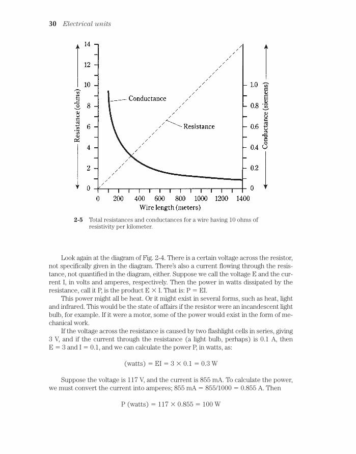
Figure 2-5 illustrates the resistance and conductance values for various lengths ofwire having a resistivity of 10 ohms per kilometer.
Power and the wattWhenever current flows through a resistance, heat results. This is inevitable. The heatcan be measured in watts, abbreviated W, and represents electrical power. Power canbe manifested in many other ways, such as in the form of mechanical motion, or radiowaves, or visible light, or noise. In fact, there are dozens of different ways that powercan be dissipated. But heat is always present, in addition to any other form of power inan electrical or electronic device. This is because no equipment is 100-percent efficient.Some power always goes to waste, and this waste is almost all in the form of heat.
Power and the watt 29
Look again at the diagram of Fig. 2-4. There is a certain voltage across the resistor,not specifically given in the diagram. There’s also a current flowing through the resis-tance, not quantified in the diagram, either. Suppose we call the voltage E and the cur-rent I, in volts and amperes, respectively. Then the power in watts dissipated by theresistance, call it P, is the product E I. That is: P EI.
This power might all be heat. Or it might exist in several forms, such as heat, lightand infrared. This would be the state of affairs if the resistor were an incandescent lightbulb, for example. If it were a motor, some of the power would exist in the form of me-chanical work.
If the voltage across the resistance is caused by two flashlight cells in series, giving3 V, and if the current through the resistance (a light bulb, perhaps) is 0.1 A, then E 3 and I 0.1, and we can calculate the power P, in watts, as:
(watts) EI 3 0.1 0.3 W
Suppose the voltage is 117 V, and the current is 855 mA. To calculate the power,we must convert the current into amperes; 855 mA 855/1000 0.855 A. Then
P (watts) 117 0.855 100 W
30 Electrical units
2-5 Total resistances and conductances for a wire having 10 ohms ofresistivity per kilometer.

You will often hear about milliwatts (mW), microwatts (µW), kilowatts (kW)
and megawatts (MW). You should, by now, be able to tell from the prefixes what theseunits represent. But in case you haven’t gotten the idea yet, you can refer to Table 2- 2.This table gives the most commonly used prefix multipliers in electricity and electron-ics, and the fractions that they represent. Thus, 1 mW 0.001 W; 1 µW 0.001 mW 0.000001 W; 1 kW 1,000 W; and 1 MW 1,000 kW 1,000, 000 W.
Energy and the watt hour 31
Table 2-2. Common prefixmultipliers.
Prefix Fraction
pico- 0.000000000001(one-trillionth)
nano- 0.000000001(one-billionth)
micro- 0.000001(one-millionth)
milli- 0.001(one-thousandth)
kilo- 1000mega- 1,000,000giga- 1,000,000,000
(one billion)tera- 1,000,000,000,000
(one trillion)
Sometimes you need to use the power equation to find currents or voltages. Thenyou should use I P/E to find current, or E P/I to find power. It’s easiest to remem-ber that P EI (watts equal volt-amperes), and derive the other equations from this bydividing through either by E (to get I) or by I (to get E).
Energy and the watt hourThere is an important difference between energy and power. You’ve probably heard thetwo terms used interchangeably, as if they mean the same thing. But they don’t. Energyis power dissipated over a length of time. Power is the rate at which energy is expended.
Physicists measure energy in joules. One joule is the equivalent of one watt ofpower, dissipated for one second of time. In electricity, you’ll more often encounter thewatt hour or the kilowatt hour. As their names imply, a watt hour, abbreviated Wh, isthe equivalent of 1 W dissipated for an hour (1 h), and 1 kilowatt hour (kWh) is theequivalent of 1 kW of power dissipated for 1 h.
An energy of 1 Wh can be dissipated in an infinite number of different ways. A60-watt bulb will burn 60 Wh in an hour, or 1 Wh per minute. A 100-W bulb would burn1 Wh in 1/100 hour, or 36 seconds. A 6-watt Christmas tree bulb would require 10 min-utes (1/6 hour) to burn 1 Wh. And the rate of power dissipation need not be constant; itcould be constantly changing.

Figure 2-6 illustrates two hypothetical devices that burn up 1 Wh of energy. DeviceA uses its power at a constant rate of 60 watts, so it consumes 1 Wh in a minute. Thepower consumption rate of device B varies, starting at zero and ending up at quite a lotmore than 60 W. How do you know that this second device really burns up 1 Wh of en-ergy? You determine the area under the graph. This example has been chosen becausefiguring out this area is rather easy. Remember that the area of a triangle is equal to halfthe product of the base length and the height. This second device is on for 72 seconds,or 1.2 minute; this is 1.2/60 0.02 hour. Then the area under the “curve” is 1/2 100
0.02 1 Wh.
32 Electrical units
2-6 Two devices that burn 1 Wh of energy. Device Adissipates a constant power; device B dissipates a changing amount ofpower.
When calculating energy values, you must always remember the units you’re using.In this case the unit is the watt hour, so you must multiply watts by hours. If you multi-ply watts by minutes, or watts by seconds, you’ll get the wrong kind of units in your answer. That means a wrong answer!
Sometimes, the curves in graphs like these are complicated. In fact, they usuallyare. Consider the graph of power consumption in your home, versus time, for a wholeday. It might look something like the curve in Fig. 2-7. Finding the area under this curveis no easy task, if you have only this graph to go by. But there is another way to deter-mine the total energy burned by your household in a day, or in a week, or most often, ina month. That is by means of the electric meter. It measures electrical energy in kilowatthours. Every month, without fail, the power company sends its representative to readthat meter. This person takes down the number of kilowatt hours displayed, subtractsthe number from the previous month, and a few days later you get a bill. This meter au-tomatically keeps track of total consumed energy, without anybody having to do so-phisticated integral calculus to find the areas under irregular curves such as the graphof Fig. 2-7.

Other energy unitsAs said before, physicists prefer to use the joule, or watt second, as their energy unit.This is the standard unit for scientific purposes.
Another unit is the erg, equivalent to one ten-millionth (0.0000001) of a joule. Thisis said to be roughly the amount of energy needed by a mosquito to take off after it hasbitten you (not including the energy needed for the bite itself). The erg is used in labexperiments involving small amounts of expended energy.
You have probably heard of the British thermal unit (Btu), equivalent to 1055joules. This is the energy unit most often used to indicate the cooling or heating capac-ity of air-conditioning equipment. To cool your room from 85 to 78 degrees needs a cer-tain amount of energy, perhaps best specified in Btu. If you are getting an airconditioner or furnace installed in your home, an expert will come look at your situa-tion, and determine the size of air conditioning/heating unit, in Btu, that best suits yourneeds. It doesn’t make any sense to get one that is way too big; you’ll be wasting yourmoney. But you want to be sure that it’s big enough—or you’ll also waste money because of inefficiency and possibly also because of frequent repair calls.
Other energy units 33
2-7 Hypothetical graph showing the powerconsumed by a typicalhousehold, as a function of the time of day.
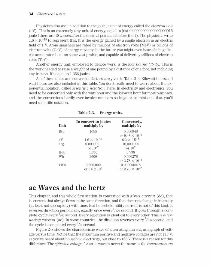
Physicists also use, in addition to the joule, a unit of energy called the electron volt
(eV). This is an extremely tiny unit of energy, equal to just 0.00000000000000000016joule (there are 18 zeroes after the decimal point and before the 1). The physicists write1.6 × 10–19 to represent this. It is the energy gained by a single electron in an electricfield of 1 V. Atom smashers are rated by millions of electron volts (MeV) or billions ofelectron volts (GeV) of energy capacity. In the future you might even hear of a huge lin-ear accelerator, built on some vast prairie, and capable of delivering trillions of electronvolts (TeV).
Another energy unit, employed to denote work, is the foot pound (ft-lb). This isthe work needed to raise a weight of one pound by a distance of one foot, not includingany friction. It’s equal to 1.356 joules.
All of these units, and conversion factors, are given in Table 2-3. Kilowatt hours andwatt hours are also included in this table. You don’t really need to worry about the ex-ponential notation, called scientific notation, here. In electricity and electronics, youneed to be concerned only with the watt hour and the kilowatt hour for most purposes,and the conversions hardly ever involve numbers so huge or so miniscule that you’llneed scientific notation.
34 Electrical units
Table 2-3. Energy units.
To convert to joules Conversely,
Unit multiply by multiply by
Btu 1055 0.000948or 9.48 10–4
eV 1.6 10–19 6.2 1018
erg 0.0000001 10,000,000or 10–7 or 107
ft-lb 1.356 0.738Wh 3600 0.000278
or 2.78 10–4
kWh 3,600,000 0.000000278or 3.6 x 10⁶ or 2.78 10–7
ac Waves and the hertzThis chapter, and this whole first section, is concerned with direct current (dc), thatis, current that always flows in the same direction, and that does not change in intensity(at least not too rapidly) with time. But household utility current is not of this kind. Itreverses direction periodically, exactly once every 1/120 second. It goes through a com-plete cycle every 1/60 second. Every repetition is identical to every other. This is alter-
nating current (ac). In some countries, the direction reverses every 1/100 second, andthe cycle is completed every 1/50 second.
Figure 2-8 shows the characteristic wave of alternating current, as a graph of volt-age versus time. Notice that the maximum positive and negative voltages are not 117 V,as you’ve heard about household electricity, but close to 165 V. There is a reason for thisdifference. The effective voltage for an ac wave is never the same as the instantaneous

maximum, or peak, voltage. In fact, for the common waveshape shown in Fig. 2-8, theeffective value is 0.707 times the peak value. Conversely, the peak value is 1.414 timesthe effective value.
Rectification and fluctuating direct current 35
2-8 One cycle of utility alternating current. The peak voltage is about165 V.
Because the whole cycle repeats itself every 1/60 second, the frequency of the util-ity ac wave is said to be 60 Hertz, abbreviated 60 Hz. The word “Hertz” literally trans-lates to “ cycles per second.” In the U.S., this is the standard frequency for ac. In someplaces it is 50 Hz. (Some remote places even use dc, but they are definitely the excep-tion, not the rule.)
In radio practice, higher frequencies are common, and you’ll hear about kilohertz
(kHz), megahertz (MHz) and gigahertz (GHz). You should know right away the sizeof these units, but in case you’re still not sure about the way the prefixes work, the re-lationships are as follows:
1 kHz = 1000 Hz1 MHz = 1000 kHz = 1,000,000 Hz1 GHz 1000 MHz = 1,000,000 kHz
1,000,000,000 Hz
Usually, but not always, the waveshapes are of the type shown in Fig. 2-8. This wave-form is known as a sine wave or a sinusoidal waveform.
Rectification and fluctuating direct currentBatteries and other sources of direct current (dc) produce a constant voltage. This canbe represented by a straight, horizontal line on a graph of voltage versus time (Fig. 2-9).

The peak and effective values are the same for pure dc. But sometimes the value of dcvoltage fluctuates rapidly with time, in a manner similar to the changes in an ac wave.This might happen if the waveform in Fig. 2-8 is rectified.
36 Electrical units
2-9 A representation of pure dc.
Rectification is a process in which ac is changed to dc. The most common methodof doing this uses a device called the diode. Right now, you need not be concerned withhow the rectifier circuit is put together. The point is that part of the ac wave is eithercut off, or turned around upside-down, so that the polarity is always the same, eitherpositive or negative.
Figure 2-10 illustrates two different waveforms of fluctuating, or pulsating, dc. In thewaveform at A, the negative (bottom) part has simply been chopped off. At B, the negativeportion of the wave has been turned around and made positive, a mirror image of its formerself. The situation at A is known as half-wave rectification, because it makes use of only halfthe wave. At B, the wave has been subjected to full-wave rectification, because all of the orig-inal current still flows, even though the alternating nature has been changed so that the cur-rent never reverses.
The effective value, compared with the peak value, for pulsating dc depends onwhether half-wave or full-wave rectification has been used. In the figure, effective volt-age is shown as a dotted line, and the instantaneous voltage is shown as a solid line.Notice that the instantaneous voltage changes all the time, from instant to instant. Thisis how it gets this name! The peak voltage is the maximum instantaneous voltage. In-stantaneous voltage is never, ever any greater than the peak.
In Fig. 2-10B, the effective value is 0.707 times the peak value, just as is the casewith ordinary ac. The direction of current flow, for many kinds of devices, doesn’t makeany difference. But in Fig. 2-10A, half of the wave has been lost. This cuts the effectivevalue in half, so that it’s just 0.354 times the peak value.
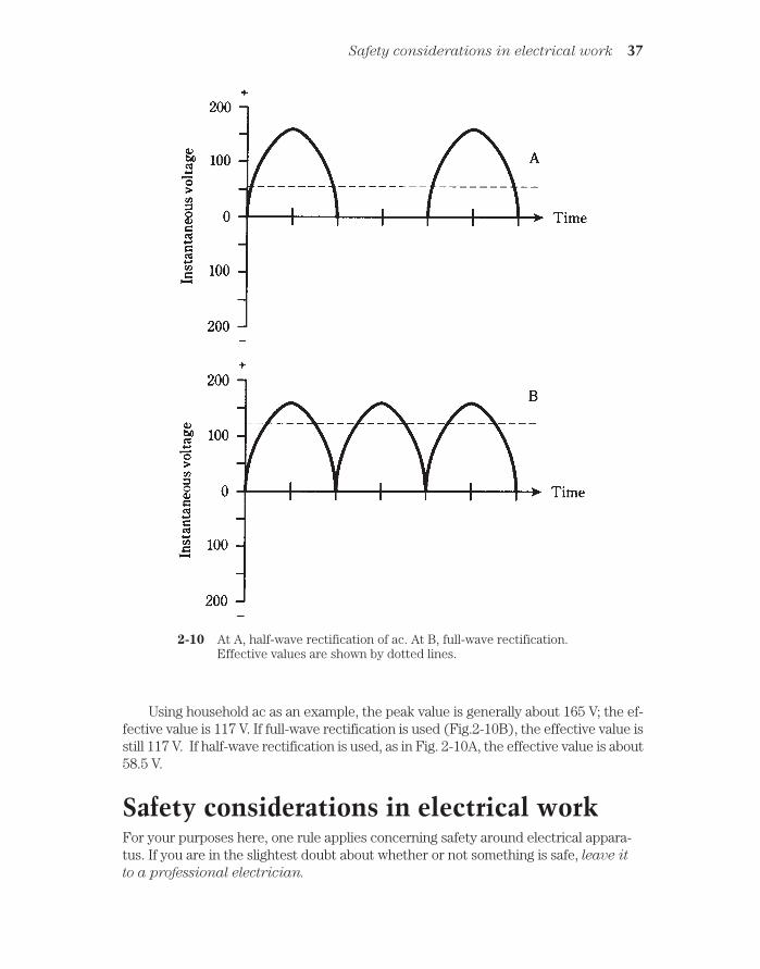
Using household ac as an example, the peak value is generally about 165 V; the ef-fective value is 117 V. If full-wave rectification is used (Fig.2-10B), the effective value isstill 117 V. If half-wave rectification is used, as in Fig. 2-10A, the effective value is about58.5 V.
Safety considerations in electrical workFor your purposes here, one rule applies concerning safety around electrical appara-tus. If you are in the slightest doubt about whether or not something is safe, leave it
to a professional electrician.
Safety considerations in electrical work 37
2-10 At A, half-wave rectification of ac. At B, full-wave rectification.Effective values are shown by dotted lines.

Household voltage, normally about 117 V but sometimes twice that, or about 234 V,is more than sufficient to kill you if it appears across your chest cavity. Certain devices,such as automotive spark coils, can produce lethal currents even from the low voltage(12 V to 14 V) in a car battery.
Consult the American Red Cross or your electrician concerning what kinds of cir-cuits, procedures and devices are safe, and which kinds aren’t.
MagnetismElectric currents and magnetic fields are closely related.
Whenever an electric current flows—that is, when charge carriers move—a mag-netic field accompanies the current. In a straight wire, the magnetic lines of flux
surround the wire in circles, with the wire at the center (Fig. 2-11). Actually, thesearen’t really lines or circles; this is just a convenient way to represent the magnetic field.You might sometimes hear of a certain number of flux lines per unit cross-sectionalarea, such as 100 lines per square centimeter. This is a relative way of talking about theintensity of the magnetic field.
38 Electrical units
2-11 Magnetic flux lines around a straight, current-carrying wire. The arrowsindicate current flow.
Magnetic fields can be produced when the atoms of certain materials align them-selves. Iron is the most common metal that has this property. The iron in the core of theearth has become aligned to some extent; this is a complex interaction caused by therotation of our planet and its motion with respect to the magnetic field of the sun. Themagnetic field surrounding the earth is responsible for various effects, such as the con-centration of charged particles that you see as the aurora borealis just after a solareruption.
When a wire is coiled up, the resulting magnetic flux takes a shape similar to theflux field surrounding the earth, or the flux field around a bar magnet. Two well-definedmagnetic poles develop, as shown in Fig. 2-12.
The intensity of a magnetic field can be greatly increased by placing a special coreinside of a coil. The core should be of iron or some other material that can be readily

magnetized. Such substances are called ferromagnetic. A core of this kind cannot actually increase the total quantity of magnetism in and around a coil, but it will causethe lines of flux to be much closer together inside the material. This is the principle bywhich an electromagnet works. It also makes possible the operation of electrical trans-formers for utility current.
Magnetic lines of flux are said to emerge from the magnetic north pole, and to runinward toward the magnetic south pole. But this is just a semantical thing, about whichtheoretical physicists might speak. It doesn’t need to concern you for ordinary electri-cal and electronics applications.
Magnetic unitsThe size of a magnetic field is measured in units called webers, abbreviated Wb. Oneweber is mathematically equivalent to one volt-second. For weaker magnetic fields, asmaller unit, called the maxwell, is sometimes used. One maxwell is equal to0.00000001 (one hundred-millionth) of a weber, or 0.01 microvolt-second.
The flux density of a magnetic field is given in terms of webers or maxwells persquare meter or per square centimeter. A flux density of one weber per square meter (1 Wb/m2) is called one tesla. One gauss is equal to 0.0001 weber, or one maxwell persquare centimeter.
Magnetic units 39
2-12 Magnetic flux lines around a coil of wire. The fines converge at the magneticpoles.

In general, the greater the electric current through a wire, the greater the flux den-sity near the wire. A coiled wire will produce a greater flux density than a single, straightwire. And, the more turns in the coil, the stronger the magnetic field will be.
Sometimes, magnetic field strength is specified in terms of ampere-turns (At).This is actually a unit of magnetomotive force. A one-turn wire loop, carrying 1 A ofcurrent, produces a field of 1 At. Doubling the number of turns, or the current, will dou-ble the number of ampere-turns. Therefore, if you have 10 A flowing in a 10-turn coil,the magnetomotive force is 10 10, or 100 At. Or, if you have 100 mA flowing in a100-turn coil, the magnetomotive force is 0.1 100, or, again, 10 At. (Remember that100 mA 0.1 A.)
Another unit of magnetomotive force is the gilbert. This unit is equal to 0.796 At.
QuizRefer to the text in this chapter if necessary. A good score is at least 18 correct answers.The answers are listed in the back of this book.
1. A positive electric pole:
A. Has a deficiency of electrons.
B. Has fewer electrons than the negative pole.
C. Has an excess of electrons.
D. Has more electrons than the negative pole
2. An EMF of one volt:
A. Cannot drive much current through a circuit.
B. Represents a low resistance.
C. Can sometimes produce a large current.
D. Drops to zero in a short time.
3. A potentially lethal electric current is on the order of:
A. 0.01 mA.
B. 0.1 mA.
C. 1 mA.
D. 0.1 A.
4. A current of 25 A is most likely drawn by:
A. A flashlight bulb.
B. A typical household.
C. A power plant.
D. A clock radio.
5. A piece of wire has a conductance of 20 siemens. Its resistance is:
A. 20 Ω.
40 Electrical units

B. 0.5 Ω.
C. 0.05 Ω.
D. 0.02 Ω.
6. A resistor has a value of 300 ohms. Its conductance is:
A. 3.33 millisiemens.
B. 33.3 millisiemens.
C. 333 microsiemens.
D. 0.333 siemens.
7. A mile of wire has a conductance of 0.6 siemens. Then three miles of the samewire has a conductance of:
A. 1.8 siemens.
B. 1.8 Ω.
C. 0.2 siemens.
D. Not enough information has been given to answer this.
8. A 2-kW generator will deliver approximately how much current, reliably, at 117V?
A. 17 mA.
B. 234 mA.
C. 17 A.
D. 234 A.
9. A circuit breaker is rated for 15 A at 117 V. This represents approximately howmany kilowatts?
A. 1.76.
B. 1760.
C. 7.8.
D. 0.0078.
10. You are told that a certain air conditioner is rated at 500 Btu. What is this inkWh?
A. 147.
B. 14.7.
C. 1.47.
D. 0.147.
11. Of the following energy units, the one most often used to define electricalenergy is:
A. The Btu.
B. The erg.
Quiz 41

C. The foot pound.
D. The kilowatt hour.
12. The frequency of common household ac in the U.S. is:
A. 60 Hz.
B. 120 Hz.
C. 50 Hz.
D. 100 Hz.
13. Half-wave rectification means that:
A. Half of the ac wave is inverted.
B. Half of the ac wave is chopped off.
C. The whole wave is inverted.
D. The effective value is half the peak value.
14. In the output of a half-wave rectifier:
A. Half of the wave is inverted.
B. The effective value is less than that of the original ac wave.
C. The effective value is the same as that of the original ac wave.
D. The effective value is more than that of the original ac wave.
15. In the output of a full-wave rectifier:
A. The whole wave is inverted.
B. The effective value is less than that of the original ac wave.
C. The effective value is the same as that of the original ac wave.
D. The effective value is more than that of the original ac wave.
16. A low voltage, such as 12 V:
A. Is never dangerous.
B. Is always dangerous.
C. Is dangerous if it is ac, but not if it is dc.
D. Can be dangerous under certain conditions.
17. Which of these can represent magnetomotive force?
A. The volt-turn.
B. The ampere-turn.
C. The gauss.
D. The gauss-turn.
18. Which of the following units can represent magnetic flux density?
A. The volt-turn.
B. The ampere-turn.
42 Electrical units

C. The gauss.
D. The gauss-turn.
19. A ferromagnetic material:
A. Concentrates magnetic flux lines within itself.
B. Increases the total magnetomotive force around a current-carrying wire.
C. Causes an increase in the current in a wire.
D. Increases the number of ampere-turns in a wire.
20. A coil has 500 turns and carries 75 mA of current. The magnetomotive forcewill be:
A. 37,500 At.
B. 375 At.
C. 37.5 At.
D. 3.75 At.
Quiz 43
3CHAPTER
Measuring devicesNOW THAT YOU’RE FAMILIAR WITH THE PRIMARY UNITS COMMON IN ELECTRIC-ITY and electronics, let’s look at the instruments that are employed to measure thesequantities.
Many measuring devices work because electric and magnetic fields produce forcesproportional to the intensity of the field. By using a tension spring against which theelectric or magnetic force can pull or push, a movable needle can be constructed. Theneedle can then be placed in front of a calibrated scale, allowing a direct reading of thequantity to be measured. These meters work by means of electromagnetic deflection
or electrostatic deflection.
Sometimes, electric current is measured by the extent of heat it produces in a re-sistance. Such meters work by thermal heating principles.
Some meters work by means of small motors whose speed depends on the mea-sured quantity. The rotation rate, or the number of rotations in a given time, can bemeasured or counted. These are forms of rate meters.
Still other kinds of meters actually count electronic pulses, sometimes in thou-sands, millions or billions. These are electronic counters. There are also various othermetering methods.
Electromagnetic deflectionEarly experimenters with electricity and magnetism noticed that an electric currentproduces a magnetic field. This discovery was probably an accident, but it was an ac-cident that, given the curiosity of the scientist, was bound to happen. When a mag-netic compass is placed near a wire carrying a direct electric current, the compassdoesn’t point toward magnetic north. The needle is displaced. The extent of the er-ror depends on how close the compass is brought to the wire, and also on how muchcurrent the wire is carrying.
Scientific experimenters are like children. They like to play around with things. Most
44 !
"# #$ !

likely, when this effect was first observed, the scientist tried different arrangements tosee how much the compass needle could be displaced, and how small a current couldbe detected. An attempt was made to obtain the greatest possible current-detectingsensitivity. Wrapping the wire in a coil around the compass resulted in a device thatwould indicate a tiny electric current (Fig. 3-1). This effect is known as galvanism, andthe meter so devised was called a galvanometer.
Electromagnetic deflection 45
3-1 A simple galvanometer. The compass must lie flat.
Once this device was made, the scientist saw that the extent of the needle dis-placement increased with increasing current. Aha—a device for measuring current!Then, the only challenge was to calibrate the galvanometer somehow, and to set upsome kind of standard so that a universal meter could be engineered.
You can easily make your own galvanometer. Just buy a cheap compass, about twofeet of insulated bell wire, and a six-volt lantern battery. Set it up as shown in Fig. 3-1.Wrap the wire around the compass four or five times, and align the compass so that theneedle points right along the wire turns while the wire is disconnected from the battery.Connect one end of the wire to the minus (–) terminal of the battery. Touch the otherend to the plus (+) terminal, intermittently, and watch the compass needle. Don’t leavethe wire connected to the battery for any length of time unless you want to drain thebattery in a hurry.
You can buy a resistor and a potentiometer at a place like Radio Shack, and set upan experiment that shows how galvanometers measure current. For a 6-V lantern bat-tery, the fixed resistor should have a value of at least 330 Ω at 1/4 watt, and the poten-tiometer should have a value of 10 KΩ (10,000 Ω) maximum. Connect the resistor andpotentiometer in series between one end of the bell wire and one terminal of the bat-tery, as shown in Fig. 3-2. The center contact of the potentiometer should be short-cir-cuited to one of the end contacts, and the resulting two terminals used in the circuit.When you adjust the potentiometer, the compass needle should deflect more or less,depending on the current through the wire. Early experimenters calibrated their me-ters by referring to the degree scale around the perimeter of the compass.

Electrostatic deflectionElectric fields produce forces, just as do magnetic fields. You have probably noticed thiswhen your hair feels like it’s standing on end in very dry or cold weather. You’ve proba-bly heard that people’s hair really does stand straight out just before a lightning bolt hitsnearby; this is no myth. Maybe you performed experiments in science classes to ob-serve this effect.
The most common device for demonstrating electrostatic forces is the electro-
scope. It consists of two foil leaves, attached to a conducting rod, and placed in a sealedcontainer so that air currents will not move the foil leaves (Fig. 3-3). When a chargedobject is brought near, or touched to, the contact at the top of the rod, the leaves standapart from each other. This is because the two leaves become charged with like electricpoles—either an excess or a deficiency of electrons—and like poles always repel.
46 Measuring devices
3-2 Circuit for demonstratinghow a galvanometerindicates relative current.
3-3 A simple electroscope.
The extent to which the leaves stand apart depends on the amount of electric charge.It is somewhat difficult to actually measure this deflection and correlate it with chargequantity; electroscopes do not make very good meters. But variations on this theme can

be employed, so that electrostatic forces can operate against tension springs or mag-nets, and in this way, electrostatic meters can be made.
An electrostatic device has the ability to measure alternating electric charges aswell as steady charges. This gives electrostatic meters an advantage over electromag-netic meters (galvanometers). If you connect ac to the coil of the galvanometer devicein Fig. 3-1 or Fig. 3-2, the compass needle might vibrate, but will not give a clear de-flection. This is because current in one direction pulls the meter needle one way, andcurrent in the other direction will deflect the needle the opposite way. But if an alter-nating electric field is connected to an electrostatic meter, the plates will repel whetherthe charge is positive or negative. The deflection will be steady, therefore, with ac aswell as with dc.
Most electroscopes aren’t sensitive enough to show much deflection with ordinary117-V utility voltage. Don’t try connecting 117 V to an electroscope anyway; it might notdeflect the foil leaves, but it can certainly present a danger to your body if you bring itout to points where you can readily come into physical contact with it.
An electrostatic meter has another property that is sometimes an advantage inelectrical or electronic work. This is the fact that the device does not draw any current,except a tiny amount at first, needed to put a charge on the plates. Sometimes, an en-gineer or experimenter doesn’t want the measuring device to draw current, becausethis affects the behavior of the circuit under test. Galvanometers, by contrast, alwaysneed at least a little bit of current in order to operate. You can observe this effect bycharging up a laboratory electroscope, say with a glass rod that has been rubbed againsta cloth. When the rod is pulled away from the electroscope, the foil leaves will remainstanding apart. The charge just sits there. If the electroscope drew any current, theleaves would immediately fall back together again, just as the galvanometer compassneedle returns to magnetic north the instant you take the wire from the battery.
Thermal heatingAnother phenomenon, sometimes useful in the measurement of electric currents, is thefact that whenever current flows through a conductor having any resistance, that con-ductor is heated. All conductors have some resistance; none are perfect. The extent ofthis heating is proportional to the amount of current being carried by the wire.
By choosing just the right metal or alloy, and by making the wire a certain lengthand diameter, and by employing a sensitive thermometer, and by putting the entire as-sembly inside a thermally insulating package, a hot-wire meter can be made. Thehot-wire meter can measure ac as well as dc, because the current-heating phenomenondoes not depend on the direction of current flow.
A variation of the hot-wire principle can be used by placing two different metalsinto contact with each other. If the right metals are chosen, the junction will heat upwhen a current flows through it. This is called the thermocouple principle. As with thehot-wire meter, a thermometer can be used to measure the extent of the heating.
But there is also another effect. A thermocouple, when it gets warm, generates a di-rect current. This current can be measured by a more conventional, dc type meter. Thismethod is useful when it is necessary to have a faster meter response time. Thehot-wire and thermocouple effects are used occasionally to measure current at radiofrequencies, in the range of hundreds of kilohertz up to tens of gigahertz.
Thermal heating 47

AmmetersGetting back to electromagnetic deflection, and the workings of the galvanometer, youmight have thought by now that a magnetic compass doesn’t make a very convenienttype of meter. It has to be lying flat, and the coil has to be aligned with the compass nee-dle when there is no current. But of course, electrical and electronic devices aren’t allturned in just the right way, so as to be aligned with the north geomagnetic pole. Thatwould not only be a great bother, but it would be ridiculous. Imagine a bunch of scien-tists running around, turning radios and other apparatus so the meters are all lying flatand are all lined up with the earth’s magnetic field! In the early days of electricity andelectronics, when the phenomena were confined to scientific labs, this was indeedpretty much how things were.
Then someone thought that the magnetic field could be provided by a permanentmagnet right inside the meter, instead of by the earth. This would supply a strongermagnetic force, and would therefore make it possible to detect much weaker currents.It would let the meter be turned in any direction and the operation would not be af-fected. The coil could be attached right to the meter pointer, and suspended by meansof a spring in the field of the magnet. This kind of meter, called a D’Arsonval move-
ment, is still extensively used today. The assembly is shown in Fig. 3-4. This is the ba-sic principle of the ammeter.
48 Measuring devices
3-4 The D’Arsonval meter movement. The spring bearing is not shown.
A variation of this is the attachment of the meter needle to a permanent magnet,and the winding of the coil in a fixed form around the magnet. Current in the coil pro-duces a magnetic field, and this in turn generates a force if the coil and magnet arealigned correctly with respect to each other. This meter movement is also sometimescalled a D’Arsonval movement. This method will work, but the inertial mass of the per-manent magnet causes a slower needle response. This kind of meter is also more proneto overshoot than the true D’Arsonval movement; the inertia of the magnet’s mass, once

overcome by the magnetic force, causes the needle to fly past the actual current levelbefore finally coming to rest at the correct reading.
It is possible to use an electromagnet in place of the permanent magnet in the me-ter assembly. This electromagnet can be operated by the same current that flows in thecoil attached to the meter needle. This gets rid of the need for a massive, permanentmagnet inside the meter. It also eliminates the possibility that the meter sensitivity willchange in case the strength of the permanent magnet deteriorates (such as might becaused by heat, or by severe mechanical vibration). The electromagnet can be either inseries with, or in parallel with, the meter movement coil.
The sensitivity of the D'Arsonval meter, and of its cousins, depends on several fac-tors. First is the strength of the permanent magnet, if the meter uses a permanent mag-net. Second is the number of turns in the coil. The stronger the magnet, and the largerthe number of turns in the coil, the less current is needed in order to produce a givenmagnetic force. If the meter is of the electromagnet type, the combined number of coilturns affects the sensitivity. Remember that the strength of a magnetomotive force isgiven in terms of ampere turns. For a given current (number of amperes), the force in-creases in direct proportion to the number of coil turns. The more force in a meter, thegreater the needle deflection, and the smaller the amount of current that is needed tocause a certain amount of needle movement.
The most sensitive ammeters can detect currents of just a microampere or two.The amount of current for full scale deflection (the needle goes all the way up withoutbanging against the stop pin) can be as little as about 50 uA in commonly available me-ters. Thus you might see a microammeter, or a milliammeter, quite often in electronicwork. Meters that measure large currents are not a problem to make; it’s easy to makean insensitive device.
Sometimes, it is desirable to have an ammeter that will allow for a wide range ofcurrent measurements. The full-scale deflection of a meter assembly cannot easily bechanged, since this would mean changing the number of coil turns and/or the strengthof the magnet. But all ammeters have a certain amount of internal resistance. If a re-sistor, having the same internal resistance as the meter, is connected in parallel with themeter, the resistor will take half the current. Then it will take twice the current throughthe assembly to deflect the meter to full scale, as compared with the meter alone. Bychoosing a resistor of just the right value, the full-scale deflection of an ammeter can beincreased by a factor of 10, or 100, or even 1000. This resistor must be capable of car-rying the current without burning up. It might have to take practically all of the currentflowing through the assembly, leaving the meter to carry only 1/10, or 1/100, or 1/1000of the current. This is called a shunt resistance or meter shunt (Fig. 3-5).
Meter shunts are frequently used when it is necessary to measure very large cur-rents, such as hundreds of amperes. They allow microammeters or milliammeters to beused in a versatile multimeter, with many current ranges.
VoltmetersCurrent is a flow of charge carriers. Voltage, or electromotive force (EMF), or potentialdifference, is the “pressure” that makes a current possible. Given a circuit whose resis-tance is constant, the current that will flow in the circuit is directly proportional to the
Voltmeters 49

voltage placed across it. Early electrical experimenters recognized that an ammetercould be used to measure voltage, since an ammeter is a form of constant-resistance circuit.
If you connect an ammeter directly across a source of voltage—a battery, say—themeter needle will deflect. In fact, a milliammeter needle will probably be “pinned” if youdo this with it, and a microammeter might well be wrecked by the force of the needlestriking the pin at the top of the scale. For this reason, you should never connect mil-liammeters or microammeters directly across voltage sources. An ammeter, perhapswith a range of 0-10 A, might not deflect to full scale if it is placed across a battery, butit’s still a bad idea to do this, because it will rapidly drain the battery. Some batteries,such as automotive lead-acid cells, can explode under these conditions. This is becauseall ammeters have low internal resistance. They are designed that way deliberately.They are meant to be connected in series with other parts of a circuit, not right acrossthe power supply.
But if you place a large resistor in series with an ammeter, and then connect theammeter across a battery or other type of power supply, you no longer have a short cir-cuit. The ammeter will give an indication that is directly proportional to the voltage ofthe supply. The smaller the full-scale reading of the ammeter, the larger the resistanceto get a meaningful indication on the meter. Using a microammeter and a very largevalue of resistor in series, a voltmeter can be devised that will draw only a little currentfrom the source.
A voltmeter can be made to have different ranges for the full-scale reading, byswitching different values of resistance in series with the microammeter (Fig. 3-6). Theinternal resistance of the meter is large because the values of the resistors are large.The greater the supply voltage, the larger the internal resistance of the meter, becausethe necessary series resistance increases as the voltage increases.
It’s always good when a voltmeter has a high internal resistance. The reason for thisis that you don’t want the meter to draw much current from the power source. This cur-rent should go, as much as possible, towards working whatever circuit is hooked up tothe supply, and not into just getting a reading of the voltage. Also, you might not want,or need, to have the voltmeter constantly connected in the circuit; you might need thevoltmeter for testing many different circuits. You don’t want the behavior of the circuitto be affected the instant you connect the voltmeter to the supply. The less current avoltmeter draws, the less it will affect the behavior of anything that is working from thepower supply.
50 Measuring devices
3-5 A resistor can beconnected across a meterto reduce the sensitivity.

Another type of voltmeter uses the effect of electrostatic deflection, rather thanelectromagnetic deflection. You remember that electric fields produce forces, just as domagnetic fields. Therefore, a pair of plates will attract or repel each other if they arecharged. The electrostatic voltmeter makes use of this effect, taking advantage of theattractive force between two plates having opposite electric charge, or having a largepotential difference. Figure 3-7 is a simplified drawing of the mechanics of an electro-static voltmeter.
The electrostatic meter draws almost no current from the power supply. The onlything between the plates is air, and air is a nearly perfect insulator. The electrostatic me-ter will indicate ac as well as dc. The construction tends to be rather delicate, however,and mechanical vibration influences the reading.
OhmmetersYou remember that the current through a circuit depends on the resistance. This prin-ciple can be used to manufacture a voltmeter using an ammeter and a resistor. Thelarger the value of the resistance in series with the meter, the more voltage is needed toproduce a reading of full scale. This has a converse, or a “flip side”: Given a constantvoltage, the current through the meter will vary if the resistance varies. This provides ameans for measuring resistances.
An ohmmeter is almost always constructed by means of a milliammeter ormicroammeter in series with a set of fixed, switchable resistances and a battery thatprovides a known, constant voltage (Fig. 3-8). By selecting the resistances appropri-ately, the meter will give indications in ohms over any desired range. Usually, zero onthe meter is assigned the value of infinity ohms, meaning a perfect insulator. Thefull-scale value is set at a certain minimum, such as 1 Ω, 100 Ω, or 10 KΩ (10,000 Ω).
Ohmmeters must be precalibrated at the factory where they are made. A slight er-ror in the values of the series resistors can cause gigantic errors in measured resistance.Therefore, precise tolerances are needed for these resistors. It is also necessary that thebattery be exactly the right kind, and that it be reasonably fresh so that it will provide
Ohmmeters 51
3-6 Circuit for using amicroammeter tomeasure voltage.

the appropriate voltage. The smallest deviation from the required voltage can cause abig error in the meter indication.
The scale of an ohmmeter is nonlinear. That is, the graduations are not the sameeverywhere. Values tend to be squashed together towards the “infinity” end of the scale.
52 Measuring devices
3-7 Simplified drawing of an electrostatic voltmeter.
3-8 Circuit for using amilliammeter to measureresistance.

It can be difficult to interpolate for high values of resistance, unless the right scale is se-lected. Engineers and technicians usually connect an ohmmeter in a circuit with themeter set for the highest resistance range first; then they switch the range until the me-ter is in a part of the scale that is easy to read. Finally, the reading is taken, and is mul-tiplied (or divided) by the appropriate amount as indicated on the range switch. Figure3-9 shows an ohmmeter reading. The meter itself says 4.7, but the range switch says 1KΩ. This indicates a resistance of 4.7 KΩ, or 4700 Ω.
Multimeters 53
3-9 An example of an ohmeterreading. This deviceshows about 4.7 1K 4.7 K 4700 ohms.
Ohmmeters will give inaccurate readings if there is a voltage between the pointswhere the meter is connected. This is because such a voltage either adds to, or sub-tracts from, the ohmmeter battery voltage. This in effect changes the battery voltage,and the meter reading is thrown way off. Sometimes the meter might even read “morethan infinity” ohms; the needle will hit the pin at the left end of the scale. Therefore,when using an ohmmeter to measure resistance, you need to be sure that there is novoltage between the points under test. The best way to do this is to switch off the equip-ment in question.
MultimetersIn the electronics lab, a common piece of test equipment is the multimeter, in whichdifferent kinds of meters are combined into a single unit. The volt-ohm-milliammeter
(VOM) is the most often used. As its name implies, it combines voltage, resistance andcurrent measuring capabilities.
You should not have too much trouble envisioning how a single milliammeter can beused for measuring voltage, current and resistance. The preceding discussions for mea-surements of these quantities have all included methods in which a current meter canbe used to measure the intended quantity.
Commercially available multimeters have certain limits in the values they can mea-sure. The maximum voltage is around 1000 V; larger voltages require special leads andheavily insulated wires, as well as other safety precautions. The maximum current

that a common VOM can measure is about 1 A. The maximum resistance is on the or-der of several megohms or tens of megohms. The lower limit of resistance indication isabout an ohm.
FET and vacuum-tube voltmetersIt was mentioned that a good voltmeter will disturb the circuit under test as little as pos-sible, and this requires that the meter have a high internal resistance. Besides the elec-trostatic type voltmeter, there is another way to get an extremely high internalresistance. This is to sample a tiny, tiny current, far too small for any meter to directlyindicate, and then amplify this current so that a meter will show it. When a minisculeamount of current is drawn from a circuit, the equivalent resistance is always extremelyhigh.
The most effective way to accomplish the amplification, while making sure that thecurrent drawn really is tiny, is to use either a vacuum tube or a field-effect transistor
(FET). You needn’t worry about how such amplifiers work right now; that subject willcome much later in this book. A voltmeter that uses a vacuum tube amplifier to mini-mize the current drain is known as a vacuum-tube voltmeter (VTVM). If an FET isused, the meter is called a FET voltmeter (FETVM). Either of these devices provide anextremely high input resistance along with good sensitivity and amplification. And theyallow measurement of lower voltages, in general, than electrostatic voltmeters.
WattmetersThe measurement of electrical power requires that voltage and current both be mea-sured simultaneously. Remember that power is the product of the voltage and current.That is, watts (P) equals volts (E) times amperes (I), written as P EI. In fact, wattsare sometimes called volt-amperes in a dc circuit.
You might think that you can just connect a voltmeter in parallel with a circuit,thereby getting a reading of the voltage across it, and also hook up an ammeter in seriesto get a reading of the current through the circuit, and then multiply volts times am-peres to get watts consumed by the circuit. And in fact, for practically all dc circuits,this is an excellent way to measure power (Fig. 3-10).
Quite often, however, it’s simpler than that. In many cases, the voltage from thepower supply is constant and predictable. Utility power is a good example. The effec-tive voltage is always very close to 117 V. Although it’s ac, and not dc, power can be mea-sured in the same way as with dc: by means of an ammeter connected in series with thecircuit, and calibrated so that the multiplication (times 117) has already been done.Then, rather than 1 A, the meter would show a reading of 117 W, because P EI 117 1 117 W. If the meter reading were 300 W, the current would be 300/117 2.56 A.
An electric iron might consume 1000 W, or a current of 1000/117 8.55 A. And alarge heating unit might gobble up 2000 W, requiring a current of 2000/117 17. 1 A. Thismight blow a fuse or breaker, since these devices are often rated for only 15 A. You’veprobably had an experience where you hooked up too many appliances to a single circuit,blowing the fuse or breaker. The reason was that the appliances, combined, drew too
54 Measuring devices

much current for the house wiring to safely handle, and the fuse or breaker, detecting theexcess current, opened the circuit.
Specialized wattmeters are necessary for the measurement of radio-frequency(RF) power, or for peak audio power in a high-fidelity amplifier, or for certain other spe-cialized applications. But almost all of these meters, whatever the associated circuitry,use simple ammeters as their indicating devices.
Watt-hour metersThe utility company is not too interested in how much power you’re using with one ap-pliance, or even how much power a single household is drawing, at any given time. Byfar the greater concern is the total energy that is used over a day, a week, a month or ayear. Electrical energy is measured in watt hours, or, more commonly for utility pur-poses, in kilowatt hours (kWh). The device that indicates this is the watt-hour meter
or kilowatt-hour meter.
The most often-used means of measuring electrical energy is by using a small elec-tric motor device, whose speed depends on the current, and thereby on the power at aconstant voltage. The number of turns of the motor shaft, in a given length of time, is di-rectly proportional to the number of kilowatt hours consumed. The motor is placed atthe point where the utility wires enter the house, apartment or building. This is usuallyat a point where the voltage is 234 V. This is split into some circuits with 234 V, forheavy-duty appliances such as the oven, washer and dryer, and the general householdfines for lamps, clock radios and, television sets.
You’ve surely seen the little disk in the utility meter going around and around,sometimes fast, other times slowly. Its speed depends on the power you’re using. Thetotal number of turns of this little disk, every month, determines the size of the bill youwill get—as a function also, of course, of the cost per kilowatt hour for electricity.
Kilowatt-hour meters count the number of disk turns by means of geared, rotarydrums or pointers. The drum type meter gives a direct digital readout. The pointer typehas several scales calibrated from 0 to 9 in circles, some going clockwise and others go-ing counterclockwise.
Watt-hour meters 55
3-10 Power can be measured with a voltmeter and an ammeter.

Reading a pointer type utility meter is a little tricky, because you must think inwhatever direction (clockwise or counterclockwise) the scale goes. An example of apointer type utility meter is shown in Fig. 3-11. Read from left to right. For each littlemeter, take down the number that the pointer has most recently passed. Write downthe rest as you go. The meter in the figure reads 3875 kWh. If you want to be really pre-cise, you can say it reads 3875-1/2 kWh.
56 Measuring devices
3-11 An example of a utility meter. The reading is a little more than 3875 kWh.
Digital readout metersIncreasingly, metering devices are being designed so that they provide a direct readout,and there’s no need (or possibility) for interpolation. The number on the meter is the in-dication. It’s that simple. Such a meter is called a digital meter.
The advantage of a digital meter is that it’s easy for anybody to read, and there is nochance for interpolation errors. This is ideal for utility meters, clocks, and some kinds ofammeters, voltmeters and wattmeters. It works very well when the value of the quan-tity does not change very often or very fast.
But there are some situations in which a digital meter is a disadvantage. One goodexample is the signal-strength indicator in a radio receiver. This meter bounces up anddown as signals fade, or as you tune the radio, or sometimes even as the signal modu-lates. A digital meter would show nothing but a constantly changing, meaningless set ofnumerals. Digital meters require a certain length of time to “lock in” to the current, volt-age, power or other quantity being measured. If this quantity never settles at any onevalue for a long enough time, the meter can never lock in.
Meters with a scale and pointer are known as analog meters. Their main advan-tages are that they allow interpolation, they give the operator a sense of the quantityrelative to other possible values, and they follow along when a quantity changes. Someengineers and technicians prefer the “feel” of an analog meter, even in situations wherea digital meter would work just as well.
One problem you might have with digital meters is being certain of where the dec-imal point goes. If you’re off by one decimal place, the error will be by a factor of 10.Also, you need to be sure you know what the units are; for example, a frequency indi-cator might be reading out in megahertz, and you might forget and think it is giving youa reading in kilohertz. That’s a mistake by a factor of 1000. Of course this latter type oferror can happen with an analog meter, too.

Frequency countersThe measurement of energy used by your home is an application to which digital me-tering is well suited. It’s easier to read the drum type, digital kilowatt-hour meter thanto read the pointer type meter. When measuring frequencies of signals, digital meteringis not only more convenient, but far more accurate.
The frequency counter measures by actually counting pulses, in a manner similarto the way the utility meter counts the number of turns of a motor. But the frequencycounter works electronically, without any moving parts. It can keep track of thousands,millions or even billions of pulses per second, and it shows the rate on a digital displaythat is as easy to read as a digital watch. It measures frequency directly by tallying upthe number of pulses in an oscillating wave, even when the number of pulses per sec-ond is huge.
The accuracy of the frequency counter is a function of the lock-in time. Lock-in isusually done in 0.1 second, 1 second or 10 seconds. Increasing the lock-in time by a fac-tor of 10 will cause the accuracy to be good by one additional digit. Modern frequencycounters are good to six, seven or eight digits; sophisticated lab devices will show fre-quency to nine or ten digits.
Other specialized meter typesThe following are some less common types of meters that you might come across inelectrical and electronic work.
VU and decibel metersIn high-fidelity equipment, especially the more sophisticated amplifiers (“amps”), loud-ness meters are sometimes used. These are calibrated in decibels, a unit that you willsometimes encounter in reference to electronic signal levels. A decibel is an increase ordecrease in sound or signal level that you can just barely detect, if you are expecting thechange.
Audio loudness is given in volume units (VU), and the meter that indicates it iscalled a VU meter. Usually, such meters have a zero marker with a red line to the rightand a black line to the left, and they are calibrated in decibels (dB) above and below thiszero marker (Fig. 3-12). The meter might also be calibrated in watts rms, an expressionfor audio power.
As music is played through the system, or as a voice comes over it, the VU meterneedle will kick up. The amplifier volume should be kept down so that the meter does-n’t go past the zero mark and into the red range. If the meter does kick up into the redscale, it means that distortion is probably taking place within the amplifier circuit.
Sound level in general can be measured by means of a sound-level meter, cali-brated in decibels (dB) and connected to the output of a precision amplifier with a mi-crophone of known, standardized sensitivity (Fig. 3-13). You have perhaps heard that avacuum cleaner will produce 80 dB of sound, and a large truck going by might subjectyour ears to 90 dB. These figures are determined by a sound-level meter. A VU meter isa special form of sound-level meter.
Other specialized meter types 57

Light metersLight intensity is measured by means of a light meter or illumination meter. You mightthink that it’s easy to make this kind of meter by connecting a milliammeter to a solar(photovoltaic) cell. And this is, in fact, a good way to construct an inexpensive light me-ter (Fig. 3-14). More sophisticated devices might use dc amplifiers to enhance sensitiv-ity and to allow for several different ranges of readings.
58 Measuring devices
3-12 A VU meter. The heavyscale is usually red,indicating high risk ofaudio distortion.
3-13 A sound-level meter.
3-14 A simple light meter.
One problem with this design is that solar cells are not sensitive to light at exactlythe same wavelengths as human eyes. This can be overcome by placing a colored filterin front of the solar cell, so that the solar cell becomes sensitive to the same wave-lengths, in the same proportions, as human eyes. Another problem is calibrating themeter. This must usually be done at the factory, in units such as lumens or candela. It’snot important that you know the precise definitions of these units in electricity andelectronics.

Sometimes, meters such as the one in Fig. 3-14 are used to measure infrared or ul-traviolet intensity. Different types of photovoltaic cells have peak sensitivity at differentwavelengths. Filters can be used to block out wavelengths that you don’t want the me-ter to detect.
Pen recordersA meter movement can be equipped with a marking device, usually a pen, to keep agraphic record of the level of some quantity with respect to time. Such a device is calleda pen recorder. The paper, with a calibrated scale, is taped to a rotating drum. Thedrum, driven by a clock motor, turns at a slow rate, such as one revolution per hour orone revolution in 24 hours. A simplified drawing of a pen recorder is shown in Fig. 3-15.
Other specialized meter types 59
3-15 Simplified drawing of a pen recorder.
A device of this kind, along with a wattmeter, might be employed to get a readingof the power consumed by your household at various times during the day. In this wayyou might tell when you use the most power, and at what particular times you might beusing too much.
OscilloscopesAnother graphic meter is the oscilloscope. This measures and records quantities thatvary rapidly, at rates of hundreds, thousands, or millions of times per second. It createsa “graph” by throwing a beam of electrons at a phosphor screen. A cathode-ray tube,
similar to the kind in a television set, is employed.Oscilloscopes are useful for looking at the shapes of signal waveforms, and also for
measuring peak signal levels (rather than just the effective levels). An oscilloscope canalso be used to approximately measure the frequency of a waveform. The horizontalscale of an oscilloscope shows time, and the vertical scale shows instantaneous voltage.An oscilloscope can indirectly measure power or current, by using a known value of re-sistance across the input terminals.

Technicians and engineers develop a sense of what a signal waveform should looklike, and then they can often tell, by observing the oscilloscope display, whether or notthe circuit under test is behaving the way it should. This is a subjective kind of“measurement, “ since it is qualitative as well as quantitative. If a wave shape “lookswrong,” it might indicate distortion in a circuit, or possibly even betray a burned-outcomponent someplace.
Bar-graph metersA cheap, simple kind of meter can be made using a string of light-emitting diodes (LEDs)or a liquid-crystal display (LCD) along with a digital scale, to indicate approximate levelsof current, voltage or power. This type of meter has no moving parts to break, just like adigital meter. But it also offers the relative-reading feeling you get with an analog meter.Figure 3-16 is an example of a bar-graph meter that is used to show the power output, inkilowatts, for a radio transmitter. It indicates 0.8 kW or 800 watts, approximately.
60 Measuring devices
3-16 A bar-graph meter. This device shows a power level of about 0.8kW or 800W.
The chief disadvantage of the bar-graph meter is that it isn’t very accurate. For thisreason it is not generally used in laboratory testing. The LED or LCD devices sometimesalso flicker when the level is “between” two values given by the bars. This can be an-noying to some people.
QuizRefer to the text in this chapter if necessary. A good score is 18 out of 20 correct. An-swers are in the back of the book.
1. The force between two electrically charged objects is called:
A. Electromagnetic deflection.
B. Electrostatic force.
C. Magnetic force.
D. Electroscopic force.
2. The change in the direction of a compass needle, when a current-carrying wireis brought near, is:
A. Electromagnetic deflection.
B. Electrostatic force.

C. Magnetic force.
D. Electroscopic force.
3. Suppose a certain current in a galvanometer causes the needle to deflect 20degrees, and then this current is doubled. The needle deflection:
A. Will decrease.
B. Will stay the same.
C. Will increase.
D. Will reverse direction.
4. One important advantage of an electrostatic meter is that:
A. It measures very small currents.
B. It will handle large currents.
C. It can detect ac voltages.
D. It draws a large current from the source.
5. A thermocouple:
A. Gets warm when current flows through it.
B. Is a thin, straight, special wire.
C. Generates dc when exposed to light.
D. Generates ac when heated.
6. One advantage of an electromagnet meter over a permanent-magnet meter isthat:
A. The electromagnet meter costs much less.
B. The electromagnet meter need not be aligned with the earth’s magneticfield.
C. The permanent-magnet meter has a more sluggish coil.
D. The electromagnet meter is more rugged.
7. An ammeter shunt is useful because:
A. It increases meter sensitivity.
B. It makes a meter more physically rugged.
C. It allows for measurement of a wide range of currents.
D. It prevents overheating of the meter.
8. Voltmeters should generally have:
A. Large internal resistance.
B. Low internal resistance.
C. Maximum possible sensitivity.
D. Ability to withstand large currents.
9. To measure power-supply voltage being used by a circuit, a voltmeter
A. Is placed in series with the circuit that works from the supply.
Quiz 61

B. Is placed between the negative pole of the supply and the circuit workingfrom the supply.
C. Is placed between the positive pole of the supply and the circuit workingfrom the supply.
D. Is placed in parallel with the circuit that works from the supply.
10. Which of the following will not cause a major error in an ohmmeter reading?
A. A small voltage between points under test.
B. A slight change in switchable internal resistance.
C. A small change in the resistance to be measured.
D. A slight error in range switch selection.
11. The ohmmeter in Fig. 3-17 shows a reading of about:
A. 33,000 Ω.
B. 3.3 KΩ.
C. 330 Ω.
D. 33 Ω.
62 Measuring devices
3-17 Illustration for quizquestion 11.
12. The main advantage of a FETVM over a conventional voltmeter is the fact thatthe FETVM:
A. Can measure lower voltages.
B. Draws less current from the circuit under test.
C. Can withstand higher voltages safely.
D. Is sensitive to ac as well as to dc.
13. Which of the following is not a function of a fuse?
A. To be sure there is enough current available for an appliance to work right.

B. To make it impossible to use appliances that are too large for a givencircuit.
C. To limit the amount of power that a circuit can deliver.
D. To make sure the current is within safe limits.
14. A utility meter’s motor speed works directly from:
A. The number of ampere hours being used at the time.
B. The number of watt hours being used at the time.
C. The number of watts being used at the time.
D. The number of kilowatt hours being used at the time.
15. A utility meter’s readout indicates:
A. Voltage.
B. Power.
C. Current.
D. Energy.
16. A typical frequency counter:
A. Has an analog readout.
B. Is usually accurate to six digits or more.
C. Works by indirectly measuring current.
D. Works by indirectly measuring voltage.
17. A VU meter is never used for measurement of:
A. Sound.
B. Decibels.
C. Power.
D. Energy.
18. The meter movement in an illumination meter measures:
A. Current.
B. Voltage.
C. Power.
D. Energy.
19. An oscilloscope cannot be used to indicate:
A. Frequency.
B. Wave shape.
C. Energy.
D. Peak signal voltage.
20. The display in Fig. 3-18 could be caused by a voltage of:
A. 6.0 V.
Quiz 63

B. 6.6 V.
C. 7. 0V.
D. No way to tell; the meter is malfunctioning.
64 Measuring devices
3-18 Illustration for quiz question 20.

4CHAPTER
Basic dc circuitsYOU’VE ALREADY SEEN SOME SIMPLE ELECTRICAL CIRCUIT DIAGRAMS. SOME OFthese are the same kinds of diagrams, using the same symbols, that professional tech-nicians and engineers use. In this chapter, you’ll get more acquainted with this type ofdiagram. You’ll also learn more about how current, voltage, resistance, and power arerelated in direct-current (dc) and low-frequency alternating-current (ac) circuits.
Schematic symbolsIn this course, the plan is to familiarize you with schematic symbols mainly by gettingyou to read and use them “in action,” rather than by dryly drilling you with them. Butit’s a good idea now to check Appendix B and look over the various symbols. Some ofthe more common ones are mentioned here.
The simplest schematic symbol is the one representing a wire or electrical conduc-tor: a straight, solid line. Sometimes dotted lines are used to represent conductors, butusually, dotted lines are drawn to partition diagrams into constituent circuits, or to in-dicate that certain components interact with each other or operate in step with eachother. Conductor lines are almost always drawn either horizontally across, or verticallyup and down the page, so that the imaginary charge carriers are forced to march in for-mation like soldiers. This keeps the diagram neat and easy to read.
When two conductor lines cross, they aren’t connected at the crossing point unlessa heavy, black dot is placed where the two lines meet. The dot should always be clearlyvisible wherever conductors are to be connected, no matter how many of them meet atthe junction.
A resistor is indicated by a zig-zaggy line. A variable resistor, or potentiometer, is in-dicated by a zig-zaggy line with an arrow through it, or by a zig-zaggy line with an arrowpointing at it. These symbols are shown in Fig. 4-1.
A cell is shown by two parallel lines, one longer than the other. The longer line rep-resents the plus terminal. A battery, or combination of cells in series, is indicated by
65 !
"# #$ !
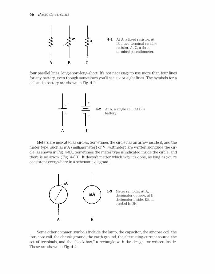
four parallel lines, long-short-long-short. It’s not necessary to use more than four linesfor any battery, even though sometimes you’ll see six or eight lines. The symbols for acell and a battery are shown in Fig. 4-2.
66 Basic dc circuits
4-1 At A, a fixed resistor. AtB, a two-terminal variableresistor. At C, a threeterminal potentiometer.
4-2 At A, a single cell. At B, abattery.
Meters are indicated as circles. Sometimes the circle has an arrow inside it, and themeter type, such as mA (milliammeter) or V (voltmeter) are written alongside the cir-cle, as shown in Fig. 4-3A. Sometimes the meter type is indicated inside the circle, andthere is no arrow (Fig. 4-3B). It doesn’t matter which way it’s done, as long as you’reconsistent everywhere in a schematic diagram.
4-3 Meter symbols. At A,designator outside; at B,designator inside. Eithersymbol is OK.
Some other common symbols include the lamp, the capacitor, the air-core coil, theiron-core coil, the chassis ground, the earth ground, the alternating-current source, theset of terminals, and the “black box,” a rectangle with the designator written inside.These are shown in Fig. 4-4.

Schematic diagramsLook back through the earlier chapters of this book and observe the schematic dia-
grams. These are all simple examples of how professionals would draw the circuits.There is no inscrutable gobbledygook to put in to make them into the sorts of circuitmaps that the most brilliant engineer would need. The diagrams you have worked withare exactly like the ones that the engineer would use to depict these circuits.
Schematic diagrams 67
4-4 Nine common schematic symbols. A: Incandescent lamp.B: Capacitor. C: Air-core coil. D: Iron-core coil. E: Chassisground. F: Earth ground. G: Source of alternating current (ac).H: Pair of terminals. I: Specialized component or device.

Wiring diagramsThe difference between a schematic diagram and a wiring diagram is the amount ofdetail included. In a schematic diagram, the interconnection of the components isshown, but the actual values of the components are not necessarily indicated.
You might see a diagram of a two-transistor audio amplifier, for example, with re-sistors and capacitors and coils and transistors, but without any data concerning thevalues or ratings of the components. This is a schematic diagram, but not a true wiringdiagram. It gives the scheme for the circuit, but you can’t wire the circuit and make itwork, because there isn’t enough information.
Suppose you want to build the circuit. You go to an electronics store to get theparts. What sizes of resistors should you buy? How about capacitors? What type of tran-sistor will work best? Do you need to wind the coils yourself, or can you get them readymade? Are there test points or other special terminals that should be installed for thebenefit of the technicians who might have to repair the amplifier? How many wattsshould the potentiometers be able to handle? All these things are indicated in a wiringdiagram, a jazzed-up schematic. You might have seen this kind of diagram in the back ofthe instruction manual for a hi-fi amp or an FM stereo tuner or a television set. Wiringdiagrams are especially useful and necessary when you must service or repair an elec-tronic device.
Voltage/current/resistance circuitMost dc circuits can be ultimately boiled down to three major components: a voltagesource, a set of conductors, and a resistance. This is shown in the schematic diagram ofFig. 4-5. The voltage or EMF source is called E; the current in the conductor is called I;the resistance is called R. The standard units for these components are the volt, the am-pere, and the ohm respectively.
68 Basic dc circuits
4-5 Simple dc circuit. Thevoltage is E, the current isI, and the resistance is R.
You already know that there is a relationship among these three quantities. If oneof them changes, then one or both of the others will also change. If you make the resis-tance smaller, the current will get larger. If you make the EMF source smaller, the cur-rent will decrease. If the current in the circuit increases, the voltage across the resistorwill increase. There is a simple arithmetic relationship between these three quantities.

Ohm’s LawThe interdependence between current, voltage, and resistance is one of the most fun-damental rules, or laws, in electrical circuits. It is called Ohm’s Law, named after the sci-entist who supposedly first expressed it. Three formulas denote this law:
E IR
I E/R
R E/I
You need only to remember the first one in order to derive the others. The easiestway to remember it is to learn the abbreviations E for EMF or voltage, I for current andR for resistance, and then remember that they appear in alphabetical order with theequals sign after the E.
Sometimes the three symbols are written in a triangle, as in Fig. 4-6. To find thevalue of one, you cover it up and read the positions of the others.
Current calculations 69
4-6 Ohm’s Law triangle.
It’s important to remember that you must use units of volts, amperes, and ohms inorder for Ohm’s Law to work right. If you use volts, milliamperes, and ohms or kilovolts,microamperes, and megohms you cannot expect to get the right answers.
If the initial quantities are given in units other than volts, amperes, and ohms, youmust convert to these units, then calculate. After that, you can convert the units backagain to whatever you like. For example, if you get 13,500,000 ohms as a calculated re-sistance, you might prefer to say that it’s 13.5 megohms.
Current calculationsThe first way to use Ohm’s Law is to find current values in dc circuits. In order to findthe current, you must know the voltage and the resistance, or be able to deduce them.
Refer to the schematic diagram of Fig. 4-7. It consists of a variable dc generator, avoltmeter, some wire, an ammeter, and a calibrated, wide-range potentiometer. Com-ponent values have been left out of this diagram, so it’s not a wiring diagram. But

values can be assigned for the purpose of creating sample Ohm’s Law problems. Whilecalculating the current in the following problems, it is necessary to mentally “cover up”the meter.
70 Basic dc circuits
4-7 Circuit for working Ohm’s Law problems.
Problem 4-1Suppose that the dc generator (Fig. 4-7) produces 10 V, and that the potentiometer isset to a value of 10 . Then what is the current?
This is easily solved by the formula I E/R. Just plug in the values for E and R; theyare both 10, because the units were given in volts and ohms. Then I 10/10 1 A.
Problem 4-2The dc generator (Fig. 4-7) produces 100 V and the potentiometer is set to 10 KΩ.What is the current?
First, convert the resistance to ohms: 10 K Ω 10,000 . Then plug the values in:I 100/10,000 0.01 A. This might better be expressed as 10 mA.
Engineers and technicians prefer to keep the numbers within reason when speci-fying quantities. Although it’s perfectly all right to say that a current is 0.01 A, it’s best ifthe numbers can be kept at 1 or more, but less than 1,000. It is a little silly to talk abouta current of 0.003 A, or a resistance of 107,000 Ω, when you can say 3 mA or 107 KΩ.
Problem 4-3The dc generator (Fig. 4-7) is set to provide 88.5 V, and the potentiometer is set to 477M. What is the current?
This problem involves numbers that aren’t exactly round, and one of them is huge. But you can use a calculator. The resistance is first changed to ohms, giving 477,000,000 . Then you plug into the Ohm’s Law formula: I E/R 88.5/477,000,000 0.000000186 A 0.186 uA. This value is less than 1, but there isn’t much

you can do about it unless you are willing to use units of nanoamperes (nA), or bil-lionths of an ampere. Then you can say that the current is 186 nA.
Voltage calculationsThe second use of Ohm’s Law is to find unknown voltages when the current and the re-sistance are known. For the following problems, uncover the ammeter and cover thevoltmeter scale instead in your mind.
Problem 4-4Suppose the potentiometer (Fig. 4-7) is set to 100 ohms, and the measured current is10 mA. What is the dc voltage?
Use the formula E I R. First, convert the current to amperes: 10 mA = 0. 01 A.Then multiply: E 0. 01 100 1 V. That’s a low, safe voltage, a little less than whatis produced by a flashlight cell.
Problem 4-5Adjust the potentiometer (Fig. 4-7) to a value of 157 K, and let the current reading be17 mA. What is the voltage of the source?
Now you have to convert both the resistance and the current values to their properunits. A resistance of 157 K is 157,000 ; a current of 17 mA is 0. 017 A. Then E IR
0.017 157,000 2669 V 2.669 kV. You might want to round this off to 2.67 kV.This is a dangerous voltage. If you touch the terminals you’ll get clobbered.
Problem 4-6You set the potentiometer (Fig. 4-7) so that the meter reads 1.445 A, and you observethat the potentiometer scale shows 99 ohms. What is the voltage?
These units are both in their proper form. Therefore, you can plug them right inand use your calculator: E IR 1. 445 99 143.055 V. This can, and should, berounded off to 143 V. A purist would go further and round it to the nearest 10 volts, to140 V.
It’s never a good idea to specify your answer to a problem with more significant fig-ures than you’re given. The best engineers and scientists go by the rule of significant
figures: keep to the least number of digits given in the data. If you follow this rule inProblem 4-6, you must round off the answer to two significant figures, getting 140 V, be-cause the resistance specified (99 ) is only accurate to two digits.
Resistance calculationsOhms’ Law can be used to find a resistance between two points in a dc circuit, when thevoltage and the current are known. For the following problems, imagine that both thevoltmeter and ammeter scales in Fig. 4-7 are visible, but that the potentiometer is un-calibrated.
Resistance calculations 71

Problem 4-7If the voltmeter reads 24 V and the ammeter shows 3.0 A, what is the value of the po-tentiometer?
Use the formula R E/I and plug in the values directly, because they are expressedin volts and amperes: R 24/3.0 8. 0.
Note that you can specify this value to two significant figures, the eight and thezero, rather than saying simply 8 . This is because you are given both the voltage andthe current to two significant figures. If the ammeter reading had been given as 3 A(meaning some value between 21/2 A and 31/2 A), you would only be entitled to expressthe answer as 8 (somewhere between 71/2 and 81/2 ). A zero can be a significant fig-ure, just as well as the digits 1 through 9.
Problem 4-8What is the value of the resistance if the current is 18 mA and the voltage is 229 mV?
First, convert these values to amperes and volts. This gives I 0.018 A and E 0.229 V. Then plug into the equation R E/I 0.229/0.018 13 . You’re justified ingiving your answer to two significant figures, because the current is only given to thatmany digits.
Problem 4-9Suppose the ammeter reads 52 uA and the voltmeter indicates 2.33 kV. What is the re-sistance?
Convert to amperes and volts, getting I 0.000052 A and E 2330 V. Then pluginto the formula: R 2330/0.000052 45,000,000 45 M.
Power calculationsYou can calculate the power, in watts, in a dc circuit such as that shown in Fig. 4-7, bythe formula P EI or the product of the voltage in volts and the current in amperes.You might not be given the voltage directly, but can calculate it if you know the currentand the resistance.
Remember the Ohm’s Law formula for obtaining voltage: E IR. If you know I andR, but don’t know E, you can get the power P by means of the formula P (IR)I I 2R.
That is, you take the current in amperes, multiply this figure by itself, and then multiplythe result by the resistance in ohms.
You can also get the power if you aren’t given the current directly. Suppose you’regiven only the voltage and the resistance. Remember the Ohm’s Law formula for ob-taining current: I E/R. Therefore, P E(E/R) E2/R. Take the voltage, multiply itby itself, and divide by the resistance.
Stated all together, these power formulas are:
P EI I 2R E 2/R
Now you are ready to do some problems in power calculations. Refer once again toFig. 4-7.
72 Basic dc circuits

Problem 4-10Suppose that the voltmeter reads 12 V and the ammeter shows 50 mA. What is thepower dissipated by the potentiometer?
Use the formula P EI. First, convert the current to amperes, getting I 0.050 A.(Note that the zero counts as a significant digit.) Then P EI 12 0.050 0.60 W.
You might say that this is 600 mW, although that is to three significant figures. It’snot easy to specify the number 600 to two significant digits without using a means ofwriting numbers called scientific notation. That subject is beyond the scope of thisdiscussion, so for now, you might want to say “600 milliwatts, accurate to two significantfigures.” (You can probably get away with “600 milliwatts” and nobody will call you onthe number of significant digits.)
Problem 4-11If the resistance in the circuit of Fig. 4-7 is 999 and the voltage source delivers 3 V,what is the dissipated power?
Use the formula P E 2/R 3 3/999 9/999 0. 009 W 9 mW. You are justi-fied in going to only one significant figure here.
Problem 4-12Suppose the resistance is 47 K and the current is 680 mA. What is the power dissi-pated by the potentiometer?
Use the formula P I 2R, after converting to ohms and amperes. Then P 0.680 0.680 47,000 22,000 W 22 kW.
This is a ridiculous state of affairs. An ordinary potentiometer, such as the one youwould get at an electronics store, dissipating 22 kW, several times more than a typicalhousehold. The voltage must be phenomenal. It’s not too hard to figure out that such avoltage would burn out the potentiometer so fast that it would be ruined before the lit-tle “Pow!” could even begin to register.
Problem 4-13Just from curiosity, what is the voltage that would cause so much current to be driventhrough such a large resistance?
Use Ohm’s Law to find the current: E IR 0.680 47, 000 32,000 V 32 kV.That’s the sort of voltage you’d expect to find only in certain industrial/commercial ap-plications. The resistance capable of drawing 680 mA from such a voltage would surelynot be a potentiometer, but perhaps something like an amplifier tube in a radio broad-cast transmitter.
Resistances in seriesWhen you place resistances in series, their ohmic values simply add together to get thetotal resistance. This is easy to see intuitively, and it’s quite simple to remember.
Resistances in series 73
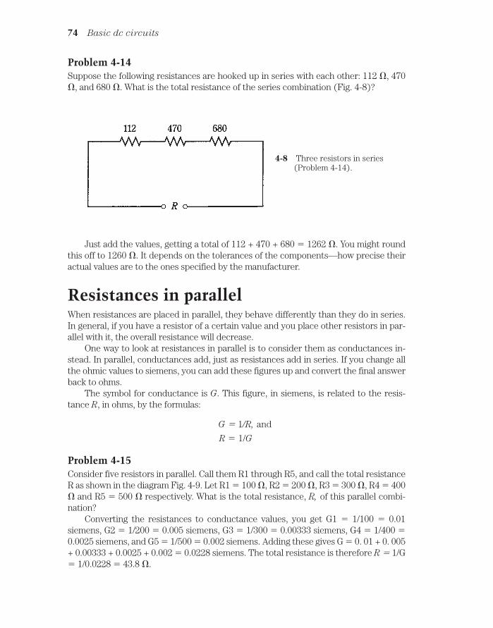
Problem 4-14Suppose the following resistances are hooked up in series with each other: 112 , 470, and 680 . What is the total resistance of the series combination (Fig. 4-8)?
74 Basic dc circuits
4-8 Three resistors in series(Problem 4-14).
Just add the values, getting a total of 112 + 470 + 680 1262 . You might roundthis off to 1260 . It depends on the tolerances of the components—how precise theiractual values are to the ones specified by the manufacturer.
Resistances in parallelWhen resistances are placed in parallel, they behave differently than they do in series.In general, if you have a resistor of a certain value and you place other resistors in par-allel with it, the overall resistance will decrease.
One way to look at resistances in parallel is to consider them as conductances in-stead. In parallel, conductances add, just as resistances add in series. If you change allthe ohmic values to siemens, you can add these figures up and convert the final answerback to ohms.
The symbol for conductance is G. This figure, in siemens, is related to the resis-tance R, in ohms, by the formulas:
G 1/R, and
R 1/G
Problem 4-15Consider five resistors in parallel. Call them R1 through R5, and call the total resistanceR as shown in the diagram Fig. 4-9. Let R1 100 , R2 200 , R3 300 , R4 400 and R5 500 respectively. What is the total resistance, R, of this parallel combi-nation?
Converting the resistances to conductance values, you get G1 1/100 0.01siemens, G2 1/200 0.005 siemens, G3 1/300 0.00333 siemens, G4 1/400 0.0025 siemens, and G5 1/500 0.002 siemens. Adding these gives G 0. 01 + 0. 005+ 0.00333 + 0.0025 + 0.002 0.0228 siemens. The total resistance is therefore R 1/G 1/0.0228 43.8 .

When you have resistances in parallel and their values are all equal, the total resis-tance is equal to the resistance of any one component, divided by the number of com-ponents.
Problem 4-16Suppose there are five resistors R1 through R5 in parallel, as shown in Fig. 4-9, all hav-ing a value of 4.7K . What is the total resistance, R?
You can probably guess that the total is a little less than 1K or 1000 . So you canconvert the value of the single resistor to 4,700 and divide by 5, getting a total resis-tance of 940 . This is accurate to two significant figures, the 9 and the 4; engineerswon’t usually be worried about the semantics, and you can just say “940 .”
Division of powerWhen combinations of resistances are hooked up to a source of voltage, they will drawcurrent. You can easily figure out how much current they will take by calculating the to-tal resistance of the combination and then considering the network as a single resistor.
If the resistances in the network all have the same ohmic value, the power from thesource will be evenly distributed among the resistances, whether they are hooked up inseries or in parallel. If there are eight identical resistors in series with a battery, the net-work will consume a certain amount of power, each resistor bearing 1/8 of the load. If yourearrange the circuit so that the resistors are in parallel, the circuit will dissipate a cer-tain amount of power (a lot more than when the resistors were in series), but again,each resistor will handle 1/8 of the total power load.
If the resistances in the network do not all have identical ohmic values, they divideup the power unevenly. Situations like this are discussed in the next chapter.
Resistances in series-parallelSets of resistors, all having identical ohmic values, can be connected together in paral-lel sets of series networks, or in series sets of parallel networks. By doing this, the totalpower handling capacity of the resistance can be greatly increased over that of a singleresistor.
Resistances in series-parallel 75
4-9 Five resistors in parallel, R1 through R5, give a totalresistance R. See Problems 4-15 and 4-16.

Sometimes, the total resistance of a series-parallel network is the same as the valueof any one of the resistors. This is always true if the components are identical, and arein a network called an n-by-n matrix. That means, when n is a whole number, there aren parallel sets of n resistors in series (A of Fig. 4-10), or else there are n series sets of nresistors in parallel (B of Fig. 4-10). Either arrangement will give exactly the same re-sults in practice.
76 Basic dc circuits
4-10 Series-parallel combinations. At A, sets of series resistors areconnected in parallel. At B, sets of parallel resistors are in series.
Engineers and technicians sometimes use this to their advantage to get resistorswith large power-handling capacity. Each resistor should have the same rating, say 1 W.Then the combination of n by n resistors will have n2 times that of a single resistor. A 3 3 series-parallel matrix of 2-W resistors can handle 32 2 9 2 18 W, for ex-ample. A 10 10 array of 1-W resistors can take 100 W. Another way to look at this is tosee that the total power-handling capacity is multiplied by the total number of individ-ual resistors in the matrix. But this is only true if all the resistors have the same ohmicvalues, and the same power-dissipation ratings.
It is unwise to build series-parallel arrays from resistors with different ohmic valuesor power ratings. If the resistors have values and/or ratings that are even a little nonuni-form, one of them might be subjected to more current than it can withstand, and it willburn out. Then the current distribution in the network can change so a second

component fails, and then a third. It’s hard to predict the current and power distribu-tion in an array when its resistor values are all different. So it’s hard to know whetherany of the components in such a matrix are going to burn out.
If you need a resistance with a certain power-handling capacity, you must be surethe network can handle at least that much power. If a 50-W rating is required, and a cer-tain combination will handle 75 W, that’s alright. But it isn’t good enough to build a cir-cuit that will handle only 48 W. Some extra tolerance, say 10 percent over the minimumrating needed, is good, but it’s silly to make a 500-W network using far more resistorsthan necessary, unless that’s the only convenient combination given the parts available.
Nonsymmetrical series-parallel networks, made up from identical resistors, will in-crease the power-handling capability. But in these cases, the total resistance will not bethe same as the value of the single resistors. The overall power-handling capacity will al-ways be multiplied by the total number of resistors, whether the network is symmetri-cal or not, provided all the resistors are the same. In engineering work, cases sometimesdo arise where nonsymmetrical networks fit the need just right.
Resistive loads in generalThe circuits you’ve seen here are good for illustrating the principles of dc. But some ofthe circuits shown here have essentially no practicality. You’ll never find a resistor con-nected across a battery, along with a couple of meters, as shown in Fig. 4-7, for exam-ple. The resistor will get warm, maybe even hot, and it will eventually drain the batteryin an unspectacular way. Aside from its educational value, the circuit does nothing ofany use.
In real life, the ammeter and voltmeter readings in an arrangement such as thatshown in Fig. 4-7 would decline with time. Ultimately, you’d be left with a dead, coldbattery, a couple of zeroed-out meters, a potentiometer, and some wire.
The resistances in the diagrams like Fig. 4-7 are always put to some use in electri-cal and electronic circuits. Instead of resistors, you might have light bulbs, appliances(60-Hz utility ac behaves much like dc in many cases), motors, computers, and radios.Voltage division is one important way in which resistors are employed. This, along withmore details about current, voltage, and resistance in dc circuits, is discussed in thenext chapter.
QuizRefer to the text in this chapter if necessary. A good score is at least 18 correct answers.The answers are in the back of the book.
1. Suppose you double the voltage in a simple dc circuit, and cut the resistance inhalf. The current will become:
A. Four times as great.
B. Twice as great.
C. The same as it was before.
D. Half as great.
Quiz 77

2. A wiring diagram would most likely be found in:
A. An engineer’s general circuit idea notebook.
B. An advertisement for an electrical device.
C. The service/repair manual for a radio receiver.
D. A procedural flowchart.
For questions 3 through 11, see Fig. 4-7.
3. Given a dc voltage source delivering 24 V and a circuit resistance of 3.3 K ,what is the current?
A. 0.73 A.
B. 138 A.
C. 138 mA.
D. 7.3 mA.
4. Suppose that a circuit has 472 of resistance and the current is 875 mA. Thenthe source voltage is:
A. 413 V.
B. 0.539 V.
C. 1.85 V.
D. None of the above.
5. The dc voltage in a circuit is 550 mV and the current is 7.2 mA. Then theresistance is:
A. 0.76 .
B. 76 .
C. 0.0040 .
D. None of the above.
6. Given a dc voltage source of 3.5 kV and a circuit resistance of 220 , what isthe current?
A. 16 mA.
B. 6.3 mA.
C. 6.3 A.
D. None of the above.
7. A circuit has a total resistance of 473,332 and draws 4.4 mA. The bestexpression for the voltage of the source is:
A. 2082 V.
B. 110 kV.
C. 2.1 kV.
D. 2.08266 kV.
78 Basic dc circuits

8. A source delivers 12 V and the current is 777 mA. Then the best expression forthe resistance is:
A. 15 .
B. 15.4 .
C. 9.3 .
D. 9.32 .
9. The voltage is 250 V and the current is 8.0 mA. The power dissipated by thepotentiometer is:
A. 31 mW.
B. 31 W.
C. 2.0 W.
D. 2.0 mW.
10. The voltage from the source is 12 V and the potentiometer is set for 470 .The power is about:
A. 310 mW.
B. 25.5 mW.
C. 39.2 W.
D. 3.26 W.
11. The current through the potentiometer is 17 mA and its value is 1.22K. Thepower is:
A. 0.24 µW.
B. 20.7 W.
C. 20.7 mW.
D. 350 mW.
12. Suppose six resistors are hooked up in series, and each of them has a value of540 . Then the total resistance is:
A. 90 .
B. 3.24 K.
C. 540 .
D. None of the above.
13. Four resistors are connected in series, each with a value of 4.0 K. The totalresistance is:
A. 1 K.
B. 4 K.
C. 8 K.
D. 16 K.
Quiz 79

14. Suppose you have three resistors in parallel, each with a value of 68,000 .Then the total resistance is:
A. 23 .
B. 23 K.
C. 204 .
D. 0.2 M.
15. There are three resistors in parallel, with values of 22 , 27, and 33 . A12-V battery is connected across this combination, as shown in Fig. 4-11. What isthe current drawn from the battery by this resistance combination?
A. 1.3 A.
B. 15 mA.
C. 150 mA.
D. 1.5 A.
80 Basic dc circuits
4-11 Illustration for quizquestion 15.
16. Three resistors, with values of 47 , 68 , and 82 , are connected in serieswith a 50-V dc generator, as shown in Fig. 4-12. The total power consumed by thisnetwork of resistors is:
A. 250 mW.
B. 13 mW.
C. 13 W.
D. Not determinable from the data given.
4-12 Illustration for quizquestion 16.
17. You have an unlimited supply of 1-W, 100- resistors. You need to get a 100-Ω,10-W resistor. This can be done most cheaply by means of a series-parallel matrixof
A. 3 3 resistors.
B. 4 3 resistors.
C. 4 4 resistors.
D. 2 5 resistors.
18. You have an unlimited supply of 1-W, 1000- resistors, and you need a 500-resistance rated at 7 W or more. This can be done by assembling:
A. Four sets of two 1000- resistors in series, and connecting these four setsin parallel.
B. Four sets of two 1000- resistors in parallel, and connecting these four setsin series.
C. A 3 3 series-parallel matrix of 1000- resistors.
D. Something other than any of the above.
19. You have an unlimited supply of 1-W, 1000- resistors, and you need to get a3000-Ω, 5-W resistance. The best way is to:
A. Make a 2 2 series-parallel matrix.
B. Connect three of the resistors in parallel.
C. Make a 3 3 series-parallel matrix.
D. Do something other than any of the above.
20. Good engineering practice usually requires that a series-parallel resistivenetwork be made:
A. From resistors that are all very rugged.
B. From resistors that are all the same.
C. From a series combination of resistors in parallel.
D. From a parallel combination of resistors in series.
A good score is at least 18 correct answers. The answers are in the back of the book.
Quiz 81

82
5CHAPTER
Direct-current circuitanalysis
IN THIS CHAPTER, YOU’LL LEARN MORE ABOUT DC CIRCUITS AND HOW THEYbehave. These principles apply to almost all circuits in utility ac applications, too.
Sometimes it’s necessary to analyze networks that don’t have obvious practical use.But even a passive network of resistors can serve to set up the conditions for operationof a complex electrical device such as a radio amplifier or a digital calculator, by pro-viding specific voltages or currents.
Current through series resistancesHave you ever used those tiny holiday lights that come in strings? If one bulb burns out,the whole set of bulbs goes dark; then you have to find out which bulb is bad, and re-place it to get the lights working again. Each bulb works with something like 10 V; thereare about a dozen bulbs in the string. You plug in the whole bunch and the 120-V utilitymains drive just the right amount of current through each bulb.
In a series circuit, such as a string of light bulbs (Fig. 5-1), the current at any givenpoint is the same as the current at any other point. The ammeter, A, is shown in the linebetween two of the bulbs. If it were moved anywhere else along the current path, it wouldindicate the same current. This is true in any series dc circuit, no matter what the com-ponents actually are and regardless of whether or not they all have the same resistance.
If the bulbs in Fig. 5-1 were of different resistances, some of them would consumemore power than others. In case one of the bulbs in Fig. 5-1 burns out, and its socket isthen shorted out instead of filled with a replacement bulb, the current through the wholechain will increase, because the overall resistance of the string would go down. Thiswould force each of the remaining bulbs to carry too much current. Another bulb wouldprobably burn out before long. If it, too, were replaced with a short circuit, the current
!"# #$ !

Voltages across series resistances 83
would be increased still further. A third bulb would probably blow out almost right awayafter the string was plugged in.
Voltages across series resistancesThe bulbs in the string of Fig. 5-1, being all the same, each get the same amount of volt-age from the source. If there are a dozen bulbs in a 120-V circuit, each bulb will have apotential difference of 10 V across it. This will be true no matter how large or small thebulbs are, as long as they’re all identical.
If you think about this for a moment, it’s easy to see why it’s true. Look at theschematic diagram of Fig. 5-2. Each resistor carries the same current. Each resis-tor Rn has a potential difference En across it, equal to the product of the currentand the resistance of that particular resistor. These En’s are in series, like cells ina battery, so they add together. What if the En’s across all the resistors added up tosomething more or less than the supply voltage, E? Then there would have to be a“phantom EMF” some place, adding or taking away voltage. But there is no such.An EMF cannot come out of nowhere. This principle will be formalized later in thischapter.
Look at this another way. The voltmeter V in Fig. 5-2 shows the voltage Eof the battery, because the meter is hooked up across the battery. The meter Valso shows the sum of the En’s across the set of resistors, because it’s con-nected across the set of resistors. The meter says the same thing whether youthink of it as measuring the battery voltage E, or as measuring the sum of theEn’s across the series combination of resistors. Therefore, E is equal to the sumof the En’s.
This is a fundamental rule in series dc circuits. It also holds for 60-Hz utility ac cir-cuits almost all the time.
5-1 Light bulbs in series. An ammeter, A is placed in the circuit to measure current.

How do you find the voltage across any particular resistor Rn in a circuit like the onein Fig. 5-2? Remember Ohm’s Law for finding voltage: E IR. The voltage is equal to theproduct of the current and the resistance. Remember, too, that you must use volts,ohms, and amperes when making calculations. In order to find the current in the circuit,I, you need to know the total resistance and the supply voltage. Then I E/R. First findthe current in the whole circuit; then find the voltage across any particular resistor.
Problem 5-1In Fig. 5-2, there are 10 resistors. Five of them have values of 10 Ω, and the other fivehave values of 20 Ω. The power source is 15 Vdc. What is the voltage across one of the10 Ω resistors? Across one of the 20 Ω resistors?
First, find the total resistance: R (10 5) (20 5) 50 100 150 Ω. Thenfind the current: I E/R 15/150 0.10 A 100 mA. This is the current through eachof the resistors in the circuit.
If Rn 10 Ω, then En I(Rn) 0.1 10 1.0 V.
If Rn 20 Ω, then En I(Rn) 0.1 20 2.0 V.
You can check to see whether all of these voltages add up to the supply voltage.There are five resistors with 1.0 V across each, for a total of 5.0 V; there are also five re-sistors with 2.0 V across each, for a total of 10 V. So the sum of the voltages across theresistors is 5.0 V 10 V 15 V.
Problem 5-2In the circuit of Fig. 5-2, what will happen to the voltages across the resistors if one ofthe 20-Ω resistors is shorted out?
In this case the total resistance becomes R (10 5) (20 4) 50 80 130Ω. The current is therefore I E/R 15/130 0.12 A. This is the current at any pointin the circuit. This is rounded off to two significant figures.
The voltage En across Rn 10 Ω is equal to En I(Rn) 0.12 10 1.2 V.
84 Direct-current circuit analysis
5-2 Analysis of voltage in a series circuit. See text for discussion.

The voltage En across Rn 20 Ω is En I(Rn) 0.12 20 2.4 V.Checking the total voltage, we add (5 1.2) (4 2.4) 6.0 9.6 15.6 V. This
rounds off to 16 V. Where did the extra volt come from?The above is an example of what can happen when you round off to significant fig-
ures and then go through a problem a different way. The rechecking process is not partof the original problem. The answers you got the first time are perfectly alright. The fig-ure 16 V is the result of a kind of mathematical trick, a “gremlin.”
If this phenomenon bothers you, go ahead and keep all the digits your calculatorwill hold, while you do Problem 5-2 and recheck. The current in the circuit, as obtainedby means of a calculator, is 0.115384615 A. When you find the voltages to all these ex-tra digits and recheck, the error will be so tiny that it will cancel itself out, and you’ll geta final rounded-off figure of 15 V rather than 16 V.
Some engineers wait until they get the final answer in a problem before they roundoff to the allowed number of significant digits. This is because the mathematical buga-boo just described can result in large errors, especially in iterative processes, involvingcalculations that are done over and over many times.
You’ll probably never be faced with situations like this unless you plan to become anelectrical engineer.
Voltage across parallel resistancesImagine now a set of ornamental light bulbs connected in parallel (Fig. 5-3). This is themethod used for outdoor holiday lighting, or for bright indoor lighting. It’s much easierto fix a parallel-wired string of holiday lights if one bulb should burn out than it is to fixa series-wired string. And the failure of one bulb does not cause catastrophic systemfailure. In fact, it might be awhile before you notice that the bulb is dark, because all theother ones will stay lit, and their brightness will not change.
In a parallel circuit, the voltage across each component is always the same and it isalways equal to the supply or battery voltage. The current drawn by each componentdepends only on the resistance of that particular device. In this sense, the componentsin a parallel-wired circuit work independently, as opposed to the series-wired circuit inwhich they all interact.
If any one branch of a parallel circuit is taken away, the conditions in the otherbranches will remain the same. If new branches are added, assuming the power supplycan handle the load, conditions in previously existing branches will not be affected.
Voltage across parallel resistances 85
5-3 Light bulbs in parallel.

Currents through parallel resistancesRefer to the schematic diagram of Fig. 5-4. The resistors are called Rn. The total paral-lel resistance in the circuit is R. The battery voltage is E. The current in branch n, con-taining resistance Rn, is measured by ammeter A and is called In.
The sum of all the In’s in the circuit is equal to the total current, I, drawn from thesource. That is, the current is divided up in the parallel circuit, similarly to the way thatvoltage is divided up in a series circuit.
If you’re astute, you’ll notice that the direction of current flow in Fig. 5-4 is out fromthe positive battery terminal. But don’t electrons flow out of the minus terminal? Yes—but scientists consider current to flow from plus to minus. This is an example of a math-ematical convention or “custom.” Such things often outlast their appropriateness. Backin the early days of electrical experimentation, physicists had to choose a direction forthe flow of current, and plus-to-minus seemed more logical than minus-to-plus. The ex-act nature of electric current flow wasn’t known then. This notation has not beenchanged. It was feared that tampering with it would just cause confusion; some peoplewould acknowledge the change while others would not. This might lead to motors run-ning the wrong way, magnets repelling when they should attract, transistors beingblown out, and other horrors. Just look at the mess caused by the conflict betweenFahrenheit and Celsius temperatures, or between miles and kilometers.
Problem 5-3Suppose that the battery in Fig. 5-4 delivers 12 V. Further suppose that there are 12 re-sistors, each with a value of 120 Ω in the parallel circuit. What is the total current, I,drawn from the battery?
86 Direct-current circuit analysis
5-4 Analysis of a current in aparallel circuit. See textfor dicussion-

First, find the total resistance. This is easy, because all the resistors have the samevalue. Just divide Rn 120 by 12 to get R 10 Ω. Then the current, I, is found byOhm’s Law: I E/R 12/10 1.2 A.
Problem 5-4In the circuit of Fig. 5-4, what does the ammeter A say?
This involves finding the current in any given branch. The voltage is 12 V acrossevery branch; Rn 120. Therefore In, the ammeter reading, is found by Ohm’s Law: In E/Rn 12/120 0.10 A 100 mA.
All of the In’s should add to get the total current, I .There are 12 identical branches,each carrying 0.1 A; therefore the sum is 0.1 12 1.2 A. It checks out. And therearen’t any problems this time with significant figures.
Those two problems were designed to be easy. Here are two that are a little moreinvolved.
Problem 5-5Three resistors are in parallel across a battery that supplies E 12 V. The resistancesare R1 22 Ω, R2 47 Ω, and R3 68 Ω. These resistors carry currents I1, I2, and I3respectively. What is the current, I3, through R3?
This is done by means of Ohm’s Law, as if R3 were the only resistor in the circuit.There’s no need to worry about the parallel combination. The other branches do not af-fect I3. Thus I3 E/R3 12/68 0.18 A 180 mA.
That problem wasn’t hard at all. But it would have seemed that way, had you need-lessly calculated the total parallel resistance of R1, R2, and R3.
Problem 5-6What is the total current drawn by the circuit described in problem 5-5?
There are two ways to go at this. One method involves finding the total resis-tance, R, of R1, R2, and R3 in parallel, and then calculating I based on R. Another, per-haps easier, way is to find the currents through R1, R2, and R3 individually, and thenadd them up.
Using the first method, first change the resistances Rn into conductances Gn. Thisgives G1 1/R1 1/22 0.04545 siemens, G2 1/R2 1/47 0.02128 siemens, andG3 1/R3 1/68 0.01471 siemens. Adding these gives G 0.08144 siemens. The re-sistance is therefore R 1/G 1/0.08144 12.279 Ω. Use Ohm’s Law to find I E/R
12/12.279 0.98 A 980 mA. Note that extra digits are used throughout the calcu-lation, rounding off only at the end.
Now let’s try the other method. Find I1 E/R1 12/22 0.5455A, 12 E/R2 12/47 0.2553 A, and 13 E/R3 12/68 0.1765 A. Adding these gives I I1 I2 3 0. 5455 0.2553 0.1765 0.9773 A, rounded off to 0.98 A.
Allowing extra digits during the calculation saved my having to explain away amathematical artifact. It could save you similar chagrin some day. Doing the prob-lem both ways helped me to be sure I didn’t make any mistakes in finding the an-swer to this problem. It could have the same benefit for you, when the optionpresents itself.
Currents through parallel resistances 87

Power distribution in series circuitsLet’s switch back now to series circuits. This is a good exercise: getting used to thinkingin different ways and to changing over quickly and often.
When calculating the power in a circuit containing resistors in series, all you needto do is find out the current, I, that the circuit is carrying. Then it’s easy to calculate thepower Pn, based on the formula Pn I 2Rn.
Problem 5-7Suppose we have a series circuit with a supply of 150 V and three resistors: R1 330Ω, R2 680 Ω, and R3 910 Ω. What is the power dissipated by R2?
You must find the current in the circuit. To do this, calculate the total resistancefirst. Because the resistors are in series, the total is R 330 680 910 1920 Ω.Then the current is I 150/1920 0. 07813 A 78.1 mA. The power in R2 is P2 I2R2 0.07813 0.07813 680 4.151 W. Round this off to two significant digits, becausethat’s all we have in the data, to obtain 4.2 W.
The total power dissipated in a series circuit is equal to the sum of the wattages dis-sipated in each resistor. In this way, the distribution of power in a series circuit is likethe distribution of the voltage.
Problem 5-8Calculate the total power in the circuit of Problem 5-7 by two different methods.
The first method is to figure out the power dissipated by each of the three resistorsseparately, and then add the figures up. The power P2 is already known. Let’s bring itback to the four significant digits while we calculate: P2 4.151 W. Recall that the cur-rent in the circuit is I 0.07813 A. Then P1 0.07813 0. 07813 330 2.014 W,and P3 0.07813 0.07813 910 5.555 W. Adding these gives P 2.014 4.151 5.555 11.720 W. Round this off to 12 W.
The second method is to find the series resistance of all three resistors. This is R 1920 Ω, as found in Problem 5-7. Then P I2R 0.07813 0.07813 1920 11.72W, again rounded to 12 W.
You might recognize this as an electrical analog of the distributive law you learnedin junior-high-school algebra.
Power distribution in parallel circuitsWhen resistances are wired in parallel, they each consume power according to the sameformula, P I2R. But the current is not the same in each resistance. An easier methodto find the power Pn, dissipated by resistor Rn, is by using the formula Pn E2/Rn
where E is the voltage of the supply. Recall that this voltage is the same across every re-sistor in a parallel circuit.
Problem 5-9A circuit contains three resistances R1 22 Ω, R2 47 Ω, and R3 68 Ω across a volt-age E 3.0 V. Find the power dissipated by each resistor.
88 Direct-current circuit analysis

First find E2, because you’ll be needing that number often: E2 3.0 3.0 9.0.Then P1 9.0/22 0.4091 W, P2 9.0/47 0.1915 W, P3 9.0/68 0.1324 W. Thesecan be rounded off to P1 0.41 W, P2 0.19 W, and P3 0.13 W. But remember thevalues to four places for the next problem.
In a parallel circuit, the total power consumed is equal to the sum of the wattagesdissipated by the individual resistances. In this respect, the parallel circuit acts like theseries circuit. Power cannot come from nowhere, nor can it vanish. It must all be ac-counted for.
Problem 5-10Find the total consumed power of the resistor circuit in Problem 5-9 using two differentmethods.
The first method involves adding P1, P2, and P3. Let’s use the four-significant-digitvalues for “error reduction insurance.” The sum is P 0.4091 0.1915 0.13240 7330 W. This can be rounded to 0.73 W or 730 mW.
The second method involves finding the resistance R of the parallel combination.You can do this calculation yourself, keeping track for four digits for insurance reasons,getting R 12.28 Ω. Then P E2/R 9.0/12.28 0.7329 W. This can be rounded to0. 73 W or 730 mW.
In pure mathematics and logic, the results are all deduced from a few simple, intu-itively appealing principles called axioms. You might already know some of these, suchas Euclid’s geometry postulates. In electricity and electronics, complex circuit analysiscan be made easier if you are acquainted with certain axioms, or laws. You’ve alreadyseen some of these in this chapter. They are:
• The current in a series circuit is the same at every point along the way.• The voltage across any component in a parallel circuit is the same as the
voltage across any other, or across the whole set.• The voltages across elements in a series circuit always add up to the supply
voltage.• The currents through elements in a parallel circuit always add up to the total
current drawn from the supply.• The total power consumed in a series or parallel circuit is always equal to the
sum of the wattages dissipated in each of the elements.
Now you will learn two of the most famous laws in electricity and electronics. Thesemake it possible to analyze extremely complicated series-parallel networks. That’s notwhat you’ll be doing in this course, but given the previous axioms and Kirchhoff’s Laws
that follow, you could if you had to.
Kirchhoff’s first lawThe physicist Gustav Robert Kirchhoff (1824-1887) was a researcher and experimen-talist in electricity back in the time before radio, before electric lighting, and beforemuch was understood about how currents flow.
Kirchhoff’s first law 89

Kirchhoff reasoned that current must work something like water in a network ofpipes, and that the current going into any point has to be the same as the current goingout. This is true for any point in a circuit, no matter how many branches lead into or outof the point. Two examples are shown in Fig. 5-5.
In a network of water pipes that does not leak, and into which no water is added alongthe way, the total number of cubic feet going in has to be the same as the total volume go-ing out. Water can’t form from nothing, nor can it disappear, inside a closed system ofpipes. Charge carriers, thought Kirchhoff, must act the same way in an electric circuit.
This is Kirchhoff’s First Law. An alternative name might be the law of conserva-
tion of current.
Problem 5-11Refer to Fig. 5-5A. Suppose all three resistors have values of 100 Ω, and that I1 2.0 Awhile I2 1.0 A. What is the battery voltage?
First, find the current I drawn from the battery. It must be 3.0 A; I I1 I2 2.0 1.0 3.0 A. Next, find the resistance of the whole combination. The two 100-Ωresistors in series give a value of 200 Ω, and this is in parallel with 100 Ω. You can do the
90 Direct-current circuit analysis
5-5 Kirchhoffs First Law. At A,the current into either X or Y is the same as thecurrent out of that point: I = Il + I2. At B, the currentinto Z equals the currentout of Z: Il + I2 = I3 + I4+ I5.Also see quiz questions 13and 14.

calculations and find that the total resistance, R, across the battery, E, is 66.67 Ω. ThenE IR 66.67 3.0 200 volts. (Some battery.)
Problem 5-12In Fig. 5-5B, suppose each of the two resistors below point Z has a value of 100 Ω, andall three resistors above Z are 10.0 Ω. The current through each 100-Ω resistor is 500mA. What is the current through any of the 10.0-Ω resistors, assuming it is equally dis-tributed? What is the voltage, then, across any of the 10. 0-Ω resistors?
The total current into Z is 500 mA + 500 mA 1.00 A. This must be divided threeways equally among the 10-Ω resistors. Therefore, the current through any one of themis 1.00/3 A 0.333 A 333 mA.
The voltage across any one of the 10.0-Ω resistors is found by Ohm’s Law: E IR
0.333 10.0 3.33 V.
Kirchhoff’s second lawThe sum of all the voltages, as you go around a circuit from some fixed point and returnthere from the opposite direction, and taking polarity into account, is always zero.
This might sound strange. Surely there is voltage in your electric hair dryer, or ra-dio, or computer. Yes, there is, between different points. But no point can have an EMFwith respect to itself. This is so simple that it’s almost laughable. A point in a circuit isalways shorted out to itself.
What Kirchhoff really was saying, when he wrote his second law, is a more generalversion of the second and third points previously mentioned. He reasoned that voltagecannot appear out of nowhere, nor can it vanish. All the potential differences must bal-ance out in any circuit, no matter how complicated and no matter how many branchesthere are.
This is Kirchhoff’s Second Law. An alternative name might be the law of conser-
vation of voltage.
Consider the rule you’ve already learned about series circuits: The voltages across allthe individual resistors add up to the supply voltage. Yes, they do, but the polarities of theEMFs across the resistors are opposite to that of the battery. This is shown in Fig. 5-6. It’sa subtle thing. But it becomes clear when a series circuit is drawn with all the components,including the battery or other EMF source, in line with each other, as in Fig. 5-6.
Problem 5-13Refer to the diagram of Fig. 5-6. Suppose the four resistors have values of 50, 60, 70 and80 Ω, and that the current through them is 500 mA. What is the supply voltage, E?
Find the voltages E1, E2, E3, and E4 across each of the resistors. This is done viaOhm’s Law. In the case of E1, say with the 50-Ω resistor, calculate E1 0. 500 50 25 V. In the same way, you can calculate E2 30 V, E3 35 V, and E4 40 V. The sup-ply voltage is the sum El E2 E3 E4 25 30 35 40 V 130 V.
Kirchhoff’s Second Law tells us that the polarities of the voltages across the resis-tors are in the opposite direction from that of the supply in the above example.
Kirchhoff’s second law 91

Problem 5-14In Fig. 5-6, suppose the battery provides 20 V. Let the resistors, having voltagedrops E1, E2, E3, and E4, have their ohmic values in the ratio 1:2:3:4 respectively.What is E3?
This problem does not tell you the current in the circuit, nor the exact resistancevalues. But you don’t need to know these things. Regardless of what the actual ohmicvalues are, the ratio E1:E2:E3:E4 will be the same. This is a sort of corollary to Kirch-hoffs Second Law. You can just invent certain ohmic values with the necessary ratio.Let’s have them be R1 1 Ω, R2 2 Ω, R3 3 Ω, and R4 4 Ω. Then the total resis-tance is R R1 R2 R3 R4 1 2 3 4 10 Ω. You can calculate the cur-rent as I E/R 20/10 2 A. Then the voltage E3, across R3, is given by Ohm’s Lawas E3 I(R3) 2 3 6 V.
You are encouraged to calculate the other voltages and observe that they add up to20 V.
In this problem, there is freedom to literally pick numbers out of the air so that cal-culations are easy. You could have chosen ohmic values like 47, 94, 141, and 188 Ω(these too are in the ratio 1:2:3:4), and you’d still get E3 6 V. (Go ahead and try it.)But that would have made needless work for yourself.
Series combinations of resistors are often used by electronic engineers to obtainvarious voltage ratios, to make circuits work just right. These resistance circuits arecalled voltage divider networks.
Voltage divider networksEarlier, you were assured that this course would not drag you through ridiculously com-plicated circuits. You can imagine, by now nightmarish series-parallel matrixes of resis-tors drawn all over whole sheets of paper, captioned with wicked queries: “What is thecurrent through R135?” But that stuff is best left to professional engineers, and eventhey aren’t likely to come across it very often. Their job is to make things as neat and ef-ficient as possible. If an engineer actually is faced with such a scenario, the reaction willprobably be, “How can this circuit be simplified?”
92 Direct-current circuit analysis
5-6 Kirchhoff’s Second Law. The sum of the voltages across the resistors is equal to, buthas opposite polarity from, the supply voltage E. Thus E E1 E2 E3 E4 0.
Also see quiz questions 15 and 16.

Resistances in series produce ratios of voltages, and these ratios can be tailored tomeet certain needs.
When designing voltage divider networks, the resistance values should be as smallas possible, without causing too much current drain on the supply. In practice the opti-mum values depend on the nature of the circuit being designed. This is a matter for en-gineers, and specific details are beyond the scope of this course. The reason forchoosing the smallest possible resistances is that, when the divider is used with a cir-cuit, you do not want that circuit to upset the operation of the divider. The voltage di-vider “fixes” the intermediate voltages best when the resistance values are as small asthe current-delivering capability of the power supply will allow.
Figure 5-7 illustrates the principle of voltage division. The individual resistancesare R1, R2, R3, … Rn. The total resistance is R R1 R2 R3 ... Rn. The sup-ply voltage is E, and the current in the circuit is therefore I E/R. At the various pointsP1, P2, P3,, … Pn, voltages will be E1, E2, E3, ..., En. The last voltage, En, is the sameas the supply voltage, E. All the other voltages are less than E, so E1 E2 E3 ... En E. (The symbol means “is less than.”)
The voltages at the various points increase according to the sum total of the resis-tances up to each point, in proportion to the total resistance, multiplied by the supplyvoltage. The voltage E1 is equal to E R1/R. The voltage E2 is equal to E (R1 R2)/R. The voltage E3 is E (R1 R2 R3)/R. You can mentally continue thisprocess to get each one of the voltages at points all the way up to En E (R1 R2 R3 ... Rn)/R E R/R E 1 E.
Voltage divider networks 93
5-7 General arrangement for voltage divider circuit. Designatorsare discussed in the text. Also see quiz questions 19 and 20.

Usually there are only two or three intermediate voltages in a voltage-divider net-work. So designing such a circuit isn’t as complicated as the above formulas might leadyou to think.
The following problems are similar to those encountered by electronic engineers.
Problem 5-15In a transistorized amplifier, the battery supplies 9.0 V. The minus terminal is at common(chassis) ground. At some point, you need to get 2.5 V. Give an example of a pair of re-sistors that can be connected in series, such that 2.5 V will be provided at some point.
See the schematic diagram of Fig. 5-8. There are infinitely many different combi-nations of resistances that will work here. You pick some total value, say R R1 R2 1000 Ω. You know that the ratio R1:R will always be the same as the ratio E1:E. In thiscase E1 2.5 V, so E1:E 2.5/9.0 0.28. Therefore R1:R should be 0.28. Because R 1000 Ω, this means R1 280 Ω. The value of R2 will be the difference 1000 280 Ω 720 Ω.
Problem 5-16What is the current drawn by the resistances in the previous problem?Simply use Ohm’s Law to get I E/R 9.0/1000 9.0 mA.
Problem 5-17Suppose that it is permissible to draw up to 100 MA of current in the problem shown byFig. 5-8. You, the engineer, want to design the circuit to draw this maximum current, be-cause that will offer the best voltage regulation for the circuit to be operated from thenetwork. What values of resistances R1 and R2 should you use?
Calculate the total resistance first, using Ohm’s Law: R E/I 9.0/0.1 90 Ω. Theratio desired is R1:R2 2.5/9. 0 0.28. Then you would use R1 0.28 X 90 25 Ω.The value of R2 is the remainder: R2 90 25 65 Ω.
94 Direct-current circuit analysis
5-8 Example of a voltagedivider network.

QuizRefer to the text in this chapter if necessary. A good score is at least 18 correct answers.The answers are in the back of the book.
1. In a series-connected string of holiday ornament bulbs, if one bulb gets shortedout, which of these is most likely?
A. All the other bulbs will go out.
B. The current in the string will go up.
C. The current in the string will go down.
D. The current in the string will stay the same.
2. Four resistors are connected in series across a 6.0-V battery. The values areR1 10 Ω, R2 20 Ω, R3 50 Ω, and R4 100 Ω as shown in Fig. 5-9. Thevoltage across R2 is:
A. 0.18 V.
B. 33 mV.
C. 5.6 mV.
D. 670 mV.
3. In question 2 (Fig. 5-9), the voltage across the combination of R3 and R4 is:
A. 0.22 V.
B. 0.22 mV.
C. 5.0 V.
D. 3.3 V.
4. Three resistors are connected in parallel across a battery that delivers 15 V.The values are R1 470 Ω, R2 2.2 KΩ, R3 3.3 KΩ (Fig. 5-10). The voltageacross R2 is:
A. 4.4 V.
Quiz 95
5-9 Illustration for quiz questions 2, 3, 8, and 9.

B 5.0 V.
C. 15 V.
D. Not determinable from the data given.
5. In the example of question 4 (Fig. 5-10), what is the current through R2?
A. 6.8 mA.
B. 43 mA.
C. 150 mA.
D. 6.8 A.
6. In the example of question 4 (Fig. 5-10), what is the total current drawn fromthe source?
A. 6.8 mA.
B. 43 mA.
C. 150 mA.
D. 6.8 A.
7. In the example of question 4 (Fig. 5-10), suppose that resistor R2 opens up.The current through the other two resistors will:
A. Increase.
B. Decrease.
C. Drop to zero.
D. No change.
8. Four resistors are connected in series with a 6.0-V supply, with values shown inFig. 5-9 (the same as question 2). What is the power dissipated by the wholecombination?
A. 200 mW.
B. 6.5 mW.
C. 200 W.
D. 6.5 W.
9. In Fig. 5-9, what is the power dissipated by R4?
96 Direct-current circuit analysis
5-10 Illustration for quiz questions 4, 5, 6, 7, 10, and 11.

A. 11 mW.
B. 0.11 W.
C. 0.2 W.
D. 6.5 mW.
10. Three resistors are in parallel in the same configuration and with the samevalues as in problem 4 (Fig. 5-10). What is the power dissipated by the whole set?
A. 5.4 W.
B. 5.4 uW.
C. 650 W.
D. 650 mW.
11. In Fig. 5-10, the power dissipated by R1 is:
A. 32 mW.
B. 480 mW.
C. 2.1 W.
D. 31 W.
12. Fill in the blank in the following sentence. In either series or a parallel circuit,the sum of the s in each component is equal to the total provided by thesupply.
A. Current.
B. Voltage.
C. Wattage.
D. Resistance.
13. Refer to Fig. 5-5A. Suppose the resistors each have values of 33 Ω. The batteryprovides 24 V. The current I1 is:
A. 1.1 A.
B. 730 mA.
C. 360 mA.
D. Not determinable from the information given.
14. Refer to Fig. 5-5B. Let each resistor have a value of 820 Ω. Suppose the topthree resistors all lead to light bulbs of the exact same wattage. If I1 50 mA andI2 70 mA, what is the power dissipated in the resistor carrying current I4?
A. 33 W.
B. 40 mW.
C. 1.3 W.
D. It can’t be found using the information given.
15. Refer to Fig. 5-6. Suppose the resistances R1, R2, R3, and R4 are in the ratio1:2:4:8 from left to right, and the battery supplies 30 V. Then the voltage E2 is:
Quiz 97

A. 4 V.
B. 8 V.
C. 16 V.
D. Not determinable from the data given.
16. Refer to Fig. 5-6. Let the resistances each be 3.3 KΩ and the battery 12 V. Ifthe plus terminal of a dc voltmeter is placed between R1 and R2 (with voltages E1
and E2), and the minus terminal of the voltmeter is placed between R3 and R4(with voltages E3 and E4), what will the meter register?
A. 0 V.
B. 3 V.
C. 6 V.
D. 12 V.
17. In a voltage divider network, the total resistance:
A. Should be large to minimize current drain.
B. Should be as small as the power supply will allow.
C. Is not important.
D. Should be such that the current is kept to 100 mA.
18. The maximum voltage output from a voltage divider:
A. Is a fraction of the power supply voltage.
B. Depends on the total resistance.
C. Is equal to the supply voltage.
D. Depends on the ratio of resistances.
19. Refer to Fig. 5-7. The battery E is 18.0 V. Suppose there are four resistors inthe network: R1 100 Ω, R2 22.0 Ω, R3 33.0 Ω, R4 47.0 Ω. The voltage E3at P3 is:
A. 4.19 V.
B. 13.8 V.
C. 1.61 V.
D. 2.94 V.
20. Refer to Fig. 5-7. The battery is 12 V; you want intermediate voltages of 3.0,6.0and 9.0 V. Suppose that a maximum of 200 mA is allowed through the network.What values should the resistors, R1, R2, R3, and R4 have, respectively?
A. 15 Ω, 30 Ω, 45 Ω, 60 Ω.
B. 60 Ω, 45 Ω, 30 Ω, 15 Ω.
C. 15 Ω, 15 Ω, 15 Ω, 15 Ω.
D. There isn’t enough information to design the circuit.
A good score is at least 18 correct answers. The answers are in the back of the book.
98 Direct-current circuit analysis
6CHAPTER
ResistorsAS YOU’VE ALREADY SEEN, ANY ELECTRICAL DEVICE HAS SOME RESISTANCE; none is a perfect conductor. You’ve also seen some examples of circuits containing com-ponents designed to oppose the flow of current. This chapter more closely examines resistors—devices that oppose, control, or limit electrical current.
Why, you might ask, would anyone want to put things into a circuit to reduce thecurrent? Isn’t it true that resistors always dissipate some power as heat, and that this in-variably means that a circuit becomes less efficient than it would be without the resis-tor? Well, it’s true that resistors always dissipate some power as heat. But resistors canoptimize the ability of a circuit to generate or amplify a signal, making the circuit maxi-mally efficient at whatever it is designed to do.
Purpose of the resistorResistors can play any of numerous different roles in electrical and electronic equip-ment. Here are a few of the more common ways resistors are used.
Voltage divisionYou’ve already learned a little about how voltage dividers can be designed using resis-tors. The resistors dissipate some power in doing this job, but the resulting voltages areneeded for the proper biasing of electronic transistors or vacuum tubes. This ensuresthat an amplifier or oscillator will do its job in the most efficient, reliable possible way.
BiasingIn order to work efficiently, transistors or tubes need the right bias. This means that thecontrol electrode—the base, gate, or grid—must have a certain voltage or current. Net-works of resistors accomplish this. Different bias levels are needed for different types
99 !
"# #$ !

of circuits. A radio transmitting amplifier would usually be biased differently than an os-cillator or a low-level receiving amplifier. Sometimes voltage division is required for bias-ing. Other times it isn’t necessary. Figure 6-1 shows a transistor whose base is biasedusing a pair of resistors in a voltage-dividing configuration.
100 Resistors
6-1 Voltage divider for biasing the base of a transistor.
Current limitingResistors interfere with the flow of electrons in a circuit. Sometimes this is essential toprevent damage to a component or circuit. A good example is in a receiving amplifier. Aresistor can keep the transistor from using up a lot of power just getting hot. Without re-sistors to limit or control the current, the transistor might be overstressed carrying di-rect current that doesn’t contribute to the signal. An improperly designed amplifiermight need to have its transistor replaced often, because a resistor wasn’t included inthe design where it was needed, or because the resistor isn’t the right size. Figure 6-2shows a current-limiting resistor connected in series with a transistor. Usually it is in theemitter circuit as shown in this diagram, but it can also be in the collector circuit.
Power dissipationDissipating power as heat is not always bad. Sometimes a resistor can be used as a“dummy” component, so that a circuit “sees” the resistor as if it were something morecomplicated. In radio, for example, a resistor can be used to take the place of an an-tenna. A transmitter can then be tested in such a way that it doesn’t interfere with sig-nals on the airwaves. The transmitter output heats the resistor, without radiating anysignal. But as far as the transmitter “knows,” it’s hooked up to a real antenna (Fig. 6-3).
Another case in which power dissipation is useful is at the input of a power amplifier.Sometimes the circuit driving the amplifier (supplying its input signal) has too much

power for the amplifier input. A resistor, or network of resistors, can dissipate this ex-cess so that the power amplifier doesn’t get too much drive.
Bleeding off chargeIn a high-voltage, direct-current (dc) power supply, capacitors are used to smooth outthe fluctuations in the output. These capacitors acquire an electric charge, and theystore it for awhile. In some power supplies, these filter capacitors hold the full outputvoltage of the supply, say something like 750 V, even after the supply has been turnedoff, and even after it is unplugged from the wall outlet. If you attempt to repair such apower supply, you might get clobbered by this voltage. Bleeder resistors, connectedacross the filter capacitors, drain their stored charge so that servicing the supply is notdangerous (Fig. 6-4).
Purpose of the resistor 101
6-2 Current-limiting resistorfor a transistor.
6-3 At A, a transmitter ishooked up to a realantenna; at B, to aresistive “dummy”antenna.

It’s always a good idea to short out all filter capacitors, using a screwdriver with aninsulated handle, before working on a high-voltage dc power supply. I recall an instancewhen I was repairing the supply for a radio power amplifier. The capacitors were holdingabout 2 kV. My supervisor, not very well acquainted with electronics, was looking overmy shoulder. I said, “Gonna be a little pop, now,” and took a Phillips screwdriver, makingsure I had hold of the insulated handle only, and shorted the filter capacitor to the chas-sis. Bang! I gave my supervisor a brief explanation while he took some deep breaths.
Even if a supply has bleeder resistors, they take awhile to get rid of the residualcharge. For safety, always do what I did, whether your supervisor is around or not.
Impedance matchingA more subtle, more sophisticated use for resistors is in the coupling in a chain of am-plifiers, or in the input and output circuits of amplifiers. In order to produce the greatestpossible amplification, the impedances must agree between the output of a given am-plifier and the input of the next. The same is true between a source of signal and the in-put of an amplifier. Also, this applies between the output of the last amplifier in a chain,and the load, whether that load is a speaker, a headset, a FAX machine, or whatever.
Impedance is the alternating-current (ac) cousin of resistance in direct-current(dc) circuits. This is discussed in the next section of this book.
The carbon-composition resistorProbably the cheapest method of making a resistor is to mix up finely powdered carbon(a fair electrical conductor) with some nonconductive substance, press the resultingclay-like stuff into a cylindrical shape, and insert wire leads in the ends (Fig. 6-5). Theresistance of the final product will depend on the ratio of carbon to the nonconductingmaterial, and also on the physical distance between the wire leads. The nonconductivematerial is usually phenolic, similar to plastic. This results in a carbon-composition resistor.
Carbon-composition resistors can be made to have quite low resistances, all theway up to extremely high resistances. This kind of resistor has the advantage of beingpretty much nonreactive. That means that it introduces almost pure resistance intothe circuit, and not much capacitance or inductance. This makes the carbon-composi-
tion resistor useful in radio receivers and transmitters.
102 Resistors
6-4 A bleeder resistor is connected across the filter capacitor in apower supply.

Carbon-composition resistors dissipate power according to how big, physically,they are. Most of the carbon-composition resistors you see in electronics stores canhandle 1⁄4 W or 1/2 W. There are 1/8-W units for miniaturized, low- power circuitry, and1-W or 2-W components for circuits where some electrical ruggedness is needed. Occa-sionally you’ll see a much larger unit, but these are rare.
The wirewound resistorA more obvious way to get resistance is to use a length of wire that isn’t a good con-ductor. Nichrome is most often used for this. The wire can be wound around a cylindri-cal form, like a coil (Fig. 6-6). The resistance is determined by how well the wire metalconducts, by its diameter or gauge, and by its length. This component is called a wire-
wound resistor.
The wirewood resistor 103
6-5 Construction of a carbon-composition resistor.
6-6 Construction of a wirewound resistor.

One of the advantages of wirewound resistors is that they can be made to have val-ues within a very close range; that is, they are precision components. Another advan-tage is that wirewound resistors can be made to handle large amounts of power. Somewirewounds might actually do well as electric heaters, dissipating hundreds, or eventhousands of watts.
A disadvantage of wirewound resistors, in some applications, is that they act like in-ductors. This makes them unsuitable for use in most radio-frequency circuits.
Wirewound resistors usually have low to moderate values of resistance.
Film type resistorsCarbon, nichrome, or some mixture of ceramic and metal (cermet) can be applied to acylindrical form as a film, or thin layer, in order to obtain a desired value of resistance.This type of resistor is called a carbon-film resistor or metal-film resistor. It looks likea carbon-composition type, but the construction technique is different (Fig. 6-7).
104 Resistors
6-7 Construction of a film type resistor.
The cylindrical form is made of an insulating substance, such as porcelain. The filmis deposited on this form by various methods, and the value tailored as desired.Metal-film units can be made to have nearly exact values. Film type resistors usuallyhave low to medium-high resistance.
A major advantage of film type resistors is that they, like carbon-composition units,do not have much inductance or capacitance. A disadvantage, in some applications, isthat they can’t handle as much power as the more massive carbon-composition units oras wirewound types.
Integrated- circuit resistorsIncreasingly, whole electronic circuits are being fabricated on semiconductor wafersknown as integrated circuits (ICs). It is possible nowadays to put a whole radio receiver

into a couple of ICs, or chips, whose total volume is about the same as that of the tip ofyour little finger. In 1930, a similar receiver would have been as large as a television set.
Resistors can be fabricated onto the semiconductor chip that makes up an IC. Thethickness, and the types and concentrations of impurities added, control the resistanceof the component.
IC resistors can only handle a tiny amount of power because of their small size. Butbecause IC circuits in general are designed to consume minimal power, this is not aproblem. The small signals produced by ICs can be amplified using circuits made fromdiscrete components if it is necessary to obtain higher signal power.
The potentiometerAll of the resistors mentioned are fixed in value. It is impossible to change or adjust theirresistances. Of course, their values will change if they overheat, or if you chip pieces ofthem out, but they’re meant to provide an unchanging opposition to the flow of electriccurrent.
It might have occurred to you that a variable resistor can be made by hooking up abunch of fixed resistors in series or parallel, and then switching more or fewer of themin and out. This is almost never done in electronic circuits because there’s a better wayto get a variable resistance: use a potentiometer.
The construction of a potentiometer is shown in simplified form in Fig. 6-8. A re-sistive strip is bent into a nearly complete circle, and terminals are connected to eitherend. This forms a fixed resistance. To obtain the variable resistance, a sliding contact isattached to a rotatable shaft and bearing, and is connected to a third terminal. The re-sistance between this middle terminal, and either of the end terminals, can vary fromzero up to the resistance of the whole strip.
Some potentiometers use a straight strip of resistive material, and the controlmoves up and down, or from side to side. This type of variable resistor, called a slide po-
tentiometer, is used in graphic equalizers, as the volume controls in some stereo ampli-fiers, and in some other applications when a linear scale is preferable to a circular scale.
Potentiometers are made to handle only very low levels of current, at low voltage.
Linear taperOne type of potentiometer uses a strip of resistive material whose density is constant allthe way around. This results in a linear taper. The resistance between the center ter-minal and either end terminal changes at a steady rate as the control shaft is turned.
Suppose a linear taper potentiometer has a value of zero to 280 Ω. In most units theshaft rotates about 280 degrees, or a little more than three-quarters of a circle. Then theresistance between the center and one end terminal will increase right along with thenumber of degrees that the shaft is turned. The resistance between the center and theother end terminal will be equal to 280 minus the number of degrees the shaft is turned.Engineers say that the resistance is a linear function of the shaft position.
Linear taper potentiometers are commonly used in electronic test instruments andin various consumer electronic devices. A graph of resistance versus shaft displacementfor a linear taper potentiometer is shown in Fig. 6-9.
The potentiometer 105

Audio or logarithmic taperThere are some applications for which linear taper potentiometers don’t work well. Thevolume control of a radio receiver is a good example. Your ear/brain perceives sound levelaccording to the logarithm of its true level. If you use a linear taper potentiometer as thevolume control of a transistor radio or other sound system, the level will seem to go up tooslowly in some parts of the control range and too fast in other parts of the control range.
To compensate for the way in which people perceive sound level, an audio taper
potentiometer is used. In this device, the resistance between the center and end termi-nal increases in a nonlinear way. This type of potentiometer is sometimes called a loga-
rithmic-taper device.If the shaft is all the way counterclockwise, the volume at the speaker is zero or
near zero. If you turn the shaft 30 degrees clockwise, the volume increases to some per-ceived level; call it one sound unit. If you then turn the volume 30 degrees further clock-wise, the volume will seem to go up to two sound units. But in fact it has increased muchmore than this, in terms of actual sound power.
You perceive sound not as a direct function of the true volume, but in units that arebased on the logarithm of the intensity. Audio-taper potentiometers are manufacturedso that as you turn the shaft, the sound seems to increase in a smooth, natural way. Agraph of resistance versus shaft displacement for an audio-taper potentiometer isshown in Fig. 6-10.
106 Resistors
6-8 At A, simplified drawing of the construction of a rotarypotentiometer. At B, schematic symbol.

This is a good time to sidetrack for a moment and exarnine how sound sensation ismeasured.
The decibelPerceived levels of sound, and of other phenomena such as light and radio signals,change according to the logarithm of the actual power level. Units have been inventedto take this into account.
The decibel 107
6-9 Resistance-vs-displacementcurve for linear taperpotentiometer.
6-10 Resistance-vs-displacementcurve for audio-taperpotentiometer.

The fundamental unit of sound change is called the decibel, abbreviated dB. A
change of 1 dB is the minimum increase in sound level that you can detect, if you areexpecting it. A change of 1 dB is the minimum detectable decrease in sound volume,when you are anticipating the change. Increases in volume are positive decibel values;decreases in volume are negative values.
If you aren’t expecting the level of sound to change, then it takes about 3 dB or -3dB of change to make a noticeable difference.
Calculating decibel valuesDecibel values are calculated according to the logarithm of the ratio of change. Sup-pose a sound produces a power of P watts on your eardrums, and then it changes (ei-ther getting louder or softer) to a level of Q watts. The change in decibels is obtainedby dividing out the ratio Q/P, taking its base-10 logarithm, and then multiplying theresult by 10:
dB = 10 log (Q/P)
As an example, suppose a speaker emits 1 W of sound, and then you turn up thevolume so that it emits 2 W of sound power. Then P = 1 and Q = 2, and dB = 10 log (2/1)= 10 log 2 = 10 0.3 = 3 dB. This is the minimum detectable level of volume change ifyou aren’t expecting it: a doubling of the actual sound power.
If you turn the volume level back down again, then P/Q = 1/2 = 0.5, and you can cal-culate dB = 10 log 0.5 = 10 × -0.3 = 3 dB.
A change of plus or minus 10 dB is an increase or decrease in sound power of 10times. A change of plus or minus 20 dB is a hundredfold increase or decrease in soundpower. It is not unusual to encounter sounds that range in loudness over plus/minus 60dB or more—a millionfold variation.
Sound power in terms of decibelsThe above formula can be worked inside-out, so that you can determine the final soundpower, given the initial sound power and the decibel change.
Suppose the initial sound power is P, and the change in decibels is dB. Let Q be thefinal sound power. Then Q = P antilog (dB/10).
As an example, suppose the initial power, P, is 10 W, and the change is 3 dB. Thenthe final power, Q, is Q = 10 antilog (3/10) = 10 × 0.5 = 5 W.
Decibels in real lifeA typical volume control potentiometer might have a resistance range such that youcan adjust the level over about plus/minus 80 dB. The audio taper ensures that thedecibel increase or decrease is a straightforward function of the rotation of theshaft.
Sound levels are sometimes specified in decibels relative to the threshold of hear-
ing, or the lowest possible volume a person can detect in a quiet room, assuming theirhearing is normal. This threshold is assigned the value 0 dB. Other sound levels canthen be quantified, as a number of decibels such as 30 dB or 75 dB.
108 Resistors

If a certain noise is given a loudness of 30 dB, it means it’s 30 dB above the thresh-old of hearing, or 1,000 times as loud as the quietest detectable noise. A noise at 60 dBis 1,000,000 times as powerful as the threshold of hearing. Sound level meters are usedto determine the dB levels of various noises and acoustic environments.
A typical conversation might be at a level of about 70 dB. This is 10,000,000 timesthe threshold of hearing, in terms of actual sound power. The roar of the crowd at a rockconcert might be 90 dB, or 1,000,000,000 times the threshold of hearing.
A sound at 100 dB, typical of the music at a large rock concert, is 10,000,000,000times as loud, in terms of power, as a sound at the threshold of hearing. If you are sittingin the front row, and if it’s a loud band, your ears might get wallopped with peaks of 110dB. That is 100 billion times the minimum sound power you can detect in a quiet room.
The rheostatA variable resistor can be made from a wirewound element, rather than a solid strip ofmaterial. This is called a rheostat. A rheostat can have either a rotary control or a slid-ing control. This depends on whether the nichrome wire is wound around a dough-nut-shaped form (toroid) or a cylindrical form (solenoid).
Rheostats always have inductance, as well as resistance. They share the advantagesand disadvantages of fixed wirewound resistors.
A rheostat is not continuously adjustable, as a potentiometer is. This is because themovable contact slides along from turn to turn of the wire coil. The smallest possible in-crement is the resistance in one turn of the coil. The rheostat resistance therefore ad-justs in a series of little jumps.
Rheostats are used in high-voltage, high-power applications. A good example is ina variable-voltage power supply. This kind of supply uses a transformer that steps upthe voltage from the 117-V utility mains, and diodes to change the ac to dc. The rheo-stat can be placed between the utility outlet and the transformer (Fig. 6-11). This re-sults in a variable voltage at the power-supply output. A potentiometer would bedestroyed instantly in this application.
The rheostat 109
6-11 Connection of a rheostat in a variable-voltage power supply.

Resistor valuesIn theory, a resistor can have any value from the lowest possible (such as a shaft of solidsilver) to the highest (open air). In practice, it is unusual to find resistors with valuesless than about 0.1 Ω, or more than about 100 MΩ.
Resistors are manufactured in standard values that might at first seem rather oddto you. The standard numbers are 1.0, 1.2, 1.5,1.8, 2.2, 2.7, 3.3, 3.9, 4.7, 5.6, 6.8, and 8.2.Units are commonly made with values derived from these values, multiplied by somepower of 10. Thus, you will see units of 47 Ω, 180 Ω, 6.8 KΩ, or 18 MΩ, but not 380 Ωor 650 KΩ. Maybe you’ve wondered at some of the resistor values that have been usedin problems and quiz questions in previous chapters. Now you know that these choicesweren’t totally arbitrary; they were picked to represent values you might find in real cir-cuits.
In addition to the above values, there are others that are used for resistors madewith greater precision, or tighter tolerance. These are power-of-10 multiples of 1.1, 1.3,1. 6, 2.0, 2.4, 3.0, 3.6, 4.3, 5.1, 6.2, 7.5, and 9.1.
You don’t have to memorize these numbers. They’ll become familiar enough overtime, as you work with electrical and electronic circuits.
ToleranceThe first set of numbers above represents standard resistance values available in tol-erances of plus or minus 10 percent. This means that the resistance might be asmuch as 10 percent more or 10 percent less than the indicated amount. In the caseof a 470-ohm resistor, for example, the value can be off by as much as 47 ohms andstill be within tolerance. That’s a range of 423 to 517 ohms. The tolerance is calcu-lated according to the specified value of the resistor, not the actual value. You mightmeasure the value of a 470-ohm resistor and find it to be 427 ohms, and it would bewithin 10 percent of the specified value; if it measures 420 ohms, it’s outside the10-percent range and is a “reject.”
The second set, along with the first set, of numbers represents standard resistancevalues available in tolerances of plus or minus 5 percent. A 470-ohm, 5-percent resistorwill have an actual value of 470 ohms plus or minus 24 ohms, or a range of 446 to 494ohms.
Some resistors are available in tolerances tighter than 5 percent. These precisionunits are employed in circuits where a little error can make a big difference. In most au-dio and radio-frequency oscillators and amplifiers, 10-percent or 5-percent tolerance isgood enough. In many cases, even a 20-percent error is all right.
Power ratingAll resistors are given a specification that determines how much power they can safelydissipate. Typical values are 1/4 W, 1/2 W, and 1 W. Units also exist with ratings of 1/8 Wor 2 W. These dissipation ratings are for continuous duty.
You can figure out how much current a given resistor can handle, by using the for-mula for power (P) in terms of current (I) and resistance (R): P = I 2R. Just work this
110 Resistors

formula backwards, plugging in the power rating for P and the resistance of the unit forR, and solve for I. Or you can find the square root of P/R. Remember to use amperes forcurrent, ohms for resistance, and watts for power.
The power rating for a given resistor can, in effect, be increased by using a networkof 2 × 2, 3 × 3, 4× 4, etc., units in series-parallel. You’ve already learned about this. If youneed a 47-ohm, 45-W resistor, but all you have is a bagful of 47-ohm, 1-W resistors, youcan make a 7 × 7 network in series-parallel, and this will handle 49 W. It might look ter-rible, but it’ll do the job.
Power ratings are specified with a margin for error. A good engineer never tries totake advantage of this and use, say, a 1/4-W unit in a situation where it will need to draw0.27 W. In fact, good engineers usually include their own safety margin. Allowing 10 per-cent, a 1/4-W resistor should not be called upon to handle more than about 0.225 W. Butit’s silly, and needlessly expensive, to use a 2-W resistor where a 1/4-W unit will do, un-less, of course, the 2-W resistor is all that’s available.
Temperature compensationAll resistors change value somewhat when the temperature changes dramatically. Andbecause resistors dissipate power, they can get hot just because of the current theycarry. Often, this current is so tiny that it doesn’t appreciably heat the resistor. But insome cases it does, and the resistance might change. Then the circuit will behave dif-ferently than it did when the resistor was still cool.
There are various ways to approach problems of resistors changing value whenthey get hot.
One method is to use specially manufactured resistors that do not appreciablychange value when they get hot. Such units are called temperature-compensated. Butone of these can cost several times as much as an ordinary resistor.
Another approach is to use a power rating that is much higher than the actual dis-sipated power in the resistor. This will keep the resistor from getting very hot. Usually,it’s a needless expense to do this, but if the small change in value cannot be tolerated,it’s sometimes the most cost effective.
Still another scheme is to use a series-parallel network of resistors that are all iden-tical, in the manner you already know about, to increase the power dissipation rating.Alternatively, you can take several resistors, say three of them, each with about threetimes the intended resistance, and connect them all in parallel. Or you can take severalresistors, say four of them, each with about 1/4 the intended resistance, and connectthem in series.
It is unwise to combine several resistors with greatly different values. This can re-sult in one of them taking most of the load while the others loaf, and the combinationwill be no better than the single hot resistor you started with.
You might get the idea of using two resistors with half (or twice) the value you need,but with opposite resistance-versus-temperature characteristics, and connecting them inseries (or in parallel). Then the one whose resistance decreases with heat (negative tem-
perature coefficient) will have a canceling-out effect on the one whose resistance goes up(positive temperature coefficient). This is an elegant theory, but in practice you proba-bly won’t be able to find two such resistors without spending at least as much money as you
Temperature compensation 111

would need to make a 3 × 3 series-parallel network. And you can’t be sure that the oppos-ing effects will exactly balance. It would be better, in such a case, to make a 2 ×2 series-par-allel array of ordinary resistors.
The color codeSome resistors have color bands that indicate their values and tolerances. You’ll seethree, four, or five bands around carbon-composition resistors and film resistors. Otherunits are large enough so that the values can be printed on them in ordinary numerals.
On resistors with axial leads, the bands (first, second, third, fourth, fifth) arearranged as shown in Fig. 6-12A. On resistors with radial leads, the bands are arranged
112 Resistors
6-12 At A, location of color-code bands on a resistor with axial leads. At B,location of color codings on a resistor having radial leads.

as shown in Fig. 6-12B. The first two bands represent numbers 0 through 9; the thirdband represents a multiplier of 10 to some power. For the moment, don’t worry aboutthe fourth and fifth bands. Refer to Table 6-1.
The color code 113
Table 6-1 Resistor color code
Numeral Multiplier
Color of band (Bands no.1 and 2.) Band no.3
Black 0 1Brown 1 10Red 2 100Orange 3 1KYellow 4 10KGreen 5 100KBlue 6 1MViolet 7 10MGray 8 100M White 9 1000M
See text for discussion of bands no. 4 and 5.
Suppose you find a resistor whose first three bands are yellow, violet, and red, inthat order. Then the resistance is 4,700 Ω or 4.7 KΩ. Read yellow 4, violet 7, red × 100.
As another example, suppose you stick your hand in a bag and pull out a unit withbands of blue, gray, orange. Refer to Table 6-1 and determine blue 6, gray 8, orange × 1000. Therefore, the value is 68,000 Ω = 68 KΩ.
After a few hundred real-life experiences with this color code, you’ll have it memo-rized. If you aren’t going to be using resistors that often, you can always keep a copy ofTable 6-1 handy and use it when you need it.
The fourth band, if there is one, indicates tolerance. If it’s silver, it means the resis-tor is rated at plus or minus 10 percent. If it’s gold, the resistor is rated at plus or minus5 percent. If there is no fourth band, the resistor is rated at plus or minus 20 percent.
The fifth band, if there is one, indicates the percentage that the value might changein 1,000 hours of use. A brown band indicates a maximum change of 1 percent of therated value. A red band indicates 0.1 percent; an orange band indicates 0.01 percent; ayellow band indicates 0.001 percent. If there is no fifth band, it means that the resistormight deviate by more than 1 percent of the rated value after 1,000 hours of use.
A good engineer always tests a resistor with an ohmmeter before installing it. If theunit happens to be labeled wrong, it’s easy to catch while assembling a complex elec-tronic circuit. But once the circuit is all together, and it won’t work because some resis-tor is mislabeled (and this happens), it’s a gigantic pain to find the problem.

QuizRefer to the text in this chapter if necessary. A good score is at least 18 correct. Answersare in the back of the book.
1. Biasing in an amplifier circuit:
A. Keeps it from oscillating.
B. Matches it to other amplifier stages in a chain.
C. Can be done using voltage dividers.
D. Maximizes current flow.
2. A transistor can be protected from needless overheating by:
A. Current-limiting resistors.
B. Bleeder resistors.
C. Maximizing the driving power.
D. Shorting out the power supply when the circuit is off.
3. Bleeder resistors:
A. Are connected across the capacitor in a power supply.
B. Keep a transistor from drawing too much current.
C. Prevent an amplifier from being overdriven.
D. Optimize the efficiency of an amplifier.
4. Carbon-composition resistors:
A. Can handle lots of power.
B. Have capacitance or inductance along with resistance.
C. Are comparatively nonreactive.
D. Work better for ac than for dc.
5. The best place to use a wirewound resistor is:
A. In a radio-frequency amplifier.
B. When the resistor doesn’t dissipate much power.
C. In a high-power, radio-frequency circuit.
D. In a high-power, direct-current circuit.
6. A metal-film resistor:
A. Is made using solid carbon/phenolic paste.
B. Has less reactance than a wirewound type.
C. Can dissipate large amounts of power.
D. Has considerable inductance.
7. A meter-sensitivity control in a test instrument would probably be:
A. A set of switchable, fixed resistors.
114 Resistors

B. A linear-taper potentiometer.
C. A logarithmic-taper potentiometer.
D. A wirewound resistor.
8. A volume control in a stereo compact-disc player would probably be:
A. A set of switchable, fixed resistors.
B. A linear-taper potentiometer.
C. A logarithmic-taper potentiometer.
D. A wirewound resistor.
9. If a sound triples in actual power level, approximately what is the decibelincrease?
A. 3 dB.
B. 5 dB.
C. 6 dB.
D. 9 dB.
10. Suppose a sound changes in volume by 13 dB. If the original sound power is1 W, what is the final sound power?
A. 13 W.
B. 77 mW.
C. 50 mW.
D. There is not enough information to tell.
11. The sound from a transistor radio is at a level of 50 dB. How many times thethreshold of hearing is this, in terms of actual sound power?
A. 50.
B. 169.
C. 5,000.
D. 100,000.
12. An advantage of a rheostat over a potentiometer is that:
A. A rheostat can handle higher frequencies.
B. A rheostat is more precise.
C. A rheostat can handle more current.
D. A rheostat works better with dc.
13. A resistor is specified as having a value of 68 Ω, but is measured with anohmmeter as 63 Ω. The value is off by:
A. 7.4 percent.
B. 7.9 percent.
C. 5 percent.
D. 10 percent.
Quiz 115

14. Suppose a resistor is rated at 3.3 KΩ, plus or minus 5 percent. This means itcan be expected to have a value between:
A. 2,970 and 3,630 Ω.B. 3,295 and 3,305 Ω.
C. 3,135 and 3,465 Ω.
D. 2.8 KΩ and 3.8 KΩ.
15. A package of resistors is rated at 56 Ω, plus or minus 10 percent. You test themwith an ohmmeter. Which of the following values indicates a reject?
A. 50.0 Ω.
B. 53.0 Ω.
C. 59.7 Ω.
D. 61.1 Ω.
16. A resistor has a value of 680 Ω, and you expect it will have to draw 1 mAmaximum continuous current. What power rating is best for this application?
A. 1/4 W.
B. 1/2 W.
C. I W.
D. 2 W.
17. Suppose a 1-KΩ resistor will dissipate 1.05 W, and you have many 1-Wresistors of all common values. If there’s room for 20-percent resistance error, thecheapest solution is to use:
A. Four 1 KΩ, 1-W resistors in series-parallel.
B. Two 2.2 KΩ, 1-W resistors in parallel.
C. Three 3.3 KΩ, 1-W resistors in parallel.
D. One 1 KΩ, 1-W resistor, since manufacturers allow for a 10-percent marginof safety.
18. Red, red, red, gold indicates a resistance of:
A. 22 Ω.
B. 220 Ω.
C. 2.2 KΩ.
D. 22 KΩ.
19. The actual resistance of the above unit can be expected to vary by how muchabove or below the specified value?
A. 11 Ω.
B. 110 Ω.
C. 22 Ω.
D 220 Ω.
116 Resistors

20. A resistor has three bands: gray, red, yellow. This unit can be expected to havea value within approximately what range?
A. 660 KΩ to 980 KΩ.
B. 740 KΩ to 900 KΩ.
C. 7.4 KΩ to 9.0 KΩ.
D. The manufacturer does not make any claim.
Quiz 117

7CHAPTER
Cells and batteriesONE OF THE MOST COMMON AND MOST VERSATILE SOURCES OF DC IS THE CELL.
The term cell means self-contained compartment, and it can refer to any of various dif-ferent things in (and out of) science. In electricity and electronics, a cell is a unit sourceof dc energy. There are dozens of different types of electrical cells.
When two or more cells are connected in series, the result is known as a battery.
Kinetic and potential energyEnergy can exist in either of two main forms. Kinetic energy is the kind you probablythink of right away when you imagine energy. A person running, a car moving down afreeway, a speeding aircraft, a chamber of superheated gas—all these things are visiblemanifestations of kinetic energy, or energy in action. The dissipation of electrical power,over time, is a form of kinetic energy too.
Potential energy is not as vividly apparent. When you raise a block of concrete intothe air, you are creating potential energy. You remember the units called foot pounds,
the best way to measure such energy, from school physics classes. If you raise aone-pound weight a foot, it gains one foot pound of potential energy. If you raise it 100feet, it gains 100 foot pounds. If you raise a 100-pound weight 100 feet, it will gain 100× 100, or 10,000, foot pounds of potential energy. This energy becomes spectacularlyevident if you happen to drop a 100-pound weight from a tenth-story window. (But don’t!)
Electrochemical energyIn electricity, one important form of potential energy exists in the atoms and moleculesof some chemicals under special conditions.
Early in the history of electrical science, laboratory physicists found that when
118 !
"# #$ !

metals came into contact with certain chemical solutions, voltages appeared betweenthe pieces of metal. These were the first electrochemical cells.
A piece of lead and a piece of lead dioxide immersed in an acid solution (Fig. 7-1)will show a persistent voltage. This can be detected by connecting a galvanometer be-tween the pieces of metal. A resistor of about 1,000 ohms should always be used in se-ries with the galvanometer in experiments of this kind; connecting the galvanometerdirectly will cause too much current to flow, possibly damaging the galvanometer andcausing the acid to “boil.”
Primary and secondary cells 119
7-1 Construction of a lead-acid electrochemical cell.
The chemicals and the metal have an inherent ability to produce a constant ex-change of charge carriers. If the galvanometer and resistor are left hooked up betweenthe two pieces of metal for a long time, the current will gradually decrease, and the elec-trodes will become coated. The acid will change, also. The chemical energy, a form ofpotential energy in the acid, will run out. All of the potential energy in the acid will havebeen turned into kinetic electrical energy as current in the wire and galvanometer. Inturn, this current will have heated the resistor (another form of kinetic energy), and es-caped into the air and into space.
Primary and secondary cellsSome electrical cells, once their potential (chemical) energy has all been changed toelectricity and used up, must be thrown away. They are no good anymore. These arecalled primary cells.

Other kinds of cells, like the lead-and-acid unit depicted above, can get their chem-ical energy back again. Such a cell is a secondary cell.
Primary cells include the ones you usually put in a flashlight, in a transistor radio,and in various other consumer devices. They use dry electrolyte pastes along withmetal electrodes. They go by names such as dry cell, zinc-carbon cell, alkaline cell,
and others. Go into a department store and find the panel of batteries, and you’ll seevarious sizes and types of primary cells, such as AAA batteries, D batteries, camera bat-teries, and watch batteries. You should know by now that these things are cells, not truebatteries. This is a good example of a misnomer that has gotten so widespread thatstore clerks might look at you funny if you ask for a couple of cells. You’ll also see realbatteries, such as the little 9-V transistor batteries and the large 6-V lantern batteries.
Secondary cells can also be found increasingly in consumer stores. Nickel-cad-
mium (Ni-Cd or NICAD) cells are probably the most common. They’re available insome of the same sizes as nonrechargeable dry cells. The most common sizes are AA, C,and D. These cost several times as much as ordinary dry cells, and a charging unit alsocosts a few dollars. But if you take care of them, these rechargeable cells can be usedhundreds of times and will pay for themselves several times over if you use a lot of “bat-teries” in your everyday life.
The battery in your car is made from secondary cells connected in series. These cellsrecharge from the alternator or from an outside charging unit. This battery has cells likethe one in Fig. 7-1. It is extremely dangerous to short-circuit the terminals of such a bat-tery, because the acid (sulfuric acid) can “boil” out and burn your skin and eyes.
An important note is worth making here: Never short-circuit any cell or battery, be-cause it might burst or explode.
The Weston standard cellMost electrochemical cells produce about 1.2 V to 1.8 V of electric potential. Differenttypes vary slightly. A mercury cell has a voltage that is a little bit less than that of azinc-carbon or alkaline cell. The voltage of a cell can also be affected by variables in themanufacturing process. Normally, this is not significant. Most consumer type dry cellscan be assumed to produce 1.5 Vdc.
There are certain types of cells whose voltages are predictable and exact. These arecalled standard cells. One example of a standard cell is the Weston cell. It produces1.018 V at room temperature. This cell uses a solution of cadmium sulfate. The positiveelectrode is made from mercury sulfate, and the negative electrode is made using mer-cury and cadmium. The whole device is set up in a container as shown in Fig. 7-2.
When properly constructed and used at room temperature, the voltage of the We-ston standard cell is always the same, and this allows it to be used as a dc voltage stan-dard. There are other kinds of standard cells, but the Weston cell is the most common.
Storage capacityRecall that the unit of energy is the watt hour (Wh) or the kilowatt hour (kWh). Any elec-trochemical cell or battery has a certain amount of electrical energy that can be gotten
120 Cells and batteries

from it, and this can be specified in watt hours or kilowatt hours. More often though it’sgiven in ampere hours (Ah).
A battery with a rating of 2 Ah can provide 2 A for an hour, or 1 A for 2 hours. Or itcan provide 100 mA for 20 hours. Within reason, the product of the current in amperes,and the use time in hours, can be as much as, but not more than 2. The limitations arethe shelf life at one extreme, and the maximum safe current at the other. Shelf life isthe length of time the battery will last if it is sitting on a shelf without being used; thismight be years. The maximum safe current is represented by the lowest load resistance(heaviest load) that the battery can work into before its voltage drops because of itsown internal resistance. A battery is never used with loads that are too heavy, becauseit can’t supply the necessary current anyway, and it might “boil”, burst, or blow up.
Small cells have storage capacity of a few milliampere hours (mAh) up to 100 or200 mAh. Medium-sized cells might supply 500 mAh or 1 Ah. Large automotive or truckbatteries can provide upwards of 50 Ah. The energy capacity in watt hours is the am-pere-hour capacity times the battery voltage.
When an ideal cell or battery is used, it delivers a fairly constant current for awhile,and then the current starts to fall off (Fig. 7-3). Some types of cells and batteries approachthis ideal behavior, called a flat discharge curve, and others have current that declinesgradually, almost right from the start. When the current that a battery can provide hastailed off to about half of its initial value, the cell or battery is said to be “weak.” At thistime, it should be replaced. If it’s allowed to run all the way out, until the current actuallygoes to zero, the cell or battery is “dead.” Some rechargeable cells and batteries,
Storage capacity 121
7-2 A Weston standard cell.

especially the nickel-cadmium type, should never be used until the current goes down tozero, because this can ruin them.
122 Cells and batteries
7-3 A flat discharge curve. This is considered ideal.
The area under the curve in Fig. 7-3 is the total capacity of the cell or battery inampere hours. This area is always pretty much the same for any particular type and sizeof cell or battery, regardless of the amount of current drawn while it’s in use.
Common dime-store cells and batteriesThe cells you see in grocery, department, drug, and hardware stores that are popular foruse in household convenience items like flashlights and transistor radios are usually ofthe zinc-carbon or alkaline variety. These provide 1.5 V and are available in sizesknown as AAA (very small), AA (small), C (medium large), and D (large). You haveprobably seen all of these sizes hanging in packages on a pegboard. Batteries made fromthese cells are usually 6 V or 9 V.
One type of cell and battery that has become available recently, the nickel-cad-mium rechargeable type, is discussed in some detail a bit later in this chapter.
Zinc-carbon cellsThese cells have a fairly long shelf life. A cylindrical zinc-carbon cutaway diagram isshown at Fig. 7-4. The zinc forms the case and is the negative electrode. A carbon rodserves as the positive electrode. The electrolyte is a paste of manganese dioxide andcarbon. Zinc-carbon cells are inexpensive and are good at moderate temperatures, andin applications where the current drain is moderate to high. They are not very good inextreme cold.

Alkaline cellsThe alkaline cell uses granular zinc for the negative electrode, potassium hydroxide asthe electrolyte, and a device called a polarizer as the positive electrode. The geometryof construction is similar to that of the zinc-carbon cell. An alkaline cell can work atlower temperatures than a zinc-carbon cell. It also lasts longer in most electronic de-vices, and is therefore preferred for use in transistor radios, calculators, and portablecassette players. Its shelf life is much longer than that of a zinc-carbon cell. As youmight expect, it costs more.
Transistor batteriesThose little 9-V things with the funny connectors on top consist of six tiny zinc-carbonor alkaline cells in series. Each of the six cells supplies 1.5 V.
Even though these batteries have more voltage than individual cells, the total en-ergy available from them is less than that from a C cell or D cell. This is because the elec-trical energy that can be gotten from a cell or battery is directly proportional to theamount of chemical energy stored in it, and this, in turn, is a direct function of the vol-
ume (size) of the cell. C or D size cells have more volume than a transistor battery, andtherefore contain more stored energy, assuming the same chemical type.
The ampere-hour capacity of a transistor battery is very small. But transistor radiosdon’t need much current. These batteries are also used in other low-current electronicdevices, such as remote-control garage-door openers, TV channel changers, remotevideo-cassette recorder (VCR) controls, and electronic calculators.
Lantern batteriesThese get their name from the fact that they find much of their use in lanterns. These arethe batteries with a good, solid mass so they last a long time. One type has spring con-tacts on the top. The other type has thumbscrew terminals. Besides keeping a lantern litfor awhile, these big batteries, usually rated at 6 V and consisting of four good-sizezinc-carbon or alkaline cells, can provide enough energy to operate a low-power radiotransceiver. Two of them in series make a 12-V battery that can power a 5-W Citizen
Common dime-store cells and batteries 123
7-4 Simplified diagram ofzinc-carbon cylindrical cellconstruction.

Band (CB) or ham radio. They’re also good for scanner radio receivers in portable loca-tions, for camping lamps, and for other medium-power needs.
Miniature cells and batteriesIn recent years, cells and batteries—especially cells—have become available in many dif-ferent sizes and shapes besides the old cylindrical cells, transistor batteries and lantern bat-teries. These are used in watches, cameras, and other microminiature electronic gizmos.
Silver-oxide typesSilver-oxide cells are usually made into button-like shapes, and can fit inside even asmall wristwatch. They come in various sizes and thicknesses, all with similar appear-ances. They supply 1.5 V, and offer excellent energy storage for the weight. They alsohave a flat discharge curve, like the one shown in the graph of Fig. 7-3. The previouslydescribed zinc-carbon and alkaline cells and batteries have a current output that de-clines with time in a steady fashion, as shown in Fig. 7-5. This is known as a declining
discharge curve.
124 Cells and batteries
7-5 A declining discharge curve.
Silver-oxide cells can be stacked to make batteries. Several of these miniature cells,one on top of the other, might provide 6 V or 9 V for a transistor radio or other light-dutyelectronic device. The resulting battery is about the size of an AAA cylindrical cell.
Mercury typesMercury cells, also called mercuric oxide cells, have advantages similar to silver-oxidecells. They are manufactured in the same general form. The main difference, often not ofsignificance, is a somewhat lower voltage per cell: 1.35 V. If six of these cells are stacked

to make a battery, the resulting voltage will be about 8.1 V rather than 9 V. One addi-tional cell can be added to the stack, yielding about 9.45 V.
There has been some decrease in the popularity of mercury cells and batteries inrecent years. This is because of the fact that mercury is highly toxic. When mercurycells and batteries are dead, they must be discarded. Eventually the mercury, a chemi-cal element, leaks into the soil and ground water. Mercury pollution has become a sig-nificant concern in places that might really surprise you.
Lithium typesLithium cells have become popular since the early eighties. There are several variationsin the chemical makeup of these cells; they all contain lithium, a light, highly reactivemetal. Lithium cells can be made to supply 1.5 V to 3.5 V, depending on the particularchemistry used. These cells, like their silver-oxide cousins, can be stacked to make bat-teries.
The first applications of lithium batteries was in memory backup for electronic mi-crocomputers. Lithium cells and batteries have superior shelf life, and they can last foryears in very-low-current applications such as memory backup or the powering of a dig-ital liquid-crystal-display (LCD) watch or clock. These cells also provide energy capac-ity per unit volume that is vastly greater than other types of electrochemical cells.
Lithium cells and batteries are used in low-power devices that must operate for along time without power-source replacement. Heart pacemakers and security systemsare two examples of such applications.
Lead-acid cells and batteriesYou’ve already seen the basic configuration for a lead-acid cell. This has a solution of sul-furic acid, along with a lead electrode (negative) and a lead-dioxide electrode (posi-tive). These batteries are rechargeable.
Automotive batteries are made from sets of lead-acid cells having a free-flowing liq-uid acid. You cannot tip such a battery on its side, or turn it upside-down, without run-ning the risk of having some of the acid electrolyte get out.
Lead-acid batteries are also available in a construction that uses a semisolid elec-trolyte. These batteries are popular in consumer electronic devices that require a mod-erate amount of current. Notebook or laptop computers, and portable video-cassetterecorders (VCRs), are the best examples.
A large lead-acid battery, such as the kind in your car, can store several tens of am-pere-hours. The smaller ones, like those in notebook computers, have less capacity butmore versatility. Their overwhelming advantage is their ability to be used many times atreasonable cost.
Nickel-cadmium cells and batteriesYou’ve probably seen, or at least heard of, NICAD cells and batteries. They have becomequite common in consumer devices such as those little radios and cassette players you canwear while doing aerobics or just sitting around. (These entertainment units are not toosafe for walking or jogging in traffic. And never wear them while riding a bicycle.) You can
Nickel-cadmium cells and batteries 125
buy two sets of cells and switch them every couple of hours of use, charging one set whileusing the other. Plug-in charger units cost only a few dollars.
Types of NICAD cellsNickel-cadmium cells are made in several types. Cylindrical cells are the standardcells; they look like dry cells. Button cells are those little things that are used in cam-eras, watches, memory backup applications, and other places where miniaturization isimportant. Flooded cells are used in heavy-duty applications and can have a charge ca-pacity of as much as 1,000 Ah. Spacecraft cells are made in packages that can with-stand the vacuum and temperature changes of a spaceborne environment.
Uses of NICADsThere are other uses for NICADs besides in portable entertainment equipment. Most or-biting satellites are in darkness half the time, and in sunlight half the time. Solar panelscan be used while the satellite is in sunlight, but during the times that the earth eclipsesthe sun, batteries are needed to power the electronic equipment on board the satellite.The solar panels can charge a set of NICADs, in addition to powering the satellite, for halfof each orbit. The NICADs can provide the power during the dark half of each orbit.
Nickel-cadmium batteries are available in packs of cells. These packs can beplugged into the equipment, and might even form part of the case for a device. An ex-ample of this is the battery pack for a handheld ham radio tranceiver. Two of thesepacks can be bought, and they can be used alternately, with one installed in the“handie-talkie” (HT) while the other is being charged.
NICAD neurosesThere are some things you need to know about NICAD cells and batteries, in order toget the most out of them.
One rule, already mentioned, is that you should never discharge them all the wayuntil they “die.” This can cause the polarity of a cell, or of one or more cells in a battery,to reverse. Once this happens, the cell or battery is ruined.
Another phenomenon, peculiar to this type of cell and battery, is called memory. Ifa NICAD is used over and over, and is discharged to exactly the same extent every time(say, two-thirds of the way), it might start to “go to sleep” at that point in its dischargecycle. This is uncommon; lab scientists have trouble forcing it to occur so they canstudy it. But when it does happen, it can give the illusion that the cell or battery has lostsome of its storage capacity. Memory problems can be solved. Use the cell or battery al-most all the way up, and then fully charge it. Repeat the process, and the memory willbe “erased.”
NICADS do best using wall chargers that take several hours to fully replenish thecells or batteries. There are high-rate or quick chargers available, but these can some-times force too much current through a NICAD. It’s best if the charger is made espe-cially for the cell or battery type being charged. An electronics dealer, such as themanager at a Radio Shack store, should be able to tell you which chargers are best forwhich cells and batteries.
126 Cells and batteries

Photovoltaic cells and batteriesThe photovoltaic cell is completely different from any of the electrochemical cells. It’salso known as a solar cell. This device converts visible light, infrared, and/or ultravioletdirectly into electric current.
Solar panelsSeveral, or many, photovoltaic cells can be combined in series-parallel to make a solar
panel. An example is shown in Fig. 7-6. Although this shows a 3 × 3 series-parallel ar-ray, the matrix does not have to be symmetrical. And it’s often very large. It might con-sist of, say, 50 parallel sets of 20 series-connected cells. The series scheme boosts thevoltage to the desired level, and the parallel scheme increases the current-deliveringability of the panel. It’s not unusual to see hundreds of solar cells combined in this wayto make a large panel.
Construction and performanceThe construction of a photovoltaic cell is shown in Fig. 7-7. The device is a flat semi-conductor P-N junction, and the assembly is made transparent so that light can fall di-rectly on the P-type silicon. The metal ribbing, forming the positive electrode, isinterconnected by means of tiny wires. The negative electrode is a metal backing,placed in contact with the N-type silicon. Most solar cells provide about 0.5 V. If thereis very low current demand, dim light will result in the full output voltage from a solarcell. As the current demand increases, brighter light is needed to produce the full out-put voltage. There is a maximum limit to the current that can be provided from a solarcell, no matter how bright the light. This limit is increased by connecting solar cells inparallel.
Practical applicationsSolar cells have become cheaper and more efficient in recent years, as researchershave looked to them as a long-term alternative energy source. Solar panels are usedin satellites. They can be used in conjunction with rechargeable batteries, such asthe lead-acid or nickel-cadmium types, to provide power independent of the com-mercial utilities.
A completely independent solar/battery power system is called a stand-alone sys-tem. It generally uses large solar panels, large-capacity lead-acid or NICAD batteries,power converters to convert the dc into ac, and a rather sophisticated charging circuit.These systems are best suited to environments where there is sunshine a high percent-age of the time.
Solar cells, either alone or supplemented with rechargeable batteries, can be con-nected into a home electric system in an interactive arrangement with the electric util-ities. When the solar power system can’t provide for the needs of the household all byitself, the utility company can take up the slack. Conversely, when the solar power sys-tem supplies more than enough for the needs of the home, the utility company can buythe excess.
Photovoltaic cells and batteries 127

How large of a battery?You might get the idea that you can connect hundreds, or even thousands, of cells in se-ries and obtain batteries with fantastically high EMFs. Why not put 1,000 zinc-carboncells in series, for example, and get 1.5 kV? Or put 2,500 solar cells in series and get 1.25kV? Maybe it’s possible to put a billion solar cells in series, out in some vastsun-scorched desert wasteland, and use the resulting 500 MV (megavolts) to feed thegreatest high-tension power line the world has ever seen.
128 Cells and batteries
7-6 Connection of cells in series-parallel.

There are several reasons why these schemes aren’t good ideas. First, high voltagesfor practical purposes can be generated cheaply and efficiently by power convertersthat work from 117-V or 234-V utility mains. Second, it would be difficult to maintain abattery of thousands, millions or billions of cells in series. Imagine a cell holder with1,000 sets of contacts. And not one of them can open up, lest the whole battery becomeuseless, because all the cells must be in series. (Solar panels, at least, can be perma-nently wired together. Not so with batteries that must often be replaced.) And finally,the internal resistances of the cells would add up and limit the current, as well as theoutput voltage, that could be derived by connecting so many cells in series. This is notso much of a problem with series-parallel combinations, as in solar panels, as long as thevoltages are reasonable. But it is a big factor if all the cells are in series, with the intentof getting a huge voltage. This effect will occur with any kind of cell, whetherelectrochemical or photovoltaic.
In the days of the Second World War, portable two-way radios were built using vac-uum tubes. These were powered by batteries supplying 103.5 V. The batteries were sev-eral inches long and about an inch in diameter. They were made by stacking many littlezinc-carbon cells on top of each other, and enclosing the whole assembly in a singlecase. You could get a nasty jolt from one of those things. They were downright danger-ous! A fresh 103.5-V battery would light up a 15-W household incandescent bulb to al-most full brilliance. But the 117-V outlet would work better, and for a lot longer.
Nowadays, handheld radio transceivers will work from NICAD battery packs or bat-teries of ordinary dry cells, providing 6 V, 9 V, or 12 V. Even the biggest power transis-tors rarely use higher voltages. Automotive or truck batteries can produce more thanenough power for almost any mobile or portable communications system. And if a reallysubstantial setup is desired, gasoline-powered generators are available, and they willsupply the needed energy at far less cost than batteries. There’s just no use for a mega-battery of a thousand, a million, or a zillion volts.
How large of a battery? 129
7-7 Cross-sectional view of silicon photovoltaic (solar) cell construction.

QuizRefer to the text in this chapter if necessary. A good score is 18 correct. Answers are inthe back of the book.
1. The chemical energy in a battery or cell:
A. Is a form of kinetic energy.
B. Cannot be replenished once it is gone.
C. Changes to kinetic energy when the cell is used.
D. Is caused by electric current.
2. A cell that cannot be recharged is:
A. A dry cell.
B. A wet cell.
C. A primary cell.
D. A secondary cell.
3. A Weston cell is generally used:
A. As a current reference source.
B. As a voltage reference source.
C. As a power reference source.
D. As an energy reference source.
4. The voltage in a battery is:
A. Less than the voltage in a cell of the same kind.
B. The same as the voltage in a cell of the same kind.
C. More than the voltage in a cell of the same kind.
D. Always a multiple of 1.018 V.
5. A direct short-circuit of a battery can cause:
A. An increase in its voltage.
B. No harm other than a rapid discharge of its energy.
C. The current to drop to zero.
D. An explosion.
6. A cell of 1.5 V supplies 100 mA for seven hours and twenty minutes, and thenit is replaced. It has supplied:
A. 7.33 Ah.
B. 733 mAh.
C. 7.33 Wh.
D. 733 mWh.
130 Cells and batteries

7. A 12-V auto battery is rated at 36 Ah. If a 100-W, 12-Vdc bulb is connectedacross this battery, about how long will the bulb stay lit, if the battery has beenfully charged?
A. 4 hours and 20 minutes.
B. 432 hours.
C. 3.6 hours.
D. 21.6 minutes.
8. Alkaline cells:
A. Are cheaper than zinc-carbon cells.
B. Are generally better in radios than zinc-carbon cells.
C. Have higher voltages than zinc-carbon cells.
D. Have shorter shelf lives than zinc-carbon cells.
9. The energy in a cell or battery depends mainly on:
A. Its physical size.
B. The current drawn from it.
C. Its voltage.
D. All of the above.
10. In which of the following places would a “lantern” battery most likely be found?
A. A heart pacemaker.
B. An electronic calculator.
C. An LCD wall clock.
D. A two-way portable radio.
11. In which of the following places would a transistor battery be the bestpower-source choice?
A. A heart pacemaker.
B. An electronic calculator.
C. An LCD wristwatch.
D. A two-way portable radio.
12. In which of the following places would you most likely choose a lithium battery?
A. A microcomputer memory backup.
B. A two-way portable radio.
C. A portable audio cassette player.
D. A rechargeable flashlight.
13. Where would you most likely find a lead-acid battery?
A. In a portable audio cassette player.
Quiz 131

B. In a portable video camera/recorder.
C. In an LCD wall clock.
D. In a flashlight.
14. A cell or battery that keeps up a constant current-delivering capability almostuntil it dies is said to have:
A. A large ampere-hour rating.
B. Excellent energy capacity.
C. A flat discharge curve.
D. Good energy storage per unit volume.
15. Where might you find a NICAD battery?
A. In a satellite.
B. In a portable cassette player.
C. In a handheld radio transceiver.
D. In more than one of the above.
16. A disadvantage of mercury cells and batteries is that:
A. They don’t last as long as other types.
B. They have a flat discharge curve.
C. They pollute the environment.
D. They need to be recharged often.
17. Which kind of battery should never be used until it “dies”?
A. Silver-oxide.
B. Lead-acid.
C. Nickel-cadmium.
D. Mercury.
18. The current from a solar panel is increased by:
A. Connecting solar cells in series.
B. Using NICAD cells in series with the solar cells.
C. Connecting solar cells in parallel.
D. Using lead-acid cells in series with the solar cells.
19. An interactive solar power system:
A. Allows a homeowner to sell power to the utility.
B. Lets the batteries recharge at night.
C. Powers lights but not electronic devices.
D. Is totally independent from the utility.
132 Cells and batteries

20. One reason why it is impractical to make an extrememly high-voltage batteryof cells is that:
A. There’s a danger of electric shock.
B. It is impossible to get more than 103.5 V with electrochemical cells.
C. The battery would weigh to much.
D. There isn’t any real need for such thing.
Quiz 133

8CHAPTER
MagnetismTHE STUDY OF MAGNETISM IS A SCIENCE IN ITSELF. ELECTRIC AND MAGNETIC phe-nomena interact; a detailed study of magnetism and electromagnetism could easily filla book. Magnetism was mentioned briefly near the end of chapter 2. Here, the subjectis examined more closely. The intent is to get you familiar with the general concepts ofmagnetism, insofar as it is important for a basic understanding of electricity and elec-tronics.
The geomagnetic fieldThe earth has a core made up largely of iron, heated to the extent that some of it is liq-uid. As the earth rotates, the iron flows in complex ways. It is thought that this flow isresponsible for the huge magnetic field that surrounds the earth. The sun has a mag-netic field, as does the whole Milky Way galaxy. These fields might have originally mag-netized the earth.
Geomagnetic poles and axisThe geomagnetic field, as it is called, has poles, just as a bar magnet does. These polesare near, but not at, the geographic poles. The north geomagnetic pole is located in thefrozen island region of northern Canada. The south geomagnetic pole is near Antarc-tica. The geomagnetic axis is somewhat tilted relative to the axis on which the earthrotates. Not only this, but it does not exactly run through the center of the earth. It’s likean apple core that’s off center.
The solar windThe geomagnetic field would be symmetrical around the earth, but charged particles fromthe sun, constantly streaming outward through the solar system, distort the lines of flux.
134 !
"# #$ !

This solar wind literally “blows” the geomagnetic field out of shape, as shown in Fig. 8-1.At and near the earth’s surface, the lines of flux are not affected very much, and the geo-magnetic field is nearly symmetrical.
Magnetic force 135
8-1 The geomagnetic field is distorted by the solar wind.
The magnetic compassThe presence of the geomagnetic field was first noticed in ancient times. Some rocks,called lodestones, when hung by strings would always orient themselves a certain way.This was correctly attributed to the presence of a “force” in the air. Even though it wassome time before the details were fully understood, this effect was put to use by early sea-farers and land explorers. Today, a magnetic compass can still be a valuable navigationaid, used by mariners, backpackers, and others who travel far from familiar landmarks.
The geomagnetic field and the magnetic field around a compass needle interact, sothat a force is exerted on the little magnet inside the compass. This force works not onlyin a horizontal plane (parallel to the earth’s surface), but vertically at most latitudes.The vertical component is zero only at the geomagnetic equator, a line running aroundthe globe equidistant from both geomagnetic poles. As the geomagnetic lattitude in-creases, either towards the north or the south geomagnetic pole, the magnetic forcepulls up and down on the compass needle more and more. You have probably noticedthis when you hold a compass. One end of the needle seems to insist on touching thecompass face, while the other end tilts up toward the glass. The needle tries to align it-self parallel to the magnetic lines of flux.
Magnetic forceMagnets “stick” to some metals. Iron, nickel, and alloys containing either or both of theseelements, are known as ferromagnetic materials. When a magnet is brought near a piece
of ferromagnetic material, the atoms in the material become lined up, so that the metal istemporarily magnetized. This produces a magnetic force between the atoms of the fer-romagnetic substance and those in the magnet.
If a magnet is brought near another magnet, the force is even stronger. Not onlyis it more powerful, but it can be repulsive or attractive, depending on the way themagnets are turned. The force gets stronger as the magnets are brought near eachother.
Some magnets are so strong that no human being can ever pull them apart if they get“stuck” together, and no person can bring them all the way together against their mutualrepulsive force. This is especially true of electromagnets, discussed later in this chapter.The tremendous forces available are of use in industry. A huge electromagnet can be usedto carry heavy pieces of scrap iron from place to place. Other electromagnets can providesufficient repulsion to suspend one object above another. This is called magnetic levita-
tion and is the basis for some low-friction, high-speed trains now being developed.
Electric charge in motionWhenever the atoms in a ferromagnetic material are aligned, a magnetic field exists. Amagnetic field can also be caused by the motion of electric charge carriers, either in awire or in free space.
The magnetic field around a permanent magnet arises from the same cause as thefield around a wire that carries an electric current. The responsible factor in either caseis the motion of electrically charged particles. In a wire, the electrons move along theconductor, being passed from atom to atom. In a permanent magnet, the movement oforbiting electrons occurs in such a manner that a sort of current is produced just by theway they move within individual atoms.
Magnetic fields can be produced by the motion of charged particles through space.The sun is constantly ejecting protons and helium nuclei. These particles carry a posi-tive electric charge. Because of this, they have magnetic fields. When these fields inter-act with the geomagnetic field, the particles are forced to change direction. Chargedparticles from the sun are accelerated toward the geomagnetic poles. If there is a solar
flare, the sun ejects far more charged particles than normal. When these arrive at thegeomagnetic poles, the result can actually disrupt the geomagnetic field. Then there isa geomagnetic storm. This causes changes in the earth’s ionosphere, affectinglong-distance radio communications at certain frequencies. If the fluctuations are in-tense enough, even wire communications and electric power transmission can be inter-fered with. Microwave transmissions are generally immune to the effects of ageomagnetic storm, although the wire links can be affected. Aurora (northern or south-ern lights) are frequently observed at night during these events.
Flux linesPerhaps you have seen the experiment in which iron filings are placed on a sheet of pa-per, and then a magnet is placed underneath the paper. The filings arrange themselvesin a pattern that shows, roughly, the “shape” of the magnetic field in the vicinity of themagnet. A bar magnet has a field with a characteristic form (Fig. 8-2).
136 Magnetism

Another experiment involves passing a current-carrying wire through the paper ata right angle, as shown in Fig. 8-3. The iron filings will be grouped along circles centeredat the point where the wire passes through the paper.
Physicists consider magnetic fields to be comprised of flux lines. The intensity ofthe field is determined according to the number of flux lines passing through a certaincross section, such as a square centimeter or a square meter. The lines don’t really ex-ist as geometric threads in space, or as anything solid, but it is intuitively appealing toimagine them, and the iron filings on the paper really do bunch themselves into lineswhen there is a magnetic field of sufficient strength to make them move.
Magnetic polarityA magnetic field has a direction at any given point in space near a current-carrying
wire or a permanent magnet. The flux lines run parallel with the direction of the field.A magnetic field is considered to begin at the north magnetic pole, and to terminate atthe south magnetic pole. In the case of a permanent magnet, it is obvious where thesepoles are.
Magnetic Polarity 137
8-2 Pattern of magnetic flux lines around a bar magnet.

With a current-carrying wire, the magnetic field just goes around and around end-lessly, like a dog chasing its own tail.
A charged electric particle, such as a proton, hovering in space, is a monopole, andthe electric flux lines around it aren’t closed (Fig. 8-4). A positive charge does not haveto be mated with a negative charge. The electric flux lines around any stationary,charged particle run outward in all directions for a theoretically infinite distance.
138 Magnetism
8-3 Pattern of magnetic flux lines around a current-carrying wire.
But a magnetic field is different. All magnetic flux lines are closed loops. With per-manent magnets, there is always a starting point (the north pole) and an ending point(the south pole). Around the current-carrying wire, the loops are circles. This can beplainly seen in the experiments with iron filings on paper. Never do magnetic flux linesrun off into infinity. Never is a magnetic pole found without an accompanying, oppositepole.
8-4 Electric flux linesaround a monopolecharge.

Dipoles and monopolesA pair of magnetic poles is called a dipole. A lone pole, like the positive pole in a pro-ton, is called a monopole.
Magnetic monopoles do not ordinarily exist in nature. If they could somehow beconjured up, all sorts of fascinating things might happen. Scientists are researching thisto see if they can create artificial magnetic monopoles.
At first you might think that the magnetic field around a current-carrying wire iscaused by a monopole, or that there aren’t any poles at all, because the concentric cir-cles don’t actually converge anywhere. But in fact, you can think of any half-plane, withthe edge along the line of the wire, as a magnetic dipole, and the lines of flux as goingaround once from the “north face” of the half-plane to the “south face.”
The lines of flux in a magnetic field always connect the two poles. Some flux linesare straight; some are curved. The greatest flux density, or field strength, around a barmagnet is near the poles, where the lines converge. Around a current-carrying wire, thegreatest field strength is near the wire.
Magnetic field strengthThe overall magnitude of a magnetic field is measured in units called webers, abbrevi-ated Wb. A smaller unit, the maxwell (Mx), is sometimes used if a magnetic field is veryweak. One weber is equivalent to 100,000,000 maxwells. Scientists would use exponen-tial notation and say that one 1 Wb = 108 Mx. Conversely, 1 Mx = 0.00000001 Wb = 10-8 Wb.
The tesla and the gaussIf you have a certain permanent magnet or electromagnet, you might see its “strength” ex-pressed in terms of webers or maxwells. But usually you’ll hear units called teslas orgauss. These units are expressions of the concentration, or intensity, of the magnetic fieldwithin a certain cross section. The flux density, or number of lines per square meter orper square centimeter, are more useful expressions for magnetic effects than the overallquantity of magnetism. A flux density of one tesla is equal to one weber per square meter.A flux density of one gauss is equal to one maxwell per square centimeter. It turns out thatthe gauss is 0.0001, or 10-4, tesla. Conversely, the tesla is 10,000, or 104, gauss.
If you are confused by the distinctions between webers and teslas, or betweenmaxwells and gauss, think of a light bulb. A 100-watt lamp might emit a total of 20 wattsof visible-light power. If you enclose the bulb completely, then 20 W will fall on the inte-rior walls of the chamber, no matter how large or small the chamber might be. But thisis not a very useful notion of the brightness of the light. You know that a single 100-wattlight bulb gives plenty of light for a small walk-in closet, but it is nowhere near adequateto illuminate a gymnasium. The important consideration is the number of watts per unitarea. When we say the bulb gives off x watts or milliwatts of light, it’s like saying a mag-net has y webers or maxwells of magnetism. When we say that the bulb provides xwatts or milliwatts per square meter, it’s analogous to saying that a magnetic field has aflux density of y teslas or gauss.
Magnetic field strength 139

The ampere-turn and the gilbertWhen working with electromagnets, another unit is employed. This is the ampere-turn
(At). It is a unit of magnetomotive force. A wire, bent into a circle and carrying 1 A ofcurrent, will produce 1 At of magnetomotive force. If the wire is bent into a loop having50 turns, and the current stays the same, the resulting magnetomotive force will be 50At. If the current is then reduced to 1/50 A or 20 mA, the magnetomotive force will goback down to 1 At.
The gilbert is also sometimes used to express magnetomotive force. This unit isequal to 0.796 At. Thus, to get ampere-turns from gilberts, multiply by 0.796; to getgilberts from ampere-turns, multiply by 1.26.
ElectromagnetsAny electric current, or movement of charge carriers, produces a magnetic field. Thisfield can become extremely intense in a tightly coiled wire having many turns, and thatcarries a large electric current. When a ferromagnetic core is placed inside the coil, themagnetic lines of flux are concentrated in the core, and the field strength in and nearthe core becomes tremendous. This is the principle of an electromagnet (Fig. 8-5).
140 Magnetism
Electromagnets are almost always cylindrical in shape. Sometimes the cylinder islong and thin; in other cases it is short and fat. But whatever the ratio of diameter tolength for the core, the principle is always the same: the magnetic field produced by thecurrent results in magnetization of the core.
Direct-current typesElectromagnets can use either direct or alternating current. The type with which youare probably familiar is the dc electromagnet.
You can build a dc electromagnet by taking a large bolt, like a stove bolt, and wrap-ping a few dozen or a few hundred turns of wire around it. These items are available inalmost any hardware store. Be sure the bolt is made of ferromagnetic material. (If a per-manent magnet “sticks” to the bolt, the bolt is ferromagnetic.) Ideally, the bolt shouldbe at least 3/8 inch in diameter and several inches long. You need to use insulated wire,preferably made of solid, soft copper. “Bell wire” works very well.
8-5 A ferromagnetic core concentrates the lines of magnetic flux.

Just be sure all the wire turns go in the same direction. A large 6-V lantern batterycan provide plenty of dc to work the electromagnet. Never leave the coil connected tothe battery for more than a few seconds at a time. And never use a car battery for thisexperiment! (The acid might boil out.)
Direct-current electromagnets have defined north and south poles, just like per-manent magnets. The main difference is that an electromagnet can get much strongerthan any permanent magnet. You should see evidence of this if you do the above ex-periment with a large enough bolt and enough turns of wire.
Aternating-current typesYou might get the idea that the electromagnet can be made far stronger if, rather thanusing a lantern battery for the current source, you plug the wires into a wall outlet. Intheory, this is true. In practice, you’ll probably blow the fuse or circuit breaker. Do nottry this. The electrical circuits in some buildings are not adequately protected and it cancreate a fire hazard. Also, you can get a lethal shock from the 117-V utility mains.
Some electromagnets use ac, and these magnets will “stick” to ferromagnetic ob-jects. But the polarity of the magnetic field reverses every time the direction of the cur-rent reverses. That means there are 120 fluctuations per second, or 60 completenorth-to-south-to-north polarity changes (Fig. 8-6) every second. If a permanent mag-net, or a dc electromagnet, is brought near either “pole” of an ac electromagnet, therewill be no net force. This is because the poles will be alike half the time, and oppositehalf the time, producing an equal amount of attractive and repulsive force.
Magnetic field strength 141
For an ac electromagnet to work, the core material must have high permeability
but low retentivity. These terms will now be discussed.
8-6 Polarity change in an ac electromagnet.

PermeabilitySome substances cause the magnetic lines of flux to get closer together than they are inthe air. Some materials can cause the lines of flux to become farther apart than they arein the air.
The first kind of material is ferromagnetic, and is of primary importance in mag-netism. Ferromagnetic substances are the ones that can be “magnetized.” Iron andnickel are examples. Various alloys are even more ferromagnetic than pure iron or purenickel.
The other kind of material is called diamagnetic. Wax, dry wood, bismuth, and sil-ver are substances that actually decrease the magnetic flux density. No diamagneticmaterial reduces the strength of a magnetic field by anywhere near the factor that fer-romagnetic substances can increase it.
Permeability is measured on a scale relative to a vacuum, or free space. Free spaceis assigned permeability 1. If you have a coil of wire with an air core, and a current isforced through the wire, then the flux in the coil core is at a certain density, just aboutthe same as it would be in a vacuum. Therefore, the permeability of pure air is aboutequal to 1. If you place an iron core in the coil, the flux density increases by a factor ofabout 60 to several thousand times. Therefore, the permeability of iron can range from60 (impure) to as much as 8,000 (highly refined).
If you use certain permalloys as the core material in electromagnets, you can in-crease the flux density, and therefore the local strength of the field, by as much as1,000,000 times. Such substances thus have permeability as great as 1,000,000.
If for some reason you feel compelled to make an electromagnet that is as weak aspossible, you could use dry wood or wax for the core material. But usually, diamagneticsubstances are used to keep magnetic objects apart, while minimizing the interactionbetween them.
Diamagnetic metals have the useful property that they conduct electric currentvery well, but magnetic current very poorly. They can be used for electrostatic shield-
ing, a means of allowing magnetic fields to pass through while blocking electric fields.Table 8-1 gives the permeability ratings for some common materials.
RetentivityCertain ferromagnetic materials stay magnetized better than others. When a substance,such as iron, is subjected to a magnetic field as intense as it can handle, say by enclos-ing it in a wire coil carrying a massive current, there will be some residual magnetism
left when the current stops flowing in the coil. Retentivity, also sometimes called re-
manence, is a measure of how well the substance will “memorize” the magnetism, andthereby become a permanent magnet.
Retentivity is expressed as a percentage. If the flux density in the material is x teslaor gauss when it is subjected to the greatest possible magnetomotive force, and then goesdown to y tesla or gauss when the current is removed, the retentivity is equal to 100(y/x).
As an example, suppose that a metal rod can be magnetized to 135 gauss when it isenclosed by a coil carrying an electric current. Imagine that this is the maximum possibleflux density that the rod can be forced to have. For any substance, there is always such a
142 Magnetism

maximum; further increasing the current in the wire will not make the rod any more mag-netic. Now suppose that the current is shut off, and 19 gauss remain in the rod. Then theretentivity, Br, is
Br = 100(19/135) = 100 0.14 = 14 percent
Various different substances have good retentivity; these are excellent for makingpermanent magnets. Other materials have poor retentivity. They might work well aselectromagnets, but not as permanent magnets.
Sometimes it is desirable to have a substance with good ferromagnetic properties,but poor retentivity. This is the case when you want to have an electromagnet that willoperate from dc, so that it maintains a constant polarity, but that will lose its magnetismwhen the current is shut off.
If a ferromagnetic substance has poor retentivity, it’s easy to make it work as thecore for an ac electromagnet, because the polarity is easy to switch. If the retentivity isvery high, the material is “sluggish” and will not work well for ac electromagnets.
Permanent magnetsAny ferromagnetic material, or substance whose atoms can be permanently aligned,can be made into a permanent magnet. These are the magnets you probably playedwith as a child. Some alloys can be made into stronger magnets than others.
One alloy that is especially suited to making strong magnets is alnico. This wordderives from the metals that comprise it: aluminum, nickel and cobalt. Other elementsare often added, including copper and titanium. But any piece of iron or steel can bemagnetized, at least to some extent. You might have used a screwdriver, for example,
Permanent magnets 143
Table 8-1. Permeability of some common materials.
Substance Permeability (approx.)
Aluminum Slightly more than 1Bismuth Slightly less than 1Cobalt 60-70Ferrite 100-3000Free space 1Iron 60-100Iron, refined 3000-8000Nickel 50-60Permalloy 3000-30,000Silver Slightly less than 1Steel 300-600Super permalloys 100,000-1,000,000Wax Slightly less than 1Wood, dry Slightly less than 1

that was magnetized, so that it could hold on to screws when installing or removingthem from hard-to-reach places.
Permanent magnets are best made from materials with high retentivity. Magnetsare made by using a high-retentivity ferromagnetic material as the core of an electro-magnet for an extended period of time. This experiment is not a good one to do at homewith a battery, because there is a risk of battery explosion.
If you want to magnetize a screwdriver a little bit so that it will hold onto screws,just stroke the shaft of the screwdriver with the end of a bar magnet several dozentimes. But remember that once you have magnetized a tool, it is difficult to completelydemagnetize it.
The solenoidA cylindrical coil, having a movable ferromagnetic core, can be useful for various things.This is a solenoid. Electrical relays, bell ringers, electric “hammers,” and other me-chanical devices make use of the principle of the solenoid.
A ringer deviceFigure 8-7 is a simplified diagram of a bell ringer. Its solenoid is an electromagnet, ex-cept that the core is not completely solid, but has a hole going along its axis. The coilhas several layers, but the wire is always wound in the same direction, so that the elec-tromagnet is quite powerful. A movable steel rod runs through the hole in the electro-magnet core.
144 Magnetism
8-7 A solenoid-coil bell ringer.

When there is no current flowing in the coil, the steel rod is held down by the forceof gravity. But when a pulse of current passes through the coil, the rod is pulled forciblyupward so that it strikes the ringer plate. This plate is like one of the plates in a xylo-phone. The current pulse is short, so that the steel rod falls back down again to its rest-ing position, allowing the plate to reverberate: Gonggg! Some office telephones areequipped with ringers that produce this noise, rather than the conventional ringing orelectronic bleeping ernitted by most phone sets.
A relayIn some electronic devices, it is inconvenient to place a switch exactly where it shouldbe. For example, you might want to switch a communications line from one branch toanother from a long distance away. In many radio transmitters, the wiring carrieshigh-frequency alternating currents that must be kept within certain parts of the cir-cuit, and not routed out to the front panel for switching. A relay makes use of a sole-noid to allow remote-control switching.
A diagram of a relay is shown in Fig. 8-8. The movable lever, called the armature,
is held to one side by a spring when there is no current flowing through the electro-magnet. Under these conditions, terminal X is connected to Y, but not to Z. When a suf-ficient current is applied, the armature is pulled over to the other side. This disconnectsterminal X from terminal Y, and connects X to Z.
There are numerous types of relays used for different purposes. Some are meant foruse with dc, and others are for ac; a few will work with either type of current. A normally
closed relay completes the circuit when there is no current flowing in its electromagnet,and breaks the circuit when current flows. A normally open relay is just the opposite.(“Normal” in this sense means no current in the coil.) The relay in the illustration (Fig.8-8) can be used either as a normally open or normally closed relay, depending on whichcontacts are selected. It can also be used to switch a line between two different circuits.
Some relays have several sets of contacts. Some relays are meant to remain in onestate (either with current or without) for a long time, while others are meant to switchseveral times per second. The fastest relays work dozens of times per second. These areused for such purposes as keying radio transmitters in Morse code or radioteletype.
The dc motorMagnetic fields can produce considerable mechanical forces. These forces can be har-nessed to do work. The device that converts direct-current energy into rotating me-chanical energy is a dc motor.
Motors can be microscopic in size, or as big as a house. Some tiny motors are beingconsidered for use in medical devices that can actually circulate in the bloodstream orbe installed in body organs. Others can pull a train at freeway speeds.
In a dc motor, the source of electricity is connected to a set of coils, producingmagnetic fields. The attraction of opposite poles, and the repulsion of like poles, isswitched in such a way that a constant torque, or rotational force, results. The greaterthe current that flows in the coils, the stronger the torque, and the more electrical en-ergy is needed.
The dc motor 145

Figure 8-9 is a simplified, cutaway drawing of a dc motor. One set of coils, called thearmature coil, goes around with the motor shaft. The other set of coils, called the field
coil, is stationary. The current direction is periodically reversed during each rotation bymeans of the commutator. This keeps the force going in the same angular direction, sothe motor continues to rotate rather than oscillating back and forth. The shaft is carriedalong by its own inertia, so that it doesn’t come to a stop during those instants when thecurrent is being switched in polarity.
Some dc motors can also be used to generate direct current. These motors containpermanent magnets in place of one of the sets of coils. When the shaft is rotated, a pul-sating direct current appears across the coil.
Magnetic data storageMagnetic fields can be used to store data in different forms. Common media for data stor-age include the magnetic tape, the magnetic disk, and magnetic bubble memory.
Magnetic tapeRecording tape is the stuff you find in cassette players. It is also sometimes seen onreel-to-reel devices. These days, magnetic tape is used for home entertainment, espe-cially hi-fi music and home video.
146 Magnetism
8-8 At A, pictorial diagram of asimple relay. At B,schematic symbol for thesame relay.

The tape itself consists of millions of particles of iron oxide, attached to a plastic ormylar strip. A fluctuating magnetic field, produced by the recording head, polarizesthese particles. As the field changes in strength next to the recording head, the tapepasses by at a constant, controlled speed. This produces regions in which the iron-ox-ide particles are polarized in either direction (Fig. 8-10).
When the tape is run at the same speed through the recorder in the playback mode,the magnetic fields around the individual particles cause a fluctuating field that is de-tected by the pickup head. This field has the same pattern of variations as the originalfield from the recording head.
Magnetic tape is available in various widths and thicknesses, for different applica-tions. The thicker tapes result in cassettes that don’t play as long, but the tape is moreresistant to stretching. The speed of the tape determines the fidelity of the recording.Higher speeds are preferred for music and video, and lower speeds for voice.
The data on a magnetic tape can be distorted or erased by external magnetic fields.Therefore, tapes should be protected from such fields. Keep magnetic tape away frommagnets. Extreme heat can also result in loss of data, and possibly even physical dam-age to the tape.
Magnetic diskThe age of the personal computer has seen the development of ever-more-compactdata-storage systems. One of the most versatile is the magnetic disk.
A magnetic disk can be either rigid or flexible. Disks are available in various sizes.Hard disks store the most data, and are generally found inside of computer units.Floppy disks or diskettes are usually either 31/2 or 51/4 inch in diameter, and can be in-serted and removed from recording/playback machines called disk drives.
The principle of the magnetic disk, on the micro scale, is the same as that of themagnetic tape. The information is stored in digital form; that is, there are only two dif-ferent ways that the particles are magnetized. This results in almost perfect, error-freestorage.
Magnetic data storage 147
8-9 Cutaway view of a dc motor.

On a larger scale, the disk works differently than the tape, simply because of thedifference in geometry. On a tape, the information is spread out over a long span, andsome bits of data are far away from others. But on a disk, no two bits are ever fartherapart than the diameter of the disk. This means that data can be stored and retrievedmuch more quickly onto, or from, a disk than is possible with a tape.
A typical diskette can store an amount of digital information equivalent to a shortnovel.
The same precautions should be observed when handling and storing magneticdisks, as are necessary with magnetic tape.
Magnetic bubble memoryBubble memory is a sophisticated method of storing data that gets rid of the need formoving parts such as are required in tape machines and disk drives. This type of mem-ory is used in large computer systems, because it allows the storage, retrieval, andtransfer of great quantities of data. The bits of data are stored as tiny magnetic fields, ina medium that is made from magnetic film and semiconductor materials.
148 Magnetism
8-10 On recording tape, particles are magnetized in a pattern that followsthe modulating waveform.

A full description of the way bubble memory systems are made, and the way theywork, is too advanced for this book. Bubble memory makes use of all the advantages ofmagnetic data storage, as well as the favorable aspects of electronic data storage. Ad-vantages of electronic memory include rapid storage and recovery, and high density (alot of data can be put in a tiny volume of space). Advantages of magnetic memory in-clude nonvolatility (it can be stored for a long time without needing a constant currentsource), high density and comparatively low cost.
QuizRefer to the text in this chapter if necessary. A good score is at least 18 correct. Answersare in the back of the book.
1. The geomagnetic field:
A. Makes the earth like a huge horseshoe magnet.
B. Runs exactly through the geographic poles.
C. Is what makes a compass work.
D. Is what makes an electromagnet work.
2. Geomagnetic lines of flux:
A. Are horizontal at the geomagnetic equator.
B. Are vertical at the geomagnetic equator.
C. Are always slanted, no matter where you go.
D. Are exactly symmetrical around the earth, even far out into space.
3. A material that can be permanently magnetized is generally said to be:
A. Magnetic.
B. Electromagnetic.
C. Permanently magnetic.
D. Ferromagnetic.
4. The force between a magnet and a piece of ferromagnetic metal that has notbeen magnetized:
A. Can be either repulsive or attractive.
B. Is never repulsive.
C. Gets smaller as the magnet gets closer to the metal.
D. Depends on the geomagnetic field.
5. Magnetic flux can always be attributed to:
A. Ferromagnetic materials.
B. Aligned atoms.
C. Motion of charged particles.
D. The geomagnetic field.
Quiz 149

6. Lines of magnetic flux are said to originate:
A. In atoms of ferromagnetic materials.
B. At a north magnetic pole.
C. Where the lines converge to a point.
D. In charge carriers.
7. The magnetic flux around a straight, current-carrying wire:
A. Gets stronger with increasing distance from the wire.
B. Is strongest near the wire.
C. Does not vary in strength with distance from the wire.
D. Consists of straight lines parallel to the wire.
8. The gauss is a unit of:
A. Overall magnetic field strength.
B. Ampere-turns.
C. Magnetic flux density.
D. Magnetic power.
9. A unit of overall magnetic field quantity is the:
A. Maxwell.
B. Gauss.
C. Tesla.
D. Ampere-turn.
10. If a wire coil has 10 turns and carries 500 mA of current, what is themagnetomotive force in ampere-turns?
A. 5000.
B. 50.
C. 5.0.
D. 0.02.
11. If a wire coil has 100 turns and carries 1.30 A of current, what is themagnetomotive force in gilberts?
A. 130.
B. 76.9.
C. 164.
D. 61.0.
12. Which of the following is not generally possible in a geomagnetic storm?
A. Charged particles streaming out from the sun.
B. Fluctuations in the earth’s magnetic field.
C. Disruption of electrical power transmission.
150 Magnetism

D. Disruption of microwave radio links.
13. An ac electromagnet:
A. Will attract only other magnetized objects.
B. Will attract pure, unmagnetized iron.
C. Will repel other magnetized objects.
D. Will either attract or repel permanent magnets, depending on the polarity.
14. An advantage of an electromagnet over a permanent magnet is that:
A. An electromagnet can be switched on and off.
B. An electromagnet does not have specific polarity.
C. An electromagnet requires no power source.
D. Permanent magnets must always be cylindrical.
15. A substance with high retentivity is best suited for making:
A. An ac electromagnet.
B. A dc electromagnet.
C. An electrostatic shield.
D. A permanent magnet.
16. A relay is connected into a circuit so that a device gets a signal only when therelay coil carries current. The relay is probably:
A. An ac relay.
B. A dc relay.
C. Normally closed.
D. Normally open.
17. A device that reverses magnetic field polarity to keep a dc motor rotating is:
A. A solenoid.
B. An armature coil.
C. A commutator.
D. A field coil.
18. A high tape-recorder motor speed is generally used for:
A. Voices.
B. Video.
C. Digital data.
D. All of the above.
19. An advantage of a magnetic disk, as compared with magnetic tape, for datastorage and retrieval is that:
A. A disk lasts longer.
B. Data can be stored and retrieved more quickly with disks than with tapes.
Quiz 151

C. Disks look better.
D. Disks are less susceptible to magnetic fields.
20. A bubble memory is best suited for:
A. A large computer.
B. A home video entertainment system.
C. A portable cassette player.
D. A magnetic disk.
152 Magnetism

Test: Part oneDO NOT REFER TO THE TEXT WHEN TAKING THIS TEST. A GOOD SCORE IS AT LEAST 37 correct. Answers are in the back of the book. It’s best to have a friend check yourscore the first time, so you won’t memorize the answers if you want to take the testagain.
1. An application in which an analog meter would almost always be preferredover a digital meter is:
A. A signal-strength indicator in a radio receiver.
B. A meter that shows power-supply voltage.
C. A utility watt-hour meter.
D. A clock.
E. A device in which a direct numeric display is wanted.
2. Which of the following statements is false?
A. The current in a series dc circuit is divided up among the resistances.
B. In a parallel dc circuit, the voltage is the same across each component.
C. In a series dc circuit, the sum of the voltages across all the components,going once around a complete circle, is zero.
D. The net resistance of a parallel set of resistors is less than the value of thesmallest resistor.
E. The total power consumed in a series circuit is the sum of the wattagesconsumed by each of the components.
3. The ohm is a unit of:
A. Electrical charge quantity.
B. The rate at which charge carriers flow.
153

C. Opposition to electrical current.
D. Electrical conductance.
E. Potential difference.
4. A wiring diagram differs from a schematic diagram in that:
A. A wiring diagram is less detailed.
B. A wiring diagram shows component values.
C. A schematic does not show all the interconnections between thecomponents.
D. A schematic shows pictures of components, while a wiring diagram showsthe electronic symbols.
E. A schematic shows the electronic symbols, while a wiring diagram showspictures of the components.
5. Which of the following is a good use, or place, for a wirewound resistor?
A. To dissipate a large amount of dc power.
B. In the input of a radio-frequency amplifier.
C. In the output of a radio-frequency amplifier.
D. In an antenna, to limit the transmitter power.
E. Between ground and the chassis of a power supply.
6. The number of protons in the nucleus of an element is the:
A. Electron number.
B. Atomic number.
C. Valence number.
D. Charge number.
E. Proton number.
7. A hot-wire ammeter:
A. Can measure ac as well as dc.
B. Registers current changes very fast.
C. Can indicate very low voltages.
D. Measures electrical energy.
E. Works only when current flows in one direction.
8. Which of the following units indicates the rate at which energy is expended?
A. The volt.
B. The ampere.
C. The coulomb.
D. The ampere hour.
E. The watt.
154 Test: Part one

9. Which of the following correctly states Ohm’s Law?
A. Volts equal amperes divided by ohms.
B. Ohms equal amperes divided by volts.
C. Amperes equal ohms divided by volts.
D. Amperes equal ohms times volts.
E. Ohms equal volts divided by amperes.
10. The current going into a point in a dc circuit is always equal to the current:
A. Delivered by the power supply.
B. Through any one of the resistances.
C. Flowing out of that point.
D. At any other point.
E. In any single branch of the circuit.
11. A loudness meter in a hi-fi system is generally calibrated in:
A. Volts.
B. Amperes.
C. Decibels.
D. Watt hours.
E. Ohms.
12. A charged atom is known as:
A. A molecule.
B. An isotope.
C. An ion.
D. An electron.
E. A fundamental particle.
13. A battery delivers 12 V to a bulb. The current in the bulb is 3 A. What is theresistance of the bulb?
A. 36 Ω.
B. 4 Ω.
C. 0.25 Ω.
D. 108 Ω.
E. 0.75 Ω.
14. Peak values are always:
A. Greater than average values.
B. Less than average values.
C. Greater than or equal to average values.
D. Less than or equal to average values.
Test: Part one 155

E. Fluctuating.
15. A resistor has a value of 680 ohms, and a tolerance of plus or minus 5 percent.Which of the following values indicates a reject?
A. 648 Ω.
B. 712 Ω.
C. 699 Ω.
D. 636 Ω.
E. 707 Ω.
16. A primitive device for indicating the presence of an electric current is:
A. An electrometer.
B. A galvanometer.
C. A voltmeter.
D. A coulometer.
E. A wattmeter.
17. A disadvantage of mercury cells is that they:
A. Pollute the environment when discarded.
B. Supply less voltage than other cells.
C. Can reverse polarity unexpectedly.
D. Must be physically large.
E. Must be kept right-side-up.
18. A battery supplies 6.0 V to a bulb rated at 12 W. How much current does thebulb draw?
A. 2.0 A.
B. 0.5 A.
C. 72 A.
D. 40 mA.
E. 72 mA.
19. Of the following, which is not a common use of a resistor?
A. Biasing for a transistor.
B. Voltage division.
C. Current limiting.
D. Use as a “dummy” antenna.
E. Increasing the charge in a capacitor.
20. When a charge builds up without a flow of current, the charge is said to be:
A. Ionizing.
B. Atomic.
C. Molecular.
156 Test: Part one
D. Electronic.
E. Static.
21. The sum of the voltages, going around a dc circuit, but not including the powersupply, has:
A. Equal value, and the same polarity, as the supply.
B. A value that depends on the ratio of the resistances.
C. Different value from, but the same polarity as, the supply.
D. Equal value as, but opposite polarity from, the supply.
E. Different value, and opposite polarity, from the supply.
22. A watt hour meter measures:
A. Voltage.
B. Current.
C. Power.
D. Energy.
E. Charge.
23. Every chemical element has its own unique type of particle, called its:
A. Molecule.
B. Electron.
C. Proton.
D. Atom.
E. Isotope.
24. An advantage of a magnetic disk over magnetic tape for data storage is that:
A. Data is too closely packed on the tape.
B. The disk is immune to the effects of magnetic fields.
C. Data storage and retrieval is faster on disk.
D. Disks store computer data in analog form.
E. Tapes cannot be used to store digital data.
25. A 6-V battery is connected across a series combination of resistors. Theresistance values are 1, 2, and 3 Ω. What is the current through the 2-Ω resistor?
A. 1 A.
B. 3 A.
C. 12 A.
D. 24 A.
E. 72 A.
26. A material that has extremely high electrical resistance is known as:
A. A semiconductor.
B. A paraconductor.
Test: Part one 157

C. An insulator.
D. A resistor.
E. A diamagnetic substance.
27. Primary cells:
A. Can be used over and over.
B. Have higher voltage than other types of cells.
C. All have exactly 1.500 V.
D. Cannot be recharged.
E. Are made of zinc and carbon.
28. A rheostat:
A. Is used in high-voltage and/or high-power dc circuits.
B. Is ideal for tuning a radio receiver.
C. Is often used as a bleeder resistor.
D. Is better than a potentiometer for low-power audio.
E. Offers the advantage of having no inductance.
29. A voltage typical of a dry cell is:
A. 12 V.
B. 6 V.
C. 1.5 V.
D. 117 V.
E. 0.15 V.
30. A geomagnetic storm:
A. Causes solar wind.
B. Causes charged particles to bombard the earth.
C. Can disrupt the earth’s magnetic field.
D. Ruins microwave communications.
E. Has no effect near the earth’s poles.
31. An advantage of an alkaline cell over a zinc-carbon cell is that:
A. The alkaline cell provides more voltage.
B. The alkaline cell can be recharged.
C. An alkaline cell works at lower temperatures.
D. The alkaline cell is far less bulky for the same amount of energy capacity.
E. There is no advantage of alkaline over zinc-carbon cells.
32. A battery delivers 12 V across a set of six 4-Ω resistors in a series voltagedividing combination. This provides six different voltages, differing by an incrementof:
A. 1/4 V.
B. 1/3 V.
158 Test: Part one

C. 1 V.
D. 2 V.
E. 3 V.
33. A unit of electrical charge quantity is the:
A. Volt.
B. Ampere.
C. Watt.
D. Tesla.
E. Coulomb.
34. A unit of sound volume is:
A. The volt per square meter.
B. The volt.
C. The watt hour.
D. The decibel.
E. The ampere per square meter.
35. A 24-V battery is connected across a set of four resistors in parallel. Eachresistor has a value of 32 ohms. What is the total power dissipated by the resistors?
A. 0.19 W.
B. 3 W.
C. 192 W.
D. 0.33 W.
E. 72 W.
36. The main difference between a “lantern” battery and a “transistor” battery is:
A. The lantern battery has higher voltage.
B. The lantern battery has more energy capacity.
C. Lantern batteries cannot be used with electronic devices such as transistorradios.
D. Lantern batteries can be recharged, but transistor batteries cannot.
E. The lantern battery is more compact.
37. NICAD batteries are most extensively used:
A. In disposable flashlights.
B. In large lanterns.
C. As car batteries.
D. In handheld radio transceivers.
E. In remote garage-door-opener control boxes.
38. A voltmeter should have:
A. Very low internal resistance.
Test: Part one 159

B. Electrostatic plates.
C. A sensitive amplifier.
D. High internal resistance.
E. The highest possible full-scale value.
39. The purpose of a bleeder resistor is to:
A. Provide bias for a transistor.
B. Serve as a voltage divider.
C. Protect people against the danger of electric shock.
D. Reduce the current in a power supply.
E. Smooth out the ac ripple in a power supply.
40. A dc electromagnet:
A. Has constant polarity.
B. Requires a core with high retentivity.
C. Will not attract or repel a permanent magnet.
D. Has polarity that periodically reverses.
E. Cannot be used to permanently magnetize anything.
41. The rate at which charge carriers flow is measured in:
A. Amperes.
B. Coulombs.
C. Volts.
D. Watts.
E. Watt hours.
42. A 12-V battery is connected to a set of three resistors in series. The resistancevalues are 1,2, and 3 ohms. What is the voltage across the 3-Ω resistor?
A. 1 V.
B. 2 V.
C. 4 V.
D. 6 V.
E. 12 V.
43. Nine 90-ohm resistors are connected in a 3 × 3 series-parallel network. Thetotal resistance is:
A. 10 Ω.
B. 30 Ω.
C. 90 Ω.
D. 270 Ω.
E. 810 Ω.
160 Test: Part one

44. A device commonly used for remote switching of wire communications signalsis:
A. A solenoid.
B. An electromagnet.
C. A potentiometer.
D. A photovoltaic cell.
E. A relay.
45. NICAD memory:
A. Occurs often when NICADs are misused.
B. Indicates that the cell or battery is dead.
C. Does not occur very often.
D. Can cause a NICAD to explode.
E. Causes NICADs to reverse polarity.
46. A 100-W bulb burns for 100 hours. It has consumed:
A. 0.10 kWh.
B. 1.00 kWh.
C. 10.0 kWh.
D. 100 kWh.
E. 1000 kWh.
47. A material with high permeability:
A. Increases magnetic field quantity.
B. Is necessary if a coil is to produce a magnetic field.
C. Always has high retentivity.
D. Concentrates magnetic lines of flux.
E. Reduces flux density.
48. A chemical compound:
A. Consists of two or more atoms.
B. Contains an unusual number of neutrons.
C. Is technically the same as an ion.
D. Has a shortage of electrons.
E. Has an excess of electrons.
49. A 6.00-V battery is connected to a parallel combination of two resistors, whosevalues are 8.00 Ω and 12.0 Ω. What is the power dissipated in the 8-Ω resistor?
A. 0.300 W.
B. 0.750 W.
C. 1.25 W.
Test: Part one 161

D. 1.80 W.
E. 4.50 W.
50. The main problem with a bar-graph meter is that:
A. Is isn’t very sensitive.
B. It isn’t stable.
C. It can’t give a very precise reading.
D. You need special training to read it.
E. It shows only peak values.
162 Test: Part one

2PART
Alternating current

This page intentionally left blank

9CHAPTER
Alternating currentbasics
DIRECT CURRENT (DC) IS SIMPLE. IT CAN BE EXPRESSED IN TERMS OF JUST TWOvariables: polarity (or direction), and magnitude. Alternating current (ac) is somewhatmore complicated, because there are three things that can vary. Because of the greaternumber of parameters, alternating-current circuits behave in more complex ways thandirect-current circuits. This chapter will acquaint you with the most common forms ofalternating current. A few of the less often-seen types are also mentioned.
Definition of alternating currentRecall that direct current has a polarity, or direction, that stays the same over a long pe-riod of time. Although the magnitude might vary—the number of amperes, volts, orwatts can fluctuate—the charge carriers always flow in the same direction through thecircuit.
In alternating current, the polarity reverses again and again at regular intervals.The magnitude usually changes because of this constant reversal of polarity, althoughthere are certain cases where the magnitude doesn’t change even though the polaritydoes.
The rate of change of polarity is the third variable that makes ac so much differentfrom dc. The behavior of an ac wave depends largely on this rate: the frequency.
Period and frequencyIn a periodic ac wave, the kind that is discussed in this chapter (and throughout the restof this book), the function of magnitude versus time repeats itself over and over, so thatthe same pattern recurs countless times. The length of time between one repetition of thepattern, or one cycle, and the next is called the period of the wave. This is illustrated in
165 !
"# #$ !

Fig. 9-1 for a simple ac wave. The period of a wave can, in theory, be anywhere from a minuscule fraction of a second to many centuries. Radio-frequency currents reverse po-larity millions or billions of times a second. The charged particles held captive by the mag-netic field of the sun, and perhaps also by the much larger magnetic fields aroundgalaxies, might reverse their direction over periods measured in thousands or millions ofyears. Period, when measured in seconds, is denoted by T.
The frequency, denoted f, of a wave is the reciprocal of the period. That is, f = 1/T
and T = 1/f .Originally, frequency was specified in cycles per second, abbreviated cps.High frequencies were sometimes given in kilocycles, megacycles, or gigacycles, rep-resenting thousands, millions, or billions of cycles per second. But nowadays, the unit isknown as the hertz, abbreviated Hz. Thus, 1 Hz = 1 cps, 10 Hz = 10 cps, and so on.
Higher frequencies are given in kilohertz (kHz), megahertz (MHz), or gigahertz
(GHz). The relationships are:
1 kHz = 1000 Hz
1 MHz = 1000 kHz = 1,000,000 Hz
1 GHz = 1000 MHz = 1,000,000,000 Hz
Sometimes an even bigger unit, the terahertz (THz), is needed. This is a trillion(1,000,000,000,000) hertz. Electrical currents generally do not attain such frequencies,although electromagnetic radiation can.
Some ac waves have only one frequency. These waves are called pure. But often,there are components at multiples of the main, or fundamental, frequency. Theremight also be components at “odd” frequencies. Some ac waves are extremely complex,consisting of hundreds, thousands, or even infinitely many different component,frequencies. In this book, most of the attention will be given to ac waves that have justone frequency.
166 Alternating current basics
9-1 A sine wave. The period is the length of time for one complete cycle.

The sine waveSometimes, alternating current has a sine-wave, or sinusoidal, nature. This meansthat the direction of the current reverses at regular intervals, and that thecurrent-versus time curve is shaped like the trigonometric sine function. The waveformin Fig. 9-1 is a sine wave.
Any ac wave that consists of a single frequency will have a perfect sine waveshape.And any perfect sine-wave current contains only one component frequency. In practice,a wave might be so close to a sine wave that it looks exactly like the sine function on anoscilloscope, when in reality there are traces of other frequencies present. Imperfec-tions are often too small to see. But pure, single-frequency ac not only looks perfect, butactually is a perfect replication of the trigonometric sine function.
The current at the wall outlets in your house has an almost perfect sine waveshape,with a frequency of 60 Hz.
The square waveEarlier in this chapter, it was said that there can be an alternating current whose mag-nitude never changes. You might at first think this is impossible. How can polarity re-verse without some change in the level? The square wave is an example of this.
On an oscilloscope, a perfect square wave looks like a pair of parallel, dotted lines,one with positive polarity and the other with negative polarity (Fig. 9-2A). The oscillo-scope shows a graph of voltage on the vertical scale, versus time on the horizontal scale.The transitions between negative and positive for a true square wave don’t show up onthe oscilloscope, because they’re instantaneous. But perfection is rare. Usually, thetransitions can be seen as vertical lines (Fig. 9-2B).
A square wave might have equal negative and positive peaks. Then the absolutemagnitude of the wave is constant, at a certain voltage, current, or power level. Half ofthe time it’s +x, and the other half it’s -x volts, amperes, or watts. Some square wavesare lopsided, with the positive and negative magnitudes differing.
Sawtooth wavesSome ac waves rise and fall in straight lines as seen on an oscilloscope screen. The slopeof the line indicates how fast the magnitude is changing. Such waves are called saw-
tooth waves because of their appearance.Sawtooth waves are generated by certain electronic test devices. These waves pro-
vide ideal signals for control purposes. Integrated circuits can be wired so that they pro-duce sawtooth waves having an exact desired shape.
Fast-rise, slow-decayIn Fig. 9-3, one form of sawtooth wave is shown. The positive-going slope (rise) is ex-tremely steep, as with a square wave, but the negative-going slope (fall or decay) isgradual. The period of the wave is the time between points at identical positions on twosuccessive pulses.
Sawtooth waves 167

Slow-rise, fast-decayAnother form of sawtooth wave is just the opposite, with a gradual positive-going slopeand a vertical negative-going transition. This type of wave is sometimes called a ramp,because it looks like an incline going upwards (Fig. 9-4). This waveshape is useful forscanning in television sets and oscilloscopes. It tells the electron beam to move, ortrace, at a constant speed from left to right during the upwards sloping part of the wave.Then it retraces, or brings the electron beam back, at a high speed for the next trace.
168 Alternating current basics
9-2 At A, a perfect square wave. At B, the more common renditionof a square wave.
9-3 Fast-rise, slow-decay sawtooth.

Variable rise and decayYou can probably guess that sawtooth waves can have rise and decay slopes in an infinitenumber of different combinations. One example is shown in Fig. 9-5. In this case, thepositive-going slope is the same as the negative-going slope. This is a triangular wave.
Complex and irregular waveforms 169
9-4 Slow-rise, fast-decay sawtooth, also called a ramp.
9-5 Triangular wave.
Complex and irregular waveformsThe shape of an ac wave can get exceedingly complicated, but as long as it has a defi-nite period, and as long as the polarity keeps switching back and forth between positiveand negative, it is ac.
Fig. 9-6 shows an example of a complex ac wave. You can see that there is a period,and therefore a definable frequency. The period is the time between two points on suc-ceeding wave repetitions.
With some waves, it can be difficult or almost impossible to tell the period. This isbecause the wave has two or more components that are nearly the same magnitude.When this happens, the frequency spectrum of the wave will be multifaceted. The en-ergy is split up among two or more frequencies.

Frequency spectrumAn oscilloscope shows a graph of magnitude versus time. Because time is on the hori-zontal axis, the oscilloscope is said to be a time-domain instrument.
Sometimes you want to see magnitude as a function of frequency, rather than as afunction of time. This can be done with a spectrum analyzer. It is a frequency-do-
main instrument with a cathode-ray display similar to an oscilloscope. Its horizontalaxis shows frequency, from some adjustable minimum (extreme left) to some ad-justable maximum (extreme right).
An ac sine wave, as displayed on a spectrum analyzer, appears as a single “pip, “ orvertical line (Fig. 9-7A). This means that all of the energy in the wave is concentratedat one single frequency.
Many ac waves contain harmonic energy along with the fundamental, or main, fre-quency. A harmonic frequency is a whole-number multiple of the fundamental fre-quency. For example, if 60 Hz is the fundamental, then harmonics can exist at 120 Hz,180 Hz, 240 Hz, and so on. The 120-Hz wave is the second harmonic; the 180-Hz waveis the third harmonic.
In general, if a wave has a frequency equal to n times the fundamental, then thatwave is the nth harmonic. In the illustration of Fig. 9-7B, a wave is shown along withseveral harmonics, as it would look on the display screen of a spectrum analyzer.
The frequency spectra of square waves and sawtooth waves contain harmonic energyin addition to the fundamental. The wave shape depends on the amount of energy in theharmonics, and the way in which this energy is distributed among the harmonic frequen-cies. A detailed discussion of these relationships is far too sophisticated for this book.
Irregular waves can have practically any imaginable frequency distribution. An ex-ample is shown at Fig. 9-8. This is a display of a voice-modulated radio signal. Much ofthe energy is concentrated at the center of the pattern, at the frequency shown by thevertical line. But there is also plenty of energy “splattered around” this carrier fre-quency. On an oscilloscope, this signal would look like a fuzzy sine wave, indicating thatit is ac, although it contains a potpourri of minor components.
170 Alternating current basics
9-6 An irregular waveform.

Frequency spectrum 171
9-7 At A, pure 60-Hz sine waveon spectrum analyzer. At B,60-Hz wave containingharmonics.
9-8 Modulated radio signal onspectrum analyzer
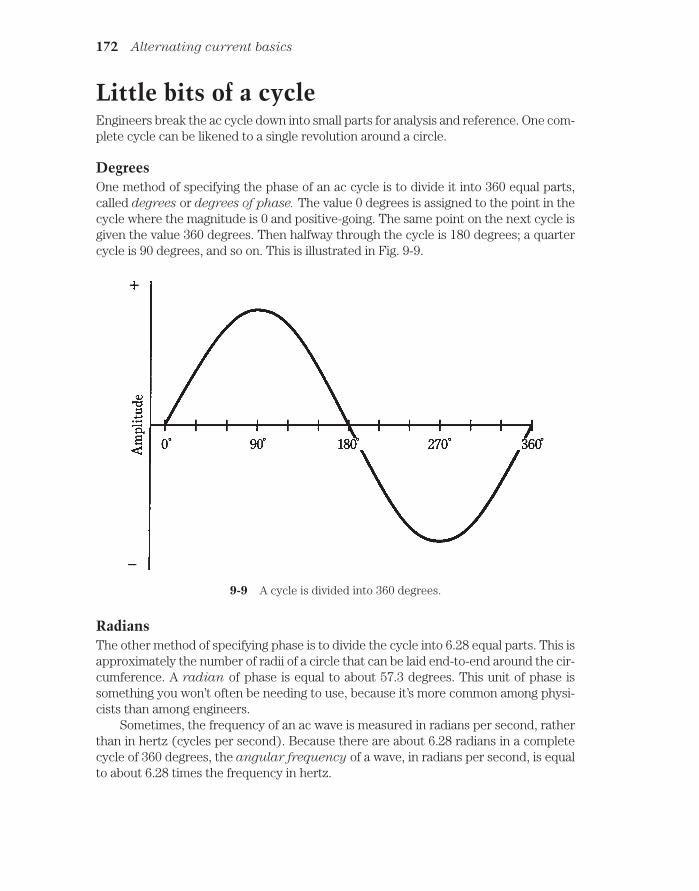
Little bits of a cycleEngineers break the ac cycle down into small parts for analysis and reference. One com-plete cycle can be likened to a single revolution around a circle.
DegreesOne method of specifying the phase of an ac cycle is to divide it into 360 equal parts,called degrees or degrees of phase. The value 0 degrees is assigned to the point in thecycle where the magnitude is 0 and positive-going. The same point on the next cycle isgiven the value 360 degrees. Then halfway through the cycle is 180 degrees; a quartercycle is 90 degrees, and so on. This is illustrated in Fig. 9-9.
172 Alternating current basics
9-9 A cycle is divided into 360 degrees.
RadiansThe other method of specifying phase is to divide the cycle into 6.28 equal parts. This isapproximately the number of radii of a circle that can be laid end-to-end around the cir-cumference. A radian of phase is equal to about 57.3 degrees. This unit of phase issomething you won’t often be needing to use, because it’s more common among physi-cists than among engineers.
Sometimes, the frequency of an ac wave is measured in radians per second, ratherthan in hertz (cycles per second). Because there are about 6.28 radians in a completecycle of 360 degrees, the angular frequency of a wave, in radians per second, is equalto about 6.28 times the frequency in hertz.

Phase differenceTwo ac waves might have exactly the same frequency, but they can still have differenteffects because they are “out of sync” with each other. This is especially true when acwaves are added together to produce a third, or composite, signal.
If two ac waves have the same frequency and the same magnitude, but differ inphase by 180 degrees (a half cycle), they will cancel each other out, and the net signalwill be zero. If the two waves are in phase, the resulting signal will have the same fre-quency, but twice the amplitude of either signal alone.
If two ac waves have the same frequency but different magnitudes, and differ inphase by 180 degrees, the resulting composite signal will have the same frequency asthe originals, and a magnitude equal to the difference between the two. If two suchwaves are exactly in phase, the composite will have the same frequency as the originals,and a magnitude equal to the sum of the two.
If the waves have the same frequency but differ in phase by some odd amount suchas 75 degrees or 310 degrees, the resulting signal will have the same frequency, but willnot have the same waveshape as either of the original signals. The variety of such casesis infinite.
Household utility current, as you get it from wall outlets, consists of a 60-Hz sinewave with just one phase component. But the energy is transmitted over long distancesin three phases, each differing by 120 degrees or 1/3 cycle. This is what is meant bythree-phase ac. Each of the three ac waves carries 1/3 of the total power in a utilitytransmission line.
Amplitude of alternating currentAmplitude is sometimes called magnitude, level, or intensity. Depending on the quan-tity being measured, the magnitude of an ac wave might be given in amperes (for cur-rent), volts (for voltage), or watts (for power).
Instantaneous amplitudeThe instantaneous amplitude of an ac wave is the amplitude at some precise momentin time. This constantly changes. The manner in which it varies depends on the wave-form. You have already seen renditions of common ac waveforms in this chapter. In-stantaneous amplitudes are represented by individual points on the wave curves.
Peak amplitudeThe peak amplitude of an ac wave is the maximum extent, either positive or negative,that the instantaneous amplitude attains.
In many waves, the positive and negative peak amplitudes are the same. But some-times they differ. Figure 9-9 is an example of a wave in which the positive peak ampli-tude is the same as the negative peak amplitude. Figure 9-10 is an illustration of a wavethat has different positive and negative peak amplitudes.
Amplitude of alternating current 173

Peak-to-peak amplitudeThe peak-to-peak (pk-pk) amplitude of a wave is the net difference between the pos-itive peak amplitude and the negative peak amplitude (Fig. 9-11). Another way of say-ing this is that the pk-pk amplitude is equal to the positive peak amplitude plus thenegative peak amplitude. Peak-to-peak is a way of expressing how much the wave level“swings” during the cycle.
In many waves, the pk-pk amplitude is just twice the peak amplitude. This is thecase when the positive and negative peak amplitudes are the same.
Root-mean-square amplitudeOften, it is necessary to express the effective level of an ac wave. This is the voltage, cur-rent or power that a dc source would have to produce, in order to have the same generaleffect. When you say a wall outlet has 117 V, you mean 117 effective volts. The most com-mon figure for effective ac levels is called the root-mean-square, or rms, value.
For a perfect sine wave, the rms value is equal to 0.707 times the peak value, or0.354 times the pk-pk value. Conversely, the peak value is 1.414 times the rms value, andthe pk-pk value is 2.828 times the rms value. The rms figures are most often used withperfect sine waves, such as the utility voltage, or the effective voltage of a radio signal.
For a perfect square wave, the rms value is the same as the peak value. The pk-pkvalue is twice the rms value or the peak value.
For sawtooth and irregular waves, the relationship between the rms value and thepeak value depends on the shape of the wave. But the rms value is never more than thepeak value for any waveshape.
174 Alternating current basics
9-10 A wave with unequal positive and negative peaks.

The name “root mean square” was not chosen just because it sounds interesting.It literally means that the value of a wave is mathematically operated on, by takingthe square root of the mean of the square of all its values. You don’t really have to beconcerned with this process, but it’s a good idea to remember the above numbers forthe relationships between peak, pk-pk, and rms values for sine waves and squarewaves.
For 117 V rms at a utility outlet, the peak voltage is considerably greater. The pk-pkvoltage is far greater.
Superimposed direct currentSometimes a wave can have components of both ac and dc. The simplest example of anac/dc combination is illustrated by the connection of a dc source, such as a battery, inseries with an ac source, like the utility mains. An example is shown in the schematic di-agram of Fig. 9-12. Imagine connecting a 12-V automotive battery in series with the walloutlet. (Do not try this experiment in real life!) Then the ac wave will be displaced ei-ther positively or negatively by 12 V, depending on the polarity of the battery. This willresult in a sine wave at the output, but one peak will be 24 V (twice the battery voltage)more than the other.
Any ac wave can have dc components along with it. If the dc component exceedsthe peak value of the ac wave, then fluctuating, or pulsating, dc will result. Thiswould happen, for example, if a 200-Vdc source were connected in series with theutility output. Pulsating dc would appear, with an average value of 200 V but with in-stantaneous values much higher and lower. The waveshape in this case is illustratedby Fig. 9-13.
Superimposed direct current 175
9-11 Peak-to-peak amplitude.

“Hybrid” ac/dc combinations are not often generated deliberately. But such wave-forms are sometimes seen at certain points in electronic circuitry.
The ac generator Alternating current is easily generated by means of a rotating magnet in a coil of wire(Fig. 9-14A), or by a rotating coil of wire inside a powerful magnet (Fig. 9-14B). In ei-ther case, the ac appears between the ends of the length of wire.
The ac voltage that a generator can develop depends on the strength of the mag-net, the number of turns in the wire coil, and the speed at which the magnet or coil ro-tates. The ac frequency depends only on the speed of rotation. Normally, for utility ac,this speed is 3,600 revolutions per minute (rpm), or 60 complete revolutions per sec-ond (rps), so that the frequency is 60 Hz.
176 Alternating current basics
9-12 Connection of a dcsource in series with anac source.
9-13 Waveform resulting from 117 Vac in series with + 200 Vdc.

When a load, such as a light bulb or heater, is connected to an ac generator, it be-comes more difficult to turn the generator. The more power needed from a generator,the greater the amount of power required to drive it. This is why it is not possible to con-nect a generator to, for instance, your stationary bicycle, and pedal an entire city intoelectrification. There’s no way to get something for nothing. The electrical power thatcomes out of a generator can never be more than the mechanical power driving it. Infact, there is always some energy lost, mainly as heat in the generator. Your legs mightgenerate 50 W of power to run a small radio, but nowhere near enough to provide elec-tricity for a household.
The efficiency of a generator is the ratio of the power output to the driving power,both measured in the same units (such as watts or kilowatts), multiplied by 100 to geta percentage. No generator is 100 percent efficient. But a good one can come fairlyclose to this ideal.
At power plants, the generators are huge. Each one is as big as a house. The gen-erators are driven by massive turbines. The turbines are turned by various natural
The ac generator 177
9-14 Two forms of ac generator. At A, the magnet rotates; at B, the coil rotates.

sources of energy. Often, steam drives the turbines, and the steam is obtained via heatderived from the natural energy source.
Why ac?You might wonder why ac is even used. Isn’t it a lot more complicated than dc?
Well, ac is easy to generate from turbines, as you’ve just seen. Rotating coil-andmagnet devices always produce ac, and in order to get dc from this, rectification andfiltering are necessary. These processes can be difficult to achieve with high voltages.
Alternating current lends itself well to being transformed to lower or higher volt-ages, according to the needs of electrical apparatus. It is not so easy to change dc volt-ages.
Electrochemical cells produce dc directly, but they are impractical for the needs oflarge populations. To serve millions of consumers, the immense power of falling or flow-ing water, the ocean tides, wind, burning fossil fuels, safe nuclear fusion, or of geother-mal heat are needed. (Nuclear fission will work, but it is under scrutiny nowadaysbecause it produces dangerous radioactive by-products.) All of these energy sourcescan be used to drive turbines that turn ac generators.
Technology is advancing in the realm of solar-electric energy; someday a significantpart of our electricity might come from photovoltaic power plants. These would gener-ate dc.
Thomas Edison is said to have favored dc over ac for electrical power transmissionin the early days, as utilities were first being planned. His colleagues argued that acwould work better. It took awhile to convince Mr. Edison to change his mind. He even-tually did. But perhaps he knew something that his contemporaries did not foresee.
There is one advantage to direct current in utility applications. This is for thetransmission of energy over great distances using wires. Direct currents, at extremelyhigh voltages, are transported more efficiently than alternating currents. The wire hasless effective resistance with dc than with ac, and there is less energy lost in the mag-netic fields around the wires.
Direct-current high-tension transmission lines are being considered for futureuse. Right now, the main problem is expense. Sophisticated power-conversion equip-ment is needed. If the cost can be brought within reason, Edison’s original sentimentswill be at least partly vindicated. His was a long view.
QuizRefer to the text in this chapter if necessary. A good score is at least 18 correct. Answersare in the back of the book.
1. Which of the following can vary with ac, but not with dc?
A. Power.
B. Voltage.
C. Frequency.
D. Magnitude.
178 Alternating current basics

2. The length of time between a point in one cycle and the same point in the nextcycle of an ac wave is the:
A. Frequency.
B. Magnitude.
C. Period.
D. Polarity.
3. On a spectrum analyzer, a pure ac signal, having just one frequencycomponent,would look like:
A. A single pip.
B. A perfect sine wave.
C. A square wave.
D. A sawtooth wave.
4. The period of an ac wave is:
A. The same as the frequency.
B. Not related to the frequency.
C. Equal to 1 divided by the frequency.
D. Equal to the amplitude divided by the frequency.
5. The sixth harmonic of an ac wave whose period is 0.001 second has afrequency of
A. 0.006 Hz.
B. 167 Hz.
C. 7 kHz.
D. 6 kHz.
6. A degree of phase represents:
A. 6.28 cycles.
B. 57.3 cycles.
C. 1/6.28 cycle.
D. 1/360 cycle.
7. Two waves have the same frequency but differ in phase by 1/20 cycle. Thephase difference in degrees is:
A. 18.
B. 20.
C. 36.
D. 5.73.
8. A signal has a frequency of 1770 Hz. The angular frequency is:
A. 1770 radians per second.
Quiz 179

B. 11,120 radians per second.
C. 282 radians per second.
D. Impossible to determine from the data given.
9. A triangular wave:
A. Has a fast rise time and a slow decay time.
B. Has a slow rise time and a fast decay time.
C. Has equal rise and decay rates.
D. Rises and falls abruptly.
10. Three-phase ac:
A. Has waves that add up to three times the originals.
B. Has three waves, all of the same magnitude.
C. Is what you get at a common wall outlet.
D. Is of interest only to physicists.
11. If two waves have the same frequency and the same amplitude, but oppositephase, the composite wave is:
A. Twice the amplitude of either wave alone.
B. Half the amplitude of either wave alone.
C. A complex waveform, but with the same frequency as the originals.
D. Zero.
12. If two waves have the same frequency and the same phase, the compositewave:
A. Has a magnitude equal to the difference between the two originals.
B. Has a magnitude equal to the sum of the two originals.
C. Is complex, with the same frequency as the originals.
D. Is zero.
13. In a 117-V utility circuit, the peak voltage is:
A. 82.7 V.
B. 165 V.
C. 234 V.
D. 331 V.
14. In a 117-V utility circuit, the pk-pk voltage is:
A. 82.7 V.
B. 165 V.
C. 234 V.
D. 331 V.
180 Alternating current basics

15. In a perfect sine wave, the pk-pk value is:
A. Half the peak value.
B. The same as the peak value.
C. 1.414 times the peak value.
D. Twice the peak value.
16. If a 45-Vdc battery is connected in series with the 117-V utility mains as shownin Fig. 9-15, the peak voltages will be:
A. 210 V and 120 V.
B. 162 V and 72 V.
C. 396 V and 286 V.
D. Both equal to 117 V.
Quiz 181
9-15 Illustration for quizquestion 16.
17. In the situation of question 16, the pk-pk voltage will be:
A. 117 V.
B. 210 V.
C. 331 V.
D. 396 V.
18. Which one of the following does not affect the power output available from aparticular ac generator?
A. The strength of the magnet.
B. The number of turns in the coil.
C. The type of natural energy source used.
D. The speed of rotation of the coil or magnet.
19. If a 175-V dc source were connected in series with the utility mains from astandard wall outlet, the result would be:
A. Smooth dc.
B. Smooth ac.

C. Ac with one peak greater than the other.
D Pulsating dc.
20. An advantage of ac over dc in utility applications is:
A. Ac is easier to transform from one voltage to another.
B. Ac is transmitted with lower loss in wires.
C. Ac can be easily gotten from dc generators.
D. Ac can be generated with less dangerous by-products.
182 Alternating current basics
10CHAPTER
InductanceTHIS CHAPTER DELVES INTO DEVICES THAT OPPOSE THE FLOW OF AC BY temporarily storing some of the electrical energy as a magnetic field. Such devices arecalled inductors. The action of these components is known as inductance.
Inductors often, but not always, consist of wire coils. Sometimes a length of wire, ora pair of wires, is used as an inductor. Some active electronic devices display induc-tance, even when you don’t think of the circuit in those terms.
Inductance can appear where it isn’t wanted. Noncoil inductance becomes increas-ingly common as the frequency of an altemating current increases. At very-high, ul-tra-high, and microwave radio frequencies, this phenomenon becomes a majorconsideration in the design of communications equipment.
The property of inductanceSuppose you have a wire a million miles long. What will happen if you make this wireinto a huge loop, and connect its ends to the terminals of a battery (Fig. 10-1)?
You can surmise that a current will flow through the loop of wire. But this is onlypart of the picture.
If the wire was short, the current would begin to flow immediately and it would at-tain a level limited by the resistance in the wire and in the battery. But because the wireis extremely long, it will take a while for the electrons from the negative terminal towork their way around the loop to the positive terminal.
The effect of the current moves along the wire at a little less than the speed of light.In this case, it’s about 180,000 miles per second, perhaps 97 percent of the speed of lightin free space. It will take a little time for the current to build up to its maximum level.The first electrons won’t start to enter the positive terminal until more than five secondshave passed.
The magnetic field produced by the loop will be small at first, because current is
183 !
"# #$ !

flowing in only part of the loop. The flux will increase over a period of a few seconds, asthe electrons get around the loop. Figure 10-2 is an approximate graph of the overallmagnetic field versus time. After about 5.5 seconds, current is flowing around the wholeloop, and the magnetic field has reached its maximum.
184 Inductance
10-1 A huge loop of wireillustrates the principle ofinductance. See text.
A certain amount of energy is stored in this magnetic field. The ability of the loop tostore energy in this way is the property of inductance. It is abbreviated by the letter L.
Practical inductorsOf course, it’s not easy to make wire loops even approaching a million miles in circum-ference. But lengths of wire can be coiled up. When this is done, the magnetic flux
10-2 Relative magneticflux in the hugewire loop, as afunction of time inseconds.

is increased many times for a given length of wire compared with the flux produced bya single-turn loop. This is how inductors are made in practical electrical and electronicdevices.
For any coil, the magnetic flux density is multiplied when a ferromagnetic core isplaced within the coil of wire. Remember this from the study of magnetism. The in-crease in flux density has the effect of multiplying the inductance of a coil, so that it ismany times greater with a ferromagnetic core than with an air core.
The current that an inductor can handle depends on the size of the wire. The in-ductance does not; it is a function of the number of turns in the coil, the diameter of thecoil, and the overall shape of the coil.
In general, inductance of a coil is directly proportional to the number of turns ofwire. Inductance is also directly proportional to the diameter of the coil. The length ofa coil, given a certain number of turns and a certain diameter, has an effect also: thelonger the coil, the less the inductance.
The unit of inductanceWhen a battery is connected across a wire-coil inductor (or any kind of inductor), ittakes a while for the current flow to establish itself throughout the inductor. The cur-rent changes at a rate that depends on the inductance: the greater the inductance, theslower the rate of change of current for a given battery voltage.
The unit of inductance is an expression of the ratio between the rate of currentchange and the voltage across an inductor. An inductance of one henry, abbreviated H,represents a potential difference of one volt across an inductor within which the currentis increasing or decreasing at one ampere per second.
The henry is an extremely large unit of inductance. Rarely will you see an inductoranywhere near this large, although some power-supply filter chokes have inductancesup to several henrys. Usually, inductances are expressed in millihenrys (mH), micro-
henrys (µH), or even in nanohenrys (nH). You should know your prefix multipliersfairly well by now, but in case you’ve forgotten, 1 mH 0.001 H 10-3 H, 1 µH 0.001mH 0.000001 H 10-6 H, and 1 nH 0.001 µH 10 -9 H.
Very small coils, with few turns of wire, produce small inductances, in which thecurrent changes quickly and the voltages are small. Huge coils with ferromagneticcores, and having many turns of wire, have large inductances, in which the currentchanges slowly and the voltages are large.
Inductors in seriesAs long as the magnetic fields around inductors do not interact, inductances in seriesadd like resistances in series. The total value is the sum of the individual values. It’s im-portant to be sure that you are using the same size units for all the inductors when youadd their values.
Problem 10-1Three 40-µH inductors are connected in series, and there is no interaction, or mutual
inductances, among them (Fig. 10-3). What is the total inductance?
Inductors in series 185

You can just add up the values. Call the inductances of the individual components L1, L2,and L3, and the total inductance L. Then L L1 L2 L3 40 40 40 120 µH.
186 Inductance
10-3 Inductors in series.
Problem 10-2Suppose there are three inductors, with no mutual inductance, and their values are 20.0mH, 55.0 µH, and 400 nH. What is the total inductance of these components if they areconnected in series as shown in Fig. 10-3?
First, convert the inductances to the same units. You might use microhenrys, be-cause that’s the “middle-sized” unit here. Call L1 20.0 mH 20,000 µH; L 2 55.0 µH;L3 400 nH 0.400 uH. Then the total inductance is L 20,000 55.0 0.400 uH 20,055.4 µH. The values of the original separate components were each given to threesignificant figures, so you should round the final figure off to 20,100 µH.
Note that subscripts are now used in designators. An example is L2 (rather thanL2). Some engineers like subscripts, while others don’t want to bother with them. Youshould get used to seeing them both ways. They’re both alright. If there are several inductors in series, and one of them has a value much larger than the values of the others, then the total inductance will be only a little bit more than the value of thelargest inductor.
Inductors in parallelIf there is no mutual inductance among two or more parallel-connected inductors, theirvalues add up like the values of resistors in parallel. Suppose you have inductances L1,L2, L3, ..., Ln all connected in parallel. Then you can find the reciprocal of the total in-ductance, 1/L, using the following formula:
1/L 1/L1 1/L2 1/L3 … 1/Ln
The total inductance, L, is found by taking the reciprocal of the number you get for 1/L.Again, as with inductances in series, it’s important to remember that all the units
have to agree. Don’t mix microhenrys with millihenrys, or henrys with nanohenrys. Theunits you use for the individual component values will be the units you get for the finalanswer.

Problem 10-3Suppose there are three inductors, each with a value of 40 µH, connected in parallelwith no mutual inductance, as shown in Fig. 10-4. What is the net inductance of the set?
Interaction among inductors 187
10-4 Inductors in parallel.
Call the inductances L1 40 µH, L2 40 µH, and L3 40 µH. Use the formulaabove to obtain1/L 1/40 1/40 1/40 3/40 0.075.Then L 1/0.075 13.333 µH.This should be rounded off to 13 µH, because the original inductances are specified toonly two significant digits.
Problem 10-4Imagine that there are four inductors in parallel, with no mutual inductance. Their val-ues are L1 75 mH, L2 40 mH, L3 333 µH, and L4 7.0 H. What is the total net inductance?
You can use henrys, millihenrys, or microhenrys as the standard units in this prob-lem. Suppose you decide to use henrys. Then L1 0.075 H, L2 0.040 H, L3 0.000333H, and L4 7.0 H. Use the above formula to obtain 1/L 13.33 25 3003 0.143 3041.473. The reciprocal of this is the inductance L 0.00032879 H 328.79 µH. Thiscan be rounded off to 330 µH because of significant-digits considerations.
This is just about the same as the 333-µH inductor alone. In real life, you could haveonly the single 333-µH inductor in this circuit, and the inductance would be essentiallythe same as with all four inductors.
If there are several inductors in parallel, and one of them has a value that is farsmaller than the values of all the others, then the total inductance is just a little smallerthan the value of the smallest inductor.
Interaction among inductorsIn practical electrical circuits, there is almost always some mutual inductance betweenor among coils when they are wound in a cylindrical shape. The magnetic fields extendsignificantly outside solenoidal coils, and mutual effects are almost inevitable. The sameis true between and among lengths of wire, especially at very-high, ultra-high, and mi-crowave radio frequencies. Sometimes, mutual inductance is all right, and doesn’t havea detrimental effect on the behavior of a circuit. But it can be a bad thing.

Mutual inductance can be minimized by using shielded wires and toroidal induc-tors. The most common shielded wire is coaxial cable. Toroidal inductors are dis-cussed a little later in this chapter.
Coefficient of couplingThe coefficient of coupling, specified by the letter k, is a number ranging from 0 (nocoupling) to 1 (maximum possible coupling). Two coils that are separated by a sheet ofsolid iron would have essentially k 0; two coils wound on the same form, one rightover the other, would have practically k 1.
Mutual inductanceThe mutual inductance is specified by the letter M and is expressed in the same unitsas inductance: henrys, millihenrys, microhenrys, or nanohenrys. The value of M is afunction of the values of the inductors, and also of the coefficient of coupling.
For two inductors, having values of L1 and L2 (both expressed in the same sizeunits), and with a coefficient of coupling k, the mutual inductance M is found by multi-plying the inductance values, taking the square root of the result, and then multiplyingby k. Mathematically,
M k (L1L2)1/2
Effects of mutual inductanceMutual inductance can operate either to increase the inductance of a pair of series con-nected inductors, or to decrease it. This is because the magnetic fields might reinforceeach other, or they might act against each other.
When two inductors are connected in series, and there is reinforcing mutual in-ductance between them, the total inductance L is given in the formula:
L L1 L2 2M
where L1 and L2 are the values of the individual inductors, and M is the mutual induc-tance. All inductances must be expressed in the same size units.
Problem 10-5Suppose two coils, having values of 30 µH and 50 µH, are connected in series so thattheir fields reinforce, as shown in Fig. 10-5, and that the coefficient of coupling is 0.5.What is the total inductance of the combination?
First, calculate M from k. According to the formula for this, given above, M .5(50 × 30)1/2 19.4 µH. Then the total inductance is equal to L L1 L2 2M 30 50 38.8 118.8 µH, rounded to 120 µH because only two significant digits are justified.
When two inductors are connected in series and the mutual inductance is in oppo-
sition, the total inductance L is given by the formula
L L1 L2 2M
where, again, L1 and L2 are the values of the individual inductors.
188 Inductance

Problem 10-6There are two coils with values L1 835 µH and L2 2.44 mH. They are connected inseries so that their coefficient of coupling is 0.922, acting so that the coils oppose eachother, as shown in Fig. 10-6. What is the net inductance of the pair?
Air-core coils 189
10-5 Illustration for Problem10-5.
10-6 Illustration for Problem10-6.
First, calculate M. Notice that the coil inductances are specified in different units.Convert them both to microhenrys, so that L2 becomes 2440 µH. Then M 0.922(835 2440)1/2 1316 µH. The total inductance is therefore L L1 L2 2M 835 2440 2632 643 µH.
It is possible for mutual inductance to increase the total series inductance of a pairof coils by as much as a factor of 2, if the coupling is total and if the flux reinforces. Con-versely, it is possible for the inductances of two coils to cancel each other. If twoequal-valued inductors are connected in series so that their fluxes oppose, the resultwill be theoretically zero inductance.
Air-core coilsThe simplest inductors (besides plain, straight lengths of wire) are coils. A coil can bewound on a plastic, wooden or other nonferromagnetic material, and it will work verywell, although no air-core inductor can have very much inductance. In practice, themaximum attainable inductance for such coils is about 1 mH.
Air-core coils are used mostly at radio frequencies, in transmitters, receivers, and an-tenna networks. In general, the higher the frequency of an alternating current, the lessinductance is needed to produce significant effects. Air-core coils can be made to have

almost unlimited current-carrying capacity, just by using heavy-gauge wire and makingthe radius of the coil large. Air does not dissipate much energy in the form of heat; it isalmost lossless. For these reasons, air-core coils can be made highly efficient.
Powdered-iron and ferrite coresFerromagnetic substances can be crushed into dust and then bound into variousshapes, providing core materials that greatly increase the inductance of a coil having agiven number of turns. Depending on the mixture used, the increase in flux density canrange from a factor of a few times, up through hundreds, thousands, and even millionsof times. A small coil can thus be made to have a large inductance.
Powdered-iron cores are common at radio frequencies. Ferrite has a higher per-meability than powdered iron, causing a greater concentration of magnetic flux lineswithin the coil. Ferrite is used at lower radio frequencies and at audio frequencies, aswell as at medium and high radio frequencies.
The main trouble with ferromagnetic cores is that, if the coil carries more than acertain amount of current, the core will saturate. This means that the ferromagneticmaterial is holding as much flux as it possibly can. Any further increase in coil currentwill not produce a corresponding increase in the magnetic flux in the core. The result isthat the inductance changes, decreasing with coil currents that are more than the crit-ical value.
In extreme cases, ferromagnetic cores can waste considerable power as heat. If acore gets hot enough, it might fracture. This will permanently change the inductance ofthe coil, and will also reduce its current-handling ability.
Permeability tuningSolenoidal, or cylindrical, coils can be made to have variable inductance by sliding fer-romagnetic cores in and out of them. This is a common practice in radio communica-tions. The frequency of a radio circuit can be adjusted in this way, as you’ll learn later inthis book.
Because moving the core in and out changes the effective permeability within a coilof wire, this method of tuning is called permeability tuning. The in/out motion can beprecisely controlled by attaching the core to a screw shaft, and anchoring a nut at oneend of the coil (Fig. 10-7). As the screw shaft is rotated clockwise, the core enters thecoil, so that the inductance increases. As the screw shaft is rotated counterclockwise,the core moves out of the coil and the inductance decreases.
ToroidsInductor coils do not have to be wound on cylindrical forms, or on cylindrical ferromag-netic cores. In recent years, a new form of coil has become increasingly common. Thisis the toroid. It gets its name from the donut shape of the ferromagnetic core. The coilis wound over a core having this shape (Fig. 10-8).
190 Inductance

There are several advantages to toroidal coils over solenoidal, or cylindrical, ones.First, fewer turns of wire are needed to get a certain inductance with a toroid, as com-pared with a solenoid. Second, a toroid can be physically smaller for a given inductanceand current-carrying capacity. Third, and perhaps most important, essentially all of theflux in a toroidal inductor is contained within the core material. This reduces unwantedmutual inductances with components near the toroid.
There are some disadvantages, or limitations in the flexibifity, of toroidal coils. It ismore difficult to permeability-tune a toroidal coil than it is to tune a solenoidal one. It’sbeen done, but the hardware is cumbersome. Toroidal coils are harder to wind than so-lenoidal ones.
Sometimes, mutual inductance between or among physically separate coils iswanted; with a toroid, the coils have to be wound on the same form for this to be possible.
Toroids 191
10-7 Permeability tuning of a solenoidal coil.
10-8 A toroidal coil winding.

Pot coresThere is another way to confine the magnetic flux in a coil so that unwanted mutual in-ductance does not occur. This is to extend a solenoidal core completely around the out-side of the coil, making the core into a shell (Fig. 10-9). This is known as a pot core.Whereas in most inductors the coil is wound around the form, in a pot core the form iswrapped around the coil.
192 Inductance
10-9 A pot core shell. Coil winding is not shown.
The core comes in two halves, inside one of which the coil is wound. Then the partsare assembled and held together by a bolt and nut. The entire assembly looks like aminiature oil tank. The wires come out of the core through small holes.
Pot cores have the same advantages as toroids. The core tends to prevent the mag-netic flux from extending outside the physical assembly. Inductance is greatly in-creased compared to solenoidal windings having a comparable number of turns. In fact,pot cores are even better than toroids if the main objective is to get an extremely largeinductance within a small volume of space.
The main disadvantage of a pot core is that tuning, or adjustment of the induc-tance, is all but impossible. The only way to do it is by switching in different numbers ofturns, using taps at various points on the coil.
Filter chokesThe largest values of inductance that can be obtained in practice are on the order ofseveral henrys. The primary use of a coil this large is to smooth out the pulsations in di-rect current that result when ac is rectified in a power supply. This type of coil is knownas a filter choke. You’ll learn more about power supplies later in this book.

Inductors at audio frequencyInductors at audio frequencies range in value from a few millihenrys up to about 1 H.They are almost always toroidally wound, or are wound in a pot core, or comprise partof an audio transformer.
Inductors can be used in conjunction with moderately large values of capacitancein order to obtain audio tuned circuits. However, in recent years, audio tuning hasbeen taken over by active components, particularly integrated circuits.
Inductors at radio frequencyThe radio frequencies range from 9 kHz to well above 100 GHz. At the low end of thisrange, inductors are similar to those at audio frequencies. As the frequency increases,cores having lower permeability are used. Toroids are quite common up through about30 MHz. Above that frequency, air-core coils are more often used.
In radio-frequency (rf) circuits, coils are routinely connected in series or in parallelwith capacitors to obtain tuned circuits. Other arrangements yield various characteris-tics of attenuation versus frequency, serving to let signals at some frequencies pass,while rejecting signals at other frequencies. You’ll learn more about this in the chapteron resonance.
Transmission-line inductorsAt radio frequencies of more than about 100 MHz, another type of inductor becomespractical. This is the type formed by a length of transmission line.
A transmission line is generally used to get energy from one place to another. In ra-dio communications, transmission lines get energy from a transmitter to an antenna,and from an antenna to a receiver.
Types of transmission lineTransmission lines usually take either of two forms, the parallel-wire type or the coax-
ial type.A parallel-wire transmission line consists of two wires running alongside each other
with a constant spacing (Fig. 10-10). The spacing is maintained by polyethylene rodsmolded at regular intervals to the wires, or by a solid web of polyethylene. You haveseen this type of line used with television receiving antennas. The substance separatingthe wires is called the dielectric of the transmission line.
A coaxial transmission line has a wire conductor surrounded by a tubular braid orpipe (Fig. 10-11). The wire is kept at the center of this tubular shield by means of poly-thylene beads, or more often, by solid or foamed polyethylene dielectric, all along thelength of the line.
Line inductanceShort lengths of any type of transmission line behave as inductors, as long as the line isless than 90 electrical degrees in length. At 100 MHz, 90 electrical degrees, or 1⁄4
Transmission-line inductors 193

wavelength, in free space is just 75 cm, or a little more than 2 ft. In general, if f is the fre-quency in megahertz, then 1⁄4 wavelength (s) in free space, in centimeters, is given by
s 7500/f
The length of a quarter-wavelength section of transmission line is shortened fromthe free-space quarter wavelength by the effects of the dielectric. In practice, 1⁄4 wave-length along the line can be anywhere from about 0.66 of the free-space length (forcoaxial lines with solid polyethylene dielectric) to about 0.95 of the free-space length(for parallel-wire line with spacers molded at intervals of several inches).
The factor by which the wavelength is shortened is called the velocity factor of theline. This is because the shortening of the wavelength is a result of a slowing-down ofthe speed with which the radio signals move in the line, as compared with their speedin space (the speed of light). If the velocity factor of a line is given by v, then the aboveformula for the length of a quarter-wave line, in centimeters, becomes
s 7500v/f
Very short lengths of line—a few electrical degrees—produce small values of in-ductance. As the length approaches 1⁄4 wavelength, the inductance increases.
Transmission line inductors behave differently than coils in one important way: theinductance of a transmission-line section changes as the frequency changes. At first, the
194 Inductance
10-10 Parallel-wire transmission line.
10-11 Coaxial transmission line.
inductance will become larger as the frequency increases. At a certain limiting fre-quency, the inductance becomes infinite. Above that frequency, the line becomes ca-
pacitive instead. You’ll learn about capacitance shortly.A detailed discussion of frequency, transmission line type and length, and induc-
tance is beyond the level of this book. Texts on radio engineering are recommended forfurther information on this subject.
Unwanted inductancesAny length of wire has some inductance. As with a transmission line, the inductance ofa wire increases as the frequency increases. Wire inductance is therefore more signifi-cant at radio frequencies than at audio frequencies.
In some cases, especially in radio communications equipment, the inductanceof, and among, wires can become a major bugaboo. Circuits can oscillate when theyshould not. A receiver might respond to signals that it’s not designed to intercept. Atransmitter can send out signals on unauthorized and unintended frequencies. Thefrequency response of any circuit can be altered, degrading the performance of theequipment.
Sometimes the effects of stray inductance are so small that they are not impor-tant; this might be the case in a stereo hi-fi set located at a distance from other elec-tronic equipment. In some cases, stray inductance can cause life-threateningmalfunctions. This might happen with certain medical devices.
The most common way to minimize stray inductance is to use coaxial cables be-tween and among sensitive circuits or components. The shield of the cable is connectedto the common ground of the apparatus.
QuizRefer to the text in this chapter if necessary. A good score is 18 correct. Answers are inthe back of the book.
1. An inductor works by:
A. Charging a piece of wire.
B. Storing energy as a magnetic field.
C. Choking off high-frequency ac.
D. Introducing resistance into a circuit.
2. Which of the following does not affect the inductance of a coil?
A. The diameter of the wire.
B. The number of turns.
C. The type of core material.
D. The length of the coil.
3. In a small inductance:
A. Energy is stored and released slowly.
Quiz 195
B. The current flow is always large.
C. The current flow is always small.
D. Energy is stored and released quickly.
4. A ferromagnetic core is placed in an inductor mainly to:
A. Increase the current carrying capacity.
B. Increase the inductance.
C. Limit the current.
D. Reduce the inductance.
5. Inductors in series, assuming there is no mutual inductance, combine:
A. Like resistors in parallel.
B. Like resistors in series.
C. Like batteries in series with opposite polarities.
D. In a way unlike any other type of component.
6. Two inductors are connected in series, without mutual inductance. Theirvalues are 33 mH and 55 mH. The net inductance of the combination is:
A. 1.8 H.
B. 22 mH.
C. 88 mH.
D. 21 mH.
7. If the same two inductors (33 mH and 55 mH) are connected in parallelwithout mutual inductance, the combination will have a value of:
A. 1.8 H.
B. 22 mH.
C. 88 mH.
D. 21 mH.
8. Three inductors are connected in series without mutual inductance. Theirvalues are 4 nH, 140 µH, and 5 H. For practical purposes, the net inductance will bevery close to:
A. 4 nH.
B. 140 µH.
C. 5 H.
D. None of these.
9. Suppose the three inductors mentioned above are connected in parallelwithout mutual inductance. The net inductance will be close to:
A. 4 nH.
B. 140 µH.
196 Inductance

C. 5 H.
D. None of these.
10. Two inductors, each of 100 µH, are in series. The coefficient of coupling is 0.40.The net inductance, if the coil fields reinforce each other, is:
A. 50 µH.
B. 120 µH.
C. 200 µH.
D. 280 µH.
11. If the coil fields oppose in the foregoing series-connected arrangement, the netinductance is:
A. 50 µH.
B. 120 µH.
C. 200 µH.
D. 280 µH.
12. Two inductors, having values of 44 mH and 88 mH, are connected in series witha coefficient of coupling equal to 1.0 (maximum possible mutual inductance). Iftheir fields reinforce, the net inductance (to two significant digits) is:
A. 7.5 mH.
B. 132 mH.
C. 190 mH.
D. 260 mH.
13. If the fields in the previous situation oppose, the net inductance will be:
A. 7.5 mH.
B. 132 mH.
C. 190 mH.
D. 260 mH.
14. With permeability tuning, moving the core further into a solenoidal coil:
A. Increases the inductance.
B. Reduces the inductance
C. Has no effect on the inductance, but increases the current-carryingcapacity of the coil.
D. Raises the frequency.
15. A significant advantage, in some situations, of a toroidal coil over a solenoid is:
A. The toroid is easier to wind.
B. The solenoid cannot carry as much current.
C. The toroid is easier to tune.
Quiz 197

D. The magnetic flux in a toroid is practically all within the core.
16. A major feature of a pot-core winding is:
A. High current capacity.
B. Large inductance in small volume.
C. Efficiency at very high frequencies.
D. Ease of inductance adjustment.
17. As an inductor core material, air:
A. Has excellent efficiency.
B. Has high permeability.
C. Allows large inductance in a small volume.
D. Has permeability that can vary over a wide range.
18. At a frequency of 400 Hz, the most likely form for an inductor would be:
A. Air-core.
B. Solenoidal.
C. Toroidal.
D. Transmission-line.
19. At a frequency of 95 MHz, the best form for an inductor would be:
A. Air-core.
B. Pot core.
C. Either of the above.
D. Neither of the above.
20. A transmission-line inductor made from coaxial cable, having velocity factor of0.66, and working at 450 MHz, would be shorter than:
A. 16.7 m.
B. 11 m.
C. 16.7 cm.
D. 11 cm.
198 Inductance
11CHAPTER
CapacitanceELECTRICAL COMPONENTS CAN OPPOSE AC IN THREE DIFFERENT WAYS, TWO OFwhich you’ve learned about already.
Resistance slows down the rate of transfer of charge carriers (usually electrons) by“brute force.” In this process, some of the energy is invariably converted from electricalform to heat. Resistance is said to consume power for this reason. Resistance is pre-sent in dc as well as in ac circuits, and works the same way for either direct or alternat-ing current.
Inductance impedes the flow of ac charge carriers by temporarily storing the en-ergy as a magnetic field. But this energy is given back later.
Capacitance, about which you’ll learn in this chapter, impedes the flow of ac chargecarriers by temporarily storing the energy as an electric field. This energy is given backlater, just as it is in an inductance. Capacitance is not generally important in pure-dc cir-cuits. It can have significance in circuits where dc is pulsating, and not steady.
Capacitance, like inductance, can appear when it is not wanted or intended. As withinductance, this effect tends to become more evident as the ac frequency increases.
The property of capacitanceImagine two very large, flat sheets of metal such as copper or aluminum, that are ex-cellent electrical conductors. Suppose they are each the size of the state of Nebraska,and are placed one over the other, separated by just a foot of space. What will happen ifthese two sheets of metal are connected to the terminals of a battery, as shown in Fig. 11-1?
The two plates will become charged electrically, one positively and the other nega-tively. You might think that this would take a little while, because the sheets are so big.This is an accurate supposition.
If the plates were small, they would both become charged almost instantly, attaininga relative voltage equal to the voltage of the battery. But because the plates are gigantic,
199 !
"# #$ !

it will take awhile for the negative one to “fill up” with electrons, and it will take an equalamount of time for the other one to get electrons “sucked out.” Finally, however, the volt-age between the two plates will be equal to the battery voltage, and an electric field willexist in the space between the plates.
This electric field will be small at first; the plates don’t charge right away. But thecharge will increase over a period of time, depending on how large the plates are, andalso depending on how far apart they are. Figure 11-2 is a relative graph showing the in-tensity of the electric field between the plates as a function of time, elapsed from the in-stant the plates are connected to the battery terminals.
200 Capacitance
11-1 A huge pair of parallel plates illustrates the principle of capacitance. See text.
11-2 Relative electric field intensity between the hugemetal plates, as a function of time.
Energy will be stored in this electric field. The ability of the plates, and of the spacebetween them, to store this energy is the property of capacitance. It is denoted by theletter C.
Practical capacitorsIt’s out of the question to make a capacitor of the above dimensions. But two sheets, orstrips, of foil can be placed one on top of the other, separated by a thin, nonconductingsheet such as paper, and then the whole assembly can be rolled up to get a large effec-tive surface area. When this is done, the electric flux becomes great enough so that thedevice exhibits significant capacitance. In fact, two sets of several plates each can bemeshed together, with air in between them, and the resulting capacitance will be sig-nificant at high ac frequencies.
In a capacitor, the electric flux concentration is multiplied when a dielectric of acertain type is placed between the plates. Plastics work very well for this purpose. Thisincreases the effective surface area of the plates, so that a physically small componentcan be made to have a large capacitance.
The voltage that a capacitor can handle depends on the thickness of the metalsheets or strips, on the spacing between them, and on the type of dielectric used.
In general, capacitance is directly proportional to the surface area of the conduct-ing plates or sheets. Capacitance is inversely proportional to the separation betweenconducting sheets; in other words, the closer the sheets are to each other, the greaterthe capacitance. The capacitance also depends on the dielectric constant of the mate-rial between the plates. A vacuum has a dielectric constant of 1; some substances havedielectric constants that multiply the effective capacitance many times.
The unit of capacitanceWhen a battery is connected between the plates of a capacitor, it takes some time be-fore the electric field reaches its full intensity. The voltage builds up at a rate that de-pends on the capacitance: the greater the capacitance, the slower the rate of change ofvoltage in the plates.
The unit of capacitance is an expression of the ratio between the amount of currentflowing and the rate of voltage change across the plates of a capacitor. A capacitance ofone farad, abbreviated F, represents a current flow of one ampere while there is a po-tential-difference increase or decrease of one volt per second. A capacitance of onefarad also results in one volt of potential difference for an electric charge of onecoulomb.
The farad is a huge unit of capacitance. You’ll almost never see a capacitor with avalue of 1 F. Commonly employed units of capacitance are the microfarad (µF) andthe picofarad (pF). A capacitance of 1 µF represents a millionth (10-6) of a farad, and1 pF is a millionth of a microfarad, or a trillionth of a farad (10-12 F).
Some quite large capacitances can be stuffed into physically small components.Conversely, some capacitors with small values take up large volumes. The bulkiness ofa capacitor is proportional to the voltage that it can handle, more than it is related to thecapacitance. The higher the rated voltage, the bigger, physically, the component will be.
The unit of capacitance 201

Capacitors in seriesWith capacitors, there is almost never any mutual interaction. This makes capacitorssomewhat easier to work with than inductors.
Capacitors in series add together like resistors in parallel. If you connect two ca-pacitors of the same value in series, the result will be half the capacitance of eithercomponent alone. In general, if there are several capacitors in series, the compositevalue will be less than any of the single components. It is important that you always usethe same size units when determining the capacitance of any combination. Don’t mixmicrofarads with picofarads. The answer that you get will be in whichever size units youuse for the individual components.
Suppose you have several capacitors with values C1, C2, C3, . . . Cn all connected inseries. Then you can find the reciprocal of the total capacitance, 1/C, using the follow-ing formula:
1/C 1/C1 1/C2 1/C3 … 1/Cn
The total capacitance, C, is found by taking the reciprocal of the number you get for1/C.
If two or more capacitors are connected in series, and one of them has a value thatis extremely tiny compared with the values of all the others, the composite capacitancecan be taken as the value of the smallest component.
Problem 11-1Two capacitors, with values of C1 0.10 µF and C2 0.050 µF, are connected in series(Fig. 11-3). What is the total capacitance?
202 Capacitance
11-3 Capacitors in series.
Using the above formula, first find the reciprocals of the values. They are 1/C1 10and 1/C2 20. Then 1/C 10 20 30, and C 1/30 0.033 µF.
Problem 11-2Two capacitors with values of 0.0010 µF and 100 pF are connected in series. What is thetotal capacitance?
Convert to the same size units. A value of 100 pF represents 0. 000100 µF. Then youcan say that C1 0.0010 µF and C2 0.00010 µF. The reciprocals are 1/C1 1000 and

1/C2 10,000. Therefore, 1/C 1,000 10,000 11,000, and C 0. 000091 µF. Thisnumber is a little awkward, and you might rather say it’s 91 pF.
In the above problem, you could have chosen pF to work with, rather than µF. In either case, there is some tricky decimal placement involved. It’s important to double-check calculations when numbers get like this. Calculators will take care of the decimalplacement problem, sometimes using exponent notation and sometimes not, but a cal-culator can only work with what you put into it! If you put a wrong number in, you willget a wrong answer, perhaps off by a factor of 10, 100, or even 1,000.
Problem 11-3Five capacitors, each of 100 pF, are in series. What is the total capacitance?
If there are n capacitors in series, all of the same value so that C1 C2 C3 . . . Cn,the total value C is just 1/n of the capacitance of any of the components alone. Becausethere are five 100-pF capacitors here, the total is C 100/5 20 pF.
Capacitors in parallelCapacitances in parallel add like resistances in series. That is, the total capacitance isthe sum of the individual component values. Again, you need to be sure that you use thesame size units all the way through.
If two or more capacitors are connected in parallel, and one of the components ismuch, much larger than any of the others, the total capacitance can be taken as simplythe value of the biggest one.
Problem 11-4Three capacitors are in parallel, having values of C1 0.100 µF, C2, 0.0100 µF, andC3 0.00100 µF, as shown in Fig. 11-4. What is the total capacitance?
Capacitors in parallel 203
11-4 Capacitors in parallel.
Just add them up: C 0.100 0.0100 0.00100 0. 111000. Because the valuesare given to three significant figures, the final answer should be stated as C 0.111 µF.
Problem 11-5Two capacitors are in parallel, one with a value of 100 µF and one with a value of 100 pF.What is the effective total capacitance?

In this case, without even doing any calculations, you can say that the total is 100µF for practical purposes. The 100-pF unit is only a millionth of the capacitance of the100-µF component; therefore, the smaller capacitor contributes essentially nothing tothe composite total.
Dielectric materialsJust as certain solids can be placed within a coil to increase the inductance, materialsexist that can be sandwiched in between the plates of a capacitor to increase the capacitance. The substance between the plates is called the dielectric of the capacitor.
Air works quite well as a dielectric. It has almost no loss. But it is difficult to get verymuch capacitance using air as the dielectric. Some solid material is usually employed asthe dielectric for most fixed capacitors, that is, for types manufactured to have a con-stant, unchangeable value of capacitance.
Dielectric materials conduct electric fields well, but they are not good conductorsof electric currents. In fact, the materials are known as good insulators.
Solid dielectrics increase the capacitance for a given surface area and spacing ofthe plates. Solid dielectrics also allow the plates to be rolled up, squashed, and placedvery close together (Fig. 11-5). Both of these act to increase the capacitance per unitvolume, allowing reasonable capacitances to exist in a small volume.
204 Capacitance
11-5 Foil sheets can be rolled up with dielectric material sandwiched inbetween.
Paper capacitorsIn the early days of radio, capacitors were commonly made by placing paper, soakedwith mineral oil, between two strips of foil, rolling the assembly up, attaching wire leadsto the two pieces of foil, and enclosing the rolled-up foil and paper in a cylindrical case.

These capacitors can still sometimes be found in electronic equipment. They havevalues ranging from about 0.001 µF to 0.1 µF, and can handle low to moderate voltages,usually up to about 1000 V.
Mica capacitorsWhen you were a child, you might have seen mica, a naturally occurring, transparentsubstance that flakes off in thin sheets. This material makes an excellent dielectric forcapacitors.
Mica capacitors can be made by alternately stacking metal sheets and layers ofmica, or by applying silver ink to the sheets of mica. The metal sheets are wired together into two meshed sets, forming the two terminals of the capacitor. This schemeis shown in Fig. 11-6.
Ceramic capacitors 205
11-6 Meshing of plates to increase capacitance.
Mica capacitors have low loss; that is, they waste very little power as heat, providedtheir voltage rating is not exceeded. Voltage ratings can be up to several thousand voltsif thick sheets of mica are used. But mica capacitors tend to be large physically in pro-portion to their capacitance. The main application for mica capacitors is in radio re-ceivers and transmitters. Their capacitances are a little lower than those of papercapacitors, ranging from a few tens of picofarads up to about 0.05 µF.
Ceramic capacitorsPorcelain is another material that works well as a dielectric. Sheets of metal are stackedalternately with wafers of ceramic to make these capacitors. The meshing/layeringgeometry of Fig. 11-6 is used. Ceramic, like mica, has quite low loss, and therefore al-lows for high efficiency.

For low values of capacitance, just one layer of ceramic is needed, and two metalplates can be glued to the disk-shaped porcelain, one on each side. This type of compo-nent is known as a disk-ceramic capacitor. Alternatively, a tube or cylinder of ceramiccan be employed, and metal ink applied to the inside and outside of the tube. Such unitsare called tubular capacitors.
Ceramic capacitors have values ranging from a few picofarads to about 0.5 µF.Their voltage ratings are comparable to those of paper capacitors.
Plastic-film capacitorsVarious different plastics make good dielectrics for the manufacture of capacitors. Poly-ester, polyethylene, and polystyrene are commonly used. The substance called mylar
that you might have seen used to tint windows makes a good dielectric for capacitors.The method of manufacture is similar to that for paper capacitors when the plastic
is flexible. Stacking methods can be used if the plastic is more rigid. The geometries canvary, and these capacitors are therefore found in several different shapes.
Capacitance values for plastic-film units range from about 50 pF to several tens ofmicrofarads. Most often they are in the range of 0.001 µF to 10 µF. Plastic capacitors areemployed at audio and radio frequencies, and at low to moderate voltages. The effi-ciency is good, although not as high as that for mica-dielectric or air-dielectric units.
Electrolytic capacitorsAll of the above-mentioned types of capacitors provide relatively small values of capac-itance. They are also nonpolarized, meaning that they can be hooked up in a circuit ineither direction. An electrolytic capacitor provides considerably greater capacitancethan any of the above types, but it must be connected in the proper direction in a cir-cuit to work right. Therefore, an electrolytic capacitor is a polarized component.
Electrolytic capacitors are made by rolling up aluminum foil strips, separated bypaper saturated with an electrolyte liquid. The electrolyte is a conducting solution.When dc flows through the component, the aluminum oxidizes because of the elec-trolyte. The oxide layer is nonconducting, and forms the dielectric for the capacitor.The layer is extremely thin, and this results in a high capacitance per unit volume.
Electrolytic capacitors can have values up to thousands of microfarads, and someunits can handle thousands of volts. These capacitors are most often seen in audio-frequency circuits and in dc power supplies.
Tantalum capacitorsAnother type of electrolytic capacitor uses tantalum rather than aluminum. The tanta-lum can be foil, as is the aluminum in a conventional electrolytic capacitor. It might alsotake the form of a porous pellet, the irregular surface of which provides a large area ina small volume. An extremely thin oxide layer forms on the tantalum.
206 Capacitance
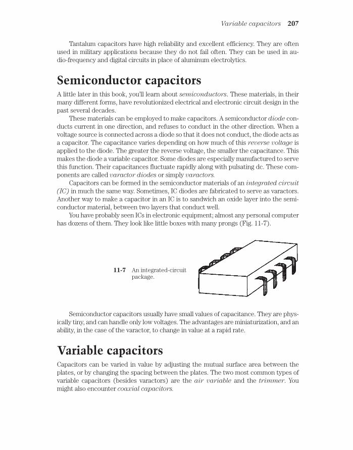
Tantalum capacitors have high reliability and excellent efficiency. They are oftenused in military applications because they do not fail often. They can be used in au-dio-frequency and digital circuits in place of aluminum electrolytics.
Semiconductor capacitorsA little later in this book, you’ll learn about semiconductors. These materials, in theirmany different forms, have revolutionized electrical and electronic circuit design in thepast several decades.
These materials can be employed to make capacitors. A semiconductor diode con-ducts current in one direction, and refuses to conduct in the other direction. When avoltage source is connected across a diode so that it does not conduct, the diode acts asa capacitor. The capacitance varies depending on how much of this reverse voltage isapplied to the diode. The greater the reverse voltage, the smaller the capacitance. Thismakes the diode a variable capacitor. Some diodes are especially manufactured to servethis function. Their capacitances fluctuate rapidly along with pulsating dc. These com-ponents are called varactor diodes or simply varactors.
Capacitors can be formed in the semiconductor materials of an integrated circuit
(IC) in much the same way. Sometimes, IC diodes are fabricated to serve as varactors.Another way to make a capacitor in an IC is to sandwich an oxide layer into the semi-conductor material, between two layers that conduct well.
You have probably seen ICs in electronic equipment; almost any personal computerhas dozens of them. They look like little boxes with many prongs (Fig. 11-7).
Variable capacitors 207
11-7 An integrated-circuitpackage.
Semiconductor capacitors usually have small values of capacitance. They are phys-ically tiny, and can handle only low voltages. The advantages are miniaturization, and anability, in the case of the varactor, to change in value at a rapid rate.
Variable capacitorsCapacitors can be varied in value by adjusting the mutual surface area between theplates, or by changing the spacing between the plates. The two most common types ofvariable capacitors (besides varactors) are the air variable and the trimmer. Youmight also encounter coaxial capacitors.

Air variablesBy connecting two sets of metal plates so that they mesh, and by affixing one set to arotatable shaft, a variable capacitor is made. The rotatable set of plates is called the rotor, and the fixed set is called the stator. This is the type of component you mighthave seen in older radio receivers, used to tune the frequency. Such capacitors are stillused in transmitter output tuning networks. Figure 11-8 is a functional rendition of anair-variable capacitor.
208 Capacitance
11-8 Simplified drawing of an air-variable capacitor.
Air variables have maximum capacitance that depends on the number of plates ineach set, and also on the spacing between the plates. Common maximum values are 50pF to about 1,000 pF; minimum values are a few picofarads. The voltage-handling ca-pability depends on the spacing between the plates; some air variables can handle manykilovolts.
Air variables are used primarily at radio frequencies. They are highly efficient, andare nonpolarized, although the rotor is usually connected to common ground (the chas-sis or circuit board).
TrimmersWhen it is not necessary to change the value of a capacitor very often, a trimmer mightbe used. It consists of two plates, mounted on a ceramic base and separated by a sheetof mylar, mica, or some other dielectric. The plates are “springy” and can be squashedtogether more or less by means of a screw (Fig. 11-9). Sometimes two sets of severalplates are interleaved to increase the capacitance.
Trimmers can be connected in parallel with an air variable, so that the range of theair variable can be adjusted. Some air-variable capacitors have trimmers built in.
Typical maximum values for trimmers range from a few picofarads up to about 200pF. They handle low to moderate voltages, and are highly efficient. They are nonpolar-ized.
Coaxial capacitorsRecall from the previous chapter that sections of transmission lines can work as induc-tors. They can act as capacitors too.

If a section of transmission line is less than 1/4 wavelength long, and is left open atthe far end (rather than shorted out), it will act as a capacitor. The capacitance will in-crease with length.
The most common transmission-line capacitor uses two telescoping sections oftubing. This is called a coaxial capacitor and works because there is a certain effectivesurface area between the inner and the outer tubing sections. A sleeve of plastic di-electric is placed between the sections of tubing, as shown in Fig. 11-10. This allows thecapacitance to be adjusted by sliding the inner section in or out of the outer section.
Tolerance 209
11-9 A trimmer capacitor.
Coaxial capacitors are used in radio-frequency applications, particularly in antennasystems. Their values are generally from a few picofarads up to about 100 pF.
ToleranceCapacitors are rated according to how nearly their values can be expected to match therated capacitance. The most common tolerance is 10 percent; some capacitors are ratedat 5 percent or even at 1 percent. In all cases, the tolerance ratings are plus-or-minus.
11-10 A coaxial variable capacitor.

Therefore, a 10-percent capacitor can range from 10 percent less than its assignedvalue to 10 percent more.
Problem 11-6A capacitor is rated at 0.001 µF, plus-or-minus 10 percent. What is the actual range ofcapacitances it can have?
First, multiply 0.001 by 10 percent to get the plus-or-minus variation. This is0.001 0.1 0.0001 µF. Then add and subtract this from the rated value to get themaximum and minimum possible capacitances. The result is 0.0011 µF to 0.0009 µF.
You might prefer to work with picofarads instead of microfarads, if the small num-bers make you feel uneasy. Just change 0.001 µF to 1000 pF. Then the variation isplus-or-minus 1000 0.1 100 pF, and the range becomes 1100 pF to 900 pF.
Temperature coefficientSome capacitors increase in value as the temperature increases. These componentshave a positive temperature coefficient. Some capacitors’ values get less as thetemperature rises; these have negative temperature coefficient. Some capacitorsare manufactured so that their values remain constant over a certain temperaturerange. Within this span of temperatures, such capacitors have zero temperature co-
efficient.
The temperature coefficient is specified in percent per degree Celsius.Sometimes, a capacitor with a negative temperature coefficient can be connected
in series or parallel with a capacitor having a positive temperature coefficient, and thetwo opposite effects will cancel each other out over a range of temperatures. In otherinstances, a capacitor with a positive or negative temperature coefficient can be used tocancel out the effect of temperature on other components in a circuit, such as inductorsand resistors.
You won’t have to do calculations involving temperature coefficients if you’re in amanagement position; you can delegate these things to the engineers. If you plan to be-come an engineer, you’ll most likely have computer software that will perform the cal-culations for you.
Interelectrode capacitanceAny two pieces of conducting material, when they are brought near each other, will actas a capacitor. Often, this interelectrode capacitance is so small that it can be ne-glected. It rarely amounts to more than a few picofarads.
In ac circuits and at audio frequencies, interelectrode capacitance is not usually sig-nificant. But it can cause problems at radio frequencies. The chances for trouble in-crease as the frequency increases. The most common phenomena are feedback, and achange in the frequency characteristics of a circuit.
Interelectrode capacitance is minimized by keeping wire leads as short as possible. Itcan also be reduced by using shielded cables and by enclosing circuits in metal housings
210 Capacitance

if interaction might produce trouble. This is why, if you’ve ever opened up a sophisti-cated communications radio, you might have seen numerous metal enclosures insidethe main box.
QuizRefer to the text in this chapter if necessary. A good score is 18 correct. Answers are inthe back of the book.
1. Capacitance acts to store electrical energy as:
A. Current.
B. Voltage.
C. A magnetic field.
D. An electric field.
2. As capacitor plate area increases, all other things being equal:
A. The capacitance increases.
B. The capacitance decreases.
C. The capacitance does not change.
D. The voltage-handling ability increases.
3. As the spacing between plates in a capacitor is made smaller, all other thingsbeing equal:
A. The capacitance increases.
B. The capacitance decreases.
C. The capacitance does not change.
D. The voltage-handling ability increases.
4. A material with a high dielectric constant:
A. Acts to increase capacitance per unit volume.
B. Acts to decrease capacitance per unit volume.
C. Has no effect on capacitance.
D. Causes a capacitor to become polarized.
5. A capacitance of 100 pF is the same as:
A. 0.01 µF.
B. 0.001 µF.
C. 0.0001 µF.
D. 0. 00001 µF.
6. A capacitance of 0.033 µF is the same as:
A. 33 pF.
Quiz 211

B. 330 pF.
C. 3300 pF.
D. 33,000 pF.
7. Five 0.050-µF capacitors are connected in parallel. The total capacitance is:
A. 0.010 µF.
B. 0.25 µF.
C. 0.50 µF.
D. 0.025 µF.
8. If the same five capacitors are connected in series, the total capacitance will be:
A. 0.010 µF.
B. 0.25 µF.
C. 0.50 µF.
D. 0.025 µF.
9. Two capacitors are in series. Their values are 47 pF and 33 pF. The compositevalue is:
A. 80 pF.
B. 47 pF.
C. 33 pF.
D. 19 pF.
10. Two capacitors are in parallel. Their values are 47 pF and 470 µF. Thecombination capacitance is:
A. 47 pF.
B. 517 pF.
C. 517 µF.
D. 470 µF.
11. Three capacitors are in parallel. Their values are 0.0200 µF, 0.0500 µF and0.10000 µF. The total capacitance is:
A. 0.0125 µF.
B. 0.170 µF.
C. 0.1 µF.
D. 0.125 µF.
12. Air works well as a dielectric mainly because it:
A. Has a high dielectric constant.
B. Is not physically dense.
C. Has low loss.
D. Allows for large capacitance in a small volume.
212 Capacitance
13. Which of the following is not a characteristic of mica capacitors?
A. High efficiency.
B. Small size.
C. Capability to handle high voltages.
D. Low loss.
14. A disk ceramic capacitor might have a value of:
A. 100 pF.
B. 33 µF.
C. 470 µF.
D. 10,000 µF.
15. A paper capacitor might have a value of:
A. 0.001 pF.
B. 0.01 µF.
C. 100 µF.
D. 3300 µF.
16. An air-variable capacitor might have a range of:
A. 0.01 µF to 1 µF.
B. 1 µF to 100 µF.
C. 1 pF to 100 pF.
D. 0.001 pF to 0.1 pF.
17. Which of the following types of capacitors is polarized?
A. Paper
B. Mica.
C. Interelectrode.
D. Electrolytic.
18. If a capacitor has a negative temperature coefficient:
A. Its value decreases as the temperature rises.
B. Its value increases as the temperature rises.
C. Its value does not change with temperature.
D. It must be connected with the correct polarity.
19. A capacitor is rated at 33 pF, plus or minus 10 percent. Which of the followingcapacitances is outside the acceptable range?
A. 30 pF.
B. 37 pF.
C. 35 pF.
D. 31 pF.
Quiz 213

20. A capacitor, rated at 330 pF, shows an actual value of 317 pF. How manypercent off is its value?
A. 0.039.
B. 3.9.
C. 0.041.
D. 4.1.
214 Capacitance

12CHAPTER
PhaseAN ALTERNATING CURRENT REPEATS THE SAME WAVE TRACE OVER AND OVER.Each 360-degree cycle is identical to every other. The wave can have any imaginableshape, but as long as the polarity reverses periodically, and as long as every cycle is thesame, the wave can be called true ac.
In this chapter, you’ll learn more about the most common type of ac, the sine wave.You’ll get an in-depth look at the way engineers and technicians think of ac sine waves.There will be a discussion of the circular-motion model of the sine wave. You’ll see howthese waves add together, and how they can cancel out.
Instantaneous voltage and currentYou’ve seen “stop motion” if you’ve done much work with a video-cassette recorder(VCR). In fact, you’ve probably seen it if you’ve watched any television sportscasts.Suppose that it were possible for you to stop time in real life, any time you wanted. Thenyou could examine any instant of time in any amount of detail that would satisfy yourimagination.
Recall that an ac sine wave has a unique, characteristic shape, as shown in Fig. 12-1. This is the way the graph of the function y sin x appears on the coordinateplane. (The abbreviation sin stands for sine in trigonometry.) Suppose that the peakvoltage is plus or minus 1 V, as shown. Further imagine that the period is 1 second, sothat the frequency is 1 Hz. Let the wave begin at time t 0. Then each cycle beginsevery time the value of t is a whole number; at every such instant, the voltage is zero andpositive going.
If you freeze time at t 446.00 seconds, say, the voltage will be zero. Looking at thediagram, you can see that the voltage will also be zero every so-many-and-a-half sec-onds; that is, it will be zero at t 446.5 seconds. But instead of getting more positive atthese instants, the voltage will be swinging towards the negative.
215 !
"# #$ !

If you freeze time at so-many-and-a-quarter seconds, say t 446.25 seconds, thevoltage will be 1 V. The wave will be exactly at its positive peak. If you stop time atso-many-and-three-quarter seconds, say t 446.75 seconds, the voltage will be exactly at its negative peak, 1 V.
At intermediate times, say, so-many-and-three-tenths seconds, the voltage willhave intermediate values.
Rate of changeBy examining the diagram of Fig. 12-1, you can see that there are times the voltage isincreasing, and times it is decreasing. Increasing, in this context, means “getting morepositive,” and decreasing means “getting more negative.” The most rapid increase involtage occurs when t 0.0 and t 1.0 in Fig. 12-1. The most rapid decrease takesplace when t 0.5.
Notice that when t 0.25, and also when t 0.75, the instantaneous voltage is notchanging. This condition exists for a vanishingly small moment. You might liken thevalue of the voltage at t 0.25 to the altitude of a ball you’ve tossed straight up into theair, when it reaches its highest point. Similarly, the value of voltage at t 0.75 is akin tothe position of a swing at its lowest altitude.
If n is any whole number, then the situation at t n.25 is the same as it is for t 0.25; also, for t n.75, things are just the same as they are when t 0.75. The sin-gle cycle shown in Fig. 12-1 represents every possible condition of the ac sine wave hav-ing a frequency of 1 Hz and a peak value of plus-or-minus 1 V.
216 Phase
12-1 A sine wave with period 1 second and frequency 1 Hz.

Suppose that you graph the rate of change in the voltage of the wave in Fig. 12-1against time. What will this graph look like? It turns out that it will have a shape that isa sine wave, but it will be displaced to the left of the original wave by one-quarter of acycle. If you plot the relative rate of change against time as shown in Fig. 12-2, you getthe derivative, or rate of change, of the sine wave. This is a cosine wave, having thesame general, characteristic shape as the sine wave. But the phase is different.
Sine waves as circular motion 217
12-2 A sine wave representing the rate of change in instantaneous amplitudeof the wave in Fig. 12-1.
Sine waves as circular motionA sine wave represents the most efficient possible way that a quantity can alternateback and forth. The reasons for this are rather complex, and a thorough discussion of itwould get into that fuzzy thought territory where science begins to overlap with es-thetics, mathematics, and philosophy. You need not worry about it. You might recall,however, that a sine wave has just one frequency component, and represents a purewave for this reason.
Suppose that you were to swing a glowing ball around and around at the end of astring, at a rate of one revolution per second. The ball would describe a circle in space(Fig. 12-3A). Imagine that you swing the ball around so that it is always at the same level;that is, so that it takes a path that lies in a horizontal plane. Imagine that you do this in aperfectly dark gymnasium. Now if a friend stands some distance away, with his or hereyes right in the plane of the ball’s path, what will your friend see? All that will be visibleis the glowing ball, oscillating back and forth (Fig. 12-3B). The ball will seem to move to-ward the right, slow down, then stop and reverse its direction, going back towards theleft. It will move faster and faster, then slower again, reaching its left-most point, at which

it will stop and turn around again. This will go on and on, with a frequency of 1 Hz, or acomplete cycle per second, because you are swinging the ball around at one revolutionper second.
218 Phase
12-3 Swinging ball and string.At A, as seen fromabove; at B, as seenfrom edge-on.
If you graph the position of the ball, as seen by your friend, with respect to time, theresult will be a sine wave (Fig. 12-4). This wave has the same characteristic shape as allsine waves.
It is true that some sine waves are taller than others, and some are stretched outhorizontally more than others. But the general wave form is the same in every case. Bymultiplying or dividing the amplitude and the wavelength of any sine wave, it can bemade to fit exactly along the curve of any other sine wave. The standard sine wave isthe function y sin x in the (x,y) coordinate plane.
You might whirl the ball around faster or slower than one revolution per second.The string might be made longer or shorter. This would alter the height and or the fre-quency of the sine wave graphed in Fig. 12-4. But the fundamental rule would alwaysapply: the sine wave can be reduced to circular motion.
Degrees of phaseBack in Chapter 9, degrees of phase were discussed. If you wondered then why phase isspoken of in terms of angular measure, the reason should be clearer now. A circle has 360

degrees. A sine wave can be represented as circular motion. Exact moments along thesine curve correspond to specific angles, or positions, around a circle.
Figure 12-5 shows the way a rotating vector is used to represent a sine wave. At A,the vector points “east,” and this is assigned the value of 0 degrees, where the wave am-plitude is zero and is increasing positively. At B, the vector points “north”; this is the90-degree instant, where the wave has attained its maximum positive amplitude. At C,the vector points “west.” This is 180 degrees, the instant where the wave has gone backto zero amplitude, and is getting more negative. At D, the wave points “south.” This is270 degrees and represents the maximum negative amplitude. When a full circle hasbeen completed, or 360 degrees, the vector once again points “east.” Thus, 360 degreesis the same as 0 degrees. In fact, a value of x degrees represents the same condition asx plus or minus any multiple of 360 degrees.
The four points for the model of Fig. 12-5 are shown on a sine wave graph in Fig. 12-6.
You can think of the vector as going around and around, at a rate that correspondsto one revolution per cycle of the wave. If the wave has a frequency of 1 Hz, the vectorgoes around at a rate of a revolution per second (1 rps). If the wave has a frequency of100 Hz, the speed of the vector is 100 rps, or a revolution every 0.01 second. If the waveis 1 MHz, then the speed of the vector is 1,000,000 or 106 rps, and it goes once aroundevery 106, or 0.000001, second.
Degrees of Phase 219
12-4 Position of ball as seen edge-on, as a function of time.

The peak amplitude of the wave can be thought of in terms of the length of the vec-tor. In Fig. 12-5, time is represented by the angle counterclockwise from “due east,” andamplitude is independent of time. This differs from the more common rendition of thesine wave, such as the one in Fig. 12-6.
In a sense, whatever force “causes” the wave is always there, whether there’s anyinstantaneous voltage or not. The wave is created by angular motion (revolution) of thisforce. This is visually apparent in the rotating-vector model. The reasons for thinking ofac as a vector quantity, having magnitude and direction, will become more clear inthe following chapters, as you learn about reactance and impedance.
If a wave has a frequency of f Hz, then the vector makes a complete 360-degree rev-olution every 1/f seconds. The vector goes through 1 degree of phase every 1/(360f)seconds.
220 Phase
12-5 Vector representation of sine wave at the start of a cycle (A), at 1⁄4 cycle(B), at 1⁄2 cycle (C), and at 3⁄4 cycle (D).

Radians of phaseAn angle of 1 radian is about 57.3 degrees. A complete circle is 6.28 radians around. Ifa wave has a frequency of f Hz, then the vector goes through 1 radian of phase every1/(57.3f) seconds. The number of radians per second for an ac wave is called the angular frequency.
Radians are used mainly by physicists. Engineers and technicians generally use degrees when talking about phase, and Hertz when talking about frequency.
Phase coincidenceWhen two sine waves have the same frequency, they can behave much differently iftheir cycles begin at different times. Whether or not the phase difference, often calledthe phase angle and specified in degrees, matters depends on the nature of the circuit.
Phase angle can have meaning only when two waves have identical frequencies. Ifthe frequencies differ, even by just a little bit, the relative phase constantly changes, andyou can’t specify a single number. In the following discussions of phase angle, assumethat the two waves always have identical frequencies.
Phase coincidence means that two waves begin at exactly the same moment.They are “lined up.” This is shown in Fig. 12-7 for two waves having different ampli-tudes. (If the amplitudes were the same, you would see only one wave.) The phase dif-ference in this case is 0 degrees. You might say it’s any multiple of 360 degrees, too, butengineers and technicians almost never speak of any phase angle of less than 0 or morethan 360 degrees.
Phase coincidence 221
12-6 The four points for the model of Fig. 12-5, shown on a standardamplitude-versus-time graph of a sine wave.

If two sine waves are in phase coincidence, the peak amplitude of the resultant wave,which will also be a sine wave, is equal to the sum of the peak amplitudes of the two com-posite waves. The phase of the resultant is the same as that of the composite waves.
Phase oppositionWhen two waves begin exactly 1⁄2 cycle, or 180 degrees, apart, they are said to be inphase opposition. This is illustrated by the drawing of Fig. 12-8. In this situation, engi-neers sometimes also say that the waves are out of phase, although this expression is alittle nebulous because it could be taken to mean some phase difference other than 180degrees.
If two sine waves have the same amplitude and are in phase opposition, they willexactly cancel each other out. This is because the instantaneous amplitudes of the twowaves are equal and opposite at every moment in time.
If two sine waves have different amplitudes and are in phase opposition, the peakvalue of the resultant, which will be a sine wave, is equal to the difference between thepeak values of the two composite waves. The phase of the resultant will be the same asthe phase of the stronger of the two composite waves.
The sine wave has the unique property that, if its phase is shifted by 180 degrees,the resultant wave is the same as turning the original wave “upside-down.” Not all wave-forms have this property. Perfect square waves do, but some rectangular and sawtoothwaves don’t, and irregular waveforms almost never do.
Leading phaseTwo waves can differ in phase by any amount from 0 degrees (in phase), through 180degrees (phase opposition), to 360 degrees (back in phase again).
222 Phase
12-7 Two sine waves in phase coincidence.

Suppose there are two sine waves, wave X and wave Y, with identical frequency. Ifwave X begins a fraction of a cycle earlier than wave Y, then wave X is said to be lead-
ing wave Y in phase. For this to be true, X must begin its cycle less than 180 degreesbefore Y. Figure 12-9 shows wave X leading wave Y by 90 degrees of phase. The differ-ence could be anything greater than 0 degrees, up to 180 degrees.
Leading phase 223
12-8 Two sine waves in phase opposition.
12-9 Wave X leads wave Y by 90 degrees.
Note that if wave X (the dotted line in Fig. 12-9) is leading wave Y(the solid line),then wave X is somewhat to the left of wave Y. In a time line, the left is earlier and theright is later.

Lagging phaseSuppose that wave X begins its cycle more than 180 degrees, but less than 360 degrees,ahead of wave Y. In this situation, it is easier to imagine that wave X starts its cycle later
than wave Y, by some value between 0 and 180 degrees. Then wave X is not leading, butinstead is lagging, wave Y. Figure 12-10 shows wave X lagging wave Y by 90 degrees.The difference could be anything between 0 and 180 degrees.
224 Phase
12-10 Wave X lags wave Y by 90 degrees.
You can surmise by now that leading phase and lagging phase are different ways oflooking at similar “animals.” In practice, ac sine waves are oscillating rapidly, sometimesthousands, millions, or even billions of times per second. If two waves have the samefrequency and different phase, how do you know that one wave is really leading theother by some small part of a cycle, instead of lagging by a cycle and a fraction, or by afew hundred, thousand, million, or billion cycles and a fraction? The answer lies in thereal-life effects of the waves. Engineers and technicians think of phase differences, forsine waves having the same frequency, as always being between 0 and 180 degrees, ei-ther leading or lagging. It rarely matters, in practice, whether one wave started a fewseconds earlier or later than the other.
So, while you might think that the diagram of Fig. 12-9 shows wave X lagging waveY by 270 degrees, or that the diagram of Fig. 12-10 shows wave X leading wave Y by 270degrees, you would get an odd look from an engineer if you said so aloud. And if you saidsomething like “This wave is leading that one by 630 degrees,” you might actually belaughed at.
Note that if wave X (the dotted line in Fig. 12-10) is lagging wave Y (the solid line),then wave X is somewhat to the right of wave Y.

Vector diagrams of phase relationshipsThe circular renditions of sine waves, such as are shown in the four drawings of Fig.12-5, are well suited to showing phase relationships.
If a sine wave X is leading a sine wave Y by some number of degrees, then the twowaves can be drawn as vectors, with vector X being that number of degrees counter-
clockwise from vector Y. If wave X lags Y by some number of degrees, then X will beclockwise from Y by that amount.
If two waves are in phase, their vectors overlap (line up). If they are in phase op-position, they point in exactly opposite directions.
The drawings of Fig. 12-11 show four phase relationships between waves X and Y. AtA, X is in phase with Y. At B, X leads Y by 90 degrees. At C, X and Y are 180 degrees op-posite in phase; at D, X lags Y by 90 degrees. In all cases, you can think of the vectors ro-tating counterclockwise at the rate of f revolutions per second, if their frequency is f Hz.
Vector diagrams of phase relationships 225
12-11 Vector representation of phase. At A, waves X and Y are in phase; atB, X leads Y by 90 degrees; at C, X and Y are 180 degrees out of phase;at D, X lags Y by 90 degrees.

QuizRefer to the text in this chapter if necessary. A good score is 18 correct. Answers are inthe back of the book.
1. Which of the following is not a general characteristic of an ac wave?
A. The wave shape is identical for each cycle.
B. The polarity reverses periodically.
C. The electrons always flow in the same direction.
D. There is a definite frequency.
2. A sine wave:
A. Always has the same general appearance.
B. Has instantaneous rise and fall times.
C. Is in the same phase as a cosine wave.
D. Rises very fast, but decays slowly.
3. The derivative of a sine wave:
A. Is shifted in phase by 1⁄2 cycle from the sine wave.
B. Is a representation of the rate of change.
C. Has instantaneous rise and fall times.
D. Rises very fast, but decays slowly.
4. A phase difference of 180 degrees in the circular model represents:
A. 1/4 revolution.
B. 1/2 revolution.
C. A full revolution.
D. Two full revolutions.
5. You can add or subtract a certain number of degrees of phase to or from awave, and end up with exactly the same wave again. This number is:
A. 90.
B. 180.
C. 270.
D. 360.
6. You can add or subtract a certain number of degrees of phase to or from a sinewave, and end up with an inverted (upside-down) representation of the original.This number is:
A. 90.
B. 180.
C. 270.
D. 360.
226 Phase

7. A wave has a frequency of 300 kHz. One complete cycle takes:
A. 1⁄300 second.
B. 0.00333 second.
C. 1⁄3,000 second.
D. 0.00000333 second.
8. If a wave has a frequency of 440 Hz, how long does it take for 10 degrees ofphase?
A. 0.00273 second.
B. 0.000273 second.
C. 0.0000631 second.
D. 0.00000631 second.
9. Two waves are in phase coincidence. One has a peak value of 3 V and the othera peak value of 5 V. The resultant will be:
A. 8 V peak, in phase with the composites.
B. 2 V peak, in phase with the composites.
C. 8 V peak, in phase opposition with respect to the composites.
D. 2 V peak, in phase opposition with respect to the composites.
10. Shifting the phase of an ac sine wave by 90 degrees is the same thing as:
A. Moving it to the right or left by a full cycle.
B. Moving it to the right or left by 1⁄4 cycle.
C. Turning it upside-down.
D. Leaving it alone.
11. A phase difference of 540 degrees would more often be spoken of as:
A. An offset of more than one cycle.
B. Phase opposition.
C. A cycle and a half.
D. 1.5 Hz.
12. Two sine waves are in phase opposition. Wave X has a peak amplitude of 4 Vand wave Y has a peak amplitude of 8 V. The resultant has a peak amplitude of:
A. 4 V, in phase with the composites.
B. 4 V, out of phase with the composites.
C. 4 V, in phase with wave X.
D. 4 V, in phase with wave Y.
13. If wave X leads wave Y by 45 degrees of phase, then:
A. Wave Y is 1⁄4 cycle ahead of wave X.
Quiz 227

B. Wave Y is 1⁄4 cycle behind wave X.
C. Wave Y is 1⁄8 cycle behind wave X.
D. Wave Y is 1⁄16 cycle ahead of wave X.
14. If wave X lags wave Y by 1⁄3 cycle, then:
A. Y is 120 degrees earlier than X.
B. Y is 90 degrees earlier than X.
C. Y is 60 degrees earlier than X.
D. Y is 30 degrees earlier than X.
15. In the drawing of Fig. 12-12:
A. X lags Y by 45 degrees.
B. X leads Y by 45 degrees.
C. X lags Y by 135 degrees.
D. X leads Y by 135 degrees.
228 Phase
12-12 Illustration for quiz question 15.
16. Which of the drawings in Fig. 12-13 represents the situation of Fig. 12-12?
A. A.
B. B.
C. C.
D. D.

17. In vector diagrams such as those of Fig. 12-13, length of the vector represents:
A. Average amplitude.
B. Frequency.
C. Phase difference.
D. Peak amplitude.
Quiz 229
12-13 Illustration for quiz questions 16 through 20.
18. In vector diagrams such as those of Fig. 12-13, the angle between two vectorsrepresents:
A. Average amplitude.
B. Frequency.
C. Phase difference.
D. Peak amplitude.

19. In vector diagrams such as those of Fig. 12-13, the distance from the center ofthe graph represents:
A. Average amplitude.
B. Frequency.
C. Phase difference.
D. Peak amplitude.
20. In diagrams like those of Fig. 12-13, the progression of time is sometimesdepicted as:
A. Movement to the right.
B. Movement to the left.
C. Rotation counterclockwise.
D. Rotation clockwise.
230 Phase

13CHAPTER
Inductive reactanceIN DC CIRCUITS, RESISTANCE IS A SIMPLE THING. IT CAN BE EXPRESSED AS Anumber, from zero (a perfect conductor) to extremely large values, increasing withoutlimit through the millions, billions, and even trillions of ohms. Physicists call resistancea scalar quantity, because it can be expressed on a one-dimensional scale. In fact, dc re-sistance can be represented along a half line, or ray, as shown in Fig. 13-1.
231
13-1 Resistance can be represented on a ray.
Given a certain dc voltage, the current decreases as the resistance increases, in ac-cordance with Ohm’s Law, as you already know. The same law holds for ac through a re-sistance, if the ac voltage and current are both specified as peak, pk-pk, or rms values.
Coils and direct currentSuppose that you have some wire that conducts electricity very well. What will happenif you wind a length of the wire into a coil and connect it to a source of dc, as shown inFig. 13-2? The wire will draw a large amount of current, possibly blowing a fuse or over-stressing a battery. It won’t matter whether the wire is a single-turn loop, or whether it’slying haphazardly on the floor, or whether it’s wrapped around a stick. The current willbe large. In amperes, it will be equal to I E/R, where I is the current, E is the dc volt-age, and R is the resistance of the wire (a low resistance).
!"# #$ !

You can make an electromagnet, as you’ve already seen, by passing dc through acoil wound around an iron rod. But there will still be a large, constant current in the coil.The coil will probably get more or less hot, as energy is dissipated in the resistance ofthe wire. The battery, too, or power supply components, will become warm or hot.
If the voltage of the battery or power supply is increased, the wire in the coil, ironcore or not, will get hotter. Ultimately, if the supply can deliver the necessary current,the wire will melt.
Coils and alternating currentSuppose you change the voltage source, connected across the coil, from dc to ac (Fig. 13-3). Imagine that you can vary the frequency of the ac, from a few hertz to hun-dreds of hertz, then kilohertz, then megahertz.
232 Inductive reactance
13-2 A coil connected across asource of dc.
13-3 A coil connected across asource of ac.
At first, the ac current will be high, just as it is with dc. But the coil has a certainamount of inductance, and it takes some time for current to establish itself in the coil.Depending on how many turns there are, and on whether the core is air or a ferromag-netic material, you’ll reach a point, as the ac frequency increases, when the coil startsto get “sluggish.” That is, the current won’t have time to get established in the coil before the polarity of the voltage reverses.

At high ac frequencies, the current through the coil will have difficulty followingthe voltage placed across the coil. Just as the coil starts to “think” that it’s making agood short circuit, the ac voltage wave will pass its peak, go back to zero, and then tryto pull the electrons the other way.
This sluggishness in a coil for ac is, in effect, similar to dc resistance. As the fre-quency is raised higher and higher, the effect gets more and more pronounced. Even-tually, if you keep on increasing the frequency of the ac source, the coil will not evenbegin to come near establishing a current with each cycle. It will act like a large resis-tance. Hardly any ac current will flow through it.
The opposition that the coil offers to ac is called inductive reactance. It, like re-sistance, is measured in ohms. It can vary just as resistance does, from near zero (ashort piece of wire) to a few ohms (a small coil) to kilohms or megohms (bigger and big-ger coils).
Like resistance, inductive reactance affects the current in an ac circuit. But, unlikesimple resistance, reactance changes with frequency. And the effect is not just a de-crease in the current, although in practice this will occur. It is a change in the way thecurrent flows with respect to the voltage.
Reactance and frequencyInductive reactance is one of two kinds of reactance; the other, called capacitive reac-
tance, will be discussed in the next chapter. Reactance in general is symbolized by thecapital letter X. Inductive reactance is indicated by the letter X with a subscript L: XL.
If the frequency of an ac source is given, in hertz, as f, and the inductance of a coilin henrys is L, then the inductive reactance is
XL 6 .28fL
This same formula applies if the frequency, f, is in kilohertz and the inductance, L,
is in millihenrys. And it also applies if f is in megahertz and L is in microhenrys. Just re-member that if frequency is in thousands, inductance must be in thousandths, and iffrequency is in millions, inductance must be in millionths.
Inductive reactance increases linearly with increasing ac frequency. This meansthat the function of XL vs f is a straight line when graphed.
Inductive reactance also increases linearly with inductance. Therefore, the func-tion of XL vs L also appears as a straight line on a graph.
The value of XL is directly proportional to f; XL is also directly proportional to L.
These relationships are graphed, in relative form, in Fig. 13-4.
Problem 13-1Suppose a coil has an inductance of 0. 50 H, and the frequency of the ac passing throughit is 60 Hz. What is the inductive reactance?
Using the above formula, XL 6.28 60 0. 50 188.4 ohms. You should round thisoff to two significant digits, or 190 ohms, because the inductance and frequency areboth expressed to only two significant digits.
Reactance and frequency 233

Problem 13-2What will be the inductive reactance of the above coil if the supply is a battery that sup-plies pure dc?
Because dc has a frequency of zero, XL 6.28 0 0. 50 0. That is, there willbe no inductive reactance. Inductance doesn’t generally have any practical effect withpure dc.
Problem 13-3If a coil has an inductive reactance of 100 at a frequency of 5.00 MHz, what is its in-ductance?
In this case, you need to plug numbers into the formula and solve for the unknownL. Start out with the equation 100 6.28 5. 00 L 31.4 L. Then, recall that be-cause the frequency is in megahertz, or millions of hertz, the inductance will come outin microhenrys, or millionths of a henry. You can divide both sides of the equation by31.4, getting L 100/31.4 3.18 µH.
Points in the RL planeInductive reactance can be plotted along a half line, just as can resistance. In a circuitcontaining both resistance and inductance, the characteristics become two-dimen-sional. You can orient the resistance and reactance half lines perpendicular to eachother to make a quarter-plane coordinate system, as shown in Fig. 13-5. Resistance isusually plotted horizontally, and inductive reactance is plotted vertically, going up-wards.
In this scheme, RL combinations form impedances. You’ll learn all about this inchapter 15. Each point on the RL plane corresponds to one unique impedance value.Conversely, each RL impedance value corresponds to one unique point on the plane.
For reasons made clear in chapter 15, impedances on the RL plane are written inthe form R jXL, where R is the resistance and XL is the inductive reactance.
If you have a pure resistance, say R 5 Ω, then the complex impedance is 5 j0,and is at the point (5,0) on the RL plane. If you have a pure inductive reactance, such as
234 Inductive reactance
13-4 Inductive reactance isdirectly proportional toinductance and also tofrequency.

XL 3 Ω, then the complex impedance is 0 j3, and is at the point (0, 3) on the RLplane. These points, and others, are shown in Fig. 13-6.
In real life, all coils have some resistance, because no wire is a perfect conductor.All resistors have at least a tiny bit of inductive reactance, because they take up somephysical space. So there is really no such thing as a mathematically perfect pure resis-tance like 5 j0, or a mathematically perfect pure reactance like 0 j3. Sometimes youcan get pretty close, but absolutely pure resistances or reactances never exist, if youwant to get really theoretical.
Often, resistance and inductive reactance are both deliberately placed in a circuit.Then you get impedances values such as 2 j3 or 4 jl.5. These are shown in Fig. 13-6as points on the RL plane.
Remember that the values for XL are reactances, not the actual inductances.Therefore, they vary with the frequency in the RL circuit. Changing the frequency hasthe effect of making the points move in the RL plane. They move vertically, going up-wards as the ac frequency increases, and downwards as the ac frequency decreases. Ifthe ac frequency goes down to zero, the inductive reactance vanishes. Then XL 0, andthe point is along the resistance axis of the RL plane.
Vectors in the RL PlaneEngineers sometimes like to represent points in the RL plane (and in other types of co-ordinate planes, too) as vectors. This gives each point a definite magnitude and a pre-cise direction.
Vectors in the RL Plane 235
13-5 The RL quarter-plane.
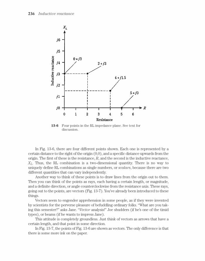
In Fig. 13-6, there are four different points shown. Each one is represented by acertain distance to the right of the origin (0,0), and a specific distance upwards from theorigin. The first of these is the resistance, R, and the second is the inductive reactance,XL. Thus, the RL combination is a two-dimensional quantity. There is no way touniquely define RL combinations as single numbers, or scalars, because there are twodifferent quantities that can vary independently.
Another way to think of these points is to draw lines from the origin out to them.Then you can think of the points as rays, each having a certain length, or magnitude,and a definite direction, or angle counterclockwise from the resistance axis. These rays,going out to the points, are vectors (Fig. 13-7). You’ve already been introduced to thesethings.
Vectors seem to engender apprehension in some people, as if they were inventedby scientists for the perverse pleasure of befuddling ordinary folks. “What are you tak-ing this semester?” asks Jane. “Vector analysis!” Joe shudders (if he’s one of the timidtypes), or beams (if he wants to impress Jane).
This attitude is completely groundless. Just think of vectors as arrows that have acertain length, and that point in some direction.
In Fig. 13-7, the points of Fig. 13-6 are shown as vectors. The only difference is thatthere is some more ink on the paper.
236 Inductive reactance
13-6 Four points in the RL impedance plane. See text fordiscussion.
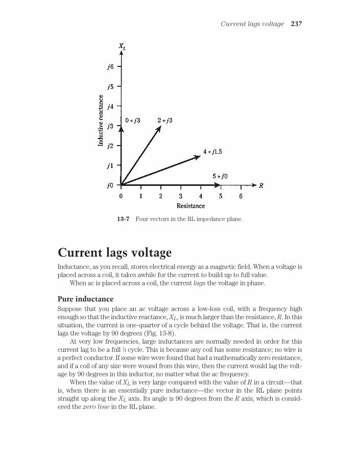
Current lags voltageInductance, as you recall, stores electrical energy as a magnetic field. When a voltage isplaced across a coil, it takes awhile for the current to build up to full value.
When ac is placed across a coil, the current lags the voltage in phase.
Pure inductanceSuppose that you place an ac voltage across a low-loss coil, with a frequency highenough so that the inductive reactance, XL, is much larger than the resistance, R. In thissituation, the current is one-quarter of a cycle behind the voltage. That is, the currentlags the voltage by 90 degrees (Fig. 13-8).
At very low frequencies, large inductances are normally needed in order for thiscurrent lag to be a full 1⁄4 cycle. This is because any coil has some resistance; no wire isa perfect conductor. If some wire were found that had a mathematically zero resistance,and if a coil of any size were wound from this wire, then the current would lag the volt-age by 90 degrees in this inductor, no matter what the ac frequency.
When the value of XL is very large compared with the value of R in a circuit—thatis, when there is an essentially pure inductance—the vector in the RL plane pointsstraight up along the XL axis. Its angle is 90 degrees from the R axis, which is consid-ered the zero line in the RL plane.
Current lags voltage 237
13-7 Four vectors in the RL impedance plane.

Inductance and resistanceWhen the resistance in a resistance-inductance circuit is significant compared with theinductive reactance, the current lags the voltage by something less than 90 degrees(Fig. 13-9). If R is small compared with XL, the current lag is almost 90 degrees; as Rgets larger, the lag decreases. A circuit with resistance and inductance is called an RL
circuit.The value of R in an RL circuit might increase relative to XL because resistance is
deliberately placed in series with the inductance. Or, it might happen because the acfrequency gets so low that XL decreases until it is in the same ball park with the loss re-sistance R in the coil winding. In either case, the situation can be schematically repre-sented by a coil in series with a resistor (Fig. 13-10).
If you know the values of XL and R, you can find the angle of lag, also called the RL
phase angle, by plotting the point R jXL on the RL plane, drawing the vector fromthe origin 0 j0 out to that point, and then measuring the angle of the vector,counterclockwise from the resistance axis. You can use a protractor to measure this an-gle, or you can compute its value using trigonometry.
In fact, you don’t need to know the actual values of XL and R in order to find the an-gle of lag. All you need to know is their ratio. For example, if L 5 Ω and R 3 Ω, youwill get the same angle as you would get if XL 50 Ω and R 30 Ω, or if XL 20 Ω andR 12 Ω. The angle of lag will be the same for any values of XL and R in the ratio of 5:3.
It’s easy to find the angle of lag whenever you know the ratio of R to XL. You’ll seesome examples shortly.
238 Inductive reactance
13-8 In a pure inductance, the current lags the voltage by 90 degrees.

Pure resistanceAs the resistance in an RL circuit becomes large with respect to the inductive reac-tance, the angle of lag gets smaller and smaller. The same thing happens if the inductivereactance gets small compared with the resistance. When R is many times greater thanXL, whatever their actual magnitudes might be, the vector in the RL plane lies almoston the R axis, going “east” or to the right. The RL phase angle is nearly zero. The cur-rent comes into phase with the voltage.
In a pure resistance, with no inductance at all, the current is precisely in phase withthe voltage (Fig. 13-11). A pure resistance doesn’t store any energy, as an inductive cir-cuit does, but sends the energy out as heat, light, electromagnetic waves, sound, orsome other form that never comes back into the circuit.
Inductance and resistance 239
13-9 In a circuit with inductance and resistance, the current lags the voltage by less than90 degrees.
13-10 Schematicrepresentation of an RLcircuit.

How much lag?If you know the ratio of the inductive reactance to the resistance, XL /R, in an RL circuit,then you can find the phase angle. Of course, you can find the angle of lag if you knowthe actual values of XL and R.
Pictorial methodIt isn’t necessary to construct an entire RL plane to find phase angles. You can use aruler that has centimeter (cm) and millimeter (mm) markings, and a protractor.
First, draw a line a little more than 10 cm long, going from left to right on a sheetof paper. Use the ruler and a sharp pencil. Then, with the protractor, construct a lineoff the left end of this first line, going vertically upwards. Make this line at least 10cm long.
The horizontal line, or the one going to the right, is the R axis of a crude coordinatesystem. The vertical line, or the one going upwards, is the XL axis.
If you know the values of XL and R, divide them down, or multiply them up (in yourhead) so that they’re both between 0 and 100. For example, if XL 680 Ω and R 840Ω, you can divide them both by 10 to get XL 68 and R 84. Plot these points lightlyby making hash marks on the vertical and horizontal lines you’ve drawn. The R markwill be 84 mm to the right of the origin, or intersection of the original two perpendicu-lar lines. The XL mark will be 68 mm up from the origin.
Draw a line connecting the two hash marks, as shown in Fig. 13-12. This line willrun at a slant, and will form a triangle along with the two axes. Your hash marks, and theorigin of the coordinate system, form vertices of a right triangle. The triangle is called“right” because one of its angles is a right angle (90 degrees.)
240 Inductive reactance
13-11 In a circuit with only resistance, the current is in phase with the voltage.

Measure the angle between the slanted line and the horizontal, or R, axis. Extendone or both of the lines if necessary in order to get a good reading on the protractor. Thisangle will be between 0 and 90 degrees, and represents the phase angle in the RL circuit.
The actual vector, R jXL , is found by constructing a rectangle using the originand your two hash marks as three of the four vertices, and drawing new horizontal andvertical lines to complete the figure. The vector is the diagonal of this rectangle, asshown in Fig. 13-13. The phase angle is the angle between this vector and the R axis. Itwill be the same as the angle of the slanted line in Fig. 13-12.
Trigonometric methodThe pictorial method is inexact. It can be a bother, sometimes, to divide down and getnumbers that are easy to work with. Drawing the pictures accurately requires care andpatience. If the phase angle is very close to 0 degrees or 90 degrees—that is, if the ratioXL/R is very small or large—the accuracy is especially poor in the drawing.
There’s a better way. If you have a calculator that can find the arctangent of a num-ber, you’ve got it made easy. Nowadays, if you intend to work with engineers, there’s noexcuse not to have a good calculator. If you don’t have one, I suggest you go out and buyone right now. It should have “trig” functions and their inverses, “log” functions, expo-nential functions, and others that engineers use often.
If you know the values XL and R, then the phase angle is simply the arctangent oftheir ratio, or arctan (XL/R). This might also be written tan1 (XL /R). Punch a few but-tons on the calculator, and you have it.
How much lag? 241
13-12 Pictorial method of finding phase angle.

Problem 13-4The inductive reactance in an RL circuit is 680 Ω, and the resistance is 840 Ω. What isthe phase angle?
Find the ratio XL/R 680/840. The calculator will display something like0.809523809. Find the arctangent, or tan1, getting a phase angle of 38.99099404 de-grees (as shown on the calculator). Round this off to 39.0 degrees.
Problem 13-5An RL circuit works at a frequency of 1.0 MHz. It has a resistance of 10 Ω, and an in-ductance of 90 µH. What is the phase angle?
This is a rather complicated problem, because it requires several steps. But eachstep is straightforward. You need to do them carefully, one at a time, and then recheckthe whole problem once or twice when you’re done calculating.
First, find the inductive reactance. This is found by the formula XL 6.28fL 6.28 1.0 90 565 Ω . Then find the ratio XL/R 565/10 56.5. The phase angleis arctan 56.5 89 degrees. This indicates that the circuit is almost purely reactive. Theresistance contributes little to the behavior of this RL circuit at this frequency.
Problem 13-6What is the phase angle of the above circuit at 10 kHz?
242 Inductive reactance
13-13 Another pictorial way of finding phase angle. This methodshows the actual impedance vector.

This requires that XL be found over again, for the new frequency. Suppose you de-cide to use megahertz, so it will go nicely in the formula with microhenrys. A frequencyof 10 kHz is the same as 0.010 MHz. Calculating, you get XL 6.28fL 6.28 0.010 90 6.28 0.90 5.65 Ω. The ratio XL /R is then 5.65/10 0. 565. The phase angle isarctan 0.565 29 degrees. At this frequency, the resistance and inductance both playsignificant roles in the RL circuit.
QuizRefer to the text in this chapter if necessary. A good score is 18 correct. Answers are inthe back of the book.
1. As the number of turns in a coil increases, the current in the coil willeventually:
A. Become very large.
B. Stay the same.
C. Decrease to near zero.
D. Be stored in the core material.
2. As the number of turns in a coil increases, the reactance:
A. Increases.
B. Decreases.
C. Stays the same.
D. Is stored in the core material.
3. As the frequency of an ac wave gets lower, the value of XL for a particular coil:
A. Increases.
B. Decreases.
C. Stays the same.
D. Depends on the voltage.
4. A coil has an inductance of 100 mH. What is the reactance at a frequency of1000 Hz?
A. 0.628 Ω.
B. 6.28 Ω.
C. 62.8 Ω.
D. 628 Ω.
5. A coil shows an inductive reactance of 200 Ω at 500 Hz. What is its inductance?
A. 0.637 H.
B. 628 H.
C. 63.7 mH.
D. 628 mH.
Quiz 243

6. A coil has an inductance of 400 µH. Its reactance is 33 Ω. What is thefrequency?
A. 13 kHz.
B. 0.013 kHz.
C. 83 kHz.
D. 83 MHz.
7. An inductor has XL 555 Ω at f 132 kHz. What is L?
A. 670 mH.
B. 670 µH.
C. 460 mH.
D. 460 µH.
8. A coil has L 689 µH at f 990 kHz. What is XL?
A. 682 Ω.
B. 4.28 Ω.
C. 4.28 KΩ.
D. 4.28 MΩ.
9. An inductor has L 88 mH with XL 100 Ω. What is f?
A. 55.3 kHz.
B. 55.3 Hz.
C. 181 kHz.
D. 181 Hz.
10. Each point in the RL plane:
A. Corresponds to a unique resistance.
B. Corresponds to a unique inductance.
C. Corresponds to a unique combination of resistance and inductive reactance.
D. Corresponds to a unique combination of resistance and inductance.
11. If the resistance R and the inductive reactance XL both vary from zero tounlimited values, but are always in the ratio 3:1, the points in the RL plane for allthe resulting impedances will fall along:
A. A vector pointing straight up.
B. A vector pointing “east.”
C. A circle.
D. A ray of unlimited length.
12. Each impedance R jXL:
A. Corresponds to a unique point in the RL plane.
B. Corresponds to a unique inductive reactance.
244 Inductive reactance

C. Corresponds to a unique resistance.
D. All of the above.
13. A vector is a quantity that has:
A. Magnitude and direction.
B. Resistance and inductance.
C. Resistance and reactance.
D. Inductance and reactance.
14. In an RL circuit, as the ratio of inductive reactance to resistance, XL /R,decreases, the phase angle:
A. Increases.
B. Decreases.
C. Stays the same.
D. Cannot be found.
15. In a purely reactive circuit, the phase angle is:
A. Increasing.
B. Decreasing.
C. 0 degrees.
D. 90 degrees.
16. If the inductive reactance is the same as the resistance in an RL circuit, thephase angle is:
A. 0 degrees.
B. 45 degrees.
C. 90 degrees.
D. Impossible to find; there’s not enough data given.
17. In Fig. 13-14, the impedance shown is:
A. 8.0.
B. 90.
C. 90 j8.0.
D. 8.0 j90.
18. In Fig. 13-14, note that the R and XL scale divisions are of different sizes. Thephase angle is:
A. About 50 degrees, from the looks of it.
B. 48 degrees, as measured with a protractor.
C. 85 degrees, as calculated trigonometrically.
D. 6.5 degrees, as calculated trigonometrically.
Quiz 245

19 An RL circuit consists of a 100-µH inductor and a 100-Ω resistor. What is thephase angle at a frequency of 200 kHz?
A. 45.0 degrees.
B. 51.5 degrees.
C. 38.5 degrees.
D. There isn’t enough data to know.
20. An RL circuit has an inductance of 88 mH. The resistance is 95 Ω. What is thephase angle at 800 Hz?
A. 78 degrees.
B. 12 degrees.
C. 43 degrees.
D. 47 degrees.
246 Inductive reactance
13-14 Illustration for quiz questions 17 and 18.

14CHAPTER
Capacitive reactanceINDUCTIVE REACTANCE IS SOMETHING LIKE RESISTANCE, IN THE SENSE THAT ITis a one-dimensional, or scalar, quantity that can vary from zero upwards without limit.Inductive reactance, like resistance, can be represented by a ray, and is measured inohms.
Inductive reactance has its counterpart in the form of capacitive reactance. Thistoo can be represented as a ray, starting at the same zero point as inductive reactance,but running off in the opposite direction, having negative ohmic values (Fig. 14-1).When the ray for capacitive reactance is combined with the ray for inductive reactance,a number line is the result, with ohmic values that range from the huge negative num-bers, through zero, to huge positive numbers.
247
14-1 Inductive and capacitive reactance can be represented on a complete ohmic numberline.
Capacitors and direct currentSuppose that you have two big, flat metal plates, both of which are excellent electricalconductors. Imagine that you stack them one on top of the other, with only air in between.What will take place if you connect a source of dc across the plates (Fig. 14-2)? The plateswill become electrically charged, and will reach a potential difference equal to the dcsource voltage. It won’t matter how big or small the plates are; their mutual voltage will al-ways be the same as that of the source, although, if the plates are monstrously large, it
!"# #$ !

might take awhile for them to become fully charged. The current, once the plates arecharged, will be zero.
248 Capacitive reactance
14-2 A capacitor connectedacross a source of dc.
If you put some insulating material, such as glass, between the plates, their mutualvoltage will not change, although the charging time might increase.
If you increase the source voltage, the potential difference between the plates willfollow along, more or less rapidly, depending on how large the plates are and on what isbetween them. If the voltage is increased without limit, arcing will eventually take place.That is, sparks will begin to jump between the plates.
Capacitors and alternating currentSuppose that the source is changed from direct to alternating current (Fig. 14-3). Imag-ine that you can adjust the frequency of this ac from a low value of a few hertz, to hun-dreds of hertz, to many kilohertz, megahertz, and gigahertz.
14-3 A capacitor across asource of ac.
At first, the voltage between the plates will follow just about exactly along as the acsource polarity reverses over and over. But the set of plates has a certain amount of ca-pacitance, as you have learned. Perhaps they can charge up fast, if they are small and ifthe space between them is large, but they can’t charge instantaneously.

As you increase the frequency of the ac voltage source, there will come a point atwhich the plates do not get charged up very much before the source polarity reverses.The set of plates will be “sluggish.” The charge won’t have time to get established witheach ac cycle.
At high ac frequencies, the voltage between the plates will have trouble followingthe current that is charging and discharging them. Just as the plates begin to get a goodcharge, the ac current will pass its peak and start to discharge them, pulling electronsout of the negative plate and pumping electrons into the positive plate.
As the frequency is raised, the set of plates starts to act more and more like a shortcircuit. When the frequency is low, there is a small charging current, but this quickly tailsoff and drops to zero as the plates become fully charged. As the frequency becomes high,the current flows for more and more of every cycle before dropping off; the charging timeremains constant while the period of the charging/discharging wave is getting shorter.Eventually, if you keep on increasing the frequency, the period of the wave will be muchshorter than the charging/discharging time, and current will flow in and out of the platesin just about the same way as it would flow if the plates were shorted out.
The opposition that the set of plates offers to ac is the capacitive reactance. It ismeasured in ohms, just like inductive reactance, and just like resistance. But it is, byconvention, assigned negative values rather than positive ones. Capacitive reactance,denoted XC, can vary, just as resistance and inductive reactance do, from near zero(when the plates are huge and close together, and/or the frequency is very high) to afew negative ohms, to many negative kilohms or megohms.
Capacitive reactance varies with frequency. But XC gets larger (negatively) as thefrequency goes down. This is the opposite of what happens with inductive reactance,which gets larger (positively) as the frequency goes up.
Sometimes, capacitive reactance is talked about in terms of its absolute value,
with the minus sign removed. Then you might say that XC is increasing as the frequencydecreases, or that XC is decreasing as the frequency is raised. It’s best, however, if youlearn to work with negative XC values right from the start. This will be important later,when you need to work with inductive and capacitive reactances together in the samecircuits.
Reactance and frequencyIn many ways capacitive reactance behaves like a mirror image of inductive reactance.But in another sense, XC is an extension of XL into negative values—below zero.
If the frequency of an ac source is given in hertz as f and the capacitance of a ca-pacitor in farads as C, then the capacitive reactance is
XC 1/(6.28fC)
This same formula applies if the frequency, f, is in megahertz and the capacitance,C, is in microfarads (µF). Just remember that if the frequency is in millions, the capac-itance must be in millionths.
Capacitive reactance varies inversely with the frequency. This means that thefunction XC vs f appears as a curve when graphed, and this curve “blows up” as the fre-quency nears zero.
Reactance and frequency 249

Capacitive reactance also varies inversely with the actual value of capacitance,given a fixed frequency. Therefore, the function of XC vs C also appears as a curve that“blows up” as the capacitance approaches zero.
The negative of Xc is inversely proportional to frequency, and also to capacitance.Relative graphs of these functions are shown in Fig. 14-4.
250 Capacitive reactance
14-4 Capacitive reactance isnegatively, and inversely,proportional to frequency(f) and also tocapacitance (C).
Problem 14-1A capacitor has a value of 0.00100 µF at a frequency of 1.00 MHz. What is the capacitivereactance?
Use the formula and plug in the numbers. You can do this directly, since the data isspecified in microfarads (millionths) and in megahertz (millions):
XC 1/(6.28 1.0 0.00100) 1/(0.00628) 159 Ω
This is rounded to three significant figures, since all the data is given to this manydigits.
Problem 14-2What will be the capacitive reactance of the above capacitor, if the frequency decreasesto zero? That is, if the source is dc?
In this case, if you plug the numbers into the formula, you’ll get zero in the denomi-nator. Mathematicians will tell you that this is a no-no. But in reality, you can say that thereactance will be “extremely large negatively, and for practical purposes, negative infinity.”
Problem 14-3Suppose a capacitor has a reactance of 100 Ω at a frequency of 10.0 MHz. What is itscapacitance?

In this problem, you need to put the numbers in the formula and solve for the un-known C. Begin with the equation
100 1/(6.28 10.0 C)
Dividing through by 100, you get:
1 1/(628 10.0 C)
Multiply each side of this by C, and you obtain:
C 1/(628 10.0)
This can be solved easily enough. Divide out C 1/6280 on your calculator, andyou’ll get C 0.000159. Because the frequency is given in megahertz, this capacitancecomes out in microfarads, so that C 0.000159 µF. You might rather say that this is 159pf (remember that 1 pF 0.000001 µF).
Admittedly, the arithmetic for dealing with capacitive reactance is a little messierthan that for inductive reactance. This is the case for two reasons. First, you have towork with reciprocals, and therefore the numbers sometimes get awkward. Second, youhave to watch those negative signs. It’s easy to leave them out. But they’re importantwhen looking at reactances in the coordinate plane, because the minus sign tells youthat the reactance is capacitive, rather than inductive.
Points in the RC planeCapacitive reactance can be plotted along a half line, or ray, just as can inductive reac-tance. In fact, capacitive and inductive reactance, considered as one, form a whole linethat is made of two half lines stuck together and pointing in opposite directions. Thepoint where they join is the zero-reactance point. This was shown back in Fig. 14-1.
In a circuit containing resistance and capacitive reactance, the characteristics aretwo-dimensional, in a way that is analogous to the situation with the RL plane from theprevious chapter. The resistance ray and the capacitive-reactance ray can be placedend to end at right angles to make a quarter plane called the RC plane (Fig. 14-5). Re-sistance is plotted horizontally, with increasing values toward the right. Capacitive re-actance is plotted downwards, with increasingly negative values as you go down.
The combinations of R and XC in this RC plane form impedances. You’ll learn aboutimpedance in greater detail in the next chapter. Each point on the RC plane corre-sponds to one and only one impedance. Conversely, each specific impedance coincideswith one and only one point on the plane.
Impedances that contain resistance and capacitance are written in the form R jXC. Remember that XC is never positive, that is, it is always negative or zero. Becauseof this, engineers will often write R jXC, dropping the minus sign from XC and re-placing addition with subtraction in the complex rendition of impedance.
If the resistance is pure, say R 3 Ω, then the complex impedance is 3 j0 and this cor-responds to the point (3,0) on the RC plane. You might at this point suspect that 3 j0 is thesame as 3 j0 , and that you really need not even write the “j0” part at all. In theory, both ofthese notions are indeed correct. But writing the “j0” part indicates that you are open to the
Points in the RC plane 251

possibility that there might be reactance in the circuit, and that you’re working in two di-mensions. It also underscores the fact that the impedance is a pure resistance.
If you have a pure capacitive reactance, say XC 4 Ω, then the complex imped-ance is 0 j4, and this is at the point (0, 4) on the RC plane. Again, it’s important, forcompleteness, to write the “0” and not just the “ j4.”
The points for 3 j0 and 0 j4, and two others, are plotted on the RC plane in Fig. 14-6.
In practical circuits, all capacitors have some leakage resistance. If the frequencygoes to zero, that is, if the source is dc, a tiny current will flow because no insulator isperfect. Some capacitors have almost no leakage resistance, and come close to beingperfect. But none are mathematically flawless. All resistors have a little bit of capacitivereactance, just because they occupy physical space. So there is no such thing as a math-ematically pure resistance, either. The points 3 – j0 and 0 j4 are idealized.
Often, resistance and capacitive reactance are both placed in a circuit deliberately.Then you get impedances such as 2 j3 and 5 j5, both shown in Fig. 14-6.
Remember that the values for XC are reactances, and not the actual capacitances.They vary with the frequency in an RC circuit. If you raise or lower the frequency, thevalue of XC will change. A higher frequency causes XC to get smaller and smaller nega-tively (closer to zero). A lower frequency causes XC to get larger and larger negatively(farther from zero, or lower down on the RC plane). If the frequency goes to zero, thenthe capacitive reactance drops off the bottom of the plane, out of sight. In that case youhave two oppositely charged plates or sets of plates, and no “action.”
252 Capacitive reactance
14-5 The RC quarter-plane.

Vectors in the RC planeIf you work much with engineers, or if you plan to become one, you’ll get familiar withthe RC plane, just as you will with the RL plane. Recall from the last chapter that RL im-pedances can be represented as vectors. The same is true for RC impedances.
In Fig. 14-6, there are four different impedance points. Each one is represented bya certain distance to the right of the origin (0,0), and a certain displacement down-wards. The first of these is the resistance, R, and the second is the capacitive reactance,Xc. Therefore, the RC impedance is a two-dimensional quantity.
Doesn’t this look like a mirror-image reflection of RL impedances? You could almostimagine that we’re looking at an RL plane reflected in a pool of still water. This is, in fact,an excellent way to envision this situation.
The impedance points in the RC plane can be rendered as vectors, just as this canbe done in the RL plane. Then the points become rays, each with a certain length anddirection. The magnitude and direction for a vector, and the coordinates for the point,both uniquely define the same impedance value. The length of the vector is the distanceof the point from the origin, and the direction is the angle measured clockwise from theresistance (R) line, and specified in negative degrees. The equivalent vectors, for thepoints in Fig. 14-6, are illustrated in Fig. 14-7.
Vectors in the RC plane 253
14-6 Four points in the RC plane. See text for discussion.

Current leads voltageCapacitance stores energy in the form of an electric field. When a current is driventhrough a capacitor, it takes a little time before the plates can fully charge to the full po-tential difference of the source voltage.
When an ac voltage source is placed across a capacitor, the voltage in the capacitorlags the current in phase. Another way of saying this is that the current leads the volt-age. The phase difference can range from zero, to a small part of a cycle, to a quarter ofa cycle (90 degrees).
Pure capacitanceImagine placing an ac voltage source across a capacitor. Suppose that the frequency ishigh enough, and/or the capacitance large enough, so that the capacitive reactance, XC,is extremely small compared with the resistance, R. Then the current leads the voltageby a full 90 degrees (Fig. 14-8).
At very high frequencies, it doesn’t take very much capacitance for this to happen.Small capacitors usually have less leakage resistance than large ones. At lower frequen-cies, the capacitance must be larger, although high-quality, low-loss capacitors are not toodifficult to manufacture except at audio frequencies and at the 60-Hz utility frequency.
The situation depicted in Fig. 14-8 represents an essentially pure capacitive reac-tance. The vector in the RC plane points just about straight down. Its angle is 90 de-grees from the R axis or zero line.
254 Capacitive reactance
14-7 Four vectors in the RC impedance plane.

Capacitance and resistanceWhen the resistance in a resistance-capacitance circuit is significant compared with thecapacitive reactance, the current leads the voltage by something less than 90 degrees(Fig. 14-9). If R is small compared with XC, the difference is almost a quarter of a cycle.As R gets larger, or as XC becomes smaller, the phase difference gets less. A circuit con-taining resistance and capacitance is called an RC circuit.
Currents leads voltage 255
14-8 In a pure capacitance, the current leads the voltage by 90 degrees.
14-9 In a circuit with capacitance and resistance, the current leads the voltage by less than90 degrees.

The value of R in an RC circuit might increase relative to XC because resistance isdeliberately put into a circuit. Or, it might happen because the frequency becomes solow that XC rises to a value comparable with the leakage resistance of the capacitor. Ineither case, the situation can be represented by a resistor, R, in series with a capacitor,C (Fig. 14-10).
256 Capacitive reactance
14-10 Schematicrepresentation of anRC circuit.
If you know the values of Xc and R, you can find the angle of lead, also called the RC
phase angle, by plotting the point R jXC on the RC plane, drawing the vector from theorigin 0 – j0 out to that point, and then measuring the angle of the vector, clockwise fromthe resistance axis. You can use a protractor to measure this angle, as you did in the pre-vious chapter for RL phase angles. Or you can use trigonometry to calculate the angle.
As with RL circuits, you only need to know the ratio of XC to R to determine thephase angle. For example, if XC 4 Ω and R 7 Ω, you’ll get the same angle as withXC 400 Ω and R 700 Ω, or with XC 16 Ω and R 28 Ω. The phase angle willbe the same for any ratio of XC:R 4:7.
Pure resistanceAs the resistance in an RC circuit gets large compared with the capacitive reactance,the angle of lead becomes smaller. The same thing happens if the value of XC gets smallcompared with the value of R. When you call XC “large,” you mean large negatively.
When you say that XC is “small,” you mean that it is close to zero, or small negatively.
When R is many times larger than XC, whatever their actual values, the vector inthe RC plane will be almost right along the R axis. Then the RC phase angle will benearly zero, that is, just a little bit negative. The voltage will come nearly into phase withthe current. The plates of the capacitor will not come anywhere near getting fullycharged with each cycle. The capacitor will be said to “pass the ac” with very little loss,as if it were shorted out. But it will still have an extremely high XC for any ac signals atmuch lower frequencies that might exist across it at the same time. (This property ofcapacitors can be put to use in electronic circuits, for example when an engineer wantsto let radio signals get through while blocking audio frequencies.)
Ultimately, if the capacitive reactance gets small enough, the circuit will act as apure resistance, and the current will be in phase with the voltage.
How much lead?If you know the ratio of capacitive reactance to resistance, or XC/R, in an RC circuit,then you can find the phase angle. Of course, you can find this angle of lead if you knowthe precise values.

Pictorial methodYou can use a protractor and a ruler to find phase angles for RC circuits, just as you didwith RL circuits, as long as the angles aren’t too close to 0 or 90 degrees.
First, draw a line somewhat longer than 10 cm, going from left to right on the pa-per. Then, use the protractor to construct a line going somewhat more than 10 cm ver-tically downwards, starting at the left end of the horizontal line.
The horizontal line is the R axis of a crude RC plane. The line going down is the XC
axis.If you know the values of XC and R, divide or multiply them by a constant, chosen
to make both values fall between 100 and 100. For example, if XC 3800 Ω and R 7400 Ω, divide them both by 100, getting 38 and 74. Plot these points on the lines ashash marks. The XC mark goes 38 mm down from the intersection point between yourtwo axes (negative 38 mm up from the intersection point). The R mark goes 74 mm tothe right of the intersection point.
Now, draw a line connecting the two hash marks, as shown in Fig. 14-11. This linewill be at a slant, and will form a triangle along with the two axes. This is a right trian-gle, with the right angle at the origin of the RC plane.
How much lead? 257
14-11 Pictorial method of finding phase angle.
Measure the angle between the slanted line and the R, or horizontal, axis. Use theprotractor for this. Extend the lines, if necessary, using the ruler, to get a good readingon the protractor. This angle will be between 0 and 90 degrees. Multiply this reading by

1 to get the RC phase angle. That is, if the protractor shows 27 degrees, the RC phaseangle is 27 degrees.
The actual vector is found by constructing a rectangle using the origin and your twohash marks, making new perpendicular lines to complete the figure. The vector is thediagonal of this rectangle, running out from the origin (Fig. 14-12). The phase angle isthe angle between the R axis and this vector, multiplied by 1. It will have the samemeasure as the angle of the slanted line you constructed in Fig. 14-11.
258 Capacitive reactance
14-12 Another pictorial way of finding phase angle. This method shows theactual impedance vector.
Trigonometric methodThe more accurate way to find RC phase angles is to use trigonometry. Then you don’thave to draw a figure and use a protractor. You only need to punch a few buttons onyour calculator. (Just make sure they’re the right ones, in the right order.)
If you know the values XC and R, find the ratio XC /R. If you know the ratio only, callit XC /R and enter it into the calculator. Be sure not to make the mistake of getting theratio upside down (R/XC). This ratio will be a negative number or zero, because XC isalways negative or zero, and R is always positive. Find the arctangent (arctan or tan1)of this number. This is the RC phase angle.
Always remember, when doing problems of this kind, to use the capacitive reac-
tance for XC, and not the capacitance. This means that, if you are given the capacitance,you must use the formula for XC and then calculate the RC phase angle.

Problem 14-4The capacitive reactance in an RC circuit is 3800 Ω, and the resistance is 7400 Ω.What is the phase angle?
Find the ratio XC /R 3800/7400. The calculator win display something like0.513513513. Find the arctangent, or tan1, getting a phase angle of 27.18111109 de-grees on the calculator display. Round this off to 27.18 degrees.
Problem 14-5An RC circuit works at a frequency of 3.50 MHz. It has a resistance of 130 Ω and a ca-pacitance of 150 pF. What is the phase angle?
This problem is a little more involved. First, you must find the capacitive reactancefor a capacitor of 150 pF. Convert this to microfarads, getting C 0.000150 µF. Remember that microfarads go with megahertz (millionths go with minions to canceleach other out). Then
XC 1/(6.28 3.50 0.000150)
1/0.003297 303 Ω
Now you can find the ratio XC/R 303/130 2.33; the phase angle is arctan (2.33) 66.8 degrees.
Problem 14-6What is the phase angle in the above circuit if the frequency is raised to 7.10 MHz?
You need to find the new value for XC, because it will change as a result of the fre-quency change. Calculating,
XC 1/(6.28 7.10 0.000150)
1/0.006688 150 Ω
The ratio Xc /R 150/130 1.15; the phase angle is therefore arctan (1.15) 49.0 degrees.
QuizRefer to the text in this chapter if necessary. A good score is at least 18 correct. Answersare in the back of the book.
1. As the size of the plates in a capacitor increases, all other things being equal:
A. The value of XC increases negatively.
B. The value of XC decreases negatively.
C. The value of XC does not change.
D. You can’t say what happens to XC without more data.
2. If the dielectric material between the plates of a capacitor is changed, all otherthings being equal:
A. The value of XC increases negatively.
Quiz 259
B. The value of XC decreases negatively.
C. The value of XC does not change.
D. You can’t say what happens to XC without more data.
3. As the frequency of a wave gets lower, all other things being equal, the value ofXC for a capacitor:
A. Increases negatively.
B. Decreases negatively.
C. Does not change.
D. Depends on the current.
4. A capacitor has a value of 330 pF. What is its capacitive reactance at afrequency of 800 kHz?
A. 1.66 Ω.
B. 0.00166 Ω.
C. 603 Ω.
D. 603 KΩ.
5. A capacitor has a reactance of 4.50 Ω at 377 Hz. What is its capacitance?
A. 9.39 µF.
B. 93.9 µF.
C. 7.42 µF.
D. 74.2 µF.
6. A capacitor has a value of 47 µF. Its reactance is 47 Ω. What is thefrequency?
A. 72 Hz.
B. 7.2 MHz.
C. 0.000072 Hz.
D. 7.2 Hz.
7. A capacitor has XC 8800 Ω at f 830 kHz. What is C?
A. 2.18 µF.
B. 21.8 pF.
C. 0.00218 µF.
D. 2.18 pF.
8. A capacitor has C 166 pF at f 400 kHz. What is XC?
A. 2.4 K Ω.
B. 2.4 Ω.
C. 2.4 × 10⁶ Ω.
D. 2.4 M Ω.
260 Capacitive reactance
9. A capacitor has C 4700 µF and XC 33 Ω. What is f?
A. 1.0 Hz.
B. 10 Hz.
C. 1.0 kHz.
D. 10 kHz.
10. Each point in the RC plane:
A. Corresponds to a unique inductance.
B. Corresponds to a unique capacitance.
C. Corresponds to a unique combination of resistance and capacitance.
D. Corresponds to a unique combination of resistance and reactance.
11 If R increases in an RC circuit, but XC is always zero, then the vector in the RCplane will:
A. Rotate clockwise.
B. Rotate counterclockwise.
C. Always point straight towards the right.
D. Always point straight down.
12. If the resistance R increases in an RC circuit, but the capacitance and thefrequency are nonzero and constant, then the vector in the RC plane will:
A. Get longer and rotate clockwise.
B. Get longer and rotate counterclockwise.
C. Get shorter and rotate clockwise.
D. Get shorter and rotate counterclockwise.
13. Each impedance R jXC:
A. Represents a unique combination of resistance and capacitance.
B. Represents a unique combination of resistance and reactance.
C. Represents a unique combination of resistance and frequency.
D. All of the above.
14. In an RC circuit, as the ratio of capacitive reactance to resistance, XC/R, getscloser to zero, the phase angle:
A. Gets closer to 90 degrees.
B. Gets closer to 0 degrees.
C. Stays the same.
D. Cannot be found.
15. In a purely resistive circuit, the phase angle is:
A. Increasing.
B. Decreasing.
Quiz 261
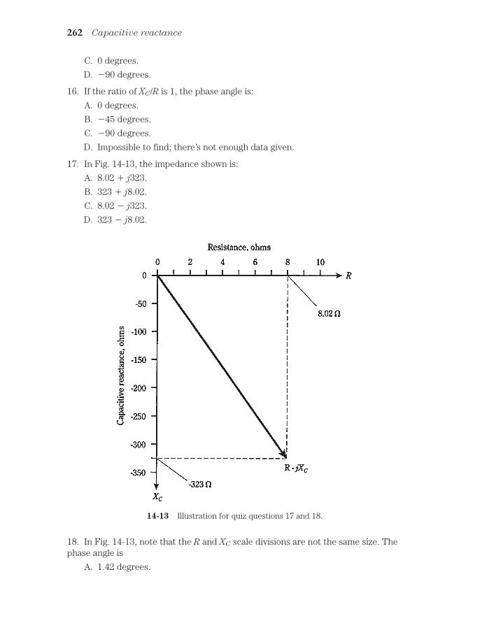
C. 0 degrees.
D. 90 degrees.
16. If the ratio of XC/R is 1, the phase angle is:
A. 0 degrees.
B. 45 degrees.
C. 90 degrees.
D. Impossible to find; there’s not enough data given.
17. In Fig. 14-13, the impedance shown is:
A. 8.02 j323.
B. 323 j8.02.
C. 8.02 j323.
D. 323 j8.02.
262 Capacitive reactance
14-13 Illustration for quiz questions 17 and 18.
18. In Fig. 14-13, note that the R and XC scale divisions are not the same size. Thephase angle is
A. 1.42 degrees.

B. About 60 degress, from the looks of it.
C.58.9 degrees.
D. 88.6 degrees.
19. An RC circuit consists of a 150-pF capacitor and a 330 Ω resisitor in series.What is the phase angle at a frequency of 1.34 MHz?
A. –67.4 degrees.
B. –22.6 degrees.
C. –24.4 degrees.
D. –65.6 degrees.
20. An RC circuit has a capitance of 0.015 µF. The resistance is 52 Ω. What is thephase angle at 90 kHz?
A. –24 degrees.
B. –0.017 degrees.
C. –66 degrees.
D. None of the above.
Quiz 263

15CHAPTER
Impedance andadmittance
YOU’VE SEEN HOW INDUCTIVE AND CAPACITIVE REACTANCE CAN BE REPRE-sented along a line perpendicular to resistance. In this chapter, you’ll put all three ofthese quantities—R, XL, and XC—together, forming a complete, working definition ofimpedance. You’ll also get acquainted with admittance, impedance’s evil twin.
To express the behavior of alternating-current (ac) circuits, you need two dimen-sions, because ac has variable frequency along with variable current. One dimension(resistance) will suffice for dc, but not for ac.
In this chapter and the two that follow, the presentation is rather mathematical. Youcan get a grasp of the general nature of the subject matter without learning how to doall of the calculations presented. The mathematics is given for those of you who wish togain a firm understanding of how ac circuits behave.
Imaginary numbersWhat does the lowercase j actually mean in expressions of impedance such as 4 j7 and45 j83? This was briefly discussed earlier in this book, but what is this thing, really?
Mathematicians use the lowercase letter i to represent j. (Mathematicians andphysicists/engineers often differ in notation as well as in philosophy.) This imaginary
number is the square root of 1. It is the number that, when multiplied by itself, gives1. So i j, and j j 1.
The entire set of imaginary numbers derives from this single unit. The square of animaginary number is negative—always. No real number has this property. Whether areal number is positive, zero, or negative, its square can never be negative—never.
The notion of j (or i, if you’re a mathematician) came about simply because somemathematicians wondered what the square root of 1 would behave like, if there weresuch a thing. So the mathematicians “imagined” the existence of this animal, and foundthat it had certain properties. Eventually, the number i was granted a place among the
264
!"# #$ !
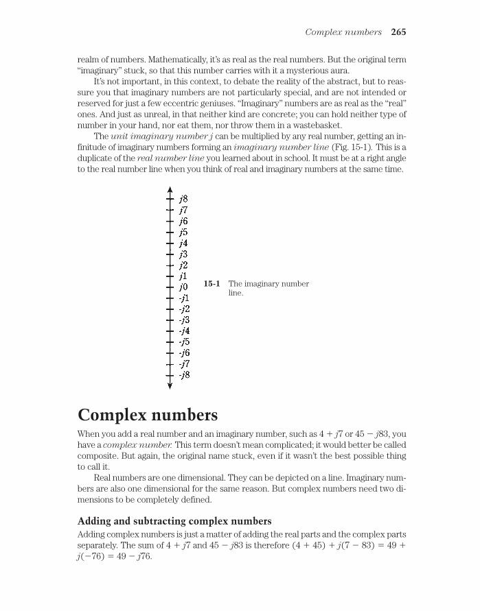
realm of numbers. Mathematically, it’s as real as the real numbers. But the original term“imaginary” stuck, so that this number carries with it a mysterious aura.
It’s not important, in this context, to debate the reality of the abstract, but to reas-sure you that imaginary numbers are not particularly special, and are not intended orreserved for just a few eccentric geniuses. “Imaginary” numbers are as real as the “real”ones. And just as unreal, in that neither kind are concrete; you can hold neither type ofnumber in your hand, nor eat them, nor throw them in a wastebasket.
The unit imaginary number j can be multiplied by any real number, getting an in-finitude of imaginary numbers forming an imaginary number line (Fig. 15-1). This is aduplicate of the real number line you learned about in school. It must be at a right angleto the real number line when you think of real and imaginary numbers at the same time.
Complex numbers 265
15-1 The imaginary numberline.
Complex numbersWhen you add a real number and an imaginary number, such as 4 j7 or 45 j83, youhave a complex number. This term doesn’t mean complicated; it would better be calledcomposite. But again, the original name stuck, even if it wasn’t the best possible thingto call it.
Real numbers are one dimensional. They can be depicted on a line. Imaginary num-bers are also one dimensional for the same reason. But complex numbers need two di-mensions to be completely defined.
Adding and subtracting complex numbersAdding complex numbers is just a matter of adding the real parts and the complex partsseparately. The sum of 4 j7 and 45 j83 is therefore (4 45) j(7 83) 49 j(76) 49 j76.

Subtracting complex numbers works similarly. The difference (4 j7) (45 j83) is found by multiplying the second complex number by 1 and then adding the re-sult, getting (4 j7) (1(45 j83) (4 j7) (45 j83) 41 j90.
The general formula for the sum of two complex numbers (a jb) and (c jd) is
(a jb) (c jd) (a c) j(b d)
The plus and minus number signs get tricky when working with sums and differ-ences of complex numbers. Just remember that any difference can be treated as a sum:multiply the second number by 1 and then add. You might want to do some exercisesto get yourself acquainted with the way these numbers behave, but in working with en-gineers, you will not often be called upon to wrestle with complex numbers at the levelof “nitty-gritty.’’
If you plan to become an engineer, you’ll need to practice adding and subtractingcomplex numbers. But it’s not difficult once you get used to it by doing a few sampleproblems.
Multiplying complex numbersYou should know how complex numbers are multiplied, to have a full understanding oftheir behavior. When you multiply these numbers, you only need to treat them as sumsof number pairs, that is, as binomials.
It’s easier to give the general formula than to work with specifics here. The productof (a + jb) and (c jd) is equal to ac jad jbc jjbd. Simplifying, remember thatjj1, so you get the final formula:
(a jb)(c jd) = (ac bd) j(ad bc)
As with the addition and subtraction of complex numbers, you must be careful withsigns (plus and minus). And also, as with addition and subtraction, you can get used todoing these problems with a little practice. Engineers sometimes (but not too often)have to multiply complex numbers.
The complex number planeReal and imaginary numbers can be thought of as points on a line. Complex numberslend themselves to the notion of points on a plane. This plane is made by taking the realand imaginary number lines and placing them together, at right angles, so that they in-tersect at the zero points, 0 and j0. This is shown in Fig. 15-2. The result is a Cartesian
coordinate plane, just like the ones you use to make graphs of everyday things likebank-account balance versus time.
Notational neurosesOn this plane, a complex number might be represented as a jb (in engineering or physi-cists’ notation), or as a bi (in mathematicians’ notation), or as an ordered pair (a, b).
“Wait,” you ask. “Is there a misprint here? Why does b go after the j, but in front of the i?”The answer is as follows: Mathematicians and engineers/physicists just don’t think alike,and this is but one of myriad ways in which this is apparent. In other words, it’s a matter of
266 Impedance and admittance

notational convention, and that is all. (It’s also a somewhat humorous illustration of the dif-ferent angle that an engineer takes in approaching a problem, as opposed to a mathemati-cian.)
Complex number vectorsComplex numbers can also be represented as vectors in the complex plane. This giveseach complex number a unique magnitude and direction. The magnitude is the distanceof the point a jb from the origin 0 j0. The direction is the angle of the vector, mea-sured counterclockwise from the a axis. This is shown in Fig. 15-3.
Absolute value The absolute value of a complex number a jb is the length, or magnitude, of its vec-tor in the complex plane, measured from the origin (0,0) to the point (a,b).
The complex number plane 267
15-2 The complex number plane.

In the case of a pure real number a j0, the absolute value is simply the numberitself, a, if it is positive, and a if a is negative.
In the case of a pure imaginary number 0 jb, the absolute value is equal to b ifb (which is a real number) is positive, and b if b is negative.
If the number is neither pure real or pure imaginary, the absolute value must befound by using a formula. First, square both a and b. Then add them. Finally, take thesquare root. This is the length of the vector a jb. The situation is illustrated in Fig.15-4.
268 Impedance and admittance
15-3 Magnitude and directionof a vector in thecomplex number plane.
15-4 Calculation of absolutevalue, or vector length.

Problem 15-1Find the absolute value of the complex number 22 – j0.
Note that this is a pure real. Actually, it is the same as22 j0, because j0 = 0.Therefore, the absolute value of this complex number is –(–22) 22.
Problem 15-2Find the absolute value of 0 j34.
This is a pure imaginary number. The value of b in this case is 34, because 0 j34 0 j( 34). Therefore, the absolute value is (34) 34.
Problem 15-3Find the absolute value of 3 j4.
In this number, a 3 and b 4, because 3 j4 can be rewritten as 3 j(4).Squaring both of these, and adding the results, gives 32 (4)2 9 16 25. Thesquare root of 25 is 5; therefore, the absolute value of this complex number is 5.
You might notice this “3, 4, 5” relationship and recall the Pythagorean theorem forfinding the length of the hypotenuse of a right triangle. The formula for finding thelength of a vector in the complex-number plane comes directly from this theorem.
If you don’t remember the Pythagorean theorem, don’t worry; just remember theformula for the length of a vector.
The RX planeRecall the planes for resistance (R) and inductive reactance (XL) from chapter 13. Thisis the same as the upper-right quadrant of the complex-number plane shown in Fig.15-2.
Similarly, the plane for resistance and capacitive reactance (XC) is the same as thelower-right quadrant of the complex number plane.
Resistances are represented by nonnegative real numbers. Reactances, whetherthey are inductive (positive) or capacitive (negative), correspond to imaginary num-bers.
No negative resistanceThere is no such thing, strictly speaking, as negative resistance. That is to say, one can-not have anything better than a perfect conductor. In some cases, a supply of direct cur-rent, such as a battery, can be treated as a negative resistance; in other cases, you canhave a device that acts as if its resistance were negative under certain changing condi-tions. But generally, in the RX (resistance-reactance) plane, the resistance value is al-ways positive. This means that you can remove the negative axis, along with theupper-left and lower-left quadrants, of the complex-number plane, obtaining a halfplane as shown in Fig. 15-5.
Reactance in generalNow you should get a better idea of why capacitive reactance, XC, is considered negative.In a sense, it is an extension of inductive reactance, XL , into the realm of negatives, in a
The RX plane 269

way that cannot generally occur with resistance. Capacitors act like “negative induc-tors.” Interesting things happen when capacitors and inductors are combined, which isdiscussed in the next couple of chapters.
Reactance can vary from extremely large negative values, through zero, to ex-tremely large positive values. Engineers and physicists always consider reactance to beimaginary. In the mathematical model of impedance, capacitances and inductancesmanifest themselves “perpendicularly” to resistance.
The general symbol for reactance is X; this encompasses both inductive reactance(XL) and capacitive reactance (XC).
Vector representation of impedanceAny impedance R jX can be represented by a complex number of the form a jb.
Just let R a and X b.
It should be easy to visualize, now, how the impedance vector changes as either Ror X, or both, are varied. If X remains constant, an increase in R will cause the vector to
270 Impedance and admittance
15-5 The complex impedanceRX plane.

get longer. If R remains constant and XL gets larger, the vector will also grow longer. IfR stays the same as XC gets larger (negatively), the vector will grow longer yet again.
Think of the point a jb, or R jX, moving around in the plane, and imaginewhere the corresponding points on the axes lie. These points are found by drawing dot-ted lines from the point R jX to the R and X axes, so that the lines intersect the axesat right angles (Fig. 15-6).
Vector representation of impedance 271
15-6 Some points in the RX plane, and their components on the Rand X axes.
Now think of the points for R and X moving toward the right and left, or up anddown, on their axes. Imagine what happens to the point R jX in various scenarios.This is how impedance changes as the resistance and reactance in a circuit are varied.
Resistance is one-dimensional. Reactance is also one-dimensional. But impedanceis two-dimensional. To fully define impedance, you must render it on a half plane, spec-ifying the resistance and the reactance, which are independent.

Absolute-value impedanceThere will be times when you’ll hear that the “impedance” of some device or componentis a certain number of ohms. For example, in audio electronics, there are “8-Ω” speak-ers and “600-Ω” amplifier inputs. How can manufacturers quote a single number for aquantity that is two-dimensional, and needs two numbers to be completely expressed?
There are two answers to this. First, figures like this generally refer to devices thathave purely resistive impedances. Thus, the “8-Ω” speaker really has a complex imped-ance of 8 j0, and the “600-Ω” input circuit is designed to operate with a complex im-pedance at, or near, 600 j0.
Second, you can sometimes talk about the length of the impedance vector, callingthis a certain number of ohms. If you talk about “impedance” this way, you are beingambiguous, because you can have an infinite number of different vectors of a givenlength in the RX plane.
Sometimes, the capital letter Z is used in place of the word “impedance” in generaldiscussions. This is what engineers mean when they say things like “Z 50 Ω” or “Z 300 Ω nonreactive.”
“Z 8 Ω” in this context, if no specific complex impedance is given, can refer to thecomplex value 8 j0, or 0 j8, or 0 j8, or any value on a half circle of points in theRX plane that are at distance 8 units away from 0 j0. This is shown in Fig. 15-7. Thereexist an infinite number of different complex impedances with Z 8 Ω.
Problems 15-1, 15-2, and 15-3 can be considered as problems in finding absolute-value impedance from complex impedance numbers.
Problem 15-4Name seven different complex impedances having an absolute value of Z 10.
It’s easy name three: 0 j10, 10 j0, and 0 j10. These are pure inductance, pureresistance, and pure capacitance, respectively.
A right triangle can exist having sides in a ratio of 6:8:10 units. This is true because62 82 = 102. (Check it and see!) Therefore, you might have 6 j8, 6 j8, 8 j6 and8 j6, all complex impedances whose absolute value is 10 ohms. Obviously, the valueZ 10 was chosen for this problem because such a whole-number right-triangle exists.It becomes quite a lot messier to do this problem (but by no means impossible) if Z 11 instead.
If you’re not specifically told what complex impedance is meant when a single-number ohmic figure is quoted, it’s best to assume that the engineers are talking aboutnonreactive impedances. That means they are pure resistances, and that the imagi-nary, or reactive, factor is zero. Engineers will often speak of nonreactive impedances,or of complex impedance vectors, as “low-Z or high-Z.” For instance, a speaker might becalled “low-Z” and a microphone “high-Z.”
Characteristic impedanceThere is one property of electronic components that you’ll sometimes hear called im-
pedance, that really isn’t “impedance” at all. This is characteristic impedance or surge
272 Impedance and admittance

impedance. It is abbreviated Zo, and is a specification of transmission lines. It can always be expressed as a positive real number.
Transmission linesAny time that it is necessary to get energy or signals from one place to another, a trans-mission line is required. These almost always take either of two forms, coaxial or two
wire. These are illustrated qualitatively in Fig. 15-8.Examples of transmission lines include the ribbon that goes from a television an-
tenna to the receiver, the cable running from a hi-fi amplifier to the speakers, and theset of wires that carries electricity over the countryside.
Factors affecting ZoThe Zoh of a parallel-wire transmission line depends on the diameter of the wires, on thespacing between the wires, and on the nature of the insulating material separating thewires.
Characteristic impedance 273
15-7 Vectors representingan absolute valueimpedance of 8 Ω.

In general, Zo increases as the wire diameter gets smaller, and decreases as the wirediameter gets larger, all other things being equal.
In a coaxial line, the thicker the center conductor, the lower the Zo if the shieldstays the same size. If the center conductor stays the same size and the shield tubing in-creases in diameter, the Zo will increase.
Also in general, Zo increases as the spacing between wires, or between the centerconductor and the shield or braid, gets greater, and decreases as the spacing is madeless.
Solid dielectrics such as polyethylene reduce the Zo of a transmission line, com-pared with air or a vacuum between the conductors.
ZO in practiceIn rigorous terms, the characteristic impedance of a line is determined according to thenature of the load with which the line works at highest efficiency.
Suppose that you have an 8-Ω hi-fi speaker, and you want to get audio energy tothat speaker with the greatest possible efficiency, so that the least possible power is dis-sipated in the line. You would use large-diameter wires, of course, but for true opti-mization, you would want the spacing between the wires to be just right. Adjusting thisspacing for optimum power transfer would result in a line Zo of 8 Ω. Then, the greatestpossible efficiency would be had with a speaker of impedance 8 j0.
Ιf you can’t get the wires to have the right size and spacing for a good match to Z 8 Ω, you might need to use an impedance transformer. This makes the speaker’s im-pedance look like something different, such as 50 Ω or 600 Ω.
274 Impedance and admittance
15-8 At A, coaxial transmission line. At B, parallel-wire transmission line.

Imagine that you have a 300-Ω television antenna, and you want the best possi-ble reception. You purchase “300-Ω” ribbon line, with a value of Zo that has been op-timized by the manufacturer for use with antennas whose impedances are close to300 j0.
For a system having an “impedance” of “R Ω,” the best line Zo is also R Ω. If R ismuch different from Zo, an unnecessary amount of power will be wasted in heating upthe transmission line. This might not be a significant amount of power, but it often is.
Impedance matching will be discussed in more detail in the next chapter.
ConductanceIn an ac circuit, electrical conductance works the same way as it does in a dc circuit.Conductance is symbolized by the capital letter G. It was introduced back in chapter 2.
The relationship between conductance and resistance is simple: G 1/R. The unitis the siemens. The larger the value of conductance, the smaller the resistance, and themore current will flow. Conversely, the smaller the value of G, the greater the value ofR, and the less current will flow.
SusceptanceSometimes, you’ll come across the term susceptance in reference to an ac circuit con-taining a capacitive reactance or an inductive reactance. Susceptance is symbolized bythe capital letter B. It is the reciprocal of reactance. That is, B 1/X. Susceptance canbe either capacitive or inductive. These are symbolized as BC and BL respectively.Therefore, BC 1/XC, and BL 1/XL.
There is a trick to determining susceptances in terms of reactances. Or, perhapsbetter stated, a trickiness. Susceptance is imaginary, just as is reactance. That is, all val-ues of B require the use of the j operator, just as do all values of X. But 1/j j. Thisreverses the sign when you find susceptance in terms of reactance.
If you have an inductive reactance of, say, 2 ohms, then this is expressed as j2 in theimaginary sense. What is 1/(j2)? You can break this apart and say that 1/(j2) (1/j)(1/2) (1/j)0.5. But what is 1/j? Without making this into a mathematical treatise,suffice it to say that 1/j j. Therefore, the reciprocal of j2 is –j0.5. Inductive sus-
ceptance is negative imaginary.
If you have a capacitive reactance XC 10 ohms, then this is expressed as XC j10. The reciprocal of this is BC 1/(j10) (1/j)(1/10) (1/j)0.1. What is1/j? Again, without going into deep theoretical math, it is equal to j. Therefore, thereciprocal of j10 is j0.1. Capacitive susceptance is positive imaginary.
This is exactly reversed from the situation with reactances.
Problem 15-5 Suppose you have a capacitor of 100 pF at a frequency of 3.00 MHz. What is BC?
First, find the reactance XC by the formula
XC 1/(6.28fC)
Susceptance 275

Remembering that 100 pF 0. 000100 µF, you can substitute in this formula for f 3.00 and C 0.000100, getting
XC 1/(6.28 3.00 0.000100) 1/0.001884 531 Ω j531
The susceptance, BC, is equal to l/XC. Thus, BC 1/(j531) j0.00188. Remem-ber that capacitive susceptance is positive. This can “short-circuit” any frustration youmight have in manipulating the minus signs in these calculations.
Note that above, you found a reciprocal of a reciprocal. You did something and thenimmediately turned around and undid it, slipping a minus sign in because of the idio-syncrasies of that little j operator. In the future, you can save work by remembering thatthe formula for capacitive susceptance simplified, is
BC 6.28fC siemens j(6.28fC)
This resembles the formula for inductive reactance.
Problem 15-6An inductor has L 163 µH at a frequency of 887 kHz. What is BL?
First, calculate XL, the inductive reactance
XL 6.28fL 6.28 0.887 163 908 Ω j908
The susceptance, BL is equal to 1/XL Therefore, BL 1/j908 j0. 00110. Remem-ber that inductive susceptance is negative.
The formula for inductive susceptance is similar to that for capacitive reactance:
BL 1/(6.28fl) siemens j(1/(6.28fL)
AdmittanceConductance and susceptance combine to form admittance, symbolized by the capitalletter Y.
Admittance, in an ac circuit, is analogous to conductance in a dc circuit.
Complex admittanceAdmittance is a complex quantity and represents the ease with which current can flowin an ac circuit. As the absolute value of impedance gets larger, the absolute value of ad-mittance becomes smaller, in general. Huge impedances correspond to tiny admit-tances, and vice-versa.
Admittances are written in complex form just like impedances. But you need tokeep track of which quantity you’re talking about! This will be obvious if you use thesymbol, such as Y 3 – j0.5 or Y 7 j3. When you see Y instead of Z, you know thatnegative j factors (such as –j0.5) mean that there is a net inductance in the circuit, andpositive j factors (such as j3) mean there is net capacitance.
276 Impedance and admittance

Admittance is the complex composite of conductance and susceptance. Thus, ad-mittance takes the form
Y G jB
The j factor might be negative, of course, so there are times you’ll write Y G jB.
Parallel circuitsRecall how resistances combine with reactances in series to form complex impedances?In chapters 13 and 14, you saw series RL and RC circuits. Perhaps you wondered whyparallel circuits were ignored in those discussions. The reason is that admittance, ratherthan impedance, is best for working with parallel ac circuits. Therefore, the subject ofparallel circuits was deferred.
Resistance and reactance combine in rather messy fashion in parallel circuits, andit can be hard to envision what’s happening. But conductance (G) and susceptance (B)just add together in parallel circuits, yielding admittance (Y). This greatly simplifies theanalysis of parallel ac circuits.
The situation is similar to the behavior of resistances in parallel when you workwith dc. While the formula is a bit cumbersome if you need to find the value of a bunchof resistances in parallel, it’s simple to just add the conductances.
Now, with ac, you’re working in two dimensions instead of one. That’s the only dif-ference.
Parallel circuit analysis is covered in detail in the next chapter.
The GB planeAdmittance can be depicted on a plane that looks just like the complex impedance (RX)plane. Actually, it’s a half plane, because there is ordinarily no such thing as negativeconductance. (You can’t have something that conducts worse than not at all.) Conduc-tance is plotted along the horizontal, or G, axis on this coordinate half plane, and sus-ceptance is plotted along the B axis. The plane is shown in Fig. 15-9 with several pointsplotted.
Although the GB plane looks superficially identical to the RX plane, the differenceis great indeed! The GB plane is literally blown inside-out from the RX plane, as if youhad jumped into a black hole and undergone a spatial transmutation, inwards out andoutwards in, turning zero into infinity and vice-versa. Mathematicians love this kind ofstuff.
The center, or origin, of the GB plane represents that point at which there is noconduction of any kind whatsoever, either for direct current or for alternating current.In the RX plane, the origin represents a perfect short circuit; in the GB plane it corre-sponds to a perfect open circuit.
The open circuit in the RX plane is way out beyond sight, infinitely far away fromthe origin. In the GB plane, it is the short circuit that is out of view.
The GB plane 277

Formula for conductanceAs you move out towards the right (“east”) along the G, or conductance, axis of the GBplane, the conductance improves, and the current gets greater, but only for dc. The for-mula for G is simply
G 1/R
where R is the resistance in ohms and G is the conductance in siemens, also sometimescalled mhos.
Formula for capacitive susceptanceIt won’t hurt to review the formulas for susceptance again. They can get a little bit con-fusing, especially after having worked with reactance.
278 Impedance and admittance
15-9 Some points in the GB plane, and their components on the Gand B axes.

When you move upwards (“north”) along the jB axis from the origin, you haveever-increasing capacitive susceptance. The formula for this quantity, BC, is
BC 6.28fL siemens
where f is in Hertz and C is in farads. The value of B is in siemens. Alternatively, you canuse frequency values in megahertz and capacitances in microfarads. The complex valueis jB = j(6.28fC).
Moving upwards along the jB axis indicates increasing capacitance values.
Formula for inductive susceptanceWhen you go down (“south”) along the jB axis from the origin, you encounter increas-ingly negative susceptance. This is inductive susceptance; the formula for it is
BL 1/(6.28fL) siemens
where f is in Hertz and L is in henrys. Alternatively, f can be expressed in megahertz,and L can be given in microhenrys. The complex value is jB j(1/(6.28fL).
Moving downwards along the jB axis indicates decreasing values of inductance.
Vector representation of admittanceComplex admittances can be shown as vectors, just as can complex impedances. In Fig.15-10, the points from Fig. 15-9 are rendered as vectors.
Generally, longer vectors indicate greater flow of current, and shorter ones indicateless current.
Imagine a point moving around on the GB plane, and think of the vector gettinglonger and shorter, and changing direction. Vectors pointing generally “northeast,” orupwards and to the right, correspond to conductances and capacitances in parallel.Vectors pointing in a more or less “southeasterly” direction, or downwards and to theright, are conductances and inductances in parallel.
Why all these different expressions?Do you think that the foregoing discussions are an elaborate mental gymnastics rou-tine? Why do you need all these different quantities: resistance, capacitance, capacitivereactance, inductance, inductive reactance, impedance, conductance, capacitivesusceptance, inductive susceptance, admittance?
Well, gymnastics are sometimes necessary to develop skill. Sometimes you need to“break a mental sweat.” Each of these expressions is important.
The quantities that were dealt with before this chapter, and also early in this chap-ter, are of use mainly with series RLC (resistance-inductance-capacitance) circuits. Theones introduced in the second half of this chapter are important when you need to an-alyze parallel RLC circuits. Practice them and play with them, especially if they intimi-date you. After awhile they’ll become familiar.
Why all these different expressions ? 279

Think in two dimensions. Draw your own RX and GB planes. (Be thankful there areonly two dimensions, and not three! Some scientists need to deal in dozens of dimensions.)
If you want to be an engineer, you’ll need to know how to handle these expressions.If you plan to manage engineers, you’ll want to know what these quantities are, at least,when the engineers talk about them.
If the math seems a bit thick right now, hang in there. Impedance and admittanceare the most mathematical subjects you’ll have to deal with.
QuizRefer to the text in this chapter if necessary. A good score is 18 or more correct. An-swers are in the back of the book.
1. The square of an imaginary number:
A. Can never be negative.
280 Impedance and admittance
15-10 Vectors representing the points of Fig. 15-9.

B. Can never be positive.
C. Might be either positive or negative.
D. Is equal to j.
2. A complex number:
A. Is the same thing as an imaginary number.
B. Has a real part and an imaginary part.
C. Is one-dimensional.
D. Is a concept reserved for elite imaginations.
3. What is the sum of 3 j7 and 3 j7?
A. 0 j0
B. 6 j14.
C. 6 j14.
D. 0 j14.
4. What is ( 5 j7) (4 j5)?
A. 1 j2.
B. 9 j2.
C. 1 j2.
D. 9 j12.
5. What is the product (4 j7)(6 j2)?
A. 24 j14.
B. 38 j34.
C. 24 – j14.
D. 24 j14.
6. What is the magnitude of the vector 18 j24?
A. 42.
B. 42.
C. 30.
D. 30.
7. The impedance vector 5 j0 represents:
A. A pure resistance.
B. A pure inductance.
C. A pure capacitance.
D. An inductance combined with a capacitance.
8. The impedance vector 0 j22 represents:
A. A pure resistance.
B. A pure inductance.
Quiz 281

C. A pure capacitance.
D. An inductance combined with a resistance.
9. What is the absolute-value impedance of 3.0 j6.0?
A. Z 9.0 Ω.
B. Z 3.0 Ω.
C. Z 45 Ω.
D. Z 6.7 Ω.
10. What is the absolute-value impedance of 50 j235?
A. Z 240 Ω.
B. Z 58,000 Ω.
C. Z 285 Ω.
D. Z 185 Ω.
11. If the center conductor of a coaxial cable is made to have smaller diameter, allother things being equal, what will happen to the Zo of the transmission line?
A. It will increase.
B. It will decrease.
C. It will stay the same.
D. There is no way to know.
12. If a device is said to have an impedance of Z 100 Ω, this would most oftenmean that:
A. R jX 100 j0.
B. R jX 0 j100.
C. R jX 0 j100.D. You need to know more specific information.
13. A capacitor has a value of 0.050 µF at 665 kHz. What is the capacitivesusceptance?
A. j4.79.
B. j4.79.
C. j0. 209.
D. j0. 209.
14. An inductor has a value of 44 mH at 60 Hz. What is the inductive susceptance?
A.. j0.060.
B. j0.060.
C. j17.
D. j17.
282 Impedance and admittance

15. Susceptance and conductance add to form:
A. Impedance.
B. Inductance.
C. Reactance.
D. Admittance.
16. Absolute-value impedance is equal to the square root of:
A. G2 B2
B. R2 X2.
C. Zo.
D. Y.
17. Inductive susceptance is measured in:
A. Ohms.
B. Henrys.
C. Farads.
D. Siemens.
18. Capacitive susceptance is:
A. Positive and real valued.
B. Negative and real valued.
C. Positive and imaginary.
D. Negative and imaginary.
19. Which of the following is false?
A. BC 1/XC.
B. Complex impedance can be depicted as a vector.
C. Characteristic impedance is complex.
D. G 1/R.
20. In general, the greater the absolute value of the impedance in a circuit:
A. The greater the flow of alternating current.
B. The less the flow of alternating current.
C. The larger the reactance.
D. The larger the resistance.
Ions 283
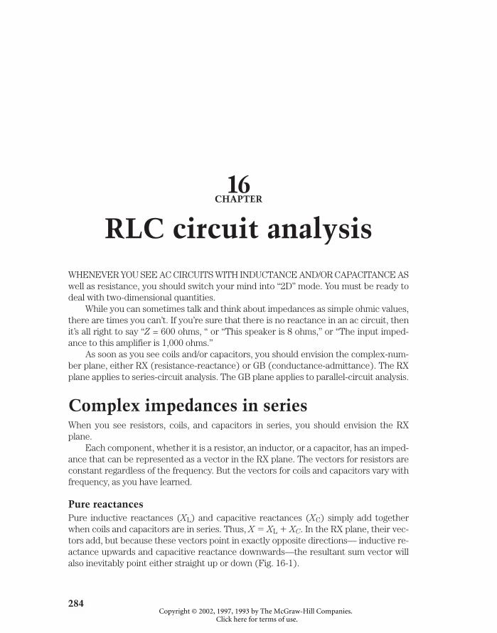
16CHAPTER
RLC circuit analysisWHENEVER YOU SEE AC CIRCUITS WITH INDUCTANCE AND/OR CAPACITANCE ASwell as resistance, you should switch your mind into “2D” mode. You must be ready todeal with two-dimensional quantities.
While you can sometimes talk and think about impedances as simple ohmic values,there are times you can’t. If you’re sure that there is no reactance in an ac circuit, thenit’s all right to say “Z = 600 ohms, “ or “This speaker is 8 ohms,” or “The input imped-ance to this amplifier is 1,000 ohms.”
As soon as you see coils and/or capacitors, you should envision the complex-num-ber plane, either RX (resistance-reactance) or GB (conductance-admittance). The RXplane applies to series-circuit analysis. The GB plane applies to parallel-circuit analysis.
Complex impedances in seriesWhen you see resistors, coils, and capacitors in series, you should envision the RXplane.
Each component, whether it is a resistor, an inductor, or a capacitor, has an imped-ance that can be represented as a vector in the RX plane. The vectors for resistors areconstant regardless of the frequency. But the vectors for coils and capacitors vary withfrequency, as you have learned.
Pure reactancesPure inductive reactances (XL) and capacitive reactances (XC) simply add togetherwhen coils and capacitors are in series. Thus, X XL XC. In the RX plane, their vec-tors add, but because these vectors point in exactly opposite directions— inductive re-actance upwards and capacitive reactance downwards—the resultant sum vector willalso inevitably point either straight up or down (Fig. 16-1).
284 !
"# #$ !
Problem 16-1A coil and capacitor are connected in series, with jXL j200 and jXC j150. What isthe net reactance vector jX?
Just add the values jX jXL jXC j200 (j150) j(200 150) j50. Thisis an inductive reactance, because it is positive imaginary.
Problem 16-2A coil and capacitor are connected in series, with jXL j30 and jXC jl10. What isthe net reactance vector jX?
Again, add jX j30 (jll0) j(30 110) j80. This is a capacitive reac-tance, because it is negative imaginary.
Problem 16-3A coil of L 5.00 µH and a capacitor of C 200 pF are in series. The frequency is f 4.00 MHz. What is the net reactance vector jX?
First calculate
jXL j6.28fL
j(6.28 × 4.00 × 5.00) j126
Then calculate
jXC j(1/(6.28fC) j(l/(6.28 × 4.00 × 0.000200) j199
Finally, add
jX jXL jXC j126 (jl99) j73
Complex impedanses in series 285
16-1 Pure inductance and purecapacitance arerepresented by reactancevectors that point straightup and down.

This is a net capacitive reactance. There is no resistance in this circuit, so the imped-ance vector is 0 j73.
Problem 16-4What is the net reactance vector jX for the above combination at a frequency of f 10.0MHz?
First calculate
jXL j6.28fL
j(6.28 × 10.0 × 5.00) j314
Then calculate
jXC j(1/(6.28fC)) j(l/(6.28 × 10.0 × 0.000200) j79.6
Finally, add
jX jXL jXC j314 (j79.6) j234
This is a net inductive reactance. Again, there is no resistance, and therefore the im-pedance vector is pure imaginary, 0 j234.
Notice that the change in frequency, between Problems 16-3 and 16-4, caused thecircuit to change over from a net capacitance to a net inductance. You might think thatthere must be some frequency, between 4.00 MHz and 10.0 MHz, at which jXL and jXC
add up to j0—that is, at which they exactly cancel each other out, yielding 0 j0 as thecomplex impedance. Then the circuit, at that frequency, would appear as a short cir-cuit. If, you suspect this, you’re right.
Any series combination of coil and capacitor offers theoretically zero opposition toac at one special frequency. This is called series resonance, and is dealt with in thenext chapter.
Adding impedance vectorsOften, there is resistance, as well as reactance, in an ac series circuit containing a coiland capacitor. This occurs when the coil wire has significant resistance (it’s never a per-fect conductor). It might also be the case because a resistor is deliberately connectedinto the circuit.
Whenever the resistance in a series circuit is significant, the impedance vectors nolonger point straight up and straight down. Instead, they run off towards the “north-east” (for the inductive part of the circuit) and “southeast” (for the capacitive part).This is illustrated in Fig. 16-2.
When vectors don’t lie along a single line, you need to use vector addition to besure that you get the correct resultant. Fortunately, this isn’t hard.
In Fig. 16-3, the geometry of vector addition is shown. Construct a parallelogram,using the two vectors Z1 R1 jX1 and Z2 R2 jX2 as two of the sides. The diago-nal is the resultant. In a parallelogram, opposite angles have equal measure. Theseequalities are indicated by single and double arcs in the figure.
286 RLC circuit analysis

Formula for complex impedances in seriesGiven two impedances, Z1 R1 jX1 and Z2 R2 jX2, the net impedance Z of thesein series is their vector sum, given by
Z (R1 R2) j(X1 X2)
The reactances X1 and X2 might both be inductive; they might both be capacitive; orone might be inductive and the other capacitive.
Complex impedances in series 287
16-2 When resistance ispresent along withreactance, impedancevectors point “northeast”or “southeast.”
16-3 Parallelogram method ofvector addition.

Calculating a vector sum using the formula is easier than doing it geometrically witha parallelogram. The arithmetic method is also more nearly exact. The resistance andreactance components add separately. That’s all there is to it.
Series RLC circuitsWhen a coil, capacitor, and resistor are connected in series (Fig. 16-4), the resistance Rcan be thought of as all belonging to the coil, when you use the above formulas. (Think-ing of it all as belonging to the capacitor will also work.) Then you have two vectors toadd, when finding the impedance of a series RLC circuit:
Z (R jXL) (0 jXC) R j(XL XC)
288 RLC circuit analysis
16-4 A series RLC circuit.
Problem 16-5A resistor, coil, and capacitor are connected in series with R 50 Ω, XL 22 Ω, and XC–33 Ω. What is the net impedance, Z?
Consider the resistor to be part of the coil, obtaining two complex vectors, 50 j22and 0 j33. Adding these gives the resistance component of 50 0 50, and the re-active component of j22 j33 j11. Therefore, Z 50 j11.
Problem 16-6A resistor, coil, and capacitor are connected in series with R 600 Ω, XL 444 Ω, andXC 444 Ω. What is the net impedance, Z?
Again, consider the resistor to be part of the inductor. Then the vectors are 600 j444 and 0 j444. Adding these, the resistance component is 600 0 600, and thereactive component is j444 j444 j0. Thus, Z 600 j0. This is a purely resistiveimpedance, and you can rightly call it “600 Ω.”
Problem 16-7A resistor, coil, and capacitor are connected in series. The resistor has a value of 330 Ω,the capacitance is 220 pF, and the inductance is 100 µH. The frequency is 7.15 MHz.What is the net complex impedance?
First, you need to calculate the inductive and capacitive reactances. Rememberingthe formula XL 6.28fL, multiply to obtain
jXL j(6.28 × 7.15 × 100) j4490

Megahertz and microhenrys go together in the formula. As for XC, recall the formulaXC 1/(6.28fC). Convert 220 pF to microfarads to go with megahertz in the formulaC 0.000220 µF. Then
jXC j(l/(6.28 × 7.15 × 0.000220)) j101
Now, you can consider the resistance and the inductive reactance to go together, soone of the impedance vectors is 330 j4490. The other is 0 j101. Adding these gives330 j4389; this rounds off to Z 330 j4390.
Problem 16-8A resistor, coil, and capacitor are in series. The resistance is 50.0 Ω, the inductance is10.0 µH, and the capacitance is 1000 pF. The frequency is 1592 kHz. What is the com-plex impedance of this series RLC circuit at this frequency?
First, calculate XL 6.28fL. Convert the frequency to megahertz; 1592 kHz 1.592 MHz. Then
jXL j(6.28 × 1.592 × 10.0) j100
Then calculate XC 1/(6.28fC). Convert picofarads to microfarads, and use megahertzfor the frequency. Therefore,
jXC j(l/(6.28 × 1.592 × 0.001000)) j100
Let the resistance and inductive reactance go together as one vector, 50.0 j100. Letthe capacitance alone be the other vector, 0 j100. The sum is 50.0 j100 j100 50.0 j0. This is a pure resistance of 50.0 Ω. You can correctly say that the impedanceis “50.0 Ω” in this case.
This concludes the analysis of series RLC circuit impedances. What about parallelcircuits? To deal with these, you must calculate using conductance, susceptance, andadmittance, converting to impedance only at the very end.
Complex admittances in parallelWhen you see resistors, coils, and capacitors in parallel, you should envision the GB(conductance-susceptance) plane.
Each component, whether it is a resistor, an inductor, or a capacitor, has an admit-tance that can be represented as a vector in the GB plane. The vectors for pure conduc-tances are constant, even as the frequency changes. But the vectors for the coils andcapacitors vary with frequency, in a manner similar to the way they vary in the RX plane.
Pure susceptancesPure inductive susceptances (BL) and capacitive susceptances (BC) add together whencoils and capacitors are in parallel. Thus, B BL BC. Remember that BL is negative
and BC is positive, just the opposite from reactances.In the GB plane, the jBL and jBC vectors add, but because these vectors point in ex-
actly opposite directions—inductive susceptance down and capacitive susceptanceup—the sum, jB, will also inevitably point straight down or up (Fig. 16-5).
Complex admittances in parallel 289

Problem 16-9A coil and capacitor are connected in parallel, with jBL j0.05 and jBC j0.08. Whatis the net admittance vector?
Just add the values jB jBL jBC j0.05 j0.08 j0.03. This is a capacitive
susceptance, because it is positive imaginary. The admittance vector is 0 j0.03.
Problem 16-10A coil and capacitor are connected in parallel, with jBL j0.60 and jBC j 0.25. Whatis the net admittance vector?
Again, add jB j0. 60 j0.25 j0.35. This is an inductive susceptance, be-cause it is negative imaginary. The admittance vector is 0 – j0. 35.
Problem 16-11A coil of L 6.00 µH and a capacitor of C 150 pF are in parallel. The frequency isf 4.00 MHz. What is the net admittance vector?
First calculate
jBL j(l/(6.28fL) j(l/(6.28 × 4.00 × 6.00)) j0.00663
Then calculate
jBC j(6.28fC) j(6.28 × 4.00 × 0.000150) j0.00377
Finally, add
jB jBL jBC j0.00663 j0.00377 j0.00286
290 RLC circuit analysis
16-5 Pure capacitance andpure inductance arerepresented bysusceptance vectors thatpoint straight up anddown.

This is a net inductive susceptance. There is no conductance in this circuit, so the ad-mittance vector is 0 – j0.00286.
Problem 16-12What is the net admittance vector for the above combination at a frequency of f 5.31MHz?
First calculate
jBL j(l/(6.28fL) j(l/(6.28 × 5.31 × 6.00)) j0.00500
Then calculate
jBC j(6.28fC) j(6.28 × 5.31 × 0.000150) j0.00500
Finally, add
jB jBL jBC j0.00500 j0.00500 j0
There is no susceptance. Because the conductance is also zero (there is nothing else inparallel with the coil and capacitor that might conduct), the admittance vector is 0 j0.
This situation, in which there is no conductance and no susceptance, seems to im-ply that this combination of coil and capacitor in parallel is an open circuit at 5.31 MHz.In theory this is true; zero admittance means no current can get through the circuit. Inpractice it’s not quite the case. There is always a small leakage. This condition is knownas parallel resonance. It’s discussed in the next chapter.
Adding admittance vectorsIn real life, there is a small amount of conductance, as well as susceptance, in an ac par-allel circuit containing a coil and capacitor. This occurs when the capacitor lets a littlebit of current leak through. More often, though, it is the case because a load is con-nected in parallel with the coil and capacitor. This load might be an antenna, or the in-put to an amplifier circuit, or some test instrument, or a transducer.
Whenever the conductance in a parallel circuit is significant, the admittance vec-tors no longer point straight up and down. Instead, they run off towards the “northeast”(for the capacitive part of the circuit) and “southeast” (for the inductive part). This isillustrated in Fig. 16-6.
In the problems above, you added numbers, but in fact you were adding vectorsthat just happened to fall along a single line, the imaginary (j) axis of the GB plane. Inpractical circuits, the vectors often do not lie along a single line. You’ve already seenhow to deal with these in the RX plane. In the GB plane, the principle is the same.
Formula for complex admittances in parallelGiven two admittances, Y1 G1 jB1 and Y2 G2 jB2, the net admittance Y of thesein parallel is their vector sum, given by
Y (G1 G2) j(B1 B2)
Complex admittances in parallel 291

The susceptances B1 and B2 might both be inductive; they might both be capacitive; orone might be inductive and the other capacitive.
Parallel GLC circuitsWhen a coil, capacitor, and resistor are connected in parallel (Fig. 16-7), the resistorshould be thought of as a conductor, whose value in siemens is equal to the reciprocal ofthe value in ohms. Think of the conductance as all belonging to the inductor. (Thinking ofit all as belonging to the capacitor will also work.) Then you have two vectors to add, whenfinding the admittance of a parallel GLC (conductance-inductance-capacitance) circuit:
Y (G jBL) (0 jBC) G j(BL BC)
292 RLC circuit analysis
16-6 When conductance ispresent along withsusceptance, admittancevectors point “northeast”or “southeast.”
16-7 A parallel GLC circuit.
Problem 16-13A resistor, coil, and capacitor are connected in parallel with G 0.1 siemens, jBL j0.010, and jBC j0.020. What is the net admittance vector?
Consider the resistor to be part of the coil, obtaining two complex vectors, 0.1– j0.010 and 0 j0.020. Adding these gives the conductance component of 0.1 0
0.1, and the susceptance component of –j0.010 j0.020 j0.010. Therefore, the ad-mittance vector is 0.1 j0.010.
Problem 16-14A resistor, coil, and capacitor are connected in parallel with G 0.0010 siemens, jBL j0.0022 and jBC j0.0022. What is the net admittance vector?
Again, consider the resistor to be part of the coil. Then the complex vectors are0.0010 – j0.0022 and 0 j0.0022. Adding these, the conductance component is 0.0010 0 0.0010, and the susceptance component is –j0.0022 j0.0022 j0. Thus, theadmittance vector is 0.0010 j0. This is a purely conductive admittance. There is nosusceptance.
Problem 16-15A resistor, coil, and capacitor are connected in parallel. The resistor has a value of 100Ω, the capacitance is 200 pF, and the inductance is 100 µH. The frequency is 1.00 MHz.What is the net complex admittance?
First, you need to calculate the inductive and capacitive susceptances. Recall jBL–j(1/(6.28fL), and “plug in” the values, getting
jBL j(l/(6.28 × 1.00 × 100) j0.00159
Megahertz and microhenrys go together in the formula. As for jBC, recall the formulajBC j(6.28fC). Convert 200 pF to microfarads to go with megahertz in the formula; C 0.000200 µF. Then
jBC j(6.28 × 1.00 × 0.000200) j0.00126
Now, you can consider the conductance, which is 1/100 0.0100 siemens, and theinductive susceptance to go together. So one of the vectors is 0.0100 – j0.00159. Theother is 0 j0.00126. Adding these gives 0.0100 – j0.00033.
Problem 16-16A resistor, coil, and capacitor are in parallel. The resistance is 10.0 Ω, the inductance is10.0 µH, and the capacitance is 1000 pF. The frequency is 1592 kHz. What is the com-plex admittance of this circuit at this frequency?
First, calculate jBL j(1/(6.28fL)). Convert the frequency to megahertz; 1592kHz 1.592 MHz. Then
jBL j/(l/(6.28 × 1.592 × 10.0)) j0.0100
Then calculate jBC j(6.28fC). Convert picofarads to microfarads, and use megahertzfor the frequency. Therefore
jBC j(6.28 × 1.592 × 0.001000) j0.0100
Let the conductance and inductive susceptance go together as one vector, 0.100 –j0.0100. (Remember that conductance is the reciprocal of resistance; here G
Parallel GLC circuits 293

1/R 1/10.0 0.100.) Let the capacitance alone be the other vector, 0 j0.0100. Thenthe sum is 0.100 – j0.0100 j0.0100 0. 100 j0. This is a pure conductance of 0.100siemens.
Converting from admittance to impedanceThe GB plane is, as you have seen, similar in appearance to the RX plane, although math-ematically the two are worlds apart. Once you’ve found a complex admittance for a par-allel RLC circuit, how do you transform this back to a complex impedance? Generally, itis the impedance, not the admittance, that technicians and engineers work with.
The transformation from complex admittance, or a vector G jB, to a complex im-pedance, or a vector R jX, requires the use of the following formulas:
R G/(G2 B2)X B/(G2 B 2)
If you know the complex admittance, first find the resistance and reactance com-ponents individually. Then assemble them into the impedance vector, R jX.
Problem 16-17The admittance vector for a certain parallel circuit is 0.010 –j0.0050. What is the im-pedance vector?
In this case, G 0.010 and B 0.0050. Find G2 B2 first, because you’ll need touse it twice as a denominator; it is 0.0102 (0.0050)2 0.000100 0.0000250.000125. Then
R G/0.000125 0.010/0.000125 80X B/0.000125 0.0050/0.000125 40
The impedance vector is therefore R jX 80 j40.
Putting it all togetherWhen you’re confronted with a parallel RLC circuit, and you want to know the compleximpedance R jX, take these steps:
1. Find the conductance G = 1/R for the resistor. (It will be positive or zero.)2. Find the susceptance BL of the inductor using the appropriate formula. (It
will be negative or zero.)3. Find the susceptance BC of the capacitor using the appropriate formula. (It
will be positive or zero.)4. Find the net susceptance B = BL + BC. (It might be positive, negative, or zero.)5. Compute R and X in terms of G and B using the appropriate formulas.6. Assemble the vector R + jX.
Problem 16-18A resistor of 10.0 Ω, a capacitor of 820 pF, and a coil of 10.0 µH are in parallel. The fre-quency is 1.00 MHz. What is the impedance R jX ?
294 RLC circuit analysis

Proceed by the steps as numbered above.
1. G 1/R 1/10.0 0.100.2. BL 1/(6.28fL) 1/(6.28 × 1.00 × 10.0) = 0.0159.3. BC 6.28fC 6.28 × 1.00 × 0.000820 0.00515. (Remember to convert
the capacitance to microfarads, to go with megahertz.)4. B BL BC 0.0159 0.00515 0.0108.5. First find G 2 B2 0.1002 (-0.0108)2 0.010117. (Go to a couple of
extra places to be on the safe side.) Then R G/0.010117 = 0.100/0.010117= 9.88, and X B/0.010117 0.0108/0.010117 1.07.
6. The vector R jX is therefore 9.88 j1.07. This is the complex impedanceof this parallel RLC circuit.
Problem 16-19A resistor of 47.0 Ω, a capacitor of 500 pF, and a coil of 10.0 µH are in parallel. What istheir complex impedance at a frequency of 2.252 MHz?
Proceed by the steps as numbered above.
1. G 1/R 1/47.0 0.0213.2. BL 1/(6.28fL) 1/(6.28 × 2.252 × 10.0) 0.00707.3. BC 6.28fC 6.28 × 2.252 × 0.000500 0.00707.4. B BL BC 0.00707 0.00707 0.5. Find G2 B 2 0.02132 0.0002 0.00045369. (Again, go to a couple of
extra places.) Then R G/0.00045369 0.0213/0.00045369 46.9, and X B/0.00045369 0.
6. The vector R jX is therefore 46.9 j0. This is a pure resistance, almostexactly the value of the resistor in the circuit.
Reducing complicated RLC circuitsSometimes you’ll see circuits in which there are several resistors, capacitors, and/or coilsin series and parallel combinations. It is not the intent here to analyze all kinds of bizarrecircuit situations. That would fill up hundreds of pages with formulas, diagrams, and cal-culations, and no one would ever read it (assuming any author could stand to write it).
A general rule applies to “complicated” RLC circuits: Such a circuit can usually bereduced to an equivalent circuit that contains one resistor, one capacitor, and one in-ductor.
Series combinationsResistances in series simply add. Inductances in series also add. Capacitances in seriescombine in a somewhat more complicated way. If you don’t remember the formula, it is
1/C 1/C1 1/C2 … 1/Cn
where C1, C2, …, Cn are the individual capacitances and C is the total capacitance. Onceyou’ve found 1/C, take its reciprocal to obtain C.
Reducing complicated RLC circuits 295

An example of a “complicated” series RLC circuit is shown in Fig. 16-8A. The equiv-alent circuit, with just one resistor, one capacitor, and one coil, is shown in Fig. 16-813.
296 RLC circuit analysis
16-8 At A, a “complicated” series RLC circuit; at B, thesame circuit simplified.
Parallel combinationsIn parallel, resistances and inductances combine the way capacitances do in series. Ca-pacitances just add up.
An example of a “complicated” parallel RLC circuit is shown in Fig. 16-9A. Theequivalent circuit, with just one resistor, one capacitor, and one coil, is shown in Fig.16-9B.
Complicated, messy nightmaresSome RLC circuits don’t fall neatly into either of the above categories. An example ofsuch a circuit is shown in Fig. 16-10. “Complicated” really isn’t the word to use here!How would you find the complex impedance at some frequency, such as 8.54 MHz?
You needn’t waste much time worrying about circuits like this. But be assured,given a frequency, a complex impedance does exist.
In real life, an engineer would use a computer to solve this problem. If a programdidn’t already exist, the engineer would either write one, or else hire it done by a pro-fessional programmer.

Reducing complicated RLC circuits 297
16-9 At A, a “complicated” parallel RLC circuit; at B, the same circuit simplified.
16-10 A series-parallel RLCnightmare.

Another way to find the complex impedance here would be to actually build the cir-cuit, connect a signal generator to it, and measure R and X directly with an impedance
bridge. Because “the proof of the pudding is in the eating,” a performance test musteventually be done anyway, no matter how sophisticated the design theory. Engineershave to build things that work!
Ohm’s law for ac circuitsOhm’s Law for a dc circuit is a simple relationship among three variables: current (I),voltage (E), and resistance (R). The formulas, again, are
I E/R
E IR
R E/I
In ac circuits containing negligible or zero reactance, these same formulas apply, as longas you are sure that you use the effective current and voltage.
Effective amplitudesThe effective value for an ac sine wave is the root-mean-square, or rms, value. Youlearned about this in chapter 9. The rms current or voltage is 0.707 times the peak am-plitude. Conversely, the peak value is 1.414 times the rms value.
If you’re told that an ac voltage is 35 V, or that an ac current is 570 mA, it is gener-ally understood that this refers to a sine-wave rms level, unless otherwise specified.
Purely resistive impedancesWhen the impedance in an ac circuit is such that the reactance X has a negligible effect,and that practically all of the current and voltage exists through and across a resistanceR, Ohm’s Law for an ac circuit is expressed as
I E/Z
E IZ
Z E/I
where Z is essentially equal to R, and the values I and E are rms current and voltage.
Complex impedancesWhen determining the relationship among current, voltage and resistance in an ac cir-cuit with resistance and reactance that are both significant, things get interesting.
Recall the formula for absolute-value impedance in a series RLC circuit,
Z2 R2 X2
so Z is equal to the square root of R2X2 . This is the length of the vector R jX in thecomplex impedance plane. You learned this in chapter 15. This formula applies only forseries RLC circuits.
298 RLC circuit analysis

The absolute-value impedance for a parallel RLC circuit, in which the resistance isR and the reactance is X, is defined by the formula:
Z2 (RX)2/(R2 X2)
Thus, Z is equal to RX divided by the square root of R2 X2.
Problem 16-20A series RX circuit (Fig. 16-11) has R 50.0 Ω of resistance and X 50.0 Ω of reac-tance, and 100 Vac is applied. What is the current?
Ohm’s law for ac circuits 299
16-11 A series RX circuit.Notation is discussed inthe text.
First, calculate Z2 R2 X2 50.02 (50.0)2 2500 2500 5000; Z is thesquare root of 5000, or 70.7 Ω. Then I E/Z 100/70.7 1.41 A.
Problem 16-21What are the voltage drops across the resistance and the reactance, respectively, in theabove problem?
The Ohm’s Law formulas for dc will work here. Because the current is I 1.41 A,the voltage drop across the resistance is equal to ER IR 1.41 × 50.0 70.5 V. Thevoltage drop across the reactance is the product of the current and the reactance: EX IX 1.41 × ( 50.0) 70.5. This is an ac voltage of equal magnitude to that acrossthe resistance. But the phase is different.
The voltages across the resistance and the reactance—a capacitive reactance inthis case, because it’s negative—don’t add up to 100. The meaning of the minus sign forthe voltage across the capacitor is unclear, but there is no way, whether you considerthis sign or not, that the voltages across the resistor and capacitor will arithmeticallyadd up to 100. Shouldn’t they? In a dc circuit, yes; in an ac circuit, generally, no.
In a resistance-reactance ac circuit, there is always a difference in phase between thevoltage across the resistive part and the voltage across the reactive part. They always addup to the applied voltage vectorially, but not always arithmetically. You don’t need to

be concerned with the geometry of the vectors in this situation. It’s enough to under-stand that the vectors don’t fall along a single line, and this is why the voltages don’t addarithmetically.
Problem 16-22A series RX circuit (Fig. 16-11) has R 10.0 Ω and a net reactance X 40.0 Ω. The ap-plied voltage is 100. What is the current?
Calculate Z2 R2 X2 100 1600 1700; thus, Z 41.2. Therefore, I E/Z
100/41.2 2.43 A. Note that the reactance in this circuit is inductive, because it is positive.
Problem 16-23What is the voltage across R in the preceding problem? Across X?
Knowing the current, calculate ER IR 2.43 × 10.0 24.3 V. Also, EX IX 2.43 × 40.0 97.2 V. If you add ER EX arithmetically, you get 24.3 V 97.2 V 121.5V as the total across R and X. Again, the simple dc rule does not work here. The reasonis the same as before.
Problem 16-24A parallel RX circuit (Fig. 16-12) has resistance R 30 ohms and a net reactance X 20 Ω. The supply voltage is 50 V. What is the total current drawn from the supply?
Find the absolute-value impedance, remembering the formula for parallel circuits:Z2 (RX)2 /(R2 X2) 360,000/1300 277. The impedance Z is the square root of277, or 16.6 Ω. The total current is therefore I E/Z 50/16.6 3.01 A.
300 RLC circuit analysis
6-12 A parallel RX circuit.Notation is discussed inthe text.
Problem 16-25What is the current through R above? Through X?
The Ohm’s Law formulas for dc will work here. For the resistance, IR E/R 50/30 1.67 A. For the reactance, IX E/X 50/( 20) 2.5 A.
These currents don’t add up to 3.01 A, the total current, whether the minus sign istaken into account, or not. It’s not really clear what the minus sign means, anyhow. Thereason that the constituent currents, IR and IX, don’t add up to the total current, I, is thesame as the reason the voltages don’t add up in a series RX circuit. These currents areactually 2D vectors; you’re seeing them through 1D glasses.

If you want to study the geometrical details of the voltage and current vectors in se-ries and parallel RX circuits, a good circuit theory text is recommended.
One of the most important practical aspects of ac circuit theory involves the waysthat reactances, and complex impedances, behave when you try to feed power to them.That subject will start off the next chapter.
QuizRefer to the text in this chapter if necessary. A good score is 18 correct. Answers are inthe back of the book.
1. A coil and capacitor are connected in series. The inductive reactance is 250 Ω,and the capacitive reactance is 300 Ω. What is the net impedance vector, R jX?
A. 0 j550.
B. 0 j50.
C. 250 j300
D. 300 j250.
2. A coil of 25.0 µH and capacitor of 100 pF are connected in series. Thefrequency is 5.00 MHz. What is the impedance vector, R jX?
A 0 j467.
B. 25 j100.
C. 0 j467.
D. 25 j100.
3. When R 0 in a series RLC circuit, but the net reactance is not zero, theimpedance vector:
A. Always points straight up.
B. Always points straight down.
C. Always points straight towards the right.
D. None of the above.
4. A resistor of 150 Ω, a coil with reactance 100 Ω and a capacitor with reactance–200 Ω are connected in series. What is the complex impedance R jX?
A. 150 j100.
B. 150 j200.
C. 100 j200.
D. 150 j100.
5. A resistor of 330 Ω, a coil of 1.00 µH and a capacitor of 200 pF are in series.What is R jX at 10.0 MHz?
A. 330 j199.
B. 300 j201.
Qiiz 301

C. 300 j142.
D. 330 j16.8.
6. A coil has an inductance of 3.00 µH and a resistance of 10.0 Ω in its winding. Acapacitor of 100 pF is in series with this coil. What is R jX at 10.0 MHz?
A. 10 j3.00.
B. 10 j29.2.
C. 10 j97.
D. 10 j348.
7. A coil has a reactance of 4.00 Ω. What is the admittance vector, G jB,
assuming nothing else is in the circuit?
A. 0 j0.25.
B. 0 j4.00.
C. 0 – j0.25.
D. 0 j4.00.
8. What will happen to the susceptance of a capacitor if the frequency is doubled,all other things being equal?
A. It will decrease to half its former value.
B. It will not change.
C. It will double.
D. It will quadruple.
9. A coil and capacitor are in parallel, with jBL j0.05 and jBC j0.03. What isthe admittance vector, assuming that nothing is in series or parallel with thesecomponents?
A. 0 j0.02.
B. 0 j0.07.
C. 0 j0.02.
D. 0.05 j0.03.
10. A coil, resistor, and capacitor are in parallel. The resistance is 1 Ω ; thecapacitive susceptance is 1.0 siemens; the inductive susceptance is 1.0 siemens.Then the frequency is cut to half its former value. What will be the admittancevector, G jB, at the new frequency?
A. 1 j0.
B. 1 jl.5.
C. 1 jl.5.
D. 1 – j2.
302 RLC circuit analysis

11. A coil of 3.50 µH and a capacitor of 47.0 pF are in parallel. The frequency is9.55 MHz. There is nothing else in series or parallel with these components. What isthe admittance vector?
A. 0 j0.00282.
B. 0 – j0.00194.
C. 0 j0.00194.
D. 0 – j0.00758.
12. A vector pointing “southeast” in the GB plane would indicate the following:
A. Pure conductance, zero susceptance.
B. Conductance and inductive susceptance.
C. Conductance and capacitive susceptance.
D. Pure susceptance, zero conductance.
13. A resistor of 0.0044 siemens, a capacitor whose susceptance is 0.035 siemens,and a coil whose susceptance is 0.011 siemens are all connected in parallel. Theadmittance vector is:
A. 0.0044 j0.024.
B. 0.035 – j0.011.
C. 0.011 j0.035.
D. 0.0044 j0.046.
14. A resistor of 100 Ω, a coil of 4.50 µH, and a capacitor of 220 pF are in parallel.What is the admittance vector at 6.50 MHz?
A. 100 j0.00354.
B. 0.010 j0.00354.
C. 100 – j0.0144.
D. 0.010 j0.0144.
15. The admittance for a circuit, G jB, is 0.02 j0.20. What is the impedance, RjX?
A. 50 j5.0.
B. 0.495 j4.95.
C. 50 j5.0.
D. 0.495 j4.95.
16. A resistor of 51.0 Ω, an inductor of 22.0 µH and a capacitor of 150 pF are inparallel. The frequency is 1.00 MHz. What is the complex impedance, R jX?
A. 51.0 j14.9.
B. 51.0 j14.9.
Ions 303

C. 46.2 j14.9.
D. 46.2 j14.9.
17. A series circuit has 99.0 Ω of resistance and 88.0 Ω of inductive reactance. Anac rms voltage of 117 V is applied to this series network. What is the current?
A. 1.18 A.
B. 1.13 A.
C. 0.886 A.
D. 0.846 A.
18. What is the voltage across the reactance in the above example?
A. 78.0 V.
B. 55.1 V.
C. 99.4 V.
D. 74.4 V.
19. A parallel circuit has 10 ohms of resistance and 15 Ω of reactance. An ac rmsvoltage of 20 V is applied across it. What is the total current?
A. 2.00 A.
B. 2.40 A.
C. 1.33 A.
D. 0.800 A.
20. What is the current through the resistance in the above example?
A. 2.00 A.
B. 2.40 A.
C. 1.33 A.
D. 0.800 A.
304 RLC circuit analysis

17CHAPTER
Power and resonance inac circuits
YOU HAVE LEARNED HOW CURRENT, VOLTAGE, AND RESISTANCE BEHAVE IN ac circuits. How can all this theoretical knowledge be put to practical use?
One of the engineer’s biggest challenges is the problem of efficient energy transfer.This is a major concern at radio frequencies. But audio design engineers, and even theutility companies, need to be concerned with ac circuit efficiency because it translatesinto energy conservation. The first two-thirds of this chapter is devoted to this subject.
Another important phenomenon, especially for the radio-frequency engineer, isresonance. This is an electrical analog of the reverberation you’re familiar with if you’veever played a musical instrument. The last third of this chapter discusses resonance inseries and parallel circuits.
What is power?There are several different ways to define power. The applicable definition depends onthe kind of circuit or device in use.
Energy per unit timeThe most all-encompassing definition of power, and the one commonly used by physi-cists, is this: Power is the rate at which energy is expended. The standard unit ofpower is the watt, abbreviated W; it is equivalent to one joule per second.
This definition can be applied to motion, chemical effects, electricity, radio waves,sound, heat, light, ultraviolet, and X rays. In all cases, the energy is “used up” somehow,converted from one form into another form at a certain rate. This expression of powerrefers to an event that takes place at some definite place or places.
Sometimes power is given as kilowatts (kW or thousands of watts), megawatts (MWor millions of watts) or gigawatts (GW or billions of watts). It might be given as milliwatts
305 !
"# #$ !

(mW or thousandths of watts), microwatts (µW or millionths of watts), or nanowatts(nW or billionths of watts).
Volt-amperesIn dc circuits, and also in ac circuits having no reactance, power can be defined thisway: Power is the product of the voltage across a circuit or component, times the
current through it. Mathematically this is written P EI. If E is in volts and I is in am-peres, then P is in volt-amperes (VA). This translates into watts when there is no re-actance in the circuit (Fig. 17-1). The root-mean-square (rms) values for voltage andcurrent are always used to derive the effective, or average, power.
306 Power and resonance in ac circuits
17-1 When there is noreactance in a circuit, thepower, P, is the product ofthe voltage E and thecurrent I.
Like joules per second, volt-amperes, also called VA power or apparent power,
can take various forms. A resistor converts electrical energy into heat energy, at a ratethat depends on the value of the resistance and the current through it. A light bulb con-verts electricity into light and heat. A radio antenna converts high-frequency ac into ra-dio waves. A speaker converts low-frequency ac into sound waves. The power in theseforms is a measure of the intensity of the heat, light, radio waves, or sound waves.
The VA power can have a meaning that the rate-of-energy-expenditure definitiondoes not encompass. This is reactive or imaginary power, discussed shortly.
Instantaneous powerUsually, but not always, engineers think of power based on the rms, or effective, acvalue. But for VA power, peak values are sometimes used instead. If the ac is a sinewave, the peak current is 1.414 times the rms current, and the peak voltage is 1.414times the rms voltage. If the current and the voltage are exactly in phase, the productof their peak values is twice the product of their rms values.
There are instants in time when the VA power in a reactance-free, sine-wave ac cir-cuit is twice the effective power. There are other instants in time when the VA power iszero; at still other moments, the VA power is somewhere between zero and twice the ef-fective power level (Fig. 17-2). This constantly changing power is called instantaneous
power.
In some situations, such as with a voice-modulated radio signal or a fast-scan tele-vision signal, the instantaneous power varies in an extremely complicated fashion. Per-haps you have seen the modulation envelope of such a signal displayed on anoscilloscope.

Imaginary powerIf an ac circuit contains reactance, things get interesting. The rate of energy expendi-ture is the same as the VA power in a pure resistance. But when inductance and/or ca-pacitance exists in an ac circuit, these two definitions of power part ways. The VApower becomes greater than the power actually manifested as heat, light, radio waves,or whatever. The extra “power” is called imaginary power, because it exists in the re-actance, and reactance can be, as you have learned, rendered in mathematically imagi-nary numerical form. It is also known as reactive power.
Inductors and capacitors store energy and then release it a fraction of a cycle later.This phenomenon, like true power, is expressible as the rate at which energy ischanged from one form to another. But rather than any immediately usable form ofpower, such as radio or sound waves, imaginary power is “stashed” as a magnetic orelectric field and then “dumped” back into the circuit, over and over again.
You might think of the relationship between imaginary and true power in the sameway as you think of potential versus kinetic energy. A brick held out of a seventh-storywindow has potential energy, just as a charged-up capacitor or inductor has imaginarypower.
Although the label “imaginary power” carries a connotation that it’s not real or im-portant, it’s significant indeed. Imaginary power is responsible for many aspects of accircuit behavior.
True power doesn’t travelAn important semantical point should be brought up concerning true power, not only inac circuits, but in any kind of circuit or device.
A common and usually harmless misconception about true power is that it “trav-els.” For example, if you connect a radio transmitter to a cable that runs outdoors to an
True power doesn’t travel 307
17-2 Peak versus effective power for a sine wave.

antenna, you might say you’re “feeding power” through the cable to the antenna. Every-body says this, even engineers and technicians. What’s moving along the cable is imag-
inary power, not true power. True power always involves a change in form, such asfrom electrical current and voltage into radio waves.
Some true power is dissipated as heat in the transmitter amplifiers and in the feedline (Fig. 17-3). The useful dissipation of true power occurs when the imaginary power,in the form of high-frequency current and voltage, gets to the antenna, where it ischanged into electromagnetic waves.
308 Power and resonance in ac circuits
17-3 True and imaginary power in a radio antenna system.
You will often hear expressions such as “forward power” and “reflected power,” or“power is fed from this amplifier to these speakers.” It is all right to talk like this, but itcan sometimes lead to wrong conclusions, especially concerning impedance and stand-ing waves. Then, you need to be keenly aware of the distinction among true, imaginaryand apparent power.
Reactance does not consume powerA coil or capacitor cannot dissipate power. The only thing that such a component cando is store energy and then give it back to the circuit a fraction of a cycle later. In reallife, the dielectrics or wires in coils or capacitors dissipate some power as heat, but idealcomponents would not do this.
A capacitor, as you have learned, stores energy as an electric field. An inductorstores energy as a magnetic field.

A reactance causes ac current to shift in phase, so that it is no longer exactly in stepwith the voltage. In a circuit with inductive reactance, the current lags the voltage by upto 90 degrees, or one-quarter cycle. In a circuit with capacitive reactance, the currentleads the voltage by up to 90 degrees.
In a resistance-reactance circuit, true power is dissipated only in the resistive com-ponents. The reactive components cause the VA power to be exaggerated comparedwith the true power.
Why does reactance cause this discrepancy between apparent (VA) power andtrue power? In a circuit that is purely resistive, the voltage and current march rightalong in step with each other, and therefore, they combine in the most efficient possi-ble way (Fig. 17-4A). But in a circuit containing reactance, the voltage and currentdon’t work together as well (Fig. 17-4B) because of their phase difference. Therefore,the actual energy expenditure, or true power, is not as great as the product of the volt-age and the current.
True power, VA power, and reactive power 309
17-4 At A, current (I) andvoltage (E) are in phasein a nonreactive accircuit. At B, I and E arenot in phase whenreactance is present.
True power, VA power, and reactive powerIn a circuit containing both resistance and reactance, the relationships among truepower PT, apparent or VA power PVA, and imaginary or reactive power PX are
PVA2 PT
2 PX2
PT < PVAPX < PVA
If there is no reactance in the circuit, then
PVA PTPX 0

Engineers often strive to eliminate, or at least minimize, the reactance in a circuit.This is particularly true for radio antenna systems, or when signals must be sent overlong spans of cable. It is also important in the design of radio-frequency amplifiers. To alesser extent, minimizing the reactance is important in audio work and in utility powertransmission.
Power factorThe ratio of the true power to the VA power, PT/PVA, is called the power factor in an accircuit. If there is no reactance, the ideal case, then PT PVA, and the power factor(PF) is equal to 1. If the circuit contains all reactance and no resistance of any signifi-cance (that is, zero or infinite resistance), then PT 0, and PF 0.
If you try to get a pure reactance to dissipate power, it’s a little like throwing afoam-rubber ball into a gale-force wind. The ball will come right back in your face. Apure reactance cannot, and will not, dissipate power.
When a load, or a circuit in which you want power to be dissipated, contains someresistance and some reactance, then PF will be between 0 and 1. That is, 0 < PF < 1. PF
might be expressed as a percentage between 0 and 100, written PF%. Mathematically,
PF PT/PVAPF% 100PT/PVA
When a load has some resistance and some reactance, a portion (but not all) of thepower is dissipated as true power, and some is “rejected” by the load and sent back tothe source as VA power.
Calculation of power factorThere are two ways to determine the power factor in an ac circuit that contains reac-tance and resistance. Either method can be used in any situation, although sometimesone scheme is more convenient than the other.
Cosine of phase angleRecall that in a circuit having reactance and resistance, the current and the voltage arenot in phase. The extent to which they differ in phase is the phase angle. If there is noreactance, then the phase angle is 0 degrees. If there is a pure reactance, then the phaseangle is either 90 degrees or −90 degrees.
The power factor is equal to the cosine of the phase angle. You can use a calculatorto find this easily.
Problem 17-1A circuit contains no reactance, but a pure resistance of 600 Ω. What is the power factor?
Without doing any calculations, it is evident that PF 1, because PVA PT in apure resistance. So PT/PVA 1. But you can also look at this by noting that the phase
310 Power and resonance in ac circuits

angle is 0 degrees, because the current is in phase with the voltage. Using your calcula-tor, find cos 0 1. Therefore, PF 1 100 percent. The vector for this case is shownin Fig. 17-5.
Calculation of power factor 311
17-6 Phase angle for a purecapacitive impedance0 − j40.
17-5 Phase angle for a pureresistance 600 j0.
Problem 17-2A circuit contains a pure capacitive reactance of −40 Ω, but no resistance. What is thepower factor?
Here, the phase angle is −90 degrees (Fig. 17-6). A calculator will tell you that cos −90 0. Therefore, PF 0. This means that PT/PVA 0 0 percent. That is, noneof the power is true power, and all of it is imaginary or reactive power.

Problem 17-3A circuit contains a resistance of 50 Ω and an inductive reactance of 50 Ω in series.What is the power factor?
The phase angle in this case is 45 degrees (Fig. 17-7).The resistance and reactancecomponents are equal, and form two sides of a right triangle, with the complex imped-ance vector forming the hypotenuse. Find cos 45 0.707. This means that PT/PVA 0.707 70.7 percent.
312 Power and resonance in ac circuits
17-7 Phase angle forimpedance 50 j50.
Ratio R/ZAnother way to calculate the power factor is to find the ratio of the resistance R to theabsolute-value impedance Z. In Fig. 17-7, this is visually apparent. A right triangle isformed by the resistance vector R (the base), the reactance vector jX (the height) andthe absolute-value impedance Z (the hypotenuse). The cosine of the phase angle isequal to the ratio of the base length to the hypotenuse length; this represents R/Z.
Problem 17-4A circuit has an absolute-value impedance Z of 100 Ω, with a resistance R 80 Ω. Whatis the power factor?
Simply find the ratio: PF R/Z 80/100 0.8 80 percent. Note that it doesn’tmatter whether the reactance in this circuit is capacitive or inductive. In fact, you don’teven have to worry about the value of the reactance here.
Problem 17-5A circuit has an absolute-value impedance of 50 Ω, purely resistive. What is the powerfactor?
Here, R Z 50. Therefore, PF R/Z 50/50 1 100 percent.

Resistance and reactanceSometimes you’ll get data that tells you the resistance and reactance components in acircuit. To calculate the power factor from this, you can either find the phase angle andtake its cosine, or find the absolute-value impedance and take the ratio R/Z.
Problem 17-6A circuit has a resistance of 50 Ω and a capacitive reactance of −30 Ω. What is the powerfactor? Use the cosine method.
The tangent of the phase angle is equal to X/R. Therefore, the phase angle is arctan(X/R) arctan (−30/50) arctan (−0.60) −31 degrees. The power factor is the co-sine of this angle; PF cos (−31) 0.86 86 percent.
Problem 17-7A circuit has a resistance of 30 Ω and an inductive reactance of 40 Ω. What is the powerfactor? Use the R/Z method.
Find the absolute-value impedance: Z2 R2 X2 302 402 900 1600 2500; therefore Z 50. The power factor is therefore PF R/Z 30/50 0.60 60percent. This problem is represented very nicely by a 3:4:5 right triangle (Fig. 17-8).
How much of the power is true? 313
17-8 Illustration for Problem17-7.
How much of the power is true?The above simple formulas allow you to figure out, given the resistance, reactance, andVA power, how many watts are true or real power, and how many watts are imaginaryor reactive power. This is important in radio-frequency (RF) equipment, because RFwattmeters will usually display VA power, and this reading is exaggerated when there isreactance in a circuit.

Problem 17-8A circuit has 50 Ω of resistance and 30 Ω of inductive reactance in series. A wattmetershows 100 watts, representing the VA power. What is the true power?
First, calculate the power factor. You might use either the phase-angle method orthe R/Z method. Suppose you use the phase-angle method, then,
Phase angle arctan (X/R) arctan (30/50) 31 degrees
The power factor is the cosine of the phase angle. Thus,
PF cos 31 0.86 86 percent
Remember that PF PT/PVA. This means that the true power, PT, is equal to 86watts.
Problem 17-9A circuit has a resistance of 1,000 Ω in parallel with a capacitance of 1000 pF. The fre-quency is 100 kHz. If a wattmeter reads a VA power of 88.0 watts, what is the truepower?
This problem requires several steps in calculation. First, note that the componentsare in parallel. This means that you have to find the conductance and the capacitive sus-ceptance, and then combine these to get the admittance. Convert the frequency tomegahertz: f 100 kHz 0.100 MHz. Convert capacitance to microfarads: C 1000 pF 0.001000 µF. From the previous chapter, use the equation for capacitive susceptance:
BC 6.28fC 6.28 0.100 0.001000 0.000628 siemens
The conductance of the resistor, G, is found by taking the reciprocal of the resistance, R:
G 1/R 1/1000 0.001000 siemens
Although you don’t need to know the actual complex admittance vector to solve thisproblem, note in passing that it is
G + jB 0.001000 + j0.000628
Now, use the formula for calculating the resistance and reactance of this circuit, interms of the conductance and susceptance. First, find the resistance:
R G/(G2 + B2)0.001000/(0.0010002 + 0.0006282)
0.001000/0.000001394717 Ω
Then, find the reactance:
X −B/(G2 + B2) −0.000628/0.000001394
−451 Ω
314 Power and resonance in ac circuits

Therefore, R 717 and X −451.Using the phase-angle method to solve this (the numbers are more manageable
that way than they are with the R/Z method), calculate
Phase angle arctan (X/R) arctan (−451/717) arctan (−0.629)
−32.2 degreesThen the power factor is
PF cos −32.2 0.846 84.6 percent
The VA power, PVA, is given as 88.0 watts, and PF PT/PVA. Therefore, the true poweris found this way:
PT/PVA 0.846PT/88.0 0.846
PT 0.846 × 88.0 74.4 watts
This is a good example of a practical problem. Although there are several steps,each requiring careful calculation, none of the steps individually is very hard. It’s just amatter of using the right equations in the right order, and plugging the numbers in. Youdo have to be somewhat careful in manipulating plus/minus signs, and also in placingdecimal points.
Power transmissionOne of the most multifaceted, and important, problems facing engineers is power:
transmission.
Generators produce large voltages and currents at a power plant, say from turbinesdriven by falling water. The problem: getting the electricity from the plant to the homes,businesses, and other facilities that need it. This process involves the use of long wiretransmission lines. Also needed are transformers to change the voltages to higher orlower values.
A radio transmitter produces a high-frequency alternating current. The problem:getting the power to be radiated by the antenna, located some distance from the trans-mitter. This involves the use of a radio-frequency transmission line. The most commontype is coaxial cable. Two-wire line is also sometimes used. At ultra-high and microwavefrequencies, another kind of transmission line, known as a waveguide, is often em-ployed.
The overriding concern in any power-transmission system is minimizing the loss.Power wastage occurs almost entirely as heat in the line conductors and dielectric, andin objects near the line. Some loss can also take the form of unwanted electromagneticradiation from a transmission line.
In an ideal transmission line, all of the power is VA power; that is, it is in the form ofan alternating current in the conductors and an alternating voltage between them.
Power transmission 315

It is undesirable to have power in a transmission line exist in the form of true power.This translates either into heat loss in the line, radiation loss, or both. The place for truepower dissipation is in the load, such as electrical appliances or radio antennas. Anytrue power in a transmission line represents power that can’t be used by the load, be-cause it doesn’t show up there.
The rest of this chapter deals mainly with radio transmitting systems.
Power measurement in a transmission lineIn a transmission line, power is measured by means of a voltmeter between the con-ductors, and an ammeter in series with one of the conductors (Fig. 17-9). Then thepower, P (in watts) is equal to the product of the voltage E (in volts) and the current I(in amperes). This technique can be used in any transmission line, be it for 60-Hz util-ity service, or in a radio transmitting station.
316 Power and resonance in ac circuits
17-9 Power measurement in a transmission line.
But is this indication of power the same as the power actually dissipated by the loadat the end of the line? Not necessarily.
Recall, from the discussion of impedance, that any transmission line has acharacteristic impedance. This value, Zo, depends on the size of the line conductors,the spacing between the conductors, and the type of dielectric material that separatesthe conductors. For a coaxial cable, Zo can be anywhere from about 50 to 150 Ω. For aparallel-wire line, it can range from about 75 Ω to 600 Ω.
If the load is a pure resistance R containing no reactance, and if R Zo , then thepower indicated by the voltmeter/ammeter scheme will be the same as the true powerdissipated by the load. The voltmeter and ammeter must be placed at the load end ofthe transmission line.
If the load is a pure resistance R, and R < Zo or R > Zo, then the voltmeter and am-meter will not give an indication of the true power. Also, if there is any reactance in theload, the voltmeter/ammeter method will not be accurate.
The physics of this is rather sophisticated, and a thorough treatment of it is beyondthe scope of this course. But you should remember that it is always desirable to have theload impedance be a pure resistance, a complex value of R j0, where R Zo. Smalldiscrepancies, in the form of a slightly larger or smaller resistance, or a small reactance,can sometimes be tolerated. But in very-high-frequency (VHF), ultra-high-frequency(UHF) and microwave radio transmitting systems, even a small impedance mismatch
between the load and the line can cause excessive power losses in the line.

An impedance mismatch can usually be corrected by means of matching trans-
formers and/or reactances that cancel out any load reactance. This is discussed in thenext chapter.
Loss in a mismatched lineWhen a transmission line is terminated in a resistance R Zo, then the current and thevoltage are constant all along the line, if the line is perfectly lossless. The ratio of thevoltage to the current, E/I, is equal to R and also equal to Zo.
Actually, this is an idealized case; no line is completely without loss. Therefore, as asignal goes along the line from a source to a load, the current and voltage gradually de-crease. But they are always in same ratio (Fig. 17-10).
Power transmission 317
17-10 In a matched line, E/I is constant, although both E and I decreasewith increasing distance from the source.
Standing wavesIf the load is not matched to the line, the current and voltage vary in a complicated wayalong the length of the line. In some places, the current is high; in other places it is low.The maxima and minima are called loops and nodes respectively. At a current loop, thevoltage is minimum (a voltage node), and at a current node, the voltage is maximum (avoltage loop). Loops and nodes make it impossible to measure power by the volt-meter/ammeter method, because the current and voltage are not in constant proportion.
The loops and nodes, if graphed, form wavelike patterns along the length of theline. These patterns remain fixed over time. They are therefore known as standing
waves—they just “stand there.”
Standing-wave lossAt current loops, the loss in the line conductors is exaggerated. At voltage loops, theloss in the line dielectric is increased. At minima, the losses are decreased. But overall,in a mismatched line, the losses are greater than they are in a perfectly matched line.

This loss occurs at heat dissipation. It is true power. Any true power that goes intoheating up a transmission line is wasted, because it cannot be dissipated in the load.The additional loss caused by standing waves, over and above the perfectly-matchedline loss, is called standing-wave loss.
IThe greater the mismatch, the more severe the standing-wave loss becomes. Themore loss a line has to begin with (that is, when it is perfectly matched), the more lossis caused by a given amount of mismatch. Standing-wave loss increases with frequency.It tends to be worst in long lengths of line at VHF, UHF, and microwaves.
Line overheatingA severe mismatch between the load and the transmission line can cause another prob-lem: physical destruction of the line!
A feed line might be able to handle a kilowatt (1 kW) of power when it is perfectlymatched. But if a severe mismatch exists and you try to feed 1 kW into the line, the ex-tra current at the current loops can heat the conductors to the point where the dielec-tric material melts and the line shorts out.
It is also possible for the voltage at the voltage loops to cause arcing between theline conductors. This perforates and/or burns the dielectric, ruining the line.
When a line must be used with a mismatch, derating functions are required to de-termine how much power the line can safely handle. Manufacturers of prefabricatedlines can supply you with this information.
Series resonanceOne of the most important phenomena in ac circuits, especially in radio-frequency en-gineering, is the property of resonance. You’ve already learned that resonance is a con-dition that occurs when capacitive and inductive reactance cancel each other out.Resonant circuits and devices have a great many different applications in electricity andelectronics.
Recall that capacitive reactance, XC, and inductive reactance, XL, can sometimesbe equal in magnitude. They are always opposite in effect. In any circuit containing aninductance and capacitance, there will be a frequency at which XL −XC. This is reso-nance. Sometimes XL −XC at just one frequency; in some special devices it can occurat many frequencies. Generally, if a circuit contains one coil and one capacitor, therewill be one resonant frequency.
Refer to the schematic diagram of Fig. 17-11. You might recognize this as a seriesRLC circuit. At some particular frequency, XL −XC. This is inevitable, if L and C arefinite and nonzero. This is the resonant frequency of the circuit. It is abbreviated fo.
318 Power and resonance in ac circuits
17-11 A series RLC circuit.
At fo, the effects of capacitive reactance and inductive reactance cancel out. Theresult is that the circuit appears as a pure resistance, with a value very close to R. If

R 0, that is, the resistor is a short circuit, then the circuit is called a series LC circuit,
and the impedance at resonance will be extremely low. The circuit will offer practicallyno opposition to the flow of alternating current at the frequency fo. This condition is se-
ries resonance.
Parallel resonanceRefer to the circuit diagram of Fig. 17-12. This is a parallel RLC circuit. You rememberthat, in this case, the resistance R is thought of as a conductance G, with G 1/R. Thenthe circuit can be called a GLC circuit.
Calculating resonant frequency 319
17-12 A parallel RLC circuit.
At some particular frequency fo, the inductive susceptance BL will exactly cancelthe capacitive susceptance BC; that is, BL −BC. This is inevitable for some frequencyfo, as long as the circuit contains finite, nonzero inductance and finite, nonzero capaci-tance.
At the frequency fo, the susceptances cancel each other out, leaving zero suscep-tance. The admittance through the circuit is then very nearly equal to the conductance,G, of the resistor. If the circuit contains no resistor, but only a coil and capacitor, it iscalled a parallel LC circuit, and the admittance at resonance will be extremely low.The circuit will offer great opposition to alternating current at fo. Engineers think moreoften in terms of impedance than in terms of admittance; low admittance translates intohigh impedance. This condition is parallel resonance.
Calculating resonant frequencyThe formula for calculating resonant frequency fo, in terms of the inductance L in hen-rys and the capacitance C in farads, is
fo 0.159/(LC)1/2
The 1/2 power is the square root.If you know L and C in henrys and farads, and you want to find fo, do these calcu-
lations in this order: First, find the product LC, then take the square root, then divide0.159 by this value. The result is fo in hertz.
The formula will also work to find fo in megahertz (MHz), when L is given in mi-
crohenrys (µH) and C is in microfarads (µF). These values are far more common thanhertz, henrys, and farads in electronic circuits. Just remember that millions of hertz gowith millionths of henrys and millionths of farads.
This formula works for both series-resonant and parallel-resonant RLC circuits.

Problem 17-10Find the resonant frequency of a series circuit with an inductance of 100 µH and a ca-pacitance of 100 pF.
First, convert the capacitance to microfarads: 100 pF 0.000100 µF. Then find theproduct LC 100 0.000100 0.0100. Take the square root of this, getting 0.100. Fi-nally, divide 0.159 by 0.100, getting fo 1.59 MHz.
Problem 17-11Find the resonant frequency of a parallel circuit consisting of a 33-µH coil and a 47-pFcapacitor.
Again, convert the capacitance to microfarads: 47 pF 0.000047 µF. Then find theproduct LC 33 × 0.000047 0.00155. Take the square root of this, getting 0.0394. Fi-nally, divide 0.159 by 0.0394, getting fo 4.04 MHz.
There are times when you might know the resonant frequency fo that you want,and you need to find a particular inductance or capacitance instead. The next two prob-lems illustrate this type of situation.
Problem 17-12A circuit must be designed to have fo 9.00 MHz. You have a 33-pF fixed capacitoravailable. What size coil will be needed to get the desired resonant frequency?
Use the formula fo 0.159/(LC)1/2, and plug in the values. Convert the capacitanceto microfarads: 33 pF 0.000033 µF. Then just manipulate the numbers, using familiarrules of arithmetic, until the value of L is “ferreted out”:
9.00 0.159/(L 0.000033)1/2
9.002 0.1592/(0.000033 × L)81.0 0.0253/(0.000033 × L)
81.0 0.000033 L 0.02530.00267 L 0.0253
L 0.0253/0.00267 9.48 µH
Problem 17-13A circuit must be designed to have fo 455 kHz. A coil of 100 µH is available. What sizecapacitor is needed?
Convert kHz to MHz: 455 kHz 0.455 MHz. Then the calculation proceeds in thesame way as with the preceding problem:
fo 0.159/(LC)1/2
0.455 0.159/(100 C)1/2
0.4552 0.1592/(100 C)0.207 0.0253/(100 C)0.207 × 100 × C 0.0253
20.7 C 0.0253C 0.0253/20.7 0.00122 µF 1220 pF
320 Power and resonance in ac circuits

In practical circuits, variable inductors and/or variable capacitors are often placedin tuned circuits, so that small errors in the frequency can be compensated for. Themost common approach is to design the circuit for a frequency slightly higher than fo,and to use a padder capacitor in parallel with the main capacitor (Fig. 17-13).
Resonant devices 321
17-13 Padding capacitors(Cp) allow adjustmentof resonant frequencyin a series LC circuit(A) or a parallel LCcircuit (B).
Resonant devicesWhile resonant circuits often consist of coils and capacitors in series or parallel, thereare other kinds of hardware that exhibit resonance. Some of these are as follows.
CrystalsPieces of quartz, when cut into thin wafers and subjected to voltages, will vibrate at highfrequencies. Because of the physical dimensions of such a crystal, these vibrations oc-cur at a precise frequency fo, and also at whole-number multiples of fo. These multiples,2fo, 3fo, 4fo, and so on, are called harmonics. The frequency fo is called the funda-
mental frequency of the crystal.Quartz crystals can be made to act like LC circuits in electronic devices. A crystal
exhibits an impedance that varies with frequency. The reactance is zero at fo and theharmonic frequencies.
CavitiesLengths of metal tubing, cut to specific dimensions, exhibit resonance at very-high, ul-tra-high, and microwave frequencies. They work in much the same way as musical in-struments resonate with sound waves. But the waves are electromagnetic, rather thanacoustic.
Cavities, also called cavity resonators, have reasonable lengths at frequencies aboveabout 150 MHz. Below this frequency, a cavity can be made to work, but it will be long and

unwieldy. Like crystals, cavities resonate at a fundamental frequency fo, and also at har-monic frequencies.
Sections of transmission lineWhen a transmission line is cut to 1/4 wavelength, or to any whole-number multiple ofthis, it behaves as a resonant circuit. The most common length for a transmission-lineresonantor is a quarter wavelength. Such a piece of transmission line is called a quar-
ter-wave section.When a quarter-wave section is short-circuited at the far end, it acts like a paral-
lel-resonant LC circuit, and has a high impedance at the resonant frequency fo. When itis open at the far end, it acts as a series-resonant LC circuit, and has a low impedanceat fo. Thus, a quarter-wave section turns a short circuit into an open circuit andvice-versa, at a specific frequency fo.
The length of a quarter-wave section depends on fo. It also depends on how fast theelectromagnetic energy travels along the line. This speed is specified in terms of a ve-
locity factor, abbreviated v. The value of v is given as a fraction of the speed of light.Typical transmission lines have velocity factors ranging from about 0.66 to 0.95. Thisfactor is provided by the manufacturers of prefabricated lines such as coaxial cable.
If the frequency in megahertz is fo and the velocity factor of a line is v, then thelength Lft of a quarter-wave section of transmission line, in feet, is
Lft 246v/foThe length in meters, Lm, is
Lm 75.0v/fo
Problem 17-14How many feet long is a quarter-wave section of transmission line at 7.05 MHz, if the ve-locity factor is 0.800?
Just use the formula
Lft 246v/fo (246 × 0.800)/7.05 197/7.05 27.9 feet
AntennasMany types of antennas exhibit resonant properties. The simplest type of resonant an-tenna, and the only kind that will be mentioned here, is the center-fed, half-wavelengthdipole antenna (Fig. 17-14).
The length Lft, in feet, for a 1/2-wave dipole at a frequency of fo MHz is given by thefollowing formula:
Lft 468/foThis takes into account the fact that electromagnetic fields travel along a wire at about95 percent of the speed of light. If Lm, is specified in meters, then
Lm 143/fo
322 Power and resonance in ac circuits
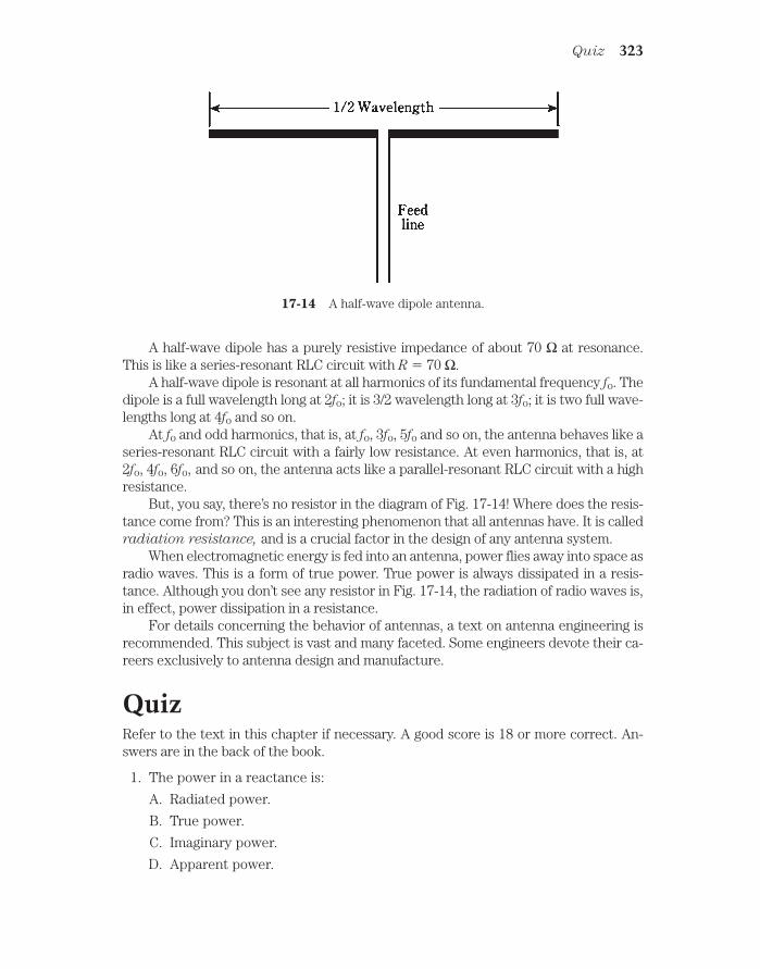
A half-wave dipole has a purely resistive impedance of about 70 Ω at resonance.This is like a series-resonant RLC circuit with R 70 Ω.
A half-wave dipole is resonant at all harmonics of its fundamental frequency fo. Thedipole is a full wavelength long at 2fo; it is 3/2 wavelength long at 3fo; it is two full wave-lengths long at 4fo and so on.
At fo and odd harmonics, that is, at fo, 3fo, 5fo and so on, the antenna behaves like aseries-resonant RLC circuit with a fairly low resistance. At even harmonics, that is, at2fo, 4fo, 6fo, and so on, the antenna acts like a parallel-resonant RLC circuit with a highresistance.
But, you say, there’s no resistor in the diagram of Fig. 17-14! Where does the resis-tance come from? This is an interesting phenomenon that all antennas have. It is calledradiation resistance, and is a crucial factor in the design of any antenna system.
When electromagnetic energy is fed into an antenna, power flies away into space asradio waves. This is a form of true power. True power is always dissipated in a resis-tance. Although you don’t see any resistor in Fig. 17-14, the radiation of radio waves is,in effect, power dissipation in a resistance.
For details concerning the behavior of antennas, a text on antenna engineering isrecommended. This subject is vast and many faceted. Some engineers devote their ca-reers exclusively to antenna design and manufacture.
QuizRefer to the text in this chapter if necessary. A good score is 18 or more correct. An-swers are in the back of the book.
1. The power in a reactance is:
A. Radiated power.
B. True power.
C. Imaginary power.
D. Apparent power.
Quiz 323
17-14 A half-wave dipole antenna.

2. Which of the following is not an example of true power?
A. Power that heats a resistor.
B. Power radiated from an antenna.
C. Power in a capacitor.
D. Heat loss in a feed line.
3. The apparent power in a circuit is 100 watts, and the imaginary power is 40watts. The true power is:
A. 92 watts.
B. 100 watts.
C. 140 watts.
D. Not determinable from this information.
4.Power factor is equal to:
A. Apparent power divided by true power.
B. Imaginary power divided by apparent power.
C. Imaginary power divided by true power.
D. True power divided by apparent power.
5. A circuit has a resistance of 300 W and an inductance of 13.5 µH in series at10.0 MHz. What is the power factor?
A. 0.334.
B. 0.999.
C. 0.595.
D. It can’t be found from the data given.
6. A series circuit has Z 88.4 Ω, with R 50.0 Ω. What is PF?
A. 99.9 percent.
B. 56.6 percent.
C. 60.5 percent.
D. 29.5 percent.
7. A series circuit has R 53.5 Ω and X 75.5 Ω. What is PF?
A. 70.9 percent.
B. 81.6 percent.
C. 57.8 percent.
D. 63.2 percent.
8. Phase angle is equal to:
A. Arctan Z/R.
B. Arctan R/Z.
324 Power and resonance in ac circuits
C. Arctan R/X.
D. Arctan X/R.
9. A wattmeter shows 220 watts of VA power in a circuit. There is a resistance of50 Ω in series with a capacitive reactance of −20 Ω. What is the true power?
A. 237 watts.
B. 204 watts.
C. 88.0 watts.
D. 81.6 watts.
10. A wattmeter shows 57 watts of VA power in a circuit. The resistance is knownto be 50 Ω, and the true power is known to be 40 watts. What is the absolute-valueimpedance?
A. 50 Ω.
B. 57 Ω.
C. 71 Ω.
D. It can’t be calculated from this data.
11. Which of the following is the most important consideration in a transmissionline?
A. The characteristic impedance.
B. The resistance.
C. Minimizing the loss.
D. The VA power.
12. Which of the following does not increase the loss in a transmission line?
A. Reducing the power output of the source.
B. Increasing the degree of mismatch between the line and the load.
C. Reducing the diameter of the line conductors.
D. Raising the frequency.
13. A problem that standing waves can cause is:
A. Feed line overheating.
B. Excessive power loss.
C. Inaccuracy in power measurement.
D. All of the above.
14. A coil and capacitor are in series. The inductance is 88 mH and the capacitanceis 1000 pF. What is the resonant frequency?
A. 17 kHz.
B. 540 Hz.
Quiz 325
C. 17 MHz.
D. 540 kHz.
15. A coil and capacitor are in parallel, with L 10.0 µH and C 10 pF. What is fo?
A. 15.9 kHz.
B. 5.04 MHz.
C. 15.9 MHz.
D. 50.4 MHz.
16. A series-resonant circuit is to be made for 14.1 MHz. A coil of 13.5 µH isavailable. What size capacitor is needed?
A. 0.945 µF.
B. 9.45 pF.
C. 94.5 pF.
D. 945 pF.
17. A parallel-resonant circuit is to be made for 21.3 MHz. A capacitor of 22.0 pF isavailable. What size coil is needed?
A. 2.54 mH.
B. 254 µH.
C. 25.4 µH.
D. 2.54 µH.
18. A 1/4-wave line section is made for 21.1 MHz, using cable with a velocity factorof 0.800. How many meters long is it?
A. 11.1 m.
B. 3.55 m.
C. 8.87 m.
D. 2.84 m.
19. The fourth harmonic of 800 kHz is:
A. 200 kHz.
B. 400 kHz.
C. 3.20 MHz.
D. 4.00 MHz.
20. How long is a 1/2-wave dipole for 3.60 MHz?
A. 130 feet.
B. 1680 feet.
C. 39.7 feet.
D. 515 feet.
326 Power and resonance in ac circuits

18CHAPTER
Transformers andimpedance matching
IN ELECTRICITY AND ELECTRONICS, TRANSFORMERS ARE EMPLOYED IN VARIOUSways . Transformers are used to obtain the right voltage for the operation of a circuit or sys-tem. Transformers can match impedances between a circuit and a load, or between two dif-ferent circuits. Transformers can be used to provide dc isolation between electronic circuitswhile letting ac pass. Another application is to mate balanced and unbalanced circuits, feedsystems, and loads.
Principle of the transformerWhen two wires are near each other, and one of them carries a fluctuating current, acurrent will be induced in the other wire. This effect is known as electromagnetic in-
duction. All ac transformers work according to the principle of electromagnetic induc-tion. If the first wire carries sine-wave ac of a certain frequency, then the induced
current will be sine-wave ac of the same frequency in the second wire.The closer the two wires are to each other, the greater the induced current will be,
for a given current in the first wire. If the wires are wound into coils and placed along acommon axis (Fig. 18-1), the induced current will be greater than if the wires arestraight and parallel. Even more coupling, or efficiency of induced-current transfer, isobtained if the two coils are wound one atop the other.
The first coil is called the primary winding, and the second coil is known as thesecondary winding. These are often spoken of as simply the primary and secondary.
The induced current creates a voltage across the secondary. In a step-down trans-former, the secondary voltage is less than the primary voltage. In a step-up transformer,the secondary voltage is greater than the primary voltage. The primary voltage is ab-breviated Epri, and the secondary voltage is abbreviated Esec. Unless otherwise stated,effective (rms) voltages are always specified.
The windings of a transformer have inductance because they are coils. The required327
!"# #$ !

inductances of the primary and secondary depend on the frequency of operation, andalso on the resistive part of the impedance in the circuit. As the frequency increases,the needed inductance decreases. At high-resistive impedances, more inductance isgenerally needed than at low-resistive impedances
328 Transformers and impedance matching
18-1 Magnetic flux between two coils of wire.
Turns ratioThe turns ratio in a transformer is the ratio of the number of turns in the primary, Tpri,to the number of turns in the secondary, Tsec. This ratio is written Tpri:Tsec or Tpri/Tsec.
In a transformer with excellent primary-to-secondary coupling, the following rela-tionship always holds:
Epri/Esec = Tpri/Tsec
That is, the primary-to-secondary voltage ratio is always equal to the primary-to-sec-ondary turns ratio (Fig. 18-2).
18-2 Primary and secondaryturns and voltages in atransformer. See text fordiscussion.
Problem 18-1A transformer has a primary-to-secondary turns ratio of exactly 9:1. The voltage at theprimary is 117 V. What is the voltage at the secondary?
This is a step-down transformer. Simply plug in the numbers in the above equationand solve for Esec:
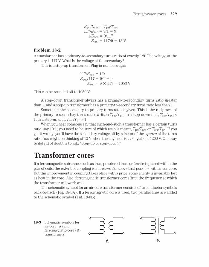
Epri/Esec Tpri/Tsec117/Esec 9/1 9
1/Esec 9/117Esec 117/9 13 V
Problem 18-2A transformer has a primary-to-secondary turns ratio of exactly 1:9. The voltage at theprimary is 117 V. What is the voltage at the secondary?
This is a step-up transformer. Plug in numbers again:
117/Esec 1/9Esec/117 9/1 9
Esec 9 117 1053 V
This can be rounded off to 1050 V.
A step-down transformer always has a primary-to-secondary turns ratio greaterthan 1, and a step-up transformer has a primary-to-secondary turns ratio less than 1.
Sometimes the secondary-to-primary turns ratio is given. This is the reciprocal ofthe primary-to-secondary turns ratio, written Tsec/Tpri. In a step-down unit, Tsec/Tpri <
1; in a step-up unit, Tsec/Tpri > 1.When you hear someone say that such-and-such a transformer has a certain turns
ratio, say 10:1, you need to be sure of which ratio is meant, Tpri/Tsec or Tsec/Tpri! If youget it wrong, you’ll have the secondary voltage off by a factor of the square of the turnsratio. You might be thinking of 12 V when the engineer is talking about 1200 V. One wayto get rid of doubt is to ask, “Step-up or step-down?”
Transformer coresIf a ferromagnetic substance such as iron, powdered iron, or ferrite is placed within thepair of coils, the extent of coupling is increased far above that possible with an air core.But this improvement in coupling takes place with a price; some energy is invariably lostas heat in the core. Also, ferromagnetic transformer cores limit the frequency at whichthe transformer will work well.
The schematic symbol for an air-core transformer consists of two inductor symbolsback-to-back (Fig. 18-3A). If a ferromagnetic core is used, two parallel lines are addedto the schematic symbol (Fig. 18-3B).
Transformer cores 329
18-3 Schematic symbols forair-core (A) andferromagnetic-core (B)transformers.

Laminated ironIn transformers for 60-Hz utility ac, and also at low audio frequencies, sheets of siliconsteel, glued together in layers, are often employed as transformer cores. The siliconsteel is sometimes called transformer iron, or simply iron.
The reason layering is used, rather than making the core from a single mass ofmetal, is that the magnetic fields from the coils cause currents to flow in a solid core.These eddy currents go in circles, heating up the core and wasting energy that wouldotherwise be transferred from the primary to the secondary. Eddy currents are chokedoff by breaking up the core into layers, so that currents cannot flow very well in circles.
Another type of loss, called hysteresis loss, occurs in any ferromagnetic trans-former core. Hysteresis is the tendency for a core material to be “sluggish” in acceptinga fluctuating magnetic field. Laminated cores exhibit high hysteresis loss above audiofrequencies, and are therefore not good above a few kilohertz.
Ferrite and powdered ironAt frequencies up to several megahertz, ferrite works well for radio-frequency (RF)transformers. This material has high permeability and concentrates the flux efficiently.High permeability reduces the number of turns needed in the coils. But at frequencieshigher than a few megahertz, ferrite begins to show loss, and is no longer effective.
For work well into the very-high-frequency (VHF) range, or up to 100 MHz ormore, powdered iron cores work well. The permeability of powdered iron is less thanthat of ferrite, but at high frequencies, it is not necessary to have high magnetic perme-ability. In fact, at radio frequencies above a few megahertz, air core coils are often pre-ferred, especially in transmitting amplifiers. At frequencies above several hundredmegahertz, ferromagnetic cores can be dispensed with entirely.
Transformer geometryThe shape of a transformer depends on the shape of its core. There are several differ-ent core geometries commonly used with transformers.
Utility transformersA common core for a power transformer is the E core, so named because it is shapedlike the capital letter E. A bar, placed at the open end of the E, completes the core oncethe coils have been wound on the E-shaped section (Fig. 18-4A).
The primary and secondary windings can be placed on an E core in either of twoways.
The simpler winding method is to put both the primary and the secondary aroundthe middle bar of the E (Fig. 18-4B). This is called the shell method of transformerwinding. It provides maximum coupling between the windings. However, the shell-winding scheme results in a considerable capacitance between the primary and thesecondary. This capacitance can sometimes be tolerated; sometimes it cannot. Anotherdisadvantage of the shell geometry is that, when windings are placed one atop the other,the transformer cannot handle very much voltage.
330 Transformers and impedance matching
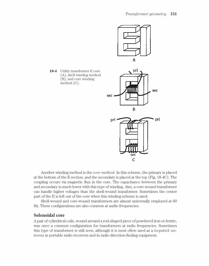
Another winding method is the core method. In this scheme, the primary is placedat the bottom of the E section, and the secondary is placed at the top (Fig. 18-4C). Thecoupling occurs via magnetic flux in the core. The capacitance between the primaryand secondary is much lower with this type of winding. Also, a core-wound transformercan handle higher voltages than the shell-wound transformer. Sometimes the centerpart of the E is left out of the core when this winding scheme is used.
Shell-wound and core-wound transformers are almost universally employed at 60Hz. These configurations are also common at audio frequencies.
Solenoidal coreA pair of cylindrical coils, wound around a rod-shaped piece of powdered iron or ferrite,was once a common configuration for transformers at radio frequencies. Sometimesthis type of transformer is still seen, although it is most often used as a loopstick an-
tenna in portable radio receivers and in radio direction-finding equipment.
Transformer geometry 331
18-4 Utility transformer E core(A), shell winding method(B), and core windingmethod (C).

The coil windings might be placed one atop the other, or they might be separated(Fig. 18-5) to reduce the capacitance between the primary and secondary.
332 Transformers and impedance matching
18-5 Solenoidal-coretransformer.
In a loopstick antenna, the primary serves to pick up the radio signals. The sec-ondary winding provides the best impedance match to the first amplifier stage, orfront end, of the radio. The use of transformers for impedance matching is discussedlater in this chapter.
Toroidal coreIn recent years, the toroidal core has become the norm for winding radio-frequencytransformers. The toroid is a donut-shaped ring of powdered iron or ferrite. The coilsare wound around the donut. The primary and secondary might be wound one over theother, or they might be wound over different parts of the core (Fig. 18-6). As with othertransformers, when the windings are one atop the other, there is more inter-winding ca-pacitance than when they are separate.
18-6 Toroidal-coretransformer.
Toroids confine practically all the magnetic flux within the core material. This al-lows toroidal coils and transformers to be placed near other components without in-ductive interaction. Also, a toroidal coil or transformer can be mounted directly on ametal chassis, and the operation will not be affected (assuming the wire is insulated).
A toroidal core provides considerably more inductance per turn, for the same kindof ferromagnetic material, than a solenoidal core. It is not uncommon to see toroidalcoils or transformers that have inductances of 10 mH or even 100 mH.
Pot coreStill more inductance per turn can be obtained with a pot core. This is a shell of ferro-magnetic material that wraps around a loop-shaped coil. The core comes in two

halves (Fig. 18-7). You wind the coil inside one of the halves, and then bolt the two to-gether. The final core completely surrounds the loop, and the magnetic flux is confinedto the core material.
The autotransformer 333
18-7 Exploded view of pot core (windings not shown).
Like the toroid, the pot core is self-shielding. There is essentially no coupling to ex-ternal components. A pot core can be used to wind a single, high-inductance coil; some-times the value can be upwards of 1 H.
In a pot-core transformer, the primary and secondary must always be wound on topof, or right next to, each other; this is unavoidable because of the geometry of the shell.Therefore, the interwinding capacitance of a pot-core transformer is always rather high.
Pot cores are useful at the lower frequencies. They are generally not employed athigher frequencies because it isn’t necessary to get that much inductance.
The autotransformerSometimes, it’s not necessary to provide dc isolation between the primary and sec-ondary windings of a transformer. Then an autotransformer can be used. This has asingle, tapped winding. Its schematic symbol is shown in Fig. 18-8A for an air core, andFig. 18-8B for a ferromagnetic core.
An autotransformer can be either a step-down or a step-up device. In Fig. 18-8, theautotransformer at A is step-down, and the one at B is step-up.
An autotransformer can have an air core, or it can be wound on any of the afore-mentioned types of ferromagnetic cores. You’ll sometimes see this type of transformerin a radio-frequency receiver or transmitter. It works quite well in impedance-matchingapplications, and also in solenoidal loopsticks.
Autotransformers are occasionally, but not often, used at audio frequencies and in60-Hz utility wiring. In utility circuits, autotransformers can step down by a large factor,but they aren’t used to step up by more than a few percent.

Power transformersAny transformer used in the 60-Hz utility line, intended to provide a certain rms ac volt-age for the operation of electrical circuits, is a power transformer. Power transformersexist in sizes ranging from smaller than a tennis ball to as big as a room.
At the generating plantThe largest transformers are employed right at the place where electricity is generated.Not surprisingly, high-energy power plants have bigger transformers that develophigher voltages than low-energy, local power plants. These transformers must be ableto handle not only huge voltages, but large currents as well. Their primaries and secon-daries must withstand a product EI of volt-amperes that is equal to the power P ulti-mately delivered by the transmission line.
When electrical energy must be sent over long distances, extremely high voltagesare used. This is because, for a given amount of power ultimately dissipated by theloads, the current is lower when the voltage is higher. Lower current translates into re-duced loss in the transmission line.
Recall the formula P EI, where P is the power in watts, E is the voltage in volts,and I is the current in amperes. If you can make the voltage 10 times larger, for a givenpower level, then the current is reduced to 1/10 as much. The ohmic losses in the wiresare proportional to the square of the current; remember that P I 2R, where P is thepower in watts, I is the current in amperes, and R is the resistance in ohms.
Engineers can’t do much about the wire resistance or the power consumed by theloads, but they can adjust the voltage, and thereby the current. Increasing the voltage10 times will cut the current to 0.1 its previous value. This will render the I 2R loss (0.1)2
0.01 (1 percent!) as much as before.For this reason, regional power plants have massive transformers capable of gener-
ating hundreds of thousands of volts. A few can produce 1,000,000 V rms. A transmis-sion line that carries this much voltage requires gigantic insulators, sometimes severalmeters long, and tall, sturdy towers.
334 Transformers and impedance matching
18-8 Schematic symbols for autotransformers. At A, air coreand at B, ferromagnetic core. The unit at A steps downand the one at B steps up.

Along the lineExtreme voltage is good for high-tension power transmission, but it’s certainly of nouse to an average consumer. The wiring in a high-tension system must be done usingprecautions to prevent arcing (sparking) and short circuits. Personnel must be kept atleast several feet, or even tens of feet, away from the wires. Can you imagine trying touse an appliance, say a home computer, by plugging it into a 500-kV electrical outlet? Abolt of artificial lightning would dispatch you before you even got near the receptacle.
Medium-voltage power lines branch out from the major lines, and step-down trans-formers are used at the branch points. These lines fan out to still lower-voltage lines,and step-down transformers are employed at these points, too. Each transformer musthave windings heavy enough to withstand the product P EI, the amount of power de-livered to all the subscribers served by that transformer, at periods of peak demand.
Sometimes, such as during a heat wave, the demand for electricity rises above thenormal peak level. This loads down the circuit to the point that the voltage drops sev-eral percent. This is a brownout. If consumption rises further still, a dangerous currentload is placed on one or more intermediate power transformers. Circuit breakers in thetransformers protect them from destruction by opening the circuit. Then there is a tem-porary blackout.
Finally, at individual homes and buildings, transformers step the voltage down to ei-ther 234 V or 117 V. Usually, 234-V electricity is in three phases, each separated by 120degrees, and each appearing at one of the three prongs in the outlet (Fig. 18-9A). Thisvoltage is commonly employed with heavy appliances, such as the kitchen oven/stove(if they are electric), heating (if it is electric), and the laundry washer and dryer. A117-V outlet supplies just one phase, appearing between two of the three prongs in theoutlet. The third prong is for ground (Fig. 18-9B).
Power transformers 335
18-9 At A, three-phase,234-Vac outlet. At B,single-phase, 117-Vacoutlet.
In electronic devicesThe lowest level of power transformer is found in electronic equipment such as televi-sion sets, ham radios, and home computers.

Most solid-state devices use low voltages, ranging from about 5 V up to perhaps 50V. This equipment needs step-down power transformers in its power supplies.Solid-state equipment usually (but not always) consumes relatively little power, so thetransformers are usually not very bulky. The exception is high-powered audio-fre-quency or radio-frequency amplifiers, whose transistors can demand more than 1000watts (1 kW) in some cases. At 12 V, this translates to 90 A or more.
Television sets have cathode-ray tubes that need several hundred volts. This is de-rived by using a step-up transformer in the power supply. Such transformers don’t haveto supply a lot of current, though, so they are not very big or heavy. Another type of de-vice that needs rather high voltage is a ham-radio amplifier with vacuum tubes. Such anamplifier requires from 2 kV to 5 kV.
Any voltage higher than about 12 V should be treated with respect. The voltages
in televisions and ham radios are extremely dangerous, even after the equipment
has been switched off. Do not try to service such equipment unless you are trained
to do so!
Audio-frequency transformersTransformers for use at audio frequency (AF) are similar to those employed for 60-Hzelectricity. The differences are that the frequency is somewhat higher (up to 20 kHz),and that audio signals exist in a band of frequencies (20 Hz to 20 kHz) rather than atjust one frequency.
Most audio transformers look like, and are constructed like miniature utility trans-formers. They have laminated E cores with primary and secondary windings woundaround the cross bars, as shown in Fig. 18-4.
Audio transformers can be either the step-up or step-down type. However, ratherthan being made to produce a specific voltage, audio transformers are designed tomatch impedances.
Audio circuits, and in fact all electronic circuits that handle sine-wave or com-plex-wave signals, exhibit impedance at the input and output. The load has a certainimpedance; a source has another impedance. Good audio design strives to minimizethe reactances in the circuitry, so that the absolute-value impedance, Z, is close tothe resistance R in the complex vector R + jX. This means that X must be zero ornearly zero.
In the following discussion of impedance-matching transformers, both at audio andat radio frequencies, assume that the reactance is zero, so that the impedance is purelyresistive, that is, Z R.
Isolation transformersOne useful function of a transformer is that it can provide isolation between electroniccircuits. While there is inductive coupling in a transformer, there is comparatively lit-tle capacitive coupling. The amount of capacitive coupling can be reduced by usingcores that minimize the number of wire turns needed in the windings, and by keepingthe windings separate from each other (rather than overlapping).
336 Transformers and impedance matching

Balanced and unbalanced loadsA balanced load is one whose terminals can be reversed without significantly affectingcircuit behavior. A plain resistor is a good example. The two-wire antenna input in atelevision receiver is another example of a balanced load. A balanced transmission
line is usually a two-wire line, such as television antenna ribbon.An unbalanced load is a load that must be connected a certain way; switching its
leads will result in improper circuit operation. Some radio antennas are of this type.Usually, unbalanced sources and loads have one side connected to ground. The coaxialinput of a television receiver is unbalanced; the shield (braid) of the cable is grounded.An unbalanced transmission line is usually a coaxial line, such as you find in a cabletelevision system.
Normally, you cannot connect an unbalanced line to a balanced load, or a balancedline to an unbalanced load, and expect good performance from an electrical or electronicsystem. But a transformer can allow for mating between these two types of systems.
In Fig. 18-10A, a balanced-to-unbalanced transformer is shown. Note that the bal-anced side is center-tapped, and the tap is grounded. In Fig. 18-10B, an unbalanced-to-balanced transformer is illustrated. Again, the balanced side has a grounded center tap.
Isolation transformers 337
18-10 At A, a balanced-to-unbalanced transformer. At B, anunbalanced-to-balanced transformer.
The turns ratio of a balanced-to-unbalanced (“balun”) or unbalanced-to-balanced(“unbal”) transformer might be 1:1, but it doesn’t have to be. If the impedances of the

balanced and unbalanced parts of the systems are the same, then a 1:1 turns ratio isideal. But if the impedances differ, the turns ratio should be such that the impedancesare matched. This is discussed in the section on impedance transfer ratio that follows.
Transformer couplingTransformers are sometimes used between amplifier stages in electronic equipmentwhere a large amplification factor is needed. There are other methods of coupling
from one amplifier stage to another, but transformers offer some advantages, especiallyin radio-frequency receivers and transmitters.
Part of the problem in getting a radio to work is that the amplifiers must operate ina stable manner. If there is too much feedback, a series of amplifiers will oscillate, andthis will severely degrade the performance of the radio. Transformers that minimize thecapacitance between the amplifier stages, while still transferring the desired signals,can help to prevent this oscillation.
Impedance-transfer ratioOne of the most important applications of transformers is in audio-frequency (AF) andradio-frequency (RF) electronic circuits. In these applications, transformers are gener-ally employed to match impedances. Thus, you might hear of an impedance step-up
transformer, or an impedance step-down device.The impedance-transfer ratio of a transformer varies according to the square of
the turns ratio, and also according to the square of the voltage-transfer ratio. Recall theformula for voltage-transfer ratio:
Epri/Esec Tpri/Tsec
If the input and output, or source and load, impedances are purely resistive, andare denoted by Zpri (at the primary winding) and Zsec (at the secondary), then
Zpri/Zsec (Tpri/Tsec)2
and
Zpri/Zsec (Epri/Esec)2
The inverses of these formulas, in which the turns ratio or voltage-transfer ratio are ex-pressed in terms of the impedance-transfer ratio, are
Tpri/Tsec (Zpri/Zsec)1/2
and
Epri/Esec (Zpri/Zsec)1/2
The 1/2 power is the same thing as the square root.
Problem 18-3A transformer is needed to match an input impedance of 50.0 Ω, purely resistive, to anoutput impedance of 300 Ω, also purely resistive. What should the ratio Tpri/Tsec be?
338 Transformers and impedance matching

The required transformer will have a step-up impedance ratio of Zpri/Zsec 50.0/300 1:6.00. From the above formulas,
Tpri/Tsec (Zpri/Zsec)1/2
(1/6.00)1/2 0.166671/2 0.40829
A couple of extra digits are included (as they show up on the calculator) to preventthe sort of error introduction you recall from earlier chapters. The decimal value0.40829 can be changed into ratio notation by taking its reciprocal, and then writing “1:”followed by that reciprocal value
0.40829 1:(1/0.40829) 1:2.4492
This can be rounded to three significant figures, or 1:2.45. This is the primary-to-secondary turns ratio for the transformer. The secondary winding has 2.45 times asmany turns as the primary winding.
Problem 18-4A transformer has a primary-to-secondary turns ratio of 4.00:1. The load, connected to thetransformer output, is a pure resistance of 37.5 Ω. What is the impedance at the primary?
The impedance-transfer ratio is equal to the square of the turns ratio. Therefore,
Zpri/Zsec (Tpri/Tsec)2
(4.00/1)2 4.002 16.0
This can be written 16.0:1. The input (primary) impedance is 16.0 times the sec-ondary impedance. We know that the secondary impedance, Zsec is 37.5 Ω. Therefore,
Zpri 16.0 Zsec 16.0 37.5 600
Anything connected to the transformer primary will “see” a purely resistive imped-ance of 600 Ω.
Radio-frequency transformersIn radio receivers and transmitters, transformers can be categorized generally by themethod of construction used. Some have primary and secondary windings, just like util-ity and audio units. Others employ transmission-line sections. These are the two mostcommon types of transformer found at radio frequencies.
Coil typesIn the wound radio-frequency (RF) transformer, powdered-iron cores can be used upto quite high frequencies. Toroidal cores are most common, because they areself-shielding (all of the magnetic flux is confined within the core material). The num-ber of turns depends on the frequency, and also on the permeability of the core.
In high-power applications, air-core coils are sometimes used, because air, althoughit has a low permeability, also has extremely low hysteresis loss. The disadvantage of
Radio-frequency transformers 339

air-core coils is that some of the magnetic flux extends outside of the coil. This affectsthe performance of the transformer when it must be placed in a cramped space, such asin a transmitter final-amplifier compartment.
A major advantage of coil type transformers, especially when they are wound ontoroidal cores, is that they can be made to work over a wide band of frequencies, suchas from 3.5 MHz to 30 MHz. These are called broadband transformers.
Transmission-line typesAs you recall, any transmission line has a characteristic impedance, or Zo, that dependson the line construction. This property is sometimes used to make impedance trans-formers out of coaxial or parallel-wire line.
Transmission-line transformers are always made from quarter-wave sections. Fromthe previous chapter, remember the formula for the length of a quarter-wave section,that is,
Lft 246v/fo
where Lft is the length of the section in feet, v is the velocity factor expressed as a frac-tion, and fo is the frequency of operation in megahertz. If the length Lm is in meters,then:
Lm 75v/fo
In the last chapter, you saw how a short circuit is changed into an open circuit, andvice versa, by a quarter-wave section of line. What happens to a pure resistive imped-ance at one end of such a line? What will be “seen” at the opposite end?
Let a quarter-wave section of line, with characteristic impedance Zo, be terminatedin a purely resistive impedance Rout. Then the input impedance is also a pure resistanceRin, and the following relationship holds:
Zo2 RinRout
This is illustrated in Fig. 18-11. This formula can be broken down to solve for Rin interms of Rout , or vice versa:
Rin Zo2/Rout
and
Rout Zo2/Rin.
These relationships hold at the frequency, fo, for which the line is 1/4 wavelength long.Neglecting line losses, these relationships will also hold at the odd harmonics of fo, thatis, at 3fo, 5fo, 7fo, and so on. At other frequencies, the line will not act as a transformer,but instead, will behave in complicated ways that are beyond the scope of this discus-sion.
Quarter-wave transformers are most often used in antenna systems, especially atthe higher frequencies, where their dimensions become practical.
Problem 18-5An antenna has a purely resistive impedance of 100 Ω. It is connected to a 1/4-wave sec-tion of 75-Ω coaxial cable. What will be the impedance at the input end of the section?
Use the formula from above:
340 Transformers and impedance matching

Rin Zo2/Rout
752/100 5625/100 56 Ω
Problem 18-6An antenna is known to have a pure resistance of 600 Ω. You want to match it to 50.0 Ωpure resistance. What is the characteristic impedance needed for a quarter-wavematching section?
Use this formula:
Zo2 RinRout
Zo2 600 50 30,000
Zo2 (30,000)1/2 173 Ω
The challenge is to find a line that has this particular Zo. Commercially manufacturedlines come in standard Zo values, and a perfect match might not be obtainable. In thatcase, the closest obtainable Zo should be used. In this case, it would probably be 150 Ω.
If nothing is available anywhere near the characteristic impedance needed for aquarter-wave matching section, then a coil-type transformer will probably have to beused instead. A quarter-wave matching section should be made using unbalanced line ifthe load is unbalanced and balanced line if the load is balanced.
The major disadvantage of quarter-wave sections is that they work only at specificfrequencies. But this is often offset by the ease with which they are constructed, if ra-dio equipment is to be used at only one frequency, or at odd-harmonic frequencies.
What about reactance?Things are simple when there is no reactance in an ac circuit using transformers. But of-ten, especially in radio-frequency circuits, pure resistance doesn’t occur naturally. It hasto be obtained by using inductors and/or capacitors to cancel the reactance out.
What about reactance? 341
18-11 A quarter-wave matching section of transmission line.Abbreviations are discussed in the text.

Reactance makes a perfect match impossible, no matter what the turns ratio or Zoof the transformer. A small amount of reactance can be tolerated at lower radio fre-quencies (below about 30 MHz). A near-perfect match becomes more important athigher frequencies.
The behavior of reactance, as it is coupled through transformer windings, is toocomplicated for a thorough analysis here. But if you’re interested in delving into it, thereare plenty of good engineering texts that deal with it in all its mathematical glory.
Recall that inductive and capacitive reactances are opposite in effect, and that theirmagnitudes can vary. If a load presents a complex impedance R + jX, with X not equalto zero, it is always possible to cancel out the reactance X by adding an equal and op-posite reactance (−X) in the circuit. This can be done by connecting an inductor or ca-pacitor in series with the load.
For radio communications over a wide band, adjustable impedance-matching andreactance-canceling networks can be placed between a transmitter and an antenna sys-tem. Such a device is called a transmatch and is popular among radio hams, who usefrequencies ranging from 1.8 MHz to the microwave spectrum.
QuizRefer to the text in this chapter if necessary. A good score is 18 or more correct. An-swers are in the back of the book.
1. In a step-up transformer:
A. The primary impedance is greater than the secondary impedance.
B. The secondary winding is right on top of the primary.
C. The primary voltage is less than the secondary voltage.
D. All of the above.
2. The capacitance between the primary and the secondary windings of atransformer can be minimized by:
A. Placing the windings on opposite sides of a toroidal core.
B. Winding the secondary right on top of the primary.
C. Using the highest possible frequency.
D. Using a center tap on the balanced winding.
3. A transformer steps a voltage down from 117 V to 6.00 V. What is itsprimary-to-secondary turns ratio?
A. 1:380.
B. 380:1.
C. 1:19.5.
D. 19.5:1.
4. A step-up transformer has a primary-to-secondary turns ratio of 1:5.00. If 117V rms appears at the primary, what is the rms voltage across the secondary?
A. 23.4 V.
342 Transformers and impedance matching

B. 585 V.
C. 117 V.
D. 2.93 kV.
5. A transformer has a secondary-to-primary turns ratio of 0.167. Thistransformer is:
A. A step-up unit.
B. A step-down unit.
C. Neither step-up nor step-down.
D. A reversible unit.
6. Which of the following is false, concerning air cores versus ferromagnetic cores?
A. Air concentrates the magnetic lines of flux.
B. Air works at higher frequencies than ferromagnetics.
C. Ferromagnetics are lossier than air.
D. A ferromagnetic-core unit needs fewer turns of wire than an equivalentair-core unit.
7. Eddy currents cause:
A. An increase in efficiency.
B. An increase in coupling between windings.
C. An increase in core loss.
D. An increase in usable frequency range.
8. A transformer has 117 V rms across its primary and 234 V rms across itssecondary. If this unit is reversed, assuming it can be done without damaging thewindings, what will be the voltage at the output?
A. 234 V.
B. 468 V.
C. 117 V.
D. 58.5 V.
9. The shell method of transformer winding:
A. Provides maximum coupling.
B. Minimizes capacitance between windings.
C. Withstands more voltage than other winding methods.
D. Has windings far apart but along a common axis.
10. Which of these core types, in general, is best if you need a winding inductanceof 1.5 H?
A. Air core.
B. Ferromagnetic solenoid core.
C. Ferromagnetic toroid core.
D. Ferromagnetic pot core.
Quiz 343

11. An advantage of a toroid core over a solenoid core is:
A. The toroid works at higher frequencies.
B. The toroid confines the magnetic flux.
C. The toroid can work for dc as well as for ac.
D. It’s easier to wind the turns on a toroid.
12. High voltage is used in long-distance power transmission because:
A. It is easier to regulate than low voltage.
B. The I2R losses are lower.
C. The electromagnetic fields are stronger.
D. Smaller transformers can be used.
13. In a household circuit, the 234-V power has:
A. One phase.
B. Two phases.
C. Three phases.
D. Four phases.
14. In a transformer, a center tap would probably be found in:
A. The primary winding.
B. The secondary winding.
C. The unbalanced winding.
D. The balanced winding.
15. An autotransformer:
A. Works automatically.
B. Has a center-tapped secondary.
C. Has one tapped winding.
D. Is useful only for impedance matching.
16. A transformer has a primary-to-secondary turns ratio of 2.00:1. The inputimpedance is 300 Ω resistive. What is the output impedance?
A. 75 Ω.
B. 150 Ω.
C. 600 Ω.
D. 1200 Ω.
17. A resistive input impedance of 50 Ω must be matched to a resistive outputimpedance of 450 Ω. The primary-to-secondary turns ratio of the transformer mustbe:
A. 9.00:1.
B. 3.00:1.
344 Transformers and impedance matching

C. 1:3.00.
D. 1:9.00.
18. A quarter-wave matching section has a characteristic impedance of 75.0 Ω. Theinput impedance is 50.0 Ω resistive. What is the resistive output impedance?
A. 150 Ω.
B. 125 Ω.
C. 100 Ω.
D. 113 Ω.
19. A resistive impedance of 75 Ω must be matched to a resistive impedance of300 Ω. A quarter-wave section would need:
A. Zo 188 Ω.
B. Zo 150 Ω.
C. Zo 225 Ω.
D. Zo 375 Ω.
20. If there is reactance at the output of an impedance transformer:
A. The circuit will not work.
B. There will be an impedance mismatch, no matter what the turns ratio of thetransformer.
C. A center tap must be used at the secondary.
D. The turns ratio must be changed to obtain a match.
Qiiz 345

Test: Part twoDO NOT REFER TO THE TEXT WHEN TAKING THIS TEST. A GOOD SCORE IS ATleast 37 correct. Answers are in the back of the book. It’s best to have a friend check yourscore the first time, so you won’t memorize the answers if you want to take the testagain.
1. A series circuit has a resistance of 100 Ω and a capacitive reactance of -200 Ω.The complex impedance is:
A. 200 j100.
B. 100 j200.
C. 200 j100.
D. 200 j100.
E. 100 j200.
2. Mutual inductance causes the net value of a set of coils to:
A. Cancel out, resulting in zero inductance.
B. Be greater than what it would be with no mutual coupling.
C. Be less than what it would be with no mutual coupling.
D. Double.
E. Vary, depending on the extent and phase of mutual coupling.
3. Refer to Fig. TEST 2-1. Wave A is:
A. Leading wave B by 90 degrees.
B. Lagging wave B by 90 degrees.
C. Leading wave B by 180 degrees.
D. Lagging wave B by 135 degrees.
346

4. A sine wave has a peak value of 30.0 V. Its rms value is:
A. 21.2 V.
B. 30.0 V.
C. 42.4 V.
D. 60.0 V.
E. 90.0 V.
5. Four capacitors are connected in parallel. Their values are 100 pF each. Thenet capacitance is:
A. 25 pF.
B. 50 pF.
C. 100 pF.
D. 200 pF.
E. 400 pF.
6. A transformer has a primary-to-secondary turns ratio of exactly 8.88:1. Theinput voltage is 234 V rms. The output voltage is:
A. 2.08 kV rms.
B. 18.5 kV rms.
C. 2.97 V rms.
D. 26.4 V rms.
E. 20.8 V rms.
7. In a series RL circuit, as the resistance becomes small compared with thereactance, the angle of lag approaches:
A. 0 degrees.
Test: Part two 347
TEST 2-1 Illustration for PART TWO test question 3.
E. Lagging wave B by 45 degrees.
B. 45 degrees.
C. 90 degrees.
D. 180 degrees.
E. 360 degrees.
8. A transmission line carries 3.50 A of ac current and 150 V ac. The true power
in the line is:
A. 525 W.
B. 42.9 W.
C. 1.84 W.
D. Meaningless; true power is dissipated, not transmitted.
E. Variable, depending on standing wave effects.
9. In a parallel configuration, susceptances:
A. Simply add up.
B. Add like capacitances in series.
C. Add like inductances in parallel.
D. Must be changed to reactances before you can work with them.
E. Cancel out.
10. A wave has a frequency of 200 kHz. How many degrees of phase change occurin a microsecond (a millionth of a second)?
A. 180 degrees.
B. 144 degrees.
C. 120 degrees.
D. 90 degrees.
E. 72 degrees.
11. At a frequency of 2.55 MHz, a 330-pF capacitor has a reactance of:
A. −5.28 Ω.
B. −0.00528 Ω.
C. −189 Ω.
D. −18.9k Ω.
E. −0.000189 Ω.
12. A transformer has a step-up turns ratio of 1:3.16. The output impedance is 499Ω purely resistive. The input impedance is:
A. 50.0 Ω.
B. 158 Ω.
C. 1.58k Ω.
D. 4.98k Ω.
E. Not determinable from the data given.
348 Test: Part two

13. A complex impedance is represented by 34 − j23. The absolute-valueimpedance is:
A. 34 Ω.
B. 11 Ω.
C. 23 Ω.
D. 41 Ω.
E. 57 Ω.
14. A coil has an inductance of 750 µH. The inductive reactance at 100 kHz is:
A. 75.0 Ω.
B. 75.0 kΩ.
C. 471 Ω.
D. 47.1 kΩ.
E. 212 Ω.
15. Two waves are 180 degrees out of phase. This is a difference of:
A. 1/8 cycle.
B. 1/4 cycle.
C. 1/2 cycle.
D. A full cycle.
E. Two full cycles.
16. If R denotes resistance and Z denotes absolute-value impedance, then R/Z isthe:
A. True power.
B. Imaginary power.
C. Apparent power.
D. Absolute-value power.
E. Power factor.
17. Two complex impedances are in series. One is 30 + j50 and the other is 50 −j30. The net impedance is:
A. 80 + j80.
B. 20 + j20.
C. 20 j20.
D. 20 + j20.
E. 80 + j20.
18. Two inductors, having values of 140 µH and 1.50 mH, are connected in series.The net inductance is:
A. 141.5 µH.
B. 1.64 µH.
Test: Part two 349

C. 0.1415 mH.
D. 1.64 mH.
E. 0.164 mH.
19. Which of the following types of capacitor is polarized?
A. Mica.
B. Paper.
C. Electrolytic.
D. Air variable.
E. Ceramic.
20. A toroidal-core coil:
A. Has lower inductance than an air-core coil with the same number of turns.
B. Is essentially self-shielding.
C. Works well as a loopstick antenna.
D. Is ideal as a transmission-line transformer.
E. Cannot be used at frequencies below about 10 MHz.
21. The efficiency of a generator:
A. Depends on the driving power source.
B. Is equal to output power divided by driving power.
C. Depends on the nature of the load.
D. Is equal to driving voltage divided by output voltage.
E. Is equal to driving current divided by output current.
22. Admittance is:
A. The reciprocal of reactance.
B. The reciprocal of resistance.
C. A measure of the opposition a circuit offers to ac.
D. A measure of the ease with which a circuit passes ac.
E. Another expression for absolute-value impedance.
23. The absolute-value impedance Z of a parallel RLC circuit, where R is theresistance and X is the net reactance, is found according to the formula:
A. Z R + X.
B. Z2 R2 + X2.
C. Z2 RX/(R2 + X2).
D. Z 1/(R2 + X2).
E. Z R2X2/(R + X).
24. Complex numbers are used to represent impedance because:
A. Reactance cannot store power.
350 Test: Part two
B. Reactance isn’t a real physical thing.
C. They provide a way to represent what happens in resistance-reactancecircuits.
D. Engineers like to work with sophisticated mathematics.
E. No! Complex numbers aren’t used to represent impedance.
25. Which of the following does not affect the capacitance of a capacitor?
A. The mutual surface area of the plates.
B. The dielectric constant of the material between the plates (within reason).
C. The spacing between the plates (within reason).
D. The amount of overlap between plates.
E. The frequency (within reason).
26. The zero-degree phase point in an ac sine wave is usually considered to be theinstant at which the amplitude is:
A. Zero and negative-going.
B. At its negative peak.
C. Zero and positive-going.
D. At its positive peak.
E. Any value; it doesn’t matter.
27. The inductance of a coil can be continuously varied by:
A. Varying the frequency.
B. Varying the net core permeability.
C. Varying the current in the coil.
D. Varying the wavelength.
E. Varying the voltage across the coil.
28. Power factor is defined as the ratio of:
A. True power to VA power.
B. True power to imaginary power.
C. Imaginary power to VA power.
D. Imaginary power to true power.
E. VA power to true power.
29. A 50 Ω feed line needs to be matched to an antenna with a purely resistiveimpedance of 200 Ω. A quarter-wave matching section should have:
A. Zo 150 Ω.
B. Zo 250 Ω.
C. Zo 125 Ω.
D. Zo 133 Ω.
E. Zo 100 Ω.
Test: Part two 351

30. The vector 40 + j30 represents:
A. 40 Ω resistance and 30 µH inductance.
B. 40 uH inductance and 30 Ω resistance.
C. 40 Ω resistance and 30 Ω inductive reactance.
D. 40 Ω inductive reactance and 30 Ω resistance.
E. 40 uH inductive reactance and 30 Ω resistance.
31. In a series RC circuit, where, R 300 Ω and XC −30 Ω:
A. The current leads the voltage by a few degrees.
B. The current leads the voltage by almost 90 degrees.
C. The voltage leads the current by a few degrees.
D. The voltage leads the current by almost 90 degrees.
E. The voltage leads the current by 90 degrees.
32. In a step-down transformer:
A. The primary voltage is greater than the secondary voltage.
B. The primary impedance is less than the secondary impedance.
C. The secondary voltage is greater than the primary voltage.
D. The output frequency is higher than the input frequency.
E. The output frequency is lower than the input frequency.
33. A capacitor of 470 pF is in parallel with an inductor of 4.44 µH. What is theresonant frequency?
A. 3.49 MHz.
B. 3.49 kHz.
C. 13.0 MHz.
D. 13.0 GHz.
E. Not determinable from the data given.
34. A sine wave contains energy at:
A. Just one frequency.
B. A frequency and its even harmonics.
C. A frequency and its odd harmonics.
D. A frequency and all its harmonics.
E. A frequency and its second harmonic only.
35. Inductive susceptance is:
A. The reciprocal of inductance.
B. Negative imaginary.
C. Equal to capacitive reactance.
D. The reciprocal of capacitive susceptance.
E. A measure of the opposition a coil offers to ac.
352 Test: Part two

36. The rate of change (derivative) of a sine wave is itself a wave that:
A. Is in phase with the original wave.
B. Is 180 degrees out of phase with the original wave.
C. Leads the original wave by 45 degrees of phase.
D. Lags the original wave by 90 degrees of phase.
E. Leads the original wave by 90 degrees of phase.
37. True power is equal to:
A. VA power plus imaginary power.
B. Imaginary power minus VA power.
C. Vector difference of VA and reactive power.
D. VA power; the two are the same thing.
E. 0.707 times the VA power.
38. Three capacitors are connected in series. Their values are 47 µF, 68 µF, and100 µF. The total capacitance is:
A. 215 µF.
B. Between 68 µF and 100 µF.
C. Between 47 µF and 68 µF.
D. 22 µF.
E. Not determinable from the data given.
39. The reactance of a section of transmission line depends on all of the followingexcept:
A. The velocity factor of the line.
B. The length of the section.
C. The current in the line.
D. The frequency.
E. The wavelength.
40. When confronted with a parallel RLC circuit and you need to find the compleximpedance:
A. Just add the resistance and reactance to get R + jX.
B. Find the net conductance and susceptance, then convert to resistance andreactance, and add these to get R + jX.
C. Find the net conductance and susceptance, and just add these together toget R + jX.
D. Rearrange the components so they’re in series, and find the compleximpedance of that circuit.
E. Subtract reactance from resistance to get R − jX.
41. The illustration in Fig. Test 2-2 shows a vector R + jX representing:
A. XC 60 Ω and R 25 Ω.
Test: part two 353

B. XL 60 Ω and R 25 Ω.
C. XL 60 µH and R 25 Ω.
D. C 60 µF and R 25 Ω.
E. L 60 µH and R 25 Ω.
354 Test: Part two
TEST 2-2 Illustration forPART TWO testquestion 41.
42. If two sine waves have the same frequency and the same amplitude, but theycancel out, the phase difference is:
A. 45 degrees.
B. 90 degrees.
C. 180 degrees.
D. 270 degrees.
E. 360 degrees.
43. A series circuit has a resistance of 50 Ω and a capacitive reactance of −37 Ω.
The phase angle is:
A. 37 degrees.
B. 53 degrees.
C. −37 degrees.
D. −53 degrees.
E. Not determinable from the data given.
44. A 200-Ω resistor is in series with a coil and capacitor; XL 200 Ω and XC −100 Ω. The complex impedance is:
A. 200 − j100.

B. 200 − j200.
C. 200 + j100.
D. 200 + j200.
E. Not determinable from the data given.
45. The characteristic impedance of a transmission line:
A. Is negative imaginary.
B. Is positive imaginary.
C. Depends on the frequency.
D. Depends on the construction of the line.
E. Depends on the length of the line.
46. The period of a wave is 2 10−8 second. The frequency is:
A. 2 108 Hz.
B. 20 MHz.
C. 50 kHz.
D. 50 MHz.
E. 500 MHz.
47. A series circuit has a resistance of 600 Ω and a capacitance of 220 pF. Thephase angle is:
A. −20 degrees.
B. 20 degrees.
C. −70 degrees.
D. 70 degrees.
E. Not determinable from the data given.
48. A capacitor with a negative temperature coefficient:
A. Works less well as the temperature increases.
B. Works better as the temperature increases.
C. Heats up as its value is made larger.
D. Cools down as its value is made larger.
E. Has increasing capacitance as temperature goes down.
49. Three coils are connected in parallel. Each has an inductance of 300µH. Thereis no mutual inductance. The net inductance is:
A. 100 µH.
B. 300 µH.
C. 900 µH.
D. 17.3 µH.
E. 173 µH.
Test: Part two 355

50. An inductor shows 100 Ω of reactance at 30.0 MHz. What is its inductance?
A. 0.531 µH.
B. 18.8 mH.
C. 531 µH.
D. 18.8 µH.
E. It can’t be found from the data given.
356 Test: Part two

3PART
Basic electronics

This page intentionally left blank

19CHAPTER
Introduction tosemiconductors
SINCE THE SIXTIES, WHEN THE TRANSISTOR BECAME COMMON IN CONSUMERdevices, semiconductors have acquired a dominating role in electronics. This chapterexplains what semiconducting materials actually are.
You’ve learned about electrical conductors, which pass current easily, and about in-sulators, which block the current flow. A semiconductor can sometimes act like a con-ductor, and at other times like an insulator in the same circuit.
The term semiconductor arises from the ability of these materials to conduct “parttime.” Their versatility lies in the fact that the conductivity can be controlled to produceeffects such as amplification, rectification, oscillation, signal mixing, and switching.
The semiconductor revolution It wasn’t too long ago that vacuum tubes were the backbone of electronic equipment.Even in radio receivers and “portable” television sets, all of the amplifiers, oscillators,detectors, and other circuits required these devices. A typical vacuum tube ranged fromthe size of your thumb to the size of your fist.
A radio might sit on a table in the living room; if you wanted to listen to it, you wouldturn it on and wait for the tube filaments to warm up. I can remember this. It makes mefeel like an old man to think about it.
Vacuum tubes, sometimes called “tubes” or “valves” (in England), are still used insome power amplifiers, microwave oscillators, and video display units. There are a fewplaces where tubes work better than semiconductor devices. Tubes tolerate momentaryvoltage and current surges better than semiconductors. They are discussed in chapter 29.
Tubes need rather high voltages to work. Even in radio receivers, turntables, andother consumer devices, 100 V to 200 V dc was required when tubes were employed.This mandated bulky power supplies and created an electrical shock hazard.
359 !
"# #$ !

Nowadays, a transistor about the size of a pencil eraser can perform the functionsof a tube in most situations. Often, the power supply can be a couple of AA cells or a 9-V“transistor battery.”
Figure 19-1 is a size comparison drawing between a typical transistor and a typicalvacuum tube.
360 Introduction to semiconductors
19-1 Transistors are smallerthan tubes.
Integrated circuits, hardly larger than individual transistors, can do the work ofhundreds or even thousands of vacuum tubes. An excellent example of this technologyis found in the personal computer, or PC. In 1950, a “PC” would have occupied a largebuilding, required thousands of watts to operate, and probably cost well over a milliondollars. Today you can buy one and carry it in a briefcase. Integrated-circuit technologyis discussed in chapter 28.
Semiconductor materialsThere are numerous different mixtures of elements that work as semiconductors. Thetwo most common materials are silicon and a compound of gallium and arsenic knownas gallium arsenide (often abbreviated GaAs).
In the early years of semiconductor technology, germanium formed the basis formany semiconductors; today it is seen occasionally, but not often. Other substancesthat work as semiconductors are selenium, cadmium compounds, indium compounds,and various metal oxides.
Many of the elements found in semiconductors can be mined from the earth. Oth-ers are “grown” as crystals under laboratory conditions.
SiliconSilicon (chemical symbol Si) is widely used in diodes, transistors, and integrated cir-cuits. Generally, other substances, or impurities, must be added to silicon to give it thedesired properties. The best quality silicon is obtained by growing crystals in a labora-tory. The silicon is then fabricated into wafers or chips.
Gallium arsenideAnother common semiconductor is the compound gallium arsenide. Engineers andtechnicians call this material by its acronym-like chemical symbol, GaAs, pronounced“gas.” If you hear about “gasfets” and “gas ICs,” you’re hearing about gallium-arsenidetechnology.

Gallium arsenide works better than silicon in several ways. It needs less voltage,and will function at higher frequencies because the charge carriers move faster. GaAsdevices are relatively immune to the effects of ionizing radiation such as X rays andgamma rays. GaAs is used in light-emitting diodes, infrared-emitting diodes, laserdiodes, visible-light and infrared detectors, ultra-high-frequency amplifying devices,and a variety of integrated circuits.
The primary disadvantage of GaAs is that it is more expensive to produce than silicon.
SeleniumSelenium has resistance that varies depending on the intensity of light that falls on it.All semiconductor materials exhibit this property, known as photoconductivity, to agreater or lesser degree, but selenium is especially affected. For this reason, seleniumis useful for making photocells.
Selenium is also used in certain types of rectifiers. This is a device that converts acto dc; you’ll learn about rectification in chapters 20 and 21. The main advantage of se-lenium over silicon is that selenium can withstand brief transients, or surges of abnor-mally high voltage.
GermaniumPure germanium is a poor electrical conductor. It becomes a semiconductor when im-purities are added. Germanium was used extensively in the early years of semiconduc-tor technology. Some diodes and transistors still use it.
A germanium diode has a low voltage drop (0.3 V, compared with 0.6 V for siliconand 1 V for selenium) when it conducts, and this makes it useful in some situations. Butgermanium is easily destroyed by heat. Extreme care must be used when soldering theleads of a germanium component.
Metal oxidesCertain metal oxides have properties that make them useful in the manufacture of semiconductor devices. When you hear about MOS (pronounced “moss”) orCMOS (pronounced “sea moss”) technology, you are hearing about metal-oxide
semiconductor and complementary metal-oxide semiconductor devices,respectively.
One advantage of MOS and CMOS devices is that they need almost no power tofunction. They draw so little current that a battery in a MOS or CMOS device lasts justabout as long as it would on the shelf. Another advantage is high speed. This allows op-eration at high frequencies, and makes it possible to perform many calculations per second.
Certain types of transistors, and many kinds of integrated circuits, make use of thistechnology. In integrated circuits, MOS and CMOS allows for a large number of discretediodes and transistors on a single chip. Engineers would say that MOS/CMOS has high
component density.
The biggest problem with MOS and CMOS is that the devices are easily damaged bystatic electricity. Care must be used when handling components of this type.
Semiconductor materials 361

DopingFor a semiconductor material to have the properties needed to work in electronic com-ponents, impurities are usually added. The impurities cause the material to conductcurrents in certain ways. The addition of an impurity to a semiconductor is called dop-
ing. Sometimes the impurity is called a dopant.
Donor impuritiesWhen an impurity contains an excess of electrons, the dopant is called a donor impu-
rity. Adding such a substance causes conduction mainly by means of electron flow, asin a metal like copper. The excess electrons are passed from atom to atom when a volt-age exists across the material. Elements that serve as donor impurities include anti-mony, arsenic, bismuth, and phosphorus.
A material with a donor impurity is called an N type semiconductor, because elec-trons have negative charge.
Acceptor impuritiesIf an impurity has a deficiency of electrons, the dopant is called an acceptor impurity.
When a substance such as aluminum, boron, gallium, or indium is added to a semicon-ductor, the material conducts by means of hole flow. A hole is a missing electron; it isdescribed in more detail shortly.
A material with an acceptor impurity is called a P-type semiconductor, becauseholes have positive charge.
Majority and minority charge carriersCharge carriers in semiconductor materials are either electrons, which have a unit neg-ative charge, or holes, having a unit positive charge. In any semiconductor material,some of the current is in the form of electrons passed from atom to atom in a nega-tive-to-positive direction. Some current occurs as holes that move from atom to atom ina positive-to-negative direction.
Sometimes electrons dominate the current flow in a semiconductor; this is the caseif the material has donor impurities. In substances having acceptor impurities, holesdominate. The dominating charge carriers (either electrons or holes) are the majority
carriers. The less abundant ones are the minority carriers.
The ratio of majority to minority carriers can vary, depending on the nature of thesemiconducting material.
Electron flowIn an N-type semiconductor, most of the current flows as electrons passed from atom to atom. But some of the current in a P-type material also takes this form. You learned about
362 Introduction to semiconductors

electron flow all the way back in chapter 1. It would be a good idea to turn back for a mo-ment and review this material, because it will help you understand the concept of hole flow.
Hole flowIn a P-type semiconductor, most of the current flows in a way that some people find pe-culiar and esoteric. In a literal sense, in virtually all electronic devices, charge transferis always the result of electron movement, no matter what the medium might be. Theexceptions are particle accelerators and cloud chambers—apparatus of interest mainlyto theoretical physicists.
The flow of current in a P-type material is better imagined as a flow of electron ab-
sences, not electrons. The behavior of P-type substances can be explained more easilythis way. The absences, called “holes,” move in a direction opposite that of the electrons.
Imagine a sold-out baseball stadium. Suppose 19 of every 20 people are randomlyissued candles. Imagine it’s nighttime, and the field lights are switched off. You stand atthe center of the field, just behind second base.The candles are lit, and the people passthem around the stands. Each person having a candle passes it to the person on theirright if, but only if, that person has no candle. You see moving dark spots: people with-out candles. The dark spots move against the candle movement. The physical imageyou see is produced by candle light, but the motion you notice is that of candles ab-
sences.
Figure 19-2 illustrates this phenomenon. Small dots represent candles or electrons.Imagine them moving from right to left in the figure as they are passed from person toperson or from atom to atom. Circles represent candle absences or holes. They “move”from left to right, contrary to the flow of the candles or the electrons, because the can-dles or electrons are being passed among stationary units (people or atoms).
This is just the way holes flow in a semiconductor material.
Behavior of a P-N junctionSimply having a semiconducting material, either P or N type, might be interesting, anda good object of science experiments. But when the two types of material are broughttogether, the P-N junction develops properties that make the semiconductor materialstruly useful as electronic devices.
Figure 19-3 shows the schematic symbol for a semiconductor diode, formed byjoining a piece of P-type material to a piece of N-type material. The N-type semicon-ductor is represented by the short, straight line in the symbol, and is called the cathode.
The P-type semiconductor is represented by the arrow, and is called the anode.
In the diode as shown in the figure, electrons flow in the direction opposite the ar-row. (Physicists consider current to flow from positive to negative, and this is in thesame direction as the arrow points.) But current cannot, under most conditions, flowthe other way. Electrons normally do not flow in the direction that the arrow points.
If you connect a battery and a resistor in series with the diode, you’ll get a currentflow if the negative terminal of the battery is connected to the cathode and the positive
Behavior of a P-N junction 363

terminal is connected to the anode (Fig. 19-4A). No current will flow if the battery is re-versed (Fig. 19-4B). The resistor is included in the circuit to prevent destruction of thediode by excessive current.
It takes a certain minimum voltage for conduction to occur. This is called the for-
ward breaker voltage of the junction. Depending on the type of material, it varies fromabout 0.3 V to 1 V. If the voltage across the junction is not at least as great as the for-ward breaker value, the diode will not conduct. This effect can be of use in amplitudelimiters, waveform clippers, and threshold detectors.
You’ll learn about the various ways diodes are used in the next chapter.
How the junction worksWhen the N-type material is negative with respect to the P-type, as in Fig. 19-4A, electrons flow easily from N to P. The N-type semiconductor, which already has an ex-cess of electrons, gets even more; the P-type semiconductor, with a shortage of
364 Introduction to semiconductors
19-2 Pictorial representation of hole flow. Small dots represent electrons,moving one way; open circles represent holes, moving the other way.
19-3 Schematic symbol for asemiconductor diode.
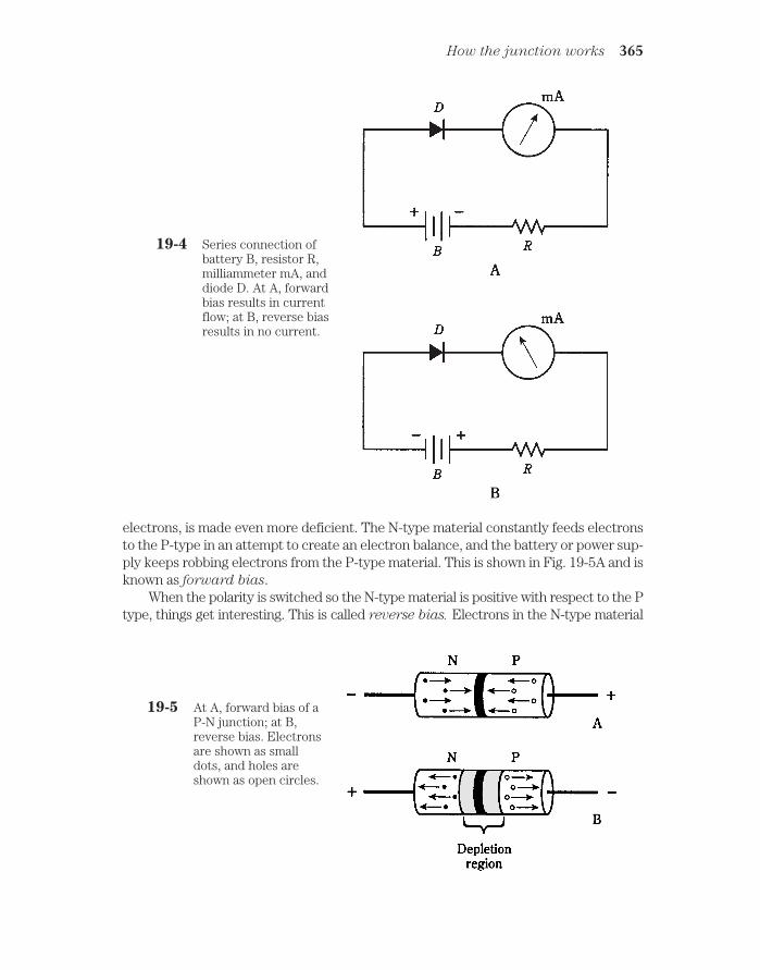
electrons, is made even more deficient. The N-type material constantly feeds electronsto the P-type in an attempt to create an electron balance, and the battery or power sup-ply keeps robbing electrons from the P-type material. This is shown in Fig. 19-5A and isknown as forward bias.
When the polarity is switched so the N-type material is positive with respect to the Ptype, things get interesting. This is called reverse bias. Electrons in the N-type material
How the junction works 365
19-4 Series connection ofbattery B, resistor R,milliammeter mA, anddiode D. At A, forwardbias results in currentflow; at B, reverse biasresults in no current.
19-5 At A, forward bias of aP-N junction; at B,reverse bias. Electronsare shown as smalldots, and holes areshown as open circles.

are pulled towards the positive charge, away from the junction. In the P-type material,holes are pulled toward the negative charge, also away from the junction. The electrons(in the N-type material) and holes (in the P type) are the majority charge carriers. Theybecome depleted in the vicinity of the P-N junction (Fig. 19-5B). A shortage of majoritycarriers means that the semiconductor material cannot conduct well. Thus, the deple-
tion region acts like an insulator.
Junction capacitanceSome P-N junctions can alternate between conduction (in forward bias) andnonconduction (in reverse bias) millions or billions of times per second. Other junctionsare slower. The main limiting factor is the capacitance at the P-N junction during con-ditions of reverse bias. The amount of capacitance depends on several factors, includ-ing the operating voltage, the type of semiconductor material, and the cross-sectionalarea of the P-N junction.
By examining Fig. 19-5B, you should notice that the depletion region, sandwichedbetween two semiconducting sections, resembles the dielectric of a capacitor. In fact,the similarity is such that a reverse-biased P-N junction really is a capacitor. Some semi-conductor components are made with this property specifically in mind.
The junction capacitance can be varied by changing the reverse-bias voltage, be-cause this voltage affects the width of the depletion region. The greater the reversevoltage, the wider the depletion region gets, and the smaller the capacitance becomes.
In the next chapter, you’ll learn how engineers take advantage of this effect.
Avalanche effectThe greater the reverse bias voltage, the “more determined an insulator” a P-N junctiongets—to a point. If the reverse bias goes past this critical value, the voltage overcomesthe ability of the junction to prevent the flow of current, and the junction conducts as ifit were forward biased. This avalanche effect does not ruin the junction (unless thevoltage is extreme); it’s a temporary thing. When the voltage drops back below the crit-ical value, the junction behaves normally again.
Some components are designed to take advantage of the avalanche effect. In othercases, avalanche effect limits the performance of a circuit.
In a device designed for voltage regulation, called a Zener diode, you’ll hear aboutthe avalanche voltage or Zener voltage specification. This might range from a coupleof volts to well over 100 V. It’s important in the design of voltage-regulating circuits insolid-state power supplies; this is discussed in the next chapter.
For rectifier diodes in power supplies, you’ll hear about the peak inverse voltage
(PIV) or peak reverse voltage (PRV) specification. It’s important that rectifier diodeshave PIV great enough so that avalanche effect will not occur (or even come close tohappening) during any part of the ac cycle. Otherwise, the circuit efficiency will becompromised.
366 Introduction to semiconductors
QuizRefer to the text in this chapter if necessary. A good score is at least 18 correct. Answersare in the back of the book.
1. The term “semiconductor” arises from:
A. Resistor-like properties of metal oxides.
B. Variable conductive properties of some materials.
C. The fact that there’s nothing better to call silicon.
D. Insulating properties of silicon and GaAs.
2. Which of the following is not an advantage of semiconductor devices overvacuum tubes?
A. Smaller size.
B. Lower working voltage.
C. Lighter weight.
D. Ability to withstand high voltages.
3. The most common semiconductor among the following substances is:
A. Germanium.
B. Galena.
C. Silicon.
D. Copper.
4. GaAs is a(n):
A. Compound.
B. Element.
C. Conductor.
D. Gas.
5. A disadvantage of gallium-arsenide devices is that:
A. The charge carriers move fast.
B. The material does not react to ionizing radiation.
C. It is expensive to produce.
D. It must be used at high frequencies.
6. Selenium works especially well in:
A. Photocells.
B. High-frequency detectors.
C. Radio-frequency power amplifiers.
D. Voltage regulators.
Quiz 367

7. Of the following, which material allows the lowest forward voltage drop in adiode?
A. Selenium.
B. Silicon.
C. Copper.
D. Germanium.
8. A CMOS integrated circuit:
A. Can only work at low frequencies.
B. Is susceptible to damage by static.
C. Requires considerable power to function.
D. Needs very high voltage.
9. The purpose of doping is to:
A. Make the charge carriers move faster.
B. Cause holes to flow.
C. Give a semiconductor material certain properties.
D. Protect devices from damage in case of transients.
10. A semiconductor material is made into N type by:
A. Adding an acceptor impurity.
B. Adding a donor impurity.
C. Injecting electrons.
D. Taking electrons away.
11. Which of the following does not result from adding an acceptor impurity?
A. The material becomes P type.
B. Current flows mainly in the form of holes.
C. Most of the carriers have positive electric charge.
D. The substance has an electron surplus.
12. In a P-type material, electrons are:
A. Majority carriers.
B. Minority carriers.
C. Positively charged.
D. Entirely absent.
13. Holes flow from:
A. Minus to plus.
B. Plus to minus.
C. P-type to N-type material.
D. N-type to P-type material.
368 Introduction to semiconductors

14. When a P-N junction does not conduct, it is:
A. Reverse biased.
B. Forward biased.
C. Biased past the breaker voltage.
D. In a state of avalanche effect.
15. Holes flow the opposite way from electrons because:
A. Charge carriers flow continuously.
B. Charge carriers are passed from atom to atom.
C. They have the same polarity.
D. No! Holes flow in the same direction as electrons.
16. If an electron has a charge of 1 unit, a hole has:
A. A charge of 1 unit.
B. No charge.
C. A charge of +1 unit.
D. A charge that depends on the semiconductor type.
17. When a P-N junction is reverse-biased, the capacitance depends on all of thefollowing except:
A. The frequency.
B. The width of the depletion region.
C. The cross-sectional area of the junction.
D. The type of semiconductor material.
18. If the reverse bias exceeds the avalanche voltage in a P-N junction:
A. The junction will be destroyed.
B. The junction will insulate; no current will flow.
C. The junction will conduct current.
D. The capacitance will become extremely high.
19. Avalanche voltage is routinely exceeded when a P-N junction acts as a:
A. Current rectifier.
B. Variable resistor.
C. Variable capacitor.
D. Voltage regulator.
20. An unimportant factor concerning the frequency at which a P-N junction willwork effectively is:
A. The type of semiconductor material.
B. The cross-sectional area of the junction.
C. The reverse current.
D. The capacitance with reverse bias.
Quiz 369

20CHAPTER
Some uses of diodesTHE TERM DIODE MEANS “TWO ELEMENTS.” IN THE EARLY YEARS OF ELEC-tronics and radio, most diodes were vacuum tubes. The cathode element emitted elec-trons, and the anode picked up electrons. Thus, current would flow as electronsthrough the tube from the cathode to the anode, but not the other way.
Tubes had filaments to drive electrons from their cathodes. The filaments wereheated via a low ac voltage, but the cathodes and anodes usually wielded hundreds oreven thousands of dc volts.
Today, you’ll still hear about diodes, anodes, and cathodes. But rather than large,heavy, hot, high-voltage tubes, diodes are tiny things made from silicon or other semi-conducting materials. Some diodes can handle voltages nearly as great as their tubecounterparts. Semiconductor diodes can do just about everything that tube diodescould, plus a few things that people in the tube era probably never imagined.
RectificationThe hallmark of a rectifier diode is that it passes current in only one direction. Thismakes it useful for changing ac to dc. Generally speaking, when the cathode is negativewith respect to the anode, current flows; when the cathode is positive relative to the an-ode, there is no current. The constraints on this behavior are the forward breakover andavalanche voltages, as you learned about in the last chapter.
Suppose a 60-Hz ac sine wave is applied to the input of the circuit in Fig. 20-1A.During half the cycle, the diode conducts, and during the other half, it doesn’t. This cutsoff half of every cycle. Depending on which way the diode is hooked up, either the pos-itive half or the negative half of the ac cycle will be removed. Figure 20-1B shows theoutput of the circuit at A. Remember that electrons flow from negative to positive,against the arrow in the diode symbol.
The circuit and wave diagram of Fig. 20-1 show a half-wave rectifier circuit. This
370 !
"# #$ !
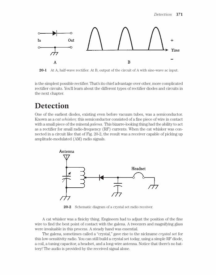
is the simplest possible rectifier. That’s its chief advantage over other, more complicatedrectifier circuits. You’ll learn about the different types of rectifier diodes and circuits inthe next chapter.
DetectionOne of the earliest diodes, existing even before vacuum tubes, was a semiconductor.Known as a cat whisker, this semiconductor consisted of a fine piece of wire in contactwith a small piece of the mineral galena. This bizarre-looking thing had the ability to actas a rectifier for small radio-frequency (RF) currents. When the cat whisker was con-nected in a circuit like that of Fig. 20-2, the result was a receiver capable of picking upamplitude-modulated (AM) radio signals.
Detection 371
20-1 At A, half-wave rectifier. At B, output of the circuit of A with sine-wave ac input.
20-2 Schematic diagram of a crystal set radio receiver.
A cat whisker was a finicky thing. Engineers had to adjust the position of the finewire to find the best point of contact with the galena. A tweezers and magnifying glasswere invaluable in this process. A steady hand was essential.
The galena, sometimes called a “crystal,” gave rise to the nickname crystal set forthis low-sensitivity radio. You can still build a crystal set today, using a simple RF diode,a coil, a tuning capacitor, a headset, and a long-wire antenna. Notice that there’s no bat-tery! The audio is provided by the received signal alone.

The diode in Fig. 20-2 acts to recover the audio from the radio signal. This is calleddetection; the circuit is a detector. If the detector is to be effective, the diode must beof the right type. It should have low capacitance, so that it works as a rectifier at radiofrequencies, passing current in one direction but not in the other. Some modern RFdiodes are actually microscopic versions of the old cat whisker, enclosed in a glass casewith axial leads. You have probably seen these in electronics hobby stores.
Details about detector circuits are discussed in chapter 27. Some detectors usediodes; others do not. Modulation methods are examined in chapter 26.
Frequency multiplicationWhen current passes through a diode, half of the cycle is cut off, as shown in Fig. 20-1.This occurs no matter what the frequency, from 60-Hz utility current through RF, aslong as the diode capacitance is not too great.
The output wave from the diode looks much different than the input wave. Thiscondition is known as nonlinearity. Whenever there is nonlinearity of any kind in a cir-cuit—that is, whenever the output waveform is shaped differently from the input wave-form—there will be harmonic frequencies in the output. These are waves at integermultiples of the input frequency. (If you’ve forgotten what harmonics are, refer back tochapter 9.)
Often, nonlinearity is undesirable. Then engineers strive to make the circuit linear,
so that the output waveform has exactly the same shape as the input waveform. Butsometimes a circuit is needed that will produce harmonics. Then nonlinearity is intro-duced deliberately. Diodes are ideal for this.
A simple frequency-multiplier circuit is shown in Fig. 20-3. The output LC circuit istuned to the desired nth harmonic frequency, nfo, rather than to the input or funda-mental frequency, fo.
372 Some uses of diodes
20-3 A frequency multipliercircuit.
For a diode to work as a frequency multiplier, it must be of a type that would alsowork well as a detector at the same frequencies. This means that the component shouldact like a rectifier, but not like a capacitor.
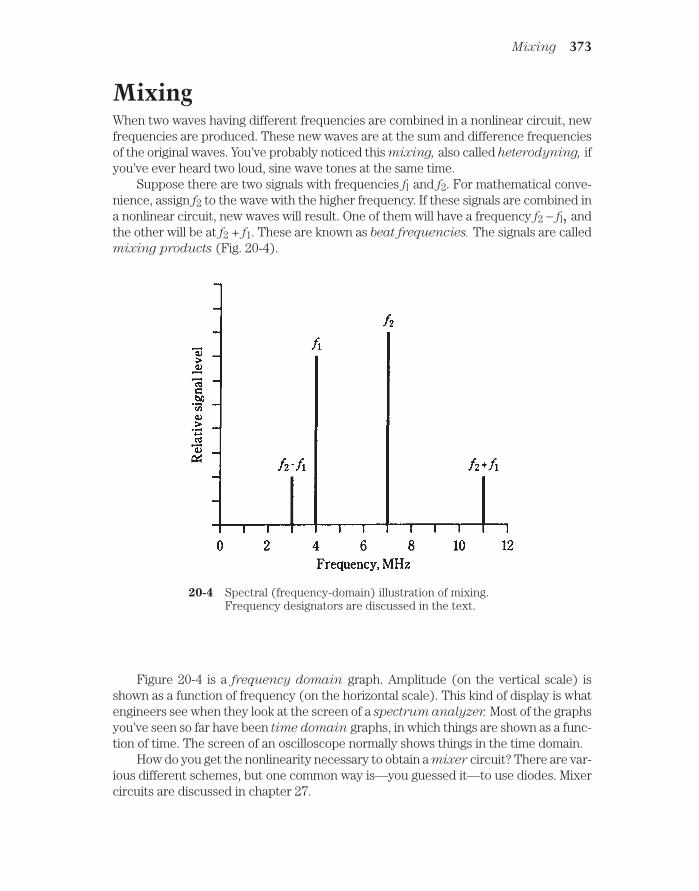
MixingWhen two waves having different frequencies are combined in a nonlinear circuit, newfrequencies are produced. These new waves are at the sum and difference frequenciesof the original waves. You’ve probably noticed this mixing, also called heterodyning, ifyou’ve ever heard two loud, sine wave tones at the same time.
Suppose there are two signals with frequencies fl and f2. For mathematical conve-nience, assign f2 to the wave with the higher frequency. If these signals are combined ina nonlinear circuit, new waves will result. One of them will have a frequency f2 − fl, andthe other will be at f2 + f1. These are known as beat frequencies. The signals are calledmixing products (Fig. 20-4).
Mixing 373
20-4 Spectral (frequency-domain) illustration of mixing.Frequency designators are discussed in the text.
Figure 20-4 is a frequency domain graph. Amplitude (on the vertical scale) isshown as a function of frequency (on the horizontal scale). This kind of display is whatengineers see when they look at the screen of a spectrum analyzer. Most of the graphsyou’ve seen so far have been time domain graphs, in which things are shown as a func-tion of time. The screen of an oscilloscope normally shows things in the time domain.
How do you get the nonlinearity necessary to obtain a mixer circuit? There are var-ious different schemes, but one common way is—you guessed it—to use diodes. Mixercircuits are discussed in chapter 27.

SwitchingThe ability of diodes to conduct with forward bias, and to insulate with reverse bias,makes them useful for switching in some electronic applications. Diodes can switch atextremely high rates, much faster than any mechanical device.
One type of diode, made for use as an RF switch, has a special semiconductor layersandwiched in between the P-type and N-type material. This layer, called an intrinsic
semiconductor, reduces the capacitance of the diode, so that it can work at higher fre-quencies than an ordinary diode. The intrinsic material is sometimes called I type. Adiode with I-type semiconductor is called a PIN diode (Fig. 20-5).
374 Some uses of diodes
20-5 The PIN diode has alayer of intrinsic (I-type) semiconductorat the P-N junction.
Direct-current bias, applied to one or more PIN diodes, allows RF currents to be ef-fectively channeled without using complicated relays and cables. A PIN diode alsomakes a good RF detector, especially at frequencies above 30 MHz.
Voltage regulationMost diodes have avalanche breakdown voltages much higher than the reverse biasever gets. The value of the avalanche voltage depends on how a diode is manufactured.Zener diodes are made to have well-defined, constant avalanche voltages.
Suppose a certain Zener diode has an avalanche voltage, also called the Zener volt-
age, of 50 V. If a reverse bias is applied to the P-N junction, the diode acts as an opencircuit below 50 V. When the voltage reaches 50 V, the diode starts to conduct. Themore the reverse bias tries to increase, the more current flows through the P-N junc-tion. This effectively prevents the reverse voltage from exceeding 50 V.
The current through a Zener diode, as a function of the voltage, is shown in Fig.20-6. The Zener voltage is indicated by the abrupt rise in reverse current as the reversebias increases. A typical Zener-diode voltage-limiting circuit is shown in Fig. 20-7.
There are other ways to get voltage regulation besides the use of Zener diodes, butZener diodes often provide the simplest and least expensive alternative. Zener diodesare available with a wide variety of voltage and power-handling ratings. Power suppliesfor solid-state equipment commonly employ Zener diode regulators.
Details about power supply design are coming up in chapter 21.
Amplitude limitingThe forward breakover voltage of a germanium diode is about 0.3 V; for a silicon diodeit is about 0.6 V. In the last chapter, you learned that a diode will not conduct until theforward bias voltage is at least as great as the forward breakover voltage. The “flip side”

is that the diode will always conduct when the forward bias exceeds the breakovervalue. In this case, the voltage across the diode will be constant: 0.3 V for germaniumand 0.6 V for silicon.
This property can be used to advantage when it is necessary to limit the amplitudeof a signal, as shown in Fig. 20-8. By connecting two identical diodes back-to-back inparallel with the signal path (A), the maximum peak amplitude is limited, or clipped, tothe forward breakover voltage of the diodes. The input and output waveforms of aclipped signal are illustrated at B. This scheme is sometimes used in radio receivers toprevent “blasting” when a strong signal comes in.
The downside of the diode limiter circuit is that it introduces distortion when lim-iting is taking place. This might not be a problem for reception of Morse code, or for sig-nals that rarely reach the limiting voltage. But for voice signals with amplitude peaksthat rise well past the limiting voltage, it can seriously degrade the audio quality, per-haps even rendering the words indecipherable.
Amplitude limiting 375
20-6 Current through a Zener diode, as a function of the biasvoltage.
20-7 Connection of Zenerdiode for voltageregulation.

Frequency controlWhen a diode is reverse-biased, there is a region at the P-N junction with dielectricproperties. As you know from the last chapter, this is called the depletion region, be-cause it has a shortage of majority charge carriers. The width of this zone depends onseveral things, including the reverse voltage.
As long as the reverse bias is less than the avalanche voltage, varying the bias canchange the width of the depletion region. This results in a change in the capacitance ofthe junction. The capacitance, which is always quite small (on the order of picofarads),varies inversely with the square root of the reverse bias.
Some diodes are manufactured especially for use as variable capacitors. These arevaractor diodes. Sometimes you’ll hear them called varicaps. They are made from sil-icon or gallium arsenide.
A common use for a varactor diode is in a circuit called a voltage-controlled oscil-
lator (VCO). A voltage-tuned circuit, using a coil and a varactor, is shown in Fig. 20-9.This is a parallel-tuned circuit. The fixed capacitor, whose value is large compared withthat of the varactor, serves to keep the coil from short-circuiting the control voltageacross the varactor. Notice that the symbol for the varactor has two lines on the cath-ode side. This is its “signature,” so that you know that it’s a varactor, and not just an or-dinary diode.
376 Some uses of diodes
20-8 At A, two diodes can work as a limiter. At B, the peaks are cut off by the action of thediodes.
20-9 Connection of a varactordiode in a tuned circuit.

Oscillation and amplificationUnder certain conditions, diodes can be made to produce microwave radio signals.There are three types of diodes that do this: Gunn diodes, IMPATT diodes, and tun-
nel diodes.
Gunn diodesA Gunn diode can produce up to 1 W of RF power output, but more commonly it worksat levels of about 0.1 W. Gunn diodes are usually made from gallium arsenide.
A Gunn diode oscillates because of the Gunn effect, named after J. Gunn of Inter-national Business Machines (IBM) who observed it in the sixties. A Gunn diode doesn’twork anything like a rectifier, detector, or mixer; instead, the oscillation takes place asa result of a quirk called negative resistance.
Gunn-diode oscillators are often tuned using varactor diodes. A Gunn-diode oscil-lator, connected directly to a microwave horn antenna, is known as a Gunnplexer.
These devices are popular with amateur-radio experimenters at frequencies of 10 GHzand above.
IMPATT diodesThe acronym IMPATT comes from the words impact avalanche transit time. This, likenegative resistance, is a phenomenon the details of which are rather esoteric. An IM-
PATT diode is a microwave oscillating device like a Gunn diode, except that it uses sil-icon rather than gallium arsenide.
An IMPATT diode can be used as an amplifier for a microwave transmitter that em-ploys a Gunn-diode oscillator. As an oscillator, an IMPATT diode produces about thesame amount of output power, at comparable frequencies, as the Gunn diode.
Tunnel diodesAnother type of diode that will oscillate at microwave frequencies is the tunnel diode,
also known as the Esaki diode. It produces only a very small amount of power, but itcan be used as a local oscillator in a microwave radio receiver.
Tunnel diodes work well as amplifiers in microwave receivers, because theygenerate very little unwanted noise. This is especially true of gallium arsenide devices.
The behavior of Gunn, IMPATT, and tunnel diodes is a sophisticated topic and is be-yond the scope of this book. College-level electrical-engineering texts are good sourcesof information on this subject. You will want to know about how these devices work ifyou plan to become a microwave engineer.
Energy emissionSome semiconductor diodes emit radiant energy when a current passes through theP-N junction in a forward direction. This phenomenon occurs as electrons fall fromhigher to lower energy states within atoms.
Energy emission 377

LEDs and IREDsDepending on the exact mixture of semiconductors used in manufacture, visible light ofalmost any color can be produced. Infrared-emitting devices also exist. The most com-mon color for a light-emitting diode (LED) is bright red. An infrared-emitting diode
(IRED) produces wavelengths too long to see.The intensity of the light or infrared from an LED or IRED depends to some extent
on the forward current. As the current rises, the brightness increases up to a certainpoint. If the current continues to rise, no further increase in brilliance takes place. TheLED or IRED is then said to be in a state of saturation.
Digital displaysBecause LEDs can be made in various different shapes and sizes, they are ideal for usein digital displays. You’ve probably seen digital clock radios that use them. They arecommon in car radios. They make good indicators for “on/off,” “a. m. /p. m.,” “batterylow,” and other conditions.
In recent years, LED displays have been largely replaced by liquid-crystal dis-
plays (LCDs). This technology has advantages over LEDs, including much lower powerconsumption and better visibility in direct sunlight.
CommunicationsBoth LEDs and IREDs are useful in communications because their intensity can bemodulated to carry information. When the current through the device is sufficient toproduce output, but not enough to cause saturation, the LED or IRED output willfollow along with rapid current changes. Voices, music, and digital signals can beconveyed over light beams in this way. Some modern telephone systems make use ofmodulated light, transmitted through clear fibers. This is known as fiberoptic tech-nology.
Special LEDs and IREDs produce coherent radiation; these are called laser
diodes. The rays from these diodes aren’t the intense, parallel beams that you probablyimagine when you think about lasers. A laser LED or IRED generates a cone-shapedbeam of low intensity. But it can be focused, and the resulting rays have some of thesame advantages found in larger lasers.
Photosensitive diodesVirtually all P-N junctions exhibit characteristics that change when electromagneticrays strike them. The reason that conventional diodes are not affected by these rays isthat most diodes are enclosed in opaque packages.
Some photosensitive diodes have variable resistance that depends on light inten-sity. Others actually generate dc voltages in the presence of electromagnetic radiation.
Silicon photodiodesA silicon diode, housed in a transparent case and constructed in such a way that vis-ible light can strike the barrier between the P-type and N-type materials, forms aphotodiode.
378 Some uses of diodes

A reverse bias is applied to the device. When light falls on the junction, currentflows. The current is proportional to the intensity of the light, within certain limits.
Silicon photodiodes are more sensitive at some wavelengths than at others. Thegreatest sensitivity is in the near infrared part of the spectrum, at wavelengths a littlelonger than visible red light.
When light of variable brightness falls on the P-N junction of a reverse-biased sili-con photodiode, the output current follows the light-intensity variations. This makes sil-icon photodiodes useful for receiving modulated-light signals of the kind used infiberoptic systems.
The optoisolatorAn LED or IRED and a photodiode can be combined in a single package to get a com-ponent called an optoisolator. This device (Fig. 20-10) actually creates a modulatedlight signal and sends it over a small, clear gap to a receptor. The LED or IRED convertsan electrical signal to visible light or infrared; the photodiode changes the visible lightor infrared back into an electrical signal.
Photosensitive diodes 379
20-10 An optoisolator uses anLED or IRED (input)and a photodiode(output).
A major source of headache for engineers has always been the fact that, when a sig-nal is electrically coupled from one circuit to another, the impedances of the two stagesinteract. This can lead to nonlinearity, unwanted oscillation, loss of efficiency, or otherproblems. Optoisolators overcome this effect, because the coupling is not done electri-cally. If the input impedance of the second circuit changes, the impedance that the firstcircuit “sees” will remain unaffected, being simply the impedance of the LED or IRED.
Photovoltaic cellsA silicon diode, with no bias voltage applied, will generate dc all by itself if enough elec-tromagnetic radiation hits its P-N junction. This is known as the photovoltaic effect. Itis the principle by which solar cells work.
Photovoltaic cells are made to have the greatest possible P-N junction surfacearea. This maximizes the amount of light that falls on the junction. A single silicon pho-tovoltaic cell can produce about 0.6 V of dc electricity. The amount of current that it candeliver depends on the surface area of the junction. For every square inch of P-N sur-face area, a silicon photovoltaic cell can produce about 160 mA in direct sunlight.
Photovoltaic cells are often connected in series-parallel combinations to providepower for solid-state electronic devices like portable radios. A large assembly of solarcells is called a solar panel.
Solar-cell technology has advanced rapidly in the last several years. Solar power isexpensive to produce, but the cost is going down—and solar cells do not pollute.

QuizRefer to the text in this chapter if necessary. A good score is at least 18 correct. Answersare in the back of the book.
1. When a diode is forward-biased, the anode:
A. Is negative relative to the cathode.
B. Is positive relative to the cathode.
C. Is at the same voltage as the cathode.
D. Alternates between positive and negative relative to the cathode.
2. If ac is applied to a diode, and the peak ac voltage never exceeds the avalanchevoltage, then the output is:
A. Ac with half the frequency of the input.
B. Ac with the same frequency as the input.
C. Ac with twice the frequency of the input.
D. None of the above.
3. A crystal set:
A. Can be used to transmit radio signals.
B. Requires a battery with long life.
C. Requires no battery.
D. Is useful for rectifying 60-Hz ac.
4. A diode detector:
A. Is used in power supplies.
B. Is employed in some radio receivers.
C. Is used commonly in high-power radio transmitters.
D. Changes dc into ac.
5. If the output wave in a circuit has the same shape as the input wave, then:
A. The circuit is linear.
B. The circuit is said to be detecting.
C. The circuit is a mixer.
D. The circuit is a rectifier.
6. The two input frequencies of a mixer circuit are 3.522 MHz and 3.977 MHz.Which of the following frequencies might be used at the output?
A. 455 kHz.
B. 886 kHz.
C. 14.00 MHz.
D. 1.129 MHz.
380 Some uses of diodes

7. A time-domain display might be found in:
A. An ammeter.
B. A spectrum analyzer.
C. A digital voltmeter.
D. An oscilloscope.
8. Zener voltage is also known as:
A. Forward breakover voltage.
B. Peak forward voltage.
C. Avalanche voltage.
D. Reverse bias.
9. The forward breakover voltage of a silicon diode is:
A. About 0.3 V.
B. About 0.6 V.
C. About 1.0 V.
D. Dependent on the method of manufacture.
10. A diode audio limiter circuit:
A. Is useful for voltage regulation.
B. Always uses Zener diodes.
C. Rectifies the audio to reduce distortion.
D. Can cause objectionable signal distortion.
11. The capacitance of a varactor varies with:
A. Forward voltage.
B. Reverse voltage.
C. Avalanche voltage.
D. Forward breakover voltage.
12. The purpose of the I layer in a PIN diode is to:
A. Minimize the diode capacitance.
B. Optimize the avalanche voltage.
C. Reduce the forward breakover voltage.
D. Increase the current through the diode.
13. Which of these diode types might be found in the oscillator circuit of amicrowave radio transmitter?
A. A rectifier diode.
B. A cat whisker.
C. An IMPATT diode.
D. None of the above.
Quiz 381

14. A Gunnplexer can be used as a:
A. Communications device.
B. Radio detector.
C. Rectifier.
D. Signal mixer.
15. The most likely place you would find an LED would be:
A. In a rectifier circuit.
B. In a mixer circuit.
C. In a digital frequency display.
D. In an oscillator circuit.
16. Coherent radiation is produced by a:
A. Gunn diode.
B. Varactor diode.
C. Rectifier diode.
D. Laser diode.
17. You want a circuit to be stable with a variety of amplifier impedanceconditions. You might consider a coupler using:
A. A Gunn diode.
B. An optoisolator.
C. A photovoltaic cell.
D. A laser diode.
18. The power from a solar panel depends on all of the following except:
A. The operating frequency of the panel.
B. The total surface area of the panel.
C. The number of cells in the panel.
D. The intensity of the light.
19. Emission of energy in an IRED is caused by:
A. High-frequency radio waves.
B. Rectification.
C. Electron energy-level changes.
D. None of the above.
20. A photodiode, when not used as a photovoltaic cell, has:
A. Reverse bias.
B. No bias.
C. Forward bias.
D. Negative resistance.
382 Some uses of diodes

21CHAPTER
Power suppliesMOST ELECTRONIC EQUIPMENT NEEDS DIRECT CURRENT (DC) TO WORK. BATTER-ies produce dc, but there is a limit to how much energy and how much voltage a bat-tery can provide. The same is true of solar panels.
The electricity from the utility company is alternating current (ac) with a fre-quency of 60 Hz. In your house, most wall outlets carry an effective voltage of 117 V;some have 234 V. The energy from a wall outlet is practically unlimited, but it must beconverted from ac to dc, and tailored to just the right voltage, to be suitable for elec-tronic equipment.
Parts of a power supplyA power supply provides the proper voltage and current for electronic apparatus.Most power supplies consist of several stages, always in the same order (Fig. 21-1).
383
21-1 Block diagram of a power supply. Sometimes a regulator is not needed.
First, the ac encounters a transformer that steps the voltage either down or up, depending on the exact needs of the electronic circuits.
!"# #$ !

Second, the ac is rectified, so that it becomes pulsating dc with a frequency of ei-ther 60 Hz or 120 Hz. This is almost always done by one or more semiconductor diodes.
Third, the pulsating dc is filtered, or smoothed out, so that it becomes a continu-ous voltage having either positive or negative polarity with respect to ground.
Finally, the dc voltage might need to be regulated. Some equipment is finicky, in-sisting on just the right amount of voltage all the time. Other devices can put up withsome voltage changes.
Power supplies that provide more than a few volts must have features that protect theuser (that’s you!) from receiving a dangerous electrical shock. All power supplies needfuses and/or circuit breakers to minimize the fire hazard in case the equipment shorts out.
The power transformerPower transformers can be categorized as step-down or step-up. As you remember, theoutput, or secondary, voltage of a step-down unit is lower than the input, or primary,voltage. The reverse is true for a step-up transformer.
Step-downMost solid-state electronic devices, such as radios, need only a few volts. The powersupplies for such equipment use step-down power transformers. The physical size ofthe transformer depends on the current.
Some devices need only a small current and a low voltage. The transformer in a ra-dio receiver, for example, can be quite small physically. A ham radio transmitter or hi-fiamplifier needs much more current. This means that the secondary winding of thetransformer must be of heavy-gauge wire, and the core must be bulky to contain themagnetic flux. Such a transformer is massive.
Step-upSome circuits need high voltage. The picture tube in a TV set needs several hundredvolts. Some ham radio power amplifiers use vacuum tubes working at kilovolts dc. Thetransformers in these appliances are step-up types. They are moderate to large in sizebecause of the number of turns in the secondary, and also because high voltages canspark, or arc, between wire turns if the windings are too tight.
If a step-up transformer needs to supply only a small amount of current, it need notbe big. But for ham radio transmitters and radio/TV broadcast amplifiers, the transform-ers are large and heavy—and expensive.
Transformer ratingsTransformers are rated according to output voltage and current. For a given unit, thevolt-ampere (VA) capacity is often specified. This is the product of the voltage and cur-rent. A transformer with a 12-V output, capable of delivering 10 A, would have 12 V 10 A 120 VA of capacity.
The nature of power-supply filtering, to be discussed a bit later in this chapter,makes it necessary for the power-transformer VA rating to be greater than just thewattage needed by the load.
384 Power supplies

A high-quality, rugged power transformer, capable of providing the necessary cur-rents and/or voltages, is crucial in any power supply. The transformer is usually themost expensive component to replace. When designing a power supply, it’s wise tospend a little extra to get a reliable transformer. Engineers might call this “maintenanceinsurance.”
The diodeRectifier diodes are available in various sizes, intended for different purposes. Most rec-tifier diodes are made of silicon and are therefore known as silicon rectifiers. A few arefabricated from selenium, and are called selenium rectifiers.
Two important features of a power-supply diode are the average forwvard cur-
rent (Io) rating and the peak inverse voltage (PIV) rating. There are other specifica-tions that engineers need to know when designing a specialized power supply, but inthis course, you only need to be concerned about Io and PIV.
Average forward currentElectric current produces heat. If the current through a diode is too great, the heat willdestroy the P-N junction.
Generally speaking, when designing a power supply, it’s wise to use diodes withan Io rating of at least 1.5 times the expected average dc forward current. If this cur-rent is 4.0 A, the rectifier diodes should be rated at Io = 6.0 A or more. Of course, itwould be wasteful of money to use a 100-A diode in a circuit where the average for-ward current is 4.0 A. While it would work, it would be a bit like shooting a sparrowwith a cannon.
Note that Io flows through the diodes. The current drawn by the load is often quitedifferent from this. Also, note that Io is an average figure. The instantaneous forwardcurrent is another thing, and can be 15 or even 20 times Io, depending on the nature ofthe power-supply filtering circuitry.
Some diodes have heatsinks to help carry heat away from the P-N junction. A se-lenium diode can be recognized by the appearance of its heatsink (Fig. 21-2).
The diode 385
21-2 A selenium rectifier can be recognized by its heatsink.

Diodes can be connected in parallel to increase the current rating. When this isdone, small-value resistors are placed in series with each diode in the set to equalize thecurrent burden among the diodes (Fig. 21-3). Each resistor should have a voltage dropof about 1 V.
386 Power supplies
21-3 When diodes areconnected in parallel,resistors help equalizethe current load.
Peak inverse voltageThe PIV rating of a diode is the instantaneous inverse, or reverse-bias, voltage that itcan withstand without avalanche taking place. A good power supply has diodes whosePIV ratings are significantly greater than the peak voltage of the ac at the input.
If the PIV rating is not great enough, the diode or diodes in a supply will conduct forpart of the reverse cycle. This will degrade the efficiency of the supply; the reverse cur-rent will “buck” the forward current. It would be like having a team of rowers in a longboat, with one or two rowers trying to propel the boat backwards instead of forwards.
Diodes can be connected in series to get a higher PIV capacity than a single diodealone. This scheme is sometimes seen in high-voltage supplies, such as those needed fortube-type ham radio power amplifiers. High-value resistors, of about 500 Ω for eachpeak-inverse volt, are placed across each diode in the set to distribute the reverse biasequally among the diodes (Fig. 21-4). Also, each diode is shunted by a capacitor of0.005 µF or 0.1 µF.
21-4 Diodes in seriesshould be shunted byresistors andcapacitors.
The half-wave rectifierThe simplest rectifier circuit uses just one diode (or a series or parallel combination) to“chop off” half of the ac input cycle. You saw this circuit in the previous chapter, dia-grammed in Fig. 20-1.
In a half-wave circuit, the average output voltage is approximately 45 percent of therms ac input voltage. But the PIV across the diode can be as much as 2.8 times the rmsac input voltage. It’s a good idea to use diodes whose PIV ratings are at least 1.5 times the

maximum expected PIV; therefore, with a half-wave supply, the diodes should be ratedfor at least 4.2 times the rms ac input voltage.
Half-wave rectification has some shortcomings. First, the output is hard to smoothout, because the waveform is so irregular. Second, the voltage output tends to dropwhen the supply is connected to a load. (This can be overcome to some extent bymeans of a good voltage regulator. Voltage regulation is discussed later in this chapter.)Third, half-wave rectification puts a disproportionate strain on the power transformerand the diodes.
Half-wave rectification is useful in supplies that don’t have to deliver much current,or that don’t need to be especially well regulated. The main advantage of using ahalf-wave circuit in these situations is that it costs a little less than full-wave or bridgecircuits.
The full-wave, center-tap rectifierA much better scheme for changing ac to dc is to use both halves of the ac cycle. Sup-pose you want to convert an ac wave to dc with positive polarity. Then you can allow thepositive half of the ac cycle to pass unchanged, and flip the negative portion of the waveupside-down, making it positive instead. This is the principle behind full-wave
rectification.
One common full-wave circuit uses a transformer with a center-tapped secondary,as shown in Fig. 21-5A. The center tap, a wire coming out of the exact middle of the sec-ondary winding, is connected to common ground. This produces out-of-phase waves atthe ends of the winding. These two waves can be individually half-wave rectified, cut-ting off the negative half of the cycle. Because the waves are 180 degrees (half a cycle)out of phase, the output of the circuit has positive pulses for both halves of the cycle(Fig. 21-5B).
In this rectifier circuit, the average dc output voltage is about 90 percent of the rmsac input voltage. The PIV across the diodes can be as much as 2.8 times the rms inputvoltage. Therefore, the diodes should have a PIV rating of at least 4.2 times the rms acinput.
Compare Fig. 21-5B with Fig. 20-1B from the last chapter. Can you see that thewaveform of the full-wave rectifier ought to be easier to smooth out? In addition to thisadvantage, the full-wave, center-tap rectifier is kinder to the transformer and diodesthan a half-wave circuit. Furthermore, if a load is applied to the output of the full-wavecircuit, the voltage will drop much less than it would with a half-wave supply, becausethe output has more “substance.”
The bridge rectifierAnother way to get full-wave rectification is the bridge rectifier. It is diagrammed inFig. 21-6. The output waveform is just like that of the full-wave, center-tap circuit.
The average dc output voltage in the bridge circuit is 90 percent of the rms ac in-put voltage, just as is the case with center-tap rectification. The PIV across the diodesis 1.4 times the rms ac input voltage. Therefore, each diode needs to have a PIV ratingof at least 2.1 times the rms ac input voltage.
The bridge rectifier 387

The bridge circuit does not need a center-tapped transformer secondary. This is itsmain practical advantage. Electrically, the bridge circuit uses the entire secondary onboth halves of the wave cycle; the center-tap circuit uses one side of the secondary forone half of the cycle, and the other side for the other half of the cycle. For this reason,the bridge circuit makes more efficient use of the transformer.
The main disadvantage of the bridge circuit is that it needs four diodes rather thantwo. This doesn’t always amount to much in terms of cost, but it can be important when
388 Power supplies
21-5 At A, schematic diagram of a full-wave, center-tap rectifier. At B, outputwaveform from this rectifier.
21-6 Schematic diagram of a full-wave bridge rectifier.

a power supply must deliver a high current. Then, the extra diodes—two for each halfof the cycle, rather than one—dissipate more overall heat energy. When current is usedup as heat, it can’t go to the load. Therefore, center-tap circuits are preferable inhigh-current applications.
The voltage doublerBy using diodes and capacitors connected in certain ways, a power supply can be madeto deliver a multiple of the peak ac input voltage. Theoretically, large whole-numbermultiples are possible. But you won’t often see power supplies that make use of multi-plication factors larger than 2.
In practice, voltage multipliers are practical only when the load draws low cur-rent. Otherwise, the regulation is poor; the output voltage changes considerably withchanges in the load resistance. This bugaboo gets worse and worse as the multiplicationfactor increases. This is why engineers don’t attempt to make, say, a factor-of-16 volt-age multiplier. For a good high-voltage power supply, the best approach is to use astep-up transformer, not a voltage multiplier.
A voltage-doubler circuit is shown in Fig. 21-7. This circuit works on the whole acinput wave cycle, and is therefore called a full-wave voltage doubler. Its dc outputvoltage, when the current drawn is low, is about twice the peak ac input voltage, orabout 2.8 times the rms ac input voltage.
The voltage doubler 389
21-7 A full-wave voltage doubler.
Notice the capacitors in this circuit. The operation of any voltage multiplier is de-pendent on the ability of these capacitors to hold a charge, even when a load is con-nected to the output of the supply. Thus, the capacitors must have large values. If theintent is to get a high dc voltage from the supply, massive capacitors will be necessary.
Also, notice the resistors in series with the diodes. These have low values, similar tothose needed when diodes are connected in parallel. When the supply is switched on,the capacitors draw a huge initial charging current. Without the resistors, it would benecessary to use diodes with astronomical Io ratings. Otherwise the surge current
would burn them out.
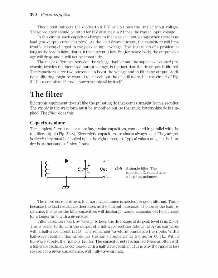
This circuit subjects the diodes to a PIV of 2.8 times the rms ac input voltage.Therefore, they should be rated for PIV of at least 4.2 times the rms ac input voltage.
In this circuit, each capacitor charges to the peak ac input voltage when there is noload (the output current is zero). As the load draws current, the capacitors will havetrouble staying charged to the peak ac input voltage. This isn’t much of a problem aslong as the load is light, that is, if the current is low. But,for heavy loads, the output volt-age will drop, and it will not be smooth dc.
The major difference between the voltage doubler and the supplies discussed pre-viously, besides the increased output voltage, is the fact that the dc output is filtered.The capacitors serve two purposes: to boost the voltage and to filter the output. Addi-tional filtering might be wanted to smooth out the dc still more, but the circuit of Fig.21-7 is a complete, if crude, power supply all by itself.
The filterElectronic equipment doesn’t like the pulsating dc that comes straight from a rectifier.The ripple in the waveform must be smoothed out, so that pure, battery-like dc is sup-plied. The filter does this.
Capacitors aloneThe simplest filter is one or more large-value capacitors, connected in parallel with therectifier output (Fig. 21-8). Electrolytic capacitors are almost always used. They are po-
larized; they must be hooked up in the right direction. Typical values range in the hun-dreds or thousands of microfarads.
390 Power supplies
21-8 A simple filter. Thecapacitor, C, should havea large capacitance.
The more current drawn, the more capacitance is needed for good filtering. This isbecause the load resistance decreases as the current increases. The lower the load re-sistance, the faster the filter capacitors will discharge. Larger capacitances hold chargefor a longer time with a given load.
Filter capacitors work by “trying” to keep the dc voltage at its peak level (Fig. 21-9).This is easier to do with the output of a full-wave rectifier (shown at A) as comparedwith a half-wave circuit (at B). The remaining waveform bumps are the ripple. With ahalf-wave rectifier, this ripple has the same frequency as the ac, or 60 Hz. With afull-wave supply, the ripple is 120 Hz. The capacitor gets recharged twice as often witha full-wave rectifier, as compared with a half-wave rectifier. This is why the ripple is lesssevere, for a given capacitance, with full-wave circuits.
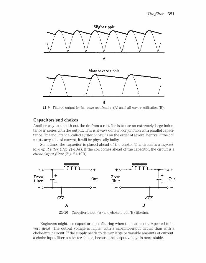
Capacitors and chokesAnother way to smooth out the dc from a rectifier is to use an extremely large induc-tance in series with the output. This is always done in conjunction with parallel capaci-tance. The inductance, called a filter choke, is on the order of several henrys. If the coilmust carry a lot of current, it will be physically bulky.
Sometimes the capacitor is placed ahead of the choke. This circuit is a capaci-
tor-input filter (Fig. 21-10A). If the coil comes ahead of the capacitor, the circuit is achoke-input filter (Fig. 21-10B).
The filter 391
21-9 Filtered output for full-wave rectification (A) and half-wave rectification (B).
21-10 Capacitor-input (A) and choke-input (B) filtering.
Engineers might use capacitor-input filtering when the load is not expected to bevery great. The output voltage is higher with a capacitor-input circuit than with achoke-input circuit. If the supply needs to deliver large or variable amounts of current,a choke-input filter is a better choice, because the output voltage is more stable.

If a supply must have a minimum of ripple, two or three capacitor/choke pairsmight be cascaded, or connected one after the other (Fig. 21-11). Each pair is called asection. Multisection filters can consist of either capacitor-input or choke-input sec-tions, but the two types are never mixed.
392 Power supplies
21-11 Two choke-input filter sections in cascade.
Voltage regulationA full-wave rectifier, followed by a choke-input filter, offers fairly stable voltage undervarying load conditions. But voltage regulator circuitry is needed for electronic de-vices that are finicky about the voltage they get.
Zener diodesYou learned about Zener diodes in the last chapter. If a reverse-biased Zener diode isconnected across the output of a power supply, as shown back in Fig. 20-7, the diodewill limit the output voltage of the supply by “brute force” as long as it has a high enoughpower rating.
Zener/transistor regulationA Zener-diode voltage regulator is not very efficient if the load is heavy. When a supplymust deliver high current, a power transistor is used along with the Zener diode to ob-tain regulation (Fig. 21-12). This greatly reduces the strain on the Zener diode, so thata lower-power (and therefore less costly) diode can be used.
Integrated circuitsIn recent years, voltage regulators have become available in integrated-circuit (IC)
form. You just connect the IC, perhaps along with some external components, at theoutput of the filter. This method provides the best possible regulation at low and mod-erate voltages. Even if the output current changes from zero to maximum, the outputvoltage stays exactly the same, for all practical purposes.
Regulator tubesOccasionally, you’ll find a power supply that uses a gas-filled tube, rather than solid-statecomponents, to obtain regulation. The tube acts something like a very-high-power Zener

diode. The voltage drop across a gaseous tube, designed for voltage regulation, is nearlyconstant. Tubes are available for regulation at moderately high voltages.
Surge currentAt the instant a power supply is switched on, a sudden current surge occurs, even withno load at the output. This is because the filter capacitor(s) need an initial charge, andthey draw a lot of current for a short time. The surge current is far greater than the op-erating current. This can destroy the rectifier diodes. The phenomenon is worst inhigh-voltage supplies and voltage-multiplier circuits. Diode failure can be prevented inat least four different ways.
The first method uses “brute force.” You can simply use diodes with a current rat-ing of many times the operating level. The main disadvantage is cost. High-voltage,high-current diodes can get expensive.
A second method involves connecting several units in parallel wherever a diode iscalled for in the circuit. This is actually a variation on the first method. The overall costmight be less. Current-equalizing resistors are necessary.
A third scheme for surge protection is to apply the input voltage little by little. Avariable transformer, called a Variac, is useful for this. You start at zero input and turna knob to get up to the full voltage. This can completely get rid of the current surge.
A fourth way to limit the current surge is to use an automatic switching circuit inthe transformer primary. This applies a reduced ac voltage for a second or two, and thenswitches in the full input voltage.
Which of these methods is best? It depends on the overall cost, the operating con-venience, and the whim of the design engineer.
Surge current 393
21-12 A voltage regulator circuit using a Zener diode and apower transistor.

Transient suppressionThe ac on the utility line is a sine wave with a constant rms voltage near 117 V. But thereare “spikes,” known as transients, lasting microseconds or milliseconds, that attainpeak values of several hundred or even several thousand volts.
Transients are caused by sudden changes in the load in a utility circuit. Lightningcan also produce them. Unless they are suppressed, they can destroy the diodes in apower supply. Transients can also befuddle the operation of sensitive equipment likepersonal computers.
The simplest way to get rid of most transients is to place a capacitor of about 0.01µF, rated for 600 V or more, across the transformer primary (Fig. 21-13). Commerciallymade transient suppressors are also available.
In the event of a thunderstorm locally, the best way to protect equipment is to un-plug it from the wall outlet. This is inconvenient, of course. But if you have a personalcomputer, hi-fi set, or other electronic appliance that you like a lot, it’s not a bad idea.
394 Power supplies
21-13 A capacitor, C, in parallelwith the primary of thetransformer, helpssuppress transients.
Fuses and breakersA fuse is a piece of soft wire that melts, breaking a circuit if the current exceeds a cer-tain level. Fuses are placed in series with the transformer primary (Fig. 21-14). Anycomponent failure, short circuit, or overload that might cause catastrophic damage (orfire!) will burn the fuse out. Fuses are easy to replace, although it’s aggravating if a fuseblows and you don’t have replacements on hand.
21-14 A fuse, F, in series withthe ac input protects thetransformer and diode,in case of overload.
If a fuse blows, it must be replaced with another of the same rating. If the replace-ment fuse is rated too low in current, it will probably blow out right away, or soon after

it has been installed. If the replacement fuse is rated too high in current, it might notprotect the equipment.
Fuses are available in two types: quick-break and slow-blow. You can usually rec-ognize a slow-blow fuse by the spring inside. A quick-break fuse has only a wire or foilstrip. When replacing a fuse, use the right kind. Quick-break fuses in slow-blow situa-tions might burn out needlessly; slow-blow units in quick-break environments won’tprovide the proper protection.
Circuit breakers do the same thing as fuses, except that a breaker can be reset byturning off the power supply, waiting a moment, and then pressing a button or flippinga switch. Some breakers reset automatically when the equipment has been shut off fora certain length of time.
If a fuse or breaker keeps blowing out often, or if it blows immediately after you’vereplaced or reset it, then something is wrong with the supply or with the equipmentconnected to it.
Personal safetyPower supplies can be dangerous. This is especially true of high-voltage circuits, butanything over 12 V should be treated as potentially lethal.
A power supply is not necessarily safe after it has been switched off. Filter capaci-tors can hold the charge for a long time. In high-voltage supplies of good design, bleeder
resistors of a high ohmic value (Fig. 21-15) are connected across each filter capacitor,so that the capacitors will discharge in a few minutes after the supply is turned off. Butdon’t bet your life on components that might not be there, and that can and do some-times fail.
Personal Saftety 395
21-15 A bleeder resistor,R, allows filter capacitors to discharge when asupply is shut off.
Most manufacturers supply safety instructions and precautions with equipmentcarrying hazardous voltages. But don’t assume something is safe just because dangersaren’t mentioned in the instructions.
Warning If you have any doubt about your ability to safely work with a powersupply, then leave it to a professional.
In this chapter, you’ve had a look at power supplies from a general standpoint.Whole books have been written on the subject of power-supply engineering. If you wantto design or build a power supply, you should refer to a college-level text or, better yet,a professional power-supply design manual.

QuizRefer to the text in this chapter if necessary. A good score is at least 18 correct. Answersare in the back of the book.
1. The output of a rectifier is:
A. 60-Hz ac.
B. Smooth dc.
C. Pulsating dc.
D. 120-Hz ac.
2. Which of the following might not be needed in a power supply?
A. The transformer.
B. The filter.
C. The rectifier.
D. All of the above are generally needed.
3. Of the following appliances, which would need the biggest transformer?
A. A clock radio.
B. A TV broadcast transmitter.
C. A shortwave radio receiver.
D. A home TV set.
4. An advantage of full-wave bridge rectification is:
A. It uses the whole transformer secondary for the entire ac input cycle.
B. It costs less than other rectifier types.
C. It cuts off half of the ac wave cycle.
D. It never needs a regulator.
5. In. a supply designed to provide high power at low voltage, the best rectifierdesign would probably be:
A. Half-wave.
B. Full-wave, center-tap.
C. Bridge.
D. Voltage multiplier.
6. The part of a power supply immediately preceding the regulator is:
A. The transformer.
B. The rectifier.
C. The filter.
D. The ac input.
396 Power supplies

7. If a half-wave rectifier is used with 117-V rms ac (house mains), the average dcoutput voltage is about:
A. 52.7 V.
B. 105 V.
C. 117 V.
D. 328 V.
8. If a full-wave bridge circuit is used with a transformer whose secondaryprovides 50 V rms, the PIV across the diodes is about:
A. 50 V.
B. 70 V.
C. 100 V.
D. 140 V.
9. The principal disadvantage of a voltage multiplier is:
A. Excessive current.
B. Excessive voltage.
C. Insufficient rectification.
D. Poor regulation.
10. A transformer secondary provides 10 V rms to a voltage-doubler circuit. The dcoutput voltage is about:
A. 14 V.
B. 20 V.
C. 28 V.
D. 36 V.
11. The ripple frequency from a full-wave rectifier is:
A. Twice that from a half-wave circuit.
B. The same as that from a half-wave circuit.
C. Half that from a half-wave circuit.
D. One-fourth that from a half-wave circuit.
12. Which of the following would make the best filter for a power supply?
A. A capacitor in series.
B. A choke in series.
C. A capacitor in series and a choke in parallel.
D. A capacitor in parallel and a choke in series.
13. If you needed exceptionally good ripple filtering for a power supply, the bestapproach would be to:
A. Connect several capacitors in parallel.
Quiz 397

B. Use a choke-input filter.
C. Connect several chokes in series.
D. Use two capacitor/choke sections one after the other.
14. Voltage regulation can be accomplished by a Zener diode connected in:
A. Parallel with the filter output, forward-biased.
B. Parallel with the filter output, reverse-biased.
C. Series with the filter output, forward-biased.
D. Series with the filter output, reverse-biased.
15. A current surge takes place when a power supply is first turned on because:
A. The transformer core is suddenly magnetized.
B. The diodes suddenly start to conduct.
C. The filter capacitor(s) must be initially charged.
D. Arcing takes place in the power switch.
16. Transient suppression minimizes the chance of:
A. Diode failure.
B. Transformer failure.
C. Filter capacitor failure.
D. Poor voltage regulation.
17. If a fuse blows, and it is replaced with one having a lower current rating, there’sa good chance that:
A. The power supply will be severely damaged.
B. The diodes will not rectify.
C. The fuse will blow out right away.
D. Transient suppressors won’t work.
18. A fuse with nothing but a straight wire inside is probably:
A. A slow-blow type.
B. A quick-break type.
C. Of a low current rating.
D. Of a high current rating.
19. Bleeder resistors are:
A. Connected in parallel with filter capacitors.
B. Of low ohmic value.
C. Effective for transient suppression.
D. Effective for surge suppression.
398 Power supplies

20. To service a power supply with which you are not completely familiar, youshould:
A. Install bleeder resistors.
B. Use proper fusing.
C. Leave it alone and have a professional work on it.
D. Use a voltage regulator.
Quiz 399

22CHAPTER
The bipolar transistorTHE WORD TRANSISTOR IS A CONTRACTION OF “CURRENT-TRANSFERRING RESIS-
tor. “ This is an excellent description of what a bipolar transistor does.Bipolar transistors have two P-N junctions connected together. This is done in ei-
ther of two ways: a P-type layer sandwiched between two N-type layers, or an N typelayer between two P-type layers.
Bipolar transistors, like diodes, can be made from various semiconductor sub-stances. Silicon is probably the most common material used.
NPN versus PNPA simplified drawing of an NPN transistor, and its schematic symbol, are shown in Fig.22-1. The P-type, or center, layer is called the base. The thinner of the N-type semi-conductors is the emitter, and the thicker is the collector. Sometimes these are labeledB, E, and C in schematic diagrams, although the transistor symbol alone is enough totell you which is which.
A PNP bipolar transistor is just the opposite of an NPN device, having two P-typelayers, one on either side of a thin, N-type layer (Fig. 22-2). The emitter layer is thinner,in most units, than the collector layer.
You can always tell whether a bipolar transistor in a diagram is NPN or PNP. Withthe NPN, the arrow points outward; with the PNP it points inward. The arrow is alwaysat the emitter.
Generally, PNP and NPN transistors can do the same things in electronic circuits.The only difference is the polarities of the voltages, and the directions of the currents.In most applications, an NPN device can be replaced with a PNP device or vice versa,and the power-supply polarity reversed, and the circuit will still work as long as the newdevice has the appropriate specifications.
400 !
"# #$ !

There are many different kinds of NPN or PNP bipolar transistors. Some are usedfor radio-frequency amplifiers and oscillators; others are intended for audio frequen-cies. Some can handle high power, and others cannot, being made for weak-signal work.Some bipolar transistors are manufactured for the purpose of switching, rather thansignal processing. If you look through a catalog of semiconductor components, you’llfind hundreds of different bipolar transistors, each with its own unique set of specifica-tions.
Why, you might ask, need there be two different kinds of bipolar transistor (NPNand PNP), if they do exactly the same things? Sometimes engineers need to have bothkinds in one circuit. Also, there are some subtle differences in behavior between thetwo types. These considerations are beyond the scope of this book. But you shouldknow that the NPN/PNP duality is not just whimsy on the part of people who want tomake things complicated.
NPN biasingYou can think of a bipolar transistor as two diodes in reverse series. You can’t normally con-nect two diodes together this way and get a good transistor, but the analogy is good for
NPN biasing 401
22-1 At A, pictorial diagram of an NPN transistor. At B, the schematic symbol. Electrodesare E emitter, B base, C collector.
22-2 At A, pictorial diagram of a PNP transistor. At B, schematic symbol; E emitter, B base, C collector.

modeling the behavior of bipolar transistors, so that their operation is easier to understand.
A dual-diode NPN transistor model is shown in Fig. 22-3. The base is formed by theconnection of the two diode anodes. The emitter is one of the cathodes, and the collec-tor is the other.
402 The bipolar transistor
22-3 At A, simple NPN circuitusing dual-diodemodeling. At B, theactual transistor circuit.
The normal method of biasing an NPN transistor is to have the emitter negative andthe collector positive. This is shown by the connection of the battery in Fig. 22-3. Typi-cal voltages for this battery (although it might be, and often is, a dc power supply) rangefrom 3 V to about 50 V. Most often, 6 V, 9 V, or 12 V supplies are used.
The base is labeled “control” in the figure. This is because the flow of currentthrough the transistor depends critically on the base bias voltage, EB, relative to theemitter-collector bias voltage, EC.
Zero biasSuppose that the base isn’t connected to anything, or is at the same potential as theemitter. This is zero base bias, sometimes simply called zero bias. How much currentwill flow through the transistor? What will the milliammeter (mA) show?
The answer is that there will be no current. The meter will register zero.Recall the discussion of diode behavior from the previous chapter. No current flows
through a P-N junction unless the forward bias is at least equal to the forward breakover

voltage. (For silicon, this is about 0.6 V.) But here, the forward bias is zero. Therefore,the emitter-base current, often called simply base current and denoted IB, is zero, andthe emitter-base junction does not conduct. This prevents any current from flowing be-tween the emitter and collector, unless some signal is injected at the base to change thesituation. This signal would have to be of positive polarity and would need to be at leastequal to the forward breakover voltage of the junction.
Reverse biasNow imagine that another battery is connected to the base at the point marked “con-trol,” so that EB is negative with respect to the emitter. What will happen? Will currentflow through the transistor?
The answer is no. The addition of this new battery will cause the emitter-base(E-B) junction to be reverse-biased. It is assumed that this new battery is not of sucha high voltage that avalanche breakdown takes place at the junction.
A signal might be injected to overcome the reverse-bias battery and the forwardbreakover voltage of the E-B junction, but such a signal would have to be of a high, pos-itive voltage.
Forward biasNow suppose that EB is made positive, starting at small voltages and gradually increasing.
If this forward bias is less than the forward breakover voltage, no current will flow.But as the base voltage EB reaches breakover, the E-B junction will start to conduct.
The base-collector (B-C) junction will remain reverse-biased as long as EB is lessthan the supply voltage (in this case 12 V). In practical transistor circuits, it is commonfor EB to be set at a fraction of the supply voltage.
Despite the reverse bias of the B-C junction, the emitter-collector current, calledcollector current and denoted IC, will flow once the E-B junction conducts. In a realtransistor (Fig. 22-3B), the meter reading will jump when the forward breakover volt-age of the E-B junction is reached. Then even a small rise in EB, attended by a rise in IB,
will cause a big increase in IC. This is shown graphically in Fig. 22-4.
SaturationIf EB continues to rise, a point will eventually be reached where IC increases less
rapidly. Ultimately, the IC vs. EB curve will level off. The transistor is then saturated orin saturation. It is conducting as much as it possibly can; it’s “wide open.”
This property of three-layer semiconductors, in which reverse-biased junctions cansometimes pass current, was first noticed in the late forties by the engineers Bardeen,Brattain, and Shockley at the Bell Laboratories. When they saw how current variationswere magnified by a three-layer device of this kind, they knew they were on to some-thing. They envisioned that the effect could be exploited to amplify weak signals, or touse small currents to switch much larger ones. They must have been excited, but theysurely had no idea how much their discovery would affect the world.
NPN biasing 403

PNP biasingFor a PNP transistor, the situation is just a “mirror image” of the case for an NPN device.The diodes are turned around the opposite way, the arrow points inward rather thanoutward in the transistor symbol, and all the polarities are reversed. The dual-diodePNP model, along with the actual bipolar transistor circuit, are shown in Fig. 22-5. Inthe discussion above, simply replace every occurrence of the word “positive” with theword “negative.”
You need not be concerned with what actually goes on inside the semiconductormaterials in NPN and PNP transistors. The important thing is the fact that either typeof device can serve as a sort of “current valve. “ Small changes in the base voltage, EB,cause small changes in the base current, IB. This induces large fluctuations in the cur-rent IC through the transistor.
In the following discussion, and in most circuits that appear later in this book, you’llsee NPN transistors used almost exclusively. This doesn’t mean that NPN is better thanPNP; in almost every case, you can replace each NPN transistor with a PNP, reverse thepolarity, and get the same results. The motivation is to save space and avoid redundancy.
Biasing for current amplificationBecause a small change in the base current, IB, results in a large collector-current (IC)variation when the bias is just right, a transistor can operate as a current amplifier. Itmight be more technically accurate to say that it is a “current-fluctuation amplifier,” be-cause it’s the magnification of current variations, not the absolute current, that’s important.
404 The bipolar transistor
22-4 Relative collectorcurrent (IC) as afunction of base voltage(EB) for a hypotheticalsilicon transistor.

If you look at Fig. 22-4 closely, you’ll see that there are some bias values at which atransistor won’t give current amplification. If the E-B junction is not conducting, or ifthe transistor is in saturation, the curve is horizontal. A small change (to the left andright) of the base voltage, EB, in these portions of the curve, will cause little or noup-and-down variation of IC.
But if the transistor is biased near the middle of the straight-line part of the curvein Fig. 22-4, the transistor will work as a current amplifier.
Static current amplificationCurrent amplification is often called beta by engineers. It can range from a factor of justa few times up to hundreds of times.
One method of expressing the beta of a transistor is as the static forward current
transfer ratio, abbreviated HFE. Mathematically, this is
HFE IC/IB
Thus, if a base current, IB, of 1 mA results in a collector current, IC, of 35 mA, HFE 35/1 35. If IB 0.5 mA yields IC 35 mA, then HFE 35/0.5 70.
This definition represents the greatest current amplification possible with a giventransistor.
Static current amplification 405
22-5 At A, simple PNPcircuit using dual-diodemodeling. At B, theactual transistor circuit.
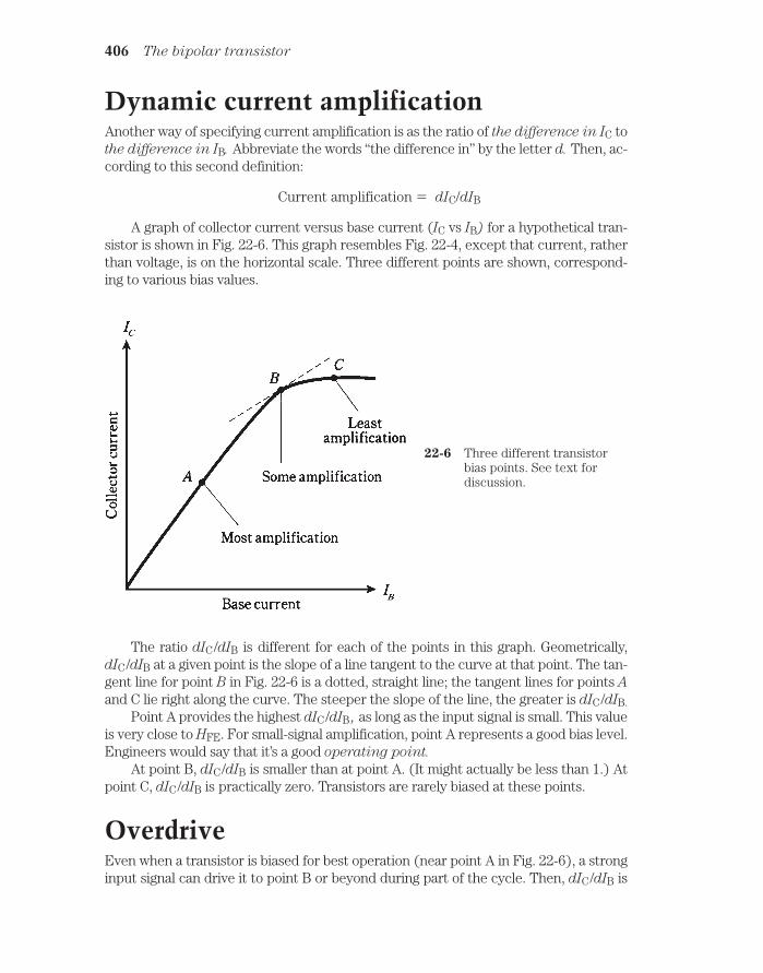
Dynamic current amplificationAnother way of specifying current amplification is as the ratio of the difference in IC tothe difference in IB. Abbreviate the words “the difference in” by the letter d. Then, ac-cording to this second definition:
Current amplification dIC/dIB
A graph of collector current versus base current (IC vs IB) for a hypothetical tran-sistor is shown in Fig. 22-6. This graph resembles Fig. 22-4, except that current, ratherthan voltage, is on the horizontal scale. Three different points are shown, correspond-ing to various bias values.
406 The bipolar transistor
22-6 Three different transistorbias points. See text fordiscussion.
The ratio dIC/dIB is different for each of the points in this graph. Geometrically,dIC/dIB at a given point is the slope of a line tangent to the curve at that point. The tan-gent line for point B in Fig. 22-6 is a dotted, straight line; the tangent lines for points Aand C lie right along the curve. The steeper the slope of the line, the greater is dIC/dIB.
Point A provides the highest dIC/dIB , as long as the input signal is small. This valueis very close to HFE. For small-signal amplification, point A represents a good bias level.Engineers would say that it’s a good operating point.
At point B, dIC/dIB is smaller than at point A. (It might actually be less than 1.) Atpoint C, dIC/dIB is practically zero. Transistors are rarely biased at these points.
OverdriveEven when a transistor is biased for best operation (near point A in Fig. 22-6), a stronginput signal can drive it to point B or beyond during part of the cycle. Then, dIC/dIB is

reduced, as shown in Fig. 22-7. Points X and Y in the graph represent the instantaneouscurrent extremes during the signal cycle.
Gain versus frequency 407
22-7 Excessive input reducesamplification.
When conditions are like those in Fig. 22-7, there will be distortion in a transistoramplifier. The output waveform will not have the same shape as the input waveform.This nonlinearity can sometimes be tolerated; sometimes it cannot.
The more serious trouble with overdrive is the fact that the transistor is in or nearsaturation during part of the cycle. When this happens, you’re getting “no bang for thebuck.” The transistor is doing futile work for a portion of every wave cycle. This reducescircuit efficiency, causes excessive collector current, and can overheat the base-collec-tor (B-C) junction. Sometimes overdrive can actually destroy a transistor.
Gain versus frequencyAnother important specification for a transistor is the range of frequencies over whichit can be used as an amplifier. All transistors have an amplification factor, or gain, thatdecreases as the signal frequency increases. Some devices will work well only up to afew megahertz; others can be used to several gigahertz.
Gain can be expressed in various different ways. In the above discussion, youlearned a little about current gain, expressed as a ratio. You will also sometimes hearabout voltage gain or power gain in amplifier circuits. These, too, can be expressed asratios. For example, if the voltage gain of a circuit is 15, then the output signal voltage(rms, peak, or peak-to-peak) is 15 times the input signal voltage. If the power gain of acircuit is 25, then the output signal power is 25 times the input signal power.
There are two expressions commonly used for the gain-versus-frequency behaviorof a bipolar transistor. The gain bandwidth product, abbreviated fT, is the frequency atwhich the gain becomes equal to 1 with the emitter connected to ground. If you try to

make an amplifier using a transistor at a frequency higher than its fT, you’ll fail! Thus fTrepresents an absolute upper limit of sorts.
The alpha cutoff frequency of a transitor is the frequency at which the gain be-comes 0.707 times its value at 1 kHz. A transistor might still have considerable gain atits alpha cutoff. By looking at the alpha cutoff frequency, you can get an idea of howrapidly the transistor loses gain as the frequency goes up. Some devices “die-off” fasterthan others.
Figure 22-8 shows the gain band width product and alpha cutoff frequency for a hy-pothetical transistor, on a graph of gain versus frequency. Note that the scales of thisgraph are nonlinear; they’re “scrunched up” at the higher values. This type of graph isuseful for showing some functions. It is called a log-log graph because both scales arelogarithmic rather than linear.
408 The bipolar transistor
22-8 Alpha cutoff and gain bandwidth product for ahypothetical transistor.
Common emitter circuitA transistor can be hooked up in three general ways. The emitter can be grounded forsignal, the base can be grounded for signal, or the collector can be grounded for signal.
Probably the most often-used arrangement is the common-emitter circuit. “Com-mon” means “grounded for the signal.” The basic configuration is shown in Fig. 22-9.
A terminal can be at ground potential for the signal, and yet have a significant dcvoltage. In the circuit shown, C1 looks like a dead short to the ac signal, so the emitteris at signal ground. But R1 causes the emitter to have a certain positive dc voltage withrespect to ground (or a negative voltage, if a PNP transistor is used). The exact dc volt-age at the emitter depends on the value of R1, and on the bias.

The bias is set by the ratio of resistances R2 and R3. It can be anything from zero,or ground potential, to + 12 V, the supply voltage. Normally it will be a couple of volts.
Capacitors C2 and C3 block dc to or from the input and output circuitry (whateverthat might be) while letting the ac signal pass. Resistor R4 keeps the output signal frombeing shorted out through the power supply.
A signal voltage enters the common-emitter circuit through C2, where it causes thebase current, IB to vary. The small fluctuations in IB cause large changes in the collectorcurrent, IC. This current passes through R4, causing a fluctuating dc voltage to appearacross this resistor. The ac part of this passes unhindered through C3 to the output.
The circuit of Fig. 22-9 is the basis for many amplifiers, from audio frequenciesthrough ultra-high radio frequencies. The common-emitter configuration produces thelargest gain of any arrangement. The output is 180 degrees out of phase with the input.
Common-base circuitAs its name implies, the common-base circuit, shown in general form by Fig. 22-10,has the base at signal ground.
The dc bias on the transistor is the same for this circuit as for the common-emittercircuit. The difference is that the input signal is applied at the emitter, instead of at thebase. This causes fluctuations in the voltage across R1, causing variations in IB. The re-sult of these small current fluctuations is a large change in the dc current through R4.Therefore amplification occurs.
Common base circuit 409
22-9 Common-emitter circuit configuration.

Instead of varying IB by injecting the signal at the base, it’s being done by injectingthe signal at the emitter. Therefore, in the common-base arrangement, the output sig-nal is in phase with the input, rather than out of phase.
The signal enters through C1. Resistor R1 keeps the input signal from beingshorted to ground. Bias is provided by R2 and R3. Capacitor C2 keeps the base at signalground. Resistor R4 keeps the signal from being shorted out through the power supply.The output is through C3.
The common-base circuit provides somewhat less gain than a common-emitter cir-cuit. But it is more stable than the common-emitter configuration in some applications,especially in radio-frequency power amplifiers.
Common-collector circuitA common-collector circuit (Fig. 22-11) operates with the collector at signal ground.The input is applied at the base just as it is with the common-emitter circuit.
The signal passes through C2 onto the base of the transistor. Resistors R2 and R3provide the correct bias for the base. Resistor R4 limits the current through the tran-sistor. Capacitor C3 keeps the collector at signal ground. A fluctuating direct currentflows through R1, and a fluctuating dc voltage therefore appears across it. The ac partof this voltage passes through C1 to the output. Because the output follows the emittercurrent, this circuit is sometimes called an emitter follower circuit.
410 The bipolar transistor
22-10 Common-base circuit configuration.

The output of this circuit is in phase with the input. The input impedance is high,and the output impedance is low. For this reason, the common-collector circuit can beused to match high impedances to low impedances. When well designed, an emitter fol-lower works over a wide range of frequencies, and is a low-cost alternative to a broad-band impedance-matching transformer.
QuizRefer to the text in this chapter if necessary. A good score is at least 18 correct. Answersare in the back of the book.
1. In a PNP circuit, the collector:
A. Has an arrow pointing inward.
B. Is positive with respect to the emitter.
C. Is biased at a small fraction of the base bias.
D. Is negative with respect to the emitter.
2. In many cases, a PNP transistor can be replaced with an NPN device and thecircuit will do the same thing, provided that:
A. The supply polarity is reversed.
Quiz 411
22-11 Common-collector circuit configuration. This arrangement is also knownas an emitter follower.

B. The collector and emitter leads are interchanged.
C. The arrow is pointing inward.
D. No! A PNP device cannot be replaced with an NPN.
3. A bipolar transistor has:
A. Three P-N junctions.
B. Three semiconductor layers.
C. Two N-type layers around a P-type layer.
D. A low avalanche voltage.
4. In the dual-diode model of an NPN transistor, the emitter corresponds to:
A. The point where the cathodes are connected together.
B. The point where the cathode of one diode is connected to the anode of theother.
C. The point where the anodes are connected together.
D. Either of the diode cathodes.
5. The current through a transistor depends on:
A. EC.
B. EB relative to EC.
C. IB.
D. More than one of the above.
6. With no signal input, a bipolar transistor would have the least IC when:
A. The emitter is grounded.
B. The E-B junction is forward biased.
C. The E-B junction is reverse biased.
D. The E-B current is high.
7. When a transistor is conducting as much as it possibly can, it is said to be:
A. In cutoff.
B. In saturation.
C. Forward biased.
D. In avalanche.
8. Refer to Fig. 22-12. The best point at which to operate a transistor as asmall-signal amplifier is:
A. A.
B. B.
C. C.
D. D.
412 The bipolar transistor
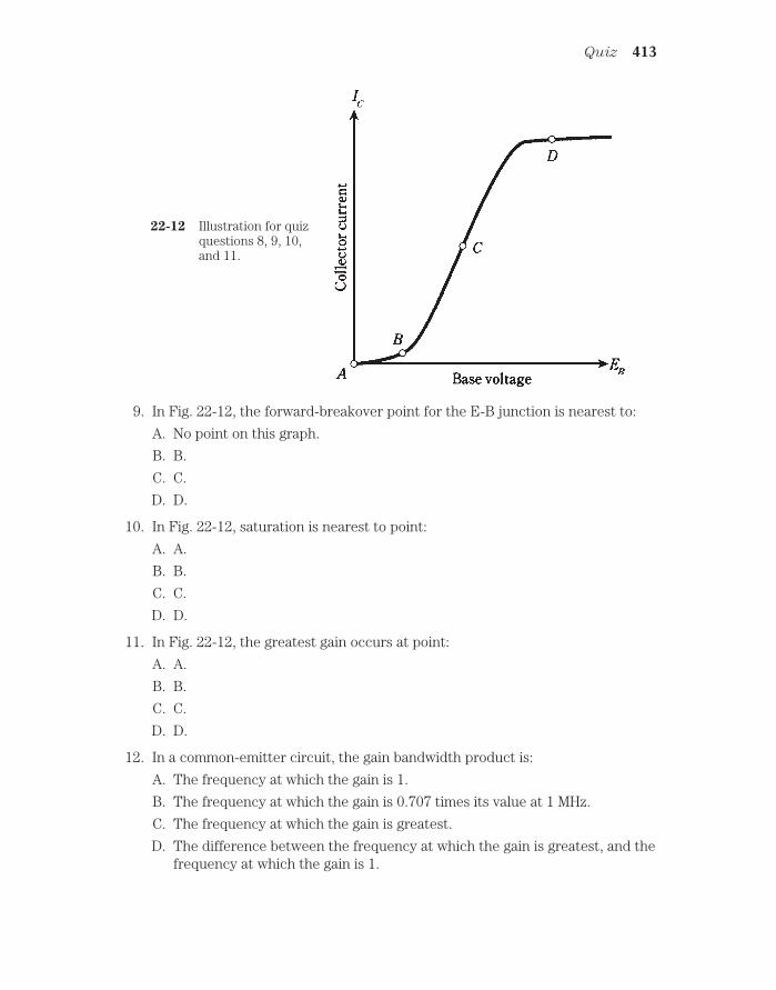
9. In Fig. 22-12, the forward-breakover point for the E-B junction is nearest to:
A. No point on this graph.
B. B.
C. C.
D. D.
10. In Fig. 22-12, saturation is nearest to point:
A. A.
B. B.
C. C.
D. D.
11. In Fig. 22-12, the greatest gain occurs at point:
A. A.
B. B.
C. C.
D. D.
12. In a common-emitter circuit, the gain bandwidth product is:
A. The frequency at which the gain is 1.
B. The frequency at which the gain is 0.707 times its value at 1 MHz.
C. The frequency at which the gain is greatest.
D. The difference between the frequency at which the gain is greatest, and thefrequency at which the gain is 1.
Quiz 413
22-12 Illustration for quizquestions 8, 9, 10,and 11.

13. The configuration most often used for matching a high input impedance to alow output impedance puts signal ground at:
A. The emitter.
B. The base.
C. The collector.
D. Any point; it doesn’t matter.
14. The output is in phase with the input in a:
A. Common-emitter circuit.
B. Common-base circuit.
C. Common-collector circuit.
D. More than one of the above.
15. The greatest possible amplification is obtained in:
A. A common-emitter circuit.
B. A common-base circuit.
C. A common-collector circuit.
D. More than one of the above.
16. The input is applied to the collector in:
A. A common-emitter circuit.
B. A common-base circuit.
C. A common-collector circuit.
D. None of the above.
17. The configuration noted for its stability in radio-frequency power amplifiers isthe:
A. Common-emitter circuit.
B. Common-base circuit.
C. Common-collector circuit.
D. Emitter-follower circuit.
18. In a common-base circuit, the output is taken from the:
A. Emitter.
B. Base.
C. Collector.
D. More than one of the above.
19. The input signal to a transistor amplifier results in saturation during part of thecycle. This produces:
A. The greatest possible amplification.
B. Reduced efficiency.
414 The bipolar transistor
C. Avalanche effect.
D. Nonlinear output impedance.
20. The gain of a transistor in a common-emitter circuit is 100 at a frequency of1000 Hz. The gain is 70.7 at 335 kHz. The gain drops to 1 at 210 MHz. The alphacutoff is:
A. 1 kHz.
B. 335 kHz.
C. 210 MHz.
D. None of the above.
Quiz 415

23CHAPTER
The field-effect transistorBIPOLAR TRANSISTORS BEHAVE AS THEY DO BECAUSE CURRENT VARIATIONS AT one P-N junction produce larger current variations at another. You’ve seen a simpli-fied picture of how this happens, and how the effect can be exploited to get currentamplification.
The bipolar transistor isn’t the only way that semiconductors can be combined toget amplification effects. The other major category of transistor, besides the bipolar de-vice, is the field-effect transistor or FET. There are two main types of FET: the junc-
tion FET (JFET) and the metal-oxide FET (MOSFET).
Principle of the JFETA JFET can have any of several different forms. They all work the same way: the cur-rent varies because of the effects of an electric field within the device.
The workings inside a JFET can be likened to the control of water flow through agarden hose. Electrons or holes pass from the source (S) electrode to the drain (D).This results in a drain current, ID , that is generally the same as the source current,
IS. This is analogous to the fact that the water comes out of a garden hose at the samerate it goes in (assuming that there aren’t any leaks in the hose).
The rate of flow of charge carriers—that is, the current—depends on the voltage ata regulating electrode called the gate (G). Fluctuations in gate voltage, EG, causechanges in the current through the channel, IS or ID. Small fluctuations in the controlvoltage EG can cause large variations in the flow of charge carriers through the JFET.This translates into voltage amplification in electronic circuits.
416 !
"# #$ !

N-channel versus P-channelA simplified drawing of an N-channel JFET, and its schematic symbol, are shown inFig. 23-1. The N-type material forms the channel, or the path for charge carriers. In theN-channel device, the majority carriers are electrons. The source is at one end of thechannel, and the drain is at the other. You can think of electrons as being “injected” intothe source and “collected” from the drain as they pass through the channel. The drainis positive with respect to the source.
N-channel versus P-channel 417
23-1 Simplified cross-sectional drawing of an N-channel JFET (at A) and itsschematic symbol (at B).
In an N-channel device, the gate consists of P-type material. Another, larger sectionP-type material, called the substrate, forms a boundary on the side of the channel op-posite the gate. The JFET is formed in the substrate during manufacture by a processknown as diffusion.
The voltage on the gate produces an electric field that interferes with the flow ofcharge carriers through the channel. The more negative EG becomes, the more theelectric field chokes off the current though the channel, and the smaller ID becomes.
A P-channel JFET (Fig. 23-2) has a channel of P-type semiconductor. The major-ity charge carriers are holes. The drain is negative with respect to the source. In a sense,holes are “injected” into the source and are “collected” from the drain. The gate and thesubstrate are of N-type material.
In the P-channel JFET, the more positive EG gets, the more the electric field chokesoff the current through the channel, and the smaller ID becomes.
You can recognize the N-channel device by the arrow pointing inward at the gate,and the P-channel JFET by the arrow pointing outward. Also, you can tell which iswhich (sometimes arrows are not included in schematic diagrams) by the power-supplypolarity. A positive drain indicates an N-channel JFET, and a negative drain indicates aP-channel type.

In electronic circuits, N-channel and P-channel devices can do the same kinds ofthings. The main difference is the polarity. An N-channel device can almost always bereplaced with a P-channel JFET, and the power-supply polarity reversed, and the cir-cuit will still work if the new device has the right specifications. Just as there are differ-ent kinds of bipolar transistors, there are various types of JFETs, each suited to aparticular application. Some JFETs work well as weak-signal amplifiers and oscillators;others are made for power amplification.
Field-effect transistors have some advantages over bipolar devices. Perhaps themost important is that FETs are available that generate less internal noise than bipolartransistors. This makes them excellent for use in sensitive radio receivers at very highor ultra-high frequencies.
Field-effect transistors have high input impedances. The gate controls the flow ofcharge carriers by means of an electric field, rather than via an electric current.
Depletion and pinchoffEither the N-channel or the P-channel JFET works because the voltage at the gatecauses an electric field that interferes, more or less, with the flow of charge carriersalong the channel. A simplified drawing of the situation for an N-channel device isshown in Fig. 23-3. For a P-channel device, just interchange polarity (minus/plus) andsemiconductor types (N/P) in this discussion.
As the drain voltage ED increases, so does the drain current ID, up to a certainlevel-off value. This is true as long as the gate voltage EG is constant, and is not too largenegatively.
But as EG becomes increasingly negative (Fig. 23-3A), a depletion region (solidblack) begins to form in the channel. Charge carriers cannot flow in this region; theymust pass through a narrowed channel. The more negative EG becomes, the wider thedepletion region gets, as shown at B. Ultimately, if the gate becomes negative enough,
418 The field-effect transistor
23-2 Simplified cross-sectional drawing of a P-channel JFET (at A) and itsschematic symbol (at B).

the depletion region will completely obstruct the flow of charge carriers. This is calledpinchoff, and is illustrated at C.
Again, think of the garden-hose analogy. More negative gate voltages, EG, corre-spond to stepping harder and harder on the hose. When pinchoff takes place, you’ve cutoff the water flow entirely, perhaps by bearing down with all your weight on one foot!Biasing beyond pinchoff is something like loading yourself up with heavy weights as youbalance on the hose, thereby shutting off the water flow with extra force.
JFET biasingTwo biasing arrangements for an N-channel JFET are shown in Fig. 23-4. Thesehookups are similar to the way an NPN bipolar transistor is connected, except that thesource-gate (SG) junction is not forward-biased.
At A, the gate is grounded through resistor R2. The source resistor, R1, limits thecurrent through the JFET. The drain current, ID, flows through R3, producing a voltageacross this resistor. The ac output signal passes through C2.
At B, the gate is connected to a voltage that is negative with respect to groundthrough potentiometer R2. Adjusting this potentiometer results in a variable negativeEG between R2 and R3. Resistor R1 limits the current through the JFET. The drain cur-rent, ID, flows through R4, producing a voltage across it; the ac output signal passesthrough C2.
In both of these circuits, the drain is positive relative to ground. For a P-channelJFET, reverse the polarities in Fig. 23-4. The connections are somewhat similar to theway a PNP bipolar transistor is used, except the SG junction isn’t forward-biased.
JFET biasing 419
23-3 At A, depletion region (solidarea) is not wide, and manycharge carriers (arrows) flow.At B, depletion region iswider, channel is narrower,and fewer carriers flow. At C,channel is completelyobstructed, and no carriersflow.

Typical JFET power-supply voltages are comparable to those with bipolar transis-tors. The voltage between the source and drain, abbreviated ED, can range from about3 V to 150 V; most often it is 6 V to 12 V.
The biasing arrangement in Fig. 23-4A is commonly used for weak-signal ampli-fiers, low-level amplifiers and oscillators. The scheme at B is more often employed inpower amplifiers having a substantial input signal.
Voltage amplificationThe graph of Fig. 23-5 shows the drain (channel) current, ID, as a function of the gatebias voltage, EG, for a hypothetical N-channel JFET. The drain voltage, ED, is assumedto be constant.
420 The field-effect transistor
23-4 Two methods of biasing an N-channel JFET. At A, fixed gate bias; atB, variable gate bias.

When EG is fairly large and negative, the JFET is pinched off, and no current flowsthrough the channel. As EG gets less negative, the channel opens up, and current be-gins flowing. As EG gets still less negative, the channel gets wider and the current ID in-creases. As EG approaches the point where the SG junction is at forward breakover, thechannel conducts as well as it possibly can.
If EG becomes positive enough so that the SG junction conducts, the JFET will nolonger work properly. Some of the current in the channel will then be shunted offthrough the gate, a situation that is never desired in a JFET. The hose will spring a leak!
The best amplification for weak signals is obtained when the gate bias, EG, is suchthat the slope of the curve in Fig. 23-5 is the greatest. This is shown roughly by therange marked X in the figure. For power amplification, however, results are often bestwhen the JFET is biased at, or even beyond, pinchoff, in the range marked Y.
The current ID passes through the drain resistor, as shown in either diagram of Fig.23-4. Small fluctuations in EG cause large changes in ID, and these variations in turnproduce wide swings in the dc voltage across R3 (at A) or R4 (at B). The ac part of thisvoltage goes through capacitor C2, and appears at the output as a signal of muchgreater ac voltage than that of the input signal at the gate. That’s voltage amplification.
Drain current versus drain voltageYou might expect that the current ID, passing through the channel of a JFET, would in-crease linearly with increasing drain voltage ED. But this is not, in general, what hap-pens. Instead, the current ID rises for awhile, and then starts to level off.
The drain current ID (which is the same as the channel current) is often plotted asa function of drain voltage, ED, for various values of gate voltage, EG. The resulting set of
Drain current versus drain voltage 421
23-5 Relative draincurrent as a functionof gate voltage for ahypotheticalN-channel JFET.

curves is called a family of characteristic curves for the device. The graph of Fig. 23-6shows a family of characteristic curves for a hypothetical N-channel JFET. Engineersmake use of these graphs when deciding on the best JFET type for an electronic circuit.Also of importance is the curve of ID vs EG, one example of which is shown in Fig. 23-5.
422 The field-effect transistor
23-6 A family ofcharacteristic curvesfor a hypotheticalN-channel JFET.
TransconductanceRecall the discussion of dynamic current amplification from the last chapter. This isa measure of how well a bipolar transistor amplifies a signal. The JFET analog of this iscalled dynamic mutual conductance or transconductance.
Refer again to Fig. 23-5. Suppose that EG is a certain value, with a corresponding IDresulting. If the gate voltage changes by a small amount dEG then the drain current willalso change by a certain increment dID. The transconductance is the ratio dID/dEG.Geometrically, this translates to the slope of a line tangent to the curve of Fig. 23-5.
The value of dID/dEG is obviously not the same everywhere along the curve. Whenthe JFET is biased beyond pinchoff, in the region marked Y in the figure, the slope ofthe curve is zero. There is no drain current, even if the gate voltage changes. Only whenthe channel is conducting will there be a change in ID when there is a change in EG. Theregion where the transconductance, dID/dEG, is the greatest is the region marked X,where the slope of the curve is steepest. This is where the most gain can be obtainedfrom the JFET.
The MOSFETThe acronym MOSFET (pronounced “moss-fet”) stands for metal-oxide-semiconductorfield-effect transistor. A simplified cross-sectional drawing of an N-channel MOSFET,along with the schematic symbol, is shown in Fig. 23-7. The P-channel device is shown in

the drawings of Fig. 23-8. The N-channel device is diffused into a substrate of P-type semi-conductor material. The P-channel device is diffused into a substrate of N-type material.
The MOSFET 423
23-7 At A, simplified cross-sectional drawing of an N-channel MOSFET. At B, theschematic symbol.
23-8 At A, simplified cross-sectional drawing of a P-channel MOSFET. At B, theschematic symbol.
Super-high input impedanceWhen the MOSFET was first developed, it was called an insulated-gate FET or IGFET.
This is perhaps more descriptive of the device than the currently accepted name. Thegate electrode is actually insulated, by a thin layer of dielectric, from the channel. As a

result, the input impedance is even higher than that of a JFET; the gate-to-source re-sistance of a typical MOSFET is comparable to that of a capacitor! This means that aMOSFET draws essentially no current, and therefore no power, from the signal source.Some MOSFETs have input resistance exceeding a trillion (1012) ohms.
The main problemThe trouble with MOSFETs is that they can be easily damaged by static electric dis-charges. When building or servicing circuits containing MOS devices, technicians mustuse special equipment to ensure that their hands don’t carry static charges that mightruin the components. If a static discharge occurs through the dielectric of a MOS de-vice, the component will be destroyed permanently. Warm and humid climates do notoffer protection against the hazard. (This author’s touch has dispatched several MOS-FETs in Miami during the summer.)
FlexibilityIn actual circuits, an N-channel JFET can sometimes be replaced directly with anN-channel MOSFET; P-channel devices can be similarly interchanged. But the charac-teristic curves for MOSFETs are not the same as those for JFETs. The main differenceis that the SG junction in a MOSFET is not a P-N junction. Therefore, forward breakovercannot occur. An EG of more than 0.6 V can be applied to an N-channel MOSFET, oran EG more negative than 0.6 V to a P-channel device, without a current “leak” tak-ing place.
A family of characteristic curves for a hypothetical N-channel MOSFET is shown inthe graph of Fig. 23-9. The device will work with positive gate bias as well as with neg-ative gate bias. A P-channel MOSFET behaves in a similar way, being usable with eitherpositive or negative EG.
424 The field-effect transistor
23-9 A family ofcharacteristic curvesfor a hypotheticalN-channel MOSFET.

Depletion mode versus enhancement modeThe JFET works by varying the width of the channel. Normally the channel is wideopen; as the depletion region gets wider and wider, choking off the channel, the chargecarriers are forced to pass through a narrower and narrower path. This is known as thedepletion mode of operation for a field-effect transistor.
A MOSFET can also be made to work in the depletion mode. The drawings andschematic symbols of Figs. 23-7 and 23-8 show depletion-mode MOSFETs.
However, MOS technology also allows an entirely different means of operation. Anenhancement-mode MOSFET normally has a pinched-off channel. It is necessary toapply a bias voltage, EG, to the gate so that a channel will form. If EG = 0 in such a MOS-FET, that is, if the device is at zero bias, the drain current ID is zero when there is no sig-nal input.
The schematic symbols for N-channel and P-channel enhancement-mode devicesare shown in Fig. 23-10. The vertical line is broken. This is how you can recognize an en-hancement-mode device in circuit diagrams.
Common source circuit 425
23-10 Schematic symbols for enhancement-mode MOSFETs. At A,N-channel; at B, P-channel.
Common-source circuitThere are three different circuit hookups for FETs, just as there are for bipolar tran-sistors. These three arrangements have the source, the gate, or the drain at signalground.
The common-source circuit places the source at signal ground. The input is at thebase. The general configuration is shown in Fig. 23-11. An N-channel JFET is used here,

but the device could be an N-channel, depletion-mode MOSFET and the circuit diagramwould be the same. For an N-channel, enhancement-mode device, an extra resistorwould be necessary, running from the gate to the positive power supply terminal. ForP-channel devices, the supply would provide a negative, rather than a positive, voltage.
426 The field-effect transistor
23-11 Common-source circuit configuration.
This circuit is an almost exact replica of the grounded-emitter bipolar arrangement.The only difference is the lack of a voltage-dividing network for bias on the control elec-trode.
Capacitor C1 and resistor R1 place the source at signal ground while elevating thiselectrode above ground for dc. The ac signal enters through C2; resistor R2 adjusts theinput impedance and provides bias for the gate. The ac signal passes out of the circuitthrough C3. Resistor R3 keeps the output signal from being shorted out through thepower supply.
The circuit of Fig. 23-11 is the basis for amplifiers and oscillators, especially at ra-dio frequencies. The common-source arrangement provides the greatest gain of thethree FET circuit configurations. The output is 180 degrees out of phase with the input.
Common-gate circuitThe common-gate circuit (Fig. 23-12) has the gate at signal ground. The input is ap-plied to the source. The illustration shows an N-channel JFET. For other types of FETs,the same considerations apply as described above for the common-source circuit.Enhancement-mode devices would require a resistor between the gate and the positivesupply terminal (or the negative terminal if the MOSFET is P-channel).

The dc bias for the common-gate circuit is basically the same as that for the com-mon-source arrangement. But the signal follows a different path. The ac input signal en-ters through C1. Resistor R1 keeps the input from being shorted to ground. Gate bias isprovided by R1 and R2; capacitor C2 places the gate at signal ground. In some com-mon-gate circuits, the gate electrode is directly grounded, and components R2 and C2are not used. The output leaves the circuit through C3. Resistor R3 keeps the outputsignal from being shorted through the power supply.
The common-gate arrangement produces less gain than its common-source coun-terpart. But this is not all bad; a common-gate amplifier is very stable, and is not likelyto break into unwanted oscillation. The output is in phase with the input.
Common-drain circuitA common-drain circuit is shown in Fig. 23-13. This circuit has the collector at signalground. It is sometimes called a source follower.
The FET is biased in the same way as for the common-source and common-gatecircuits. In the illustration, an N-channel JFET is shown, but any other kind of FETcould be used, reversing the polarity for P-channel devices. Enhancement-mode MOS-FETs would need a resistor between the gate and the positive supply terminal (or thenegative terminal if the MOSFET is P-channel).
The input signal passes through C2 to the gate. Resistors R1 and R2 provide gatebias. Resistor R3 limits the current. Capacitor C3 keeps the drain at signal ground. Fluc-tuating dc (the channel current) flows through R1 as a result of the input signal; this
Common draine circuit 427
23-12 Common-gate circuit configuration.

causes a fluctuating dc voltage to appear across the resistor. The output is taken fromthe source, and its ac component passes through C1.
The output of the common-drain circuit is in phase with the input. This scheme isthe FET analog of the bipolar common-collector arrangement. The output impedanceis rather low, making this circuit a good choice for broadband impedance matching.
428 The field-effect transistor
23-13 Common-drain circuit configuration.
Table 23-1. Transistor circuitabbreviations.
Quantity Abbreviations
Base-emitter voltage EB, VB, EBE, VBECollector-emitter voltage EC, VC, ECE, VCECollector-base voltage EBC, VBC, ECB, VCBGate-source voltage EG, VG, EGS, VGSDrain-source voltage ED, VD, EDS, VDSDrain-gate voltage EDG, VDG, EGD, VGDEmitter current IEBase current IB, IBE, IEBCollector current IC, ICE, IECSource current ISGate current IG, IGS, ISG*
Drain current ID, IDS, ISD
*This is almost always insignificant.

A note about notationIn electronics, you’ll encounter various different symbols that denote the same things.You might have already noticed that voltage is sometimes abbreviated by the letter E,and sometimes by the letter V. In bipolar and field-effect transistor circuits, you’ll some-times come across symbols like VCE and VGS; in this book they appear as EC and EG, re-spectively. Subscripts can be either uppercase or lowercase.
Remember that, although notations vary, the individual letters almost always standfor the same things. A variable might be denoted in different ways, depending on theauthor or engineer; but it’s rare for one notation to acquire multiple meanings. The mostcommon sets of abbreviations from this chapter and chapter 22 are shown in Table 23-1.
Wouldn’t it be great if there were complete standardization in electronics? And itwould be wonderful if everything were standardized in all other aspects of life, too,would it not?
Or would it?
QuizRefer to the text in this chapter if necessary. A good score is at least 18 correct. Answersare in the back of the book.
1. The current through the channel of a JFET is directly affected by all of thefollowing except:
A. Drain voltage.
B. Transconductance.
C. Gate voltage.
D. Gate bias.
2. In an N-channel JFET, pinchoff occurs when the gate bias is:
A. Slightly positive.
B. Zero.
C. Slightly negative.
D. Very negative.
3. The current consists mainly of holes when a JFET:
A. Has a P-type channel.
B. Is forward-biased.
C. Is zero-biased.
D. Is reverse-biased.
4. A JFET might work better than a bipolar transistor in:
A. A rectifier.
B. A radio receiver.
C. A filter.
D. A transformer.
Quiz 429

5. In a P-channel JFET:
A. The drain is forward-biased.
B. The gate-source junction is forward biased.
C. The drain is negative relative to the source.
D. The gate must be at dc ground.
6. A JFET is sometimes biased at or beyond pinchoff in:
A. A power amplifier.
B. A rectifier.
C. An oscillator.
D. A weak-signal amplifier.
7. The gate of a JFET has:
A. Forward bias.
B. High impedance.
C. Low reverse resistance.
D. Low avalanche voltage.
8. A JFET circuit essentially never has:
A. A pinched-off channel.
B. Holes as the majority carriers.
C. A forward-biased P-N junction.
D. A high-input impedance.
9. When a JFET is pinched off:
A. dID/dEG is very large with no signal.
B. dID/dEG might vary considerably with no signal.
C. dID/dEG is negative with no signal.
D. dID/dEG is zero with no signal.
10. Transconductance is the ratio of:
A. A change in drain voltage to a change in source voltage.
B. A change in drain current to a change in gate voltage.
C. A change in gate current to a change in source voltage.
D. A change in drain current to a change in drain voltage.
11. Characteristic curves for JFETs generally show:
A Drain voltage as a function of source current.
B. Drain current as a function of gate current.
C. Drain current as a function of drain voltage.
D. Drain voltage as a function of gate current.
12. A disadvantage of a MOS component is that:
430 The field-effect transistor

A. It is easily damaged by static electricity.
B. It needs a high input voltage.
C. It draws a large amount of current.
D. It produces a great deal of electrical noise.
13. The input impedance of a MOSFET:
A. Is lower than that of a JFET.
B. Is lower than that of a bipolar transistor.
C. Is between that of a bipolar transistor and a JFET.
D. Is extremely high.
14. An advantage of MOSFETs over JFETs is that:
A. MOSFETs can handle a wider range of gate voltages.
B. MOSFETs deliver greater output power.
C. MOSFETs are more rugged.
D. MOSFETs last longer.
15. The channel in a zero-biased JFET is normally:
A. Pinched off.
B. Somewhat open.
C. All the way open.
D. Of P-type semiconductor material.
16. When an enhancement-mode MOSFET is at zero bias:
A. The drain current is high with no signal.
B. The drain current fluctuates with no signal.
C. The drain current is low with no signal.
D. The drain current is zero with no signal.
17. An enhancement-mode MOSFET can be recognized in schematic diagrams by:
A. An arrow pointing inward.
B. A broken vertical line inside the circle.
C. An arrow pointing outward.
D. A solid vertical line inside the circle.
18. In a source follower, which of the electrodes of the FET receives the inputsignal?
A. None of them.
B. The source.
C. The gate.
D. The drain.
Quiz 431

19. Which of the following circuits has its output 180 degrees out of phase with itsinput?
A. Common source.
B. Common gate.
C. Common drain.
D. All of them.
20. Which of the following circuits generally has the greatest gain?
A. Common source.
B. Common gate.
C. Common drain.
D. It depends only on bias, not on which electrode is grounded.
432 The field-effect transistor

24CHAPTER
AmplifiersIN THE PRECEDING TWO CHAPTERS, YOU SAW SCHEMATIC DIAGRAMS WITH BIPOLARand field-effect transistors. The main intent was to acquaint you with biasing schemes.Some of the diagrams were of basic amplifier circuits. This chapter examines amplifiersmore closely, but the subject is vast. For a thorough treatment, you should consult abook devoted to amplifiers and amplification.
The decibelThe extent to which a circuit amplifies is called the amplification factor. This can begiven as a simple number, such as 100, meaning that the output signal is 100 times asstrong as the input. More often, amplification factor is specified in units called decibels,
abbreviated dB.
It’s important to keep in mind what is being amplified: current, voltage, or power. Cir-cuits are designed to amplify one of these aspects of a signal, but not necessarily the oth-ers. In a given circuit, the amplification factor is not the same for all three parameters.
Perception is logarithmicYou don’t perceive loudness directly. Instead, you sense it in a nonlinear way. Physicistsand engineers have devised the decibel system, in which amplitude changes are ex-pressed according to the logarithm of the actual value (Fig. 24-1), to define relativesignal strength.
Gain is assigned positive decibel values; loss is assigned negative values. Therefore,if signal A is at 6 dB relative to signal B, then A is stronger than B; if signal A is at 14 dB relative to B, then A is weaker than B.
An amplitude change of plus or minus 1 dB is about equal to the smallest change alistener can detect if the change is expected. If the change is not expected, then thesmallest difference a listener can notice is about plus or minus 3 dB.
433 !
"# #$ !

For voltageSuppose there is a circuit with an rms ac input voltage of Ein and an rms ac output volt-age of Eout. Then the voltage gain of the circuit, in decibels, is given by the formula:
Gain (dB) 20 log10(Eout/Ein)
The logarithm function is abbreviated log. The subscript 10 means that the base of thelogarithm is 10. (Logarithms can have bases other than 10. This gets a little sophisti-cated, and it won’t be discussed here.) You don’t have to know the mathematical theoryof logarithms to calculate them. All you need, and should buy right this minute if youdon’t have one, is a calculator that includes logarithm functions.
From now on, the base-10 logarithm will be called just the “logarithm,” and the sub-script 10 will be omitted.
Problem 24-1A circuit has an rms ac input of 1.00 V and an rms ac output of 14.0 V. What is the gainin decibels?
First, find the ratio Eout/Ein. Because Eout 14. 0 V and Ein 1.00 V, this ratio is14.0/1.00, or 14.0. Then, find the logarithm of 14.0. Your calculator will tell you that log14.0 1.146128036 (it adds a lot of unnecessary digits). Finally, press the various but-tons to multiply this number by 20, getting (with my calculator, anyway) 22.92256071.Round off to three significant figures, because that’s all you’re entitled to: Gain 22.9dB.
Problem 24-2A circuit has an rms ac input voltage of 24.2 V and an rms ac output voltage of 19.9 V.What is the gain in decibels?
434 Amplifiers
24-1 The base-10 logarithmfunction foroutput/input ratios of 1to 10.

Find the ratio Eout/Ein 19.9/24.2 0.822.... (The three dots indicate extra digitsintroduced by the calculator. You can leave them in untill the final roundoff.) Find thelogarithm of this: log 0.822... 0.0849.... Then multiply by 20: Gain 1.699... dB,rounded off to 1.70 dB.
Negative gain translates into loss. A gain of 1.70 dB is equivalent to a loss of 1.70dB. The circuit of Problem 24-2 is not an amplifier—or if it is supposed to be, it isn’tworking!
If a circuit has the same output voltage as input voltage, that is, if Eout Ein, thenthe gain is 0 dB. The ratio Eout/Ein is always equal to 1 in this case, and log 1 0.
It’s important to remember, when doing gain calculations, always to use the sameunits for the input and the output signal levels. Don’t use millivolts for Eout and micro-volts for Ein, for example. This applies to current and power also.
For currentThe current gain of a circuit is calculated just the same way as for voltage. If Iin is therms ac input current and Iout is the rms ac output current, then
Gain (dB) 20 log (Iout/Iin)
Often, a circuit that produces voltage gain will produce current loss, and vice versa.An excellent example is a simple ac transformer.
Some circuits have gain for both the voltage and the current, although not the samedecibel figures. The reason is that the output impedance is different from the input im-pedance, altering the ratio of voltage to current.
For power The power gain of a circuit, in decibels, is calculated according to the formula
Gain (dB) 10 log (Pout/Pin)
where Pout is the output signal power and Pin is the input signal power.
Problem 24-3A power amplifier has an input of 5.03 W and an output of 125 W. What is the gain indecibels?
First find the ratio Pout/Pin 125/5.03 24.85.... Then find the logarithm: log24.85... 1.395.... Finally, multiply by 10 and round off: Gain 10 1.395... 14.0 dB.
Problem 24-4An attenuator provides 10 dB power reduction. The input power is 94 W. What is theoutput power?
This problem requires you to “plug values into” the formula. An attenuator pro-duces a power loss. When you hear that the attenuation is 10 dB, it is the same thing asa gain of 10 dB. You know Pin 94 W, the unknown is Pout. Therefore,
10 10 log (Pout/94)
The decibel 435

Solving this formula proceeds in several steps. First, divide each side by 10, getting
1 log (Pout/94)
Then, take the base-10 antilogarithm, also known as the antilog, of each side.The antilog function is the inverse of the log function; that is, it “undoes” the log func-tion. The function antilog (x) is sometimes written as 10x. Thus
antilog (1) 101 0.1 Pout/94
Now, multiply each side of the equation by 94, getting
94 0.1 9.4 Pout
Therefore, the output power is 9.4 W.Don’t confuse the voltage/current and power formulas. In general, for a given out-
put/input ratio, the dB gain for voltage or current is twice the dB gain for power. Table24-1 gives dB gain figures for various ratios of voltage, current, and power.
436 Amplifiers
Table 24-1. Decibel gain figures for various ratios of voltage,current, and power.
Ratio Voltage or current gain Power gain
0.000 000 001 (109) 180 dB 90 dB0.000 000 01 (108) 160 dB 80 dB0.000 000 1 (107) 140 dB 70 dB0.000 001 (106) 120 dB 60 dB0.000 01 (105) l00 dB 50 dB0.000 1 (104) 80 dB 40 dB0.001 60 dB 30 dB0.01 40 dB 20 dB0.1 20 dB 10 dB0.25 12 dB 6 dB0.5 6 dB 3 dB1 0 dB 0 dB2 6 dB 3 dB4 12 dB 6 dB10 20 dB 10 dB100 40 dB 20 dB1000 60 dB 30 dB10,000 (104) 80 dB 40 dB100,000 (105) 100 dB 50 dB1,000,000 (106) 120 dB 60 dB10,000,000 (107) 140 dB 70 dB100,000,000 (108) 160 dB 80 dB1,000,000,000 (109) 180 dB 90 dB10,000,000,000 (1010) 200 dB 100 dB

Basic bipolar amplifier circuitIn the previous chapters, you saw some circuits that will work as amplifiers. The princi-ple is the same for all electronic amplification circuits. A signal is applied at some con-trol point, causing a much greater signal to appear at the output.
In Fig. 24-2, an NPN bipolar transistor is connected as a common-emitter amplifier.The input signal passes through C2 to the base. Resistors R2 and R3 provide bias. Re-sistor R1 and capacitor C1 allow for the emitter to have a dc voltage relative to ground,while being grounded for signals. Resistor R1 also limits the current through the tran-sistor. The ac output signal goes through capacitor C3. Resistor R4 keeps the ac outputsignal from being short-circuited through the power supply.
Basic bipolar amplifier circuit 437
24-2 An amplifier using a bipolar transistor. Component designators and valuesare discussed in the text.
In this amplifier, the capacitors must have values large enough to allow the ac sig-nal to pass with ease. But they shouldn’t be much larger than the minimum necessaryfor this purpose. If an 0.1-µF capacitor will suffice, there’s no point in using a 47-µF ca-pacitor. That would introduce unwanted losses into the circuit, and would also makethe circuit needlessly expensive to build.
The ideal capacitance values depend on the design frequency of the amplifier, and alsoon the impedances at the input and output. In general, as the frequency and/or circuit im-pedance increase, less and less capacitance is needed. At audio frequencies, say 300 Hz to20 kHz, and at low impedance, the capacitors might be as large as 100 µF. At radio fre-quencies, such as 1 MHz to 50 MHz, and with high impedances, values will be only a

fraction of a microfarad, down to picofarads at the highest frequencies and impedances.The exact values are determined by the design engineers, working to optimize circuit per-formance in the lab.
The resistor values likewise depend on the application. Typical values are R1 470 Ω, R2 4.7 KΩ, R3 10KΩ, and R4 4.7 KΩ for a weak-signal, broadband am-plifier.
If the circuit is used as a power amplifier, such as in a radio transmitter or a stereohi-fi amplifier, the values of the resistors will be different. It might be necessary to biasthe base negatively with respect to the emitter, using a second power supply with a volt-age negative with respect to ground.
Basic FET amplifier circuitIn Fig. 24-3, an N-channel JFET is hooked up as a common-source amplifier. The inputsignal passes through C2 to the gate. Resistor R2 provides the bias. Resistor R1 and ca-pacitor C1 give the source a dc voltage relative to ground, while grounding it for ac sig-nals. The ac output signal goes through capacitor C3. Resistor R3 keeps the ac outputsignal from being short-circuited through the power supply.
438 Amplifiers
24-3 An amplifier using an FET. Component designators and valuesare discussed in the text.
Concerning the values of the capacitors, the same considerations apply for this am-plifier, as apply in the bipolar circuit. A JFET amplifier almost always has a high inputimpedance, and therefore the value of C2 will usually be small. If the device is a MOS-FET, the input impedance is even higher, and C2 will be smaller yet, sometimes as littleas 1 pF or less.

The resistor values depend on the application. In some instances, R1 and C1 are notused, and the source is grounded directly. If R1 is used, its value will depend on the in-put impedance and the bias needed for the FET. Nominal values might be R1 680 Ω,R2 = 10 KΩ, and R3 100 Ω for a weak-signal, wideband amplifier.
If the circuit is used as a power amplifier, the values of the resistors will be differ-ent. It might be necessary to bias the gate negatively with respect to the source, usinga second power supply with a voltage negative relative to ground.
The class-A amplifierWith the previously mentioned component values, the amplifier circuits in Figs. 24-2and 24-3 will operate in class A. Weak-signal amplifiers, such as the kind used in the firststage of a sensitive radio receiver, are always class-A. The term does not arise from in-herent superiority of the design or technique (it’s not like saying “grade-A eggs”). It’sjust a name chosen by engineers so that they know the operating conditions in the bipo-lar transistor or FET.
A class-A amplifier is always linear. That means that the output waveform has thesame shape as (although a much greater amplitude than) the input waveform.
For class-A operation with a bipolar transistor, the bias must be such that, with nosignal input, the device is near the middle of the straight-line portion of the IC vs EB(collector current versus base voltage) curve. This is shown for an NPN transistor inFig. 24-4. For PNP, reverse the polarity signs.
With a JFET or MOSFET, the bias must be such that, with no signal input, the de-vice is near the middle of the straight-line part of the ID vs EG (drain current versus gate
The class-A amplifier 439
24-4 Various classes ofamplifier operationfor an NPN bipolartransistor.

voltage) curve. This is shown in Fig. 24-5 for an N-channel device. For P-channel, re-verse the polarity signs.
440 Amplifiers
24-5 Various classes ofamplifier operationfor an N-channelJFET.
It is important with class-A amplifiers that the input signal not be too strong. Oth-erwise, during part of the cycle, the base or gate voltage will be driven outside of thestraight-line part of the curve. When this occurs, the output waveshape will not be afaithful reproduction of the input waveshape; the amplifier will be nonlinear. This willcause distortion of the signal. In an audio amplifier, the output might sound “raspy” or“scratchy.” In a radio-frequency amplifier, the output signal will contain a large amountof energy at harmonic frequencies, The problem of harmonics, however, can be dealtwith by means of resonant circuits in the output. These circuits attenuate harmonic en-ergy, and allow amplifiers to be biased near, at, or even past cutoff or pinchoff.
The class-AB amplifierWhen a class-A amplifier is working properly, it has low distortion. But class-A opera-tion is inefficient. (Amplifier efficiency will be discussed later in this chapter.) This ismainly because the bipolar transistor or FET draws a large current, whether there is asignal input or not. Even with zero signal, the device is working hard.
For weak-signal work, efficiency is not very important; it’s gain and sensitivity thatmatter. In power amplifiers, efficiency is a significant consideration, and gain and sensi-tivity are not so important. Any power not used toward generating a strong output sig-nal will end up as heat in the bipolar transistor or FET. If an amplifier is designed toproduce high power output, inefficiency translates to a lot of heat.

When a bipolar transistor is biased close to cutoff under no-signal conditions (Fig.24-4), or when an FET is near pinchoff (Fig. 24-5), the input signal will drive the deviceinto the nonlinear part of the operating curve. A small collector or drain current willflow when there is no input, but it will be less than the no-signal current that flows in aclass-A amplifier. This is called class-AB operation.
With class-AB operation, the input signal might or might not cause the device to gointo cutoff or pinchoff for a small part of the cycle. Whether or not this happens de-pends on the actual bias point, and also on the strength of the input signal. You can vi-sualize this by imagining the dynamic operating point oscillating back and forth alongthe curve, in either direction from the static (no-signal) operating point.
If the bipolar transistor or FET is never driven into cutoff/pinchoff during any part ofthe signal cycle, the amplifier is working in class-AB1. If the device goes into cutoff pin-choff for any part of the cycle (up to almost half), the amplifier is working in class-AB2.
In a class-AB amplifier, the output waveshape is not identical with the input wave-shape. But if the wave is modulated, such as in a voice radio transmitter, the waveformof the modulations will come out undistorted. Thus class-AB operation is useful in ra-dio-frequency power amplifiers.
The class-B amplifierWhen a bipolar transistor is biased exactly at cutoff, or an FET at pinchoff, underzero-input-signal conditions, an amplifier is working in class B. These operating pointsare labeled on the curves in Figs. 24-4 and 24-5.
In class-B operation, there is no collector or drain current when there is no signal.This saves energy, because the circuit is not eating up any power unless there is a sig-nal going into it. (Class-A and class-AB amplifiers draw current even when the input iszero.) When there is an input signal, current flows in the device during exactly half ofthe cycle. The output waveshape is greatly different from the input waveshape in aclass-B amplifier; in fact, it is half-wave rectified.
Sometimes two bipolar transistors or FETs are used in a class-B circuit, one for thepositive half of the cycle and the other for the negative half. In this way, distortion iseliminated. This is called a class-B push-pull amplifier. A class-B push-pull circuit us-ing two NPN bipolar transistors is illustrated in Fig. 24-6. This configuration is popularfor audio-frequency power amplification. It combines the efficiency of class B with thelow distortion of class A. Its main disadvantage is that it needs two center-tappedtransformers, one at the input and the other at the output. This translates into twothings that engineers don’t like: bulk and high cost. Nonetheless, the advantages oftenoutweigh these problems.
The class-B scheme lends itself well to radio-frequency power amplification. Al-though the output waveshape is distorted, resulting in harmonic energy, this problemcan be overcome by a resonant LC circuit in the output. If the signal is modulated, themodulation waveform will not be distorted.
You’ll sometimes hear of class-AB or class-B “linear amplifiers,” especially in hamradio. The term “linear” refers to the fact that the modulation waveform is not distortedby the amplifier. The carrier wave is, as you’ve seen, affected in a nonlinear fashion,because the amplifiers are not biased in the straight-line part of the operating curve.
The class-B amplifier 441

Class-AB2 and class-B amplifiers take some power from the input signal source. En-gineers say that such amplifiers require a certain amount of drive or driving power tofunction. Class-A and class-AB1 amplifiers theoretically need no driving power, al-though there must be an input voltage.
The class-C amplifierA bipolar transistor or FET can be biased past cutoff or pinchoff, and it will still work asa power amplifier (PA), provided that the drive is sufficient to overcome the bias dur-ing part of the cycle. You might think, at first, that this bias scheme couldn’t possibly re-sult in amplification. Intuitively, it seems as if this could produce a marginal signal loss,at best. But in fact, if there is significant driving power, class-C operation can work verywell. And, it is more efficient than any of the aforementioned methods. The operatingpoints for class C are labeled in Figs. 24-4 and 24-5.
Class-C PAs are never linear, even for amplitude modulation on a signal. Because ofthis, a class-C circuit is useful only for signals that are either full-on or full-off. Contin-
uous-wave (CW), also known as Morse code, and radioteletype (RYTY) are examplesof such signals. Class-C PAs also work well with frequency modulation (FM) becausethe amplitude never changes.
A class-C PA needs a lot of drive. The gain is fairly low. It might take 300 W of ra-dio-frequency (RF) drive to get 1 kW of RF power output. That’s a gain of only a little
442 Amplifiers
24-6 A class-B push-pull amplifier.

over 5 dB. Nonetheless, the efficiency is excellent, and class-C operation is common inCW, RTTY, or FM radio transmitters.
PA efficiencySaving energy is a noble thing. But in electronic power amplifiers, as with many otherkinds of hardware, energy conservation also translates into lower cost, smaller size andweight, and longer equipment life.
Power inputSuppose you connect an ammeter or milliammeter in series with the collector or drainof an amplifier and the power supply, as shown in Fig. 24-7. While the amplifier is in op-eration, this meter will have a certain reading. The reading might appear constant, or itmight fluctuate with changes in the input signal level.
PA efficiency 443
24-7 Connection of a current meter for dc power input measurement.
The dc collector power input to a bipolar-transistor amplifier circuit is the prod-uct of the collector current in amperes, and the collector voltage in volts. Similarly, foran FET, the dc drain power input is the product of the drain current and the drainvoltage. These power figures can be further categorized as average or peak values.(This discussion involves only average power.)
The dc collector or drain power input can be high even when there is no signal ap-plied to an amplifier. A class-A circuit operates this way. In fact, when a signal is appliedto a class-A amplifier, the meter reading, and therefore the dc collector or drain powerinput, will not change compared to the value under no-signal conditions!

In class-AB1 or class-AB2, there is low current (and therefore low dc collector ordrain power input) with zero signal, and a higher current (and therefore a higher dcpower input) with signal.
In class-B and class-C, there is no current (and therefore zero dc collector or drainpower input) when there is no input signal. The current, and therefore the dc power in-put, increases with increasing signal.
The dc collector or drain power input is usually measured in watts, the product ofamperes and volts. It might be indicated in milliwatts for low-power amplifiers, or kilo-watts for high-power amplifiers.
Power outputThe power output of an amplifier must be measured by means of a specialized acwattmeter. A dc ammeter/voltmeter combination won’t work. The design of audio fre-quency and radio-frequency wattmeters is a sophisticated specialty in engineering.
When there is no signal input to an amplifier, there is no signal output, and there-fore the power output is zero. This is true no matter what the class of amplification. Thegreater the signal input, in general, the greater the power output of a power amplifier,up to a certain point.
Power output, like dc collector or drain input, is measured in watts. For verylow-power circuits, it might be in milliwatts; for high-power circuits it is often given inkilowatts.
Definition of efficiencyThe efficiency of a power amplifier is the ratio of the ac power output to the dc collec-tor or drain power input.
For a bipolar-transistor amplifier, let PC be the dc collector power input, and Poutbe the ac power output. For an FET amplifier, let PD be the dc drain power input. Thenthe efficiency, eff, is given by
eff Pout /PCfor a bipolar-transistor circuit, and
eff Pout /PD
for an FET circuit. These are ratios, and they will always be between 0 and 1.Efficiency is often expressed as a percentage, so that the formulas become
eff(%) 100 Pout /PCand
eff(%) 100 Pout /PD
Problem 24-5A bipolar-transistor amplifier has a dc collector input of 115 W and an ac power outputof 65.0 W. What is the efficiency in percent?
Use the formula eff(%) 100Pout/PC 100 × 65/115 100 × 0.565 56.5percent.
444 Amplifiers
Problem 24-6An FET amplifier is 60 percent efficient. If the power output is 3.5 W, what is the dcdrain power input?
“Plug in” values to the formula eff(%) 100 Pout/PD. This gives
60 100 × 3.5/PD60 350/PD
60/350 1/PDPD 350/60 5.8 W
Efficiency versus classClass-A amplifiers are the least efficient, in general. The efficiency ranges from 25 to 40percent, depending on the nature of the input signal and the type of bipolar or field-ef-fect transistor used.
If the input signal is very weak, such as might be the case in a shortwave radio re-ceiver, the efficiency of a class-A circuit is near zero. But in that application, the circuitis not working as a power amplifier, and efficiency is not of primary importance.
Class-AB amplifiers have better efficiency. A good class-AB1 amplifier might be 35to 45 percent efficient; a class-AB2 amplifier will be a little better, approaching 60 per-cent with the best designs.
Class-B amplifiers are typically 50 to 60 percent efficient, although some radio fre-quency PA circuits work up to 65 percent or so.
Class-C amplifiers are the best of all. This author has seen well-designed class-C cir-cuits that are 75 percent efficient.
These are not absolute figures, and you shouldn’t memorize them as such. It’s suf-ficient to know ballpark ranges, and that efficiency improves as the operating pointmoves towards the left on the curves shown in Figs. 24-4 and 24-5.
Drive and overdriveClass-A power amplifiers do not, in theory, take any power from the signal source in or-der to produce a significant amount of output power. This is one of the advantages ofclass-A operation. The same is true for class-AB1 amplifiers. It is only necessary that acertain voltage be present at the control electrode (the base, gate, emitter, or source).
Class-AB2 amplifiers need some driving power to produce ac power output. Class-Bamplifiers require more drive than class-AB2, and class-C amplifiers need still more drive.
Whatever kind of PA is used in a given situation, it is important that the driving signalnot be too strong. If overdrive takes place, there will be distortion in the output signal.
An oscilloscope can be used to determine whether or not an amplifier is being over-driven. The scope is connected to the amplifier output terminals, and the waveshape ofthe output signal is examined. The output waveform for a particular class of amplifieralways has a characteristic shape. Overdrive is indicated by a form of distortion knownas flat topping.
In Fig. 24-8A, the output signal waveshape for a properly operating class-B ampli-fier is shown. It looks like the output of a half-wave rectifier, because the bipolar tran-sistor or FET is drawing current for exactly half (180 degrees) of the cycle.
Drive and overdrive 445
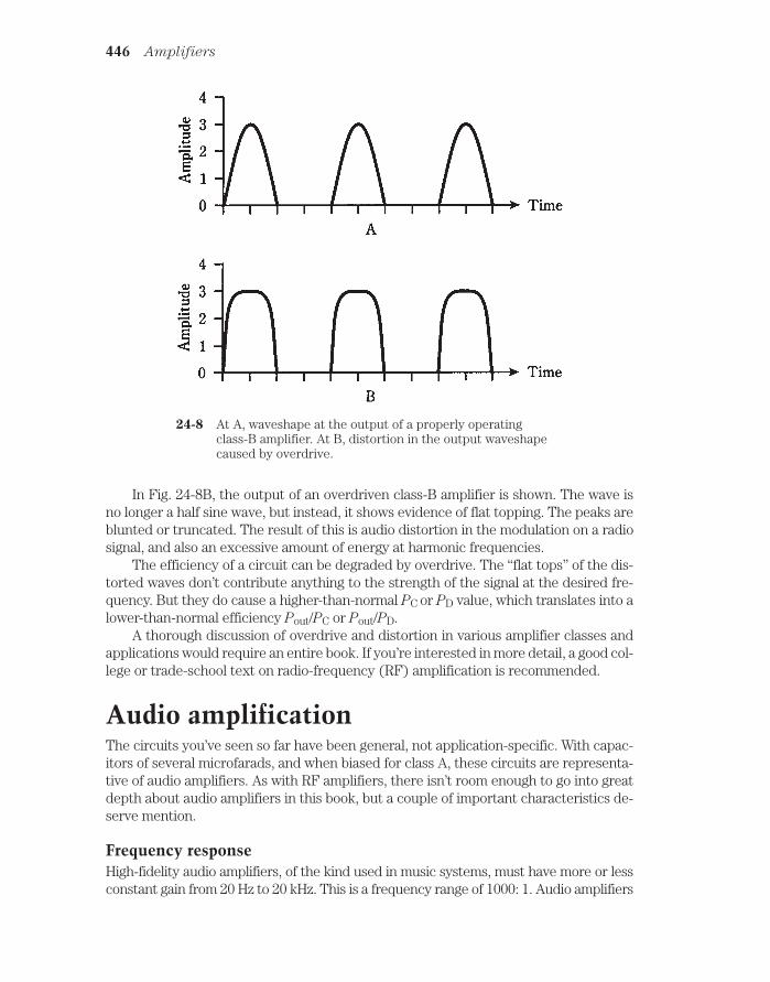
In Fig. 24-8B, the output of an overdriven class-B amplifier is shown. The wave isno longer a half sine wave, but instead, it shows evidence of flat topping. The peaks areblunted or truncated. The result of this is audio distortion in the modulation on a radiosignal, and also an excessive amount of energy at harmonic frequencies.
The efficiency of a circuit can be degraded by overdrive. The “flat tops” of the dis-torted waves don’t contribute anything to the strength of the signal at the desired fre-quency. But they do cause a higher-than-normal PC or PD value, which translates into alower-than-normal efficiency Pout/PC or Pout/PD.
A thorough discussion of overdrive and distortion in various amplifier classes andapplications would require an entire book. If you’re interested in more detail, a good col-lege or trade-school text on radio-frequency (RF) amplification is recommended.
Audio amplificationThe circuits you’ve seen so far have been general, not application-specific. With capac-itors of several microfarads, and when biased for class A, these circuits are representa-tive of audio amplifiers. As with RF amplifiers, there isn’t room enough to go into greatdepth about audio amplifiers in this book, but a couple of important characteristics de-serve mention.
Frequency responseHigh-fidelity audio amplifiers, of the kind used in music systems, must have more or lessconstant gain from 20 Hz to 20 kHz. This is a frequency range of 1000: 1. Audio amplifiers
446 Amplifiers
24-8 At A, waveshape at the output of a properly operatingclass-B amplifier. At B, distortion in the output waveshapecaused by overdrive.
for voice communications must work from 300 Hz to 3 kHz, a 10: 1 span of frequencies.In digital communications, audio amplifiers are designed to work over a narrow range offrequencies, sometimes less than 100 Hz wide.
Hi-fi amplifiers are usually equipped with resistor-capacitor (RC) networks that tai-lor the frequency response. These are tone controls, also called bass and treble con-trols. The simplest hi-fi amplifiers use a single knob to control the tone. Moresophisticated “amps” have separate controls, one for bass and the other for treble. Themost advanced hi-fi systems make use of graphic equalizers, having controls that af-fect the amplifier gain over several different frequency spans.
Gain-versus-frequency curves for three hypothetical audio amplifiers are shownin Fig. 24-9. At A, a wideband, flat curve is illustrated. This is typical of hi-fi systemamplifiers. At B, a voice communications response is shown. At C, a narrowband re-sponse curve, typical of audio amplifiers in Morse code or low-speed digital-signal re-ceivers, is illustrated.
Volume controlAudio amplifier systems usually consist of two or more stages. A stage is one bipolartransistor or FET (or a push-pull combination), plus peripheral resistors and capaci-tors. Stages are cascaded one after the other to get high gain.
In one of the stages in an audio system, a volume control is used. This controlis usually a potentiometer that allows the gain of a stage to be adjusted without af-fecting its linearity. An example of a simple volume control is shown in Fig. 24- 10.In this amplifier, the gain through the transistor itself is constant. The ac output sig-nal passes through C1 and appears across R1, a potentiometer. The wiper (indi-cated by the arrow) of the potentiometer “picks off” more or less of the ac outputsignal, depending on the position of the control shaft. When the shaft is fully coun-terclockwise, the arrow is at the bottom of the zig-zaggy line, and none of the signalpasses to the output. When the shaft is fully clockwise, the arrow is at the top of thezig-zaggy line, and all of the signal passes to the output. At intermediate positionsof the control shaft, various proportions of the full output signal will appear at theoutput. Capacitor C2 isolates the potentiometer from the dc bias of the followingstage.
Volume control is usually done in a stage where the audio power level is quitelow. This allows the use of a small potentiometer, rated for perhaps 1 W. If volumecontrol were done at high audio power levels, the potentiometer would need to beable to dissipate large amounts of power, and would be needlessly expensive.
Coupling methodsIn all of the amplifiers you’ve seen so far, with the exception of the push-pull circuit(Fig. 24-6), capacitors have been used to allow ac to pass while blocking dc. But thereis another way to do this, and in some amplifier systems, it is preferred. This is the useof a transformer to couple signals from one stage to the next.
An example of transformer coupling is shown in Fig. 24-11. Capacitors C1 and C2keep one end of the transformer primary and secondary at signal ground. Resistor R1
Coupling methods 447

limits the current through the first transistor, Q1. (In some cases, R1 might be elimi-nated.) Resistors R2 and R3 provide the proper base bias for transistor Q2.
The main disadvantage of this scheme is that it costs more than capacitive cou-
pling. But transformer coupling can provide an optimum signal transfer between am-plifier stages with a minimum of loss. This is because of the impedance-matching abilityof transformers. Remember that the turns ratio of a transformer affects not only the in-put and output voltage, but the ratio of impedances. By selecting the right transformer,the output impedance of Q1 can be perfectly matched to the input impedance of Q2.
448 Amplifiers
24-9 At A, frequency responsefor music; at B, for voicesignals; at C, fornarrowband digitalsignals.

In some amplifier systems, capacitors are added across the primary and/or secondaryof the transformer. This results in resonance at a frequency determined by the capaci-tance and the transformer winding inductance. If the set of amplifiers is intended for justone frequency (and this is often the case in RF systems), this method of coupling, calledtuned-circuit coupling, enhances the system efficiency. But care must be taken to besure that the amplifier chain doesn’t get so efficient that it oscillates at the resonant fre-quency of the tuned circuits! You’ll learn about oscillation in the next chapter. I
Coupling methods 449
24-10 A simple volume control. Component designators and functions are discussed in thetext.
24-11 Transformer coupling. Component designators and functions are discussed in thetext.

Radio-frequency amplificationThe RF spectrum begins at about 9 kHz and extends upward in frequency to well over300 GHz, or 300,000,000,000 Hz. A complete discussion of RF amplifier design wouldoccupy a book. Therefore, again, only a sketch of the most important characteristicscan be given here.
Weak-signal versus power amplifiersSome RF amplifiers are designed for weak-signal work. The general circuits, shown ear-lier in this chapter, are representative of such amplifiers, when the capacitors have val-ues of about 1 µF or less. The higher the frequency, the smaller the values of thecapacitors.
The front end, or first amplifying stage, of a radio receiver requires the most sen-sitive possible amplifier. Sensitivity is determined by two factors: gain and noise fig-
ure.
The noise figure of an amplifier is a measure of how well it can amplify the desiredsignal, without injecting unwanted noise. All bipolar transistors or FETs; create somewhite noise because of the movement of charge carriers. In general, JFETs produceless noise than bipolar transistors. Gallium arsenide FETs, also called GaAsFETs (pro-nounced “gasfets”), are the least noisy of all.
The higher the frequency at which a weak-signal amplifier is designed, the moreimportant the noise figure gets. This is because there is less atmospheric noise at thehigher radio frequencies, as compared with the lower frequencies. At 1.8 MHz, for ex-ample, the airwaves contain much atmospheric noise, and it doesn’t make a significantdifference if the receiver introduces a little noise itself. But at 1.8 GHz the atmosphericnoise is almost nonexistent, and receiver performance depends much more critically onthe amount of internally generated noise.
Weak-signal amplifiers almost always use resonant circuits. This optimizes the am-plification at the desired frequency, while helping to cut out noise on unwanted fre-quencies. A typical tuned GaAsFET weak-signal RF amplifier is diagrammed in Fig.24-12. It is designed for about 10 MHz.
Broadband PAsAt RF, a PA might be either broadband or tuned.
The main advantage of a broadband PA is ease of operation, because it does notneed tuning. A broadbanded amplifier is not “particular” with respect to the fre-quency within its design range, such as 1.5 MHz through 15 MHz. The operator neednot worry about critical adjustments, nor bother to change them when changing thefrequency.
One disadvantage of broadband PAs is that they are slightly less efficient thantuned PAs. This usually isn’t too hard to put up with, though, considering the conve-nience of not having to fiddle with the tuning.
The more serious problem with broadband PAs is that they’ll amplify anything inthe design range, whether or not you want it to go over the air. If some earlier stage in atransmitter is oscillating at a frequency nowhere near the intended signal frequency, and
450 Amplifiers

if this undesired “signal” falls within the design frequency range of the broadband PA, itwill be amplified. The result will be unintended (and illegal!) RF emission from the radiotransmitter. Such unwanted signals are called spurious emissions, and they occur moreoften than you might think.
A typical broadband PA circuit is diagrammed schematically in Fig. 24-13. The NPNbipolar transistor is a power transistor. It will reliably provide about 3 W of continuousRF output from 1.5 MHz through 15 MHz. The transformers are a critical part of this cir-cuit; they must be designed to work well over a 10:1 range of frequencies. This circuitis suitable for use on the ham radio bands at 160, 80, 75, 40, 30, and 20 meters.
Tuned PAsA tuned RF power amplifier offers improved efficiency compared with broadband de-signs. Also, the tuning helps to reduce the chances of spurious signals being amplifiedand transmitted over the air.
Another advantage of tuned PAs is that they can work into a wide range of load im-pedances. In addition to a tuning control, or resonant circuit that adjusts the output ofthe amplifier to the operating frequency, there is a loading control that optimizes thesignal transfer between the amplifier and the load (usually an antenna).
The main drawback of a tuned PA is that the adjustment takes time, and im-proper adjustment can result in damage to the amplifying device (bipolar transistoror FET). If the tuning and/or loading controls are out of kilter, the efficiency of theamplifier will be extremely low—sometimes practically zero—while the dc collectoror drain power input is unnaturally high. Solid-state devices overheat quickly underthese conditions.
Radio-frequency amplification 451
24-12 A tuned RF amplifier for use at about 10 MHz. Resistances are in ohms.Capacitances are in F if less than 1, and in pF if more than 1. Inductances are inµH.

A tuned RF PA, providing 3 W output at 10 MHz or so, is shown in Fig. 24-14. Thetransistor is the same as for the broadband amplifier discussed above. The tuning andloading controls should be adjusted for maximum RF power output as indicated on awattmeter in the feed line going to the load.
452 Amplifiers
24-13 A broadband RF power amplifier, capable of producing a few watts output.
24-14 A tuned RF power amplifier, capable of producing a few watts output.

QuizRefer to the text in this chapter if necessary. A good score is at least 18 correct. Answersare in the back of the book.
1. The decibel is a unit of:
A. Relative signal strength.
B. Voltage.
C. Power.
D. Current.
2. If a circuit has a voltage-amplification factor of 20, then the voltage gain is:
A. 13 dB.
B. 20 dB.
C. 26 dB.
D. 40 dB.
3. A gain of 15 dB in a circuit means that:
A. The output signal is stronger than the input.
B. The input signal is stronger than the output.
C. The input signal is 15 times as strong as the output.
D. The output signal is 15 times as strong as the input.
4. A device has a voltage gain of 23 dB. The input voltage is 3.3 V. The outputvoltage is:
A. 76 V.
B. 47 V.
C. 660 V.
D. Not determinable from the data given.
5. A power gain of 44 dB is equivalent to an output/input power ratio of:
A. 44.
B. 160.
C. 440.
D. 25,000.
6. A resistor between the base of an NPN bipolar transistor and the positivesupply voltage is used to:
A. Provide proper bias.
B. Provide a path for the input signal.
C. Provide a path for the output signal.
D. Limit the collector current.
Quiz 453

7. The capacitance values in an amplifier circuit depend on:
A. The supply voltage.
B. The polarity.
C. The signal strength.
D. The signal frequency.
8. A class-A circuit would not work well as:
A. A stereo hi-fi amplifier.
B. A television transmitter PA.
C. A low-level microphone preamplifier.
D. The first stage in a radio receiver.
9. In which of the following FET amplifier types does drain current flow for 50percent of the signal cycle?
A. Class A.
B. Class AB1.
C. Class AB2.
D. Class B.
10. Which of the following amplifier types produces the least distortion of thesignal waveform?
A. Class A.
B. Class AB1.
C. Class AB2.
D. Class B.
11. Which bipolar amplifier type has some distortion in the signal wave, withcollector current during most, but not all, of the cycle?
A. Class A.
B. Class AB1.
C. Class AB2.
D. Class B.
12. How can a class-B amplifier be made suitable for hi-fi audio applications?
A. By increasing the bias.
B. By using two transistors in push-pull.
C. By using tuned circuits in the output.
D. A class-B amplifier cannot work well for hi-fi audio.
13. How can a class-C amplifier be made linear?
A. By reducing the bias.
454 Amplifiers

B. By increasing the drive.
C. By using two transistors in push-pull.
D. A class-C amplifier cannot be made linear.
14. Which of the following amplifier classes generally needs the most drivingpower?
A. Class A.
B. Class AB1.
C. Class AB2.
D. Class B.
15. A graphic equalizer is a form of:
A. Bias control.
B. Gain control.
C. Tone control.
D. Frequency control.
16. A disadvantage of transfer coupling, as opposed to capacitive coupling, is that:
A. Transformers can’t match impedances.
B. Transformers can’t work above audio frequencies.
C. Transformers cost more.
D. Transformers reduce the gain.
17. A certain bipolar-transistor PA is 66 percent efficient. The output power is 33 W.The dc collector power input is:
A. 22 W.
B. 50 W.
C. 2.2 W.
D. None of the above.
18. A broadband PA is:
A. Generally easy to use.
B. More efficient than a tuned PA.
C. Less likely than a tuned PA to amplify unwanted signals.
D. Usable only at audio frequencies.
19. A tuned PA must always be:
A. Set to work over a wide range of frequencies.
B. Adjusted for maximum power output.
C. Made as efficient as possible.
D. Operated in class C.
Quiz 455

20. A loading control in a tuned PA:
A. Provides an impedance match between the bipolar transistor or FET andthe load.
B. Allows broadband operation.
C. Adjusts the resonant frequency.
D. Controls the input impedance.
456 Amplifiers

25CHAPTER
OscillatorsSOMETIMES AMPLIFIERS WORK TOO WELL. YOU’VE PROBABLY HEARD THIS WHENsomeone was getting ready to speak over a public-address system. The gain was set toohigh. The person began to speak; sound from the speakers got into the microphone,was amplified, went to the speakers again, and back to the microphone. A vicious cycleof feedback ensued. The result might have been a rumble, a howl, or a shriek. The sys-tem broke into oscillation. The amplifiers became temporarily useless until the gainwas reduced.
Oscillation can be controlled, so that it takes place at a specific, stable, predictablefrequency. An oscillator is a circuit that is deliberately designed to oscillate.
Uses of oscillatorsSome oscillators work at audio frequencies, and others are intended to produce radiosignals. Most generate sine waves, although some are built to emit square waves, saw-tooth waves, or other waveshapes.
The subject of oscillators, once you understand amplifiers, is elementary. All oscil-lators are amplifiers with positive feedback. In this chapter, radio-frequency (RF) os-cillators are discussed in some detail, and then audio oscillators are examined.
In radio communications, oscillators generate the “waves” or signals, that are ulti-mately sent over the air. For data to be sent, the signal from an oscillator must be mod-
ulated. Modulation is covered in chapter 26.Oscillators are used in radio and TV receivers for frequency control and for detec-
tion and mixing. Detectors and mixers are discussed in chapter 27.Audio-frequency oscillators find applications in such devices as music synthesiz-
ers, FAX modems, doorbells, beepers, sirens and alarms, and electronic toys.
457 !
"# #$ !

Positive feedbackFeedback can be in phase or out of phase. For a circuit to oscillate, the feedback mustbe in phase, or positive. Negative feedback (out of phase) simply reduces the gain.
The output of a common-emitter or common-source amplifier is out of phase fromthe input. If you couple the collector to the base through a capacitor, you won’t get os-cillation.
The output of a common-base or common-gate amplifier is in phase with the input.But these circuits have limited gain. It’s hard to make them oscillate, even with positivefeedback.
Common-collector and common-drain circuits don’t have enough gain to make os-cillators.
But take heart: There are lots of ways to make circuits oscillate. Obtaining oscillationhas never been a problem in electronics. Public-address systems do it willingly enough!
Concept of the oscillatorFor a circuit to oscillate, the gain must be high, the feedback must be positive, and thecoupling from output to input must be good. The feedback path must be easy for a sig-nal to follow. The phase of a fed-back signal can be reversed without any trouble, so thatcommon-emitter or common-source amplifiers can be made to oscillate.
Feedback at a single frequencyRecalling the public-address fiasco, some variation of which you’ve doubtless heardmany times, could you know in advance whether the feedback would have a low pitch,a midrange pitch, or a high pitch? No. The oscillation was not intended, and might havestarted at any audio frequency.
The frequency of an oscillator is controlled by means of tuned, or resonant, circuits.These are usually inductance-capacitance (LC) or resistance-capacitance (RC)combinations. The LC scheme is common at RF; the RC method is more often used foraudio oscillators.
The tuned circuit makes the feedback path easy for a signal to follow at one fre-quency, but hard to follow at all other frequencies (Fig. 25-1). The result is that the os-cillation takes place at a predictable and stable frequency, determined by theinductance and capacitance or by the resistance and capacitance.
458 Oscillators
25-1 Basic concept of the oscillator.

The Armstrong oscillatorA common-emitter or common-source amplifier can be made to oscillate by couplingthe output back to the input through a transformer that reverses the phase of thefed-back signal. The phase at a transformer output can be inverted by reversing the sec-ondary terminals.
The schematic diagram of Fig. 25-2 shows a common-source amplifier whose draincircuit is coupled to the gate circuit via a transformer. In practice, getting oscillation iseasy. If the circuit won’t oscillate with the transformer secondary hooked up one way,you can just switch the wires.
The Hartley circuit 459
25-2 An Armstrong oscillator.
The frequency of this oscillator is controlled by means of a capacitor across eitherthe primary or the secondary winding of the transformer. The inductance of the wind-ing, along with the capacitance, forms a resonant circuit. The formula for determiningthe LC resonant frequency is in chapter 17. If you’ve forgotten it, now is a good time toreview it.
The oscillator of Fig. 25-2 is known as an Armstrong oscillator. A bipolar transistorcan be used in place of the JFET. It would need to be biased, using a resistive volt-age-divider network, like a class-A amplifier.
The Hartley circuitA method of obtaining controlled feedback at RF is shown in Fig. 25-3. At A, an NPNbipolar transistor is used; at B, an N-channel JFET is employed. The PNP and P-chan-nel circuits are identical, but the power supply is negative instead of positive.

The circuit uses a single coil with a tap on the windings to provide the feedback. Avariable capacitor in parallel with the coil determines the oscillating frequency, and al-lows for frequency adjustment. This circuit is called a Hartley oscillator.
The Hartley oscillator uses about one-quarter of its amplifier power to produce feed-back. (Remember, all oscillators are really specialized amplifiers.) The other three-quar-ters of the power can be used as output. Oscillators do not, in general, produce
460 Oscillators
25.3 Hartley oscillators. At A, NPN bipolar transistor; at B, N-channel JFET.

more than a fraction of a watt of power. If more power is needed, the signal can beboosted by one or more stages of amplification.
It’s important to use only the minimum amount of feedback necessary to get oscil-lation. The amount of feedback is controlled by the position of the coil tap.
The Colpitts circuitAnother way to provide RIF feedback is to tap the capacitance instead of the induc-tance in the tuned circuit. In Fig. 25-4, NPN bipolar (at A) and N-channel JFET (at B)Colpitts oscillator circuits are diagrammed.
The amount of feedback is controlled by the ratio of capacitances. The coil, ratherthan the capacitors, is variable in this circuit. This is a matter of convenience. It’s almostimpossible to find a dual variable capacitor with the right capacitance ratio betweensections. Even if you find one, you cannot change the ratio of capacitances. It’s easy toadjust the capacitance ratio using a pair of fixed capacitors.
Unfortunately, finding a good variable inductor might not be much easier than get-ting hold of a suitable dual-gang variable capacitor. A permeability-tuned coil can beused, but ferromagnetic cores impair the frequency stability of an RF oscillator. A roller
inductor might be employed, but these are bulky and expensive. An inductor with sev-eral switch-selectable taps can be used, but this wouldn’t allow for continuous fre-quency adjustment. The tradeoff is that the Colpitts circuit offers exceptional stabilityand reliability when properly designed.
As with the Hartley circuit, the feedback should be kept to the minimum necessaryto sustain oscillation.
In these circuits, the outputs are taken from the emitter or source. Why? Shouldn’tthe output be taken from the collector or drain? The answer is that the output can betaken from the collector or drain circuit, and an oscillator will usually work just fine. Butgain is not important in an oscillator; what matters is stability under varying load condi-tions. Stability is enhanced when the output of an oscillator is taken from the emitter orsource portion of the circuit.
To prevent the output signal from being short-circuited to ground, an RF choke
(RFC) is connected in series with the emitter or source lead in the Colpitts circuit. Thechoke lets dc pass while blocking ac (just the opposite of a blocking capacitor). Typicalvalues for RF chokes range from about 100 µH at high frequencies, like 15 MHz, to 10mH at low frequencies, such as 150 kHz.
The Clapp circuitA variation of the Colpitts oscillator makes use of series resonance, instead of parallelresonance, in the tuned circuit. Otherwise, the circuit is basically the same as the par-allel-tuned Colpitts oscillator. A schematic diagram of an N-channel JFET Clapp oscil-
lator circuit is shown in Fig. 25-5. The P-channel circuit is identical, except for thepower supply polarity, which is reversed.
The bipolar-transistor Clapp circuit is almost exactly the same as the circuit of Fig. 25-5,with the emitter in place of the source, the base in place of the gate, and the collector
The Clapp circuit 461

in place of the drain. The only difference, as you can probably guess by now, is the additionof a resistor between the base and the positive supply voltage (for NPN) or the negative sup-ply voltage (for PNP).
The Clapp oscillator offers excellent stability at RF. Its frequency won’t changemuch when high-quality components are used. The Clapp oscillator is a reliable circuit;
462 Oscillators
25-4 Colpitts oscillators. At A, NPN bipolar transistor; at B, N-channel JFET.

it isn’t hard to get it to oscillate. Another advantage of the Clapp circuit is that it allowsthe use of a variable capacitor for frequency control, while still accomplishing feedbackthrough a capacitive voltage divider.
StabilityThe term stability is used often by engineers when they talk about oscillators. In an os-cillator, stability has two meanings: constancy of frequency and reliability of perfor-mance. Obviously, both of these considerations are important in the design of a goodoscillator circuit.
Constancy of frequencyThe foregoing oscillator types allow for frequency adjustment using variable capacitorsor variable inductors. The component values are affected by temperature, and some-times by humidity. When designing a variable-frequency oscillator (VFO), it’s crucialthat the components maintain constant values, as much as possible, under all antici-pated conditions.
Some types of capacitors maintain their values better than others, when the tem-perature goes up or down. Among the best are polystyrene capacitors. Silver-mica ca-pacitors also work well when polystyrene units can’t be found.
Inductors are most temperature-stable when they have air cores. They should bewound, when possible, from stiff wire with strips of plastic to keep the windings in place.Some air-core coils are wound on hollow cylindrical cores, made of ceramic or phenolic
Stability 463
25-5 Series-tuned Colpitts oscillators using an N-channel JFET.

material. Ferromagnetic solenoidal or toroidal cores aren’t very good for VFO coils, be-cause these materials change their permeability as the temperature varies. This changesthe inductance, in turn affecting the oscillator frequency.
Engineers spend much time and effort in finding components that will minimizedrift (unwanted changes in frequency over time) in VFOs.
Reliability of performanceAn oscillator should always start working as soon as power is supplied. It should keeposcillating under all normal conditions, not quitting if the load changes slightly or if thetemperature rises or falls. A “finicky” oscillator is a great annoyance. The failure of a sin-gle oscillator can cause an entire receiver, transmitter, or transceiver to stop working.An oscillator is sometimes called unstable if it has to be “coaxed” into starting, or if itquits unpredictably.
Some oscillator circuits are more reliable than others. The circuits generalized inthis chapter are those that engineers have found, through trial and error over the years,to work the best.
When an oscillator is built and put to use in a radio receiver, transmitter, or audiodevice, debugging is always necessary. This is a trial-and-error process of getting theflaws, or “bugs” out of the circuit. Rarely can an engineer build something straight fromthe drawing board and have it work just right the first time. In fact, if two oscillators arebuilt from the same diagram, with the same component types and values in the samegeometric arrangement, one circuit might work fine, and the other might be unstable.This usually happens because of differences in the quality of components that don’tshow up until the “acid test.”
Oscillators are designed to work into a certain range of load impedances. It’s im-portant that the load impedance not be too low. (You need never be concerned that itmight be too high. In general, the higher the load impedance, the better.) If the load im-pedance is too low, the load will try to draw power from an oscillator. Then, even awell-designed oscillator might be unstable. Oscillators aren’t meant to produce power-ful signals. High power can be obtained using amplification after the oscillator.
Crystal-controlled oscillatorsQuartz crystals can be used in place of tuned LC circuits in RF oscillators, if it isn’t nec-essary to change the frequency often. Crystal oscillators offer excellent frequency sta-bility— far superior to that of LC-tuned VFOs.
There are several ways that crystals can be connected in bipolar or FET circuits to getoscillation. One common circuit is the Pierce oscillator. An N-channel JFET and quartz crys-tal are connected in a Pierce configuration as shown in the schematic diagram of Fig. 25-6.
The crystal frequency can be varied somewhat (by about 0.1 percent) by means of aninductor or capacitor in parallel with the crystal. But the frequency is determined mainlyby the thickness of the crystal, and by the angle at which it is cut from the quartz rock.
Crystals change in frequency as the temperature changes. But they are far morestable than LC circuits, most of the time. Some crystal oscillators are housed in tem-perature-controlled chambers called ovens. They maintain their frequency so well that
464 Oscillators
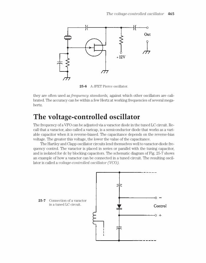
they are often used as frequency standards, against which other oscillators are cali-brated. The accuracy can be within a few Hertz at working frequencies of several mega-hertz.
The voltage-controlled oscillatorThe frequency of a VFO can be adjusted via a varactor diode in the tuned LC circuit. Re-call that a varactor, also called a varicap, is a semiconductor diode that works as a vari-able capacitor when it is reverse-biased. The capacitance depends on the reverse-biasvoltage. The greater this voltage, the lower the value of the capacitance.
The Hartley and Clapp oscillator circuits lend themselves well to varactor-diode fre-quency control. The varactor is placed in series or parallel with the tuning capacitor,and is isolated for dc by blocking capacitors. The schematic diagram of Fig. 25-7 showsan example of how a varactor can be connected in a tuned circuit. The resulting oscil-lator is called a voltage-controlled oscillator (VCO).
The voltage-controlled oscillator 465
25-6 A JFET Pierce oscillator.
25-7 Connection of a varactorin a tuned LC circuit.

Why control the frequency of an oscillator in this way? It is commonly done in mod-ern communications equipment; there must be a reason. In fact there are several goodreasons why varactor control is better than the use of mechanically variable capacitorsor inductors. But it all comes down to basically one thing: Varactors are cheaper.They’re also less bulky than mechanically variable capacitors and inductors.
Nowadays, many frequency readouts are digital. You look at a numeric display in-stead of interpolating a dial scale. Digital control is often done by a microcomputer. Youprogram the operating frequency by pressing a sequence of buttons, rather than by ro-tating a knob. The microcomputer might set the frequency via a synchro on the shaft ofa variable capacitor or inductor. But that would be unwieldy. It would also be ridiculous,a “Rube Goldberg” contraption. A varactor can control the frequency without all thatnonsense.
The PLL frequency synthesizerOne type of oscillator that combines the flexibility of a VFO with the stability of a crys-tal oscillator is known as a PLL frequency synthesizer. This scheme is extensively usedin modern digital radio transmitters and receivers.
The output of a VCO is passed through a programmable divider, a digital circuitthat divides the VCO frequency by any of hundreds or even thousands of numerical val-ues chosen by the operator. The output frequency of the programmable divider islocked, by means of a phase comparator, to the signal from a crystal-controlled refer-
ence oscillator.
As long as the output from the programmable divider is exactly on the referenceoscillator frequency, the two signals are in phase, and the output of the phase com-parator is zero volts dc. If the VCO frequency begins to drift, the output frequency of theprogrammable divider will drift, too (although at a different rate). But even the tiniestfrequency change—a fraction of 1 Hz—causes the phase comparator to produce a dcerror voltage. This error voltage is either positive or negative, depending on whetherthe VCO has drifted higher or lower in frequency. The error voltage is applied to a var-actor in the VCO, causing the VCO frequency to change in a direction opposite to thatof the drift. This forms a dc feedback circuit that maintains the VCO frequency at a pre-cise multiple of the reference-oscillator frequency, that multiple having been chosen bythe programmable divider. It is a loop circuit that locks the VCO onto a precise fre-quency, by means of phase sensing, hence the term phase-locked loop (PLL).
The key to the stability of the PLL frequency synthesizer lies in the fact that the refer-ence oscillator is crystal-controlled. A block diagram of such a synthesizer is shown in Fig.25-8. When you hear that a radio receiver, transmitter, or transceiver is “synthesized,” itusually means that the frequency is determined by a PLL frequency synthesizer.
The stability of a synthesizer can be enhanced by using an amplified signal from theNational Bureau of Standards, transmitted on shortwave by WWV at 5, 10, or 15 MHz,directly as the reference oscillator. These signals are frequency-exact to a minusculefraction of 1 Hz, because they are controlled by atomic clocks. Most people don’t needprecision of this caliber, so you won’t see consumer devices like ham radios and short-wave receivers with primary-standard PLL frequency synthesis. But it is employed bysome corporations and government agencies, such as the military.
466 Oscillators

Diode oscillatorsAt ultra-high and microwave frequencies, certain types of diodes can be used as oscil-lators. These diodes, called Gunn, IMPATT, and tunnel diodes, were discussed inchapter 20.
Audio waveformsThe above described oscillators work above the human hearing range. At audio fre-quencies (AF), oscillators can use RC or LC combinations to determine frequency. If LCcircuits are used, the inductances must be rather large, and ferromagnetic cores areusually necessary.
All RF oscillators produce a sine-wave output. A pure sine wave represents en-ergy at one and only one frequency. Audio oscillators, by contrast, don’t necessarilyconcentrate all their energy at a single frequency. A pure AF sine wave, especially ifit is continuous and frequency-constant, causes ear/mind fatigue. Perhaps you’veexperienced it.
The various musical instruments in a band or orchestra all sound different fromeach other, even when they play the same note (such as middle C). The reason for thisis that each instrument has its own unique waveform. A clarinet sounds different thana trumpet, which in turn sounds different than a cello or piano.
Suppose you were to use an oscilloscope to look at the waveforms of musical in-struments. This can be done using a high-fidelity microphone, a low-distortion ampli-fier, and a scope. You’d see that each instrument has its own “signature.” Eachinstrument’s unique sound qualities can be reproduced using AF oscillators whosewaveform outputs match those of the instrument.
The art of electronic music is a subject to which whole books have been devoted.All electronic music synthesizers use audio oscillators to generate the tones you hear.
Audio waveforms 467
25-8 Block diagram of a PLL frequency synthesizer.

Audio oscillatorsAudio oscillators find uses in doorbells, ambulance sirens, electronic games, and thoselittle toys that play simple musical tunes. All AF oscillators work in the same way, con-sisting of amplifiers with positive feedback.
A simple audio oscillatorOne form of AF oscillator that is popular for general-purpose use is the twin-T oscillator
(Fig. 25-9). The frequency is determined by the values of the resistors R and capacitors C.The output is a near-perfect sine wave. The small amount of distortion helps to alleviate theirritation produced by an absolutely pure sinusoid. This circuit uses two NPN bipolar tran-sistors. Two JFETs could also be used, biased for class-A amplifier operation.
The multivibratorAnother audio-oscillator circuit uses two identical common-emitter or common-sourceamplifier circuits, hooked up so that the signal goes around and around between them.
468 Oscillators
25-9 A twin-T audio oscillator.

This is sometimes called a multivibrator circuit, although that is technically a mis-nomer, the term being more appropriate to various digital signal-generating circuits.
Two N-channel JFETs are connected to form an oscillator as shown in Fig. 25-10.Each “stage” amplifies the signal in class-A, and reverses the phase by 180 degrees.Thus, the signal goes through a 360-degree shift each time it gets back to any particu-lar point. A 360-degree shift results in positive feedback, being effectively equivalent tono phase shift.
The frequency is set by means of an LC circuit. The coil uses a ferromagnetic core,because stability is not of great concern and because such a core is necessary to obtainthe large inductance needed for resonance at audio frequencies. The value of L is typi-cally from 10 mH to as much as 1 H. The capacitance is chosen according to the formulafor resonant circuits, to obtain an audio tone at the frequency desired.
Quiz 469
IC oscillatorsIn recent years, solid-state technology has advanced to the point that whole circuits canbe etched onto silicon chips. Such devices are called integrated circuits (ICs). The op-
erational amplifier (op amp) is one type of IC that is especially useful as an oscilla-tor. Op-amp oscillators are most commonly employed as audio oscillators. Integratedcircuits are discussed in chapter 28.
QuizRefer to the text in this chapter if necessary. A good score is at least 18 correct. Answersare in the back of the book.
25-10 A “multivibrator” type audio oscillator.

1. Negative feedback in an amplifier:
A. Causes oscillation.
B. Increases sensitivity.
C. Reduces the gain.
D. Is used in an Armstrong oscillator.
2. Oscillation requires:
A. A common-drain or common-collector circuit.
B. A stage with gain.
C. A tapped coil.
D. Negative feedback.
3. A Colpitts oscillator can be recognized by:
A. A split capacitance in the tuned circuit.
B. A tapped coil in the tuned circuit.
C. A transformer for the feedback.
D. A common-base or common-gate arrangement.
4. In an oscillator circuit, the feedback should be:
A. As great as possible.
B. Kept to a minimum.
C. Just enough to sustain oscillation.
D. Done through a transformer whose wires can be switched easily.
5. A tapped coil is used in a(n):
A. Hartley oscillator.
B. Colpitts oscillator.
C. Armstrong oscillator.
D. Clapp oscillator.
6. An RF choke:
A. Passes RF but not dc.
B. Passes both RF and dc.
C. Passes dc but not RF.
D. Blocks both dc and RF.
7. Ferromagnetic coil cores are not generally good for use in RF oscillatorsbecause:
A. The inductances are too large.
B. It’s hard to vary the inductance of such a coil.
C. Such coils are too bulky.
D. Air-core coils have better thermal stability.
470 Oscillators

8. An oscillator might fail to start for any of the following reasons except:
A. Low-power-supply voltage.
B. Low stage gain.
C. In-phase feedback.
D. Very low output impedance.
9. An advantage of a crystal-controlled oscillator over a VFO is:
A. Single-frequency operation.
B. Ease of frequency adjustment.
C. High output power.
D. Low drift.
10. The frequency at which a crystal oscillator functions is determined mainly by:
A. The values of the inductor and capacitor.
B. The thickness of the crystal.
C. The amount of capacitance across the crystal.
D. The power-supply voltage.
11. The different sounds of musical instruments are primarily the result of:
A. Differences in the waveshape.
B. Differences in frequency.
C. Differences in amplitude.
D. Differences in phase.
12. A radio-frequency oscillator usually:
A. Has an irregular waveshape.
B. Has most or all of its energy at a single frequency.
C. Produces a sound that depends on its waveform.
D. Uses RC tuning.
13. A varactor diode:
A. Is mechanically flexible.
B. Has high power output.
C. Can produce different waveforms.
D. Is good for use in frequency synthesizers.
14. A frequency synthesizer has:
A. High power output.
B. High drift rate.
C. Exceptional stability.
D. Adjustable waveshape.
Quiz 471

15. A ferromagnetic-core coil is preferred for use in the tuned circuit of an RFoscillator:
A. That must have the best possible stability.
B. That must have high power output.
C. That must work at microwave frequencies.
D. No! Air-core coils work better in RF oscillators.
16. If the load impedance for an oscillator is too high:
A. The frequency might drift.
B. The power output might be reduced.
C. The oscillator might fail to start.
D. It’s not a cause for worry; it can’t be too high.
17. The bipolar transistors or JFETs in a multivibrator are usually connected in:
A. Class B.
B. A common-emitter or common-source arrangement.
C. Class C.
D. A common-collector or common-drain arrangement.
18. The arrangement in the block diagram of Fig. 25-11 represents:
A. A waveform analyzer.
B. An audio oscillator.
C. An RF oscillator.
D. A sine-wave generator.
472 Oscillators
25-11 Illustration for quiz question 18.
19. Acoustic feedback in a public-address system:
A. Is useful for generating RF sine waves.
B. Is useful for waveform analysis.
C. Can be used to increase the amplifier gain.
D. Serves no useful purpose.

20. An IMPATT diode:
A. Makes a good audio oscillator.
B. Can be used for waveform analysis.
C. Is used as a microwave oscillator.
D. Allows for frequency adjustment of a VCO.
Quiz 473

26CHAPTER
Data transmissionTO CONVEY DATA, SOME ASPECT OF A SIGNAL MUST BE VARIED. THERE ARE several different characteristics of a signal that can be made to change in a controlledway, so that data is “imprinted” on it. Modulation is the process of imprinting data ontoan electric current or radio wave.
Modulation can be accomplished by varying the amplitude, the frequency, or thephase of a wave. Another method is to transmit a series of pulses, whose duration, am-plitude, or spacing is made to change in accordance with the data to be conveyed.
The carrier waveThe “heart” of most communications signals is a sine wave, usually of a frequency wellabove the range of human hearing. This is called a carrier or carrier wave. The lowestcarrier frequency used for radio communications is 9 kHz. The highest frequency is inthe hundreds of gigahertz.
For modulation to work effectively, the carrier must have a frequency manytimes the highest frequency of the modulating signal. For example, if you want tomodulate a radio wave with hi-fi music, which has a frequency range from a few hertzup to 20 kHz or so, the carrier wave must have a frequency well above 20 kHz. A goodrule is that the carrier must have a frequency of at least 10 times the highest modu-lating frequency. So for good hi-fi music transmission, a radio carrier should be at200 kHz or higher.
This rule holds for all kinds of modulation, whether it be of the amplitude, phase, orfrequency. If the rule is violated, the efficiency of transmission will be degraded, result-ing in less-than-optimum data transfer.
474 !
"# #$ !

The Morse codeThe simplest, and oldest, form of modulation is on-off keying. Early telegraph systemsused direct currents that were keyed on and off, and were sent along wires. The first ra-dio transmitters employed spark-generated “hash” signals that were keyed using thetelegraph code. The noise from the sparks, like ignition noise from a car, could be heardin crystal-set receivers several miles away. At the time of their invention, this phenom-enon was deemed miraculous: a wireless telegraph!
Keying is usually accomplished at the oscillator of a continuous-wave (CW) radiotransmitter. A block diagram of a simple CW transmitter is shown in Fig. 26-1. This isthe basis for a mode of communications that is, and always has been, popular among ra-dio amateurs and experimenters.
Frequency-shift keying 475
26-1 A simple CW transmitter.
While the use of Morse code might seem old-fashioned, even archaic, a CW trans-mitter is extremely simple to build. A human operator, listening to Morse code and writ-ing down the characters as they are sent, is one of the most efficient data receivers everdevised. Until computers are built to have intuition, there’ll always be a place for Morsecode radio communications. Besides being efficient, as any “CW fanatic” radio ham willtell you, it’s just plain fun to send and receive signals in Morse code.
Morse code is a form of digital communications. It can be broken down into bits,each having a length of one dot. A dash is three bits long. The space between dots anddashes, within a single character, is one bit. The space between characters in a word isthree bits. The space between words is seven bits. Punctuation marks are sent as char-acters attached to their respective words. An amplitude-versus-time rendition of theMorse word “eat” is shown in Fig. 26-2.
Morse code is a rather slow way to send and receive data. Human operators typi-cally use speeds ranging from about 5 words per minute (wpm) to 40 or 50 wpm.
Frequency-shift keyingMorse code keying is the most primitive form of amplitude modulation (AM). Thestrength, or amplitude, of the signal is varied between two extreme conditions: full-onand full-off. There is another way to achieve two-state keying that works better with

teleprinter machines than on-off switching. That is to shift the frequency of the carrierwave back and forth. It is called frequency-shift keying (FSK).
Teleprinter codesThe Morse code is not the only digital code of its kind. There are two commonteleprinter codes used to send and receive radioteletype (RTTY) signals. These codesare known as the Baudot (pronounced “Bo-doe”) and ASCII (pronounced “ask-ee”)codes. (You needn’t worry about where these names come from.) A carrier wave can bekeyed on and off using either of these codes, at speeds ranging from 60 wpm to over1000 wpm. In recent years, ASCII has been replacing Baudot as the standard teleprintercode.
A special circuit, called a terminal unit, converts RTTY signals into electrical im-pulses to work a teleprinter or to display the characters on a monitor screen. The termi-nal unit also generates the signals necessary to send RTTY, as the operator types on thekeyboard of a teleprinter terminal. A personal computer can be made to work as anRTTY terminal by means of terminal emulation software. This software is available inseveral different forms, and is popular among radio amateurs and electronics hobbyists.
Mark and spaceThe trouble with using simple on-off keying for RTTY is that noise pulses, such as thun-derstorm static crashes, can be interpreted by the terminal unit as signal pulses. Thiscauses misprints. There is no problem if a crash takes place during the full-on, or mark,
part of the signal; but if it happens during a pause or space interval, the terminal unitcan be fooled into thinking it’s a mark pulse instead.
This problem can be helped greatly by sending a signal during the space part of thesignal, but at a different frequency from the mark pulse. Then the terminal unit knowsfor sure that a mark is not being sent. Instead of sending “Not mark,” the transmittersends “Not mark, but space instead.” The easiest way to do this is to send the mark partof the signal at one carrier frequency, and the space part at another frequency a fewhundred hertz higher or lower. This is FSK. The difference between the mark and spacefrequencies is called the shift, and is usually between 100 Hz and 1 kHz.
A frequency-versus-time graph of the Morse code word “eat,” sent using FSK, isshown in Fig. 26-3. Normally, Baudot or ASCII, rather than Morse, is used for teleprinteroperation. A block diagram of an FSK transmitter is shown in Fig. 26-4. The FSK mode,
476 Data transmission
26-2 The Morse code word “eat” as sent on CW.

like on-off code keying, is a digital form of communications. But unlike on-off Morsekeying, FSK is frequency modulation (FM).
Frequency-shift keying 477
26-3 The Morse code word “eat” as sent using FSK.
26-4 A simple FSKtransmitter.
The telephone modemTeleprinter data can be sent over the telephone lines using FSK entirely within the au-dio range. Two audio tones are generated, one for mark and the other for space. Thereare three sets of standard tone frequencies: 1200 Hz and 2200 Hz for generalcommunications, 1070 Hz and 1270 Hz for message origination, and 2025 and 2225 Hzfor answering. These represent shifts of 1000 Hz or 200 Hz.
Because this FSK takes place at audio, it is sometimes called audio-frequency-shift
keying (AFSK). A device that sends and receives AFSK teleprinter over the phonelines is known as a telephone modem. If you’ve used a personal computer via the phonelines, you’ve used a telephone modem. Perhaps you’ve heard the “bleep-bleep” of thetones as data is sent or received.

Amplitude modulation for voiceA voice signal is a complex waveform with frequencies mostly in the range 300 Hz to 3kHz. Direct currents can be varied, or modulated, by these waveforms, thereby trans-mitting voice information over wires. This is how early telephones worked.
Around 1920, when CW oscillators were developed to replace spark-gap transmit-ters, engineers wondered, “Can a radio wave be modulated with a voice, like dc in a tele-phone?” If so, voices could be sent by “wireless.” Radio communications via Morse codewas being done over thousands of miles, but CW was slow. The idea of sending voiceswas fascinating, and engineers set about to find a way to do it.
A simple amplitude modulatorAn amplifier was built to have variable gain. The idea was to make the gain fluctuate atvoice-frequency rates—up to 3 kHz or so. Vacuum tubes were used as amplifiers backthen, because solid-state components hadn’t been invented yet. But the principle ofamplitude modulation (AM) is the same, whether the active devices are tubes, bipo-lar transistors, or FETs.
If bipolar transistors had been around in 1920, the first amplitude modulator
would have resembled the circuit shown in Fig. 26-5. This circuit is simply a class-A RFamplifier, whose gain is varied in step with a voice signal coupled into the emitter cir-cuit. The voice signal affects the instantaneous voltage between the emitter and base,varying the instantaneous bias. The result is that the instantaneous RF output increasesand decreases, in a way that exactly duplicates the waveform of the voice signal.
The circuit of Fig. 26-5 will work quite well as an AM voice modulator, provided thatthe audio input isn’t too great. If the AF is excessive, overmodulation will occur. Thiswill result in a distorted signal.
The AM transmitterTwo complete AM transmitters are shown in block-diagram form in Fig. 26-6. At A,modulation is done at a low power level. This is low-level AM. All the amplificationstages after the modulator must be linear. That means class AB or class B must be used.If a class-C PA is used, the signal will be distorted.
In some broadcast transmitters, AM is done in the final PA, as shown in Fig. 26-6B.This is high-level AM. The PA operates in class C; it is the modulator as well as the fi-nal amplifier. As long the PA is modulated correctly, the output will be a “clean” AM sig-nal; RF linearity is of no concern.
The extent of modulation is expressed as a percentage, from 0 percent, represent-ing an unmodulated carrier, to 100 percent, representing full modulation. Increasingthe modulation past 100 percent will cause distortion of the signal, and will degrade, notenhance, the effectiveness of data transmission.
In an AM signal that is modulated 100 percent, only 1/3 of the power is actuallyused to convey the data; the other 2/3 is consumed by the carrier wave. For this reason,AM is rather inefficient. There are voice modulation techniques that make better use ofavailable transmitter power. Perhaps the most widely used is single sideband (SSB),
which you’ll learn about shortly.
478 Data transmission

Bandwidth of an AM voice signalSuppose you could get a graphic display of an AM signal, with frequency on the hori-zontal axis and amplitude on the vertical axis. This is in fact done using an instrumentcalled a spectrum analyzer. In Fig. 26-7, the spectral display for an AM voice radiosignal at 1340 kHz is illustrated.
On a spectrum analyzer, unmodulated radio carriers look like vertical lines, or“pips,” of various heights depending on how strong they are. The carrier wave at 1340kHz shows up in Fig. 26-7 as a strong pip.
The horizontal scale of the display in Fig. 26-7 is calibrated in increments of 1 kHzper division. This is an ideal scale for looking at an AM signal.
The vertical scale is calibrated in decibels below the signal level that produces 1mW at the input terminals. Each vertical division represents 3 dB. Decibels relative to 1mW are abbreviated dBm by engineers. Thus, in Fig. 26-7, the top horizontal line is 0dBm; the first line below it is − 3 dBm; the second line is − 6 dBm and so on.
The audio components of the voice signal show up as sidebands on either side ofthe carrier. All of the voice energy in this example is at audio below 3 kHz. This resultsin sidebands within the range 1340 kHz plus or minus 3 kHz, or 1337 to 1343 kHz. Thefrequencies between 1337 and 1340 kHz are the lower sideband (LSB); those from1340 to 1343 kHz are the upper sideband (USB). The bandwidth of the RF signal isthe difference between the maximum and minimum sideband frequencies. In this caseit is 1343 to 1337 kHz, or 6 kHz.
Amplitude modulation for voice 479
26-5 An AM modulator.

In an AM signal, the bandwidth is twice the highest audio modulating frequency. Inthe example of Fig. 26-7, the voice energy is all below 3 kHz, and the bandwidth of thecomplete RF signal is 6 kHz. At 3 kHz above and below the carrier, the frequency cut-
offs are abrupt. This transmitter uses an audio lowpass filter that cuts out the audioabove 3 kHz. Audio above 3 kHz contributes nothing to the intelligibility of a humanvoice. It’s important to keep the bandwidth of a signal as narrow as possible, so therewill be room for many signals in a given band of frequencies.
Single sidebandAs mentioned previously, AM is not efficient. Most of the power is used up by the car-rier; only 33 percent of it carries data. Besides that, the two sidebands are mirror-imageduplicates. An AM signal is redundant, as well as inefficient, for voice transmission.
480 Data transmission
26-6 At A, transmitter using low-level AM. At B, a transmitter using high-level AM.

Voice SSBDuring the fifties, engineers began to work on an alternative to conventional AM. Theymused, “Suppose all of the transmitter power could go into the voice, and none betaken up by the carrier? That would be a threefold effective increase in transmitterpower! And what if the bandwidth could be cut to 3 kHz rather than 6 kHz, by gettingrid of the sideband redundancy? That would put all the energy into half the spectrumspace, so that twice as many voice signals could fit in a band.” Spectrum-space conser-vation was getting to be a big deal. The airwaves were starting to become overcrowded.
These improvements were realized by means of circuits that cancel out, or sup-
press, the carrier in the modulator circuit, and that filter out, or phase out, one of the twosidebands. The remaining voice signal has a spectrum display that looks like the graph ofFig. 26-8. Either LSB or USB can be used, and either mode works as well as the other.
The SSB transmitterThe heart of an SSB transmitter is a balanced modulator. This circuit works like an or-dinary AM modulator, except that the carrier wave is phased out. This leaves only theLSB and USB. One of the sidebands is removed by a filter that passes only the RF withina 3-kHz-wide band. A block diagram of an SSB transmitter is shown in Fig. 26-9.
High-level modulation won’t work for SSB. The balanced modulator is in alow-power part of the transmitter. Therefore, the RF amplifiers after the modulator mustall be linear. They usually work in class A except for the PA, which is class AB or class B.If class-C amplification is used with an SSB signal, or if any of the RF amplifiers aren’t lin-ear for any reason, the signal envelope (waveform) will be distorted. This will degradethe quality of the signal. It can also cause the bandwidth to exceed the nominal 3 kHz,
Amplitude Modulation for Voice 481
26-7 Spectral display of atypical voice AM signal.
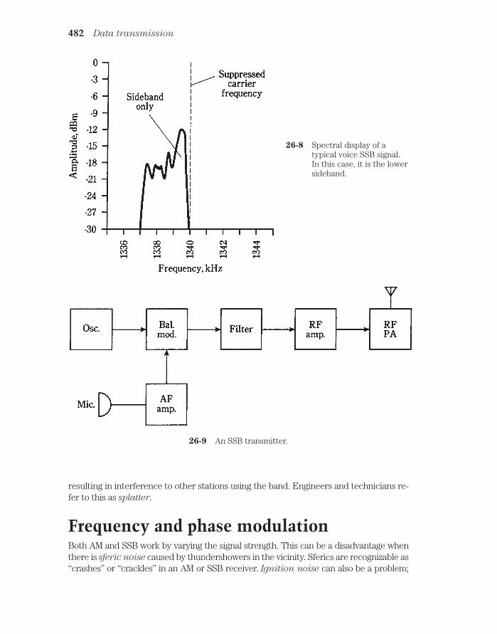
resulting in interference to other stations using the band. Engineers and technicians re-fer to this as splatter.
Frequency and phase modulationBoth AM and SSB work by varying the signal strength. This can be a disadvantage whenthere is sferic noise caused by thundershowers in the vicinity. Sferics are recognizable as“crashes” or “crackles” in an AM or SSB receiver. Ignition noise can also be a problem;
482 Data transmission
26-8 Spectral display of atypical voice SSB signal.In this case, it is the lowersideband.
26-9 An SSB transmitter.

this sounds like a “buzz” or “whine.” Sferics and ignition noise are both predominantly am-plitude-modulated.
In frequency modulation (FM), the amplitude of the signal remains constant, andthe instantaneous frequency or phase is made to change. Because the carrier is always“full-on,” class-C power amplifiers can be used. Linearity is of no concern when the sig-nal level does not change.
Reactance modulation versus phase modulationThe most direct way to get FM is to apply the audio signal to a varactor diode in a VFOcircuit. An example of this scheme, known as reactance modulation, is shown in Fig.26-10. The varying voltage across the varactor causes its capacitance to change in ac-cordance with the audio waveform. The changing capacitance results in anup-and-down swing in the frequency generated by the VFO. In the illustration, only thetuned circuit of a Hartley oscillator is shown.
Frequency and phase modulation 483
26-10 Reactance modulation to obtain FM.
Another way to get FM is to modulate the phase of the oscillator signal. This causessmall fluctuations in the frequency as well, because any instantaneous phase changeshows up as an instantaneous frequency change (and vice versa). This scheme is calledphase modulation. The circuit is more complicated than the reactance modulator.When phase modulation is used, the audio signal must be processed, adjusting theamplitude versus-frequency response of the audio amplifiers. Otherwise the signal willsound muffled in an FM receiver.

Frequency deviationThe amount by which the carrier frequency varies will depend on the relative audio sig-nal level, and also on the degree to which the audio is amplified before it’s applied to themodulator. The deviation is the maximum extent to which the instantaneous carrierfrequency differs from the unmodulated-carrier frequency. For most FM voicetransmitters, the deviation is standardized at plus or minus 5.0 kHz (Fig. 26-11).
484 Data transmission
26-11 Frequency-versus-time rendition of an FM signal.
The deviation obtainable by means of direct FM is greater, for a given oscillator fre-quency, than the deviation that can be gotten via phase modulation. But the deviationof a signal can be increased by a frequency multiplier. This is an RF amplifier circuitwhose output is tuned to some integral multiple of the input. A multiply-by-two circuitis called a frequency doubler; a multiply-by-three circuit is a frequency tripler.
When an FM signal is passed through a frequency multiplier, the deviation getsmultiplied along with the carrier frequency. If a modulator provides plus or minus 1.6kHz deviation, the frequency can be doubled and the result will be a deviation of plus orminus 3.2 kHz. If the frequency is tripled, the deviation increases to plus or minus 4.8kHz, which is just about the standard amount for FM voice communications.
Wideband FMIn FM hi-fi broadcasting, and in some other applications, the deviation is much greaterthan plus or minus 5.0 kHz. This is called wideband FM, as opposed to narrowband
FM just discussed.For ordinary voice communications, there’s nothing to be gained by using wide-
band FM. The only result will be that the signal will take up an unnecessary amount ofradio spectrum space. But for music, the fidelity improves as the bandwidth increases.
The deviation for an FM signal should be equal to the highest modulating audio fre-quency, if optimum fidelity is to be obtained. Thus, plus or minus 5.0 kHz is more thanenough for voice (3.0 kHz would probably suffice). For music, a deviation of about plusor minus 15 kHz or 20 kHz is needed for excellent hi-fi reception.

The ratio of the frequency deviation to the highest modulating audio frequency iscalled the modulation index. For good fidelity, it should be at least 1: 1. But it shouldnot be much more; that would waste spectrum space.
Pulse modulationStill another method of modulation works by varying some aspect of a constant streamof signal pulses. Several types of pulse modulation (PM) are briefly described below.They are diagrammed in Fig. 26-12 as amplitude-versus-time graphs. The modulatingwaveforms are shown as curvy lines, and the pulses as vertical lines.
Pulse modulation 485
26-12 Pulse modulation. At A, pulse amplitude modulation; at B, pulse widthmodulation; at C, pulse interval modulation; and at D, pulse codemodulation.
Pulse amplitude modulationIn pulse amplitude modulation (PAM), the strength of each individual pulse variesaccording to the modulating waveform. In this respect, PAM is very much like ordinaryamplitude modulation. An amplitude-versus-time graph of a hypothetical PAM signal isshown in Fig. 26-12A.

Normally, the pulse amplitude increases as the instantaneous modulating-signallevel increases. But this can be reversed, so that higher audio levels cause the pulse am-plitude to go down. Then the signal pulses are at their strongest when there is no mod-ulation.
Either the positive or negative PAM methods provide good results. The transmit-ter works a little harder if the negative modulation method is used.
Pulse duration modulationIn PAM, the pulses all last for the same length of time. The effective transmitted poweris varied by changing the actual peak amplitude of the pulses. Another way to changethe transmitter output is to vary the duration, or width, of the pulses. This scheme iscalled pulse duration modulation (PDM) or pulse width modulation (PWM),
shown in Fig. 26-12B.Normally, the pulse duration increases as the instantaneous modulating-signal level
increases. But, as with PAM, this can be reversed. The transmitter must work harder toaccomplish negative PDM. Regardless of whether positive or negative PDM is em-ployed, the peak pulse amplitude remains constant.
Pulse interval modulationEven if all the pulses have the same amplitude and the same duration, modulation canstill be accomplished by varying how often they occur. In PAM and PDM, the pulses arealways sent at the same time interval, such as 0.0001 second. But in pulse interval
modulation (PIM), also called pulse frequency modulation (PFM), pulses might oc-cur more or less frequently than the zero-modulation interval. This is shown in Fig.26-12C. Every pulse has the same amplitude and the same duration; it is their fre-quency that changes.
When there is no modulation, the pulses are evenly spaced with respect to time. Anincrease in the instantaneous data amplitude might cause pulses to be sent more often,as is the case in Fig. 26-12C. Or, an increase in instantaneous data level might slowdown the rate at which the pulses are sent. Either scheme will work equally well.
Pulse code modulationIn recent years, the transmission of data has been done more and more by digital
means. In digital communications, the modulating data attains only certain definedstates, rather than continuously varying in an analog way. Digital transmission offersbetter efficiency than analog transmission.
With digital modes, the signal-to-noise ratio is better, the bandwidth is narrower,and there are fewer errors. Teleprinter data is always sent digitally, as is Morse code.But voices and video can be sent digitally, too. The only drawback that early digital ex-perimenters faced was somewhat degraded fidelity. But today, that has been overcometo the extent that digitized music recordings and transmissions actually sound betterthan the best analog reproductions.
In pulse-code modulation (PCM), any of the above aspects—amplitude, duration, orfrequency—of a pulse train can be varied. But rather than having infinitely many possiblestates, there are finitely many. The greater the number of states, the better the fidelity. Butthe transmitting and receiving equipment must be more and more sophisticated as the
486 Data transmission

number of digital states increases. An example of eight-level PAM/PCM is shown in Fig. 26-12D.
Analog-to-digital conversionThe graph of Fig. 26-12D illustrates a method of analog-to-digital (A/D) conversion.
A voice signal, or any continuously variable signal, can be digitized, or converted intoa string of pulses, whose amplitudes can achieve only a finite number of states.
ResolutionThe number of states is always a power of 2, so that it can be represented as a bi-nary-number code. Fidelity gets better as the exponent increases. The number of statesis called the sampling resolution, or simply the resolution.
You might think that the resolution would have to be very large for good reproductionto be possible. But in fact, a resolution of 23= 8 (as shown in Fig. 26-12D) is good enoughfor voice transmission, and is the standard resolution for commercial digital voice circuits.A resolution of 24 = 16 is adequate for compact disks used in advanced hi-fi systems!
Sampling rateThe efficiency with which a signal can be digitized depends on the frequency at whichsampling is done. In general, the sampling rate must have a frequency that is at leasttwice the highest data frequency.
For an audio signal with components as high as 3 kHz, the minimum sampling ratefor effective digitization is 6 kHz, or one sample every 167 microseconds (µs). Ideally,the sampling rate should be somewhat higher; the commercial voice standard is 8 kHz,or one sample every 125 µs.
For music and hi-fi digital transmission, the standard sampling rate is 44.1 kHz, orone sample every 22.7 µs. This is based on a maximum audio frequency of 20 kHz, theapproximate upper limit of the human hearing range.
Image transmissionThe modulation techniques used for image transmission are similar to those employedfor sending voices. Nonmoving pictures can be sent within the same bandwidth as avoice. For high-resolution, fast-scan moving images, the necessary bandwidth is greater.
A thorough discussion of image transmission is beyond the scope of this book. Thebasics of the three most common video communications modes are discussed here. Forfurther detail, a text on video communications is recommended.
Facsimile“Still” images are transmitted by facsimile ( fax). If data is sent slowly enough, anyamount of detail can be transmitted within a voice band. This is how telephone fax works.
A high-resolution commercial fax image has upwards of 1000 lines of data. The im-age is scanned from left to right and from top to bottom like reading a book. The com-plete image takes several minutes to send. Many of the black-and-white photographs inthe daily newspaper are sent via fax. Practically all weather satellite images are faxed.
Image transmission 487

A fax signal sounds somewhat like AFSK. But the modulation occurs over a contin-uously variable range of audio tones, rather than at only two frequencies.
To send an image by fax, a document or photo is wrapped around a drum. Thedrum is rotated at a slow, controlled rate. A spot of light scans from left to right; thedrum moves the document or photo so that a “slice,” or line, is scanned with each passof the light spot. This continues, line by line, until the complete frame, or picture, hasbeen scanned. The reflected light is picked up by a photodetector. Darker parts of theimage reflect less light than whiter parts, so the current through the photodetectorvaries. This current modulates a carrier in one of the modes described earlier, such asAM, FM, or SSB. Typically, black is sent as a 1.5-kHz tone, and white as 2.3 kHz. Grayshades produce intermediate tones.
At the receiver, the scanning rate and pattern can be duplicated, with a cathode-ray tube or special printer used to reproduce the image in black-and-white.Cathode-ray-tube reception of fax is popular among radio amateurs. Personal com-puters can be programmed to act as fax receivers.
Slow-scan televisionOne way to think of slow-scan television (SSTV) is to imagine “fast fax.” An SSTV sig-nal, like a fax signal, is sent within a band of frequencies as narrow as that of a humanvoice. And, like fax, SSTV transmission is of still pictures, not moving ones.
The big difference between SSTV and fax is that SSTV images are sent in much lesstime. The frame time is 8 seconds, rather than several minutes. This speed bonus comeswith a tradeoff: lower resolution, meaning less fineness of detail. The resolution of anSSTV image is a bit less than that of an ordinary television picture.
All SSTV signals are received on cathode-ray-tube (CRT) displays. A computer canbe programmed so that its monitor will act as an SSTV receiver. Converters are alsoavailable that allow SSTV signals to be viewed on a consumer type TV set.
An SSTV frame has 120 lines. The black and white frequencies are the same as forfax transmission; the darkest parts of the picture are sent at 1.5 kHz and the brightestat 2.3 kHz.
Synchronization (sync) pulses, that keep the receiving apparatus in step withthe transmitter, are sent at 1.2 kHz. A vertical sync pulse tells the receiver it’s time tobegin a new frame; it lasts for 30 milliseconds (ms). A horizontal sync pulse tells thereceiver it’s time to start a new line in a frame; its duration is 5 ms. These pulses prevent“rolling” or “tearing” of the image.
Ham radio operators like to send SSTV with SSB transmitters. It’s also possible totransmit SSTV using AM, FM, or PM. But these modes take up more spectrum spacethan SSB.
An SSTV signal, like a fax signal, can be sent over the telephone. This puts the“video phone” within reach of current technology, and the equipment isn’t too expen-sive. Although the images don’t convey movement, because the frame time is long, tele-phone SSTV lets you see people on the other end of the line, and also lets them see you.The bugaboo is that the other person—or you—might not want to be looked at. Thecamera can be switched off easily enough. And, as often as not, users of video phonesprefer it that way.
488 Data transmission

Fast-scan televisionConventional television is also known as fast-scan TV (FSTV). This is the TV that bringsyou sports events, newscasts, and all the other programming with which you’re familiar.
In FSTV, the frames come at the rate of 30 per second. The human eye/brain per-ceives bursts of motion down to a time resolution of about 1/20 second. Therefore, inFSTV, the sequence of still images blends together to give the appearance of continu-ous motion.
The FSTV image has 525 lines per frame. In recent years, technological advanceshave been made that promise to make high-resolution TV widely available and afford-able. This mode has more than 525 lines per frame.
The quick frame time, and the increased resolution, of FSTV make it necessary touse a much wider frequency band than is the case with fax or SSTV. A typical videoFSTV signal takes up 6 MHz of spectrum space, or 2000 times the bandwidth of a fax orSSTV signal.
Fast-scan TV is almost always sent using conventional AM. Wideband FM can alsobe used. With AM, one of the sidebands can be filtered out, leaving just the carrier andthe other sideband. This mode is called vestigial sideband (VSB) transmission. It cutsthe bandwidth of an FSTV signal down to about 3 MHz.
Because of the large amount of spectrum space needed to send FSTV, this mode isn’t practical at frequencies below about 30 MHz (10 times the bandwidth of a VSB sig-nal). All commercial FSTV transmission is done above 50 MHz, with the great majorityof channels having frequencies far higher than this. Channels 2 through 13 on your TVreceiver are sometimes called the VHF (very-high-frequency) channels; the higherchannels are called the UHF (ultra-high-frequency) channels.
An amplitude-versus-time graph of the waveform of a TV signal is illustrated in Fig.26-13. This represents one line of one frame, or 1/525 of a complete picture. The high-est instantaneous signal amplitude corresponds to the blackest shade, and the lowestamplitude to the lightest shade. Thus, the FSTV signal is sent “negatively.”
The reason that FSTV signals are sent “upside down” is that retracing (movingfrom the end of one line to the beginning of the next) must stay synchronized betweenthe transmitter and receiver. This is guaranteed by a defined, strong blanking pulse.This pulse tells the receiver when to retrace; it also shuts off the beam while the CRT isretracing. You’ve probably noticed that weak TV signals have poor contrast. Weakenedblanking pulses result in incomplete retrace blanking. But this is better than having theTV receiver completely lose track of when it should retrace!
Weak TV signals are received better when the strongest signals correspond toblack, rather than to white. This was discovered, as things so often are, by experimen-tation.
When you tune your TV set to a vacant channel, you see “snow,” or white-and-gray,fast-moving dots. If a TV signal comes on the air without modulation, the screen goesdark. Only when there is modulation do portions of the screen get light again.
Color FSTV works by sending three separate monocolor signals, corresponding to the primary colors red, blue, and green. The signals are literally black-and-red,black-and-blue, and black-and-green. These are recombined at the receiver and displayedon the screen as a fine, interwoven matrix of red, blue, and green dots. When viewed
Analog-to-digital conversion 489

from a distance, the dots are too small to be individually discernible. Various combinationsof red, blue, and green intensities result in reproduction of all possible hues and satura-tions of color.
The electromagnetic fieldIn a radio or television transmitting antenna, electrons are moving back and forth at anextreme speed. Their velocity is constantly changing as they speed up in one direction,slow down, reverse direction, speed up again, and so on. Any change of velocity is ac-
celeration.
When electrons move, a magnetic field is created. When electrons accelerate, achanging magnetic field is produced. An alternating magnetic (M) field gives rise to analternating electric (E) field, and this generates another changing M field. The processhas come full circle. Thus it repeats, the effects propagating through space at the speedof light. The E and M fields expand alternately outward from the source in sphericalwavefronts. At any given point in space, the E flux is perpendicular to the M flux. Thedirection of wave travel is perpendicular to both the E and M flux lines (Fig. 26-14).
The EM flux field can oscillate at any conceivable frequency, ranging from manyyears per cycle to quadrillions of cycles per second. The sun has a magnetic field that os-cillates with a 22-year cycle. Radio waves oscillate at thousands, millions, or billions of cy-cles per second. Infrared, visible light, ultraviolet, and X rays oscillate at many trillions ofcycles per second. All of these effects are electromagnetic fields, and as such, they all
490 Data transmission
26-13 An FSTV signal. This shows one line of data.

have exactly the same form. The difference is in their frequency. The frequency of anelectromagnetic wave is directly related to the wavelength in space.
Frequency versus wavelengthAll electromagnetic fields have frequencies and wavelengths that are inversely related.If fMHz is the frequency of a wave in megahertz, and Lft is the wavelength in feet, then
Lft = 984/fMHz
for waves in outer space or in the atmosphere of the earth. If the wavelength is given asLm in meters, then
Lm = 300/fMHz
The inverses of these formulas, for finding the frequency if the wavelength is known,are
fMHZ = 984/Lft
The electromagnetic field 491
26-14 An electromagnetic field consists of electric and magnetic flux lines at right angles.

andfMHz = 300/Lm
The electromagnetic spectrumThe whole range of electromagnetic frequencies or wavelengths is called theelectromagnetic spectrum. Theoretically there is no limit to how low or high the fre-quency can be, nor, correspondingly, to how long or short the wavelength can be. Themost common electromagnetic wavelengths range from about 106 m, or 1000 km, toaround 1012 m, or a trillionth of a meter.
Scientists use a logarithmic scale to depict the electromagnetic spectrum. A sim-plified rendition is shown in Fig. 26-15, labeled for wavelength in meters. To find the fre-quencies in megahertz, divide 300 by the wavelength shown. For frequencies in hertz,use 300,000,000 instead of 300. For kilohertz, use 300,000; for gigahertz, use 0.300.
492 Data transmission
26-15 The electromagnetic spectrum, with the radio portion expanded.
Radio waves fall into a subset of this spectrum, at frequencies between approxi-mately 9 kHz and 1000 GHz. This corresponds to wavelengths of 33 km and 0.3 mm. Theradio spectrum, which includes television and microwaves, is “blown up” in Fig. 26- 15,and is labeled for frequency. To find wavelengths, use the conversion formulas. Just besure you have the decimal point in the right place with respect to the “3.”

Transmission mediaData can be transmitted over various different media. The most common are cable, ra-
dio, satellite links, and fiberoptics. Cable, radio/TV, and satellite communications usethe radio-frequency spectrum. Fiberoptics uses infrared or visible light energy.
CableThe earliest cables were wires that carried dc. Nowadays, data-transmission cablesmore often carry ac at radio frequencies. One advantage of using RF is that the signalscan be amplified at intervals on a long span. This greatly increases the distances overwhich data can be sent by cable. Another advantage of using RF is that numerous sig-nals can be carried over a single cable, with each signal on a different frequency.
Cables can consist of pairs of wires, somewhat akin to lamp cords. But more oftencoaxial cable is used. This has a center conductor surrounded by a cylindrical shield.
The shield is grounded, and the center conductor carries the signals (Fig. 26-16). Thecenter conductor is kept in place by an insulating dielectric, usually made of polyeth-ylene. The shield keeps signals confined to the cable, and also keeps external electro-magnetic fields from interfering with the signals.
Transmission media 493
26-16 A coaxial cable has a center conductor surrounded by a cylindrical shield.
Cable signals can be modulated using any of the techniques outlined earlier in thischapter. The most familiar example is cable television.
RadioAll radio and TV signals are electromagnetic waves. The radio or TV transmitter outputis coupled into an antenna system located at some distance from the transmitter. Theenergy follows a transmission line, also called a feed line, from the transmitter PAoutput to the antenna itself.
Most transmission lines are coaxial cables. There are other types, used in specialapplications. At microwaves, hollow tubes called waveguides are used to transfer theenergy from a transmitter to the antenna. A waveguide is more efficient than coaxial ca-ble at the shortest radio wavelengths.

Radio amateurs sometimes use parallel-wire transmission lines, resembling the“ribbon” cable popular for use with consumer TV receiving antennas. In a parallel-wireline, the RF currents in the two conductors are always 180 degrees out of phase, so thattheir electromagnetic fields cancel each other. This keeps the transmission line from ra-diating, guiding the EM field along toward the antenna. The energy is radiated when itreaches the antenna.
The radio frequency bands are generally categorized from very low frequency
(VLF) through microwaves, according to the breakdown in Table 26-1. These wavespropagate through the atmosphere, or through space, in different ways depending ontheir frequency. Radio signal propagation is discussed in the next chapter.
Satellite linksAt very high frequencies (VHF) and above, many communications circuits use satellitesin geostationary orbits around the earth. If a satellite is directly over the equator at analtitude of 22,300 miles and orbits from west to east, it will follow the earth’s rotation,thereby staying in the same spot in the sky as seen from the surface.
A single geostationary satellite is on a line of sight with about 40 percent of theearth’s surface. Three such satellites, placed at 120-degree (1/3-circle) intervals aroundthe planet, allow coverage of all populated regions. A dish antenna can be aimed at ageostationary satellite, and once the antenna is in place, it needn’t be turned or ad-justed. Perhaps you have a satellite TV system.
FiberopticsBeams of infrared or visible light can be modulated just as can radio-frequency carriers.The frequencies of infrared and visible light are extremely high, allowing modulation bydata at rates into the gigahertz range.
A simple modulated-light transmitter is diagrammed schematically in Fig. 26-17.The output of the light-emitting diode (LED) is modulated by audio from the transistor.The light is guided into an optical fiber, made from a special mixture of very clear glass.In recent years, fiberoptics has begun to replace conventional cable networks on a mas-sive scale.
Fiberoptics has several advantages over wire cables. A fiberoptic cable is cheap,and it’s light in weight. It is totally immune to interference from outside electromagnetic
494 Data transmission
Table 26-1. Radio frequency classifications.
Classification Abbreviation Frequency range
Very Low Frequency VLF 9 kHz and belowLow Frequency (Longwave) LF 30 kHz–300 kHzMedium Frequency MF 300 kHz–3 MHzHigh Frequency (Shortwave) HF 3 MHz–30 MHzVery High Frequency VHF 30 MHz–300 MHzUltra High Frequency UHF 300 MHz–3 GHzMicrowaves 3 GHz and above

fields. A fiberoptic cable will not corrode as metallic wires do. Fiberoptic cables are in-expensive to maintain and easy to repair. An optical fiber can carry far more signalsthan a cable, because the “carrier” frequency is practically infinite. The whole radiospectrum, from VLF through microwaves, can be imprinted on a beam of light and sentthrough a single glass fiber no thicker than a strand of your hair.
QuizRefer to the text in this chapter if necessary. A good score is at least 18 correct. Answersare in the back of the book.
1. A radio wave has a frequency of 1.55 MHz. The highest modulating frequencythat can be used effectively is about:
A. 1.55 kHz.
B. 15.5 kHz.
C. 155 kHz.
D. 1.55 MHz.
2. Morse code is a form of:
A. Digital modulation.
B. Analog modulation.
C. Phase modulation.
D. dc modulation.
3. An advantage of FSK over simple on-off keying for RTTY is:
A. Better frequency stability.
B. Higher speed capability.
Quiz 495
26-17 A simple circuit for voice modulating a light beam.

C. Reduced number of misprints.
D. On-off keying is just as good as FSK.
4. The maximum AM percentage possible without distortion is:
A. 33 percent.
B. 67 percent.
C. 100 percent.
D. 150 percent.
5. If an AM signal is modulated with audio having frequencies up to 5 kHz, thenthe complete signal bandwidth will be:
A. 10 kHz.
B. 6 kHz.
C. 5 kHz.
D. 3 kHz.
6. An AM transmitter using a class-C PA should employ:
A. Carrier suppression.
B. High-level modulation.
C. Lower sideband.
D. Single sideband.
7. Which of the following modulation methods is used to send teleprinter dataover the phone lines?
A. CW.
B. SSB.
C. AM.
D. AFSK.
8. An advantage of SSB over AM is:
A. Higher data transmission rate.
B. More effective use of transmitter power.
C. Greater bandwidth.
D. Enhanced carrier wave level.
9. An SSB suppressed carrier is at 14.335 MHz. The voice data is contained in aband from 14.335-14.338 MHz. The mode is:
A. AM.
B. LSB.
C. USB.
D. FSK.
496 Data transmission

10. A spectrum analyzer displays:
A. Time as a function of frequency.
B. Frequency as a function of time.
C. Signal strength as a function of time.
D. Signal strength as a function of frequency.
11. The deviation for voice FM signals is usually:
A. Plus-or-minus 3 kHz.
B. Plus-or-minus 5 kHz
C. Plus-or-minus 6 kHz.
D. Plus-or-minus 10 kHz.
12. Wideband FM is preferable to narrowband FM for music transmission because:
A. Lower frequencies are heard better.
B. Spectrum space is conserved.
C. The fidelity is better.
D. No! Narrowband FM is better for music.
13. In which mode of PM does the pulse level vary?
A. PAM.
B. PDM.
C. PWM.
D. PFM.
14. In which PM mode do pulses last for varying times?
A. PAM.
B. PWM.
C. PFM.
D. PCM.
15. How many states are commonly used for the transmission of digitized voicesignals?
A. Two.
B. Four.
C. Six.
D. Eight.
16. In an SSTV signal, the frame time is:
A. 1/525 second.
B. 1/30 second.
C. 1/8 second.
D. 8 seconds.
Quiz 497

17. The bandwidth of a fax signal is kept narrow by:
A. Sending the data at a slow rate of speed.
B. Limiting the image resolution.
C. Limiting the range of shades sent.
D. Using pulse modulation.
18. What is the wavelength of a 21.3-MHz signal?
A. 46.2 m.
B. 14.1 m.
C. 21.0 km.
D. 6.39 km.
19. A coaxial cable:
A. Keeps the signal confined.
B. Radiates efficiently.
C. Works well as a transmitting antenna.
D. Can pick up signals from outside.
20. An advantage of fiberoptics over cable communications is:
A. More sensitivity to noise.
B. Improved antenna efficiency.
C. Higher RF output.
D. Simpler and easier maintenance.
498 Data transmission

27CHAPTER
Data receptionONCE A SIGNAL HAS LEFT A TRANSMITTER, THE IMPULSES TRAVEL, ORpropagate, in a cable, optical fiber, or space.
In cables, the signals are ac (usually) or dc (sometimes). In fiberoptic systems, thesignals are infrared or visible light. The signals are confined in cables and fibers; theonly important variable is the attenuation per kilometer. This depends on the ac fre-quency, the thickness of wire, or the clarity of optical fiber material.
In communication via electromagnetic waves, the propagation is affected by sev-eral factors.
Radio wave propagationHere is a summary of the main things that affect EM wave communications.
PolarizationThe orientation of the E flux is the polarization of an EM wave. If the E flux lines areparallel to the earth’s surface, you have horizontal polarization. If the E flux lines areperpendicular to the surface, you have vertical polarization. Polarization can beslanted at any angle between horizontal and vertical.
The orientation of the E flux lines sometimes rotates as the wave travels throughspace. This is circular polarization if the E-field intensity remains constant. If theE-field intensity is more intense in some planes than in others, the polarization is saidto be elliptical. Rotating polarization can be either clockwise or counterclockwise,
viewed as the wavefronts approach you. This is the sense of polarization.
The line-of-sight waveElectromagnetic waves follow straight lines unless something makes them bend.Line-of-sight propagation can take place even when the receiving antenna can’t be seen
499 !
"# #$ !
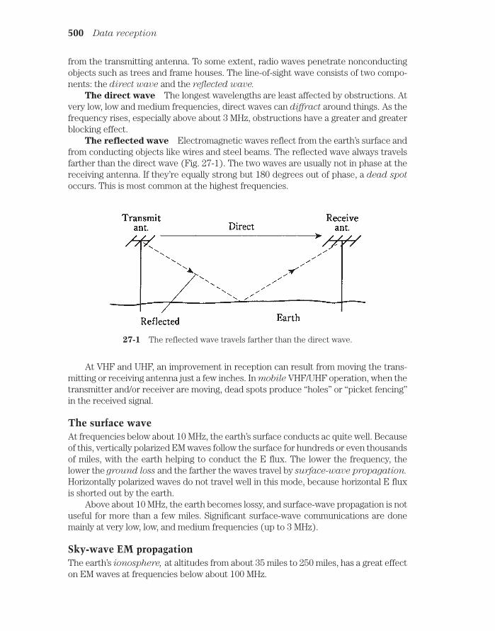
from the transmitting antenna. To some extent, radio waves penetrate nonconductingobjects such as trees and frame houses. The line-of-sight wave consists of two compo-nents: the direct wave and the reflected wave.
The direct wave The longest wavelengths are least affected by obstructions. Atvery low, low and medium frequencies, direct waves can diffract around things. As thefrequency rises, especially above about 3 MHz, obstructions have a greater and greaterblocking effect.
The reflected wave Electromagnetic waves reflect from the earth’s surface andfrom conducting objects like wires and steel beams. The reflected wave always travelsfarther than the direct wave (Fig. 27-1). The two waves are usually not in phase at thereceiving antenna. If they’re equally strong but 180 degrees out of phase, a dead spot
occurs. This is most common at the highest frequencies.
500 Data reception
27-1 The reflected wave travels farther than the direct wave.
At VHF and UHF, an improvement in reception can result from moving the trans-mitting or receiving antenna just a few inches. In mobile VHF/UHF operation, when thetransmitter and/or receiver are moving, dead spots produce “holes” or “picket fencing”in the received signal.
The surface waveAt frequencies below about 10 MHz, the earth’s surface conducts ac quite well. Becauseof this, vertically polarized EM waves follow the surface for hundreds or even thousandsof miles, with the earth helping to conduct the E flux. The lower the frequency, thelower the ground loss and the farther the waves travel by surface-wave propagation.
Horizontally polarized waves do not travel well in this mode, because horizontal E fluxis shorted out by the earth.
Above about 10 MHz, the earth becomes lossy, and surface-wave propagation is notuseful for more than a few miles. Significant surface-wave communications are donemainly at very low, low, and medium frequencies (up to 3 MHz).
Sky-wave EM propagationThe earth’s ionosphere, at altitudes from about 35 miles to 250 miles, has a great effecton EM waves at frequencies below about 100 MHz.
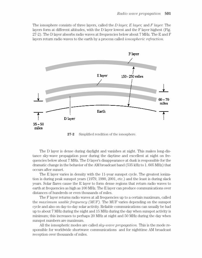
The ionosphere consists of three layers, called the D layer, E layer, and F layer. Thelayers form at different altitudes, with the D layer lowest and the F layer highest (Fig.27-2). The D layer absorbs radio waves at frequencies below about 7 MHz. The E and Flayers return radio waves to the earth by a process called ionospheric refraction.
Radio wave propagation 501
27-2 Simplified rendition of the ionosphere.
The D layer is dense during daylight and vanishes at night. This makes long-dis-tance sky-wave propagation poor during the daytime and excellent at night on fre-quencies below about 7 MHz. The D layer’s disappearance at dusk is responsible for thedramatic change in the behavior of the AM broadcast band (535 kHz to 1. 605 MHz) thatoccurs after sunset.
The E layer varies in density with the 11-year sunspot cycle. The greatest ioniza-tion is during peak sunspot years (1979, 1990, 2001, etc.) and the least is during slackyears. Solar flares cause the E layer to form dense regions that return radio waves toearth at frequencies as high as 100 MHz. The E layer can produce communications overdistances of hundreds or even thousands of miles.
The F layer returns radio waves at all frequencies up to a certain maximum, calledthe maximum usable frequency (MUF). The MUF varies depending on the sunspotcycle and also on day-to-day solar activity. Reliable communications can usually be hadup to about 7 MHz during the night and 15 MHz during the day when sunspot activity isminimum; this increases to perhaps 20 MHz at night and 50 MHz during the day whensunspot numbers are maximum.
All the ionospheric modes are called sky-wave propagation. This is the mode re-sponsible for worldwide shortwave communications and for nighttime AM broadcastreception over thousands of miles.

Tropospheric EM propagationAt frequencies above about 30 MHz, the lower atmosphere bends radio waves towardsthe surface (Fig. 27-3). Tropospheric banding or tropo occurs because the index of
refraction of air, with respect to EM waves, decreases with altitude. The effect is simi-lar to sound waves hugging the surface of a lake in the early morning, letting you hear aconversation a mile away. Tropo makes it possible to communicate for hundreds ofmiles when the ionosphere will not return waves to the earth.
502 Data reception
27-3 The lower atmosphere bends EM waves toward the surface.
Another type of tropospheric propagation is called ducting. It takes place whenEM waves are trapped in a layer of cool, dense air sandwiched between two layers ofwarmer air. Like bending, ducting occurs almost entirely at frequencies above 30 MHz.
Still another tropospheric-propagation mode is troposcatter. This takes place be-cause air molecules, dust grains, and water droplets scatter some of the EM field at veryhigh and ultra-high frequencies (above 30 MHz).
Exotic modes of EM propagationRadio waves can bounce off the aurora (northern and southern lights). This is auroral
propagation, and it occurs at frequencies from roughly 15 to 250 MHz. It can take placebetween stations separated by up to about 2000 miles.
Meteors entering the upper atmosphere produce ionized trails that persist for sev-eral seconds up to about a minute; these ions reflect EM waves and cause meteor-scat-
ter propagation. This mode allows communication for hundreds of miles atfrequencies from 20 to 150 MHz.
The moon, like the earth, reflects EM fields. This makes it possible to communicatevia earth-moon-earth (EME), also called moonbounce. High-powered transmitters,sophisticated antenna systems, and sensitive receivers are needed for EME. Most EMEis done by radio hams at frequencies from 50 MHz to over 2 GHz.
Receiver specificationsAny communications receiver, whether analog or digital, audio or video, must do certainbasic things well.

SensitivityThe sensitivity of a receiver is its ability to recover weak signals and process them intoreadable data. The most common way to express receiver sensitivity is to state the numberof ac signal microvolts at the antenna, needed to produce a given signal-to-noise (S/N)
ratio. Sometimes, the signal-plus-noise-to-noise ratio, abbreviated S+N/N, is given.When you look at the specifications table for a radio receiver, you might see, for ex-
ample, “better than 0.3 V for 10 dB S/N.” This means that a signal of 0.3 V or less, atthe antenna terminals, will result in a S/N ratio of 10 dB. This figure is given as an ex-ample only and not as any sort of standard separating the good from the bad. Techno-logical advancements are always improving the sensitivity figures for communicationsreceivers. Besides that, a poor figure for one application, or on one frequency band,might be fine for some other intended use, or on some other frequency band.
The front end, or first RF amplifier stage, of a receiver is the most important stagewith regard to sensitivity. Sensitivity is directly related to the gain of this stage; but theamount of noise it generates is even more significant. A good front end should producethe best possible S/N or S+N/N ratio at its output. All subsequent stages will amplify thefront-end noise output as well as the front-end signal output.
SelectivitySelectivity is the ability of a receiver to respond to a desired signal, but not to undesiredones. This generally means that a receiver must have a frequency “window” withinwhich it is sensitive, but outside of which it is not at all sensitive. This “window” is es-tablished by a preselector in the early RF amplification stages of the receiver and ishoned to precision by a narrowband filter in a later amplifier stage.
Suppose you want to receive an LSB signal whose suppressed-carrier frequencyis 3.885 MHz. The signal information is contained in a band from 3.882 to 3.885 MHz,a span of 3 kHz. The preselector makes the receiver sensitive in a range of about plusor minus 10 percent of the signal frequency; other frequencies are attenuated. Thisreduces the chance for a strong, out-of-band signal to impair the performance of thereceiver. The narrowband filter responds only to the frequencies 3.882 to 3.885 MHz,so that signals in adjacent channels are rejected. The better this filter works, the bet-ter the adjacent channel rejection.
Dynamic rangeThe signals at a receiver input vary over several orders of magnitude. If you are listen-ing to a weak signal and a strong one comes on the same frequency, you don’t want toget your eardrums damaged! But also, you want the receiver to work well if a strong sig-nal appears at a frequency near (but not exactly on top of) the weak one. Dynamic
range is the ability of a receiver to maintain a fairly constant output—and to keep itssensitivity—in the presence of signals ranging from the very weak to the extremelystrong. Dynamic range is specified in decibels and is typically over 100 dB.
Noise figureAll RF amplifier circuits generate some wideband noise. The less internal noise a re-ceiver produces, the better the S/N ratio. This becomes more and more important as thefrequency increases. It is paramount at very high frequencies and above (over 30 MHz).
Receiver specifications 503

The noise figure (NF) of a receiver is specified in various different ways. Thelower the noise figure, the better the sensitivity. You might see a specification such as“NF: 6 dB or better.”
Noise figure depends on the type of active amplifier device used in the front end ofa receiver. Gallium-arsenide field-effect transistors (GaAsFETs) are well known for thelow levels of noise they generate, even at quite high frequencies. Other types of FETscan be used at lower frequencies. Bipolar transistors tend to be rather noisy.
Definition of detectionDetection, also called demodulation, is the recovery of information such as audio, avisible image (either still or moving), or printed data from a signal. The way this is donedepends on the modulation mode.
Detection of AM signalsAmplitude modulation is done by varying the instantaneous strength of the carrier wave.The fluctuations follow the waveform of the voice or video data. The carrier itself is ac,of a frequency many times that of the modulating audio or video. The modulation peaks
occur on the positive and negative swings of the carrier. This is shown in Fig. 27-4.
504 Data reception
27-4 An AM signal. The heavy lines show the output after passingthrough the envelope-detector diode or transistor.
If you feed the AM carrier current directly into a headset, fax machine, or whatever,you can’t recover the data because the positive and negative peaks come by in suchrapid succession that they cancel each other out.
A simple way to get the modulating waveform out of an AM signal is to cut off half ofthe carrier wave cycle. The result (Fig. 27-4) is fluctuating, pulsating dc. The pulsations
occur at the carrier frequency, the slower fluctuation is a duplication of the modulating au-dio or video. This process can be done by passing the signal through a diode with a small
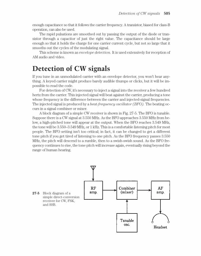
enough capacitance so that it follows the carrier frequency. A transistor, biased for class-Boperation, can also be used.
The rapid pulsations are smoothed out by passing the output of the diode or tran-sistor through a capacitor of just the right value. The capacitance should be largeenough so that it holds the charge for one carrier current cycle, but not so large that itsmooths out the cycles of the modulating signal.
This scheme is known as envelope detection. It is used extensively for reception ofAM audio and video.
Detection of CW signalsIf you tune in an unmodulated carrier with an envelope detector, you won’t hear any-thing. A keyed carrier might produce barely audible thumps or clicks, but it will be im-possible to read the code.
For detection of CW, it’s necessary to inject a signal into the receiver a few hundredhertz from the carrier. This injected signal will beat against the carrier, producing a tonewhose frequency is the difference between the carrier and injected-signal frequencies.The injected signal is produced by a beat-frequency oscillator (BFO). The beating oc-curs in a signal combiner or mixer.
A block diagram of a simple CW receiver is shown in Fig. 27-5. The BFO is tunable.Suppose there is a CW signal at 3.550 MHz. As the BFO approaches 3.550 MHz from be-low, a high-pitched tone will appear at the output. When the BFO reaches 3.549 MHz,the tone will be 3.550–3.549 MHz, or 1 kHz. This is a comfortable listening pitch for mostpeople. The BFO setting isn’t too critical; in fact, it can be changed to get a differenttone pitch if you get tired of listening to one pitch. As the BFO frequency passes 3.550MHz, the pitch will descend to a rumble, then to a swish-swish sound. As the BFO fre-quency continues to rise, the tone pitch will increase again, eventually rising beyond therange of human hearing.
Detection of CW signals 505
27-5 Block diagram of asimple direct-conversionreceiver for CW, FSK,and SSB.

This demodulation scheme is called heterodyne detection. A receiver that makesuse of a heterodyne detector is called a direct-conversion receiver.
Detection of FSK signalsFrequency-shift keying can be detected by using the same methods as CW detection.The carrier beats against the BFO in the mixer, producing an audio tone that alternatesbetween two different pitches. The block diagram of Fig. 27-5 can therefore apply toFSK reception as well as to CW reception.
With FSK, the BFO frequency is always set well above, or well below, both the markand the space carrier frequencies. The offset affects the audio tone frequencies and is setso that certain standard pitches result. There are several sets of standard tone frequen-cies, depending on whether the communications is amateur, commercial, or military. Toget the proper pitches, the BFO must be set precisely at the right frequency. There is lit-tle tolerance for error.
Detection of SSB signalsA single-sideband signal is really just an AM signal, minus the carrier and one of thesidebands. If the BFO frequency of a CW receiver is set exactly where the carrier shouldbe, the sideband, either upper or lower, will beat against the BFO and produce audiooutput. In this way, the receiver of Fig. 27-5 can be used to detect SSB.
The BFO frequency is critical for good SSB reception. If it is not set exactly at thefrequency of the suppressed carrier, the voice will sound bizarre, like “monkey chatter.”
A more advanced method of receiving CW, FSK, and SSB makes use of a product
detector. This is a specialized form of mixer and is discussed a little later in this chapter.
Detection of FM signalsFrequency-modulated or phase-modulated signals can be detected in several ways. Thebest FM receivers respond to frequency/phase changes, but not to amplitude changes.
Slope detectionAn AM receiver can be used to detect FM. This is done by setting the receiver near, butnot exactly on, the FM signal.
An AM receiver has a narrowband filter with a passband of about 6 kHz. This givesa selectivity curve such as that shown in Fig. 27-6. If the FM carrier frequency is nearthe skirt, or slope, of the filter response, modulation will cause the signal to move in andout of the passband. This will make the receiver output vary with the modulating data.
Because this scheme takes advantage of the filter slope, it is called slope detection.
It has two disadvantages. First, the receiver will respond to amplitude variations (be-cause that’s what it’s designed for). Second, there will be nonlinearity in the receivedsignal, producing distortion, because the slope is not a straight line.
506 Data reception
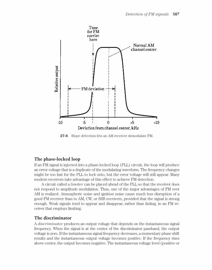
The phase-locked loopIf an FM signal is injected into a phase-locked loop (PLL) circuit, the loop will producean error voltage that is a duplicate of the modulating waveform. The frequency changesmight be too fast for the PLL to lock onto, but the error voltage will still appear. Manymodern receivers take advantage of this effect to achieve FM detection.
A circuit called a limiter can be placed ahead of the PLL so that the receiver doesnot respond to amplitude modulation. Thus, one of the major advantages of FM overAM is realized. Atmospheric noise and ignition noise cause much less disruption of agood FM receiver than to AM, CW, or SSB receivers, provided that the signal is strongenough. Weak signals tend to appear and disappear, rather than fading, in an FM re-ceiver that employs limiting.
The discriminatorA discriminator produces an output voltage that depends on the instantaneous signalfrequency. When the signal is at the center of the discriminator passband, the outputvoltage is zero. If the instantaneous signal frequency decreases, a momentary phase shiftresults and the instantaneous output voltage becomes positive. If the frequency risesabove center, the output becomes negative. The instantaneous voltage level (positive or
Detection of FM signals 507
27-6 Slope detection lets an AM receiver demodulate FM.

negative) is directly proportional to the instantaneous frequency. Therefore, the outputvoltage is a duplicate of the modulating waveform.
A discriminator is sensitive to amplitude variations in the signal, but this problemcan be overcome by the use of a limiter.
The ratio detectorA discriminator with a built-in limiting effect is known as a ratio detector. This type ofFM detector was developed by RCA and is used in high-fidefity receivers and in the au-dio portions of TV receivers.
A simple ratio detector circuit is shown in Fig. 27-7. A transformer splits the signalinto two components.
508 Data reception
27-7 A ratio detector for demodulating FM.
A change in signal amplitude causes equal level changes in both halves of the cir-cuit. These effects cancel because they are always 180 degrees out of phase. This nulli-fies amplitude variations on the signal.
A change in signal frequency causes a phase shift in the circuit. This unbalances it,so that the outputs in the two halves of the circuit become different, which produces anoutput in direct proportion to the instantaneous phase shift. The output signal is a du-plication of the modulating waveform on the FM signal.
Detection of PM signalsPulse modulation (PM) operates at a low duty cycle. The pulses are far shorter in du-ration than the intervals between them. A PM signal is “mostly empty space.” The ratioof average signal power to peak signal power is low, often much less than 1 percent.
When the amplitude or duration of the pulses changes, the average transmitterpower also changes. Stronger or longer pulses increase the effective signal amplitude;

weaker or shorter pulses result in decreased amplitude. Because of this, PM can be de-tected in the same way as AM.
A major advantage of PM is that it’s “mostly empty space.” With pulse amplitudemodulation (PAM), pulse duration modulation (PDM), or pulse code modulation(PCM), the time interval is constant between pulse centers. Even at maximum modu-lation, the ratio of “on” time to “off” time is low. Therefore, two or more signals can beintertwined on a single carrier (Fig. 27-8). A PM receiver can pick out one of these sig-nals and detect it, ignoring the others. This is known as time-division multiplexing.
Digital-to-analog conversion 509
27-8 Time-division multiplexing of two different signals (A and B) on a single-pulsed carrier.
A time-division-multiplex communications circuit requires that the receiver be syn-chronized with the transmitter. This is easy to do if the pulse frequency is constant. Thereceiver and transmitter can be clocked from a single, independent, primary time stan-dard such as the broadcasts of radio station WWV. The receiver detector is blocked offduring intervals between transmitter pulses and “opens up” only during “windows” last-ing as long as the longest transmitter pulses.
The received data is selected by adjusting the windows to correspond with the de-sired pulse train. Because the duty cycle of any single signal is so low, it is possible tomultiplex dozens or even hundreds of signals on one transmitted carrier.
Digital-to-analog conversionWhen receiving a digital signal such as pulse code modulation (PCM), a digital-to-ana-
log (D/A) converter is used. This reverses the process of A/D conversion at the trans-mitter, so that the original analog data is recovered.

You might ask, “Why convert a signal to digital form in the first place, if it’s going tobe changed back to analog form at the receiver anyway?” The reason is that a digital sig-nal is inherently simpler than an analog signal, in the sense that is less random. Thus,a digital signal resembles noise less than an analog signal.
It’s good to make a signal as different from noise as possible, in as many ways (orsenses) as possible. This is because the more different a signal is from unwanted noise,the easier it is to separate the data from the noise, and the better is the realizable S/Nratio.
You might think of signal/noise separation in terms of apples, oranges, and a water-melon. It takes awhile to find an orange in a tub of apples. (You’ll probably have to dumpthe tub). Think of the orange as an analog signal and the apples as noise. But supposethere’s a watermelon in a bushel basket with apples. You’ll have no trouble at all findingthe watermelon. Think of the melon as a digital signal and the apples as noise.
Another, more interesting feature of digital communications arises when you thinkof a watermelon in a tub of oranges. It’s as easy to separate a digital signal from a jum-ble of analog signals as it is to extract a digital signal from noise. In a band occupied bythousands of analog signals, a lone digital signal can be picked out easily—far more eas-ily than any of the analog signals.
In recent years, digitization has become commonplace not only in data communica-tions, but in music recording and even in video recording. The main advantage of digi-tal recording is that a selection can be recorded, re-recorded, re-re-recorded, etc., andthe quality does not diminish.
Digital signal processingA new and rapidly advancing communications technique, digital signal processing
(DSP), promises to revolutionize voice, digital, and image communications.In analog modes, DSP works by converting the received voice or video signal input
into digital data by means of an analog-to-digital (A/D) converter. The digital signal isprocessed and is reconverted back to the original voice or video via a D/A converter(Fig. 27-9).
510 Data reception
27-9 Digital signal processing.
In digital modes, A/D and D/A conversion is not necessary, but DSP can still be usedto “clean up” the signal. This reduces the number of errors.
It is in the digital part of the DSP circuit that the signal enhancement takes place.Digital signals have a finite number of discrete, well-defined states. It is easier to processa signal of this kind than to process an analog signal, which has a theoretically infinite
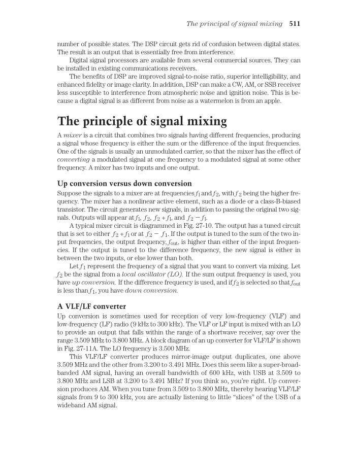
number of possible states. The DSP circuit gets rid of confusion between digital states.The result is an output that is essentially free from interference.
Digital signal processors are available from several commercial sources. They canbe installed in existing communications receivers.
The benefits of DSP are improved signal-to-noise ratio, superior intelligibility, andenhanced fidelity or image clarity. In addition, DSP can make a CW, AM, or SSB receiverless susceptible to interference from atmospheric noise and ignition noise. This is be-cause a digital signal is as different from noise as a watermelon is from an apple.
The principle of signal mixingA mixer is a circuit that combines two signals having different frequencies, producinga signal whose frequency is either the sum or the difference of the input frequencies.One of the signals is usually an unmodulated carrier, so that the mixer has the effect ofconverting a modulated signal at one frequency to a modulated signal at some otherfrequency. A mixer has two inputs and one output.
Up conversion versus down conversionSuppose the signals to a mixer are at frequencies f l and f2, with f 2 being the higher fre-quency. The mixer has a nonlinear active element, such as a diode or a class-B-biasedtransistor. The circuit generates new signals, in addition to passing the original two sig-nals. Outputs will appear at f l, f2, f2 + f l, and f2 f l.
A typical mixer circuit is diagrammed in Fig. 27-10. The output has a tuned circuitthat is set to either f2 + f l or at f2 f1. If the output is tuned to the sum of the two in-put frequencies, the output frequency, fout, is higher than either of the input frequen-cies. If the output is tuned to the difference frequency, the new signal is either inbetween the two inputs, or else lower than both.
Let f1 represent the frequency of a signal that you want to convert via mixing. Letf2 be the signal from a local oscillator (LO). If the sum output frequency is used, youhave up conversion. If the difference frequency is used, and if f2 is selected so that foutis less than f1, you have down conversion.
A VLF/LF converterUp conversion is sometimes used for reception of very low-frequency (VLF) andlow-frequency (LF) radio (9 kHz to 300 kHz). The VLF or LF input is mixed with an LOto provide an output that falls within the range of a shortwave receiver, say over therange 3.509 MHz to 3.800 MHz. A block diagram of an up converter for VLF/LF is shownin Fig. 27-11A. The LO frequency is 3.500 MHz.
This VLF/LF converter produces mirror-image output duplicates, one above3.509 MHz and the other from 3.200 to 3.491 MHz. Does this seem like a super-broad-banded AM signal, having an overall bandwidth of 600 kHz, with USB at 3.509 to3.800 MHz and LSB at 3.200 to 3.491 MHz? If you think so, you’re right. Up conver-sion produces AM. When you tune from 3.509 to 3.800 MHz, thereby hearing VLF/LFsignals from 9 to 300 kHz, you are actually listening to little “slices” of the USB of awideband AM signal.
The principal of signal mixing 511

A UHF/microwave converterDown conversion is often used to allow reception of ultra-high-frequency (UHF) andmicrowave signals (above 300 MHz). The UHF or microwave input is mixed with an LOto provide an output that falls within the tuning range of a shortwave VHF receiver. Ablock diagram of a down converter for UHF/microwave reception is shown in Fig.27-11B.
This converter has an output that covers a huge band of frequencies. In fact, a sin-gle frequency allocation at UHF or microwave might be larger than the entire frequencyrange of a shortwave receiver. An example is a UHF converter designed to cover 1.000GHz to 1.100 GHz. This is a span of 100 MHz, more than three times the whole range ofa shortwave radio.
To receive 1.000 to 1.100 GHz using a down converter and a shortwave receiver, theLO frequency must be switchable. Suppose you have a communications receiver thattunes in 1-MHz bands. You might choose one of these bands, say 7.000 to 8.000 MHzand use a keypad to choose LO frequencies from 0.993 GHz to 1.092 GHz. This will pro-duce a difference-frequency output at 7.000 to 8.000 MHz for 100 segments, each 1MHz wide, in the desired band of reception.
If you want to hear the segment 1.023 to 1.024 GHz, you set the LO at 1.016 MHz.This produces an output range from 1023 − 1016 = 7 MHz to 1024 − 1016 = 8 MHz.
The product detectorFor the reception of CW, FSK, and SSB signals, a product detector is generally used. Itworks according to the same basic principle as the mixer. The incoming signal combineswith the signal from an unmodulated local oscillator, producing audio or video output.
512 Data reception
27-10 A passive mixer.
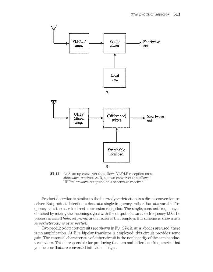
Product detection is similar to the heterodyne detection in a direct-conversion re-ceiver. But product detection is done at a single frequency, rather than at a variable fre-quency as is the case in direct-conversion reception. The single, constant frequency isobtained by mixing the incoming signal with the output of a variable-frequency LO. Theprocess is called heterodyning, and a receiver that employs this scheme is known as asuperheterodyne or superhet.
Two product-detector circuits are shown in Fig. 27-12. At A, diodes are used; thereis no amplification. At B, a bipolar transistor is employed; this circuit provides somegain. The essential characteristic of either circuit is the nonlinearity of the semiconduc-tor devices. This is responsible for producing the sum and difference frequencies thatyou hear or that are converted into video images.
The product detector 513
27-11 At A, an up converter that allows VLF/LF reception on ashortwave receiver. At B, a down converter that allowsUHF/microwave reception on a shortwave receiver.

514 Data reception
27-12 At A, a passive product detector. At B, a product detector that providessome amplification.

The superheterodyneThe superheterodyne uses one or more mixers to convert an incoming signal, re-
gardless of its frequency, to an identically modulated signal at some other, constant fre-quency. The signal frequency can be heterodyned once, twice, or even three times.Thus, you might hear of a single-conversion, double-conversion, or triple-conver-
sion superheterodyne receiver.
A single-conversion superhetA block diagram of a single-conversion receiver is shown in Fig. 27-13.
The superheterodyne 515
27-13 A single-conversion superheterodyne receiver.
The incoming signal first passes through a sensitive, low-noise, tunable front-endamplifier. The tuning range of this amplifier must be sufficient to cover all the desiredreception frequencies fIN.
The second stage is a mixer/LO combination. The LO has a variable frequency thattunes over the received-signal range plus 9.000 MHz. The LO frequency control is themain tuning control for the entire receiver. The LO tuning might track along with thetuning of the front end, or the front end might tune independently by means of a sepa-rate preselector control. The mixer output is always at 9.000 MHz, no matter what theincoming signal frequency.
The intermediate frequencyThe 9.000-MHz mixer output signal is called the intermediate frequency (IF) of thesuperhet. This signal has the same modulation waveform, and the same bandwidth, asthe incoming signal. The only difference is that it might be “upside down”; LSB wouldbe changed to USB, or the sense of FSK would be reversed. But this is an inconsequen-tial difference insofar as it has no effect on the quality of the received signal.

The IF is easy to process because its frequency never changes. Several IF ampli-
fier stages, along with filtering, provide the best possible sensitivity and selectivity. Thispart of the receiver is the IF amplifier chain or IF chain.
Image rejectionIn the superhet of Fig. 27-13, the LO frequency, fLO, is above fIN. The difference is al-ways exactly 9.000 MHz. Thus, if fIN = 3.510 MHz, then fLo = 3.510 + 9.000 MHz = 12.510MHz. And if fIN = 15.555 MHz, then fLO = 15.555 + 9.000 MHz = 24.555 MHz. The IF isalways obtained by difference mixing. The 9. 000-MHz IF is the signal at fLO – fIN.
But there is another possible frequency that can mix with the LO signal to producea 9.000-MHz output. That is the difference fIN − fLO. Suppose you have the LO set at fLO= 12.510 MHz, so that the receiver hears signals at fIN = 3.510 MHz. If a signal comes onat fLO + 9.000 MHz = 12.510 + 9.000 MHz = 21.510 MHz, and if this signal gets throughthe front end of the receiver, then it will mix with the LO signal to produce a false sig-nal at 21.510 − 12.510 MHz = 9.00 MHz. This is called an image signal.
Suppose you set the LO at fLO = 24.555 MHz, so that the receiver hears signals atfIN = 15.555 MHz. If a signal appears at fLO + 9.000 MHz = 24.555 + 9.000 MHz = 33.555MHz, then you’ll hear it in the 9.000-MHz IF chain as an image signal.
Clearly, you don’t want the receiver to hear image signals; you want it to receiveonly at the desired fIN. A good preselector will provide image rejection. This is helpedalong by choosing a high IF, so that the image frequency, fIMAGE, is much different fromfIN. That way, the tuned circuit in the front end has an easy time separating the realthing from the impostor.
Multiple conversionAnother way to improve image rejection is to convert the 9.000-MHz (or whatever fre-quency) first IF to a lower IF, known as the second IF. This is usually a frequency be-tween about 50 kHz and 500 kHz. A standard second IF is 455 kHz. The resultingreceiver is a double-conversion superhet.
Sometimes the second IF is converted to a still lower frequency, called the third IF,
usually 50 kHz. This is a triple-conversion superhet.The main advantage of using double or triple conversion, besides superior image
rejection, is the fact that low IFs can be easily filtered to provide superior adjacent-channel rejection.
Low IFs aren’t practical with single-conversion receivers, because fIMAGE would betoo close to fIN, and the front end could not adequately differentiate between them. Thisproblem would be worst at the highest frequencies fIN.
Detector and audio/video amplifierOnce the IF signal has been filtered and amplified, it passes through a detector. This isgenerally a product detector for CW, FSK, and SSB, a ratio detector or PLL for FM, andan envelope detector for AM.
Following the detector, a DSP circuit might be used. This further enhances the S/Nratio, minimizing the number of printer or display errors, or clarifying the audio orvideo.
516 Data reception

Finally, an audio/video amplifier is used to boost the level to whatever is needed todrive the speaker, teleprinter, monitor, or instrumentation at the receiver output.
A modulated-light receiverModulated light beams can be demodulated easily using photodiodes or photovoltaiccells, as long as the modulating frequency isn’t too high. At audio frequencies, a circuitsuch as the one in Fig. 27-14 will provide sufficient output to drive a headset. Thisdemonstrates the method by which fiberoptic signals are detected.
Quiz 517
27-14 A simple modulated-light receiver.
For use with a speaker, another bipolar amplifier stage can be added following thestage shown. To increase the sensitivity of the receiver (that is, to allow reception ofmuch fainter modulated-light beams), an FET stage can be added between thephotovoltaic cell and the bipolar stage shown.
Modulated-light experiments can be done with simple apparatus, costing only a fewdollars. If reasonably large lenses and/or reflectors are used, line-of-sight voice commu-nications can be had for distances up to several hundred feet, using circuits based onthe transmitter of Fig. 26-17 and the receiver of Fig. 27-14. With additional amplifica-tion and very large reflectors, the range can be increased to several miles on clearnights. This could make a great science-fair project.
QuizRefer to the text in this chapter if necessary. A good score is at least 18 correct. Answersare in the back of the book.
1. The reflected wave in a radio signal:
A. Travels less distance than the direct wave.

B. Travels just as far as the direct wave.
C. Travels farther than the direct wave.
D. Might travel less far than, just as far as, or farther than the direct wave.
2. The reflected wave:
A. Arrives in phase with the direct wave.
B. Arrives out of phase with the direct wave.
C. Arrives in a variable phase compared with the direct wave.
D. Is horizontally polarized.
3. The ionospheric layer that absorbs radio waves is:
A. The D layer.
B. The E layer.
C. The F layer.
D. No layers ever absorb radio waves.
4. The highest layer of the ionosphere is:
A. The D layer.
B. The E layer.
C. The F layer.
D. Dependent on the time of day and the solar cycle.
5. Radio waves that curve earthward in the lower atmosphere are being affectedby:
A. Troposcatter.
B. The D layer.
C. Ionospheric ducting.
D. Tropospheric bending.
6. Single-sideband can be demodulated by:
A. An envelope detector.
B. A diode.
C. A BFO and mixer.
D. A ratio detector.
7. A diode and capacitor can be used to detect:
A. CW.
B. AM.
C. SSB.
D. FSK.
8. The SN/N ratio is a measure of.
A. Sensitivity.
518 Data reception

B. Selectivity.
C. Dynamic range.
D. Adjacent-channel rejection.
9. The ability of a receiver to perform in the presence of strong signals is aconsequence of its:
A. Sensitivity.
B. Noise figure.
C. Dynamic range.
D. Adjacent-channel rejection.
10. A receiver that responds to a desired signal, but not to one very nearby infrequency, has good:
A. Sensitivity.
B. Noise figure.
C. Dynamic range.
D. Adjacent-channel rejection.
11. An AM receiver can be used to demodulate FM by means of:
A. Envelope detection.
B. Product detection.
C. Slope detection.
D. Pulse detection.
12. An FM detector with built-in limiting is:
A. A ratio detector.
B. A discriminator.
C. An envelope detector.
D. A product detector.
13. Time-division multiplex is often done with:
A. AM.
B. FM.
C. FSK.
D. PM.
14. A continuously variable signal is recovered from a signal having discrete statesby:
A. A ratio detector.
B. A D/A converter.
C. A product detector.
D. An envelope detector.
Quiz 519

15. Digital modulation is superior to analog modulation in the sense that:
A. Analog signals have discrete states, while digital ones vary continuously.
B. Digital signals resemble noise less than analog ones.
C. Digital signals are easier to use with FM.
D. Digital signals have greater bandwidth.
16. A product detector would most often be used to receive:
A. AM.
B. CW.
C. FM.
D. None of the above.
17. To receive UHF signals on a shortwave receiver, you would need:
A. A heterodyne detector.
B. A product detector.
C. An up converter.
D. A down converter.
18. Image rejection in a superhet receiver is enhanced by:
A. Front-end selectivity.
B. A product detector.
C. A variable LO.
D. A sensitive IF amplifier chain.
19. A low IF is not practical with a single-conversion receiver because:
A. Product detection cannot be used.
B. The image frequency would be too close to the incoming-signal frequency.
C. Sensitivity would be impaired.
D. Adjacent-channel rejection would be poor.
20. Digital signal processing can be used to advantage with:
A. SSB.
B. SSTV.
C. FSK.
D. Any of the above.
520 Data reception

28CHAPTER
Integrated circuits anddata storage media
THE MOST ADVANCED ELECTRONIC CIRCUITS CONTAIN HUNDREDS,thousands, or even millions of diodes, transistors, resistors, and capacitors. This is es-pecially true of industrial and personal computers. These devices use circuits fabri-cated onto wafers, or chips, of semiconductor material, usually silicon. The chips areenclosed in little boxes or cans with pins for connection to external components.
Integrated circuits (ICs) have stimulated as much change as, and perhaps moreevolution than, any other single development in the history of electronic technology.
Boxes and cansMost ICs look like gray or black plastic boxes with protruding pins. Common configura-tions are the single inline package (SIP), the dual inline package (DIP) and the flat-
pack. Another package looks like a transistor with too many leads. This is a metal-can
package, sometimes also called a TO package. Examples are shown in Fig. 28-1.Not only does an IC look like a box or can; the schematic symbols for most ICs are
simple geometric shapes such as triangles or rectangles. A component designator isusually written inside the polygon, and the wires emerging from it are labeled accord-ing to their specific functions. But the circuit details are usually too complicated to bedrawn in schematic diagrams. There’s no point in rendering all that detail anyway; itwould only confuse engineers and technicians, and make the schematic diagrams solarge that they might cover a wall, or a football field, or the state of Kansas.
So then an IC is a “black box.” The engineer or technician can forget about its innerworkings, just as you don’t dwell upon what’s happening inside your personal computeras you use it. Even with the simplicity of the IC symbol, an apparatus using many ICs canhave nightmarish schematic diagrams, with dozens of wires running around as parallellines so close together that you must run a pencil along them to keep track of them.
521 !
"# #$ !

Advantages of IC technologyIntegrated circuits have several advantages over individual, or discrete, components.
CompactnessAn obvious asset of IC design is economy of space; ICs are far more compact than equiv-alent circuits made from individual transistors, diodes, capacitors, and resistors.
A corollary to this is the fact that far more complex circuits can be built, and keptdown to a reasonable size, using ICs as compared with discrete components. Thus, yousee notebook computers, also known as laptops, with capabilities more advanced thanearly computers that took up whole rooms.
High speedAnother corollary to the compactness of ICs is the fact that the interconnections amongcomponents are physically tiny, making high switching speeds possible. Electric cur-rents travel fast, but not instantaneously. The less time charge carriers need to get fromcomponent X to component Y, in general, the more computations are possible within agiven span of time, and the less time is needed for complex operations.
Low power requirementAnother advantage of ICs is that they use less power than equivalent discrete-componentcircuits. This is especially important if batteries are to be used for operation. Because ICsuse so little current, they produce less heat than their discrete-component equivalents.This translates into better efficiency. It also minimizes the problems that plague equip-ment that gets hot with use, such as frequency drift and generation of internal noise.
522 Integrated circuits and data storage media
28-1 IC packages: SIP (A), DIP (B), flatpack (C), and metalcan (D).

ReliabilityIntegrated circuits fail less often, per component-hour of use, than appliances thatmake use of discrete components. This is mainly a result of the fact that all intercon-nections are sealed within the IC case, preventing corrosion or the intrusion of dust.The reduced failure rate translates into less downtime, or time during which theequipment is out of service for repairs.
Ease of maintenanceIntegrated-circuit technology lowers maintenance costs, mainly because repair proce-dures are simplified when failures do occur.
Many appliances use sockets for ICs, and replacement is simply a matter of findingthe faulty IC, unplugging it, and plugging in a new one. Special desoldering equipmentis used with appliances having ICs soldered directly to the circuit boards.
Modular constructionModern IC appliances use modular construction. In this scheme, individual ICs per-form defined functions within a circuit board; the circuit board or card, in turn, fits intoa socket and has a specific purpose. Computers, programmed with customized soft-ware, are used by repair technicians to locate the faulty card in an appliance. The wholecard can be pulled and replaced, getting the appliance back to the consumer in theshortest possible time. Then the computer can be used to troubleshoot the faulty card,getting the card ready for use in the next appliance that happens to come along with afailure in the same card.
Modular construction can theoretically be used with discrete-component design.But this is rarely done. When a device is sophisticated enough to need modular con-struction, IC design is usually needed to keep the size within reason. Can you envisionseveral people, or perhaps a crane, pulling and replacing a 500-pound, 10-by-15-footcard from an appliance as big as a house?
Limitations of IC technologyNo technological advancement ever comes without some sacrifice or compromise. In-tegrated circuits aren’t a ticket to electronic utopia.
Inductors impracticalWhile some components are easy to fabricate onto chips, other components defy the ICmanufacturing process. Inductances, except for extremely low values, are one suchbugaboo. Devices using ICs must generally be designed to work without inductors. For-tunately, resistance-capacitance (RC) circuits are capable of doing most things that in-ductance-capacitance (LC) circuits can do.
Mega-power impossibleThe small size and low current consumption of ICs comes with a “flip side.” This is the factthat high-power amplifiers cannot, in general, be fabricated onto semiconductor chips.
Limitations of IC technology 523
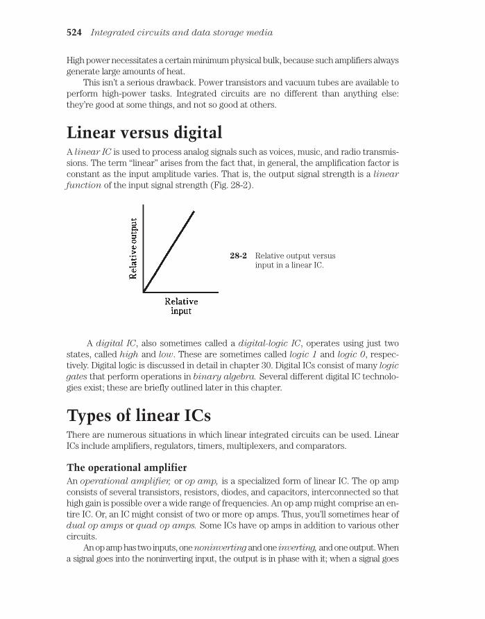
High power necessitates a certain minimum physical bulk, because such amplifiers alwaysgenerate large amounts of heat.
This isn’t a serious drawback. Power transistors and vacuum tubes are available toperform high-power tasks. Integrated circuits are no different than anything else:they’re good at some things, and not so good at others.
Linear versus digitalA linear IC is used to process analog signals such as voices, music, and radio transmis-sions. The term “linear” arises from the fact that, in general, the amplification factor isconstant as the input amplitude varies. That is, the output signal strength is a linear
function of the input signal strength (Fig. 28-2).
524 Integrated circuits and data storage media
28-2 Relative output versusinput in a linear IC.
A digital IC, also sometimes called a digital-logic IC, operates using just twostates, called high and low. These are sometimes called logic 1 and logic 0, respec-tively. Digital logic is discussed in detail in chapter 30. Digital ICs consist of many logic
gates that perform operations in binary algebra. Several different digital IC technolo-gies exist; these are briefly outlined later in this chapter.
Types of linear ICsThere are numerous situations in which linear integrated circuits can be used. LinearICs include amplifiers, regulators, timers, multiplexers, and comparators.
The operational amplifierAn operational amplifier, or op amp, is a specialized form of linear IC. The op ampconsists of several transistors, resistors, diodes, and capacitors, interconnected so thathigh gain is possible over a wide range of frequencies. An op amp might comprise an en-tire IC. Or, an IC might consist of two or more op amps. Thus, you’ll sometimes hear ofdual op amps or quad op amps. Some ICs have op amps in addition to various othercircuits.
An op amp has two inputs, one noninverting and one inverting, and one output. Whena signal goes into the noninverting input, the output is in phase with it; when a signal goes

into the inverting input, the output is 180 degrees out of phase with it. An op amp has twopower supply connections, one for the emitters of the transistors (Vee) and one for the col-lectors (Vcc).
The symbol for an op amp is a triangle. The inputs, output, and power supply con-nections are drawn as lines emerging from it, as shown in Fig. 28-3. You don’t have to beconcerned with the details of the circuit inside the triangle.
Types of linear ICs 525
28-3 Symbol for an op amp.Connections arediscussed in the text.
The gain characteristics of an op amp are determined by external resistors. Nor-mally, a resistor is connected between the output and the inverting input. This is calledthe closed-loop configuration. The feedback is negative (out of phase), causing the gainof the op amp to be less than it would be if there were no feedback (open loop). Aclosed-loop amplifier using an op amp is shown in Fig. 28-4.
Why, you might ask, would you want to reduce the gain of an amplifier? The answeris that excessive gain can cause problems. An amplifier can be too sensitive, overloadingthe following circuits, generating too much noise, or producing unwanted responses.
28-4 Closed-loop op-amp configuration.
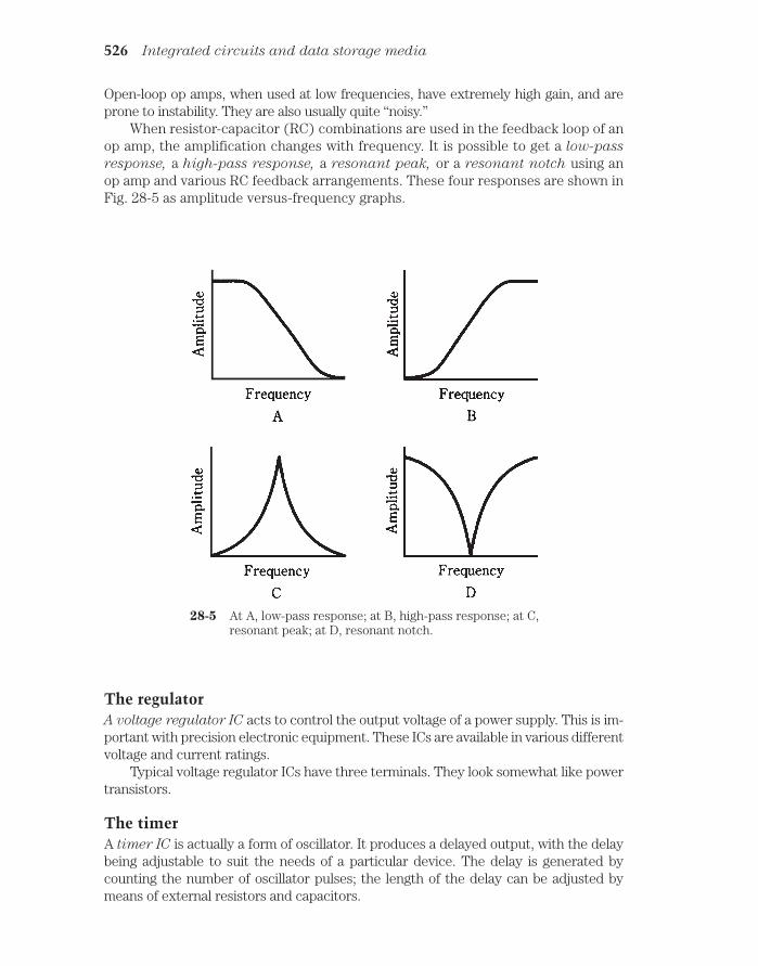
Open-loop op amps, when used at low frequencies, have extremely high gain, and areprone to instability. They are also usually quite “noisy.”
When resistor-capacitor (RC) combinations are used in the feedback loop of anop amp, the amplification changes with frequency. It is possible to get a low-pass
response, a high-pass response, a resonant peak, or a resonant notch using anop amp and various RC feedback arrangements. These four responses are shown inFig. 28-5 as amplitude versus-frequency graphs.
526 Integrated circuits and data storage media
28-5 At A, low-pass response; at B, high-pass response; at C,resonant peak; at D, resonant notch.
The regulatorA voltage regulator IC acts to control the output voltage of a power supply. This is im-portant with precision electronic equipment. These ICs are available in various differentvoltage and current ratings.
Typical voltage regulator ICs have three terminals. They look somewhat like powertransistors.
The timerA timer IC is actually a form of oscillator. It produces a delayed output, with the delaybeing adjustable to suit the needs of a particular device. The delay is generated bycounting the number of oscillator pulses; the length of the delay can be adjusted bymeans of external resistors and capacitors.

The analog multiplexerThe analog multiplexer IC allows several different signals to be combined in a singlechannel via time-division multiplexing, in a manner similar to that used with pulse mod-ulation. (This was discussed in chapter 27.) An analog multiplexer can also be used inreverse; then it works as a demultiplexer. Thus, you’ll sometimes hear engineers talkabout multiplexer/demultiplexer ICs.
The comparatorLike an op amp, a comparator IC has two inputs. The comparator does just what itsname implies: it compares the voltages at the two inputs (called A and B). If the inputat A is significantly greater than the input at B, the output will be about + 5 V. This islogic 1, or high. If the input at A is not greater than the input at B, the output voltagewill be about + 2 V. This is designated as logic 0, or low.
Voltage comparators are available for a variety of applications. Some can switch be-tween low and high states at a rapid rate of speed; others are slower. Some have low in-put impedance, and others have high impedance. Some are intended for audio orlow-frequency use; others are fabricated for video or high-frequency applications.
Voltage comparators are used to actuate, or trigger, other devices such as relaysand electronic switching circuits.
Bipolar digital ICsDigital ICs consist of gates that perform logical operations at high speeds. There areseveral different technologies, each with its own unique characteristics. Digital-logictechnology might use bipolar transistors or metal-oxide-semiconductor (MOS) devices.
TTLIn transistor-transistor logic (TTL), arrays of bipolar transistors, some with multipleemitters, operate on dc pulses. This technology has several variants, some of which dateback to around 1970. The hallmark of TTL is immunity to noise pulses. A simple TTLgate is illustrated in Fig. 28-6. The transistors are either completely cut off, or else com-pletely saturated. This is the reason why TTL is not very much affected by externalnoise “distractions.”
ECLAnother bipolar-transistor logic form is known as emitter-coupled logic (ECL). In ECL,the transistors are not operated at saturation, as they are with TTL. This increases thespeed of operation of ECL compared with TTL. But noise pulses have a greater effect inECL, because unsaturated transistors amplify as well as switch signals. The schematicof Fig. 28-7 shows a simple ECL gate.
MOS digital ICsSeveral variants of MOS technology have been developed for use in digital devices. Theyall offer superior miniaturization and reduced power requirements as compared withbipolar digital ICs.
MOS digital ICs 527

528 Integrated circuits and data storage media
28-6 A simple TTL gate.
28-7 A simple ECL gate.

CMOSComplementary-metal-oxide-semiconductor (CMOS), pronounced “seamoss” (andsometimes written that way by lay people who have heard the term but never seen it indocumentation), employs both N-type and P-type silicon on a single chip. This is anal-ogous to using N-channel and P-channel FETs in a circuit. The main advantages ofCMOS technology are extremely low current drain, high operating speed, and immunityto noise.
NMOS/PMOSN-channel MOS (NMOS) offers simplicity of design, along with high operating speed.P-channel MOS is similar to NMOS, but the speed is slower. An NMOS or PMOS digitalIC is like a circuit that uses only N-channel FETs, or only P-channel FETs. You mightthink of NMOS as batting right-handed, and PMOS as batting left-handed. (Then CMOSis analogous to switch hitting.)
New trendsResearch is constantly being done to find ways to increase the speed, reduce the powerrequirements, and improve the miniaturization of digital ICs. The motivation arisesmainly from constant consumer pressure for more sophisticated and portable comput-ers. As the technology advances, you can expect to see notebook (laptop) personalcomputers with more memory and higher working speed. The batteries will also lastlonger, because evolving technologies will consume less current.
Component densityThe number of elements per chip in an IC is called the component density. There hasbeen a steady increase in the number of components that can be fabricated on a singlechip. Of course there is an absolute limit on the component density that can be attained;it is imposed by the atomic structure of the semiconductor material. A logic gate willnever be devised that is smaller than an individual atom. Technology hasn’t bumped upagainst that barrier yet.
MSIIn medium-scale integration (MSI), there are 10 to 100 gates per chip. This allows forconsiderable miniaturization, but it is not a high level of component density, relativelyspeaking. An advantage of MSI (in a few applications) is that fairly large currents can becarried by the individual gates. Both bipolar and MOS technologies can be adapted toMSI.
LSIIn large-scale integration (LSI), there are 100 to 1000 gates per semiconductor chip.This is an order of magnitude (a factor of 10) more dense than MSI.
Component density 529

Electronic wristwatches, single-chip calculators, and small microcomputers are ex-amples of devices using LSI ICs. They can be 10 times more sophisticated than MSI de-vices.
VLSIVery-large-scale integration (VLSI) devices have from 1,000 to 10,000 componentsper chip. This is an order of magnitude more dense than LSI. Complex microcomputers,and peripheral circuits such as memory storage ICs, are made using VLSI.
ULSI, ELSI, and OLSIYou might sometimes hear of ultra-large-scale integration (ULSI). Devices of thiskind have more than 10,000 elements per chip. The principal use for this technology liesin ever-larger random-access memory (RAM) capability for personal computing.
In the future, you can expect new names to arise to fit new technologies. But com-mon sense will ultimately prevail over the ridiculous. While abbreviations like “ELSI,”for “extremely large-scale integration,” might be coined (this one happens to be anacronym, too), engineers have to be careful. What is “extremely dense” at one point intime might be “ho-hum” a few years later. No one wants to be cornered into christeninga new invention with some laughable name like “OLSI” (overwhelmingly large-scale in-tegration), just because all the other superlatives have been used up.
IC memoryBinary digital data, in the form of high and low levels (logic ones and zeros), can bestored in ICs. Data storage is generally known as memory. In ICs, memory can take var-ious forms.
RAMA random-access memory (RAM) stores binary data in arrays. The data can be ad-
dressed (selected) from anywhere in the matrix. Data is easily changed and stored backin RAM, in whole or in any part. A RAM is sometimes called a read/write memory.
An example of RAM is a word-processing computer file that you are actively work-ing on. This paragraph, this chapter, and in fact the whole text of this book was writtenin semiconductor RAM before being stored on disk (another kind of RAM) and ulti-mately printed on the paper now before you.
There are two kinds of RAM: dynamic RAM (DRAM) and static RAM (SRAM). ADRAM employs IC transistors and capacitors, and data is stored as charges on the ca-pacitors. The charge must be replenished frequently, or it will be lost via discharge. Re-plenishing is done automatically several hundred times per second. An SRAM uses acircuit called a flip-flop to store the data. This gets rid of the need for constant replen-ishing of charge, but the tradeoff is that SRAM ICs require more elements to store agiven amount of data.
With any RAM, the data is erased when the appliance is switched off, unless someprovision is made for memory backup. The most common means of memory backup isthe use of a cell or battery. Modern IC memories need so little current to store their datathat a backup battery lasts as long in the circuit as it would on the shelf.
530 Integrated circuits and data storage media

A memory that disappears when power is removed is called a volatile memory. Ifmemory is retained when power is removed, it is nonvolatile.
ROMBy contrast to RAM, read-only memory (ROM) can be accessed, in whole or in anypart, but not written over. A standard ROM is programmed at the factory. This perma-nent programming is known as firmware. But there are also ROMs that you can pro-gram and reprogram yourself.
EPROMAn erasable programmable ROM (EPROM) is an IC whose memory is of the read-onlytype, but that can be reprogrammed by a certain procedure. It is more difficult torewrite data in an EPROM than in a RAM; the usual process for erasure involves expo-sure to ultraviolet. An EPROM IC can be recognized by the presence of a transparentwindow with a removable cover, through which the ultraviolet is focused to erase thedata. The IC must be taken from the circuit in which it is used, exposed to the ultravio-let for several minutes, and then reprogrammed via a special process.
There are EPROMs that can be erased by electrical means. Such an IC is called anEEPROM, for electrically erasable programmable read-only memory. These do nothave to be removed from the circuit for reprogramming.
Bubble memoryBubble memory uses magnetic fields within ICs. The scheme is especially popular incomputers, because a large amount of data can be stored in a small physical volume.
A single bubble is a tiny magnetic field about 0.002 millimeters across. Logic highsand lows correspond to the existence or absence, respectively, of a bubble. The IC con-tains a ferromagnetic film that acts as a reprogrammable permanent magnet on whichbubbles are stored (Fig. 28-8).
IC memory 531
28-8 Cross-sectional view of a bubble-memory IC.
Magnetic bubbles do not disappear when power is removed from the IC. Bubbles areeasily moved by electrical signals. An advantage of bubble memory is that it’s a nonvolatile

RAM that doesn’t need a backup battery. Another asset is that data can be moved fromplace to place in large chunks. This process is called block memory transfer.
IC memory storage capacityIt’s difficult to write about the amount of data that can be stored in an IC memory, sim-ply because the numbers keep increasing so fast. The best way to keep track of thetechnology is to look at the advertisements for personal computers (PCs). These useRAM ICs in practical, affordable appliances.
This book was written with word-processing software on a PC with 640 kilobytes
(640 KB) RAM. A kilobyte is about 1,000 bytes; this is about 200 words of text. A dou-ble-spaced manuscript page in pica type size (10 characters per inch) has about 200words. Thus, the RAM in this computer can theoretically hold 640 typewritten pages.That’s an average novel.
By the time you read this, PCs will probably have several megabytes (MB), per-haps even 1,000 MB, of RAM. A megabyte is about 1,000 KB or a million bytes.
How much RAM is really needed by the average PC user? Technology eventuallycomes up against a point of diminishing returns. In consumer word processing, this isalready happening. But in other computer endeavors, such as graphics, simulations, in-teractive games, and high-level mathematics, more RAM simply means more accurate,more realistic, faster, and more powerful results. As technological capabilities increase,demand has a way of following along. (Have you ever noticed this in regards to yourspending habits versus your income?) The largest RAMs are found in computers usedby commerce and the government.
Trendier than fashionNew technologies for IC memory are constantly in the research-and-development (R &D) phase. Thus, you’ll hear and read abbreviations and acronyms not mentioned here.So rapidly does the art advance, that manufacturers have trouble keeping their owndatabooks up to date. It’s even worse than the fashion industry. In electronic technol-ogy, once something is obsolete, it never comes back. You can’t store today’s PROMsand hope that they’ll be of any use to your grandchildren.
Magnetic mediaFor permanent storage of information, magnetic media are commonly used. These in-clude magnetic tape and magnetic disks. They’re compact (especially modern disks anddiskettes) and easy to reprogram. But they are damaged by heat, and their contents canbe destroyed by magnetic fields.
Audio tapeThe earliest computers used audio tape to store data. Printed matter was recorded onthe tape using audio-frequency-shift keying (AFSK). This can still be done, but disksare more often used in modern computers, especially personal computers. Nowadays,tape is used mainly for storing voice, music, and/or image data.
Audio tapes are available in reel-to-reel or cassette form. You’ve used them forrecording voices and/or music, or at least for enjoying your favorite musical talent.
532 Integrated circuits and data storage media

Recently, however, compact disks (CDs) have begun to displace magnetic tape for therecording of speech and music.
Magnetic tape has millions of iron-oxide or other ferromagnetic particles on a my-lar film. In the recording process, a signal is applied to coils in the recording head. Therecording head is an electromagnet. It polarizes the particles on the tape as the tapemoves by (Fig. 28-9). The particles hold tiny magnetic fields until they are changed byrerecording. When the tape is played back, the movement of magnetic fields past thepickup head generates a fluctuating current in a small coil; this current replicates theoriginal recorded signal.
Video tape 533
28-9 In a magnetic tape, particles are polarized by the modulatingwaveform.
Typical speeds for audio tape are from about one inch per second (1 ips) for dicta-tion microcassettes, to 3.75 or 7.5 ips for reel-to-reel hi-fi tapes, to 15 ips for commer-cial hi-fi audio tapes.
There are usually at least four tracks on an audio tape, providing a left and rightchannel for each direction of movement. Some tapes have 8, 16, or 24 tracks. The tracksrun parallel to the length of the tape.
Typical tape widths are 1/8 or 1/4 inch for consumer use, although in commercial andmilitary applications, wider tape is often used. The thickness varies, being specified inmils, where 1 mil = 0.001 inch. Typical thicknesses are 0.5 mil, 1.0 mil, or 1.5 mils. Thethinner a tape, the longer it will run for a given cassette or reel size. But thicker tapeshave less tendency to stretch. Tape stretching causes “wow” in music and garbling ofdigital signals.
Video tapeVideo tape is wider than audio tape and must deal with a much larger amount of dataper unit time. This is simply because a video signal contains far more information thanan audio signal. A picture is, indeed, worth many words, or in this case, many magne-tized particles!

The videocassette recorder (VCR) is used to produce video tapes. These deviceshave become so common that most families today own and use them in the same waythat 8-mm film cameras and projectors were once used. The VCR literally records andplays back a fast-scan television signal.
The most common videocassette tape is called VHS. The tape itself comes in cas-settes that measure 7-3/8 × 4 inches and are about an inch thick. The tape is 1/2 inchwide.
The video tracks on a video tape run slantwise with respect to the tape, rather thanlengthwise (Fig. 28-10). This facilitates a higher scanning speed as the tape movesthrough the VCR than would be possible if the tracks were parallel to the edges of thetape. Each slantwise track represents one video frame. The audio and control tracksrun parallel with respect to the edges of the tape.
534 Integrated circuits and data storage media
28-10 On video tape, image data is recorded diagonally; audio and control signals arerecorded lengthwise.
A typical VCR can use a camera for recording home video, or can be connected toa TV set to record movies, sports events, newscasts, etc. Playback is done through theTV set. A VCR allows you to fast-forward and rewind, so that you can skip over parts ofa recording or replay certain parts. Slow-motion and stop-motion features are also in-cluded in many VCRs.
Video tape, like audio tape, must be protected from magnetic fields and from ex-cessive heat.
Magnetic disksA major problem with any recording tape is the fact that the data is strewn out along a“highway.” To get from one bit of information to some other bit, it might be necessary totraverse the entire length of the highway. The distance can be hundreds of feet!
But on a magnetic disk, no two bits of data are, in practice, ever separated by a dis-tance greater than the diameter of the disk. Because of this, disks are faster than tapesfor data storage and retrieval. Magnetic disks are popular for digital data. They aren’t of-ten used in analog applications, although R & D continues in the quest for a reliable,high-resolution, magnetic video disk.
Personal and commercial computers almost always use magnetic disks. They comein two forms: the hard disk and the floppy disk or diskette.
The hard disk in a typical PC can hold several gigabytes of data. This figure doublesevery few years, and the trend can be expected to continue until the point of diminishing

returns is reached. Hard disks are permanently installed in the computer. You can’t takeout and replace a hard disk. Complex software—particularly the kind involving graphics,video games and simulations, and complex mathematics—needs a lot of memory space,and as the software itself becomes more and more sophisticated, consumer demand willfollow along with it. Thus, you might see, before too long, a hard disk with several tera-
bytes (TB) of capacity. A terabyte is about 106 MB. (You are invited to figure out howmany average-sized novels could be written on such a disk!)
Floppy disks and diskettes can be interchanged in seconds, so there is no limit tohow much data you can sock away on them. A full-wall bookcase of floppies could havemore manuscript than you’d write in 1,000,000 years. A typical PC floppy disk comes ina flexible, square package measuring 5-1/4 × 5-1/4 inches and is about 1 mm thick.These disks usually have 1.2 Mb of capacity. Larger “floppies” are used in commercialcomputers. A smaller diskette is in a rigid, square package measuring 3-1/2 × 3-1/2inches and is slightly thicker than the floppy package. It holds (oddly) a little more datathan its physically larger floppy cousin: 1.44 Mb.
It probably won’t be long before the memory capacities of floppy disks anddiskettes increase, so don’t take these figures too seriously.
Compact disksSpeech and music are commonly stored on compact disks (CDs). This medium offersseveral advantages over magnetic tape. Some CDs can store video data.
The main asset of CDs is their superior reproduction quality. All of the problems as-sociated with older vinyl disks are eliminated. There is no limit to the number of timesa CD can be replayed, because laser beams are used to recover the sound. The lasersbounce off tiny pits on the disk. Light beams, of course, do not scratch the CD; nothingmechanically rubs against the disk. A CD won’t jam because it does not move while it isbeing replayed. The data can’t be distorted by stretching, as can happen with magnetictape.
Modern CD recording devices digitize the speech or music. This results in theoreti-cally infinite reproducibility, because digital highs and lows (logic ls and 0s) are unmis-takable and do not get distorted. A multigeneration reproduction (say, a recording of arecording of a recording of a recording of a recording) sounds every bit as good as afirst-generation reproduction. Of course, there’s a limit to how many digital reproduc-tions can be made without error; no system is perfect. A 500th-generation digital record-ing might have a few errors, where stray noise pulses have mutated ls into 0s or vice-versa.But a 500th-generation analog reproduction would consist of indecipherable “hash.”
QuizRefer to the text in this chapter if necessary. A good score is at least 18 correct. Answersare in the back of the book.
1. Because of the small size of ICs compared with equivalent circuits made fromdiscrete components:
A. More heat is generated.
Quiz 535

B. Higher power output is possible.
C. Higher switching speeds are attainable.
D. Fewer calculations need be done in a given time.
2. Which of the following is not an advantage of ICs over discrete components?
A. Higher component density.
B. Ease of maintenance.
C. Greater power capability.
D. Lower current consumption.
3. In which of the following devices would you be least likely to find an integratedcircuit as the main component?
A. A radio broadcast transmitter’s final amplifier.
B. A notebook computer.
C. A battery-powered calculator.
D. A low-power audio amplifier.
4. Which type of component is generally not practical for fabrication in an IC?
A. Resistors.
B. Inductors.
C. Diodes.
D. Capacitors.
5. An op amp usually employs negative feedback to:
A. Maximize the gain.
B. Control the gain.
C. Allow oscillation over a wide band of frequencies.
D. No! Op amps do not employ negative feedback.
6. A channel carries several signals at once. Which type of IC might be used toselect one of the signals for reception?
A. An op amp.
B. A timer.
C. A comparator.
D. A multiplexer/demultiplexer.
7. Which type of IC is used to determine whether voltage levels are the same ornot?
A. An op amp.
B. A timer.
C. A comparator.
D. A multiplexer/demultiplexer.
536 Integrated circuits and data storage media

8. Which type of digital IC is least susceptible to noise?
A. Transistor-transistor logic.
B. Base-coupled logic.
C. Emitter-coupled logic.
D. N-channel-coupled logic.
9. Which of the following is not an advantage of CMOS?
A. Relative immunity to noise pulses.
B. Low-current requirements.
C. Ability to work at high speed.
D. Ability to handle high power levels.
10. An absolute limit on IC component density is:
A. The current levels needed.
B. The maximum attainable impedance.
C. The size of the semiconductor atoms.
D. No! There is no limit on component density.
11. In a ROM:
A. It’s easy to get data out and put it in.
B. It’s hard to get data out, but easy to put it in.
C. It’s easy to get data out, but hard to put it in.
D. It’s hard to get data out or put it in.
12. In a RAM:
A. It’s easy to get data out and put it in.
B. It’s hard to get data out, but easy to put it in.
C. It’s easy to get data out, but hard to put it in.
D. It’s hard to get data out or put it in.
13. Which of the following IC types must be physically removed from the circuit tohave its memory contents changed?
A. EEPROM.
B. EPROM.
C. ROM.
D. RAM.
14. A kilobyte is:
A. Equivalent to a novel.
B. About 1,000 bytes.
C. About 1,000,000 bytes.
D. Equivalent to about one typewritten line.
Quiz 537

15. In magnetic audio tape:
A. The tracks are parallel to the edges.
B. The tracks are diagonal.
C. The tracks are perpendicular to the edges.
D. The tracks can be oriented at any angle.
16. In magnetic video tape:
A. The video tracks are parallel to the edges.
B. The video tracks are diagonal.
C. The video tracks are perpendicular to the edges.
D. The video tracks can be oriented at any angle.
17. An advantage of magnetic disks over magnetic tape is:
A. Disks are immune to damage by heat.
B. Tapes are difficult to rewind.
C. Disks allow faster data storage and retrieval.
D. Disks are immune to external magnetic fields.
18. A typical audio recording tape thickness is:
A. 0.001 mil.
B. 0.01 mil.
C. 0.1 mil.
D. 1 mil.
19. Compact disks (CDs) are not generally used for recording:
A. Voices.
B. Music.
C. In digital form.
D. Via magnetic fields.
20. A reason CDs don’t wear out with repeated playback is:
A. The magnetic fields are strong.
B. Nothing touches the disk.
C. The data is analog.
D. The magnetic particle density is high.
538 Integrated circuits and data storage media
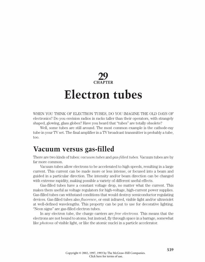
29CHAPTER
Electron tubesWHEN YOU THINK OF ELECTRON TUBES, DO YOU IMAGINE THE OLD DAYS OFelectronics? Do you envision radios in racks taller than their operators, with strangelyshaped, glowing, glass globes? Have you heard that “tubes” are totally obsolete?
Well, some tubes are still around. The most common example is the cathode-raytube in your TV set. The final amplifier in a TV broadcast transmitter is probably a tube,too.
Vacuum versus gas-filledThere are two kinds of tubes: vacuum tubes and gas-filled tubes. Vacuum tubes are byfar more common.
Vacuum tubes allow electrons to be accelerated to high speeds, resulting in a largecurrent. This current can be made more or less intense, or focused into a beam andguided in a particular direction. The intensity and/or beam direction can be changedwith extreme rapidity, making possible a variety of different useful effects.
Gas-filled tubes have a constant voltage drop, no matter what the current. Thismakes them useful as voltage regulators for high-voltage, high-current power supplies.Gas-filled tubes can withstand conditions that would destroy semiconductor regulatingdevices. Gas-filled tubes also fluoresce, or emit infrared, visible light and/or ultravioletat well-defined wavelengths. This property can be put to use for decorative lighting.“Neon signs” are gas-filled electron tubes.
In any electron tube, the charge carriers are free electrons. This means that theelectrons are not bound to atoms, but instead, fly through space in a barrage, somewhatlike photons of visible light, or like the atomic nuclei in a particle accelerator.
539 !
"# #$ !

The diode tubeBefore the start of the twentieth century, scientists knew that electrons could carry acurrent through a vacuum. They also knew that hot electrodes would emit electronsmore easily than cool ones. These phenomena were put to use in the first electrontubes, known as diode tubes, for the purpose of rectification.
Cathode, filament, plateIn any tube, the electron-emitting electrode is called the cathode. The cathode is usu-ally heated by means of a wire filament, similar to the glowing element in an incandes-cent bulb. The electron-collecting electrode is known as the anode or plate.
Directly heated cathodeIn some tubes, the filament also serves as the cathode. This is called a directly heated
cathode. The negative supply voltage is applied directly to the filament. The filament
voltage for most tubes is 6 V or 12 V. The schematic symbol for a diode tube with a di-rectly heated cathode is shown at A in Fig. 29-1.
540 Electron tubes
29-1 Schematic symbols for diode tubes; C = cathode, F =filament, P = plate. At A, directly heated cathode; at B,indirectly heated cathode; at C, cold cathode.
Indirectly heated cathodeIn many tubes, the filament is enclosed within a cylindrical cathode, and the cathodegets hot from infrared radiation. This is known as an indirectly heated cathode. Thecathode itself is grounded. The filament normally receives 6 V or 12 Vac. The schematicsymbol for a diode tube with an indirectly heated cathode is shown at B in Fig. 29-1.
In either the directly heated or indirectly heated cathode, electrons are driven offthe element by the heat of the filament. The cathode of a tube is thus somewhat analo-gous to the source of a field-effect transistor, or to the emitter of a bipolar transistor.
Because the electron emission in a tube depends on the filament or “heater,” tubesneed a certain amount of time—normally 30 seconds to a few minutes—to “warm up.”

This waiting period can be an annoyance, and it seems bizarre at first to people whohaven’t dealt with tubes before.
Cold cathodeIn a gas-filled voltage-regulator tube, the cathode might not have a filament to heat it.Such a device is called a cold-cathode tube. The schematic symbol for a cold-cathodetube is shown at C in Fig. 29-1. The solid dot indicates that the tube is gas filled, ratherthan completely evacuated. Various different chemical elements are used in gas-filledtubes; mercury vapor is probably most common. In this type of tube, the “warmup” periodis the time needed for the elemental mercury to vaporize, usually a couple of minutes.
PlateThe plate, or anode, of a tube is a cylinder concentric with the cathode and filament(Fig. 29-2). The plate is connected to the positive dc supply voltage. Tubes typically op-erate at about 50 V to more than 3 kVdc.
The triode 541
29-2 Construction of diode tube.For clarity, electrodes areshown transparent. Actuallythey are opaque metal.
Because the plate readily attracts electrons but is not a good emitter of them, andbecause the exact opposite is true of the cathode, a diode tube works well as a rectifierfor ac. Diode tubes can also work as envelope detectors for AM, although they are nolonger used for that purpose.
The triodeIn a diode tube, the flow of electrons from cathode to plate depends mainly on the dcpower supply voltage. The greater this voltage, the greater the current through thetube.
The flow of current can be controlled by means of an electrode between the cath-ode and the plate. This electrode, called the control grid, is a wire mesh or screen thatlets electrons physically pass through. But the control grid (also called simply the grid)interferes with the electrons if it is provided with a voltage that is negative with respectto ground. The greater this negative grid bias, the more the grid impedes the flow ofelectrons through the tube.

A tube with a control grid, in addition to the cathode and plate, is a triode. This isillustrated schematically in Fig. 29-3. In this case, the cathode is indirectly heated; thefilament is not shown. This omission is almost standard in schematics showing tubeswith indirectly heated cathodes. When the cathode is directly heated, the filament sym-bol serves as the cathode symbol.
542 Electron tubes
29-3 Schematic symbol of triodetube. The filament is notshown.
Now perhaps you see the resemblance between a triode tube and an N-channelFET. The cathode is analogous to the source; the grid is analogous to the gate; the platecorresponds to the drain. The only major differences, in fact, between the triode tubeand the N-channel FET are that the tube is constructed differently, and the tube workswith much higher voltages.
In a tube amplifier, the control grid is where the signal input is normally applied. Atriode amplifier or oscillator circuit looks just like an FET circuit, except that the tubeplate and grid bias voltages are far greater than the FET drain and gate voltages.
Extra gridsMany tubes have multiple grids. These extra elements allow for improved gain and sta-bility in tube type amplifiers.
The tetrodeA second grid can be added between the control grid and the plate. This is a spiral ofwire or a coarse screen and is called the screen grid or screen. This grid normally car-ries positive dc voltage, roughly 1/4 to 1/3 that of the plate voltage.
The screen grid reduces the capacitance between the control grid and plate, mini-mizing the tendency of a tube amplifier to oscillate. The screen grid can also serve as asecond control grid, allowing two signals to be injected into a tube. This tube has fourelements and is known as a tetrode. Its schematic symbol is shown at A in Fig. 29-4.
The pentodeThe electrons in a tetrode can strike the plate with extreme speed, especially if the platevoltage is high. The electrons might bombard the plate with such force that some of thembounce back or knock other electrons from the plate. Imagine hurling a baseball into a
bushel basket full of other baseballs. If you throw the ball hard enough, some of theother balls might be jostled out of the basket. Many of these electrons end up “leakingout” through the screen grid, rather than going through the plate circuit of the tube.The result is diminished plate current and increased screen current. Because it’s theplate current that produces the output signal for the tube, this secondary emission
hinders the performance of the tube. If secondary emission is extensive, it can causescreen current so high that the screen grid might be damaged.
The problem of secondary emission can be dealt with by placing yet another grid,called the suppressor grid or suppressor, between the screen and the plate. The sup-pressor also reduces the capacitance between the control grid and the plate still morethan is the case with the tetrode.
Greater gain and stability are possible with a pentode, or tube with five elements,than with a tetrode or triode. The schematic symbol for a pentode is shown at B in Fig.29-4. The suppressor grid is generally grounded, or connected directly to the cathode.It, therefore, carries a negative charge with respect to the screen grid and the plate.
The hexode and heptodeIn some older radio and TV receivers, tubes with four or five grids were sometimes used.These tubes had six and seven elements, respectively, and were called hexode and
Extra grids 543
29-4 At A, a tetrode tube. At B, a pentode; at C, a hexode; at D, aheptode.

heptode. The usual function of such tubes was signal mixing. The schematic symbol fora hexode is shown at C in Fig. 29-4; the symbol for a heptode is illustrated at D.
You’ll probably never hear about these devices in modern electronics, becausesolid-state components are used for signal mixing nowadays. You might elicit a raisedeyebrow if you talk about a “pentagrid converter” or a “heptode mixer.” And you can besure an engineer is kidding you if (s)he mentions an “octode” or “nonode.”
Some tubes are obsoleteVacuum tubes aren’t used in receivers anymore, except for picture tubes in TV sets.This is because, at low-signal levels, solid-state components (bipolar transistors, FETsand, ICs) can do everything that tubes ever could, with greater efficiency and usinglower voltages and currents.
Some electronics hobbyists like to work with antique radios. There is a certaincharm in a broadcast receiver that takes up as much space as, and that weighs as muchas, a small refrigerator. It brings back memories of a time when drama was broadcast onlocal AM stations, complete with whining heterodynes and static from summer thun-dershowers. The action was not rendered on high-resolution, color video, but insteadwas envisioned in listeners’ minds as they sat around the radio on a bare, varnishedhardwood floor.
Tube type, antique broadcast/shortwave receivers were about twice as bulky asnecessary, because compactness was not a major concern. Such radios were 10 to 100times bigger and heavier than their modern semiconductor counterparts. The high (andpotentially lethal) voltages caused dust to accumulate via electrostatic precipitationfrom the air, giving the radio’s “innards” a greasy, gritty film.
If the above scenarios, possibilities, and hazards appeal to you, perhaps you’d liketo collect and operate radio antiques, just as some people collect and drive vintage cars.But be aware that replacement receiving tubes are hard to find. When your relic breaks,you’ll need to become a spare-parts sleuth.
Radio-frequency power amplifiersThe most common application of vacuum tubes in modern technology is in RF ampli-fiers, especially at very high frequencies and/or power levels of more than 1kW. Twoconfigurations are employed: grounded cathode and grounded grid.
Grounded cathodeA simplified schematic diagram of a grounded-cathode RF power amplifier, using a pen-tode tube, is shown in Fig. 29-5. The output circuit is tuned to the operating frequency.The circuit can be operated in class-AB, B, or C. If the amplifier is to be linear, class Ccannot be used.
The input impedance of a grounded-cathode power amplifier is moderate; the plateimpedance is high. Impedance matching between the amplifier and the load (usually anantenna) is obtained by tapping the coil of the output tuned circuit, or by using a trans-former. In the example of Fig. 29-5, transformer output coupling is used.
544 Electron tubes

Grounded gridGrounded-cathode RF power amplifiers can (and sometimes do) oscillate, unless theyare neutralized or provided with some negative feedback. The oscillation usually oc-curs at some frequency far removed from the operating frequency. Known as parasitic
oscillation, it can rob the amplifier of output power at the desired frequency, as well ascausing interference to communications on the frequency or frequencies of oscillation.Neutralization can be a tricky business. When the tube is replaced, the neutralizing cir-cuit must be readjusted. The adjustment is rather critical. Improved stability, withoutthe need for neutralization, can be obtained by grounding the grid, rather than the cath-ode, of the tube in an RF power amplifier.
The grounded-grid configuration requires more driving power than the grounded-cathode scheme. While a grounded-cathode amplifier might produce 1 kW of RF outputfor 10 W input, a grounded-grid amplifier needs about 50 W to 100 W of driving powerto produce 1 kW of RF output.
A simple grounded-grid RF power amplifier is shown in Fig. 29-6. The cathode in-put impedance is low, and the plate output impedance is high. The output impedance ismatched by the same means as with the grounded-cathode arrangement. In Fig. 29-6, atransformer is used between the plate circuit and the load.
Plate voltages in the circuits of Figs. 29-5 and 29-6 are given only as examples.The amplifiers shown would produce perhaps 75 W to 150 W of RF power output. Anamplifier with 1 kW of RF output would have a plate voltage of 2 to 5 kV, dependingon the tube characteristics and the class of amplifier operation.
Typical grounded-grid linear amplifiers are operated in class-AB or B. If linearity isnot important (as in CW, FSK, or FM operation), then class-C provides improved effi-ciency, although the driving power requirement increases, so that 100 W or even 200 Wof RF input is necessary to get 1 kW of RF output.
Radio-frequency power amplifiers 545
29-5 A grounded-cathode RF power amplifier.

Cathode-ray tubesEveryone encounters TV picture tubes. You’ve almost certainly looked at a computermonitor (even cash registers have them now), and you’ve probably seen an oscilloscopein some form. These video displays all use cathode-ray tubes (CRTs).
The electron beamIn any CRT, an electron gun emits a high-intensity stream of electrons. This beam is fo-cused and accelerated as it passes through anodes that carry positive charge. The an-odes of a CRT work differently than the anode of a radio-frequency vacuum tube.Rather than hitting the anode, the electrons pass on until they strike a screen whose in-ner surface is coated with phosphor. The phosphor glows visibly as seen from the faceof the CRT.
Unless deflection is used to move the electron beam around the screen of the CRT,you’ll only get a brilliant spot in the center of the screen. Deflection of the beam makesvarious displays possible. The beam can be deflected by electrostatic fields or by mag-netic fields.
Electrostatic deflectionA simplified cross-sectional drawing of an electrostatic CRT is shown in Fig. 29-7. Theelectron beam is pulled toward the positive deflecting plates and is repelled away fromthe negative plates. There are two sets of deflecting plates, one for the horizontal planeand the other for the vertical plane. The higher the voltage between the plates, the greaterthe intensity of the electrostatic field, and the more the electron beam is deflected.
546 Electron tubes
29-6 A grounded-grid RF power amplifier.

In an oscilloscope, the horizontal deflecting plates receive a sawtooth voltage wave-form. This causes the beam to scan or sweep at a precise, adjustable speed across thescreen from left to right as seen from the outside. After each timed left- to-right sweep,the beam jumps instantly back to the left side of the screen for the next sweep.
The vertical deflecting plates receive the waveform to be analyzed. This waveformmakes the electron beam undulate up and down. The combination of vertical and hori-zontal motions results in the display of the input waveform as a function of time. This isa time-domain display.
Oscilloscopes can be adapted to show phenomena as a function having some do-main other than time. An example is a spectrum analyzer, showing signal amplitude asa function of frequency: a frequency-domain display. A radar set shows the distanceand direction of signal echoes from objects in the sky or in space; these are position-do-
main or location-domain renditions.
Electromagnetic deflectionCoils can be used instead of charged plates for deflection of the electron beam in a CRT.When currents pass through the coils, the beam changes direction at right angles to themagnetic lines of flux. The greater the current in a deflecting coil, the stronger the mag-netic field, and the greater the extent to which the beam is deflected. This is an elec-
tromagnetic CRT.
You can use Fig. 29-7 to imagine the workings of an electromagnetic CRT, just bythinking of coils outside the neck of the tube, rather than deflection plates inside thetube. There are two coils, one for horizontal deflection and the other for vertical de-flection.
Video camera tubesVideo cameras use a form of electron tube that converts visible light into varying elec-tric currents. The two most common types of camera tube are the vidicon and the im-
age orthicon.
Video camera tubes 547
29-7 Simplified cutaway view of an electrostatic CRT.

The vidiconVirtually every videocassette recorder (VCR) makes use of a vidicon camera tube.Closed-circuit TV systems, such as the kind you see in convenience stores and banks,also employ the vidicon. The main advantage of the vidicon is its small physical bulk; it’seasy to carry around.
In the vidicon, which might be almost as small as a photo camera, a lens focuses theincoming image onto a photoconductive screen. An electron gun generates an electronbeam that scans across the screen via deflecting coils, in a manner similar to the opera-tion of an electromagnetic cathode-ray tube. The scanning in the vidicon is exactlysynchronized with the scanning in the picture tube that displays the image “seen” bythe camera tube.
As the electron beam scans the photoconductive surface, the screen becomescharged. The rate of discharge in a certain region on the screen depends on the inten-sity of the visible light falling on that region. A simplified cutaway view of a vidicon tubeis shown in Fig. 29-8.
548 Electron tubes
29-8 Simplified cutaway view of a vidicon camera tube.
A vidicon is sensitive, working well in dim light. But its response becomes sluggishwhen the level of illumination is low. This causes images to persist for a short while. Youmight have noticed this when using a VCR in a dimly lit environment. The motion“smears” and images blur.
The image orthiconAnother type of camera tube, also quite sensitive, but having a quicker response to im-age changes, is the image orthicon. It is constructed much like the vidicon, except thatthere is a target electrode behind the photocathode (Fig. 29-9). When an electron fromthe photocathode strikes this target electrode, several secondary electrons are emit-ted as a result. This is a form of current amplification. The image orthicon acts as aphotomultiplier, improving its sensitivity.

A fine beam of electrons, emitted from the electron gun, scans the target electrode.The secondary electrons cause some of this beam to be reflected back toward the elec-tron gun. Areas of the target electrode with the most secondary-electron emission pro-duce the greatest return beam intensity; regions with the least emission produce thelowest return beam intensity. The greatest return beam intensity corresponds to thebrightest parts of the video image. The return beam is modulated as it scans the targetelectrode in a pattern just like the one in the TV receiver CRT. The return beam ispicked up by a receptor electrode.
The main disadvantage of the image orthicon is that it produces significant noise inaddition to the signal output. But when a fast response is needed (when there is a lot ofaction in a scene) and the light ranges from very dim to very bright, the image orthiconis the camera tube of choice. It is common in commercial broadcasting.
Traveling-wave tubesA traveling-wave tube is a form of electron-beam tube that is useful at ultra-high fre-quencies (UHF) and microwave frequencies. There are several variations on thistheme; the two most common are the magnetron and the klystron.
The magnetronMost magnetrons contain a cathode at the center, and a surrounding plate as shown inFig. 29-10. The plate is divided into sections, or cavities, by radial barriers. The outputis taken from an opening in the plate and passes into a hollow waveguide that servesas a transmission line for the UHF or microwave energy.
The cathode is connected to the negative terminal of a high-voltage source, and theanode is connected to the positive terminal. Therefore, electrons flow radially outward.A magnetic field is applied lengthwise through the cavities. As a result, the electronsmove outward in spirals from the cathode to the anode, rather than in straight lines.
The electric field produced by the high voltage, interacting with the longitudinal mag-netic field and the effects of the cavities, causes the electrons to bunch up into clouds.
The swirling movement of the electron clouds causes a fluctuating current in the anode.
Traveling-wave tubes 549
29-9 Simplified cutaway viewof an image orthicon.

This is the UHF or microwave signal. The frequency depends mainly on the shape and sizeof the cavities within the magnetron. Small cavities result in the highest oscillation fre-quencies; larger cavities produce oscillation at relatively lower frequencies.
A magnetron can generate more than 1 kW of RF power at a frequency of 1 GHz.As the frequency increases, the realizable power output decreases. At 10 GHz, a typicalmagnetron generates about 20 W of RF power output.
Magnetrons can produce microwaves for use in cooking. The energy at these fre-quencies excites the molecules in organic substances like meat, vegetables, and grains.Your microwave oven uses a magnetron rated at about 500 W to 1 kW continuous out-put power.
The klystronA klystron is a linear-beam electron tube. It has an electron gun, one or more cavities,and a device that modulates the electron beam. There are several different types of kly-stron tube. The most common are the multicavity and reflex klystrons.
A multicavity klystron is shown in Fig. 29-11. In the first cavity, the electron beamis velocity modulated. This means that the speeds of the electrons are made to in-crease and decrease alternately at a rapid rate. This causes the density of electrons inthe beam to change as the beam moves through subsequent cavities. The intermediatecavities increase the magnitude of the electron-beam modulation, resulting in amplifi-cation. Output is taken from the last cavity. Peak power levels in some multicavity kly-strons can exceed 1 MW (1,000,000 W).
A reflex klystron has only one cavity. A retarding field causes the electron beamto periodically reverse direction. This produces a phase reversal that allows largeamounts of energy to be drawn from the electrons. The reflex klystron produceslow-power UHF and microwave signals, on the order of a few watts.
550 Electron tubes
29-10 A magnetron. Here, only two cavities are shown for clarity; often there areseveral cavities.

QuizRefer to the text in this chapter if necessary. A good score is at least 18 correct. Answersare in the back of the book.
1. One difference between a triode and an N-channel FET is that:
A. Triodes work with lower voltages.
B. Triodes are more compact.
C. Triodes need more voltage.
D. Triodes don’t need filaments.
2. The control grid of a tube corresponds to the:
A. Source of an FET.
B. Collector of a bipolar transistor.
C. Anode of a diode.
D. Gate of an FET.
3. The intensity of the electron flow in a vacuum tube depends on all of thefollowing except:
A. The gate voltage.
B. The power supply voltage.
C. The grid voltage.
D. The voltage between the cathode and the plate.
4. Which type of tube maintains constant voltage drop with changes in current?
A. A triode.
B. A gas-filled regulator.
C. A tetrode.
D. A pentagrid converter.
Quiz 551
29-11 A multicavity klystron.

5. In a tube with a directly heated cathode:
A. The filament is separate from the cathode.
B. The grid is connected to the filament.
C. The filament serves as the cathode.
D. There is no filament.
6. In a tube with a cold cathode:
A. The filament is separate from the cathode.
B. The grid is connected to the filament.
C. The filament serves as the cathode.
D. There is no filament.
7. A screen grid enhances tube operation by:
A. Decreasing the gain.
B. Decreasing the plate voltage.
C. Decreasing the grid-to-plate capacitance.
D. Pulling excess electrons from the plate.
8. A tube with three grids is called a:
A. Triode.
B. Tetrode.
C. Pentode.
D. Hexode.
9. A tube type radio receiver:
A. Is bulky and heavy.
B. Requires low voltage.
C. Is more sensitive than a transistorized radio.
D. All of the above.
10. An advantage of a grounded-grid power amplifier is:
A. Excellent sensitivity.
B. High impedance.
C. Low noise.
D. Good stability.
11. A heptode tube has:
A. Two grids.
B. Three grids.
C. Five grids.
D. Seven grids.
552 Electron tubes

12. The electron gun in a CRT is another name for its:
A. Cathode.
B. Anode.
C. Control grid.
D. Screen grid.
13. The electron beam in an electrostatic CRT is bent by:
A. A magnetic field.
B. An electric field.
C. A fluctuating current.
D. A constant current.
14. The horizontal displacement on an oscilloscope CRT screen is usuallymeasured in:
A. Frequency per unit division.
B. Current per unit division.
C. Time per unit division.
D. Voltage per unit division.
15. In a time-domain oscilloscope, the waveform to be analyzed is usually appliedto the:
A. Control grid plates or coils.
B. Anode plates or coils.
C. Vertical deflection plates or coils.
D. Horizontal deflection plates or coils.
16. A vidicon camera tube is noted for its:
A. Sensitivity.
B. Large size.
C. Heavy weight.
D. Rapid response.
17. In a magnetron, as the frequency is increased:
A. The achievable power output increases.
B. The achievable power output decreases.
C. The output power stays the same.
D. The output power increases and decreases alternately.
18. The paths of the electrons in a magnetron are spirals, rather than straightlines, because of:
A. The extreme voltage used.
Quiz 553

B. The longitudinal magnetic flux.
C. The bunching-up of the electrons.
D. The shapes of the cavities.
19. A klystron is noted for its:
A. Spiralling electrons.
B. Low noise output.
C. High achievable output power.
D. Magnetic-field intensity.
20. In a multicavity klystron, the electrons:
A. Have variable speed.
B. Travel in circles.
C. Are reflected by the cavities.
D. Are drawn out via the cathode.
554 Electron tubes

30CHAPTER
Basic digital principlesYOU’VE SEEN HOW DIGITAL SIGNALS DIFFER FROM ANALOG SIGNALS. THE MANI-pulation of digital signals is known as digital logic. Digital logic consists of many—sometimes innumerable—pulses racing around. It can be staggering in terms ofquantity, but it is simple at heart: 1 or 0, high or low, yes or no.
Suppose a few electronics engineers from, say, 1950 could ride a time machine tothe present day. They would be flabbergasted at the speed and compactness of digitallogic circuitry. Some might be struck with disbelief. Others would say, “I told you so,” or“I knew it would happen.” And then there would inevitably be the one who would quip,“Is this all the further you’ve gotten?”
Well, digital-logic circuits are getting smaller, faster, and more sophisticated everyday.
Numbering systemsAny number, such as 35912, can be rendered in some other number base or modulus.Then it’s written differently. But it’s always the same quantity.
The decimal systemIn the decimal number system, each digit 0 through 9 represents either itself, or else it-self times some power of 10. The value of the digit depends on its position or place inthe number. In the case of the number 35912, the digit 2 is in the units place, and hasa value of simply 2. The digit 1 is in the 10s place; it takes the value of 1 101 10.The digit 9 is in the 100s place, having a value of 9 × 10² 900. The digit 5 is in the1,000s place, and represents 5 103 5000. The digit 3 is in the 10,000s place, andhas a value of 3 104 30,000. The total value is the sum of all these: 2 10 900 5,000 30,000 35,912.
555 !
"# #$ !

A decimal number can be represented in digital form, but it requires 10 differentpossible states. Any decimal number has a binary equivalent composed of digits thatare all either 0 or 1: just two different possible states. Much simpler!
Modulo what?You probably learned “modular arithmetic” in elementary school. If so, you ought to re-member working with modulo 8 (the octal system), or modulo 16 (hexadecimal), orbase 4, or 12, or 20. In computer electronics, octal and hexadecimal numbers are occa-sionally encountered, in addition to decimal numbers.
At various times, special-interest groups have tried to get the whole world to switchto some modulus besides 10. Some people think base 12 should be used (isn’t a “baker’sdozen” a more logical standard than the number of toes on a baby’s two feet?). Othersbelieve that base 20 makes the most sense (it’s the total number of fingers and toes, in-cluding thumbs, on a typical baby). Still others argued for base 8 or base 16 becausethese values are “elegant”: they can be repeatedly cut in half all the way down to 1.
Would you like to change the world over to, say, octal numbering because it’s easyto count rhythmically by eights? Or to base 12 because then a gross would be an even100? Lots of luck. Even the metric system hasn’t caught on that well.
The Binary systemBinary numbers are in modulo 2. In this system, the digits are all either 1 or 0, andthe places go in powers of 2. Therefore, to the immediate left of the units place is the2’s place (21), then the 4’s Place(22), then the 8’s place (23), and so on. In Table 30-1,powers of 2 are represented up to 215.
556 Basic digital principles
Table 30-1. Powers of 2.
Exponent Binary number value Decimal value
0 1 11 10 22 100 43 1000 84 10000 165 100000 326 1000000 647 10000000 1288 100000000 2569 1000000000 512
10 10000000000 102411 100000000000 204812 1000000000000 409613 10000000000000 819214 100000000000000 1638415 1000000000000000 32768
In general, the nth place from the right has the decimal value 2n. The total decimalvalue, for a given binary number, is the sum of the decimal values of each of the places.
Converting decimal numbers to binary form can be done using Table 30-1. Sup-pose, for example, that you want to convert 35912 to binary notation. First, find thelargest decimal number on the table that is no greater than the decimal number youwish to convert. In this case, it is 32768 215 . From this, you know that there will be 16digits in the binary representation of this number, one for each place 20 through 215.
Mark off 16 slots or spaces on a sheet of paper (quadrille graph paper is perfect for this),and place a digit “1” in the left-most space, representing 215.
Now, use Table 30-1 to determine which number can be added to 32768 to get thelargest decimal number that doesn’t exceed 35912. It happens to be 2048 211. Placedigits “0” in the slots for 214, 213, and 212. Then place “1” in the space for 211.
If you continue this process, you’ll ultimately get the binary number1000110001001000. This 16-digit binary number is equivalent to the decimal 35912 8 64 1024 2048 32768 23 26 210 + 211 215. The slots for exponents 3, 6,10, 11, and 15 each are filled with binary digit 1; the others are filled with binary digit 0.
It is possible to have fractional values in binary notation, just as it is in decimal no-tation. The first place to the right of the point (perhaps best called a “binary point”rather than a “decimal point”) is the 1/2’s place (2-1). The next place is the 1/4’s place
(2-2); then comes the 1/8’s place (2-3), and so on. Thus, 0.001 in binary notation repre-sents the decimal fraction 1/8. You can think of it as repeatedly dividing the size in halfas you progress towards the right.
Why use such cumbersome notation?Perhaps you’ve noticed that binary notation gets into long number strings. This is true.(Try writing the decimal quadrillion, or 1015, in binary form!) But computers don’t havetrouble dealing with long strings of digits. That’s what we build them for! To a computer,the important thing is to be certain of the value of each digit. This is easiest when theattainable states are as few as possible: two. High or low. Logic 1 or 0. On/off. Yes/no.
Logic signalsOn a single wire or line, a binary digital signal is either full-on or full-off at any given mo-ment. These are the logic high and low, and are represented by dc voltages. The highvoltage is approximately 3 V to 5 V, and the low voltage is between 0 V and 2 V.
Parallel data transferA binary number has several binary digits, or bits. The number of bits depends on how bigthe numbers can get. For example, if you want to send binary numbers from 0000 to 1111(which corresponds to the decimal numbers 0 through 15), you need four bits. If you wantto be able to transmit numbers as high as 11111111, or the decimal 0 to 255, you needeight bits. For large decimal numbers, you’ll need many bits—sometimes several dozen.
The bits can be sent along separate wires or lines. When this is done, the numberof lines corresponds to the number of bits in the binary number. That is, in order to sendbinary numbers up to 1111, you need four lines; to send numbers up to 11111111, you
Logic signals 557

need eight lines. This is called parallel data transfer, because the bits are sent alonglines that are effectively in parallel with each other (Fig. 30-1). Clearly, parallel datatransfer has limitations. For large numbers, it would need many lines. This can presentcertain logistic problems, for example in long-distance radio or wire transmission.
558 Basic digital principles
30-1 Parallel data transferof the binary number0110.
Serial data transferIn radio communications using parallel data transfer, each line must correspond to a dif-ferent frequency; the result is that large binary numbers need many channels. Thistranslates into a wide signal bandwidth. The necessary bandwidth is not always easy toobtain. It is especially difficult at low and “shortwave” frequencies, where wideband sig-nals present not only an engineering hassle, but tend to “hog” spectrum space.
Fortunately, there is another way to send binary data, and this method needs onlyone line or radio frequency. It is called serial data transfer. Instead of sending each biton a separate line, the bits are transmitted one after the other in a defined sequence.
To send binary numbers up to 1111 serially, you need four time slots. For the serialtransmission of binary numbers up to 11111111, you need eight slots. Each slot has acertain duration. Generally, all the slots are of equal length. A four-bit serial signal isshown in Fig. 30-2.
30-2 Serial representationof the binary number0110.
Suppose the duration of a bit is 1 ms (a millisecond). The bit rate is then 1,000 bits
per second (bps). In general, if the bit duration in seconds is t, then the bps rate is 1/t.Radio data-communications systems operate at speeds upwards of 10,000 bps, or 10 kbps.
Serial data transfer is somewhat slower than parallel transfer. This is the necessarytradeoff for the convenience of a single transmission line, or for narrower radio-signalbandwidth. In electronics, as in life, you never get something for nothing.

Positive versus negative logicUsually, logic 1 is high and logic 0 is low. This is known as positive logic. But these
states can be reversed, and the results will be just as good. When logic 1 is low and logic0 is high (so that a bit 1 is “off” and a bit 0 is “on”), negative logic is being used.
In the rest of this chapter, positive logic is the rule. This is simply to minimize con-fusion.
Basic logic operationsPerhaps you’ve taken sentenial logic, also called propositional logic or propositional
calculus (it sounds a lot more sophisticated than it really is) in high school or college.Electronic digital logic is basically the same thing.
In logic, there are three basic operations. These are depicted in Table 30-2.
Basic logic operations 559
Table 30-2. Logic operations.
Operation Description Symbology
NOT Negation or complement of X –XX
AND Conjunction of X, Y XYX Y
OR Disjunction of X, Y X Y
NOTThe logic NOT, also called negation or inversion, involves only a single logic variable.It changes the value of a bit from 1 to 0, or from 0 to 1, as shown in the truth table forlogic operations (Table 30-3). It is represented by a minus sign in front of a capital let-ter, usually from the end of the alphabet (W, X, Y, or Z). It might also be represented bya squiggly dash before the letter, an apostrophe after the letter, or a line over the letter.
Table 30-3. Truth table for logic operations.
X Y -X XY X+Y0 0 1 0 00 1 1 0 11 0 0 0 11 1 0 1 1
ANDThe logic AND, or conjunction, involves two variables. The resultant is high if, but onlyif, both variables are high. If either variable is low, or if both are low, then the resultant is

low. This operation gets its name from the fact that it corresponds to the function of theword “and” in propositional calculus. It is usually represented as multiplication. SeeTable 30-3.
ORThe logic OR, or disjunction, also involves two variables. The resultant is high if eitherof the variables are high. The resultant is low if, but only if, both variables are low. Thisis sometimes called the inclusive OR operation. It corresponds to the word “or” inpropositional calculus. It is represented as addition. See Table 30-3.
XOROccasionally you’ll hear about the exclusive OR or XOR operation. The resultant of XXOR Y is high if X and Y have opposite states. The resultant X XOR Y is low if X and Yhave the same state. It can be thought of as “either/or, but not both.” The “X” means“exclusive.” The XOR operation is shown in Table 30-4.
560 Basic digital principles
Table 30-4. More logic operations.
X Y XOR NAND NOR XNOR
0 0 0 1 1 10 1 1 1 0 01 0 1 1 0 01 1 0 0 0 1
NANDThe logic NAND is a combination of two operations, NOT and AND. It involves two vari-ables. The AND is performed first, and the result is negated. The value of X NAND Y islow if, but only if, both X and Y are high. Otherwise, X NAND Y is high. This is shown inTable 30-4.
NORThe logic NOR combines NOT and OR. It involves two variables. The OR is done first,and then the result is negated. The value of X NOR Y is high if, but only if, X and Y arelow. Otherwise, X NOR Y is low (Table 30-4).
XNORThe logic XNOR combines NOT and XOR. As with all the basic logic operations exceptNOT, it involves two variables. The XOR is done first, and then the result is negated.This is shown in Table 30-4.

Symbols for logic gatesA logic gate is an electronic switch that performs a logic operation. The earliest logicgates were built using vacuum tubes; later, transistors and diodes were employed. Mod-ern logic gates are fabricated on integrated circuits (ICs), with hundreds or even thou-sands of gates per chip.
An inverter (NOT gate) has one input and one output. Other logic gates usuallyhave two inputs and a single output. The symbols for the various logic gates are shownin Fig. 30-3.
Complex logic operations 561
30-3 Symbols for logic gates: NOT (A), AND (), OR (C), XOR (D), NAND (E),NOR (F), and XNOR (G).
It is possible for AND, NAND, OR, or NOR gates to have three or more inputs. Foran AND gate, the output is high if and only if all of the inputs are high. For an OR gate,the output is low if and only if all the inputs are low. The multiple-input NAND and NORgates perform the conjunction or disjunction operation first, followed by negation. Fig-ure 30-4 shows schematic symbols for four-input AND four-input NOR gates.
The XOR and XNOR operations are hard to define when there are three or more in-puts. These fall into the category of complex logic operation.
Complex logic operationsThe term “complex,” when used to describe a logic operation, does not necessarilymean complicated. A more apt adjective might be composite. But there are cases whenlogic operations are indeed quite complicated.
No matter how messy a particular logic operation might appear, it can always bebroken down into the elementary operations defined above.

Suppose you want to find an arrangement of logic gates for some complex logic op-eration. This can be done in two ways. You can use either truth tables or Boolean al-
gebra. For any complex logic operation, there might be several solutions, somerequiring more gates than others. A digital design engineer has the job not only of find-ing an arrangement of gates for a given complex operation, but of finding the schemethat will yield the desired result with the least number of gates.
Working with truth tablesTruth tables are, in theory, infinitely versatile. It is possible to construct or break downlogic operations of any complexity by using these tables, provided you have lots of pa-per and a fondness for column-and-row matrix drawing. Computers can also be pro-grammed to work with truth tables, although the displays and printouts get horrible todeal with if the logic functions are messy.
Building upYou can build complex logic operations up easily by means of a truth table. An exampleof such a building process is shown in Table 30-5.
562 Basic digital principles
30-4 Four-input AND gate(A) and four-input NORgate (B).
Table 30-5. Truth table for -(X + Y) + XZ.
X Y Z X Y − (X Y) XZ − (X Y) XZ
0 0 0 0 1 0 10 0 1 0 1 0 10 1 0 1 0 0 00 1 1 1 0 0 01 0 0 1 0 0 01 0 1 1 0 1 11 1 0 1 0 0 01 1 1 1 0 1 1

There are three variables X, Y, and Z. Each can be either 0 or 1 (low or high). All thepossible combinations are listed by writing binary numbers XYZ upwards from 000through 111. This forms the first column of the truth table. If there are n total variables,there will be 2n possible combinations.
The second column lists the values of X Y, the OR function. Some rows are du-plicates of each other; you write all the resultants down anyway.
The third column lists the negations of the values in the second column; this is theNOR operation − (X Y).
The fourth column shows the values of XZ.The fifth column is the disjunction (OR operation) of the values in the third and
fourth column. It renders values for the complex logic operation − (X Y) XZ.
Breaking downSuppose you were called upon to break down a logical operation, rather than to build itup. This is the kind of problem encountered by engineers. In the process of designing acertain digital circuit, the engineer is faced with figuring out what combination of logicgates will yield the complex operation, say, XY − (XZ) YZ.
Proceed by listing all the possible logic states for the three variables X, Y, and Z, exactly as in Table 30-5. Then find the values of XY (X AND Y), listing them in thefourth column. Next, find values XZ and list them in a fifth column. Negate these valuesto form a sixth column, depicting − (XZ). (You might be able to perform the AND andNOT operations together in your head, skipping over the XZ column. But be careful! It’seasy to make errors, and in a digital circuit, one error can be catastrophic.) Next, findvalues YZ and list them in a seventh column. Finally, perform the OR operation on thevalues in the columns for XY, − (XZ), and YZ. A multiple-valued OR is 0 only if all the in-dividual variables are 0; if any or all of the inputs are 1, then the output is 1.
This process yields Table 30-6.
Working with truth tables 563
Table 30-6. Truth table for XY (XZ) YZ.
X Y Z XY XZ (XZ) YZ XY (XZ) YZ
0 0 0 0 0 1 0 10 0 1 0 0 1 0 10 1 0 0 0 1 0 10 1 1 0 0 1 1 11 0 0 0 0 1 0 11 0 1 0 1 0 0 01 1 0 1 0 1 0 11 1 1 1 1 0 1 1
This is a little like middle-school algebra, isn’t it? The rules of algebra can, with cer-tain adjustments, be directly applied to digital logic operations. This is called Boolean
algebra, named after the mathematician Boole who first devised it as an alternative totruth tables.

Boolean algebraUsing Boolean representations for logic operations, some of the mathematical proper-ties of multiplication, addition, and negation can be applied to form Boolean equations.
The logical combinations on either side of any equation are equivalent.In some ways, Boolean algebra differs from conventional algebra. You must use
logic rules rather than “regular” rules for addition, additive inverse (negation), andmultiplication. Using these rules, certain facts, called theorems, can be derived.Boolean theorems all take the form of equations. Some common Boolean theorems arelisted in Table 30-7.
564 Basic digital principles
Table 30-7 Common theorems in Boolean algebra.
X 0 X OR identityX1 X AND identityX 1 1X0 0X X XXX X ( X) X Double negationX (X) XX( X) 0X Y Y X Commutativity of ORXY YX Commutativity of ANDX XY XX( Y) Y X YX Y Z (X + Y) Z X (Y Z) Associativity of ORXYZ (XY)Z X(YZ) Associativity of ANDX(Y Z) XY XZ Distributivity (X Y) ( X)( Y) DeMorgan’s Theorem (XY) X Y DeMorgan’s Theorem
Boolean algebra is less messy than truth tables for designing and evaluating logiccircuits. Some engineers prefer truth tables because the various logic operations areeasier to envision, and all the values are shown for all logic states in all parts of a digitalcircuit. Other engineers would rather not deal with all those ls and 0s, nor cover wholetabletops with gigantic printouts. Boolean algebra gets around that.
For extremely complex logical circuits, computers are used as an aid in design.They’re good at combinatorial derivations and optimization problems that would be un-economical (besides tedious) if done by a salaried engineer.
The flip-flopSo far, all the logic gates discussed have outputs that depend only on the inputs. Theyare sometimes called combinational logic gates, because the output state is simply afunction of the combination of input states.

A flip-flop is a form of sequential logic gate. In a sequential gate, the output statedepends on both the inputs and the outputs. The term “sequential” comes from the factthat the output depends not only on the current states, but on the states immediatelypreceding. A flip-flop has two states, called set and reset. Usually, the set state is calledlogic 1, and the reset state is called logic 0.
There are several different kinds of flip-flop.
R-SIn schematic diagrams, a flip-flop is usually shown as a rectangle with two or more in-puts and two outputs. If the rectangle symbol is used, the letters FF, for “ flip-flop,” areprinted or written inside at the top.
The inputs of an R-S flip-flop are labeled R (reset) and S (set). The outputs are Qand − Q. (Often, rather than − Q, you will see Q, or perhaps Q with a line over it.) Astheir symbols imply, the two outputs are always in logically opposite states. The symbolfor an R-S flip-flop is shown in Fig. 30-5.
The flip-f;op 565
Table 30-8 Truth tablefor an R-S flip-flop.
R S Q Q
0 0 Q Q0 1 1 01 0 0 11 1 ? ?
30-5 Schematic symbol for anR-S flip-flop.
In an R-S flip-flop, if R 0 and S 0, the output states do not change; they stay atwhatever values they’re already at. If R 0 and S 1, then Q 1 and − Q 0. If R 1 and S 0, then Q 0 and − Q 1. That is, the Q and − Q outputs will attain thesevalues, no matter what states they were at before.
But if S 1 and R 1, things get bizarre. The flip-flop becomes unpredictable. Be-cause of this, engineers avoid letting logic ls get into both inputs of an R-S flip flop. Youwant logic, not absurdity!
Table 30-8 is the truth table for an R-S flip-flop.
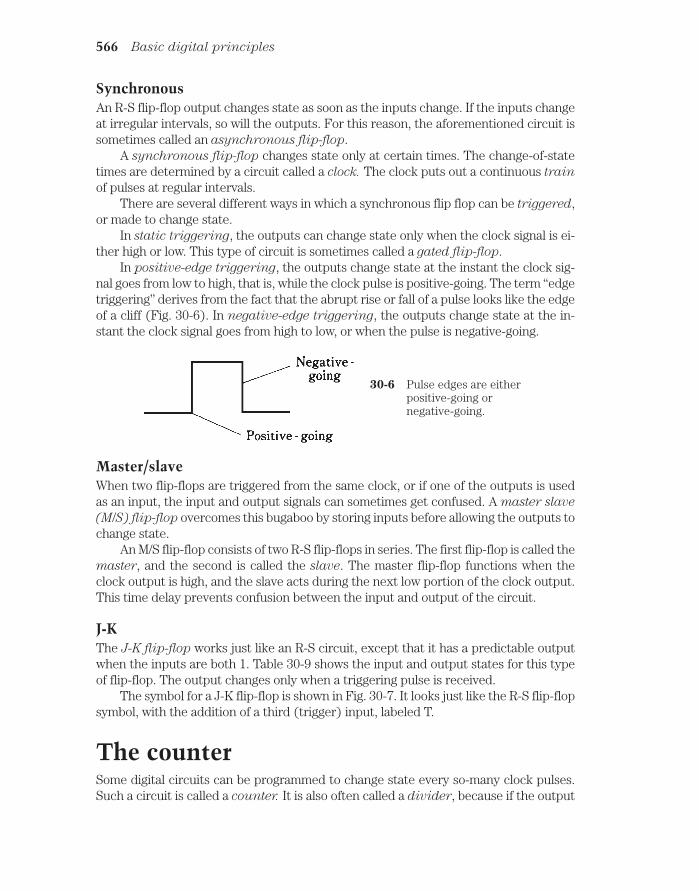
SynchronousAn R-S flip-flop output changes state as soon as the inputs change. If the inputs changeat irregular intervals, so will the outputs. For this reason, the aforementioned circuit issometimes called an asynchronous flip-flop.
A synchronous flip-flop changes state only at certain times. The change-of-statetimes are determined by a circuit called a clock. The clock puts out a continuous train
of pulses at regular intervals.There are several different ways in which a synchronous flip flop can be triggered,
or made to change state.In static triggering, the outputs can change state only when the clock signal is ei-
ther high or low. This type of circuit is sometimes called a gated flip-flop.In positive-edge triggering, the outputs change state at the instant the clock sig-
nal goes from low to high, that is, while the clock pulse is positive-going. The term “edgetriggering” derives from the fact that the abrupt rise or fall of a pulse looks like the edgeof a cliff (Fig. 30-6). In negative-edge triggering, the outputs change state at the in-stant the clock signal goes from high to low, or when the pulse is negative-going.
566 Basic digital principles
30-6 Pulse edges are eitherpositive-going ornegative-going.
Master/slaveWhen two flip-flops are triggered from the same clock, or if one of the outputs is usedas an input, the input and output signals can sometimes get confused. A master slave
(M/S) flip-flop overcomes this bugaboo by storing inputs before allowing the outputs tochange state.
An M/S flip-flop consists of two R-S flip-flops in series. The first flip-flop is called themaster, and the second is called the slave. The master flip-flop functions when theclock output is high, and the slave acts during the next low portion of the clock output.This time delay prevents confusion between the input and output of the circuit.
J-KThe J-K flip-flop works just like an R-S circuit, except that it has a predictable outputwhen the inputs are both 1. Table 30-9 shows the input and output states for this typeof flip-flop. The output changes only when a triggering pulse is received.
The symbol for a J-K flip-flop is shown in Fig. 30-7. It looks just like the R-S flip-flopsymbol, with the addition of a third (trigger) input, labeled T.
The counterSome digital circuits can be programmed to change state every so-many clock pulses.Such a circuit is called a counter. It is also often called a divider, because if the output

changes state after every n input pulses, the output frequency is 1/n of the input fre-quency. Counters are built up by interconnecting many flip-flops.
A special type of counter can be instructed to divide by any desired positive inte-ger n. This is a programmable divider. It forms the heart of a digital frequency syn-
thesizer, an oscillator whose frequency can be digitally set. You learned about thiscircuit back in chapter 25.
The registerA register is a combination of flip-flops that can delay digital signals, or store them fora short time.
Shift registersIn a shift register, the flip-flops pass signal bits along from one to the next each time atriggering pulse is received. The most common use for a shift register is to produce atimed delay in digital data.
Any input signal to a shift register will eventually arrive at the output. The outputbits occur in the same order as the input bits, except later. The length of the delay canbe set by changing the clock (triggering) pulse frequency. Higher clock frequencies re-sult in less delay, and lower frequencies result in more delay.
Storage registersIn a storage register, a byte, word, or group of words is held for awhile for later use.This allows the circuit to work as a small-capacity, short-term memory. Storage regis-ters are common in digital computers.
The register 567
Table 30-9. Truth tablefor a J-K Hip-flop.
J K Q Q
0 0 Q Q0 1 1 01 0 0 11 1 Q Q
30-7 Schematic symbol for aJ-K flip-flop.

The digital revolutionThis chapter has touched upon digital basics, but cannot possibly go into depth. Thescope of digital electronics is vast, and it grows and changes daily. If you are studying tobe an electrical engineer, you’ll take numerous courses in digital electronics.
Specialties include data communications, video communications, satellite communi-cations, space communications, navigation, medical devices, modems, calculators, com-puters, video games, control systems, and so on almost ad infinitum. It would be easyto fill a book as large as this one with material devoted only to digital technology. Engi-neers devote careers to fields as specific as digital signal processing, digital CD record-ing, or digital robotics-control devices.
During the 1980s, digital technology replaced analog circuits in everything fromwristwatches to radios. Along with proliferation, costs have plummeted while sophistica-tion has grown geometrically. These trends will continue in the twenty-first century.
QuizRefer to the text in this chapter if necessary. A good score is at least 18 correct. Answersare in the back of the book.
1. The value of the decimal number 23 in binary form is:
A. 1011.
B. 110111.
C. 10111.
D. 11100.
2. The binary number 110001 represents the digital number:
A. 49.
B. 25.
C. 21.
D. 13.
3. The fifth digit from the right in a binary number carries a decimal value of:
A. 64.
B. 32.
C. 24.
D. 16.
4. The largest possible decimal number that can be represented by six binarydigits (bits) is:
A. 256.
B. 128.
C. 64.
D. 63.
568 Basic digital principles

5. Which of the following voltages could normally represent a 1 in positive logic?
A. 0 V.
B. 1 V.
C. 4 V.
D. 12 V.
6. Which of the following voltages might normally represent a 1 in negative logic?
A. 0 V.
B. 4 V.
C. 6 V.
D. 12 V.
7. If X is low, what is the state of X AND Y?
A. There is not enough information to tell.
B. Low.
C. High.
D. This logic statement makes no sense.
8. If X is high, what is the state of X NOR Y?
A. There is not enough information to tell.
B. Low.
C. High.
D. This logic statement makes no sense.
9. If X and Y are both high, what is the state of X NAND Y?
A. There is not enough information to tell.
B. Low.
C. High.
D. This logic statement makes no sense.
10. If X is high and Y is low, what is the state of X NOT Y?
A. There is not enough information to tell.
B. Low.
C. High.
D. This logic statement makes no sense.
11. A logic circuit has four inputs W, X, Y, and Z. How many possible inputcombinations are there?
A. 4.
B. 8.
C. 16.
D. 32.
Quiz 569

12. Data sent along a single line, one bit after another, is called:
A. Serial.
B. Synchronous.
C. Parallel.
D. Asynchronous.
13. If X 1 and Y 1, then X YZ is:
A. Always 0.
B. 0 if Z 0, and 1 if Z 1.
C. 1 if Z 0, and 0 if Z 1.
D. Always 1.
14. If X 0 and Y 1, then X(Y + Z) is:
A. Always 0.
B. 0 if Z 0, and 1 if Z 1.
C. 1 if Z 0, and 0 if Z 1.
D. Always 1.
15. An advantage of a J-K over an R-S flip-flop is that:
A. The J-K flip-flop is faster.
B. The J-K can attain more states.
C. The J-K always has predictable outputs.
D. No! An R-S flip-flop is superior to a J-K.
16. In positive-edge triggering, the change of state occurs when:
A. The pulse level is high.
B. The pulse level is going from high to low.
C. The pulse level is going from low to high.
D. The pulse level is low.
17. The inputs of an R-S flip-flop are known as:
A. Low and high.
B. Asynchronous.
C. Synchronous.
D. Set and reset.
18. When both inputs of an R-S flip-flop are 0:
A. The outputs stay as they are.
B. Q 0 and Q 1.
C. Q 1 and Q 0.
D. The resulting outputs can be absurd.
570 Basic digital principles

19. When both inputs of an R-S flip-flop are 1:
A. The outputs stay as they are.
B. Q 0 and Q 1.
C. Q 1 and Q 0.
D. The resulting outputs can be absurd.
20. A frequency synthesizer makes use of
A. An OR gate.
B. A divider.
C. The octal numbering system.
D. The hexadecimal numbering system.
Quiz 571

Test: Part ThreeDo not refer to the text when taking this test.
1. In a junction FET, the control electrode is usually the:
A. Source.
B. Emitter.
C. Drain.
D. Base.
E. Gate.
2. A diode can be used as a frequency multiplier because of its:
A. Junction capacitance.
B. Nonlinearity.
C. Avalanche voltage.
D. Forward breakover.
E. Charge-carrier concentration.
3. Which of the following is not a common form of data transmission?
A. Parallel modulation.
B. Frequency modulation.
C. Amplitude modulation.
D. Phase modulation.
E. Pulse modulation.
4. A very brief, high-voltage spike on an ac power line is called:
A. A surge.
B. An arc.
C. A transient.
D. An avalanche.
F. A clamp.
572

5. Which of the following is not characteristic of an oscillator?
A. Negative feedback.
B. Good output-to-input coupling.
C. Reasonably high transistor gain.
D. Ac output.
E. Usefulness as a signal generator.
6. Which layer of the ionosphere absorbs radio signals below about 7 MHz duringthe daylight hours?
A. The F layer.
B. The E layer.
C. The D layer.
D. The C layer.
E. The B layer.
7. The beta of a bipolar transistor is its:
A. Current amplification factor.
B. Voltage amplification factor.
C. Power amplification factor.
D. Maximum amplification frequency.
E. Optimum amplification frequency.
8. Which type of component is impractical to fabricate on a silicon chip?
A. A capacitor.
B. A transistor.
C. A diode.
D. An inductor.
E. Any component can be fabricated on a silicon chip.
9. The extent to which an oscillator maintains a constant frequency is called its:
A. Sensitivity.
B. Drift ratio.
C. Gain.
D. Selectivity.
E. Stability.
10. A Zener diode would most likely be used in:
A. A mixer.
B. A voltage-controlled oscillator.
C. A detector.
D. A power supply regulating circuit.
E. An oscillator.
Test: Part three 573
11. When the bias in an FET stops the flow of current, the condition is called:
A. Forward breakover.
B. Cutoff.
C. Reverse bias.
D. Pinchoff.
E. Avalanche.
12. A vacuum tube would most likely be found in:
A. The front end of a radio receiver.
B. A high-power radio-frequency linear amplifier.
C. A low-level audio amplifier.
D. A digital computer.
E. Antique radios only.
13. In an N-type semiconductor, the minority carriers are:
A. Electrons.
B. Protons.
C. Holes.
D. Neutrons.
E. Silicon chips.
14. A disadvantage of a half-wave rectifier is that:
A. The voltage is excessive.
B. The current output is low.
C. The output is hard to filter.
D. It needs many diodes.
E. The transformer must have a center tap.
15. A power gain of 30 dB is equivalent to an amplification factor of:
A. 0.001.
B. 1/30.
C. 30.
D. 1000.
E. None of the above.
16. An amplifier has a dc collector power input of 300 W, and is 75.0 percentefficient. The signal output power is:
A. 400 W.
B. 300 W.
C. 225 W.
D. Variable, depending on the bias.
E. Impossible to determine from this data.
574 Test: Part three

17. When both N-channel and P-channel transistors are found in a metal-oxide-semiconductor-type integrated circuit, the technology is known as:
A. Transistor-transistor logic.
B. CMOS.
C. Bipolar logic.
D. NPNP.
E. PNPN.
18. A common-base circuit is commonly employed as:
A. A microwave oscillator.
B. A low-pass filter.
C. A noise generator.
D. A phase-locked loop.
E. A radio-frequency power amplifier.
19. Which of the following devices always uses an IC as one of its main activecomponents?
A. A radio-frequency power amplifier.
B. A digital computer.
C. A low-level audio amplifier.
D. A power transformer.
E. An impedance matching network.
20. Which type of amplifier circuit provides the greatest efficiency?
A. Class A.
B. Class AB.
C. Class B.
D. Class C.
E. Any of the above can be as efficient as any other.
21. ASCII is a form of:
A. Video modulation.
B. Diode.
C. Teleprinter code.
D. Voice modulation.
E. AM detector.
22. The most stable type of oscillator circuit uses:
A. A tapped coil.
B. A split capacitor.
C. Negative feedback.
D. A common-base arrangement.
E. A quartz crystal.
Test: Part three 575

23. If the source-gate junction in an FET conducts:
A. It is a sign of improper bias.
B. The device will work in class C.
C. The device will oscillate.
D. The device will work in class A.
E. The circuit will have good stability.
24. The octal number system uses modulo:
A. 2.
B. 8.
C. 10.
D. 12.
E. 16.
25. Signal-plus-noise-to-noise ratio (SN/N) is often specified when stating areceiver’s:
A. Selectivity.
B. Stability.
C. Modulation coefficient.
D. Sensitivity.
E. Polarization.
26. In a reverse-biased semiconductor diode, the capacitance depends on:
A. The width of the depletion region.
B. The reverse current.
C. The P:N ratio.
D. The gate bias.
E. The avalanche voltage.
27. The effective speed of a recording or playback head with respect to the data ona tape can be maximized by making the tracks:
A. Parallel with the edges of the tape.
B. Perpendicular to the edges of the tape.
C. Slanted with respect to the edges of the tape.
D. Elliptically polarized.
E. Rectangularly polarized.
28. A simple power supply filter can be built with:
A. A capacitor in series with the dc output.
B. An inductor in parallel with the dc output.
C. A rectifier in parallel with the dc output.
576 Test: Part three

D. A resistor in series and an inductor in parallel with the dc output.
E. A capacitor in parallel with the dc output.
29. Which of the following bipolar-transistor circuits can, in theory, provide themost amplification?
A. Common emitter.
B. Common base.
C. Common collector.
D. Common gate.
E. Common drain.
30. Magnetic fields within ICs can store data in a device called:
A. Magnetic media.
B. IC memory.
C. Tape memory.
D. Bubble memory.
E. Random-access memory.
31. An example of a device that commonly oscillates is:
A. A rectifier diode.
B. A weak-signal diode.
C. A Gunn diode.
D. A Zener diode.
E. An avalanche diode.
32. In a PNP bipolar transistor:
A. The collector is positive relative to the emitter.
B. The collector is at the same voltage as the emitter.
C. The collector is negative relative to the emitter.
D. The collector might be either positive or negative relative to the emitter.
E. The collector must be at ground potential.
33. In a cathode-ray tube (CRT), the term electrostatic deflection means:
A. The device is not working correctly.
B. Static electricity is distorting the image.
C. The beam is bent by an electric field.
D. The beam is bent by coils carrying a variable current.
E. Nothing! There is no such thing as electrostatic deflection in a CRT.
34. Which type of modulation consists of one voice sideband, with a suppressedcarrier?
A. AM.
Test: Part three 577

B. SSB.
C. FM.
D. RTTY.
E. PCM.
35. A type of electron tube that can be used to generate microwave energy is:
A. A triode.
B. An oscillotron.
C. A cathode-ray tube.
D. A videotron.
E. A magnetron.
36. In an AND gate, the output is high:
A. If any input is high.
B. Only when all inputs are low.
C. If any input is low.
D. Only when all inputs are high.
E. Only when the inputs have opposite logic states.
37. A voltage-controlled oscillator makes use of:
A. A varactor diode.
B. A Zener diode.
C. Negative feedback.
D. A split capacitance.
E. Adjustable gate or base bias.
38. Which of the following is not an advantage of a transistor over a vacuum tube?
A. Smaller size.
B. Lighter weight.
C. Less heat generation.
D. Lower operating voltages.
E. Higher power-handling capacity.
39. An amplifier has an output signal voltage that is 35 times the input signalvoltage. This is a gain of:
A. 15 dB.
B. 31 dB.
C. 35 dB.
D. 350 dB.
E. 700 dB.
40. In an exclusive OR gate, the output is high:
578 Test: Part three

A. If any input is high.
B. Only when all inputs are low.
C. If any input is low.
D. Only when all inputs are high.
E. Only when the inputs have opposite logic states.
41. A ratio detector is a circuit for demodulating:
A. AM.
B. PM.
C. FM.
D. SSB.
E. AFSK.
42. In a radio-frequency power amplifier using a vacuum tube, stability can beenhanced by using a circuit in which the following electrode is at RF groundpotential:
A. The cathode.
B. The plate.
C. The filament.
D. The control grid.
E. The screen grid.
43. A method of modulation in which the strength of pulses varies is called:
A. Pulse amplitude modulation.
B. Pulse position modulation.
C. Pulse frequency modulation.
D. Pulse ratio modulation.
E. Pulse width modulation.
44. Boolean algebra is:
A. Just like ordinary algebra.
B. A useful tool in digital logic circuit design.
C. Used to calculate the value of an unknown.
D. Used with negative logic only.
E. Used with positive logic only.
45. A voltage-doubler power supply is best for use in:
A. Circuits that need low current at high voltage.
B. Low-voltage devices.
C. High-current appliances.
D. All kinds of electronic equipment.
Test: Part three 579

E. Broadcast transmitter power amplifiers.
46. An optoisolator consists of:
A. Two Zener diodes back to back.
B. An LED and a photodiode.
C. Two NPN transistors in series.
D. An NPN transistor followed by a PNP transistor.
E. A PNP transistor followed by an NPN transistor.
47. When a semiconductor is reverse-biased with a large enough voltage, it willconduct. This is because of:
A. Bias effect.
B. Avalanche effect.
C. Forward breakover.
D. An excess of charge carriers.
E. Conduction effect.
48. Synchronizing pulses in a video signal:
A. Keep the brightness constant.
B. Keep the contrast constant.
C. Keep the image from tearing or rolling.
D. Ensure that the colors are right.
E. Keep the image in good focus.
49. In an enhancement-mode MOSFET:
A. The channel conducts fully with zero gate bias.
B. The channel conducts partially with zero gate bias.
C. The channel conducts ac but not dc.
D. The channel conducts dc but not ac.
E. The channel does not conduct with zero gate bias.
50. In a step-up power transformer:
A. The primary voltage is more than the secondary voltage.
B. The secondary voltage is more than the primary voltage.
C. The primary and secondary voltages are the same.
D. The secondary must be center-tapped.
E. The primary must be center-tapped.
A good score is at least 37 correct. Answers are in the back of the book. It’s best tohave a friend check your score the first time, so you won’t memorize the answers ifyou want to take the test again.
580 Test: Part three

4Part
Advancedelectronicsand related technology

This page intentionally left blank

31CHAPTER
Acoustics, audio, andhigh fidelity
UP TO THIS POINT, WE HAVE STUDIED COMPONENTS, CIRCUITS, AND SYSTEMS INwhich esthetic appeal is not especially important. When you are stranded in a snow-storm and you switch on the cell phone to call for help, you probably won’t care whatthe phone set looks like, nor will you be too worried about the fidelity of the audio com-ing through the earpiece (as long as you can understand what the other party is saying).Efficiency and reliability will be your main concerns. But when it comes to soundrecording and reproduction, especially when music is involved, quality comes to thefore. Minimizing distortion, for example, becomes more important than amplifier efficiency.
AcousticsThe term acoustics refers to the physics of sound waves as they are transmittedthrough air. Acoustics is important to architects and engineers who design and buildconcert halls, where sound must propagate from a stage or speaker system to a largenumber of people. Engineers consider acoustics in the construction of speaker en-closures. Some knowledge of acoustics is helpful if you want to set up a high-fidelity(hi-fi) sound system.
The sound spectrumSound consists of molecular vibrations at audio frequency, ranging from about 20 Hzto 20 kHz. Young people can hear the full range of audio frequencies; older peoplelose hearing sensitivity at the upper and lower extremes. An elderly person mightonly hear sounds from 50 to 5000 Hz.
583 !
"# #$ !

In music, audio frequencies are divided into three broad, vaguely defined parts,called bass (pronounced “base”), midrange, and treble. The bass frequencies start at 20Hz and extend to 150 or 200 Hz. Midrange begins at this point, and extends to 2000 or3000 Hz. Treble consists of the audio frequencies higher than midrange. As the fre-quency increases, the wavelength becomes shorter. In air, sound travels at about 1100ft/s, or 335 m/s. The relationship between the frequency f of a sound wave in hertz, andthe wavelength w
ftin feet, is as follows:
wft 1100/f
In the metric system, the relationship between f in hertz and wm
in meters is given by
wm 335/f
The metric formula is also valid for frequencies in kilohertz and wavelengths in mil-limeters. When using the formulas, be sure you don’t get the units confused.
A sound of 20 Hz has a wavelength of 55 ft, or 16.8 m, in the air. A sound of 1000 Hzproduces a wave measuring 1.1 ft (13 in), or 33.5 cm. At the extreme treble end of theaudio spectrum, a wave is just 0.055 ft (two-thirds of an inch), or 17 millimeters, long at20 kHz. In substances other than air, such as water or metal, the above formulas do notapply. There is also some change in the speed of sound with changes in air pressure andhumidity.
Sound waves 55 ft long behave much differently than waves measuring less than aninch, and both of these act differently than a wave 13 in in length. Acoustics engineersmust take this matter into consideration when designing sound systems.
WaveformsThe frequency, or pitch, of a sound is only one of several variables that acousticwaves can possess. Another important factor is the shape of the wave itself.
The simplest acoustic waveform is a sine wave, in which all of the sound energy isconcentrated at a single frequency. Sine-wave sounds are rare in nature. A good exam-ple of a sine-wave sound is the beat note, or heterodyne, produced by a steady carrierin a communications receiver.
In music, most of the notes are complex waveforms, consisting of energy at somefrequency and various multiples, or harmonics. Examples are sawtooth, square, and tri-angular waves. We looked at these in chapter 9. An instrument might produce a note at1 kHz and also at numerous harmonics: 2, 3, 4 kHz and so on. The shape of the wave-form depends on the distribution of energy among the fundamental frequency (lowestfrequency) and the harmonics. There are infinitely many different shapes that a wavecan have at a single frequency such as 1 kHz. Music comprises many different tones thatintermingle to make the overall waveform almost unfathomably complicated.
Path effectsA flute, a clarinet, a guitar, and a piano can each produce a sound at 1 kHz, but thetone quality is different for each instrument. The waveform affects the way a soundis reflected from objects. Acoustics engineers must consider this when designing
584 Acoustics, audio, and high fidelity

sound systems and concert halls. The goal is to make sure that all the instrumentssound realistic everywhere in the room.
Suppose you have a sound system set up in your living room. You sit on the couchand listen to music. Imagine that, for the particular placement of speakers with respectto your ears, sounds propagate well at 1, 3, and 5 kHz, but poorly at 2, 4, and 6 kHz. Thiswill affect the way musical instruments sound. It will distort the sounds from some in-struments more than the sounds from others. Unless all sounds, at all frequencies,reach your ears in the same proportions that they come from the speakers, you will nothear the music the way it originally came from the instruments. For certain instrumentsand notes, the sound can be altered so much that it doesn’t resemble the original at all.
Figure 31-1 shows a listener, a speaker, and three sound reflectors, also known asbaffles. It is almost certain that the waves traveling along paths X, Y, and Z will add upto something different, at the listener’s ears, than the waves that come directly from thespeaker. Path X might be most effective for the bass, path Y most effective for themidrange, and path Z most effective for the treble. This will distort the waveforms pro-duced by various musical instruments. It is just about impossible to design an acousti-cal room, such as a concert auditorium, to propagate sound perfectly at all frequenciesfor every listener. The best an engineer can do is optimize the situation and try to avoidthe existence of any “disaster zones.”
Loudness and PhasePeople do not perceive the loudness (also called volume) of sound in direct pro-portion to the actual power contained in the waves. Instead, your ears and brain
Loudness and Phase 585
SpeakerListener
X Y
Z
Baffles
D
31-1 Sounds from reflected paths (such as X, Y, and Z)combine with direct-path sound (D) to producewhat a listener hears.

sense sound levels according to the logarithm of the actual intensity. Another vari-able in the transmission of sound is the phase with which waves arrive at your ears.This allows you to tell from which direction a sound is coming, and it can producedramatic variations in perceived sound volume as well.
The decibelIf you change the volume control on a hi-fi set until you can just barely tell the dif-ference, the increment is one decibel (1 dB). If you use the volume control to dou-ble the actual acoustic-wave power coming from a set of speakers, you will hear anincrease of 3 dB, or 3 times the minimum detectable difference.
For decibels to have meaning, there must be a reference level against which every-thing is measured. Sometimes you’ll hear decibels used as if they are absolute; for ex-ample, a vacuum cleaner might produce 80 dB of sound, and a jet taking off mightgenerate 100 dB as it passes overhead at a low altitude. These figures are determinedwith respect to the threshold of hearing, which is the faintest sound that “good ears”can hear when there is no background noise.
In hi-fi amplifiers, you’ll sometimes see meters that show the relative sound level.Such a meter indicates volume units, and accordingly, it is called a volume-unit (VU)meter. These meters are often calibrated in decibels with respect to some referencesound level.
When thinking of decibels as they apply to sound, remember that a doubling of ac-tual acoustic energy equals a 3-dB increase in amplitude. A rise in the sound level is in-dicated by positive decibel values, and a decrease is indicated by negative values. Achange of 6 dB means that the sound power is cut to one-quarter of its previous level;a change of 9 dB means an eightfold increase in sound power. “Zero decibels” (0 dB)means that there is no change in the sound level or that two different sounds have equalamplitudes.
PhaseEven if there is only one sound source, acoustic waves reflect from the walls, ceiling,and floor of a room. Some concert halls have baffles strategically placed to reflect thesound from the stage toward the audience.
In Fig. 31-1 the three sound paths X, Y, and Z are likely to have different lengths.Therefore, the three reflected waves will not arrive in the same phase at the listener’sears. The direct path (D), a straight line from the speaker to the listener, is always theshortest path. In this situation, there are at least four different paths via which soundgets from the speaker to the listener. In many practical situations there are more.
Suppose that, at a frequency of 700 Hz, the acoustic waves for all four paths arrivein exactly the same phase in the listener’s ears. Then sounds at that frequency will beexaggerated in volume. The same phase coincidence might also occur at harmonics of700 Hz: that is, 1.4, 2.1, 2.8 kHz, and so on. But it is not likely to happen at any other fre-quencies. This is an undesirable effect because it causes acoustic peaks, called anti-
nodes, at specific frequencies, distorting the original sound. At some frequencies, thewaves might mix in phase opposition, so that the energy is nearly canceled out. Thisproduces dead zones, also called nodes, a phenomenon that acoustics engineers dread.
586 Acoustics, audio, and high fidelity

If the listener moves a few feet, the antinodes will no longer be observed at 700 Hzand its harmonics. The frequency might change; the effect might diminish or even seemto disappear altogether. As produced by the set of baffles, the antinode for 700 Hz andits harmonics might well be confined to a single, small spot in the room.
One of the most important considerations in acoustical design is the avoidance, tothe greatest extent possible, of significant nodes and antinodes at any frequency withinthe range of human hearing. The perfect acoustic chamber delivers sound effectively toall members of the listening audience, without favoring any particular regions of theroom or frequencies of the sound.
Technical ConsiderationsHigh-fidelity, or hi-fi, audio systems can be found in most homes, in many cars andtrucks, in businesses, and even in government offices. They range in size from tiny“headphone radios” that operate from one AAA cell to huge, multicomponent sys-tems that consume thousands of watts and provide the sound for musical concerts inauditoriums and stadiums. However big or small the system, it must have certaincharacteristics to truly earn the label “hi-fi.”
LinearityLinearity is the extent to which the output waveform of an amplifier is a faithful re-production of the input waveform. In hi-fi equipment, all the amplifiers must be aslinear as the state of the art allows.
If you connect a dual-trace oscilloscope (one that lets you observe two waveformsat the same time) to the input and output terminals of a good hi-fi audio amplifier, theoutput waveform will appear as a vertically magnified duplicate of the input waveform.If you adjust the vertical gain control of the oscilloscope so the two waveforms have thesame peak-to-peak displacement on the screen, the input and output waveforms willlook identical. When the input signal is applied to the horizontal scope input and theoutput signal is applied to the vertical scope input, the display will be a straight line.
Figures 31-2 and 31-3 illustrate the principle of linearity. The graph and waveformsin Fig. 31-2 show the characteristics of a linear circuit. The graph of the instantaneousoutput versus the instantaneous input is a straight line. When the input is a sine wave,the output is also a sine wave. Figure 31-3 shows what takes place in a hypothetical non-linear circuit. The instantaneous output-versus-input function is not a straight line.Therefore, the output waveform is not a faithful reproduction of the input, and distor-tion occurs. In this case, as the input increases, the output-to-input ratio (amplifica-
tion factor, or gain) decreases, as indicated by the decreasing slope of the curve. Athigh input levels, the circuit doesn’t amplify as much as it does at low input levels, whichflattens the peaks of the output wave. This happens with all amplifiers if the input sig-nal amplitude is great enough. In some radio-frequency circuits this is all right; in hi-fiaudio systems, it is not.
Linear amplifiers are designed to work with input signals up to a certain peak (max-imum instantaneous) amplitude. If the peak input exceeds this level, the amplifier willbecome nonlinear, and distortion will result. In a hi-fi system equipped with VU or
Technical considerations 587

distortion meters, excessive input will cause the needles to kick into the red range ofthe scale during peaks. If the input is driven up still more, the needle will stay in the redrange much of the time. Some people might say it’s “cool” to run a hi-fi amplifier thisway. If lousy sound is what you want, maybe that is true. But generally it’s stupid, andin some cases can damage system components.
Dynamic rangeDynamic range is a prime consideration in hi-fi recording and reproduction. In gen-eral, the greater the dynamic range, the better the sound quality over a wide rangeof volume levels. Dynamic range is expressed in decibels (dB). The larger the dy-namic-range specification in dB, the better the system, all other factors being constant.
At low volume levels, the limiting factor in dynamic range is the background noise
in the system. In a traditional analog system, most of this noise comes from the audio
588 Acoustics, audio, and high fidelity
Input
Output
Inputwave
Outputwave
Input
Output
Inputwave
Outputwave
Flattenedpeaks
31-2 A linear circuit produces no distortion of the input waveform.
31-3 A nonlinear circuit distorts the input waveform.

amplification stages. In tape recording, there is also some tape hiss. A scheme calledDolby (a trademark of Dolby Laboratories) is used in professional recording studios,and also in high-end consumer tape equipment, to minimize this hiss. Digital recordingtechniques, such as is used in compact disk (CD) or digital audio tape (DAT) recording,have less internal noise than older analog systems.
At high volume levels, the power-handling capability of an audio amplifier limits thedynamic range. If all other factors are equal, a 100-watt system will have greater dy-namic range than a 50-watt system. The speaker size is also important; the larger thespeakers, the greater the dynamic range. This is why serious audio enthusiasts some-times purchase sound systems with amplifiers and speakers that seem unnecessarilylarge. The reason for such overengineering is usually twofold: (1) to ensure that thesound peaks will always be distortion-free and cannot possibly damage the speakersand (2) to impress people.
Basic ComponentsThere are myriad ways to set up a hi-fi system. Almost every true audiophile (liter-ally, “sound lover”) builds a system over a period of time, component by component.Some people own two or three stereo systems. Here are some basic considerations.
ConfigurationThe simplest home stereo system is contained in a single box, with an AM/FM radioreceiver, a tape player, and a CD player. The speakers are generally external. The as-sets of a so-called compact hi-fi system are small size and low cost.
More sophisticated hi-fi systems have separate boxes for the radio receiver, thetape player, the CD player, and, in some cases, a turntable, a computer, or other non-standard peripheral. The units in such a component hi-fi system are interconnectedwith shielded cables. This allows you to choose each unit to suit your own taste andneeds. A typical component system costs several times as much as a compact system,but the sound quality is better, and you can have high-power audio.
Some hi-fi manufacturers build all their equipment cabinets to a standard width sothey can be mounted one above the other in a rack. A rack hi-fi system has an appear-ance reminiscent of military hardware. This scheme saves floor space and makes thesystem look professional. The rack can be mounted on wheels so the whole system (ex-cept for the external speakers) can be rolled from place to place.
Figure 31-4 is a block diagram of a typical home stereo hi-fi system. The amplifierchassis should be grounded to minimize hum and noise and to reduce the system’s sus-ceptibility to electromagnetic interference (EMI). The AM antenna is typically a loop-stick built into the cabinet or mounted on the rear panel. The FM antenna can be anindoor type, such as television “rabbit ears,” or a sophisticated outdoor antenna. If anoutdoor antenna is used, lightning safety precautions must be observed.
The tunerA tuner is a radio receiver, usually capable of receiving signals in the standard AMbroadcast band (535 to 1605 kHz) and the standard FM broadcast band (88 to 108
Basic components 589

MHz). Tuners don’t have built-in amplifiers. Although they can provide enoughpower to drive a headset, an amplifier must usually be added if you want to usespeakers.
Modern hi-fi tuners are synthesized, deriving their frequency from a quartz crystaland phase-locking circuits. When a station is received, the circuit tunes itself automati-cally and stays exactly on the correct frequency. This is important for good fidelity, es-pecially in FM stereo. There are two types of frequency readout: analog and digital. Theanalog readout resembles a slide rule; the digital readout displays the frequency in nu-merals, usually ranging from about 540 to 1600 in increments of 10 for AM (represent-ing kHz) or from about 88.1 to 107.9 in increments of 0.2 for FM (representing MHz).
Most tuners have several memory channels. These are programmable, and allowyou to select your favorite stations with a push of a single button, no matter where thestations happen to be in the frequency band. Some tuners have seek and/or scan modesthat allow the radio to automatically search the band for any station strong enough to
590 Acoustics, audio, and high fidelity
Turntable
CD player Amplifier
AM tuner FM tuner
Tapeplayer
Speaker Speaker
31-4 A basic stereo hi-fi system.

be received clearly. Commercially manufactured tuners often have CD and tape players built in.
The amplifierIn hi-fi, an amplifier is usually a self-contained box that delivers medium or high au-dio power to a set of speakers. There is at least one input, but more often there areseveral: one for a CD player, another for a tape deck, another for a radio tuner, andanother for a microphone or turntable.
Hi-fi amplifiers are available from retail and mail-order houses. Input requirementsare a few milliwatts; the output can range up to hundreds of watts. Prices increase withincreasing power output. Some amplifiers contain built-in tuners, CD players, or tapedecks. A simplified hi-fi amplifier forms the basis for a public-address system. Massiveamplifiers are used by popular music bands. Some such systems employ vacuum tubes,because tubes offer electrical ruggedness and linearity.
Speakers and headsetsNo amplifier can deliver sound that is better than the speakers will allow. Speakersare rated according to the audio power they can handle. It’s a good idea to purchasespeakers that can tolerate at least twice the audio output power that the amplifiercan deliver. This will ensure that speaker distortion will not occur during loud, low-frequency sound bursts. It will also prevent physical damage to the speakers thatmight otherwise result from accidentally overdriving them.
Good speakers contain two or three individual units within a single cabinet. Thewoofer reproduces bass (low-frequency) sound. The midrange speaker handlesmedium and, sometimes, treble (high) audio frequencies. A tweeter is designed espe-cially for enhanced treble reproduction.
Speakers are sometimes called loudspeakers. This term does not have anything todo with the relative volume or power-handling capability of the components. It proba-bly arose in the early days of radio, when earphones or headsets were the norm. Com-pared to the output from a typical headset, of course, speakers really are loud.
For privacy of listening, and to avoid irritating other people when you really wantto “blast” yourself with some good music, a good pair of headsets is important. Headsetscome in at least as many different forms as speakers. In general, they are rated accord-ing to how well they reproduce sound. But this is a subjective consideration. Equally ex-pensive headsets can, and often do, exhibit huge differences in the quality of the soundthat they put out. Not only that, but people often disagree about what, exactly, consti-tutes “good sound.”
If you’re buying speakers or headsets, it’s a good idea to listen to them in action be-fore you part with your money. With speakers, try to test them under conditions similarto those in the place where they will be used. Speakers never sound quite the same in astore as they do in a bedroom or living room.
Other ComponentsMost hi-fi systems are more than “just the basics.” Features such as balance control,
tone control, and graphic equalizers are common. Audio mixers are sometimes
Other components 591

seen in home entertainment systems, especially those used by children and youngadults who have visions of becoming popular-music icons.
Balance controlIn hi-fi stereo sound equipment, the balance control allows adjustment of the rela-tive volumes of the left and right channels.
In simple hi-fi receivers, tape players, and amplifiers, the balance control consists of asingle knob (Fig. 31-5A). This knob is connected to a pair of potentiometers. When theknob is rotated counterclockwise, the left-channel volume increases and the right-channel
592 Acoustics, audio, and high fidelity
A
B
C
Left Right
Inputs
Leftspkr
Leftspkr
Leftspkr
Rightspkr
Rightspkr
Rightspkr
Balance
Leftvolume
Leftvolume
Rightvolume
Rightvolume
Graphicequalizer
Left
Left
Right
Right
Inputs
Inputs
Graphicequalizer
31-5 Methods of balance control. At A, a single control. At B, separate vol-ume controls. At C, separate volume controls and graphic equalizers.

volume decreases. When the knob is rotated clockwise, the right-channel volume in-creases and the left-channel volume decreases.
In sophisticated sound systems, the balance is adjusted via two volume controls,one for the left channel and the other for the right channel. The most advanced soundsystems make use of independent volume controls and graphic equalizers for the twochannels. Figures 31-5B and 31-5C are functional block diagrams showing the generalcircuits for these methods of balance control.
Proper balance is important for faithful stereo sound reproduction. A balance con-trol can compensate for such factors as variations in speaker placement, relative loud-ness in the channels, and the acoustics of the room in which the hi-fi equipment isinstalled. Adjustment of the balance control(s) can sometimes be aided by the use of aVU meter in each channel. However, the best overall results are often obtained by sim-ply adjusting the balance control(s) until the system produces the most pleasing sound.
Tone controlThe amplitude-versus-frequency characteristics of a high-fidelity sound system areadjusted by means of a tone control or controls. There are various types of tone con-trols; some are extremely simple whereas others are sophisticated.
In its simplest form, a tone control consists of a single knob or slide device. Thecounterclockwise, lower, or left-hand settings of this control result in strong bass (low-frequency) and weak treble (high-frequency) audio output. The clockwise, upper, orright-hand settings result in weak bass and strong treble. When the control is set to mid-position, the audio response of the amplifier is more or less flat; that is, the bass,midrange, and treble are in roughly the same proportions as in the recorded or receivedsignal.
Figure 31-6A is a simple example of how a single-knob tone control might be in-corporated into the output of an audio amplifier. The amplifier itself is designed suchthat the treble output is exaggerated. The potentiometer attenuates the treble to a vari-able extent, so when the tone control is at midposition, the frequency-versus-amplitudeaudio output curve is relatively flat.
A somewhat more versatile tone control has two capacitors and two potentiome-ters, as shown in Fig. 31-6B. One combination is in series, and the other is in parallel.The series-connected resistance-capacitance (RC) circuit is connected in parallel withthe audio output; this control attenuates the treble to a variable extent. The parallel RCcircuit is in series with the audio path; it attenuates the bass to a variable extent. Thetwo potentiometers can be adjusted separately, although there is some interaction be-tween their effects.
The most sophisticated type of tone control allows independent adjustment of sev-eral different frequency ranges within the range of human hearing. This device, thegraphic equalizer, has several slide potentiometers. By moving these controls to variouspositions, many different audio response curves can be obtained.
Audio mixerIf you simply connect two or more audio sources to the same input of an amplifier, youcan’t expect good results. Different signal sources (such as a microphone, tape deck,FM tuner, and CD player) are likely to have different impedances. When connected
Other components 593

together, the impedances are connected in parallel. This will cause impedance mis-matches for most or all of the sources, as well as at the amplifier input. The result willbe degradation of system efficiency and poor overall performance.
Another problem is that the signal amplitudes from various sources almost al-ways differ, sometimes greatly. A microphone produces minuscule audio-frequencycurrents, whereas some tape decks produce enough power to drive a pair of smallloudspeakers. Connecting both of these together will cause the microphone signalto be obliterated by the signal from the tape deck. The tape deck audio might dam-age the microphone, because the microphone is directly connected across the tapedeck output.
An audio mixer eliminates both of these problems. First, it isolates the inputs fromeach other, so there is no impedance mismatch or competition among the sources. Second, the gain at each input can be varied independently. This allows adjustment ofamplitudes so the signals blend in the desired ratio. The microphone input gain, for ex-ample, could be set much higher than the tape-deck input gain so that the signals fromboth would come out at equal intensity.
594 Acoustics, audio, and high fidelity
A
B
Input Output
Input Output
31-6 Methods of tone control.At A, a single potentiome-ter provides continuousbass-to-treble adjustment.At B, two potentiometersallow more precise adjust-ment.
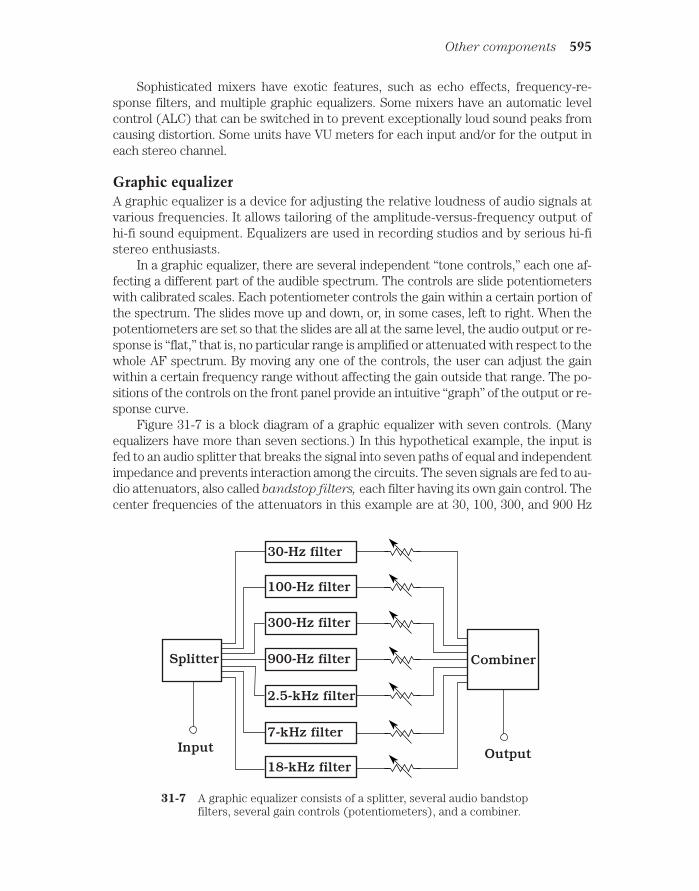
Sophisticated mixers have exotic features, such as echo effects, frequency-re-sponse filters, and multiple graphic equalizers. Some mixers have an automatic levelcontrol (ALC) that can be switched in to prevent exceptionally loud sound peaks fromcausing distortion. Some units have VU meters for each input and/or for the output ineach stereo channel.
Graphic equalizerA graphic equalizer is a device for adjusting the relative loudness of audio signals atvarious frequencies. It allows tailoring of the amplitude-versus-frequency output ofhi-fi sound equipment. Equalizers are used in recording studios and by serious hi-fistereo enthusiasts.
In a graphic equalizer, there are several independent “tone controls,” each one af-fecting a different part of the audible spectrum. The controls are slide potentiometerswith calibrated scales. Each potentiometer controls the gain within a certain portion ofthe spectrum. The slides move up and down, or, in some cases, left to right. When thepotentiometers are set so that the slides are all at the same level, the audio output or re-sponse is “flat,” that is, no particular range is amplified or attenuated with respect to thewhole AF spectrum. By moving any one of the controls, the user can adjust the gainwithin a certain frequency range without affecting the gain outside that range. The po-sitions of the controls on the front panel provide an intuitive “graph” of the output or re-sponse curve.
Figure 31-7 is a block diagram of a graphic equalizer with seven controls. (Manyequalizers have more than seven sections.) In this hypothetical example, the input isfed to an audio splitter that breaks the signal into seven paths of equal and independentimpedance and prevents interaction among the circuits. The seven signals are fed to au-dio attenuators, also called bandstop filters, each filter having its own gain control. Thecenter frequencies of the attenuators in this example are at 30, 100, 300, and 900 Hz
Other components 595
OutputInput
Splitter
30-Hz filter
100-Hz filter
300-Hz filter
900-Hz filter
2.5-kHz filter
7-kHz filter
18-kHz filter
Combiner
31-7 A graphic equalizer consists of a splitter, several audio bandstopfilters, several gain controls (potentiometers), and a combiner.

and 2.5, 7, and 18 kHz. (These are not standard frequencies; they are given here onlyfor illustrative purposes.) The slide potentiometers are shown as variable resistors fol-lowing the attenuators. Finally, the signals pass through an audio combiner (mixer); thecomposite is sent to the output.
The design of a graphic equalizer is not an easy task. The main challenge is to en-sure that the controls do not interact with each other. Judicious choice of filter fre-quencies and responses is also important. If the filters employ active devices such asoperational amplifiers, they must not introduce any distortion into the signal wave-forms. The active devices must not generate significant audio noise. Graphic equalizersare placed at low-level points because they are not built to handle high power. In a mul-tichannel circuit such as a stereo sound system, a separate graphic equalizer can beused for each channel. In stereo equipment, there are usually two equalizers, one forthe left channel and the other for the right channel.
Specialized SystemsMobile and portable hi-fi systems operate at low direct current (dc) voltages. Typi-cal audio power levels are much lower than in home hi-fi systems. Speakers aremuch smaller also. In portable systems, headsets are often used in place of speakers.
Mobile systemsCar stereos usually have four speakers. The left and right channels each supply apair of speakers. The left stereo channel drives the left front and left rear speakers;the right stereo channel drives the right front and right rear speakers. The balancecontrol adjusts the ratio of sound volume between the left and right channels forboth the front and rear speaker sets. Another control adjusts the ratio of sound vol-ume between the front and rear sets. This gives the impression of “surround sound.”But it is not a true quadraphonic system because there are only two independentsound channels: left (front and rear) and right (front and rear).
An automotive hi-fi stereo system usually has an AM/FM receiver and a cassettetape player. More expensive systems incorporate CD players. It’s important to remem-ber that both tapes and CDs are heat-sensitive and should not be stored in a car or truckthat might become hot. On a sunny summer day, the interior of a closed parked car canrise to a level sufficient to damage tapes and CDs.
Car stereo systems can relieve some of the tedium of long driving trips. But thesound can present a safety hazard if the volume is excessive. Loud music obscures out-side traffic noises, including sirens and honking horns. A headset, if worn by the driver,presents an even greater danger. In many states, it is illegal to wear a headset while dri-ving a motor vehicle.
Portable systemsPortable hi-fi systems operate from sets of dry cells or rechargeable cells and can re-quire anything from 1.5 V (one cell) to 12 V (eight cells).
The most well-known portable hi-fi set is the so-called headphone radio. Thereare numerous designs. Some include only an FM radio; some have AM/FM reception ca-pability. Some have a small box with a cord that runs to the headset; others are entirely
596 Acoustics, audio, and high fidelity

contained within the headset. There are portable cassette tape players and CD playersthat allow private hi-fi listening via headsets. The sound quality from these systems canbe excellent. The most important factor is the quality of the headset.
A headphone radio should never be worn while driving a car or truck, while ridinga bicycle or motorcycle, or while jogging in traffic. The music obscures external soundsand increases the risk of an accident. If you want to walk or jog while wearing a head-set, do it someplace where cars never go. Don’t even think about getting behind thewheel of a motor vehicle with a headset on.
Another form of portable hi-fi set is popularly known as a boom box. It can pro-duce several watts of audio output, and delivers the sound to a pair of speakers builtinto the box. A typical boom box is about 8 in high by 18 in wide by 6 in deep. It in-cludes an AM/FM radio and a cassette tape player; some also have CD players. Thesystem gets its name from the amazingly loud bass acoustic energy peaks its speak-ers can deliver.
Quadraphonic soundQuadraphonic sound refers to four-channel audio recording and reproduction. It isalso called quad stereo or four-channel stereo.
A conventional stereophonic circuit splits sound into two channels, the left channeland the right channel. In a quad stereo system, both of these channels are separatedinto front and rear components. In a true quadraphonic system, each of the four chan-nels is independent of the other three. This is not the case in all so-called quadraphonicsystems. Although true quad sound needs four tracks on a recording, some systems usetwo tracks and combine the left and right channels in phase quadrature (90 degrees outof phase) to obtain the front and rear signals.
Figure 31-8 shows the ideal placement of the speakers with respect to the lis-tener in a quadraphonic sound system. The speakers should be level with the lis-tener, equidistant from the listener, and separated by angles of 90 degrees from thelistener’s point of view. If the listener is facing north, the left front speaker is to thenorthwest, the right front speaker is to the northeast, the left rear speaker is to thesouthwest, and the right rear speaker is to the southeast. This provides optimum bal-ance, and also facilitates the greatest possible left-to-right and front-to-rear contrastin the perceived sounds.
It is possible to add two more channels to quad sound, placing a fifth channel abovethe listener and a sixth channel below. These might be called “zenith” and “nadir” chan-nels, respectively, and the system called hexaphonic sound. The main problem withthis scheme is that the optimum placement of the listener is critical and rather bizarre.The ideal arrangement would require that the user sit or lie suspended in the exact spa-tial center of a perfectly cubical room. However, some audiophiles might put up withthat to enjoy the effects.
Recorded MediaAudio music recordings are available in three traditional forms: vinyl disk, compactdisk, and magnetic tape. A fourth scheme, digital audio computer files, is not dis-cussed here; this technology falls into the category of personal computing.
Recorded media 597

Vinyl diskVinyl disks require a turntable that spins at speeds of 33 and 45 revolutions perminute (rpm). There are various drive systems. These are called rim drive, belt
drive, and direct drive. The best type is a matter of individual taste because thereare various factors to consider, such as cost, audio quality, ruggedness, and durabil-ity. If you are planning to buy a turntable, it’s a good idea to consult several hi-fi ex-perts for advice.
Although vinyl disks have been largely replaced by digital CDs, some audiophilesare still intrigued by vinyl. Some of these items have attained considerable value as col-lectors’ items. The main trouble with vinyl is that it can be physically damaged by eventhe slightest mishandling. Electrostatic effects can produce noise when the humidity islow, as in alpine or far northern regions in the winter.
With music recorded on vinyl disks, it is fairly easy to change from one song to an-other. You can simply lift the stylus (needle) from the disk surface and place it at the be-ginning of the band representing the song you want to hear. The problem is that, if yourhand slips or trembles, you might scratch the vinyl and cause permanent damage to thedisk. Also, it takes a keen eye to position the needle exactly in the right place.
Compact diskA CD is a plastic disk with diameter 4.72 in, on which data is permanently recordedin digital form. Any kind of data can be digitized: sound, images, and computer pro-grams and files. In computer lingo, a CD containing files and/or software is called aCD-ROM (compact-disk read-only memory).
598 Acoustics, audio, and high fidelity
Left front Right front
Left rear Right rear
Listener
Frominputdevices
4-channelamplifier
31-8 Quad stereo provides true 360-degree directional reproduction us-ing four speakers.

Digital sound, recorded on the surface of a compact disk, is practically devoid of thehiss and crackle that have historically bedeviled recordings on other media. This is be-cause the information on the disk is binary: a bit (binary digit) is either 1 (high) or 0(low). The distinction between these two states is more clear-cut than the subtle fluc-tuations of an analog signal. Noise is further reduced by a scattering/unscatteringprocess that “smears” recordings throughout the disk.
When a CD is manufactured, the sound is first subjected to analog-to-digital
(A/D) conversion. This changes the continuously variable audio waves into logic bits.These bits are then “burned” into the surface of the disk in the form of microscopic pits.The pits are arranged in a long spiral track that measures several miles in length. Whenthe sound is played back, the bits are unscattered. Digital signal processing (DSP)can eliminate some noise that has been introduced by environmental factors beyondpeople’s control, such as microscopic particles on the disk or random electronic noise incircuit hardware. Then the data is subjected to digital-to-analog (D/A) conversion.
Finally, the signal is amplified and sent to speakers or a headset.Compact-disk players recover the sound from a disk without physically touching
the surface on which the data is recorded. A laser beam scans the disk. The beam isscattered by the pits and is reflected from the unpitted plastic. The result is a digitallymodulated beam that is picked up by a sensor and converted into electrical currents.These currents then proceed to the unscattering (or descrambling), DSP, D/A, and au-dio amplification circuits. The speakers or headphones finally convert the audio cur-rents into sound waves.
With a CD player, the track location processes are electronic, and they can all bedone quickly. Tracks are assigned numbers that you select by pressing buttons. It is im-possible to damage the CD, no matter how much you skip around among the songs. Youcan “fast-forward” or “rewind” to different points within an individual track. You canprogram a CD player to play only those tracks you want, ignoring the others.
Analog magnetic tapeMagnetic tape is unique in consumer audio because it conveniently allows con-sumers to record, as well as play back, hi-fi sound. (CD burners exist, but they areexpensive compared to tape recorders.) Any form of private recording or reproduc-tion can give rise to copyright infringement concerns. If you’re in doubt about the le-gality of making a tape recording of anything, consult a lawyer before you do it.
Tape recorders can be classified as either cassette or reel-to-reel. In the past sev-eral decades, cassette tape has gradually replaced reel-to-reel tape in consumer appli-cations. Reel-to-reel tape is still used in some professional settings.
Magnetic-tape cassettes come in a variety of sizes and shapes for various applica-tions. A typical audio cassette plays for 30 minutes on each side; longer-playing cas-settes allow recording for as much as 60 minutes per side. The longer tapes are thinnerand more subject to stretching than the shorter tapes. Some cassettes, such as the kindused in stereo tape players, have endless loops of tape. Four recording paths, each withtwo channels for the left and the right half of the sound track, provide a total of eightrecording tracks.
A reel-to-reel tape feed system resembles that of an old-fashioned movie projector.The tape is wound on two flat spools called the supply reel and the take-up reel. The
Recorded media 599

supply reel is usually on the left, and the take-up reel is on the right. The reels rotatecounterclockwise as the tape passes through the recording/playback mechanism. Whenthe take-up reel is full and the supply reel is empty, both reels can be flipped over andinterchanged. This allows recording or playback on the “other side” of the tape. (Actu-ally, the process takes place on the same side of the tape, but on different tracks.) A 7-inch-diameter reel can hold about 3000 ft of 0.5-mil-thick tape. The speed is usually1.875, 3.75, or 7.5 in per second (IPS). At the slowest speed, the tape can run for sev-eral hours on each side.
All tape recorders work the same way, acting as transducers between acoustic, dig-ital, or video signals and variable magnetic fields. Figure 31-9 is a simplified rendition ofthe recording/playback apparatus in a typical audio tape recorder. The same basicscheme is used in cassette machines and reel-to-reel machines.
600 Acoustics, audio, and high fidelity
Recordinghead
Tape
Erase head PlaybackheadErase
signalgenerator
Audioamp.
Audioamp.
Microphone Speaker
31-9 Simplified diagram of an analog audio tape recorder.
In the “record” mode, the tape moves past the erase head before anything isrecorded on it. If the tape is not blank (that is, if magnetic impulses already exist on it),the erase head removes these before anything else is recorded. This prevents dou-
bling, or the simultaneous presence of two programs on the tape. The erase head canbe disabled in some tape recorders when doubling is wanted. This is sometimes done,for example, in audio recording studios. The recording head is a miniature, precisionelectromagnet that generates a fluctuating magnetic field whose instantaneous fluxdensity is proportional to the instantaneous level of the audio input signal. This magne-tizes the tape in a pattern that duplicates the waveform of the signal. The playback headis usually not activated in the record mode. However, the playback head and circuitscan be used while recording to create an echo effect.
In the “playback” mode, the erase head and recording head are not activated. Theplayback head acts as a sensitive magnetic-field detector, something like a miniaturelow-frequency radio antenna. As the tape moves past this device, the playback head isexposed to a fluctuating magnetic field whose waveform is identical to that produced by

the recording head when the audio was originally recorded on the tape. This magneticfield induces weak alternating currents in the playback head. These currents are ampli-fied and delivered to a speaker, headset, or other output device.
Digital audio tapeDigital audio tape (DAT) is magnetic recording tape on which binary digital data canbe recorded. Digital recording provides better fidelity than analog recording. Thedifference between DAT and conventional analog audio tape is similar to the im-provement afforded by the digital CD over the vinyl audio disk.
In digital audio recording, tape noise is eliminated. This is because such noise isanalog in nature, and is therefore ignored by digital sound reproduction equipment.Some electronic noise is generated in the analog amplification stages following D/A con-version, but this is minimal compared with the noise generated in older, fully analog sys-tems. The reduced noise in DAT equipment provides more true-to-life reproductionthan is possible with analog methods.
Another advantage of DAT is virtually unlimited copiability. The reason for this isthe same as the reason a computer can repeatedly read and overwrite data on a mag-netic disk. On DAT, the impulses are well defined: high and low states (logic ones andzeros) are represented by distinct magnetized regions on the tape. While analog signalsare “fuzzy” in the sense that they vary continuously, digital signals are “crisp.” Imper-fections in the recording apparatus, the tape itself, and the pickup head affect digitalsignals less than they affect analog signals. Digital signal processing (DSP) can elimi-nate the minute flaws that creep into a digital signal each time it is recorded and playedback. Thus, you can make copies of copies of DAT recordings, and the fidelity will notdeteriorate to any noticeable extent even after dozens of generations.
Electromagnetic InterferenceAs hi-fi equipment becomes more sophisticated and complex, the circuits seem to begetting more susceptible to interference from outside sources. If a radio transmitteris operated near a stereo system, the radio signals can be intercepted by the hi-fiwiring and peripherals, and delivered to the amplifier. Unshielded interconnectingcables act as radio receiving antennas. This problem is exacerbated if any of the con-necting cables happen to resonate at the operating frequency of the radio transmit-ter. In the amplifier, the RF currents are rectified, causing changes in the audio gain.Sometimes the signal data can be heard in the speakers or headset. This is known aselectromagnetic interference (EMI).
In most cases when EMI takes place in a hi-fi setup, the fault exists in the stereosystem design, not in the radio transmitter. The transmitter system is doing its job: gen-erating and radiating electromagnetic signals. There are several steps that can be takenwhen installing a stereo hi-fi system to minimize the likelihood that EMI will occur.These precautions should be followed:
• Connect the stereo amplifier chassis to a good electrical ground.• Use shielded interconnecting cables as much as possible.• Use shielded (coaxial) speaker cables.• Keep all cables as short as possible.
Electromagnetic interference 601

If you have an amateur or citizens’ band (CB) radio station in your house and itcauses EMI to your hi-fi system, two more steps might be necessary:
• Locate the radio transmitting antenna as far from the hi-fi equipment aspossible.
• Use the lowest possible transmitter output power that will ensure reliablecommunications.
If EMI problems continue even after all the above steps have been taken, a profes-sional engineer might be able to help. If the radio transmitter is not always in use (a CBor amateur station, for example), efforts should be made to avoid using both the radioand the hi-fi at the same time.
QuizRefer to the text in this chapter if necessary. A good score is 18 correct. Answers arein the back of the book.
1. Acoustics is important in the design of:
A. Amplifier power supplies.
B. Speaker enclosures.
C. Cables that connect components of a hi-fi system together.
D. Graphic equalizers.
2. Electromagnetic interference to a hi-fi amplifier can be caused by:
A. A nearby radio broadcast station.
B. Improperly designed receiving antennas.
C. Excessive utility voltage.
D. Improper balance between the left and right channels.
3. The midrange audio frequencies:
A. Are halfway between the lowest and highest audible frequencies.
B. Represent sounds whose volume levels are not too loud or too soft.
C. Are above the treble range but below the bass range.
D. Are between approximately 0.2 and 2 kHz.
4. An indoor concert hall such that sound reaches every listener’s ears perfectlyat all audio frequencies requires:
A. A suspended ceiling with acoustical tile completely covering it.
B. Numerous baffles on the walls and ceiling.
C. A level of engineering beyond reasonable expectation.
D. Avoidance of excessive background noise.
5. A sound volume change of 3 dB represents:
A. A doubling of acoustic power.
B. A threefold increase in acoustic power.
602 Acoustics, audio, and high fidelity

C. A tenfold increase in acoustic power.
D. No change in acoustic power.
6. A sound whose wavelength is 6 in in the air has a frequency of:
A. 550 Hz.
B. 1100 Hz.
C. 2200 Hz.
D. It is impossible to calculate from this information.
7. A sound wave that travels at 335 m per second has a frequency of:
A. 335 Hz.
B. 3350 Hz.
C. 33.5 Hz.
D. It is impossible to calculate from this information.
8. The relative phase of two acoustic waves, as they arrive at your ears, can affect:
A. How loud the sound seems.
B. The direction from which the sound seems to be coming.
C. Both A and B.
D. Neither A nor B.
9. In an acoustic sine wave:
A. The frequency and phase are identical.
B. The sound power is inversely proportional to the frequency.
C. The sound power is directly proportional to the frequency.
D. All of the sound power is concentrated at a single frequency.
10. Vinyl disks are:
A. Susceptible to physical damage.
B. Useful primarily in high-power sound systems.
C. Digital media.
D. Preferred for off-the-air sound recording.
11. If an amplifier introduces severe distortion in the waveforms of input signals,then that amplifier is:
A. Not delivering enough power.
B. Operating at the wrong frequency.
C. Operating in a nonlinear fashion.
D. Being underdriven.
12. If a 10-watt amplifier is used with speakers designed for a 100-watt amplifier:
A. The speakers are capable of handling the amplifier output.
B. The amplifier might be damaged by the speakers.
Quiz 603

C. Electromagnetic interference is likely to occur.
D. The speakers are likely to produce distortion of the sound.
13. Which of the following frequencies cannot be received by an AM/FM tuner?
A. 830 kHz.
B. 95.7 kHz.
C. 100.1 MHz.
D. 107.3 MHz.
14. A woofer:
A. Is especially useful for reproducing the sounds of barking dogs.
B. Is designed to handle short, intense bursts of sound.
C. Should not be used with a graphic equalizer.
D. Is designed to reproduce low-frequency sounds.
15. Suppose you have an amateur radio station and its transmitter causes EMI toyour hi-fi system. Which of the following would almost certainly not help?
A. Buy a radio transmitter that works on the same frequencies with the samepower output, but is made by a different manufacturer.
B. Reduce the transmitter output power.
C. Use shielded speaker wires in the hi-fi system.
D. Move the radio transmitting antenna to a location farther away from the hi-fi system.
16. A tape recording head:
A. Converts sound waves to radio signals.
B. Converts sound waves to fluctuating electric current.
C. Converts audio-frequency currents to a fluctuating magnetic field.
D. Converts direct current to audio-frequency currents.
17. A microphone:
A. Converts sound waves to radio signals.
B. Converts sound waves to fluctuating electric current.
C. Converts audio-frequency currents to a fluctuating magnetic field.
D. Converts direct current to audio-frequency currents.
18. An audio mixer:
A. Cannot match impedances.
B. Cannot make an amplifier more powerful.
C. Will eliminate EMI.
D. Allows a microphone to be used as a speaker.
604 Acoustics, audio, and high fidelity

19. Which of the following media or devices use digital-to-analog conversion?
A. A CD player.
B. A speaker.
C. A microphone.
D. A vinyl disk.
20. Phase quadrature is sometimes used to:
A. Increase the output from a microphone.
B. Reduce the susceptibility of a hi-fi system to EMI.
C. Create the illusion of four-channel stereo when there are really only twochannels.
D. Convert an analog signal to a digital signal, or vice-versa.
Quiz 605

32CHAPTER
Wireless and personalcommunications systemsTHE TERM WIRELESS WAS COINED IN THE LATE NINETEENTH CENTURY WHENinventors toyed with the idea of sending and receiving telegraph messages using elec-tromagnetic fields rather than electric currents. In the early twentieth century, thetechnology became known as radio; video and data broadcasting and communicationswere added in the middle of the century and the general term electromagnetic com-
munications emerged. The word wireless was relegated to history.In the late 1980s, the term found new life. Today it refers to communications, net-
working, control devices, and security systems in which signals travel without directelectrical connections.
Cellular communicationsRadio transceivers can be used as telephones in a specialized communications sys-tem called cellular. Originally, the cellular communications network was patchy andunreliable, and was used mainly by traveling business people. Nowadays, cellulartelephone units are so common that many people regard them as necessities.
How cellular systems workA cellular telephone set, or cell phone, looks and functions like a cross between acordless telephone receiver and a walkie-talkie. The unit contains a radio transmit-ter and receiver combination called a transceiver. Transmission and reception takeplace on different frequencies, so you can talk and listen at the same time. This ca-pability, which allows you to hear the other person interrupt you if he or she chooses,is known as full duplex.
606 !
"# #$ !

In an ideal cellular network, all the transceivers are always within range of at leastone repeater. The repeaters pick up the transmissions from the portable units and re-transmit the signals to the telephone network and to other portable units. The region ofcoverage for any repeater (also known as a base station) is called a cell.
When a cell phone is in motion, say in a car or on a boat, the set goes from cellto cell in the network. This situation is shown in Fig. 32-1. The curved line is the pathof the vehicle. Base stations (dots) transfer access to the cell phone. This is calledhandoff. Solid lines show the limits of the transmission/reception range for eachbase station. All the base stations are connected to the regional telephone system.This makes it possible for the user of the portable unit to place calls to, or receivecalls from, anyone else in the system, whether those other subscribers have cellphones or regular phones.
Cellular communications 607
Basestations
Path ofvehicle
Cells
32-1 In a cellular system, a moving vehicle is always within range ofat least one base station.
Older cellular systems occasionally suffer from call loss or breakup when sig-nals are handed off from one repeater to another. This problem has been largelyovercome by a technology called code-division multiple access (CDMA). InCDMA, the repeater coverage zones overlap significantly, but signals do not inter-fere with each other because every phone set is assigned a unique signal code.Rather than abruptly switching from one base-station zone to the next, the signalgoes through a region in which it is actually sent through more than one base sta-tion at a time. This make-before-break scheme gets rid of one of the most annoy-ing problems inherent in cellular communications.
To use a cellular network, you must purchase or rent a transceiver and pay amonthly fee. The fees vary, depending on the location and the amount of time permonth you use the service. When using such a system, it is important to keep in

mind that your conversations are not necessarily private. It is easier for unautho-rized people to eavesdrop on wireless communications than to intercept wire or ca-ble communications.
Cell phones and computersA personal computer (PC) can be hooked up to the telephone lines for use with on-line networks such as the Internet. For some people, getting on the Internet is themost important justification for buying a computer.
You can connect a laptop or notebook computer to a cell phone with a portable mo-
dem that converts incoming computer data from analog to digital and also converts out-going data from digital to analog. This will let you get on-line from anywhere withinrange of a cellular base station. Figure 32-2 is a block diagram of this scheme.
608 Wireless and personal communications systems
Most commercial aircraft have telephones at each row of seats, complete with jacksinto which you can plug a modem. If you plan to get on-line from an aircraft, you mustuse the phones provided by the airline, not your own cell phone, because radio trans-ceivers can cause interference to flight instruments. You must also observe the airline’srestrictions concerning the operation of electronic equipment while in flight. If youaren’t sure what these regulations are, ask one of the flight attendants.
Satellite systemsA satellite system is, in a certain sense, a gigantic cellular network. The repeaters,rather than being in fixed locations, are constantly moving. The zones of coverage
Peripherals Cell phonetransceiver
Radio signals
Portablecomputer
Control signals Analog data
Digital data
Modem
32-2 A cell phone can be equipped with a modem, allowingportable or mobile access to on-line computer networks.

are much larger in a satellite network than in a cellular network, and they change insize and shape if the satellite moves relative to the earth’s surface.
Geostationary-orbit satellitesFor any satellite in a circular orbit around the earth, the revolution period getslonger as the altitude increases. At an altitude of about 22,300 miles, a satellite in acircular orbit takes precisely one day to complete each revolution. If a satellite isplaced in such an orbit over the equator, and if it revolves in the same direction asthe earth rotates, it is called a geostationary-orbit (GEO) satellite or simply a geostationary satellite. From the viewpoint of someone on the earth, a GEO satel-lite stays in the same spot in the sky all the time.
One GEO satellite can cover about 40 percent of the earth’s surface. A satellite overEcuador, for example, can link most cities in North America and South America. Threesatellites in geostationary orbits spaced 120 degrees apart (one-third of a circle) pro-vide coverage over the entire civilized world. Geostationary satellites are used in televi-sion (TV) broadcasting, telephone and data communication, for gathering weather andenvironmental data, and for radiolocation.
In GEO-satellite networks, earth-based stations can communicate via a single “bird”only when the stations are both on a line of sight with the satellite. If two stations are nearlyon opposite sides of the planet, say in Australia and Wisconsin, they must operate throughtwo satellites to obtain a link (Fig. 32-3). In this situation, signals are relayed between thetwo satellites, as well as between either satellite and its respective earth-based station.
The main problem with two-way GEO-satellite communication is the fact that thesignal path is long: at least 22,300 miles up to the satellite, and at least 22,300 miles backdown to the earth. If two satellites are used in the circuit, the path is substantially
Satellite systems 609
North geographicpole
Satellite X Satellite Y
Station X Station Y
Signal path
Signalpath
Signalpath
Earth
32-3 A communications link that employs two GEO satellites.
longer. This doesn’t cause problems in television broadcasting or in one-way data trans-fers, but it slows things down when computers are linked with the intention of combin-ing their processing power. It is also noticeable in telephone conversations.
Problem 32-1What is the minimum round-trip signal delay when a GEO satellite is used? Assumethat the satellite retransmits signals at the same instant they are received.
Radio waves travel at the speed of light (186,282 miles per second). The minimumpath length to and from a geostationary satellite is 22,300 miles, for a total round-tripdistance of 44,600 miles. Therefore, the delay is at least 44,600/186,282 second, orabout 0.239 seconds, or 239 milliseconds.
The delay will be a little longer if the transmitting and receiving stations are locateda great distance from each other as measured over the earth’s surface. In practice, aslight additional delay might also be caused by conditions in the ionosphere.
Low-earth-orbit satellitesThe earliest communications satellites orbited only a few hundred miles above the earth.They were low-earth-orbit (LEO) satellites. Because of their low orbits, LEO satellitestook only about 90 minutes to complete one revolution. This made communication spottyand inconvenient, because a satellite was in range of any given ground station for only afew minutes at a time. Because of this, GEO satellites became predominant.
However, GEO satellites have certain limitations. A geostationary orbit requiresconstant adjustment, because a tiny change in altitude will cause the satellite to get outof sync with the earth’s rotation. Geostationary satellites are expensive to launch andmaintain. When communicating through them, there is always a delay because of thepath length. It takes high transmitter power, and a sophisticated, precisely aimed an-tenna, to communicate reliably.
These problems with GEO satellites have brought about a revival of the LEOscheme. Instead of one single satellite, the new concept is to have a large fleet of them.Imagine dozens of LEO satellites in orbits such that, for any point on the earth, there isalways at least one satellite in range. Further, suppose that the satellites can relay mes-sages throughout the fleet. Then any two points on the surface can always make, andmaintain, contact through the satellites.
A LEO system employs satellites in orbits strategically spaced around the globe.The satellites are placed in polar orbits (routes that pass over or near the earth’s geo-graphic poles) because such orbits optimize the coverage of the system. A LEO satellitewireless communications link is easier to access and use than a GEO satellite link. Asmall, simple antenna will suffice, and it doesn’t have to be aimed in any particular di-rection. The transmitter can reach the network using only a few watts of power. Thepropagation delay is much shorter than is the case with a geostationary link, usuallymuch less than 0.1 second.
Medium-earth-orbit satellitesSome satellites revolve in orbits higher than those normally considered low-earth, butat altitudes lower than the geostationary level of 22,300 miles. These intermediate
610 Wireless and personal communications systems

“birds” are called medium-earth-orbit (MEO) satellites. A MEO satellite takesseveral hours to complete each orbit. MEO satellites operate in fleets, in a mannersimilar to the way LEO satellites are deployed. Because the average MEO altitudeis higher than the average LEO altitude, each “bird” can cover a larger region onthe surface at any given time. A fleet of MEO satellites can be smaller than a com-parable fleet of LEO satellites, and still provide continuous, worldwide communi-cations.
The orbits of GEO satellites are essentially perfect circles, and most LEO satel-lites orbit in near-perfect circles. But MEO satellites often have elongated, or ellip-tical, orbits. The point of lowest altitude is called perigee; the point of greatestaltitude is called apogee. The apogee can be, and often is, much greater than theperigee. Such a satellite orbits at a speed that depends on its altitude. The lowerthe altitude, the faster the satellite moves. A satellite with an elliptical orbitcrosses the sky rapidly when it is near perigee, and slowly when it is near apogee;it is easiest to use when its apogee is high above the horizon, because then it staysin the visible sky for a long time.
Every time a MEO satellite completes one orbit, the earth rotates beneath it. Therotation of the earth need not, and usually does not, correspond to the orbital period ofthe satellite. Therefore, successive apogees for a MEO satellite occur over differentpoints on the earth’s surface. This makes the tracking of individual satellites a compli-cated business, requiring computers programmed with accurate orbital data. For aMEO system to be effective in providing worldwide coverage without localized periodicblackouts, the orbits must be diverse, yet coordinated in a precise and predictable way.In addition, there must be enough satellites so that each point on the earth is always ona line of sight with one or more satellites, and preferably, there should be at least one“bird” in sight near apogee at all times.
The Global Positioning SystemThe Global Positioning System (GPS) is a network of satellites that operates on aworldwide basis. This system allows a user to determine exact latitude, longitude,and (if applicable) altitude.
All GPS satellites transmit signals in the microwave part of the radio spectrum,where the wavelengths are a few centimeters. The signals are modulated with specialtiming and identification codes. A GPS receiver allows its user to find his or her positionby measuring the distances to four different satellites. This is done by precisely timingthe signals as they travel between the satellites and the receiver. The receiver uses acomputer to process the information received from the satellites. From this informa-tion, it can give the user an indication to within a few feet (for government and indus-trial subscribers) or a few hundred feet (for civilians).
An increasing number of automobiles, trucks, and pleasure boats have GPS re-ceivers installed. If you are driving your car in a remote area and get stranded, say ina blizzard, you might use the GPS to locate your position. Using a cell phone, youcould call for help and inform authorities of your location. Someday, perhaps everymotor vehicle and boat will be equipped with GPS and wireless communicationsequipment.
Satellite systems 611

Acoustic transducersAn acoustic transducer is an electronic component that converts sound waves intosome other form of energy, or vice versa. The other form of energy is usually an al-ternating-current (ac) electrical signal. The waveforms of the acoustical and electri-cal signals are identical, or nearly so.
Acoustic transducers are designed for various frequency ranges. The human hear-ing spectrum extends from about 20 Hz to 20 kHz. But acoustic energy can have fre-quencies lower than 20 Hz or higher than 20 kHz. Energy at frequencies below 20 Hz iscalled infrasound; if the frequency is above 20 kHz, it is known as ultrasound. Inacoustic wireless devices, ultrasound is generally used, because the wavelength is shortand the necessary transducers can be small. Also, ultrasound cannot be heard, andtherefore it will not distract or annoy people.
Figure 32-4 is a simplified diagram of a piezoelectric transducer. This device con-sists of a crystal, such as quartz or ceramic material, sandwiched between two metalplates. When an acoustic wave strikes one or both of the plates, the metal vibrates. Thisvibration is transferred to the crystal. The piezoelectric crystal generates weak electric
612 Wireless and personal communications systems
Metalplates
Crystal
Signal input/output
32-4 Simplified cross-sectionaldiagram of a piezoelectricacoustic transducer.
currents when it is subjected to mechanical stress. Therefore, an ac voltage developsbetween the two metal plates, with a waveform similar to that of the acoustic waves.
If an ac signal is applied to the plates, it causes the crystal to vibrate in sync withthe current. The result is that the metal plates vibrate also, producing an acoustic dis-turbance in the air. The piezoelectric transducer can thus act either as an acoustic
pickup or an acoustic emitter. Piezoelectric transducers are common in ultrasonic ap-plications, such as intrusion detection systems.
Figure 32-5 shows another type of acoustic transducer that can function either asa pickup or emitter. This is known as an electrostatic transducer. When a sound wavestrikes the flexible plate, the plate vibrates. This causes rapid changes in the spacing be-tween the flexible plate and the rigid plate, producing fluctuation in the capacitance be-tween the plates. A direct-current (dc) voltage source is connected to the plates. As the

capacitance fluctuates, the plates alternately charge and discharge a little. This causesa weak ac signal to be produced, whose waveform is similar to that of the acoustic dis-turbance. The blocking capacitor allows this ac signal to pass to the transducer output,while keeping the dc confined to the plates.
If an ac signal is applied to the terminals of the transducer, it passes through theblocking capacitor and onto the metal plates. The signal creates a fluctuating voltagebetween the plates. The dc source, combined with the ac signal, results in an electro-static field of constant polarity, but of rapidly varying intensity. This exerts a fluctuatingforce between the plates, causing the flexible plate to vibrate and generate an acousticwave in the air.
The most well-known type of acoustic transducer has a coil surrounding a perma-nent magnet or electromagnet. A diaphragm or cone is attached to either the coil or themagnet. When the diaphragm vibrates as a result of acoustic waves striking it, ac is pro-duced in the coil. Conversely, if ac is applied to the coil, it produces electromagneticforce that causes the diaphragm to vibrate. This device is called a dynamic trans-
ducer. Most microphones, headphones, and loudspeakers are of this type.Acoustic transducers are used in security systems. They are also used in robotics
to help mobile machines navigate in their surroundings. Acoustic transducers are em-ployed in depth-finding apparatus commonly found on boats.
Radio-frequency transducersThe term radio-frequency (RF) transducer is a fancy name for an antenna. An-tennas are so common that you probably don’t think about them very often. Your carradio has one. Your portable headphone radio, which you might use while jogging ona track (but never in traffic), employs one. Cellular and cordless telephones,portable television receivers, and handheld radio transceivers use antennas. Hun-dreds of books have been written on the subject.
There are two basic types of RF transducer: the receiving antenna and the trans-
mitting antenna. A receiving antenna converts electromagnetic (EM) fields, in the RF
Radio-frequency transducers 613
+
_
Signalinput/output
Blockingcapacitor
Rigidplate
Flexibleplate
32-5 Simplified diagram of an electrostatic acoustic transducer.

range from about 9 kHz to several hundred gigahertz, into ac signals that are amplifiedby the receiving apparatus. A transmitting antenna converts powerful alternating cur-rents into EM fields, which propagate through space.
There are a few significant differences between receiving antennas and trans-mitting antennas designed for a specific radio frequency. The efficiency of an an-tenna is important in transmitting applications, but not so important in reception.Efficiency is the percentage of the power going into a transducer that is convertedinto the desired form. If the input power to a transducer is P
inwatts and the output
power is Pout
watts, the efficiency in percent, Eff%, can be found using the following
equation:
Eff % 100 Pout /Pin
Problem 32-2In a transmitting antenna, 75 W of RF power are delivered to the transducer, and 62W are radiated as an EM field. What is the efficiency of the transducer?
To solve this problem, plug the numbers into the formula. In this particular case, Pin
75 and Pout
62. Therefore,
Eff% 100 62/75 100 0.83 83 percent
Another difference between transmitting and receiving antennas is the fact that,for any given frequency, transmitting antennas are often larger than receiving antennas.Transmitting antennas are also more critical as to their location. Whereas a small loopor whip antenna might work well indoors in a portable radio receiver for the frequency-modulation (FM) broadcast band, the same antenna would not function well at thebroadcasting station for use with the transmitter.
Still another difference between transmitting and receiving antennas involvespower-handling capability. Obviously, very little power strikes the antenna in a wirelessreceiver; it can be measured in fractions of a microwatt. However, a transmitter mightproduce kilowatts or even megawatts of output power. A small loop antenna, for exam-ple, would get hot if it were supplied with 1 kW of RF power; if it were forced to dealwith 100 kW, it would probably melt.
Infrared transducersMany wireless devices transmit and receive energy at infrared (IR) wavelengths,rather than at radio wavelengths. Infrared energy has a frequency higher than thatof radio waves, but lower than that of visible light. Infrared is sometimes called heatradiation, but this is a misnomer. Some wireless devices transmit and receive theirsignals in the visible-light range, although these are encountered much less oftenthan IR devices.
The most common IR transmitting transducer is the infrared-emitting diode
(IRED). You learned about this type of diode in chapter 20. A fluctuating direct currentis applied to the IRED. The current causes the device to emit IR rays; the fluctuationsin the current constitute the modulation, and produce rapid variations in the intensity
614 Wireless and personal communications systems

of the rays emitted by the semiconductor junction. The modulation contains informa-tion, such as which channel your television set should seek, or whether the volume is tobe raised or lowered. Infrared energy is not visible, but at some wavelengths it can befocused by ordinary optical lenses and reflected by ordinary optical mirrors. This makesit possible to collimate IR rays (make them essentially parallel) so they can be trans-mitted for distances up to several hundred feet.
Infrared receiving transducers resemble photodiodes or photovoltaic cells, whichwere also discussed in chapter 20. The only real difference is that the diodes are maxi-mally sensitive in the IR, rather than in the visible, part of the electromagnetic spec-trum. The fluctuating IR energy from the transmitter strikes the P/N junction of thereceiving diode. If the receiving device is a photodiode, a current is applied to it, andthis current varies rapidly in accordance with the signal waveform on the IR beam fromthe transmitter. If the receiving device is a photovoltaic cell, it produces the fluctuatingcurrent all by itself, without the need for an external power supply. In either case, thecurrent fluctuations are weak, and must be amplified before they are delivered to what-ever equipment (television set, garage door, oven, security system, etc.) is controlled bythe wireless system.
Infrared wireless devices work best on a line of sight, that is, when the transmittingand receiving transducers are located so the rays can travel without encountering anyobstructions. You have probably noticed this when using television remote controlboxes, most of which work at IR wavelengths. Sometimes enough energy will bounce offthe walls or ceiling of a room to let you change the channel when the remote box is noton a direct line of sight with the television set. But the best range is obtained by makingsure you and the television set can “see” each other. You cannot put an IR control boxin your pants pocket and expect it to work. Radio and IR control boxes are often mis-taken for one another because they look alike to the casual observer.
Wireless local area networksA local area network (LAN) is a group of computers linked together within a build-ing, campus, or other small region. The interconnections in early LANs were madewith wire cables, but increasingly, radio links are being used. A wireless LAN offersflexibility because the computer users can move around without having to botherwith plugging and unplugging cables. This arrangement is ideal when notebook com-puters (also known as laptops) are used.
The way in which a LAN is arranged is called the LAN topology. There are two ma-jor topologies: the client-server wireless LAN and the peer-to-peer wireless LAN.
In a client-server wireless LAN (Fig. 32-6), there is one large, powerful, centralcomputer called a file server, to which all the smaller personal computers (labeled PC)are linked. The file server has enormous computing power, high speed, and large stor-age capacity, and can contain all the data for every user. End users do not communicatedirectly. All the data must pass through the file server.
In a peer-to-peer LAN (Fig. 32-7), all of the computers in the network are PCs withmore or less equal computing power, speed, and storage capacity. Each user generallymaintains his or her own data. Subscribers can, and almost always do, communicate
Wireless local area networks 615

directly without the data having to pass through any intermediary. This offers greater privacy and individuality than the client-server topology, but it is slower when a largenumber of users need to share data.
In the illustrations, only three PCs are shown in the networks. But any LAN canhave as few as two, or as many as several dozen, PC workstations. Client-server LANsare favored by large institutions. Small businesses and schools, or departments within alarger corporation or university, prefer to use peer-to-peer LANs, mainly because theyare cheaper and easier to maintain.
Wireless security systemsWireless technology lends itself to certain security applications, especially those in-volving mobile vehicles such as cars, boats, and trucks. Also, a wireless link can alertyou to a fire or intrusion at your home or business, when you are not physically pre-sent at the location.
One well-known wireless security system for cars employs a device that trans-mits a radio signal when the vehicle is being improperly operated. The system cir-cuits and antenna are concealed, although there might be a warning sticker on the
616 Wireless and personal communications systems
PC
PC PC
32-7 A peer-to-peerwireless LAN.
PC
PC PC
File server
32-6 A client-server wireless LAN.

car. If a potential thief knows your vehicle has a wireless security system, he or shewill probably not want to spend a lot of time snooping around to find and disable the system.
If someone manages to steal your car and it has a wireless security system in-stalled, and if you’re lucky enough to find out about the theft within a short time, tellthe police about the security system. The police have a wireless transmitter thatsends out a signal that contains the vehicle identification number (VIN) for your car.This signal is received by the equipment in your car, which starts up its own trans-mitter. Using radiolocation equipment, the police can pinpoint the position of yourcar on a map. From there, mobile direction-finding radio receivers can be used toreach the car. In some cases the police have caught thieves while they were actuallydriving stolen cars.
A home or business wireless security system operates like a paging device orbeeper. If something happens that triggers the security system, a radio signal is trans-mitted that sets off a small radio receiver you carry. Such a system will ideally telephonethe police and/or fire department as well. If you happen to be reasonably near yourhome or business, you can drive to the site.
Hobby radioIn most countries of the world, people can obtain government-issued licenses tosend and receive messages via radio for nonprofessional purposes. In America, thishobby is called amateur radio or ham radio. If you want only to listen to commu-nications and broadcasting, and not to transmit signals, you do not need a license inthe United States (although you might need one in certain other countries).
Who uses amateur radio?Anyone can use ham radio. Amateur radio operators, often called radio hams, can com-municate using any of numerous modes, including speech, Morse code, television, andradioteletype (RTTY). This last mode, RTTY, can be done in real time, or by postingmessages in a manner similar to the way computer users exchange information by electronic mail (e-mail). Radio hams have set up their own radio networks. Some ofthese networks have Internet gateways. This is known as packet radio.
Some radio hams chat about anything they can think of (except business matters,which are illegal to discuss via ham radio). Others like to practice emergency-commu-nications skills, so they can be of public service during crises such as hurricanes, earth-quakes, or floods. Still others like to go out into the wilderness and talk to peoplethousands of miles away while sitting out under the stars. Amateur radio operatorscommunicate from cars, boats, aircraft, and bicycles; this is called mobile operation.
When transceivers are used while walking or hiking, it is known as portable or hand-
held operation.
Amateur equipment and licensingA simple ham radio station has a transceiver (transmitter/receiver), a microphone,and an antenna. A small station can fit on a desktop and is about the size of a home
Hobby radio 617

computer or hi-fi stereo system. Accessories can be added until a ham “rig” is a largeinstallation, comparable to a small commercial broadcast station.
Figure 32-8 shows an example of a fixed, computer-controlled amateur radio sta-tion. The PC can be used to communicate via packet radio with other hams who own
618 Wireless and personal communications systems
To all units To utility mains
VHF/UHFantenna
HFantenna
Coaxialcable
Coaxialcable
VHF/UHFtransceiver
HFtransceiver
Linearamplifier
ComputerPrinter Videocamera
Powersupplies
32-8 A computer-controlled amateur radio station.
computers. The station can be equipped for on-line telephone (landline) services. ThePC can control the antennas for the station and can keep a log of all stations that havebeen contacted. Some transceivers can be operated by computer, either locally or by re-mote control over the radio or landline.
A good way to learn about ham radio is to contact the headquarters of the Ameri-can Radio Relay League, 225 Main Street, Newington, CT 06111. Their Web site is athttp://www.arrl.org.
Shortwave listeningThe high-frequency (HF) portion of the radio spectrum, at frequencies between 3and 30 MHz, is sometimes called shortwave. This is a misnomer by contemporarystandards; the waves are long compared with microwaves (a few millimeters) or IR(a tiny fraction of one millimeter), which are commonly used in wireless devices. Afrequency of 3 MHz corresponds to a wavelength of 100 meters in free space; 30 MHzcorresponds to 10 meters. But in the early years of radio when the shortwave bandgot its name, the wavelengths between 3 and 30 MHz were short compared with the

wavelengths of most broadcast and communications signals, which had wavelengthsin the kilometer range.
Anyone can build or obtain a shortwave or general-coverage radio receiver, installa modest outdoor antenna, and listen to signals from all around the world. This hobbyis called shortwave listening or SWLing. In the United States, the proliferation ofcomputers and on-line communications has, to some extent, overshadowed SWLing,and many young people grow up today ignorant of a realm of broadcasting and com-munications that still predominates in much of the world. But some people are still fas-cinated by the idea that people can contact each other by wireless devices without theneed for any human-made infrastructure other than an antenna at the source and an-other antenna at the destination. The ionosphere returns shortwave signals to theearth’s surface and allows reliable global broadcasting and communication to take placetoday, just as it always has, and just as it always will.
There are various commercially manufactured shortwave receivers on the markettoday, and some of these are inexpensive. An outdoor wire antenna costs practicallynothing. Most electronics stores carry one or more models of shortwave receiver, alongwith antenna equipment, for a complete installation. One problem with low-pricedshortwave receivers is that they usually lack the mode flexibility, selectivity, and sensi-tivity necessary to engage in serious SWLing. If you are interested in this hobby andwant to obtain high-end equipment, shop around in consumer electronics and amateurradio magazines. Most electronics and book stores carry periodicals and books for thebeginner as well as the experienced SWLer. A library can also be a good source of in-formation, especially if you are interested in “antique” shortwave receivers, some ofwhich can be found at amateur-radio conventions and flea markets.
NoiseIn a wireless system, the term noise refers to an electromagnetic field that usuallyhas large bandwidth; that is, it occurs over a wide range of frequencies and wave-lengths. Noise does not convey information. It can be either natural or human-made.
It’s never good newsNoise never helps, and often degrades, the performance of a wireless system. It is aconcern in any device or system in which data is sent from one place to another. Thehigher the noise level, the stronger a signal must be if it is to be received error-free.At any given signal power level, higher noise levels translate into more errors and re-duced communications range.
Figure 32-9 is a spectral display of signals and noise, with amplitude as a functionof frequency. The device that generates this display is called a spectrum analyzer. Thehorizontal axis shows frequency; the vertical axis shows amplitude. The backgroundnoise level is called the noise floor. Signals above the noise floor appear in the displayand can be received. The strongest signals are received with the fewest errors; weaksignals are subject to the most errors. Signals below the noise floor are not displayedand cannot be retrieved unless a more sophisticated receiving system is used, or thetransmitter power output is increased, or both.
Noise 619

Minimizing noiseThe noise level in any electronic system can be minimized by using components thatdraw the least possible current. Noise can also be kept down by lowering the tem-perature tremendously. Some experimentation has been done at extremely coldtemperatures; this is called cryotechnology.
The narrower the bandwidth of the signal, the better the signal-to-noise ratio willbe, if all other factors remain constant. But this improvement takes place at the expenseof data speed. When the noise originates mainly in sources outside the wireless equip-ment (for example, atmospheric “static”), reducing the bandwidth of the receivingequipment is generally necessary. This means that, in wireless communications withhigh external noise levels, the data speed must usually be slower than it would be ifthere were little external noise.
A noise limiter or noise blanker can sometimes provide improved communica-tions without reducing data speed. Noise limiters “chop off” high-amplitude noisepeaks, and blankers in effect turn the receiver off during noise pulses. Such circuits canbe effective against human-made impulse noise, characterized by high-amplitude peaksof very short duration. But thermal, atmospheric, solar, and galactic noise, which are es-sentially random, are not significantly affected by limiters and blankers.
QuizRefer to the text in this chapter if necessary. A good score is 18 correct. Answers arein the back of the book.
1. A network that employs one powerful central computer and several PCs iscalled:
A. A wireless network.
620 Wireless and personal communications systems
Readable signals
Noisefloor
Amplitude axis
Frequencyaxis
Signals below noise floordo not appear in display
32-9 A spectrum-analyzerdisplay. The vertical axisshows amplitude, andthe horizontal axis showsfrequency.

B. A local-area network.
C. A client-server network.
D. A peer-to-peer network.
2. Infrared and optical wireless links work best:
A. Over distances exceeding 1000 miles.
B. On a line of sight.
C. At low radio frequencies.
D. In situations with high levels of noise.
3. Which of the following devices or systems is not generally considered wireless?
A. A remote-control garage-door opener.
B. An amateur radio station.
C. A beeper/pager.
D. A telephone set that requires a wall jack.
4. A noise blanker can improve the quality of:
A. Radio reception.
B. Radio transmission.
C. Infrared reception.
D. Infrared transmission.
5. In the United States, a license is required for:
A. Receiving on amateur-radio frequencies.
B. Transmitting on amateur-radio frequencies.
C. Using infrared wireless devices.
D. Using a wireless automobile security system.
6. Noise in a wireless receiver can be minimized by:
A. Raising the temperature to very high values.
B. Reducing the temperature to very low values.
C. Maximizing the amplification.
D. Minimizing the relative humidity.
7. As the data speed increases in a wireless system, all other factors being equal:
A. The signal bandwidth increases.
B. The signal bandwidth decreases.
C. The overall noise level increases.
D. The overall noise level decreases.
8. The term shortwave, in reference to radio, refers to signals havingwavelengths of approximately:
A. 10 to 100 millimeters.
Quiz 621
B. 100 millimeters to 1 meter.
C. 1 to 10 meters.
D. 10 to 100 meters.
9. In general, as the noise level in a wireless system increases:
A. Stronger incoming signals are needed to overcome it.
B. Weaker signals can be received.
C. The temperature of the system rises.
D. The bandwidth of the system increases.
10. In a spectrum analyzer, the horizontal axis shows:
A. Voltage.
B. Power.
C. Frequency.
D. Time.
11. A device consisting of a receiver and transmitter in the same box is called a:
A. Modem.
B. Transverter.
C. Transceiver.
D. Transponder.
12. The use of direction-finding equipment to determine the latitude and longitudeof a radio transmitter is an example of:
A. Radiolocation.
B. IR wireless.
C. The Global Positioning System.
D. Packet radio.
13. A LAN in which each user’s computer stores its own data is called:
A. A wireless LAN.
B. A wide-area LAN.
C. LAN topology.
D. A peer-to-peer LAN.
14. Which of the following constitutes illegal use of ham radio?
A. Selling cars by broadcasting prices to other hams.
B. Talking about the weather and exchanging local forecasts.
C. Talking about who might be the next president of the United States.
D. Connecting a radio to the Internet.
622 Wireless and personal communications systems

15. An electromagnetic wave can be considered to fall in the shortwave band if itsfree-space wavelength is:
A. 55 kilometers.
B. 55 meters.
C. 55 centimeters.
D. 55 millimeters.
16. In a cellular network, a base station is sometimes called a:
A. Transceiver.
B. Cell.
C. Repeater.
D. Cell phone.
17. An advantage of conventional hard-wired telephone over cellular is:
A. Privacy.
B. Portability.
C. Ease of use in a car.
D. LAN topology.
18. An advantage of cellular over conventional hard-wired telephone is:
A. Security.
B. Lower cost.
C. Mobility.
D. Data speed.
19. Infrared waves are:
A. Longer than radio waves.
B. Longer than visible-light waves.
C. Shorter than visible-light waves.
D. Inaccurately named; they are really heat rays.
20. The GPS might be useful:
A. For improving the performance of a LAN.
B. For increasing the data speed in a wireless system.
C. For minimizing noise in a wireless system.
D. To a motorist who is lost.
Quiz 623

624
33CHAPTER
Computers andthe Internet
DURING THE 1980S, PERSONAL COMPUTING BOOMED INTO A HOBBY. BY THEmid-1990s, these machines, which had been esoteric to most people only a generationbefore, were common electronic appliances in households, businesses, and governmentagencies at all levels. Computers are used for communications, word processing, dataprocessing, arithmetic and mathematical calculations, drawing, photo processing, mu-sic composition, radio location, radio navigation, information searches, robot control,and many other purposes.
There are two major “lines” of personal and small-business computers: IBM (Inter-national Business Machines) -compatible and Macintosh (often called “the Mac”).There are a few other, less-well-known systems. Regardless of the “line,” however, allcomputers have similar components. Figure 33-1 is a block diagram showing the majorparts of a typical small computer system, such as the kind you might buy for personalor small-business use.
The microprocessor and CPUThe microprocessor is the integrated circuit (IC), or chip, that forms the core ofyour computer’s “brain.” It coordinates all the action and does all the calculations. Itis located on the motherboard, or main circuit board, of the main unit. This board issometimes called the logic board.
Basic componentsThe microprocessor, together with various other circuits, comprise the central pro-
cessing unit (CPU) of a computer. Auxiliary circuits can be integrated onto the
!"# #$ !

same chip as the microprocessor, but they are often separate. The external chipscontain memory and programming instructions.
You might think of the microprocessor as the computer’s conscious mind, which di-rects the behavior of the machine by deliberate control. The CPU, dominated by the mi-croprocessor, represents the PC’s entire mind, conscious and subconscious. All theancillary circuits, in conjunction with the CPU, create the computer’s central nervoussystem. Peripherals such as printers, disk drives, mice, speech recognition/synthesisapparatus, modems, and monitors are the hands, ears, eyes, and mouth of the machine.(There is, as of this writing, no common computer analog for the human nose. But it’sprobably only a matter of time.) In advanced computer systems there might be robots,vision systems, various home appliances, surveillance apparatus, medical devices, andother exotic equipment under the control of the CPU.
Microprocessors get more powerful every year. Physically, this translates to an in-creasing number of digital switching transistors per chip. The Intel 486, a primitive chipby today’s standards, had more than 1,000,000 transistors. The number of digitalswitches that can be fabricated onto a semiconductor chip of a particular size is limitedonly by the structure of matter.
It’s possible that someday an elementary logic unit, called a binary digit or bit, willbe represented by the presence or absence of a single electron in an atom. Some re-searchers have even discussed the possibility that a single electron might represent morethan one data bit at a time. Of course, factors that we don’t yet know about will probablyenter into this picture. Alternatives to digital technology, such as analog computers orneural networks, might produce new developments, creating machines with power andspeed that we can only dream about today. There is considerable disagreement aboutthis, however. More than a few scientists think that the digital modus operandi has wonthe cyber-supremacy battle for all time.
The microprocessor and CPU 625
Phone line orTV cable
Main unitData
backup
Modem
Printer
Monitor
33-1 Block diagram of asimple personal com-puter system.

Bytes, kilobytes, megabytes, and gigabytesA byte is a unit of digital data, consisting of a string of eight bits. One byte constitutesroughly the same amount of data as one character, such as a letter, numeral, punc-tuation mark, space, or line-feed/return command.
Today’s computers work with files that are very large in terms of bytes. Therefore,kilobytes (units of 210 1024 bytes), megabytes (units of 220 1,048,576 bytes), andgigabytes (units of 230 1,073,741,824 bytes) are commonly mentioned by people talk-ing about computers. The abbreviations for these units are KB, MB, and GB, respec-tively. Alternatively you might see them abbreviated as K, M, and G.
As computer technology advances during the new century, you’ll be hearing moreand more about a unit of data called a terabyte (TB or T). This is equivalent to 240 bytes,or 1,048,576 MB. And the day might come when we commonly use the terms petabyte
(PB or P), which refers to 250 bytes or 1,048,576 GB, and even exabyte (EB or E), whichrefers to 260 bytes of 1,048,576 TB. Does that sound incredible? If so, think about thefact that even a computer with storage or memory capacities in the exabyte range can-not begin to approach the sophistication and subtlety of the human mind. But never-theless, a machine juggling a few exabytes of data might have a fascinating, if perhapsalien, sort of intelligence.
Personal-computer memory is usually specified in megabytes or gigabytes. Thesame holds true for removable data storage media such as diskettes. The hard drive ina computer generally has capacity measured in gigabytes, although a few get into theterabyte range. Older computers might have hard-drive capacities quoted as a few hun-dred megabytes or less.
The hard driveA hard drive, also known as a hard disk, is a common form of mass storage for com-puter data. The drive consists of several disks, called platters, arranged in a stack.They are made from aluminum or other rigid material, coated with a ferromagneticsubstance similar to that used in audio or video tape. The platters are spaced a frac-tion of an inch apart. Each has two sides (top and bottom) and two read/write
heads (one for the top and one for the bottom). The assembly is enclosed in a sealedcabinet. Figure 33-2A is an edgewise, cutaway view of the platters and heads in atypical hard drive.
Drive actionWhen the computer is switched off, the hard drive mechanism locks the heads in aposition away from the platters. This prevents damage to the heads and platters ifthe computer is moved. When the computer is powered up, the platters spin at sev-eral thousand revolutions per minute (rpm). The heads hover a few millionths of aninch above and below the platter surfaces.
When you type a command or click on an icon telling the computer to read or writedata, the hard drive mechanism goes through a series of rapid, complex, and precisemovements. The head must be positioned over the particular spot on the platter where
626 Computers and the Internet
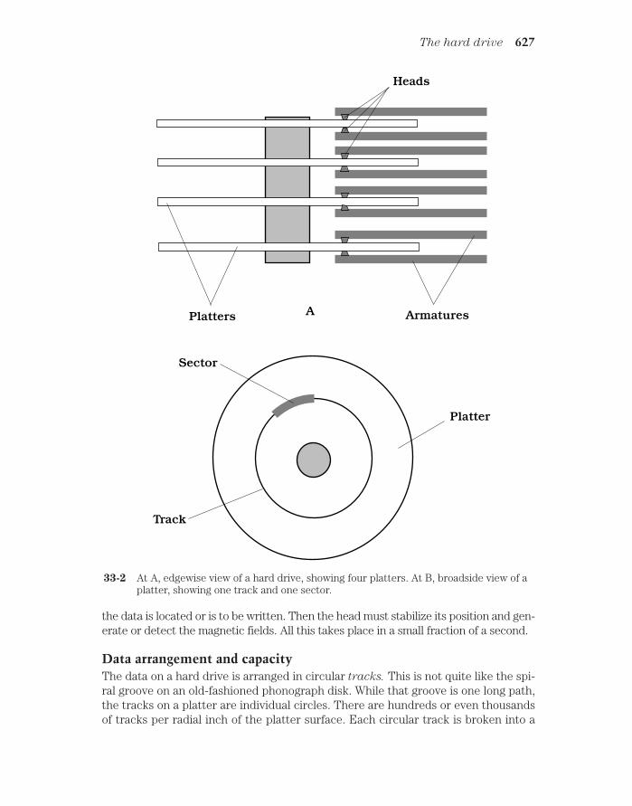
the data is located or is to be written. Then the head must stabilize its position and gen-erate or detect the magnetic fields. All this takes place in a small fraction of a second.
Data arrangement and capacityThe data on a hard drive is arranged in circular tracks. This is not quite like the spi-ral groove on an old-fashioned phonograph disk. While that groove is one long path,the tracks on a platter are individual circles. There are hundreds or even thousandsof tracks per radial inch of the platter surface. Each circular track is broken into a
The hard drive 627
Heads
ArmaturesPlatters
Sector
Platter
Track
A
33-2 At A, edgewise view of a hard drive, showing four platters. At B, broadside view of aplatter, showing one track and one sector.

number of arcs called sectors. A cylinder is the set of equal-radius tracks on all theplatters in the drive. Tracks and sectors are set up on the hard drive during the ini-tial formatting process. There are also data units called clusters. These are unitsconsisting of one to several sectors, depending on the arrangement of data on theplatters. Figure 33-2B is a face-on view of a single hard-disk platter, showing a trackand one of its constituent sectors.
The average new computer hard-drive data storage capacity roughly doublesevery year, and thus increases by about three orders of magnitude per decade. Atthe end of the year 2000, during the holiday computer-buying season, a new desktopmachine had between 10 and 100 GB of hard-drive capacity. By the end of the year2010, if trends continue, these figures will be approximately 1000 times greater—arange of 10 to 100 TB. Do petabyte and exabyte machines mentioned a few para-graphs ago seem out of this world, impossible, or ridiculous? Extrapolate. Chancesare good that you will live to see them.
When you buy a computer, whether it is a desktop, notebook (also called laptop),or portable (also called handheld) unit, it will have a hard drive built in. The drive comesinstalled and formatted. Most new computers are sold with several commonly used pro-grams preinstalled on the hard drive. Some computer users prefer to buy new comput-ers with only the operating system, by means of which the programs run, installed; thisfrees up hard-drive space and gives the user control over which programs to install (ornot to install).
Other forms of mass storageThere are several types of mass storage (besides the hard drive) in which data canbe kept in large quantities. Computer experts categorize mass storage in two ways:access time and cost per megabyte. In general, the less the access time (that is, thefaster the storage medium), the greater the cost per megabyte. The fastest massstorage media usually have the lowest capacity.
Flash memoryFlash memory is an all-electronic form of storage that is useful especially in high-level graphics, big-business applications, and scientific work. The capacity is compa-rable to that of a small hard drive, but there are no moving parts.
Because there are no mechanical components, flash memory is faster than any othermass-storage scheme. PC cards (also called PCMCIA cards) are credit-card-sized, re-movable components, some of which are designed to serve as removable flash memory.
Disk mediaMagnetic diskettes, also called (imprecisely) “floppies,” are 3.5 inches in diameterand enclosed in a rigid, square case about 4 millimeters thick. They can be inter-changed in seconds, so there is no limit to how much data you can put on them. Buttheir capacity, individually, is limited. A full-wall bookcase of diskettes could holdmore work than you’d create in your lifetime.
Zip and Jaz disks (trademarks of Iomega Corporation) are slightly larger than 3.5-inch diskettes in physical dimension, but vastly larger in storage capacity. The original
628 Computers and the Internet

Zip disks can hold about 100 MB of data; newer ones can hold 250 MB. Jaz disks holdabout 1 GB. There are several variants on the Zip/Jaz theme, produced by various man-ufacturers. All these disk types require special drives. Some new computers includebuilt-in Zip drives.
A popular mass-storage medium is compact-disk, read-only memory (CD-ROM).You can buy CD-ROMs for various applications. They are commonly used for commer-cial software and also to store reference materials such as dictionaries and telephone di-rectories. The main asset of CD-ROM is its fairly large capacity and its long shelf life.The main drawback is that the medium cannot be erased and overwritten, unless youare willing to spend the money for a compact-disk, recordable (CD-R) drive.
Tape mediaThe earliest computers used magnetic tape to store data. This is still done in somesystems. You can get a tape drive for making an emergency backup of the data onyour hard drive, or for archiving data you rarely need to use.
Magnetic tape has very high storage capacity. There are microcassettes that canhold more than 1 GB of data; standard cassettes can hold many gigabytes. But tapes areextremely slow because, unlike their disk-shaped counterparts, they are a serial-ac-
cess storage medium. This means that the data bits are written in a string, one after an-other, along the entire length of the tape. The drive might have to mechanically rewindor fast-forward through a football field’s length of tape to get to a particular data bit,whereas on a disk medium, the read/write head never has to travel further than the di-ameter of the disk to reach a given data bit.
Random-access memoryIn a computer, the term random-access memory (RAM) refers to integrated cir-cuits (ICs) that store working data. The amount, and speed, of memory is a crucialfactor in determining what a computer can and cannot do.
Data flowFigure 33-3 shows how data moves between a hard drive or diskette and the mem-ory, controlled by the CPU. When you open a file on your hard drive or on a diskette,the data goes immediately into the memory. The CPU, under direction of the micro-processor, manipulates the data in the memory as you work on the file. Thus, thedata in memory changes from moment to moment.
When you hit a key to add a character, or drag the mouse to draw a line that showsup on your display, that character or line goes into memory at the same time. If you hitthe backspace key to delete a character, or drag the mouse to erase a line on the screen,it disappears from the memory. During this time the original file on the disk stays as itwas before you accessed it. No change is made to the disk data until you specifically in-struct the computer to overwrite the data on the disk.
When you’re done working on a file, you tell the microprocessor to close it. Thenthe data leaves memory and goes back to the hard drive or diskette from which it came,or to some other place, as you might direct. If you tell the computer to overwrite the fileon the disk from which it came, many programs send the new data (containing the
Random-access memory 629

changes you have made) to unused space on the disk; the old data (as it was before youopened the file) stays in its old location. This is a safeguard, in case you decide to undothe changes you made.
All the data passing between the disks and the memory, and between the memoryand the CPU, is in machine language. This consists of binary digits (bits) 0 and 1. Butthe data passing between you and the CPU is in plain English (or whatever other lan-guage you prefer), or in some high-level programming language, having been translatedby the machine into a form you can understand.
Memory capacityThe maximum number of bytes of data that can be stored in a computer’s memory isknown as the memory capacity. The main factor that determines memory capacityis the number of transistors that can be fabricated onto a single memory IC, or
630 Computers and the Internet
Diskette A
Diskette B
Microprocessor
Centralprocessingunit
Memory
Harddrive
33-3 The flow of data between disk media and memory is con-trolled by the CPU.

“chip.” Other factors, such as microprocessor speed, have a practical effect on theusable memory capacity. A gigantic memory will not be of much use if the micro-processor is slow. Nor will a fast microprocessor be of practical value if the memorycapacity is too small for applications that demand high speed.
The amount of memory you need depends on the applications you intend to run onyour computer. Most software packages will tell you how much memory you need.They’ll often quote two specifications: a minimum memory requirement and a figure foroptimum performance (approximately twice the minimum requirement). If possible,you should equip your computer with enough memory for optimum performance. Thisyear’s optimum machine is next year’s minimal one when it comes to popular software.
If your computer lacks the memory to run a given application, you can usually addmore. But this can only be done up to a certain point. Eventually, your microprocessorwill no longer be able to run contemporary software at reasonable speed, no matter howmuch memory you have. When buying a new computer, it’s not a bad idea to err on theside of “too much” memory, rather than risk running short. How much memory do youthink your machine will require to run two or three of your favorite applications at thesame time? Double or triple it, and you will come close to the amount you are likely toneed for the next two or three years, until you are overcome by the urge to buy a newcomputer again. And you will get the urge. Computers can be downright seductive, es-pecially to people who have gotten this far in this book.
Memory volatilityIn most computers, the memory is volatile. This means that it requires a source of powerto be maintained. If you switch the computer off, or if there’s a power failure, you’ll loseall the data in the memory. This problem can be avoided if the memory chips are suppliedwith power continuously. Some machines have rechargeable memory backup batteriesthat keep memory data intact for short periods if there is a power failure.
In contrast to memory, the data on magnetic disks, or on optical media, will stay putwhen the power is removed. When you’re working on a file, it is wise to store the fileevery few minutes on the hard drive and/or diskette. That way, in the rare event a powerfailure does occur, you won’t lose much work.
The displayThe visual interface between you and your computer is known as the display. Indesktop computers, an external display is often called a monitor. A cathode-ray-
tube (CRT) monitor resembles a television set without the tuning or volume con-trols. A liquid-crystal-display (LCD) is lightweight and thin. This type of display isused in notebook and portable computers. It has become increasingly popular fordesktop computers because the technology has improved and has become some-what less expensive.
Showing detailThe image resolution of a computer display is important. This is the extent towhich it can show detail: the better the resolution, the sharper the image. Resolutioncan be specified in terms of dot size or dot pitch. This is the diameter, in millimeters
The display 631
(mm), of the individual elements in the display—the “smallest unbreakable pieces.”A good display has a dot pitch that is a small fraction of a millimeter. A typical CRThas a dot pitch of 0.25 or 0.26 mm. The smaller the number, the higher the resolutionand, all other factors being equal, the crisper the image in an absolute sense.
Image resolution can be specified in a general sense as a pair of numbers, repre-senting the number of pixels (picture elements) the screen shows horizontally and ver-tically. For a particular screen size, the greater the number of pixels the unit can display,the crisper the image. In personal computers, typical displays have either 800 600resolution (800 pixels wide by 600 pixels high) or 1024 768 resolution. A few canwork up to 1600 1200. Older computers often work at 640 480.
Screen sizes are given in terms of diagonal measure; a popular size is the so-called17-inch CRT (which actually has a viewable display measure of about 15.5 inches). Thiswill work quite well at 800 600 pixels. For higher pixel dimensions, a larger screen ispreferable, such as 19 or even 21 inch, but CRTs that size are rather expensive, can eas-ily take up most of the surface of your desk, and can weigh 50 to 100 pounds. A small“15-inch” CRT (with viewable display measure of 13 to 14 inches) is sufficient if you in-tend to work at 640 480 pixels.
A high-end display is crucial for doing graphics work, when using the Internet, inremote-control robotics, and in computer games. Besides these practical advantages, asharp display is more pleasant to work with than a marginal one. Along with memoryand hard drive capacity, the display is one of the most important parts of a computerfrom a user-friendliness standpoint. On the job, long hours at a computer can get te-dious even if the machine is perfect. An inadequate display can give rise to eye strainand headaches and can also degrade the quality and accuracy of work done by peopleusing the computer.
Choice of displaySome computer users can get along with one display until it wears out. If you useyour computer only for text-based applications, you’ll probably find a modest 15-inch monitor adequate for your needs. But if you find yourself scrolling left and rightbecause you work with lines longer than 80 characters or because the program youjust purchased assumes you have a larger monitor, it’s a good idea to upgrade. If youhave to squint to see tiny images on screen, likewise, you should think about enlarg-ing the image rather than wearing eyeglasses (unless you really need glasses).
If you’re buying a whole new computer system, this is a good time to buy the bestmonitor you can afford. Many new desktop computers are sold with monitors, but someare not, allowing you to choose your own. In that case, again, you must be sure the mon-itor is compatible with the rest of the system. If you’re buying a notebook computer,you’ll have options between less expensive and more expensive displays. The best wayto decide what you want is to look at several displays in the store. Side-by-side com-parisons can be especially revealing.
Some displays can show more colors than others. The color resolution of a moni-tor is quoted as a number, such as “256 colors,” “thousands of colors,” or “millions of col-ors.” Color specifications are somewhat oversimplified, because color has two distinctproperties, called the hue and the saturation. The hue is technically represented bythe peak wavelength, but more often is described in terms of words (red, orange,
632 Computers and the Internet

yellow, green, blue, indigo, violet). Saturation is the “richness” of color; the higher thesaturation, the more intense a given hue appears. The “techies” use numbers from180 to 180 to represent hue, and from 0 to 100 to represent saturation. Another wayto specify color is according to the red/green/blue (RGB) scheme, in which each colorhas an intensity number independent of the other two, and ranging from 0 to 255, cor-responding to the binary number range 00000000 to 11111111.
Interlacing (or lack thereof) is important in a desktop monitor. A noninterlacedmonitor is better than an interlaced one if you’re working with fast-moving graphic im-ages. Interlacing translates into a lower refresh rate (number of times the entire imageis renewed). A low refresh rate can cause noticeable flickering in the image, and can beespecially disruptive in applications where rapid motion must be displayed. A good re-fresh-rate specification is 70 Hz or more. For applications not involving much motion,60 or 66 Hz is adequate for some people, but others complain of eye fatigue becausethey can vaguely sense the flicker. Most people find 56-Hz refresh rates too slow forcomfort in any application.
If you’re concerned about the extremely-low-frequency (ELF) electromag-netic fields produced by CRT monitors, you might consider buying a unit that hasbeen designed to reduce this “radiation” or buying a stand-alone LCD display panelinstead (LCDs do not emit significant ELF). There is disagreement among experts asto the actual danger posed by ELF emission. It’s a good idea to arrange your work-station so your eyes are at least 18 inches away from the screen of a CRT monitor,and if you are working near other computer users, workstations should be at least 3feet apart.
The printerA computer printer is an electromechanical device that produces hard copy (textand images on paper). The most common printers are dot-matrix, thermal, inkjet,and laser.
Dot-matrix printersThe “horse and buggy” of the printing family is the dot-matrix printer. This type ofprinter is the least expensive, in terms of both the purchase price and the long-termoperating cost. Dot-matrix printers produce fair print quality for most manuscripts,reports, term papers, and theses. The mechanical parts are rugged, and mainte-nance requirements are minimal.
Older dot-matrix printers are noisy in operation; newer machines are quieter. Butnone of them have the typeset-grade image quality of more expensive printers. Dot-ma-trix printers can render some simple graphic images, but the quality is fair at best, andit can take a long time to print a single image. Dot-matrix printers cannot reproduce de-tailed artwork or photographs with acceptable quality.
Thermal printersA thermal printer uses temperature-sensitive dye and/or paper to create hard copy textand images. Some thermal printers produce only black-and-white images, while otherscan render full color. Thermal printers are often preferred by traveling executives
The printer 633

who use portable computers, because these printers are physically small and light. Asimple gray-scale thermal printer employs special paper that darkens when it gets hot.The print mechanism works something like that of a dot-matrix printer. But instead ofthe print head pressing ink onto the page, the pins in the print mechanism are heated,and they cause the paper to darken.
A color thermal printer uses thick, heat-sensitive dyes of the primary pigments: ma-genta (pinkish red), yellow, and cyan (bluish green). Sometimes black dye is also used,although it can be obtained by combining large, equal amounts of the primary pigments.The print head uses heat to liquefy the dye, so it bleeds onto the paper. This is done foreach color of pigment separately. There are three separate, overlapping images pro-duced, one for each primary pigment.
Some, if not most, thermal printouts fade after awhile. Have you ever pulled out anold store receipt and found that it was washed-out or blank? Thermal printers can beconvenient in a pinch, but you should be aware that they have this problem—and it’s notrestricted to old machines. In fact, stores and even some post offices seem to be in-stalling brand new printers with this “feature” more and more. If you’re keeping a receiptfor tax purposes or for proof-of-purchase and you notice that it has been printed on ther-mal paper, go to a print shop and make a photocopy of the receipt right away. How canyou recognize a thermal printout? The paper curls up when it’s fresh out of the machine.
Inkjet printersIn an inkjet printer, tiny nozzles spray ink onto the paper. Some inkjet printers arealmost silent; others make strange, intermittent, loud beeps and clicks. Most of theseprinters are comparatively slow to produce an image, and the ink needs time to dryeven after the image comes out, but the quality can be excellent. Inkjet printers areavailable in single-color and multicolor designs. The best color machines producephotographlike images.
A high-end inkjet printer costs roughly twice as much as a high-end dot-matrix ma-chine, although some monochrome inkjets are as inexpensive as dot-matrix printers.Inkjet printers require periodic replacement of the ink cartridges. There are three orfour of these, containing cyan, magenta, yellow, and sometimes black ink.
Inkjet printers need a certain kind of paper; some papers have fibers that carry theink along via capillary action, causing characters and images to blur. The finest, mostexpensive “bond” for typing might prove disastrous if used with an inkjet printer. If youhave doubts, read the instruction manual or call the manufacturer of the printer.
Laser printersA laser printer works like a photocopy machine. The main difference is that, whilea photocopier creates a copy of a real image (the paper original), a laser printermakes a copy of a digital computer image.
When data arrives at the printer from the computer, the encoded image is stored inthe printer’s memory. The memory stores one page of data, and then sends it along tothe laser and other devices. Some printers use a light-emitting-diode (LED) matrix,rather than a single laser. These printers are called LED printers. For practical pur-poses, LED printers are equivalent to laser printers.
634 Computers and the Internet

The laser blinks rapidly while it scans a cylindrical drum. The drum has specialproperties that cause it to attract the printing chemical, called toner, in some places butnot others, creating an image pattern that will ultimately appear on the paper. A sheetof paper is pulled past the drum and also past an electrostatic charger. Toner from thedrum is attracted to the paper. The image thus goes onto the paper, although it has notyet been permanently fused, or bonded, to the paper. The fuser, a hot pair ofroller/squeezers, does this job, completing the printing process.
The main asset of laser printers is their excellent print and graphics quality. The im-age resolution of a laser printer ranges from about 300 dots per inch (DPI) for older unitsto 1200, 2400, or even more DPI in state-of-the-art machines. As far as the untrained eyecan tell, 600 DPI is as good as a photograph. Laser printers can handle graphics and textequally well. If an image can be rendered on a photocopy machine, it can be renderedjust as well on a laser printer. Another asset of laser printers is that they make almost nonoise. Yet another good feature is that this type of printer is relatively fast. The best high-end machines can produce a couple of dozen copies per minute.
The laser printer is the best device for rendering high-resolution hard copy text andgraphics. If you’re doing desktop publishing, presentation graphics, or anything elsethat requires top-grade or high-volume hard copy, you’ll want a laser printer. Ask somefriends for their opinions, and if printing is really important to you, don’t cut corners. Agood laser printer is the “geek’s” equivalent of a reliable truck.
The modemThe term modem is a contraction of modulator/demodulator. A modem interfacesa computer to a telephone line, television cable system, fiber-optic network, or radiotransceiver, allowing you to communicate with other computer users and to “surf theInternet.”
External versus internalAn external modem is a self-contained unit (box) that you can use with any com-puter. It has a cord that runs to the computer’s serial data port (also called the com-
munications port) and another cord that runs to the telephone jack. The modemwill probably also have a jack into which you can plug your phone set.
An internal modem is a printed-circuit board, also called a card, that is commonlyinstalled in new computers. Virtually all desktop computers come with modems. A newnotebook computer might not have an internal modem installed; in that case you canpurchase one in the form of a PC card that fits into a slot on the side of the computer.This card is roughly the height and width of a credit card, but somewhat thicker.
Digital versus analogA computer works with binary digital signals, which are rapidly fluctuating directcurrents. For digital data to be conveyed over a telephone or radio circuit, the datamust be converted to analog form. In a telephone modem or radio-transceiver mo-dem, this is done by changing the digit 1 into an audio tone, and the digit 0 into an-other tone with a different pitch. The result is an extremely fast back-and-forth
The modem 635

alternation between the two tones. In modulation, digital data is changed into ana-log data. It is a type of digital-to-analog (D/A) conversion. Demodulation changesthe analog signals back to digital ones; this is analog-to-digital (A/D) conversion.
If you happen to pick up a telephone extension while someone is on-line with thecomputer from another extension, you’ll hear the analog signals from the two modems;it sounds like a hiss or roar. But don’t make a habit of doing this. It can cause the com-puter to be disconnected from the on-line network.
Data speedModems work at various speeds, usually measured in bits per second (bps). You willoften hear about kilobits per second (kbps), where 1 kbps 1000 bps, or megabits
per second (Mbps), where 1 Mbps 1000 kbps. Sometimes you’ll hear about speedunits called the baud and kilobaud. (A kilobaud is 1000 baud.) Baud and bps are al-most the same units, but not they are not identical. People often use the term baud
when they really mean bps.
The higher the speed as specified in bps, the faster the data is sent and receivedthrough the modem. Speeds keep increasing as computer communications technologyadvances. Modems are rated according to the highest data speed they can handle, in bitsper second (bps), kilobits per second (kbps), or megabits per second (Mbps). A typical“telephone modem” works at about 56 kbps. Digital-subscriber-line (DSL) modems worksomewhat faster, around 128 kbps. Television cable modems can work upward of 1 Mbps.
Basic components of a modemFigure 33-4 is a block diagram of a modem suitable for interfacing a home or businesscomputer with the telephone line. The modulator, or D/A converter, changes the dig-ital computer data into audio tones. The demodulator, or A/D converter, changes theincoming audio tones into digital signals for the computer. The audio tones fallwithin the frequency range, or band, of approximately 300 Hz to 3 kHz. This is theband needed to clearly transmit a human voice.
It’s amazing how much computer data can race over a single telephone or radio cir-cuit having such a narrow bandwidth. Even pictures can be sent and received in brilliantcolor and in quite good detail (high resolution). As you might imagine, color images takelonger than gray-scale images to send and receive; also, the more detail an image con-tains, the longer it takes to be transferred at any given data speed.
The InternetThe Internet is a worldwide system, or network, of computers. It got started in thelate 1960s, originally conceived as a network that could survive nuclear war. Backthen it was called ARPAnet, named after the Advanced Research Project Agency(ARPA) of the United States federal government.
Protocol and packetsWhen people began to connect their computers into ARPAnet, the need becameclear for a universal set of standards, called a protocol, to ensure that all the
636 Computers and the Internet

machines “speak the same language.” The modern Internet is such that you can useany type of computer—IBM-compatible, Mac, or other—and take advantage of allthe network’s resources.
All Internet activity consists of computers “talking” to one another. This occurs inmachine language. However, the situation is vastly more complicated than when datagoes from one place to another within a single computer. In the Internet (often calledsimply the Net), data must often go through several different computers to get from thetransmitting or source computer to the receiving or destination computer. These in-termediate computers are called nodes, servers, hosts, or Internet service providers
(ISPs). Millions of people are simultaneously using the Net; the most efficient route between a given source and destination can change from moment to moment. The Netis set up in such a way that signals always try to follow the most efficient route.
If you are connected to a distant computer, say a machine at the National HurricaneCenter, the requests you make of it and the data it sends you, are broken into small unitscalled packets. Each packet coming to you has, in effect, your computer’s name writtenon it. But not all packets necessarily travel the same route through the network. Ulti-mately, all the packets are reassembled into the data you want, say, the infrared satelliteimage of a hurricane, even though they might not arrive in the same order they were sent.
Figure 33-5 is a simplified drawing of Internet data transfer for a hypothetical filecontaining five packets transferred during a period of extremely heavy usage. Nodesare shown as black dots surrounded by circles. In this example, some packets passthrough more nodes, and/or over a much greater physical distance, than others. If Nettraffic were very light, all the packets might follow the same route through fewer nodes.This is why it takes longer to acquire data on the Net during peak hours of use, as com-pared with times when there are comparatively few people connected into it. A file
The Internet 637
Computer
Amplifier Amplifier
Data in Data out
A/D D/A
33-4 Block diagram of acomputer modem.

cannot be completely reconstructed until all the packets have arrived and the destina-tion computer has ensured that there are no errors.
E-mail and newsgroupsFor many computer users, communication via Internet electronic mail (e-mail)and/or newsgroups has practically replaced the postal service. You can leave messagesfor, and receive them from, friends and relatives scattered throughout the world.
638 Computers and the Internet
1 2 3 4 5
Source data
Destination data
1
1
1
1
1
2
2
2
3
3
3
33
3
3
4
4
4
4
5
5
5
5
5
1
1 2 3 4 5
33-5 Internet data flows in packets from the source to the destination.

To effectively use e-mail or newsgroups, everyone must have an Internet address.
These tend to be arcane. An example is
The first part of the address, before the @ symbol, is the username. The word afterthe @ sign and before the period (or dot) represents the domain name. The three-letter abbreviation after the dot is the domain type. In this case, “com” stands for“commercial.” Nanosecond is a commercial provider. Other common domain typesinclude “net” (network), “org” (organization), “edu” (educational institution), and“gov” (government). In recent years, country abbreviations have been increasinglyused at the ends of Internet addresses, such as “us” for United States, “de” for Ger-many, “uk” for United Kingdom, and “jp” for Japan.
Internet conversationsYou can carry on a teletype-style conversation with other computer users via the In-ternet, but takes a bit of getting used to. When done among users within a single ser-vice provider, this is called chat. When done among people connected to differentservice providers, it is called Internet relay chat (IRC). Typing messages to andreading them from other people in real time is more personal than letter writing, be-cause your addressees get their messages immediately. But it’s less personal thantalking on the telephone, especially at first, because you cannot hear, or make, vocalinflections.
It is possible to digitize voice signals and transfer them via the Internet. This hasgiven rise to hardware and software schemes that claim to provide virtually toll-freelong-distance telephone communications. As of this writing, this is similar to amateurradio in terms of reliability and quality of connection. When Net traffic is light, such con-nections can be good. But when Net traffic is heavy, the quality is marginal to poor. Au-dio signals, like any other form of Internet data, are broken into packets. All, or nearlyall, the packets must be received and reassembled before a good signal can be heard.This takes variable time, depending on the route each packet takes through the Net. Ifmany of the packets arrive disproportionately late, and the destination computer canonly “do its best” to reassemble the signal. In the worst case, the signal might not getthrough at all.
Getting informationOne of the most important features of Internet is the fact that it can get you intouch with thousands of sources of information. Data is transferred among comput-ers by means of a file transfer protocol (FTP) that allows the files on the harddrives of distant computers to become available exactly as if the data were storedon your own computer’s hard drive, except the access time is slower. You can alsostore files on distant computers’ hard drives. When using FTP, you should be awareof the time at the remote location, and avoid, if possible, accessing files during thepeak hours at the remote computer. Peak hours usually correspond to workinghours, or approximately 8:00 a.m. to 5:00 p.m. local time, Monday through Friday.
The Internet 639

You must take time differences into account if you’re not in the same time zone asthe remote computer.
The World Wide Web (also called WWW or the Web) is one of the most powerfulinformation servers you will find on-line. Its outstanding feature is hypertext, a schemeof cross-referencing. Certain words, phrases, and images make up so-called links.
When you select a link in a Web page or Web site (a document containing text andgraphics and sometimes also other types of files), your computer is transferred to an-other document dealing with the same or a related subject. This site will probably alsocontain numerous links. Before long, you might find yourself “surfing” the Web forhours going from site to site. The word surfing derives from the similarity of this activ-ity to television “channel surfing.”
The Web works fastest during the predawn hours in the United States, when thefewest number of people are connected to the Internet. When Net traffic is heavy, Webdocuments can take a long time to appear. In some instances you won’t be able to get apage at all; you’ll sit there staring at a blank display or at an hourglass. This problem isworst with comparatively slow telephone-line modems, but it can occur even with themost expensive, high-speed Internet connections. When you experience it, you’ll knowwhy some people refer to the Web as the “World Wide Wait.”
Getting connectedIf you’re not an Internet user but would like to get access, try calling the computerscience department of the nearest trade school, college, or university. Many, if notmost, academic institutions have Internet access, and some will let you in for a rea-sonable charge. If you aren’t near a school that can provide you with Internet service,you can get connected through a commercial provider. You’ll have to pay a fee, gen-erally by the month. You might also have to pay for any hours you use per month pasta certain maximum.
QuizRefer to the text in this chapter if necessary. A good score is 18 correct. Answers arein the back of the book.
1. One megabyte is the same amount of data as:
A. 1024 bytes.
B. 1024 KB.
C. 1024 GB.
D. 1/1024 KB.
2. The Web would probably work fastest for a user in New York at:
A. 2:00 a.m. local time on a Tuesday.
B. 4:00 p.m. local time on a Wednesday.
C. 12:30 p.m. local time on a Thursday.
D. Any of the above times; it does not matter.
640 Computers and the Internet

3. Image resolution can be specified in terms of:
A. Megahertz.
B. Color intensity.
C. Wavelength.
D. Dot pitch.
4. A cluster is a unit of:
A. Frequency on a hard drive.
B. Data on the Internet.
C. Data on a hard drive.
D. Bandwidth on the Internet.
5. An example of a mass-storage device is a:
A. Hard drive.
B. Microprocessor.
C. Modem.
D. Read-write head.
6. The character string [email protected] might represent:
A. A Web site.
B. The location of data in memory.
C. An e-mail address.
D. A computer’s serial number.
7. Bits per second (bps) is a unit of:
A. Computer memory.
B. Mass storage.
C. Image resolution.
D. Data speed.
8. A platter is a:
A. Part of a hard drive.
B. Unit of memory.
C. Element of a digital image.
D. Semiconductor chip.
9. Protocol ensures that:
A. A hard drive runs smoothly.
B. A monitor reproduces color accurately.
C. A printer generates a clear image.
D. Computers can exchange data.
Quiz 641

10. A packet is:
A. A computer memory module.
B. A unit of 210 bytes.
C. A piece of a file sent over the Net.
D. A picture element in a computer monitor.
11. A motherboard contains:
A. A microprocessor.
B. An external modem.
C. A diskette drive.
D. A display screen.
12. Cross-referencing among web pages is done with:
A. Digital signal processing.
B. A modem.
C. Internet relay chat (IRC).
D. Links.
13. The abbreviation FTP stands for:
A. Fast Text Packet.
B. File Transfer Protocol.
C. Frequency/Time Processing.
D. Federal Trade Program.
14. A telephone modem contains:
A. An internal hard drive.
B. A microprocessor.
C. An A/D converter.
D. A printer interface.
15. An asset of a dot-matrix printer is:
A. Low operating cost.
B. Excellent image detail.
C. Resemblance to a photocopy machine.
D. Compatibility with most modems.
16. Which of the following types of mass storage provide the fastest access time?
A. Magnetic tape.
B. CD-ROM.
C. Flash memory.
D. Hard drive.
642 Computers and the Internet

17. Which of the following is a serial-access medium?
A. Computer memory.
B. Magnetic tape.
C. A hard drive.
D. CD-ROM.
18. When computer data is sent over long-distance telephone circuits, the digitalhighs and lows are generally represented by:
A. Audio tones.
B. A series of clicks.
C. Positive and negative direct currents.
D. Pixels.
19. For animated graphics involving fast motion, you should ideally use:
A. A laser printer.
B. A hard drive.
C. Hypertext.
D. A noninterlaced monitor.
20. A thermal printer might be the best type of printer for:
A. Someone who travels a lot.
B. Someone who works with animated graphics.
C. Someone who needs to print huge text documents.
D. Someone who needs top-quality printouts.
Quiz 643

34CHAPTER
Robotics andartificial intelligence
A ROBOT IS A SOPHISTICATED MACHINE, OR A SET OF MACHINES WORKING together, that performs certain tasks. Some people imagine robots as having two legs, ahead, two arms with functional end effectors (hands), an artificial voice, and an elec-tronic brain. The technical name for a humanoid robot is android. Androids are withinthe realm of technological possibility, but most robots are structurally simpler than, anddon’t look or behave like, people.
An electronic brain, also called artificial intelligence (AI), is more than mere fic-tion, thanks to the explosive evolution of computer hardware and software. But eventhe smartest computer these days would make a dog seem brilliant by comparison.Some scientists think computers and robots might become as smart as, or smarter than,human beings. Others believe the human brain and mind are more complicated thananything that can be duplicated with electronic circuits.
Asimov’s three lawsIn one of his early science-fiction stories, the famous author Isaac Asimov first men-tioned the word robotics, along with three “fundamental rules” that all robots oughtto obey:
• First Law: A robot must not injure, or allow the injury of, any human being.
• Second Law: A robot must obey all orders from humans, except ordersthat would contradict the First Law.
• Third Law: A robot must protect itself, except when to do so would con-tradict the First Law or the Second Law.
644 !
"# #$ !

These rules were first coined in the 1940s, but they are still considered good stan-dards for robots nowadays.
Robot generationsSome researchers have analyzed the evolution of robots, marking progress accord-ing to so-called robot generations. This has been done with computers and inte-grated circuits, so it only seems natural to do it with robots, too. One of the firstengineers to make formal mention of robot generations was the Japanese engineerEiji Nakano.
First generationAccording to Nakano, a first-generation robot is a simple mechanical arm withoutAI. Such machines have the ability to make precise motions at high speed, manytimes, for a long time. They have found widespread industrial application and havebeen around for more than half a century. These are the fast-moving systems that in-stall rivets and screws in assembly lines, that solder connections on printed circuits,and that, in general, have taken over tedious, mind-numbing chores that used to bedone by humans.
First-generation robots can work in groups if their actions are synchronized. Theoperation of these machines must be constantly watched, because if they get out ofalignment and are allowed to keep operating anyway, the result can be a series of badproduction units. At worst, a misaligned and unsupervised robot might create havoc ofa sort that you can hardly begin to imagine even if you let your mind run wild.
Second generationA second-generation robot has some level of AI. Such a machine is equipped withpressure sensors, proximity sensors, tactile sensors, binocular vision, binaural hear-ing, and/or other devices that keep it informed about goings-on in the world aroundit. A computer called a robot controller processes the data from the sensors and ad-justs the operation of the robot accordingly. The earliest second-generation robotscame into common use around 1980.
Second-generation robots can stay synchronized with each other, without having tobe overseen constantly by a human operator. Of course, periodic checking is neededwith any machine, because things can always go wrong, and the more complex the sys-tem, the more ways it can malfunction.
Third generationNakano gave mention to third-generation robots, but in the years since the publi-cation of his original paper, some things have changed. Two major avenues are de-veloping for advanced robot technology. These are the autonomous robot and theinsect robot. Both of these technologies hold promise for the future.
An autonomous robot can work on its own. It contains a controller and can dothings largely without supervision, either by an outside computer or by a human being.A good example of this type of third-generation robot is the personal robot aboutwhich technophiles dream.
Robot generations 645

There are some situations in which autonomous robots don’t work well. In thesecases, many simple robots, all under the control of one central computer, can be used.They function like ants in an anthill or bees in a hive. The individual machines are stu-pid, but the group as a whole is intelligent.
Fourth generation and beyondNakano did not write about anything past the third generation of robots. But wemight mention a fourth-generation robot: a machine of a sort yet to be deployed.An example is a fleet or population of robots that reproduce and evolve. Past that,we might say that a fifth-generation robot is something humans haven’t yetdreamed of—or, if someone has thought up such a thing, he or she has not publishedthe brainstorm.
Independent or dependent?Years ago, roboticist and engineer Rodney Brooks became well known for his workwith insect robots. His approach to robotics and AI was at first considered unortho-dox. Before his time, engineers wanted robotic AI systems to mimic human thoughtprocesses. The machines were supposed to stand alone and be capable of operatingindependently of humans or other machines. But Brooks believed that insectlike in-telligence might be superior to humanlike intelligence in many applications. Supportfor his argument came from the fact that insect colonies are highly efficient, and of-ten they survive adversity better than supposedly higher life forms.
Insect robotsInsect robots operate in large numbers under the control of a central AI system. Amobile insect robot has several legs, a set of wheels, or a track drive. The first ma-chines of this type, developed by Brooks, looked like beetles. They ranged in sizefrom more than a foot long to less than a millimeter across. Most significant is thefact that they worked collectively.
Individual robots, each with its own controller, do not necessarily work well to-gether in a team. This shouldn’t be too surprising; people are the same way. Professionalsports teams have been assembled by buying the best players in the business, but theteam won’t win unless the players get along. Insects, in contrast, are stupid at the indi-vidual level. Ants and bees are like idiot robots, or, perhaps, like ideal soldiers. But ananthill or beehive, just like a well-trained military unit, is an efficient system, controlledby a powerful central brain.
Rodney Brooks saw this fundamental difference between autonomous and collec-tive intelligence. He saw that most of his colleagues were trying to build autonomous ro-bots, perhaps because of the natural tendency for humans to envision robots ashumanoid. To Brooks, it was obvious that a major avenue of technology was being ne-glected. Thus he began designing robot colonies, each consisting of many units underthe control of a central AI system.
Brooks envisioned microscopic insect robots that might live in your house, comingout at night to clean your floors and countertops. “Antibody robots” of even tinier pro-portions could be injected into a person infected with some previously incurable
646 Robotics and artificial intelligence

disease. Controlled by a central microprocessor, they could seek out the disease bacte-ria or viruses and swallow them up.
Autonomous robotsA robot is autonomous if it is self-contained, housing its own computer system, andnot depending on a central computer for its commands. It gets around under its ownpower, usually by rolling on wheels or by moving on two, four, or six legs.
Figure 34-1 shows the locations of controllers (computers) in robot systems. Ro-bots are shown as squares and controllers as solid black dots. In the drawing at A, thereis only one controller; it is central and is common to all the individual robots. The com-
Independent or dependent? 647
A
B
34-1 Controllers in robot systems.Squares represent robots, anddots represent controllers.Straight lines represent possiblecommunication paths. At A, an in-sect robot fleet; at B, a set of au-tonomous robots.

puter communicates with, and coordinates, the robots through wires or fiber optics orvia radio. In the drawing at B, each robot has its own controller, and there is no centralcomputer. Straight lines show possible paths of communication among robot con-trollers in both scenarios.
Simple robots, like those in assembly lines, are not autonomous. The more complexthe task, and the more different things a robot must do, the more autonomy it will have.The most autonomous robots have AI. The ultimate autonomous robot will act like a liv-ing animal or human. Such a machine has not yet been developed, and it will probablybe at least the year 2050 before this level of sophistication is reached.
AndroidsAn android is a robot, often very sophisticated, that takes a more or less human form.An android usually propels itself by rolling on small wheels in its base. The technol-ogy for fully functional arms is under development, but the software needed for theiroperation has not been made cost-effective for small robots. Legs are hard to designand engineer and aren’t really necessary; wheels or track drives work well enough.(Elevators can be used to allow a rolling android to get from floor to floor in a build-ing.) An android has a rotatable head equipped with position sensors. Binocular, orstereo, vision allows the android to perceive depth, thereby locating objects any-place within a large room. Speech recognition and synthesis are common.
Because of their humanlike appearance, androids are ideal for use wherever thereare children. Androids, in conjunction with computer terminals, might someday replaceschool teachers in some situations. It is possible that the teaching profession will sufferbecause of this, but it is more likely that the opposite will be true. There will be a de-mand for people to teach children how to use robots. Robots might free human teach-ers to spend more time in areas like humanities and philosophy, while robots instructstudents in computer programming, reading, arithmetic, and other rote-memory sub-jects. Robotic teachers, if responsibly used, might help us raise children into sensitiveand compassionate adults.
Robot armsRobot arms are technically called manipulators. Some robots, especially industrialrobots, are nothing more than sophisticated manipulators. A robot arm can be cate-gorized according to its geometry. Some manipulators resemble human arms. Thejoints in these machines can be given names like “shoulder,” “elbow,” and “wrist.”Other manipulators are so much different from human arms that these names don’tmake sense. An arm that employs revolute geometry is similar to a human arm, witha “shoulder,” “elbow,” and “wrist.” An arm with cartesian geometry is far differentfrom a human arm, and moves along axes (x, y, z) that are best described as “up-and-down,” “right-and-left,” and “front-to-back.”
Degrees of freedomThe term degrees of freedom refers to the number of different ways in which a ro-bot manipulator can move. Most manipulators move in three dimensions, but oftenthey have more than three degrees of freedom.
648 Robotics and artificial intelligence

You can use your own arm to get an idea of the degrees of freedom that a robot armmight have. Extend your right arm straight out toward the horizon. Extend your indexfinger so it is pointing. Keep your arm straight, and move it from the shoulder. You canmove in three ways. Up-and-down movement is called pitch. Movement to the right andleft is called yaw. You can rotate your whole arm as if you were using it as a screwdriver.This motion is called roll. Your shoulder therefore has three degrees of freedom: pitch,yaw, and roll.
Now move your arm from the elbow only. This is hard to do without also movingyour shoulder. Holding your shoulder in the same position constantly, you will see thatyour elbow joint has the equivalent of pitch in your shoulder joint. But that is all. Yourelbow, therefore, has one degree of freedom.
Extend your arm toward the horizon again. Now move only your wrist. Try to keepthe arm above the wrist straight and motionless. Your wrist can bend up-and-down,side-to-side, and it can also twist a little. Your lower arm has the same three degrees offreedom that your shoulder has, although its roll capability is limited.
In total, your arm has seven degrees of freedom: three in the shoulder, one in theelbow, and three in the arm below the elbow.
You might think that a robot should never need more than three degrees of free-dom. But the extra possible motions, provided by multiple joints, give a robot arm ver-satility that it could not have with only three degrees of freedom. (Just imagine howinconvenient life would be if your elbow and wrist were locked and only your shouldercould move.)
Degrees of rotationThe term degrees of rotation refers to the extent to which a robot joint, or a set ofrobot joints, can turn clockwise or counterclockwise about a prescribed axis. Somereference point is always used, and the angles are given in degrees with respect tothat joint.
Rotation in one direction (usually clockwise) is represented by positive angles;rotation in the opposite direction is specified by negative angles. Thus, if angle X 58 degrees, it refers to a rotation of 58 degrees clockwise with respect to the refer-ence axis. If angle Y 274 degrees, it refers to a rotation of 74 degrees counter-clockwise.
Figure 34-2 shows a robot arm with three joints. The reference axes are J1, J2, andJ3, for rotation angles X, Y, and Z. The individual angles add together. To move this ro-bot arm to a certain position within its work envelope, or the region in space that thearm can reach, the operator enters data into a computer. This data includes the mea-sures of angles X, Y, and Z. The operator has specified X 39, Y 75, and Z 51. Inthis example, no other parameters are shown. (This is to keep the illustration simple.)But there would probably be variables such as the length of the arm sections, the baserotation angle, and the position of the robot gripper (hand).
Articulated geometryThe word articulated means “broken into sections by joints.” A robot arm with ar-
ticulated geometry bears some resemblance to the arm of a human. The versatilityis defined in terms of the number of degrees of freedom. For example, an arm might
Robot arms 649
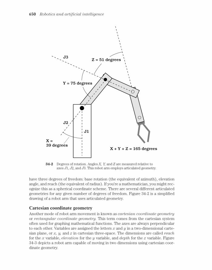
have three degrees of freedom: base rotation (the equivalent of azimuth), elevationangle, and reach (the equivalent of radius). If you’re a mathematician, you might rec-ognize this as a spherical coordinate scheme. There are several different articulatedgeometries for any given number of degrees of freedom. Figure 34-2 is a simplifieddrawing of a robot arm that uses articulated geometry.
Cartesian coordinate geometryAnother mode of robot arm movement is known as cartesian coordinate geometry
or rectangular coordinate geometry. This term comes from the cartesian systemoften used for graphing mathematical functions. The axes are always perpendicularto each other. Variables are assigned the letters x and y in a two-dimensional carte-sian plane, or x, y, and z in cartesian three-space. The dimensions are called reach
for the x variable, elevation for the y variable, and depth for the z variable. Figure34-3 depicts a robot arm capable of moving in two dimensions using cartesian coor-dinate geometry.
650 Robotics and artificial intelligence
Y = 75 degrees
Z = 51 degrees
X + Y + Z = 165 degrees
J1
J2
J3
X =39 degrees
34-2 Degrees of rotation. Angles X, Y, and Z are measured relative toaxes J1, J2, and J3. This robot arm employs articulated geometry.
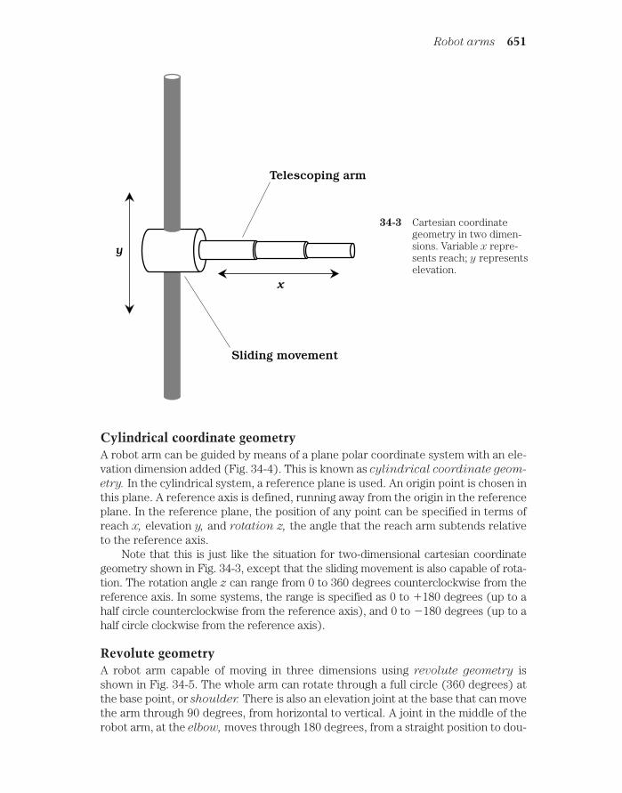
Cylindrical coordinate geometryA robot arm can be guided by means of a plane polar coordinate system with an ele-vation dimension added (Fig. 34-4). This is known as cylindrical coordinate geom-
etry. In the cylindrical system, a reference plane is used. An origin point is chosen inthis plane. A reference axis is defined, running away from the origin in the referenceplane. In the reference plane, the position of any point can be specified in terms ofreach x, elevation y, and rotation z, the angle that the reach arm subtends relativeto the reference axis.
Note that this is just like the situation for two-dimensional cartesian coordinategeometry shown in Fig. 34-3, except that the sliding movement is also capable of rota-tion. The rotation angle z can range from 0 to 360 degrees counterclockwise from thereference axis. In some systems, the range is specified as 0 to 180 degrees (up to ahalf circle counterclockwise from the reference axis), and 0 to 180 degrees (up to ahalf circle clockwise from the reference axis).
Revolute geometryA robot arm capable of moving in three dimensions using revolute geometry isshown in Fig. 34-5. The whole arm can rotate through a full circle (360 degrees) atthe base point, or shoulder. There is also an elevation joint at the base that can movethe arm through 90 degrees, from horizontal to vertical. A joint in the middle of therobot arm, at the elbow, moves through 180 degrees, from a straight position to dou-
Robot arms 651
x
y
Telescoping arm
Sliding movement
34-3 Cartesian coordinategeometry in two dimen-sions. Variable x repre-sents reach; y representselevation.

bled back on itself. There might be, but is not always, a wrist joint that can flex likethe elbow and/or twist around and around.
A 90-degree-elevation revolute robot arm can reach any point within a half sphere.The radius of the half sphere is the length of the arm when its elbow and wrist (if any)are straightened out. A 180-degree-elevation revolute arm can be designed that willreach any point within a fully defined sphere, with the exception of the small obstructedregion around the base.
Robotic hearing and visionMachine hearing involves more than just the picking up of sound (done with a mi-crophone) and the amplification of the resulting audio signals (done with an ampli-fier). A sophisticated robot can tell from which direction the sound is coming andperhaps deduce the nature of the source: human voice, gasoline engine, fire, or bark-ing dog.
652 Robotics and artificial intelligence
x
y
Telescoping arm
Sliding androtating movement
Reference axis
z
Reference plane
34-4 Cylindrical coordinate geometry in three dimensions. Variable xrepresents reach; y represents elevation; z represents rotation.
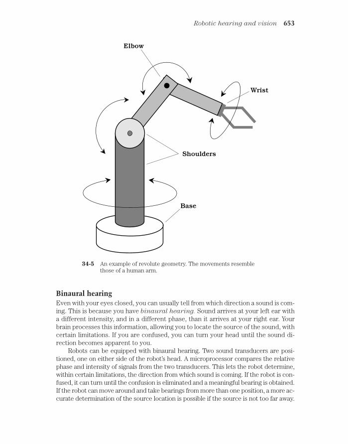
Binaural hearingEven with your eyes closed, you can usually tell from which direction a sound is com-ing. This is because you have binaural hearing. Sound arrives at your left ear witha different intensity, and in a different phase, than it arrives at your right ear. Yourbrain processes this information, allowing you to locate the source of the sound, withcertain limitations. If you are confused, you can turn your head until the sound di-rection becomes apparent to you.
Robots can be equipped with binaural hearing. Two sound transducers are posi-tioned, one on either side of the robot’s head. A microprocessor compares the relativephase and intensity of signals from the two transducers. This lets the robot determine,within certain limitations, the direction from which sound is coming. If the robot is con-fused, it can turn until the confusion is eliminated and a meaningful bearing is obtained.If the robot can move around and take bearings from more than one position, a more ac-curate determination of the source location is possible if the source is not too far away.
Robotic hearing and vision 653
Base
Elbow
Wrist
Shoulders
34-5 An example of revolute geometry. The movements resemblethose of a human arm.

Hearing and AIWith the advent of microprocessors that can compare patterns, waveforms, andhuge arrays of numbers in a matter of microseconds, it is possible for a robot to de-termine the nature of a sound source, as well as where it comes from. A human voiceproduces one sort of waveform, a clarinet produces another, a growling bear pro-duces another, and shattering glass produces yet another. Thousands of differentwaveforms can be stored by a robot controller and incoming sounds compared withthis repertoire. In this way, a robot can immediately tell if a particular noise is a lawnmower going by or person shouting, an aircraft taking off or a car going down thestreet.
Beyond this coarse mode of sound recognition, an advanced robot can identify aperson by analyzing the waveform of his or her voice. The machine can even deciphercommonly spoken words. This allows a robot to recognize a voice as yours or that ofsome unknown person and react accordingly. For example, if you tell your personal ro-bot to get you a hammer and a box of nails, it can do so by recognizing the voice as yoursand the words as giving that particular command. But if a burglar comes up your walk-way, approaches your robot, and tells it to go jump in the lake, the robot can trundle off,find you by homing in on the transponder you’re wearing for that very purpose, and letyou know that an unidentified person in your yard just told it to hydrologically disposeof itself.
Visible-light visionA visible-light robotic vision system must have a device for receiving incoming im-ages. This is usually a charge-coupled device (CCD) video camera, similar to thetype used in home video cameras. The camera receives an analog video signal. Thisis processed into digital form by an analog-to-digital converter (ADC). The digitalsignal is clarified by digital signal processing (DSP). The resulting data goes to therobot controller. The moving image, received from the camera and processed by thecircuitry, contains an enormous amount of information. It’s easy to present a robotcontroller with a detailed and meaningful moving image. But getting the machine’sbrain to know what’s happening, and to determine whether or not these events aresignificant, is another problem altogether.
Vision and AIThere are subtle things about an image that a machine will not notice unless it hasadvanced AI. How, for example, is a robot to know whether an object presents athreat? Is that four-legged thing there a big dog, or is it a bear cub? How is a robot toforecast the behavior of an object? Is that stationary biped a human or a mannequin?Why is it holding a stick? Is the stick a weapon? What does the biped want to do withthe stick, if anything? The biped could be a department-store dummy with a closed-up umbrella or a baseball bat. It could be an old man with a cane. Maybe it is a hunterwith a rifle.
You can think up various images that look similar, but that have completely differ-ent meanings. You know right away if a person is carrying a tire iron to help you fix a flattire, or if the person is clutching it with the intention of smashing something up. How is
654 Robotics and artificial intelligence

a robot to determine subtle things like this from the images it sees? It is important for apolice robot or a security robot to know what constitutes a threat and what does not.
In some robot applications, it isn’t necessary for the robot to know much aboutwhat’s happening. Simple object recognition is good enough. Industrial robots are pro-grammed to look for certain things, and usually they aren’t hard to identify. A bottle thatis too tall or too short, a surface that’s out of alignment, or a flaw in a piece of fabric iseasy to pick out.
Sensitivity and resolutionSensitivity is the ability of a machine to see in dim light or to detect weak impulsesat invisible wavelengths. In some environments, high sensitivity is necessary. In oth-ers, it is not needed and might not be wanted. A robot that works in bright sunlightdoesn’t need to be able to see well in a dark cave. A robot designed for working inmines, pipes, or caverns must be able to see in dim light, using a system that mightbe blinded by ordinary daylight.
Resolution is the extent to which a machine can differentiate between objects. Thebetter the resolution, the keener the vision. Human eyes have excellent resolution, butmachines can be designed with greater resolution. In general, the better the resolution,the more confined the field of vision must be. To understand why this is true, think of atelescope. The higher the magnification, the better the resolution (up to a certain max-imum useful magnification). Increasing the magnification reduces the angle, or field, ofvision. Zeroing in on one object or zone is done at the expense of other objects or zones.
Sensitivity and resolution are interdependent. If all other factors remain constant,improved sensitivity causes a sacrifice in resolution. Also, the better the resolution, theless well the vision system will function in dim light.
Invisible and passive visionRobots have a big advantage over people when it comes to vision. Machines can seeat wavelengths to which humans are blind.
Human eyes are sensitive to electromagnetic waves whose length ranges from 390to 750 nanometers (nm). The nanometer is a billionth (109) of a meter, or a millionthof a millimeter. The longest visible wavelengths look red. As the wavelength getsshorter, the color changes through orange, yellow, green, blue, and indigo. The shortestwaves look violet. Energy at wavelengths somewhat longer than 750 nm is infrared
(IR); energy at wavelengths somewhat shorter than 390 nm is ultraviolet (UV).Machines, and even nonhuman living species, often do not see in this exact same
range of wavelengths. In fact, insects can see UV that we can’t and are blind to red andorange light that we can see. (Maybe you’ve used orange “bug lights” when camping tokeep the flying pests from coming around at night or those UV devices that attract bugsand then zap them.) A robot might be designed to see IR or UV or both, as well as (orinstead of) visible light. Video cameras can be sensitive to a range of wavelengths muchwider than the range we see.
Robots can be made to “see” in an environment that is dark and cold and that radi-ates too little energy to be detected at any electromagnetic wavelength. In these casesthe robot provides its own illumination. This can be a simple lamp, a laser, an IR device,
Robotic hearing and vision 655

or a UV device. Or the robot might emanate radio waves and detect the echoes; this isradar. Some robots can navigate via ultrasonic echoes, like bats; this is sonar.
Binocular visionBinocular machine vision is the analog of binocular human vision. It is sometimescalled stereo vision.
In humans, binocular vision allows perception of depth. With only one eye, that is,with monocular vision, you can infer depth to a limited extent on the basis of perspec-tive. Almost everyone, however, has had the experience of being fooled when looking ata scene with one eye covered or blocked. A nearby pole and a distant tower might seemto be adjacent, when in fact they are a city block apart.
Figure 34-6 shows the basic concept of binocular robot vision. Of primary impor-tance are high-resolution video cameras and a sufficiently powerful robot controller.
656 Robotics and artificial intelligence
Left eye sees: Right eye sees:
Controller
Machine seesDepth andperspective
34-6 Binocular machine vision. Two different views of the same ob-ject are combined to achieve a sense of depth and perspective.
Color sensingRobot vision systems often function only in gray scale, like old-fashioned 1950s tele-vision. But color sensing can be added, in a manner similar to the way it is added totelevision systems.
Color sensing can help a robot with AI tell what an object is. Is that horizontal sur-face a floor inside a building, or is it a grassy yard? (If it is green, it’s probably a grassyyard or maybe a playing field with artificial turf.) Sometimes, objects have regions of dif-ferent colors that have identical brightness as seen by a gray-scale system; these ob-jects, obviously, can be seen in more detail with a color-sensing system than with avision system that sees only shades of gray.
In a typical color-sensing vision system, three gray-scale cameras are used. Eachcamera has a color filter in its lens. One filter is red, another is green, and another is blue.

These are the three primary colors. All possible hues, levels of brightness, and levels ofsaturation are made up of these three colors in various ratios. The signals from the threecameras are processed by a microcomputer, and the result is fed to the robot controller.
Robotic navigationMobile robots must get around in their environment without wasting motion, with-out running into things, and without tipping over or falling down a flight of stairs.The nature of a robotic navigation system depends on the size of the work area, thetype of robot used, and the sorts of tasks the robot is required to perform. In this sec-tion, we’ll look at a few of the more common methods of robotic navigation.
ClinometerA clinometer is a device for measuring the steepness of a sloping surface. Mobile ro-bots use clinometers to avoid inclines that might cause them to tip over or that aretoo steep for them to ascend while carrying a load.
The floor in a building is almost always horizontal. Thus, its incline is zero. Butsometimes there are inclines such as ramps. A good example is the kind of ramp usedfor wheelchairs, in which a very small elevation change occurs. A rolling robot can’tclimb stairs, but it might use a wheelchair ramp, provided the ramp isn’t so steep that itwould upset the robot’s balance or cause it to lose its payload.
In a clinometer, a transducer produces an electrical signal whenever the device istipped from the horizontal. The greater the angle of incline, the greater the electrical out-put, as shown in the graph of Fig. 34-7A. A clinometer might also show whether an inclinegoes down or up. A downward slope might cause a negative voltage at the transducer out-put, and an upward slope a positive voltage, as shown in the graph at Fig. 34-7B.
Robotic navigation 657
Slope
Output
Down Up
Positiveoutput
Negativeoutput
A B
34-7 Two types of clinometer. At A, the output voltage is a simple func-tion of slope. At B, upslope causes positive output voltage; downs-lope causes negative output voltage.

Edge detectionThe term edge detection refers to the ability of a robotic vision system to locateboundaries. It also refers to the robot’s knowledge of what to do with respect tothose boundaries.
A robot car, bus, or truck might use edge detection to see the edges of a road anduse the data to keep itself on the road. But it would have to stay a certain distance fromthe right-hand edge of the pavement to avoid crossing into the lane of oncoming traffic(Fig. 34-8). It would have to stay off the road shoulder. It would have to tell the differ-ence between pavement and other surfaces, such as gravel, grass, sand, and snow. The
658 Robotics and artificial intelligence
Sky
Roadshoulder
Grass
Blacktop
Centerline
Visionframe
34-8 In edge detection, a robot uses visual boundaries to facilitatenavigation. This is what the controller might “see” in a robot cardriving down the center line of a highway.
robot car could use beacons for this purpose, but this would require the installation ofthe guidance system beforehand. That would limit the robot car to roads that areequipped with such navigation aids.
The interior of a home contains straight-line edge boundaries of all kinds, and eachboundary represents a potential point of reference for a mobile robotic navigation sys-tem. The controller in a personal home robot would have to be programmed to knowthe difference between, say, the line where carpet ends and tile begins and the linewhere a flight of stairs begins. The vertical line produced by the intersection of twowalls would present a different situation than the vertical line produced by the edge ofa doorway.

Embedded pathAn embedded path is a means of guiding a robot along a specific route. This schemeis commonly used by a mobile robot called an automated guided vehicle (AGV). Acommon embedded path consists of a buried, current-carrying wire. The current inthe wire produces a magnetic field that the robot can follow. This method of guid-ance has been suggested as a way to keep a car on a highway, even if the driver isn’tpaying attention. The wire needs a constant supply of electricity for this guidancemethod to work. If this current is interrupted for any reason, the robot will lose its way unless some backup navigation method (or good old human control) is substituted.
Alternatives to wires, such as colored or reflective paints or tapes, do not need asupply of power, and this gives them an advantage. Tape is easy to remove and putsomewhere else; this is difficult to do with paint and practically impossible with wiresembedded in concrete. However, tape will be obscured by even the lightest snowfall,and at night, glare from oncoming headlights might be confused for reflections from thetape.
Range sensing and plottingRange sensing is the measurement of distances to objects in a robot’s environmentin a single dimension. Range plotting is the creation of a graph of the distance(range) to objects, as a function of the direction in two or three dimensions.
For one-dimensional (1-D) range sensing, a signal is sent out, and the robot mea-sures the time it takes for the echo to come back. This signal can be sound, in which casethe device is sonar. Or it can be a radio wave; this constitutes radar. Laser beams can alsobe used. Close-in, one-dimensional range sensing is known as proximity sensing.
Two-dimensional (2-D) range plotting involves mapping the distance to various ob-jects, as a function of their direction. The echo return time for a sonar signal, for exam-ple, might be measured every few degrees around a complete circle, resulting in a set ofrange points. A better plot would be obtained if the range were plotted every degree,every tenth of a degree, or even every minute of arc (1/60 degree). But no matter howdetailed the direction resolution, a 2-D range plot renders only one plane, such as thefloor level in a room, or some horizontal plane above the floor. The greater the numberof echo samples in a complete circle (that is, the smaller the angle between samples),the more detail can be resolved at a given distance from the robot, and the greater thedistance at which a given amount of detail can be resolved.
Three-dimensional (3-D) range plotting is done in spherical coordinates: az-imuth (compass bearing), elevation (degrees above the horizontal), and range(distance). The distance must be measured for a large number of directions—preferably at least several thousand—at all orientations. In a furnished room, a 3-D sonar range plot would show ceiling fixtures, things on the floor, objects on topof a desk, and other details not visible with a 2-D plot. The greater the number ofecho samples in a complete sphere surrounding the robot, the more detail can beresolved at a given distance, and the greater the range at which a given amount ofdetail can be resolved.
Robotic navigation 659

Epipolar navigationEpipolar navigation is a means by which a machine can locate objects in three-di-mensional space. It can also navigate, and figure out its own position and path.Epipolar navigation works by evaluating the way an image changes as the viewermoves. The human eyes and brain do this without having to think, although they arenot very precise. Robot vision systems, along with AI, can do it with extreme precision.
Imagine you’re piloting an airplane over the ocean. The only land you see is asmall island. You have an excellent map that shows the location, size, and shape ofthis island (Fig. 34-9). For instrumentation, you have only a computer, a video cam-
660 Robotics and artificial intelligence
Sighting A Sighting B Sighting C
Ocean
Island
Sighting B
Sighting CSighting A
34-9 Epipolar navigation is a form of electronic spatial perception re-quiring only one observation point, but that point must be moving.
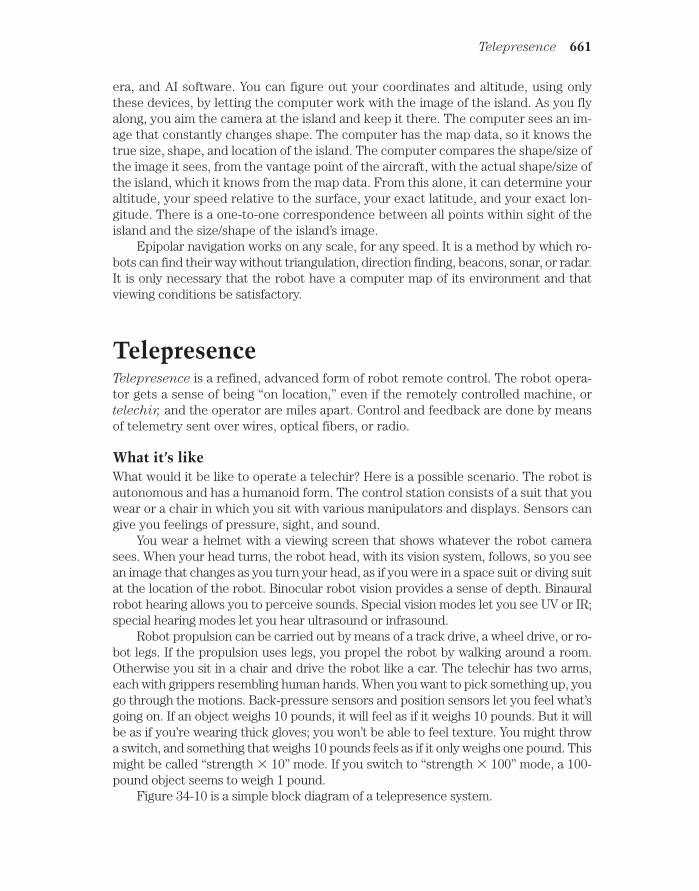
era, and AI software. You can figure out your coordinates and altitude, using onlythese devices, by letting the computer work with the image of the island. As you flyalong, you aim the camera at the island and keep it there. The computer sees an im-age that constantly changes shape. The computer has the map data, so it knows thetrue size, shape, and location of the island. The computer compares the shape/size ofthe image it sees, from the vantage point of the aircraft, with the actual shape/size ofthe island, which it knows from the map data. From this alone, it can determine youraltitude, your speed relative to the surface, your exact latitude, and your exact lon-gitude. There is a one-to-one correspondence between all points within sight of theisland and the size/shape of the island’s image.
Epipolar navigation works on any scale, for any speed. It is a method by which ro-bots can find their way without triangulation, direction finding, beacons, sonar, or radar.It is only necessary that the robot have a computer map of its environment and thatviewing conditions be satisfactory.
TelepresenceTelepresence is a refined, advanced form of robot remote control. The robot opera-tor gets a sense of being “on location,” even if the remotely controlled machine, ortelechir, and the operator are miles apart. Control and feedback are done by meansof telemetry sent over wires, optical fibers, or radio.
What it’s likeWhat would it be like to operate a telechir? Here is a possible scenario. The robot isautonomous and has a humanoid form. The control station consists of a suit that youwear or a chair in which you sit with various manipulators and displays. Sensors cangive you feelings of pressure, sight, and sound.
You wear a helmet with a viewing screen that shows whatever the robot camerasees. When your head turns, the robot head, with its vision system, follows, so you seean image that changes as you turn your head, as if you were in a space suit or diving suitat the location of the robot. Binocular robot vision provides a sense of depth. Binauralrobot hearing allows you to perceive sounds. Special vision modes let you see UV or IR;special hearing modes let you hear ultrasound or infrasound.
Robot propulsion can be carried out by means of a track drive, a wheel drive, or ro-bot legs. If the propulsion uses legs, you propel the robot by walking around a room.Otherwise you sit in a chair and drive the robot like a car. The telechir has two arms,each with grippers resembling human hands. When you want to pick something up, yougo through the motions. Back-pressure sensors and position sensors let you feel what’sgoing on. If an object weighs 10 pounds, it will feel as if it weighs 10 pounds. But it willbe as if you’re wearing thick gloves; you won’t be able to feel texture. You might throwa switch, and something that weighs 10 pounds feels as if it only weighs one pound. Thismight be called “strength 10” mode. If you switch to “strength 100” mode, a 100-pound object seems to weigh 1 pound.
Figure 34-10 is a simple block diagram of a telepresence system.
Telepresence 661

ApplicationsYou can certainly think of many different uses for a telepresence system. Some ap-plications are
• Working in extreme heat or cold• Working under high pressure, such as on the sea floor• Working in a vacuum, such as in space• Working where there is dangerous radiation• Disarming bombs• Handling toxic substances• Police robotics• Robot soldier• Neurosurgery
Of course, the robot must be able to survive conditions at its location. Also, it musthave some way to recover if it falls or gets knocked over.
662 Robotics and artificial intelligence
Human operator
Telechir
Trans-ducers
Trans-ducers
Modem
Modem
Trans-ceiver
Trans-ceiver
34-10 Telepresence combines remote monitoring and control, givingthe operator the feeling of being onsite at a distant location.

LimitationsIn theory, the technology for telepresence exists right now. But there are some prob-lems that will be difficult, if not impossible, to overcome.
The most serious limitation is the fact that telemetry cannot, and never will, travelfaster than the speed of light in free space. This seems fast at first thought (186,282miles, or 299,792 kilometers, per second). But it is slow on an interplanetary scale. Themoon is more than a light second away from the earth; the sun is 8 light minutes away.The nearest stars are at distances of several light years. The delay between the sendingof a command, and the arrival of the return signal, must be less than 0.1 second if telep-resence is to be realistic. This means that the telechir cannot be more than about 9300miles, or 15,000 kilometers, away from the control operator.
Another problem is the resolution of the robot’s vision. A human being with goodeyesight can see things with several times the detail of the best fast-scan television sets.To send that much detail, at realistic speed, would take up a huge signal bandwidth.There are engineering problems (and cost problems) that go along with this.
Still another limitation is best put as a question: How will a robot be able to “feel”something and transmit these impulses to the human brain? For example, an apple feelssmooth, a peach feels fuzzy, and an orange feels shiny yet bumpy. How can this sense oftexture be realistically transmitted to the human brain? Will people allow electrodes tobe implanted in their brains so they can perceive the universe as if they are robots?
The mind of the machineA simple electronic calculator doesn’t have AI. But a machine that can learn from itsmistakes, or that can show reasoning power, does. Between these extremes, there isno precise dividing line. As computers become more powerful, people tend to sethigher standards for what they will call AI. Things that were once thought of as AIare now quite ordinary. Things that seem fantastic now will someday be humdrum.There is a tongue-in-cheek axiom: AI is AI only as long as it remains esoteric.
Relationship with roboticsRobotics and artificial intelligence go together; they complement each other. Scien-tists have dreamed for more than a century about building smart androids: robotsthat look and act like people. Androids exist, but they aren’t very smart. Powerfulcomputers exist, but they lack mobility.
If a machine has the ability to move around under its own power, to lift things, andto move things, it seems reasonable that it should do so with some degree of intelligenceif it is to accomplish anything worthwhile. Otherwise it is little more than a bumblingbox, and might even be dangerous, like a driverless car with a brick on the gas pedal.
If a computer is to manipulate anything, it will need to be able to move around, tograsp, to lift, and to carry objects. It might contemplate fantastic exploits and discovernew secrets about the cosmos, but if it can’t act on its thoughts, the work (and the risk)must be undertaken by people, whose strength, maneuverability, and courage are limited.
The mind of the machine 663

Expert systemsThe term expert systems refers to a method of reasoning in AI. Sometimes thisscheme is called the rule-based system. Expert systems are used in the control ofsmart robots.
The heart of an expert system is a set of facts and rules. In the case of a robotic sys-tem, the facts consist of data about the robot’s environment, such as a factory, an office,or a kitchen. The rules are statements of the logical form “If X, then Y,” similar to manyof the statements in high-level programming languages. An inference engine decideswhich logical rules should be applied in various situations and instructs the robot tocarry out certain tasks. But the operation of the system can only be as sophisticated asthe data supplied by human programmers.
Expert systems can be used in computers to help people do research, make deci-sions, and make forecasts. A good example is a program that assists a physician in mak-ing a diagnosis. The computer asks questions and arrives at a conclusion based on theanswers given by the patient and doctor.
One of the biggest advantages of expert systems is the fact that reprogramming iseasy. As the environment changes, the robot can be taught new rules, and supplied withnew facts.
How smart a machine?Experts in the field of AI have been disappointed in the past few decades. Comput-ers have been designed that can handle tasks no human could ever contend with,such as navigating a space probe. Machines have been built that can play chess andcheckers well enough to compete with human masters. Modern machines can un-derstand, as well as synthesize, much of any spoken language. But these abilities, bythemselves, don’t count for much in the dreams of scientists who hope to create ar-
tificial life.
The human mind is incredibly complicated. A circuit that would have occupied, andused all the electricity in, a whole city in 1940 can now be housed in a box the size of avitamin pill and run by a battery. Imagine this degree of miniaturization happeningagain, then again, and then again. Would that begin to approach the level of sophistica-tion in your body’s nervous system? Perhaps.
A human brain might be nothing more than a digital switching network, but no elec-tronic device yet conceived has come anywhere near its level of intelligence. Some ex-perts think that a machine might someday be built that is smarter than a human. Butmost concede that if it’s ever done, it won’t be for a very long time. Other experts saythat we humans cannot create a mind more powerful than our own, because that wouldviolate the laws of nature.
Artificial lifeWhat, exactly, constitutes something living, which makes it different from somethingnonliving? This has been one of the great questions of science throughout history. Insome cultures, life is ascribed to things that Americans think of as inanimate.
One definition of artificial life involves the ability of a human-made thing to repro-duce itself. Suppose you were to synthesize a new kind of molecule in a beaker and
664 Robotics and artificial intelligence

named it QNA (which stands for some weird name nobody can ever remember). Sup-pose this molecule, like DNA, could make replicas of itself, so that when you put one ofthem in a glass of water, you’d have a whole glassful in a few days. This molecule wouldbe artificial life, in the sense that it could reproduce and that it was made by humans,rather than by nature in general.
You might build a robot that could assemble other robots like itself. The machinewould also be artificial life according to the above definition. It would, of course, be fardifferent from the QNA molecule in terms of size and environment. But reproductionability is the basis for the definition. The QNA molecule and the self-replicating robotboth meet the definition.
A truly self-replicating robot hasn’t yet been developed. Society is a long way fromhaving to worry that robots might build copies of themselves and take over the wholeplanet. But artificially living robots might be possible from a technological standpoint.Robots would probably reproduce by merely assembling other robots similar to them-selves. Robots could also build machines much different from themselves individually.It’s interesting to think of the ways in which artificially living machine populations mightevolve.
Another definition for artificial life involves thought processes. At what point doesmachine intelligence become consciousness? Can a machine ever be aware of its ownexistence, and be able to ponder its place in the universe, the way a human being can?The reproduction question is answerable by an “either/or,” but the consciousness ques-tion can be endlessly debated. One person might say that all computers are fully con-scious; another person could point out that a sizable proportion of the humanpopulation, at any given time, is semiconscious or unconscious. In the end, questionslike this might not matter much. As long as smart robots obey Asimov’s three laws, theissue of whether or not they are living beings will most likely take second place to morepragmatic concerns.
QuizRefer to the text in this chapter if necessary. A good score is 18 correct. Answers arein the back of the book.
1. An android takes the form of:
A. An insect.
B. A human body.
C. A simple robot arm.
D. Binocular vision.
2. According to Asimov’s three laws, under what circumstances is it all right for arobot to injure a human being?
A. Never.
B. When the human being specifically requests it.
C. In case of an accident.
D. In case the robot controller is infected with a computer virus.
Quiz 665
3. Second-generation robots first were used around the year:
A. 1950.
B. 1960.
C. 1970.
D. 1980.
4. The extent to which a machine vision system can differentiate between twoobjects is called the:
A. Magnification.
B. Sensitivity.
C. Selectivity.
D. Resolution.
5. An automotive robot might best keep itself traveling down a specific lane oftraffic by using:
A. Binaural hearing.
B. Epipolar navigation.
C. Edge detection.
D. A second-generation end effector.
6. A rule-based system is also known as:
A. Artificial intelligence.
B. An expert system.
C. An analytical engine.
D. An automated guided vehicle.
7. A robot that has its own computer, and can work independently of other robotsor computers, is called an:
A. Android.
B. Insect robot.
C. Automated guided vehicle.
D. Autonomous robot.
8. A manipulator is also known as a:
A. Track drive.
B. Robot arm.
C. Vision system.
D. Robot controller.
9. An android is well suited for operation in:
A. Extreme weather conditions.
B. Total darkness.
C. An assembly line.
D. An environment with children.
666 Robotics and artificial intelligence
10. Proximity sensing is most closely akin to:
A. Direction measurement.
B. Epipolar navigation.
C. Distance measurement.
D. Machine vision.
11. A telechir is used in conjunction with:
A. An automated guided vehicle.
B. Telepresence.
C. An insect robot.
D. An autonomous robot.
12. An absolute limit to the distance over which teleoperation is practical isimposed by:
A. The speed of light.
B. The image resolution of the vision system.
C. The ability of a robot to determine texture.
D. All of the above.
13. Rodney Brooks is best known for his work with:
A. Epipolar navigation.
B. Binocular vision.
C. Range sensing and plotting.
D. Insect robots.
14. An asset of epipolar navigation is the fact that it:
A. Does not require binaural hearing.
B. Does not require a computer.
C. Can be done from a single observation frame.
D. Requires no reference points at all.
15. Spherical coordinates can uniquely define the position of a point in up to:
A. One dimension.
B. Two dimensions.
C. Three dimensions.
D. Four dimensions.
16. The number of ways in which a robot arm can move is known as:
A. Degrees of rotation.
B. Degrees of freedom.
C. Degrees of arc.
D. Coordinate geometry.
Quiz 667

17. The region throughout which a robot arm can accomplish tasks is called its:
A. Coordinate geometry.
B. Reference axis.
C. Reference frame.
D. Work envelope.
18. A robot arm that moves along three independent axes, each of which is straightand perpendicular to the other two, employs:
A. Revolute geometry.
B. Spherical coordinate geometry.
C. Cartesian coordinate geometry.
D. Cylindrical coordinate geometry.
19. A color vision system can use three gray-scale cameras, equipped with filtersthat allow which three colors of light to pass?
A. Blue, red, and yellow.
B. Blue, red, and green.
C. Cyan, magenta, and yellow.
D. Orange, green, and violet.
20. A robot can determine the steepness of a slope using a(n):
A. Epipolar navigation system.
B. Clinometer.
C. End effector.
D. Manipulator.
668 Robotics and artificial intelligence

Test: Part fourDo not refer to the text when taking this test.
1. A machine vision system that uses two cameras to allow a robot to sense depthis:
A. Binaural.
B. Binocular.
C. Monaural.
D. Monocular.
E. High resolution.
2. A VU meter contains a scale that measures relative:
A. Decibels.
B. Current.
C. Voltage.
D. Power.
E. Frequency.
3.. A fleet of insect robots generally has:
A. Low individual intelligence but high group intelligence.
B. High individual intelligence but low group intelligence.
C. Low individual intelligence and low group intelligence.
D. High individual intelligence and high group intelligence.
E. None of the above.
4. When two or more audio sources drive a single amplifier, it is good engineeringpractice to use:
A. A synthesizer.
B. An audio-frequency choke.
669

C. An audio mixer.
D. A graphic equalizer.
E. A phase control.
5. The use of a stereo headset to listen to music while driving:
A. Is good because it keeps passengers from distracting the driver.
B. Is dangerous.
C. Keeps the driver’s mind on the road.
D. Is good because it prevents road rage.
E. Is better than using car speakers.
6. A quantitative measure of the ability of a machine vision system to detect dimlight is its:
A. Selectivity.
B. Resolution.
C. Sensitivity.
D. Field of view.
E. Amplitude ratio.
7. The pitch of an audio sine-wave tone depends on:
A. The amplitude of the disturbance.
B. The frequency of the disturbance.
C. The polarization of the disturbance.
D. The medium through which the sound travels.
E. The waveform of the disturbance.
8. Three-dimensional range plotting is generally done in:
A. Linear coordinates.
B. Rectangular coordinates.
C. Polar coordinates.
D. Celestial coordinates.
E. Spherical coordinates.
9. A form of communications in which either party can “hear” while “talking,”thus allowing one party to instantly interrupt the other at any time, is called:
A. Half simplex.
B. Full simplex.
C. Half duplex.
D. Full duplex.
E. Nothing. There is no such mode of communications.
10. Which of the following is an example of wireless technology?
A. The Global Positioning System.
670 Test: Part four

B. A field-effect transistor.
C. A junction diode.
D. A carbon-composition resistor.
E. Digital-to-analog conversion.
11. A satellite in a LEO system is usually:
A. At an altitude of 22,300 miles.
B. Geosynchronous.
C. In a retrograde orbit.
D. In a polar orbit.
E. Midway between the earth and the moon.
12. Which consideration is the most important in a hi-fi audio amplifier?
A. Power output.
B. Efficiency.
C. Linearity.
D. Input impedance.
E. Output impedance.
13. The microprocessor in a computer is part of the:
A. Random-access memory.
B. Central processing unit.
C. Read-only memory.
D. Hard drive.
E. Internet controller.
14. An RF transducer is:
A. Sensitive only within the range of human hearing.
B. Sensitive only to visible light.
C. An antenna.
D. An analog-to-digital converter.
E. A digital-to-analog converter.
15. Vacuum tubes might be found in:
A. A portable headset tape player.
B. The amplifier used by a band at a rock concert.
C. A meter for measuring sound intensity.
D. A robot controller.
E. A GPS receiver.
16. One kilobyte is the same amount of data as:
A. 1024 bits.
B. 1024 kilobits.
Test: Part four 671

C. 1024 megabits.
D. 1024 gigabits.
E. None of the above.
17. Hexaphonic sound is not common, but if it were, it would most likely be used for:
A. True three-dimensional hi-fi audio reproduction.
B. Two-way radio communications.
C. Ensuring that an AM/FM tuner can receive at least six stations.
D. Improving the dynamic range of a speaker system.
E. Robot control.
18. Range sensing and range plotting are basically the same thing except for the:
A. Light-detecting sensitivity.
B. Image resolution.
C. Selectivity.
D. Wavelength at which the system functions.
E. Number of dimensions involved.
19. In a component-type hi-fi system, cables connecting the various units should be:
A. As long as possible.
B. Single-conductor only.
C. Connected in parallel.
D. Shielded whenever possible.
E. Connected in series.
20. A radio antenna receives 50 watts of RF power from a transmitter, and radiates49 watts of that power into space. Which of the following statements is true?
A. The antenna is 98 percent efficient.
B. The loss resistance is 1 ohm.
C. The loss resistance is 1 percent.
D. The ground loss is 1 watt.
E. The antenna feed line loss is 1 watt.
21. The technical expression for robot-arm joint flexibility is:
A. Degrees of rotation.
B. Radians of rotation.
C. Degrees of flexibility.
D. Manipulator flexibility.
E. The work envelope.
22. In an Internet connection, the receiving computer is also known as the:
A. Server.
672 Test: Part four

B. Host.
C. Peer.
D. Node.
E. Destination.
23. The term refresh rate refers to:
A. The number of times per second that an image is renewed in a computerdisplay.
B. The number of times per second that a computer memory contents change.
C. The speed at which files on a hard drive are overwritten.
D. The number of bits per second transferred in an Internet connection.
E. The time it takes to recharge a nickel-cadmium electrochemical cell.
24. The “brain” of a computer is the:
A. Hard drive.
B. Controller.
C. Microprocessor.
D. CD-ROM.
E. Monitor.
25. On a computer hard drive, the circular tracks are broken into arcs called:
A. Clusters.
B. Bytes.
C. Sectors.
D. Divisions.
E. Storage units.
26. A robot arm moves in three dimensions according to a polar coordinate schemewith a linear elevation dimension added. This is called:
A. Spherical coordinate geometry.
B. Rectangular coordinate geometry.
C. Cartesian coordinate geometry.
D. Concentric coordinate geometry.
E. Cylindrical coordinate geometry.
27. In a volatile memory chip:
A. The stored data is retained even when power is removed.
B. The stored data vanishes when power is removed.
C. The stored data capacity is greater than that of a hard drive.
D. The stored data capacity declines with the passage of time.
E. The reliability has deteriorated and the chip should be replaced.
Test: Part four 673

28. At low volume levels in an audio amplifier system, the dynamic range is limitedprimarily by the:
A. Input impedance.
B. Efficiency.
C. Input power.
D. Noise level.
E. Frequency.
29. In a wireless system, noise always:
A. Improves the bandwidth.
B. Increases data transfer rate.
C. Reduces the transmitted signal power.
D. Degrades performance.
E. Makes communication or data transfer impossible.
30. The noise level in a wireless receiver can be reduced using:
A. A more powerful final amplifier.
B. A grounded-grid configuration.
C. Cryotechnology.
D. The Global Positioning System.
E. A large antenna.
31. Image resolution is an important specification in:
A. Oscillators.
B. Computer monitors.
C. Receiver sensitivity.
D. Rectifier diodes.
E. Superheterodyne receivers.
32. According to Asimov’s laws, a robot must obey all orders from humans:
A. No matter what.
B. As long as nobody gets hurt or killed as a result.
C. As long as the power is on.
D. Unless its controller is infected with a computer virus.
E. As long as it does not cause the robot controller to crash.
33. The use of a cell phone is prohibited in a commercial aircraft in flight because:
A. It can annoy other passengers.
B. It can interfere with other people’s cell phones.
C. The interior of the aircraft produces a dangerous RF resonant cavity.
D. It won’t work anyhow.
674 Test: Part four

E. It can interfere with flight instruments and communications.
34. A satellite can remain over the same spot on the earth’s surface at all times:
A. Only if it orbits at an altitude of 22,300 miles.
B. Only if it is a member of a LEO fleet.
C. Only if its orbit is retrograde.
D. Only if its orbit is polar.
E. Never. An orbiting satellite always moves relative to the earth’s surface.
35. Signal-plus-noise-to-noise ratio (SN/N) is often specified when stating areceiver’s:
A. Selectivity.
B. Stability.
C. Modulation coefficient.
D. Sensitivity.
E. Polarization.
36. A platter is a part of a device known as:
A. A videotape recorder.
B. A ceramic filter.
C. Tape memory.
D. A hard drive.
E. A voltage-controlled oscillator.
37. Which type of modulation consists of one voice sideband, with a suppressedcarrier?
A. AM.
B. SSB.
C. FM.
D. RTTY.
E. PCM.
38. In a machine vision system, enhanced sensitivity often involves a sacrifice in the:
A. Image resolution.
B. Memory capacity.
C. Data speed.
D. Short-wavelength response.
E. Long-wavelength response.
39. A machine hearing system can best identify the sort of device or objectproducing a sound by analyzing the:
A. Distance to the sound source.
Test: Part four 675
B. Direction from which the sound is coming.
C. Duration of the sound.
D. Number of sources from which the sound is coming.
E. Waveform of the sound.
40. A ratio detector is a circuit for demodulating:
A. AM.
B. HM.
C. FM.
D. SSB.
E. AFSK.
41. A belt drive might be found in a:
A. Synthesized AM/FM tuner.
B. Robotic vision system.
C. CD player.
D. Graphic equalizer.
E. Turntable.
42. A robot can be considered autonomous if:
A. It is self-contained.
B. It has its own computer system.
C. It does not rely on a central computer to receive its commands.
D. Conditions A, B, and C are all true.
E. Any one of conditions A, B, or C is true.
43. Sound waves in air consist of:
A. Fluctuating magnetic fields.
B. Fluctuating electric fields.
C. Fluctuating electric and magnetic fields.
D. Vibrating electron orbits.
E. Vibrating molecules.
44. An AM/FM hi-fi tuner that derives its frequency from a quartz crystal andphase-locking circuits is said to be:
A. Broadband.
B. Synthesized.
C. Phased.
D. Modulated.
E. Analog.
676 Test: Part four

45. Epipolar navigation is a means by which a machine can locate objects and plota course in:
A. The total darkness of the deep ocean.
B. A straight line.
C. Three-dimensional space.
D. A circular path.
E. The north and south polar regions only.
46. The term robot generation refers to:
A. The time period in which a particular type of robot was developed.
B. A robot-controlled electric power plant.
C. The manufacture of robots by other robots.
D. The manufacture of robots by human beings.
E. The number of times a robot has copied itself.
47. Which word best completes the following sentence? “ The human ear/brainperceives sound volume according to the _________ of the actual intensity.”
A. Sum.
B. Product.
C. Square.
D. Square root.
E. Logarithm.
48. Human eyes can see electromagnetic radiation over a wavelength range ofapproximately:
A. 390 to 750 meters.
B. 390 to 750 millimeters.
C. 390 to 750 micrometers.
D. 390 to 750 nanometers.
E. 390 to 750 kilometers.
49. The World Wide Web is:
A. Part of the Internet.
B. A company that manufactures communications equipment.
C. An agreement between nations concerning data protocols.
D. Another name for the Global Positioning System.
E. A satellite television network.
50. Synchronizing pulses in a video signal:
A. Keep the brightness constant.
B. Keep the contrast constant.
Test: Part four 677

C. Keep the image from rolling.
D. Ensure that the colors are right.
E. Keep the image in good focus.
A good score is at least 37 correct. Answers are in the back of the book. It’s best tohave a friend check your score the first time, so you won’t memorize the answers ifyou want to take the test again.
678 Test: Part four

Final examDo not refer to the text when taking this exam.
1. As the frequency of ac increases in a coil, the reactance:
A. Gets larger negatively.
B. Gets smaller negatively.
C. Stays the same.
D. Gets larger positively.
E. Gets smaller positively.
2. A beat-frequency oscillator is useful for:
A. Generating FM.
B. Detecting FM.
C. Generating CW.
D. Detecting CW.
E. Any of the above.
3. A Colpitts circuit is a form of:
A. Amplifier.
B. Detector.
C. Modulator.
D. Oscillator.
E. Rectifier.
4. The high component density of integrated circuits acts to:
A. Maximize the power output.
B. Increase the current drain.
C. Increase the voltage requirements.
D. Increase the operating speed.
E. Reduce the frequency range.
679

5. A utility meter generally measures:
A. Watts.
B. Amperes.
C. Kilowatt hours.
D. Kilowatts.
E. Volt hours.
6. High voltages are better than low voltages for long-distance electric powertransmission because:
A. The lines can better withstand lightning strokes.
B. The magnetic fields are weaker.
C. The electric fields are weaker.
D. The I2R losses are lower.
E. No. Low voltages are better.
7. A member of a fleet of robots, all under the control of a single centralcomputer and able to communicate only with that computer and not witheach other, is called:
A. An android.
B. An autonomous robot.
C. A dependent robot.
D. An independent robot.
E. An insect robot.
8. An advantage of a laser printer over a dot-matrix printer for computerapplications is:
A. Lower cost.
B. Superior image quality.
C. Greater bandwidth.
D. Lower resolution.
E. Better voltage regulation.
9. The output electrode of a bipolar transistor is usually the:
A. Grid.
B. Gate.
C. Base.
D. Source.
E. Collector.
10. The schematic symbol for an op amp is:
A. A triangle.
B. A circle.
680 Final exam

C. A circle with a line through it.
D. A rectangle.
E. A D-shaped figure.
11. For a given value of capacitance, as the frequency goes down, the reactance:
A. Approaches zero from the negative side.
B. Gets more and more negative.
C. Approaches zero from the positive side.
D. Gets more and more positive.
E. Stays the same.
12. In a 360-Hz wave, a degree of phase represents:
A. 1.00 second.
B. 1/360 second.
C. 360 milliseconds.
D. 7.72 microseconds.
E. A quantity you can’t calculate from this data.
13. A device that converts visible light into dc is:
A. A phototransistor.
B. A photovoltaic cell.
C. An optovoltaic cell.
D. An optocell.
E. An optoisolator.
14. Which of the following is not an example of wireless?
A. The connection between a computer and its monitor.
B. A cellular telephone system.
C. The Global Positioning System.
D. A beeper.
E. A LEO satellite system.
15. A circuit has a battery of 3.0 V and a bulb with a resistance of 12.0 ohms. Thecurrent through the bulb is:
A. 36 A.
B. 4.0 A.
C. 250 mA.
D. 40 mA.
E. 36 mA.
16. A small 9-V battery might be used to provide power to:
A. An electronic calculator.
Final exam 681

B. A personal computer.
C. A radio transmitter.
D. An electric iron.
E. Any of the above.
17. In an AM voice signal, the audio information is:
A. Exactly at the carrier frequency.
B. Contained in sidebands.
C. At harmonics of the carrier frequency.
D. Rectified before being impressed onto the carrier.
E. Detected before being impressed onto the carrier.
18. The oscillating frequency of a quartz crystal can be varied slightly by:
A. Changing the bias on the transistor.
B. Changing the voltage across the varactor.
C. Reversing the power supply polarity.
D. Placing a small variable capacitor across the crystal.
E. No. The frequency of a crystal cannot be changed at all.
19. When several resistances are connected in series:
A. The current is the same through each one.
B. The voltage is the same across each one.
C. Both A and B are true.
D. Neither A nor B is true.
E. They must all have the same value.
20. In a power supply, resistors are sometimes connected in series with thediodes in order to:
A. Increase the current output.
B. Protect the diodes against surge currents.
C. Help the diodes discharge.
D. Bleed charge from the filter capacitors.
E. Regulate the output voltage.
21. In a purely resistive impedance, there is:
A. A net capacitance.
B. A net inductance.
C. Zero resistance.
D. Zero reactance.
E. Zero conductance.
682 Final exam

22. Two 400-H inductors are connected in series. There is no mutualinductance. The total inductance is:
A. 100 H.
B. 200 H.
C. 400 H.
D. 800 H.
E. 1.6 mH.
23. The current-carrying part of a field-effect transistor, analogous to a gardenhose in some ways, is called the:
A. Source.
B. Gate.
C. Drain.
D. Source-drain junction.
E. Channel.
24. In a rectifier diode, current flows for approximately how much of the accycle?
A. 360 degrees.
B. 270 degrees.
C. 180 degrees.
D. 90 degrees.
E. 45 degrees.
25. A millivolt is:
A. 103 V.
B. 103 V.
C. 106 V.
D. 106 V.
E. 109 V.
26. The reciprocal of reactance is called:
A. Impedance.
B. Conductance.
C. Resistance.
D. Admittance.
E. Susceptance.
27. Another name for joules per second is:
A. Volts.
B. Amperes.
Final exam 683

C. Ohms.
D. Gilberts.
E. Watts.
28. In a pure inductance:
A. Current lags voltage by 90 degrees.
B. Current lags voltage by less than 90 degrees.
C. Current and voltage are in phase.
D. Current leads voltage by 90 degrees.
E. Current leads voltage by 180 degrees.
29. A form of microwave electron tube is:
A. A cavity resonator.
B. A triode.
C. A Klystron.
D. A cathode-ray tube.
E. None of the above.
30. Magnetic lines of flux are generally:
A. Parallel with the flow of electric current.
B. In the plane of the electric current.
C. At right angles to the flow of current.
D. At a 45 degree angle to the flow of current.
E. Impossible to predict as to their direction.
31. A class-A amplifier conducts during how much of the input cycle?
A. Less than 90 degrees.
B. 90–180 degrees.
C. 180–270 degrees.
D. 270–360 degrees.
E. 360 degrees.
32. An advantage of parallel data transfer over serial transfer is:
A. Higher speed.
B. Narrower bandwidth.
C. Lower frequency.
D. Higher power.
E. Better signal-to-noise ratio.
33. One way to keep interelectrode capacitance to a minimum is to:
A. Use only electrolytic capacitors.
684 Final exam

B. Avoid the use of sheet metal.
C. Use batteries as the source of power.
D. Keep wire leads short.
E. Use air-core transformers.
34. One advantage of ac (compared with dc) as a source of utility power is that:
A. It can be used at safer voltage levels.
B. It can be easily stepped up or down in voltage.
C. There is lower transmission line loss.
D. The waveshape can be varied easily.
E. Higher voltages can be used.
35. An element of matter:
A. Is a good conductor.
B. Has a unique number of protons.
C. Is an insulator.
D. Makes a good electronic component.
E. Can be fabricated onto an IC chip.
36. A transformer quadruples the ac voltage. The primary-to-secondaryimpedance ratio is therefore:
A. 1:16.
B. 1:4.
C. 1:1.
D. 4:1.
E. 16:1.
37. Frequency multiplication is possible with a semiconductor diode because the diode is:
A. Amplifying.
B. Detecting.
C. Forward-biased.
D. Reverse-biased.
E. Nonlinear.
38. An ammeter measures:
A. Current.
B. Voltage.
C. Resistance.
D. Power.
E. Energy.
Final exam 685
39. A good type of resistor to use in a radio amplifier is:
A. Carbon composition.
B. Wirewound.
C. Silver mica.
D. Reactive.
E. Tantalum.
40. An advantage of machine vision over human vision is the fact that:
A. Machines can see at wavelengths to which human eyes are blind.
B. Machine vision systems have equal sensitivity at all wavelengths.
C. Machine vision can measure pressure.
D. Machine vision engineers need not take image resolution into account.
E. Machine vision engineers need not take sensitivity into account.
41. A logic circuit has an output 0 when the input is 1, and vice versa. This is:
A. A NOR gate.
B. An AND gate.
C. A NOT gate.
D. An XOR gate.
E. An XNOR gate.
42. A type of FM detector that has its limiter built in is:
A. A balanced modulator.
B. A beat-frequency oscillator.
C. An envelope detector.
D. A product detector.
E. A ratio detector.
43. Which of the following materials is/are commonly used as a semiconductor?
A. Silver-mica.
B. Ferrite.
C. Gallium arsenide.
D. Tantalum.
E. All of the above.
44. In an NPN bipolar transistor circuit:
A. The dc collector voltage is negative.
B. The output is taken from the base.
C. The dc collector voltage is positive.
D. The output is taken from the drain.
E. Negative feedback must be used.
686 Final exam
45. A simple power supply filter can be made using:
A. A capacitor in parallel with the rectifier output.
B. A resistor in parallel with the rectifier output.
C. An inductor in parallel with the rectifier output.
D. A capacitor in series with the rectifier output.
E. A resistor in series with the rectifier output.
46. If an ac admittance contains finite, nonzero resistance and finite, nonzerosusceptance:
A. The impedance is a pure resistance.
B. The impedance is zero.
C. The resistance is zero.
D. The impedance is complex.
E. No. An ac admittance cannot contain susceptance.
47. Three resistances are in parallel, with values of 100, 200, and 300 ohms. Thecurrent through the 200-ohm resistor is 500 mA. What is the voltage acrossthe whole combination?
A. There isn’t enough information to figure it out.
B. 400 V.
C. 400 mV.
D. 100 V.
E. 100 mV.
48. As the frequency of ac increases, the reactance of an inductor:
A. Remains constant.
B. Becomes small positively.
C. Becomes small negatively.
D. Becomes large negatively.
E. Becomes large positively.
49. The rate of change in a quantity is called the:
A. Effective value.
B. Instantaneous value.
C. Average value.
D. Peak value.
E. Derivative.
50. The axis of the geomagnetic field:
A. Corresponds exactly with the rotational axis.
B. Is slanted with respect to the rotational axis.
C. Is perpendicular to the rotational axis.
Final exam 687
D. Runs parallel to lines of latitude.
E. Is circular in shape.
51. One of the main shortcomings of MOSFETs is that they:
A. Are easily damaged by static electricity.
B. Require high voltages.
C. Consume large amounts of current.
D. Have very low gain.
E. Do not have good sensitivity.
52. Resistivity of wire can be specified in:
A. Volts per ohm.
B. Ohms per volt.
C. Ohms per meter.
D. Amperes per ohm.
E. Ohms per ampere.
53. A complementary-metal-oxide-semiconductor (CMOS) IC:
A. Employs diodes and NPN transistors on a single chip.
B. Employs N-channel and P-channel FETs on a single chip.
C. Uses two chips connected together in a special way.
D. Uses resistors and PNP transistors on a single chip.
E. Consists of metal oxide sandwiched between two layers of P-type material.
54. A piano sounds different than a saxophone, even if the notes are at the samefrequency, because of a difference in:
A. Bias.
B. Waveform.
C. Voltage.
D. Current.
E. The way you imagine it.
55. Inductances in parallel, assuming there is no mutual inductance, add up like:
A. Resistances in series.
B. Resistances in parallel.
C. Capacitances in parallel.
D. Batteries in parallel.
E. No other type of electrical component.
56. A reactance modulator produces:
A. CW.
B. AM.
688 Final exam

C. SSB.
D. FM.
E. PCM.
57. Antenna efficiency is:
A. Usually more important in transmitting systems than in receiving systems.
B. The difference between the input and output power.
C. A direct function of the noise in a transmitting system.
D. The proportion of input power that gets converted into heat.
E. Highest when the transmitter final amplifier is maximally efficient.
58. In a parallel-resonant LC circuit, the impedance is:
A. Low and reactive.
B. High and reactive.
C. Low and resistive.
D. High and resistive.
E. Any of the above.
59. In a resistance/inductance (RL) series circuit:
A. Current lags voltage by 180 degrees.
B. Current lags voltage by 90 degrees.
C. Current lags voltage by less than 90 degrees.
D. Current and voltage are in phase.
E. Current leads voltage by 90 degrees.
60. In three-phase ac, the difference in phase between any two waves is:
A. 30 degrees.
B. 45 degrees.
C. 60 degrees.
D. 90 degrees.
E. 120 degrees.
61. Electrostatic forces can be measured to directly indicate:
A. Power.
B. Frequency.
C. Current.
D. Resistance.
E. Voltage.
62. A circuit has a complex impedance of 9 j12. The absolute-value impedance is:
A. 15 ohms.
B. 9 ohms.
Final exam 689

C. 12 ohms.
D. 21 ohms.
E. Impossible to calculate from this data.
63. Three resistors, each of 30 ohms, are connected in parallel. The net resistance is:
A. 90 ohms.
B. 60 ohms.
C. 33 ohms.
D. 10 ohms.
E. Impossible to determine from the data given.
64. The logical statement X Y Y X depicts:
A. The distributive property.
B. The associative property.
C. The commutative property.
D. The de Morgan theorem.
E. The behavior of a NOR gate.
65. A cell that can be recharged, and therefore used again and again, is called:
A. A secondary cell.
B. A multiple-use cell.
C. A primary cell.
D. A tertiary cell.
E. A battery.
66. A resistor has a positive temperature coefficient of 1.00 percent per degree C.If its value is 100 ohms at 20 degrees C, what is its value at 25 degrees C?
A. 100 ohms.
B. 105 ohms.
C. 95 ohms.
D. 125 ohms.
E. It can’t be calculated from this data.
67. A memory that can be easily accessed, but not written over, is called:
A. RAM.
B. PRAM.
C. CMOS.
D. ROM.
E. CROM.
68. The capacitance between two parallel sheets of metal is:
A. Directly proportional to the distance between them.
690 Final exam

B. Inversely proportional to the distance between them.
C. Not dependent on the distance between them.
D. Inversely proportional to their surface area.
E. Negligible unless the sheets are both gigantic.
69. The forward base bias in a transistor is increased until the collector currentlevels off. This condition is:
A. Cutoff.
B. Saturation.
C. Pinchoff.
D. Forward breakover.
E. Avalanche.
70. An advantage of a LEO communications satellite system over a geostationarycommunications satellite is the fact that:
A. The bandwidth is greater.
B. The image resolution is superior.
C. The satellites never change their position in the sky.
D. Large, high-gain antennas are not required.
E. The satellites orbit at higher altitudes.
71. A coil has 20 mH of inductance. What is the inductive reactance?
A. 20 ohms.
B. 0.05 ohms.
C. 50 ohms.
D. 20k ohms.
E. There isn’t enough information given here to figure it out.
72. What is an advantage of digital signal processing (DSP)?
A. Improved signal-to-noise ratio.
B. Enhanced fidelity.
C. Improved intelligibility.
D. Relative immunity to atmospheric noise.
E. All of the foregoing.
73. A dc voltage-divider network is made using:
A. Inductors.
B. Resistors.
C. Capacitors.
D. Bipolar transistors.
E. FETs.
Final exam 691

74. The electron volt is a unit of:
A. Voltage.
B. Current.
C. Power.
D. Electric field strength.
E. Energy.
75. A transformer has a primary-to-secondary turns ratio of 10:1. The input is 120V rms ac. The output is:
A. 12 kV rms ac.
B. 1.2 kV rms ac.
C. 120 V rms ac.
D. 12 V rms ac.
E. 1.2 V rms ac.
76. Wave X leads wave Y by 270 degrees. This would be better expressed bysaying that:
A. Wave X lags wave Y by 90 degrees.
B. Wave X lags wave Y by 180 degrees.
C. Wave X lags wave Y by 270 degrees.
D. Waves X and Y are out of phase.
E. Waves X and Y are in phase.
77. Which type of amplifier circuit has the transistor or FET biased exactly atcutoff or pinchoff when there is no signal input?
A. Class-A.
B. Class-AB.
C. Class-B.
D. Class-C.
E. Class-D.
78. The term resolution might apply to:
A. A hi-fi amplifier system.
B. A power supply.
C. A machine vision system.
D. An NPN bipolar transistor.
E. An electrolytic capacitor.
79. An audio oscillator that uses two amplifiers in cascade, with positive feedbackfrom the output of the second stage to the input of the first stage, is known as a:
A. Colpitts circuit.
B. Hartley circuit.
692 Final exam
C. Multivibrator.
D. VCO.
E. Clapp circuit.
80. The main factor that limits the frequency at which a P-N junction will rectifyis the:
A. PIV rating.
B. Junction capacitance.
C. Junction resistance.
D. Junction inductance.
E. Reverse bias current.
81. The henry is a:
A. Very small unit.
B. Unit of capacitive reactance.
C. Measure of transistor gain.
D. Unit of phase.
E. Very large unit.
82. A diode that can be used as a variable capacitance is a:
A. GaAsFET.
B. Silicon rectifier.
C. Point-contact diode.
D. Varactor.
E. Germanium detector.
83. Elements can join together to form:
A. Ions.
B. Isotopes.
C. Nuclei.
D. Compounds.
E. Majority carriers.
84. The rms value for an ac wave is also sometimes called the:
A. Absolute value.
B. Direct-current value.
C. Effective value.
D. Equivalent value.
E. Reactive value.
85. The gigabyte is a unit commonly used as a measure of:
A. Data access time.
Final exam 693

B. Data frequency.
C. Data transfer speed.
D. Data storage capacity.
E. Data communications accuracy.
86. In a parallel combination of light bulbs, if one bulb socket totally shorts out:
A. The circuit had better have a fuse or a circuit breaker.
B. The other bulbs will burn out.
C. The other bulbs will dim slightly, but stay lit.
D. The current drawn from the source will decrease.
E. None of the above.
87. A common lab multimeter cannot measure:
A. Current.
B. Frequency.
C. Voltage.
D. Resistance.
E. It can measure any of the above.
88. In a P-channel JFET:
A. The drain is positive with respect to the source.
B. The gate must be grounded.
C. The majority carriers are holes.
D. The source receives the input signal.
E. All of the above are true.
89. If you place a bar of iron inside a cylindrical coil of wire, and then run dcthrough the wire, you have:
A. A rheostat.
B. A permanent magnet.
C. A flux meter.
D. An electric generator.
E. An electromagnet.
90. Admittance is a quantity expressing:
A. Opposition to dc.
B. Opposition to audio signals.
C. Ease with which a circuit passes ac.
D. The ratio of capacitance to inductance.
E. The ratio of reactance to resistance.
694 Final exam

91. In a common-emitter bipolar-transistor circuit:
A. The collector is at signal ground.
B. The output is taken from the base.
C. The emitter is at signal ground.
D. The bases of two transistors are connected together.
E. The output is taken from the emitter.
92. In a certain resistance-capacitance (RC) circuit, the current leads the voltageby 45 degrees. The resistance is 50 ohms. The capacitive reactance is:
A. 25 ohms.
B. 25 ohms.
C. 50 ohms.
D. 50 ohms.
E. Impossible to determine from this information.
93. The VA power is equal to the true power only when:
A. A circuit has no resistance.
B. A circuit has no impedance.
C. A circuit has no reactance.
D. The complex impedance is high.
E. The phase angle is 45 degrees.
94. Binaural machine hearing can be advantageous over monaural machinehearing because the binaural scheme:
A. Allows a robot to measure the frequency of a sound.
B. Allows a robot to determine the amplitude of a sound.
C. Allows a robot to tell from which direction a sound is coming.
D. Allows a robot to ascertain the waveform of a sound.
E. Allows a robot to interpret spoken commands.
95. The standard unit of inductance is the:
A. Farad.
B. Henry.
C. Gilbert.
D. Gauss.
E. Tesla.
96. The output of an amplifier circuit is 20 V and the input is 5.0 V. The input andoutput impedances are identical. The circuit thus has a gain of:
A. 4 dB.
B. 6 dB.
Final exam 695

C. 12 dB.
D. 4 dB.
E. 6 dB.
97. An example of a device that converts electrical energy into visible radiantenergy is:
A. A photocell.
B. A phototransistor.
C. A photovoltaic cell.
D. A light-emitting diode.
E. A speaker.
98. What is the function of bleeder resistors in a power supply?
A. To regulate the current.
B. To regulate the voltage.
C. To protect the rectifier diodes against electromagnetic interference.
D. To protect the rectifier diodes against current surges.
E. To discharge the filter capacitors after the supply is shut off.
99. A resistor of 100 ohms carries 333 mA dc. The power dissipated by thatresistor is:
A. 300 mW.
B. 3.33 W.
C. 33.3 W.
D. 3.33 W.
E. 11.1 W.
100. The data in nonvolatile memory:
A. Is stored on magnetic disks.
B. Consists of analog waveforms.
C. Is retained after the power is removed.
D. Must pass through a modem before it can be understood by the CPU.
E. Cannot be used by a microprocessor.
A good score is at least 75 correct. Answers are in the back of the book. It’s best tohave a friend check your score the first time, so you won’t memorize the answers ifyou want to take the test again.
696 Final exam

AAPPENDIX
Answers to quiz, test, andexam questions
Chapter 1
1. B 2. C 3. D 4. D
5. D 6. A 7. B 8. C
9. A 10. B 11. C 12. A
13. D 14. C 15. C 16. A
17. C 18. B 19. C 20. D
Chapter 2
1. B 2. C 3. D 4. B
5. C 6. A 7. C 8. C
9. A 10. D 11. D 12. A
13. B 14. B 15. C 16. D
17. B 18. C 19. A 20. C
Chapter 3
1. B 2. A 3. C 4. C
5. A 6. D 7. C 8. A
9. D 10. C 11. A 12. B
13. A 14. C 15. D 16. B
17. D 18. A 19. C 20. B
697

Chapter 4
1. A 2. C 3. D 4. A
5. B 6. D 7. C 8. A
9. C 10. A 11. D 12. B
13. D 14. B 15. A 16. C
17. C 18. A 19. D 20. B
Chapter 5
1. B 2. D 3. C 4. C
5. A 6. B 7. D 8. A
9. B 10. D 11. B 12. C
13. B 14. C 15. A 16. C
17. B 18. C 19. B 20. C
Chapter 6
1. C 2. A 3. A 4. C
5. D 6. B 7. B 8. C
9. B 10. C 11. D 12. C
13. A 14. C 15. A 16. A
17. B 18. C 19. B 20. A
Chapter 7
1. C 2. C 3. B 4. C
5. D 6. B 7. A 8. B
9. A 10. D 11. B 12. A
13. B 14. C 15. D 16. C
17. C 18. C 19. A 20. D
Chapter 8
1. C 2. A 3. D 4. B
5. C 6. B 7. B 8. C
9. A 10. C 11. C 12. D
13. B 14. A 15. D 16. D
17. C 18. B 19. B 20. A
698 Appendix A
Test: Part One
1. A 2. A 3. C 4. B
5. A 6. B 7. A 8. E
9. E 10. C 11. C 12. C
13. B 14. C 15. D 16. B
17. A 18. A 19. E 20. E
21. D 22. D 23. D 24. C
25. A 26. C 27. D 28. A
29. C 30. C 31. C 32. D
33. E 34. D 35. E 36. B
37. D 38. D 39. C 40. A
41. A 42. D 43. C 44. E
45. C 46. C 47. D 48. A
49. E 50. C
Chapter 9
1. C 2. C 3. A 4. C
5. D 6. D 7. A 8. B
9. C 10. B 11. D 12. B
13. B 14. D 15. D 16. A
17. C 18. C 19. D 20. A
Chapter 10
1. B 2. A 3. D 4. B
5. B 6. C 7. D 8. C
9. A 10. D 11. B 12. D
13. A 14. A 15. D 16. B
17. A 18. C 19. A 20. D
Chapter 11
1. D 2. A 3. A 4. A
5. C 6. D 7. B 8. A
9. D 10. D 11. B 12. C
13. B 14. A 15. B 16. C
17. D 18. A 19. B 20. B
Answers to quiz, test, and exam questions 699

Chapter 12
1. C 2. A 3. B 4. B
5. D 6. B 7. D 8. C
9. A 10. B 11. B 12. D
13. C 14. A 15. C 16. B
17. D 18. C 19. D 20. C
Chapter 13
1. C 2. A 3. B 4. D
5. C 6. A 7. B 8. C
9. D 10. C 11. D 12. D
13. A 14. B 15. D 16. B
17. D 18. C 19. B 20. A
Chapter 14
1. B 2. D 3. A 4. C
5. B 6. A 7. B 8. A
9. A 10. D 11. C 12. B
13. B 14. B 15. C 16. B
17. C 18. D 19. A 20. C
Chapter 15
1. B 2. B 3. A 4. D
5. B 6. C 7. A 8. C
9. D 10. A 11. A 12. A
13. C 14. A 15. D 16. B
17. D 18. C 19. C 20. B
Chapter 16
1. B 2. A 3. D 4. D
5. D 6. B 7. C 8. C
9. A 10. C 11. B 12. B
13. A 14. B 15. B 16. D
17. C 18. A 19. B 20. A
700 Appendix A

Chapter 17
1. C 2. C 3. A 4. D
5. A 6. B 7. C 8. D
9. B 10. C 11. C 12. A
13. D 14. A 15. C 16. B
17. D 18. D 19. C 20. A
Chapter 18
1. C 2. A 3. D 4. B
5. B 6. A 7. C 8. D
9. A 10. D 11. B 12. B
13. C 14. D 15. C 16. A
17. C 18. D 19. B 20. B
Test: Part Two
1. E 2. E 3. A 4. A
5. E 6. D 7. C 8. D
9. A 10. E 11. C 12. A
13. D 14. C 15. C 16. E
17. E 18. D 19. C 20. B
21. B 22. D 23. C 24. C
25. E 26. C 27. B 28. A
29. E 30. C 31. A 32. A
33. A 34. A 35. B 36. E
37. C 38. D 39. C 40. B
41. B 42. C 43. C 44. C
45. D 46. D 47. E 48. E
49. A 50. A
Chapter 19
1. B 2. D 3. C 4. A
5. C 6. A 7. D 8. B
9. C 10. B 11. D 12. B
13. B 14. A 15. B 16. C
17. A 18. C 19. D 20. C
Answers to quiz, test, and exam questions 701

Chapter 20
1. B 2. D 3. C 4. B
5. A 6. A 7. D 8. C
9. B 10. D 11. B 12. A
13. C 14. A 15. C 16. D
17. B 18. A 19. C 20. A
Chapter 21
1. C 2. D 3. B 4. A
5. B 6. C 7. A 8. B
9. D 10. C 11. A 12. D
13. D 14. B 15. C 16. A
17. C 18. B 19. A 20. C
Chapter 22
1. D 2. A 3. B 4. D
5. D 6. C 7. B 8. C
9. B 10. D 11. C 12. A
13. C 14. D 15. A 16. D
17. B 18. C 19. B 20. B
Chapter 23
1. B 2. D 3. A 4. B
5. C 6. A 7. B 8. C
9. D 10. B 11. C 12. A
13. D 14. A 15. C 16. D
17. B 18. C 19. A 20. A
Chapter 24
1. A 2. C 3. B 4. B
5. D 6. A 7. D 8. B
9. D 10. A 11. C 12. B
13. D 14. D 15. C 16. C
17. B 18. A 19. B 20. A
702 Appendix A

Chapter 25
1. C 2. B 3. A 4. C
5. A 6. C 7. D 8. C
9. D 10. B 11. A 12. B
13. D 14. C 15. D 16. D
17. B 18. A 19. D 20. C
Chapter 26
1. C 2. A 3. C 4. C
5. A 6. B 7. D 8. B
9. C 10. D 11. B 12. C
13. A 14. B 15. D 16. D
17. A 18. B 19. A 20. D
Chapter 27
1. C 2. C 3. A 4. C
5. D 6. C 7. B 8. A
9. C 10. D 11. C 12. A
13. D 14. B 15. B 16. B
17. D 18. A 19. B 20. D
Chapter 28
1. C 2. C 3. A 4. B
5. B 6. D 7. C 8. A
9. D 10. C 11. C 12. A
13. B 14. B 15. A 16. B
17. C 18. D 19. D 20. B
Chapter 29
1. C 2. D 3. A 4. B
5. C 6. D 7. C 8. C
9. A 10. D 11. C 12. A
13. B 14. C 15. C 16. A
17. B 18. B 19. C 20. A
Answers to quiz, test, and exam questions 703

Chapter 30
1. C 2. A 3. D 4. D
5. C 6. A 7. B 8. B
9. B 10. D 11. C 12. A
13. D 14. A 15. C 16. C
17. D 18. A 19. D 20. B
Test: Part Three
1. E 2. B 3. A 4. C
5. A 6. C 7. A 8. D
9. E 10. D 11. D 12. B
13. C 14. C 15. D 16. C
17. B 18. E 19. B 20. D
21. C 22. E 23. A 24. B
25. D 26. A 27. C 28. E
29. A 30. D 31. C 32. C
33. C 34. B 35. E 36. D
37. A 38. E 39. B 40. E
41. C 42. D 43. A 44. B
45. A 46. B 47. B 48. C
49. E 50. B
Chapter 31
1. B 2. A 3. D 4. C
5. A 6. C 7. D 8. C
9. D 10. A 11. C 12. A
13. B 14. D 15. A 16. C
17. B 18. B 19. A 20. C
Chapter 32
1. C 2. B 3. D 4. A
5. B 6. B 7. A 8. D
9. A 10. C 11. C 12. A
13. D 14. A 15. B 16. C
17. A 18. C 19. B 20. D
704 Appendix A

Chapter 33
1. B 2. A 3. D 4. C
5. A 6. C 7. D 8. A
9. D 10. C 11. A 12. D
13. B 14. C 15. A 16. C
17. B 18. A 19. D 20. A
Chapter 34
1. B 2. A 3. D 4. D
5. C 6. B 7. D 8. B
9. D 10. C 11. B 12. A
13. D 14. C 15. C 16. B
17. D 18. C 19. B 20. B
Test: Part Four
1. B 2. A 3. A 4. C
5. B 6. C 7. B 8. E
9. D 10. A 11. D 12. C
13. B 14. C 15. B 16. E
17. A 18. E 19. D 20. A
21. A 22. E 23. A 24. C
25. C 26. E 27. B 28. D
29. D 30. C 31. B 32. B
33. E 34. A 35. D 36. D
37. B 38. A 39. E 40. C
41. E 42. D 43. E 44. B
45. C 46. A 47. E 48. D
49. A 50. C
Final Exam
1. D 2. D 3. D 4. D
5. C 6. D 7. E 8. B
9. E 10. A 11. B 12. D
13. B 14. A 15. C 16. A
17. B 18. D 19. A 20. B
Answers to quiz, test, and exam questions 705

21. D 22. D 23. E 24. C
25. B 26. E 27. E 28. A
29. C 30. C 31. E 32. A
33. D 34. B 35. B 36. A
37. E 38. A 39. A 40. A
41. C 42. E 43. C 44. C
45. A 46. D 47. D 48. E
49. E 50. B 51. A 52. C
53. B 54. B 55. B 56. D
57. A 58. D 59. C 60. E
61. E 62. A 63. D 64. C
65. A 66. B 67. D 68. B
69. B 70. D 71. E 72. E
73. B 74. E 75. D 76. A
77. C 78. C 79. C 80. B
81. E 82. D 83. D 84. C
85. D 86. A 87. B 88. C
89. E 90. C 91. C 92. D
93. C 94. C 95. B 96. C
97. D 98. E 99. E 100. C
706 Appendix A

BAPPENDIX
Schematic symbols
707
Ammeter
Amplifier general
Amplifier, inverting
Amplifier, operational
AND gate
Antenna, balanced
Antenna, general
Antenna, loop
Antenna, loop, multiturn
Battery
Capacitor, feedthrough
Capacitor, fixed
Capacitor, variable
Capacitor, variable, split-rotor
Capacitor, variable, split-stator
Cathode, electron-tube, cold
Cathode, electron-tube, directly heated
Cathode, electron-tube indirectly heated
Cavity resonator
Cell, electrochemical
Circuit breaker
Coaxial cable
Crystal, piezoelectric
Delay line

Diac
Diode, field-effect
Diode, general
Diode, Gunn
Diode, light-emitting
Diode, photosensitive
Diode, PIN
Diode, Schottky
Diode, tunnel
Diode, varactor
Diode, zener
Directional coupler
Directional wattmeter
Exclusive-OR gate
Female contact, general
Ferrite bead
Filament, electron-tube
Fuse
Galvanometer
Grid, electron-tube
Ground, chassis
Ground, earth
Handset
Headset, double
Headset, single
Headset, stereo
Inductor, air core
Inductor, air core, bifilar
Inductor, air core, tapped
Inductor, air core, variable
Inductor, iron core
Inductor, iron core, bifilar
Inductor, iron core, tapped
Inductor iron core, variable
Inductor, powdered-iron core
Inductor, powdered-iron core, bifilar
708 Appendix B

Inductor, powdered-iron core, tapped
Inductor, powdered-iron core, variable
Integrated circuit, general
Jack, coaxial or phono
Jack, phone, two-conductor
Jack, phone, three-conductor
Key, telegraph
Lamp, incandescent
Lamp, neon
Male contact, general
Meter, general
Microammeter
Microphone
Microphone, directional
Milliammeter
NAND gate
Negative voltage connection
NOR gate
NOT gate
Optoisolator
OR gate
Outlet, two-wire, nonpolarized
Outlet, two-wire, polarized
Outlet, three-wire
Outlet, 234-V
Plate, electron-tube
Plug, two-wire, nonpolarized
Plug, two-wire, polarized
Plug, three-wire
Plug, 234-V
Plug, coaxial or phono
Plug, phone, two-conductor
Plug, phone, three-conductor
Schematic symbols 709

Positive voltage connection
Potentiometer
Probe, radio-frequency
Rectifier, gas-filled
Rectifier, high-vacuum
Rectifier, semiconductor
Rectifier, silicon-controlled
Relay, double-pole, double-throw
Relay, double-pole, single-throw
Relay, single-pole, double-throw
Relay, single-pole, single-throw
Resistor, fixed
Resistor, preset
Resistor, tapped
Resonator
Rheostat
Saturable reactor
Signal generator
Solar battery
Solar cell
Source, constant-current
Source, constant-voltage
Speaker
Switch, double-pole, double-throw
Switch, double-pole, rotary
Switch, double-pole, single-throw
Switch, momentary-contact
Switch, silicon-controlled
710 Appendix B

Switch, single-pole, rotary
Switch, single-pole, double-throw
Switch, single-pole, single-throw
Terminals, general, balanced
Terminals, general, unbalanced
Test point
Thermocouple
Transformer, air core
Transformer, air core, step-down
Transformer, air core, step-up
Transformer, air core, tapped primary
Transformer, air core, tapped secondary
Transformer, iron core
Transformer, iron core, step-down
Transformer, iron core, step-up
Transformer, iron core, tapped primary
Transformer, iron core, tapped secondary
Transformer, powdered-iron core
Transformer, powdered-iron core, step-down
Transformer, powdered-iron core, step-up
Transformer, powdered-iron core, tapped primary
Transformer, powdered-iron core, tapped secondary
Transistor, bipolar, NPN
Transistor, bipolar, PNP
Transistor, field-effect, N-channel
Transistor, field-effect, P-channel
Transistor, MOS field-effect, N-channel
Transistor, MOS field-effect, P-channel
Transistor, photosensitive, NPN
Transistor, photosensitive, PNP
Transistor, photosensitive, field-effect, N-channel
Transistor, photosensitive, field-effect, P-channel
Transistor, unijunction
Schematic symbols 711

Triac
Tube, diode
Tube, heptode
Tube, hexode
Tube, pentode
Tube, photosensitive
Tube, tetrode
Tube, triode
Voltmeter
Wattmeter
Waveguide, circular
Waveguide, flexible
Waveguide, rectangular
Waveguide, twisted
Wires, crossing, connected
Wires, crossing, not connected
712 Appendix B

Suggested additionalreference
Crowhurst, N., and Gibilisco, S., Mastering Technical Mathematics, 2d ed. NewYork: McGraw-Hill, 1999.
Dorf, R., Electrical Engineering Handbook, 2d ed. Boca Raton, Fla.: CRC Press,1997.
Gibilisco, S., Electronics Portable Handbook. New York: McGraw-Hill, 1999.
Gibilisco, S., Electronics Formulas Pocket Reference. New York: McGraw-Hill,1999.
Gibilisco, S., The Illustrated Dictionary of Electronics, 8th ed. New York: Mc-Graw-Hill, 2001.
Van Valkenburg, M., Reference Data for Engineers: Radio, Electronics, Com-
puter and Communications. Indianapolis, Ind.: Howard W. Sams & Co.,1998.
Veley, V., The Benchtop Electronics Reference Manual. New York: McGraw-Hill,1994.
713

This page intentionally left blank
715
Index
Aabsolute value:
complex numbers and, 267–268impedance, 272
acceptor impurity, 362acoustic emitter, 612acoustic pickup, 612acoustic transducers, 612–613acoustics, 583–585admittance, 276–280
complex in parallel, 289–292converting to impedance, 294GB plane, 277–279parallel circuits and, 277
air cores, 189–190, 329air-variable capacitors, 208alpha cutoff frequency, 408alternating current (ac), 164–356
advantages of using, 178amplitude, 173–175capacitors and, 248–249coils and, 232–233cycles/phases, 172definition, 165generator, 176–178hertz and, 34–35period/frequency, 165–166
amateur radio, 617–618ammeters, 48–49ampere, 15, 26ampere hours, 121ampere-turn, 40,140
amplification, 377bipolar transistors, 404–406voltage, 420–421
amplification factor, 433, 587amplifiers, 433–456
audio, 446–447bipolar, 437–438class-A, 439–440class-AB, 440–441class-B, 441–442class-C, 442–443coupling methods, 447–449drive/overdrive, 445–446FET, 438–439hi-fi audio, 591operational, 469, 524–526power, 443–445, 450–452radio-frequency, 450–452
amplitude, 173–175instantaneous, 173peak, 173peak-to-peak, 174root-mean-square, 174–175
amplitude limiting, 374–375amplitude modulation (AM), 475
bandwidth of voice signal,479–480
demodulation, 504–505transmitter, 478voice, 478–480
analog magnetic tape, 599–601analog meter, 56analog multiplexer, 527
analog-to-digital conversion,487–490, 636
AND gate, 559–560, 561androids, 648angle of lag, 238, 240–243
pictorial method of determining,240–241
trigonometric method of deter-mining, 241
angle of lead, 256–259pictorial method of determining,
257–258trigonometric method of deter-
mining, 258anodes, 363, 540–541antennas, 322–323
dipole, 322–323loopstick, 331receiving, 613–614transmitting, 613–614
apogee, 611armature coil, 146Armstrong oscillator, 459articulated geometry, 649–650artificial intelligence (AI), 654, 655,
663–665artificial life, 664–665ASCII, 476Asimov’s three laws, 644–645aspect ratio, 597atomic numbers, 4, 6–8atomic weight, 5–8atoms, 3–4

716 Index
audio amplifiers, 446–447frequency response, 446–447volume control, 447
audio frequency (AF), 467inductors at, 193
audio-frequency-shift keying(AFSK), 477, 532
audio-frequency transformers, 336audio mixer, 593–595audio oscillators, 468–469audio potentiometer, 106–107audio tape, 146–147, 532–533audio waveforms, 467auroral propagation, 502autonomous robots, 647–648autotransformers, 333avalanche effect, 366average forward current, 385–386
Bbalance control, 592–593bandwidth, voice signal, 479–480bar-graph meters, 60base, 99, 400base current, 403base station, 607batteries, 118–133
alkaline, 120, 123dry, 120lantern, 123–124lead-acid, 125lithium, 125mercury, 124–125nickel-cadmium, 120, 125–126silver-oxide, 124size needed, 128–129storage capacity, 120, 122transistor, 123zinc-carbon, 120, 122
baud, 558Baudot, 476beat frequency, 373beat-frequency oscillator (BFO),
505beta, 405bias, 99–100
current amplification, 404–405forward/reverse, 365, 403JFET, 419–420NPN, 402–403PNP, 404zero, 402–403
binary number system, 556–557binaural hearing, 653–654binocular machine vision, 656bipolar amplifier, 437–438bipolar transistors, 400–415
amplification, 404–406gain vs. frequency, 407–408NPN biasing, 402–403NPN vs. PNP, 400–401overdrive, 406–407PNP biasing, 404
bits per second (bps), 558, 636bleeder resistors, 101blocking capacitor, 613Boolean algebra, 564breakers, 395–395bridge rectifiers, 387–389British thermal unit (BTU), 33broadband transformers, 340Brooks, Rodney, 646–647brownout, 335bubble memory, 148–149, 531–532bytes, 626
Ccable, 493candela, 58capacitance, 199–214
interelectrode, 210–211junction, 366property of, 199–201pure, 254resistance and, 255–256unit of, 201
capacitive reactance, 233, 247–263current leads voltage, 254–256frequency and, 249–251RC plane points, 251–252RC plane vectors, 253
capacitive susceptance, 275formula, 278
capacitors, 28air-variable, 208alternating current and, 248–249ceramic, 205–206chokes and, 391–392coaxial, 208–209coupling, 448direct current and, 247–248disk-ceramic, 206electrolytic, 206filter, 101–102, 390
capacitors (Cont.)mica, 205paper, 204–205parallel, 203–204plastic-film, 206practical, 201semiconductor, 207series, 202–203tantalum, 206–207temperature coefficient, 210tolerance ratings, 209–210trimmers, 208tubular, 206variable, 207–209
carbon-composition resistors,102–103
carbon-film resistors, 104carrier frequency, 170carrier wave, 474Cartesian coordinate geometry,
650–651cathode-ray tube (CRT), 59,
546–547cathodes, 363, 540–545
grounded, 544–545cavities, 321–322, 549–550CD-ROM, 629CDMA, 607cell, 118–133
battery (see batteries)in cellular communications,
607electrochemical, 118–119miniature, 124–125photovoltaic, 127primary, 119–120secondary, 120solar, 127storage capacity, 120–122Weston standard, 120
cell phone, 606–608cellular communications, 606–608central processing unit (CPU), 589,
624–625, 630ceramic capacitors, 205–206channels, 416
N- vs. P-, 417–418television, 489
characteristic impedance, 272–275,316
charge carriers, 362chemical energy, 19chips (see integrated circuits)

Index 717
circuits:analysis of dc, 82–98dc, 65–81GLC, 292–294integrated (see integrated circuits)power distribution in parallel,
88–89power distribution in series, 88RC, 255–256RL, 238RLC, 284–304transistors abbreviations for, 428voltage/current/resistance, 68
Clapp oscillator, 461–463class-A amplifier, 439–440class-AB amplifier, 440–441class-B amplifier, 441–442class-C amplifier, 442–443clinometer, 657coaxial capacitors, 208–209code-division multiple access, 607coefficient of coupling, 188coherent radiation, 378coils, 146, 185, 189–191, 339–340
alternating current and, 232–233direct current and, 231–232
collector, 400collector current, 403color codes, resistors, 112–113color resolution, 632color sensing, 656–657Colpitts oscillator, 461common base, 409–410common collector, 410–411common drain, 427–428common emitter, 408–409common gate, 426–427common source, 425–426communications:
data reception, 499–520data transmission, 474–498
commutator, 146compact disk, 598–599compact-disk, read-only memory
(CD-ROM), 629compact hi-fi system, 589comparators, 527complementary metal-oxide semi-
conductor (CMOS), 361- 529complex admittance:
adding vectors, 291formula, 291–292parallel, 289–292
complex impedance:adding vectors, 286formula, 287series, 284–288
complex numbers, 265–269absolute value, 267–268adding/subtracting, 265–266multiplying, 266plane, 266–269vectors, 267
component hi-fi system, 589compounds, 9–10conductance, 275
formula, 278siemens and, 28–29
conductivity, 29conductors, 11continuous-wave (CW), 442, 475
demodulation, 505–506converters:
analog-to-digital, 487–490digital-to-analog, 509–510UHF/microwave, 512up vs. down, 511VLF/LF, 511
cores, 339–340air, 189–190, 329E, 330ferrite, 190, 330geometries of transformer,
330–333pot, 191, 332–333powdered-iron, 190, 330solenoidal, 331–332toroidal, 190–191, 332
cosine waveform, 217cosmic radiation, 18coulombs, 15counter, 566–567coupling, 102, 327, 336
capacitive, 448transformer, 338, 447–448tuned-circuit, 449
cryotechnology, 620crystal-controlled oscillators,
464–465crystal set, 371crystals, 321
quartz, 464current, 15
ac (see alternating current)calculating, 69–71dc (see direct current)
current (Cont.)flow, 24–25gain, 407, 435limiting, 100relative vs. relative voltage, 25surge, 393–395through parallel resistance, 86–87through series resistance, 82–83
current amplifier, 404–405dynamic, 406static, 405
cylinder, 628cylindrical coordinate geometry,
651–652
DD’Arsonval movement, 48–49data reception, 499–520
demodulation, 504–509digital-to-analog conversion,
509–510modulated-light receiver, 517product detector, 512–517radio wave propagation, 499–502receiver specifications, 502–504superheterodyne, 515–517
data speed, 636data transmission, 474–498
analog-to-digital conversion,487–490
electromagnetic fields, 490–492media, 493–495modulation, 474–487
dc motors, 145–146decibel, 586decibel meter, 57
calculating values, 108current, 435gain figures, 436power, 435sound power in terms of, 108threshold of hearing, 108–109voltage, 433
decimal number system, 555–556declining discharge curve, 124degrees of freedom, 648–649degrees of phase, 172, 218–220degrees of rotation, 649demodulation:
AM signals, 504–505continuous-wave, 505–506frequency modulation, 506–508
718 Index
demodulation (Cont.)frequency-shift keying, 506pulse modulation, 508–509single sideband, 506
depletion mode, 418vs. enhancement mode, 425
destination computer, 637, 638detection (see demodulation)detection diodes, 371–372diamagnetism, 142dielectric, 13, 193, 204, 493diffusion, 417digital audio tape, 601digital logic, 559–563
complex operations, 561–562symbols, 561truth tables, 562–563
digital meter, 56digital principles, 555–571digital signal processing (DSP),
510–511digital-to-analog conversion,
509–510, 636diodes, 36, 207, 363, 385–386
average forward current, 385–386cat whisker, 371–372detection, 371–372Esaki, 377Gunn, 377IMPATT, 377infrared-emitting, 378laser, 378light-emitting, 60, 378, 494photosensitive, 378–379PIN, 374rectifier, 366, 370–371tubes, 540–541tunnel, 377uses, 370–382using as oscillators, 467varactor, 376Zener, 366, 374, 392
dipoles, 139direct current:
capacitors and, 247–248circuit analysis, 82–98circuits, 65–81coils and, 231–232rectification and fluctuating,
35–37superimposed, 175–176
discriminator, 507–508disk media, 628–629
disks and disk drives, 147–148,534–535
display, 631–633division of power, 75Dolby, 589domain name, 639domain type, 639donor impurity, 362doping, 362dot-matrix printer, 633dot pitch, 631–632dot size, 631–632drain, 416drain current, 416
vs. drain voltage, 421–422drain voltage vs. drain current,
421–422dual inline package (DIP), 521ducting, 502dynamic current amplifier, 406dynamic mutual conductance (see
transconductance)dynamic RAM (DRAM), 530dynamic range, 588–589
Ee-mail, 638earth-moon-earth (EME), 502eddy currents, 330edge detection, 658Edison, Thomas, 178electric field, 23electrical power (see power)electrical units, 23–43electrically erasable programmable
read-only memory (EEPROM),531
electricity:prefix multipliers, 31static, 15–16
electrochemical energy, 118–119electrolytic capacitors, 206electromagnetic deflection, 44–45,
547electromagnetic fields, 490–492
frequency vs. wavelength, 491electromagnetic induction, 327electromagnetic interference,
601–602electromagnetic radiation, 166electromagnetic spectrum, 492electromagnetism, 19
electromagnets, 136, 140–141ac, 141dc, 140–141
electromotive force (EMF), 16–18,23–24
electron flow, 362–363electron tubes, 539–554electron volt, 34electronic counters, 44electronic mail, 638electrons, 5, 490
path of, 13secondary, 548
electroscope, 46–47electrostatic deflection, 46–47,
546–547electrostatic transducer, 612–613elements, 3–4
atomic numbers/weight, 6–8embedded path, 659emitter, 400emitter-coupled logic (ECL), 527energy:
chemical, 19difference between power and, 31electrochemical, 118–119emission, 377–378harmonic, 170kinetic, 118nonelectrical, 18–19nuclear, 18potential, 118units of, 33–34watt hour and, 31–32
energy per unit time, 305–306enhancement mode vs. depletion
mode, 425envelope detection, 505epipolar navigation, 660–661erasable programmable ROM
(EPROM), 531electrically, 531
erg, 33Esaki diodes, 377exabyte, 626, 628expert systems, 664external modem, 635extremely low frequency (ELF), 633
Ffacsimile, 487–488farad, 201
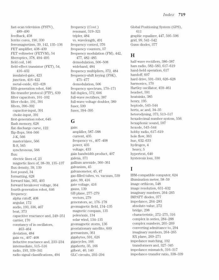
Index 719
fast-scan television (FSTV),489–490
feedback, 458ferrite cores, 190, 330ferromagnetism, 39, 142, 135–136FET amplifier, 438–439FET voltmeter (FETVM), 54fiberoptics, 378, 494–495field coil, 146field-effect transistor (FET), 54,
416–432insulated-gate, 423junction, 416–422metal-oxide, 422–428
fifth-generation robot, 646file-transfer protocol (FTP), 639filter capacitors, 101–102filter choke, 191, 391filters, 390–392
capacitor-input, 391choke-input, 391
first-generation robot, 645flash memory, 628flat discharge curve, 122flip-flops, 564–566
J-K, 566master/slave, 566R-S, 565synchronous, 566
flux:electric lines of, 23magnetic lines of, 38–39, 135–137
flux density, 39, 139foot pound, 34formatting, 628forward bias, 365, 403forward breakover voltage, 364fourth-generation robot, 646frequency:
alpha cutoff, 408angular, 172audio, 193, 336, 467beat, 373capacitive reactance and, 249–251carrier, 170constancy of in oscillators,
463–464deviation, 484gain vs., 407–408inductive reactance and, 233–234intermediate, 515–516radio, 193, 339–341radio signal classifications, 494
frequency (Cont.)resonant, 319–321tripler, 484vs. wavelength, 491
frequency control, 376frequency counters, 57frequency modulation (FM), 442,
477, 482–485demodulation, 506–508wideband, 484
frequency multipliers, 372, 484frequency-shift keying (FSK),
475–477demodulation, 506
frequency spectrum, 170–171full duplex, 572, 606full-wave rectifiers, 387full-wave voltage doubler, 389fuser, 599fuses, 394–395
Ggain:
amplifier, 587–588current, 435frequency vs., 407–408power, 435voltage, 433
gain bandwidth product, 407galena, 371gallium arsenide, 360–361galvanism, 45galvanometer, 45, 47gas-filled tubes, vs. vacuum, 539gate, 99, 416gate voltage, 416gauss, 139GB plane, 277–279
vectors, 279generators, ac, 176–178geomagnetic field, 134–135
magnetic compass, 135poles/axis, 134solar wind, 134–135
geomagnetic storm, 136geostationary satellite, 609germanium, 361gigabytes, 591, 626gigacycles, 166gigahertz, 35, 166gilbert, 40, 140GLC circuits, 292–294
Global Positioning System (GPS),611
graphic equalizer, 447, 595–596grid, 99, 541–542Gunn diodes, 377
Hhalf-wave rectifiers, 386–387ham radio, 582–583, 617–619hand-held operation, 617handoff, 607hard drive, 591–593, 626–628harmonics, 170Hartley oscillator, 459–461headset, 591heatsinks, 385henry, 195heptode, 543–544hertz, ac and, 34–35heterodyning, 373, 513–517hexadecimal number system, 556hexaphonic sound, 597hexode, 543–544hobby radio, 617–619hole flow, 363hue, 632–633hydrogen, 4
heavy, 5hypertext, 640hysteresis loss, 330
IIBM-compatible computer, 624illumination meter, 58–59image orthicon, 548image resolution, 631–632imaginary numbers, 264–265IMPATT diodes, 377impedance, 264–283
absolute-value, 272bridge, 298characteristic, 272–275, 316complex in series, 284–288complex numbers, 265–269converting admittance to, 294imaginary numbers, 264–265RX plane, 269–271
impedance matching, 102transformers and, 327–345
impedance mismatch, 316–317impedance-transfer ratio, 338–339
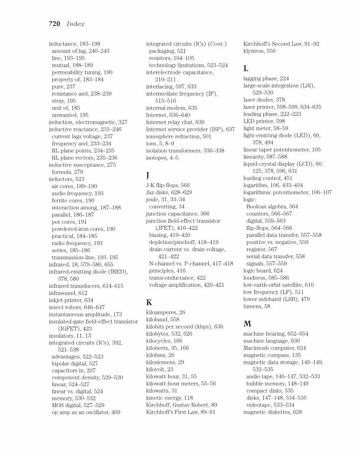
720 Index
inductance, 183–198amount of lag, 240–243line, 193–195mutual, 188–189permeability tuning, 190property of, 183–184pure, 237resistance and, 238–239stray, 195unit of, 185unwanted, 195
induction, electromagnetic, 327inductive reactance, 231–246
current lags voltage, 237frequency and, 233–234RL plane points, 234–235RL plane vectors, 235–236
inductive susceptance, 275formula, 279
inductors, 523air cores, 189–190audio frequency, 193ferrite cores, 190interaction among, 187–188parallel, 186–187pot cores, 191powdered-iron cores, 190practical, 184–185radio frequency, 193series, 185–186transmission-line, 193–195
infrared, 18, 579–580, 655infrared-emitting diode (IRED),
378, 580infrared transducers, 614–615infrasound, 612inkjet printer, 634insect robots, 646–647instantaneous amplitude, 173insulated-gate field-effect transistor
(IGFET), 423insulators, 11, 13integrated circuits (ICs), 392,
521–538advantages, 522–523bipolar digital, 527capacitors in, 207component density, 529–530linear, 524–527linear vs. digital, 524memory, 530–532MOS digital, 527–529op amp as an oscillator, 469
integrated circuits (ICs) (Cont.)packaging, 521resistors, 104–105technology limitations, 523–524
interelectrode capacitance,210–211
interlacing, 597, 633intermediate frequency (IF),
515–516internal modem, 635Internet, 636–640Internet relay chat, 639Internet service provider (ISP), 637ionosphere refraction, 501ions, 5, 8–9isolation transformers, 336–338isotopes, 4–5
JJ-K flip-flops, 566Jaz disks, 628–629joule, 31, 33–34
converting, 34junction capacitance, 366junction field-effect transistor
(JFET), 416–422biasing, 419–420depletion/pinchoff, 418–419drain current vs. drain voltage,
421–422N-channel vs. P-channel, 417–418principles, 416transconductance, 422voltage amplification, 420–421
Kkiloamperes, 26kilobaud, 558kilobits per second (kbps), 636kilobytes, 532, 626kilocycles, 166kilohertz, 35, 166kilohms, 26kilosiemens, 29kilovolt, 23kilowatt hour, 31, 55kilowatt-hour meters, 55–56kilowatts, 31kinetic energy, 118Kirchhoff, Gustav Robert, 89Kirchhoff’s First Law, 89–91
Kirchhoff’s Second Law, 91–92klystron, 550
Llagging phase, 224large-scale integration (LSI),
529–530laser diodes, 378laser printer, 598–599, 634–635leading phase, 222–223LED printer, 598light meter, 58–59light-emitting diode (LED), 60,
378, 494linear taper potentiometer, 105linearity, 587–588liquid-crystal display (LCD), 60,
125, 378, 596, 631loading control, 451logarithm, 106, 433–434logarithmic potentiometer, 106–107logic:
Boolean algebra, 564counters, 566–567digital, 559–563flip-flops, 564–566parallel data transfer, 557–558positive vs. negative, 559register, 567serial data transfer, 558signals, 557–559
logic board, 624loudness, 585–586low-earth-orbit satellite, 610low frequency (LF), 511lower sideband (LSB), 479lumens, 58
Mmachine hearing, 652–654machine language, 630Macintosh computer, 624magnetic compass, 135magnetic data storage, 146–149,
532–535audio tape, 146–147, 532–533bubble memory, 148–149compact disks, 535disks, 147–148, 534–535videotape, 533–534
magnetic diskettes, 628

Index 721
magnetic field, 136magnetic field strength, 139–141
ampere-turn/gilbert units, 140electromagnets, 140–141tesla/gauss units, 139
magnetic force, 135–136magnetic levitation, 136magnetic polarity, 38, 137–138magnetic tape, analog, 599–601magnetic units, 39–40magnetism, 19, 38–39, 134–152
electric charge in motion, 136geomagnetic field, 134–135lines of flux, 38–39, 135–137permeability, 142–143retentivity, 142–143
magnetomotive force, 40, 140magneto-optical storage, 593magnetron, 549–550magnets, permanent, 143–144make-before-break, 607mass storage, 591–594master/slave (M/S) flip-flops, 566maximum usable frequency (MUF),
501maxwell, 39measuring devices, 44–64medium-earth-orbit satellite,
610–611medium-scale integration (MSI),
529megabits per second (Mbps), 636megabytes, 532, 626megacycles, 166megahertz, 35, 166megasiemens, 29megavolt, 23megawatt, 31memory, 148–149, 530–532
bubble, 148–149, 531–532capacity, 630erasable programmable ROM, 531IC storage capacity, 532random-access, 530–531read-only, 531volatility, 631
metal-can package, 521metal-film resistors, 104metal-oxide semiconductors
(MOS), 361, 527–529complementary, 361, 529N-channel, 529P-channel, 529
metal-oxide-semiconductor field-effect transistor (MOSFET),422–428
depletion mode vs. enhancementmode, 425
flexibility, 424problems with, 424super-high input impedance, 423
metal oxides, 361meter shunt, 49meters (see test equipment)mica capacitors, 205microammeter, 49microamperes, 26microfarad, 201microhenry, 185microprocessor, 624–625microsiemens, 29microvolt, 23microwatt, 31microwave signals, 512milliammeter, 49milliampere, 26millihenry, 185millisiemens, 29millivolt, 23milliwatt, 31mixing, 373mobile operation, 617mobile sound system, 596modem, 477, 608, 635–636modulated-light receiver, 517modulation:
amplitude, 475, 478–480de-, 504–509frequency, 442, 477, 482–485phase, 482–485pulse, 485–487pulse amplitude, 485–486pulse code, 486–487pulse duration, 486pulse frequency, 486pulse interval, 486pulse width, 486reactance vs. phase, 483
molecules, 10–12monitor, 631monopoles, 138–139moonbounce, 502Morse code, 442, 475motherboard, 624motors, dc, 145–146multimeters, 49, 53–54
multiplexers, analog, 527multiplexing, time-division, 509multivibrator, 468–469mutual inductance, 188
effects of, 188–189
NNAND gate, 560, 561nanoampere, 26nanohenry, 185neutrons, 4newsgroups, 638noise, 482–483, 619–620noise blanker, 620noise figure (NF), 503–504noise floor, 619noise limiter, 620NOR gate, 560, 561NOT gate, 559, 561nuclear energy, 18nucleus, 4numbering systems:
binary, 556–557decimal, 555–556hexadecimal, 556octal, 556
numbers:atomic, 4, 6–8Boolean algebra, 564complex, 265–269imaginary, 264–265real, 264
Ooctal number system, 556Ohm’s law, 17–18, 69, 298–301ohmmeter, 51–53ohms, 14, 29
resistance and, 26–28operational amplifier (op amp),
524–526as an oscillator, 469
optoisolator, 379OR gate, 560, 561oscillation, 377oscillators, 457–473
Armstrong, 459audio, 468–469beat-frequency, 505Clapp, 461–463Colpitts, 461

722 Index
oscillators (Cont.)concept, 458crystal-controlled, 464–465diode, 467feedback, 458Hartley, 459–461IC, 469parasitic, 545performance reliability, 464Pierce, 464PLL frequency synthesizer, 466stability, 463–464uses, 457variable-frequency, 463–464voltage-controlled, 376, 465–466
oscilloscope, 59–60, 170overdrive, 406–407, 445–446overwhelmingly large-scale integra-
tion (OLSI), 530oxidation, 206ozone, 11
PP-N junction, 363–366packet radio, 617packets, 601paper capacitors, 204–205parallel data transfer, 557–558parallelogram, 286parasitic oscillators, 545peak amplitude, 173peak inverse voltage (PIV), 366,
385–386peak reverse voltage (PRV), 366peak-to-peak amplitude, 174peer-to-peer wireless LAN, 580pen recorders, 59pentode, 542–543perigee, 611permanent magnets, 143–144permeability, 142–143permeability tuning, 190petabyte, 626, 628phase, 172–173, 215–230
degrees of, 172, 218–220instantaneous voltage/current,
215–216lagging, 224leading, 222–223radians of, 172, 221rate of change, 216–217sound, 585–587
phase (Cont.)vector diagrams, 225–226
phase angle, 221, 238cosine of, 310
phase coincidence, 221–222phase-locked loop (PLL), 466, 507phase modulation, 482–485
vs. reactance modulation, 483phase opposition, 222phosphor, 546photoconductivity, 361photodiodes, silicon, 378–379photomultiplier, 548photovoltaic cells, 18, 127, 379photovoltaic effect, 379picofarad, 201Pierce oscillator, 464piezoelectric transducer, 612PIN diode, 374pinchoff, 419plastic-film capacitors, 206plates, 541platters, 591PLL frequency synthesizer, 466polarity, 36polarization, 206, 499portable operation, 617portable sound system, 596–597pot cores, 191potential energy, 118potentiometers, 105–107
audio, 106–107linear taper, 105logarithmic, 106–107
powdered-iron cores, 190, 330power:
ac circuits and, 305–318calculating, 72–73definition, 305–307difference between energy and, 31dissipation, 100–101distribution in parallel circuits,
88–89distribution in series circuits, 88division of, 75energy per unit time, 305–306imaginary, 307instantaneous, 306rating of resistors, 110–111reactive, 308–310true, 307–308, 309–310, 313–315volt-amperes (VA), 306, 309–310watt and, 29–31
power amplifiers, 443–445broadband, 450–451definition of efficiency, 444efficiency vs. class, 445power input, 443–444power output, 444radio-frequency, 544–545tuned, 451–452weak-signal vs., 450
power factor, 310–313power gain, 407,435power supplies, 383–399
parts, 383–384power surges, 393–395power transformers, 334–336,
384–385electronic device, 335–336generating plant, 334ratings, 384–385step-up/step-down, 384transmission lines, 335
power transmission, 315–318measuring, 316–317standing waves, 317–318
printer, 633–635product detectors, 512–517propagation:
auroral, 502radio-wave, 499–502sky-wave, 500–501surface-wave, 500tropospheric, 502
protocol, 636–637protons, 4proximity sensing, 659pulse amplitude modulation (PAM),
485–486, 509pulse code modulation (PCM),
486–487, 509pulse duration modulation (PDM),
486, 509pulse frequency modulation (PFM),
486pulse interval modulation (PIM),
486pulse modulation (PM), 485–487
demodulation, 508–509pulse width modulation (PWM),
486
Qquadraphonic sound, 597
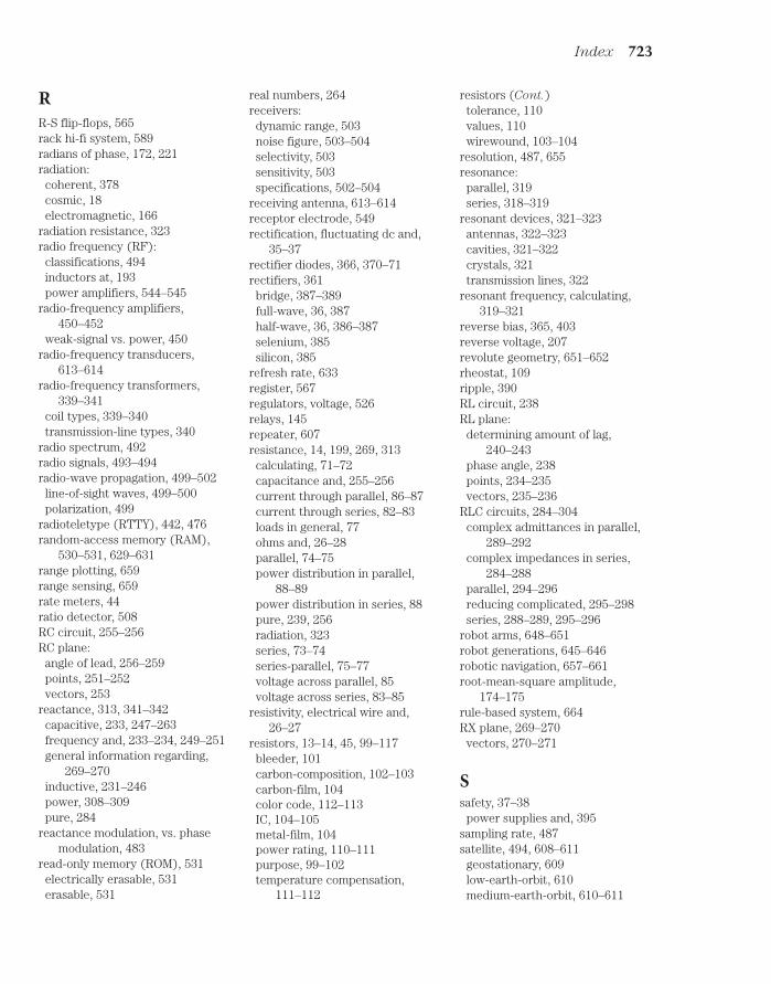
Index 723
RR-S flip-flops, 565rack hi-fi system, 589radians of phase, 172, 221radiation:
coherent, 378cosmic, 18electromagnetic, 166
radiation resistance, 323radio frequency (RF):
classifications, 494inductors at, 193power amplifiers, 544–545
radio-frequency amplifiers,450–452
weak-signal vs. power, 450radio-frequency transducers,
613–614radio-frequency transformers,
339–341coil types, 339–340transmission-line types, 340
radio spectrum, 492radio signals, 493–494radio-wave propagation, 499–502
line-of-sight waves, 499–500polarization, 499
radioteletype (RTTY), 442, 476random-access memory (RAM),
530–531, 629–631range plotting, 659range sensing, 659rate meters, 44ratio detector, 508RC circuit, 255–256RC plane:
angle of lead, 256–259points, 251–252vectors, 253
reactance, 313, 341–342capacitive, 233, 247–263frequency and, 233–234, 249–251general information regarding,
269–270inductive, 231–246power, 308–309pure, 284
reactance modulation, vs. phasemodulation, 483
read-only memory (ROM), 531electrically erasable, 531erasable, 531
real numbers, 264receivers:
dynamic range, 503noise figure, 503–504selectivity, 503sensitivity, 503specifications, 502–504
receiving antenna, 613–614receptor electrode, 549rectification, fluctuating dc and,
35–37rectifier diodes, 366, 370–71rectifiers, 361
bridge, 387–389full-wave, 36, 387half-wave, 36, 386–387selenium, 385silicon, 385
refresh rate, 633register, 567regulators, voltage, 526relays, 145repeater, 607resistance, 14, 199, 269, 313
calculating, 71–72capacitance and, 255–256current through parallel, 86–87current through series, 82–83loads in general, 77ohms and, 26–28parallel, 74–75power distribution in parallel,
88–89power distribution in series, 88pure, 239, 256radiation, 323series, 73–74series-parallel, 75–77voltage across parallel, 85voltage across series, 83–85
resistivity, electrical wire and,26–27
resistors, 13–14, 45, 99–117bleeder, 101carbon-composition, 102–103carbon-film, 104color code, 112–113IC, 104–105metal-film, 104power rating, 110–111purpose, 99–102temperature compensation,
111–112
resistors (Cont.)tolerance, 110values, 110wirewound, 103–104
resolution, 487, 655resonance:
parallel, 319series, 318–319
resonant devices, 321–323antennas, 322–323cavities, 321–322crystals, 321transmission lines, 322
resonant frequency, calculating,319–321
reverse bias, 365, 403reverse voltage, 207revolute geometry, 651–652rheostat, 109ripple, 390RL circuit, 238RL plane:
determining amount of lag,240–243
phase angle, 238points, 234–235vectors, 235–236
RLC circuits, 284–304complex admittances in parallel,
289–292complex impedances in series,
284–288parallel, 294–296reducing complicated, 295–298series, 288–289, 295–296
robot arms, 648–651robot generations, 645–646robotic navigation, 657–661root-mean-square amplitude,
174–175rule-based system, 664RX plane, 269–270
vectors, 270–271
Ssafety, 37–38
power supplies and, 395sampling rate, 487satellite, 494, 608–611
geostationary, 609low-earth-orbit, 610medium-earth-orbit, 610–611

724 Index
saturation, 190, 378, 403color, 597, 632–633
sawtooth wave, 167–169fast-rise/slow-decay, 167slow-rise/fast-decay, 168variable-rise/variable-decay, 169
schematic diagrams, 67vs. wiring diagrams, 68
schematic symbols, 65–67scientific notation, 34second-generation robot, 645sectors, 592, 627selenium, 361selenium rectifiers, 385self-replicating robot, 665semiconductor capacitors, 207semiconductors, 14–15, 359–369
acceptor impurity, 362avalanche effect, 366charge carriers, 362donor impurity, 362doping, 362electron flow, 362–363hole flow, 363materials, 360–361metal-oxide, 361, 527–529P-N junction, 363–366revolution, 359–360
sensitivity, 655serial data port, 635serial data transfer, 558shift register, 567shortwave listening, 618–619shunt resistance, 49sidebands, 479–482, 489siemens, conductance and, 28–29signal logic, 557–559signal mixing, 511–512signals:
low-frequency (LF), 511microwave, 512product detector, 512–517radio, 493–494ultra-high-frequency (UHF), 512very-low-frequency (VLF), 511voice, 479–480
silicon, 360silicon rectifiers, 385sine waves, 35, 167, 216, 474
as circular motion, 217–218single inline package (SIP), 521single sideband (SSB), 480–482
demodulation, 506
single sideband (SSB) (Cont.)transmitter, 481–482voice, 481
sky-wave EM propagation, 500–501slope detection, 506slow-scan television (SSTV), 488smart androids, 663solar cell, 127solar flare, 136solar panel, 127, 379solar wind, 134–135solenoid, 109, 144–145, 331–332
relay device, 145ringer device, 144–145
sound-level meter, 57sound path effects, 584–585sound spectrum, 583–584sound waveforms, 584source, 416source current, 416source computer, 600, 637, 638speaker, 591spectrum analyzer, 170, 373, 479,
547, 584, 619–620spurious emissions, 451square wave, 167stability, 463–464standing waves, 317–318static current amplifier, 405static electricity, 15–16static RAM (SRAM), 530storage register, 567substrate, 417superconductivity, 28superheterodyne, 515–517surface-wave propagation, 500surge current, 393–395surge impedance, 272–275, 316susceptance, 275–276
formulas, 278–279pure, 289
switching, 374symbols and notations, 65–67, 429,
647–650synchronization pulses, 488synchronous flip-flops, 566
Ttantalum capacitors, 206–207tape drive, 593, 629tape media, 629tape recorder, 599–601
telechir, 661–663telepresence, 661–663television:
fast-scan, 489–490slow-scan, 488
temperature coefficient:capacitors, 210negative/positive, 111
temperature compensation, resis-tors, 111–112
terabyte, 626terahertz, 166terminal emulation software, 476terminal unit, 476tesla, 39, 139test equipment, measuring devices,
44–64tests:
alternating current, 345–356answers, 637–646direct current, 153–162
tetrode, 542thermal heating, 44, 47thermal printer, 633–634thermocouple principle, 47third-generation robot, 645–646time-division multiplexing, 509timers, 526tolerance, 110
capacitor, 209–210tone control, 447, 593, 594toroid, 109, 190–191, 332torque, 145tracks, 627transceiver, 606transconductance, 422transformers, 327–345
air-core, 329audio-frequency, 336auto-, 333balanced/unbalanced loads,
337–338broadband, 340core geometries, 330–333cores, 329–330coupling, 338, 447–448ferrite cores, 330impedance-transfer ratio, 338–339isolation, 336–338laminated iron, 330powdered-iron cores, 330power, 334–336, 384–385principles, 327–328

Index 725
transformers (Cont.)radio-frequency, 339–341reactance, 341–342step-up/step-down, 327turns ratio, 328–329utility, 330–331Variac, 393
transient suppressors, 394transistors:
bipolar, 400–415circuit abbreviations, 428field-effect, 54, 416–432NPN vs. PNP, 400–401
transistor-transistor logic (TTL),527
transmission lines, 273–275,315–318
capacitors, 208–209inductors, 193–195measuring power, 316–317overheating, 318power transformers and, 335radio, 493sections, 322transformers, 340types of, 193
transmitters:amplitude modulation, 478single sideband, 481–482
transmitting antenna, 613–614traveling-wave tubes, 549–550treble control, 447triangular wave, 169trimmers, 208triodes, 541–542tropospheric EM propagation,
502truth tables, 562–563tubes:
cathode, 540–541, 544cathode-ray, 546–547diode, 540–541electron, 539–554heptode, 543–544hexode, 543–544klystron, 550magnetron, 549–550obsolete, 544pentode, 542–543RF power amplifiers, 544–545tetrode, 542traveling-wave, 549–550triode, 541–542
tubes (Cont.)vacuum vs. gas-filled, 539video camera, 547–549
tuner, 589–591tuning control, 451tunnel diodes, 377turns ratio, 328–329
Uultra-large-scale integration
(ULSI), 530ultra-high frequency (UHF), 512ultrasound, 577, 612ultraviolet, 655upper sideband (USB), 479username, 639
Vvacuum tubes, vs. gas-filled, 539vacuum-tube voltmeter (VTVM), 54varactors, 207, 376variable capacitors, 207–209variable-frequency oscillator
(VFO), 463–464Variac transformer, 393vector diagrams, phase relation-
ship, 225–226very large-scale integration (VLSI),
530very low frequency (VLF), 511vestigial sideband (VSB), 489video camera tubes, 547–549videotape, 533–534vidicon, 548vinyl disk, 598visible wavelengths, 655vision system, 654–655volt, 23–24volt-amperes (VA), 306volt-ohm-milliammeter (VOM),
53–54voltage:
calculating, 71forward breakover, 364across parallel resistances, 85reverse, 207across series resistances, 83–85
voltage amplification, 420–421voltage-controlled oscillator (VCO),
376, 465–466voltage dividers, 92–94, 99
voltage doubler, 389–390voltage gain, 407voltage multipliers, 389voltage regulation, 374voltage regulators, 392–393,
526tubes, 392–393
voltmeters, 49–51FET, 54vacuum-tube, 54
volume control, 447volume units (VU), 57VU meter, 57
Wwatt, power and, 29–31watt hour, energy and, 31–32watt-hour meters, 55–56watts rms, 57waveforms, 222
amplitude, 173–175angular frequency, 172audio, 467carrier, 474complex/irregular, 169cosine, 217cycles/phases, 172frequency spectrum, 170–171out of phase, 222period/frequency, 165–166phase difference, 173ramp, 168sawtooth, 167–169sine, 35, 167, 216–218, 474square, 167standing, 317–318triangular, 169(See also phase)
waveguides, 493waves:
direct, 500line-of-sight, 499–500reflected, 500surface, 500
webers, 39Web, 640Web site, 603, 640Weston standard cell, 120winding:
core method, 331primary/secondary, 327shell method, 330–331

726 Index
wire:resistivity, 26–27(See also transmission lines)
wireless local area networks,615–616
wireless security systems, 616–617
wirewound resistors, 103–104wiring diagrams, 68World Wide Web, 640
XXNOR gate, 560, 561
XOR gate, 560, 562
ZZener diodes, 366, 374, 392zero bias, 402–403Zip disks, 628–629

About the AuthorStan Gibilisco is a popular and respected electronics and science author specializingin reference works. His Encyclopedia of Electronics was named a “Best Referenceof the 1980s” by the American Library Association. A former radio engineer andtechnical writer in electronics, he has also written The Illustrated Dictionary of
Electronics, now in its eighth edition, and the Handbook of Radio and Wireless
Technology, among many other books.
727