Tailoring the Local Design of Deep Water Composite Risers to ...
33
Citation: Amaechi, C.V.; Gillet, N.; Ja’e, I.A.; Wang, C. Tailoring the Local Design of Deep Water Composite Risers to Minimise Structural Weight. J. Compos. Sci. 2022, 6, 103. https:// doi.org/10.3390/jcs6040103 Academic Editor: Jiadeng Zhu Received: 17 December 2021 Accepted: 22 March 2022 Published: 26 March 2022 Publisher’s Note: MDPI stays neutral with regard to jurisdictional claims in published maps and institutional affil- iations. Copyright: © 2022 by the authors. Licensee MDPI, Basel, Switzerland. This article is an open access article distributed under the terms and conditions of the Creative Commons Attribution (CC BY) license (https:// creativecommons.org/licenses/by/ 4.0/). Article Tailoring the Local Design of Deep Water Composite Risers to Minimise Structural Weight Chiemela Victor Amaechi 1,2, * , Nathaniel Gillet 3, *, Idris Ahmed Ja’e 4,5 and Chunguang Wang 6 1 Department of Engineering, Lancaster University, Bailrigg, Lancaster LA1 4YR, UK 2 Standards Organisation of Nigeria (SON), 52 Lome Crescent, Wuse Zone 7, Abuja 900287, Nigeria 3 Department of Production Engineering, Trident Energy, Wilton Road, London SW1V 1JZ, UK 4 Department of Civil Engineering, Universiti Teknologi PETRONAS, Seri Iskander 32610, Malaysia; [email protected] 5 Department of Civil Engineering, Ahmadu Bello University, Zaria 810107, Nigeria 6 School of Civil and Architectural Engineering, Shandong University of Technology, Zibo 255000, China; [email protected] * Correspondence: [email protected] (C.V.A.); [email protected] (N.G.) Abstract: Following the rising technological advancements on composite marine structures, there is a corresponding surge in the demand for its deployment as ocean engineering applications. The push for exploration activities in deep waters necessitates the need for composite marine structures to reduce structural payload and lessen weights/loads on platform decks. This gain is achieved by its high strength–stiffness modulus and light-in-weight attributes, enabling easier marine/offshore oper- ations. Thus, the development of composite marine risers considers critical composite characteristics to optimize marine risers’ design. Hence, an in-depth study on composite production risers (CPR) is quite pertinent in applying composite materials to deep water applications. Two riser sections of 3 m and 5 m were investigated under a 2030 m water depth environment to minimise structural weight. ANSYS Composites ACP was utilized for the CPR’s finite element model (FEM) under different load conditions. The choice of the material, the fibre orientation, and the lay-up configurations utilised in the modelling technique have been reported. In addition, the behaviour of the composite risers’ layers under four loadings has been investigated under marine conditions. Recommendations were made for the composite tubular structure. Results on stresses and weight savings were obtained from different composite riser configurations. The recommended composite riser design that showed the best performance is AS4/PEEK utilising PEEK liner, however more work is suggested using global design loadings on the CPR. Keywords: composite riser; tailored local design; finite element model (FEM); marine pipeline risers; composite marine structures; numerical modelling; advanced composite material; stress 1. Introduction Presently, the global demand for oil/gas products has induced the incremental need for rapid technological advances in novel materials [1–6]. Such an advancement in composite materials has been induced by the increased application of marine composites [7,8] and the shift in the fluid-transfer operations from shallow water to deep water [9–13]. This trend is particularly evident in the developments achieved on deep water composite risers [14–18]. However, the deep water operations require more riser lengths, resulting in a considerable increment in weight. The number of the risers needed depends on the type of offshore structure, the type of risers required, the riser configuration considered, and the water depth [19–22]. Improving the riser technology is a challenge, as such composite materials are recommended as an excellent choice. The composites proffer superior positives, which can be utilised. These benefits include weight gains, high strength attributes, high fatigue resistance, low bending stiffness, high corrosion resistance, and light weight [23–30]. Due J. Compos. Sci. 2022, 6, 103. https://doi.org/10.3390/jcs6040103 https://www.mdpi.com/journal/jcs
-
Upload
khangminh22 -
Category
Documents
-
view
4 -
download
0
Transcript of Tailoring the Local Design of Deep Water Composite Risers to ...

�����������������
Citation: Amaechi, C.V.; Gillet, N.;
Ja’e, I.A.; Wang, C. Tailoring the Local
Design of Deep Water Composite
Risers to Minimise Structural Weight.
J. Compos. Sci. 2022, 6, 103. https://
doi.org/10.3390/jcs6040103
Academic Editor: Jiadeng Zhu
Received: 17 December 2021
Accepted: 22 March 2022
Published: 26 March 2022
Publisher’s Note: MDPI stays neutral
with regard to jurisdictional claims in
published maps and institutional affil-
iations.
Copyright: © 2022 by the authors.
Licensee MDPI, Basel, Switzerland.
This article is an open access article
distributed under the terms and
conditions of the Creative Commons
Attribution (CC BY) license (https://
creativecommons.org/licenses/by/
4.0/).
Article
Tailoring the Local Design of Deep Water Composite Risers toMinimise Structural WeightChiemela Victor Amaechi 1,2,* , Nathaniel Gillet 3,*, Idris Ahmed Ja’e 4,5 and Chunguang Wang 6
1 Department of Engineering, Lancaster University, Bailrigg, Lancaster LA1 4YR, UK2 Standards Organisation of Nigeria (SON), 52 Lome Crescent, Wuse Zone 7, Abuja 900287, Nigeria3 Department of Production Engineering, Trident Energy, Wilton Road, London SW1V 1JZ, UK4 Department of Civil Engineering, Universiti Teknologi PETRONAS, Seri Iskander 32610, Malaysia;
[email protected] Department of Civil Engineering, Ahmadu Bello University, Zaria 810107, Nigeria6 School of Civil and Architectural Engineering, Shandong University of Technology, Zibo 255000, China;
[email protected]* Correspondence: [email protected] (C.V.A.); [email protected] (N.G.)
Abstract: Following the rising technological advancements on composite marine structures, thereis a corresponding surge in the demand for its deployment as ocean engineering applications. Thepush for exploration activities in deep waters necessitates the need for composite marine structuresto reduce structural payload and lessen weights/loads on platform decks. This gain is achieved by itshigh strength–stiffness modulus and light-in-weight attributes, enabling easier marine/offshore oper-ations. Thus, the development of composite marine risers considers critical composite characteristicsto optimize marine risers’ design. Hence, an in-depth study on composite production risers (CPR) isquite pertinent in applying composite materials to deep water applications. Two riser sections of 3 mand 5 m were investigated under a 2030 m water depth environment to minimise structural weight.ANSYS Composites ACP was utilized for the CPR’s finite element model (FEM) under different loadconditions. The choice of the material, the fibre orientation, and the lay-up configurations utilisedin the modelling technique have been reported. In addition, the behaviour of the composite risers’layers under four loadings has been investigated under marine conditions. Recommendations weremade for the composite tubular structure. Results on stresses and weight savings were obtained fromdifferent composite riser configurations. The recommended composite riser design that showed thebest performance is AS4/PEEK utilising PEEK liner, however more work is suggested using globaldesign loadings on the CPR.
Keywords: composite riser; tailored local design; finite element model (FEM); marine pipeline risers;composite marine structures; numerical modelling; advanced composite material; stress
1. Introduction
Presently, the global demand for oil/gas products has induced the incremental need forrapid technological advances in novel materials [1–6]. Such an advancement in compositematerials has been induced by the increased application of marine composites [7,8] and theshift in the fluid-transfer operations from shallow water to deep water [9–13]. This trend isparticularly evident in the developments achieved on deep water composite risers [14–18].However, the deep water operations require more riser lengths, resulting in a considerableincrement in weight. The number of the risers needed depends on the type of offshorestructure, the type of risers required, the riser configuration considered, and the waterdepth [19–22]. Improving the riser technology is a challenge, as such composite materialsare recommended as an excellent choice. The composites proffer superior positives, whichcan be utilised. These benefits include weight gains, high strength attributes, high fatigueresistance, low bending stiffness, high corrosion resistance, and light weight [23–30]. Due
J. Compos. Sci. 2022, 6, 103. https://doi.org/10.3390/jcs6040103 https://www.mdpi.com/journal/jcs

J. Compos. Sci. 2022, 6, 103 2 of 33
to the exciting features of composite materials, there is growth in the application andrecent research on offshore composites, marine composites, and composite risers [31–40].However, recent studies on these structures reflect the necessity to design composite risersby considering the loadings including environmental loads [41–48]. A typical compositeriser pipe technology called M-pipe developed by Magma is shown in Figure 1.
J. Compos. Sci. 2022, 6, x FOR PEER REVIEW 2 of 36
high fatigue resistance, low bending stiffness, high corrosion resistance, and light weight [23–30]. Due to the exciting features of composite materials, there is growth in the appli-cation and recent research on offshore composites, marine composites, and composite ris-ers [31–40]. However, recent studies on these structures reflect the necessity to design composite risers by considering the loadings including environmental loads [41–48]. A typical composite riser pipe technology called M-pipe developed by Magma is shown in Figure 1.
(a) (b)
Figure 1. Composite riser pipe section with Magma m-pipe end fittings, showing (a) end-fitting with fittings, pipe, seal and smaller flange (b) end-fitting coupled with pipe and bigger flange with unique bolt ends (courtesy: Technip FMC’s Magma Global).
Composite marine risers have been considered for deployment, utilisation in deep waters, and as composite production risers [49–58]. These studies reflect different novel approaches on composite riser design and analysis. These studies also underpin the stress deformations alongside the buckling attributes of the structure. Research on composite risers stems from previous studies on shells, composite tubulars, and cylindrical struc-tures [34,59–65] as seen in current related standards [66–71]. The first successful deploy-ment of composite risers was a joint for composite risers installed on the Heidrun offshore platform [2,23,72–74]. Subsequently, the design evolution of composite risers has been achieved progressively for over 30 years [2,14–18,23]. The solutions on weight reduction and efficiency improvement were conducted using fibre reinforcements at an angle of +/− 55° by Doris Engineering [15]. The authors presented their design that assumed the fibres in each layer were load-bearing, according to netting theory [25,74–78]. However, there were no stresses in the transverse direction, and that resulted in an efficient angle of +/− 54.7°. This study helped in the application of the filament winding technique on composite risers [60,61], design of prototypes [17,38,79,80], experimental tests [81–86], and the global–local design [42–46,87–91] and safety-reliability assessments [92–95]. Similarly, the developments led to advances in end-fitting designs, the metal–composite interface (MCI), debonding, delamination, and composite riser joint design. In a nutshell, more studies focused on the strength performance, buckling, material choice, and fibre orienta-tion and optimization of composite risers [96–105]. The technology for composite risers is not fully enabled for full deployment. It is currently used as a hybrid riser system, since it is a supporting or enabling technology which implies that it requires more investigation for its qualification for deep water applications [106]. Jha et al. [107] presented various optimised hybrid composite pipe solutions by appreciating the variety of composite pipe design concepts and addressing key concerns bearing on both the manufacturing and cus-tomer acceptability point of view. Tan et al. [44] investigated 1500 m composite risers by utilising coupling analysis in both global and local analysis, whereby the authors found that titanium liner had lesser root mean square (RMS) strains than aluminium liner. How-ever, the technology challenges for composite risers are based on the weight of risers lim-iting their lengths and motion of offshore operation facilities when applied further into
Figure 1. Composite riser pipe section with Magma m-pipe end fittings, showing (a) end-fitting withfittings, pipe, seal and smaller flange (b) end-fitting coupled with pipe and bigger flange with uniquebolt ends (courtesy: Technip FMC’s Magma Global).
Composite marine risers have been considered for deployment, utilisation in deepwaters, and as composite production risers [49–58]. These studies reflect different novelapproaches on composite riser design and analysis. These studies also underpin thestress deformations alongside the buckling attributes of the structure. Research on com-posite risers stems from previous studies on shells, composite tubulars, and cylindricalstructures [34,59–65] as seen in current related standards [66–71]. The first successful de-ployment of composite risers was a joint for composite risers installed on the Heidrunoffshore platform [2,23,72–74]. Subsequently, the design evolution of composite risers hasbeen achieved progressively for over 30 years [2,14–18,23]. The solutions on weight reduc-tion and efficiency improvement were conducted using fibre reinforcements at an angle of+/− 55◦ by Doris Engineering [15]. The authors presented their design that assumed thefibres in each layer were load-bearing, according to netting theory [25,74–78]. However,there were no stresses in the transverse direction, and that resulted in an efficient angleof +/− 54.7◦. This study helped in the application of the filament winding technique oncomposite risers [60,61], design of prototypes [17,38,79,80], experimental tests [81–86], andthe global–local design [42–46,87–91] and safety-reliability assessments [92–95]. Similarly,the developments led to advances in end-fitting designs, the metal–composite interface(MCI), debonding, delamination, and composite riser joint design. In a nutshell, more stud-ies focused on the strength performance, buckling, material choice, and fibre orientationand optimization of composite risers [96–105]. The technology for composite risers is notfully enabled for full deployment. It is currently used as a hybrid riser system, since itis a supporting or enabling technology which implies that it requires more investigationfor its qualification for deep water applications [106]. Jha et al. [107] presented variousoptimised hybrid composite pipe solutions by appreciating the variety of composite pipedesign concepts and addressing key concerns bearing on both the manufacturing andcustomer acceptability point of view. Tan et al. [44] investigated 1500 m composite risers byutilising coupling analysis in both global and local analysis, whereby the authors found thattitanium liner had lesser root mean square (RMS) strains than aluminium liner. However,the technology challenges for composite risers are based on the weight of risers limitingtheir lengths and motion of offshore operation facilities when applied further into deepwaters [35–37,47,89]. An illustration of the composite marine risers with loads acting onthe structure is represented in Figure 2.

J. Compos. Sci. 2022, 6, 103 3 of 33
J. Compos. Sci. 2022, 6, x FOR PEER REVIEW 3 of 36
deep waters [35–37,47,89]. An illustration of the composite marine risers with loads acting on the structure is represented in Figure 2.
Figure 2. Typical composite riser showing composite stack-up, cross-section, and some loads (not drawn to scale).
Another engineering challenge is the qualification of lengthy CPRs, as more novel optimized designs are required. Some discussions on optimization were presented in dif-ferent literature [97–104]. Harte et al. [101,102] carried out some optimisation techniques on composite pipelines using a safety factor of 4.5. The authors observed that to lessen the composite pipeline’s weight, optimisation had to be conducted around the composite pipeline joint (CPJ). They also found a significant reduction in the peak stresses and the weight of the pipeline. Composite riser designs evolved into optimized designs as pre-sented with a prototype using bonded and unbonded armours [108]. Amaechi et al. [87,88] introduced a novel numerical approach for the 18-layered composite riser structure using the ANSYS Composites ACP module and presented some safety factors on the structure under six unique loading cases and concluded that the finite element model was recom-mended for the validated design. Wang et al. [45–48,89] investigated global and local de-sign of composite risers using ANSYS APDL and presented stress profiles for some con-figurations used to investigate the reduction in the structural weight under critical load cases. In addition, this technique considered the manual tailoring effects by using multiple variables for less, which was later optimised using surrogate-assisted evolutionary algo-rithm (SAEA) optimisation [104], which led to a weight reduction of 25% from the designs. Singh and Ahmad [91] presented a numerical design of carbon epoxy composite produc-tion risers carried out using ABAQUS AQUA in random water waves and investigated the global and local design using steel liner by considering the limit state failure criteria and validated the study with a composite riser model by Kim [108]. Other numerical methods deployed include homogenization of the multilayered composite offshore pro-duction risers [109,110]. In another study on the failure analysis of composite cylindrical structure by Bhavya et al. [111], the failure criteria applied were the Tsai-Wui and the maximum normal stress theories. They studied the influence of diameter to thickness ratio
Figure 2. Typical composite riser showing composite stack-up, cross-section, and some loads (notdrawn to scale).
Another engineering challenge is the qualification of lengthy CPRs, as more noveloptimized designs are required. Some discussions on optimization were presented in differ-ent literature [97–104]. Harte et al. [101,102] carried out some optimisation techniques oncomposite pipelines using a safety factor of 4.5. The authors observed that to lessen the com-posite pipeline’s weight, optimisation had to be conducted around the composite pipelinejoint (CPJ). They also found a significant reduction in the peak stresses and the weight ofthe pipeline. Composite riser designs evolved into optimized designs as presented with aprototype using bonded and unbonded armours [108]. Amaechi et al. [87,88] introduced anovel numerical approach for the 18-layered composite riser structure using the ANSYSComposites ACP module and presented some safety factors on the structure under sixunique loading cases and concluded that the finite element model was recommendedfor the validated design. Wang et al. [45–48,89] investigated global and local design ofcomposite risers using ANSYS APDL and presented stress profiles for some configurationsused to investigate the reduction in the structural weight under critical load cases. Inaddition, this technique considered the manual tailoring effects by using multiple variablesfor less, which was later optimised using surrogate-assisted evolutionary algorithm (SAEA)optimisation [104], which led to a weight reduction of 25% from the designs. Singh andAhmad [91] presented a numerical design of carbon epoxy composite production riserscarried out using ABAQUS AQUA in random water waves and investigated the global andlocal design using steel liner by considering the limit state failure criteria and validatedthe study with a composite riser model by Kim [108]. Other numerical methods deployedinclude homogenization of the multilayered composite offshore production risers [109,110].In another study on the failure analysis of composite cylindrical structure by Bhavyaet al. [111], the failure criteria applied were the Tsai-Wui and the maximum normal stresstheories. They studied the influence of diameter to thickness ratio under pressure loads onfour-layered and six-layered cylindrical structures using the finite element model.
The tailored local design on composite risers for deep water environments to minimisethe structural weight is presented herein. In this paper, Section 1 presents the introduction,
J. Compos. Sci. 2022, 6, 103 4 of 33
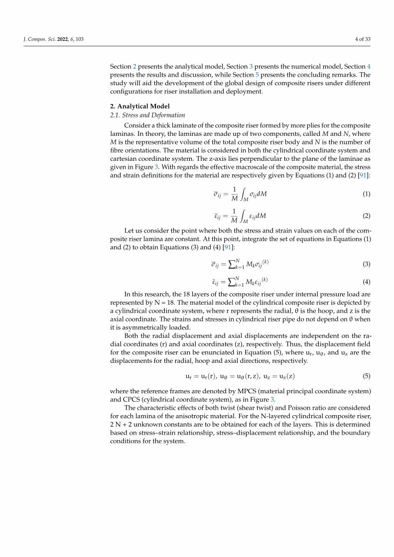
Section 2 presents the analytical model, Section 3 presents the numerical model, Section 4presents the results and discussion, while Section 5 presents the concluding remarks. Thestudy will aid the development of the global design of composite risers under differentconfigurations for riser installation and deployment.
2. Analytical Model2.1. Stress and Deformation
Consider a thick laminate of the composite riser formed by more plies for the compositelaminas. In theory, the laminas are made up of two components, called M and N, whereM is the representative volume of the total composite riser body and N is the number offibre orientations. The material is considered in both the cylindrical coordinate system andcartesian coordinate system. The z-axis lies perpendicular to the plane of the laminae asgiven in Figure 3. With regards the effective macroscale of the composite material, the stressand strain definitions for the material are respectively given by Equations (1) and (2) [91]:
σij =1M
∫M
σijdM (1)
εij =1M
∫M
εijdM (2)
Let us consider the point where both the stress and strain values on each of the com-posite riser lamina are constant. At this point, integrate the set of equations in Equations (1)and (2) to obtain Equations (3) and (4) [91]:
σij = ∑Nk=1 Mkσij
(k) (3)
εij = ∑Nk=1 Mkεij
(k) (4)
In this research, the 18 layers of the composite riser under internal pressure load arerepresented by N = 18. The material model of the cylindrical composite riser is depicted bya cylindrical coordinate system, where r represents the radial, θ is the hoop, and z is theaxial coordinate. The strains and stresses in cylindrical riser pipe do not depend on θ whenit is asymmetrically loaded.
Both the radial displacement and axial displacements are independent on the ra-dial coordinates (r) and axial coordinates (z), respectively. Thus, the displacement fieldfor the composite riser can be enunciated in Equation (5), where ur, uθ, and uz are thedisplacements for the radial, hoop and axial directions, respectively.
ur = ur(r), uθ = uθ(r, z), uz = uz(z) (5)
where the reference frames are denoted by MPCS (material principal coordinate system)and CPCS (cylindrical coordinate system), as in Figure 3.
The characteristic effects of both twist (shear twist) and Poisson ratio are consideredfor each lamina of the anisotropic material. For the N-layered cylindrical composite riser,2 N + 2 unknown constants are to be obtained for each of the layers. This is determinedbased on stress–strain relationship, stress–displacement relationship, and the boundaryconditions for the system.

J. Compos. Sci. 2022, 6, 103 5 of 33J. Compos. Sci. 2022, 6, x FOR PEER REVIEW 5 of 36
Figure 3. Representation of cylindrical coordinate and material principal coordinate systems.
2.2. Elastic Solution of Stresses The classical laminate theory has been utilised in the design approach for the CPR.
This is used to evaluate the stack-up and laminate properties by considering the laminate forces. The composite riser is considered as a shell model with nodal deformations. Ade-quate bonding of the layers is necessary to ensure less stress on the laminates. The material properties for the composite riser are provided for each layer with different thickness, as described in Section 3. The mechanical behaviour of the composite riser is dependent on the material attributes, the orientation angle of the lay-ups, and the laminate thicknesses. Although risers are slender structures, we design the composite riser as a shell with char-acteristic values. These are given as the in-plane laminate stiffness and flexural laminate stiffness, respectively. Under operational conditions, we can formulate the boundary con-ditions for the composite riser.
Consider the three-dimensional material properties for multilayered composite ma-terials, having engineering constants where the matrix elements for the material modulus are given by Cij (i,j = x,y,z) and Gii (i = x,y,z). Assume transverse isotropy for the unknown equivalent characteristics along the y-z axis of the unidirectional composite material(s). The denotation for the engineering constant is Ei (i = x,y,z), the material’s principal axis along the fibre direction is x, and the material’s principal axis along the transverse direc-tion is y; thus the illustration in Figure 3.
2.3. Constitutive Equation For the local design of the composite risers, consider a composite hose tube acted
upon by internal pressure; thus, it will be subject to the orientation of the composite lam-inate and the winding angle ∅. However, when there is axisymmetric loading acting on the composite tube, such as internal pressure loads, the relationship for the stresses and
Figure 3. Representation of cylindrical coordinate and material principal coordinate systems.
2.2. Elastic Solution of Stresses
The classical laminate theory has been utilised in the design approach for the CPR. Thisis used to evaluate the stack-up and laminate properties by considering the laminate forces.The composite riser is considered as a shell model with nodal deformations. Adequatebonding of the layers is necessary to ensure less stress on the laminates. The materialproperties for the composite riser are provided for each layer with different thickness, asdescribed in Section 3. The mechanical behaviour of the composite riser is dependent onthe material attributes, the orientation angle of the lay-ups, and the laminate thicknesses.Although risers are slender structures, we design the composite riser as a shell withcharacteristic values. These are given as the in-plane laminate stiffness and flexural laminatestiffness, respectively. Under operational conditions, we can formulate the boundaryconditions for the composite riser.
Consider the three-dimensional material properties for multilayered composite mate-rials, having engineering constants where the matrix elements for the material modulus aregiven by Cij (i, j = x, y, z) and Gii (i = x, y, z). Assume transverse isotropy for the unknownequivalent characteristics along the y-z axis of the unidirectional composite material(s).The denotation for the engineering constant is Ei (i = x, y, z), the material’s principal axisalong the fibre direction is x, and the material’s principal axis along the transverse directionis y; thus the illustration in Figure 3.
2.3. Constitutive Equation
For the local design of the composite risers, consider a composite hose tube acted uponby internal pressure; thus, it will be subject to the orientation of the composite laminateand the winding angle ∅. However, when there is axisymmetric loading acting on thecomposite tube, such as internal pressure loads, the relationship for the stresses and strainsbecomes dependent on θ, such that Equation (6) holds, where u, σ, and ε represent thedisplacement vector, stress tensor, and strain tensor, respectively.
∂u∂θ
= 0,∂σ
∂θ= 0,
∂ε
∂θ= 0 (6)

J. Compos. Sci. 2022, 6, 103 6 of 33
There will be a resultant force that acts laterally on the material of the compositehose tube or composite riser pipe when it is subjected to constant internal pressure. Thatresultant force is proportional to the constant tension force which produces a constantaxial strain. Considering the stress analysis of composite tubes and composite risers, it isdetermined based on the thickness of the wall. For the present study, the stress analysisof thick-walled composite is applied. Details on the numerical modelling approach arediscussed in Section 3. The results of this analytical model were computed and comparedwith the numerical model as presented in Section 4.1. See analytical formulations in [112].
3. Numerical Model3.1. The Model Design
The model designed for the CPR in this research is the local design investigatedutilising the ANSYS workbench. It was used to design the riser by considering it as a multi-layered structure. A comparative study between the tailored model and the conventionalmodel of the composite riser was conducted in the local design. Optimisation and globaldesign were also carried out but not detailed in the present study. The particulars for theCPR are detailed in Table 1. This design was carried out for a CPR operating in a waterdepth of 2030 m. The effective weight of the riser was taken into account in the riser’stension computation depending on the wall thickness(es) utilised. The extreme cases forthe burst analysis are not included, and the tension of the riser was designed differently.In the design of the composite riser, three approaches were considered: numerical design,conventional design, and analytical design. The constitutive model for the composite riserwas derived using the analytical design. The traditional design of composites is based onorthogonal design, in which laminate reinforcements are exclusively positioned along thehoop and axial fibre directions. In this approach, the composite risers’ plies are orientedsimilarly, wherein both the axial and hoop layers are oriented at 0◦ and 90◦, respectively.
The composite riser design was analysed by applying maximal stress distributionas the failure criteria. This was on each composite lamina (layer), as the design targetsthe implementation in deep waters. The effects of the fibre orientation and materialcombinations were investigated in in-plane shear, transverse, and fibre directions. Thedistribution was formulated under four different load cases. In order to analyse the stressesin composite riser body of the composite materials, we used the finite element model (FEM)software, utilising ANSYS ACP (versions R18.2 and R1 2021) [113,114]. Two riser sectionsof 3 m and 5 m were applied in the local design, and the consequence of the burst case wasvalidated numerically. The riser design was considered for application in deep waters ofabout 2030 m depth. The water depth is vital for global design, which is not conductedherein; however, further considerations should include the global design of the compositeriser.
Table 1. Parameters for the composite riser model.
Particulars Value Unit
Material Composites -
Number of Layers 17, 18, and 21 -
Failure Criteria Max. Stress -
Innermost Layer Liner -
Outer Diameter 0.305 m
Length of Riser Section 3.000 m
Ocean Depth 2030.000 m
Surface Area 7.661 m2

J. Compos. Sci. 2022, 6, 103 7 of 33
3.2. Material Properties
The material properties considered in this local design are used to model the com-posite riser. The setup for the material model includes the materials for the matrix, thefibre reinforcements, and the liners considered in the design, as presented in Tables 2 and 3.The scientific basis for selecting parameters in Tables 2 and 3 is based on specificationsrecommended in the ABS industry standard [70]. The design considerations for the con-ditions for the composite production riser (CPR) are pressure resistance, fluid tightness,and fluid capillarity. As such, the choice of design materials for the CPR, particularly theliner, includes the prevention of fluid leakage. On that note, the key considerations are notonly the choice of the fibre reinforcements and the matrix but also the materials selection.Hence, the materials selected must be able to withstand different mechanical loadings anddifferent environmental conditions, as specified in DNV and ABS standards [66–70]. Con-sidering a composite marine riser that is fully operational, high pressure conditions mustbe considered. The elastic constants considered in the material properties were utilisedbased on the theory applied by Sun and Li [115]. Based on the classical laminate theory,the laminates for the composite riser were efficiently analysed. The walls of this compositemarine riser are considered as thick laminates. Thus, higher-order mathematical theories(HOMT) with three-dimensional (3D) material characteristics are required. The homoge-nous solid was used for a characteristic lengthwise span of the CPR. Due to deformation inthe global composite riser, there is comparative deformation when compared to compositematerials of shorter lengths. Considering the classical laminate theory (CLT), constantson the in-plane effective properties of the composite body can be generated. Thus, theremust be three-dimensional effective properties. The material properties of the compositeriser depend on time, static loads (tension and pressure), and environmental conditions(such as temperature, chemicals, or water). These properties were obtained via severalvalidated scientific studies, as in referenced publications and technical reports [116–119].These selected composite materials were also validated for the composite riser model, usingverified modelling methods [3–5,87–91].
Table 2. Material characteristics for unidirectional FRP lamina.
Parameter/Description
Fibre VolumeFraction
Density(kg/m3)
E1(GPa)
E2 = E3(GPa)
G12 = G13(GPa)
G23(GPa)
σT1
(GPa)σc
1(GPa)
σT2
(GPa)σc
2(GPa)
τ12(GPa) V12 = V13 V23
(APC2)IM7/PEEK 0.55 1320.0 172.00 8.30 5.50 2.80 2900 1300 48.3 152.0 68.0 0.27 0.48
(V2021) Carbonfibre/Epoxy 0.55 1580.0 10.32 10.32 7.97 3.70 4900 1470 69.0 146.0 98.0 0.27 0.50
(APC2)P75/PEEK 0.55 1773.0 280.00 6.70 3.43 1.87 668 364 24.8 136.0 68.0 0.30 0.69
(T700) Carbonfibre/Epoxy 0.58 1580.0 230.00 20.90 27.60 2.70 4900 1470 69.0 146.0 98.0 0.20 0.27
(APC2)AS4/PEEK 0.58 1561.0 131.00 8.70 5.00 2.78 1648 864 62.4 156.8 125.6 0.28 0.48
(S-2) Glassfibre/Epoxy 0.55 2464.0 87.93 16.00 9.00 2.81 4890 1586 55.0 148.0 70.0 0.26 0.28
(938)P75/Epoxy 0.55 1776.0 310.00 6.60 4.10 2.12 720 328 22.4 55.2 176.0 0.29 0.70
(938)AS4/Epoxy 0.60 1530.0 135.40 9.37 4.96 3.20 1732 1256 49.4 167.2 71.2 0.32 0.46
FRP—fibre-reinforced plastics; S-2—AGY glass fibre; T700—Toray carbon fibre; PEEK—polyether-ether-ketone.1st subscript—fibre path; 2nd subscript—transverse path; 3rd subscript—in-plane shear path. Composite plycalculations were on stress components with orientations in these 3 directions called stress directions or stresspaths. V1, V2, V3—Poisson’s ratios; G12, G13, G23—shear moduli; E2, E2, E3—elastic moduli. HS—high-strength;superscript C—compression; superscript T—tension.

J. Compos. Sci. 2022, 6, 103 8 of 33
Table 3. Material characteristics for liners.
Parameter/Description Poisson’sRatio, V
Elongation atBreak (%)
Ultimate Stress(MPa)
Yield Stress(MPa)
Elastic Modulus(MPa)
Density(kg/m3)
(Victrex) PEEK 0.400 45.00 125.0 110.0 4.0 1300.0
HDPE 0.460 10.00 43.0 1350.0 565.0 995.0
(Nylon PA) PA12 0.400 10.00 54.0 1500.0 540.0 1010.0
PVDF 0.400 10.00 54.0 1540.0 550.0 1780.0
(X80) Steel 0.300 5.90 950.0 880.0 207.0 7850.0
(1953T1) Aluminium alloy 0.300 7.50 540.0 480.0 71.0 2780.0
(Ti6Al4V) Titanium alloy 0.342 14.00 950.0 880.0 113.8 4430.0
PEEK—polyether-ether-ketone; HDPE—high-density polyethelene; PVDF—polyvinylidene fluoride; PA12—polyamide 12.
3.3. Stack-Up Sequence
Modelling of the composite riser layers was conducted by considering the arrangementof the plies. The layers were arranged by considering the stack-up sequence in Table 4. Thisincluded the arrangement of the matrix and the fibre reinforcements. Sketch of stack-upsequence of laminate ply showing different layer orientations is shown in Figure 4. Table 4only shows the matrix mix using titanium liner, but other liners were also used as seen inSection 4. The rules of matrix used in this study are not discussed herein. However, it isnoteworthy that the rules of matrix should be considered in selecting the matrix mix, linersand the stacking sequence (see related literature [87,88,112]).
J. Compos. Sci. 2022, 6, x FOR PEER REVIEW 9 of 36
Table 4. Selected design, stack-up sequences, material configurations, and CPR’s composite lamina orientations.
Liner Material Liner Thickness
(mm) Fibre Matrix Lay-Up Lamina Thickness (mm)
0° ±53.5° 90° Titanium 9 AS4 PEEK [903,(±53.5)5,05] 1.84 1.48 0.6 Titanium 9 IM7 PEEK [903,(±53.5)5,05] 1.84 1.48 0.6 Titanium 9 P75 PEEK [903,(±53.5)5,05] 1.84 1.48 0.6 Titanium 9 AS4 Epoxy [903,(±53.5)5,05] 1.84 1.48 0.6 Titanium 9 IM7 Epoxy [903,(±53.5)5,05] 1.84 1.48 0.6 Titanium 9 P75 Epoxy [903,(±53.5)5,05] 1.84 1.48 0.6
Figure 4. Fibre reinforcements for (a) axial ply, (b) hoop ply, and (c,d) off-axis plies.
3.4. Design Load Cases Five (5) different loading cases have been investigated on the local design in Table 5.
The loadings on this CPR designed in this research were conducted using the load cases stipulated in industry recommendations on designing CPRs [66–70]. Figure 2 depicts the loads acting on a typical CPR. The fixed ends of the composite riser section include a top boundary and bottom boundary as in Figure 5. The boundary condition for the burst load was developed using one fixed end while the other was free with an end effect. Both the pressure and tension loads considered on the CPR are tabulated in Table 5. Both the com-posite body and the liner contribute to the effective weight of the CPR. According to the ABS Standard [70], effective tensions are established from dual trials. The first is the riser model’s effective weight when the annulus is filled with mud. A safety factor of 1.5 was used, as recommended by the standards. The second factor is the effective weight of the riser model with an oil-filled annulus. A safety factor (S.F) of 2.25 is indicated in recom-mendations from the ABS standard for the tension study, but S.F. of 2 was applied.
(d)
Figure 4. Fibre reinforcements for (a) axial ply, (b) hoop ply, and (c,d) off-axis plies.

J. Compos. Sci. 2022, 6, 103 9 of 33
Table 4. Selected design, stack-up sequences, material configurations, and CPR’s composite laminaorientations.
Liner MaterialLiner Thickness
(mm) Fibre Matrix Lay-UpLamina Thickness (mm)
0◦◦◦ ±±±53.5◦◦◦ 90◦◦◦
Titanium 9 AS4 PEEK [903,(±53.5)5,05] 1.84 1.48 0.6
Titanium 9 IM7 PEEK [903,(±53.5)5,05] 1.84 1.48 0.6
Titanium 9 P75 PEEK [903,(±53.5)5,05] 1.84 1.48 0.6
Titanium 9 AS4 Epoxy [903,(±53.5)5,05] 1.84 1.48 0.6
Titanium 9 IM7 Epoxy [903,(±53.5)5,05] 1.84 1.48 0.6
Titanium 9 P75 Epoxy [903,(±53.5)5,05] 1.84 1.48 0.6
3.4. Design Load Cases
Five (5) different loading cases have been investigated on the local design in Table 5.The loadings on this CPR designed in this research were conducted using the load casesstipulated in industry recommendations on designing CPRs [66–70]. Figure 2 depicts theloads acting on a typical CPR. The fixed ends of the composite riser section include a topboundary and bottom boundary as in Figure 5. The boundary condition for the burstload was developed using one fixed end while the other was free with an end effect. Boththe pressure and tension loads considered on the CPR are tabulated in Table 5. Both thecomposite body and the liner contribute to the effective weight of the CPR. According tothe ABS Standard [70], effective tensions are established from dual trials. The first is theriser model’s effective weight when the annulus is filled with mud. A safety factor of 1.5was used, as recommended by the standards. The second factor is the effective weightof the riser model with an oil-filled annulus. A safety factor (S.F) of 2.25 is indicated inrecommendations from the ABS standard for the tension study, but S.F. of 2 was applied.
Table 5. The design loadings for modelling the composite riser.
Design Loads Parameters Detailed Information of Load
Design Load 01 Tension Load Using 2.25 as factor of load and the max. tensions
Design Load 02 Internal Pressure (Burst) + effect of load at ends Using the int. pres. at 155.25 MPa is utilised
Design Load 03 External Pressure (Collapse) Using the ext. pres. at 60.00 MPa is utilised
Design Load 04 Combined—Tension cum Internal Pressure Using the int. pres. at 155.25 MPa for the tensions
Design Load 05 Combined—Tension cum External Pressure Using 2.25 as factor of load for 19.50 MPa ext. pres.J. Compos. Sci. 2022, 6, x FOR PEER REVIEW 10 of 36
Figure 5. Stress result for ply 17 in ANSYS ACP.
Table 5. The design loadings for modelling the composite riser.
Design Loads Parameters Detailed Information of Load Design Load 01 Tension Load Using 2.25 as factor of load and the max. tensions Design Load 02 Internal Pressure (Burst) + effect of load at ends Using the int. pres. at 155.25 MPa is utilised Design Load 03 External Pressure (Collapse) Using the ext. pres. at 60.00 MPa is utilised Design Load 04 Combined—Tension cum Internal Pressure Using the int. pres. at 155.25 MPa for the tensions Design Load 05 Combined—Tension cum External Pressure Using 2.25 as factor of load for 19.50 MPa ext. pres.
3.5. Design Method In the numerical approach, the composite riser’s reinforcements were developed in
three directions: axial, angled, and hoop. This provided different orientations for this com-posite riser as designed. Furthermore, the plies’ stacking lay-up pattern and angles of the fibres for the composite riser’s structure were meticulously planned and specially ar-ranged. This is depicted in Table 4. The liner properties are given in Tables 2–4, and dif-ferent orientations were used. The riser design is a multilayered tubular structure having eighteen (18) layers. Figure 6 presents the simplified methodology for the design approach used. This procedure was followed in order to obtain the optimum model for the project, as researched. This method is iterative with an advantage of presenting the strength per-formance of more layers. After inputting the basic design parameters, a finite element (FE) investigation was undertaken. With these variable values, the boundary conditions were set as fixed at one end and open at the other end. The burst load case was first conducted to calculate the composite riser’s thickness. At this point, a decision was taken, leading to a corresponding update to be carried out on the CPR model. Hoop-, angled- (or off-axis), and axial-reinforced bracings were considered in the tailored local design. In addition, the hoop- and axial-fibre-reinforced bracings were considered in the conventional orthogonal method. In the design, the burst case dictates the performance results of the composite riser. It is the fundamentally crucial loading for the design and also firstly investigated among other loadings. When the burst case results show good performance, the other load cases in the model will also have good performance. Thus, the burst load case is consid-ered the most sensitive of all the load cases.
Figure 5. Stress result for ply 17 in ANSYS ACP.

J. Compos. Sci. 2022, 6, 103 10 of 33
3.5. Design Method
In the numerical approach, the composite riser’s reinforcements were developed inthree directions: axial, angled, and hoop. This provided different orientations for thiscomposite riser as designed. Furthermore, the plies’ stacking lay-up pattern and anglesof the fibres for the composite riser’s structure were meticulously planned and speciallyarranged. This is depicted in Table 4. The liner properties are given in Tables 2–4, anddifferent orientations were used. The riser design is a multilayered tubular structurehaving eighteen (18) layers. Figure 6 presents the simplified methodology for the designapproach used. This procedure was followed in order to obtain the optimum model forthe project, as researched. This method is iterative with an advantage of presenting thestrength performance of more layers. After inputting the basic design parameters, a finiteelement (FE) investigation was undertaken. With these variable values, the boundaryconditions were set as fixed at one end and open at the other end. The burst load casewas first conducted to calculate the composite riser’s thickness. At this point, a decisionwas taken, leading to a corresponding update to be carried out on the CPR model. Hoop-,angled- (or off-axis), and axial-reinforced bracings were considered in the tailored localdesign. In addition, the hoop- and axial-fibre-reinforced bracings were considered in theconventional orthogonal method. In the design, the burst case dictates the performanceresults of the composite riser. It is the fundamentally crucial loading for the design andalso firstly investigated among other loadings. When the burst case results show goodperformance, the other load cases in the model will also have good performance. Thus, theburst load case is considered the most sensitive of all the load cases.
Is the burst case result satisfied?
Yes
No Extract and record stress results from ‘top’, ‘mid’, and ‘bot’ along the stress components in fibre direction, transverse direction, and in-plane shear direction (or path)
Initial Design Variables in Tubular Geometry
Finite Element Analysis
Design Pre-processing of Composite Model
Update CPR Model
Design Post-Processing
*Set boundary conditions
*Design using burst load case to determine thickness
Update Variables, xi, … in mechanical model
Figure 6. Simplified methodology for the design approach.

J. Compos. Sci. 2022, 6, 103 11 of 33
3.6. Stress Plot Criteria
The stresses for each layer were obtained and plotted in series of the composite riser.The stress distributions were obtained from the top, middle, and bottom locations of thecomposite riser layers as depicted in Figure 7. The results for each of the load cases arepresented in Section 4. The results are from the laminae directions, as illustrated in Figure 8.The typical stress result is depicted in Figure 5. Maximum stress criterion was used todetermine the Factor of Safety (FOS) for failure in the first ply. Using ANSYS ACP module,the design criterion was chosen with caution, by incorporating numerous failure criteriasuch as maximum stress, LaRC, and Puck rather than employing a single criterion. Foreach load instance, these criteria were utilised to consider all the out-of-plane and in-planeshear stress components in each composite lamina. This method was then carried out againby guesswork to optimise the design. Thus, the trials involved the use of different layerthicknesses and configurations until a minimal safety factor was obtained as 1.0.
J. Compos. Sci. 2022, 6, x FOR PEER REVIEW 12 of 36
Figure 7. Layers of composite riser depicting locations of top, mid, and bottom for stress plots.
Figure 8. Illustrations of composite laminae showing (a) axial cum hoop directions, (b) the compo-site tubular and (c) its lay-up.
3.7. Finite Element Modelling Table 1 lists the characteristics of the composite riser. The composite riser’s finite el-
ement modelling (FEM) was carried out numerically in ANSYS Composites ACP. For the FEA, 3D layered structural solid elements called Solid 186 elements were used. This class of element can allow quadratic displacements as well as 3-degrees-of-freedom translation motion around the vertices. These linking vertices (or nodes) are 20 in number. Solid-186-layered components were used to simulate CPR laminates. Therefore, Solid-186-homoge-nous element was utilised to simulate solitary elements such as radial axis liners. The cir-cumference of the sketched CPR section in Figures 4–8 were designed in ANSYS Design Modeler. Figures 4 and 5 show that the CPR model has two end-edges located at the top and two edges located at the bottom created using two semicircles at each end. Next, two side edges were designed to define the circumferential divisions on the outer wall of the
Figure 7. Layers of composite riser depicting locations of top, mid, and bottom for stress plots.
J. Compos. Sci. 2022, 6, x FOR PEER REVIEW 12 of 36
Figure 7. Layers of composite riser depicting locations of top, mid, and bottom for stress plots.
Figure 8. Illustrations of composite laminae showing (a) axial cum hoop directions, (b) the compo-site tubular and (c) its lay-up.
3.7. Finite Element Modelling Table 1 lists the characteristics of the composite riser. The composite riser’s finite el-
ement modelling (FEM) was carried out numerically in ANSYS Composites ACP. For the FEA, 3D layered structural solid elements called Solid 186 elements were used. This class of element can allow quadratic displacements as well as 3-degrees-of-freedom translation motion around the vertices. These linking vertices (or nodes) are 20 in number. Solid-186-layered components were used to simulate CPR laminates. Therefore, Solid-186-homoge-nous element was utilised to simulate solitary elements such as radial axis liners. The cir-cumference of the sketched CPR section in Figures 4–8 were designed in ANSYS Design Modeler. Figures 4 and 5 show that the CPR model has two end-edges located at the top and two edges located at the bottom created using two semicircles at each end. Next, two side edges were designed to define the circumferential divisions on the outer wall of the
Figure 8. Illustrations of composite laminae showing (a) axial cum hoop directions, (b) the compositetubular and (c) its lay-up.
J. Compos. Sci. 2022, 6, 103 12 of 33
3.7. Finite Element Modelling
Table 1 lists the characteristics of the composite riser. The composite riser’s finiteelement modelling (FEM) was carried out numerically in ANSYS Composites ACP. Forthe FEA, 3D layered structural solid elements called Solid 186 elements were used. Thisclass of element can allow quadratic displacements as well as 3-degrees-of-freedom trans-lation motion around the vertices. These linking vertices (or nodes) are 20 in number.Solid-186-layered components were used to simulate CPR laminates. Therefore, Solid-186-homogenous element was utilised to simulate solitary elements such as radial axis liners.The circumference of the sketched CPR section in Figures 4–8 were designed in ANSYSDesign Modeler. Figures 4 and 5 show that the CPR model has two end-edges located at thetop and two edges located at the bottom created using two semicircles at each end. Next,two side edges were designed to define the circumferential divisions on the outer wall ofthe composite riser. The FEM was performed utilising a ratio of axial to circumferentialdivisions as 50:65 per semicircle. 6000 nodes and 6500 elements were applied in the firstfinite element model, whereas in the second model, there were 8632 nodes and 8684 ele-ments in the finite element model. In ANSYS ACP, the composite riser was modelled asa shell structure to apply the composite materials. The material layup for the compositeriser was designed for different configurations with each having 18 layers. Various linerswere considered on the designs studied. Figure 4 represents the resulting plot depictingplies in ANSYS ACP for the composite riser’s FEM. The load cases were used to obtainstress values for every composite layer across various thicknesses as part of the local designtechnique. Specific initial values for the composite riser layers were estimated and usedin the numerical method by first guessing the behaviour. The next step was ensuring thecarryout of the analysis for the different load cases. Figure 8 represents the fibre directionand orientation for the composite riser at 90◦. The green arrows represent the fibre directionwhile the purple arrows represent the orientation. The values of the layers along the axial,angled, and hoop paths had increased and decreased magnitudes based on the values,orientation, and condition used in the design.
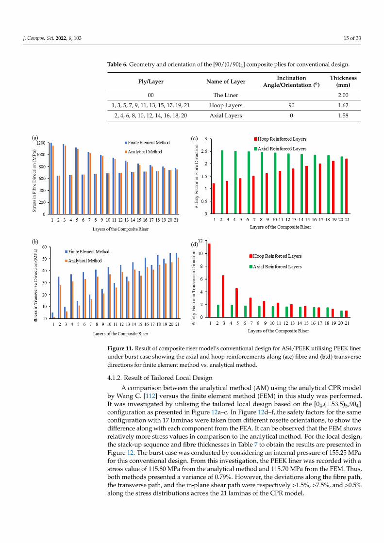
3.8. Mesh and Convergence
The mesh convergence study on the 3D CPR model was implemented using twomethods as presented in this section. The mesh model for the CPR is shown in Figure 4.A convergence investigation was conducted using the mesh of the CPR. The goal of theinvestigation includes mesh convergence. Establishing the strength-wise behaviour of thecomposite riser requires the convergence study. This was calculated using the highest valueof the aggregate deformation. Figure 9a,b depicts the convergence study using differentmesh numbers of divisions for obtaining the mesh sizes. The convergence results show thatconvergence occurred at maximum total deformation of 2.4599. The divisions were in twodirections: the axial divisions and circumferential divisions. In Figure 9, the convergenceoccurred for the mesh case for 50 axial divisions and 65 circumferential divisions. Thismethod enables the fibres to be formed around the circumferential axis of the compositeriser. It can be observed also from the results that when less nodes and elements areused, the stress values obtained from the mesh elements are less, as in the case of 30 axialdivisions and 55 circumferential divisions. This is observed to be consistent in the hoop,angled, and axial layers. When the element and nodes are smallest, more time is consumedin processing the finite element analysis. However, with the convergence study, the bestmesh size has been determined.

J. Compos. Sci. 2022, 6, 103 13 of 33
J. Compos. Sci. 2022, 6, x FOR PEER REVIEW 13 of 36
composite riser. The FEM was performed utilising a ratio of axial to circumferential divi-sions as 50:65 per semicircle. 6000 nodes and 6500 elements were applied in the first finite element model, whereas in the second model, there were 8632 nodes and 8684 elements in the finite element model. In ANSYS ACP, the composite riser was modelled as a shell structure to apply the composite materials. The material layup for the composite riser was designed for different configurations with each having 18 layers. Various liners were con-sidered on the designs studied. Figure 4 represents the resulting plot depicting plies in ANSYS ACP for the composite riser’s FEM. The load cases were used to obtain stress val-ues for every composite layer across various thicknesses as part of the local design tech-nique. Specific initial values for the composite riser layers were estimated and used in the numerical method by first guessing the behaviour. The next step was ensuring the car-ryout of the analysis for the different load cases. Figure 8 represents the fibre direction and orientation for the composite riser at 90°. The green arrows represent the fibre direc-tion while the purple arrows represent the orientation. The values of the layers along the axial, angled, and hoop paths had increased and decreased magnitudes based on the val-ues, orientation, and condition used in the design.
3.8. Mesh and Convergence The mesh convergence study on the 3D CPR model was implemented using two
methods as presented in this section. The mesh model for the CPR is shown in Figure 4. A convergence investigation was conducted using the mesh of the CPR. The goal of the investigation includes mesh convergence. Establishing the strength-wise behaviour of the composite riser requires the convergence study. This was calculated using the highest value of the aggregate deformation. Figure 9a,b depicts the convergence study using dif-ferent mesh numbers of divisions for obtaining the mesh sizes. The convergence results show that convergence occurred at maximum total deformation of 2.4599. The divisions were in two directions: the axial divisions and circumferential divisions. In Figure 9, the convergence occurred for the mesh case for 50 axial divisions and 65 circumferential divi-sions. This method enables the fibres to be formed around the circumferential axis of the composite riser. It can be observed also from the results that when less nodes and elements are used, the stress values obtained from the mesh elements are less, as in the case of 30 axial divisions and 55 circumferential divisions. This is observed to be consistent in the hoop, angled, and axial layers. When the element and nodes are smallest, more time is consumed in processing the finite element analysis. However, with the convergence study, the best mesh size has been determined.
Figure 9. Convergence study using different mesh numbers of divisions for two different composite riser models, showing (a) Model 1 having Case 1 (30 axial, 55 circumferential), Case 2 (50 axial, 65 circumferential), and Case 3 (50 axial, 75 circumferential), and (b) Model 2 having Case 1 (50 axial, 65 circumferential), Case 2 (30 axial, 55 circumferential), and Case 3 (50 axial, 75 circumferential).
Figure 9. Convergence study using different mesh numbers of divisions for two different compositeriser models, showing (a) Model 1 having Case 1 (30 axial, 55 circumferential), Case 2 (50 axial,65 circumferential), and Case 3 (50 axial, 75 circumferential), and (b) Model 2 having Case 1 (50 axial,65 circumferential), Case 2 (30 axial, 55 circumferential), and Case 3 (50 axial, 75 circumferential).
3.9. Validation
According to DNV [66] and ABS [70], the factor of safety (F.S) approach could beutilised to evaluate the stress distribution of composite riser layers. The results acquired forthe CPR’s local design from the current research were compared to the research findingsfrom Wang et al. [45]. The ratioed proportion of permissible (or allowable) strength to theactual strength is known as the factor of safety (F.S). The output of the numerical analysison the composite riser model under the burst load case are presented in Figure 10a. Theresults show good agreement and, as also observed, this model had 18 layers representedas layers 1–18, while the CPR model by Wang et al. [45] had 17 layers, represented aslayers 2–18. In addition, layers 1–4 represent the axial layers for both models, but ofmaterial properties. Thus, the factor of safety values have some variance. This is due to thedifference in the material’s modulus used, the material’s thickness utilised, and the lengthof the composite tube. Thus, the behaviour of the reinforcements considering the factorof safety shows that the method applied in this design is in good agreement with that ofWang’s model. The safety factor method and stress component magnitudes were used invalidating this study and they were shown to be in good agreement across the off-axislamina and the hoop lamina. In addition, layers 1–4 represent the axial layers for bothmodels, with variance in the factor of safety. However, despite the similarity in the models,there was some variance observed across the axial lamina. This is due to the differencein the modulus of the material used, the material’s thickness used, and the compositetube’s length. In this current research modelling, 5 m composite riser was used, whileWang et al. [45] employed a 3 m composite riser. Thus, the behaviour of the reinforcementsconsidering the factor of safety is also a function of the length of the composite riser. Thestudy shows that the method applied in this design is in good agreement with Wang’s CPRmodel [45]. The second method considered was the element sizes in the investigation asdepicted in Figure 10b. The ANSYS model was thus specified utilising the thickness forthe PEEK liner as 6 mm. It was configured as [03,(±52)10,904] laminates having 17 laminalayers for the hoop, off-axis, and axial layers in the ratio 90◦:52◦:0◦. The fibre-reinforcedbracings had respective thicknesses of 1.6 mm, 1.30 mm, and 1.40 mm. The same laminatematerials were employed in this scenario, but the ANSYS model’s liner assumed PEEKpolymer characteristics. Figure 10b contrasts the findings of both analyses in the burstinstance, illustrating the validity of the FE model applied in this research. The hoop, off-axis, and axial laminae all had analogous tensile stresses along the fibre direction, with anaverage difference of 2.096% across all layers. In Figure 10b, the maximum tensile stressdistributions for the burst instance are compared during the CPR’s local analysis, and theelement size of 30 mm is used versus a 5 mm element size. There were 158,316 nodes

J. Compos. Sci. 2022, 6, 103 14 of 33
and 158,000 elements generated. The stress values at the top and bottom of each ply wereobtained for both mesh sizes. From the results of the stresses obtained, no considerablevariation was seen. For the 5 mm mesh size, the stress in the hoop plies (14–18) was almost20.0 MPa less. Since improving the mesh very slightly improves the validity of the findings,this verifies that the 30 mm element size findings were adequately convergent.
J. Compos. Sci. 2022, 6, x FOR PEER REVIEW 15 of 36
(a) (b)
Figure 10. Validation of the model using (a) current ANSYS ACP model compared against Wang’s ANSYS APDL model and (b) burst instance stress profiles of the original mesh (30 mm) and the improved mesh compared to convergence study (5 mm).
4. Results The results are presented using bar charts depicting the maximal stresses across each
lamina (ply). Starting with the deepest inner lamina encircling the liner and culminating at the uttermost outer lamina of the laminate, the layers are numbered along the horizon-tal plane. The maximal interlaminar stresses are investigated using pressures located along the outermost (top), innermost (bottom), and centre (midpoint). This was recorded across the whole CPR plies; they are known respectively as top, bot, and mid. The maxi-mal stresses can be calculated using the highest stress in the middle of each lamina.
4.1. Studies on the Design Models 4.1.1. Result of Conventional Design
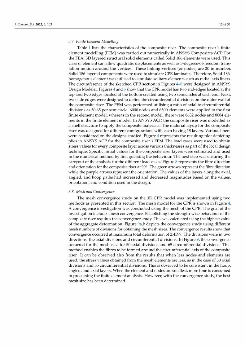
The analytical method was computed by utilising the exact elastic solution that con-siders 3D anisotropic elasticity by Xia M. et al. [61] and the analytical CPR model by Wang C. [112]. It was studied via a comparative investigation by utilising the FEM computed via ANSYS ACP and ANSYS Structural modules. The geometry and orientation of the composite layers under conventional design were configured as [90/(0/90)4], as tabulated in Table 6. The stresses were obtained based on the simulation using the 3 m geometry of the composite riser. From the finite element analysis (FEA), stresses were obtained along the various layers, as presented in Figure 11a,b. In Figure 11c,d, the safety factors for the same configuration are taken from different rosette orientation to show the difference along each component from FEA. It can be observed that this FEM presents relatively more stress values in comparison to the analytical method. The burst case was conducted by considering an internal pressure of 155.25 MPa for this conventional design. From this investigation, the PEEK liner was recorded to have a stress value of 98.90 MPa from the analytical method and 99.70 MPa from the finite element method. Thus, both methods presented a variance of 0.79%. However, the deviations along the fibre path and the trans-verse path were respectively >5% and >2% on these stress distributions across the 21 layers of the CPR model.
Figure 10. Validation of the model using (a) current ANSYS ACP model compared against Wang’sANSYS APDL model and (b) burst instance stress profiles of the original mesh (30 mm) and theimproved mesh compared to convergence study (5 mm).
4. Results
The results are presented using bar charts depicting the maximal stresses across eachlamina (ply). Starting with the deepest inner lamina encircling the liner and culminating atthe uttermost outer lamina of the laminate, the layers are numbered along the horizontalplane. The maximal interlaminar stresses are investigated using pressures located along theoutermost (top), innermost (bottom), and centre (midpoint). This was recorded across thewhole CPR plies; they are known respectively as top, bot, and mid. The maximal stressescan be calculated using the highest stress in the middle of each lamina.
4.1. Studies on the Design Models4.1.1. Result of Conventional Design
The analytical method was computed by utilising the exact elastic solution that con-siders 3D anisotropic elasticity by Xia M. et al. [61] and the analytical CPR model by WangC. [112]. It was studied via a comparative investigation by utilising the FEM computedvia ANSYS ACP and ANSYS Structural modules. The geometry and orientation of thecomposite layers under conventional design were configured as [90/(0/90)4], as tabulatedin Table 6. The stresses were obtained based on the simulation using the 3 m geometry ofthe composite riser. From the finite element analysis (FEA), stresses were obtained alongthe various layers, as presented in Figure 11a,b. In Figure 11c,d, the safety factors forthe same configuration are taken from different rosette orientation to show the differencealong each component from FEA. It can be observed that this FEM presents relatively morestress values in comparison to the analytical method. The burst case was conducted byconsidering an internal pressure of 155.25 MPa for this conventional design. From thisinvestigation, the PEEK liner was recorded to have a stress value of 98.90 MPa from theanalytical method and 99.70 MPa from the finite element method. Thus, both methods pre-sented a variance of 0.79%. However, the deviations along the fibre path and the transversepath were respectively >5% and >2% on these stress distributions across the 21 layers ofthe CPR model.
J. Compos. Sci. 2022, 6, 103 15 of 33
Table 6. Geometry and orientation of the [90/(0/90)4] composite plies for conventional design.
Ply/Layer Name of Layer InclinationAngle/Orientation (◦◦◦)
Thickness(mm)
00 The Liner 2.00
1, 3, 5, 7, 9, 11, 13, 15, 17, 19, 21 Hoop Layers 90 1.62
2, 4, 6, 8, 10, 12, 14, 16, 18, 20 Axial Layers 0 1.58
J. Compos. Sci. 2022, 6, x FOR PEER REVIEW 16 of 36
Table 6. Geometry and orientation of the [90/(0/90)4] composite plies for conventional design.
Ply/Layer Name of Layer Inclination Angle/Orientation (°) Thickness (mm) 00 The Liner 2.00
1, 3, 5, 7, 9, 11, 13, 15, 17, 19, 21 Hoop Layers 90 1.62 2, 4, 6, 8, 10, 12, 14, 16, 18, 20 Axial Layers 0 1.58
Figure 11. Result of composite riser model’s conventional design for AS4/PEEK utilising PEEK liner under burst case showing the axial and hoop reinforcements along (a,c) fibre and (b,d) transverse directions for finite element method vs. analytical method.
4.1.2. Result of Tailored Local Design A comparison between the analytical method (AM) using the analytical CPR model
by Wang C. [112] versus the finite element method (FEM) in this study was performed. It was investigated by utilising the tailored local design based on the [04,(±53.5)5,904] config-uration as presented in Figure 12a–c. In Figure 12d–f, the safety factors for the same con-figuration with 17 laminas were taken from different rosette orientations, to show the dif-ference along with each component from the FEA. It can be observed that the FEM shows relatively more stress values in comparison to the analytical method. For the local design, the stack-up sequence and fibre thicknesses in Table 7 to obtain the results are presented in Figure 12. The burst case was conducted by considering an internal pressure of 155.25 MPa for this conventional design. From this investigation, the PEEK liner was recorded with a stress value of 115.80 MPa from the analytical method and 115.70 MPa from the FEM. Thus, both methods presented a variance of 0.79%. However, the deviations along the fibre path, the transverse path, and the in-plane shear path were respectively >1.5%, >7.5%, and >0.5% along the stress distributions across the 21 laminas of the CPR model.
Figure 11. Result of composite riser model’s conventional design for AS4/PEEK utilising PEEK linerunder burst case showing the axial and hoop reinforcements along (a,c) fibre and (b,d) transversedirections for finite element method vs. analytical method.
4.1.2. Result of Tailored Local Design
A comparison between the analytical method (AM) using the analytical CPR modelby Wang C. [112] versus the finite element method (FEM) in this study was performed.It was investigated by utilising the tailored local design based on the [04,(±53.5)5,904]configuration as presented in Figure 12a–c. In Figure 12d–f, the safety factors for the sameconfiguration with 17 laminas were taken from different rosette orientations, to show thedifference along with each component from the FEA. It can be observed that the FEM showsrelatively more stress values in comparison to the analytical method. For the local design,the stack-up sequence and fibre thicknesses in Table 7 to obtain the results are presented inFigure 12. The burst case was conducted by considering an internal pressure of 155.25 MPafor this conventional design. From this investigation, the PEEK liner was recorded with astress value of 115.80 MPa from the analytical method and 115.70 MPa from the FEM. Thus,both methods presented a variance of 0.79%. However, the deviations along the fibre path,the transverse path, and the in-plane shear path were respectively >1.5%, >7.5%, and >0.5%along the stress distributions across the 21 laminas of the CPR model.

J. Compos. Sci. 2022, 6, 103 16 of 33
J. Compos. Sci. 2022, 6, x FOR PEER REVIEW 17 of 36
Table 7. Lay-up/ply inclination angle for local design for the [04,(±53.5)5,904] and [903,(±53.5)5,05] con-figurations.
Design Configuration [04,(±53.5)5,904] [903,(±53.5)5,05]
Ply/Layer Name of Layer Inclination An-
gle/Orientation (°) Thickness (mm) Inclination Angle/Ori-
entation (°) Thickness (mm)
00 The Liner 0.0 2.00 0.0 9.00 01
Axial Layers
0.0 1.58 0.0 1.84 02 0.0 1.58 0.0 1.84 03 0.0 1.58 0.0 1.84 04 0.0 1.58 0.0 1.84 05
Angled Layers (or Off-axis Layers)
53.5 1.88 53.5 1.48 06 −53.5 1.88 −53.5 1.48 07 53.5 1.88 53.5 1.48 08 −53.5 1.88 −53.5 1.48 09 53.5 1.88 53.5 1.48 10 −53.5 1.88 −53.5 1.48 11 53.5 1.88 53.5 1.48 12 −53.5 1.88 −53.5 1.48 13 53.5 1.88 53.5 1.48 14 −53.5 1.88 −53.5 1.48 15
Hoop Layers
90.0 1.62 90.0 1.60 16 90.0 1.62 90.0 1.60 17 90.0 1.62 90.0 1.60 18 90.0 1.62 90.0 1.60
J. Compos. Sci. 2022, 6, x FOR PEER REVIEW 18 of 36
Figure 12. Result of composite riser model’s local design for AS4/PEEK utilising PEEK liner under burst case showing the axial, angled, and hoop reinforcements along (a,d) fibre, (b,e) transverse, and (c,f) in-plane shear directions for finite element method vs. analytical method.
4.2. Result of Load Cases 4.2.1. Result of Burst Case
This subsection presents the findings from the preliminary CPR design, which was the development’s first model. Figure 13a,b shows a preliminary design with 18 laminae (plies) and a comparatively thick 2 mm titanium liner but greater layer thicknesses. Figure 13a shows the maximal stressed profiles along the fibre path. This was conducted using the same titanium liner on the CPR structure subjected to burst loads. Tensile stresses were found in the laminae as a result of the internal pressure causing significant tension in the riser. The highest maximal stress along the fibre path was 1480.8 MPa, recorded from hoop’s ply 14 across the bottom section, whereas the least maximal stress was 1125.9 MPa, recorded from hoop’s ply 3 across the top portion. However, across the axial plies, there were high stresses of 2597 MPa which have more weight. Thus, there is a need for weight reduction, or to optimise the model by minimising the weight as presented in Sec-tion 4.3. Along the fibre path, the maximal tensile permissible stress was 1648 MPa for AS4/PEEK unidirectional composites. This maximum stress value was much below that, as along axial’s layers 1–4, there were relatively minor tensile stresses. Figure 13b depicts the maximal stressed profiles along the transverse path. This was also conducted using
Figure 12. Result of composite riser model’s local design for AS4/PEEK utilising PEEK liner underburst case showing the axial, angled, and hoop reinforcements along (a,d) fibre, (b,e) transverse, and(c,f) in-plane shear directions for finite element method vs. analytical method.

J. Compos. Sci. 2022, 6, 103 17 of 33
Table 7. Lay-up/ply inclination angle for local design for the [04,(±53.5)5,904] and [903,(±53.5)5,05]configurations.
Design Configuration [04, (±±±53.5)5,904] [903,(±±±53.5)5,05]
Ply/Layer Name of Layer InclinationAngle/Orientation (◦◦◦) Thickness (mm) Inclination
Angle/Orientation (◦◦◦) Thickness (mm)
00 The Liner 0.0 2.00 0.0 9.00
01
Axial Layers
0.0 1.58 0.0 1.84
02 0.0 1.58 0.0 1.84
03 0.0 1.58 0.0 1.84
04 0.0 1.58 0.0 1.84
05
Angled Layers (orOff-axis Layers)
53.5 1.88 53.5 1.48
06 −53.5 1.88 −53.5 1.48
07 53.5 1.88 53.5 1.48
08 −53.5 1.88 −53.5 1.48
09 53.5 1.88 53.5 1.48
10 −53.5 1.88 −53.5 1.48
11 53.5 1.88 53.5 1.48
12 −53.5 1.88 −53.5 1.48
13 53.5 1.88 53.5 1.48
14 −53.5 1.88 −53.5 1.48
15
Hoop Layers
90.0 1.62 90.0 1.60
16 90.0 1.62 90.0 1.60
17 90.0 1.62 90.0 1.60
18 90.0 1.62 90.0 1.60
4.2. Result of Load Cases4.2.1. Result of Burst Case
This subsection presents the findings from the preliminary CPR design, which was thedevelopment’s first model. Figure 13a,b shows a preliminary design with 18 laminae (plies)and a comparatively thick 2 mm titanium liner but greater layer thicknesses. Figure 13ashows the maximal stressed profiles along the fibre path. This was conducted using thesame titanium liner on the CPR structure subjected to burst loads. Tensile stresses werefound in the laminae as a result of the internal pressure causing significant tension in theriser. The highest maximal stress along the fibre path was 1480.8 MPa, recorded from hoop’sply 14 across the bottom section, whereas the least maximal stress was 1125.9 MPa, recordedfrom hoop’s ply 3 across the top portion. However, across the axial plies, there were highstresses of 2597 MPa which have more weight. Thus, there is a need for weight reduction, orto optimise the model by minimising the weight as presented in Section 4.3. Along the fibrepath, the maximal tensile permissible stress was 1648 MPa for AS4/PEEK unidirectionalcomposites. This maximum stress value was much below that, as along axial’s layers 1–4,there were relatively minor tensile stresses. Figure 13b depicts the maximal stressed profilesalong the transverse path. This was also conducted using the same burst load on thelaminae. Along the transverse path, the minimal stress recorded was 74.89 MPa, recordedfrom axial’s plies 1–4 located across the top portion, whereas the maximal stress recordedacross the hoop’s plies 15–18 were 193.84 MPa, located across the bottom portion. FromFigure 13a,b, the axial layers had the maximum stress at 1017.7 MPa along the fibre pathand 517.7 MPa along the transverse path. 60 MPa was the value of the external pressureintroduced to the collapse instance. The results show similar behaviour for the fibre and

J. Compos. Sci. 2022, 6, 103 18 of 33
transverse paths (or directions). However, the stress values in the fibre direction werehigher than the stress values along the transverse direction. It was also observed that theaxial layers had the highest stress values, but the stresses decreased when it reached theangled layers. This is due to debonding between the different materials and the orientationangle. As shown in Table 8, the liner’s corresponding stress was 550.0 MPa, which is about62% of the yield strength. This titanium liner yielded a maximal deformation of 3.37 mm.Since this liner’s thickness is fairly considerable, it was lowered in subsequent updatesto minimise weight. From this investigation, there is the need to minimise the structuralweight of the CPR based on the preliminary designs while maintaining the integrity of theCPR structure and without violating acceptable limits of stress.
J. Compos. Sci. 2022, 6, x FOR PEER REVIEW 19 of 36
the same burst load on the laminae. Along the transverse path, the minimal stress rec-orded was 74.89 MPa, recorded from axial’s plies 1–4 located across the top portion, whereas the maximal stress recorded across the hoop’s plies 15–18 were 193.84 MPa, lo-cated across the bottom portion. From Figure 13a,b, the axial layers had the maximum stress at 1017.7 MPa along the fibre path and 517.7 MPa along the transverse path. 60 MPa was the value of the external pressure introduced to the collapse instance. The results show similar behaviour for the fibre and transverse paths (or directions). However, the stress values in the fibre direction were higher than the stress values along the transverse direction. It was also observed that the axial layers had the highest stress values, but the stresses decreased when it reached the angled layers. This is due to debonding between the different materials and the orientation angle. As shown in Table 8, the liner’s corre-sponding stress was 550.0 MPa, which is about 62% of the yield strength. This titanium liner yielded a maximal deformation of 3.37 mm. Since this liner’s thickness is fairly con-siderable, it was lowered in subsequent updates to minimise weight. From this investiga-tion, there is the need to minimise the structural weight of the CPR based on the prelimi-nary designs while maintaining the integrity of the CPR structure and without violating acceptable limits of stress.
Table 8. Riser deformation and liner stress during burst event’s preliminary design.
Particulars Value Unit Maximum Riser Deformation 3.37 mm
Ultimate Stress of Titanium Alloy 950.00 MPa Yield Stress of Titanium Alloy 880.00 MPa
Titanium Liner’s Equivalent Stress 550.00 MPa
Figure 13. Stress profiles for the top, middle, and bottom lamina along the (a) fibre and (b) trans-verse directions under burst case.
4.2.2. Result of Collapse Case From Figure 14, the titanium alloy liner is observed to be important in the reinforce-
ment of the composite body. The axial layers in the fibre direction had the highest stress, up to 2930 MPa, while the titanium liner’s stress was 1057.7 MPa. The value of the maxi-mum stress decreased for the angled layers to 1174.8 MPa. The stresses spiked up to 1362.5 MPa for the hoop layers. As seen in Figure 14, the burst case for the transverse direction had a different pattern. The highest stress occurred at the titanium liner, up to 239.5 MPa. This shows that there was a lot of pressure applied, up to 155.25 MPa, and the other layers could not withstand much of the pressure load, so the liner had to take in a lot of the pressure. The stress value in the axial layers (layers 2–4) went low to 76.71 MPa. This
Figure 13. Stress profiles for the top, middle, and bottom lamina along the (a) fibre and (b) transversedirections under burst case.
Table 8. Riser deformation and liner stress during burst event’s preliminary design.
Particulars Value Unit
Maximum Riser Deformation 3.37 mm
Ultimate Stress of Titanium Alloy 950.00 MPa
Yield Stress of Titanium Alloy 880.00 MPa
Titanium Liner’s Equivalent Stress 550.00 MPa
4.2.2. Result of Collapse Case
From Figure 14, the titanium alloy liner is observed to be important in the reinforce-ment of the composite body. The axial layers in the fibre direction had the highest stress, upto 2930 MPa, while the titanium liner’s stress was 1057.7 MPa. The value of the maximumstress decreased for the angled layers to 1174.8 MPa. The stresses spiked up to 1362.5 MPafor the hoop layers. As seen in Figure 14, the burst case for the transverse direction had adifferent pattern. The highest stress occurred at the titanium liner, up to 239.5 MPa. Thisshows that there was a lot of pressure applied, up to 155.25 MPa, and the other layers couldnot withstand much of the pressure load, so the liner had to take in a lot of the pressure.The stress value in the axial layers (layers 2–4) went low to 76.71 MPa. This shows thatat that stage, the liner took in much of the pressure. However, the angle’s layers (layers5–14) had stresses of up to 145.85 MPa, while the hoop’s layers had pressure effects of up to193.8 MPa. Figure 6 represents the stress postprocessing of ply 17. Since the fibre-reinforcedbracings perpendicularly align across that of the direction of the load, the highest stressesoccur across the axial plies. The laminate had insignificant tensile stresses profiled acrossthe fibre path. Additionally, all the maximal stresses that were highest were recorded acrosscompressed portions of the laminates, thus yielding compressive laminae. The highest

J. Compos. Sci. 2022, 6, 103 19 of 33
stresses via the transverse path of each ply, on the other hand, were tensile, while the com-pressive stresses via the transverse path were of low capacity. The stresses in the transversedirection were tensile because the laminate was perpendicular to the imparted compressiveforce in this direction, resulting in tension. This resulted in low compressive stress along thefibre path and higher tensile stress via the transverse path. The highest stresses recordedwere via the transverse path of the plies during the collapse instance. Across the transversepath, it was recorded that the axial’s ply 1 has the highest maximal stress of 54.0 MPa. Onthe other hand, the hoop’s ply 14 has the least maximal stress of 28.0 MPa. The laminate’smaximal tensile long-term strength was 62.4 MPa, correspondingly about 85.0% that of themaximal stress. As seen in Figure 14, the collapse case satisfied the design requirement, butthere were some inconsistencies between the top, middle, and bottom layers, which wasdue to some design nonlinearities and environmental factors. The comparable stress in thetitanium alloy liner in the collapse instance was 525.0 MPa, about 60% of the yield strength,as shown in Table 9.
J. Compos. Sci. 2022, 6, x FOR PEER REVIEW 20 of 36
shows that at that stage, the liner took in much of the pressure. However, the angle’s layers (layers 5–14) had stresses of up to 145.85 MPa, while the hoop’s layers had pressure effects of up to 193.8 MPa. Figure 6 represents the stress postprocessing of ply 17. Since the fibre-reinforced bracings perpendicularly align across that of the direction of the load, the high-est stresses occur across the axial plies. The laminate had insignificant tensile stresses pro-filed across the fibre path. Additionally, all the maximal stresses that were highest were recorded across compressed portions of the laminates, thus yielding compressive laminae. The highest stresses via the transverse path of each ply, on the other hand, were tensile, while the compressive stresses via the transverse path were of low capacity. The stresses in the transverse direction were tensile because the laminate was perpendicular to the imparted compressive force in this direction, resulting in tension. This resulted in low compressive stress along the fibre path and higher tensile stress via the transverse path. The highest stresses recorded were via the transverse path of the plies during the collapse instance. Across the transverse path, it was recorded that the axial’s ply 1 has the highest maximal stress of 54.0 MPa. On the other hand, the hoop’s ply 14 has the least maximal stress of 28.0 MPa. The laminate’s maximal tensile long-term strength was 62.4 MPa, cor-respondingly about 85.0% that of the maximal stress. As seen in Figure 14, the collapse case satisfied the design requirement, but there were some inconsistencies between the top, middle, and bottom layers, which was due to some design nonlinearities and envi-ronmental factors. The comparable stress in the titanium alloy liner in the collapse in-stance was 525.0 MPa, about 60% of the yield strength, as shown in Table 9.
Table 9. Riser deformation and liner stress during collapse event’s preliminary design.
Particulars Value Unit Riser’s Maximum Deformation 1.34 mm
Ultimate Stress of Titanium Alloy 950.00 MPa Yield Stress of Titanium Alloy 880.00 MPa
Titanium Liner’s Equivalent Stress 525.00 MPa
Figure 14. Stress profiles for the top, middle, and bottom lamina along the (a) fibre and (b) trans-verse directions under collapse case.
4.2.3. Result of Tension Case The calculations for the tension cases were achieved by using the effective weight of
the riser when carrying fluid and the riser’s net weight. The composite riser’s effective weight can be referred to as a function of the wall thickness of the composite riser being analysed. It was utilised to compute the tension of the riser. The maximum stress profiles measured in the laminae’s fibre path under tension are shown in Figure 15a,b. At 4584
Figure 14. Stress profiles for the top, middle, and bottom lamina along the (a) fibre and (b) transversedirections under collapse case.
Table 9. Riser deformation and liner stress during collapse event’s preliminary design.
Particulars Value Unit
Riser’s Maximum Deformation 1.34 mm
Ultimate Stress of Titanium Alloy 950.00 MPa
Yield Stress of Titanium Alloy 880.00 MPa
Titanium Liner’s Equivalent Stress 525.00 MPa
4.2.3. Result of Tension Case
The calculations for the tension cases were achieved by using the effective weight of theriser when carrying fluid and the riser’s net weight. The composite riser’s effective weightcan be referred to as a function of the wall thickness of the composite riser being analysed.It was utilised to compute the tension of the riser. The maximum stress profiles measuredin the laminae’s fibre path under tension are shown in Figure 15a,b. At 4584 kN, the riserwas fully tensioned and exposed. The laminae’s tensile stress profiles were examined forthe composite’s long-term tensile stress. The least peak stress along the fibre path was59.4 MPa across the hoop plies 1–4 and 55.1 MPa across the angled plies, followed by254.5 MPa across the axial plies 1–4. The maximum long-term allowable tensile stress in thefibre direction of the AS4/PEEK unidirectional composite is around 8% greater than thismaximum stress figure of 1648.0 MPa. It is worth noting that the hoop layers, plies 14–18,exhibited compressive stresses. The majority of the load was carried in pure tension by the

J. Compos. Sci. 2022, 6, 103 20 of 33
fibres that were orientated in the force direction; as shown by the profiles in Figure 15, theaxial laminae had the highest tensile stresses. Since the hoop fibres were perpendicularlyaligned to the load, compressive stresses were found along the fibre direction. The averagemaximum compressive stress across all hoop plies was 48.2 MPa, which is considerably lessthan the AS4/PEEK composite’s maximal long-term compressive strength of 864.0 MPa.For the tension scenario, Figure 15 illustrates the potential stresses present in the transversedirection of the laminae. The least maximum stress in the transverse direction was 1 MPain axial ply 1 and the largest maximum stress was 12 MPa in hoop ply 14. This maximumstress value is 80% less than the unidirectional AS4/PEEK laminate’s maximum long-termallowable tensile strength of 62 MPa. The highest tensile stress in plies 4–17 is greaterthan the maximum stresses in the mid and top sections of each lamina, which could be anexception. In comparison to the collapse instance, there were no considerable compressivestresses across the transverse path. From the results presented in Figure 15a,b, the axiallamina along the fibre path for the tension instance had the maximum stresses of 252.6 MPa.Based on the angled lamina and hoop lamina, the stresses had a maximum value of61.74 MPa, and they were fairly uniform. However, different behaviour is observed inthe transverse direction for the tension instance, as recorded in Figure 15. The higheststress values recorded across the axial, angled, and hoop lamina were 3.74 MPa, 11.36 MPa,and 15.15 MPa, respectively. The comparable stress in the titanium alloy liner in the puretension scenario was 162 MPa, or about 20% of the yield strength, as shown in Table 10.This demonstrates titanium alloy’s exceptional tensile behaviour in pure tension.
J. Compos. Sci. 2022, 6, x FOR PEER REVIEW 21 of 36
kN, the riser was fully tensioned and exposed. The laminae’s tensile stress profiles were examined for the composite’s long-term tensile stress. The least peak stress along the fibre path was 59.4 MPa across the hoop plies 1–4 and 55.1 MPa across the angled plies, fol-lowed by 254.5 MPa across the axial plies 1–4. The maximum long-term allowable tensile stress in the fibre direction of the AS4/PEEK unidirectional composite is around 8% greater than this maximum stress figure of 1648.0 MPa. It is worth noting that the hoop layers, plies 14–18, exhibited compressive stresses. The majority of the load was carried in pure tension by the fibres that were orientated in the force direction; as shown by the profiles in Figure 15, the axial laminae had the highest tensile stresses. Since the hoop fibres were perpendicularly aligned to the load, compressive stresses were found along the fibre direction. The average maximum compressive stress across all hoop plies was 48.2 MPa, which is considerably less than the AS4/PEEK composite’s maximal long-term compressive strength of 864.0 MPa. For the tension scenario, Figure 15 illustrates the po-tential stresses present in the transverse direction of the laminae. The least maximum stress in the transverse direction was 1 MPa in axial ply 1 and the largest maximum stress was 12 MPa in hoop ply 14. This maximum stress value is 80% less than the unidirectional AS4/PEEK laminate’s maximum long-term allowable tensile strength of 62 MPa. The high-est tensile stress in plies 4–17 is greater than the maximum stresses in the mid and top sections of each lamina, which could be an exception. In comparison to the collapse in-stance, there were no considerable compressive stresses across the transverse path. From the results presented in Figure 15 a,b, the axial lamina along the fibre path for the tension instance had the maximum stresses of 252.6 MPa. Based on the angled lamina and hoop lamina, the stresses had a maximum value of 61.74 MPa, and they were fairly uniform. However, different behaviour is observed in the transverse direction for the tension in-stance, as recorded in Figure 15. The highest stress values recorded across the axial, an-gled, and hoop lamina were 3.74 MPa, 11.36 MPa, and 15.15 MPa, respectively. The com-parable stress in the titanium alloy liner in the pure tension scenario was 162 MPa, or about 20% of the yield strength, as shown in Table 10. This demonstrates titanium alloy’s exceptional tensile behaviour in pure tension.
Table 10. Riser deformation and liner stress during tension event’s preliminary design.
Particulars Value Unit Riser’s Maximum Deformation 7.78 mm
Ultimate Stress of Titanium Alloy 950.00 MPa Yield Stress of Titanium Alloy 880.00 MPa
Titanium Liner’s Equivalent Stress 162.00 MPa
Figure 15. Stress profiles for the top, middle, and bottom lamina along the (a) fibre and (b) transversedirections under tension case.
Table 10. Riser deformation and liner stress during tension event’s preliminary design.
Particulars Value Unit
Riser’s Maximum Deformation 7.78 mm
Ultimate Stress of Titanium Alloy 950.00 MPa
Yield Stress of Titanium Alloy 880.00 MPa
Titanium Liner’s Equivalent Stress 162.00 MPa
4.2.4. Result of Tension cum External Pressure Case
The highest stresses present along the fibre direction of the laminae for the tensioncum external pressure condition are shown in Figure 16a,b. The riser was subjected to amaximum tensile load of 2037.0 kN and an external pressure of 19.5 MPa. The composite’slong-term strength values were then compared to the maximum stress in each ply. Tensilestresses existed in axial laminae 1–4, but compressive stresses existed in off-axis laminae

J. Compos. Sci. 2022, 6, 103 21 of 33
4–13 and hoop laminae 14–18. The rationale here is due to two factors: when the CPR istensioned, the axial fibres are tensile and the hoop fibres are in compression, as previouslystated. Furthermore, an external pressure load compresses both the hoop and off-axislaminae. Due to the 88◦ hoop fibre reinforcements, these fibres contribute to the CPR’scollapse and burst capacity, with the hoop laminae offering the best collapse resistance. Thestress distribution illustrated in Figure 16 clearly demonstrates this behaviour; the axialand hoop laminae had the highest tensile and compressive stresses, in respective order. Thehoop laminae provided the best collapse resistance due to the 88◦ hoop fibre reinforcing.Off-axis ply 7 had the lowest maximum fibre direction compressive stress of 72 MPa,followed by hoop ply 14 with 278 MPa. The highest stress value was around 30% higherthan the maximum long-term compressive stress value that can be tolerated at 864.0 MPa.The highest tensile stress along the fibre direction was 300.0 MPa on average, which is about20% of the maximum long-term tensile strength of 1648.0 MPa. For the tension condition,Figure 16a,b depicts the maximum stresses in the plies’ transverse direction. There wereno substantial tensile stress distributions throughout the laminate, and the majority of thestresses across the transverse path were compressive. The least maximum stress in thetransverse path was 5.90 MPa in angled ply 5 down to 1.50 MPa at angled ply 14, whilethe largest maximum stress was 12.77 MPa in hoop ply 17. This maximum stress is around75% less than the maximum long-term permitted compressive stress of 156.80 MPa viathe transverse path of unidirectional AS4/PEEK laminate. From the results presented inFigure 16a,b, the axial layers across the fibre path for the tension instance had the maximumstresses of 374.1 MPa. For the angled layer, the stresses had a maximum value of 87.2 MPa,and the minimum value was fairly uniform. However, a different behaviour was observedin the transverse direction for the tension instance. The highest stress values for the axial,angled, and hoop lamina were 3.74 MPa, 11.36 MPa, and 15.15 MPa, respectively. Thecomparable stress in the titanium alloy liner in the tension and external pressure situationwas 253 MPa, which is about 30% of the yield strength, as shown in Table 11.
J. Compos. Sci. 2022, 6, x FOR PEER REVIEW 23 of 36
Figure 16. Stress profiles for the top, middle, and bottom lamina along the (a) fibre and (b) trans-verse directions under tension and external pressure case.
4.3. Result of Minimum Weight Study 4.3.1. Effect of Weight Per Unit Area
Figure 17 represents the distribution of the thickness of layers and the weight per unit area for 12 different composite riser configurations. This study was investigated us-ing the same liner material—titanium liner—on AS4/PEEK material. From this study, it can be observed that different configurations have different weight per unit areas and thicknesses, which also has an implication on the structural strength of the composite riser. As observed in Figure 17 and Table 12, the best configuration based on this analysis was DesignCase7, as it had the least weight per unit area and would be the lightest with a weight/area value of 6.60 × 10⁻⁸ kg/mm2. However, more investigation is suggested on the detailed weight savings of the riser models from the local design against the conven-tional design.
Table 12. Considerations for effect of weight per unit area for 12 design cases.
Design Case Liner Mate-rial
Fibre Matrix Lay-Up Lamina Thickness (mm)
0° ±53.5° 90° Case 1 Titanium AS4 PEEK [05,(±53.5)5,905] 2.49 1.7 0.6 Case 2 Titanium AS4 PEEK [903,(±53.5)5,05] 2.49 1.7 1.84 Case 3 Titanium AS4 PEEK [903,(±53.5)5,05] 2.49 1.7 3.25 Case 4 Titanium AS4 PEEK [05,(±53.5)5,905] 2.49 1.7 1.7 Case 5 Titanium AS4 PEEK [905,(±53.5)5,05] 2.49 1.7 1.84 Case 6 Titanium AS4 PEEK [(±53.5)5,05,905] 1.15 1.7 1.84 Case 7 Titanium AS4 PEEK [06,(±53.5)5,904] 2.49 1.7 0.6 Case 8 Titanium AS4 PEEK [905,(±53.5)5,05] 2.49 1.7 0.6 Case 9 Titanium AS4 PEEK [905,(±53.5)5,05] 1.15 1.7 1.84
Case 10 Titanium AS4 PEEK [(±53.5)5,905,05] 1.15 1.7 1.84 Case 11 Titanium AS4 PEEK [(±53.5)5,905,05] 1.15 1.7 3.25 Case 12 Titanium AS4 PEEK [06,(±53.5)5,904] 2.49 1.7 1.7
Figure 16. Stress profiles for the top, middle, and bottom lamina along the (a) fibre and (b) transversedirections under tension and external pressure case.
Table 11. Riser deformation and liner stress during tension cum external pressure event’s preliminarydesign.
Particulars Value Unit
Riser’s Maximum Deformation 11.80 mm
Ultimate Stress of Titanium Alloy 950.00 MPa
Yield Stress of Titanium Alloy 880.00 MPa
Titanium Liner’s Equivalent Stress 253.00 MPa

J. Compos. Sci. 2022, 6, 103 22 of 33
4.3. Result of Minimum Weight Study4.3.1. Effect of Weight per Unit Area
Figure 17 represents the distribution of the thickness of layers and the weight per unitarea for 12 different composite riser configurations. This study was investigated using thesame liner material—titanium liner—on AS4/PEEK material. From this study, it can beobserved that different configurations have different weight per unit areas and thicknesses,which also has an implication on the structural strength of the composite riser. As observedin Figure 17 and Table 12, the best configuration based on this analysis was DesignCase7,as it had the least weight per unit area and would be the lightest with a weight/area valueof 6.60 × 10⁻⁸ kg/mm2. However, more investigation is suggested on the detailed weightsavings of the riser models from the local design against the conventional design.
J. Compos. Sci. 2022, 6, x FOR PEER REVIEW 24 of 36
Figure 17. Effect of weight per unit area for 12 different composite riser configurations.
4.3.2. Effect of Matrix Cracking The failure order of the liner, fibre, or matrix is numerically predictable; however, it
is dependent on the composite material, composition of the lay-up, and matrix cracking [87,88]. Thus, there is a need to investigate further on the failure pattern by utilising matrix cracking. Matrix cracking could be taken as a time-dependent phenomenon that can ensue prior to failure or post failure of the liner. In most cases, it begins to propagate from the hoop lamina when the resultant forces perpendicularly act along the fibre path. The axial lamina (or layers) support the displaced load as a result of this damage. According to the research, matrix cracking can cause a 10% drop in laminate stiffness [29,32,108]. As a result of the unpredictability as it is uncertain, the local analysis used lower long-term strength and stiffness parameters to account for matrix cracking with fatigue, wear, and service failure over time. The influence of matrix cracking on the CPR model was comparatively studied. This considered the structural weight using PEEK liners on AS4/PEEK and AS4/Epoxy designed with matrix cracking and without matrix cracking permissions, as presented in Figure 18. Matrix cracking study is important to avoid any failure due to liner leakages, according to specifications in design standards. As such, matrix cracking can be considered as the failure mode that is most critical for composite riser designs. As such, the design considered in this research does not permit matrix cracking. The comparison between the conventional design versus the tailored local design shows that both designs give some weight gains when there are permissions for matrix cracking. It can also be observed that when there was no matrix cracking, lower weight profiles were generated. In the design application of AS4/PEEK configured utilising PEEK liner, the ratio of per-centage weight savings for the conventional to the tailored local design was 68.5%:83.5% without matrix cracking. However, permitting matrix cracking offered some weight sav-ings of about 5.88%:8.33% for the tailored designs for AS4/PEEK and AS4/Epoxy respec-tively. Thus, the study satisfied this design requirement.
Figure 17. Effect of weight per unit area for 12 different composite riser configurations.
Table 12. Considerations for effect of weight per unit area for 12 design cases.
Design Case Liner Material Fibre Matrix Lay-UpLamina Thickness (mm)
0◦◦◦ ±±±53.5◦◦◦ 90◦◦◦
Case 1 Titanium AS4 PEEK [05,(±53.5)5,905] 2.49 1.7 0.6
Case 2 Titanium AS4 PEEK [903,(±53.5)5,05] 2.49 1.7 1.84
Case 3 Titanium AS4 PEEK [903,(±53.5)5,05] 2.49 1.7 3.25
Case 4 Titanium AS4 PEEK [05,(±53.5)5,905] 2.49 1.7 1.7
Case 5 Titanium AS4 PEEK [905,(±53.5)5,05] 2.49 1.7 1.84
Case 6 Titanium AS4 PEEK [(±53.5)5,05,905] 1.15 1.7 1.84
Case 7 Titanium AS4 PEEK [06,(±53.5)5,904] 2.49 1.7 0.6
Case 8 Titanium AS4 PEEK [905,(±53.5)5,05] 2.49 1.7 0.6
Case 9 Titanium AS4 PEEK [905,(±53.5)5,05] 1.15 1.7 1.84
Case 10 Titanium AS4 PEEK [(±53.5)5,905,05] 1.15 1.7 1.84
Case 11 Titanium AS4 PEEK [(±53.5)5,905,05] 1.15 1.7 3.25
Case 12 Titanium AS4 PEEK [06,(±53.5)5,904] 2.49 1.7 1.7

J. Compos. Sci. 2022, 6, 103 23 of 33
4.3.2. Effect of Matrix Cracking
The failure order of the liner, fibre, or matrix is numerically predictable; however, it isdependent on the composite material, composition of the lay-up, and matrix cracking [87,88].Thus, there is a need to investigate further on the failure pattern by utilising matrix cracking.Matrix cracking could be taken as a time-dependent phenomenon that can ensue priorto failure or post failure of the liner. In most cases, it begins to propagate from the hooplamina when the resultant forces perpendicularly act along the fibre path. The axial lamina(or layers) support the displaced load as a result of this damage. According to the research,matrix cracking can cause a 10% drop in laminate stiffness [29,32,108]. As a result of theunpredictability as it is uncertain, the local analysis used lower long-term strength andstiffness parameters to account for matrix cracking with fatigue, wear, and service failureover time. The influence of matrix cracking on the CPR model was comparatively studied.This considered the structural weight using PEEK liners on AS4/PEEK and AS4/Epoxydesigned with matrix cracking and without matrix cracking permissions, as presented inFigure 18. Matrix cracking study is important to avoid any failure due to liner leakages,according to specifications in design standards. As such, matrix cracking can be consideredas the failure mode that is most critical for composite riser designs. As such, the designconsidered in this research does not permit matrix cracking. The comparison between theconventional design versus the tailored local design shows that both designs give someweight gains when there are permissions for matrix cracking. It can also be observed thatwhen there was no matrix cracking, lower weight profiles were generated. In the designapplication of AS4/PEEK configured utilising PEEK liner, the ratio of percentage weightsavings for the conventional to the tailored local design was 68.5%:83.5% without matrixcracking. However, permitting matrix cracking offered some weight savings of about5.88%:8.33% for the tailored designs for AS4/PEEK and AS4/Epoxy respectively. Thus, thestudy satisfied this design requirement.
J. Compos. Sci. 2022, 6, x FOR PEER REVIEW 25 of 36
Figure 18. Comparative study on structural weight using PEEK liners on AS4/PEEK and AS4/Epoxy designed with matrix cracking and without matrix cracking permissions.
4.3.3. Result of Structural Weight The investigation on the structural weight of the layers for the composite riser was
conducted using P75/PEEK and AS4/PEEK for six different liners as presented in Figure 19. It can be observed that the optimization of the structural weight with the tailored local design proved to be effective as it presented lower structural weight for the two fibre re-inforcements investigated. It can be also observed that the P75/PEEK had higher structural weight than the AS4/PEEK because it had higher strength modulus. Based on the liners, it was observed that the combination with thermoplastic liners such as PA12 liners was comparatively less than the combination with the metallic liners. It was recorded that the AS4/PEEK with PEEK liner had a normalised weight saving ratio of the conventional and tailored designs of 0.30:0.24. In addition, the structural weight savings for the composite riser configured using the metallic liners—aluminium, titanium, and steel—are respec-tively 25%:23%:23% for the tailored design versus the conventional design. On the other hand, the structural weight savings for the thermoplastic liners—PA12, PEEK, and PVDF—are respectively 23%:20%:20% for the tailored design versus the conventional de-sign.
Figure 18. Comparative study on structural weight using PEEK liners on AS4/PEEK and AS4/Epoxydesigned with matrix cracking and without matrix cracking permissions.
4.3.3. Result of Structural Weight
The investigation on the structural weight of the layers for the composite riser wasconducted using P75/PEEK and AS4/PEEK for six different liners as presented in Figure 19.It can be observed that the optimization of the structural weight with the tailored local

J. Compos. Sci. 2022, 6, 103 24 of 33
design proved to be effective as it presented lower structural weight for the two fibre rein-forcements investigated. It can be also observed that the P75/PEEK had higher structuralweight than the AS4/PEEK because it had higher strength modulus. Based on the liners,it was observed that the combination with thermoplastic liners such as PA12 liners wascomparatively less than the combination with the metallic liners. It was recorded that theAS4/PEEK with PEEK liner had a normalised weight saving ratio of the conventional andtailored designs of 0.30:0.24. In addition, the structural weight savings for the compositeriser configured using the metallic liners—aluminium, titanium, and steel—are respectively25%:23%:23% for the tailored design versus the conventional design. On the other hand,the structural weight savings for the thermoplastic liners—PA12, PEEK, and PVDF—arerespectively 23%:20%:20% for the tailored design versus the conventional design.
J. Compos. Sci. 2022, 6, x FOR PEER REVIEW 26 of 36
Figure 19. Comparative study at optimized angled plies for normalized structural weight.
4.3.4. Result of Aggregate Thickness The investigation on the aggregate thickness of the layers of the composite riser was
conducted using P75/PEEK and AS4/PEEK for six different liners as presented in Figure 20. It can be observed that the optimization of the aggregate thickness with the tailored local design proved to be effective as it presented lower normalized values for the two fibre reinforcements investigated. It can be also observed that the P75/PEEK had higher magnitudes than the AS4/PEEK because it had higher strength modulus. In addition, com-posite risers had higher thickness than the steel model, as increasing the thickness re-flected to be relative to the type of liner combination and the reinforcement matrix. The worst thickness was reflected by the P75/PEEK model, as the thickness is over four times (4×) higher than that of AS4/PEEK model, as well as that of steel riser model. Thus, it will be the least desirable material combination to be considered. Based on the liners, it was recorded that the AS4/PEEK with PEEK liner had the best performance in normalised ag-gregate thickness and it is the recommended configuration.
Figure 19. Comparative study at optimized angled plies for normalized structural weight.
4.3.4. Result of Aggregate Thickness
The investigation on the aggregate thickness of the layers of the composite riserwas conducted using P75/PEEK and AS4/PEEK for six different liners as presented inFigure 20. It can be observed that the optimization of the aggregate thickness with thetailored local design proved to be effective as it presented lower normalized values forthe two fibre reinforcements investigated. It can be also observed that the P75/PEEKhad higher magnitudes than the AS4/PEEK because it had higher strength modulus. Inaddition, composite risers had higher thickness than the steel model, as increasing thethickness reflected to be relative to the type of liner combination and the reinforcementmatrix. The worst thickness was reflected by the P75/PEEK model, as the thickness is overfour times (4×) higher than that of AS4/PEEK model, as well as that of steel riser model.Thus, it will be the least desirable material combination to be considered. Based on theliners, it was recorded that the AS4/PEEK with PEEK liner had the best performance innormalised aggregate thickness and it is the recommended configuration.
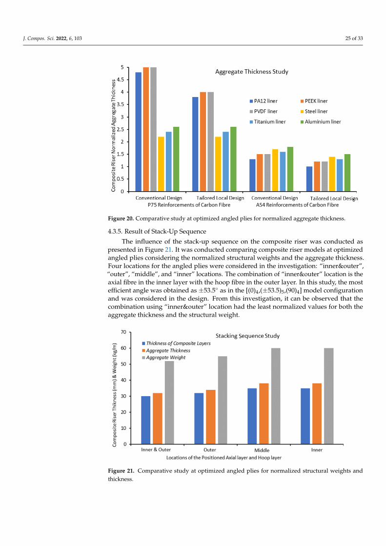
J. Compos. Sci. 2022, 6, 103 25 of 33J. Compos. Sci. 2022, 6, x FOR PEER REVIEW 27 of 36
Figure 20. Comparative study at optimized angled plies for normalized aggregate thickness.
4.3.5. Result of Stack-Up Sequence The influence of the stack-up sequence on the composite riser was conducted as pre-
sented in Figure 21. It was conducted comparing composite riser models at optimized angled plies considering the normalized structural weights and the aggregate thickness. Four locations for the angled plies were considered in the investigation: “inner&outer”, “outer”, “middle”, and “inner” locations. The combination of “inner&outer” location is the axial fibre in the inner layer with the hoop fibre in the outer layer. In this study, the most efficient angle was obtained as +53.5° as in the [(0)4,(±53.5)5,(90)4] model configuration and was considered in the design. From this investigation, it can be observed that the combination using “inner&outer” location had the least normalized values for both the aggregate thickness and the structural weight.
Figure 20. Comparative study at optimized angled plies for normalized aggregate thickness.
4.3.5. Result of Stack-Up Sequence
The influence of the stack-up sequence on the composite riser was conducted aspresented in Figure 21. It was conducted comparing composite riser models at optimizedangled plies considering the normalized structural weights and the aggregate thickness.Four locations for the angled plies were considered in the investigation: “inner&outer”,“outer”, “middle”, and “inner” locations. The combination of “inner&outer” location is theaxial fibre in the inner layer with the hoop fibre in the outer layer. In this study, the mostefficient angle was obtained as ±53.5◦ as in the [(0)4,(±53.5)5,(90)4] model configurationand was considered in the design. From this investigation, it can be observed that thecombination using “inner&outer” location had the least normalized values for both theaggregate thickness and the structural weight.
J. Compos. Sci. 2022, 6, x FOR PEER REVIEW 27 of 36
Figure 20. Comparative study at optimized angled plies for normalized aggregate thickness.
4.3.5. Result of Stack-Up Sequence The influence of the stack-up sequence on the composite riser was conducted as pre-
sented in Figure 21. It was conducted comparing composite riser models at optimized angled plies considering the normalized structural weights and the aggregate thickness. Four locations for the angled plies were considered in the investigation: “inner&outer”, “outer”, “middle”, and “inner” locations. The combination of “inner&outer” location is the axial fibre in the inner layer with the hoop fibre in the outer layer. In this study, the most efficient angle was obtained as +53.5° as in the [(0)4,(±53.5)5,(90)4] model configuration and was considered in the design. From this investigation, it can be observed that the combination using “inner&outer” location had the least normalized values for both the aggregate thickness and the structural weight.
Figure 21. Comparative study at optimized angled plies for normalized structural weights andthickness.

J. Compos. Sci. 2022, 6, 103 26 of 33
4.3.6. Result of CPR Weight Reduction
An investigation of the CPR weight reduction in steel riser against composite riserwas conducted as presented herein. The minimum structural weights of the steel riserjoints used in TTR production riser strings are listed in Table 13. The weights of the initialand final CPR designs are compared to the weight limit of a TTR of an X80 steel riser inTable 14. This global design for the Truss SPAR used was detailed in earlier studies [25,30].These results are close to the 50%–70% savings from weight reduction reported in theliterature for composite risers. In challenging conditions such as the Gulf of Mexico (GOM),the North Sea (NS), or Offshore West Africa (OWA), which are the loading conditions forwhich this CPR is intended, thicker steel risers are normally employed. As a result, theindicated weight savings are the absolute least that this CPR design can provide. Lastly,a comparative study of the structural weight of three design configurations presentedin Figure 22 shows that the tailored local design also proffered more weight savings forcomposite risers. Between the three configurations, the AS4/Epoxy with titanium liner hadthe highest weight, followed by the AS4/Epoxy configured utilising aluminium liner, andthe least was the AS4/PEEK configured utilising PEEK liner. Thus, the least configurationis the best design as shown.
Table 13. Comparison of deep water TTR steel riser under 2000 m water depth against its structuralweight.
Depth (m) Thickness (mm) Weight (kg/m)
0–1000 155 23
1000–1600 162 24
1600–2000 170 25
~2000 (approx. range) 160
Table 14. Comparison of weights between a typical TTR steel riser and composite riser.
Design Configuration OD, OuterDiameter OD Increase Riser Weight Weight
Saving
Steel TTR [90/(0/90)4] 273–275 - 160 -
Preliminary [54,(±54.7)10,884] 314.6 13% 73 54%
Second [04,(±53.5)5,904] 315.2 13.5% 70 57%
Final [33,(±62)10,885] 316.6 14% 54 66%
J. Compos. Sci. 2022, 6, x FOR PEER REVIEW 28 of 36
Figure 21. Comparative study at optimized angled plies for normalized structural weights and thickness.
4.3.6. Result of CPR Weight Reduction An investigation of the CPR weight reduction in steel riser against composite riser
was conducted as presented herein. The minimum structural weights of the steel riser joints used in TTR production riser strings are listed in Table 13. The weights of the initial and final CPR designs are compared to the weight limit of a TTR of an X80 steel riser in Table 14. This global design for the Truss SPAR used was detailed in earlier studies [25,30]. These results are close to the 50%–70% savings from weight reduction reported in the lit-erature for composite risers. In challenging conditions such as the Gulf of Mexico (GOM), the North Sea (NS), or Offshore West Africa (OWA), which are the loading conditions for which this CPR is intended, thicker steel risers are normally employed. As a result, the indicated weight savings are the absolute least that this CPR design can provide. Lastly, a comparative study of the structural weight of three design configurations presented in Figure 22 shows that the tailored local design also proffered more weight savings for com-posite risers. Between the three configurations, the AS4/Epoxy with titanium liner had the highest weight, followed by the AS4/Epoxy configured utilising aluminium liner, and the least was the AS4/PEEK configured utilising PEEK liner. Thus, the least configuration is the best design as shown.
Figure 22. Comparative study of different designs using structural weights on design configura-tions.
Table 13. Comparison of deep water TTR steel riser under 2000 m water depth against its structural weight.
Depth (m) Thickness (mm) Weight (kg/m) 0–1000 155 23
1000–1600 162 24 1600–2000 170 25
~2000 (approx. range) 160
Figure 22. Comparative study of different designs using structural weights on design configurations.

J. Compos. Sci. 2022, 6, 103 27 of 33
5. Concluding Remarks
The 18-layered composite production riser (CPR) was designed specifically for deepwater conditions. The tailored design of the composite riser was conducted for deep waterenvironments. This research presents different CPR configurations designed to minimisethe structural weight. To achieve this, the material attributes listed in Section 3.2 wereutilised. The CPR is comprised of a liner and a multilayered body. Three lamina designswere numerically studied using ANSYS Composites ACP R1 2021, consisting of 17, 18,and 21 layers. In this research, a variety of liners, including titanium and aluminiumalloys, were investigated. The stresses on the CPR lamina in both the fibre and transversedirections were calculated utilising four distinct loadings. The stress profiles were foundto be affected differently depending on the design orientation. The results for all stressprofiles in the fibre and transverse orientations for the CPR model were also provided. Theresults were validated and show good agreement. In the current model, two models of 3 mand 5 m composite riser were considered.
The model highlights include the following: Firstly, composite materials applied inthe local analysis of composite marine risers are useful in prototype production. Secondly,the local design of composite risers using different materials minimises structural weightwas presented. Thirdly, there is novelty in the analysis of composite riser assessmentto minimise the weight, useful in the global design. Fourthly, the comparative study ofcomposite riser designs is presented with detailed mechanical characterization for deepwater application. Lastly, the study uses indicators such as safety factors to investigate thestress magnitudes and make recommendations for standards development on compositerisers.
From this model, it is observed that there is an influence of metal cracking and metal–composite interface on the lamina, between the hoop plies, off-axis plies, and axial plies.Moreover, the results show that the stresses along the fibre directions are higher than thestresses in the hoop layers. Overall, the technique for this design revealed the compositerisers’ stress profiles for various load scenarios, guiding offshore designers on compositerisers. The angled layers were more affected by tension and external pressure loading, asshown in Section 4.2. The loads operating on the riser lamina (or plies) led to the behavioursalong the direction of the applied forces. In addition, the design revealed that throughoutthe burst instance, the liner withstood considerable pressure. This means that the innerliners do not need to be reinforced any further. For the first load instance (burst), the resultsshowed high stress magnitudes and safety factor values along the fibre direction actingupon the axial plies. The implication is that the CPR will be extremely strong and able totolerate harsh weather conditions. It is noteworthy that the stress profiles of the inner axiallamina, alternated angled lamina, and outer hoop lamina show substantial variation in allof the results.
However, more research into the global design of the CPR under various oceanconditions is recommended. This is desirable to explain the possible cause leading toparticular observations. Finally, the analysis indicates that adapting the design of theCPR to appropriate fibre reinforcement angles and liner combinations can save enoughweight. This study shows sufficient weight savings on the CPR design by tailoring thedesigns to achieve suitable fibre reinforcements, fibre orientation angles, unique lay-upsequences and liner combinations. Further study is recommended on cost with factorsfor the cost model for CPRs, as the cost model and manufacturing may be considered inthe future. In addition, data-driven optimization methods for composite shells shouldbe supplemented with proper-orthogonal-decomposition-based buckling analysis andoptimization of hybrid fiber composite risers [120–122]. These could include a multi-fidelity competitive sampling method for surrogate-based stacking sequence optimizationof composite shells with multiple cut-outs, as well as other techniques. Lastly, furtherwork on the composite riser should include robust global design [42–46], fatigue analysisof the composite riser [93,123–126], and the structural integrity/reliability of the compositeriser [94,127].

J. Compos. Sci. 2022, 6, 103 28 of 33
Supplementary Materials: The following supporting information can be downloaded at: https://www.mdpi.com/article/10.3390/jcs6040103/s1, There are supplementary data available for themodel used and summary: Amaechi, Chiemela Victor; Wang, Chunguang (2022), “Composite CLTtheory MATLAB codes”, Mendeley Data, V1, doi:10.17632/pdjytm9gzx.1. Also, Amaechi ChiemelaVictor (2022), “Dataset on Composite Risers for Deep Water Application”, Mendeley Data, V1,doi:10.17632/4rvvwkjs27.1.
Author Contributions: Conceptualization, C.V.A. and N.G.; methodology, C.V.A., N.G., I.A.J. andC.W.; software, C.V.A., N.G., I.A.J. and C.W.; validation, C.V.A., N.G. and C.W.; formal analysis,C.V.A., N.G. and C.W.; investigation, C.V.A., N.G. and C.W.; resources, C.V.A., N.G. and C.W.; datacuration, C.V.A. and N.G.; writing—original draft preparation, C.V.A. and N.G.; writing—reviewand editing, C.V.A., N.G., I.A.J. and C.W.; visualization, C.V.A., N.G., I.A.J. and C.W.; supervision,C.V.A.; project administration, C.V.A. and N.G.; funding acquisition, C.V.A. All authors have readand agreed to the published version of the manuscript.
Funding: The Department of Engineering, Lancaster University, UK and Engineering and PhysicalSciences Research Council (EPSRC)’s Doctoral Training Centre (DTC), UK are highly appreciated.In addition, the funding of the Overseas Postgraduate Scholarship by Niger Delta DevelopmentCommission (NDDC), Nigeria is also appreciated. The authors also recognizes the support ofthe Standards Organisation of Nigeria (SON), F.C.T Abuja, Nigeria. The funding support on thefollowing projects and for supporting this study are also acknowledged as follows: (a) ShandongProvisional Natural Science Foundation (ZR2020ME269), (b) Key Research and Development Programof Shandong Province (2019GHY112076), and (c) Shandong Provincial Key Laboratory of OceanEngineering with grant No. KLOE202005. Lastly, the funding support for the APC charges to Author1, C.V.A, from MDPI’s JCS is well appreciated.
Institutional Review Board Statement: Not applicable.
Informed Consent Statement: Not applicable.
Data Availability Statement: The data for this study are not shared because they are still part of apresent study on this research. However, see supplementary materials for some data on the study.
Acknowledgments: The authors acknowledge the technical support with computational resourcesfrom Lancaster University Engineering Department. We also appreciate the approvals and necessarytechnical permissions obtained during the COVID-19 pandemic. The feedback and supervision byJianqiao Ye of Lancaster University on this research is highly acknowledged. This paper is a productof a BEng dissertation and a research project. The feedback of Charles Odijie of MSCM Limited, UKin an earlier version was noted. In addition, the authors acknowledge the project contributions ofArmin Kanani in the development of the ANSYS composite riser model. Lastly, the ANSYS supportteam is appreciated for technical support in the global marine riser design.
Conflicts of Interest: The authors declare no conflict of interest. The funders had no role in the designof the study; in the collection, analyses, or interpretation of data; in the writing of the manuscript; orin the decision to publish the results.
References1. Zhang, H.; Tong, L.; Addo, M.A. Mechanical Analysis of Flexible Riser with Carbon Fiber Composite Tension Armor. J. Compos.
Sci. 2020, 5, 3. [CrossRef]2. Ochoa, O.; Salama, M. Offshore composites: Transition barriers to an enabling technology. Compos. Sci. Technol. 2005, 65,
2588–2596. [CrossRef]3. Savari, A. Failure analysis of composite repaired pipes subjected to internal pressure. J. Reinf. Plast. Compos. 2022, 1–20,
ahead-of-print. [CrossRef]4. Amaechi, C.V.; Chesterton, C.; Butler, H.O.; Gu, Z.; Odijie, A.C.; Wang, F.; Hou, X.; Ye, J. Finite Element Modelling on the
Mechanical Behaviour of Marine Bonded Composite Hose (MBCH) under Burst and Collapse. J. Mar. Sci. Eng. 2022, 10, 151.[CrossRef]
5. Amaechi, C.V.; Chesterton, C.; Butler, H.O.; Gu, Z.; Odijie, A.C. Numerical Modelling on the Local Design of a Marine BondedComposite Hose (MBCH) and Its Helix Reinforcement. J. Compos. Sci. 2022, 6, 79. [CrossRef]
6. Odijie, A.C.; Wang, F.; Ye, J. A review of floating semisubmersible hull systems: Column stabilized unit. Ocean Eng. 2017, 144,191–202. [CrossRef]
7. Johnson, D.; Salama, M.; Long, J.; Wang, S. Composite Production Riser—Manufacturing Development and Qualification Testing.In Proceedings of the Offshore Technology Conference, Houston, TX, USA, 4–7 May 1998; pp. 113–123. [CrossRef]

J. Compos. Sci. 2022, 6, 103 29 of 33
8. Johnson, D.B.; Baldwin, D.D.; Long, J.R. Mechanical Performance of Composite Production Risers. In Proceedings of the OffshoreTechnology Conference, Houston, TX, USA, 3–6 May 1999; pp. 1–10. [CrossRef]
9. Amaechi, C.V. Novel Design, Hydrodynamics and Mechanics of Marine Hoses in Oil/Gas Applications. Ph.D. Thesis, LancasterUniversity, Engineering Department, Lancaster, UK, 2021.
10. Amaechi, C.V.; Chesterton, C.; Butler, H.O.; Wang, F.; Ye, J. Review on the design and mechanics of bonded marine hoses forCatenary Anchor Leg Mooring (CALM) buoys. Ocean Eng. 2021, 242, 110062. [CrossRef]
11. Amaechi, C.V.; Wang, F.; Ja’E, I.A.; Aboshio, A.; Odijie, A.C.; Ye, J. A literature review on the technologies of bonded hoses formarine applications. Ships Offshore Struct. 2022, 1–32, ahead-of-print. [CrossRef]
12. Amaechi, C.V.; Chesterton, C.; Butler, H.O.; Wang, F.; Ye, J. An Overview on Bonded Marine Hoses for sustainable fluid transferand (un)loading operations via Floating Offshore Structures (FOS). J. Mar. Sci. Eng. 2021, 9, 1236. [CrossRef]
13. Amaechi, C.V.; Wang, F.; Ye, J. Mathematical Modelling of Bonded Marine Hoses for Single Point Mooring (SPM) Systems, withCatenary Anchor Leg Mooring (CALM) Buoy Application—A Review. J. Mar. Sci. Eng. 2021, 9, 1179. [CrossRef]
14. Pham, D.-C.; Sridhar, N.; Qian, X.; Sobey, A.; Achintha, M.; Shenoi, A. A review on design, manufacture and mechanics ofcomposite risers. Ocean Eng. 2016, 112, 82–96. [CrossRef]
15. Picard, D.; Hudson, W.; Bouquier, L.; Dupupet, G.; Zivanovic, I. Composite Carbon Thermoplastic Tubes for DeepwaterApplications. In Proceedings of the Offshore Technology Conference, Houston, TX, USA, 30 April–3 May 2007; pp. 1–9.[CrossRef]
16. Rasheed, H.; Tassoulas, J. Strength Evaluation of Composite Risers. In Proceedings of the Offshore Technology Conference,Houston, TX, USA, 1–4 May 1995; pp. 215–222. [CrossRef]
17. Carpenter, C. Qualification of Composite Pipe. J. Pet. Technol. 2016, 68, 56–58. [CrossRef]18. Wilkins, J. Qualification of Composite Pipe. In Proceedings of the Offshore Technology Conference, Houston, TX, USA, 2–5 May
2016; pp. 1–15, Paper Number: OTC-27179-MS. [CrossRef]19. Bai, Y.; Bai, Q. Subsea Pipelines and Risers, 1st ed.; Elsevier Science Ltd.: Kidlington, UK, 2005; pp. 3–19. [CrossRef]20. Dareing, D.W. Oilwell Drilling Engineering; ASME: New York, NY, USA, 2019. [CrossRef]21. Dareing, D.W. Mechanics of Drillstrings and Marine Risers, 1st ed.; ASME Press: New York, NY, USA, 2012. [CrossRef]22. Sparks, C.P. Fundamentals of Marine Riser—Basic Principles and Simplified Analyses, 2nd ed.; PennWell: Oklahoma, TN, USA, 2018.23. Amaechi, C.V.; Chesterton, C.; Butler, H.O.; Gillet, N.; Wang, C.; Ja’E, I.A.; Reda, A.; Odijie, A.C. Review of Composite Marine
Risers for Deep-Water Applications: Design, Development and Mechanics. J. Compos. Sci. 2022, 6, 96. [CrossRef]24. Amaechi, C.V. A review of state-of-the-art and meta-science analysis on composite risers for deep seas. Ocean Eng. 2022. under
review.25. Gillett, N. Design and Development of a Novel Deepwater Composite Riser. BEng Dissertation, Engineering Department,
Lancaster University, Lancaster, UK, 2018.26. Chesterton, C. A Global and Local Analysis of Offshore Composite Material Reeling Pipeline Hose, with FPSO Mounted Reel
Drum. BEng Dissertation, Engineering Department, Lancaster University, Lancaster, UK, 2020.27. Amaechi, C.V.; Ye, J. A numerical modeling approach to composite risers for deep waters. In Proceedings of the International
Conference on Composite Structures (ICCS20), ICCS20 20th International Conference on Composite Structures, Paris, France,4–7 September 2017; Published in Structural and Computational Mechanics Book Series. Ferreira, A.J.M., Larbi, W., Deu, J.-F.,Tornabene, F., Fantuzzi, N., Eds.; Societa Editrice Esculapio: Bologna, Italy, 2017; pp. 262–263.
28. Ye, J.; Cai, H.; Liu, L.; Zhai, Z.; Amaechi, C.V.; Wang, Y.; Wan, L.; Yang, D.; Chen, X.; Ye, J. Microscale intrinsic properties of hybridunidirectional/woven composite laminates: Part I experimental tests. Compos. Struct. 2021, 262, 113369. [CrossRef]
29. Ward, E.G.; Ochoa, O.; Kim, W.; Gilbert, R.M.; Jain, A.; Miller, C.; Denison, E. A Comparative Risk Analysis of Composite and SteelProduction Risers; MMS Project 490, Minerals Management Service (MMS); Texas A&M University: College Station, TX, USA,2007. Available online: https://www.bsee.gov/sites/bsee.gov/files/tap-technical-assessment-program/490ab.pdf (accessed on4 March 2022).
30. Amaechi, C.V.; Gillett, N.; Odijie, A.C.; Wang, F.; Hou, X.; Ye, J. Local and Global Design of Composite Risers on Truss SPARPlatform in Deep waters, Paper 20005. In Proceedings of the 5th International Conference on Mechanics of Composites, Lisbon,Portugal, 1–4 July 2019; pp. 1–3. Available online: https://eprints.lancs.ac.uk/id/eprint/136431 (accessed on 4 March 2022).
31. Sparks, C.; Odru, P.; Metivaud, G.; Le Floc’h, C. Composite Riser Tubes: Defect Tolerance Assessment and Nondestructive Testing.Paper presented at the Offshore Technology Conference, Houston, TX, USA, 4 May 1992; pp. 191–198.
32. Ochoa, O.O. Composite Riser Experience and Design Guidance; Prepared for MMS as a Guideline for Composite Offshore Engage-ments. Final Project Report. MMS Project Number 490, Offshore Technology Research Center; Texas A&M University: CollegeStation, TX, USA, 2006; pp. 1–42. Available online: https://www.bsee.gov/sites/bsee.gov/files/tap-technical-assessment-program//490aa.pdf (accessed on 18 March 2022).
33. Pham, D.C.; Narayanaswamy, S.; Qian, X.; Zhang, W.; Sobey, A.; Achintha, M.; Shenoi, R.A. Composite riser design anddevelopment—A review. In Analysis and Design of Marine Structures V; CRC Press: Boca Raton, FL, USA, 2015; pp. 651–660.Available online: https://eprints.soton.ac.uk/372798/1/DC%2520Pham%2520et%2520al%2520%2520Composite%2520riser%2520design%2520and%2520development%2520%2520A%2520review_2.pdf (accessed on 18 March 2022). [CrossRef]
34. Bakaiyan, H.; Hosseini, H.; Ameri, E. Analysis of multi-layered filament-wound composite pipes under combined internalpressure and thermomechanical loading with thermal variations. Compos. Struct. 2009, 88, 532–541. [CrossRef]

J. Compos. Sci. 2022, 6, 103 30 of 33
35. Baldwin, D.; Newhouse, N.; Lo, K.; Burden, R. Composite Production Riser Design. In Proceedings of the Offshore TechnologyConference, Houston, TX, USA, 5–8 May 1997; pp. 1–8. [CrossRef]
36. Baldwin, D.D.; Johnson, D.B. Rigid Composite Risers: Design for Purpose Using Performance-Based Requirements. In Proceedingsof the Offshore Technology Conference, Houston, TX, USA, 6–9 May 2002; pp. 1–10. [CrossRef]
37. Baldwin, D.; Lo, K.; Long, J. Design Verification of a Composite Production Riser. In Proceedings of the Offshore TechnologyConference, Houston, TX, USA, 4–7 May 1998; pp. 103–112. [CrossRef]
38. Chen, Y.; Seemann, R.; Krause, D.; Tay, T.-E.; Tan, V. Prototyping and testing of composite riser joints for deepwater application. J.Reinf. Plast. Compos. 2016, 35, 95–110. [CrossRef]
39. Salama, M.M.; Murali, J.; Baldwin, D.D.; Jahnsen, O.; Meland, T. Design Consideration for Composite Drilling Riser. InProceedings of the Offshore Technology Conference, Houston, TX, USA, 3–6 May 1999; pp. 1–11. [CrossRef]
40. Salama, M. Lightweight Materials For Deepwater Offshore Structures. In Proceedings of the Offshore Technology Conference,Houston, TX, USA, 5–8 May 1986; pp. 297–304. [CrossRef]
41. Salama, M.M.; Spencer, B.E. Metal Lined Composite Risers in Offshore Applications. U.S. Patent 20040086341A1, 6 May 2004.Available online: https://patentimages.storage.googleapis.com/ce/83/5d/acfffc9dadc312/US20040086341A1.pdf (accessed on 4March 2022).
42. Chen, Y.; Bin Tan, L.; Jaiman, R.K.; Sun, X.; Tay, T.E.; Tan, V.B.C. Global-Local Analysis of a Full-Scale Composite Riser DuringVortex-Induced Vibration. In Proceedings of the ASME 2013 32nd International Conference on Ocean, Offshore and ArcticEngineering. Volume 7: CFD and VIV, Nantes, France, 9–14 June 2013. [CrossRef]
43. Akula, V.M.K. Global-Local Analysis of a Composite Riser. In Proceedings of the ASME 2014 Pressure Vessels and PipingConference. Volume 3: Design and Analysis, Anaheim, CA, USA, 20–24 July 2014; pp. 1–9. [CrossRef]
44. Tan, L.; Chen, Y.; Jaiman, R.K.; Sun, X.; Tan, V.; Tay, T. Coupled fluid–Structure simulations for evaluating a performance offull-scale deepwater composite riser. Ocean Eng. 2015, 94, 19–35. [CrossRef]
45. Wang, C.; Shankar, K.; Morozov, E.V. Global design and analysis of deep sea FRP composite risers under combined environmentalloads. Adv. Compos. Mater. 2017, 26, 79–98. [CrossRef]
46. Wang, C.; Shankar, K.; Morozov, E.V. Design of deep sea composite risers under combined environmental loads. In Proceedingsof the 9th Composites Australia & CRC-ACS conference Diversity in Composites Conference, Leura, Australia, 15–16 March 2012;pp. 1–14.
47. Wang, C.; Shankar, K.; Morozov, E.V. Local design of composite risers under burst, tension and collapse cases. In Proceedingsof the 18th International Conference on Composite Materials (ICCM18), Jeju, Korea, 22 August 2011; pp. 1–6. Availableonline: http://www.iccm-central.org/Proceedings/ICCM18proceedings/data/2.%20Oral%20Presentation/Aug22%28Monday%29/M04%20Applications%20of%20Composites/M4-1-IF0161.pdf (accessed on 4 March 2022).
48. Wang, C.G.; Shankar, K.; Morozov, E.V. Tailoring of Composite Reinforcements for Weight Reduction of Offshore ProductionRisers. Appl. Mech. Mater. 2011, 66, 1416–1421. [CrossRef]
49. Calash & MagmaGlobal. Commercial Review of 8 Riser SLOR System: Magma M-Pipe Versus Steel Pipe; CALASH Report; Preparedfor MagmaGlobal; Calash & MagmaGlobal: Portsmouth, UK, 2015; pp. 1–16.
50. MagmaGlobal. Ocyan-Magma CompRisers. 2016. Available online: https://www.magmaglobal.com/risers/ocyan-compriser/(accessed on 23 May 2021).
51. MagmaGlobal. Magma M-Pipe® End Fittings, Monitoring and Bend Test. 2015. Available online: https://www.youtube.com/watch?v=kNoM32UZcgc (accessed on 22 May 2021).
52. Salama, M.M.; Johnson, D.B.; Long, J.R. Composite Production Riser—Testing and Qualification. SPE Prod. Facil. 1998, 13,170–177. [CrossRef]
53. Beyle, A.I.; Gustafson, C.G.; Kulakov, V.L.; Tarnopol’Skii, Y.M. Composite risers for deep-water offshore technology: Problemsand prospects. 1. Metal-composite riser. Polym. Mech. 1997, 33, 403–414. [CrossRef]
54. Smits, A.; Neto, T.B.; de Boer, H. Thermoplastic Composite Riser Development for Ultradeep Water. In Proceedings of theOffshore Technology Conference, Houston, TX, USA, 30 April–3 May 2018; pp. 1–9. [CrossRef]
55. Van, O.M.; Gioccobi, S.; de Boer, H. Evaluation of the first deployment of a composite downline in deepwater Brazil. InProceedings of the IBP1852_14, Rio Oil & Gas Conference 2014, Rio De Janeiro, Brazil, 15–18 September 2014.
56. Van Onna, M.; O’Brien, P. A New Thermoplastic Composite Riser for Deepwater Application. In Proceedings of the SubseaUK Conference; Subsea UK News: Aberdeen, UK, 2011; pp. 1–23. Available online: https://www.subseauk.com/documents/martinvanonnasubsea2011presentation.pdf (accessed on 4 March 2022).
57. Van, O.M.; Lyon, J. Installation of World’s 1st Subsesa Thermoplastic Composite Pipe Jumper on Alder 2011. 2017. Availableonline: https://www.subseauk.com/documents/presentations/martin%20van%20onna%20-%20fields%20of%20the%20future%20-%20airborne.pdf (accessed on 4 March 2022).
58. Steuten, B.; van, O.M. Reduce Project and Life Cycle Cost with TCP Flowline. In Proceedings of the Offshore TechnologyConference Asia, Kuala Lumpur, Malaysia, 22–25 March 2016; pp. 1–10. [CrossRef]
59. Ye, J.; Soldatos, K.P. Three-dimensional buckling analysis of laminated composite hollow cylinders and cylindrical panels. Int. J.Solids Struct. 1995, 32, 1949–1962. [CrossRef]
60. Bhudolia, S.; Fischer, S.; He, P.; Yue, C.Y.; Joshi, S.C.; Yang, J. Design, Manufacturing and Testing of Filament Wound CompositeRisers for Marine and Offshore Applications. Mater. Sci. Forum 2015, 813, 337–343. [CrossRef]

J. Compos. Sci. 2022, 6, 103 31 of 33
61. Xia, M.; Takayanagi, H.; Kemmochi, K. Analysis of multi-layered filament-wound composite pipes under internal pressure.Compos. Struct. 2001, 53, 483–491. [CrossRef]
62. Jones, R.M. Mechanics of Composite Materials, 2nd ed.; Taylor & Francis: Philadelphia, PA, USA, 1999. [CrossRef]63. Kaw, A.K. Mechanics of Composite Materials, 2nd ed.; CRC Press Imprint; Taylor & Francis: Boca Raton, FL, USA, 2005. [CrossRef]64. Ye, J. Laminated Composite Plates and Shells: 3D Modelling; Springer: London, UK, 2003.65. Ye, J. Structural and Stress Analysis: Theories, Tutorials and Examples Second; CRC Press: New York, NY, USA, 2016.66. DNV. Recommended Practice: Composite Risers DNV-RP-F202 October; Det Norske Veritas: Oslo, Norway, 2010. Available online:
https://rules.dnv.com/docs/pdf/dnvpm/codes/docs/2010-10/RP-F202.pdf (accessed on 4 March 2022).67. DNV. DNV-OS-C501: Composite Components; Det Norske Veritas: Oslo, Norway, 2013. Available online: https://rules.dnv.com/
docs/pdf/dnvpm/codes/docs/2013-11/OS-C501.pdf (accessed on 4 March 2022).68. DNVGL. Recommended Practice: Thermoplastic Composite Pipes—DNVGL-RP-F119 December; Det Norske Veritas & Germanis-
cher Lloyd: Oslo, Norway, 2015. Available online: https://www.dnvgl.com/oilgas/download/dnvgl-st-f119-thermoplastic-composite-pipes.html (accessed on 4 March 2022).
69. DNV. Dynamic Risers: Offshore Standard DNV-OS-F201, October; Det Norske Veritas: Oslo, Norway, 2010. Available online:https://rules.dnv.com/docs/pdf/dnvpm/codes/docs/2010-10/Os-F201.pdf (accessed on 4 March 2022).
70. ABS. Guide for Building and Classing Subsea Riser Systems, 3rd ed.; American Bureau of Shipping: New York, NY, USA, 2017.Available online: https://ww2.eagle.org/content/dam/eagle/rules-and-guides/current/offshore/123_guide_building_and_classing_subsea_riser_systems_2017/Riser_Guide_e-Mar18.pdf (accessed on 16 May 2021).
71. Schuett, C.; Paternoster, A. Full Generic Qualification of Nylon 12 Carbon Fiber Composite for Dynamic Thermoplastic CompositePipe and Hybrid Flexible Pipe Applications. In Proceedings of the Offshore Technology Conference, Houston, TX, USA, 16–19August 2021. [CrossRef]
72. Salama, M.M.; Stjern, G.; Storhaug, T.; Spencer, B.; Echtermeyer, A. The First Offshore Field Installation for a Composite RiserJoint. In Proceedings of the Offshore Technology Conference, Houston, TX, USA, 6–9 May 2002. [CrossRef]
73. Bybee, K. The First Offshore Installation of a Composite Riser Joint. J. Pet. Technol. 2003, 55, 72–74. [CrossRef]74. Echtermeyer, A.; Steuten, B. Thermoplastic Composite Riser Guidance Note. In Proceedings of the Offshore Technology
Conference, Houston, TX, USA, 6–9 May 2013; pp. 1–10. [CrossRef]75. Hossain, R.; Carey, J.; Mertiny, P. Framework for a Combined Netting Analysis and Tsai-Wu-Based Design Approach for Braided
and Filament-Wound Composites. J. Press. Vessel Technol. 2013, 135, 031204. [CrossRef]76. Evans, J.T.; Gibson, A.G. Composite angle ply laminates and netting analysis. Proc. R. Soc. A Math. Phys. Eng. Sci. 2002, 458,
3079–3088. [CrossRef]77. Tew, B.W. Preliminary Design of Tubular Composite Structures Using Netting Theory and Composite Degradation Factors. J.
Press. Vessel Technol. 1995, 117, 390–394. [CrossRef]78. DOD. Military Handbook, MIL-HDBK-17-3F: Composite Materials Handbook; Polymer Matrix Composites Materials Usage, Design
and Analysis; U.S. Department of Defense (DOD): Arlington, VA, USA, 17 June 2002; Volume 3 of 5, pp. 43–53. Available online:https://www.library.ucdavis.edu/wp-content/uploads/2017/03/HDBK17-3F.pdf (accessed on 4 March 2022).
79. Andersen, W.; Anderson, J.; Landriault, L. Full-Scale Testing of Prototype Composite Drilling Riser Joints-Interim Report. InProceedings of the Offshore Technology Conference, Houston, TX, USA, 4–7 May 1998; pp. 147–154. [CrossRef]
80. Roberts, D.; Hatton, S.A. Development and Qualification of End Fittings for Composite Riser Pipe. In Proceedings of the OffshoreTechnology Conference, Houston, TX, USA, 6–9 May 2013. [CrossRef]
81. Cederberg, C.A.; Baldwin, D.D.; Bhalla, K.; Tognarelli, M.A. Composite-Reinforced Steel Drilling Riser for Ultra-Deepwater HighPressure Wells. In Proceedings of the Offshore Technology Conference, Houston, TX, USA, 6–9 May 2013. [CrossRef]
82. Pham, D.C.; Su, Z.; Narayanaswamy, S.; Qian, X.; Huang, Z.; Sobey, A.; Shenoi, A. Experimental and numerical studies of large-scaled filament wound T700/X4201 composite risers under bending. In Proceedings of the ECCM17—17th European Conferenceon Composite Materials, Munich, Germany, 26–30 June 2016. Available online: https://www.researchgate.net/publication/307631336_Experimental_and_numerical_studies_of_large-scaled_filament_wound_T700X4201_composite_risers_under_bending (ac-cessed on 15 February 2022).
83. Huang, Z.; Zhang, W.; Qian, X.; Su, Z.; Pham, D.-C.; Sridhar, N. Fatigue behaviour and life prediction of filament wound CFRPpipes based on coupon tests. Mar. Struct. 2020, 72, 102756. [CrossRef]
84. Huang, Z.; Qian, X.; Su, Z.; Pham, D.C.; Sridhar, N. Experimental investigation and damage simulation of large-scaled filamentwound composite pipes. Compos. Part B Eng. 2020, 184, 107639. [CrossRef]
85. Sparks, C.; Odru, P.; Bono, H.; Metivaud, G. Mechanical Testing Of High-Performance Composite Tubes For TLP ProductionRisers. In Proceedings of the Offshore Technology Conference, Houston, TX, USA, 2–5 May 1988; pp. 467–472. [CrossRef]
86. Tamarelle, P.; Sparks, C. High-Performance Composite Tubes for Offshore Applications. In Proceedings of the Offshore TechnologyConference, Houston, TX, USA, 27–30 April 1987; pp. 255–260. [CrossRef]
87. Amaechi, C.V.; Gillett, N.; Odijie, A.C.; Hou, X.; Ye, J. Composite risers for deep waters using a numerical modelling approach.Compos. Struct. 2019, 210, 486–499. [CrossRef]
88. Amaechi, C.V. Local tailored design of deep water composite risers subjected to burst, collapse and tension loads. Ocean Eng.2022, in press. [CrossRef]

J. Compos. Sci. 2022, 6, 103 32 of 33
89. Wang, C.; Shankar, K.; Morozov, E.V. Design of composite risers for minimum weight. Publisher: World Academy of Science,Engineering and Technology. Int. J. Mech. Mechatron. Eng. 2012, 6, 2627–2636. Available online: https://publications.waset.org/4236/pdf (accessed on 17 March 2022).
90. Wang, C.; Sun, M.; Shankar, K.; Xing, S.; Zhang, L. CFD Simulation of Vortex Induced Vibration for FRP Composite Riser withDifferent Modeling Methods. Appl. Sci. 2018, 8, 684. [CrossRef]
91. Singh, M.; Ahmad, S. Local Stress Analysis of Composite Production Riser Under Random Sea. In Proceedings of the ASME 201433rd International Conference on Ocean, Offshore and Arctic Engineering. Volume 4B: Structures, Safety and Reliability, SanFrancisco, CA, USA, 8–13 June 2014. [CrossRef]
92. Singh, M.; Ahmad, S. Bursting Capacity and Debonding of Ultra Deep Composite Production Riser: A Safety Assessment. InProceedings of the ASME 2014 33rd International Conference on Ocean, Offshore and Arctic Engineering. Volume 6A: Pipelineand Riser Technology, San Francisco, CA, USA, 8–13 June 2014. [CrossRef]
93. Singh, M.; Ahmad, S. Probabilistic Analysis and Risk Assessment of Deep Water Composite Production Riser Against FatigueLimit State. In Proceedings of the ASME 2015 34th International Conference on Ocean, Offshore and Arctic Engineering. Volume3: Structures, Safety and Reliability, St. John’s, NL, Canada, 31 May–5 June 2015. [CrossRef]
94. Ragheb, H.; Goodridge, M.; Pham, D.; Sobey, A. Extreme response based reliability analysis of composite risers for applications indeepwater. Mar. Struct. 2021, 78, 103015. [CrossRef]
95. Ragheb, H.; Sobey, A. Effects of extensible modelling on composite riser mechanical responses. Ocean Eng. 2021, 220, 108426.[CrossRef]
96. Amaechi, C.V.; Wang, F.; Hou, X.; Ye, J. Strength of submarine hoses in Chinese-lantern configuration from hydrodynamic loadson CALM buoy. Ocean Eng. 2019, 171, 429–442. [CrossRef]
97. Sonmez, F.O.; 2017. Optimum Design of Composite Structures: A Literature Survey. J. Reinf. Plast. Compos. 2017, 36, 3–39.[CrossRef]
98. Da Silva, R.F.; Teófilo, F.A.F.; Parente, E., Jr.; de Melo, A.M.C.; de Holanda, Á.S. Optimization of composite catenary risers. MarineStruct. 2013, 33, 1–20. [CrossRef]
99. Ghiasi, H.; Fayazbakhsh, K.; Pasini, D.; Lessard, L. Optimum stacking sequence design of composite materials Part II: Variablestiffness design. Compos. Struct. 2010, 93, 1–13. [CrossRef]
100. Ghiasi, H.; Pasini, D.; Lessard, L. Optimum stacking sequence design of composite materials Part I: Constant stiffness design.Compos. Struct. 2009, 90, 1–11. [CrossRef]
101. Harte, A.; McNamara, J.; Roddy, I. Evaluation of optimisation techniques in the design of composite pipelines. J. Mater. Process.Technol. 2001, 118, 478–484. [CrossRef]
102. Harte, A.; McNamara, J.; Roddy, I. Application of optimisation methods to the design of high performance composite pipelines. J.Mater. Process. Technol. 2003, 142, 58–64. [CrossRef]
103. Teófilo, A.F.F.; Parente, E., Jr.; de Melo, A.M.C.; de Holanda, Á.S.; da Silva, R.F. Premilinary Design of Composite Catenary RisersUsing Optimization Techniques. Mecánica Computacional, XXIX. 2010, pp. 7927–7948. Available online: https://repositorio.ufc.br/bitstream/riufc/5474/1/2010_eve_amcmelo.pdf (accessed on 18 March 2022).
104. Wang, C.; Shankar, K.; A Ashraf, M.; Morozov, E.V.; Ray, T. Surrogate-assisted optimisation design of composite riser. Proc. Inst.Mech. Eng. Part L J. Mater. Des. Appl. 2016, 230, 18–34. [CrossRef]
105. Wang, C.; Shankar, K.; Morozov, E.V. Tailored design of top-tensioned composite risers for deep-water applications using threedifferent approaches. Adv. Mech. Eng. 2017, 9, 1–18. [CrossRef]
106. Hatton, S. Carbon fibre—A riser system enabler. Offshore Eng. 2012, 37, 42–43. Available online: http://www.oedigital.com/engineering/item/696-carbon-fibre---a-riser-system-enabler (accessed on 4 March 2022).
107. Jha, V.; Finch, D.; Dodds, N.; Latto, J. Optimized Hybrid Composite Flexible Pipe for Ultra-Deepwater Applications. InProceedings of the ASME 2015 34th International Conference on Ocean, Offshore and Arctic Engineering. Volume 5A: Pipelineand Riser Technology, St. John’s, NL, Canada, 31 May–5 June 2015. [CrossRef]
108. Kim, W.K. Composite Production Riser Assessment. Ph.D. Thesis, Department of Mechanical Engineering, Texas A & MUniversity, College Station, TX, USA, 2007. Available online: https://core.ac.uk/download/pdf/4272879.pdf (accessed on 18March 2022).
109. Sun, X.S.; Chen, Y.; Tan, V.B.C.; Jaiman, R.K.; Tay, T.-E. Homogenization and Stress Analysis of Multilayered Composite OffshoreProduction Risers. J. Appl. Mech. 2013, 81, 031003. [CrossRef]
110. Sun, X.S.; Tan, V.B.C.; Chen, Y.; Tan, L.B.; Jaiman, R.K.; Tay, T.E. Stress analysis of multi-layered hollow anisotropic compositecylindrical structures using the homogenization method. Acta Mech. 2013, 225, 1649–1672. [CrossRef]
111. Bhavya, S.; Kumar, P.R.; Kalam, A. Failure analysis of a composite cylinder. IOSR J. Mech. Civil Eng. 2012, 3, 1–7. Available online:https://www.iosrjournals.org/iosr-jmce/papers/vol3-issue3/A0330107.pdf (accessed on 4 March 2022). [CrossRef]
112. Wang, C. Tailored Design of Composite Risers for Deep Water Applications. Ph.D. Thesis, School of Engineering and InformationTechnology, The University of New South Wales, Canberra, Australia, 2013. Available online: http://unsworks.unsw.edu.au/fapi/datastream/unsworks:11345/SOURCE01?view=true (accessed on 15 February 2022).
113. ANSYS. ANSYS Composite PrepPost User’s Guide Release 18.2; ANSYS Inc.: Canonsburg, PA, USA, 2017.114. ANSYS. ANSYS Meshing User’s Guide, Release 18.2; ANSYS Inc.: Canonsburg, PA, USA, 2017.115. Sun, C.T.; Li, S. Three-dimensional effective elastic constant for thick laminates. J. Compos. Mater. 1988, 22, 629–639. [CrossRef]

J. Compos. Sci. 2022, 6, 103 33 of 33
116. Toray. T700S Data Sheet, Santa Ana, CA, USA, 2008. Available online: https://www.toraycma.com/file_viewer.php?id=4459%0A(accessed on 12 April 2018).
117. Hartman, D.; Greenwood, M.E.; Miller, D.M. High Strength Glass Fibers 2006 Repri; AGY: Aiken, SC, USA, 1996. Available online:https://www.agy.com/wp-content/uploads/2014/03/High_Strength_Glass_Fibers-Technical.pdf (accessed on 4 March 2022).
118. MatWeb.AS4 PEEK Plus Carbon Fiber Reinforced Unidirectional—MatWeb Material Property Data. MatWeb Material PropertyData. 2018. Available online: http://www.matweb.com/search/datasheet.aspx?matguid=1e8a25336d7645d8a24cdbd10ed2dd29&ckck=1 (accessed on 12 April 2018).
119. MatWeb. Solvay 934 Epoxy-S2 Glass Fiber Reinforced Unidirectional—MatWeb Material Property Data. MatWeb MaterialProperty Data. 2021. Available online: http://www.matweb.com/search/datasheettext.aspx?matguid=0e86c9201a2d45f7bb61f85b28a3e681 (accessed on 17 March 2018).
120. Da Silva, R.F.; Da Rocha, I.B.C.M.; Parente, E., Jr.; De Melo, A.M.C. Optimum Design of Composite Risers Using A GeneticAlgorithm. In Proceedings of the 10th World Congress on Computational Mechanics, Sao Paulo, Brazil, 8–13 July 2012. Avail-able online: http://pdf.blucher.com.br.s3-sa-east-1.amazonaws.com/mechanicalengineeringproceedings/10wccm/18916.pdf(accessed on 4 March 2022).
121. Meniconi, L.; Reid, S.; Soden, P. Preliminary design of composite riser stress joints. Compos. Part A Appl. Sci. Manuf. 2001, 32,597–605. [CrossRef]
122. Ja’E, I.A.; Ali, M.O.A.; Yenduri, A.; Nizamani, Z.; Nakayama, A. Optimisation of mooring line parameters for offshore floatingstructures: A review paper. Ocean Eng. 2022, 247, 110644. [CrossRef]
123. Singh, M.; Ahmad, S. Fatigue Life Calculation of Deep Water Composite Production Risers by Rain Flow Cycle Counting Method.In Proceedings of the ASME 2015 34th International Conference on Ocean, Offshore and Arctic Engineering. Volume 5B: Pipelineand Riser Technology, St. John’s, NL, Canada, 31 May–5 June 2015. [CrossRef]
124. Singh, M.; Ahmad, S.; Jain, A.K. S-N Curve Model for Assessing Cumulative Fatigue Damage of Deep-Water Composite Riser. InProceedings of the ASME 2020 39th International Conference on Ocean, Offshore and Arctic Engineering. Volume 1: OffshoreTechnology, Online, 3–7 August 2020. [CrossRef]
125. Khan, R.A.; Ahmad, S. Nonlinear Dynamic and Bilinear Fatigue Performance of Composite Marine Risers in Deep OffshoreFields. In Proceedings of the ASME 2020 39th International Conference on Ocean, Offshore and Arctic Engineering. Volume 2A:Structures, Safety, and Reliability, Online, 3–7 August 2020. [CrossRef]
126. Khan, R.A.; Ahmad, S. Bilinear Fatigue Performance of Composite Marine Risers in Deep Offshore Fields Due to Vortex InducedVibrations. In Proceedings of the ASME 2021 40th International Conference on Ocean, Offshore and Arctic Engineering. Volume2: Structures, Safety, and Reliability, Online, 21–30 June 2021. [CrossRef]
127. Hastie, J.C.; Guz, I.A.; Kashtalyan, M. Structural integrity of deepwater composite pipes under combined thermal and mechanicalloading. Procedia Struct. Integr. 2020, 28, 850–863. [CrossRef]