Concepto jurídico del colaboracionismo - E-Prints Complutense
Upload
khangminh22Category
view
0download
0
UNIVERSIDAD COMPLUTENSE DE MADRID
FACULTAD DE CIENCIAS QUÍMICAS
DEPARTAMENTO DE QUÍMICA ANALÍTICA
Nuevos nanomateriales para el
diseño de Biosensores Electroquímicos y
Sistemas de liberación controlada
Directores:
Dr. Reynaldo Villalonga Santana
Investigador Ramón y Cajal
Dr. José Manuel Pingarrón Carrazón
Catedrático de Universidad
TESIS DOCTORAL PRESENTADA POR:
PAULA DÍEZ SÁNCHEZ
Madrid, 2016

D. Reynaldo Villalonga Santana, Investigador Ramón y Cajal del Departamento de
Química Analítica de la Facultad de Ciencias Químicas de la Universidad Complutense de
Madrid.
D. Jose Manuel Pingarrón Carrazón, Catedrático de Universidad del Departamento de
Química Analítica de la Facultad de Ciencias Químicas de la Universidad Complutense de
Madrid.
HACEN CONSTAR,
Que el trabajo titulado “Nuevos nanomateriales para el diseño de biosensores
electroquímicos y sistemas de liberación controlada” ha sido realizado bajo su dirección
en el Grupo de Electroanálisis y (bio)sensores electroquímicos (GEBE) del Departamento
Química Analítica de la Facultad de Ciencias Químicas de la Universidad Complutense de
Madrid, constituyendo la Tesis Doctoral de su autora.
Madrid, 31 de Octubre 2016
Fdo. Reynaldo Villalonga Santana Fdo. José Manuel Pingarrón Carrazón
Fdo. Paula Díez Sánchez

ÍNDICE

ÍNDICE
i
1. Índice de figuras y Tablas…………………………………..…………………………………. 1
2. Abreviaturas y Símbolos……………………………………………….………………………. 15
3. Summary……………………………………………………..……………………………………………. 17
4. Resumen……………………………………………………….…………………………………………. 23
5. Introducción……………………………………………………..…………………………….……….. 31
5.1. Nanomateriales………………………..………………………………………………………… 31
5.1.1. Conceptos fundamentales………………………………………………………….…… 31
5.1.2. Propiedades de los nanomateriales………………………………………………... 33
5.1.3. Clasificación de los nanomateriales……………………….………………...……... 35
5.1.3.1. Clasificación de acuerdo a su composición……………………………….. 35
5.1.3.2. Clasificación de acuerdo a sus dimensiones espaciales…………….. 35
5.1.3.3. Clasificación de acuerdo a su forma de obtención………………..…. 36
5.1.4. Aplicaciones de los nanomateriales………………………………………….….…. 36
5.1.5. Limitaciones de los nanomateriales……………………………………………….…. 40
5.2. Biosensores electroquímicos…………………………………………..……….………. 42
5.2.1. Conceptos fundamentales……………………………………………………………...… 42
5.2.2. Clasificación de los biosensores…………………………………………………….… 44
5.2.2.1. Clasificación de acuerdo con el transductor……………………………… 44
5.2.2.2. Clasificación de acuerdo con el elemento de reconocimiento biológico………………………………………………………………………………..………………
45
5.2.2.3. Biosensores de carácter combinado…………………………………………. 48
5.2.3. Nanomateriales utilizados en biosensores…………………………….………….. 50
5.2.3.1. Nanopartículas metálicas…………………………………………………….. 52
5.2.3.2. Nanomateriales de carbono………………………………………………… 56
5.2.3.3. Nanomateriales polímericos……………………………………………….. 59
5.2.3.4. Nanomateriales de óxidos metálicos…………………………………… 61
5.3. Sistemas de liberación controlada…………………………………………… 63
5.3.1 Conceptos básicos……………………………………………………………………………… 63
ÍNDICE
ii
5.3.2. Clasificación de los sistemas de liberación controlada de fármacos…… 65
5.3.2.1. Clasificación de acuerdo a la orientación………………………………… 65
5.3.2.3. Clasificación de acuerdo al mecanismo de liberación del fármaco………………….……………………………………………………………………………..
66
5.3.2.1. Clasificación de acuerdo con el tipo de plataforma utilizada……. 67
5.3.3. Sistemas de liberación controlada basados en MSN………………………… 74
5.3.1. Puertas moleculares estímulo-respuesta…………………………………. 76
6. Objectives…………………………………………………………………………………………………… 81
7. Publicaciones científicas………………………………………………………….…………… 83
7.1. Electrochimica Acta 56 (2011) 4672-4677……….…………………………………… 83
7.2. Analyst 137 (2012) 342-348…………………….…………………………….……………. 107
7.3. ChemElectroChem. 1 (2014) 200-206…………………………………………………… 127
7.4. ACS Applied Materials & Interfaces 4 (2012) 4312-4319………………………. 149
7.5. Electroanalysis 23 (2011) 1790-1796……………………………………………………. 177
7.6. Journal of Materials Chemistry 21 (2011) 12858-12864………………………. 195
7.7. Analytical and Bioanalytical Chemistry 405 (2013) 3773-3781……………… 217
7.8. Electrochimica Acta 76 (2012) 249-255……………………………………………….. 243
7.9. ACS Applied Materials & Interfaces 8 (12) (2016) 7657–7665………………. 265
7.10. Electrochemistry Communications 30 (2013) 51–54………………………….. 309
7.11. Chemistry - A European Journal 19(24) (2013) 7889–7894………………… 321
7.12. Journal of the American Chemical Society 136 (25) (2014) 9116–9123. 343
8. Discusión integradora………………………………………………………………………….… 375
8.1. Nanomateriales funcionalizados y nanohíbridos para el ensanblaje de biosensores electroquímicos…………………………………………………………….… 375
8.1.1. Biosensores basados en redes de nanopartículas de oro polifuncionalizada………………………………………………………………………. 375
8.1.2. Biosensores nanoestructurados con nanotubos de carbono modificados mediante interacciones no covalentes……………………. 389
8.1.3. Biosensores basados en dendrímeros y dendrones de poliamidoamina modificados con ciclodextrina…………………………..
394
ÍNDICE
iii
8.2. Sistemas de liberación inteligente de fármacos controlados por enzimas y basados en nanomateriales de sílice mesoporosa…………….. 400
8.2.1. Nanomáquinas basadas en nanopartículas de sílice mesoporosa funcionalizadas con neoglicoenzimas…………………………………………. 400
8.2.2. Nanomáquinas controladas por enzimas y basadas en nanopartículas Janus de oro y sílice mesoporosa………………………… 403
9. Conclusions……………………………………………………………………………………………… 409
10. Referencias……………………………………………………………………………………………. 411

1 ÍNDICE DE FIGURAS
Y TABLAS

1. ÍNDICE DE FIGURAS Y TABLAS
1
5. INTRODUCCIÓN:
Figuras:
Figura 5.1. Comparaciones de tamaños en la escala nanométrica……………………… 31
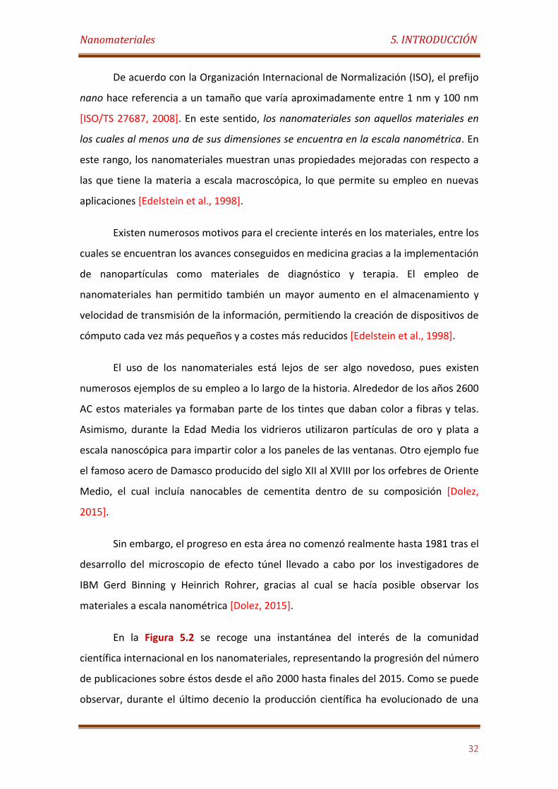
Figura 5.2. Número de publicaciones científicas sobre nanomateriales desde el año 2000 al 2015. (Fuente consultada: Web of Science)…………………….………..……. 33
Figura 5.3. Aplicaciones de los nanomateriales en diferentes áreas…………………… 36
Figura 5.4. Esquema de funcionamiento de un biosensor………………….......……..…. 43
Figura 5.5. Representación esquemática de una reacción enzimática catalizada……………………………………………………………………………………………..……......... 46
Figura 5.6. Esquema básico de biosensor electroquímico nanoestructurado……. 50
Figura 5.7. Diferentes arquitecturas de nanopartículas metálicas en la modificación de las superficies electródicas…………………………………………..…..……… 53
Figura 5.8. Modificación de la superficie del electrodo con nanopartículas metálicas, solas y combinados con otros materiales………………………..………………… 54
Figura 5.9. Transferencia directa de electrones (e-) entre en centro redox de una enzima y la superficie del electrodo a través de CNTs…………………..……………. 57
Figura 5.10. Parámetros estructurales de una molécula de dendrímero y sus métodos de síntesis A) divergentes y B) convergentes………….………………..………… 60
Figura 5.11. Resumen de los mecanismos básicos de liberación de fármacos en los sistemas de administración controlada por: A) difusión, B) hinchamiento controlada, C) erosión y D) estímulos……………………………..…………………………………. 67
Figura 5.12. Ilustración de los nanomateriales usados como plataformas en los sistemas de liberación de fármacos……………………………………………………………………. 68
Figura 5.13. Diagrama esquemático de los materiales MCM-41 (hexagonal) y MCM-48 (cúbica)……………………………………………………………….……………….……………… 74
Figura 5.14. Ilustración esquemática de la síntesis de MCM-41. Mecanismo de polimerización del TEOS…………………………………………………………………………………….. 75
Figura 5.15. Representación esquemática de una MSN funcionalizada con una puerta molecular para la liberación controlada de fármacos mediante un estímulo…………………………………………………………………………………………………………….. 76
Tablas:
Tabla 5.1. Evolución de los sistemas controlados de administración de fármacos desde1950……………………………………………………………………….………….…………………….. 64
1. ÍNDICE DE FIGURAS Y TABLAS
2
7. PUBLICACIONES CIENTÍFICAS:
7. 1. Electrochimica Acta 56 (2011) 4672-4677
Figuras:
Figure 1. HRTEM image of AuNPs……………..………………………………………………….. 88
Figure 2. UV-vis spectra of 0.2 mg/mL solution of functionalized AuNPs in 50 mM sodium phosphate buffer, pH 7.0 in the absence (A) and the presence of 0.5 mg/mL BSA (B) and HRP (C)…………………………………………………………………..… 89
Figure 3. Field emission SEM image of the polyAuNP-modified electrode……. 90
Figure 4. AFM images of the polyAuNP-modified electrode…………………………. 91
Figure 5. Cyclic voltammograms recorded at a bare gold disk electrode (A), and a polyAuNPs-modified electrode before (B) and after HRP immobilization (C), in 0.1 M KCl solution containing 5 mM K3[Fe(CN)6]/K4[Fe(CN)6] (1:1)…………………………………………………………………………
92
Figure 6. Impedance plane diagram (−Z″ versus Z′) for the EIS measurements at a bare gold disk electrode () and a polyAuNPs-modified electrode before () and after HRP immobilization (), in 0.1 M KCl solution containing 5 mM K3[Fe(CN)6]/K4[Fe(CN)6] (1:1)……………….………………………………………………..……… 93
Figure 7. Cyclic voltammograms recorded at HRP-modified electrodes in the absence and the presence of H2O2 in 0.1 M sodium phosphate buffer, pH 7.0. HRP-Au electrode (A), HRP-polyAuNPs-Au electrode (B), HRP-Au electrode + 1 µM H2O2 (C), HRP-Au electrode + 2 µM H2O2 (D), HRP-polyAuNPs-Au electrode + 1 µM H2O2 (E) and HRP-polyAuNPs-Au electrode + 2 µM H2O2 (F)…………………………………………………………………………………………………………………
95
Figure 8. Amperometric responses recorded with HRP-Au (A) and HRP-polyAuNPs-Au (B) electrodes for successive additions of 10 mM H2O2 to 10 mL of 0.1 M sodium phosphate buffer, pH 7.0. Eapp. = 0.0 V………………………. 96
Figure 9. Calibration curve for H2O2 obtained with a HRP-polyAuNPs-Au biosensor in the 5 µM to 1.1 mM H2O2 concentration range…………………….………………………………………………………………………………………. 97
Figure 10. Effect of the storage time at 4°C of the HRP-polyAuNPs-Au biosensor on the sensitivity for H2O2 determination…………………………………..… 110
Tablas:
Table 1. Comparison of analytical properties of the biosensor with previously reported AuNP-based mediatorless biosensors…………………………… 98
1. ÍNDICE DE FIGURAS Y TABLAS
3
7. 2. Analyst 137 (2012) 342-348
Figuras:
Fig. 1. Scheme displaying the steps involved in the construction of an electrochemical tyrosinase biosensor based on a gold electrode nanostructured with electropolymerized PAMAM G-4 dendron-coated AuNPs……………………………………………………………………………………………………………. 110
Fig. 2. HRTEM image of dendron-functionalized AuNPs………………................... 111
Fig. 3. Cyclic voltammograms for the first electropolymerization process of PAMAM G-4 dendron-coated AuNPs on gold electrode surface, in 0.1 M H2SO4. Scan rate: 100 mV/s……………….…………………………………..……………………… 112
Fig. 4. AFM images and height histogram of the PAMAM G-4 dendron-coated AuNPs-modified electrode………….……………………….……………………………. 113
Fig. 5. Impedance plane diagram (−Z´´ versus Z´) for the EIS measurements at a bare gold disk electrode () and at the electropolymerized PAMAM G-4 dendron-coated AuNPs-modified electrode before () and after tyrosinase immobilization (), in 0.1 M KCl solution containing 5 mM K3[Fe(CN)6]/K4[Fe(CN)6] (1:1)………………………………………………………………………… 115
Fig. 6. Cyclic voltammograms recorded at a bare gold disk electrode (A), and at the electropolymerized PAMAM G-4 dendron-coated AuNPs-modified electrode before (B) and after tyrosinase immobilization (C), in 0.1 M KCl solution containing 5 mM K3[Fe(CN)6]/K4[Fe(CN)6] (1:1)……………………………….. 116
Fig. 7. Amperometric response of the tyrosinase-functionalized p-aminothiophenol-coated non-nanostructured gold electrode (A) and electropolymerized PAMAM G-4 dendron-coated AuNPs-modified electrode (B) to successive additions of 100 µM catechol solution to 10 mL of 0.1 M sodium phosphate buffer, pH 7.0. Eapp. = -100 mV………………………………………. 117
Fig. 8. Effect of the storage time at 4°C of the tyrosinase biosensor on the relative bioelectrocatalytic activity towards 100 nM catechol determination……………………………………………………………………………………………… 119
7. 3. ChemElectroChem. 1 (2014) 200-206
Figuras:
Scheme 1. Preparation of the immunosensor for fibrinogen on gold electrodes coated with electropolymerized matrix of biotin-labelled AuNPs……………………………………………………………………………………………………………. 131
Figure 1. Cyclic voltammograms recorded in the electropolymerization of the polyfunctionalized AuNPs on gold electrode surface in 0.1 M H2SO4 at 100 V/s…………………………………………………………………………………………………………..
134
1. ÍNDICE DE FIGURAS Y TABLAS
4
Figure 2. FE-SEM (A) and AFM (B) analysis of gold surface coated with electropolymerized matrix of biotin-labelled AuNPs…………………………………….. 135
Figure 3. Nyquist plots obtained at a bare gold electrode (a) and at a gold electrode sequentially modified with p-aminothiophenol (b), polymerized AuNPs (c), streptavidin (d), biotinilated fibrinogen (e), casein (f) and HRP-labeled anti-fibrinogen antibody (g) in 0.1 M KCl solution containing 5 mM K3[Fe(CN)6]/K4[Fe(CN)6] (1:1)………..……………..……………………………………………….. 136
Figure 4. Cyclic voltammograms recorded in 0.1 M KCl solution containing 5 mM K3[Fe(CN)6]/K4[Fe(CN)6] (1:1) at a bare gold electrode (a) and at a gold electrode sequentially modified with p-aminothiophenol (b), polymerized AuNPs (c), streptavidin (d), biotinilated fibrinogen (e), casein (f) and HRP-labeled anti-fibrinogen antibody (g). Scan rate: 50 mV/s………………………………. 138
Figure 5. Calibration curve for fibrinogen quantification using the electropolymerized AuNPs-based immunosensor………………………………………… 140
Figure 1S. A) HR-TEM image, B) size distribution and C) selected area electron diffraction analysis of biotin-labeled gold nanoparticles……………...... 146
Figure 2S. UV-vis spectra of 0.2 mg/mL solution of functionalized AuNPs in 50 mM sodium phosphate buffer, pH 7.0 in the absence (a) and the presence of 0.5 mg/mL BSA (b) and streptavidin (c)…………………………………………………….. 147
Figure 3S. Height histogram of the gold surface coated with electropolymerized matrix of biotin-labeled AuNPs……………………………………... 147
7. 4. ACS Applied Materials & Interfaces 4 (2012) 4312-4319
Figuras:
Figure 1. Schematic display of the steps involved in the preparation of XO-CD/pAuNP/SWNT/GCE enzyme biosensors………………..................................... 155
Figure 2. FT-IR spectrum of the polyfunctionalized Au nanoparticles…………… 156
Figure 3. UV-vis spectra of 0.4 mg/mL solution of Au nanoparticles in 50 mM sodium phosphate buffer, pH 7.0 without (A) and with 0.5 mg/mL XO (B) and XO-CD (C)………………………………………..……………………………………………………………. 157
Figure 4. Cyclic voltammograms recorded in 0.1 M H2SO4 at a bare GCE (A), a SWNT-modified GCE (B), and upon electropolymerization of Au nanoparticles for five (C) and ten (D) potential cycles, and after polymer growing for 1 h at +850 mV (E). Scan rate: 50 mV/s………………………………………. 158
Figure 5. Field emission SEM image of the pAuNP/SWNT/GCE……………………… 159
Figure 6. Nyquist plots of bare GCE (), SWNT/GCE (), pAuNP/SWNT/GCE (X) and XO-CD/pAuNP/SWNT/GCE () in 0.1 M KCl solution containing 5 mM K3[Fe(CN)6] /K4[Fe(CN)6] (1:1)……………………………………………………………………….. 160
1. ÍNDICE DE FIGURAS Y TABLAS
5
Figure 7. Cyclic voltammograms recorded in 0.1 M KCl solution containing 5 mM K3[Fe(CN)6]/K4[Fe(CN)6] (1:1) at bare GCE (A), SWNT/GCE (B), pAuNP/SWNT/GCE (C) and XO-CD/pAuNP/SWNT: 50 mV/s…….…………………… 161
Figure 8. Cyclic voltammograms recorded in 0.1 M sodium phosphate buffer, pH 7.0, at a scan rate of 50 mV/s for: A) XO-CD/pAuNP/SWNT/GCE and XO/pAuNP/SWNT/GCE without addition of xanthine (curves (a) and (b), respectively) and after addition of 200 µM xanthine (curves (d) and (c), respectively). B) XO-CD/pAuNP/SWNT/GCE and XO/pAuNP/SWNT/GCE in the presence of 200 µM xanthine before (curves (e) and (c), respectively) and after 1 h incubation in saturated 1-adamantane carboxylic acid solution (curves (g) and (f), respectively)……………………………………………………………………. 162
Figure 9. Amperometric responses of the XO-CD/pAuNP/SWNT/GCE and Naf/XO-CD/pAuNP/SWNT/GCE biosensors toward 500 nM xanthine upon addition of glucose (a), sacarose (b), ethanol (c), acetic acid (d), lactic acid (e), citric acid (f), uric acid (g) and ascorbic acid (h) at a 5.0 µM concentration level……………………………………………………………………………………………………………….
168
Figure S1. TEM image of the polyfunctionalized Au nanoparticles acquired with a JEOL JEM-2100 microscope at 200 kV…………………………………………………. 174
Figure S2. HR-TEM image of the polyfunctionalized Au nanoparticles acquired with a JEOL JEM-3000 F microscope at 300 kV……………………………..... 175
Figure S3. Dynamic amperometric response of XO-CD/pAuNP/SWNT/GCE poised at +650 mV to successive addition of 100 µM xanthine solution. Inset: Amperometric response of the electrode at lower concentrations of xanthine. Initial working volume: 10 ml. Supporting electrolyte: 0.1 M sodium phosphate buffer, pH 7.0…………………………………….……………………………. 175
Figure S4. Calibration curves for xanthine obtained with XO-CD/pAuNP/SWNT/GCE (), Naf/XO-CD/pAuNP/SWNT/GCE () and
XO/pAuNP/SWNT/GCE () biosensors………………………………………………………….. 176
Figure S5. Evaluation of the storage stability with time for XO-CD/pAuNP/SWNT/GCE () and Naf/XO-CD/pAuNP/SWNT/GCE () biosensors. Measurements were carried out toward 500 nM xanthine……………………………………………............................................................... 176
Tablas:
Table 1. Comparison of the analytical characteristics of the developed biosensors with those previously reported for other electrochemical xanthine biosensors……….…………………………………………………………………………….. 167
7. 5. Electroanalysis 23 (2011) 1790-1796
Figuras:
Figure 1. Scheme displaying the steps and fundamentals involved in the enzyme biosensor preparation……………………………………………………………………… 183
1. ÍNDICE DE FIGURAS Y TABLAS
6
Figure 2. Quartz crystal microbalance responses for gold disks coated with: SWNT during immobilization of native XO (a), SWNT/Pyr-βCD during the immobilization of adamantane-modified (b), and native XO (c)………….………… 184
Figure 3. Nyquist plots recorded at bare () and SWNT/Pyr-βCD-modified
GCE before () and after immobilization of native () and adamantane-modified XO (), in 0.1 M KCl solution containing 5 mM K3[Fe(CN)6]/K4[Fe(CN)6] (1:1)…………………………………………………………………………. 185
Figure 4. Cyclic voltammograms of XO/SWNT/Pyr-βCD and XO-ADA/SWNT/Pyr-βCD modified GCE in the absence (voltammograms A and B, respectively) and in the presence of 40 µM xanthine (voltammograms C and D, respectively). Scan rate, 50 mV/s in 0.1 M sodium phosphate buffer, pH 7.0…………………………………………………………………………………………………………………. 187
Figure 5. Dynamic amperometric response of the XO-ADA/SWNT/Pyr-βCD (A) and XO/SWNT/Pyr-βCD (B) modified GCE at +600 mV to successive additions of a 10 mM xanthine solution. Initial working volume: 10 ml. Supporting electrolyte: 0.1 M sodium phosphate buffer, pH 7.0……………………………………………………………………...............................................
188
Figure 6. Long-term stability of the XO-ADA/SWNT/Pyr-βCD/GCE biosensor toward the determination of xanthine………………………………………………………….. 190
7. 6. Journal of Materials Chemistry 21 (2011) 12858-12864
Figuras:
Figure 1. Schematic display of the construction of Fe3O4/APTES-PEG-XO/SWNT magnetic nanomaterials-based biosensors………………………………….. 201
Figure 2. TEM images of A) Fe3O4, B) Fe3O4/APTES, C) Fe3O4/APTES-PEG and D) Fe3O4/APTES-PEG/SWNT magnetic nanomaterials……………………………………. 202
Figure 3. FT-IR spectra of A) Fe3O4, B) Fe3O4/APTES and C) Fe3O4/APTES-PEG magnetic nanoparticles…………….…………………………………………………………………… 204
Figure 4. Magnetization curves of Fe3O4 (), Fe3O4/APTES (), Fe3O4/APTES-PEG (X) and Fe3O4/APTES-PEG/SWNT () nanomateriales at 298K………………… 205
Figure 5. FE-SEM images of A) Fe3O4/APTES-PEG-XO and B) 1:27 SWNT: Fe3O4/APTES-PEG-XO-modified AuSPE………………………………………………………….. 207
Figure 6. Impedance plane diagram (−Z″ versus Z′) recorded for AuSPE before () and after modification with Fe3O4/APTES-PEG-XO (), 1:80 SWNT: Fe3O4/APTES-PEG-XO (), 1:27 SWNT: Fe3O4/APTES-PEG-XO () and 1:16 SWNT: Fe3O4/APTES-PEG-XO (Δ) in 0.1 M KCl solution containing 5 mM K3[Fe(CN)6]/K4[Fe(CN)6] (1:1)…………………………………………………………………………
208
Figure 7. Cyclic voltammograms recorded with AuSPEs modified with: Fe3O4/APTES-PEG/XO (A); Fe3O4/APTES-PEG-XO (B); 1:80 SWNT: Fe3O4/APTES-PEG-XO (C); 1:16 SWNT: Fe3O4/APTES-PEG-XO (D) and 1:27
1. ÍNDICE DE FIGURAS Y TABLAS
7
SWNT: Fe3O4/APTES-PEG-XO (E) from a 2.5 µM xanthine solution in 0.1 M sodium phosphate buffer, pH 7.0; v = 50 mV/s……………………………….……………..
209
Figure 8. Calibration plots for xanthine recorded with Fe3O4/APTES-PEG/XO (), Fe3O4/APTES-PEG-XO (), 1:80 SWNT: Fe3O4/APTES-PEG-XO (), 1:27 SWNT: Fe3O4/APTES-PEG-XO () and 1:16 SWNT: Fe3O4/APTES-PEG-XO (Δ) modified AuSPEs; Eapp. = + 600 mV………………………………………………………………. 211
Tablas:
Table 1. Comparison of analytical properties of the biosensor with previously reported xanthine biosensor……………………………………………………….. 212
7. 7. Analytical and Bioanalytical Chemistry 405 (2013) 3773-3781
Figuras:
Figure 1. Schematic display of the steps involved in the preparation of GO-ADA/CD-PAMAM/PtNP/Au based enzyme biosensors…………………………………. 223
Figure 2. SPR sensogram recorded on Au surfaces upon successive incubation with CD-PAMAM G-4 and GO-ADA (a), PAMAM G-4 and GO (b) and CD-PAMAM G-4 and GO (c)……………………………………………………………………. 224
Figure 3. Field emission SEM image of the CD-PAMAM G-4/PtNP-modified Au surface……………………………………………………………………………………………………… 226
Figure 4. Three dimensional AFM analysis of the Au surface before (A) and after modification with CD-PAMAM (B), CD-PAMAM/PtNP (C) and GO-ADA/CD-PAMAM/PtNP (D)……………………………………………………………………………. 227
Figure 5. Nyquist plots of bare Au (a), CD-PAMAM/Au (b), CD-PAMAM/PtNPs/Au (c) and GO-ADA/CD-PAMAM/PtNP/Au (d) electrodes in 0.1 M KCl solution containing 5 mM K3[Fe(CN)6]/K4[Fe(CN)6] (1:1)……………….. 228
Figure 6. Cyclic voltammograms recorded in 0.1 M KCl solution containing 5 mM K3[Fe(CN)6]/K4[Fe(CN)6] (1:1) at bare Au (a), CD-PAMAM/Au (b), CD-PAMAM/PtNPs/Au (c) and GO-ADA/CD-PAMAM/PtNP/Au (d) electrodes. Scan rate: 50 mV/s……………………………………………………………………………………..... 229
Figure 7. Cyclic voltammograms recorded in 0.1 M sodium phosphate buffer, pH 7.0, at a scan rate of 50 mV/s, for GO-ADA/CD-PAMAM/PtNP/Au electrode before (a) and after (b) addition of 200 µM glucose…………………………………………………………………………………………………………..
230
Figure 8. Amperometric responses recorded with GO-ADA/CD-PAMAM/PtNP/Au (a), GO/PAMAM/PtNP/Au (b), GO/CD-PAMAM/PtNP/Au (c) and GO/PtNP/Au (d) electrodes upon successive additions of 5.0 mM glucose. Eapp.= + 400 mV……………………………………………………………………………… 232
Figure 1S. 1H NMR spectrum of CD-branched cysteamine core PAMAM G-4 dendron………………………………………………………………………………………..………………. 241

1. ÍNDICE DE FIGURAS Y TABLAS
8
Tablas:
Table 1. Comparison of the analytical performance of the GO-ADA/CD-PAMAM/PtNP/Au biosensor with that reported previously for mediatorless glucose biosensors………………………………………………………………………………………… 234
7. 8. Electrochimica Acta 76 (2012) 249-255
Figuras:
Figure 1. Scheme displaying the steps involved in the preparation of the layer-by-layer self-assembly of dendrimer and HRP on Au surface. D1: CD-PAMAM G-4 dendron layer, D2 and D3: CD-PAMAM G-5 dendrimer layers, and HRP: enzyme layers…………………………………………………………………..……………. 250
Figure 2. A) Cyclic voltammograms of native (a) and CD-PAMAM G-4 dendron-modified Au electrode in 0.1 M sodium phosphate buffer, pH 7.0 solutions containing 1.0 mM hydroquinone before (b) and after (c) addition of H2O2 up to 100 µM final concentration. B) Cyclic voltammograms of Au electrodes modified with CD-PAMAM G-4 dendron (c), D1/HRP1 (d), D2/HRP2 (e), D3/HRP3 (f) and D4/HRP4 (g) bilayers in the presence of 100 µM H2O2…………………………………………………………………………………………………….… 251
Figure 3. Cyclic voltammograms recorded with Au electrodes modified with CD-PAMAM G-4 dendron/HRP (E) and D3/HRP3 bilayers in 0.1 M sodium phosphate buffer, pH 7.0 solutions containing 1.0 mM hydroquinone and 100 µM H2O2 before (A) and after 30 (B), 60 (C) and 120 (D) min incubation in 10 mM 1-adamantane carboxylic acid solution…………………………………………. 253
Figure 4. SPR sensogram recorded upon the layer-by-layer self-assembling of CD-modified PAMAM dendritic scaffolds and HRP-ADA on Au surfaces……………………………………………………………………………………………………….… 254
Figure 5. Calculated molar content of enzyme and dendrimers in the layer-by-layer assembly from QCM (black) and SPR (white) measurements. Each value corresponds to the molar content per layer……………………………………….. 255
Figure 6. Three dimensional AFM analysis of the Au surface before (A) and after modification with the D1/HRP1 (B), D2/HRP2 (C) and D3/HRP3 (D) bilayers………………………………………………………………………………………………………… 256
Figure 7. Amperometric responses recorded with CD-PAMAM G-4 dendron/HRP (A), D1/HRP1 (B), D2/HRP2 (C) and D3/HRP3 (D) modified Au electrodes upon successive additions of 1.0 mM H2O2. Eapp.= - 100 mV. Inset: Electroanalytical behavior of the D3/HRP3 modified Au electrode toward low H2O2 concentration…………………………………………………………………….. 258
Figure 8. Calibration curves for H2O2 constructed with biosensors prepared with D1/HRP1 (), D2/HRP2 (), D3/HRP3 () and D1/native HRP (×) modified Au electrodes………………………………………………………………………………….
259
1. ÍNDICE DE FIGURAS Y TABLAS
9
7. 9. ACS Applied Materials & Interfaces 8 (12) (2016) 7657–7665
Figuras:
Scheme 1. Performance of dual stimuli-responsive nanodevice S3 for the programmed and sequential delivery of the [Ru(bpy)3]Cl2 complex using glucose and ethyl butyrate as triggers…………………………………………………………… 267
Figure 1. A) Release efficiency for [Ru(bpy)3]Cl2 from S3 (a) and S2 (b) after a 90-minute incubation with different trigger substances at a 200 µM concentration. B) Dye release efficiency from S3 (a) and S2 (b) after 90-minute incubation in the presence of glucose at different concentrations……………………………………………………………………………….……………… 271
Figure 2. Kinetics of the dye release from S3 (A) and S2 (B) in 20 mM Na2SO4, pH 7.5, without (a) and with addition of ethyl butyrate (b) and glucose + ethyl butyrate (c) at a 200 µM final concentration. Triggers were added at the times indicated in the graphics……………………………………………………………….. 272
Scheme 2. Proposed mechanisms for the stimuli-responsive controlled delivery from nanocarriers S2 (A) and S3 (B)………………………………………………… 274
Figure 3. Internalization and release of cargo in HeLa cells. Culture were incubated with S4 (3A) or S5 (3B) in presence/absence of different input I1 (D-glucose) or input I2 (ethyl butyrate) and examined for Doxorubicin staining (Doxo) by confocal microscopy. Representative images at 24 h form phase contrast (PhC), Doxorubicin (Doxo), Hoescht (Hoe) and combined (Merged) are shown. Quantification of cell viability and cell death was performed by flow cytometry by means of 7-AAD and Ann V staining. The percentage of dead cells (black), cells undergoing cell death (gray) and healthy cells (white) are shown for 50 μg/ml concentration of S4 (3C) and S5 (3D) in HeLa cells under different conditions at 24 h……………………………………. 276
Figure S1. TEM images of S0 (a), S1 (b), S2 (c) and S3 (d) nanoparticles………. 292
Figure S2. Powder X-ray diffraction of S0 (a), S1 (b), S2 (c) and S3 (d) nanoparticles at low angles………………………………………………………………………….. 294
Figure S3. FT-IR analysis for S0 (a), S1 (b), S2 (c) and S3 (d) nanoparticles…… 294
Figure S4. Solid state 13C NMR spectra for S0 loaded with tris(2,2′-bipyridyl)dichlororuthenium (II) hexahydrate and modified with epoxy groups (A), S1 (B) and S2 (C) nanoparticles…………………………………………………… 295
Figure S5. A) TG and B) DTG analysis for S0 (a), S1 (b), S2 (c) and S3 (d) nanoparticles……………………………………….……………………………………………………….. 296
Figure S6. A) Nitrogen adsorption (closed)/desorption (open) isotherms and B) pore size distribution for S0 (a), S1 (b), S2 (c) and S3 (d) nanoparticles………………………………………………………………………………………………… 297
1. ÍNDICE DE FIGURAS Y TABLAS
10
Figure S7. Nanoparticle size distribution of S0, S2 and S3 in H2O (black line), PBS (dotted line) and DMEM (striped line)……………………………………………………. 298
Figure S8. TEM images of S1 (A), S2 (B) and S3 (C) nanoparticles after staining with 1% uranyl acetate…………………………………………………………………….. 299
Figure S9. Trigger reactions mediated by D-glucose (A) and ethyl butyrate (B)…………………………………………………………………………………………………………………. 300
Figure S10. A) Confocal images of HeLa cells incubated with solid S4 for 30 minutes and then treated with input A (D-Glucose) and/or input B (ethyl butyrate) or untreated. Representative images at 24 h from phase contrast (PhC), Doxorubicin (Doxo), Hoescht (Hoe) and combined (Merged) are shown. B) Cell viability (%) of HeLa cells treated with S5 using WST-1 assay. Results expressed in % (refereed to untreated cells) ± standard deviation of three different experiments. C) Mean fluorescent intensity of Doxo in HeLa cells treated with S4 using FACS analysis…………………………………………………....... 301
Figure S11. A) Confocal images of HeLa cells incubated with solid S5 for 30 minutes and then treated with input A (D-Glucose) and/or input B (ethyl butyrate) or untreated. Representative images at 24 h from phase contrast (PhC), Doxorubicin (Doxo), Hoescht (Hoe) and combined (Merged) are shown. B) Cell viability (%) of HeLa cells treated with S5 using WST-1 assay. Results expressed in % (refereed to untreated cells) ± standard deviation of three different experiments. C) Mean fluorescent intensity of Doxo in HeLa cells treated with S5 using FACS analysis………………………………………………………. 302
Figure S12. Quantification of cell viability and cell death was performed by flow cytometry by means of 7-AAD and Ann V- FITC staining for S4. The percentage of dead cells (black), cells undergoing cell death (gray) and healthy cells (white) are shown after 24 h of treatment. Three independent experiments containing triplicates were performed and the data are reported as (mean ± SE)………………………………..……………………………………………... 301
Figure S13. Quantification of cell viability and cell death was performed by flow cytometry by means of 7-AAD and Ann V- FITC staining for S5. The percentage of dead cells (black), cells undergoing cell death (gray) and healthy cells (white) are shown after 24 h of treatment. Three independent experiments containing triplicates were performed and the data are reported as (mean ± SE).………………………………………………………………………………..
304
Figure S14. CLSM images of HeLa cells incubated with 30 μg/mL of S4 for 1 hour, washed and then incubated during 1.5h and 12 h in PBS with 10 % FBS (-/-) or PBS with 10 % FBS and ethylbutyrate (-/+) . Lysotracker was used to stain the organelles of the cell and Hoescht for the nucleus…………………………. 305
Figure S15. CLSM images of HeLa cells incubated with 30 μg/mL of S5 for 1 hour and post incubated during 1.5h and 12 h in PBS and 10 % FBS (-/-) or PBS with 10 % FBS and ethylbutyrate (-/+) . Lysotracker was used to stain the organelles of the cell and Hoescht for the nucleus……………………………………….. 306
1. ÍNDICE DE FIGURAS Y TABLAS
11
Figure S16. CLSM images of HeLa cells incubated with 30 μg/mL of S4 or S5 during 1 hour, washed and then incubated in PBS with fetal bovine serum (No input) or in PBS with ethyl butyrate (Input I2). The green fluorescence is from the endocytosed nanoparticles and from released Doxo……………………… 307
Tablas:
Table S1. BET specific surface values, pore volumes and pore sizes calculated from the N2 adsorption-desorption isotherms for selected materials…………. 298
Table S2. Nanoparticle size (nm) and zeta potential values (mV) of S0, S2 and S3 in pure H2O, PBS buffer solution with 10 % FBS and DMEM culture medium with 10 % FBS………………………………………………….….………………………….. 299
7. 10. Electrochemistry Communications 30 (2013) 51–54
Figuras:
Figure 1. Preparation of the Janus nanoparticle-based biorecognition-signaling system……………………………………………………………………………………………. 313
Figure 2. A) SPR sensograms recorded upon modification of Au surfaces with thiolated biotin (1), Au-MS JNP-HRP-Stv-PEG (2) and Au-MS JNP-HRP-PEG (3). B) AFM analysis of Au-MS JNP-HRP-Stv-PEG adsorbed on biotin-modified Au surface………………………………………………..……………………………………………….….. 315
Figure 3. A) Nyquist plots and B) cyclic voltammograms obtained at a bare Au electrode (a) and after modification with thiolated biotin (b), Au-MS JNP-HRP-Stv-PEG (c) and Au-MS JNP-HRP-PEG (d) in 0.1 M KCl, 5 mM K3[Fe(CN)6]/K4[Fe(CN)6]. C) Cyclic voltammograms recorded with Au/biotin/Au-MS JNP-HRP-Stv-PEG (a) and Au/biotin/Au-MS JNP-HRP-PEG (b) electrodes in the absence and presence (*) of 50 µM H2O2 in 0.1 M sodium phosphate buffer, pH 7.0………………………………………………………………….
316
7. 11. Chemistry - A European Journal 19(24) (2013) 7889–7894
Figuras:
Scheme 1. Preparation of Janus Au-MS nanoparticles for enzyme-controlled release………………………………………………………………………………………………………… 324
Figure 1. TEM images of J1 (A), J2 (B), J3 (C) and J4 (D) Janus Au-MS nanoparticles………………………………………………………………………………………………… 326
Figure 2. Representative TEM image of J2 nanoparticles…………..………………….. 327
Figure 3. A) Nitrogen adsorption (closed)/desorption (open) isotherms for MS (,) and J2 nanoparticles (,). Inset: pore size distribution of MS () and J2 () nanoparticles. B) Normalized visible spectra of Au (a) and J2 (b) nanoparticles…………………………………………………………………….………………………….. 328
Figure 4. Kinetics of dye release from J2Ru-U in 5 mM sodium acetate buffer pH 5.0 in the absence () and the presence of 180 mM urea at t = 0 () or t = 5 h ()…………………………………………………………………………………………………………..
332
1. ÍNDICE DE FIGURAS Y TABLAS
12
Figure 1S. TEM images and distribution of sizes of MS nanoparticles……………. 340
Figure 2S. Distribution of sizes of J1 (A), J2 (B), J3 (C) and J4 (D) nanoparticles…………………………………………………………………………………………………. 340
Figure 3S. TEM images of J2 nanoparticles……………………………………………………. 341
Figure 4S. A) TG and B) DTG analysis for MS (a), J2 (b) and J2Ru (c) nanoparticles………………………………………………………………………………………………... 341
Figure 5S. A) FT-IR analysis for MS (a), J2 (b) and J2Ru (c) nanoparticles. B) X-ray diffraction of J2 (a) and J2Ru (b) nanoparticles………………………………………..
342
7. 12. Journal of the American Chemical Society 136 (25) (2014) 9116–9123
Figuras:
Scheme 1. Schematic representation of “smart” delivery systems containing an attached control unit that regulates the delivery activity of the gated material………………………………………………………………………………………………………... 345
Figure 1. Performance of the Janus-based nanodevice S3. The “control unit” (Au face) is functionalized with two effectors (enzymes) which control cargo delivery from the silica mesoporous face via interpretation of different chemical inputs (D-glucose, ethyl butyrate). Overall the system functions as an enzymatic logical OR operator………………………………………………………………….. 346
Figure 2. Kinetics of dye release from S3 in 20 mM Na2SO4, pH 7.5 in the absence (a) and the presence of 40 µM ethyl butyrate (b), D-glucose (c) and ethyl butyrate + D-glucose (d). Substrates were added after 1 h of incubation…………………………………………………………..…………………………………………. 350
Figure 3. Kinetics of dye release from S4 in 20 mM Na2SO4, pH 7.5 in the absence (a) and the presence of 40 µM ethyl butyrate (b), D-glucose (c) and ethyl butyrate + D-glucose (d) without (closed circles) and with 200 µM urea (open circles). Substrates were added ter 1 h of incubation………………………….
351
Figure 4. Kinetics of dye release from S4 in 20 mM Na2SO4, pH 7.5 in the absence (a) and the presence of 40 µM D-glucose without (f) and with addition of urea at 200 µM final concentration at different times (b-e). Substrates were added after 1 h of incubation……………………………………………… 353
Figure 5. Kinetics of Doxo release from S5 in 20 mM Na2SO4, pH 7.5 in the absence (a) and the pres-ence of 40 µM ethyl butyrate (b), D-glucose (c) and ethyl butyrate + D-glucose (d). Substrates were added after 1 h of incubation……………………………………………………………………………………………………..
354
1. ÍNDICE DE FIGURAS Y TABLAS
13
Figure 6. Internalization and release of cargo in HeLa cells A) controlled release of Doxorubicin (Doxo) loaded S5 nanoparticles in HeLa cells. Culture were incubated with 100 μg/mL of S5 and in presence of different inputs and examined for Doxo by confocal microscopy. Representative images at 24 h form phase contrast (PhC), Doxo (DOX), Hoescht (HOE) and combined (Merge) are shown. B) Cell viability test of 150 μg/mL concentration of S5 and glucose and/or ethyl butyrate at 24 h in HeLa cells using WST- assay and C) quantification of Doxo fluorescence intensity by flow cytometry in cells under different conditions. Ethyl butyrate treatment (input A), glucose treatment (input B)……………………………………………………………………………………….. 357
Figure SI-1. Powder X-ray diffraction of nanoparticles S0, S1, S2 and S3 at low (A) and high (B) angles……………………………………………………………………………. 369
Figure SI-2. FT-IR analysis for the nanoparticles S0, S1, S2 and S3…………………. 370
Figure SI-3.Thermogravimetric analysis for S0, S1, S2 and S3……………………….. 370
Figure SI-4. Nitrogen adsorption (closed)/desorption (open) isotherms for S0 to S3 nanoparticles…………………………………………..…………………………………………… 372
Figure SI-5. Kinetics of dye release from S3 in 20 mM Na2SO4, pH 7.5 in the absence (a) and the presence of 40 µM D-glucose + ethyl butyrate (b). Kinetics of release from S3 in 50 mM sodium phosphate buffer, pH 7.5 in the presence of 40 µM D-glucose + ethyl butyrate (c). Substrates were added after 1 h of incubation……………………………………………………………………………………
373
Figure SI-6. Influence of time of incubation in reconstituted human serum at 37ºC on the release activi-ty of S5 upon addition of 40 µM D-glucose + ethyl butyrate……………………………………………………………………………………………………..…. 374
Tablas:
Table SI-1. Elemental analysis for S0, S1, S2 and S3………………………………………. 371
Table SI-2. BET specific surface values, pore volumes and pore sizes calculated from the N2 adsorption-desorption isotherms for selected materials………………………………………………………………………………………………………. 372
8. DISCUSIÓN INTEGRADORA:
Figuras:
Figura 8.1. Representación esquemática de las nanopartículas de oro polifuncionalizadas……………………………………………………………………………………….. 376
Figura 8.2. Imágenes de las nanopartículas de oro polifuncionalizadas con residuos de ácido 3-mercaptofenilborónico, obtenida mediante TEM a 200 kV (A) y 300 kV (B)…………………………………………………………………………………………. 378
Figura 8.3. Espectro FT-IR de las nanopartículas de oro polifuncionalizadas con residuos de ácido 3-mercaptofenilborónic………….…………………………………. 379
1. ÍNDICE DE FIGURAS Y TABLAS
14
Figura 8.4. Imágenes FE-SEM de redes de nanopartículas de oro polifuncionalizadas con residuos de ácido 3-mercaptofenilborónico, obtenida mediante métodos químicos (A) y electroquímicos (B) de polimerización………………………………………………………………………………………………. 380
Figura 8.5. Imágenes FE-SEM de redes de nanopartículas de oro polifuncionalizadas y (A) con residuos de ácido 3-mercaptofenilborónico crecidas sobre electrodos de oro, y (B) con residuos de 1-adamantano y crecidas sobre electrodos de carbono vitrificado recubiertos con nanotubos de carbono de pared simple………………………………………………………………………….. 381
Figura 8.6. Representación esquemática de los procesos de síntesis y electropolimerización de las nanopartículas de oro polifuncionalizadas……….. 382
Figura 8.7. Estructura del polímero conductor de polianilina………………………… 383
Figura 8.8. Voltamperogramas cíclicos para el primer paso de electropolimerización de las nanopartículas de oro polifuncionalizadas con residuos de ácido 3-mercaptofenilborónico sobre electrodos de oro, en solución de H2SO4 0.1 M. Velocidad de barrido: 100 mV/s……………………………. 384
Figura 8.9. Representación esquemática del proceso de ensamblado del electrodo enzimático para la detección de H2O2…………………………………………….
385
Figura 8.10. Estructura tridimensional de la peroxidasa de rábano……………….. 386
Figura 8.11. Funcionalización supramolecurar no covalente de SWCNTs con: A) Nanoparticulas Fe3O4 modificadas con PEG y XO; y B) Pireno funcionalizado con CD para la formación de un complejo de inclusión con la XO-ADA………......................................................................................................
391
Figura 8.12. Efecto del campo magnético externo generado por un imán de neodimio sobre una dispersión de nanotubos de carbono de pared simple de concentración 0.1 mg/mL, antes (A) y después (B) de su funcionalización con nanopartículas superparamagnéticas de Fe3O4 modificadas con polietilenglicol……………………………………………………………………………………………….
393
Figura 8.13. Representación esquemática del proceso de ensamblado del electrodo con: (A) PAMAM G4-CD/Enzima-ADA y (B) PAMAM G4-CD/Enzima-ADA/PAMAM G5-CD/ Enzima-ADA……………………………………………………………….. 396
Figura 8.14. Representación esquemática del mecanismo de formación de ésteres cíclicos de ácido borónico con azúcares……………………………………………
397
Figura 8.15. Representación esquemática de una nanomáquina para la liberación sitio-específica, autónoma e inteligente de fármacos bajo control lógico modulado por enzimas………………………………………………………………………
404
Figura 8.16. Estrategia de enmascaramiento y manipulación selectiva de interfases empleada en la preparación de nanopartículas Janus de oro y sílice mesoporosa………………………………………………………………………………………..… 405
Figura 8.17. Imagen FE-SEM de los coloidosomas de parafina recubiera con nanopartículas de sílice mesoporosa…………………………….…………………………….…
405

2 ABREVIATURAS Y
SÍMBOLOS

2. ABREVIATURAS Y SÍMBOLOS
15
ADA: Adamantano
AFM: Microscopía de fuerza atómica
APTES: Aminopropiltrimetoxisilano
BSA: Albúmina de suero bovino
CD: Ciclodextrina
CNTs: Nanotubos de carbono
CTAB: Bromuro de hexadeciltrimetilamonio
CV: Voltamperometría Cíclica
DMF: Dimetilformamida
DMSO: Dimetilsulfóxido
DNA: Ácido desoxirribonucleico
e-: Electrones
EDAC: 1-Etil-3-(3-dimetilaminopropil) carbodiimida
EIS: Espectroscopía de impedancia electroquímica
EtOH: Etanol
FE-SEM: Microscopía Electrónica de Barrido con Emisión de Campo
FTIR: Espectroscopia de infrarrojo con transformada de Fourier
GA: Glutaraldehído
GCE: Electrodo de carbono vitrificado
GO: Óxido de grafeno
GOx: Glucosa oxidasa
GPTMS: (3-glicidiloxipropil)trimetoxisilano
HRP: Peroxidasa de rábano picante
HR-TEM: Microscopía de transmisión electrónica de alta resolución
ISO: Organización Internacional de Normalización
IUPAC: Unión Internacional de Química Pura y Aplicada
MES: Ácido 2-morfolinoetanosulfónico
mRNA: Ácido ribonucleico mensajero
MSNs: Nanopartículas de sílice mesoporosa
MWCNTs: Nanotubos de carbono de pared múltiple
NADH: Nicotinamida adenina dinucleótido de hidrógeno
NHS: N-hidroxisuccinimida
NPs: Nanopartículas
PAMAM: Dendrímero de poliamidoamina
PBS: Disolución reguladora de fosfato salino
PEG: Polietilenglicol
PolyAuNPs: Nanopartículas de oro polimerizadas
QDots: Puntos cuánticos
SDS: Dodecilsulfato sódico
SPCEs: Electrodos serigrafiados de carbono
Strep-HRP: Estreptavidina-Peroxidasa
Sulfo-NHS: N-sulfohidroxisuccinimida
SWCNTs: Nanotubos de carbono de pared simple
TEM: Microscopía de transmisión electrónica
TEOS: Tetraetilortosilicato
TG: Termogravimetría
Tyr: Tirosinasa
UV-VIS: Ultravioleta visible
XO: Xantina Oxidasa
XRD: Difracción de Rayos X

3 SUMMARY

3. SUMMARY
17
Nanotechnology, and specially nanomaterials engineering, has opened new
possibilities to science and nowadays is the core of emerging technologies by providing
a great variety of advanced functional nanomaterials with unique and well-defined
characteristics. These nanomaterials have allowed the design of novel drug delivery
systems, biomaterials, protective coatings, electronic devices, functional and wearable
textiles and sensor systems with improved properties and nanometric dimensions.
In this context, the ultimate goal for nanomaterials engineering is the
establishment of original strategies for the tailor-made preparation of nanosized
structures with desired physicochemical and functional properties by rational
manipulation of their chemical composition, morphology, size and surface
derivatization. In special, great attention is currently devoted to the design of novel
functionalized nanomaterials and nanohybrids for emergent biologically driven
applications. These materials should be provided with specific chemical functionalities
to ensure high biocompatibility, hydrophilicity and capacity for the stable
immobilization of biologically-active macromolecules.
This PhD Thesis, presented as a compendium of published research articles,
describes original approaches for the preparation and assembly of nanomaterials-
based devices for sensitive electrochemical biosensing and smart drug delivery. In the
part devoted to electrochemical biosensors, the first paper (Electrochimica Acta 56,
2011, 4672-4677) describes the construction of a reagentless amperometric biosensor
for H2O2 wherein a novel one-pot preparation of gold nanoparticles polyfunctionalized
with 2-mercaptoethanesulfonic acid as solubilizing agent, p-aminothiophenol as
polymer-forming residue, and 3-mercaptophenyl boronic acid for enzyme
immobilization is presented. Gold electrodes were functionalized with an
electropolymerized matrix of these nanoparticles, and the resulting nanostructured
electroconductive matrix was used as support for the oriented immobilization of the
enzyme horseradish peroxidase to construct the reagentless amperometric biosensor
for H2O2 detection. The electrode, poised at 0.0 mV, exhibited a rapid response within
8 s and a linear calibration range from 5 µM to 1.1 mM H2O2. The sensitivity of the
biosensor was determined as 498 µA/M cm2, and its detection limit was 1.5 µM H2O2
3. SUMMARY
18
at a signal-to-noise ratio of 3. The electrode retained 95% and 72% of its initial activity
after 21 and 40 days of storage at 4ºC.
In the second paper (Analyst 137, 2012, 342-348), a biosensor for catechol is
presented herein polyfuntionalized gold nanoparticles provided with 2-
mercaptoethanesulfonic acid, p-aminothiophenol and cysteamine core
polyamidoamine G-4 dendron moieties were prepared. The nanoparticles were
electropolymerized on Au electrode surface through the formation of bis-aniline cross-
linked network. The enzyme tyrosinase was further crosslinked on this nanostructured
matrix. The enzyme electrode, poised at -100 mV, was then used for the amperometric
quantification of catechol. The biosensor showed a linear response from 50 nM to 10
µM catechol, with a low detection limit of 20 nM and a sensitivity of 1.94 A/M cm2.
The electrode retained 96% and 67% of its initial activity after 16 and 30 days of
storage at 4°C under dry conditions.
The third presented paper (ChemElectroChem 1, 2014, 200-206) describes an
amperometric immunosensor system to detect human fibrinogen. In this work we
introduce the preparation of water soluble gold nanoparticles (3.1 ± 0.6 nm) with
polymerization ability and affinity to streptavidin, by reducing HAuCl4 in the presence
of the capping ligands 2-mercaptoethanesulfonic acid, p-aminothiophenol and a
biotin-cysteamine derivative. This colloid was used to modify gold electrodes by
formation of an electropolymerized 3D network of bis-aniline cross-linked
nanoparticles on the metal surface. The modified electrode was employed as scaffold
for the assembly of an amperometric immunosensor system to detect human
fibrinogen. The immunosensor showed excellent analytical characteristics, with a
dynamic range of detection between 0.018 and 2.208 µg/mL, a detection limit of 4
ng/mL and an IC50 value of 177 ng/mL. The immunosensor was markedly stable,
retaining full analytical capacity after 45 days of storage at 4ºC.
In the fourth presented paper (ACS Applied Materials & Interfaces 4, 2012,
4312-4319) we report a new xanthine biosensor design. The novel preparation of the
biosensor is based on glassy carbon electrodes modified with single walled carbon
nanotubes and a three-dimensional network of electropolymerized Au nanoparticles
3. SUMMARY
19
capped with 2-mercaptoethanesulfonic acid, p-aminothiophenol and 1-
adamantanethiol which were used as hybrid electrochemical platforms for
supramolecular immobilization of a synthesized artificial neoglycoenzyme of xanthine
oxidase and β-cyclodextrin through host-guest interactions. This ensemble was thus
further employed for the bioelectrochemical determination of xanthine. The biosensor
showed fast amperometric response within 5 s and a linear behavior in the 50 nM –
9.5 µM xanthine concentration range with high sensitivity, 2.47 A/M·cm2, and very low
detection limit of 40 nM. The stability of the biosensor was significantly improved and
the interferences caused by ascorbic and uric acids were noticeably minimized by
coating the electrode surface with a Nafion thin film.
The fifth paper (Electroanalysis 23, 2011, 1790-1796) reports a xanthine
biosensor based on a novel approach for the non-covalent functionalization of single
walled carbon nanotubes with enzymes, using a β-cyclodextrin-modified pyrene
derivative, mono-6-ethylenediamino-(2-pyrene carboxamido)-6-deoxy-β-cyclodextrin,
as a molecular bridge for the construction of a supramolecular assembly between the
nanotube surface and an adamantane-modified enzyme. The β-cyclodextrin-modified
pyrene derivative was synthesized and its stacking to single-walled carbon nanotubes
through π-π interactions accomplished. The functionalized carbon nanotubes showed
low capacity for the non-specific adsorption of proteins, but were able to immobilize
adamantane-modified xanthine oxidase via host-guest associations. This double
supramolecular junctions-based approach was employed to modify a glassy carbon
electrode with the enzyme/nanotubes complex for designing a biosensor device
toward xanthine. The biosensor showed fast electroanalytical response (10 s), high
sensitivity (5.9 mA/M cm2) low detection limit (2 µM) and high stability.
In the sixth presented paper (Journal of Materials Chemistry 21, 2011, 12858-
12864) an original xanthine biosensor is reported. Here, superparamagnetic Fe3O4
nanoparticles were coated with (3-aminopropyl)triethoxysilane and further branched
with monomethoxypolyethylene glycol chains. These nanoparticles were employed for
the non-covalent surface modification of single walled carbon nanotubes, conferring
them magnetic properties. This nanomaterial was employed to immobilize the enzyme
3. SUMMARY
20
xanthine oxidase in order to construct magnetically modified disposable gold screen-
printed electrodes as bioelectrodes for the determination of xanthine. The
electroanalytical properties of the biosensor were modulated by the nanomaterial
composition, being optimal at a carbon nanotubes:magnetic nanoparticles ratio of
1:27. The resulting biosensor showed a linear dependence on the xanthine
concentration in the 0.25-3.5 µM range with a fast amperometric response in 12 s. The
biosensor also showed a noticeable high sensitivity of 1.31 A/M cm2 and a very low
detection limit of 60 nM, which can be compared advantageously with other biosensor
designs for xanthine determination.
The seventh paper (Analytical and Bioanalytical Chemistry 405, 2013, 3773-
3781) reports the construction of a reagentless amperometric biosensor for glucose.
Wherein the novel biosensor fabrication process describes the modification of Au
electrodes with cysteamine core polyamidoamine G-4 dendrons branched with β-
cyclodextrins and further decoration with Pt nanoparticles. Adamantane-modified
glucose oxidase was subsequently immobilized on the nanostructured electrode
surface through supramolecular associations. The so-constructed enzyme electrode
was then employed for constructing a reagentless amperometric biosensor for glucose
making use of the electrochemical oxidation of H2O2 generated in the enzyme reaction.
The biosensor exhibited a fast amperometric response (6 s) and a linear response
toward glucose concentration between 5 µM and 705 µM. The biosensor showed a
low detection limit of 2.0 µM, a sensitivity of 197 mA/M cm2, and retained 94% of its
initial response after nine days of storage at 4ºC.
And finally, the eighth paper of this thesis (Electrochimica Acta 76, 2012, 249-
255) describes the design of an original bioelectrode for the detection of H2O2. It
presents a new layer-by-layer supramolecular approach for the construction of self-
assembled nanoarchitectures of polyamidoamine dendrimers and peroxidase on gold
surface. The methodology was based on the supramolecular self-assembly of
alternated layers of adamantane-modified horseradish peroxidase and β-cyclodextrin-
branched polyamidoamine G-5 dendrimers on a gold electrode, previously coated with
β-cyclodextrin-modified cysteamine core polyamidoamine G-4 dendrons. The
3. SUMMARY
21
formation of layer-by-layer assemblies (up to three dendrimer/peroxidase bilayers)
was studied by Surface Plasmon Resonance, quartz crystal microbalance, Atomic Force
Microscopy and cyclic voltammetry. The analytical applicability of these architectures
was evaluated by constructing a H2O2 biosensor. The electroanalytical response of the
biosensor towards H2O2 increased with the number of enzyme layers. The bioelectrode
constructed with three enzyme layers showed a low detection limit of 160 nM, a
sensitivity of 602 µA/M cm2 and retained 63% of its initial activity after 30 days of
storage in wet conditions.
In the second part devoted to the design of enzyme-controlled smart drug
delivery nanosystems based on mesoporous silica, the first paper (ACS Applied
Materials and Interfaces 8, 2016, 7657−7665) describes the assembly of a stimulus-
programmed pulsatile delivery system for sequential cargo release based on the use of
a lactose-modified esterase as a capping agent in phenylboronic acid functionalized
mesoporous silica nanoparticles. The dual release mechanism was based on the
distinct stability of the cyclic boronic acid esters formed with lactose residues and the
long naturally-occurring glycosylation chains in the modified neoglycoenzyme. Cargo
delivery in succession was achieved by using glucose and ethyl butyrate as triggers.
Moreover, it was also demonstrated that the same control was observed with
nanoparticles loaded with the anticancer drug Doxorubicin and tested in HeLa cancer
cells.
In thereafter presented papers we report our results on the novel use of
original Au-mesoporous silica Janus nanoparticles as “hardware” for the assembly of
enzyme-empowered smart nanomachines for drug delivery. In the paper published in
Electrochemistry Communications 30, 2013, 51-54, we demonstrated the capacity of
these nanoparticles to recognize small molecules after proper functionalization with
affinity-based bioreceptors. In this sense, Janus Au-mesoporous silica nanoparticles
were used as scaffolds to design an integrated electrochemical biorecognition-
signaling system. A proof of concept of this strategy, based on the face-selective
functionalization of the anisotropic colloid, involves the covalent immobilization of
horseradish peroxidase on the mesoporous silica face as enzymatic signaling element,
3. SUMMARY
22
as well as the modification of the Au face with streptavidin and polyethylenglycol
chains as biorecognition and solubilizing agents, respectively. The functionalized Janus
nanoparticles were successful to recognize biotin on gold surfaces.
In thereafter presented paper, published in Chemistry – A European Journal 19,
2013, 7889-7894, we described the assembly of a prime enzyme-controlled Janus
nanoparticle-based nanomachine. In summary, novel Janus nanoparticles with Au and
mesoporous silica opposite faces were prepared by Pickering emulsion template using
paraffin wax as oil phase. These anisotropic colloids were employed to design an
integrated sensing-actuating nanomachine for the enzyme-controlled stimulus-
responsible cargo delivery. As a proof-of-concept, we demonstrated the successful use
of the Janus colloids for controlled delivery of tris(2,2´-bipyridyl) ruthenium(II) chloride
from the mesoporous silica face grafted with pH-sensitive gate-like scaffoldings. The
release was mediated by the on-demand catalytic decomposition of urea by urease,
which was covalently immobilized on the Au face.
Finally, in the paper published in Journal of the American Chemical Society 136,
2014, 9116-9123, we described a more sophisticated nanomachine controlled by an
enzyme logic gate. In this sense, we reported the design of a smart delivery system in
which cargo delivery from capped mesoporous silica nanoparticles was controlled by
an integrated enzyme-based “control unit”. The system consisted of Janus-type
nanoparticles having Au and mesoporous silica nanoparticles opposite faces, which
were properly functionalized with a pH-responsive β-cyclodextrin based
supramolecular nanovalve on the silica mesoporous surface and two effectors, glucose
oxidase and esterase, immobilized on the Au face. The nanodevice behaves as an
enzymatic logical OR operator which is selectively fuelled by the presence of D-glucose
and ethyl butyrate as INPUT signals. This enzyme logic system was also coupled to a
urease-based RESET operator to switch-off the opening of the supramolecular
nanovalves and control the extension of dye delivery upon addition of urea. The smart
nanomachine controlled by the logical OR operator and loaded with the anticancer
drug Doxorubicin, was successfully tested toward HeLa cancer cells.

4 RESUMEN

4. RESUMEN
23
La Nanotecnología, y en especial la ingeniería de nanomateriales, han abierto
nuevas posibilidades a la ciencia y la tecnología, proporcionando una gran variedad de
nanomateriales funcionales avanzados con propiedades únicas y bien definidas. Estos
nanomateriales han permitido el diseño de nuevos sistemas de liberación de fármacos,
biomateriales, recubrimientos protectores, dispositivos electrónicos, textiles
funcionales y sistemas sensores de dimensiones nanométricas y propiedades
mejoradas.
En este contexto, el objetivo último de la ingeniería de nanomateriales es el
diseño de estrategias originales para la preparación a medida de nanoestructuras con
las propiedades fisicoquímicas y funcionales deseadas, mediante la manipulación
racional de la composición química, morfología, tamaño y superficie de derivatización.
Actualmente, el desarrollo de nuevos nanomateriales funcionalizados y nanohíbridos
para el desarrollo de aplicaciones biológicas emergentes es de especial interés. Estos
materiales deben proporcionar grupos funcionales específicos para garantizar una alta
biocompatibilidad y capacidad para la inmovilización estable de macromoléculas
bioactivas, e hidrófilas.
En esta Tesis Doctoral, presentada como un compendio de artículos de
investigación publicados, se describen distintas posibilidades para la preparación y el
ensamblaje de sistemas basados en nanomateriales para el desarrollo de biosensores
electroquímicos altamente sensibles y sistemas de liberación inteligente de fármacos.
En la sección dedicada a los biosensores electroquímicos, en el primer artículo
(Electrochimica Acta 56, 2011, 4672-4677) se describe la construcción de un biosensor
amperométrico de H2O2 en la cual se realiza la preparación en una sola etapa de
nanopartículas de oro polifuncionalizadas con ácido 2-mercaptoetanosulfónico como
agente solubilizante, p-aminotiofenol como polimerizante y ácido 3-mercaptofenil
borónico para la inmovilización enzimática. Estas novedosas nanopartículas se crearon
para la formación mediante electropolimerización de una matriz sobre la superficie de
electrodos de oro. La nanoestructura generada, con propiedades electroconductoras
mejoradas, se empleó para la inmovilización orientada de peroxidasa de rábano, con
objeto de preparar un biosensor amperométrico de H2O2. El potencial de trabajo del
4. RESUMEN
24
electrodo (0.0 mV) elimina posibles interferencias. Además, el biosensor exhibe una
respuesta rápida (8 s), y un intervalo lineal entre 5 µM y 1.1 mM frente a H2O2. Se
determinó la sensibilidad, con un valor de 498 µA/M cm2, y el límite de detección, 1.5
µM, con una relación señal-ruido de 3. Pasados 21 y 40 días de almacenamiento a 4oC,
la actividad del electrodo, respecto a la que poseía inicialmente, fue del 95 y 72%
respectivamente.
En el segundo artículo (Analyst 137, 2012, 342-348) presentado, se muestra la
preparación de nanopartículas de oro polifuncionalizadas con ácido 2-
mercaptoetanosulfónico, p-aminotiofenol y dendrones de poliamidoamina G-4 con
núcleo de cisteamina. Las nanopartículas se electropolimerizaron sobre la superficie de
electrodos de oro, mediante la formación de una red entrecruzada de enlaces bis-
anilina. La enzima tirosinasa fue posteriormente inmovilizada en la matriz mediante
entrecruzamiento. El electrodo enzimático obtenido, con un potencial de trabajo de
-100 mV, se empleó para la cuantificación mediante amperometría de catecol. Este
biosensor mostró una respuesta lineal entre 50 nM y 10 µM frente a catecol, con un
límite de detección de 20 nM y una sensibilidad de 1.94 A/M cm2. El electrodo retuvo
el 96% y el 67% de su actividad inicial después de 16 y 30 días de almacenamiento
respectivamente, a 4oC y en condiciones de humedad.
En el tercer artículo (ChemElectroChem 1, 2014, 200-206) se describe la
preparación de nanopartículas de oro hidrosolubles (3.1 ± 0.6 nm), con capacidad de
polimerización y afinidad frente a la estreptavidina, mediante reducción de HAuCl4, en
presencia de ácido 2-mercaptoetanosulfónico, biotina-tiolada y ácido p-aminotiofenol
como agentes funcionales. La estructura generada se empleó, mediante el uso de
anticuerpos modificados con estreptavidina, para la modificación de electrodos de oro
mediante formación de una red tridimensional electropolimerizada por
entrecruzamiento mediante enlaces tipo bis-anilina sobre la superficie del metal. El
electrodo modificado se empleó como soporte para el ensamblaje de un
inmunosensor para la detección de fibrinógeno humano. El inmunosensor mostró
excelentes propiedades analíticas, con un rango lineal entre 0.018 and 2.208 µg/mL,
un límite de detección de 4 ng/mL y un valor de IC50 de 177 ng/mL. El inmunosensor
4. RESUMEN
25
fue notablemente estable, conservando todo su potencial analítico después de 45 días
de almacenamiento a 4oC.
El cuarto artículo (ACS Applied Materials & Interfaces 4, 2012, 4312-4319)
recoge el ensamblaje de una plataforma híbrida sobre electrodos de carbono
vitrificado, para la inmovilización supramolecular de una neoglicoenzima sintetizada
artificialmente a partir de xantina oxidasa y β-cyclodextrin, mediante interacciones
“host-guest”. El nanomaterial empleado como estructura base se preparó a partir de
nanotubos de carbono de pared simple y una red tridimensional de nanopartículas de
oro electropolimerizadas, modificadas con ácido 2-mercaptoetanosulfónico,
p-aminotiofenol y 1-adamantanotiol. La estructura diseñada se empleó para la
determinación electroquímica de xantina. El biosensor mostró una respuesta
amperométrica rápida, del orden de 5 s, un comportamiento líneal entre 50 nM – 9.5
µM de xantina, una alta sensibilidad (2.47 A/M·cm2) y un bajo límite de detección. La
estabilidad del biosensor fue significativamente mejorada, y las interferencias
provocadas por los ácidos ascórbico y úrico notablemente minimizadas, gracias al
recubrimiento de la superficie electródica con una película delgada de Nafión.
En el quinto artículo (Electroanalysis 23, 2011, 1790-1796) se presenta una
estrategia novedosa para la funcionalización no covalente de nanotubos de carbono de
pared simple con enzimas, mediante un derivado de pireno modificado con
β-ciclodextrina [mono-6-etilenediamino-(2-pireno carboxamido)-6-desoxi-β-
ciclodextrina], como puente molecular para la construcción de un ensamblaje
supramolecular entre la superficie de los nanotubos y una enzima modificada con
adamantano. El derivado de β-ciclodextrina modificado con pireno se sintetizó e
inmovilizó sobre los nanotubos de carbono de pared simple mediante interacciones
π-π. Los nanotubos funcionalizados permitieron la inmovilización de xantina oxidasa
modificada con adamantano mediante interacciones huésped-hospedero, pero
mostraron una baja adsorción inespecífica frente a otras proteínas. Este enfoque de
asociaciones supramoleculares dobles fue empleado para la modificación de
electrodos de carbono vitrificado con el complejo enzima/nanotubos para el diseño de
4. RESUMEN
26
un sensor de xantina. El dispositivo mostró una respuesta electroanalítica rápida (10 s),
alta sensibilidad (5.9 mA/M cm2), bajo límite de detección (2 µM) y alta estabilidad.
En el sexto artículo seleccionado (Journal of Materials Chemistry 21, 2011,
12858-12864) se presenta un biosensor para la detección de xantina. En este caso se
cubrieron partículas superparamagnéticas de Fe3O4 con (3-aminopropil)trietoxisilano y
posteriormente se modificaron con cadenas de monometoxipolietilenglicol, generando
una estructura ramificada. Estas nanopartículas se emplearon para la modificación no
covalente de nanotubos de carbono de pared simple, confiriendo sus propiedades
magnéticas. Este nanomaterial se empleó para la inmovilización de la enzima xantina
oxidasa, con el fin de construir un biosensor desechable sobre la superficie de
electrodos serigrafiados de oro para la determinación de xantina. Las propiedades
electroanalíticas del biosensor fueron moduladas mediante la composición del
material, siendo 1/27 la proporción óptima entre nanotubos de
carbono/nanopartículas magnéticas. El biosensor resultante mostró una tendencia
lineal frente a la xantina entre 0.25-3.5 µM, proporcionando una respuesta
amperométrica en 12 s. Además, la sensibilidad del dispositivo fue notablemente alta,
con un valor de 1.31 A/M cm2, y un límite de detección de 60 nM, considerablemente
mejor que otros biosensores para la determinación de xantina.
El séptimo artículo que aquí se presenta (Analytical and Bioanalytical Chemistry
405, 2013, 3773-3781) recoge la construcción de un biosensor amperométrico para la
determinación de glucosa. El proceso de preparación del biosensor describe la
modificación de electrodos de oro con dendrones de poliamidoamina G-4 con núcleo
de cisteamina ramificados con β-ciclodextrinas y posteriormente decorados con
nanopartículas de platino. Seguidamente, la enzima glucosa oxidasa fue modificada
con adamantano, e inmovilizada en la nanoestructura del electrodo mediante
asociaciones supramoleculares. El electrodo enzimático preparado se utilizó para la
determinación de glucosa, a partir de la oxidación electroquímica del H2O2 generado
en la reacción enzimática. La respuesta amperométrica del biosensor fue
extraordinariamente rápida (6s), y lineal en un intervalo entre 5 y 705 µM. El límite de
detección del biosensor fue de 2.0 µM, con una sensibilidad de 197 mA/M cm2.

4. RESUMEN
27
Después de 9 días de almacenamiento a 4oC, la respuesta analítica seguía siendo del
94% respecto a la inicial.
El octavo artículo que aquí se recoge (Electrochimica Acta 76, 2012, 249-255)
describe el diseño original de un bioelectrodo para la detección de H2O2. Se presenta
una aproximación novedosa de nanoarquitecturas autoensambladas de dendrímeros
de poliamidoamina y peroxidasa sobre la superficie de oro. La metodología está
basada en el autoensamblaje supramolecular de capas de peroxidasa de rábano
modificada con andamantano, y dendrímeros G-5 ramificados con β-ciclodextrinas,
sobre la superficie de electrodos de oro, previamente cubiertos con núcleos de
dendrones G-4 de poliamidoamina recubiertos con β-ciclodextrinas modificada con
cisteamina. La formación de estructuras autoensambladas capa a capa (hasta tres
bicapas de dendrímero/ peroxidasa) se estudió mediante Resonancia de Plasmón
Superficial, Microbalanza de Cristal de Cuarzo, Microscopía de Fuerza Atómica y
Voltamperometría Cíclica. La aplicabilidad analítica de estas arquitecturas se evaluó
mediante la construcción de un biosensor de H2O2, incrementándose la respuesta al
aumentar el número de capas de enzima. El bioelectrodo preparado con tres estratos
de enzima mostró un límite de detección de 160 nM, y una sensibilidad de 602 µA/M
cm2. La actividad del sensor tras 30 días de almacenamiento en condiciones de
humedad se mantuvo en el 63% respecto a la inicial.
La segunda parte de esta tesis doctoral está dedicada al diseño de
nanosistemas inteligentes de liberación de fármacos basados en sílice mesoporosa,
controlados mediante enzimas. En el primer artículo de este capítulo (ACS Applied
Materials and Interfaces 8, 2016, 7657−7665) se describe el ensamblaje de sistemas
estímulo-dependientes pulsátiles para la liberación secuencial del cargo, basado en el
empleo de esterasa modificada con lactosa como elemento terminal sobre partículas
de sílice mesoporosa modificadas con ácido fenilborónico. El mecanismo de liberación
dual está basado en la diferencia de estabilidad de los ésteres cíclicos del ácido
borónico generados con los residuos de lactosa y las cadenas glicosiladas presentes de
forma natural en la neoglicoenzima. La liberación sucesiva del cargo se desencadena
4. RESUMEN
28
en presencia de glucosa y etil butirato. Además, se ensayó la posibilidad de liberar el
fármaco anticancerígeno Doxorubicina encapsulado en las nanopartículas previamente
descritas en células de la línea HeLa.
En los últimos artículos incluidos en esta tesis doctoral se describe el empleo de
nanopartículas tipo Janus, integradas por una nanopartícula de sílice mesoporosa
“sistema contenedor” y una de oro “sistema efector”, como “hardware”, para el
ensamblaje de nanomáquinas inteligentes para la liberación de fármacos.
En el artículo publicado en Electrochemistry Communications 30, 2013, 51-54 se
mostró la capacidad de estas nanopartículas para reconocer pequeñas moléculas
después de la adecuada funcionalización mediante biorreceptores de afinidad. En este
sentido, las nanopartículas Janus de oro y sílice mesoporosa se emplearon como
estructura para el diseño de un sistema de reconocimiento de señales electroquímicas.
Como prueba de concepto, y aprovechando la funcionalización selectiva de las
partículas gracias a su anisotropía, se inmovilizó peroxidasa de rábano en la cara de
sílice mesoporosa como elemento de emisión de señal enzimática, y cadenas de
polietilenglicol y estreptavidina en la cara del oro, como agentes solubilizantes y de
bioreconocimiento respectivamente. La nanoestructura generada se inmovilizó sobre
un electrodo de oro y se aplicó al reconocimiento de biotina.
La primera nanomáquina basada en el empleo de Janus controlada
enzimáticamente fue publicada en el artículo Chemistry – A European Journal 19,
2013, 7889-7894. En resumen, novedosas nanopartículas Janus con caras opuestas de
oro y sílice mesoporosa se sintetizaron mediante una emulsión de Pickering,
empleando aceite de parafina como fase oleosa. Estos nanomateriales de naturaleza
anisotrópica se emplearon en el diseño de nanomáquinas sensibles a estímulos para la
liberación del cargo que contenían mediante control enzimático. Como prueba de
concepto, se demostró la aplicación exitosa de las nanopartículas Janus para la
liberación controlada de cloruro de tris(2,2´-bipiridil) rutenio (II) de la cara de sílice
mesoporosa, cubierta con puertas moleculares sensibles a pH. La liberación de este
complejo fue mediada por descomposición catalítica de urea por parte de la enzima
ureasa, inmovilizada en la cara de oro.
4. RESUMEN
29
Por último, la nanomáquina más sofisticada que se recoge en esta tesis doctoral
fue descrita en el artículo Journal of the American Chemical Society 136, 2014, 9116-
9123. Este dispositivo está controlado por una puerta enzimática lógica, que regula la
liberación del cargo encapsulado en la nanopartícula de sílice mesoporosa mediante
un sistema enzimático integrado, denominado “unidad control”. Al igual que en casos
anteriores, el nanorrobot está constituido por caras opuestas de oro (donde se
inmovilizan los efectores enzimáticos esterasa y glucosa esterasa), y sílice mesoporosa,
funcionalizada convenientemente con una nanoválvula supramolecular sensible a pH,
integrada por β-ciclodextrina. El nanodispositivo funciona como una puerta enzimática
lógica tipo OR, sensible a la presencia de D-glucosa y butirato de etilo. Este sistema
lógico enzimático se acopló a un operador tipo RESET mediado por la presencia de
ureasa, capaz de detener la apertura de la nanoválvula supramolecular, y por tanto,
controlar la extensión en que el colorante era liberado frente a la adición de urea. La
nanomáquina inteligente controlada por el operador enzimático OR y cargado con el
fármaco anticancerígeno Doxorubicina fue probada con éxito en células cancerígenas
de la línea celular HeLa.

5 INTRODUCCIÓN

Nanomateriales 5. INTRODUCCIÓN
31
5.1. NANOMATERIALES
5.1.1. Conceptos fundamentales
La nanotecnología se basa en manipular estructuras a nivel atómico o
molecular para diseñar nuevos materiales, componentes y dispositivos con nuevas o
mejoradas propiedades físicas, biológicas, químicas y electrónicas [Puzder et al., 2003].
Durante los últimos años el desarrollo de nanomateriales se ha convertido en uno de
los campos de investigación más dinámicos en el área de la nanotecnología. Este
interés alcanza también otras áreas de la ciencia como la química, la física, la biología y
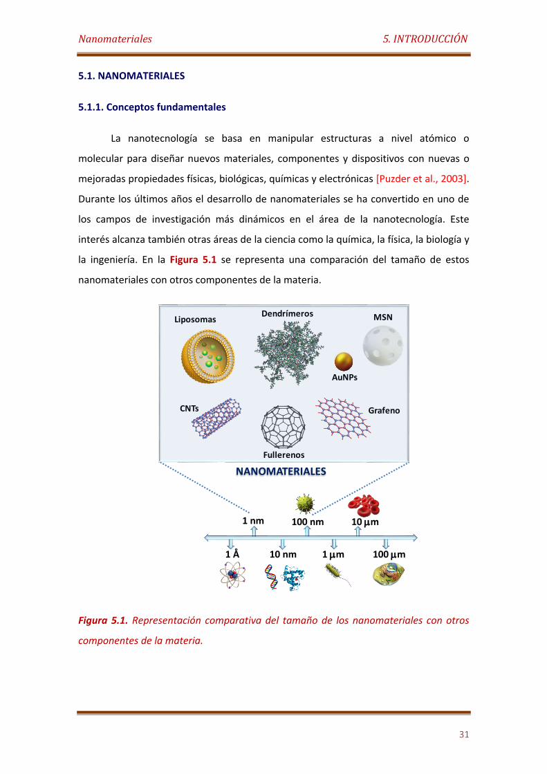
la ingeniería. En la Figura 5.1 se representa una comparación del tamaño de estos
nanomateriales con otros componentes de la materia.
Figura 5.1. Representación comparativa del tamaño de los nanomateriales con otros
componentes de la materia.
1 nm
10 nm
100 nm
1 mm
10 mm
100 mm1 Å
Dendrímeros
CNTs
Fullerenos
Grafeno
Liposomas
AuNPs
MSN
NANOMATERIALES
Nanomateriales 5. INTRODUCCIÓN
32
De acuerdo con la Organización Internacional de Normalización (ISO), el prefijo
nano hace referencia a un tamaño que varía aproximadamente entre 1 nm y 100 nm
[ISO/TS 27687, 2008]. En este sentido, los nanomateriales son aquellos materiales en
los cuales al menos una de sus dimensiones se encuentra en la escala nanométrica. En
este rango, los nanomateriales muestran unas propiedades mejoradas con respecto a
las que tiene la materia a escala macroscópica, lo que permite su empleo en nuevas
aplicaciones [Edelstein et al., 1998].
Existen numerosos motivos para el creciente interés en los materiales, entre los
cuales se encuentran los avances conseguidos en medicina gracias a la implementación
de nanopartículas como materiales de diagnóstico y terapia. El empleo de
nanomateriales han permitido también un mayor aumento en el almacenamiento y
velocidad de transmisión de la información, permitiendo la creación de dispositivos de
cómputo cada vez más pequeños y a costes más reducidos [Edelstein et al., 1998].
El uso de los nanomateriales está lejos de ser algo novedoso, pues existen
numerosos ejemplos de su empleo a lo largo de la historia. Alrededor de los años 2600
AC estos materiales ya formaban parte de los tintes que daban color a fibras y telas.
Asimismo, durante la Edad Media los vidrieros utilizaron partículas de oro y plata a
escala nanoscópica para impartir color a los paneles de las ventanas. Otro ejemplo fue
el famoso acero de Damasco producido del siglo XII al XVIII por los orfebres de Oriente
Medio, el cual incluía nanocables de cementita dentro de su composición [Dolez,
2015].
Sin embargo, el progreso en esta área no comenzó realmente hasta 1981 tras el
desarrollo del microscopio de efecto túnel llevado a cabo por los investigadores de
IBM Gerd Binning y Heinrich Rohrer, gracias al cual se hacía posible observar los
materiales a escala nanométrica [Dolez, 2015].
En la Figura 5.2 se recoge una instantánea del interés de la comunidad
científica internacional en los nanomateriales, representando la progresión del número
de publicaciones sobre éstos desde el año 2000 hasta finales del 2015. Como se puede
observar, durante el último decenio la producción científica ha evolucionado de una
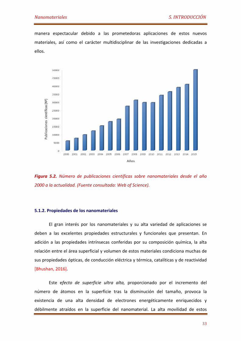
Nanomateriales 5. INTRODUCCIÓN
33
manera espectacular debido a las prometedoras aplicaciones de estos nuevos
materiales, así como el carácter multidisciplinar de las investigaciones dedicadas a
ellos.
Figura 5.2. Número de publicaciones científicas sobre nanomateriales desde el año
2000 a la actualidad. (Fuente consultada: Web of Science).
5.1.2. Propiedades de los nanomateriales
El gran interés por los nanomateriales y su alta variedad de aplicaciones se
deben a las excelentes propiedades estructurales y funcionales que presentan. En
adición a las propiedades intrínsecas conferidas por su composición química, la alta
relación entre el área superficial y volumen de estos materiales condiciona muchas de
sus propiedades ópticas, de conducción eléctrica y térmica, catalíticas y de reactividad
[Bhushan, 2016].
Este efecto de superficie ultra alta, proporcionado por el incremento del
número de átomos en la superficie tras la disminución del tamaño, provoca la
existencia de una alta densidad de electrones energéticamente enriquecidos y
débilmente atraídos en la superficie del nanomaterial. La alta movilidad de estos
Nanomateriales 5. INTRODUCCIÓN
34
electrones confiere marcadas propiedades de electroconductividad y
termoconductividad a muchos nanomateriales. Asimismo, la fácil excitación de estos
electrones a niveles energéticos superiores confiere propiedades ópticas únicas a estos
materiales nanométricos [Liu et al., 2015].
Por lo que respecta a la reactividad, la alta densidad de electrones superficiales,
así como la presencia de orbitales vacantes en los átomos localizados en la superficie
de los nanomateriales, condicionan la alta reactividad química y las inusuales
propiedades catalíticas que presentan muchos de estos nuevos materiales [Jana et al.,
2002]. Además, muchos materiales no magnéticos adquieren nuevas propiedades
magnéticas al pasar de dimensiones macroscópicas a nanométricas. Este fenómeno se
debe a la existencia de momentos magnéticos y anisotropía magnética en dichos
nanomateriales [Liu et al., 2015].
Adicionalmente, muchos nanomateriales poseen excelentes propiedades
mecánicas. Ejemplo de ello son los nanotubos de carbono, los cuales constituyen uno
de los materiales más resistentes de los conocidos o preparados por el hombre
[Salvetat et al., 1999]. Estas propiedades mecánicas excepcionales están
fundamentadas por la alta ordenación de los átomos dentro de estos nanomateriales.
Por otro lado, una de las características distintivas de los nanomateriales es la
posibilidad de ser preparados en diversas formas y tamaños, mediante métodos
relativamente poco costosos [Hulteen et al., 1997]. Esto permite modular muchas de
las propiedades anteriormente citadas de los nanomateriales. Asimismo, la mayoría de
los nanomateriales pueden ser fácilmente derivatizados en su superficie mediante
métodos químicos convencionales, o pueden ser mezclados o modificados con otros
materiales moleculares, poliméricos, cerámicos o nanométricos dando como
resultados nanohíbridos y nanocompósitos con propiedades únicas.
Nanomateriales 5. INTRODUCCIÓN
35
5.1.3. Clasificación de los nanomateriales
Los nanomateriales se pueden clasificar en función de diferentes parámetros:
5.1.3.1. Clasificación de acuerdo a su composición:
La clasificación más utilizada viene determinada por la naturaleza química de
los nanomateriales, dividiéndolos entre orgánicos e inorgánicos. En adición, los
nanomateriales inorgánicos sueles ser sub-clasificados en base a su composición en:
nanomateriales de carbono, metálicos, de óxidos metálicos, etc.
5.1.3.2. Clasificación de acuerdo a sus dimensiones espaciales:
Esta clasificación se basa en el número de dimensiones del nanomaterial que
no pueden ser confinadas en el rango nanométrico (<100 nm). En este sentido, los
nanomateriales cero-dimensionales o de dimensión cero (0D) son aquellos en los cuales
las tres dimensiones (X, Y, Z) se incluyen en la escala de 1 nm a 100 nm. Ejemplo de
ellos son los puntos cuánticos, los fullerenos, las nanopartícula coloidades, los
nanoclusters, etc. [Liu et al., 2015].
Los nanomateriales unidimensionales (1D) son aquellos en los cuales una de sus
dimensiones es mayor de 100 nm, tales como los nanotubos de carbono, los
nanocables, las nanofibras, etc. En el caso de los nanomateriales bidimensionales (2D),
tales como el grafeno, las monocapa poliméricas, etc., dos de las dimensiones no se
incluyen en el rango de 1 nm a 100 nm. Por otra parte, cuando las tres dimensiones del
material son mayores de 100 nm, este se clasifica como tridimensional (3D). Estos no
son propiamente nanomateriales, salvo que su estructura interna sea
nanoestructurada.
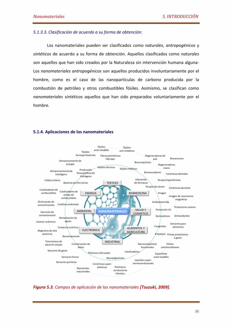
Nanomateriales 5. INTRODUCCIÓN
36
5.1.3.3. Clasificación de acuerdo a su forma de obtención:
Los nanomateriales pueden ser clasificados como naturales, antropogénicos y
sintéticos de acuerdo a su forma de obtención. Aquellos clasificados como naturales
son aquellos que han sido creados por la Naturaleza sin intervención humana alguna-
Los nanomateriales antropogénicos son aquellos producidos involuntariamente por el
hombre, como es el caso de las nanopartículas de carbono producida por la
combustión de petróleo y otros combustibles fósiles. Asimismo, se clasifican como
nanomateriales sintéticos aquellos que han sido preparados voluntariamente por el
hombre.
5.1.4. Aplicaciones de los nanomateriales
Figura 5.3. Campos de aplicación de los nanomateriales [Tsuzuki, 2009].
NANOMATERIALES
TEXTILES
INDUSTRIAL
ALIMENTOS Y AGRICULTURA
ELECTRONICA
ENERGIA BIOMEDICINA
SALUD Y COSMETICA
AMBIENTAL
Tejidos técnicosTejidos médicos
Liberación de fármacos
Terapia de cáncer
Imagen
Antibactericida
Protección UV
Nutracéticos
Fungicidas
Empaque
Nanocompósitosfuncionales
Catalizadores
Nanopigmentos
Plásticos reforzados
Conservación de datos
Nanoimpresión
Computo cuántico
Remediación de aguas
Catálisis ambiental
Catalizadores de celdas de
combustibles
Baterías de litio iónico
Producción fotocatalítica de
hidrógeno
Fibras poliméricas híbridas
Tejidos auto-lavables
Tejidos anti-estáticos
Biocompósitos
Biomarcadores
Terapia hipertérmica
Regeneradores de piel
Regeneradores óseos
Cerámicas dentales
Cerámicas dentales
Imagen de resonancia magnética
Protectores solares
Antioxidantes
Sensores para alimentos
Filmes protectores a gases
Filmes antimicrobianos
Biosensores
Superficies auto-lavables
Líquidos super-termoconductores
Polímeros conductores
híbridos
Cerámicas super-plásticasNanotintes
industriales
Sensores físicos
Sensores de gases
Transistores de electrón simple
Sensores químicos
Magnetos de alta potencia
Láseres cuánticos
Sensores de contaminación
Eliminación de contaminantes
Catalizadores de combustibles
Celdas solares
Almacenamiento de hidrógeno
Almacenamiento de energía
Tejidos termoprotectores
Nanomateriales 5. INTRODUCCIÓN
37
Durante las últimas décadas, los nanomateriales han sido ampliamente
utilizados en la obtención de nuevos productos y el desarrollo de aplicaciones
innovadoras en una amplia gama de sectores industriales, como el energético, la
electrónica, la medicina, las telecomunicaciones, la construcción, la alimentación y la
protección y control medioambiental, causando un elevado impacto en la economía
mundial (Figura 5.3).
En 2013 el mercado mundial de los productos de la nanotecnología fue
valorado en 22,9 mil millones de dólares, aumentando en tan solo un año a 26 mil
millones. Con los nuevos avances tecnológicos y el crecimiento de las preocupaciones
por la salud pública y conservación medioambiental, así como la gran demanda por la
miniaturización electrónica, se prevé para el 2019 que el valor en el mercado mundial
haya alcanzado los 64,2 mil millones de dólares, lo que supone una tasa de crecimiento
anual del 19,8 % [McWilliams, 2015].
En un futuro cercano, se espera que los nanomateriales den respuesta a
muchos de los problemas a los que se enfrenta la sociedad en la actualidad. A
continuación se detallan algunas de las aplicaciones más prometedoras:
Alimentación y agricultura: Hoy en día existe un gran interés por mejorar el
valor nutricional de los alimentos, con el fin de aumentar la calidad de vida, así como
de disminuir los gastos sanitarios derivados de la mala alimentación y del aumento en
la esperanza de vida. El uso de la nanotecnología en esta área es cada día más
relevante ya que es barata, relativamente segura y limpia. Los principales avances
conseguidos en este campo son: i) la creación de nuevos productos y materiales
funcionalizados; ii) el desarrollo de métodos de tratamientos de cultivos a escala
nanométrica; y iii) el diseño de métodos e instrumentos para mejorar la seguridad y el
envasado de alimentos.
Por otro lado, se espera que la tecnología de nanoencapsulación ejerza un rol
muy importante en el futuro de la agricultura, mejorando la estabilidad y el control en
la liberación de nutrientes esenciales y pesticidas [Imran et al., 2010].
Nanomateriales 5. INTRODUCCIÓN
38
Industria cosmética: El uso de nanomateriales en este campo se orienta
fundamentalmente a las siguientes direcciones: i) mejora de la estabilidad de
ingredientes como vitaminas, antioxidantes y ácidos grasos insaturados; ii) mejora de
la penetración transdermal de vitaminas y antioxidantes; iii) aumento de la eficacia y
tolerancia de los filtros UV para la superficie de la piel; y iv) preparación de productos
estéticamente más agradables [Mu et al., 2010].
Actualmente, muchos de los resultados de las investigaciones en el desarrollo
de nanosistemas de liberación controlada de fármacos están siendo aplicados en esta
industria para el desarrollo de nuevos productos cosméticos. Estos nuevos productos
buscan la mejora de los tratamientos de enfermedades epidérmicas, así como la
liberación controlada de agentes cosméticos como vitaminas, antioxidantes y
coenzimas.
Industria textil: El uso de nanomateriales en la industria textil ha crecido
rápidamente durante los últimos años, fundamentalmente orientados al diseño de
prendas con características mejoradas. En este sentido, la implantación de
nanomateriales puede aportar múltiples funcionalidades a los tejidos, tales como
super hidrofobicidad, blindaje electromagnético, propiedades antibacterianas,
ignifugas, de auto-limpieza, etc. [Hu, 2016].
Industria energética: La necesidad de buscar fuentes de energía alternativas a
los combustibles fósiles que sean sostenibles, respetuosas con el medio ambiente y
rentables económicamente, hacen que en la actualidad se explore con mucho interés
el campo de los nanomateriales como herramientas para la producción y
almacenamiento de energía.
Una de las líneas de investigación más activa en esta área se centra en la
mejora de los sistemas fotovoltaicos existentes mediante el uso de nanomateriales
avanzados con propiedades semiconductores, capaces de capturar los fotones
procedentes del sol y transformarlos en electrones [Sakimoto et al., 2016]. Otra línea
prioritaria en esta área es el desarrollo de nuevos nanomateriales para el diseño de
pilas de combustibles y supercapacitores.
Nanomateriales 5. INTRODUCCIÓN
39
Industria de los materiales para la construcción: En la actualidad existen ya
infraestructuras y edificaciones que contienen nanoaditivos añadidos al acero y al
hormigón tradicional. Los nanomateriales han sido también empleados para la
preparación de pinturas y lacas con propiedades de auto-limpieza y protección anti-
grafiti y anti-plagas.
Las investigaciones actuales en este campo se focalizan en el diseño de nuevos
nanoaditivos, nanomateriales aislantes avanzados, recubrimientos funcionales, vidrios
anti-incendios, materiales autorreparables y materiales inteligentes que respondan a
estímulos.
Medioambiente: En los últimos años se han diseñado nuevos nanomateriales
para la remediación del suelo y de los acuíferos contaminados. Algunos de los trabajos
más recientes en este campo se centran en la fabricación de nanomateriales
adsorbentes más eficientes y el diseño de sistemas sensores nanoestructurados para la
monitorización ambiental [Louie et al.; 2016].
Industria electrónica: En este campo destacan las nuevas tecnologías de
visualización y almacenamiento basadas en nanomateriales con propiedades ópticas,
electroconductoras, magnéticas y termoconductoras. Estas tecnologías han sido
aplicadas al diseño de pantallas de alta definición, sistemas de almacenamiento de
gran densidad para el registro de datos, sistemas de disipación de calor para
dispositivos electrónicos, nuevas tintas electroconductoras, etc. [Shahzad et al., 2016].
Biomedicina: Los nanomateriales y la nanotecnología están llamados a
transformar la medicina por su potencial aplicación en el diagnóstico precoz y
tratamiento de una gran variedad de enfermedades. Las investigaciones realizadas con
nanomateriales a lo largo de los últimos años han dado lugar a una nueva área dentro
de las ciencias biomédicas: la nanomedicina.
La nanomedicina abarca el diagnóstico temprano de enfermedades, la
liberación controlada de fármacos y la medicina regenerativa mediante el uso de
nanomateriales o técnicas nanotecnológicas [Tibbals, 2013]. Hasta el momento, los
avances más significativos en esta área se basan en el desarrollo de sistemas
Nanomateriales 5. INTRODUCCIÓN
40
nanométricos para la liberación controlada de fármacos (liposomas y nanocápsulas
poliméricas), el uso de nanopartículas y puntos cuánticos como sistemas de marcaje
para ensayos biomédicos y de imagen de tejidos, el empleo de nanopartículas de plata
como agentes antibactericidas, etc.
Aplicaciones analíticas: Durante los últimos años los nanomateriales han sido
ampliamente utilizados para el análisis clínico, fundamentalmente en el desarrollo de
nuevos sistemas de detección de biomarcadores para enfermedades. Los avances más
importantes en esta área se centran en el diseño de nuevos sistemas de detección
visual o óptica basados en cromatografía lateral de flujo y tecnologías automatizadas
de análisis clínico ultrasensible, mediante el uso de nanopartículas metálicas y puntos
cuánticos como elementos de marcaje [Selvan et al., 2016].
Por otra parte, se ha demostrado que los nanomateriales electroconductores
mejoran el rendimiento de los sistemas sensores y biosensores electroquímicos. En
este sentido, su empleo como elementos de transducción genera nuevas interfaces de
mayor área electroquímicamente activa, permitiendo detecciones más sensibles.
Muchos nanomateriales poseen asimismo propiedades electrocatalíticas, lo cual
favorece el diseño de sistemas sensores y biosensores más selectivos y menos
propensos a la acción de sustancias interferentes.
Los nanomateriales ofrecen además numerosas oportunidades en la
amplificación de señales, tanto en sistemas con detección óptica [Swierczewska, 2012]
como electroquímica [Zhu et al., 2015; Hasanzadeh, 2015].
5.1.5. Limitaciones de los nanomateriales
A pesar de las grandes ventajas que presentan, algunos nanomateriales
muestran una serie de limitaciones las cuales limitan su uso en determinadas
aplicaciones. Desde un punto de vista biomédico y analítico, las principales
limitaciones de estos materiales son la falta de estabilidad en fluidos biológicos, alta
toxicidad, baja biocompatibilidad, corta vida media en la circulación por el torrente
Nanomateriales 5. INTRODUCCIÓN
41
sanguíneo, tendencia a la agregación, baja especificidad, etc [Lehner et al., 2013].
Además, en la actualidad no se conocen los efectos a largo plazo que este tipo de
materiales pueden tener sobre la salud humana debido a su reciente empleo [Yan et
al., 2014].
Estas desventajas pueden ser corregidas mediante la funcionalización
superficial con ligandos específicos, creando nanomateriales funcionalizados, o
mediante la unión o combinación con otros materiales y nanomateriales,
obteniéndose una nueva generación de nanomateriales híbridos.
En la investigación que nos concierne nos centramos en el diseño, preparación
y caracterización de diversos nanomateriales funcionalizados y nanohíbridos para su
uso en la construcción de biosensores electroquímicos y sistemas inteligentes de
liberación controlada de fármacos.
Biosensores Electroquímicos 5. INTRODUCCIÓN
42
5.2. BIOSENSORES ELECTROQUÍMICOS
5.2.1. Conceptos fundamentales
Un sensor químico es un dispositivo que transforma la información química,
que comprende tanto la concentración de un componente específico de la muestra
como el análisis total de su composición, en una señal analíticamente útil. Los sensores
químicos contienen por lo general dos componentes básicos conectados en serie: un
sistema químico de reconocimiento (receptor) y un transductor físico-químico. Los
biosensores son sensores químicos en los que el sistema de reconocimiento utiliza un
mecanismo bioquímico [Thévenot, 2001].
Durante los últimos años, el desarrollo de biosensores ha sido uno de los
campos de más rápida evolución en Química por su gran impacto en análisis
biomédicos, químicos e industriales, así como en el control del medio ambiente. Hoy
en día, los biosensores representan un mercado en rápida expansión, donde el mayor
impulso procede de la industria sanitaria. En el mercado global se espera que a finales
del 2016 alcance la cifra de 16 millones de dólares y llegue hasta los 21.5 millones en el
2020 [MarketsandMarkets, 2015].
Desde un punto de vista analítico, la tecnología de los biosensores permite el
diseño de dispositivos de detección miniaturizados y portátiles, los cuales presentan
una alta sensibilidad y un bajo límite de detección, combinado con la especificidad
característica proporcionada por los sistemas de reconocimiento biológico. Debido a
estas propiedades, se espera en un futuro cercano el aumento en el uso de
biosensores como alternativas prometedoras a los instrumentos analíticos
tradicionales.
En el pasado, los biosensores se definieron como cualquier dispositivo que
utiliza reacciones bioquímicas específicas para detectar compuestos químicos en
muestras biológicas. Los primeros biosensores, construidos por Clark, Lyons, Updike y
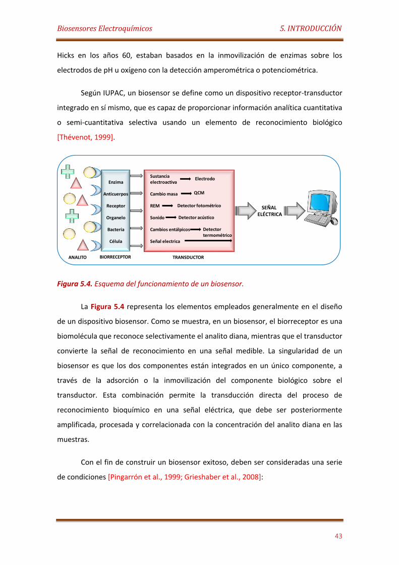
Biosensores Electroquímicos 5. INTRODUCCIÓN
43
Hicks en los años 60, estaban basados en la inmovilización de enzimas sobre los
electrodos de pH u oxígeno con la detección amperométrica o potenciométrica.
Según IUPAC, un biosensor se define como un dispositivo receptor-transductor
integrado en sí mismo, que es capaz de proporcionar información analítica cuantitativa
o semi-cuantitativa selectiva usando un elemento de reconocimiento biológico
[Thévenot, 1999].
Figura 5.4. Esquema del funcionamiento de un biosensor.
La Figura 5.4 representa los elementos empleados generalmente en el diseño
de un dispositivo biosensor. Como se muestra, en un biosensor, el biorreceptor es una
biomolécula que reconoce selectivamente el analito diana, mientras que el transductor
convierte la señal de reconocimiento en una señal medible. La singularidad de un
biosensor es que los dos componentes están integrados en un único componente, a
través de la adsorción o la inmovilización del componente biológico sobre el
transductor. Esta combinación permite la transducción directa del proceso de
reconocimiento bioquímico en una señal eléctrica, que debe ser posteriormente
amplificada, procesada y correlacionada con la concentración del analito diana en las
muestras.
Con el fin de construir un biosensor exitoso, deben ser consideradas una serie
de condiciones [Pingarrón et al., 1999; Grieshaber et al., 2008]:
Enzima
Anticuerpos
Receptor
Organelo
Bacteria
Célula
Sustancia electroactiva
Cambio masa
REM
Sonido
Cambios entálpicos
Señal electrica
Electrodo
QCM
Detector fotométrico
Detector acústico
Detector termométrico
SEÑAL ELÉCTRICA
BIORRECEPTOR TRANSDUCTORANALITO
Biosensores Electroquímicos 5. INTRODUCCIÓN
44
El elemento de reconocimiento biológico debe ser altamente específico para
los fines del análisis, estable bajo condiciones normales de almacenamiento y
mostrar una baja variación entre ensayos.
La reacción de biorreconocimiento debe ser tan independiente como sea
posible de parámetros físicos tales como la agitación, el pH y la temperatura. Lo
cual permitirá el análisis de las muestras con un pre-tratamiento mínimo.
La respuesta debe ser exacta, precisa, reproducible y lineal en todo el rango de
concentraciones de interés, sin dilución o concentración. También debe estar
libre de ruido inducido por el transductor eléctrico u otro.
Si el biosensor se va a utilizar para la monitorización invasiva en situaciones
clínicas, la sonda debe ser pequeña y biocompatible, sin efectos tóxicos o
antigénicos. Además, el biosensor no debe ser sensible a la inactivación o la
proteólisis.
Para mediciones rápidas de analitos a partir de muestras humanas, es deseable
que el biosensor pueda proporcionar análisis en tiempo real.
El biosensor completo debe ser barato, pequeño, portátil y capaz de ser
utilizado por operadores semicualificados.
5.2.2. Clasificación de los biosensores
Los biosensores se pueden clasificar de acuerdo con i) el modo de transducción
de la señal; ii) la especificidad conferida por el elemento biológico; o alternativamente,
iii) una combinación de ambos.
5.2.2.1. Clasificación de acuerdo con el transductor
Según el modo de transducción de la señal, los biosensores se pueden clasificar
principalmente como:
Óptico (con la posibilidad de utilizar muchos tipos diferentes de
espectroscopias como método de detección: UV-Vis, absorción en el IR
Biosensores Electroquímicos 5. INTRODUCCIÓN
45
cercano, fluorescencia, fosforescencia, Raman, dispersión Raman de superficie
amplificada, espectroscopia de interferencia por reflexión, resonancia de
plasmón superficial, refracción, espectrometría de dispersión)
Electroquímico (biosensores amperométricos, potenciométricos,
conductimétricos e impedimétricos)
Piezoeléctrico (biosensores utilizando la microbalanza de cristal de cuarzo
sensible a la masa, de onda acústica superficial con polarización horizontal o
métodos de detección basados en microcantilever.
Termométrica (colorimétrico)
5.2.2.2. Clasificación de acuerdo con el elemento de reconocimiento biológico
- Biosensores basados en elementos de reconocimiento biocatalíticos:
En este caso, el biosensor se basa en una reacción catalizada por
macromoléculas, que están presentes en su entorno biológico original, se han aislado
previamente o que han sido fabricadas. En consecuencia, se consigue un consumo
continuo de sustrato llevado a cabo por el biocatalizador inmovilizado en el sensor y se
obtienen respuestas transitorias o de estado estacionario supervisadas por el detector
integrado.
Se utilizan habitualmente cuatro tipos de biocatalizador:
Las células enteras (microorganismos, tales como bacterias, hongos, células
eucariotas o levaduras), orgánulos celulares o partículas (mitocondrias, paredes
celulares).
Tejido (lámina de tejido animal o vegetal).
ARN catalítico (ribozimas) y anticuerpos (abzimas).
Enzima (mono o multi-enzima).
Las enzimas son los receptores más antiguos y todavía más utilizados en el
diseño de biosensores debido a su alta actividad biocatalítica y especificidad. Las
enzimas son proteínas globulares compuestas principalmente de los 20 aminoácidos
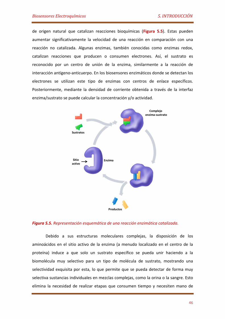
Biosensores Electroquímicos 5. INTRODUCCIÓN
46
de origen natural que catalizan reacciones bioquímicas (Figura 5.5). Estas pueden
aumentar significativamente la velocidad de una reacción en comparación con una
reacción no catalizada. Algunas enzimas, también conocidas como enzimas redox,
catalizan reacciones que producen o consumen electrones. Así, el sustrato es
reconocido por un centro de unión de la enzima, similarmente a la reacción de
interacción antígeno-anticuerpo. En los biosensores enzimáticos donde se detectan los
electrones se utilizan este tipo de enzimas con centros de enlace específicos.
Posteriormente, mediante la densidad de corriente obtenida a través de la interfaz
enzima/sustrato se puede calcular la concentración y/o actividad.
Figura 5.5. Representación esquemática de una reacción enzimática catalizada.
Debido a sus estructuras moleculares complejas, la disposición de los
aminoácidos en el sitio activo de la enzima (a menudo localizado en el centro de la
proteína) induce a que solo un sustrato específico se pueda unir haciendo a la
biomolécula muy selectivo para un tipo de molécula de sustrato, mostrando una
selectividad exquisita por esta, lo que permite que se pueda detectar de forma muy
selectiva sustancias individuales en mezclas complejas, como la orina o la sangre. Esto
elimina la necesidad de realizar etapas que consumen tiempo y necesiten mano de
Sustratos
Productos
EnzimaSitio activo
Complejoenzima-sustrato
Biosensores Electroquímicos 5. INTRODUCCIÓN
47
obra especializada, tales como las de pretratamiento de la muestra y de separación de
interferencias, normalmente necesarias en este tipo de muestras complejas.
[Copeland, 2000].
Las interacciones enzima-sustrato pueden ser caracterizadas por estudios
cinéticos, siendo el modelo de Michaelis-Menten uno de los enfoques más simple, más
conocido y ampliamente utilizado para este tipo de determinaciones cinéticas. Este
modelo cinético se puede aplicar cuando la concentración del sustrato es mayor que la
concentración de enzima, y suponiendo que la concentración del complejo enzima-
sustrato no cambia en el tiempo de reacción (hipótesis de estado estacionario).
Suponiendo que la concentración total de enzima no cambia con el tiempo, la
velocidad de reacción inicial de la formación de productos en una reacción enzimática
unimolecular está dada por:
Donde KM es la constante de Michaelis-Menten, [S] es la concentración de
sustrato, y V0 y Vmax son las velocidades de reacción iniciales y máxima,
respectivamente. El valor KM se corresponde con la concentración de sustrato a la que
la velocidad de reacción es la mitad con respecto a la máxima, y es una medida inversa
de la afinidad de la enzima por el sustrato.
- Biosensores basados en elementos de reconocimiento biocomplejante o de
bioafinidad
En este caso, la operación del biosensor se basa en la interacción del analito
con macromoléculas o ensamblajes moleculares organizados que, o bien han sido
aislados de su entorno biológico original o fabricados mediante ingeniería. Por lo
Biosensores Electroquímicos 5. INTRODUCCIÓN
48
tanto, generalmente se alcanza el equilibrio y no hay consumo neto del analito por el
agente biocomplejante inmovilizado. Estas respuestas de equilibrio son controladas
por el detector integrado. En algunos casos, esta reacción biocomplejante es
monitorizada utilizando una reacción biocatalítica complementaria. Las señales en el
estado estacionario o transitorio son monitorizadas por el detector integrado. Los
mecanismos de bioafinidad más comúnmente utilizados en la construcción de
biosensores son los siguientes:
Interacción antígeno-anticuerpo (Inmunosensores)
Reconocimiento basado en ácidos nucleicos (Genosensores y aptasensors)
Receptor / antagonista / agonista, en el que los canales de iones, receptores de
membrana o proteínas de unión se utilizan como sistemas de reconocimiento
molecular
Receptores artificiales
5.2.2.3. Biosensores de carácter combinado
La tercera clasificación de los biosensores se basa en la combinación de dos de
los conceptos anteriormente mencionados. Ejemplos de esto son biosensor enzimático
amperométrico, inmunosensores ópticos, etc.
- Biosensor amperométrico:
Hoy en día, los transductores electroquímicos son los más ampliamente
utilizados en el diseño de biosensores debido a las importantes ventajas que
presentan. Estos dispositivos suelen tener diseños relativamente simples y no
requieren instrumentación costosa. Por lo tanto, son dispositivos de fácil manejo,
compactos y de bajo coste.
Otras ventajas inherentes de biosensores electroquímicos son su robustez, fácil
miniaturización, excelentes límites de detección, también con volúmenes de analitos
Biosensores Electroquímicos 5. INTRODUCCIÓN
49
pequeños, y la capacidad para ser utilizado en biofluidos turbios con compuestos
ópticamente absorbentes y fluorescentes [Ronkainen et al., 2010; Grieshaber et al.,
2008].
Los transductores electroquímicos se organizan generalmente en tres
categorías principales según el tipo de medición empleado: corriente, potencial e
impedancia. Entre ellas, las técnicas más comúnmente empleadas en biosensores son
las que miden la corriente (métodos amperométricos y voltamperométricos).
En amperometría, cambios en la corriente generada por la oxidación o la
reducción electroquímica de los analitos diana se controlan directamente con el
tiempo, mientras que se mantiene un potencial constante en el electrodo de trabajo
con respecto a un electrodo de referencia. La corriente es proporcional a la
concentración de la especie electroactiva en la muestra, lo que permite su
cuantificación fácil.
La detección amperométrica se ha utilizado exhaustivamente con biosensores
de afinidad biocatalíticos debido a su simplicidad y bajo límite de detección.
Ventajosamente, el potencial fijo durante la detección amperométrica resulta en una
insignificante corriente de carga (la corriente necesaria para aplicar el potencial al
sistema), lo que minimiza la señal de fondo que afecta negativamente al límite de
detección. Además, los biosensores amperométricos tienen una selectividad adicional
ya que el potencial de oxidación o reducción utilizado es característico para la
detección de los distintos analitos [Eggins, 2002].
Cuando se preparan biosensores enzimáticos amperométricos es imporante
determinar la sensibilidad de la enzima a las condiciones experimentales tales como el
pH, la temperatura, y la agitación. Deben ser también considerados otros parámetros
tales como el origen y la disponibilidad de la enzima, su estabilidad operacional y de
almacenamiento, así como el procedimiento de inmovilización y las características del
soporte (superficie del electrodo).
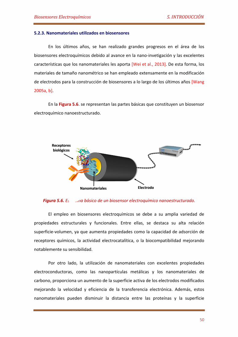
Biosensores Electroquímicos 5. INTRODUCCIÓN
50
5.2.3. Nanomateriales utilizados en biosensores
En los últimos años, se han realizado grandes progresos en el área de los
biosensores electroquímicos debido al avance en la nano-invetigación y las excelentes
características que los nanomateriales les aporta [Wei et al., 2013]. De esta forma, los
materiales de tamaño nanométrico se han empleado extensamente en la modificación
de electrodos para la construcción de biosensores a lo largo de los últimos años [Wang
2005a, b].
En la Figura 5.6. se representan las partes básicas que constituyen un biosensor
electroquímico nanoestructurado.
Figura 5.6. Esquema básico de un biosensor electroquímico nanoestructurado.
El empleo en biosensores electroquímicos se debe a su amplia variedad de
propiedades estructurales y funcionales. Entre ellas, se destaca su alta relación
superficie-volumen, ya que aumenta propiedades como la capacidad de adsorción de
receptores químicos, la actividad electrocatalítica, o la biocompatibilidad mejorando
notablemente su sensibilidad.
Por otro lado, la utilización de nanomateriales con excelentes propiedades
electroconductoras, como las nanopartículas metálicas y los nanomateriales de
carbono, proporciona un aumento de la superficie activa de los electrodos modificados
mejorando la velocidad y eficiencia de la transferencia electrónica. Además, estos
nanomateriales pueden disminuir la distancia entre las proteínas y la superficie
Electrodo
Receptores biológicos
Nanomateriales

Biosensores Electroquímicos 5. INTRODUCCIÓN
51
electródica, permitiendo una transferencia directa de electrones al centro activo de las
biomoléculas por mecanismos de tunelización [Yáñez-Sedeño et al., 2015].
El papel fundamental de los nanomateriales en los biosensores electroquímicos
se basa en su empleo como elementos: i) de transducción o plataforma para la
inmovilización de biomoléculas; ii) de amplificación de la señal electroquímica o iii) de
etiquetado para la señalización [Hayat et al., 2014].
Esta Tesis Doctoral ha centrado la atención en el desarrollado de nuevas
estrategias para la preparación de superficies electródicas nanoestructuradas como
elementos de transducción para la construcción de nuevos biosensores
electroquímicos con un rendimiento bioanalítico mejorado y de mayor robustez.
En general, el desarrollo de metodologías para la nanoestructuración de las
superficies de los electrodos con tal propósito debe considerar los siguientes puntos: i)
el tipo de superficie a modificar; ii) el nanomaterial que se utiliza; iii) otros compuestos
o materiales que podrían ser también empleados; iv) el método físico o químico para la
modificación de la superficie, v) la biomolécula a inmovilizar y el método para hacerlo;
y vi) la reacción electroquímica que tiene lugar en la superficie del electrodo
funcionalizado [Yañez-Sedeño et al., 2015].
Estas estrategias deben proporcionar interfaces eléctricas con nano- o micro-
topología tridimensional que permita con éxito la inmovilización estable de las
biomoléculas sin afectar a su función biológica, pero también favoreciendo la aparición
rápida y eficiente de los procesos electroquímicos que participan en la reacción
analítica sobre tales interfaces [Wang 2005 a, b].
Los nanomateriales más empleados en la nanoestructuración electródica son
principalmente: las nanopartículas metálicas, los puntos cuánticos, nanotubos de
carbono, grafeno, nanofibras de carbono y nanopartículas de óxido de metal [Zhang et
al., 2006; Liu et al., 2007; Agüí et al., 2008; Shao et al., 2010; Lu et al., 2008; Vamvakaki
et al., 2006; Pingarrón et al., 2008; Luo et al., 2006; Zhang et al., 2007].
Biosensores Electroquímicos 5. INTRODUCCIÓN
52
5.2.3.1. Nanopartículas metálicas:
Hay varios factores que justifican el interés de la investigación en
nanopartículas metálicas para la tecnología de biosensores, tales como:
Las nanopartículas metálicas, de manera similar a otros nanomateriales,
tienen una elevada superficie en relación al volumen. Esta característica
domina las propiedades ópticas, conductoras y magnéticas únicas que
poseen las nanopartículas con composición química adecuada.
El área superficial de las nanopartículas metálicas permite una gran
inmovilización de biomolécula sobre los electrodos modificados con ellas.
En general, la superficie de las nanopartículas de metal se puede modificar
fácilmente mediante métodos químicos o físicos, para favorecer la
inmovilización con éxito de biomoléculas de análisis a través de diferentes
mecanismos covalentes y no covalentes.
En comparación con otros nanomateriales duros y blandos, las
nanopartículas de metal se pueden preparar fácilmente por métodos
hidrotérmicos o electroquímicas convencionales, utilizando materias primas
y equipos relativamente económicos.
Las nanopartículas de metal se pueden diseñar racionalmente y con gran
versatilidad (con respecto a su geometría, tamaño y distribución) mediante
el control de las condiciones experimentales usadas para su preparación.
Las nanopartículas metálicas pueden favorecer la transferencia directa de
electrones entre el centro redox en el sitio activo de las enzimas y el
material del electrodo, a través de mecanismos de efecto túnel.
Varias nanopartículas metálicas pueden catalizar la conversión de
compuestos con interés analítico importante (como NADH, H2O2 y O2) en la
superficie del electrodo, reduciendo el potencial necesario para tales
transformaciones.
Las nanopartículas puede actuar como unidades de montaje
supramoleculares con propiedades funcionales avanzadas para la
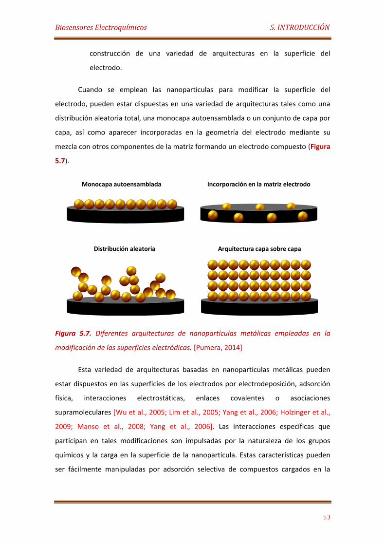
Biosensores Electroquímicos 5. INTRODUCCIÓN
53
construcción de una variedad de arquitecturas en la superficie del
electrodo.
Cuando se emplean las nanopartículas para modificar la superficie del
electrodo, pueden estar dispuestas en una variedad de arquitecturas tales como una
distribución aleatoria total, una monocapa autoensamblada o un conjunto de capa por
capa, así como aparecer incorporadas en la geometría del electrodo mediante su
mezcla con otros componentes de la matriz formando un electrodo compuesto (Figura
5.7).
Figura 5.7. Diferentes arquitecturas de nanopartículas metálicas empleadas en la
modificación de las superficies electródicas. [Pumera, 2014]
Esta variedad de arquitecturas basadas en nanopartículas metálicas pueden
estar dispuestos en las superficies de los electrodos por electrodeposición, adsorción
física, interacciones electrostáticas, enlaces covalentes o asociaciones
supramoleculares [Wu et al., 2005; Lim et al., 2005; Yang et al., 2006; Holzinger et al.,
2009; Manso et al., 2008; Yang et al., 2006]. Las interacciones específicas que
participan en tales modificaciones son impulsadas por la naturaleza de los grupos
químicos y la carga en la superficie de la nanopartícula. Estas características pueden
ser fácilmente manipuladas por adsorción selectiva de compuestos cargados en la
Monocapa autoensamblada
Distribución aleatoria Arquitectura capa sobre capa
Incorporación en la matriz electrodo
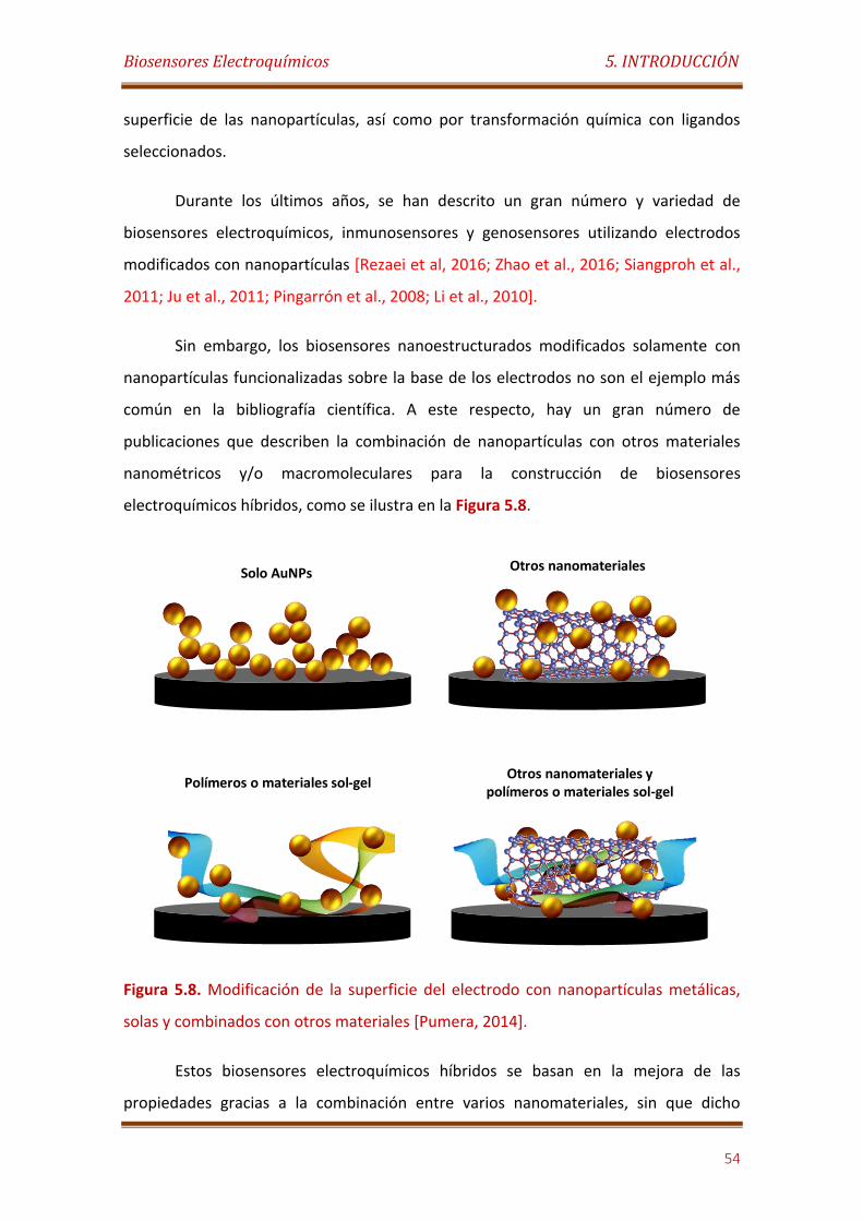
Biosensores Electroquímicos 5. INTRODUCCIÓN
54
superficie de las nanopartículas, así como por transformación química con ligandos
seleccionados.
Durante los últimos años, se han descrito un gran número y variedad de
biosensores electroquímicos, inmunosensores y genosensores utilizando electrodos
modificados con nanopartículas [Rezaei et al, 2016; Zhao et al., 2016; Siangproh et al.,
2011; Ju et al., 2011; Pingarrón et al., 2008; Li et al., 2010].
Sin embargo, los biosensores nanoestructurados modificados solamente con
nanopartículas funcionalizadas sobre la base de los electrodos no son el ejemplo más
común en la bibliografía científica. A este respecto, hay un gran número de
publicaciones que describen la combinación de nanopartículas con otros materiales
nanométricos y/o macromoleculares para la construcción de biosensores
electroquímicos híbridos, como se ilustra en la Figura 5.8.
Figura 5.8. Modificación de la superficie del electrodo con nanopartículas metálicas,
solas y combinados con otros materiales [Pumera, 2014].
Estos biosensores electroquímicos híbridos se basan en la mejora de las
propiedades gracias a la combinación entre varios nanomateriales, sin que dicho
Solo AuNPs Otros nanomateriales
Polímeros o materiales sol-gelOtros nanomateriales y
polímeros o materiales sol-gel
Biosensores Electroquímicos 5. INTRODUCCIÓN
55
acoplamiento afecte a sus propiedades individuales. Durante los últimos años, se han
diseñado una gran cantidad de superficies electródicas por combinación de las AuNPs
con grafeno [Azzouzi et al., 2015; Abraham et al., 2015; Wang et al., 2012a; Song et al.,
2011; Chen et al., 2011], CNTs [Eguílaz et al., 2015; Villalonga et al., 2012],
dendrímeros [Liu et al., 2005b], polímeros electroconductores [German et al., 2015],
óxidos metálicos [Zhao et al., 2015; Boujakhrout et al., 2015], polisacararidos
[Villalonga et al., 2007], etc.
Una de las combinaciones más utilizadas es la formada por las AuNPs, los CNTs
y/o grafeno. Estos biosensores utilizan las ventajas proporcionadas por la sinergia de
los nanomateriales, obteniéndose una transferencia directa de electrones entre los
nanomateriales funcionalizados y el centro redox de la biomolécula, sin la participación
de mediadores electroquímicos [Yu et al., 2014]. En este sentido, la transferencia
electrónica directa entre los receptores biológicos y la superficie del electrodo
posibilita la construcción de biosensores de tercera generación, libres de mediadores
electroquímicos.
Un ejemplo interesante de este diseño es el desarrollado recientemente en
nuestro grupo de investigación. El biosensor emplea un nanohíbrido formado por
nanocintas de Ag: bipiridina decoradas con AuNPs para la inmovilización de la enzima
peroxidasa de rabano picante (HRP). Gracias a este diseño, se detectan
concentraciones de H2O2 a nivel picomolar [Boujakhrout et al., 2016]. Por otro lado,
también se han empleado otras nanopartículas metálicas en la preparación de
biosensores electroquímicos, aunque con menos frecuencia, las más destacadas son
las nanopartículas de Pt (PtNPs) y de Ag (AgNPs). La propiedad más importante de las
PtNPs es su gran capacidad catalítica, particularmente en la descomposición de H2O2 y
reducción de O2. El empleo de estas nanopartículas reduce drásticamente el potencial
requerido para oxidar el H2O2 (≥ 0.6 V vs Ag/AgCl) [Pumera, 2014].
Por lo que respecta a las AgNPs, estas muestran un gran interés debido a su
excelente actividad catalítica, propiedades antibacterianas, biocompatibilidad y baja
toxicidad. Gracias a su alta reactividad y la combinación con CNTs, se ha construido un

Biosensores Electroquímicos 5. INTRODUCCIÓN
56
sensor de glucosa con excelentes propiedades sin la necesidad de enzimas [Baghayeri
et al., 2015].
5.2.3.2. Nanomateriales de carbono:
El empleo de los materiales de carbono como elementos de transducción en el
diseño de biosensores electroquímicos ha crecido rápidamente durante los últimos
años. Entre los nanomateriales de carbono más empleados destacan, con mucha
diferencia con respecto a otros, los nanotubos de carbono y el grafeno.
La utilización de estos nanomateriales como andamios 3D para la construcción
de biosensores electroquímicos se basa en sus excelentes propiedades intrínsecas,
tales como [Lawal et al., 2016]:
Alta relación superficie/volumen
Alta estabilidad química
Fuerte resistencia mecánica
Biocompatibilidad
Excelente conductividad eléctrica y térmica
Baja corriente residual superficial
Amplia ventana de potencial
Bajo coste
Facilidad para la producción
- Nanotubos de carbono:
Los nanotubos de carbono son cilindros compuestos de anillos hexagonales de
carbono con hibridación sp2. Los nanotubos conformados por una lámina de grafeno
enrollada son los nanotubos monocapa, o SWNTs (Single-Walled Nanotubes), mientras
que existen también nanotubos donde unas láminas se incluyen dentro de otras
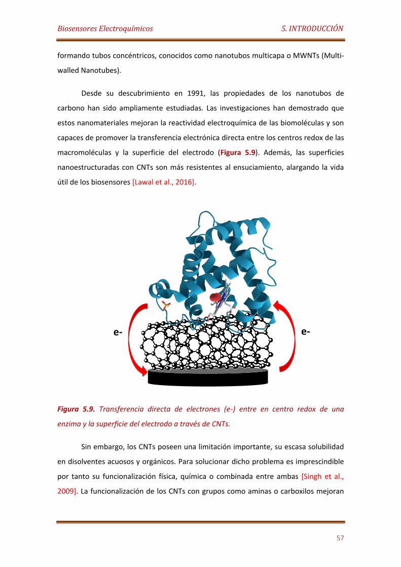
Biosensores Electroquímicos 5. INTRODUCCIÓN
57
formando tubos concéntricos, conocidos como nanotubos multicapa o MWNTs (Multi-
walled Nanotubes).
Desde su descubrimiento en 1991, las propiedades de los nanotubos de
carbono han sido ampliamente estudiadas. Las investigaciones han demostrado que
estos nanomateriales mejoran la reactividad electroquímica de las biomoléculas y son
capaces de promover la transferencia electrónica directa entre los centros redox de las
macromoléculas y la superficie del electrodo (Figura 5.9). Además, las superficies
nanoestructuradas con CNTs son más resistentes al ensuciamiento, alargando la vida
útil de los biosensores [Lawal et al., 2016].
Figura 5.9. Transferencia directa de electrones (e-) entre en centro redox de una
enzima y la superficie del electrodo a través de CNTs.
Sin embargo, los CNTs poseen una limitación importante, su escasa solubilidad
en disolventes acuosos y orgánicos. Para solucionar dicho problema es imprescindible
por tanto su funcionalización física, química o combinada entre ambas [Singh et al.,
2009]. La funcionalización de los CNTs con grupos como aminas o carboxilos mejoran
e- e-

Biosensores Electroquímicos 5. INTRODUCCIÓN
58
su biocompatibilidad para la unión de los elementos de reconocimiento biológico, y
también aumentan la tasa de electrones a transferir [Kumar et al., 2015].
Existen multitud de biosensores electroquímicos en los que se emplean SWCNT
y MWCNT para la modificación electródica [Eguílaz et al., 2016 a,b; Kim, 2017]. No
obstante, como en el caso de las nanopartículas metálicas, la mayoría de los trabajos
encontrados en la bibliografía utilizan nanohíbridos, conjugando los CNTs con otros
nanomateriales como polímeros [Hernández-Ibáñez et al., 2016], grafeno
[Devasenathipathy et al., 2015], óxidos metálicos [Tu et al., 2015], dendrímeros [Zhang
et al., 2016], etc.
Un ejemplo original de la utilización de MWCNTs en biosensores
electroquímicos fue desarrollado por el grupo del Prof. Wang [Jia et al., 2013]. En ese
trabajo, se describe el primer biosensor para la detección de lactato, no invasiva y en
tiempo real, en la transpiración humana durante un ejercicio físico. El biosensor
consiste en un tatuaje temporal flexible para adaptarlo a la piel de los usuarios. La
superficie del electrodo epidérmico está modificada con tetratiofulvalelo y MWCNTs,
para la inmovilización de la enzima Lactato Oxidasa (LOx), y cubierto por un polímero
de quitosano biocompatible.
- Grafeno:
El grafeno es un nanomaterial de dos dimensiones, ya que está formado por
anillos hexagonales de átomos de carbono con hibridación sp2, dispuestos en una
monocapa de un átomo de espesor.
Las propiedades físico-químicas, como en el caso de los CNTs, son excelentes.
Entre las propiedades electroquímicas, que hacen tan interesante su uso en la
modificación de superficies electródicas, se incluyen una baja resistencia a la
transferencia de carga, una gran actividad electrocatalítica y una amplia ventana de
potencial de trabajo [Gao et al., 2015].
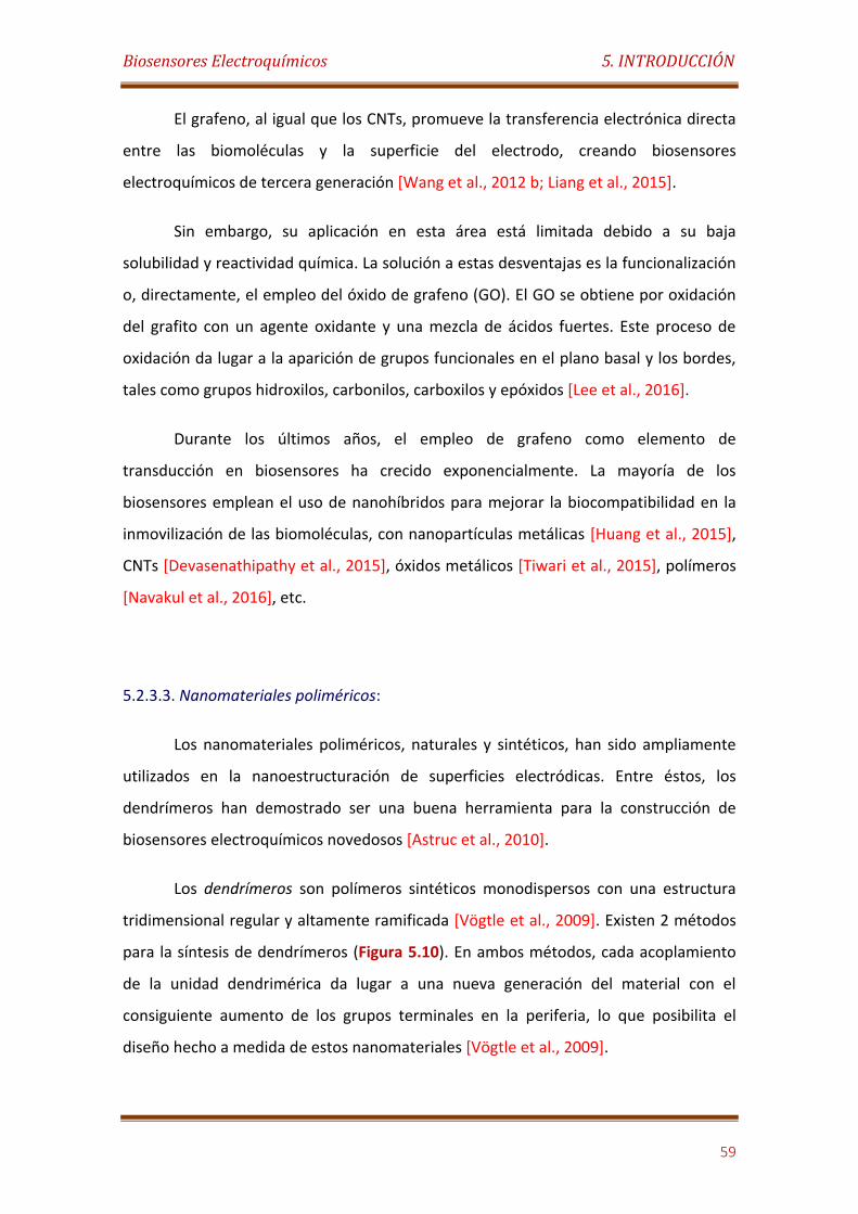
Biosensores Electroquímicos 5. INTRODUCCIÓN
59
El grafeno, al igual que los CNTs, promueve la transferencia electrónica directa
entre las biomoléculas y la superficie del electrodo, creando biosensores
electroquímicos de tercera generación [Wang et al., 2012 b; Liang et al., 2015].
Sin embargo, su aplicación en esta área está limitada debido a su baja
solubilidad y reactividad química. La solución a estas desventajas es la funcionalización
o, directamente, el empleo del óxido de grafeno (GO). El GO se obtiene por oxidación
del grafito con un agente oxidante y una mezcla de ácidos fuertes. Este proceso de
oxidación da lugar a la aparición de grupos funcionales en el plano basal y los bordes,
tales como grupos hidroxilos, carbonilos, carboxilos y epóxidos [Lee et al., 2016].
Durante los últimos años, el empleo de grafeno como elemento de
transducción en biosensores ha crecido exponencialmente. La mayoría de los
biosensores emplean el uso de nanohíbridos para mejorar la biocompatibilidad en la
inmovilización de las biomoléculas, con nanopartículas metálicas [Huang et al., 2015],
CNTs [Devasenathipathy et al., 2015], óxidos metálicos [Tiwari et al., 2015], polímeros
[Navakul et al., 2016], etc.
5.2.3.3. Nanomateriales poliméricos:
Los nanomateriales poliméricos, naturales y sintéticos, han sido ampliamente
utilizados en la nanoestructuración de superficies electródicas. Entre éstos, los
dendrímeros han demostrado ser una buena herramienta para la construcción de
biosensores electroquímicos novedosos [Astruc et al., 2010].
Los dendrímeros son polímeros sintéticos monodispersos con una estructura
tridimensional regular y altamente ramificada [Vögtle et al., 2009]. Existen 2 métodos
para la síntesis de dendrímeros (Figura 5.10). En ambos métodos, cada acoplamiento
de la unidad dendrimérica da lugar a una nueva generación del material con el
consiguiente aumento de los grupos terminales en la periferia, lo que posibilita el
diseño hecho a medida de estos nanomateriales [Vögtle et al., 2009].
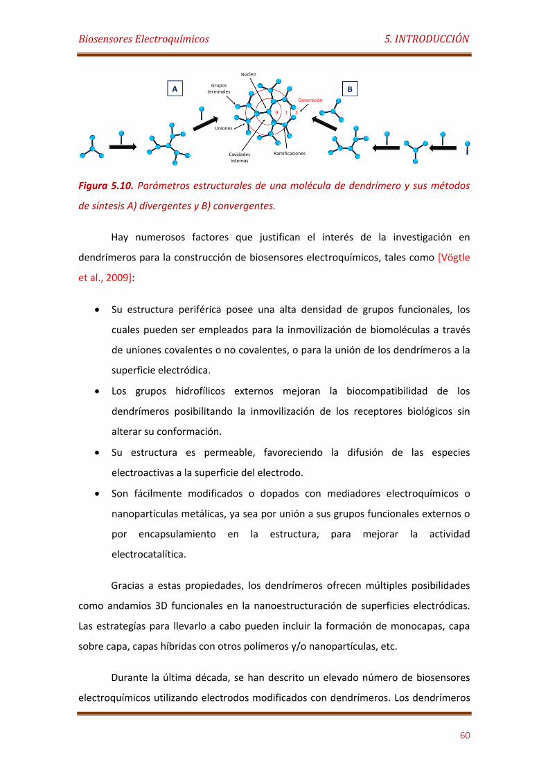
Biosensores Electroquímicos 5. INTRODUCCIÓN
60
Figura 5.10. Parámetros estructurales de una molécula de dendrímero y sus métodos
de síntesis A) divergentes y B) convergentes.
Hay numerosos factores que justifican el interés de la investigación en
dendrímeros para la construcción de biosensores electroquímicos, tales como [Vögtle
et al., 2009]:
Su estructura periférica posee una alta densidad de grupos funcionales, los
cuales pueden ser empleados para la inmovilización de biomoléculas a través
de uniones covalentes o no covalentes, o para la unión de los dendrímeros a la
superficie electródica.
Los grupos hidrofílicos externos mejoran la biocompatibilidad de los
dendrímeros posibilitando la inmovilización de los receptores biológicos sin
alterar su conformación.
Su estructura es permeable, favoreciendo la difusión de las especies
electroactivas a la superficie del electrodo.
Son fácilmente modificados o dopados con mediadores electroquímicos o
nanopartículas metálicas, ya sea por unión a sus grupos funcionales externos o
por encapsulamiento en la estructura, para mejorar la actividad
electrocatalítica.
Gracias a estas propiedades, los dendrímeros ofrecen múltiples posibilidades
como andamios 3D funcionales en la nanoestructuración de superficies electródicas.
Las estrategías para llevarlo a cabo pueden incluir la formación de monocapas, capa
sobre capa, capas híbridas con otros polímeros y/o nanopartículas, etc.
Durante la última década, se han descrito un elevado número de biosensores
electroquímicos utilizando electrodos modificados con dendrímeros. Los dendrímeros
Generación
0 1 2
A B
Biosensores Electroquímicos 5. INTRODUCCIÓN
61
más empleados son los de poliamidoamina o PAMAM [Borisova et al., 2016; Miodek et
al., 2016].
5.2.3.4. Nanomateriales de óxidos metálicos:
Los nanomateriales de óxidos metálicos han sido utilizados en numerosos
diseños para la construcción de biosensores. La propiedad más importante que poseen
para este cometido es su alta actividad electrocatalítica [Yañez-Sedeño et al., 2015].
Las nanopartículas de óxidos metálicos, como TiO2, NiO, ZnO, SnO2 y Co3O4, se
emplean en la modificación de superficies electródicas por su alta actividad
electrocatalítica, buena estabilidad química, baja toxicidad, alta relación
superficie/volumen y buena biocompatibilidad.
En los últimos años, se han descrito multitud de biosensores electroquímicos
construidos con híbridos preparados entre nanopartículas de óxido metálico,
materiales de carbono y/o polímeros conductores [Devi et al., 2012; Yadav et al., 2011;
Li et al., 2009]. Estas superficies nanoestructuradas también permiten la transferencia
directa de electrones entre los centros redox de los receptores biológicos y los
electrodos [Zhu et al., 2015; Dong et al., 2014; Shamsipur et al., 2012; Li et al., 2006;
Liu et al., 2005a].
Otro nanomaterial metálico muy interesante para ser empleado como
elemento de transducción son las nanopartículas de Fe3O4. En este caso, la propiedad
más destacable es el magnetismo. Otras ventajas son su excelente solubilidad en agua,
gran área superficial, fácil fabricación, menor toxicidad que las nanopartículas
metálicas y bajo coste [Yu et al., 2013].
Un enfoque alternativo en la construcción de biosensores es el empleo de estas
nanopartículas de forma desechable por adsorción no específica a la superficie del
electrodo, de modo que mediante la utilización de un imán externo se puede renovar
la superficie. En este sentido, las nanopartículas magnéticas pueden también
emplearse para purificar y/o concentrar el analito de interés [Eguílaz et al., 2011].
Biosensores Electroquímicos 5. INTRODUCCIÓN
62
Otros nanomateriales de este grupo, empleados para el diseño de plataformas
estables en biosensores, son las nanopartículas y películas finas de SiO2 porosa. Ambas
estructuras de SiO2, se caracterizan por su fácil síntesis y modificación superficial, alta
estabilidad química y térmica, y su gran área superficial biocompatible para la
inmovilización de los receptores biológicos. Existen numerosos trabajos que describen
el uso de sílice para la construcción de biosensores con buenas propiedades [Saadaoui
et al., 2016; Wang et al., 2009]. Sin embargo, estos nanomateriales son aislantes y
bloquean la transferencia electrónica. Generalmente, en los biosensores
electroquímicos se usan combinados con otros materiales que mejoran su
conductividad como los materiales de carbono o nanopartículas métalicas [Zhang et
al., 2016; Tiwari et al., 2008].
Sistemas de liberación controlada 5. INTRODUCCIÓN
63
5.3. SISTEMAS DE LIBERACIÓN CONTROLADA
5.3.1 Conceptos básicos
El papel principal de los sistemas de liberación controlada es el de administrar
la cantidad correcta del fármaco eficazmente, es decir controlar el lugar y el ritmo de
la liberación. El desarrollo de nuevos sistemas de liberación controlada de fármacos es
de vital importancia. Se prevé que en un futuro cercano estos sistemas sean una
alternativa útil para el tratamiento de enfermedades que requieren la administración
de fármacos altamente tóxicos, como el cáncer [Baezaet al., 2014].
Los primeros sistemas de liberación controlada datan de la década de 1950.
Estos sistemas estaban basados en polímeros sólidos donde se incorporaban fármacos
para productos agrícolas, pero no fue hasta la década siguiente cuando estos diseños
se extendieron a la medicina. En los primeros estudios, se utilizaban tubos de silicona o
matrices de polietileno [Lager, 1981]. Hasta los años 80, época denominada 1ª
generación, se establecieron los mecanismos básicos de la liberación de fármacos, los
cuales comprenden la disolución, difusión, ósmosis y el intercambio iónico, y se
desarrollaron sistemas de administración orales y transdérmicos.
Durante la 2ª generación (1980-2010), se diseñaron los polímeros e hidrogeles
"inteligentes" donde la liberación de fármacos estaba provocada por cambios en los
factores ambientales, tales como temperatura, pH o nivel de glucosa. En la última
década de esta generación, comenzó a utilizarse la nanotecnología [Park, 2014], sin
embargo, estos sistemas eran incapaces de superar las barreras biológicas. Con
respecto a la tercera generación, ya son posibles algunas de las aplicaciones mostradas
en la Tabla 5.1., pero se espera que gracias a la nanotecnología los sistemas de
administración de fármacos superen las barreras biológicas y físico-químicas con las
enormes ventajas que ese avance supondría para el empleo de estos sistemas en
estudios in vivo.
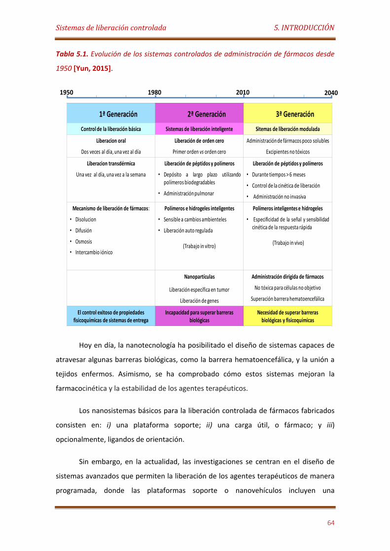
Sistemas de liberación controlada 5. INTRODUCCIÓN
64
Tabla 5.1. Evolución de los sistemas controlados de administración de fármacos desde
1950 [Yun, 2015].
Hoy en día, la nanotecnología ha posibilitado el diseño de sistemas capaces de
atravesar algunas barreras biológicas, como la barrera hematoencefálica, y la unión a
tejidos enfermos. Asimismo, se ha comprobado cómo estos sistemas mejoran la
farmacocinética y la estabilidad de los agentes terapéuticos.
Los nanosistemas básicos para la liberación controlada de fármacos fabricados
consisten en: i) una plataforma soporte; ii) una carga útil, o fármaco; y iii)
opcionalmente, ligandos de orientación.
Sin embargo, en la actualidad, las investigaciones se centran en el diseño de
sistemas avanzados que permiten la liberación de los agentes terapéuticos de manera
programada, donde las plataformas soporte o nanovehículos incluyen una
1950 1980 20402010
1ª Generación 2ª Generación 3ª Generación
Control de la liberación básica Sistemas de liberación inteligente Sitemas de liberación modulada
Liberacion oral
Dos veces al día, una vez al día
Liberación de orden cero
Primer orden vs orden cero
Administración de fármacos poco solubles
Excipientes no tóxicos
Liberacion transdérmica
Una vez al día, una vez a la semana
Liberación de péptidos y polímeros
• Depósito a largo plazo utilizandopolímeros biodegradables
• Administración pulmonar
Liberación de péptidos y polímeros
• Durante tiempos > 6 meses
• Control de la cinética de liberación
• Administración no invasiva
Mecanismo de liberación de fármacos:
• Disolucion
• Difusión
• Osmosis
• Intercambio iónico
Polímeros e hidrogeles inteligentes
• Sensible a cambios ambienteles
• Liberación auto regulada
(Trabajo in vitro)
Polímeros inteligentes e hidrogeles
• Especificidad de la señal y sensibilidadcinética de la respuesta rápida
(Trabajo in vivo)
Nanopartículas
Liberación específica en tumor
Liberación de genes
Administración dirigida de fármacos
No tóxica para células no objetivo
Superación barrera hematoencefálica
El control exitoso de propiedades fisicoquímicas de sistemas de entrega
Incapacidad para superar barreras biológicas
Necesidad de superar barreras biológicas y fisicoquímicas
Sistemas de liberación controlada 5. INTRODUCCIÓN
65
funcionalidad sensible a un estímulo, ya sea externo o interno, que permite una
liberación más eficaz, segura, estable, así como una mayor absorción celular [Lehner et
al., 2012].
Las características deseadas en los dispositivos “inteligentes” de administración
de fármacos son: i) mejora de la permeabilidad: para facilitar el paso de las drogas a
través de la membrana celular u otras bio-barreras; ii) aumento de la estabilidad del
fármaco: los nanomateriales pueden proteger a las drogas de su autodegradación o de
la limpieza de los macrófagos; iii) entrega localizada o específica: para liberar los
fármacos en regiones concretas, como en cánceres locales; iv) capacidad de control:
para que la liberación del fármaco se produzca mediante una señal externa o a través
de los cambios ambientales; y v) aumentar la eficacia de la terapia y reducir la
toxicidad de la droga: los nanomateriales pueden minimizar los efectos secundarios
de los fármacos y sin embargo, aumentar el terapéutico al ser liberado en un área
específica [Yan et al., 2014].
5.3.2. Clasificación de los sistemas de liberación controlada de fármacos
Los nanosistemas pueden clasificarse de acuerdo a numerosos parámetros. Los
más importantes son i) la orientación para la administración dirigida del fármaco; ii) el
mecanismo de liberación de los agentes terapéuticos; y iii) el tipo de plataforma.
5.3.2.1. De acuerdo a la orientación
La orientación para la administración dirigida de los agentes terapéuticos,
puede considerarse pasiva, activa o combinación de ambas.
La orientación pasiva se basa en fenómenos de permeabilidad y retención. Se
ha demostrado que en algunos tejidos tumorales las macromoléculas con
tamaños superiores a 50 KDa se retienen en el intersticio del tumor durante
periodos largos de tiempo. Además, en estos tejidos el drenaje linfático es
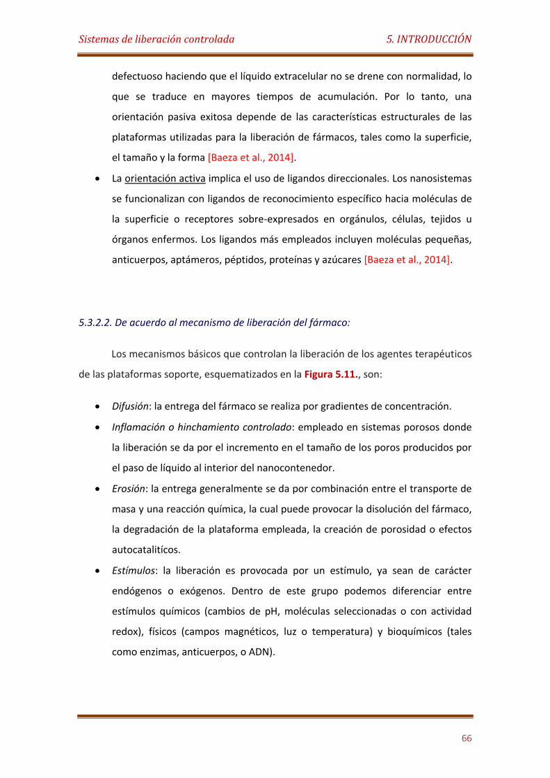
Sistemas de liberación controlada 5. INTRODUCCIÓN
66
defectuoso haciendo que el líquido extracelular no se drene con normalidad, lo
que se traduce en mayores tiempos de acumulación. Por lo tanto, una
orientación pasiva exitosa depende de las características estructurales de las
plataformas utilizadas para la liberación de fármacos, tales como la superficie,
el tamaño y la forma [Baeza et al., 2014].
La orientación activa implica el uso de ligandos direccionales. Los nanosistemas
se funcionalizan con ligandos de reconocimiento específico hacia moléculas de
la superficie o receptores sobre-expresados en orgánulos, células, tejidos u
órganos enfermos. Los ligandos más empleados incluyen moléculas pequeñas,
anticuerpos, aptámeros, péptidos, proteínas y azúcares [Baeza et al., 2014].
5.3.2.2. De acuerdo al mecanismo de liberación del fármaco:
Los mecanismos básicos que controlan la liberación de los agentes terapéuticos
de las plataformas soporte, esquematizados en la Figura 5.11., son:
Difusión: la entrega del fármaco se realiza por gradientes de concentración.
Inflamación o hinchamiento controlado: empleado en sistemas porosos donde
la liberación se da por el incremento en el tamaño de los poros producidos por
el paso de líquido al interior del nanocontenedor.
Erosión: la entrega generalmente se da por combinación entre el transporte de
masa y una reacción química, la cual puede provocar la disolución del fármaco,
la degradación de la plataforma empleada, la creación de porosidad o efectos
autocatalitícos.
Estímulos: la liberación es provocada por un estímulo, ya sean de carácter
endógenos o exógenos. Dentro de este grupo podemos diferenciar entre
estímulos químicos (cambios de pH, moléculas seleccionadas o con actividad
redox), físicos (campos magnéticos, luz o temperatura) y bioquímicos (tales
como enzimas, anticuerpos, o ADN).
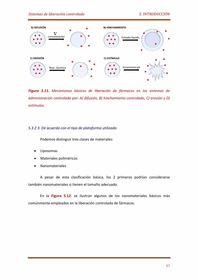
Sistemas de liberación controlada 5. INTRODUCCIÓN
67
Figura 5.11. Mecanismos básicos de liberación de fármacos en los sistemas de
administración controlada por: A) difusión, B) hinchamiento controlado, C) erosión y D)
estímulos.
5.3.2.3. De acuerdo con el tipo de plataforma utilizada:
Podemos distinguir tres clases de materiales:
Liposomas
Materiales poliméricos
Nanomateriales
A pesar de esta clasificación básica, los 2 primeros podrían considerarse
también nanomateriales si tienen el tamaño adecuado.
En la Figura 5.12. se ilustran algunos de los nanomateriales básicos más
comúnmente empleados en la liberación controlada de fármacos.
concentración Entrada líquido
Reac. Química Incremento pH
A) DIFUSIÓN B) HINCHAMIENTO
C) EROSIÓN C) ESTÍMULO
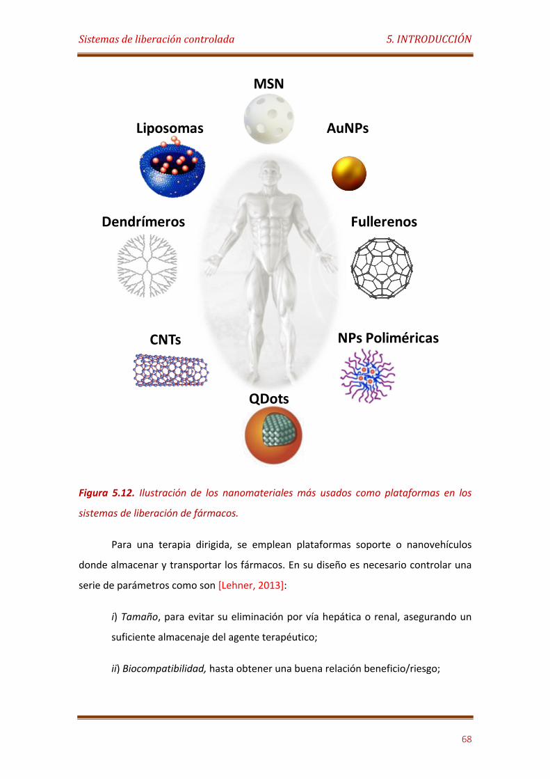
Sistemas de liberación controlada 5. INTRODUCCIÓN
68
Figura 5.12. Ilustración de los nanomateriales más usados como plataformas en los
sistemas de liberación de fármacos.
Para una terapia dirigida, se emplean plataformas soporte o nanovehículos
donde almacenar y transportar los fármacos. En su diseño es necesario controlar una
serie de parámetros como son [Lehner, 2013]:
i) Tamaño, para evitar su eliminación por vía hepática o renal, asegurando un
suficiente almacenaje del agente terapéutico;
ii) Biocompatibilidad, hasta obtener una buena relación beneficio/riesgo;
Liposomas
MSN
AuNPs
Dendrímeros Fullerenos
CNTs
QDots
NPs Poliméricas
Sistemas de liberación controlada 5. INTRODUCCIÓN
69
iii) Propiedades enmascarantes, para evitar el reconocimiento inmunológico o
la interacción con proteínas séricas;
iv) Tiempo óptimo de circulación por el torrente sanguíneo;
v) Alta especificidad hacia un objetivo que provoque la liberación del fármaco;
vi) Mecanismos de liberación controlables;
vii) Que esos mecanismos respondan a un estímulo.
Los nanovehículos pueden ser clasificados en 3 grandes grupos:
- Liposomas:
Son vesículas con forma esférica, formadas por una doble membrana de
fosfolípidos. Su carácter anfifílico posibilita el encapsulamiento de moléculas hidrófilas
en su interior acuoso o, por el contrario, el transporte de compuestos hidrofóbicos
sobre su membrana lipídica.
Otras de las ventajas que aporta la membrana a estos portadores son su fácil
modificación y su alta biocompatibilidad, haciendo que los nanosistemas puedan
adherirse a las membranas celulares o introducirse en el interior de las células por
endocitosis [Faraji et al., 2009]. Además, gracias a la fácil modificación de estos
sistemas comentada anteriormente, ya están siendo empleados clínicamente como
sistemas inteligentes en la liberación de fármacos para el tratamiento del sarcoma o el
cáncer de ovarios entre otros, empleando diferentes funcionalidades que responden a
estímulos ambientales (como el pH, la temperatura, la luz o la respuesta enzimática)
[Lehner et al., 2013].
Durante los últimos años, se han descrito un gran número de nanosistemas
utilizando liposomas como nanocontenedores para el almacenamiento de fármacos.
En algunos ejemplos recientes, se emplean nanoliposomas termosensibles orientados
Sistemas de liberación controlada 5. INTRODUCCIÓN
70
hacia receptores del factor de crecimiento epidérmico, sobreexpresado en células
cancerosas, para la liberación de un compuesto anti-cancerígeno [Haeri et al., 2016].
- Materiales poliméricos:
Su aplicación en la entrega controlada de agentes terapéuticos se basa en la
conjunción formada entre el polímero y el fármaco, denominado “profármaco
polimérico”, ya que mejora la solubilidad de fármacos hidrofóbicos y evita la liberación
inicial que se produce con otros materiales [Hu et al., 2010].
Los polímeros utilizados como nanovehículos para la entrega regulada de
fármacos son biodegradables y biocompatibles. Es decir, tras la liberación del fármaco
el polímero se degrada en moléculas inocuas como agua, hidrógeno o nitrógeno. La
liberación de la droga se modula en función del polímero empleado [Parveen et al.,
2008].
Dentro de este gran grupo de materiales, los más empleados en la
nanomedicina son los las nanopartículas o micelas de ácido poliglicólico (PGA), del
ácido poliláctico (PLA) y los dendrímeros. El crecimiento en empleo de dendrímeros
como nanosistemas se debe a la facilidad con la que se modifica o funcionaliza su
superficie, su cavidad interior hidrófoba para la encapsulación de los fármacos
hidrófobos o el control del grado de ramificación. Sin embargo, para ser empleados
clínicamente necesitan mejorar su biocompatibilidad, citotoxicidad y biodistribución
[Lehner et al., 2013; Cho et al., 2008].
Los dendrímeros más utilizados son los de poliamidoamina (PAMAM). En los
últimos años, la conjunción entre estos y otros ligandos, como el polietilenglicol (PEG)
ha sido el método más empleado para reducir la toxidad de los agentes terapéuticos
[Luong et al., 2016].
Sistemas de liberación controlada 5. INTRODUCCIÓN
71
- Nanomateriales:
Durante la última década, la nanotecnología ha creado una amplia gama de
nanomateriales, los cuales se están aplicando en el campo de la nanomedicina. Como
materiales básicos más extendidos encontramos los CNTs, fullerenos, nanopartículas
metálicas, puntos cuánticos y nanopartículas de materiales inorgánicos.
Nanotubos de carbono:
El almacenaje de los fármacos se puede dar tanto en la cavidad interior, como
en la superficie externa, funcionalizando covalentemente la pared lateral o las puntas
con ligandos que permitan el transporte de moléculas y su liberación al ser sensibles a
las condiciones ambientales tales como temperatura, pH o agentes reductores.
Asimismo, esa modificación se utiliza para mejorar su biocompatibilidad y su
solubilidad disminuyendo la citotoxicidad, aunque sigue siendo un inconveniente a
mejorar en estos dispositivos [Lehner et al., 2013]. Se espera que una de las
aplicaciones más prometedoras en la liberación controlada de fármacos y genes a las
células, se regule mediante el empleo de SWCNTs funcionalizados con péptidos
[Razzazan et al., 2016; Ohta et al., 2016].
Otra de las formas alotrópica del carbono que está siendo investigada en los
últimos años, son los fullerenos, aunque en menor medida que los CNTs [Raza et al.,
2015].
Puntos cuánticos:
Estos materiales consisten en nanocristales de tamaño pequeño (1-10 nm) y
constan de un núcleo formado por un elemento semiconductor rodeado por una capa
metálica.
Los fármacos pueden ser inmovilizados en su superficie mediante enlaces
covalentes escindibles, de modo que los conjugados formados presentan un mayor
Sistemas de liberación controlada 5. INTRODUCCIÓN
72
tamaño, lo que evita su eliminación renal aumentando el tiempo de circulación en el
plasma, y al romperse este enlace se libera la droga, quedando el nanomaterial con un
tamaño adecuado para ser excretados. Sin embargo, estos nanomateriales están
fabricados con metales pesados (los más utilizados son CdS, CdSe, ZnS…) tóxicos a
largo plazo, lo que limita su uso clínicamente [Qi et al., 2008].
Durante los últimos años se han desarrollado puntos cuánticos de carbono
(CQD), los cuales, a diferencia de los fabricados con semiconductores, poseen buena
biocompatibilidad, alta fotoestabilidad y baja toxicidad. Estas nuevas nanoplataformas
se están empleando para el diseño de nuevos sistemas de liberación de agentes
terapéuticos y genes [Zhou et al., 2016; Chiu et al., 2016].
Nanopartículas metálicas:
Las nanopartículas metálicas son uno de los nanomateriales más empleados en
la liberación de fármacos, debido a la posibilidad de controlar el tamaño y propiedades
magnéticas, la baja citotoxicidad y la fácil modificación superficial que presentan, lo
que posibilita la creación de sistemas con funcionalidades avanzadas, sensibles y con
capacidad de respuesta frente a cambios de pH, redox… [Zhang et al., 2016].
Los materiales más empleados para su uso como plataformas son de óxido de
hierro y el oro.
En el caso de las nanopartículas magnéticas, de Fe3O4 y Fe2O3 principalmente,
poseen una alta biocompatibilidad y presentan un comportamiento paramagnético
debido a su pequeño tamaño. Este hecho trae como consecuencia que no aporten un
campo magnético propio (por lo que no tienden a aglomerarse), pero que sí actúen
como nanomateriales magnéticos en presencia de un campo externo. En este sentido,
estas nanopartículas pueden ser transportadas hasta las células diana mediante la
aplicación de campos magnéticos y una vez allí liberar los fármacos [Lehner et al.,
2013]. Además, otra característica que presentan estos nanomateriales es la
posibilidad de hacer tratamientos de hipertermia. Éstos consisten en la aplicación de
Sistemas de liberación controlada 5. INTRODUCCIÓN
73
un campo magnético externo que oscila con una elevada frecuencia, provocando que
también el campo propio de las nanopartículas oscile muy rápidamente generando un
calentamiento de la nanopartícula, capaz de matar (atacar) las células cercanas a las
nanopartículas [Zamora-Mora et al., 2017; Niemirowicz et al., 2016].
Las AuNPs, debido a sus excelentes propiedades ya comentadas en el capítulo
anterior, han atraído la atención en el campo de la nanomedicina. Su uso como
transportadores de fármacos se basa en su gran área superficial, fácil modificación
superficial y buena biocompatibilidad. Durante los últimos años, se han descrito un
gran número de nanosistemas para la entrega de agentes terapéuticos empleando
estos materiales [Manivasagana et al., 2016; Peng et al., 2016].
Estas plataformas basadas en nanomateriales metálicos poseen una
desventaja, la relación en peso existente entre la carga útil y la plataforma. Por este
motivo, suelen ir acompañadas de otros nanomateriales o polímeros [Zhang et al.,
2016].
Nanopartículas mesoporosas:
Una de las características más interesantes de estos materiales inorgánicos
para su uso como nanovehículo, es la posibilidad de crear estructuras con tamaños,
superficie y porosidad diferentes. Estas nanoestructuras porosas actúan como carcasa,
protegiendo la carga útil de la desnaturalización o degradación [Lehner et al., 2012].
Además, estos nanoportadores pueden ser fácilmente modificados por
diferentes funcionalidades que respondan a estímulos ambientales como el pH, la
temperatura, la luz o enzimas y activen la liberación de los fármacos. De esta forma es
posible controlar fácilmente esta liberación mediante estímulos propios del sistema o
inducirla mediante estímulos externos.
Entre todos los nanomateriales inorgánicos, las nanopartículas mesoporosas de
sílice, con mucho, ocupan el lugar más relevante en la entrega controlada de fármacos.
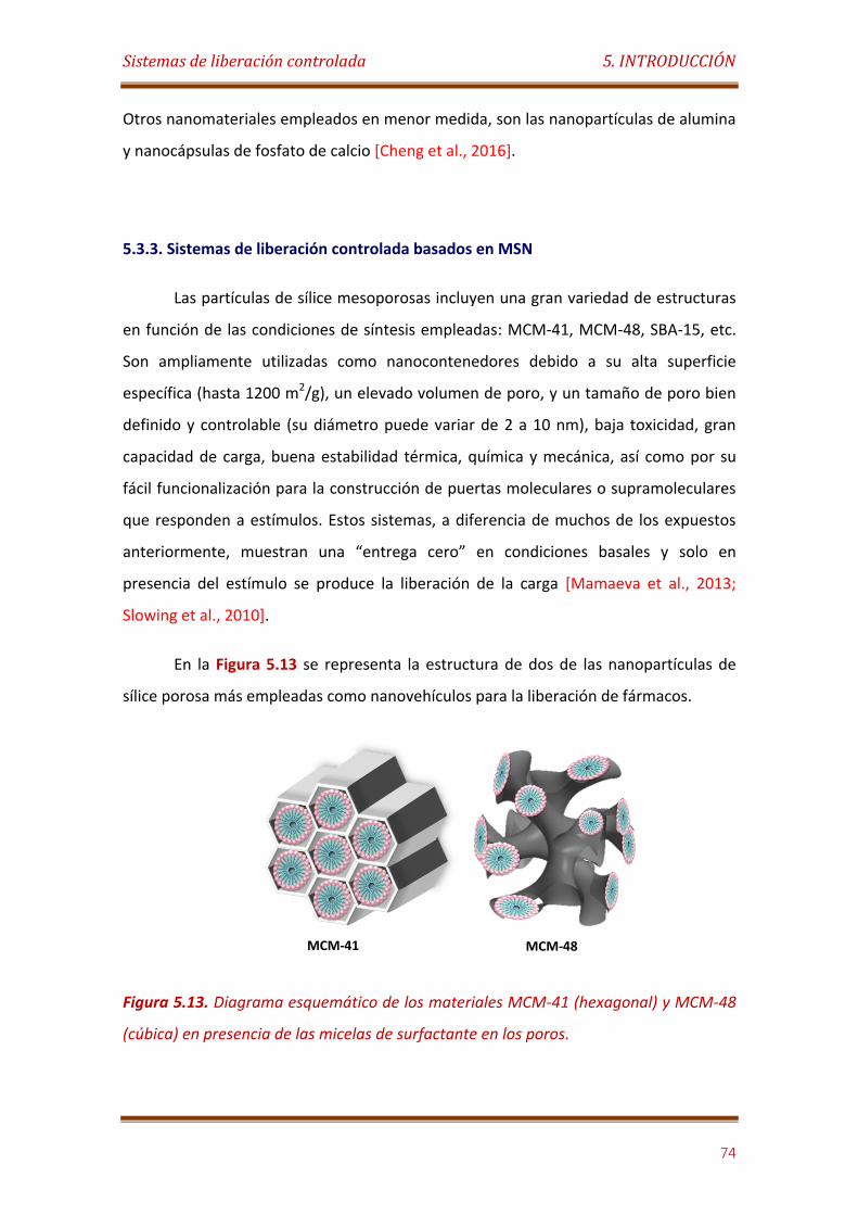
Sistemas de liberación controlada 5. INTRODUCCIÓN
74
Otros nanomateriales empleados en menor medida, son las nanopartículas de alumina
y nanocápsulas de fosfato de calcio [Cheng et al., 2016].
5.3.3. Sistemas de liberación controlada basados en MSN
Las partículas de sílice mesoporosas incluyen una gran variedad de estructuras
en función de las condiciones de síntesis empleadas: MCM-41, MCM-48, SBA-15, etc.
Son ampliamente utilizadas como nanocontenedores debido a su alta superficie
específica (hasta 1200 m2/g), un elevado volumen de poro, y un tamaño de poro bien
definido y controlable (su diámetro puede variar de 2 a 10 nm), baja toxicidad, gran
capacidad de carga, buena estabilidad térmica, química y mecánica, así como por su
fácil funcionalización para la construcción de puertas moleculares o supramoleculares
que responden a estímulos. Estos sistemas, a diferencia de muchos de los expuestos
anteriormente, muestran una “entrega cero” en condiciones basales y solo en
presencia del estímulo se produce la liberación de la carga [Mamaeva et al., 2013;
Slowing et al., 2010].
En la Figura 5.13 se representa la estructura de dos de las nanopartículas de
sílice porosa más empleadas como nanovehículos para la liberación de fármacos.
Figura 5.13. Diagrama esquemático de los materiales MCM-41 (hexagonal) y MCM-48
(cúbica) en presencia de las micelas de surfactante en los poros.
MCM-41 MCM-48

Sistemas de liberación controlada 5. INTRODUCCIÓN
75
La ruta y velocidad de difusión del fármaco depende de la estructura de la MSN.
MCM-41 y la MCM-48. La MCM-41 contiene canales de poros unidireccionales con
disposición hexagonal, lo que permite una liberación de la carga directa al exterior,
mientras que en el caso de la MCM-48, con estructura porosa cúbica tridimensional, el
recorrido para la liberación es mucho mayor [He et al., 2011]. Por este motivo,
además del resto de excelentes propiedades, la estructura MCM-41 fue elegida para el
desarrollo de diferentes trabajos en la entrega controlada de fármacos.
Desde su descubrimiento en 1992, su uso ha crecido exponencialmente [Beck
et al., 1992]. Típicamente se sintetizan mediante procesos sol-gel en presencia de un
tensioactivo, que controla el tamaño del poro. El método estándar se realiza
mezclando una baja concentración de surfactante catiónico, siendo el más utilizado el
bromuro de cetiltrimetilamonio (CTAB), con un precursor de silicato, generalmente
tetraetilortosilicato (TEOS), en medio básico a una temperatura de entre 30-80ºC
durante 2h. Las MSN se sintetizan en dos pasos, una hidrólisis y una condensación. Por
último, se elimina el surfactante del interior de los poros mediante una extracción con
una fase líquida o calcinando a alta temperatura el material sintetizado (Figura 5.15).
Figura 5.14. Ilustración esquemática de la síntesis de MCM 41. Mecanismo de
polimerización del TEOS. Adaptado de la referencia [Llinàs et al., 2014].
El modelo típico de un nanosistema de MSN para la liberación controlada de
fármacos consiste en cargar el agente terapéutico de forma reversible dentro de la
nanopartícula y funcionalizar su superficie, de forma covalente o por adsorción, con
Micelas CTAB
Alineaciónen matrices
hexagonales
Calcinación
Arreglo hexagonal con paredes de SiO2
MCM 41
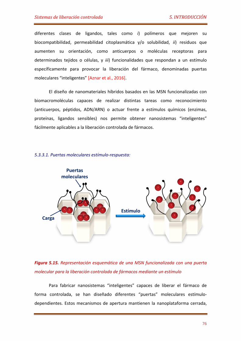
Sistemas de liberación controlada 5. INTRODUCCIÓN
76
diferentes clases de ligandos, tales como i) polímeros que mejoren su
biocompatibilidad, permeabilidad citoplasmática y/o solubilidad, ii) residuos que
aumenten su orientación, como anticuerpos o moléculas receptoras para
determinados tejidos o células, y iii) funcionalidades que respondan a un estímulo
específicamente para provocar la liberación del fármaco, denominadas puertas
moleculares “inteligentes” [Aznar et al., 2016].
El diseño de nanomateriales híbridos basados en las MSN funcionalizadas con
biomacromoléculas capaces de realizar distintas tareas como reconocimiento
(anticuerpos, péptidos, ADN/ARN) o actuar frente a estímulos químicos (enzimas,
proteínas, ligandos sensibles) nos permite obtener nanosistemas “inteligentes”
fácilmente aplicables a la liberación controlada de fármacos.
5.3.3.1. Puertas moleculares estímulo-respuesta:
Figura 5.15. Representación esquemática de una MSN funcionalizada con una puerta
molecular para la liberación controlada de fármacos mediante un estímulo
Para fabricar nanosistemas “inteligentes” capaces de liberar el fármaco de
forma controlada, se han diseñado diferentes “puertas” moleculares estímulo-
dependientes. Estos mecanismos de apertura mantienen la nanoplataforma cerrada,
Carga
Estímulo
Puertas moleculares
Sistemas de liberación controlada 5. INTRODUCCIÓN
77
cubriendo los poros, y se accionan de forma selectiva en respuesta a un estímulo
determinado liberando la carga útil (Figura 5.15.).
Principalmente, se han desarrollado puertas moleculares sensibles a estímulos
con potenciales aplicaciones biomédicas. Es decir, cambios de pH, medios reductores,
actividad enzimática, luz, temperatura, moléculas y biomoléculas, campos magnéticos
y ultrasonidos, ya que estos estímulos se pueden encontrar en mayor concentración
en las proximidades de las células diana o son fácilmente aplicables de forma externa y
con terapias poco invasivas [Aznar et al.,2016].
Sensibles al pH:
El pH es el estímulo más utilizado en el desarrollo de nanosistemas para la
liberación controlada de agentes terapéuticos. El motivo principal se debe a que en los
tejidos inflamados o tumorales el medio es más ácido que en los tejidos sanos, y esta
variación de pH a nivel local va a provocar la liberación del fármaco directamente
sobre el tejido dañado [He et al., 2016].
El mecanismo de funcionamiento de estos sistemas, de un estado cerrado a
uno abierto, se basa en los cambios producidos tras la adición o sustracción de
protones. Esas modificaciones en la puerta pueden ser debidos a:
Una transformación en el tamaño o la forma
Interacciones de atracción o repulsión
Se han descrito numerosos sistemas que emplean este tipo de puertas
sensibles al pH, constituidos por una gran variedad de ligandos y funcionalidades para
el control de la liberación con macrociclos, aminas, polímeros, enzimas, ADN,
proteínas, nanopartículas metálicas nanopartículas inorgánicas, etc [AbouAitah et al.,
2016; Yilmaz, 2016; Muhammad et al., 2011; Lee et al., 2010; Liu et al., 2010].
Las aplicaciones de estas nanomáquinas en la nanomedicina presentan
limitaciones debido a que la vía de entrada habitual en las células es por endocitosis. El
Sistemas de liberación controlada 5. INTRODUCCIÓN
78
pH del medio en un endosoma es de 5, lo que provocaría la liberación involuntaria del
fármaco antes de tiempo [Aznar et al.,2016].
Sensibles a cambios redox
El empleo de este estímulo para nanosistemas de liberación controlada es
debido al aumento en la concentración de especies con actividad redox que se observa
en el medio cercano a algunos tumores cancerosos [Aznar et al.,2016].
En este caso, el mecanismo de liberación se basa en:
Cambios en las interacciones supramoleculares de tipo redox entre ligandos
que funcionalizan la MSN y macrociclos como ciclodextrinas o curcubiturilos
que actúan como un pistón [Kim et al., 2010].
Ruptura de un enlace di-sulfuro, entre ligandos anclados en la MSN y agentes
de terminación. Los agentes de terminación, empleados generalmente para el
bloqueo del poro o para la orientación selectiva, pueden ser enzimas,
anticuerpos, nanopartículas metálicas o inorgánicas, polímeros, etc [Cui, 2012;
Xiao, 2016].
A diferencia de los nanosistemas sensibles al pH, la aplicabilidad de estos en la
nanomedicina es muy alta [Wang Y. et al., 2015].
Sensibles a la actividad enzimática:
Las enzimas proporcionan a los nanosistemas de liberación controlada una alta
selectividad. Actualmente, no es uno de los estímulos más utilizados, pero se prevé
que en un futuro cercano se invierta esa tendencia gracias a sus buenas características.
Existen enzimas que se sobre-expresan en pacientes con determinadas enfermedades,
luego su uso como estímulo está bien justificado.
Sistemas de liberación controlada 5. INTRODUCCIÓN
79
La liberación del fármaco, está basada en las 2 posibles funciones que puede
realizar la enzima en los nanosistemas [Aznar et al., 2016]:
Las enzimas actúan hidrolizando o degradando los ligandos que funcionalizan y
cierran los poros de la MSN [Mas et al., 2013].
Las enzimas actúan como tapa, ancladas sobre la MSN, y la apertura se produce
mediada por los productos derivados de la actividad catalítica [Yang et al.,
2012].
Sensibles a luz:
El empleo de la luz como estímulo se basa en la posibilidad de provocar la
liberación controlada de agentes terapéuticos de forma no invasiva. El paciente puede
ser irradiado de forma focalizada, sin afectar a los tejidos sanos, aunque para ello se
necesita una luz potente que atraviese las capas epidérmicas.
Los mecanismos de apertura de la puerta se deben a:
Foto-dimerizaciones: los ligandos que funcionalizan la MSN son isómeros cis-
trans que al cambiar de conformación producen la liberación del fármaco
[Angelos et al., 2007].
Foto-ruptura: los ligandos que funcionalizan la MSN son fotosensibles,
rompiéndose al incidir la luz sobre ellos [Guardado-Alvarez et al., 2013].
Calentamiento foto-inducido de nanopartículas metálicas que actúan como
tapas [Vivero-Escoto et al., 2009].
Sensibles a la temperatura:
Como en el caso anterior, la temperatura tiene la ventaja de poder ser utilizada
como un estímulo no invasivo. Además, su empleo está bien justificado por el aumento
Sistemas de liberación controlada 5. INTRODUCCIÓN
80
de temperatura que se registra en tejidos inflamados, infecciosos o tumorales. Dicho
aumento es de apenas 5ºC lo que limita mucho las aplicaciones biomédicas de estos
sistemas, a sistemas muy sensibles [Aznar et al., 2016].
Los materiales más empleados en este tipo de puerta son los polímeros
termosensibles. En este caso, el mecanismo de apertura se debe a que el aumento de
la temperatura provoca un cambio de fase en los polímeros, haciendo que colapsen y
abran el poro [Liu et al., 2009].
Sensibles a moléculas y biomoléculas:
La liberación del fármaco en estos sistemas se fundamenta en un cambio en la
polaridad de las interacciones supramoleculares existentes entre la superficie de la
MSN y los ligandos que forman la puerta.
Se pueden emplear una amplia gama de moléculas cargadas, tanto aniones
como cationes, o neutras como las biomoléculas. A excepción de estas últimas, estos
sistemas son muy poco específicos y su aplicabilidad médica no está muy extendida
[Choi et al., 2011].
Sensibles a la ultrasonidos y campos magnéticos:
Ambos estímulos son no invasivos, a pesar de ser necesaria su aplicación de
forma externa. Éstos, al contrario que la luz, sí pueden alcanzar tejidos profundos, lo
que aumenta su aplicabilidad en el campo de la biomedicina. Sin embargo, el empleo
de US como estímulo para la liberación de fármacos en personas está más que
cuestionado por el efecto genotóxico que podría causar [Aznar et al., 2016].
Por otro lado, el uso del magnetismo como estímulo, tiene una ventaja extra.
Los nanosistemas pueden ser también orientados hasta los tejidos diana antes de la
liberación de los agentes terapéuticos [Thomas et al., 2010].

6 OBJECTIVES

6. OBJECTIVES
81
The main objective of this Thesis is the preparation and characterization of
novel functionalized nanomaterials and nanohybrids for their evaluation as
transduction elements for electrochemical biosensors construction and the design of
advanced enzyme-controlled smart drug delivery systems. This Thesis aims to reach its
specific objective goal by:
For biosensors design:
• Preparation and characterization of polyfunctionalized gold nanoparticles to be
used as building blocks for the assembly of electropolymerized networks of
nanoparticles on electrodes surfaces.
• Establishment of original non-covalent strategies for the modification of single-
walled carbon nanotubes with magnetic nanoparticles and β-cyclodextrins
derivatives.
• Preparation and characterization of poliamidoamine dendron and dendrimer
derivatives bearing β-cyclodextrins units for the self-assembly of layered
supramolecular architectures on electrodes surfaces by using adamantane-
modified enzymes as biomolecular building blocks.
• Establishment of optimized protocols for the proper assembly of electrochemical
enzyme biosensors and immunosensors on the nanostructured electrode surfaces.
• Determination of the analytical and stability properties of the electroanalytical
devices.
For drug delivery systems:
Preparation and characterization of mesoporous silica nanoparticles based on
functional nanocontainers capped with lactose-esterase neoglycoenzyme.

6. OBJECTIVES
82
Design and development of original gold-mesoporous silica Janus nanoparticles to
be used as “hardware” for the assembly of single enzyme/multienzyme logic gate-
based nanomachines for smart delivery.
Establishment of optimized protocols for the proper assembly of the
biofunctionalized nanomachines.
Structural, functional and operational characterization of the enzyme-controlled
nanomachines for on-command delivery.
7 PUBLICACIONES
CIENTÍFICAS

7.1
Electrochimica Acta 56, 2011, 4672-4677
Wiring horseradish peroxidase on gold nanoparticles-based
nanostructured polymeric network for the construction of mediatorless
hydrogen peroxide biosensor

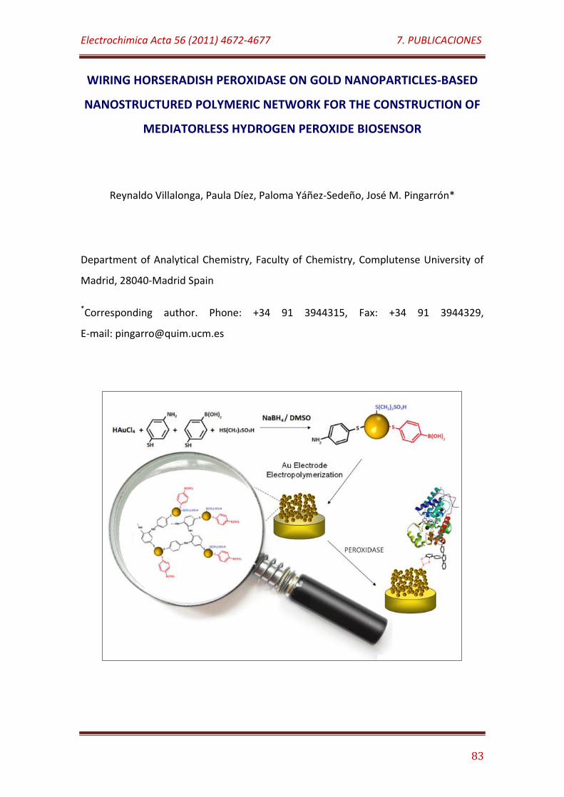
Electrochimica Acta 56 (2011) 4672-4677 7. PUBLICACIONES
83
WIRING HORSERADISH PEROXIDASE ON GOLD NANOPARTICLES-BASED
NANOSTRUCTURED POLYMERIC NETWORK FOR THE CONSTRUCTION OF
MEDIATORLESS HYDROGEN PEROXIDE BIOSENSOR
Reynaldo Villalonga, Paula Díez, Paloma Yáñez-Sedeño, José M. Pingarrón*
Department of Analytical Chemistry, Faculty of Chemistry, Complutense University of
Madrid, 28040-Madrid Spain
*Corresponding author. Phone: +34 91 3944315, Fax: +34 91 3944329,
E-mail: [email protected]
Electrochimica Acta 56 (2011) 4672-4677 7. PUBLICACIONES
84
ABSTRACT
Gold electrodes were functionalized with an electropolymerized matrix of Au
nanoparticles modified with 2-mercaptoethanesulfonic acid, 3-mercaptophenyl
boronic acid and p-aminothiophenol. The resulting nanostructured electroconductive
matrix was used as support for the oriented immobilization of horseradish peroxidase
to construct a reagentless amperometric biosensor for H2O2. The electrode, poised at
0.0 mV, exhibited a rapid response within 8 s and a linear calibration range from 5 µM
to 1.1 mM H2O2. The sensitivity of the biosensor was determined as 498 µA/M cm2,
and its detection limit was 1.5 µM H2O2 at a signal-to-noise ratio of 3. The electrode
retained 95% and 72% of its initial activity after 21 and 40 days of storage at 4ºC.
KEYWORDS: Biosensor, gold nanoparticles, peroxidase, wired enzyme, nanostructured
surface.
INTRODUCTION
Noble metal nanoparticles have been extensively employed in the design and
construction of amperometric enzyme biosensors [Kwon et al., 2010; Pingarrón et al.,
2008; Ren et al., 2005] due to their unique characteristics such as high surface energy
and surface-to-volume ratio, ability to decrease proteins-metal particles distance, and
the possibility to act as electroconductive wires between the enzyme and the
electrodes [Pingarrón et al., 2008]. These properties allow the direct electron transfer
between the electrode surfaces and the catalytic site of enzymes through a tunnelling
mechanism [Bharathi et al., 2001].
Several approaches have been used for coupling noble metal nanoparticles on
enzyme electrodes including electrodeposition [Wu et al., 2005; Lim et al., 2005],
covalent attachment [Yang et al., 2006], supramolecular association [Holzinger et al.,
2009] or electrostatic adsorption [Manso et al., 2008; Yang et al., 2006] to the
modified electrode surface, as well as physical inclusion into the electrode matrix
Electrochimica Acta 56 (2011) 4672-4677 7. PUBLICACIONES
85
[Carralero et al., 2006]. In addition, metal nanoparticles-modified enzymes have been
successfully employed in the construction of amperometric biosensors [Chico et al.,
2009].
Recently, it has been reported the synthesis of novel aniline and boronic acid-
modified gold nanoparticles (AuNPs) [Riskin et al., 2010]. These nanoparticles were
electropolymerized to form suitable AuNPs-based molecularly imprinted electrodes for
the successful construction of SPR sensors towards low molecular weight compounds
having 1,2-vicinal diols into their structure [Riskin et al., 2010; Frasconi et al., 2010].
Such kind of nanostructured electroconductive material opens a promising field in
electroanalytical chemistry. However, their use in the design of enzyme
electrochemical biosensors has not been reported yet.
In the present work we describe a novel approach for preparing reagentless
biosensors by using polymerized AuNPs (polyAuNPs) as wiring material for redox
enzymes. In this sense, AuNPs modified with 2-mercaptoethanesulfonic acid, 3-
mercaptophenyl boronic acid and p-aminothiophenol were synthesized and further
electropolymerized in acid media on a gold electrode surface through the formation of
bisaniline-cross-linked network. The presence of pendant boronic acid residues in this
electroconductive matrix allows the oriented and reversible immobilization of
glycoproteins by the formation of cyclic esters between the sugar residues and the
boronic acid groups [Qi et al., 2010].
As a model glycoenzyme, we selected horseradish peroxidase (HRP, EC 1.11.1.7,
H2O2 oxidoreductase), a redox enzyme having an accessible ferroprotoporphyrin group
at the active site [Veitch, 2004]. This structural characteristic allows its wiring to
properly modified electrode surfaces and, consequently, HRP constitutes the enzyme
most commonly used in the construction of third-generation biosensor [Shan et al.,
2010; Xi et al., 2009; Yin et al., 2009].
Electrochimica Acta 56 (2011) 4672-4677 7. PUBLICACIONES
86
MATERIALS AND METHODS
1. Reagents and apparatus
Horseradish peroxidase (HRP, Type II, 105 U/mg), HAuCl4, NaBH4, 2-
mercaptoethanesulfonic acid, 3-mercaptophenyl boronic acid and p-aminothiophenol
were purchased from Sigma (USA). All other chemicals were of analytical grade.
Cyclic voltammetry and electrochemical impedance spectroscopy experiments
were performed using a FRA2 µAutolab Type III potentiostat/galvanostat and the data
were acquired using GPES Ver. 4.9 and Frequency Response Analyser softwares,
respectively (Metrohm Autolab B.V., The Netherlands). Amperometric measurements
were performed with a dual-channel ultrasensitive Inbea potentiostat (Inbea
Biosensores S.L., Spain). A conventional three-electrode system was employed in all
electrochemical studies. The working electrode was a gold disk (CHI Instruments, UK,
2.0 mm diameter) modified with the electropolymerized AuNPs network and the
immobilized enzyme. An Ag/AgCl/KCl (3 M) and a Pt wire were used as reference and
counter electrodes, respectively. Bioelectrode measurements were carried out at 25ºC
in 0.1 M sodium phosphate buffer, pH 7.0 (working volume 10 ml). The solution was
exhaustively de-aerated before each electrochemical experiment. The solutions were
stirred at 300 rpm with a magnetic bar during amperometric measurements. For
analytical purposes, 10 mM H2O2 solutions in 50 mM sodium phosphate buffer, pH 7.0
were freshly prepared.
The microstructure and surface morphology of the electropolymerized
bisaniline-cross-linked AuNPs network was characterized using high resolution field
emission scanning electron microscopy (FE-SEM) with a JEOL JSM-6335F electron
microscope (JEOL Ltd., Japan). Transmission electron microscopy (TEM) measurements
were performed with a JEOL JEM-2000 FX microscope. The morphology
of gold nanostructured surface was investigated using atomic force microscopy (AFM)
with a SPM Nanoscope IIIa multimode microscope (Veeco Instruments Inc., USA).
Spectrophotometric determinations were performed using an Agilent 8453 UV/VIS
spectrophotometer (Hewlett Packard, USA).
Electrochimica Acta 56 (2011) 4672-4677 7. PUBLICACIONES
87
2. Synthesis of the functionalized AuNPs
To prepare the modified AuNPs, 197 mg of HAuCl4 were dissolved in 50 mL of
de-aerated dimethyl sulfoxide (DMSO). This solution was added dropwise to other 50
mL of de-aerated DMSO containing 300 mg sodium borohydride, 36 mg 2-
mercaptoethanesulfonic acid, 11 mg 3-mercaptophenyl boronic acid and 8 mg p-
aminothiophenol under vigorous stirring. The reaction mixture turned deep brown
immediately, but the reaction was allowed to continue for 24 h. The functionalized
AuNPs were then precipitated by adding 100 mL CH3CN, collected by centrifugation,
and washed with 60 mL CH3CN:DMSO (1:1 v/v), 60 mL ethanol and 20 mL diethyl ether.
The nanoparticles were finally isolated by centrifugation and dried under N2. The
nanoparticles were characterized by FT-IR and UV-vis spectroscopy as well as by TEM.
3. Preparation of the electropolymerized AuNPs-modified enzyme electrode
The disk gold electrode was first exhaustively polished with alumina powder
(0.3 µm), then rinsed with double distilled water and immersed in an ultrasonic bath
for 5 min. The electrode was further dipped in concentrated HNO3 for 1 h, followed by
rinsing in absolute EtOH and double distilled water. Finally, the electrode was
electrochemically cleaned by ten consecutive voltammetric cycles in 0.1 M H2SO4 and
further dry under N2.
To modify the electrode with the polyAuNPs network, its surface was initially
capped with a monolayer of p-aminothiophenol by dipping the electrode for 2 h in a 10
mM ethanolic solution of the thiol. The electrode was exhaustively washed with
ethanol and double distilled water, and dipped into a 2 mg/mL solution of the AuNPs in
0.1 M H2SO4. The electrode surface was then coated with the electropolymerized
bisaniline-cross-linked AuNPs network by application of 10 potential cycles between -
0.35 and +0.85 V vs Ag/AgCl at a scan rate of 100 mV/s, followed by application of a
constant potential of 0.85 for 1 h. The modified electrode was further exhaustively
washed with 0.1 M H2SO4 and double distilled water before enzyme immobilization.
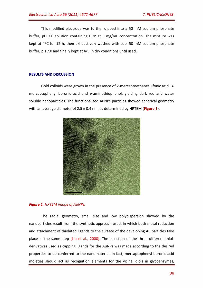
Electrochimica Acta 56 (2011) 4672-4677 7. PUBLICACIONES
88
This modified electrode was further dipped into a 50 mM sodium phosphate
buffer, pH 7.0 solution containing HRP at 5 mg/mL concentration. The mixture was
kept at 4ºC for 12 h, then exhaustively washed with cool 50 mM sodium phosphate
buffer, pH 7.0 and finally kept at 4ºC in dry conditions until used.
RESULTS AND DISCUSSION
Gold colloids were grown in the presence of 2-mercaptoethanesulfonic acid, 3-
mercaptophenyl boronic acid and p-aminothiophenol, yielding dark red and water
soluble nanoparticles. The functionalized AuNPs particles showed spherical geometry
with an average diameter of 2.5 ± 0.4 nm, as determined by HRTEM (Figure 1).
Figure 1. HRTEM image of AuNPs.
The radial geometry, small size and low polydispersion showed by the
nanoparticles result from the synthetic approach used, in which both metal reduction
and attachment of thiolated ligands to the surface of the developing Au particles take
place in the same step [Liu et al., 2000]. The selection of the three different thiol-
derivatives used as capping ligands for the AuNPs was made according to the desired
properties to be conferred to the nanomaterial. In fact, mercaptophenyl boronic acid
moieties should act as recognition elements for the vicinal diols in glycoenzymes,
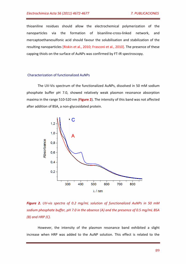
Electrochimica Acta 56 (2011) 4672-4677 7. PUBLICACIONES
89
thioaniline residues should allow the electrochemical polymerization of the
nanoparticles via the formation of bisaniline-cross-linked network, and
mercaptoethanesulfonic acid should favour the solubilisation and stabilization of the
resulting nanoparticles [Riskin et al., 2010; Frasconi et al., 2010]. The presence of these
capping thiols on the surface of AuNPs was confirmed by FT-IR spectroscopy.
Characterization of functionalized AuNPs
The UV-Vis spectrum of the functionalized AuNPs, dissolved in 50 mM sodium
phosphate buffer pH 7.0, showed relatively weak plasmon resonance absorption
maxima in the range 510-520 nm (Figure 2). The intensity of this band was not affected
after addition of BSA, a non-glycosidated protein.
Figure 2. UV-vis spectra of 0.2 mg/mL solution of functionalized AuNPs in 50 mM
sodium phosphate buffer, pH 7.0 in the absence (A) and the presence of 0.5 mg/mL BSA
(B) and HRP (C).
However, the intensity of the plasmon resonance band exhibited a slight
increase when HRP was added to the AuNP solution. This effect is related to the
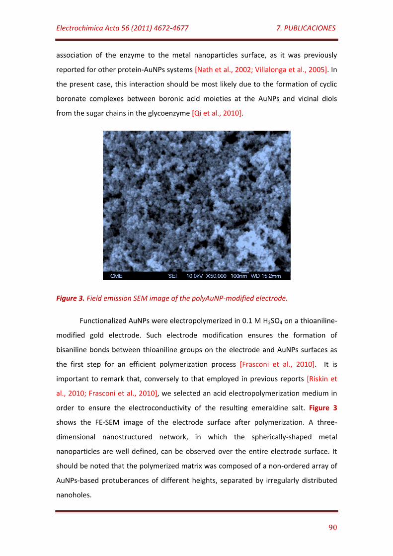
Electrochimica Acta 56 (2011) 4672-4677 7. PUBLICACIONES
90
association of the enzyme to the metal nanoparticles surface, as it was previously
reported for other protein-AuNPs systems [Nath et al., 2002; Villalonga et al., 2005]. In
the present case, this interaction should be most likely due to the formation of cyclic
boronate complexes between boronic acid moieties at the AuNPs and vicinal diols
from the sugar chains in the glycoenzyme [Qi et al., 2010].
Figure 3. Field emission SEM image of the polyAuNP-modified electrode.
Functionalized AuNPs were electropolymerized in 0.1 M H2SO4 on a thioaniline-
modified gold electrode. Such electrode modification ensures the formation of
bisaniline bonds between thioaniline groups on the electrode and AuNPs surfaces as
the first step for an efficient polymerization process [Frasconi et al., 2010]. It is
important to remark that, conversely to that employed in previous reports [Riskin et
al., 2010; Frasconi et al., 2010], we selected an acid electropolymerization medium in
order to ensure the electroconductivity of the resulting emeraldine salt. Figure 3
shows the FE-SEM image of the electrode surface after polymerization. A three-
dimensional nanostructured network, in which the spherically-shaped metal
nanoparticles are well defined, can be observed over the entire electrode surface. It
should be noted that the polymerized matrix was composed of a non-ordered array of
AuNPs-based protuberances of different heights, separated by irregularly distributed
nanoholes.
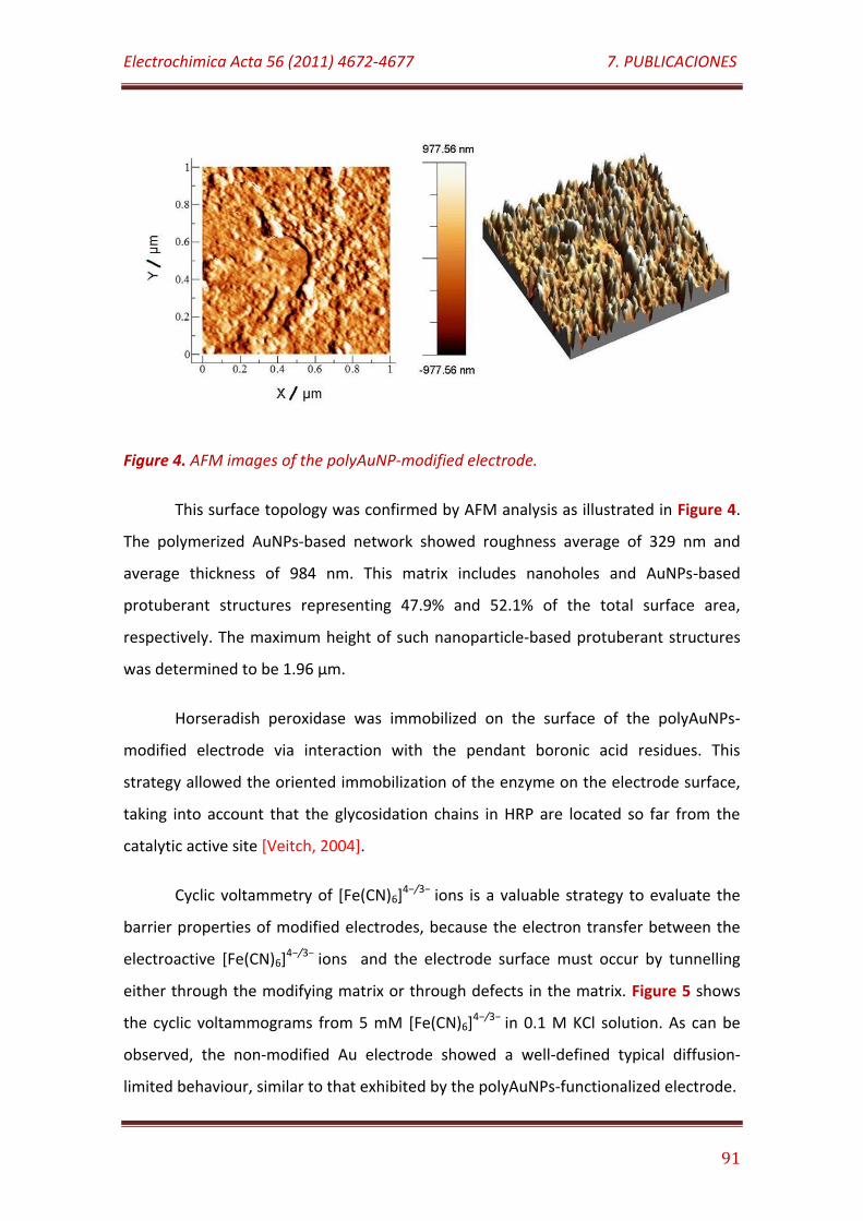
Electrochimica Acta 56 (2011) 4672-4677 7. PUBLICACIONES
91
Figure 4. AFM images of the polyAuNP-modified electrode.
This surface topology was confirmed by AFM analysis as illustrated in Figure 4.
The polymerized AuNPs-based network showed roughness average of 329 nm and
average thickness of 984 nm. This matrix includes nanoholes and AuNPs-based
protuberant structures representing 47.9% and 52.1% of the total surface area,
respectively. The maximum height of such nanoparticle-based protuberant structures
was determined to be 1.96 µm.
Horseradish peroxidase was immobilized on the surface of the polyAuNPs-
modified electrode via interaction with the pendant boronic acid residues. This
strategy allowed the oriented immobilization of the enzyme on the electrode surface,
taking into account that the glycosidation chains in HRP are located so far from the
catalytic active site [Veitch, 2004].
Cyclic voltammetry of [Fe(CN)6]4−/3− ions is a valuable strategy to evaluate the
barrier properties of modified electrodes, because the electron transfer between the
electroactive [Fe(CN)6]4−/3− ions and the electrode surface must occur by tunnelling
either through the modifying matrix or through defects in the matrix. Figure 5 shows
the cyclic voltammograms from 5 mM [Fe(CN)6]4−/3− in 0.1 M KCl solution. As can be
observed, the non-modified Au electrode showed a well-defined typical diffusion-
limited behaviour, similar to that exhibited by the polyAuNPs-functionalized electrode.
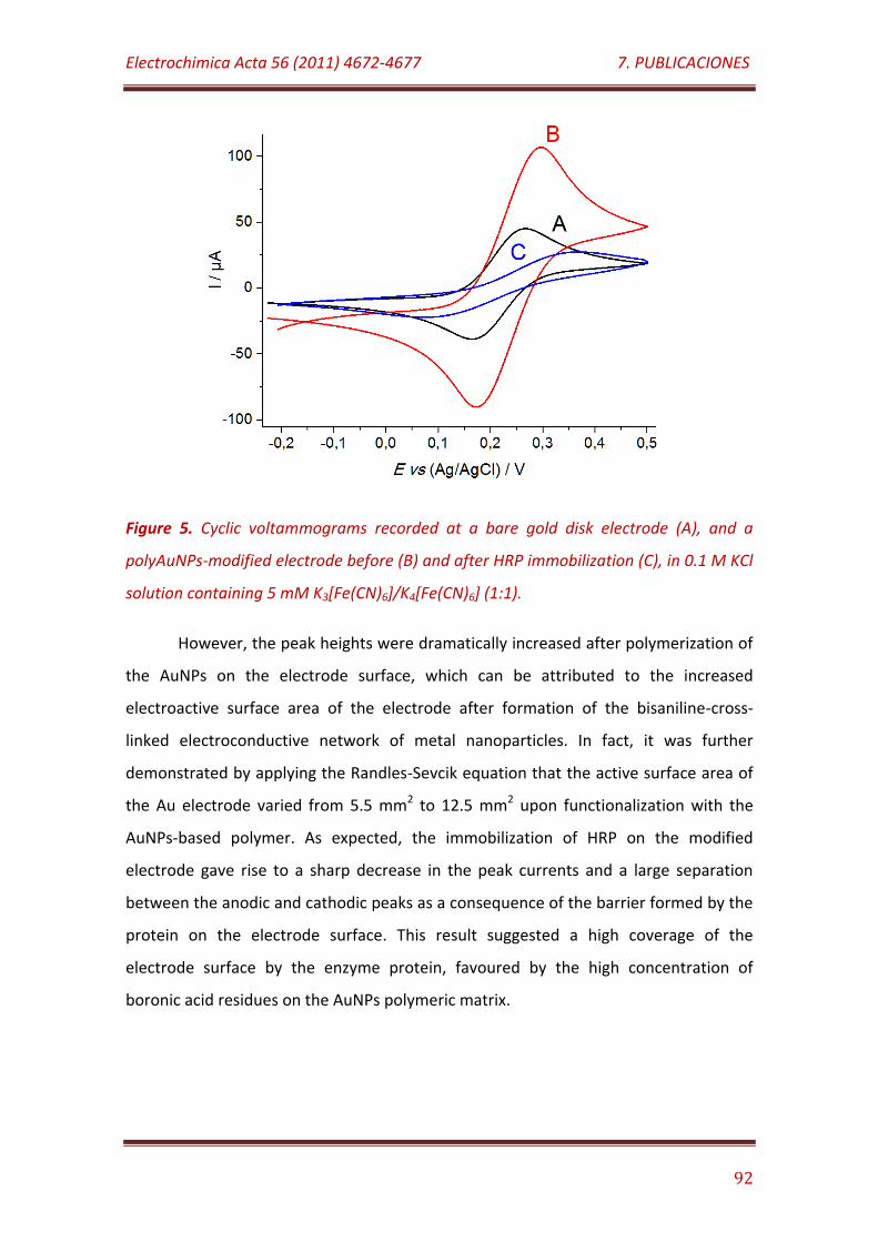
Electrochimica Acta 56 (2011) 4672-4677 7. PUBLICACIONES
92
Figure 5. Cyclic voltammograms recorded at a bare gold disk electrode (A), and a
polyAuNPs-modified electrode before (B) and after HRP immobilization (C), in 0.1 M KCl
solution containing 5 mM K3[Fe(CN)6]/K4[Fe(CN)6] (1:1).
However, the peak heights were dramatically increased after polymerization of
the AuNPs on the electrode surface, which can be attributed to the increased
electroactive surface area of the electrode after formation of the bisaniline-cross-
linked electroconductive network of metal nanoparticles. In fact, it was further
demonstrated by applying the Randles-Sevcik equation that the active surface area of
the Au electrode varied from 5.5 mm2 to 12.5 mm2 upon functionalization with the
AuNPs-based polymer. As expected, the immobilization of HRP on the modified
electrode gave rise to a sharp decrease in the peak currents and a large separation
between the anodic and cathodic peaks as a consequence of the barrier formed by the
protein on the electrode surface. This result suggested a high coverage of the
electrode surface by the enzyme protein, favoured by the high concentration of
boronic acid residues on the AuNPs polymeric matrix.
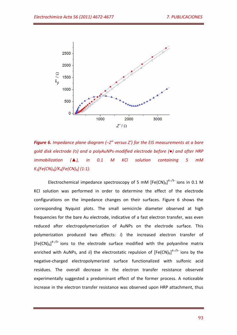
Electrochimica Acta 56 (2011) 4672-4677 7. PUBLICACIONES
93
Figure 6. Impedance plane diagram (−Z″ versus Z′) for the EIS measurements at a bare
gold disk electrode () and a polyAuNPs-modified electrode before () and after HRP
immobilization (), in 0.1 M KCl solution containing 5 mM
K3[Fe(CN)6]/K4[Fe(CN)6] (1:1).
Electrochemical impedance spectroscopy of 5 mM [Fe(CN)6]4−/3− ions in 0.1 M
KCl solution was performed in order to determine the effect of the electrode
configurations on the impedance changes on their surfaces. Figure 6 shows the
corresponding Nyquist plots. The small semicircle diameter observed at high
frequencies for the bare Au electrode, indicative of a fast electron transfer, was even
reduced after electropolymerization of AuNPs on the electrode surface. This
polymerization produced two effects: i) the increased electron transfer of
[Fe(CN)6]4−/3− ions to the electrode surface modified with the polyaniline matrix
enriched with AuNPs, and ii) the electrostatic repulsion of [Fe(CN)6]4−/3− ions by the
negative-charged electropolymerized surface functionalized with sulfonic acid
residues. The overall decrease in the electron transfer resistance observed
experimentally suggested a predominant effect of the former process. A noticeable
increase in the electron transfer resistance was observed upon HRP attachment, thus
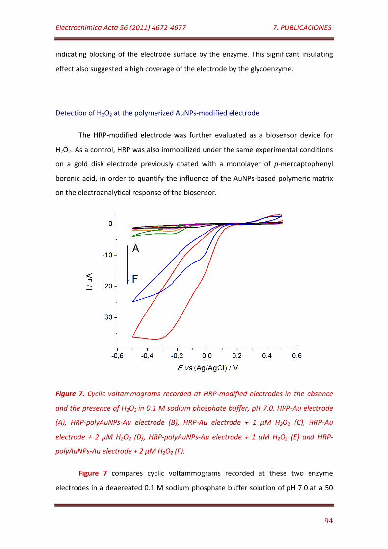
Electrochimica Acta 56 (2011) 4672-4677 7. PUBLICACIONES
94
indicating blocking of the electrode surface by the enzyme. This significant insulating
effect also suggested a high coverage of the electrode by the glycoenzyme.
Detection of H2O2 at the polymerized AuNPs-modified electrode
The HRP-modified electrode was further evaluated as a biosensor device for
H2O2. As a control, HRP was also immobilized under the same experimental conditions
on a gold disk electrode previously coated with a monolayer of p-mercaptophenyl
boronic acid, in order to quantify the influence of the AuNPs-based polymeric matrix
on the electroanalytical response of the biosensor.
Figure 7. Cyclic voltammograms recorded at HRP-modified electrodes in the absence
and the presence of H2O2 in 0.1 M sodium phosphate buffer, pH 7.0. HRP-Au electrode
(A), HRP-polyAuNPs-Au electrode (B), HRP-Au electrode + 1 µM H2O2 (C), HRP-Au
electrode + 2 µM H2O2 (D), HRP-polyAuNPs-Au electrode + 1 µM H2O2 (E) and HRP-
polyAuNPs-Au electrode + 2 µM H2O2 (F).
Figure 7 compares cyclic voltammograms recorded at these two enzyme
electrodes in a deaereated 0.1 M sodium phosphate buffer solution of pH 7.0 at a 50
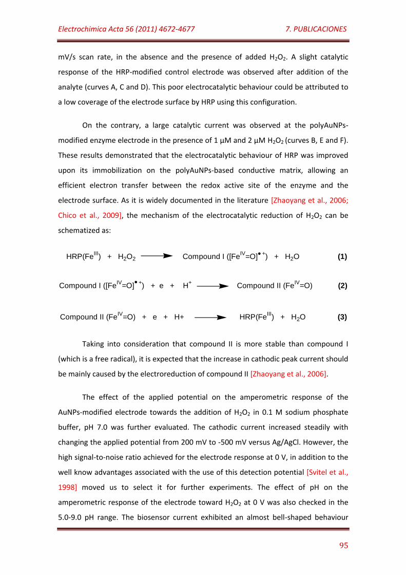
Electrochimica Acta 56 (2011) 4672-4677 7. PUBLICACIONES
95
mV/s scan rate, in the absence and the presence of added H2O2. A slight catalytic
response of the HRP-modified control electrode was observed after addition of the
analyte (curves A, C and D). This poor electrocatalytic behaviour could be attributed to
a low coverage of the electrode surface by HRP using this configuration.
On the contrary, a large catalytic current was observed at the polyAuNPs-
modified enzyme electrode in the presence of 1 µM and 2 µM H2O2 (curves B, E and F).
These results demonstrated that the electrocatalytic behaviour of HRP was improved
upon its immobilization on the polyAuNPs-based conductive matrix, allowing an
efficient electron transfer between the redox active site of the enzyme and the
electrode surface. As it is widely documented in the literature [Zhaoyang et al., 2006;
Chico et al., 2009], the mechanism of the electrocatalytic reduction of H2O2 can be
schematized as:
HRP(FeIII
) + H2O2 Compound I ([FeIV
=O] +) + H2O (1)
Compound I ([FeIV
=O] +) + e + H
+ Compound II (Fe
IV=O) (2)
Compound II (FeIV
=O) + e + H+ HRP(FeIII
) + H2O (3)
Taking into consideration that compound II is more stable than compound I
(which is a free radical), it is expected that the increase in cathodic peak current should
be mainly caused by the electroreduction of compound II [Zhaoyang et al., 2006].
The effect of the applied potential on the amperometric response of the
AuNPs-modified electrode towards the addition of H2O2 in 0.1 M sodium phosphate
buffer, pH 7.0 was further evaluated. The cathodic current increased steadily with
changing the applied potential from 200 mV to -500 mV versus Ag/AgCl. However, the
high signal-to-noise ratio achieved for the electrode response at 0 V, in addition to the
well know advantages associated with the use of this detection potential [Svitel et al.,
1998] moved us to select it for further experiments. The effect of pH on the
amperometric response of the electrode toward H2O2 at 0 V was also checked in the
5.0-9.0 pH range. The biosensor current exhibited an almost bell-shaped behaviour
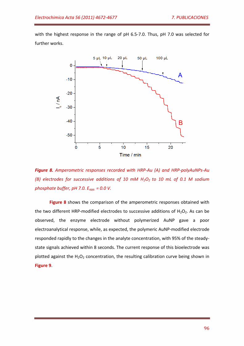
Electrochimica Acta 56 (2011) 4672-4677 7. PUBLICACIONES
96
with the highest response in the range of pH 6.5-7.0. Thus, pH 7.0 was selected for
further works.
Figure 8. Amperometric responses recorded with HRP-Au (A) and HRP-polyAuNPs-Au
(B) electrodes for successive additions of 10 mM H2O2 to 10 mL of 0.1 M sodium
phosphate buffer, pH 7.0. Eapp. = 0.0 V.
Figure 8 shows the comparison of the amperometric responses obtained with
the two different HRP-modified electrodes to successive additions of H2O2. As can be
observed, the enzyme electrode without polymerized AuNP gave a poor
electroanalytical response, while, as expected, the polymeric AuNP-modified electrode
responded rapidly to the changes in the analyte concentration, with 95% of the steady-
state signals achieved within 8 seconds. The current response of this bioelectrode was
plotted against the H2O2 concentration, the resulting calibration curve being shown in
Figure 9.
Electrochimica Acta 56 (2011) 4672-4677 7. PUBLICACIONES
97
Figure 9. Calibration curve for H2O2 obtained with a HRP-polyAuNPs-Au biosensor in
the 5 µM to 1.1 mM H2O2 concentration range.
The amperometric response exhibited a linear range between 5 µM and 1.1
mM H2O2, with an equation:
y = 62.3 x + 0.001
Where y is the amperometric current in µA and x is the molar concentration of
hydrogen peroxide, and a correlation coefficient of 0.996 (n = 12). The sensitivity of the
biosensor towards H2O2 was determined as 498 µA/M cm2. A detection limit of 1.5 µM
(S/N = 3) was calculated. Furthermore, an apparent Michaelis-Menten constant, KMapp ,
and a maximum rate of the enzyme reaction, Vmax, values of 1.01 mM and 89.3 nA,
respectively, were obtained. Table 1 shows the comparison of the analytical
characteristics of the developed biosensor with those reported recently for other HRP
mediatorless biosensors based on the use of AuNPs. As it can be seen, the detection
limit and the apparent Michaelis-Menten constant are among the lowest values
reported despite the much less extreme detection potential applied. These values
suggested that the immobilized HRP retained high catalytic activity and high affinity to
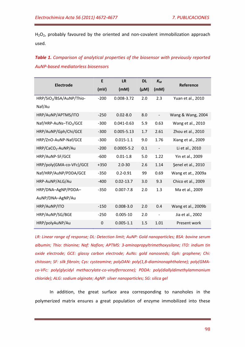
Electrochimica Acta 56 (2011) 4672-4677 7. PUBLICACIONES
98
H2O2, probably favoured by the oriented and non-covalent immobilization approach
used.
Table 1. Comparison of analytical properties of the biosensor with previously reported
AuNP-based mediatorless biosensors
Electrode E
(mV)
LR
(mM)
DL
(µM)
KM
(mM) Reference
HRP/SiO2/BSA/AuNP/Thio-
Naf/Au
-200 0.008-3.72 2.0 2.3 Yuan et al., 2010
HRP/AuNP/APTMS/ITO -250 0.02-8.0 8.0 - Wang & Wang, 2004
Naf/HRP-AuNs–TiO2/GCE -300 0.041-0.63 5.9 0.63 Wang et al., 2010
HRP/AuNP/Gph/Chi/GCE -300 0.005-5.13 1.7 2.61 Zhou et al., 2010
HRP/ZnO-AuNP-Naf/GCE -300 0.015-1.1 9.0 1.76 Xiang et al., 2009
HRP/CaCO3-AuNP/Au -200 0.0005-5.2 0.1 - Li et al., 2010
HRP/AuNP-SF/GCE -600 0.01-1.8 5.0 1.22 Yin et al., 2009
HRP/poly(GMA-co-VFc)/GCE +350 2.0-30 2.6 1.14 Şenel et al., 2010
Naf/HRP/AuNP/PDDA/GCE -350 0.2-0.91 99 0.69 Wang et at., 2009a
HRP-AuNP/ALG/Au -400 0.02-13.7 3.0 9.3 Chico et al., 2009
HRP/DNA–AgNP/PDDA–
AuNP/DNA–AgNP/Au
-350 0.007-7.8 2.0 1.3 Ma et al., 2009
HRP/AuNP/ITO -150 0.008-3.0 2.0 0.4 Wang et al., 2009b
HRP/AuNP/SG/BGE -250 0.005-10 2.0 - Jia et al., 2002
HRP/polyAuNP/Au 0 0.005-1.1 1.5 1.01 Present work
LR: Linear range of response; DL: Detection limit; AuNP: Gold nanoparticles; BSA: bovine serum
albumin; Thio: thionine; Naf: Nafion; APTMS: 3-aminopropyltrimethoxysilane; ITO: indium tin
oxide electrode; GCE: glassy carbon electrode; AuNs: gold nanoseeds; Gph: graphene; Chi:
chitosan; SF: silk fibroin; Cys: cysteamine; polyDAN: poly(1,8-diaminonaphthalene); poly(GMA-
co-VFc: poly(glycidyl methacrylate-co-vinylferrocene); PDDA: poly(diallyldimethylammonium
chloride); ALG: sodium alginate; AgNP: silver nanoparticles; SG: silica gel
In addition, the great surface area corresponding to nanoholes in the
polymerized matrix ensures a great population of enzyme immobilized into these
Electrochimica Acta 56 (2011) 4672-4677 7. PUBLICACIONES
99
nanocavities, and it is expected that such nanostructures protect the hydrophilic
microenvironment around the immobilized HRP.
On the other hand, the amperometric response was shown to be highly
repeatable toward successive additions of H2O2. A relative standard deviation, RSD,
value of 3.6% was calculated for ten successive calibration curves for H2O2.
Additionally, the electrode-to-electrode reproducibility was evaluated from the
response of 12 equivalently prepared biosensors yielding a RSD value of 7.8%.
The selectivity of the sensor was evaluated by measuring the amperometric
response towards 20 µM H2O2 in the presence of seven possible interfering substances
at a 100 µM concentration level: L-glucose, ethanol, acetic acid, ascorbic acid, lactic
acid, citric acid and uric acid. The biosensor exhibited an excellent selectivity towards
H2O2 since no significant changes in the steady-state current measured for the analyte
occurred under the above mentioned conditions. It should be highlighted that only in
the presence of an ascorbic acid concentration as high as 250 µM, the amperometric
response was reduced to 92% of its initial value. This excellent behaviour could be
justified by the high concentration of sulfonic acid residues at the surface of the
AuNPs-based polymeric matrix, which constitutes a protective electrostatic barrier to
the diffusion of the main interference substances to the electrode surface.
Figure 10 shows the effect of time of storage at 4ºC under dry conditions on
the slope value of the calibration plot for H2O2. As it can be observed, the biosensor
using the AuNPs-based polymeric matrix exhibited an excellent long-term stability,
retaining 95% and 72% of its initial activity after 21 and 40 days of storage,
respectively. This high stability behaviour can be attributed to the strong multipoint
attachment of the glycoenzyme on the boronic acid-functionalized conductive
polymer, thus avoiding denaturation and leaking of the active protein molecule from
the electrode surface during storage and testing.
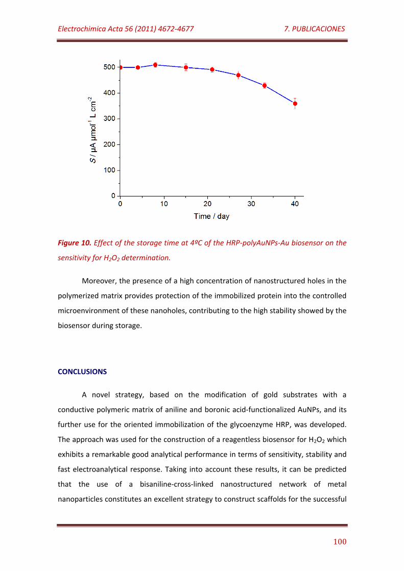
Electrochimica Acta 56 (2011) 4672-4677 7. PUBLICACIONES
100
Figure 10. Effect of the storage time at 4ºC of the HRP-polyAuNPs-Au biosensor on the
sensitivity for H2O2 determination.
Moreover, the presence of a high concentration of nanostructured holes in the
polymerized matrix provides protection of the immobilized protein into the controlled
microenvironment of these nanoholes, contributing to the high stability showed by the
biosensor during storage.
CONCLUSIONS
A novel strategy, based on the modification of gold substrates with a
conductive polymeric matrix of aniline and boronic acid-functionalized AuNPs, and its
further use for the oriented immobilization of the glycoenzyme HRP, was developed.
The approach was used for the construction of a reagentless biosensor for H2O2 which
exhibits a remarkable good analytical performance in terms of sensitivity, stability and
fast electroanalytical response. Taking into account these results, it can be predicted
that the use of a bisaniline-cross-linked nanostructured network of metal
nanoparticles constitutes an excellent strategy to construct scaffolds for the successful

Electrochimica Acta 56 (2011) 4672-4677 7. PUBLICACIONES
101
immobilization of redox enzymes in order to prepare mediatorless amperometric
biosensors.
ACKNOWLEDGEMENTS
R. Villalonga acknowledge to Ramón & Cajal contract from the Spanish Ministry
of Science and Innovation. Financial support from the Spanish Ministerio de Ciencia e
Innovación CTQ2009-12650, CTQ2009-09351) and Comunidad de Madrid S2009/PPQ-
1642, programme AVANSENS is gratefully acknowledged.
REFERENCES
Bharathi, S., Nogami, M., Ikeda, S. (2001) Novel electrochemical interfaces with
a tunable kinetic barrier by self-assembling organically modified silica gel and gold
nanoparticles. Langmuir 17: 1-4.
Carralero, V., Mena, M.L., González-Cortés, A., Yáñez-Sedeño, P., Pingarrón,
J.M. (2006) Development of a high analytical performance-tyrosinase biosensor based
on a composite graphite-Teflon electrode modified with gold nanoparticles. Biosens.
Bioelectron. 22: 730-736.
Chen, H.J., Dong, S.J. (2007) Direct electrochemistry and electrocatalysis of
horseradish peroxidase immobilized in sol-gel-derived ceramic-carbon nanotube
nanocomposite film. Biosens. Bioelectron. 22: 1811-1815.
Chico, B., Camacho, C., Pérez, M., Longo, M.A., Sanromán, M.A., Pingarrón,
J.M., Villalonga, R. (2009) Polyelectrostatic immobilization of gold nanoparticles-
modified peroxidase on alginate-coated gold electrode for mediatorless biosensor
construction. J. Electroanal. Chem. 629: 126-132.
Electrochimica Acta 56 (2011) 4672-4677 7. PUBLICACIONES
102
Frasconi, M., Tel-Vered, R., Riskin, M., Willner, I. (2010) Surface plasmon
resonance analysis of antibiotics using imprinted boronic acid-functionalized Au
nanoparticle composites. Anal. Chem. 82: 2512-2519.
Guo, C., Song, Y., Wei, H., Li, P., Wang, L., Sun, L., Sun, Y., Li, Z. (2007) Room
temperature ionic liquid doped DNA network immobilized horseradish peroxidase
biosensor for amperometric determination of hydrogen peroxide. Anal. Bioanal. Chem.
389: 527-532.
Holzinger, M., Bouffier, L., Villalonga, R., Cosnier, S. (2009) Adamantane/β-
cyclodextrin affinity biosensors based on single-walled carbon nanotubes. Biosens.
Bioelectron. 24: 1128-1134.
Jia, J., Wang, B., Wu, A., Cheng, G., Li, Z., Dong, S. (2002) A method to construct
a third-generation horseradish peroxidase biosensor: self-assembling gold
nanoparticles to three-dimensional sol-gel network. Anal. Chem. 74: 2217-2223.
Kang, X., Wang, J., Tang, Z., Wu, H., Lin, Y. (2009) Direct electrochemistry and
electrocatalysis of horseradish peroxidase immobilized in hybrid organic-inorganic film
of chitosan/sol–gel/carbon nanotubes. Talanta 78: 120-125.
Kwon, K.Y., Yang, S.B., Kong, B.S., Kim, J., Jung, H.T. (2010) High-performance
biosensors based on enzyme precipitate coating in gold nanoparticle-conjugated
single-walled carbon nanotube network films. Carbon 48: 4504-4509.
Li, F., Feng, Y., Wang, Z., Yang, L. M., Zhuo, L. H., Tang, B. (2010) Direct
electrochemistry of horseradish peroxidase immobilized on the layered calcium
carbonate-gold nanoparticles inorganic hybrid composite. Biosens. Bioelectron. 25:
2244-2248.
Lim, S.H., Wei, J., Lin, J., Li, Q., You, J.K. (2005) A glucose biosensor based on
electrodeposition of palladium nanoparticles and glucose oxidase onto Nafion-
solubilized carbon nanotube electrode. Biosens. Bioelectron. 20: 2341-2346.
Electrochimica Acta 56 (2011) 4672-4677 7. PUBLICACIONES
103
Liu, J., Ong, W., Román, E., Lynn, M.J., Kaifer, A.E. (2000) Cyclodextrin-modified
gold nanospheres. Langmuir 16: 3000-3002.
Liu, Y., Hu, L.M., Yang, S.Q. (2008) Amplification of bioelectrocatalytic signalling
based on silver nanoparticles and DNA-derived horseradish peroxidase biosensors.
Microchim. Acta 160: 357-365.
Ma, L., Yuan, R., Chai, Y., Chen, S. (2009) Amperometric hydrogen peroxide
biosensor based on the immobilization of HRP on DNA-silver nanohybrids and PDDA-
protected gold nanoparticles. J. Mol. Catal. B Enzymatic 56: 215-220.
Manso, J., Mena, M.L., Yáñez-Sedeño, P., Pingarrón, J.M. (2008) Bienzyme
amperometric biosensor using gold nanoparticle-modified electrodes for the
determination of inulin in foods. Anal. Biochem. 375: 345-353.
Nath, N., Chilkoti, A. (2002) A colorimetric gold nanoparticle sensor to
interrogate biomolecular interactions in real time on a surface. Anal. Chem. 74: 504-
509.
Pingarrón, J. M., Yáñez-Sedeño, P., González-Cortés, A. (2008)
Gold nanoparticle-based electrochemical biosensors. Electrochim. Acta 53 (2008)
5848-5866.
Qi, D., Zhang, H., Tang, J., Deng, C., Zhang, X. (2010) Facile synthesis of
mercaptophenylboronic acid-functionalized core-shell structure Fe3O4@C@Au
magnetic microspheres for selective enrichment of glycopeptides and glycoproteins. J.
Phys. Chem. C 114: 9221-9226.
Ren, X., Meng, X., Chen, D., Tang, F., Jiao, J. (2005) Using silver nanoparticle to
enhance current response of biosensor. Biosens. Bioelectron. 21: 433-437.
Riskin, M., Tel-Vered, R., Willner, I. (2010) Imprinted Au-nanoparticle
composites for the ultrasensitive surface plasmon resonance detection of hexahydro-
1,3,5-trinitro-1,3,5-triazine (RDX). Adv. Mater. 22: 1387-1391.
Electrochimica Acta 56 (2011) 4672-4677 7. PUBLICACIONES
104
Şenel, M., Çevik, E., Abasiyanik, M. F. (2010) Amperometric hydrogen
peroxide biosensor based on covalent immobilization of horseradish peroxidase
on ferrocene containing polymeric mediator. Sens. Actuators B Chem. 145: 444-450.
Shan, D., Li, Q.B., Ding, S.N., Xu, J.Q., Cosnier, S., Xue, H.G. (2010) Reagentless
biosensor for hydrogen peroxide based on self-assembled films of horseradish
peroxidase/laponite/chitosan and the primary investigation on the inhibitory effect by
sulphide. Biosens. Bioelectron. 26: 536-541.
Svitel, J., Stredansky, M., Pizzariello, A., Miertus, S. (1998) Composite biosensor
for sulfite assay: use of water-insoluble hexacyanoferrate(iii) salts as electron-transfer
mediators. Electroanalysis 10: 591-596.
Veitch, N.C. (2004) Horseradish peroxidase: a modern view of a classic enzyme.
Phytochemistry 65: 249-259.
Villalonga, R., Cao, R., Fragoso, A., Damiao, A.E., Ortiz, P.D.,Caballero, J. (2005)
Supramolecular assembly of β-cyclodextrin-modified gold nanoparticles and Cu,Zn-
superoxide dismutase on catalase. J. Mol. Catal. B Enzymatic 35: 79-85.
Wang, L., Wang, E. (2004) A novel hydrogen peroxide sensor based on
horseradish peroxidase immobilized on colloidal Au modified ITO electrode.
Electrochem. Comm. 6: 225-229.
Wang, Y., Ma, Y., Wen, Y., Duan, G., Ren, W., Zhang, Z., Yang, H. (2009a)
Electrochemistry and electrocatalytic properties of mixed assemblies of horseradish
peroxidase, poly(diallyl dimethylammonium chloride) and gold nanoparticles on a
glassy carbon electrode. Microchim. Acta 166: 283-288.
Wang, J., Wang, L., Di, J., Tu, Y. (2009b) Electrodeposition of gold nanoparticles
on indium/tin oxide electrode for fabrication of a disposable hydrogen peroxide
biosensor. Talanta 77: 1454-1459.

Electrochimica Acta 56 (2011) 4672-4677 7. PUBLICACIONES
105
Wang, Y., Ma, X. L., Wen, Y., Xing, Y. Y., Zhang, Z. R., Yang, H. F. (2010) Direct
electrochemistry and bioelectrocatalysis of horseradish peroxidase based on gold
nano-seeds dotted TiO2 nanocomposite. Biosens. Bioelectron. 25: 2441-2446.
Wu, Z., Chen, L., Shen, G., Yu, R. (2006) Platinum nanoparticle-modified carbon
fiber ultramicroelectrodes for mediator-free biosensing. Sens. Actuators B Chem. 119
(2006) 295-301.
Xi, F., Liu, L.; Chen, Z., Lin, X. (2009) One-step construction of reagentless
biosensor based on chitosan-carbon nanotubes-nile blue-horseradish peroxidase
biocomposite formed by electrodeposition. Talanta 78: 1077-1082.
Xiang, C., Zou, Y., Sun, L. X., Xu, F. (2009) Direct electrochemistry and enhanced
electrocatalysis of horseradish peroxidase based on flowerlike ZnO-gold nanoparticle-
Nafion nanocomposite. Sens. Actuators B Chem. 136: 158-162.
Yang M., Yang Y., Yang H., Shen G., Yu R. (2006) Layer-by-layer self-assembled
multilayer films of carbon nanotubes and platinum nanoparticles with polyelectrolyte
for the fabrication of biosensors. Biomaterials 27: 246-255.
Yang, W., Wang, J., Zhao, S., Sun, Y., Sun, C. (2006) Multilayered construction of
glucose oxidase and gold nanoparticles on Au electrodes based on layer-by-layer
covalent attachment. Electrochem. Comm. 8: 665-672.
Yin, H., Ai, S., Shi, W., Zhu, L. (2009) A novel hydrogen peroxide biosensor based
on horseradish peroxidase immobilized on goldnanoparticles-silk fibroin modified
glassy carbon electrode and direct electrochemistry of horseradish peroxidase. Sens.
Actuators B Chem. 137: 747-753.
Yuan, S. R., Yuan, R., Chai, Y. Q., Zhuo, Y., Yang, X., Yuan, Y. L. (2010) Enzyme
biosensor based on the immobilization of HRP on SiO2/BSA/Au composite
nanoparticles. Appl. Biochem. Biotechnol. 162: 2189-2196.

Electrochimica Acta 56 (2011) 4672-4677 7. PUBLICACIONES
106
Zhao, X.J., Mai, Z.B., Kang, X.H., Zou, X.Y. (2008) Direct electrochemistry and
electrocatalysis of horseradish peroxidase based on clay-chitosan-gold nanoparticle
nanocomposite. Biosens. Bioelectron. 23: 1032-1038.
Zhaoyang, W., Liguo, C., Guoli, S., Ruqin, Y. (2008) Platinum nanoparticle-
modified carbon fiber ultramicroelectrodes for mediator-free biosensing Sens.
Actuators B Chem. 119 (2006) 295-301.
Zhou, K. F., Zhu, Y. H., Yang, X. L., Luo, J., Li, C. Z., Luan, S. R. (2010) A
novel hydrogen peroxide biosensor based on Au-graphene-HRP-
chitosan biocomposites. Electrochim. Acta 55: 3055-3060.
7.2
Analyst 137, 2012, 342-348
Electropolymerized network of polyamidoamine dendron-coated
gold nanoparticles as novel nanostructured electrode surface
for biosensor construction

Analyst 137 (2012) 342-348 7. PUBLICACIONES
107
ELECTROPOLYMERIZED NETWORK OF POLYAMIDOAMINE DENDRON-
COATED GOLD NANOPARTICLES AS NOVEL NANOSTRUCTURED
ELECTRODE SURFACE FOR BIOSENSOR CONSTRUCTION
Reynaldo Villalonga,a Paula Díez,a Santiago Casado,b Marcos Eguílaz,a Paloma Yáñez-
Sedeño,a José M. Pingarrón*a
ABSTRACT
Polyfuntionalized gold nanoparticles were prepared by using 2-
mercaptoethanesulfonic acid, p-aminothiophenol and cysteamine core
polyamidoamine G-4 dendron as capping ligands. The nanoparticles were
electropolymerized on Au electrode surface through the formation of bisaniline-cross-
linked network. The enzyme tyrosinase was further crosslinked on this nanostructured
matrix. The enzyme electrode, poised at -100 mV, was used for the amperometric
quantification of catechol. The biosensor showed a linear response from 50 nM to 10
µM catechol, with a low detection limit of 20 nM and a sensitivity of 1.94 A/M cm2.
The electrode retained 96% and 67% of its initial activity after 16 and 30 days of
storage at 4ºC under dry conditions.
INTRODUCTION
Nowaday, the construction of new electrochemical biosensors with improved
bioanalytical performance and robustness is frequently directly linked to the
development of novel strategies for tailor-made design of electrode surfaces. Such
strategies should provide electrical interfaces with nano- or microsized tree-
dimensional topology that allow the successful and stable immobilisation of the
biomolecules without affecting their biological function, but also favouring the fast and
Analyst 137 (2012) 342-348 7. PUBLICACIONES
108
efficient occurrence of the electrochemical processes involved in the analytical
reaction on such interface.1
During last recent years, nanosized materials have been exhaustively employed
in the modification of electrodes for biosensing purposes.1,2 In general, the
development of methodologies for nanostructuring electrode surfaces with such
purpose should consider the following points: i) the type of surface to be modified, ii)
the nanomaterial to be used, iii) other compounds/materials that could be also
employed, iv) the physical/chemical method for surface modification, v) the
biomolecule to be immobilized and the method to do that, and vi) the electrochemical
reaction to take place on the functionalized electrode surface.
Strategies for nanostructuring electrode surfaces have been mainly based on
the use of “hard” nanomaterials, such as quantum dots,3 carbon nanotubes,1,4
graphene,5 carbon nanofibers,6 as well as metal7 and metal oxide nanoparticles.8 Such
approaches include the use of single nanomateriales, mixtures of them, or composites
with polymeric materials or low molecular weight compounds.1,2,4 Since the number of
nanomaterials with electroanalytical interest is finite, and the use of most of them in
biosensor technology is well documented, the state-of-the-art of nanostructuring
electrode surface is mainly addressed to the development of innovative
functionalization strategies in which other novel co-materials and modifying ligands
are considered.
Recently, it has been described the synthesis of polyfunctionalyzed gold
nanoparticles (AuNPs) carrying aniline and boronic acid moieties, which have been
employed for the modification of electrode surfaces with a nanostructured conductive
matrix through electropolymerization.9,10 The presence of boronic acid residues as
pedant ligands on such surfaces allowed their successful use for the construction of
glycoenzyme-based biosensors,10 as well as for surface plasmon resonance (SPR)
sensors towards molecules having 1,2-vicinal diols.9
The possibility of tailor-made design of novel AuNPs with desired and specific
properties by manipulation of the capping ligands, as well as the electroconductive
Analyst 137 (2012) 342-348 7. PUBLICACIONES
109
character of the resulting nanostructured three dimensional networks opens a
promising field in electroanalytical chemistry for this kind of materials. In this regards,
we are concerned to evaluate high molecular weight dendritic ligands as capping
material for the preparation of AuNPs-based polymeric matrix and its potential
application in biosensor technology. It should be highlighted that this strategy of
surface coverage with electropolymerized tailor-made nanoparticles could be also a
valuable tool for the preparation of functional materials for biomedicine,
biotechnology, microelectronics and other fields.
Dendrimers and dendrons are nanosized and monodisperse macromolecules
with a regular and highly branched three-dimensional architecture. These “soft”
nanomaterials have unique properties such as structural homogeneity, high surface
reactivity and molecular host capacity.11 Such properties, resulting from the size, the
hydrophilic/hydrophobic character of the internal cavities and the nature of the
chemical groups at the surface of these hyperbranched polymers, support their wide
application in several fields including the design of novel catalysts, chemical sensors,
drug and gene delivery systems, and biosensors.12,13
In this work we describe a novel approach for preparing dendron-coated
AuNPs-based nanostructured electrodes by synthesizing, firstly, polyfunctionalysed
nanoparticles with 2-mercaptoethanesulfonic acid, p-aminothiophenol and cysteamine
core polyamidoamine (PAMAM) G-4 dendron as capping ligands. These
polyfunctionalized AuNPs were further electropolymerized on a gold electrode surface
through the formation of bisaniline-cross-linked network, yielding a three dimensional
matrix on which the enzyme tyrosinase, as a model enzyme, was finally immobilised
through covalent crosslinking. The functionalised enzyme electrode was employed for
the construction of an amperometric biosensor device towards catechol as a model
target compound.
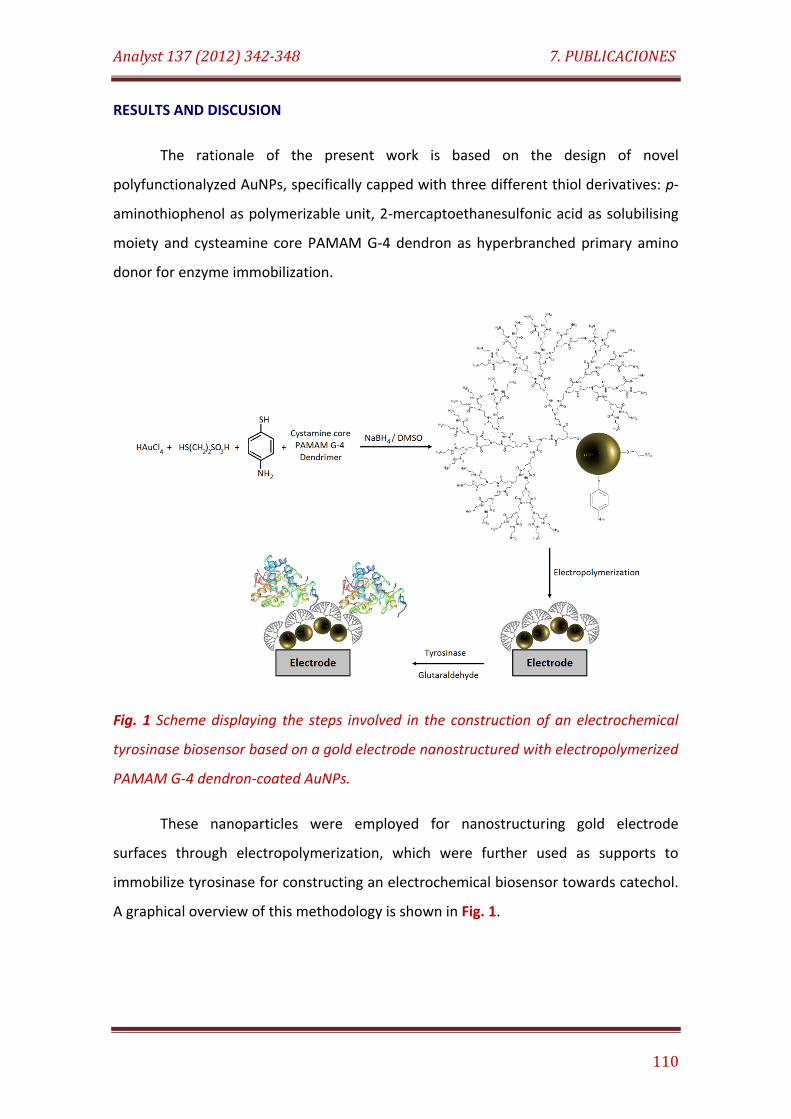
Analyst 137 (2012) 342-348 7. PUBLICACIONES
110
RESULTS AND DISCUSION
The rationale of the present work is based on the design of novel
polyfunctionalyzed AuNPs, specifically capped with three different thiol derivatives: p-
aminothiophenol as polymerizable unit, 2-mercaptoethanesulfonic acid as solubilising
moiety and cysteamine core PAMAM G-4 dendron as hyperbranched primary amino
donor for enzyme immobilization.
Fig. 1 Scheme displaying the steps involved in the construction of an electrochemical
tyrosinase biosensor based on a gold electrode nanostructured with electropolymerized
PAMAM G-4 dendron-coated AuNPs.
These nanoparticles were employed for nanostructuring gold electrode
surfaces through electropolymerization, which were further used as supports to
immobilize tyrosinase for constructing an electrochemical biosensor towards catechol.
A graphical overview of this methodology is shown in Fig. 1.
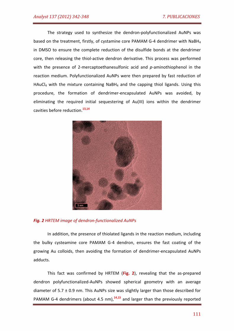
Analyst 137 (2012) 342-348 7. PUBLICACIONES
111
The strategy used to synthesize the dendron-polyfunctionalized AuNPs was
based on the treatment, firstly, of cystamine core PAMAM G-4 dendrimer with NaBH4
in DMSO to ensure the complete reduction of the disulfide bonds at the dendrimer
core, then releasing the thiol-active dendron derivative. This process was performed
with the presence of 2-mercaptoethanesulfonic acid and p-aminothiophenol in the
reaction medium. Polyfunctionalized AuNPs were then prepared by fast reduction of
HAuCl4 with the mixture containing NaBH4 and the capping thiol ligands. Using this
procedure, the formation of dendrimer-encapsulated AuNPs was avoided, by
eliminating the required initial sequestering of Au(III) ions within the dendrimer
cavities before reduction.13,14
Fig. 2 HRTEM image of dendron-functionalized AuNPs
In addition, the presence of thiolated ligands in the reaction medium, including
the bulky cysteamine core PAMAM G-4 dendron, ensures the fast coating of the
growing Au colloids, then avoiding the formation of dendrimer-encapsulated AuNPs
adducts.
This fact was confirmed by HRTEM (Fig. 2), revealing that the as-prepared
dendron polyfunctionalized-AuNPs showed spherical geometry with an average
diameter of 5.7 ± 0.9 nm. This AuNPs size was slightly larger than those described for
PAMAM G-4 dendrimers (about 4.5 nm),14,15 and larger than the previously reported
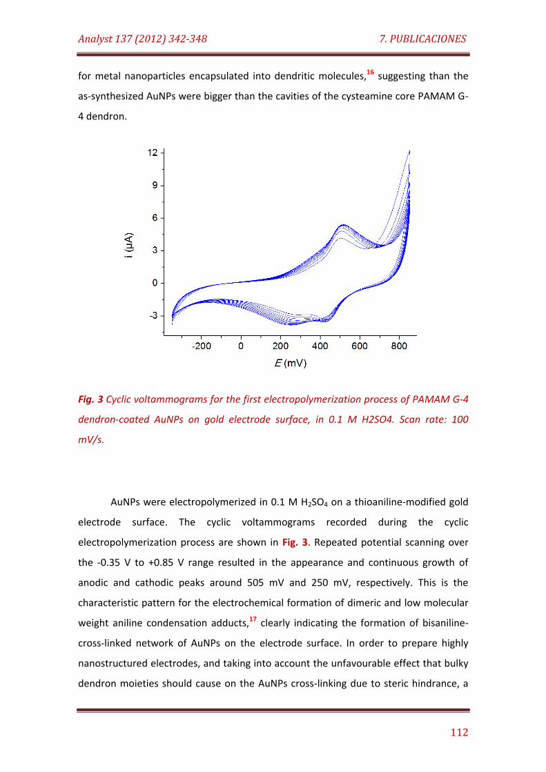
Analyst 137 (2012) 342-348 7. PUBLICACIONES
112
for metal nanoparticles encapsulated into dendritic molecules,16 suggesting than the
as-synthesized AuNPs were bigger than the cavities of the cysteamine core PAMAM G-
4 dendron.
Fig. 3 Cyclic voltammograms for the first electropolymerization process of PAMAM G-4
dendron-coated AuNPs on gold electrode surface, in 0.1 M H2SO4. Scan rate: 100
mV/s.
AuNPs were electropolymerized in 0.1 M H2SO4 on a thioaniline-modified gold
electrode surface. The cyclic voltammograms recorded during the cyclic
electropolymerization process are shown in Fig. 3. Repeated potential scanning over
the -0.35 V to +0.85 V range resulted in the appearance and continuous growth of
anodic and cathodic peaks around 505 mV and 250 mV, respectively. This is the
characteristic pattern for the electrochemical formation of dimeric and low molecular
weight aniline condensation adducts,17 clearly indicating the formation of bisaniline-
cross-linked network of AuNPs on the electrode surface. In order to prepare highly
nanostructured electrodes, and taking into account the unfavourable effect that bulky
dendron moieties should cause on the AuNPs cross-linking due to steric hindrance, a
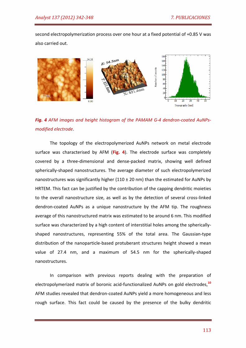
Analyst 137 (2012) 342-348 7. PUBLICACIONES
113
second electropolymerization process over one hour at a fixed potential of +0.85 V was
also carried out.
Fig. 4 AFM images and height histogram of the PAMAM G-4 dendron-coated AuNPs-
modified electrode.
The topology of the electropolymerized AuNPs network on metal electrode
surface was characterised by AFM (Fig. 4). The electrode surface was completely
covered by a three-dimensional and dense-packed matrix, showing well defined
spherically-shaped nanostructures. The average diameter of such electropolymerized
nanostructures was significantly higher (110 ± 20 nm) than the estimated for AuNPs by
HRTEM. This fact can be justified by the contribution of the capping dendritic moieties
to the overall nanostructure size, as well as by the detection of several cross-linked
dendron-coated AuNPs as a unique nanostructure by the AFM tip. The roughness
average of this nanostructured matrix was estimated to be around 6 nm. This modified
surface was characterized by a high content of interstitial holes among the spherically-
shaped nanostructures, representing 55% of the total area. The Gaussian-type
distribution of the nanoparticle-based protuberant structures height showed a mean
value of 27.4 nm, and a maximum of 54.5 nm for the spherically-shaped
nanostructures.
In comparison with previous reports dealing with the preparation of
electropolymerized matrix of boronic acid-functionalized AuNPs on gold electrodes,10
AFM studies revealed that dendron-coated AuNPs yield a more homogeneous and less
rough surface. This fact could be caused by the presence of the bulky dendritic
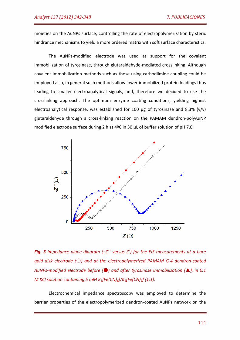
Analyst 137 (2012) 342-348 7. PUBLICACIONES
114
moieties on the AuNPs surface, controlling the rate of electropolymerization by steric
hindrance mechanisms to yield a more ordered matrix with soft surface characteristics.
The AuNPs-modified electrode was used as support for the covalent
immobilization of tyrosinase, through glutaraldehyde-mediated crosslinking. Although
covalent immobilization methods such as those using carbodiimide coupling could be
employed also, in general such methods allow lower immobilized protein loadings thus
leading to smaller electroanalytical signals, and, therefore we decided to use the
crosslinking approach. The optimum enzyme coating conditions, yielding highest
electroanalytical response, was established for 100 µg of tyrosinase and 8.3% (v/v)
glutaraldehyde through a cross-linking reaction on the PAMAM dendron-polyAuNP
modified electrode surface during 2 h at 4ºC in 30 µL of buffer solution of pH 7.0.
Fig. 5 Impedance plane diagram (−Z´´ versus Z´) for the EIS measurements at a bare
gold disk electrode () and at the electropolymerized PAMAM G-4 dendron-coated
AuNPs-modified electrode before () and after tyrosinase immobilization (), in 0.1
M KCl solution containing 5 mM K3[Fe(CN)6]/K4[Fe(CN)6] (1:1).
Electrochemical impedance spectroscopy was employed to determine the
barrier properties of the electropolymerized dendron-coated AuNPs network on the
Analyst 137 (2012) 342-348 7. PUBLICACIONES
115
electrode surface, before and after enzyme immobilization. Fig. 5 shows the Nyquist
plots for the electrodes in a 0.1 M KCl solution containing 5 mM [Fe(CN)6]4−/3− ions. In
order to interpret the experimental results, the Randles equivalent circuit was
assumed as a model, taking into account the shape of the resulting Nyquist plots.
As can be observed, the Nyquist plot of bare gold electrode was characterized
by a small semicircle at high frequencies and a predominant line with slope close to
the unit over the broad range of low frequencies. These facts indicated a predominant
diffusion-controlled mechanism for the redox reaction over a broad range of low
frequencies, as well as the occurrence of fast electron transfer for the [Fe(CN)6]4−/3−
ions pair on the electrode surface at high values of frequencies. Similar behaviour was
observed for the electrode after electropolymerization of PAMAM dendron-coated
AuNPs on its surface, but the Nyquist plots revealed that the electron transfer
resistance was reduced from 205 Ω to 52 Ω after this modification. This fact can be
justified by the synergic contribution of several factors, including: i) the demonstrated
ability of [Fe(CN)6]4−/3− ions to easily penetrate the surface-confined dendrimers as well
as the interstices between them,15 ii) the electrostatic attraction of [Fe(CN)6]4−/3− ions
to the positive charged electrode surface due to multiple amino terminal groups in
dendron residues, and iii) the increased electron transfer of [Fe(CN)6]4−/3− ions to the
electrode surface modified with the polyaniline matrix enriched with AuNPs. On the
other hand, a noticeable increase in the electron transfer resistance (760 Ω) was
observed upon tyrosinase attachment, thus indicating high coverage of the electrode
surface by the enzyme molecules.
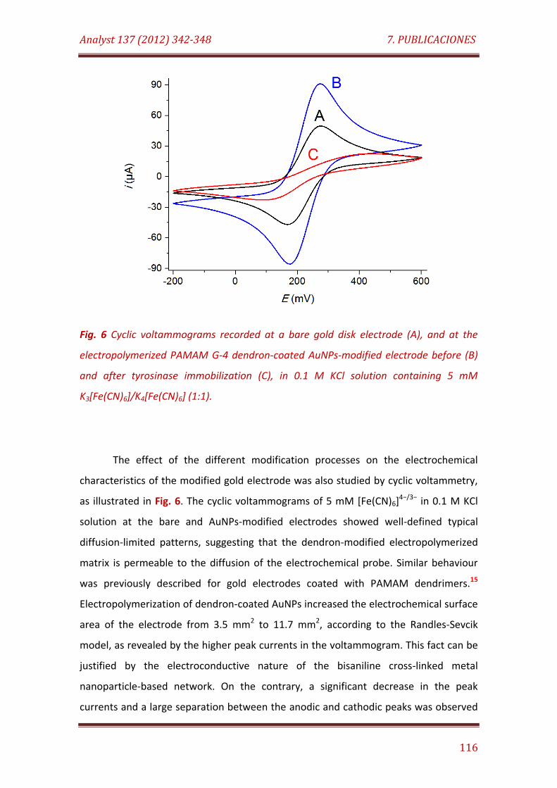
Analyst 137 (2012) 342-348 7. PUBLICACIONES
116
Fig. 6 Cyclic voltammograms recorded at a bare gold disk electrode (A), and at the
electropolymerized PAMAM G-4 dendron-coated AuNPs-modified electrode before (B)
and after tyrosinase immobilization (C), in 0.1 M KCl solution containing 5 mM
K3[Fe(CN)6]/K4[Fe(CN)6] (1:1).
The effect of the different modification processes on the electrochemical
characteristics of the modified gold electrode was also studied by cyclic voltammetry,
as illustrated in Fig. 6. The cyclic voltammograms of 5 mM [Fe(CN)6]4−/3− in 0.1 M KCl
solution at the bare and AuNPs-modified electrodes showed well-defined typical
diffusion-limited patterns, suggesting that the dendron-modified electropolymerized
matrix is permeable to the diffusion of the electrochemical probe. Similar behaviour
was previously described for gold electrodes coated with PAMAM dendrimers.15
Electropolymerization of dendron-coated AuNPs increased the electrochemical surface
area of the electrode from 3.5 mm2 to 11.7 mm2, according to the Randles-Sevcik
model, as revealed by the higher peak currents in the voltammogram. This fact can be
justified by the electroconductive nature of the bisaniline cross-linked metal
nanoparticle-based network. On the contrary, a significant decrease in the peak
currents and a large separation between the anodic and cathodic peaks was observed
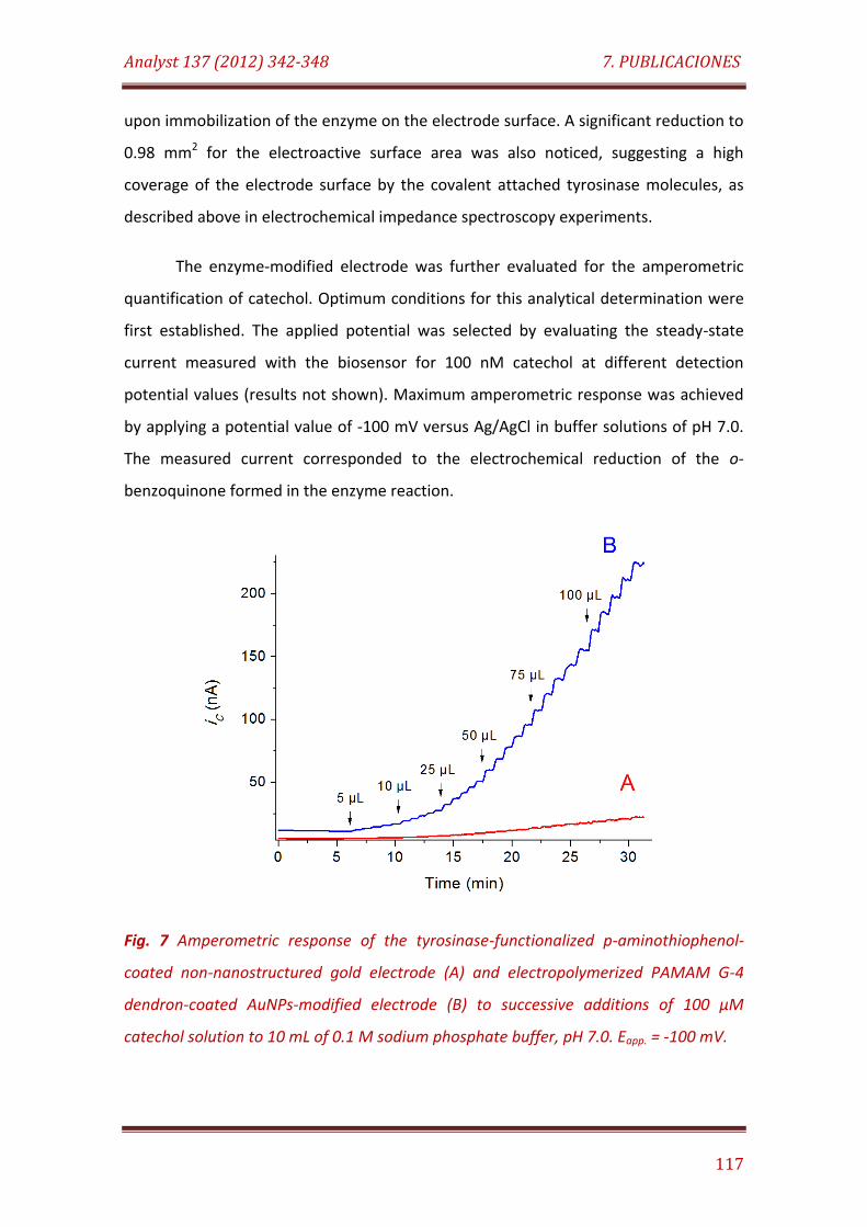
Analyst 137 (2012) 342-348 7. PUBLICACIONES
117
upon immobilization of the enzyme on the electrode surface. A significant reduction to
0.98 mm2 for the electroactive surface area was also noticed, suggesting a high
coverage of the electrode surface by the covalent attached tyrosinase molecules, as
described above in electrochemical impedance spectroscopy experiments.
The enzyme-modified electrode was further evaluated for the amperometric
quantification of catechol. Optimum conditions for this analytical determination were
first established. The applied potential was selected by evaluating the steady-state
current measured with the biosensor for 100 nM catechol at different detection
potential values (results not shown). Maximum amperometric response was achieved
by applying a potential value of -100 mV versus Ag/AgCl in buffer solutions of pH 7.0.
The measured current corresponded to the electrochemical reduction of the o-
benzoquinone formed in the enzyme reaction.
Fig. 7 Amperometric response of the tyrosinase-functionalized p-aminothiophenol-
coated non-nanostructured gold electrode (A) and electropolymerized PAMAM G-4
dendron-coated AuNPs-modified electrode (B) to successive additions of 100 µM
catechol solution to 10 mL of 0.1 M sodium phosphate buffer, pH 7.0. Eapp. = -100 mV.
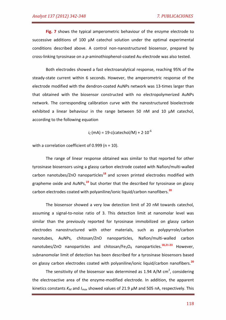
Analyst 137 (2012) 342-348 7. PUBLICACIONES
118
Fig. 7 shows the typical amperometric behaviour of the enzyme electrode to
successive additions of 100 µM catechol solution under the optimal experimental
conditions described above. A control non-nanostructured biosensor, prepared by
cross-linking tyrosinase on a p-aminothiophenol-coated Au electrode was also tested.
Both electrodes showed a fast electroanalytical response, reaching 95% of the
steady-state current within 6 seconds. However, the amperometric response of the
electrode modified with the dendron-coated AuNPs network was 13-times larger than
that obtained with the biosensor constructed with no electropolymerized AuNPs
network. The corresponding calibration curve with the nanostructured bioelectrode
exhibited a linear behaviour in the range between 50 nM and 10 µM catechol,
according to the following equation
iC (mA) = 19·c(catechol/M) + 2·10-6
with a correlation coefficient of 0.999 (n = 10).
The range of linear response obtained was similar to that reported for other
tyrosinase biosensors using a glassy carbon electrode coated with Nafion/multi-walled
carbon nanotubes/ZnO nanoparticles18 and screen printed electrodes modified with
grapheme oxide and AuNPs,19 but shorter that the described for tyrosinase on glassy
carbon electrodes coated with polyaniline/ionic liquid/carbon nanofibers.20
The biosensor showed a very low detection limit of 20 nM towards catechol,
assuming a signal-to-noise ratio of 3. This detection limit at nanomolar level was
similar than the previously reported for tyrosinase immobilized on glassy carbon
electrodes nanostructured with other materials, such as polypyrrole/carbon
nanotubes, AuNPs, chitosan/ZnO nanoparticles, Nafion/multi-walled carbon
nanotubes/ZnO nanoparticles and chitosan/Fe3O4 nanoparticles.18,21-23 However,
subnanomolar limit of detection has been described for a tyrosinase biosensors based
on glassy carbon electrodes coated with polyaniline/ionic liquid/carbon nanofibers.20
The sensitivity of the biosensor was determined as 1.94 A/M cm2, considering
the electroactive area of the enzyme-modified electrode. In addition, the apparent
kinetics constants KM and Imax showed values of 21.9 µM and 505 nA, respectively. This
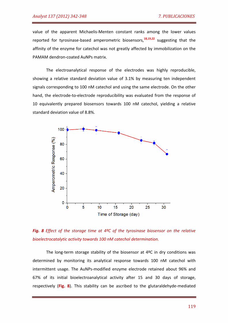
Analyst 137 (2012) 342-348 7. PUBLICACIONES
119
value of the apparent Michaelis-Menten constant ranks among the lower values
reported for tyrosinase-based amperometric biosensors,18,19,22 suggesting that the
affinity of the enzyme for catechol was not greatly affected by immobilization on the
PAMAM dendron-coated AuNPs matrix.
The electroanalytical response of the electrodes was highly reproducible,
showing a relative standard deviation value of 3.1% by measuring ten independent
signals corresponding to 100 nM catechol and using the same electrode. On the other
hand, the electrode-to-electrode reproducibility was evaluated from the response of
10 equivalently prepared biosensors towards 100 nM catechol, yielding a relative
standard deviation value of 8.8%.
Fig. 8 Effect of the storage time at 4ºC of the tyrosinase biosensor on the relative
bioelectrocatalytic activity towards 100 nM catechol determination.
The long-term storage stability of the biosensor at 4ºC in dry conditions was
determined by monitoring its analytical response towards 100 nM catechol with
intermittent usage. The AuNPs-modified enzyme electrode retained about 96% and
67% of its initial bioelectroanalytical activity after 15 and 30 days of storage,
respectively (Fig. 8). This stability can be ascribed to the glutaraldehyde-mediated
Analyst 137 (2012) 342-348 7. PUBLICACIONES
120
multipoint attachment of the enzyme to the primary amino groups at the surface of
the PAMAM hyperbranched structures capping the AuNPs-based electropolymerized
network. Such kind of multipoint covalent cross-linking trends to preserve the catalytic
activity of the enzyme by fixing the three dimensional active enzyme structure and by
avoiding the lack of tyrosinase molecules from the electrode surface.
EXPERIMENTAL
Reagents and apparatus
Tyrosinase (Tyr, 5370 U/mg), HAuCl4, NaBH4, 2-mercaptoethanesulfonic acid, p-
aminothiophenol and cystamine core PAMAM G-4 dendrimer were purchased from
Sigma (USA). All other chemicals were of analytical grade.
Dendron-coated gold nanoparticles were characterized by high resolution
transmission electron microscopy (HRTEM) using a JEOL JEM-4000 EX microscope. The
morphology of the nanostructured gold surface was studied by atomic force
microscopy (AFM) with a Nanotec Cervantes SPM microscope.
Cyclic voltammetry and electrochemical impedance spectroscopy experiments
were performed using a FRA2 µAutolab Type III potentiostat/galvanostat and the data
were acquired using GPES Ver. 4.9 and Frequency Response Analyser softwares,
respectively (Metrohm Autolab B.V., The Netherlands). Amperometric measurements
were performed with a dual-channel ultrasensitive Inbea potentiostat (Inbea
Biosensores S.L., Spain). A conventional three-electrode system was employed in all
electrochemical studies. The working electrode was a gold disk (CHI Instruments, UK,
2.0 mm diameter) modified with the electropolymerized AuNPs network and the
immobilized enzyme. An Ag/AgCl/KCl (3 M) and a Pt wire were used as reference and
counter electrodes, respectively. Bioelectrode measurements were carried out at 25ºC
in 0.1 M sodium phosphate buffer, pH 7.0 (working volume 10 ml). The solutions were
stirred at 300 rpm with a magnetic bar during amperometric measurements. For
Analyst 137 (2012) 342-348 7. PUBLICACIONES
121
analytical purposes, 100 µM catechol solutions in 50 mM sodium phosphate buffer, pH
7.0 were freshly prepared.
Synthesis of the dendron-coated AuNPs
To prepare the dendron-caped AuNPs, 150 mg of sodium borohydride, 18 mg of
2-mercaptoethanesulfonic acid, 250 mg of cystamine core PAMAM dendrimer G-4 and
5 mg of p-aminothiophenol were dissolved in 25 mL of de-aerated dimethyl sulfoxide
(DMSO) and stirred during 30 min. Another solution was prepared by dissolving 99 mg
of HAuCl4 in 50 mL of de-aerated DMSO, and rapidly added to the first reducing
mixture. The reaction mixture turned deep brown immediately, but the reaction was
allowed to proceed for 24 h under N2 atmosphere. Then, the functionalized AuNPs
were precipitated by adding 50 mL CH3CN, collected by centrifugation, and washed
with 50 mL CH3CN:DMSO (1:1 v/v), 50 mL ethanol and 50 mL diethyl ether. The
nanoparticles were finally isolated by centrifugation and dried under N2. The
nanoparticles were characterized by FT-IR and HRTEM.
Preparation of the electropolymerizad AuNPs-modified enzyme electrode
A clean gold disk electrode was first dipped into a 10 mM ethanolic solution of
p-aminothiophenol in order to modify the metal surface with a monolayer of the
aniline derivative. After 2 h incubation, the electrode was washed several times with
ethanol and double distilled water, and further dipped into a freshly prepared 2
mg/mL solution of PAMAM dendron-AuNPs in 0.1 M H2SO4. Electropolymerization was
performed by applying 10 potential cycles between -0.35 V and +0.85 V vs Ag/AgCl at a
scan rate of 100 mV/s, followed by application of a constant potential of 0.85 V for 1 h.
The electrode coated with the electropolymerized PAMAM dendron-AuNPs network
was exhaustively washed with 0.1 M H2SO4 and double distilled water before enzyme
immobilization.
Analyst 137 (2012) 342-348 7. PUBLICACIONES
122
To functionalize the electrode with tyrosinase, a mixture of 20 µL of 5 mg/mL
enzyme solution in 50 mM sodium phosphate buffer, pH 7.0 and 10 µL of 25% (v/v)
glutaraldehyde was dropped on the electrode surface and kept at 4ºC during 2 h in wet
atmosphere. The enzyme-modified electrode was then exhaustively washed with cool
50 mM sodium phosphate buffer, pH 7.0 and finally kept at 4ºC in dry conditions until
used.
CONCLUSIONS
A novel nanostructured electrode surface, based on the modification of gold
substrates with a polymeric matrix of PAMAM G-4 dendron coated AuNPs, was
developed and used as support for the covalent immobilization of tyrosinase. The
nanostructured enzyme electrode was evaluated for biosensing catechol, showing
excellent analytical performance regarding to detection limit, sensitivity and stability.
Considering the experimental results here presented, we suggest that the covalent
immobilization of enzymes on metal electrodes coated with electropolymerized
network of dendron-modified metal nanoparticles constitutes an excellent strategy to
construct robust and reliable amperometric biosensors.
ACKNOWLEDGEMENTS
R. Villalonga acknowledge to Ramón & Cajal contract from the Spanish Ministry
of Science and Innovation. Financial support from the Spanish Ministerio de Ciencia e
Innovación CTQ2009-12650, CTQ2009-09351) and Comunidad de Madrid S2009/PPQ-
1642, programme AVANSENS is gratefully acknowledged.
Analyst 137 (2012) 342-348 7. PUBLICACIONES
123
NOTES AND REFERENCES
aDepartment of Analytical Chemistry, Faculty of Chemistry, Complutense University of
Madrid, 28040-Madrid, Spain. Fax: 34 913944329; Tel: 34 913944315; E-mail:
bIMDEA Nanoscience, Campus Universitario de Cantoblanco, Avenida Francisco Tomás
y Valiente 7, 28049-Madrid, Spain. Fax: 34 914976855; Tel: 34 914976837; E-mail:
†This article is part of a web theme in Analyst and Analytical Methods on Future
Electroanalytical Developments, highlighting important developments and novel
applications. Also in this theme is work presented at the Eirelec 2011 meeting,
dedicated to Professor Malcolm Smyth on the occasion of his 60th birthday.
1 J. Wang, Analyst, 2005, 130, 421; J. Wang, Electroanalysis, 2005, 17, 7.
2 C.S.S.R. Kumar, Nanomaterials for biosensors. Nanotechnologies for the life
sciences, 2006, 8, Wiley-VCH, Weinheim; .S. Li, J. Singh, H. Li, I.A. Banerjee,
Biosensor Nanomaterials, 2011, Wiley-VCH, Weinheim.
3 F. Zhang, C. Li, X. Li, X. Wang, Q. Wan, Y. Xian, L. Jin, K. Yamamoto, Talanta, 2006,
68, 1353; Q. Liu, X. Lu, J. Li, X. Yao, J. Li, Biosens. Bioelectron., 2007, 22, 3203.
4 L. Agüi, P. Yañez-Sedeño, J.M. Pingarrón, Anal. Chim. Acta, 2008, 622, 11.
5 Y. Shao, J. Wang, H. Wu, J. Liu, I.A. Aksay, Y. Lin, Electroanalysis, 2010, 22, 1027.
6 X. Lu, J. Zhou, W. Lu, Q. Liu, J. Li, Biosens. Bioelectron., 2008, 23, 1236; V.
Vamvakaki, K. Tsagaraki, N. Chaniotakis, Anal. Chem., 2006, 78, 5538.
7 J.M. Pingarrón, P. Yáñez-Sedeño, A. González-Cortés, Electrochim. Acta, 2008, 53,
5848; X. Luo, A. Morrin, A.J. Killard, M.R. Smyth, Electroanalysis, 2006, 18, 319.
8 Y. Zhang, G.M. Zeng, L. Tang, D.L. Huang, X.Y. Jiang, Y.N. Chen, Biosens.
Bioelectron., 2007, 22, 2121.
Analyst 137 (2012) 342-348 7. PUBLICACIONES
124
9 M. Riskin, R. Tel-Vered, I. Willner, Adv. Mater., 2010, 22, 1387; M. Frasconi, R. Tel-
Vered, M. Riskin, I. Willner, Anal. Chem., 2010, 82, 2512.
10 R. Villalonga, P. Diez, P. Yañez-Sedeño, J.M. Pingarrón, Electrochim. Acta, 2011, 56,
4672.
11 F. Vögtle, G. Richardt, N. Werner, Dendrimer chemistry: Concepts, synthesis,
properties, applications, 2009, Wiley-VCH, Weinheim.
12 N. Malik, E.G. Evagorou, R. Duncan, Anticancer Drugs, 1999, 10, 767; W.C. Floyd,
G.K. Datta, S. Imamura, H.M. Kieler-Ferguson, K. Jerger, A.W. Patterson, M.E. Fox,
F.C. Szoka, J.M.J. Fréchet, J.A. Ellman, ChemMedChem., 2011, 6, 49; U. Boas, J.B.
Christensen, P.M.H. Heegaard, New molecular tools, 2006, The Royal Society of
Chemistry.
13 R.P. Singh, Analyst, 2011, 136, 1216.
14 R.M. Crooks, M. Zhao, L. Sun, V. Chechik, L.K. Yeung, Accounts Chem. Res., 2011,
34, 181.
15 H. Tokuhisa, M. Zhao, L.A. Baker, V.T. Phan, D.L. Dermody, M.E. Garcia, R.F. Peez,
R.M. Crooks, T.M. Mayer, J. Am. Chem. Soc., 1998, 120, 4492.
16 M.A. Rahman, H.B. Noh, Y.B. Shim, Anal. Chem., 2008, 80, 8020; Y.G. Kim, S.K. Oh,
R.M. Crooks, Chem. Mater., 2004, 16, 167.
17 L. Duić, Z. Mandić, S. Kovač, Electrochim. Acta, 1995, 40, 1681.
18 J.M. Lee, G.R. Xu, B.K. Kim, H.N. Choi, W.Y. Lee, Electroanalysis, 2011, 23, 962.
19 W. Song, D.W. Li, Y.T. Li, Y. Li, Y.T. Long, Biosens. Bioelectron., 2011, 26, 3181.
20 J. Zhang, J. Lei, Y. Liu, J. Zhao, H. Ju, Biosens. Bioelectron., 2009, 24, 1858.
21 S.K. Ozoner, M. Yalvac, E. Erhan, Current Appl. Phys., 2010, 10, 323; V. Carralero,
M. Luz Mena, A. González-Cortes, P. Yañez-Sedeño, J.M. Pingarrón, Anal. Chim.
Acta, 2005, 528, 1.

Analyst 137 (2012) 342-348 7. PUBLICACIONES
125
22 Y.F. Li, Z.M. Liu, Y.L. Liu, Y.H. Yang, G.L. Shen, R.Q. Yu, Anal. Biochem., 2006, 349,
33.
23 S. Wang, Y. Tan, D. Zhao, G. Liu, Biosens. Bioelectron., 2008, 23, 1781.

7.3
ChemElectroChem. 1 (2014) 200-206
Biotin-labeled electropolymerized network of gold nanoparticles for amperometric immunodetection
of human fibrinogen


ChemElectroChem 1 (2014) 200-206 7. PUBLICACIONES
127
BIOTIN-LABELED ELECTROPOLYMERIZED NETWORK OF GOLD
NANOPARTICLES FOR AMPEROMETRIC IMMUNODETECTION OF HUMAN
FIBRINOGEN
Paula Díez,[a] María Gamella,[a] Paloma Martínez-Ruíz,[b] Valentina Lanzone,[c] Alfredo
Sánchez,[a] Enrique Sánchez,[a] Belit Garcinuño,[a] Reynaldo Villalonga,*[a,d] José M.
Pingarrón*[a,d]
[a] Department of Analytical Chemistry, Complutense University of Madrid, 28040-
Madrid, Spain. E-mail: [email protected], [email protected]
[b] Department of Organic Chemistry I, Complutense University of Madrid, 28040-
Madrid, Spain
[c] Department of Food Sciences, University of Teramo, 64100-Teramo, Italy
[d] IMDEA Nanoscience, Cantoblanco Universitary City, 28049-Madrid, Spain
ChemElectroChem 1 (2014) 200-206 7. PUBLICACIONES
128
ABSTRACT
Water soluble gold nanoparticles (3.1 ± 0.6 nm) with polymerization ability and
affinity to streptavidin were prepared by reducing HAuCl4 in the presence of the
capping ligands 2-mercaptoethanesulfonic acid, biotin-cysteamine and p-
aminothiophenol. This colloid was used to modify gold electrodes by formation of an
electropolymerized 3D network of bis-aniline cross-linked nanoparticles on the metal
surface. The modified electrode was employed as scaffold for the assembly of an
amperometric immunosensor system to detect human fibrinogen. The immunosensor
showed excellent analytical characteristics, with a dynamic range of detection
between 0.018 and 2.208 µg/mL, a detection limit of 4 ng/mL and an IC50 value of 177
ng/mL. The immunosensor was markedly stable, retaining full analytical capacity after
45 days of storage at 4ºC.
KEYWORDS: immunosensor, gold nanoparticles, fibrinogen, biotin, nanostructured
surface
INTRODUCTION
Electrochemical biosensors constitute promising analytical tools for the clinical
diagnosis of relevant diseases, as well as for the development of point-of-care sensing
systems able to permit real-time and remote health monitoring. In general, these
biomedical applications require highly sensitive, stable and specific biosensing
platforms able to detect very low concentrations of the target analyte in complex
biological samples.[1]
The advent of nanotechnology has favoured the construction of such biosensor
systems with improved analytical characteristics through the use of conducting
nanomaterials for the tailor made design of electrode surfaces with 3D architectures.[2]
The success of this strategy relies on the unique physicochemical properties of
nanomaterials such as high surface energy and surface-to-volume ratio, easy
ChemElectroChem 1 (2014) 200-206 7. PUBLICACIONES
129
functionalization, ability to decrease proteins-nanomaterial distance, and the
possibility to wire the redox center of some biomolecules with the electrode surface.[3]
Consequently, nanostructured electrodes can provide a large electroconductive
active surface area allowing high loadings of the biological recognition elements and
the proper occurrence of the electrocatalytic and electron transfer processes.
Gold nanoparticles (AuNPs) are, by far, the conducting nanomaterial more
widely employed for the modification of the transduction element in electrochemical
biosensors.[4] In addition to their high electroconductive and thermal properties, they
possess several advantages including simple preparation through different well-
established methods, relative low cost and easy stabilization of the colloidal dispersion
by covalent or non-covalent surface coating. Gold nanoparticles can catalyze the
transformation of the target analyte at their surface, then reducing the overpotential
and avoiding unwanted interference from other electroactive compounds. Gold
nanoparticles-modified surfaces can also work as nanoelectrode ensembles,
contributing to reduce the detection limit of analytes by increasing the ratio between
the faradaic and capacitive currents.
There are a great variety of strategies for assembling gold nanoparticles on
electrode surfaces for biosensing purposes, including electrodeposition, physical
adsorption, electrostatic interactions, covalent linkages or supramolecular
associations.[5] Recently, it has been reported an electrochemical approach to prepare
porous three-dimensional networks of polyfunctionalized gold nanoparticles capped
with aniline moieties by the formation of cross-linked bis-aniline bonds.[6] We have
employed this strategy for the preparation of nanostructured electrode surfaces with
predesigned properties for interfacing biological recognition events with excellent
electronic signal transduction for electrochemical biosensing.[7] The rational of this
strategy is based on the synthesis of gold nanoparticles capped with three different
thiol ligands, which should provide solubility, polymerization ability and chemical
functionality to favour the proper immobilization of the sensing biomolecule. These
systems have been successfully employed to construct enzyme biosensors with
ChemElectroChem 1 (2014) 200-206 7. PUBLICACIONES
130
improved analytical characteristics by covalent and supramolecular immobilization of
the biocatalyst.[7]
In this work, a novel approach to prepare an amperometric immunosensor for
human plasma fibrinogen by using electropolymerized biotin-labelled gold
nanoparticles modified electrodes is described. Plasma fibrinogen is an important
component of the coagulation cascade which determines blood flow and viscosity.[8]
Fibrinogen is cleaved by thrombin to form the fibrin monomer during coagulation,
which undergoes polymerization to form an insoluble fibrin clot, a complex lattice to
close off the injured blood vessel walls. The normal concentration of fibrinogen in
plasma is about 1.5 - 4.5 mg/ml, and elevated levels are associated with an increased
risk of cardiovascular disorders, such as stroke, ischemic heart disease and other
thromboembolisms.[9] Taking into account that cardiovascular diseases are the leading
cause of deaths worldwide, the development of analytical devices to detect fibrinogen
as a cardiac disease marker constitutes a relevant research topic in electrochemical
biosensors.
RESULTS AND DISCUSION
Scheme 1 illustrates the strategy employed to prepare the amperometric
immunosensor for fibrinogen. The rational of this electrochemical biosensor was based
on the use of a polymeric matrix of AuNPs as scaffold for the assembly of the
biorecognition architecture on the gold electrode surface. This nanomaterial has the
advantage to provide a large and 3D nanostructured surface with a high density of
biotin residues to be employed for the further immobilization of streptavidin
molecules in high yield. Streptavidin, which has the capacity to strongly bind four
residues of biotin per protein molecule, was then employed as multivalent affinity-
based linker to construct a sandwich-type assembly with biotinilated fibrinogen on the
modified surface.
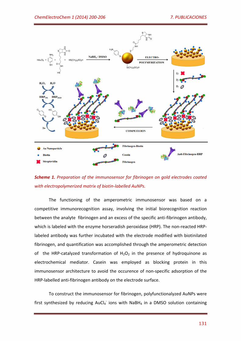
ChemElectroChem 1 (2014) 200-206 7. PUBLICACIONES
131
Scheme 1. Preparation of the immunosensor for fibrinogen on gold electrodes coated
with electropolymerized matrix of biotin-labelled AuNPs.
The functioning of the amperometric immunosensor was based on a
competitive immunorecognition assay, involving the initial biorecognition reaction
between the analyte fibrinogen and an excess of the specific anti-fibrinogen antibody,
which is labeled with the enzyme horseradish peroxidase (HRP). The non-reacted HRP-
labeled antibody was further incubated with the electrode modified with biotinilated
fibrinogen, and quantification was accomplished through the amperometric detection
of the HRP-catalyzed transformation of H2O2 in the presence of hydroquinone as
electrochemical mediator. Casein was employed as blocking protein in this
immunosensor architecture to avoid the occurence of non-specific adsorption of the
HRP-labelled anti-fibrinogen antibody on the electrode surface.
To construct the immunosensor for fibrinogen, polyfunctionalyzed AuNPs were
first synthesized by reducing AuCl4- ions with NaBH4 in a DMSO solution containing
ChemElectroChem 1 (2014) 200-206 7. PUBLICACIONES
132
three different thiol capping ligands. These ligands were rationally selected to confer
specific characteristics to the resulting nanoparticles. In this case, biotin-cysteamine
residues, resulting from the in situ reduction of biotin-cystamine,[10] acted as
recognition elements for the affinity-based immobilization of streptavidin molecules.
Moreover, p-aminothiophenol and 2-mercaptoethanesulfonic acid were included in
the design of the functionalized AuNPs to allow their electrochemical polymerization
and solubilisation, respectively.
Water soluble dark red nanoparticles with optimal solubility, polymerization
ability and biorecognition properties were prepared by using p-aminothiophenol,
biotin-cysteamine and 2-mercaptoethanesulfonic acid in a 1:1.7:3.7 molar ratio. This
optimal ratio of capping ligands was deduced by evaluation of the obtained water
soluble AuNPs providing the higher loading of streptavidin molecules on the electrode
surface upon electropolymerization. HR-TEM analysis revealed that these
nanoparticles showed spherical geometry with an average diameter of 3.1 ± 0.6 nm
and a narrow size distribution (Figure 1S in Supporting Information). Reduction of
AuCl4- ions in the presence of the thiol capping ligands caused their fast attachment to
the surface of the developing Au colloids, then resulting in the radial geometry, small
size and low polydispersion of the nanoparticles. Similar results were previously
reported for other AuNPs prepared by the same approach, but capped with different
water-soluble thiol ligands.[7,11]
The AuNPs mainly contain crystalline lattice planes with d-spacing of 2.35 Å for
adjacent lattice planes, corresponding to the (111) planes of face-centered cubic gold.
Selected area electron diffraction analysis showed the characteristic concentric rings
pattern of a face-centered cubic gold structure, then confirming the crystalline
structure of these colloids. Elemental analysis revealed that the AuNPs were capped
with an average of 16, 10 and 59 molecules of biotin-cysteamine, p-aminothiophenol
and 2-mercaptoethanesulfonic acid, respectively, assuming that the nanoparticles are
perfect spheres. This value corresponded to a total ligand surface coverage of 5.6
molecules/nm2, which is in agreement with the coverage range reported for gold
nanoparticles modified with different alkanethiols (4.3 – 6.3 molecules/nm2).[12]
ChemElectroChem 1 (2014) 200-206 7. PUBLICACIONES
133
The UV-Vis spectrum of the biotin-labelled AuNPs, dissolved in 50 mM sodium
phosphate buffer pH 7.0, showed a relatively weak plasmon resonance absorption
band around 515 nm (Figure 2S in Supporting Information). The intensity of this band
was not affected after addition of bovine serum albumin, although a little broadening
was observed, suggesting little interaction of this protein with the metal nanoparticles.
On the contrary, a noticeable increase in the intensity of the plasmon resonance band
was noticed when streptavidin was added to the nanoparticles solution, which could
be attributed to the strong association of this protein to the metal nanoparticles
surface. A similar effect was previously reported for other protein-AuNPs systems.[7a,13]
In this case, the affinity-based association of biotin-labelled AuNPs with streptavidin
was expected due to the ability of this tetrameric protein to bind four biotin residues
with a Ka ≈ 2.5x10¹³ M-1.[14]
Polyfunctionalized AuNPs were further electropolymerized in 0.1 M H2SO4 on a
p-aminothiophenol modified gold electrode. This previous modification of the
electrode surface with p-aminothiophenol moieties ensured the formation of bis-
aniline linkages between thioaniline groups on the electrode and AuNPs surfaces as
the first step for an efficient polymerization process. The formation of the 3D
electropolymerized matrix of AuNPs was performed through two sequential steps: the
formation of a bisaniline-cross-linked network of nanoparticles by means of cyclic
voltammetric scans between -0.35 V and +0.85 V vs Ag/AgCl reference electrode, and
the further growing of the polymer during 30 min at a fixed potential of +0.85 V.
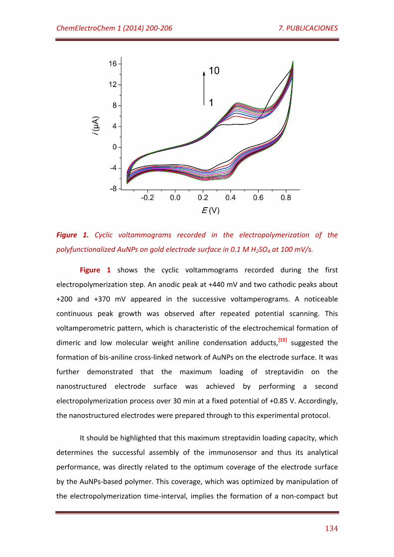
ChemElectroChem 1 (2014) 200-206 7. PUBLICACIONES
134
Figure 1. Cyclic voltammograms recorded in the electropolymerization of the
polyfunctionalized AuNPs on gold electrode surface in 0.1 M H2SO4 at 100 mV/s.
Figure 1 shows the cyclic voltammograms recorded during the first
electropolymerization step. An anodic peak at +440 mV and two cathodic peaks about
+200 and +370 mV appeared in the successive voltamperograms. A noticeable
continuous peak growth was observed after repeated potential scanning. This
voltamperometric pattern, which is characteristic of the electrochemical formation of
dimeric and low molecular weight aniline condensation adducts,[15] suggested the
formation of bis-aniline cross-linked network of AuNPs on the electrode surface. It was
further demonstrated that the maximum loading of streptavidin on the
nanostructured electrode surface was achieved by performing a second
electropolymerization process over 30 min at a fixed potential of +0.85 V. Accordingly,
the nanostructured electrodes were prepared through to this experimental protocol.
It should be highlighted that this maximum streptavidin loading capacity, which
determines the successful assembly of the immunosensor and thus its analytical
performance, was directly related to the optimum coverage of the electrode surface
by the AuNPs-based polymer. This coverage, which was optimized by manipulation of
the electropolymerization time-interval, implies the formation of a non-compact but
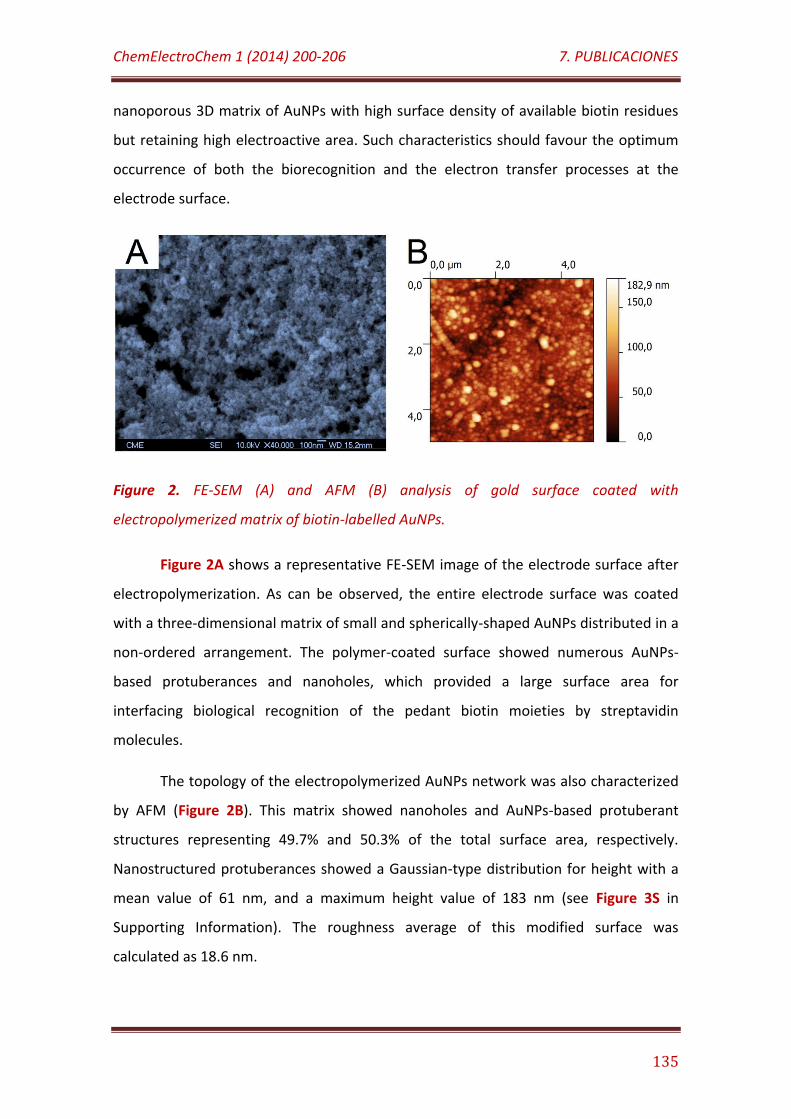
ChemElectroChem 1 (2014) 200-206 7. PUBLICACIONES
135
nanoporous 3D matrix of AuNPs with high surface density of available biotin residues
but retaining high electroactive area. Such characteristics should favour the optimum
occurrence of both the biorecognition and the electron transfer processes at the
electrode surface.
Figure 2. FE-SEM (A) and AFM (B) analysis of gold surface coated with
electropolymerized matrix of biotin-labelled AuNPs.
Figure 2A shows a representative FE-SEM image of the electrode surface after
electropolymerization. As can be observed, the entire electrode surface was coated
with a three-dimensional matrix of small and spherically-shaped AuNPs distributed in a
non-ordered arrangement. The polymer-coated surface showed numerous AuNPs-
based protuberances and nanoholes, which provided a large surface area for
interfacing biological recognition of the pedant biotin moieties by streptavidin
molecules.
The topology of the electropolymerized AuNPs network was also characterized
by AFM (Figure 2B). This matrix showed nanoholes and AuNPs-based protuberant
structures representing 49.7% and 50.3% of the total surface area, respectively.
Nanostructured protuberances showed a Gaussian-type distribution for height with a
mean value of 61 nm, and a maximum height value of 183 nm (see Figure 3S in
Supporting Information). The roughness average of this modified surface was
calculated as 18.6 nm.
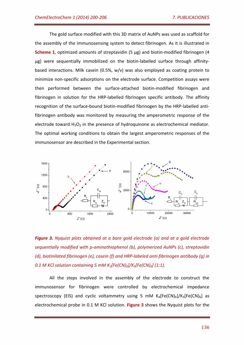
ChemElectroChem 1 (2014) 200-206 7. PUBLICACIONES
136
The gold surface modified with this 3D matrix of AuNPs was used as scaffold for
the assembly of the immunosensing system to detect fibrinogen. As it is illustrated in
Scheme 1, optimized amounts of streptavidin (5 µg) and biotin-modified fibrinogen (4
µg) were sequentially immobilized on the biotin-labelled surface through affinity-
based interactions. Milk casein (0.5%, w/v) was also employed as coating protein to
minimize non-specific adsorptions on the electrode surface. Competition assays were
then performed between the surface-attached biotin-modified fibrinogen and
fibrinogen in solution for the HRP-labelled fibrinogen specific antibody. The affinity
recognition of the surface-bound biotin-modified fibrinogen by the HRP-labelled anti-
fibrinogen antibody was monitored by measuring the amperometric response of the
electrode toward H2O2 in the presence of hydroquinone as electrochemical mediator.
The optimal working conditions to obtain the largest amperometric responses of the
immunosensor are described in the Experimental section.
Figure 3. Nyquist plots obtained at a bare gold electrode (a) and at a gold electrode
sequentially modified with p-aminothiophenol (b), polymerized AuNPs (c), streptavidin
(d), biotinilated fibrinogen (e), casein (f) and HRP-labeled anti-fibrinogen antibody (g) in
0.1 M KCl solution containing 5 mM K3[Fe(CN)6]/K4[Fe(CN)6] (1:1).
All the steps involved in the assembly of the electrode to construct the
immunosensor for fibrinogen were controlled by electrochemical impedance
spectroscopy (EIS) and cyclic voltammetry using 5 mM K4[Fe(CN)6]/K3[Fe(CN)6] as
electrochemical probe in 0.1 M KCl solution. Figure 3 shows the Nyquist plots for the
ChemElectroChem 1 (2014) 200-206 7. PUBLICACIONES
137
electrode at the different stages of assembling. A noticeable reduction in the charge
transfer resistance with respect to that observed at the bare gold electrode was
apparent for the p-aminothiophenol coated electrode which could be caused by the
electrostatic attraction of the [Fe(CN)6]4−/3− ions by the positive charged aniline
residues on the electrode surface.
Electropolymerization of polyfunctionalized AuNPs changed totally the shape of
the impedance spectrum, where two semicircles and one Warburg diffusion region
were observed. This fact could be ascribed to changes in the mass transport conditions
at the electrode interface due to the modification with AuNPs-based polymer. The high
surface coverage of AuNPs with thiolated ligands may reduce their metal conducting
properties and create a negatively charged interface on the electrode surface.
This perturbation can be represented by a modified Randles equivalent circuit,
in which the AuNPs-polymer/Au interface is represented by the double-layer
capacitance (Cdl) in parallel with a charge-transfer resistance (Rct) and the Warburg
diffusion impedance Zw. Additionally, the electrolyte/AuNPs-polymer interface is
represented by the parallel combination of another charge-transfer resistance (Rctp)
and capacitance (Cp) elements. Thus, the first semicircle at high frequencies is
indicative of the charge transfer process at the AuNPs-polymer/Au interface while the
second semicircle is associated to the charge transfer at the electrolyte/AuNPs-
polymer interface. Similar models were employed to explain the EIS behavior of other
polymer-modified electrodes.[16] It should be highlighted that this EIS behavior was
different than those previously described for gold electrodes modified with
electropolymerized networks of AuNPs labeled with mercaptophenylboronic acid and
polyamidoamine dendron moieties, which showed lower barrier properties than the
bare electrode and could be represented by a conventional Randles equivalent
circuit.[7a,c]
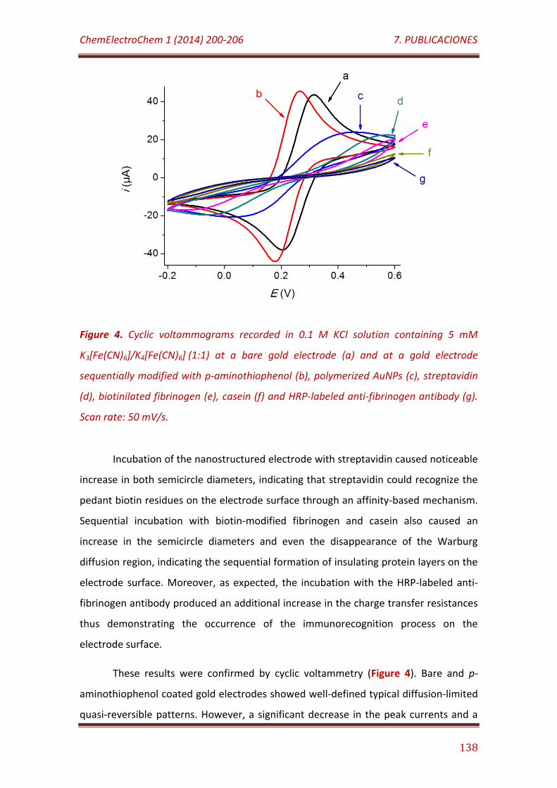
ChemElectroChem 1 (2014) 200-206 7. PUBLICACIONES
138
Figure 4. Cyclic voltammograms recorded in 0.1 M KCl solution containing 5 mM
K3[Fe(CN)6]/K4[Fe(CN)6] (1:1) at a bare gold electrode (a) and at a gold electrode
sequentially modified with p-aminothiophenol (b), polymerized AuNPs (c), streptavidin
(d), biotinilated fibrinogen (e), casein (f) and HRP-labeled anti-fibrinogen antibody (g).
Scan rate: 50 mV/s.
Incubation of the nanostructured electrode with streptavidin caused noticeable
increase in both semicircle diameters, indicating that streptavidin could recognize the
pedant biotin residues on the electrode surface through an affinity-based mechanism.
Sequential incubation with biotin-modified fibrinogen and casein also caused an
increase in the semicircle diameters and even the disappearance of the Warburg
diffusion region, indicating the sequential formation of insulating protein layers on the
electrode surface. Moreover, as expected, the incubation with the HRP-labeled anti-
fibrinogen antibody produced an additional increase in the charge transfer resistances
thus demonstrating the occurrence of the immunorecognition process on the
electrode surface.
These results were confirmed by cyclic voltammetry (Figure 4). Bare and p-
aminothiophenol coated gold electrodes showed well-defined typical diffusion-limited
quasi-reversible patterns. However, a significant decrease in the peak currents and a
ChemElectroChem 1 (2014) 200-206 7. PUBLICACIONES
139
much larger separation between the anodic and cathodic peaks was observed after
electropolymerization of the polyfunctionalized AuNPs on the electrode surface. This
suggested that the AuNPs-based polymer caused a kinetic barrier to the diffusion of
the electrochemical probes to the active electrode surface.
By using the Randles-Sevcik equation, the electrochemical surface area of the
gold electrode was estimated to change from 5.4 mm2 to 5.8 mm2 and 2.0 mm2 after
sequential modification with p-aminothiophenol and electropolymerized AuNPs,
respectively. Accordingly, about 62.9% of the electroactive surface area of the
electrode was coated with the AuNPs matrix.
These barrier effects were noticeably higher upon further modification of the
nanostructured electrode with the proteins involved in the immunosensor
construction due to the sequential formation of insulating protein layers on the
electrode surface. We estimated using the Randles-Sevcik equation that over 43.3% of
the AuNPs-modified surface was further coated with streptavidin, and about 11.3% of
this biofunctionalized interface was then covered with biotinilated fibrinogen. Cyclic
voltametric studies also revealed a coverage of about 45.1% by incubation with HRP-
labeled anti-fibrinogen antibody of the casein-modified electrode for the experiment
involving the minimun fibrinogen concentration in the competitive assay. This fact
suggested the succesful occurence of the immunochemical biorecognition process at
the electrode surface.
The assembled bioelectrode was used to detect fibrinogen through a
competitive configuration and amperometric measurements. Optimal conditions for
maxima amperometric signals were established by using 1 mM hydroquinone as
electrochemical mediator and a working potential of -100 mV vs Ag/AgCl.
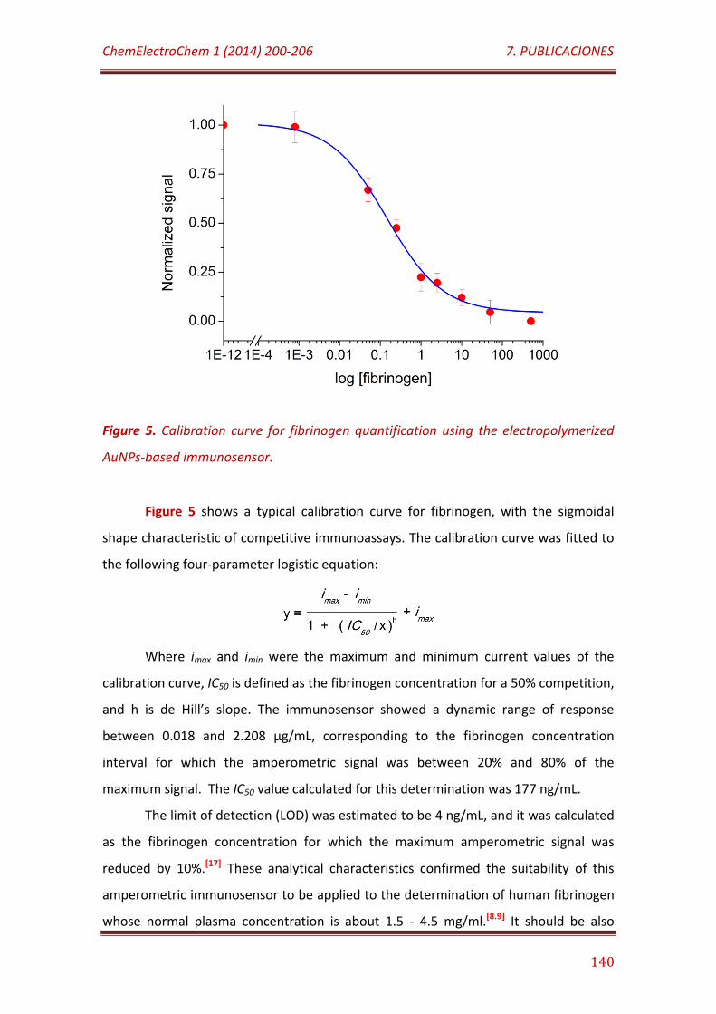
ChemElectroChem 1 (2014) 200-206 7. PUBLICACIONES
140
Figure 5. Calibration curve for fibrinogen quantification using the electropolymerized
AuNPs-based immunosensor.
Figure 5 shows a typical calibration curve for fibrinogen, with the sigmoidal
shape characteristic of competitive immunoassays. The calibration curve was fitted to
the following four-parameter logistic equation:
Where imax and imin were the maximum and minimum current values of the
calibration curve, IC50 is defined as the fibrinogen concentration for a 50% competition,
and h is de Hill’s slope. The immunosensor showed a dynamic range of response
between 0.018 and 2.208 µg/mL, corresponding to the fibrinogen concentration
interval for which the amperometric signal was between 20% and 80% of the
maximum signal. The IC50 value calculated for this determination was 177 ng/mL.
The limit of detection (LOD) was estimated to be 4 ng/mL, and it was calculated
as the fibrinogen concentration for which the maximum amperometric signal was
reduced by 10%.[17] These analytical characteristics confirmed the suitability of this
amperometric immunosensor to be applied to the determination of human fibrinogen
whose normal plasma concentration is about 1.5 - 4.5 mg/ml.[8.9] It should be also
ChemElectroChem 1 (2014) 200-206 7. PUBLICACIONES
141
highlighted that the immunosensor system showed a noticeable stability, being able to
retain full capacity to detect fibrinogen after 45 days of storage at 4ºC.
CONCLUSIONS
A novel nanostructured electrode surface, based on the modification of gold
electrodes with a three-dimensional polymeric matrix of aniline, sulfonic acid and
biotin-functionalized AuNPs, is here described. This modified surface showed affinity-
based biorecognition properties for streptavidin, and was evaluated for the
construction of an amperometric immunosensor for human fibrinogen. The
immunosensor exhibited excellent analytical characteristics in terms of dynamic range
of response, limit of detection, IC50 value and stability.
According to these results, we propose the use of bis-aniline cross-linked
networks of biotin-labeled AuNPs as scaffolds for the assembly of biomolecular
building blocks on electrode surfaces via biotin-streptavidin affinity interactions, for
the successful design of electrochemical biosensors.
EXPERIMENTAL SECTION
Reagents and apparatus
Human fibrinogen, biotin, horseradish peroxidase (HRP) labeled anti-fibrinogen
antibody, HAuCl4, NaBH4, 2-mercaptoethanesulfonic acid, p-aminothiophenol and
biotin-NHS were purchased from Sigma (USA). All other chemicals were of analytical
grade.
To prepare the biotinilated fibrinogen derivative, the protein (1 mg/mL in PBS)
was mixed with 20-fold molar excess of biotin-NHS, re-constituted at 25 mg/mL in
dimethylsulfoxide. After 2 h incubation at room temperature, the reaction was
stopped by addition of TrisHCl pH 7.5 at a final concentration of 50 mM and the
samples were placed on ice for 1 h. The reaction mixture was loaded onto a Sephadex
ChemElectroChem 1 (2014) 200-206 7. PUBLICACIONES
142
G25 PD-10 column, and the biotinylated protein was eluted in 500 μL fractions with
PBS. Protein concentration was estimated using the bicinchoninic acid protein assay.
Cyclic voltammetry and EIS experiments were performed using a
FRA2 µAutolab Type III potentiostat/galvanostat (Metrohm Autolab B.V., The
Netherlands). Amperometric measurements were performed with an Inbea
potentiostat (Inbea Biosensores S.L., Spain). A conventional three-electrode system
was employed in all electrochemical studies. The working electrode was a gold disk
(CHI Instruments, UK, 2.0 mm diameter) modified with the electropolymerized AuNPs
network. An Ag/AgCl/KCl (3 M) and a Pt wire were used as reference and counter
electrodes, respectively.
The morphology of the nanostructured electrode surface was characterized by
high resolution field emission scanning electron microscopy (FE-SEM) with a JEOL JSM-
6335F electron microscope (JEOL Ltd., Japan), and atomic force microscopy (AFM) with
a SPM Nanoscope IIIa multimode microscope (Veeco Instruments Inc., USA). High
resolution transmission electron microscopy (HR-TEM) measurements were performed
with a JEOL JEM-3000 F microscope. Spectrophotometric determinations were
performed using an Agilent 8453 UV/VIS spectrophotometer (Hewlett Packard, USA).
Synthesis of biotin-labeled AuNPs
Biotin-cystamine was synthesized as described earlier.[10] The
polyfunctionalized AuNPs were prepared by modification of our previously published
method,[7] by first dissolving 197 mg of HAuCl4 in 50 mL of de-aerated dimethyl
sulfoxide (DMSO). This solution was added dropwise to 50 mL of de-aerated DMSO
containing 100 mg of sodium borohydride, 36 mg 2-mercaptoethanesulfonic acid, 21
mg of biotin-cystamine and 8 mg p-aminothiophenol under vigorous stirring. The
reaction mixture turned deep brown immediately, but the reaction was allowed to
continue for 24 h. The functionalized AuNPs were then precipitated by adding 100 mL
CH3CN, collected by centrifugation, and washed with 60 mL CH3CN:DMSO (1:1 v/v), 60
mL ethanol and 20 mL diethyl ether. The nanoparticles were finally isolated by

ChemElectroChem 1 (2014) 200-206 7. PUBLICACIONES
143
centrifugation and dried under N2. The nanoparticles were characterized by HR-TEM,
UV-vis spectroscopy and elemental analysis.
Preparation of the AuNPs-modified electrode for fibrinogen detection
A clean gold disk electrode was first capped with a monolayer of p-
aminothiophenol by dipping the electrode for 2 h in a 10 mM ethanolic solution of the
thiol. The electrode was exhaustively washed with ethanol and double distilled water,
and dipped into a 2 mg/mL solution of the AuNPs in 0.1 M H2SO4. The electrode
surface was then coated with the electropolymerized bisaniline-cross-linked AuNPs
network by application of 10 potential cycles between -0.35 and +0.85 V vs Ag/AgCl at
a scan rate of 100 mV/s, followed by application of a constant potential of 0.85 for 30
min. The modified electrode was further exhaustively washed with double distilled
water.
The electrode was then coated with 10 µL of 0.5 mg/mL streptavidin solution in
B&W buffer, and incubated during 1 h at 37ºC. After exhaustive washing with B&W
buffer, 10 µL of 0.4 mg/mL biotinilated fibrinogen solution were dropped on the
electrode surface, and further incubated during 1 h at 37ºC. The electrode was then
washed with B&W buffer, further coated with 10 µL of 0.5 % (w/v) casein solution,
incubated for 30 min incubation at room temperature, and finally washed with
phosphate buffered saline (PBS) solution.
Fibrinogen was detected through a competitive assay by mixing 10 µg/mL of
HRP-labeled anti-fibrinogen antibody with fibrinogen at variable concentrations in PBS
solutions made 1 M NaCl. The electrode surface was incubated with 10 µL of this
mixture during 30 min at room temperature, then washed with PBS solution, and
finally tested for amperometric quantification of immobilized HRP activity. To do that,
the modified electrode was dipped into an electrochemical cell containing 10 mL of a
stirred solution of 1 mM hydroquinone in 0.1 M sodium phosphate buffer, pH 6.0.
Changes in the cathodic current were measured at -100 mV vs Ag/AgCl after addition
of 25 µL of a freshly prepared 100 mM H2O2 solution.

ChemElectroChem 1 (2014) 200-206 7. PUBLICACIONES
144
ACKNOWLEDGEMENTS
R. Villalonga acknowledges to Ramón & Cajal contract from the Spanish
Ministry of Science and Innovation. Financial support from the Spanish Ministry of
Science and Innovation (CTQ2011-24355 and CTQ2012-34238), and Comunidad de
Madrid S2009/PPQ-1642, Programme AVANSENS is gratefully acknowledged.
REFERENCIA
[1] a) J. Wang, Biosens. Bioelectron. 2006, 21, 1887-1892; b) M. Mascini, S. Tombelli,
Biomarkers 2008, 13, 637-657; c) J. Li, S. Li, C.F. Yang, Electroanalysis 2012, 24,
2213-2229.
[2] a) K. Kerman, M. Saito, E. Tamiya, S. Yamamura, Y. Takamura, Trends Anal. Chem.
2008, 27, 585-592; b) A. Chen, S. Chatterjee, Chem. Soc. Rev. 2013, 42, 5425-5438.
[3] a) Y. Shao, J. Wang, H. Wu, J. Liu, I.A. Aksay, Y. Lin, Electroanalysis 2010, 22, 1027-
1036; b) S. Guo, S. Dong, Trends Anal. Chem. 2009, 28, 96-109.
[4] a) J.M. Pingarrón, P. Yáñez-Sedeño, A. González-Cortés, Electrochim. Acta 2008,
53, 5848-5866; b) K. Saha, S.S. Agasti, C. Kim, X. Li, V.M. Rotello, Chem. Rev. 2012,
112, 2739-2779.
[5] a) J. Wang, L. Wang, J. Di, Y. Tu, Talanta 2009, 77, 1454-1459; b) W. Yang, J. Wang,
S. Zhao, Y. Sun, C. Sun, Electrochem. Comm. 2006, 8, 665-672; c) J. Manso, M.L.
Mena, P. Yáñez-Sedeño, J.M. Pingarrón, Anal. Biochem. 2008, 375, 345-353; d) M.
Holzinger, L. Bouffier, R. Villalonga, S. Cosnier, Biosens. Bioelectron. 2009, 24,
1128-1134; e) B. Chico, C. Camacho, M. Pérez, M.A. Longo, M.A. Sanromán, J.M.
Pingarrón, R. Villalonga, J. Electroanal. Chem. 2009, 629, 126-132.
[6] a) M. Riskin, R. Tel-Vered, I. Willner, Adv. Mater. 2010, 22, 1387-1391; b) M.
Frasconi, R. Tel-Vered, M. Riskin, I. Willner, Anal. Chem. 2010, 82, 2512-2519; c) L.
Bahshi, M. Frasconi, R. Tel-Vered, O. Yehezkeli, I. Willner, Anal. Chem. 2008, 80,
8253-8259.
[7] a) R. Villalonga, P. Díez, P. Yáñez-Sedeño, J.M. Pingarrón, Electrochim. Acta 2011,
56, 4672-4677; b) R. Villalonga, P. Díez, M. Eguílaz, P. Martínez, J.M. Pingarrón,
ChemElectroChem 1 (2014) 200-206 7. PUBLICACIONES
145
ACS Appl. Mat. Interfaces 2012, 4, 4312-4319; c) R. Villalonga, P. Díez, S. Casado,
M. Eguílaz, P. Yáñez-Sedeño, J.M. Pingarrón, Analyst 2012, 137, 342-348.
[8] G.D. Lowe, A. Rumley, I.J. Mackie, Ann. Clin. Biochem. 2004, 41, 430-440.
[9] S. Kamath, G.Y. Lip, QJM 2003, 96, 711-729.
[10] A. Sánchez, P. Díez, P. Martínez-Ruíz, R. Villalonga, J.M. Pingarrón, Electrochem.
Commun. 2013, 30, 51-54.
[11] J. Liu, W. Ong, E. Román, M.J. Lynn, A.E. Kaifer, Langmuir 2000, 16, 3000-3002.
[12] H. Hinterwirth, S. Kappel, T. Waitz, T. Prohaska, W. Lindner, M. Lämmerhofer, ACS
Nano 2013, 7, 1129-1136.
[13] a) N. Nath, A. Chilkoti, Anal. Chem. 2002, 74, 504-509; b) R. Villalonga, R. Cao, A.
Fragoso, A.E. Damiao, P.D. Ortiz, J. Caballero, J. Mol. Catal. B Enzymatic 2005, 35,
79-85.
[14] A. Chilkoti, P.S. Stayton, J. Am. Chem. Soc. 1995, 117, 10622-10628.
[15] L. Duić, Z. Mandić, S. Kovač, Electrochim. Acta 1995, 40, 1681-1688.
[16] a) Y. Shao, Y. Jin, J. Wang, L. Wang, F. Zhao, S. Dong, Biosens. Bioelectron. 2005,
20, 1373-1379; b) D. Tang, R. Yuan, Y. Chai, J. Phys. Chem. B. 2006, 110, 11640-
11646.
[17] B. Esteban-Fernández de Ávila, V. Escamilla-Gómez, S. Campuzano, M. Pedrero,
J.M. Pingarrón, Anal. Chim. Acta 2013, 784, 18-24.
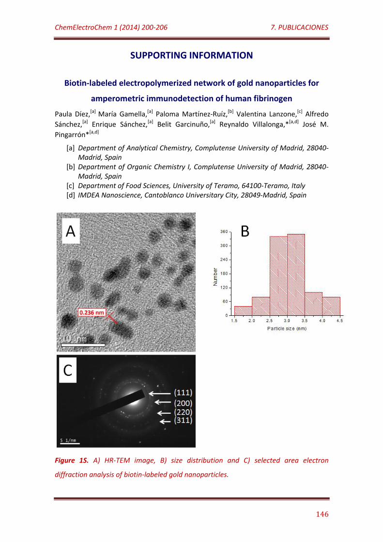
ChemElectroChem 1 (2014) 200-206 7. PUBLICACIONES
146
SUPPORTING INFORMATION
Biotin-labeled electropolymerized network of gold nanoparticles for
amperometric immunodetection of human fibrinogen
Paula Díez,[a] María Gamella,[a] Paloma Martínez-Ruíz,[b] Valentina Lanzone,[c] Alfredo
Sánchez,[a] Enrique Sánchez,[a] Belit Garcinuño,[a] Reynaldo Villalonga,*[a,d] José M.
Pingarrón*[a,d]
[a] Department of Analytical Chemistry, Complutense University of Madrid, 28040-Madrid, Spain
[b] Department of Organic Chemistry I, Complutense University of Madrid, 28040-Madrid, Spain
[c] Department of Food Sciences, University of Teramo, 64100-Teramo, Italy [d] IMDEA Nanoscience, Cantoblanco Universitary City, 28049-Madrid, Spain
Figure 1S. A) HR-TEM image, B) size distribution and C) selected area electron
diffraction analysis of biotin-labeled gold nanoparticles.
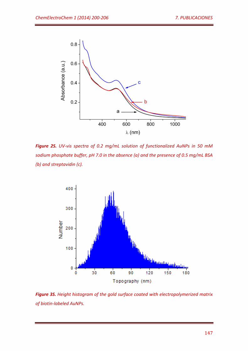
ChemElectroChem 1 (2014) 200-206 7. PUBLICACIONES
147
Figure 2S. UV-vis spectra of 0.2 mg/mL solution of functionalized AuNPs in 50 mM
sodium phosphate buffer, pH 7.0 in the absence (a) and the presence of 0.5 mg/mL BSA
(b) and streptavidin (c).
Figure 3S. Height histogram of the gold surface coated with electropolymerized matrix
of biotin-labeled AuNPs.

7.4
ACS Applied Materials & Interfaces 4 (2012) 4312-4319
Supramolecular immobilization of xanthine oxidase on
electropolymerized matrix of functionalized hybrid gold
nanoparticles/single-walled carbon nanotubes for the preparation of
electrochemical biosensors

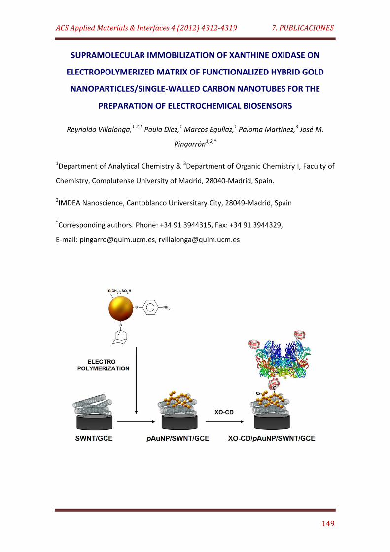
ACS Applied Materials & Interfaces 4 (2012) 4312-4319 7. PUBLICACIONES
149
SUPRAMOLECULAR IMMOBILIZATION OF XANTHINE OXIDASE ON
ELECTROPOLYMERIZED MATRIX OF FUNCTIONALIZED HYBRID GOLD
NANOPARTICLES/SINGLE-WALLED CARBON NANOTUBES FOR THE
PREPARATION OF ELECTROCHEMICAL BIOSENSORS
Reynaldo Villalonga,1,2,* Paula Díez,1 Marcos Eguílaz,1 Paloma Martínez,3 José M.
Pingarrón1,2,*
1Department of Analytical Chemistry & 3Department of Organic Chemistry I, Faculty of
Chemistry, Complutense University of Madrid, 28040-Madrid, Spain.
2IMDEA Nanoscience, Cantoblanco Universitary City, 28049-Madrid, Spain
*Corresponding authors. Phone: +34 91 3944315, Fax: +34 91 3944329,
E-mail: [email protected], [email protected]
ACS Applied Materials & Interfaces 4 (2012) 4312-4319 7. PUBLICACIONES
150
ABSTRACT
Glassy carbon electrodes modified with single walled carbon nanotubes and a
three-dimensional network of electropolymerized Au nanoparticles capped with 2-
mercaptoethanesulfonic acid, p-aminothiophenol and 1-adamantanethiol were used
as hybrid electrochemical platforms for supramolecular immobilization of a
synthesized artificial neoglycoenzyme of xanthine oxidase and β-cyclodextrin through
host-guest interactions. The ensemble was further employed for the
bioelectrochemical determination of xanthine. The biosensor showed fast
amperometric response within 5 s and a linear behavior in the 50 nM – 9.5 µM
xanthine concentration range with high sensitivity, 2.47 A/M·cm2, and very low
detection limit of 40 nM. The stability of the biosensor was significantly improved and
the interferences caused by ascorbic and uric acids were noticeably minimized by
coating the electrode surface with a Nafion thin film.
KEYWORDS: Single walled carbon nanotube, gold nanoparticle, supramolecular
assembly, enzyme biosensor, cyclodextrin
INTRODUCTION
Electrochemical biosensors constitute one of the most rapidly evolving fields in
Chemistry. From an analytical point of view, they allow the design of portable and
affordable sensing devices exhibiting high sensitivity and the characteristic specificity
provided by biological recognition systems.1,2 The successful development of this
technology is linked to the rational design of novel electrode surfaces able to improve
the speed of the electrochemical processes associated with the analytical responses as
well as the stable immobilization of the biomolecules preserving their three-
dimensional active conformation. In this context, electroconductive nanosized
materials have been exhaustively employed to prepare novel nanostructured surfaces
with improved performance.3-7 This success relies on the unique properties of
ACS Applied Materials & Interfaces 4 (2012) 4312-4319 7. PUBLICACIONES
151
nanomaterials such as high surface energy and surface-to-volume ratio, ability to
decrease proteins-nanomaterial distance, thermal stability, easy functionalization and
the possibility to act as electroconductive wires between the electrodes and the redox
centers in some biomolecules.8 In particular, gold nanoparticles (AuNPs) and carbon
nanotubes (CNTs) have been at the central core of novel advanced materials widely
used in biosensor technology.6,8-11 Furthermore, the combination of these
nanomaterials to prepare synergic hybrid nanomaterials has demonstrated to
constitute a successful strategy to construct electrochemical interfaces with unique
properties for the preparation of more efficient and robust biosensors.12
The synthesis of novel polyfunctionalized gold nanoparticles, bearing aniline
moieties able to be electropolymerized to form electroconductive three-dimensional
networks on electrodes, as well as their use for the preparation of molecularly
imprinted surfaces suitable for the construction of SPR biosensors, has been recently
reported.13,14 Furthermore, our group demonstrated recently the usefulness of such
electropolymerized nanostructures for the construction of enzyme electrochemical
biosensors. In this context, the preparation of metal surfaces nanostructured with
networks of Au nanoparticles functionalized with boronic acid and PAMAM dendron
moieties to design amperometric biosensors toward hydrogen peroxide and cathecol,
respectively, were reported.15,16 However, to our knowledge, the combined use of
these electropolymerized nanoparticle networks with other nanomaterials has not
been evaluated until now.
On the other hand, the use of host-guest supramolecular interactions was
previously proposed as a soft, reversible and multivalence method for the
immobilization of enzymes on metal nanoparticles and surfaces taking advantage of
the complementary interaction of adamantane derivatives with β-cyclodextrin (CD).17-
19 This strategy was successfully employed to construct stable enzyme biosensors.20-22
This work describes a novel approach for the construction of a nanostructured
electrode surface by electropolymerization of polyfunctionalized Au nanoparticles on a
glassy carbon electrode (GCE) which was previously coated with single-walled carbon
nanotubes (SWNT). For this purpose, Au nanoparticles modified with 2-
ACS Applied Materials & Interfaces 4 (2012) 4312-4319 7. PUBLICACIONES
152
mercaptoethanesulfonic acid, 1-adamantanethiol and p-aminothiophenol were
synthesized and further electropolymerized on the SWNT-coated GCE through the
formation of a bisaniline-cross-linked network. The presence of pendant adamantane
residues in this electroconductive matrix allows the subsequent supramolecular
immobilization of CD-based neoglycoproteins by formation of the complementary
host-guest inclusion complexes. As a model system to demonstrate this proof of
concept, we prepared a CD-modified xanthine oxidase (XO, EC 1.17.3.2) derivative
which was employed as the target neoglycoprotein. Moreover, an electrochemical
enzyme biosensor for xanthine based on this supramolecular design was constructed
and evaluated.
MATERIALS AND METHODS
1. Reagents
Xanthine oxidase (Type III, 1.3 U/mg), HAuCl4, NaBH4, 2-
mercaptoethanesulfonic acid, p-aminothiophenol, 1-adamantanethiol and CD were
purchased from Sigma-Aldrich Co. (USA). SWNT were from Wako Pure Chemical
Industries, Ltd. (Japan). All other chemicals were of analytical grade.
2. Apparatus and electrodes
Electrochemical impedance spectroscopy and cyclic voltammetry were
performed using a FRA2 µAutolab Type III potentiostat/galvanostat and data were
acquired using Frequency Response Analyser and GPES Ver. 4.9 software, respectively
(Metrohm Autolab B.V., The Netherlands). Amperometric measurements were carried
out with a dual-channel ultrasensitive InBea potentiostat (InBea Biosensores S.L.,
Spain). A conventional three-electrode system was employed for all electrochemical
measurements. The working electrode was a glassy carbon electrode (GCE, 3.0 mm
diameter) coated with SWNT, the electropolymerized network of Au nanoparticles and
the immobilized CD-enzyme derivative (XO-CD/pAuNP/SWNT/GCE). This electrode
ACS Applied Materials & Interfaces 4 (2012) 4312-4319 7. PUBLICACIONES
153
coated with a Nafion thin film (Naf/XO-CD/pAuNP/SWNT/GCE) was evaluated for
biosensing xanthine. An Ag/AgCl/KCl (3 M) and a Pt wire were used as reference and
counter electrodes, respectively.
High resolution transmission electron microscopy (HR-TEM) measurements
were performed with a JEOL JEM-3000 F microscope. The surface morphology of the
electrode surface was characterized using high resolution field emission scanning
electron microscopy (FE-SEM) with a JEOL JSM-6335F electron microscope (JEOL Ltd.,
Japan). FT-IR spectra were acquired with a Perkin-Elmer instrument.
Spectrophotometric measurements were performed using an Agilent 8453 UV/VIS
spectrophotometer (Hewlett Packard, USA).
3. Electrochemical measurements
All measurements with the prepared bioelectrodes were carried out at 25ºC in
0.1 M sodium phosphate buffer, pH 7.0 (working volume 10 mL). The solution was
stirred at 300 rpm with a magnetic bar during amperometric measurements. 100 µM
xanthine solutions in 50 mM sodium phosphate buffer, pH 7.0 were freshly prepared.
4. Preparation of nanomaterials
To prepare the adamantane-caped Au nanoparticles, 197 mg of HAuCl4 were
dissolved in 50 mL deaerated DMSO. This solution was added dropwise to 50 mL
deaerated DMSO containing 284 mg NaBH4, 36 mg 2-mercaptoethanesulfonic acid, 11
mg 1-adamantanethiol and 8 mg p-aminothiophenol under vigorous stirring. The
reaction mixture turned deep brown immediately, but the reaction was allowed
proceeding for 24 h. The polyfunctionalized nanoparticles prepared in this way were
precipitated by adding 50 mL CH3CN, collected by centrifugation and washed with 50
mL CH3CN:DMSO (1:1 v/v), 50 mL ethanol and 50 mL diethyl ether. The nanoparticles
were finally isolated by centrifugation and dried under N2.
ACS Applied Materials & Interfaces 4 (2012) 4312-4319 7. PUBLICACIONES
154
SWNT were purified and partially oxidized by treatment with a mixture of
HNO3/H2SO4 (3:1, v/v) during 2 h in an ultrasonic bath. The treated nanotubes were
centrifuged, washed with double distilled water until neutral pH and finally dried in
vacuum under P2O5.
These nanomaterials were characterized by FT-IR and HR-TEM.
5. Preparation of the enzyme electrode
The mono-6-ethylenediamino-6-deoxy-β-cyclodextrin was obtained by treating
the corresponding mono-6-O-tosyl derivative23 with freshly distilled ethylenediamine
as reported previously.24 XO was covalently glycosylated with this CD derivative via a
carbodiimide-catalyzed reaction (XO-CD) as previously described.22 The modified
enzyme contained an average of 12 mol of CD residues attached to each mol of
protein, as determined by the the phenol-sulfuric acid assay.
To prepare the enzyme-modified electrode, a bare GCE was polished to mirror-
like surface with alumina powder (0.3 µm), rinsed thoroughly with double distilled
water, successively washed with double distilled water, anhydrous ethanol and
acetone in an ultrasonic bath, and dried under N2 before use.
Coating of the treated GCE was accomplished by depositing two 10-µL aliquots
of a 0.4 mg/mL aqueous dispersion of SWNT on the electrode surface and allowing
drying. The SWNT-modified electrode was then dipped into a 2 mg/mL Au
nanoparticles solution in 0.1 M H2SO4 and electropolymerization was accomplished by
cycling the potential 10 times between -0.35 and +0.85 V vs Ag/AgCl at a scan rate of
100 mV/s, followed by applying a constant potential of 0.85 V for 1 h. The electrode
modified with the electropolymerized bisaniline-cross-linked network of Au
nanoparticles (pAuNP/SWNT/GCE) was exhaustively washed with 0.1 M H2SO4 and
double distilled water before enzyme immobilization.
Subsequently, the pAuNP/SWNT/GCE was dipped into a 5 mg/mL XO-CD
solution in 50 mM sodium phosphate buffer, pH 7.0, for 4 h. The enzyme-modified
electrode (XO-CD/pAuNP/SWNT/GCE) was finally washed with the same cool buffer,
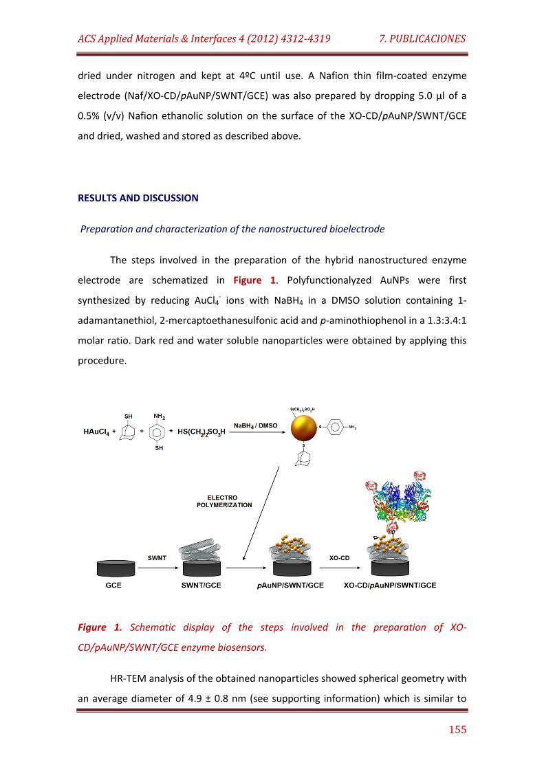
ACS Applied Materials & Interfaces 4 (2012) 4312-4319 7. PUBLICACIONES
155
dried under nitrogen and kept at 4ºC until use. A Nafion thin film-coated enzyme
electrode (Naf/XO-CD/pAuNP/SWNT/GCE) was also prepared by dropping 5.0 µl of a
0.5% (v/v) Nafion ethanolic solution on the surface of the XO-CD/pAuNP/SWNT/GCE
and dried, washed and stored as described above.
RESULTS AND DISCUSSION
Preparation and characterization of the nanostructured bioelectrode
The steps involved in the preparation of the hybrid nanostructured enzyme
electrode are schematized in Figure 1. Polyfunctionalyzed AuNPs were first
synthesized by reducing AuCl4- ions with NaBH4 in a DMSO solution containing 1-
adamantanethiol, 2-mercaptoethanesulfonic acid and p-aminothiophenol in a 1.3:3.4:1
molar ratio. Dark red and water soluble nanoparticles were obtained by applying this
procedure.
Figure 1. Schematic display of the steps involved in the preparation of XO-
CD/pAuNP/SWNT/GCE enzyme biosensors.
HR-TEM analysis of the obtained nanoparticles showed spherical geometry with
an average diameter of 4.9 ± 0.8 nm (see supporting information) which is similar to

ACS Applied Materials & Interfaces 4 (2012) 4312-4319 7. PUBLICACIONES
156
the size reported for other polyfunctionalized Au nanoparticles bearing other capping
ligands.15,16 19
4000 3000 2000 1000
85
90
95
100
S-O
cm-1
cm-1
C(aliph)
cm-1
S=O
C=C
CH2
cm-1
cm-1
Tra
nsm
itta
nce
(%
)
Wavenumbers (cm-1)
cm-1
Figure 2. FT-IR spectrum of the polyfunctionalized Au nanoparticles.
Figure 2 shows an FT-IR spectrum of the polyfunctionalyzed nanoparticles. The
presence of aniline residues in the nanomaterial was revealed by the broad and
intense band around 3460 cm-1, corresponding to the stretch vibration of the N-H
bonds. In addition, the presence of aniline moieties was confirmed by the bands at
1630 cm-1 and 1335 cm-1, corresponding to the N-H blending and C-N stretching,
respectively. This latter band is partially overlapped with the large band appearing in
the range of 1433 to 1385 cm-1, which can be ascribed to the overlapped S=O and C=C
stretching vibrations and CH2 blending, suggesting the presence of sulfonate, aromatic
and aliphatic groups in the modified nanoparticles, respectively. The presence of
sufonate residues can be also supported by the intense stretching vibration band of
the S-O bonds at 1040 cm-1, as well as by the stretching of aliphatic C-H bonds at 2850
cm-1. On the other hand, adamantane residues were confirmed by the C-H stretching
vibration at 2928 cm-1 revealing the presence of a cyclic aliphatic compound on the
nanoparticles surface. Finally, the formation of a covalent Au-S bond is supported by
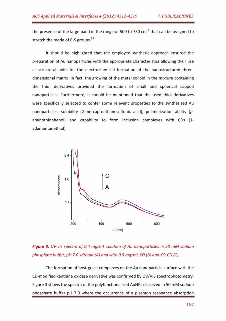
ACS Applied Materials & Interfaces 4 (2012) 4312-4319 7. PUBLICACIONES
157
the presence of the large band in the range of 500 to 750 cm-1 that can be assigned to
stretch the mode of C-S groups.25
It should be highlighted that the employed synthetic approach ensured the
preparation of Au nanoparticles with the appropriate characteristics allowing their use
as structural units for the electrochemical formation of the nanostructured three-
dimensional matrix. In fact, the growing of the metal colloid in the mixture containing
the thiol derivatives provided the formation of small and spherical capped
nanoparticles. Furthermore, it should be mentioned that the used thiol derivatives
were specifically selected to confer some relevant properties to the synthesized Au
nanoparticles: solubility (2-mercaptoethanesulfonic acid), polimerization ability (p-
aminothiophenol) and capability to form inclusion complexes with CDs (1-
adamantanethiol).
200 400 600 800
Ab
sorb
an
ce
(nm)
C
A
2.4
1.6
0.8
Figure 3. UV-vis spectra of 0.4 mg/mL solution of Au nanoparticles in 50 mM sodium
phosphate buffer, pH 7.0 without (A) and with 0.5 mg/mL XO (B) and XO-CD (C).
The formation of host-guest complexes on the Au nanoparticle surface with the
CD-modified xanthine oxidase derivative was confirmed by UV/VIS spectrophotometry.
Figure 3 shows the spectra of the polyfunctionalized AuNPs dissolved in 50 mM sodium
phosphate buffer pH 7.0 where the occurrence of a plasmon resonance absorption
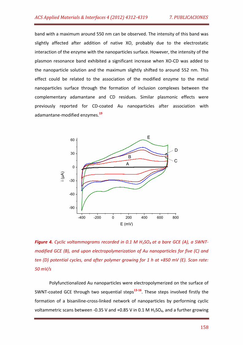
ACS Applied Materials & Interfaces 4 (2012) 4312-4319 7. PUBLICACIONES
158
band with a maximum around 550 nm can be observed. The intensity of this band was
slightly affected after addition of native XO, probably due to the electrostatic
interaction of the enzyme with the nanoparticles surface. However, the intensity of the
plasmon resonance band exhibited a significant increase when XO-CD was added to
the nanoparticle solution and the maximum slightly shifted to around 552 nm. This
effect could be related to the association of the modified enzyme to the metal
nanoparticles surface through the formation of inclusion complexes between the
complementary adamantane and CD residues. Similar plasmonic effects were
previously reported for CD-coated Au nanoparticles after association with
adamantane-modified enzymes.19
-400 -200 0 200 400 600 800
-90
-60
-30
0
30
60E
CB
D
i (µ
A)
E (mV)
A
Figure 4. Cyclic voltammograms recorded in 0.1 M H2SO4 at a bare GCE (A), a SWNT-
modified GCE (B), and upon electropolymerization of Au nanoparticles for five (C) and
ten (D) potential cycles, and after polymer growing for 1 h at +850 mV (E). Scan rate:
50 mV/s
Polyfunctionalized Au nanoparticles were electropolymerized on the surface of
SWNT-coated GCE through two sequential steps13-16. These steps involved firstly the
formation of a bisaniline-cross-linked network of nanoparticles by performing cyclic
voltammetric scans between -0.35 V and +0.85 V in 0.1 M H2SO4, and a further growing
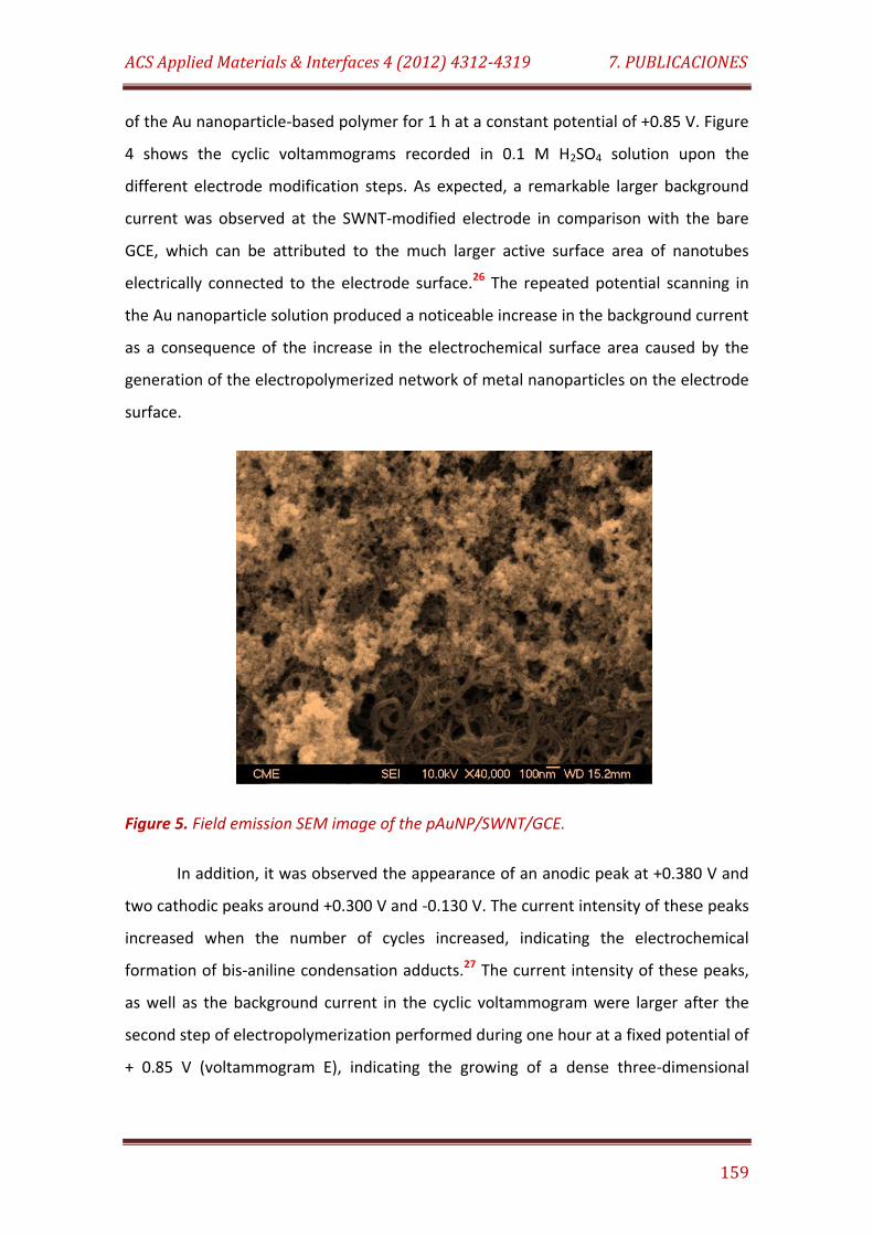
ACS Applied Materials & Interfaces 4 (2012) 4312-4319 7. PUBLICACIONES
159
of the Au nanoparticle-based polymer for 1 h at a constant potential of +0.85 V. Figure
4 shows the cyclic voltammograms recorded in 0.1 M H2SO4 solution upon the
different electrode modification steps. As expected, a remarkable larger background
current was observed at the SWNT-modified electrode in comparison with the bare
GCE, which can be attributed to the much larger active surface area of nanotubes
electrically connected to the electrode surface.26 The repeated potential scanning in
the Au nanoparticle solution produced a noticeable increase in the background current
as a consequence of the increase in the electrochemical surface area caused by the
generation of the electropolymerized network of metal nanoparticles on the electrode
surface.
Figure 5. Field emission SEM image of the pAuNP/SWNT/GCE.
In addition, it was observed the appearance of an anodic peak at +0.380 V and
two cathodic peaks around +0.300 V and -0.130 V. The current intensity of these peaks
increased when the number of cycles increased, indicating the electrochemical
formation of bis-aniline condensation adducts.27 The current intensity of these peaks,
as well as the background current in the cyclic voltammogram were larger after the
second step of electropolymerization performed during one hour at a fixed potential of
+ 0.85 V (voltammogram E), indicating the growing of a dense three-dimensional
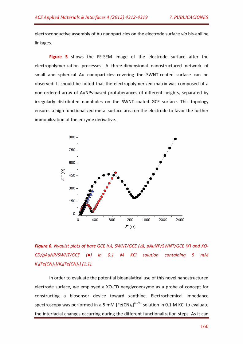
ACS Applied Materials & Interfaces 4 (2012) 4312-4319 7. PUBLICACIONES
160
electroconductive assembly of Au nanoparticles on the electrode surface via bis-aniline
linkages.
Figure 5 shows the FE-SEM image of the electrode surface after the
electropolymerization processes. A three-dimensional nanostructured network of
small and spherical Au nanoparticles covering the SWNT-coated surface can be
observed. It should be noted that the electropolymerized matrix was composed of a
non-ordered array of AuNPs-based protuberances of different heights, separated by
irregularly distributed nanoholes on the SWNT-coated GCE surface. This topology
ensures a high functionalized metal surface area on the electrode to favor the further
immobilization of the enzyme derivative.
Figure 6. Nyquist plots of bare GCE (), SWNT/GCE (), pAuNP/SWNT/GCE (X) and XO-
CD/pAuNP/SWNT/GCE () in 0.1 M KCl solution containing 5 mM
K3[Fe(CN)6]/K4[Fe(CN)6] (1:1).
In order to evaluate the potential bioanalytical use of this novel nanostructured
electrode surface, we employed a XO-CD neoglycoenzyme as a probe of concept for
constructing a biosensor device toward xanthine. Electrochemical impedance
spectroscopy was performed in a 5 mM [Fe(CN)6]4−/3− solution in 0.1 M KCl to evaluate
the interfacial changes occurring during the different functionalization steps. As it can
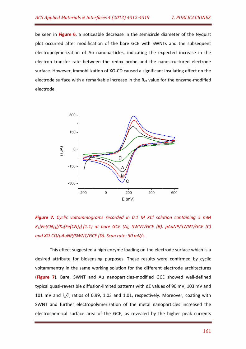
ACS Applied Materials & Interfaces 4 (2012) 4312-4319 7. PUBLICACIONES
161
be seen in Figure 6, a noticeable decrease in the semicircle diameter of the Nyquist
plot occurred after modification of the bare GCE with SWNTs and the subsequent
electropolymerization of Au nanoparticles, indicating the expected increase in the
electron transfer rate between the redox probe and the nanostructured electrode
surface. However, immobilization of XO-CD caused a significant insulating effect on the
electrode surface with a remarkable increase in the Ret value for the enzyme-modified
electrode.
-200 0 200 400 600
-300
-150
0
150
300
i (µ
A)
E (mV)
A
B
C
D
Figure 7. Cyclic voltammograms recorded in 0.1 M KCl solution containing 5 mM
K3[Fe(CN)6]/K4[Fe(CN)6] (1:1) at bare GCE (A), SWNT/GCE (B), pAuNP/SWNT/GCE (C)
and XO-CD/pAuNP/SWNT/GCE (D). Scan rate: 50 mV/s.
This effect suggested a high enzyme loading on the electrode surface which is a
desired attribute for biosensing purposes. These results were confirmed by cyclic
voltammentry in the same working solution for the different electrode architectures
(Figure 7). Bare, SWNT and Au nanoparticles-modified GCE showed well-defined
typical quasi-reversible diffusion-limited patterns with ∆E values of 90 mV, 103 mV and
101 mV and ia/ic ratios of 0.99, 1.03 and 1.01, respectively. Moreover, coating with
SWNT and further electropolymerization of the metal nanoparticles increased the
electrochemical surface area of the GCE, as revealed by the higher peak currents
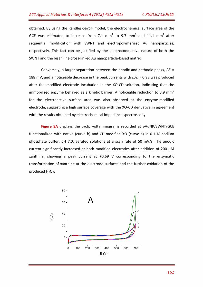
ACS Applied Materials & Interfaces 4 (2012) 4312-4319 7. PUBLICACIONES
162
obtained. By using the Randles-Sevcik model, the electrochemical surface area of the
GCE was estimated to increase from 7.1 mm2 to 9.7 mm2 and 11.1 mm2 after
sequential modification with SWNT and electropolymerized Au nanoparticles,
respectively. This fact can be justified by the electroconductive nature of both the
SWNT and the bisaniline cross-linked Au nanoparticle-based matrix.
Conversely, a larger separation between the anodic and cathodic peaks, ∆E =
188 mV, and a noticeable decrease in the peak currents with ia/ic = 0.93 was produced
after the modified electrode incubation in the XO-CD solution, indicating that the
immobilized enzyme behaved as a kinetic barrier. A noticeable reduction to 3.9 mm2
for the electroactive surface area was also observed at the enzyme-modified
electrode, suggesting a high surface coverage with the XO-CD derivative in agreement
with the results obtained by electrochemical impedance spectroscopy.
Figure 8A displays the cyclic voltammograms recorded at pAuNP/SWNT/GCE
functionalized with native (curve b) and CD-modified XO (curve a) in 0.1 M sodium
phosphate buffer, pH 7.0, aerated solutions at a scan rate of 50 mV/s. The anodic
current significantly increased at both modified electrodes after addition of 200 µM
xanthine, showing a peak current at +0.69 V corresponding to the enzymatic
transformation of xanthine at the electrode surfaces and the further oxidation of the
produced H2O2.
0 100 200 300 400 500 600 700
0
20
40
60
80d
c
b
i (µ
A)
E (V)
a
A
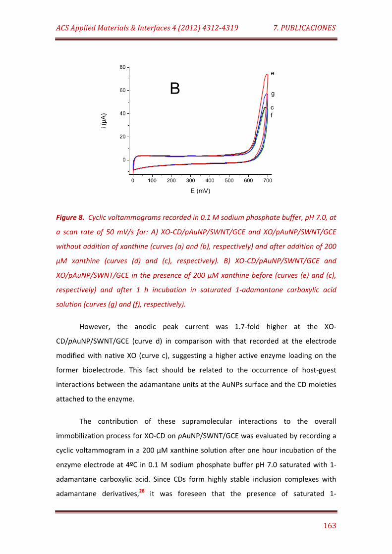
ACS Applied Materials & Interfaces 4 (2012) 4312-4319 7. PUBLICACIONES
163
0 100 200 300 400 500 600 700
0
20
40
60
80
g
e
ci (µ
A)
E (mV)
f
B
Figure 8. Cyclic voltammograms recorded in 0.1 M sodium phosphate buffer, pH 7.0, at
a scan rate of 50 mV/s for: A) XO-CD/pAuNP/SWNT/GCE and XO/pAuNP/SWNT/GCE
without addition of xanthine (curves (a) and (b), respectively) and after addition of 200
µM xanthine (curves (d) and (c), respectively). B) XO-CD/pAuNP/SWNT/GCE and
XO/pAuNP/SWNT/GCE in the presence of 200 µM xanthine before (curves (e) and (c),
respectively) and after 1 h incubation in saturated 1-adamantane carboxylic acid
solution (curves (g) and (f), respectively).
However, the anodic peak current was 1.7-fold higher at the XO-
CD/pAuNP/SWNT/GCE (curve d) in comparison with that recorded at the electrode
modified with native XO (curve c), suggesting a higher active enzyme loading on the
former bioelectrode. This fact should be related to the occurrence of host-guest
interactions between the adamantane units at the AuNPs surface and the CD moieties
attached to the enzyme.
The contribution of these supramolecular interactions to the overall
immobilization process for XO-CD on pAuNP/SWNT/GCE was evaluated by recording a
cyclic voltammogram in a 200 µM xanthine solution after one hour incubation of the
enzyme electrode at 4ºC in 0.1 M sodium phosphate buffer pH 7.0 saturated with 1-
adamantane carboxylic acid. Since CDs form highly stable inclusion complexes with
adamantane derivatives,28 it was foreseen that the presence of saturated 1-
ACS Applied Materials & Interfaces 4 (2012) 4312-4319 7. PUBLICACIONES
164
adamantane carboxylic acid in the incubation medium could compete with the
multiple host-guest interactions between the immobilized enzyme and the
adamantane-coated Au nanoparticles electropolymerized network at the GCE surface.
As a control, a pAuNP/SWNT/GCE modified with native XO was also checked under the
same conditions.
Figure 8B shows as the peak current measured at +0.69 V did not significantly
change for the XO/pAuNP/SWNT/GCE after 1 hour incubation in the 1-adamantane
carboxylic acid solution, suggesting that the activity of the native enzyme was not
affected by the incubation process.22, 29 However, a noticeable decrease in the peak
current was observed with the XO-CD/pAuNP/SWNT/GCE after incubation, suggesting
lower amount of enzyme activity at the electrode surface. This effect could be caused
by the competitive interaction of 1-adamantane carboxylic acid with the CD moieties
attached to the enzyme surface, then affecting the supramolecular association of the
enzyme with the adamantane moieties at the nanoparticles and releasing certain
amount of enzyme molecules from the electrode surface. However, further studies
should be performed to demonstrate this hypothesis.
Nevertheless, it should be stated that there are other forces that should also
contribute to the immobilization of XO-CD on the surface of pAuNP/SWNT/GCE
besides the commented host-guest supramolecular interactions. The occurrence of
physical adsorption of the enzyme derivative on the exposed SWNT-coated surface as
well as electrostatic interactions with the charged groups at the surface of the
nanoparticle-based matrix can play also a role in the overall enzyme immobilization
process.
Analytical performance of the nanostructured enzyme electrode
The bioelectrode prepared through the supramolecular approach was used to
construct an amperometric enzyme biosensor toward xanthine. The values to be
selected for the working pH and applied potential were determined by checking the
steady-state current and the signal-to- noise ratio measured for 500 nM xanthine.
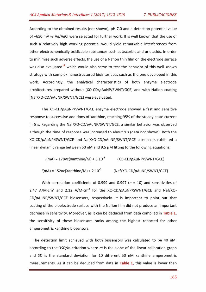
ACS Applied Materials & Interfaces 4 (2012) 4312-4319 7. PUBLICACIONES
165
According to the obtained results (not shown), pH 7.0 and a detection potential value
of +650 mV vs Ag/AgCl were selected for further work. It is well known that the use of
such a relatively high working potential would yield remarkable interferences from
other electrochemically oxidizable substances such as ascorbic and uric acids. In order
to minimize such adverse effects, the use of a Nafion thin film on the electrode surface
was also evaluated12 which would also serve to test the behavior of this well-known
strategy with complex nanostructured biointerfaces such as the one developed in this
work. Accordingly, the analytical characteristics of both enzyme electrode
architectures prepared without (XO-CD/pAuNP/SWNT/GCE) and with Nafion coating
(Naf/XO-CD/pAuNP/SWNT/GCE) were evaluated.
The XO-CD/pAuNP/SWNT/GCE enzyme electrode showed a fast and sensitive
response to successive additions of xanthine, reaching 95% of the steady-state current
in 5 s. Regarding the Naf/XO-CD/pAuNP/SWNT/GCE, a similar behavior was observed
although the time of response was increased to about 9 s (data not shown). Both the
XO-CD/pAuNP/SWNT/GCE and Naf/XO-CD/pAuNP/SWNT/GCE biosensors exhibited a
linear dynamic range between 50 nM and 9.5 µM fitting to the following equations:
i(mA) = 178×c(Xanthine/M) + 3·10-5 (XO-CD/pAuNP/SWNT/GCE)
i(mA) = 152×c(Xanthine/M) + 2·10-5 (Naf/XO-CD/pAuNP/SWNT/GCE)
With correlation coefficients of 0.999 and 0.997 (n = 10) and sensitivities of
2.47 A/M·cm2 and 2.12 A/M·cm2 for the XO-CD/pAuNP/SWNT/GCE and Naf/XO-
CD/pAuNP/SWNT/GCE biosensors, respectively. It is important to point out that
coating of the bioelectrode surface with the Nafion film did not produce an important
decrease in sensitivity. Moreover, as it can be deduced from data compiled in Table 1,
the sensitivity of these biosensors ranks among the highest reported for other
amperometric xanthine biosensors.
The detection limit achieved with both biosensors was calculated to be 40 nM,
according to the 3SD/m criterion where m is the slope of the linear calibration graph
and SD is the standard deviation for 10 different 50 nM xanthine amperometric
measurements. As it can be deduced from data in Table 1, this value is lower than
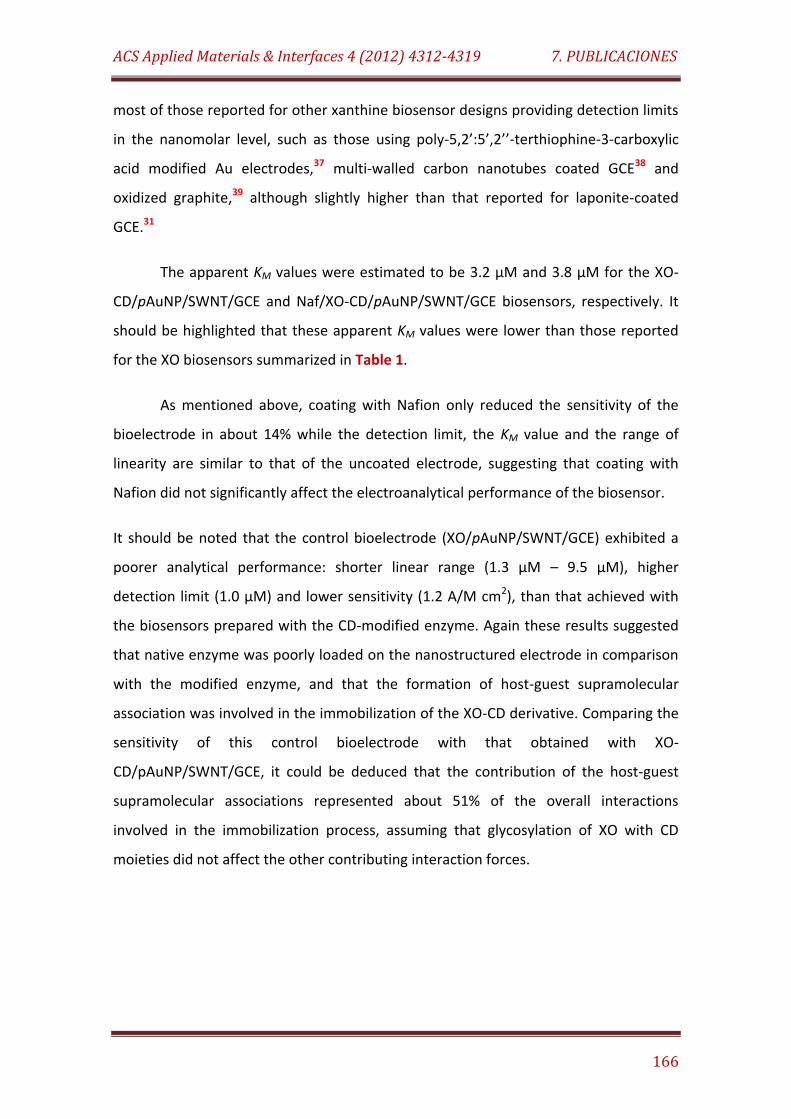
ACS Applied Materials & Interfaces 4 (2012) 4312-4319 7. PUBLICACIONES
166
most of those reported for other xanthine biosensor designs providing detection limits
in the nanomolar level, such as those using poly-5,2’:5’,2’’-terthiophine-3-carboxylic
acid modified Au electrodes,37 multi-walled carbon nanotubes coated GCE38 and
oxidized graphite,39 although slightly higher than that reported for laponite-coated
GCE.31
The apparent KM values were estimated to be 3.2 µM and 3.8 µM for the XO-
CD/pAuNP/SWNT/GCE and Naf/XO-CD/pAuNP/SWNT/GCE biosensors, respectively. It
should be highlighted that these apparent KM values were lower than those reported
for the XO biosensors summarized in Table 1.
As mentioned above, coating with Nafion only reduced the sensitivity of the
bioelectrode in about 14% while the detection limit, the KM value and the range of
linearity are similar to that of the uncoated electrode, suggesting that coating with
Nafion did not significantly affect the electroanalytical performance of the biosensor.
It should be noted that the control bioelectrode (XO/pAuNP/SWNT/GCE) exhibited a
poorer analytical performance: shorter linear range (1.3 µM – 9.5 µM), higher
detection limit (1.0 µM) and lower sensitivity (1.2 A/M cm2), than that achieved with
the biosensors prepared with the CD-modified enzyme. Again these results suggested
that native enzyme was poorly loaded on the nanostructured electrode in comparison
with the modified enzyme, and that the formation of host-guest supramolecular
association was involved in the immobilization of the XO-CD derivative. Comparing the
sensitivity of this control bioelectrode with that obtained with XO-
CD/pAuNP/SWNT/GCE, it could be deduced that the contribution of the host-guest
supramolecular associations represented about 51% of the overall interactions
involved in the immobilization process, assuming that glycosylation of XO with CD
moieties did not affect the other contributing interaction forces.
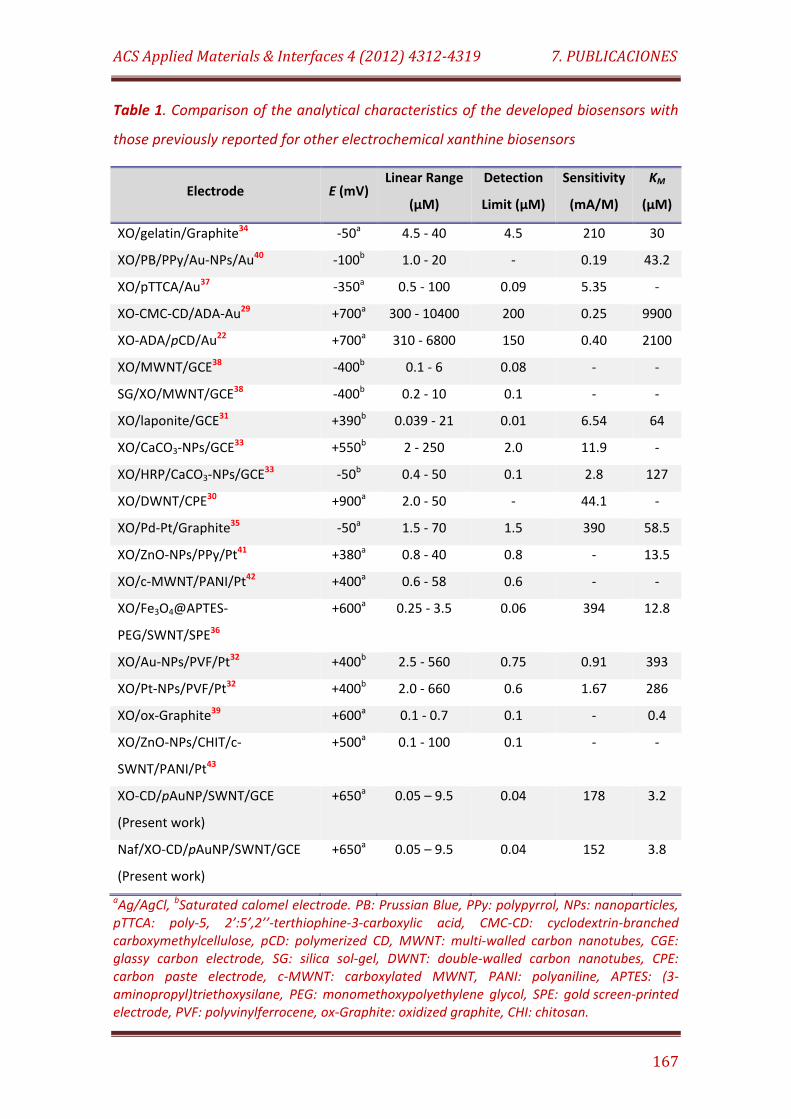
ACS Applied Materials & Interfaces 4 (2012) 4312-4319 7. PUBLICACIONES
167
Table 1. Comparison of the analytical characteristics of the developed biosensors with
those previously reported for other electrochemical xanthine biosensors
Electrode E (mV) Linear Range
(µM)
Detection
Limit (µM)
Sensitivity
(mA/M)
KM
(µM)
XO/gelatin/Graphite34 -50a 4.5 - 40 4.5 210 30
XO/PB/PPy/Au-NPs/Au40 -100b 1.0 - 20 - 0.19 43.2
XO/pTTCA/Au37 -350a 0.5 - 100 0.09 5.35 -
XO-CMC-CD/ADA-Au29 +700a 300 - 10400 200 0.25 9900
XO-ADA/pCD/Au22 +700a 310 - 6800 150 0.40 2100
XO/MWNT/GCE38 -400b 0.1 - 6 0.08 - -
SG/XO/MWNT/GCE38 -400b 0.2 - 10 0.1 - -
XO/laponite/GCE31 +390b 0.039 - 21 0.01 6.54 64
XO/CaCO3-NPs/GCE33 +550b 2 - 250 2.0 11.9 -
XO/HRP/CaCO3-NPs/GCE33 -50b 0.4 - 50 0.1 2.8 127
XO/DWNT/CPE30 +900a 2.0 - 50 - 44.1 -
XO/Pd-Pt/Graphite35 -50a 1.5 - 70 1.5 390 58.5
XO/ZnO-NPs/PPy/Pt41 +380a 0.8 - 40 0.8 - 13.5
XO/c-MWNT/PANI/Pt42 +400a 0.6 - 58 0.6 - -
XO/Fe3O4@APTES-
PEG/SWNT/SPE36
+600a 0.25 - 3.5 0.06 394 12.8
XO/Au-NPs/PVF/Pt32 +400b 2.5 - 560 0.75 0.91 393
XO/Pt-NPs/PVF/Pt32 +400b 2.0 - 660 0.6 1.67 286
XO/ox-Graphite39 +600a 0.1 - 0.7 0.1 - 0.4
XO/ZnO-NPs/CHIT/c-
SWNT/PANI/Pt43
+500a 0.1 - 100 0.1 - -
XO-CD/pAuNP/SWNT/GCE
(Present work)
+650a 0.05 – 9.5 0.04 178 3.2
Naf/XO-CD/pAuNP/SWNT/GCE
(Present work)
+650a 0.05 – 9.5 0.04 152 3.8
aAg/AgCl, bSaturated calomel electrode. PB: Prussian Blue, PPy: polypyrrol, NPs: nanoparticles, pTTCA: poly-5, 2’:5’,2’’-terthiophine-3-carboxylic acid, CMC-CD: cyclodextrin-branched carboxymethylcellulose, pCD: polymerized CD, MWNT: multi-walled carbon nanotubes, CGE: glassy carbon electrode, SG: silica sol-gel, DWNT: double-walled carbon nanotubes, CPE: carbon paste electrode, c-MWNT: carboxylated MWNT, PANI: polyaniline, APTES: (3-aminopropyl)triethoxysilane, PEG: monomethoxypolyethylene glycol, SPE: gold screen-printed electrode, PVF: polyvinylferrocene, ox-Graphite: oxidized graphite, CHI: chitosan.

ACS Applied Materials & Interfaces 4 (2012) 4312-4319 7. PUBLICACIONES
168
The repeatability of the measurements carried out with one single XO-
CD/pAuNP/SWNT/GCE or Naf/XO-CD/pAuNP/SWNT/GCE biosensor was checked for
500 nM xanthine (n = 10), yielding relative standard deviation (RSD) values of 3.9% and
5.2%, respectively. Moreover, the electrode-to-electrode reproducibility was
calculated from the responses of ten different bioelectrodes prepared in the same
manner toward 500 nM xanthine. The obtained RSD values were 6.7% and 8.6% for the
XO-CD/pAuNP/SWNT/GCE and Naf/XO-CD/pAuNP/SWNT/GCE biosensors, respectively.
The slightly higher RSD values observed for the Naf/XO-CD/pAuNP/SWNT/GCE should
be related to the additional step of Nafion thin film formation during the preparation
of the enzyme electrodes.
Naf/XO-CD/pAuNP/SWNT/GCE
Interferants
5.0 µM
Xanthine
0.5 µMa b c d e f g h
g h
XO-CD/pAuNP/SWNT/GCE
Xanthine
0.5 µM
200 nA
Figure 9. Amperometric responses of the XO-CD/pAuNP/SWNT/GCE and Naf/XO-
CD/pAuNP/SWNT/GCE biosensors toward 500 nM xanthine upon addition of glucose
(a), sacarose (b), ethanol (c), acetic acid (d), lactic acid (e), citric acid (f), uric acid (g)
and ascorbic acid (h) at a 5.0 µM concentration level.
The selectivity of the biosensors was evaluated in the presence of eight possible
interfering substances: glucose, sacarose, ethanol, acetic acid, lactic acid, citric acid,
uric acid and ascorbic acid. Figure 9 shows the influence of these possible interfering
compounds added at a 5.0 µM concentration level on the amperometric signal
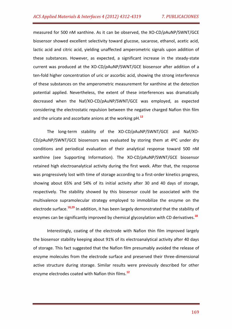
ACS Applied Materials & Interfaces 4 (2012) 4312-4319 7. PUBLICACIONES
169
measured for 500 nM xanthine. As it can be observed, the XO-CD/pAuNP/SWNT/GCE
biosensor showed excellent selectivity toward glucose, sacarose, ethanol, acetic acid,
lactic acid and citric acid, yielding unaffected amperometric signals upon addition of
these substances. However, as expected, a significant increase in the steady-state
current was produced at the XO-CD/pAuNP/SWNT/GCE biosensor after addition of a
ten-fold higher concentration of uric or ascorbic acid, showing the strong interference
of these substances on the amperometric measurement for xanthine at the detection
potential applied. Nevertheless, the extent of these interferences was dramatically
decreased when the Naf/XO-CD/pAuNP/SWNT/GCE was employed, as expected
considering the electrostatic repulsion between the negative charged Nafion thin film
and the uricate and ascorbate anions at the working pH.12
The long-term stability of the XO-CD/pAuNP/SWNT/GCE and Naf/XO-
CD/pAuNP/SWNT/GCE biosensors was evaluated by storing them at 4ºC under dry
conditions and periodical evaluation of their analytical response toward 500 nM
xanthine (see Supporting Information). The XO-CD/pAuNP/SWNT/GCE biosensor
retained high electroanalytical activity during the first week. After that, the response
was progressively lost with time of storage according to a first-order kinetics progress,
showing about 65% and 54% of its initial activity after 30 and 40 days of storage,
respectively. The stability showed by this biosensor could be associated with the
multivalence supramolecular strategy employed to immobilize the enzyme on the
electrode surface.18,29 In addition, it has been largely demonstrated that the stability of
enzymes can be significantly improved by chemical glycosylation with CD derivatives.18
Interestingly, coating of the electrode with Nafion thin film improved largely
the biosensor stability keeping about 91% of its electroanalytical activity after 40 days
of storage. This fact suggested that the Nafion film presumably avoided the release of
enzyme molecules from the electrode surface and preserved their three-dimensional
active structure during storage. Similar results were previously described for other
enzyme electrodes coated with Nafion thin films.12
ACS Applied Materials & Interfaces 4 (2012) 4312-4319 7. PUBLICACIONES
170
CONCLUSIONS
The electropolymerization of polyfunctionalized Au nanoparticles, bearing
aniline, sulfonic acid and adamantane residues, through the formation of bis-aniline
linkages on SWNTs-modified GCEs served as efficient electrode platforms to form
supramolecular host-guest complexes with CD-modified enzymes. These electrode
surfaces, exhibiting molecular receptor capacity, were, in particular, employed as
support for the supramolecular immobilization of the glycoenzyme XO-ADA and
further construction of an amperometric biosensor for xanthine. The enzyme electrode
exhibited good sentitivity and stability, a very low detection limit, as well as fast
electroanalytical response toward the analyte. In fact, the analytical performance of
the supramolecular enzyme immobilization based biosensor ranked among the best
achieved when compared with those previosly reported for other XO electrochemical
biosensors. Therefore, according to these results, we can anticipate the use of this
bisaniline-cross-linked nanostructured network of metal nanoparticles on SWNT-
coated electrodes as an excellent strategy to prepare enzyme biosensors with
supramolecular architecture.
ASSOCIATED CONTENT
Supporting Information. Additional characterization of the nanoparticles and
chronoamperometric and stability studies for the biosensors. This material is available
free of charge via the Internet at http://pubs.acs.org.
AUTHOR INFORMATION
Corresponding Authors
*E-mail: [email protected], [email protected]
ACS Applied Materials & Interfaces 4 (2012) 4312-4319 7. PUBLICACIONES
171
ACKNOWLEDGEMENTS
R. Villalonga acknowledge to Ramón & Cajal contract from the Spanish Ministry
of Science and Innovation. Financial support from the Spanish Ministry of Science and
Innovation CTQ2011-24355, CTQ2009-12650, CTQ2009-09351 and Comunidad de
Madrid S2009/PPQ-1642, programme AVANSENS is gratefully acknowledged.
REFERENCES
(1) Grieshaber, D.; MacKenzie, R.; Vörös, J.; Reimhult, E. Sensors 2008, 8, 1400-
1458.
(2) Wang, J. Analyst 2005, 130, 421-426.
(3) Kumar, C. S. S. R. Nanomaterials for biosensors. Nanotechnologies for the life
sciences, Wiley-VCH, Weinheim, 2006, Vol. 8.
(4) Li, S.; Singh, J.; Li, H.; Banerjee, I. A. Biosensor Nanomaterials, Wiley-VCH,
Weinheim, 2011.
(5) Shao, Y.; Wang, J.; Wu, H.; Liu, J.; Aksay, I. A.; Lin, Y. Electroanalysis 2010, 22,
1027-1036.
(6) Yang, W.; Ratinac, K. R.; Ringer, S. P.; Thordarson, P.; Gooding, J. J.; Braet, F.
Angew. Chem., Int. Ed. 2010, 49, 2114-2138.
(7) Yeom, S. H.; Kang, B. H.; Kim, K. J.; Kang, S. W. Front. Biosci. 2011, 16, 997-1023.
(8) Pingarrón, J. M.; Yáñez-Sedeño, P.; González-Cortés, A. Electrochim. Acta 2008,
53, 5848-5866.
(9) Luo, X.; Morrin, A.; Killard, A. J.; Smyth, M. R. Electroanalysis 2006, 18, 319-326.
(10) Agüi, L.; Yañez-Sedeño, P.; Pingarrón, J. M. Anal. Chim. Acta 2008, 622, 11-47.
(11) Wang, J. Electroanalysis 2005, 17, 7-14.
ACS Applied Materials & Interfaces 4 (2012) 4312-4319 7. PUBLICACIONES
172
(12) Eguílaz, M.; Villalonga, R.; Agüí, L.; Yáñez-Sedeño, P.; Pingarrón, J.M. J.
Electroanal. Chem. 2011, 661, 171-178.
(13) Riskin, M.; Tel-Vered, R.; Willner, I. Adv. Mater. 2010, 22, 1387-1391.
(14) Frasconi, M.; Tel-Vered, R.; Riskin, M.; Willner, I. Anal. Chem. 2010, 82, 2512-
2519.
(15) Villalonga, R.; Díez, P.; Yañez-Sedeño, P.; Pingarrón, J. M. Electrochim. Acta
2011, 56, 4672-4677.
(16) Villalonga, R.; Diez, P.; Casado, S.; Eguílaz, M.; Yañez-Sedeño, P.; Pingarrón, J.
M. Analyst 2012, 137, 342-348.
(17) Fragoso, A.; Caballero, J.; Almirall, E.; Villalonga, R.; Cao, R. Langmuir 2002, 18,
5051-5054.
(18) Villalonga, R.; Cao, R.; Fragoso, A. Chem. Rev. 2007, 107, 3088-3116.
(19) Villalonga, R.; Cao, R.; Fragoso, A.; Damiao, A. E.; Ortiz, P. D.; Caballero, J. J.
Mol. Catal. B: Enzym. 2005, 35, 79-85.
(20) Camacho, C.; Chico, B.; Cao, R.; Matías, J. C.; Hernández, J.; Palchetti, I.;
Simpson, B. K.; Mascini, M.; Villalonga, R. Biosens. Bioelectron. 2009, 24, 2028-2033.
(21) Camacho, C.; Matías, J. C.; Cao, R.; Matos, M.; Chico, B.; Hernández, J.; Longo,
M. A.; Sanromán, M. A.; Villalonga, R. Langmuir 2008, 24, 7654-7657.
(22) Villalonga, R.; Camacho, C.; Cao, R.; Hernández, J.; Matias, J. C. Chem. Commun.
2007, 942-944.
(23) Baussanne, I.; Benito, J. M.; Ortiz Mellet, C.; García Fernández, J. M.; Lawa, H.;
Defaye, J. Chem. Commun. 2000, 1489-1490.
(24) Fernández, M.; Fragoso, A.; Cao, R.; Villalonga, R. J. Mol. Catal. B: Enzym. 2003,
21, 133-141.
(25) Tlili, A.; Abdelghani, A.; Hleli, S.; Maaref, M. A. Sensors 2004, 4, 105-114.
ACS Applied Materials & Interfaces 4 (2012) 4312-4319 7. PUBLICACIONES
173
(26) Lu, T. L.; Tsai, Y. C. Sens. Actuators, B 2010, 148, 590-594.
(27) Duić, L.; Mandić, Z.; Kovač, S. Electrochim. Acta 1995, 40, 1681-1688.
(28) Cromwell, W. C.; Byström, K.; Eftink, M. R. J. Phys. Chem. 1985, 89, 326-332.
(29) Villalonga, R.; Matos, M.; Cao, R. Electrochem. Commun. 2007, 9, 454-458.
(30) Anik, Ü.; Çevi, S. Microchim. Acta 2009, 166, 209-213.
(31) Shan, D.; Wang, Y. N.; Xue, H. G.; Cosnier, S.; Ding, S. N. Biosens. Bioelectron.
2009, 24, 3556-3561.
(32) Bas, S. Z.; Gulce, H.; Yildiz, S.; Gulce, A. Talanta 2011, 87, 189-196.
(33) Shan, D.; Wang, Y.; Xue, H.; Cosnier, S. Sens. Actuators, B 2009, 136, 510-515.
(34) Dimcheva, N.; Horozova, E.; Jordanova, Z. Z. Naturforsch., C: J. Biosci. 2002, 57,
883-889.
(35) Dodevska, T.; Horozova, E.; Dimcheva, N. Cent. Eur. J. Chem. 2010, 8, 19-27.
(36) Villalonga, R.; Villalonga, M. L.; Díez, P; Pingarrón, J. M. J. Mater. Chem. 2011,
21, 12858-12864.
(37) Rahman, M. A.; Won, M. S.; Shim, Y. B. Electroanalysis 2007, 19, 631-637.
(38) Gao, Y.; Shen, C.; Di, J.; Tu, Y. Mater. Sci. Eng., C 2009, 29, 2213-2216.
(39) Devi, R.; Narang, J.; Yadav, S.; Pundir, C. S. J. Anal. Chem. 2012, 67, 273-277.
(40) Liu, Y.; Nie, L.; Tao, W.; Yao, S. Electroanalysis 2004, 16, 1271-1278.
(41) Devi, R.; Thakur, M.; Pundir, C. S. Biosens. Bioelectron. 2011, 26, 3420-3426.
(42) Devi, R.; Yadav, S.; Pundir, C. S. Biochem. Eng. J. 2011, 58–59, 148-153.
(43) Devi, R.; Yadav, S.; Pundir, C. S. Analyst 2012, 137, 754-759.
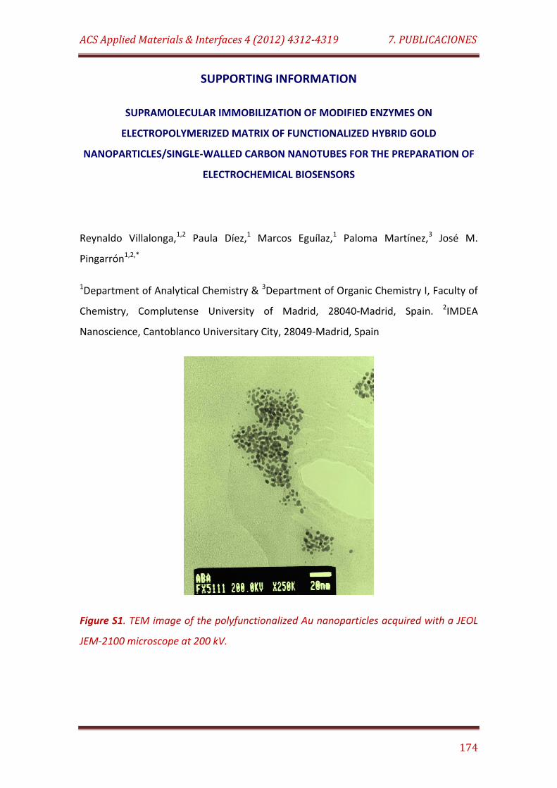
ACS Applied Materials & Interfaces 4 (2012) 4312-4319 7. PUBLICACIONES
174
SUPPORTING INFORMATION
SUPRAMOLECULAR IMMOBILIZATION OF MODIFIED ENZYMES ON
ELECTROPOLYMERIZED MATRIX OF FUNCTIONALIZED HYBRID GOLD
NANOPARTICLES/SINGLE-WALLED CARBON NANOTUBES FOR THE PREPARATION OF
ELECTROCHEMICAL BIOSENSORS
Reynaldo Villalonga,1,2 Paula Díez,1 Marcos Eguílaz,1 Paloma Martínez,3 José M.
Pingarrón1,2,*
1Department of Analytical Chemistry & 3Department of Organic Chemistry I, Faculty of
Chemistry, Complutense University of Madrid, 28040-Madrid, Spain. 2IMDEA
Nanoscience, Cantoblanco Universitary City, 28049-Madrid, Spain
Figure S1. TEM image of the polyfunctionalized Au nanoparticles acquired with a JEOL
JEM-2100 microscope at 200 kV.
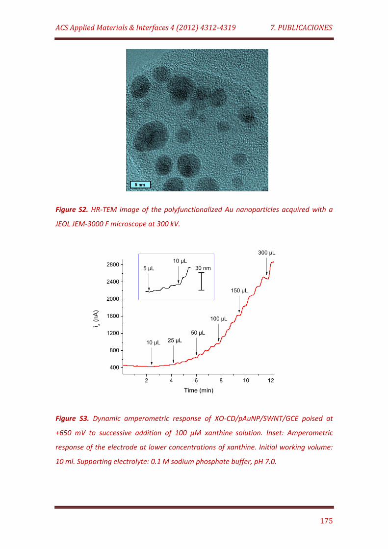
ACS Applied Materials & Interfaces 4 (2012) 4312-4319 7. PUBLICACIONES
175
Figure S2. HR-TEM image of the polyfunctionalized Au nanoparticles acquired with a
JEOL JEM-3000 F microscope at 300 kV.
2 4 6 8 10 12
400
800
1200
1600
2000
2400
2800
300 µL
i a (
nA
)
Time (min)
30 nm5 µL
10 µL
150 µL
100 µL
50 µL
25 µL 10 µL
Figure S3. Dynamic amperometric response of XO-CD/pAuNP/SWNT/GCE poised at
+650 mV to successive addition of 100 µM xanthine solution. Inset: Amperometric
response of the electrode at lower concentrations of xanthine. Initial working volume:
10 ml. Supporting electrolyte: 0.1 M sodium phosphate buffer, pH 7.0.
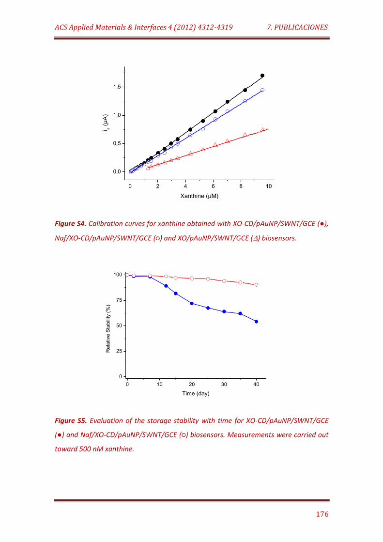
ACS Applied Materials & Interfaces 4 (2012) 4312-4319 7. PUBLICACIONES
176
0 2 4 6 8 10
0,0
0,5
1,0
1,5
i a (
µA
)
Xanthine (µM)
Figure S4. Calibration curves for xanthine obtained with XO-CD/pAuNP/SWNT/GCE (),
Naf/XO-CD/pAuNP/SWNT/GCE () and XO/pAuNP/SWNT/GCE () biosensors.
0 10 20 30 40
0
25
50
75
100
Re
lative
Sta
bili
ty (
%)
Time (day)
Figure S5. Evaluation of the storage stability with time for XO-CD/pAuNP/SWNT/GCE
() and Naf/XO-CD/pAuNP/SWNT/GCE () biosensors. Measurements were carried out
toward 500 nM xanthine.
7.5
Electroanalysis 23 (2011) 1790-1796
Immobilization of xanthine oxidase on carbon nanotubes through
double supramolecular junctions for biosensor construction

Electroanalysis 23 (2011) 1790-1796 7. PUBLICACIONES
177
IMMOBILIZATION OF XANTHINE OXIDASE ON CARBON NANOTUBES
THROUGH DOUBLE SUPRAMOLECULAR JUNCTIONS FOR BIOSENSOR
CONSTRUCTION
Reynaldo Villalonga, Paula Diez, María Gamella, Julio Reviejo, José M. Pingarrón*
Department of Analytical Chemistry, Faculty of Chemistry, Complutense University of
Madrid, 28040-Madrid, Spain
*Corresponding author. Phone: +34 91 3944315, Fax: +34 91 3944329,
E-mail: [email protected]
ABSTRACT
A novel approach for the non-covalent functionalization of single walled carbon
nanotubes with enzymes, using a β-cyclodextrin-modified pyrene derivative, mono-6-
ethylenediamino-(2-pyrene carboxamido)-6-deoxy-β-cyclodextrin (Pyr-βCD), as a
molecular bridge for the construction of a supramolecular assembly between the
nanotube surface and an adamantane-modified enzyme, is reported. The Pyr-βCD
derivative was synthesized and its stacking to SWNT through π-π interactions
accomplished. The functionalized nanotubes showed low capacity for the non-specific
adsorption of proteins, but were able to immobilize adamantane-modified xanthine
oxidase via host-guest associations. This double supramolecular junctions-based
approach was employed to modify a glassy carbon electrode with the
enzyme/nanotubes complex for designing a biosensor device toward xanthine. The
biosensor showed fast electroanalytical response (10 s), high sensitivity (5.9 mA/M
cm2) low detection limit (2 µM) and high stability.
Electroanalysis 23 (2011) 1790-1796 7. PUBLICACIONES
178
KEYWORDS: Single walled carbon nanotube, supramolecular assembly, enzyme
biosensor, cyclodextrin
INTRODUCTION
Multi- and single walled carbon nanotubes (SWNT) are wire-shaped nanosized
materials with unique electrical, mechanical and thermal characteristics [1-2]. These
properties allow carbon nanotubes to be the central core of novel advanced materials
with potential applications in hydrogen storage [3], tissue engineering [4-5], the
preparation of reinforced materials and coatings [6-7], nano and molecular electronics
[8], drug delivery systems [9] and biosensor construction [10-12].
However, there are several disadvantages associated with the intrinsic
characteristics of carbon nanotubes that make rather difficult their wide use with
biomolecules. For instance, unmodified carbon nanotubes have poor solubility in any
solvent and lack proper chemical functionalities needed to obtain stable and specific
unions with proteins and nucleic acids [13]. These problems can be overcome by
chemical activation of carbon nanotubes through a great variety of well know
reactions, but it has been proved that such activation methods significantly affect the
structure and electroconductive properties of these materials [14-15]. It has been also
described that several proteins undergo structural changes and inactivation upon
adsorption on SWNT [16], reducing the success of this immobilization strategy for
biomolecules. On the other hand, the occurrence of non-specific adsorption of
proteins on the side wall of carbon nanotubes affects the design of reliable drug
delivery systems and analytical biosensors [17-18]. For these reasons, the
development of new strategies for improving solubility of carbon nanotubes in
aqueous systems, reducing non-specific protein adsorption processes and favouring
the specific immobilization of biomolecules without affecting the structure and
properties of these nanomaterials receives considerable attention.
Dai´s group [19] proposed the use of pyrene derivatives as a controlled and
specific method for the non-covalent functionalization of SWNT via the formation of π-
Electroanalysis 23 (2011) 1790-1796 7. PUBLICACIONES
179
π stacking. It was confirmed that solubility and capacity to immobilize protein via
covalent linkage to the pyrene derivatives was conferred to SWNT through this
supramolecular approach. Furthermore, it has been reported the synthesis of β-
cyclodextrin (βCD) modified pyrene derivatives which were used to functionalize
SWNT. This strategy conferred enhanced solubility and molecular receptor properties
to these nanomaterials [20-22]. This kind of βCD-based adducts were evaluated as
molecular receptors for the host-guest immobilization of chemically hydrophobized
proteins on electrode surfaces. In fact, it was previously reported that adamantane-
modified proteins could be easily immobilized on βCD-coated metal electrodes
through the formation of supramolecular complexes [23]. Such approach was further
employed to construct stable enzyme biosensors with supramolecular design [24-26].
In this work we propose a novel approach for the non-covalent
functionalization of SWNT with enzymes, using a βCD-modified pyrene derivative as a
molecular bridge for the construction of a supramolecular assembly between the
nanotube surface and an adamantane-modified enzyme. In order to do that, the
synthesis of mono-6-ethylenediamino-(2-pyrene carboxamido)-6-deoxy-β-cyclodextrin
(Pyr-βCD) is reported as well as its stacking to SWNT through π-π interactions.
Furthermore, the second supramolecular layer was constructed by host-guest
associations between adamantane-modified xanthine oxidase (XO-ADA) and the Pyr-
βCD coated SWNT. As a proof of concept, this immobilization strategy through double
supramolecular junctions was employed for the design of an enzyme biosensor for the
determination of xanthine.
EXPERIMENTAL
1. Reagents and solutions
Xanthine oxidase (XO, Type III, 1.3 U/mg) and βCD were purchased from Sigma-
Aldrich Co. (USA). SWNT, 1-hydroxybenzotriazole (HOBt), 2-pyrene carboxylic acid and
N,N'-dicyclohexylcarbodiimide (DCC) were acquired from Wako Pure Chemical
Industries, Ltd. (Japan). All other chemicals were of analytical grade. 10 mM and 500
Electroanalysis 23 (2011) 1790-1796 7. PUBLICACIONES
180
µM xanthine solutions in 50 mM sodium phosphate buffer of pH 7.0 were freshly
prepared for analytical purposes.
2. Apparatus and electrodes
Cyclic voltammetry was performed using a µAutolab Type III
potentiostat/galvanostat and the data were acquired using GPES Ver. 4.9 software
(Metrohm Autolab B.V. The Netherlands). Electrochemical impedance spectroscopy
experiments were performed with a Voltalab PGZ 402 potentiostat/galvanostat
equipped with the VoltaMaster 4 Upgrade 4.00 electrochemical software (Radiometer
Analytical SAS, France). Amperometric measurements were performed with a dual-
channel ultrasensitive Inbea potentiostat (Inbea Biosensores S.L., Spain). A
conventional three-electrode system was employed in all electrochemical studies. The
working electrode was a glassy carbon electrode (GCE, 3.0 mm diameter) coated with
SWNT-Pyr-βCD and the immobilized enzyme. An Ag/AgCl/KCl (3 M) and a Pt wire were
used as reference and counter electrodes, respectively. Bioelectrode measurements
were carried out at 25ºC in 0.1 M sodium phosphate buffer, pH 7.0 (working volume
10 ml). The solution was exhaustively deaerated before each electrochemical
experiment. The solutions were stirred at 300 rpm with a magnetic bar for
amperometric measurements.
The mass variation during the immobilization of the native and modified enzyme
forms on SWNT was followed by a Maxtek RQCM 603200-2 quartz crystal microbalance
(Inficon, USA), oscillating at a nominal frequency of 9.0 Hz. The surface morphology of
the electrode was checked by high resolution field emission scanning electron
microscopy (FE-SEM) using a JEOL JSM-6335F microscope (JEOL Ltd., Japan). 1H NMR
studies were performed with an Avance III 400 spectrometer (Bruker BioSpin GmbH,
Germany). Positive-ion FAB-MS spectra were recorder with a Jeol HX-110 mass
spectrometer (Jeol Ltd., Japan).
Electroanalysis 23 (2011) 1790-1796 7. PUBLICACIONES
181
3. Synthesis of mono-6-ethylenediamino-(2-pyrene carboxamido)-6-deoxy-β-
cyclodextrin (Pyr-βCD) derivative
The mono-6-ethylenediamino-6-deoxy-β-cyclodextrin was obtained by treating
the corresponding mono-6-O-tosyl derivative [27] with freshly distilled
ethylenediamine as previously described [28]. The product was purified by ion
exchange chromatography on CM-Sephadex C-25 (NH4+ form) and the purity and
identity of this derivative was checked by TLC, 1H- and positive-ion FAB-MS. The
synthesis of the Pyr-βCD derivative was accomplished as follows [20]: 600 mg (0.51
mmol) of mono-6-ethylenediamino-6-deoxy-β-cyclodextrin and 254 mg (1.03 mmol) of
2-pyrene carboxylic acid were dissolved in 5 mL DMF under nitrogen atmosphere. The
mixture was continuously stirred and cooled at 0ºC in an ice/NaCl bath. Then, 200 mg
(0.97 mmol) DCC and 100 mg (0.74 mmol) HOBt were added. After complete
dissolution, the mixture was allowed to rise at room temperature and the reaction was
stirred overnight. The mixture was filtered and the resulting solution was precipitated
over cool acetone. The excess of mono-6-ethylenediamino-6-deoxy-β-cyclodextrin was
eliminated by washing the precipitate with water for several times. The yellow solid
was finally dried in vacuum over P2O5. Yield: 470 mg (0.33 mmol, 66%). 1H-NMR
(DMSO-d6) 2.33 (q, 2H, -CH2NHCH2CH2-), 2.67 (q, 2H, -NHCH2CH2NHCO-), 3.10-3.46
(m, 15H, C(2)H and C(4)H of CD, -CH2NHCH2-), 3.55-3.75 (m, 28H, C(5)H, C(3)H and
C(6)H of CD), 4.34-4.40 (m, 6H, O(6)H of CD), 4.43-4.58 (br, 1H, -NHCO-), 4.80-4.88 (d,
7H, C(1)H of CD), 5.66-5.88 (m, 14H, O(2)H and O(3)H of CD) and 7.82-8.26 (m, 9H,
pyrene group). FAB-MS m/z 1405.7 (M+H)+.
4. Solubilization of SWNT
Firstly, SWNT were purified by heating in an air flow oven at 350ºC for 2 h in
order to remove amorphous carbon materials and further soaking in 30% HCl for one
day to remove the metal impurities. The treated nanotubes were washed with double
distilled water until neutral pH, then washed with EtOH and finally dried in vacuum
under P2O5.
Electroanalysis 23 (2011) 1790-1796 7. PUBLICACIONES
182
Solubilization of nanotubes with Pyr-βCD was performed as previously
described [20]. Briefly, 50 mg Pyr-βCD was dissolved in 10 mL of 0.1 M NaOH. Ten
milligrams of SWNT were added to this mixture and dispersed by sonication during 4 h
in a conventional low-energy ultrasonic bath. The mixture was further centrifuged and
the supernatant was exhaustively dialyzed against 0.1 M NaOH solution to remove the
excess of Pyr-βCD. The resulting solution of Pyr-βCD-coated SWNT (SWNT/Pyr-βCD)
was raised to 20 mL final volume with 0.1 M NaOH, and kept at room temperature
until use.
5. Preparation of the enzyme electrode
XO was first hydrophobized with 1-adamantane carboxylic acid via a
carbodiimide-catalyzed reaction as previously described [25]. To prepare the enzyme-
modified electrode, a bare GCE was polished to a mirror-like with alumina powder (0.3
µm), rinsed thoroughly with double distilled water, then washed successively with
double distilled water, anhydrous ethanol and acetone in an ultrasonic bath, and dried
under N2 before use. In order to accomplish electrode coating, two 10 µL-aliquots of
the SWNT/Pyr-βCD solution were successively deposited and dried on the electrode
surface. Then, the electrode was treated with 20 µL of 0.1 M HCl, dried and further
washed with double distilled water. The modified GCE was dried again and dipped in a
5 mg/mL solution of adamantane-modified XO (XO-ADA) in 50 mM sodium phosphate
buffer of pH 7.0 during 4 h. The enzyme-modified electrode was finally washed with
the same cool buffer, dried under nitrogen and kept at 4ºC until use.
RESULTS AND DISCUSSION
The fundamentals of the enzyme biosensor construction are schematized in
Figure 1. Firstly, the Pyr-βCD adduct was synthesized through a two steps reaction
involving the preparation of mono-6-ethylenediamino-6-deoxy-β-cyclodextrin from the
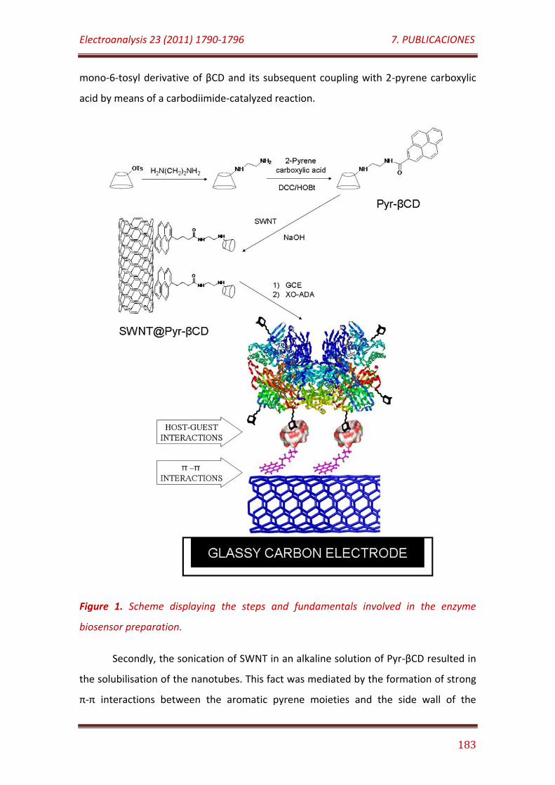
Electroanalysis 23 (2011) 1790-1796 7. PUBLICACIONES
183
mono-6-tosyl derivative of βCD and its subsequent coupling with 2-pyrene carboxylic
acid by means of a carbodiimide-catalyzed reaction.
Figure 1. Scheme displaying the steps and fundamentals involved in the enzyme
biosensor preparation.
Secondly, the sonication of SWNT in an alkaline solution of Pyr-βCD resulted in
the solubilisation of the nanotubes. This fact was mediated by the formation of strong
π-π interactions between the aromatic pyrene moieties and the side wall of the
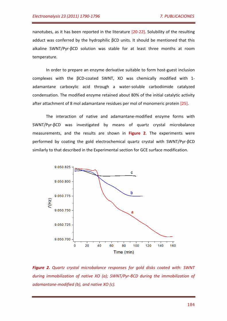
Electroanalysis 23 (2011) 1790-1796 7. PUBLICACIONES
184
nanotubes, as it has been reported in the literature [20-22]. Solubility of the resulting
adduct was conferred by the hydrophilic βCD units. It should be mentioned that this
alkaline SWNT/Pyr-βCD solution was stable for at least three months at room
temperature.
In order to prepare an enzyme derivative suitable to form host-guest inclusion
complexes with the βCD-coated SWNT, XO was chemically modified with 1-
adamantane carboxylic acid through a water-soluble carbodiimide catalyzed
condensation. The modified enzyme retained about 80% of the initial catalytic activity
after attachment of 8 mol adamantane residues per mol of monomeric protein [25].
The interaction of native and adamantane-modified enzyme forms with
SWNT/Pyr-βCD was investigated by means of quartz crystal microbalance
measurements, and the results are shown in Figure 2. The experiments were
performed by coating the gold electrochemical quartz crystal with SWNT/Pyr-βCD
similarly to that described in the Experimental section for GCE surface modification.
Figure 2. Quartz crystal microbalance responses for gold disks coated with: SWNT
during immobilization of native XO (a); SWNT/Pyr-βCD during the immobilization of
adamantane-modified (b), and native XO (c).
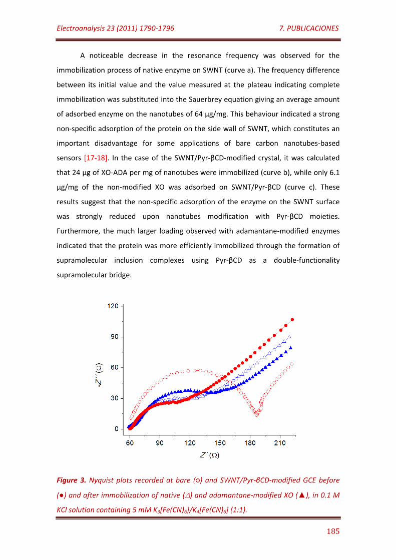
Electroanalysis 23 (2011) 1790-1796 7. PUBLICACIONES
185
A noticeable decrease in the resonance frequency was observed for the
immobilization process of native enzyme on SWNT (curve a). The frequency difference
between its initial value and the value measured at the plateau indicating complete
immobilization was substituted into the Sauerbrey equation giving an average amount
of adsorbed enzyme on the nanotubes of 64 µg/mg. This behaviour indicated a strong
non-specific adsorption of the protein on the side wall of SWNT, which constitutes an
important disadvantage for some applications of bare carbon nanotubes-based
sensors [17-18]. In the case of the SWNT/Pyr-βCD-modified crystal, it was calculated
that 24 µg of XO-ADA per mg of nanotubes were immobilized (curve b), while only 6.1
µg/mg of the non-modified XO was adsorbed on SWNT/Pyr-βCD (curve c). These
results suggest that the non-specific adsorption of the enzyme on the SWNT surface
was strongly reduced upon nanotubes modification with Pyr-βCD moieties.
Furthermore, the much larger loading observed with adamantane-modified enzymes
indicated that the protein was more efficiently immobilized through the formation of
supramolecular inclusion complexes using Pyr-βCD as a double-functionality
supramolecular bridge.
Figure 3. Nyquist plots recorded at bare () and SWNT/Pyr-βCD-modified GCE before
() and after immobilization of native () and adamantane-modified XO (), in 0.1 M
KCl solution containing 5 mM K3[Fe(CN)6]/K4[Fe(CN)6] (1:1).
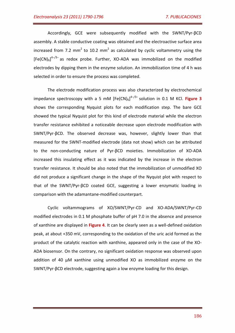
Electroanalysis 23 (2011) 1790-1796 7. PUBLICACIONES
186
Accordingly, GCE were subsequently modified with the SWNT/Pyr-βCD
assembly. A stable conductive coating was obtained and the electroactive surface area
increased from 7.2 mm2 to 10.2 mm2 as calculated by cyclic voltammetry using the
[Fe(CN)6]4−/3− as redox probe. Further, XO-ADA was immobilized on the modified
electrodes by dipping them in the enzyme solution. An immobilization time of 4 h was
selected in order to ensure the process was completed.
The electrode modification process was also characterized by electrochemical
impedance spectroscopy with a 5 mM [Fe(CN)6]4−/3− solution in 0.1 M KCl. Figure 3
shows the corresponding Nyquist plots for each modification step. The bare GCE
showed the typical Nyquist plot for this kind of electrode material while the electron
transfer resistance exhibited a noticeable decrease upon electrode modification with
SWNT/Pyr-βCD. The observed decrease was, however, slightly lower than that
measured for the SWNT-modified electrode (data not show) which can be attributed
to the non-conducting nature of Pyr-βCD moieties. Immobilization of XO-ADA
increased this insulating effect as it was indicated by the increase in the electron
transfer resistance. It should be also noted that the immobilization of unmodified XO
did not produce a significant change in the shape of the Nyquist plot with respect to
that of the SWNT/Pyr-βCD coated GCE, suggesting a lower enzymatic loading in
comparison with the adamantane-modified counterpart.
Cyclic voltammograms of XO/SWNT/Pyr-CD and XO-ADA/SWNT/Pyr-CD
modified electrodes in 0.1 M phosphate buffer of pH 7.0 in the absence and presence
of xanthine are displayed in Figure 4. It can be clearly seen as a well-defined oxidation
peak, at about +350 mV, corresponding to the oxidation of the uric acid formed as the
product of the catalytic reaction with xanthine, appeared only in the case of the XO-
ADA biosensor. On the contrary, no significant oxidation response was observed upon
addition of 40 µM xanthine using unmodified XO as immobilized enzyme on the
SWNT/Pyr-βCD electrode, suggesting again a low enzyme loading for this design.
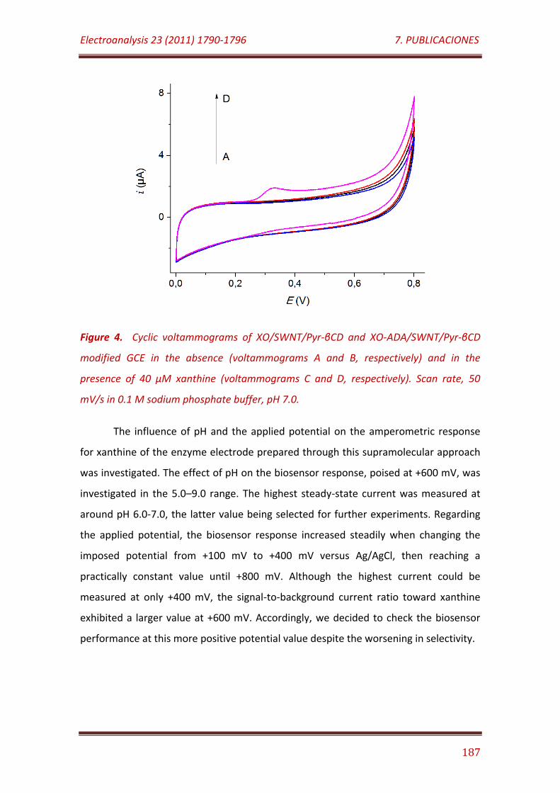
Electroanalysis 23 (2011) 1790-1796 7. PUBLICACIONES
187
Figure 4. Cyclic voltammograms of XO/SWNT/Pyr-βCD and XO-ADA/SWNT/Pyr-βCD
modified GCE in the absence (voltammograms A and B, respectively) and in the
presence of 40 µM xanthine (voltammograms C and D, respectively). Scan rate, 50
mV/s in 0.1 M sodium phosphate buffer, pH 7.0.
The influence of pH and the applied potential on the amperometric response
for xanthine of the enzyme electrode prepared through this supramolecular approach
was investigated. The effect of pH on the biosensor response, poised at +600 mV, was
investigated in the 5.0–9.0 range. The highest steady-state current was measured at
around pH 6.0-7.0, the latter value being selected for further experiments. Regarding
the applied potential, the biosensor response increased steadily when changing the
imposed potential from +100 mV to +400 mV versus Ag/AgCl, then reaching a
practically constant value until +800 mV. Although the highest current could be
measured at only +400 mV, the signal-to-background current ratio toward xanthine
exhibited a larger value at +600 mV. Accordingly, we decided to check the biosensor
performance at this more positive potential value despite the worsening in selectivity.
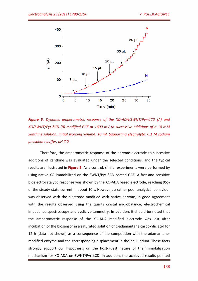
Electroanalysis 23 (2011) 1790-1796 7. PUBLICACIONES
188
Figure 5. Dynamic amperometric response of the XO-ADA/SWNT/Pyr-βCD (A) and
XO/SWNT/Pyr-βCD (B) modified GCE at +600 mV to successive additions of a 10 mM
xanthine solution. Initial working volume: 10 ml. Supporting electrolyte: 0.1 M sodium
phosphate buffer, pH 7.0.
Therefore, the amperometric response of the enzyme electrode to successive
additions of xanthine was evaluated under the selected conditions, and the typical
results are illustrated in Figure 5. As a control, similar experiments were performed by
using native XO immobilized on the SWNT/Pyr-βCD coated GCE. A fast and sensitive
bioelectrocatalytic response was shown by the XO-ADA based electrode, reaching 95%
of the steady-state current in about 10 s. However, a rather poor analytical behaviour
was observed with the electrode modified with native enzyme, in good agreement
with the results observed using the quartz crystal microbalance, electrochemical
impedance spectroscopy and cyclic voltammetry. In addition, it should be noted that
the amperometric response of the XO-ADA modified electrode was lost after
incubation of the biosensor in a saturated solution of 1-adamantane carboxylic acid for
12 h (data not shown) as a consequence of the competition with the adamantane-
modified enzyme and the corresponding displacement in the equilibrium. These facts
strongly support our hypothesis on the host-guest nature of the immobilization
mechanism for XO-ADA on SWNT/Pyr-βCD. In addition, the achieved results pointed
Electroanalysis 23 (2011) 1790-1796 7. PUBLICACIONES
189
out that functionalization of SWNT with Pyr-βCD significantly reduced the non-specific
protein adsorption on the nanotube surface.
The developed biosensor exhibited a linear amperometric response towards
xanthine over the 5.0 - 600 µM concentration range. This range of linearity extended
about one order of magnitude wider than those previously reported for other xanthine
biosensors [29-32].
The regression equation of the present biosensor was:
ia(µA) = 610×c(Xanthine/M) + 0.02
with a correlation coefficient of 0.998 (n = 10) and a sensitivity of 5.9 mA/M cm2.
According to the signal-to-noise = 3 criterion, the detection limit was found to
be 2 µM, which is similar to those achieved with other biosensor designs [25, 29, 30,
33]. Furthermore, an apparent Michaelis-Menten constant, KM , and a maximum rate
for the enzyme reaction, IMAX, were calculated as 0.58 mM and 503 nA, respectively.
It should be noted that the biosensor provided also a remarkable high
sensitivity when operated at a detection potential of + 400 mV. However, the range of
linearity available in this case was shown to be much shorter than at +600 mV, which is
an important analytical limitation for its real applicability.
Repetitive amperometric measurements at +600 mV for successive additions of
10 mM xanthine yielded a relative standard deviation (RSD) value (n = 10) of 6.1%.
Moreover, the RSD value calculated from the measurements carried out with ten
different biosensors prepared in the same manner was 9.3%. It is interesting to
compare these figures with those obtained by applying a detection potential of +400
mV, where the respective RSD values were 8.5% and 13.6%.
The selectivity of the biosensor, poised at +600 mV, was evaluated in the
presence of eight potential interfering substances. The current measured for each
possible interfering at a 50 µM concentration level in the presence of 20 µM xanthine
was used to evaluate the biosensor selectivity. The enzyme biosensor showed good
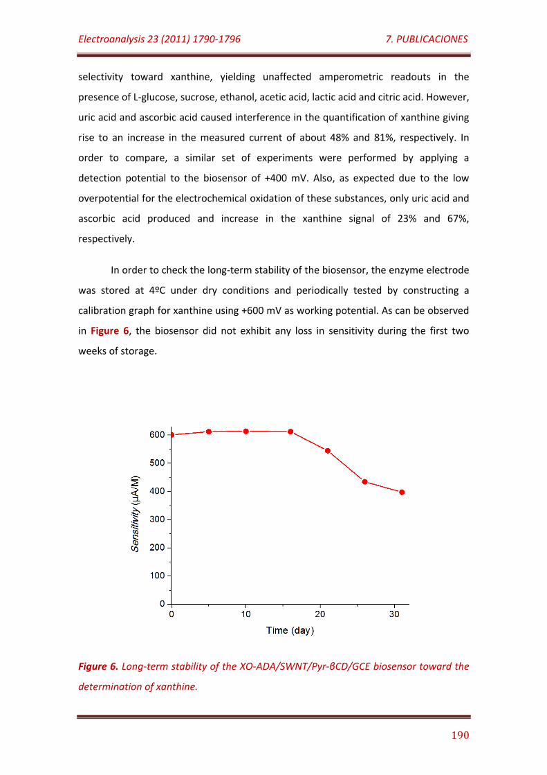
Electroanalysis 23 (2011) 1790-1796 7. PUBLICACIONES
190
selectivity toward xanthine, yielding unaffected amperometric readouts in the
presence of L-glucose, sucrose, ethanol, acetic acid, lactic acid and citric acid. However,
uric acid and ascorbic acid caused interference in the quantification of xanthine giving
rise to an increase in the measured current of about 48% and 81%, respectively. In
order to compare, a similar set of experiments were performed by applying a
detection potential to the biosensor of +400 mV. Also, as expected due to the low
overpotential for the electrochemical oxidation of these substances, only uric acid and
ascorbic acid produced and increase in the xanthine signal of 23% and 67%,
respectively.
In order to check the long-term stability of the biosensor, the enzyme electrode
was stored at 4ºC under dry conditions and periodically tested by constructing a
calibration graph for xanthine using +600 mV as working potential. As can be observed
in Figure 6, the biosensor did not exhibit any loss in sensitivity during the first two
weeks of storage.
Figure 6. Long-term stability of the XO-ADA/SWNT/Pyr-βCD/GCE biosensor toward the
determination of xanthine.
Electroanalysis 23 (2011) 1790-1796 7. PUBLICACIONES
191
Longer times of storage produced a progressive loss of sensitivity reaching
about 67% of the initial activity after 1 month. This relative high long-term stability of
the biosensor could be attributed to the beneficial effect of β-CD in the vicinity of the
enzyme molecules, providing a beneficial hydrophilic microenvironment for its
catalytic activity and folding stability [34].
CONCLUSIONS
A novel non-covalent strategy has been developed to functionalize SWNT with
adamantane-modified XO by using Pyr-βCD as double-functionality supramolecular
bridge. This functionalization approach with the supramolecular assembly has
demonstrated to be useful for the construction of an amperometric biosensor for
xanthine with acceptable analytical characteristics. This strategy may be generalized to
other enzyme biosensors, because it is based on the host-guest association of βCD
with hydrophobic compounds such as the adamantane derivatives, which can be easily
conjugated to any protein by conventional methods. According to these results, it can
be concluded that this supramolecular-based approach can be used as a successful
strategy to functionalize SWNT with enzymes giving rise to new biosensing devices
with analytical applicability. There are potential advantages associated with the use of
the Pyr-βCD linker in the design of new supramolecular assemblies of enzymes on
SNWT at the electrode surface. In fact, the π-π stacking of Pyr-βCD moieties confers
solubility, hydrophilicity and molecular receptor properties to SWNT without affecting
their chemical structure and electroconductive characteristics. This non-covalent
surface transformation also contributes to the reduction of non-specific adsorption of
protein molecules on SWNT side walls, but serves as a double-functionality
supramolecular bridge for the rational host-guest immobilization of protein molecules,
previously modified with hydrophobic compounds such as adamantane derivatives.
Electroanalysis 23 (2011) 1790-1796 7. PUBLICACIONES
192
ACKNOWLEDGEMENTS
R. Villalonga acknowledge to Ramón & Cajal contract from the Spanish Ministry
of Science and Innovation. Financial support from the Spanish Ministerio de Ciencia e
Innovación CTQ2009-12650, CTQ2009-09351) and Comunidad de Madrid S2009/PPQ-
1642, programme AVANSENS is gratefully acknowledged.
REFERENCES
[1] R. H. Baughman, A. A. Zakhidov, W. A. de Heer, Science 2002, 297, 787.
[2] H. Dai, Acc. Chem. Res. 2002, 35, 1035.
[3] H. S. Kim, H. Lee, K. S. Han, J. H. Kim, M. S. Song, M. S. Park, J. Y. Lee, J. K. Kang, J.
Phys. Chem. B 2005, 109, 8983.
[4] B. S. Harrison, A. Atala, Biomaterials 2007, 28, 344.
[5] X. Shi, J. L. Hudson, P. P. Spicer, J. M. Tour, R. Krishnamoorti, A. G. Mikos,
Biomacromolecules 2006, 7, 2237.
[6] L. Ci, J. Suhr, V. Pushparaj, X. Zhang, P. M. Ajayan, Nano Letters 2008, 8, 2762.
[7] K. Balani, R. Anderson, T. Laha, M. Andara, J. Tercero, E. Crumpler, A. Agarwal,
Biomaterials 2007, 28, 618.
[8] V. Sgobba, D. M. Guldi, Chem. Soc. Rev. 2009, 38, 165.
[9] M. Prato, K. Kostarelos, A. Bianco, Acc. Chem. Res. 2008, 41, 60.
[10] L. Agüí, P. Yáñez-Sedeño, J. M. Pingarron, J. M., Anal. Chim. Acta 2008, 622, 11.
[11] P. Yáñez-Sedeño, J. Riu, J. M. Pingarron, F. X. Rius, Trends Anal. Chem. 2010, 29,
939.
[12] G. A. Rivas, M. D. Rubianes, M. C. Rodríguez, N. F. Ferreyra, G. L. Luque, M. L.
Pedano, S. A. Miscoria, C. Parrado, Talanta 2007, 74, 291.
[13] Y. P. Sun, K. Fu, Y. Lin, W. Huang, Acc. Chem. Res. 2002, 35, 1096.
[14] S. Niyogi, M. A. Hamon, H. Hu, B. Zhao, P. Bhowmik, R. Sen, M. E. Itkis, R. C.
Haddon, Acc. Chem. Res. 2002, 35, 1105.
[15] N. Karousis, N. Tagmatarchis, D. Tasis, Chem. Rev. 2010, 110, 5366.
[16] S. S. Karajanagi, A. A. Vertegel, R. S. Kane, J. S. Dordick, Langmuir 2004, 20, 11594.
Electroanalysis 23 (2011) 1790-1796 7. PUBLICACIONES
193
[17] R. J. Chen, S. Bangsaruntip, K. A. Drouvalakis, N. W. S. Kam, M. Shim, Y. Li, W.
Kim, P. J. Utz, H. Dai, Proc. Natl. Acad. Sci. USA 2003, 100, 4984.
[18] Z. Liu, S. Tabakman, K. Welsher, H. Dai, Nano Res. 2009, 2, 85.
[19] R. J. Chen, Y. Zhang, D. Wang, H. Dai, J. Am. Chem. Soc. 2001, 123, 3838.
[20] T. Ogoshi, Y. Takashima, H. Yamaguchi, A. Harada, J. Am. Chem. Soc. 2007, 129,
4878.
[21] Y. L. Zhao, L. Hu, J. F. Stoddart, G. Grüner, Adv. Mater. 2008, 20, 1910.
[22] Y. L. Zhao, J. F. Stoddart, Acc. Chem. Res. 2009, 42, 1161.
[23] A. Fragoso, J. Caballero, E. Almirall, R. Villalonga, R. Cao, Langmuir 2002, 18, 5051.
[24] C. Camacho, B. Chico, R. Cao, J. C. Matías, J. Hernández, I. Palchetti, B. K. Simpson,
M. Mascini, R. Villalonga, Biosens. Bioelectron. 2009, 24, 2028.
[25] R. Villalonga, C. Camacho, R. Cao, J. Hernández, J. C. Matias, Chem. Commun. 2007,
942.
[26] C. Camacho, J. C. Matías, R. Cao, M. Matos, B. Chico, J. Hernández, M. A. Longo, M.
A. Sanromán, R. Villalonga, Langmuir 2008, 24, 7654.
[27] I. Baussanne, H. Law, J. Defaye, J. M. Benito, C. Ortiz Mellet, J. M. García Fernández,
Chem. Commun. 2000, 1489.
[28] M. Fernández, A. Fragoso, R. Cao, R. Villalonga, J. Mol. Cat. B: Enzymatic 2003, 21,
133.
[29] T. Dodevska, E. Horozova, N. Dimcheva, Cent. Eur. J. Chem. 2010, 8, 19.
[30] Y. Gao, C. Shen, J. Di, Y. Tu, Mater. Sci. Eng. C 2009, 29, 2213.
[31] Y. Liu, L. Nie, W. Tao, S. Yao, Electroanalysis 2004, 16, 1271.
[32] Ü. Anik, S. Çevi, Microchim. Acta 2009, 166, 209.
[33] R. Villalonga, M. Matos, R. Cao, Electrochem. Comm. 2007, 9, 454.
[34] R. Villalonga, R. Cao, A. Fragoso, Chem. Rev. 2007, 107, 3088.

7.6
Journal of Materials Chemistry 21 (2011) 12858-12864
Decorating carbon nanotubes with polyethyleneglycol-coated magnetic
nanoparticles for implementing highly sensitive enzyme biosensors

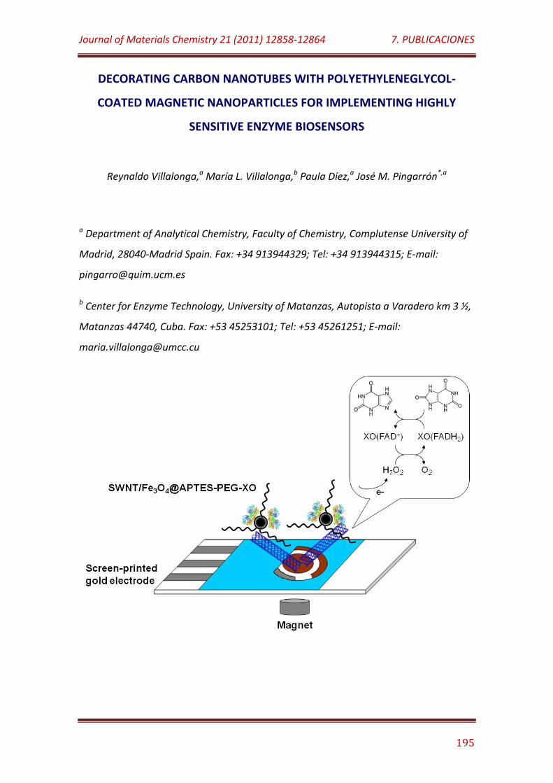
Journal of Materials Chemistry 21 (2011) 12858-12864 7. PUBLICACIONES
195
DECORATING CARBON NANOTUBES WITH POLYETHYLENEGLYCOL-
COATED MAGNETIC NANOPARTICLES FOR IMPLEMENTING HIGHLY
SENSITIVE ENZYME BIOSENSORS
Reynaldo Villalonga,a María L. Villalonga,b Paula Díez,a José M. Pingarrón*,a
a Department of Analytical Chemistry, Faculty of Chemistry, Complutense University of
Madrid, 28040-Madrid Spain. Fax: +34 913944329; Tel: +34 913944315; E-mail:
b Center for Enzyme Technology, University of Matanzas, Autopista a Varadero km 3 ½,
Matanzas 44740, Cuba. Fax: +53 45253101; Tel: +53 45261251; E-mail:
Journal of Materials Chemistry 21 (2011) 12858-12864 7. PUBLICACIONES
196
ABSTRACT
Superparamagnetic Fe3O4 nanoparticles were coated with (3-
aminopropyl)triethoxysilane and further branched with monomethoxypolyethylene
glycol chains. These nanoparticles were employed for the non-covalent surface
modification of single walled carbon nanotubes, conferring them magnetic properties.
This nanomaterial was employed to immobilize the enzyme xanthine oxidase in order
to construct magnetically modified disposable gold screen-printed electrodes as
bioelectrodes for the determination of xanthine. The electroanalytical properties of
the biosensor were modulated by the nanomaterial composition, being optimal at a
carbon nanotubes:magnetic nanoparticles ratio of 1:27. The resulting biosensor
showed a linear dependence on the xanthine concentration in the 0.25-3.5 µM range
with a fast amperometric response in 12 s. The biosensor also showed a noticeable
high sensitivity of 1.31 A/M cm2 and a very low detection limit of 60 nM, which can be
compared advantageously with other biosensor designs for xanthine.
INTRODUCTION
Last challenges in electrochemical analysis have been predominantly linked to
the use of nanosized materials for the construction of sensing electrodes. This trend is
justified by the unique structural, physico-chemical and surface-to-volume ratio
properties of nanomaterials. In addition, they also offer the possibility to design a wide
variety of original tree-dimensional nanoarchitectures at the electrode surface, based
on the single or combined use of different nanomaterials.1
Multi- and single walled carbon nanotubes (SWNT) are among the
nanomaterials more widely used in electroanalysis due to their relevant chemical
stability, protein adsorption ability, electro-conductive properties and capability to
promote fast electron transfer reactions of some enzymatically generated species.2 In
this regards, a large number of nanostructured biosensors based on carbon nanotubes
have been reported, in which they have been used alone2a,3 or combined with other
Journal of Materials Chemistry 21 (2011) 12858-12864 7. PUBLICACIONES
197
nanomaterials such as quantum dots,4 metal and metal oxide nanoparticles5 and
nanowires.6
During last years, a significant interest has been devoted to prepare carbon
nanotubes-based magnetic nanomaterials, not only for analytical applications but also
for magnetic data storage, microelectronic, xerography and magnetic resonance
imaging.7 Such kind of hybrid nanomaterials can be prepared by filling the nanotubes
with the magnetic material7,8 or by coating the outer wall of the nanotubes with
magnetic nanoparticles.5c,9 The later is, by far, the strategy most commonly used
because it is easier to manipulate the outer wall surface rather than the inner cavity of
nanotubes, offering in this way more experimental alternatives. In addition, nanotubes
filled with magnetic nanoparticles did not show useful magnetic properties because it
is difficult to control the amount and location of magnetic material inside the
nanotubes.8c Location of iron oxide nanoparticles on the outer wall of nanotubes is
also a better choice for biosensor applications, due to high biocompatibility and
protein load capacity of magnetic nanoparticles.10
In general, decoration of carbon nanotubes with magnetic nanoparticles has
been accomplished by adsorption,11 covalent attachment,9b π-π stacking9a and coating
with polymeric films containing the iron oxide nanoparticles.5c Furthermore, it has
been reported that polyethylene glycol derivatives can be irreversibly adsorbed on
carbon nanotubes.12 On this basis, we expected that small nanoparticles functionalized
with this polymer could be also irreversibly adsorbed on carbon nanotubes.
In this work we propose a novel approach for decorating SWNT with magnetic
nanoparticles, based on the non-covalent attachment of monomethoxypolyethylene
glycol (PEG)-coated superparamagnetic Fe3O4 nanoparticles on the nanotube surface.
In addition, the bioelectroanalytical potential of this hybrid nanomaterial was
evaluated by immobilizing xanthine oxidase as a model enzyme and constructing a
biosensor device towards xanthine.
Journal of Materials Chemistry 21 (2011) 12858-12864 7. PUBLICACIONES
198
MATERIALS AND METHODS
1. Electrodes and reagents
Disposable gold screen-printed electrodes (AuSPE, Model DRP-220BT, 4 mm
diameter) were purchased from DropSens (Spain). The AuSPE also included a gold
counter electrode and a silver pseudo-reference electrode, screen-printed on a
ceramic substrate (3.4 cm × 1.0 cm). To allow the magnetic immobilization of the
Fe3O4-based nanomateriales, AuSPE were transformed by fastening nickel-plated
neodymium disk magnets (3.2 mm diameter) on the other side of the gold working
electrodes using commercial acrylic glue.
Xanthine oxidase (XO, Type III, 1.3 U/mg), (3-aminopropyl)triethoxysilane
(APTES), methoxypolyethylene glycol succinate N-hydroxysuccinimide (PEG-NHS, MW
= 5000 Da), xanthine and SWNT were acquired from Sigma-Aldrich Co. (USA). All other
chemicals were of analytical grade.
2. Instrumentation and solutions
Electrochemical impedance spectroscopy, cyclic voltammetry and
amperometric measurements was performed using a FRA2 µAutolab Type III
potentiostat/galvanostat, and the data were acquired using a Frequency Response
Analyser and GPES Ver. 4.9 software, respectively (Metrohm Autolab B.V., The
Netherlands). All potential values were referred to the screen-printed silver pseudo-
reference electrode.
The measurements with the developed biosensors were carried out at 25ºC in
0.1 M sodium phosphate buffer, pH 7.0 (working volume 10 ml). The solution was
exhaustively aerated before each electrochemical experiment. The solutions were
stirred at 300 rpm with a magnetic bar during amperometric studies. 1 mM xanthine
solution in 50 mM sodium phosphate buffer, pH 7.0 was freshly prepared.
Transmission electron microscopy (TEM) measurements were performed with a
Philips CM 200 FEG microscope (FEI Co., USA). The surface morphology of the
nanostructured electrode surfaces was investigated by high resolution field emission
Journal of Materials Chemistry 21 (2011) 12858-12864 7. PUBLICACIONES
199
scanning electron microscopy (FE-SEM) using a JEOL JSM-6335F apparatus (JEOL Ltd.,
Japan). Magnetization measurements were carried out in a MPMS Squid
magnetometer (Quantum Design, Inc. USA). FT-IR spectra were acquired with a Perkin-
Elmer instrument.
3. Synthesis of Fe3O4/APTES-PEG nanoparticles
Fe3O4 magnetic nanoparticles were prepared according to the literature with
little modification.13 Briefly, 5.4 g of FeCl3·6H2O and 2.0 g of FeCl2·4H2O were dissolved
in 25 mL of 0.5 M HCl under N2 atmosphere. The solution was dropwise added to 250
mL of a 1.5 M NaOH solution with vigorous mechanical stirring and ultrasound
treatment under continuous N2 bubbling. The black precipitate formed was isolated by
magnetic decantation, exhaustively washed with double distilled water until neutrality,
then washed twice with ethanol and dried under vacuum.
The core-shell Fe3O4/APTES nanoparticles were prepared as previously
described,14 by dispersing 300 mg of the as-synthesized Fe3O4 nanoparticles in a
mixture of 600 mL ethanol and 4 mL of water by sonication. APTES (120 µL) was then
added, and the mixture was mechanically stirred under N2 atmosphere for 7 h. The
nanoparticles were isolated by magnetic decantation and purified by five cycles of re-
dispersion in ethanol and magnetic decantation. The Fe3O4/APTES nanoparticles were
finally dried at room temperature under vacuum.
To modify the core-shell Fe3O4/APTES nanoparticles with the PEG chains, 120
mg of Fe3O4/APTES nanoparticles were dispersed in 50 mL sodium phosphate buffer,
pH 7.4 by sonication before 400 mg of PEG-NHS were added. The mixture was
mechanically stirred during 24 h, and then the modified nanoparticles were
magnetically decanted and sequentially washed with double distilled water, ethanol
and acetone. The resulting solid was finally dried at room temperature under vacuum.
4. Immobilization of XO on Fe3O4/APTES-PEG nanoparticles
Core-shell Fe3O4/APTES-PEG nanoparticles (10 mg) were suspended in 9.0 mL of
50 mM sodium phosphate buffer, pH 8.0, by sonication and mixed with 1.0 mL of 25%
Journal of Materials Chemistry 21 (2011) 12858-12864 7. PUBLICACIONES
200
(v/v) glutaraldehyde. The mixture was shacked in the dark at 4ºC during 2 h. Then, the
solid was magnetically decanted and exhaustively washed with double distilled water.
The solid was re-dispersed in 4.0 mL of 50 mM sodium phosphate buffer, pH 7.0, and
mixed with 10 mg XO, previously dissolved in 1.0 mL of the same buffer. The mixture
was gently shacked at 4ºC during 2 h, and the solid was decanted and isolated by
centrifugation. The enzyme-modified nanoparticles were repeatedly washed by
sequential re-dispersion in cold 50 mM sodium phosphate buffer, pH 7.0, and
magnetic decantation. The amount of attached enzyme was estimated by difference
after measuring the non-immobilized protein by Bradford method.15 The Fe3O4/APTES-
PEG-XO nanocatalyst was finally suspended in 5.0 mL of the same buffer and kept in
refrigerator until use.
The catalytic activity of native and immobilized enzyme forms was estimated by
the time course increase of absorbance at 290 nm, corresponding to the production of
uric acid (ε = 1.22x10⁴ M-1cm-1) by xanthine oxidation.16
5. Preparation of the enzyme electrode
To prepare the Fe3O4/APTES-PEG-XO/SWNT nanomaterial, SWNT was first
oxidized by ultrasound treatment with a 3:1 (v/v) mixture of concentrated H2SO4 and
HNO3 at room temperature during 4 h.17 Moreover, AuSPEs were activated by
dropping 50 µL of 0.1 M H2SO4 solution on the electrode surface and scanning ten
cyclic voltammograms from 0.0 to 1.25 V at 100 mV/s. Finally the electrode was
washed with deionized water and dried under N2. In a typical experiment for electrode
preparation, 20 µL of a 2.0 mg/mL dispersion of Fe3O4/APTES-PEG-XO in 50 mM
sodium phosphate buffer, pH 7.0, were mixed with 3.0 µL of 0.5 mg/mL aqueous
dispersion of oxidized SWNT. The mixture was magnetically deposited on the gold
working electrode surface with the neodymium disk magnet, washed with cold 50 mM
sodium phosphate buffer, pH 7.0 and finally dried under N2 before use.
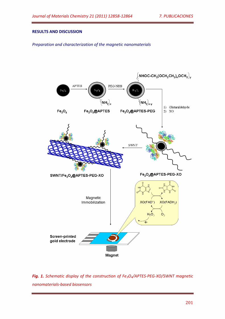
Journal of Materials Chemistry 21 (2011) 12858-12864 7. PUBLICACIONES
201
RESULTS AND DISCUSSION
Preparation and characterization of the magnetic nanomaterials
Fig. 1. Schematic display of the construction of Fe3O4/APTES-PEG-XO/SWNT magnetic
nanomaterials-based biosensors
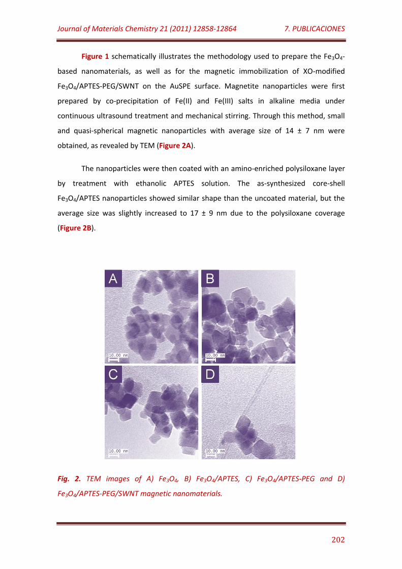
Journal of Materials Chemistry 21 (2011) 12858-12864 7. PUBLICACIONES
202
Figure 1 schematically illustrates the methodology used to prepare the Fe3O4-
based nanomaterials, as well as for the magnetic immobilization of XO-modified
Fe3O4/APTES-PEG/SWNT on the AuSPE surface. Magnetite nanoparticles were first
prepared by co-precipitation of Fe(II) and Fe(III) salts in alkaline media under
continuous ultrasound treatment and mechanical stirring. Through this method, small
and quasi-spherical magnetic nanoparticles with average size of 14 ± 7 nm were
obtained, as revealed by TEM (Figure 2A).
The nanoparticles were then coated with an amino-enriched polysiloxane layer
by treatment with ethanolic APTES solution. The as-synthesized core-shell
Fe3O4/APTES nanoparticles showed similar shape than the uncoated material, but the
average size was slightly increased to 17 ± 9 nm due to the polysiloxane coverage
(Figure 2B).
Fig. 2. TEM images of A) Fe3O4, B) Fe3O4/APTES, C) Fe3O4/APTES-PEG and D)
Fe3O4/APTES-PEG/SWNT magnetic nanomaterials.
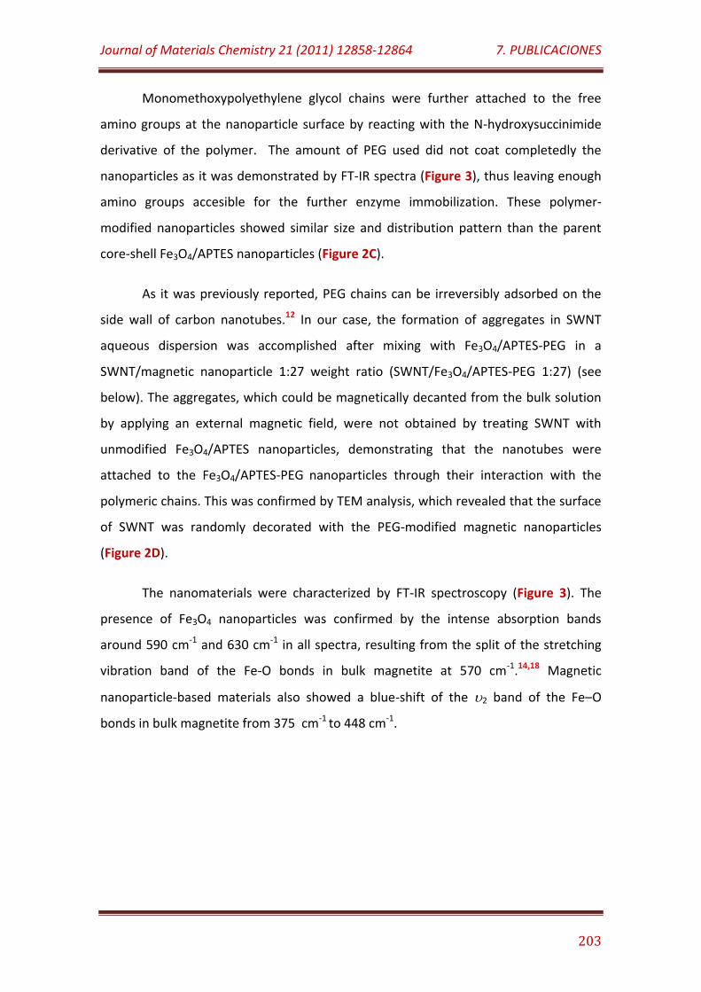
Journal of Materials Chemistry 21 (2011) 12858-12864 7. PUBLICACIONES
203
Monomethoxypolyethylene glycol chains were further attached to the free
amino groups at the nanoparticle surface by reacting with the N-hydroxysuccinimide
derivative of the polymer. The amount of PEG used did not coat completedly the
nanoparticles as it was demonstrated by FT-IR spectra (Figure 3), thus leaving enough
amino groups accesible for the further enzyme immobilization. These polymer-
modified nanoparticles showed similar size and distribution pattern than the parent
core-shell Fe3O4/APTES nanoparticles (Figure 2C).
As it was previously reported, PEG chains can be irreversibly adsorbed on the
side wall of carbon nanotubes.12 In our case, the formation of aggregates in SWNT
aqueous dispersion was accomplished after mixing with Fe3O4/APTES-PEG in a
SWNT/magnetic nanoparticle 1:27 weight ratio (SWNT/Fe3O4/APTES-PEG 1:27) (see
below). The aggregates, which could be magnetically decanted from the bulk solution
by applying an external magnetic field, were not obtained by treating SWNT with
unmodified Fe3O4/APTES nanoparticles, demonstrating that the nanotubes were
attached to the Fe3O4/APTES-PEG nanoparticles through their interaction with the
polymeric chains. This was confirmed by TEM analysis, which revealed that the surface
of SWNT was randomly decorated with the PEG-modified magnetic nanoparticles
(Figure 2D).
The nanomaterials were characterized by FT-IR spectroscopy (Figure 3). The
presence of Fe3O4 nanoparticles was confirmed by the intense absorption bands
around 590 cm-1 and 630 cm-1 in all spectra, resulting from the split of the stretching
vibration band of the Fe-O bonds in bulk magnetite at 570 cm-1.14,18 Magnetic
nanoparticle-based materials also showed a blue-shift of the 2 band of the Fe–O
bonds in bulk magnetite from 375 cm-1 to 448 cm-1.
Journal of Materials Chemistry 21 (2011) 12858-12864 7. PUBLICACIONES
204
Fig. 3. FT-IR spectra of A) Fe3O4, B) Fe3O4/APTES and C) Fe3O4/APTES-PEG magnetic
nanoparticles.
The presence of the Fe-O-Si bonds, characteristics of the cross-linked
polysiloxane matrix in the core-shell Fe3O4/APTES nanoparticles was not evidenced in
the FT-IR spectrum, because this band appears around 584 cm-1 and therefore overlaps
with the Fe-O vibration band in magnetite.19 However, the presence of the covering
APTES film was confirmed by the broad band around 1020 cm-1, corresponding to the
overlapped Si-O-Si and Si-OH bands. In addition, the presence of the Si-OH groups can
be justified by the broad bands at 3698 cm-1 and 3200 cm-1, which can be ascribed to
the free and hydrogen-bonded hydroxyl groups linked to Si atoms. It should be noted
that the latter band could be also overlapped with the corresponding to N-H vibration,
but the presence of the amino groups in the core-shell Fe3O4/APTES magnetic
nanoparticles was more evident by the band appearing at 1628 cm-1, characteristic of
the NH2 stretching.
Furthermore, the attached polyether chains in the core-shell Fe3O4/APTES-PEG
nanoparticles were confirmed by the bands at 1740 cm-1 and 2918 cm-1, corresponding
to the C=O and C-H stretching, respectively. It should be noted that FT-IR was not able
to identify the Fe3O4/APTES-PEG/SWNT adduct, because the signal corresponding to
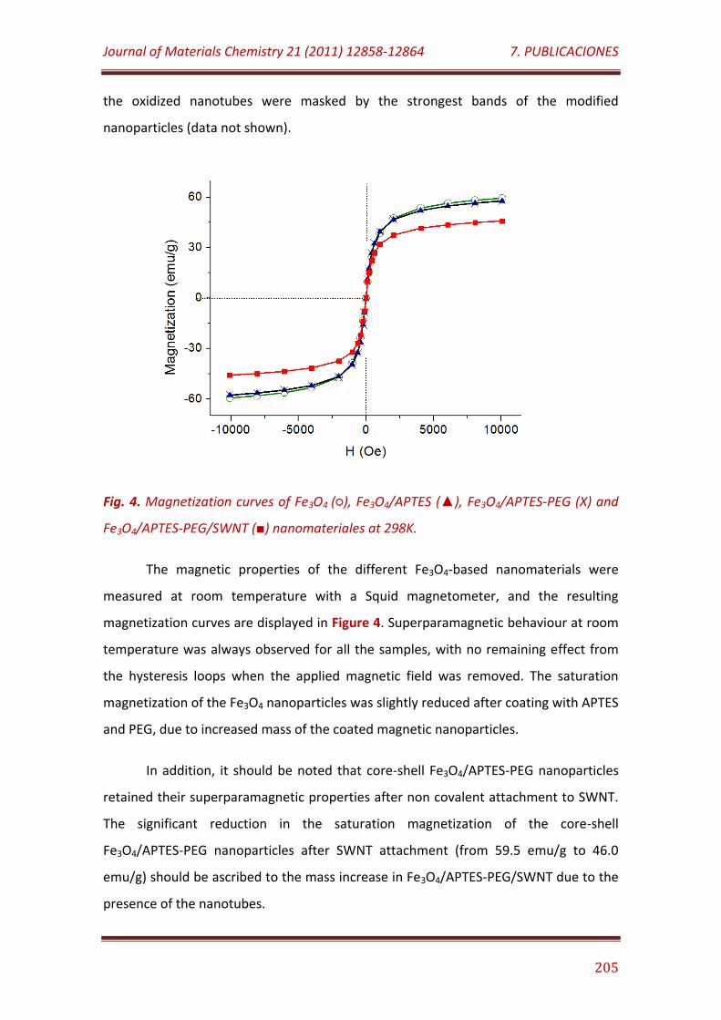
Journal of Materials Chemistry 21 (2011) 12858-12864 7. PUBLICACIONES
205
the oxidized nanotubes were masked by the strongest bands of the modified
nanoparticles (data not shown).
Fig. 4. Magnetization curves of Fe3O4 (), Fe3O4/APTES (), Fe3O4/APTES-PEG (X) and
Fe3O4/APTES-PEG/SWNT () nanomateriales at 298K.
The magnetic properties of the different Fe3O4-based nanomaterials were
measured at room temperature with a Squid magnetometer, and the resulting
magnetization curves are displayed in Figure 4. Superparamagnetic behaviour at room
temperature was always observed for all the samples, with no remaining effect from
the hysteresis loops when the applied magnetic field was removed. The saturation
magnetization of the Fe3O4 nanoparticles was slightly reduced after coating with APTES
and PEG, due to increased mass of the coated magnetic nanoparticles.
In addition, it should be noted that core-shell Fe3O4/APTES-PEG nanoparticles
retained their superparamagnetic properties after non covalent attachment to SWNT.
The significant reduction in the saturation magnetization of the core-shell
Fe3O4/APTES-PEG nanoparticles after SWNT attachment (from 59.5 emu/g to 46.0
emu/g) should be ascribed to the mass increase in Fe3O4/APTES-PEG/SWNT due to the
presence of the nanotubes.
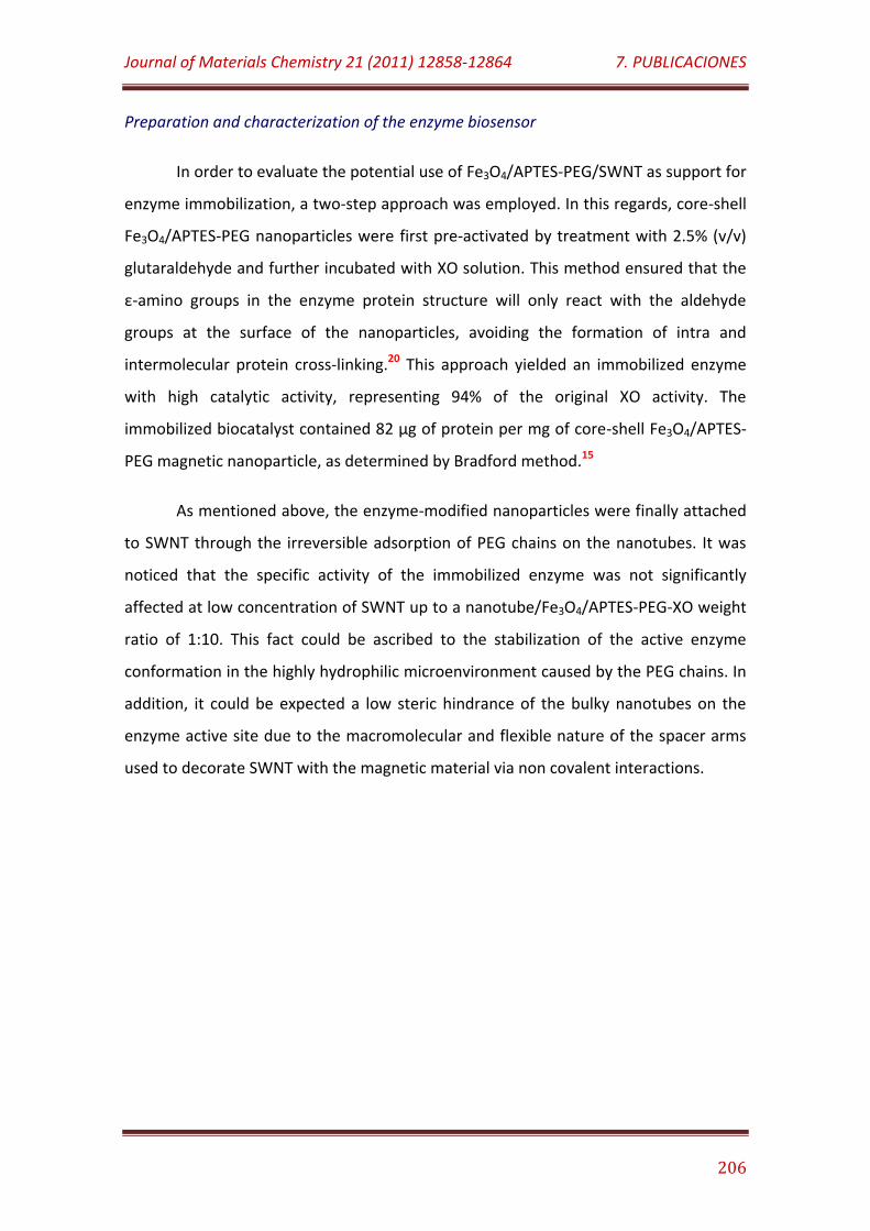
Journal of Materials Chemistry 21 (2011) 12858-12864 7. PUBLICACIONES
206
Preparation and characterization of the enzyme biosensor
In order to evaluate the potential use of Fe3O4/APTES-PEG/SWNT as support for
enzyme immobilization, a two-step approach was employed. In this regards, core-shell
Fe3O4/APTES-PEG nanoparticles were first pre-activated by treatment with 2.5% (v/v)
glutaraldehyde and further incubated with XO solution. This method ensured that the
ε-amino groups in the enzyme protein structure will only react with the aldehyde
groups at the surface of the nanoparticles, avoiding the formation of intra and
intermolecular protein cross-linking.20 This approach yielded an immobilized enzyme
with high catalytic activity, representing 94% of the original XO activity. The
immobilized biocatalyst contained 82 µg of protein per mg of core-shell Fe3O4/APTES-
PEG magnetic nanoparticle, as determined by Bradford method.15
As mentioned above, the enzyme-modified nanoparticles were finally attached
to SWNT through the irreversible adsorption of PEG chains on the nanotubes. It was
noticed that the specific activity of the immobilized enzyme was not significantly
affected at low concentration of SWNT up to a nanotube/Fe3O4/APTES-PEG-XO weight
ratio of 1:10. This fact could be ascribed to the stabilization of the active enzyme
conformation in the highly hydrophilic microenvironment caused by the PEG chains. In
addition, it could be expected a low steric hindrance of the bulky nanotubes on the
enzyme active site due to the macromolecular and flexible nature of the spacer arms
used to decorate SWNT with the magnetic material via non covalent interactions.
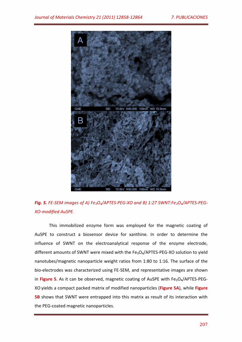
Journal of Materials Chemistry 21 (2011) 12858-12864 7. PUBLICACIONES
207
Fig. 5. FE-SEM images of A) Fe3O4/APTES-PEG-XO and B) 1:27 SWNT:Fe3O4/APTES-PEG-
XO-modified AuSPE.
This immobilized enzyme form was employed for the magnetic coating of
AuSPE to construct a biosensor device for xanthine. In order to determine the
influence of SWNT on the electroanalytical response of the enzyme electrode,
different amounts of SWNT were mixed with the Fe3O4/APTES-PEG-XO solution to yield
nanotubes/magnetic nanoparticle weight ratios from 1:80 to 1:16. The surface of the
bio-electrodes was characterized using FE-SEM, and representative images are shown
in Figure 5. As it can be observed, magnetic coating of AuSPE with Fe3O4/APTES-PEG-
XO yields a compact packed matrix of modified nanoparticles (Figure 5A), while Figure
5B shows that SWNT were entrapped into this matrix as result of its interaction with
the PEG-coated magnetic nanoparticles.
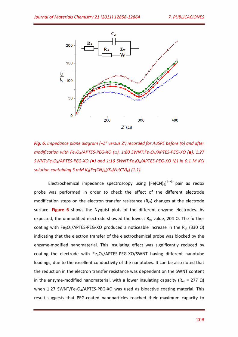
Journal of Materials Chemistry 21 (2011) 12858-12864 7. PUBLICACIONES
208
Fig. 6. Impedance plane diagram (−Z″ versus Z′) recorded for AuSPE before () and after
modification with Fe3O4/APTES-PEG-XO (), 1:80 SWNT:Fe3O4/APTES-PEG-XO (), 1:27
SWNT:Fe3O4/APTES-PEG-XO () and 1:16 SWNT:Fe3O4/APTES-PEG-XO (Δ) in 0.1 M KCl
solution containing 5 mM K3[Fe(CN)6]/K4[Fe(CN)6] (1:1).
Electrochemical impedance spectroscopy using [Fe(CN)6]4−/3− pair as redox
probe was performed in order to check the effect of the different electrode
modification steps on the electron transfer resistance (Ret) changes at the electrode
surface. Figure 6 shows the Nyquist plots of the different enzyme electrodes. As
expected, the unmodified electrode showed the lowest Ret value, 204 Ω. The further
coating with Fe3O4/APTES-PEG-XO produced a noticeable increase in the Ret (330 Ω)
indicating that the electron transfer of the electrochemical probe was blocked by the
enzyme-modified nanomaterial. This insulating effect was significantly reduced by
coating the electrode with Fe3O4/APTES-PEG-XO/SWNT having different nanotube
loadings, due to the excellent conductivity of the nanotubes. It can be also noted that
the reduction in the electron transfer resistance was dependent on the SWNT content
in the enzyme-modified nanomaterial, with a lower insulating capacity (Ret = 277 Ω)
when 1:27 SWNT/Fe3O4/APTES-PEG-XO was used as bioactive coating material. This
result suggests that PEG-coated nanoparticles reached their maximum capacity to
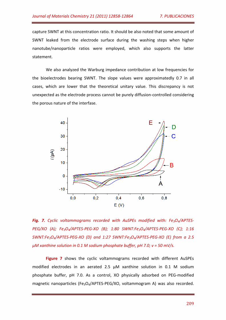
Journal of Materials Chemistry 21 (2011) 12858-12864 7. PUBLICACIONES
209
capture SWNT at this concentration ratio. It should be also noted that some amount of
SWNT leaked from the electrode surface during the washing steps when higher
nanotube/nanoparticle ratios were employed, which also supports the latter
statement.
We also analyzed the Warburg impedance contribution at low frequencies for
the bioelectrodes bearing SWNT. The slope values were approximatedly 0.7 in all
cases, which are lower that the theoretical unitary value. This discrepancy is not
unexpected as the electrode process cannot be purely diffusion-controlled considering
the porous nature of the interfase.
Fig. 7. Cyclic voltammograms recorded with AuSPEs modified with: Fe3O4/APTES-
PEG/XO (A); Fe3O4/APTES-PEG-XO (B); 1:80 SWNT:Fe3O4/APTES-PEG-XO (C); 1:16
SWNT:Fe3O4/APTES-PEG-XO (D) and 1:27 SWNT:Fe3O4/APTES-PEG-XO (E) from a 2.5
µM xanthine solution in 0.1 M sodium phosphate buffer, pH 7.0; v = 50 mV/s.
Figure 7 shows the cyclic voltammograms recorded with different AuSPEs
modified electrodes in an aerated 2.5 µM xanthine solution in 0.1 M sodium
phosphate buffer, pH 7.0. As a control, XO physically adsorbed on PEG-modified
magnetic nanoparticles (Fe3O4/APTES-PEG/XO, voltammogram A) was also recorded.
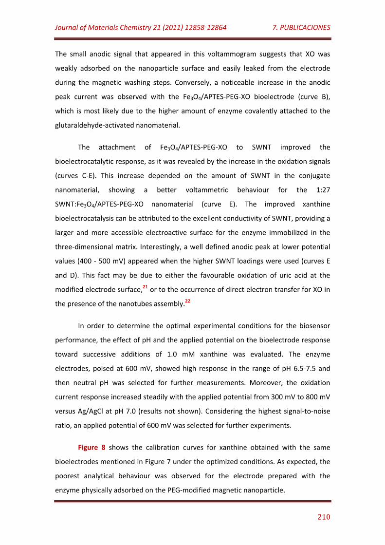
Journal of Materials Chemistry 21 (2011) 12858-12864 7. PUBLICACIONES
210
The small anodic signal that appeared in this voltammogram suggests that XO was
weakly adsorbed on the nanoparticle surface and easily leaked from the electrode
during the magnetic washing steps. Conversely, a noticeable increase in the anodic
peak current was observed with the Fe3O4/APTES-PEG-XO bioelectrode (curve B),
which is most likely due to the higher amount of enzyme covalently attached to the
glutaraldehyde-activated nanomaterial.
The attachment of Fe3O4/APTES-PEG-XO to SWNT improved the
bioelectrocatalytic response, as it was revealed by the increase in the oxidation signals
(curves C-E). This increase depended on the amount of SWNT in the conjugate
nanomaterial, showing a better voltammetric behaviour for the 1:27
SWNT:Fe3O4/APTES-PEG-XO nanomaterial (curve E). The improved xanthine
bioelectrocatalysis can be attributed to the excellent conductivity of SWNT, providing a
larger and more accessible electroactive surface for the enzyme immobilized in the
three-dimensional matrix. Interestingly, a well defined anodic peak at lower potential
values (400 - 500 mV) appeared when the higher SWNT loadings were used (curves E
and D). This fact may be due to either the favourable oxidation of uric acid at the
modified electrode surface,21 or to the occurrence of direct electron transfer for XO in
the presence of the nanotubes assembly.22
In order to determine the optimal experimental conditions for the biosensor
performance, the effect of pH and the applied potential on the bioelectrode response
toward successive additions of 1.0 mM xanthine was evaluated. The enzyme
electrodes, poised at 600 mV, showed high response in the range of pH 6.5-7.5 and
then neutral pH was selected for further measurements. Moreover, the oxidation
current response increased steadily with the applied potential from 300 mV to 800 mV
versus Ag/AgCl at pH 7.0 (results not shown). Considering the highest signal-to-noise
ratio, an applied potential of 600 mV was selected for further experiments.
Figure 8 shows the calibration curves for xanthine obtained with the same
bioelectrodes mentioned in Figure 7 under the optimized conditions. As expected, the
poorest analytical behaviour was observed for the electrode prepared with the
enzyme physically adsorbed on the PEG-modified magnetic nanoparticle.
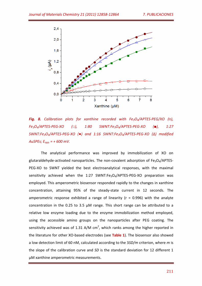
Journal of Materials Chemistry 21 (2011) 12858-12864 7. PUBLICACIONES
211
Fig. 8. Calibration plots for xanthine recorded with Fe3O4/APTES-PEG/XO (),
Fe3O4/APTES-PEG-XO (), 1:80 SWNT:Fe3O4/APTES-PEG-XO (), 1:27
SWNT:Fe3O4/APTES-PEG-XO () and 1:16 SWNT:Fe3O4/APTES-PEG-XO (Δ) modified
AuSPEs; Eapp. = + 600 mV.
The analytical performance was improved by immobilization of XO on
glutaraldehyde-activated nanoparticles. The non-covalent adsorption of Fe3O4/APTES-
PEG-XO to SWNT yielded the best electroanalytical responses, with the maximal
sensitivity achieved when the 1:27 SWNT:Fe3O4/APTES-PEG-XO preparation was
employed. This amperometric biosensor responded rapidly to the changes in xanthine
concentration, attaining 95% of the steady-state current in 12 seconds. The
amperometric response exhibited a range of linearity (r = 0.996) with the analyte
concentration in the 0.25 to 3.5 µM range. This short range can be attributed to a
relative low enzyme loading due to the enzyme immobilization method employed,
using the accessible amino groups on the nanoparticles after PEG coating. The
sensitivity achieved was of 1.31 A/M cm2, which ranks among the higher reported in
the literature for other XO-based electrodes (see Table 1). The biosensor also showed
a low detection limit of 60 nM, calculated according to the 3SD/m criterion, where m is
the slope of the calibration curve and SD is the standard deviation for 12 different 1
µM xanthine amperometric measurements.
Journal of Materials Chemistry 21 (2011) 12858-12864 7. PUBLICACIONES
212
Table 1. Comparison of analytical properties of the biosensor with previously reported
xanthine biosensors
Electrode E (mV) Linear Range
(µM)
Detection Limit
(µM)
Sensitivity
(mA/M)
KM
(µM)
XO/Pd-Pt/Graphite23 -50a 1.5 - 70 1.5 390 58.5
XO/MWNT/GCE24 -400b 0.1 - 6 0.08 - -
SG/XO/MWNT/GCE24 -400b 0.2 - 10 0.1 - -
XO/laponite/GCE25 +390b 0.039 - 21 0.01 6.54 64
XO/PB/PPy/Au colloid/Au26 -100b 1.0 - 20 - 0.19 43.2
XO/DWNT/CPE27 +900a 2.0 - 50 - 44.1 -
XO/ZnO NPs/PPy/Pt16 +380a 0.8 - 40 0.8 - 13.51
XO/pTTCA/Au28 -350a 0.5 - 100 0.09 5.35 -
XO/CMC-CD/Au29 +700a 300 - 10400 200 - -
SWNT/Fe3O4/APTES-PEG-XO* +600a 0.25 - 3.5 0.06 394 12.8
aAg/AgCl, bSCE, *Present work, PB: Prussian Blue, NPs: nanoparticles, PPy: polypyrrol, DWNT: double-walled carbon nanotubes, MWNT: multi-walled carbon nanotubes, SG: silica sol-gel, pTTCA: poly-5, 2’:5’,2’’-terthiophine-3-carboxylic acid, CGE: glassy carbon electrode, SCE: saturated calomel electrode.
The kinetics constants for the enzyme reaction at the developed bioelectrode
were estimated by using the Eadie-Hofstee plot. According to this analysis, the
immobilized enzyme showed apparent KM and IMAX values of 12.8 µM and 6.3 µA,
respectively. As it is illustrated in Table 1, both the detection limit and the apparent
Michaelis-Menten constant values are comparable with the best ones previously found
in literature using other approaches.
The reproducibility of the measurements carried out with a single biosensor was
calculated by constructing ten successive calibration plots for xanthine with the same
bioelectrode. A relative standard deviation value (RSD) of 6.5% was obtained. The
electrode-to-electrode reproducibility was estimated as 13.6% from the calibration
plots of ten equivalently prepared biosensors. This relatively low electrode-to-
electrode reproducibility could be ascribed to the low reproducibility of disposable
SPEs.
Journal of Materials Chemistry 21 (2011) 12858-12864 7. PUBLICACIONES
213
The selectivity of the biosensor was evaluated in the presence of eight possible
interfering substances at a 10 µM concentration level: L-glucose, sucrose, ethanol,
acetic acid, lactic acid, citric acid, uric acid and ascorbic acid. The XO-based biosensor
showed good selectivity because, as expected considering the detection potential, only
uric acid and ascorbic acid caused interference to the quantification of 1.0 µM
xanthine, with increase in the anodic current of about 27% and 78%, respectively.
The long-term stability of the biosensor was tested by storing the electrode at 4ºC
under dry conditions and constructing xanthine calibration curves for over 40 days.
The slope value of the calibration plot was practically constant value for the first 10
days and then decreased gradually to 76% of its initial value after 40 days. This rather
good stability of the enzyme electrode can be ascribed to the presence of the highly
hydrophilic macromolecular chains of PEG in the vicinity of the immobilized XO, which
provides an adequate microenvironment for the preservation of both the three-
dimensional structure and catalytic ability of the enzyme. In addition, the multipoint
attachment of XO to glutaraldehyde-activated nanoparticles should contribute to
increase the rigidity of the three-dimensional protein structure, then avoiding the
occurrence of unfolding phenomena over time.
CONCLUSIONS
A novel nanomaterial has been prepared by decorating SWNTs with core-shell
Fe3O4/APTES-PEG nanoparticles via non-covalent interactions. This nanomaterial was
further employed as magnetic support for the immobilization of xanthine oxidase on
AuSPE. The modified electrode was successful evaluated in the design of an
amperometric biosensor toward xanthine with high sensitivity and low detection limit.
According to our results, it can be concluded that SWNT functionalized with core-shell
Fe3O4/APTES-PEG magnetic nanoparticles can be successfully employed for the design
of novel electrochemical biosensing devices.
Journal of Materials Chemistry 21 (2011) 12858-12864 7. PUBLICACIONES
214
ACKNOWLEDGEMENTS
R. Villalonga acknowledge to Ramón & Cajal contract from the Spanish Ministry
of Science and Innovation. Financial support from the Spanish Ministerio de Ciencia e
Innovación CTQ2009-12650, CTQ2009-09351) and Comunidad de Madrid S2009/PPQ-
1642, programme AVANSENS is gratefully acknowledged.
NOTES AND REFERENCES
1 C.S.S.R. Kumar, Nanomaterials for biosensors, 2007, Wiley-VCH Weinheim; S. Li,
J. Singh, H. Li, I.A. Banerjee, Biosensor nanomaterials, 2011, Wiley-VCH Weinheim.
2 a) L. Agüí, P. Yañez-Sedeño, J.M. Pingarrón, Anal. Chim. Acta, 2008, 622, 11; b) P.
Yañez-Sedeño, J. Riu, J.M. Pingarrón, F.X. Rius, Trends Anal. Chem., 2010, 29, 939;
c) G.A. Rivas, M.D. Rubianes, M.C. Rodriguez, N.F. Ferreyra, G.L. Luque, M.L.
Pedano, S.A. Miscoria, C. Parrado, Talanta, 2007, 74: 291.
3 R.L. McCreery, Chem. Rev., 2008, 108, 2646; X. Zhong, G.S. Qian, J.J. Xu, H.Y. Chen,
J. Phys. Chem. C, 2010, 114, 19503.
4 D. Du, W. Chen, W. Zhang, D. Liu, H. Li, Y. Lin, Biosens. Bioelectron., 2010, 25,
1370.
5 a) Y. Cheng, Y. Liu, J. Huang, K. Li, Y. Xian, W. Zhang, L. Jin, Electrochim. Acta, 2009,
54, 2588; b) J. Manso, M.L. Mena, P. Yañez-Sedeño, J.M. Pingarron, J. Electroanal.
Chem., 2007, 603, 1; c) M. Holzinger, L. Bouffier, R. Villalonga, S. Cosnier, Biosens.
Bioelectron., 2008, 24, 1128.
6 C. Li, M. Curreli, H. Lin, B. Lei, F.N. Ishikawa, R. Datar, R.J. Cote, M.E. Thompson, C.
Zhou, J. Am. Chem. Soc., 2005, 127, 12484.
7 S. Liu, R.J. Wehmschulte, Carbon, 2005, 43, 1550.
8 a) D. Seifu, Y. Hijji, G. Hirsch, S.P. Karna, J. Magn. Magn. Mat., 2008, 320, 312; b)
W.J. Yu, P.X. Hou, L.L. Zhang, F. Li, C. Liu, H.M. Cheng, Chem. Commun., 2010, 46,
Journal of Materials Chemistry 21 (2011) 12858-12864 7. PUBLICACIONES
215
8576; c) G. Korneva, H. Ye, Y. Gogotsi, D. Halverson, G. Friedman, J.C. Bradley, K.G.
Kornev, Nano Lett., 2005, 5, 879.
9 a) V. Georgakilas, V. Tzitzios, D. Gournis, D. Petridis, Chem. Mat., 2005, 17, 1613;
b) H. Zhou, C. Zhang, H. Li, Z. Du, J. Polym. Sci. A Polym. Chem., 2010, 48, 4697.
10 D. Li, W.Y. Teoh, J.J. Gooding, C. Selomulya, R. Amal, Adv. Funct. Mater., 2010, 20,
1767.
11 T.T. Baby, S. Ramaprabhu, Talanta, 2010, 80, 2016.
12 M. Shim, N.W.S. Kam, R.J. Chen, Y. Li, H. Dai, Nano Lett., 2002, 2: 285.
13 J.L. Lyon, D.A Fleming, M.B. Stone, P. Schiffer, M.E. Williams, Nano Lett., 2004, 4,
719.
14 H. Cao, J. He, L. Deng, X. Gao, Appl. Surf. Sci., 2009, 255, 7974.
15 M.M. Bradford., Anal. Biochem., 1976, 72, 248.
16 R. Devi, M. Thakur, C.S. Pundir, Biosens. Bioelectron., 2011, 26, 3420.
17 J. Chen, A.M. Rao, S. Lyuksyutov, M.E. Itkis, M.A. Hamon, H. Hu, R.W. Cohn, P.C.
Eklund, D.T. Colbert, R.E. Smalley, R.C. Haddon, J. Phys. Chem. B, 2001, 105, 2525.
18 M. Ma, Y. Zhang, W. Yu, H.Y. Shen, H.G. Zhang, N. Gu, Colloids Surf. A
Physicochem. Eng. Asp., 2003, 212, 219.
19 S. Bruni, F. Cariati, M. Casu, A. Lai, A. Musinu, G. Piccaluga, S. Solinas, Nanostruct.
Mater., 1999, 11, 573.
20 D.R. Walt, V.I. Agayn, Trends Anal. Chem., 1994, 13, 425.
21 E. González, F. Pariente, E. Lorenzo, L. Hernández, Anal. Chim. Acta, 1991, 242,
267; S. Hason, S. Stepankova, A. Kourilova, V. Vetterl, J. Lata, M. Fojta, F. Jelen,
Anal. Chem., 2009, 81, 4302.
Journal of Materials Chemistry 21 (2011) 12858-12864 7. PUBLICACIONES
216
22 P.V. Bernhardt, M.J. Honeychurch, A.G. McEwan, Electrochem. Comm., 2006, 8,
257.
23 T. Dodevska, E. Horozova, N. Dimcheva, Cent. Eur. J. Chem., 2010, 8, 19.
24 Y. Gao, C. Shen, J. Di, Y. Tu, Mater. Sci. Eng. C, 2009, 29, 2213.
25 D. Shan, Y.N. Wang, H.G. Xue, S. Cosnier, S.N. Ding, Biosens. Bioelectron., 2009, 24,
3556.
26 Y. Liu, L. Nie, W. Tao, S. Yao, Electroanalysis, 2004, 16, 1271.
27 Ü. Anik, S. Çevi, Microchim. Acta, 2009, 166, 209.
28 M.A. Rahman, M.S. Won, Y.B. Shim, Electroanalysis, 2007, 19, 631.
29 R. Villalonga, M. Matos, R. Cao, Electrochem. Comm., 2007, 9, 454.
7.7
Analytical and Bioanalytical Chemistry 405 (2013) 3773-3781
Supramolecular immobilization of glucose oxidase on gold coated with
cyclodextrin-modified cysteamine core PAMAM G-4 dendron/pt nanoparticles for mediatorless
biosensor design

Analytical and Bioanalytical Chemistry 405 (2013) 3773-3781 7. PUBLICACIONES
217
SUPRAMOLECULAR IMMOBILIZATION OF GLUCOSE OXIDASE ON GOLD
COATED WITH CYCLODEXTRIN-MODIFIED CYSTEAMINE CORE PAMAM
G-4 DENDRON/PT NANOPARTICLES FOR MEDIATORLESS BIOSENSOR
DESIGN
Paula Díez,1 Ciprian-George Piuleac,2 Paloma Martínez-Ruiz,3 Santiago Romano,3 María
Gamella,1 Reynaldo Villalonga,1,* José M. Pingarrón1,*
1Department of Analytical Chemistry & 3Department of Organic Chemistry I, Faculty of
Chemistry, Complutense University of Madrid, 28040-Madrid Spain
2Department of Chemical Engineering, “Gh. Asachi” Technical University, Bd. D.
Mangeron No. 71A, 700050, Iasi, Romania
*Corresponding author. Phone: +34 91 3944315, Fax: +34 91 3944329,
E-mail: [email protected], [email protected]
Analytical and Bioanalytical Chemistry 405 (2013) 3773-3781 7. PUBLICACIONES
218
ABSTRACT
Cysteamine core polyamidoamine G-4 dendron branched with β-cyclodextrins
was chemisorbed on the surface of Au electrodes and further decorated with Pt
nanoparticles. Adamantane-modified glucose oxidase was subsequently immobilized
on the nanostructured electrode surface through supramolecular associations. The so
constructed enzyme electrode was employed for constructing a reagentless
amperometric biosensor for glucose making use of the electrochemical oxidation of
H2O2 generated in the enzyme reaction. The biosensor exhibited a fast amperometric
response (6 s) and a linear response toward glucose concentration between 5 µM and
705 µM. The biosensor showed a low detection limit of 2.0 µM, a sensitivity of 197
mA/M cm2, and retained 94% of its initial response after nine days of storage at 4ºC.
Keywords: Biosensor, β-cyclodextrin, dendrimer, glucose oxidase, Platinum
nanoparticles, supramolecular complex
INTRODUCTION
The development of enzyme-based electrochemical biosensors has received
considerable attention due to their potential use as highly selective analytical devices
in chemical and clinical laboratories, food industry, environmental monitoring and
other related fields [1]. In general, the development and performance of enzyme
biosensors are directly linked to the strategy employed to immobilize the protein on
the transducer surface, as well as to the physicochemical properties of the materials
used to design the electrodes [2].
A major challenge in biosensor technology has been promoted by the use of
nanosized materials in the design of novel electrode architectures [3]. Hard
nanomaterials such as metal and metal oxide nanoparticles [4, 5], graphene [6] and
carbon nanotubes [7] have been widely employed to create reliable biosensor
surfaces. This fact has been supported by the unique properties of these
Analytical and Bioanalytical Chemistry 405 (2013) 3773-3781 7. PUBLICACIONES
219
nanomaterials, such as high surface energy and surface-to-volume ratio, the ability to
decrease proteins-metal particles distance, high electroconductivity and protein load
capacity, the ability to catalyze the electrochemical processes associated with several
compounds produced in the enzyme-mediated reactions, and the possibility to act as
electroconductive wires between the enzyme and the electrode substrate [2].
Organic polymer-based nanomaterials, such as dendrimers and dendrons, have
been also used in biosensor design [8,9]. These soft nanomaterials are monodisperse
macromolecules with a regular and highly branched three-dimensional architecture.
They have a high structural homogeneity, a surface reactivity and a molecular host
capacity [10], which are important characteristics for the multipoint immobilization of
enzymes on electrode surfaces. In addition, it has been demonstrated previously that
metal nanoparticles can be stabilized in aqueous media by polyamidoamide (PAMAM)
dentritic structures through the interaction with the primary amino groups at the
polymer surface as well as by association with the amide and tertiary amine groups
into the dendrimer cavities [11,12]. These properties can be profited to prepare stable
hybrid nanomaterials based on metal nanoparticles/PAMAM dendritic structures for
suitable modification of electrode surfaces and further construction of electrochemical
enzyme biosensors [13,14].
On the other hand, functionalization of solid surfaces with enzymes and other
proteins has not only played a key role in biosensor technology but has also in the
future development of advanced biomaterials, biotechnological processes and
biologically inspired nanomaterials. Generally, proteins are able to be immobilized on
solid surfaces through covalent linkages, physical entrapment/encapsulation and
adsorption. Although covalent attachment and physical entrapment/encapsulation
provide a higher stability, the enzymatic activity is often reduced due to the harsh
reaction conditions and large distance between substrates and enzymes, respectively.
On the contrary, enzymes present an easily capability to be immobilized under mild
conditions by adsorption strategies, but the stability of such adducts is low and the
proteins can be often easily released from supports. An alternative approach to
immobilize enzymes on solid supports is the formation of multipoint supramolecular
Analytical and Bioanalytical Chemistry 405 (2013) 3773-3781 7. PUBLICACIONES
220
complexes based on the complementary host-guest properties of β-cyclodextrin (CD)
and 1-adamantane derivatives [15]. Such supramolecular strategies have been
previously employed in the successful construction of amperometric enzyme
biosensors [16-18].
In this work it was proposed the modification of gold surfaces with CD-modified
PAMAM dendron/Pt nanoparticles (PtNPs), and the further supramolecular
immobilization of adamantane-modified glucose oxidase (GO, EC 1.1.3.4) on the hybrid
nanomaterial. The rational of this original approach is based on the use of a thiol
containing CD-modified PAMAM dendron derivative as permeable and stable coating
material for the electrode surface. This hyperbranched polymer showed molecular
receptor capacity due to the branched CD moieties, favoring the formation of host-
guest supramolecular complexes with adamantane-modified enzymes. The PAMAM
dendron derivative also showed capacity to stabilize PtNPs, allowing the preparation of
an inorganic/organic hybrid nanomaterial able to catalyze the transformation of H2O2
thus the construction of a third generation GO-based biosensor toward glucose. GO
was selected as model enzyme due to its importance in biosensor technology for
glucose detection [19] as well as extensively studied on GO-based amperometric
biosensors have been accomplished, thus allowing a reliable comparison of the new
biosensor design’s performance, involving the hybrid nanomaterial and
supramolecular enzyme immobilization.
MATERIALS AND METHODS
1. Reagents and apparatus
Glucose oxidase, cystamine core PAMAM G-4 dendrimer and CD were
purchased from Sigma-Aldrich Co. (USA). All other chemicals (analytical grade or
higher) were used.
The amperometric measurements were performed with a dual-channel
ultrasensitive Inbea amperometric detector (Inbea Biosensores S.L., Spain). The cyclic
Analytical and Bioanalytical Chemistry 405 (2013) 3773-3781 7. PUBLICACIONES
221
voltammetry (CV) and the electrochemical impedance spectroscopy (EIS) experiments
were carried out using a FRA2 µAutolab Type III potentiostat/galvanostat. Also, the
data were acquired using a GPES Ver. 4.9 and a Frequency Response Analyser software
(Metrohm Autolab B.V., The Netherlands), respectively. A conventional three-
electrode system was applied in all electrochemical studies. A gold disk (CHI
Instruments, UK, 2.0 mm diameter) modified with the CD-PAMAM dendron/PtNPs
hybrid nanomaterial and the enzyme was considered as working electrode. An
Ag/AgCl/KCl (3 M) and a Pt wire were used as reference and counter electrode,
respectively. All the measurements with the modified electrode were carried out at
25ºC in 0.1 M sodium phosphate buffer and pH 7.0 (working volume 10 mL).
Amperometric measurements were accomplished in stirred solutions at 300 rpm. 5.0
mM glucose solutions in 50 mM sodium phosphate buffer, pH 7.0 were freshly
prepared.
The transmission electron microscopy (TEM) measurements were performed
with a JEOL JEM-2100 microscope (JEOL Ltd., Japan). The surface of the nanostructured
electrode was investigated by high resolution field emission scanning electron
microscopy (SEM) implying a JEOL JSM-6335F apparatus (JEOL Ltd., Japan). The
morphology of the gold modified surface was studied by atomic force microscopy
(AFM) with a SPM Nanoscope IIIa multimode microscope (Veeco Instruments Inc., USA).
Surface plasmon resonance (SPR) measurements were carried out at a fixed wavelength
of 670 nm by means of a Springle Autolab-SPR equipment from Metrohm Autolab B.V.
(The Netherlands). 1H NMR characterizations were performed with a Bruker Avance 500
MHz spectrometer (Bruker BioSpin GmbH, Germany).
2. Synthesis of CD-modified cysteamine core PAMAM G-4 dendron (CD-PAMAM G-4)
Fifty milligrams of cystamine core PAMAM G-4 dendrimer and 510 mg of mono-
6-O-tosyl CD (CDTs) were dissolved in 100 mL of deoxygenated DMSO, and the mixture
was stirred at room temperature under N2 atmosphere during four days. After that,
the solution was concentrated in vacuum at the limit of 5 mL, diluted with 150 mL
Analytical and Bioanalytical Chemistry 405 (2013) 3773-3781 7. PUBLICACIONES
222
distilled water and, finally, dialyzed vs. distilled water based on Amicon Ultra-15
centrifugal filter units with Ultracel-10 membranes (Millipore, USA). Subsequently, the
solution was concentrated at the limit of 20 mL and treated with NaBH4 solution (10
mM final concentration) for 2 h under magnetic stirring. After this procedure, the
mixture was dialyzed and concentrated by Amicon centrifugal tubes as described
above, yielding a CD-PAMAM G-4 solution of 4 mg/mL final concentration. The
characterization of CD-PAMAM G-4 dendron has been accomplished through a 1H NMR
in D2O. Yield: 93 mg.
3. Preparation of the GO-ADA/CD-PAMAM/PtNP/Au enzyme electrode
First of all, GO was modified with 1-adamantanecarboxylic acid (GO-ADA) as
described previously [16], and concentrated with Amicon centrifugal tubes up to a
final concentration of 5 mg/mL in 50 mM sodium phosphate buffer, pH 7.0. A disk gold
electrode was polished with alumina powder (0.3 µm), then rinsed with double
distilled water and immersed in an ultrasonic bath for 5 min. The electrode was further
dipped in boiling 8 M KOH solution for 1 h, washed with distilled water and immersed
in piranha solution for 30 min. After a new washing it was electrochemically treated by
cyclic voltammetry in 0.1 M H2SO4 solution through twenty cycles between -0.2 V and
1.85 V at a scan rate of 100 mV/s. The cleaned gold surface was firstly dipped into 10
mL of a 0.5 mg/mL CD-PAMAM G-4 aqueous solution to coat the metal surface with a
CD-branched dendron derivative monolayer. After 2 h of incubation, the modified
electrode was washed several times with distilled water and subsequently dipped into
10 mL of a 10 mM H4PtCl6 solution. After 10 min of incubation under continuous
magnetic stirring, 1.0 mL of 50 mM NaBH4 solution was added to cause PtNPs
formation. The electrode was kept into the stirred solution for 10 min, then
exhaustively washed with distilled water, and finally coated with 20 µL of a 5 mg/mL
GO-ADA solution. The enzyme immobilization was accomplished by allowing the
incubation to proceed for 2 h at 4ºC. Finally, the enzyme electrode was washed with
cold 50 mM sodium phosphate buffer, pH 7.0, solution and kept at 4ºC in this solution
until use.
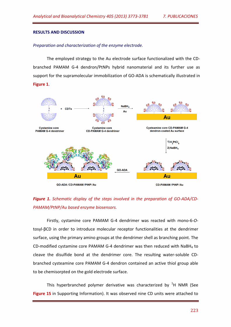
Analytical and Bioanalytical Chemistry 405 (2013) 3773-3781 7. PUBLICACIONES
223
RESULTS AND DISCUSSION
Preparation and characterization of the enzyme electrode.
The employed strategy to the Au electrode surface functionalized with the CD-
branched PAMAM G-4 dendron/PtNPs hybrid nanomaterial and its further use as
support for the supramolecular immobilization of GO-ADA is schematically illustrated in
Figure 1.
Figure 1. Schematic display of the steps involved in the preparation of GO-ADA/CD-
PAMAM/PtNP/Au based enzyme biosensors.
Firstly, cystamine core PAMAM G-4 dendrimer was reacted with mono-6-O-
tosyl-βCD in order to introduce molecular receptor functionalities at the dendrimer
surface, using the primary amino groups at the dendrimer shell as branching point. The
CD-modified cystamine core PAMAM G-4 dendrimer was then reduced with NaBH4 to
cleave the disulfide bond at the dendrimer core. The resulting water-soluble CD-
branched cysteamine core PAMAM G-4 dendron contained an active thiol group able
to be chemisorpted on the gold electrode surface.
This hyperbranched polymer derivative was characterized by 1H NMR (See
Figure 1S in Supporting Information). It was observed nine CD units were attached to
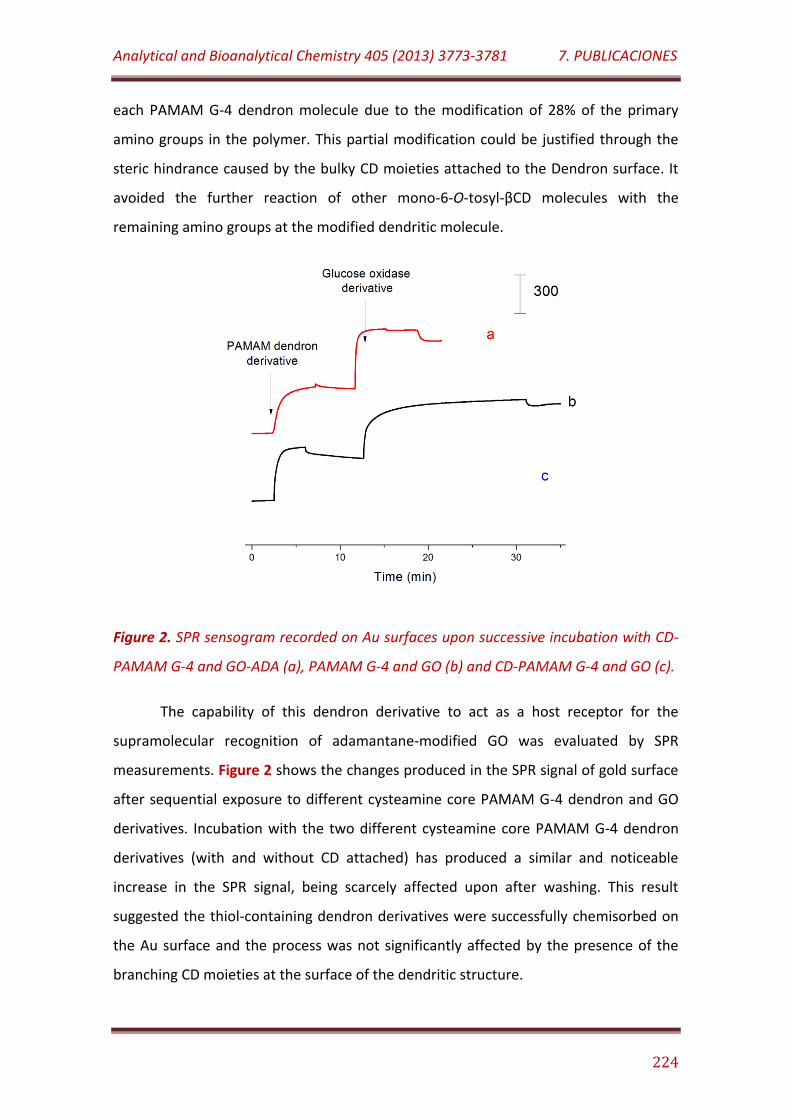
Analytical and Bioanalytical Chemistry 405 (2013) 3773-3781 7. PUBLICACIONES
224
each PAMAM G-4 dendron molecule due to the modification of 28% of the primary
amino groups in the polymer. This partial modification could be justified through the
steric hindrance caused by the bulky CD moieties attached to the Dendron surface. It
avoided the further reaction of other mono-6-O-tosyl-βCD molecules with the
remaining amino groups at the modified dendritic molecule.
Figure 2. SPR sensogram recorded on Au surfaces upon successive incubation with CD-
PAMAM G-4 and GO-ADA (a), PAMAM G-4 and GO (b) and CD-PAMAM G-4 and GO (c).
The capability of this dendron derivative to act as a host receptor for the
supramolecular recognition of adamantane-modified GO was evaluated by SPR
measurements. Figure 2 shows the changes produced in the SPR signal of gold surface
after sequential exposure to different cysteamine core PAMAM G-4 dendron and GO
derivatives. Incubation with the two different cysteamine core PAMAM G-4 dendron
derivatives (with and without CD attached) has produced a similar and noticeable
increase in the SPR signal, being scarcely affected upon after washing. This result
suggested the thiol-containing dendron derivatives were successfully chemisorbed on
the Au surface and the process was not significantly affected by the presence of the
branching CD moieties at the surface of the dendritic structure.
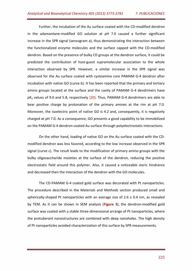
Analytical and Bioanalytical Chemistry 405 (2013) 3773-3781 7. PUBLICACIONES
225
Further, the incubation of the Au surface coated with the CD-modified dendron
in the adamantane-modified GO solution at pH 7.0 caused a further significant
increase in the SPR signal (sensogram a), thus demonstrating the interaction between
the functionalized enzyme molecules and the surface capped with the CD-modified
dendron. Based on the presence of bulky CD groups at the dendron surface, it could be
predicted the contribution of host-guest supramolecular association to the whole
interaction observed by SPR. However, a similar increase in the SPR signal was
observed for the Au surface coated with cysteamine core PAMAM G-4 dendron after
incubation with native GO (curve b). It has been reported that the primary and tertiary
amino groups located at the surface and the cavity of PAMAM G-4 dendrimers have
pKa values of 9.0 and 5.8, respectively [20]. Thus, PAMAM G-4 dendrimers are able to
bear positive charge by protonation of the primary amines at the rim at pH 7.0.
Moreover, the isoelectric point of native GO is 4.2 and, consequently, it is negatively
charged at pH 7.0. As a consequence, GO presents a good capability to be immobilized
on the PAMAM G-4 dendron-coated Au surface through polyelectrostatic interactions.
On the other hand, loading of native GO on the Au surface coated with the CD-
modified dendron was less favored, according to the low increase observed in the SPR
signal (curve c). The result leads to the modification of primary amino groups with the
bulky oligosaccharide moieties at the surface of the dendron, reducing the positive
electrostatic field around this polymer. Also, it caused a noticeable steric hindrance
and decreased then the interaction of the dendron with the GO molecules.
The CD-PAMAM G-4 coated gold surface was decorated with Pt nanoparticles.
The procedure described in the Materials and Methods section produced small and
spherically-shaped Pt nanoparticles with an average size of 2.6 ± 0.4 nm, as revealed
by TEM. As it can be shown in SEM analysis (Figure 3), the dendron-modified gold
surface was coated with a stable three-dimensional arrange of Pt nanoparticles, where
the protuberant nanostructures are combined with deep nanoholes. The high density
of Pt nanoparticles avoided characterization of this surface by SPR measurements.

Analytical and Bioanalytical Chemistry 405 (2013) 3773-3781 7. PUBLICACIONES
226
Figure 3. Field emission SEM image of the CD-PAMAM G-4/PtNP-modified Au surface.
This modified Au surface was further used as support for the immobilization of
the adamantane-modified GO derivative. The changes on the topology and the
electrochemical characteristics of the Au surface after the different modifications steps
were checked by AFM, EIS and CV.
Figure 4 presents the tapping mode AFM images for different gold surfaces.
The characteristic flat topology by an average roughness of 0.9 nm and an average
height of 3.2 nm with a maximum at 5.6 nm on the unmodified gold surface was
observed.
Coating with the CD-PAMAM dendron derivative yielded a modified surface
pattern with ellipsoidal nanostructures, an average roughness of 3.1 nm and an
average height of 12.0 nm with a maximum at 18.6 nm. After the deposition of Pt
nanoparticles on the dendron-modified surface, a more irregular pattern was observed
exhibiting a higher density of protuberant nanostructures with an average and a
maximum height value of 34.6 nm and 92.9 nm, respectively. Moreover, an average
roughness of 15.1 nm was estimated for the Pt nanoparticles-modified surface.
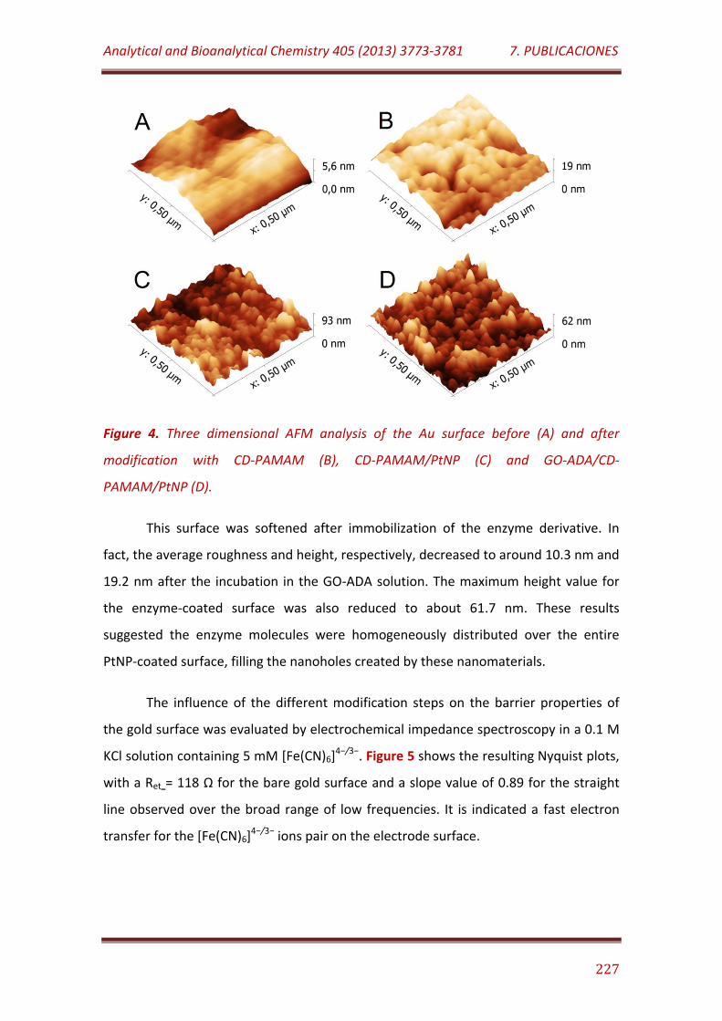
Analytical and Bioanalytical Chemistry 405 (2013) 3773-3781 7. PUBLICACIONES
227
Figure 4. Three dimensional AFM analysis of the Au surface before (A) and after
modification with CD-PAMAM (B), CD-PAMAM/PtNP (C) and GO-ADA/CD-
PAMAM/PtNP (D).
This surface was softened after immobilization of the enzyme derivative. In
fact, the average roughness and height, respectively, decreased to around 10.3 nm and
19.2 nm after the incubation in the GO-ADA solution. The maximum height value for
the enzyme-coated surface was also reduced to about 61.7 nm. These results
suggested the enzyme molecules were homogeneously distributed over the entire
PtNP-coated surface, filling the nanoholes created by these nanomaterials.
The influence of the different modification steps on the barrier properties of
the gold surface was evaluated by electrochemical impedance spectroscopy in a 0.1 M
KCl solution containing 5 mM [Fe(CN)6]4−/3−. Figure 5 shows the resulting Nyquist plots,
with a Ret = 118 Ω for the bare gold surface and a slope value of 0.89 for the straight
line observed over the broad range of low frequencies. It is indicated a fast electron
transfer for the [Fe(CN)6]4−/3− ions pair on the electrode surface.
Analytical and Bioanalytical Chemistry 405 (2013) 3773-3781 7. PUBLICACIONES
228
Figure 5. Nyquist plots of bare Au (a), CD-PAMAM/Au (b), CD-PAMAM/PtNPs/Au (c)
and GO-ADA/CD-PAMAM/PtNP/Au (d) electrodes in 0.1 M KCl solution containing 5
mM K3[Fe(CN)6]/K4[Fe(CN)6] (1:1).
A small increase in the electron transfer resistance, Ret = 195 Ω, and a linear
behavior at low frequencies with similar slope value were observed for the electrode
surface coated with the CD-modified dendron derivative. That is suggesting a low
barrier effect of the dendron molecules on the electron transfer process at the
electrode surface most likely due to the permeable and polycationic nature of the
polyamidoamine polymer. Also, the Nyquist plots revealed the electron transfer
resistance was decreased (Ret = 29 Ω) after modification with the highly conductive Pt
nanoparticles. However, as it was expected, an opposed effect was evident after
immobilization of adamantane-modified GO, producing a noticeable increase in the
diameter of the semicircle at high frequency values (Ret = 639 Ω). In addition, the slope
value of the straight line observed at low frequencies also decreased to 0.58. This
higher resistance to the electron transfer and diffusion-controlled processes suggested
a high coverage of the electrode surface by the non-conductive enzyme molecules.
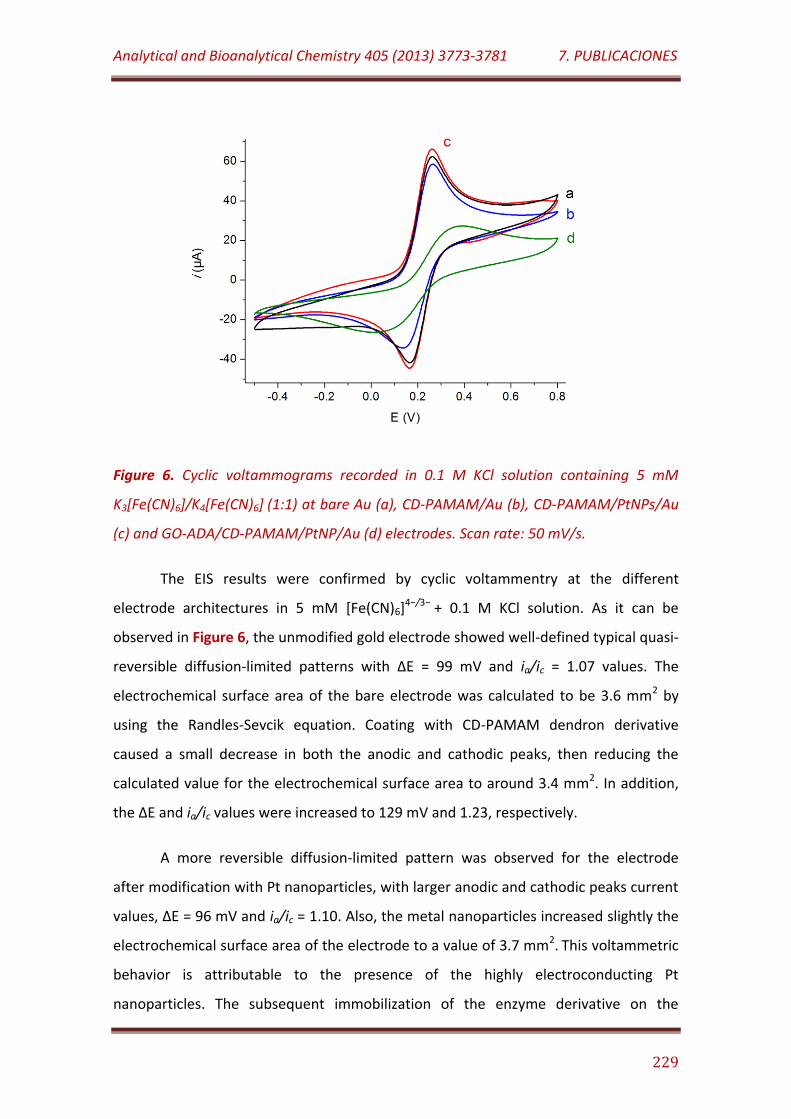
Analytical and Bioanalytical Chemistry 405 (2013) 3773-3781 7. PUBLICACIONES
229
Figure 6. Cyclic voltammograms recorded in 0.1 M KCl solution containing 5 mM
K3[Fe(CN)6]/K4[Fe(CN)6] (1:1) at bare Au (a), CD-PAMAM/Au (b), CD-PAMAM/PtNPs/Au
(c) and GO-ADA/CD-PAMAM/PtNP/Au (d) electrodes. Scan rate: 50 mV/s.
The EIS results were confirmed by cyclic voltammentry at the different
electrode architectures in 5 mM [Fe(CN)6]4−/3− + 0.1 M KCl solution. As it can be
observed in Figure 6, the unmodified gold electrode showed well-defined typical quasi-
reversible diffusion-limited patterns with ∆E = 99 mV and ia/ic = 1.07 values. The
electrochemical surface area of the bare electrode was calculated to be 3.6 mm2 by
using the Randles-Sevcik equation. Coating with CD-PAMAM dendron derivative
caused a small decrease in both the anodic and cathodic peaks, then reducing the
calculated value for the electrochemical surface area to around 3.4 mm2. In addition,
the ∆E and ia/ic values were increased to 129 mV and 1.23, respectively.
A more reversible diffusion-limited pattern was observed for the electrode
after modification with Pt nanoparticles, with larger anodic and cathodic peaks current
values, ∆E = 96 mV and ia/ic = 1.10. Also, the metal nanoparticles increased slightly the
electrochemical surface area of the electrode to a value of 3.7 mm2. This voltammetric
behavior is attributable to the presence of the highly electroconducting Pt
nanoparticles. The subsequent immobilization of the enzyme derivative on the
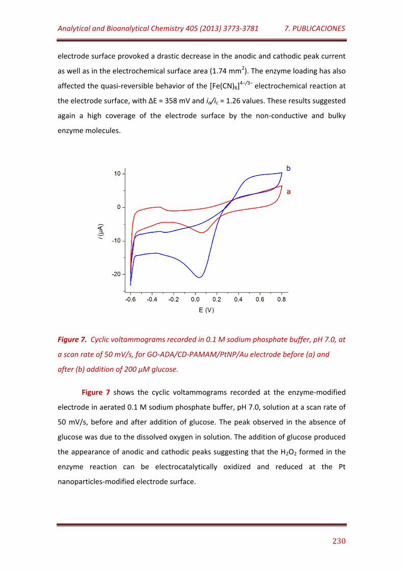
Analytical and Bioanalytical Chemistry 405 (2013) 3773-3781 7. PUBLICACIONES
230
electrode surface provoked a drastic decrease in the anodic and cathodic peak current
as well as in the electrochemical surface area (1.74 mm2). The enzyme loading has also
affected the quasi-reversible behavior of the [Fe(CN)6]4−/3− electrochemical reaction at
the electrode surface, with ∆E = 358 mV and ia/ic = 1.26 values. These results suggested
again a high coverage of the electrode surface by the non-conductive and bulky
enzyme molecules.
Figure 7. Cyclic voltammograms recorded in 0.1 M sodium phosphate buffer, pH 7.0, at
a scan rate of 50 mV/s, for GO-ADA/CD-PAMAM/PtNP/Au electrode before (a) and
after (b) addition of 200 µM glucose.
Figure 7 shows the cyclic voltammograms recorded at the enzyme-modified
electrode in aerated 0.1 M sodium phosphate buffer, pH 7.0, solution at a scan rate of
50 mV/s, before and after addition of glucose. The peak observed in the absence of
glucose was due to the dissolved oxygen in solution. The addition of glucose produced
the appearance of anodic and cathodic peaks suggesting that the H2O2 formed in the
enzyme reaction can be electrocatalytically oxidized and reduced at the Pt
nanoparticles-modified electrode surface.
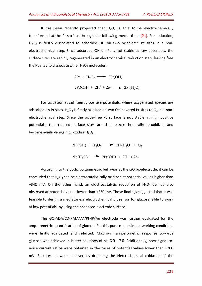
Analytical and Bioanalytical Chemistry 405 (2013) 3773-3781 7. PUBLICACIONES
231
It has been recently proposed that H2O2 is able to be electrochemically
transformed at the Pt surface through the following mechanisms [21]. For reduction,
H2O2 is firstly dissociated to adsorbed OH on two oxide-free Pt sites in a non-
electrochemical step. Since adsorbed OH on Pt is not stable at low potentials, the
surface sites are rapidly regenerated in an electrochemical reduction step, leaving free
the Pt sites to dissociate other H2O2 molecules.
2Pt + H2O2 2Pt(OH)
2Pt(OH) + 2H+ + 2e- 2Pt(H2O)
For oxidation at sufficiently positive potentials, where oxygenated species are
adsorbed on Pt sites, H2O2 is firstly oxidized on two OH-covered Pt sites to O2 in a non-
electrochemical step. Since the oxide-free Pt surface is not stable at high positive
potentials, the reduced surface sites are then electrochemically re-oxidized and
become available again to oxidize H2O2.
According to the cyclic voltammetric behavior at the GO bioelectrode, it can be
concluded that H2O2 can be electrocatalytically oxidized at potential values higher than
+340 mV. On the other hand, an electrocatalytic reduction of H2O2 can be also
observed at potential values lower than +230 mV. These findings suggested that it was
feasible to design a mediatorless electrochemical biosensor for glucose, able to work
at low potentials, by using the proposed electrode surface.
The GO-ADA/CD-PAMAM/PtNP/Au electrode was further evaluated for the
amperometric quantification of glucose. For this purpose, optimum working conditions
were firstly evaluated and selected. Maximum amperometric response towards
glucose was achieved in buffer solutions of pH 6.0 - 7.0. Additionally, poor signal-to-
noise current ratios were obtained in the cases of potential values lower than +200
mV. Best results were achieved by detecting the electrochemical oxidation of the
Analytical and Bioanalytical Chemistry 405 (2013) 3773-3781 7. PUBLICACIONES
232
enzymatically-produced H2O2 at potential values higher than +350 mV. In order to
minimize the undesirable effect of common interfering substances during the
amperometric detection of glucose, it was selected the lowest anodic potential value
at which a good signal-to-noise ratio was observed. Summarizing, further
amperometric measurements were performed in 0.1 M sodium phosphate buffer of
pH 7.0 at a constant potential of +400 mV vs Ag/AgCl.
Figure 8. Amperometric responses recorded with GO-ADA/CD-PAMAM/PtNP/Au (a),
GO/PAMAM/PtNP/Au (b), GO/CD-PAMAM/PtNP/Au (c) and GO/PtNP/Au (d) electrodes
upon successive additions of 5.0 mM glucose. Eapp.= + 400 mV.
Under these conditions mentioned above, the dynamic amperometric response
of the bioelectrode upon successive additions of 5.0 mM glucose is illustrated in Figure
8 (curve a). As control measures, Au electrodes coated with PAMAM/PtNP (curve b),
CD-PAMAM/PtNP (curve c), PtNP (d) and PAMAM (data not shown), on which an
equivalent activity of native GO was immobilized under similar conditions, were also
checked. The GO-ADA/CD-PAMAM/PtNP/Au-based biosensor showed fast catalytic
response, reaching 95% of the steady-state current in about 6 s. Not significant
increase in the anodic current was observed for the GO/PAMAM/Au electrode,
demonstrating that PtNPs are needed for the electrocatalytic oxidation of H2O2 at +400
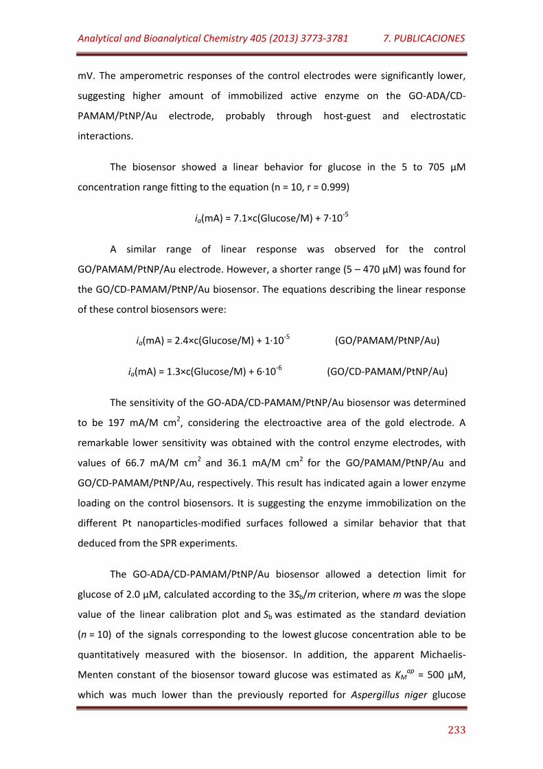
Analytical and Bioanalytical Chemistry 405 (2013) 3773-3781 7. PUBLICACIONES
233
mV. The amperometric responses of the control electrodes were significantly lower,
suggesting higher amount of immobilized active enzyme on the GO-ADA/CD-
PAMAM/PtNP/Au electrode, probably through host-guest and electrostatic
interactions.
The biosensor showed a linear behavior for glucose in the 5 to 705 µM
concentration range fitting to the equation (n = 10, r = 0.999)
ia(mA) = 7.1×c(Glucose/M) + 7·10-5
A similar range of linear response was observed for the control
GO/PAMAM/PtNP/Au electrode. However, a shorter range (5 – 470 µM) was found for
the GO/CD-PAMAM/PtNP/Au biosensor. The equations describing the linear response
of these control biosensors were:
ia(mA) = 2.4×c(Glucose/M) + 1·10-5 (GO/PAMAM/PtNP/Au)
ia(mA) = 1.3×c(Glucose/M) + 6·10-6 (GO/CD-PAMAM/PtNP/Au)
The sensitivity of the GO-ADA/CD-PAMAM/PtNP/Au biosensor was determined
to be 197 mA/M cm2, considering the electroactive area of the gold electrode. A
remarkable lower sensitivity was obtained with the control enzyme electrodes, with
values of 66.7 mA/M cm2 and 36.1 mA/M cm2 for the GO/PAMAM/PtNP/Au and
GO/CD-PAMAM/PtNP/Au, respectively. This result has indicated again a lower enzyme
loading on the control biosensors. It is suggesting the enzyme immobilization on the
different Pt nanoparticles-modified surfaces followed a similar behavior that that
deduced from the SPR experiments.
The GO-ADA/CD-PAMAM/PtNP/Au biosensor allowed a detection limit for
glucose of 2.0 µM, calculated according to the 3Sb/m criterion, where m was the slope
value of the linear calibration plot and Sb was estimated as the standard deviation
(n = 10) of the signals corresponding to the lowest glucose concentration able to be
quantitatively measured with the biosensor. In addition, the apparent Michaelis-
Menten constant of the biosensor toward glucose was estimated as KMap = 500 µM,
which was much lower than the previously reported for Aspergillus niger glucose
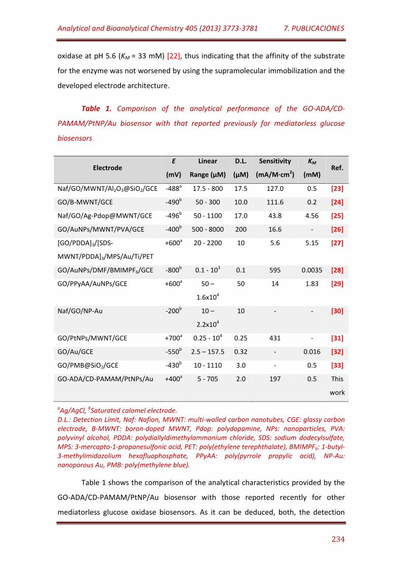
Analytical and Bioanalytical Chemistry 405 (2013) 3773-3781 7. PUBLICACIONES
234
oxidase at pH 5.6 (KM = 33 mM) [22], thus indicating that the affinity of the substrate
for the enzyme was not worsened by using the supramolecular immobilization and the
developed electrode architecture.
Table 1. Comparison of the analytical performance of the GO-ADA/CD-
PAMAM/PtNP/Au biosensor with that reported previously for mediatorless glucose
biosensors
Electrode E
(mV)
Linear
Range (µM)
D.L.
(µM)
Sensitivity
(mA/M·cm2)
KM
(mM) Ref.
Naf/GO/MWNT/Al2O3@SiO2/GCE -488a 17.5 - 800 17.5 127.0 0.5 [23]
GO/B-MWNT/GCE -490b 50 - 300 10.0 111.6 0.2 [24]
Naf/GO/Ag-Pdop@MWNT/GCE -496b 50 - 1100 17.0 43.8 4.56 [25]
GO/AuNPs/MWNT/PVA/GCE -400b 500 - 8000 200 16.6 - [26]
[GO/PDDA]3/[SDS-
MWNT/PDDA]3/MPS/Au/Ti/PET
+600a 20 - 2200 10 5.6 5.15 [27]
GO/AuNPs/DMF/BMIMPF6/GCE -800b 0.1 - 103 0.1 595 0.0035 [28]
GO/PPyAA/AuNPs/GCE +600a 50 –
1.6x10⁴
50 14 1.83 [29]
Naf/GO/NP-Au -200b 10 –
2.2x10⁴
10 - - [30]
GO/PtNPs/MWNT/GCE +700a 0.25 - 104 0.25 431 - [31]
GO/Au/GCE -550b 2.5 – 157.5 0.32 - 0.016 [32]
GO/PMB@SiO2/GCE -430b 10 - 1110 3.0 - 0.5 [33]
GO-ADA/CD-PAMAM/PtNPs/Au +400a 5 - 705 2.0 197 0.5 This
work
aAg/AgCl, bSaturated calomel electrode. D.L.: Detection Limit, Naf: Nafion, MWNT: multi-walled carbon nanotubes, CGE: glassy carbon electrode, B-MWNT: boron-doped MWNT, Pdop: polydopamine, NPs: nanoparticles, PVA: polyvinyl alcohol, PDDA: polydiallyldimethylammonium chloride, SDS: sodium dodecylsulfate, MPS: 3-mercapto-1-propanesulfonic acid, PET: poly(ethylene terephthalate), BMIMPF6: 1-butyl-3-methylimidazolium hexafluophosphate, PPyAA: poly(pyrrole propylic acid), NP-Au: nanoporous Au, PMB: poly(methylene blue).
Table 1 shows the comparison of the analytical characteristics provided by the
GO-ADA/CD-PAMAM/PtNP/Au biosensor with those reported recently for other
mediatorless glucose oxidase biosensors. As it can be deduced, both, the detection
Analytical and Bioanalytical Chemistry 405 (2013) 3773-3781 7. PUBLICACIONES
235
limit and sensitivity, and apparent Michaelis-Menten constant are among the best
values reported. They are only surpassed by biosensors using extreme working
potentials and then more susceptible to be interfered by other analytes during glucose
determination.
The good electroanalytical behavior of the GO-ADA/CD-PAMAM/PtNP/Au
biosensor could be assigned to the high amount of immobilized enzyme, as well as the
cooperative contribution of several factors on the maintenance of the active enzyme
protein conformation on the electrode surface. In particular, the supramolecular
strategy used for GO immobilization as well as the presence of metal nanoparticles
should avoid the structural deformation of the active globular enzyme form upon
immobilization on the electrode surface. In addition, the presence of highly hydrophilic
CD-PAMAM G-4 dendron units on that surface should contribute to keep a hydrophilic
microenvironment around the enzyme. The occurrence of randomly-arranged
nanocavities originated by the Pt nanoparticles should also ensure a high population of
enzyme immobilized into these nanoholes being expected that such nanostructures
should protect the hydrophilic microenvironment around the immobilized enzyme.
The repeatability of the measurements carried out for 25 µM glucose with one
single GO-ADA/CD-PAMAM/PtNP/Au electrode (n = 10) yielded a relative standard
deviation (RSD) value of 4.7%. The electrode-to-electrode reproducibility was
calculated from the responses obtained with ten different GO-ADA/CD-
PAMAM/PtNP/Au electrodes prepared in the same manner toward the same glucose
concentration yielding a RSD value of 7.2%.
The selectivity of the enzyme electrode was evaluated by measuring the
amperometric response for 25 µM glucose in the presence of seven possible
interfering substances. Fructose, galactose, sucrose, arabinose, cysteine, citric acid and
caffeine at 100 µM concentration did not cause significant changes in the steady-state
current signal of glucose. However, as expected, the amperometric response of the
biosensor toward glucose was affected in 2.1% and 20% after addition of uric acid and
ascorbic acid at a 2.5 µM concentration, respectively.

Analytical and Bioanalytical Chemistry 405 (2013) 3773-3781 7. PUBLICACIONES
236
Regarding the effect of the biosensor storage time at 4ºC under dry conditions
on the amperometric response of the biosensor, it was observed that the biosensor
retained more than 94% of its initial activity after 9 days of storage. Longer storage
times provoked a gradual loss of the biosensor activity, retaining about 45% of the
initial amperometric response after one month. It should be also noted that the
activity of the biosensor was reduced to about 35% upon two hours of incubation in a
saturated solution of 1-adamantane carboxylic acid, indicating the disruption of the
supramolecular host-guest interactions between the modified enzyme molecules and
the CD-branched dendron derivatives at the electrode surface.
CONCLUSIONS
A novel electrode surface involving gold coated with PtNPs-decorated CD-
branched cysteamine core PAMAM G-4 dendron was used as support for the
immobilization of adamantane modified glucose oxidase, mainly through the
formation of host-guest supramolecular associations. The enzyme electrode was
evaluated for the construction of a third generation biosensor for glucose. The
biosensor was highly selective and presented a good sensitivity and stability, as well as
a low detection limit and a fast electroanalytical response toward glucose. Attending
to these results, it was suggested the use of Au surface modified with this
inorganic/organic hybrid nanomaterial as a useful electrode platform for preparing
mediatorless oxidase-based amperometric enzyme biosensors.
ACKNOWLEDGEMENTS
R. Villalonga acknowledge to Ramón & Cajal contract from the Spanish Ministry
of Science and Innovation. Financial support from the Spanish Ministry of Science and
Innovation CTQ2011-24355, CTQ2009-12650, CTQ2009-09351 and Comunidad de
Madrid S2009/PPQ-1642, programme AVANSENS are gratefully acknowledged.
Analytical and Bioanalytical Chemistry 405 (2013) 3773-3781 7. PUBLICACIONES
237
REFERENCES
1. Newman JD, Setford SJ (2006) Enzymatic biosensors. Mol Biotechnol 32: 249-268
2. North SH, Lock EH, Taitt CR, Walton SG. (2010) Critical aspects of biointerface
design and their impact on biosensor development. Anal Bioanal Chem 397: 925-
933
3. Li H, Liu S, Dai Z, Bao J, Yang X (2009) Applications of nanomaterials in
electrochemical enzyme biosensors. Sensors 9: 8547-856
4. Guo S, Dong S (2009) Biomolecule-nanoparticle hybrids for electrochemical
biosensors. Trends Anal. Chem. 28: 96-109
5. Pingarrón JM, Yáñez-Sedeño P, González-Cortés A (2008) Gold nanoparticle-based
electrochemical biosensors. Electrochim. Acta 53: 5848-5866
6. Shao Y, Wang J, Wu H, Liu J, Aksay IA, Lin Y (2010) Graphene based
electrochemical sensors and biosensors: a review. Electroanal 22: 1027-1036
7. Wang J (2005) Carbon-nanotube based electrochemical biosensors: a review.
Electroanal 17: 7-14
8. Villalonga R, Díez P, Casado S, Eguílaz M, Yáñez-Sedeño P, Pingarrón JM (2012)
Electropolymerized network of polyamidoamine dendron-coated gold
nanoparticles as novel nanostructured electrode surface for biosensor
construction. Analyst 137: 342-348
9. Zhu N, Gao H, Gu Y, Xu Q, He P, Fang Y (2009) PAMAM dendrimer-enhanced DNA
biosensors based on electrochemical impedance spectroscopy. Analyst 134: 860-
866
10. Vögtle F, Richardt G, Werner N (2009) Dendrimer chemistry: concepts, synthesis,
properties, applications. Wiley-VCH, Weinheim
Analytical and Bioanalytical Chemistry 405 (2013) 3773-3781 7. PUBLICACIONES
238
11. Endo T, Yoshimura T, Esumi K (2005) Synthesis and catalytic activity of gold–silver
binary nanoparticles stabilized by PAMAM dendrimer. J Colloid Interface Sci 286:
602-609
12. Crooks RM, Zhao M, Sun L, Chechik V, Yeung LK (2001) Dendrimer-encapsulated
metal nanoparticles: synthesis, characterization, and applications to catalysis. Acc
Chem Res 34: 181-190
13. Xu L, Zhu Y, Tang L, Yang X, Li C (2007) Biosensor based on self-assembling glucose
oxidase and dendrimer-encapsulated Pt nanoparticles on carbon nanotubes for
glucose detection. Electroanal 19: 717-722
14. Zhu Y, Zhu H, Yang X, Xu L, Li C (2007) Sensitive biosensors based on (dendrimer
encapsulated Pt nanoparticles)/enzyme multilayers. Electroanal 19: 698-703
15. Villalonga R, Cao R, Fragoso A (2007) Supramolecular chemistry of cyclodextrins in
enzyme technology. Chem Rev 107: 3088-3116
16. Holzinger M, Bouffier L, Villalonga R, Cosnier S (2009) Adamantane/β-cyclodextrin
affinity biosensors based on single-walled carbon nanotubes. Biosens Bioelectron
24: 1128-1134
17. Villalonga R, Camacho C, Cao R, Hernández J, Matías JC (2007) Amperometric
biosensor for xanthine with supramolecular architecture. Chem Commun 942-944
18. Villalonga R, Matos M, Cao R (2007) Construction of an amperometric biosensor
for xanthine via supramolecular associations. Electrochem Commun 9: 454-458
19. Wang J (2008) Electrochemical glucose biosensors. Chem Rev 108: 814-825
20. Cakara D, Kleimann J, Borkovec M (2003) Microscopic protonation equilibra of
poly(amidoamine) dendrimers from macroscopic titrations. Macromolecules 36:
4201-4207
21. Katsounaros I, Schneider WB, Meier JC, Benedikt U, Biedermann PU, Auer AA,
Mayrhofer KJJ (2012) Hydrogen peroxide electrochemistry on platinum: towards
Analytical and Bioanalytical Chemistry 405 (2013) 3773-3781 7. PUBLICACIONES
239
understanding the oxygen reduction reaction mechanism. Phys Chem Chem Phys
14: 7384-7391
22. Swoboda BEP, Massey V (1965) Purification and properties of glucose oxidase
from Aspergillus niger. J Biol Chem 240: 2209-2215
23. Wu WC, Huang JL, Tsai YC (2012) Direct electron transfer and biosensing of
glucose oxidase immobilized at multiwalled carbon nanotube-alumina-coated
silica modified electrode. Mat Sci Eng C 32: 983-987
24. Deng C, Chen J, Chen X, Xiao C, Nie L, Yao S (2008) Direct electrochemistry of
glucose oxidase and biosensing for glucose based on boron-doped carbon
nanotubes modified electrode. Biosens Bioelectron 23: 1272-1277
25. Wang Y, Liu L, Li M, Xu S, Gao F (2011) Multifunctional carbon nanotubes for direct
electrochemistry of glucose oxidase and glucose bioassay. Biosens Bioelectron 30:
107-111
26. Zhang H, Meng Z, Wang Q, Zheng J (2011) A novel glucose biosensor based on
direct electrochemistry of glucose oxidase incorporated in biomediated gold
nanoparticles–carbon nanotubes composite film. Sens Actuat B Chem 158: 23-27
27. Yan XB, Chen XJ, Tay BK, Khor KA (2007) Transparent and flexible glucose
biosensor via layer-by-layer assembly of multi-wall carbon nanotubes and glucose
oxidase, Electrochem Commun 9: 1269-1275
28. Li J, Yu J, Zhao F, Zeng B (2007) Direct electrochemistry of glucose oxidase
entrapped in nano gold particles-ionic liquid-N,N-dimethylformamide composite
film on glassy carbon electrode and glucose sensing. Anal Chim Acta 587: 33-40
29. Şenel M, Nergiz C (2012) Novel amperometric glucose biosensor based on
covalent immobilization of glucose oxidase on poly(pyrrole propylic acid)/Au
nanocomposite. Curr Appl Phys 12: 1118-1124
30. Qiu H, Zou F (2012) Fabrication of stratified nanoporous gold for enhanced
biosensing. Biosens Bioelectron 35: 349-354
Analytical and Bioanalytical Chemistry 405 (2013) 3773-3781 7. PUBLICACIONES
240
31. Male KB, Hrapovic S, Luong JHT (2007) Electrochemically-assisted deposition of
oxidases on platinum nanoparticle/multi-walled carbon nanotube-modified
electrodes. Analyst 132: 1254-1261
32. Qiu C, Wang X, Liu X, Hou S, Ma H (2012) Direct electrochemistry of glucose
oxidase immobilized on nanostructured gold thin films and its application to
bioelectrochemical glucose sensor, Electrochim Acta 67: 140-146
33. Xiao X, Zhou B, Zhu L, Xu L, Tan L, Tang H, Zhang Y, Xie Q, Yao S (2012) An
reagentless glucose biosensor based on direct electrochemistry of glucose oxidase
immobilized on poly(methylene blue) doped silica nanocomposites. Sens Actuat B
Chem 165: 126-132
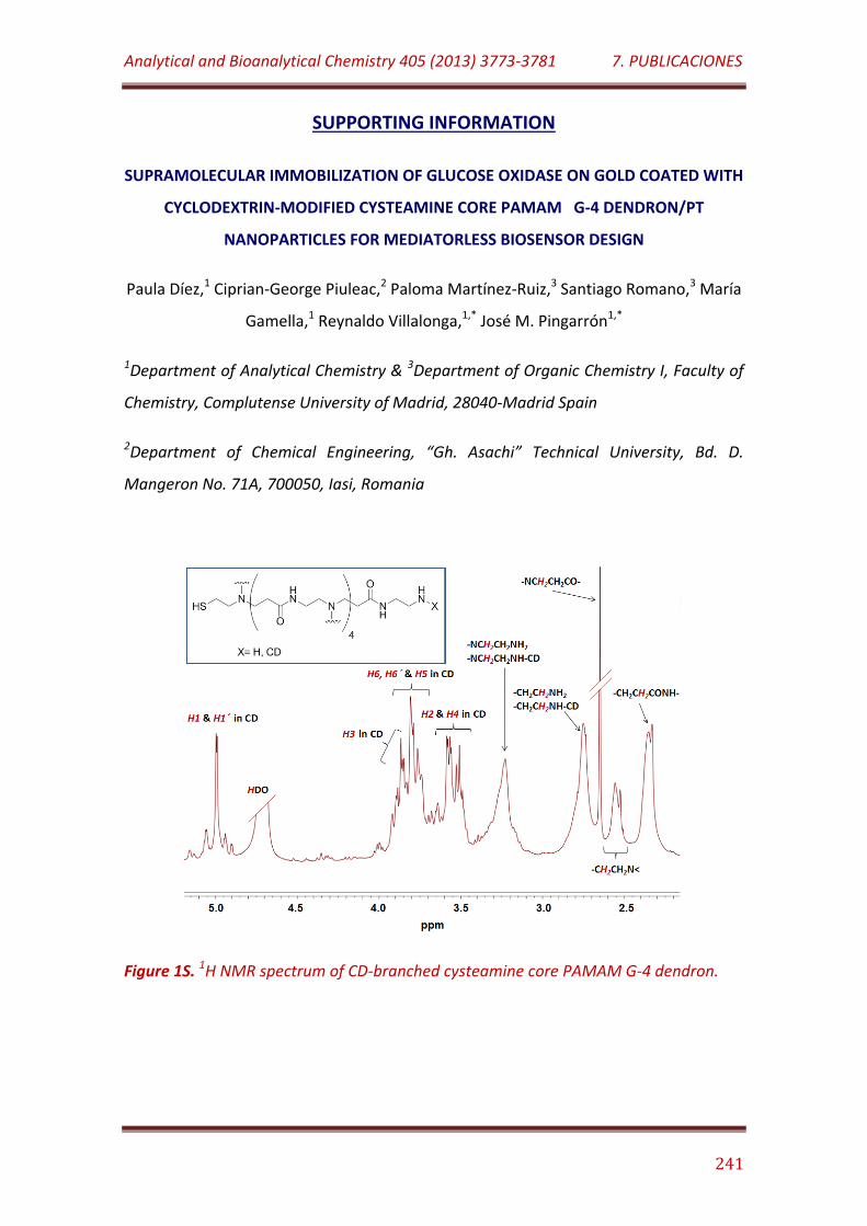
Analytical and Bioanalytical Chemistry 405 (2013) 3773-3781 7. PUBLICACIONES
241
SUPPORTING INFORMATION
SUPRAMOLECULAR IMMOBILIZATION OF GLUCOSE OXIDASE ON GOLD COATED WITH
CYCLODEXTRIN-MODIFIED CYSTEAMINE CORE PAMAM G-4 DENDRON/PT
NANOPARTICLES FOR MEDIATORLESS BIOSENSOR DESIGN
Paula Díez,1 Ciprian-George Piuleac,2 Paloma Martínez-Ruiz,3 Santiago Romano,3 María
Gamella,1 Reynaldo Villalonga,1,* José M. Pingarrón1,*
1Department of Analytical Chemistry & 3Department of Organic Chemistry I, Faculty of
Chemistry, Complutense University of Madrid, 28040-Madrid Spain
2Department of Chemical Engineering, “Gh. Asachi” Technical University, Bd. D.
Mangeron No. 71A, 700050, Iasi, Romania
Figure 1S. 1H NMR spectrum of CD-branched cysteamine core PAMAM G-4 dendron.

7.8
Electrochimica Acta 76 (2012) 249-255
Layer-by-layer supramolecular architecture of cyclodextrin-
modified pamam dendrimers and adamantane-modified
peroxidase on gold surface for electrochemical biosensing

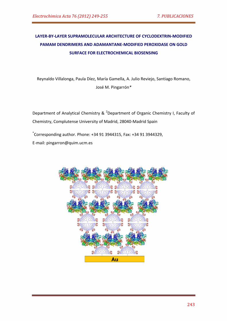
Electrochimica Acta 76 (2012) 249-255 7. PUBLICACIONES
243
LAYER-BY-LAYER SUPRAMOLECULAR ARCHITECTURE OF CYCLODEXTRIN-MODIFIED
PAMAM DENDRIMERS AND ADAMANTANE-MODIFIED PEROXIDASE ON GOLD
SURFACE FOR ELECTROCHEMICAL BIOSENSING
Reynaldo Villalonga, Paula Díez, María Gamella, A. Julio Reviejo, Santiago Romano,
José M. Pingarrón*
Department of Analytical Chemistry & 2Department of Organic Chemistry I, Faculty of
Chemistry, Complutense University of Madrid, 28040-Madrid Spain
*Corresponding author. Phone: +34 91 3944315, Fax: +34 91 3944329,
E-mail: [email protected]
Electrochimica Acta 76 (2012) 249-255 7. PUBLICACIONES
244
ABSTRACT
A new layer-by-layer supramolecular approach for the construction of self-
assembled nanoarchitectures of polyamidoamine (PAMAM) dendrimers and
peroxidase on gold surface is reported. The methodology is based on the
supramolecular self-assembly of alternated layers of adamantane-modified
horseradish peroxidase and β-cyclodextrin-branched PAMAM G-5 dendrimers on a
gold electrode, previously coated with β-cyclodextrin-modified cysteamine core
PAMAM G-4 dendron. The formation of layer-by-layer assemblies (up to three
dendrimer/peroxidase bilayers) was studied by SPR, quartz crystal microbalance, AFM
and cyclic voltammetry. The analytical applicability of these architectures was
evaluated by constructing a H2O2 biosensor. The electroanalytical response of the
biosensor towards H2O2 increased with the number of enzyme layers. The bioelectrode
constructed with three enzyme layers showed a low detection limit of 160 nM, a
sensitivity of 602 µA/M cm2 and retained 63% of its initial activity after 30 days of
storage in wet conditions.
KEYWORDS: Biosensor, β-cyclodextrin, dendrimer, horseradish peroxidase, layer-by-
layer, supramolecular complex.
INTRODUCTION
The design of hybrid biomolecule/nanomaterial-based three-dimensional
architectures on metal surfaces is a current research priority with the aim of
developing novel biosensing devices, functional biomaterials and efficient biocatalysts
[1-4]. These nanostructured constructions should ensure the accurate interaction of
the modified surface with the biomolecule without affecting its biological activity. In
general, the successful preparation of these hybrid arrangements depends largely on
the surface properties, the characteristics of the selected nanomaterials, the chemical
Electrochimica Acta 76 (2012) 249-255 7. PUBLICACIONES
245
and biological properties of the target biomolecules, the immobilization strategy and
the sequential approach used to construct such 3D assemblies.
Solid state nanomaterials have been largely employed to modify metal
surfaces, offering a great variety of three-dimensional nanosized architectures for
biomolecule immobilization [5, 6]. However, the native conformation of proteins and
other biomolecules is often affected at the interface with solid nanomaterials leading
to a lack of functional activity [7, 8]. Therefore, the evaluation of non-rigid nanosized
materials as alternative 3D scaffolds for the construction of biofunctionalized
nanoarchitectures on solid surfaces is receiving considerable attention [9, 10].
Dendrimers are monodisperse synthetic polymers with a regular and highly
branched three-dimensional structure [11, 12]. These hyperbranched soft
nanomaterials have been widely used in the functionalization of solid surfaces for the
preparation of biosensor systems [9, 10]. Such applications have been supported by
the unique structural properties of dendrimers, such as structural uniformity, globular
shape, nanometric size, monodispersity, high density of functional groups at the
surface and high permeability of the internal cavities. In addition, the possibility to
manipulate such properties by controlling chemical transformation or tailor-made
designing of dendrimers with specific composition offers versatile possibilities to these
polymers as 3D scaffolds for constructing nanostructured designs at the electrode
surfaces [9-12].
Layer-by-layer arrangements on solid surfaces, mainly using electrostatic
interactions as assembling forces, have been reported for dendrimer and
dendrimer/protein hybrid based architectures [9, 13, 14]. However, at our knowledge,
the use of host-guest interactions for the layer-by-layer supramolecular self-assembly
of proteins and dendrimers on metal surfaces has not been described yet. In previous
works, we have reported supramolecular-based strategies for immobilizing
adamantane-modified enzymes and other proteins on nanomaterials and metal
electrodes, previously capped with β-cyclodextrin (CDs) derivatives [15-18]. Similar
supramolecular approaches have been also employed in the formation of layer-by-
Electrochimica Acta 76 (2012) 249-255 7. PUBLICACIONES
246
layer architectures of enzymes and enzyme/nanoparticle on metal surfaces via host-
guest interactions [19, 20].
In this work we propose a novel supramolecular approach for the preparation
of hybrid dendrimer/enzyme nanostructured architectures on Au surfaces, through the
layer-by-layer self-assembly of chemically-modified horseradish peroxidase (HRP, EC
1.11.1.7, H2O2 oxidoreductase) and CD-branched PAMAM dendrimers via host-guest
interactions. CD cavity functions as a macrocyclic receptor with the ability of including
hydrophobic guest compounds with the appropriate geometry such as enzyme-
adamantane derivatives, forming stable supramolecular inclusion complexes. HRP was
selected as model enzyme due to its importance in biosensor technology for H2O2
determination and as a second enzyme for the quantification of selected compounds
transformed by oxidases [21].
MATERIALS AND METHODS
1. Reagents and apparatus
HRP (Type II, 250 U/mg, d = 2.5 - 3.0 nm), NaBH4, CD, cystamine core PAMAM
G-4 dendrimer (d = 4.5 nm) and ethylenediamine core PAMAM G-5 dendrimer (d = 5.4
nm) were purchased from Sigma-Aldrich Co. (USA). All other chemicals were of
analytical grade.
Amperometric measurements were performed with a dual-channel
ultrasensitive Inbea potentiostat (Inbea Biosensores S.L., Spain). Cyclic voltammetry
and electrochemical impedance spectroscopy experiments were performed using a
FRA2 µAutolab Type III potentiostat/galvanostat and the data were acquired using
GPES Ver. 4.9 and Frequency Response Analyser softwares, respectively (Metrohm
Autolab B.V., The Netherlands). A conventional three-electrode system was employed
in all electrochemical studies. The working electrode was a gold disk (CHI Instruments,
UK, 2.0 mm diameter) modified with the hybrid dendrimer/HRP layer-by-layer
architectures. An Ag/AgCl/KCl (3 M) and a Pt wire were used as reference and counter

Electrochimica Acta 76 (2012) 249-255 7. PUBLICACIONES
247
electrodes, respectively. Bioelectrode measurements were carried out at 25ºC in 0.1 M
sodium phosphate buffer, pH 7.0 (working volume 10 ml), using 1.0 mM hydroquinone
as redox mediator. The solutions were stirred at 300 rpm with a magnetic bar during
amperometric measurements. For analytical purposes, 1.0 mM H2O2 solutions in 50
mM sodium phosphate buffer, pH 7.0 were freshly prepared.
The optical measurements of the surface plasmon resonance (SPR) angles were
performed at a fixed wavelength of 670 nm using a Springle Autolab-SPR equipment
from Metrohm Autolab B.V. (The Netherlands). The mass variation during the formation
of the dendrimer/HRP layer-by-layer assemblies was followed by a Maxtek RQCM
603200-2 quartz crystal microbalance (QCM, Inficon, USA), oscillating at a nominal
frequency of 9.0 Hz. The morphology of gold modified surface was studied using atomic
force microscopy (AFM) with a SPM Nanoscope IIIa multimode microscope (Veeco
Instruments Inc., USA). 1H NMR characterizations were performed with a Bruker Avance
500 MHz spectrometer (Bruker BioSpin GmbH, Germany).
2. Synthesis of CD-modified ethylenediamine core PAMAM G-5 dendrimer (CD-PAMAM
G-5)
The mono-6-O-tosyl β-cyclodextrin derivative was synthesized as previously
described [22]. To prepare the CD branched dendrimer, 50 mg of ethylenediamine
core PAMAM G-5 dendrimer and 510 mg of mono-6-O-tosyl CD were dissolved in 100
mL of DMSO, previously deoxygenated by continuous bubbling of N2. The mixture was
stirred at room temperature under N2 atmosphere during four days, then
concentrated in vacuum to about 5 mL and further diluted with 150 mL of distilled
water. The solution was exhaustively dialyzed vs. distilled water using Amicon Ultra-15
centrifugal filter units with Ultracel-10 membranes (Millipore, USA), and finally
concentrated to a 4 mg/mL concentration. The CD-PAMAM G-5 dendrimer was
characterized by 1H NMR in D2O. Yield: 107 mg.
Electrochimica Acta 76 (2012) 249-255 7. PUBLICACIONES
248
3. Synthesis of CD-modified cysteamine core PAMAM G-4 dendron (CD-PAMAM G-4)
Fifty milligrams of cystamine core PAMAM G-4 dendrimer and 510 mg of mono-
6-O-tosyl CD were dissolved in 100 mL of deoxygenated DMSO, and the mixture was
stirred at room temperature under N2 atmosphere during four days. The solution was
then concentrated in vacuum to about 5 mL, diluted with 150 mL of distilled water and
finally dialyzed vs. distilled water using Amicon Ultra-15 centrifugal filter units with
Ultracel-10 membranes (Millipore, USA). The resulting solution was concentrated to
about 20 mg/mL and treated with NaBH4 (10 mM final concentration) during 2 h under
magnetic stirring. The mixture was then dialyzed/concentrated with Amicon
centrifugal tubes as described above, yielding a CD-PAMAM G-4 solution of 4 mg/mL
final concentration. The CD-PAMAM G-4 dendron was characterized by 1H NMR in D2O.
Yield: 93 mg.
4. Preparation of the layer-by-layer assemblies on gold surface
First, the gold surfaces were exhaustively cleaned to ensure the chemisorption
of thiolated PAMAM dendron derivative. A disk gold electrode was polished with
alumina powder (0.3 µm), then rinsed with double distilled water and immersed in an
ultrasonic bath for 5 min. The electrode was further dipped in boiling 8 M KOH solution
for 1 h, washed with distilled water and immersed in piranha solution for 30 min. The
electrode was washed and electrochemically cleaned by cyclic voltammetry in 0.1 M
H2SO4 solution through twenty cycles between -0.2 V and 1.85 V at scan rate of 100
mV/s. For AFM studies, a gold foil (thickness 0.1 mm) was treated as described above
and further annealed on flame for 30 seconds. The gold surface in the QCM sensor
disks were cleaned by boiling for 5 min in a H2O/H2O2/NH3 solution (5/1/1, v/v), rinsed
thoroughly with water and dried with N2. SPR sensor disks were cleaned by sequential
shaking during 10 min in 100 mM NaOH and 1% Triton X-100 (v/v) solutions, rinsed
with water and dried with N2.
In a typical experiment, a clean gold surface was first dipped into a 0.5 mg/mL
aqueous solution of CD-PAMAM G-4 to covering the metal surface with a monolayer of
Electrochimica Acta 76 (2012) 249-255 7. PUBLICACIONES
249
the CD-branched dendron derivative. After 2 h incubation, the electrode was washed
several times with distilled water and further covered with a 2 mg/mL solution of HRP-
ADA, prepared as previously described [17], in 50 mM sodium phosphate buffer, pH
7.0. The formation of the first enzyme layer was accomplished by incubating the
system during 2 h at 4ºC. The gold surface was then washed with cold buffer solution
and incubated for 2 h with a 0.5 mg/mL solution of CD-PAMAM G-5 dendrimer in the
same buffer. After washing, further enzyme and CD-PAMAM G-5 layers were prepared
by sequential treatment of the modified metal surface as described above. The
modified metal surfaces were kept at 4ºC in 50 mM sodium phosphate buffer, pH 7.0
until use.
RESULTS AND DISCUSSION
1. Preparaction and characterization of the layer-by-layer modified electrode
Figure 1 displays schematically the strategy employed to construct the self-
assembled layer-by-layer architectures of PAMAM dendritic structures and HRP on
gold surfaces via host-guest interactions. To promote the formation of supramolecular
complexes between the different molecular scaffolds, HRP was chemically modified
with 1-adamantanecarboxylic acid using a water-soluble carbodiimide as coupling
agent [17]. As it was demonstrated previously, this modification yielded an enzyme
derivative that contained an average of 5 mol adamantane (ADA) residues per mol of
modified protein molecule and retained about 87% of the enzyme initial catalytic
activity.

Electrochimica Acta 76 (2012) 249-255 7. PUBLICACIONES
250
Figure 1. Scheme displaying the steps involved in the preparation of the layer-by-layer
self-assembly of dendrimer and HRP on Au surface. D1: CD-PAMAM G-4 dendron layer,
D2 and D3: CD-PAMAM G-5 dendrimer layers, and HRP: enzyme layers.
Moreover, the primary amino groups at the surface of PAMAM dendrimers
were reacted with the βCD-mono-6-O-tosyl derivative in order to provide
hyperbranched molecular receptors for the multivalent association with the
adamantane-modified enzyme. In the case of the cystamine core PAMAM G-4
dendrimer, it was further treated with NaBH4 to reduce the disulfide bond at the
dendrimer core, yielding a thiol-containing dendron derivative able to form the first
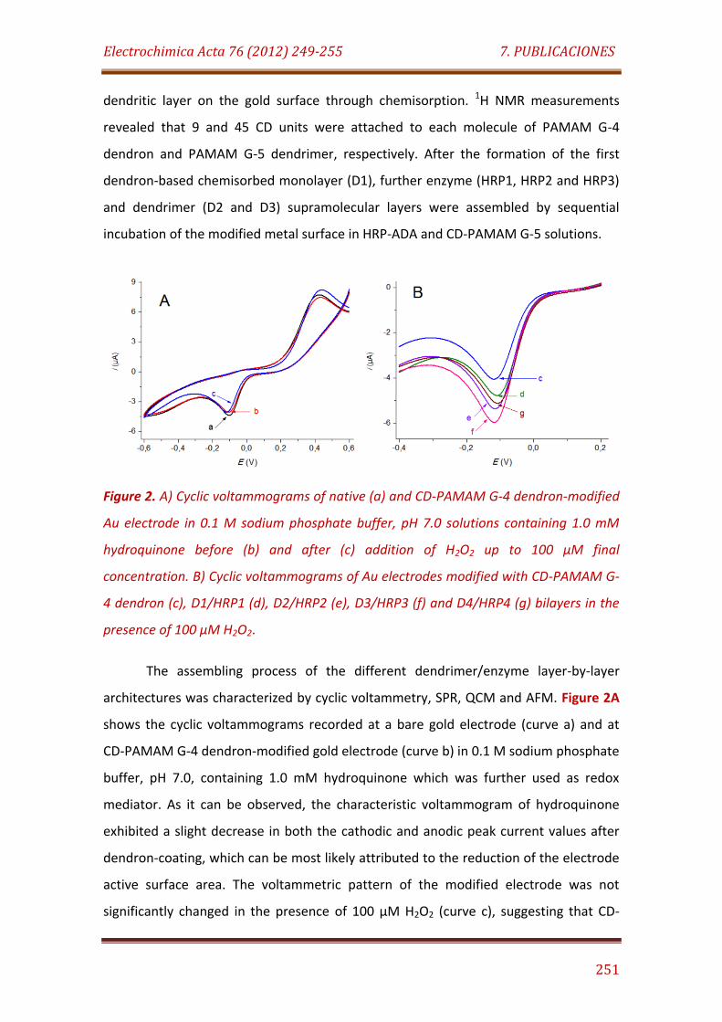
Electrochimica Acta 76 (2012) 249-255 7. PUBLICACIONES
251
dendritic layer on the gold surface through chemisorption. 1H NMR measurements
revealed that 9 and 45 CD units were attached to each molecule of PAMAM G-4
dendron and PAMAM G-5 dendrimer, respectively. After the formation of the first
dendron-based chemisorbed monolayer (D1), further enzyme (HRP1, HRP2 and HRP3)
and dendrimer (D2 and D3) supramolecular layers were assembled by sequential
incubation of the modified metal surface in HRP-ADA and CD-PAMAM G-5 solutions.
Figure 2. A) Cyclic voltammograms of native (a) and CD-PAMAM G-4 dendron-modified
Au electrode in 0.1 M sodium phosphate buffer, pH 7.0 solutions containing 1.0 mM
hydroquinone before (b) and after (c) addition of H2O2 up to 100 µM final
concentration. B) Cyclic voltammograms of Au electrodes modified with CD-PAMAM G-
4 dendron (c), D1/HRP1 (d), D2/HRP2 (e), D3/HRP3 (f) and D4/HRP4 (g) bilayers in the
presence of 100 µM H2O2.
The assembling process of the different dendrimer/enzyme layer-by-layer
architectures was characterized by cyclic voltammetry, SPR, QCM and AFM. Figure 2A
shows the cyclic voltammograms recorded at a bare gold electrode (curve a) and at
CD-PAMAM G-4 dendron-modified gold electrode (curve b) in 0.1 M sodium phosphate
buffer, pH 7.0, containing 1.0 mM hydroquinone which was further used as redox
mediator. As it can be observed, the characteristic voltammogram of hydroquinone
exhibited a slight decrease in both the cathodic and anodic peak current values after
dendron-coating, which can be most likely attributed to the reduction of the electrode
active surface area. The voltammetric pattern of the modified electrode was not
significantly changed in the presence of 100 µM H2O2 (curve c), suggesting that CD-
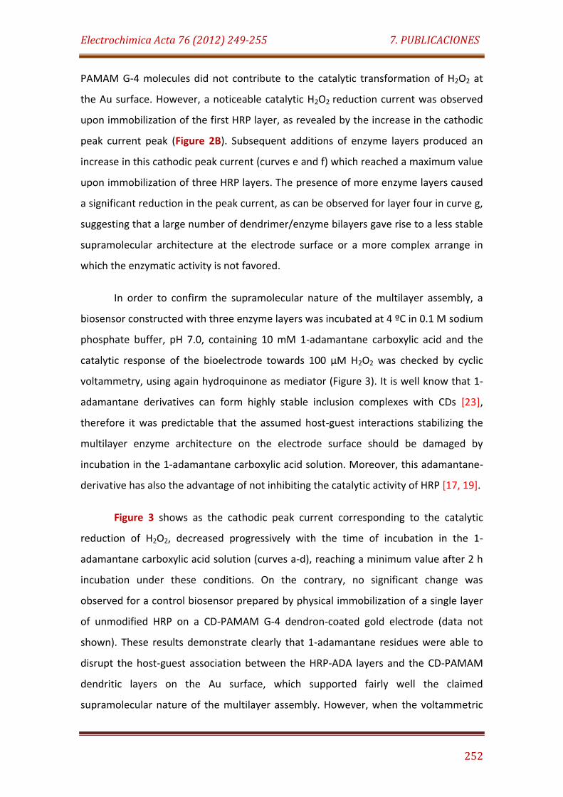
Electrochimica Acta 76 (2012) 249-255 7. PUBLICACIONES
252
PAMAM G-4 molecules did not contribute to the catalytic transformation of H2O2 at
the Au surface. However, a noticeable catalytic H2O2 reduction current was observed
upon immobilization of the first HRP layer, as revealed by the increase in the cathodic
peak current peak (Figure 2B). Subsequent additions of enzyme layers produced an
increase in this cathodic peak current (curves e and f) which reached a maximum value
upon immobilization of three HRP layers. The presence of more enzyme layers caused
a significant reduction in the peak current, as can be observed for layer four in curve g,
suggesting that a large number of dendrimer/enzyme bilayers gave rise to a less stable
supramolecular architecture at the electrode surface or a more complex arrange in
which the enzymatic activity is not favored.
In order to confirm the supramolecular nature of the multilayer assembly, a
biosensor constructed with three enzyme layers was incubated at 4 ºC in 0.1 M sodium
phosphate buffer, pH 7.0, containing 10 mM 1-adamantane carboxylic acid and the
catalytic response of the bioelectrode towards 100 µM H2O2 was checked by cyclic
voltammetry, using again hydroquinone as mediator (Figure 3). It is well know that 1-
adamantane derivatives can form highly stable inclusion complexes with CDs [23],
therefore it was predictable that the assumed host-guest interactions stabilizing the
multilayer enzyme architecture on the electrode surface should be damaged by
incubation in the 1-adamantane carboxylic acid solution. Moreover, this adamantane-
derivative has also the advantage of not inhibiting the catalytic activity of HRP [17, 19].
Figure 3 shows as the cathodic peak current corresponding to the catalytic
reduction of H2O2, decreased progressively with the time of incubation in the 1-
adamantane carboxylic acid solution (curves a-d), reaching a minimum value after 2 h
incubation under these conditions. On the contrary, no significant change was
observed for a control biosensor prepared by physical immobilization of a single layer
of unmodified HRP on a CD-PAMAM G-4 dendron-coated gold electrode (data not
shown). These results demonstrate clearly that 1-adamantane residues were able to
disrupt the host-guest association between the HRP-ADA layers and the CD-PAMAM
dendritic layers on the Au surface, which supported fairly well the claimed
supramolecular nature of the multilayer assembly. However, when the voltammetric
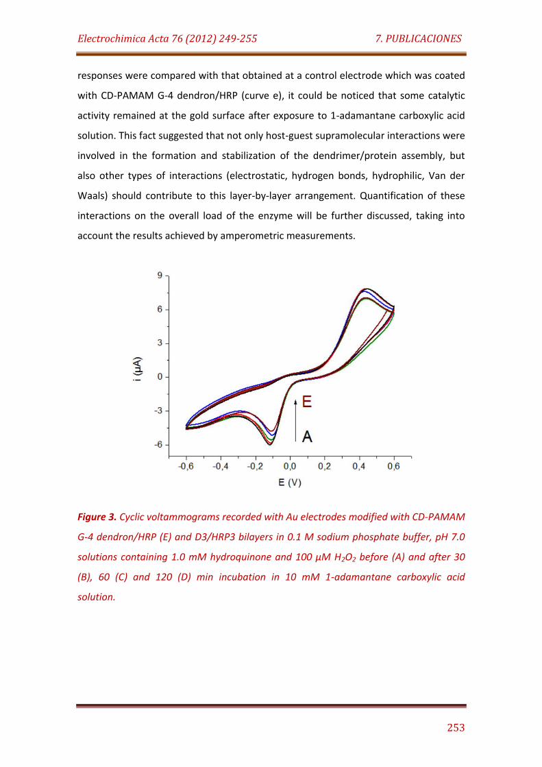
Electrochimica Acta 76 (2012) 249-255 7. PUBLICACIONES
253
responses were compared with that obtained at a control electrode which was coated
with CD-PAMAM G-4 dendron/HRP (curve e), it could be noticed that some catalytic
activity remained at the gold surface after exposure to 1-adamantane carboxylic acid
solution. This fact suggested that not only host-guest supramolecular interactions were
involved in the formation and stabilization of the dendrimer/protein assembly, but
also other types of interactions (electrostatic, hydrogen bonds, hydrophilic, Van der
Waals) should contribute to this layer-by-layer arrangement. Quantification of these
interactions on the overall load of the enzyme will be further discussed, taking into
account the results achieved by amperometric measurements.
Figure 3. Cyclic voltammograms recorded with Au electrodes modified with CD-PAMAM
G-4 dendron/HRP (E) and D3/HRP3 bilayers in 0.1 M sodium phosphate buffer, pH 7.0
solutions containing 1.0 mM hydroquinone and 100 µM H2O2 before (A) and after 30
(B), 60 (C) and 120 (D) min incubation in 10 mM 1-adamantane carboxylic acid
solution.
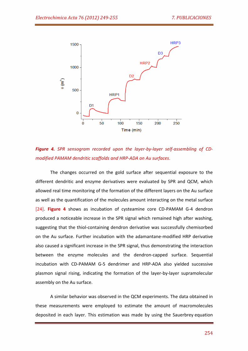
Electrochimica Acta 76 (2012) 249-255 7. PUBLICACIONES
254
Figure 4. SPR sensogram recorded upon the layer-by-layer self-assembling of CD-
modified PAMAM dendritic scaffolds and HRP-ADA on Au surfaces.
The changes occurred on the gold surface after sequential exposure to the
different dendritic and enzyme derivatives were evaluated by SPR and QCM, which
allowed real time monitoring of the formation of the different layers on the Au surface
as well as the quantification of the molecules amount interacting on the metal surface
[24]. Figure 4 shows as incubation of cysteamine core CD-PAMAM G-4 dendron
produced a noticeable increase in the SPR signal which remained high after washing,
suggesting that the thiol-containing dendron derivative was successfully chemisorbed
on the Au surface. Further incubation with the adamantane-modified HRP derivative
also caused a significant increase in the SPR signal, thus demonstrating the interaction
between the enzyme molecules and the dendron-capped surface. Sequential
incubation with CD-PAMAM G-5 dendrimer and HRP-ADA also yielded successive
plasmon signal rising, indicating the formation of the layer-by-layer supramolecular
assembly on the Au surface.
A similar behavior was observed in the QCM experiments. The data obtained in
these measurements were employed to estimate the amount of macromolecules
deposited in each layer. This estimation was made by using the Sauerbrey equation
Electrochimica Acta 76 (2012) 249-255 7. PUBLICACIONES
255
but assuming the incorporation of an average of 75% and 45% (w/w) of water in the
protein and PAMAM dendrimer layers, respectively [25, 26]. In addition, the amount of
protein in the HRP layers was calculated from the SPR data considering that the
adsorption of 1 ng/mm2 of protein on a thick Au layer causes a change in SPR angle of
122 millidegree (mº) at 25 ºC [27].
Figure 5. Calculated molar content of enzyme and dendrimers in the layer-by-layer
assembly from QCM (blue) and SPR (red) measurements. Each value corresponds to the
molar content per layer.
As illustrated in Figure 5, larger amounts of both dendrimer and enzyme were
immobilized with the first layers, which suggested a higher stability for these initial
assemblies. This fact can be attributed to the high coverage of the metal surface with
the thiol-containing CD-PAMAM G-4 dendron derivative through strong chemisorption
linkages. This first layer served as a stable support for the multiple immobilization of
the first enzyme monolayer via host-guest associations. A stable multivalent
supramolecular association of the second dendrimer layer could be also expected due
to the high oligosaccharide content in CD-PAMAM G-5 dendrimer. However, the
subsequent increase in the number of layers seemed to reduce the capability of the
assembly to immobilize macromolecules, as revealed by the lower enzyme and

Electrochimica Acta 76 (2012) 249-255 7. PUBLICACIONES
256
dendrimer contents measured in both QCM and SPR experiments. This effect should
be mainly attributed to the low capability of the multivalent host-guest interactions to
support high mass assemblies, reaching a limit after the immobilization of the third
enzyme layer, as it was previously observed in CV experiments.
Figure 6. Three dimensional AFM analysis of the Au surface before (A) and after
modification with the D1/HRP1 (B), D2/HRP2 (C) and D3/HRP3 (D) bilayers.
The formation of the layer-by-layer arrangement on the Au surface was also
confirmed by examining the topology of the modified gold surface by AFM. The
corresponding images are displayed in Figure 6. The raw metal surface showed an
average height of 10.06 nm with a maximum at 19.57 nm. The surface area and the
average roughness of this metal surface were estimated as 253.7x10³ nm2 and 2.48
nm, respectively. Coverage with the first CD-PAMAM G-4 dendron/HRP-ADA layer
yielded a modified surface pattern with average and maximum height values of 13.53
nm and 35.72 nm, respectively. The average roughness and surface area of Au
increased to 3.53 nm and 259.9x10³ nm2, respectively, after coverage with the first CD-
PAMAM G-4 dendron/HRP-ADA layer.
More irregular surface patterns were observed after the assembly of the
second and third dendrimer/enzyme bilayers, probably due to the higher molecular
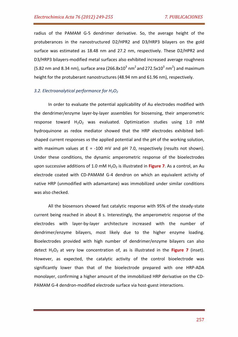
Electrochimica Acta 76 (2012) 249-255 7. PUBLICACIONES
257
radius of the PAMAM G-5 dendrimer derivative. So, the average height of the
protuberances in the nanostructured D2/HPR2 and D3/HRP3 bilayers on the gold
surface was estimated as 18.48 nm and 27.2 nm, respectively. These D2/HPR2 and
D3/HRP3 bilayers-modified metal surfaces also exhibited increased average roughness
(5.82 nm and 8.34 nm), surface area (266.8x10³ nm2 and 272.5x10³ nm2) and maximum
height for the protuberant nanostructures (48.94 nm and 61.96 nm), respectively.
3.2. Electroanalytical performance for H2O2
In order to evaluate the potential applicability of Au electrodes modified with
the dendrimer/enzyme layer-by-layer assemblies for biosensing, their amperometric
response toward H2O2 was evaluated. Optimization studies using 1.0 mM
hydroquinone as redox mediator showed that the HRP electrodes exhibited bell-
shaped current responses vs the applied potential and the pH of the working solution,
with maximum values at E = -100 mV and pH 7.0, respectively (results not shown).
Under these conditions, the dynamic amperometric response of the bioelectrodes
upon successive additions of 1.0 mM H2O2 is illustrated in Figure 7. As a control, an Au
electrode coated with CD-PAMAM G-4 dendron on which an equivalent activity of
native HRP (unmodified with adamantane) was immobilized under similar conditions
was also checked.
All the biosensors showed fast catalytic response with 95% of the steady-state
current being reached in about 8 s. Interestingly, the amperometric response of the
electrodes with layer-by-layer architecture increased with the number of
dendrimer/enzyme bilayers, most likely due to the higher enzyme loading.
Bioelectrodes provided with high number of dendrimer/enzyme bilayers can also
detect H2O2 at very low concentration of, as is illustrated in the Figure 7 (inset).
However, as expected, the catalytic activity of the control bioelectrode was
significantly lower than that of the bioelectrode prepared with one HRP-ADA
monolayer, confirming a higher amount of the immobilized HRP derivative on the CD-
PAMAM G-4 dendron-modified electrode surface via host-guest interactions.

Electrochimica Acta 76 (2012) 249-255 7. PUBLICACIONES
258
Figure 7. Amperometric responses recorded with CD-PAMAM G-4 dendron/HRP (A),
D1/HRP1 (B), D2/HRP2 (C) and D3/HRP3 (D) modified Au electrodes upon successive
additions of 1.0 mM H2O2. Eapp.= - 100 mV. Inset: Electroanalytical behavior of the
D3/HRP3 modified Au electrode toward low H2O2 concentration.
As it was suggested above, the formation and stabilization of the
dendrimer/protein assembly should be caused by the co-operative contribution of
several interactions, mainly based on host-guest supramolecular associations but also
including other types of interactions such as electrostatic, hydrogen bonds,
hydrophilic, Van der Waals forces, etc. Assuming that the catalytic activity of native
and ADA-modified HRP was similarly affected after immobilization on the dendron
monolayer, we can estimate the contribution of these other non-supramolecular
interactions on the overall immobilization process (at least for the first
dendrimer/enzyme bilayer) by comparing the slope of the calibration curves
corresponding to the control and ADA-HRP enzyme forms.
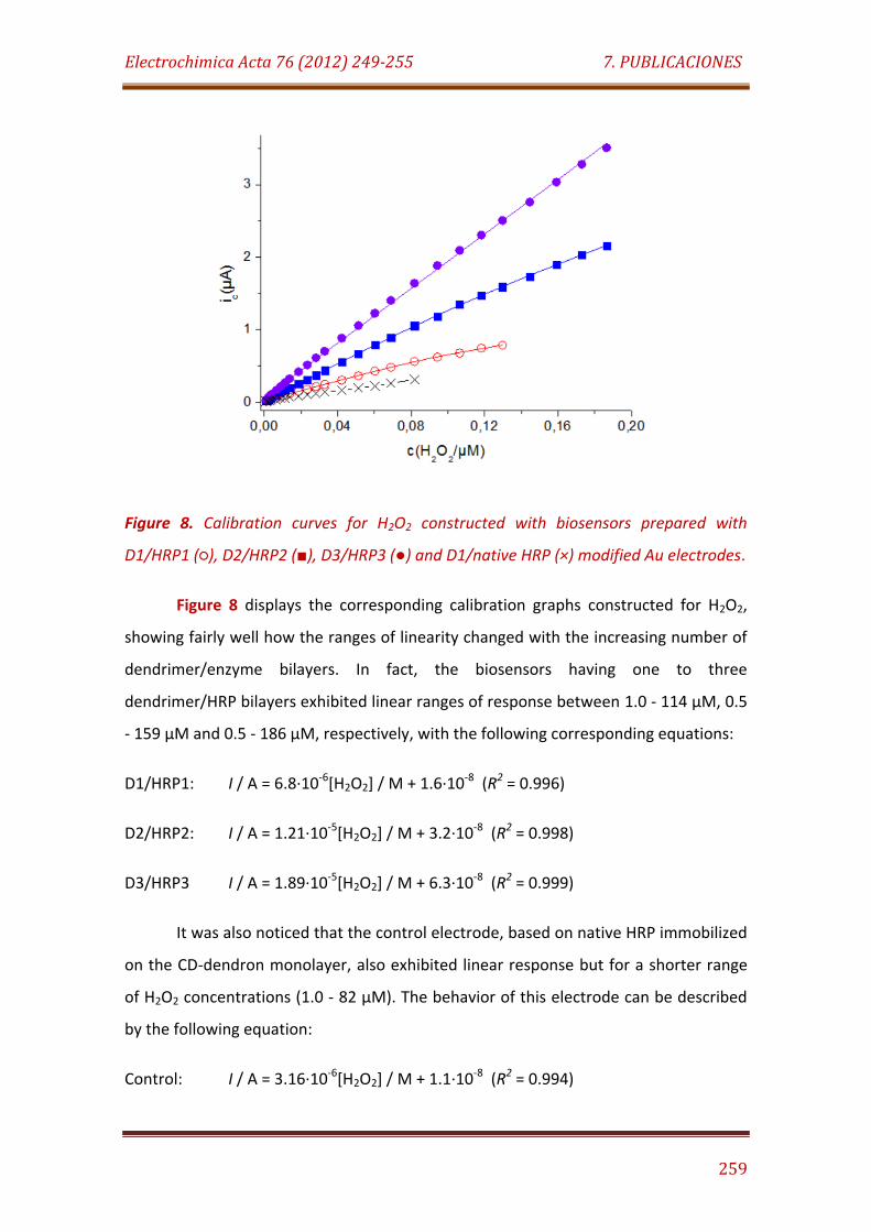
Electrochimica Acta 76 (2012) 249-255 7. PUBLICACIONES
259
Figure 8. Calibration curves for H2O2 constructed with biosensors prepared with
D1/HRP1 (), D2/HRP2 (), D3/HRP3 () and D1/native HRP (×) modified Au electrodes.
Figure 8 displays the corresponding calibration graphs constructed for H2O2,
showing fairly well how the ranges of linearity changed with the increasing number of
dendrimer/enzyme bilayers. In fact, the biosensors having one to three
dendrimer/HRP bilayers exhibited linear ranges of response between 1.0 - 114 µM, 0.5
- 159 µM and 0.5 - 186 µM, respectively, with the following corresponding equations:
D1/HRP1: I / A = 6.8·10-6[H2O2] / M + 1.6·10-8 (R2 = 0.996)
D2/HRP2: I / A = 1.21·10-5[H2O2] / M + 3.2·10-8 (R2 = 0.998)
D3/HRP3 I / A = 1.89·10-5[H2O2] / M + 6.3·10-8 (R2 = 0.999)
It was also noticed that the control electrode, based on native HRP immobilized
on the CD-dendron monolayer, also exhibited linear response but for a shorter range
of H2O2 concentrations (1.0 - 82 µM). The behavior of this electrode can be described
by the following equation:
Control: I / A = 3.16·10-6[H2O2] / M + 1.1·10-8 (R2 = 0.994)
Electrochimica Acta 76 (2012) 249-255 7. PUBLICACIONES
260
The comparison of this result with that obtained with the electrode coated with
the D1/HRP1 bilayer allow concluding that the contribution of the host-guest
supramolecular associations represent about 54% of the overall interactions involved
in the immobilization process, assuming that modification of HRP with adamantane did
not affect the other contributing interaction forces. This result agree with the
described above for cyclic voltammetric studies.
The sensitivity of the biosensors with supramolecular designs increased with
the number of dendrimer/HRP bilayers, showing values of 216, 385 and 602 µA/M cm2
for D1/HRP1, D2/HRP2 and D3/HRP3, respectively, considering the geometric area of
the raw electrode. A similar improvement was found regarding the detection limits,
270 nM (first bilayer), 200 nM (second bilayer) and 160 nM (third bilayer), which were
calculated according to the 3Sb/m criterion, where m is the slope value of the
calibration plot and Sb was estimated as the standard deviation (n = 10) of the signals
corresponding to the lower H2O2 concentration detected for by each biosensor. It
should be highlighted that such detection limits at nanomolar level rank among the
lower values reported for HRP-based biosensors [28]. In addition, the detection limit
achieved with the biosensor constructed with three dendrimer/enzyme bilayers was
lower than those reported for other HRP-modified electrodes with a layer-by-layer
design, based on the assembly of colloidal gold nanoparticles, cysteine and HRP on
Nafion modified electrode surface by electrostatic adsorption (500 nM) [29],
supramolecular self-assembly of HRP-ADA and HRP-modified with CD-branched
polysaccharides on CD-coated Au electrodes (2.0 µM) [19], HRP immobilized on carbon
electrodes coated with a layer-by-layer self-assembly of Au nanoparticles-based films
(4.9 µM) [30] and host-guest association of HRP-ADA and CD-capped Au nanoparticles
on Au surface (3.0 µM) [20].
The value of the apparent Michaelis-Menten constant for the enzyme
electrodes, KM, calculated according to the Eadie-Hofstee method, slightly changed
from 104 mM to 152 mM and 143 mM when the number of dendrimer/HRP bilayers
was increased. Moreover, IMAX increased with the number of dendrimer/enzyme
bilayers, showing values of 1.04 µA, 2.58 µA and 3.97 µA, respectively.
Electrochimica Acta 76 (2012) 249-255 7. PUBLICACIONES
261
Aspects concerning reproducibility of the measurements and stability were
evaluated for the biosensor constructed with three dendrimer/enzyme bilayers. So,
ten successive measurements for 10 µM H2O2 yielded a relative standard deviation
(RSD) value of 4.1%, while the electrode-to-electrode reproducibility was checked from
the responses obtained with ten different biosensors prepared in the same manner
providing a RSD value of 6.7%.
The stability of the biosensor was tested by storing it at 4ºC under dry and wet
(100 mM sodium phosphate buffer, pH 7.0) conditions, and periodical evaluation of
the measured current for 10 µM H2O2. Although the stability of the biosensor under
dry storage was found to be poor, losing all electroanalytical response after 5 days of
storage, the enzyme electrode exhibited good long-term stability under wet
conditions, retaining 91% and 63% of its initial activity after 15 and 30 days of storage
at 4ºC. This stability behaviour could be associated with the multipoint supramolecular
attachment of the enzyme to the CD-modified dendrimers into the layer-by-layer
design, which seems to be relatively stable in aqueous solution but not when dried.
Previous AFM studies demonstrated than the volume and deformability of PAMAM
dendrimers are different in aqueous and dry conditions [31]. Therefore, it could be
then expected that the stability of the dendrimer/HRP layer-by-layer assembly would
be affected by drying and swelling processes during storage and measurement with
the consequent loss of enzyme molecules from the Au surface.
CONCLUSIONS
In summary, this is the first report dealing with the preparation of
dendrimer/enzyme layer-by-layer assemblies based on supramolecular interactions.
The characteristics of these arrangements on Au surfaces were established, and their
potential use for biosensor construction demonstrated. Experiments are now in
progress to generalize this type of supramolecular-based self-assemblies for the
construction of multienzymatic biosensors.
Electrochimica Acta 76 (2012) 249-255 7. PUBLICACIONES
262
ACKNOWLEDGEMENTS
R. Villalonga acknowledge to Ramón & Cajal contract from the Spanish Ministry
of Science and Innovation. Financial support from the Spanish Ministerio de Ciencia e
Innovación CTQ2011-24355, CTQ2009-12650, CTQ2009-09351 and Comunidad de
Madrid S2009/PPQ-1642, Programme AVANSENS is gratefully acknowledged.
REFERENCES
[1] C.S.S.R. Kumar, Nanomaterials for biosensors. Wiley-VCH Weinheim, 2007.
[2] J.M. Pingarrón, P. Yáñez-Sedeño, A. González-Cortés, Electrochim. Acta 53
(2008) 5848.
[3] W. Yang, K.R. Ratinac, S.P. Ringer, P. Thordarson, J.J. Gooding, F. Braet,
Angew. Chem. Int. Ed. 49 (2010) 2114.
[4] S.H. Yeom, B.H. Kang, K.J. Kim, S.W. Kang, Front. Biosci. 16 (2011) 997.
[5] J. Kim, J.W. Grate, P. Wang, Trends Biotechnol. 26 (2008) 639.
[6] P. Wang, Curr. Opin. Biotechnol. 17 (2006) 574.
[7] S.S. Karajanagi, A.A. Vertegel, R.S. Kane, J.S. Dordick, Langmuir 20 (2004) 11594.
[8] W. Shang, J.H. Nuffer, J.S. Dordick, R.W. Siegel, Nano Lett. 7 (2007) 1991.
[9] F.N. Crespilho, M.E. Ghica, M. Florescu, F.C. Nart, O.N. Oliveira, C.M.A. Brett,
Electrochem. Comm. 8 (2006) 1665.
[10] L. Svobodová, M. Šnejdárková, T. Hianik, Anal. Bioanal. Chem. 8 (2002) 735.
[11] F. Vögtle, G. Richardt, N. Werner, Dendrimer chemistry. Wiley-VCH Weinheim,
2009.
[12] U. Boas, J.B. Christensen, P.H.M. Heegaard, Dendrimers in medicine and
biotechnology: New molecular tools. The Royal Society of Chemistry,
Cambridge, 2006.
Electrochimica Acta 76 (2012) 249-255 7. PUBLICACIONES
263
[13] L. Shen, N. Hu, Biomacromolecules 6 (2005) 1475.
[14] H.C. Yoon, M.Y. Hong, H.S. Kim, Anal. Chem. 72 (2000) 4420.
[15] R. Villalonga, C. Camacho, R. Cao, J. Hernández, J.C. Matias, Chem.
Comm. (2007a) 942-944.
[16] R. Villalonga, R. Cao, A. Fragoso, Chem. Rev. 107 (2007b) 3088.
[17] C. Camacho, B. Chico, R. Cao, J.C. Matías, J. Hernández, I. Palchetti, B.K.
Simpson, M. Mascini, R. Villalonga, Biosens. Bioelectron. 24 (2009) 2028.
[18] R. Villalonga, P. Diez, M. Gamella, J. Reviejo, J.M. Pingarrón, Electroanalysis 23
(2011) 1790.
[19] C. Camacho, J.C. Matías, R. Cao, M. Matos, B. Chico, J. Hernández, M.A. Longo,
M.A. Sanromán, R. Villalonga, R. Langmuir 24 (2008) 7654.
[20] A. Fragoso, B. Sanromà, M. Ortiz, C.K. O'Sullivan, Soft Matter 5 (2009) 400.
[21] T. Ruzgas, E. Csöregi, J. Emnéus, L. Gorton, G. Marko-Varga, Anal. Chim. Acta
330 (1996) 123.
[22] I. Baussanne, J.M. Benito, C. Ortiz Mellet, J.M. García Fernández, H. Lawa, J.
Defaye, Chem. Commun. (2000) 1489.
[23] D. Harries, D.C. Rau, V.A. Parsegian, J. Am. Chem. Soc. 127 (2005) 2184.
[24] P. Ansorena, A. Zuzuarregui, E. Pérez-Lorenzo, M. Mujika, S. Arana, Sens.
Actuat. B Chem. 155 (2011) 667.
[25] J. Rickert, A. Brecht, W. Göpel, Biosens. Bioelectron. 12 (1997) 567.
[26] P.K. Maiti, T. Cagin, S.T. Lin, W.A. Goddard III, Macromolecules 38 (2005) 979.
[27] E. Stenberg, B. Persson, H. Roos, C. Urbaniczky, J. Colloid Interface Sci. 143
(2001) 513.
[28] F. Li, Y. Feng, Z. Wang, L.M. Yang, L.H. Zhuo, B. Tang, Biosens. Bioelectron. 25
(2010) 2244.
Electrochimica Acta 76 (2012) 249-255 7. PUBLICACIONES
264
[29] Y. Liu, T. Geng, J. Gao, Microchim. Acta 161 (2008) 241.
[30] W.T. Li, M.H. Wang, Y.J. Li, Y. Sun, J.C. Li, Electrochim. Acta 56 (2011) 6919.
[31] A. Mecke, I. Lee, J.R. Baker, M.M. Banaszak Holl, B.G. Orr, Eur. Phys. J. E 14
(2004) 7.
[32] A. Mecke, I. Lee, J.R. Baker, M.M. Banaszak Holl, B.G. Orr, Eur. Phys. J. E 14
(2004) 7.
7.9
ACS Applied Materials & Interfaces 8 (12) (2016) 7657–7665
Neoglycoenzyme-gated mesoporous
silica nanoparticles. towards the design of nano-devices for pulsatile
programmed sequential delivery

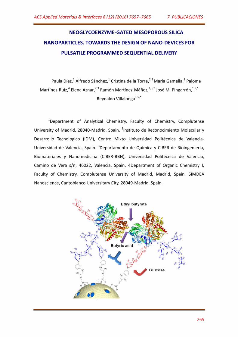
ACS Applied Materials & Interfaces 8 (12) (2016) 7657–7665 7. PUBLICACIONES
265
NEOGLYCOENZYME-GATED MESOPOROUS SILICA
NANOPARTICLES. TOWARDS THE DESIGN OF NANO-DEVICES FOR
PULSATILE PROGRAMMED SEQUENTIAL DELIVERY
Paula Díez,1 Alfredo Sánchez,1 Cristina de la Torre,2,3 María Gamella,1 Paloma
Martínez-Ruíz,4 Elena Aznar,2,3 Ramón Martínez-Máñez,2,3,* José M. Pingarrón,1,5,*
Reynaldo Villalonga1,5,*
1Department of Analytical Chemistry, Faculty of Chemistry, Complutense
University of Madrid, 28040-Madrid, Spain. 2Instituto de Reconocimiento Molecular y
Desarrollo Tecnológico (IDM), Centro Mixto Universidad Politécnica de Valencia-
Universidad de Valencia, Spain. 3Departamento de Química y CIBER de Bioingeniería,
Biomateriales y Nanomedicina (CIBER-BBN), Universidad Politécnica de Valencia,
Camino de Vera s/n, 46022, Valencia, Spain. 4Department of Organic Chemistry I,
Faculty of Chemistry, Complutense University of Madrid, Madrid, Spain. 5IMDEA
Nanoscience, Cantoblanco Universitary City, 28049-Madrid, Spain.
ACS Applied Materials & Interfaces 8 (12) (2016) 7657–7665 7. PUBLICACIONES
266
ABSTRACT
We report herein the design of a stimulus-programmed pulsatile delivery
system for sequential cargo release based on the use of a lactose-modified esterase as
a capping agent in phenylboronic acid functionalized mesoporous silica nanoparticles.
The dual release mechanism was based on the distinct stability of the cyclic boronic
acid esters formed with lactose residues and the long naturally-occurring glycosylation
chains in the modified neoglycoenzyme. Cargo delivery in succession was achieved
using glucose and ethyl butyrate as triggers.
KEYWORDS: Enzymes, mesoporous silica, delivery, nanoparticles, esterase,
neoglycoenzyme, glucose.
INTRODUCTION
Controlled delivery technology is one of the most rapidly advancing areas in
material science, with the major driving force stemming from the pharmaceutical
sector. In fact, advanced release systems offer numerous pharmacological and
pharmacokinetics advantages as compared to conventional dosage forms such as
enhanced drug efficacy, reduced toxicity, and improved patient compliance and
convenience.1 In particular, the design of advanced carriers that enable time- or
stimulus-programmed drug release is of much importance and is relevant for the
treatment of many diseases.
This field has been traditionally dominated by the use of polymers as carriers.2-4
Recently, however, attention has been paid to mesoporous silica nanoparticles (MSN)
as nanosized containers for controlled delivery due to their unique properties such as
large specific volume, large loading capacity, low toxicity and easy preparation in
different forms, as well as varying morphology, size and pore diameter.5-9 MSN can be
easily functionalized to allow the rational building of stimuli-responsive molecular or
supramolecular ensembles on their external surface to develop gated nanocarriers that
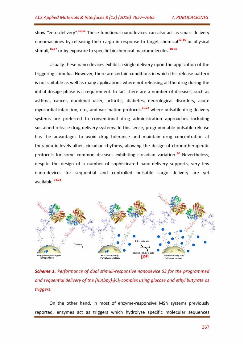
ACS Applied Materials & Interfaces 8 (12) (2016) 7657–7665 7. PUBLICACIONES
267
show “zero delivery”.10,11 These functional nanodevices can also act as smart delivery
nanomachines by releasing their cargo in response to target chemical12-15 or physical
stimuli,16,17 or by exposure to specific biochemical macromolecules.18-20
Usually these nano-devices exhibit a single delivery upon the application of the
triggering stimulus. However, there are certain conditions in which this release pattern
is not suitable as well as many applications where not releasing all the drug during the
initial dosage phase is a requirement. In fact there are a number of diseases, such as
asthma, cancer, duodenal ulcer, arthritis, diabetes, neurological disorders, acute
myocardial infarction, etc., and vaccination protocols21,22 where pulsatile drug delivery
systems are preferred to conventional drug administration approaches including
sustained-release drug delivery systems. In this sense, programmable pulsatile release
has the advantages to avoid drug tolerance and maintain drug concentration at
therapeutic levels albeit circadian rhythms, allowing the design of chronotherapeutic
protocols for some common diseases exhibiting circadian variation.22 Nevertheless,
despite the design of a number of sophisticated nano-delivery supports, very few
nano-devices for sequential and controlled pulsatile cargo delivery are yet
available.23,24
Scheme 1. Performance of dual stimuli-responsive nanodevice S3 for the programmed
and sequential delivery of the [Ru(bpy)3]Cl2 complex using glucose and ethyl butyrate as
triggers.
On the other hand, in most of enzyme-responsive MSN systems previously
reported, enzymes act as triggers which hydrolyze specific molecular sequences

ACS Applied Materials & Interfaces 8 (12) (2016) 7657–7665 7. PUBLICACIONES
268
anchored on the gated mesoporous support. As an alternative, we have recently
reported that enzymes can act as caps in gated materials in which the uncapping
process is triggered by the product obtained by the enzyme activity on target guests.15
Neoglycoenzymes are artificially glycosylated enzymes in which the new
appended carbohydrates moieties confer novel and improved characteristics to the
enzyme, such as stability, catalytic activity, and chemical and biochemical recognition
properties.25,26 Based on our experience in the design of neoglycoenzymes26 we
envisioned that the modification of a glycoenzyme with short-chain carbohydrate
residues can lead to a neoglycoconjugate able to be used as a capping element in
phenylboronic acid-grafted MSN by forming cyclic boronic acid esters through either
naturally-occurring long glycosylation chains or chemically attached short disaccharide
chains (vide infra). In this context, we speculated that considering the different amount
and geometry of the long and short glycosylation chains, as well as their different
affinities and stabilities with the boronic acid groups, it might be possible to design
pulsatile drug delivery systems capable of delivering the cargo sequentially under the
effect of different triggering conditions.
As a proof of concept of sequential delivery with MSN using neoglycoenzymes,
we report herein the preparation of solid S3 (vide infra) consisting of an MCM-41-type
MSN containing phenylboronic acid residues, capped with lactose-modified pig liver
esterase (see Scheme 1). This engineered nanoparticle was successfully evaluated as
novel sequential and pulsatile drug delivery system for in vitro and ex vivo experiments.
RESULTS AND DISCUSSION
To assemble the integrated delivery nanomachine, mesoporous silica
nanoparticles (S0) were first prepared as previously described.27 These nanoparticles
were then loaded with tris(2,2´-bipyridyl)ruthenium(II) chloride ([Ru(bpy)3]Cl2) as
model drug for cargo delivery monitoring5f, and further treated with (3-
glycidyloxypropyl) trimethoxysilane to provide the surface of the nanoparticles with
ACS Applied Materials & Interfaces 8 (12) (2016) 7657–7665 7. PUBLICACIONES
269
highly reactive epoxy groups. The resulting solid was then treated with 3-amino
phenylboronic acid to yield solid S1.
Subsequently, S1 nanoparticles were treated with native esterase to prepare
the enzyme-capped control solid S2 via the formation of boronic acid cyclic esters
between the naturally-occurring long glycosylation chains in the enzyme and the
phenylboronic acid groups on the surface of the MSN.
In order to construct the pulsatile nano-device, a neoglycoenzyme was
prepared by covalent anchoring of lactose to the free amino groups of lysine residues
in esterase through a reductive alkylation reaction with NaBH3CN.28 The resulting
glycoconjugate retained 92% of initial specific activity after the incorporation of 61 mol
lactose per mol of trimeric enzyme, as determined by phenol-sulfuric acid method (see
Experimental Section), which corresponded to a modification of ca. 66% of the lysine
residues in the protein.29 A low degree of modification was estimated by MALDI-TOF
analysis, which revealed a molecular weight of 60858 Da and 64227 Da for the native
and lactose-modified enzyme, respectively. This fact suggests an average of 12 mol
lactose attached to each mol of monomeric enzyme in the neoglycoconjugate. This
neoglycoenzyme was then employed as a capping element for S1 yielding S3, following
a similar procedure to that used to prepare the control solid S2. The amount of native
and lactose-modified esterase immobilized on S2 and S3 nanoparticles was estimated
at 10.5 U/mg and 4.3 U/mg, respectively.
All the MSN were fully characterized. The TEM analysis revealed that the
different prepared nanoparticles showed the typical porous pattern of the MCM-41
mesoporous matrix with the average size for the nanoparticles of 97 ± 15 nm (Fig. S1).
Moreover TEM images of S2 and S3 displayed a diffuse thin layer that wrapped the
nanoparticles, suggesting their coverage with an amorphous organic material, which
could be ascribed to the esterase enzymes immobilized on the nanoparticle surfaces.
All the samples also showed the characteristic X-ray diffraction pattern of the MCM-41-
type materials, with a well-defined peak at ca. 2.59º attributed to the (100) Bragg
reflection of MCM-41-type materials. The position of this peak was not significantly
affected by dye loading and the different chemical modifications processes carried out
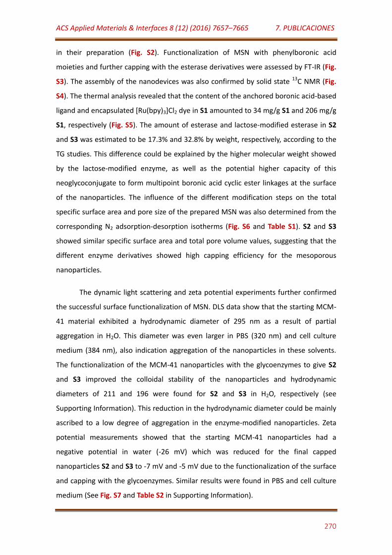
ACS Applied Materials & Interfaces 8 (12) (2016) 7657–7665 7. PUBLICACIONES
270
in their preparation (Fig. S2). Functionalization of MSN with phenylboronic acid
moieties and further capping with the esterase derivatives were assessed by FT-IR (Fig.
S3). The assembly of the nanodevices was also confirmed by solid state 13C NMR (Fig.
S4). The thermal analysis revealed that the content of the anchored boronic acid-based
ligand and encapsulated [Ru(bpy)3]Cl2 dye in S1 amounted to 34 mg/g S1 and 206 mg/g
S1, respectively (Fig. S5). The amount of esterase and lactose-modified esterase in S2
and S3 was estimated to be 17.3% and 32.8% by weight, respectively, according to the
TG studies. This difference could be explained by the higher molecular weight showed
by the lactose-modified enzyme, as well as the potential higher capacity of this
neoglycoconjugate to form multipoint boronic acid cyclic ester linkages at the surface
of the nanoparticles. The influence of the different modification steps on the total
specific surface area and pore size of the prepared MSN was also determined from the
corresponding N2 adsorption-desorption isotherms (Fig. S6 and Table S1). S2 and S3
showed similar specific surface area and total pore volume values, suggesting that the
different enzyme derivatives showed high capping efficiency for the mesoporous
nanoparticles.
The dynamic light scattering and zeta potential experiments further confirmed
the successful surface functionalization of MSN. DLS data show that the starting MCM-
41 material exhibited a hydrodynamic diameter of 295 nm as a result of partial
aggregation in H2O. This diameter was even larger in PBS (320 nm) and cell culture
medium (384 nm), also indication aggregation of the nanoparticles in these solvents.
The functionalization of the MCM-41 nanoparticles with the glycoenzymes to give S2
and S3 improved the colloidal stability of the nanoparticles and hydrodynamic
diameters of 211 and 196 were found for S2 and S3 in H2O, respectively (see
Supporting Information). This reduction in the hydrodynamic diameter could be mainly
ascribed to a low degree of aggregation in the enzyme-modified nanoparticles. Zeta
potential measurements showed that the starting MCM-41 nanoparticles had a
negative potential in water (-26 mV) which was reduced for the final capped
nanoparticles S2 and S3 to -7 mV and -5 mV due to the functionalization of the surface
and capping with the glycoenzymes. Similar results were found in PBS and cell culture
medium (See Fig. S7 and Table S2 in Supporting Information).
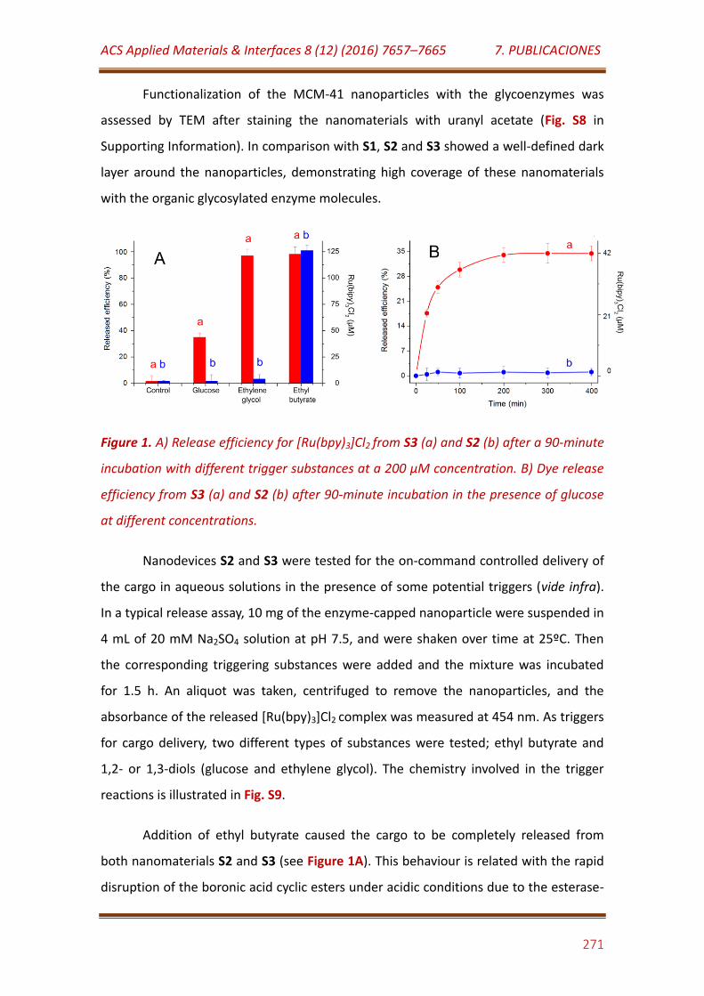
ACS Applied Materials & Interfaces 8 (12) (2016) 7657–7665 7. PUBLICACIONES
271
Functionalization of the MCM-41 nanoparticles with the glycoenzymes was
assessed by TEM after staining the nanomaterials with uranyl acetate (Fig. S8 in
Supporting Information). In comparison with S1, S2 and S3 showed a well-defined dark
layer around the nanoparticles, demonstrating high coverage of these nanomaterials
with the organic glycosylated enzyme molecules.
Figure 1. A) Release efficiency for [Ru(bpy)3]Cl2 from S3 (a) and S2 (b) after a 90-minute
incubation with different trigger substances at a 200 µM concentration. B) Dye release
efficiency from S3 (a) and S2 (b) after 90-minute incubation in the presence of glucose
at different concentrations.
Nanodevices S2 and S3 were tested for the on-command controlled delivery of
the cargo in aqueous solutions in the presence of some potential triggers (vide infra).
In a typical release assay, 10 mg of the enzyme-capped nanoparticle were suspended in
4 mL of 20 mM Na2SO4 solution at pH 7.5, and were shaken over time at 25ºC. Then
the corresponding triggering substances were added and the mixture was incubated
for 1.5 h. An aliquot was taken, centrifuged to remove the nanoparticles, and the
absorbance of the released [Ru(bpy)3]Cl2 complex was measured at 454 nm. As triggers
for cargo delivery, two different types of substances were tested; ethyl butyrate and
1,2- or 1,3-diols (glucose and ethylene glycol). The chemistry involved in the trigger
reactions is illustrated in Fig. S9.
Addition of ethyl butyrate caused the cargo to be completely released from
both nanomaterials S2 and S3 (see Figure 1A). This behaviour is related with the rapid
disruption of the boronic acid cyclic esters under acidic conditions due to the esterase-

ACS Applied Materials & Interfaces 8 (12) (2016) 7657–7665 7. PUBLICACIONES
272
catalysed hydrolysis of ethyl butyrate to ethanol and butyric acid (pKa = 4.82) resulting
in the leakage of the immobilized enzyme from the nanosized support and cargo
delivery.
Figure 2. Kinetics of the dye release from S3 (A) and S2 (B) in 20 mM Na2SO4, pH 7.5,
without (a) and with addition of ethyl butyrate (b) and glucose + ethyl butyrate (c) at a
200 µM final concentration. Triggers were added at the times indicated in the graphics.
In contrast, and interestingly, the encapsulated [Ru(bpy)3]Cl2 complex was only
partially released from S3 under the trigger effect of glucose, whereas no release was
observed for S2. Delivery from S3 is related with the competition of glucose for the
boronic acid residues anchored to the neoglycoenzyme on the nanoparticle surface,
which results in a partial cargo release. The extent of such a delivery process in S3
increased with the sugar concentration in the incubation media, a plateau value being
reached for concentrations of glucose above 200 µM (Figure 1B). Similar behaviour was
observed by incubation at high glucose concentration up to 5 mM. On the contrary, no
significant dye release was observed for similar experiments with nanoparticles S2,
even at relatively high glucose concentrations up to 5 mM. Studies with ethylene
glycol, which is able to form highly stable 5-member rings with boronic acid residues,
showed an almost complete cargo release from S3, but no noticeable effect was
produced with S2 (see Figure 1A).
Based on these results, S3 was tested for the two-step controlled cargo delivery
by triggering the uncapping process through the sequential incubation with glucose
ACS Applied Materials & Interfaces 8 (12) (2016) 7657–7665 7. PUBLICACIONES
273
and ethyl butyrate. In parallel, S2 was also tested under the same experimental
conditions (see Figure 2). In the absence of glucose or ethyl butyrate, both nanodevices
are tightly capped and showed a negligible release of [Ru(bpy)3]Cl2. Conversely, the
presence of glucose resulted in the opening of some pores in S3 producing a
subsequent partial cargo delivery. Further incubation of S3 with ethyl butyrate, which is
transformed by the immobilized enzyme glycoconjugate in ethanol and butyric acid
with a consequent drop in pH, caused the acid-mediated hydrolysis of the boronic acid
cyclic esters and induced cargo delivery (see Figure 2A). On the contrary, S2 delivered
the cargo only by incubation with the enzyme substrate ethyl butyrate (see Figure 2B).
It should be noted that the pH of the incubating media remained unchanged after the
S2 and S3 treatment with glucose, but changed from 7.5 to about 5.2 after incubation
with ethyl butyrate.
It should be highlighted that similar release patterns were observed by
performing the experiments in PBS, but slightly lower degree of cargo delivery was
achieved by using ethyl butyrate as trigger. This fact suggests the esterase-mediated
release of Ru(bpy)32+ from the nanoparticles was mainly caused by a local decrease of
pH at the microenvironment of the modified colloids.
In order to confirm that the opening mechanism with ethyl butyrate was due to
the enzyme-mediated decrease of pH after the substrate hydrolysis, suspensions of S2
and S3 at pH 7.5 were heated to 100ºC for 10 min to inactivate the enzymes, and were
further incubated with ethyl butyrate. In this case, no appreciable cargo delivery was
observed from the nanodevices after 24 h of incubation.
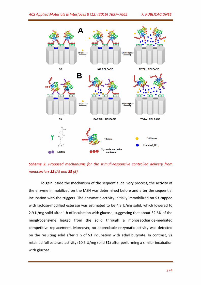
ACS Applied Materials & Interfaces 8 (12) (2016) 7657–7665 7. PUBLICACIONES
274
Scheme 2. Proposed mechanisms for the stimuli-responsive controlled delivery from
nanocarriers S2 (A) and S3 (B).
To gain inside the mechanism of the sequential delivery process, the activity of
the enzyme immobilized on the MSN was determined before and after the sequential
incubation with the triggers. The enzymatic activity initially immobilized on S3 capped
with lactose-modified esterase was estimated to be 4.3 U/mg solid, which lowered to
2.9 U/mg solid after 1 h of incubation with glucose, suggesting that about 32.6% of the
neoglycoenzyme leaked from the solid through a monosaccharide-mediated
competitive replacement. Moreover, no appreciable enzymatic activity was detected
on the resulting solid after 1 h of S3 incubation with ethyl butyrate. In contrast, S2
retained full esterase activity (10.5 U/mg solid S2) after performing a similar incubation
with glucose.
ACS Applied Materials & Interfaces 8 (12) (2016) 7657–7665 7. PUBLICACIONES
275
Treatment of S2 with ethyl butyrate also caused the total reduction of
immobilized enzyme activity, demonstrating that the enzyme was completely leaked
from the nanoparticle surface.
Taking into account these results, a mechanism for the two-step pulsatile
programmed sequential delivery from S3 triggered by glucose and ethyl butyrate is
proposed in Scheme 2. The obtained results indicate that native esterase is strongly
attached to the nanoparticle surface in S2, probably through the formation of
multipoint boronic acid cyclic ester linkages between the saccharide units at the
naturally-occurring glycosylation chains of the enzyme and the phenylboronic acid
groups grafted on the nanoparticle surface.
Regarding S3, the lactose-modified esterase is most likely linked to the boronic
acid residues through two different ways: i) by the attachment of the naturally-
occurring glycosylation chains of the enzyme, yielding highly stable linkages that are
not displaced by incubation with glucose or ethylene glycol; and ii) via the lactose
residues in the neoglycoenzyme, which yield linkages that can be disrupted in the
presence of glucose or ethylene glycol. Moreover, both kinds of linkages are prone to
being hydrolyzed in acidic media, which is provoked by the enzyme-mediated
hydrolysis of ethyl butyrate.
In addition, the enzyme-controlled capped MSN were tested for in-cell
controlled delivery applications. Therefore, after the in vitro characterization of the
solid S2 and S3 (vide ante), similar nanoparticles were used for ex vivo assays by
loading nanoparticles as S2 and S3 with the cytotoxic doxorubicin (Doxo) (solid S4 and
S5, respectively).
Solids S4 and S5 were evaluated in HeLa cells under the premise that they
would be internalised by cells and would stay nearly closed until glucose or ethyl
butyrate were added. In this sense, the capacity of HeLa cells to uptake 100 nm silica-
modified nanoparticles has been largely documented in the literature.7,30-33
According to the in vitro S2 and S3 behaviour (see Figure 2B and 2A
respectively), the addition of D-glucose in S5 in ex vivo assays would be expected to
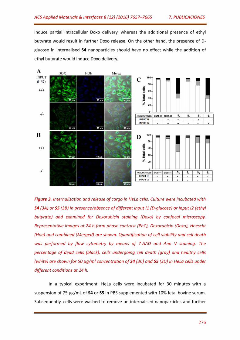
ACS Applied Materials & Interfaces 8 (12) (2016) 7657–7665 7. PUBLICACIONES
276
induce partial intracellular Doxo delivery, whereas the additional presence of ethyl
butyrate would result in further Doxo release. On the other hand, the presence of D-
glucose in internalised S4 nanoparticles should have no effect while the addition of
ethyl butyrate would induce Doxo delivery.
Figure 3. Internalization and release of cargo in HeLa cells. Culture were incubated with
S4 (3A) or S5 (3B) in presence/absence of different input I1 (D-glucose) or input I2 (ethyl
butyrate) and examined for Doxorubicin staining (Doxo) by confocal microscopy.
Representative images at 24 h form phase contrast (PhC), Doxorubicin (Doxo), Hoescht
(Hoe) and combined (Merged) are shown. Quantification of cell viability and cell death
was performed by flow cytometry by means of 7-AAD and Ann V staining. The
percentage of dead cells (black), cells undergoing cell death (gray) and healthy cells
(white) are shown for 50 μg/ml concentration of S4 (3C) and S5 (3D) in HeLa cells under
different conditions at 24 h.
In a typical experiment, HeLa cells were incubated for 30 minutes with a
suspension of 75 µg/mL of S4 or S5 in PBS supplemented with 10% fetal bovine serum.
Subsequently, cells were washed to remove un-internalised nanoparticles and further
ACS Applied Materials & Interfaces 8 (12) (2016) 7657–7665 7. PUBLICACIONES
277
incubated alone or in the presence of D-glucose (input I1), ethyl butyrate (input I2) or a
mixture of both (see Experimental Section). Sequential addition of D-glucose and ethyl
butyrate as input signals was also evaluated.
Doxo delivery details obtained by confocal microscopy and cytometry are
provided in the Supporting Information (see Figures S10 and S11), whereas cell viability
was determined by flow cytometry studies (see Figure 3) and by WST-1 assays under
different conditions.
Figure 3 also shows representative phase contrast images of Doxo, Hoescht, and
combined for HeLa cells first loaded with S4 or S5 and then untreated (-/-) or treated
with both D-glucose and ethyl butyrate (+/+). These nanomaterials were mainly
internalized into the HeLa cells, as observed from Figure 3. However, some few
nanoparticles could remain outside the cells as revealed for S5 in Figure 3B (see +/+).
In flow cytometry studies, quantification of Doxo-associated cell death was
performed by using 7-aminoactinomycin (7-AAD) and Annexin V-FITC (Ann V) markers,
which stain dead cells and cells undergoing cell death, respectively. As it can be
deduced from the viability studies, the simple internalization of S4 in HeLa cells (see -/-
) or the treatment with D-glucose (see +/-) did not induce significant cell death,
whereas ca. 60% of cells were dead or underwent cell death after addition of ethyl
butyrate (see Figure 3C). It was also found that S5 nanoparticles were not significantly
toxic for HeLa cells, whereas in this case both the presence of D-glucose (see +/-), ethyl
butyrate (see -/+) and specially a mixture of D-glucose and ethyl butyrate (see +/+)
induced an increment in dead cells and cells undergoing cell death (see Figure 3D). In
particular nearly 50% of the cells were dead or undergoing cell death when treated
with both D-glucose and ethyl butyrate simultaneously (see also Figures S12 and S13).
Although significantly very low, cell death caused by S4 and S5 nanoparticles in
the absence of the trigger compounds could be ascribed to unspecific release of Doxo
inside the cells. This fact, which was revealed by some few leaking signals in Figure 3
(see -/-), could be caused by local acidic conditions at the microenvironment of the
nanoparticles into the HeLa cells.
ACS Applied Materials & Interfaces 8 (12) (2016) 7657–7665 7. PUBLICACIONES
278
Cell viability observations using flow cytometry were in agreement with cell
viability studies using WST-1 assays. Moreover cell viability studies were also in
agreement with Doxo fluorescence observed in cells by confocal microscopy and
determined with flow cytometry (Figures S10 and S11). Analogous results were
achieved by using sequential addition of D-glucose and ethyl butyrate to the incubation
medium, showing similar release patterns than those observed in experiments
involving the incubation with D-glucose and the mixture of both trigger compounds
(data not shown).
In addition, the intracellular distribution of S4 or S5 was evaluated by confocal
laser scanning microscopy upon the addition of ethyl butyrate. A red Lysotracker probe
was used to stain acidic organelles in HeLa cells. It was found that S4 and S5 were
predominantly localized in Lysotracker-labelled organelles after 1.5 h of incubation.
Moreover after 12 h a homogeneous distribution of Doxo in the cytosol and partly in
the nucleus was observed (see Figure S14 and S15). Conversely, when intracellular
distribution of S4 or S5 was evaluated in the absence of ethyl butyrate, much less Doxo
was released after 12 h incubation. On the other hand, Doxo fluorescence was co-
localized mostly with Lysotracker dye, strongly suggesting that the nanoparticles were
internalized into the nanoparticles and remained mainly in the lysosomes without
delivering the entrapped cargo (see Figure S14 and S15).
To further study intracellular Doxo release in S4 and S5 for different times (2, 5
or 30 h), confocal images of HeLa cells were taken in the presence or absence of ethyl
butyrate. A clear Doxo fluorescence was observed for both S4 and S5 in the nucleus
after 30 h when ethyl butyrate was used as input, whereas this effect was clearly not
observed in its absence (see Figure S16).
It should be highlighted that the design of novel multi-stimuli responsive
nanodevices receives considerable attention due to the advantages of such systems,
such as extraordinary control over drug delivery and release and the possibility to
program the release sequence, leading to superior therapeutic efficacy.34 In this sense,
a great variety of smart nanodevices able to respond to combination of multiple signals
(pH, temperature, magnetic field, enzymes, light, guest molecules, etc.) have been
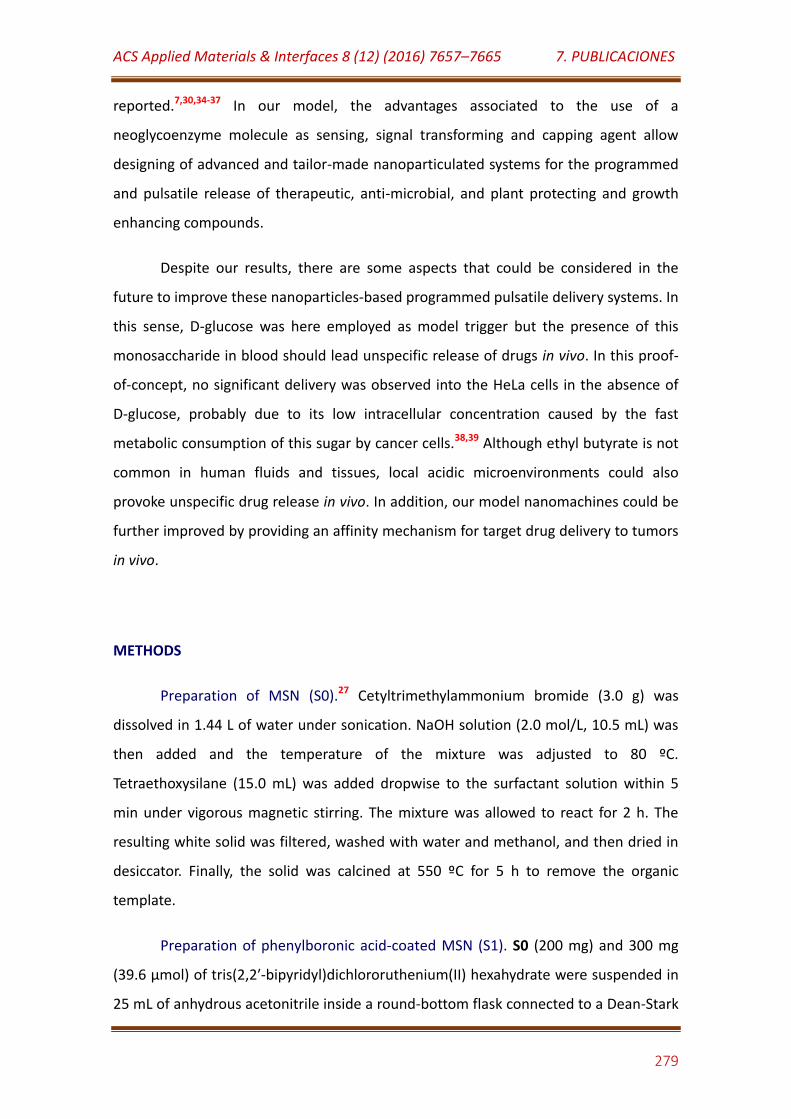
ACS Applied Materials & Interfaces 8 (12) (2016) 7657–7665 7. PUBLICACIONES
279
reported.7,30,34-37 In our model, the advantages associated to the use of a
neoglycoenzyme molecule as sensing, signal transforming and capping agent allow
designing of advanced and tailor-made nanoparticulated systems for the programmed
and pulsatile release of therapeutic, anti-microbial, and plant protecting and growth
enhancing compounds.
Despite our results, there are some aspects that could be considered in the
future to improve these nanoparticles-based programmed pulsatile delivery systems. In
this sense, D-glucose was here employed as model trigger but the presence of this
monosaccharide in blood should lead unspecific release of drugs in vivo. In this proof-
of-concept, no significant delivery was observed into the HeLa cells in the absence of
D-glucose, probably due to its low intracellular concentration caused by the fast
metabolic consumption of this sugar by cancer cells.38,39 Although ethyl butyrate is not
common in human fluids and tissues, local acidic microenvironments could also
provoke unspecific drug release in vivo. In addition, our model nanomachines could be
further improved by providing an affinity mechanism for target drug delivery to tumors
in vivo.
METHODS
Preparation of MSN (S0).27 Cetyltrimethylammonium bromide (3.0 g) was
dissolved in 1.44 L of water under sonication. NaOH solution (2.0 mol/L, 10.5 mL) was
then added and the temperature of the mixture was adjusted to 80 ºC.
Tetraethoxysilane (15.0 mL) was added dropwise to the surfactant solution within 5
min under vigorous magnetic stirring. The mixture was allowed to react for 2 h. The
resulting white solid was filtered, washed with water and methanol, and then dried in
desiccator. Finally, the solid was calcined at 550 ºC for 5 h to remove the organic
template.
Preparation of phenylboronic acid-coated MSN (S1). S0 (200 mg) and 300 mg
(39.6 µmol) of tris(2,2′-bipyridyl)dichlororuthenium(II) hexahydrate were suspended in
25 mL of anhydrous acetonitrile inside a round-bottom flask connected to a Dean-Stark
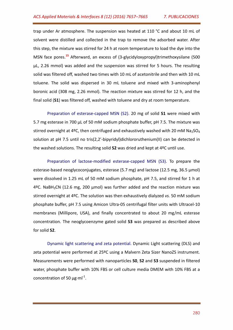
ACS Applied Materials & Interfaces 8 (12) (2016) 7657–7665 7. PUBLICACIONES
280
trap under Ar atmosphere. The suspension was heated at 110 °C and about 10 mL of
solvent were distilled and collected in the trap to remove the adsorbed water. After
this step, the mixture was stirred for 24 h at room temperature to load the dye into the
MSN face pores.15 Afterward, an excess of (3-glycidyloxypropyl)trimethoxysilane (500
µL, 2.26 mmol) was added and the suspension was stirred for 5 hours. The resulting
solid was filtered off, washed two times with 10 mL of acetonitrile and then with 10 mL
toluene. The solid was dispersed in 30 mL toluene and mixed with 3-aminophenyl
boronic acid (308 mg, 2.26 mmol). The reaction mixture was stirred for 12 h, and the
final solid (S1) was filtered off, washed with toluene and dry at room temperature.
Preparation of esterase-capped MSN (S2). 20 mg of solid S1 were mixed with
5.7 mg esterase in 700 µL of 50 mM sodium phosphate buffer, pH 7.5. The mixture was
stirred overnight at 4ºC, then centrifuged and exhaustively washed with 20 mM Na2SO4
solution at pH 7.5 until no tris(2,2′-bipyridyl)dichlororuthenium(II) can be detected in
the washed solutions. The resulting solid S2 was dried and kept at 4ºC until use.
Preparation of lactose-modified esterase-capped MSN (S3). To prepare the
esterase-based neoglycoconjugates, esterase (5.7 mg) and lactose (12.5 mg, 36.5 µmol)
were dissolved in 1.25 mL of 50 mM sodium phosphate, pH 7.5, and stirred for 1 h at
4ºC. NaBH3CN (12.6 mg, 200 µmol) was further added and the reaction mixture was
stirred overnight at 4ºC. The solution was then exhaustively dialyzed vs. 50 mM sodium
phosphate buffer, pH 7.5 using Amicon Ultra-05 centrifugal filter units with Ultracel-10
membranes (Millipore, USA), and finally concentrated to about 20 mg/mL esterase
concentration. The neoglycoenzyme gated solid S3 was prepared as described above
for solid S2.
Dynamic light scattering and zeta potential. Dynamic Light scattering (DLS) and
zeta potential were performed at 25ºC using a Malvern Zeta Sizer NanoZS instrument.
Measurements were performed with nanoparticles S0, S2 and S3 suspended in filtered
water, phosphate buffer with 10% FBS or cell culture media DMEM with 10% FBS at a
concentration of 50 µg·ml-1.
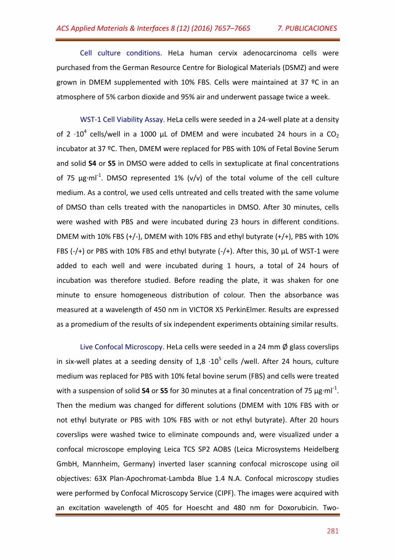
ACS Applied Materials & Interfaces 8 (12) (2016) 7657–7665 7. PUBLICACIONES
281
Cell culture conditions. HeLa human cervix adenocarcinoma cells were
purchased from the German Resource Centre for Biological Materials (DSMZ) and were
grown in DMEM supplemented with 10% FBS. Cells were maintained at 37 ºC in an
atmosphere of 5% carbon dioxide and 95% air and underwent passage twice a week.
WST-1 Cell Viability Assay. HeLa cells were seeded in a 24-well plate at a density
of 2 ·104 cells/well in a 1000 μL of DMEM and were incubated 24 hours in a CO2
incubator at 37 ºC. Then, DMEM were replaced for PBS with 10% of Fetal Bovine Serum
and solid S4 or S5 in DMSO were added to cells in sextuplicate at final concentrations
of 75 μg·ml-1. DMSO represented 1% (v/v) of the total volume of the cell culture
medium. As a control, we used cells untreated and cells treated with the same volume
of DMSO than cells treated with the nanoparticles in DMSO. After 30 minutes, cells
were washed with PBS and were incubated during 23 hours in different conditions.
DMEM with 10% FBS (+/-), DMEM with 10% FBS and ethyl butyrate (+/+), PBS with 10%
FBS (-/+) or PBS with 10% FBS and ethyl butyrate (-/+). After this, 30 μL of WST-1 were
added to each well and were incubated during 1 hours, a total of 24 hours of
incubation was therefore studied. Before reading the plate, it was shaken for one
minute to ensure homogeneous distribution of colour. Then the absorbance was
measured at a wavelength of 450 nm in VICTOR X5 PerkinElmer. Results are expressed
as a promedium of the results of six independent experiments obtaining similar results.
Live Confocal Microscopy. HeLa cells were seeded in a 24 mm Ø glass coverslips
in six-well plates at a seeding density of 1,8 ·105 cells /well. After 24 hours, culture
medium was replaced for PBS with 10% fetal bovine serum (FBS) and cells were treated
with a suspension of solid S4 or S5 for 30 minutes at a final concentration of 75 µg·ml-1.
Then the medium was changed for different solutions (DMEM with 10% FBS with or
not ethyl butyrate or PBS with 10% FBS with or not ethyl butyrate). After 20 hours
coverslips were washed twice to eliminate compounds and, were visualized under a
confocal microscope employing Leica TCS SP2 AOBS (Leica Microsystems Heidelberg
GmbH, Mannheim, Germany) inverted laser scanning confocal microscope using oil
objectives: 63X Plan-Apochromat-Lambda Blue 1.4 N.A. Confocal microscopy studies
were performed by Confocal Microscopy Service (CIPF). The images were acquired with
an excitation wavelength of 405 for Hoescht and 480 nm for Doxorubicin. Two-
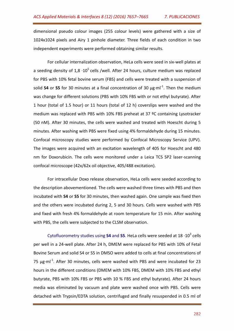
ACS Applied Materials & Interfaces 8 (12) (2016) 7657–7665 7. PUBLICACIONES
282
dimensional pseudo colour images (255 colour levels) were gathered with a size of
1024x1024 pixels and Airy 1 pinhole diameter. Three fields of each condition in two
independent experiments were performed obtaining similar results.
For cellular internalization observation, HeLa cells were seed in six-well plates at
a seeding density of 1,8 ·105 cells /well. After 24 hours, culture medium was replaced
for PBS with 10% fetal bovine serum (FBS) and cells were treated with a suspension of
solid S4 or S5 for 30 minutes at a final concentration of 30 µg·ml-1. Then the medium
was change for different solutions (PBS with 10% FBS with or not ethyl butyrate). After
1 hour (total of 1.5 hour) or 11 hours (total of 12 h) coverslips were washed and the
medium was replaced with PBS with 10% FBS preheat at 37 ºC containing Lysotracker
(50 nM). After 30 minutes, the cells were washed and treated with Hoescht during 5
minutes. After washing with PBS were fixed using 4% formaldehyde during 15 minutes.
Confocal microscopy studies were performed by Confocal Microscopy Service (UPV).
The images were acquired with an excitation wavelength of 405 for Hoescht and 480
nm for Doxorubicin. The cells were monitored under a Leica TCS SP2 laser-scanning
confocal microscope (42x/62x oil objective, 405/488 excitation).
For intracellular Doxo release observation, HeLa cells were seeded according to
the description abovementioned. The cells were washed three times with PBS and then
incubated with S4 or S5 for 30 minutes, then washed again. One sample was fixed then
and the others were incubated during 2, 5 and 30 hours. Cells were washed with PBS
and fixed with fresh 4% formaldehyde at room temperature for 15 min. After washing
with PBS, the cells were subjected to the CLSM observation.
Cytofluorometry studies using S4 and S5. HeLa cells were seeded at 18 ·103 cells
per well in a 24-well plate. After 24 h, DMEM were replaced for PBS with 10% of Fetal
Bovine Serum and solid S4 or S5 in DMSO were added to cells at final concentrations of
75 μg·ml-1. After 30 minutes, cells were washed with PBS and were incubated for 23
hours in the different conditions (DMEM with 10% FBS, DMEM with 10% FBS and ethyl
butyrate, PBS with 10% FBS or PBS with 10 % FBS and ethyl butyrate). After 24 hours
media was eliminated by vacuum and plate were washed once with PBS. Cells were
detached with Trypsin/EDTA solution, centrifuged and finally resuspended in 0.5 ml of
ACS Applied Materials & Interfaces 8 (12) (2016) 7657–7665 7. PUBLICACIONES
283
DMEM with 10% FBS. Quantification of Doxorubicin fluorescence in the cells was
performed with WinMDI program, version 2.0 in a FC500 MCL Flow Cytometer
(Beckman-Coulter, CA, USA). Three independent experiments containing
quadruplicates were performed with similar results.
For cytotoxicity assays employing flow cytometry, cells were seeded at the same
conditions. After 24 h, solids S0, S4 or S5 in DMSO were added at final concentration of
50 µg· ml-1. After 30 minutes, cells were washed and incubated for 23 hours in the
different conditions. After 24 hours, cells were stained with 7-AAD and Ann V-FITC
according to the manufacturer’s protocol (Life Technologies). Quantification of 7-AAD-
positive and AnnV-positive staining was done by the WinMDI program, version 2.9 in a
FC500 MCL Flow Cytometer (Beckman-Coulter, CA, USA). Three independent
experiments were done and contained triplicates with analogous results.
CONCLUSIONS
In summary, here we demonstrate that the modification of a glycoenzyme by
artificial glycosylation is a useful approach to manipulate the strength of the
supramolecular interaction with phenylboronic acid-coated supports. Based on this
concept, novel neoglycoenzyme-gated MSN, for programmed and pulsatile sequential
cargo delivery, are reported. In particular, gated support S3 is able to release ca. half
the cargo in the presence of glucose, whereas the remaining entrapped payload is
delivered upon the addition of ethyl butyrate. Moreover, it was also demonstrated that
the same control was observed with nanoparticles loaded with an anticancer drug (S5)
and tested in HeLa cells. We believe that the possibility of using a wide variety of
different derivatized enzymes, combined with a variety of functionalized MSN as
supports, opens up new possibilities for the design of novel smart pulsatile delivery
nanodevices for on-command programmed sequential delivery. These, or similar,
release systems have the potential of being applied to diseases for which a pulsatile
drug delivery is preferred and in which triggering can be achieved using simple non-
toxic small molecules.
ACS Applied Materials & Interfaces 8 (12) (2016) 7657–7665 7. PUBLICACIONES
284
ASSOCIATED CONTENT
Supporting Information
Experimental details, nanomaterials characterization and ex vivo experiments.
This material is available free of charge via the Internet at http://pubs.acs.org.
AUTHOR INFORMATION
Corresponding Author
[email protected], [email protected], [email protected].
Notes
The authors declare no competing financial interests.
ACKNOWLEDGMENT
R. Villalonga acknowledges to Ramón & Cajal contract from the Spanish
Ministry of Science and Innovation. Financial support from the Spanish Ministry of
Science and Innovation CTQ2011-24355, CTQ2009-12650, CTQ2009-09351, MAT2012-
38429-C04-01 and Comunidad de Madrid S2009/PPQ-1642, programme AVANSENS is
gratefully acknowledged. The Generalitat Valencia (project PROMETEOII/2014/047) is
also acknowledged.
REFERENCES
(1) Uhrich, K.E.; Cannizzaro, S.M.; Langer, R.S.; Shakesheff, K.M. Polymeric Systems for
Controlled Drug Release. Chem. Rev. 1999, 99, 3181-3198.
(2) Allen, T.M.; Cullis, P.R. Drug Delivery Systems: Entering the Mainstream. Science
2004, 303, 1818-1822.
ACS Applied Materials & Interfaces 8 (12) (2016) 7657–7665 7. PUBLICACIONES
285
(3) Valdivia, A.; Perez, Y.; Dominguez, A.; Caballero, J.; Gomez, L.; Schacht, E.H.;
Villalonga, R. Improved Anti-Inflammatory and Pharmacokinetic Properties for
Superoxide Dismutase by Chemical Glycosidation with Carboxymethylchitin. Macromol.
Biosci. 2005, 5, 118-123.
(4) Allen, T.M.; Cullis, P.R. Liposomal Drug Delivery Systems: From Concept to Clinical
Applications. Adv. Drug Delivery Rev. 2013, 65, 36-48.
(5) Tang, F.; Li, L.; Chen, D. Mesoporous Silica Nanoparticles: Synthesis, Biocompatibility
and Drug Delivery. Adv. Mater. 2012, 24, 1504-1534.
(6) Li, Z.; Barnes, J.C.; Bosoy, A.; Stoddart, J.F.; Zink, J.I. Mesoporous Silica Nanoparticles
in Biomedical Applications. Chem. Soc. Rev. 2012, 41, 2590-2605.
(7) Villalonga, R.; Díez, P.; Sánchez, A.; Aznar, E.; Martínez-Máñez, R.; Pingarrón, J.M.
Enzyme-Controlled Sensing–Actuating Nanomachine Based on Janus Au–Mesoporous
Silica Nanoparticles. Chem. Eur. J. 2013, 19, 7889-7894.
(8) Hakeem, A.; Duan, R.; Zahid, F.; Dong, C.; Wang, B.; Hong, F.; Ou, X.; Jia, Y.; Lou, X.;
Xia, F. Dual Stimuli-Responsive Nano-Vehicles for Controlled Drug Delivery:
Mesoporous Silica Nanoparticles End-Capped with Natural Chitosan. Chem. Commun.
2014, 50, 13268-13271.
(9) Tarn, D.; Ashley, C.E.; Xue, M.; Carnes, E.C.; Zink, J.I.; Brinker, C.J. Mesoporous Silica
Nanoparticle Nanocarriers: Biofunctionality and Biocompatibility. Acc. Chem. Res. 2013,
46, 792-801.
(10) Coll, C.; Bernardos, A.; Martínez-Máñez, R.; Sancenón, F. Gated Silica Mesoporous
Supports for Controlled Release and Signaling Applications. Acc. Chem. Res. 2013, 46,
339-349.
(11) Cotí, K.; Belowich, M.E.; Liong, M.; Ambrogio, M.W.; Lau, Y.A.; Khatib, H.A.; Zink,
J.I.; Khashab, N.M.; Stoddart, J.F. Mechanised Nanoparticles for Drug Delivery.
Nanoscale 2009, 1, 16-39.
ACS Applied Materials & Interfaces 8 (12) (2016) 7657–7665 7. PUBLICACIONES
286
(12) Lai, C.-Y.; Trewyn, B.G.; Jeftinija, D.M.; Jeftinija, K.; Xu, S.; Jeftinija, S.; Lin, V.S.–Y. A
Mesoporous Silica Nanosphere-Based Carrier System with Chemically Removable CdS
Nanoparticle Caps for Stimuli-Responsive Controlled Release of Neurotransmitters and
Drug Molecules. J. Am. Chem. Soc. 2003, 125, 4451-4459.
(13) Díez, P.; Sánchez, A.; Gamella, M.; Martínez-Ruíz, P.; Aznar, E.; de la Torre, C.;
Murguía, J.R.; Martínez-Máñez, R.; Villalonga, R.; Pingarrón, J.M. Toward the Design of
Smart Delivery Systems Controlled by Integrated Enzyme-Based Biocomputing
Ensembles. J. Am. Chem. Soc. 2014, 136, 9116-9123.
(14) Zhao, Z.; Meng, H.; Wang, N.; Donovan, M.J.; Fu, T.; You, M.; Chen, Z.; Zhang, X.;
Tan, W. A Controlled-Release Nanocarrier with Extracellular pH Value Driven Tumor
Targeting and Translocation for Drug Delivery. Angew. Chem. Int. Ed. 2013, 52, 7487-
7491.
(15) Aznar, E.; Villalonga, R.; Giménez, C.; Sancenón, F.; Marcos, M.D.; Martínez-Máñez,
R.; Díez, P.; Pingarrón, J.M.; Amorós, P. Glucose-Triggered Release Using Enzyme-Gated
Mesoporous Silica Nanoparticles. Chem. Commun. 2013, 49, 6391-6393.
(16) Mal, N. K.; Fujiwara, M.; Tanaka, Y. Photocontrolled Reversible Release of Guest
Molecules from Coumarin-Modified Mesoporous Silica. Nature 2003, 421, 350-353.
(17) Fu, Q.; Rao, G.V.R.; Ista, L.K.; Wu, Y.; Andrzejewski, B.P.; Sklar, L.A.; Ward, T.L.;
López, G.P. Control of Molecular Transport Through Stimuli-Responsive Ordered
Mesoporous Materials. Adv. Mater. 2003, 15, 1262-1266.
(18) Bernardos, A.; Mondragon, L.; Aznar, E.; Marcos, M.D.; Martínez-Máñez, R.;
Sancenón, F.; Soto, J.; Barat, J.M.; Pérez-Payá, E.; Guillem, C.; Amorós, P. Enzyme-
Responsive Intracellular Controlled Release Using Nanometric Silica Mesoporous
Supports Capped with “Saccharides”. ACS Nano 2010, 4, 6353-6368.
(19) Schlossbauer, A.; Warncke, S.; Gramlich, P.M.E.; Kecht, J.; Manetto, A.; Carell, T.;
Bein, T. A Programmable DNA-Based Molecular Valve for Colloidal Mesoporous Silica.
Angew. Chem. Int. Ed. 2010, 49, 4734-4737.
ACS Applied Materials & Interfaces 8 (12) (2016) 7657–7665 7. PUBLICACIONES
287
(20) Li, L.-L.; Xie, M.; Wang, J.; Li, X.; Wang, C.; Yuan, Q.; Pang, D.-W.; Lu, Y.; Tan, W. A
Vitamin-Responsive Mesoporous Nanocarrier with DNA Aptamer-Mediated Cell
Targeting. Chem. Commun., 2013, 49, 5823-5825.
(21) Jaganathan, K.S.; Rao, Y.U.; Singh, P.; Prabakaran, D.; Gupta, S.; Jain, A.; Vyas, S.P.
Development of a Single Dose Tetanus Toxoid Formulation Based on Polymeric
Microspheres: A Comparative Study of Poly(D,L-Lactic-Co-Glycolic Acid) Versus Chitosan
Microspheres. Int. J. Pharm. 2005, 294, 23-32.
(22) Zhang, Z.; Qi, X.; Li, X.; Xing, J.; Zhu, X.; Wu, Z. A Novel Pulsatile Drug Delivery
System Based on the Physiochemical Reaction Between Acrylic Copolymer and Organic
Acid: In Vitro and In Vivo Evaluation. Int. J. Pharm. 2014, 462, 66-73.
(23) Tasciotti, E.; Liu, X.; Bhavane, R.; Plant, K.; Leonard, A.D.; Price, B.K.; Cheng,
M.M.C.; Decuzzi, P.; Tour, J.M.; Robertson, F.; Ferrari, M. Mesoporous Silicon Particles
as a Multistage Delivery System for Imaging and Therapeutic Applications. Nat.
Nanotechnol. 2008, 3, 151-157.
(24) Wang, C.; Li, Z.; Cao, D.; Zhao, Y.-L.; Gaines, J.W.; Bozdemir, O.A.; Ambrogio, M.W.;
Frasconi, M.; Botros, Y.Y.; Zink, J.I.; Stoddart, J.F. Stimulated Release of Size-Selected
Cargos in Succession From Mesoporous Silica Nanoparticles. Angew. Chem. Int. Ed.,
2012, 51, 5460-5465.
(25) Darias, R.; Herrera, I.; Fragoso, A.; Cao, R.; Villalonga, R. Supramolecular
Interactions Mediated Thermal Stabilization for α-Amylase Modified with a β-
Cyclodextrin-Carboxymethylcellulose Polymer. Biotechnol. Lett. 2002, 24, 1665-1668.
(26) Villalonga, M.L.; Díez, P.; Sánchez, A.; Gamella, M.; Pingarrón, J.M.; Villalonga, R.
Neoglycoenzymes. Chem. Rev. 2014, 114, 4868-4917.
(27) Zhao, Y.; Trewyn, B.G.; Slowing, I.I.; Lin, V.S.Y. Mesoporous Silica Nanoparticle-
Based Double Drug Delivery System for Glucose-Responsive Controlled Release of
Insulin and Cyclic AMP. J. Am. Chem. Soc. 2009, 131, 8398-8400.
ACS Applied Materials & Interfaces 8 (12) (2016) 7657–7665 7. PUBLICACIONES
289
(37) Cheng, Y.J.; Luo, G.F.; Zhu, J.Y.; Xu, X.D.; Zeng, X.; Cheng, D.B.; Li, Y.M.; Wu, Y.;
Zhang, X.Z.; Zhuo, R.X.; He, F. Enzyme-Induced and Tumor-Targeted Drug Delivery
System Based on Multifunctional Mesoporous Silica Nanoparticles. ACS Appl. Mater.
Interfaces 2015, 7, 9078-9087.
(38) Annibaldi, A.; Widmann, C. Glucose Metabolism in Cancer Cells. Curr. Opin. Clin.
Nutr. Metab. Care 2010, 13, 466-470.
(39) Hitosugi, T.; Chen, J. Post-Translational Modifications and the Warburg Effect.
Oncogene 2014, 33, 4279-4285.
ACS Applied Materials & Interfaces 8 (12) (2016) 7657–7665 7. PUBLICACIONES
288
(28) Fernández, M.; Fragoso, A.; Cao, R.; Baños, M.; Villalonga, M.L.; Villalonga, R.
Stabilization of Trypsin by Chemical Modification with β-Cyclodextrin Monoaldehyde.
Biotechnol. Lett. 2002, 24, 1455-1459.
(29) Heymann, E.; Junge, W. Characterization of the Isoenzymes of Pig-Liver Esterase 1.
Chemical Studies. Eur. J. Biochem. 1979, 95, 509-518.
(30) De la Torre, C.; Mondragón, L.; Coll, C.; Sancenón, F., Marcos, M.D.; Martínez‐
Máñez, R.; Amorós, P.; Pérez‐Payá, E.; Orzáez, M. Cathepsin‐B Induced Controlled
Release from Peptide‐Capped Mesoporous Silica Nanoparticles. Chem. Eur. J. 2014, 20,
15309-15314.
(31) Slowing, I.; Trewyn, B.G.; Lin, V.S.Y. Effect of Surface Functionalization of MCM-41-
Type Mesoporous Silica Nanoparticles on the Endocytosis by Human Cancer Cells. J.
Am. Chem. Soc. 2006, 128, 14792-14793.
(32) Lin, Y.S.; Tsai, C.P.; Huang, H.Y.; Kuo, C.T.; Hung, Y.; Huang, D.M.; Chen, Y.C.; Mou,
C.Y. Well-Ordered Mesoporous Silica Nanoparticles as Cell Markers. Chem. Mater. 2005,
17, 4570-4573.
(33) Chen, X.; Cheng, X.; Soeriyadi, A.H.; Sagnella, S.M.; Lu, X.; Scott, J.A.; Lowe, S.B.;
Kavallaris, M.; Gooding, J.J. Stimuli-Responsive Functionalized Mesoporous Silica
Nanoparticles for Drug Release in Response to Various Biological Stimuli. Biomater. Sci.
2014, 2, 121-130.
(34) Cheng, R.; Meng, F.; Deng, C.; Klok, H.A.; Zhong, Z. Dual and Multi-Stimuli
Responsive Polymeric Nanoparticles for Programmed Site-Specific Drug Delivery.
Biomaterials 2013, 34, 3647-3657.
(35) Pacardo, D.B.; Ligler, F.S.; Gu, Z. Programmable Nanomedicine: Synergistic and
Sequential Drug Delivery Systems. Nanoscale 2015, 7, 3381-3391.
(36) Liu, J.; Luo, Z.; Zhang, J.; Luo, T.; Zhou, J.; Zhao, X.; Cai, K. Hollow Mesoporous Silica
Nanoparticles Facilitated Drug Delivery Via Cascade pH Stimuli in Tumor
Microenvironment for Tumor Therapy. Biomaterials 2016. 83, 51-65.
ACS Applied Materials & Interfaces 8 (12) (2016) 7657–7665 7. PUBLICACIONES
290
SUPPORTING INFORMATION
NEOGLYCOENZYME-GATED MESOPOROUS SILICA NANOPARTICLES. TOWARDS
THE DESIGN OF NANO-DEVICES FOR PULSATILE PROGRAMMED SEQUENTIAL
DELIVERY
Paula Díez,1 Alfredo Sánchez,1 Cristina de la Torre,2,3 María Gamella,1 Paloma
Martínez-Ruíz,4 Elena Aznar,2,3 Ramón Martínez-Máñez,2,3,* José M. Pingarrón,1,5,*
Reynaldo Villalonga1,5,*
1Department of Analytical Chemistry, Faculty of Chemistry, Complutense
University of Madrid, 28040-Madrid, Spain. 2Instituto de Reconocimiento Molecular y
Desarrollo Tecnológico (IDM), Centro Mixto Universidad Politécnica de Valencia-
Universidad de Valencia, Spain. 3Departamento de Química y CIBER de Bioingeniería,
Biomateriales y Nanomedicina (CIBER-BBN), Universidad Politécnica de Valencia,
Camino de Vera s/n, 46022, Valencia, Spain. 4Department of Organic Chemistry I,
Faculty of Chemistry, Complutense University of Madrid, Madrid, Spain. 5IMDEA
Nanoscience, Cantoblanco Universitary City, 28049-Madrid, Spain.
EXPERIMENTAL SECTION
Chemicals
Pig liver esterase, tetraethoxysilane, cetyltrimethylammonium bromide,
tris(2,2′-bipyridyl)dichlororuthenium(II) hexahydrate, (3-
glycidyloxypropyl)trimethoxysilane, 3-aminophenyl boronic acid, D-glucose, ethyl
butyrate, trypan blue solution (0.4%) cell culture grade and DMSO, PBS and Dulbecco's
Modified Eagle's medium (DMEM) with glucose, L-glutamine and pyruvate for cell
culture were provided by Sigma-Aldrich. Solvents were provided by Scharlau. Fetal
Bovine Serum (FBS), Lysotracker red DND-99, 7-aminoactinomycin D and trypsin were
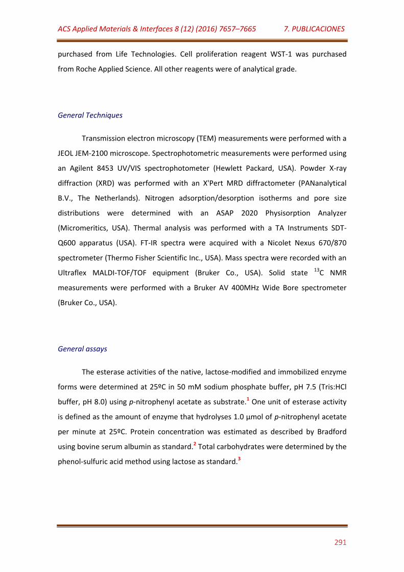
ACS Applied Materials & Interfaces 8 (12) (2016) 7657–7665 7. PUBLICACIONES
291
purchased from Life Technologies. Cell proliferation reagent WST-1 was purchased
from Roche Applied Science. All other reagents were of analytical grade.
General Techniques
Transmission electron microscopy (TEM) measurements were performed with a
JEOL JEM-2100 microscope. Spectrophotometric measurements were performed using
an Agilent 8453 UV/VIS spectrophotometer (Hewlett Packard, USA). Powder X-ray
diffraction (XRD) was performed with an X'Pert MRD diffractometer (PANanalytical
B.V., The Netherlands). Nitrogen adsorption/desorption isotherms and pore size
distributions were determined with an ASAP 2020 Physisorption Analyzer
(Micromeritics, USA). Thermal analysis was performed with a TA Instruments SDT-
Q600 apparatus (USA). FT-IR spectra were acquired with a Nicolet Nexus 670/870
spectrometer (Thermo Fisher Scientific Inc., USA). Mass spectra were recorded with an
Ultraflex MALDI-TOF/TOF equipment (Bruker Co., USA). Solid state 13C NMR
measurements were performed with a Bruker AV 400MHz Wide Bore spectrometer
(Bruker Co., USA).
General assays
The esterase activities of the native, lactose-modified and immobilized enzyme
forms were determined at 25ºC in 50 mM sodium phosphate buffer, pH 7.5 (Tris:HCl
buffer, pH 8.0) using p-nitrophenyl acetate as substrate.1 One unit of esterase activity
is defined as the amount of enzyme that hydrolyses 1.0 µmol of p-nitrophenyl acetate
per minute at 25ºC. Protein concentration was estimated as described by Bradford
using bovine serum albumin as standard.2 Total carbohydrates were determined by the
phenol-sulfuric acid method using lactose as standard.3
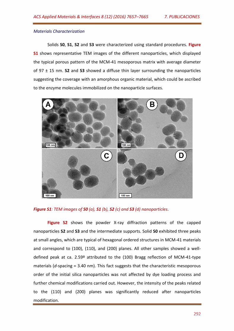
ACS Applied Materials & Interfaces 8 (12) (2016) 7657–7665 7. PUBLICACIONES
292
Materials Characterization
Solids S0, S1, S2 and S3 were characterized using standard procedures. Figure
S1 shows representative TEM images of the different nanoparticles, which displayed
the typical porous pattern of the MCM-41 mesoporous matrix with average diameter
of 97 ± 15 nm. S2 and S3 showed a diffuse thin layer surrounding the nanoparticles
suggesting the coverage with an amorphous organic material, which could be ascribed
to the enzyme molecules immobilized on the nanoparticle surfaces.
Figure S1: TEM images of S0 (a), S1 (b), S2 (c) and S3 (d) nanoparticles.
Figure S2 shows the powder X-ray diffraction patterns of the capped
nanoparticles S2 and S3 and the intermediate supports. Solid S0 exhibited three peaks
at small angles, which are typical of hexagonal ordered structures in MCM-41 materials
and correspond to (100), (110), and (200) planes. All other samples showed a well-
defined peak at ca. 2.59º attributed to the (100) Bragg reflection of MCM-41-type
materials (d-spacing = 3.40 nm). This fact suggests that the characteristic mesoporous
order of the initial silica nanoparticles was not affected by dye loading process and
further chemical modifications carried out. However, the intensity of the peaks related
to the (110) and (200) planes was significantly reduced after nanoparticles
modification.
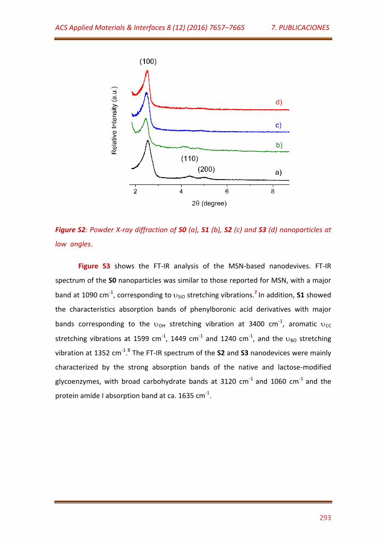
ACS Applied Materials & Interfaces 8 (12) (2016) 7657–7665 7. PUBLICACIONES
293
Figure S2: Powder X-ray diffraction of S0 (a), S1 (b), S2 (c) and S3 (d) nanoparticles at
low angles.
Figure S3 shows the FT-IR analysis of the MSN-based nanodevives. FT-IR
spectrum of the S0 nanoparticles was similar to those reported for MSN, with a major
band at 1090 cm-1, corresponding to SiO stretching vibrations.7 In addition, S1 showed
the characteristics absorption bands of phenylboronic acid derivatives with major
bands corresponding to the OH stretching vibration at 3400 cm-1, aromatic CC
stretching vibrations at 1599 cm-1, 1449 cm-1 and 1240 cm-1, and the BO stretching
vibration at 1352 cm-1.8 The FT-IR spectrum of the S2 and S3 nanodevices were mainly
characterized by the strong absorption bands of the native and lactose-modified
glycoenzymes, with broad carbohydrate bands at 3120 cm-1 and 1060 cm-1 and the
protein amide I absorption band at ca. 1635 cm-1.
ACS Applied Materials & Interfaces 8 (12) (2016) 7657–7665 7. PUBLICACIONES
294
Figure S3. FT-IR analysis for S0 (a), S1 (b), S2 (c) and S3 (d) nanoparticles.
The assembly of the nanodevice was confirmed by solid state 13C NMR. Figure
S4A shows the spectrum of MSN loaded with tris(2,2′-bipyridyl)dichlororuthenium(II)
hexahydrate and further modified with epoxy groups, which showed the
characteristics peaks of the aromatic rings in the dye at 158 ppm, 149 ppm, 139 ppm,
130 ppm and 125 ppm. In addition, the peak at 49 ppm can be ascribed to the epoxy
groups on the nanoparticle surface. A noticeable reduction in the intensity of the peak
at 49 ppm was observed in the spectrum of S1 solid, due to reaction of epoxy groups
with 3-aminophenyl boronic acid. In addition, new peaks at 145 ppm, 127 ppm, 121
ppm and 112 ppm are observed, which can be ascribed to the aromatic rings in the
attached phenyl boronic acid residues. No covalent immobilization of esterase on S1
caused the appearance of new peaks at 75 ppm and 26 ppm, which could be assigned
to aliphatic carbon atoms in the protein. However, it was not possible to detect the
characteristic peak of carbon atoms at the peptide bond around 170-180 ppm.
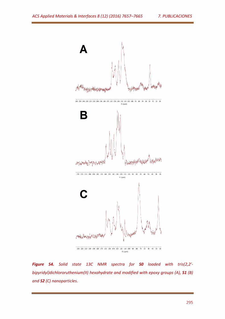
ACS Applied Materials & Interfaces 8 (12) (2016) 7657–7665 7. PUBLICACIONES
295
Figure S4. Solid state 13C NMR spectra for S0 loaded with tris(2,2′-
bipyridyl)dichlororuthenium(II) hexahydrate and modified with epoxy groups (A), S1 (B)
and S2 (C) nanoparticles.
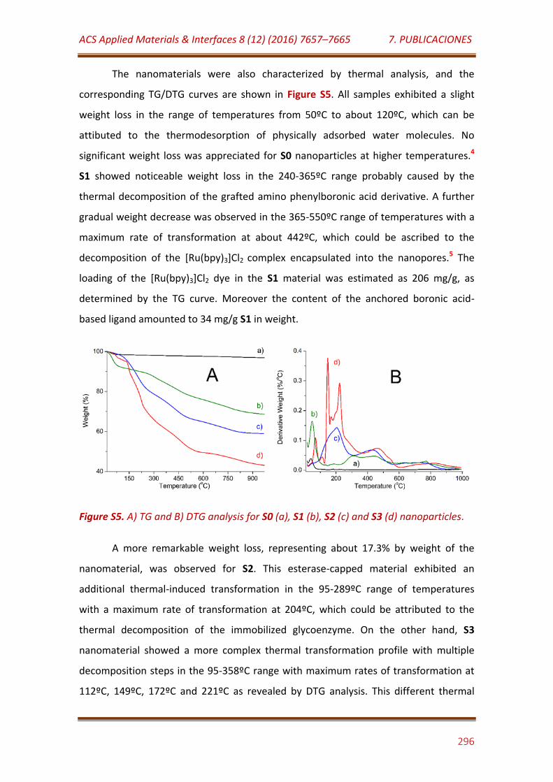
ACS Applied Materials & Interfaces 8 (12) (2016) 7657–7665 7. PUBLICACIONES
296
The nanomaterials were also characterized by thermal analysis, and the
corresponding TG/DTG curves are shown in Figure S5. All samples exhibited a slight
weight loss in the range of temperatures from 50ºC to about 120ºC, which can be
attibuted to the thermodesorption of physically adsorbed water molecules. No
significant weight loss was appreciated for S0 nanoparticles at higher temperatures.4
S1 showed noticeable weight loss in the 240-365ºC range probably caused by the
thermal decomposition of the grafted amino phenylboronic acid derivative. A further
gradual weight decrease was observed in the 365-550ºC range of temperatures with a
maximum rate of transformation at about 442ºC, which could be ascribed to the
decomposition of the [Ru(bpy)3]Cl2 complex encapsulated into the nanopores.5 The
loading of the [Ru(bpy)3]Cl2 dye in the S1 material was estimated as 206 mg/g, as
determined by the TG curve. Moreover the content of the anchored boronic acid-
based ligand amounted to 34 mg/g S1 in weight.
Figure S5. A) TG and B) DTG analysis for S0 (a), S1 (b), S2 (c) and S3 (d) nanoparticles.
A more remarkable weight loss, representing about 17.3% by weight of the
nanomaterial, was observed for S2. This esterase-capped material exhibited an
additional thermal-induced transformation in the 95-289ºC range of temperatures
with a maximum rate of transformation at 204ºC, which could be attributed to the
thermal decomposition of the immobilized glycoenzyme. On the other hand, S3
nanomaterial showed a more complex thermal transformation profile with multiple
decomposition steps in the 95-358ºC range with maximum rates of transformation at
112ºC, 149ºC, 172ºC and 221ºC as revealed by DTG analysis. This different thermal
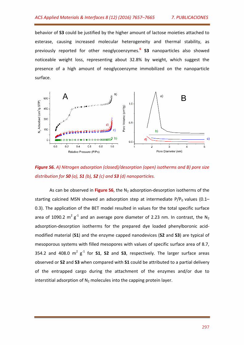
ACS Applied Materials & Interfaces 8 (12) (2016) 7657–7665 7. PUBLICACIONES
297
behavior of S3 could be justified by the higher amount of lactose moieties attached to
esterase, causing increased molecular heterogeneity and thermal stability, as
previously reported for other neoglycoenzymes.6 S3 nanoparticles also showed
noticeable weight loss, representing about 32.8% by weight, which suggest the
presence of a high amount of neoglycoenzyme immobilized on the nanoparticle
surface.
Figure S6. A) Nitrogen adsorption (closed)/desorption (open) isotherms and B) pore size
distribution for S0 (a), S1 (b), S2 (c) and S3 (d) nanoparticles.
As can be observed in Figure S6, the N2 adsorption-desorption isotherms of the
starting calcined MSN showed an adsorption step at intermediate P/P0 values (0.1–
0.3). The application of the BET model resulted in values for the total specific surface
area of 1090.2 m2 g-1 and an average pore diameter of 2.23 nm. In contrast, the N2
adsorption-desorption isotherms for the prepared dye loaded phenylboronic acid-
modified material (S1) and the enzyme capped nanodevices (S2 and S3) are typical of
mesoporous systems with filled mesopores with values of specific surface area of 8.7,
354.2 and 408.0 m2 g-1 for S1, S2 and S3, respectively. The larger surface areas
observed or S2 and S3 when compared with S1 could be attributed to a partial delivery
of the entrapped cargo during the attachment of the enzymes and/or due to
interstitial adsorption of N2 molecules into the capping protein layer.
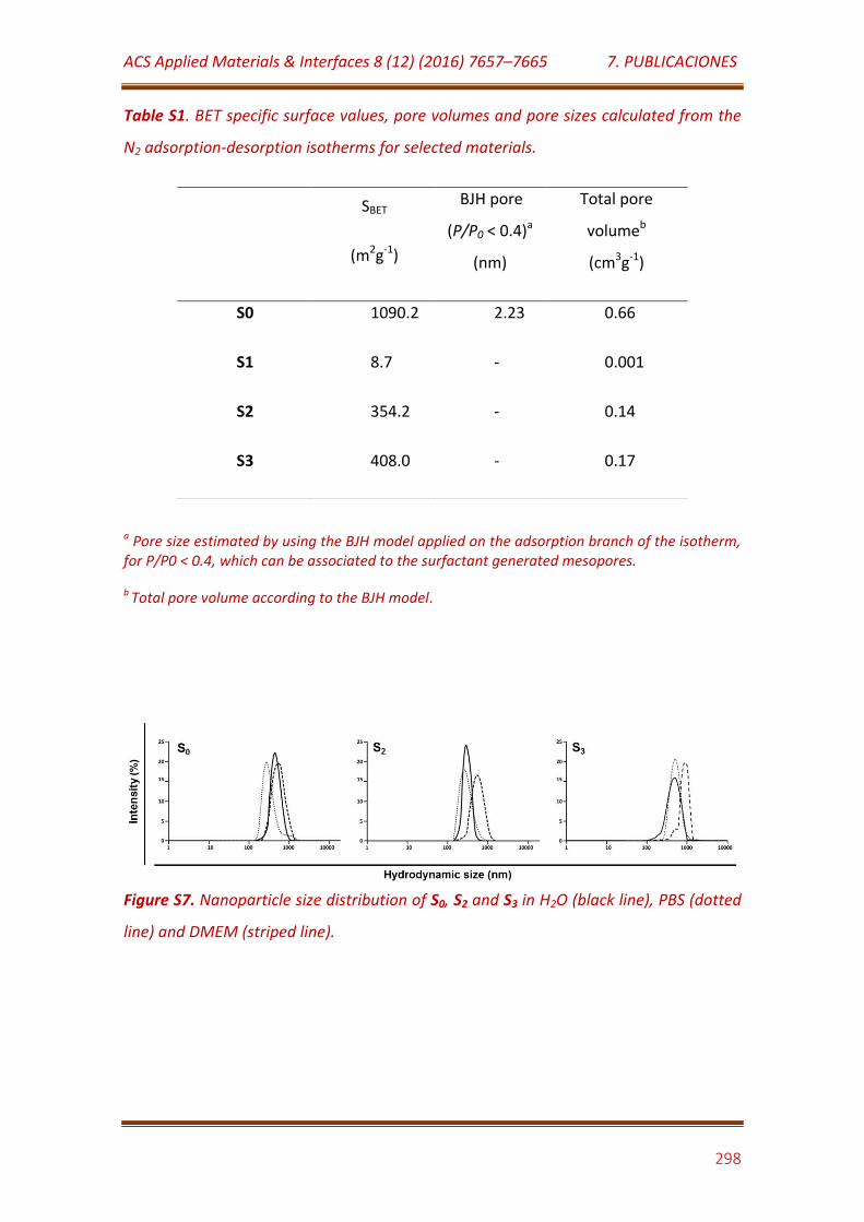
ACS Applied Materials & Interfaces 8 (12) (2016) 7657–7665 7. PUBLICACIONES
298
Table S1. BET specific surface values, pore volumes and pore sizes calculated from the
N2 adsorption-desorption isotherms for selected materials.
a Pore size estimated by using the BJH model applied on the adsorption branch of the isotherm, for P/P0 < 0.4, which can be associated to the surfactant generated mesopores.
b Total pore volume according to the BJH model.
Figure S7. Nanoparticle size distribution of S0, S2 and S3 in H2O (black line), PBS (dotted
line) and DMEM (striped line).
SBET
(m2g-1)
BJH pore
(P/P0 < 0.4)a
(nm)
Total pore
volumeb
(cm3g-1)
S0 1090.2 2.23 0.66
S1 8.7 - 0.001
S2 354.2 - 0.14
S3 408.0 - 0.17
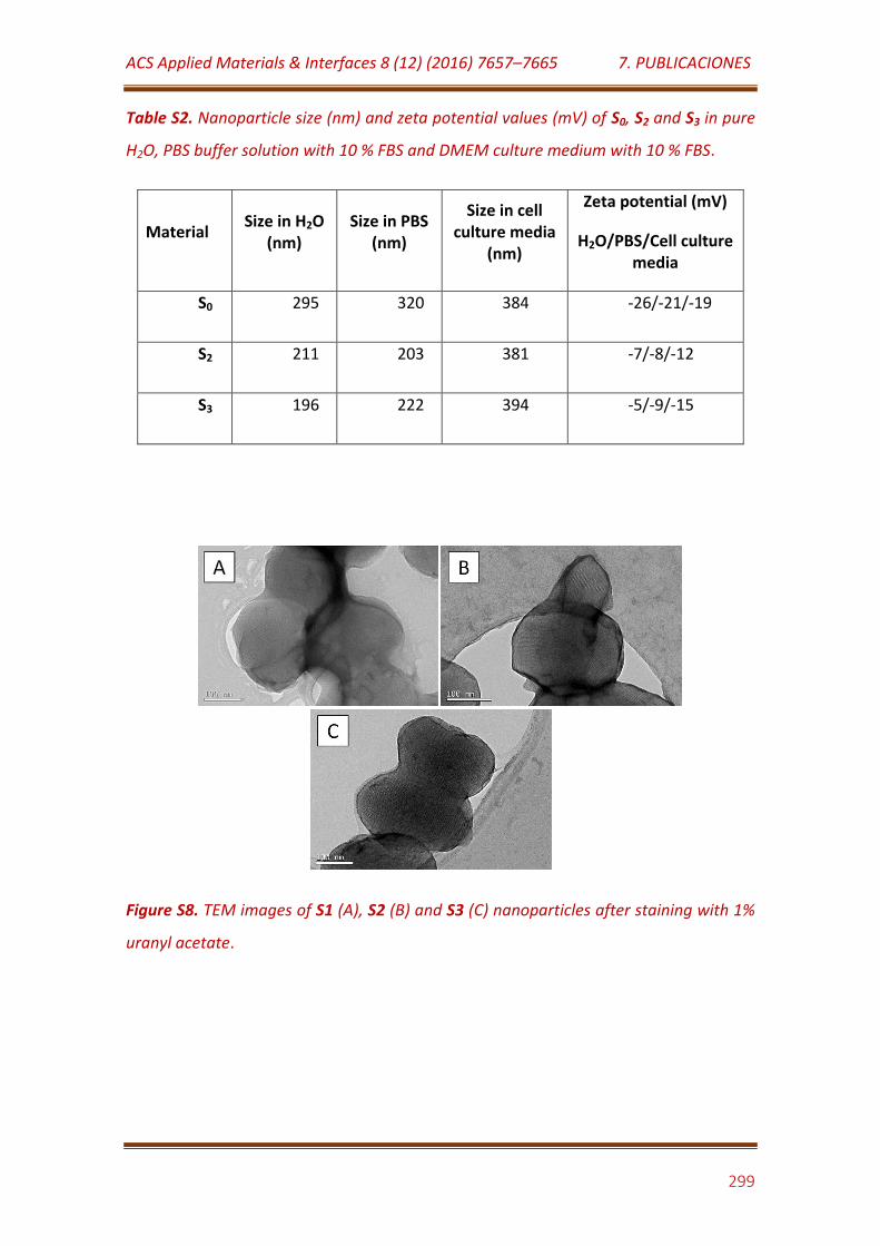
ACS Applied Materials & Interfaces 8 (12) (2016) 7657–7665 7. PUBLICACIONES
299
Table S2. Nanoparticle size (nm) and zeta potential values (mV) of S0, S2 and S3 in pure
H2O, PBS buffer solution with 10 % FBS and DMEM culture medium with 10 % FBS.
Material Size in H2O
(nm) Size in PBS
(nm)
Size in cell culture media
(nm)
Zeta potential (mV)
H2O/PBS/Cell culture media
S0 295 320 384 -26/-21/-19
S2 211 203 381 -7/-8/-12
S3 196 222 394 -5/-9/-15
Figure S8. TEM images of S1 (A), S2 (B) and S3 (C) nanoparticles after staining with 1%
uranyl acetate.
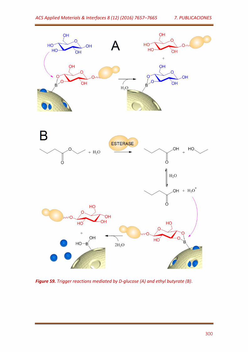
ACS Applied Materials & Interfaces 8 (12) (2016) 7657–7665 7. PUBLICACIONES
300
Figure S9. Trigger reactions mediated by D-glucose (A) and ethyl butyrate (B).
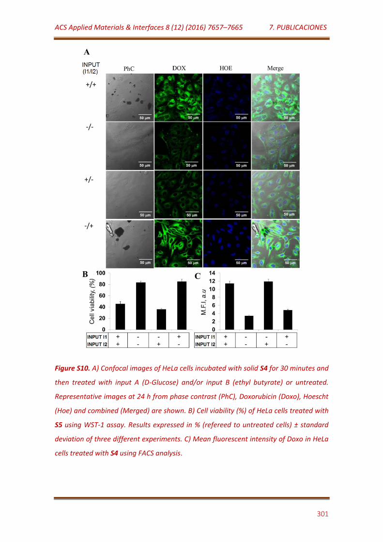
ACS Applied Materials & Interfaces 8 (12) (2016) 7657–7665 7. PUBLICACIONES
301
Figure S10. A) Confocal images of HeLa cells incubated with solid S4 for 30 minutes and
then treated with input A (D-Glucose) and/or input B (ethyl butyrate) or untreated.
Representative images at 24 h from phase contrast (PhC), Doxorubicin (Doxo), Hoescht
(Hoe) and combined (Merged) are shown. B) Cell viability (%) of HeLa cells treated with
S5 using WST-1 assay. Results expressed in % (refereed to untreated cells) ± standard
deviation of three different experiments. C) Mean fluorescent intensity of Doxo in HeLa
cells treated with S4 using FACS analysis.
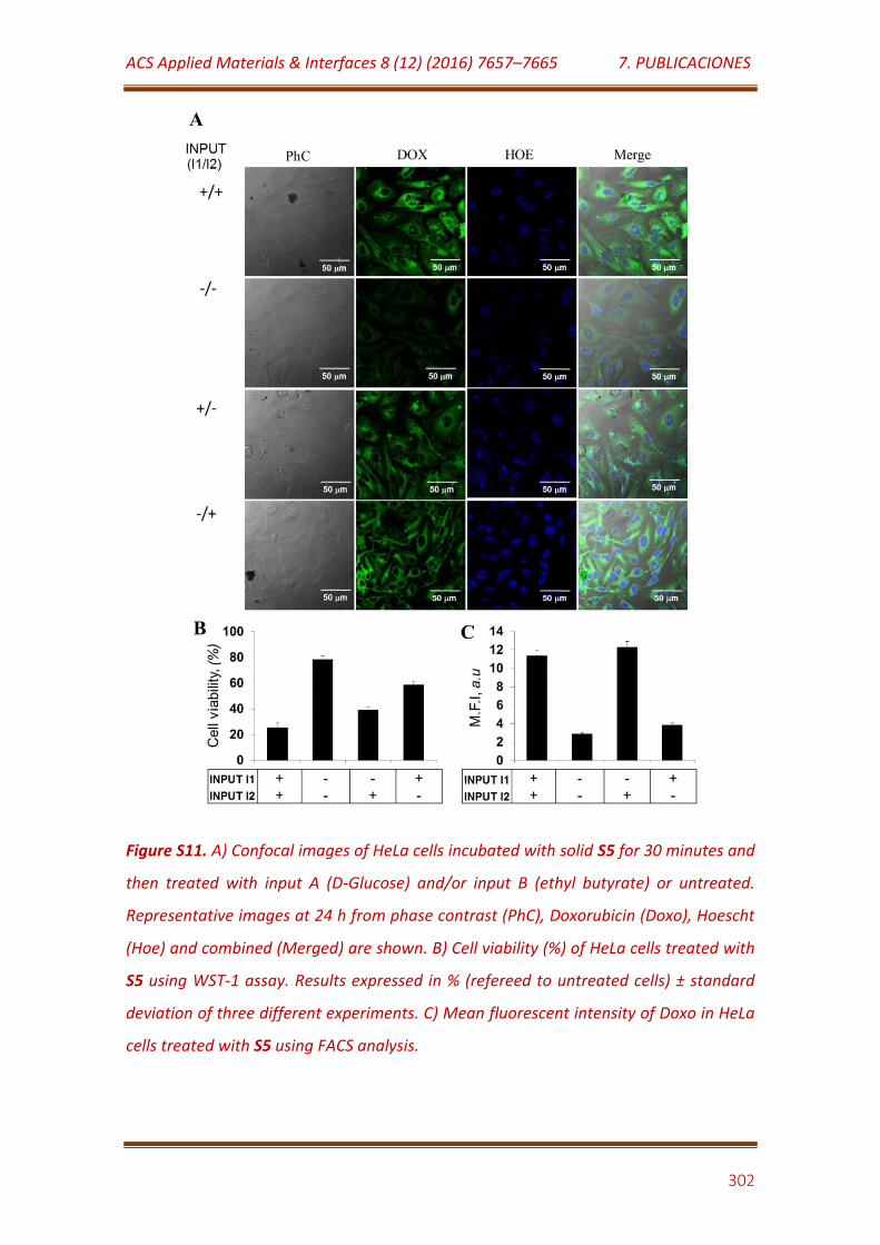
ACS Applied Materials & Interfaces 8 (12) (2016) 7657–7665 7. PUBLICACIONES
302
Figure S11. A) Confocal images of HeLa cells incubated with solid S5 for 30 minutes and
then treated with input A (D-Glucose) and/or input B (ethyl butyrate) or untreated.
Representative images at 24 h from phase contrast (PhC), Doxorubicin (Doxo), Hoescht
(Hoe) and combined (Merged) are shown. B) Cell viability (%) of HeLa cells treated with
S5 using WST-1 assay. Results expressed in % (refereed to untreated cells) ± standard
deviation of three different experiments. C) Mean fluorescent intensity of Doxo in HeLa
cells treated with S5 using FACS analysis.
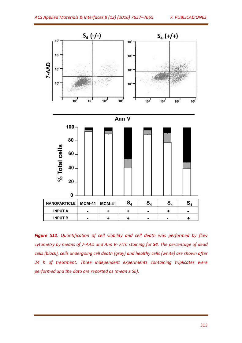
ACS Applied Materials & Interfaces 8 (12) (2016) 7657–7665 7. PUBLICACIONES
303
Figure S12. Quantification of cell viability and cell death was performed by flow
cytometry by means of 7-AAD and Ann V- FITC staining for S4. The percentage of dead
cells (black), cells undergoing cell death (gray) and healthy cells (white) are shown after
24 h of treatment. Three independent experiments containing triplicates were
performed and the data are reported as (mean ± SE).
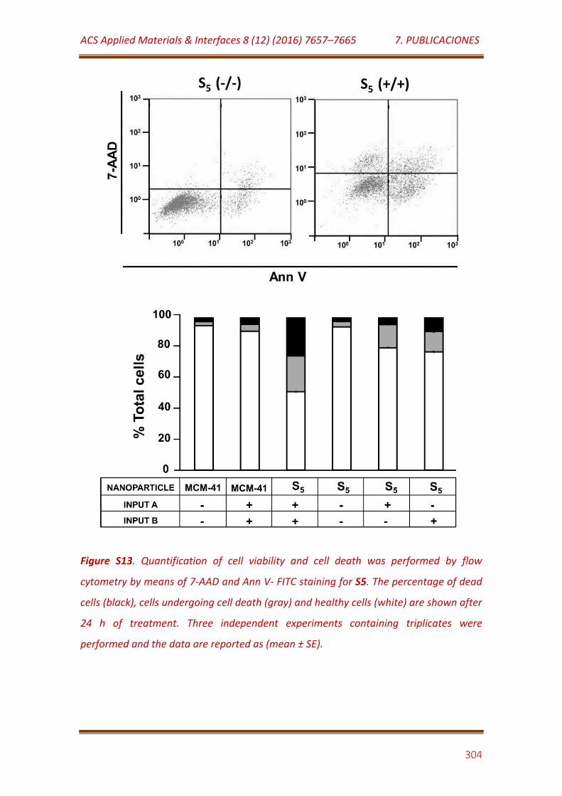
ACS Applied Materials & Interfaces 8 (12) (2016) 7657–7665 7. PUBLICACIONES
304
Figure S13. Quantification of cell viability and cell death was performed by flow
cytometry by means of 7-AAD and Ann V- FITC staining for S5. The percentage of dead
cells (black), cells undergoing cell death (gray) and healthy cells (white) are shown after
24 h of treatment. Three independent experiments containing triplicates were
performed and the data are reported as (mean ± SE).
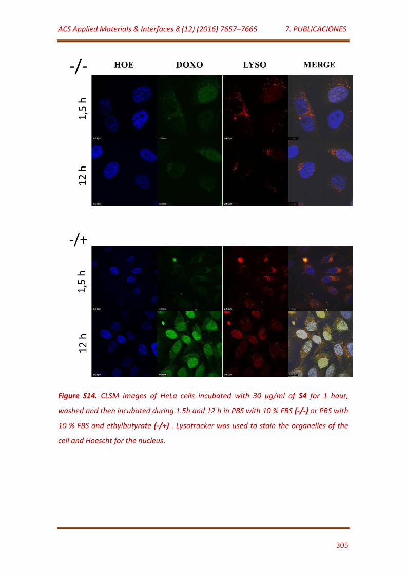
ACS Applied Materials & Interfaces 8 (12) (2016) 7657–7665 7. PUBLICACIONES
305
Figure S14. CLSM images of HeLa cells incubated with 30 μg/ml of S4 for 1 hour,
washed and then incubated during 1.5h and 12 h in PBS with 10 % FBS (-/-) or PBS with
10 % FBS and ethylbutyrate (-/+) . Lysotracker was used to stain the organelles of the
cell and Hoescht for the nucleus.
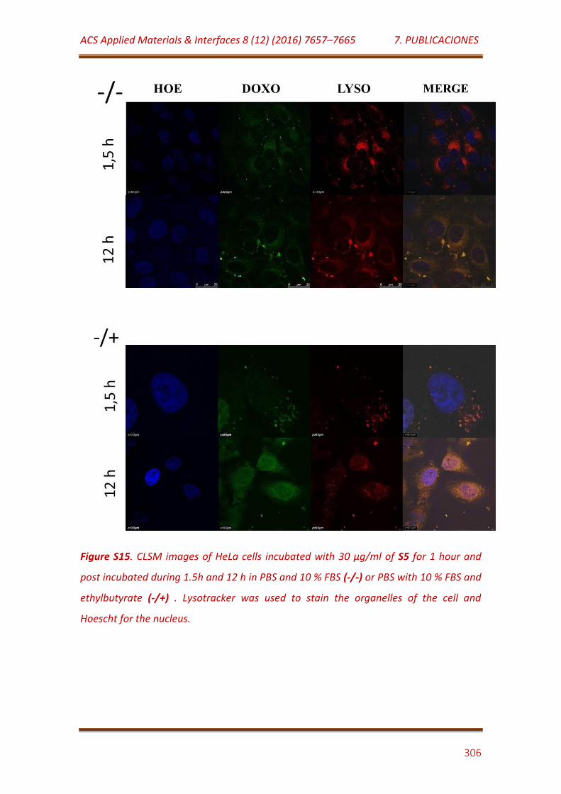
ACS Applied Materials & Interfaces 8 (12) (2016) 7657–7665 7. PUBLICACIONES
306
Figure S15. CLSM images of HeLa cells incubated with 30 μg/ml of S5 for 1 hour and
post incubated during 1.5h and 12 h in PBS and 10 % FBS (-/-) or PBS with 10 % FBS and
ethylbutyrate (-/+) . Lysotracker was used to stain the organelles of the cell and
Hoescht for the nucleus.
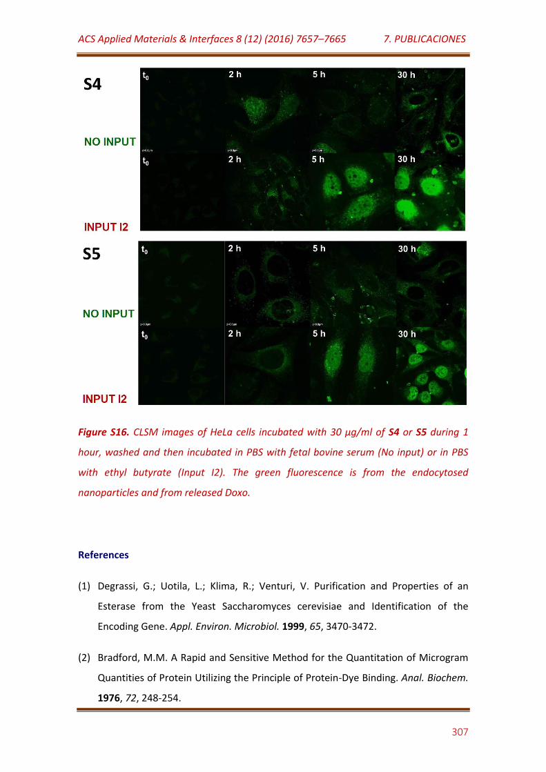
ACS Applied Materials & Interfaces 8 (12) (2016) 7657–7665 7. PUBLICACIONES
307
Figure S16. CLSM images of HeLa cells incubated with 30 μg/ml of S4 or S5 during 1
hour, washed and then incubated in PBS with fetal bovine serum (No input) or in PBS
with ethyl butyrate (Input I2). The green fluorescence is from the endocytosed
nanoparticles and from released Doxo.
References
(1) Degrassi, G.; Uotila, L.; Klima, R.; Venturi, V. Purification and Properties of an
Esterase from the Yeast Saccharomyces cerevisiae and Identification of the
Encoding Gene. Appl. Environ. Microbiol. 1999, 65, 3470-3472.
(2) Bradford, M.M. A Rapid and Sensitive Method for the Quantitation of Microgram
Quantities of Protein Utilizing the Principle of Protein-Dye Binding. Anal. Biochem.
1976, 72, 248-254.
ACS Applied Materials & Interfaces 8 (12) (2016) 7657–7665 7. PUBLICACIONES
308
(3) Dubois, M.; Gilles, K.A.; Hamilton, J.K.; Rebers, P.T.; Smith, F. Colorimetric Method
for Determination of Sugars and Related Substances. Anal. Chem. 1956, 28, 350-
356.
(4) Kumar, R.; Chen, H.T.; Escoto, J.L.; Lin, V.S.Y.; Pruski, M. Template Removal and
Thermal Stability of Organically Functionalized Mesoporous Silica Nanoparticles.
Chem. Mat. 2006, 18, 4319-4327.
(5) Armelao, L.; Bertoncello, R.; Gross, S.; Badocco, D.; Pastore, P. Construction and
Characterization of Ru(II)Tris(bipyridine)-Based Silica Thin Film
Electrochemiluminescent Sensors. Electroanalysis 2003, 15, 803-811.
(6) Villalonga, M.L.; Fernández, M.; Fragoso, A.; Cao, R.; Villalonga, R. Functional
Stabilization of Trypsin by Conjugation with β-Cyclodextrin-Modified
Carboxymethylcellulose. Prep. Biochem. Biotechnol. 2003, 33, 53-66.
(7) Villalonga, R.; Díez, P.; Sánchez, A.; Aznar, E.; Martínez-Máñez, R.; Pingarrón, J.M.
Enzyme-Controlled Sensing–Actuating Nanomachine Based on Janus Au–
Mesoporous Silica Nanoparticles. Chem. Eur. J. 2013, 19, 7889-7894.
(8) Faniran, J.A.; Shurvell, H.F. Infrared Spectra of Phenylboronic Acid (Normal and
Deuterated) and Diphenyl Phenylboronate. Can. J. Chem. 1968, 46, 2089-2095.
7.10
Electrochemistry Communications 30 (2013) 51–54
Janus Au-Mesoporous silica
nanoparticles as electrochemical biorecognition-signaling system

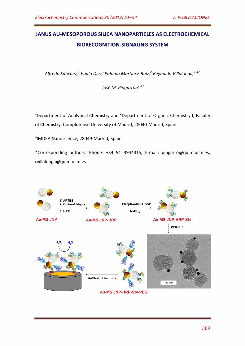
Electrochemistry Communications 30 (2013) 51–54 7. PUBLICACIONES
309
JANUS AU-MESOPOROUS SILICA NANOPARTICLES AS ELECTROCHEMICAL
BIORECOGNITION-SIGNALING SYSTEM
Alfredo Sánchez,1 Paula Díez,1Paloma Martínez-Ruíz,2 Reynaldo Villalonga,1,3,*
José M. Pingarrón1,3,*
1Department of Analytical Chemistry and 2Department of Organic Chemistry I, Faculty
of Chemistry, Complutense University of Madrid, 28040-Madrid, Spain.
3IMDEA Nanoscience, 28049-Madrid, Spain.
*Corresponding authors. Phone: +34 91 3944315, E-mail: [email protected],
Electrochemistry Communications 30 (2013) 51–54 7. PUBLICACIONES
310
ABSTRACT
Janus Au-mesoporous silica nanoparticles were used as scaffolds to design an
integrated electrochemical biorecognition-signaling system. A proof of concept of this
strategy, based on the face-selective functionalization of the anisotropic colloid,
involves the covalent immobilization of horseradish peroxidase on the mesoporous
silica face as enzymatic signaling element, as well as the modification of the Au face
with streptavidin and polyethylenglycol chains as biorecognition and solubilizing
agents, respectively. The functionalized Janus nanoparticles were sucessfull to
recognize biotin on gold surfaces.
KEYWORDS: Janus nanoparticle, mesoporous silica, electrochemical biosensor, enzyme
.
INTRODUCTION
Nanomaterials-based biosensors is a continuously growing field in
electroanalysis [1]. This trend is supported by the unique physicochemical, structural
and surface-to-volume ratio properties of nanomaterials, which allow their multiple
functional roles in biosensor design. Nanomaterials are also excellent building blocks
for the assembly of a wide variety of novel three-dimensional nanoarchitectures at the
electrode surface [2,3], favoring the spatial arrangement of the analytical biomolecules
in more propitious microenvironments.
In this context, nanoparticles are by far the nanomaterials most widely
employed in electrochemical biosensing [4]. Nanoparticles can be used to enhance the
amount of immobilized biomolecules, catalyze biochemical reactions, increase
efficiency of photochemical reactions and facilitate the electron transfer processes on
the electrode surface. Nanoparticles can be also employed as electrochemical labels as
well as to amplify transduction of biomolecular recognition events [5].
A great variety of nanoparticles differing in size, shape and composition have
been employed in bioelectrochemical analysis. Although Janus nanoparticles have
Electrochemistry Communications 30 (2013) 51–54 7. PUBLICACIONES
311
been proposed recently for electrochemical sensing [6], however, they have never
been explored for the development of electrochemical biosensors. Janus nanoparticles
are anisotropic materials showing two different faces with dissimilar chemical
composition and properties [7,8]. This structural characteristic allows their zone-
specific functionalization with selected biomolecules, which can be relevant to design
novel multienzymatic and affinity-based biosensors.
In this communication we describe for the first time the use of Janus
nanoparticles as biorecognition-signaling element in electrochemical biosensing. As a
first proof-of-concept, Janus Au-mesoporouos silica nanoparticles (Au-MS JNP) were
prepared and further functionalized with horseradish peroxidase (HRP, EC 1.11.1.7) on
the silica face, whereas the Au surface was modified with streptavidin.
Methoxypolyethylene glycol thiol (PEG-SH, MW = 5000) chains were also attached to
the metal face to confer solubility to the nanoparticle. This nanomaterial was finally
evaluated toward a thiolated biotin derivative previously chemisorpted on Au surfaces.
MATERIALS AND METHODS
1. Reagents
HRP, streptavidin, (3-aminopropyl)triethoxysilane (APTES), (3-mercaptopropyl)-
trimethoxysilane, PEG-SH and biotin were purchased from Sigma-Aldrich Co. 3,3´-
Dithiobis(sulfosuccinimidylpropionate) (DTSSP) was purchased from Thermo Fisher
Scientific.
2. Preparation of functionalized Au-MS JNP
Calcined mesoporouos silica nanoparticles (200 mg, 97 ± 15 nm) [9] were
dispersed in 1 g of paraffin wax at 75 °C and then mixed with 10 mL of water. The
mixture was stirred during 1 h, then cooled and the resulting colloidosomes were
collected by decantation, washed with water, and dispersed in 75 mL of methanol. The
mixture was treated with (3-mercaptopropyl)trimethoxysilane (30 mM final
concentration) during 30 min under stirring. The suspension was filtered, washed with
Electrochemistry Communications 30 (2013) 51–54 7. PUBLICACIONES
312
methanol and dispersed in 20 mL of 3 µM solution of 20 nm citrate-capped Au
nanoparticles [10]. The mixture was stirred during 1 h, then filtered, sequentially
washed with water, ethanol and chloroform, and finally dried.
Au-MS JNP (200 mg) were dispersed in 200 mL methanol and mixed with 8 mL
of APTES. After 3 h under continuous stirring, the solid was filtered, washed with
methanol and dried. The APTES-modified nanoparticles (200 mg) were dispersed in 20
mL of 50 mM sodium phosphate buffer, pH 7.0, and treated with glutaraldehyde (5%
v/v, final concentration) during 1 h under stirring in the dark. The activated
nanoparticles were collected by centrifugation, washed with buffer solution and then
dispersed in 10 mL of the same buffer. HRP (10 mg) was further added and the mixture
was stirred at 4ºC during 2 h. The resulting Au-MS JNP-HRP colloid was collected by
centrifugation, washed with cold buffer solution and then dispersed in 2 mL of buffer.
In parallel, streptavidin (100 µg) and DTSSP (4.0 mg) were dissolved in 2.0 mL of
50 mM sodium phosphate buffer, pH 7.0, and stirred during 2 h at 4 ºC. Thereafter, 20
µL of 100 mM NaBH4 solution were added, and the mixture was stirred at 4 ºC for 30
min. The solution was dialyzed vs. 50 mM sodium phosphate buffer, pH 7.0 and then
added to 5 mL of sodium phosphate buffer, pH 7.0, containing 50 mg of Au-MS JNP-
HRP, and stirred at 4ºC overnight. The resulting solid was isolated by centrifugation,
washed several times and dispersed in 10 mL of the same cold buffer solution. PEG-SH
(4 mg) was added and the mixture was stirred at 4ºC during 2 h. The mixture was
centrifuged and the resulting Au-MS JNP-HRP-Stv-PEG colloid was washed several
times with 50 mM sodium phosphate buffer, pH 7.0, and kept in refrigerator until use.
3. Synthesis of biotin-cystamine
Biotin (0.503 mmol) was dissolved in 2.0 mL of anhydrous dimethylformamide
under Ar, and then mixed with N-(3-dimethylaminopropyl)-N′-ethylcarbodiimide
hydrochloride (0.572 mmol) and N-hydroxysuccinimide (0.515 mmol). The mixture was
stirred during 1 h and then cystamine dihydrochloride (0.229 mmol) and triethylamine
(2.06 mmol) were successively added. The mixture was stirred for 4 days at RT and
concentrated in vacuo. After addition of water (1 mL), the precipitate was filtered and
Electrochemistry Communications 30 (2013) 51–54 7. PUBLICACIONES
313
sequentially washed with saturated NaHCO3 (2 mL), water (2 mL) and 10% (v/v) HCl (2
mL) solutions, and finally dried (54% yield). The purity and identity of the product was
checked by TLC, IR and NMR; experimental data agree with those described by
Dondoni et al starting from biotin-succinimide ester [11].
4. Electrode modification
To evaluate the biorecognition ability of Au-MS JNP-HRP-Stv-PEG, a 5 mM
biotin-cystamine solution was first treated with 20 µL of 100 mM NaBH4 solution, and
further dropped (20 µL) on the surface of a gold disk electrode (2.0 mm diameter).
After 1 h incubation at room temperature, the electrode was washed with water and
further coated with 10 µL of 1.0 mg/mL Au-MS JNP-HRP-Stv-PEG solution in 50 mM
sodium phosphate buffer, pH 7.0. After 1 h incubation at 4ºC, the Au/biotin/Au-MS
JNP-HRP-Stv-PEG electrode was exhaustively washed with cold buffer solution. A
similar procedure was employed to modify Au-coated glass slides for SPR and AFM
experiments.
RESULTS AND DISCUSSION
The strategy employed to prepare these novel functionalized nanomaterials is
illustrated in Figure 1. Au-MS JNP with average size of 104 ± 17 nm were prepared via
stable and multi-punctual Au-S binding by Pickering emulsion template, and used as
scaffolds to integrate a biological recognition element and an enzymatic signaling
system for biosensing purposes. We take advantage over the anisotropic chemical
properties of Janus nanoparticles [7,8] for the face-selective assembly of these
biochemical elements on the two different faces of the colloid. In this particular case,
and as a first proof-of-concept, the signaling enzyme HRP was covalently immobilized
on the mesoporous silica face, whereas the gold surface was functionalized with
streptavidin which serve as affinity-based biorecognition element.
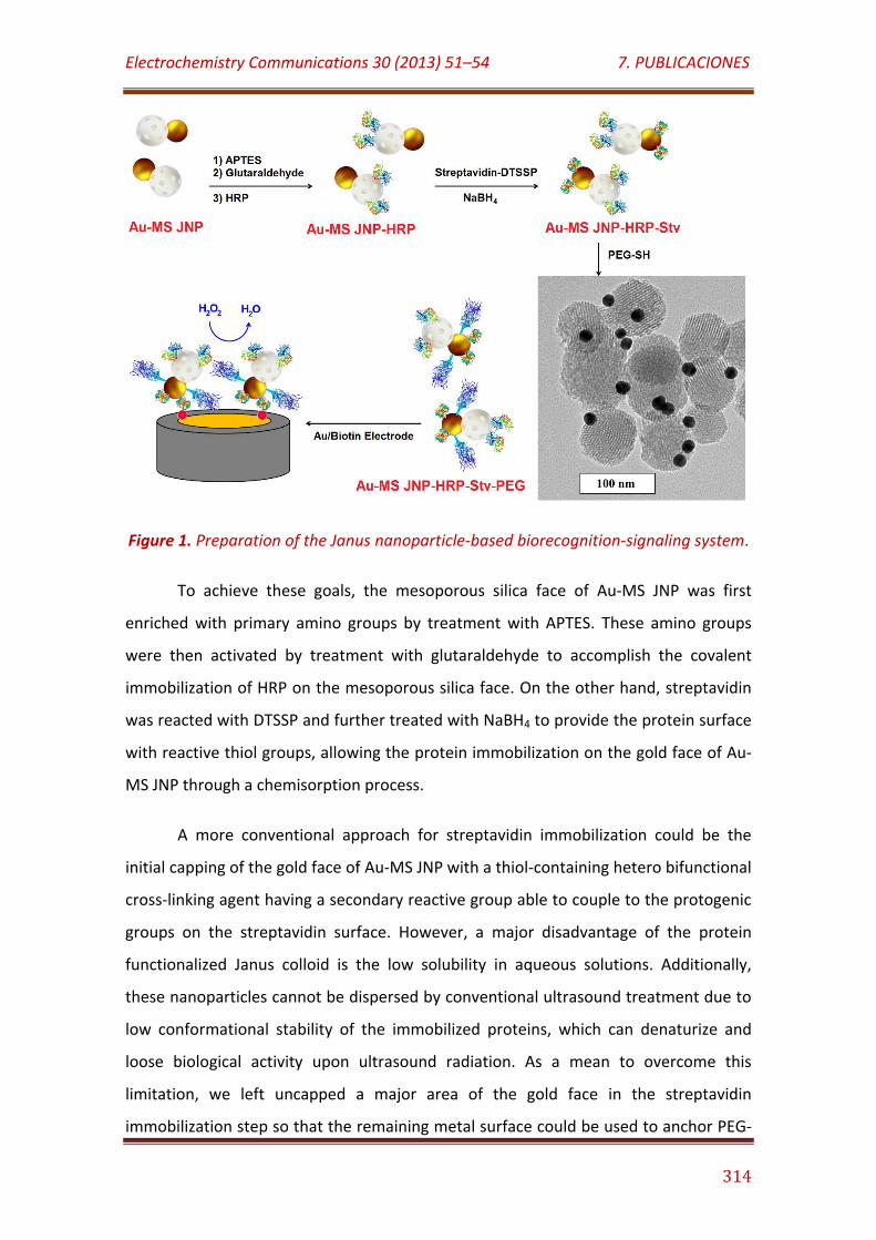
Electrochemistry Communications 30 (2013) 51–54 7. PUBLICACIONES
314
Figure 1. Preparation of the Janus nanoparticle-based biorecognition-signaling system.
To achieve these goals, the mesoporous silica face of Au-MS JNP was first
enriched with primary amino groups by treatment with APTES. These amino groups
were then activated by treatment with glutaraldehyde to accomplish the covalent
immobilization of HRP on the mesoporous silica face. On the other hand, streptavidin
was reacted with DTSSP and further treated with NaBH4 to provide the protein surface
with reactive thiol groups, allowing the protein immobilization on the gold face of Au-
MS JNP through a chemisorption process.
A more conventional approach for streptavidin immobilization could be the
initial capping of the gold face of Au-MS JNP with a thiol-containing hetero bifunctional
cross-linking agent having a secondary reactive group able to couple to the protogenic
groups on the streptavidin surface. However, a major disadvantage of the protein
functionalized Janus colloid is the low solubility in aqueous solutions. Additionally,
these nanoparticles cannot be dispersed by conventional ultrasound treatment due to
low conformational stability of the immobilized proteins, which can denaturize and
loose biological activity upon ultrasound radiation. As a mean to overcome this
limitation, we left uncapped a major area of the gold face in the streptavidin
immobilization step so that the remaining metal surface could be used to anchor PEG-
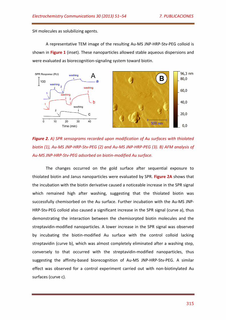
Electrochemistry Communications 30 (2013) 51–54 7. PUBLICACIONES
315
SH molecules as solubilizing agents.
A representative TEM image of the resulting Au-MS JNP-HRP-Stv-PEG colloid is
shown in Figure 1 (inset). These nanoparticles allowed stable aqueous dispersions and
were evaluated as biorecognition-signaling system toward biotin.
Figure 2. A) SPR sensograms recorded upon modification of Au surfaces with thiolated
biotin (1), Au-MS JNP-HRP-Stv-PEG (2) and Au-MS JNP-HRP-PEG (3). B) AFM analysis of
Au-MS JNP-HRP-Stv-PEG adsorbed on biotin-modified Au surface.
The changes occurred on the gold surface after sequential exposure to
thiolated biotin and Janus nanoparticles were evaluated by SPR. Figure 2A shows that
the incubation with the biotin derivative caused a noticeable increase in the SPR signal
which remained high after washing, suggesting that the thiolated biotin was
successfully chemisorbed on the Au surface. Further incubation with the Au-MS JNP-
HRP-Stv-PEG colloid also caused a significant increase in the SPR signal (curve a), thus
demonstrating the interaction between the chemisorpted biotin molecules and the
streptavidin-modified nanoparticles. A lower increase in the SPR signal was observed
by incubating the biotin-modified Au surface with the control colloid lacking
streptavidin (curve b), which was almost completely eliminated after a washing step,
conversely to that occurred with the streptavidin-modified nanoparticles, thus
suggesting the affinity-based biorecognition of Au-MS JNP-HRP-Stv-PEG. A similar
effect was observed for a control experiment carried out with non-biotinylated Au
surfaces (curve c).
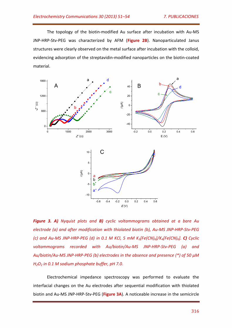
Electrochemistry Communications 30 (2013) 51–54 7. PUBLICACIONES
316
The topology of the biotin-modified Au surface after incubation with Au-MS
JNP-HRP-Stv-PEG was characterized by AFM (Figure 2B). Nanoparticulated Janus
structures were clearly observed on the metal surface after incubation with the colloid,
evidencing adsorption of the streptavidin-modified nanoparticles on the biotin-coated
material.
Figure 3. A) Nyquist plots and B) cyclic voltammograms obtained at a bare Au
electrode (a) and after modification with thiolated biotin (b), Au-MS JNP-HRP-Stv-PEG
(c) and Au-MS JNP-HRP-PEG (d) in 0.1 M KCl, 5 mM K3[Fe(CN)6]/K4[Fe(CN)6]. C) Cyclic
voltammograms recorded with Au/biotin/Au-MS JNP-HRP-Stv-PEG (a) and
Au/biotin/Au-MS JNP-HRP-PEG (b) electrodes in the absence and presence (*) of 50 µM
H2O2 in 0.1 M sodium phosphate buffer, pH 7.0.
Electrochemical impedance spectroscopy was performed to evaluate the
interfacial changes on the Au electrodes after sequential modification with thiolated
biotin and Au-MS JNP-HRP-Stv-PEG (Figure 3A). A noticeable increase in the semicircle
Electrochemistry Communications 30 (2013) 51–54 7. PUBLICACIONES
317
diameter of the Nyquist plot occurred after modification of the electrode surface with
the biotin derivative indicating a high coverage of the electrode surface. A remarkable
further increase of the electron transfer resistance was also apparent after incubation
of the biotin-coated Au electrode with Au-MS JNP-HRP-Stv-PEG, suggesting the
attachment of the modified nanoparticles with significant insulating effect on the
electrode surface. Conversely, a much lower increase in the semicircle diameter was
observed in the Nyquist plot corresponding to the electrode modified with the control
nanoparticle lacking streptavidin.
Similar conclusion was achieved from cyclic voltammetry (Figure 3B), attending
to the decrease in the peak currents observed after sequential modification of the
electrode. By using the Randles-Sevcik equation, the electrochemical surface area of
the Au electrode was estimated to decrease from 3.58 mm2 to 3.30 and 2.13 mm2 after
modification of with thiolated biotin and Au-MS JNP-HRP-Stv-PEG, respectively.
Comparatively, the estimated surface area for the Au/biotin/Au-MS JNP-HRP-PEG
control electrode was 2.89 mm2. These results suggest lower non-specific adsorption
of the nanoparticles non containing streptavidin on the biotin-coated gold surface.
The results achieved in the experiments described above suggested that Au-MS
JNP-HRP-Stv-PEG has the ability to specifically biorecognize biotin residues on an Au
surface. The capacity of this colloid to produce an enzyme-mediated electroanalytical
signal was then estimated by comparing the cyclic voltammetric responses of the
Au/biotin/Au-MS JNP-HRP-PEG and Au/biotin/Au-MS JNP-HRP-Stv-PEG electrodes
upon addition of H2O2. As it is shown in Figure 3C, an increase in the cathodic currents
was observed at both modified electrodes in the presence of 50 µM H2O2. However,
large cathodic currents were appreciated in the electrode modified with Au/biotin/Au-
MS JNP-HRP-Stv-PEG, suggesting higher amount of these nanoparticles adsorbed on
the electrode in which the immobilized HRP was successful to electrocatalyze the
transformation of H2O2.
Electrochemistry Communications 30 (2013) 51–54 7. PUBLICACIONES
318
CONCLUSIONS
A novel nanomaterial-based biorecognition-signaling system was designed by
using Janus nanoparticles with opposite Au and mesoporous silica faces as scaffolds for
the face-selective assembly of HRP and streptavidin. These nanoparticles were
successful evaluated for the affinity-based recognition of biotin attached to gold
surfaces, as revealed by electrochemical and microscopic characterization. Although
this Janus nanoparticles-based biorecognition-signaling system with electrochemical
detection is here proposed as an initial proof-of-concept, it is predictable a direct use
of this nanomaterial in the design of electrochemical immuno- and genosensors via
linking of commercially available biotin-labeled antibodies and nucleic acids.
Acknowledgements
R. Villalonga acknowledge to Ramón & Cajal contract from the Spanish Ministry of
Science and Innovation. Financial support from the Spanish Ministerio de Ciencia e
Innovación CTQ2011-24355, CTQ2012-34238 and Comunidad de Madrid S2009/PPQ-
1642, Programme AVANSENS is gratefully acknowledged.
References
[1] J. Wang, Analyst 130 (2005) 421.
[2] R. Villalonga, M.L. Villalonga, P. Díez, J.M. Pingarrón, J. Mat. Chem. 21 (2011)
12858.
[3] M. Holzinger, L. Bouffier, R. Villalonga, S. Cosnier, Biosens. Bioelectron. 24 (2009)
1128.
[4] J.M. Pingarrón, P. Yáñez-Sedeño, A. González-Cortés, Electrochim. Acta 53 (2008)
5848.
[5] J. Wang, Small 1 (2005) 1036.
[6] P. Biji, A. Patnaik, Analyst 137 (2012) 4795.

Electrochemistry Communications 30 (2013) 51–54 7. PUBLICACIONES
319
[7] S. Jiang, Q. Chen, M. Tripathy, E. Luijten, K.S. Schweizer, S. Granick, Adv. Mater. 22
(2010) 1060.
[8] A. Walther, A.H.E. Müller, Soft Matter 4 (2008) 663.
[9] Y. Zhao, B.G. Trewyn, I.I. Slowing, V.S.Y. Lin, J. Am. Chem. Soc. 131 (2009) 8398.
[10] G. Frens, Nature 241 (1973) 20.
[11] M.L. Conte, S. Pacifico, A. Chambery, A. Marra, A. Dondoni., J. Org. Chem. 75
(2010) 4644.

7.11
Chemistry - A European Journal 19 (24) (2013) 7889–7894
Enzyme-controlled sensing-actuating nanomachine based on Janus Au-Mesoporous silica
nanoparticles

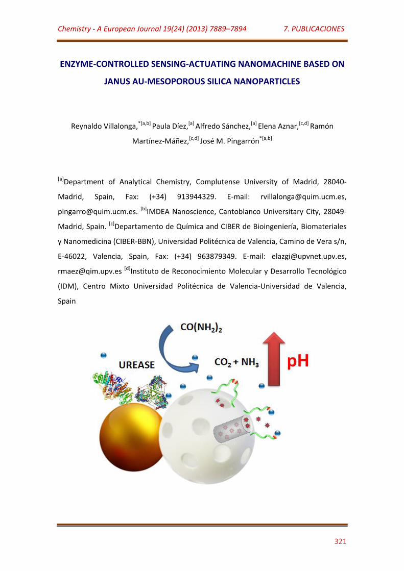
Chemistry - A European Journal 19(24) (2013) 7889–7894 7. PUBLICACIONES
321
ENZYME-CONTROLLED SENSING-ACTUATING NANOMACHINE BASED ON
JANUS AU-MESOPOROUS SILICA NANOPARTICLES
Reynaldo Villalonga,*[a,b] Paula Díez,[a] Alfredo Sánchez,[a] Elena Aznar,[c,d] Ramón
Martínez-Máñez,[c,d] José M. Pingarrón*[a,b]
[a]Department of Analytical Chemistry, Complutense University of Madrid, 28040-
Madrid, Spain, Fax: (+34) 913944329. E-mail: [email protected],
[email protected]. [b]IMDEA Nanoscience, Cantoblanco Universitary City, 28049-
Madrid, Spain. [c]Departamento de Química and CIBER de Bioingeniería, Biomateriales
y Nanomedicina (CIBER-BBN), Universidad Politécnica de Valencia, Camino de Vera s/n,
E-46022, Valencia, Spain, Fax: (+34) 963879349. E-mail: [email protected],
[email protected] [d]Instituto de Reconocimiento Molecular y Desarrollo Tecnológico
(IDM), Centro Mixto Universidad Politécnica de Valencia-Universidad de Valencia,
Spain
Chemistry - A European Journal 19(24) (2013) 7889–7894 7. PUBLICACIONES
322
ABSTRACT
Novel Janus nanoparticles with Au and mesoporous silica opposite faces were
prepared by Pickering emulsion template using paraffin wax as oil phase. These
anisotropic colloids were employed to design an integrated sensing-actuating
nanomachine for the enzyme-controlled stimulus-responsible cargo delivery. As a
proof-of-concept, we demonstrated the successful use of the Janus colloids for
controlled delivery of tris(2,2´-bipyridyl) ruthenium(II) chloride from the mesoporous
silica face grafted with pH-sensitive gate-like scaffoldings. The release was mediated by
the on-demand catalytic decomposition of urea by urease, which was covalently
immobilized on the Au face.
KEYWORDS: Janus nanoparticle, mesoporous silica, molecular gates, controlled
release, enzyme
INTRODUCTION
The development of novel biologically-inspired nanomachines and smart drug
delivery systems is linked to the tailor-made design of advanced nanomaterials with
desired physical properties and chemical functionalities.[1] Among these, particular
interest has been devoted to the preparation of anisotropic colloidal particles which
exhibit two surfaces of different chemical composition.[2] These so-called “Janus
nanoparticles” can be designed to show amphiphilic character as well as anisotropic
electrical, magnetic or optical properties.[3] Additionally, each face of the Janus
nanoparticles can be independently modified with selected ligands allowing specific
functionalization with proteins and other biomacromolecules.[4] These unique
characteristics have favored the successful use of Janus nanomaterials as emulsion
stabilizers, hydrophobic coat for textiles, self-propelled machines, imaging probes, and
drug delivery systems.[5]
On a different approach nanotechnology has proved to bring new innovative
concepts to drug-delivery therapies. Drug delivery systems able to release active
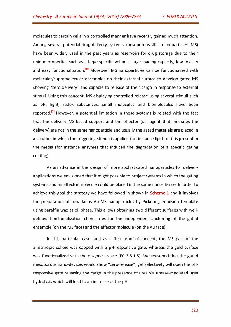
Chemistry - A European Journal 19(24) (2013) 7889–7894 7. PUBLICACIONES
323
molecules to certain cells in a controlled manner have recently gained much attention.
Among several potential drug delivery systems, mesoporous silica nanoparticles (MS)
have been widely used in the past years as reservoirs for drug storage due to their
unique properties such as a large specific volume, large loading capacity, low toxicity
and easy functionalization.[6] Moreover MS nanoparticles can be functionalized with
molecular/supramolecular ensembles on their external surface to develop gated-MS
showing “zero delivery” and capable to release of their cargo in response to external
stimuli. Using this concept, MS displaying controlled release using several stimuli such
as pH, light, redox substances, small molecules and biomolecules have been
reported.[7] However, a potential limitation in these systems is related with the fact
that the delivery MS-based support and the effector (i.e. agent that mediates the
delivery) are not in the same nanoparticle and usually the gated materials are placed in
a solution in which the triggering stimuli is applied (for instance light) or it is present in
the media (for instance enzymes that induced the degradation of a specific gating
coating).
As an advance in the design of more sophisticated nanoparticles for delivery
applications we envisioned that it might possible to project systems in which the gating
systems and an effector molecule could be placed in the same nano-device. In order to
achieve this goal the strategy we have followed in shown in Scheme 1 and it involves
the preparation of new Janus Au-MS nanoparticles by Pickering emulsion template
using paraffin wax as oil phase. This allows obtaining two different surfaces with well-
defined functionalization chemistries for the independent anchoring of the gated
ensemble (on the MS face) and the effector molecule (on the Au face).
In this particular case, and as a first proof-of-concept, the MS part of the
anisotropic colloid was capped with a pH-responsive gate, whereas the gold surface
was functionalized with the enzyme urease (EC 3.5.1.5). We reasoned that the gated
mesoporous nano-devices would show “zero-release”, yet selectively will open the pH-
responsive gate releasing the cargo in the presence of urea via urease-mediated urea
hydrolysis which will lead to an increase of the pH.
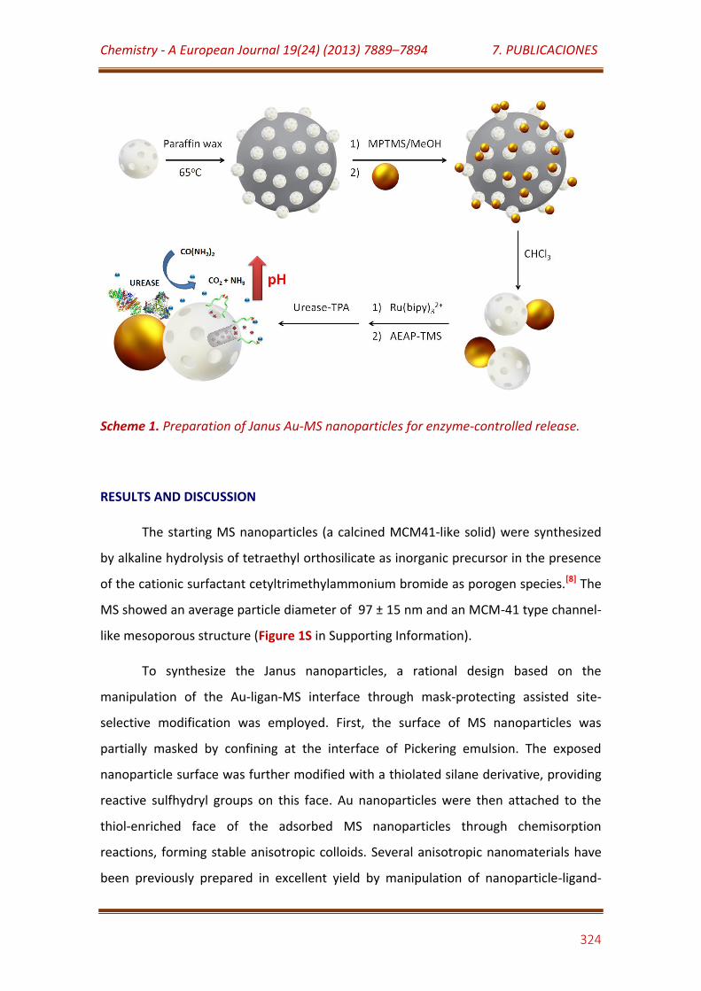
Chemistry - A European Journal 19(24) (2013) 7889–7894 7. PUBLICACIONES
324
Scheme 1. Preparation of Janus Au-MS nanoparticles for enzyme-controlled release.
RESULTS AND DISCUSSION
The starting MS nanoparticles (a calcined MCM41-like solid) were synthesized
by alkaline hydrolysis of tetraethyl orthosilicate as inorganic precursor in the presence
of the cationic surfactant cetyltrimethylammonium bromide as porogen species.[8] The
MS showed an average particle diameter of 97 ± 15 nm and an MCM-41 type channel-
like mesoporous structure (Figure 1S in Supporting Information).
To synthesize the Janus nanoparticles, a rational design based on the
manipulation of the Au-ligan-MS interface through mask-protecting assisted site-
selective modification was employed. First, the surface of MS nanoparticles was
partially masked by confining at the interface of Pickering emulsion. The exposed
nanoparticle surface was further modified with a thiolated silane derivative, providing
reactive sulfhydryl groups on this face. Au nanoparticles were then attached to the
thiol-enriched face of the adsorbed MS nanoparticles through chemisorption
reactions, forming stable anisotropic colloids. Several anisotropic nanomaterials have
been previously prepared in excellent yield by manipulation of nanoparticle-ligand-
Chemistry - A European Journal 19(24) (2013) 7889–7894 7. PUBLICACIONES
325
nanoparticle interfaces in solutions.[9] In the present work, such toposelective
manipulation was performed in a solid-liquid interface.
According to this synthetic scheme, the as-prepared MS were first adsorbed
onto the liquid-liquid interface of an emulsion prepared with water and molten
paraffin wax, forming colloidosomes that remained stable after cooling. [10] Although
the formation of such colloidosomes was previously reported using silica nanoparticles
with average diameters larger than 400 nm,[10,11] we have proved here that this
procedure can also be also used using MS nanoparticles of smaller diameter.
The toposelective modification of the MS nanoparticles adsorbed onto the
colloidosome surface was performed by reaction with (3-mercaptopropyl)-
trimethoxysilane in water:methanol solution. After exhaustive washing, the
colloidosomes containing the thiol-functionalized MS nanoparticles were stirred in Au
nanoparticles solution. Janus Au-MS nanoparticles were finally obtained with
acceptable yield (about 85% for J2 sample) after dissolving the paraffin wax in CHCl3.
Figure 1 shows the TEM images of Janus colloids prepared by using Au
nanoparticles of different sizes: 3.7 ± 0.8 nm (J1),[12] 20 ± 2 nm (J2), 31 ± 6 nm (J3) and
43 ± 5 nm (J4).[13] In all cases, anisotropic colloids were successfully synthesized, mainly
with a 1:1 Au:MS nanoparticles ratio except for J1 samples in which the use of smaller
Au nanospheres favored the attachment of more than one metal nanoparticle to the
same MS colloid. J1 nanoparticles showed similar average diameter (98 ± 17 nm) and
size distribution than the native MS colloid, with only slight difference at higher values
of diameter (Figure 2S in Supporting Information). This fact can be justified by the
small diameter and low polydispersity of the attached Au nanoparticles. Moreover, J1
anisotropic colloids showed low metal content, which should be counterproductive for
the further immobilization of urease and the preparation of the enzyme-controlled
nanomachines.
Chemistry - A European Journal 19(24) (2013) 7889–7894 7. PUBLICACIONES
326
Figure 1. TEM images of J1 (A), J2 (B), J3 (C) and J4 (D) Janus Au-MS nanoparticles.
Large average diameter and broad size distribution was observed for J3 (117 ±
19 nm) and J4 (126 ± 23 nm) nanoparticles. This could be ascribed to the large
diameter and size dispersion of Au nanoparticles prepared by Frens method using low
citrate concentration, [13] which often yield nanoparticles with non-spherical shape. In
J4 samples, prepared using large Au nanoparticles,[13] it was observed that some Au
nanoparticles were assembled to more than one MS nanoparticle, yielding aggregated
structures. This fact could be justified by the close packing of the MS nanoparticles
onto the colloidosome surface, allowing the interaction of several thiol-modified
mesoporous colloids with the same large and non-spherical Au nanoparticle. It should
be highlighted that sample J2 (104 ± 17 nm) showed narrow distribution of size and
maximum yield of Au-MS anisotropic nanoparticles with 1:1 ratio, and accordingly this
Janus colloid was selected for further experiments. A representative TEM image
corresponding to J2 nanoparticles is shown in Figure 2. Other different TEM images of
J2 nanoparticles are also shown in Figure 3S in Supporting Information.

Chemistry - A European Journal 19(24) (2013) 7889–7894 7. PUBLICACIONES
327
Figure 2. Representative TEM image of J2 nanoparticles
The pore morphologies of the MS and Janus Au-MS nanoparticles in the J2
nanoparticles were determined by nitrogen adsorption/desorption surface analysis
(BET isotherms and BJH pore size distributions). Figure 3A illustrates the corresponding
nitrogen adsorption/desorption isotherms and the pore size distributions for the
starting MS material and for the corresponding J2 Janus nanoparticles. Both
nanomaterials showed type IV isotherms typical of mesoporous supports.
The absence of hysteresis loops for MS nanoparticles suggested that all pores
are highly accessible. On the contrary, the small hysteresis loops observed at high
relative pressure values in the Janus nanoparticle isotherm suggested that some pores
were partially blocked most likely due to the toposelective silanization with (3-
mercaptopropyl)trimethoxysilane and the attachment of the Au nanoparticles. In fact
the attachment of Au nanoparticles on one face of the siliceous matrix reduced the
BET specific surface area from 1037 m²/g in the starting MS to 820 m²/g in J2. Yet the
average pore size of the MS support (ca. 2.5 nm) was unchanged after formation of the
anisotropic colloid (see inset of Figure 3A).
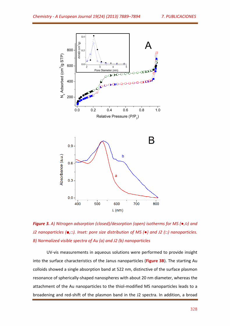
Chemistry - A European Journal 19(24) (2013) 7889–7894 7. PUBLICACIONES
328
Figure 3. A) Nitrogen adsorption (closed)/desorption (open) isotherms for MS (,) and
J2 nanoparticles (,). Inset: pore size distribution of MS () and J2 () nanoparticles.
B) Normalized visible spectra of Au (a) and J2 (b) nanoparticles
UV-vis measurements in aqueous solutions were performed to provide insight
into the surface characteristics of the Janus nanoparticles (Figure 3B). The starting Au
colloids showed a single absorption band at 522 nm, distinctive of the surface plasmon
resonance of spherically-shaped nanospheres with about 20 nm diameter, whereas the
attachment of the Au nanoparticles to the thiol-modified MS nanoparticles leads to a
broadening and red-shift of the plasmon band in the J2 spectra. In addition, a broad
Chemistry - A European Journal 19(24) (2013) 7889–7894 7. PUBLICACIONES
329
shoulder band from 585 nm to 630 nm was also observed in the spectrum of J2 which
can be tentatively attributed to the attachment of more than one Au nanospheres on
the surface of the MS nanoparticles in some Janus particles, causing a coupling of the
plasma modes due to metal particle-particle interactions. [14]
J2 colloid was further employed as nanosized hardware for the assembly of a
self-controlled nanomachine able to release a cargo compound by an enzyme-based
pH-mediated mechanism. In a first step J2 nanoparticles were loaded with tris(2,2´-
bipyridyl)ruthenium(II) chloride ([Ru(bpy)3]2+) as model dye for monitoring cargo
delivery.[7c] Thereafter, an excess of the alkyl amino derivative 3-(2-
aminoethylamino)propyltrimethoxysilane (the pH-responsive molecular gate) was
anchored on the external surface of the mesoporous face to yield the J2Ru
nanomaterial.[7a] It should be mentioned that Janus nanoparticles exhibited good
water solubility, but its stability in aqueous solutions was reduced after modification
with 3-(2-aminoethylamino)propyltrimethoxysilane.
Thermal analysis of the MS, J2 and J2Ru nanomaterials was accomplished, the
TG/DTG curves being displayed in Figures 4S-A,B (see Supporting Information). The
unmodified MS nanoparticles exhibited a slight weight loss at temperatures up to ca.
70ºC, which was attributed to the thermodesorption of physically adsorbed water
molecules from the silica surface. At higher temperatures no weight loss was apparent
showing relatively flat TG/DTG curves.[15] Janus nanoparticles showed a more
noticeable weight loss at temperatures up to ca. 140ºC suggesting that higher amount
of water molecules were adsorbed on the Au nanoparticles surface. The anisotropic
nanoparticle exhibited a second thermal-induced transformation, with maximum rate
of weight loss at approximately 275ºC, which could be associated with the
decomposition of the bonded thiol ligands but also with the condensation of the
ligand's side silanols with one another or with surface silanols.
In comparison with J2, the weight loss profile for J2Ru exhibited a lower
decrease at T < 120ºC, suggesting lower amount of water molecules physically
adsorbed on this nanomaterial. This fact could be justified by the azeotropic treatment
of the Janus nanoparticles before adsorption of the [Ru(bpy)3]2+ complex and
Chemistry - A European Journal 19(24) (2013) 7889–7894 7. PUBLICACIONES
330
silanization with 3-(2-aminoethylamino)propyltrimethoxysilane, as well as to the
introduction of the long chain aminosilane groups on the MS face. The weight loss at
higher temperatures can be divided into two regions. The first region, with maximum
rate of weight loss at 245ºC, could be attributed to decomposition/condensation of
the bounded ligands. The second thermal-induced process, which showed a maximum
rate of transformation at about 330ºC, could be associated with the decomposition of
the [Ru(bpy)3]2+ complex, which is thermally stable up to 320 °C.[16] The loading of the
[Ru(bpy)3]Cl2 dye in the J2Ru material amounted to 62 mg/g J2Ru in weight, as
determined by the TG curve. Moreover the content of the anchored amine-based gate
amounted to 49 mg/ g J2Ru in weight.
Figure 5S-A in Supporting Information shows an FT-IR spectrum of the MS, J2 and J2Ru
nanoparticles. MS nanoparticles showed the characteristics IR absorption bands of
siliceous materials at 456 cm-1 attributed to the vibration of the Si-O bonds, a shoulder
at 576 cm-1 ascribed to cyclic Si-O-Si structures, at 803 cm-1 attributed to SiO4
tetrahedrons, at 946 cm-1 attributed to the Si-OH groups, and a band at 1080 cm-1
with a shoulder at 1200 cm-1 ascribed to the bond stretching vibrations of Si-O-Si.[17]
The broad band at 3700-3000 cm-1 can be ascribed to the O-H bonding vibration of
adsorbed water and SiO-H groups, and the band at 1629 cm-1 is attributed to the
deformation vibration of the HO-H bond in water molecules.
Spectrum of J2 nanoparticles presented the antisymmetric and symmetric stretching
vibrations of the CH2 groups at 2933 cm-1 and 2856 cm-1, confirming the modification
of the MS nanomaterial with (3-mercaptopropyl)trimethoxysilane. The absence of the
characteristic bands of S-H vibration in the range of 2500-2600 cm−1 suggested that the
thiol groups were chemisorpted to the Au nanoparticle surface. Loading of J2 with
[Ru(bpy)3]2+ and derivatization with 3-(2-aminoethylamino)propyltrimethoxysilane
was further confirmed by the bands at 2946 cm-1 and 2859 cm-1 ([C-H]), 1633 cm-1 ([N-
H]), 1568 cm-1 ([C-C] + [C=C-H]), 1480 cm-1 ([C-C] + [C=C-H]) and 1319 cm-1 ([NC-H]) in the
J2Ru spectrum.[18] Another important characteristic is the drop in intensity of the band
around 950 cm-1, which is attributed to the vibration of the silanol groups, confirming
the modification of the mesoporous silica surface with the amine-bearing silane.[7a]
Chemistry - A European Journal 19(24) (2013) 7889–7894 7. PUBLICACIONES
331
The powder X-ray diffraction patterns of J2 and J2Ru are shown in Figure 5S-B
(see Supporting Information). The low angle diffractogram of J2 shows four
distinguishable peaks at 2.59º, 4.30º, 4.93º and 6.46º which correspond to (100),
(110), (200) and (210) of MCM-41 with d-spacing values of 3.40 nm, 2.05 nm, 1.79 nm
and 1.37 nm, respectively. This pattern suggested perfect long-range order in this
mesoporous nanomaterial. Additionally, from these data and the pore value diameter
obtained from nitrogen adsorption isotherms, an a0 cell parameter of 3.93 nm and a
pore wall thickness of 1.40 nm can be calculated. Moreover, the diffraction pattern of
J2 at high angle showed three peaks at 38.34º, 44.50º and 81.21º, corresponding to
the (111), (200) and (222) Bragg reflections for cubic gold nanocrystals,[19] confirming
the Janus architecture previously observed by TEM. J2Ru sample showed similar X-ray
diffraction pattern, suggesting that the loading process with the dye and the further
functionalization with amine groups did not damage neither the mesoporous MCM-41
type structure nor of the gold face of the Janus colloid.[7c]
In order to prepare the self-controlled enzyme-powered nanodevice for cargo
delivery, the Au face of the Jan2Ru nanoparticles were functionalized with the enzyme
urease. For preparing an enzyme form suitable to be anchored on the metal surface,
urease was covalently modified with 3,3´-dithiobis(sulfosuccinimidylpropionate)
(DTSSP). After reduction of the dithiol linkage with NaBH4, the modified enzyme
solution was dialyzed and finally incubated with J2Ru to yield the J2Ru-U nanomaterial.
All these processes were performed in 50 mM sodium phosphate buffer, pH 7.0, at
4ºC.
The ability of J2Ru-U nanoparticle to deliver the [Ru(bpy)3]2+ dye under urease
control was tested in 5 mM sodium acetate buffer at pH 4.0 and 5.0. It is well know
that the pH-activity profile of urease has a bell-shaped behavior with maximum at pH
7.0.[20] However, more than 66% of the 3-(2-aminoethylamino) propyltrimethoxysilane
grafting moieties on the MS surface are unprotonated at this pH value [7a] then the
gate-like ensembles was partially open. To avoid this undesirable effect, we used
buffer solution of pH 5.0 where urease retains about 60% of its maximum catalytic
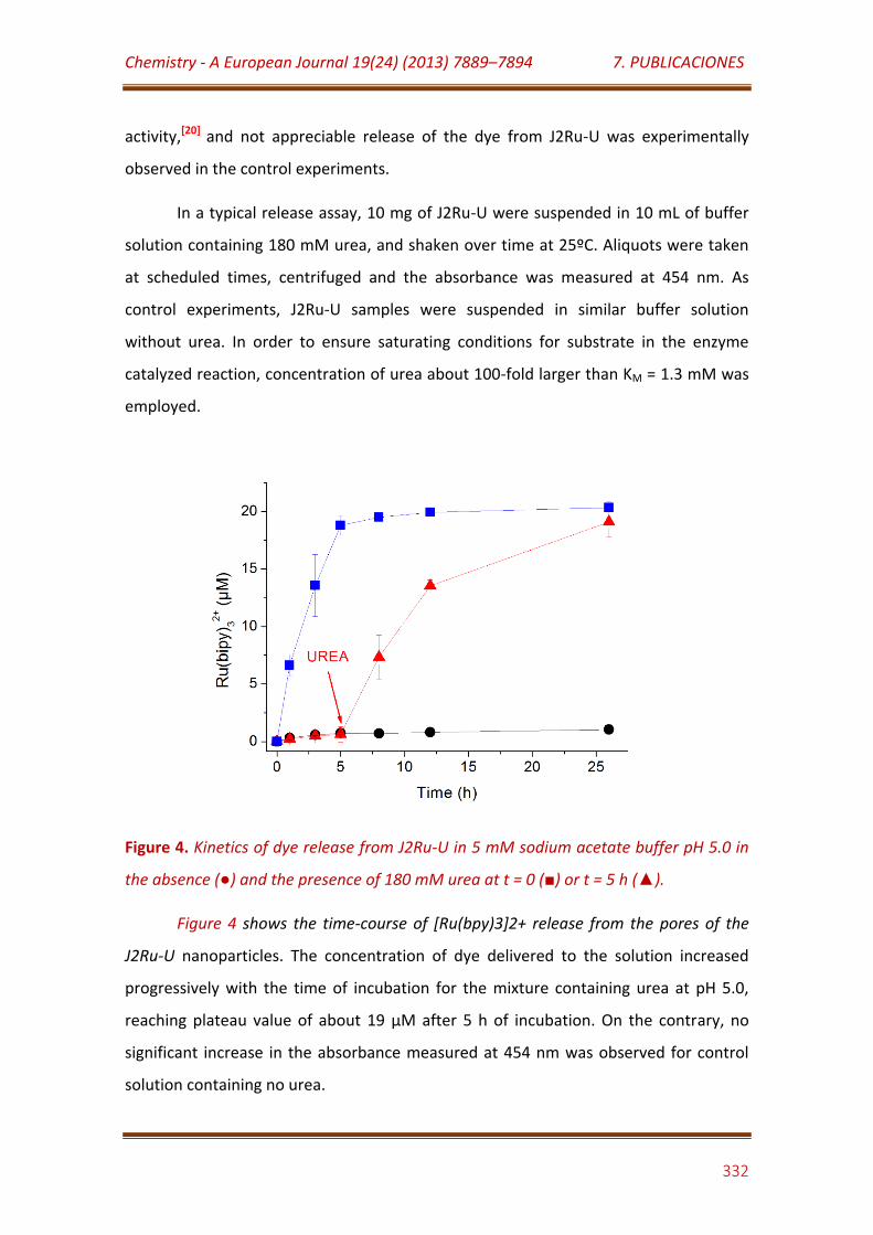
Chemistry - A European Journal 19(24) (2013) 7889–7894 7. PUBLICACIONES
332
activity,[20] and not appreciable release of the dye from J2Ru-U was experimentally
observed in the control experiments.
In a typical release assay, 10 mg of J2Ru-U were suspended in 10 mL of buffer
solution containing 180 mM urea, and shaken over time at 25ºC. Aliquots were taken
at scheduled times, centrifuged and the absorbance was measured at 454 nm. As
control experiments, J2Ru-U samples were suspended in similar buffer solution
without urea. In order to ensure saturating conditions for substrate in the enzyme
catalyzed reaction, concentration of urea about 100-fold larger than KM = 1.3 mM was
employed.
Figure 4. Kinetics of dye release from J2Ru-U in 5 mM sodium acetate buffer pH 5.0 in
the absence () and the presence of 180 mM urea at t = 0 () or t = 5 h ().
Figure 4 shows the time-course of [Ru(bpy)3]2+ release from the pores of the
J2Ru-U nanoparticles. The concentration of dye delivered to the solution increased
progressively with the time of incubation for the mixture containing urea at pH 5.0,
reaching plateau value of about 19 µM after 5 h of incubation. On the contrary, no
significant increase in the absorbance measured at 454 nm was observed for control
solution containing no urea.
Chemistry - A European Journal 19(24) (2013) 7889–7894 7. PUBLICACIONES
333
Urease catalyzed the transformation of urea to CO2 and NH3 yielding a
progressive increase in the pH value of the incubation solutions, as it was qualitatively
demonstrated by adding bromothymol blue to control assays. As it was previously
reported, the 3-(2-aminoethylamino)propyltrimethoxysilane moieties located on the
MS surface became gradually deprotonated when the solution pH reached alkaline
values.[7a] Consequently, the nanoscopic molecular gates located at the pore outlets
trended to be opened favoring the release of the dye.
To provide insight into this enzyme-controlled dye release mechanism, J2Ru-U
nanomaterials were incubated in buffer solution without urea under the conditions
described above. Urea (180 mM final solution) was then added after 5 h of incubation,
the results being shown in Figure 4. No appreciable dye release was observed during
the first 5 h of incubation but the further increase in the absorbance at 454 nm
revealed that the dye was successfully delivered to the solution after adding urea.
CONCLUSION
In summary, we described the preparation of Janus-type nanoparticles having
Au and MS opposite faces and have used them for the design of an integrated nano-
device containing on the same nanoparticle a gating systems and an effector molecule
for the stimulus-responsible delivery of a cargo. In this particular case, as a proof-of-
concept the release was mediated by the on-demand catalytic decomposition of urea
by the enzyme urease, which was immobilized on the Au face, whereas the gated
ensemble consisted of a pH-responsive system which was anchored on the pore
outlets of the MS phase. In spite of the many reports dealing with the preparation of
silica-based anisotropic colloids, approaches to produce MS-based Janus nanoparticles
and their evaluation as on-demand control release systems are scarce to our
knowledge. We believe that the possibility of incorporate different effector molecules
and gated ensembles on this Janus-type integrated nanoarchitecture, which
constitutes a proof-of-concept, open new routes for the development of novel
biologically-inspired smart nanomachines for drug delivery and sensing applications
and research is this line is currently being performed by us.
Chemistry - A European Journal 19(24) (2013) 7889–7894 7. PUBLICACIONES
334
EXPERIMENTAL SECTION
1. Preparation of MS nanoparticles:[8]
Cetyltrimethylammonium bromide (3.0 g) was dissolved in 1.44 L of water
under sonication. NaOH solution (2.0 mol/L, 10.5 mL) was then added and the
temperature of the mixture was adjusted to 80 ºC. Tetraethoxysilane (15.0 mL) was
added dropwise to the surfactant solution within 5 min under vigorous magnetic
stirring. The mixture was allowed to react for 2 h. The resulting white solid was
filtered, washed with water and methanol, and then dried in desiccator. The solid was
finally calcinated at 550 ºC for 5 h.
2. Preparation of 3.7 nm Au nanoparticles:[12]
An ice-cold, freshly prepared 0.1 M NaBH4 solution (600 µL) was quickly added
to 20 mL aqueous solution containing 300 µM HAuCl4 and 300 µM trisodium citrate
under continuous stirring. The mixture was stirred for 30 min, and 100-fold diluted
with 300 µM trisodium citrate before J1 preparation.
3. Preparation of 18 nm, 29 nm and 41 nm Au nanoparticles:[13]
Freshly prepared 3 µM HAuCl4 solutions (50 µL) were heated to boiling. Au
nanoparticles of 18 nm, 29 nm and 41 nm were synthesized by adding 750 µL, 500 µL
and 300 µL of 3.9 µM trisodium citrate solution, respectively. The mixtures were
heated for 10 min, cooled to room temperature and finally raised to 50 mL with
ultrapure water.
Preparation of Janus Au-MS nanoparticles: Janus nanoparticles were synthesized by
adapting two methods previously reported in literature.[10] MS nanoparticles (200 mg)
were dispersed homogeneously in 10 mL of 1.0 µM of CTAB in 6.7% ethanol aqueous
solution. The mixture was heated at 75ºC and then 1 g of paraffin wax was added.
Chemistry - A European Journal 19(24) (2013) 7889–7894 7. PUBLICACIONES
335
When the paraffin wax was melted, the mixture was vigorously mixed at 25000 rpm
during 2 min using an Ultra-Turrax T-10 homogenizer (IKA, Germany). The resulting
emulsion was further mixed during 5 min at 4000 rpm and 75 ºC, using the same
apparatus. The resulting Pickering emulsion was then cooled to room temperature,
mixed with 10 mL methanol and treated with 200 µL of (3-
mercaptopropyl)trimethoxysilane. After 3 h under magnetic stirring, the silanized
emulsion was filtered, three-times washed with methanol and further dispersed in 400
mL of the corresponding 3 µM Au nanoparticles aqueous solutions. The mixture was
stirred overnight, then filtered and exhaustively washed with ultrapure water. The
solid was suspended in ethanol, centrifuged and washed two-times with ethanol and
three-times with chloroform. The Janus nanoparticles were finally dried and kept in
dissecator until use.
4. Preparation of J2Ru-U:
To synthesize J2Ru, 100 mg of J2 and 60 mg of tris(2,2´-bipyridyl)ruthenium(II)
chloride hexahydrate were suspended in 10 mL of anhydrous acetonitrile inside a
round-bottom flask connected to a Dean-Stark trap under Ar atmosphere.[7a] The
suspension was refluxed at 110 °C in azeotropic distillation, collecting about 4 mL in
the trap in order to remove the adsorbed water. The mixture was stirred for 24 h at
room temperature to load the dye into the MS face pores. Afterward, an excess of 3-
(2-aminoethylamino)propyltrimethoxysilane (500 µL) was added, and the suspension
was stirred for 5.5 h. Finally, the orange solid (J2Ru) was filtered off, washed two times
with 30 mL of CH3CN, and dried at 70 °C for 12 h.
To synthesize J2Ru-U, 4.0 mg of urease and 4.0 mg of 3,3´-dithiobis-
(sulfosuccinimidylpropionate) were dissolved in 5.0 mL of 50 mM sodium phosphate
buffer, pH 7.0, and stirred during 2 h at 4 ºC. Afterward, 200 µL of 100 mM NaBH4
solution were added, and the mixture was stirred at 4 ºC for 30 min. The solution was
exhaustively dialyzed vs. 50 mM sodium phosphate buffer, pH 7.0 using Amicon Ultra-
05 centrifugal filter units with Ultracel-10 membranes (Millipore, USA), and finally
concentrated to about 10 mg/mL concentration. The modified enzyme solution was
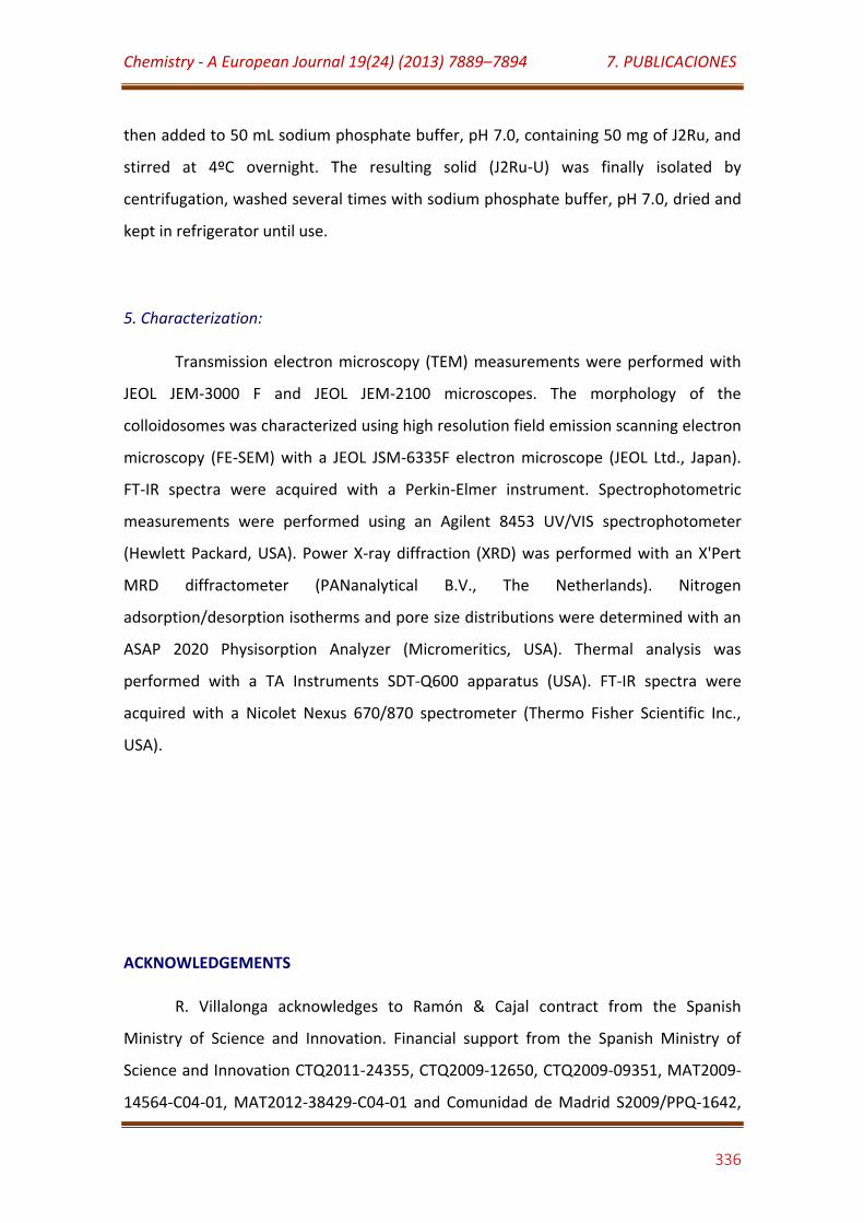
Chemistry - A European Journal 19(24) (2013) 7889–7894 7. PUBLICACIONES
336
then added to 50 mL sodium phosphate buffer, pH 7.0, containing 50 mg of J2Ru, and
stirred at 4ºC overnight. The resulting solid (J2Ru-U) was finally isolated by
centrifugation, washed several times with sodium phosphate buffer, pH 7.0, dried and
kept in refrigerator until use.
5. Characterization:
Transmission electron microscopy (TEM) measurements were performed with
JEOL JEM-3000 F and JEOL JEM-2100 microscopes. The morphology of the
colloidosomes was characterized using high resolution field emission scanning electron
microscopy (FE-SEM) with a JEOL JSM-6335F electron microscope (JEOL Ltd., Japan).
FT-IR spectra were acquired with a Perkin-Elmer instrument. Spectrophotometric
measurements were performed using an Agilent 8453 UV/VIS spectrophotometer
(Hewlett Packard, USA). Power X-ray diffraction (XRD) was performed with an X'Pert
MRD diffractometer (PANanalytical B.V., The Netherlands). Nitrogen
adsorption/desorption isotherms and pore size distributions were determined with an
ASAP 2020 Physisorption Analyzer (Micromeritics, USA). Thermal analysis was
performed with a TA Instruments SDT-Q600 apparatus (USA). FT-IR spectra were
acquired with a Nicolet Nexus 670/870 spectrometer (Thermo Fisher Scientific Inc.,
USA).
ACKNOWLEDGEMENTS
R. Villalonga acknowledges to Ramón & Cajal contract from the Spanish
Ministry of Science and Innovation. Financial support from the Spanish Ministry of
Science and Innovation CTQ2011-24355, CTQ2009-12650, CTQ2009-09351, MAT2009-
14564-C04-01, MAT2012-38429-C04-01 and Comunidad de Madrid S2009/PPQ-1642,
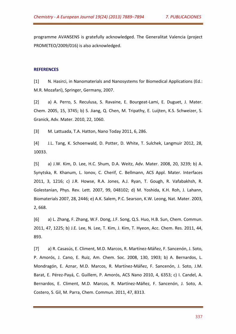
Chemistry - A European Journal 19(24) (2013) 7889–7894 7. PUBLICACIONES
337
programme AVANSENS is gratefully acknowledged. The Generalitat Valencia (project
PROMETEO/2009/016) is also acknowledged.
REFERENCES
[1] N. Hasirci, in Nanomaterials and Nanosystems for Biomedical Applications (Ed.:
M.R. Mozafari), Springer, Germany, 2007.
[2] a) A. Perro, S. Reculusa, S. Ravaine, E. Bourgeat-Lami, E. Duguet, J. Mater.
Chem. 2005, 15, 3745; b) S. Jiang, Q. Chen, M. Tripathy, E. Luijten, K.S. Schweizer, S.
Granick, Adv. Mater. 2010, 22, 1060.
[3] M. Lattuada, T.A. Hatton, Nano Today 2011, 6, 286.
[4] J.L. Tang, K. Schoenwald, D. Potter, D. White, T. Sulchek, Langmuir 2012, 28,
10033.
[5] a) J.W. Kim, D. Lee, H.C. Shum, D.A. Weitz, Adv. Mater. 2008, 20, 3239; b) A.
Synytska, R. Khanum, L. Ionov, C. Cherif, C. Bellmann, ACS Appl. Mater. Interfaces
2011, 3, 1216; c) J.R. Howse, R.A. Jones, A.J. Ryan, T. Gough, R. Vafabakhsh, R.
Golestanian, Phys. Rev. Lett. 2007, 99, 048102; d) M. Yoshida, K.H. Roh, J. Lahann,
Biomaterials 2007, 28, 2446; e) A.K. Salem, P.C. Searson, K.W. Leong, Nat. Mater. 2003,
2, 668.
[6] a) L. Zhang, F. Zhang, W.F. Dong, J.F. Song, Q.S. Huo, H.B. Sun, Chem. Commun.
2011, 47, 1225; b) J.E. Lee, N. Lee, T. Kim, J. Kim, T. Hyeon, Acc. Chem. Res. 2011, 44,
893.
[7] a) R. Casasús, E. Climent, M.D. Marcos, R. Martínez-Máñez, F. Sancenón, J. Soto,
P. Amorós, J. Cano, E. Ruiz, Am. Chem. Soc. 2008, 130, 1903; b) A. Bernardos, L.
Mondragón, E. Aznar, M.D. Marcos, R. Martínez-Máñez, F. Sancenón, J. Soto, J.M.
Barat, E. Pérez-Payá, C. Guillem, P. Amorós, ACS Nano 2010, 4, 6353; c) I. Candel, A.
Bernardos, E. Climent, M.D. Marcos, R. Martínez-Máñez, F. Sancenón, J. Soto, A.
Costero, S. Gil, M. Parra, Chem. Commun. 2011, 47, 8313.

Chemistry - A European Journal 19(24) (2013) 7889–7894 7. PUBLICACIONES
338
[8] Y. Zhao, B.G. Trewyn, I.I. Slowing, V.S.Y. Lin, J. Am. Chem. Soc. 2009, 131, 8398.
[9] Y. Feng, J. He, H. Wang, Y.Y. Tay, H. Sun, L. Zhu, H. Chen, J. Am. Chem. Soc.
2012, 134, 2004; T. Chen, G. Chen, S. Xing, T. Wu, H. Chen, Chem. Mat. 2010, 22, 3826.
[10] L. Hong, S. Jiang, S. Granick, Langmuir 2006, 22, 9495; A. Perro, F. Meunier, V.
Schmitt, S. Ravaine, Colloids Surf. A 2009, 332, 57.
[11] D. Rodríguez-Fernández, J. Pérez-Juste, I. Pastoriza-Santos, L.M. Liz-Marzán,
ChemistryOpen 2012, 1, 90.
[12] N.R. Jana, L. Gearheart, C.J. Murphy, Langmuir 2001, 17, 6782.
[13] G. Frens, Nature 1973, 241, 20.
[14] S.K. Ghosh, T. Pal, Chem. Rev. 2007, 107, 4797.
[15] a) C.P. Jaroniec, M. Kruk, M. Jaroniec, A. Sayari, J. Phys. Chem. B 1998, 102,
5503; b) C.P. Jaroniec, R.K. Gilpin, M. Jaroniec, J. Phys. Chem. B 1997, 101, 6861.
[16] P. Innocenzi, H. Kozuka, T. Yoko, J. Phys. Chem. B 1997, 101, 2285.
[17] M. Stefanescu, M. Stoia, O. Stefanescu, J. Sol-Gel Sci. Techn. 2007, 41, 71.
[18] M. Ammam, E.B. Easton, Sens. Actuators B 2012, 161, 520.
[19] D.V. Leff, L. Brandt, J.R. Heath, Langmuir 1996, 12, 4723.
[20] B. Sahoo, S.K. Sahu, P. Pramanik, J. Mol. Catal. B: Enzym. 2011, 69, 95.
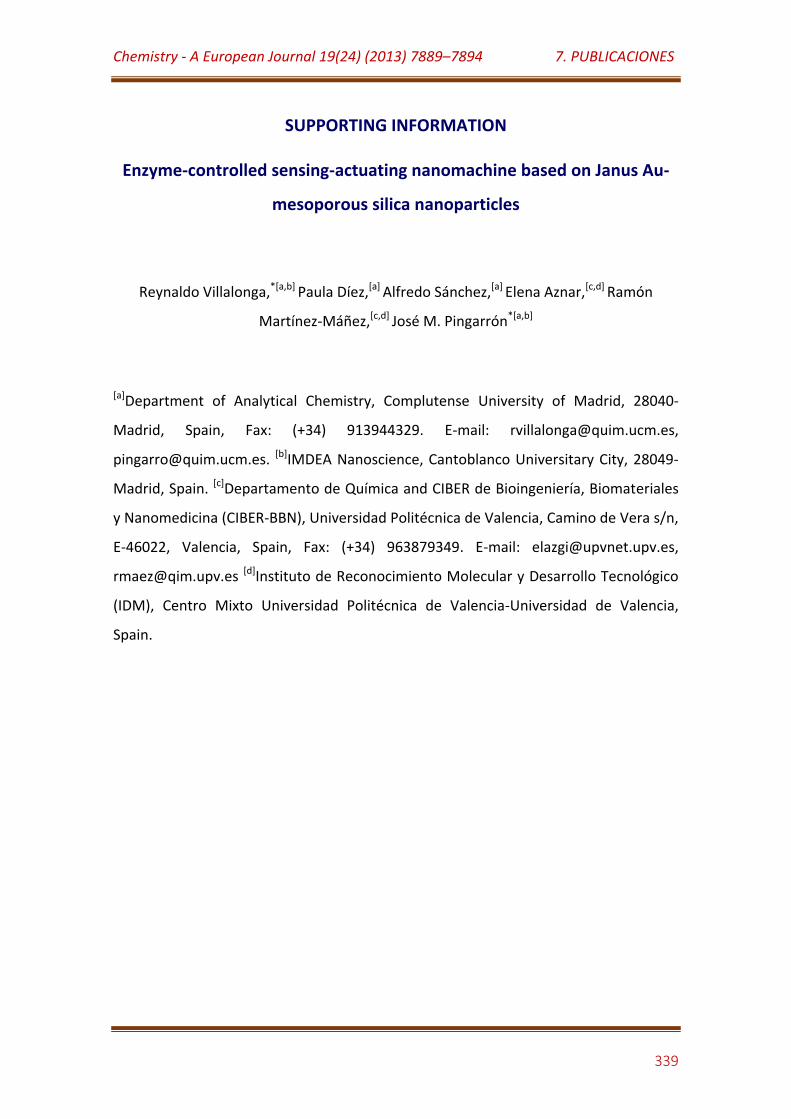
Chemistry - A European Journal 19(24) (2013) 7889–7894 7. PUBLICACIONES
339
SUPPORTING INFORMATION
Enzyme-controlled sensing-actuating nanomachine based on Janus Au-
mesoporous silica nanoparticles
Reynaldo Villalonga,*[a,b] Paula Díez,[a] Alfredo Sánchez,[a] Elena Aznar,[c,d] Ramón
Martínez-Máñez,[c,d] José M. Pingarrón*[a,b]
[a]Department of Analytical Chemistry, Complutense University of Madrid, 28040-
Madrid, Spain, Fax: (+34) 913944329. E-mail: [email protected],
[email protected]. [b]IMDEA Nanoscience, Cantoblanco Universitary City, 28049-
Madrid, Spain. [c]Departamento de Química and CIBER de Bioingeniería, Biomateriales
y Nanomedicina (CIBER-BBN), Universidad Politécnica de Valencia, Camino de Vera s/n,
E-46022, Valencia, Spain, Fax: (+34) 963879349. E-mail: [email protected],
[email protected] [d]Instituto de Reconocimiento Molecular y Desarrollo Tecnológico
(IDM), Centro Mixto Universidad Politécnica de Valencia-Universidad de Valencia,
Spain.
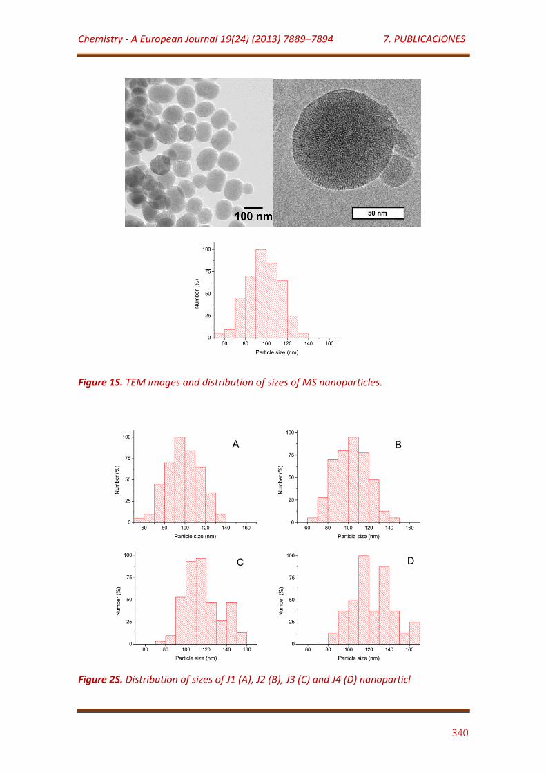
Chemistry - A European Journal 19(24) (2013) 7889–7894 7. PUBLICACIONES
340
Figure 1S. TEM images and distribution of sizes of MS nanoparticles.
Figure 2S. Distribution of sizes of J1 (A), J2 (B), J3 (C) and J4 (D) nanoparticl
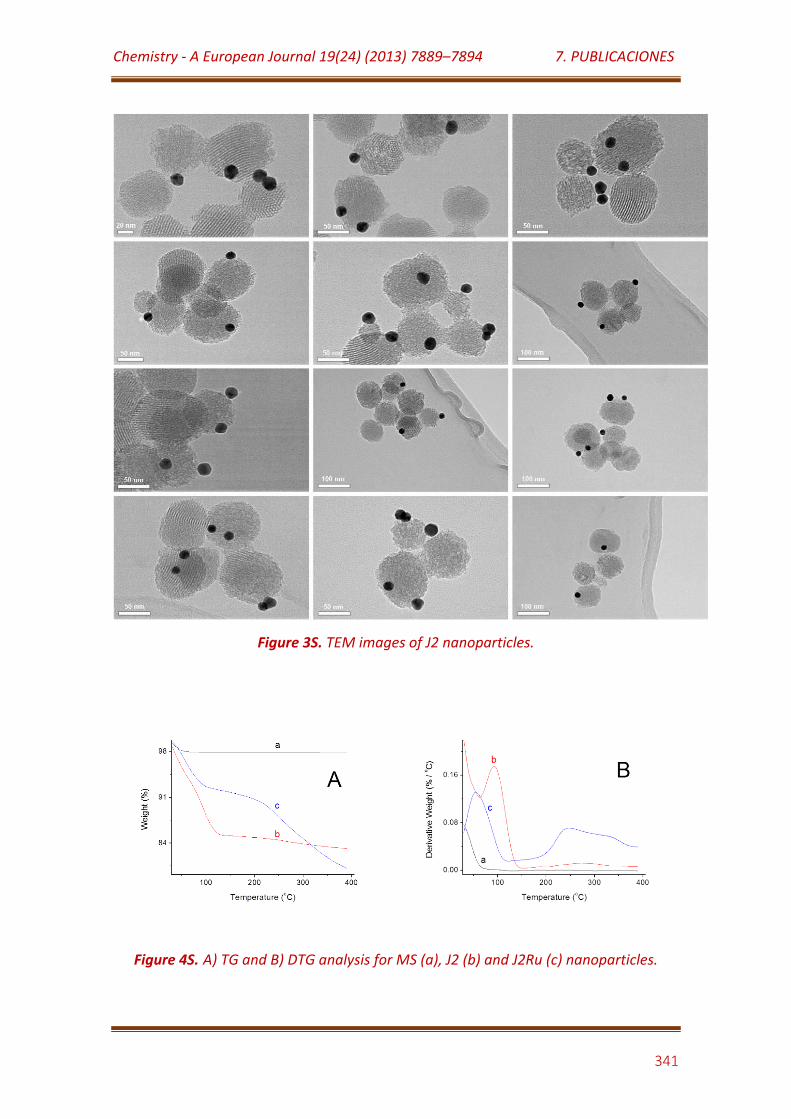
Chemistry - A European Journal 19(24) (2013) 7889–7894 7. PUBLICACIONES
341
Figure 3S. TEM images of J2 nanoparticles.
Figure 4S. A) TG and B) DTG analysis for MS (a), J2 (b) and J2Ru (c) nanoparticles.
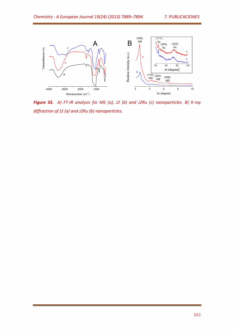
Chemistry - A European Journal 19(24) (2013) 7889–7894 7. PUBLICACIONES
342
Figure 5S. A) FT-IR analysis for MS (a), J2 (b) and J2Ru (c) nanoparticles. B) X-ray
diffraction of J2 (a) and J2Ru (b) nanoparticles.
7.12
Journal of the American Chemical Society 136 (25) (2014) 9116–9123
Towards the design of smart delivery systems controlled by
integrated enzyme-based biocomputing ensembles

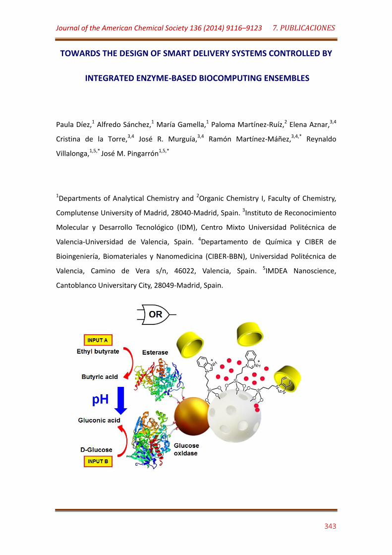
Journal of the American Chemical Society 136 (2014) 9116–9123 7. PUBLICACIONES
343
TOWARDS THE DESIGN OF SMART DELIVERY SYSTEMS CONTROLLED BY
INTEGRATED ENZYME-BASED BIOCOMPUTING ENSEMBLES
Paula Díez,1 Alfredo Sánchez,1 María Gamella,1 Paloma Martínez-Ruíz,2 Elena Aznar,3,4
Cristina de la Torre,3,4 José R. Murguía,3,4 Ramón Martínez-Máñez,3,4,* Reynaldo
Villalonga,1,5,* José M. Pingarrón1,5,*
1Departments of Analytical Chemistry and 2Organic Chemistry I, Faculty of Chemistry,
Complutense University of Madrid, 28040-Madrid, Spain. 3Instituto de Reconocimiento
Molecular y Desarrollo Tecnológico (IDM), Centro Mixto Universidad Politécnica de
Valencia-Universidad de Valencia, Spain. 4Departamento de Química y CIBER de
Bioingeniería, Biomateriales y Nanomedicina (CIBER-BBN), Universidad Politécnica de
Valencia, Camino de Vera s/n, 46022, Valencia, Spain. 5IMDEA Nanoscience,
Cantoblanco Universitary City, 28049-Madrid, Spain.
Journal of the American Chemical Society 136 (2014) 9116–9123 7. PUBLICACIONES
344
ABSTRACT
We report herein the design of a smart delivery system in which cargo delivery
from capped mesoporous silica (MS) nanoparticles is controlled by an integrated
enzyme-based “control unit”. The system consists of Janus-type nanoparticles having
Au and MS opposite faces, which were properly functionalized with a pH-responsive β-
cyclodextrin based supramolecular nanovalve on the silica mesoporous surface and
two effectors, glucose oxidase and esterase, immobilized on the Au face. The nano-
device behaves as an enzymatic logical OR operator which is selectively fuelled by the
presence of D-glucose and ethyl butyrate.
KEYWORDS: Janus nanoparticles, enzymes, mesoporous silica, logic gates, delivery
INTRODUCTION
Evolution in bio-molecular chemistry combined with nanotechnology has
recently resulted in the design of biologically based systems with innovative functions.1
A significant issue in this field has been the development of new “intelligent” devices
using nanoscopic structures and a variety of biomolecules, fuelling areas such as bio-
engineering, bio-sensing and drug delivery. In this context, the design of smart delivery
systems able to release entrapped guests in a controlled fashion has received great
attention in recent years.2 The advent of nanotechnology has provided a large variety
of novel nanomaterials which have found application in this area.3 Mesoporous silica
(MS) supports have been widely explored as promising alternatives for delivery uses
due to their large specific volume, large loading capacity, low cost and low toxicity.4 An
interesting characteristic of these MS nanoparticles is that they can be rationally
functionalized with molecular or supramolecular ensembles on their external surface
to develop gated-nanocarriers showing “zero delivery”,5 which can further release their
cargo in response to target physical (such as light, temperature or magnetic fields),6
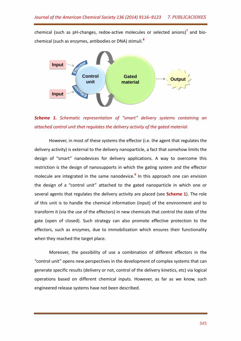
Journal of the American Chemical Society 136 (2014) 9116–9123 7. PUBLICACIONES
345
chemical (such as pH-changes, redox-active molecules or selected anions)7 and bio-
chemical (such as enzymes, antibodies or DNA) stimuli.8
Scheme 1. Schematic representation of “smart” delivery systems containing an
attached control unit that regulates the delivery activity of the gated material.
However, in most of these systems the effector (i.e. the agent that regulates the
delivery activity) is external to the delivery nanoparticle, a fact that somehow limits the
design of “smart” nanodevices for delivery applications. A way to overcome this
restriction is the design of nanosupports in which the gating system and the effector
molecule are integrated in the same nanodevice.9 In this approach one can envision
the design of a “control unit” attached to the gated nanoparticle in which one or
several agents that regulates the delivery activity are placed (see Scheme 1). The role
of this unit is to handle the chemical information (input) of the environment and to
transform it (via the use of the effectors) in new chemicals that control the state of the
gate (open of closed). Such strategy can also promote effective protection to the
effectors, such as enzymes, due to immobilization which ensures their functionality
when they reached the target place.
Moreover, the possibility of use a combination of different effectors in the
“control unit” opens new perspectives in the development of complex systems that can
generate specific results (delivery or not, control of the delivery kinetics, etc) via logical
operations based on different chemical inputs. However, as far as we know, such
engineered release systems have not been described.
Gated
material
Control
unitOutput
Input
Input
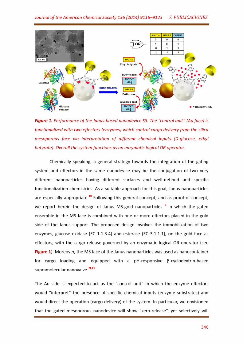
Journal of the American Chemical Society 136 (2014) 9116–9123 7. PUBLICACIONES
346
Figure 1. Performance of the Janus-based nanodevice S3. The “control unit” (Au face) is
functionalized with two effectors (enzymes) which control cargo delivery from the silica
mesoporous face via interpretation of different chemical inputs (D-glucose, ethyl
butyrate). Overall the system functions as an enzymatic logical OR operator.
Chemically speaking, a general strategy towards the integration of the gating
system and effectors in the same nanodevice may be the conjugation of two very
different nanoparticles having different surfaces and well-defined and specific
functionalization chemistries. As a suitable approach for this goal, Janus nanoparticles
are especially appropriate.10 Following this general concept, and as proof-of-concept,
we report herein the design of Janus MS-gold nanoparticles 9 in which the gated
ensemble in the MS face is combined with one or more effectors placed in the gold
side of the Janus support. The proposed design involves the immobilization of two
enzymes, glucose oxidase (EC 1.1.3.4) and esterase (EC 3.1.1.1), on the gold face as
effectors, with the cargo release governed by an enzymatic logical OR operator (see
Figure 1). Moreover, the MS face of the Janus nanoparticles was used as nanocontainer
for cargo loading and equipped with a pH-responsive β-cyclodextrin-based
supramolecular nanovalve.7f,11
The Au side is expected to act as the “control unit” in which the enzyme effectors
would “interpret“ the presence of specific chemical inputs (enzyme substrates) and
would direct the operation (cargo delivery) of the system. In particular, we envisioned
that the gated mesoporous nanodevice will show “zero-release”, yet selectively will

Journal of the American Chemical Society 136 (2014) 9116–9123 7. PUBLICACIONES
347
open in the presence of either D-glucose, ethyl butyrate or a combination of both
substrates through enzyme-catalyzed substrate transformations which will lead to a
reduction of the pH and, consequently, to the opening of the β-cyclodextrin-gatted
nanovalves. The overall output (cargo delivery) will function as a Boolean logic OR
gate.12
RESULTS AND DISCUSSION
To assemble the integrated nanomachine, Janus Au-MS nanoparticles were first
prepared as previously described.9,13 The synthetic procedure is based on the
manipulation of the Au-ligand-MS interface through a mask-protecting assisted site-
selective modification approach. Briefly, MS nanoparticles (S0, average diameter: 97 ±
15 nm) were synthesized by alkaline hydrolysis of tetraethyl orthosilicate as inorganic
precursor in the presence of the cationic surfactant cetyltrimethylammonium bromide
as porogen species. The subsequent removal of the surfactant by calcination in air at
high temperature resulted in the starting mesoporous inorganic support. These
nanoparticles were then partially confined at the interface of a Pickering emulsion
using paraffin wax as oil phase. The exposed nanoparticle surface was further modified
with (3-mercaptopropyl) trimethoxysilane on which Au nanoparticles (average
diameter: 20 ± 2 nm) were then attached, yielding stable anisotropic colloids (S1,
average diameter: 104 ± 17 nm, yield 85%) after dissolving the paraffin wax in CHCl3.
The MS nanoparticles in the anisotropic colloids were then loaded with
Ru(bipy)32+, which was used as dye for monitoring the release process, and the external
surface of the siliceous face was further modified with 3-iodopropyltrimethoxysilane.
Benzimidazole moieties were attached to the anchored 3-iodopropyl residues through
a nucleophilic substitution reaction, yielding a solid functionalized with 1-propyl-1-H-
benzimidazole groups (S2). These nanoparticles were then gated with a pH-sensitive
supramolecular nanovalve by stirring the colloid with β-cyclodextrin moieties in water
at pH 7.5 for 24 h that resulted in the formation of inclusion complexes between the
benzimidazole groups and the β-cyclodextrins.7f,11 Finally, esterase and glucose oxidase,

Journal of the American Chemical Society 136 (2014) 9116–9123 7. PUBLICACIONES
348
previously modified with 3,3´-dithiobis(sulfosuccinimidylpropionate), were selectively
and covalently immobilized on the Au face of the S2 colloid by incubation in 50 mM
sodium phosphate buffer, pH 7.5, at 4ºC, yielding the final nanodevice S3.
Au nanoparticles were selected as scaffold for the assembly of the effector
system, instead of using direct enzymes immobilization on the MS surface. This choice
was relied on the large surface area of Au nanoparticles which allows high enzyme
loadings with the immobilization method emploeyd. In addition, the relative low Au
reactivity allows the metal nanoparticles surface to remain unaltered during the
further assembly of the gated system in the MS face, thus avoiding chemical protection
steps that should be employed to directly link the enzymes to the MS face.
All supports were characterized by standard methods (see Supporting
Information). TEM analysis conf irmed the mesoporous morphology of the silica
nanoparticles as well as the presence of the Au nanoparticles in the Janus colloids
(Figure 1). Powder X-ray diffraction patterns of the final nano-device S3 and the
intermediate S0, S1 and S2 supports are shown in Figure SI-1. All samples showed a
well-defined low-angle reflexion around 2.6º which corresponds to a hexagonal
ordered array indexed as a (100) Bragg peak, suggesting a MCM41-like mesoporous
order in these materials which was not affected by the different chemical modifications
and dye loading processes. In addition, the diffraction patterns of S1, S2 and S3
samples at high angle also showed the cubic gold characteristic (111), (200), (220) and
(311) diffraction peaks,14 confirming the Janus Au-MS architecture observed by TEM.
FT-IR spectrum of the S0 and S1 nanoparticles were similar to those reported for MS
and Janus Au-MS nanoparticles, whereas the characteristics IR absorption bands of
benzimidazole were clearly observed in the spectrum of S2 (Figure SI-2 in Supporting
Information).15 On the other hand, the presence of β-cyclodextrin moieties in S3 was
confirmed by the broad band at ca. 1060 cm-1, which is characteristic for this cyclic
oligosaccharide. The presence of the immobilized enzymes in S3 was confirmed by the
band at 1642 cm-1 which can be ascribed to the amide I absorption band of proteins.
Moreover, thermogravimetric (Figure SI-3 in Supporting Information) and elemental
analysis studies (Table SI-1 in Supporting Information) on S1, S2 and S3 revealed a
content of the Ru(bpy)32+ dye and anchored benzimidazole in S2 of 15 µmol/g and 160
Journal of the American Chemical Society 136 (2014) 9116–9123 7. PUBLICACIONES
349
µmol/g, respectively. In addition, the amount of glucose oxidase and esterase
immobilized on S3 was estimated as of 2.5 U/mg and 4.8 U/mg, respectively.
The N2 adsorption-desorption isotherms of the starting calcined MS
nanoparticles (S0) and the Janus colloid (S1) showed an adsorption step at
intermediate P/P0 values (0.1–0.3). The application of the BET model for these solids
resulted in values for the total specific surface area of 1037 and 819 m2 g-1,
respectively (see Figure SI-4 and Table SI-2). In contrast the N2 adsorption-desorption
isotherms for the prepared dye loaded material (S2) and the final capped support (S3)
are typical of mesoporous systems with filled mesopores and a significant decrease in
the N2 volume adsorbed and surface area was observed (i.e. 51.3 and 18.2 m2 g-1 for S2
and S3, respectively, see Supporting Information). 7f
The capacity of the S3 nano-device to deliver the cargo in aqueous solution was
further tested. In a typical release assay, 10 mg of S3 were suspended in 4 mL of 20
mM Na2SO4 solution at pH 7.5 and shaken over time at 25ºC. Aliquots were taken at
scheduled times, centrifuged to remove the nanoparticles, and the absorbance at 454
nm of the released Ru(bpy)32+ was measured. After 1 h incubation, the enzyme
substrates D-glucose and ethyl butyrate, used as input signals, were added to the
mixtures at a concentration of 40 µM.
Figure 2 shows the time-course of Ru(bpy)32+ release from the pores of S3
nanoparticles in the presence and absence of substrates. In the absence of D-glucose
or ethyl butyrate solid S3 is tightly capped and shows a negligible release of Ru(bpy)32+
(ca. 1.2 ± 0.5 µM Ru(bpy)32+, see curve a). In contrast, the presence of either ethyl
butyrate (curve b), D-glucose (curve c) or a mixture of both (curve d) results in the
opening of the pores and the subsequent release of the cargo. Overall, delivery from
nanoparticles S3 is triggered by the presence of ethyl butyrate and D-glucose via the
“interpretation“ of these chemical inputs by the glucose oxidase and esterase enzymes
(effectors) in the “control unit” that resulted in the dethreading of the inclusion
complex between benzimidazole moieties and β-cyclodextrin. In particular glucose
oxidase catalyze the oxidation of D-glucose yielding H2O2 and D-glucono-1,5-lactone
which hydrolyses in water to gluconic acid (pKa = 3.6). Moreover, ethyl butyrate is
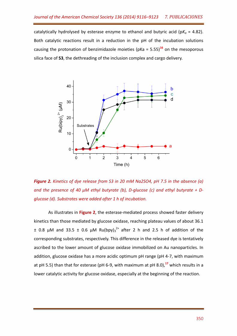
Journal of the American Chemical Society 136 (2014) 9116–9123 7. PUBLICACIONES
350
catalytically hydrolysed by esterase enzyme to ethanol and butyric acid (pKa = 4.82).
Both catalytic reactions result in a reduction in the pH of the incubation solutions
causing the protonation of benzimidazole moieties (pKa = 5.55)16 on the mesoporous
silica face of S3, the dethreading of the inclusion complex and cargo delivery.
Figure 2. Kinetics of dye release from S3 in 20 mM Na2SO4, pH 7.5 in the absence (a)
and the presence of 40 µM ethyl butyrate (b), D-glucose (c) and ethyl butyrate + D-
glucose (d). Substrates were added after 1 h of incubation.
As illustrates in Figure 2, the esterase-mediated process showed faster delivery
kinetics than those mediated by glucose oxidase, reaching plateau values of about 36.1
± 0.8 µM and 33.5 ± 0.6 µM Ru(bpy)32+
after 2 h and 2.5 h of addition of the
corresponding substrates, respectively. This difference in the released dye is tentatively
ascribed to the lower amount of glucose oxidase immobilized on Au nanoparticles. In
addition, glucose oxidase has a more acidic optimum pH range (pH 4-7, with maximum
at pH 5.5) than that for esterase (pH 6-9, with maximum at pH 8.0),17 which results in a
lower catalytic activity for glucose oxidase, especially at the beginning of the reaction.

Journal of the American Chemical Society 136 (2014) 9116–9123 7. PUBLICACIONES
351
Figure 3. Kinetics of dye release from S4 in 20 mM Na2SO4, pH 7.5 in the absence (a)
and the presence of 40 µM ethyl butyrate (b), D-glucose (c) and ethyl butyrate + D-
glucose (d) without (closed circles) and with 200 µM urea (open circles). Substrates
were added after 1 h of incubation.
Moreover, to demonstrate that the opening mechanism was due to the
enzyme-mediated reduction of pH it was confirmed that in the experiments in which
ethyl butyrate or D-glucose were added to aqueous suspensions of S3 the pH of the
incubating media changed from 8.0 to ca. 5.0 after 6 h. In addition, in order to
demonstrate that it is the presence of the glucose oxidase and esterase enzymes in the
Au “control unit” that governed cargo delivery, suspension of S3 at pH 7.5 were boiled
for 10 min to inactivate the enzymes, and further tested toward D-glucose and ethyl
butyrate. In this case no appreciable cargo delivery was observed from S3 after 24 h of
incubation.
To elucidate whether the release of Ru(bpy)32+ from the Janus colloid was
caused either by a local decrease of pH at the microenvironment of the nanoparticles
or by pH decrease in the bulk solution, parallel release experiments in buffered
solutions at pH 7.5 were performed. As it is exemplified in Figure SI-5 when D-glucose +
ethyl butyrate are used as triggers, the concentrations of Ru(bpy)32+ released at a given
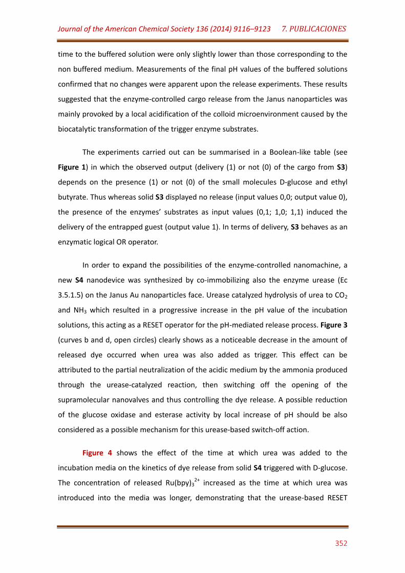
Journal of the American Chemical Society 136 (2014) 9116–9123 7. PUBLICACIONES
352
time to the buffered solution were only slightly lower than those corresponding to the
non buffered medium. Measurements of the final pH values of the buffered solutions
confirmed that no changes were apparent upon the release experiments. These results
suggested that the enzyme-controlled cargo release from the Janus nanoparticles was
mainly provoked by a local acidification of the colloid microenvironment caused by the
biocatalytic transformation of the trigger enzyme substrates.
The experiments carried out can be summarised in a Boolean-like table (see
Figure 1) in which the observed output (delivery (1) or not (0) of the cargo from S3)
depends on the presence (1) or not (0) of the small molecules D-glucose and ethyl
butyrate. Thus whereas solid S3 displayed no release (input values 0,0; output value 0),
the presence of the enzymes’ substrates as input values (0,1; 1,0; 1,1) induced the
delivery of the entrapped guest (output value 1). In terms of delivery, S3 behaves as an
enzymatic logical OR operator.
In order to expand the possibilities of the enzyme-controlled nanomachine, a
new S4 nanodevice was synthesized by co-immobilizing also the enzyme urease (Ec
3.5.1.5) on the Janus Au nanoparticles face. Urease catalyzed hydrolysis of urea to CO2
and NH3 which resulted in a progressive increase in the pH value of the incubation
solutions, this acting as a RESET operator for the pH-mediated release process. Figure 3
(curves b and d, open circles) clearly shows as a noticeable decrease in the amount of
released dye occurred when urea was also added as trigger. This effect can be
attributed to the partial neutralization of the acidic medium by the ammonia produced
through the urease-catalyzed reaction, then switching off the opening of the
supramolecular nanovalves and thus controlling the dye release. A possible reduction
of the glucose oxidase and esterase activity by local increase of pH should be also
considered as a possible mechanism for this urease-based switch-off action.
Figure 4 shows the effect of the time at which urea was added to the
incubation media on the kinetics of dye release from solid S4 triggered with D-glucose.
The concentration of released Ru(bpy)32+ increased as the time at which urea was
introduced into the media was longer, demonstrating that the urease-based RESET
Journal of the American Chemical Society 136 (2014) 9116–9123 7. PUBLICACIONES
353
operator, and thus the amount of dye released, can be operated through a time-
controlled scheme.
Figure 4. Kinetics of dye release from S4 in 20 mM Na2SO4, pH 7.5 in the absence (a)
and the presence of 40 µM D-glucose without (f) and with addition of urea at 200 µM
final concentration at different times (b-e). Substrates were added after 1 h of
incubation.
One goal of this study was to demonstrate that Janus enzyme-controlled
capped MS can be used for in-cell controlled delivery applications. Therefore, after the
in vitro characterization of the solid S3 (vide ante), similar nanoparticles were tested in
further ex vivo assays. In particular for these experiments nanoparticles as S3 but
loaded with the cytotoxic doxorubicin (Doxo) were prepared (solid S5, see Supporting
Information). The amount of Doxo loaded on the Janus colloid was estimated
spectrophotometrically as 0.56 µmol per gram of nanoparticles. The S5 nanomachine
showed similar patterns for in vitro Doxo release than those filled with Ru(bpy)32+ upon
addition of ethyl butyrate or D-glucose + ethyl butyrate, but lower release kinetics in
the presence of D-glucose (Figure 5).

Journal of the American Chemical Society 136 (2014) 9116–9123 7. PUBLICACIONES
354
Figure 5. Kinetics of Doxo release from S5 in 20 mM Na2SO4, pH 7.5 in the absence (a)
and the presence of 40 µM ethyl butyrate (b), D-glucose (c) and ethyl butyrate + D-
glucose (d). Substrates were added after 1 h of incubation.
S5 nanomachine retained full functional activity after one month of storage at
4ºC. In addition, the operational stability of the S5 nanomachine was tested by
incubation at 37 ºC in reconstituted human serum and further quantification of Doxo
released after 1 h addition of D-glucose + ethyl butyrate as triggers (see Supporting
Information for details). As it is illustrated in Figure SI-6 (Supporting Information), the
integrated nanomachine lost release activity progressively with time according to
biphasic inactivation kinetics. However, the S5 solid retained over 40% of the initial
functional activity after a week of incubation, suggesting its potential use for long term
ex vivo assays.
The solid S5 was ex vivo analysed in HeLa cells under the premise that S5 could
be internalised by the cells and would remain closed until glucose or ethyl butyrate are
added. The action of enzymes in the Janus nanoparticle on these molecules would
induce a local pH reduction that is expected to result in an intracellular Doxo release,
which would induce cell death. In a typical experiment HeLa cells were incubated for
40 minutes with a suspension of 100 µg/mL of S5 in PBS supplemented with 10 % fetal

Journal of the American Chemical Society 136 (2014) 9116–9123 7. PUBLICACIONES
355
bovine serum. After this, cells were washed in order to remove un-internalised
nanoparticles and were further incubated alone or in the presence of ethyl butyrate
(input A), glucose (input B) or a mixture of both (see Experimental section for details).
Delivery of Doxo from S5 in the presence of the different inputs was first studied by
confocal microscopy by tracking Doxo-associated fluorescence. Moreover in these
experiments the cell nuclei were stained with Hoechst 33342.
Figure 6A shows representative images of phase contrast, Doxo, Hoescht and
combined for HeLa cells first loaded with S5 and then untreated (-/-) or treated with
ethyl butyrate (+/-), glucose (-/+) or with a mixture of both (+/+). Internalization of S5
in HeLa cells (see -/-) did not produce, in the absence of further input, a significant
Doxo release, thus demonstrating that not unspecific cargo release occurred in a large
extent as a consequence of the acidification in the endosomes. In contrast when cells
were incubated simultaneously with ethyl butyrate and glucose a clear dispersed Doxo
fluorescence was found indicating cargo delivery from S5. Figure 6C shows a
quantitation using flow cytometry of the Doxo fluorescence intensity for HeLa cells
incubated with S5 (-/-) and further treated with ethyl butyrate (+/-), glucose (-/+) or
with a mixture of both (+/+). Whereas emission was low in the absence of inputs, an
enhanced Doxo fluorescence was detected upon exposure to ethyl butyrate or glucose.
Moreover a synergistic enhanced Doxo emission was observed when both ethyl
butyrate and glucose treatments were combined simultaneously.
These observations correlate with cell viability studies determined after 24
hours of the corresponding treatment using WST-1 assays (see Figure 6B). Indeed, it
was confirmed that HeLa cells treated at 100 μg/mL of S5 in the presence of glucose
and ethyl butyrate showed apoptotic cell death. More specifically, around 50% of the
cells were dead 24h after the addition of S5, whereas values of ca. 40% and 15% of
dead cells were found when only glucose or ethyl butyrate were added, respectively. In
contrast, the HeLa cells treated with only S5 remained unaffected.
In summary, we have demonstrated that it is possible to design nanodevices in
which the gating mechanisms and different effector ensembles can be integrated in a
unique system. In particular we have reported here the preparation of Janus-type
Journal of the American Chemical Society 136 (2014) 9116–9123 7. PUBLICACIONES
356
nanoparticles having Au and MS opposite faces, which were properly functionalized
with a pH-responsive β-cyclodextrin based supramolecular nanovalve on the silica
mesoporous surface and two effectors, glucose oxidase and esterase, immobilized on
the Au face. The nano-device behaves as an enzymatic logical OR operator which is
fuelled by the presence of D-glucose and ethyl butyrate. This enzyme logic system was
also coupled to a urease-based RESET operator to switch-off the opening of the
supramolecular nanovalves and control the extension of dye delivery upon addition of
urea. To our knowledge, this is the first report dealing with the use of anisotropic
colloids for the design of smart nanodevices for on-command release controlled by
biochemical logic operations. The smart nanomachine controlled by the logical OR
operator and loaded with an anti-cancer drug, was successfully tested toward HeLa
cancer cells. The possibility of using a large variety of different gating nanovalves on
the silica mesoporous face combined with a potential number of enzyme-based
effectors on the Au surface makes this approach appealing and opens a wide range of
new possibilities for the development of novel smart delivery systems controlled by
enzyme-based biocomputing ensembles.
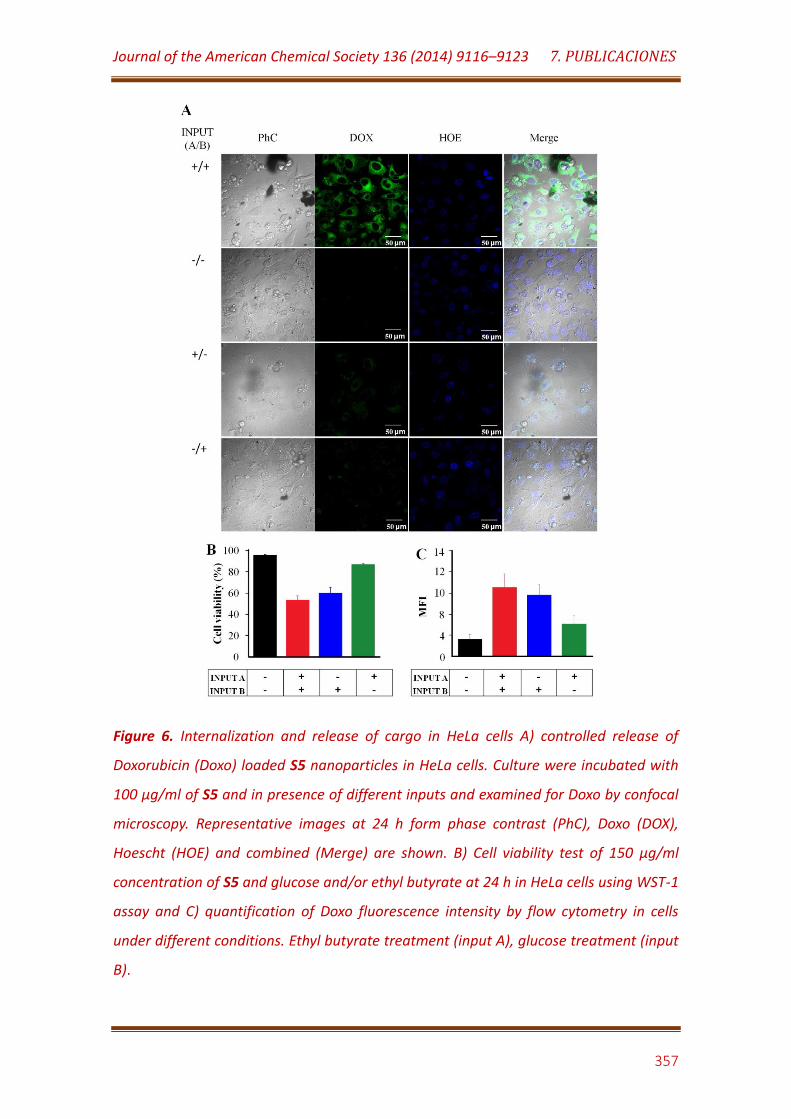
Journal of the American Chemical Society 136 (2014) 9116–9123 7. PUBLICACIONES
357
Figure 6. Internalization and release of cargo in HeLa cells A) controlled release of
Doxorubicin (Doxo) loaded S5 nanoparticles in HeLa cells. Culture were incubated with
100 μg/ml of S5 and in presence of different inputs and examined for Doxo by confocal
microscopy. Representative images at 24 h form phase contrast (PhC), Doxo (DOX),
Hoescht (HOE) and combined (Merge) are shown. B) Cell viability test of 150 μg/ml
concentration of S5 and glucose and/or ethyl butyrate at 24 h in HeLa cells using WST-1
assay and C) quantification of Doxo fluorescence intensity by flow cytometry in cells
under different conditions. Ethyl butyrate treatment (input A), glucose treatment (input
B).
Journal of the American Chemical Society 136 (2014) 9116–9123 7. PUBLICACIONES
358
METHODS
1. Preparation of MS nanoparticles (S0).18
Cetyltrimethylammonium bromide (3.0 g) was dissolved in 1.44 L of water
under sonication. NaOH solution (2.0 mol/L, 10.5 mL) was then added and the
temperature of the mixture was adjusted to 80 ºC. Tetraethoxysilane (15.0 mL) was
added dropwise to the surfactant solution within 5 min under vigorous magnetic
stirring. The mixture was allowed to react for 2 h. The resulting white solid was filtered,
washed with water and methanol, and then dried in desiccator. Finally, the solid was
calcined at 550 ºC for 5 h to remove the organic template.
2. Preparation of 20 nm Au nanoparticles.19
Freshly prepared 3 µM HAuCl4 solution (50 mL) was heated to boiling. Then, 20
nm gold nanoparticles were synthesized by adding 750 µL of a 3.9 µM trisodium citrate
solution. The mixture was heated for 10 min, cooled to room temperature and finally
raised to 50 mL with ultrapure water.
3. Preparation of Janus Au-MS nanoparticles (S1).9,13
MS nanoparticles (200 mg) were dispersed homogeneously in 10 mL of 1.0 µM
of cetyltrimethylammonium bromide in 6.7% ethanol aqueous solution. The mixture
was heated at 75ºC and then 1 g of paraffin wax was added. When the paraffin wax
was melted, the mixture was vigorously stirred at 25000 rpm for 10 min using an Ultra-
Turrax T-10 homogenizer (IKA, Germany). The resulting emulsion was further stirred for
1 h at 4000 rpm and 75 ºC, using a magnetic stirrer. The resulting Pickering emulsion
was then cooled to room temperature, mixed with 10 mL methanol and treated with
200 µL of (3-mercaptopropyl)trimethoxysilane. After 3 h under magnetic stirring, the
silanized emulsion was filtered, three-times washed with methanol and further
dispersed in 400 mL of the corresponding 3 µM Au nanoparticles aqueous solutions.
Journal of the American Chemical Society 136 (2014) 9116–9123 7. PUBLICACIONES
359
The mixture was stirred overnight, then filtered and exhaustively washed with
ultrapure water. The solid was suspended in ethanol, centrifuged and washed two-
times with ethanol and three-times with chloroform. The Janus nanoparticles were
finally dried and kept in desiccators until use.
4. Preparation of S2.
To synthesize S2, 400 mg of S1 and 250 mg (33 µmol) of tris(2,2′-bipyridyl)
dichlororuthenium(II) hexahydrate were suspended in 17 mL of anhydrous acetonitrile
inside a round-bottom flask connected to a Dean-Stark trap under Ar atmosphere. The
suspension was heated at 110 °C and about 7 mL of solvent were distilled and collected
in the trap to remove the adsorbed water. After this step, the mixture was stirred for
24 h at room temperature to load the dye into the MS face pores. Afterward, an excess
of 3-iodopropyltrimethoxysilane (200 µL, 1 mmol) was added and the suspension was
stirred for 24 hours.7f The final solid was filtered off, washed two times with 5 mL of
acetonitrile and dried at 60 ºC overnight. To attach the benzimidazole moieties to the
MS surface, 400 mg of the resulting solid were suspended in a 40 mL of a saturated
solution of benzimidazole in toluene at 80ºC and containing triethylamine
(benzimidazol and triethylamine in a 1:3 proportion). The suspension was refluxed and
stirred for 72 hours. The resulting solid was filtered off, washed with 40 mL of
acetonitrile and dried at 70 ºC overnight.
5. Preparation of S3, S4 and S5.
To prepare the gated solid S3, 400 mg of S2 were suspended in 100 mL of a β-
cyclodextrin solution (1.6 mg/ml) in 50 mM sodium phosphate buffer, pH 7.5.7f The
suspension was stirred for 12 hours at room temperature. The capped solid was
centrifuged, washed with water at pH 7.5 and dried. In a second step, to functionalize
these nanoparticles with the enzymes, 2.0 mg of enzyme (esterase or glucose oxidase)
and 2.0 mg of 3,3´-dithiobis(sulfosuccinimidylpropionate) were dissolved in 2.0 mL of
Journal of the American Chemical Society 136 (2014) 9116–9123 7. PUBLICACIONES
360
50 mM sodium phosphate buffer, pH 7.0, and stirred for 2 h at 4 ºC.9 Afterward, 200 µL
of 100 mM NaBH4 solution were added, and the mixture was stirred at 4 ºC for 30 min.
The solution was exhaustively dialyzed vs 50 mM sodium phosphate buffer, pH 7.0
using Amicon Ultra-05 centrifugal filter units with Ultracel-10 membranes (Millipore,
USA), and finally concentrated to about 10 mg/mL concentration. The modified
enzyme solutions were then added to 20 mL of 50 mM sodium phosphate buffer, pH
7.5, containing 20 mg of the β-cyclodextrin capped solid, and stirred at 4ºC overnight.
The resulting solid (S3) was finally isolated by centrifugation, washed several times
with a cold solution of 50 mM sodium phosphate buffer, pH 7.5, dried and kept in
refrigerator until use. Solid S4 was prepared through a similar protocol, but co-
immobilizing a third enzyme, urease, on the Au nanoparticles surface. For ex vivo cell
experiments, nanoparticles as S3 but loaded with the cytotoxic doxorubicin (Doxo)
were also prepared (solid S5, see Supporting Information).
6. Cell Culture Conditions.
HeLa human cervix adenocarcinoma cells were purchased from the German
Resource Centre for Biological Materials (DSMZ) and were grown in DMEM
supplemented with 10% FBS. Cells were maintained at 37 ºC in an atmosphere of 5%
carbon dioxide and 95% air and underwent passage twice a week.
7. WST-1 Cell Viability Assay.
HeLa cells were seeded in a 24-well plate at a density of 2 ·104 cells/well in a
1000 uL of DMEM and were incubated 24 hours in a CO2 incubator at 37 ºC. Then,
DMEM were replaced for PBS with 10 % of Fetal Bovine Serum and solid S5 in DMSO
were added to cells in sextuplicate at final concentrations of 150 μg/ml. After 40
minutes, cells were washed with PBS and were incubated for 23 hours in different
conditions. DMEM with 10% FBS, DMEM with 10% FBS and ethyl butyrate, PBS with
10% FBS or PBS with 10 % FBS and ethyl butyrate. After this, 35 μL of WST-1 were
Journal of the American Chemical Society 136 (2014) 9116–9123 7. PUBLICACIONES
361
added to each well and were incubated for 1.5 hours. Before reading the plate was
shaken for one minute to ensure homogeneous distribution of colour. Then the
absorbance was measured at a wavelength of 450 nm in a VICTOR X5 PerkinElmer.
Results are expressed as a promedium of the results of six independent experiments
obtaining similar results.
8. Live Confocal Microscopy.
HeLa cells were seeded in a 24 mm Ø glass coverslips in six-well plates at a
seeding density of 1,8 ·105 cells /well. After 24 hours, culture medium were replaced
for PBS with 10% fetal bovine serum (FBS) and cells were treated with a suspension of
solid S5 for 40 minutes at a final concentration of 100 μg/ml. Then the medium was
change for different solutions (DMEM with 10%FBS with or without ethyl butyrate, or
PBS with 10% FBS with or without ethyl butyrate). After 18 hours coverslips were
washed twice to eliminate compounds and, were visualized under a confocal
microscope employing Leica TCS SP2 AOBS (Leica Microsystems Heidelberg GmbH,
Mannheim, Germany) inverted laser scanning confocal microscope using oil objectives:
63X Plan-Apochromat-Lambda Blue 1.4 N.A. The images were acquired with an
excitation wavelength of 405 for Hoescht and 480 nm for Doxorubicin. Two-
dimensional pseudo colour images (255 colour levels) were gathered with a size of
1024x1024 pixels and Airy 1 pinhole diameter. All confocal images were acquired using
the same settings and the distribution of fluorescence was analysed using the Image J
Software. Three fields of each condition in two independent experiments were
performed obtaining similar results.
ASSOCIATED CONTENT
Supporting Information
Experimental details and nanomaterials characterization. This material is available free
of charge via the Internet at http://pubs.acs.org.
Journal of the American Chemical Society 136 (2014) 9116–9123 7. PUBLICACIONES
362
AUTHOR INFORMATION
Corresponding Author
[email protected], [email protected], [email protected].
Notes
The authors declare no competing financial interests.
ACKNOWLEDGMENT
R. Villalonga acknowledges to Ramón & Cajal contract from the Spanish
Ministry of Science and Innovation. Financial support from the Spanish Ministry of
Science and Innovation CTQ2011-24355, CTQ2009-12650, CTQ2009-09351, MAT2012-
38429-C04-01 and Comunidad de Madrid S2009/PPQ-1642, programme AVANSENS is
gratefully acknowledged. The Generalitat Valencia (project PROMETEO/2009/016) is
also acknowledged.
REFERENCES
(1) (a) Ozin, G.A. Adv. Mater. 1992, 4, 612-649; (b) E. Katz, I. Willner, Angew. Chem., Int.
Ed., 2004, 43, 6042-6108.
(2) (a) Allen, T.M.; Cullis, P.R. Science 2004, 303, 1818-1822; (b) Valdivia, A.; Perez, Y.;
Dominguez, A.; Caballero, J.; Gomez, L.; Schacht, E.H.; Villalonga, R. Macromol. Biosci.
2005, 5, 118-123; (c) Allen, T.M.; Cullis, P.R. Adv. Drug Deliv. Rev. 2013, 65, 36-48; (d)
Ramírez, H.L.; Valdivia, A.; Cao, R.; Torres-Labandeira, J.J.; Fragoso, A.; Villalonga, R.
Bioorg. Med. Chem. Lett. 2006, 16, 1499-1501.
(3) (a) Brannon-Peppas, L.; Blanchette, J.O. Adv. Drug Deliv. Rev. 2012, 64, 206-212; (b)
Doane, T.L.; Burda, C. Chem. Soc. Rev. 2012, 41, 2885-2911; (c) Wang, A.Z.; Langer, R.;
Farokhzad, O.C. Annu. Rev. Med. 2012, 63, 185-198.
Journal of the American Chemical Society 136 (2014) 9116–9123 7. PUBLICACIONES
363
(4) (a) Tang, F.; Li, L.; Chen, D. Adv. Mater. 2012, 24, 1504-1534; (b) Li, Z.; Barnes, J.C.;
Bosoy, A.; Stoddart, J.F.; Zink, J.I. Chem. Soc. Rev. 2012, 41, 2590-2605.
(5) (a) Coll, C.; Bernardos, A.; Martínez-Máñez, R.; Sancenón, F. Acc. Chem. Res. 2013,
46, 339-349; (b) Cotí, K.; Belowich, M.E.; Liong, M.; Ambrogio, M.W.; Lau, Y.A.; Khatib,
H.A.; Zink, J.I.; Khashab, N.M.; Stoddart, J.F. Nanoscale, 2009, 1, 16-39; (c) Yang, P.; Gai,
S.; Lin, J. Chem. Soc. Rev. 2012, 41, 3679-3698.
(6) (a) Mal, N.K.; Fujiwara, M.; Tanaka, Y. Nature 2003, 421, 350-353; (b) Aznar, E.;
Mondragón, L.; Ros-Lis, J.V.; Sancenón, F.; Marcos, M.D.; Martínez-Máñez, R.; Soto, J.;
Pérez-Payá, E.; Amorós, P. Angew. Chem. Int. Ed. 2011, 50, 11172-11175.
(7) See for example: (a) Lai, C.Y.; Trewyn, B.G.; Jeftinija, D.M.; Jeftinija, K.; Xu, S.;
Jeftinija, S.; Lin, V.S.Y. J. Am. Chem. Soc. 2003, 125, 4451-4459; (b) Park, C.; Oh, K.; Lee,
S.C.; Kim, C. Angew. Chem. Int. Ed. 2007, 46, 1455-1457; (c) Casasús, R.; Climent, E.;
Marcos, M.D.; Martínez-Máñez, R.; Sancenón, F.; Soto, J.; Amorós, P.; Cano, J.; Ruiz, E. J.
Am. Chem. Soc. 2008, 130, 1903-1917; (d) Liu, R.; Liao, P.; Liu, J.; Feng, P. Langmuir
2011, 27, 3095-3099; (e) Zhao, Z.; Meng, H.; Wang, N.; Donovan, M.J.; Fu, T.; You, M.;
Chen, Z.; Zhang, X.; Tan, W. Angew. Chem. Int. Ed. 2013, 52, 7487 –7491; (f) Aznar, E.;
Villalonga, R.; Giménez, C.; Sancenón, F.; Marcos, M.D.; Martínez-Máñez, R.; Díez, P.;
Pingarrón, J.M.; Amorós, P. Chem. Commun. 2013, 49, 6391-6393
(8) See for example: (a) Patel, K.; Angelos, S.; Dichtel, W.R.; Coskun, A.; Yang, Y.W.; Zink,
J.I.; Stoddart, J.F. J. Am. Chem. Soc., 2008, 130, 2382-2383; (b) Schlossbauer, A.; Kecht,
J.; Bein, J. Angew. Chem., Int. Ed., 2009, 48, 3092-3095; (c) Park, C.; Kim, H.; Kim, S.;
Kim, C. J. Am. Chem. Soc., 2009, 131, 16614-16615.
(9) Villalonga, R.; Díez, P.; Sánchez, A.; Aznar, E.; Martínez-Máñez, R.; Pingarrón, J.M.
Chem. Eur. J. 2013, 19, 7889-7894.
(10) (a) Perro, A.; Reculusa, S.; Ravaine, S.; Bourgeat-Lami, E.; Duguet, E.J. J. Mater.
Chem. 2005, 15, 3745-3760; (b) Jiang, S.; Chen, Q.; Tripathy, M.; Luijten, E.; Schweizer,
K.S.; Granick, S. Adv. Mater. 2010, 22, 1060-1071.

Journal of the American Chemical Society 136 (2014) 9116–9123 7. PUBLICACIONES
364
(11) Du, L.; Liao, S.; Khatib, H.A.; Stoddart, J.F.; Zink, J.I. J. Am. Chem. Soc. 2009, 131,
15136-15142
(12) (a) Tokarev, I.; Gopishetty, V.; Zhou, J.; Pita, M.; Motornov, M.; Katz, E.; Minko, S.
ACS Appl. Mater. Interfaces 2009, 1, 532-536;.(b) Du, L.; Liao, S.; Khatib, H.A.; Stoddart,
J.F.; Zink, J.I. J. Am. Chem. Soc. 2009, 131, 15136-15142.
(13) Sánchez, A.; Díez, P.; Martínez-Ruíz, P.; Villalonga, R.; Pingarrón, J.M. Electrochem.
Commun. 2013, 30, 51-54.
(14) Leff, D.V.; Brandt, L.; Heath, J.R. Langmuir 1996, 12, 4723-4730.
(15) Mohan, S.; Sundaraganesan, N.; Mink, J. Spectrochim. Acta Mol. Biomol. Spectros.
1991, 47, 1111-1115.
(16) Jerez, G.; Kaufman, G.; Prystai, M.; Schenkeveld, S.; Donkor, K.K. J. Sep. Sci. 2009,
32, 1087-1095.
(17) (a) Tsuge, H.; Natsuaki, O.; Ohashi, K. J. Biochem. 1975, 78, 835-843; (b) Junge, W.;
Heymann, E. Eur. J. Biochem. 1979, 95, 519-525.
(18) Zhao, Y.; Trewyn, B.G.; Slowing, I.I.; Lin, V.S.Y. J. Am. Chem. Soc. 2009, 131, 8398-
8400.
(19) Frens, G. Nature 1973, 241, 20-22.
Journal of the American Chemical Society 136 (2014) 9116–9123 7. PUBLICACIONES
365
SUPPORTING INFORMATION
Towards the design of smart delivery systems controlled by
integrated enzyme-based biocomputing ensembles
Paula Díez,1 Alfredo Sánchez,1 María Gamella,1 Paloma Martínez-Ruíz,2 Elena Aznar,3,4
Cristina de la Torre,3,4 José R. Murguía,3,4 Ramón Martínez-Máñez,3,4,* Reynaldo
Villalonga,1,5,* José M. Pingarrón1,5,*
1Departments of Analytical Chemistry and 2Organic Chemistry I, Faculty of Chemistry,
Complutense University of Madrid, 28040-Madrid, Spain. 3Instituto de Reconocimiento
Molecular y Desarrollo Tecnológico (IDM), Centro Mixto Universidad Politécnica de
Valencia-Universidad de Valencia, Spain. 4Departamento de Química y CIBER de
Bioingeniería, Biomateriales y Nanomedicina (CIBER-BBN), Universidad Politécnica de
Valencia, Camino de Vera s/n, 46022, Valencia, Spain. 5IMDEA Nanoscience,
Cantoblanco Universitary City, 28049-Madrid, Spain.
EXPERIMENTAL SECTION
Chemicals
Glucose oxidase from A. Niger, pig liver esterase, tetraethoxysilane,
cetyltrimethylammonium bromide, tris(2,2′-bipyridyl)dichlororuthenium(II)
hexahydrate, hydrogen tetrachloroaurate, 3-iodopropyltrimethoxysilane,
benzimidazole, triethylamine, (3-mercaptopropyl)trimethoxysilane, D-glucose, ethyl
butyrate, paraffin wax, 3,3´-dithiobis(sulfosuccinimidylpropionate), DMSO and PBS for
cell culture were purchased from Sigma-Aldrich. For cell culture experiments,
Dulbecco's Modified Eagle's medium (DMEM) with L-glutamine, pyruvate, human
serum (H4522) and Fetal Bovine Serum (FBS), trypan blue solution (0.4%) cell culture
Journal of the American Chemical Society 136 (2014) 9116–9123 7. PUBLICACIONES
366
grade, trypsin and the cell proliferation reagent WST-1were purchased from Roche
Applied Science. Solvents were provided by Scharlau. All other reagents were of
analytical grade.
General Techniques
Transmission electron microscopy (TEM) measurements were performed with a
JEOL JEM-2100 microscope. Spectrophotometric measurements were performed using
an Agilent 8453 UV/VIS spectrophotometer (Hewlett Packard, USA). Powder X-ray
diffraction (XRD) was performed with an X'Pert MRD diffractometer (PANanalytical
B.V., The Netherlands). Nitrogen adsorption/desorption isotherms and pore size
distributions were determined with an ASAP 2020 Physisorption Analyzer
(Micromeritics, USA). Thermal analysis was performed with a TA Instruments SDT-
Q600 apparatus (USA). FT-IR spectra were acquired with a Nicolet Nexus 670/870
spectrometer (Thermo Fisher Scientific Inc., USA).
Preparation of S5.
To prepare the solid S5, 400 mg of S1 were first suspended in 17 mL of
anhydrous acetonitrile inside a round-bottom flask and then treated with an excess of
3-iodopropyltrimethoxysilane (200 µL, 1 mmol). The suspension was stirred for 24
hours and the resulted solid was filtered off, washed two times with 5 mL of
acetonitrile and dried at 60 ºC overnight. To attach the benzimidazole moieties to the
MS surface, 400 mg of the resulting solid were suspended in a 40 mL of a saturated
solution of benzimidazole in toluene at 60ºC and containing triethylamine
(benzimidazol and triethylamine in a 1:3 proportion). The suspension was refluxed and
stirred for 72 hours. The resulting solid was filtered off, washed with 40 mL of
acetonitrile and dried at 60 ºC overnight. 50 mg of this solid was then suspended in 5
mL of 50 mM sodium phosphate buffer, pH 7.5 and then 40 µmol Doxorubicin (Doxo)
were added. The mixture was stirred for 12 h and then 12 mL of a β-cyclodextrin
Journal of the American Chemical Society 136 (2014) 9116–9123 7. PUBLICACIONES
367
solution (16 mg/ml) in 50 mM sodium phosphate buffer, pH 7.5 was added. The
suspension was stirred for 12 hours at room temperature, and the resulting capped
solid was centrifuged, washed with water at pH 7.5 and dried. In a second step, to
functionalize these nanoparticles with the enzymes, 5.0 mg of enzyme (esterase or
glucose oxidase) and 5.0 mg of 3,3´-dithiobis(sulfosuccinimidylpropionate) were
dissolved in 2.0 mL of 50 mM sodium phosphate buffer, pH 7.0, and stirred for 2 h at 4
ºC. Afterward, 200 µL of 100 mM NaBH4 solution were added, and the mixture was
stirred at 4 ºC for 30 min. The solution was exhaustively dialyzed vs 50 mM sodium
phosphate buffer, pH 7.0 using Amicon Ultra-05 centrifugal filter units with Ultracel-10
membranes (Millipore, USA), and finally concentrated to about 10 mg/mL
concentration. The modified enzyme solutions were then added to 20 mL of 50 mM
sodium phosphate buffer, pH 7.5, containing 50 mg of the β-cyclodextrin capped solid,
and stirred at 4ºC overnight. The resulting Doxo-loaded solid (S5) was finally isolated
by centrifugation, washed several times with a cold solution of 50 mM sodium
phosphate buffer, pH 7.5, centrifuged and kept wet in refrigerator until use. The
amount of Doxo entrapped within nanoparticles was calculated by the difference
between the total amount used to prepare nanoparticles and the amount of
doxorubicin present in the aqueous phase after capping with β-cyclodextrin, by
measuring the absorbance at 495 nm.1
Release and stability studies using S5
In vitro release studies for S5 were performed as described for S3.
Storage stability studies were performed by incubation of 4 mg/mL dispersion
S5 in 50 mM sodium phosphate buffer, pH 7.5 at 4ºC. Samples were collected at
scheduled times and assayed for enzyme-mediated on-command release of Doxo after
1 h addition of 40 µM ethyl butyrate + D-glucose. Operational stability of S5 was
assayed by incubation of 4 mg/mL dispersion S5 in reconstituted human serum at
37ºC. Samples were collected at scheduled times and assayed for enzyme-mediated
Journal of the American Chemical Society 136 (2014) 9116–9123 7. PUBLICACIONES
368
on-command release of Doxo after 1 h addition of 40 µM ethyl butyrate + D-glucose.
The amount of released drug was monitored by visible spectrophotometry at 495 nm.1
Cytofluorometry studies using S5
HeLa cells were seeded at 18 x 103 cells per well in a 24-well plate. After 24 h,
DMEM were replaced for PBS with 10 % of Fetal Bovine Serum and solid S5 in DMSO
were added to cells at final concentrations of 150 μg·ml-1. After 40 minutes, cells were
washed with PBS and were incubated for 23 hours in the different conditions (DMEM
with 10% FBS, DMEM with 10% FBS and ethyl butyrate, PBS with 10% FBS or PBS with
10 % FBS and ethyl butyrate). After 24 hours media were eliminated by vacuum and
plate were washed once with PBS. Cells were detached with Trypsin/EDTA solution,
centrifuged and finally resuspended in 1 ml of DMEM with 10% FBS. Quantification of
Doxorubicin fluorescence in the cells was performed with WinMDI program, version
2.0 in a FC500 MCL Flow Cytometer (Beckman-Coulter, CA, USA). Three independent
experiments containing quadruplicates were performed with similar results.
Materials Characterization
Solids S0, S1, S2 and S3 were characterized using standard procedures. Figure
SI-1 shows powder X-ray diffraction patterns in the 1.5 < 2θ < 7 range (SI-1A) and in
the 30 < 2θ < 80 range (SI-1B) for the calcined nanoparticulated MS support S0, the
Janus nanoparticles S1 and the S2 and S3 functionalized materials. The low angle
diffractogram of S0 shows the MCM-41 characteristic (100) reflection. This typical
reflexion is preserved in the Janus nanoparticles (S1). Moreover, the diffraction pattern
of S1 shows the cubic gold characteristic (111), (200), (220) and (311) diffraction peaks,
confirming the presence of gold nanocrystals and the Janus Au-MS architecture.
Finally, S2 and S3 samples display similar X-ray diffraction pattern than S1, suggesting
that the loading process with the dye, the further anchoring of the pH-responsive β-
cyclodextrin based nanovalve and the enzymes immobilization did not modify the
characteristics of the Janus colloid.
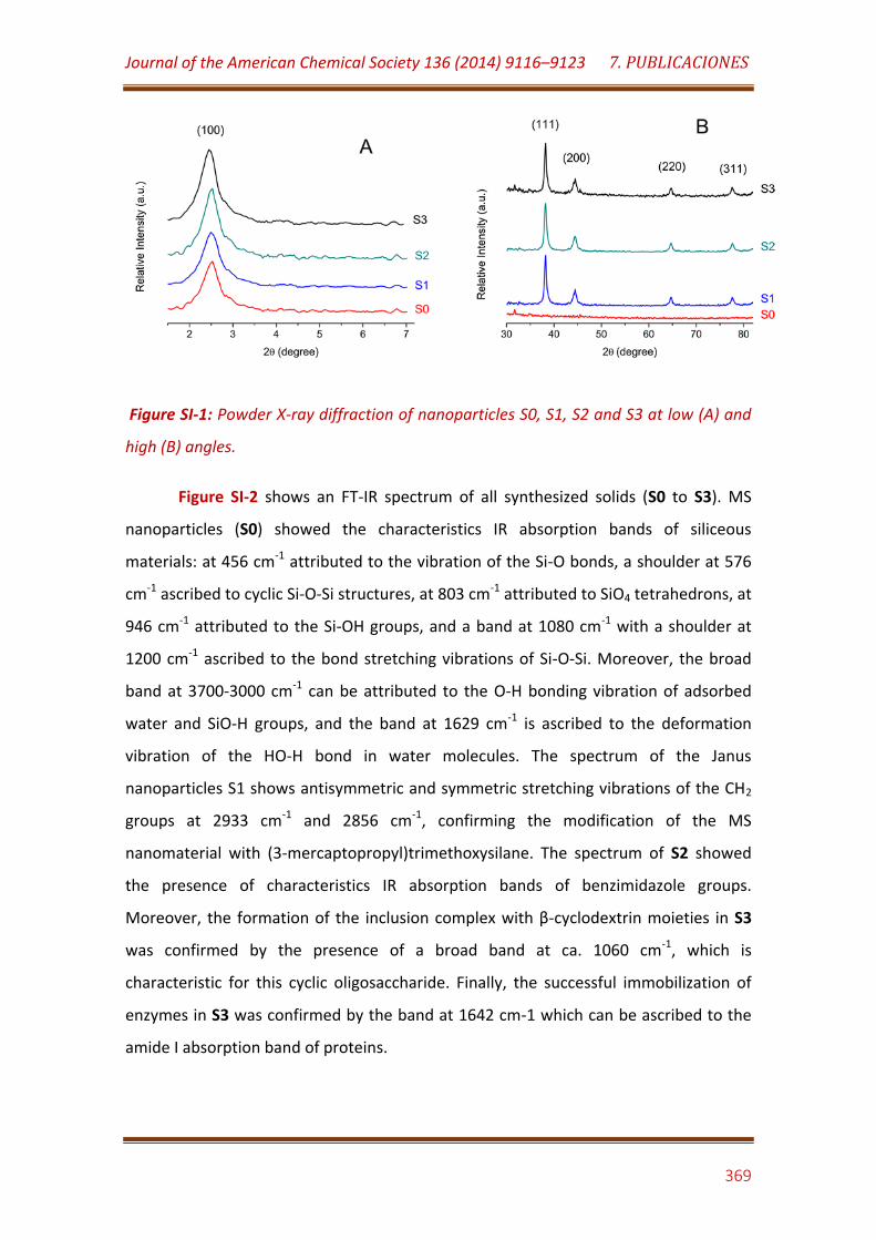
Journal of the American Chemical Society 136 (2014) 9116–9123 7. PUBLICACIONES
369
Figure SI-1: Powder X-ray diffraction of nanoparticles S0, S1, S2 and S3 at low (A) and
high (B) angles.
Figure SI-2 shows an FT-IR spectrum of all synthesized solids (S0 to S3). MS
nanoparticles (S0) showed the characteristics IR absorption bands of siliceous
materials: at 456 cm-1 attributed to the vibration of the Si-O bonds, a shoulder at 576
cm-1 ascribed to cyclic Si-O-Si structures, at 803 cm-1 attributed to SiO4 tetrahedrons, at
946 cm-1 attributed to the Si-OH groups, and a band at 1080 cm-1 with a shoulder at
1200 cm-1 ascribed to the bond stretching vibrations of Si-O-Si. Moreover, the broad
band at 3700-3000 cm-1 can be attributed to the O-H bonding vibration of adsorbed
water and SiO-H groups, and the band at 1629 cm-1 is ascribed to the deformation
vibration of the HO-H bond in water molecules. The spectrum of the Janus
nanoparticles S1 shows antisymmetric and symmetric stretching vibrations of the CH2
groups at 2933 cm-1 and 2856 cm-1, confirming the modification of the MS
nanomaterial with (3-mercaptopropyl)trimethoxysilane. The spectrum of S2 showed
the presence of characteristics IR absorption bands of benzimidazole groups.
Moreover, the formation of the inclusion complex with β-cyclodextrin moieties in S3
was confirmed by the presence of a broad band at ca. 1060 cm-1, which is
characteristic for this cyclic oligosaccharide. Finally, the successful immobilization of
enzymes in S3 was confirmed by the band at 1642 cm-1 which can be ascribed to the
amide I absorption band of proteins.
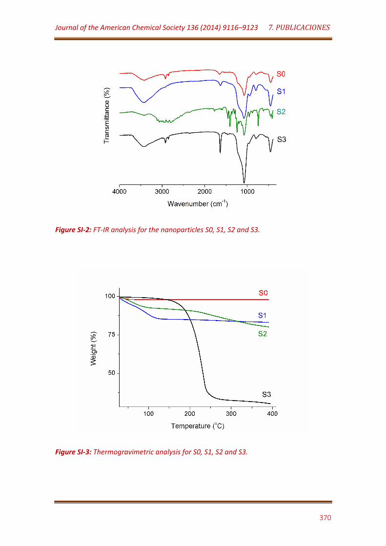
Journal of the American Chemical Society 136 (2014) 9116–9123 7. PUBLICACIONES
370
Figure SI-2: FT-IR analysis for the nanoparticles S0, S1, S2 and S3.
Figure SI-3: Thermogravimetric analysis for S0, S1, S2 and S3.
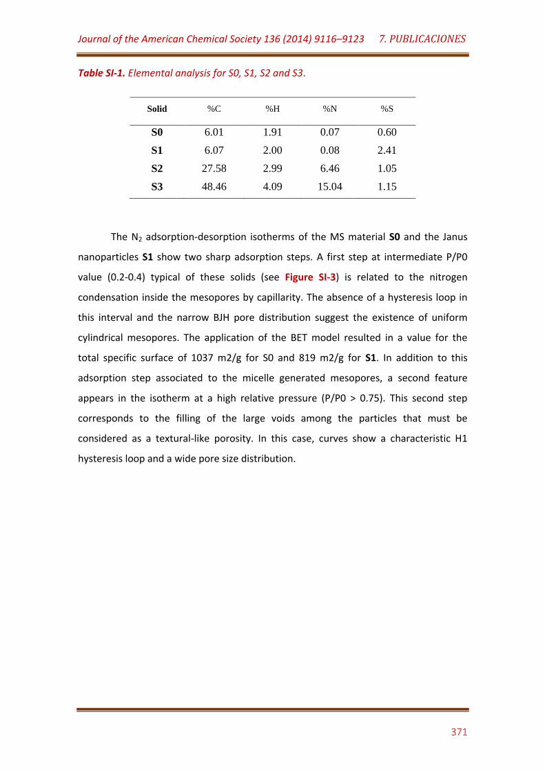
Journal of the American Chemical Society 136 (2014) 9116–9123 7. PUBLICACIONES
371
Table SI-1. Elemental analysis for S0, S1, S2 and S3.
Solid %C %H %N %S
S0 6.01 1.91 0.07 0.60
S1 6.07 2.00 0.08 2.41
S2 27.58 2.99 6.46 1.05
S3 48.46 4.09 15.04 1.15
The N2 adsorption-desorption isotherms of the MS material S0 and the Janus
nanoparticles S1 show two sharp adsorption steps. A first step at intermediate P/P0
value (0.2-0.4) typical of these solids (see Figure SI-3) is related to the nitrogen
condensation inside the mesopores by capillarity. The absence of a hysteresis loop in
this interval and the narrow BJH pore distribution suggest the existence of uniform
cylindrical mesopores. The application of the BET model resulted in a value for the
total specific surface of 1037 m2/g for S0 and 819 m2/g for S1. In addition to this
adsorption step associated to the micelle generated mesopores, a second feature
appears in the isotherm at a high relative pressure (P/P0 > 0.75). This second step
corresponds to the filling of the large voids among the particles that must be
considered as a textural-like porosity. In this case, curves show a characteristic H1
hysteresis loop and a wide pore size distribution.
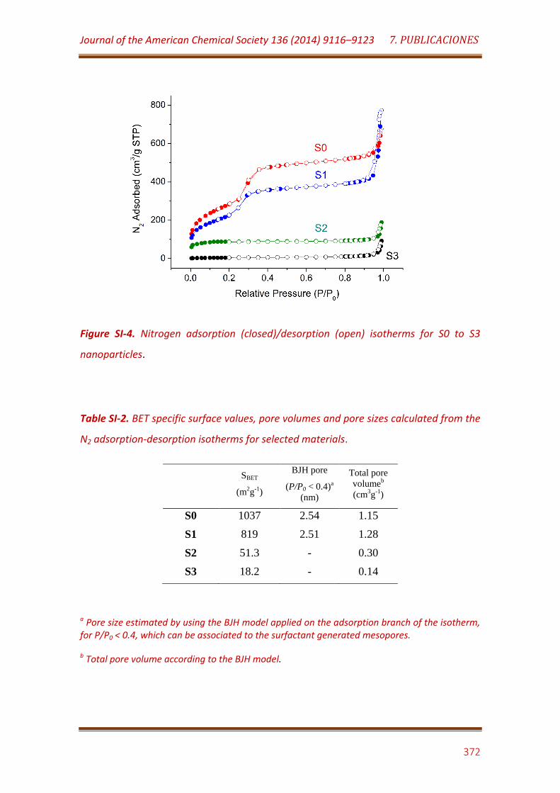
Journal of the American Chemical Society 136 (2014) 9116–9123 7. PUBLICACIONES
372
Figure SI-4. Nitrogen adsorption (closed)/desorption (open) isotherms for S0 to S3
nanoparticles.
Table SI-2. BET specific surface values, pore volumes and pore sizes calculated from the
N2 adsorption-desorption isotherms for selected materials.
SBET
(m2g-1)
BJH pore
(P/P0 < 0.4)a
(nm)
Total pore
volumeb
(cm3g-1)
S0 1037 2.54 1.15
S1 819 2.51 1.28
S2 51.3 - 0.30
S3 18.2 - 0.14
a Pore size estimated by using the BJH model applied on the adsorption branch of the isotherm, for P/P0 < 0.4, which can be associated to the surfactant generated mesopores.
b Total pore volume according to the BJH model.
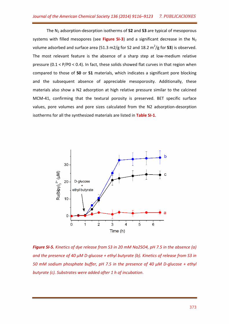
Journal of the American Chemical Society 136 (2014) 9116–9123 7. PUBLICACIONES
373
The N2 adsorption-desorption isotherms of S2 and S3 are typical of mesoporous
systems with filled mesopores (see Figure SI-3) and a significant decrease in the N2
volume adsorbed and surface area (51.3 m2/g for S2 and 18.2 m2/g for S3) is observed.
The most relevant feature is the absence of a sharp step at low-medium relative
pressure (0.1 < P/P0 < 0.4). In fact, these solids showed flat curves in that region when
compared to those of S0 or S1 materials, which indicates a significant pore blocking
and the subsequent absence of appreciable mesoporosity. Additionally, these
materials also show a N2 adsorption at high relative pressure similar to the calcined
MCM-41, confirming that the textural porosity is preserved. BET specific surface
values, pore volumes and pore sizes calculated from the N2 adsorption-desorption
isotherms for all the synthesized materials are listed in Table SI-1.
Figure SI-5. Kinetics of dye release from S3 in 20 mM Na2SO4, pH 7.5 in the absence (a)
and the presence of 40 µM D-glucose + ethyl butyrate (b). Kinetics of release from S3 in
50 mM sodium phosphate buffer, pH 7.5 in the presence of 40 µM D-glucose + ethyl
butyrate (c). Substrates were added after 1 h of incubation.
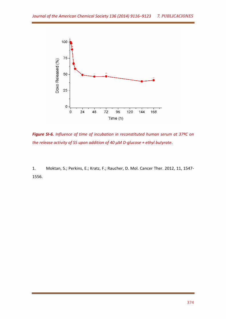
Journal of the American Chemical Society 136 (2014) 9116–9123 7. PUBLICACIONES
374
Figure SI-6. Influence of time of incubation in reconstituted human serum at 37ºC on
the release activity of S5 upon addition of 40 µM D-glucose + ethyl butyrate.
1. Moktan, S.; Perkins, E.; Kratz, F.; Raucher, D. Mol. Cancer Ther. 2012, 11, 1547-
1556.
8 DISCUSIÓN
INTEGRADORA

8. DISCUSIÓN INTEGRADORA
375
8.1. NANOMATERIALES FUNCIONALIZADOS Y NANOHÍBRIDOS PARA EL ENSAMBLAJE
DE SENSORES Y BIOSENSORES ELECTROQUÍMICOS.
En este apartado se discuten los resultados relacionados con la construcción de
electrodos nanoestructurados con diferentes nanomateriales funcionalizados y
nanohíbridos, y su empleo como interfaz de transducción para la construcción de
plataformas electroquímicas de (bio)sensorización.
Los nanomateriales preparados se clasifican en:
- Redes de nanopartículas de oro polifuncionalizadas
- Nanotubos de carbono derivatizados mediante interacciones no covalentes
- Derivados de dendrímeros y dendrones de poliamidoamina
8.1.1. Biosensores basados en redes de nanopartículas de oro polifuncionalizadas.
En los artículos incluidos en este apartado se describen los resultados
relacionados con la construcción de electrodos nanoestructurados con redes
tridimensionales de nanopartículas de oro electropolimerizadas, los cuales fueron
posteriormente empleados en la construcción de biosensores electroquímicos
empleando enzimas y anticuerpos como biorreceptores.
La estrategia propuesta se basa en la preparación de nanopartículas de oro
funcionalizadas con tres tipos de ligandos tiolados diferentes, los cuales desempeñan
funciones distintas en el nanomaterial resultante:
- Ácido 2-mercaptoetanosulfónico: Ligando encargado de conferir hidrofilia,
solubilidad y estabilidad coloidal a las nanopartículas de oro.
- p-Aminotiofenol: Ligando aromático capaz de facilitar la polimerización de las
nanopartículas mediante la formación de enlaces tipo bis-anilina.
- Tercer ligando: Encargado de facilitar la inmovilización de la molécula
biorreceptora.
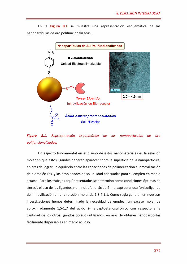
8. DISCUSIÓN INTEGRADORA
376
En la Figura 8.1 se muestra una representación esquemática de las
nanopartículas de oro polifuncionalizadas.
Figura 8.1. Representación esquemática de las nanopartículas de oro
polifuncionalizadas.
Un aspecto fundamental en el diseño de estos nanomateriales es la relación
molar en que estos ligandos deberán aparecer sobre la superficie de la nanopartícula,
en aras de lograr un equilibrio entre las capacidades de polimerización e inmovilización
de biomoléculas, y las propiedades de solubilidad adecuadas para su empleo en medio
acuoso. Para los trabajos aquí presentados se determinó como condiciones óptimas de
síntesis el uso de los ligandos p-aminotiofenol:ácido 2-mercaptoetanosulfónico:ligando
de inmovilización en una relación molar de 1:3,4:1,1. Como regla general, en nuestras
investigaciones hemos determinado la necesidad de emplear un exceso molar de
aproximadamente 1,5-1,7 del ácido 2-mercaptoetanosulfónico con respecto a la
cantidad de los otros ligandos tiolados utilizados, en aras de obtener nanopartículas
fácilmente dispersables en medio acuoso.
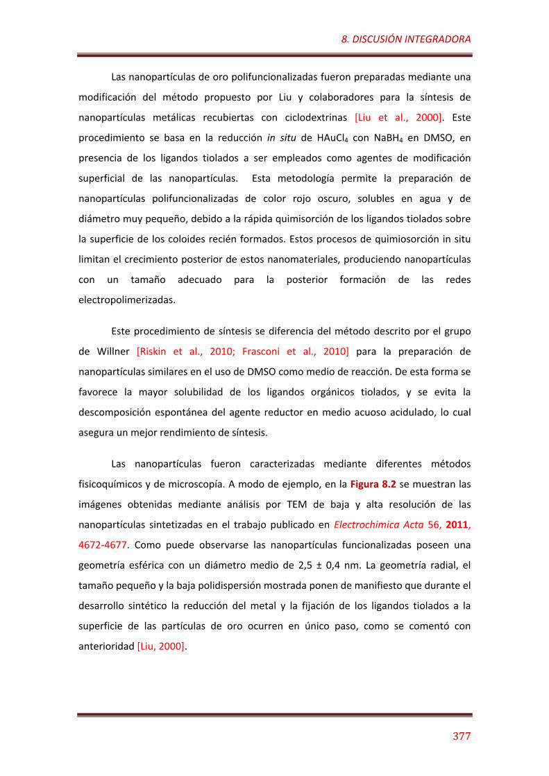
8. DISCUSIÓN INTEGRADORA
377
Las nanopartículas de oro polifuncionalizadas fueron preparadas mediante una
modificación del método propuesto por Liu y colaboradores para la síntesis de
nanopartículas metálicas recubiertas con ciclodextrinas [Liu et al., 2000]. Este
procedimiento se basa en la reducción in situ de HAuCl4 con NaBH4 en DMSO, en
presencia de los ligandos tiolados a ser empleados como agentes de modificación
superficial de las nanopartículas. Esta metodología permite la preparación de
nanopartículas polifuncionalizadas de color rojo oscuro, solubles en agua y de
diámetro muy pequeño, debido a la rápida quimisorción de los ligandos tiolados sobre
la superficie de los coloides recién formados. Estos procesos de quimiosorción in situ
limitan el crecimiento posterior de estos nanomateriales, produciendo nanopartículas
con un tamaño adecuado para la posterior formación de las redes
electropolimerizadas.
Este procedimiento de síntesis se diferencia del método descrito por el grupo
de Willner [Riskin et al., 2010; Frasconi et al., 2010] para la preparación de
nanopartículas similares en el uso de DMSO como medio de reacción. De esta forma se
favorece la mayor solubilidad de los ligandos orgánicos tiolados, y se evita la
descomposición espontánea del agente reductor en medio acuoso acidulado, lo cual
asegura un mejor rendimiento de síntesis.
Las nanopartículas fueron caracterizadas mediante diferentes métodos
fisicoquímicos y de microscopía. A modo de ejemplo, en la Figura 8.2 se muestran las
imágenes obtenidas mediante análisis por TEM de baja y alta resolución de las
nanopartículas sintetizadas en el trabajo publicado en Electrochimica Acta 56, 2011,
4672-4677. Como puede observarse las nanopartículas funcionalizadas poseen una
geometría esférica con un diámetro medio de 2,5 ± 0,4 nm. La geometría radial, el
tamaño pequeño y la baja polidispersión mostrada ponen de manifiesto que durante el
desarrollo sintético la reducción del metal y la fijación de los ligandos tiolados a la
superficie de las partículas de oro ocurren en único paso, como se comentó con
anterioridad [Liu, 2000].
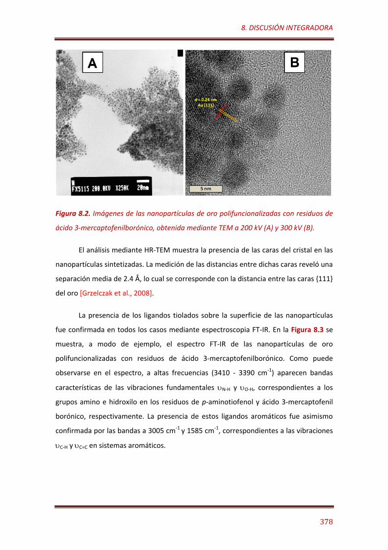
8. DISCUSIÓN INTEGRADORA
378
Figura 8.2. Imágenes de las nanopartículas de oro polifuncionalizadas con residuos de
ácido 3-mercaptofenilborónico, obtenida mediante TEM a 200 kV (A) y 300 kV (B).
El análisis mediante HR-TEM muestra la presencia de las caras del cristal en las
nanopartículas sintetizadas. La medición de las distancias entre dichas caras reveló una
separación media de 2.4 Å, lo cual se corresponde con la distancia entre las caras 111
del oro [Grzelczak et al., 2008].
La presencia de los ligandos tiolados sobre la superficie de las nanopartículas
fue confirmada en todos los casos mediante espectroscopia FT-IR. En la Figura 8.3 se
muestra, a modo de ejemplo, el espectro FT-IR de las nanopartículas de oro
polifuncionalizadas con residuos de ácido 3-mercaptofenilborónico. Como puede
observarse en el espectro, a altas frecuencias (3410 - 3390 cm-1) aparecen bandas
características de las vibraciones fundamentales N-H y O-H, correspondientes a los
grupos amino e hidroxilo en los residuos de p-aminotiofenol y ácido 3-mercaptofenil
borónico, respectivamente. La presencia de estos ligandos aromáticos fue asimismo
confirmada por las bandas a 3005 cm-1 y 1585 cm-1, correspondientes a las vibraciones
C-H y C=C en sistemas aromáticos.
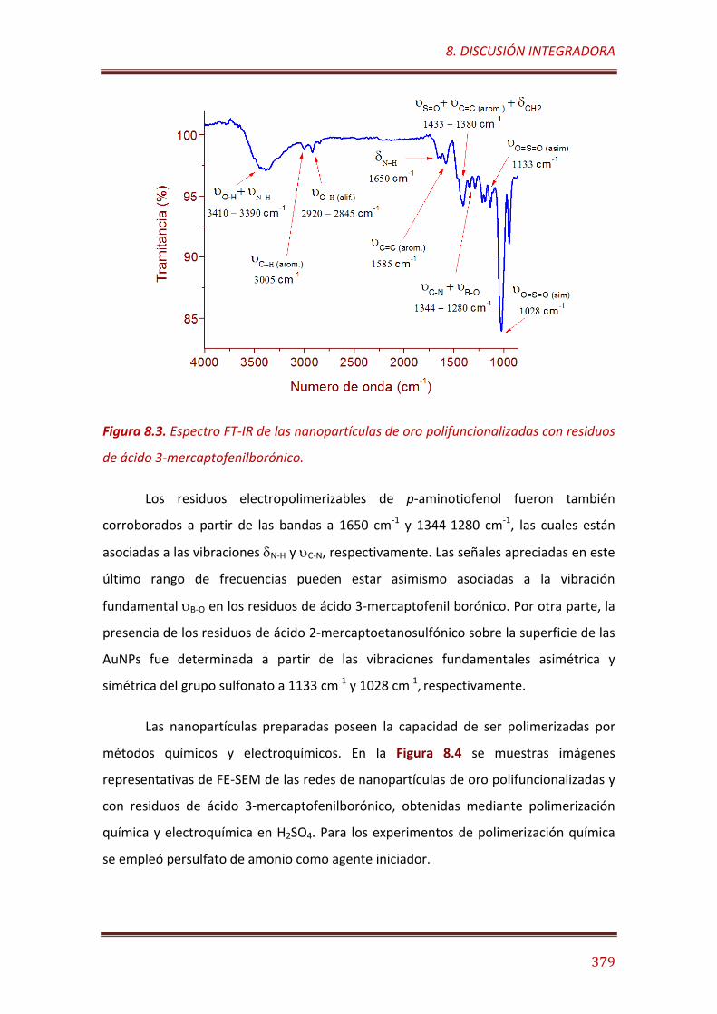
8. DISCUSIÓN INTEGRADORA
379
Figura 8.3. Espectro FT-IR de las nanopartículas de oro polifuncionalizadas con residuos
de ácido 3-mercaptofenilborónico.
Los residuos electropolimerizables de p-aminotiofenol fueron también
corroborados a partir de las bandas a 1650 cm-1 y 1344-1280 cm-1, las cuales están
asociadas a las vibraciones N-H y C-N, respectivamente. Las señales apreciadas en este
último rango de frecuencias pueden estar asimismo asociadas a la vibración
fundamental B-O en los residuos de ácido 3-mercaptofenil borónico. Por otra parte, la
presencia de los residuos de ácido 2-mercaptoetanosulfónico sobre la superficie de las
AuNPs fue determinada a partir de las vibraciones fundamentales asimétrica y
simétrica del grupo sulfonato a 1133 cm-1 y 1028 cm-1, respectivamente.
Las nanopartículas preparadas poseen la capacidad de ser polimerizadas por
métodos químicos y electroquímicos. En la Figura 8.4 se muestras imágenes
representativas de FE-SEM de las redes de nanopartículas de oro polifuncionalizadas y
con residuos de ácido 3-mercaptofenilborónico, obtenidas mediante polimerización
química y electroquímica en H2SO4. Para los experimentos de polimerización química
se empleó persulfato de amonio como agente iniciador.
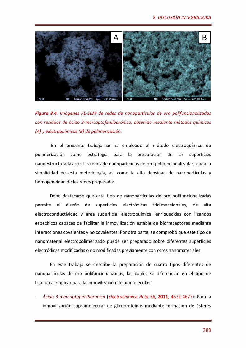
8. DISCUSIÓN INTEGRADORA
380
Figura 8.4. Imágenes FE-SEM de redes de nanopartículas de oro polifuncionalizadas
con residuos de ácido 3-mercaptofenilborónico, obtenida mediante métodos químicos
(A) y electroquímicos (B) de polimerización.
En el presente trabajo se ha empleado el método electroquímico de
polimerización como estrategia para la preparación de las superficies
nanoestructuradas con las redes de nanopartículas de oro polifuncionalizadas, dada la
simplicidad de esta metodología, así como la alta densidad de nanopartículas y
homogeneidad de las redes preparadas.
Debe destacarse que este tipo de nanopartículas de oro polifuncionalizadas
permite el diseño de superficies electródicas tridimensionales, de alta
electroconductividad y área superficial electroquímica, enriquecidas con ligandos
específicos capaces de facilitar la inmovilización estable de biorreceptores mediante
interacciones covalentes y no covalentes. Por otra parte, se comprobó que este tipo de
nanomaterial electropolimerizado puede ser preparado sobre diferentes superficies
electródicas modificadas o no modificadas previamente con otros nanomateriales.
En este trabajo se describe la preparación de cuatro tipos diferentes de
nanopartículas de oro polifuncionalizadas, las cuales se diferencian en el tipo de
ligando a emplear para la inmovilización de biomoléculas:
- Ácido 3-mercaptofenilborónico (Electrochimica Acta 56, 2011, 4672-4677): Para la
inmovilización supramolecular de glicoproteínas mediante formación de ésteres
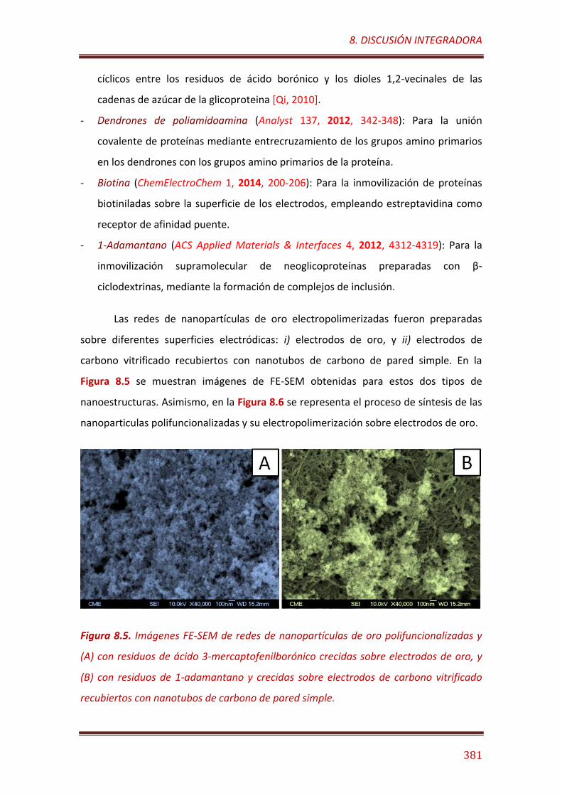
8. DISCUSIÓN INTEGRADORA
381
cíclicos entre los residuos de ácido borónico y los dioles 1,2-vecinales de las
cadenas de azúcar de la glicoproteina [Qi, 2010].
- Dendrones de poliamidoamina (Analyst 137, 2012, 342-348): Para la unión
covalente de proteínas mediante entrecruzamiento de los grupos amino primarios
en los dendrones con los grupos amino primarios de la proteína.
- Biotina (ChemElectroChem 1, 2014, 200-206): Para la inmovilización de proteínas
biotiniladas sobre la superficie de los electrodos, empleando estreptavidina como
receptor de afinidad puente.
- 1-Adamantano (ACS Applied Materials & Interfaces 4, 2012, 4312-4319): Para la
inmovilización supramolecular de neoglicoproteínas preparadas con β-
ciclodextrinas, mediante la formación de complejos de inclusión.
Las redes de nanopartículas de oro electropolimerizadas fueron preparadas
sobre diferentes superficies electródicas: i) electrodos de oro, y ii) electrodos de
carbono vitrificado recubiertos con nanotubos de carbono de pared simple. En la
Figura 8.5 se muestran imágenes de FE-SEM obtenidas para estos dos tipos de
nanoestructuras. Asimismo, en la Figura 8.6 se representa el proceso de síntesis de las
nanoparticulas polifuncionalizadas y su electropolimerización sobre electrodos de oro.
Figura 8.5. Imágenes FE-SEM de redes de nanopartículas de oro polifuncionalizadas y
(A) con residuos de ácido 3-mercaptofenilborónico crecidas sobre electrodos de oro, y
(B) con residuos de 1-adamantano y crecidas sobre electrodos de carbono vitrificado
recubiertos con nanotubos de carbono de pared simple.
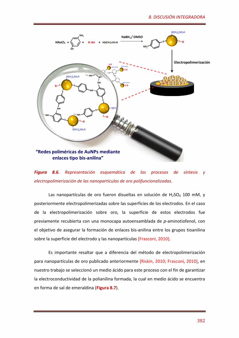
8. DISCUSIÓN INTEGRADORA
382
Figura 8.6. Representación esquemática de los procesos de síntesis y
electropolimerización de las nanopartículas de oro polifuncionalizadas.
Las nanopartículas de oro fueron disueltas en solución de H2SO4 100 mM, y
posteriormente electropolimerizadas sobre las superficies de los electrodos. En el caso
de la electropolimerización sobre oro, la superficie de estos electrodos fue
previamente recubierta con una monocapa autoensamblada de p-aminotiofenol, con
el objetivo de asegurar la formación de enlaces bis-anilina entre los grupos tioanilina
sobre la superficie del electrodo y las nanopartículas [Frasconi, 2010].
Es importante resaltar que a diferencia del método de electropolimerización
para nanopartículas de oro publicado anteriormente [Riskin, 2010; Frasconi, 2010], en
nuestro trabajo se seleccionó un medio ácido para este proceso con el fin de garantizar
la electroconductividad de la polianilina formada, la cual en medio ácido se encuentra
en forma de sal de emeraldina (Figura 8.7).
Electropolimerización
“Redes poliméricas de AuNPs medianteenlaces tipo bis-anilina”
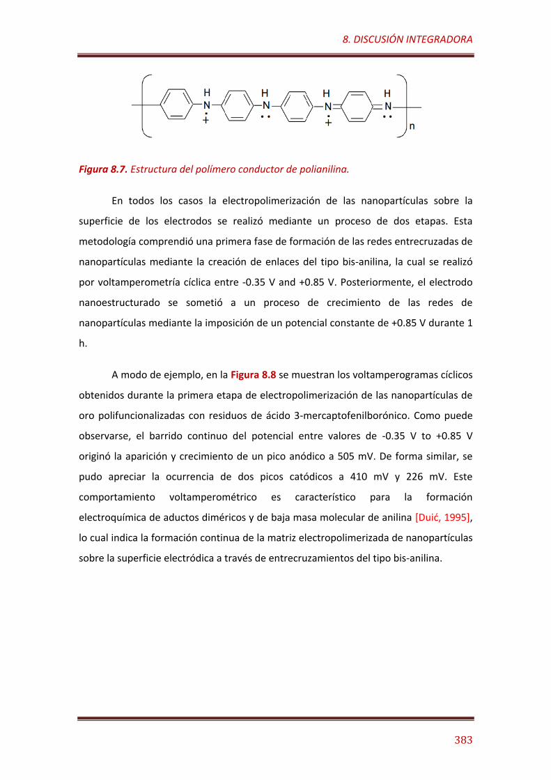
8. DISCUSIÓN INTEGRADORA
383
Figura 8.7. Estructura del polímero conductor de polianilina.
En todos los casos la electropolimerización de las nanopartículas sobre la
superficie de los electrodos se realizó mediante un proceso de dos etapas. Esta
metodología comprendió una primera fase de formación de las redes entrecruzadas de
nanopartículas mediante la creación de enlaces del tipo bis-anilina, la cual se realizó
por voltamperometría cíclica entre -0.35 V and +0.85 V. Posteriormente, el electrodo
nanoestructurado se sometió a un proceso de crecimiento de las redes de
nanopartículas mediante la imposición de un potencial constante de +0.85 V durante 1
h.
A modo de ejemplo, en la Figura 8.8 se muestran los voltamperogramas cíclicos
obtenidos durante la primera etapa de electropolimerización de las nanopartículas de
oro polifuncionalizadas con residuos de ácido 3-mercaptofenilborónico. Como puede
observarse, el barrido continuo del potencial entre valores de -0.35 V to +0.85 V
originó la aparición y crecimiento de un pico anódico a 505 mV. De forma similar, se
pudo apreciar la ocurrencia de dos picos catódicos a 410 mV y 226 mV. Este
comportamiento voltamperométrico es característico para la formación
electroquímica de aductos diméricos y de baja masa molecular de anilina [Duić, 1995],
lo cual indica la formación continua de la matriz electropolimerizada de nanopartículas
sobre la superficie electródica a través de entrecruzamientos del tipo bis-anilina.
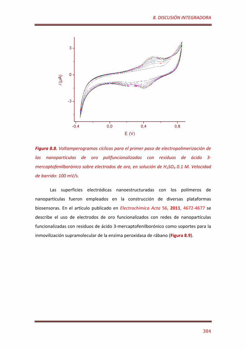
8. DISCUSIÓN INTEGRADORA
384
Figura 8.8. Voltamperogramas cíclicos para el primer paso de electropolimerización de
las nanopartículas de oro polifuncionalizadas con residuos de ácido 3-
mercaptofenilborónico sobre electrodos de oro, en solución de H2SO4 0.1 M. Velocidad
de barrido: 100 mV/s.
Las superficies electródicas nanoestructuradas con los polímeros de
nanopartículas fueron empleados en la construcción de diversas plataformas
biosensoras. En el artículo publicado en Electrochimica Acta 56, 2011, 4672-4677 se
describe el uso de electrodos de oro funcionalizados con redes de nanopartículas
funcionalizadas con residuos de ácido 3-mercaptofenilborónico como soportes para la
inmovilización supramolecular de la enzima peroxidasa de rábano (Figura 8.9).
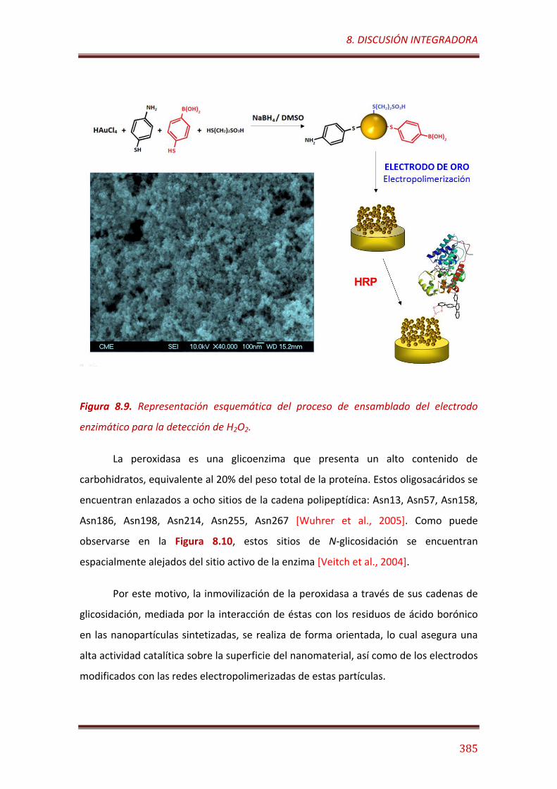
8. DISCUSIÓN INTEGRADORA
385
Figura 8.9. Representación esquemática del proceso de ensamblado del electrodo
enzimático para la detección de H2O2.
La peroxidasa es una glicoenzima que presenta un alto contenido de
carbohidratos, equivalente al 20% del peso total de la proteína. Estos oligosacáridos se
encuentran enlazados a ocho sitios de la cadena polipeptídica: Asn13, Asn57, Asn158,
Asn186, Asn198, Asn214, Asn255, Asn267 [Wuhrer et al., 2005]. Como puede
observarse en la Figura 8.10, estos sitios de N-glicosidación se encuentran
espacialmente alejados del sitio activo de la enzima [Veitch et al., 2004].
Por este motivo, la inmovilización de la peroxidasa a través de sus cadenas de
glicosidación, mediada por la interacción de éstas con los residuos de ácido borónico
en las nanopartículas sintetizadas, se realiza de forma orientada, lo cual asegura una
alta actividad catalítica sobre la superficie del nanomaterial, así como de los electrodos
modificados con las redes electropolimerizadas de estas partículas.
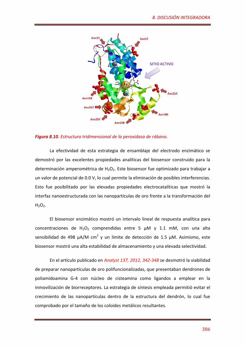
8. DISCUSIÓN INTEGRADORA
386
Figura 8.10. Estructura tridimensional de la peroxidasa de rábano.
La efectividad de esta estrategia de ensamblaje del electrodo enzimático se
demostró por las excelentes propiedades analíticas del biosensor construido para la
determinación amperométrica de H2O2. Este biosensor fue optimizado para trabajar a
un valor de potencial de 0.0 V, lo cual permite la eliminación de posibles interferencias.
Esto fue posibilitado por las elevadas propiedades electrocatalíticas que mostró la
interfaz nanoestructurada con las nanopartículas de oro frente a la transformación del
H2O2.
El biosensor enzimático mostró un intervalo lineal de respuesta analítica para
concentraciones de H2O2 comprendidas entre 5 µM y 1.1 mM, con una alta
sensibilidad de 498 µA/M cm2 y un límite de detección de 1.5 µM. Asimismo, este
biosensor mostró una alta estabilidad de almacenamiento y una elevada selectividad.
En el artículo publicado en Analyst 137, 2012, 342-348 se desmotró la viabilidad
de preparar nanopartículas de oro polifuncionalizadas, que presentaban dendrones de
poliamidoamina G-4 con núcleo de cisteamina como ligandos a emplear en la
inmovilización de biorreceptores. La estrategia de síntesis empleada permitió evitar el
crecimiento de las nanopartículas dentro de la estructura del dendrón, lo cual fue
comprobado por el tamaño de los coloides metálicos resultantes.
8. DISCUSIÓN INTEGRADORA
387
Estas nanopartículas funcionalizadas con un ligando macromolecular fueron
electropolimerizadas sobre la superficie de electrodos de oro, los cuales fueron
posteriormente empleados como soporte para la inmovilización covalente de la
enzima tirosinasa mediante entrecruzamiento con glutaraldehido. El electrodo
enzimático obtenido se utilizó en la construcción de un biosensor amperométrico para
la determinación de catecol, sustancia de alto impacto ambiental clasificada como
disruptor endocrino [Bindhumol, 2003].
El biosensor ensamblado mostró un rango de respuesta lineal para
concentraciones de catecol entre 50 nM y 10 µM, con una sensibilidad de 1.94 A/M
cm2 y un límite de detección de 20 nM. Este biosensor mostró alta reproducibilidad en
la medida, y se demostró que su ensamblado se realizaba con un alto grado de
repetibilidad. El biosensor enzimático mostró una elevada estabilidad de almacenaje,
reteniendo el 96% de su actividad inicial después de dos semanas de almacenamiento
a 4 oC en condiciones de humedad.
En aras de demostrar la versatilidad de esta metodología de construcción de
superficies electródicas nanoestructuradas, se sintetizó una nanopartícula de oro
polifuncionalizada provista de residuos de biotina. La biotina (ácido 5-[(3aS,4S,6aR)-2-
oxohexahidro-1H-tieno[3,4-d]imidazol-4-il]pentanoico) es un importante cofactor
enzimático [Maurice et al., 2007] que forma asociaciones muy estables con las
proteínas avidina y estreptavidina, con valores de constante de disociación de sus
complejos del orden de 10−14 M [Korpela, 1984]. Esta elevada afinidad molecular ha
sido ampliamente utilizada para el diseño de sistemas de bioconjugación [Narain et al.,
2007], inmovilización biomolecular [Larsson et al., 2003], inmunodetección [Morgan et
al., 1992] y biosensorización [Rehák et al., 1994] basados en la formación de complejos
biotina-avidina y biotina-estreptavidina.
En nuestro trabajo publicado en ChemElectroChem 1, 2014, 200-206 se
describió la electropolimerización de nanopartículas de oro polifuncionalizadas con
residuos de biotina sobre la superficie de electrodos de oro, los cuales fueron
empleados como soporte nanoestructurado para el ensamblaje capa-a-capa de un
inmunosensor electroquímico para la detección de fibrinógeno humano, un
8. DISCUSIÓN INTEGRADORA
388
importante marcador de enfermedades cardiovasculares [Lowe et al., 2004]. La
estrategia de ensamblaje utilizada se basó en la inmovilización de moléculas de
estreptavidina sobre la superficie del electrodo mediante interacciones de afinidad.
Estas moléculas de estreptavidina fueron empleadas como puente para el posterior
ensamblado de anticuerpos específicos para el fibrinógeno humano, derivatizados con
residuos de biotina.
El electrodo biofuncionalizado se empleó en la construcción de un
inmunosensor amperométrico, capaz de detectar fibrinógeno humano en un rango de
concentraciones entre 18 ng/mL y 2.208 µg/mL, con un límite de detección de 4 ng/mL
y un valor de IC50 de 177 ng/mL. Este inmunosensor fue notablemente estable,
conservando todo su potencial analítico después de 45 días de almacenamiento a 4 oC.
Finalmente, nuestra investigación se dirigió a comprobar la posibilidad de
electropolimerizar nanopartículas de oro sobre superficies electródicas previamente
modificadas con otro nanomaterial, así como emplear estas interfaces
nanoestructuradas para la inmovilización de biorreceptores mediante interacciones
supramoleculares del tipo “host-guest”. Para ello se prepararon nanopartículas de oro
polifuncionalizadas con residuos de adamantano, las cuales fueron
electropolimerizadas sobre electrodos de carbono vitrificado recubierto con
nanotubos de carbono de pared simple. Los resultados de este trabajo fueron
publicados en ACS Applied Materials & Interfaces 4, 2012, 4312-4319.
Para comprobar nuestra hipótesis de trabajo se sintetizó una neoglicoenzima
de xantina oxidasa modificada covalentemente con residuos de mono-6-etilendiamino-
6-deoxi-β-ciclodextrina. Esta reacción de derivatización se realizó empleando una
carbodiimida hidrosoluble como agente de activación de los grupos carboxilatos en la
superficie de la enzima, siguiendo protocolos previamente descubiertos en la
bibliografía para la síntesis de neoglicoenzimas con ciclodextrinas [Villalonga et al.,
2007].
Se comprobó la capacidad de la enzima artificialmente glicosidada de formar
complejos de inclusión estables con los residuos de 1-adamantano localizados sobre la
8. DISCUSIÓN INTEGRADORA
389
superficie de las nanopartículas de oro electropolimerizadas sobre el electrodo, lo cual
permitió su inmovilización supramolecular sobre la interfaz nanoestructurada. El
electrodo enzimático resultante se empleó en la construcción de un biosensor
amperométrico para la determinación de xantina, el cual mostró un rango de
respuesta linear para concentraciones del analito comprendidas entre 50 nM y 9.5 µM,
con una alta sensibilidad de 2.47 A/M·cm2 y un bajo límite de detección de 40 nM.
Este biosensor mostró una alta estabilidad, lo cual puede justificarse por la alta
estabilidad estructural y funcional que generalmente es conferida a las enzimas tras su
modificación covalente con residuos de ciclodextrinas [Villalonga et al., 2003;
Fernández, 2003]. Por otra parte, se comprobó que las señales analíticas obtenidas con
este biosensor mostraron cierta afectación en presencia de los ácidos ascórbico y
úrico. Esta acción interferente fue notablemente minimizada mediante el
recubrimiento de la matriz electródica con una película delgada de Nafión.
8.1.2. Biosensores nanoestructurados con nanotubos de carbono modificados
mediante interacciones no covalentes.
En los artículos incluidos en este punto se describen los resultados obtenidos
en el diseño de superficies nanoestructuradas para la construcción de biosensores
electroquímicos, mediante el empleo de nanohíbridos preparados a partir de
nanotubos de carbono de pared simple.
Estos nanomateriales son muy empleados en la construcción de biosensores
electroquímicos gracias a sus excelentes propiedades electroconductoras y
electrocatalíticas. Sin embargo, de manera general los nanotubos de carbono poseen
desventajas asociadas a sus características intrínsecas, las cuales limitan su mayor uso
en la tecnología de los biosensores. En este sentido, la ausencia de grupos funcionales
superficiales en estos nanomateriales dificulta la inmovilización estable de
biorreceptores. Por otra parte, la alta hidrofobicidad de estas estructuras carbonáceas
afecta a su solubilidad o dispersabilidad en medios acuosos. Por tal motivo, se hace
necesaria la funcionalización de estos nanomateriales para su empleo en la
8. DISCUSIÓN INTEGRADORA
390
construcción de plataformas biosensoras electroquímicas [Ajayan, 1999; Agüí et al.,
2008].
La funcionalización de los nanotubos de carbono puede realizarse mediante
transformación covalente o no covalente tanto de su cavidad interior como de su
superficie externa [Wang et al., 2008]. La funcionalización covalente introduce grupos
funcionales mediante transformación directa de los átomos de carbono en la
estructura del nanomaterial. Esta transformación reduce las capacidades
electroconductoras de los nanotubos y puede afectar a la actividad de las biomoléculas
posteriormente inmovilizadas debido a efectos de impedimento estérico [Wang,
2005b].
Por el contrario, la funcionalización no covalente se basa en interacciones de
adsorción física o atrapamiento, que no alteran las propiedades de los nanotubos de
carbono. Estas estrategias no covalentes generan una menor afectación en las
propiedades electroconductoras del nanomaterial. Sin embargo, los derivados no
covalentes de los nanotubos de carbono a ser empleados en la construcción de
biosensores deben ser específicamente diseñados para asegurar que proporcionen
estabilidad o vida útil a estos dispositivos bioanalíticos [Georgakilas et al., 2010].
En este trabajo se desarrollaron dos estrategias de derivatización no
covalente que mejoraban la solubilidad de los nanotubos de carbono en sistemas
acuosos y favorecían la inmovilización específica de biomoléculas sobre su superficie
sin afectar su estructura y propiedades, reduciendo a la vez los procesos de adsorción
no específicos de proteínas. Estos nuevos nanomateriales derivatizados fueron
evaluados como elementos de transducción para el diseño de biosensores
amperométricos, tomando la enzima xantina oxidasa como modelo de biorreceptor
catalítico. En la Figura 8.11 se muestra una representación esquematizada de las dos
estrategias de derivatización de nanotubos de carbono de pared simple descritas en
este trabajo.
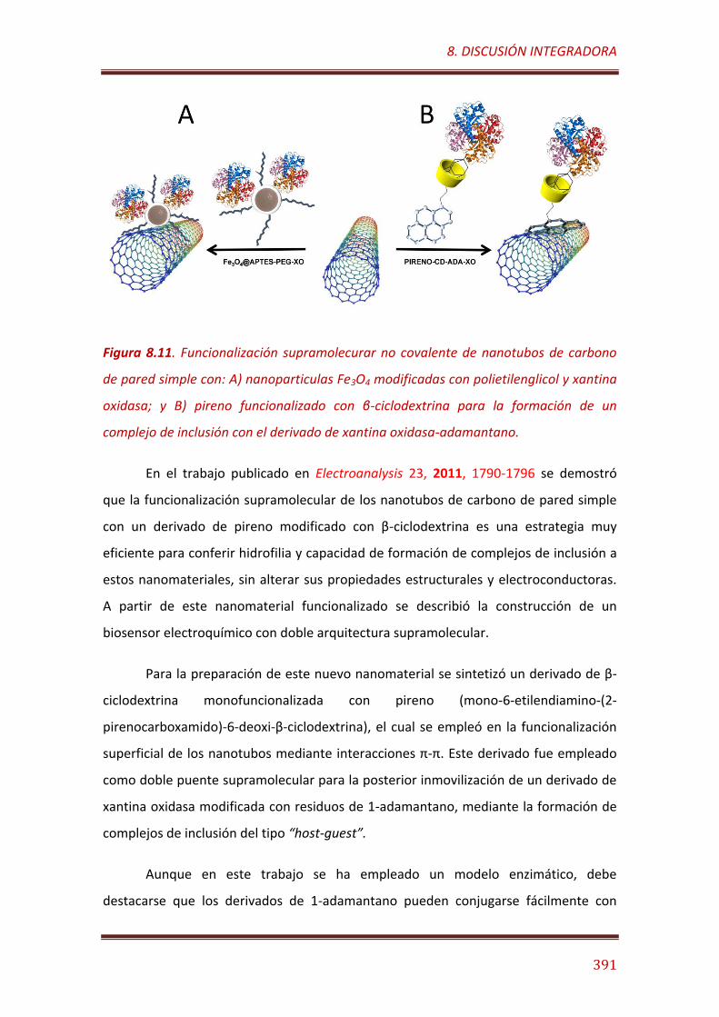
8. DISCUSIÓN INTEGRADORA
391
Figura 8.11. Funcionalización supramolecurar no covalente de nanotubos de carbono
de pared simple con: A) nanoparticulas Fe3O4 modificadas con polietilenglicol y xantina
oxidasa; y B) pireno funcionalizado con β-ciclodextrina para la formación de un
complejo de inclusión con el derivado de xantina oxidasa-adamantano.
En el trabajo publicado en Electroanalysis 23, 2011, 1790-1796 se demostró
que la funcionalización supramolecular de los nanotubos de carbono de pared simple
con un derivado de pireno modificado con β-ciclodextrina es una estrategia muy
eficiente para conferir hidrofilia y capacidad de formación de complejos de inclusión a
estos nanomateriales, sin alterar sus propiedades estructurales y electroconductoras.
A partir de este nanomaterial funcionalizado se describió la construcción de un
biosensor electroquímico con doble arquitectura supramolecular.
Para la preparación de este nuevo nanomaterial se sintetizó un derivado de β-
ciclodextrina monofuncionalizada con pireno (mono-6-etilendiamino-(2-
pirenocarboxamido)-6-deoxi-β-ciclodextrina), el cual se empleó en la funcionalización
superficial de los nanotubos mediante interacciones π-π. Este derivado fue empleado
como doble puente supramolecular para la posterior inmovilización de un derivado de
xantina oxidasa modificada con residuos de 1-adamantano, mediante la formación de
complejos de inclusión del tipo “host-guest”.
Aunque en este trabajo se ha empleado un modelo enzimático, debe
destacarse que los derivados de 1-adamantano pueden conjugarse fácilmente con
8. DISCUSIÓN INTEGRADORA
392
cualquier proteína o ácido nucleico mediante métodos convencionales, por lo cual
podemos considerar esta estrategia como una metodología general para la
biofuncionalización supramolecular de nanotubos de carbono.
Esta estrategia de doble funcionalización supramolecular se utilizó para la
modificación de un electrodo de carbono vitrificado con el nanohíbrido preparado, en
aras de construir un biosensor amperométrico para xantina. El biosensor resultante
mostró muy buenas propiedades analíticas, destacando su bajo tiempo de respuesta
de 10 s, alta sensibilidad de 5.9 mA / M·cm2, bajo límite de detección de 2 mM y alta
estabilidad.
Por otra parte, en el artículo publicado en Journal of Materials Chemistry 21,
2011, 12858-12864 se describió un procedimiento de funcionalización basado en la
adsorción de derivados de polietilenglicol sobre la superficie de los nanotubos de
carbono de pared simple. Este polímero posee alta afinidad por los nanotubos de
carbono, adsorbiéndose de forma estable sobre su superficie, lo cual aumenta las
propiedades de solubilidad/dispersabilidad del nanomaterial y reduce los procesos de
adsorción inespecífica de proteínas [Shim et al., 2002; Sun et al., 2002]. En nuestro
caso, se prepararon nanopartículas superparamagnéticas de Fe3O4 (14 ± 7), las cuales
fueron inicialmente derivatizadas mediante reacción con (3-aminopropil)trietoxisilano
con el objetivo de introducir grupos amino primarios sobre su superficie. Estos grupos
amino primarios fueron posteriormente empleados como puntos de anclaje para la
funcionalización de las nanopartículas con cadenas de polietilenglicol (Mw = 5000 Da)
mediante reacción con un derivado del polímero monoactivado con N-
hidroxisuccinimida.
Las nanopartículas modificadas con polietilenglicol mostraron una mejor
capacidad de dispersión en disoluciones acuosas, y mantuvieron altas propiedades de
magnetización. Estas nanopartículas fueron posteriormente empleadas para la
funcionalización de nanotubos de carbono de pared simple, obteniéndose un derivado
de los nanotubos con buenas propiedades de dispersión en medios acuosos, y nuevas
propiedades de magnetización.
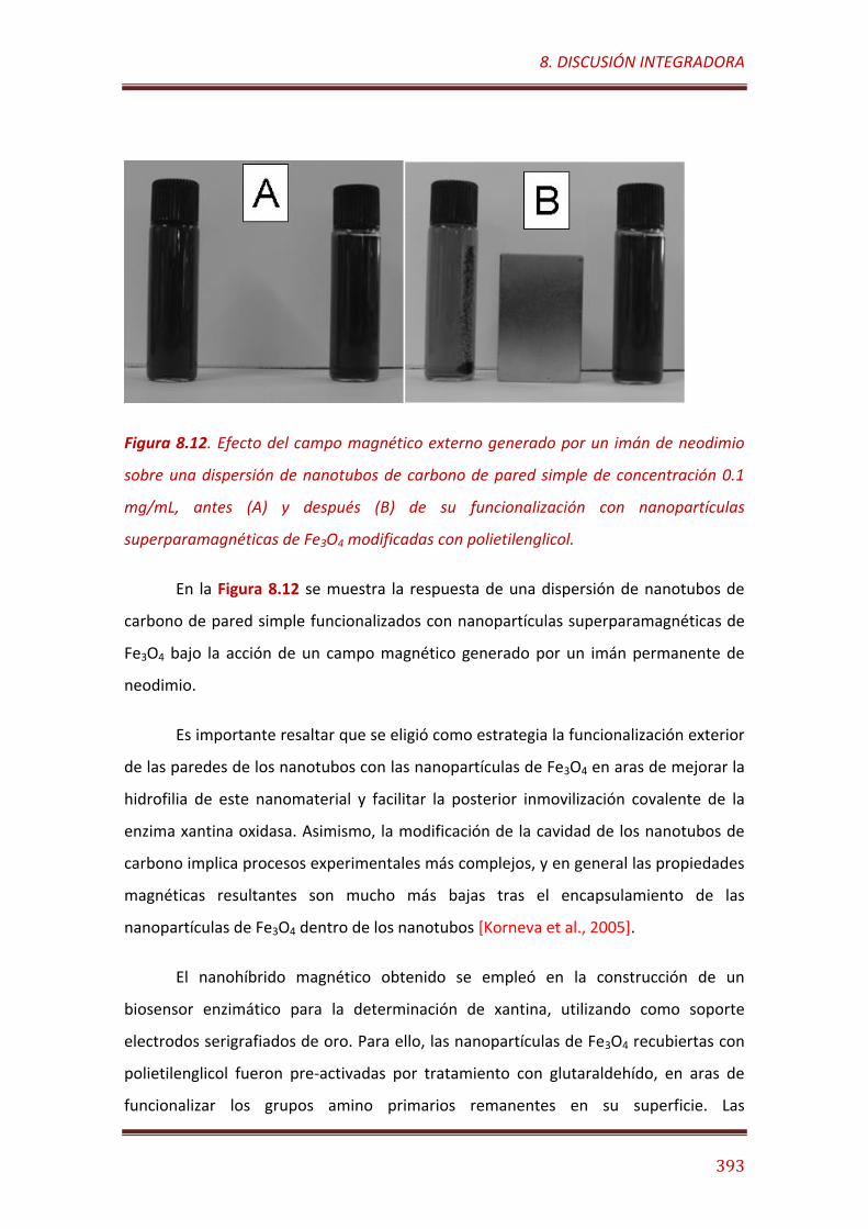
8. DISCUSIÓN INTEGRADORA
393
Figura 8.12. Efecto del campo magnético externo generado por un imán de neodimio
sobre una dispersión de nanotubos de carbono de pared simple de concentración 0.1
mg/mL, antes (A) y después (B) de su funcionalización con nanopartículas
superparamagnéticas de Fe3O4 modificadas con polietilenglicol.
En la Figura 8.12 se muestra la respuesta de una dispersión de nanotubos de
carbono de pared simple funcionalizados con nanopartículas superparamagnéticas de
Fe3O4 bajo la acción de un campo magnético generado por un imán permanente de
neodimio.
Es importante resaltar que se eligió como estrategia la funcionalización exterior
de las paredes de los nanotubos con las nanopartículas de Fe3O4 en aras de mejorar la
hidrofilia de este nanomaterial y facilitar la posterior inmovilización covalente de la
enzima xantina oxidasa. Asimismo, la modificación de la cavidad de los nanotubos de
carbono implica procesos experimentales más complejos, y en general las propiedades
magnéticas resultantes son mucho más bajas tras el encapsulamiento de las
nanopartículas de Fe3O4 dentro de los nanotubos [Korneva et al., 2005].
El nanohíbrido magnético obtenido se empleó en la construcción de un
biosensor enzimático para la determinación de xantina, utilizando como soporte
electrodos serigrafiados de oro. Para ello, las nanopartículas de Fe3O4 recubiertas con
polietilenglicol fueron pre-activadas por tratamiento con glutaraldehído, en aras de
funcionalizar los grupos amino primarios remanentes en su superficie. Las
8. DISCUSIÓN INTEGRADORA
394
nanopartículas pre-activadas se incubaron posteriormente con una disolución de
xantina oxidasa, asegurando que solo los grupos amino terminales de la enzima
reaccionen con los aldehídos de la superficie de las nanopartículas. Finalmente, las
nanopartículas biofuncionalizadas con la enzima fueron empleadas para la
funcionalización no covalente de los nanotubos de carbono de pared simple, a través
de la adsorción irreversible de las cadenas de polímero sobre los nanotubos.
Se comprobó que la actividad catalítica de la enzima no se vió afectada
significativamente tras su inmovilización en el nanomaterial, lo cual puede atribuirse
tanto a la estrategia de pre-activación empleada en el proceso de inmovilización, como
al microambiente hidrofílico creado por las cadenas de polietilenglicol, y al bajo
impedimento estérico que los nanotubos de carbono ejercen sobre el centro activo de
la enzima debido a la naturaleza flexible de los brazos espaciadores de polímero
empleados en la funcionalización de los nanotubos.
El nanomaterial biofuncionalizado fue inmovilizado magnéticamente sobre la
superficie de los electrodos para la construcción de un biosensor amperométrico para
xantina. La efectividad de esta estrategia de ensamblaje se confirmó con las excelentes
propiedades analíticas obtenidas para este dispositivo. El biosensor resultante mostró
una dependencia lineal con la concentración de xantina en el rango de 250 µM a 3.5
mM, con una rápida respuesta amperométrica en 12 s. Asimismo, el biosensor mostró
una alta sensibilidad de 1.31 A·M/ cm2 y un bajo límite de detección de 60 nM.
8.1.3. Biosensores basados en dendrímeros y dendrones de poliamidoamina
modificados con ciclodextrinas.
En los artículos incluidos en este apartado se describen los resultados
relacionados con la construcción de electrodos nanoestructurados mediante derivados
de dendrímeros y dendrones de poliamidoamina funcionalizados con β-ciclodextrina
para el diseño de biosensores electroquímicos empleando enzimas como
biorreceptores.
8. DISCUSIÓN INTEGRADORA
395
La estrategia propuesta se basa en la utilización de estos derivados de los
dendrímeros y dendrones como elementos estructurales para el ensamblaje de
arquitecturas tridimensionales sobre las superficies electródicas. Este tipo de
polímeros dendríticos posibilita el diseño de estructuras tridimensionales con una alta
densidad de grupos reactivos superficiales, lo que permite la inmovilización estable y
multipuntual de una alta densidad de biomoléculas mediante uniones covalentes o no
covalentementes. Este hecho favorece la construcción de biosensores con alta
sensibilidad [Soler et al., 2015].
Asimismo, la estructura permeable de estos polímeros favorece la difusión de
las especies electroactivas hacia la superficie de los electrodos. Este hecho es una
ventaja en comparación con otras macromoléculas comúnmente empleadas en la
construcción de arquitecturas capa-a-capa, las cuales en general ejercen serios
impedimentos estéricos que limitan los fenómenos de difusión de sustancias y
transferencia de carga en las interfases electródicas [Vögtle et al., 2009].
Debe destacarse que uno de los aspectos más importantes a tener en cuenta
en el diseño de un biosensor es la necesidad de garantizar la inmovilización estable de
los biorreceptores sin afectar significativamente su estructura biológicamente activa, y
por tanto su actividad funcional [Wang et al., 2008]. Por ese motivo, en el presente
trabajo se eligió una estrategia de inmovilización supramolecular del tipo “host-guest”
para las enzimas en estudio, funcionalizando los grupos amino primarios terminales de
los dendrímeros y dendrones con unidades de -cliclodextrinas y modificando las
enzimas con residuos de 1-adamantano. Estas estrategias de inmovilización
supramolecular de biorreceptores han sido validadas en otros sistemas biosensores
previamente publicados en la literatura [Díez et al., 2012; Villalonga et al., 2003;
Fernández, 2003]
Por otra parte, la introducción de residuos de -cliclodextrinas en la superficie
de los polímeros dendríticos favorece la formación de sistemas multicapas
supramoleculares estables mediante el uso de biomoléculas modificadas con
compuestos hidrofóbicos de alta afinidad por estos oligosacáridos cíclicos, tales como
los derivados de 1-adamantano [Fragoso et al., 2002].
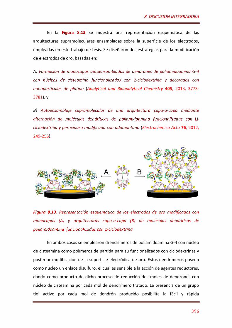
8. DISCUSIÓN INTEGRADORA
396
En la Figura 8.13 se muestra una representación esquemática de las
arquitecturas supramoleculares ensambladas sobre la superficie de los electrodos,
empleadas en este trabajo de tesis. Se diseñaron dos estrategias para la modificación
de electrodos de oro, basadas en:
A) Formación de monocapas autoensambladas de dendrones de poliamidoamina G-4
-ciclodextrina y decorados con
nanopartículas de platino (Analytical and Bioanalytical Chemistry 405, 2013, 3773-
3781), y
B) Autoensamblaje supramolecular de una arquitectura capa-a-capa mediante
alternación de -
ciclodextrina y peroxidasa modificada con adamantano (Electrochimica Acta 76, 2012,
249-255).
Figura 8.13. Representación esquemática de los electrodos de oro modificados con
monocapas (A) y arquitecturas capa-a-capa (B) de moléculas dendríticas de
-ciclodextrina
En ambos casos se emplearon drendrímeros de poliamidoamina G-4 con núcleo
de cisteamina como polímeros de partida para su funcionalizados con ciclodextrinas y
posterior modificación de la superficie electródica de oro. Estos dendrímeros poseen
como núcleo un enlace disulfuro, el cual es sensible a la acción de agentes reductores,
dando como producto de dicho proceso de reducción dos moles de dendrones con
núcleo de cisteamina por cada mol de dendrímero tratado. La presencia de un grupo
tiol activo por cada mol de dendrón producido posibilita la fácil y rápida
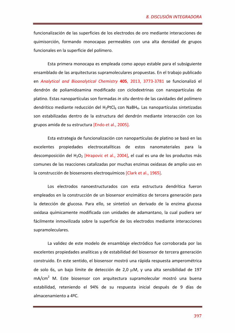
8. DISCUSIÓN INTEGRADORA
397
funcionalización de las superficies de los electrodos de oro mediante interacciones de
quimisorción, formando monocapas permeables con una alta densidad de grupos
funcionales en la superficie del polímero.
Esta primera monocapa es empleada como apoyo estable para el subsiguiente
ensamblado de las arquitecturas supramoleculares propuestas. En el trabajo publicado
en Analytical and Bioanalytical Chemistry 405, 2013, 3773-3781 se funcionalizó el
dendrón de poliamidoamina modificado con ciclodextrinas con nanopartículas de
platino. Estas nanopartículas son formadas in situ dentro de las cavidades del polímero
dendrítico mediante reducción del H2PtCl6 con NaBH4. Las nanopartículas sintetizadas
son estabilizadas dentro de la estructura del dendrón mediante interacción con los
grupos amida de su estructura [Endo et al., 2005].
Esta estrategia de funcionalización con nanopartículas de platino se basó en las
excelentes propiedades electrocatalíticas de estos nanomateriales para la
descomposición del H2O2 [Hrapovic et al., 2004], el cual es una de los productos más
comunes de las reacciones catalizadas por muchas enzimas oxidasas de amplio uso en
la construcción de biosensores electroquímicos [Clark et al., 1965].
Los electrodos nanoestructurados con esta estructura dendrítica fueron
empleados en la construcción de un biosensor enzimático de tercera generación para
la detección de glucosa. Para ello, se sintetizó un derivado de la enzima glucosa
oxidasa químicamente modificada con unidades de adamantano, la cual pudiera ser
fácilmente inmovilizada sobre la superficie de los electrodos mediante interacciones
supramoleculares.
La validez de este modelo de ensamblaje electródico fue corroborada por las
excelentes propiedades analíticas y de estabilidad del biosensor de tercera generación
construido. En este sentido, el biosensor mostró una rápida respuesta amperométrica
de solo 6s, un bajo límite de detección de 2,0 M, y una alta sensibilidad de 197
mA/cm2 M. Este biosensor con arquitectura supramolecular mostró una buena
estabilidad, reteniendo el 94% de su respuesta inicial después de 9 días de
almacenamiento a 4ºC.
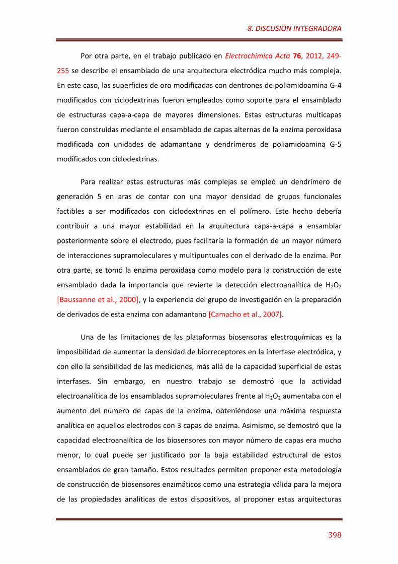
8. DISCUSIÓN INTEGRADORA
398
Por otra parte, en el trabajo publicado en Electrochimica Acta 76, 2012, 249-
255 se describe el ensamblado de una arquitectura electródica mucho más compleja.
En este caso, las superficies de oro modificadas con dentrones de poliamidoamina G-4
modificados con ciclodextrinas fueron empleados como soporte para el ensamblado
de estructuras capa-a-capa de mayores dimensiones. Estas estructuras multicapas
fueron construidas mediante el ensamblado de capas alternas de la enzima peroxidasa
modificada con unidades de adamantano y dendrímeros de poliamidoamina G-5
modificados con ciclodextrinas.
Para realizar estas estructuras más complejas se empleó un dendrímero de
generación 5 en aras de contar con una mayor densidad de grupos funcionales
factibles a ser modificados con ciclodextrinas en el polímero. Este hecho debería
contribuir a una mayor estabilidad en la arquitectura capa-a-capa a ensamblar
posteriormente sobre el electrodo, pues facilitaría la formación de un mayor número
de interacciones supramoleculares y multipuntuales con el derivado de la enzima. Por
otra parte, se tomó la enzima peroxidasa como modelo para la construcción de este
ensamblado dada la importancia que revierte la detección electroanalítica de H2O2
[Baussanne et al., 2000], y la experiencia del grupo de investigación en la preparación
de derivados de esta enzima con adamantano [Camacho et al., 2007].
Una de las limitaciones de las plataformas biosensoras electroquímicas es la
imposibilidad de aumentar la densidad de biorreceptores en la interfase electródica, y
con ello la sensibilidad de las mediciones, más allá de la capacidad superficial de estas
interfases. Sin embargo, en nuestro trabajo se demostró que la actividad
electroanalítica de los ensamblados supramoleculares frente al H2O2 aumentaba con el
aumento del número de capas de la enzima, obteniéndose una máxima respuesta
analítica en aquellos electrodos con 3 capas de enzima. Asimismo, se demostró que la
capacidad electroanalítica de los biosensores con mayor número de capas era mucho
menor, lo cual puede ser justificado por la baja estabilidad estructural de estos
ensamblados de gran tamaño. Estos resultados permiten proponer esta metodología
de construcción de biosensores enzimáticos como una estrategia válida para la mejora
de las propiedades analíticas de estos dispositivos, al proponer estas arquitecturas

8. DISCUSIÓN INTEGRADORA
399
tridimensionales como vía para el aumento de la densidad espacial de biorreceptores
sobre los electrodos.
Los electrodos construidos con 3 capas de peroxidasa mostraron un bajo límite
de detección de 160 nM y una sensibilidad de 602 A/cm2 M frente al H2O2. Asimismo,
estos biosensores mostraron una alta estabilidad, reteniendo el 63% de la respuesta
inicial después de 30 días de almacenaje a 4°C en condiciones de humedad a 4°C, lo
cual demuestra la alta estabilidad estructural de las arquitecturas supramoleculares
capa-a-capa construidas sobre los electrodos.
8. DISCUSIÓN INTEGRADORA
400
8.2. SISTEMAS DE LIBERACIÓN INTELIGENTE DE FÁRMACOS CONTROLADOS POR
ENZIMAS Y BASADOS EN NANOMATERIALES DE SÍLICE MESOPOROSA.
En la segunda parte de este trabajo se discuten los resultados relacionados con
el diseño de nanomateriales mesoporosos funcionalizados para el ensamblaje de
sistemas de liberación inteligente de fármacos controlados por enzimas.
La estrategia general seguida en esta investigación se basa en la integración, en
una misma nanopartícula funcionalizada, de una unidad de control biomolecular con la
unidad de encapsulamiento del fármaco. Para ello se han diseñado unidades de
control enzimático, encargadas de detectar la presencia de determinados compuestos
en el medio (señales INPUT) y transformarlos catalíticamente en productos capaces de
activar los mecanismos de aperturas de los mesoporos donde se encuentra
encapsulada la sustancia que se desea liberar (OUTPUT).
Atendiendo a esta estrategia, se han desarrollado dos modelos diferentes de
nanomáquinas basadas en:
- Nanopartículas de sílice mesoporosa funcionalizadas con neoglicoenzimas, que
actúan dualmente como puertas moleculares y sistemas sensores-efectores.
- Nanopartículas Janus de oro y sílice mesoporosa, funcionalizadas con enzimas en la
cara metálica como sistemas sensores-efectores y mecanizadas con puertas
moleculares estímulo-dependientes en la cara mesoporosa.
8.2.1. Nanomáquinas basadas en nanopartículas de sílice mesoporosa
funcionalizadas con neoglicoenzimas.
El primer modelo descrito en esta Tesis, publicado en ACS Applied Materials
and Interfaces 8, 2016, 7657−7665, describe la preparación de nanopartículas de sílice
mesoporosa funcionalizadas superficialmente con residuos de ácido borónico. Estos
residuos son empleados como puntos de enlace para la inmovilización supramolecular
de un derivado artificialmente glicosidado de la enzima esterasa de hígado de cerdo.

8. DISCUSIÓN INTEGRADORA
401
La esterasa es una enzima que se encuentra en la Naturaleza en forma de glicoenzima
[Arpigny et al., 1999], por lo cual puede formar en medios alcalinos ésteres cíclicos con
los residuos de ácido borónico empleando los grupos 1,2-diol vecinales de los residuos
de azúcares enlazados a su cadena polipeptídica.
Figura 8.14. Representación esquemática del mecanismo de formación de ésteres
cíclicos de ácido borónico con azúcares.
Estos ésteres cíclicos son reversibles y sensibles al pH del medio,
descomponiéndose con el aumento de la acidez. Por otra parte, la estabilidad de estos
ésteres cíclicos depende de la orientación espacial de los grupos 1,2-diol vecinales,
siendo mayor en aquellos que poseen una configuración cis que en los que presentan
configuración trans. Por tal motivo, los residuos de ácido borónico forman
asociaciones supramoleculares de diferente estabilidad con los distintos tipos de
monosacáridos [Lorand et al., 1959], lo cual ha sido anteriormente empleado en el
establecimiento de sistemas sensores selectivos para diferentes tipos de azúcares
[James et al., 1996].
Sobre estas bases, nuestra hipótesis de trabajo se basó en la posibilidad de
conferir diferentes grados de estabilidad a los complejos de la esterasa con los
residuos de ácido borónico sobre la superficie de las nanopartículas de sílice
mesoporosa, mediante la manipulación de la estructura de la enzima por modificación
química con residuos de lactosa. De esta forma, la neoglicoenzima resultante podría
ser empleada como elemento de cierre para ensamblar puestas moleculares
reversibles con diferente grado de estabilidad y nivel de respuesta ante diferentes
estímulos. Esta estrategia de empleo dual de derivados enzimáticos como sistemas
8. DISCUSIÓN INTEGRADORA
402
sensores-efectores y como elementos de cierre en puertas moleculares estímulo-
dependientes ha sido anteriormente propuesta por el equipo de investigación
involucrado en este trabajo [Aznar et al., 2013].
La hipótesis planteada fue demostrada a partir de los resultados
experimentales obtenidos. En este sentido se comprobó que las nanomáquinas
construidas con la neoglicoenzimas poseían diferente comportamiento ante la
presencia de glucosa o etilenglicol, que frente al butirato de etilo. En el primer caso, las
nanomáquinas cargadas con un colorante de prueba, experimentaban una apertura
parcial de las puertas moleculares al adicionar glucosa o etilenglicol en el medio. Estos
compuestos, que poseen grupos 1,2-diol vecinales, son capaces de desplazar los
residuos de azúcares más débilmente enlazados en los complejos con ácido borónico,
promoviendo así la liberación parcial del colorante encapsulado.
Por otra parte, en presencia de butirato de etilo se observó una apertura total
de las puertas moleculares ensambladas con la neoglicoenzima, con la consiguiente
liberación total del colorante de prueba encapsulado. El mecanismo propuesto para
este fenómeno se basa en la trasformación catalítica del butirato de etilo por la
esterasa, produciendo ácido butírico, el cual al disminuir el pH del medio promueve la
ruptura de los ésteres cíclicos de ácido borónico con los azúcares de la enzima.
Sobre la base de estos resultados, la nanopartícula funcionalizada con la
neoglicoenzima de esterasa-lactosa fue empleada en el ensamblaje de una
nanomáquina controlada por la enzima para la liberación bajo demanda, secuencial y
pulsátil de medicamentos. Este tipo de nanomáquinas podría ser muy valiosa en el
establecimiento de cronoterapias personalizadas para el tratamiento de enfermedades
influenciadas por el ritmo circadiano del paciente [Youan, 2004].
Estas nanomáquinas fueron validadas con éxito en experimentos ex vivo para la
liberación secuencial y programada del fármaco antitumoral Doxorrubicina en células
HeLa de cáncer. En este sentido, se comprobó que las nanomáquinas eran fácilmente
internalizadas dentro de las células tumorales, y que eran capaces de liberar
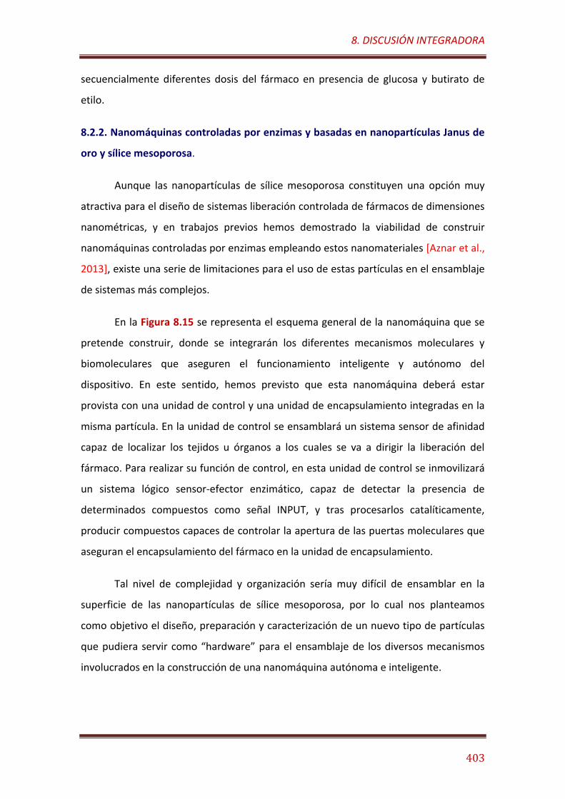
8. DISCUSIÓN INTEGRADORA
403
secuencialmente diferentes dosis del fármaco en presencia de glucosa y butirato de
etilo.
8.2.2. Nanomáquinas controladas por enzimas y basadas en nanopartículas Janus de
oro y sílice mesoporosa.
Aunque las nanopartículas de sílice mesoporosa constituyen una opción muy
atractiva para el diseño de sistemas liberación controlada de fármacos de dimensiones
nanométricas, y en trabajos previos hemos demostrado la viabilidad de construir
nanomáquinas controladas por enzimas empleando estos nanomateriales [Aznar et al.,
2013], existe una serie de limitaciones para el uso de estas partículas en el ensamblaje
de sistemas más complejos.
En la Figura 8.15 se representa el esquema general de la nanomáquina que se
pretende construir, donde se integrarán los diferentes mecanismos moleculares y
biomoleculares que aseguren el funcionamiento inteligente y autónomo del
dispositivo. En este sentido, hemos previsto que esta nanomáquina deberá estar
provista con una unidad de control y una unidad de encapsulamiento integradas en la
misma partícula. En la unidad de control se ensamblará un sistema sensor de afinidad
capaz de localizar los tejidos u órganos a los cuales se va a dirigir la liberación del
fármaco. Para realizar su función de control, en esta unidad de control se inmovilizará
un sistema lógico sensor-efector enzimático, capaz de detectar la presencia de
determinados compuestos como señal INPUT, y tras procesarlos catalíticamente,
producir compuestos capaces de controlar la apertura de las puertas moleculares que
aseguran el encapsulamiento del fármaco en la unidad de encapsulamiento.
Tal nivel de complejidad y organización sería muy difícil de ensamblar en la
superficie de las nanopartículas de sílice mesoporosa, por lo cual nos planteamos
como objetivo el diseño, preparación y caracterización de un nuevo tipo de partículas
que pudiera servir como “hardware” para el ensamblaje de los diversos mecanismos
involucrados en la construcción de una nanomáquina autónoma e inteligente.
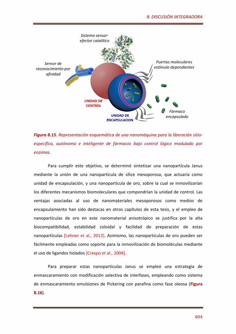
8. DISCUSIÓN INTEGRADORA
404
Figura 8.15. Representación esquemática de una nanomáquina para la liberación sitio-
específica, autónoma e inteligente de fármacos bajo control lógico modulado por
enzimas.
Para cumplir este objetivo, se determinó sintetizar una nanopartícula Janus
mediante la unión de una nanopartícula de sílice mesoporosa, que actuaría como
unidad de encapsulación, y una nanopartícula de oro, sobre la cual se inmovilizarían
los diferentes mecanismos biomoleculares que compondrían la unidad de control. Las
ventajas asociadas al uso de nanomateriales mesoporosos como medios de
encapsulamiento han sido destacas en otros capítulos de esta tesis, y el empleo de
nanopartículas de oro en este nanomaterial anisotrópico se justifica por la alta
biocompatibilidad, estabilidad coloidal y facilidad de preparación de estas
nanopartículas [Lehner et al., 2012]. Asimismo, las nanopartículas de oro pueden ser
fácilmente empleadas como soporte para la inmovilización de biomoléculas mediante
el uso de ligandos tiolados [Crespo et al., 2004].
Para preparar estas nanopartículas Janus se empleó una estrategia de
enmascaramiento con modificación selectiva de interfases, empleando como sistema
de enmascaramiento emulsiones de Pickering con parafina como fase oleosa (Figura
8.16).
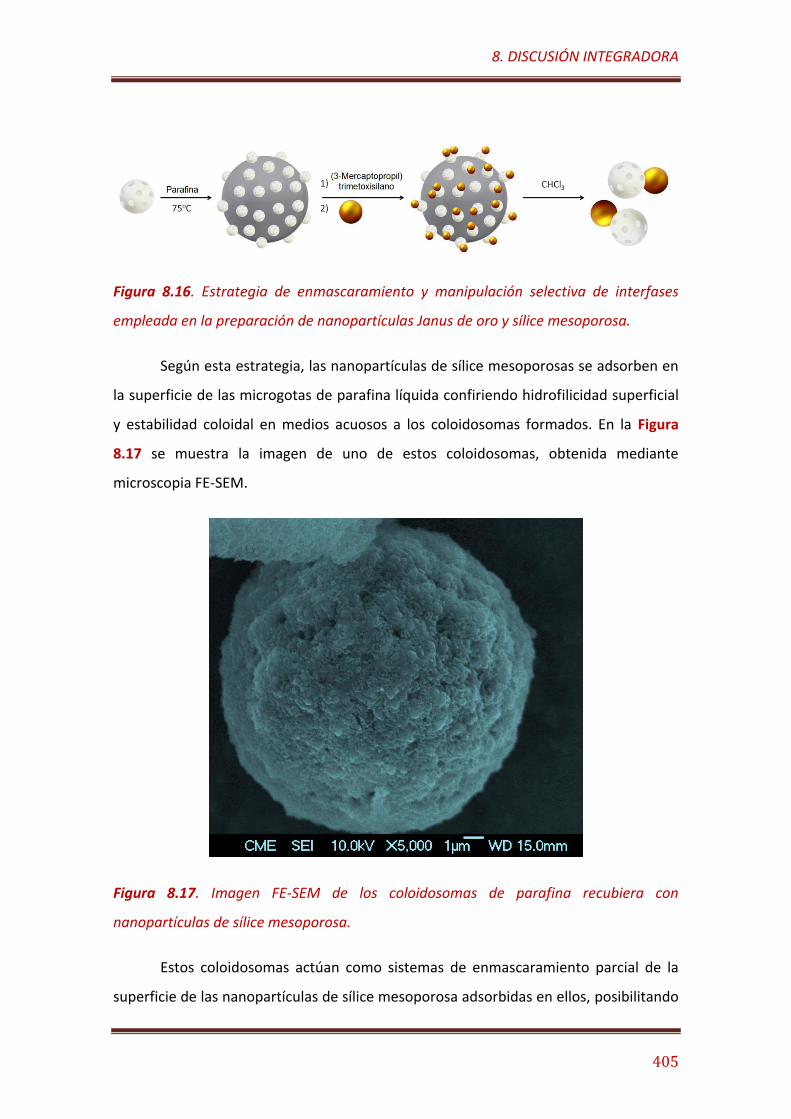
8. DISCUSIÓN INTEGRADORA
405
Figura 8.16. Estrategia de enmascaramiento y manipulación selectiva de interfases
empleada en la preparación de nanopartículas Janus de oro y sílice mesoporosa.
Según esta estrategia, las nanopartículas de sílice mesoporosas se adsorben en
la superficie de las microgotas de parafina líquida confiriendo hidrofilicidad superficial
y estabilidad coloidal en medios acuosos a los coloidosomas formados. En la Figura
8.17 se muestra la imagen de uno de estos coloidosomas, obtenida mediante
microscopia FE-SEM.
Figura 8.17. Imagen FE-SEM de los coloidosomas de parafina recubiera con
nanopartículas de sílice mesoporosa.
Estos coloidosomas actúan como sistemas de enmascaramiento parcial de la
superficie de las nanopartículas de sílice mesoporosa adsorbidas en ellos, posibilitando
8. DISCUSIÓN INTEGRADORA
406
la modificación selectiva de la interfase expuesta al medio acuoso. Para ello, se
funcionalizó esta superficie expuesta con (3-mercaptopropil)trimetosilano, con el
objetivo de introducir grupos tioles libres en esta interfaz, sobre los cuales
posteriormente se enlazan las nanopartículas de oro mediante interacciones
multipuntuales de quimiosorción.
Las nanopartículas Janus preparadas poseen la ventaja de poseer dos caras
químicamente diferentes, lo cual facilita en ensamblado secuencial y topoespecífico de
los diferentes mecanismos moleculares y biomoleculares necesarios para el
funcionamiento de las nanomáquinas. Los trabajos incluidos en este apartado de Tesis
describen los experiementos realizados para comprobar la factibilidad de ensamblar
los diferentes mecanismos de las nanomáquinas.
Inicialmente, en el trabajo publicado en Electrochemistry Communications 30,
2013, 51-54, se describe el diseño de un modelo para comprobar la viabilidad de
incorporar un receptor de afinidad, capaz de actuar como sensor de localización, en la
unidad de control de la nanomáquina. Para ello se inmovilizó estreptavidina en la cara
de oro de la nanopartícula Janus, biomolécula que posee una alta afinidad por la
biotina. Para detectar el proceso de biorreconocimiento, se inmovilizó la enzima
peroxidasa en la cara de sílice mesoporosa de la nanopartícula Janus, y se prepararon
electrodos de oro recubiertos con residuos de biotina con objeto de comprobar este
reconocimiento mediante técnicas electroquímicas. Los resultados obtenidos
demostraron claramente que esta nanopartícula Janus biofuncionalizada actúa como
un nanosistema de biorreconocimiento y señalización.
Debe destacarse que este trabajo, además de servir de demostración sobre la
posibilidad de biofuncionalizar las nanopartículas Janus con receptores de afinidad en
la unidad de control, constituyó la primera publicación sobre el uso de nanopartículas
como nanosistemas de biorreconocimiento y señalización electroquímica.
En el trabajo publicado en Chemistry – A European Journal 19, 2013, 7889-
7894, se planteó la construcción de la primera nanomáquina basada en estas
nanopartículas Janus, controlada por una enzima. Para construir esta nanomáquina se
8. DISCUSIÓN INTEGRADORA
407
empleó cloruro de tris(2,2´-bipiridil) rutenio (II) como modelo de sustancia a
encapsular, dada las excelentes propiedades ópticas de este complejo. Este colorante
fue encapsulado dentro de los nanoporos de la cara mesoporosa de las nanopartículas
Janus, empleando puertas de poliaminas sensibles al pH ensambladas en la superficie
exterior de los poros.
Por otra parte, se inmovilizó la enzima ureasa sobre la cara de oro de la
nanopartícula anisotrópica con el objetivo de emplear este biocatalizador como
sistema sensor-efector, dada su capacidad de reconocer la presencia de urea en el
medio como señal INPUT, y transformar este substrato enzimático en NH3 y CO2 con el
consiguiente aumento de la basicidad del medio.
La nanomáquina ensamblada fue validada en experimentos in vitro,
comprobándose su capacidad de liberar el colorante encapsulado ante la presencia de
urea en el medio.
Finalmente, en el artículo publicado en Journal of the American Chemical
Society 136, 2014, 9116-9123, se describe el ensamblaje de una nanomáquina más
sofisticada. Este dispositivo está regulado por un sistema multienzimático integrado
sobre la superficie de oro de las nanopartículas Janus, basado en la combinación de las
enzimas glucosa oxidasa y esterasa. Esta combinación enzimática opera como una
puerta lógica tipo OR, y con ella se propuso la modulación del mecanismo de liberación
del compuesto encapsulado en la cara de sílice mesoporosa.
Para ello, se encapsuló el colorante cloruro de tris(2,2´-bipiridil) rutenio (II)
dentro de los poros de la cara de sílice mesoporosa de las nanopartículas Janus,
ensamblando nanoválvulas supramoleculares de benzimidazol:β-ciclodextrina sobre la
superficie externa de los poros. Estas nanovávulas son sensibles al cambio de pH del
medio, y su mecanismo de apertura puede ser controlado mediante el reconocimiento
y transformación de la glucosa y el butirato de etilo, como señales INPUT, por el
sistema enzimático inmovilizado, que actúa como operador tipo OR.
El funcionamiento de esta nanomáquina fue comprobado en experimentos in
vitro, determinándose que el colorante solo era liberado al medio tras la adición de
8. DISCUSIÓN INTEGRADORA
408
glucosa, butirato de etilo, o una mezcla de ambos compuestos, de acuerdo a la
combinación de señales INPUT necesarias para un operador tipo OR.
El nivel de complejidad de esta nanomáquina fue incrementado mediante el
acoplamiento de un operador enzimático tipo RESET, para ello se co-inmovilizó la
enzima ureasa sobre la cara de oro de la nanopartícula Janus. En este sentido, se
comprobó que este operador RESET era capaz de detener la apertura de la nanoválvula
supramolecular, y por tanto la liberación al medio de incubación del colorante
encapsulado mediante la adición de urea.
Este control por el operador enzimático RESET resultó ser asimismo sensible a
la concentración de urea en el medio, por lo cual la extensión en que la nanomáquina
operada por la puerta lógica OR era capaz de liberar el colorante pudo ser controlada
mediante la manipulación de la concentración de urea adicionada.
En aras de validar esta nanomáquina en modelos ex vitro de liberación de
fármacos, se preparó una nanopartícula Janus controlada por el operador enzimático
OR, en la cual se encapsuló el fármaco antitumoral Doxorrubicina. Esta nanomáquina
fue incubada con células HeLa de cáncer, comprobándose la internalización de éstas
nanopartículas dentro de las células tumorales. Asimismo, se comprobó la capacidad
de esta nanomáquina de liberar, de forma autónoma y bajo demanda, el fármaco
antitumoral en presencia de glucosa y butirato de etilo como señales INPUT.

9 CONCLUSIONS

9. CONCLUSIONS
409
The present thesis has compiled novel design strategies for nanomaterial based
biosensors and drug delivery systems. In addition, these tailor made nanomaterials
present clear advantages over the conventional ones increasing the performance of
final obtained biosensors and giving versatility to newly introduced drug delivery
systems. In the following the most important conclusions are outlined and
summarized.
For biosensors design:
Novel polyfunctionalized gold nanoparticles capped with 2-
mercaptoethanesulfonic acid, p-aminothiophenol and a third ligand able to be
used as immobilization point for biorreceptors, were prepared through a one-pot
reaction scheme. These nanomaterials were successfully employed to assemble
electropolymerized networks of nanoparticles on electrode surfaces. These
networks are used for the construction of enzymatic and affinity-based
electrochemical biosensors. The efficacy of these nanostructured transduction
elements was confirmed by the low detection limit and high sensitivity of the
resulting electroanalytical devices.
Two original non-covalent strategies for the modification of single-walled carbon
nanotubes were reported. The first approach was based on the non-covalent
surface modification of carbon nanotubes with polyethyleneglycol-modified Fe3O4
superparamagnetic nanoparticles, providing magnetic properties to the resulting
hybrid nanomaterial. The second method was based on the supramolecular
attachment of a β-cyclodextrin-modified pyrene derivative through π-π
interactions. The functionalized nanomaterials were successfully employed to
construct highly sensitive xanthine oxidase-based amperometric biosensors for
xanthine.
Original β-cyclodextrin-modified polyamidoamine dendrons and dendrimers were
synthesized and employed for the self-assembly of layered supramolecular
architectures on electrodes surfaces by using adamantane-modified enzymes as
biomolecular building blocks. These polymer derivatives with molecular receptor
9. CONCLUSIONS
410
properties were successfully employed to design a reagentless amperometric
enzyme biosensor for glucose, as well as a horseradish peroxidase-based layer-by-
layer supramolecular architecture for the electrochemical detection of H2O2.
For drug delivery systems:
A novel smart delivery system for the controlled and pulsatile release of
nanoencapsulated compounds was designed by using functionalized mesoporous
silica nanoparticles as nanocontainers and lactose-modified esterase as sensing
and gating elements. This model was validated for the on-command and
neoglycoenzyme-controlled delivery of the anticancer drug doxorubicin to HeLa
cancer cells in ex vivo experiments.
Original Au-mesoporous silica Janus nanoparticles were prepared through a
masking approach and employed as “hardware” for the assembly of enzyme-
controlled nanomachines. We demonstrated that biofunctionalized Janus
nanoparticles-based nanomachines can be provided with affinity biorecognition
properties by using the biotin-streptavidin system as model.
It was also proved that the on-command delivery of payloads from Janus
nanomachines can be controlled by a single enzyme, or by combinations of
enzymes acting as logic operators. Janus nanomachines were validated for the
smart, autonomous and enzyme-controlled release of the anticancer drug
doxorubicin to HeLa cancer cells.
10 REFERENCIAS

10. Referencias
411
[AbouAitah et al., 2016]: AbouAitah, K.E.A.; Farghali, A.A.; Swiderska-Sroda, A.;
Lojkowski, W.; Razin, A.F.M.; Khedr, M.H. J. Nanomed. Nanotechnol. 7(1), (2016) 1-11.
[Abraham et al., 2015]: Abraham, S.; Nirala, N.R.; Pandey, S.; Srivastava, M.; Srivastava,
S.; Walkenfort, B.; Srivastava, A. Anal. Met. 7, (2015) 3993–4002.
[Agüí et al., 2008]: Agüí, L.; Yáñez-Sedeño, P.; Pingarrón, J.M. Anal. Chim. Acta. 622(1-
2), (2008) 11-47.
[Ajayan, 1999]: Ajayan, P.M. Chem. Rev. 99 (1999) 1787- 1799.
[Angelos et al., 2007]: Angelos, S.; Choi, E.; Vögtle, F.; De Cola, L.; Zink, J.I. J. Phys.
Chem. C. 111(18), (2007), 6589–6592.
[Arpigny et al., 1999]: Arpigny, J.L.; Jaeger, J-L. Biochem. J. 343(1), (1999) 177-183.
[Astruc et al., 2010]: Astruc, D.; Boisselier, E.; Ornelas, C. Chemical Reviews. 110(4),
(2010) 1857-1959.
[Aznar et al., 2013]: Aznar, E.; Villalonga, R,; Giménez. C.; Sancenón, F.; Marcos, M.D.;
Martínez-Máñez, R.; Díez, P.; Pingarrón, J.M.; Amorós, P. Chem. Commun. 49, (2013)
6391-6393.
[Aznar et al., 2016]: Aznar, E.; Oroval, M.; Pascual, L.; Murguía, J. R.; Martínez-Máñez,
R.; Sancenón, F. Chemical Reviews, 116(2), (2016) 561–718.
[Azzouzi et al., 2015]: Azzouzi, S.; Rotariu, L.; Benito, A.M.; Maser, W.K.; Ali, M.B.; Bala,
C. Biosens. Bioelectron. 69, (2015) 280–286
[Baeza et al., 2014]: Baeza, A.; Colilla, M.; Vallet-Regí, M. Expert. Opin. Drug Deliv. 12,
(2015) 319-337.
[Baghayeri et al., 2015]: Baghayeri, M.; Amiri, A.; Farhadi, S. Sens. Actuators, B. 225,
(2016) 354–362.
[Balanĉ et al., 2016]: Balanĉ, B.; Trifkovic, K.; ÐorCevic, V.; Markovic, S.; Pjanovic, R.;
Nedovic, V.; Bugarski, B. Food Hydrocoll. 61, (2016) 832-842.
[Baussanne et al., 2000]: Baussanne, I.; Benito, J.M.; Ortiz Mellet, C.; García Fernández,
J.M.; Lawa, H.; Defaye, J. Chem. Commun. (2000) 1489
10. Referencias
412
[Beck et al., 1992]: Beck, J.S.; Vartuli, J.C.; Roth, W.J.; Leonowicz, M.E.; Kresge, C.T.;
Schmitt, K.D.; Chu, C.T.W.; Olson, D.H.; Sheppard, E.W. J. Am. Chem. Soc. 114(27),
(1992) 10834-10843.
[Bindhumol et al., 2003]: Bindhumol, V.; Chitra, K.C.; Mathur, P.P. Toxicology. 188(2–
3), (2003) 117–124.
[Borisova et al., 2016]: Borisova, B.; Sánchez, A.; Jiménez-Falcao, S.; Martín, M.;
Salazar, P.; Parrado, C.; Pingarróna, J.M.; Villalonga, R. Sens. Actuators, B. 232, (2016)
84–90
[Boujakhrout et al., 2015]: Boujakhrout, A.; Sánchez, E.; Díez, P.; Sánchez, A.; Martínez-
Ruíz, P.; Parrado, C.; Pingarrón, J. M.; Villalonga, R. Chem. Electro. Chem. 2, (2015)
1735–1741.
[Boujakhrout et al., 2016]: Boujakhrout, A.; Díez, P.; Sánchez, A.; Martínez-Ruíz, P.;
Pingarrón, J. M.; Villalonga, R. Journal of Colloid and Interface Science. 482, (2016)
105–111.
[Bräuchle et al., 2014]: Bräuchle, C.; Argyo, C.; Weiss, V.; Bra, C.; Bein, T. Chem. Mater.
26(1), (2014). 435–451.
[Bhushan, 2016]: Bhushan, B. “Introduction to Nanotechnology: History, Status, and
Importance of Nanoscience and Nanotechnology Education”. (2016). Eds. Winkelmann,
K,.; Bhushan, B. Springer International Publishing Switzerland.
[Caban et al., 2014]: Caban, S.; Aytekin, E.; Sahin, A.; Capa, Y. Nanosystems for drug
delivery. OA Drug Design & Delivery. 2(1), (2014) 2.
[Camacho et al., 2007]: Camacho, C.; Matías, J.C.; Chico, B.; Cao, R.; Gómez, L.;
Simpson, B.K.; Villalonga, R. Electroanalysis. 19(24), (2007) 2538-2542.
[Chauhan et al., 2011]: Chauhan, B. P. S. (2011) Hybrid Nanomaterials: Synthesis,
Characterization, and Applications, First Edition. John Wiley & Sons, Inc.
[Chen et al., 2011]: Chen, Y.; Li, Y.; Sun, D.; Tian, D.; Zhang, J.; Zhu, J-J. J. Mater. Chem.
21, (2011) 7604-7611.
10. Referencias
413
[Cheng et al., 2016]: Yin-Jia Cheng, Xuan Zeng, Dong-Bing Cheng, Xiao-Ding Xu∗, Xian-
Zheng Zhang, Ren-Xi Zhuo, Feng He. Colloids Surf., B. 145 (2016) 217–225.
[Chiu et al., 2016]: Chiu, S-H.; Gedda, G.; Girma, W.M.; Chen, J-K.; Ling, Y-C.; Ghule,
A.V.; Ou, K-L.; Chang, J-Y. Acta Biomater., In Press,
[Cho et al., 2008]: Cho, K.; Wang, X.; Nie, S.; Chen, Z.; Shin, D. M. Clin. Cancer Res.
14(5), (2008) 1310-1316.
[Choi et al., 2011]: Choi, Y.L.; Jaworski, J.; Seo, M.L.; Lee, S.J.; Jung, J.H. J. Mater. Chem.
21, (2011) 7882.
[Clark et al., 1965]: Clark, L.C.Jr.“Membrane polarographic electrode system and
method with electrochemical compensation”. U.S. Patent 3539455, (1965).
[Copeland, 2000]: Copeland, R. A. (2000) “Enzymes”. John Wiley & Sons VCH.
[Crespo et al., 2004]: Crespo, P.; Litrán, R.; Rojas, T. C.; Multigner, M.; de la Fuente,
J.M.; Sánchez-López, J. C.; García, M. A.; Hernando, A.; Penadés, S. ; Fernández, A.
Phys. Rev. Lett. 93, (2004) 087204.
[Cui et al., 2012]: Cui, Y.; Dong, H.; Cai, X.; Wang, D.; Li, Y. ACS Appl. Mater. Interfaces.
4, (2012) 3177−3183.
[Devasenathipathy et al., 2015]: Devasenathipathy, R.; Mani, V.; Chen, S.M.; Huang, S-
T.; Huang, T-T.; Lind, C-M.; Hwa, K-Y.; Chen, T-Y.; Chen, B-J. Enzyme Microb. Technol.
78, (2015) 40–45.
[Devi et al., 2012]: Devi, R.; Yadav, S.; Pundir, C.S. Analyst. 137(3), (2012) 754–759.
[Díez et al., 2012]: Díez, P.; Villalonga, R.; Villalonga, M.L.; Pingarrón, J.M. J.
Colloid Interface Sci. 386, (2012) 181-188.
[Dolez, 2015]: Dolez, P. I. (2015). Nanomaterials Definitions, Classifications, and
Applications. Nanoengineering, 3-40.
[Dong et al., 2014]: Dong, S.; Peng, L.; Liu, D.; Yang, Q.; Huang, T. Bioelectrochemistry.
98, (2014) 87–93.
[Duić,1995]: Duić, Z.; Mandić, S.; Kovač. Electrochim. Acta, 40 (1995) 1681.
10. Referencias
414
[Edelstein et al., 1998]: Edelstein, A.S; Cammaratra, R.C. (1998) Nanomaterials
Synthesis Properties and Applications, Second Edition. IOP Publishing.
[Eggins, 2002]: Eggins, B. R. (2002) “Chemical Sensors and Biosensor”. England.
[Eguílaz et al., 2011]: Eguílaz, M.; Villalonga, R.; Yáñez-Sedeño, P.; Pingarrón, J.M. Anal.
Chem. 83, (2011) 7807–7814.
[Eguílaz et al., 2015]: Eguílaz, M.; Villalonga, R.; Pingarrón, J.M.; Ferreyra, N.F.; Rivas,
G.A. Sens. Actuator B Chem. 216, (2015) 629–637.
[Eguílaz et al., 2016a]: Eguílaz, M.; Gutierrez, F.; González-Domínguez, J. M.; Martínez,
M.T.; Rivas, G. Biosens. Bioelectron. 86, (2016) 308–314.
[Eguílaz et al., 2016b]: Eguílaz, M.; Venegas, C. J.; Gutiérrez, A.; Rivas, G. A.; Bollo, S.
Microchem. J. 128, (2016) 161–165.
[Endo et al., 2005]: Endo, T.; Yoshimura, T.; Esumi, K. J. Colloid. Interface Sci. 286,
(2005): 602-609
[Faraji et al., 2009]: Faraji, A. H.; Wipf, P. Bioorg. Med. Chem. 17, (2009) 2950–2962.
[Fernández, 2003]: Fernández, M.; Fragoso, A.; Cao, R.; Villalonga, R. J. Mol. Catal. B:
Enzym. 21 (2003) 133–141.
[Fragoso et al., 2002]: Fragoso, A.; Caballero, J.; Almirall, E.; Villalonga, R.; Cao, R.
[Frasconi, 2010]: Frasconi, M.; Tel-Vered,R.; Riskin,M.; Willner, I. Anal. Chem. 82 (2010)
2512-2519.
[Gao et al., 2015]: Gao, H.; Duan, H. Biosens. Bioelectron. 65, (2015) 404–419.
[German et al., 2015]: German, N.; Kausaite-Minkstimiene, A.; Ramanavicius, A.;
Semashko, T.; Mikhailova, R.; Ramanaviciene, A. Electrochim. Acta. 169, (2015) 326–
333.
[Gokoglan et al., 2017]: Gokoglan, T.C.; Soylemez, S.; Kesik, M.; Dogru, I.B.; Turel, O.;
Yuksel, R.; Unalan, H.E.; Toppare, L. Food Chem. 220 (2017) 299–305.
[Grieshaber et al., 2008]: Grieshaber, D.; MacKenzie, R.; Vörös, J.; Reimhult, E. Sensors.
8 (2008) 1400-1458.
10. Referencias
415
[Grzelczak, 2008]: Grzelczak, M.; Pérez-Juste, J.; Mulvaney, P.; Liz-Marzán, L.M. Chem.
Soc. Rev. 37 (2008) 1783-1791.
[Guardado-Alvarez et al., 2013]: Guardado-Alvarez, T.M.; Devi, L.S.; Russell, M.M.;
Schwartz, B.J.; Zink, J.I. J. Am. Chem. Soc. 135, (2013) 14000−14003.
[Haeri et al., 2016]: Haeri, A.; Zalba, S.; ten Hagenb, T.L.M.; Dadashzadeha, S.; Koning,
G.A. Colloids Surf., B. 146 (2016) 657–669.
[Hasanzadeh, 2015]:Hasanzadeh, M.; Shadjou, N.; de la Guardia, M. TrAC-Trend. Anal.
Chem. 72 (2015) 1–9.
[Hayat et al., 2014]: Hayat, A.; Catanante, G.; Marty, J. L. Sensors (Basel). 14(12),
(2014) 23439–23461.
[He et al., 2011]: He, Q.; Shi, J. J. Mater. Chem. 21(16), (2011) 5845-5855.
[Hernández-Ibáñez et al., 2016]: Hernández-Ibáñez, N.; García-Cruz, L.; Montiel, Foster,
C.W.; Banks, C. E.; Iniesta, J. Biosens. Bioelectron. 77, (2016) 1168–1174.
[Holzinger et al., 2009]: Holzinger, M.; Bouffier, L.; Villalonga, R.; Cosnier, S. Biosens.
Bioelectron. 24, (2009) 1128-1134.
[Hrapovic et al., 2004]: Hrapovic, S.; Liu, Y.; Male, K.B.; Luong, J.H.T. Anal. Chem. 76,
(2004)1083-1088.
[Hu et al., 2010]: Hu, X.; Liu, S.; Huang, Y.; Chen, X. Jing, X. Biomacromolecules. 11,
(2010) 2094–2102.
[Hu, 2016]: Hu, J. (2016) “Active Coatings for Smart Textiles”, 1st Edition. Ed. Hu, J.
[Huang et al., 2015]: Huang, H.; Bai, W.; Dong, C.; Guo, R.; Liu, Z. Biosens. Bioelectron.
68, (2015) 442–446.
[Hulteen et al., 1997]: Hulteen, J.C.; Martin, C.R. J. Mater. Chem. 7(7), (1997) 1075–
1087
[Imran et al., 2010]: Imran, M.; Revol-Junelles, A.; Agnieszka, M.; Tehrany, E.A.;
Jacquot, M.; Linder, M.; Desobry, E. Crit. Rev. Food Sci. Nutr. 50, (2010) 799–821.
10. Referencias
416
[ISO/TS 27687. 2008]: ISO/TS 27687. Nanotechnologiesd-terminology and definitions
for nano-objects-nanoparticle, nanofibre and nanoplate. (2008) International
Organization for Standardization.
[Jana et al., 2002]: Jana, N.R.; Gearheart, L.; Obare, S.O.; Murphy, C.J. Langmuir. 18(3),
(2002) 922-927.
[James et al., 1996]: James, T.D.; Sandanayake, K.R.A.S.; Shinkai, S. Angew. Chem. Int.
Ed. Engl. 35, (1996) 1910–1922
[Jia et al., 2013]: Jia, W.; Bandodkar, A.J.; Valdés-Ramírez, G.J.; Windmiller, R.; Yang, Z.;
Ramírez, J.; Chan, G.; Wang, J. Anal. Chem. 85, (2013) 6553–6560.
[Ju et al., 2011]: Ju, H.; Zhang, X.; Wang, J. (2011) “NanoBiosensing. Biological and
Medical Physics, Biomedical Engineering”. Eds. Ju, H., Zhang, X., Wang, J. Springer,
New York, 305–332.
[Kim et al., 2010]: Kim, H.; Kim, S.; Park, C.; Lee, H.; Park , H. J.; Kim, C. Adv. Mater. 22,
(2010) 4280–4283
[Kim et al., 2017]: Kim, J. H.; Hong, S-G.; Wee, Y.; Hu, S.; Kwon, Y.; Ha, S.; Kim, J.
Biosens. Bioelectron. 87, (2017) 365–372
[Korneva et al., 2005]: Korneva, G.; Ye, H.; Gogotsi, Y.; Halverson, D.; Friedman, G.;
Bradley, J.C.; Kornev, k.G. Nano Lett. 5, (2005), 879.
[Korpela, 1984]: Korpela, J. Medical Biology. 62 (1) (1984).: 5-26.
[Kumar et al., 2015]: Kumar, S.; Kumar, S.; Ahlawat, W.; Kumar, R.; Dilbaghiet, N.
Biosens. Bioelectron. 70, (2015) 498–503
[Lager, 1981]: Lager, R.S. Biomaterials. 2(4), (1981) 201-214.
[Larsson et al., 2003]: Larsson, C.; Rodahl, M.; Höök, F. Anal. Chem. 75(19) (2003)
5080–5087.
[Lee et al, 2010]: Lee, C-H.; Cheng, S-H.; Huang, I-P.; Souris, J.S.; Yang, C-S.; Mou, C-Y.;
Lo, L-W. Angew. Chem. 122, (2010) 8390 –8395.
[Lee et al., 2016]: Lee, J.; Kim, J.; Kim, S.; Min, D-H. Adv. Drug Deliv. Rev. 105, (2016)
275–287.

10. Referencias
417
[Lehner et al., 2012]: Lehner, R.; Wang, X.; Marsch, S.; Hunziker, P.; Wolf, p.; Hunziker,
P. J. Control. Release. 161 (2012) 307–316
[Lehner et al., 2013]: Lehner, R.; Wang, X.; Marsch, S.; Hunziker, P. Nanomedicine. 9(6),
(2013), 742–757.
[Li et al., 2006]: Li, Y.F.; Liu, Z.M.; Liu, Y.L.; Yang, Y.H.; Shen, G.L.; Yu, R.Q. Anal.
Biochem. 349(1), (2006) 33–40.
[Li et al., 2009]: Li, Y.; Liu, X.Y.; Yuan, H.Y.; Xiao, D. Biosens. Bioelectron. 24(12), (2009)
3706–3710.
[Li et al., 2010]: Li, F.; Feng, Y.; Wang, Z.; Yang, L; Zhuo, M. L. H.; Tang, B. Biosens.
Bioelectron. 25, (2010) 2244-2248.
[Liang et al., 2015]: Liang, B.; Guo, X.; Fang, L.; Hu, Y.; Yang, G.; Zhu, Q.; Wei, J.; Ye, X.
Electrochem. Commun. 50, (2015) 1–5.
[Lim et al., 2005]: Lim, S.H.; Wei, J.; Lin, J.; Li, Q.; You, J.K. Biosens. Bioelectron. 20,
(2005) 2341-2346.
[Liu et al., 2000]: Liu, J.; Ong, W.; Román, E.; Lynn, M.J.; Kaifer, A.E. Langmuir. 16
(2000) 3000-3002.
[Liu et al., 2005a]: Liu, Z.M.; Liu Y.L.; Yang, H.F.; Yang, Y.; Shen, G.L.; Yu, R.Q.
Electroanalysis. 17(12), (2005) 1065–1070
[Liu et al., 2005b]: Liu, Z.M.; Yang, Y.; Wang, H.; Liu, Y.L.; Shen, G.L.; Yu, R.Q. Sens.
Actuator B Chem. 106, (2005) 394–400.
[Liu et al., 2007]: Liu, Q.; Lux.; Li, Y.; Yao, XLi, J. Biosens. Bioelectron. 22, (2007) 3203-
3209.
[Liu et al., 2009]: Liu, C.; Guo, J.; Yang, W.; Hu, J.; Wang, C.; Fu, S. J. Mater. Chem. 19,
(2009) 4764-4770.
[Liu et al., 2010]: Liu, R.; Zhang, Y.; Zhao, X.; Agarwal, A.; Mueller, L.J.; Feng, P. J. Am.
Chem. Soc. 132(5), (2010) 1500–1501.
[Liu et al., 2015]: Liu, J.; Bashir, J. (2015). Advanced Nanomaterials and Their
Applications in Renewable Energy, 1st Edition. Elsevier Science.
10. Referencias
418
[Llinàs et al. 2014]: Llinàs, M.; Sánchez-García, D. Afinidad LXXI. 565, (2014) 20-31.
[Lorand et al., 1959]: Lorand, J. P.; Edwards, D. J. Urg. Cliem. 24, (1959) 769.
[Louie et al.; 2016]: Louie, S.M.; Pettibone, J.M. Environ. Sci.: Nano. 3, (2016) 11–14.
[Lowe et al., 2004]: Lowe, G. D.; Rumley, A.; Mackie, I. J. Ann. Clin. Biochem. 41, (2004)
430 – 440.
[Lu et al., 2008]: Lu, X.; Zhou, J.; Lu, W.; Liu, Q.; Li, J. Biosens. Bioelectron. 23(8), (2008)
1236-1243.
[Luo et al., 2006]: Luo, A; Morrin, A.J.; Killard, M.R.; Smyth. Electroanalysis. 18(4),
(2006) 319-326.
[Luong et al., 2016]: Luong, D.; Kesharwani, P.; Deshmukh, R.; Amin, C.I.M.; Gupta, U.;
Greish, K.; Iyer, A.K. Acta Biomater. 43, (2016) 14–29.
[Mamaeva et al., 2013]: Mamaeva, V.; Sahlgren, C.; Linden, M. Adv. Drug Deliv. Rev.
65, (2013) 689-702,
[Manivasagana et al., 2016]: Manivasagan, P.; Bharathiraja, S.; Bui, N. Q.; Jang, B.; Oh,
Y-O.; Lim, I.G.; Oh, J. Int. J. Biol. Macromol. 91, (2016) 578–588
[Manso et al., 2008]: Manso, J.; Mena, M.L., Yáñez-Sedeño, P.; Pingarrón, J.M. Anal.
Biochem. 375, (2008) 345-353.
[MarketsandMarkets, 2015]: MarketsandMarkets, “Biosensors Market by Application
(Point of Care, Home Diagnostics, Research Labs, Biodefense, Environmental
Monitoring, Food Industry), Product (Wearable, Non-Wearable), Technology
(Electrochemical, Piezoelectric, Optical) & Geography - Analysis & Forecast to 2020”.
Report Code: SE 3097, (2015).
[Mas et al., 2013]: Mas, N.; Agostini, A.; Mondragón, L.; Bernardos, A.; Sancenón, F.;
Marcos, M.D.; Martínez-Mañez, R.; Costero, A.M.; Gil, S.; Merino-Sanjuán, M.; Amorós,
P.; Orzáez, M.; Pérez-Pay, E. Chem. Eur. J. 19, (2013) 1346 – 1356.
10. Referencias
419
[Maurice et al., 2007]: Maurice, M.S.; Reinhardt, L.; Surinya, K.H.; Attwood, P.V.;
Wallace, J.C.;Wallace, J.C.; Cleland, W.W.; Rayment, I. Science. 317(5841), (2007) 1076-
1079.
[McWilliams, 2015]: McWilliams, A (ASM International). A. M. & P. 173(2), (2015), 6-6.
[Miodek et al., 2016]: Mejri-Omrani, N.; Khoder, R.; Korri-Youssouf, H. Talanta. 154,
(2016) 446–454
[Mitragotri et al., 2015]: Mitragotri, S.; Anderson, D. G.; Chen, X.; Chow, E. K.; Ho, D.;
Kabanov, A. V.; Karp, J. M.; Kataoka, K.; Mirkin, C. A.; Petrosko, S. H.; Shi, J., Stevens, M.
M.; Sun, S.; Teoh, S.: Venkatraman, S. S.; Xia, Y.; Wang, S.; Gu, Z.; Xu, C. ACS Nano. 9(7),
(2015) 6644–6654.
[Morgan et al., 1992]: Morgan, H.; Taylor, D.M. Biosens. Bioelectron. 7(6), (1992) 405-
410.
[Mu et al., 2010]: Mu, L.; Sprando, R.L. Pharm. Res. 27, (2010), 1746–1749
[Muhammad et al., 2011]: Muhammad, F.; Guo, M.; Qi, W.; Sun, F.; Wang, A.; Guo, Y.;
Zhu, G. J. Am. Chem. Soc. 133(23), (2011) 8778–8781.
[Narain et al., 2007]: Narain, R.; Gonzales, M.; Hoffman, A.S.; Stayton, P.S.; Krishnan,
K.M. Langmuir. 23(11), (2007) 6299–6304.
[Navakul et al., 2016]: Navakul, K.; Warakulwit, C.; Yenchitsomanus, P.; Panya, A.;
Lieberzeit, P.A.; Sangma, C. Nanomedicine. S1549-9634 (2016) 30117-4.
[Niemirowicz et al., 2016]: Niemirowicz, K.; Durnaś, B.; Tokajuk, G.; Głuszek, K.;
Wilczewska, A.Z.; Misztalewska, I.; Mystkowska, J.; Michalak, G.; Sodo, A; Wątek, M.;
Kiziewicz, B.; Góźdź, S.; Głuszekh, S.; Bucki, R. Nanomedicine: NBM. 12, (2016) 2395–
2404
[Ohta et al., 2016]: Ohta, T.; Hashida, Y.; Yamashita, F.; Hashida, M. J. Pharm. Sci.
105(9), (2016) 2815-2824.
[Park, 2014]: Park, K. J. Control Release. 28, (2014) 190: 3–8.
[Parveen et al., 2008]: Parveen, S.; Sahoo, S. K. J. Drug Target. 16(2), (2008) 108–123.
10. Referencias
420
[Peng et al., 2016]: Peng, L-H.;. Huang, Y-F; Zhang, C-Z.; Niu, J.; Chen, Y. Chu, Y.; Jiang,
Z-H.; Gao, J-Q.; Mao, Z-W. Biomaterials. 103, (2016) 137-149.
[Pingarrón et al., 1999]: Pingarrón, J.M.; Sánchez-Batanero, P. (1999) “Química
electroanalítica, Fundamentos y aplicaciones”. Ed. Síntesis.
[Pingarrón et al., 2008]: Pingarrón, J.M.; Yáñez-Sedeño, P.; González-Cortés, A.
Electrochim. Acta. 53 (2008) 5848-5866.
[Puzder et al., 2003]: Puzder, A.; Williamson, A.J.; Reboredo, F.A.; Galli, G. Phys. Rev.
Lett. 91 (15) (2003) 157405.
[Pumera, 2014]: Pumera, M. (2014). “Nanomaterials for electrochemical sensing and
biosensing”. Ed. Pumera, M. Pan Stanford Publishing Pte. Ltd.
[Qi et al., 2008]: Qi, L.; Gao, X. Expert Opin. Drug Deliv. 5(3) (2008) 263-7.
[Qi et al., 2010]: Qi, D.; Zhang, H.; Tang, J.; Deng, C.; Zhang, X. Phys. Chem. C. 114
(2010) 9221-9226.
[Raza et al., 2015]: Raza, K.; Thotakura, N.; Kumar, P.; Joshi, M.; Bhushan, S.; Bhatia, A.;
Kumar, V.; Malik, R.; Sharma, G.; Guru, S.K.; Katare, O.P. Int. J. Pharm. 495 (2015) 551–
559.
[Razzazan et al. 2016]: Razzazan, A.; Atyabi, F.; Kazemi, B.; Dinarvand, R. Mater. Sci.
Eng. C. 62, (2016) 614–625.
[Rehák et al., 1994]: Rehák, M.; Šnejdárková, M.; Otto, M. Biosens. Bioelectron. 9(4–5),
(1994) 337-341.
[Rezaei et al, 2016]: Rezaei, B.; Shams-Ghahfarokhi, L.; Havakeshian, E.; Ensafi, A. A.
Talanta. 158, (2016) 42-50.
[Riskin, 2010]: Riskin, M.; Tel-Vered, R.; Willner, I. Adv. Mater. 22 (2010) 1387-1391.
[Ronkainen et al., 2010]: Ronkainen, N.J.; Halsall, H.B.; Heineman, W.R. Chem. Soc. Rev.
39 (2010) 1747-1763.
[Saadaoui et al., 2016]: Saadaoui, M.; Sánchez, A.; Díez, P.; Raouafi, N.; Pingarrón, J.M.;
Villalonga, R. Microchim. Acta. 183(6), (2016) 2023–2030

10. Referencias
421
[Sakimoto et al., 2016]: Sakimoto, K.K.; Wong, A.B; Yang, P. Microbiol. Res. 351, (2016)
6268.
[Salvetat et al., 1999]: Salvetat, J.-P.; Bonard, J.-M.; Thomson, N.H.; Kulik, A.J. Forró, L.;
Benoit, W.; Zuppiroli, L. Applied Physics A. 69(3), (1999) 255–260
[Shahzad et al., 2016]: M. I.; Giorcelli, M.; Ventola, L.; Perrone, D.; Shahzad, N.;
Chiavazzo, E.; Asinari, P.; Cocuzza, M.; Tagliaferro, A. Heat Transfer Eng. 37(9), (2016).
783-790.
[Selvan et al., 2016]: Selvan, S. T.; Narayanan, K. “Semiconducting Nanoparticles or
Quantum Dots for Theranostics”.(2016) Springer Singapore.
[Shamsipur et al., 2012]: Shamsipur, M.; Asgari, M.; Mousavi, M.F.; Davarkhah, R.
Electroanalysis. 24(2), (2012) 357–367.
[Shao et al., 2010]: Shao, Y.; Wang, J.; Wu, H.; Liu, J.; Aksay, I.A.; Lin, Y. Electroanalysis.
22,(2010) 1027-1036.
[Siangproh et al., 2011]: Siangproh, W.; Dungchai, W.; Rattanarat, P.; Chailapakul, O.
Anal. Chim. Acta. 690, (2011) 10-25.
[Singh et al., 2009]: Singh, P.; Campidelli, S.; Giordani, S.; Bonifazi, D.; Bianco, A.; Prato,
M. Chem. Soc. Rev. 38, (2009) 2214–2230.
[Shim et al., 2002]: Shim, M.; Wong, N.; Kam ,S.; Chen, R.J.; Li, Y.; Dai, H. Nano Letters.
2(4), (2002) 285–288.
[Slowing et al., 2010]: Slowing, I.I., Vivero-Escoto, J. L., Trewyn, B. G., Lin, V. S. –Y. J.
Mater. Chem. 20, (2010) 7924-7937.
[Soler et al., 2015]: Soler, M.; Mesa-Antunez, P.; Estevez, M.C.; Ruiz-Sanchez, A.J.; Otte,
M.A.; Sepulveda, B.; Collado, D.; Mayorga, C.; Torres, M.J.; Perez-Inestrosa, E.;
Lechuga, L.M. Biosens. Bioelectron. 66, (2015) 115–123
[Song et al., 2011]: Song, W.; Li, D.; Li, Y.; Li, Y.; Long, Y. Biosens. Bioelectron. 26, (2011)
3181–3186.
[Sun et al., 2002]: Sun, Y-P.; Fu, K.; Lin, Y.; Huang, W. Acc. Chem. Res. 35, (2002) 1096-
1104.
10. Referencias
422
[Swierczewska, 2012]: Swierczewska, M.; Liu, G.; Lee, S.; Chen, X. Chem. Soc. Rev. 41
(2012) 2641–2655.
[Thévenot et al., 2001]: Thévenot, D.R.; Toth, K.; Durst, R.A.; Wilson, G.S. Biosens.
Bioelectron. 16 (2001) 121–131.
[Thomas et al., 2010]: Thomas, C.R.; Ferris, D.P.; Lee, J-H.; Choi, E.; Cho, M.H.; Kim, E.S.;
Stoddart, J.F.; Shin, J-S.; Cheon, J.; Zink, J.I. J. Am. Chem. Soc. 132(31), (2010) 10623–
10625.
[Tibbals, 2011]: Tibbals, H.F. (2011) “Medical nanotechnology and nanomedicine”. CRC
Press.
[Tiwari et al., 2008]: Tiwari, A.; Gong, S. Electroanalysis. 20, (2008) 2119 – 2126.
[Tiwari et al., 2015]: Tiwari, I.; Singh, M.; Pandey, C.M.; Suman, G. Sens. Actuators, B.
206, (2015) 276–28.
[Tsuzuki, 2009]: Tsuzuki, T. Int. J. Nanotechnol. 6, (2009) 567-578.[Khot, 2012]: Khot,
L.R.; Sankaran, S.; Maja, J.M.; Ehsani, R.; Schuster, E.W. Crop Protection. 35, (2012) 64-
70.
[Tu et al., 2015]: Tu, M-C.; Chen, H-Y.; Wang, Y.; Moochhala, S.M.; Alagappana, P.;
Liedberg, B. Anal. Chim. Acta. 853, (2015), 228–233
[Vamvakaki et al., 2006]: Vamvakaki, V.; Tsagaraki, K.; Chaniotakis, N. Anal. Chem. 78
(15), (2006) 5538–5542.
[Veitch, 2004]: Veitch, N.C. Phytochem. 65 (2004) 249-259.
[Villalonga et al., 2003]: Villalonga, R.; Fernández, M.; Fragoso, A.; Cao, R.; Mariniello,
L.; Porta, R. Biotechnol. Appl. Biochem. 38(1), (2003) 53-59.
[Villalonga et al., 2007]: Villalonga, R.; Cao, R.; Fragoso, A. Chem. Rev. 107 (7), (2007)
3088–3116)
[Villalonga et al., 2007]: Villalonga, R.; Cao, R.; Hernández, J.; Camacho, C. Chem.
Commun. (2007) 942– 944.
[Villalonga et al., 2012]: Villalonga, R.; Díez, P.; Eguílaz, M.; Martínez, P.; Pingarrón,
J.M. ACS Appl. Mater. Interfaces. 4, (2012) 4312–4319.
10. Referencias
423
[Vivero-Escoto et al., 2009]: Vivero-Escoto, J.L.; Slowing, I.I.; Wu, C-W.; Victor S.-Y. Lin.
J. Am. Chem. Soc. 131(10), (2009) 3462–3463.
[Vögtle et al., 2009]: Vögtle, F.; Richardt, G.; Werner, N. (2009) “Dendrimer chemistry:
concepts, synthesis, properties, applications”. Wiley-VCH, Weinheim.
[Wang et al., 2008]: Wang, J.; Lin, Y. Trend.Anal.Chem. 27(7), (2008), 619-625.
[Wang et al., 2009]: Wang, K.; Yang, H.; Zhu, L.; Liao, J.; Lu, T.; Xing, W.; Xing, S.; Lv, Q.
J. Mol. Catal. B. 58, (2009) 194–198.
[Wang et al., 2011]: Wang, Y.; Yuan, R.; Chai, Y.Q.; Yuan, Y.L.; Bai, L.J. Biosens.
Bioelectron. 30, (2011) 61–66.
[Wang et al., 2012a]: Wang, Y.; Yuan, R.; Chai, Y.Q.; Yuan, Y.L.; Bai, L.J. Biosens.
Bioelectron.38, (1), (2012) 50–54.
[Wang et al., 2012b]: Wang, Y.; Yao, Y. 2. Microchim. Acta. 176, (2012) 271–277
[Wang et al., 2015]: Wang, J.; Shi, A.; Fang, X.; Han, X.; Zhang, Y. Anal. Biochem. 15,
(2015) 71–75.
[Wang Y. et al., 2015]: Ying Wang, Ning Han, Qinfu Zhao, Ling Bai, Jia Li, Tongying Jiang,
Siling Wang. Eur. J. Pharm. Sci. 72 (2015) 12–20.
[Wang, 2005a]: Wang, J. Analyst. 130(4) (2005) 421-426.
[Wang, 2005b]: Wang, J. Electroanalysis. 17 (2005) 7-14.
[Wei et al., 2013]: Wei, H.; Wang, E. Chem. Soc. Rev. 42 (2013) 6060–6093.
[Wu et al., 2006]: Wu, Z.; Chen, L.; Shen, G.; Yu, R. Sens. Actuators B: Chem. 119, (2006)
295-301.
[Wuhrer, 2005]: Wuhrer, M.; Balog, C.I.A.; Koeleman, C.A.M.; Deelder, A.M.; Hokke,
C.H. Biochim. Biophys. Acta. 1723 (2005) 229-239.
[Xiao et al., 2016]: Xiao, D.; Hu, J-J.; Zhu, J-Y.; Wang, S-B.; Zhuo, R-X.; Zhang, X-Z.
Nanoscale. 8, (2016) 16702-16709.
10. Referencias
424
[Yadav et al., 2011]: Yadav, S.; Devi, R.; Kumar, A.; Pundir, C.S. Biosens. Bioelectron.
28(1), (2011) 64–70.
[Yan et al., 2014]: Yan, L.; Chen, X. Chapter 7: Nanomaterials for drug delivery.
Nanocrystalline Materials (Second Edition), (2014) 221–26.
[Yang et al., 2012]: Yang, X.; Pu, F.; Chen, C.; Ren, J.; Qu, X. Chem. Commun. 48, (2012)
11133–11135.
[Yang M. et al., 2006]: Yang, M.; Yang, Y.; Yang, H.; Shen, G.; Yu, R. Biomaterials. 27,
(2006) 246-255.
[Yang S. et al., 2006]: Yang, S.; Chen, Z.; Jin, X.; Lin, X. Electrochim. Acta. 52, (2006)
200–205.
[Yañez-Sedeño et al., 2015]: Yáñez-Sedeño, P.; Villalonga, R.; Pingarrón, J.M. (2015)
“Encyclopedia of Analytical Chemistry”, Ed. R.A. Meyers, John Wiley & Sons,
Chichester, UK. DOI:10.1002/9780470027318, ISBN: 9780470027318.
[Yilmaz, 2016]: Yilmaz, M. D. Carbohydr. Polym. 146, (2016) 174–180.
[Yu et al., 2013]: Yu, S.; Wei. Q.; Du, B.; Wu, D.; Li, H.; Yan, L.; Ma, H.; Zhang, Y. Biosens.
Bioelectron. 48, (2013) 224–229
[Yu et al., 2014]: Yu, Y.; Chen, Z.; He, S.; Zhang, B.; Li, X.; Yao, M. Biosens. Bioelectron.
52, (2014) 147–152.
[Youan, 2004]: Youan, B-B.C. J. Control. Release. 98, (2004) 337 – 353
[Yun et al., 2015]: Yun, Y. H.; Lee, B. K.; Park, K. J. Control. Rel. 219 (2015) 2–7.
[Zamora-Mora et al, 2017]: Zamora-Mora, V.; Fernández-Gutiérrez, M.; González-
Gómez, A.; Sanz, B.; San Román, J.; Goya, G.F.; Hernández, R.; Mijangos, C. Carbohydr.
Polym. 157 (2017) 361–370.
[Zhang et al., 2006]: Zhang, F., Li, C.; Li, X.; Wang, X.; Wan, Q.; Xian, Y.; Jin, L.;
Yamamoto, K. Talanta. 68 (4) (2006) 1353-1358.
[Zhang et al., 2007]: Zhang, Y.; Zeng, G.M.; Tang, L.; Huang, D.L.; Jiang, X.Y.; Chen, Y.N.
Biosens. Bioelectron. 22(9-10), (2007) 2121-2126.
10. Referencias
425
[Zhang et al., 2011]: Zhang, M.H.; Yuan, R.; Chai, Y.Q.; Li, W.J.; Zhong, H.; Wang, C.
Bioprocess Biosyst. Eng. 34(9), (2011) 1143–1150.
[Zhang et al., 2016]: Zhang, G.; Fang, L.; Lia, F.; Gao, B. RSC Adv. 6, (2016) 56936-56943,
[Zhang et al., 2016]: Zhang, X.; Shen, J.; Ma, H.; Jiang, Y.; Huang, C.; Han, E.; Yao, B.; He,
Y. Biosens. Bioelectron. 80, (2016) 666–673
[Zhang et al., 2016]: Zhang, Y.; Wei, Q. J. Electroanalytical Chemistry (2016)
http://dx.doi.org/10.1016/j.jelechem.2016.09.011
[Zhao et al., 2016]: Zhao, L., Li, C.; Qi, H.; Gao, Q.; Zhang, C. Sens. Actuator B: Chem.
235, (2016) 575-582.
[Zhao, 2015]: Zhao, Y.; Fang, X.; Yan, X.; Zhang, X.; Kang, Z.; Zhang, G.; Zhang, Y.
Microchim. Acta. 182, (2015) 605–610.
[Zhou et al., 2016]: Zhou , J.; Deng,W.; Wang, Y.; Cao, X.; Chen, X.; Wang, Q.; Xu, W.;
Du, P.; Yu, Q.; Chen,J.; Spector, M.; Yu, J.; Xu, X. Acta Biomater. 42 (2016) 209–214
[Zhu et al., 2015]: Zhu, C.; Yang, G.; Li, H.; Du, D.; Lin, Y. Anal. Chem. 87 (2015) 230–
249.
[Zhu et al., 2015]: Zhu, J.; Liu, X.; Wang, X.; Huo, X.; Yan, R. Sens. Actuators, B. 221,
(2015) 450–457
Copyright © 2022 FDOKUMEN