T R O L L E Y - Overhead Door
68
04-14 111212.502351 This Installation Manual provides the information required to install, troubleshoot and maintain an RSX ® Commercial / Industrial Door Operator. T R O L L E Y WITH EXCLUSIVE FEATURES: Voltamatic® Limit Lock® SuperBelt® NOT FOR RESIDENTIAL USE PROPER APPLICATION Operator Type Max Door Weight/HP Trolley 1/2HP = 1120 lbs. (Standard, Sidemount 3/4HP = 1370 lbs. or Dual) Door Type Sectional (Standard or Low Headroom Track only) 1HP = 1620 lbs. ®
-
Upload
khangminh22 -
Category
Documents
-
view
1 -
download
0
Transcript of T R O L L E Y - Overhead Door

04-14 111212.502351
This Installation Manual provides the information required to install, troubleshoot and maintain anRSX® Commercial / Industrial Door Operator.
T R O L L E Y
WITH EXCLUSIVE FEATURES: Voltamatic®
Limit Lock® SuperBelt®
NOT FOR RESIDENTIAL USE
PROPER APPLICATION
Operator Type Max Door Weight/HP
Trolley 1/2HP = 1120 lbs.(Standard, Sidemount 3/4HP = 1370 lbs.or Dual)
Door Type
Sectional (Standard or Low Headroom Track only)
1HP = 1620 lbs.
®

THIS PAGE LEFT BLANK

THIS PAGE LEFT BLANK

Table of ContentsSection 1 How to use this manual ................................................. 1.1
Section 2 Safety Information & Instructions ........................ 2.1-2.2
Section 3 Critical Installation Information ............................ 3.1-3.4
Section 4 Installation ............................................................. 4.1-4.10 Drawbar Assembly ...............................................................4.1-4.4 Drawbar Installation .........................................................4.5-4.8 Connection to the Door ......................................................... 4.9 Clutch Adjustment .................................................................... 4.10
Section 5 Wiring ..................................................................... 5.1-5.12 Safety Information/ Line Voltage Wiring ................... 5.1-5.2 Low Voltage Control Wiring ....................................................5.3 External Wire Diagram ...............................................................5.4 Wall Control ...................................................................................5.5 Interlock Switches .......................................................................5.6 Photocell Wiring ..........................................................................5.7 Sensing Edge Wiring ......................................................... 5.8-5.9 External Radio Installation ................................................... 5.10
Motor Connection/ Safety Instructions .................. 5.11-5.13
Section 6 Operator Setup Procedures .................................. 6.1-6.11 Setting Close Direction ...............................................................6.2
Setting Braking Rate ................................................................... 6.3 Setting Travel Limits ...................................................................6.4
Section 7 Special Operational Features ..................................7.1-7.2 Operator Cycle Count ................................................................ 7.1 GDO & Display Firmware .......................................................... 7.1 Operator Type............................................................................... 7.2
Section 8 Troubleshooting ......................................................8.1-8.5 Display Operation ....................................................................... 8.1 Error Codes .............................................................................8.1-8.2 Run Codes ...............................................................................8.2-8.3 Troubleshooting Example using Codes .............................. 8.3 LED Indicators ............................................................................... 8.4 Safe-T-Beam® Troubleshooting Chart ................................. 8.5
Section 9 Service & Maintenance ................................................... 9.1 Preventive Maintenance Schedule .........................................9.1
Section 10 Appendixes ........................................................ 10.1-10.11 Appendix A ........................................................................10.1-10.7 Operator Parts Breakdown ...............................................10.1 Motor Options .......................................................................10.2 Shafts Parts Breakdown .....................................................10.3 Rail Parts Breakdown ..........................................................10.4 Carriage/Door Arms Parts Breakdown .........................10.5 Basic Electric Box Parts Breakdown ...............................10.6 Electric Box Layout ..............................................................10.7 Appendix B ..................................................................................10.8 Screw Terminal Assignments ..........................................10.8 Appendix C ...................................................................... 10.9-10.11 Run Codes ...............................................................................10.9 Error Codes ...............................................................10.10-10.11
Section 11 Warranty .......................................................................11.1
TOCwww.overheaddoor.com 04-14
®
Setting Limit Overrun .............................................................. 6.6 Setting Open & Close Modes ................................................ 6.7 (Optional) Transmitter Programming ................................ 6.8 Setting Mid-Stop Limit ............................................................ 6.9 Restting the MRT ...................................................................... 6.10 Monitored Reversing Devices .............................................. 6.11
Remotely Setting Limits .......................................................... 6.5

Section 1: How to use this manualThe 11 sections of this Installation Manual provide the information required to install, troubleshoot and maintain an RSX® commercial/industrial door operator.
1.1
Section 2 Provides important defining information related to safety terminology used throughout this manual, as well as safety related instructions which must be followed at all times while doing any steps/tasks/instructions detailed in this manual.
Section 3 Details pre-installation concerns/issues/decisions that are recommended to be considered and/or resolved prior to beginning any commercial door operator installation.
Sections 4-6 Provide step by step installation and set-up instructions for the RSX® commercial door operator. Each section is written such that it must be followed in a step by step order to complete a successful installation.
Sections 7-8 Detail important features and troubleshooting information for typical installation and normal operations that may occur.
Sections 9-11 Provide related information on service and maintenance items, operator drawings for use in troubleshooting and service activities, along with important warranty and returned goods policy information.
www.overheaddoor.com 02-14
®
Failure to correctly perform all steps in sections 4-6 can result in serious injury or death. WARNING
AVERTISSEMENTNe pas effectuer correctement toutes les étapes dans les sections 4-6 peut entraîner des blessures graves voire la mort.

Section 2: Safety Information & Instructions
WARNING gnivom ecniS .srotom cirtcele dna noisnet hgih rednu sgnirps fo pleh eht htiw evom taht stcejbo yvaeh ,egral era srooD daehrevO
objects, springs under tension, and electric motors can cause injuries, your safety and the safety of others depend on you reading the information in this manual. If you have any questions or do not understand the information presented, call your nearest service representative. For the number of your local Overhead Door Dealer, call 800-929-3667, and for Overhead Door Factory Technical Advice, call 800-275-6187.
In this Manual, the words Danger, Warning, and Caution are used to stress important safety information. The word: DANGER indicates an imminently hazardous situation which, if not avoided, will result in death or serious injury. WARNING indicates a potentially hazardous situation which, if not avoided, could result in death or serious injury. CAUTION indicates a potentially hazardous situation which, if not avoided, may result in injury or property damage.
The word NOTE is used to indicate important steps to be followed or important considerations.
IMPORTANTREAD PRIOR TO ANY DOOR OPERATION
POTENTIAL HAZARD EFFECT PREVENTION
Do Not operate unless the doorway is in sight and free of obstructions. Keep people clear of opening while door is moving.Do Not allow children to play with the door operator.Do Not change operator control to momentary contact unless an external reversing means is installed.Do Not operate a door that jams or one that has a broken spring
Could result inSerious Injury
or Death
Turn off electrical power before removing operator cover. When replacing the cover, make sure wires are not pinched or near moving parts.Operator must be electrically grounded.
ELECTRICAL SHOCKDo Not try to remove, repair or adjust springs or anything to which door spring parts are fastened, such as, wood block, steel bracket, cable or any other structure or like item.Repairs and adjustments must be made by a trained service
.snoitcurtsni dna sloot reporp gnisu evitatneserperHIGH SPRING TENSION
WARNING
MOVING DOOR
1. Read manual and warnings carefully.2. Keep the door in good working condition. Periodically lubricate all moving parts of door.3. If door has a sensing edge, check operations monthly. Make any necessary repairs to keep it functional.4. AT LEAST twice a year, manually operate door by disconnecting it from the operator. The Door should open and close freely. If it does not, the door must be taken out of service and a trained service representative must correct the condition causing the malfunction.5. The Operator Motor is protected against overheating by an internal thermal protector. If the operator ceases to function because motor protector has tripped, a trained service technician may need to correct the condition which caused the overheating. When motor has cooled, thermal protector will automatically reset and normal operation can be resumed.6. In case of power failure, the door can be operated manually by pulling the release cable to disconnect the operator drive system. 7. Keep instructions in a prominent location near the pushbutton.
Could result inSerious Injury
or Death
WARNING
Could result inSerious Injury
or Death
WARNING
2.1www.overheaddoor.com 03-11
®

2.2
Section 2: Safety Information & Instructions
www.overheaddoor.com 04-14®
AVERTISSEMENTLes portes basculantes sont de gros objets lourds qui fonctionnent à l’aide de ressorts soumis à une haute tension et de moteurs électriques. Dans la mesure où les objets en mouvement, les ressorts sous tension et les moteurs électriques peuvent entraîner des blessures, votre sécurité et celle des autres exigent que vous preniez connaissance des informations stipulées dans ce manuel. Si vous avez des questions ou si vous ne comprenez pas les informations ci-incluses, veuillez contacter le représentant de service le plus près. Pour obtenir le numéro du revendeur Overhead Door local, appelez le +1 (800) 929-3667, et pour obtenir des conseils techniques de l'usine Overhead Door, appelez le +1 (800) -275-6187.
Dans ce manuel, les mots Danger, Avertissement, et Attention sont utilisés pour faire ressortir d’importantes informations relatives à la sécurité. Le mot : DANGER signale une situation dangereuse imminente qui si elle n'est pas évitée, risque d'entraîner des blessures graves, voire mortelles.
Le terme REMARQUE est utilisé pour signaler les étapes importantes à suivre ou d’importants éléments à prendre en considération.
ATTENTION signale une situation potentiellement dangereuse qui, si elle n'est pas évitée, risque d'entraîner des blessures ou des dommages matériels. AVERTISSEMENT signale une situation potentiellement dangereuse qui, si elle n'est pas évitée, risque d'entraîner la mort ou des blessures graves.
DANGER POTENTIEL
EFFET PRÉVENTION
Utiliser uniquement si la porte est en vue et libre de tout obstacle. Ne laisser personne se tenir dans l’ouverture de la porte pendant qu’elle est en mouvement.Ne pas permettre aux enfants de jouer avec l’opérateur de la porte.Ne pas modifier la commande de l'opérateur à contact momentané à moins qu'un moyen d'inversion externe soit installé.Ne pas faire fonctionner une porte qui bloque ou dont le ressort est cassé.
Pourrait entraîner des blessures graves voire la mort
AVERTISSEMENT
Pourrait entraîner des blessures graves voire la mort
CHOC ÉLECTRIQUE
TENSION ÉLEVÉE DU RESSORT
PORTE EN MOUVEMENT
Pourrait entraîner des blessures graves voire la mort
Couper le courant avant d’enlever le couvercle de l'opérateur.Lorsque le couvercle doit être remplacé, s’assurer que les fils ne sont ni coincés ni près des pièces mobiles.L’opérateur doit être correctement mis à la terre.
Ne pas essayer d’enlever, réparer ni ajuster les ressorts ou toute autre pièce à laquelle le ressort de la porte est attaché, y compris blocs de bois, supports en acier, câbles ou autres articles semblables.Les réparations et les réglages doivent être effectués par technicien qualifié qui se sert d’outils appropriés et qui respecte les instructions.
AVERTISSEMENT
AVERTISSEMENT

3.1www.overheaddoor.com 04-14
Job Site Issues to Consider/ConcernsThe following list of items should be considered prior to selecting an operator for a given job site.1-Available power supply. 2-Type of door. 3-Potential operator mounting obstructions. Items to consider include, but are not limited to: side room, room above door shaft, room below door shaft, available mounting surface integrity, power supply location, and convenient chain hoist and release cable positioning. 4-Size of door for appropriate operator torque and door travel speed selection. 5-Operator mounting environment. Items to consider include operator location, dampness of location, dustiness of the location and corrosiveness of the location. 6-Door activation needs/requirements. Examples include 3 button control stations, 1 button control stations, radio controls, pull cords, loop detectors, photoelectric controls, key switches, etc. See “Entrapment Protection” section below. 7-Interlock switches are required under certain conditions for doors with pass doors and door locks. See Section 5.6 below. 8-Accessory equipment. Examples include reversing edges and/or photocell beams, which are required for doors set to operate as momentary contact, auxiliary control relays, warning lights, etc. See “Entrapment Protection” section below.
Section 3: Critical Installation Information
®
WARNING: DO NOT apply line voltage until instructed to do so.
AVERTISSEMENT: NE PAS mettre sous tension tant que l'instruction n'est pas donnée de le faire.
ENTRAPMENT PROTECTION The installation of a fail safe external reversing device (such as a monitored reversing edge or photocell system, etc.) is required on all momentary contact electronically operated commercial doors. If such a reversing device is not installed, the operator will revert to a constant contact control switch for operation (Closing only). The Reversing Devices currently UL Approved are:
MillerEdge ME and MT series monitored edge sensors used in combination with Timer-Close Module P/N OPABTCX.SMillerEdge ME and MT series monitored edge sensors used in combination with MillerEdge Interface Module OPAKMEIGX.S. (Direct connect through STB inputs.)
4) Residential Safe-T-Beam® Monitored Photocells - P/N 37221R (OSTB-BX) and 38176R.S (includes extension brackets). 5) Series II Commercial Safe-T-Beam® Monitored Photocells - P/N OPAKPE.S and OPAKPEN4GX.S (NEMA 4).
1)2)
6) Monitored Retro-Reflective Photoeye - P/N OPRAKRPEN4X.S
MillerEdge Wireless monitored edge sensor OPAKMMWE.S. 3)
3.2www.overheaddoor.com 04-14
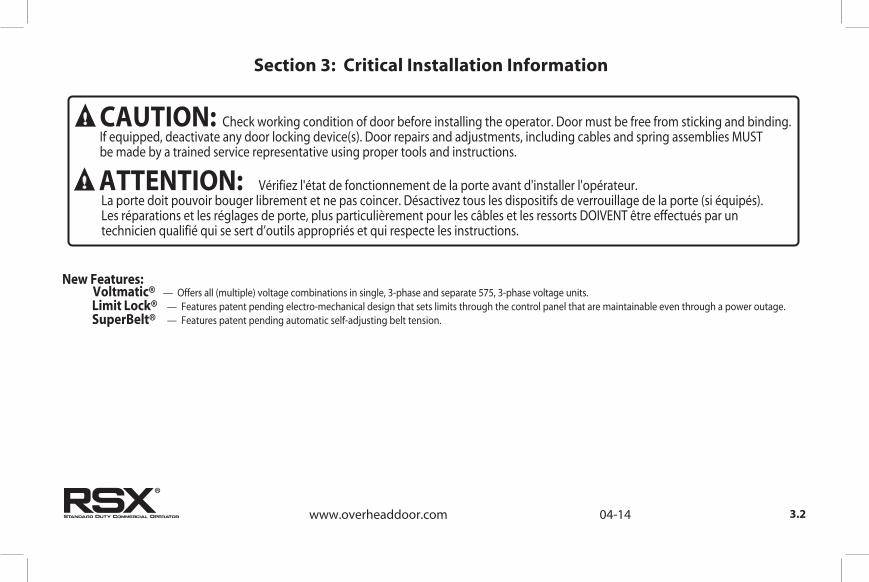
New Features: .stinu egatlov esahp-3 ,575 etarapes dna esahp-3 ,elgnis ni snoitanibmoc egatlov )elpitlum( lla sreffO —
LimitVoltmatic®
Lock® — Features patent pending electro-mechanical design that sets limits through the control panel that are maintainable even through a power outage.SuperBelt® — Features patent pending automatic self-adjusting belt tension.
Section 3: Critical Installation Information
®
CAUTION:
Check working condition of door before installing the operator. Door must be free from sticking and binding.If equipped, deactivate any door locking device(s). Door repairs and adjustments, including cables and spring assemblies MUST be made by a trained service representative using proper tools and instructions.
ATTENTION: Vérifiez l'état de fonctionnement de la porte avant d'installer l'opérateur. La porte doit pouvoir bouger librement et ne pas coincer. Désactivez tous les dispositifs de verrouillage de la porte (si équipés). Les réparations et les réglages de porte, plus particulièrement pour les câbles et les ressorts DOIVENT être effectués par un technicien qualifié qui se sert d’outils appropriés et qui respecte les instructions.

3.3www.overheaddoor.com 03-14
416 418 420 422 424 426 430 432 591 592 593 594 595 598
T ype
Max.Door
Weight(Lbs)
16G A.F lushS teel
16G A.F lushS teel
Insulated
20G A.R ibbed
S teel
20G A.R ibbed
S teelInsulated
24G A.R ibbed
S teel
24G A.R ibbed
S teelInsulated
Nominal24G A.R ibbed
S teel
Nominal24G A.
R ibbed S teelInsulated
R ibbedS teel1 5/8"
R ibbedS teel 2"
R ibbedS teel1 3/8"
R aisedP anelS teel1 3/8"
20G A.F lushS teel1 5/8"
R ibbedS teel
1"
RSX® 1/2 Y es T S C 1120 294 230 366 294 448 330 326 326 406 406 326 326 366 200 326 406
RSX® 3/4 Y es T S C 1370 366 294 448 366 490 406 326 326 490 448 326 326 406 200 326 506
RSX® 1 Y es
RSX® S ectional Door C hart (S q. F t.)
S = J ackshaft, S ide MountC = J ackshaft, C enter Mount
UL L is tedHPModel
T = T rolley
C ommercial S teel Ins ulated & Non-Insulated T hermacore Aluminum
P anoramicAluminum
Com
Aluminum
Door S eries ->
ENTRAPMENT PROTECTION.0102 ,92 tsuguA gnitrats evitca stnemeriuqer 523LU htiw ecnailpmoc ni secived tnempartne detsiL LU gniwollof eht htiw desu eb nac ®XSR ehT
UNTIL ONE OF THESE MONITORED EXTERNAL ENTRAPMENT DEVICES IS INSTALLED, THE RSX® WILL NOT ALLOW MOMENTARY CONTACT OPERATION IN THE CLOSE DIRECTION.
Section 3: Critical Installation Information
T S C 1620 488 366 536 488 536 500 326 326 591 494 326 326 450 200 326 526
Note: Total door weight, and not the square footage, is the critical factor in selecting the proper operator.Square footage are based on “square doors”. (Example = 16’-2” x 16’-2”)Note: Doors that require special windloading and wide doors normally require increased strutting (reinforcement). Strutting doors can significantly increase door weight beyond maximum weight shown. Consult factory personel in these situations.
®
MillerEdge ME & MT series monitored edge sensors used incombination with OPABTCX.S Timer-Close Module or MillerEdgeInterface Module OPAKMEIGX.S. MillerEdge Wireless monitored edge sensor OPAKMMWE.S
ANY WIDTH
Residential Safe-T-Beams® P/N 37221R (OSTB-BX) and 38176R.S (includes ext. brkt’s)
Commercial Photoeye Kit P/N OPAKPE.S and OPAKPEN4GX.S (NEMA 4)
LISTED DEVICES ALLOWABLE DOOR WIDTH
30 FEET
35 FEETMonitored Retro-Refective Photoeye Kit P/N OPRAKRPEN4X.S

3.4www.overheaddoor.com 04-14
IMPORTANTINSTALLATION INSTRUCTIONS
WARNING- To reduce the risk of severe injury or death:
READ AND FOLLOW ALL INSTALLATION INSTRUCTIONS.Install only on a properly operating and balanced door. A door that is operating improperly could cause severe injury. Have qualified service personnel make repairs to cables, spring assemblies and other hardware before installing the operator.
Remove all pull ropes and remove, or make inoperative, all locks (unless mechanically and/or electronically interlocked to the power unit) that are connected to the door before installing the operator.Install the door operator at least 8 feet above the floor if the operator has exposed moving parts.Do not connect the door operator to the power source until instructed to do so.
Locate the control station: (a) within sight of the door, (b) a minimum of 5 feet above the floor so that small children cannot reach it, and (c) away from all moving parts of the door.Install the Entrapment Warning Placard next to the control station and in a prominent location.For products having a manual release, instruct the end user on the operation of the manual release.
IMPORTANTINSTRUCTIONS D’INSTALLATION
AVERTISSEMENT- Pour réduire les risques de
blessures graves ou de mort :1) LIRE ET RESPECTER TOUTES LES INSTRUCTIONS D'INSTALLATION.2) Installez uniquement sur une porte fonctionnant correctement et bien
équilibrée. Une porte qui fonctionne mal peut provoquer des blessures graves. Demandez à un technicien qualifié d'effectuer les réparations des câbles, des ressorts et de toute autre quincaillerie avant de procéder à l'installation de l'opérateur.
Retirez toutes les cordes de traction ainsi que tous les verrous ou rendez-les inopérants (à moins qu'ils ne soient mécaniquement et/ou électroniquement interverrouillés à l'unité motrices) qui sont connectés à la porte avant de procéderà l'installation de l'opérateur.
Installez l'opérateur de la porte à 2,4 m minimum au-dessus du sol lorsque des pièces mobiles de l'opérateur sont exposées.Ne pas raccorder l'opérateur de la porte à la source d’alimentation avant que l'instruction ne soit donnée de le faire.
Installez la station de commande : (a) en vue de la porte, (b) à 1,5 m minimum au-dessus du sol pour que les jeunes enfants ne puissent pas l'atteindre, et (c) à l'écart de toutes les pièces mobiles de la porte.
Installez le poster d'avertissement de pincement à côté de la station de commande à un endroit bien en vue.Pour les produits ayant un déclenchement manuel, indiquez à l'utilisateur comment déclencher manuellement.
3)
4)
5)
6)
7)
8)
1)2)
3)
4)
5)
6)
7)
8)
Section 3: Critical Installation Information

4.1
The Model RSX® Drawbar Operator consists of the Power Unit (A),Drawbar Track (B), Chain Guides (C), Front Spreader (D), Front IdlerPulley (E), Drive Chain (F), Drive Sprocket (G), and Drawbar Arm (H).The Drawbar track length, chain length and quanity of chain guideswill vary by door heights. Fig. 1.
Drawbar Assembly
Figure 1
A
B
GF
C
E
D
www.overheaddoor.com 04-14
®
H
NOTE: Drawbar tracks must be (29) inches longer than the door’s height.Tracks have been sized properly and pre-punched for the chain guideassemblies from the factory.
Section 4: Installation
Drawbar Assembly (continued)
4.2
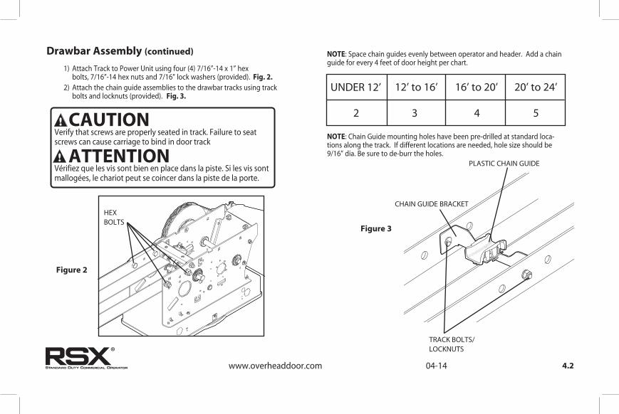
1) Attach Track to Power Unit using four (4) 7/16”-14 x 1” hex bolts, 7/16”-14 hex nuts and 7/16” lock washers (provided). Fig. 2. 2) Attach the chain guide assemblies to the drawbar tracks using track bolts and locknuts (provided). Fig. 3.
Figure 3
CHAIN GUIDE BRACKET
TRACK BOLTS/LOCKNUTS
PLASTIC CHAIN GUIDE
NOTE: Space chain guides evenly between operator and header. Add a chain guide for every 4 feet of door height per chart.
NOTE: Chain Guide mounting holes have been pre-drilled at standard loca-tions along the track. If different locations are needed, hole size should be 9/16” dia. Be sure to de-burr the holes.
UNDER 12’ 12’ to 16’ 16’ to 20’ 20’ to 24’
2 3 4 5
www.overheaddoor.com 04-14
Figure 2
HEXBOLTS
®
CAUTIONVerify that screws are properly seated in track. Failure to seatscrews can cause carriage to bind in door track
Vérifiez que les vis sont bien en place dans la piste. Si les vis sont mallogées, le chariot peut se coincer dans la piste de la porte.
ATTENTION
Drawbar Assembly (continued)
4.3
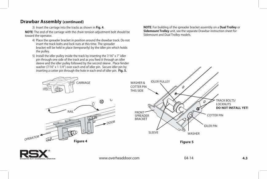
3) Insert the carriage into the tracks as shown in Fig. 4.NOTE: The end of the carriage with the chain tension adjustment bolt should be toward the operator. 4) Place the spreader bracket in position around the drawbar track. Do not insert the track bolts and lock nuts at this time. The spreader bracket will be held in place (temporarily) by the idler pin which holds the pulley. 5) Install the idler pulley inside the track by inserting the 7/16” x 7” idler pin through one side of the track and as you feed it through an idler sleeve and the idler pulley followed by the second sleeve . Place fender washer (7/16” x 1-1/4”) over each end of idler pin. Secure idler pin by inserting a cotter pin through the hole in each end of idler pin. Fig. 5.
CARRIAGE
RAIL
Figure 4 Figure 5
FRONTSPREADERBRACKET
WASHER
COTTER PIN
IDLER PIN
IDLER PULLEY
TRACK BOLTS/LOCKNUTSDO NOT INSTALL YET!
SLEEVE
NOTE: For building of the spreader bracket assembly on a Dual Trolley or Sidemount Trolley unit, see the separate Drawbar instruction sheet for Sidemount and Dual Trolley models.
OPERATOR
DOOR
www.overheaddoor.com 04-14
WASHER &COTTER PINTHIS SIDE
®
4.4www.overheaddoor.com 04-14
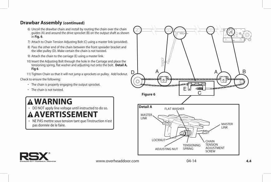
6) Uncoil the drawbar chain and install by routing the chain over the chain guides (A) and around the drive sprocket (B) on the output shaft as shown in Fig. 6.
7) Attach to Chain Tension Adjusting Bolt (C) using a master link (provided).
8) Pass the other end of the chain between the front spreader bracket and the idler pulley (D). Make certain the chain is not twisted.
9) Attach the chain to the carriage (E) using a master link.
10) Insert the Adjusting Bolt through the hole in the Carriage and place the tensioning spring, flat washer and adjusting nut onto the bolt. Detail A, Fig 6.
11) Tighten Chain so that it will not jump a sprockets or pulley. Add locknut.
Check to ensure the following:
• The chain is properly engaging the output sprocket.
• The chain is not twisted.
Drawbar Assembly (continued)
Detail A
CHAINTENSION ADJUSTMENT SCREW
FLAT WASHER
LOCKNUT
ADJUSTING NUTTENSIONING SPRING
MASTERLINK
MASTERLINK
Figure 6
®
• DO NOT apply line voltage until instructed to do so. WARNING
• NE PAS mettre sous tension tant que l'instruction n'est pas donnée de le faire.
AVERTISSEMENT

4.5www.overheaddoor.com 04-14
Drawbar Installation
®
• Repairs and adjustments, including particularly to cables and spring assemblies under high tension, must be made by a trained service representative using proper tools and instructions.
WARNING
•
Les réparations et les réglages, plus particulièrement aux câbles et ensembles de ressort sous tension élevée doivent être effectués par un professionnel qui se sert d’outils appropriés et qui respecte les instructions.
AVERTISSEMENT
CAUTION
Check the working condition of the door before installing the operator. The Door must be free from sticking and binding. If the door is equipped with a latching device, secure the locking bar in the open (unlocked) position. This style operator will act as a latching device when the door is down and therefor the door’s lock is no longer needed.
If the door lock is to remain functional, an interlock switch MUST be installed which will prevent operation of the door whenever the door lock is engaged. Refer to the Wiring Instructions, section 5, of this manual for proper connection of the interlock switch.
ATTENTIONVérifiez l'état de fonctionnement de la porte avant d'installer l'opérateur. La porte doit pouvoir bouger librement. Si la porte est équipée d'un dispositif de verrouillage, fixez la barre de verrouillage en position ouverte (déverrouillée). Cet opérateur agit comme un dispositif de verrouillage lorsque la porte est en bas et que le verrouillage de la porte n'est donc plus nécessaire.
Si le verrouillage de la porte doit rester fonctionnel, un commutateur de verrouillage DOIT être installé pour empêcher le fonctionnement de la porte chaque fois que le verrouillage de la porte est engagé. Reportez-vous aux instructions de câblage, section 5, de ce manuel pour établir une connexion correcte de l'interrupteur de verrouillage.

VERTICAL LINE(SEE STEP 1)
HEADER
ATTACHMENT MATERIAL(SEE STEP 2)
HORIZONTAL LINE(SEE STEP 6)
CENTERLINEOF DOOR
4.6www.overheaddoor.com 04-14
1) Measure the width of the door to determine the center. Make a vertical line above the door, as shown in Fig. 7. (If the vertical line is not in line with a door stile, a means of attaching the door bracket to the door must be provided. This can be accomplished by spanning the center of the door’s top section (between the top and bottom rail) with a suitable material such as wood or steel).2) Prepare for attaching drawbar to header. If woodwork, or other suitable material is not already in place, securely affix a 2” x 6” block of wood or metal plate as shown in Fig. 7.3) Center the block/plate on the header.
4) Mark the door’s vertical center line on this block/plate.
Drawbar Installation (continued)
Figure
7
NOTE: On torsion spring doors with an uneven number of panels, the operator may be attached to the stile nearest to the center.
®

4.7www.overheaddoor.com 04-14
Drawbar Installation (continued)
2" X 6"
HEADER
MARK A HORIZONTAL LINE 5" ABOVE HIGHEST POINT OF TRAVEL
LEVEL
HIGHEST POINT OF TRAVEL
Figure 8
Figure 9
7) Raise the door end (idler pulley) of the drawbar while resting the operator
on the floor or other desired material.
8) Position the spreader bracket on your centerline with its bottom edge on
your horizontal mark. Fig. 9.
• Fasten spreader bracket to header using fasteners appropriate for the
header material.
®
5) Use a level, as shown in Fig. 8 to find the highest point of travel for the door.6) Mark a horizontal line across the vertical line you made on the header at 5” above the highest point of door travel.

4.8www.overheaddoor.com 04-14
1) Raise the operator and position it so that the drawbar tracks are level and perpendicular to the face of the door (or the stile where the door bracket will be attached). Fig. 10. 2) Lock the drawbar tracks into the spreader bracket using the two (2) track bolts (1/4”-20 X 9/16”) and two (2) locknuts. 3) Secure the operator in position by installing steel angles (not provided) between the ceiling superstructure and the operator power unit. Fig. 11.
Drawbar Installation (continued)
TRACK BOLTS& LOCK NUTS
ROPE, CABLE, CHAIN, ETC.
LEVEL
WALL WALL
TRACK90°
DOOR FROM ABOVE
Figure 10
DRILL HOLE IN ANGLEAND MOUNT USINGREAR SUPPORTCARRIAGE BOLT
STEELANGLES(NOT INCLUDED)
Figure 11
NOTE: Track bolts MUST be installed from inside the track.
®

4.9
1) Pull down on the drawbar arm locking sleeve and attach to carriage. (See NOTE 2.) 2) Position the door bracket on the door as shown in Fig. 12, with mounting holes on the door centerline. (Even with or above top door roller).NOTE: Make sure to use reinforcement bracket when attaching door bracket to door. Do not attach door bracket directly to door section. 3) For wood doors fasten the door bracket to the door using two 1/4” -20 X 2-1/4” carriage bolts and nuts. For metal doors use two 1/4”- 20 self tapping sheet metal screws, or as recommended by the door manufacturer. 4) Use two (2) 3/8” -16 X 7/8” bolts and nuts to attach the door arms together.NOTE: Use the set of holes that align the drawbar in a near vertical position for operators without a brake. Set arms at a 20-30 degree rearward angle for operators with a brake. Fig. 13.For units without a brake, set arms as close to 0 degrees (vertical) as possible.NOTE: If the door strut interferes with the mounting of the door bracket, position
NOTE 2: In case of emergency, pulling the Emergency Release Knob (Fig. 13) disengages the door from theoperator allowing for manual operation of the door.the door bracket below the strut. DO NOT, in any way, cut or modify the strut.
Connection to the Door
Figure 13
Figure 12
www.overheaddoor.com 11-09
E
When installing non-brake units with drawbar near vertical, it is important to make sure there is adequate room between the door bracket and drawbar rail for the door arms to go vertical. Without sufficient clearance and by running the dood arms vertical, a significant amount of force could be applied possibly leading to damage. There is an optional drawbar kit with a cusion springbox available: P/N OPAKDBT.S
WITH BRAKE WITHOUT BRAKEAVOID THIS SETUP
WITHOUT BRAKECORRECT
www.overheaddoor.com 04-14®
4.10
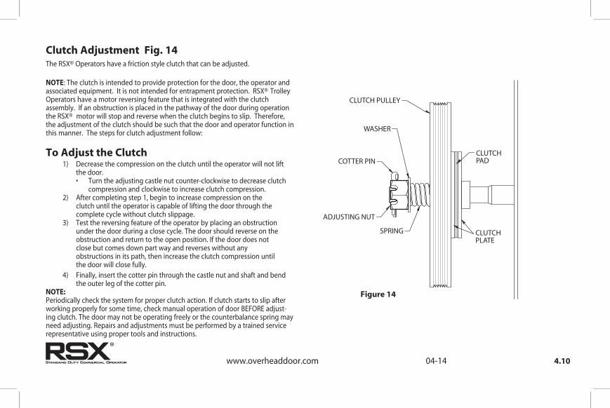
The RSX® Operators have a friction style clutch that can be adjusted. NOTE: The clutch is intended to provide protection for the door, the operator and associated equipment. It is not intended for entrapment protection. RSX® Trolley Operators have a motor reversing feature that is integrated with the clutch assembly. If an obstruction is placed in the pathway of the door during operation the RSX® motor will stop and reverse when the clutch begins to slip. Therefore, the adjustment of the clutch should be such that the door and operator function in this manner. The steps for clutch adjustment follow:
To Adjust the Clutch 1) Decrease the compression on the clutch until the operator will not lift the door. • Turn the adjusting castle nut counter-clockwise to decrease clutch compression and clockwise to increase clutch compression. 2) After completing step 1, begin to increase compression on the clutch until the operator is capable of lifting the door through the complete cycle without clutch slippage. 3) Test the reversing feature of the operator by placing an obstruction under the door during a close cycle. The door should reverse on the obstruction and return to the open position. If the door does not close but comes down part way and reverses without any obstructions in its path, then increase the clutch compression until the door will close fully. 4) Finally, insert the cotter pin through the castle nut and shaft and bend the outer leg of the cotter pin. NOTE:Periodically check the system for proper clutch action. If clutch starts to slip after working properly for some time, check manual operation of door BEFORE adjust-ing clutch. The door may not be operating freely or the counterbalance spring may need adjusting. Repairs and adjustments must be performed by a trained service representative using proper tools and instructions.
Clutch Adjustment Fig. 14
CLUTCH PULLEY
WASHER
COTTER PIN
ADJUSTING NUT
CLUTCHPAD
CLUTCH PLATE
SPRING
www.overheaddoor.com 04-14
Figure 14
®

5.1
Section 5: Wiring
www.overheaddoor.com 04-14®
WARNING
• DO NOT apply power to operator until instructed to do so. • It is strongly recommended, and may be required by law
in some areas, that line voltage wiring be performed bya qualified electrician.
• Be sure that electrical power has been disconnected fromthe input power wires being connected to the operator prior to handling these wires. An appropriate lock-out/tag-out procedure is recommended.
• Line voltage wiring must meet all local building codes.•
Make sure operator voltage, phase and frequency nameplateratings are identical to the job site line voltage ratings.
• Input power wiring must be properly sized for the operatorsamperage rating located on the nameplate.
• To reduce the risk of electric shock, make sure the chassis of this unit is properly grounded.
AVERTISSEMENT • NE PAS mettre sous tension tant que l'instruction n'est
pas donnée de le faire.
• Il est fortement recommandé voire même exigé par la loi dans certaines régions, de contacter un électricien qualifié pour l'acheminement du fil électrique.
• Assurez-vous que l'alimentation électrique a été déconnectée des câbles d'alimentation d'entrée connectés à l'opérateur avant de manipuler ces câbles. Une procédure de verrouillage/étiquetage appropriée est recommandée.
• Le câblage au secteur doit satisfaire à tous les codes de construction locaux.
•
Assurez-vous que les valeurs nominales de la plaque signalétique pour tension, phase et fréquence de l'opérateur correspondent à celles des tensions de l'alimentation sur site.
•
La capacité d'entrée doit correspondre à la valeur nominale de l'ampérage des opérateurs indiquée sur la plaque signalétique.
•
Pour réduire le risque de choc électrique, assurez-vous que le châssis de l'unité est correctement mis à la terre.

5.2
1) Remove LINE VOLTAGE INPUT PLUG and install proper
fittings and 1/2”conduit.2) Route proper LINE VOLTAGE wires into operator.3) Locate LINE INPUT terminals on circuit board. Using
correct connectors, attach wires to LINE INPUTS, and GROUND
terminal.
• Keep low voltage and line voltage wires separate. • Route all line voltage wires as shown. • Plug all unused conduit holes.
115V1 PH
208/230V1 PH
HIGHVOLTAGEINPUT PLUGS(Right & Left)
ROUTE HIGH VOLTAGE WIRING IN THE SHADED AREA AS SHOWN
OptionalAccessoryModules
LINE INPUTTERMINALS
LINEGROUND
208/240V 480/575VLINE INPUTTERMINALS
LINEGROUND
ROUTE HIGH VOLTAGE WIRING IN THE SHADED AREA AS SHOWN
L1/L1 N/L2
GND
LINE IN
POWER CONNECTIONS
LINE INPOWER CONNECTIONS
LINE(HOT)
NEUTRAL
LINE 1 LINE 2
L1 L2
GND
LINE 1 LINE 2 LINE 3
L3
Three Phase
Single Phase
115V
208V230V
HIGHVOLTAGEINPUT PLUGS(Right & Left)
Figure 1
Line Voltage Wiring Fig. 1
www.overheaddoor.com 02-14®

5.3
1) Connect all LOW VOLTAGE control circuit wires to this side of unit using 1/2” conduit or flexible convoluted tubing. • Keep low voltage and line voltage wires separate. • Route all low voltage control wiring as shown. This includes all control circuit wires such as wall controls, timers and single button input devices as well as radio control and safety circuit wiring. See Figs 2 through 13 in this section. • Plug all unused conduit holes.
Low Voltage Control Wiring (general) Fig. 2 ROUTE LOW VOLTAGE WIRING IN THE SHADED AREA AS SHOWN
LOWVOLTAGEINPUT PLUGS(Left & Right)
OptionalAccessoryModules
LOW VOLTAGE CONTROL WIRE TERMINALS
Figure 2
NOTE: For a detailed description of control wire terminals see Appendix B.
www.overheaddoor.com 02-14
®

5.4
External Wire DiagramSee Appendix B for detailed description of terminals.
www.overheaddoor.com 01-14
1-BTNSTATION
KEYSWITCHSTATION
CARD READER
O/C PULLSWITCH
N/O
N/O
N/O
N/O
REMOVE JUMPER WHEN INSTALLING EXTERNAL INTERLOCK
MULTIPLE 3-BUTTONSTATION INSTALLATIONSREQUIRE THE STOP BUTTON TO BE WIREDIN SERIES. See Fig. 5, pg 5.5
*
EXTINTLK
EXTINTLK
N-OREVERSE
N-OREVERSE
ODCSTB
ODCSTB
1-BTNGNDSTOPCLOSEOPEN
EXT RADIO CONNECTOR
SENSING EDGE SWITCH
(DO NOT CONNECT 2-WIRE MONITORED SENSING EDGE SWITCH TO THESE INPUTS)
THRU-BEAM PHOTOCELLS
+
-
+-
PWR 20-40 VDC @ 250mA MAX CURRENT
RELAY
GNDNOM+ 24VDC
RADIO
SERIES II SAFE-T-BEAM ® (STB)
(*CONNECT STB WIRES TO EITHER TERMINAL)
*
OPEN
CLOSE
STOP
REMOVEJUMPERIF STOPBUTTONIS USED
3-BUTTON STATION *
BLU
E
ORA
NG
E
YEL
LOW
Located inside Electrical Box
2-WIRE MONITORED SENSING EDGE SWITCH
INTERFACEMODULE
®

1) For a single 3-button installation, make connections as shown in Fig. 3.
2)
3)
NOTE: If an External STOP button is NOT being installed, a jumper wire mustbe installed between the “STOP” and “GND” terminals as shown.
NOTE: Long Distance Relay Kit wiring is not required for long
distance control runs and should not be used.
5.5
Wall Control
NOTE
Figure 4
GND
Figure 5
NOTE
Figure
3Entrapment
Warning Placard
Figure 3A
www.overheaddoor.com 03-14
For single button accessory controls, make connections as shown in Fig. 4.For multiple 3-button installations, make connections as shown in Fig. 5.
WARNING: • Wall Control(s) must be located so that the door is within sight of
the user and is far enough from the door, or postioned such thatthe user is prevented from coming in contact with the door whileoperating controls.
• Attach the Warning placard adjacent to the Wall Control. Fig. 3A.
AVERTISSEMENT: • La ou les commandes murales doivent être situées de telle sorte que
l'utilisateur puisse voir la porte et positionnées de telle sorte que l'utilisateur ne puisse pas entrer en contact avec la porte lorsqu'il se sert des commandes.
• Fixez le poster d'avertissement à côté de la commande murale. Fig. 3A.
WARNING: Before momentary contact control can be used on the CLOSE button, a monitored external reversing device such as a photocell system or sensing edge switch must be used. See pages 5.7-5.9 for installation of entrapment protection devices.
AVERTISSEMENT: Avant d'utiliser la commande à contact momentané sur le bouton FERMETURE, un dispositif d'inversion externe surveillée tel qu'un système de cellule photoélectrique ou un commutateur de détection de bord doit être utilisé. Voir l'installation des dispositifs de protection contre le coincement en pages 5.7-5.9.

CONTROL SIGNAL TERMINAL STRIP
EXTINTLK
EXTINTLK
* REMOVE JUMPER WHEN INSTALLING EXTERNAL INTERLOCK
*
NOTE: If External Interlock is used, THE JUMPER WIRE BETWEEN THE EXT INTLK TERMINALS MUST BE REMOVED.
1) Optional external interlock switches are required with some Sectional or Rolling Steel Doors to prevent the door from operating under certain conditions including the following: • If the door is equipped with a functioning door lock, an interlock switch (A) must be installed to prevent electric operation when the lock is engaged. • If the door is equipped with a pedestrian pass-through door, an interlock switch (B) must be installed at the pass-through door in order to prevent electrical operation when the pass-through door is open. 2) The Switches must be set in the field.
SWITCH 075412-0000 (N.O.)
ANGLE 405964-0000
STANDARDSLIDELOCK
TRACK
SWITCH (N.C.) P/N 110324.0001 For Sectional Door
Interlock Switches
5.6
A
B
Pass door interlock: Should be open when door is open. Closed when door is closed.
Side lock interlock: Should be open when door is locked. Closed when door
is unlocked.
www.overheaddoor.com 01-14
Figure 6
®

Photocell Wiring
NOTE: Installer must enable ODC STB in calibration mode. See page 6.11.
2) To Mount Photocells: (Kit includes detailed Instructions). • Determine location for mounting. They do not need to be directly adjacent to the door but must be somewhere along the wall where there will be an unobstructed line between them. Fig. 9. • They must extend out away from the wall sufficiently that no door hardware breaks the plane of the photo-beam.
1) Nominal 24 Volt DC Commercial photocells with normally open contacts can be connected as shown in Fig. 8.NOTE : Blue wire supplies 20 – 40VDC. Photocells used must be compatible with this voltage range.
NOTE: If no voltage is present at Blue wire, check fuse F-1 on Control board.
Series II Safe-T-Beam® Monitored Photocells
Commercial Non-Monitored Photocells
DOOR Top of lensto floor.
Figure
9
5.7www.overheaddoor.com 04-14
1) Monitored SERIES II (STB) photocells (P/N OPAKPE.S) and Residential Safe-T-Beam® Monitored
be connected to either terminal (they are not polarity sensitive.) (Troubleshooting in Section 8) .
Photocells from Overhead Door® (P/N 37221R & 38176R.S). Fig. 7. Wiring to these photocells can be
®
SERIES II RESDENTALSAFE-T-BEAM® (STB)
CONTROL SIGNAL TERMINAL STRIP
ODCSTB
ODCSTB
Figure
7
CONNECT WIRES TO EITHER TERMINAL. (NOT POLARITY SENSITIVE)
N-OREVERSE
N-OREVERSE
+
-
+-
THRU-BEAMPHOTOCELLS
CONTROL SIGNALTERMINAL STRIP
RECEIVER
TRANSMITTER
EXT RADIO CONNECTOR
PWR 20-40 VDC @ 250mA MAX. CURRENT
RELAY
GNDNOM
+ 24VDC
RADIO
Blu
e
Ora
ng
e
Yello
w
Figure
8
WARNING:
Actuating the operator by using constant contact on the CLOSE button will override non-functioning external reversing devices, including photocells.
AVERTISSEMENT: L'activation de l'operateur en utilisant un contact constant sur le bouton FERMER annulera les dispositifs d'inversions externes, y compris les cellules photoelectriques.
WARNING: Photocell systems provide entrapment protection when mounted near thedoorway in such a way that the lower portion of an individual’s leg will break the photocell beam during normal walking conditions.
AVERTISSEMENT:
Les systèmes de cellules photoélectriques fournissent une protection contre le coincement pour le montage à proximité de la porte de manière à ce que la partie inférieure de la jambe d'un individu ne puisse pas rompre le faisceau de la cellule photoélectrique lors de passages normaux par la porte.
5.8www.overheaddoor.com 04-14
Figure 11
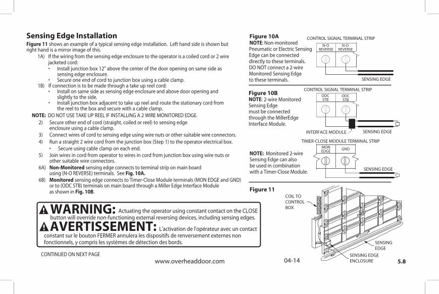
Figure 11 shows an example of a typical sensing edge installation. Left hand side is shown but right hand is a mirror image of this. 1A) If the wiring from the sensing edge enclosure to the operator is a coiled cord or 2 wire
jacketed cord:
• Install junction box 12” above the center of the door opening on same side as sensing edge enclosure. • Secure one end of cord to junction box using a cable clamp. 1B) If connection is to be made through a take up reel cord: • Install on same side as sensing edge enclosure and above door opening and slightly to the side. • Install junction box adjacent to take up reel and route the stationary cord from the reel to the box and secure with a cable clamp.
2) Secure other end of cord (straight, coiled or reel) to sensing edge enclosure using a cable clamp.
3) Connect wires of cord to sensing edge using wire nuts or other suitable wire connectors.
4) Run a straight 2 wire cord from the junction box (Step 1) to the operator electrical box. • Secure using cable clamp on each end. 5) Join wires in cord from operator to wires in cord from junction box using wire nuts or other suitable wire connectors. 6A) Non-Monitored sensing edge connects to terminal strip on main board using (N-O REVERSE) terminals. See Fig. 10A. 6B) Monitored sensing edge connects to Timer-Close Module terminals (MON EDGE and GND) or to (ODC STB) terminals on main board through a Miller Edge Interface Module
as shown in Fig. 10B.
Sensing Edge Installation
Figure 10BNOTE:
:
2-wire Monitored Sensing Edge
must be connected through the MillerEdge Interface Module.
NOTE: Monitored 2-wireSensing Edge can alsobe used in combinationwith a Timer-Close Module.
Figure 10ANOTE Non-monitoredPneumatic or Electric Sensing Edge can be connected directly to these terminals. DO NOT connect a 2-wire Monitored Sensing Edge to these terminals.
INTERFACE MODULE
NOTE: DO NOT USE TAKE UP REEL IF INSTALLING A 2 WIRE MONITORED EDGE.
SENSING EDGE
SENSING EDGE
SENSING EDGE
TIMER-CLOSE MODULE TERMINAL STRIPMONEDGE GND
CONTROL SIGNAL TERMINAL STRIPODCSTB
ODCSTB
CONTROL SIGNAL TERMINAL STRIP
COIL TOCONTROLBOX
SENSINGEDGE
SENSING EDGEENCLOSURE
N-OREVERSE
N-OREVERSE
WARNING:
Actuating the operator using constant contact on the CLOSE button will override non-functioning external reversing devices, including sensing edges.
AVERTISSEMENT:
L'activation de l'opérateur avec un contact constant sur le bouton FERMER annulera les dispositifs de renversement externes non fonctionnels, y compris les systèmes de détection des bords.
CONTINUED ON NEXT PAGE

5.9www.overheaddoor.com 04-14
®
Sensing Edge Installation (continued)
shows the connection of OPAKMMWE.S MEL Miller Edge Monitored Wireless Sensing Edge.Figure 12
Figure 12
CONTROL SIGNAL TERMINAL STRIP
ODCSTB
ODCSTB
SENSING EDGE
WIRELESS EDGE RECEIVER
WIRELESS EDGE TRANSMITTER
EXT RADIO CONNECTOR
PWR 20-40 VDC @ 250mA MAX. CURRENT RA
DIO
NOM+24VDC
GND
RELAY
BLUE
YELLOW
ORANGE
BLK
RED
WIRE NUT
WHTGRN
7) Operate the door to make certain cord is free to travel and does not become snared during door opening or closing. • Check sensing edge for proper operation.
8) While the door is closing actuate the sensing edge to verify the door reverses to open limit.
WARNING:
To obtain proper operation of the MEL edge sensor, each transmitter/receiver setmust be set to a unique address. Follow instructions provided with the Miller Edge MEL kit to set the address.
AVERTISSEMENT: Pour obtenir un fonctionnement correct du capteur de bord MEL, réglez chaque ensemble émetteur/récepteur sur une adresse unique. Suivez les instructions fournies avec le kit Miller Edge MEL pour définir l'adresse.

5.10www.overheaddoor.com 04-14
Although the RSX® Operators are equipped with an internal radio, they also .oidar lanretxe na rof noitcennoc lasrevinu a edivorp
To Add the External Radio 1) Plug the 3-wire pigtail (provided) onto the plug connector marked ”.OIDAR TXE“ 31 .giF . 2) Make wiring connections to the wires as shown.
External Radio Installation
EXT RADIO CONNECTOR
PWR 20-40 VDC @ 250mA
MAX CURRENT
RELAY
GNDNOM
+ 24VDC
RADIO
Blu
e
Ora
ng
e
Yello
w
Figure 13
EXTERNAL RADIO
CONNECTOR
F1 (.25A)
®
5.11www.overheaddoor.com 04-14
208/240V 120V
208/240V
480/575V
SINGLE PHASE
THREE PHASE
MotorConnectors
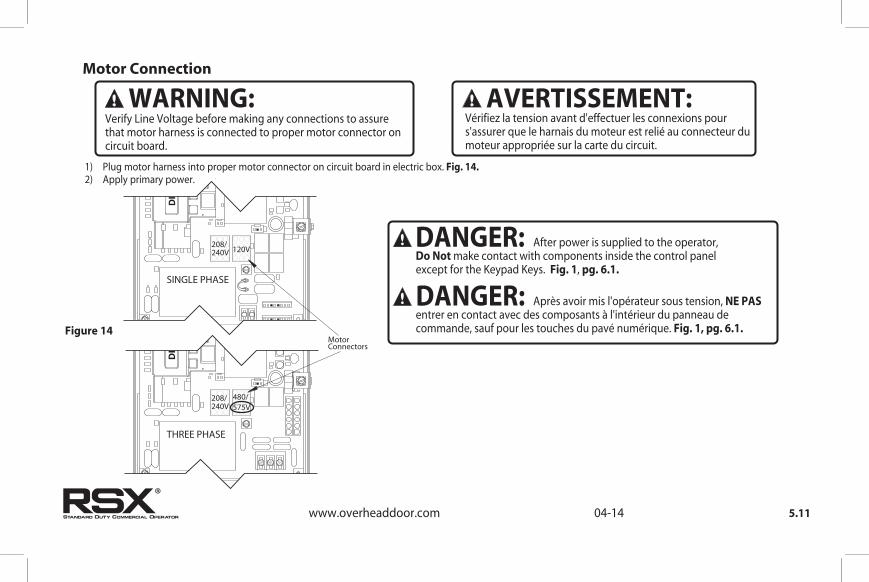
1) Plug motor harness into proper motor connector on circuit board in electric box. Fig. 14.
2) Apply primary power.
Figure 14
®
Motor Connection
WARNING:Verify Line Voltage before making any connections to assure that motor harness is connected to proper motor connector on circuit board.
AVERTISSEMENT:Vérifiez la tension avant d'effectuer les connexions pour s'assurer que le harnais du moteur est relié au connecteur du moteur appropriée sur la carte du circuit.
DANGER: After power is supplied to the operator, Do Not make contact with components inside the control panel except for the Keypad Keys. Fig. 1, pg. 6.1.
DANGER: Après avoir mis l'opérateur sous tension, NE PAS entrer en contact avec des composants à l'intérieur du panneau de commande, sauf pour les touches du pavé numérique. Fig. 1, pg. 6.1.

5.12www.overheaddoor.com 04-14®
Safety Instructions
1) READ AND FOLLOW ALL INSTRUCTIONS.2) Never let children operate or play with door controls. Keep the remote control (where provided) away from children.
3) Personnel should keep away from a door in motion and keep the moving door in sight until it is completely closed or opened. NO ONE SHOULD CROSS THE PATH OF A MOVING DOOR.4) Test the door’s safety features at least once a month. After adjusting either the force or the limit of travel, retest the door operator’s safety features. Failure to adjust the operator properly may cause severe injury or death.5) For products having a manual release, if possible, use the manual release only when the door is closed. Use caution when operating the release while the door is open. Weak or broken springs may cause the door to fall rapidly, causing severe injury or death.6) KEEP DOOR PROPERLY OPERATING AND BALANCED. See Door Manufacturer’s Owner’s Manual. An improperly operating or improperly balanced door could cause severe injury or death. Have only trained door systems technicians make repairs to cables, spring assemblies, other hardware and any wooden blocks or like items to which they may be attached.
IMPORTANTSAFETY INSTRUCTIONS
WARNING- To reduce the risk of severe injury or death:
7) SAVE THESE INSTRUCTIONS.

5.13www.overheaddoor.com 04-14®
Safety Instructions (continued)
1) LIRE ET RESPECTER TOUTES LES INSTRUCTIONS.2) Ne jamais permettre aux enfants d’actionner ni de jouer avec les commandes de la porte. Tenir les télécommandes (si fournies) hors de la portée des enfants.
3) Le personnel doit se tenir à l'écart d'une porte en mouvement et garder bien en vue une porte en mouvement jusqu'à ce qu'elle soit complètement fermée ou ouverte. PERSONNE NE DOIT TRAVERSER LA TRAJECTOIRE D'UNE PORTE EN MOUVEMENT. 4) Testez les fonctionnalités de sécurité de la porte au moins une fois par mois. Après avoir réglé la force ou la limite de la course, retestez les éléments de sécurité de l’opérateur de la porte. Un mauvais réglage de l’ouvre-porte peut entraîner des blessures graves voire la mort.
5) Pour les produits ayant un déclenchement manuel, dans la mesure du possible, utilisez le déclenchement manuel uniquement lorsque la porte est fermée. Prenez toutes les précautions nécessaires lors de l'utilisation du déclenchement manuel alors que la porte est ouverte. Des ressorts faibles ou brisés peuvent faire descendre la porte rapidement ce qui peut entraîner des blessures graves voire la mort.6) VEILLER À CE QUE LA PORTE SOIT CORRECTEMENT ÉQUILIBRÉE ET FONCTIONNE BIEN. Consultez le manuel de l’utilisateur du fabricant de la porte. Une porte déséquilibrée ou fonctionnant incorrectement pourrait entraîner de graves blessures voire la mort. Seuls des techniciens formés sur systèmes de portes peuvent effectuer des réparations aux câbles, aux ressorts, aux autres matériels et aux blocs de bois ou éléments semblables auxquels ces éléments peuvent être attachés.7) CONSERVER CES CONSIGNES.
CONSIGNESDE SÉCURITÉ IMPORTANTES
AVERTISSEMENT- Pour réduire les risques de
blessures graves ou de mort :

OPEN
CLOSE
STOP
CALRUN SCROLL
SCROLL
SETCLEAR
6.1
Section 6: Operator Setup Procedure
RSX® Operators include a full function control panel including a liquid crystal display (LCD), calibration keys and Open, Close and Stop keys for on board operator control. See Fig. 1. The open, close and stop keys function as a 3-button wall control. The Display will show current operator conditions and calibration information. Due to limited character space, some displays will be abbreviated. See Appendix C (pgs. 10.9-10.11) for full display descriptions.RSX® Operators include a non-volatile memory. The unit will remember all calibration settings plus error code and run code logs, if power is removed from unit.
Control Operating Modes RSX® Operator control boards operate in two modes: Run Mode and Calibration Mode. The control board should normally operate in the Run Mode. The operator is calibrated in Calibration Mode.With the operator standing idle: PRESS CAL/RUN TO TOGGLE BETWEEN OPERATING MODES. The first display in calibration mode is “SET CLOSE DIR.” The display in run mode will be one of the condition codes listed in Appendix C.
Control Panel Operation Keys, operate unit like a 3-button wall station.
Scroll Keys, used in Calibration Mode.
Set/Clear Key, used to reset and adjust calibration settings.
Figure 1
Calibration & Run Mode Toggle Key.
Display Backlighting Toggle Key.
LCD DISPLAY
www.overheaddoor.com 04-14
®
DANGER: After power is supplied to the operator, Do Not make contact with components inside the control panel except for the Keypad Keys. Fig. 1.
DANGER: Après avoir mis l'opérateur sous tension, NE PAS entrer en contact avec des composants à l'intérieur du panneau de commande, sauf pour les touches du pavé numérique. Fig. 1.
WARNING: DO NOT calibrate operator or operate door unless doorway is in sight and free obstructions. Door will move during setup. Keep people clear of opening while door is moving.
AVERTISSEMENT: Calibrer l'opérateur et utiliser la porte uniquement si la porte est en vue et libre de tout obstacle. La porte se déplacera pendant la programmation. Ne laisser personne se tenir dans l’ouverture de la porte pendant qu’elle est en mouvement.
AFTER WIRING HAS BEEN COMPLETED, TURN ON POWER TO THE OPERATOR.
OPEN
CLOSE
STOP
CAL SET
6.2
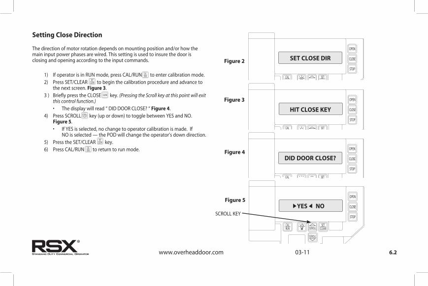
The direction of motor rotation depends on mounting position and/or how the main input power phases are wired. This setting is used to insure the door is closing and opening according to the input commands.
1) If operator is in RUN mode, press CAL/RUN to enter calibration mode. 2) Press SET/CLEAR to begin the calibration procedure and advance to the next screen. Figure 3. 3 ) Briefly press the CLOSE key. (Pressing the Scroll key at this point will exit this control function.) • The display will read “ DID DOOR CLOSE? “ Figure 4. 4) Press SCROLL key (up or down) to toggle between YES and NO. Figure 5. • If YES is selected, no change to operator calibration is made. If NO is selected — the POD will change the operator’s down direction. 5) Press the SET/CLEAR key. 6) Press CAL/RUN to return to run mode.
Setting Close Direction
SET CLOSE DIR Figure 2
OPEN
CLOSE
STOP
CAL SET
HIT CLOSE KEY
OPEN
CLOSE
STOP
CAL SET
DID DOOR CLOSE?
Figure 3
Figure 4
OPEN
CLOSE
STOP
CALRUN SCROLL
SCROLL
SETCLEAR
YES NO Figure 5
SCROLL KEY
OPEN
CLOSE
STOP
CALRUN
SCROLL
SCROLL
SETCLEAR
SETCLEAR
OPEN
CLOSE
SCROLL
SETCLEAR
SETCLEAR
OPEN
CLOSE
STOP
CALRUN
SCROLL
SCROLL
SETCLEAR
www.overheaddoor.com 03-11
®

OPEN
CLOSE
STOP
CALRUN
SCROLL
SCROLL
SETCLEAR
SETCLEAR
SCROLL
SCROLL
SETCLEAR
OPEN
CLOSE
STOP
CALRUN
SCROLL
SCROLL
SETCLEAR
6.3www.overheaddoor.com 03-11
1) If operator is in RUN mode, press CAL/RUN to enter calibration mode. 2) Press Scroll until display reads “BRAKING RATE >#.” where # is the deceleration rate, ranging from 0 to 9. 0=Max. braking. 9=Min. braking. Figure 6. 3) Press SET/CLEAR key to toggle between 0 and 9—one digit at a time. 4) Pick a value and operate the door. Adjust as necessary. 5) Press a SCROLL key to shift to a new function and lock in the setting. 6) Press CAL/RUN to return to run mode.
Setting Braking Rate
OPEN
CLOSE
STOP
CALRUN SCROLL
SCROLL
SETCLEAR
BRAKING RATE 0
Figure 6
®
SCROLL
SETCLEAR
OPEN
CLOSE
STOP
CALRUN SCROLL
SCROLL
SETCLEAR
6.4
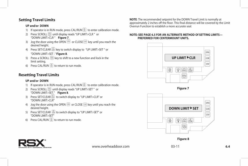
UP and/or DOWN 1) If operator is in RUN mode, press CAL/RUN to enter calibration mode. 2) Press SCROLL until display reads “UP LIMIT>CLR ” or “DOWN LIMIT>CLR ” Figure 7. 3) Jog the door using the OPEN or CLOSE key until you reach the desired height. 4) Press SET/CLEAR key to switch display to “UP LIMIT>SET “ or “DOWN LIMIT>SET .“ Figure 8. 5) Press a SCROLL key to shift to a new function and lock in the limit setting. 6) Press CAL/RUN to return to run mode.
Setting Travel Limits
UP LIMIT CLR
Figure 7
OPEN
CLOSE
STOP
CALRUN SCROLL
SCROLL
SETCLEAR
DOWN LIMIT SET
Figure 8
NOTE: The recommended setpoint for the DOWN Travel Limit is normally at approximately 2 inches off the floor. This final distance will be covered by the Limit Overrun Function to establish a more accurate seal.
NOTE: SEE PAGE 6.5 FOR AN ALTERNATE METHOD Of SETTING LIMITS— PREFERRED FOR CENTERMOUNT UNITS.
OPEN
CLOSE
STOP
CALRUN
SCROLL
SCROLL
SETCLEARSET
CLEAR
OPEN
SCROLL
SETCLEAR
OPEN
CLOSE
STOP
CALRUN
SCROLL
SCROLL
SETCLEAR
OPEN
CLOSE
UP and/or DOWN 1) If operator is in RUN mode, press CAL/RUN to enter calibration mode. 2) Press SCROLL until display reads “UP LIMIT>SET ” or “DOWN LIMIT>SET.” Figure 8. 3) Press SET/CLEAR to switch display to ”UP LIMIT>CLR” or ”DOWN LIMIT>CLR” 4) Jog the door using the OPEN or CLOSE key until you reach the desired height. 5) Press SET/CLEAR to switch display to ”UP LIMIT>SET” or ”DOWN LIMIT>SET” 6) Press CAL/RUN to return to run mode.
Resetting Travel Limits
OPEN
CLOSE
STOP
CALRUN
SCROLL
SCROLL
SETCLEAR
SCROLL
SETCLEAR
OPEN
SETCLEAR
OPEN
CLOSE
STOP
CALRUN
SCROLL
SCROLL
SETCLEAR
OPEN
CLOSE
SETCLEAR
www.overheaddoor.com 03-11
®

6.5www.overheaddoor.com 04-14
Alternate Method for Remotely Setting all Limits
This method will not clear or change an already set limit. To use this method you must first clear the existing limit setpoint. 1) Using the OPEN,CLOSE, STOP buttons on the Wall Station, place the door in the desired position for the limit you wish to set (UP, DOWN or MID-STOP). 2) With the door stopped and in desired position: • Press and hold the STOP button for, at least 10 seconds. DO NOT press any other button. NOTE: Following the setting of a limit you will hear the operator move for a split second as it confirms the setting. 3) While still holding the STOP button: • To set the Up Limit a. Press and hold the OPEN button for one second. b. Release the STOP button, then release the OPEN button. • To set the Down Limit a. Press and hold the CLOSE button for one second. b. Release the STOP button, then release the CLOSE button. • To set the Mid-Stop Limit a. Press and hold both OPEN and CLOSE buttons for one second. b. Release the STOP button, then release the OPEN and CLOSE buttons. This procedure will work with the Cal Pod (keypad) in either CAL or RUN mode.This procedure was specifically designed to prevent the accidental altering of a limit through normal use or a faulty button or wiring.
®

6.6www.overheaddoor.com 04-14
®
A) The Limit Overrun setting is a matter of trial and error. The goal is to adjust the Limit Overrun until an appropriate seal is obtained between the bottom edge of the door and the floor.
B) The Limit Overrun setting can be varied between 0 and 9. 0 - disables the LimitOverrun so that the door stops at the down limit switch setting. 9 - causes the greatest amount of door travel beyond the limit switch setting. Door should close gently with light tension on door cables,or minimal stacking on rolling steel slats. 1) Press CAL-RUN to enter calibration mode2) Press scroll (DN) until the display reads “LIMIT OVERRUN >(0-9).” Fig. 9.
3) Press SET/CLEAR until the display reads the desired value.4) Press the OPEN key to open the door a few feet,then release 5) Press the CLOSE key to close the door and hold until the operator stops. 6) Check the door seal and repeat steps 3-5 until the appropriate
seal is obtained between the door and the floor.
7) Press CAL-RUN to return to Run mode.
Setting Limit Overrun
WARNING: The Limit Overrun will override externalreversing devices, including photocells and sensing edges orreversing edges. Therefore, any externally connected devices willbe disabled during that portion of the door travel controlled by theLimit Overrun function.The Down Limit Overrun function should be used to close the doorno more than the final 2”.
AVERTISSEMENT: La fonction de dépassement de limite annulera les dispositifs de renversement externes, y compris les cellules photoélectriques et des systèmes de détection ou d'inversion aux bords. En conséquence, tous les dispositifs externes connectés seront désactivés pendant la partie de la course de la porte qui est contrôlée par la fonction de dépassement de limite. La fonction de dépassement de limite inférieure doit être utilisée pour fermer la porte uniquement aux derniers 5 cm.
CAUTION: If proper seal cannot be obtained at a setting of 9, Reset the Limit Overrun back to 0 and reset the Down Limit position as described on 6.4. Then adjust the Limit Overrun as instructed above.
ATTENTION: Si une adhésion appropriée ne peut être obtenue à un réglage de 9, réinitialiser le dépassement de limite à 0 puis la position de déplacement de la limite inférieure selon les instructions de la page 6.4. Régler ensuite le dépassement de limite tel qu'indiqué ci-dessus.
OPEN
CLOSE
STOP
CALRUN SCROLL
SCROLL
SETCLEAR
LIMIT OVERRUN #
Figure 9

6.7
OPEN
CLOSE
STOP
CALRUN SCROLL
SCROLL
SETCLEAR
OPEN 1) If operator is in RUN mode, press CAL/RUN to enter calibration mode. 2) Press SCROLL until display reads “OPEN MODE>MOM” or “OPEN MODE>C-STP.”Figure 10. MOM=momentary contact, meaning you press and release the OPEN or CLOSE key and the door will continue to move until it reaches its travel limit. (See NOTE) C-STP=constant contact-stop, meaning if you release the key prior to the door reaching its travel limit, the door will stop. 3) Press SET/CLEAR key to toggle between “OPEN MODE>C-STP” or “OPEN MODE>MOM” on the display. 4) Press a SCROLL key to shift to a new function and lock in the setting. 5) Press CAL/RUN to return to run mode.
CLOSE 1) If operator is in RUN mode, press CAL/RUN to enter calibration mode. 2) Press SCROLL until display reads “CLOSE MODE>MOM,” “CLOSE MODE>C-STP” or “CLOSE MODE>C-REV.” Figure 10.
MOM=momentary contact, meaning you press and release the OPEN or CLOSE key and the door will continue to move until it reaches its travel limit. (See NOTE)
C-STP=constant contact-stop, meaning if you release the key prior to the door reaching its travel limit, the door will stop.
C-REV=constant contact-reverse, meaning if you release the key prior to the door reaching its travel limit, the door will reverse direction. (See NOTE) 3) Press SET/CLEAR key to toggle between “CLOSE MODE>C-STP” or “CLOSE MODE>C-REV” or ”CLOSE MODE>MOM” on the display. 4) Press a SCROLL key to shift to a new function and lock in the setting. 5) Press CAL/RUN to return to run mode.
Setting Open and Close Modes (Constant vs Momentary Contact)
OPEN MODE MOM
Figure 10
NOTE: Momentary contact (MOM) or Constant Reverse (C-REV) may not be used unless both the OPEN and CLOSE Limits have been set.In situations where an external reversing device is either not installed or not operating properly, Constant Contact (C-STP) MUST BE USED.
NOTE: During adjustment of a Travel Limit, the Open and Close Modes will automatically fail-safe to Constant Contact until the Limit has been set or reset. At that time the Open and Close Modes will revert to their previous setting.
OPEN
CLOSE
STOP
CALRUN
SCROLL
SCROLL
SETCLEAR
SCROLL
SCROLL
SETCLEAR
OPEN
OPEN
CLOSE
SETCLEAR
SCROLL
SCROLL
SETCLEAR
OPEN
CLOSE
STOP
CALRUN
SCROLL
SCROLL
SETCLEAR OPEN
CLOSE
STOP
CALRUN
SCROLL
SCROLL
SETCLEAR
SCROLL
SCROLL
SETCLEAR
OPEN
OPEN
CLOSE
SETCLEAR
SCROLL
SCROLL
SETCLEAR
OPEN
CLOSE
STOP
CALRUN
SCROLL
SCROLL
SETCLEAR
www.overheaddoor.com 04-14
®
WARNING: Before momentary contact control can be used on the CLOSE button, a monitored external reversing device such as a photocell system or sensing edge switch must be used. See pages 5.7-5.9 for installation of entrapment protection devices.
AVERTISSEMENT: Avant d'utiliser la commande à contact momentané sur le bouton FERMETURE, un dispositif d'inversion externe surveillée tel qu'un système de cellule photoélectrique ou un commutateur de détection de bord doit être utilisé. Voir l'installation des dispositifs de protection contre le coincement en pages 5.7-5.9.

6.8
CLOSE
STOP
CAL SET
LEARN NEW XMTR?
Figure 11
Adding a Transmitter 1) If operator is in RUN mode, press CAL/RUN to enter calibration mode. 2) Press SCROLL (up or down) until display reads “LEARN NEW XMTR? ” Figure 11. This question along with the instruction “HIT SET FOR YES” will continuously pan across the display window. (Pressing SCROLL or CAL/RUN will cancel the operation.) 3) Press SET/CLEAR . Display will read “PUSH XMTR BUTTON TWO TIMES TO LEARN XMTR.” 4) Press Transmitter button two times. The display will read “XMTR ___LEARNED.” Where it assigns a random number between 1 and 255 to the transmitter. That transmitter is entered and ready to operate the door. (Label/mark the transmitter.) 5) Press SCROLL (up or down) to move on to another menu item, or CAL/RUN to exit the CAL mode.
(Optional) Transmitter Programming
OPEN
CLOSE
STOP
CALRUN
SCROLL
SCROLL
SETCLEAR
SCROLL
SCROLL
SETCLEAR
SETCLEAR
SCROLL
SETCLEAR
OPEN
CLOSE
STOP
CALRUN
SCROLL
SCROLL
SETCLEAR
Removing Individual Transmitter 1) If operator is in RUN mode, press CAL/RUN to enter calibration mode. 2) Press SCROLL (up or down) until display reads “REMOVE XMTR? ” Figure 12. This question along with the instruction “HIT SET FOR YES” will continuously pan across the display window. (Pressing SCROLL or CAL/RUN will cancel the operation.)
A menu displaying the available transmitter numbers will appear. Press SCROLL (up or down) to cycle through the menu to the number of the transmitter to be removed. (Pressing CAL/RUN will cancel the operation.)
The transmitter is removed. 5) Press SCROLL (up or down) to move on to another menu item, or CAL/RUN to exit the CAL mode.
OPEN
CLOSE
STOP
CALRUN
SCROLL
SCROLL
SETCLEAR
SCROLL
SCROLL
SETCLEAR
SCROLL
SETCLEAR
OPEN
CLOSE
STOP
CALRUN
SCROLL
SCROLL
SETCLEAR
CLOSE
STOP
CAL SET
REMOVE XMTR?
Figure 12
Removing All Transmitters 1) If operator is in RUN mode, press CAL/RUN to enter calibration mode. 2) Press SCROLL (up or down) until display reads “REMOVE ALL XMTRS” Figure 13. This question along with the instruction “HIT SET FOR YES” will continuously pan across the display window. (Pressing SCROLL or CAL/RUN will cancel the operation.) 3) Press the SET/CLEAR key. The display will read “ARE YOU SURE.” 4) All transmitters are removed. 5) Press SCROLL (up or down) to move on to another menu item, or CAL/RUN to exit the cal mode.
OPEN
CLOSE
STOP
CALRUN
SCROLL
SCROLL
SETCLEAR
SCROLL
SCROLL
SETCLEAR
SETCLEAR
Press the SET/CLEAR key. SETCLEAR
ESCROLL
SETCLEAR
OPEN
CLOSE
STOP
CALRUN
SCROLL
SCROLL
SETCLEAR
CLOSE
STOP
CAL SET
REMOVE ALL XMTRS?
Figure 13
www.overheaddoor.com 01-14
SCROLL
SETCLEAR
3) Press SET/CLEARSET
CLEAR
4) Press SET/CLEAR SETCLEAR
®

6.9
OPEN
CLOSE
STOP
CALRUN SCROLL
SCROLL
SETCLEAR
Setting Mid-Stop Limit
MID-STOP SET
Figure 14
The RSX® Operator includes a programmable Mid-Stop. This feature allows the operator to stop at a user selectable point when opening. It is used when operating very tall doors that only open to their full height occasionally. The Mid-Stop does not effect the operator when closing. To operate door to full open position from mid-stop, press open button again.
NOTE: Setting of the MID-STOP should only be performed AFTER Travel Limit and Max Run Timer settings have been made. 1) Press CAL/RUN to enter calibration mode. 2) Press the CLOSE to close the door to the down limit. 3) Press SCROLL until display reads “MID-STOP >CLR” Figure 14.
: If the display reads MID-STOP > SET at this point, first clear the MID-STOP as described below then repeat steps 1-3 and continue.
4) Press the OPEN to open the door to desired mid-stop height. 5) Press SET/CLEAR until the display reads ”MID-STOP > SET” 6) Press CAL/RUN to return to run mode.To CLEAR the Limit 7) Press CAL/RUN to enter calibration mode. 8) Press SCROLL until display reads “MID-STOP >SET” 9) Press SET/CLEAR until the display reads ”MID-STOP > CLR” 10) Press CAL/RUN to return to run mode.
OPEN
CLOSE
STOP
CALRUN
SCROLL
SCROLL
SETCLEAR
SCROLL
SETCLEAR
SETCLEAR
OPEN
CLOSE
STOP
CALRUN
SCROLL
SCROLL
SETCLEAR
OPEN
CLOSE
OPEN
OPEN
CLOSE
STOP
CALRUN
SCROLL
SCROLL
SETCLEAR
OPEN
CLOSE
STOP
CALRUN
SCROLL
SCROLL
SETCLEAR
SETCLEAR
SCROLL
SETCLEAR
www.overheaddoor.com 01-14
®
NOTE

6.10www.overheaddoor.com 04-14
OPEN
CLOSE
STOP
CALRUN SCROLL
SCROLL
SETCLEAR
MAX RUN TMR SET
Figure 15
TO RESET 1) Press CAL/RUN to enter calibration mode. 2) Press SCROLL (up or down) until display reads ”MAX RUN TMR > SET.” Figure 15. 3) Press SET/CLEAR until display reads ”MAX RUN TMR > CLR.” 4) Press CAL/RUN to return to RUN mode. 5) Cycle the door between limits.NOTE: The Max Run Timer must be reset each and every time the Travel Limits are adjusted.
Resetting the MRT (The Max Run Timer is set automatically once the unit is cycled between Limits. The Max Run Timer prevents the unit from running continuously in the event of a problem. The MRT’s are set to the time required to run from one limit to the other, plus 5 seconds (nominal). When the MRT is exceeded, the operator stops and will not respond to any command until it is reset by pressing one of the calibration keys or by cycling power to the unit.
OPEN
CLOSE
STOP
CALRUN
SCROLL
SCROLL
SETCLEAR
OPEN
CLOSE
STOP
CALRUN
SCROLL
SCROLL
SETCLEAR
OPEN
CLOSE
STOP
CALRUN
SCROLL
SCROLL
SETCLEAR
OPEN
CLOSE
STOP
CALRUN
SCROLL
SCROLL
SETCLEAR
®
CAUTION: The MID-STOP feature must be turned off in order to properly set the Max Run Timer.
ATTENTION: La fonction MID-STOP doit être désactivée afin de régler correctement la minuterie de course maximum.

6.11www.overheaddoor.com 04-14
OPEN
CLOSE
STOP
CALRUN SCROLL
SCROLL
SETCLEAR
ODC STB ON
Figure 16
Monitored Reversing Devices ODC Safe-T-Beams® (OPTIONAL) 1) If operator is in RUN mode, press CAL/RUN to enter calibration mode. 2) Press SCROLL (up or down) until display reads “ODC STB>ON” or “ODC STB>OFF” Figure 16. 3) Press SET/CLEAR key to toggle between ON and OFF. 4) Press SCROLL (up or down) to shift to a new function and lock setting. 5) Press CAL/RUN to return to run mode.
OPEN
CLOSE
STOP
CALRUN
SCROLL
SCROLL
SETCLEAR
SETCLEAR
SCROLL
SETCLEAR
OPEN
CLOSE
STOP
CALRUN
SCROLL
SCROLL
SETCLEAR
SCROLL
SETCLEAR
NOTE: Installation of Series II Safe-T-Beam® or Residential Safe-T-Beam® Monitored Photocells DOES NOT make the RSX® unit legal for residential use. The Overhead Door Corporation strictly prohibits any installation of an RSX™ unit in any residentially zoned construction.
®
WARNING: Photocell systems provide entrapment protection when mounted near the doorway in such a way that the lower portion of an individuals leg will break the photocell beam during normal walking through the doorway.
AVERTISSEMENT: Les systèmes de cellules photoélectriques fournissent une protection contre le coincement s'ils sont installés à proximité de la porte de manière à ce que la partie inférieure de la jambe d'un individu puisse rompre le faisceau de la cellule photoélectrique lors de passages normaux par la porte.
Current UL Approved Monitored Reversing Devices
with Timer-Close Module P/N OPABTCX.S.
2) MillerEdge ME and MT series monitored edge sensors used in combination
with MillerEdge Interface Module OPAKMEIGX.S. (Direct connect through STB inputs).
4) Residential Safe-T-Beam® Monitored Photocells - P/N 37221R (OSTB-BX) and 38176R.S (includes extension brackets) 5) Series II Commercial Safe-T-Beam® Monitored Photocells - P/N OPAKPE.S and OPAKPEN4GX.S (NEMA 4).
1) MillerEdge ME and MT series monitored edge sensors used in combination
6) Monitored Retro-Reflective Photoeye - P/N OPRAKRPEN4X.S
3) MillerEdge Wireless monitored edge sensor OPAKMMWE.S.
7.1www.overheaddoor.com 03-11
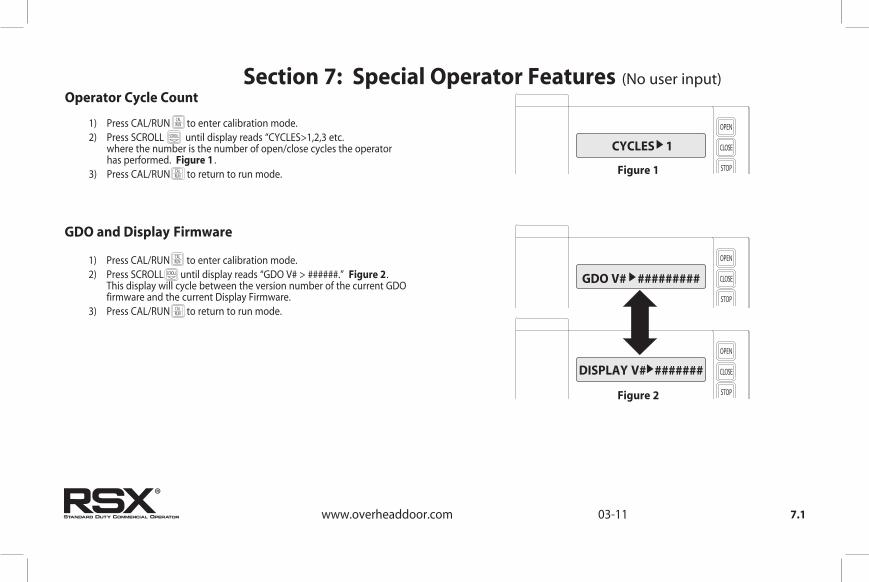
Section 7: Special Operator Features (No user input)
OPEN
CLOSE
STOP
CALRUN SCROLL
SCROLL
SETCLEAR
1) Press CAL/RUN to enter calibration mode. 2) Press SCROLL until display reads “CYCLES>1,2,3 etc. where the number is the number of open/close cycles the operator has performed. Figure 1 . 3) Press CAL/RUN to return to run mode.
Operator Cycle Count
CYCLES 1
Figure 1
OPEN
CLOSE
STOP
CALRUN SCROLL
SCROLL
SETCLEAR
1) Press CAL/RUN to enter calibration mode. 2) Press SCROLL until display reads “GDO V# > ######.” Figure 2. This display will cycle between the version number of the current GDO firmware and the current Display Firmware. 3) Press CAL/RUN to return to run mode.
GDO and Display Firmware
GDO V# #########
OPEN
CLOSE
STOP
CALRUN SCROLL
SCROLL
SETCLEAR
DISPLAY V# #######
Figure 2
OPEN
CLOSE
STOP
CALRUN
SCROLL
SCROLL
SETCLEAR
SCROLL
SETCLEAR
OPEN
CLOSE
STOP
CALRUN
SCROLL
SCROLL
SETCLEAR
OPEN
CLOSE
STOP
CALRUN
SCROLL
SCROLL
SETCLEAR
SCROLL
SETCLEAR
OPEN
CLOSE
STOP
CALRUN
SCROLL
SCROLL
SETCLEAR
®

RSX® operators are available for use in jackshaft or trolley configurations. The same control board is used for either configuration, however the control board must be set for the appropriate GDO configuration. A board set for trolley mode will not work in a jackshaft operator and vice-versa. NOTE: The GDO type is factory set. The installer should not have to set this fea-ture. However, if the GDO type is inadvertently changed, or if a board needs to be replaced in the field, follow these instructions to set GDO type. 1) Press CAL/RUN to enter calibration mode. 2) Press SCROLL until display reads “GDO TYPE > .” This will display the current GDO type. 3) Press SET/CLEAR until display indicates correct GDO type ( J-SHAFT or TROLLEY) 4) Press CAL/RUN to return to run mode.
7.2www.overheaddoor.com 03-11
OPEN
CLOSE
STOP
CALRUN SCROLL
SCROLL
SETCLEAR
Operator Type Fig. 3
GDO TYPE J-SHAFT
Figure 3
OPEN
CLOSE
STOP
CALRUN
SCROLL
SCROLL
SETCLEAR
OPEN
CLOSE
STOP
CALRUN
SCROLL
SCROLL
SETCLEAR
OPEN
CLOSE
STOP
CALRUN
SCROLL
SCROLL
SETCLEAR
OPEN
CLOSE
STOP
CALRUN
SCROLL
SCROLL
SETCLEAR
®

8.1www.overheaddoor.com 03-11
OPEN
CLOSE
STOP
CALRUN SCROLL
SCROLL
SETCLEAR
OPEN
CLOSE
STOP
CALRUN SCROLL
SCROLL
SETCLEAR
Section 8: Troubleshooting
RSX® operators display their status on the integrated display. Each time the operator runs, stops, reverses or refuses to run, the display will indicate why the action did, or did not, take place.Once an error code has been generated, the RSX® operator will continue to display the error code while the operator is not running. This error code can be cleared by pressing the STOP button or STOP key on the keypad. The error code will automatically clear when the operator stops at the down limit. Error codes will continue to be stored in the RSX® operator’s Error Code Memory after they have been cleared from the display in the Run Mode.
Display Operation in Run Mode
To aid in troubleshooting problems, RSX® operators include an error code memory that stores the last 10 error events. These codes are stored with or without power. The last error code detected is also displayed on the LCD until the stop button or key is pressed or the operator stops at the down limit.The error code memory stores the last 10 error codes in sequence. Once 10 codes are stored, the oldest code is erased to make room for the newest code. These codes are displayed in calibration mode. The display will flash the number of the error code and the 2-digit error code followed by a description of the error code. Fig. 1 & 2.
Error Codes
ERROR CODE 1 41
Figure 1
REV ONE BUTTON
Figure 2
®

To view the error code memory: 1) Press CAL/RUN to enter calibration mode. 2) Press SCROLL until display reads “ERROR CODE 1 >”. • The display will begin flashing the error code number and 2-digit error code followed by its description. • Reminder: Error code number 1 is the latest code generated. 3) Press SET/CLEAR . The display will now read “ERROR CODE 2 > .” (This is the error code which was generated before error code 1.) 4) Repeat step 3 until all 10 error codes have been displayed or move on to step 5 when ready. 5) Press CAL/RUN to return to run mode.
NOTE: For all error codes see Appendix C, Sections 10.10 - 10.11.
8.2www.overheaddoor.com 03-11
OPEN
CLOSE
STOP
CALRUN SCROLL
SCROLL
SETCLEAR
OPEN
CLOSE
STOP
CALRUN SCROLL
SCROLL
SETCLEAR
Error Codes (continued)
RSX® operators also include a run code memory that stores the last 10 run events. These codes are stored with or without power. Each time the operator runs or stops, it generates a code that it stores in this memory (Why the operator ran or stopped). Used together with the error code memory, it becomes a powerful troubleshooting aid. The run code memory stores the last 10 codes in sequence. Once 10 codes are stored, the oldest code is erased to make room for the newest code. These codes are displayed in calibration mode. The display will flash the number of the run code and the 2-digit run code followed by a description of the run code. Fig. 3 & 4.
Run Codes
RUN CODE 1 3C
Figure 3
HALT DOWN LIMIT
Figure 4
OPEN
CLOSE
STOP
CALRUN
SCROLL
SCROLL
SETCLEAR
OPEN
CLOSE
STOP
CALRUN
SCROLL
SCROLL
SETCLEAR
OPEN
CLOSE
STOP
CALRUN
SCROLL
SCROLL
SETCLEAR
OPEN
CLOSE
STOP
CALRUN
SCROLL
SCROLL
SETCLEAR
®

8.3www.overheaddoor.com 03-11
To view the run code memory: 1) Press CAL/RUN to enter calibration mode. 2) Press SCROLL until display reads “RUN CODE 1 > .” • The display will begin flashing the run code number and code followed by its description. • Remember: run code number 1 is the latest code generated. 3) Press SET/CLEAR . The display will now read “RUN CODE 2 > .” (This is the run code which was generated before run code 1.) 4) Repeat step 3 until all 10 run codes have been displayed or move on to step 5 when ready. 5) Press CAL/RUN to return to run mode.
NOTE: For all run codes see Appendix C, Section 10.9.
Run Codes (continued)
TROUBLESHOOTING EXAMPLE USING RUN AND ERROR
CODE MEMORIES. Fig. 51. In Calibration Mode, display and write down each Run Code and Error Code stored in memory.2. List as shown in Fig. 5.3. Refer to Appendix C to interpret the codes.In this example, the operator was opened using the OPEN key on the keypad and stopped at the up limit. The OPEN wall button was then activated, causing the “6D” code to be generated since the operator could not open when it is already at the up limit. The CLOSE wall button was then activated, causing the operator to close. While closing, the Normally-Open (N-O) Safety Input was activated, causing the operator to stop and then reverse, stopping at the up limit.
ERRORCODES
RUNCODES
1
2
3
4
5
6
7
8
9
10
1
2
3
4
5
6
7
8
9
10
11
45
6D
00
00
00
00
00
00
00
00
00
00
00
00
00
00
00
00
00
3D
35
20
3D
14
REVERSED DUE TO ACTIVE N-O SAFETY INPUT
WOULD NOT OPEN —ALREADY AT UP LIMIT
STOPPED AT UP LIMIT
STOPPED DUE TO ACTIVE N-O SAFETY INPUT
CLOSED FROM CLOSE WALL BUTTON
STOPPED AT UP LIMIT
OPENED FROM OPEN KEY ACTIVATION
RSX STORES “00” CODES IN UNUSED RUN AND ERROR CODE MEMORY LOCATIONS AT THE TIME OF MANUFACTURE. AS ERROR OR RUN CODES ARE RECORDED, THE “00” CODES ARE REPLACED WITH VALID CODES
NUMBER CODE NUMBERCODE
Figure 5
OPEN
CLOSE
STOP
CALRUN
SCROLL
SCROLL
SETCLEAR
SCROLL
SETCLEAR
SETCLEAR
OPEN
CLOSE
STOP
CALRUN
SCROLL
SCROLL
SETCLEAR
®

8.4www.overheaddoor.com 03-11
RSX® operators include a self-diagnostic circuit board using troubleshooting LED indicators to signal the technician of a problem.
LED Indicators Fig. 6
+24VDC
STBENAB
Figure 6
TROUBLESHOOTING LED’s
+ 24 VOLTSDC
STBENABLE NORMALLY ON - STB ENABLED OFF - STB DISABLED
NORMALLY ON - POWER AVAILABLE OFF - CHECK AC POWER SUPPLY CHECK FUSES
®

8.5
Safe-T-Beam® Monitored Photocell Self-diagnostic Troubleshooting Chart
ON ON NORMAL OPERATION NONE REQUIRED
OFF OFF1. POWER HEAD NOT POWERED 2. WIRING FROM POWER HEAD BAD
1. CHECK BREAKERS, FUSES, PLUGS 2. CHECK WIRING FOR OBVIOUS SHORTS
OFF ON 1. WIRING TO SOURCE MISSING OR BAD 2. POWER HAS BEEN INTERRUPTED
1. CHECK WIRING 2. REMOVE POWER AND REAPPLY
2 BLINKS, PAUSE (REPEAT)
ON1. BEAM NOT ALIGNED 2. BEAM OBSTRUCTED 3. SENSOR DEFECTIVE
1.CHECK ALIGNMENT 2. CHECK FOR OBSTRUCTION 3. CALL CUSTOMER SERVICE
1. WIRE TO SENSOR MISSING OR BAD 2. SENSOR DEFECTIVE
1. CHECK WIRING 2. CALL CUSTOMER SERVICEOFF
ON1. SENSOR RECEIVING INTERFERENCE
ON 1. SOURCE NOT SENDING PULSES 2. SOURCE DEFECTIVE
1. CALL CUSTOMER SERVICE 2. CALL CUSTOMER SERVICE
SOURCE (RED LED) SENSOR (GREEN LED) INDICATED CONDITION REQUIRED ACTION
2 BLINKS, PAUSE (REPEAT)
3 BLINKS, PAUSE (REPEAT)
4 BLINKS, PAUSE (REPEAT)
1. ATTEMPT TO DETERMINE SOURCE OF
INTERFERENCE 2. CALL CUSTOMER SERVICE
www.overheaddoor.com 04-14
®
WARNING: ACTUATING THE OPERATOR BY USING CONSTANT CONTACT ON THE CLOSE BUTTON WILL OVERRIDE NON-FUNCTIONING EXTERNAL REVERSING DEVICES, INCLUDING PHOTOCELLS.
AVERTISSEMENT: L'ACTIVATION DE L'OPERATEUR EN UTILISANT UN CONTACT CONSTANT SUR LE BOUTON FERMER ANNULERA LES DISPOSITIFS D'INVERSIONS EXTERNES, Y COMPRIS LES CELLULES PHOTOELECTRIQUES.
WARNING: Overhead Door Corporation recommends that line voltage wiring be performed by qualified electrician. See Section 5 for additional wiring instructions.
AVERTISSEMENT: Overhead Door Corporation recommande que le câblage au secteur soit effectué par un électricien qualifié. Voir la section 5 pour des instructions supplémentaires sur le câblage.

9.1www.overheaddoor.com 04-14
Section 9: Service and MaintenanceMaintenance ScheduleThe following table provides a schedule of recommended Service and Maintenance items to be completed by a trained service representative.
SERVICE ITEM EVERY 6 MO. EVERY 12 MO. EVERY 36 MO. MONTHLY OR OR OR 5,000 CYCLES 10,000 CYCLES 30,000 CYCLE MANUAL OPERATION OF DOOR CHECK DRIVE CHAINS AND LUBRICATE PHOTOCELL/ SENSING EDGE OPERATION CLUTCH ADJUSTMENT CHECK FOR LOOSE OR MISSING HARDWARE CHECK LIMIT POSITION GEAR TRAIN WEAR
®
SERVICE INTERVAL (FREQUENCY)
CAUTION: Failure to perform the recommended Service & Maintenance may result in premature failure of the operator.
ATTENTION: Si les instructions de service et de maintenance recommandés ne sont pas suivies, l'opérateur pourrait tomber en panne prématurément.
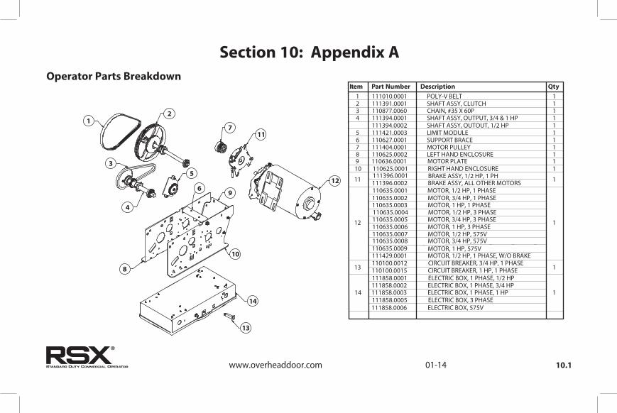
10.1
Section 10: Appendix AOperator Parts Breakdown
12
711
125
3
4
69
10
8
14
13
www.overheaddoor.com 01-14
1 111010.0001 POLY-V BELT2 111391.0001 SHAFT ASSY, CLUTCH3 110877.0060 CHAIN, #35 X 60P
4 111394.0001 SHAFT ASSY, OUTPUT, 3/4 & 1 HP111394.0002 SHAFT ASSY, OUTOUT, 1/2 HP
5 111421.0003 LIMIT MODULE 6 110627.0001 SUPPORT BRACE7 111404.0001 MOTOR PULLEY8 110625.0002 LEFT HAND ENCLOSURE
9 110636.0001 MOTOR PLATE10 110625.0001 RIGHT HAND ENCLOSURE
111396.0001 BRAKE ASSY, 1/2 HP, 1 PH
111396.0002 BRAKE ASSY, ALL OTHER MOTORS 110635.0001 MOTOR, 1/2 HP, 1 PHASE
110635.0002 MOTOR, 3/4 HP, 1 PHASE 110635.0003 MOTOR, 1 HP, 1 PHASE 110635.0004 MOTOR, 1/2 HP, 3 PHASE 110635.0005 MOTOR, 3/4 HP, 3 PHASE 110635.0006 MOTOR, 1 HP, 3 PHASE 110635.0007 MOTOR, 1/2 HP, 575V 110635.0008 MOTOR, 3/4 HP, 575V 110635.0009 MOTOR, 1 HP, 575V
110100.0012 CIRCUIT BREAKER, 3/4 HP, 1 PHASE
110100.0015 CIRCUIT BREAKER, 1 HP, 1 PHASE 111858.0001 ELECTRIC BOX, 1 PHASE, 1/2 HP
111858.0002 ELECTRIC BOX, 1 PHASE, 3/4 HP 111858.0003 ELECTRIC BOX, 1 PHASE, 1 HP 111858.0005 ELECTRIC BOX, 3 PHASE
111429.0001 MOTOR, 1/2 HP, 1 PHASE, W/O BRAKE
111858.0006 ELECTRIC BOX, 575V
Item Part Number Description Qty
12
11
13
14
11111111111
1
1
1
1
®

10.2www.overheaddoor.com 01-14
Section 10: Appendix A
Alternate Motor Options (Not UL Approved)
TEFC, SINGLE PHASE*111306.0001, 1/2 HP, 115/208,230 V111306.0002, 3/4 HP, 115/208/230 V111306.0003, 1 HP, 115/208/230 V
TEFC, THREE PHASE*111308.0001, 1/2 HP, 208/230/460 V
111308.0002, 3/4 HP, 208/230/460 V111308.0003, 1 HP, 208/230/460 V111308.0006, 1 HP, 575 V
TENV, SINGLE PHASE*111309.0001, 1/2 HP, 115/208/230 V
111309.0002, 3/4 HP, 115/208/230 V
TENV, THREE PHASE*111309.0004, 1/2 HP, 208/230/460 V
111309.0005, 3/4 HP, 208/230/460 V111309.0006, 1 HP, 208/230/460 V111309.0009, 1 HP, 575 V
*NOT AVAILIABLE ONOPERATOR W/O BRAKE
®

10.3www.overheaddoor.com 01-14
Appendix A (continued)
Shafts Parts Breakdown
7
58
29
111
23
4
1011
14
2
57
68
9
31615
10
6
1310 1
Item Part Number Description Qty
3
SHAFT, OUTPUT, .749 DIA, TROLLEY111027.0001
1
111348.0001 SPROCKET, 10T, #65, 1/2P (3/4 & 1HP)
111
111073.0001 GEAR, 26T, LIMIT 19 110
110313.0004
110818.0004
PIN, SPRING, .250” DIA X 1.50”L 16
WASHER, WAVE SPRING, .780” ID 18 110313.0010 PIN, SPRING, .250” DIA X 2.00 17
BEARING, .750” ID110695.0001 WASHER, .770” ID110819.0003RING, RTNG, EXT, “E”, .744 ID080415.0022SPROCKET, 32T, #35 CH, 3/8P110738.0001
PIN, DOWEL, .188 X 1.13/1.00110881.0001
111394.0001 OUTPUT SHAFT ASSY (3/4 & 1HP)
1 2
4 5
12
11
110739.0001 SPROCKET, 10T, #41, 1/2P (1/2 HP)
111394.0002 OUTPUT SHAFT ASSY (1/2 HP)
Output Shaft
Clutch Shaft
Item Part Number Description Qty
3
SHAFT, CLUTCH, .625” DIA110730.0001
1
080401.0624 PIN, COTTER, 3/16” X 1-1/2” L 19 210
075197.0000
110472.0001
SPRING, CLUTCH 16
NUT, HEX, SLOTTED, 5/8”-11 18 086649.0029 WASHER, THRUST, .64 17
PIN, DOWEL, .188 X 1.13/1.00110881.0001 LINING, CLUTCH075193.0000DISC, CLUTCH108015.0001PULLEY ASSY, CLUTCH111324.0001
BEARING, .625 ID110813.0001
111391.0001 CLUTCH SHAFT ASSY, TROLLEY1 2
4 5
11
11
13
SPROCKET, 11T, #35 CH, 3/8P110465.0001
2
111037.0001 DISC, CLUTCH 116
RING, RTNG, EXT, “E”, 5/8 SFT080415.0021WASHER, PLAIN, .651 ID110819.0001PIN SPRING, .188 DIA X 1.38”110313.0008WASHER, WAVE SPRING, .650 ID110818.0001
11 12
14 15
11
11
4
12
®

10.4www.overheaddoor.com 01-14
Appendix A (continued)Rail Parts Breakdown
12
5
4
6
1311
10
12
87 9
Item Part Number Description Qty
1
RAIL ASSY, TROLLEY
BOLT, HH, PLD, 7/16-14 X 1080105.0708
SPREADER BRACKET
18
4
110732.1245
TRACK, 18’ DOOR
080019.0001 BOLT, TRK, 1/4-20 X 9/16 29 086480.1620 NUT, HEX, W/LK WSHR, 1/4-20 210
110732.1197 TRACK, 14’ DOOR 25
110732.1317 TRACK, 24’ DOOR110732.1269 TRACK, 20’ DOOR
110768.0001 PIN, IDLER 17
110732.1125
110732.1173
TRACK, 8’ DOOR
TRACK, 12’ DOOR110732.1149 TRACK, 10’ DOOR
110744.0001 SPACER 26
NUT, HEX, PLD, 7/16-14080352.0714 WSHR, LK, 7/16 X 25/32 OD080322.0446 CHAIN GUIDE111390.0001
TRACK, 16’ DOOR110732.1221
PIN, COTTER
111078.0001
WASHER, PLAIN, STEEL080401.0616 11
12 22
23 4
442
080302.3240 111178.0001 13 IDLER, PULLEY, W/BUSHING 1
3
®

10.5www.overheaddoor.com 01-14
Appendix A (continued)
Carriage/Door Arms Parts Breakdown
27
6
5
4
32
1
89 10
11
12
13
14
Item Part Number Description Qty
1
#65 CHAIN, 1/2 HP
NUT, 3/8-16
212
1
110616.0001 CARRIAGE, TROLLEY
17
26013D DOOR ARM, CURVED 113 5973-Q04 BOLT, 3/8-16 X 7/8 214
080302.2626 WASHER, FLAT, PLD, 3/8” X 13/16” 15 26
606-E04 PIN, COTTER 19 110844.0001 DOOR ARM ASSY 18
086621.0620 PIN, CLEVIS 111
080884.0003
075064.0000
CONNECTING LINK, #41 CHAIN 22
SPRING, CRG, .796 OD X 1-1/4” 14 110784.0001 ROD, THREADED, 3/8-16 13
110
8’ DOOR10’ DOOR12’ DOOR14’ DOOR16’ DOOR18’ DOOR
080839.4951080839.5911080839.6871080839.7831080839.8791080839.9751
NUT, HEX, W/LK WSHR, 3/8-16086480.2416
24121-D05
BRACKET, DOOR110842.0001
#41 CHAIN, 3/4 & 1 HP8’ DOOR10’ DOOR12’ DOOR14’ DOOR16’ DOOR18’ DOOR20’ DOOR24’ DOOR
111342.0495111342.0591111342.0687111342.0783111342.0879111342.0975111342.1071111342.1263
®

10.6www.overheaddoor.com 03-14
Appendix A (cont’)
13
NS
Electric Box Parts Breakdown
Item Part Number Description Qty
1 112077.0001 COVER ASSY, 1 PHASE
112077.0002 COVER ASSY, 3 PHASE 1 112077.0003 COVER ASSY, 575V
2
111854.0001 CIRCUIT BOARD ASSY, 1 PHASE, 1/2 HP
1 111854.0002 CIRCUIT BOARD ASSY, 1 PHASE, 3/4 - 1HP
111854.0004 CIRCUIT BOARD ASSY,
3 PHASE
111854.0005 CIRCUIT BOARD ASSY, 575V 3 111401.0001 INSULATOR BOARD ASSY 1
4 111087.0001 XFMR, 115/208/230V, 1 PHASE
111087.0002 XFMR, 208/230/460V, 3 PHASE 1 111087.0003 XFMR, 575V 5 6 7
22634A WASHER, CUP 1
8
110950.0001 HINGE ASSY 2
9
110630.0001 ELECTRIC BOX 1
10
111397.0001 RECEIVER ASSY 1111398.0001 LATCH ASSY 1111352.0001 ANTENNA ASSY 1
NS 111405.0001 SPARE FUSE KIT
1 2 3 4 5 6 7 8 9 10
NS=NOT SHOWN
12
11
11 8706F29 SCREW, GROUND, #10-32 X 3/8 12 8706E29 SCREW, GROUND, #8-32 X 3/8
11
1434004DR250 34004C02R5
FUSE, .250A, SLOW BLOW FUSE, 2.5A, FAST ACTING
112402.0001 KIT, RELAY, (FOR NO BRAKE ONLY)111439.0001 PARTS PACK, RADIO PIGTAILNS
11
®
13
14
.250 AMP (FUSE WITH WHITE MARK)
2.5 AMP (FUSE WITH RED MARK)

10.7
Electric Box LayoutAppendix A (cont’)
www.overheaddoor.com 03-11
TransformerConnectors
Input Power Connectors
460V3 PH
208/230V3 PH
TransformerConnectors
115V1 PH
208/230V1 PH
External Radio Connector
Internal Radio Board
Radio
Fuse
Fuse
AntennaInput (Coax)
BrakeConnector
Input Power Connectors
Hoist InterlockConnector MotorConnectors
MotorConnectors
ExpansionBoard PortLimit Sensor Connector
Three PhaseSingle Phase
®

10.8www.overheaddoor.com 01-14
Section 10: Appendix BScrew Terminal Assignments FUNCTION CONNECTION TYPE
11-POSITION TERMINAL BLOCK INSIDE ELECTRIC BOX
OPEN Causes door to open if not at Up Limit. Causes a closing door to reverse.CLOSE Causes door to close if not at Down Limit. Normally-Open Dry Contact to GND.
Normally-Open Dry Contact to GND.
STOP Causes a moving door to stop. Prevents the operator from running. Normally-Closed Dry Contact to GND.GND Common ground connection for Open, Close, Stop & 1-Btn Inputs.
1-BTNCauses door to open if not at Up Limit or Mid-Stop Limit. Causes door to close if at Up Limit or Mid-Stop Limit. Causes door to stop if opening. Causes a closing door to reverse.
Normally-Open Dry Contact to GND.
ODC STB
Reverses a closing door if photocell beam is blocked. NOTE: STB's must be enabled in Calibration Mode.
ODC Series II Safe-T-Beams® ONLY to these inputs.
ODC STB
Reverses a closing door if photocell beam is blocked.NOTE: STB's must be enabled in Calibration Mode.
N-O REVERSE Causes a closing door to reverse. NOTE: Will not open a stopped door. Normally-Open 2-Wire Non-Monitored Edge Sensor.
N-O REVERSE Causes a closing door to reverse. NOTE: Will not open a stopped door. Normally-Open 2-Wire Non-Monitored Edge Sensor.
EXT INTLKCauses a moving door to stop. Prevents the operator from running when contact is open. Operates even if microcontroller is non-functional.
Normally-Closed dry contacts. (board will energize these contacts at nominal +24VDC).
EXT INTLKCauses a moving door to stop. Prevents the operator from running when contact is open. Operates even if microcontroller is non-functional.
Normally-Closed dry contacts. (board will energize these contacts at nominal +24VDC).
2-POS TERMINAL BLOCK L1 / L1 120VAC: Connect to Line (Hot) / 240VAC: Connect to Line 1.Power to Operator.1 PHASE (INSIDE ELECTRIC BOX) N / L2 120VAC: Connect to Neutral / 240VAC: Connect to Line 2.Power to Operator.
PWR Power for radio & other accessories. +20 to +40VDC, fused at 250mA (F1). Connect to radio or other accessory's power input.
RAD
GND
Causes door to open if not at Up Limit or Mid-Stop Limit. Causes door to close if at Up Limit or Mid-Stop Limit. Causes a closing door to reverse.Common ground connection for PWR and RAD terminals. Connect to radio or other accessory's ground input.
EXPANSION PORT Accessory Module Ribbon Cable.PLUG CONNECTIONSINSIDE ELECTRIC BOX TRANSFORMER Connects main transformer to control board. Transformer Plug.
BRAKE Connects brake solenoid to control board. Brake Solenoid Plug.Motor Plug.
HOIST INTLK Causes moving door to stop. Prevents the operator from running. Operates even if microcontroller is non-functional.
Limit Sensor Plug.
Hoist Interlock Plug or Jumper.
INPUT
(Radio Input Control)
(not polarity sensitive)
ODC Series II Safe-T-Beams® ONLY to these inputs. (not polarity sensitive)
(not polarity sensitive)
(not polarity sensitive)
LIMIT SENSOR Causes door to stop at top and bottom of normal travel.
MOTOR Connects motor and capacitor to control board.
Connects accessory modules to operator.
RADIO ANDACCESSORIES
PIGTAIL
L1L2L3
Power to Operator.Power to Operator.Power to Operator.
3-POS TERMINAL BLOCK3 PHASE (INSIDE ELECTRIC BOX)
Connect to radio or other accessory’s signal (output).
®

10.9www.overheaddoor.com 3
Section 10: Appendix CRun Code Displays
CODE DISPLAY Condition Code Description 0C IDLE > DOWN LIMIT STANDING BY AT DOWN LIMIT (NOTE: THIS MESSAGE IS DISPLAYED IF BOTH LIMITS ARE ACTIVE) 0D IDLE > UP LIMIT STANDING BY AT UP LIMIT 0E IDLE > MID STOP STANDING BY AT MID-STOP LIMIT 0F IDLE > NO LIMIT STANDING BY BETWEEN LIMITS 10 OPENING > OPEN BTN OPENING FROM OPEN BUTTON 11 OPENING > ONE BTN OPENING FROM 1 BUTTON 12 OPENING > RADIO OPENING FROM RADIO 13 OPENING > AUX OPEN OPENING FROM AUXILIARY OPEN INPUT 14 OPENING > OPEN KEY OPENING FROM KEYPAD OPEN KEY 20 CLOSING > CLOSE PB CLOSING FROM CLOSE BUTTON 21 CLOSING > ONE BTN CLOSING FROM 1 BUTTON 22 CLOSING > RADIO CLOSING FROM RADIO 24 CLOSING > CLOSE KP CLOSING FROM KEYPAD CLOSE KEY 2A CLOSING > TCM CLS CLOSING FROM TIMER CLOSE MODULE 30 HALT > WALL BUTTON GDO STOPPED BECAUSE STOP OR OPEN BUTTON WAS ACTIVATED, POSSIBLY STARTING A REVERSAL 31 HALT > ONE BUTTON GDO STOPPED BECAUSE 1 BUTTON WAS ACTIVATED, POSSIBLY STARTING A REVERSAL 32 HALT > RADIO GDO STOPPED BECAUSE RADIO INPUT WAS ACTIVATED, STARTING A REVERSAL 33 HALT > AUX. OPEN GDO STOPPED BECAUSE AUXILIARY OPEN INPUT WAS ACTIVATED, STARTING A REVERSAL 34 HALT > KEYPAD KEY GDO STOPPED BECAUSE KEYPAD STOP OR OPEN KEY WAS ACTIVATED, POSSIBLY STARTING A REVERSAL 35 HALT > N-O SAFETY GDO STOPPED BECAUSE N-O REVERSING INPUT WAS ACTIVATED, STARTING A REVERSAL 36 HALT > ODC STB GDO STOPPED BECAUSE ODC STB WAS BLOCKED, STARTING A REVERSAL 37 HALT > N-C SAFETY GDO STOPPED BECAUSE N-C REVERSING INPUT WAS ACTIVATED, STARTING A REVERSAL 38 HALT > MON. EDGE GDO STOPPED BECAUSE MONITORED EDGE SENSOR INPUT WAS ACTIVATED, STARTING A REVERSAL 39 HALT > DOOR FORCE GDO STOPPED BECAUSE THE FORCE REQUIRED TO OPERATE THE DOOR WAS TOO HIGH, POSSIBLY STARTING A REVERSAL 3A HALT > LOSS OF C/C GDO STOPPED BECAUSE CONSTANT CONTACT ON THE CONTROL WAS REMOVED BEFORE REACHING A LIMIT, POSSIBLY STARTING A REVERSAL 3B HALT > SHUTDOWN GDO STOPPED BECAUSE THE GDO DETECTED A FAULT SUCH AS AN OPEN INTERLOCK, OVERHEATED MOTOR, ETC. 3C HALT > DOWN LIMIT GDO STOPPED BECAUSE IT REACHED THE DOWN LIMIT 3D HALT > UP LIMIT GDO STOPPED BECAUSE IT REACHED THE UP LIMIT 3E HALT > MID STOP GDO STOPPED BECAUSE IT REACHED THE MID-STOP LIMIT 3F HALT > MODULE FAIL GDO STOPPED BECAUSE AN EXPANSION MODULE WAS NOT WORKING PROPERLY
®

Condition Code DISPLAY Condition Code Description
40 REV > OPEN BUTTON GDO REVERSED BECAUSE THE OPEN BUTTON WAS ACTIVATED 41 REV > ONE BUTTON GDO REVERSED BECAUSE THE 1 BUTTON WAS ACTIVATED 42 REV > RADIO GDO REVERSED BECAUSE THE RADIO INPUT WAS ACTIVATED 43 REV > AUX OPEN GDO REVERSED BECAUSE THE AUXILIARY OPEN INPUT WAS ACTIVATED 44 REV > OPEN KEY GDO REVERSED BECAUSE THE KEYPAD OPEN KEY WAS ACTIVATED 45 REV > N-O SAFETY GDO REVERSED BECAUSE THE N-O REVERSING INPUT WAS ACTIVATED 46 REV > ODC STB GDO REVERSED BECAUSE THE ODC STB WAS BLOCKED 47 REV > N-C SAFETY GDO REVERSED BECAUSE THE N-C REVERSING INPUT WAS ACTIVATED 48 REV > MON. EDGE GDO REVERSED BECAUSE THE MONITORED EDGE SENSOR WAS ACTIVATED 49 REV > DOOR FORCE GDO REVERSED BECAUSE THE FORCE REQUIRED TO CLOSE THE DOOR WAS TOO HIGH 4A REV > LOSS OF C/C GDO REVERSED BECAUSE CONSTANT CONTACT ON THE CONTROL WAS REMOVED BEFORE REACHING THE DOWN LIMIT 4B REV > MAX RUN TMR GDO REVERSED BECAUSE THE CLUTCH SLIPPED OR SOME OTHER FAULT OCCURRED THAT ALLOWED THE GDO TO RUN TOO LONG 4F REV > EXP MOD FAIL GDO REVERSED BECAUSE AN EXPANSION MODULE WAS NOT WORKING PROPERLY 50 STOP > HOT MOTOR GDO STOPPED BECAUSE THE MOTOR WAS OVERHEATED 51 STOP > OPEN MRT GDO STOPPED BECAUSE THE CLUTCH SLIPPED OR SOME OTHER FAULT OCCURRED THAT ALLOWED THE GDO TO RUN OPEN TOO LONG 52 STOP > CLOSE MRT GDO STOPPED BECAUSE THE CLUTCH SLIPPED OR SOME OTHER FAULT OCCURRED THAT ALLOWED THE GDO TO RUN DOWN TOO LONG 57 STOP > OPEN INTLK GDO STOPPED BECAUSE THE HOIST INTERLOCK OR EXTERNAL INTERLOCK IS OPEN 58 STOP > WRONG GDO GDO STOPPED BECAUSE THE BOARD IS SET FOR JACKSHAFT MODE, BUT INSTALLED IN A TROLLEY OPERATOR 59 STOP > DOOR FORCE GDO STOPPED BECAUSE THE FORCE REQUIRED TO OPEN THE DOOR WAS TOO HIGH 5A STOP > WRONG LIMIT GDO STOPPED BECAUSE THE UP LIMIT ACTIVATED WHEN CLOSING OR THE DOWN LIMIT ACTIVATED WHEN OPENING 5C STALL > DOWN LIMIT GDO STOPPED BECAUSE IT COULDN'T LEAVE THE DOWN LIMIT DUE TO A SLIPPING CLUTCH OR OTHER PROBLEM 5D STALL > UP LIMIT GDO STOPPED BECAUSE IT COULDN'T LEAVE THE UP LIMIT DUE TO A SLIPPING CLUTCH OR OTHER PROBLEM 60 CHECK STOP BTN GDO WON'T RUN BECAUSE THE STOP BUTTON IS ACTIVE 61 TCM DISABLED TIMER CLOSE WON'T WORK BECAUSE NO SAFETIES ARE ENABLED 62 NO RADIO >> C/C RADIO INPUT WON'T WORK WITH OPEN OR CLOSE FUNCTION IN CONSTANT CONTACT MODE 63 CHECK AUX OPEN GDO WON'T CLOSE BECAUSE AUXILIARY OPEN INPUT IS ACTIVE 64 CHECK STOP KEY GDO WON'T RUN BECAUSE THE KEYPAD STOP KEY IS ACTIVE 65 CHECK N-O SAFETY GDO WON'T CLOSE BECAUSE THE N-O REVERSING IS ACTIVE 66 CHECK ODC STB GDO WON'T CLOSE BECAUSE THE ODC STB IS BLOCKED 67 CHECK N-C SAFETY GDO WON'T CLOSE BECAUSE THE N-C REVERSING INPUT IS ACTIVE 68 CHECK MON. EDGE GDO WON'T CLOSE BECAUSE THE MONITORED EDGE SENSOR IS ACTIVE 69 OVERHEATED MOTOR GDO WON'T RUN BECAUSE THE MOTOR IS OVERHEATED 6C NO RUN > DOWN LIM GDO WON'T CLOSE BECAUSE ITS ALREADY AT THE DOWN LIMIT 6D NO RUN > UP LIMIT GDO WON'T OPEN BECAUSE ITS ALREADY AT THE UP LIMIT 6E NO RUN > MID STOP GDO WON'T RUN BECAUSE ITS AT OR ABOVE THE MID-STOP LIMIT & CAN'T RUN UP & A REVERSING INPUT IS PREVENTING IT FROM CLOSING 6F EXP MODULE FAIL GDO WON'T RUN BECAUSE AN EXPANSION MODULE FAILURE IS PREVENTING IT
10.10www.overheaddoor.com 3
Error Code Displays Section 10: Appendix C
®

10.11www.overheaddoor.com 3
Section 10: Appendix CError Codes Displays (continued)
Condition Code DISPLAY Condition Code Description
70 BOARD FAILURE 70 CONTROL BOARD FAILURE 70, CONTACT FACTORY TECHNICAL SERVICE DEPT. 71 BOARD FAILURE 71 CONTROL BOARD FAILURE 71, CONTACT FACTORY TECHNICAL SERVICE DEPT. 74 BOARD FAILURE 74 CONTROL BOARD FAILURE 74, CONTACT FACTORY TECHNICAL SERVICE DEPT. 75 BOARD FAILURE 75 CONTROL BOARD FAILURE 75, CONTACT FACTORY TECHNICAL SERVICE DEPT. 76 BOARD FAILURE 76 CONTROL BOARD FAILURE 76, CONTACT FACTORY TECHNICAL SERVICE DEPT. 77 BOARD FAILURE 77 CONTROL BOARD FAILURE 77, CONTACT FACTORY TECHNICAL SERVICE DEPT. 80 BOARD FAILURE 80 CONTROL BOARD FAILURE 80, CONTACT FACTORY TECHNICAL SERVICE DEPT. 81 BOARD FAILURE 81 CONTROL BOARD FAILURE 81, CONTACT FACTORY TECHNICAL SERVICE DEPT. 82 BOARD FAILURE 82 CONTROL BOARD FAILURE 82, CONTACT FACTORY TECHNICAL SERVICE DEPT. 83 BOARD FAILURE 83 CONTROL BOARD FAILURE 83, CONTACT FACTORY TECHNICAL SERVICE DEPT. 84 BOARD FAILURE 84 CONTROL BOARD FAILURE 84, CONTACT FACTORY TECHNICAL SERVICE DEPT. 85 EXP PORT PROBLEM EXPANSION PORT IS SHORT CIRCUITED, TRY DISCONNECTING EXPANSION MODULES OR CONTACT FACTORY TECHNICAL SERVICE DEPT. 86 BOARD FAILURE 86 CONTROL BOARD FAILURE 86, DISCONNECT EXPANSION MODULES. IF NO CHANGE, CONTACT FACTORY TECHNICAL SERVICE DEPT. 88 TCM FAILURE TIMER CLOSE MODULE (TCM) HAS FAILED 8A AOM FAILURE AUXILIARY OUTPUT MODULE (AOM) HAS FAILED 8E REV INTERRUPTED GDO LOST POWER OR ENCOUNTERED ANOTHER PROBLEM DURING THE REVERSAL PROCESS, REVERSAL IS COMPLETING NOW 8F LIMIT MOD. FAIL GDO WON'T RUN, LIMIT MODULE HAS FAILED 90 DIAGNOSTIC MODE GDO IS IN DIAGNOSTIC MODE, NORMAL FUNCTIONS ARE NOT ALLOWED A0 OPEN BTN BAD > PU OPEN & CLOSE BUTTONS WON'T WORK, THE OPEN BUTTON WAS ACTIVE WHEN THE GDO WAS POWERED-UP A1 CLOSE BTN BAD > PU OPEN & CLOSE BUTTONS WON'T WORK, THE CLOSE BUTTON WAS ACTIVE WHEN THE GDO WAS POWERED-UP A2 ONE BTN BAD > PU 1 BUTTON WON'T WORK, THE 1 BUTTON WAS ACTIVE WHEN THE GDO WAS POWERED-UP A3 RADIO BAD > PWR UP RADIO INPUT WON'T WORK, THE RADIO INPUT WAS ACTIVE WHEN THE GDO WAS POWERED-UP A4 AUX OPEN BAD > PU AUXILIARY OPEN INPUT WON'T WORK, THE AUXILIARY OPEN INPUT WAS ACTIVE WHEN THE GDO WAS POWERED-UP A5 OPEN KEY BAD > PU KEYPAD OPEN & CLOSE KEYS WON'T WORK, THE OPEN KEY WAS ACTIVE WHEN THE GDO WAS POWERED-UP A6 CLOSE KEY BAD > PU KEYPAD OPEN & CLOSE KEYS WON'T WORK, THE CLOSE KEY WAS ACTIVE WHEN THE GDO WAS POWERED-UP A7 MULT KEYS BAD > PU 1 OR MORE KEYPAD CALIBRATION KEYS WON'T WORK, 1 OR MORE WERE ACTIVE WHEN THE GDO WAS POWERED-UP AA TCM BAD > POWER UP TIMER CLOSE MODULE WON'T CLOSE DOOR, IT WAS ACTIVE WHEN THE GDO WAS POWERED-UP
®

11.1www.overheaddoor.com 01-14
Section 11: WarrantyThe authorized distributor of Overhead Door Corporation products whose name appears below (“Seller”) warrants to the original purchaser of the Operator specified below (“Operator”), subject to all the terms and conditions hereof, that the Operator will be free from defects in material and workmanship under normal use and service until the earlier of the following to occur:
1. Two (2) years after the date of installation
or
2. When the Operator exceeds 20,000 cycles of operation, as measured by the integrated cycle counter contained in the Operator.
Sellers sole obligation under this warranty is specifically limited to repairing or replacing, at it’s option, any parts which shall be determined by Seller to be defective during the warranty period. Any labor charges are excluded and will be the responsibility of the owner.
This warranty applies only to an operator which is installed in commercial or industrial building applications. This warranty does not apply if the Operator has been altered or repaired by any person not authorized by Overhead Door Corporation to do so, or if it has been damaged due to misuse, accident or failure to provide necessary maintenance. This warranty is made only to the original purchaser of the Operator and is not transferrable or assignable.
THIS WARRANTY IS EXCLUSIVE AND IN LIEU OF ANY OTHER WARRANTIES, EITHER EXPRESSED OR IMPLIED, INCLUDING BUT NOT LIMITED TO ANY IMPLIED WARRANTY OF MERCHANTABILITY OR FITNESS FOR A PARTICULAR PURPOSE.
IN NO EVENT SHALL OVERHEAD DOOR CORPORATION BE RESPONSIBLE FOR, OR LIABLE TO ANYONE FOR, SPECIAL, INDIRECT, COLLATERAL, PUNITIVE,INCIDENTAL OR CONSEQUENTIAL DAMAGES, even if Overhead Door Corporation has been advised of the possibility of such damages. Such excluded damages include, but are not limited to, loss of goodwill, loss of profits, loss of use, interruption of business, or other similar indirect financial loss.
Claims under this warranty must be made in writing promptly to the Seller whose name and address appears to the right, and must be made within the warranty period. (Proof of purchase and identification as the original purchaser may be required.)
Overhead Door Corporation’s Operator Division will only accept returned materials that are in warranty. Products being returned must be accompanied by a Return Authorization (RA) Tag. To obtain a Return Authorization Tag please use the following guidelines. • Complete Operators will not be replaced without prior approval from the Operator Division.
• To return an Operator part during the warranty period, the Seller must contact the Technical Service Group of the Operator Division at 1-800-275-6187. The following information is required: Operator Model Number, Date Code, Voltage, Phase & Horsepower, and a description of the malfunction. The Technical Service Group will issue, via mail, an RA Tag for the part. • Upon receipt of the part, the Operator Division will evaluate the part for a defect in material and/or workmanship. If it is determined there is a defect, the Seller will be credited the cost of the part. If it is determined there is not a defect in material and/or workmanship, no credit will be issued.Model # (On electric box cover)________________________________________________Serial # (On electric box cover)_________________________________________________Date Code _________________________________________________________________Original Purchaser___________________________________________________________Installation Address__________________________________________________________Door Number (Multiple door installations)_______________________________________Door Type _________________________________________________________________
Seller______________________________________________________________________Sellers Address______________________________________________________________
Date of Installation___________________________________________________________Signature of Seller___________________________________________________________
®

THIS PAGE LEFT BLANK

THIS PAGE LEFT BLANK

1 DOOR DRIVEMT. HOPE, OHIO 44660 www.overheaddoor.com
1 1 1 2 1 2 . 5 0 2 3 5 1