


System Description - Amazon S3
1000
6 BAS-PRC010-EN 21 August 2012 System Description The Tracker Version 12 BAS is reliable and easily installed, operated, and serviced. It simplifies the work of the building operator and the installing contractor. Tracker System Devices In addition to the Tracker controller and the optional Tracker PC Workstation, a Tracker system consists of the interconnected devices on the Comm5 link. Currently, all equipment that makes up a comprehensive Tracker system is available from Trane. In addition to a Tracker BAS, a Tracker system can include the following Trane HVAC components: • Voyager™ constant-volume rooftop units (RTUs) • Precedent™ constant-volume RTUs with ReliaTel™ controls • VariTrac™ central control panels (CCPs) • Voyager III variable air volume (VAV) RTU (with CCP) • Tracer ZN510 zone controller, Tracer ZN511 zone controller, and ZN517 unitary controller • Tracer MP503 I/O modules The Tracer I/O modules in a Tracker system are used to monitor and control building equipment such as lights, exhaust fans, ventilation fans, and humidity control equipment. The components of the Tracker network are connected in a daisy chain (refer to Figure 2, p. 7) configuration. Communication wire is twisted (shielded) pair wire. Tracker Applications The Tracker system goes well beyond accurate temperature control. It provides centralized scheduling and control for multiple RTUs and split systems. In addition, it provides multiple-zone control when paired with a VariTrac system and control for multiple VariTrac systems. The Tracker BAS is packaged and delivered for use in three (3) major applications: • Multiple constant-volume rooftop and split single-zone system • Changeover bypass system • Variable air volume system
-
Upload
khangminh22 -
Category
Documents
-
view
10 -
download
0
Transcript of System Description - Amazon S3

6 BAS-PRC010-EN 21 August 2012
System Description
The Tracker Version 12 BAS is reliable and easily installed, operated, and serviced. It simplifies the work of the building operator and the installing contractor.
Tracker System Devices
In addition to the Tracker controller and the optional Tracker PC Workstation, a Tracker system consists of the interconnected devices on the Comm5 link.
Currently, all equipment that makes up a comprehensive Tracker system is available from Trane. In addition to a Tracker BAS, a Tracker system can include the following Trane HVAC components:
• Voyager™ constant-volume rooftop units (RTUs)
• Precedent™ constant-volume RTUs with ReliaTel™ controls
• VariTrac™ central control panels (CCPs)
• Voyager III variable air volume (VAV) RTU (with CCP)
• Tracer ZN510 zone controller, Tracer ZN511 zone controller, and ZN517 unitary controller
• Tracer MP503 I/O modules
The Tracer I/O modules in a Tracker system are used to monitor and control building equipment such as lights, exhaust fans, ventilation fans, and humidity control equipment.
The components of the Tracker network are connected in a daisy chain (refer to Figure 2, p. 7) configuration. Communication wire is twisted (shielded) pair wire.
Tracker Applications
The Tracker system goes well beyond accurate temperature control. It provides centralized scheduling and control for multiple RTUs and split systems. In addition, it provides multiple-zone control when paired with a VariTrac system and control for multiple VariTrac systems.
The Tracker BAS is packaged and delivered for use in three (3) major applications:
• Multiple constant-volume rooftop and split single-zone system
• Changeover bypass system
• Variable air volume system

BAS-PRC010-EN 21 August 2012 7
System Description
Multiple Constant Volume Trane Rooftop and Split Single-zone System
The Tracker BAS is capable of controlling multiple constant volume Trane rooftop and split single-zone systems (Figure 2). The Trane unitary controller enables non-Trane HVAC systems to be easily integrated into the Tracker system.
The Tracker BAS communicates with the unit controllers on the Comm5 network and controls them to temperature setpoints and operating parameters determined by the operator. With established communications, the Tracker BAS receives alarms automatically.
Connecting multiple unit controllers to the Tracker BAS enables the installer and operator to:
• Save installation time and materials costs by reducing the amount of wire used and by requiring only a thermistor in each area, rather than a programmable zone sensor.
• Schedule all devices from one location, rather than requiring that each device be scheduled independently.
• Monitor alarms from one location.
Figure 2. Example of Tracker System, Models 12 and 24
Tracker PC Workstation(optional)
Dial-in, direct,
connection
orEthernet/IP
Tracer ZN517unitary controller
Zonesensor
Zonesensor
Zonesensor
Generic RTU Voyager RTU PrecedentRTU
Thermostatwire
Communication linkwire (daisy chain)
Communication linkwire
Trackercontroller
Tracer MP503I/O module
Tracer MP503I/O module

8 BAS-PRC010-EN 21 August 2012
System Description
Changeover Bypass System
The Tracker BAS is capable of supervising and scheduling a VariTrac VAV system. To do this, Trane VariTrac changeover bypass zoning systems are introduced into the Tracker system.
A Tracker controller is connected to one or more VariTrac CCPs (Figure 3). Each CCP is connected to one RTU, bypass dampers, and up to 24 zone dampers.
The Tracker controller provides centralized scheduling and access to CCP alarms. Each CCP monitors its zone sensors and allows each zone to vote its needs, which are determined by the schedule and its setpoints. Based on that data, the CCP sets the operating mode (heat or cool) of the HVAC equipment. In addition, the CCP also maintains a operator-defined static pressure in the ductwork by controlling a bypass damper.
Figure 3. Example of Changeover Bypass System
Trackercontroller
VariTrac CCP VariTrac CCP
Voyager RTUVoyager RTU
Zonesensor
VariTracdamper
Zonesensor
VariTracdamper
Bypassdamper
Zonesensor
VariTracdamper
Zonesensor
VariTracdamper
Bypassdamper
Tracker PC Workstation(optional)
Dial-in, direct,
connection
orEthernet/IP
BAS-PRC010-EN 21 August 2012 9
System Description
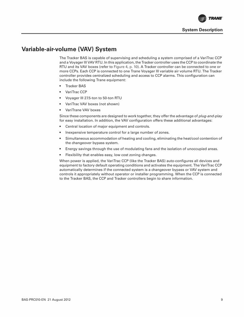
Variable-air-volume (VAV) System
The Tracker BAS is capable of supervising and scheduling a system comprised of a VariTrac CCP and a Voyager III VAV RTU. In this application, the Tracker controller uses the CCP to coordinate the RTU and its VAV boxes (refer to Figure 4, p. 10). A Tracker controller can be connected to one or more CCPs. Each CCP is connected to one Trane Voyager III variable air volume RTU. The Tracker controller provides centralized scheduling and access to CCP alarms. This configuration can include the following Trane equipment:
• Tracker BAS
• VariTrac CCP
• Voyager III 27.5-ton to 50-ton RTU
• VariTrac VAV boxes (not shown)
• VariTrane VAV boxes
Since these components are designed to work together, they offer the advantage of plug-and-play for easy installation. In addition, the VAV configuration offers these additional advantages:
• Central location of major equipment and controls.
• Inexpensive temperature control for a large number of zones.
• Simultaneous accommodation of heating and cooling, eliminating the heat/cool contention of the changeover bypass system.
• Energy savings through the use of modulating fans and the isolation of unoccupied areas.
• Flexibility that enables easy, low cost zoning changes.
When power is applied, the VariTrac CCP (like the Tracker BAS) auto-configures all devices and equipment to factory default operating conditions and activates the equipment. The VariTrac CCP automatically determines if the connected system is a changeover bypass or VAV system and controls it appropriately without operator or installer programming. When the CCP is connected to the Tracker BAS, the CCP and Tracker controllers begin to share information.
10 BAS-PRC010-EN 21 August 2012
System Description
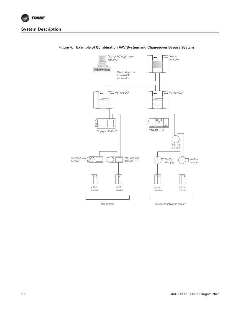
Figure 4. Example of Combination VAV System and Changeover Bypass System
VariTrac CCP VariTrac CCP
Voyager III VAV RTU Voyager RTU
Zonesensor
Zonesensor
Zonesensor
VariTracdamper
Zonesensor
VariTracdamper
VariTrane VAVdamper
VariTrane VAVdamper
Bypassdamper
VAV system Changeover bypass system
Trackercontroller
Tracker PC Workstation(optional)
Dial-in, direct,
connection
orEthernet/IP
BAS-PRC010-EN 21 August 2012 11
Connection CapacitiesC
on
ne
cti
on
Ca
pa
cit
ies
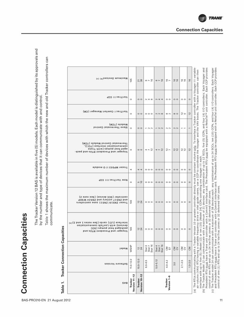
Th
e Tr
acke
r Ver
sio
n 1
2 B
AS
is a
vaila
ble
in fi
ve (5
) mo
del
s. E
ach
mo
del
is d
isti
ng
uis
hed
by
its
app
rova
ls a
nd
b
y th
e n
um
ber
an
d t
ype
of
dev
ices
th
at it
can
co
mm
un
icat
e w
ith
an
d c
on
tro
l.
Tab
le 1
sh
ow
s th
e m
axim
um
nu
mb
er o
f d
evic
es w
ith
wh
ich
th
e n
ew a
nd
old
Tra
cker
co
ntr
olle
rs c
an
com
mu
nic
ate.
Tab
le 1
.Tra
cker
Co
nn
ecti
on
Ca
pa
cit
ies
BAS
Software Version
Model
Voyager and Precedent RTUs and packaged heat pumps (SCC devices) with LonTalk communication interface (LCI) cards (See notes 1 and 2)(a)
Tracer ZN510/ZN511 zone controllers and ZN517 unitary and ZN524 WSHPcontroller (SCC device) (See note 2)
New VariTrac III CCP
Tracer MP503 I/O module
Voyager and Precedent RTUs and pack-aged heat pumps (with Trane communication interface [TCI]), Thermostat Control Module (TCM)
Slave Thermostat ControlModule (TCM)
VariTrac I Comfort Manager (CM)
VariTrac II CCP
Maximum Devices(b)(c)
Trac
ker
Ver
sio
n 1
1–1
211
.0–1
2.0
WS
HP
100
100
04
00
00
105
Trac
ker
Ver
sio
n 1
0–1
210
.0–1
2.0
12 2412 24
12 245 10
4 40 0
0 00 0
0 021 38
Trac
ker
V
ers
ion
1–6
6.0–
6.5
Sta
t 4
Sta
t 7
Sta
t 16
0 0 0
0 0 0
0 0 0
0 0 0
4 7 12
1 2 2
0 0 0
2 4 8
6 7 16
5.0–
5.12
Sta
t 4
Sta
t 7
Sta
t 16
0 0 0
0 0 0
0 0 0
0 0 0
4 7 12
1 2 2
2 2 8
2 4 4
6 7 16
4.0–
4.2
CM S7
0 00 0
0 00 0
12 72 2
8 20 0
16 7
3.0
CM CV
0 00 0
0 00 0
12 122 2
8 00 0
16 16
2.1–
2.5
CM CV
0 00 0
0 00 0
12 121 1
12 00 0
16 16
1.3–
2.0
CM
00
00
121
120
16
(a)
The
RTU
s co
mm
unic
atin
g w
ith a
Tra
cker
Ver
sion
10
or g
reat
er c
ontr
olle
r di
rect
ly m
ust b
e co
nsta
nt v
olum
e on
ly. T
o in
terf
ace
a Tr
acke
r co
ntro
ller w
ith a
Voy
ager
III
var
iabl
e-ai
r-vo
lum
e (V
AV)
RTU
hav
ing
a va
riab
le f
requ
ency
drive
or
inle
t gu
ide
vane
s, u
se a
CCP
to c
oord
inat
e th
e Voy
ager
and
the
VAV b
oxes
. Th
e Tr
acke
r co
ntro
ller
can
then
in
terf
ace
with
up
to f
ive
(5)
[Mod
el 1
2] o
r te
n (1
0) [
Mod
el 2
4] C
CPs
con
trol
ling
one
Voy
ager
III
eac
h.(b
)The
Tra
cker
Mod
el 1
2 ca
n co
mm
unic
ate
with
a m
axim
um o
f 21
dev
ices
: an
y co
mbi
natio
n of
up
to 1
2 SC
Cs,
fiv
e (5
) CCPs
, an
d fo
ur (
4) I
/O c
ontr
olle
rs.
Each
Voy
ager
and
Pr
eced
ent
RTU
mus
t ha
ve a
Tra
ne u
nit
cont
rolle
r w
ith a
Com
m5
inte
rfac
e ca
rd.
The
Prec
eden
t RTU
mus
t be
equ
ippe
d w
ith a
Rel
iaTe
l™ u
nit
cont
rolle
r. E
ach
CCP
prov
ides
co
ntro
l of
one
RTU
and
up
to 2
4 Var
iTra
c zo
nes
or 3
2 de
liver
ed V
AV z
ones
.(c
)Th
e Tr
acke
r m
odel
24
can
com
mun
icat
e w
ith a
max
imum
of 3
8 de
vice
s ea
ch:
any
com
bina
tion
of u
p to
24
SCCs,
ten
(10
) CCPs
, and
four
(4)
I/O
con
trol
lers
. Eac
h Voy
ager
an
d Pr
eced
ent RTU
mus
t ha
ve a
Tra
ne u
nit co
ntro
ller
with
a C
omm
5 in
terf
ace
card
. The
Pre
cede
nt R
TU m
ust b
e eq
uipp
ed w
ith a
Rel
iaTe
l uni
t co
ntro
ller.
Eac
h CCP
prov
ides
co
ntro
l of
one
(1)
RTU
and
up
to 2
4 Var
iTra
c zo
nes
or 3
2 de
liver
ed V
AV z
ones
.
12 BAS-PRC010-EN 21 August 2012
Supported Devices
Voyager and Precedent Rooftop Units
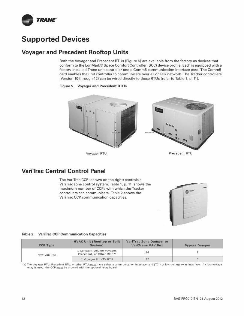
Both the Voyager and Precedent RTUs (Figure 5) are available from the factory as devices that conform to the LonMark® Space Comfort Controller (SCC) device profile. Each is equipped with a factory-installed Trane unit controller and a Comm5 communication interface card. The Comm5 card enables the unit controller to communicate over a LonTalk network. The Tracker controllers (Version 10 through 12) can be wired directly to these RTUs (refer to Table 1, p. 11).
Figure 5. Voyager and Precedent RTUs
VariTrac Central Control Panel
The VariTrac CCP (shown on the right) controls a VariTrac zone control system. Table 1, p. 11, shows the maximum number of CCPs with which the Tracker controllers can communicate. Table 2 shows the VariTrac CCP communication capacities.
Voyager RTU Precedent RTU
Voyager RTU Precedent RTU
Table 2. VariTrac CCP Communication Capacities
CCP TypeHVAC Unit (Rooftop or Split
System)VariTrac Zone Damper or
VariTrane VAV Box Bypass Damper
New VariTrac1 Constant Volume Voyager, Precedent, or Other RTU(a) 24 1
1 Voyager III VAV RTU 32 0
(a) The Voyager RTU, Precedent RTU, or other RTU must have either a communication interface card (TCI) or low-voltage relay interface. If a low-voltage relay is used, the CCP must be ordered with the optional relay board.

BAS-PRC010-EN 21 August 2012 13
Supported Devices
Tracer ZN510/ZN511 Controllers
The Tracer ZN510 is a Trane factory-installed, application-specific, direct digital control (DDC) controller. The ZN511 is the same controller as the ZN510, but a field-installed version (shown on the right). They communicate on the Comm5 link and are configured to support:
• Single speed fan
• Up to two (2) compressors
• Reversing valve
• Two-position outdoor air damper
The controllers have three (3) binary inputs for low temperature (Freeze Stat), condensate overflow, and occupancy/generic. Other features include random start, occupied/unoccupied, manual output test, automatic heat/cool determination, smart reset, and peer-to-peer communications.
Table 1, p. 11 shows the maximum number of Tracer ZN510/511 controllers with which the Tracker controllers can communicate. Table 3 shows the Tracer ZN510/ZN511 I/O capacities.
Table 3. Tracer ZN510/511 I/O Capacities
Binary Inputs (Isolated Contacts) Binary Outputs Analog Inputs
• Low Temperature Detector (Freeze Stat)
• Condensate Overflow• Occupancy/Generic
• Fan• Reversing Valve• Compressor 1• Compressor 2• Two-position Damper Actuator
• Zone Space Temperature• Local Setpoint• Fan Input Mode• Leaving Water Temperature• Discharge Air Temperature

14 BAS-PRC010-EN 21 August 2012
Supported Devices
Tracer ZN517 Unitary Controller
The Tracer ZN517 unitary controller is a stand-alone HVAC controller (shown on the right). When connected to a Tracker controller, the Tracer ZN517 unitary controller becomes a communicating LonMark®-compliant device with an SCC profile. The Tracker controller, through the Tracer ZN517, can then communicate with and control the equipment.
Devices controlled by the Tracer ZN517 unitary controller include electro-mechanically controlled 2-heat/2-cool (2H/2C) or 4-cool (4C) rooftop units, heat pumps, and split systems. The Tracer ZN517 controls temperature and other comfort-related conditions. Connecting a Tracker controller to it enables an operator to schedule, route alarms, and monitor the entire system.
Table 1, p. 11 shows the maximum number of Tracer ZN517 unitary controllers with which the Tracker controllers can communicate. Table 4 shows the Tracer ZN517 I/O capacities.
Table 4. Tracer ZN517 I/O Capacities
Binary Inputs (Isolated Contacts) Binary Outputs(a)
(a) Each output is rated for a maximum of 1 A at 24 Vac. One normally open (Form A) relay contact is provided. The 24 Vac is wired in common to one side of all relay contacts.
Analog Inputs
• Enable/Disable or Occupancy• Status: Fan or Generic
• Supply fan• Cool 1/Compressor 1• Cool 2/Compressor 2• Heat 1/Reversing Valve/Cool3• Heat 2/Auxiliary Heat/Cool 4• Exhaust Fan• Economizer Open/Close
• Space temperature from Trane thermistor• Setpoint input from Trane zone sensor (0–
1k W)• Discharge air temperature from Trane
thermistor• Universal input from an outside air
temperature/generic temperature Trane thermistor, RH, or CO2 sensor
BAS-PRC010-EN 21 August 2012 15
Supported Devices
Tracer MP503 I/O Module
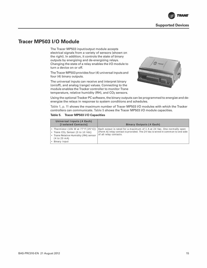
The Tracer MP503 input/output module accepts electrical signals from a variety of sensors (shown on the right). In addition, it controls the state of binary outputs by energizing and de-energizing relays. Changing the state of a relay enables the I/O module to turn a device on or off.
The Tracer MP503 provides four (4) universal inputs and four (4) binary outputs.
The universal inputs can receive and interpret binary (on/off), and analog (range) values. Connecting to the module enables the Tracker controller to monitor Trane temperature, relative humidity (RH), and CO2 sensors.
Using the optional Tracker PC software, the binary outputs can be programmed to energize and de-energize the relays in response to system conditions and schedules.
Table 1, p. 11 shows the maximum number of Tracer MP503 I/O modules with which the Tracker controllers can communicate. Table 5 shows the Tracer MP503 I/O module capacities.
Table 5. Tracer MP503 I/O Capacities
Universal Inputs (4 Each) [Isolated Contacts] Binary Outputs (4 Each)
• Thermistor (10k W at 77°F [25°C])• Trane CO2 Sensor (0 to 10 Vdc)• Trane Relative Humidity (RH) sensor
(4 to 20 mA)• Binary Input
Each output is rated for a maximum of 1 A at 24 Vac. One normally open (Form A) relay contact is provided. The 24 Vac is wired in common to one side of all relay contacts.

16 BAS-PRC010-EN 21 August 2012
Comm5 Communication
The Tracker Version 12 BAS controller is a Comm5 device with 5th-generation Trane communication architecture. It implements LonTalk, an open, industry-standard protocol.
The RTUs, CCPs, unitary controllers, and I/O controllers that the Tracker controller communicates with reside on a LonTalk FTT-10A network. They provide data using LonMark® standard network variable types (SNVTs, pronounced sniv-its) and configuration properties.
The HVAC equipment controllers employ SCC profiles, as defined by LonMark® Interoperability Association. Table 6 shows the devices with which the Tracker controller can communicate and the LonMark® profiles that the devices use.
Note: Ancillary sensors (such as temperature and humidity sensors) that are hard wired to the terminals on the Tracker, CCP, and I/O module, are standard resistive-type sensors and do not communicate using LonTalk. They only provide analog inputs or binary inputs/outputs.
LonTalk devices from other manufacturers are tested for compatibility with the Tracker BAS. Devices that are compatible are approved for inclusion in the Tracker system. Necessary support documentation for approved devices will be released, when completed.
Table 6. Comm5 Network Devices
Comm5 Devices LonMark® Profile
SCCs:• Voyager RTU (with a LonTalk
communication interface [LCI] card)• Precedent RTU (with a ReliaTel LCI [RLCI])• Tracer ZN517 unitary controller
SCCs:• Generic (85.00) with unit type HVT_ROOFTOP• Generic (85.00) with unit type HVT_GENERIC• Generic (85.00) with unit type HVT_HEAT_PUMP
New VariTrac CCP Custom profile (82.06)
Tracer MP503 I/O module Custom profile (82.08)
BAS-PRC010-EN 21 August 2012 17
Installation
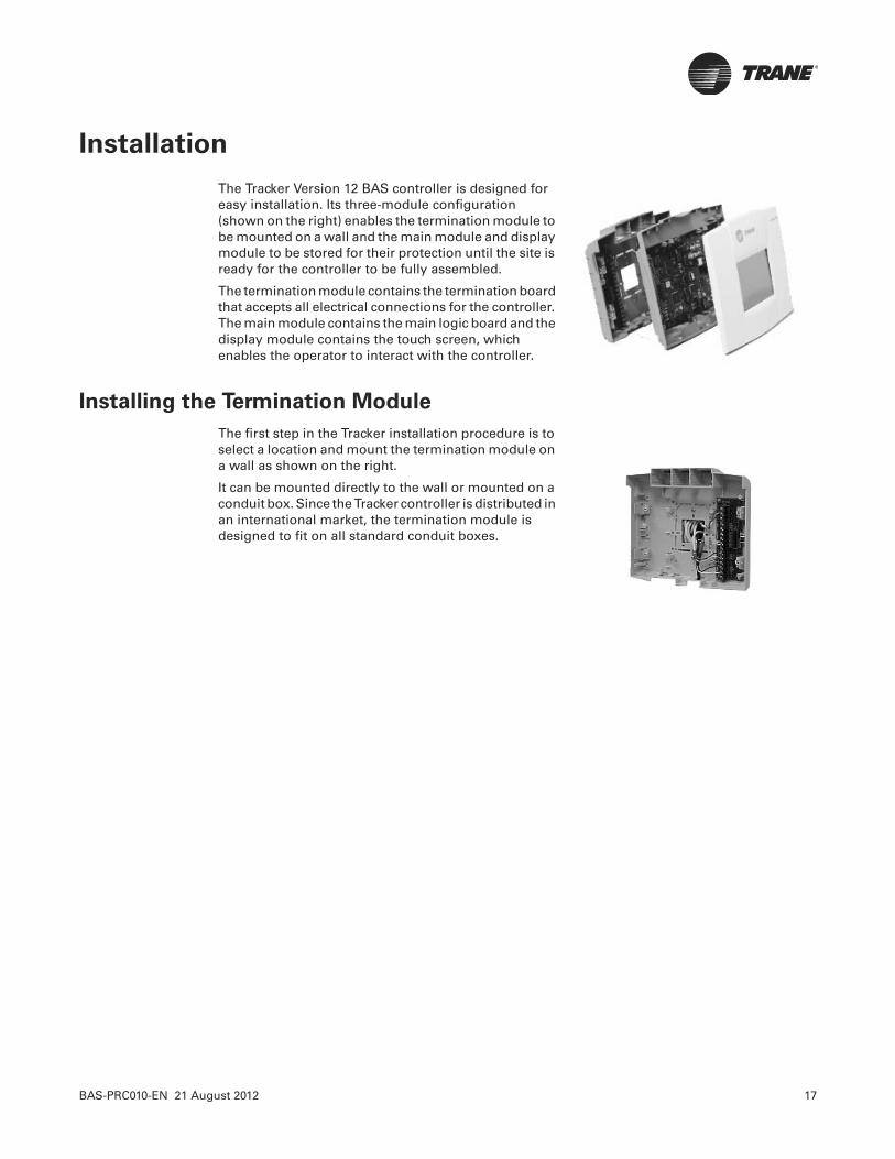
The Tracker Version 12 BAS controller is designed for easy installation. Its three-module configuration (shown on the right) enables the termination module to be mounted on a wall and the main module and display module to be stored for their protection until the site is ready for the controller to be fully assembled.
The termination module contains the termination board that accepts all electrical connections for the controller. The main module contains the main logic board and the display module contains the touch screen, which enables the operator to interact with the controller.
Installing the Termination Module
The first step in the Tracker installation procedure is to select a location and mount the termination module on a wall as shown on the right.
It can be mounted directly to the wall or mounted on a conduit box. Since the Tracker controller is distributed in an international market, the termination module is designed to fit on all standard conduit boxes.
18 BAS-PRC010-EN 21 August 2012
Installation
Wiring the Termination Board
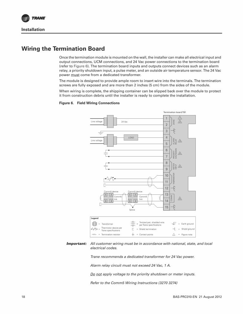
Once the termination module is mounted on the wall, the installer can make all electrical input and output connections, UCM connections, and 24 Vac power connections to the termination board (refer to Figure 6). The termination board inputs and outputs connect devices such as an alarm relay, a priority shutdown input, a pulse meter, and an outside air temperature sensor. The 24 Vac power must come from a dedicated transformer.
The module is designed to provide ample room to insert wire into the terminals. The termination screws are fully exposed and are more than 2 inches (5 cm) from the sides of the module.
When wiring is complete, the shipping container can be slipped back over the module to protect it from construction debris until the installer is ready to complete the installation.
Figure 6. Field Wiring Connections
24VA
CTH
ER
MIS
TOR
CO
MM
ALA
RM
RE
LAY
PR
IOR
ITY
SH
UTD
OW
NM
ETE
RIN
PU
T
1
2
3
4
5
6
7
8
9
10
11
12
13
14
15
24 VacLine voltage
Line voltage
Comm5link
Comm5link
Comm5 deviceComm5 device
Splice
2
1
3
5
4
4
AA
BB
AA
BB
Legend
Twisted pair, shielded wireper Trane specifications
Shield termination
Earth ground
Contact points
Thermistor device perTrane specifications
Transformer
Termination resistor
Shield ground
=
=
=
=
==
=
=
LOAD
Termination boardTB1
Figure note=
Important: All customer wiring must be in accordance with national, state, and local electrical codes.
Trane recommends a dedicated transformer for 24 Vac power.
Alarm relay circuit must not exceed 24 Vac, 1 A.
Do not apply voltage to the priority shutdown or meter inputs.
Refer to the Comm5 Wiring Instructions (3270 3274)
BAS-PRC010-EN 21 August 2012 19
Installation
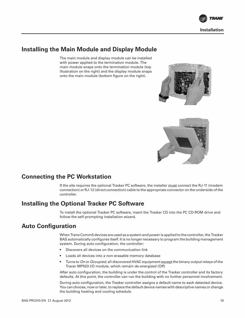
Installing the Main Module and Display Module
The main module and display module can be installed with power applied to the termination module. The main module snaps onto the termination module (top illustration on the right) and the display module snaps onto the main module (bottom figure on the right).
Connecting the PC Workstation
If the site requires the optional Tracker PC software, the installer must connect the RJ-11 (modem connection) or RJ-12 (direct connection) cable to the appropriate connector on the underside of the controller.
Installing the Optional Tracker PC Software
To install the optional Tracker PC software, insert the Tracker CD into the PC CD-ROM drive and follow the self-prompting installation wizard.
Auto Configuration
When Trane Comm5 devices are used as a system and power is applied to the controller, the Tracker BAS automatically configures itself. It is no longer necessary to program the building management system. During auto configuration, the controller:
• Discovers all devices on the communication link
• Loads all devices into a non-erasable memory database
• Turns to On or Occupied, all discovered HVAC equipment except the binary output relays of the Tracer MP503 I/O module, which remain de-energized (Off)
After auto configuration, the building is under the control of the Tracker controller and its factory defaults. At this point, the controller can run the building with no further personnel involvement.
During auto configuration, the Tracker controller assigns a default name to each detected device. You can choose, now or later, to replace the default device names with descriptive names or change the building heating and cooling schedule.
20 BAS-PRC010-EN 21 August 2012
Operation
An operator can set up and change HVAC operating parameters and collect and display building information at either the Tracker controller or the PC workstation. Each location provides access to an easy-to-use user interface.
Tracker Controller Operation
The LCD touch screen, combined with an intuitive menu-driven user interface, provides access to the Tracker system from the controller.
Using the Controller User Interface
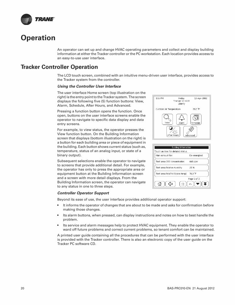
The user interface Home screen (top illustration on the right) is the entry point to the Tracker system. The screen displays the following five (5) function buttons: View, Alarm, Schedule, After Hours, and Advanced.
Pressing a function button opens the function. Once open, buttons on the user interface screens enable the operator to navigate to specific data display and data entry screens.
For example, to view status, the operator presses the View function button. On the Building Information screen that displays (bottom illustration on the right) is a button for each building area or piece of equipment in the building. Each button shows current status (such as, temperature, status of an analog input, or state of a binary output).
Subsequent selections enable the operator to navigate to screens that provide additional detail. For example, the operator has only to press the appropriate area or equipment button at the Building Information screen and a screen with more detail displays. From the Building Information screen, the operator can navigate to any status in one to three steps.
Controller Operator Support
Beyond its ease of use, the user interface provides additional operator support:
• It informs the operator of changes that are about to be made and asks for confirmation before making those changes.
• Its alarm buttons, when pressed, can display instructions and notes on how to best handle the problem.
• Its service and alarm messages help to protect HVAC equipment. They enable the operator to ward off future problems and correct current problems, so tenant comfort can be maintained.
A printed user guide containing all the procedures that can be performed with the user interface is provided with the Tracker controller. There is also an electronic copy of the user guide on the Tracker PC software CD.
BAS-PRC010-EN 21 August 2012 21
Operation
PC Software Operation
A personal computer running Tracker PC software provides local (direct connection) or remote (dial-in or LAN) access to the Tracker controller.
The PC operator can access all functions that the controller operator can access. In addition, the PC operator has access to functions that are not available to the controller operator: Binary Output Programming, Custom Alarming, and Print.
Using the PC User Interface
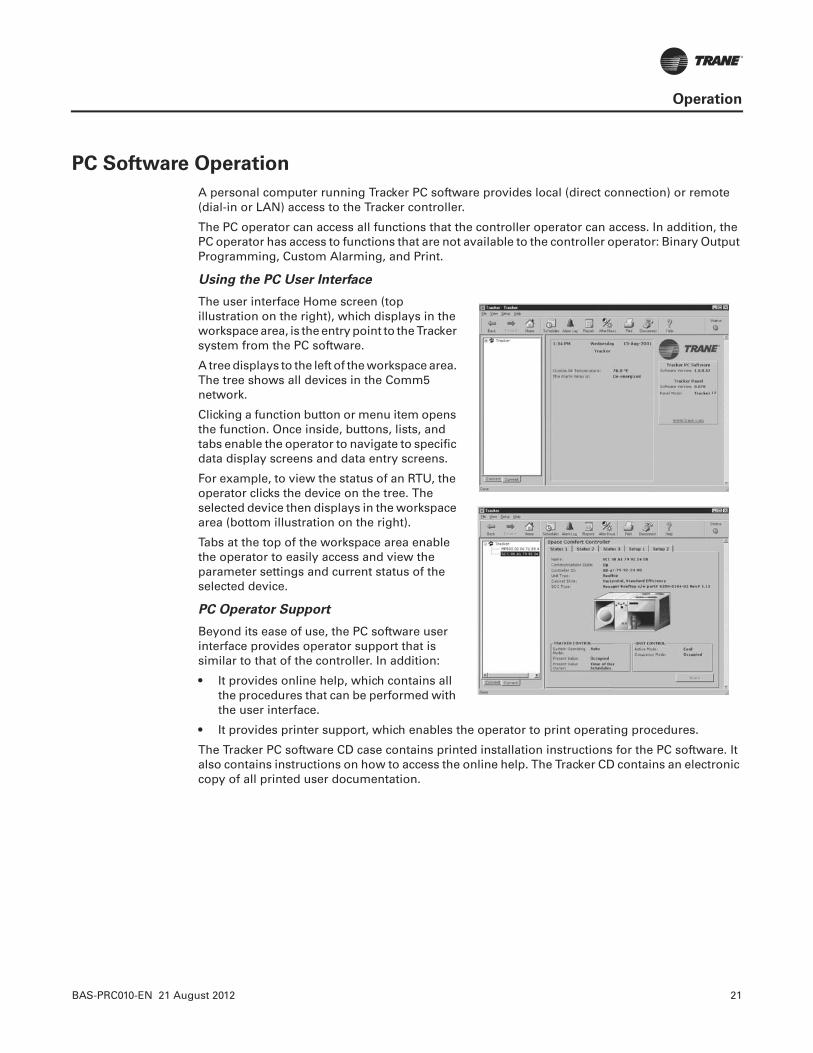
The user interface Home screen (top illustration on the right), which displays in the workspace area, is the entry point to the Tracker system from the PC software.
A tree displays to the left of the workspace area. The tree shows all devices in the Comm5 network.
Clicking a function button or menu item opens the function. Once inside, buttons, lists, and tabs enable the operator to navigate to specific data display screens and data entry screens.
For example, to view the status of an RTU, the operator clicks the device on the tree. The selected device then displays in the workspace area (bottom illustration on the right).
Tabs at the top of the workspace area enable the operator to easily access and view the parameter settings and current status of the selected device.
PC Operator Support
Beyond its ease of use, the PC software user interface provides operator support that is similar to that of the controller. In addition:
• It provides online help, which contains all the procedures that can be performed with the user interface.
• It provides printer support, which enables the operator to print operating procedures.
The Tracker PC software CD case contains printed installation instructions for the PC software. It also contains instructions on how to access the online help. The Tracker CD contains an electronic copy of all printed user documentation.

22 BAS-PRC010-EN 21 August 2012
Operation
Scheduling
Running a building as efficiently as possible means using the HVAC system only when needed. Most often, the need is based on the occupancy of the building, or better yet, the occupancy of specific areas of the building.
The Tracker BAS simplifies scheduling. It is no longer necessary to create a separate occupancy schedule for each HVAC device. The operator can create a schedule and attach several devices (members) to it. From 1 to 10 schedules may be created. Grouping devices in a schedule means that changes to the building schedule are no longer a time-consuming, labor-intensive effort. The top illustration on the right shows a scheduling screen from the controller user interface. The bottom illustration on the right shows a scheduling screen from the PC software user interface.
Building occupants can easily override unoccupied areas to provide comfort for predetermined lengths of time by pressing the On button on the zone sensor or by using the Tracker controller or PC user interface.
In addition, the Tracker BAS can be set up to override a schedule based on the input of occupancy sensors. The heating and cooling setpoints for the area are automatically adjusted to standby settings when the area is not occupied and to occupied settings when people are detected.
BAS-PRC010-EN 21 August 2012 23
Controller Specifications, Dimensions, and Clearances
StorageTemperature: –40°F to 185°F (–40°C to 85°C)
Relative Humidity: Between 5% and 95% (non-condensing)
OperatingTemperature: 32°F to 122°F (0°C to 50°C)
Humidity: Between 105% and 90% (non-condensing)
Input Power: 24 Vac nominal (19—30), 50Hz to 60Hz, 1 phase 40 VA minimum(Class 2 transformer required)
Mounting weight of controller: Supporting mounting surface: must be 2.5 lb. (1.13 kg)
Environmental rating (enclosure): NEMA 1
Mounting:Flat wall surface with a conduit box that is either:• Recessed 2 in. x 4 in. (5 cm x 10 cm)• Recessed 4 in. x4 in. (10cm x 10cm)
Analog Input:Thermistor:• 10KW at 77°F (25°C)• From –50°F to 200°F (–46°C to 93°C)
Binary Inputs:
Utility pulse meter:• User-supplied dry contacts only• Tracker-supplied voltage: 12 Vdc nominal (10–14 Vdc), 12 mA nominal (10–14 mA)Priority shutdown:• User-supplied dry contacts only• Tracker-supplied voltage: 12 Vdc nominal (10–14 Vdc), 12 mA nominal (10–14 mA)
Binary Output:Alarm relay:• Tracker-supplied relay• Single-pole single-throw (SPST) dry contact rated at 24 Vac, 1 A maximum
Memory Backup: At power loss, the Tracker controller performs memory backup stores all data for seven days; after seven days, alarms are not retained
Agency Listing• UL and C-UL Listed: 916 Energy Management Equipment• Flammable Rating: UL94-5V, Flammability Rating for Plenum Use• CE Approvals: For Models 12 and 24• FCC Part 15, Class A, CFR 47
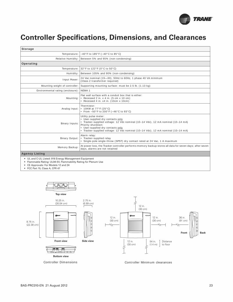
Front view Side view
8.75 in.(22.38 cm)
2.75 in.(6.99 cm)
10.25 in.(26.04 cm)
Top view
Bottom view
36 in.(91 cm)
12 in.(30 cm)
12 in.(30 cm)
12 in.(30 cm)
12 in.(30 cm)
54 in.(1.4 m)
Distanceto floor
Front Back
Controller Dimensions Controller Minimum clearances

Trane optimizes the performance of homes and buildings around the world. A business of Ingersoll Rand, the leader in creating and sustaining safe, comfortable and energy efficient environments, Trane offers a broad portfolio of advanced controls and HVAC systems, comprehensive building services, and parts. For more information, visit www.Trane.com.
Trane has a policy of continuous product and product data improvement and reserves the right to change design and specifications without notice.
We are committed to using environmentally
conscious print practices that reduce waste.
© 2012 Trane. All rights reserved.
BAS-PRC010-EN 21 August 2012
Supersedes BAS-PRC010-EN (09 Aug 2010)
Tracer™ Controls
Tracer ZN517 Unitary Control
August 2010 BAS-PRC012-EN
Product Catalog
1 BAS-PRC012-EN, 09 Aug 2010
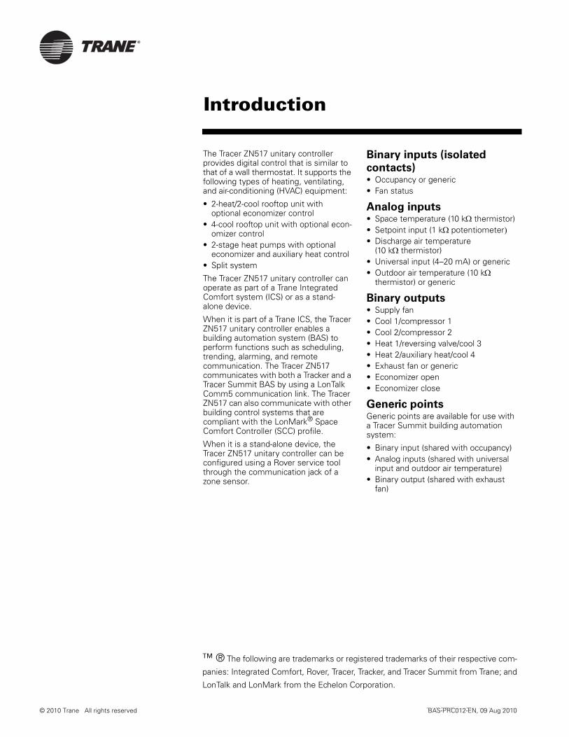
The Tracer ZN517 unitary controller provides digital control that is similar to that of a wall thermostat. It supports the following types of heating, ventilating, and air-conditioning (HVAC) equipment:
• 2-heat/2-cool rooftop unit with optional economizer control
• 4-cool rooftop unit with optional econ-omizer control
• 2-stage heat pumps with optional economizer and auxiliary heat control
• Split system
The Tracer ZN517 unitary controller can operate as part of a Trane Integrated Comfort system (ICS) or as a stand-alone device.
When it is part of a Trane ICS, the Tracer ZN517 unitary controller enables a building automation system (BAS) to perform functions such as scheduling, trending, alarming, and remote communication. The Tracer ZN517 communicates with both a Tracker and a Tracer Summit BAS by using a LonTalk Comm5 communication link. The Tracer ZN517 can also communicate with other building control systems that are compliant with the LonMark® Space Comfort Controller (SCC) profile.
When it is a stand-alone device, the Tracer ZN517 unitary controller can be configured using a Rover service tool through the communication jack of a zone sensor.
Binary inputs (isolated
contacts)• Occupancy or generic• Fan status
Analog inputs• Space temperature (10 kΩ thermistor)• Setpoint input (1 kΩ potentiometer)• Discharge air temperature
(10 kΩ thermistor) • Universal input (4–20 mA) or generic• Outdoor air temperature (10 kΩ
thermistor) or generic
Binary outputs• Supply fan• Cool 1/compressor 1• Cool 2/compressor 2• Heat 1/reversing valve/cool 3• Heat 2/auxiliary heat/cool 4• Exhaust fan or generic• Economizer open• Economizer close
Generic pointsGeneric points are available for use with a Tracer Summit building automation system:
• Binary input (shared with occupancy)• Analog inputs (shared with universal
input and outdoor air temperature)• Binary output (shared with exhaust
fan)
Introduction
© 2010 Trane All rights reserved BAS-PRC012-EN, 09 Aug 2010
™ ® The following are trademarks or registered trademarks of their respective com-
panies: Integrated Comfort, Rover, Tracer, Tracker, and Tracer Summit from Trane; and
LonTalk and LonMark from the Echelon Corporation.

BAS-PRC012-EN 0 Aug 2010 2
Easy installationThe controller can be installed in existing Trane and competitive HVAC equipment without major wiring changes, and clearly labeled screw terminals ensure that wires are connected quickly and accurately. A compact enclosure design simplifies installation in minimal space.
Automatic heat/cool mode
determinationThe Tracer ZN517 unitary controller automatically determines whether heating or cooling is needed to maintain comfort levels, without the need to manually adjust unit controls. The controller measures the zone temperature and setpoint temperature, then uses a proportional/integral algorithm to maintain zone temperature at the setpoint.
Discharge air temperingIn cold weather, outside air brought into a space for ventilation can cause the discharge air to be too cold. Although the overall space may be at the correct temperature, occupants near vents may experience discomfort. Discharge air tempering minimizes this problem by raising the discharge air temperature when:
• The controller is in the heating mode • Outside air is being used for
ventilation• The discharge air temperature is lower
than expected
Tempering stops when the occupied heating setpoint is exceeded.
Demand control ventilationIncreasing/decreasing the amount of outdoor air based on CO2 levels is referred to as demand control ventilation. The Tracer ZN517 unitary controller modulates the economizer position in direct response to the CO2 level, controlling the volume of outside air. The allowable CO2 threshold is user defined.
Occupied and unoccupied
operationThe occupancy input works with a motion (occupancy) sensor or time clock. A communicated value from a building automation system through the Comm5 (LonTalk) link can also be used. The input allows the controllers to use unoccupied (setback) temperature setpoints.
Continuous fan or
fan-cycling operationFan operation can be configured to either run continuously or cycle on and off automatically.
Equipment protection• Minimum on/off timer: Extends
compressor life by preventing equip-ment from unnecessary cycling.
• Fan status: The controller can monitor fan status to protect equipment from damage. If airflow is not detected after the fan is commanded on and fol-lowing a 60-second delay, a diagnostic message is generated and unit opera-tion is disabled.
• Fan off delay: The fan stays on for an additional 30 seconds (adjustable) to allow the residual cooling or heating energy to be circulated through the system.
• Filter maintenance status is based on the cumulative hours of operation of the unit fan. The controller has a timer that can be reset. When the time limit expires, the Tracer ZN517 unitary controller sends a message to the BAS indicating that unit mainte-nance is recommended.
EconomizingIf outdoor air conditions are suitable for cooling the zone, the Tracer ZN517 will modulate both the outdoor air damper and return air damper (between the active minimum damper position and 100%) to provide economizing or free cooling.
Timed overrideThe timed override function for after hours operation allows users to request unit operation from a push button on the unit zone sensor. Additionally, users can press the CANCEL button at any time to place the unit back into unoccupied mode.
Manual output testPressing the Test button on the controller activates all binary outputs in sequence. The test is used to verify that the outputs are operating properly.
Peer-to-peer communicationMultiple controllers can share data when they are bound together. Shared data can include setpoints, zone temperature, mode, and fan status. Applications having more than one unit serving a single large zone can benefit from this feature, which prevents multiple units from simultaneously heating and cooling.
InteroperabilityThe Tracer ZN517 unitary controller follows the guidelines of the LonMark® SCC profile and communicates using the LonTalk protocol. This allows the controller to work with other control systems that support LonTalk and the SCC profile.
Features

3 BAS-PRC012-EN, 09 Aug 2010
DimensionsPlastic-cover model dimensions
(see Figure 1)
Height: 5.375 in.(137 mm)Width: 6.875 in. (175 mm)Depth: 2.0 in. (51 mm)
Metal-cover model dimensions
(see Figure 2 on page 3)
Height: 9.0 in. (25 mm)Width: 10.37 in. (263 mm)Depth: 2.25 in. (58 mm)
Power19–30 Vac (24 Vac nominal)
50/60 Hz
9 VA and 12 VA maximum per binary output utilized
Operating environmentTemperature: From –40°F to 160°F (–40°C to 70°C)
Relative humidity: From 5% to 90% non-condensing
Storage environmentTemperature: From –40°F to 185°F (–40°C to 85°C)
Relative humidity: From 5% to 95% non-condensing
Agency listings/complianceCE—Immunity:
EN50082-2:1995
EN61000-6-2:1999
CE—Emissions:
EN61000-3-2:1995
EN61000-3-3:1995
EN50081-1:1992 (CISPR 22)
EN55011:1998, Class B
UL and C-UL listed: 916, Energy management equipment
UL 94-5V (UL flammability rating for plenum use)
FCC Part 15, Class A, CFR 47
Figure 1: Tracer ZN517 plastic-cover model dimensions
Figure 2: Tracer ZN517 metal-cover model dimensions
5.625 in.(143 mm)
6.31 in.(160 mm)
5.375 in.(137 mm)
2.0 in.(51 mm)
6.875 in.(175 mm)
10.37 in.(263 mm)with cover
6.5 in.(165 mm)
0.28 in.(7 mm)
10.25 in.(260 mm)without cover
9.0 in.(229 mm)
7.0 in.(178 mm)
1.875 in.(48 mm)
9.0 in.(229 mm)
2.25 in.(58 mm)
Dimensions and specifications
BAS-PRC012-EN 0 Aug 2010 4
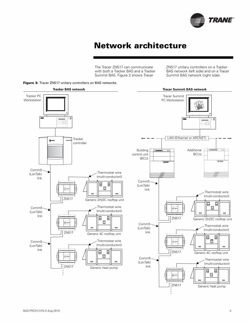
The Tracer ZN517 can communicate with both a Tracker BAS and a Tracker Summit BAS. Figure 3 shows Tracer
ZN517 unitary controllers on a Tracker BAS network (left side) and on a Tracer Summit BAS network (right side).
Figure 3: Tracer ZN517 unitary controllers on BAS networks
®
®
®
TRACER SUMMIT ALM PWR
TRACER SUMMIT ALM PWRTRACER SUMMIT
®
®
®
Buildingcontrol unit
(BCU)
Tracer SummitPC Workstation
Generic 2H/2C rooftop unit
ZN517
LAN (Ethernet or ARCNET)
ZN517
ZN517
Tracker PCWorkstation
Tracker controller
ZN517
ZN517
ZN517
Generic 4C rooftop unit
Generic heat pump
Generic 4C rooftop unit
Generic 2H/2C rooftop unit
AdditionalBCUs
Generic heat pump
Comm5(LonTalk)
link
Tracer Summit BAS networkTracker BAS network
Comm5(LonTalk)
link
Comm5(LonTalk)
link
Thermostat wire (multi-conductor))
Thermostat wire (multi-conductor))
Thermostat wire (multi-conductor))
Thermostat wire (multi-conductor))
Thermostat wire (multi-conductor))
Thermostat wire (multi-conductor))
Comm5(LonTalk)
link
Comm5(LonTalk)
link
Comm5(LonTalk)
link
Network architecture
5 BAS-PRC012-EN, 09 Aug 2010
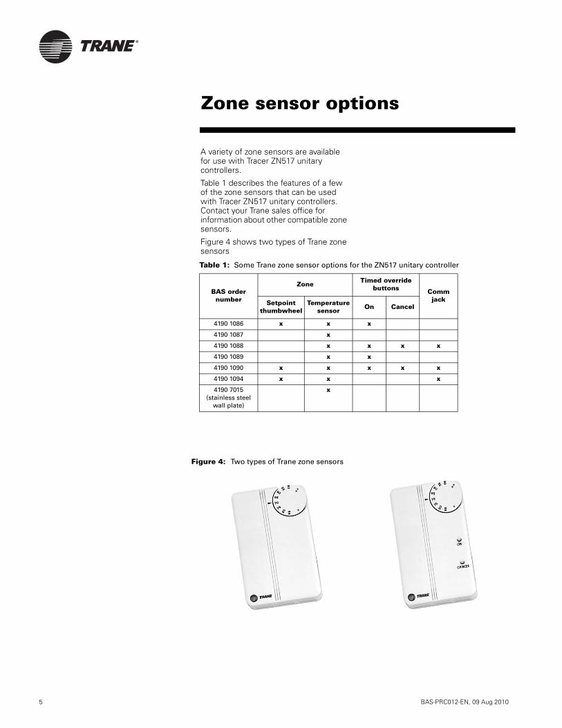
A variety of zone sensors are available for use with Tracer ZN517 unitary controllers.
Table 1 describes the features of a few of the zone sensors that can be used with Tracer ZN517 unitary controllers. Contact your Trane sales office for information about other compatible zone sensors.
Figure 4 shows two types of Trane zone sensors
Table 1: Some Trane zone sensor options for the ZN517 unitary controller
BAS order number
Zone Timed override buttons Comm
jackSetpoint thumbwheel
Temperature sensor On Cancel
4190 1086 x x x
4190 1087 x
4190 1088 x x x x
4190 1089 x x
4190 1090 x x x x x
4190 1094 x x x
4190 7015(stainless steel
wall plate)
x
Figure 4: Two types of Trane zone sensors
Zone sensor options
BAS-PRC012-EN 0 Aug 2010 6
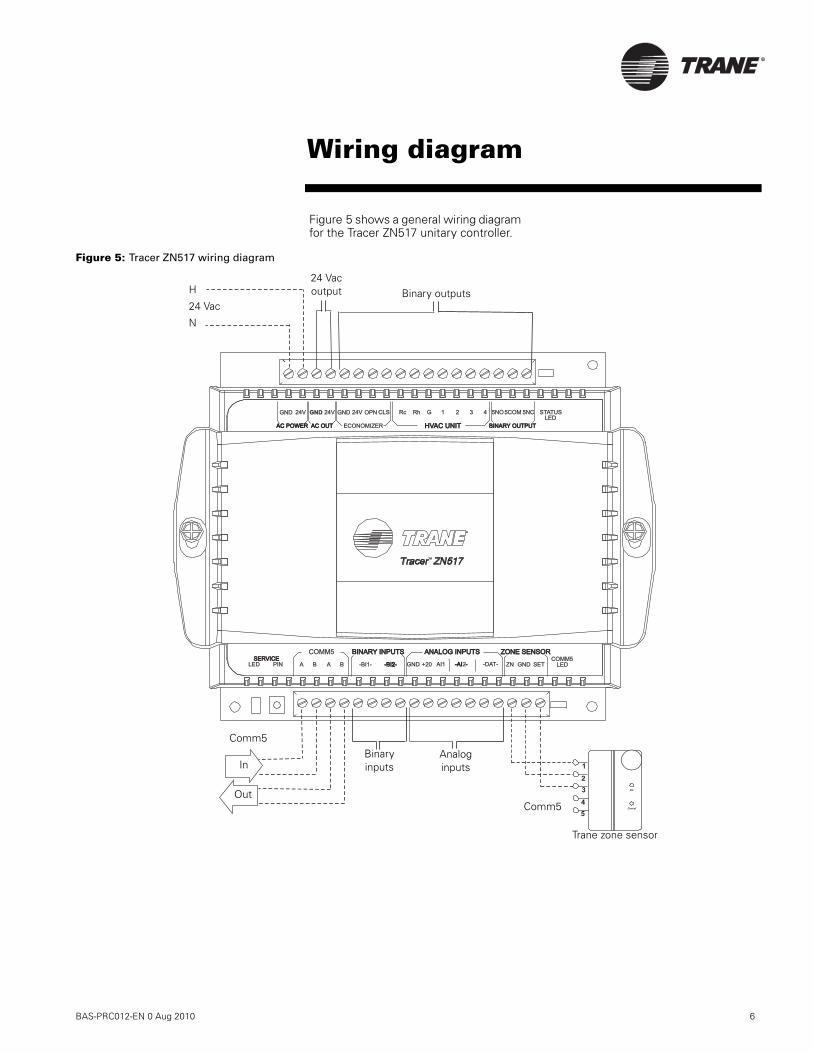
Figure 5 shows a general wiring diagram for the Tracer ZN517 unitary controller.
Figure 5: Tracer ZN517 wiring diagram
LEDA BBA +20GND-BI -2-BI -2 SET-BI1- ZNLED GNDPIN
ZONE SENSORZONE SENSOR
SERVICESERVICE
ANALOG INPUTSANALOG INPUTSCOMM5
COMM5
24VGND
HVAC UNITHVAC UNIT
RhRc 1G 432 5NO5COM
LED
STATUS5NC
BINARY INPUTSBINARY INPUTS
AI1 -AI --AI - -DAT-
24VGND GND 24V OPN CLS
BINARY OUTPUTBINARY OUTPUTECONOMIZERAC OUTAC OUTAC POWERAC POWER
On
Cancel
5
4
3
2
1
2
H
24 Vac
N
Binary inputs
Binary outputs
Trane zone sensor
Analog inputs
Comm5
Out
In
Comm5
24 Vac output
Wiring diagram

Trane optimizes the performance of homes and buildings around the world. A business of Ingersoll Rand, theleader in creating and sustaining safe, comfortable and energy efficient environments, Trane offers a broadportfolio of advanced controls and HVAC systems, comprehensive building services, and parts. For more information, visit www.Trane.com.
Trane has a policy of continuous product and product data improvement and reserves the right to change design and specifications without notice.
© 2010 Trane All rights reserved
BAS-PRC012-EN, 09 Aug 2010
Supersedes Jan 2005
Produced on 20% post-consumer recycled paper, using
environmentally friendly print practices that reduce waste.

Tracer™Controllers
Tracer AH541 Version 2Air Handler Controllers
August 2010 BAS-PRC013-EN
Product Catalog

®
2 BAS-PRC013-EN, 09 Aug 2010
The Tracer AH541 air-handler controller is available for field installation on constant-volume and variable-air-volume (VAV) air handlers. The Tracer AH541 controller provides the same functionality as the Tracer AH540 controller, which is factory-installed on Trane air handlers.
ApplicationsThe Tracer AH541 controller supports a variety of air-handler configurations that conform to the LonMark® Space Comfort Controller (SCC) profile or the Discharge Air Controller (DAC) profile. Possible configurations include:
• Cooling-only unit• Heating-only unit without bypass• Heating-only unit with bypass• Cooling and heating unit (coils in
either order) without bypass• Heating and cooling unit (coils in this
order) with bypass for the heating coil• Heating and cooling unit (coils in this
order) with bypass for both coils• Heating cooling changeover (single
coil)• Heating cooling changeover (single
coil) with electric heat
Heating options
• Hydronic• Steam• Electric (staged)
Cooling options
• Hydronic• DX (up to four stages)
Product modelsThe following Tracer AH541 models are available:
• Enclosure with door-mounted opera-tor display
• Enclosure without operator display• Frame-mounted controller
(termination board and circuit board in a plastic frame assembly)
The following operator-display models are available:
• Stand-alone operator display• Portable operator display• Door-mounted operator display
retrofit kit
For more detailed information on each model, see “Product models” on page 4.
Overview
© 2010 Trane All rights reserved
™ ® The following are trademarks or registered trademarks of their respective companies: LonTalk and LonMark from Echelon Corporation; Rover, Tracer, and Tracer Summit from American Standard Inc.

®
BAS-PRC013-EN, 09 Aug 2010 3
Contents
Overview. . . . . . . . . . . . . . . . . . . . . . . . . . . 2
Applications . . . . . . . . . . . . . . . . . . . . . . . . . . . . . . . . 2Product Models . . . . . . . . . . . . . . . . . . . . . . . . . . . . . 2
Product Models . . . . . . . . . . . . . . . . . . . . . 4
Tracer AH541 models. . . . . . . . . . . . . . . . . . . . . . . . . 4Operator display models . . . . . . . . . . . . . . . . . . . . . . 4
Features. . . . . . . . . . . . . . . . . . . . . . . . . . . . 6
Duct static-pressure control . . . . . . . . . . . . . . . . . . . 6Space dehumidification . . . . . . . . . . . . . . . . . . . . . . . 6Filter status . . . . . . . . . . . . . . . . . . . . . . . . . . . . . . . . . 6Generic binary input . . . . . . . . . . . . . . . . . . . . . . . . . 6Manual output test . . . . . . . . . . . . . . . . . . . . . . . . . . . 6Emergency override. . . . . . . . . . . . . . . . . . . . . . . . . . 6System integration. . . . . . . . . . . . . . . . . . . . . . . . . . . 6Operator display. . . . . . . . . . . . . . . . . . . . . . . . . . . . . 6
Network architecture . . . . . . . . . . . . . . . . . 7
Inputs and outputs. . . . . . . . . . . . . . . . . . . 8
Enclosure interior . . . . . . . . . . . . . . . . . . . . 9
Dimensions. . . . . . . . . . . . . . . . . . . . . . . . 10
Specifications . . . . . . . . . . . . . . . . . . . . . . 11
Power requirements. . . . . . . . . . . . . . . . . . . . . . . . . 11Power consumption . . . . . . . . . . . . . . . . . . . . . . . . . 11Operating environment . . . . . . . . . . . . . . . . . . . . . . 11Storage environment . . . . . . . . . . . . . . . . . . . . . . . . 11Enclosure . . . . . . . . . . . . . . . . . . . . . . . . . . . . . . . . . 11Weight . . . . . . . . . . . . . . . . . . . . . . . . . . . . . . . . . . . . 11Dimensions . . . . . . . . . . . . . . . . . . . . . . . . . . . . . . . . 11Minimum clearances . . . . . . . . . . . . . . . . . . . . . . . . 11Mounting. . . . . . . . . . . . . . . . . . . . . . . . . . . . . . . . . . 11Operator interface . . . . . . . . . . . . . . . . . . . . . . . . . . 11Time clock . . . . . . . . . . . . . . . . . . . . . . . . . . . . . . . . . 11Battery . . . . . . . . . . . . . . . . . . . . . . . . . . . . . . . . . . . . 11Agency listings/compliance. . . . . . . . . . . . . . . . . . . 11
®
4 BAS-PRC013-EN, 09 Aug 2010
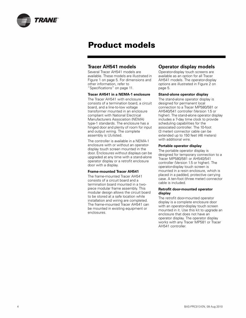
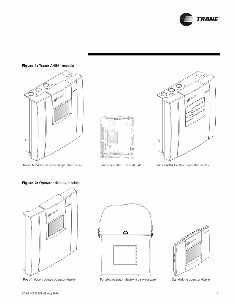
Tracer AH541 modelsSeveral Tracer AH541 models are available. These models are illustrated in Figure 1 on page 5. For dimensions and other information, refer to “Specifications” on page 11.
Tracer AH541 in a NEMA-1 enclosure
The Tracer AH541 with enclosure consists of a termination board, a circuit board, and a line-to-low voltage transformer mounted in an enclosure compliant with National Electrical Manufacturers Association (NEMA) type-1 standards. The enclosure has a hinged door and plenty of room for input and output wiring. The complete assembly is UL-listed.
The controller is available in a NEMA-1 enclosure with or without an operator-display touch screen mounted in the door. Enclosures without displays can be upgraded at any time with a stand-alone operator display or a retrofit enclosure door with a display.
Frame-mounted Tracer AH541
The frame-mounted Tracer AH541 consists of a circuit board and a termination board mounted in a two-piece modular frame assembly. This modular design allows the circuit board to be stored at a safe location while installation and wiring are completed. The frame-mounted Tracer AH541 can be mounted in existing equipment or enclosures.
Operator display modelsOperator-display touch screens are available as an option for all Tracer AH541 models. The operator-display options are illustrated in Figure 2 on page 5.
Stand-alone operator display
The stand-alone operator display is designed for permanent local connection to a Tracer MP580/581 or AH540/541 controller (Version 1.5 or higher). The stand-alone operator display includes a 7-day time clock to provide scheduling capabilities for the associated controller. The 10-foot (3 meter) connector cable can be extended up to 150 feet (46 meters) with additional wire.
Portable operator display
The portable operator display is designed for temporary connection to a Tracer MP580/581 or AH540/541 controller (Version 1.5 or higher). The operator-display touch screen is mounted in a resin enclosure, which is placed in a padded, protective carrying case. A ten-foot (three meter) connector cable is included.
Retrofit door-mounted operator display
The retrofit door-mounted operator display is a complete enclosure door with an operator-display touch screen mounted in it. Use this kit to upgrade an enclosure that does not have an operator display. The operator display works with any Tracer MP581 or Tracer AH541 controller.
Product models
®
BAS-PRC013-EN, 09 Aug 2010 5
Figure 1: Tracer AH541 models
Figure 2: Operator display models
BO
1B
O3
BO
5B
O2
BO
4B
O6
BO5
BO4
BO3
BO2
BO1
BO6
24VAC
AO4
AO3
AO6
AO5
AO2
IN3
IN2
IN1
AO1
IN6
IN7
IN5
IN11
IN12
IN10
IN9
IN8
IN4
SE
RV
ICE
CO
MM
FA
NE
XFA
NT
ES
TS
TA
TU
S
Tracer AH541 with optional operator display Tracer AH541 without operator displayFrame-mounted Tracer AH541
Stand-alone operator displayPortable operator display in carrying caseRetrofit door-mounted operator display

®
6 BAS-PRC013-EN, 09 Aug 2010
Duct static-pressure controlIn the variable-air-volume (VAV) mode, the Tracer AH541 controls duct static pressure. When the supply fan is on, the controller compares the duct static-pressure input to the duct static setpoint and adjusts the supply fan speed accordingly. If the controller does not receive a valid duct static-pressure value, it generates a diagnostic and shuts down the unit.
Space dehumidificationThe AH541 controller provides both occupied and unoccupied dehumidification control for space temperature control applications. The dehumidification control sequence is allowed on unit configurations with hydronic or DX cooling and hydronic or electric reheat. A hardwired or communicated space relative humidity value is required.
Filter statusThe Tracer AH541 can monitor the filter status in one of two ways:
• By tracking the cumulative run hours of the supply fan. When the run time expires, the controller sends a notice to the operator display and Tracer Summit system that maintenance is recommended.
• From a positive-proof switch wired to binary input IN11.
Generic binary inputThe occupancy binary input can be configured as a generic binary input for use as a network point with the Tracer Summit system. The generic input does not affect unit operation.
Manual output testThe manual output test allows a service technician to quickly check all outputs for proper operation. Each press of the Test button on the circuit board steps through the outputs, energizing them in succession.
Emergency overrideThe emergency override mode can be selected from the Rover service tool or the Tracer Summit system. The operator can use this mode to pressurize, depressurize, or purge the air from a building space by overriding the outdoor-air damper, supply fan, and exhaust fan.
System integrationThe Tracer AH541 controller communicates using the LonTalk communication protocol and a TP/FT-10 communication channel. The controller can be configured to conform to the LonMark® Space Comfort Controller (SCC) profile or the Discharge Air Controller (DAC) profile.
Operator displayThe operator-display touch screen has a common look and feel across Tracer controllers. This similarity simplifies training and enhances operator efficiency in buildings with multiple Tracer controllers. Because the operator display has no buttons, keyboard, or mouse, it is easy to learn and use.
The operator display is designed for connection to a Tracer MP580/581 or Tracer AH540/541 controller (Version 1.5 or higher).
Available models
The operator display is available in portable, stand-alone, and door-mounted models, or as a retrofit door-mounted kit. The operator-display models are illustrated in Figure 2 on page 5.
Multiple-language support
The operator display supports multiple languages, which can be can be selected through the Rover service tool. English, Spanish, and French-Canadian (Version 2.0 or higher) are currently available.
Navigation
Navigation of the touch screen is intuitive, with logical paths to find information in the fewest steps. The Home screen, shown in Figure 3, appears on power-up, and can be reached from any page by pressing the Home button. The Home screen menu shows information about the controller and has buttons to access common tasks and information.
Figure 3: Home screen
From the touch screen, the operator can:
• Change setpoints and timer values• Calibrate the space sensor value• View input/output and communication
status• View and reset alarms• Schedule 7-day start /stop times and
exception schedules• Override schedules and outputs• Perform a manual output test • Balance the hydronic system
Features
®
BAS-PRC013-EN, 09 Aug 2010 7
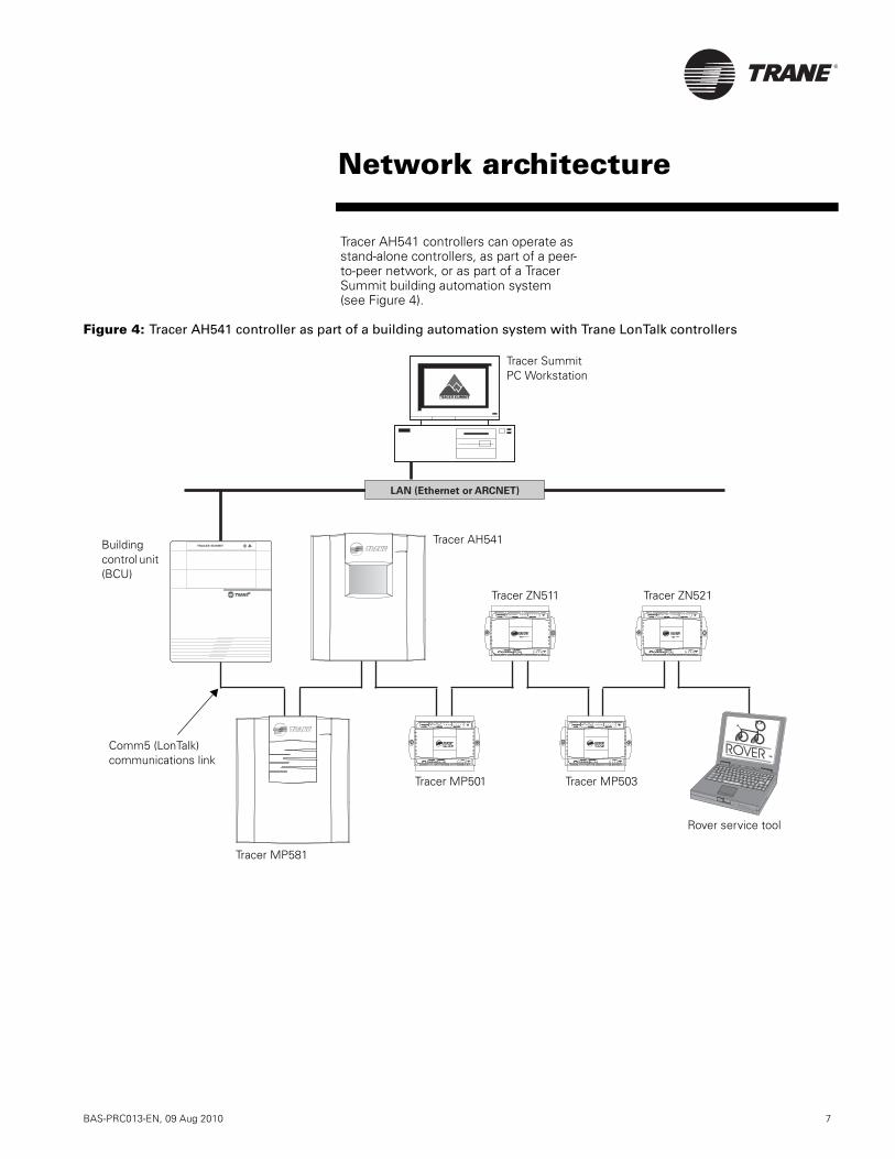
Tracer AH541 controllers can operate as stand-alone controllers, as part of a peer-to-peer network, or as part of a Tracer Summit building automation system (see Figure 4).
Figure 4: Tracer AH541 controller as part of a building automation system with Trane LonTalk controllers
o oo
TM
ROVER
TRACER SUMMIT ALM PWR
LAN (Ethernet or ARCNET)
A BABAI2AI1
BI3BI2BI1 BI4V4 3BI5V5 21 4 5 6
BINARY INPUTSBINARY INPUTS BINARY OUTPUTSBINARY OUTPUTSAC POWERAC POWER
STATUSLED
GND GND GND 24VGND GND GND 24V
ZONE SENSORZONE SENSOR ANALOG INPUTSANALOG INPUTS COMM5COMM5
LEDZN GND SET FAN GNDZN GND SET FAN GNDSERVICE
PIN LEDPIN LED A BABAI2AI1
BI3BI2BI1 BI4V4 3BI5V5 21 4 5 6
BINARY INPUTSBINARY INPUTS BINARY OUTPUTSBINARY OUTPUTSAC POWERAC POWER
STATUSLED
GND GND GND 24VGND GND GND 24V
ZONE SENSORZONE SENSOR ANALOG INPUTSANALOG INPUTS COMM5COMM5COMM5
LEDZN GND SET FAN GNDZN GND SET FAN GNDSERVICESERVICE
PIN LEDPIN LED
A BABAI2AI1
BI3BI2BI1 BI4V4 3BI5V5 21 4 5 6
BINARY INPUTSBINARY INPUTS BINARY OUTPUTSBINARY OUTPUTSAC POWERAC POWER
STATUSLED
GND GND GND 24VGND GND GND 24V
ZONE SENSORZONE SENSOR ANALOG INPUTSANALOG INPUTS COMM5COMM5
LEDZN GND SET FAN GNDZN GND SET FAN GNDSERVICESERVICE
PIN LEDPIN LED A BABAI2AI1
BI3BI2BI1 BI4V4 3BI5V5 21 4 5 6
BINARY INPUTSBINARY INPUTS BINARY OUTPUTSBINARY OUTPUTSAC POWERAC POWER
STATUSSTATUSLED
GND GND GND 24VGND GND GND 24V
ZONE SENSORZONE SENSOR ANALOG INPUTSANALOG INPUTS COMM5COMM5COMM5
LEDZN GND SET FAN GNDZN GND SET FAN GNDSERVICESERVICE
PIN LEDPIN LED
Rover service tool
Comm5 (LonTalk) communications link
Tracer AH541
Tracer ZN511 Tracer ZN521
Tracer MP501 Tracer MP503
Tracer MP581
Building control unit (BCU)
Tracer SummitPC Workstation
Network architecture

®
8 BAS-PRC013-EN, 09 Aug 2010
The Tracer AH541 controller has the following inputs and outputs (illustrated in Figure 5):
• Six binary outputs• Five analog outputs• Six analog inputs• Six binary inputs• Duct static-pressure input• Universal analog input on main controller
The inputs and outputs must be used for the functions listed in Figure 5. For example, an outside-air temperature sensor can be connected only to terminal IN5.
Note that analog output 6 (AO6) is not used.
Figure 5: Wiring diagramCommon terminals
Signal terminals
Jack for Rover service toolNot usedDuct static pressure connector
BO1 Supply fan start/stopBO2 Exhaust fan start/stop
AO1 Supply fan speedAO2 Cool outputAO3 Heat output
AO4 Face and bypass damperAO5 Outdoor air damper
IN1 Space temperatureIN2 Space setpoint
IN3 Fan-mode switchIN4 Discharge-air temperature
IN5 Outdoor air temperature
IN7 Low temp detect or coil defrost
IN6 Mixed-air temperature
IN8 Run/stopIN9 Occupancy (or generic)
IN10 Supply fan statusIN11 Filter status
IN12 Exhaust fan status or coil defrost
Termination board
Main circuit board
BO3 DX stage 1 or Electric heat stage 4BO4 DX stage 2 or Electric heat stage 3BO5 DX stage 3 or Electric heat stage 2BO6 DX stage 4 or Electric heat stage 1
IN13 Space relative humidity, CO2 sensor, entering water temperature, or evaporator refrigerant temperature
Comm5 terminalsNot used
Inputs and outputs

®
BAS-PRC013-EN, 09 Aug 2010 9
Figure 6 shows the interior of the Tracer AH541 NEMA-1 enclosure. Significant space is available for wiring inputs and outputs. Wires should be routed over the optional pressure sensor.
Figure 6: Tracer AH541 enclosure interior
(-) LO(-) LO
OU
T
GN
D
IN0
to5”
wc
0.2
5to
4V
DC
EX
C.:
5V
DC
3299
0356
Pate
ntP
endin
g
0to
5”
wc
0.2
5to
4V
DC
EX
C.:
5V
DC
3299
0356
Pate
ntP
endin
g
SEN
TRA
263
SEN
TRA
263
BO5
BO4
BO3
BO2
BO1
BO6
24VAC
AO4
AO3
AO6
AO5
AO2
IN3
IN2
IN1
AO1
IN6
IN7
IN5
IN11
IN12
IN10
IN9
IN8
IN4
SE
RV
ICE
CO
MM
FA
NE
XFA
NT
ES
TS
TA
TU
S
BO
1B
O3
BO
5B
O2
BO
4B
O6
Line-to-low voltage power transformer
Main circuit board
Termination board
Mounting location for optional static-pressure sensor
Space for input and output wire-routing
Enclosure interior
®
10 BAS-PRC013-EN, 09 Aug 2010
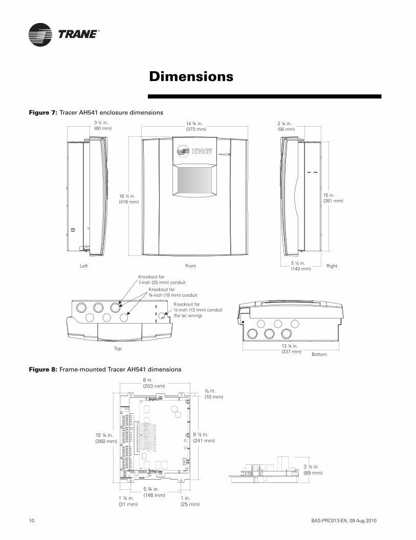
Figure 7: Tracer AH541 enclosure dimensions
Figure 8: Frame-mounted Tracer AH541 dimensions
8 in.(203 mm)
9 ½ in.(241 mm)
1 ¼ in.(31 mm)
10 ¼ in.(260 mm)
in.(10 mm)
1 in.(25 mm)
5 ¾ in.(146 mm)
3 ½ in.(89 mm)
BO5
BO4
BO3
BO2
BO1
BO6
24VAC
AO4
AO3
AO6
AO5
AO2
IN3
IN2
IN1
AO1
IN6
IN7
IN5
IN11
IN12
IN10
IN9
IN8
IN4
Dimensions
®
BAS-PRC013-EN, 09 Aug 2010 11
Power requirementsNominal rating: 24/120/230 Vac; 50/60 Hz; 1 phase
Voltage utilization range24 Vac (frame-mounted): 19–30 Vac120 Vac nominal: 98–132 Vac230 Vac nominal: 196–264 Vac
Power consumptionTracer AH541 controller: 21 VA
Optional operator display: 7 VA
Operating environmentTemperature
Without display: From –40°F to 158°F (–40°C to 70°C)With display: From 32°F to 122°F (0°C to 50°C)
Humidity: 10–90% non-condensing
Storage environmentTemperature
Without display: From –40°F to 185°F(–40°C to 85°C)With display: From –13°F to 149°F (–25°C to 65°C)
Humidity: 5–95% non-condensing
EnclosureEnclosure compliant with National Electrical Manufacturers Association (NEMA) type-1 standards
WeightWith NEMA-1 enclosure: 15 lb (7 kg)
Frame-mounted: 2 lb (1 kg)
DimensionsTracer AH541 NEMA-1 enclosure
16 ½ in. × 14 ¾ in. × 5 ½ in.(418 mm × 373 mm × 140 mm)
Frame-mounted Tracer AH54110 ¼ in. × 8 in. × 3 ½ in.(260 mm × 203 mm × 89 mm)
Minimum clearancesNEMA-1 enclosure
12 in. (30 cm) top, bottom, and right 24 in. (60 cm) left36 in. (90 cm) front
Frame-mounted½ in. (1.3 cm) top, right, and front6 in. (15 cm) left (for I/O wiring)3 in. (8 cm) bottom (for communications wiring)
MountingNEMA-1 enclosure: wall-mounted with #10 (5 mm) screws
Frame-mounted: #8 (4 mm) screws
Operator interfaceVideo graphics adapter (VGA) backlit liquid crystal display (LCD) with touch screen; 4.5 in. × 3.4 in. (115 mm × 86 mm) viewable area; resolution of 320 × 240 pixels
Time clockIncluded with operator display; crystal controlled, super-capacitor backed
BatteryNot required—backed by super capacitor for seven days under normal operating conditions; all other programs backed by non-volatile memory
Agency listings/complianceUL and C-UL
UL 916 Energy ManagementCUL C22.2 No. 205-M1985 Signal Devices
FCC approved: CFR 47, Part 15, Subpart A, Class A
CE ConformanceEmissions
EN55022 Class BEN61000-3-2EN61000-3-3
ImmunityEN50082-2 Industrial
Specifications

Trane optimizes the performance of homes and buildings around the world. A business of Ingersoll Rand, theleader in creating and sustaining safe, comfortable and energy efficient environments, Trane offers a broadportfolio of advanced controls and HVAC systems, comprehensive building services, and parts. For more information, visit www.Trane.com.
Trane has a policy of continuous product and product data improvement and reserves the right to change design and specifications without notice.
© 2010 Trane All rights reserved
BAS-PRC013-EN, 09 Aug 2010
Supersedes Feb 2004
Produced on 20% post-consumer recycled paper, using
environmentally friendly print practices that reduce waste.
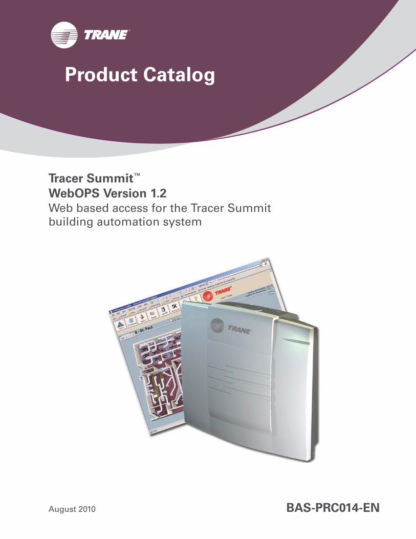
Tracer Summit™
WebOPS Version 1.2
Web based access for the Tracer Summitbuilding automation system
August 2010 BAS-PRC014-EN
Product Catalog

2 BAS-PRC014-EN
Introduction. . . . . . . . . . . . . . . . . . . . . . . . 3
Features and benefits . . . . . . . . . . . . . . . . 4
Graphical operation . . . . . . . . . . . . . . . . . . . . . . . . . 5Time-of-day scheduling . . . . . . . . . . . . . . . . . . . . . . . 5Event and alarm management . . . . . . . . . . . . . . . . . 6Viewing and printing trends with dynamic charts 7Setup . . . . . . . . . . . . . . . . . . . . . . . . . . . . . . . . . . . . . 8Security . . . . . . . . . . . . . . . . . . . . . . . . . . . . . . . . . . . 8System integration . . . . . . . . . . . . . . . . . . . . . . . . . . 8
Network architecture . . . . . . . . . . . . . . . . . 9
Power requirements . . . . . . . . . . . . . . . . . . . . . . . . 11Operating environment . . . . . . . . . . . . . . . . . . . . . 11Storage environment . . . . . . . . . . . . . . . . . . . . . . . 11Cabinet . . . . . . . . . . . . . . . . . . . . . . . . . . . . . . . . . . . 11Memory . . . . . . . . . . . . . . . . . . . . . . . . . . . . . . . . . . 11Processor . . . . . . . . . . . . . . . . . . . . . . . . . . . . . . . . . 11Network. . . . . . . . . . . . . . . . . . . . . . . . . . . . . . . . . . 11Security . . . . . . . . . . . . . . . . . . . . . . . . . . . . . . . . . . 11Software requirements . . . . . . . . . . . . . . . . . . . . . . 11Dimensions . . . . . . . . . . . . . . . . . . . . . . . . . . . . . . . 11Weight . . . . . . . . . . . . . . . . . . . . . . . . . . . . . . . . . . . 11Agency listings/compliance . . . . . . . . . . . . . . . . . . 11
Specifications and dimensions . . . . . . . . 11
Contents

BAS-PRC014-EN, 09 Aug 2010 3
Tracer Summit WebOPS provides the ability to access the Tracer Summit building automation system (BAS) from any PC using a Web browser, such as Internet Explorer. WebOPS accesses real-time system data from the Tracer Summit system and uses Web pages that allow you to perform daily operations with your Tracer Summit system. This allows for daily operator functionality and access to system information from within a facility or from a remote location anywhere in the world using any Web browser.
Tracer Summit WebOPS:
• Eliminates the need for multiple Tracer Summit PC Workstations
• Increases accessibility and convenience
With WebOPS installed on a Tracer Summit system, any PC with a Web browser can be used to:
• View the graphics for a facility, change setpoints, and perform overrides
• View and change schedules• View and acknowledge alarms• View, print, save, and e-mail trend
information
WebOPS is compatible with Tracer Summit Version 13 and higher. It has full SSL encryption capablity and can easily be added to new or existing Tracer Summit installations on Ethernet or Ethernet IP networks.
WebOPS also provides single-seat operation to help solve your system integration needs (see “System integration”, page 7).
Introduction
© 2010 Trane All rights reserved
™ ® The following are trademarks or registered trademarks of their respective companies: BACnet from ASHRAE; Internet Explorer from Microsoft Corporation; and Tracer and Tracer Summit from Trane.

4 BAS-PRC014-EN, 09 Aug 2010
WebOPS is designed for easy installation and operation. It is an embedded device, which means that it has no mechanical hardware, such as a fan or a disk drive, that can fail over time. Minimal effort is required from your IT staff to install WebOPS.
Daily operators (or other building occupants) can use their Web browser to access their facility by entering the Internet address for WebOPS. After logging on, the user’s home page displays. Figure 1 shows an example of a home page.
Users can access system graphics, schedules, event logs, and trends from their Tracer Summit system. The extent of their access depends on their security privileges.
The following functions are supported by WebOPS:
• Graphical operation/navigation• Setpoint monitor and control• Time-of-day scheduling• Alarm monitoring and
acknowledgement• Historical trend viewing• WebOPS security and setup
Figure 1. Example of a user’s home page on WebOPS
Features and benefits
BAS-PRC014-EN, 09 Aug 2010 5
Graphical operationWith WebOPS, remote users can view all graphics created at a Tracer Summit PC Workstation.
The following graphical elements of Tracer Summit software are accessible using WebOPS:
• Any data available in the system as a numerical or text value
• Analog values that can change colors based on deviation from a desired value for quick recognition of opera-tional issues
• User-defined static text in a wide choice of fonts and colors
• Animation using binary images or ani-mated GIFs
• Linked text and images that can be added to move between graphics
• Links to other Web sites• Multiple graphic images that conform
to standard JPEG, GIF, or BMP for-mats, in addition to the library of HVAC equipment images included
with the Tracer Summit software package
• User controls including push buttons and entry fields
Real-time values are automatically updated every 10 seconds without having to refresh the page. Users can easily move between graphics by clicking links or using the browser Forward and Back buttons. They can also change system setpoints and perform overrides if they have appropriate security privileges.
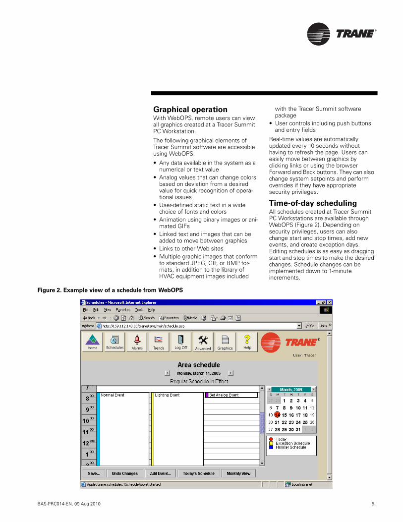
Time-of-day schedulingAll schedules created at Tracer Summit PC Workstations are available through WebOPS (Figure 2). Depending on security privileges, users can also change start and stop times, add new events, and create exception days. Editing schedules is as easy as dragging start and stop times to make the desired changes. Schedule changes can be implemented down to 1-minute increments.
Figure 2. Example view of a schedule from WebOPS

6 BAS-PRC014-EN, 09 Aug 2010
Event and alarm
managementUsers with a BCU (Version 13 or higher) can display the event log and system alarms (Figure 3). The events and alarms can be sorted according to properties,
such as date, type, unacknowledged or acknowledged, and who performed the acknowledgement.
Users with the appropriate security privileges can acknowledge alarms from this screen.
Figure 3. Example view of an event log from WebOPS

BAS-PRC014-EN, 09 Aug 2010 7
Viewing and printing trends
with dynamic chartsIn addition to the daily operator activities of WebOPS, users can perform troubleshooting activities and gain a deeper understanding of their facility operations by viewing and printing trend information (Figure 4). All trends created with Tracer Summit software can be viewed through WebOPS. WebOPS will chart the entire trend data set contained in the BCU and will update the chart with new information every 10 minutes or can be refreshed manually.
The trend chart has the ability to chart multiple properties (up to 10) and includes a legend to identify each data line. For example, multiple space temperature trend lines can be plotted together on the same chart so that users can compare information between trends.
Multiple charts can be displayed on the same Web page. The charts can be enlarged so that the trend line can be seen in greater detail.
All current data displayed in the charts can be printed, saved, and e-mailed.
Figure 4. Example view of a trend from WebOPS, with the selected trend zoomed
8 BAS-PRC014-EN, 09 Aug 2010
SetupSetting up WebOPS is quick and easy. After the hardware has power and is connected to the network, the installer assigns it an IP address (provided by the customer’s IT staff). WebOPS then automatically locates the schedules, trends, and BCU event logs in the Tracer Summit system and makes them accessible with a browser.
Publishing graphics to WebOPS
An extensive library of standard graphics representing all Trane equipment and applications is included in the Tracer Summit PC Workstation software. Workstation operators can modify these or create new custom graphics.
By using the new Customize Graphics Templates tool in Tracer Summit software, any graphic, either standard or custom, can be quickly converted for publishing to WebOPS. These converted graphics can then be easily imported into WebOPS for immediate viewing by using the WebOPS publishing tool.
Administrator setup
Users with administrative privileges have access to a series of setup pages after logging in. These setup pages allow administrators to add, delete, or modify user names, passwords, home page selection, and security privileges for each user.
SecurityWebOPS supports both user security and data security.
User
User security privileges are set up by the Administrator and depend on a combination of the user’s home page and security level. The three security levels offer a mix of functionality and security.
Data
Data security prevents unauthorized users from gaining access to the building automation system through WebOPS. Customers have the option of securing the Logon and Administration pages only or securing all pages. WebOPS is encrypted using Secure Sockets Layer (SSL) technology. This 128-bit encryption is the same used to protect credit card transactions on the Internet.
Security updates
WebOPS is equipped with functionality that can be used to update its security at any time with new patches or updates as they are provided by industry.
System integrationStandard communication technology (for example, BACnet) is essential for enabling system integration. It promotes single-seat operation, which means that only one front-end system, or tool, is used to operate all of a facility’s equipment, regardless of manufacturer. WebOPS uses open BACnet protocol so that data can be freely communicated between WebOPS, the PC Workstations, BCUs, and any other facility equipment or building automation systems.
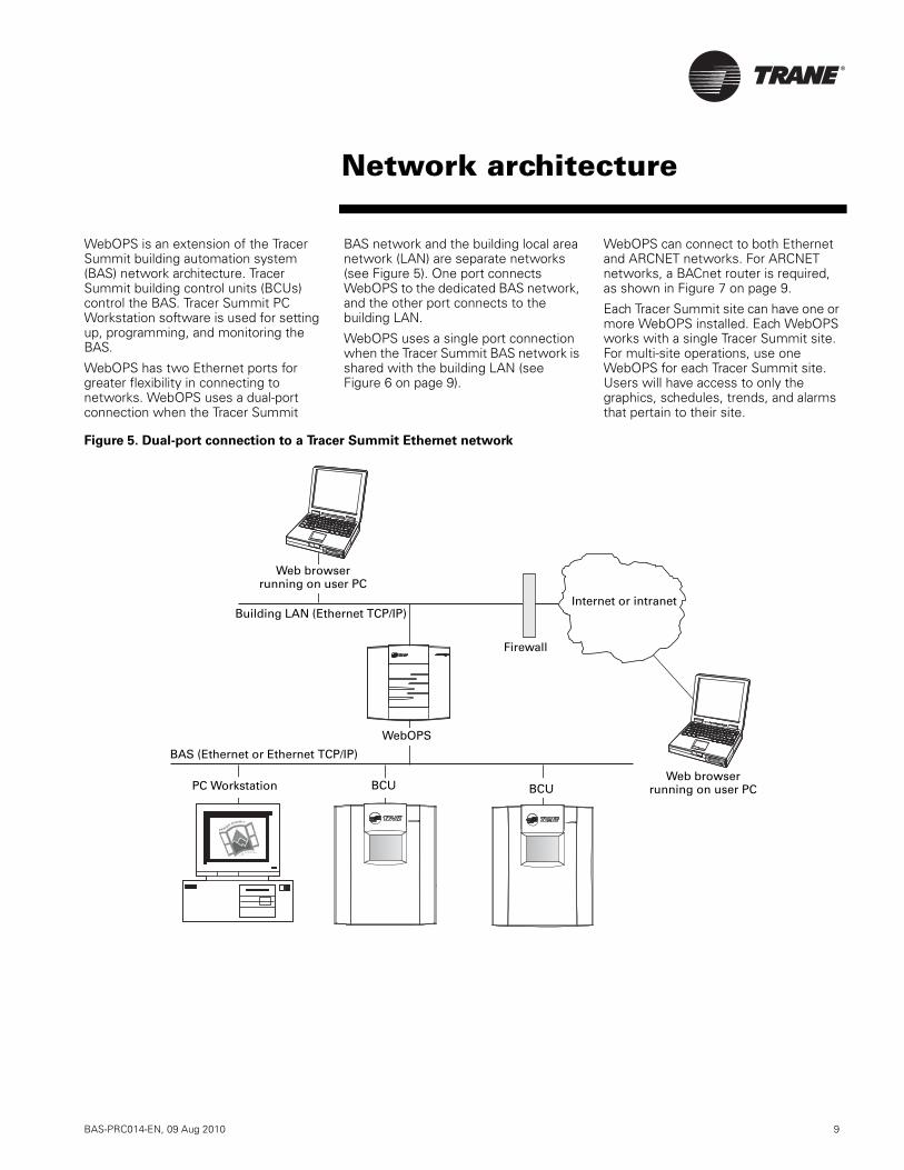
BAS-PRC014-EN, 09 Aug 2010 9
WebOPS is an extension of the Tracer Summit building automation system (BAS) network architecture. Tracer Summit building control units (BCUs) control the BAS. Tracer Summit PC Workstation software is used for setting up, programming, and monitoring the BAS.
WebOPS has two Ethernet ports for greater flexibility in connecting to networks. WebOPS uses a dual-port connection when the Tracer Summit
BAS network and the building local area network (LAN) are separate networks (see Figure 5). One port connects WebOPS to the dedicated BAS network, and the other port connects to the building LAN.
WebOPS uses a single port connection when the Tracer Summit BAS network is shared with the building LAN (see Figure 6 on page 9).
WebOPS can connect to both Ethernet and ARCNET networks. For ARCNET networks, a BACnet router is required, as shown in Figure 7 on page 9.
Each Tracer Summit site can have one or more WebOPS installed. Each WebOPS works with a single Tracer Summit site. For multi-site operations, use one WebOPS for each Tracer Summit site. Users will have access to only the graphics, schedules, trends, and alarms that pertain to their site.
Figure 5. Dual-port connection to a Tracer Summit Ethernet network
Internet or intranet
Firewall
Building LAN (Ethernet TCP/IP)
BAS (Ethernet or Ethernet TCP/IP)
Web browser running on user PC
WebOPS
Web browser running on user PCPC Workstation BCU
Network architecture
BCU
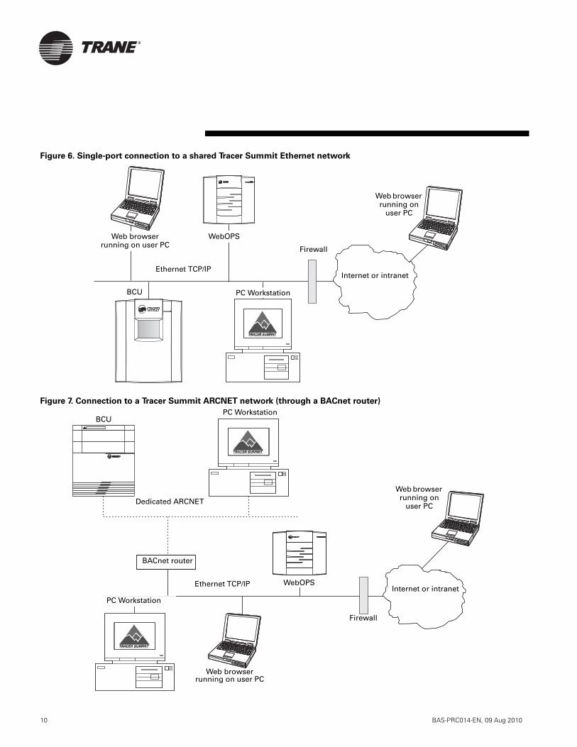
10 BAS-PRC014-EN, 09 Aug 2010
Figure 6. Single-port connection to a shared Tracer Summit Ethernet network
Figure 7. Connection to a Tracer Summit ARCNET network (through a BACnet router)
BCU
Ethernet TCP/IP
Web browser running on
user PC
WebOPS
Internet or intranet
Web browser running on user PC Firewall
PC Workstation
WebOPS
Web browserrunning on user PC
BACnet router
BCU
Dedicated ARCNET
PC Workstation
Ethernet TCP/IP
Web browser running on
user PC
Internet or intranet
Firewall
PC Workstation

BAS-PRC014-EN, 09 Aug 2010 11
Power requirements24 Vac nominal (19–30 Vac)50/60 Hz, 1 phase 40 VA minimumClass 2 transformer required
2 removable time-lag hik-break 2 A 250 V TR5 fuses
Operating environmentTemperature:
From 32°F to 122°F (0°C to 50°C)
Relative humidity: From 10% to 90%, noncondensing
Storage environmentTemperature:
From –40°F to 185°F (–40°C to 85°C)
Relative humidity: From 10% to 90%, noncondensing
CabinetNEMA 1 resin enclosurePlenum rated
Memory256 MB of SDRAM512 MB capacity on compact flash card
ProcessorGeode SC100 32-bit x86, 266 MHz
NetworkTwo RJ-45 Ethernet 10/100 BaseT ports with auto-detection rate
1 RS-232 port galvanically isolated (up to 50 V)
SecuritySecure Sockets Layer (SSL) protocol
Software requirementsJava 2 plug in 1.4.2 or higher
Web browser: Internet Explorer 6 or higher, or Mozilla 1.3 or higher
Dimensions(See Figure 9)
(Height: 8.75 in. (22.38 cm)Width: 10.25 in. (26.04 cm)Depth: 2.75 in. (6.99 cm)
Weight2.5 lb (1.13 kg)
Agency listings/complianceCE compliance:
EN61326:1998, Industrial environmentEN55022 (Emission): Class AEN61000-4-2 (ESD): ±4 kV direct, ±8 kV airEN61000-4-3 (Radiated RF): 10 V/mEN61000-4-4 (EFT): AC port ±1 kVI/O & comm port ±1 kVEN61000-4-5 (Surge): AC port ±2 kVI/O & comm port ±1 kVEN61000-4-6 (Conducted RF): 10 VEN61000-4-8 (Magnetic): 30 A/mEN61000-4-11 (Power interruption): Passed
UL and C-UL listed:
1950, Information technology equipment60950, Information technology equipmentUL 94-5V, UL flammability rating for plenum use
FCC Part 15, Class A
Specifications and dimensions
Figure 9. WebOPS controller dimensions
10.25 in. (26.04 cm)
8.75 in. (22.38 cm)
2.75 in. (6.99 cm)
Top
SideFront
Bottom

Trane optimizes the performance of homes and buildings around the world. A business of Ingersoll Rand, theleader in creating and sustaining safe, comfortable and energy efficient environments, Trane offers a broadportfolio of advanced controls and HVAC systems, comprehensive building services, and parts. For more information, visit www.Trane.com.
Trane has a policy of continuous product and product data improvement and reserves the right to change design and specifications without notice.
© 2010 Trane All rights reserved
BAS-PRC014-EN, 23 Aug 2010
Supersedes Mar 2008
Produced on 20% post-consumer recycled paper, using
environmentally friendly print practices that reduce waste.

Tracer Summit
Energy Services™
Energy Management and Advanced Reporting Software
August 2010 BAS-PRC015-EN
Product Catalog
2 BAS-PRC015-EN, 09 Aug 2010
®
Tracer Summit Energy Services is an energy management and advanced reporting software product that is used with the Tracer Summit building automation system. It provides tools to monitor, analyze, trend, benchmark, and allocate both energy consumption and energy costs for your business along with the means to create reports from this data. Its purpose is to help you manage energy operations and expenses more efficiently so that your organization can improve its productivity and profitability. It is designed for both the technical and non-technical user.
Two options of Tracer Summit Energy Services are available: Energy Manager and Energy Analyst. Energy Manager provides a basic platform to enable tracking, analysis, cost allocation, benchmarking, and invoicing of energy meters and sub-meters as well as non-energy points such as weather data. Energy Analyst provides more comprehensive energy management tools to enable in-depth analysis, reporting, and plant analysis.
Both the Energy Manager and the Energy Analyst options are available with a desktop database or with an enterprise database, depending on the needs of your organization. The desktop database is best suited for single-site Tracer Summit applications or multi-site applications that have a central energy manager station. The enterprise database is best suited for multi-site applications with multiple users as well as larger national account customers, campus, or school district applications.
Introduction
© 2010 Trane All rights reserved
™ ® The following are trademarks or registered trademarks of their respective companies: BACnet of ASHRAE; Pentium of Intel Corporation; SQL Server of Sybase Corporation; Tracer and Tracer Summit of American Standard Inc.; Windows and Windows XP of Microsoft Corpora-tion in the United States and other countries.

BAS-PRC015-EN, 09 Aug 2010 3
®
Introduction . . . . . . . . . . . . . . . . . . . . . . . . 2
Product highlights . . . . . . . . . . . . . . . . . . . 4
Features and benefits . . . . . . . . . . . . . . . . 5
Energy Manager . . . . . . . . . . . . . . . . . . . . . . . . . . . . 5Energy Analyst . . . . . . . . . . . . . . . . . . . . . . . . . . . . . 7
Architecture and network compatibility . 9
Desktop database . . . . . . . . . . . . . . . . . . . . . . . . . . . . 9Enterprise database . . . . . . . . . . . . . . . . . . . . . . . . . 10
Seamless data transfer . . . . . . . . . . . . . . 11
Specifications . . . . . . . . . . . . . . . . . . . . . 12
Contents
4 BAS-PRC015-EN, 09 Aug 2010
®
Tracer Summit Energy Services is a comprehensive metering application and reporting tool for optimizing the energy usage and costs of your facility. The Tracer Summit Energy Services product provides the means to:
• Monitor energy use, allocate costs, verify utility billings, and identify ways to optimize energy consumption and reduce expenditures
• Monitor virtually any energy resource: electricity, natural gas, steam, and chilled water
• Create advanced reports with Tracer Summit data
• Organize sub-meter data into catego-ries
• Support energy-buying decisions• Create ready-to-use reports that aid in
the rapid analysis of data• Generate utility invoices and verify
accuracy of actual utility bill charges• Compare purchasing options from var-
ious energy providers and perform multiple “what-if” scenarios
• Evaluate the effect of weather or other variables on facility energy requirements
• Standardize units of measure to allow data comparison and benchmarking
• Generate energy benchmarking data• Export Tracer Summit data into stan-
dard IT format
Product highlights
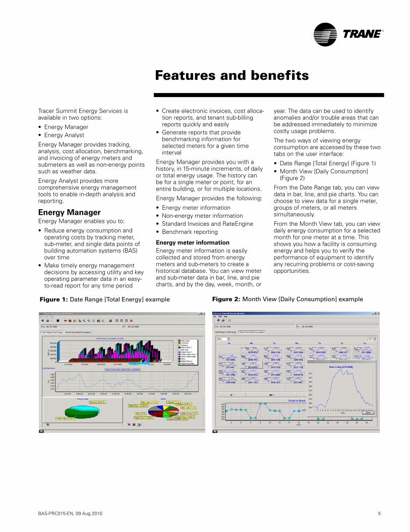
BAS-PRC015-EN, 09 Aug 2010 5
®
Tracer Summit Energy Services is available in two options:
• Energy Manager• Energy Analyst
Energy Manager provides tracking, analysis, cost allocation, benchmarking, and invoicing of energy meters and submeters as well as non-energy points such as weather data.
Energy Analyst provides more comprehensive energy management tools to enable in-depth analysis and reporting.
Energy ManagerEnergy Manager enables you to:
• Reduce energy consumption and operating costs by tracking meter, sub-meter, and single data points of building automation systems (BAS) over time
• Make timely energy management decisions by accessing utility and key operating parameter data in an easy-to-read report for any time period
• Create electronic invoices, cost alloca-tion reports, and tenant sub-billing reports quickly and easily
• Generate reports that provide benchmarking information for selected meters for a given time interval
Energy Manager provides you with a history, in 15-minute increments, of daily or total energy usage. The history can be for a single meter or point, for an entire building, or for multiple locations.
Energy Manager provides the following:
• Energy meter information• Non-energy meter information• Standard Invoices and RateEngine• Benchmark reporting
Energy meter information
Energy meter information is easily collected and stored from energy meters and sub-meters to create a historical database. You can view meter and sub-meter data in bar, line, and pie charts, and by the day, week, month, or
year. The data can be used to identify anomalies and/or trouble areas that can be addressed immediately to minimize costly usage problems.
The two ways of viewing energy consumption are accessed by these two tabs on the user interface:
• Date Range [Total Energy] (Figure 1)• Month View [Daily Consumption]
(Figure 2)
From the Date Range tab, you can view data in bar, line, and pie charts. You can choose to view data for a single meter, groups of meters, or all meters simultaneously.
From the Month View tab, you can view daily energy consumption for a selected month for one meter at a time. This shows you how a facility is consuming energy and helps you to verify the performance of equipment to identify any recurring problems or cost-saving opportunities.
Features and benefits
Figure 1: Date Range [Total Energy] example Figure 2: Month View [Daily Consumption] example
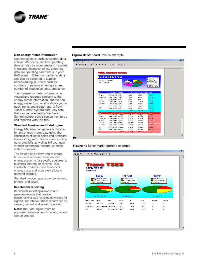
6 BAS-PRC015-EN, 09 Aug 2010
®
Non-energy meter information
Non-energy data, such as weather data, critical BAS points, and key operating data can also be monitored and included in reports. Examples of key operating data are operating parameters in your BAS system. Other nontraditional data can also be collected to support benchmarking activities, such as numbers of patrons entering a store, number of production units, and so on.
The non-energy meter information is viewed and reported similarly to the energy meter information, but the non-energy meter functionality allows you to track, trend, and create reports from Tracer Summit system data. Any data that can be collected by the Tracer Summit control panels can be monitored and reported with this tool.
Standard Invoices and RateEngine
Energy Manager can generate invoices for any energy meter data using the capabilities of RateEngine and Standard Invoices (Figure 3). You can verify utility-generated bills as well as bill your own internal customers, tenants, or areas with this feature.
The RateEngine allows you to create time-of-use rates and independent energy accounts for specific equipment, business centers, or tenants. This information can be used to recover energy costs and accurately allocate demand charges.
Standard invoice reports can be viewed, printed, and saved.
Benchmark reporting
Benchmark reporting allows you to generate reports that provide benchmarking data for selected meters for a given time interval. These reports can be viewed, printed, and saved (Figure 4).
Note: The RateEngine must be populated before a benchmarking report can be created.
Figure 4: Benchmark reporting example
Figure 3: Standard Invoice example
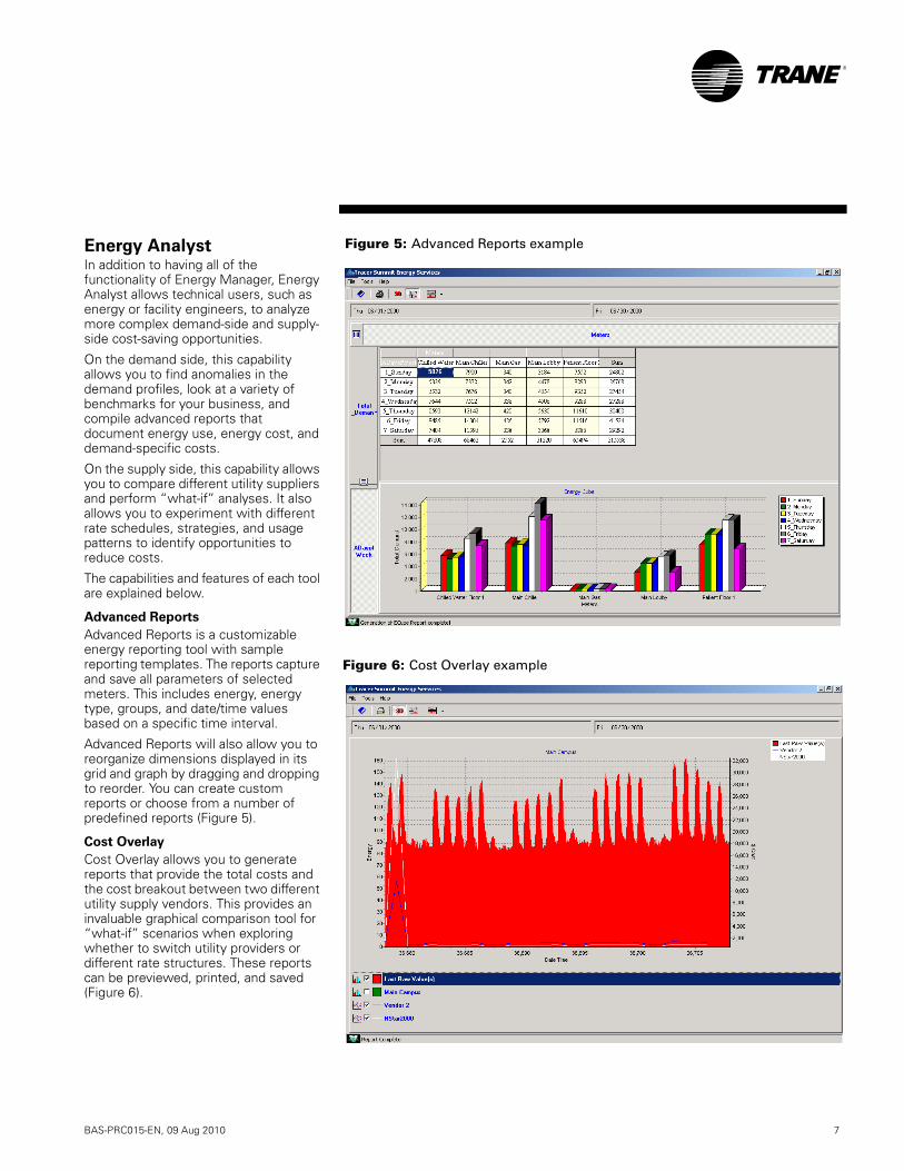
BAS-PRC015-EN, 09 Aug 2010 7
®
Energy AnalystIn addition to having all of the functionality of Energy Manager, Energy Analyst allows technical users, such as energy or facility engineers, to analyze more complex demand-side and supply-side cost-saving opportunities.
On the demand side, this capability allows you to find anomalies in the demand profiles, look at a variety of benchmarks for your business, and compile advanced reports that document energy use, energy cost, and demand-specific costs.
On the supply side, this capability allows you to compare different utility suppliers and perform “what-if” analyses. It also allows you to experiment with different rate schedules, strategies, and usage patterns to identify opportunities to reduce costs.
The capabilities and features of each tool are explained below.
Advanced Reports
Advanced Reports is a customizable energy reporting tool with sample reporting templates. The reports capture and save all parameters of selected meters. This includes energy, energy type, groups, and date/time values based on a specific time interval.
Advanced Reports will also allow you to reorganize dimensions displayed in its grid and graph by dragging and dropping to reorder. You can create custom reports or choose from a number of predefined reports (Figure 5).
Cost Overlay
Cost Overlay allows you to generate reports that provide the total costs and the cost breakout between two different utility supply vendors. This provides an invaluable graphical comparison tool for “what-if” scenarios when exploring whether to switch utility providers or different rate structures. These reports can be previewed, printed, and saved (Figure 6).
Figure 5: Advanced Reports example
Figure 6: Cost Overlay example
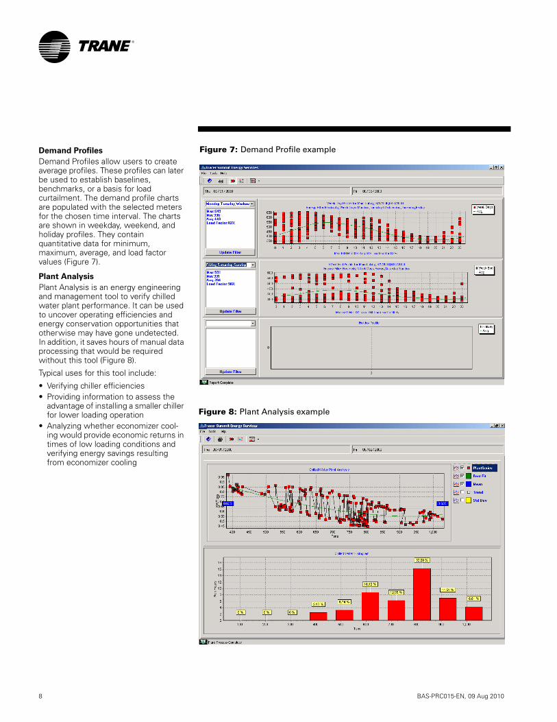
8 BAS-PRC015-EN, 09 Aug 2010
®
Demand Profiles
Demand Profiles allow users to create average profiles. These profiles can later be used to establish baselines, benchmarks, or a basis for load curtailment. The demand profile charts are populated with the selected meters for the chosen time interval. The charts are shown in weekday, weekend, and holiday profiles. They contain quantitative data for minimum, maximum, average, and load factor values (Figure 7).
Plant Analysis
Plant Analysis is an energy engineering and management tool to verify chilled water plant performance. It can be used to uncover operating efficiencies and energy conservation opportunities that otherwise may have gone undetected. In addition, it saves hours of manual data processing that would be required without this tool (Figure 8).
Typical uses for this tool include:
• Verifying chiller efficiencies• Providing information to assess the
advantage of installing a smaller chiller for lower loading operation
• Analyzing whether economizer cool-ing would provide economic returns in times of low loading conditions and verifying energy savings resulting from economizer cooling
Figure 7: Demand Profile example
Figure 8: Plant Analysis example
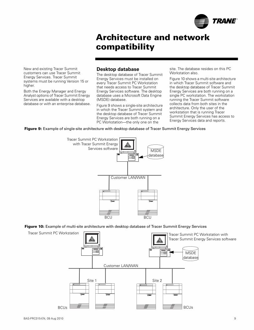
BAS-PRC015-EN, 09 Aug 2010 9
®
New and existing Tracer Summit customers can use Tracer Summit Energy Services. Tracer Summit systems must be running Version 15 or higher.
Both the Energy Manager and Energy Analyst options of Tracer Summit Energy Services are available with a desktop database or with an enterprise database.
Desktop databaseThe desktop database of Tracer Summit Energy Services must be installed on every Tracer Summit PC Workstation that needs access to Tracer Summit Energy Services software. The desktop database uses a Microsoft Data Engine (MSDE) database.
Figure 9 shows a single-site architecture in which the Tracer Summit system and the desktop database of Tracer Summit Energy Services are both running on a PC Workstation—the only one on the
site. The database resides on this PC Workstation also.
Figure 10 shows a multi-site architecture in which Tracer Summit software and the desktop database of Tracer Summit Energy Services are both running on a single PC workstation. The workstation running the Tracer Summit software collects data from both sites in the architecture. Only the user of the workstation that is running Tracer Summit Energy Services has access to Energy Services data and reports.
Figure 9: Example of single-site architecture with desktop database of Tracer Summit Energy Services
BCU
Customer LAN/WAN
MSDE database
Tracer Summit PC Workstationwith Tracer Summit Energy
Services software
BCU
Figure 10: Example of multi-site architecture with desktop database of Tracer Summit Energy Services
Tracer Summit PC Workstation Tracer Summit PC Workstation with Tracer Summit Energy Services software
Site 1 Site 2
MSDE database
Customer LAN/WAN
BCUsBCUs
Architecture and network compatibility
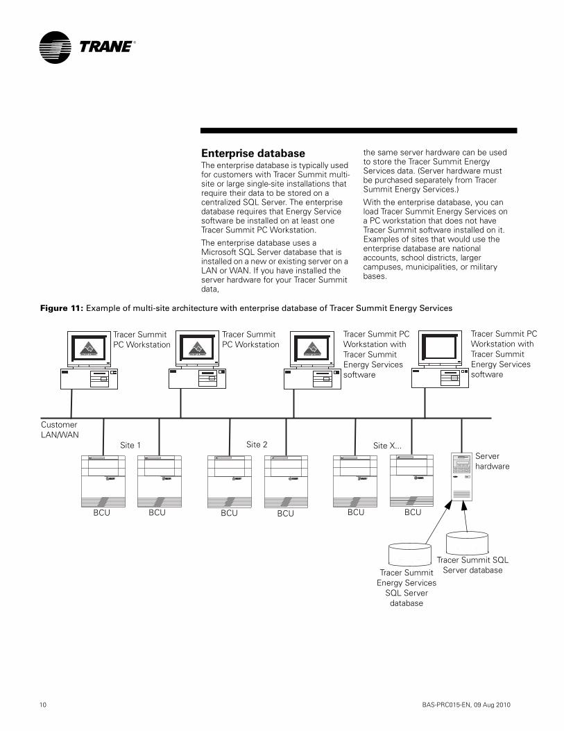
10 BAS-PRC015-EN, 09 Aug 2010
®
Enterprise databaseThe enterprise database is typically used for customers with Tracer Summit multi-site or large single-site installations that require their data to be stored on a centralized SQL Server. The enterprise database requires that Energy Service software be installed on at least one Tracer Summit PC Workstation.
The enterprise database uses a Microsoft SQL Server database that is installed on a new or existing server on a LAN or WAN. If you have installed the server hardware for your Tracer Summit data,
the same server hardware can be used to store the Tracer Summit Energy Services data. (Server hardware must be purchased separately from Tracer Summit Energy Services.)
With the enterprise database, you can load Tracer Summit Energy Services on a PC workstation that does not have Tracer Summit software installed on it. Examples of sites that would use the enterprise database are national accounts, school districts, larger campuses, municipalities, or military bases.
Figure 11: Example of multi-site architecture with enterprise database of Tracer Summit Energy Services
BCU
Tracer Summit PC Workstation
Site 1 Site 2 Site X...
Tracer Summit PC Workstation
BCU BCU BCU BCU BCU
Tracer Summit PC Workstation with Tracer Summit Energy Services software
Tracer Summit PC Workstation with Tracer Summit Energy Services software
Tracer Summit Energy Services
SQL Server database
Tracer Summit SQL Server database
Serverhardware
Customer LAN/WAN
BAS-PRC015-EN, 09 Aug 2010 11
®
Tracer Summit Energy Services is a software product that has been developed to work seamlessly with the Tracer Summit building automation system. Tracer Summit Energy Services allows Tracer Summit trend object data to be collected and stored in an MSDE or SQL database. This provides two major benefits:
• Data from the building control unit (BCU) panels are easily collected and stored for historical reporting.
• Tracer Summit data (BACNet) is converted into standard IT format when collected in the MSDE or SQL database.
Data is shared between Tracer Summit and Tracer Summit Energy Services by setting up trend objects in the Tracer Summit software. Once the required trends are defined, the user simply chooses which trends Tracer Summit Energy Services will utilize. Once these are selected, Tracer Summit Energy Services begins collecting the selected trend data into its database for use with Tracer Summit Energy Services. Tracer Summit Energy Services then presents the selected data in different graphical and reporting formats that allow quick and easy access to the data. Analysis tools within Tracer Summit Energy Services also utilize the database and provide the user with timely data to make informed business and operational decisions.
Seamless data transfer
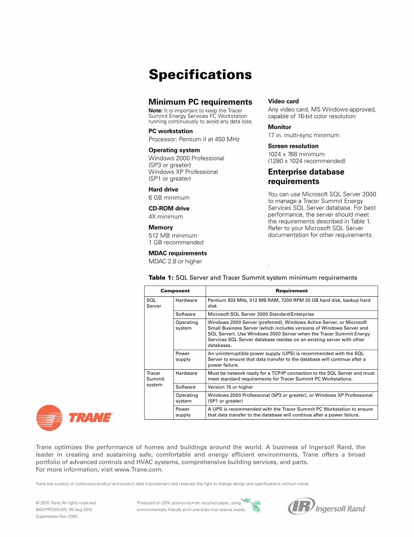
Trane optimizes the performance of homes and buildings around the world. A business of Ingersoll Rand, theleader in creating and sustaining safe, comfortable and energy efficient environments, Trane offers a broadportfolio of advanced controls and HVAC systems, comprehensive building services, and parts. For more information, visit www.Trane.com.
Trane has a policy of continuous product and product data improvement and reserves the right to change design and specifications without notice.
© 2010 Trane All rights reserved
BAS-PRC015-EN, 09 Aug 2010
Supersedes Nov 2003
Produced on 20% post-consumer recycled paper, using
environmentally friendly print practices that reduce waste.
Minimum PC requirementsNote: It is important to keep the Tracer Summit Energy Services PC Workstation running continuously to avoid any data loss.
PC workstation
Processor: Pentium II at 450 MHz
Operating system
Windows 2000 Professional (SP3 or greater)Windows XP Professional (SP1 or greater)
Hard drive
6 GB minimum
CD-ROM drive
4X minimum
Memory
512 MB minimum1 GB recommended
MDAC requirements
MDAC 2.8 or higher
Video card
Any video card, MS Windows-approved, capable of 16-bit color resolution
Monitor
17 in. multi-sync minimum
Screen resolution
1024 x 768 minimum (1280 x 1024 recommended)
Enterprise database
requirements
You can use Microsoft SQL Server 2000 to manage a Tracer Summit Energy Services SQL Server database. For best performance, the server should meet the requirements described in Table 1. Refer to your Microsoft SQL Server documentation for other requirements.
.
Table 1: SQL Server and Tracer Summit system minimum requirements
Component Requirement
SQL Server
Hardware Pentium 933 MHz, 512 MB RAM, 7200 RPM 20 GB hard disk, backup hard disk
Software Microsoft SQL Server 2000 Standard/Enterprise
Operating system
Windows 2000 Server (preferred), Windows Active Server, or Microsoft Small Business Server (which includes versions of Windows Server and SQL Server). Use Windows 2000 Server when the Tracer Summit Energy Services SQL Server database resides on an existing server with other databases.
Power supply
An uninterruptible power supply (UPS) is recommended with the SQL Server to ensure that data transfer to the database will continue after a power failure.
Tracer Summit system
Hardware Must be network ready for a TCP/IP connection to the SQL Server and must meet standard requirements for Tracer Summit PC Workstations.
Software Version 15 or higher
Operating system
Windows 2000 Professional (SP3 or greater), or Windows XP Professional (SP1 or greater)
Power supply
A UPS is recommended with the Tracer Summit PC Workstation to ensure that data transfer to the database will continue after a power failure.
Specifications
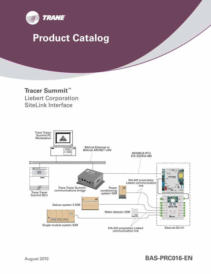
Tracer Summit™
Liebert CorporationSiteLink Interface
August 2010 BAS-PRC016-EN
Trane TracerSummit PC
Workstation
BACnet Ethernet or BACnet ARCNET LAN
MODBUS RTU EIA-232/EIA-485
EIA-422 proprietary Liebert communication
linkPower
conditioningsystem IGM
Water detector IGM
EIA-422 proprietary Liebert communication link
SiteLink-DC121Single module system IGM
Trane Tracer Summit BCU
Trane Tracer Summitcommunications bridge
Deluxe system 3 IGM
Product Catalog

2 BAS-PRC016-EN, 09 Aug 2010
®
Liebert Corporation is a leading supplier of computer room air-conditioning equipment and uninterruptable power supply (UPS) systems.
A Trane Tracer Summit PC Workstation and a Trane Tracer Summit building control unit (BCU) monitor and control the present value of Liebert information gathering module (IGM) data. A Tracer Summit BCU connects to the MODBUS port of a Liebert SiteLink panel using a Trane Tracer Summit communications bridge.
Overview
© 2010 Trane All rights reserved
™ ® The following are trademarks or registered trademarks of their respective companies: Tracer Summit and Trane of Trane; ARCNET of Datapoint Corporation; BACnet of ASHRAE; Liebert and SiteLink of Liebert Corporation; MODBUS of Schneider Automation, Inc.
BAS-PRC016-EN, 09 Aug 2010 3
®
Functionality
ApplicationLiebert information gathering modules (IGMs) connect to a Liebert SiteLink using an EIA-422 proprietary Liebert communication link. Each SiteLink input supports a communication link to one Liebert IGM. Each SiteLink input is specifically configured for the type of Liebert IGM connected to it.
The SiteLink connects to a Tracer Summit communications bridge using an EIA-232 or EIA-485 link. The bridge connects to a Tracer Summit PC Workstation and a Tracer Summit BCU using a BACnet Ethernet or ARCNET LAN.
A SiteLink multiplexor polls inputs in a round-robin sequence. As it polls, SiteLink updates a cache of MODBUS registers corresponding to unit controller data. The Tracer Summit communications bridge receives the content of the registers using MODBUS Remote Terminal Unit (RTU) protocols and maps the MODBUS registers into BACnet objects.
Once mapped, either the Tracer Summit PC Workstation or BCU can monitor Liebert points by reading the status of the BACnet objects in the gateway. When the Tracer Summit PC Workstation comes online, it polls the gateway and adds BACnet analog input, binary input, analog output, and binary output objects to its database. Like other Tracer Summit input/output objects, the points can be added to graphics, used in schedules and reports, or included in CPL routines.
Note: If more than one SiteLink connects to the Tracer Summit communications bridge, each requires a Liebert REPOPT amplifier/converter.
Note: Liebert can also supply network interface cards (OpenComm NIC Cards) for MODBUS connectivity directly to their units.
System functions include status/control, alarm management, scheduling, and trending.
Status/controlTracer Summit PC Workstation and Tracer Summit building control unit (BCU) application programs monitor and control the present value of BACnet objects in the Tracer Summit communications bridge. The objects are mapped to MODBUS registers that describe analog and binary input points at Liebert information gathering modules (IGMs). The Tracer Summit PC Workstation and BCU can access the point data.
Alarm managementTo include Liebert input points in Tracer Summit alarm management applications, Tracer Summit requires a CPL routine. Tracer Summit determines the alarm condition by using the local saved value of the CPL routine. Liebert IGM alarm diagnostics are identified by binary code. The CPL routine translates the values to an alarm.
SchedulingSchedule Liebert IGMs directly from the Tracer Summit scheduling application.
TrendingTracer Summit reports and trend logs may include Liebert data.
Special considerations
When setting up a SiteLink interface, consider scaling and alarm manage-ment.
Scaling
The Tracer Summit communications bridge sends a present value as an unsigned integer. Edit appropriate scaling factors for each point when mapping MODBUS registers to BACnet objects in the Sierra Monitor gateway. No scaling is required in Tracer Summit.
Alarm management
CPL routines must include Liebert IGM alarms for Tracer Summit alarm management.
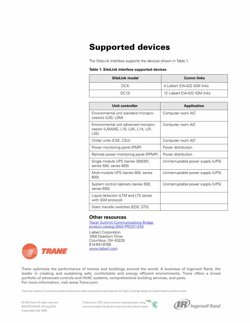
Trane optimizes the performance of homes and buildings around the world. A business of Ingersoll Rand, theleader in creating and sustaining safe, comfortable and energy efficient environments, Trane offers a broadportfolio of advanced controls and HVAC systems, comprehensive building services, and parts. For more information, visit www.Trane.com.
Trane has a policy of continuous product and product data improvement and reserves the right to change design and specifications without notice.
© 2010 Trane All rights reserved
BAS-PRC016-EN, 09 Aug 2010
Supersedes Mar 2008
Produced on 20% post-consumer recycled paper, using
environmentally friendly print practices that reduce waste.
The SiteLink interface supports the devices shown in Table 1.
Other resourcesTracer Summit Communications Bridge product catalog (BAS-PRC011-EN)
Liebert Corporation1050 Dearborn DriveColumbus, OH 43229 614-841-8108www.liebert.com
Table 1. SiteLink interface supported devices
SiteLink model Comm links
DC4i 4 Liebert EIA-422 IGM links
DC12i 12 Liebert EIA-422 IGM links
Unit controller Application
Environmental unit standard micropro-cessors (L00, LSM)
Computer room A/C
Environmental unit advanced micropro-cessor (LAM/AG, L10, L0A, L1A, L01, L02)
Computer room A/C
Chiller units (CSE, CSU) Computer room A/C
Power monitoring panel (PMP) Power distribution
Remote power monitoring panel (RPMP) Power distribution
Single module UPS (series 300/301, series 500, series 600)
Uninterruptable power supply (UPS)
Multi-module UPS (series 500, series 600)
Uninterruptable power supply (UPS)
System control cabinets (series 500, series 600)
Uninterruptable power supply (UPS)
Liquid detection (LTM and LTS series with IGM protocol)
Static transfer switches (EDS, STS)
Supported devices
Tracer ES™
Web-based Enterprise Building Management
June 2013 BAS-PRC019-EN
Product Catalog

2 BAS-PRC019-EN
Copyright
© 2013 Trane All rights reserved
This document and the information in it are the property of Trane and may not be used or reproduced in whole or in part, without the written permission of Trane. Trane reserves the right to revise this publication at any time and to make changes to its content without obligation to notify any person of such revision or change.
Trademarks
Trane and its logo are trademarks of Trane in the United States and other countries. All trademarks referenced in this document are the trademarks of their respective owners.

Table of Contents
BAS-PRC019-EN 3
Product Introduction . . . . . . . . . . . . . . . . . . . . . . . . . . . . . . . . . . . . . . . . . . . . . . . 4Tracer Building Automation System . . . . . . . . . . . . . . . . . . . . . . . . . . . . . . 4Tracer ES Network Architecture . . . . . . . . . . . . . . . . . . . . . . . . . . . . . . . . . . 5
The Tracer ES Solution . . . . . . . . . . . . . . . . . . . . . . . . . . . . . . . . . . . . . . . . . . . . . 6Software . . . . . . . . . . . . . . . . . . . . . . . . . . . . . . . . . . . . . . . . . . . . . . . . . . . . . 6Hardware . . . . . . . . . . . . . . . . . . . . . . . . . . . . . . . . . . . . . . . . . . . . . . . . . . . . 6Tracer ES Express . . . . . . . . . . . . . . . . . . . . . . . . . . . . . . . . . . . . . . . . . . . . . 6Implementation . . . . . . . . . . . . . . . . . . . . . . . . . . . . . . . . . . . . . . . . . . . . . . . 6IT/Networking . . . . . . . . . . . . . . . . . . . . . . . . . . . . . . . . . . . . . . . . . . . . . . . . 6Systems engineering . . . . . . . . . . . . . . . . . . . . . . . . . . . . . . . . . . . . . . . . . . 6Operational requirements . . . . . . . . . . . . . . . . . . . . . . . . . . . . . . . . . . . . . . . 7On-going maintenance and support . . . . . . . . . . . . . . . . . . . . . . . . . . . . . . 7Training . . . . . . . . . . . . . . . . . . . . . . . . . . . . . . . . . . . . . . . . . . . . . . . . . . . . . 7
Features and Benefits . . . . . . . . . . . . . . . . . . . . . . . . . . . . . . . . . . . . . . . . . . . . . . 8Ease of Operation . . . . . . . . . . . . . . . . . . . . . . . . . . . . . . . . . . . . . . . . . . . . . 8Daily Building Operation . . . . . . . . . . . . . . . . . . . . . . . . . . . . . . . . . . . . . . . . 9Enterprise management . . . . . . . . . . . . . . . . . . . . . . . . . . . . . . . . . . . . . . . 10Data collection, analysis, and reporting . . . . . . . . . . . . . . . . . . . . . . . . . . 12
System Requirements and Specifications . . . . . . . . . . . . . . . . . . . . . . . . . . . . 13
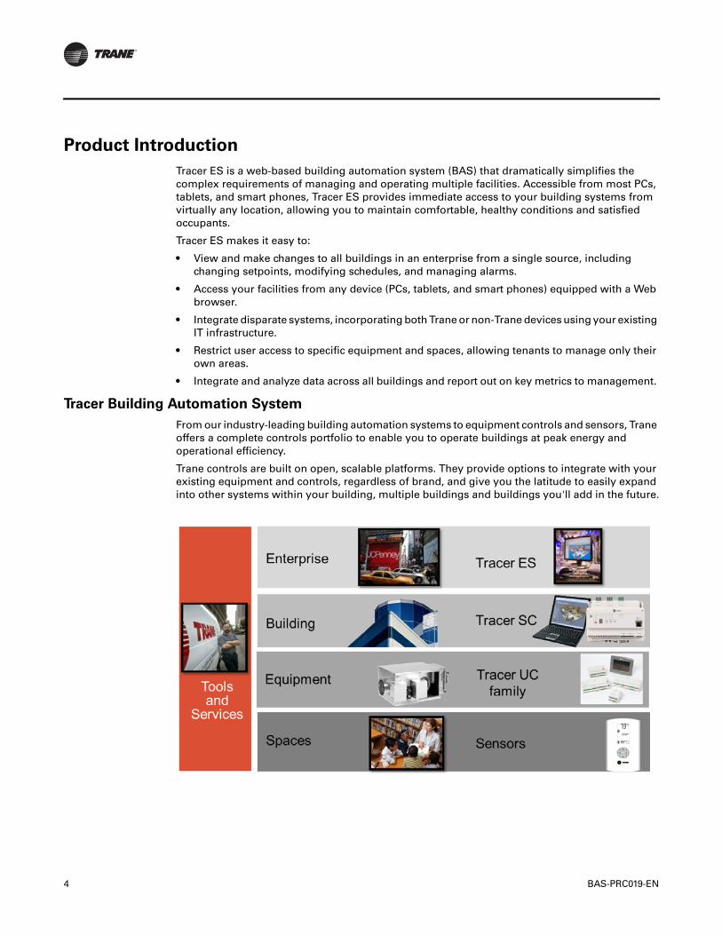
4 BAS-PRC019-EN
Product Introduction
Tracer ES is a web-based building automation system (BAS) that dramatically simplifies the complex requirements of managing and operating multiple facilities. Accessible from most PCs, tablets, and smart phones, Tracer ES provides immediate access to your building systems from virtually any location, allowing you to maintain comfortable, healthy conditions and satisfied occupants.
Tracer ES makes it easy to:
• View and make changes to all buildings in an enterprise from a single source, including changing setpoints, modifying schedules, and managing alarms.
• Access your facilities from any device (PCs, tablets, and smart phones) equipped with a Web browser.
• Integrate disparate systems, incorporating both Trane or non-Trane devices using your existing IT infrastructure.
• Restrict user access to specific equipment and spaces, allowing tenants to manage only their own areas.
• Integrate and analyze data across all buildings and report out on key metrics to management.
Tracer Building Automation System
From our industry-leading building automation systems to equipment controls and sensors, Trane offers a complete controls portfolio to enable you to operate buildings at peak energy and operational efficiency.
Trane controls are built on open, scalable platforms. They provide options to integrate with your existing equipment and controls, regardless of brand, and give you the latitude to easily expand into other systems within your building, multiple buildings and buildings you'll add in the future.
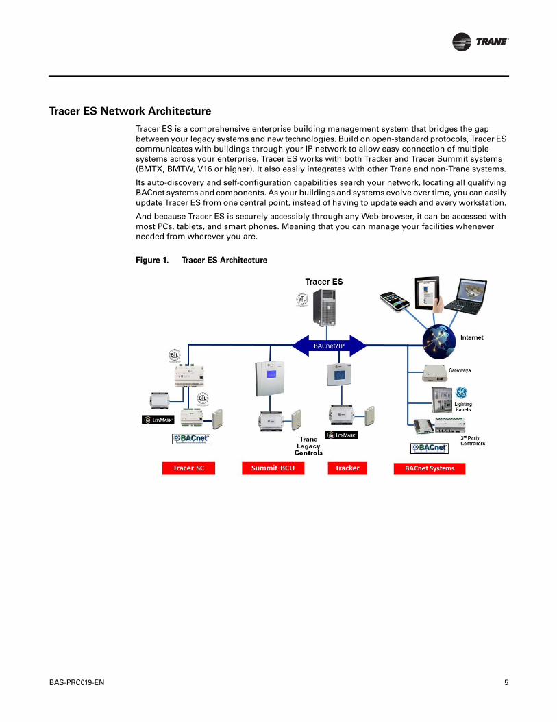
BAS-PRC019-EN 5
Tracer ES Network Architecture
Tracer ES is a comprehensive enterprise building management system that bridges the gap between your legacy systems and new technologies. Build on open-standard protocols, Tracer ES communicates with buildings through your IP network to allow easy connection of multiple systems across your enterprise. Tracer ES works with both Tracker and Tracer Summit systems (BMTX, BMTW, V16 or higher). It also easily integrates with other Trane and non-Trane systems.
Its auto-discovery and self-configuration capabilities search your network, locating all qualifying BACnet systems and components. As your buildings and systems evolve over time, you can easily update Tracer ES from one central point, instead of having to update each and every workstation.
And because Tracer ES is securely accessibly through any Web browser, it can be accessed with most PCs, tablets, and smart phones. Meaning that you can manage your facilities whenever needed from wherever you are.
Figure 1. Tracer ES Architecture
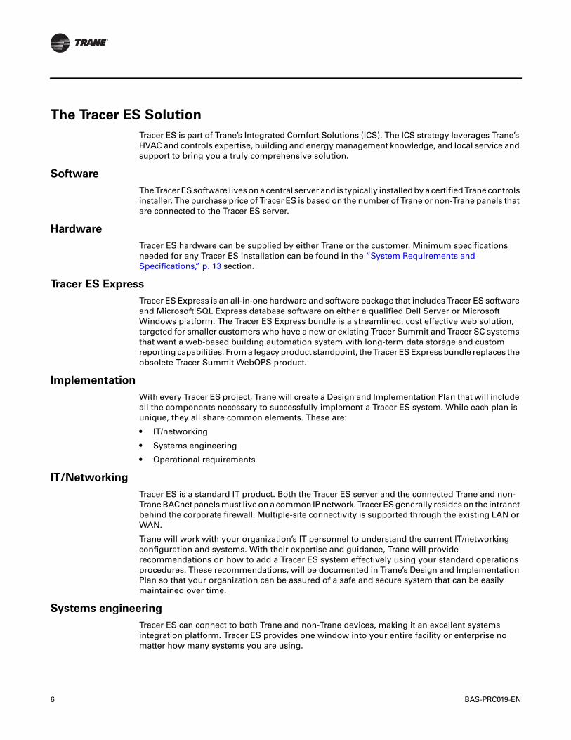
6 BAS-PRC019-EN
The Tracer ES Solution
Tracer ES is part of Trane’s Integrated Comfort Solutions (ICS). The ICS strategy leverages Trane’s HVAC and controls expertise, building and energy management knowledge, and local service and support to bring you a truly comprehensive solution.
Software
The Tracer ES software lives on a central server and is typically installed by a certified Trane controls installer. The purchase price of Tracer ES is based on the number of Trane or non-Trane panels that are connected to the Tracer ES server.
Hardware
Tracer ES hardware can be supplied by either Trane or the customer. Minimum specifications needed for any Tracer ES installation can be found in the “System Requirements and Specifications,” p. 13 section.
Tracer ES Express
Tracer ES Express is an all-in-one hardware and software package that includes Tracer ES software and Microsoft SQL Express database software on either a qualified Dell Server or Microsoft Windows platform. The Tracer ES Express bundle is a streamlined, cost effective web solution, targeted for smaller customers who have a new or existing Tracer Summit and Tracer SC systems that want a web-based building automation system with long-term data storage and custom reporting capabilities. From a legacy product standpoint, the Tracer ES Express bundle replaces the obsolete Tracer Summit WebOPS product.
Implementation
With every Tracer ES project, Trane will create a Design and Implementation Plan that will include all the components necessary to successfully implement a Tracer ES system. While each plan is unique, they all share common elements. These are:
• IT/networking
• Systems engineering
• Operational requirements
IT/Networking
Tracer ES is a standard IT product. Both the Tracer ES server and the connected Trane and non-Trane BACnet panels must live on a common IP network. Tracer ES generally resides on the intranet behind the corporate firewall. Multiple-site connectivity is supported through the existing LAN or WAN.
Trane will work with your organization’s IT personnel to understand the current IT/networking configuration and systems. With their expertise and guidance, Trane will provide recommendations on how to add a Tracer ES system effectively using your standard operations procedures. These recommendations, will be documented in Trane’s Design and Implementation Plan so that your organization can be assured of a safe and secure system that can be easily maintained over time.
Systems engineering
Tracer ES can connect to both Trane and non-Trane devices, making it an excellent systems integration platform. Tracer ES provides one window into your entire facility or enterprise no matter how many systems you are using.

BAS-PRC019-EN 7
The Tracer ES Design and Implementation Plan will include systems engineering documentation to identify and integrate any non-Trane BACnet system that will be connected to the Tracer ES server.
Operational requirements
Tracer ES can be customized to meet the exact needs of your organization and users. Trane will interview the key administrative users to understand how many people will be using the system and what their roles and responsibilities are. This ensures that Tracer ES will be ready for them as soon as it is installed and commissioned. Also, the operational requirements for scheduling, troubleshooting, and data analysis will also be obtained and documented in the Design and Implementation Plan. Trane will use this information to assure that the systems are working together as one common enterprise.
On-going maintenance and support
Trane excels at providing world-class maintenance and support to our customers. We will work with you to select a Tracer ES Software Maintenance plan that meets your organization’s needs for ongoing product maintenance and support.
Local Trane offices provide 24-hour service and support. Trane employees have lived and worked in your community for more than 80 years. With Trane, our customers receive personalized attention from locally-rooted offices, and confidence in knowing that a large corporation is standing behind each project. This level of commitment and expertise will ensure that your Tracer ES system is running at its best.
Training
Trane provides both Web-based training as well as classroom training to support your new investment. Training assures that you and your staff are using your Tracer ES to its fullest potential to meet the needs of your business.
8 BAS-PRC019-EN
Features and Benefits
Tracer ES simplifies the management of building systems within multiple facilities for owners, managers, and daily operators. Tracer ES provides centralized management of scheduling and alarms, supports long-term data storage to document and monitor performance, enables remote troubleshooting, and brings disparate systems together for upgrade flexibility. And because Tracer ES offers full browser support, you can access your facility from wherever you are from your PC, tablet, or smart phone.
Ease of Operation
The daily operator is the most critical user of the system. To optimize the daily user’s experience, Tracer ES employs user-centered design principles, resulting in a simple and intuitive design. Ongoing user testing and user interface improvements ensure that Tracer ES is easy to use.
Site management
Tracer ES site management features can help facility management personnel take a more proactive approach to site management. The building index, flexible search tool, and navigational aid features can significantly increase response time to address occupant issues across a large enterprise.
Mobility
The interface is easy to navigate and can be used effectively with very little training. The Tracer ES user interface lets you operate a multiple-building, facility management system from any device equipped with a Web browser from a PC to smart phone. If you can surf the web, you can master Tracer ES.
Auto-discovery and self-configuration
The auto-discovery and self-configuration feature greatly simplifies the time-consuming task of the installer having to build the equipment list and status pages during site setup. During the installation process, Tracer ES discovers all of the equipment for the site, and then automatically builds the equipment list and status Web pages. This feature can also be used to quickly and easily bring new equipment online.
Navigate with graphics
With Tracer ES, users can graphically navigate through all levels of a facility by clicking on an image of a building, room, or piece of equipment. Graphical navigation enables operators to view status or change setpoints easily and efficiently.
Customizable building index
The Buildings Index can be customized to view building information in a hierarchical structure or by building type. For example, the owner/operator of a retail chain might want to use a hierarchical structure to describe a group of buildings. This gives users access to building information at different levels of the hierarchy.
Flexible search tool
The Finding a Building feature is a powerful search tool that helps the user quickly find a building or a group of buildings in the system. Users can search on any attribute that is specified during administrator setup. To find a specific building, enter the building name or other building attribute in the Find Building field and click “Go.” The user is taken to the Summary page for a particular building or group of buildings, where other building information can be readily viewed.

BAS-PRC019-EN 9
Figure 2. Tracer ES Home Page
Recent Visits
The Recent Visits list can be used as a navigational aid for finding the most recently viewed buildings. This list displays the last 10 buildings that were visited, giving the operator access to buildings that have been worked on most often. If the Remote Building Operator is supporting hundreds of buildings but only working on a few, this list enables the operator to get to those buildings quickly without having to retrace navigation steps.
Daily Building Operation
Tracer ES automatically and dynamically constructs Web pages that incorporate building summaries, systems, and equipment, accessed by a left-hand navigation pane. This makes both the installation process and daily operation of Tracer ES efficient and effective.
Auto-discovery and self-configuration
Auto discovery and self-configuration automatically builds the following pages:
• Summary
• Alarms
• Spaces
• Equipment
• Subsystems
• Schedules
• Data Logs
• Advanced
Summary. This page shows a summary of the alarms and space status for a selected building in the enterprise.
Alarms. This page displays a list of all alarms for a selected building in the enterprise.
Spaces. This page shows all spaces in a selected building and its related equipment. Users can view the equipment summary page of a building space and can also modify data points.
Equipment. This pages shows status of a selected building and its related equipment. Users can view the status of all equipment and subsystems, which displays data points for all equipment in a building.
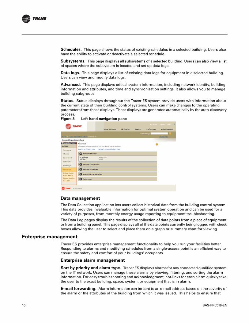
10 BAS-PRC019-EN
Schedules. This page shows the status of existing schedules in a selected building. Users also have the ability to activate or deactivate a selected schedule.
Subsystems. This page displays all subsystems of a selected building. Users can also view a list of spaces where the subsystem is located and set up data logs.
Data logs. This page displays a list of existing data logs for equipment in a selected building. Users can view and modify data logs.
Advanced. This page displays critical system information, including network identity, building information and attributes, and time and synchronization settings. It also allows you to manage building subgroups.
Status. Status displays throughout the Tracer ES system provide users with information about the current state of their building control systems. Users can make changes to the operating parameters from these displays. These displays are generated automatically by the auto-discovery process. Figure 3. Left-hand navigation pane
Data management
The Data Collection application lets users collect historical data from the building control system. This data provides invaluable information for optimal system operation and can be used for a variety of purposes, from monthly energy usage reporting to equipment troubleshooting.
The Data Log pages display the results of the collection of data points from a piece of equipment or from a building panel. This page displays all of the data points currently being logged with check boxes allowing the user to select and place them on a graph or summary chart for viewing.
Enterprise management
Tracer ES provides enterprise management functionality to help you run your facilities better. Responding to alarms and modifying schedules from a single-access point is an efficient way to ensure the safety and comfort of your buildings’ occupants.
Enterprise alarm management
Sort by priority and alarm type. Tracer ES displays alarms for any connected qualified system on the IT network. Users can manage these alarms by viewing, filtering, and sorting the alarm information. For easy troubleshooting and acknowledgment, hot-links for each alarm quickly take the user to the exact building, space, system, or equipment that is in alarm.
E-mail forwarding. Alarm information can be sent to an e-mail address based on the severity of the alarm or the attributes of the building from which it was issued. This helps to ensure that
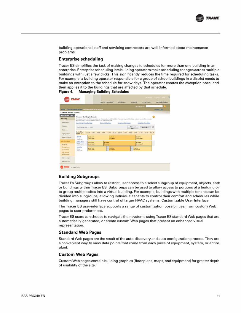
BAS-PRC019-EN 11
building operational staff and servicing contractors are well informed about maintenance problems.
Enterprise scheduling
Tracer ES simplifies the task of making changes to schedules for more than one building in an enterprise. Enterprise scheduling lets building operators make scheduling changes across multiple buildings with just a few clicks. This significantly reduces the time required for scheduling tasks. For example, a building operator responsible for a group of school buildings in a district needs to make an exception to the schedule for snow days. The operator creates the exception once, and then applies it to the buildings that are affected by that schedule. Figure 4. Managing Building Schedules
Building Subgroups
Tracer Es Subgroups allow to restrict user access to a select subgroup of equipment, objects, and/or buildings within Tracer ES. Subgroups can be used to allow access to portions of a building or to group multiple sites into a virtual building. For example, buildings with multiple tenants can be divided into subgroups, allowing individual tenants to control their comfort and schedules while building managers still have control of larger HVAC systems. Customizable User Interface
The Tracer ES user-interface supports a range of customization possibilities, from custom Web pages to user preferences.
Tracer ES users can choose to navigate their systems using Tracer ES standard Web pages that are automatically generated, or create custom Web pages that present an enhanced visual representation.
Standard Web Pages
Standard Web pages are the result of the auto-discovery and auto-configuration process. They are a convenient way to view data points that come from each piece of equipment, system, or entire plant.
Custom Web Pages
Custom Web pages contain building graphics (floor plans, maps, and equipment) for greater depth of usability of the site.
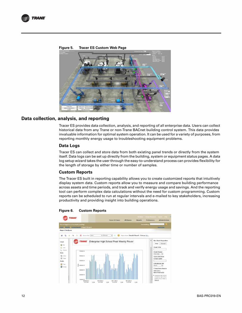
12 BAS-PRC019-EN
Figure 5. Tracer ES Custom Web Page
Data collection, analysis, and reporting
Tracer ES provides data collection, analysis, and reporting of all enterprise data. Users can collect historical data from any Trane or non-Trane BACnet building control system. This data provides invaluable information for optimal system operation. It can be used for a variety of purposes, from reporting monthly energy usage to troubleshooting equipment problems.
Data Logs
Tracer ES can collect and store data from both existing panel trends or directly from the system itself. Data logs can be set up directly from the building, system or equipment status pages. A data log setup wizard takes the user through the easy-to-understand process can provides flexibility for the length of storage by either time or number of samples.
Custom Reports
The Tracer ES built in reporting capability allows you to create customized reports that intuitively display system data. Custom reports allow you to measure and compare building performance across assets and time periods, and track and verify energy usage and savings. And the reporting tool can perform complex data calculations without the need for custom programming. Custom reports can be scheduled to run at regular intervals and e-mailed to key stakeholders, increasing productivity and providing insight into building operations.
Figure 6. Custom Reports
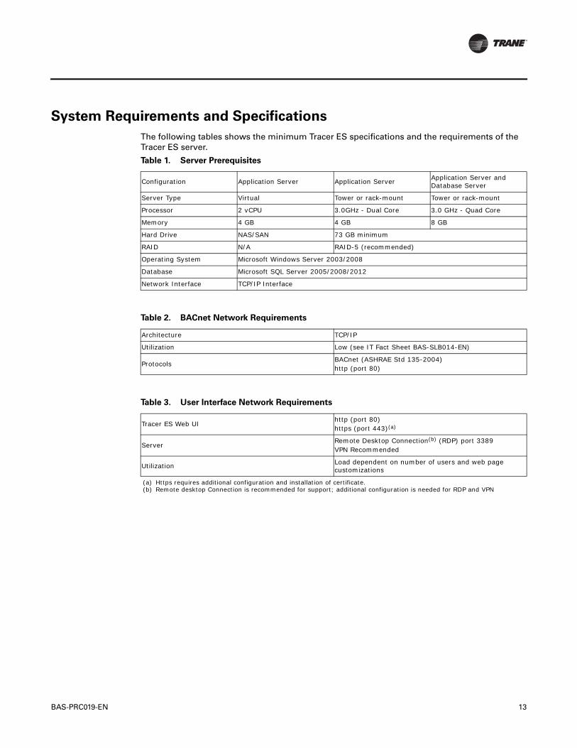
BAS-PRC019-EN 13
System Requirements and Specifications
The following tables shows the minimum Tracer ES specifications and the requirements of the Tracer ES server.
Table 1. Server Prerequisites
Configuration Application Server Application Server Application Server and Database Server
Server Type Virtual Tower or rack-mount Tower or rack-mount
Processor 2 vCPU 3.0GHz - Dual Core 3.0 GHz - Quad Core
Memory 4 GB 4 GB 8 GB
Hard Drive NAS/SAN 73 GB minimum
RAID N/A RAID-5 (recommended)
Operating System Microsoft Windows Server 2003/2008
Database Microsoft SQL Server 2005/2008/2012
Network Interface TCP/IP Interface
Table 2. BACnet Network Requirements
Architecture TCP/IP
Utilization Low (see IT Fact Sheet BAS-SLB014-EN)
ProtocolsBACnet (ASHRAE Std 135-2004)http (port 80)
Table 3. User Interface Network Requirements
Tracer ES Web UIhttp (port 80)https (port 443)(a)
(a) Https requires additional configuration and installation of certificate.
ServerRemote Desktop Connection(b) (RDP) port 3389VPN Recommended
(b) Remote desktop Connection is recommended for support; additional configuration is needed for RDP and VPN
Utilization Load dependent on number of users and web page customizations

Trane optimizes the performance of homes and buildings around the world. A business of Ingersoll Rand, the leader in creating and sustaining safe, comfortable and energy efficient environments, Trane offers a broad portfolio of advanced controls and HVAC systems, comprehensive building services, and parts. For more information, visit www.Trane.com.
Trane has a policy of continuous product and product data improvement and reserves the right to change design and specifications without notice.
We are committed to using environmentally
conscious print practices that reduce waste.
© 2013 Trane All rights reserved
BAS-PRC019-EN 14 Jun 2013
Supersedes BAS-PRC019-EN 09 Aug 2010

Duct MountWall Mount
December 2011 BAS-PRC024-EN
Product Data Sheet
CO2 Sensors
Part numbers: (Duct Mount) X13790423010, VACO2DUCT010,
SEN01092 (Wall Mount) X13790422010, VACO2ZONE010,
SEN01087
The maintenance-free carbon dioxide (CO2) sensor is primarily designed for return air based demand-controlledventilation applications.The exceptional stability and reliable performance comes from advanced silicon-basedNon-Dispersive InfraRed (NDIR) technology combined with Automatic Background Calibration (ABC) andpassive gas diffusion (no moving parts).The CO2 sensor is designed to operate from either a 24 Vac or 24 Vdcpower supplied from the HVAC controller.
Features and Benefits
Features Benefits
High accuracy Reduced energy costs and improved environmental quality
0–2000 ppm range Effective control of CO2 levels for optimized energy efficiency and air quality
Multiple outputs (0–10VDC or 4–20 mA)
Flexible for use with a wide range of Trane direct digital control (DDC) control
Automatic self-diagnostics Diagnostic tools are built-in for minimized troubleshooting expenses
Maintenance-free design Auto-calibration and reduced maintenance costs
Trane wall enclosure Consistent enclosure designs for improved aesthetics
Specifications
Type Description
Duct mount 3.3 in x 1.8 in x 5.6 in (84 mm x 46 mm x 142 mm)
Wall mount 4.8 in x 2.9 in x 1.1 in (121 mm x 74 mm x 28 mm)
Probe length 8.00 in (203 mm)
CO2 range 0–2000 ppm CO2
Accuracy at 25°C ±30 ppm CO2 +3% of reading (includes repeatability)
Pressure dependence of output +1.6% of reading per kPa
Annual zero drift ±10 ppm
Recommended calibration interval None (auto-calibrated)
Response time < 3 minutes
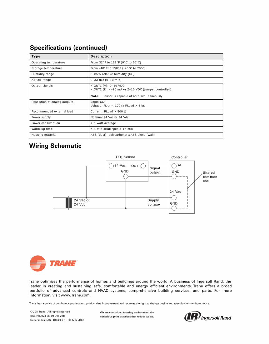
Trane optimizes the performance of homes and buildings around the world. A business of Ingersoll Rand, theleader in creating and sustaining safe, comfortable and energy efficient environments, Trane offers a broadportfolio of advanced controls and HVAC systems, comprehensive building services, and parts. For moreinformation, visit www.Trane.com.
Trane has a policy of continuous product and product data improvement and reserves the right to change design and specifications without notice.
© 2011Trane All rights reserved
BAS-PRC024-EN 09 Dec 2011
Supersedes BAS-PRC024-EN (05 Mar 2010)
We are committed to using environmentally
conscious print practices that reduce waste.
Wiring Schematic
Operating temperature From 32°F to 122°F (0°C to 50°C)
Storage temperature From -40°F to 158°F (-40°C to 70°C)
Humidity range 0–85% relative humidity (RH)
Airflow range 0–33 ft/s (0–10 m/s)
Output signals • OUT1 (V): 0–10 VDC• OUT2 (I): 4–20 mA or 2–10 VDC (jumper controlled)
Note: Sensor is capable of both simultaneously
Resolution of analog outputs 2ppm CO2Voltage: Rout < 100 RLoad > 5 k
Recommended external load Current: RLoad > 500
Power supply Nominal 24 Vac or 24 Vdc
Power consumption < 1 watt average
Warm-up time < 1 min @full spec < 15 min
Housing material ABS (duct), polycarbonate/ABS blend (wall)
Specifications (continued)
Type Description
CO2 Sensor Controller
Shared common line
24 Vac
GNDSupply voltage
24 Vac
GNDOUT
24 Vac or 24 Vdc
AI
GNDSignal output

© 2010 Trane All rights reserved
Product Data Sheet
Wireless Zone SensorsTrane™ wireless sensors are an ideal alternative to wired sensors with the advantage of easy and flexible installation. The wireless feature allows for quick mounting in optimal locations for space comfort while minimizing installation time and relocation expense. The radio is designed specifically for this application and provides excellent signal range, long battery life, and reliable operation.
Trane wireless sensors are compatible with Trane unit controllers, approved for use in most worldwide locations, and are available in three models: universal display (WDS), temperature-only (WTS) and setpoint/occupancy override (WZS).
Features, Benefits, and Part Numbers:
Features Benefits
All Models
Reduces installation time and expense Reduces project expense and risk
Location flexibility Reduces life cycle costs due to:• The ease of optimal mounting• Improved aesthetics• Comfort for higher productivity and ROI
Reliable operation Minimal operation expenses, increased up-time, and increased ROI
WDSEasy-to-use interface Clear and simple monitoring and control
Universal configurations Can be configured for any Trane system and customer preference
WTS Simplicity Eliminates local temperature control when higher control level is required
WZS Local control Provides limited occupant temperature control and timed occupancy overrides
Models Part Number BAYSENS Global Parts
Sensors
Universal Display (WDS) X1379082201 SEN01428
Temperature-only (WTS) X13790821 SEN01427
°F Setpoint/Override (WZS) X13790492 SEN01364
°C Setpoint/Override (WZS) X13790494 SEN01366
Receiver 100 mW (milliwatt)16 Channel (North America)
X13790854 SEN01544
Sensor/Receiver Sets
Universal Display (WDS) X1379082401 BAYSENS050A SEN01430
Temperature-only (WTS) X1379082301 SEN01429
°F Setpoint/Override (WZS) X13790496 SEN01367
°C Setpoint/Override (WZS) X13790498 SEN01368
April 2010 BAS-PRC025-EN
WZS
WDS
WTS
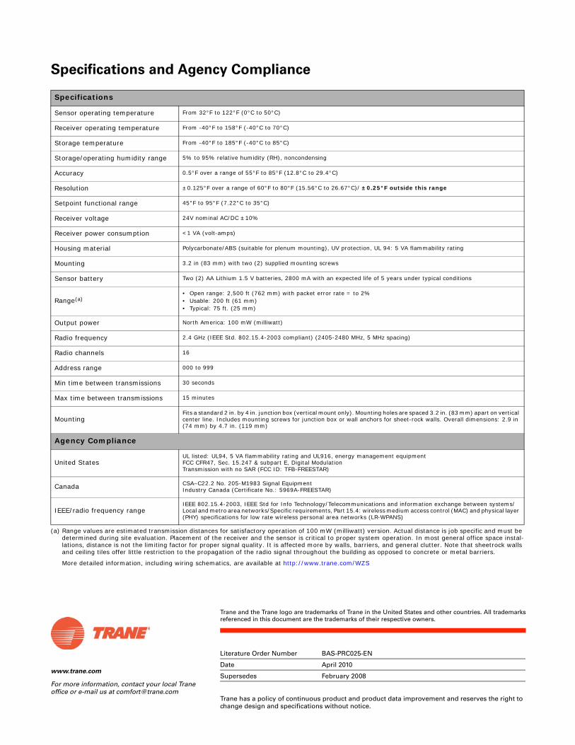
www.trane.com
For more information, contact your local Trane office or e-mail us at [email protected]
Literature Order Number BAS-PRC025-EN
Date April 2010
Supersedes February 2008
Trane has a policy of continuous product and product data improvement and reserves the right to change design and specifications without notice.
Trane and the Trane logo are trademarks of Trane in the United States and other countries. All trademarksreferenced in this document are the trademarks of their respective owners.
Specifications and Agency Compliance
Specifications
Sensor operating temperature From 32°F to 122°F (0°C to 50°C)
Receiver operating temperature From -40°F to 158°F (-40°C to 70°C)
Storage temperature From -40°F to 185°F (-40°C to 85°C)
Storage/operating humidity range 5% to 95% relative humidity (RH), noncondensing
Accuracy 0.5°F over a range of 55°F to 85°F (12.8°C to 29.4°C)
Resolution ±0.125°F over a range of 60°F to 80°F (15.56°C to 26.67°C)/ ±0.25°F outside this range
Setpoint functional range 45°F to 95°F (7.22°C to 35°C)
Receiver voltage 24V nominal AC/DC ±10%
Receiver power consumption <1 VA (volt-amps)
Housing material Polycarbonate/ABS (suitable for plenum mounting), UV protection, UL 94: 5 VA flammability rating
Mounting 3.2 in (83 mm) with two (2) supplied mounting screws
Sensor battery Two (2) AA Lithium 1.5 V batteries, 2800 mA with an expected life of 5 years under typical conditions
Range(a)
(a) Range values are estimated transmission distances for satisfactory operation of 100 mW (milliwatt) version. Actual distance is job specific and must be determined during site evaluation. Placement of the receiver and the sensor is critical to proper system operation. In most general office space instal-lations, distance is not the limiting factor for proper signal quality. It is affected more by walls, barriers, and general clutter. Note that sheetrock walls and ceiling tiles offer little restriction to the propagation of the radio signal throughout the building as opposed to concrete or metal barriers.
More detailed information, including wiring schematics, are available at http://www.trane.com/WZS
• Open range: 2,500 ft (762 mm) with packet error rate = to 2%• Usable: 200 ft (61 mm)• Typical: 75 ft. (25 mm)
Output power North America: 100 mW (milliwatt)
Radio frequency 2.4 GHz (IEEE Std. 802.15.4-2003 compliant) (2405-2480 MHz, 5 MHz spacing)
Radio channels 16
Address range 000 to 999
Min time between transmissions 30 seconds
Max time between transmissions 15 minutes
MountingFits a standard 2 in. by 4 in. junction box (vertical mount only). Mounting holes are spaced 3.2 in. (83 mm) apart on vertical center line. Includes mounting screws for junction box or wall anchors for sheet-rock walls. Overall dimensions: 2.9 in (74 mm) by 4.7 in. (119 mm)
Agency Compliance
United StatesUL listed: UL94, 5 VA flammability rating and UL916, energy management equipmentFCC CFR47, Sec. 15.247 & subpart E, Digital ModulationTransmission with no SAR (FCC ID: TFB-FREESTAR)
Canada CSA–C22.2 No. 205-M1983 Signal EquipmentIndustry Canada (Certificate No.: 5969A-FREESTAR)
IEEE/radio frequency rangeIEEE 802.15.4-2003, IEEE Std for Info Technology/Telecommunications and information exchange between systems/Local and metro area networks/Specific requirements, Part 15.4: wireless medium access control (MAC) and physical layer (PHY) specifications for low rate wireless personal area networks (LR-WPANS)

© 2007 Trane All rights reserved
Product Data Sheet
Zone SensorsTrane™ offers a full line of wireless and wired temperature sensors. Wireless temperature sensors are an ideal and cost-effective alternative to wired sensors that provide easy and flexible installation. Conventional wired sensors are best suited where wireless sensors are not allowed or when a wired connection to a service tool is required.
Features, Benefits, and Part Numbers:
Features Benefits
Temperature-only sensors Simplifies tenant interaction by moving the temperature setpoint to a centralized source.
Temperature setpoint control Allows the tenant to choose a temperature setpoint that satisfies their personal preference.
Occupancy override Allows the tenant to request temporary timed override system operation that permits the building conditions to remain in occupied comfort conditions.
COMM module (optional) Compatible with all Trane-wired temperature sensors. This optional accessory provides local RJ22 connection to Trane service tools for easy, low cost maintenance.
Hot/cold thumbwheel (optional) Allows the tenant to choose a temperature setpoint relative to their zone of comfort as opposed to exact numbers.
Part Numbers
Description
Part Number BAYSENS Global PartsSetpoint Occupancy
Single Yes X1351152701 BAYSENS074A SEN01447
NA No X1351152801 BAYSENS077A SEN01448
Single No X1351152901 BAYSENS075A SEN01449
NA Yes X1351153001 BAYSENS073A SEN01450
COMM Module (Box of 12) X1365146702 BAYCOMM005A CON01313
Thumbwheel; Hot/Cold (Box of 12) X1316105702 NA KNB00182
November 2007 BAS-PRC027-EN

www.trane.com
For more information, contact your local Trane office or e-mail us at [email protected]
Literature Order Number BAS-PRC027-EN
Date November 2007
Supersedes New
Trane has a policy of continuous product and product data improvement and reserves the right to change design and specifications without notice.
Trane and the Trane logo are trademarks of Trane in the United States and other countries. All trademarksreferenced in this document are the trademarks of their respective owners.
Specifications
Schematic (Typical)
Description
Sensor operating temperature From 32°F to 122°F (0°C to 50°C)
Storage temperature From -40°F to 185°F (-40°C to 85°C)
Storage/operating humidity range 5% to 95% relative humidity (RH), noncondensing
Thermistor accuracy 0.2°C at 25°C, 1%
Setpoint functional range 45°F to 90°F (7.2°C to 32.2°C)
Setpoint thumbwheel markings50°F to 85°F (in 5°F increments) with */** icons on thumbwheel11°C to 29°C (in 3°C increments) with */** icons on thumbwheel
Housing material Polycarbonate/ABS (suitable for plenum mounting), UV protection, UL 94: 5 VA flammability rating
MountingFits a standard 2 in. by 4 in. junction box (vertical mount only). Mounting holes are spaced 3.2 in. (83 mm) apart on vertical center line. Includes mounting screws for junction box or wall anchors for sheet-rock walls. Overall dimensions: 2.9 in (74 mm) by 4.7 in. (119 mm)
R1, 1.5 kΩ
Timed overrideunoccupied(cancel) SW2
RT1 thermistor, 10 kΩ at 25°C
SetpointpotentiometerPot 1, 1 kΩ
Calibration potentiometer Pot2
COMM Module
Zone temperature
Signal common
Setpoint-Not available on allmodels
Timed override occupied (on) SW1

© 2008 Trane All rights reserved
Product Data Sheet
Zone Sensors with Fan andSystem SwitchTrane™ offers a full line of wireless and wired temperature sensors. Wireless temperature sensors are an ideal and cost-effective alternative to wired sensors that provide easy and flexible installation. Conventional wired sensors are best suited where wireless sensors are not allowed or when a wired connection to a service tool is required.
Features, Benefits, and Part Numbers:
Features Benefits
Temperature setpoint control Allows the tenant to choose a temperature setpoint that satisfies their personal preference.
Fan and system switch Allows the tenant to locally control the operating mode and fan speed to better satisfy their personal preferences.
COMM module (optional) Compatible with all Trane-wired temperature sensors. This optional accessory provides local RJ22 connection to Trane service tools for easy, low cost maintenance.
Hot/cold thumbwheel (optional) Allows the tenant to choose a temperature setpoint relative to their zone of comfort as opposed to exact numbers.
Part Numbers
Description
Part Number BAYSENS Global PartsSetpoint Fan System LED
Dual Auto/High Cool/Off/Auto/Heat/Em Heat Yes X1379084701 BAYSENS109A SEN01523
Single Auto/High Cool/Off/Heat/Em Heat Yes X1379085201 BAYSENS107A SEN01528
Dual Auto/High Cool/Off/Auto/Heat No X1379083701 BAYSENS108A SEN01513
Dual Auto/High Cool/Off/Auto/Heat Yes X1379084601 BAYSENS110A SEN01522
Single Auto/High Cool/Off/Heat No X1379083901 BAYSENS106A SEN01515
Single Low/High Cool/Off/Heat/Fan No X1379085001 NA SEN01526
COMM Module (Box of 12) X1365146702 BAYCOMM005A CON01313
Thumbwheel; Hot/Cold (Box of 12) X1316105702 NA KNB00182
January 2008 BAS-PRC028-EN
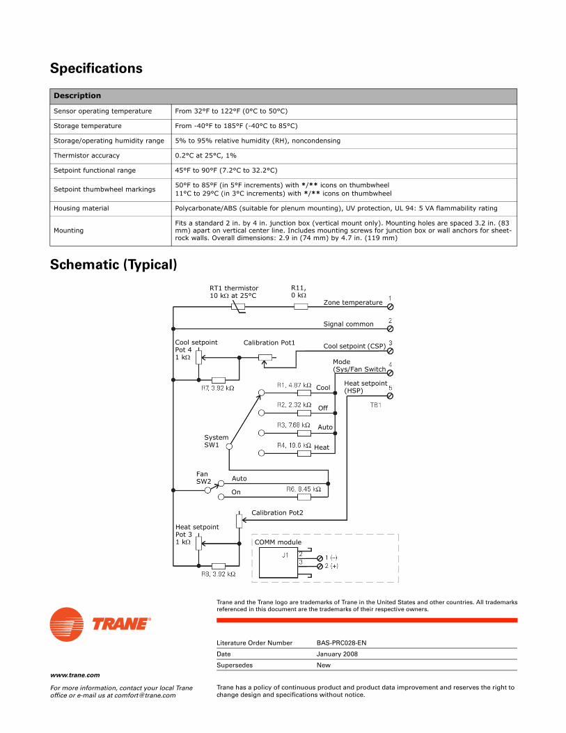
www.trane.com
For more information, contact your local Trane office or e-mail us at [email protected]
Literature Order Number BAS-PRC028-EN
Date January 2008
Supersedes New
Trane has a policy of continuous product and product data improvement and reserves the right to change design and specifications without notice.
Trane and the Trane logo are trademarks of Trane in the United States and other countries. All trademarksreferenced in this document are the trademarks of their respective owners.
Specifications
Schematic (Typical)
Description
Sensor operating temperature From 32°F to 122°F (0°C to 50°C)
Storage temperature From -40°F to 185°F (-40°C to 85°C)
Storage/operating humidity range 5% to 95% relative humidity (RH), noncondensing
Thermistor accuracy 0.2°C at 25°C, 1%
Setpoint functional range 45°F to 90°F (7.2°C to 32.2°C)
Setpoint thumbwheel markings50°F to 85°F (in 5°F increments) with */** icons on thumbwheel11°C to 29°C (in 3°C increments) with */** icons on thumbwheel
Housing material Polycarbonate/ABS (suitable for plenum mounting), UV protection, UL 94: 5 VA flammability rating
MountingFits a standard 2 in. by 4 in. junction box (vertical mount only). Mounting holes are spaced 3.2 in. (83 mm) apart on vertical center line. Includes mounting screws for junction box or wall anchors for sheet-rock walls. Overall dimensions: 2.9 in (74 mm) by 4.7 in. (119 mm)
RT1 thermistor10 kΩ at 25°C
R11,0 kΩ
Zone temperature
Signal common
Cool setpoint (CSP)
Mode (Sys/Fan Switch
Heat setpoint (HSP)
Heat
Cool
Off
Auto
FanSW2 Auto
On
Calibration Pot2
Heat setpointPot 31 kΩ COMM module
Calibration Pot1Cool setpointPot 41 kΩ
SystemSW1

© 2008 Trane All rights reserved
Product Data Sheet
Zone Sensors with Fan SwitchTrane™ offers a full line of wireless and wired temperature sensors. Wireless temperature sensors are an ideal and cost-effective alternative to wired sensors that provide easy and flexible installation. Conventional wired sensors are best suited where wireless sensors are not allowed or when a wired connection to a service tool is required.
Features, Benefits, and Part Numbers:
Features Benefits
Temperature setpoint control Allows the tenant to choose a temperature setpoint that satisfies their personal preference.
Fan switch Allows the tenant to locally control the operating mode and fan speed to better satisfy their personal preferences.
Occupancy override Allows the tenant to request temporary timed override system operation that permits the building conditions to remain in occupied comfort conditions.
COMM module (optional) Compatible with all Trane-wired temperature sensors. This optional accessory provides local RJ22 connection to Trane service tools for easy, low cost maintenance.
Hot/cold thumbwheel (optional) Allows the tenant to choose a temperature setpoint relative to their zone of comfort as opposed to exact numbers.
Part Numbers
Description
Part Number Global PartsSetpoint Fan Control Occupancy
Single Off/Auto Yes X1379084501 SEN01521
Single Off/Run Yes X1379085101 SEN01527
Single Off/Auto/Low/High Yes X1379084801 SEN01524
Single Off/Auto/Low/Med/High — X1379084101 SEN01517
Single Off/Auto/Low/Med/High Yes X1379084201 SEN01518
COMM Module (Box of 12) X1365146702 CON01313
Thumbwheel; Hot/Cold (Box of 12) X1316105702 KNB00182
January 2008 BAS-PRC029-EN
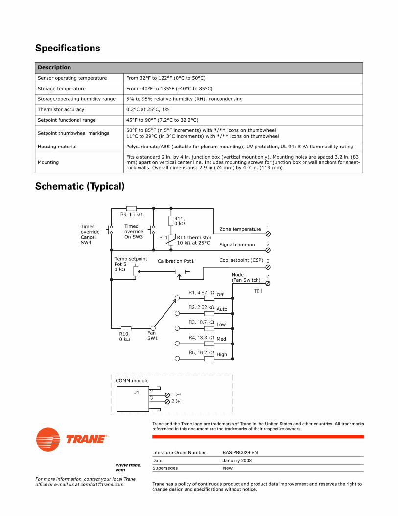
www.trane.
com
For more information, contact your local Trane office or e-mail us at [email protected]
Literature Order Number BAS-PRC029-EN
Date January 2008
Supersedes New
Trane has a policy of continuous product and product data improvement and reserves the right to change design and specifications without notice.
Trane and the Trane logo are trademarks of Trane in the United States and other countries. All trademarksreferenced in this document are the trademarks of their respective owners.
Specifications
Schematic (Typical)
Description
Sensor operating temperature From 32°F to 122°F (0°C to 50°C)
Storage temperature From -40°F to 185°F (-40°C to 85°C)
Storage/operating humidity range 5% to 95% relative humidity (RH), noncondensing
Thermistor accuracy 0.2°C at 25°C, 1%
Setpoint functional range 45°F to 90°F (7.2°C to 32.2°C)
Setpoint thumbwheel markings50°F to 85°F (n 5°F increments) with */** icons on thumbwheel11°C to 29°C (in 3°C increments) with */** icons on thumbwheel
Housing material Polycarbonate/ABS (suitable for plenum mounting), UV protection, UL 94: 5 VA flammability rating
MountingFits a standard 2 in. by 4 in. junction box (vertical mount only). Mounting holes are spaced 3.2 in. (83 mm) apart on vertical center line. Includes mounting screws for junction box or wall anchors for sheet-rock walls. Overall dimensions: 2.9 in (74 mm) by 4.7 in. (119 mm)
Zone temperature
Signal common
Cool setpoint (CSP)
Mode (Fan Switch)
Med
Off
Auto
Low
High
COMM module
FanSW1
R11,0 kΩ
RT1 thermistor10 kΩ at 25°C
Calibration Pot1
R10,0 kΩ
Temp setpointPot 51 kΩ
Timed overrideOn SW3
Timed overrideCancel SW4

Tracer™ SC System Controller
ForTracer Building Automated Systems
June 2013 BAS-PRC031-EN
Product Catalog

2 BAS-PRC031-EN, 10 Jun 2013
Copyright
© 2013Trane. All rights reserved.
This document and the information in it are the property ofTrane and may not be usedor reproduced in whole or in part, without the written permission ofTrane.Trane reservesthe right to revise this publication at any time and to make changes to its content withoutobligation to notify any person of such revision or change.
Trademarks
Trane and its logo are trademarks ofTrane in the United States and other countries. Alltrademarks referenced in this document are the trademarks of their respective owners.
Table of Contents
BAS-PRC031-EN, 10 Jun 2013 3
Product Introduction . . . . . . . . . . . . . . . . . . . . . . . . . . . . . . . . . . . . . . . . . . . . . . . . . . . . 4
Tracer Building Automation System . . . . . . . . . . . . . . . . . . . . . . . . . . . . . . . . . . 5
Tracer SC System Architecture . . . . . . . . . . . . . . . . . . . . . . . . . . . . . . . . . . . . . . 6
User Interface . . . . . . . . . . . . . . . . . . . . . . . . . . . . . . . . . . . . . . . . . . . . . . . . . . . . . . . . . . 7
Alarms and Events . . . . . . . . . . . . . . . . . . . . . . . . . . . . . . . . . . . . . . . . . . . . . . . . . 7
Data Logs . . . . . . . . . . . . . . . . . . . . . . . . . . . . . . . . . . . . . . . . . . . . . . . . . . . . . . . . . 8
Schedules . . . . . . . . . . . . . . . . . . . . . . . . . . . . . . . . . . . . . . . . . . . . . . . . . . . . . . . . . 9
Overrides . . . . . . . . . . . . . . . . . . . . . . . . . . . . . . . . . . . . . . . . . . . . . . . . . . . . . . . . 10
Reports . . . . . . . . . . . . . . . . . . . . . . . . . . . . . . . . . . . . . . . . . . . . . . . . . . . . . . . . . . 11
Graphics and the Tracer Graphics Editor . . . . . . . . . . . . . . . . . . . . . . . . . . . . . 12
Navigation Tree . . . . . . . . . . . . . . . . . . . . . . . . . . . . . . . . . . . . . . . . . . . . . . . . . . . 15
User Security . . . . . . . . . . . . . . . . . . . . . . . . . . . . . . . . . . . . . . . . . . . . . . . . . . . . . 15
System Control . . . . . . . . . . . . . . . . . . . . . . . . . . . . . . . . . . . . . . . . . . . . . . . . . . . . . . . . 16
Area Application . . . . . . . . . . . . . . . . . . . . . . . . . . . . . . . . . . . . . . . . . . . . . . . . . . 16
Variable Air Systems (VAS) . . . . . . . . . . . . . . . . . . . . . . . . . . . . . . . . . . . . . . . . 16
Chilled Plant Control (CPC) . . . . . . . . . . . . . . . . . . . . . . . . . . . . . . . . . . . . . . . . . 16
Trane EarthWise™ Systems . . . . . . . . . . . . . . . . . . . . . . . . . . . . . . . . . . . . . . . . 17
Tracer Graphical Programming (TGP2) . . . . . . . . . . . . . . . . . . . . . . . . . . . . . . 17
Unit Control . . . . . . . . . . . . . . . . . . . . . . . . . . . . . . . . . . . . . . . . . . . . . . . . . . . . . . . . . . . 18
Resources . . . . . . . . . . . . . . . . . . . . . . . . . . . . . . . . . . . . . . . . . . . . . . . . . . . . . . . . . . . . 19
Specifications . . . . . . . . . . . . . . . . . . . . . . . . . . . . . . . . . . . . . . . . . . . . . . . . . . . . . . . . . 20
Hardware Components . . . . . . . . . . . . . . . . . . . . . . . . . . . . . . . . . . . . . . . . . . . . . . . . 23
Tracer SC System Controller . . . . . . . . . . . . . . . . . . . . . . . . . . . . . . . . . . . . . . . 23
Trane PM014 Power Supply Module . . . . . . . . . . . . . . . . . . . . . . . . . . . . . . . . . 24
Tracer™ BACnet® Terminator . . . . . . . . . . . . . . . . . . . . . . . . . . . . . . . . . . . . . . . 24
Medium Enclosure (optional) . . . . . . . . . . . . . . . . . . . . . . . . . . . . . . . . . . . . . . . 25
Large Enclosure (optional) . . . . . . . . . . . . . . . . . . . . . . . . . . . . . . . . . . . . . . . . . 26
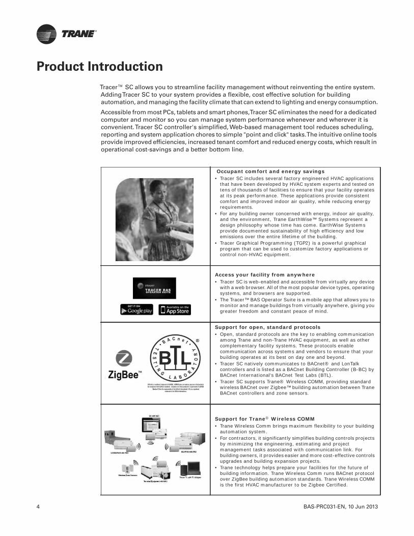
4 BAS-PRC031-EN, 10 Jun 2013
Product Introduction
Tracer™ SC allows you to streamline facility management without reinventing the entire system.AddingTracer SC to your system provides a flexible, cost effective solution for buildingautomation, and managing the facility climate that can extend to lighting and energy consumption.
Accessible from most PCs, tablets and smart phones,Tracer SC eliminates the need for a dedicatedcomputer and monitor so you can manage system performance whenever and wherever it isconvenient.Tracer SC controller's simplified, Web-based management tool reduces scheduling,reporting and system application chores to simple "point and click" tasks.The intuitive online toolsprovide improved efficiencies, increased tenant comfort and reduced energy costs, which result inoperational cost-savings and a better bottom line.
Occupant comfort and energy savings• Tracer SC includes several factory engineered HVAC applications
that have been developed by HVAC system experts and tested on tens of thousands of facilities to ensure that your facility operates at its peak performance. These applications provide consistent comfort and improved indoor air quality, while reducing energy requirements.
• For any building owner concerned with energy, indoor air quality, and the environment, Trane EarthWise™ Systems represent a design philosophy whose time has come. EarthWise Systems provide documented sustainability of high efficiency and low emissions over the entire lifetime of the building.
• Tracer Graphical Programming (TGP2) is a powerful graphical program that can be used to customize factory applications or control non-HVAC equipment.
Access your facility from anywhere• Tracer SC is web-enabled and accessible from virtually any device
with a web browser. All of the most popular device types, operating systems, and browsers are supported.
• The Tracer™ BAS Operator Suite is a mobile app that allows you to monitor and manage buildings from virtually anywhere, giving you greater freedom and constant peace of mind.
Support for open, standard protocols• Open, standard protocols are the key to enabling communication
among Trane and non-Trane HVAC equipment, as well as other complementary facility systems. These protocols enable communication across systems and vendors to ensure that your building operates at its best on day one and beyond.
• Tracer SC natively communicates to BACnet® and LonTalk controllers and is listed as a BACnet Building Controller (B-BC) by BACnet International's BACnet Test Labs (BTL).
• Tracer SC supports Trane® Wireless COMM, providing standard wireless BACnet over Zigbee™ building automation between Trane BACnet controllers and zone sensors.
Support for Trane® Wireless COMM• Trane Wireless Comm brings maximum flexibility to your building
automation system.• For contractors, it significantly simplifies building controls projects
by minimizing the engineering, estimating and project management tasks associated with communication link. For building owners, it provides easier and more cost-effective controls upgrades and building expansion projects.
• Trane technology helps prepare your facilities for the future of building information. Trane Wireless Comm runs BACnet protocol over ZigBee building automation standards. Trane Wireless COMM is the first HVAC manufacturer to be Zigbee Certified.

BAS-PRC031-EN, 10 Jun 2013 5
Product Introduction
Tracer Building Automation System
From our industry-leading building automation systems to equipment controls and sensors,Traneoffers a complete controls portfolio to enable you to operate buildings at peak energy andoperational efficiency.
Trane controls are built on open, scalable platforms.They provide options to integrate with yourexisting equipment and controls, regardless of brand, and give you the latitude to easily expandinto other systems within your building, multiple buildings and buildings you'll add in the future.
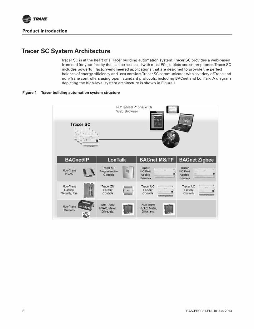
6 BAS-PRC031-EN, 10 Jun 2013
Product Introduction
Tracer SC System Architecture
Tracer SC is at the heart of aTracer building automation system.Tracer SC provides a web-basedfront end for your facility that can be accessed with most PCs, tablets and smart phones.Tracer SCincludes powerful, factory-engineered applications that are designed to provide the perfectbalance of energy efficiency and user comfort.Tracer SC communicates with a variety ofTrane andnon-Trane controllers using open, standard protocols, including BACnet and LonTalk. A diagramdepicting the high-level system architecture is shown in Figure 1.
Figure 1. Tracer building automation system structure
PC/Tablet/Phone with Web Browser
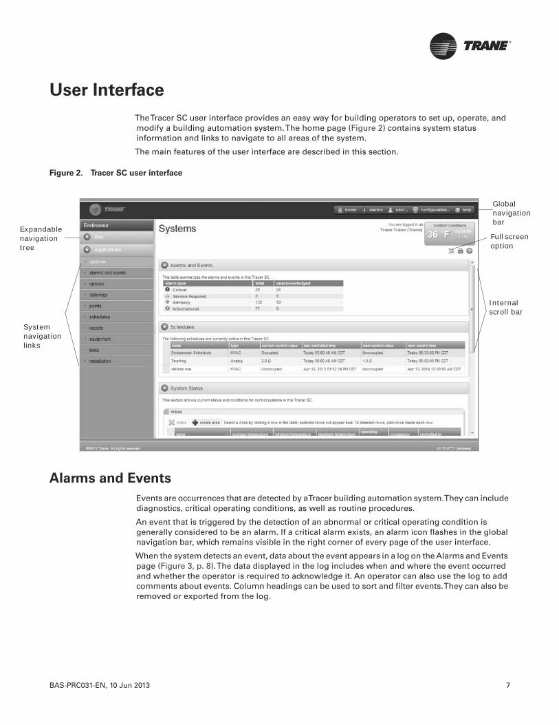
BAS-PRC031-EN, 10 Jun 2013 7
User Interface
TheTracer SC user interface provides an easy way for building operators to set up, operate, andmodify a building automation system.The home page (Figure 2) contains system statusinformation and links to navigate to all areas of the system.
The main features of the user interface are described in this section.
Alarms and Events
Events are occurrences that are detected by aTracer building automation system.They can includediagnostics, critical operating conditions, as well as routine procedures.
An event that is triggered by the detection of an abnormal or critical operating condition isgenerally considered to be an alarm. If a critical alarm exists, an alarm icon flashes in the globalnavigation bar, which remains visible in the right corner of every page of the user interface.
When the system detects an event, data about the event appears in a log on the Alarms and Eventspage (Figure 3, p. 8).The data displayed in the log includes when and where the event occurredand whether the operator is required to acknowledge it. An operator can also use the log to addcomments about events. Column headings can be used to sort and filter events.They can also beremoved or exported from the log.
Figure 2. Tracer SC user interface
Internalscroll bar
Globalnavigation bar
Full screen option
System navigation links
Expandablenavigation tree
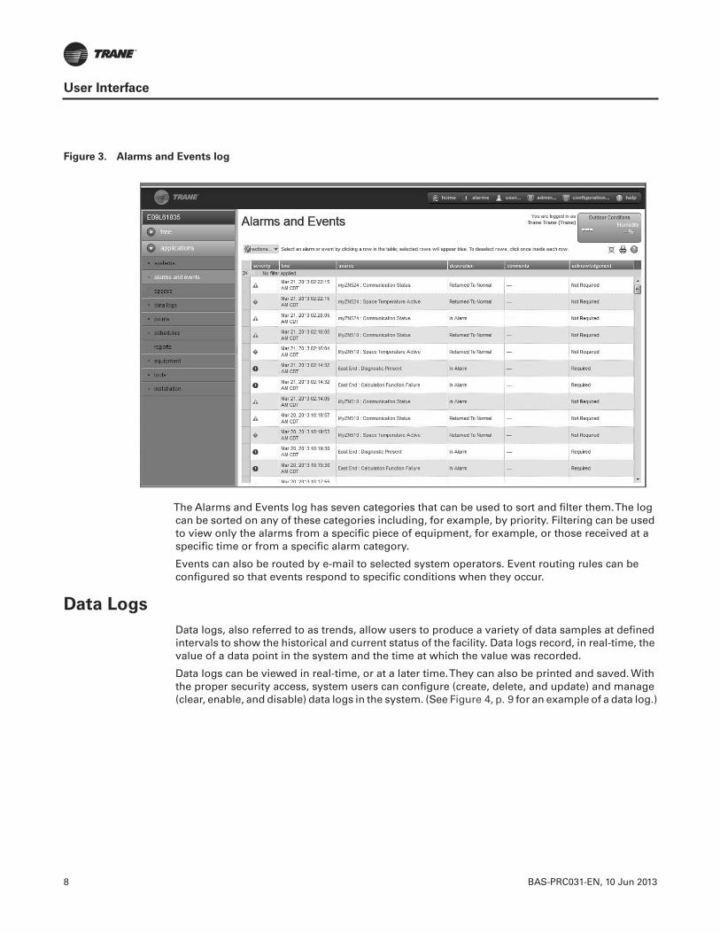
8 BAS-PRC031-EN, 10 Jun 2013
User Interface
The Alarms and Events log has seven categories that can be used to sort and filter them.The logcan be sorted on any of these categories including, for example, by priority. Filtering can be usedto view only the alarms from a specific piece of equipment, for example, or those received at aspecific time or from a specific alarm category.
Events can also be routed by e-mail to selected system operators. Event routing rules can beconfigured so that events respond to specific conditions when they occur.
Data Logs
Data logs, also referred to as trends, allow users to produce a variety of data samples at definedintervals to show the historical and current status of the facility. Data logs record, in real-time, thevalue of a data point in the system and the time at which the value was recorded.
Data logs can be viewed in real-time, or at a later time.They can also be printed and saved. Withthe proper security access, system users can configure (create, delete, and update) and manage(clear, enable, and disable) data logs in the system. (See Figure 4, p. 9 for an example of a data log.)
Figure 3. Alarms and Events log
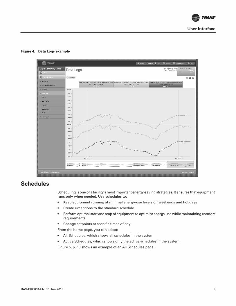
BAS-PRC031-EN, 10 Jun 2013 9
User Interface
Schedules
Scheduling is one of a facility’s most important energy-saving strategies. It ensures that equipmentruns only when needed. Use schedules to:
• Keep equipment running at minimal energy-use levels on weekends and holidays
• Create exceptions to the standard schedule
• Perform optimal start and stop of equipment to optimize energy use while maintaining comfortrequirements
• Change setpoints at specific times of day
From the home page, you can select:
• All Schedules, which shows all schedules in the system
• Active Schedules, which shows only the active schedules in the system
Figure 5, p. 10 shows an example of an All Schedules page.
Figure 4. Data Logs example
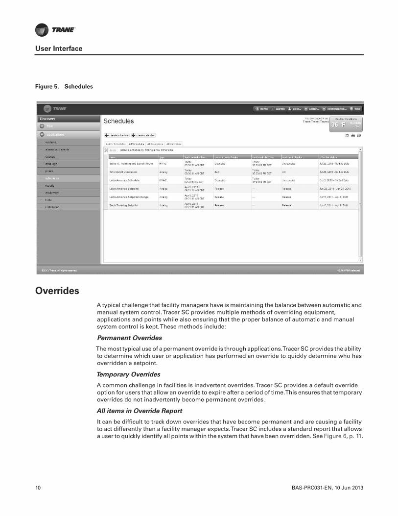
10 BAS-PRC031-EN, 10 Jun 2013
User Interface
Overrides
A typical challenge that facility managers have is maintaining the balance between automatic andmanual system control.Tracer SC provides multiple methods of overriding equipment,applications and points while also ensuring that the proper balance of automatic and manualsystem control is kept.These methods include:
Permanent Overrides
The most typical use of a permanent override is through applications.Tracer SC provides the abilityto determine which user or application has performed an override to quickly determine who hasoverridden a setpoint.
Temporary Overrides
A common challenge in facilities is inadvertent overrides.Tracer SC provides a default overrideoption for users that allow an override to expire after a period of time.This ensures that temporaryoverrides do not inadvertently become permanent overrides.
All items in Override Report
It can be difficult to track down overrides that have become permanent and are causing a facilityto act differently than a facility manager expects.Tracer SC includes a standard report that allowsa user to quickly identify all points within the system that have been overridden. See Figure 6, p. 11.
Figure 5. Schedules

BAS-PRC031-EN, 10 Jun 2013 11
User Interface
Reports
Standard reports forTrane equipment are available fromTracer SC.These reports provide avaluable source of data that can be used for record-keeping and troubleshooting.
Report types include:• Site reports• VAS commissioning reports• Points reports• Chiller reports
Report features include:
• Scheduling reports to run during specific date periods and run frequencies
• Specifying file storage options for scheduled reports
• Exporting reports to save to your PC as CSV, HTML, or PDF files
• Editing scheduled reports
See Figure 7, p. 12.
Figure 6. All Items in Override Report
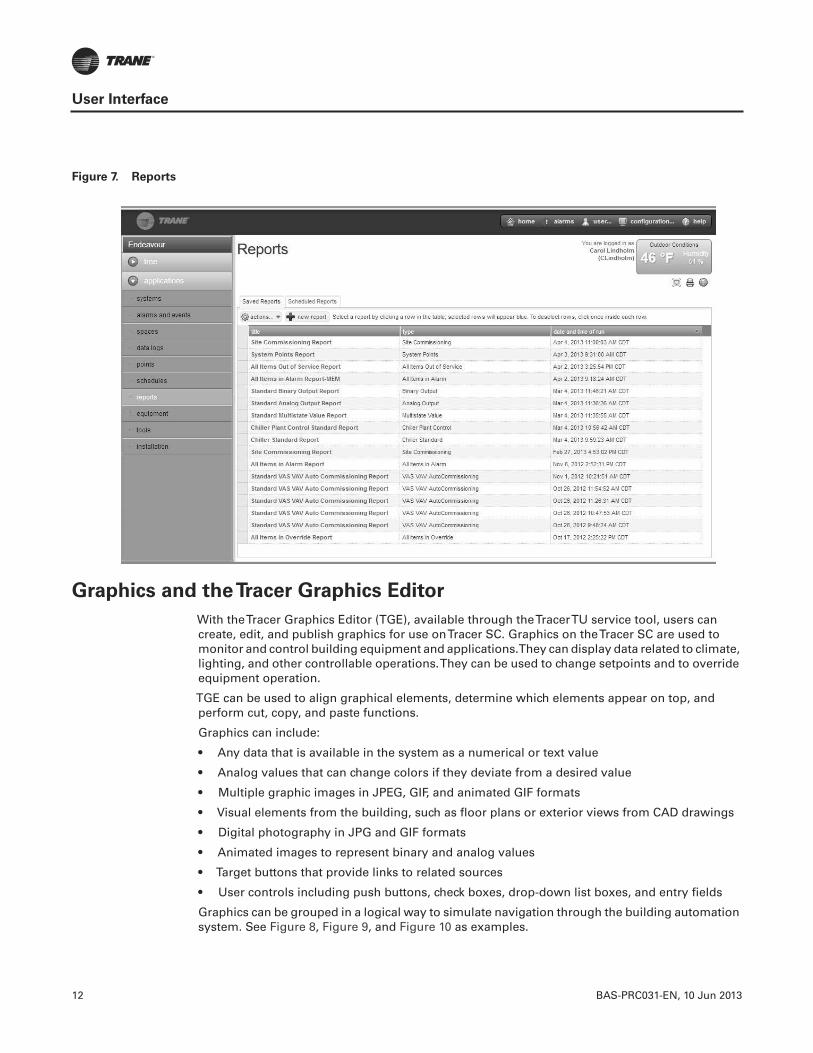
12 BAS-PRC031-EN, 10 Jun 2013
User Interface
Graphics and theTracer Graphics Editor
With theTracer Graphics Editor (TGE), available through theTracerTU service tool, users cancreate, edit, and publish graphics for use onTracer SC. Graphics on theTracer SC are used tomonitor and control building equipment and applications.They can display data related to climate,lighting, and other controllable operations.They can be used to change setpoints and to overrideequipment operation.
TGE can be used to align graphical elements, determine which elements appear on top, andperform cut, copy, and paste functions.
Graphics can include:
• Any data that is available in the system as a numerical or text value
• Analog values that can change colors if they deviate from a desired value
• Multiple graphic images in JPEG, GIF, and animated GIF formats
• Visual elements from the building, such as floor plans or exterior views from CAD drawings
• Digital photography in JPG and GIF formats
• Animated images to represent binary and analog values
• Target buttons that provide links to related sources
• User controls including push buttons, check boxes, drop-down list boxes, and entry fields
Graphics can be grouped in a logical way to simulate navigation through the building automationsystem. See Figure 8, Figure 9, and Figure 10 as examples.
Figure 7. Reports
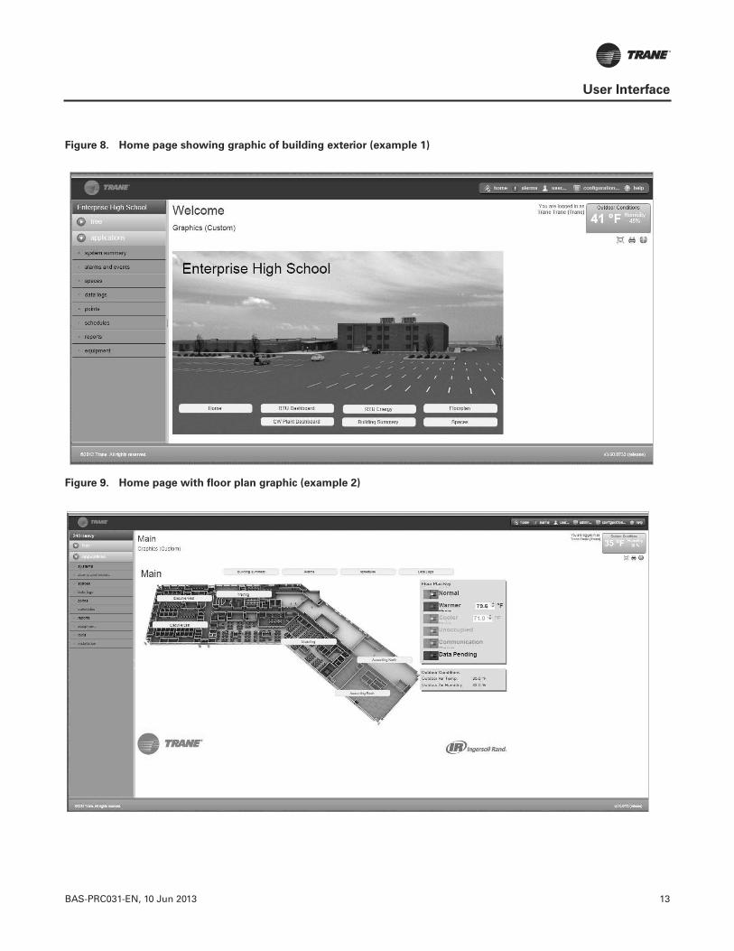
BAS-PRC031-EN, 10 Jun 2013 13
User Interface
Figure 8. Home page showing graphic of building exterior (example 1)
Figure 9. Home page with floor plan graphic (example 2)
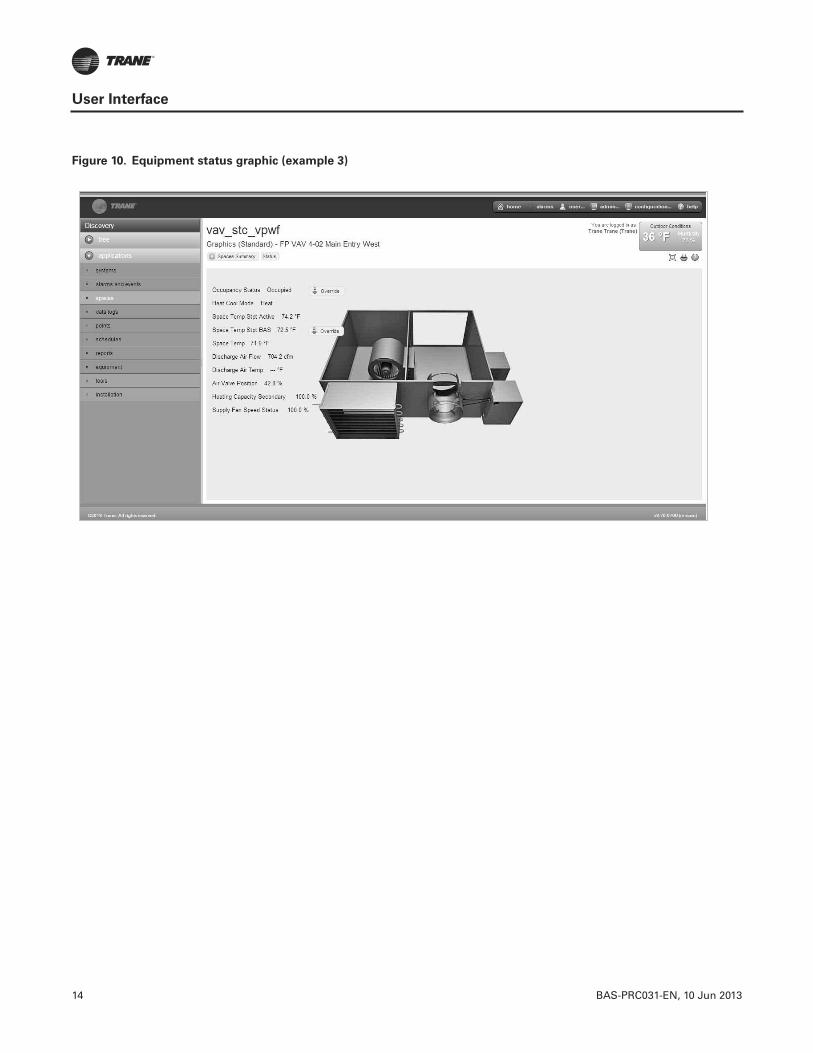
14 BAS-PRC031-EN, 10 Jun 2013
User Interface
Figure 10. Equipment status graphic (example 3)

BAS-PRC031-EN, 10 Jun 2013 15
User Interface
NavigationTree
The navigation tree contains the logically ordered and grouped content of all the elements of yourHVAC system.The navigation tree populates automatically when spaces, systems, points, andequipment are installed. A navigation tree provides an alternate way to navigate through the userinterface (Figure 11).
The navigation tree consists of nodes, display text, and icons.You build the tree by choosingdisplay text for nodes, arranging the nodes, and assigning associated graphics to them.Thegraphics represent equipment and areas of the facility.
User Security
A sophisticated password system protects aTracer system from unauthorized access. Operatorsare assigned a role, which defines their access rights. Operators have access only to those featureswhich are defined in their roles. Several predefined roles can be selected from theTracer SCinterface and roles can also be customized. An operator with administrative-level security canmanage users and roles and has the ability to reset passwords.
Figure 11. Navigation tree example
Click to open the navigation tree
Click to expand the contents of a node
Use the edit bar to move nodes, rename nodes, add graphics, or remove items from the tree

16 BAS-PRC031-EN, 10 Jun 2013
System Control
Tracer SC includes a powerful system control engine. EveryTracer SC ships with several factoryengineered HVAC applications, support forTrane Earthwise™ Systems, and a powerful customgraphical programming language.
Area Application
The Area application coordinates groups of equipment that represent the tenant or occupantorganization within a building, which allows for standard calculations/functions and a simplifieduser interaction with the facility.TheArea application allows users to assign unit controllers, binaryoutputs, and binary values as members of a common area.The area application can be configuredto use multiple algorithms, along with area temperatures and humidity inputs, to make aneconomizing decision.
The Area application also supports:
• Optimal start/stop
• Humidity pulldown
• Night purge
• Unoccupied heating/cooling set-points
• Unoccupied humidify/dehumidify
• Timed override functions
Additionally, the Area application allows users to efficiently perform a single operation, such aschanging a setpoint, creating a schedule, performing an override, and apply it to all members ofthe area. For more information, see the “Air Systems forTracer SC Applications Guide”,BAS-APG007-EN.
Variable Air Systems (VAS)
The Variable-Air-Volume Air System (VAS) coordinates the control of air handlers, rooftop units,and variable air volume terminal units.TheTracer SC VAS includes valuable tools to help managetasks that were previously problematic and time consuming, such as:
• Coordinating AHU and VAV box operation
• Commissioning VAV boxes
• Scheduling common spaces
• Optimizing ventilation
• Optimizing duct static pressure
For more information, see the “Air Systems forTracer SC Applications Guide”, BAS-APG007-EN.
Chilled Plant Control (CPC)
The Chiller Plant Control (CPC) application permits you to configure a chiller plant for optimalefficiency and reliability, and provides a means for you to monitor and control the daily operation.Depending upon the many possible chiller plant configurations and design differences, the CPCapplication can do the following:
• Provide overall chiller plant status information and alarms to local and remoteTracer SC users
• Enable or disable chiller plants
• Start, stop, and monitor the status of system chilled water pumps
• Calculate individual chilled water setpoints for individual chillers in series chiller plants
• Request when chillers are added or subtracted according to building load requirements anduser-specified add and subtract logic

BAS-PRC031-EN, 10 Jun 2013 17
System Control
• Rotate chillers according to user-defined intervals
• Remove chillers from the rotation in the event
For more information, see the “Chiller Plant Control forTracer SC Application Guide”,BAS-APG012-EN.
Trane EarthWise™ Systems
For any building owner concerned with energy, indoor air quality, and the environment,Trane'sEarthWise Systems represent a design philosophy whose time has come. EarthWise and EarthWiseElite Systems, by definition, provide documented sustainability of high efficiency and lowemissions over the entire lifetime of the building.
Trane EarthWise Systems include:
• Low Flow, LowTemperature CentraVac™ Chilled Water Systems
• Ice Enhanced, Air-Cooled Chiller Plant
• Intelligent Variable Air System for chilled-water applications
• Intelligent Variable Air System for IntelliPak™ rooftop applications
• Central Geothermal Systems
Find out more about EarthWise at http://www.trane.com/Commercial/HvacSystems/1_3_EarthWise.aspx
Tracer Graphical Programming (TGP2)
Tracer Graphical Programming (TGP2) is a powerful graphical program that allows you tocustomizeTracer system applications.TGP2 routines are typically used for sequencing equipment,calculating setpoints and values, and performing shutdown sequences.
Note: TGP2 is available through theTracer™TU service tool.
Figure 12. TGP2 example

18 BAS-PRC031-EN, 10 Jun 2013
Unit Control
Unit controllers provide all necessary unit control functions.They operate associated unitaryequipment, while ensuring that all built-in safety features are enabled and that diagnostics areissued.
Each controller is designed to operate in stand-alone mode.Therefore, if system control fails, unitoperation can continue.
Unit controllers installed on aTracer SC can be a combination of the following BACnet and LonTalkunit controllers:
BACnet (MS/TP) Unit Controllers Supported byTracer SC
• Tracer UC210 unit controller for variable-air-volume (VAV) equipment
• Tracer UC400 unit controller for variable-air-volume (VAV) equipment
• Tracer UC400 unit controller for programmable equipment
• Tracer UC800/AdaptiView unit controller for CenTraVac chillers
• BCI-I: BACnet communications interface for IntelliPak system
• BCI-C: BACnet communications interface for chillers
• BCI-R: BACnet communications interface for ReliaTel
• Non-Trane BACnet (MS/TP) devices
Wireless COMM Unit Controllers Support byTracer SC
• Tracer UC400 unit controller for variable-air-volume (VAV) equipment
• Tracer UC400 unit controller for programmable equipment
• Tracer UC600 unit controller for Air Handler (AHU) equipment
• Tracer UC600 unit controller for programmable equipment
LonTalk Unit Controllers Supported byTracer SC
• Tracer AH540/541 air-handler controller
• Tracer MP501 multi-purpose controller
• Tracer MP503 input/output module
• Tracer MP580/581 programmable controller
• Tracer VV550/551 VAV controller
• Tracer ZN510/511 zone controller
• Tracer ZN517 unit controller
• Tracer ZN520/521 zone controller
• Tracer ZN523 zone controller
• Tracer ZN524 water-source heat pump unit controller
• Tracer ZN525 zone controller
• Tracer CH530 chiller controller
• Tracer CH532 chiller controller
• LCI-C: LonTalk communications interface for chillers
• LCI-I: LonTalk communications interface for IntelliPak systems
• LCI-R: LonTalk communications interface for ReliaTel systems
• Non-Trane LonTalk devices using SCC, DAC, and chiller profiles; and devices supportingLonTalk standard network generic variables

BAS-PRC031-EN, 10 Jun 2013 19
Resources
The following resources are available for managingTracer building automation systems:
Tracer SC Installation, setup, and operation
• Tracer SC System Controller Installation and Setup Guide (BAS-SVX31-EN)• Tracer SC online help• Tracer SC Installation Instructions (X39641154)• BACnet Wiring Best Practices andTroubleshooting (BAS-SVX51-EN)• Expanded Communication Options – FAQs (BAS-PRC073-EN)
Programming
• Tracer Graphical Programming (TGP2) Editor
• Tracer Graphical Programming (TGP2) Application Guide (BAS-APG008) and online help
• Tracer UC400/UC600 withTracer SC Programming Guide (BAS-SVP06-EN)
HVAC applications
• Tracer SC Air Systems Application Guide (BAS-APG007)• Tracer SC Chiller Plant Control Application Guide (BAS-APG012)
Service tools
• TracerTU—TracerTU ServiceTool Getting Started Guide (TTU-SVN01) and online help• Rover Version 7 Operation and Setup Guide (EMTX-SVX01) and online help
GraphicsTools
• Tracer Graphics Editor (TGE) User Guide (BAS-SVU06-EN)• Working with Standard GraphicTemplates (BAS-SVU15-EN)• Offline Graphics Creation (BAS-SVU16-EN)• Centralized Services
Software updates
• TracerTU ServiceTool Getting Started Guide (TTU-SVN01)
Web sites
• MyTraneControls.com: A free online Web site designed to assistTracer building automationsystem owners and operators.
Tracer BAS training courses
• TheTrane College of Building Automation offers a comprehensive portfolio of technicalcourses on the operation, installation, and programming ofTracer building automationsystems. Refer to http://trane.com/COMMERCIAL/DNA/View.aspx?i=586.
Service, maintenance, troubleshooting
In addition to the resources listed above:• Trane Product Support• Warranty information
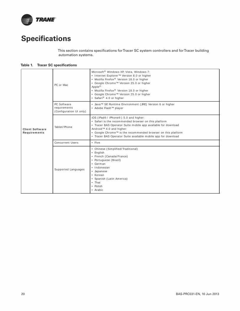
20 BAS-PRC031-EN, 10 Jun 2013
Specifications
This section contains specifications forTracer SC system controllers and forTracer buildingautomation systems.
Table 1. Tracer SC specifications
Client Software Requirements
PC or Mac
Microsoft® Windows XP, Vista, Windows 7:• Internet Explorer™ Version 8.0 or higher• Mozilla Firefox® Version 18.0 or higher• Google Chrome™ Version 25.0 or higherApple®:
• Mozilla Firefox® Version 18.0 or higher• Google Chrome™ Version 25.0 or higher• Safari® 4.0 or higher
PC Software requirements(Configuration UI only)
• Java™ SE Runtime Environment (JRE) Version 6 or higher• Adobe Flash™ player
Tablet/Phone
iOS (iPad®/ iPhone®) 5.0 and higher:• Safari is the recommended browser on this platform• Tracer BAS Operator Suite mobile app available for downloadAndroid™ 4.0 and higher: • Google Chrome™ is the recommended browser on this platform• Tracer BAS Operator Suite available mobile app for download
Concurrent Users • Five
Supported Languages
• Chinese (Simplified/Traditional)• English• French (Canada/France)• Portuguese (Brazil)• German• Indonesian• Japanese• Korean• Spanish (Latin America)• Thai• Polish• Arabic
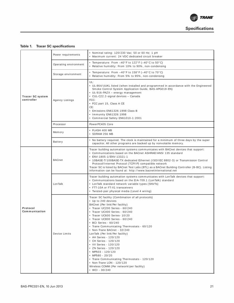
BAS-PRC031-EN, 10 Jun 2013 21
Specifications
Tracer SC system controller
Power requirements • Nominal rating: 120/230 Vac; 50 or 60 Hz; 1 pH • Maximum current: 24 VDC dedicated circuit breaker
Operating environment• Temperature: From –40°F to 122°F (–40°C to 50°C) • Relative humidity: From 10% to 90%, non-condensing
Storage environment • Temperature: From –40°F to 158°F (–40°C to 70°C) • Relative humidity: From 5% to 95%, non-condensing
Agency Listings
UL:• UL-864/UUKL listed (when installed and programmed in accordance with the Engineered
Smoke Control System Application Guide, BAS-APG019-EN) • UL-916-PAZX – energy management• CUL-C22.2-signal devices – Canada FCC:• FCC part 15, Class A CECE:• Emissions EN61326:1998 Class B• Immunity EN61326:1998• Commercial Safety EN61010-1:2001
Processor PowerPC405 Core
Memory• FLASH 400 MB• SDRAM 256 MB
Battery • No battery required. The clock is maintained for a minimum of three days by the super capacitor. All other programs are backed up by nonvolatile memory.
ProtocolCommunication
BACnet
Tracer building automation systems communicates with BACnet devices that support:• Communications based on the BACnet ASHRAE/ANSI 135 standard • ENV-1805-1/ENV-13321-1• 10BASE-T/100BASE-TX dedicated Ethernet (ISO/IEC 8802-3) or Transmission Control
Protocol/Internet Protocol (TCP/IP) compatible networkTracer SC is listed by BACnet Test Labs (BTL) as a BACnet Building Controller (B-BC). Listing information can be found at: http://www.bacnetinternational.net
LonTalk
Tracer building automation systems communicates with LonTalk devices that support:• Communications based on the EIA-709.1 (LonTalk) standard• LonTalk standard network variable types (SNVTs)• FTT-10A or FT-X1 transceivers• Twisted-pair physical media (Level 4 wiring)
Device Limits
Tracer SC facility (Combination of all protocols)• Up to 240 devicesBACnet (Per link/Per facility)• Tracer UC200 Series - 60/240• Tracer UC400 Series - 60/240• Tracer UC600 Series- 10/20• Tracer UC800 Series - 60/240• BCI Series - 60/240• Trane Communicating Thermostats - 60/120• Non-Trane BACnet - 32/240LonTalk (Per link/Per facility)• AH Series - 120/120• CH Series - 120/120• VV Series - 120/120• ZN Series - 120/120 • MP503 - 120/120• MP580 - 20/20• Trane Communicating Thermostats - 120/120• Non-Trane LON - 120/120Wireless COMM (Per network/per facility)• WCI - 30/240
Table 1. Tracer SC specifications

22 BAS-PRC031-EN, 10 Jun 2013
Specifications
Medium Enclosure (optional)
NEMA Type NEMA-1
Weight 14 lb. (6.5 kg)
Mounting Wall-mounted with #10 (5 mm) screws and #10 wall anchors. Mounting surface must be able to support 60 lb. (28 kg)
Large Enclosure (optional)
NEMA Type NEMA-1
Weight 50 lb.(23.0 kg)
Mounting Wall-mounted with #10 (5 mm) screws and #10 wall anchors. Mounting surface must be able to support 120 lb. (56 kg)
Table 1. Tracer SC specifications
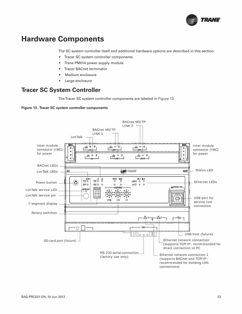
BAS-PRC031-EN, 10 Jun 2013 23
Hardware Components
The SC system controller itself and additional hardware options are described in this section.
• Tracer SC system controller components
• Trane PM014 power supply module
• Tracer BACnet terminator
• Medium enclosure
• Large enclosure
Tracer SC System Controller
TheTracer SC system controller components are labeled in Figure 13.
Figure 13. Tracer SC system controller components
LonTalk
BACnet MS/TP LINK 1
BACnet MS/TP LINK 2
Status LED
Inter-module connector (IMC) for power
Inter-module connector (IMC) for power
BACnet LEDs
LonTalk LEDs
Power button
LonTalk service LED
LonTalk service pin
Ethernet LEDs
USB port for service tool connection
7-segment display
Rotary switches
SD card port (future)
RS-232 serial connection (factory use only) Ethernet network connection 1
(supports BACnet and TCP/IP - recommended for building LAN connections)
Ethernet network connection (supports TCP/IP - recommended for direct connection to PC
USB host (future)

24 BAS-PRC031-EN, 10 Jun 2013
Hardware Components
Trane PM014 Power Supply Module
TheTrane PM014 power supply module provides 24 Vdc forTrane inter-module communication(IMC) buses. IMC buses are used in components ofTrane building automation systems, includingtheTracer SC system controller. Refer to the “Power Supply Module Installation, Operation, andTroubleshooting Guide”, BAS-SVX33-EN.
Tracer™ BACnet® Terminator
ATracer BACnet terminator (order no. X13651524-01) is placed at the end of each communicationlink in order to decrease communication signal degradation. Refer to the “BACnet Wiring BestPractices andTroubleshooting Guide”, BAS-SVX51-EN.
Figure 14. PM014 power supply module (dimensions)
2424VACVAC
XFMRXFMROUTOUT2424
VACVAC
4.0 in. (102 mm)
4.2 in. (107.6 mm)
2.4 in. (60.9 mm)
2.4in. (60.9 mm)
1.8 in. (45.7 mm)
Figure 15. BACnet terminator (wiring)
BACnet-
Use either IMCconnection
BACnet+
Tracer SC
BACnetTerminator
Ground(black wire)
Power(includedwith TBT)
Comm (field-supplied)
24 Vac/Vdc(red wire)
Cut and tapeback the shield wire
BACnet- BACnet+ Ground 24Vac/Vdc
FrontLINK 2
BACnet Link(maintain polarity)
Use either Link 1or Link 2
+–

BAS-PRC031-EN, 10 Jun 2013 25
Hardware Components
Medium Enclosure (optional)
The medium enclosure forTracer DIN-mounted controllers is available in the following:
• 120 VAC (order number: X13651559010)
• 230 VAC (order number: X13651560010)
Figure 16. Medium enclosure (dimensions)
1.13 in. (28.6 mm) + 1.38 in. (34.9 mm) Knockout
0.88 in. (22.2 mm) Knockout
1.13 in. (28.6 mm) + 1.38 in. (34.9 mm) Knockout
14.75 in. (373 mm)
31.13 in. (80 mm)
2.25 in. (56 mm)
16.5 in. (418 mm)
15 in. (381 mm)
5.5 in. (140 mm)
13.25 in. (337 mm)
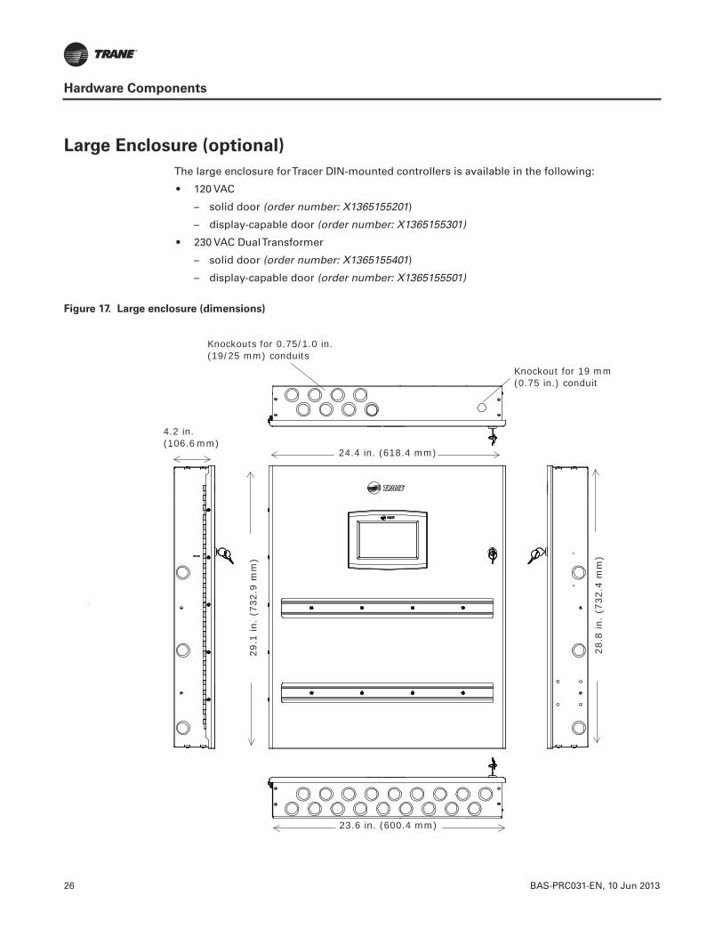
26 BAS-PRC031-EN, 10 Jun 2013
Hardware Components
Large Enclosure (optional)
The large enclosure forTracer DIN-mounted controllers is available in the following:
• 120 VAC
– solid door (order number: X1365155201)
– display-capable door (order number: X1365155301)
• 230 VAC DualTransformer
– solid door (order number: X1365155401)
– display-capable door (order number: X1365155501)
Figure 17. Large enclosure (dimensions)
Knockouts for 0.75/1.0 in. (19/25 mm) conduits
Knockout for 19 mm (0.75 in.) conduit
24.4 in. (618.4 mm)
23.6 in. (600.4 mm)
28.8
in.
(732
.4 m
m)
29.1
in.
(732
.9 m
m)
4.2 in. (106.6 mm)


Trane optimizes the performance of homes and buildings around the world. A business of Ingersoll Rand, the leader increating and sustaining safe, comfortable and energy efficient environments,Trane offers a broad portfolio of advancedcontrols and HVAC systems, comprehensive building services, and parts. For more information, visit www.Trane.com.
Trane has a policy of continuous product and product data improvement and reserves the right to change design and specifications without notice.
We are committed to using environmentally
conscious print practices that reduce waste.
© 2013Trane All rights reserved
BAS-PRC031-EN 10 Jun 2013
Supersedes BAS-PRC031-EN (27 Apr 2013)

August 2012 BAS-PRC032-EN
Product Data Sheet
The features, benefits, and specifications of the Trane wired temperature sensor with an LCD display are summarized in this document.
In addition to this sensor, Trane® offers a full line of wired and wireless temperature sensors. Wired temperature sensors are the suitable alternative for locations that cannot accommodate wireless sensors or that require a service tool connection. Wireless temperature sensors, which provide easy and flexible installation, are a cost-effective alternative to wired sensors.
Features and Benefits
Part Numbers
Feature Benefits
Temperature setpoint control Allows tenants to choose their preferred temperature setpoint.
Occupancy override Allows tenants to request temporary timed override system operation, which permits the building to maintain comfortable conditions.
Fan and system settings Allows tenants to locally control the system operating mode and fan speed according to their personal preferences.
COMM module Provides a local RJ11 (RJ22 compatible) connection to a Trane service tool for easy, low-cost maintenance.
Setpoint Fan control System OccupancyCOMM module
Part number BAYSENS
Global parts
Single No No Yes Yes X1379088601 NA SEN02076
Single Off/Auto/Low/Med/High No No Yes X1379088604 NA NA
Dual Auto/HighCool/Off/Auto/Heat/Emergency Heat
No Yes X1379088605 BAYSENS131A NA
Note: All sensors listed can be field configured to match the applicable unit controller options.
Temperature Sensor With Display

Trane optimizes the performance of homes and buildings around the world. A business of Ingersoll Rand, the leader in creating and sustaining safe, comfortable and energy efficient environments, Trane offers a broad portfolio of advanced controls and HVAC systems, comprehensive building services, and parts. For more information, visit www.Trane.com.
Trane has a policy of continuous product and product data improvement and reserves the right to change design and specifications without notice.
© 2012 Trane All rights reserved
BAS-PRC032-EN 28 Aug 2012
Supersedes BAS-PRC032-EN 01 Dec 2008
We are committed to using environmentally
conscious print practices that reduce waste.
Specifications
Agency Compliance
• United States: UL listed• Canada: CUL listed• Europe: CE marked
Wiring Terminations
Specification Range, Value, or Comment
Sensor operating temperature From 32°F to 122°F (0°C to 50°C)
Storage temperature From -40°F to 185°F (-40°C to 85°C)
Storage/operating humidity range 5% to 95% relative humidity (RH), noncondensing
Thermistor accuracy 0.2°C at 25°C, 1%
Setpoint functional range 50°F to 89.6°F (10°C to 32°C)
Housing material Polycarbonate/ABS blend, UV protected, UL 94-5VA flammability rating, suitable for application in a plenum
MountingFits a standard 2 in. by 4 in. junction box (vertical mount only). Mounting holes are spaced 3.2 in. (83 mm) apart on vertical center line. Includes mounting screws for junction box and wall anchors for sheetrock walls. Overall dimensions: 2.9 in (74 mm) by 4.7 in. (119 mm)
Resolution 0.125ºF over a range of 60 to 80ºF (15.6 to 26.7°C); 0.25ºF when outside this range
Accuracy 0.5°F over a range of 55 to 85°F (12.8 to 29.4ºC)
Power consumption <1 VA
]
]11 24 VAC/VDC
10 (GROUND)
9
8
7 COMM–
6 COMM+
5 HEAT SETPOINT (HSP)
4 SYS/FAN MODE (MODE)
3 SETPOINT
2 SIGNAL COMMON (COMMON)
1 ZONE TEMPERATURE (ZONE TEMP)
S2 REMOTE TEMP SENSOR
S1 REMOTE TEMP SENSOR
Jumper is installed from factory to display local temperature reading. To enable external sensor option, move jumper to “Ext” location.
If jumper is positioned as shown here, the display shows the local temperature sensor reading (default)
If jumper is positioned as shown here, the display shows the external temperature sensor reading.
Local
Ext
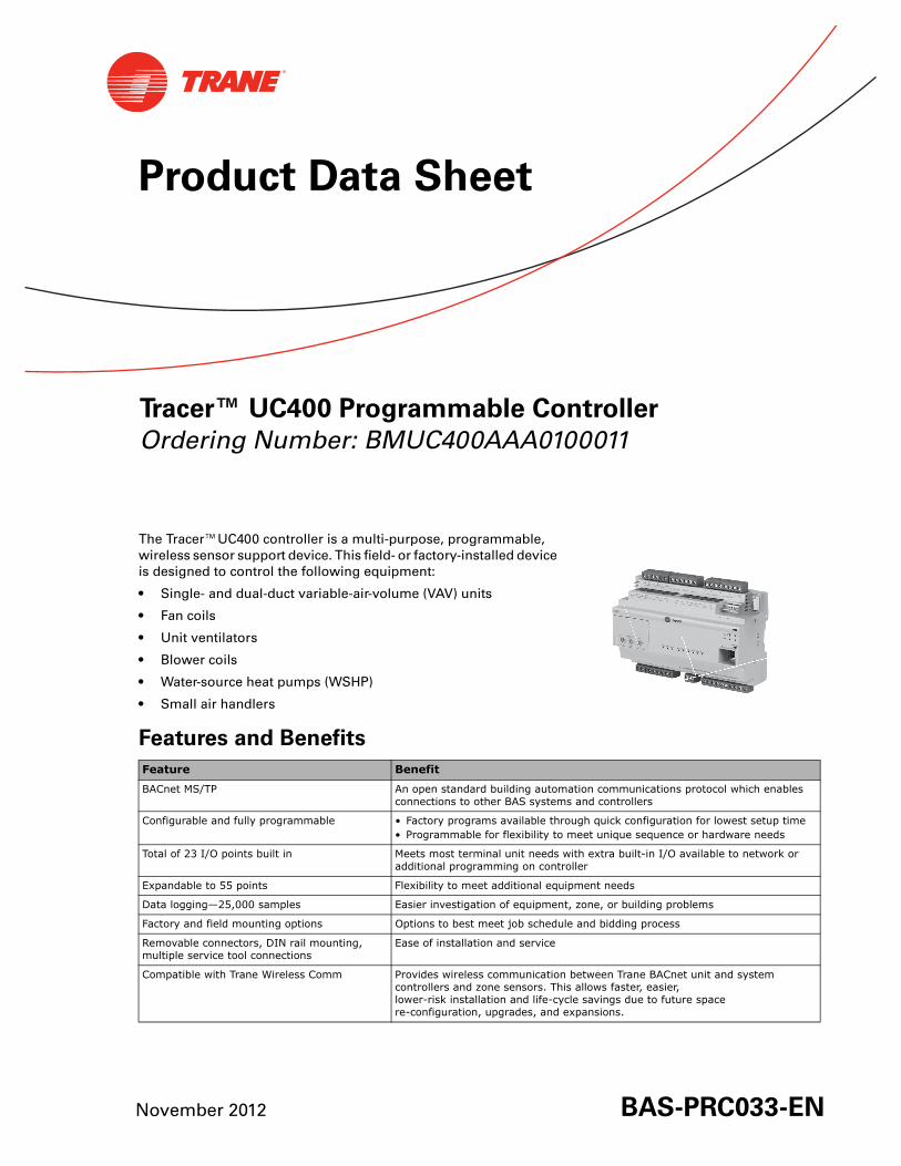
Tracer™ UC400 Programmable Controller
Ordering Number: BMUC400AAA0100011
November 2012 BAS-PRC033-EN
Product Data Sheet
The Tracer™UC400 controller is a multi-purpose, programmable, wireless sensor support device. This field- or factory-installed device is designed to control the following equipment:
• Single- and dual-duct variable-air-volume (VAV) units
• Fan coils
• Unit ventilators
• Blower coils
• Water-source heat pumps (WSHP)
• Small air handlers
Features and Benefits
Feature Benefit
BACnet MS/TP An open standard building automation communications protocol which enables connections to other BAS systems and controllers
Configurable and fully programmable • Factory programs available through quick configuration for lowest setup time• Programmable for flexibility to meet unique sequence or hardware needs
Total of 23 I/O points built in Meets most terminal unit needs with extra built-in I/O available to network or additional programming on controller
Expandable to 55 points Flexibility to meet additional equipment needs
Data logging—25,000 samples Easier investigation of equipment, zone, or building problems
Factory and field mounting options Options to best meet job schedule and bidding process
Removable connectors, DIN rail mounting, multiple service tool connections
Ease of installation and service
Compatible with Trane Wireless Comm Provides wireless communication between Trane BACnet unit and system controllers and zone sensors. This allows faster, easier, lower-risk installation and life-cycle savings due to future space re-configuration, upgrades, and expansions.
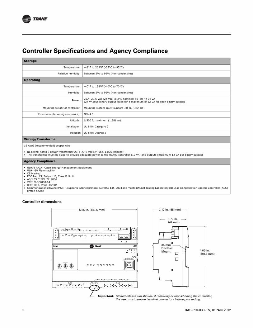
2 BAS-PRC033-EN, 01 Nov 2012
Controller Specifications and Agency Compliance
Controller dimensions
Storage
Temperature: -48°F to 203°F (-55°C to 95°C)
Relative humidity: Between 5% to 95% (non-condensing)
Operating
Temperature: -40°F to 158°F (-40°C to 70°C)
Humidity: Between 5% to 95% (non-condensing)
Power: 20.4–27.6 Vac (24 Vac, ±15% nominal) 50–60 Hz 24 VA(24 VA plus binary output loads for a maximum of 12 VA for each binary output)
Mounting weight of controller: Mounting surface must support .80 lb. (.364 kg)
Environmental rating (enclosure): NEMA 1
Altitude: 6,500 ft maximum (1,981 m)
Installation: UL 840: Category 3
Pollution UL 840: Degree 2
Wiring/Transformer
16 AWG (recommended) copper wire
• UL Listed, Class 2 power transformer 20.4–27.6 Vac (24 Vac, ±15% nominal)• The transformer must be sized to provide adequate power to the UC400 controller (12 VA) and outputs (maximum 12 VA per binary output)
Agency Compliance
• UL916 PAZX- Open Energy Management Equipment• UL94-5V Flammability• CE Marked• FCC Part 15, Subpart B, Class B Limit• AS/NZS CISPR 22:2006• VCCI V-3/2008.04• ICES-003, Issue 4:2004• Communications BACnet MS/TP, supports BACnet protocol ASHRAE 135-2004 and meets BACnet Testing Laboratory (BTL) as an Application Specific Controller (ASC)
profile device
5.65 in. (143.5 mm) 2.17 in. (55 mm)
1.73 in. (44 mm)
4.00 in. (101.6 mm)
35 mm DIN Rail Mount
Important: Slotted release clip shown– if removing or repositioning the controller, the user must remove terminal connectors before proceeding.

BAS-PRC033-EN, 01 Nov 2012 3
Device Connections Table 1. Device connections
Connection Quantity Types Range Notes
*Analog input(AI1 to AI5) 5
Temperature 10 kΩ thermistor
Setpoint 0 Ω to 1,000 Ω
Resistive 200 Ω to 20 kΩ Typically used for fan speed switch.
Universal input(UI1 and UI2) 2
Linear 0–20 mA
These inputs may be configured to be thermistor inputs, 0–10 Vdc inputs, or 4–20 mA inputs.
Linear 0–10 Vdc
Resistive * Refer to analog input connection for ranges and types above
Binary Solid state open collector
Pulse Solid state open collector Minimum dwell time is 25 milliseconds (ms) ON and 25 milliseconds OFF.
Binary input(a)
(BI1 to BI3)
(a) Binary Inputs, Binary Outputs, and TRIACs: For safety precautions, do not mix Class 1 and Class 2 voltages in an enclosure or on a controller without a physical barrier between these units.
3 24 Vac detectThe UC400 controller provides the 24 Vac that is required to drive the binary inputs when using the recommended connections.
Binary output(a)
(BO1 to BO3) 3 Relay
2.88 A @24 Vac pilot duty(For further power ratings, refer to the Tracer UC400 Installation, Operation, and Maintenance Manual [BAS-SVX20]).
Power needs to be wired to the binary output. All outputs are isolated from each other and from ground or power. Ranges given are per contact.
Binary output(a)
(BO4 to BO9) 6 TRIAC
0.5 A max @24-277 Vac, resistive and pilot duty (For further power ratings, refer to the Tracer UC400 Installation, Operation, and Maintenance Manual [BAS-SVX20]).
Use for modulating TRIAC. User determines whether closing high side (providing voltage to the grounded load) or low side (providing ground to the power load). Ranges given are per contact and power comes from TRIAC SUPPLY circuit.
Analog output/binary input(AO1/BI4 and AO2/BI5)
2
Linear output 0–20 mA
Each termination must be configured as either an analog output or binary input.Linear output 0–10 Vdc
Binary input Dry contact
Pressure inputs(PI1 and PI2) 2 3-wire 0–5 in H2O
Pressure inputs supplied with 5 volts of power. Designed for Kavlico™ pressure transducers.
Overall Point Total 23

Trane optimizes the performance of homes and buildings around the world. A business of Ingersoll Rand, the leader in creating and sustaining safe, comfortable and energy efficient environments, Trane offers a broad portfolio of advanced controls and HVAC systems, comprehensive building services, and parts. For more information, visit www.Trane.com.
Trane has a policy of continuous product and product data improvement and reserves the right to change design and specifications without notice.
© 2012 Trane. All rights reserved.
BAS-PRC033-EN 1 Nov 2012
Supersedes BAS-PRC033-EN 01 Mar 2012
We are committed to using environmentally
conscious print practices that reduce waste.
TR200 Series
January 2011 • 176R0643 BAS-PRC034-EN
Variable Frequency Drives
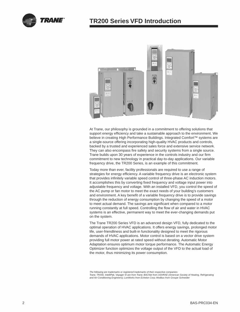
2 BAS-PRC034-EN
The following are trademarks or registered trademarks of their respective companies:Trane, TR200, IntelliPak, Voyager III are from Trane; BACNet from ASHRAE (American Society of Heating, Refrigerating and Air-Conditioning Engineers); LonWorks from Echelon Corp; Modbus from Groupe Schneider
TR200 Series VFD Introduction
At Trane, our philosophy is grounded in a commitment to offering solutions that support energy efficiency and take a sustainable approach to the environment. We believe in creating High Performance Buildings. Integrated Comfort™ systems are a single-source offering incorporating high-quality HVAC products and controls, backed by a trusted and experienced sales force and extensive service network. They can also encompass fire safety and security systems from a single source. Trane builds upon 30 years of experience in the controls industry and our firm commitment to new technology in practical day-to-day applications. Our variable frequency drive, the TR200 Series, is an example of this commitment.
Today more than ever, facility professionals are required to use a range of strategies for energy efficiency. A variable frequency drive is an electronic system that provides infinitely variable speed control of three-phase AC induction motors. It accomplishes this by converting fixed frequency and voltage input power into adjustable frequency and voltage. With an installed VFD, you control the speed of the AC pump or fan motor to meet the exact needs of your building’s customers and environment. A key benefit of a variable frequency drive is to provide savings through the reduction of energy consumption by changing the speed of a motor to meet actual demand. The savings are significant when compared to a motor running constantly at full speed. Controlling the flow of air and water in HVAC systems is an effective, permanent way to meet the ever-changing demands put on the system.
The Trane TR200 Series VFD is an advanced design VFD, fully dedicated to the optimal operation of HVAC applications. It offers energy savings, prolonged motor life, user-friendliness and built-in functionality designed to meet the rigorous demands of HVAC applications. Motor control is based on a vector drive system providing full motor power at rated speed without derating. Automatic Motor Adaptation ensures optimum motor torque performance. The Automatic Energy Optimizer function optimizes the voltage output of the VFD to the actual load of the motor, thus minimizing its power consumption.
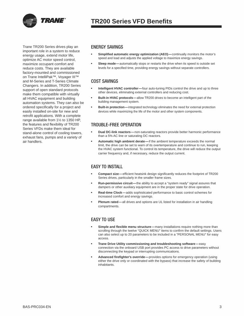
3BAS-PRC034-EN
ENERGY SAVINGSSimplified automatic energy optimization (AEO)—continually monitors the motor’s speed and load and adjusts the applied voltage to maximize energy savings.
Sleep mode—automatically stops or restarts the drive when its speed is outside set levels for a specified time, providing energy savings without separate controllers.
COST SAVINGSIntelligent HVAC controller— four auto-tuning PIDs control the drive and up to three other devices, eliminating external controllers and reducing cost.
Built-in HVAC protocols—allow TR200 drives to become an intelligent part of the building management system.
Built-in protection— integrated technology eliminates the need for external protection devices while maximizing the life of the motor and other system components.
TROUBLE-FREE OPERATIONDual DC-link reactors—non-saturating reactors provide better harmonic performance than a 5% AC line or saturating DC reactors.
Automatic high ambient derate— if the ambient temperature exceeds the normal limit, the drive can be set to warn of its overtemperature and continue to run, keeping the HVAC system functional. To control its temperature, the drive will reduce the output carrier frequency and, if necessary, reduce the output current.
EASY TO INSTALLCompact size—efficient heatsink design significantly reduces the footprint of TR200 Series drives, particularly in the smaller frame sizes.
Run-permissive circuit— the ability to accept a “system ready” signal assures that dampers or other auxiliary equipment are in the proper state for drive operation.
Real-time Clock—adds sophisticated performance to basic control schemes for increased comfort and energy savings.
Plenum rated—all drives and options are UL listed for installation in air handling compartments.
EASY TO USESimple and flexible menu structure—many installations require nothing more than scrolling through the twelve “QUICK MENU” items to confirm the default settings. Users can also select up to 20 parameters to be included in a ”PERSONAL MENU” for easy access.
Trane Drive Utility commissioning and troubleshooting software—easyconnection via the onboard USB port provides PC access to drive parameters without disconnecting the keypad or interrupting communications.
Advanced firefighter’s override—provides options for emergency operation (using either the drive only or coordinated with the bypass) that increase the safety of building inhabitants.
TR200 Series VFD Benefits
Trane TR200 Series drives play an important role in a system to reduce energy usage, extend motor life, optimize AC motor speed control, maximize occupant comfort and reduce costs. They are available factory-mounted and commissioned on Trane IntelliPak™, Voyager III™ and M-Series and T-Series Climate Changers. In addition, TR200 Series support of open standard protocols make them compatible with virtually all HVAC equipment and building automation systems. They can also be ordered specifically for a project and easily installed on-site for new and retrofit applications. With a complete range available from 1½ to 1350 HP, the features and flexibility of TR200 Series VFDs make them ideal for stand-alone control of cooling towers, exhaust fans, pumps and a variety of air handlers.
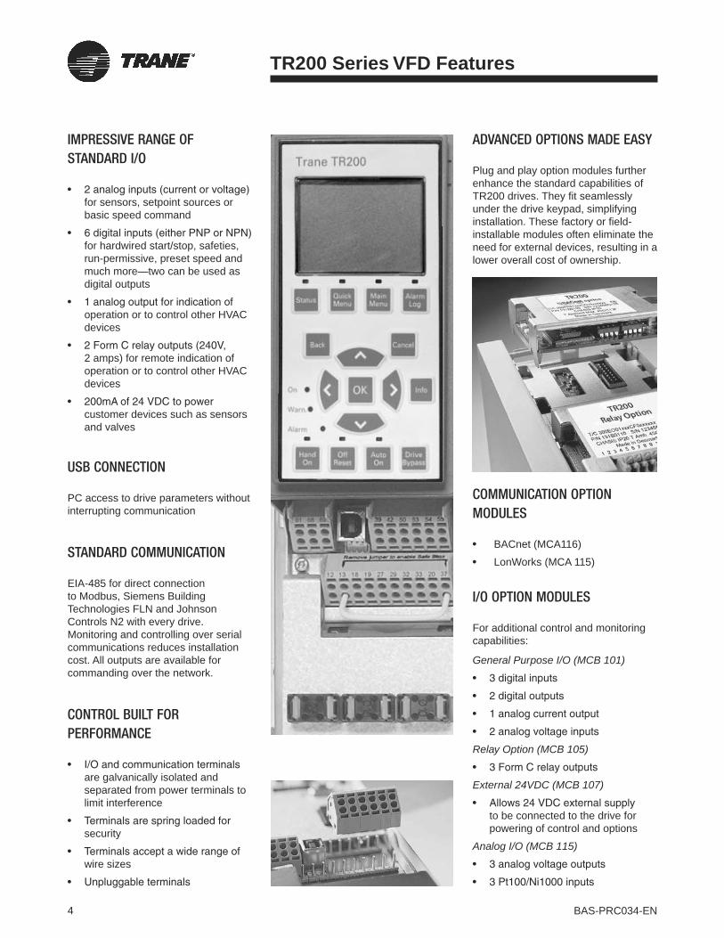
4 BAS-PRC034-EN
TR200 Series VFD Features
IMPRESSIVE RANGE OF STANDARD I/O
for sensors, setpoint sources or basic speed command
for hardwired start/stop, safeties, run-permissive, preset speed and much more—two can be used as digital outputs
operation or to control other HVAC devices
2 amps) for remote indication of operation or to control other HVAC devices
customer devices such as sensors and valves
USB CONNECTION
PC access to drive parameters without interrupting communication
STANDARD COMMUNICATION
EIA-485 for direct connection to Modbus, Siemens Building Technologies FLN and Johnson Controls N2 with every drive.Monitoring and controlling over serial communications reduces installation cost. All outputs are available for commanding over the network.
CONTROL BUILT FOR PERFORMANCE
are galvanically isolated and separated from power terminals to limit interference
security
wire sizes
ADVANCED OPTIONS MADE EASY
Plug and play option modules further enhance the standard capabilities of TR200 drives. They fit seamlessly under the drive keypad, simplifying installation. These factory or field-installable modules often eliminate the need for external devices, resulting in a lower overall cost of ownership.
COMMUNICATION OPTION MODULES
BACnet (MCA116)
LonWorks (MCA 115)
I/O OPTION MODULES
For additional control and monitoring capabilities:
General Purpose I/O (MCB 101)
Relay Option (MCB 105)
External 24VDC (MCB 107)
to be connected to the drive for powering of control and options
Analog I/O (MCB 115)

5BAS-PRC034-EN
TR200 Series VFD Features
Cold plate cooling technologyFor efficient heat dissipation
Balanced DC-link reactorsFor reduced harmonics
Advanced controller optionsAddress the needs of complex applications
Surface-mount componentsFor compactness and reliability
USB interfaceFor easy connection to PC software suite
a
a
b
b
c
c
d
d
e
e
f
f
g
g
h
h
i
i
Removable terminal stripsAngled for easy access
Option modulesProvide additional functionality
Hot-pluggable keypadFeatures on-board memory with user-friendly ergonomic design
Removable, temperature-controlled fanFor easy servicing
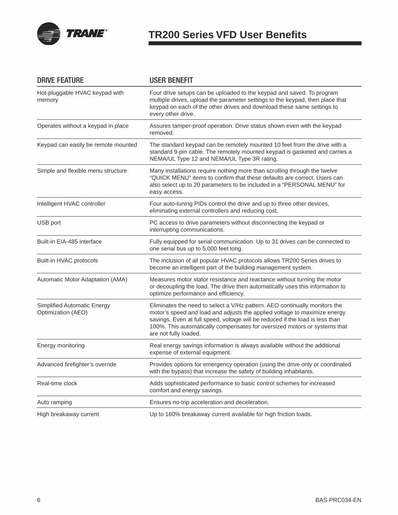
6 BAS-PRC034-EN
DRIVE FEATURE USER BENEFIT
Hot-pluggable HVAC keypad with memory
Four drive setups can be uploaded to the keypad and saved. To program multiple drives, upload the parameter settings to the keypad, then place that keypad on each of the other drives and download these same settings to every other drive.
Operates without a keypad in place Assures tamper-proof operation. Drive status shown even with the keypad removed.
Keypad can easily be remote mounted The standard keypad can be remotely mounted 10 feet from the drive with a standard 9-pin cable. The remotely mounted keypad is gasketed and carries a NEMA/UL Type 12 and NEMA/UL Type 3R rating.
Simple and flexible menu structure Many installations require nothing more than scrolling through the twelve “QUICK MENU” items to confirm that these defaults are correct. Users can also select up to 20 parameters to be included in a “PERSONAL MENU” for easy access.
Intelligent HVAC controller Four auto-tuning PIDs control the drive and up to three other devices, eliminating external controllers and reducing cost.
USB port PC access to drive parameters without disconnecting the keypad or interrupting communications.
Built-in EIA-485 interface Fully equipped for serial communication. Up to 31 drives can be connected to one serial bus up to 5,000 feet long.
Built-in HVAC protocols The inclusion of all popular HVAC protocols allows TR200 Series drives to become an intelligent part of the building management system.
Automatic Motor Adaptation (AMA) Measures motor stator resistance and reactance without turning the motor or decoupling the load. The drive then automatically uses this information to optimize performance and efficiency.
Simplified Automatic Energy Optimization (AEO)
Eliminates the need to select a V/Hz pattern. AEO continually monitors the motor’s speed and load and adjusts the applied voltage to maximize energy savings. Even at full speed, voltage will be reduced if the load is less than 100%. This automatically compensates for oversized motors or systems that are not fully loaded.
Energy monitoring Real energy savings information is always available without the additional expense of external equipment.
Advanced firefighter’s override Provides options for emergency operation (using the drive only or coordinated with the bypass) that increase the safety of building inhabitants.
Real-time clock Adds sophisticated performance to basic control schemes for increased comfort and energy savings.
Auto ramping Ensures no-trip acceleration and deceleration.
High breakaway current Up to 160% breakaway current available for high friction loads.
TR200 Series VFD User Benefits

7BAS-PRC034-EN
DRIVE FEATURE USER BENEFIT
VVCPLUS output switching pattern Superior Voltage Vector Control provides high efficiency and full motor performance.
Automatic high ambient derate If the ambient temperature exceeds the normal limit, the drive can be set to warn of its overtemperature and continue to run, keeping the HVAC system functional. To control its temperature, the drive will reduce the output carrier frequency and then, if necessary, reduce the output current.
Preventive maintenance scheduling The TR200 Series drive can monitor system usage and notify the operator when preventive maintenance is required.
Dual DC-link reactors Non-saturating reactors provide better harmonic performance than a 5% AC line or saturating DC reactor.
Built-in protection Eliminate the need for external protection devices while maximizing the life of the motor and other system components.
Automatic Switching Frequency Modulation (ASFM)
Adjusts the carrier frequency based on the load.
Protected from input or output switching Input or output can be disconnected while the drive is running without the need for interlocks to protect the drive.
Full torque to base speed Direct drive fans run without derating. The full output torque can be set to coincide with the maximum design operating speed of the driven equipment, up to 60 Hz.
Flying start Allows starting into a “windmilling” fan at any speed, in either direction.
Sleep mode Automatically stops the drive when its speed drops below the “sleep” level for a specified time, and automatically restarts when the speed command exceeds the “wake” level. Provides increased energy savings without separate controllers.
Run-permissive circuit The ability to accept a “system ready” signal assures that dampers or other auxiliary equipment are in the proper state for drive operation.
Safety Interlock Provides external fault indication.
UL and C-UL listed All drives and options sold for US and Canadian applications carry this safety certification.
CE marked All drives carry the CE mark for sale into international markets.
Plenum rated All drives and options are UL listed for installation in air handling compartments.
TR200 Series VFD User Benefits

8 BAS-PRC034-EN
REAL-TIME CLOCK
The energy savings potential of the TR200 Series drive is maximized with a real-time clock, allowing the system to respond to the changing needs of the building throughout the day and week. The real-time clock allows the system to anticipate conditions or temporarily override the setpoint, enhancing control, comfort and efficiency. It also allows the drive to provide reminders when preventive maintenance is required.
Previously, a building automation system was required to obtain these features. The real-time clock gives these sophisticated functions to any facility.
With the real-time clock, the fault log in all TR200 Series drives contains not only a list of the ten most recent drive faults, but also the year, month, day, hour and minute of each fault, greatly simplifying troubleshooting.
HVAC INTELLIGENT CONTROL
TR200 Series drives include a PID controller with four setpoints and three feedbacks, a feature not currently offered anywhere else in the market. The built-in combination of HVAC system control features and flexible I/O result in the highest level of control possible at the lowest overall cost of ownership.Four on-board, self-tuning PID controllers can operate as a basic air handling unit controller. One PID maintains fan speed while up to three other PID loops can be used to operate other HVAC devices. In pump applications, short-cycle prevention allows maintained operation within a desired range without the wear and tear produced by system overstarting. Combined with a flowmeter or a differential pressure transmitter, the TR200 Series drive can measure and regulate flow and replace throttling valves for more accurate control and energy savings.
Fan tracking allows return fans to maintain the desired pressure by utilizing two air flow sensors. An enhanced sleep mode saves energy and system wear by shuttting down fans during idle periods.
TR200 Series VFD HVAC Control Features
Time
Speed
Setpoint
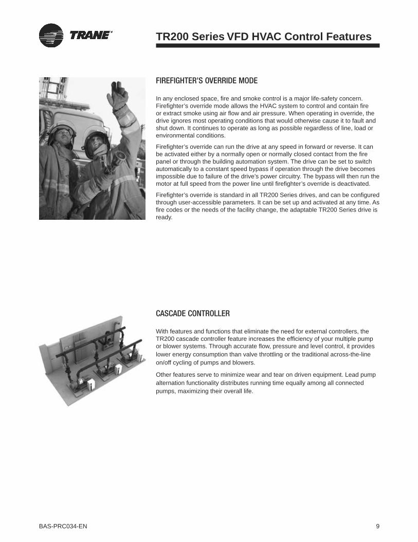
9BAS-PRC034-EN
FIREFIGHTER’S OVERRIDE MODE
In any enclosed space, fire and smoke control is a major life-safety concern. Firefighter’s override mode allows the HVAC system to control and contain fire or extract smoke using air flow and air pressure. When operating in override, the drive ignores most operating conditions that would otherwise cause it to fault and shut down. It continues to operate as long as possible regardless of line, load or environmental conditions.
Firefighter’s override can run the drive at any speed in forward or reverse. It can be activated either by a normally open or normally closed contact from the fire panel or through the building automation system. The drive can be set to switch automatically to a constant speed bypass if operation through the drive becomes impossible due to failure of the drive’s power circuitry. The bypass will then run the motor at full speed from the power line until firefighter’s override is deactivated.
Firefighter’s override is standard in all TR200 Series drives, and can be configured through user-accessible parameters. It can be set up and activated at any time. As fire codes or the needs of the facility change, the adaptable TR200 Series drive is ready.
CASCADE CONTROLLER
With features and functions that eliminate the need for external controllers, the TR200 cascade controller feature increases the efficiency of your multiple pump or blower systems. Through accurate flow, pressure and level control, it provides lower energy consumption than valve throttling or the traditional across-the-line on/off cycling of pumps and blowers.
Other features serve to minimize wear and tear on driven equipment. Lead pump alternation functionality distributes running time equally among all connected pumps, maximizing their overall life.
TR200 Series VFD HVAC Control Features

10 BAS-PRC034-EN
NETWORK COMMUNICATION
Standard EIA-485 interface
Built-in serial communication—allows seamless communication over networks using Modbus™ RTU and most building automation systems communications protocols.
Option modules for BACnet™ and LonWorks®—factory- and field-installable; mounts easily and securely inside the drive.
Easy installation and operation—simple two-wire connection and programmable through the network or the drive’s keypad.
HVAC-SPECIFIC FEATURES BUILT IN
Keypad-programmable automatic bypass
Common start/stop selectable operation in drive and bypass mode
Coordinated run-permissive in drive and bypass mode
Advanced firefighter’s override coordinated with TR200 Series drive override mode
Serial and BAS control of drive and bypass operation
PROPORTIONAL, INTEGRAL, DERIVATIVE (PID) CONTROLLER
Closed loop control
Two setpoints and two feedbacks—a feature unique to TR200 Series drives
Eliminates the need for extra I/O modules
Allows for two-zone regulation
Cooling tower systems—improved efficiency by automatically matching its speed to air flow requirements
Pump applications
Used with a flowmeter, can maintain a given rate–
Used with a differential pressure transmitter, can provide more accurate –control and energy savings
Optional cascade controller board provides a wide range of efficient –control in large pumping systems
TR200 Series VFD Features
While offering single-source solutions, Trane stands committed to open-standard protocols to meet the needs of building professionals. The TR200 Series demonstrates this with “plug-and-play” communication capabilities that reduce or eliminate the need for integration gateways.
The TR200 support of major building communication protocols allows seamless communication with open standard protocols such as BACnet™, LonWorks™ and Modbus™ as well as other popular building automation system protocols. Whether factory-installed on Trane HVAC equipment, field-installed on new equipment, or retrofit on existing equipment, the result is an easily programmable drive in an easy-to-manage package that simplifies installation and results in a lower total cost of ownership.
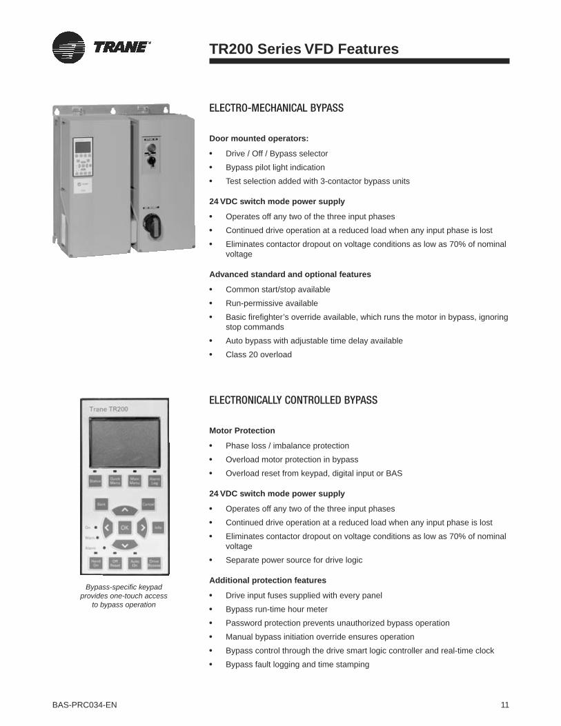
11BAS-PRC034-EN
ELECTRO-MECHANICAL BYPASS
Door mounted operators:
Drive / Off / Bypass selector
Bypass pilot light indication
Test selection added with 3-contactor bypass units
24 VDC switch mode power supply
Operates off any two of the three input phases
Continued drive operation at a reduced load when any input phase is lost
Eliminates contactor dropout on voltage conditions as low as 70% of nominal voltage
Advanced standard and optional features
Common start/stop available
Run-permissive available
Basic firefighter’s override available, which runs the motor in bypass, ignoring stop commands
Auto bypass with adjustable time delay available
Class 20 overload
TR200 Series VFD Features
ELECTRONICALLY CONTROLLED BYPASS
Motor Protection
Phase loss / imbalance protection
Overload motor protection in bypass
Overload reset from keypad, digital input or BAS
24 VDC switch mode power supply
Operates off any two of the three input phases
Continued drive operation at a reduced load when any input phase is lost
Eliminates contactor dropout on voltage conditions as low as 70% of nominal voltage
Separate power source for drive logic
Additional protection features
Drive input fuses supplied with every panel
Bypass run-time hour meter
Password protection prevents unauthorized bypass operation
Manual bypass initiation override ensures operation
Bypass control through the drive smart logic controller and real-time clock
Bypass fault logging and time stamping
Bypass-specific keypad provides one-touch access
to bypass operation

12 BAS-PRC034-EN
TR200 Series VFD PC Software
Trane Drive Utility features include:
parameter
improved system performance and documentation
drive conversion projects
simplified programming of the TR200’s Smart Logic Controller
Scope function
TR200 drive’s internal data buffer, providing up to four channels of high speed (down to 1 millisec) data collection
TRANE DRIVE UTILITY
The Trane Drive Utility software offers advanced programming functionality for TR200 Series drives, greatly reducing programming and setup time.
Drives are managed in a standard folder-based user interface that’s familiar and easy to understand. Parameter settings for each drive are contained in a single file, allowing easy duplication of parameter sets between drives.
Project folders can also store user-defined files such as PDFs, CAD drawings, or Word documents. Trane Drive Utility software is the one PC tool for all your drive programming tasks.
13BAS-PRC034-EN
TR200 Series VFD Protective Features
With an unmatched combination of drive, motor, and system protection features, the TR200 Series drive is a cost-effective overall solution. Designed and built for long-term, worry-free operation without the need for external devices to protect driven equipment, the TR200 Series drive provides secure, reliable results, right out of the box.
SYSTEM PROTECTION
Belt monitoring
The TR200 Series drive's sophisticated belt monitoring measures both speed and load and calculates the difference between actual torque and expected torque at all speeds. A time delay allows for reduced load during deceleration.
No-flow detection
Operation under dead head conditions provides no flow to the system and may damage the pump. Differential pressure switches or flow meters increase the installation costs and add complexity. The TR200 Series drive can automatically detect no-flow situations and take the appropriate corrective action.
End-of-curve protection
The TR200 Series drive can automatically detect over-flow conditions that indicate operation off the end of the pump curve. Its response can be customized to trigger an alarm and stop the pump, issue a warning while maintaining operation, or perform a variety of other functions to protect both the pump and the system.
Automated vibration avoidance
Fan systems often have resonant speeds that must be avoided to reduce vibration and noise. The TR200 Series drive automates the process of setting up frequency avoidance bands, minimizing system commissioning time.
DRIVE PROTECTION
Metal oxide varistors (MOVs) and capacitor snubbers in both the AC and DC input circuitry reduce the impact of voltage spikes on the input. In addition, a balanced pair of DC-link reactors between the input rectifier and the bank of DC-bus capacitors reduces the severity of any current surge resulting from abrupt changes in the AC supply line.
Conformal coating is available to protect electronic components in aggressive environments.
MOTOR PROTECTION
The TR200 Series drive’s built-in I2Tmotor overload, thermistor input and motor preheat functions increase the life of the controlled motor without the added cost of separately supplied protection. The drive’s built-in I2T motor overload is UL-listed as a true overload device, eliminating the need for external motor protection hardware.
HARMONIC MITIGATION
DC-link reactors limit harmonic distortion on the power line, reducing RMS input current by more than 40% compared to drives without input reactors.
Other drive manufacturers address harmonics with AC line reactors, usually external to the drive. Often, these optional AC line reactors are 50% larger than the DC-link reactors standard on the TR200 Series drive. This results in significant additional heat generation and reduced efficiency.The harmonic performance of the DC-link reactors in the TR200 Series drive is equal to that of a 5% AC line reactor, but without the associated voltage drop and efficiency losses.
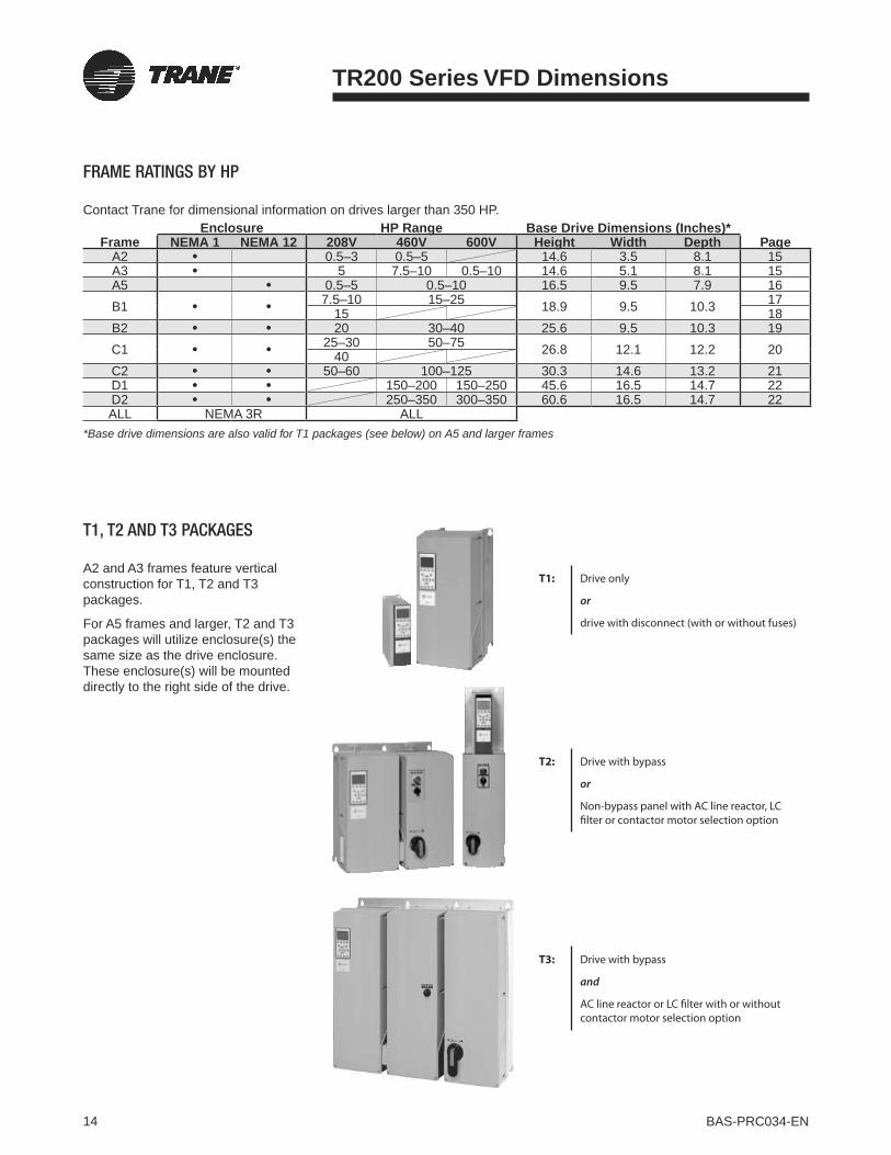
14 BAS-PRC034-EN
TR200 Series VFD Dimensions
FRAME RATINGS BY HP
Contact Trane for dimensional information on drives larger than 350 HP.
FrameEnclosure HP Range Base Drive Dimensions (Inches)*
NEMA 1 NEMA 12 208V 460V 600V Height Width Depth PageA2 0.5–3 0.5–5 14.6 3.5 8.1 15A3 5 7.5–10 0.5–10 14.6 5.1 8.1 15A5 0.5–5 0.5–10 16.5 9.5 7.9 16B1 7.5–10 15–25 18.9 9.5 10.3 17
15 18B2 20 30–40 25.6 9.5 10.3 19C1 25–30 50–75 26.8 12.1 12.2 2040C2 50–60 100–125 30.3 14.6 13.2 21D1 150–200 150–250 45.6 16.5 14.7 22D2 250–350 300–350 60.6 16.5 14.7 22ALL NEMA 3R ALL
*Base drive dimensions are also valid for T1 packages (see below) on A5 and larger frames
T1: Drive only
or
drive with disconnect (with or without fuses)
T2: Drive with bypass
or
Non-bypass panel with AC line reactor, LC filter or contactor motor selection option
T3: Drive with bypass
and
AC line reactor or LC filter with or without contactor motor selection option
T1, T2 AND T3 PACKAGES
A2 and A3 frames feature vertical construction for T1, T2 and T3 packages.
For A5 frames and larger, T2 and T3 packages will utilize enclosure(s) the same size as the drive enclosure. These enclosure(s) will be mounted directly to the right side of the drive.

15BAS-PRC034-EN
A2 and A3 Frames
DRIVE ONLY
T1
TR200 Series VFD Dimensions
IN (MM)
WITHOUT A OR B OPTION
A2 MOUNTING BASE
A3 MOUNTING BASE
DETAIL B
DETAIL A
8.15(207)
8.74(220)
17.62(448)
0.2(5)
0.39(10)
1.97(50)
1.97(50)
0.63(16) 7.75
(197)
8.64(220)
11.74(298)
3.54(90)
2.76(70)
0.26(7)
0.26(7)
10.55(268)
10.55(268)
10.1(257)
0.22(6)
0.22(6)
0.2(4)
0.43(11)
0.32(8)
10.1(257)
4.33(110)
5.12(130)
1.48(38)
4.33(110)
19.1(485)
5.21(132)
9.63(245)
5.91(150)
6.3(160)
0.98(25)
4.92(125)
2.56(65)
4.13(105)
4.53(115)
3X Ø1.1(28)
3X Ø0.89(23)
Ø0.39(10)
MIN3.94(100)
MIN3.94(100)
MIN3.94(100)
MIN3.94(100)
AIRFLOW AIRFLOW
DETAIL A
DETAIL A
DETAIL B
DETAIL B
AIRFLOW
WITH A OR B OPTION
OPTIONALDRIVE
DISCONNECT
QuickMenu
Ext.Menu
AlarmLog
Cancel
InfoOKOn
Warn.
Alarm
Status
Back
AutoOn
Reset

16 BAS-PRC034-EN
A2 and A3 Frames
T3
T2
TR200 Series VFD Dimensions
IN (MM)WITHOUT A OR B OPTION
WITHOUT A OR B OPTION
WITH A OR B OPTION
WITH A OR B OPTION
7.63(194)
31.74(806)
9.73(247)
4.95(126)
5.88(149)
5.44(138)
2.37(137)
4(102)
2.42(62)
0.98(25)
8.27(210)
8.75(222)
30.81(783)
0.39(10)
1.45(37)
4.72(120)
0.28(7)
2.49(63) 1.75
(44)
3.82(97)
8.25(210)
7.63(194)
51.35(1304)
20.74(527)
0.98(25)
2.42(62)
4(102)5.37
(137)
2.49(63)
5.44(138)
4.95(126)2.68
(68)
9.73(247)
5.88(149)
1.75(44)
3.82(97)
8.75(222)
0.39(10)
1.45(37) 4.72
(120)
51.56(1284)
2.68(68)
OPTIONALDRIVE
DISCONNECT
OPTIONALDRIVE
DISCONNECT
OPTIONALEM CONTROL
OPTIONALCONTACTOR
MOTOR SELECT
OPTIONALEM CONTROL
3X Ø1.1(28)
2X Ø0.89(23)
Ø0.89(23)
4X Ø0.89(23)
2X Ø0.89(23)
3X Ø1.11(28)
Ø0.35(9)
Ø0.35(9)
Ø0.59(15)
2X Ø1.11(28)
8X Ø1.11(28)
DETAIL A
DETAIL A
DETAIL B
DETAIL B
DETAIL BDETAIL A
AIRFLOWMIN3.94(100)
AIRFLOW

17BAS-PRC034-EN
A5 Frames
T3
T2
T1
TR200 Series VFD Dimensions
IN (MM)
15.82(402)
0.4(10)
8.46(215)
8.9(226)
15.82(402)
19.18(487)
19.18(487)
17.8(452)
0.69(18)
0.69(18)
10.3(262)
28.7(729)
5.41(137)
8.55(217)
4.06(103)
2.84(72)
10.3(262)6.5
(165)0.73(19)
17.8(452)
0.69(18)
0.98(25)
8.9(226)
17.8(452) 26.69
(678)
18.86(479)
6.5(165)
0.73(19)
2.85(73)
5.41(137)4.06
(103)
8.53(217)
0.53(14)5.41
(137) 4.06(103)2.82
(72)0.73(19)
5.79(147)
7.92(201)
9.57(243)
16.54(420)
9.53(242)
0.24(6)
Ø0.26(7)
Ø0.26(7)
3X Ø10.3(26)
3X Ø1.03(26)
3X Ø10.3(26)
Ø0.47(12)
DETAIL A
DETAIL A
DETAIL A
DETAIL B
DETAIL B
DETAIL B
AIRFLOW
ALLOW 100MM CLEARANCE FOR
FAN REMOVAL
ALLOW 100MM CLEARANCE FOR
FAN REMOVAL
ALLOW 100MM CLEARANCE FOR
FAN REMOVAL
OPTIONALDRIVE
DISCONNECT
OPTIONALDRIVE
DISCONNECT
OPTIONALDRIVE
DISCONNECT
OPTIONALEM CONTROL
OPTIONALEM CONTROL
OPTIONAL CONTACTOR
MOTOR SELECT
AIRFLOW
DETAIL B
DETAIL A
MIN3.94(100)
MIN3.94(100)

18 BAS-PRC034-EN
B1 Frames
T2
T1
T3
TR200 Series VFD Dimensions
18.89(480)
9.53(242)
ALLOW 100MM CLEARANCE FOR
FAN REMOVAL
OPTIONALEM CONTROL
OPTIONALDRIVE
DISCONNECT
OPTIONALDRIVE
DISCONNECT
AIRFLOW
AIRFLOW
MIN3.94(100)
MIN3.94(100)
Ø0.35(9)
Ø0.35(9)
Ø1.03(26)2X Ø
1.29(33)
0.35(9)
Ø0.7(19)
DETAIL B
DETAIL A
17.9(454)
20.1(511)
0.4(10)
17.72(450)
8.3(210)
8.86(225)
0.6(16)
0.69(18)
0.69(18)
6.61(168) 4.92
(125)1.46(37) 1.34
(34)
7.43(189)
12.12(308)
10.23(260)
19.09(485)
21.48(546)
DETAIL A
DETAIL A
DETAIL B
DETAIL B
Ø1.03(26)
2X Ø1.29(33)
6.61(168)7.66
(195)0.93(24)
12.86(327)
28.66(728)
21.48(546)
10.84(275) 7.66
(195)
2.29(58)
4.92(125) 1.46
(37)1.34(34)
8.08(205)
20.1(511)
18(457) 27
(686)
9(229)
0.69(18)
0.83(21)
DETAIL A
DETAIL B
3X 58,12.29[ ]
20.07(510)
12.86(327)
10.54(268)
10.81(275)
7.57(192)
2.29(58)
7.56(192)
0.98(25)
ALLOW 100MM CLEARANCE FOR
FAN REMOVAL
ALLOW 100MM CLEARANCE FOR
FAN REMOVAL
OPTIONALDRIVE
DISCONNECT
OPTIONALEM CONTROL
OPTIONAL CONTACTOR
MOTOR SELECT
IN (MM)
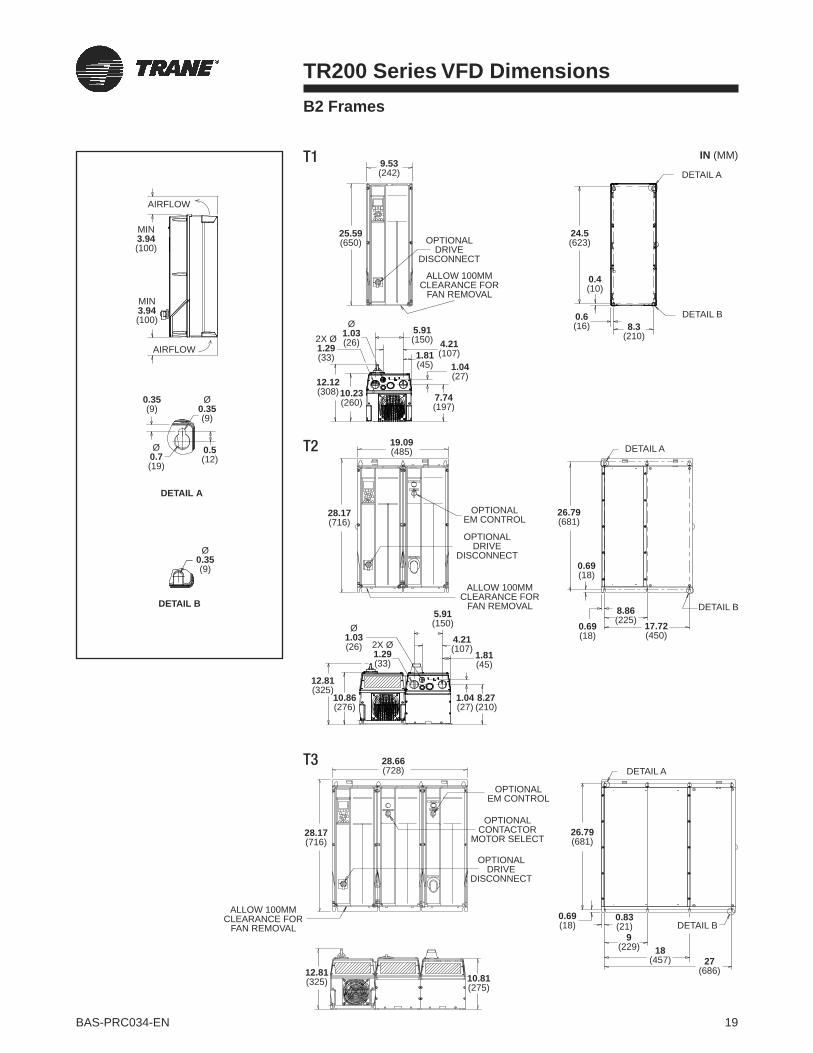
19BAS-PRC034-EN
OPTIONALDRIVE
DISCONNECT
OPTIONALEM CONTROL
ALLOW 100MM CLEARANCE FOR
FAN REMOVAL
B2 Frames
T2
T3
T1
TR200 Series VFD Dimensions
AIRFLOW
AIRFLOW
MIN3.94(100)
MIN3.94(100)
Ø0.35(9)
Ø0.35(9)
0.35(9)
0.5(12)
Ø0.7(19)
DETAIL B
DETAIL A
24.5(623)
0.4(10)
0.69(18)
0.69(18)
17.72(450)
8.86(225)
8.3(210)
0.6(16)
DETAIL A
DETAIL A
DETAIL B
DETAIL B
25.59(650)
9.53(242)
OPTIONALDRIVE
DISCONNECT
Ø1.03(26)2X Ø
1.29(33)
5.91(150) 4.21
(107)1.81(45) 1.04
(27)
7.74(197)
12.12(308)10.23
(260)
28.17(716)
26.79(681)
19.09(485)
ALLOW 100MM CLEARANCE FOR
FAN REMOVAL
Ø1.03(26) 2X Ø
1.29(33)
5.91(150)
4.21(107) 1.81
(45)
1.04(27)
8.27(210)
12.81(325)
10.86(276)
28.66(728)
28.17(716)
0.69(18)
10.81(275)
12.81(325)
0.83(21)
18(457) 27
(686)
9(229)
DETAIL A
DETAIL B
26.79(681)
ALLOW 100MM CLEARANCE FOR
FAN REMOVAL
OPTIONALDRIVE
DISCONNECT
OPTIONALEM CONTROL
OPTIONAL CONTACTOR
MOTOR SELECT
IN (MM)
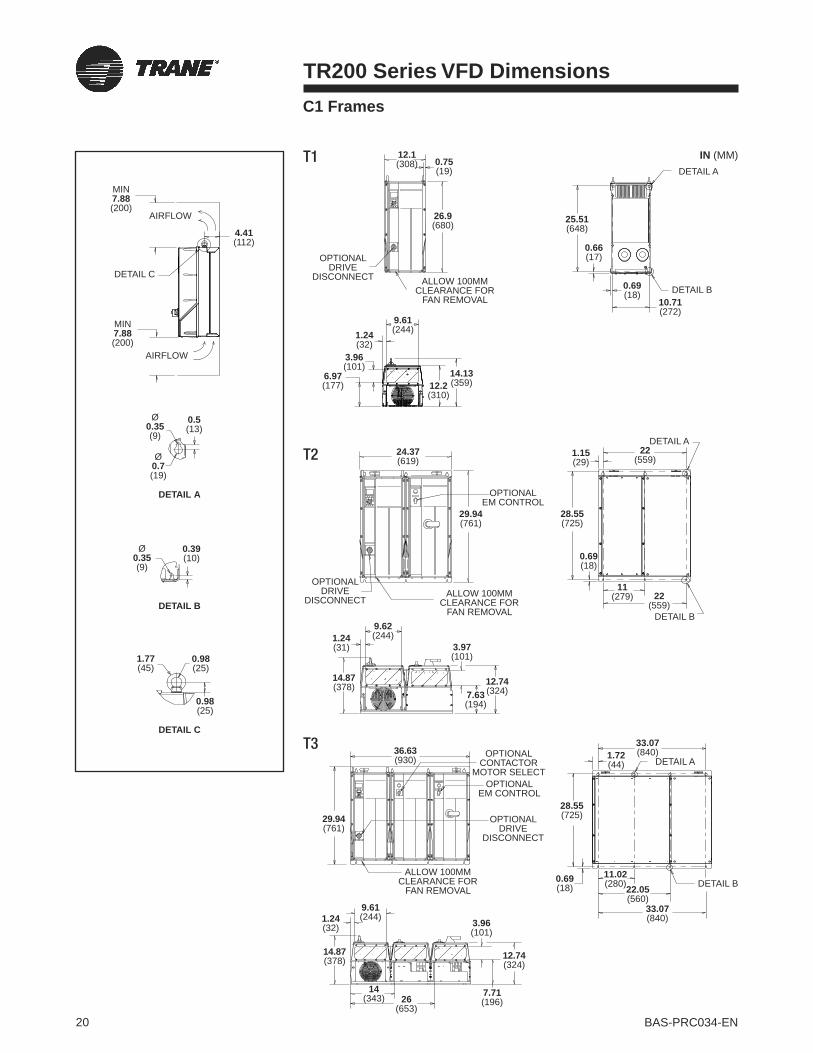
20 BAS-PRC034-EN
C1 Frames
T2
T1
T3
TR200 Series VFD Dimensions
ALLOW 100MM CLEARANCE FOR
FAN REMOVAL
26.9(680)
9.61(244)
14.13(359)12.2
(310)
1.24(32)
3.96(101)
6.97(177)
0.75(19)
12.1(308)
4.41(112)
OPTIONALDRIVE
DISCONNECT
AIRFLOW
AIRFLOW
MIN7.88(200)
DETAIL B
DETAIL C
DETAIL A
DETAIL C
MIN7.88(200)
0.5(13)
0.39(10)
0.98(25)
0.98(25)
1.77(45)
Ø0.35 (9)
Ø0.35(9)
Ø0.7(19)
25.51(648)
10.71(272)
0.66(17)
0.69(18)
DETAIL A
DETAIL B
9.62(244)1.24
(31)
14.87(378)
3.97(101)
12.74(324)7.63
(194)
36.63(930)
29.94(761)
14.87(378)
1.24(32)
9.61(244)
26(653)
3.96(101)
14(343)
24.37(619)
OPTIONALDRIVE
DISCONNECTALLOW 100MM
CLEARANCE FOR FAN REMOVAL
OPTIONALEM CONTROL
22(559)
22(559)
1.15(29)
28.55(725)
29.94(761)
0.69(18)
11(279)
DETAIL A
DETAIL B
OPTIONALDRIVE
DISCONNECT
ALLOW 100MM CLEARANCE FOR
FAN REMOVAL
OPTIONAL CONTACTOR
MOTOR SELECTOPTIONAL
EM CONTROL
33.07(840)
33.07(840)
1.72(44)
28.55(725)
0.69(18) 22.05
(560)
11.02(280)
DETAIL A
DETAIL B
12.74(324)
7.71(196)
IN (MM)

21BAS-PRC034-EN
C2 Frames
T2
T1
T3
TR200 Series VFD Dimensions
DETAIL B
DETAIL C
DETAIL A
0.5(13)
0.39(10)
0.98(25)
0.98(25)
1.77(45)
Ø0.35 (9)
Ø0.35(9)
Ø0.7(19)
29.09(739)
13.15(334)
0.39(10)
0.69(18)
DETAIL A
DETAIL B
DETAIL B
DETAIL A
ALLOW 100MM CLEARANCE FOR
FAN REMOVAL
ALLOW 100MM CLEARANCE FOR
FAN REMOVAL
ALLOW 100MM CLEARANCE FOR FAN REMOVAL
30.2(770)
7(178)
4.62(117)
11.94(303)1.34
(34)
14.93(379)12.98
(330)
33.49(851)
16.22(412)
11.94(303)
4.62(117)
13.72(349)7.82
(199)
43.93(1116)
33.49(851)
38.39(975)
1.34(34)
32.09(815)
0.69(18)
1.79(46)
25.59(650)
12.8(325)
25.59(650)29.24
(743)
0.83(21)
14.6(370)
OPTIONALDRIVE
DISCONNECT
OPTIONALEM CONTROL
4.41(112)
AIRFLOW
AIRFLOW
MIN8.86(225)
MIN8.86(225)
DETAIL C
OPTIONALDRIVE
DISCONNECT
OPTIONALDRIVE
DISCONNECT
OPTIONAL CONTACTOR
MOTOR SELECT
DETAIL B
DETAIL A
32.09(815)
0.69(18)
30.66(779)
16.05(408)
11.94(303)1.34
(34)
15.67(398)
4.62(117)
13.72(349)7.75
(197)
2.73(69)
25.59(650)
38.39(975)
12.8(325)
IN (MM)
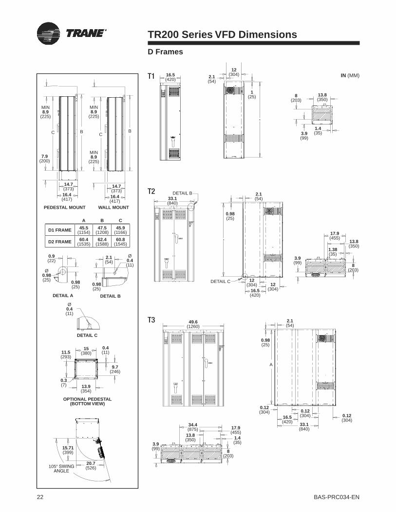
22 BAS-PRC034-EN
TR200 Series VFD DimensionsD Frames
16.5(420)
33.1(840)
7.9(200)
14.7(373) 14.7
(373)16.4(417)
0.9(22)
0.98(25)
2.1(54)
0.98(25)
16.4(417)
MIN8.9
(225)
MIN8.9
(225)
MIN8.9
(225)
C B BC
2.1(54)
0.98(25)
12(304) 12
(304)
3.9(99)
17.9(455)
13.8(350)
1.38(35)
8(203)
16.5(420)
49.6(1260)
2.1(54)
0.98(25)
0.12(304)
33.1(840)
16.5(420)
0.12(304)
0.12(304)
34.4(875)
3.9(99)
17.9(455)
1.4(35)
8(203)
13.8(350)
A
DETAIL B
DETAIL C
1(25)
12(304)2.1
(54)
A
8(203)
13.8(350)
1.4(35)3.9
(99)
A
DETAIL B
DETAIL C
OPTIONAL PEDESTAL (BOTTOM VIEW)
PEDESTAL MOUNT
DETAIL A
WALL MOUNT
Ø0.98(25)
Ø0.4(11)
15(380)
0.4(11)
9.7(246)
11.5(293)
0.3(7) 13.9
(354)
15.71(399)
20.7(526)105°
Ø0.4(11)
A B C
D1 FRAME 45.5(1154)
47.5(1208)
45.9(1166)
D2 FRAME 60.4(1535)
62.4(1588)
60.8(1545)
T2
T1
T3
IN (MM)

23BAS-PRC034-EN
TR200 Series VFD Specifications
DRIVE INPUT POWER
Input voltage, 3-phase.........200–240, 380–460 or 525–600 VACInput voltage range for full output .......................Nominal ±10%Undervoltage trip point ........................164, 313 VAC or 394 VACOvervoltage trip point ......................................... 299, 538 or 690
(792 for 100 HP and above) VACInput frequency ............................................ 50 or 60 Hz, ± 2 HzDisplacement power factor .........................0.98 or greater at all
speeds and loadsTotal power factor ............................. 0.90 or greater at full load
and nominal motor speed
DRIVE OUTPUT POWER
Output frequency ..................................... Selectable 0 to 120 Hz Motor voltages ......................................200, 208, 220, 230; 380,
400, 415, 440, 460; 550 or 575 VACContinuous output current ........................... 100% rated currentOutput current limit setting ...Adjustable to 110% of drive ratingCurrent limit timer ............................. 0 to 60 seconds or infiniteAdjustable max. speed .........From min. speed setting to 120 HzAdjustable min. speed ............. From max. speed setting to 0 HzAcceleration time .....................To 3,600 seconds to base speedDeceleration time ................ To 3,600 seconds from base speedBreakaway torque time ..................................0.0 to 0.5 seconds
(1.6 times motor nameplate current)Start voltage .................................................................. 0 to 10%DC braking time .................................................0 to 60 secondsDC braking start .................................. 0 to maximum frequencyDC braking current ................... 0 to 50% of rated motor current
PROTECTIONS
Low and high frequency warnings ........................... 0 to 120 HzLow and high current warnings ...............0 to maximum currentLow and high reference warnings .............−999,999 to 999,999Low and high feedback warnings ..............−999,999 to 999,999Ground fault .................................................................. ProtectedMotor stall .................................................................... Protected Motor overtemperature ........ Protected (predictive motor temp.)Motor condensation ................Protected (motor preheat circuit)Motor overload ....................... Protected (programmable action)Vibration protection ...........Protected (programming automated)
ENVIRONMENTAL LIMITS
Efficiency ........................................... 97% or greater at full load and nominal motor speed
Ambient operating temp. ...................................... 14°F to 113°F (−10°C to 45°C) frames A2–C2;
14°F to 104°F (−10°C to 40°C) frames D1–E1
Humidity ................................................< 95%, non-condensingAltitude: maximum without derating .............3,300 ft. (1,000 m)Drive / options enclosure(s) ..................NEMA/UL Types 1 or 12;
3R optional
CONTROL CONNECTIONS
Follower signal, analog input ................. 2; selectable voltage or current, direct and inverse acting
Programmable digital inputs .............................6 (2 can be used as digital outputs)
Programmable analog outputs ............................1; 0/4 to 20 mAProgrammable relay outputs... 2 standard Form C 240 VAC, 2 A;
1 or 3 additional optionalAuxiliary voltage ............................ +24 V DC, maximum 200 mA
CONTROL OPTIONAL
MCB 101 General Purpose I/O...............3 DI, 2 DO, 2 AI (voltage) and 1 AO (current)
MCB 105 Relay Card ................ 3 standard Form C 240 VAC, 2 AMCB 107 24V DC Supply ....................... Allows external 24 V DC
power to be connected to the TR200 DriveMCB 115 Programmable I/O ..............Available 2nd half of 2009
SOFTWARE
Lost speed reference action ........... Selectable to go to a preset speed, max. speed, last speed,
stop, turn off, or stop and tripTime delay for lost speed reference action .......1 to 99 secondsAdjustable auto restart time delay ...................0 to 600 secondsAutomatic restart attempts ..............................0 to 20 or infiniteAutomatic restart time delay ... 0 to 600 sec. between attemptsRelay ON delay and relay OFF delay ................0 to 600 secondsMaximum number of preset speeds ........................................16Maximum number of frequency stepovers ............................... 4Maximum stepover width .................................................100 HzMaximum number of accel rates ...............................................4Maximum number of decel rates ...............................................4Delayed start ....................................................0 to 120 seconds

And behind every Trane Variable Frequency Drive
you will find a world leader in HVAC equipment,
controls and services. Whether pre-installed
on Trane equipment, field applied or retrofit,
the Trane TR Series VFD comes with the most
important feature of all—our proven capabilities
throughout the life of your facilities.
We have a dedicated team of professionals
located at over 150 local offices in the U.S. and
Canada and a network of over 200 parts centers
to get you what you want, when you need it. To
learn more about our drives and what’s behind
them, visit www.trane.com/vfd.
Just as important as what’s in your VFD...
...is what’s behind it
Ingersoll Rand (NYSE:IR) is a world leader in creating and sustaining safe, comfortable and efficient environments in commercial, residential and
industrial markets. Our people and our family of brands—including Club Car®, Hussmann®, Ingersoll Rand®, Schlage®, Thermo King® and Trane®—
work together to enhance the quality and comfort of air in homes and buildings, transport and protect food and perishables, secure homes and
commercial properties, and increase industrial productivity and efficiency. We are a $13 billion global business committed to sustainable business
practices within our company and for our customers.
© 2011 Trane All rights reserved
BAS-PRC034-EN January 20, 2011 ingersollrand.com
Produced on post-consumer recycled paper, using
environmentally friendly print practices that reduce waste.

May 2013 BAS-PRC035-EN
Product Data Sheet
Tracer™ XM30 Expansion Module
Ordering Number: X13651537010
TheTracer XM30 Expansion Module provides additional points when needed forTracer UC600,Tracer UC400,andTracer UC210 applications. Each expansion module has a total of 4 points that can be configured using anycombination of inputs/outputs (refer to the table below). A maximum of eight (8) expansion modules can beadded to aTracer UC400. Use of a PM014 DC power supply is required for applications requiring more than twoXM30 modules.
Configurable Connections
Connection Quantity Types Range
InputsCan be configured using any
combination of analog or
binary inputs/analog outputs
Thermistor 2252 10k, 20k, 100k
Resistive (Setpoint) 100 to 1 M
RTD 1 k; platinum, Balco™ or nickel
Current 0–20 mA (linear)
Voltage 0–20 Vdc (linear)
Binary Dry Contact
Pulse Accumulator Minimum 20 milliseconds open or closed
OutputsCurrent 0–20 mA @ 16V
Voltage 0–16 Vdc @ 20mA
Point Total 4
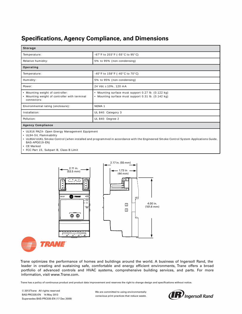
Trane optimizes the performance of homes and buildings around the world. A business of Ingersoll Rand, theleader in creating and sustaining safe, comfortable and energy efficient environments, Trane offers a broadportfolio of advanced controls and HVAC systems, comprehensive building services, and parts. For moreinformation, visit www.Trane.com.
Trane has a policy of continuous product and product data improvement and reserves the right to change design and specifications without notice.
We are committed to using environmentally
conscious print practices that reduce waste.
© 2013Trane All rights reserved
BAS-PRC035-EN 14 May 2013
Supersedes BAS-PRC035-EN (17 Dec 2009)
Specifications, Agency Compliance, and Dimensions
Storage
Temperature: -67°F to 203°F (-55°C to 95°C)
Relative humidity: 5% to 95% (non-condensing)
Operating
Temperature: -40°F to 158°F (-40°C to 70°C)
Humidity: 5% to 95% (non-condensing)
Power: 24 Vdc ±10%, 120 mA
• Mounting weight of controller:• Mounting weight of controller with terminal
connectors:
• Mounting surface must support 0.27 lb. (0.122 kg)• Mounting surface must support 0.31 lb. (0.142 kg)
Environmental rating (enclosure): NEMA 1
Installation: UL 840: Category 3
Pollution: UL 840: Degree 2
Agency Compliance
• UL916 PAZX- Open Energy Management Equipment• UL94-5V, Flammability• UL864/UUKL Smoke Control (when installed and programmed in accordance with the Engineered Smoke Control System Applications Guide,
BAS-APG019-EN)• CE Marked• FCC Part 15, Subpart B, Class B Limit
ADDRESSADDRESSADDRESS
1.73 in(44 mm)
2.11 in.(53.5 mm)
4.00 in.(101.6 mm)
2.17 in. (55 mm)

Trane™ ThermostatsProgrammable and Non-programmable
July 2011 BAS-PRC036-EN
Product Data Sheet
Trane offers a line of programmable and non-programmable commercial thermostats for conventional (rooftop)air conditioners and heat pumps. Features and benefits include:
• Intuitive Liquid Crystal Display— are easy to use and read for all users and languages.
• Soft-touch Buttons or Touch Screen— both are easy and responsive for setup.
• Configurable— permits usage in conventional (RTU) systems or heat pumps with and without auxiliary heat.
• Dehumidification— only with touch screen model.
Part Numbers
Model X Code ClarksvilleGlobal Parts
Thermostat, non-programmable, 1-heat/1-cool X13511535010 BAYSTAT151A THT02772
Thermostat, non-programmable, 3-heat/2-cool X13511536010 BAYSTAT155A THT02773
Thermostat, programmable, 3-heat/2-cool X13511537010 BAYSTAT150A THT02774
Thermostat, programmable, touch screen, 3-heat/2-cool/dehumidification X13511538010 BAYSTAT152A THT02775
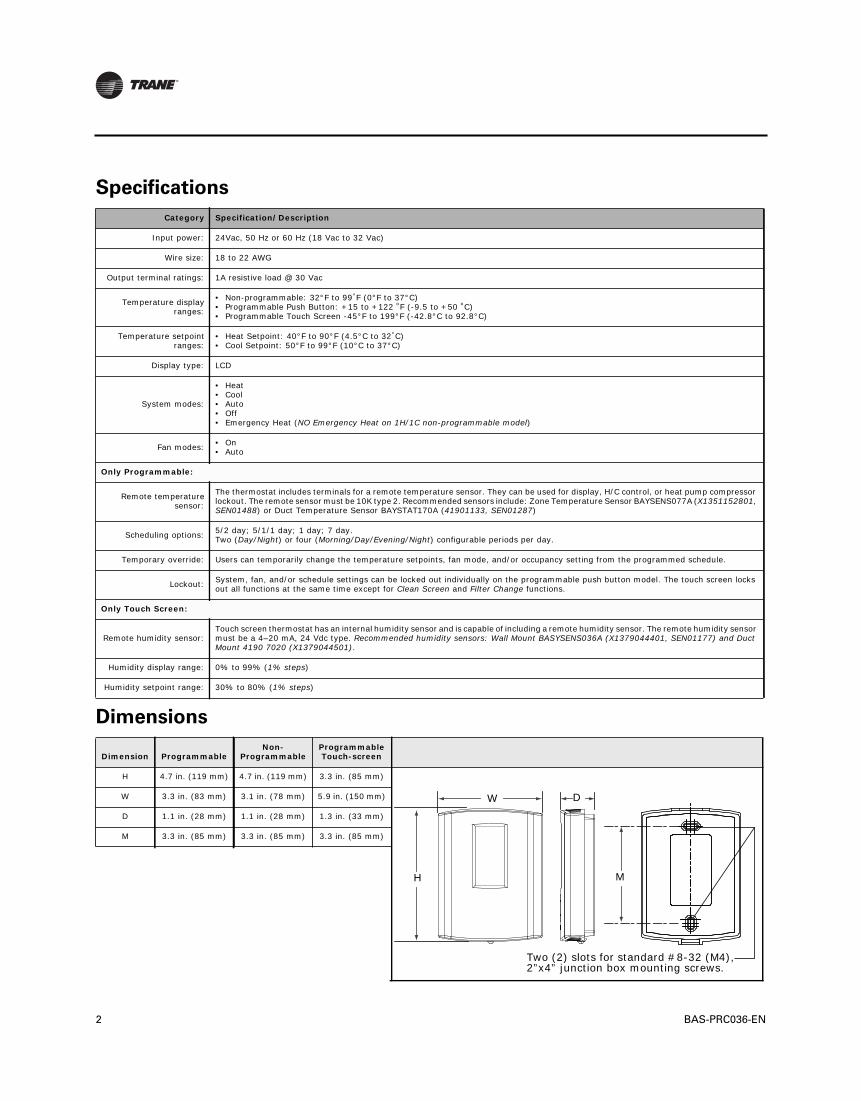
2 BAS-PRC036-EN
Specifications
Dimensions
Category Specification/Description
Input power: 24Vac, 50 Hz or 60 Hz (18 Vac to 32 Vac)
Wire size: 18 to 22 AWG
Output terminal ratings: 1A resistive load @ 30 Vac
Temperature display ranges:
• Non-programmable: 32°F to 99°F (0°F to 37°C)• Programmable Push Button: +15 to +122 ºF (-9.5 to +50 ºC)• Programmable Touch Screen -45°F to 199°F (-42.8°C to 92.8°C)
Temperature setpoint ranges:
• Heat Setpoint: 40°F to 90°F (4.5°C to 32°C)• Cool Setpoint: 50°F to 99°F (10°C to 37°C)
Display type: LCD
System modes:
• Heat• Cool• Auto• Off• Emergency Heat (NO Emergency Heat on 1H/1C non-programmable model)
Fan modes: • On• Auto
Only Programmable:
Remote temperature sensor:
The thermostat includes terminals for a remote temperature sensor. They can be used for display, H/C control, or heat pump compressor lockout. The remote sensor must be 10K type 2. Recommended sensors include: Zone Temperature Sensor BAYSENS077A (X1351152801, SEN01488) or Duct Temperature Sensor BAYSTAT170A (41901133, SEN01287)
Scheduling options: 5/2 day; 5/1/1 day; 1 day; 7 day. Two (Day/Night) or four (Morning/Day/Evening/Night) configurable periods per day.
Temporary override: Users can temporarily change the temperature setpoints, fan mode, and/or occupancy setting from the programmed schedule.
Lockout: System, fan, and/or schedule settings can be locked out individually on the programmable push button model. The touch screen locks out all functions at the same time except for Clean Screen and Filter Change functions.
Only Touch Screen:
Remote humidity sensor:Touch screen thermostat has an internal humidity sensor and is capable of including a remote humidity sensor. The remote humidity sensor must be a 4–20 mA, 24 Vdc type. Recommended humidity sensors: Wall Mount BASYSENS036A (X1379044401, SEN01177) and Duct Mount 4190 7020 (X1379044501).
Humidity display range: 0% to 99% (1% steps)
Humidity setpoint range: 30% to 80% (1% steps)
Dimension ProgrammableNon-
ProgrammableProgrammable Touch-screen
H 4.7 in. (119 mm) 4.7 in. (119 mm) 3.3 in. (85 mm)
W 3.3 in. (83 mm) 3.1 in. (78 mm) 5.9 in. (150 mm)
D 1.1 in. (28 mm) 1.1 in. (28 mm) 1.3 in. (33 mm)
M 3.3 in. (85 mm) 3.3 in. (85 mm) 3.3 in. (85 mm)
W
H
D
M
Two (2) slots for standard #8-32 (M4), 2”x4” junction box mounting screws.
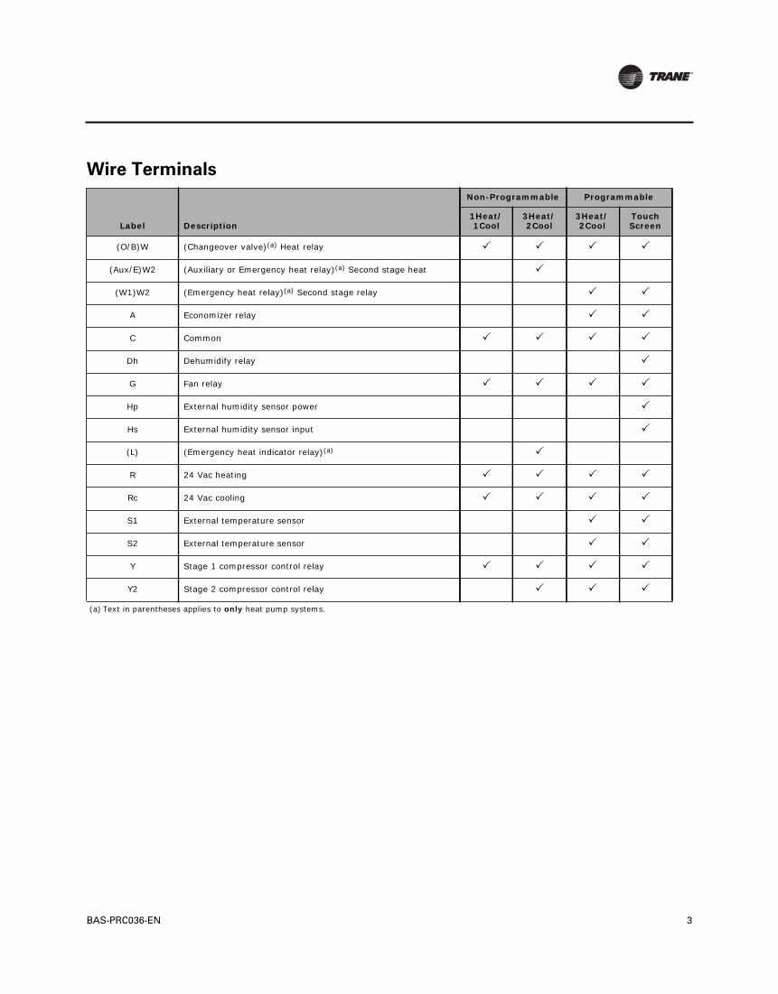
BAS-PRC036-EN 3
Wire Terminals
Label Description
Non-Programmable Programmable
1Heat/1Cool
3Heat/2Cool
3Heat/2Cool
Touch Screen
(O/B)W (Changeover valve)(a) Heat relay
(Aux/E)W2 (Auxiliary or Emergency heat relay)(a) Second stage heat
(a) Text in parentheses applies to only heat pump systems.
(W1)W2 (Emergency heat relay)(a) Second stage relay
A Economizer relay
C Common
Dh Dehumidify relay
G Fan relay
Hp External humidity sensor power
Hs External humidity sensor input
(L) (Emergency heat indicator relay)(a)
R 24 Vac heating
Rc 24 Vac cooling
S1 External temperature sensor
S2 External temperature sensor
Y Stage 1 compressor control relay
Y2 Stage 2 compressor control relay

Trane optimizes the performance of homes and buildings around the world. A business of Ingersoll Rand, theleader in creating and sustaining safe, comfortable and energy efficient environments, Trane offers a broadportfolio of advanced controls and HVAC systems, comprehensive building services, and parts. For moreinformation, visit www.Trane.com.
Trane has a policy of continuous product and product data improvement and reserves the right to change design and specifications without notice.
© 2011 Trane. All rights reserved.
BAS-PRC036-EN 28 July 2011
Supersedes BAS-PRC036-EN 01 Mar 2010

© 2009 Trane. All rights reserved.November 2009 BAS-PRC038-EN
Product Data Sheet
BACnet™ Communication Interface for Chillers (BCI-C)The BCI-C device is a communications module that allows heating, ventilation, and air-conditioning (HVAC) equipment to communicate on a BACnet communications network. This device is a non-programmable communication module that connects directly to the Tracer™ CH530 series of equipment. The BACnet Communication Interface is comprised of a Tracer™ UC400 controller with interface software.
Ordering Number
Features and Benefits
Order Number Description
KIT15548 BACnet Communication Interface Kit for Chillers
Features Benefits
BCI Installation The BCI-C can be offered as a factory- or field-mounted unit and easily installed on DIN rail.
Self-configuring/Data Point Manager The BCI-C is a self-configuring unit that determines data points based on the type of chiller equipment and installed equipment options.
BACnet protocolThe BCI-C device supports BACnet protocol per ASHRAE 135-2004 and meets requirements for BACnet Testing Laboratory (BTL) certification as an Application Specific Controller (ASC) profile device.

www.trane.com
For more information, contact your local Trane office or e-mail us at [email protected]
Literature Order Number BAS-PRC038-EN
Date November 2009
Supersedes BAS-PRC038-EN (Aug 2009)
Trane has a policy of continuous product and product data improvement and reserves the right to change design and specifications without notice.
IntelliPak, Tracer, Trane, and the Trane logo are trademarks of Trane in the United States and other countries.All trademarks referenced in this document are the trademarks of their respective owners.
Specifications and Controller Dimensions
Note: Controller dimensions are referenced to DIN rail surface.
Storage
Temperature: -48°F to 203°F (-44°C to 95°C)
Relative humidity: Between 5% to 95% (noncondensing)
Operating
Temperature: -40°F to 158°F (-40°C to 70°C)
Humidity: Between 5% to 95% (noncondensing)
Power: 24 Vdc ±15%, maximum load of 90 mA
Controller mounting weight: Mounting surface must support: .80 lb. (.364 kg)
Environmental rating (enclosure): NEMA 1
Altitude: 6,500 ft maximum (1,981 m)
Installation: U.L. 840: Category 3
Pollution U.L. 840: Degree 2
5.65 in. (143.5 mm) width
2.17 in. (55 mm)depth
1.73 in. (44 mm)
4.00 in. (101.6 mm)
height
35 mmDin Rail Mount
Important: Slotted release clip shown– if removing or repositioning the controller, the user must remove connectors before proceeding.

July 2013 BAS-PRC039-EN
Product Data Sheet
Wireless Comm Interface (WCI)
Part Numbers: X13790901010 (Indoor Mounting)
X13790941010 (Outdoor Mounting)
TraneWireless Comm replaces the BACnet communication link and sensor wire onTracer™ building automation systemsfor faster, easier, lower-risk installation and life-cycle savings.
Features and Benefits
Features Benefits
Reduced project complexity and labor
Reduces installation time and risks for on-time project completion while increasing return on investment.
Life-cycle savings By avoiding (re)wiring, savings are incurred both for the initial installation and whenever the spaces are reconfigured or expanded.
Reliability and safety The WCI is based on the IEEE 802.15.4 standard. The Institute of Electrical and Electronics Engineers (IEEE) is an international non-profit, professional organization, in which coexistence is a fundamental requirement.
Security ZigBee™ Building Automation includes methods for network key establishment, network key transport, frame protection, and device management. Trane wireless networks are extremely secure, allowing building automation to efficiently maintain comfortable, productive environments.
Available factory or field installed Factory installation, testing, and addressing increases installed quality and further reduces installation labor. Field installation is available when factory installation is not practical or for field installation of a Tracer SC or as a repeater (if needed).
ZigBee Building Automation Certified
Wireless Comm runs BACnet® protocol over ZigBee® Building Automation standards. Adding unit controllers, zone sensors and other devices down the road will be easy and affordable.
Indoor and Outdoor Mounting Available for indoor or outdoor mounting. Outdoor mounting is ideal for any outdoor equipment or network setup above a roof deck. Indoor mounting is suitable for plenum applications.
Outdoor Mounting
Indoor Mounting

2 BAS-PRC039-EN
Specifications
Product Attribute Range/DescriptionOperating temperature -40 to 158ºF (-40 to 70ºC)
Storage temperature -40 to 185ºF (-40 to 85°C)
Storage and operating humidity range
5% to 95% relative humidity (RH), non-condensing
Voltage 24 Vac/Vdc nominal ± 10%If using 24 Vac, polarity must be maintained.
Receiver power consumption <2.5 VA
Housing material Polycarbonate/ABS (suitable for plenum mounting), UV protected, UL 94: 5 VA flammability rating
Range(a)
(a)Range values are estimated transmission distances for satisfactory operation. Actual distance is job specific and must be determined during site evaluation. Placement of the WCI is critical to proper system operation. In most general office space installations, distance is not the limiting factor for proper signal quality. Signal quality is more greatly affected by walls, barriers, and general clutter. Note that sheetrock walls and ceiling tiles offer little restriction to the propagation of the radio signal throughout the building as opposed to concrete or metal barriers. More detailed information, including wiring sche-matics, are available at http://www.trane.com.
Open range: 2,500 ft (762 m) with packet error rate of 2%.Indoor: Typical range is 200 ft (61 mm); actual range is dependent on the environment. See BAS-SVX55 for more detail.
Output power North America: 100 mW
Radio frequency 2.4 GHz (IEEE Std 802.15.4-2003 compliant) (2405–2480 MHz, 5 MHz spacing)
Radio channels 16
Indoor Mounting Fits a standard 2 in. by 4 in. junction box (vertical mount only). Mounting holes are spaced 3.2 in. (83 mm) apart on vertical center line. Includes mounting screws for junction box or wall anchors for sheet-rock walls. Overall dimensions: 2.9 in. (74 mm) by 4.7 in. (119 mm)
Outdoor Mounting Position enclosure in desired flat mounting location and mount using four (4) #8 sheet metal screws with the conduit connection pointing down. If not mounted to the HVAC equipment exterior wall, the conduit connection on the bottom of the enclosure is also available. Please note that the supplied plug must be installed into the unused conduit connection. Overall dimensions: 3.9 in. (98 mm) by 6.4 in. (163 mm) by 1.7 in. (42 mm)
Wireless protocol ZigBee PRO—ZigBee Building Automation Profile, ANSI/ASHRAE Standard 135-2008 Addendum q (BACnet™/ZigBee)
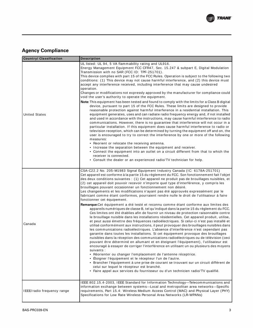
BAS-PRC039-EN 3
Agency Compliance
Country/Classification Description
United States
UL listed: UL 94, 5 VA flammability rating and UL916.Energy Management Equipment FCC CFR47, Sec. 15.247 & subpart E, Digital Modulation Transmission with no SAR (FCC ID: TPF-251701).This device complies with part 15 of the FCC Rules. Operation is subject to the following two conditions: (1) This device may not cause harmful interference, and (2) this device must accept any interference received, including interference that may cause undesired operation. Changes or modifications not expressly approved by the manufacturer for compliance could void the user’s authority to operate the equipment. Note: This equipment has been tested and found to comply with the limits for a Class B digital
device, pursuant to part 15 of the FCC Rules. These limits are designed to provide reasonable protection against harmful interference in a residential installation. This equipment generates, uses and can radiate radio frequency energy and, if not installed and used in accordance with the instructions, may cause harmful interference to radio communications. However, there is no guarantee that interference will not occur in a particular installation. If this equipment does cause harmful interference to radio or television reception, which can be determined by turning the equipment off and on, the user is encouraged to try to correct the interference by one or more of the following measures: • Reorient or relocate the receiving antenna. • Increase the separation between the equipment and receiver. • Connect the equipment into an outlet on a circuit different from that to which the
receiver is connected. • Consult the dealer or an experienced radio/TV technician for help.
Canada
CSA-C22.2 No. 205-M1983 Signal Equipment Industry Canada (IC: 6178A-251701)Cet appareil est conforme à la partie 15 du règlement du FCC. Son fonctionnement fait l’objet des deux conditions suivantes : (1) Cet appareil ne produit pas de brouillages nuisibles, et (2) cet appareil doit pouvoir recevoir n’importe quel type d’interférence, y compris les brouillages pouvant occasionner un fonctionnement non désiré.Les changements et les modifications n’ayant pas été approuvés expressément par le fabricant comme étant conformes, pourraient rendre nulle le droit de l’utilisateur à faire fonctionner cet équipement.Remarque:Cet équipement a été testé et reconnu comme étant conforme aux limites des
appareils numériques de classe B, tel qu’indiqué dans la partie 15 du règlement du FCC. Ces limites ont été établies afin de fournir un niveau de protection raisonnable contre le brouillage nuisible dans les installations résidentielles. Cet appareil produit, utilise, et peut aussi émettre des fréquences radioélectriques. Si celui-ci n’est pas installé et utilisé conformément aux instructions, il peut provoquer des brouillages nuisibles dans les communications radioélectriques. L’absence d’interférence n’est cependant pas garantie dans toutes les installations. Si cet équipement provoque des brouillages nuisibles dans la réception des communications radioélectriques ou de télévision (ceci pouvant être déterminé en allumant et en éteignant l’équipement), l’utilisateur est encouragé à essayer de corriger l’interférence en utilisant un ou plusieurs des moyens suivants :• Réorienter ou changer l’emplacement de l’antenne réceptrice.• Éloigner l’équipement et le récepteur l’un de l’autre.• Brancher l’équipement à une prise de courant se trouvant sur un circuit différent de
celui sur lequel le récepteur est branché.• Faire appel aux services du fournisseur ou d’un technicien radio/TV qualifié.
IEEE/radio frequency range
IEEE 802.15.4-2003, IEEE Standard for Information Technology—Telecommunications and information exchange between systems—Local and metropolitan area networks—Specific requirements, Part 15.4: Wireless Medium Access Control (MAC) and Physical Layer (PHY) Specifications for Low Rate Wireless Personal Area Networks (LR-WPANs)

Trane optimizes the performance of homes and buildings around the world. A business of Ingersoll Rand, theleader in creating and sustaining safe, comfortable and energy efficient environments, Trane offers a broadportfolio of advanced controls and HVAC systems, comprehensive building services, and parts. For moreinformation, visit www.Trane.com.
Trane has a policy of continuous product and product data improvement and reserves the right to change design and specifications without notice.
We are committed to using environmentally
conscious print practices that reduce waste.© 2013Trane All rights reserved
BAS-PRC039-EN 11 July 2013
Supercedes BAS-PRC039-EN 16 Apr 2013

May 2013 BAS-PRC052-EN
Tracer™ XM32 Expansion ModuleThe Tracer XM32 Expansion Module provides additional points when needed for Tracer UC600, Tracer UC400, and Tracer UC210 applications. Each expansion module has a total of four (4) relay outputs. A PM014 24Vac/24Vdc power supply module (Order Number X136515380) is required for applications that require more than two expansion modules.
Configurable Connections
Dimensions
Connection Quantity Types Range Notes
Binary output (BO1 to BO4) 4
General purpose General Purpose (Resistive) 10 A max up to 277 Vac 10 A max up to 30 VdcMotor Duty (Inductive) 1/3 hp at 125 Vac (7.5 A max) 1/2 hp at 277 Vac (7.5 A max)
POWER MUST BE WIRED TO THE BINARY OUTPUT. ALL OUTPUTS ARE ISOLATED FROM EACH OTHER AND FROM GROUND OR POWER.RANGES ARE GIVEN PER CONTACT
Motor
Pilot duty (inductive load)
Resistive load
IMC
+24VDC
RELAYSBO1 BO2 BO3 BO4
NO NC C NO NC C NO NC C NO NC C
A B
CL
4.00 in. (101.6 mm)
2.82 in. (71.63 mm)
1.93 in. (49.02 mm)
1.12 in. (28.45 mm)
Product Data Sheet

Trane optimizes the performance of homes and buildings around the world. A business of Ingersoll Rand, the leader in creating and sustaining safe, comfortable and energy efficient environments, Trane offers a broad portfolio of advanced controls and HVAC systems, comprehensive building services, and parts. For more information, visit www.Trane.com.
Trane has a policy of continuous product and product data improvement and reserves the right to change design and specifications without notice.
We are committed to using environmentally
conscious print practices that reduce waste.
Specifications and Agency Compliance
Storage
Temperature: -67°F to 203°F (-55°C to 95°C)
Relative humidity: 5% to 95% (non-condensing)
Operating
Temperature: -40°F to 158°F (-40°C to 70°C)
Humidity: 5% to 95% (non-condensing)
Power: 24 Vdc ±10%, 100 mA
• Mounting weight of controller:• Mounting weight of controller with terminal
connectors:
• Mounting surface must support 0.43 lb. (0.195 kg)• Mounting surface must support 0.47 lb. (0.213 kg)
Environmental rating (enclosure): NEMA 1
Installation: UL 840: Category 3
Pollution: UL 840: Degree 2
Agency Compliance
• UL916 PAZX- Open Energy Management Equipment• UL94-5V Flammability• UL864/UUKL Smoke Control (when installed and programmed in accordance with the Engineered Smoke Control System Applications Guide,
BAS-APG019-EN)• CE Marked• FCC Part 15, Subpart B, Class B Limit
© 2013 Trane All rights reserved
BAS-PRC052-EN 14 May 2013
Supersedes: BAS-PRC052-EN (12 Apr 2012)

© 2010 Trane All rights reserved
Product Data Sheet
Programmable Zone SensorThe Trane® programmable zone sensor is an excellent choice for customers who wish to reduce first cost when expanding communication and application flexibility for their controls equipment.
The programmable zone sensor is configurable with commercial rooftop units (RTU), heat pumps, and variable air volume (VAV) applications. Its compact size, combined with an intuitive liquid crystal display (LCD), is both aesthetically pleasing and easy to use.
The Trane programmable zone sensor can be used with UCP, ReliaTel™, and IntelliPak™control units.
Features and Benefits
Part Numbers
Feature Benefits
Intuitive LCD with symbols Clear and simple use independent of the user’s language.
Multiple system modes Can be used on a wide variety of applications: conventional RTUs, heat pumps, and VAV equipment.
Field-configurable Only one sensor required for the applications listed above, simplifying installation and replacement.
Flexible scheduling functionScheduling function: 7 days per week and up to 4 periods per day, occupied/unoccupied mode. Flexible programming saves energy on most all commercial applications.
Temporary override function Short or long term comfort and/or engery savings without the need to reset the schedule.
Non-battery backupRetains configuration and schedule for more than 3 days without power, minimizing the added maintenance costs associated with reprogramming and battery replacement.
Model X Code Clarksville Global Parts
Programmable Zone Sensor X13790884010 BAYSENS119A SEN01577
June 2010 BAS-PRC053-EN
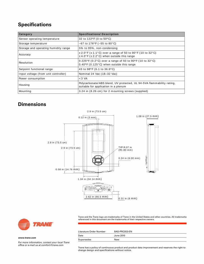
www.trane.com
For more information, contact your local Trane office or e-mail us at [email protected]
Literature Order Number BAS-PRC053-EN
Date June 2010
Supersedes New
Trane has a policy of continuous product and product data improvement and reserves the right to change design and specifications without notice.
Trane and the Trane logo are trademarks of Trane in the United States and other countries. All trademarksreferenced in this document are the trademarks of their respective owners.
Specifications
Dimensions
Category Specifications/Description
Sensor operating temperature 32 to 122ºF (0 to 50ºC)
Storage temperature –67 to 176ºF (–55 to 80°C)
Storage and operating humidity range 5% to 95%, non-condensing
Accuracy ±2.0°F (±1.1°C) over a range of 50 to 90°F (10 to 32°C)±4.0°F (±2.2°C) when outside this range
Resolution0.225ºF (0.2°C) over a range of 50 to 90ºF (10 to 32°C)0.40ºF (0.125°C) when outside this range
Setpoint functional range 43 to 98ºF (6.1 to 36.6ºC)
Input voltage (from unit controller) Nominal 24 Vac (18–32 Vac)
Power consumption <3 VA
Housing Polycarbonate/ABS blend, UV protected, UL 94-5VA flammability rating, suitable for application in a plenum
Mounting 3.24 in (8.26 cm) for 2 mounting screws (supplied)
2.9 in (73.5 cm)
0.12 in (3 mm)
2.9 in (73.5 cm)
2.9 in (73.5 cm)
0.31 in (8 mm)
1.08 in (27.5 mm)
0.24 in (6.00 mm)
1.34 in (34.14 mm)
TYP R.07 in (R1.80 mm)
0.58 in (14.76 mm)
2.62 in (66.5 mm)

Trane eView™
Energy Reporting Software
November 2010 BAS-PRC054-EN
Product Catalog

2 BAS-PRC054-EN, 18 Nov 2010
Copyright
© 2010 Trane
This document and the information in it are the property of Trane and may not be used or reproduced in whole or in part, without the written permission of Trane. Trane reserves the right to revise this publication at any time and to make changes to its content without obligation to notify any person of such revision or change.
Trademarks
Trane and its logo are trademarks of Trane in the United States and other countries. All trademarks referenced in this document are the trademarks of their respective owners.

Table of Contents
BAS-PRC054-EN, 18 Nov 2010 3
Introduction . . . . . . . . . . . . . . . . . . . . . . . . . . . . . . . . . . . . . . . . . . . . . . . . . . . . . . . . . . . . 4
Features and Benefits . . . . . . . . . . . . . . . . . . . . . . . . . . . . . . . . . . . . . . . . . . . . . . . . . . . 5
Dashboards . . . . . . . . . . . . . . . . . . . . . . . . . . . . . . . . . . . . . . . . . . . . . . . . . . . . . . . 5
Reports . . . . . . . . . . . . . . . . . . . . . . . . . . . . . . . . . . . . . . . . . . . . . . . . . . . . . . . . . . . 5Financial and Forecasting Tools . . . . . . . . . . . . . . . . . . . . . . . . . . . . . . . . . . 7
Proactive Alarms and Exception Reporting . . . . . . . . . . . . . . . . . . . . . . . . . . . . 7
Energy Analysis Tools . . . . . . . . . . . . . . . . . . . . . . . . . . . . . . . . . . . . . . . . . . . . . . . . . . 9
Trane eView Editions . . . . . . . . . . . . . . . . . . . . . . . . . . . . . . . . . . . . . . . . . . . . . . . . . . 12
eView Express . . . . . . . . . . . . . . . . . . . . . . . . . . . . . . . . . . . . . . . . . . . . . . . . . . . . 12
eView Manager . . . . . . . . . . . . . . . . . . . . . . . . . . . . . . . . . . . . . . . . . . . . . . . . . . . 12
eView Expert . . . . . . . . . . . . . . . . . . . . . . . . . . . . . . . . . . . . . . . . . . . . . . . . . . . . . 13
System Network Diagram . . . . . . . . . . . . . . . . . . . . . . . . . . . . . . . . . . . . . . . . . . . . . . 14
Technical Specifications . . . . . . . . . . . . . . . . . . . . . . . . . . . . . . . . . . . . . . . . . . . . . . . . 15

4 BAS-PRC054-EN 18 Nov 2010
Introduction
The Trane eView™ energy management solution provides automated monitoring, analysis, alerts, reporting, data visualization, and facilitates the sharing of results through the use of dashboards, reports, and other tools.
As energy costs continue to rise and the impact that over-consumption has on the environment, the need to operate and maintain buildings as efficiently as possible has never been so important. eView can help by raising awareness of how much energy your building consumes and then developing strategies to control energy costs.
eView energy management software tracks energy use, costs, and CO2 emissions and processes the information for review, analysis, and compliance reporting. It provides the information you need to identify and assess opportunities. eView makes it easy to showcase the results of your energy conservation programs to internal and public audiences.
eView highlights
• Assess data from various sites or meters.
• Review energy data in a wide range of graphs, tables, reports and exports.
• Compare energy use and costs on a day-to-day, month-to-month, year-to-year basis and normalize for weather and critical business metrics.
• Schedule monthly reports to be sent to your e-mail account.
• Set up alarms to proactively notify and attach meaningful reports to each alarm.
• Use custom dashboards to track and communicate your critical energy use and cost information.
• See how energy use translates into greenhouse gas emissions.
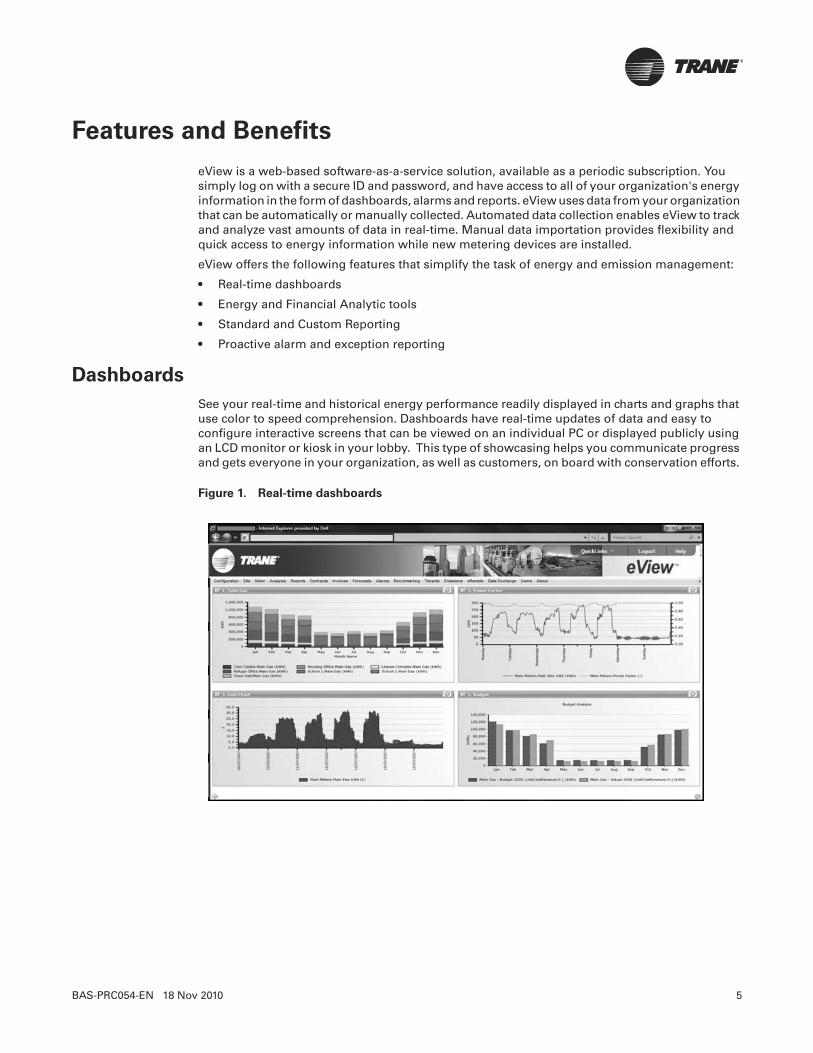
BAS-PRC054-EN 18 Nov 2010 5
Features and Benefits
eView is a web-based software-as-a-service solution, available as a periodic subscription. You simply log on with a secure ID and password, and have access to all of your organization's energy information in the form of dashboards, alarms and reports. eView uses data from your organization that can be automatically or manually collected. Automated data collection enables eView to track and analyze vast amounts of data in real-time. Manual data importation provides flexibility and quick access to energy information while new metering devices are installed.
eView offers the following features that simplify the task of energy and emission management:
• Real-time dashboards
• Energy and Financial Analytic tools
• Standard and Custom Reporting
• Proactive alarm and exception reporting
Dashboards
See your real-time and historical energy performance readily displayed in charts and graphs that use color to speed comprehension. Dashboards have real-time updates of data and easy to configure interactive screens that can be viewed on an individual PC or displayed publicly using an LCD monitor or kiosk in your lobby. This type of showcasing helps you communicate progress and gets everyone in your organization, as well as customers, on board with conservation efforts.
Figure 1. Real-time dashboards
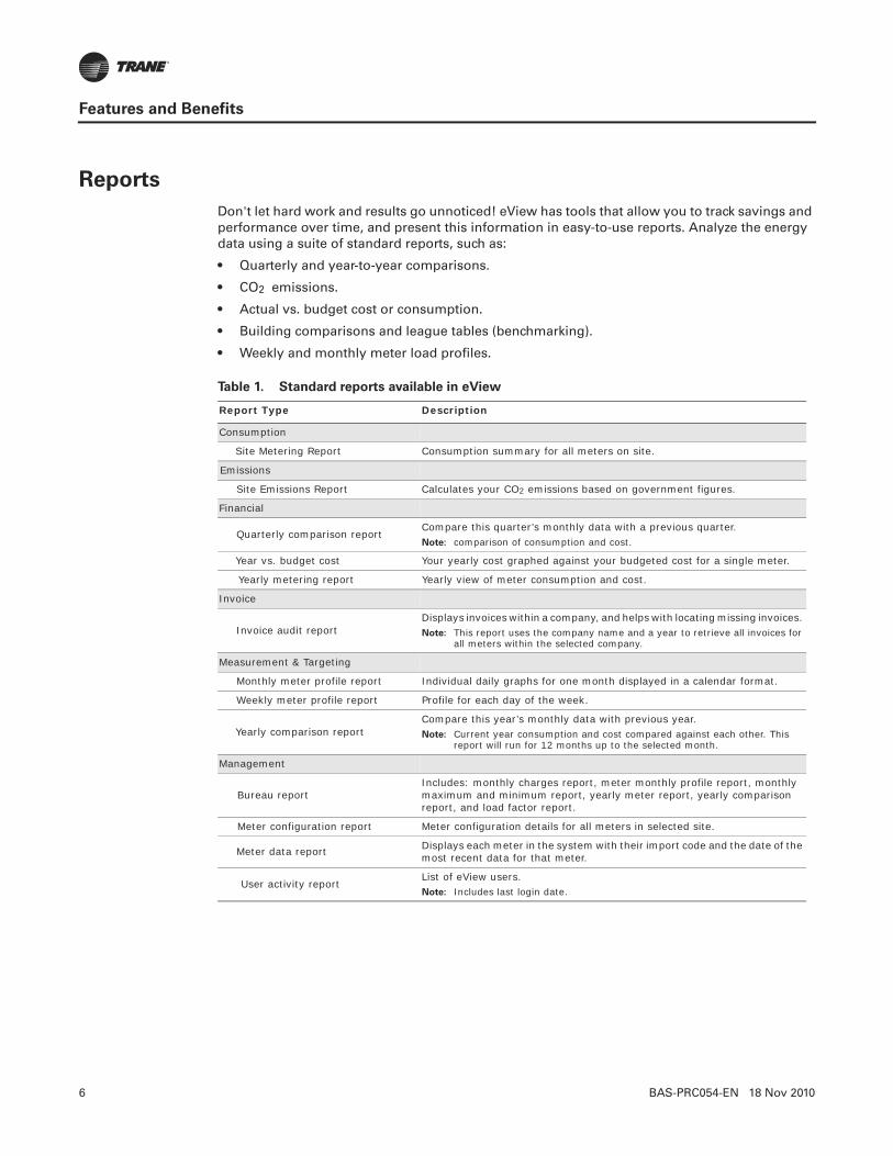
6 BAS-PRC054-EN 18 Nov 2010
Features and Benefits
Reports
Don't let hard work and results go unnoticed! eView has tools that allow you to track savings and performance over time, and present this information in easy-to-use reports. Analyze the energy data using a suite of standard reports, such as:
• Quarterly and year-to-year comparisons.
• CO2 emissions.
• Actual vs. budget cost or consumption.
• Building comparisons and league tables (benchmarking).
• Weekly and monthly meter load profiles.
Table 1. Standard reports available in eView
Report Type Description
Consumption
Site Metering Report Consumption summary for all meters on site.
Emissions
Site Emissions Report Calculates your CO2 emissions based on government figures.
Financial
Quarterly comparison reportCompare this quarter’s monthly data with a previous quarter. Note: comparison of consumption and cost.
Year vs. budget cost Your yearly cost graphed against your budgeted cost for a single meter.
Yearly metering report Yearly view of meter consumption and cost.
Invoice
Invoice audit reportDisplays invoices within a company, and helps with locating missing invoices. Note: This report uses the company name and a year to retrieve all invoices for
all meters within the selected company.
Measurement & Targeting
Monthly meter profile report Individual daily graphs for one month displayed in a calendar format.
Weekly meter profile report Profile for each day of the week.
Yearly comparison reportCompare this year’s monthly data with previous year. Note: Current year consumption and cost compared against each other. This
report will run for 12 months up to the selected month.
Management
Bureau reportIncludes: monthly charges report, meter monthly profile report, monthly maximum and minimum report, yearly meter report, yearly comparison report, and load factor report.
Meter configuration report Meter configuration details for all meters in selected site.
Meter data report Displays each meter in the system with their import code and the date of the most recent data for that meter.
User activity reportList of eView users. Note: Includes last login date.

BAS-PRC054-EN 18 Nov 2010 7
Features and Benefits
Financial and Forecasting Tools
eView provides the ability to analyze and manage not only your energy consumption, but your energy costs as well. Enter and store multiple ultility rates to improve the accuracy of cost forecasting and tenant invoicing.
Benchmarking
How does today’s energy use compare to last months—or last year? eView normalizes energy data for building size, weather (degree days), and business metrics (units or widgets produced, sales dollars, occupants). You can rank buildings against others in the portfolio to enable prioritization of energy conservation efforts.
Standard invoicing and Tenant Billing
Standard invoicing converts meter readings into invoices for building tenants or internal departments. This provides the benefit of eliminating the need for multiple meters. Provides the functionality and the ability to auto-generate invoices that can be distributed to multiple tenants or occupants for cost allocation or revenue-generating purposes.
Figure 2. Example of a Generated Consumption vs. Budget Report

8 BAS-PRC054-EN 18 Nov 2010
Features and Benefits
Proactive Alarms and Exception Reporting
Alarms in eView are managed by exception, allowing you to be more proactive in the alarm management process. eView employs an alarm management system that allows for ranges to be set against energy use and cost targets. If conditions exceed target ranges, alarms will alert users and even provide reports addressing the alarm condition.
eView allows you to:
• Set up different types of alarms (profile, range, average, missing data, deviation, budget deviation).
• Set up alarms according to severity—critical, non-critical, advisory.
• Set up alarms simultaneously for multiple meters.
• Determine which users will receive alarm notifications; this can also be based on the criteria set up for the alarm.
• Determine which reports can be sent with an alarm.
• Prevent nuisance alarms.

BAS-PRC054-EN 18 Nov 2010 9
Energy Analysis Tools
eView provides a wide range of comprehensive energy analysis tools and reports for monitoring consumption, comparing data, and targeting different areas for improvement. It displays data in charts, tables, reports and exported file formats.
eView Energy Analysis Tools include:
Energy Analysis
This tool offers a wide range of analysis techniques for all types of data. Create a chart, table, or template and view information on-screen or in an exported data format. Data can be exported as a PDF, an electronic spreadsheet, or as a CSV file.
Single Meter Analysis
Provides analysis techniques that include comparison of multiple days across a single 24-hour period. These techniques include: day comparison, surface mapping and 3D contouring.
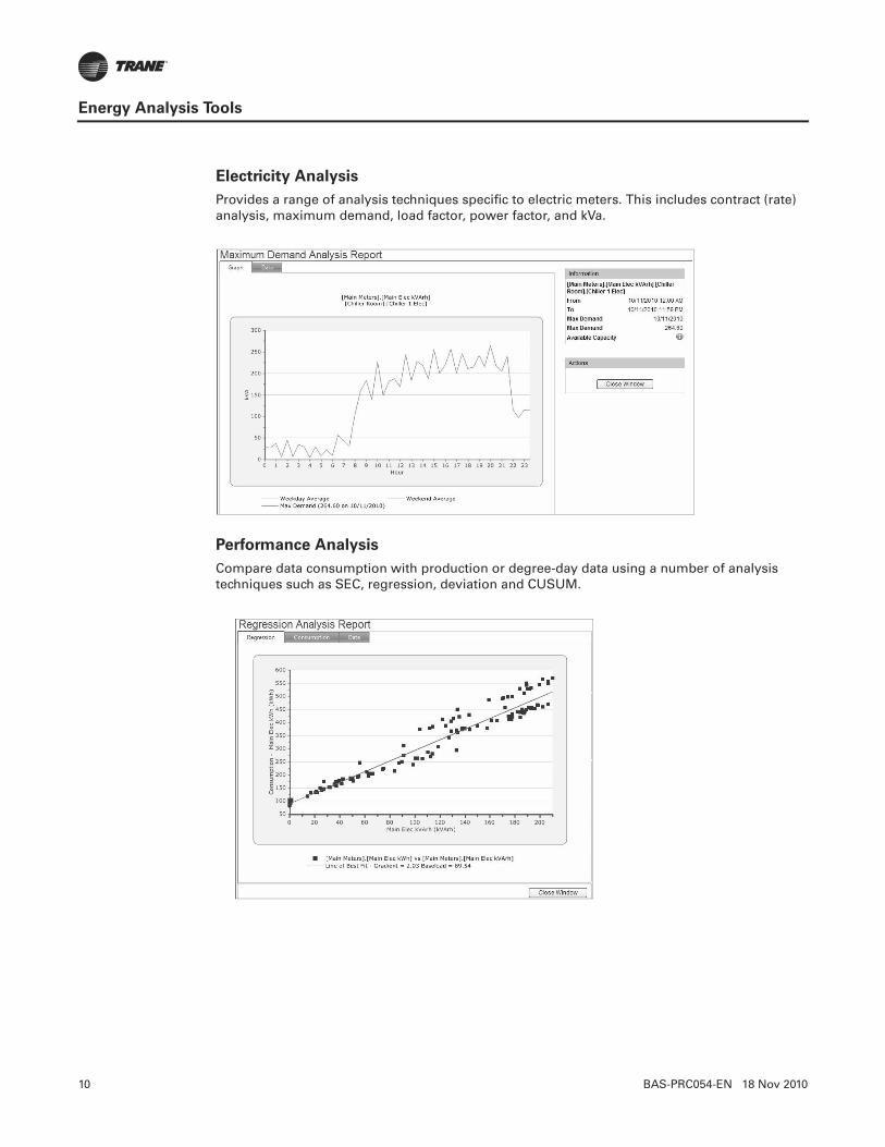
10 BAS-PRC054-EN 18 Nov 2010
Energy Analysis Tools
Electricity Analysis
Provides a range of analysis techniques specific to electric meters. This includes contract (rate) analysis, maximum demand, load factor, power factor, and kVa.
Performance Analysis
Compare data consumption with production or degree-day data using a number of analysis techniques such as SEC, regression, deviation and CUSUM.

BAS-PRC054-EN 18 Nov 2010 11
Energy Analysis Tools
Baseload Analysis
View the base load consumption of a meter for active or inactive periods.
League Tables
Compare sites or meters based on a range of key performance indicators (KPIs).

12 BAS-PRC054-EN 18 Nov 2010
Energy Analysis Tools
Energy Temperature (ET) Analysis
Analyze energy usage against outdoor air temperature. The target line is derived from either the previous year’s usage, or pre-set with the graph highlighting over-usage, under-usage or normal usage compared to a percentage deviation from this target.

BAS-PRC054-EN 18 Nov 2010 13
Trane eView Editions
Trane eView provides insight into energy use, cost, and environmental performance at the organizational, building, and meter levels.
eView is available in the following three packages: eView Express, eView Manager, and eView Expert. All three editions are available in English, Spanish, Dutch, French, German and Norwegian. Additional languages are available upon request.
• Assess data from various sites or meters
• Compare energy use and costs on a day-to-day, month-to-month, year-to-year basis and normalize for weather and critical business metrics
• Review energy data in a wide range of graphs, tables, reports and exports
• See how energy use translates into greenhouse gas emissions
eView Express
The most cost effective choice, eView Express offers practical energy use and cost metrics, delivered to you automatically on a weekly or monthly basis. Show energy performance, tracked against organizational goals, through pre-configured dashboards and reports that can be shared throughout your organization. This practical solution allows you to focus on other business, knowing the reports you need will arrive in your "in-box" as scheduled . . . or if an alarm condition warrants your immediate attention.
Highlights
• Simple user interface.
• Dashboard (pre-configured at start-up).
• Reports (pre-selected reports are automatically sent to your e-mail account).
• Alarms (pre-configured energy use alarms will be setup to alert you to abnormal energy use patterns or spikes).
• Ad Hoc Reporting (view standard reports or run your own using a simple report generation wizard).
eView Manager
Along with the same practical features that are included in eView Express, the eView Manager edition offers a more advanced set of financial tools that supports forecasting, budgeting, and tenant invoicing. Use the standard pre-configured features, or create your own customized dashboards, reports (Figure 3) and alarm notifications.
Highlights
• Rates (create your own rates or have Trane create them for you).
• Budgets (create your own for both energy use and costs).
• Budget Analysis (use tools to analyze and compare the following types of data: actual meter data, budget data, actual data normalized, or the target budget).
• Invoices (validate your utility invoices against eView data).
• Tenant Billing (create invoices that are automatically routed by e-mail to your tenants each month).

14 BAS-PRC054-EN 18 Nov 2010
Trane eView Editions
eView Expert
The eView Expert edition includes all the capabilities of Express and Manager, plus an extended set of energy analysis tools. It is geared toward the energy manager who requires a more sophisticated set of tools to identify energy-saving and cost reduction opportunities across multiple facilities.
Highlights
• Energy Analysis enables data to be presented in a wide range of graphs, tables, reports and exports. Run reports on an ad hoc basis, save as a template for later, or schedule for automatic production and delivery by e-mail.
• Energy analysis tools and reports provide a range of options for monitoring consumption, comparing data, and targeting different areas for improvement. See “Energy Analysis Tools,” p. 9.
Contract (rates) Forecast
Tax rates Budget analysis
Contract groups Budgets
Contract bid management Quickset budgets
Import contracts Import budgets
Figure 3. Budget Report and Tenant Bill Figures
One of many reports that can be generated by eView Manager, this report displays electrical usage over a 14 day period. The contract was stored against the main meters, which graphically depicts energy usage and a breakdown of costs.
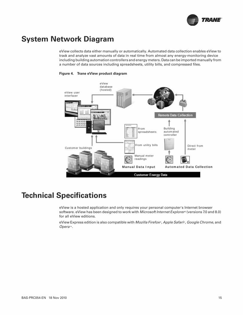
BAS-PRC054-EN 18 Nov 2010 15
System Network Diagram
eView collects data either manually or automatically. Automated data collection enables eView to track and analyze vast amounts of data in real time from almost any energy-monitoring device including building automation controllers and energy meters. Data can be imported manually from a number of data sources including spreadsheets, utility bills, and compressed files.
Technical Specifications
eView is a hosted application and only requires your personal computer's Internet browser software. eView has been designed to work with Microsoft Internet Explorer® (versions 7.0 and 8.0) for all eView editions.
eView Express edition is also compatible with Mozilla Firefox®, Apple Safari®, Google Chrome, and Opera™.
Figure 4. Trane eView product diagram
Customer buildings
eView user interfacer
eView database(hosted)
Manual meter readings
From utility bills
Fromspreadsheets
Building automated controller
Direct from meter
Manual Data Input Automated Data Collection

Trane optimizes the performance of homes and buildings around the world. A business of Ingersoll Rand, the leader in creating and sustaining safe, comfortable and energy efficient environments, Trane offers a broad portfolio of advanced controls and HVAC systems, comprehensive building services, and parts.For more information, visit www.Trane.com.
Trane has a policy of continuous product and product data improvement and reserves the right to change design and specifications without notice.
© 2010 Trane All rights reserved
BAS-PRC054-EN 18 Nov 2010
New

Tracer™ MP580/581
Programmable Controller
December 2010 BAS-PRC056-EN
Product Data Sheet
The Tracer™MP580/581 programmable controller is a factory-installed unit on Trane™ air handlers such as M-series and T-series Climate Changers and custom AireSystems. In addition, this controller can be field-installed on a variety of HVAC applications such as:
• Air handler control
• Support of Space Comfort Control (SCC) and Discharge Air Control (DAC) LonMark™ profiles
• Control of mechanical equipment in commercial buildings
Features and Benefits
Features Benefits
Product model availability:
• Factory installed.• NEMA-1 enclosure (with or without touch screen).• Frame-mounted.• Touch screen operator displays: door mounted, portable, or stand-alone.
Total of 25 I/O points and expandable to 55 points: Meets most terminal needs with the flexibility to add up to 4 EX2 expansion modules.
Graphical programming:
• Programming ease.• Built-in PID functionality.• Pictorial representation and simulation.• Offline programming.
LonTalk™ interoperability: Can be programmed as a DAC or SCC LonMark profile.
Optional operator display:Monitor, change, identify, troubleshoot, view, and manually override building control functions and schedules.
Smoke control protection:UUKL versions of the MP581 (P/N 49500548), the EX2 expansion module (P/N: 49500550), and the Tracer BCU controller are available to create a UUKL-rated system.

2 BAS-PRC056-EN 14 Dec 2010
Specifications
Category Specification/Description
Input power:• With NEMA-1 Enclosure: (Nominal rating) 120/230 Vac, 50 Hz/60 Hz, 1 Phase• Frame-mounted: (Nominal rating) 24 Vac, 50 Hz/60 Hz, 1 Phase• EX2 expansion Module: (Nominal rating) 24 Vac, 50 Hz/60 Hz, 1 Phase
Microprocessor/memory:
• Motorola MC68332, 20 MHz• RAM; 512K• ROM; 2Mb flash• EEPROM; 256K
Operating temperature:• With NEMA-1 Enclosure: 32°F to 122°F (0°F to 50°C)• Frame-mounted: -40°F to 158°F (-40°F to 70°C)• EX2 Expansion Module: -40°F to 158°F (-40°F to 70°C)
Storage temperature:• With NEMA-1 Enclosure: -58°F to 203°F (-50°C to 95°C) [without display]; -13°F to 149°F (-25°C to 65°C) [with display]• EX2 expansion Module: -40°F to 185°F (-40°F to 85°C)
Storage/operatinghumidity range:
• With NEMA-1 Enclosure and Frame-mounted: 10% to 90% non-condensing• EX2 Expansion Module 10% to 90% non-condensing
Input/output points:
• Tracer MP580/581:•12 universal inputs; dry contact binary (including pulse accumulation), 0–20 mA, 0–10 Vdc, linear resistance, or thermistor•6 binary outputs; 3 VA per ordered binary output isolation relay (MP580) and 12 VA at 24 Vac powered relay contacts (MP581)•6 analog outputs; 0–10 Vdc or 0–20 mA•1 static pressure input; 5 Vdc, 0–5 in. wc (used with a Trane differential pressure sensor)
• EX2 expansion module:•6 universal inputs•4 binary outputs•4 analog outputs
Mounting weight:• With NEMA-1 Enclosure: 15 lb. (7 kg) and mounted with #10 (5 mm) screws.• Frame-mounted: 2 lb. (1 kg) and mounted with #8 (4 mm) screws.
Agency Compliance
• U.L. and C.U.L 916 Energy Management• CE Immunity (directive 89/336/EEC) EN 50090-2-2:1996• CE Emissions (directive 89/336/EEC) EN 50090-2-2:1996, EN 61000-3-2: 1995, EN 61000-3-3:1995• FCC Part 15, Subpart B, Class A• U.L. 864 UUKL Engineered Smoke Control (MP581 P/N: 49500548)(EX2 Expansion Module P/N: 49500550)
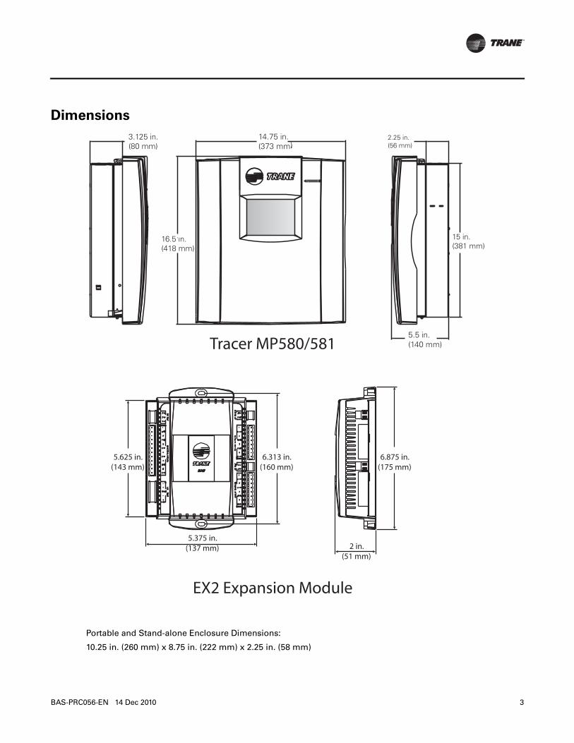
BAS-PRC056-EN 14 Dec 2010 3
Dimensions
Tracer MP580/581
EX2 Expansion Module
5.625 in.(143 mm)
6.313 in.(160 mm)
6.875 in.(175 mm)
5.375 in.(137 mm) 2 in.
(51 mm)
Portable and Stand-alone Enclosure Dimensions:
10.25 in. (260 mm) x 8.75 in. (222 mm) x 2.25 in. (58 mm)
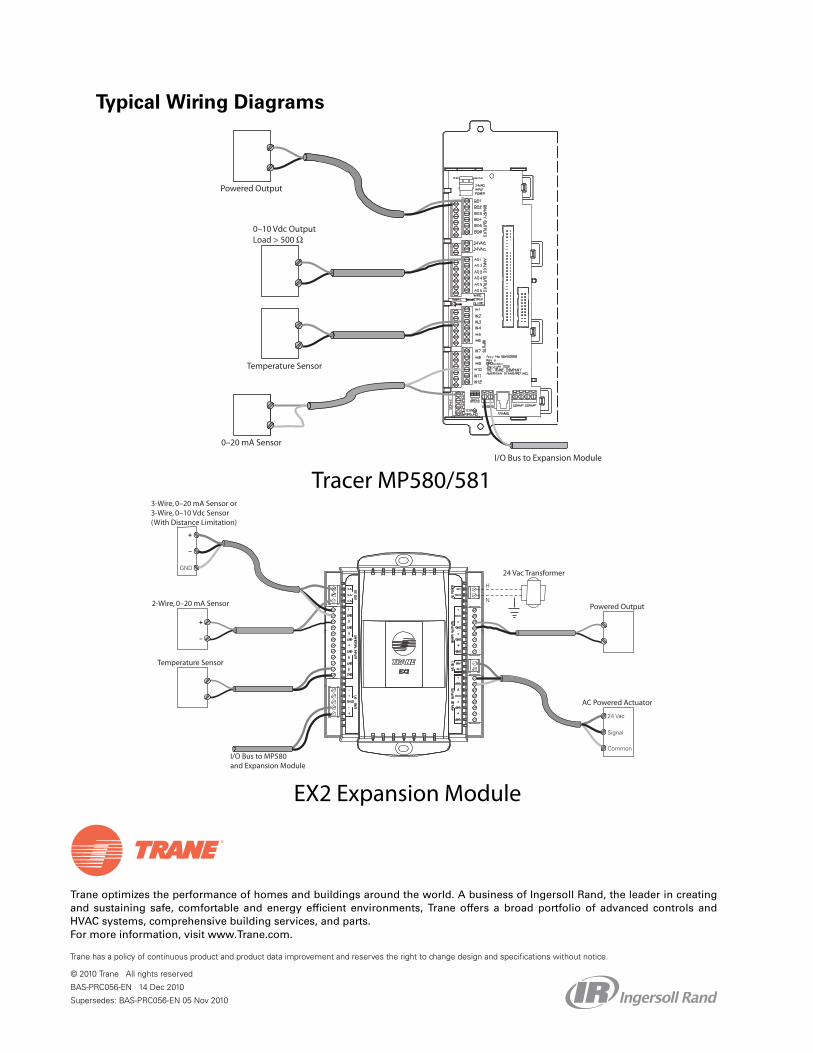
Trane optimizes the performance of homes and buildings around the world. A business of Ingersoll Rand, the leader in creatingand sustaining safe, comfortable and energy efficient environments, Trane offers a broad portfolio of advanced controls andHVAC systems, comprehensive building services, and parts. For more information, visit www.Trane.com.
Trane has a policy of continuous product and product data improvement and reserves the right to change design and specifications without notice.
© 2010 Trane All rights reserved
BAS-PRC056-EN 14 Dec 2010
Supersedes: BAS-PRC056-EN 05 Nov 2010
Typical Wiring Diagrams
Powered Output
0–20 mA Sensor
0–10 Vdc OutputLoad > 500 Ω
Temperature Sensor
I/O Bus to Expansion Module
3-Wire, 0–20 mA Sensor or3-Wire, 0–10 Vdc Sensor(With Distance Limitation)
2-Wire, 0–20 mA Sensor
Temperature Sensor
24 Vac Transformer
Powered Output
AC Powered Actuator
I/O Bus to MP580 and Expansion Module
Tracer MP580/581
EX2 Expansion Module
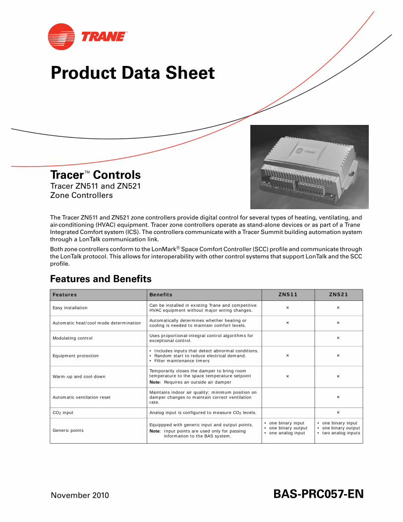
November 2010 BAS-PRC057-EN
Product Data Sheet
Tracer™ ControlsTracer ZN511 and ZN521 Zone Controllers
The Tracer ZN511 and ZN521 zone controllers provide digital control for several types of heating, ventilating, and air-conditioning (HVAC) equipment. Tracer zone controllers operate as stand-alone devices or as part of a Trane Integrated Comfort system (ICS). The controllers communicate with a Tracer Summit building automation system through a LonTalk communication link.
Both zone controllers conform to the LonMark® Space Comfort Controller (SCC) profile and communicate through the LonTalk protocol. This allows for interoperability with other control systems that support LonTalk and the SCC profile.
Features and Benefits
Features Benefits ZN511 ZN521
Easy installation Can be installed in existing Trane and competitive HVAC equipment without major wiring changes. × ×
Automatic heat/cool mode determination Automatically determines whether heating or cooling is needed to maintain comfort levels. × ×
Modulating control Uses proportional-integral control algorithms for exceptional control. ×
Equipment protection• Includes inputs that detect abnormal conditions.• Random start to reduce electrical demand.• Filter maintenance timers
× ×
Warm-up and cool-downTemporarily closes the damper to bring room temperature to the space temperature setpointNote: Requires an outside air damper
× ×
Automatic ventilation resetMaintains indoor air quality; minimum position on damper changes to maintain correct ventilation rate.
×
CO2 input Analog input is configured to measure CO2 levels. ×
Generic pointsEquippped with generic input and output points.Note: Input points are used only for passing
information to the BAS system.
• one binary input• one binary output• one analog input
• one binary input• one binary output• two analog inputs
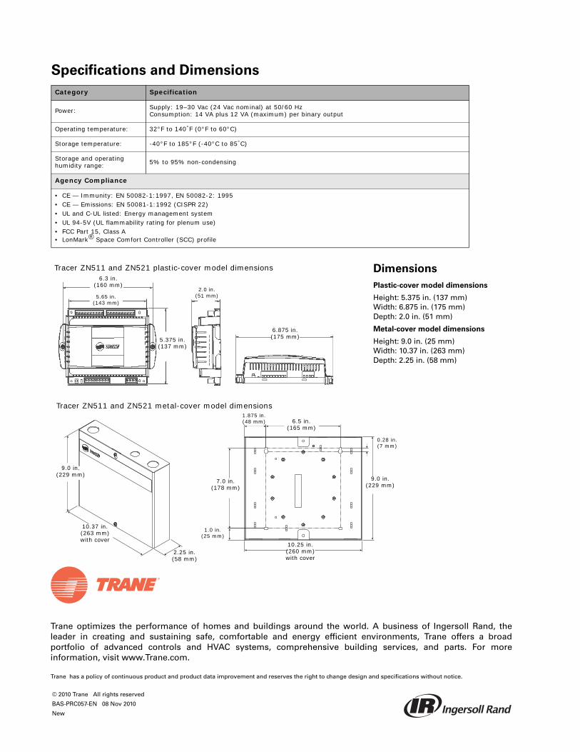
Trane optimizes the performance of homes and buildings around the world. A business of Ingersoll Rand, theleader in creating and sustaining safe, comfortable and energy efficient environments, Trane offers a broadportfolio of advanced controls and HVAC systems, comprehensive building services, and parts. For moreinformation, visit www.Trane.com.
Trane has a policy of continuous product and product data improvement and reserves the right to change design and specifications without notice.
© 2010 Trane All rights reserved
BAS-PRC057-EN 08 Nov 2010
New
Specifications and Dimensions
Category Specification
Power: Supply: 19–30 Vac (24 Vac nominal) at 50/60 HzConsumption: 14 VA plus 12 VA (maximum) per binary output
Operating temperature: 32°F to 140°F (0°F to 60°C)
Storage temperature: -40°F to 185°F (-40°C to 85°C)
Storage and operating humidity range: 5% to 95% non-condensing
Agency Compliance
• CE — Immunity: EN 50082-1:1997, EN 50082-2: 1995• CE — Emissions: EN 50081-1:1992 (CISPR 22)• UL and C-UL listed: Energy management system• UL 94-5V (UL flammability rating for plenum use)• FCC Part 15, Class A• LonMark® Space Comfort Controller (SCC) profile
Tracer ZN511 and ZN521 metal-cover model dimensions
Tracer ZN511 and ZN521 plastic-cover model dimensions6.3 in.
(160 mm)
5.65 in.(143 mm)
2.0 in.(51 mm)
5.375 in.(137 mm)
6.875 in.(175 mm)
Dimensions
Plastic-cover model dimensions
Height: 5.375 in. (137 mm)Width: 6.875 in. (175 mm)Depth: 2.0 in. (51 mm)
Metal-cover model dimensions
Height: 9.0 in. (25 mm)Width: 10.37 in. (263 mm)Depth: 2.25 in. (58 mm)
9.0 in.(229 mm)
10.37 in.(263 mm) with cover
2.25 in.(58 mm)
1.875 in.(48 mm)
0.28 in.(7 mm)
1.0 in.(25 mm)
10.25 in.(260 mm) with cover
6.5 in.(165 mm)
9.0 in.(229 mm)
7.0 in.(178 mm)

January 2011 BAS-PRC059-EN
Product Data Sheet
Tracer™ Controls
Tracer MP501 ControllerThe Tracer MP501 controller is a configurable, multi-purpose controller that provides direct-digital control for heating, ventilation, and air conditioning (HVAC) equipment. The controller can operate as a stand-alone device or as part of a building automation system (BAS). It communicates with a BAS through a LonTalk Comm5 communication link.
The controller can be configured by using the Rover service tool for Tracer controllers, or any other PC-based service tool compliant with the EIA/CEA-860 standard. This tool can be connected to a communication jack on a zone temperature sensor or at any accessible location on the LonTalk Comm5 communication link.
Features and Benefits
Features Benefits
Easy installation Suitable for indoor mounting in a variety of locations. Clearly labeled screw terminals ensure that wires are connected quickly and accurately.
Flexible controlUsing a single proportional, integral, and derivative (PID) control loop, the controller controls an output based on a measured input value and a specified setpoint.
Adjustable PID loop Provides a single control loop with adjustable PID control parameters, which allows control to be customized for a variety of applications.
Interoperability
In SCC mode, the controller conforms to the LonMark SCC profile. In generic mode, the controller does not conform to a specific LonMark profile, but supports standard network variable types (SNVTs). Both modes communicate through the LonTalk protocol.
Occupied and unoccupied operation
Available in SCC mode only, the occupancy input works with a motion (occupancy) sensor or a time clock. A communicated value from a BAS can also be used. The input allows the controller to use unoccupied (setback) temperature setpoints.
Manual output test Pressing the Test button on the controller exercises all of the outputs in sequence; does not require a PC-based service tool.
Peer-to-peer communication The MP501 and other controllers can be bound as peers to share data such as setpoint, zone temperature, and heating/cooling mode.
Generic pointEquipped with one generic point for use with a Tracer Summit BAS: binary input shared with occupancy/enable. Input points are used only for passing information to the BAS system.

2 BAS-PRC059-EN
Specifications
Category Specification
Power:Supply: 21–27 Vac (24 Vac nominal) at 50/60 HzConsumption: 10 VA (70 VA at maximum utilization)
Operating environment: 32°F to 122°F (0°F to 50°C)
Storage environment: -4°F to 160°F (-20°C to 75°C)
Storage and operating humidity range: 10% to 90% non-condensing
Input/output points:
Analog inputs SCC mode: zone temperature, zone temperature setpoint. Generic mode: 4—20 mA input.Binary inputs SCC mode: occupany. Generic mode: enable/disable.Outputs 2-stage, tri-state modulation or 0—10 Vdc analog. SCC mode: fan on/off. Generic mode: interlock device on/off (follows the enable/disable binary input).Generic point For use with a Tracer Summit BAS: binary input (shared with occupancy/enable).Note: Generic inputs pass information to the BAS. They do not directly affect the operation of the Tracer
MP501 outputs.
Dimensions:
Plastic-cover model dimensionsHeight: 5.375 in. (137 mm) Width: 6.875 in. (175 mm) Depth: 2.0 in. (51 mm)Metal-cover model dimensionsHeight: 9.0 in. (25 mm) Width: 10.37 in. (263 mm) Depth: 2.25 in. (58 mm)
Agency Listings/Compliance
• CE — Immunity: EN 50082-1:1997• CE — Emissions: EN 50081-1:1992 (CISPR 11) Class B, EN 61000-3-2, EN61000-3-3• UL and C-UL listed: Energy management system• UL 94-5V (UL flammability rating for plenum use)• FCC Part 15, Class A

BAS-PRC059-EN 3
Dimensions
Tracer MP501 plastic-cover model dimensions
6.3 in.(161 mm)
5.65 in.(143 mm)
5.375 in.(137 mm)
2.0 in.(51 mm)
6.875 in.(175 mm)
9.0 in.(229 mm)
Tracer MP501 metal-cover model dimensions
10.37 in.(263 mm) with cover
2.25 in.(58 mm)
1.875 in.(48 mm)
7.0 in.(178 mm)
1.0 in.(25 mm)
6.5 in.(165 mm)
0.28 in.(7 mm)
10.25 in.(260 mm)
without cover
Trane optimizes the performance of homes and buildings around the world. A business of Ingersoll Rand, the leader in creating and sustaining safe, comfortable and energy efficient environments, Trane offers a broad portfolio of advanced controls and HVAC systems, comprehensive building services, and parts. For more information, visit www.Trane.com.
Trane has a policy of continuous product and product data improvement and reserves the right to change design and specifications without notice.
© 2011 Trane All rights reserved
BAS-PRC059-EN 27 Jan 2011
New

Tracer™ UC400 Programmable Controller
Ordering Number: BMUC400AAA0100011
November 2012 BAS-PRC033-EN
Product Data Sheet
The Tracer™UC400 controller is a multi-purpose, programmable, wireless sensor support device. This field- or factory-installed device is designed to control the following equipment:
• Single- and dual-duct variable-air-volume (VAV) units
• Fan coils
• Unit ventilators
• Blower coils
• Water-source heat pumps (WSHP)
• Small air handlers
Features and Benefits
Feature Benefit
BACnet MS/TP An open standard building automation communications protocol which enables connections to other BAS systems and controllers
Configurable and fully programmable • Factory programs available through quick configuration for lowest setup time• Programmable for flexibility to meet unique sequence or hardware needs
Total of 23 I/O points built in Meets most terminal unit needs with extra built-in I/O available to network or additional programming on controller
Expandable to 55 points Flexibility to meet additional equipment needs
Data logging—25,000 samples Easier investigation of equipment, zone, or building problems
Factory and field mounting options Options to best meet job schedule and bidding process
Removable connectors, DIN rail mounting, multiple service tool connections
Ease of installation and service
Compatible with Trane Wireless Comm Provides wireless communication between Trane BACnet unit and system controllers and zone sensors. This allows faster, easier, lower-risk installation and life-cycle savings due to future space re-configuration, upgrades, and expansions.

2 BAS-PRC033-EN, 01 Nov 2012
Controller Specifications and Agency Compliance
Controller dimensions
Storage
Temperature: -48°F to 203°F (-55°C to 95°C)
Relative humidity: Between 5% to 95% (non-condensing)
Operating
Temperature: -40°F to 158°F (-40°C to 70°C)
Humidity: Between 5% to 95% (non-condensing)
Power: 20.4–27.6 Vac (24 Vac, ±15% nominal) 50–60 Hz 24 VA(24 VA plus binary output loads for a maximum of 12 VA for each binary output)
Mounting weight of controller: Mounting surface must support .80 lb. (.364 kg)
Environmental rating (enclosure): NEMA 1
Altitude: 6,500 ft maximum (1,981 m)
Installation: UL 840: Category 3
Pollution UL 840: Degree 2
Wiring/Transformer
16 AWG (recommended) copper wire
• UL Listed, Class 2 power transformer 20.4–27.6 Vac (24 Vac, ±15% nominal)• The transformer must be sized to provide adequate power to the UC400 controller (12 VA) and outputs (maximum 12 VA per binary output)
Agency Compliance
• UL916 PAZX- Open Energy Management Equipment• UL94-5V Flammability• CE Marked• FCC Part 15, Subpart B, Class B Limit• AS/NZS CISPR 22:2006• VCCI V-3/2008.04• ICES-003, Issue 4:2004• Communications BACnet MS/TP, supports BACnet protocol ASHRAE 135-2004 and meets BACnet Testing Laboratory (BTL) as an Application Specific Controller (ASC)
profile device
5.65 in. (143.5 mm) 2.17 in. (55 mm)
1.73 in. (44 mm)
4.00 in. (101.6 mm)
35 mm DIN Rail Mount
Important: Slotted release clip shown– if removing or repositioning the controller, the user must remove terminal connectors before proceeding.

BAS-PRC033-EN, 01 Nov 2012 3
Device Connections Table 1. Device connections
Connection Quantity Types Range Notes
*Analog input(AI1 to AI5) 5
Temperature 10 kΩ thermistor
Setpoint 0 Ω to 1,000 Ω
Resistive 200 Ω to 20 kΩ Typically used for fan speed switch.
Universal input(UI1 and UI2) 2
Linear 0–20 mA
These inputs may be configured to be thermistor inputs, 0–10 Vdc inputs, or 4–20 mA inputs.
Linear 0–10 Vdc
Resistive * Refer to analog input connection for ranges and types above
Binary Solid state open collector
Pulse Solid state open collector Minimum dwell time is 25 milliseconds (ms) ON and 25 milliseconds OFF.
Binary input(a)
(BI1 to BI3)
(a) Binary Inputs, Binary Outputs, and TRIACs: For safety precautions, do not mix Class 1 and Class 2 voltages in an enclosure or on a controller without a physical barrier between these units.
3 24 Vac detectThe UC400 controller provides the 24 Vac that is required to drive the binary inputs when using the recommended connections.
Binary output(a)
(BO1 to BO3) 3 Relay
2.88 A @24 Vac pilot duty(For further power ratings, refer to the Tracer UC400 Installation, Operation, and Maintenance Manual [BAS-SVX20]).
Power needs to be wired to the binary output. All outputs are isolated from each other and from ground or power. Ranges given are per contact.
Binary output(a)
(BO4 to BO9) 6 TRIAC
0.5 A max @24-277 Vac, resistive and pilot duty (For further power ratings, refer to the Tracer UC400 Installation, Operation, and Maintenance Manual [BAS-SVX20]).
Use for modulating TRIAC. User determines whether closing high side (providing voltage to the grounded load) or low side (providing ground to the power load). Ranges given are per contact and power comes from TRIAC SUPPLY circuit.
Analog output/binary input(AO1/BI4 and AO2/BI5)
2
Linear output 0–20 mA
Each termination must be configured as either an analog output or binary input.Linear output 0–10 Vdc
Binary input Dry contact
Pressure inputs(PI1 and PI2) 2 3-wire 0–5 in H2O
Pressure inputs supplied with 5 volts of power. Designed for Kavlico™ pressure transducers.
Overall Point Total 23

Trane optimizes the performance of homes and buildings around the world. A business of Ingersoll Rand, the leader in creating and sustaining safe, comfortable and energy efficient environments, Trane offers a broad portfolio of advanced controls and HVAC systems, comprehensive building services, and parts. For more information, visit www.Trane.com.
Trane has a policy of continuous product and product data improvement and reserves the right to change design and specifications without notice.
© 2012 Trane. All rights reserved.
BAS-PRC033-EN 1 Nov 2012
Supersedes BAS-PRC033-EN 01 Mar 2012
We are committed to using environmentally
conscious print practices that reduce waste.
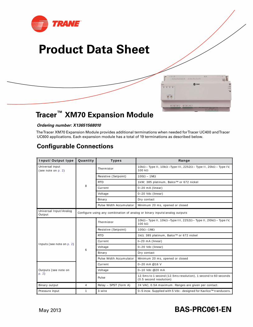
May 2013 BAS-PRC061-EN
Product Data Sheet
Tracer™ XM70 Expansion Module
Ordering number: X13651568010
TheTracer XM70 Expansion Module provides additional terminations when needed forTracer UC400 andTracerUC600 applications. Each expansion module has a total of 19 terminations as described below.
Configurable Connections
Input/Output type Quantity Types Range
Universal input(see note on p. 2)
8
Thermistor 10k– Type II, 10k –Type III, 2252– Type II, 20k – Type IV, 100 k
Resistive (Setpoint) 100 – 1M
RTD 1kW; 385 platinum, Balco™ or 672 nickel
Current 0–20 mA (linear)
Voltage 0–20 Vdc (linear)
Binary Dry contact
Pulse Width Accumulator Minimum 20 ms, opened or closed
Universal Input/Analog Output Configure using any combination of analog or binary inputs/analog outputs
6
Thermistor 10k– Type II, 10k –Type III, 2252– Type II, 2l0k – Type IV, 100 k
Inputs (see note on p. 2)
Resistive (Setpoint) 100–1M
RTD 1k; 385 platinum, Balco™ or 672 nickel
Current –20 mA (linear)
Voltage 0–20 Vdc (linear)
Binary Dry contact
Pulse Width Accumulator Minimum 20 ms, opened or closed
Outputs (see note on p. 2)
Current 0–20 mA @16 V
Voltage 0–10 Vdc @20 mA
Pulse 12.5ms to 1 second (12.5ms resolution), 1 second to 60 seconds (0.5 second resolution)
Binary output 4 Relay – SPST (form A) 24 VAC, 0.5A maximum. Ranges are given per contact.
Pressure input 1 3-wire 0–5 incw. Supplied with 5 Vdc - designed for Kavlico™ tranducers.
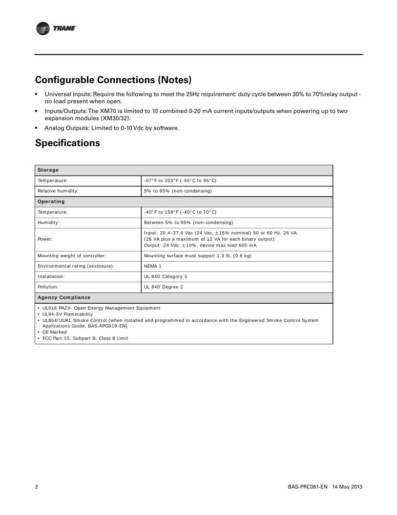
2 BAS-PRC061-EN 14 May 2013
Configurable Connections (Notes)
• Universal Inputs: Require the following to meet the 25Hz requirement: duty cycle between 30% to 70%relay output -no load present when open.
• Inputs/Outputs:The XM70 is limited to 10 combined 0-20 mA current inputs/outputs when powering up to twoexpansion modules (XM30/32).
• Analog Outputs: Limited to 0-10 Vdc by software.
Specifications
Storage
Temperature: -67°F to 203°F (-55°C to 95°C)
Relative humidity: 5% to 95% (non-condensing)
Operating
Temperature: -40°F to 158°F (-40°C to 70°C)
Humidity: Between 5% to 95% (non-condensing)
Power:Input: 20.4–27.6 Vac (24 Vac, ±15% nominal) 50 or 60 Hz, 26 VA(26 VA plus a maximum of 12 VA for each binary output)Output: 24 Vdc, ±10%, device max load 600 mA
Mounting weight of controller: Mounting surface must support 1.3 lb. (0.6 kg)
Environmental rating (enclosure): NEMA 1
Installation: UL 840:Category 3
Pollution: UL 840:Degree 2
Agency Compliance
• UL916 PAZX- Open Energy Management Equipment• UL94-5V Flammability• UL864/UUKL Smoke Control (when installed and programmed in accordance with the Engineered Smoke Control System
Applications Guide, BAS-APG019-EN)• CE Marked• FCC Part 15, Subpart B, Class B Limit

BAS-PRC061-EN 14 May 2013 3
Dimensions
The following figure illustrate dimensions for theTracer XM70 expansion module. DIN width measurements helpdetermine how many modules can be installed on a DIN rail. Use the following standard:
DIN Standard 43 880 standard profile, Built-in Equipment for Electrical Installations, Overall Dimensions and RelatedMounting Dimensions.*One DIN unit = 18 mm.
AO6UI14
AO5UI13
AO4UI12
AO3UI11
AO2UI10
AO1UI9
BO4BO3BO2BO1
RELAYS 0.5 A MAX
IMC
1
IMC
P1
UI8UI7UI6UI5UI4UI3UI2UI1
IMC
+24VDC
OUT
+24VDC
+24VDC
OUT
24VAC
XFMR
24VAC
SERVICE
IMC
RX
TX
XM70
ADDRESS0 1
23
456
78
9
x1
0 1
23
456
78
9
x10
BO4BO3BO2BO1
8.50 in. (215.9 mm) width *12 DIN units
1.73 in (44 mm)
4.00 in. (101.6 mm)
2.17 in. (55 mm)

Trane optimizes the performance of homes and buildings around the world. A business of Ingersoll Rand, theleader in creating and sustaining safe, comfortable and energy efficient environments, Trane offers a broadportfolio of advanced controls and HVAC systems, comprehensive building services, and parts. For moreinformation, visit www.Trane.com.
Trane has a policy of continuous product and product data improvement and reserves the right to change design and specifications without notice.
© 2013Trane All rights reserved
BAS-PRC061-EN 14 May 2013
Supersedes BAS-PRC061-EN (31 Jul 2012)
We are committed to using environmentally
conscious print practices that reduce waste.
May 2013 BAS-PRC063-EN
Product Data Sheet
Tracer™ UC600 Programmable Controller
Ordering number: BMUC600AAA0100011
TheTracer UC600 controller is a multi-purpose, programmable device.This field-installed device is designedto control the following types of equipment:
• Air-handling units (AHUs)
• Rooftop units
• Chillers
• Central heating and cooling plants
• Cooling towers
• Generic input/output (I/O) control
Features and Benefits
Feature Benefit
BACnet MS/TP An open standard building automation communications protocol which enables connections to other BAS systems and controllers
Scheduling—supports up to 3 weekly schedules Easy to set up and access (3 schedule types supported: Analog, Binary, Multistate)
Graphics—support for up to 10 custom graphics with optional TD7 Display.
Perform overrides, link directly to alarms, reports, or other graphics directly from a graphic.
Custom data graphs Create and view graphically formatted data logs. Up to 8 custom data graphs can be created with a maximum of 4 data logs per graph.
Configurable and fully programmable• Factory programs available through quick configuration for lowest setup time• Programmable for flexibility to meet unique sequence or hardware needs
Total of 19 built-in I/O hardware terminations Meets most applied product needs with built-in I/O or with additional custom programming on the controller
Expandable up to 120 hardware terminations (with the use of optional expansion modules) Flexibility to meet additional equipment needs
Data logging—25,000 samples Easier investigation of equipment, zone, or building problems
Removable connectors, DIN rail mounting, multiple service tool connections Ease of installation and service
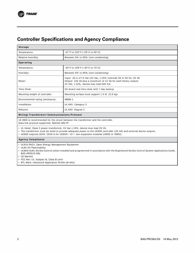
2 BAS-PRC063-EN 14 May 2013
Controller Specifications and Agency Compliance
Storage
Temperature: -67°F to 203°F (-55°C to 95°C)
Relative humidity: Between 5% to 95% (non-condensing)
Operating
Temperature: -40°F to 158°F (-40°C to 70°C)
Humidity: Between 5% to 95% (non-condensing)
Power:Input: 20.4–27.6 Vac (24 Vac, ±15% nominal) 50 or 60 Hz, 26 VAOutput: (26 VA plus a maximum of 12 VA for each binary output)24 Vdc, ±10%, device max load 600 mA
Time Clock: On-board real time clock with 7 day backup
Mounting weight of controller: Mounting surface must support 1.3 lb. (0.6 kg)
Environmental rating (enclosure): NEMA 1
Installation: UL 840: Category 3
Pollution UL 840: Degree 2
Wiring/Transformer/Communications Protocol
18 AWG is recommended for the circuit between the transformer and the controller.Data link protocol supported: BACnet MS/TP
• UL listed, Class 2 power transformer, 24 Vac ±10%, device max load 26 VA.• The transformer must be sized to provide adequate power to the UC600 controller (26 VA) and external device outputs. • UC600 requires 26VA: 26VA is for UC600+ IO + two expansion modules (XM30 or XM32).
Agency Compliance
• UL916 PAZX, Open Energy Management Equipment• UL94-5V Flammability• UL864/UUKL Smoke Control (when installed and programmed in accordance with the Engineered Smoke Control System Applications Guide,
BAS-APG019-EN)• CE Marked• FCC Part 15, Subpart B, Class B Limit• BTL Mark—Advanced Application Profile (B-AAC)

BAS-PRC063-EN 14 May 2013 3
Input and Output Specifications
Input/Output type Quantity Types Range Notes
Universal Input
8
Thermistor10k– Type II, 10k –Type III, 2252– Type II, 20k – Type IV, 100 k
The UC600 provides 600 mA of DC power for 0–20 mA inputs and/or outputs, and to power expansion modules. See the power
budget table in the Tracer UC600 Installation, Operation, and Maintenance
guide, BAS-SVX045-EN.
Resistive (setpoint) 100 – 1M
RTD Balco™ (Ni-Fe), 1k; 375 (Pt), 385 (Pt), 1k
Current 0–20 mA (linear)
Voltage 0–20 Vdc (linear)
Binary Dry contact
Pulse Accumulator Minimum 20 ms, opened or closed
Universal Input/Analog Output
Configure using any combination of analog or binary inputs/analog outputs
6
Thermistor10k– Type II, 10k –Type III, 2252– Type II, 20k – Type IV, 100 k
Inputs
Resistive (setpoint) 100–1M
RTD Balco™ (Ni-Fe), 1k; 375 (Pt), 385 (Pt), 1k
Current –20 mA (linear)
Voltage 0–20 Vdc (linear)
Binary Dry contact
Pulse accumulator Minimum 20 ms, opened or closed
Outputs
Current 0–20 mA @16 V
Voltage 0–10 Vdc @20 mA
Pulse12.5ms to 1 second (12.5ms resolution), 1 second to 60 seconds (0.5 second resolution)
Binary Output 4 Relay (form A) wet 24 VAC, 0.5A maximum Ranges are given per contact.
Pressure Input 1 3-wire 0–5 in H2OPressure input supplied with 5 Vdc. Designed for Kavlico™ pressure transducers.
Point total 19
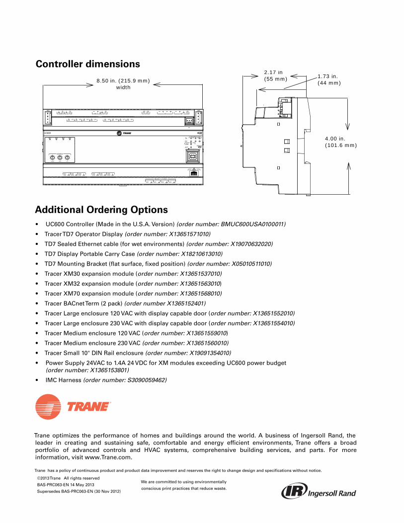
Trane optimizes the performance of homes and buildings around the world. A business of Ingersoll Rand, theleader in creating and sustaining safe, comfortable and energy efficient environments, Trane offers a broadportfolio of advanced controls and HVAC systems, comprehensive building services, and parts. For moreinformation, visit www.Trane.com.
Trane has a policy of continuous product and product data improvement and reserves the right to change design and specifications without notice.
©2013Trane All rights reserved
BAS-PRC063-EN 14 May 2013
Supersedes BAS-PRC063-EN (30 Nov 2012)
We are committed to using environmentally
conscious print practices that reduce waste.
Controller dimensions
Additional Ordering Options
• UC600 Controller (Made in the U.S.A. Version) (order number: BMUC600USA0100011)
• TracerTD7 Operator Display (order number: X13651571010)
• TD7 Sealed Ethernet cable (for wet environments) (order number: X19070632020)
• TD7 Display Portable Carry Case (order number: X18210613010)
• TD7 Mounting Bracket (flat surface, fixed position) (order number: X05010511010)
• Tracer XM30 expansion module (order number: X13651537010)
• Tracer XM32 expansion module (order number: X13651563010)
• Tracer XM70 expansion module (order number: X13651568010)
• Tracer BACnetTerm (2 pack) (order number X1365152401)
• Tracer Large enclosure 120 VAC with display capable door (order number: X13651552010)
• Tracer Large enclosure 230 VAC with display capable door (order number: X13651554010)
• Tracer Medium enclosure 120 VAC (order number: X13651559010)
• Tracer Medium enclosure 230 VAC (order number: X13651560010)
• Tracer Small 10" DIN Rail enclosure (order number: X19091354010)
• Power Supply 24VAC to 1.4A 24 VDC for XM modules exceeding UC600 power budget(order number: X1365153801)
• IMC Harness (order number: S3090059462)
AO6UI14
AO5UI13
AO4UI12
AO3UI11
AO2UI10
AO1UI9
BO4BO3BO2BO1
RELAYS 0.5 A MAX
IMC
1
IMC
P1
UI8UI7UI6UI5UI4UI3UI2UI1
IMC
+24VDC
LINKOUT
+24VDC
+24VDC
OUT
24VAC
MBUSOUT
24VAC
XFMR
24VAC
SERVICE TOOL
SERVICELINK
ACT
IMCMBUSLINK
RX
TX
UC600
ADDRESS0 1
23
456
78
9
x1
0 1
23
456
78
9
x10
0 1
23
456
78
9
x100
BO4BO3BO2BO1
8.50 in. (215.9 mm)width
2.17 in (55 mm) 1.73 in.
(44 mm)
4.00 in. (101.6 mm)

September 2012 BAS-PRC064-EN
Product Data Sheet
CommunicatingThermostats for Rooftop and Heat
Pump Control
Ordering Numbers
Use the following ordering numbers.
Trane CommunicatingThermostats are ideal for existingbuilding retrofits and controls upgrades when integrationwith a building automation system is desired. Increasedenergy efficiency can be gained through use of theeconomizer output or through the use of optional covers withbuilt-in occupancy sensors.
Existing thermostat wire and junction box and conduit canoften be re-used to reduce installation hardware and laborcost. A hinged PCB board, removable terminal blocks, andonboard configuration can further reduce installation andcommissioning time and expense.
DescriptionProtocol/Interface Part Number
Rooftop 2H2C Econ BACnet X13511541010
Rooftop 2H2C Econ LON X13511541020
Heat Pump 3H2C BACnet X13511542010
Heat Pump 3H2C LON X13511542020
Heat Pump w/Humidity BACnet X13511541050
Heat Pump w/Humidity LON X13511541080
Optional Cover with Occupancy Sensor NA or RTU/HP X13511544020
Optional Integrated Occupancy Sensor
Easy-to-use Interface for Setup and Daily Operation
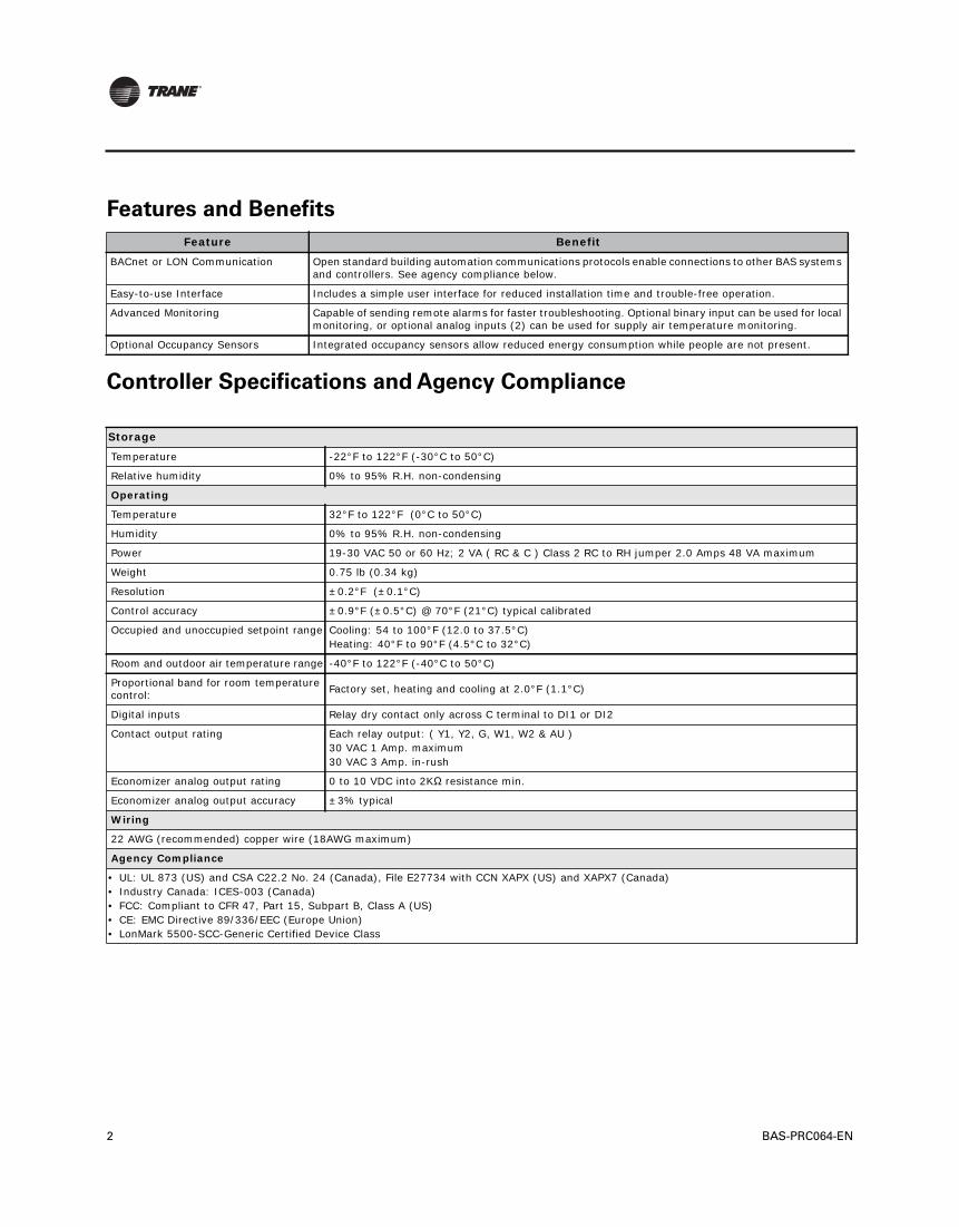
2 BAS-PRC064-EN
Features and Benefits
Controller Specifications and Agency Compliance
Feature Benefit
BACnet or LON Communication Open standard building automation communications protocols enable connections to other BAS systems and controllers. See agency compliance below.
Easy-to-use Interface Includes a simple user interface for reduced installation time and trouble-free operation.
Advanced Monitoring Capable of sending remote alarms for faster troubleshooting. Optional binary input can be used for local monitoring, or optional analog inputs (2) can be used for supply air temperature monitoring.
Optional Occupancy Sensors Integrated occupancy sensors allow reduced energy consumption while people are not present.
Storage
Temperature -22°F to 122°F (-30°C to 50°C)
Relative humidity 0% to 95% R.H. non-condensing
Operating
Temperature 32°F to 122°F (0°C to 50°C)
Humidity 0% to 95% R.H. non-condensing
Power 19-30 VAC 50 or 60 Hz; 2 VA ( RC & C ) Class 2 RC to RH jumper 2.0 Amps 48 VA maximum
Weight 0.75 lb (0.34 kg)
Resolution ±0.2°F (±0.1°C)
Control accuracy ±0.9°F (±0.5°C) @ 70°F (21°C) typical calibrated
Occupied and unoccupied setpoint range Cooling: 54 to 100°F (12.0 to 37.5°C)Heating: 40°F to 90°F (4.5°C to 32°C)
Room and outdoor air temperature range -40°F to 122°F (-40°C to 50°C)
Proportional band for room temperature control: Factory set, heating and cooling at 2.0°F (1.1°C)
Digital inputs Relay dry contact only across C terminal to DI1 or DI2
Contact output rating Each relay output: ( Y1, Y2, G, W1, W2 & AU )30 VAC 1 Amp. maximum30 VAC 3 Amp. in-rush
Economizer analog output rating 0 to 10 VDC into 2KΩ resistance min.
Economizer analog output accuracy ±3% typical
Wiring
22 AWG (recommended) copper wire (18AWG maximum)
Agency Compliance
• UL: UL 873 (US) and CSA C22.2 No. 24 (Canada), File E27734 with CCN XAPX (US) and XAPX7 (Canada)• Industry Canada: ICES-003 (Canada)• FCC: Compliant to CFR 47, Part 15, Subpart B, Class A (US)• CE: EMC Directive 89/336/EEC (Europe Union)• LonMark 5500-SCC-Generic Certified Device Class
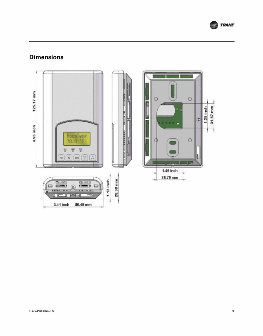
BAS-PRC064-EN 3
Dimensions

Trane optimizes the performance of homes and buildings around the world. A business of Ingersoll Rand, theleader in creating and sustaining safe, comfortable and energy efficient environments, Trane offers a broadportfolio of advanced controls and HVAC systems, comprehensive building services, and parts. For moreinformation, visit www.Trane.com.
Trane has a policy of continuous product and product data improvement and reserves the right to change design and specifications without notice.
© 2012Trane All rights reserved
BAS-PRC064-EN 21 Sep 2012
Supersedes: 04 May 2011
We are committed to using environmentally
conscious print practices that reduce waste.

May 2011 BAS-PRC065-EN
Product Data Sheet
Communicating Thermostats for Fan Coil Control
Ordering Numbers
Use the following ordering numbers.
Trane Communicating Thermostats are ideal for existing building retrofits and controls upgrades when integration with a building automation system is desired. Increased comfort and energy efficiency can be gained through use of multi-speed fans; two (2) position or floating temperature control valves; or through the use of optional covers with built-in occupancy sensors.
Existing thermostat wire and junction box and conduit can often be re-used to reduce installation hardware and labor cost. A hinged PCB board, removable terminal blocks, and onboard configuration can further reduce installation and commissioning time and expenses.
DescriptionProtocol/Interface Part Number
Fan Coil BACnet X13511543010
Fan Coil LON X13511543020
Optional Cover with Occupancy Sensor
Fan Coil X13511544010
Easy-to-use Interface for Setup and Daily Operation
Optional Integrated Occupancy Sensor
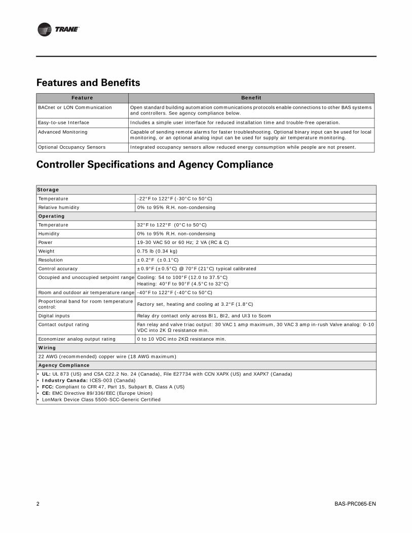
2 BAS-PRC065-EN
Features and Benefits
Controller Specifications and Agency Compliance
Feature Benefit
BACnet or LON Communication Open standard building automation communications protocols enable connections to other BAS systems and controllers. See agency compliance below.
Easy-to-use Interface Includes a simple user interface for reduced installation time and trouble-free operation.
Advanced Monitoring Capable of sending remote alarms for faster troubleshooting. Optional binary input can be used for local monitoring, or an optional analog input can be used for supply air temperature monitoring.
Optional Occupancy Sensors Integrated occupancy sensors allow reduced energy consumption while people are not present.
Storage
Temperature -22°F to 122°F (-30°C to 50°C)
Relative humidity 0% to 95% R.H. non-condensing
Operating
Temperature 32°F to 122°F (0°C to 50°C)
Humidity 0% to 95% R.H. non-condensing
Power 19-30 VAC 50 or 60 Hz; 2 VA (RC & C)
Weight 0.75 lb (0.34 kg)
Resolution ±0.2°F (±0.1°C)
Control accuracy ±0.9°F (±0.5°C) @ 70°F (21°C) typical calibrated
Occupied and unoccupied setpoint range Cooling: 54 to 100°F (12.0 to 37.5°C)Heating: 40°F to 90°F (4.5°C to 32°C)
Room and outdoor air temperature range -40°F to 122°F (-40°C to 50°C)
Proportional band for room temperature control: Factory set, heating and cooling at 3.2°F (1.8°C)
Digital inputs Relay dry contact only across BI1, BI2, and UI3 to Scom
Contact output rating Fan relay and valve triac output: 30 VAC 1 amp maximum, 30 VAC 3 amp in-rush Valve analog: 0-10 VDC into 2K Ω resistance min.
Economizer analog output rating 0 to 10 VDC into 2KΩ resistance min.
Wiring
22 AWG (recommended) copper wire (18 AWG maximum)
Agency Compliance
• UL: UL 873 (US) and CSA C22.2 No. 24 (Canada), File E27734 with CCN XAPX (US) and XAPX7 (Canada)• Industry Canada: ICES-003 (Canada)• FCC: Compliant to CFR 47, Part 15, Subpart B, Class A (US)• CE: EMC Directive 89/336/EEC (Europe Union)• LonMark Device Class 5500-SCC-Generic Certified

BAS-PRC065-EN 3
Dimensions

Trane optimizes the performance of homes and buildings around the world. A business of Ingersoll Rand, theleader in creating and sustaining safe, comfortable and energy efficient environments, Trane offers a broadportfolio of advanced controls and HVAC systems, comprehensive building services, and parts. For moreinformation, visit www.Trane.com.
Trane has a policy of continuous product and product data improvement and reserves the right to change design and specifications without notice.
© 2011 Trane All rights reserved
BAS-PRC065-EN 05 May 2011
New

Tracer™ UC400 Programmable Controller
VAV Field Kit
November 2011 BAS-PRC066-EN
Product Data Sheet
The Tracer UC400 VAV field-installed kit uses aprogrammable controller that can be used for suchapplications as:
• Space temperature control
• Flow tracking
• Ventilation flow control
Ordering Numbers, Features,
and Benefits
Order Numbers Descriptions
5018-9454-01 UC400 VAV kit in control box with Belimo™ actuator
5018-9455-01 UC400 VAV kit in control box with Trane actuator
5018-9456-01 UC400 VAV kit in control box without actuator
5018-9474-01 UC400 VAV kit on a plate with Belimo actuator
5018-9476-01 UC400 VAV kit on a plate without actuator
Features Benefits
BACnet MS/TP An open standard building automation communications protocol which enables connections to other BAS systems and controllers
Configurable and fully programmable• VAV programs available through quick configuration for lowest setup time• Programmable for flexibility to meet unique sequence or hardware needs
Total of 23 built-in I/O points Meets most terminal unit needs with extra built-in I/Os available to network or additional programming on controller
Expandable to 55 points Flexibility to meet additional equipment needs
Data logging; 25,000 samples Easier investigation of equipment, zone, or building problems
Removable connectors, DIN rail mounting, multiple service tool connections Ease of installation and service
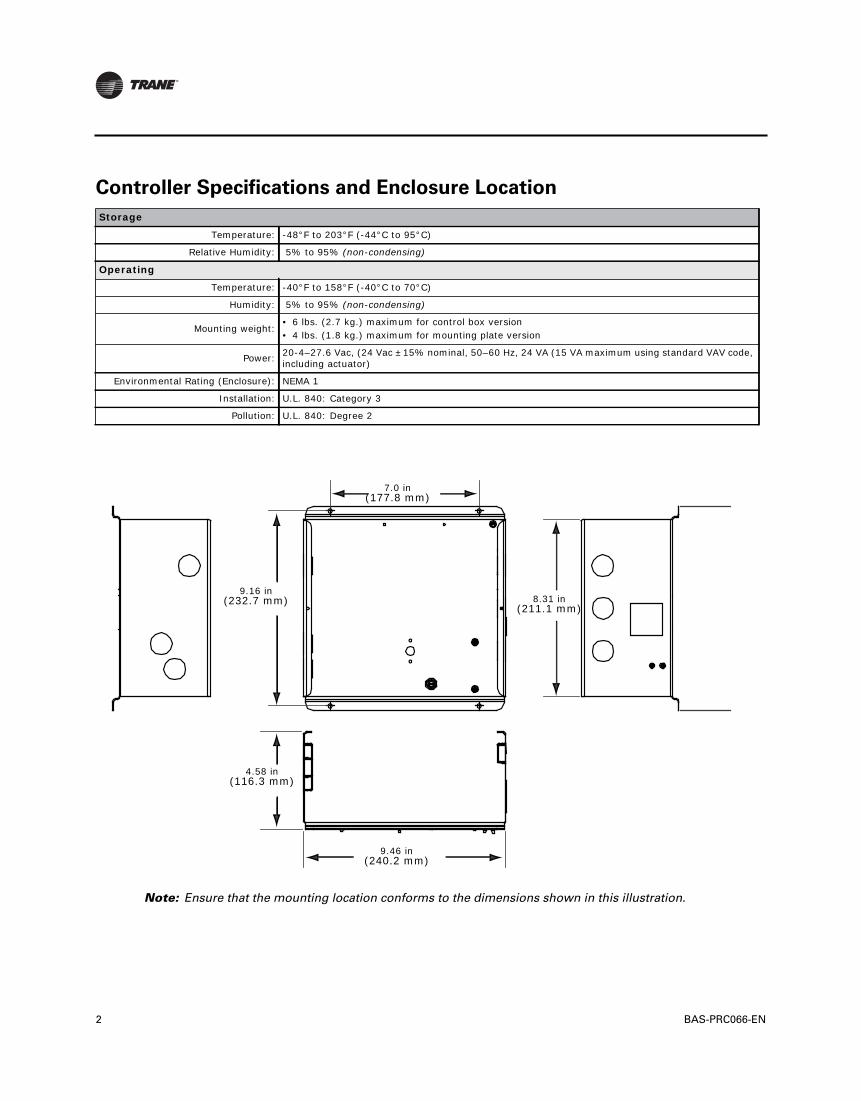
2 BAS-PRC066-EN
Controller Specifications and Enclosure Location
Storage
Temperature: -48°F to 203°F (-44°C to 95°C)
Relative Humidity: 5% to 95% (non-condensing)
Operating
Temperature: -40°F to 158°F (-40°C to 70°C)
Humidity: 5% to 95% (non-condensing)
Mounting weight:• 6 lbs. (2.7 kg.) maximum for control box version• 4 lbs. (1.8 kg.) maximum for mounting plate version
Power: 20-4–27.6 Vac, (24 Vac ±15% nominal, 50–60 Hz, 24 VA (15 VA maximum using standard VAV code, including actuator)
Environmental Rating (Enclosure): NEMA 1
Installation: U.L. 840: Category 3
Pollution: U.L. 840: Degree 2
Note: Ensure that the mounting location conforms to the dimensions shown in this illustration.
8.31 in(211.1 mm)
9.16 in(232.7 mm)
4.58 in(116.3 mm)
7.0 in(177.8 mm)
9.46 in(240.2 mm)
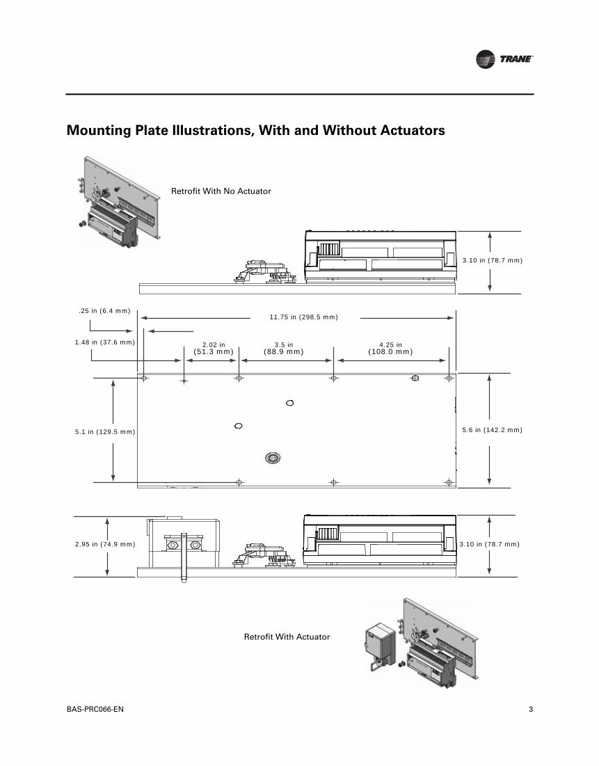
BAS-PRC066-EN 3
Mounting Plate Illustrations, With and Without Actuators
Retrofit With No Actuator
Retrofit With Actuator
3.10 in (78.7 mm)
3.10 in (78.7 mm)
5.6 in (142.2 mm)
11.75 in (298.5 mm).25 in (6.4 mm)
1.48 in (37.6 mm) 2.02 in(51.3 mm)
3.5 in(88.9 mm)
4.25 in(108.0 mm)
5.1 in (129.5 mm)
2.95 in (74.9 mm)
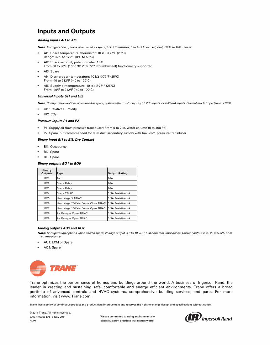
Trane optimizes the performance of homes and buildings around the world. A business of Ingersoll Rand, theleader in creating and sustaining safe, comfortable and energy efficient environments, Trane offers a broadportfolio of advanced controls and HVAC systems, comprehensive building services, and parts. For moreinformation, visit www.Trane.com.
Trane has a policy of continuous product and product data improvement and reserves the right to change design and specifications without notice.
We are committed to using environmentally
conscious print practices that reduce waste.
© 2011 Trane. All rights reserved.
BAS-PRC066-EN 8 Nov 2011
NEW
Inputs and Outputs
Analog inputs AI1 to AI5
Note: Configuration options when used as spare; 10k thermistor, 0 to 1k linear setpoint, 200 to 20k linear.
• AI1: Space temperature; thermistor: 10 k @77°F (25°C)Range: 32°F to 122°F (0°C to 50°C)
• AI2: Space setpoint; potentiometer: 1 kFrom 50 to 90°F (10 to 32.2°C), */** (thumbwheel) functionality supported
• AI3: Spare
• AI4: Discharge air temperature: 10 k@77°F (25°C)From -40 to 212°F (-40 to 100°C)
• AI5: Supply air temperature: 10 k @77°F (25°C)From -40°F to 212°F (-40 to 100°C)
Universal Inputs UI1 and UI2
Note: Configuration options when used as spare; resistive/thermistor inputs, 10 Vdc inputs, or 4–20mA inputs. Current mode impedance is 200
• UI1: Relative Humidity
• UI2: CO2
Pressure Inputs P1 and P2
• P1: Supply air flow; pressure transducer: From 0 to 2 in. water column (0 to 498 Pa)
• P2: Spare, but recommended for dual duct secondary airflow with Kavlico™ pressure transducer
Binary input BI1 to BI3, Dry Contact
• BI1: Occupancy
• BI2: Spare
• BI3: Spare
Binary outputs BO1 to BO9
Analog outputs AO1 and AO2
Note: Configuration options when used a spare; Voltage output is 0 to 10 VDC, 500 ohm min. impedance. Current output is 4 - 20 mA, 500 ohmmax. impedance.
• AO1: ECM or Spare
• AO2: Spare
Binary Outputs Type Output Rating
BO1 Fan 10A
BO2 Spare Relay 10A
BO3 Spare Relay 10A
BO4 Spare TRIAC 0.5A Resistive VA
BO5 Heat stage 3 TRIAC 0.5A Resistive VA
BO6 Heat stage 2/Water Valve Close TRIAC 0.5A Resistive VA
BO7 Heat stage 1/Water Valve Open TRIAC 0.5A Resistive VA
BO8 Air Damper Close TRIAC 0.5A Resistive VA
BO9 Air Damper Open TRIAC 0.5A Resistive VA
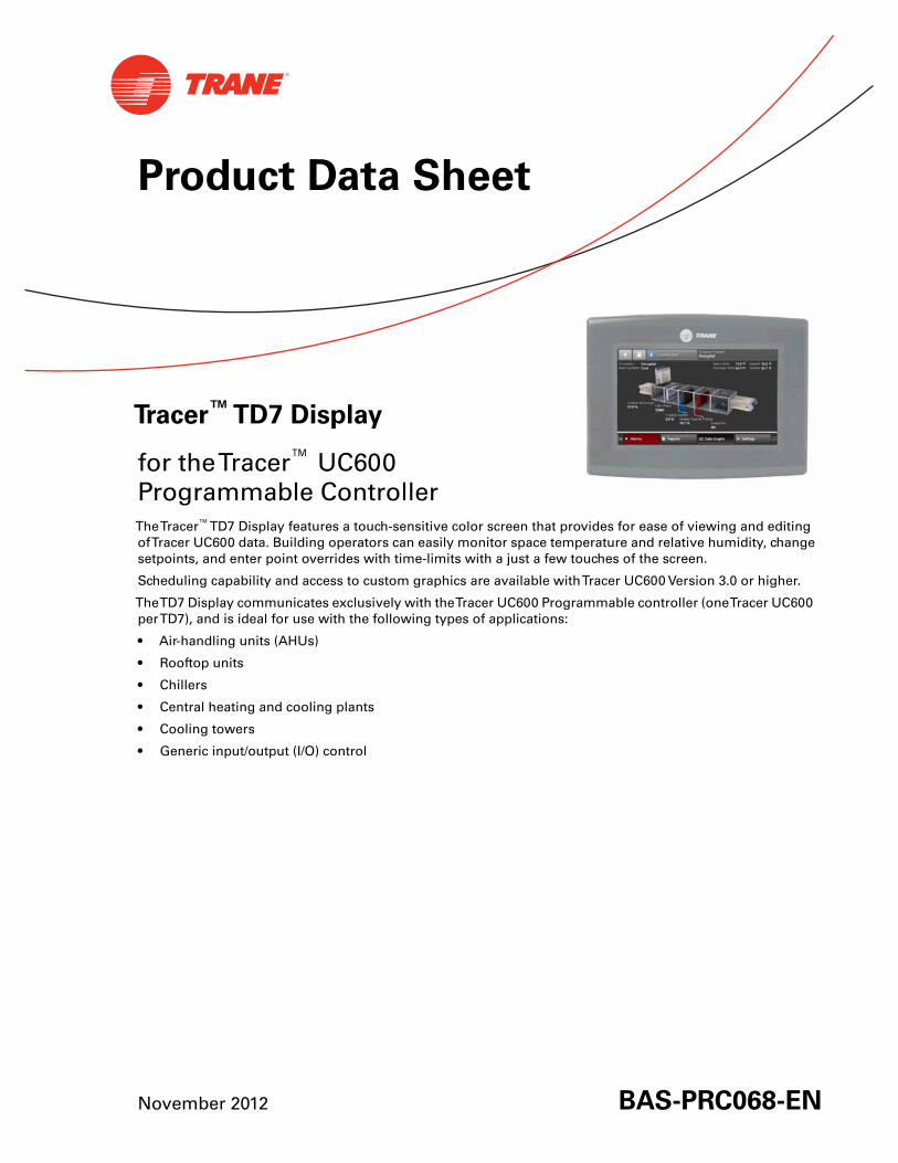
November 2012 BAS-PRC068-EN
Product Data Sheet
Tracer™ TD7 Display
for theTracer™ UC600Programmable ControllerTheTracer™TD7 Display features a touch-sensitive color screen that provides for ease of viewing and editingofTracer UC600 data. Building operators can easily monitor space temperature and relative humidity, changesetpoints, and enter point overrides with time-limits with a just a few touches of the screen.
Scheduling capability and access to custom graphics are available withTracer UC600 Version 3.0 or higher.
TheTD7 Display communicates exclusively with theTracer UC600 Programmable controller (oneTracer UC600perTD7), and is ideal for use with the following types of applications:
• Air-handling units (AHUs)
• Rooftop units
• Chillers
• Central heating and cooling plants
• Cooling towers
• Generic input/output (I/O) control
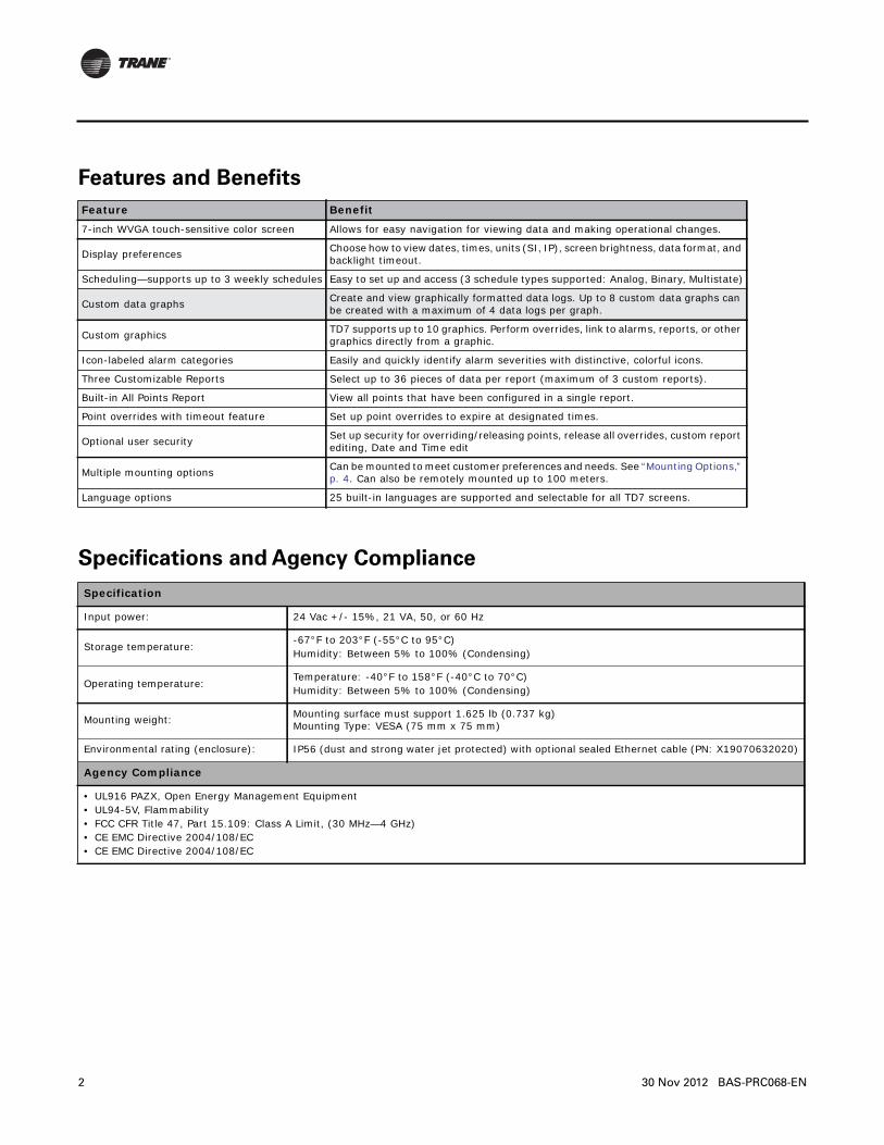
2 30 Nov 2012 BAS-PRC068-EN
Features and Benefits
Specifications and Agency Compliance
Feature Benefit
7-inch WVGA touch-sensitive color screen Allows for easy navigation for viewing data and making operational changes.
Display preferences Choose how to view dates, times, units (SI, IP), screen brightness, data format, and backlight timeout.
Scheduling—supports up to 3 weekly schedules Easy to set up and access (3 schedule types supported: Analog, Binary, Multistate)
Custom data graphs Create and view graphically formatted data logs. Up to 8 custom data graphs can be created with a maximum of 4 data logs per graph.
Custom graphics TD7 supports up to 10 graphics. Perform overrides, link to alarms, reports, or other graphics directly from a graphic.
Icon-labeled alarm categories Easily and quickly identify alarm severities with distinctive, colorful icons.
Three Customizable Reports Select up to 36 pieces of data per report (maximum of 3 custom reports).
Built-in All Points Report View all points that have been configured in a single report.
Point overrides with timeout feature Set up point overrides to expire at designated times.
Optional user security Set up security for overriding/releasing points, release all overrides, custom report editing, Date and Time edit
Multiple mounting options Can be mounted to meet customer preferences and needs. See “Mounting Options,” p. 4. Can also be remotely mounted up to 100 meters.
Language options 25 built-in languages are supported and selectable for all TD7 screens.
Specification
Input power: 24 Vac +/- 15%, 21 VA, 50, or 60 Hz
Storage temperature:-67°F to 203°F (-55°C to 95°C)Humidity: Between 5% to 100% (Condensing)
Operating temperature:Temperature: -40°F to 158°F (-40°C to 70°C)Humidity: Between 5% to 100% (Condensing)
Mounting weight: Mounting surface must support 1.625 lb (0.737 kg) Mounting Type: VESA (75 mm x 75 mm)
Environmental rating (enclosure): IP56 (dust and strong water jet protected) with optional sealed Ethernet cable (PN: X19070632020)
Agency Compliance
• UL916 PAZX, Open Energy Management Equipment• UL94-5V, Flammability• FCC CFR Title 47, Part 15.109: Class A Limit, (30 MHz—4 GHz)• CE EMC Directive 2004/108/EC• CE EMC Directive 2004/108/EC

BAS-PRC068-EN 30 Nov 2012 3
Dimensions
7.9 in. (200.7 mm)
2.1 in. (53.2 mm)8.3 in. (211.6 mm)1.7 in. (41.9 mm)
5.5 in. (139.9 mm) 6.3 in. (158.8 mm)
Trane optimizes the performance of homes and buildings around the world. A business of Ingersoll Rand, theleader in creating and sustaining safe, comfortable and energy efficient environments, Trane offers a broadportfolio of advanced controls and HVAC systems, comprehensive building services, and parts. For moreinformation, visit www.Trane.com.
Trane has a policy of continuous product and product data improvement and reserves the right to change design and specifications without notice.
© 2012Trane All rights reserved
BAS-PRC068-EN 30 Nov 2012
Supersedes BAS-PRC068-EN (19 Jun 2012)
We are committed to using environmentally
conscious print practices that reduce waste.
Supported Languages
Mounting Options
TheTD7 Display can be mounted using either of the following:
• Large Enclosure with display-capable door 120 VAC (order number: X13651553-01)
• Large Enclosure with display-capable door 230 VAC (order number: X13651555-01)
• TD7 Display Low Profile Mounting Bracket VESA 75 mm (order number: X05010511010)
• TD7 Display Portable Carry Case (order number: 31800912B)
• Any user-supplied VESA 75 mm mounting bracket
English (United States) Greek
German Czech
Dutch Romanian
Italian Russian
Spanish (Spain) Arabic (Gulf Regions)
Spanish (Mexico) Hebrew
Portuguese (Portugal) Thai
Portuguese (Brazil) Chinese Simplified (China)
Swedish Chinese Simplified (Taiwan)
Norwegian Japanese
French Korean
Polish Indonesian
Hungarian

SAFETY WARNINGOnly qualified personnel should install and service the equipment. The installation, starting up, and servicing of heating, ventilating, and air-conditioning equipment can be hazardous and requires specific knowledge and training. Improperly installed, adjusted or altered equipment by an unqualified person could result in death or serious injury. When working on the equipment, observe all precautions in the literature and on the tags, stickers, and labels that are attached to the equipment.
September 2012 BAS-PRC070-EN
Product Data Sheet
Tracer™ Communications Bridge
Comm2 to BACnet™/IPOrdering Number: X13651587010
The Tracer™ Communications Bridge for Comm2 to BACnet/IP (referred to also as the Comm2 Bridge or the Bridge) provides a Comm2 interface to a BMTX BCU for up to three UCP1-controlled chillers (CenTraVac and Series-R) into newer Tracer systems for monitoring and control purposes. The Comm2 Bridge uses the Comm2 communications protocol to access points stored in a UCP1 controller and converts them to BACnet objects and properties. These BACnet objects and properties are available for system communication through the BACnet/IP communications protocol. The Comm2 Bridge is configured using a standard Web browser.
The Tracer Communications Bridge is shipped with the following accessories:
Note: Inspect the contents of the package for damaged or missing components. If damaged, notify the appropriate carrier at once and return any damaged components for immediate repair or replacement.
• 15 Vdc plug-in transformer
• RS-485 connector
• Grounding cable with spade connector
• CD containing product manuals
Features and Benefits
Features Benefits
Comm2 to BACnet/IP Represents information from Tracer UCP1 (Comm2) chiller controls as standard BACnet objects and properties for use with current Tracer platforms.
Web-based user interface Setup and configuration without the need for special software tools.
Minimal system configuration Quick, easy setup for standard UCP1-controlled chiller implementations.
Data polling Provides real-time information updates.

Trane optimizes the performance of homes and buildings around the world. A business of Ingersoll Rand, the leader in creating and sustaining safe, comfortable and energy efficient environments, Trane offers a broad portfolio of advanced controls and HVAC systems, comprehensive building services, and parts. For more information, visit www.Trane.com.
Trane has a policy of continuous product and product data improvement and reserves the right to change design and specifications without notice.
We are committed to using environmentally
conscious print practices that reduce waste.
Specifications Platform
PowerPC 405EP processor 250 MHz 64 MB SDRAM, 64 MB serial flash
Battery backup Provides power to complete data backup and shutdown (typically, 5 minutes). Shutdown begins within 10 seconds after power loss.
Real-time clock 3 months backup maximum with battery
Onboard communication
2 Ethernet ports 10/100 Mbps (RJ-45 connectors)
1 RS-232 port 9-pin D-shell connector
1 RS-485 port Non-isolated, 3-screw connector
Communication interface card
Comm2/Comm3 isolated RS-485 portComm3 non-isolated Comm4 RS-485 port
Isolated, 3-screw connectorNon-isolated, 3-screw connector
Operating system
QNX RTOS
IBM J9 JVM Java Virtual Machine
NiagaraAX
Power supply
Plug-in transformer (included)Input: 90–260 Vac, 50/60 Hz, Type A plugOutput: 15 Vdc output
Chassis
Construction Plastic; DIN rail or screw-mount chassis; plastic cover
Cooling Internal air convection
Dimensions W: 6.313 in. (16.04 cm) x H, including connectors: 4.820 in. (12.24 cm) x D: 2.438 in. (6.19 cm)
Environment
Operating temperature range: 0°F to 50°C (32°F to 122°F)
Storage Temperature range: 0°F to 60°C (32°F to 140°F)
Relative humidity range: 5% to 95%, non-condensing
Agency compliance
• UL 916 (Generic Part Number 10515, UL Category PAZX; Management Equipment—Energy, UL File E207782)• C-UL listed to Canadian Standards Association (CSA); (Generic Part Number 10515, UL Category PAZX7; Management Equipment—Energy
Certified for Canada, UL File E207782)• CSA: C22.2 No. 205-M1983 “Signal Equipment”• FCC part 15 Class A• CE marked
© 2012 Trane All rights reserved
BAS-PRC070-EN 30 Sep 2012
New
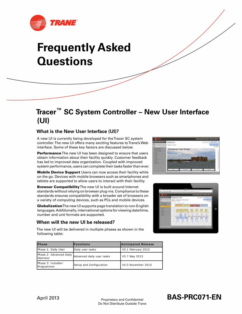
Proprietary and ConfidentialDo Not Distribute Outside Trane
April 2013 BAS-PRC071-EN
Frequently Asked
Questions
Tracer™ SC System Controller – New User Interface
(UI)
What is the New User Interface (UI)?
A new UI is currently being developed for theTracer SC systemcontroller.The new UI offers many exciting features toTrane’s Webinterface. Some of these key factors are discussed below.
PerformanceThe new UI has been designed to ensure that usersobtain information about their facility quickly. Customer feedbackhas led to improved data organization. Coupled with improvedsystem performance, users can complete their tasks faster than ever.
Mobile Device Support Users can now access their facility whileon the go. Devices with mobile browsers such as smartphones andtablets are supported to allow users to interact with their facility.
Browser CompatibilityThe new UI is built around Internetstandards without relying on browser plug-ins. Compliance to thesestandards ensures compatibility with a broader set of browsers ona variety of computing devices, such as PCs and mobile devices.
GlobalizationThe new UI supports page translation to non-Englishlanguages.Additionally, international options for viewing date/time,number and unit formats are supported.
When will the new UI be released?
The new UI will be delivered in multiple phases as shown in thefollowing table:
Phase Functions Anticipated Release
Phase 1: Daily User Daily user tasks V3.1 February 2012
Phase 2: Advanced Daily Operator Advanced daily user tasks V3.7 May 2013
Phase 3: Installer/Programmer Setup and Configuration V4.0 November 2013

2 BAS-PRC071-EN 02 Apr 2013
How do I determine which UIis right for my customer?
The new UI is the proper choice for mostend users. Details on the specific featuresthat will be a part of each software releaseare included in the adjacent table.
Users who require access to the featuresthat are not currently a part of the new UIcan easily revert back to the ConfigurationUI from the login screen or any other pagethroughout the system.
Daily Operator V3.1 V3.7 V4.0
System Summary X X X
Spaces and Equipment – Status with Standard Graphics, Data Logs X X X
Alarms – View, Acknowledge, Delete, Comment X X X
Data Logs – View and Export X X X
Display Custom Graphics X X X
Language Pack Support X X X
Schedules – Status with Summary X X X
Reports – Run and View X X X
Data Logs – Create, Edit, Delete X X
Schedules – Create, Edit, Delete Schedules, Exceptions, and Calendars X X
Schedules – Exception and Calendar List X X
Reports – Scheduling function X X
Alarms – Setup, E-Mail Forwarding X
Applications V3.1 V3.7 V4.0
Points – Status X X X
Outdoor Air Conditions – Status X X X
Area/CPC/VAS – Status X X X
Outdoor Air Conditions – Edit X X
Area/CPC/VAS – Create, Edit, Delete X X
Points – Create, Edit, Delete X
Administration and User Preferences V3.1 V3.7 V4.0
Administration (Users and Roles) – Create, Edit, Delete X X
User Preferences – Units, Date/Time Format, Home Page, Tree Setup, Table Filters X X
Installation and Tools V3.1 V3.7 V4.0
Tools – Backup & Restore, System Logs, Global References, TGP2 Programs X X
Upload License, Application Defaults, Priority Levels X X
Installation – Import Language Pack X X
Tools – View Custom Graphic List, Delete Custom Graphics X X
Tools – TES Direct Link Setup X X
Initial Tracer SC Setup Page X
Setup/Configuration – Facility settings, IP, BACnet, LON, Wireless, TIS X
Installation – Set time, System Units X
Installation – Device Discovery, Installation, Templates and Keys X
Devices Page X
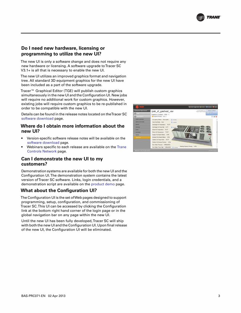
BAS-PRC071-EN 02 Apr 2013 3
Do I need new hardware, licensing or
programming to utilize the new UI?
The new UI is only a software change and does not require anynew hardware or licensing. A software upgrade toTracer SCV3.1+ is all that is necessary to enable the new UI.
The new UI utilizes an improved graphics format and navigationtree. All standard 3D equipment graphics for the new UI havebeen included as a part of the software upgrade.
Tracer™ Graphical Editor (TGE) will publish custom graphicssimultaneously in the new UI and the Configuration UI. New jobswill require no additional work for custom graphics. However,existing jobs will require custom graphics to be re-published inorder to be compatible with the new UI.
Details can be found in the release notes located on theTracer SCsoftware download page.
Where do I obtain more information about thenew UI?
• Version-specific software release notes will be available on thesoftware download page.
• Webinars specific to each release are available on the TraneControls Network page.
Can I demonstrate the new UI to mycustomers?
Demonstration systems are available for both the new UI and theConfiguration UI.The demonstration system contains the latestversion ofTracer SC software. Links, login credentials, and ademonstration script are available on the product demo page.
What about the Configuration UI?
The Configuration UI is the set ofWeb pages designed to supportprogramming, setup, configuration, and commissioning ofTracer SC.This UI can be accessed by clicking the Configurationlink at the bottom right hand corner of the login page or in theglobal navigation bar on any page within the new UI.
Until the new UI has been fully developed,Tracer SC will shipwith both the new UI and the Configuration UI. Upon final releaseof the new UI, the Configuration UI will be eliminated.

Trane optimizes the performance of homes and buildings around the world. A business of Ingersoll Rand, theleader in creating and sustaining safe, comfortable and energy efficient environments, Trane offers a broadportfolio of advanced controls and HVAC systems, comprehensive building services, and parts. For moreinformation, visit www.Trane.com.
Trane has a policy of continuous product and product data improvement and reserves the right to change design and specifications without notice.
We are committed to using environmentally
conscious print practices that reduce waste.
Proprietary and Confidential. Do Not Distribute Outside Trane
© 2013Trane. All rights reserved.
BAS-PRC071-EN 02 Apr 2013
Supersedes BAS-PRC071-EN (10 Feb 2012)
SAFETY WARNINGOnly qualified personnel should install and service the equipment. The installation, starting up, and servicing of heating, ventilating, and air-conditioning equipment can be hazardous and requires specific knowledge and training. Improperly installed, adjusted or altered equipment by an unqualified person could result in death or serious injury. When working on the equipment, observe all precautions in the literature and on the tags, stickers, and labels that are attached to the equipment.
September 2012 BAS-PRC072-EN
Product Data Sheet
Plug-in Transformer (15 Vdc)
for Tracer™ Communications BridgesOrdering Number: X13770036010
The 15 Vdc plug-in transformer is used to supply power to the Tracer Communications Bridges. Order this part only if you need to replace the transformer that was shipped with a Tracer Communications Bridge.
Specifications
Input data Output data Working environment Mechanical data
Voltage: 90–264 Vac
Holdup time: 10 ms typical @115 Vac
Operating temperature:0–40 °C
Dimensions:2.83 x 2.06 x 1.38 inches
Frequency: 47–63 Hz
Short-circuit protection: Continuous (auto-recovery)
Storage temperature:–20–85°C
Weight: 160 grams
Input current: 0.5 A maximum
Over-voltage protection: Option
Inrush current: 50 A maximum @ 264 Vac
Over-current protection: Constant current type
Isolation: Input to output = 4242 Vdc
Voltage: 15 Vdc @ 1 A
Leakage current: 0.25 mA maximum

Trane optimizes the performance of homes and buildings around the world. A business of Ingersoll Rand, the leader in creating and sustaining safe, comfortable and energy efficient environments, Trane offers a broad portfolio of advanced controls and HVAC systems, comprehensive building services, and parts. For more information, visit www.Trane.com.
Trane has a policy of continuous product and product data improvement and reserves the right to change design and specifications without notice.
We are committed to using environmentally
conscious print practices that reduce waste.
© 2012 Trane All rights reserved
BAS-PRC072-EN 30 Sep 2012
New
December 2012 BAS-PRC075-EN
Frequently Asked
Questions
Tracer™ BAS Operator Suite Mobile App
for theTracer™ SC System ControllerThis document contains frequently asked questions about the newTracer BAS Operators Suite mobile app.
Where do I get the mobile app? How much does it cost?
The mobile app is available free of charge from the both the Apple Store (Apple® devices) and Google Play(Android™ devices), which are factory-installed on your mobile device. In order to use the mobile app, or todemonstrate it, you must connect to aTracer SC.
What version ofTracer SC is the mobile app compatible with?
The mobile app is compatible withTracer SC V3.6 and higher.
What type of mobile device can I use with the app?
The mobile app can be used on Apple mobile devices and Android mobile devices. It is designed forsmartphones but works on tablets as well.
Device platform requirements:
• Apple iPhone®, iPad®, iPod®: iOS 5 and 6.
• Android: (V2.3 Gingerbread, 4.0 Ice Cream Sandwich, 4.1 Jelly Bean)
How do find out which operating system version is running on my mobile device?
Software version information is typically found under the settings tab on your mobile device:
Android devices:
• V2.3.3: Settings > About phone > Android version
• V4.0.4: Settings > About > Software information > Android version
Apple devices:
• Settings > General > About > Version
2 BAS-PRC075-EN 18 Dec 2012
Can the mobile app do everything that theTracer SC Web pages can?
No.The mobile app is designed for daily operation tasks, such as troubleshooting hot/cold calls, overriding setpoints, andchecking alarms.
With the mobile app you can:
• Override setpoints
• Override occupancy
• View standard graphics
• View, acknowledge, and comment on alarms
• View status of spaces, equipment, and systems
How does the mobile app interact with theTracer SC Web pages?
When you make a change using the mobile app, the change will appear in the associatedTracer SC Web page. Forexample, if you override a point on the mobile app, you (or your colleague), will be able to see the override on theTracerSCWeb page. Similarly, if a setpoint is changed on aTracer SCWeb page, the new setpoint value will appear on the mobileapp.
If I make comments on the alarms, can those comments be seen by other users from aPC Web interface?
Yes. When you enter a comment with the mobile app, it is saved in theTracer SC. Other users, whether using a PC or themobile app on their phones, will be able see the comment associated with that alarm.
How can I create or edit schedules using the app?
You cannot create or edit a schedule with the mobile app. However, you can override the occupancy of a space (or area)in order to make it occupied or unoccupied.These overrides can have a timer, such that the override is released after thetimer runs out. For example, if the gymnasium will be used for a couple hours after normal school hours, the gym canbe overridden occupied with a two hour time duration. After two hours, the timer will finish and the gym will be releasedback to the unoccupied state.
Can I change the standard graphics?
No.The standard graphics cannot be changed or customized.
Can I add custom graphics?
No. Capability for custom graphics is not available at this time.
Does the app have an auto log off feature?
No.The app does not automatically log off.
How do I manually log off the mobile app?
To log off tap the More button on the lower right of the mobile app, which opens the More screen.Tap the Log Out button,which will return you to theTracer SC list screen.
Will the mobile app continue to communicate to theTracer SC after the phone goes tosleep?
No.When the phone goes to sleep, or when you navigate away from the app screen, the mobile app will stop requestinginformation for that screen.When you wake up your phone and the app is still open, it will begin to request information.

BAS-PRC075-EN 18 Dec 2012 3
What happens if I lose my connection with theTracer SC while using the mobile app?
If the mobile app loses its connection with theTracer SC, a bright yellow indicator will appear at the top of the screen.The data on the screen will freeze, capturing the most recent data received from theTracer SC, until a connection isrestored or the mobile app is closed.
What does "---" mean?
Three dashes appear as status value when theTracer SC does not have the data that is being requested. Often, it indicatesthat the unit controller has not provided the data to theTracer SC. One possible cause may be communication lossbetween the unit controller and theTracer SC.
If I'm away from the building, at the store, on the golf course, or running errands acrosstown, can I connect to theTracer SC?
Yes. If theTracer SC is available directly from the Internet, you can connect to it. If not, you will need to log into the networkusing a VPN (Virtual Private Network) client.You may need to request VPN access from your network administrator. VPNallows you to connect to your network from anywhere on the Internet using either a WiFi connection or cellular access(3G/4G). After you have connected to your network withVPN, you can then connect to theTracer SC. Refer to the “GettingStarted andTroubleshooting Guide,” BAS-SVU23A-EN, for more information.
What is required in order to connect with VPN?
VPN requirements vary from site to site. For some networks, VPN can be established as a setting on your phone. Othernetworks require a separate app on the phone forVPN connection. See your network administrator for more information.
Is the mobile app secure?
Using the mobile app to accessTracer SC is, for the most part, secure. Additional steps can be taken to increase the levelof security on your mobile device.Tracer SC already has some security measures in place, such as granting userpermissions and setting up automatic log-off. Some of these measures have been carried over to the mobile app.
The following security features describe how you can enhance security while accessingTracer SC with the mobile app:
User ID and password
The mobile app requires a valid IP address (or domain name) and a user ID and password, in order to connect to aTracerSC.The user ID and passwords are the same as those you use for theTracer SCWeb pages and have the same permissions.Therefore, if a user is not set up with permissions to change setpoints, that user will not be able to change setpoints oneither theTracer SC Web page or the mobile app.
Remember Login
You can choose whether or not to have the mobile app remember your user ID and password.To increase security, setthe "Remember Login" slider to OFF, which requires that you enter your user ID and password each time you connect totheTracer SC. Some users may consider this inconvenient, but many prefer the higher level of security. If others use yourphone, this prevents them from accessing theTracer SC. Additionally, most cellular phones are equipped with an optionalscreen lock password setting.This feature locks the phone display (after it enters sleep mode or is turned off), and thenrequires a password to unlock and use the phone.This increases security and also deters unauthorized usage of yourphone.
Encryption
The mobile app encrypts saved-passwords, rendering them unreadable outside of the app on the mobile device.

Trane optimizes the performance of homes and buildings around the world. A business of Ingersoll Rand, theleader in creating and sustaining safe, comfortable and energy efficient environments, Trane offers a broadportfolio of advanced controls and HVAC systems, comprehensive building services, and parts. For moreinformation, visit www.Trane.com.
Trane has a policy of continuous product and product data improvement and reserves the right to change design and specifications without notice.
©2012Trane All rights reserved
BAS-PRC075-EN 18 Dec 2012
New
We are committed to using environmentally
conscious print practices that reduce waste.
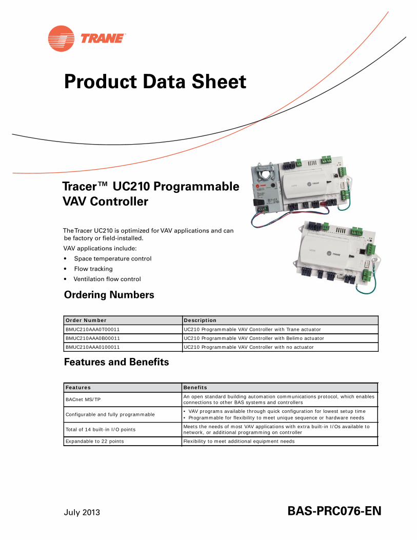
July 2013 BAS-PRC076-EN
Product Data Sheet
TheTracer UC210 is optimized for VAV applications and canbe factory or field-installed.
VAV applications include:
• Space temperature control
• Flow tracking
• Ventilation flow control
Ordering Numbers
Features and Benefits
Order Number Description
BMUC210AAA0T00011 UC210 Programmable VAV Controller with Trane actuator
BMUC210AAA0B00011 UC210 Programmable VAV Controller with Belimo actuator
BMUC210AAA0100011 UC210 Programmable VAV Controller with no actuator
Features Benefits
BACnet MS/TP An open standard building automation communications protocol, which enables connections to other BAS systems and controllers
Configurable and fully programmable • VAV programs available through quick configuration for lowest setup time• Programmable for flexibility to meet unique sequence or hardware needs
Total of 14 built-in I/O points Meets the needs of most VAV applications with extra built-in I/Os available to network, or additional programming on controller
Expandable to 22 points Flexibility to meet additional equipment needs
Tracer™ UC210 Programmable
VAV Controller

2 BAS-PRC076-EN 22 Jul 2013
Controller Specifications and Enclosure Location
Dimensions (Without Actuator)
Storage
Temperature: -40°F to 185°F (-40°C to 85°C)
Humidity: 5% to 95% (non-condensing)
Operating
Temperature: -40°F to 158°F (-40°C to 70°C)
Humidity: 5% to 95% (non-condensing)
Power: 20-4–27.6 Vac, (24 Vac ±15% nominal, 50–60 Hz, 10.5 VA plus 1 VA per 20mA of 24 VDC load plus 12 VA maximum per binary load
Environmental Rating (Enclosure): NEMA 1
Installation: U.L. 840: Category 3
Pollution: U.L. 840: Degree 2
Agency Compliance• UL916 PAZX- Open Energy Management Equipment• UL94-5V Flammability• CE Marked• FCC Part 15, Subpart B, Class B Limit• AS/NZS CISPR 22:2006• VCCI V-3/2008.04• ICES-003, Issue 4:2004• Communications BACnet MS/TP, supports BACnet protocol ASHRAE 135-2004 and meets BACnet Testing Laboratory (BTL) as an Application Specific Controller (ASC)
profile device• Suitable for Plenum mounting
UC210 120.0 mm(4.72 in)
161.0 mm(6.34 in)

BAS-PRC076-EN 22 Jul 2013 3
Dimensions (with Actuator)
Dimensions (Trane VAV Factory Version)
UC210
251.4 mm (9.90 in.)
120.0 mm (4.72 in.)
155.6 mm (6.13 in.)
114.3 mm (4.50 in.)

Trane optimizes the performance of homes and buildings around the world. A business of Ingersoll Rand, theleader in creating and sustaining safe, comfortable and energy efficient environments, Trane offers a broadportfolio of advanced controls and HVAC systems, comprehensive building services, and parts. For moreinformation, visit www.Trane.com.
Trane has a policy of continuous product and product data improvement and reserves the right to change design and specifications without notice.
We are committed to using environmentally
conscious print practices that reduce waste.
© 2013Trane All rights reserved
BAS-PRC076-EN 22 July 2013
New
Inputs and Outputs
Analog Inputs 1 through 3Note: Configuration options when used as spare; 10kthermistor, 0 to
1klinear setpoint, 200 to 20k linear.
Universal Inputs UI1 and UI2Note: Configuration options when used as spare; 4–20mA, 0-10V,
resistive (see AI specifications), binary (solid state open collector).
• AI1: Space temperature; thermistor: 10k @77°F (25°C) range: 32°F to 122°F (0°C to 50°C)
• AI2: Space setpoint; potentiometer: 1k from 50 to 90°F (10 to 32.2°C), */** (thumbwheel) functionality supported
• AI3: Discharge air temperature: 10k@77°F (25°C) from -40°F to 212°F (-40 to 100°C)
• UI1: Relative Humidity• UI2: CO2
Pressure Input P1 Binary Input BI1, Dry Contact
• P1: Supply air flow; pressure transducer: From 0 to 2 in. water column (0 to 498 Pa)
• BI1: Occupancy
Analog Outputs AO1 and AO2Note: Configuration options when used a spare; Voltage output is 0 to 10
VDC, 500 ohm min. impedance. Current output is 4 - 20 mA, 500max. impedance.
Binary Outputs 1 through 5Note: 0.5A Resistive Maximum Rating
• AO1: ECM • AO2: SCR Heat
• BO1: Heat stage 3 TRIAC• BO2: Heat stage 2/Water Valve Close TRIAC• BO3: Heat stage 1/Water Valve Open TRIAC• BO4: Air Damper Close TRIAC• BO5: Damper Open TRIAC
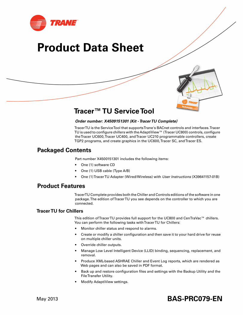
Product Data Sheet
Tracer™TU ServiceTool
Order number: X4509151301 (Kit -TracerTU Complete)
TracerTU is the ServiceTool that supportsTrane's BACnet controls and interfaces.TracerTU is used to configure chillers with theAdaptiView™ (Tracer UC800) controls, configuretheTracer UC600,Tracer UC400, andTracer UC210 programmable controllers, createTGP2 programs, and create graphics in the UC600,Tracer SC, andTracer ES.
Packaged Contents
Part number X4500151301 includes the following items:
• One (1) software CD
• One (1) USB cable (Type A/B)
• One (1)TracerTU Adapter (Wired/Wireless) with User Instructions (X39641157-01B)
Product Features
TracerTU Complete provides both the Chiller and Controls editions of the software in onepackage.The edition ofTracerTU you see depends on the controller to which you areconnected.
TracerTU for Chillers
This edition ofTracerTU provides full support for the UC800 and CenTraVac™ chillers.You can perform the following tasks withTracerTU for Chillers:
• Monitor chiller status and respond to alarms.
• Create or modify a chiller configuration and then save it to your hard drive for reuseon multiple chiller units.
• Override chiller outputs.
• Manage Low Level Intelligent Device (LLID) binding, sequencing, replacement, andremoval.
• Produce XML-based ASHRAE Chiller and Event Log reports, which are rendered asWeb pages and can also be saved in PDF format.
• Back up and restore configuration files and settings with the Backup Utility and theFileTransfer Utility.
• Modify AdaptiView settings.
May 2013 BAS-PRC079-EN
Trane optimizes the performance of homes and buildings around the world. A business of Ingersoll Rand, theleader in creating and sustaining safe, comfortable and energy efficient environments, Trane offers a broadportfolio of advanced controls and HVAC systems, comprehensive building services, and parts. For moreinformation, visit www.Trane.com.
Trane has a policy of continuous product and product data improvement and reserves the right to change design and specifications without notice.
© 2013Trane All rights reserved
BAS-PRC079-EN 24 May 2013
(New)
We are committed to using environmentally
conscious print practices that reduce waste.
TracerTU for Controls
You can perform the following tasks withTracerTU for Controls:
• Connect to a controller directly with a USB cable or indirectly viaTracer SC pass-through, a zonesensor, or a wireless network using theTracerTU Adapter (Wired/Wireless).
• View the status of controller, points, and alarms.
• Configure, edit, and override points.
• Create configurations andTGP2 programs for VAVs,Trane factory blower coils, fan coils, unitventilators, and variable speed water source heat pumps.
• Create and preconfigure graphics offline usingTracerTU andTracer Graphics Editor.
• Balance air and water valves.
• Manage controller settings and set up expansion modules.
• Create and maintain wireless networks.
• Configure UC600 schedules and theTD7 Display.
• Download/backup configuration files to/from multiple devices in one operation.
Laptop Requirements
Your laptop must meet the following hardware and software requirements:
Note: TracerTU is designed and validated for this minimum laptop configuration. Any variationfrom this configuration may have different results.Therefore, support forTracerTU islimited to only those laptops with the configuration previously specified.
• 1 GB RAM (minimum) • An available USB 2.0 port
• 1024 x 768 screen resolution
• CD-ROM drive
• Ethernet 10/100 LAN card
• Windows XP Professional operating system withService Pack 3 (SP3) orWindows 7 Enterprise or Professional operatingsystem(32-bit or 64-bit)
• Microsoft .NET Framework 4.0 or later
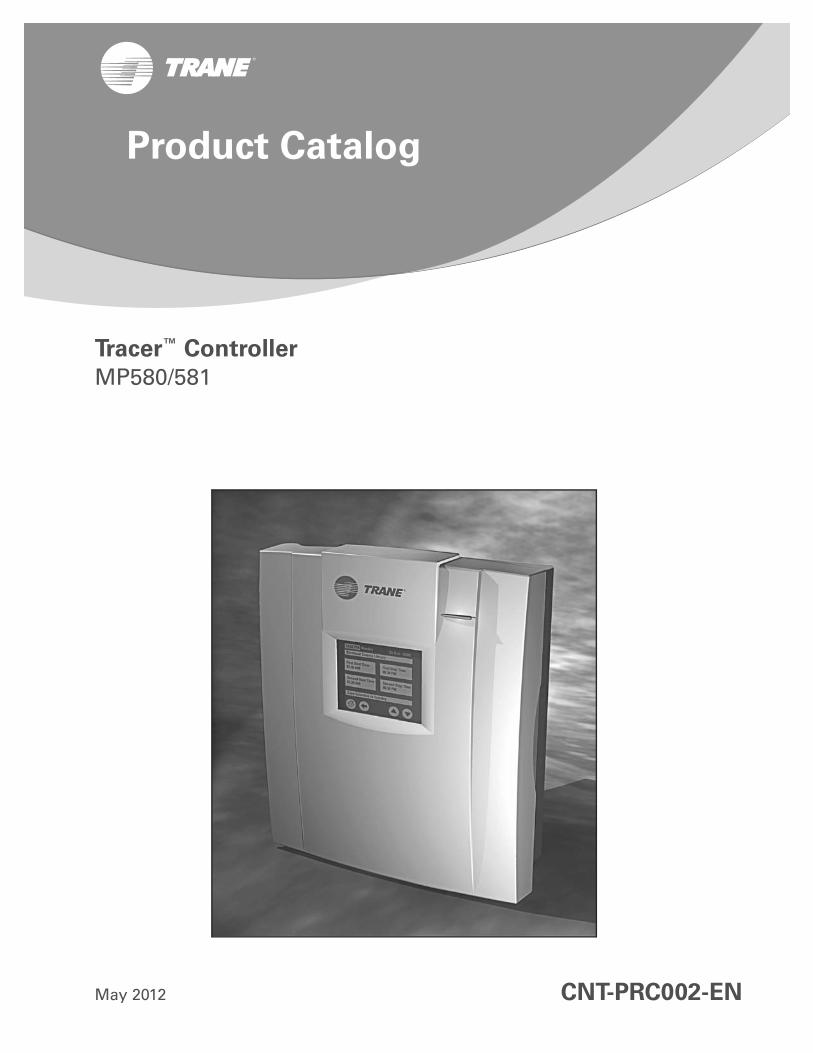
Tracer™ Controller
MP580/581
May 2012 CNT-PRC002-EN
Product Catalog

2 CNT-PRC002-EN 30 May 2012
Copyright
© 2012 Trane. All rights reserved.
This document and the information in it are the property of Trane and may not be used or reproduced in whole or in part, without the written permission of Trane. Trane reserves the right to revise this publication at any time and to make changes to its content without obligation to notify any person of such revision or change.
Trademarks
Trane and its logo are trademarks of Trane in the United States and other countries. All trademarks referenced in this document are the trademarks of their respective owners.
Revision Summary
CNT-PRC002-EN (30 May 2012)
Cost Savings: Update to mount plate and metal enclosure to remove metal screw/nut and use plastic PEM nut. Change to figure illustrations.
Table of Contents
CNT-PRC002-EN 30 May 2012 3
Product Overview . . . . . . . . . . . . . . . . . . . . . . . . . . . . . . . . . . . . . . . . . . . . . . . . . . . . . . 4
Applications . . . . . . . . . . . . . . . . . . . . . . . . . . . . . . . . . . . . . . . . . . . . . . . . . . . . . . . 4
Product Models . . . . . . . . . . . . . . . . . . . . . . . . . . . . . . . . . . . . . . . . . . . . . . . . . . . . 4
Inputs and Outputs . . . . . . . . . . . . . . . . . . . . . . . . . . . . . . . . . . . . . . . . . . . . . . . . . 4
Product Models and Accessories . . . . . . . . . . . . . . . . . . . . . . . . . . . . . . . . . . . . . 5Tracer MP580/581 Models . . . . . . . . . . . . . . . . . . . . . . . . . . . . . . . . . . . . . . 5Operator Display Models . . . . . . . . . . . . . . . . . . . . . . . . . . . . . . . . . . . . . . . 6Expansion Module . . . . . . . . . . . . . . . . . . . . . . . . . . . . . . . . . . . . . . . . . . . . . 7
Features . . . . . . . . . . . . . . . . . . . . . . . . . . . . . . . . . . . . . . . . . . . . . . . . . . . . . . . . . . . . . . . 8
Network Architecture . . . . . . . . . . . . . . . . . . . . . . . . . . . . . . . . . . . . . . . . . . . . . . . . . . 11
Wiring Diagram . . . . . . . . . . . . . . . . . . . . . . . . . . . . . . . . . . . . . . . . . . . . . . . . . . . . . . . 12
Enclosure Interior . . . . . . . . . . . . . . . . . . . . . . . . . . . . . . . . . . . . . . . . . . . . . . . . . . . . . . 14
Dimensions and Specifications . . . . . . . . . . . . . . . . . . . . . . . . . . . . . . . . . . . . . . . . . 15
Dimensions . . . . . . . . . . . . . . . . . . . . . . . . . . . . . . . . . . . . . . . . . . . . . . . . . . . . . . 15
Specifications . . . . . . . . . . . . . . . . . . . . . . . . . . . . . . . . . . . . . . . . . . . . . . . . . . . . 17
4 CNT-PRC002-EN 30 May 2012
Product Overview
The Tracer MP580 programmable controller is available factory installed on the following Trane air handlers:
• M-Series Climate Changer air handlers.
• T-Series Climate Changer air handlers.
• AireSystems custom air handlers.
The Tracer MP581 programmable controller is available for field installation for a variety of heating, ventilation, and air-conditioning (HVAC) applications.
Applications
Tracer MP580/581 controllers support a wide variety of building control applications, including:
• Air-handler control.
• Support of the LonMark® Space Comfort Controller (SCC) profile and the Discharge Air Controller (DAC) profile for air handlers.
• Control of mechanical room equipment, including cooling towers, pumps, boilers, and heat exchangers.
• Supervisory control of an HVAC network for mid-sized buildings.
• Nearly any control process needed in a commercial building.
Product Models
The following Tracer MP580/581 models are available:
• Tracer MP580 factory installed on certain Trane air handlers.
• Tracer MP581 in a NEMA-1 enclosure (with or without a touch screen).
• Frame-mounted Tracer MP581 (the termination board and circuit board in a plastic frame assembly).
Touch-screen operator displays are available in the following configurations:
• Door-mounted operator display.
• Portable operator display.
• Stand-alone operator display.
Note: For more details, refer to the section, “Product Models and Accessories,” p. 5.
Inputs and Outputs
Tracer MP580/581 controllers have the following inputs and outputs (illustrated in Figure 8 on page 9):
• Twelve (12) universal inputs
• Six (6) binary outputs
• Six (6) analog outputs
• One (1) static pressure input
You can add up to four (4) optional expansion modules to a Tracer MP580/581 controller. Each expansion module adds the following points:
• Six (6) universal inputs
• Four (4) binary outputs
• Four (4) analog outputs
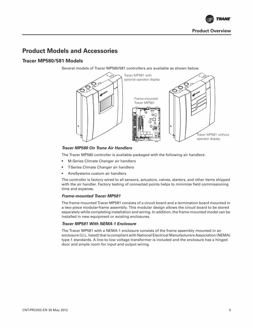
CNT-PRC002-EN 30 May 2012 5
Product Overview
Product Models and Accessories
Tracer MP580/581 Models
Several models of Tracer MP580/581 controllers are available as shown below.
Tracer MP580 On Trane Air Handlers
The Tracer MP580 controller is available packaged with the following air handlers:
• M-Series Climate Changer air handlers
• T-Series Climate Changer air handlers
• AireSystems custom air handlers
The controller is factory wired to all sensors, actuators, valves, starters, and other items shipped with the air handler. Factory testing of connected points helps to minimize field commissioning time and expense.
Frame-mounted Tracer MP581
The frame-mounted Tracer MP581 consists of a circuit board and a termination board mounted in a two-piece modular-frame assembly. This modular design allows the circuit board to be stored separately while completing installation and wiring. In addition, the frame-mounted model can be installed in new equipment or existing enclosures.
Tracer MP581 With NEMA-1 Enclosure
The Tracer MP581 with a NEMA-1 enclosure consists of the frame assembly mounted in an enclosure (U.L. listed) that is compliant with National Electrical Manufacturers Association (NEMA) type-1 standards. A line-to-low voltage transformer is included and the enclosure has a hinged door and ample room for input and output wiring.
Frame-mounted Tracer MP581
Tracer MP581 with optional operator display
Tracer MP581 without operator display
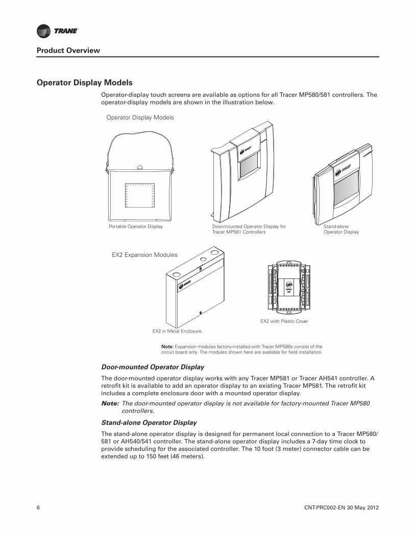
6 CNT-PRC002-EN 30 May 2012
Product Overview
Operator Display Models
Operator-display touch screens are available as options for all Tracer MP580/581 controllers. The operator-display models are shown in the illustration below.
Door-mounted Operator Display
The door-mounted operator display works with any Tracer MP581 or Tracer AH541 controller. A retrofit kit is available to add an operator display to an existing Tracer MP581. The retrofit kit includes a complete enclosure door with a mounted operator display.
Note: The door-mounted operator display is not available for factory-mounted Tracer MP580 controllers.
Stand-alone Operator Display
The stand-alone operator display is designed for permanent local connection to a Tracer MP580/581 or AH540/541 controller. The stand-alone operator display includes a 7-day time clock to provide scheduling for the associated controller. The 10 foot (3 meter) connector cable can be extended up to 150 feet (46 meters).
Door-mounted Operator Display for Tracer MP581 Controllers
Portable Operator Display Stand-alone Operator Display
EX2 in Metal Enclosure
EX2 with Plastic Cover
Note: Expansion modules factory-installed with Tracer MP580s consist of the circuit board only. The modules shown here are available for field installation.
Operator Display Models
EX2 Expansion Modules
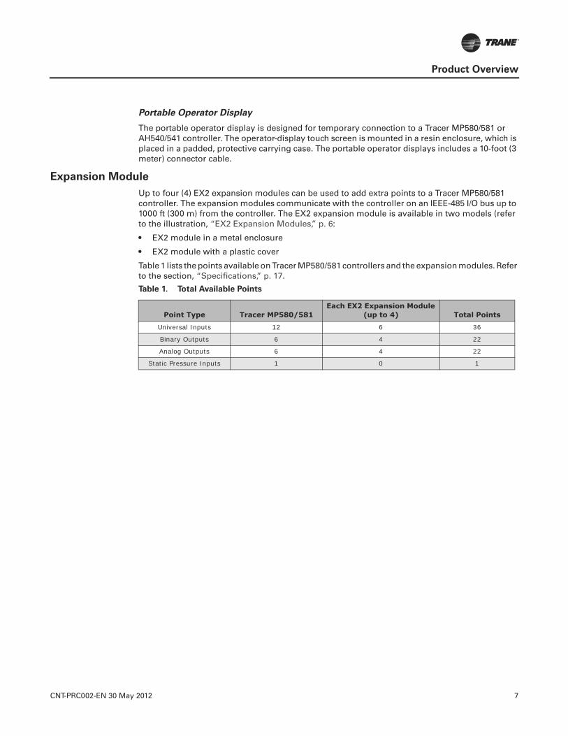
CNT-PRC002-EN 30 May 2012 7
Product Overview
Portable Operator Display
The portable operator display is designed for temporary connection to a Tracer MP580/581 or AH540/541 controller. The operator-display touch screen is mounted in a resin enclosure, which is placed in a padded, protective carrying case. The portable operator displays includes a 10-foot (3 meter) connector cable.
Expansion Module
Up to four (4) EX2 expansion modules can be used to add extra points to a Tracer MP580/581 controller. The expansion modules communicate with the controller on an IEEE-485 I/O bus up to 1000 ft (300 m) from the controller. The EX2 expansion module is available in two models (refer to the illustration, “EX2 Expansion Modules,” p. 6:
• EX2 module in a metal enclosure
• EX2 module with a plastic cover
Table 1 lists the points available on Tracer MP580/581 controllers and the expansion modules. Refer to the section, “Specifications,” p. 17.
Table 1. Total Available Points
Point Type Tracer MP580/581Each EX2 Expansion Module
(up to 4) Total Points
Universal Inputs 12 6 36
Binary Outputs 6 4 22
Analog Outputs 6 4 22
Static Pressure Inputs 1 0 1
8 CNT-PRC002-EN 30 May 2012
Features
Graphical Programming
The Tracer graphical programming (TGP) editor eliminates the need for line-by-line programming (refer to Figure 1, p. 9). The TGP editor is a software component of the Trane Rover™ Service tool. TGP has the following advantages:
• Easy to learn; programming is as easy as assembling logic blocks with a computer mouse, much like creating a flow chart.
• Powerful; the TGP editor has built-in PID functions and more than 50 logic blocks for building programs.
• Self -documenting; programs can be printed and used as pictorial representations of sequences of operation (refer to Figure 1, p. 9).
• Programs are stored in the controller; along with their graphical representation. Can be uploaded, viewed, and re-used.
• Offline programming; configuration and TGP programming can be done without connecting to a Tracer MP580/581 controller.
• Program simulation; programmers can simulate TGP programs offline. The programmer can verify, test, and troubleshoot controller operation at a remote location, simplifying setup, maintenance, and service.

CNT-PRC002-EN 30 May 2012 9
Features
Figure 1. TGP Editor and Printout
10 CNT-PRC002-EN 30 May 2012
Features
Operator Display
The optional operator-display touch screen is an intuitive operator interface for monitoring and changing building control functions. The operator display allows the user to:
• Monitor space temperature, relative humidity, and other variables.
• Change setpoints and scheduled occupancy times.
• Identify and troubleshoot problems.
• View and reset controller alarms.
• Manually override outputs.
The operator display includes a 7-day time clock that gives Tracer MP580/581 controllers the ability to manage time-of-day scheduling, with two ON/OFF times per day and up to 20 exception schedules per year.
Engineered Smoke Control
Tracer MP580/581 controllers and EX2 expansion modules can be used to control an engineered smoke control system. When used with a fire alarm control panel (provided by other suppliers), the smoke-control system can help protect occupants by controlling the flow of smoke during a fire.
In addition to smoke control, with a firefighter’s control panel, a firefighter can see the status of smoke control and implement overrides as required. The Tracer MP580/581 and EX2 expansion module are UL-864-UUKL-listed for this application. For details, refer to Engineered Smoke Control System for Tracer Summit Applications Guide (BAS-APG001-EN).
Interoperability
Tracer MP580/581 controllers communicate by means of the LonTalk® protocol. The controllers can be configured to conform to the LonMark® Space Comfort Controller (SCC) profile or the Discharge Air Controller (DAC) profile. The user can integrate the Tracer MP580/581 controllers with any control system that supports LonTalk protocols and FTT10-A communications.
Security
Eight (8) security passwords are allowed to limit access to a Tracer MP580/581 controller.
Use the security passwords to prevent unauthorized access to:
• TGP programs stored in the controller.
• Operator display functions, such as setpoints and schedules.
• Configuration downloads from a LonTalk service tool.
For each of the security passwords, the user can choose what features can or cannot be accessed, including specific screens on the operator display.
Note: The controller ships with security disabled.
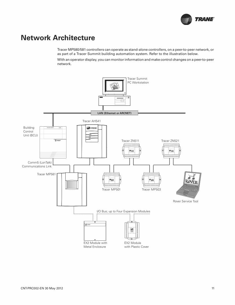
CNT-PRC002-EN 30 May 2012 11
Network Architecture
Tracer MP580/581 controllers can operate as stand-alone controllers, on a peer-to-peer network, or as part of a Tracer Summit building automation system. Refer to the illustration below.
With an operator display, you can monitor information and make control changes on a peer-to-peer network.
Rover Service Tool
Comm5 (LonTalk)Communications Link
Tracer MP581
Tracer ZN511 Tracer ZN521
Tracer MP501 Tracer MP503
Tracer AH541
Building Control Unit (BCU)
Tracer SummitPC Workstation
I/O Bus; up to Four Expansion Modules
EX2 Module withMetal Enclosure
EX2 Module with Plastic Cover
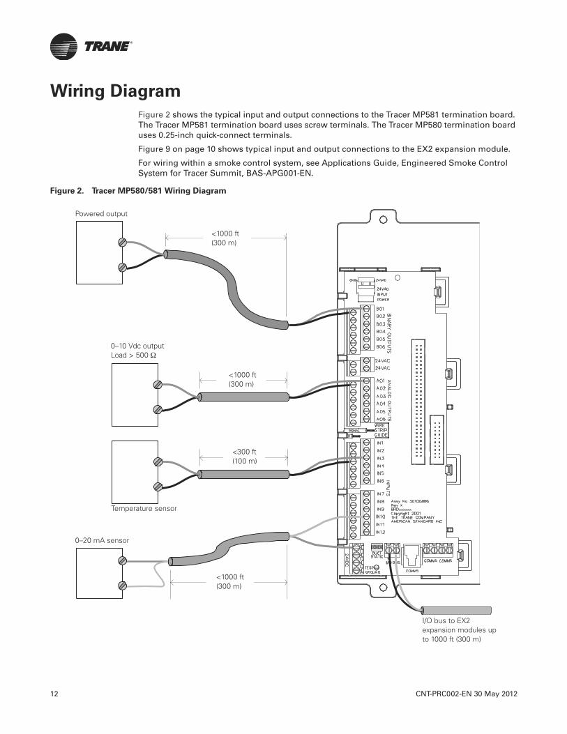
12 CNT-PRC002-EN 30 May 2012
Wiring Diagram
Figure 2 shows the typical input and output connections to the Tracer MP581 termination board. The Tracer MP581 termination board uses screw terminals. The Tracer MP580 termination board uses 0.25-inch quick-connect terminals.
Figure 9 on page 10 shows typical input and output connections to the EX2 expansion module.
For wiring within a smoke control system, see Applications Guide, Engineered Smoke Control System for Tracer Summit, BAS-APG001-EN.
Figure 2. Tracer MP580/581 Wiring Diagram
0–20 mA sensor
Temperature sensor
<300 ft(100 m)
<1000 ft(300 m)
0–10 Vdc outputLoad > 500 Ω
Powered output
<1000 ft(300 m)
<1000 ft(300 m)
I/O bus to EX2 expansion modules up to 1000 ft (300 m)
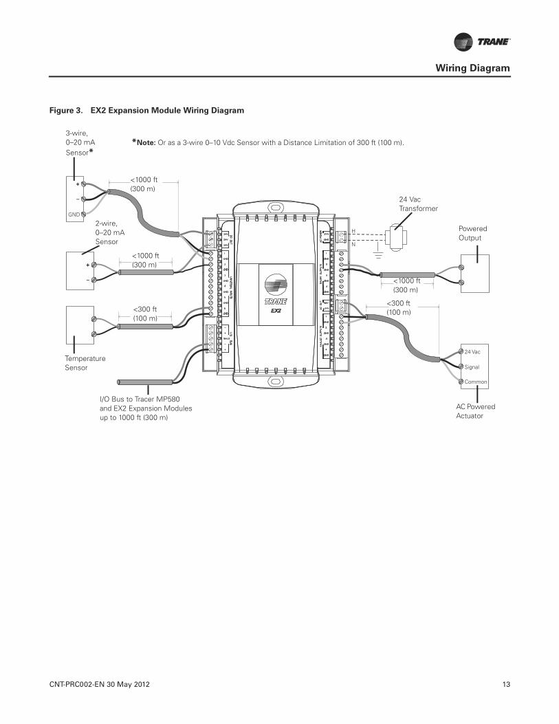
CNT-PRC002-EN 30 May 2012 13
Wiring Diagram
Figure 3. EX2 Expansion Module Wiring Diagram
2-wire,0–20 mA Sensor
Temperature Sensor
<1000 ft(300 m)
<1000 ft(300 m)
<300 ft(100 m)
PoweredOutput
AC Powered Actuator
24 Vac Transformer
I/O Bus to Tracer MP580 and EX2 Expansion Modulesup to 1000 ft (300 m)
<300 ft(100 m)
3-wire, 0–20 mA Sensor*
*Note: Or as a 3-wire 0–10 Vdc Sensor with a Distance Limitation of 300 ft (100 m).
<1000 ft(300 m)
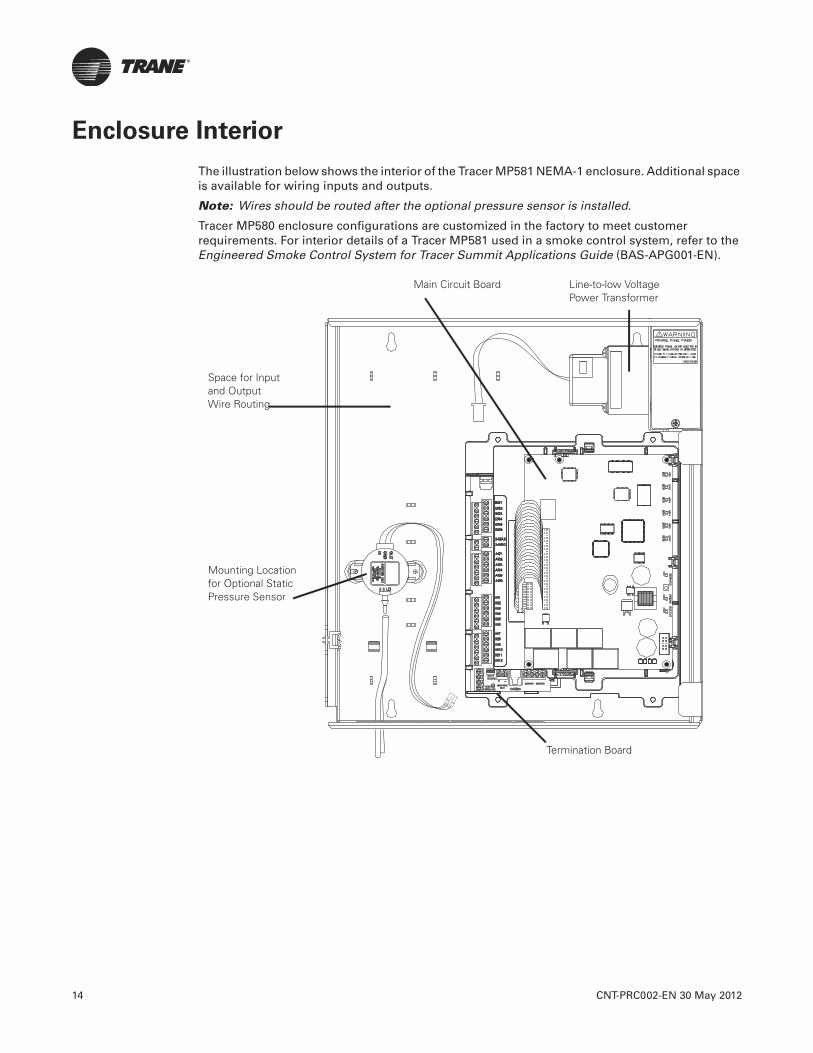
14 CNT-PRC002-EN 30 May 2012
Enclosure Interior
The illustration below shows the interior of the Tracer MP581 NEMA-1 enclosure. Additional space is available for wiring inputs and outputs.
Note: Wires should be routed after the optional pressure sensor is installed.
Tracer MP580 enclosure configurations are customized in the factory to meet customer requirements. For interior details of a Tracer MP581 used in a smoke control system, refer to the Engineered Smoke Control System for Tracer Summit Applications Guide (BAS-APG001-EN).
Line-to-low Voltage Power Transformer
Termination Board
Mounting Location for Optional Static Pressure Sensor
Space for Inputand OutputWire Routing
Main Circuit Board
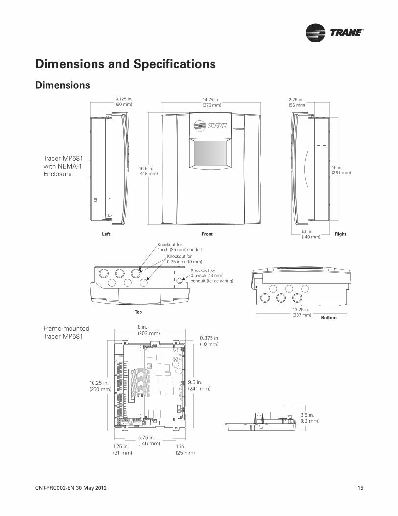
CNT-PRC002-EN 30 May 2012 15
Dimensions and Specifications
Dimensions
Tracer MP581 with NEMA-1 Enclosure
Frame-mounted Tracer MP581

16 CNT-PRC002-EN 30 May 2012
Dimensions and Specifications
5.625 in.(143 mm)
6.313 in(160 mm)
5.375 in.(137 mm)
2.0 in.(51 mm)
2.0 in.(51mm)
6.5 in.(165 mm)
9.0 in.(229mm)
10.37 in.(263 mm)with cover
7.0 in.(178 mm)
2.25 in.(58 mm)
1.0 in.(25 mm)
10.25 in.(260 mm)without cover
9.0 in.(229 mm)
6.875 in.(175 mm)
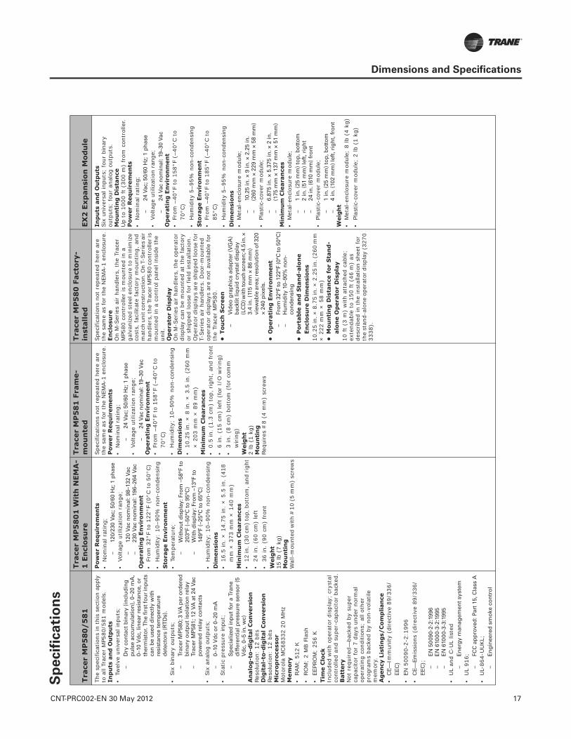
CNT-PRC002-EN 30 May 2012 17
Dimensions and Specifications
Sp
ecif
icati
on
s
Tra
cer
MP
58
0/
58
1Tra
cer
MP
58
01
Wit
h N
EM
A-
1 E
ncl
osu
reTra
cer
MP
58
1 F
ram
e-
mo
un
ted
Tra
cer
MP
58
0 F
act
ory
-in
stall
ed
EX
2 E
xp
an
sio
n M
od
ule
The
spec
ifica
tions
in t
his
sect
ion
appl
y to
all
Trac
er M
P580
/581
mod
els.
Inp
uts
an
d O
utp
uts
•Tw
elve
uni
vers
al in
puts
;–
Dry
co
nta
ct b
inar
y (i
ncl
ud
ing
p
uls
e ac
cum
ula
tio
n),
0–2
0 m
A,
0–10
Vd
c, li
nea
r re
sist
ance
, or
ther
mis
tor.
Th
e fi
rst f
ou
r in
pu
ts
can
be
use
d d
irec
tly
wit
h
resi
stan
ce t
emp
erat
ure
d
etec
tors
(R
TD
s).
•Six
bin
ary
outp
uts;
–Tr
acer
MP
580;
3 V
A p
er o
rder
ed
bin
ary
ou
tpu
t is
ola
tio
n r
elay
–Tr
acer
MP
581;
12
VA
at
24 V
ac
po
wer
ed r
elay
co
nta
cts
•Six
ana
log
outp
uts;
–0–
10 V
dc
or
0–20
mA
•Sta
tic p
ress
ure
inpu
t;–
Sp
ecia
lized
inp
ut
for
a Tr
ane
diff
eren
tial
pre
ssu
re s
enso
r (5
V
dc,
0–5
in. w
c)A
nalo
g-t
o-d
igit
al C
on
vers
ion
Reso
lutio
n: 1
2 bi
tsD
igit
al-
to-d
igit
al
Co
nvers
ion
Reso
lutio
n: 1
2 bi
tsM
icro
pro
cess
or
Mot
orol
a M
C68
332
20 M
Hz
Mem
ory
•RAM
; 51
2 K
•RO
M;
2 M
B F
lash
•EE
PRO
M;
256
K
Tim
e C
lock
Incl
uded
with
ope
rato
r di
spla
y; c
ryst
al
cont
rolle
d an
d su
per-
capa
cito
r ba
cked
.B
att
ery
Not
req
uire
d—ba
cked
by
supe
r ca
paci
tor
for
7 da
ys u
nder
nor
mal
op
erat
ing
cond
ition
s; a
ll ot
her
prog
ram
s ba
cked
by
non-
vola
tile
mem
ory.
Ag
en
cy L
isti
ng
s/C
om
plian
ce•
CE—
Imm
unity
(di
rect
ive
89/3
36/
EEC)
•EN
500
90-2
-2:1
996
•CE—
Emis
sion
s (d
irec
tive
89/3
36/
EEC);
–E
N 5
009
0-2-
2:19
96–
EN
610
00-3
-2:1
995
–E
N 6
1000
-3-3
:199
5•
UL
and
C-U
L lis
ted
–E
ner
gy
man
agem
ent
syst
em•
UL
916;
–FC
C a
pp
rove
d: P
art
15, C
lass
A•
UL-
864-
UU
KL;
–E
ng
inee
red
sm
oke
co
ntr
ol
Pow
er
Req
uir
em
en
ts•
Nom
inal
rat
ing;
–12
0/23
0 Va
c; 5
0/60
Hz;
1 p
has
e•
Volta
ge u
tiliz
atio
n ra
nge;
–12
0 Va
c n
om
inal
: 98–
132
Vac
–23
0 Va
c n
om
inal
: 196
–264
Vac
Op
era
tin
g E
nvir
on
men
t•
From
32°
F to
122
°F (
0°C t
o 50
°C)
•H
umid
ity:
10–9
0% n
on-c
onde
nsin
gS
tora
ge E
nvir
on
men
t•
Tem
pera
ture
;–
Wit
ho
ut
dis
pla
y: F
rom
–58
°F t
o
203°
F (–
50°C
to
95°
C)
–W
ith
dis
pla
y: F
rom
–13
°F t
o
149°
F (–
25°C
to
65°
C)
•H
umid
ity;
10–9
0% n
on-c
onde
nsin
gD
imen
sio
ns
•16
.5 in
. ×
14.
75 in
. ×
5.5
in.
(418
m
m ×
373
mm
× 1
40 m
m)
Min
imu
m C
leara
nce
s•
12 in
. (30
cm
) to
p, b
otto
m, a
nd rig
ht•
24 in
. (6
0 cm
) le
ft•
36 in
. (9
0 cm
) fr
ont
Weig
ht
15 lb
(7
kg)
Mo
un
tin
gW
all-
mou
nted
with
#10
(5
mm
) sc
rew
s
Spe
cific
atio
ns n
ot r
epea
ted
here
are
th
e sa
me
as fo
r th
e N
EMA-
1 en
clos
ure.
Po
wer
Req
uir
em
en
ts•
Nom
inal
rat
ing;
–24
Vac
; 50/
60 H
z; 1
ph
ase
•Vo
ltage
util
izat
ion
rang
e;–
24 V
ac n
om
inal
: 19–
30 V
acO
pera
tin
g E
nvir
on
men
t•
From
–40
°F t
o 15
8°F
(–40
°C t
o 70
°C)
•H
umid
ity;
10–9
0% n
on-c
onde
nsin
gD
imen
sio
ns
•10
.25
in. ×
8 in
. ×
3.5
in. (2
60 m
m
× 2
03 m
m ×
89
mm
)M
inim
um
Cle
ara
nce
s•
0.5
in. (1
.3 c
m)
top,
rig
ht, an
d fr
ont
•6
in.
(15
cm)
left
(fo
r I/
O w
irin
g)•
3 in
. (8
cm
) bo
ttom
(fo
r co
mm
w
irin
g)W
eig
ht
2 lb
(1
kg)
Mou
nti
ng
Requ
ires
#8
(4 m
m)
scre
ws
Spe
cific
atio
ns n
ot r
epea
ted
here
are
th
e sa
me
as fo
r th
e N
EMA-
1 en
clos
ure.
En
closu
reO
n M
-Ser
ies
air
hand
lers
, th
e Tr
acer
M
P580
con
trol
ler
is m
ount
ed in
a
galv
aniz
ed s
teel
enc
losu
re to
min
imiz
e co
sts,
fac
ilita
te fac
tory
mou
ntin
g, a
nd
mat
ch u
nit c
onst
ruct
ion.
On
T-Ser
ies
air
hand
lers
, the
Tra
cer M
P580
con
trol
ler i
s m
ount
ed in
a c
ontr
ol p
anel
insi
de t
he
unit.
Op
era
tor
Dis
pla
yO
n M
-Ser
ies
air
hand
lers
, th
e op
erat
or
disp
lay
can
be m
ount
ed a
t th
e fa
ctor
y or
shi
pped
loos
e fo
r fie
ld in
stal
latio
n.
Ope
rato
r di
spla
ys a
re s
hipp
ed lo
ose
for
T-Ser
ies
air
hand
lers
. D
oor-
mou
nted
op
erat
or d
ispl
ays
are
not
avai
labl
e fo
r th
e Tr
acer
MP5
80.
•T
ou
ch S
creen
–V
ideo
gra
ph
ics
adap
ter
(VG
A)
bac
klit
liq
uid
cry
stal
dis
pla
y (L
CD
) wit
h to
uch
scr
een
; 4.5
in. ×
3.
4 in
. (11
5 m
m ×
86
mm
) vi
ewab
le a
rea;
reso
luti
on
of 3
20
× 24
0 p
ixel
s.•
Op
era
tin
g E
nvir
on
men
t–
Fro
m 3
2°F
to 1
22°F
(0°C
to 5
0°C
)–
Hu
mid
ity
10–9
0% n
on
-co
nd
ensi
ng
•P
ort
ab
le a
nd
Sta
nd
-alo
ne
En
clo
sure
Dim
en
sio
ns
10.2
5 in
. × 8
.75
in. ×
2.2
5 in
. (26
0 m
m
× 2
22 m
m ×
58
mm
)•
Mo
un
tin
g D
ista
nce
for
Sta
nd
-alo
ne O
pera
tor
Dis
pla
y10
ft
(3 m
) w
ith a
ttac
hed
cabl
e;
exte
ndab
le t
o 15
0 ft
(46
m)
as
desc
ribe
d in
the
inst
alla
tion
shee
t fo
r th
e st
and-
alon
e op
erat
or d
ispl
ay (32
70
3338
).
Inp
uts
an
d O
utp
uts
Six
uni
vers
al in
puts
; fo
ur b
inar
y ou
tput
s; f
our
anal
og o
utpu
ts.
Mo
un
tin
g D
ista
nce
Up
to 1
000
ft (
300
m)
from
con
trol
ler.
Po
wer
Req
uir
em
en
ts•
Nom
inal
rat
ing;
–24
Vac
; 50/
60 H
z; 1
ph
ase
•Vo
ltage
util
izat
ion
rang
e;–
24 V
ac n
om
inal
: 19–
30 V
acO
pera
tin
g E
nvir
on
men
t•
From
–40
°F t
o 15
8°F
(–40
°C t
o 70
°C)
•H
umid
ity 5
–95%
non
-con
dens
ing
Sto
rag
e E
nvir
on
men
t•
From
–40
°F t
o 18
5°F
(–40
°C t
o 85
°C)
•H
umid
ity 5
–95%
non
-con
dens
ing
Dim
en
sio
ns
•M
etal
-enc
losu
re m
odul
e;–
10.2
5 in
. × 9
in. ×
2.2
5 in
.–
(260
mm
× 2
29 m
m ×
58
mm
)•
Plas
tic-c
over
mod
ule;
–6.
875
in. ×
5.3
75 in
. × 2
in.
–(1
75 m
m ×
137
mm
× 5
1 m
m)
Min
imu
m C
leara
nce
s•
Met
al-e
nclo
sure
mod
ule;
–1
in. (
25 m
m)
top
, bo
tto
m–
2 in
. (51
mm
) le
ft, r
igh
t–
24 in
. (61
0 m
m)
fro
nt
•Pl
astic
-cov
er m
odul
e;–
1 in
. (25
mm
) to
p, b
ott
om
–4
in. (
102
mm
) le
ft, r
igh
t, f
ron
tW
eig
ht
•M
etal
-enc
losu
re m
odul
e; 8
lb (
4 kg
)•
Plas
tic-c
over
mod
ule;
2 lb
(1
kg)


Trane optimizes the performance of homes and buildings around the world. A business of Ingersoll Rand, theleader in creating and sustaining safe, comfortable and energy efficient environments, Trane offers a broadportfolio of advanced controls and HVAC systems, comprehensive building services, and parts. For moreinformation, visit www.Trane.com.
Trane has a policy of continuous product and product data improvement and reserves the right to change design and specifications without notice.
We are committed to using environmentally
conscious print practices that reduce waste.
© 2012 Trane. All rights reserved.
CNT-PRC002-EN 30 May 2012
Supersedes CNT-PRC002-EN (23 Aug 2010)

Tracer™Controls
Tracer VV550/551 VAV Controllers
August 2010 CNT-PRC003-EN
Product Catalog

®
2 CNT-PRC003-EN, 09 Aug 2010
Tracer VV550 and Tracer VV551 variable air volume (VAV) controllers provide single-duct digital control for VAV boxes. They support the following VAV control sequences:
• Space temperature control• Flow tracking• Ventilation flow control
The Tracer VV550 VAV controller is available factory-installed on Trane VariTrane VAV boxes (Figure 1). The Tracer VV551 VAV controller is available for field installation for a variety of VAV applications (Figure 2).
Figure 1. Tracer VV550 controller
Figure 2. Tracer VV551 controller
(uses same board as Tracer VV550)
Because the Tracer VV550 and Tracer VV551 VAV controllers use the same logic controller, both offer the same wide range of application and control flexibility. The Tracer VV551 VAV controller includes additional labor-saving packaging features for field-installed applications.
Tracer VV550/551 VAV controllers can operate as part of a Trane Integrated Comfort™ system (ICS), as part of a building management system from another manufacturer, or as a standalone device.
When it is part of a Trane ICS, a Tracer VV550/551 VAV controller enables the building automation system (BAS) to perform functions such as scheduling, trending, alarming, remote communications, and VAV air system (VAS) coordination. The controller communicates with a Tracer Summit BAS over the LonTalk® communications link. The controller can also communicate with other building control systems that are compliant with the LonMark® Space Comfort Controller (SCC) profile.
Tracer VV550/551 VAV controllers can be configured using the Rover™ service tool. They have the following inputs and outputs (Figure 3 on page 6):
Analog inputs:
• Space temperature (10 kΩ thermistor)• Space setpoint (1 kΩ potentiometer)• Primary/discharge air temperature
(10 kΩ thermistor)• Primary air flow
Binary inputs:
• Occupancy or generic
Binary outputs:
• Air valve close• Air valve open• Heat 1• Heat 2• Heat 3 or fan On/Off
Introduction
© 2010 Trane All rights reserved
™ ® The following are trademarks or registered trademarks of their respective compa-nies: ICS, Rover, Tracer, Tracer Summit, and Trane of American Standard Inc.; LonMark, LonTalk, and LonWorks of the Echelon Corporation.

CNT-PRC003-EN, 09 Aug 2010 3
®
Contents
Introduction . . . . . . . . . . . . . . . . . . . . . . . . 2
Features and benefits . . . . . . . . . . . . . . . . 4
Automatic calibration. . . . . . . . . . . . . . . . . . . . . . . . . 4Ventilation flexibility . . . . . . . . . . . . . . . . . . . . . . . . . 4Flow tracking . . . . . . . . . . . . . . . . . . . . . . . . . . . . . . . 4Ventilation flow control with tempering . . . . . . . . . 4Local versus remote reheat flexibility . . . . . . . . . . . 4Occupied and unoccupied operation . . . . . . . . . . . . 4Timed override . . . . . . . . . . . . . . . . . . . . . . . . . . . . . . 4Service pin from the Trane zone sensor . . . . . . . . . 4Auto-commissioning sequence . . . . . . . . . . . . . . . . 5Manual test function . . . . . . . . . . . . . . . . . . . . . . . . . 5Drive minimum and maximum from zone sensor . 5Trane controller compatibility. . . . . . . . . . . . . . . . . . 5Interoperability . . . . . . . . . . . . . . . . . . . . . . . . . . . . . . 5Wiring diagram. . . . . . . . . . . . . . . . . . . . . . . . . . . . . . 5
Wiring diagram for Tracer VV550/551 VAV controllers. . . . . . . . . . . . . . . . . . . . . . . . . . 6
Network architecture . . . . . . . . . . . . . . . . . 7
Zone sensor options . . . . . . . . . . . . . . . . . 8
Dimensions and specifications . . . . . . . . . 9
Power requirements. . . . . . . . . . . . . . . . . . . . . . . . . . 9Operating environment . . . . . . . . . . . . . . . . . . . . . . . 9Storage environment . . . . . . . . . . . . . . . . . . . . . . . . . 9Dimensions . . . . . . . . . . . . . . . . . . . . . . . . . . . . . . . . . 9Weight with enclosure (Tracer VV551) . . . . . . . . . . . 9Analog inputs . . . . . . . . . . . . . . . . . . . . . . . . . . . . . . . 9Binary input . . . . . . . . . . . . . . . . . . . . . . . . . . . . . . . . 9Binary outputs . . . . . . . . . . . . . . . . . . . . . . . . . . . . . . 9Agency listings/compliance. . . . . . . . . . . . . . . . . . . . 9
Data lists . . . . . . . . . . . . . . . . . . . . . . . . . . 11

®
4 CNT-PRC003-EN, 09 Aug 2010
Automatic calibrationTracer VV550/551 VAV controllers automatically calibrate the flow transducer each time the box transitions to the unoccupied state. This eliminates the need to initiate/schedule calibration for most installations. The exception is 24/7 sites, in which case the Tracer Summit building automation system can be used to initiate/schedule calibration.
Ventilation flexibilityTracer VV550/551 VAV controllers can manage ventilation in the following ways:
• Fixed occupancy ventilation setpoint• Scheduled (or otherwise calculated)
ventilation setpoint• Occupancy sensor to switch between
normal and reduced ventilation• CO2 sensor for demand-controlled
ventilation
This flexibility gives owners and facility managers an option to simply select one of several effective solutions for managing ventilation.
Flow trackingTracer VV550/551 VAV controllers can easily be applied in flow tracking applications. In a flow tracking application, supply and exhaust boxes are paired together for the purpose of maintaining either positive or negative space static pressure. This feature allows the installer to quickly define the relationship of the supply and exhaust air boxes without the need for custom programming.
Ventilation flow control
with temperingTracer VV550/551 VAV controllers have been designed for ventilation flow control applications. These applications pair a fresh air unit or self-contained unit with ventilation boxes to provide fresh (tempered) air to a floor/area. With this feature, the installer can quickly configure the flow control boxes and set up the system without the need for custom programming.
Local versus remote reheat
flexibilityTracer VV550/551 VAV controllers can be configured to have local and/or remote heat. This configuration flexibility enables the controllers to be applied across a broad range of VAV applications.
Occupied and unoccupied
operationThe occupancy input on a Tracer VV550/551 VAV controller works with a motion (occupancy) sensor or a time clock to determine the occupancy mode. An occupancy request can also be communicated from a building automation system to determine the mode of the controller. Whether stand-alone or combined with a communicated occupancy request, a Tracer VV550/551 controller can be used with an occupancy sensor to save energy whenever a space is vacant.
Timed overrideThe timed override function for after-hours operation allows users to request unit operation by the touch of a button on the unit zone sensor. Additionally, users can press the CANCEL button at any time to place the unit back into unoccupied mode. This occupancy feature minimizes energy use by running the system only as scheduled or as demanded after hours.
Service pin from the Trane
zone sensorCertain installation scenarios require access to the SERVICE button on the controller. Access to this button typically requires a ladder or a lift. The Tracer VV550/551 VAV controller allows a technician to replicate pressing the SERVICE button by pressing the zone sensor ON button. This feature eliminates the need for accessing the SERVICE button, saving the technician time and energy.
Features and benefits

CNT-PRC003-EN, 09 Aug 2010 5
®
Auto-commissioning
sequenceTracer VV550/551 VAV controllers provide an automatic commissioning sequence. With a discharge air temperature sensor installed, this feature exercises the air valve, fan, and heat in the box and records the discharge air temperature before and after the action. This allows the installer to easily checkout the operation of the box and commission by exception. The data from this test is retained in the controller for immediate reports or retrieval at a later date (for comparison purposes).
Manual test functionA Tracer VV550/551 VAV controller includes a manual test button, which enables a technician to easily exercise the outputs of the controller. On consecutive button presses, the controller steps through a predefined sequence that exercises all of the controller outputs.
Drive minimum and
maximum from zone sensorWhen applied with a Trane zone sensor module that includes a thumbwheel setpoint, a Tracer VAV VV550/551 controller can easily be overridden to minimum and maximum flow. By simply turning the thumbwheel to ∗, the controller drives the air valve to the minimum cooling flow setpoint. Similarly, turning the thumbwheel to ∗∗ drives the air valve to the maximum cooling flow setpoint. This simple override feature is most useful during the checkout and balancing phases of a project.
Trane controller
compatibilityTracer VV550/551 VAV controllers are compatible with the latest generation of Trane control products. The controllers communicate over a LonTalk® communications link. This allows Tracer VV550/551 VAV controllers to exist on the same communication wire as other Trane controllers and to share data with them as required.
InteroperabilityTracer VV550/551 VAV controllers are designed with LonWorks® technology and are LonMark® certified. They follow the guidelines of the LonMark® Space Comfort Controller (SCC) profile. As such, the Tracer VV550/551 controllers enable control system integration flexibility.
Wiring diagramSee Figure 3 on page 6.
Wiring diagram 2
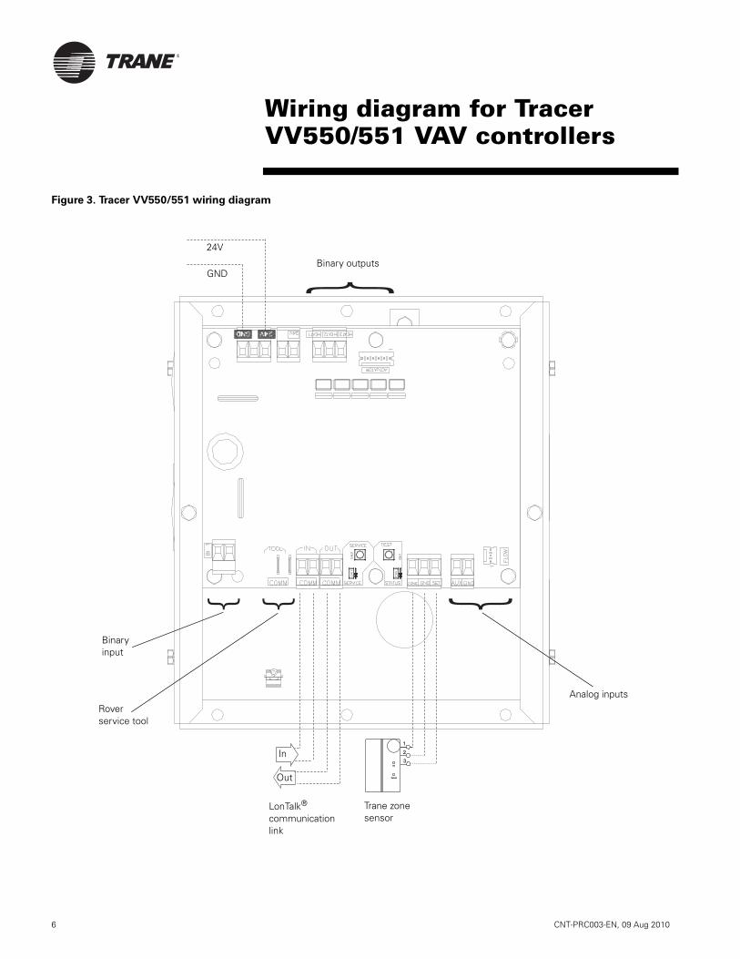
®
6 CNT-PRC003-EN, 09 Aug 2010
Figure 3. Tracer VV550/551 wiring diagram
3
2
1
On
Cancel
Binary input
Trane zone sensor
In
Out
Rover service tool
Analog inputs
Binary outputs
LonTalk®
communication link
24V
GND
Wiring diagram for Tracer VV550/551 VAV controllers
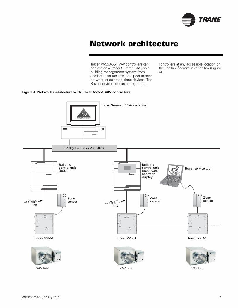
CNT-PRC003-EN, 09 Aug 2010 7
®
Tracer VV550/551 VAV controllers can operate on a Tracer Summit BAS, on a building management system from another manufacturer, on a peer-to-peer network, or as stand-alone devices. The Rover service tool can configure the
controllers at any accessible location on the LonTalk® communication link (Figure 4).
Cancel
ON
85
*
80
75
70
65
60 5
5
50
**
o oo
TM
ROVER
Cancel
ON
85
*
80
75
70
65
60 5
5
50
**
Cancel
ON
85
*
80
75
70
65
60 5
5
50
**
Figure 4. Network architecture with Tracer VV551 VAV controllers
Tracer Summit PC Workstation
LonTalk®
link
LAN (Ethernet or ARCNET)
Building control unit (BCU)
Building control unit (BCU) with operator display
Rover service tool
Zone sensor
Tracer VV551 Tracer VV551 Tracer VV551
VAV box VAV box VAV box
LonTalk®
link
Zone sensor
Zone sensor
Network architecture
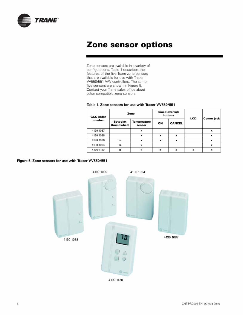
®
8 CNT-PRC003-EN, 09 Aug 2010
Zone sensors are available in a variety of configurations. Table 1 describes the features of the five Trane zone sensors that are available for use with Tracer VV550/551 VAV controllers. The same five sensors are shown in Figure 5. Contact your Trane sales office about other compatible zone sensors.
Figure 5. Zone sensors for use with Tracer VV550/551
GCC order number
Zone Timed override buttons
LCD Comm jackSetpoint
thumbwheelTemperature
sensor ON CANCEL
4190 1087 x x
4190 1088 x x x x
4190 1090 x x x x x
4190 1094 x x x
4190 1120 x x x x x x
4190 1088
4190 1090 4190 1094
4190 1087
4190 1120
Zone sensor options
Table 1. Zone sensors for use with Tracer VV550/551

CNT-PRC003-EN, 09 Aug 2010 9
®
Power requirementsSupply: 18–32 Vac (24 Vac nominal) at 50/60 Hz
Operating environmentTemperature:32 to 140°F (0 to 60°C)
Relative humidity:From 5 to 95% non-condensing
Storage environmentTemperature:-40 to 185°F (-40 to 85°C)
Relative humidity:From 5 to 95% non-condensing
Dimensions(See Figure 6 on page 10.)
Board only
Height: 4.5 in. (11.4 cm)Width: 5.5 in. (13.8 cm)Depth: 2 in. (5.1 cm)
With enclosure (VV551)
Height: 7.5 in. (13.7 cm)Width: 6.5 in. (16.7 cm)Depth: 5.5 in. (14.0 cm)
Weight with enclosure
(Tracer VV551)With no actuator: 3.9 lb (1.77 kg)With Belimo actuator: 5.0 lb (2.27 kg)With Trane actuator: 5.2 lb (2.36 kg)
Analog inputsSpace temperature; thermistor:
10 kΩ@ 77°F (25°C)From 14 to 122°F (-10 to 50°C)
Space setpoint; potentiometer:1 kΩFrom 50 to 90°F (-10 to 32.2°C)
Primary/discharge air temperature; thermistor:
10 kΩ@ 77°F (25°C)From -40 to 212°F (-40 to 100°C)
Primary air flow; pressure transducer:From 0 to 2 in. water (0 to 498 Pa)
Binary inputOccupancy or generic (dry contact)
Binary outputs
Air valve close:maximum output rating: 12 VA
Air valve open:maximum output rating: 12 VA
Heat stage 1:maximum output rating: 12 VA
Heat stage 2:maximum output rating: 12 VA
Heat stage 3/Fan on/off:maximum output rating: 12 VA
Agency listings/compliance
Tracer VV550:
UL 873 and CSA C22.2 No. 24-93: Temperature Indicating and Regulating Equipment
Tracer VV551:
UL-916-PAZX—energy management
CUL-C22.2—signal devices—Canada
UL 94-5V (UL flammability rating for plenum use)
FCC Part 15, Class A
CE marked
Dimensions and specifications
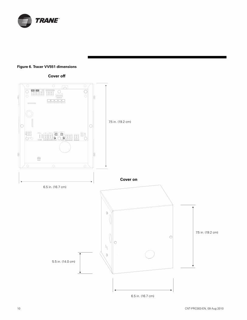
®
10 CNT-PRC003-EN, 09 Aug 2010
Figure 6. Tracer VV551 dimensions
7.5 in. (19.2 cm)
6.5 in. (16.7 cm)
6.5 in. (16.7 cm)
7.5 in. (19.2 cm)
5.5 in. (14.0 cm)
Cover off
Cover on
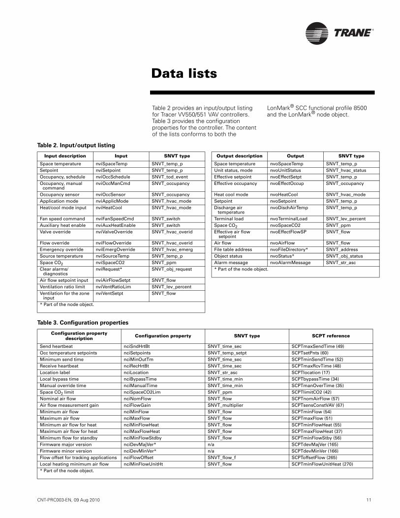
CNT-PRC003-EN, 09 Aug 2010 11
®
Data lists
Table 2 provides an input/output listing for Tracer VV550/551 VAV controllers. Table 3 provides the configuration properties for the controller. The content of the lists conforms to both the
LonMark® SCC functional profile 8500 and the LonMark® node object.
Table 2. Input/output listing
Input description Input SNVT type Output description Output SNVT type
Space temperature nviSpaceTemp SNVT_temp_p Space temperature nvoSpaceTemp SNVT_temp_pSetpoint nviSetpoint SNVT_temp_p Unit status, mode nvoUnitStatus SNVT_hvac_statusOccupancy, schedule nviOccSchedule SNVT_tod_event Effective setpoint nvoEffectSetpt SNVT_temp_pOccupancy, manual
commandnviOccManCmd SNVT_occupancy Effective occupancy nvoEffectOccup SNVT_occupancy
Occupancy sensor nviOccSensor SNVT_occupancy Heat cool mode nvoHeatCool SNVT_hvac_modeApplication mode nviApplicMode SNVT_hvac_mode Setpoint nvoSetpoint SNVT_temp_pHeat/cool mode input nviHeatCool SNVT_hvac_mode Discharge air
temperaturenvoDischAirTemp SNVT_temp_p
Fan speed command nviFanSpeedCmd SNVT_switch Terminal load nvoTerminalLoad SNVT_lev_percentAuxiliary heat enable nviAuxHeatEnable SNVT_switch Space CO2 nvoSpaceCO2 SNVT_ppmValve override nviValveOverride SNVT_hvac_overid Effective air flow
setpointnvoEffectFlowSP SNVT_flow
Flow override nviFlowOverride SNVT_hvac_overid Air flow nvoAirFlow SNVT_flowEmergency override nviEmergOverride SNVT_hvac_emerg File table address nvoFileDirectory* SNVT_addressSource temperature nviSourceTemp SNVT_temp_p Object status nvoStatus* SNVT_obj_statusSpace CO2 nviSpaceCO2 SNVT_ppm Alarm message nvoAlarmMessage SNVT_str_ascClear alarms/
diagnosticsnviRequest* SNVT_obj_request * Part of the node object.
Air flow setpoint input nviAirFlowSetpt SNVT_flowVentilation ratio limit nviVentRatioLim SNVT_lev_percentVentilation for the zone
inputnviVentSetpt SNVT_flow
* Part of the node object.
Table 3. Configuration properties
Configuration property description Configuration property SNVT type SCPT reference
Send heartbeat nciSndHrtBt SNVT_time_sec SCPTmaxSendTime (49)Occ temperature setpoints nciSetpoints SNVT_temp_setpt SCPTsetPnts (60)Minimum send time nciMinOutTm SNVT_time_sec SCPTminSendTime (52)Receive heartbeat nciRecHrtBt SNVT_time_sec SCPTmaxRcvTime (48)Location label nciLocation SNVT_str_asc SCPTlocation (17)Local bypass time nciBypassTime SNVT_time_min SCPTbypassTime (34)Manual override time nciManualTime SNVT_time_min SCPTmanOverTime (35)Space CO2 limit nciSpaceCO2Lim SNVT_ppm SCPTlimitCO2 (42)Nominal air flow nciNomFlow SNVT_flow SCPTnomAirFlow (57)Air flow measurement gain nciFlowGain SNVT_multiplier SCPTsensConstVAV (67)Minimum air flow nciMinFlow SNVT_flow SCPTminFlow (54)Maximum air flow nciMaxFlow SNVT_flow SCPTmaxFlow (51)Minimum air flow for heat nciMinFlowHeat SNVT_flow SCPTminFlowHeat (55)Maximum air flow for heat nciMaxFlowHeat SNVT_flow SCPTmaxFlowHeat (37)Minimum flow for standby nciMinFlowStdby SNVT_flow SCPTminFlowStby (56)Firmware major version nciDevMajVer* n/a SCPTdevMajVer (165)Firmware minor version nciDevMinVer* n/a SCPTdevMinVer (166)Flow offset for tracking applications nciFlowOffset SNVT_flow_f SCPToffsetFlow (265)Local heating minimum air flow nciMinFlowUnitHt SNVT_flow SCPTminFlowUnitHeat (270)* Part of the node object.

Trane optimizes the performance of homes and buildings around the world. A business of Ingersoll Rand, theleader in creating and sustaining safe, comfortable and energy efficient environments, Trane offers a broadportfolio of advanced controls and HVAC systems, comprehensive building services, and parts. For more information, visit www.Trane.com.
Trane has a policy of continuous product and product data improvement and reserves the right to change design and specifications without notice.
© 2010 Trane All rights reserved
CNT-PRC003-EN, 09 Aug 2010
Supersedes Oct 2005
Produced on 20% post-consumer recycled paper, using
environmentally friendly print practices that reduce waste.

Creating sustainable campusesCampus Green Dashboard, BTU Crew™ and you
As leaders in society, colleges and universities
are at the forefront of sustainability efforts.
University leaders are focused on attracting students and
faculty, maintaining technology leadership and providing a
quality educational environment. This is why Trane has taken
a whole campus approach to sustainability.
Trane supports your efforts. We have over 700 LEED™
accredited professionals and broad experience designing
sustainable solutions for the multi-building campus.
With our leading-edge analysis tools, HVAC systems and
knowledge, Trane is uniquely qualifi ed to help colleges
and universities fi ne-tune energy and indoor environmental
strategies, possibly incorporating alternative energy sources
such as geothermal and cogeneration.
The BTU Crew™ was developed to engage students in all
career paths to use their campus as a living energy lab. This
curriculum allows students to take action around improving
energy use on campus and investigate the role energy will
play in their future careers.
The Campus Green Dashboard is an easy-to-use
computer tool for colleges and universities that lets you
share environmental achievements with students, faculty,
staff and the community.
Build awareness with students and
the community
Encouraging students to
use their campus as a living
energy lab

The Campus Green Dashboard will help you: • Inspire students to save energy and improve the environment
• Reduce energy spending across the campus
• Promote the concept of sustainability
• Share environmental achievements with the community
Students and others can see detailed information on the energy use
of buildings on campus and historical data that tracks environmental
progress. Students can create energy and environmental competitions
between campus buildings to encourage energy reduction practices.
Administrators and facility managers can obtain detailed information
to help monitor and report campus energy performance.
Ingersoll Rand (NYSE:IR) is the world leader in creating and sustaining safety, comfort and effi cient environments in commercial, residential and industrial markets. Our people, and our family of
brands – including Club Car®, Ingersoll Rand®, Schlage®, Thermo King® and Trane® – work together to enhance the quality and comfort of air in homes and buildings, transport and protect food
and perishables, secure homes and commercial properties, and increase industrial productivity and effi ciency. We’re a $14 billion global business committed to sustainable business practices
within our company and for our customers. For more information, visit www.ingersollrand.com.
© 2010 Trane All rights reserved Produced on post-consumer recycled paper, using
CNT-PRC005-EN October 7, 2011 environmentally friendly print practices that reduce waste. ingersollrand.com
Students can create competitions between
buildings to drive energy reduction
Dorms/homes
Classrooms
Building lobbies
The dashboard can be accessed from: • Dorms/Homes
• Classrooms
• Building Lobbies
Contact your Trane sales representative to learn how you
can install and use the Trane Campus Green Dashboard at your
college or university. For more information, visit Trane.com.

Education Green DashboardBring energy efficiency and sustainability into your classrooms
Teaching environmental responsibilitySchools today are leaders in encouraging good environmental
stewardship and teaching these concepts to the next generation
of leaders.
Trane supports your efforts. We have over 700 LEED accredited
professionals and experience designing sustainable solutions for
multi-building school districts. With our leading-edge analysis
tools, HVAC systems and knowledge, Trane is qualified to help
schools fine-tune energy and indoor environmental strategies,
even incorporating alternative energy sources such as geothermal
and cogeneration.
The Education Green Dashboard helps both teach sustainability to
students and improve the efficiency of school facilities. It is an
interactive, fun and easy-to-use web site that brings the concepts
of energy efficiency and sustainability into the classroom. Using
interactive web pages, students learn about the efficiency of
classrooms and the environmental impact of the school’s energy
consumption.
BTU Crew™ educational program
Available to supplement the Education Green Dashboard, the BTU
Crew™ educational program gives students the knowledge and
tools needed to make a positive contribution to the environment
today. Through a series of interactive, hands-on lessons and
experiments, students learn about energy use and conservation in
buildings, as well as science, technology, engineering and math
(STEM) careers. The curriculum can be customized to meet local
needs, and while it can be adapted for older or younger students,
it is targeted for those in grades four through six.
Students can monitor energy use at their school and compare it to other schools in the district.
Energy calculators help students understand the benefits ofenergy saving appliances and lighting.
A hands-on audit lab helps students understand the impact of energy use in their homes.
1010_2014_EduGreenDashboard:0710_1077_CampusGreenDashboardSellSheet 10/14/2010 9:04 AM Page 1

The Education Green Dashboard will help you:= Teach students the impact of energy use on
the environment
= Inspire students to practice energy conservation at homeand at school
= Use live data and illustrations to create a fun, interactivelearning experience
The Education Green Dashboard can be accessed via theweb from:
= Home= Classrooms= Common areas such as libraries or lobbies
Contact your Trane sales representative to learn how youcan install and use the Education Green Dashboard in yourschool district. For more information, visit trane.com.
A related dashboard provides facility and administrative
staffs with more detailed information to monitor and track
energy use and costs for individual schools and the district.
Home
Classrooms
Common areas such as librariesor lobbies
Ingersoll Rand (NYSE:IR) is the world leader in creating and sustaining safety, comfort and efficiency where we work and live. Our people, and our family of brands - including Club Car®, Hussmann®,Ingersoll Rand®, Schlage®, Thermo King® and Trane® - work together to enhance the quality and comfort of air in homes and buildings, transport and protect food and perishables, secure homes andcommercial properties, and increase industrial productivity and efficiency. We’re a $13 billion global business with approximately 57,000 employees committed to sustainable business practices withinour company and for our customers.
© 2010 Trane All rights reservedCNT-PRC006-EN October 12, 2010
Produced on post-consumer recycled paper, using environmentally friendly print practices that reduce waste. ingersollrand.com
1010_2014_EduGreenDashboard:0710_1077_CampusGreenDashboardSellSheet 10/14/2010 9:04 AM Page 2

Building ControlsYour partner in comfort

2 Building Controls
What are you looking
for in a controls company?
A partner, more than a supplier. Local
support that you can depend on. A company
with a history of quality and a commitment
to your future. Knowledgeable people who
respond when you need them. Reliable,
proven technology.
At Trane, we are committted to offering
solutions that support energy efficiency and take
a sustainable approach to the environment. We
believe in creating high performance buildings.
Trane builds upon 30 years of experience in
the controls industry. Trane controls are the
keystone to making a building work better for
life. They are engineered to be user friendly.
Whether you are looking for a web-based,
enterprise-wide, integrated control system for
flexibility and reduced operating expenses, or a
widely-compatible field controller for building
renovation, Trane has the controls that can
optimize your system’s performance throughout
the life of your building. Today Trane controls
are installed in tens of thousands of buildings
around the world. People are comfortable
because they have Trane controls in their
buildings and critical process systems
can maintain strict temperature and humidity
control conditions using a Trane building
automation system.
3
Total system support
Local supportTrane sells building control software and
equipment through sales offices around the
world. Those offices provide system selection
advice and building analysis during the design
phases of a project.
The Trane sales consultant continues to work
with customers through the construction and
commissioning phases of a project. When the
project is complete, Trane can provide local
support through the life of your building:
operating reliably
local inventory
for added protection
Financial optionsTrane can help you offset the cost of a new
or renovated control system for an existing
building. A solutions-based approach, PACT™
(Performance Agreement for Comfort from
Trane), is one way for customers to pay for
the system without up-front capital. A facility
analysis by Trane energy auditors will identify
mechanical system improvements and building
infrastructure renovations that will yield annual
energy savings to help pay for the renovations
and improvements. The PACT performance
contract brings together a team of experts to
work with business owners to develop a program
tailored specifically for their facilities. Trane
manages the project, monitors results, and
delivers savings with no up-front
capital expenditure.
Upgrade/retrofit solutionsThe Tracer™ R’newal™ Program will help
you maximize building performance, improve
occupant comfort, and increase operation
productivity, while meeting your budget
and long-term service needs. This program
will assess your building control system as it
exists today, and will present a migration path
to a more efficient and productive control
solution. You’ll get reliability and performance,
backed by a factory warranty and long-term
service agreement.
TrainingTo ensure that operators learn about the many
functions of their building control systems,
Trane offers a comprehensive portfolio of
training courses. These range from HVAC
fundamentals, system applications, technical
services, refrigerant safety, and the operation,
installation, and programming of Trane building
automation control systems. Practical and
results-oriented, these courses are designed
and taught by professional instructors using
proven best practices gained through decades
of experience.

4 Building Controls
Integrated comfort
An Integrated Comfort™ system combines
Trane HVAC equipment with factory installed
unit controls together with a Trane building
automation system. The benefits that can
result from an Integrated Comfort HVAC system
are impressive.
the components are optimized for
system performance
designed to work together
equipment has turnkey factory controls
commissioning makes installation
and startup faster
diagnostics to identify problems before they
become serious
can be field mounted on Trane equipment,
non-Trane products and ancillary components
Single source simplicityTrane is one of the few companies in the
industry that designs, tests and manufactures
nearly all products comprising a high-
performance HVAC system. And our system
and application knowledge is second to none.
Our Integrated Comfort Solutions (ICS) meet
the most challenging temperature, humidity
and ventilation needs by applying our
controls, system components, and applications
engineering expertise to create the most
effective and efficient system.
In addition, owning a Trane Integrated Comfort
HVAC system is easier and more cost effective
because the components are manufactured,
installed, warranted and serviced by a single
source—Trane.
InteroperabilityWhile offering single-source solutions, Trane
stands committed to open standard protocols to
meet the needs of building professionals. System
designers and building owners today expect that
system components from different equipment
manufacturers will be able to communicate
with each other, that is be interoperable.
Trane supports the leading interoperable
communications standards; including BACnet™
and LonTalk™.
Thousands of Trane interoperable systems have
been installed since the Tracer Summit® building
control unit, a native BACnet device, first shipped
in 1993. Typical applications for BACnet at the
system level include the integration of HVAC,
lighting and fire alarm systems. The introduction
of Tracer™ SC allows BACnet communication
from the unit level up to the system level, with
web-enabled building control, providing a total
cost-effective solution. LonTalk at the unit level
provides a common platform for integrating
complementary controllers such as variable
speed drives, generators and power monitoring
equipment from third party suppliers.
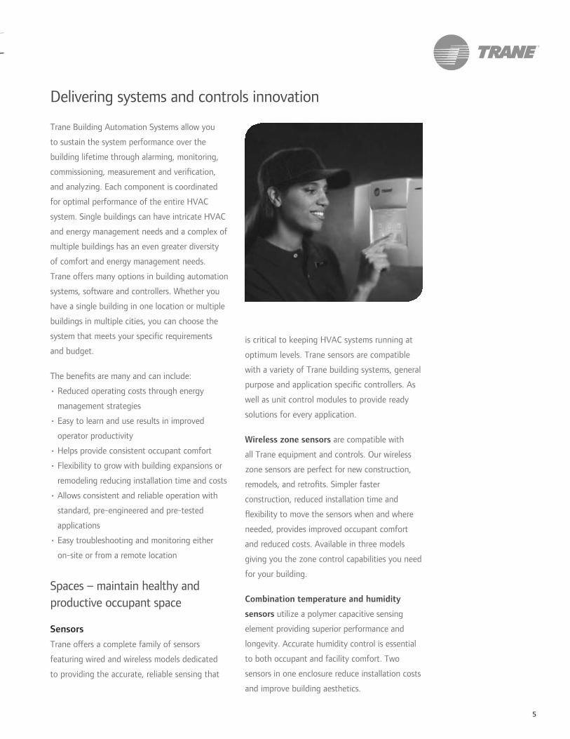
5
Delivering systems and controls innovation
Trane Building Automation Systems allow you
to sustain the system performance over the
building lifetime through alarming, monitoring,
commissioning, measurement and verification,
and analyzing. Each component is coordinated
for optimal performance of the entire HVAC
system. Single buildings can have intricate HVAC
and energy management needs and a complex of
multiple buildings has an even greater diversity
of comfort and energy management needs.
Trane offers many options in building automation
systems, software and controllers. Whether you
have a single building in one location or multiple
buildings in multiple cities, you can choose the
system that meets your specific requirements
and budget.
The benefits are many and can include:
management strategies
operator productivity
remodeling reducing installation time and costs
standard, pre-engineered and pre-tested
applications
on-site or from a remote location
Spaces – maintain healthy and
productive occupant space
SensorsTrane offers a complete family of sensors
featuring wired and wireless models dedicated
to providing the accurate, reliable sensing that
is critical to keeping HVAC systems running at
optimum levels. Trane sensors are compatible
with a variety of Trane building systems, general
purpose and application specific controllers. As
well as unit control modules to provide ready
solutions for every application.
Wireless zone sensors are compatible with
all Trane equipment and controls. Our wireless
zone sensors are perfect for new construction,
remodels, and retrofits. Simpler faster
construction, reduced installation time and
flexibility to move the sensors when and where
needed, provides improved occupant comfort
and reduced costs. Available in three models
giving you the zone control capabilities you need
for your building.
Combination temperature and humidity
sensors utilize a polymer capacitive sensing
element providing superior performance and
longevity. Accurate humidity control is essential
to both occupant and facility comfort. Two
sensors in one enclosure reduce installation costs
and improve building aesthetics.
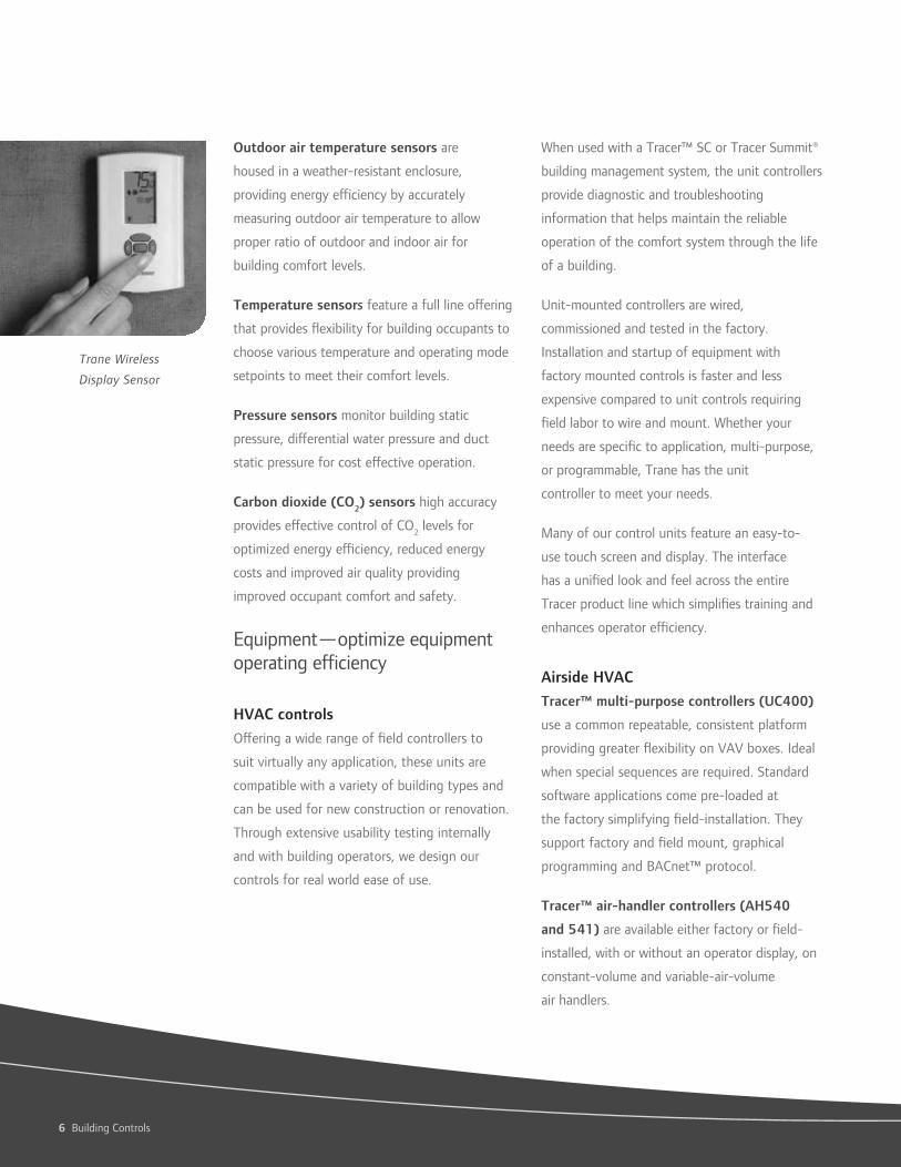
6 Building Controls
Outdoor air temperature sensors are
housed in a weather-resistant enclosure,
providing energy efficiency by accurately
measuring outdoor air temperature to allow
proper ratio of outdoor and indoor air for
building comfort levels.
Temperature sensors feature a full line offering
that provides flexibility for building occupants to
choose various temperature and operating mode
setpoints to meet their comfort levels.
Pressure sensors monitor building static
pressure, differential water pressure and duct
static pressure for cost effective operation.
Carbon dioxide (CO2) sensors high accuracy
provides effective control of CO2 levels for
optimized energy efficiency, reduced energy
costs and improved air quality providing
improved occupant comfort and safety.
Equipment—optimize equipment
operating efficiency
HVAC controlsOffering a wide range of field controllers to
suit virtually any application, these units are
compatible with a variety of building types and
can be used for new construction or renovation.
Through extensive usability testing internally
and with building operators, we design our
controls for real world ease of use.
When used with a Tracer™ SC or Tracer Summit®
building management system, the unit controllers
provide diagnostic and troubleshooting
information that helps maintain the reliable
operation of the comfort system through the life
of a building.
Unit-mounted controllers are wired,
commissioned and tested in the factory.
Installation and startup of equipment with
factory mounted controls is faster and less
expensive compared to unit controls requiring
field labor to wire and mount. Whether your
needs are specific to application, multi-purpose,
or programmable, Trane has the unit
controller to meet your needs.
Many of our control units feature an easy-to-
use touch screen and display. The interface
has a unified look and feel across the entire
Tracer product line which simplifies training and
enhances operator efficiency.
Airside HVACTracer™ multi-purpose controllers (UC400)
use a common repeatable, consistent platform
providing greater flexibility on VAV boxes. Ideal
when special sequences are required. Standard
software applications come pre-loaded at
the factory simplifying field-installation. They
support factory and field mount, graphical
programming and BACnet™ protocol.
Tracer™ air-handler controllers (AH540
and 541) are available either factory or field-
installed, with or without an operator display, on
constant-volume and variable-air-volume
air handlers.
Trane Wireless
Display Sensor
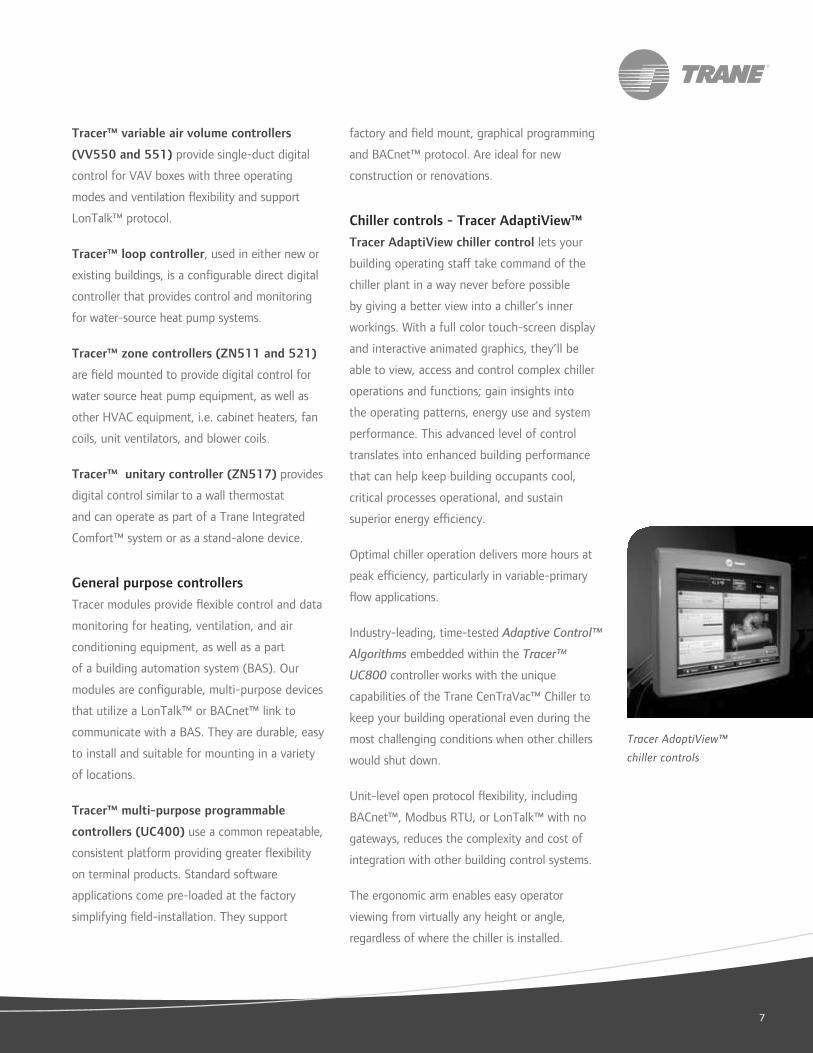
57
Tracer™ variable air volume controllers
(VV550 and 551) provide single-duct digital
control for VAV boxes with three operating
modes and ventilation flexibility and support
LonTalk™ protocol.
Tracer™ loop controller, used in either new or
existing buildings, is a configurable direct digital
controller that provides control and monitoring
for water-source heat pump systems.
Tracer™ zone controllers (ZN511 and 521)
are field mounted to provide digital control for
water source heat pump equipment, as well as
other HVAC equipment, i.e. cabinet heaters, fan
coils, unit ventilators, and blower coils.
Tracer™ unitary controller (ZN517) provides
digital control similar to a wall thermostat
and can operate as part of a Trane Integrated
Comfort™ system or as a stand-alone device.
General purpose controllersTracer modules provide flexible control and data
monitoring for heating, ventilation, and air
conditioning equipment, as well as a part
of a building automation system (BAS). Our
modules are configurable, multi-purpose devices
that utilize a LonTalk™ or BACnet™ link to
communicate with a BAS. They are durable, easy
to install and suitable for mounting in a variety
of locations.
Tracer™ multi-purpose programmable
controllers (UC400) use a common repeatable,
consistent platform providing greater flexibility
on terminal products. Standard software
applications come pre-loaded at the factory
simplifying field-installation. They support
factory and field mount, graphical programming
and BACnet™ protocol. Are ideal for new
construction or renovations.
Chiller controls - Tracer AdaptiView™ Tracer AdaptiView chiller control lets your
building operating staff take command of the
chiller plant in a way never before possible
by giving a better view into a chiller’s inner
workings. With a full color touch-screen display
and interactive animated graphics, they’ll be
able to view, access and control complex chiller
operations and functions; gain insights into
the operating patterns, energy use and system
performance. This advanced level of control
translates into enhanced building performance
that can help keep building occupants cool,
critical processes operational, and sustain
superior energy efficiency.
Optimal chiller operation delivers more hours at
peak efficiency, particularly in variable-primary
flow applications.
Industry-leading, time-tested Adaptive Control™
Algorithms embedded within the Tracer™
UC800 controller works with the unique
capabilities of the Trane CenTraVac™ Chiller to
keep your building operational even during the
most challenging conditions when other chillers
would shut down.
Unit-level open protocol flexibility, including
BACnet™, Modbus RTU, or LonTalk™ with no
gateways, reduces the complexity and cost of
integration with other building control systems.
The ergonomic arm enables easy operator
viewing from virtually any height or angle,
regardless of where the chiller is installed.
Tracer AdaptiView™
chiller controls

8 Building Controls
Tracer™ programmable controllers (MP580
and 581) are fully programmable, and available
both factory and field-installed on Trane air
handlers, boilers, cooling towers, etc. They
are available with or without operator display,
provide a link into a Trane Integrated Comfort™
system and are ideal for new construction
or renovations.
Tracer™ controllers (MP501 and 503) can
operate as a stand-alone device or as part of a
building automation system. It is a configurable,
multi-purpose controller used to provide
direct-digital control for a wide range of
HVAC equipment.
Other general controllers include the universal
programmable control module, the Tracer™
programmable control module and terminal
unit controller all providing digital control and
monitoring for a wide range of HVAC equipment.
Variable frequency drivesVariable frequency drives play an important
role in a system to reduce energy usage,
extend motor life, optimize AC motor speed
control, maximize occupant comfort and reduce
costs. They are available factory-mounted and
commissioned on Trane IntelliPak™, Voyager
III™ and M-Series™ and T-Series™ Climate
Changers. In addition, TR200 Series drives
support open standard protocols—making them
compatible with virtually all HVAC equipment
and building automation systems. They can
also be ordered specifically for a project and
easily installed on-site for new and retrofit
applications. With a complete range available
from 1½ to 1350 HP, the features and flexibility
of TR200 Series drives make them ideal for
stand-alone control of cooling towers, exhaust
fans, pumps and a variety of air handlers.
Buildings—control building comfort
and energy
Tracer™ SCTracer™ SC controls allow you to streamline
facility management without reinventing the
wheel. Adding Tracer SC to your system offers a
flexible, efficient and cost-effective solution for
maintaining facility climate. Tracer SC is easily
adapted for most buildings—small, medium or
large and will grow with your building and your
needs. Expandable from 30 to 60 to 120 unit
controller communications, it is a flexible and
cost-effective choice. It is web accessible from
any PC with an internet connection, eliminating
the need for a dedicated computer and monitor,
thus allowing monitoring at your convenience.
Tracer SC controller’s simplified scheduling,
reporting and applications programs reduce
maintenance chores to “point and click” tasks.
The intuitive functions will result in an improved
bottom line, increased efficiencies and reduced
costs. With its web-based online management
tool, you can reduce energy costs and installation
time and improve tenant comfort.
Tracer SC controller’s scalable and flexible
controls technology is now supporting
BACnet™ top to bottom as well as existing
LonWorks™ controllers.
from any computer
that provide consistent comfort and deliver
optimized indoor air quality to help eliminate
or reduce comfort issues
building operations
Tracer™ SC delivers
open, web-based
management to Trane
Rooftop Systems
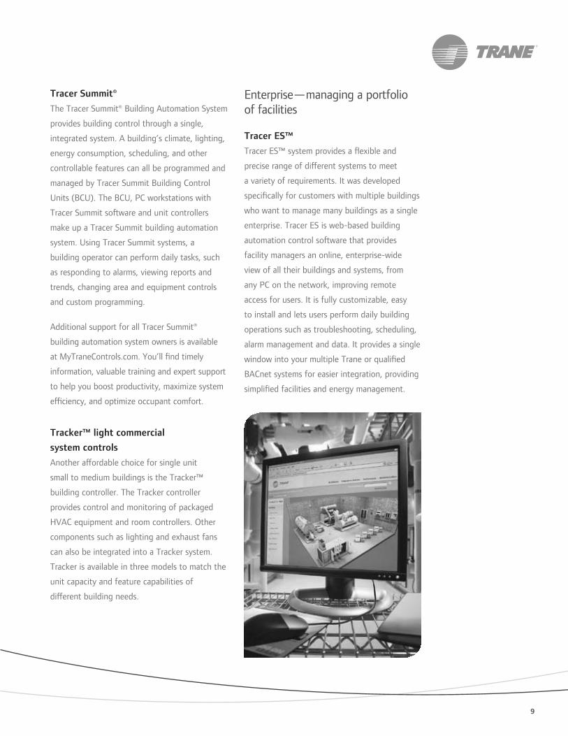
9
Tracer Summit® The Tracer Summit® Building Automation System
provides building control through a single,
integrated system. A building’s climate, lighting,
energy consumption, scheduling, and other
controllable features can all be programmed and
managed by Tracer Summit Building Control
Units (BCU). The BCU, PC workstations with
Tracer Summit software and unit controllers
make up a Tracer Summit building automation
system. Using Tracer Summit systems, a
building operator can perform daily tasks, such
as responding to alarms, viewing reports and
trends, changing area and equipment controls
and custom programming.
Additional support for all Tracer Summit®
building automation system owners is available
at MyTraneControls.com. You’ll find timely
information, valuable training and expert support
to help you boost productivity, maximize system
efficiency, and optimize occupant comfort.
Tracker™ light commercial system controlsAnother affordable choice for single unit
small to medium buildings is the Tracker™
building controller. The Tracker controller
provides control and monitoring of packaged
HVAC equipment and room controllers. Other
components such as lighting and exhaust fans
can also be integrated into a Tracker system.
Tracker is available in three models to match the
unit capacity and feature capabilities of
different building needs.
Enterprise—managing a portfolio
of facilities
Tracer ES™Tracer ES™ system provides a flexible and
precise range of different systems to meet
a variety of requirements. It was developed
specifically for customers with multiple buildings
who want to manage many buildings as a single
enterprise. Tracer ES is web-based building
automation control software that provides
facility managers an online, enterprise-wide
view of all their buildings and systems, from
any PC on the network, improving remote
access for users. It is fully customizable, easy
to install and lets users perform daily building
operations such as troubleshooting, scheduling,
alarm management and data. It provides a single
window into your multiple Trane or qualified
BACnet systems for easier integration, providing
simplified facilities and energy management.
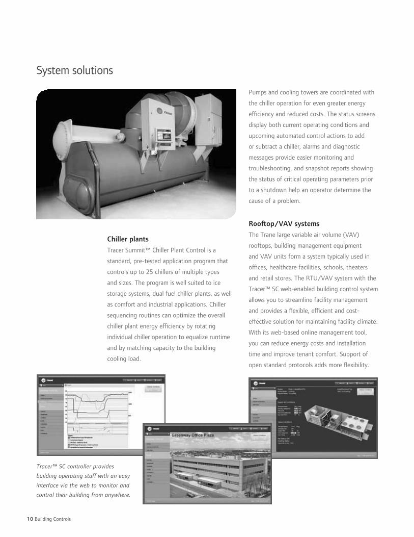
10 Building Controls
System solutions
Chiller plantsTracer Summit™ Chiller Plant Control is a
standard, pre-tested application program that
controls up to 25 chillers of multiple types
and sizes. The program is well suited to ice
storage systems, dual fuel chiller plants, as well
as comfort and industrial applications. Chiller
sequencing routines can optimize the overall
chiller plant energy efficiency by rotating
individual chiller operation to equalize runtime
and by matching capacity to the building
cooling load.
Pumps and cooling towers are coordinated with
the chiller operation for even greater energy
efficiency and reduced costs. The status screens
display both current operating conditions and
upcoming automated control actions to add
or subtract a chiller, alarms and diagnostic
messages provide easier monitoring and
troubleshooting, and snapshot reports showing
the status of critical operating parameters prior
to a shutdown help an operator determine the
cause of a problem.
Rooftop/VAV systemsThe Trane large variable air volume (VAV)
rooftops, building management equipment
and VAV units form a system typically used in
offices, healthcare facilities, schools, theaters
and retail stores. The RTU/VAV system with the
Tracer™ SC web-enabled building control system
allows you to streamline facility management
and provides a flexible, efficient and cost-
effective solution for maintaining facility climate.
With its web-based online management tool,
you can reduce energy costs and installation
time and improve tenant comfort. Support of
open standard protocols adds more flexibility.
Tracer™ SC controller provides
building operating staff with an easy
interface via the web to monitor and
control their building from anywhere.
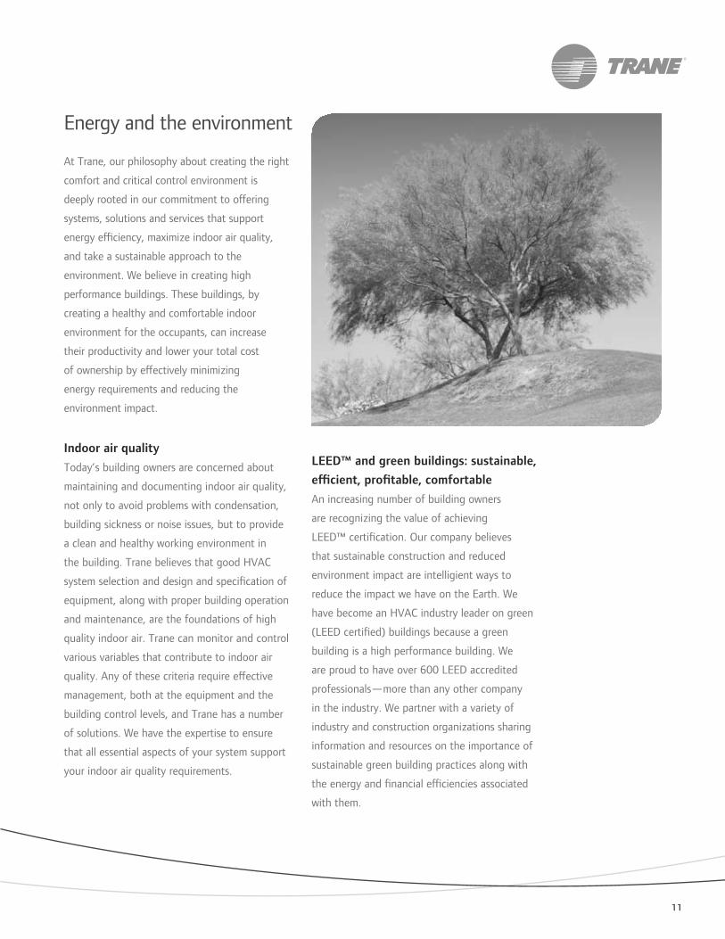
11
Energy and the environment
At Trane, our philosophy about creating the right
comfort and critical control environment is
deeply rooted in our commitment to offering
systems, solutions and services that support
energy efficiency, maximize indoor air quality,
and take a sustainable approach to the
environment. We believe in creating high
performance buildings. These buildings, by
creating a healthy and comfortable indoor
environment for the occupants, can increase
their productivity and lower your total cost
of ownership by effectively minimizing
energy requirements and reducing the
environment impact.
Indoor air qualityToday’s building owners are concerned about
maintaining and documenting indoor air quality,
not only to avoid problems with condensation,
building sickness or noise issues, but to provide
a clean and healthy working environment in
the building. Trane believes that good HVAC
system selection and design and specification of
equipment, along with proper building operation
and maintenance, are the foundations of high
quality indoor air. Trane can monitor and control
various variables that contribute to indoor air
quality. Any of these criteria require effective
management, both at the equipment and the
building control levels, and Trane has a number
of solutions. We have the expertise to ensure
that all essential aspects of your system support
your indoor air quality requirements.
LEED™ and green buildings: sustainable, efficient, profitable, comfortableAn increasing number of building owners
are recognizing the value of achieving
LEED™ certification. Our company believes
that sustainable construction and reduced
environment impact are intelligient ways to
reduce the impact we have on the Earth. We
have become an HVAC industry leader on green
(LEED certified) buildings because a green
building is a high performance building. We
are proud to have over 600 LEED accredited
professionals—more than any other company
in the industry. We partner with a variety of
industry and construction organizations sharing
information and resources on the importance of
sustainable green building practices along with
the energy and financial efficiencies associated
with them.

Trane optimizes the performance of homes and buildings around the world. A business of Ingersoll Rand, the leader in creating and sustaining safe, comfortable
and energy efficient environments, Trane offers a broad portfolio of advanced controls and HVAC systems, comprehensive building services, and parts.
For more information, visit www.Trane.com.
© 2009 Trane All rights reserved
BAS-SLC001-EN August 15, 2009
Produced on 20% post-consumer recycled paper, using
environmentally friendly print practices that reduce waste.
Beyond HVAC and forward
to the future
Making Buildings Better is our commitment. All
building systems should be economical, safe
and secure, comfortable, energy efficient and
integrated. This commitment, combined with the
strength of Ingersoll Rand, is a reality. Utilizing
a single web-based command center, from a
single-source supplier, you can control security
access to your building, monitor and record
building activity, manage HVAC systems, lighting,
and alarm systems.
You’ll benefit from a world leader in
creating and sustaining safe, comfortable
and efficient environments.
Committed to quality
Trust Trane for the right advice, the right tools,
the right systems and the right services to help
make your building environmentally friendly.
Around the world, our environmental
commitment is to provide state-of-the-art HVAC
systems, solutions and services that are good
for our customers, good for our businesses and
environmentally responsible.
Integrated comfort and critical control solutions
for high performance buildings—building owners
who depend on quality systems, controls and
services depend on Trane.

FORM A
PRODUCTS & SERVICES
DDC Controls: .
Type: Controllers
Brand Name: Trane MP501, MP503, MP580, MP581 and UC400 programmable controllers
Standard Warranty: One year on parts from date of start-up or 18 months from date of shipment whichever comes first.
Optional Warranty: Extended warranties for all parts and labor are covered under separate warranties. Standard optional warranties are extended to five years from date of shipment with special circumstances to ten years. See Appendix for these optional terms and conditions. Also delayed warranties are available if equipment ships earlier than the eighteen months from startup. See Appendix for these optional terms and conditions.
Estimated Lead/Delivery time: Typical delivery ranges from one week for quick shipping Super "E" cycle, three to five weeks on quick "E" cycle to standard cycles of four to six weeks and special cycles from eight to twelve weeks.
Location of Manufacturing City: St Paul, Minnesota, USA
Estimated market Share: Domestically: Not measurable –always a part of the total solutions
Detail Features and Benefits:
The Tracer MP501 controller is a configurable, multi-purpose controller used to provide direct-digital control for heating, ventilation, and air conditioning (HVAC) equipment. The controller can operate as a stand-alone device or as part of a building automation system (BAS). Communication between the controller and a BAS occurs via a LonTalk Comm5 communication link. The Tracer MP503 Input/output (I/O) module is a configurable, multi-purpose device used to provide data monitoring and binary control as part of a building automation system (BAS). Communication between the module and a BAS occurs over a LonTalk communication link. The Tracer Summit MP580 programmable controller is available factory-installed on the following Trane air handlers: M-Series Climate Changer air handler T-Series Climate Changer air handler Custom Climate Changer air handler The Tracer MP581 programmable controller is available for field installation for a variety of heating, ventilation, and air-conditioning (HVAC) applications

The Tracer UC400 is a programmable BACnet unit controller that is designed to work with the Tracer SC and third party BACnet MS/TP systems. The UC400 has the I/O and size to meet the controls needs for VAV, fan coil, blower coil, unit ventilators, small air handlers, valves, boiler sequencing, and other general I/Os.

FORM A
PRODUCTS & SERVICES
DDC Controls:
Type: Sensors
Brand Name: Trane Wireless, Combination Temperature & Humidity, Temperature, Carbon Dioxide, and Programmable Zone Sensors
Standard Warranty: One year on parts from date of start-up or 18 months from date of shipment whichever comes first. See Appendix for standard terms and conditions.
Optional Warranty: Extended warranties for all parts and labor are covered under separate warranties. Standard optional warranties are extended to five years from date of shipment with special circumstances to ten years. See Appendix for these optional terms and conditions. Also delayed warranties are available if equipment ships earlier than the eighteen months from startup. See Appendix for these optional terms and conditions.
Estimated Lead/Delivery time: Typical delivery ranges from one week for quick shipping Super "E" cycle, three to five weeks on quick "E" cycle to standard cycles of four to six weeks and special cycles from eight to twelve weeks.
Location of Manufacturing City: St Paul, Minnesota, USA
Estimated market Share: Domestically: Not measurable –always a part of the total solutions
Detail Features and Benefits:
Trane™ wireless sensors are an ideal alternative to wired sensors with the advantage of easy and flexible installation. The wireless feature allows for quick mounting in optimal locations for space comfort while minimizing installation time and relocation expense. The radio is designed specifically for this application and provides excellent signal range, long battery life, and reliable operation. Features
• Compatible with any Trane unit controller • Includes sensor, receiver, wiring harness and two AA five-year lithium batteries • Zone temperature is standard on all wireless sensors • Temperature setpoint & occupied/unoccupied override provided with the WZS • Temperature setpoint is available in Fahrenheit or Celsius
Combination Temperature and Humidity sensors utilize a polymer capacitive sensing element, which provides superior performance and longevity. The polymer capacitive element has excellent recovery from saturation compared to other humidity sensing technologies. Temperature sensors have also been added on the most popular models. Temperature sensors feature a full line offering that provides flexibility for building occupants to choose various temperature and operating mode setpoints to meet their comfort levels. • Thermistor - Best value

• Platinum curve sensor - Most accurate • Balco - Can be used with legacy controllers When connected to a Tracer building management system and the appropriate ventilation equipment, the Trane Carbon Dioxide (CO2) sensor measures and records carbon dioxide in parts per million (ppm) in occupied building spaces. These carbon dioxide measurements are typically used to identify under-ventilated building zones and override outdoor air flow beyond design ventilation rates if the CO2 exceeds acceptable levels The Trane® programmable zone sensor is an excellent choice for customers who wish to reduce first cost when expanding communication and application flexibility for their controls equipment. The programmable zone sensor is configurable with commercial rooftop units (RTU), heat pumps, and variable air volume (VAV) applications. Its compact size, combined with an intuitive liquid crystal display (LCD), is both aesthetically pleasing and easy to use. The Trane programmable zone sensor can be used with UCP, ReliaTel™, and IntelliPak™ control units.

FORM A
PRODUCTS & SERVICES
DDC Controls:
Type: Software Service Tools
Brand Name: Trane Rover and Tracer TU
Standard Warranty: One year on parts from date of start-up or 18 months from date of shipment whichever comes first. See Appendix for standard terms and conditions.
Optional Warranty: Extended warranties for all parts and labor are covered under separate warranties. Standard optional warranties are extended to five years from date of shipment with special circumstances to ten years. See Appendix for these optional terms and conditions. Also delayed warranties are available if equipment ships earlier than the eighteen months from startup. See Appendix for these optional terms and conditions.
Estimated Lead/Delivery time: Typical delivery ranges from one week for quick shipping Super "E" cycle, three to five weeks on quick "E" cycle to standard cycles of four to six weeks and special cycles from eight to twelve weeks.
Location of Manufacturing City: St Paul, Minnesota, USA
Estimated market Share: Domestically: Not measurable –always a part of the total solutions
Detail Features and Benefits: The Rover™ service tool helps with configuring, monitoring, and testing Tracer™ controllers that use Comm4 and LonTalk™ communications. The Rover service tool can also be used with LonTalk devices that are compliant with the EIA/CEA-860 standard. Tracer TU is the Service Tool for Trane Technicians. Tracer TU is used to configure chillers with the AdaptiView™ control, create TGP2 routines, create graphics in the Tracer SC, and program and configure the Tracer UC400 programmable and the VAV UC400 from Rushville. Tracer TU provides exclusive features to Trane technicians such as Data Logging and Graphical Trending — designed to improve the technician’s productivity.

FORM A
PRODUCTS & SERVICES
DDC Controls:
Type: Thermostats
Brand Name: Trane Programmable, Non-Programmable, Touch Screen Thermostats
Standard Warranty: One year on parts from date of start-up or 18 months from date of shipment whichever comes first. See Appendix for standard terms and conditions.
Optional Warranty: Extended warranties for all parts and labor are covered under separate warranties. Standard optional warranties are extended to five years from date of shipment with special circumstances to ten years. See Appendix for these optional terms and conditions. Also delayed warranties are available if equipment ships earlier than the eighteen months from startup. See Appendix for these optional terms and conditions.
Estimated Lead/Delivery time: Typical delivery ranges from one week for quick shipping Super "E" cycle, three to five weeks on quick "E" cycle to standard cycles of four to six weeks and special cycles from eight to twelve weeks.
Location of Manufacturing City: St Paul, Minnesota, USA
Estimated market Share: Domestically: Not measurable –always a part of the total solutions
Detail Features and Benefits:
A full line of both programmable and non-programmable thermostats to fit most needs. They are available for conventional (RTU) and water source heat pumps through North America's distribution and Parts Centers. Leveraging the intuitive user interface developed for our digital display sensor line, these new thermostats are easier to program and read. Universal graphics allow easy understanding and language independence. Thermostats are ideal for customers who desire a lower first cost and easy installation. Programmable Thermostats Automatically controls the temperature settings based on a predetermined schedule to reduce energy costs during unoccupied periods, maintain a comfortable room temperature during occupied periods, and provide dependable system performance. Non-Programmable Thermostats Provides consistent temperature 24/7 based on customer’s preference. Touch Screen Programmable Thermostats Menu-driven programmable thermostat with a large clear back-lit display that's easy to read with touch screen precision.

FORM A
PRODUCTS & SERVICES
DDC Controls:
Type: Single Building Control Systems
Brand Name: Trane Summit V17
Standard Warranty: One year on parts from date of start-up or 18 months from date of shipment whichever comes first. See Appendix or standard terms and conditions.
Optional Warranty: Extended warranties for all parts and labor are covered under separate warranties. Standard optional warranties are extended to five years from date of shipment with special circumstances to ten years. See Appendix for these optional terms and conditions. Also delayed warranties are available if equipment ships earlier than the eighteen months from startup. See Appendix for these optional terms and conditions.
Estimated Lead/Delivery time: Typical delivery ranges from one week for quick shipping Super "E" cycle, three to five weeks on quick "E" cycle to standard cycles of four to six weeks and special cycles from eight to twelve weeks.
Location of Manufacturing City: St Paul, Minnesota, USA
Estimated market Share: Domestically: Not measurable –always a part of the total solutions
Detail Features and Benefits:
The Tracer Summit® building automation system provides building control through a single, integrated system. A building's climate, lighting, energy consumption, scheduling, and other controllable features can all be programmed and managed by Tracer Summit building control units (BCUs). Building control units (BCUs), PC workstations with Tracer Summit software, and unit controllers make up a Tracer Summit building automation system. A building operator performs system operator tasks by using either a PC workstation, or the operator display (touch screen) on the BCU. Enhancements include:
Override simplification Multi-state analog outputs Trend Viewer Recent reports option Analog animation Standard 3D graphics Graphical status tool Eventlog enhancements Expanded messaging options BCU operator display translation Enterprise package additions – audit trail (SQL only) and active alarm count


FORM A
PRODUCTS & SERVICES
DDC Controls:
Type: Single Building Control Systems
Brand Name: Trane Tracker System CB, VAV, CV Heat Pump
Standard Warranty: One year on parts from date of start-up or 18 months from date of shipment whichever comes first. See Appendix for standard terms and conditions.
Optional Warranty: Extended warranties for all parts and labor are covered under separate warranties. Standard optional warranties are extended to five years from date of shipment with special circumstances to ten years. See Appendix for these optional terms and conditions. Also delayed warranties are available if equipment ships earlier than the eighteen months from startup. See Appendix for these optional terms and conditions.
Estimated Lead/Delivery time: Typical delivery ranges from one week for quick shipping Super "E" cycle, three to five weeks on quick "E" cycle to standard cycles of four to six weeks and special cycles from eight to twelve weeks.
Location of Manufacturing City: St Paul, Minnesota, USA
Estimated market Share: Domestically: Not measurable –always a part of the total solutions
Detail Features and Benefits:
The Tracker Light Commercial Systems control heating, ventilating, and air conditioning energy management systems for small to mid-sized buildings. They provide reliable, centralized control for HVAC equipment, managing it for optimal comfort and energy ef The Tracker system includes a controller with a liquid crystal display (LCD) touch screen. The Tracker also includes optional Windows-based software that can be installed on a PC workstation. VariTrac III Changeover/Bypass zoning system interfaces with Tracker. The VariTrac zoning system brings individual temperature control to each comfort zone in a building, while using the same single zone air conditioning unit. The Delivered VAV RTU system brings individual temperature control to each comfort zone in a building. It uses the 27½ to 50-ton Voyager Commercial rooftop unit, up to 32 VariTrane VAV boxes, and the VariTrac Central Control Panel (CCP) for true DDC VAV control. The Tracker System CV provides reliable, centralized control of constant-volume HVAC equipment for optimum comfort and efficiency. This system is capable of controlling multiple (up to 24) constant-volume rooftop units and split single-zone systems — those manufactured by Trane, as well as most others.

Tracker™ Light Commercial Systems
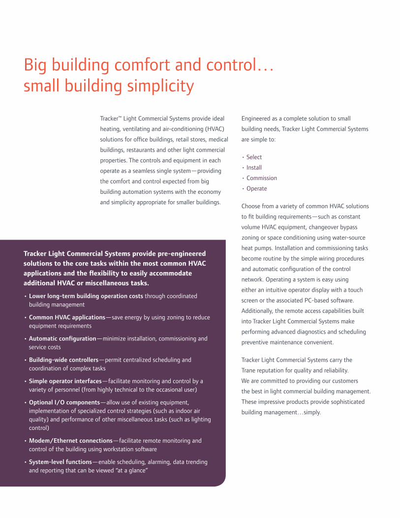
Tracker™ Light Commercial Systems provide ideal
heating, ventilating and air-conditioning (HVAC)
solutions for offi ce buildings, retail stores, medical
buildings, restaurants and other light commercial
properties. The controls and equipment in each
operate as a seamless single system—providing
the comfort and control expected from big
building automation systems with the economy
and simplicity appropriate for smaller buildings.
Big building comfort and control…
small building simplicity
Engineered as a complete solution to small
building needs, Tracker Light Commercial Systems
are simple to:
• Select
• Install
• Commission
• Operate
Choose from a variety of common HVAC solutions
to fi t building requirements—such as constant
volume HVAC equipment, changeover bypass
zoning or space conditioning using water-source
heat pumps. Installation and commissioning tasks
become routine by the simple wiring procedures
and automatic confi guration of the control
network. Operating a system is easy using
either an intuitive operator display with a touch
screen or the associated PC-based soft ware.
Additionally, the remote access capabilities built
into Tracker Light Commercial Systems make
performing advanced diagnostics and scheduling
preventive maintenance convenient.
Tracker Light Commercial Systems carry the
Trane reputation for quality and reliability.
We are committed to providing our customers
the best in light commercial building management.
These impressive products provide sophisticated
building management…simply.
Tracker Light Commercial Systems provide pre-engineered
solutions to the core tasks within the most common HVAC
applications and the fl exibility to easily accommodate
additional HVAC or miscellaneous tasks.
• Lower long-term building operation costs through coordinated
building management
• Common HVAC applications—save energy by using zoning to reduce
equipment requirements
• Automatic confi guration—minimize installation, commissioning and
service costs
• Building-wide controllers—permit centralized scheduling and
coordination of complex tasks
• Simple operator interfaces—facilitate monitoring and control by a
variety of personnel (from highly technical to the occasional user)
• Optional I/O components—allow use of existing equipment,
implementation of specialized control strategies (such as indoor air
quality) and performance of other miscellaneous tasks (such as lighting
control)
• Modem/Ethernet connections—facilitate remote monitoring and
control of the building using workstation soft ware
• System-level functions—enable scheduling, alarming, data trending
and reporting that can be viewed “at a glance”

Tracker Light Commercial
Systems are available in four
options to accommodate
most typical light commercial
buildings:
Tracker System CV
Constant volume equipment control
(integrates individual HVAC areas into a single,
larger coordinated system)
Tracker™ System CV provides reliable, centralized
control of constant-volume HVAC equipment for
optimum comfort and effi ciency. This system is
capable of controlling multiple (up to 24)
constant-volume rooft op units and split single-
zone systems—those manufactured by Trane as
well as most others.
Tracker System CB
Tracker System CB
Changeover-bypass zoning system
(constant-volume rooft op unit with
multiple zones)
Tracker™ System CB is a changeover-bypass
variable-air-volume (VAV) system developed for
light commercial applications. It combines the
comfort benefi ts of VAV with the economy and
simplicity of packaged, constant-volume unitary
equipment. This system responds to changing
cooling or heating requirements by varying the
amount of air delivered to each zone. Each zone
has its own thermostat for individual comfort
control. A central (unitary) air-conditioning unit
delivers a constant volume of air to the system. As
the volume of air required by the zones changes,
excess supply air is directed to the return duct by
a bypass duct and damper.
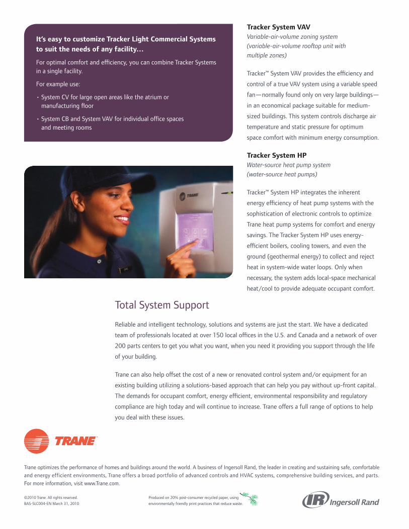
Trane optimizes the performance of homes and buildings around the world. A business of Ingersoll Rand, the leader in creating and sustaining safe, comfortable
and energy efficient environments, Trane offers a broad portfolio of advanced controls and HVAC systems, comprehensive building services, and parts.
For more information, visit www.Trane.com.
©2010 Trane. All rights reserved.
BAS-SLC004-EN March 31, 2010
Produced on 20% post-consumer recycled paper, using
environmentally friendly print practices that reduce waste.
It’s easy to customize Tracker Light Commercial Systems
to suit the needs of any facility…
For optimal comfort and effi ciency, you can combine Tracker Systems
in a single facility.
For example use:
• System CV for large open areas like the atrium or
manufacturing fl oor
• System CB and System VAV for individual offi ce spaces
and meeting rooms
Tracker System VAV
Variable-air-volume zoning system
(variable-air-volume rooft op unit with
multiple zones)
Tracker™ System VAV provides the effi ciency and
control of a true VAV system using a variable speed
fan—normally found only on very large buildings—
in an economical package suitable for medium-
sized buildings. This system controls discharge air
temperature and static pressure for optimum
space comfort with minimum energy consumption.
Tracker System HP
Water-source heat pump system
(water-source heat pumps)
Tracker™ System HP integrates the inherent
energy effi ciency of heat pump systems with the
sophistication of electronic controls to optimize
Trane heat pump systems for comfort and energy
savings. The Tracker System HP uses energy-
effi cient boilers, cooling towers, and even the
ground (geothermal energy) to collect and reject
heat in system-wide water loops. Only when
necessary, the system adds local-space mechanical
heat/cool to provide adequate occupant comfort.
Total System Support
Reliable and intelligent technology, solutions and systems are just the start. We have a dedicated
team of professionals located at over 150 local offi ces in the U.S. and Canada and a network of over
200 parts centers to get you what you want, when you need it providing you support through the life
of your building.
Trane can also help off set the cost of a new or renovated control system and/or equipment for an
existing building utilizing a solutions-based approach that can help you pay without up-front capital.
The demands for occupant comfort, energy effi cient, environmental responsibility and regulatory
compliance are high today and will continue to increase. Trane off ers a full range of options to help
you deal with these issues.

TCPN Proposal
Region 4 Education Service Center April 2015
Appendix B: Product / Services Specifications Page 1 of 20
Cooling Towers

TCPN Proposal
Region 4 Education Service Center April 2015
Appendix B: Product / Services Specifications Page 2 of 20
FORM A
PRODUCTS & SERVICES
Cooling Towers:
Type: Cooling Towers
Brand Name: EVAPCO – Model UT Capacity Range: 112 to 4,995 nominal tons
Standard Warranty: Motor/Drive: 5 Years; Product: 1 year, 18 months.
Optional Warranty: Up to 5 Years total product
Estimated Lead/Delivery time: 4-6 weeks
Location of' Manufacturing City: Greenup, IL; Taneytown, MD; Madera, CA USA
Estimated market Share: This is proprietary information and is not available
Detail Features and Benefits:
The NEW Ultra-quieT Cooling Tower comes standard with Super Low Sound Fan that reduces the overall sound generated from the top of the cooling tower. The Ultra-quieT provides deep sound reductions and can be used in combination with Water Silencers to produce the lowest sound levels commercially available. Consult EVAPCO’s iES selection software for unit sound levels. If a detailed analysis or full octave band datasheet is required for your application, please consult your EVAPCO Sales Representative.

TCPN Proposal
Region 4 Education Service Center April 2015
Appendix B: Product / Services Specifications Page 3 of 20
The Super Low Sound Fan
9 – 15 dB(A) Reduction versus Model AT Standard Fan
EVAPCO’s Super Low Sound Fan on the Ultra-quieT tower utilizes an extremely wide chord blade design available for sound sensitive applications where the lowest sound levels are desired. The fan is one piece molded heavy duty FRP construction utilizing a forward swept blade design.
The Super Low Sound Fan reduces sound levels 9 to 15 dB(A) compared to the Model AT standard fan. 10 dB(A) decrease is half as loud!
The Ultra-quieT tower is better than half as loud as other fans! (refer to the Sound Basics section for more information on Sound) Improved Sound Quality Emitted Super Low Sound Fan on the Ultra-quieT Tower!
The SUPER Low Sound Fan on the Ultra-quieT tower reduces sound levels 9-15 dB(A) and eliminates audible blade passing frequencies indicative of straight bladed axial type fans. Refer to the Narrow Band Spectrum graph, which indicates straight bladed axial fans produce blade passing frequencies – the same phenomena that produce the signature pulsating helicopter noise. The blade passing frequencies are audible spikes in sound pressure levels, but are not apparent in the octave band sound spectrum.
The Super Low Sound Fan on the Ultra-quieT cooling tower reduced sound levels and betters the sound quality!

TCPN Proposal
Region 4 Education Service Center April 2015
Appendix B: Product / Services Specifications Page 4 of 20
FORM A
PRODUCTS & SERVICES
Cooling Towers:
Type: Cooling Towers
Brand Name: EVAPCO – Model USS Capacity Range: 109 to 4,995 nominal tons
Standard Warranty: 5 Years Total Product.
Optional Warranty: none
Estimated Lead/Delivery time: 4-6 weeks
Location of' Manufacturing City: Greenup, IL; Taneytown, MD; Madera, CA, USA
Estimated market Share: This is proprietary information and is not available
Detail Features and Benefits:
· Independently certified to withstand seismic and wind load forces at ALL Building locations in North America.
The Ultra SST is a type 316/304 stainless steel, 100% corrosion free, induced draft, counterflow design cooling tower.
· Standard construction consists of type 316 stainless steel basin and type 304 stainless steel upper casing and fan sector panels and fan deck.
The Ultra-SST Cooling Tower product line is a type 316/304 stainless steel Advanced Technology design which utilizes induced draft, counterflow technology–the most efficient in the industry and the best design for operation in a freezing climate. The counterflow design provides the Ultra-SST Cooling Tower with inherently better operational and maintenance features.

TCPN Proposal
Region 4 Education Service Center April 2015
Appendix B: Product / Services Specifications Page 5 of 20
FORM A
PRODUCTS & SERVICES
Cooling Towers:
Type: Cooling Towers
Brand Name: EVAPCO – eco-PMC Evaporative Condenser Capacity Range: 130 to 1,544 nominal tons
Standard Warranty: 1 year, 18 months.
Optional Warranty: Up to 5 Years total product
Estimated Lead/Delivery time: 4-6 weeks
Location of' Manufacturing City: Greenup, IL; Taneytown, MD; Madera, CA, USA
Estimated market Share: This is proprietary information and is not available
Detail Features and Benefits:
The eco-PMC offers the same features and benefits of the PMC line of evaporative condensers but utilizes EVAPCO's patented ellipti-fin coil technology to offer water savings benefits through expanded dry operation. The line is comprised of models ranging in size from 130 to 1,544 nominal ammonia tons. The forced draft counterflow condensers are designed to be easy install to install and easy to maintain.

TCPN Proposal
Region 4 Education Service Center April 2015
Appendix B: Product / Services Specifications Page 6 of 20
FORM A
PRODUCTS & SERVICES
Cooling Towers:
Type: Cooling Towers
Brand Name: EVAPCO – Model LPT Capacity Range: 27 to 331 nominal tons
Standard Warranty: 1 year, 18 months.
Optional Warranty: Up to 5 Years total product
Estimated Lead/Delivery time: 4-6 weeks
Location of' Manufacturing City: Greenup, IL; Taneytown, MD; Madera, CA, USA
Estimated market Share: This is proprietary information and is not available
Detail Features and Benefits:
The LPT is a low noise, low height, forced draft, centrifugal fan design cooling tower with a capacity range of 27 to 331 nominal tons (119 to 1455 kW). Standard construction consists of type 304 stainless steel cold water basin and G-235 (Z-725 Europe) galvanized steel casing with all type 304 stainless steel construction available.

TCPN Proposal
Region 4 Education Service Center April 2015
Appendix B: Product / Services Specifications Page 7 of 20
FORM A
PRODUCTS & SERVICES
Cooling Towers:
Type: Cooling Towers
Brand Name: EVAPCO – Model cAT Capacity Range: 173 to 472 nominal tons
Standard Warranty: 1 year, 18 months.
Optional Warranty: Up to 5 Years total product
Estimated Lead/Delivery time: 4-6 weeks
Location of' Manufacturing City: Greenup, IL; Taneytown, MD; Madera, CA, USA
Estimated market Share: This is proprietary information and is not available
Detail Features and Benefits:
· Designed to provide the maximum capacity with the lowest ocean shipping cost.
The cAT is an induced draft, counterflow design cooling tower.
· Standard construction consists of G-235 galvanized steel with type 304 or 316 stainless steel
available for the basin or the entire tower.
· The cAT Cooling Tower product line is an Advanced Technology design which utilizes induced draft
counterflow technology -the most efficient in the industry and the best design for operation in a freezing
climate.
The counterflow design provides the cAT Cooling Tower with inherently better operational and
maintenance features.

TCPN Proposal
Region 4 Education Service Center April 2015
Appendix B: Product / Services Specifications Page 8 of 20
FORM A
PRODUCTS & SERVICES
Cooling Towers:
Type: Cooling Towers
Brand Name: EVAPCO – Model AT Capacity Range: 33 to 5,141 nominal tons
Standard Warranty: Motor/Drive: 5 Years; Product: 1 year, 18 months.
Optional Warranty: Up to 5 Years total product
Estimated Lead/Delivery time: 4-6 weeks
Location of' Manufacturing City: Greenup, IL; Taneytown, MD; Madera, CA, USA
Estimated market Share: This is proprietary information and is not available
Detail Features and Benefits:
· The AT is an induced draft, counterflow design cooling tower with a CTI certified capacity
range of 33 to 5,141 nominal tons (144 to 22,596 kW). Standard construction consists of G-235 (Z-725 Europe) galvanized steel with type 304 or 316 stainless steel available for the basin or the entire tower.
The largest AT tower ever - the 14'x26', dual fan "Big AT". Up to 1,332 nominal tons per cell.
NEW !!! Additional 14'x26' cell configurations: the AT 42'x26' and 56'x26'.

TCPN Proposal
Region 4 Education Service Center April 2015
Appendix B: Product / Services Specifications Page 9 of 20
FORM A
PRODUCTS & SERVICES
Cooling Towers:
Type: Cooling Towers
Brand Name: EVAPCO – Model ATC-DC Capacity Range: 33 to 5,141 nominal tons
Standard Warranty: Motor/Drive: 5 Years; Product: 1 year, 18 months.
Optional Warranty: Up to 5 Years total product
Estimated Lead/Delivery time: 4-6 weeks
Location of' Manufacturing City: Greenup, IL; Taneytown, MD; Madera, CA, USA
Estimated market Share: This is proprietary information and is not available
Detail Features and Benefits:
· The ATC-DC is an induced draft, counterflow design evaporative condenser. Standard
construction includes the patented, high efficiency EVAPCO Ellipti-fin Coil, EVAPCO’s new ARID fin Pak™ dry coil, and G-235 (Z-725 Europe) galvanized steel casing and basin. Type 304 or 316 stainless steel construction is available for the basin or the entire unit.

TCPN Proposal
Region 4 Education Service Center April 2015
Appendix B: Product / Services Specifications Page 10 of 20
FORM A
PRODUCTS & SERVICES
Cooling Towers:
Type: Cooling Towers
Brand Name: EVAPCO – Model ATC-E Capacity Range: 25 to 2,637 nominal tons
Standard Warranty: Motor/Drive: 5 Years; Product: 1 year, 18 months.
Optional Warranty: Up to 5 Years total product
Estimated Lead/Delivery time: 4-6 weeks
Location of' Manufacturing City: Greenup, IL; Taneytown, MD; Madera, CA, USA
Estimated market Share: This is proprietary information and is not available
Detail Features and Benefits:
· The ATC-E line of evaporative condensers represents Evapco’s commitment to product
development. The line is comprised of 181 models ranging in size from 25 to 2,637 nominal ammonia tons (107 kW to 11,360 kW). The induced draft counterflow condensers are designed especially for easy maintenance and long, trouble-free operation.

TCPN Proposal
Region 4 Education Service Center April 2015
Appendix B: Product / Services Specifications Page 11 of 20
FORM A
PRODUCTS & SERVICES
Cooling Towers:
Type: Cooling Towers
Brand Name: EVAPCO – Model ATWB Capacity Range: 85 to 46,667 MBH
Standard Warranty: Motor/Drive: 5 Years; Product: 1 year, 18 months.
Optional Warranty: Up to 5 Years total product
Estimated Lead/Delivery time: 4-6 weeks
Location of' Manufacturing City: Greenup, IL; Taneytown, MD; Madera, CA, USA
Estimated market Share: This is proprietary information and is not available
Detail Features and Benefits:
· Independently certified to withstand seismic and wind load forces at ALL Building locations
in North America.
The ATWB is an induced draft, counterflow design closed circuit cooler with a capacity range of 85 to 46,667 MBH (24 to 13,664 kW). Standard construction includes the patented, high efficiency Thermal-Pak® Coil and G-235 (Z-725 Europe)galvanized steel casing and basin. Type 304 or 316 stainless steel construction is available for the basin or the entire unit.

TCPN Proposal
Region 4 Education Service Center April 2015
Appendix B: Product / Services Specifications Page 12 of 20
FORM A
PRODUCTS & SERVICES
Cooling Towers:
Type: Cooling Towers
Brand Name: EVAPCO – Model AXS Capacity Range: 312 to 1,148 Tons
Standard Warranty: Motor/Drive: 5 Years; Product: 1 year, 18 months.
Optional Warranty: Up to 5 Years total product
Estimated Lead/Delivery time: 4-6 weeks
Location of' Manufacturing City: Greenup, IL; Taneytown, MD; Madera, CA, USA
Estimated market Share: This is proprietary information and is not available
Detail Features and Benefits:
· The AXS puts a new spin on induced draft, crossflow cooling towers with a CTI certified capacity range of 312 - 1,148 nominal tons. Standard construction consisits of G-235 galvanized steel with type 304 or 316 stainless steel availiable for the basin or entire tower. All models are CTI Certified and IBC Compliant.
.

TCPN Proposal
Region 4 Education Service Center April 2015
Appendix B: Product / Services Specifications Page 13 of 20
FORM A
PRODUCTS & SERVICES
Cooling Towers:
Type: Cooling Towers
Brand Name: EVAPCO – Model cATC Capacity Range: 128 to 357 Tons
Standard Warranty: Motor/Drive: 5 Years; Product: 1 year
Optional Warranty: Up to 5 Years total product
Estimated Lead/Delivery time: 4-6 weeks
Location of' Manufacturing City: Greenup, IL; Taneytown, MD; Madera, CA, USA
Estimated market Share: This is proprietary information and is not available
Detail Features and Benefits:
The cATC line of evaporative condensers represents Evapco’s commitment to product development. The line is comprised of 24 models ranging in size from 128 to 357 nominal ammonia tons (551 kW to 1,538 kW). The induced draft counterflow condensers are designed especially for easy maintenance and long, trouble-free operation.

TCPN Proposal
Region 4 Education Service Center April 2015
Appendix B: Product / Services Specifications Page 14 of 20
FORM A
PRODUCTS & SERVICES
Cooling Towers:
Type: Cooling Towers
Brand Name: EVAPCO – Model cATWB Capacity Range: 1,080 to 5,015 MBH
Standard Warranty: Motor/Drive: 5 Years; Product: 1 year, 18 months.
Optional Warranty: Up to 5 Years total product
Estimated Lead/Delivery time: 4-6 weeks
Location of' Manufacturing City: Greenup, IL; Taneytown, MD; Madera, CA, USA
Estimated market Share: This is proprietary information and is not available
Detail Features and Benefits:
The cATWB is an induced draft, counterflow design closed circuit cooler with a capacity range of 1,080 to 5,015 MBH (316 to 1,470 kW). Standard construction includes the patented, high efficiency Thermal-Pak® Coil and G-235 (Z-725 Europe) galvanized steel casing and basin. Type 304 or 316 stainless steel construction is available for the basin or the entire unit. cATWB has been designed to deliver the maximum capacity and fit inside of a standard shipping container.

TCPN Proposal
Region 4 Education Service Center April 2015
Appendix B: Product / Services Specifications Page 15 of 20
FORM A
PRODUCTS & SERVICES
Cooling Towers:
Type: Cooling Towers
Brand Name: EVAPCO – Model eco-ATC-A Capacity Range: 125 to 2,900 Tons
Standard Warranty: Motor/Drive: 5 Years; Product: 1 year, 18 months.
Optional Warranty: Up to 5 Years total product
Estimated Lead/Delivery time: 4-6 weeks
Location of' Manufacturing City: Greenup, IL; Taneytown, MD; Madera, CA, USA
Estimated market Share: This is proprietary information and is not available
Detail Features and Benefits:
The eco-ATC-A line of evaporative condensers represents Evapco’s commitment to product development. The line is comprised of models ranging in size from 125 to 2,900 nominal ammonia tons (537 kW to 12,470 kW). The induced draft counterflow condensers are designed especially for easy maintenance and long, trouble-free operation.

TCPN Proposal
Region 4 Education Service Center April 2015
Appendix B: Product / Services Specifications Page 16 of 20
FORM A
PRODUCTS & SERVICES
Cooling Towers:
Type: Cooling Towers
Brand Name: EVAPCO – Model eco-ATWB
Capacity Range: 150 to 38280 MBH
Standard Warranty: Motor/Drive: 5 Years; Product: 1 year, 18 months.
Optional Warranty: Up to 5 Years total product
Estimated Lead/Delivery time: 4-6 weeks
Location of' Manufacturing City: Greenup, IL; Taneytown, MD; Madera, CA, USA
Estimated market Share: This is proprietary information and is not available
Detail Features and Benefits:
The eco-ATWB is an induced draft, counterflow design closed circuit cooler with a capacity range of 150 to 38280 MBH (42 to 10813 kW). Standard construction includes the patented, high efficiency EVAPCO Ellipti-fin Coil and G-235 (Z-725 Europe) galvanized steel casing and basin. Type 304 or 316 stainless steel construction is available for the basin or the entire unit.

TCPN Proposal
Region 4 Education Service Center April 2015
Appendix B: Product / Services Specifications Page 17 of 20
FORM A
PRODUCTS & SERVICES
Cooling Towers:
Type: Cooling Towers
Brand Name: EVAPCO – Model eco-ATWBe
Capacity Range: 1320 to 9225 MBH
Standard Warranty: Motor/Drive: 5 Years; Product: 1 year, 18 months.
Optional Warranty: Up to 5 Years total product
Estimated Lead/Delivery time: 4-6 weeks
Location of' Manufacturing City: Greenup, IL; Taneytown, MD; Madera, CA, USA
Estimated market Share: This is proprietary information and is not available
Detail Features and Benefits:
The eco-ATWB-E is an induced draft, counterflow design closed circuit cooler with a capacity range of 1320 to 9225 MBH (377 to 2636 kW). Standard construction includes the patented, high efficiency Ellipti-fin Coil and G-235 (Z-725 Europe) galvanized steel casing and basin. Type 304 or 316 stainless steel construction is available for the basin or the entire unit.

TCPN Proposal
Region 4 Education Service Center April 2015
Appendix B: Product / Services Specifications Page 18 of 20
FORM A
PRODUCTS & SERVICES
Cooling Towers:
Type: Cooling Towers
Brand Name: EVAPCO – Model eco-ATWB-H
Capacity Range: 850 to 16700 MBH
Standard Warranty: Motor/Drive: 5 Years; Product: 1 year, 18 months.
Optional Warranty: Up to 5 Years total product
Estimated Lead/Delivery time: 4-6 weeks
Location of' Manufacturing City: Greenup, IL; Taneytown, MD; Madera, CA, USA
Estimated market Share: This is proprietary information and is not available
Detail Features and Benefits:
The eco-ATWB-H is an induced draft, counterflow design closed circuit cooler with a CTI
Certified capacity range of 850 to 16700 MBH (250 to 4895 kW). Standard construction includes
the patented, high efficiency EVAPCO Ellipti-fin Coil, EVAPCO’s new ARID fin Pak™ dry coil,
and G-235 (Z-725 Europe) galvanized steel casing and basin. Type 304 or 316 stainless steel
construction is available for the basin or the entire unit.
Continuous water savings, even when the spray pump is energized
Highest dry bulb switchover temperatures
Plume abatement
Plume elimination
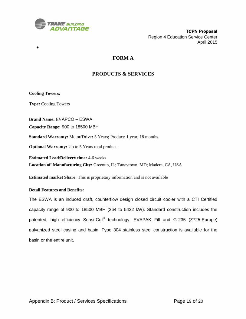
TCPN Proposal
Region 4 Education Service Center April 2015
Appendix B: Product / Services Specifications Page 19 of 20
FORM A
PRODUCTS & SERVICES
Cooling Towers:
Type: Cooling Towers
Brand Name: EVAPCO – ESWA
Capacity Range: 900 to 18500 MBH
Standard Warranty: Motor/Drive: 5 Years; Product: 1 year, 18 months.
Optional Warranty: Up to 5 Years total product
Estimated Lead/Delivery time: 4-6 weeks
Location of' Manufacturing City: Greenup, IL; Taneytown, MD; Madera, CA, USA
Estimated market Share: This is proprietary information and is not available
Detail Features and Benefits:
The ESWA is an induced draft, counterflow design closed circuit cooler with a CTI Certified
capacity range of 900 to 18500 MBH (264 to 5422 kW). Standard construction includes the
patented, high efficiency Sensi-Coil® technology, EVAPAK Fill and G-235 (Z725-Europe)
galvanized steel casing and basin. Type 304 stainless steel construction is available for the
basin or the entire unit.

TCPN Proposal
Region 4 Education Service Center April 2015
Appendix B: Product / Services Specifications Page 20 of 20
FORM A
PRODUCTS & SERVICES
Cooling Towers:
Type: Cooling Towers
Brand Name: EVAPCO – ESWB
Capacity Range: 583 to 7264 MBH
Standard Warranty: Motor/Drive: 5 Years; Product: 1 year, 18 months.
Optional Warranty: Up to 5 Years total product
Estimated Lead/Delivery time: 4-6 weeks
Location of' Manufacturing City: Greenup, IL; Taneytown, MD; Madera, CA, USA
Estimated market Share: This is proprietary information and is not available
Detail Features and Benefits:
The ESWB is an induced draft, counterflow design closed circuit cooler with a CTI Certified
capacity range of 583 to 7264 MBH (171 to 2129 kW). Standard construction includes the
patented, high efficiency Sensi-Coil® Technology featuring CrossCool™ Internal Tube
Enhancement , EVAPAK Fill and G-235 (Z725-Europe) galvanized steel casing and basin. Type
304 stainless steel construction is available for the basin, the redistribution basin, or the entire
unit.

FORM A
PRODUCTS & SERVICES
Building Services Type: Chiller Upgrade Programs
Description: Service Products and Retrofits are designed to upgrade existing chiller equipment leading to improved safety, increased efficiency and reliability Utilizing systems and products analytic tools such as:
Trane Option Analyzer R’Newal Evaluator Trane Energy Analyzer Trane Energy Optimizer Kestrelview Tracer TU
Helps Owners make intelligent upgrade and replacement decisions prior to a catastrophic failure. Upgrades can include but not limited to the following:
Adaptive Frequency Drive Trane AdaptaView Panels Earthwise Purge Systems Engineered Conversions CTV Remanufactured Motors Replacement Starters
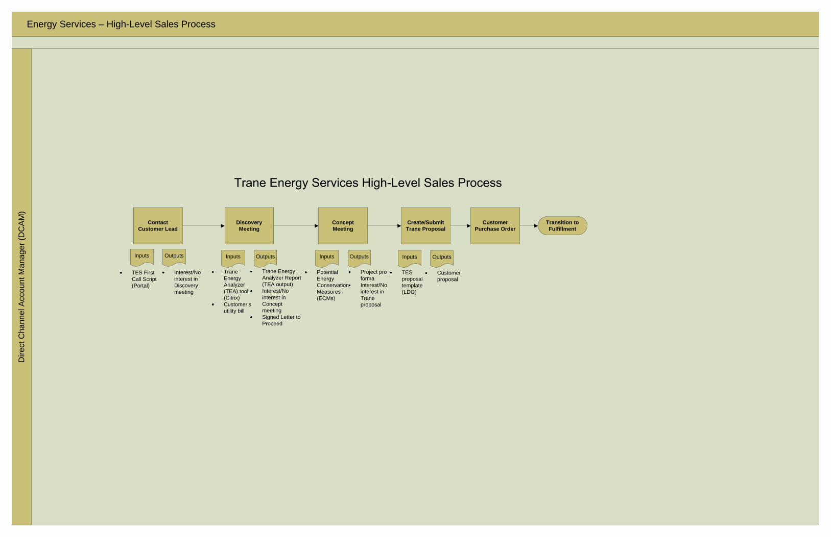
Energy Services – High-Level Sales ProcessD
irect
Cha
nnel
Acc
ount
Man
ager
(DC
AM
)
Contact Customer Lead
Trane Energy Analyzer (TEA) tool (Citrix)Customer’s utility bill
OutputsInputs
Trane Energy Analyzer Report (TEA output)Interest/No interest in Concept meetingSigned Letter to Proceed
Interest/No interest in Discovery meeting
Discovery Meeting
Concept Meeting
OutputsInputs
Project pro formaInterest/No interest in Trane proposal
Potential Energy Conservation Measures (ECMs)
Customer Purchase Order
Transition to Fulfillment
Create/Submit Trane Proposal
OutputsInputs
Customer proposal
TES proposal template (LDG)
TES First Call Script (Portal)
OutputsInputs

Energy Services – Sales Process OverviewD
irect
Cha
nnel
Acc
ount
Man
ager
(DC
AM
)
NO
YES
Discovery Customer Meeting
Savings Objections?
Transition to Fulfillment
Preliminary Study Detailed StudyCreate/Submit
Proposal
Solution Development/
Estimate
Concept Customer Meeting
Cost Objections?
Update Proposal (if required)
Customer Purchase Order
Initial Targeting & Prequalification
Set up Discovery Meeting with
Customer
Existing Trane Customer
YESInputs Inputs Inputs
Proposal template (LDG)
Inputs
Letter to Proceed (LTP) (Portal)
Inputs Inputs
Letter of Commitment (LOC) (Portal)
NO
Trane Energy Analyzer (TEA) tool (Citrix)Customer’s utility billCRM Lead ID #
Meeting agenda (Portal)Talking points (Portal)Initial survey form (Portal)
Trane Energy Optimizer (TEO) tool (Citrix)
Meeting agenda (Portal)Talking points (Portal)Energy benchmarking report (TEA output)Completed survey formCRM Lead ID #Customer hurdle rate
Phone call to CustomerCustomer Account PlanES First Call Script (Portal)
Items in RED text will be delivered by Phase 1 of the Energy Services project.Items in BLUE text will be delivered by Phase 2 of the Energy Services project.

Energy Services – Detailed Sales ProcessD
irect
Cha
nnel
Acc
ount
Man
ager
(DC
AM
)S
ales
Man
ager
YES
NO
Target Customer Is there a Lead?
Contact Customer Lead
Explore other Opportunities
Discovery Meeting
Review/Assign Accounts
Inputs Outputs
Leads list –Existing Customers
List of Customers to TargetAssignments to DCAMs
Identify Lead
OutputsInputs
Interest/No interest in meetingMeeting date
Enter Lead into CRM
OutputsInputs
Lead StatusEstimated RevenueLead RatingPriorityCompany infoSite infoContact infoAM assignedMeeting (folow-up) date
CRM Lead ID #
Meeting Prep
OutputsInputs
Meeting agenda (Portal)Talking points (Portal)
Customized agendaMeeting plan
OutputsInputs
Customized agendaMeeting plan
Facility usage discussion
Benchmark Customer’s
Energy UsageWalk Facility
Initial survey form (Portal)
Completed survey form
OutputsInputs OutputsInputs
Energy benchmarking report (TEA output)
Trane Energy Analyzer (TEA) tool (Citrix)Customer’s utility billCRM Lead ID #
Review Energy Benchmarking
Report with Customer
OutputsInputs
Facility energy benchmarking report Meeting date
Phone call to CustomerCustomer Account Plan
OutputsInputsOutputsInputs
CRM Lead ID #Facility typeFuel types used
Cooling/heating efficiencyChiller typeHVAC control info
TEA Facility Information
TEA Heating & Cooling
OutputsInputsOutputsInputs
Facility utility bills (electric, gas, steam, propane, fuel oil)
TEA Facility Setup
Window area, type, tintWall constructionRoof construction
OutputsInputs
Facility locationSquare footageHVAC system typeFacility usage info
TEA Facility ShellTEA Utility Billing Data
OutputsInputs
Hot water system fuel source, usage, temperature, efficiency
TEA Domestic Hot Water
TEA Lighting & Miscellaneous
Lighting load, controlElevator infoCooking info
OutputsInputs
ERS First Call Script (Portal)
Items in RED text will be delivered by Phase 1 of the Energy Services project.Items in BLUE text will be delivered by Phase 2 of the Energy Services project.

Energy Services – Detailed Sales ProcessD
irect
Cha
nnel
Acc
ount
Man
ager
(DC
AM
)S
ales
Man
ager
YES
NO NO
YES YES
NO NO
YESConcept Meeting
Customer interest in
Trane solutions?
Meeting agenda (Portal)Talking points (Portal)Energy benchmarking report (TEA output)Completed survey form
Customized agendaMeeting plan
Explore other Opportunities Trane
Energy Optimizer (TEO) tool (Citrix)
Energy saving opportunities
exists?
Customized agendaMeeting plan
Customer interest in
Trane solutions?
Update CRM –Lead to
Opportunity
Customer discussion per meeting plan
Explore other Opportunities
OutputsInputs
Energy saving opportunities
exists?
OutputsInputs
CRM Opportunity ID #
Review Pro Forma with Customer
Meeting Prep
OutputsInputs
Develop initial project scope
Project pro forma
ECM selection (TBO input)Potential energy savings % (TBO input)Project cost estimate
Pro forma (TBO output)Meeting date
OutputsInputs OutputsInputs
Opp. StatusEstimated RevenueOpp. RatingPriorityCompany infoSite infoContact infoAM assignedMeeting (folow-up) date
TEO Base Survey
OutputsInputs
CRM Lead ID #Building mechanical system info
Relevant building surveys
TEO Building Surveys
Potential energy conservation measures (ECMs)
OutputsInputs
Chiller plant infoHeating plant infoAirside system infoLighting system infoPlumbing info
Review TEO ECMs with Customer
Targeted ECMsEstimated energy savings
Potential ECMsEnergy savings range
OutputsInputs
TEO Pro Forma
Estimated energy savingsEstimated project costEstimated service agreement costHurdle rateTax rate
Project pro forma (NPV, IRR, payback)
OutputsInputs
Solution Development
Items in RED text will be delivered by Phase 1 of the Energy Services project.Items in BLUE text will be delivered by Phase 2 of the Energy Services project.

Energy Services – Detailed Sales ProcessD
irect
Cha
nnel
Acc
ount
Man
ager
(DC
AM
)S
ales
Man
ager
NO
YES
YES
NO
NO
Detailed Study
Updated Customer proposal
Letter to Proceed (LTP) (Portal)
OutputsInputs
Update/Submit Proposal
Proposal template (LDG)
Preliminary Study
OutputsInputs OutputsInputs
Update/Submit Proposal (if
required)
Customer proposal
Letter of Commitment (LOC) (Portal)
Create/Submit Proposal
Proposal Accepted?
Customer Purchase Order
Updated estimate/pro forma
Updated estimate/pro forma
Estimate Scope using Trane Estimator
Cost Objections?
Existing Customer proposal
Existing Customer proposal
Savings Objections?
Update CRM –Project Closed
OutputsInputsExplore other Opportunities
OutputsInputs
Transition to Fulfillment
Updated Customer proposal
YES
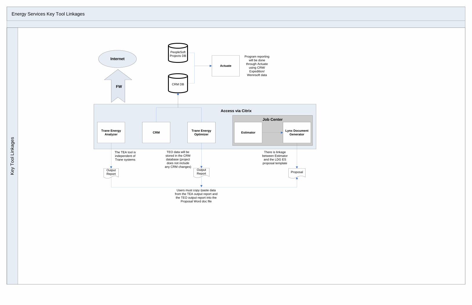
Energy Services Key Tool LinkagesK
ey T
ool L
inka
ges
Access via Citrix
CRM Lynx Document Generator
Trane Energy Optimizer
Trane Energy Analyzer Estimator
CRM DB
PeopleSoft Projects DB
TEO data will be stored in the CRM database (project does not include
any CRM changes)
Actuate
The TEA tool is independent of Trane systems
There is linkage between Estimator and the LDG ES
proposal template
Program reporting will be done
through Actuate using CRM/Expedition/
Wennsoft data
Output Report
Output Report Proposal
Users must copy /paste data from the TEA output report and the TEO output report into the
Proposal Word doc file
Internet
FW
Job Center

BUILDING SERVICESENERGY RETROFIT SERVICES

TEACH YOUR OLD BUILDING SOME NEW TRICKS
WHETHER IT IS OBVIOUS OR NOT, YOU AREPROBABLY PAYING MORE FOR ENERGY ANDBUILDING SYSTEM MAINTENANCE THAN YOUNEED TO.
Increased costs in a commercial building can force you to
reduce your margins or charge higher rents. You lose money
either way — through lower profits or the ability to remain
competitive. And you may be missing out on local
government incentives to adopt newer energy conservation
products and practices.
Like most commercial building owners, you’ve seen youroperational costs increase steadily through the years.Certainly some of this increase is due to rising utility rates.But consider this.
As your building systems age, they become less energyefficient, less reliable and more costly to maintain.
It’s been years since start up and commissioning of your HVAC andBuilding Automation Systems. Your HVAC system is less reliable andefficient than it was when it was new. Your lighting system is antiquated.Even your plumbing is using more resources than necessary.
REDUCE ENERGY COSTS AND IMPROVE BUILDING EFFICIENCY WITHTRANE’S ENERGY RETROFIT SERVICES.
Trane System Specialists Can Optimize Your Building
System Operations

www.trane.com
Discover opportunities for improvingyour infrastructure that will pay forthemselves
Trane’s Energy Retrofit Services can help
you do just that with a free, no-obligation
energy analysis.
If you own or operate a commercial building built or upgraded before 2000 this service is for you! Invite us to your facility and
we will use our proprietary building analysis and optimization tools to show you how your building’s energy profile compares
with other buildings in your area, based on U.S. Government statistics. We will then show you how much you can expect to pay
and how much you can expect to save over time after applying carefully targeted retrofit improvements.
Once we have these benchmarks, we will identify retrofits and other saving opportunities for:
Our analysis provides you with a financial pro forma and ROI that you can use to focus on the most important steps to improving
your building’s operation and justify infrastructure improvement expenditures.
This is your risk-free opportunity to evaluate your building’s system
efficiency and receive actionable recommendations for improvements.
Count on Trane, the energy upgrade specialist.
Trane is your single source for benchmarking, analysis and execution of
your energy enhancement plan using unique, state-of-the-art analysis
tools based on standardized regional data and best practices from an
energy industry leader. Our energy upgrade best practices have been
developed over years of energy analysis and upgrade experience.
BUILDINGCONTROLS
BUILDINGSYSTEM OPERATIONS
CHILLER PLANTS
AIRSIDE HVACSYSTEMS
HEATING PLANTS
LIGHTING SYSTEMS
PLUMBING
2.00
1.80
1.60
1.40
1.20
1.00
0.80
0.60
0.40
0.20
0.00Your Facility Industry Average Efficient Facility
ELECTRICITY NATURAL GAS
See how your building performs against
regional averages and achievable goals

For more information, contact your local Trane office or e-mail us at [email protected]
Trane has a policy of continuous product and product data improvement and reserves the right to change design and specificationswithout notice. © 2008 Trane. All rights reserved.
www.trane.com
Literature Order Number SRV-SLB021-EN
Date April 2008
Supersedes New
Your building could join the growing ranks
of commercial structures whose systems
have been updated with new, powerful,
energy-efficient building systems and
operating procedures — resulting in lower
costs for business and a smaller energy
footprint for the planet.
Why not call us today for a consultation?
NATIONWIDE NETWORK OF PROFESSIONAL ENERGY SPECIALISTS
Typical North American Office Building
Cooling26%
Space Heating5%
Misc. Use7%
Office Equipment20%
Water Heating1%
Lighting29%
Ventilation12%
Trane Can Impact Up To 70% Of Total
Consumption
Trane Building Services (NYSE: TT) optimizes the performance of buildings around the world, helping owners maximize their return
on investment over the life of the building. Trane’s suite of High Performance Building offers are totally customized and scalable, and
include Energy Retrofit Services, Performance Contracting, Turn-Key Services and Comprehensive Solutions. An early developer of
energy-conscious applications and methods, Trane has received numerous environmental awards, including the Sustainable Building
Industry Council Best Practices Award, the U.S. EPA Climate Protection Award, the U.S. EPA Stratospheric Ozone Protection Award and
the Federal Energy and Water Management Award. Trane is also a certified Energy Service Company (ESCO), a tenured member of
ASHRAE, ARI, and USGBC, and boasts the largest percentage of USGBC LEED-accredited professionals in the industry.

FORM A
PRODUCTS & SERVICES
Building Services
Type: Energy Retrofit Services Description: Trane Energy Retrofit Services is designed to grow the direct channel contracting and service business by focusing on proven strategies to reduce energy in HVAC and building control systems. The program utilizes a standardized consultative sales approach that fits within the lead qualification process. It includes two new online sales tools, the Trane Energy Analyzer and the Trane Energy Optimizer, which will help Account Managers to engage the customer, identify opportunities, and qualify the lead. In addition to cutting operating costs, energy-smart office buildings can actually enhance the comfort and performance of workers and boost productivity. Many of the same measures that improve a building's energy performance also make it a more comfortable place to work. Employees benefit from better temperature control, ventilation, and indoor air quality. With the high cost of labor, payback on energy features is shortened even further when savings from reduced absenteeism are combined with energy cost savings. Energy-efficient building features also help building owners attract and retain tenants. (DOE report) The main steps in the sales process include:
1) Energy benchmarking Use the Trane Energy Analyzer (TEA) tool to quickly benchmark the customer's energy usage against similar buildings in the same climate zone
The Trane Energy Analyzer tool is an energy analysis tool capable of benchmarking energy usage against other buildings with similar characteristics using EIA building data. Users enter information about their facilities to receive detailed profiles of the energy use, as well as benchmark comparison results. The tool helps identify opportunities to reduce energy and costs, and provides potential next steps for long-term savings. The Energy Analyzer utilizes hundreds of model-based archetypes for its analysis. The archetypes are derived from thermal, hourly energy performance models using the DOE2.1e software and encompass more than 100,000 hourly simulations. Unlike most statistically-based analysis approaches, the Energy Analyzer does not simply draw upon the relationship among easily quantifiable characteristics to predict energy savings. Instead, the Energy Analyzer's engine derives its calculations from engineering practices and thermodynamic principles that are embodied in hourly energy performance simulations. The calculation engine embodies a unique process for rapidly accessing the results from a vast range of building energy simulations. More specifically, it makes use of response factors produced from performing dozens of simulations on a specific archetype model. Each simulation represents a discrete change to a building characteristic (roof insulation, for instance). By also

applying the engineering principles of how the discrete change affects energy use, the tool can calculate the end-use impacts from changing a building characteristic by nearly any amount. The calculation engine then calibrates the results to match user monthly/annual energy bills and allocate to respective end uses.
2) Project concept Use the Trane Energy Optimizer (TEO) to identify energy saving opportunities and review typical industry savings and costs to arrive at a potential ROI 3) Propose and finalize Use Lynx Document Generator to pull all information into a final customer proposal and finalize the deal Trane has developed several energy services offerings. They are as follows: Tracer ES was developed specifically for customers with multiple buildings who want to manage their many buildings as a single enterprise. Tracer ES is a web-based systems integration solution that gives facility managers an online, enterprise-wide view of all their buildings and systems, from any PC on the network. Tracer ES is fully customizable, easy to install and lets users perform daily operations such as online scheduling, alarm management, troubleshooting, status updates and data analysis. Tracer ES can help educational, healthcare, and government organizations create healthier, more comfortable environments for their occupants – while allowing management to make better operational decisions to reduce energy usage and maintenance expenses. The Tracer SC is an intelligent field panel that communicates with unit controllers (LON or BACnet) that provide standalone control of HVAC equipment. The Tracer SC scans all unit controllers to update information and coordinate building control, including building subsystems such as VAV systems. A facility may have up to 5 Tracer SCs connected over a local area network (LAN). The LAN allows building operators to manage these varied components as one system using web access. The Tracer SC is housed in a protective enclosure to protect from tampering. Trane E-view This solution provides new capabilities to help analyze, manage and communicate their energy use, energy costs and track CO2 emissions for both new & existing Trane customers. Energy and environmental issues are a large concern of our customers and they are asking for products and services that allow them to provide more energy management awareness to their constituents, improve their ability to manage and report on energy usage and costs and also allow them to proactively manage energy related events that affect their bottom line Trane Integrated Solutions capabilities helps provide customers with a broader facility and enterprise solutions offering that will create and sustain safe, comfortable and efficient environments. They leverage the products and services of the combined Ingersoll Rand companies along with products and services from other business partnerships. Trane is “best-in-class” in providing Integrated Comfort™ Systems (integrated HVAC and HVAC control). Our “Integrated Solutions” (formerly referred to as “System Integration”) capabilities allows customers to go beyond HVAC-related control and provide customers with products, applications and services that enable information to be shared between a variety of building control devices and systems in order to: • Make occupants more comfortable

• Save energy • Be better prepared for emergencies • Operate more efficiently • Maintain (service) equipment effectively • Sustain facilities over time Our strategy is to provide open platforms that facilitate product and system integration, leverage our knowledge in HVAC, leverage the knowledge of partner experts for other building systems and deliver integrated building and enterprise environments that provide value to your customer. Integrated Solutions may include either or both of the following: Contractual integration The capability to bundle systems and solutions through a single source contract; moving you from a commodity supplier to a solutions provider. Functional integration The technology to connect diverse intelligent devices and systems—regardless of manufacturer or communication protocol—into a unified facility or enterprise solution that can be easily managed and controlled in real-time. In addition to ICS, we support the functional integration of a wide variety of building and business products and systems including controls for: • HVAC • Fire • Security • Lighting • Energy management Open Standard Protocols (OSPs) Tracer™ building management systems are designed to communicate using OSPs. Whichever protocol is needed, BACnet™, LonWorks™, Modbus, XML, or Web Services, a completely open solution can be provided. Functional Integration Trane employs several technologies and infrastructure products including hardwiring, OSPs, gateways, routers, bridges, and a powerful integration platform to help you functionally integrate a variety of building and enterprise products and systems. JENEsys™ Integration Suite The Trane Tracer product line continues to expand and grow the Trane tradition of delivering comprehensive HVAC control systems, services and solutions. Our integration platform, the JENEsys™ Integration Suite from Lynxspring™, is part of the solutions we offer. JENEsys is used to bring information from older, proprietary (legacy) non-Trane controllers and control systems into Trane Tracer systems. JENEsys, which is powered by the NiagaraAX Framework™ from Tridium®, facilitates interoperability between Tracer control systems and other systems in existing buildings that are based on select older communication protocols or on the NiagaraAX Framework. Use the JENEsys products to tie into existing building automation systems and deepens the relationship with customers disgruntled with competition who don’t feel they can afford to replace all existing controls. Tracer delivers depth in HVAC systems and solutions; the complementary new integration

platform brings: • Access to additional buildings to sell service contracts • More data to feed intelligent services • Pull-through for Trane equipment and contracts • Expanded Trane retrofit capability JENEsys BAS Bridge products from Lynxspring, Inc., are licensed JENEsys controllers with specific network drivers that utilize Lynxspring’s Bridge Appliance Framework to provide self-contained gateways that require only a standard Internet browser for configuration. The AM-BIP (Modbus RTU or Modbus TCP to BACnet/IP) models are used in the field to integrate third-party products that use the Modbus communications protocol into Tracer systems that use the BACnet communications protocol by translating Modbus RTU or Modbus TCP to BACnet/IP. The browser interface comes fully functional and includes complete online help. Finished databases (product mapping files) can be saved and uploaded to subsequent JENEsys BAS Bridges for repeat or similar applications. There are two different size units available; the normal capacity unit generally facilitates translation of up to 5001 points while the expanded capacity unit generally facilitates translation of up to 25001 points. To expand the capacity in the normal unit memory can be added to translate an additional 5001 points. Personnel: See TAB 3-Company Profile-Value Added Services-Question #4 for list of Building Automation Technicians and Engineers at each Trane facility. Detail Features and Benefits: Tracer Summit Energy Services is a comprehensive metering application and reporting tool for optimizing the energy usage and costs of the facility. The Tracer Summit Energy Services products provides the means to:
Monitor energy use, allocate costs, verify utility billings, and identify ways to optimize energy consumption and reduce expenditures.
Monitor virtually any energy resource: electricity, natural gas, steam, and chilled water
Create advanced reports with Tracer Summit data
Organize sub-meter data into categories
Support energy buying decisions
Create ready to use reports that aid in the rapid analysis of data
Generate utility invoices and verify accuracy of actual utility bill charges
Compare purchasing options from various energy providers and perform multiple “what if”
scenarios
Evaluate the effect of weather or other variables on facility energy requirements

Standardize units of measure to allow data comparison and benchmarking
Generate energy benchmarking data
Export Tracer Summit data into standard IT format
Tracer Summit Energy Services is available in two options:
Energy Manager Energy Analyst
Energy Manager provides tracking, analysis, cost allocation, benchmarking, and invoicing of energy meters and submeters as well as non-energy points such as weather data. Energy Analyst provides more comprehensive energy management tools to enable in-depth analysis and reporting. Energy Manager Energy Manager enables you to:
Reduce energy consumption and operating costs by tracking meter, sub-meter, and single data points of building automation systems (BAS) over time.
Make timely energy management decisions by accessing utility and key operating parameter data
in an easy to read report for any time period.
Create electronic invoices, cost allocation reports, and tenant sub-billing reports quickly and easily.
Generate reports that provide benchmarking information for selected meters for a given time interval.
Energy Manager provides you with a history, in 15 minute increments, of daily or total energy usage. The history can be for a single meter or point, for an entire building, or for multiple locations. Energy Manager provides the following:
Energy meter information Non-energy meter information Standard Invoices and RateEngine Benchmark reporting
Energy meter information: Energy meter information is easily collected and stored from energy meters and sub-meters to create a historical database. You can view meter and sub-meter data in bar, line and pie charts, and by the day, week, month, or year. The data can be used to identify anomalies and/or trouble areas that can be addressed immediately to minimize costly usage problems. The two ways of viewing energy consumption are accessed by two tabs on the user interface:
Date Range (Total Energy)

Month View (Daily consumption) From the Month View tab, you can view daily energy consumption for a selected month for one meter at a time. This shows you how a facility is consuming energy and helps you to verify the performance of equipment to identify any recurring problems or cost-saving opportunities. Non-Energy meter information: Non-energy data, such as weather data, critical BAS points, and key operating data can also be monitored and included in reports. Examples of key operating data are operating parameters in your BAS system. Other nontraditional data can also be collected to support benchmarking activities, such as numbers of patrons entering a store, number of production units, and so on. The non-energy meter information is viewed and reported similarly to the energy meter information, but the non-energy meter functionality allows you to track, trend, and create reports from Tracer Summit system data. Any data that can be collected by the Tracer Summit control panels can be monitored and reported with this tool. Standard Invoices and RateEngine Energy Manager can generate invoices for any energy meter data using the capabilities of RateEngine and Standard Invoices. You can verify utility generated bills as well as bill your own internal customers, tenants, or areas with this feature. The RateEngine allows you to create time-of-use rates and independent energy accounts for specific equipment, business centers, or tenants. This information can be used to recover energy costs and accurately allocate demand charges. Standard invoice reports can be viewed, printed, and saved. Benchmark Reporting Benchmark reporting allows you to generate reports that provide benchmarking data for selected meters for a given time interval. These reports can be viewed, printed, and saved. Note: The RateEngine must be populated before a benchmarking report can be created. Energy Analyst In addition to having all of the functionality of Energy Manager, Energy Analyst allows technical users, such as energy or facility engineers, to analyze more complex demand-side and supply-side cost saving opportunities. On the demand side, this capability allows you to find anomalies in the demand profiles, look at a variety of benchmarks for your business, and compile advanced reports that document energy use, energy cost, and demand specific costs. On the supply side, this capability allows you to compare different utility suppliers and perform “what-if” analysis. It also allows you to experiment with different rate schedules, strategies, and usage patterns to identify opportunities to reduce costs.

The capabilities and features of each tool are explained below. Advanced Reports Advanced Reports is a customizable energy reporting tool with sample reporting templates. The reports capture and save all parameters of selected meters. This includes energy, energy type, groups, and date/time values based on a specific time interval. Advanced Reports will also allow you to reorganize dimensions displayed in its grid and graph by dragging and dropping to reorder. You can create custom reports or choose from a number of pre-defined reports. Cost Overlay Cost Overlay allows you to generate reports that provide the total costs and the cost breakout between two different utility supply venders. This provides an invaluable graphical comparison tool for “what-if” scenarios when exploring whether to switch utility providers or different rate structures. These reports can be previewed, printed and saved.

FORM A
PRODUCTS & SERVICES
Energy Services
Type: Energy Services Description: Trane has developed several energy services offerings. They are as follows: Tracer ES was developed specifically for customers with multiple buildings who want to manage their many buildings as a single enterprise. Tracer ES is a web-based systems integration solution that gives facility managers an online, enterprise-wide view of all their buildings and systems, from any PC on the network. Tracer ES is fully customizable, easy to install and lets users perform daily operations such as online scheduling, alarm management, troubleshooting, status updates and data analysis. Tracer ES can help educational, healthcare, and government organizations create healthier, more comfortable environments for their occupants – while allowing management to make better operational decisions to reduce energy usage and maintenance expenses. The Tracer SC is an intelligent field panel that communicates with unit controllers (LON or BACnet) that provide standalone control of HVAC equipment. The Tracer SC scans all unit controllers to update information and coordinate building control, including building subsystems such as VAV systems. A facility may have up to 5 Tracer SCs connected over a local area network (LAN). The LAN allows building operators to manage these varied components as one system using web access. The Tracer SC is housed in a protective enclosure to protect from tampering. Trane E-view This solution provides new capabilities to help analyze, manage and communicate their energy use, energy costs and track CO2 emissions for both new & existing Trane customers. Energy and environmental issues are a large concern of our customers and they are asking for products and services that allow them to provide more energy management awareness to their constituents, improve their ability to manage and report on energy usage and costs and also allow them to proactively manage energy related events that affect their bottom line Trane Integrated Solutions capabilities helps provide customers with a broader facility and enterprise solutions offering that will create and sustain safe, comfortable and efficient environments. They leverage the products and services of the combined Ingersoll Rand companies along with products and services from other business partnerships. Trane is “best-in-class” in providing Integrated Comfort™ Systems (integrated HVAC and HVAC control). Our “Integrated Solutions” (formerly referred to as “System Integration”) capabilities allows customers to go beyond HVAC-related control and provide customers with products, applications and services that enable information to be shared between a variety of building control devices and systems in order to: • Make occupants more comfortable • Save energy
• Be better prepared for emergencies • Operate more efficiently • Maintain (service) equipment effectively • Sustain facilities over time Our strategy is to provide open platforms that facilitate product and system integration, leverage our knowledge in HVAC, leverage the knowledge of partner experts for other building systems and deliver integrated building and enterprise environments that provide value to your customer. Integrated Solutions may include either or both of the following: Contractual integration The capability to bundle systems and solutions through a single source contract; moving you from a commodity supplier to a solutions provider. Functional integration The technology to connect diverse intelligent devices and systems—regardless of manufacturer or communication protocol—into a unified facility or enterprise solution that can be easily managed and controlled in real-time. In addition to ICS, we support the functional integration of a wide variety of building and business products and systems including controls for: • HVAC • Fire • Security • Lighting • Energy management Open Standard Protocols (OSPs) Tracer™ building management systems are designed to communicate using OSPs. Whichever protocol is needed, BACnet™, LonWorks™, Modbus, XML, or Web Services, a completely open solution can be provided. Functional Integration Trane employs several technologies and infrastructure products including hardwiring, OSPs, gateways, routers, bridges, and a powerful integration platform to help you functionally integrate a variety of building and enterprise products and systems. JENEsys™ Integration Suite The Trane Tracer product line continues to expand and grow the Trane tradition of delivering comprehensive HVAC control systems, services and solutions. Our integration platform, the JENEsys™ Integration Suite from Lynxspring™, is part of the solutions we offer. JENEsys is used to bring information from older, proprietary (legacy) non-Trane controllers and control systems into Trane Tracer systems. JENEsys, which is powered by the NiagaraAX Framework™ from Tridium®, facilitates interoperability between Tracer control systems and other systems in existing buildings that are based on select older communication protocols or on the NiagaraAX Framework. Use the JENEsys products to tie into existing building automation systems and deepens the relationship with customers disgruntled with competition who don’t feel they can afford to replace all existing controls. Tracer delivers depth in HVAC systems and solutions; the complementary new integration platform brings:

• Access to additional buildings to sell service contracts • More data to feed intelligent services • Pull-through for Trane equipment and contracts • Expanded Trane retrofit capability JENEsys BAS Bridge products from Lynxspring, Inc., are licensed JENEsys controllers with specific network drivers that utilize Lynxspring’s Bridge Appliance Framework to provide self-contained gateways that require only a standard Internet browser for configuration. The AM-BIP (Modbus RTU or Modbus TCP to BACnet/IP) models are used in the field to integrate third-party products that use the Modbus communications protocol into Tracer systems that use the BACnet communications protocol by translating Modbus RTU or Modbus TCP to BACnet/IP. The browser interface comes fully functional and includes complete online help. Finished databases (product mapping files) can be saved and uploaded to subsequent JENEsys BAS Bridges for repeat or similar applications. There are two different size units available; the normal capacity unit generally facilitates translation of up to 5001 points while the expanded capacity unit generally facilitates translation of up to 25001 points. To expand the capacity in the normal unit memory can be added to translate an additional 5001 points. Personnel: See TAB 3-Company Profile-Value Added Services-Question #4 for list of Building Automation Technicians and Engineers at each Trane facility. Detail Features and Benefits: Tracer Summit Energy Services is a comprehensive metering application and reporting tool for optimizing the energy usage and costs of the facility. The Tracer Summit Energy Services products provides the means to:
Monitor energy use, allocate costs, verify utility billings, and identify ways to optimize energy consumption and reduce expenditures.
Monitor virtually any energy resource: electricity, natural gas, steam, and chilled water
Create advanced reports with Tracer Summit data
Organize sub-meter data into categories
Support energy buying decisions
Create ready to use reports that aid in the rapid analysis of data
Generate utility invoices and verify accuracy of actual utility bill charges
Compare purchasing options from various energy providers and perform multiple “what if”
scenarios
Evaluate the effect of weather or other variables on facility energy requirements

Standardize units of measure to allow data comparison and benchmarking
Generate energy benchmarking data
Export Tracer Summit data into standard IT format
Tracer Summit Energy Services is available in two options: Energy Manager Energy Analyst
Energy Manager provides tracking, analysis, cost allocation, benchmarking, and invoicing of energy meters and submeters as well as non-energy points such as weather data. Energy Analyst provides more comprehensive energy management tools to enable in-depth analysis and reporting. Energy Manager Energy Manager enables you to:
Reduce energy consumption and operating costs by tracking meter, sub-meter, and single data points of building automation systems (BAS) over time.
Make timely energy management decisions by accessing utility and key operating parameter data
in an easy to read report for any time period.
Create electronic invoices, cost allocation reports, and tenant sub-billing reports quickly and easily.
Generate reports that provide benchmarking information for selected meters for a given time interval.
Energy Manager provides you with a history, in 15 minute increments, of daily or total energy usage. The history can be for a single meter or point, for an entire building, or for multiple locations. Energy Manager provides the following:
Energy meter information Non-energy meter information Standard Invoices and RateEngine Benchmark reporting
Energy meter information: Energy meter information is easily collected and stored from energy meters and sub-meters to create a historical database. You can view meter and sub-meter data in bar, line and pie charts, and by the day, week, month, or year. The data can be used to identify anomalies and/or trouble areas that can be addressed immediately to minimize costly usage problems. The two ways of viewing energy consumption are accessed by two tabs on the user interface:
Date Range (Total Energy) Month View (Daily consumption)

From the Month View tab, you can view daily energy consumption for a selected month for one meter at a time. This shows you how a facility is consuming energy and helps you to verify the performance of equipment to identify any recurring problems or cost-saving opportunities. Non-Energy meter information: Non-energy data, such as weather data, critical BAS points, and key operating data can also be monitored and included in reports. Examples of key operating data are operating parameters in your BAS system. Other nontraditional data can also be collected to support benchmarking activities, such as numbers of patrons entering a store, number of production units, and so on. The non-energy meter information is viewed and reported similarly to the energy meter information, but the non-energy meter functionality allows you to track, trend, and create reports from Tracer Summit system data. Any data that can be collected by the Tracer Summit control panels can be monitored and reported with this tool. Standard Invoices and RateEngine Energy Manager can generate invoices for any energy meter data using the capabilities of RateEngine and Standard Invoices. You can verify utility generated bills as well as bill your own internal customers, tenants, or areas with this feature. The RateEngine allows you to create time-of-use rates and independent energy accounts for specific equipment, business centers, or tenants. This information can be used to recover energy costs and accurately allocate demand charges. Standard invoice reports can be viewed, printed, and saved. Benchmark Reporting Benchmark reporting allows you to generate reports that provide benchmarking data for selected meters for a given time interval. These reports can be viewed, printed, and saved. Note: The RateEngine must be populated before a benchmarking report can be created. Energy Analyst In addition to having all of the functionality of Energy Manager, Energy Analyst allows technical users, such as energy or facility engineers, to analyze more complex demand-side and supply-side cost saving opportunities. On the demand side, this capability allows you to find anomalies in the demand profiles, look at a variety of benchmarks for your business, and compile advanced reports that document energy use, energy cost, and demand specific costs. On the supply side, this capability allows you to compare different utility suppliers and perform “what-if” analysis. It also allows you to experiment with different rate schedules, strategies, and usage patterns to identify opportunities to reduce costs. The capabilities and features of each tool are explained below.

Advanced Reports Advanced Reports is a customizable energy reporting tool with sample reporting templates. The reports capture and save all parameters of selected meters. This includes energy, energy type, groups, and date/time values based on a specific time interval. Advanced Reports will also allow you to reorganize dimensions displayed in its grid and graph by dragging and dropping to reorder. You can create custom reports or choose from a number of pre-defined reports. Cost Overlay Cost Overlay allows you to generate reports that provide the total costs and the cost breakout between two different utility supply venders. This provides an invaluable graphical comparison tool for “what-if” scenarios when exploring whether to switch utility providers or different rate structures. These reports can be previewed, printed and saved.

System IntegrationSolutions
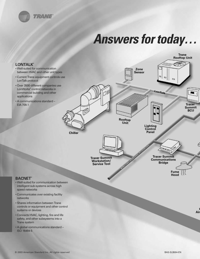
© 2003 American Standard Inc. All rights reserved BAS-SLB004-EN
BACNET®
• Well-suited for communication betweenintelligent sub-systems across highspeed networks
• Communicates over existing facilitynetworks
• Shares information between Tranecontrols or equipment and other controlsystems or devices
• Connects HVAC, lighting, fire and lifesafety, and other subsystems into aTrane system
• A global communications standard –ISO 16484-5
LONTALK®
• Well-suited for communicationbetween HVAC and other unit types
• Current Trane equipment controls useLonTalk protocol
• Over 3500 different companies useLonWorks® control networks incommercial building and otherapplications
• A communications standard – EIA 709.1
Answers for today…
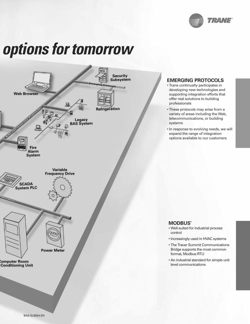
BAS-SLB004-EN
MODBUS®
• Well-suited for industrial processcontrol
• Increasingly used in HVAC systems
• The Tracer Summit CommunicationsBridge supports the most commonformat, Modbus RTU
• An industrial standard for simple unitlevel communications
EMERGING PROTOCOLS• Trane continually participates indeveloping new technologies andsupporting integration efforts thatoffer real solutions to buildingprofessionals
• These protocols may arise from avariety of areas including the Web,telecommunications, or buildingsystems
• In response to evolving needs, we willexpand the range of integrationoptions available to our customers
options for tomorrow

Building Automation Systems
HVAC controllersFront end services and systemsWeb-based control systems
Electrical Systems
GeneratorsPower consumptionPower qualityUPS systems Switch gear
Fire and Life Safety
Alarm annunciationSmoke control
Security
Card access
HVAC
BoilersChillersComputer room unitsPumpsRooftop unitsSmart sensorsTerminal productsVariable speed drives
Laboratory Systems
Fume hoodsRoom pressurization control
Lighting Control
Industrial Process Control
PLCsSCADA systems
BAS-SLB004-EN
April 2003
June 2001
Inland
Successful system integration encompasses a variety of protocols andnetwork types. A Trane control system can become your integration platform,translating custom or proprietary communications to the open standardprotocols of BACnet, LonTalk, and Modbus RTU. This gives you the answersyou need for today, and the options you want for tomorrow. Here are justsome of the different types of equipment and systems that will integrate intoa Trane system…
In the Trane system integration lab, engineers
test and validate interfaces between Trane
systems and those of many other suppliers.

TM
The online answer tomultiple-facility control

Tracer ES™ is a powerful web-based solution that gives you anenterprise management view into allyour building control systems. TracerES, the online answer to multiple-facility control:
• Enables better decision making
• Provides easy integration andcompatibility
• Offers superior performanceand cost savings
• Delivers a positive return oninvestment
When you log on with Tracer ES,you can view your entire enterpriseand instantly see all of the BACnetsystems throughout your facilities.Now you have the power to:
• Manage multiple buildings asan “enterprise”
• Respond to unexpected orglobal events
• Troubleshoot system problems, remotely
• Track and analyze systemdata over time
It’s all available through anintuitive system that is both easyto use and easy to customize tomeet any of your facility manage-ment needs.
You don’t have tobeeverywhere
to controleverything
SECUREDENTRY

With Tracer ES, you havedirect computer access to everyBACnet building system in everybuilding you manage. You havecomplete control at your fingertipsto make global schedule changes,answer alarms and diagnose problems instantly, from anywhere.
That’s the power of TracerES…a front-end system that letsoperators of multiple facilitiesmanage all their buildings as a single enterprise. No more run-ning from building to building, or campus to campus. Tracer ESbrings it all to you. Just log on.And manage your buildings – and your business – better!
Trane delivers a complete, single-source approach to all yourbuilding automation, equipment,service, parts and environmentalneeds. No more settling for halfthe answer. No more proprietarysystems that don’t play well withothers, or lock you into their tech-nology with expensive upgrades.
Tracer ES gives you completefreedom. The freedom of a systemthat’s easy to integrate, operateand maintain – and makes it easyto better manage and reduce youroperating costs.
Taketherunaroundoutof managing multiplebuildings
“I’ve got 350,000 square feet of old, run down space. We’vealso built three state-of-the-art buildings, and in between, we’vegot partially renovated buildings that aren’t even up to standards. I need a building control systemthat can bring it all together,and still deliver the ROI thatFinance craves.”
Welcome to the world of Tracer ES.Finally, you’re in complete control
of all your facilities.

Tracer ES was specificallydesigned to be the most user-friendly control system you’llfind. To put it simply…if you cansurf the Web, you can masterTracer ES.
You now have the power tocomplete daily operations fromany computer on your network.You’ll enjoy the flexibility to quick-ly change set points, make sched-uling adjustments to a room, a single building, or across all yourfacilities – and respond to lastminute changes, unexpectedevents or even changing weatherconditions.
When an alarm shows up onyour system, Tracer ES automati-cally pinpoints the problem anddisplays it on your monitor –which building, which room,which piece of equipment – allow-ing you to troubleshoot the problem immediately. If service isneeded, you’ll know who to sendand what parts to bring to addressthe problems they’ll likely face.
Tracer ES seamlessly integrateswith your existing IT infrastructure,while its standard technologiesmakes it the ideal IT citizen – peace-fully residing on your IT network,going about its business.
It even offers an auto-recogni-tion and self-configuration featurethat searches your network far andwide, locating all BACnet systemsand components. Once located,Tracer ES automatically creates itsown web pages that display status,schedules, trends and alarms. Thinkof the efficiency. It saves you timeand lets you focus on the job athand – facility operations.
As your buildings and systemsevolve, and improvements arerequired, you can painlessly enhanceor expand Tracer ES at one centralpoint, instead of at multiple worksta-
tions. At last, you can say goodbye tothe headaches and costs of manag-ing multiple PCs with specialized soft-ware. With Tracer ES, it’s all in one.
• Connect with existing IT infrastructure
• Run on central server withSQL database
• Integrate with, and access datafrom, other building systems
• Compatible with TracerSummit™ and Tracker™ building automation systems
Your worst day justgot better
It’s easier to maketheconnection
• Deliver instant productivity
• Dramatically streamline dailyfacility management activities
• Instantly pinpoint alarms attheir source
• Diagnose problems from yourcomputer
• Eliminate fruitless trips tosites
• Manage service and maintenance calls

A sound investment
todayand tomorrow
In addition, Tracer ES givesyou the ability to collect and ana-lyze energy and operating datafrom multiple sources. So you cancompare and contrast your “bestof class” buildings with those thatare not top performers to helpraise them to a higher level – andwring out extra savings.
With Tracer ES, you get asystem that not only allows youto work more efficiently; it allowsyou to buy more efficiently.Tracer ES features a unique modular and scalable design thatlets you purchase only the components you need, and gives you the freedom to addother value-added modules asyou need them – plus, it easilyconnects with your Trane or non-Trane systems.
“
”
Energy is a major cost
for our organization
and anything we can
do to make our
buildings more
efficient benefits the
bottom line. I’m
looking for a better
way to track and
analyze data across
all our facilities.
Of course Tracer ES helpsyou secure energy and opera-tional savings. But today, that’sjust the price of admission.Tracer ES takes you far beyondturning lights off and on and set-ting temperatures. With TracerES, you get total control of allyour buildings – right from yourdesktop – taking energy savings,diagnostics and scheduling effi-ciencies to a whole new level.
You’ll save time, money andheadaches by being able toimmediately respond to alarmsand send the right service peoplewith the right equipment tomake the repair…or in manycases you can solve the problemyourself, right from your com-puter. No more running back andforth wasting time and effort.

For over 90 years Trane hasbeen the name building ownerstrust for the most reliable andefficient heating, cooling andcontrol systems. The Trane nameis synonymous with expert solu-tions for workplace comfort,health and productivity.
Our nationwide network ofsales offices assures that expertadvice and quality service arealways nearby. You can count onyour local Trane Office for fast,knowledgeable support for allyour facility management needs.
Trane control products arethe result of over 25 years ofresearch and refinement inbuilding control products. TracerES is an easy-to-use, intuitivesolution that delivers completecontrol of your entire enterprise.
If you’re ready to take control of all your buildings,take the next step. Contact your local Trane Office or visit the Tracer ES website atwww.traceres.trane.com andcheck out the Tracer ES demo.You’ll discover how easy we’remaking it to take control of everything, from anywhere.
Tracer ES is the online answer to multiple-facility control.
Brought to you by Tranethenameyou count on
for comfort

Trane
A business of American Standard Companies
www.trane.com
For more information, contact your local Traneoffice or e-mail us at [email protected]
Trane has a policy of continuous product and product data improvement and reserves the right to change design and specifications without notice.
Literature Order Number BAS-SLB009-EN
Date September 2005
Supersedes New
Stocking Location Inland

9/29/2014
1
Trane Energy Services:Supply-Side
September 10, 2014
SUPPLY SIDE
Procurement RiskManagement
DataManagement OPEX CAPEX
TOTAL ENERGY COST
DEMAND SIDE
Confidential & Proprietary
Change in Conversation
Two main ways to lower your energy costs are by reducing your energy use(demand-side) and by buying your energy smarter (supply-side)
2

9/29/2014
2
Confidential & Proprietary
Fellon-McCord Overview
Some of Our Clients
What We DoKey Statistics1992Founded in Louisville,Kentucky
$14 BillionAnnual client energyspend in North Americaand UK/Europe
80Full-time energyprofessionals focused onyour energy supply needsin North America
24/7Power Control Centerstaffed 24 hours per day7 days per week withcertified energyprofessionals
Energy Consulting &Management
Data Management &Utility Bill Payment
Energy Scheduling &Dispatching
Manage and Reduce Supply Costs for Energy Consumers
Services
3
Class of Customer
4
Supply procurement for clients from 50,000 kWh +
Full-suite ofsupply-sidesolutions forintensiveenergy useclients
Proprietary & Confidential
9/29/2014
3
Proprietary & Confidential
Supply-Side Services
5
1.) Data Management 2.) Risk Management
3.) SupplierManagement
4.) UtilityManagement
Proprietary & Confidential
Aggregating information to give strategicdirection to your energy spend
Invoice processingBill-pay solutionsCustom reportingBenchmarkingBudget & forecastingComprehensive client library
Online Dashboard
Data ManagementM
EET
STEV
E
6

9/29/2014
4
Making you a price shopper, not aprice taker
Fully-staffed Risk & Research departmentExtensive suite of industry publicationsClient market callsRegulatory updates
Proprietary & Confidential
Risk Management
MEE
TSU
7
24/7 market visibility brings uniquesolutions and benefits all of our clients
Asset managementWholesale power accessPeak load managementScheduling & dispatch
Proprietary & Confidential
24/7 Power Control CenterW
HO
LESA
LEM
EET
DU
RG
A
8
9/29/2014
5
Leveraging 20 years of experience andmarket presence for clients
Over 400+ national suppliersExpert RFPsDirect supplier negotiationAggregate buying power
Proprietary & Confidential
Supplier Management
9
MEE
TB
EAU
The Hotel Lesson
Advertised Room Rate:$189.00 a room
$162.04 a room
$179.55 a roomOptimized Purchasing
$170.57 a room
$149.99 a room
10
9/29/2014
6
MarketKnowledge
Proprietary & Confidential
Look Familiar?
Aggregationof Units
ProfessionalRFP
PortfolioSize
Total AnnualEnergy Supply8-20% Savings
Unique Solutions
Expertise
11
Proprietary & Confidential
Bid Response
12

9/29/2014
7
Texas
IllinoisOhio
Penn.
New York
Maine
New Hampshire
Massachusetts
Rhode Island
ConnecticutNew Jersey
MarylandDelaware
Washington D.C.
Calif.
Mich.
Electricity Deregulation
None
Retail Choice
Partial Retail Choice
Oregon.
13
Texas
IllinoisOhio
Penn.
New York
Maine
New Hampshire
Massachusetts
Rhode Island
ConnecticutNew Jersey
MarylandDelaware
Washington D.C.
Calif.
Mich.
Natural Gas Deregulation
None
Retail Choice
Partial Retail Choice
Georgia.Miss.
Ark.
Missouri.
Iowa
Ind.
Kentucky
W.V.
North Carolina
Virginia
South Dakota
Nebraska
Montana
Wyoming
Colorado
Arizona
Nevada
Washington
New Mexico
*Legend as applies to distribution centers
14
9/29/2014
8
Ensuring all locations are effectivelymanaging their utility costs
Rate ReviewsTax ExemptionsPower Factor Analysis
Proprietary & Confidential
Utility Management
15
CA
SEST
UD
Y
TCPN Class ofCustomer
9/29/2014
9
Proprietary & Confidential
TCPN Class of Customer
WH
OLE
SALE
17
Gas Aggregation Program
Wholesale Power Management
Proprietary & Confidential
TCPN Class of CustomerW
HO
LESA
LE
18

9/29/2014
10
Gas Aggregation ProgramExecutive Summary
Proprietary & Confidential
TCPN Class of Customer
WH
OLE
SALE
19
Bid Summary
Proprietary & Confidential
TCPN Class of CustomerW
HO
LESA
LE
20

10/2/2014
1
A Brand of Ingersoll Rand®
Supply-Side Solutions
for:
Confidential Information 2
Fellon-McCord – Elevator Speech
• An energy procurement consulting and management
company
• Help businesses know where and how to purchase
and manage reliable energy supplies at the best
available price
• A pioneer in the energy procurement consulting and
management industry since 1992
10/2/2014
2
Confidential Information 3
Some of Our Clients
What We DoKey Statistics
1992Founded in Louisville,Kentucky
$14 BillionAnnual client energyspend in NorthAmerica andUK/Europe
400Supported by apartnership networkof more than 400energy professionalsworldwide
24/7Power Control Centerstaffed 24 hours perday 7 days per weekwith certified energyprofessionals
Energy Consulting &Management
Data Management &Utility Bill Payment
Energy Scheduling &Dispatching
Reduce Costs for Energy Consumers
Services
Company Overview
Confidential Information 4
commodity transportation
distribution
Retail Energy RFPAssess renewable energy options
Optimize market timing
Design best fit product
Negotiate contracts
Audit supply invoices
Risk ManagementAssess client risk tolerance
Forecast NYMEX/index pricing
Recommend hedges by risk category
Intra-month SupplyManage imbalances
Optimize storage
Buy/sell intra-month
Asset OptimizationNominate/schedule gas and power
Assess transportation options
Assess storage opportunities
Assess onsite generation
Wholesale Power ProcurementMinimize peak load demand
Negotiate counterparty contracts
Remove retail margin
Utility Tariff AnalysisUtility vs. 3rd party power supply
Transportation vs. sales service
Special riders / incentives
Voltage discounts
OtherBill validation
Billing error resolution
Utility negotiation
Sales tax exemptions
Demand response programs
Invoice/contract management
How We Help ClientsReduce Costs
consumptionEnergy Efficiency3-day Onsite Energy Treasure Hunts (Audits)
Identify low-cost efficiency improvement projects
Research available utility, state, and federal incentives
Focus on Service
We are an extension of our clients’ facilities and procurement teams.

10/2/2014
3
Confidential Information 5
*Included in Supply-Side Audit
Service Offerings
5
SUPPLY-SIDE SERVICES NATURAL GAS ELECTRICITY
Supply Procurement*
Rate Review*
Power Factor Correction*
Tax Exemptions*
Utility Negotiation
Demand Response
Risk Management
Load Profile Optimization
On-Site Generation
Confidential Information 6
Market
Knowledge
2-5% Savings
Focus on Value
Confidential & Proprietary
24/7 Power
Center
2-5% Savings
Aggregation
of Units
2-5% Savings
Professional
RFP
2-5% Savings
Portfolio
Size
2-5% Savings
Total Annual
Energy Spend
10-25% Savings
Unique Solutions Expertise

10/2/2014
4
A Brand of Ingersoll Rand®
Synergy
of
Partnership
Confidential Information 8
Synergy Discussion
• Our competitors are offering similar services
• Creates new and ongoing reasons to talk to clients
• Socialized savings – Can use supply-side savings in
support of relationship development and demand-side
sales growth
• Revenue to Trane – “Get paid to stay in touch with your
clients.”
Why Partner?

10/2/2014
5
Confidential Information 9
Competitive Analysis –Current State
Energy
Consulting
&
Managemen
t
24/7 Energy
Asset
Managemen
t
Data
Managemen
t & Utility
Bill Pay
Sustainabilit
y Solutions
International
Capability
S D S D S D S D S D
JCI
Siemens Schneider
Electric
Trane
Fellon-McCord Trane/
Fellon- McCord
S: Supply-side services D: Demand-side services
Confidential Information 10
Synergy Discussion:
Why Supply-side Management?
CEO’s, CFO’s, COO’s, CPO’s are looking for:
• A centralized solution (i.e., single source)for energy supply and demand
• Ways to leverage energy needs to createsavings across all locations
• Ways to track Plan performance
• Ability to demonstrate EnvironmentalStewardship
10/2/2014
6
Confidential Information 11
Supply & Demand Side Services: Future
SUPPLY
Procurement Risk Management Data Management OPEX CAPEX
More and more businesses want reduced energy usage and the most reliableand economic energy supplies available
• Aggregation• RFPs• Contract Optimization
• Market Intelligence• Market Timing• Continuous Monitoring
• Benchmarking• Opportunity Targeting• Performance Assessment
• System Optimization• Operating Procedures• Behavior Modification
• Equipment• Controls• Building Modification
TOTAL ENERGY COST
DEMAND
CUSTOMER’STOTAL ENERGY COST
A Brand of Ingersoll Rand®
Examples ofSuccessful Partnering

10/2/2014
7
Confidential Information 13
Local Success
• Sylvania Schools is part of a state of Ohio
aggregation, and unknowingly defaulted
to utility supply as a result of some large
demand-side projects and new buildings.
• Fellon-McCord was able to run an RFP for the six
buildings that were on utility, saving the district over $50,000
annually. Pricing was 8% less than the state buying
aggregation and 20% less than utility.
• Trane utilized the savings identified to help justify state
funding for a long-proposed $5.4 million project
Confidential Information 14
• CHI purchased KentuckyOne Health,
a group of hospital systems with strong
ties and trust in Harshaw Trane.
• Fellon-McCord was introduced by Harshaw Trane
and identified $160,000 in electricity supply-side savings,
enhancing Harshaw Trane’s relationship with
KentuckyOne Health.
• Fellon-McCord and Trane are working together to
establish a national approach to energy management,
an initiative which was requested by the client.
National Success
10/2/2014
8
A Brand of Ingersoll Rand®
Qualifying and SalesProcess
Confidential Information 16
• Segment your customer market by vertical (see nextslide)
• Look to those customers that:
• Have locations in de-regulated states• No current vendor• No internal resources• Decentralized purchasing• Per facility spend is > $100K• Combined Heating and Power (CHP)
•“Add on” to Energy Services & Controls programs• PC – both installed and targets• TREPS• ESPC• Large BAS install• Facility maintenance agreement
How we get started
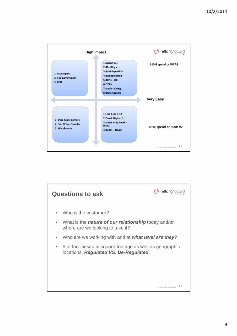
10/2/2014
9
Confidential Information 17
1) Municipals
2) Fed Government
3) REIT
1)Industrials
2)50+ Bldg K-12
3) Mid- lrge Hi-Ed
4) Big Box Retail
5) IDNs – HC
6) TCPN
7) Senior Living
8) Data Centers
1) Strip Malls Centers
2) Sml Office Complex
3) Warehouses
1) <50 Bldg K-12
2) Small Higher Ed
3) Small Bldg Retail -(FMC)
4) Malls – (FMC)
High Impact
Very Easy
$10M spend or 5M ft2
$1M spend or 500k ft2
Confidential Information 18
Questions to ask
• Who is the customer?
• What is the nature of our relationship today and/or
where are we looking to take it?
• Who are we working with and at what level are they?
• # of facilities/total square footage as well as geographic
locations. Regulated VS. De-Regulated

10/2/2014
10
Confidential Information 19
Questions to ask…
• Their cost of use for gas/electric – rate structures,utility bills etc.
• Their total utility spend broken out by gas andelectric. If they have spend and usage by facilitylocation, even better
• What is their current state? Are they self-procuringor contracted with a third party company similar toFellon McCord?
• If they have an existing contract, with whom andwhen does it expire?
Confidential Information 20
Capture information and submit

10/2/2014
11
Confidential Information 21
• Client Information & Invoice Capture – Trane Office
• Invoice Review – Fellon-McCord Office
• Determination of best approach with customer – Trane/Fellon-
McCord team
• 2 Approaches:
1) Energy Procurement Only -
2) Energy Procurement & Management -
Process Outline
Confidential Information 22
• Client call to discuss high-level savings and supply
opportunities - Fellon-McCord/Customer (Trane optional)
• Obtain Letter of Authorization (LOA) – Trane/Customer
• Perform energy supply Request for Proposal (RFP) –
Fellon-McCord
• Review RFP responses and provide recommendation(s)
– Fellon-McCord/Customer
• Contract Negotiation – Fellon-McCord
• Contract Execution - Customer
1) Energy Procurement Only -
Process Outline

10/2/2014
12
Confidential Information 23
- Perform Detailed Baseline Review Project Work
- Perform Supply-Side Project Work targeted to specific area(s) and/or
locations
- Enter into term supply-side Energy Services Agreement for all services
and locations
2) Energy Procurement & Management -
Supply Procurement
Rate Review
Power Factor
Correction
Tax Exemptions
• Client call to discuss high-level savings and supply opportunities
– Fellon-McCord/Customer (Trane optional)
Utility Negotiations
Risk Management
Load Profile Optimization
On-Site Generation
Process Outline
Confidential Information 24
• Invoices* – from customers spending $100,000 or moreannually on natural gas and electricity in deregulated states
• Invoices* – from customers spending $100,000 or moreannually on natural gas and electricity in deregulated states
• Invoices* – from existing customers, where you want toimprove or expand relationships
• Invoices* – from prospective customers that meet costand usage minimums and with whom you want to createmore opportunity for conducting business now and in thefuture
How we get started
* Anytime supply contracts are available we would want to have copies.

10/2/2014
13
Confidential Information 25
Questions?
Confidential Information 26
Thank you
We appreciate the opportunity
to be a part of the Trane family
Drew Fellon
Fellon-McCord
502-214-9418
Adrian Stasiuk
Trane Energy Services and Controls
973) 434-2191
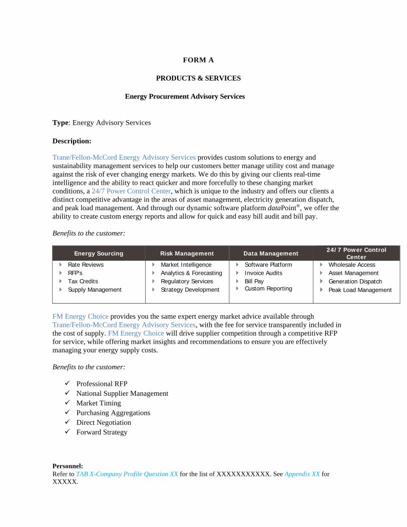
FORM A
PRODUCTS & SERVICES
Energy Procurement Advisory Services
Type: Energy Advisory Services
Description:
Trane/Fellon-McCord Energy Advisory Services provides custom solutions to energy and sustainability management services to help our customers better manage utility cost and manage against the risk of ever changing energy markets. We do this by giving our clients real-time intelligence and the ability to react quicker and more forcefully to these changing market conditions, a 24/7 Power Control Center, which is unique to the industry and offers our clients a distinct competitive advantage in the areas of asset management, electricity generation dispatch, and peak load management. And through our dynamic software platform dataPoint®, we offer the ability to create custom energy reports and allow for quick and easy bill audit and bill pay. Benefits to the customer:
Energy Sourcing Risk Management Data Management 24/7 Power Control Center
Rate Reviews RFP’s Tax Credits Supply Management
Market Intelligence Analytics & Forecasting Regulatory Services Strategy Development
Software Platform Invoice Audits Bill Pay Custom Reporting
Wholesale Access Asset Management Generation Dispatch Peak Load Management
FM Energy Choice provides you the same expert energy market advice available through Trane/Fellon-McCord Energy Advisory Services, with the fee for service transparently included in the cost of supply. FM Energy Choice will drive supplier competition through a competitive RFP for service, while offering market insights and recommendations to ensure you are effectively managing your energy supply costs. Benefits to the customer: Professional RFP National Supplier Management Market Timing Purchasing Aggregations Direct Negotiation Forward Strategy
Personnel: Refer to TAB X-Company Profile Question XX for the list of XXXXXXXXXXX. See Appendix XX for XXXXX.

1
Clint Pechacek
From: Jack Cutting <[email protected]>Sent: Tuesday, July 08, 2014 10:51 AMTo: Deborah BushnellCc: Stuart Verdon; Spencer, Greg; Jon SymkoSubject: FW: Fellon McCord and TCPAttachments: Form A- Energy Procurement Advisory Services.docx
Deborah, Please see the request by Greg Spencer below to add Energy Procurement Services to the Trane contracts R 5045 and R 5239. After review, I recommend that TCPN approve this request. Thanks, Jack Cutting, C.P.M. Contract Manager
TCPN 11280 West Road Houston, TX 77065 713-554-3512 Office 713-775-9074 Cell [email protected] www.tcpn.org This message contains information that may be confidential and privileged. Unless you are the addressee (or authorized to receive for the addressee), you may not use, copy or disclose to anyone the message or any information contained in the message. If you have received this message in error, please notify the sender by reply e-mail, and delete the message and any attachments.
From: Spencer, Greg [mailto:[email protected]] Sent: Tuesday, July 08, 2014 10:30 AM To: Jack Cutting Cc: Stuart Verdon Subject: FW: Fellon McCord and TCP Jack & Stuart, Good morning from Paramus , New Jersey. I’m attaching a Form A for Trane’s newest offering, Energy Procurement Advisory Services. I am asking that this be incorporated into our R5045 contract and also feel it is applicable to R5239. Please review and advise if there is additional information needed. Pricing for this service will be via one of our already approved labor categories. Best Regards, Greg Spencer

2
TCPN Strategic Program Leader Office: 972‐406‐6090 Cell: 469‐442‐6055
From: Stasiuk, Adrian Sent: Tuesday, July 08, 2014 9:22 AM To: Spencer, Greg Subject: Fellon McCord and TCP Greg – wanted to make sure you got this. Adrian G. Stasiuk Supply Side Sales Leader Trane Energy Services and Controls Ingersoll Rand 4 Wood Hollow Road Parsippany, New Jersey 07054 Tel: 973-434-2191 Mobile: 973-219-4834 E-mail: [email protected] www.trane.com
The information in this message is the property of TRANE. This message is intended only for the use of the addressee named above and may contain legally privileged and/or confidential information. If you are not the intended recipient of this message, you are hereby notified that any use, dissemination, distribution or copying of this message is strictly prohibited. If you receive this message in error, please notify us immediately by telephone or return e‐mail and delete the message, all copies thereof and any attachments. We thank you for your cooperation.
The information contained in this message is privileged and intended only for the recipients named. If the reader is not a representative of the intended recipient, any review, dissemination or copying of this message or the information it contains is prohibited. If you have received this message in error, please immediately notify the sender, and delete the original message and attachments.

1
Clint Pechacek
From: Deborah Bushnell <[email protected]>Sent: Tuesday, July 08, 2014 2:17 PMTo: Spencer, GregCc: Stuart Verdon; Jon Symko; Jack Cutting; Clint Pechacek; Lorraine VuongSubject: RE: Fellon McCord and TCP
Good Afternoon Greg, Please accept this correspondence as official TCPN acceptance & approval to add Energy Procurement Advisory Servicesto the following Trane contracts:
R5045 ‐ HVAC Equipment, Refrigeration, Installation, Service, and Related Products R5239 – Energy Performance Contracting Services Heating, Ventilating, Air Conditioning & Plumbing
This update is effective immediately and support documentation has been added to your contract file and description of services has been posted to your TCPN vendor information page. If I can be of further assistance, please let me know. Thank you for your ongoing support. Deborah Bushnell Contracts/Compliance Manager
11280 West Road Houston, TX 77065 713-554-0460 (Direct) 832-814-9985 (Cell) [email protected] www.tcpn.org
From: Jack Cutting Sent: Tuesday, July 08, 2014 10:51 AM To: Deborah Bushnell Cc: Stuart Verdon; Spencer, Greg; Jon Symko Subject: FW: Fellon McCord and TCP Deborah, Please see the request by Greg Spencer below to add Energy Procurement Services to the Trane contracts R 5045 and R 5239. After review, I recommend that TCPN approve this request. Thanks, Jack Cutting, C.P.M. Contract Manager
TCPN 11280 West Road Houston, TX 77065 713-554-3512 Office

2
713-775-9074 Cell [email protected] www.tcpn.org This message contains information that may be confidential and privileged. Unless you are the addressee (or authorized to receive for the addressee), you may not use, copy or disclose to anyone the message or any information contained in the message. If you have received this message in error, please notify the sender by reply e-mail, and delete the message and any attachments.
From: Spencer, Greg [mailto:[email protected]] Sent: Tuesday, July 08, 2014 10:30 AM To: Jack Cutting Cc: Stuart Verdon Subject: FW: Fellon McCord and TCP Jack & Stuart, Good morning from Paramus , New Jersey. I’m attaching a Form A for Trane’s newest offering, Energy Procurement Advisory Services. I am asking that this be incorporated into our R5045 contract and also feel it is applicable to R5239. Please review and advise if there is additional information needed. Pricing for this service will be via one of our already approved labor categories. Best Regards, Greg Spencer TCPN Strategic Program Leader Office: 972‐406‐6090 Cell: 469‐442‐6055
From: Stasiuk, Adrian Sent: Tuesday, July 08, 2014 9:22 AM To: Spencer, Greg Subject: Fellon McCord and TCP Greg – wanted to make sure you got this. Adrian G. Stasiuk Supply Side Sales Leader Trane Energy Services and Controls Ingersoll Rand 4 Wood Hollow Road Parsippany, New Jersey 07054 Tel: 973-434-2191 Mobile: 973-219-4834 E-mail: [email protected] www.trane.com
The information in this message is the property of TRANE. This message is intended only for the use of the addressee named above and may contain legally privileged and/or confidential information. If you are not the intended recipient of this message, you are hereby notified that any use, dissemination, distribution or copying of this message is

3
strictly prohibited. If you receive this message in error, please notify us immediately by telephone or return e‐mail and delete the message, all copies thereof and any attachments. We thank you for your cooperation.
The information contained in this message is privileged and intended only for the recipients named. If the reader is not a representative of the intended recipient, any review, dissemination or copying of this message or the information it contains is prohibited. If you have received this message in error, please immediately notify the sender, and delete the original message and attachments.

Building Health Check is a Division of Pure Air Control Services, Inc.
Air Flow Velocity and Pressure AnalysisPrepared for
Mr. Rick GerunAccount Executive
Trane - Tampa902 N. Himes Ave.Tampa, FL 33609
(813) 877-8251
Date of Study: July 28 – July 29, 2014Date of Report: July 30, 2014
Report # 6378-17514
Lakeland Regional Medical Center (LRMC)1324 Lakeland Hills Blvd.
Lakeland, FL 33805
Prepared ByBob Mulcahy, LEED AP BD+C, CIE
Building ScientistIndoor Environmental Diagnostic & Remediation Specialist
HVAC FL License # CAC0579921(727) 572-45501(800) 422-7873
Copyright 2014 Pure Air Control Services, Inc.
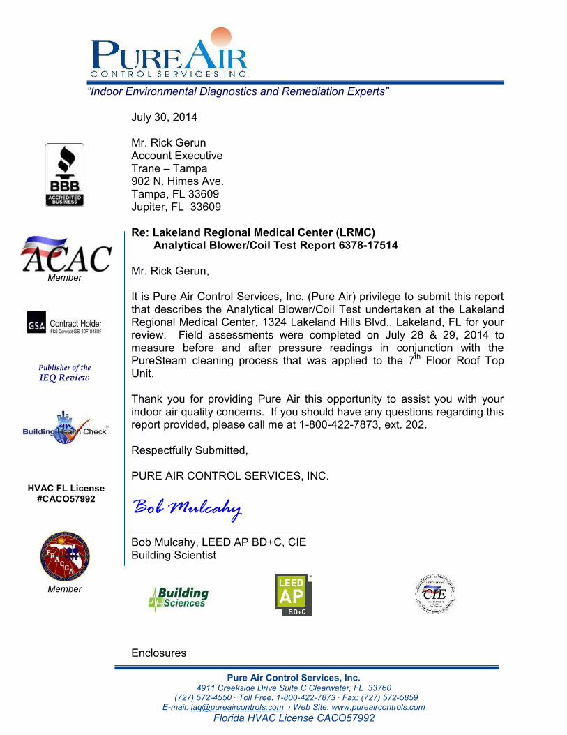
“Indoor Environmental Diagnostics and Remediation Experts”
Pure Air Control Services, Inc.4911 Creekside Drive Suite C Clearwater, FL 33760
(727) 572-4550 · Toll Free: 1-800-422-7873 · Fax: (727) 572-5859E-mail: [email protected] · Web Site: www.pureaircontrols.com
Florida HVAC License CACO57992
July 30, 2014
Mr. Rick GerunAccount ExecutiveTrane – Tampa902 N. Himes Ave.Tampa, FL 33609Jupiter, FL 33609
Re: Lakeland Regional Medical Center (LRMC)Analytical Blower/Coil Test Report 6378-17514
Mr. Rick Gerun,
It is Pure Air Control Services, Inc. (Pure Air) privilege to submit this reportthat describes the Analytical Blower/Coil Test undertaken at the LakelandRegional Medical Center, 1324 Lakeland Hills Blvd., Lakeland, FL for yourreview. Field assessments were completed on July 28 & 29, 2014 tomeasure before and after pressure readings in conjunction with thePureSteam cleaning process that was applied to the 7th Floor Roof TopUnit.
Thank you for providing Pure Air this opportunity to assist you with yourindoor air quality concerns. If you should have any questions regarding thisreport provided, please call me at 1-800-422-7873, ext. 202.
Respectfully Submitted,
PURE AIR CONTROL SERVICES, INC.
Bob Mulcahy____________________________Bob Mulcahy, LEED AP BD+C, CIEBuilding Scientist
Enclosures
Member
Publisher of theIEQ Review
HVAC FL License#CACO57992
Member
TTTaaammmpppaaa ––– TTTrrraaannneee
LLLaaakkkeeelllaaannnddd RRReeegggiiiooonnnaaalll MMMeeedddiiicccaaalll CCCeeennnttteeerrr
RRReeepppooorrrttt ### 666333777888---111777555111444
CONTENTS
INTRODUCTION 1
BACKGROUND 1
SCOPE OF WORK 1
ENVIRONMENTAL SUMMARY REPORT 1
ANALYTICAL BLOWER/COIL TEST (ABCT) 2
METHODS 3
DISCLAIMERS 3

TTTaaammmpppaaa ––– TTTrrraaannneee
LLLaaakkkeeelllaaannnddd RRReeegggiiiooonnnaaalll MMMeeedddiiicccaaalll CCCeeennnttteeerrr
RRReeepppooorrrttt ### 666333777888---111777555111444
INTRODUCTIONThis report describes the Analytical Blower/Coil Test undertaken at the LakelandRegional Medical Center, 1324 Lakeland Hills Blvd., Lakeland, FL. The assessmentwas completed on July 28 & 29, 2014 at the request of Mr. Rick Gerun, to measurebefore and after pressure readings in conjunction with the PureSteam cleaningprocess that was applied to the 7th Floor Roof Top Unit.
BACKGROUNDTampa - Trane requested a study to assess the airflow improvement (if any) fromcleaning the cooling coils of two roof top units.
SCOPE OF WORKObtain air volume readings from the supply side of the evaporator coil of the 7th FloorRoof Top Unit before and after applying the PureSteam coil cleaning process. Thisdata may be used to estimate the rate of airflow improvement.
ENVIRONMENTAL SUMMARY REPORTThe test results revealed a significant improvement of the airflow performance of the7th Floor Roof Top Unit:
Airflow measurements through the evaporator coiled increased by atotal average of 43%.
The following table describes the measurements obtained before and after cleaningthe coils within the roof top unit using the PureSteam process.
1
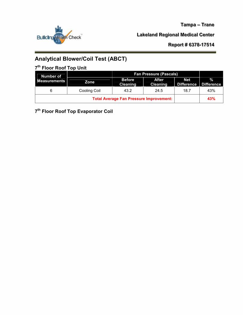
TTTaaammmpppaaa ––– TTTrrraaannneee
LLLaaakkkeeelllaaannnddd RRReeegggiiiooonnnaaalll MMMeeedddiiicccaaalll CCCeeennnttteeerrr
RRReeepppooorrrttt ### 666333777888---111777555111444
Analytical Blower/Coil Test (ABCT)7th Floor Roof Top Unit
Fan Pressure (Pascals)Number ofMeasurements Zone Before
CleaningAfter
CleaningNet
Difference%
Difference6 Cooling Coil 43.2 24.5 18.7 43%
Total Average Fan Pressure Improvement: 43%
7th Floor Roof Top Evaporator Coil
B = Before Steam Cleaning A = After Steam Cleaning
Roof Top Unit #9 Calculation: Before cleaning average fan pressure: 93.2Pa – 50Pa (Baseline) = 43.2Pa After cleaning average fan pressure: 74.5Pa – 50PA (Baseline) = 24.5Pa = Net Difference/Improvement = 18.7Pa 43.2 – 24.5 ÷ 43.2 X100 = 43.28%
Pa = Pascals
B: 40.9
A: 24.7
B: 40.4
A: 24.3
B: 39.6
A: 24.4
B: 58.6
A: 24.8B: 39.6
A: 24.2
B: 39.8
A: 24.8
2
TTTaaammmpppaaa ––– TTTrrraaannneee
LLLaaakkkeeelllaaannnddd RRReeegggiiiooonnnaaalll MMMeeedddiiicccaaalll CCCeeennnttteeerrr
RRReeepppooorrrttt ### 666333777888---111777555111444
METHODSAirflow readings were measured with the following equipment: The Minneapolis Model 3 Blower Fan The Energy Conservatory Digital Pressure Gauge
The following method was utilized to measure fan pressure rates before and after thecleaning of the coils.
Analytical Blower Coil Test (ABCT)The ABCT fan is approximately 11” in diameter with a designed baseline speed of 50Pa that is measured with a pressure and air flow gauge. With the ABCT fan engagedat 50 Pa the blower fan is then placed on the coil to determine the static pressure ofair as it flows through the coil. This method is primarily utilized when measuring largerair handler units with larger coils. Before final reporting, the ABCT measurements arededucted by the original 50 Pa baseline.
DISCLAIMERS:The results addressed in this report represent the system conditions at the time theevaluation was undertaken. These conditions my change over the course of time asa result of dynamic and/or seasonal factors such as but not limited to occupancyrates, building operations, mechanical performance, weather, sporulation cycles, etc.
Although great care has been taken in the preparation of this document, nowarranties, either expressed or implied, are made in connection with the accuracy orcompleteness of the information contained herein, and no responsibility can beassumed by Environmental Diagnostics Laboratory (EDL) or Pure Air ControlServices, Inc. or its affiliates for any claims arising herewith.
Pure Air Control Services, Inc. reserves the rights to amend, clarify, rectify, and/orchange the opinions rendered in this report as any new information or guidelinesbecome available.
Pure Air Control Services, Inc. is not responsible for third party interpretations of thisreport.
3

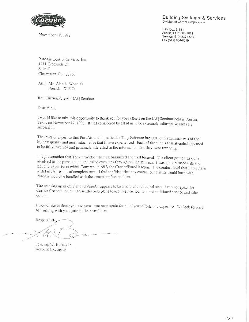

Pure Air Control Services
Estimated Energy Savings
Calculations based on:- 8hr operating time per day (average per year) - 2 Pipe Chilled Water Coil fouled 10%- Inside Temp and Rh of 75 and 55% - Air ∆t of 25ºF - 400 CFM per Ton $.10 KWh
Equipment TonnageKW Hour Per Season
(Clean)Cost Per Season
(Clean)KW Hours Per Season
(Foul) Cost Per Season (Foul)Savings Per Season
per AHU
5 66,439 $6,644 73,821 $7,382 $738
10 132,878 $13,288 147,642 $14,764 $1,476
15 199,317 $19,932 221,463 $22,146 $2,215
20 265,756 $26,576 295,284 $29,528 $2,953
25 332,195 $33,220 369,106 $36,911 $3,691
30 398,634 $39,863 442,927 $44,293 $4,429
40 531,512 $53,151 590,569 $59,057 $5,906
50 664,390 $66,439 738,211 $73,821 $7,382
60 797,268 $79,727 885,853 $88,585 $8,859
vs.Conventional Cleaning

Federal Aviation Administration
Standard Contractor Performance Report
Evaluation Type: Final Reporting Period: From: 11/01/2007 To: 01/15/2008
Host Agency: FAA Evaluating Organization: FAA Contracting Office: FAA
Contract Number: DTFA06-08-C-00002
Order Number:
Contractor Name and Address: U S ENERGY SERVICES INC PURE AIR CONTROL SERVICES 4911 CREEKSIDE DR STE C CLEARWATER, FL 33760-4026 UNITED STATES
DUNS:175078799 SIC/NAICS: 561790 Commodity Code: Contract Type: Fixed-Price
Contract Award Date: 11/01/2007
Contract Expiration Date: 01/15/2008 Contract Value: $117,400.00
Description of Requirement: ENVIRONMENTAL CLEANING OF HVAC DUCTWORK FOR CONTROL ROOM, AIR ROUTE TRAFFIC CONTROL CENTER (ARTCC), HAMPTON, GEORGIA.
RATINGS
Quality of Product or Service
Cost Control
0=Unsatisfactory 1=Poor 2=Fair 3=Good 4=Excellent 5=Outstanding Rating: 5 - Outstanding The contractor has demonstrated an outstanding performance level that was significantly in excess of anticipated achievements and is commendable as an example for others, so that it justifies adding a point to the score. It is expected that this rating will be used in those rare circumstances where contractor performance clearly exceeds the performance levels described as "Excellent".
Government Comments for Quality Of Product Or Service Very impressive. They had to work in attic and ceiling areas that were difficult to reach and located directly above the active air traffic DSR Control Room. They worked flawlessly without disturbing facility operations. They were precise and efficient in thoroughly cleaning all ductwork. They were knowledgeable about the industry standards, their work was outstanding, and they did right the first time. They worked in cooperation with the FAA in all phases including planning and execution of the work.
0=Unsatisfactory 1=Poor 2=Fair 3=Good 4=Excellent 5=Outstanding
Rating: 5 - Outstanding
Page 1 of 5CPS - Contractor Performance Review Copy
3/26/2008https://cps.nih.gov/print.asp

Timeliness of Performance
Business Relations
The contractor has demonstrated an outstanding performance level that justifies adding a point to the score. It is expected that this rating will be used in those rare circumstances where the contractor achieved cost savings and performance clearly exceeds the performance levels described as "Excellent".
Government Comments for Cost Control Outstanding. No claims or requests for equitable adjustment. Fairly negotiated deletion of portion of work.
0=Unsatisfactory 1=Poor 2=Fair 3=Good 4=Excellent 5=Outstanding Rating: 5 - Outstanding The contractor has demonstrated an outstanding performance level that justifies adding a point to the score. It is expected that this rating will be used in those rare circumstances where contractor performance clearly exceeds the performance levels described as "Excellent".
Government Comments for Timeliness Of Performance Perfect .... The FAA had an absolute required completion date of 1/15/2008 due to required follow-on work, and Pure Air met the date with flying colors.
0=Unsatisfactory 1=Poor 2=Fair 3=Good 4=Excellent 5=Outstanding Rating: 5 - Outstanding The contractor has demonstrated an outstanding performance level that justifies adding a point to the score. It is expected that this rating will be used in those rare circumstances where contractor performance clearly exceeds the performance levels described as "Excellent".
Government Comments for Business Relations The Pure Air team was profesional at all times, and was understanding of the unique circumstances and restrictions at the FAA ARTCC facility. They were extremely responsive to our needs, including scheduling and execution of work, timely submission of any required paperwork, promptly returning phone calls, and responding to e-mails. They also went out of their way to have management on site for preliminary meetings to discuss the project with facility personnel, answer questions, and ask questions to insure a complete understanding of the scope of work, as well as restrictions and requirements of working in the facility.
Subcontracts
Are subcontracts involved ? No
Government Comments on Subcontracts None entered - Contractor does not reply
Page 2 of 5CPS - Contractor Performance Review Copy
3/26/2008https://cps.nih.gov/print.asp

Contractor Key Personnel
Contractor Manager/Principal Investigator WOZNIAK, ALAN
Government Comments for Contractor Manager/Principal Investigator Mr. Wozniak, President of Pure Air, was readily accessible to discuss and assist with the project.
Contractor Key Person MCKEE, KEVIN
Government Comments for Contractor Key Person Mr. McKee, Remediation Sciences Specialist and Project Manager, was also readily available and worked extremely well with the FAA to ensure the success of the project.
Contractor Key Person
Government Comments for Contractor Key Person None entered - Contractor does not reply
Small Business Subcontracting Plan
Did the contractor make a good faith effort to comply with its subcontracting plan consistent with the goals and objectives, reporting and other aspects of the plan? N/A If this is a bundled contract, did the contractor meet the goals and objectives for small business participation? N/A
Government Comments on Small Business Subcontracting Plan None entered - Contractor does not reply
Small Disadvantaged Business Goals
Did the contractor make a good faith effort to comply with its subcontracting plan consistent with the goals and objectives, for small disadvantaged business (SDB) participation,monetary targets for SDB participation, and required notifications? N/A
Government Comments for Meeting SDB Subcontracting Requirements None entered - Contractor does not reply
Customer Satisfaction
Is/was the contractor committed to customer satisfaction? Yes
Would you recommend the selection of this firm again? Yes
Page 3 of 5CPS - Contractor Performance Review Copy
3/26/2008https://cps.nih.gov/print.asp

Government Comments for Customer Satisfaction Excellent contractor.
Project Officer/COTR
SHANNON KING Phone: (770)210-7576 Ext: Fax:(770)210-7915 Internet Address: [email protected]
Contracting Officer
Teresa Burgess Phone: (770)210-7369 Ext: Fax:(770)210-7915 Internet Address: [email protected]
Contractor Representative
Alan Wozniak Phone: (800)422-7873 Ext:802 Fax:(727)572-5859 Internet Address: [email protected]
Summary Ratings: Quality of Product or Service Rating : 5 Cost Control Rating : 5 Timeliness of Performance Rating : 5 Business Relations Rating : 5
CONTRACTOR COMMENTS
Contractor Comments for Quality Of Product Or Service The FAA was very cooperative and responsive to our needs on this fast moving critical project
Contractor Comments for Cost Control Contractor has elected not to comment
Contractor Comments for Timeliness Of Performance Contractor has elected not to comment
Contractor Comments for Business Relations The FAA procurement group and facilities group were very professional and diligent to work with and assisted in procuring the desired results for the very difficult project.
Contractor Comments on Subcontracts No Government Comments. Contractor does not reply
Page 4 of 5CPS - Contractor Performance Review Copy
3/26/2008https://cps.nih.gov/print.asp

Contractor Comments for Contractor Manager/Principal Investigator Both Teresa Burgess, Senior Acquisition Specialist and Shannon King, COTR were intrumental in making the otherwise difficult project run very smooth.
Contractor Comments for Contractor Key Person Contractor has elected not to comment
Contractor Comments for Contractor Key Person No Government Comments. Contractor does not reply
Contractor Comments on Small Business Subcontracting Plan No Government Comments. Contractor does not reply
Contractor Comments for Meeting SDB Subcontracting Requirements No Government Comments. Contractor does not reply
Contractor Comments for Customer Satisfaction Contractor has elected not to comment
Contractor Comments for Overall Comment Contractor has elected not to comment
COMPLETION DATE
Report Completion Date: 03/26/2008
OMB CLEARANCE NO. 9000-0142 SOURCE SELECTION INFORMATION/CONFIDENTIAL
Page 5 of 5CPS - Contractor Performance Review Copy
3/26/2008https://cps.nih.gov/print.asp

The Florida State University Facilities Maintenance 969 Learning Way, 114 Mendenhall Bldg A Tallahassee, Florida 32306
Doug, 6/1/11 I want to thank you for the truly wonderful service provided by Pure Air Controls at Florida State University. It has been a true pleasure working with your organization. In particular Brock, Dennis, and led by Barrington. These 3 gentlemen have performed above and beyond the terms of our contract the entire time on campus. They have represented Pure Air Controls wonderfully! I would define these men as true professionals. They do not just show up for work. They truly do take pride in their work and always look beyond the task at hand to add value to their job. As the person escorting this crew here at FSU, I’m most impressed with Barrington’s work ethics and leadership style. Put plainly here, I don’t babysit these guys, I get out of the way so as to not slow their roll. I’m impressed that when they get to the work area they have already decided what is to be done and who will do it. There are no group discussions, Brock and Dennis are doing prep work, and if there are any questions, Barrington already has them prepared. So time has been spent preparing for work, before their arrival is very obvious. The truly impressive part here is that this is every single time, no exception. The attention to detail these guys put on every single job is amazing. So it’s very easy to take all this for granted, because the work is excellent. I don’t want that to happen here. These three guys worked their tails off the entire time up here and did a truly great job at cleaning coils, plus truly being a service to Florida State University, at every opportunity. I hope that when our work continues that you’ll send me this same 3 man crew. Realizing that both Dennis, and Brock probably should be running their own crews by now. Selfishly I want the same three back. As the FSU guy that is responsible for the job being done and done right. Well, these guys have spoiled me rotten. I simply don’t have to worry about them working on campus anywhere at all. Every place these guys have worked, the FSU tenants have been also impressed with them. Since the tenants are like my customers, these guys represent both our interest just right. While they don’t stray from the task at hand, they are friendly and helpful as possible with any and every person they come in contact with. Just true professionals! I truly do hope that you’ll recognize all three of them individually for their hard work done on this campus. They have all three represented Pure Air Controls the absolute best it could be done. It is these guys work that will be in my mind as I attempt to help Pure Air Controls continue on with this work and gain new business here at Florida State University. Thank you very much for the great service. Eric Perkins, Controls & Alarms Tech

1
Clint Pechacek
From: Jon Symko <[email protected]>Sent: Wednesday, September 17, 2014 4:03 PMTo: Spencer, GregSubject: FW: PURE-Steam Coil Cleaning - TCPN Contract OptionsAttachments: image001.gif; ATT00001.htm; FAA Hampton CPS Final Report Pure Air.pdf;
ATT00002.htm; NAVFAC Kings Bay Performance Review PPQ_1.pdf; ATT00003.htm; GA TECH Contract PURE Steam Sanosil Equipment.pdf; ATT00004.htm; HVAC System Environmental Cleaning Specifications.pdf; ATT00005.htm; Energy Savings Data Page.ppt; ATT00006.htm; FSUPureAirRef2011pdf.pdf; ATT00007.htm
FYI Thanks Jon @TCPNJON
" People who think they’re generous to a fault usually think that’s their only fault” From: Stuart Verdon [mailto:[email protected]] Sent: Tuesday, July 01, 2014 6:53 PM To: Jon S New Tcpn Subject: Fwd: PURE-Steam Coil Cleaning - TCPN Contract Options Jon , just say thanks and you will look into it. If you have a moment tomorrow, need to speak with you about Dave n. Sent from my iPhone Begin forwarded message:
From: "Jack Cutting" <[email protected]> To: "Jon Symko" <[email protected]>, "Stuart Verdon" <[email protected]> Cc: "Amber Mackel" <[email protected]> Subject: FW: PURE-Steam Coil Cleaning - TCPN Contract Options
Jon and Stuart, I had a conversation and feel it might be a possibility going into an RFP. If Stuart agrees Jon, you may want to contact for future discussions and meeting. Jack From: Alan Wozniak [mailto:[email protected]] Sent: Tuesday, July 01, 2014 5:35 PM To: Jack Cutting

2
Subject: FW: PURE-Steam Coil Cleaning - TCPN Contract Options Jack – How are you doing? I appreciate the introduction and look forward to serving the TCPN community. As discussed, we provide a very unique service to the HVAC | IAQ industry in our PURE-Steam Coil Cleaning<http://www.pureaircontrols.com/Puresteamcasestudy.pdf> services. More recently, we have been asked by many of our city, county, state, school and university clients if we have a TCPN contract that they can utilize. To date, we do not have one though we would like to start the process. We would like to discuss a RFP with TCPN that would include this specialty type service. Can you utilize an existing contract that we have with Georgia Tech to start the process? I’ve attached the following for your edification: · Florida State University reference letter · Federal Aviation Administration (FAA) Performance review · NAVFAC – Kings Bay Naval Performance Review · Georgia Tech steam coil cleaning contract · Steam Coil Cleaning Specifications | Energy savings via Steam Coil Cleaning As an overview, our national professional IAQ/energy services offerings (click link for SOQ) include: • PURE-Steam Coil Cleaning<http://www.pureaircontrols.com/puresteam.pdf> – performance of generated steam to over 350 degrees utilizing steam cleaning of the evaporator coils as well as internal AHU components • HVAC System Cleaning<http://www.pureaircontrols.com/soqbrs.pdf>/Mold Remediation – performs HVAC system cleaning and mold remediation • Indoor Air Quality Testing<http://www.pureaircontrols.com/soqbs.pdf> - our IH/Building Sciences staff performs IAQ assessments • Environmental Lab Analytics<http://www.edlab.org/soqedlab.pdf> – our AIHA accredited laboratory and CDC ELITE Lab provides analytical lab services I’ve included the recent research paper that was published in the Continental Automated Buildings Association (CABA) magazine on Evaluation of Steam Cleaning in AHU Coil Sanitization and Energy Conservation<http://www.pureaircontrols.com/EvaluationofSteamCoilCleaning.pdf>. Our PURE-Steam Coil Cleaning process is totally GREEN – uses no chemicals, utilizing a proprietary (up to) 350 degree steam for a deep cleansing of the coils helping to: • Sanitize the coils/blowers assembly (Green process)

3
• Removes latent debris from deep within the coils • Creates improved air flow • Create better cooling capacity • Saving energy (approx .22 cents per sq ft) • Improving indoor air quality • Extends HVAC equipment life Here’s is what other school facilities are saying about our process: Tom Shewan, PE Facilities Manager with Florida State University (FSU) discusses the energy savings from our steam coil cleaning process: * “I would estimate we are saving 7-10% on the chilled water equipment. Some of this is from reduced fan energy and the rest is from an increased delta T across the coil which reduces pumping energy and increases chiller efficiency. As an estimate 35-40% of our utility bills are for HVAC so just keeping our coils clean should save between $600K to $800K off our utility bills annually at the low end. As for ROI if you use the most conservative numbers we have paid approximately $0.14 per square foot for coil cleaning to date. We have saved about $0.22 per square foot annually. So the payback is less than 8 months and the ROI 157% annually.” Don Terry, Manager Maintenance, Charlotte County School District stated: * "The Pure-Steam Coil Cleaning (PSCC) process is absolutely remarkable. We have been cleaning our coils the conventional way for many years with chemicals and water and we never were able to get the coils as clean as we would like to have oftentimes still leaving an odor. The Pure-Steam Coil Cleaning process is all natural (no chemicals), actually sterilizes our coils using 300 degree steam getting our coils sparking clean like never before, our static pressure is now back to manufacturer spec, we are getting better air flow and increase of cooling capacity. Not only are we saving energy, but we are creating a healthy learning environment for our students and faculty. Your staff, crew and support team are great to work with. I would highly recommend your Pure-Steam Coil Cleaning process to any facility/HVAC manager interested in saving energy, improving indoor air quality and creating a healthy school." Please provide an introduction to both Greg Spenser as well as John Simco. We look forward to serving the TCPN community. You can reach me at (404) 525-5570 or 1-800-422-7873 ext 802. Sincerely, Alan Wozniak, CIAQP, CIEC President/CEO Building Health Check, LLC<http://www.indoorairtest.com/> Pure Air Control Services<http://www.pureaircontrols.com/soq.pdf> Environmental Diagnostics Laboratory (EDLab)<http://www.edlab.org/soqEDLab.pdf> AIHA Accredited Microbiology Lab EMLAP # 102795 Graduated 8(a) Certified MBE GSA Contract # GS-10F-0488R

4
1-800-422-7873 ext 802 www.pureaircontrols.com<http://www.pureaircontrols.com/> https://mybizcard.co/alan.wozniakciaqpciec.891180


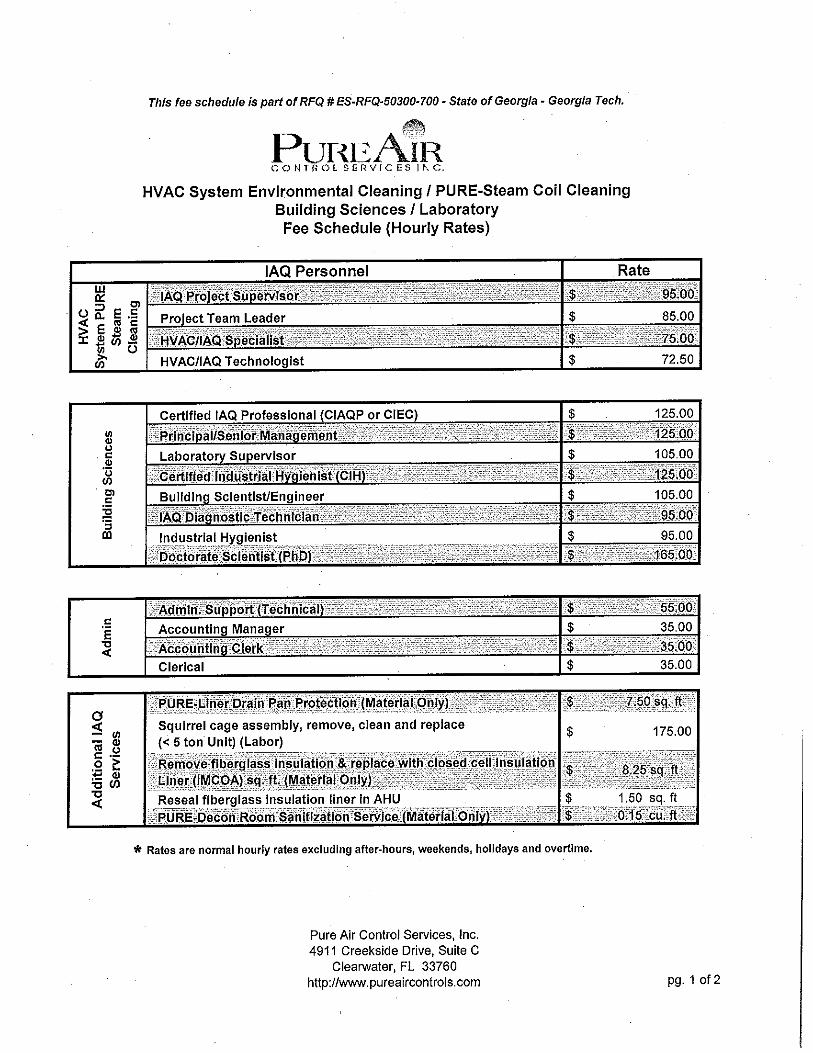
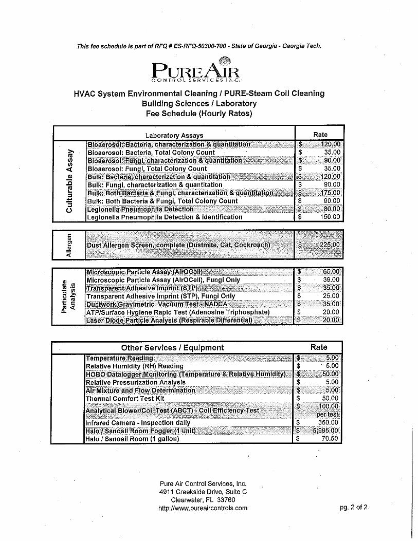
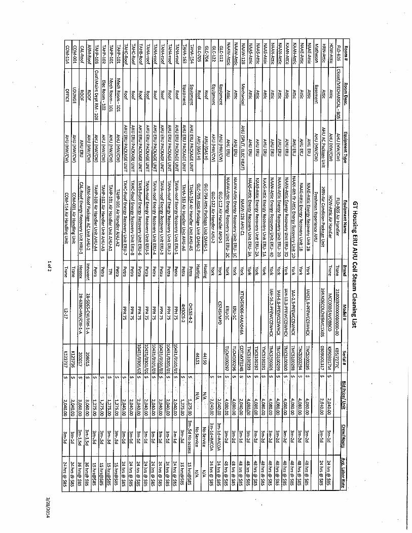
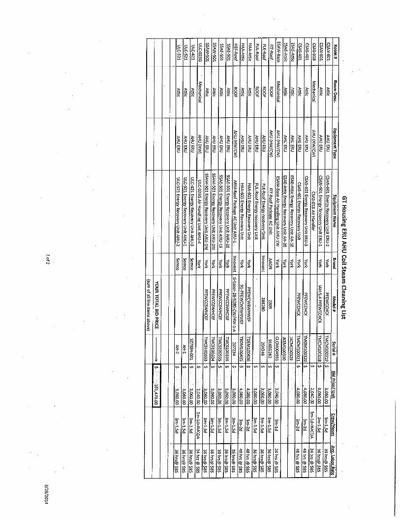
FORM A PRODUCT S & SERVICES
HVAC System Cleaning – PURE-Steam Coil Cleaning Type: HVAC Indoor Environmental
Description: PURE-Steam Coil Cleaning is the only certified totally GREEN HVAC Coil cleaning and sanitization process which provides a deep sterilization of the heating / cooling coils and the blower assembly saving energy and improving IAQ.
The interior of air handling units (AHU’s) are dark, damp, oftentimes wet conditions that can harbor formations of endotoxins, mycotoxins, bacteria, fungus, pollen, particulate and other bio pollutants. These bio pollutants cover metal surfaces with a thin, almost invisible layer and permeable materials e.g. fiberglass liner which can be impregnated with millions and millions of tiny microscopic spores. Oftentimes, this bio-mass leads to a musty earth-like smell sometimes known as “Dirty Sock Syndrome” a primary cause offensive odors.
This microbial growth on surfaces acts an insulation on the evaporator coils, which decreases system efficiency. These pollutants are known to produce allergy-like symptoms, coughing, wheezing, watery eyes, asthma type conditions and other symptoms in building occupants. Fouled coils lead to increased pressure drop across them. Increased pressure drop increases fan horsepower requirements, which, in turn, draw more power, increasing current consumption.
Personnel: PURE-Steam Coil cleaning environmentally trained technicians are on call at all times. Project References: Value Added Services http://www.pureaircontrols.com/EvaluationofSteamCoilCleaning.pdf
Detailed Features and Benefits: The PURE-Steam Coil Cleaning process is totally GREEN – uses no chemicals, utilizing a proprietary (up to) 350 degree steam and high volume flushing for a deep cleansing of the coils helping to:
Create better cooling capacity Save energy (approx .22 cents per sq ft) Creates improved air flow – typical 20-40% improvement Improve indoor air quality Sanitize the coils/blowers assembly (Green process – no chemicals – Certified GREEN) Removes latent debris, mold, bacteria, endotoxins, construction dust, etc.. from deep
within the coils Extends the life of the HVAC equipment

HVAC Environmental cleaning options:
PURE-Liner drain pan protection system – provides a relining of the interior drain pan
protecting it from leaking, meets ASTM 25-50 standard Closed Cell Insulation - remove wetted fiberglass insulation and replace with a closed
cell 0 porosity insulation liner. meets ASTM 25-50 standard Environmental Efficacy Test (EET) – provides real time analytical turbidity test
evaluation of AHU environmental integrity assuring HVAC system equipment is environmentally clean
Coil Cleaning Verification Test (CCVT) – provides analytical assessment before and after environmental cleaning for QA/QC
FORM A PRODUCT S & SERVICES
HVAC System Cleaning – PURE-Steam Coil Cleaning Type: HVAC Indoor Environmental
Description: PURE-Steam Coil Cleaning is the only certified totally GREEN HVAC Coil cleaning and sanitization process which provides a deep sterilization of the heating / cooling coils and the blower assembly saving energy and improving IAQ.
The interior of air handling units (AHU’s) are dark, damp, oftentimes wet conditions that can harbor formations of endotoxins, mycotoxins, bacteria, fungus, pollen, particulate and other bio pollutants. These bio pollutants cover metal surfaces with a thin, almost invisible layer and permeable materials e.g. fiberglass liner which can be impregnated with millions and millions of tiny microscopic spores. Oftentimes, this bio-mass leads to a musty earth-like smell sometimes known as “Dirty Sock Syndrome” a primary cause offensive odors.
This microbial growth on surfaces acts an insulation on the evaporator coils, which decreases system efficiency. These pollutants are known to produce allergy-like symptoms, coughing, wheezing, watery eyes, asthma type conditions and other symptoms in building occupants. Fouled coils lead to increased pressure drop across them. Increased pressure drop increases fan horsepower requirements, which, in turn, draw more power, increasing current consumption.
Personnel: PURE-Steam Coil cleaning environmentally trained technicians are on call at all times. Project References: Value Added Services http://www.pureaircontrols.com/EvaluationofSteamCoilCleaning.pdf
Detailed Features and Benefits: The PURE-Steam Coil Cleaning process is totally GREEN – uses no chemicals, utilizing a proprietary (up to) 350 degree steam and high volume flushing for a deep cleansing of the coils helping to:
Create better cooling capacity Save energy (approx .22 cents per sq ft) Creates improved air flow – typical 20-40% improvement Improve indoor air quality Sanitize the coils/blowers assembly (Green process – no chemicals – Certified
GREEN) Removes latent debris, mold, bacteria, endotoxins, construction dust, etc.. from
deep within the coils Extends the life of the HVAC equipment

HVAC Environmental cleaning options:
PURE-Liner drain pan protection system – provides a relining of the interior
drain pan protecting it from leaking, meets ASTM 25-50 standard Closed Cell Insulation - remove wetted fiberglass insulation and replace with a
closed cell 0 porosity insulation liner. meets ASTM 25-50 standard Environmental Efficacy Test (EET) – provides real time analytical turbidity test
evaluation of AHU environmental integrity assuring HVAC system equipment is environmentally clean
Coil Cleaning Verification Test (CCVT) – provides analytical assessment before and after environmental cleaning for QA/QC


HVAC System Environmental Cleaning Specificationsfor the Assessment and Improvement of
Air Handlers, Cooling/Heating Coils and Energy Recovery Units
HVAC System Environmental CleaningSpecifications for the Assessment and
Improvement of Air Handlers,Cooling/Heating Coils and Energy Recovery Units

HVAC System Environmental Cleaning Specificationsfor the Assessment and Improvement of
Air Handlers, Cooling/Heating Coils and Energy Recovery Units
1.0 GENERAL INFORMATION
2.0 CONTRACT DOCUMENTS
3.0 STATEMENT OF WORK
4.0 PERFORMANCE OF WORK -BASELINE CONDITIONS & POST TESTING/INSPECTION QA/QC
5.0 STANDARD GENERAL CONDITIONS
6.0 CORRECTION OF WORK
7.0 ROTALTIES & PATENTS
8.0 PROTECTION OF WORK, PROPERTY, PERSONS
9.0 ACCESS TO WORK
10.0 CHANGES IN THE WORK
11.0 PLAN ERRORS, OMISSIONS & SPECIFICATION DEVISTIONS
12.0 WORK SCHEDULE
13.0 MATERIALS, EQUIPMENT & PERSONNEL
14.0 CONTRACTORS RESPONSIBILITIES
15.0 SPECIAL CARE
16.0 AIR HANDLER CLEANING/STERILIZATION DECONTAMINATION
17.0 STEAM CLEANING EQUIPMENT
18.0 POST CLEANING/STERILIZATION INSPECTION & TESTING
19.0 WARRANTY
20.0 EVALUATION OF PROPOSALS

HVAC System Environmental Cleaning Specificationsfor the Assessment and Improvement of
Air Handlers, Cooling/Heating Coils and Energy Recovery Units
1.0 GENERAL INFORMATION:
1.1 These performance based specifications pertain to the hygienic assessment and improvementof air conditioning air handlers, heat exchangers and energy recovering units.
1.2 From this point forward the HVAC Air Handler and Cooling/Heating Coils System CleaningContractor will be referred in this document as the contractor. Qualifications of the contractorshall be the following:
(A) Membership: The contractor shall be a certified member of the National Air Duct CleanersAssociation (NADCA), or shall maintain membership in a nationally recognized non-profitindustry organization dedicated to the cleaning of HVAC systems.
(B) Certification: The contractor shall have a minimum of two (2) Air System CleaningSpecialist (ASCS) certified by NADCA on a full time basis, or shall have staff certified by anationally recognized certification program and organization dedicated to the cleaning ofHVAC systems. The contractor shall also have a minimum of one (1) Commercial CertifiedNational Comfort Institute Technician, or equivalent standard.
(C) License: The contractor is required to operate under the appropriate state certified HVACLicense or mechanical license.
(D) Field Supervisor Qualifications: A person certified as an ASCS by NADCA, or maintainingan equivalent certification.
(E) Experience: The HVAC system cleaning contractor shall submit records of at least 5 yearsexperience in the field of HVAC system contractor as requested by the owner. Bids shall onlybe considered from firms which are regularly engaged in HVAC system maintenance with anemphasis on HVAC system cleaning and decontamination.
(F) Indoor Environmental Professional: The HVAC system cleaning contractor shall have aminimum of one (1) certified American Council for Accredited Certification (ACAC) indoorenvironmentalist – CIE, CIEC, CIAQP, or CIH on staff on a full time basis, or shall have staffcertified by a nationally recognized certification program and organization dedicated to indoorenvironmental testing.
2.0 CONTRACT DOCUMENTS
2.1 The Contract includes the STATEMENT OF WORK and the STANDARD GENERALCONDITIONS of the Contract. Two copies of the Contract shall be signed by both parties and onesigned copy retained by each party.
2.2 The intent of these documents is to include all labor, materials, equipment and services of everykind necessary for the proper execution of the work and the terms and conditions of payment.
2.3 The documents are to be considered as one, and whatever is called for by any one of thedocuments shall be as binding as if called for by all.
2.4 The bidding requirements, contractual conditions and requirements of the subject project shallapply to work hereunder, and in case of conflicts shall take precedence if duly noted andwarranties are adjusted accordingly.
2.5 The Contractor shall provide complete bid packages. The bid packages shall be submitted tothe General Contractor, Owner or Owner’s Project Representative before the announced dateand time. The packages may be hand delivered, mailed or by received by electronic mail.

HVAC System Environmental Cleaning Specificationsfor the Assessment and Improvement of
Air Handlers, Cooling/Heating Coils and Energy Recovery Units
The bid package will include:
2.5.1 Training History of Contractor's employees expected to be working on campus,including stated experience with steam coil cleaning and AHU restoration.(Name, years or related experience, years of experience with steam coilcleaning).
2.5.2 Medical Surveillance Programs2.5.3 MSDS and product specifications for all products to be used,2.5.4 List of all equipment and products to be used to complete the Statement of Work,2.5.5 A copy of company certificate of insurance (workman’s comp, general liability and
professional liability) and Umbrella policy2.5.6 List of personnel who will supervise and perform the work (with social security
numbers, if required for clearance)2.5.7 Statement from a licensed physician that each employee has been found
medically qualified within the past twelve months to wear the respirator(s) that willbe used on the job
2.5.8 Evidence of respirator training and fit testing as required in 29 CFR 1910.134,2.5.9 Evidence that all of Contractors workers have been trained in these additional
items:• OSHA 1910.1200 - Hazard Communication• OSHA 1910.147 - Lock Out/Tag Out procedures• OSHA 1910.134 - Respiratory Protection Program• OSHA 1910.146 - Confined Space Program• OSHA Fall Protection Standards• OSHA 10 Hour Construction Certification
2.5.10 Copy of Contractors QA/QC Program (site specific if required)2.5.11 Copy of Contractors Corporate Health and Safety Program (site specific if
required)2.5.12 Record of safety meetings2.5.13 Documented daily plan of work flow (arrive on site, safety briefing, set-up and
prep, environmental cleaning, break down, clean-up, etc.).
3.0 STATEMENT OF WORK:
3.1 Work required under this section consists of providing all labor, equipment, materials andsupervision necessary to perform the HVAC air handler and Cooling/Heating Coils cleaning ofagents potentially deleterious to human health and removal of visible surface contaminants as wellas implementing QA/QC protocols designed herein and the techniques specifically required.
4.0 PERFORMANCE OF WORK - BASELINE CONDITIONS – QA/QC PROTOCOLS AND CLEARANCE
4.1 Baseline conditions, QA/QC protocols and clearance.
4.2 QA/QC shall be limited to the areas specified herein, and the specific zone/air handler to becleaned/sterilized. No other areas shall be monitored or other tests conducted, without theauthorization of the Owner.
4.3 All samples collected for the baseline, QA/QC and clearance shall be analyzed by an AIHAaccredited environmental microbiology laboratory and accredited CDC Elite Lab (Legionella).
4.4 Testing for the base, QA/QC and clearance for the air handlers and heat exchangers shall beperformed in each zone/air handler unit area prior to any work in that area.

HVAC System Environmental Cleaning Specificationsfor the Assessment and Improvement of
Air Handlers, Cooling/Heating Coils and Energy Recovery Units
Testing shall include but may not be limited to:
Temperatures and Relative Humidity of the air entering and exiting the heat exchanger Static Pressure measurements immediately before and after the heat exchangers. Air flow quantities. Surface Tape Preparations sampling (quantification and identification of surficial aerosols. Estimated energy usage based on improvements of the air flow and local degree days.
4.5 Initial air flow and differential pressure readings, are to be performed by the Contractor usingappropriate equipment. For example, vane anemometer, digital pressure gauges, pitot tubes,velometers, calibrated axial fans, etc. Air flow shall be measured across each heat exchanger,energy recovery unit and across the complete air handler assembly, without filters in place.
4.6 The Cooling/Heating Coils will be considered clean only if the Cooling/Heating Coils is free offoreign matter and chemical residue, based on a thorough visual inspection. Cleaning of theheat exchangers shall be performed utilizing steam at 310ºF at a rate of 6 minutes per every 1square foot of heat exchanger.
4.7 Provide Owner with QA/QC Report, including: photographs and; environmental conditions;surface tape preparation laboratory results; and air flow and pressure differential results.
4.8 All QA/QC requirements, procedures, etc. of Paragraph 3.1 inclusive, shall be completed for post-remediation quality analysis.
In addition, the following will be required to complete the post-remediation QA/QC.
Provide Owner with a Post Cleaning/Sterilization QA/QC Report including: Written ProgressReport summary, a compilation of daily progress reports of work performed, all correspondenceduring air handler cleaning/sterilization, differential pressure readings, static pressure reading,Surface tape preparation laboratory results, digital images of all surface/heat exchangers cleanedbefore and after, weekly record of safety meetings, and documentation of any deficiencies.Provide Owner with compliance records of the above mentioned after the completion of each airhandler cleaning/sterilization project.
5.0 STANDARD GENERAL CONDITIONS
5.1 All decontamination/cleaning procedures shall be accomplished by an indoor environmentalcompany whose personnel have specialized knowledge and expertise in the methods required forthe removal/cleaning of agents potentially deleterious to human health and visible surfacecontaminants.
5.2 The Contractor shall endeavor to provide a safe, healthful and productive work environmental forits employees by supporting maintenance Drug-Free Workplace.
5.3 Occupational Health and Safety Administration (OSHA) standards must be complied with. Theseinclude, but may not be limited to:
• OSHA 1910.1200 - Hazard Communication• OSHA 1910.147 - Lock Out/Tag Out procedures• OSHA 1910.134 - Respiratory Protection Program• OSHA 1910.146 - Confined Space Program• OSHA Fall Protection Standards• OSHA 10 Hour Construction Certification
The Contractor shall provide all necessary training and equipment required by these OSHAprograms for their personnel.
5.4 The Contractor shall assure that its employees have received the necessary safety equipment

HVAC System Environmental Cleaning Specificationsfor the Assessment and Improvement of
Air Handlers, Cooling/Heating Coils and Energy Recovery Units
training, medical surveillance programs, individual health protection measures, and manufacturer'sproduct and material safety data sheets (MSDS) required for the work described by the ContractDocument. Personnel must be trained in the hazards associated with microbial exposures thatmay occur on the project, and provide appropriate personal protection and work procedures tominimize these exposed to employees and building occupants.
5.5 Prior to initiating any work in a new area and at the beginning of each work shift, Contractors sitesupervisor will conduct an on-site safety inspection of each work area to ensure that appropriatelockout/tagout procedures have been implemented, the work area is free of hazardous situations,and the workers are properly equipped with appropriate safety equipment
5.6 The Contractor shall maintain a copy of all current MSDS documentation and safety certificationsat the site at all times, as well as comply with all other site documentation requirements of theOSHA programs and this specification.
5.7 All cleaning procedures shall be accomplished by an indoor environmental company withpersonnel that have specialized knowledge and expertise in the methods required for thecleaning/sterilization of such materials. The contractor is required to be licensed in accordance tothe state regulations.
5.8 The contractor must have a minimum of five years experience in commercial air handler steamcleaning/sterilization. Additionally, the contractor providing QA/QC must have experience withmodern IAQ sampling techniques on facilities at least 75,000 square feet and hold current IAQcertifications such as CIE, CIEC, CIAQP, or Certified Industrial Hygienist.
5.9 The Contractor must supply documentation that the work performance has been in accordancewith the specifications; specifically that the cleaning/sterilization techniques performed involved theproper temperatures and pressures suitable to the task and that the systems resulted in an airhandler unit that was cleaned satisfactorily to the owner.
5.10 The contractor must supply documentation that the aforementioned techniques have beensuccessfully performed on a minimum of one building 100,000 square feet in size or larger. Thisproject must have utilized steam technology followed by high volume, low pressure (HVLP)technology.
5.11 List and give a brief description of similar work completed with locations, names, phone numbersand address of each project. Proof of experience, to be submitted with bid, must include companynames, contact names and telephone numbers.
6.0 CORRECTION OF WORK
6.1 The Contractor shall re-execute any work that fails to conform to the requirements of the Contract,and which appears during the progress of the project, shall remedy any defects due to faultymaterials or workmanship which appear within a period of one year from the date of finalacceptance of the work by the owner. The provisions of this article apply to work completed bysubcontractors as well as to work completed by employees of the Contractor.
6.2 THE CONTRACTOR SHALL NOT BE RESPONSIBLE FOR PROBLEMSRESULTING FROM INAPPROPRIATE OR CARELESS CLEANINGTECHNIQUES PREVIOUSLY PERFORMED.

HVAC System Environmental Cleaning Specificationsfor the Assessment and Improvement of
Air Handlers, Cooling/Heating Coils and Energy Recovery Units
7.0 ROYALTIES AND PATENTS
7.1 The Contractor shall pay all royalties and patent fees.
8.0 PROTECTION OF WORK, PROPERTY AND PERSONS
8.1 The Contractor shall adequately protect the work, client's property and the public and shall beresponsible for the cost arising out of any damage or injury due to his act or neglect.
8.2 If the building remains occupied the Contractor shall protect and isolate the occupied areas fromthe cleaning areas by using HEPA filtered air particulate collector (negative air machines),temporary plastic polyethylene walls, plastic/visqueen sheeting or other critical barrier.
8.3 The Contractor shall maintain contaminated work areas continually under negative pressurerelative to adjacent non-work areas.
8.4 Contractor shall employ appropriate testing methods to determine the particulate retentioncapability of each negative air machine (NAM) prior to starting the project, as well as during thecourse of the work.
9.0 ACCESS TO WORK
9.1 The Contractor shall permit and facilitate observation of the work by the Owner and his agents andpublic authorities at all times.
10.0 CHANGES IN THE WORK
10.1 The Owner may order changes in the work, the Contract Sum being adjusted accordingly. All suchorders and adjustments shall be in writing. Claims by the Contractor for extra cost must besupported by accurate cost data, and approved by the Owner before executing the work involved.
10.2 Any changes to the original Contract (work order or task order) will be executed as agreed uponutilizing labor and material rates.
10.3 In order to facilitate checking of quotations for extras or credits, all proposals, except those sominor that their property can be seen by inspection, shall be accompanied by a completeitemization of costs including labor, materials and subcontracts.
10.4 Provide all receipts to the Owner and Architects for change orders, as requested.
11.0 PLAN ERRORS, OMISSIONS, AND SPECIFICATIONS DEVIATIONS
11.1 Claims of Plan Errors, Omissions and/or Specification errors by the Contractor for extra cost mustbe supported by subject documents in error, field inspection and accurate cost data, and approvedby the Owner before Contractor will continue with the contract work. Consequently, the Ownermay order changes in the work, the Contract Sum being adjusted accordingly. All such orders andadjustments shall be in writing. All procedures from this point shall be handled as normal changeorders.
12.0 WORK SCHEDULE
12.1 No work shall be completed on HVAC mechanical systems while they are active. All workshall be completed during hours as defined by the Client. Night and weekend hours available.
12.2 Contractor acknowledges that that a portion of the work may be performed in an occupied setting(e.g., Owner employees and/or guests). Safety for these people and a minimal amount ofdisruption in services are the foremost important considerations in the performance of the project.

HVAC System Environmental Cleaning Specificationsfor the Assessment and Improvement of
Air Handlers, Cooling/Heating Coils and Energy Recovery Units
Contractor will be constantly vigilant for potential slip/trip and fall hazards that may be created bythe work, and shall take appropriate actions to ensure the safety of employees, visitors and guests.
12.3 All work hours shall be pre-approved by the Owner or his designated representative.
12.4 Contractor will submit a work schedule to the Owner for coordination with facility management orother appropriate personnel.
12.5 Owner should not schedule conflicting maintenance of an area, during a shut down period, unlessit is properly coordinated with Contractor to not interrupt the work, or be a safety hazard forpersonnel of either the Owner or Contractor.
12.6 All systems shall be back on line and operating at full capacity, and all areas cleaned and ready foroffice personnel, no later than the time indicated by Owner.
13.0 MATERIALS, EQUIPMENT & PERSONNEL
13.1 Except as otherwise noted, the Contractor shall provide and pay for all materials, labor, tools, andother items necessary to complete the work.
13.2 All material shall be new, and both workmanship and materials shall be of a high standard ofquality, approved by the Owner's Representative.
13.3 All workmen and subcontractors shall be skilled in their trades as evidenced by training documentsand certifications listed in General Information, Special Provisions 1.2.
13.4 The contractor shall use materials and equipment which are specified herein and pre-approved bythe owner or his representative. No chemicals will be utilized in the steam cleaning processhowever; any chemicals required by Owner are to be EPA registered for specific application.
13.5 The contractor shall clean specified components of herein contracted air handler units.
13.6 The cleaning procedures shall be accomplished by the use of specialized equipment, i.e., highefficiency vacuum system utilizing HEPA filters, low pressure/high heat steam pressure washers,high volume/low pressure (HVLP) rinsing devices, etc., as required.
13.7 Special attention shall be taken during cleaning/sterilization to prevent high levels of contaminants,water and steam from becoming airborne and disseminated into the ductwork, mechanical roomand occupied areas, by utilizing proper containment protocols.
13.8 The contractor shall, during cleaning, sterilization and decontamination, maintain certifiedrespirators, safety glasses and clothing according to the OSHA respiratory protection standard 29-CFR-1910.134.
13.9 NOTE: The contractor shall utilize steam cleaning procedures and equipment that arecertified by the Green Clean Institute or equivalent green cleaning certification process.
14.0 CONTRACTORS RESPONSIBILITIES:
THE CONTRACTOR SHALL:
14.1 Be responsible for cleaning/sterilizing/decontaminating air handler heat exchangers fouled by dustand other contaminants.
HVAC System Environmental Cleaning Specificationsfor the Assessment and Improvement of
Air Handlers, Cooling/Heating Coils and Energy Recovery Units
14.2 Report all damaged or deteriorating heat exchangers and/or air handler insulation to the owner forhis inspection and decision as to remediation.
14.3 Guarantee unsupervised night work: A "Progress Report" is to be faxed or otherwise delivereddaily to the Owner.
15.0 SPECIAL CARE:
15.1 The contractor shall exercise care to prevent damage to client's equipment (including electricalmotors) from water and steam used in the cleaning process. Containment protocols will beutilized to protect all interior equipment (including furniture and files) and protected to preventdamage. Any damaged fixtures, equipment or system shall be repaired, if possible or replacedwith equal equipment at no expense to the owner. All surface water shall be removed from the airhandling system before restarting the system.
16.0 AIR HANDLER, COOLING/HEATING COILSAND ENERGY RECOVERY UNIT (ERV) CLEANING:
16.1 Prior to gaining access or starting work inside the units or duct work, the unit will be de-energizedand locked out (and tagged) by the Contractor, as specified by OSHA requirements. After thesystem has been de-energized, the air handler (mechanical room) unit will be put under anegative pressure by HEPA-filtered negative air machine(s). This negative pressure shall bemaintained during the entire process, inspection, cleaning, and decontamination procedure foreach air handler. The negative air machine(s) should be exhausted outdoors (where applicable)with flexible ducts.
16.2 Prior to opening any air handlers or ducts, the Contractor's employees shall be properly suited indisposable protective suits, and donned with at least a NIOSH-approved half-mask respiratorequipped with a HEPA filters.
16.3 After the units have been properly de-energized (and lock out procedures have been completed)and then accessed, the inside surfaces of these areas shall be HEPA-vacuumed to remove anyvisible surface debris. The insulation (if any) inside the units shall be inspected. If any rips, tearsor other degradation is observed, the Owner will be notified on daily Progress Report.
16.4 Steam cleaning system must be rated at 300-350 psi, 310ºF Wet or Dry steam produced on acontinuous basis. Temperature and pressure should be capable of being delivered as far as 300ft. from the steam producing equipment. A proven demonstration may be required post award.Water is the only fluid that will be utilized in the cleaning process.
16.5 Any Cooling/Heating Coils surface with contamination deposits shall be cleaned/sterilized utilizinga combination of steam technology and HVLP flushing technology in the manner previouslyoutlined.
HVAC System Environmental Cleaning Specificationsfor the Assessment and Improvement of
Air Handlers, Cooling/Heating Coils and Energy Recovery Units
16.6 Contractor will protect all motors, valves, fire system components, controllers, electrical andpneumatic components from exposure to steam or excessive heat.
16.7 The interior insulation, frame-work and metal surfaces, (excluding heat transfer components) shallbe cleaned, painted, or relined with a closed cell insulation product, as required in the Statement ofWork. Any existing insulation impacted with moisture, physical damage, or microbial growth atunmanageable levels will need to be replaced with new materials having the same or higherinsulation values per inch, flame spread of not over 25 and smoke development rate of not over50. The utilization of a closed cell liner such as IMCOA, or equivalent, is required for the airhandler and Cooling/Heating Coils cabinets.
16.8 The contractor shall remove contamination from the heat exchangers. Heat exchangers shall bethoroughly-cleaned using only steam/water on all exterior surfaces i.e., both upstream anddownstream. In the interior Cooling/Heating Coils bank all contamination shall be removedpermitting air flow and heat transfer. Heat exchangers shall be thoroughly flushed to remove latentresidues.
16.9 No black particles or chemical residues shall be visually observed or detected at any location inthe system after the cleaning process
16.10 The condensation pan shall be thoroughly cleaned and shall be free of all visible debris. If thecondensation pan appears to be rusted, aged, or otherwise degradated, then the pan shall berelined with PureLiner™ sheet membrane system, or equivalent,.
16.11 Any energy recovery unit shall be cleaned using compressed air and direct contact cleaningtechniques with vacuums equipped with HEPA filtration.
16.12 Mechanical rooms shall be cleaned and vacuumed.
16.13 Air handler unit air filters will be removed and protected from damage prior to commencingsteaming and reinstalled after unit has been inspected by Client.
16.14 Contractor will ensure there is no chilled water or refrigerant is flowing through coils duringcleaning process.
17.0 MINIMUM STEAM COOLING/HEATING COILSCLEANING EQUIPMENT REQUIREMENTS:
17.1 Minimum equipment requirements are as follows:
A) Either wet or dry steam producing equipment. This equipment is rated at 300-350psithrough a minimum of a 2” wide nozzle, 310ºF Wet or Dry steam produced on a continuousbasis. Temperature and pressure should be capable of being delivered as far as 300 feetfrom the steam producing equipment. Steam wand will be trigger less and flow will beinitiated with a local valve accessible to the person controlling the wand. Steam generatingequipment will be attended at all times while operational.
B) WET/DRY Vacuum systems fitted with HEPA filters.
C) High Efficiency HEPA filter fitted negative air scrubbers. HEPA filtration is to meet aminimum of 99.97% at .3 microns as tested by MIL-STD-282.
D) Set up mini-containment with coaxial blowers to capture steam/moisture in sealedreceptacle containers to minimize disbursement of steam.

HVAC System Environmental Cleaning Specificationsfor the Assessment and Improvement of
Air Handlers, Cooling/Heating Coils and Energy Recovery Units
E) Vortex Ducted Axial Fans designed for air ventilation, circulation, extraction and drying.With airflow at a minimum of 3,450 RPM, 3.2” static pressure.
F) High Volume, Low Pressure flushing/rinsing device, containing only water, delivering 55gallons of water in 10-20 minutes to flush heat exchanger.
18.0 POST CLEANING/ STERILIZATION INSPECTION & Testing: (See 3.0)
18.1 QA/QC shall be limited to the areas specified herein, and the specific zone/air handler to becleaned/sterilized. No other areas shall be monitored or other tests conducted, without theauthorization of the Owner.
18.2 All samples shall be quantified and qualified for microbial content in an AIHA certified laboratory.
18.3 QA/QC of the existing HVAC parameters shall be performed in each zone/air handler unit areaprior to any work, in that area. Final testing subject to the Project Managers discretion.
Testing shall include but may not be limited to:
Temperatures and Relative Humidity of the air entering and exiting the heat exchanger Static Pressure measurements immediately before and after the heat exchangers. Air flow quantities. Surface Tape Preparations sampling (quantification and identification of surficial aerosols. Estimated energy usage based on improvements of the air flow and local degree days.
18.4 Final air flow and differential pressure readings are to be performed by the Contractor usingappropriate equipment. For example, vane anemometer, digital pressure gauges, pitot tubes,velometers, calibrated axial fans, etc. Air flow shall be measured across each heat exchanger,energy recovery unit and across the complete air handler assembly, without filters in place. Boththe initial and final air flow results will be employed in the calculation of the estimated energyconservation.
18.5 Provide Owner with a Post Cleaning/Sterilization QA/QC Report including: Written ProgressReport summary, a compilation of daily progress reports of work performed, all correspondenceduring air handler cleaning/sterilization, differential pressure readings, static pressure reading,surface tape preparations laboratory results, digital images of all surface/heat exchangers cleanedbefore and after, weekly record of safety meetings, and documentation of any deficiencies.Provide Owner with compliance records of the above mentioned after the completion of each airhandler cleaning/sterilization project.
19.0 WARRANTY:
19.1 Contractor is to issue warranty on workmanship and material for a period of one year from the timeof completion of subject contracted work
20.0 EVALUATION OF PROPOSALS
20.1 The procedure for selecting is as follows:
1. The owner shall appoint a Selection Committee to review all proposals submitted.2. Requests for Proposal issued.3. Subsequent to the closing of proposals, the Purchasing Agent and Project Manager shall
review the proposals received and verify whether each proposal appears to be minimallyresponsive to the requirements of the published RFP.
4. Meetings shall be open to the public and the Purchasing Agent shall publicly post prior noticeof such meetings in the lobby of the Purchasing Building at least one (1) day in advance of all

HVAC System Environmental Cleaning Specificationsfor the Assessment and Improvement of
Air Handlers, Cooling/Heating Coils and Energy Recovery Units
such meetings.5. The committee members shall review each Proposal individually and score each proposal
based on the evaluation criteria stated herein.6. Prior to the meeting of the selection committee, the Purchasing Agent will post a notice
announcing the date, time and place of the committee meeting. Said notice shall be posted inthe lobby of the Purchasing Building no less than three (3) working days prior to the meeting.The Purchasing Agent shall also post prior notice of all subsequent committee meetings andshall endeavor to post such notices at least one (1) day in advance of all subsequentmeetings.
7. The committee will compile individual rankings, based on the evaluation criteria as statedherein, for each proposal to determine committee recommendations. The committee may attheir discretion, schedule presentations or demonstrations from the top-ranked firm(s), makesite visits, and obtain guidance from third party subject matter experts. The finalrecommendation will be decided based on review of scores and consensus of committee.
The owner reserves the right to withdraw this RFP at any time and for any reason, and to issuesuch clarifications, modifications, and/or amendments as it may deem appropriate.
Receipt of a proposal by the owner or a submission of a proposal to the owner offers no rightsupon the Vendor nor obligates the owner in any manner.
Acceptance of the proposal does not guarantee issuance of any other governmental approvals.Proposals which include provision requiring the granting of zoning variances shall not beconsidered.
20.2 References
The owner reserves the right to contact any and all references to obtain, without limitation, ratingsfor the following performance indicators:
On a scale of 1 – 10, with 1 being very dissatisfied and ten exceeding your everyexpectation, how satisfied were you with the firm’s performance?
What specifically did you like about their approach? What do you believe were shortcomings of that they could have done better? Did they meet your schedule requirements? How were their communications? Were you always kept in the loop? How responsive were they in addressing problems with the project? How was the quality/experience/personality of their personnel? (Specifically the project
manager?) Would you use this firm again? Additional comments
A uniform sample of references will be checked for each Vendor. Vendors will be scored on ascale of 1 to 10, with 10 being the highest possible score. This score will also be used indetermining the score to be given to the “past performance” evaluation factor for each proposal.
Provide a listing of all previous customers who during the past three years for work demonstrateexperience of similar size and scope to the scope described in this RFP. The services provided tothese clients should have characteristics as similar as possible to those requested in this RFP.Information provided for each client shall include the following:
Client name, address and current telephone number. Description of services provided. Time period of the project or contract; briefly describe if project met or exceeded the

HVAC System Environmental Cleaning Specificationsfor the Assessment and Improvement of
Air Handlers, Cooling/Heating Coils and Energy Recovery Units
scheduled outlined. Client’s contact reference name, email and current telephone number. Dollar value of project; briefly describe if the completed project met, or came under budget.
Failure to provide complete and accurate client information, as specified here, may result in thedisqualification of your proposal.
20.2 ProposalThe owner shall appoint a Selection Committee to review all proposals submitted. The factors tobe considered in the evaluation of proposal responses are listed as follows:
Grading Criteria Points
1. Ability of Proposer to provide turn-key services 30
2.Quality and comprehensiveness of the Proposer understands of the general scope ofwork and technical approach to similar projects. 30
3. Qualifications and experience of key personnel and level of commitment to this project. 20
4. OSHA documentation and Health & Safety Plan submitted with proposal 10
5. Price offered. 10
Total Points: 100
END OF DOCUMENT

140083- 14-Q-32 10
ATTACHMENT B
PAST PERFORMANCE QUESTIONNAIRE COVER SHEET
(NOTE TO OFFEROR: For each past performance questionnaire to be completed by a client and submitted to the Government as a reference, provide a copy of this cover sheet with your proposal identifying the client's point-of-contact information. Ensure correct phone numbers and email addresses are provided for the client point of contact.)
1 _ OFFEROR: Department of the Navy, Naval Facilities Engineering Command Midwest (NAVFAC MW)
2_ FIRM BEING EVALUATED: Pure Air Control Services, Inc.
3. CONTRACT NUMBER: N69450-11-D-4575 ~~~~~~~~~~~~~~~~~~~~~
4. PROJECT DESCRIPTION: HVAC Restoration & Duct Cleaning at NSB Kings Bay.
5. CONTRACT/TASK ORDER AMOUNT: 4 ,000,000 .00 ~~~~~~~~~~~~~~~-
6. PERFORMANCEPERIOD: 30 MAR 2011 - 29 MAR 2014
Naval Facilities Engineering Command Southeast (NAVFAC SE) 7. REFERENCE ORGANIZATION NAME: _____________ _
8. EVALUATOR'S CONTACT INFO: 910 USS Hunley Ave, Bldg 2015, Rm 108, Kings Bay, GA
a. NAME & TITLE: Andrew L Miller, Contracting Officer
b. PHONE NUMBER: Office (912) 573-1598
c. FAX NUMBER: (912) 573-3768 ~~~~~~~~~~~~~~~~~~~~~~~~-
and re w. mi 11er8@ navy.mi I

N-10083-1-1-Q-32 l 0
Page 3 1 of36
ATTACHMENT B NAVFAC/USACE PAST PERFORMANCE QUESTIONNAIRE (Form PPQ-0)
C O NTRACT INFORMATION (Contractor to complete Blocks 1-4)
I. Contractor Information Firm ame: Pure Air Control Services, Inc. CAGE Code: 1 QKG9 Address: 4911 Creekside Drive, Suite C, Clearwater FL 33760 DU s N umber: 175078799 Phone umber: 800-422-7873 x802 Email Address: [email protected] Point of Contact: Alan Wozniak Contact Phone Number: 727-572-4550 x802
2. W ork Performed as: Ii] Prime Contractor D Sub Contractor D Joint Venture D Other (Explain) Percent o f project work performed: 95%
If subcontracto r, who was the prime (Name/Phone #): NIA
3. Contract Information Contract Number: N69450-11-D4575 Delivery/Task Order umber (if applicable): 0001 through 0012 Contract Type: Ii] Firm Fixed Price D Cost Reimbursement Ii] Other (Please specify): 1010Task0<de,.
Contract T itle: HVAC Duct Cleaning and Mold Remedialion Projects
Contract Location: NSB Kings Bay Facilities
Award Date (m m/dd/yy): 0313012011
Contract Completion Date (mm/dd/yy): 0312912014
Actual Comple tion Date (mm/dd/yy): 0312912014
Explain Differences: Base Period & 2 options exercised.
Original Contract Price (Award Amount): 4.000.000.001010 Maximum
Final Contract Price (to include all modifications, if applicable): $1.454.076.88 in Task orders
Explain Differences: Base Period & all options exercised.
4. Project Descr iption: ~('2! Complexity of Work Ii] High ~ Med D Ro utine How is this project re levant to project of subm ission? (Please proride de/ails such as si111ilar eq11ip111e111, req11ire111e111s, co11di1ions, e/c.)
HVAC Restoration & Duct Cleaning in Federal Naval Facilities.
C LI ENT INFOR MATION (Client to com1>lete Blocks 5-8)
5. C lient Info rmation ame: Andrew L Miller. Contracting Officer
Title: NAVFAC SE, PWD Kings Bay, GA 31547 Phone umber: 912-573-1598 Emai l Address: [email protected]
6. Describe the client's role in the project :
Contracting Officer/Negotiator for Government
7. Date Q uestionna ire was comple ted (mm/dd/yy): 04/29/1 4
8. C lien t's Sig nature: MILLER.ANOREW.LAURENCE.104932324 ::~-.::....~~::.~ 3 - ....... -"._ ·-
NOTE: NAVf AC l!EQUESTS 1 llAT Tll E C LIENT COMPLET ES TlllS QUEST IONNAIRE ANO SUll.\11 rs DIRECTLY BACK 10 T llE OfFEllOI!. TllE OHEl!Olt WILL SUll) llT T ll E COMPLETED QUESTIONNAmE TO NA\'FAC \\'ITll Tl I Em PROPOSAL, A;\0 MAY DUPLICATE TlllS QUESTIO;\~AIRE FOi! fUTCR E SUll)llSSION ON NAVfACSOLICITATIONS. C LIENTS ARE lllGllLY ENCOUllAGEDTO SUllMIT QUESTIONNAIRES 0 11\ECr LY TOTll E OffEl!OI! . llOWEVEI\, QUESTIONNAIRES IA Y BE SUlli\ l ITTED DlllECTLY TO NAVl"AC. PLEASE CONTACT TllE OffEltOR FOR NAVfAC l'OC INFOR.\IATIO'I. Tll E GOVER'l,\ IE'IT RESERVES TllE RIGllT TO VERIFY A:\Y A'ID ALL INFOR)IA TIO'I ON TlllS FOR.\I .

N40083- 14-Q-32 l 0
Page 32 of 36
ADJECT/l'E RATIXGS r!.\'D DEFIXIT!O.YS TO 8£ USED TO BEST REFLECT YOUR El 'ALUATJON OF THE CO/\'TRr!CTOR 'S PERFOR.\JA.VCE
RATING DEFI NITION NOTE
(E) Exceptional Performance meets contractual requirements and An Exceptional rating is appropriate exceeds many to the Government/Owner's when the Contractor successfully benefit. The contractual performance of the performed multiple sign ificant events element or sub-element being assessed was that were of benefit to the accomplished with few mino r problems for Government/Owner. A singular benefit, wh ich corrective actions taken by the contractor however, could be of such magnitude that was highly effective. it alone constitutes an Exceptional rati ng.
Also, there should have been NO I
significant weaknesses identified. (VG) Very Good Performance meets contractual requirements and A Very Good rating is appropriate when
exceeds some to the Government's/Owner's the Contractor successfully performed a benefit. The contractual per formance of the significant event that was a benefit to the element or sub-element being assessed was Government/Owner. There sho uld have accomplished w ith some m inor problems for been no significant weaknesses identified. which corrective actions taken by the contractor were effective.
(S) Satisfactory Performance meets minimum contractual A Satisfactory rating is appropriate when requirements. The contractual performance of there were only minor problems, or major the element or sub-element conta ins some minor problems that the contractor recovered problems for which corrective actions taken by from without impact to the contract. the contractor appear or were sati sfactory. There should have been ro significant
weaknesses identified. Per DOD policy, a fundamental princ iple of assigning rati ngs is that contractors will not be assessed a rating lower than Satisfactory solely fo r not performing beyond the requ irements of the contract.
(M) Margina l Performance does no t meet some contractual A Marginal is appropriate when a requirements. T he contractual performance of significant event occurred that the the element or sub-element being assessed contractor had trouble overcoming which reflects a serious problem for which the impacted the Government/Owner. contractor has not yet identified corrective actions. The contractor's proposed actio ns appear only marginally effective or were not fu lly implemented.
(U) Unsatisfactory Performance does not meet most contractual An Unsatisfactory rating is appro priate requirements and recovery is not I ikely in a when multip le significant events occurred timely manner. T he contractual per formance of that the contractor had trouble the element or sub-e lement contains serio us overcom ing and which impacted the problem(s) for which the contractor's corrective Governmen t/Owner. A singular problem, actions appear o r were ineffective. however, could be of such serious
magnitude that it a lone constitutes an unsatisfactory rating.
(N) Not Applicable No information o r did not apply to your contract Rating w ill be neither positive nor negative.

40083- 14-Q-32 l 0
Page 33 of36
Contractor In formation ( Fim1 ame ): _P_ur_e_Air_c_on_1ro_1 _se_rv_ic_es_. _1n_c. _____________ _ Client Information (Name): Naval Fac1hties Engineering Command Southeast (NAVFAC SE)
TO BE CO MPLETED BY C LI ENT
I PLEASE C IRC LE T HE ADJ ECTIVE RATI NG WHICll BEST REFLECTS I YOUR EVALUATIO:X O F T ll E C O:'\T RACTOR'S P ERFOR'.\IA :-iCE.
I. Q UALITY:
a) Quali ty of technical data/report preparation efforts E ( vg) s M u N
b) Ability to meet quality standards specified for technical performance E ~ s M u c) Timeliness/effectiveness of contract problem resolution without extensive
E @ s M u customer guidance
d) Adequacy/effectiveness of quality control program and adherence to
GJ contract quality assurance requirements (without adverse effect on E s M u performance)
2. SCHEDULE/TIMELINESS OF PERFORMANCE:
a) Compliance wi th contract delivery/completion schedules including any
(!;) significan t intermediate milestones. (If liquidated damages were assessed or E s M u the schedule ll!as 110/ met, please address belo11~
b) Rate the contractor' s use of available resources to accomplish tasks @ VG s M u N identified in the contract
3. CUSTOMER SATISFACTION:
a) To what extent were the end users satisfied with the project? E (Yo..) s M u b) Contractor was reasonable and cooperative in dealing with your staff
ct> (including the ability to successfu lly resolve disagreements/disputes; VG s M u N responsiveness to administrative reports, businesslike and communication)
c) To what extent was the contractor cooperative, businesslike, and concerned @ VG s M u with the interests o f the customer?
d) Overall customer satisfaction E fi9 s M u N -
4. MANAGEMENT/ PERSONNEU LABOR
a) Effectiveness o f on-site management, including management of E @ s M u N subcontractors, suppliers, materials, and/or labor force?
b) Ability to hire, apply, and reta in a qualified workforce to this effort E @ s M u c) Government Property Control E VG s M u 'N) d) Knowledge/expertise demonstrated by contractor personnel E i1Q) s M u e) Utilization of Small Business concerns E (16) s M u N
f) Abil ity to simultaneously manage multiple projects with multiple disciplines ~ VG s M u N
g) Ability to assimilate and incorporate changes in requirements and/or E @ s M u N priority, including planning, execution and response to Government changes
h) Effectiveness ofoverall management (including abi lity to effectively lead, E G> s M u manage and contro l the program)
5. COST/FINANCIAL MANAGEMENT
a) Ability to meet the terms and condi tions within the contractual ly agreed E CV s M u ' price(s)?
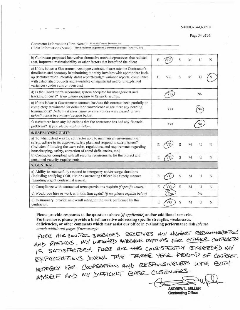
N40083-1 4-Q-32 IO
Page 34 of36
Contractor Information (Firm ame): Pure Air Control Services, Inc. Client l n formation ( ame ): Naval Fac1lrtie·-:s::-En:-::g-::-1ne ___ e-rm---g-=c-om_m_a_nd~s=-o-u1,.-heas_l(_N---AV-F-AC-SE_) ___ ____ _
b) Contractor proposed innovative alternative methods/processes that reduced E ~ s cost, improved maintainability or other factors that benefited the client
M u N
c) If this is/was a Government cost type contract, please rate the Contractor' s timeliness and ~ccuracy in submitting monthly invoices with appropriate back- v u~ docume~tat1on, monthly status reports/budget variance reports, compliance E VG s M u w1t~1 established budgets and avoidance of significant and/or unexplained variances (under runs or overruns)
d) ls the Contractor's accounting system adequate for manao-ement and tracking of costs? if no. please explain in Remarks section.~ <!!iJ No
e) If this i s/was~ Government contract, has/was this contract been partially or com~let~ ly term mated for default or convenience or are there any pending Yes 8 term 111at1ons? Indicate if show cause or cure notices were issued. or any default action in comment section below.
f) Have there been any indications that the contractor has had any financial Yes e problems? If yes, please explain below.
6. SAFETY/SECU RITY
a) To what extent was the contractor able to maintain an environment of safety, adhere to its approved safety plan, and respond to safety issues?
E @ s (Includes: '.allowing the user~ rules, regulations, and requirements regarding M u N
housekeeo11111, safetv, correction of noted deficiencies, etc.) b) Contractor complied with all security requirements for the project and
E fJJ s M u personnel security requirements.
7. G ENERAL
a_) Abil~ty to s~c~essfully respond to emergency and/or surge situations
@ ( 111cl u~111g not1fy111g COR, PM or Contracting Officer in a timely manner E s M u N regarding urgent contractual issues). -b) Compliance with contractual terms/provisions (explain if.specific issues) E (Vg) s M u N
c) Would you hire or work with this firm again? (If no. please explain below) ~ No
d) In summary, provide an overall rating for the work performed by this E CV s M u contractor.
Please provide responses to the questions above (if applicable) and/or addi tional remarks. Furt1.1ern~o re, please provide a brief narrative addressing specific strengths, weaknesses, defic1enc1es, or other comments which may assist our office in evaluating per forma nce risk (please atlach additional pages if necessary) :
pue€. A-1..e. ~~ ~®eVrl'E<s e€~\v'€5 W\y' -Ht~ ~""(e/_M-7io~~ ArJ!> ~~&S. wty ~ii:t'6~~_!) M~ '21\-7'..isS ~ 6~"2.. CDN~t:fi. l<t; $ J¥"(\ $F~oe__'f. Pu'2JZ A-'(Z_ ~ Ct>~ i'S'"«E.~IL 'f a:.~~'S) w..y'
~P~c~4-'"?\&~ )t-<.--e.~ ~<=2: ~~ YE'At'L .P~op eF ~. N~Y F~ ~~D~ A-NJ:> 2£5~\\€\JfS'3, ~ ~~ tv''f'!,fel.F Af" !:> W'..'( _b\.Q;l CUC( 9 <\-~z_ C .. u'.S<Z:MAEI<'~-::::, , ' (lD
-€$c-:z~~ ANDREW L Miu.ER Contracting omcer

Case StudyFlorida State University
w w w . p u r e a i r c o n t r o l s . c o m 1 . 8 0 0 . 4 2 2 . 7 8 7 3 4 9 1 1 C r e e k s i d e D r , S t e C , C l e a r w a t e r F L 3 3 7 6 0
Steam Coil Cleaning Saves
$800K Energy Consumption
Annually for University
Tallahassee, FL -- Pure Air Control Services, an industry leader in mechanical and environmental cleaning technologies, tackledhead-on, Florida State’s (FSU’s) dirty coils to provide the students and teachers a healthier learning environment.
Cleaning the coil with the Environmentally Friendly, and proven PURE-Steam method from the foam/rinse method that only superficially cleaned the surface of the coil and pushed small debris along with residue, further into the coil causing decreased air flow, a musty odor, and decreased temperature and humidity control and decreased the quality of the indoor air.
T h e P r o j e c t :
0
500K
1Mil
1.5Mil
2Mil
2.5Mil
3Mil
4Mil
Estimated 1stYr 2ndYr 3rdYr
$4 Mil Est - 5 year Savings
4thYr 5thYr© 2014 Building Remediation Sciencesa division of Pure Air Control Services, Inc.
a Coil Sterilization ProcessTM
The totally GREEN HVAC sanitizing process
*
*4 Million in saving over the course of the 5 year plan
b e f o r e
a f t e r
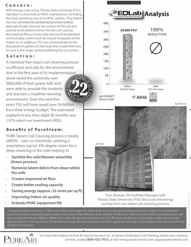
With energy costs rising, Florida State University (FSU), had taken a close look at HVAC maintenance, including the total operating cost of its HVAC system. They found that the conventional coil cleaning foam/rinse method only superficially cleaned the surface of the coil and pushed small debris further into the coil causing decreased air flow, a musty odor, decreased temperature and humidity control and decreased thequality of the indoor air. In addition, FSU was concerned about the thousands of gallons of chemicals that would otherwise be sent in the water system polluting the eco system.
C o n c e r n :
a f t e r
©2
01
4
PU
RE
AI
R
Co
nt
ro
ls
0
5K
10K
15K
20K
25K
30K
35K
40K
BeforeCFU/Per Gram
AfterCFU/ Per Gram
34,000 CFU
Lab ID #04077WO# 012589
Analysis
100%
REDUCTION
S o l u t i o n :
B e n e fi t s o f P u r e S t e a m :
A chemical free steam coil cleaning process so efficient and safe for the environment that in the first year of its implementation alone saved the university over $800,000 of their power bills and were able to provide the students and teachers a healthier learning environment. Over the next five years FSU will have saved over $4 Million from their energy budget. The estimated payback in less than eight (8) months was 157% return on investment (ROI).
b e f o r e
PURE-Steam Coil Cleaning process is totally GREEN – uses no chemicals, utilizing a proprietary (up to) 350 degree steam for a deep cleansing of the coils helping to
· Sanitize the coils/blowers assembly
(Green process)
· Removes latent debris from deep within
the coils
· Creates improved air flow
· Create better cooling capacity
· Saving energy (approx .22 cents per sq ft)
· Improving indoor air quality
· Extends HVAC equipment life
“I would estimate we are saving 7-10% on the chilled water equipment. Some of this is from reduced fan energy and the rest is from an increased delta T
across the coil which reduces pumping energy and increases chiller efficiency. As an estimate 35-40% of our utility bills are for HVAC so just keeping our coils
clean should save between $600K to $800K off our utility bills annually at the low end. As for ROI if you use the most conservative numbers we have paid
approximately $0.14 per square foot for coil cleaning to date. We have saved about $0.22 per square foot annually. So the payback is less than 8 months and
the ROI 157% annually.”
A
5
10
Lab IDWO# 0
vironment ementationrnd
ents ng
ve$4 Milliioonnestimated
months was
ntation
ll
Tom Shewan, PE Facilities Manager with Florida State University (FSU) discusses the energy
savings from our steam coil cleaning process:
For more information on Pure Air Service Services, Inc,. its Steam Sterilization Coil Cleaning, and/or duct-cleaning services, contact(800) 422-7873, or visit www.pureaircontrols.com, [email protected].

Case StudyGeorgia Institute of Technology
w w w . p u r e a i r c o n t r o l s . c o m 1 . 8 0 0 . 4 2 2 . 7 8 7 3 4 9 1 1 C r e e k s i d e D r , S t e C , C l e a r w a t e r F L 3 3 7 6 0
PURE-Steam Coil Cleaning Help
Georgia Tech Save Energy
and Improve IAQ
Georgia Tech (GT), founded in 1885, covers over 400 acres, 275 buildings, 9 million sq ft, occupied by over 25K students. GT is a leading technology and science university renowned for their deeply-held commitment to improving the human condition. The faculty and students are solving some of the world’s most pressing challenges: clean and sustainable energy; disease diagnosis and treatment; and national defense and security, among others. The campus of GT participates in the GREEN BUZZ and Leadership in Energy and Environmental Design (LEED) a third-party certification program and the nationally accepted benchmark for the design, construction and operation of high-performance green buildings.
T h e P r o j e c t :
© 2014 Building Remediation Sciencesa division of Pure Air Control Services, Inc.
a Coil Sterilization ProcessTM
The totally GREEN HVAC sanitizing process
BE
FO
RE
AF
TE
R

With energy costs rising, Georgia Tech University had taken a close look at HVAC maintenance, including the total operating cost of its HVAC system. They found that the conventional coil cleaning foam/rinse method only superficially cleaned the surface of the coil and pushed small debris further into the coil causing decreased air flow, a musty odor, decreased temperature and humidity control and decreased the quality of the indoor air. In addition, GT was concerned about the thousands of gallons of chemicals that would otherwise be sent in the water system polluting the eco system.
The forward thinking facilities staff at GT felt these dirty coils were nothing but a pot of gold buried in dust and debris in these air handling systems. They were right.
C o n c e r n :
©2
01
4
PU
RE
AI
R
Co
nt
ro
ls
S o l u t i o n :
B e n e fi t s o f t h e P U R E - S t e a m
C o i l C l e a n i n g p r o c e s s :
Due to Georgia Techs desire for going green, saving energy and providing a healthy learning environment for staff, guests and students they turned to the scientitists at Pure Air Control Services and the uniquely developed process of cleaning coils: PURE-Steam Coil Cleaning. The process is totally green (no chemicals) certified by the Green Clean Institute (one of the few in the country) and has a proven track record for saving energy, improving indoor air quality and improving comfort.
PURE-Steam Coil Cleaning process is totally GREEN – uses no chemicals, utilizing a proprietary (up to) 350 degree steam for a deep cleansing of the coils helping to
· Sanitize the coils/blowers assembly
(Green process)
· Removes latent debris from deep within
the coils
· Creates improved air flow
· Create better cooling capacity
· Saving energy (approx .22 cents per sq ft)
· Improving indoor air quality
· Extends HVAC equipment life
For more information on Pure Air Service Services, Inc,. its Steam Sterilization Coil Cleaning, and/or duct-cleaning services, contact(800) 422-7873, or visit www.pureaircontrols.com, [email protected].
0
20
40
60
80
100
160
140
120
Average Mold
Spore Count ( cts/m2)
Mic
rob
ial
Re
du
cti
on
Air
Flo
w I
mp
rov
em
en
t
Before
Analysis Preformed by
After
Total Air Flow
Improvement = 24%
Measured in Pascals (Pa)
97.01%
Drop withPURE-Steam
Standard
Cleaning
Leaves
Contaminants
Extremely Dirty Air Flow
Clean CoilAir Flow
Before PURE-Steam 37.125%
After PURE-Steam 28.025%

Case StudyUniversity of South Florida
w w w . p u r e a i r c o n t r o l s . c o m 1 . 8 0 0 . 4 2 2 . 7 8 7 3 4 9 1 1 C r e e k s i d e D r , S t e C , C l e a r w a t e r F L 3 3 7 6 0
USF Housing Saves
Energy while improving IAQ
The University of South Florida (USF) founded in 1956, covers over 1900 acres, 250 buildings, 10 million sq ft, 34 residence halls occupy over 5,000 on campus beds, with an enrollment of over 48K students, making USF the
Carnegie Foundation for Advancement of Teaching in the top tier of research universities, and is among three other
The campus of USF participates in the Leadership in Energy and
and the nationally accepted benchmark for the design, construction and operation of high-performance green buildings.
T h e P r o j e c t :
© 2014 Building Remediation Sciencesa division of Pure Air Control Services, Inc.
a Coil Sterilization ProcessTM
The totally GREEN HVAC sanitizing process
Be
fore
Aft
er

With energy costs rising, USF Housing had taken a close look at HVAC maintenance, including the total operating cost of its HVAC system. They found that the conventional coil cleaning
coil and pushed small debris further into the coil causing decreased
and decreased the quality of the indoor air. In addition, USF Housing was concerned about the thousands of gallons of chemicals that would otherwise be sent in the water system polluting the aquatic ecosystem.
were nothing but a pot of gold buried in dust and debris in these air handling systems. They were right. The energy savings, improved IAQ
T h e C o n c e r n : M a g n o l i a H a l l
Due to USF Housing desire for going green, saving energy and providing
to the scientitists at Pure Air Control Services and the uniquely developed process of cleaning coils: PURE-Steam Coil Cleaning. The process is totally
in the country) and has a proven track record for saving energy, improving indoor air quality and improving comfort. To date, Pure Air Control Services has environmentally cleaned over 500 AHU systems at USF Housing with PURE-Steam Coil Cleaning.
An example of the improved conditions at USF Housing:
Caster Hall
Magnolia Hall 38.7%
20%
· Saving energy
· Better cooling capacity
· Improved indoor air quality
· Extending HVAC equipment life
· Sterilized odor free coils
· Totally GREEN - No harsh chemicals dumped into
the ecosystem
T h e S o l u t i o n :
For more information on Pure Air Service Services, Inc,. its Steam Sterilization Coil Cleaning, and/or duct-cleaning services, contact(800) 422-7873, or visit www.pureaircontrols.com, [email protected].
©2
01
4
PU
RE
AI
R
Co
nt
ro
ls
Alan,
I would like at this time to pass along to you our complete satisfaction on all the work PureAir Control
Services has been providing us here at USF Housing and Residential Education. Over the course of the
past two years since we brought you and your company on board we have experienced nothing less
than positive results in all the buildings HVAC systems which you have pure-steamed. It has greatly
improved and extended the operation of the equipment and systems, enhanced the air quality for all of
our residential students and cut back on maintenance work requests. You l timeline’s/deadlines and following
in the residential setting.
We look forward to working with you and PureAir in the future preventive maintenance projects in our
residential buildings on campus.Thank you again,
Mark D. HauserUniversity of South FloridaAssociate Director Housing & Residential Education
Facilities Maintenance
July 11, 2014
HOUSING & RESIDENTIAL EDUCATION
University of South Florida 4202 East Fowler Avenue, RAR229 Tampa, FL 33620-7700
(813) 974-001 Fax (813) 974-5152 www.housing.usf.edu
“Over the course of the past two years since we brought you and your company (Pure Air Control Services) on board we have experienced nothing less than positive results in all the buildings HVAC systems which you have PURE-Steamed. It has and extended the operation of the equipment and systems, enhanced the air quality for all of our residential students and cut back on maintenance work requests.”
- Mark Hauser, Associate Director of USF Housing& Residential Education
Extremely Dirty Air Flow40 - 50%
Clean CoilAir Flow
95 - 100%
Before PURE-Steam 463 CFM
After PURE-Steam 640 CFM
or 38.7%
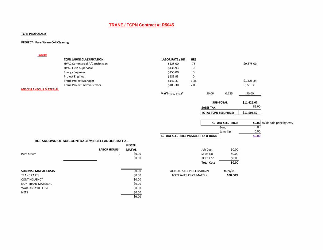
TCPN PROPOSAL #
PROJECT: Pure Steam Coil Cleaning
TCPN LABOR CLASSIFICATION LABOR RATE / HR HRS
HVAC Commercial A/C technician $125.00 75 $9,375.00HVAC Field Supervisor $135.93 0Energy Engineer $155.00 0Project Engineer $135.93 0Trane Project Manager $141.37 9.38 $1,325.34Trane Project Administrator $103.30 7.03 $726.33
MISCELLANEOUS MATERIAL
Mat'l (sub, etc.)* $0.00 0.725 $0.00
$11,426.67
SALES TAX 81.90
TOTAL TCPN SELL PRICE: $11,508.57
$0.00 divide sale price by .945Bond 0.00Sales Tax 0.00
ACTUAL SELL PRICE W/SALES TAX & BOND $0.00
LABOR HOURS
MISCELL
MAT'AL Job Cost $0.00Pure Steam 0 $0.00 Sales Tax $0.00
0 $0.00 TCPN Fee $0.00Total Cost $0.00
SUB MISC MAT'AL COSTS $0.00 #DIV/0!
TRANE PARTS $0.00 100.00%
CONTINGUENCY $0.00NON‐TRANE MATERIAL $0.00WARRANTY RESERVE $0.00NETS $0.00
$0.00
TCPN SALES PRICE MARGIN
TRANE / TCPN Contract #: R5045
SUB‐TOTAL
LABOR
ACTUAL SELL PRICE:
BREAKDOWN OF SUB-CONTRACT/MISCELLANOUS MAT'AL
ACTUAL SALE PRICE MARGIN

Tampa Bay Trane
902 North Himes Avenue P.O. Box 18547
Tampa, Florida, 33609
813-877-8251 800-966-8251 Toll Free
813-877-8252 Service Dispatch
800-966-8252 Toll Free Service Dispatch 813-877-8257 Fax
www.tampabaytrane.com
August 13, 2014 Pure Air Control Services Inc. 4911 Creekside DriveSuite C Clearwater, Fl. 33760 Attention: Alan L. Wosniak
Re: Lakeland Regional Medical Center (LRMC)
1324 Lakeland Hills Blvd. Lakeland, FL 33805 Air-Handler M8-03 Remediation
Dear Mr. Wosniak, I wanted to personally thank you for the Environmental Remediation Summary Report that I received from your office today. Additionally, I want to really thank you, your account manager, the project manager and your entire staff and work crew for the great effort and professionalism they put forth in meeting the immediate needs and concerns of one of my best customers. Even though you personally were out of the state on business, your staff was able to complete a job-site visit, schedule the coils for remediation and actually start the project on less than 12-hours’ notice. Everything your staff did while working with the facilities staff at Lakeland Regional Medical Center was handled with true professionalism. We all went into this project not knowing what we were going to find with this impacted chilled water coil, or how long it would take to correct the problem. Even though it took four separate steam cleanings to correct the problem, myself and the Hospital Facilities Staff were always kept up to date on the situation and the progress of the cleanings. It has been a pleasure doing business with you and your staff and I hope to continue to do business with you in the future. Thank you Alan. Rick Gerun Trane Building Services Account Manager Tampa Bay Trane 902 N. Himes Avenue Tampa, Fl. 33609 813-877-8251 X 1272 813-309-8024 Cell [email protected]
Tampa Bay Trane

1
Clint Pechacek
From: Deborah Bushnell <[email protected]>Sent: Thursday, August 21, 2014 11:44 AMTo: Spencer, GregCc: Stuart Verdon; Jack Cutting; Lorraine VuongSubject: Trane Product Update
Good Morning Greg, Please accept this correspondence as official TCPN acceptance and approval to add Pure Steam Coil Cleaning to Trane contract # R5045 for HVAC Equipment, Refrigeration, Installation, Service, and Related Products. This update is effective immediately and support documentation has been added to your contract file. If I can be of further assistance please let me know. Thank you for your ongoing support. Deborah Bushnell Contracts/Compliance Manager
11280 West Road Houston, TX 77065 713-554-0460 (Direct) 832-814-9985 (Cell) [email protected] www.tcpn.org
From: Jack Cutting Sent: Wednesday, August 20, 2014 11:52 AM To: Deborah Bushnell Cc: Stuart Verdon; Spencer, Greg Subject: FW: Verification of pricing for Trane Quote dated August 4, 2014 TCPN # 40-10325-14-022 Deborah, Good morning. Please see the request from Greg Spencer at Trane to add Pure Steam Coil Cleaning to their contract R 5045. After review, I recommend that TCPN approve this request. Thanks, Jack Cutting, C.P.M. Contract Manager
TCPN 11280 West Road Houston, TX 77065 713-554-3512 Office 713-775-9074 Cell [email protected] www.tcpn.org

2
This message contains information that may be confidential and privileged. Unless you are the addressee (or authorized to receive for the addressee), you may not use, copy or disclose to anyone the message or any information contained in the message. If you have received this message in error, please notify the sender by reply e-mail, and delete the message and any attachments.
From: Spencer, Greg [mailto:[email protected]] Sent: Wednesday, August 20, 2014 11:10 AM To: Jack Cutting Cc: Stuart Verdon Subject: RE: Verification of pricing for Trane Quote dated August 4, 2014 TCPN # 40-10325-14-022 Morning and yes, I’ll get the audit. Am in Houston helping training the Houston service folks. Looking forward to our meeting tomorrow. Anything specific other than a general update? I’d like to submit, today, a new coil cleaning service that we could bring to the market. Jon Symko was already aware of the company and suggested we meet. I’ve had several discussions, checked some of the references and reviewed how we would run the business thru R5045. They certainly fit into 3‐4 of the existing labor classifications and seem to be a good fit. I’m attaching Form A for your review. Thanks Greg Spencer TCPN Strategic Program Leader Office: 972‐406‐6090 Cell: 469‐442‐6055
From: Jack Cutting [mailto:[email protected]] Sent: Wednesday, August 20, 2014 11:01 AM To: Spencer, Greg Cc: Stuart Verdon Subject: FW: Verification of pricing for Trane Quote dated August 4, 2014 TCPN # 40-10325-14-022 Importance: High Greg, Good morning. Please see Donna’s request below. It looks like she is going to run all the Trane proposals by us. Let me know if you need anything from me. Thanks, Jack From: SAPP, DONNA D. [mailto:[email protected]] Sent: Wednesday, August 20, 2014 10:52 AM To: Jack Cutting Subject: Verification of pricing for Trane Quote dated August 4, 2014 TCPN # 40-10325-14-022 Importance: High

3
Good morning Jack, Can you verify this quote for me also per the TCPN Contract? Thank you and have a great day! Donna Sapp
Purchasing Department [email protected]
772-429-3990
Please Note: Florida has broad public records laws. E‐mails and e‐mail addresses received by the School District are public records and available to the public for inspection and copying. If you do not want your e‐mail or e‐mail address released in response to a public records request, then do not send e‐mails to the School District. Furthermore, the School District cannot guarantee that e‐mail transmissions are secure and error free. Therefore, the School District is not responsible for any errors or omissions in the contents of this e‐mail that may occur during its transmission. Finally, if you request that confidential records be sent by e‐mail, then you assume all risk that confidential information may be disclosed during transmission. St. Lucie Public Schools
The information contained in this message is privileged and intended only for the recipients named. If the reader is not a representative of the intended recipient, any review, dissemination or copying of this message or the information it contains is prohibited. If you have received this message in error, please immediately notify the sender, and delete the original message and attachments.
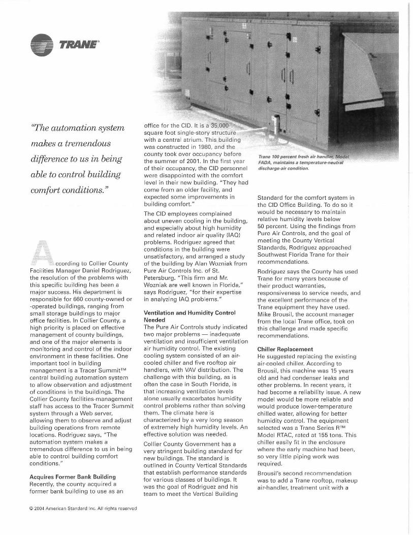

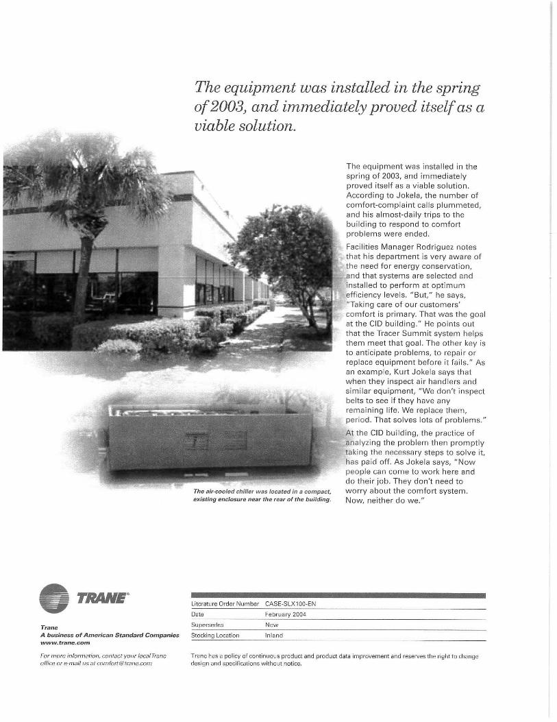


SAFETY WARNING
Only qualified personnel should install and service the equipment. The installation, starting up, and servicing of solar heating and power equipment can be hazardous and requires specific knowledge and training. Improperly installed, adjusted or altered equipment by an unqualified person could result in death or serious injury. When working on the equipment, observe all precautions in the literature and on the tags, stickers, and labels that are attached to the equipment.
Solar PanelsPhotovoltaic (PV) Modules, Thermal Collectors, andHybrid Photovoltaic/Thermal Collectors (PVT)
December 2011
Installation, Operation,
and Maintenance
SOL-SVX01A-EN
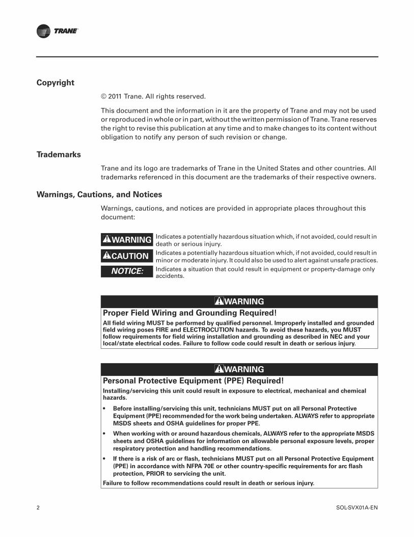
2 SOL-SVX01A-EN
Copyright
© 2011 Trane. All rights reserved.
This document and the information in it are the property of Trane and may not be used or reproduced in whole or in part, without the written permission of Trane. Trane reserves the right to revise this publication at any time and to make changes to its content without obligation to notify any person of such revision or change.
Trademarks
Trane and its logo are trademarks of Trane in the United States and other countries. All trademarks referenced in this document are the trademarks of their respective owners.
Warnings, Cautions, and Notices
Warnings, cautions, and notices are provided in appropriate places throughout this document:
WARNINGIndicates a potentially hazardous situation which, if not avoided, could result in death or serious injury.
CAUTIONsIndicates a potentially hazardous situation which, if not avoided, could result in minor or moderate injury. It could also be used to alert against unsafe practices.
NOTICE: Indicates a situation that could result in equipment or property-damage only accidents.
WARNING
Proper Field Wiring and Grounding Required!
All field wiring MUST be performed by qualified personnel. Improperly installed and grounded field wiring poses FIRE and ELECTROCUTION hazards. To avoid these hazards, you MUST follow requirements for field wiring installation and grounding as described in NEC and your local/state electrical codes. Failure to follow code could result in death or serious injury.
WARNING
Personal Protective Equipment (PPE) Required!
Installing/servicing this unit could result in exposure to electrical, mechanical and chemical hazards.
• Before installing/servicing this unit, technicians MUST put on all Personal Protective
Equipment (PPE) recommended for the work being undertaken. ALWAYS refer to appropriate
MSDS sheets and OSHA guidelines for proper PPE.
• When working with or around hazardous chemicals, ALWAYS refer to the appropriate MSDS
sheets and OSHA guidelines for information on allowable personal exposure levels, proper
respiratory protection and handling recommendations.
• If there is a risk of arc or flash, technicians MUST put on all Personal Protective Equipment
(PPE) in accordance with NFPA 70E or other country-specific requirements for arc flash
protection, PRIOR to servicing the unit.
Failure to follow recommendations could result in death or serious injury.
Table of Contents
SOL-SVX01A-EN 3
Overview . . . . . . . . . . . . . . . . . . . . . . . . . . . . . . . . . . . . . . . . . . . . . . . . . . . . . . . . . . . . . . 5
Model Number Description . . . . . . . . . . . . . . . . . . . . . . . . . . . . . . . . . . . . . . . . . . 5
Unit Nameplate . . . . . . . . . . . . . . . . . . . . . . . . . . . . . . . . . . . . . . . . . . . . . . . . . . . . 5
Handling, Inspecting, and Storing Solar Products . . . . . . . . . . . . . . . . . . . . . . 5
First Aid Measures (Applies to Thermal and Hybrid PVT Collectors) . . . . . . 6
Care and Maintenance . . . . . . . . . . . . . . . . . . . . . . . . . . . . . . . . . . . . . . . . . . . . . . 6Periodic Maintenance Schedule . . . . . . . . . . . . . . . . . . . . . . . . . . . . . . . . . . 6Exterior System Cleaning . . . . . . . . . . . . . . . . . . . . . . . . . . . . . . . . . . . . . . . 7Exterior System Inspection . . . . . . . . . . . . . . . . . . . . . . . . . . . . . . . . . . . . . . 7Solar Solution Testing . . . . . . . . . . . . . . . . . . . . . . . . . . . . . . . . . . . . . . . . . 7Mechanical Maintenance . . . . . . . . . . . . . . . . . . . . . . . . . . . . . . . . . . . . . . . 7Electrical Maintenance . . . . . . . . . . . . . . . . . . . . . . . . . . . . . . . . . . . . . . . . . 8Warranty . . . . . . . . . . . . . . . . . . . . . . . . . . . . . . . . . . . . . . . . . . . . . . . . . . . . 8
Photovoltaic (PV) Modules Solar Panel System . . . . . . . . . . . . . . . . . . . . . . . . . . . . 9
Recommendations . . . . . . . . . . . . . . . . . . . . . . . . . . . . . . . . . . . . . . . . . . . . . . . . . 9
Precautions . . . . . . . . . . . . . . . . . . . . . . . . . . . . . . . . . . . . . . . . . . . . . . . . . . . . . . 10
Model Number Description . . . . . . . . . . . . . . . . . . . . . . . . . . . . . . . . . . . . . . . . . 11
Characteristics . . . . . . . . . . . . . . . . . . . . . . . . . . . . . . . . . . . . . . . . . . . . . . . . . . . . 11
PV Panel Dimensions and Series . . . . . . . . . . . . . . . . . . . . . . . . . . . . . . . . . . . . 12TPVM72A Series . . . . . . . . . . . . . . . . . . . . . . . . . . . . . . . . . . . . . . . . . . . . . 12TPVP60B Series . . . . . . . . . . . . . . . . . . . . . . . . . . . . . . . . . . . . . . . . . . . . . . 13TPVP72B Series . . . . . . . . . . . . . . . . . . . . . . . . . . . . . . . . . . . . . . . . . . . . . 13TPVM96A Series . . . . . . . . . . . . . . . . . . . . . . . . . . . . . . . . . . . . . . . . . . . . . 13TPVM72B Series . . . . . . . . . . . . . . . . . . . . . . . . . . . . . . . . . . . . . . . . . . . . . 14TPVM60B Series . . . . . . . . . . . . . . . . . . . . . . . . . . . . . . . . . . . . . . . . . . . . . 14
Installation Guidelines . . . . . . . . . . . . . . . . . . . . . . . . . . . . . . . . . . . . . . . . . . . . . 14
Wiring and Connection . . . . . . . . . . . . . . . . . . . . . . . . . . . . . . . . . . . . . . . . . . . . 16
Installation . . . . . . . . . . . . . . . . . . . . . . . . . . . . . . . . . . . . . . . . . . . . . . . . . . . . . . . 16
Grounding . . . . . . . . . . . . . . . . . . . . . . . . . . . . . . . . . . . . . . . . . . . . . . . . . . . . . . . 17
Mounting Grounding Clip to Frame . . . . . . . . . . . . . . . . . . . . . . . . . . . . . . . . . 18
Charge Controllers and Batteries . . . . . . . . . . . . . . . . . . . . . . . . . . . . . . . . . . . . 19
Tracking Systems . . . . . . . . . . . . . . . . . . . . . . . . . . . . . . . . . . . . . . . . . . . . . . . . . 19
Array - Initial Tests . . . . . . . . . . . . . . . . . . . . . . . . . . . . . . . . . . . . . . . . . . . . . . . . 19
Array - Full Tests . . . . . . . . . . . . . . . . . . . . . . . . . . . . . . . . . . . . . . . . . . . . . . . . . . 19
System Operation . . . . . . . . . . . . . . . . . . . . . . . . . . . . . . . . . . . . . . . . . . . . . . . . . 20
Commissioning and Warranty . . . . . . . . . . . . . . . . . . . . . . . . . . . . . . . . . . . . . . 20
Solar Thermal Collector Systems . . . . . . . . . . . . . . . . . . . . . . . . . . . . . . . . . . . . . . . 22
Model Number Description . . . . . . . . . . . . . . . . . . . . . . . . . . . . . . . . . . . . . . . . . 22
Thermal Panel Dimensions and Series . . . . . . . . . . . . . . . . . . . . . . . . . . . . . . . 23
4 SOL-SVX01A-EN
System Design Considerations . . . . . . . . . . . . . . . . . . . . . . . . . . . . . . . . . . . . . 23
Installation . . . . . . . . . . . . . . . . . . . . . . . . . . . . . . . . . . . . . . . . . . . . . . . . . . . . . . . 23Before Installation . . . . . . . . . . . . . . . . . . . . . . . . . . . . . . . . . . . . . . . . . . . . 23
Mounting Solar Thermal Collectors . . . . . . . . . . . . . . . . . . . . . . . . . . . . . . . . . 24Roof Kits . . . . . . . . . . . . . . . . . . . . . . . . . . . . . . . . . . . . . . . . . . . . . . . . . . . . 24Wind Uplift and Roof Safety . . . . . . . . . . . . . . . . . . . . . . . . . . . . . . . . . . . . 24
Mounting Types . . . . . . . . . . . . . . . . . . . . . . . . . . . . . . . . . . . . . . . . . . . . . . . . . . 25On-roof System Installation . . . . . . . . . . . . . . . . . . . . . . . . . . . . . . . . . . . . 25Flat-roof System Installation . . . . . . . . . . . . . . . . . . . . . . . . . . . . . . . . . . . 28In-roof System Installation . . . . . . . . . . . . . . . . . . . . . . . . . . . . . . . . . . . . . 28
Piping Connections . . . . . . . . . . . . . . . . . . . . . . . . . . . . . . . . . . . . . . . . . . . . . . . 29
Roof Penetrations . . . . . . . . . . . . . . . . . . . . . . . . . . . . . . . . . . . . . . . . . . . . . . . . . 30
Solar Pumping Stations . . . . . . . . . . . . . . . . . . . . . . . . . . . . . . . . . . . . . . . . . . . . 30
Solar Solution Controller (SSC) . . . . . . . . . . . . . . . . . . . . . . . . . . . . . . . . . . . . . 31
Commissioning and Warranty . . . . . . . . . . . . . . . . . . . . . . . . . . . . . . . . . . . . . . 32Thermal System Startup . . . . . . . . . . . . . . . . . . . . . . . . . . . . . . . . . . . . . . . 32Operation, Repair, and Troubleshooting . . . . . . . . . . . . . . . . . . . . . . . . . . 33
Hybrid PVT Collectors . . . . . . . . . . . . . . . . . . . . . . . . . . . . . . . . . . . . . . . . . . . . . . . . . . 37
Effective PV Performance and Operation Temperature . . . . . . . . . . . . . . . . . 37
The Benefits of Cooling a PV Module . . . . . . . . . . . . . . . . . . . . . . . . . . . . . . . . 37
Model Number Description . . . . . . . . . . . . . . . . . . . . . . . . . . . . . . . . . . . . . . . . . 37
Product Selection . . . . . . . . . . . . . . . . . . . . . . . . . . . . . . . . . . . . . . . . . . . . . . . . . 38
TPVT-T and TPVT-V Panel Dimensions . . . . . . . . . . . . . . . . . . . . . . . . . . . . . . . 39
Product Specifications . . . . . . . . . . . . . . . . . . . . . . . . . . . . . . . . . . . . . . . . . . . . . 40
System Design Considerations . . . . . . . . . . . . . . . . . . . . . . . . . . . . . . . . . . . . . 41
Installation Guidelines . . . . . . . . . . . . . . . . . . . . . . . . . . . . . . . . . . . . . . . . . . . . . 42
Commissioning and Warranty . . . . . . . . . . . . . . . . . . . . . . . . . . . . . . . . . . . . . . 43PVT System Start-up . . . . . . . . . . . . . . . . . . . . . . . . . . . . . . . . . . . . . . . . . . 45

SOL-SVX01A-EN 5
Overview
Note: One copy of this document ships inside the solar panel packaging and is the property of the customer. It must be retained by the maintenance personnel and stored in a safe place.
A solar thermal panel is normally referred to as a collector. A solar photovoltaic module is made up of solar cells and is either referred to as a solar panel or as a solar module.
Note: Throughout this manual the term collector describes a solar thermal collector and the terms panel or module describes a PV module.
Important: Carefully review the information within this manual and follow the instructions to avoid the risk of improper operation and/or minimize component damage. Review the installation and components with the building owner and representatives to explain the system operation and maintenance requirements.
This manual provides information about the following:
• Installation and maintenance considerations
• Model number description and unit nameplate
• Handling and inspecting solar products
• First-aid measures
• Care and maintenance
• Photovoltaic (PV) modules
• Solar thermal collector systems
• Hybrid photovoltaic/thermal (PVT) collectors
Model Number Description
All solar panels are identified by a multiple-character model number that precisely identifies a particular type. An explanation of the alphanumeric identification code is provided at the beginning of the section for each panel type that follows. The model number enables the owner/operator, installing contractors, and service engineers to define the operation, specific components, and other options for any specific unit.
When requesting service, refer to the specific model and serial numbers printed on the panel nameplate.
Unit Nameplate
A unit nameplate is affixed to each panel. It includes the unit model and serial numbers as well as other pertinent specifications.
Handling, Inspecting, and Storing Solar Products
As soon as the solar panels arrive at the job site:
• Handle with care, all system components and accessories during storage, transport and installation.
• Inspect packaging and components as soon as possible after delivery and before storing any of the items.
• If concealed damage is discovered, notify the carrier terminal about any damage immediately by phone and by mail. Concealed damage must be reported within fifteen (15) days. Request an immediate joint inspection of the damage by the carrier and the consignee. Do not remove damaged material from the receiving location. Take photos of the damage, if possible.
• Notify the appropriate sales representative before installing or repairing a damaged collector.

6 SOL-SVX01A-EN
Overview
• Verify that the nameplate data matches the data on the sales order and bill of lading (including electrical data).
• After installation, dispose of all packing materials appropriately and according to relevant waste disposal requirements.
• The following applies to Thermal and Hybrid PVT collectors:
• When handling solar solutions (for example, propylene glycol and corrosion inhibitors), avoid contact with the skin or eyes.
• During handling, wear long-sleeved, loose-fitting clothing, gloves, and eye protection.
• Solar solutions can reach high temperatures. Exercise caution around hot solutions and surfaces.
• Wash clothes separately from other clothing; rinse thoroughly.
• Take precautions when storing panels before installation. Utilize the shipping crates/containers and keep them in a safe and dry location before installation.
• The manufacturer will not assume any responsibility for equipment damage resulting from storage or handling neglect.
First Aid Measures (Applies to Thermal and Hybrid PVT Collectors)
Eye Contact:
Flush eyes thoroughly with water to remove contaminants. If symptoms persist, seek medical attention.
Skin Contact
Refer to the Material Safety Data Sheet (MSDS) for the exact products employed and carefully review and follow recommended safe handling and usage procedures.
Care and Maintenance
Periodic Maintenance Schedule
There are several periodic maintenance requirements for the PV, Thermal, and PVT systems. The follow sections describe the care and maintenance of this system. In addition, use the table below to inspect and maintain these systems for maximum performance.
Maintenance and Inspection Schedule
Activity Recommended FrequencyClean glass surfaces Quarterly or in weather events
Solar solution testing Quarterly or in replacement events
Pump service Per manufacturer requirements
Pump motor service Per Manufacturer Requirements
Controls Observe Settings and adjust as needed
Electrical System Annual inspection
Piping system inspection Quarterly inspection
SOL-SVX01A-EN 7
Overview
Exterior System Cleaning
Frequent cleaning of the glass surface is important for performance output. A build up of dust or dirt on the module(s) front face will result in a decreased energy output. The following are exterior cleaning guidelines:
• Exercise caution when carrying water buckets, hoses, squeegees, and cleaning solutions/supplies.
• The surface cleaning should be done at least quarterly, after dust storms, or after other weather events that may cause a limiting of the solar absorption.
• Use a mild soap solution in a spray bottles, a squeegee, and soft cloths to clean modules.
Important: Read the MSDS for the cleaning solution and follow proper handling procedures.
• Never use abrasive material under any circumstances.
• Examine the PV module(s) for signs of deterioration. Check all wiring for possible rodent damage, weathering, and ensure that all connections are tight and corrosion free. Check electrical leakage to ground.
• Check screws and mounting brackets and tracking systems to ensure they are tight.
• Tie-off if near a roof edge or on a wet or icy roof.
• Inspect the panels for cracked glass, cracked wiring and loose wires or conduit.
Exterior System Inspection
It is important to check for solar solution leaks quarterly. Leaks can indicate a dilution of the solar thermal solution which, if not tested and maintained, could allow freezing. Furthermore, make-up water can cause hardness build up on the inside of the heat transfer tubes which can deteriorate the system performance.
Solar Solution Testing
It is recommended that the solar solution be tested twice per year as a preventative measure. The freeze prevention is essential to prevent a system failure or damage to the collectors or system piping. With an automatic water make-up system, a pipe leak can cause exterior and interior building damage that is costly to repair. It is best to hire a professional to perform a closed circuit (solar solution) water chemistry testing. They will test for biological fouling, freeze protection, pH, and a few other chemical properties.
Mechanical Maintenance
Follow the pump and pump motor manufacturer recommendations for scheduled maintenance services and inspections. These inspections check the pump seals and casings for leaks, ensuring that any flexible couplings are in good order, and that bearing lubrication is performed, as needed or required.
Expansion tanks should also be inspected to ensure that the bladder and pressure control system is functioning. The pressure relief valves should be inspected to ensure that they are in good working condition, that the air vent valves are inspected for leaks, and that all storage tanks and their fittings checked for leaks.
WARNING
Hazardous Voltage!
Disconnect all electric power, including remote disconnects before servicing. Follow proper lockout/tagout procedures to ensure the power can not be inadvertently energized. Failure to disconnect power before servicing could result in death or serious injury.
8 SOL-SVX01A-EN
Overview
For domestic hot water systems, some authorities having jurisdiction may require that periodic disinfection of the systems in contact with drinking water or food preparation be inspected and/or tested.
Electrical Maintenance
Follow the manufacturer recommendations for preventive maintenance and inspections of the controls system and power system for the pumping system and automatic glycol feed system (if installed). It is important to also validate the controls settings during these inspections.
Ensure that all safety disconnects, junction boxes, connection points, string connectors, and other electrical connections are weatherproof and in good working condition.
Warranty
Trane PV Modules are guaranteed to be free of manufacturing defects for a period of 10 years from the date of collector delivery.
Performance Guarantee
The electrical output performance will guarantee the following:
• During the first ten (10) years from the date of sale, produce at least 92% of the minimum power output rating.
• During the first twenty (20) years from the date of sale, produce at least 84% of the minimum power output rating.
• During twenty-five (25) years from the date of sale, produce at least 80% of the minimum power output rating, where the minimum power output rating is the rated power minus the applicable tolerance.

SOL-SVX01A-EN 9
Photovoltaic (PV) Modules Solar Panel System
Solar photovoltaic systems consist of the following:
• Solar PV modules
• String connectors
• Manual disconnect switches and monitors (larger systems)
• Direct current (DC) to alternating current (AC) inverters
• Electrical power metering and monitoring equipment.
Each installation has a unique number and configuration of solar modules, inverters, and disconnects for its particular application and could contain automatic solar tracking systems.
The system designer has intentionally configured the solar photovoltaic system to fulfill its intended purpose.
Recommendations
• The installer, operations personnel, and maintenance/repair personnel or contractors should become familiar with the design drawings, system specifications, and product submittals. In particular, this personnel should become familiar with the controls design and as-built controls drawings so that the designer's intentions and actual installation characteristics are well understood.
• The system designer or installer should provide operator training to the individuals responsible for the day-to-day operations and maintenance of the systems.
• A licensed contractor and/or certified solar installer should be employed to properly install and commission solar photovoltaic systems.
In most applications, PV modules should be installed in a location where they will receive maximum sunlight throughout the year. In the Northern Hemisphere, the modules should typically face south, and in the Southern Hemisphere, the modules should typically face north. Modules facing 30 degrees away from true South (or North) will lose approximately 10 to 15 percent of power output. If the module faces 60 degrees away from true South (or North), the power loss will be 20 to 30 percent. When choosing a site, avoid trees, buildings or obstructions, which could cast shadows on the array.
Once the system is commissioned (tested, properly adjusted, and proven to be installed safely to fulfill its intended purpose), the electrical safety disconnects are closed and the system begins to allow the energy from the sun to produce electrical current. The system will automatically direct the power produced to the power distribution system within the operating range of the array and inverter.
Monitoring systems should be used so that operators can be made aware of system malfunctions. When alarm conditions arise, trained personnel should be engaged to perform trouble-shooting and system repairs. Figure 1 shows an example of a typical PVT installation.
PV
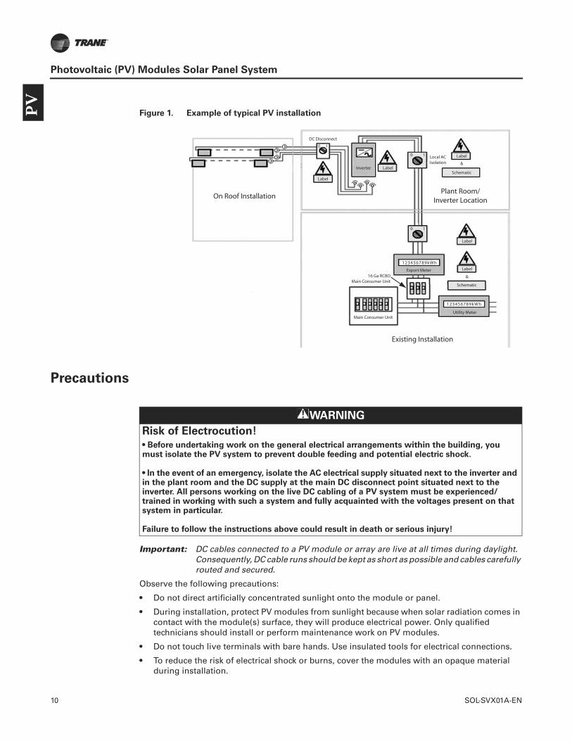
10 SOL-SVX01A-EN
Photovoltaic (PV) Modules Solar Panel System
Figure 1. Example of typical PV installation
Precautions
Important: DC cables connected to a PV module or array are live at all times during daylight. Consequently, DC cable runs should be kept as short as possible and cables carefully routed and secured.
Observe the following precautions:
• Do not direct artificially concentrated sunlight onto the module or panel.
• During installation, protect PV modules from sunlight because when solar radiation comes in contact with the module(s) surface, they will produce electrical power. Only qualified technicians should install or perform maintenance work on PV modules.
• Do not touch live terminals with bare hands. Use insulated tools for electrical connections.
• To reduce the risk of electrical shock or burns, cover the modules with an opaque material during installation.
0 1
0 1
Label
LabelInverter
DC Disconnect
On Roof Installation
Existing Installation
Plant Room/Inverter Location
Label
Label
Schematic
Schematic
Utility MeterMain Consumer Unit
16 Ga RCBOMain Consumer Unit
Export Meter
123456789kWh
123456789kWh
Label
Local ACIsolation &
&
0 1
WARNING
Risk of Electrocution!
• Before undertaking work on the general electrical arrangements within the building, you must isolate the PV system to prevent double feeding and potential electric shock.
• In the event of an emergency, isolate the AC electrical supply situated next to the inverter and in the plant room and the DC supply at the main DC disconnect point situated next to the inverter. All persons working on the live DC cabling of a PV system must be experienced/trained in working with such a system and fully acquainted with the voltages present on that system in particular.
Failure to follow the instructions above could result in death or serious injury!
PV

SOL-SVX01A-EN 11
Photovoltaic (PV) Modules Solar Panel System
• If batteries are used with modules, follow manufacturer recommendations.
• Under normal conditions, a photovoltaic module is likely to experience conditions that produce more current and/or voltage than reported at standard test conditions. Accordingly, the value of Isc (short circuit current) and Voc (open circuit voltage) marked on this module should be multiplied by of 1.25 when determining component voltage ratings, conductor current ratings, fuse sizes, and the size of controls connected to the PV output.
• Do not attach any other devices (antennae, piping, conduit, and so on) to the collector racks
Model Number Description
Below is an illustration that describes the model number.
Characteristics
Standard Test Condition: Tc = 25°C, AM = 1.5, E = 1000W/m2
The electrical characteristics are within ±10 percent of the indicated values of Isc, Voc, and Pmax under standard test conditions (irradiance of 100 mW/cm2, AM 1.5 spectrum, and a cell temperature of 25°C [77 °F]).
Example Model Number: TPVM96A240
T PV M 96 A 240
Digit 1;Brand
T = Trane
PV = Photovoltaic
M = MonocrystallineP = Polycrystalline
60, 72, or 96
A = 125 mm x 125 mmB = 156 mm x 156 mm
240 = 240Wp (Typical) Characteristics
Digit 2, 3;Product
Digit 4;Crystalline Type
Digit 5, 6;Cell Count
Digit 7;Cell Size
(Area of Ea. Cell)
Digit 8, 9, 10;Power Peak
(Watts)
PV

12 SOL-SVX01A-EN
Photovoltaic (PV) Modules Solar Panel System
PV Panel Dimensions and Series
The following figure and tables provide information about PV system series.
Figure 2. Module dimensions
TPVM72A Series
A
B
C
Dimension A: 62.2 in. (1580 mm)
Dimension B: 31.8 in. (808 mm)
Dimension C: 1.8 in. (45 mm)
Max. power [W]: 180 185 190
Power tolerance: ±10%
Open-circuit voltage [V]: 43.2 43.2 43.8
Voltage at max. power [V]: 36.0 36.0 36.5
Current at max. power [A]: 5.00 5.14 5.20
Short-circuit current [A]: 5.60 5.76 5.83
Max. system voltage: 600VDC
Series fuse rating [A]: 10
PV

SOL-SVX01A-EN 13
Photovoltaic (PV) Modules Solar Panel System
TPVP60B Series
:
TPVP72B Series
TPVM96A Series
Dimension A: 65.0 in. (1650 mm)
Dimension B: 39.1 in. (992 mm)
Dimension C: 2.0 in. (50 mm)
Max. power [W]: 225 230
Power tolerance: ±10%
Open-circuit voltage [V]: 35.4 36.0
Voltage at max. power [V]: 29.5 30.0
Current at max. power [A]: 7.63 7.67
Short-circuit current [A]: 8.55 8.59
Max. system voltage: 600VDC
Series fuse rating [A]: 10
Dimension A: 77.0 in. (1956 mm)
Dimension B: 39.1 in. (992 mm)
Dimension C: 2.0 in. (50 mm)
Max. power [W]: 240 245 250 255 260 265 270 275 280
Power tolerance: ±10%
Open-circuit voltage [V]: 42.0 42.0 42.4 42.4 42.6 42.6 43.0 43.0 43.2
Voltage at max. power [V]: 35.0 35.0 35.3 35.3 35.5 35.5 35.8 35.8 36.0
Current at max. power [A]: 6.86 7.00 7.08 7.22 7.32 7.46 7.54 7.68 7.78
Short-circuit current [A]: 7.68 7.84 7.93 8.09* 8.2 8.36 8.45 8.60 8.72
Max. system voltage: 600VDC
Series fuse rating [A]: 10
Dimension A: 62.0 in (1575 mm)
Dimension B: 42.6 in. (1082 mm)
Dimension C: 2.0 in. (50 mm)
Max. power [W]: 200 205 210 215 220 225 230 235 240
Power tolerance: ±10%
Open-circuit voltage [V]: 56.4 56.4 57.0 57.0 57.6 57.6 57.6 58.2 58.2
Voltage at max. power [V]: 47.0 47.0 47.5 47.5 48.0 48.0 48.0 48.5 48.5
Current at max. power [A]: 4.26 4.36 4.42 4.53 4.58 4.69 4.79 4.85 4.95
Short-circuit current [A]: 4.77 4.88 4.95 5.07 5.13 5.25 5.36 5.43 5.55
Max. system voltage: 600VDC
Series fuse rating [A]: 10
PV
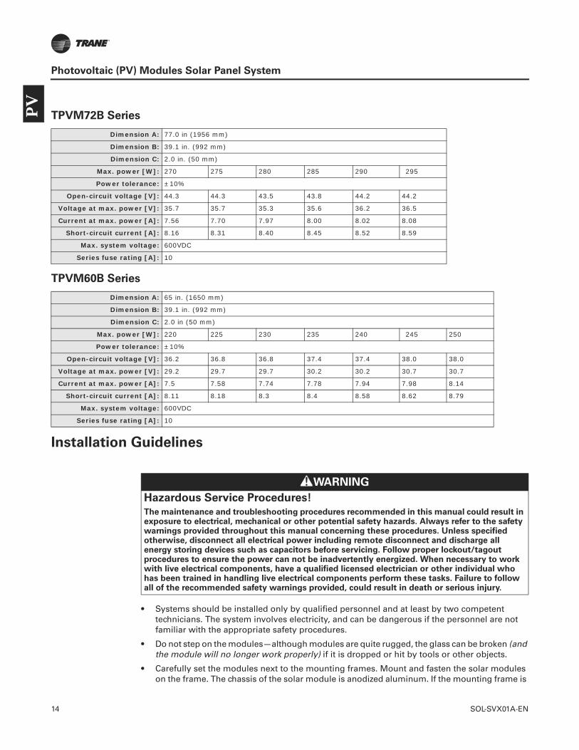
14 SOL-SVX01A-EN
Photovoltaic (PV) Modules Solar Panel System
TPVM72B Series
TPVM60B Series
Installation Guidelines
• Systems should be installed only by qualified personnel and at least by two competent technicians. The system involves electricity, and can be dangerous if the personnel are not familiar with the appropriate safety procedures.
• Do not step on the modules—although modules are quite rugged, the glass can be broken (and the module will no longer work properly) if it is dropped or hit by tools or other objects.
• Carefully set the modules next to the mounting frames. Mount and fasten the solar modules on the frame. The chassis of the solar module is anodized aluminum. If the mounting frame is
Dimension A: 77.0 in (1956 mm)
Dimension B: 39.1 in. (992 mm)
Dimension C: 2.0 in. (50 mm)
Max. power [W]: 270 275 280 285 290 295
Power tolerance: ±10%
Open-circuit voltage [V]: 44.3 44.3 43.5 43.8 44.2 44.2
Voltage at max. power [V]: 35.7 35.7 35.3 35.6 36.2 36.5
Current at max. power [A]: 7.56 7.70 7.97 8.00 8.02 8.08
Short-circuit current [A]: 8.16 8.31 8.40 8.45 8.52 8.59
Max. system voltage: 600VDC
Series fuse rating [A]: 10
Dimension A: 65 in. (1650 mm)
Dimension B: 39.1 in. (992 mm)
Dimension C: 2.0 in (50 mm)
Max. power [W]: 220 225 230 235 240 245 250
Power tolerance: ±10%
Open-circuit voltage [V]: 36.2 36.8 36.8 37.4 37.4 38.0 38.0
Voltage at max. power [V]: 29.2 29.7 29.7 30.2 30.2 30.7 30.7
Current at max. power [A]: 7.5 7.58 7.74 7.78 7.94 7.98 8.14
Short-circuit current [A]: 8.11 8.18 8.3 8.4 8.58 8.62 8.79
Max. system voltage: 600VDC
Series fuse rating [A]: 10
WARNING
Hazardous Service Procedures!
The maintenance and troubleshooting procedures recommended in this manual could result in exposure to electrical, mechanical or other potential safety hazards. Always refer to the safety warnings provided throughout this manual concerning these procedures. Unless specified otherwise, disconnect all electrical power including remote disconnect and discharge all energy storing devices such as capacitors before servicing. Follow proper lockout/tagout procedures to ensure the power can not be inadvertently energized. When necessary to work with live electrical components, have a qualified licensed electrician or other individual who has been trained in handling live electrical components perform these tasks. Failure to follow all of the recommended safety warnings provided, could result in death or serious injury.
PV
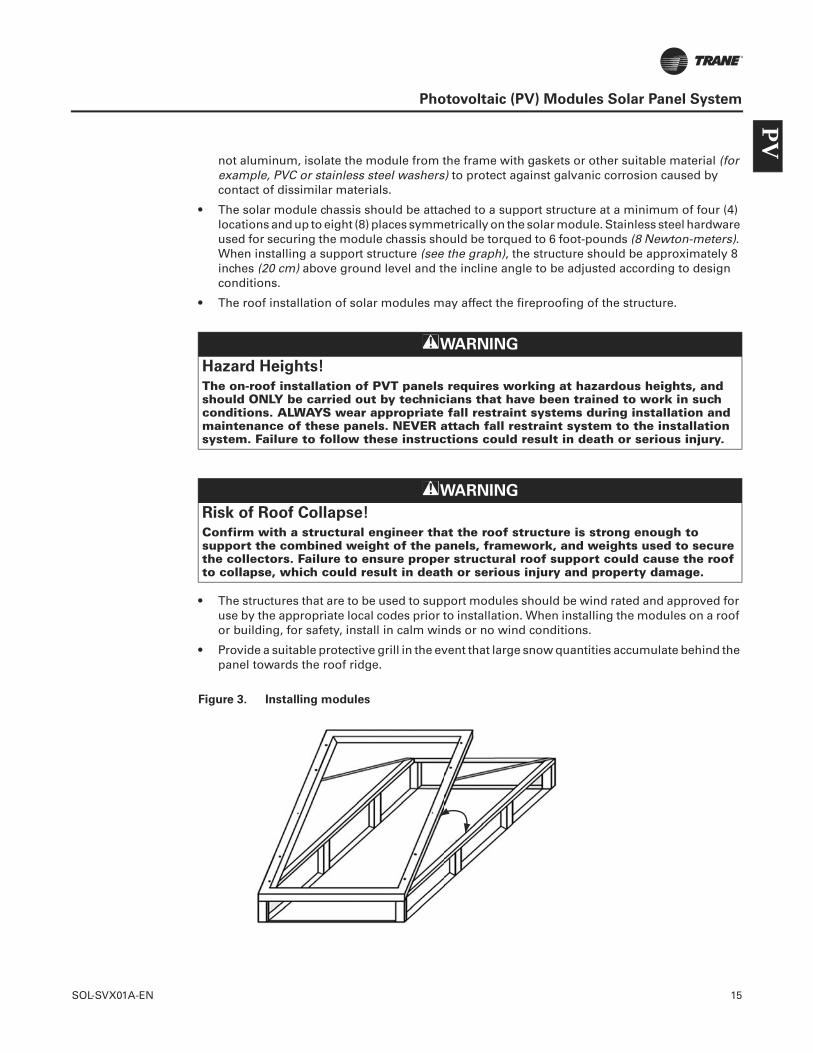
SOL-SVX01A-EN 15
Photovoltaic (PV) Modules Solar Panel System
not aluminum, isolate the module from the frame with gaskets or other suitable material (for example, PVC or stainless steel washers) to protect against galvanic corrosion caused by contact of dissimilar materials.
• The solar module chassis should be attached to a support structure at a minimum of four (4) locations and up to eight (8) places symmetrically on the solar module. Stainless steel hardware used for securing the module chassis should be torqued to 6 foot-pounds (8 Newton-meters). When installing a support structure (see the graph), the structure should be approximately 8 inches (20 cm) above ground level and the incline angle to be adjusted according to design conditions.
• The roof installation of solar modules may affect the fireproofing of the structure.
• The structures that are to be used to support modules should be wind rated and approved for use by the appropriate local codes prior to installation. When installing the modules on a roof or building, for safety, install in calm winds or no wind conditions.
• Provide a suitable protective grill in the event that large snow quantities accumulate behind the panel towards the roof ridge.
Figure 3. Installing modules
WARNING
Hazard Heights!
The on-roof installation of PVT panels requires working at hazardous heights, and should ONLY be carried out by technicians that have been trained to work in such conditions. ALWAYS wear appropriate fall restraint systems during installation and maintenance of these panels. NEVER attach fall restraint system to the installation system. Failure to follow these instructions could result in death or serious injury.
WARNING
Risk of Roof Collapse!
Confirm with a structural engineer that the roof structure is strong enough to support the combined weight of the panels, framework, and weights used to secure the collectors. Failure to ensure proper structural roof support could cause the roof to collapse, which could result in death or serious injury and property damage.
PV

16 SOL-SVX01A-EN
Photovoltaic (PV) Modules Solar Panel System
Wiring and Connection
The electrical installation shall be in accordance with CSA C22.1, Safety Standard for Electrical Installations, National Electric Codes, Part 1.
Note: Refer to Section 690-8 of the National Electrical Code™ (NEC) for an additional multiplying factor of 125 percent (80 percent derating) which may be applicable. For field connections, use minimum 12 AWG copper wires insulated for a minimum of 90°C.
Connect conductors between the PV modules in series or parallel connection. This is determined by the user configuration requirement for system power, current, and voltage. In a single component array, the maximum allowable number of modules connected in series is determined by local electrical codes. The total voltage of the array must not exceed the rated working voltage of the selected controller and inverter.
Installation
If possible, all DC wiring should be completed prior to installing a PV array. This will allow effective electrical isolation of the DC system (via the DC disconnect switch and PV module cable connectors) while the array is installed and effective electrical isolation of the PV array while the inverter is installed.
Typically this would require an installation of the following:
• DC disconnect switch and DC junction boxes.
• String/array positive and negative cables - from the DC disconnect/junction box to either end of the PV string/array.
• PV array main cables from DC switch to inverter.
This should be carried out in such a way that it should never be necessary for an installer to work in any enclosure or situation featuring simultaneously accessible live PV string positive and negative parts.
• Each module should be electrically tested individually and then interconnected as they are laid. Each module has a positive and negative connector on the back of the module. Modules should be interconnected into a series string as per the circuit diagram.
WARNING
Proper Field Wiring and Grounding Required!
All field wiring MUST be performed by qualified personnel. Improperly installed and grounded field wiring poses FIRE and ELECTROCUTION hazards. To avoid these hazards, you MUST follow requirements for field wiring installation and grounding as described in NEC and your local/state electrical codes. Failure to follow code could result in death or serious injury.
WARNING
Hazardous Voltage!
Disconnect all electric power, including remote disconnects before servicing. Follow proper lockout/tagout procedures to ensure the power can not be inadvertently energized. Failure to disconnect power before servicing could result in death or serious injury.
PV
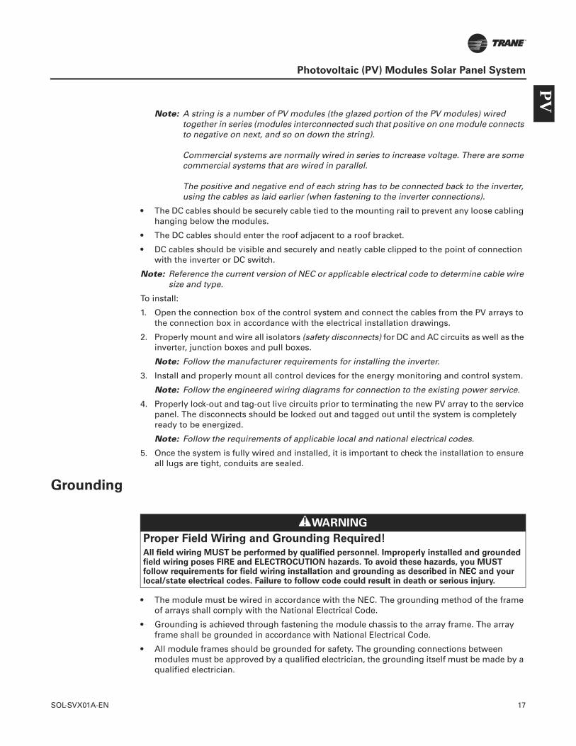
SOL-SVX01A-EN 17
Photovoltaic (PV) Modules Solar Panel System
Note: A string is a number of PV modules (the glazed portion of the PV modules) wired together in series (modules interconnected such that positive on one module connects to negative on next, and so on down the string).
Commercial systems are normally wired in series to increase voltage. There are some commercial systems that are wired in parallel.
The positive and negative end of each string has to be connected back to the inverter, using the cables as laid earlier (when fastening to the inverter connections).
• The DC cables should be securely cable tied to the mounting rail to prevent any loose cabling hanging below the modules.
• The DC cables should enter the roof adjacent to a roof bracket.
• DC cables should be visible and securely and neatly cable clipped to the point of connection with the inverter or DC switch.
Note: Reference the current version of NEC or applicable electrical code to determine cable wire size and type.
To install:
1. Open the connection box of the control system and connect the cables from the PV arrays to the connection box in accordance with the electrical installation drawings.
2. Properly mount and wire all isolators (safety disconnects) for DC and AC circuits as well as the inverter, junction boxes and pull boxes.
Note: Follow the manufacturer requirements for installing the inverter.
3. Install and properly mount all control devices for the energy monitoring and control system.
Note: Follow the engineered wiring diagrams for connection to the existing power service.
4. Properly lock-out and tag-out live circuits prior to terminating the new PV array to the service panel. The disconnects should be locked out and tagged out until the system is completely ready to be energized.
Note: Follow the requirements of applicable local and national electrical codes.
5. Once the system is fully wired and installed, it is important to check the installation to ensure all lugs are tight, conduits are sealed.
Grounding
• The module must be wired in accordance with the NEC. The grounding method of the frame of arrays shall comply with the National Electrical Code.
• Grounding is achieved through fastening the module chassis to the array frame. The array frame shall be grounded in accordance with National Electrical Code.
• All module frames should be grounded for safety. The grounding connections between modules must be approved by a qualified electrician, the grounding itself must be made by a qualified electrician.
WARNING
Proper Field Wiring and Grounding Required!
All field wiring MUST be performed by qualified personnel. Improperly installed and grounded field wiring poses FIRE and ELECTROCUTION hazards. To avoid these hazards, you MUST follow requirements for field wiring installation and grounding as described in NEC and your local/state electrical codes. Failure to follow code could result in death or serious injury.
PV
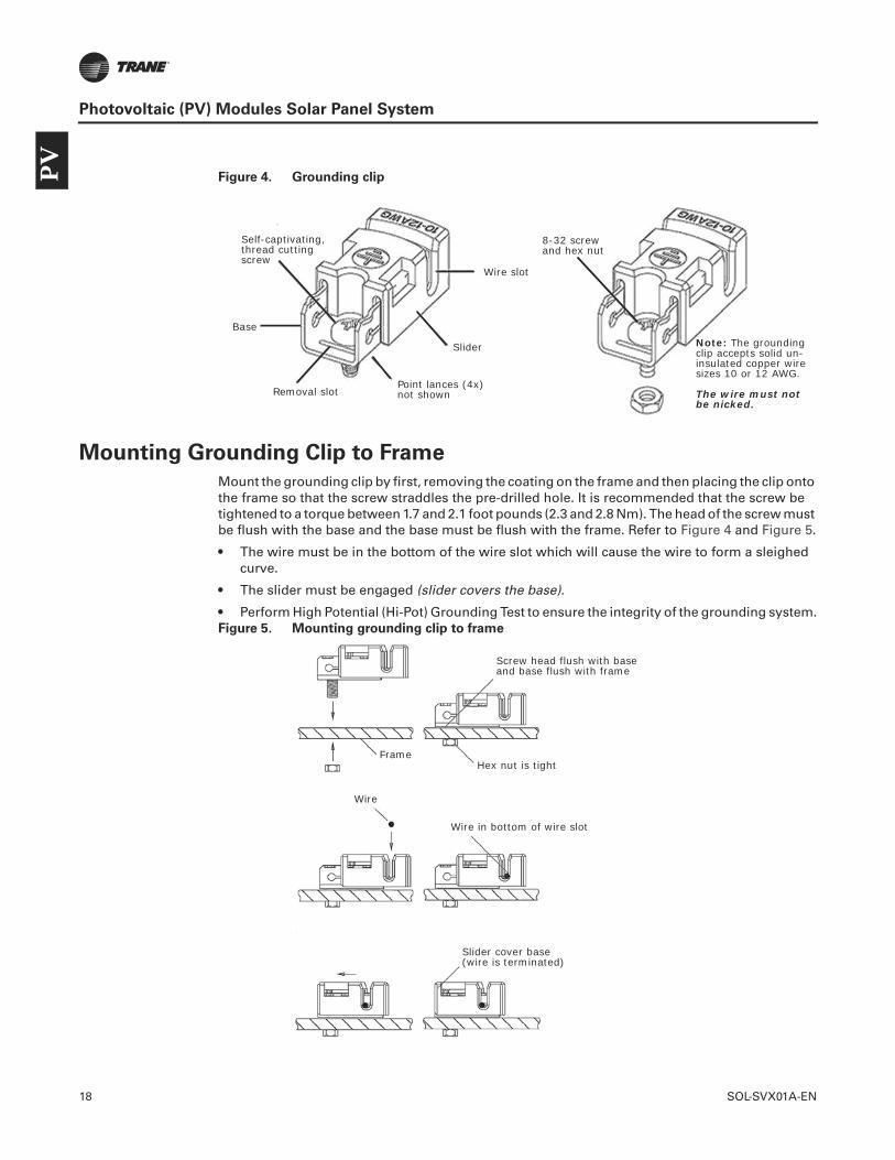
18 SOL-SVX01A-EN
Photovoltaic (PV) Modules Solar Panel System
Figure 4. Grounding clip
Mounting Grounding Clip to Frame
Mount the grounding clip by first, removing the coating on the frame and then placing the clip onto the frame so that the screw straddles the pre-drilled hole. It is recommended that the screw be tightened to a torque between 1.7 and 2.1 foot pounds (2.3 and 2.8 Nm). The head of the screw must be flush with the base and the base must be flush with the frame. Refer to Figure 4 and Figure 5.
• The wire must be in the bottom of the wire slot which will cause the wire to form a sleighed curve.
• The slider must be engaged (slider covers the base).
• Perform High Potential (Hi-Pot) Grounding Test to ensure the integrity of the grounding system.Figure 5. Mounting grounding clip to frame
Self-captivating, thread cutting screw
Point lances (4x) not shown
Wire slot
Note: The grounding clip accepts solid un-insulated copper wire sizes 10 or 12 AWG.
The wire must not be nicked.
Removal slot
Base
8-32 screwand hex nut
Slider
Screw head flush with base and base flush with frame
Slider cover base(wire is terminated)
Wire in bottom of wire slot
Wire
Hex nut is tightFrame
PV
SOL-SVX01A-EN 19
Photovoltaic (PV) Modules Solar Panel System
Charge Controllers and Batteries
When charging batteries with solar modules, the charge controller and batteries must be installed in a way that will protect the performance of the system and the safety of its users. Follow battery manufacturer guidelines concerning installation, operation, and maintenance recommendations. In general, the battery (or battery bank) should be away from the main flow of people and animal traffic. Select a battery site that is protected from sunlight, rain, snow, debris, and is well ventilated.
Tracking Systems
Most tracking systems are specifically designed for the application. Carefully follow the tracking system manufacturer installation instructions and drawings.
Array - Initial Tests
Before completion, it is very important to ensure the array has been correctly interconnected. The purpose of this initial first check is to ensure:
• All modules/cables have been interconnected
• The correct number of modules are connected in a string (refer to the schematic)
• Correct polarity
Important: Use a multimeter to check polarity before the PV array is connected to the inverter. This is best done at the inverter board to ensure all connections are correct.
Check the open circuit voltage (Voc) to ensure it is in line with the values provided by Trane. Where two or more identical strings are installed, the values of Voc shall be compared to ensure that all strings contain the same number of modules.
Array - Full Tests
Full array tests are out of the scope of this document. Refer to Trane for more information.
WARNING
Hazard of Explosion!
Most batteries generate hydrogen gas when charging, which can be explosive. Do not light matches or create sparks near the battery bank. When a battery is installed outdoors, it should be placed in an insulated and ventilated battery case specifically designed for the purpose. Failure to follow instructions could result in death or serious injury.
NOTICE:
Inverter Damage!
The modules must be wired correctly and terminated in the inverter at the proper terminal. If not, the inverter could be damaged and require replacement. Follow the inverter manufacturer instructions for properly connecting the wiring from the array to the inverter.
WARNING
Live Electrical Components!
PV modules are live at all times when a light source is present. Failure to follow all electrical safety precautions when exposed to live electrical components could result in death or serious injury.
PV
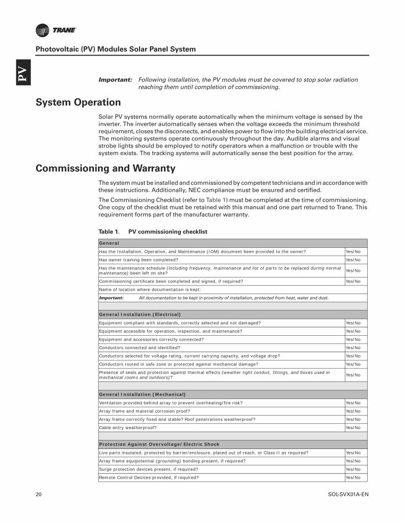
20 SOL-SVX01A-EN
Photovoltaic (PV) Modules Solar Panel System
Important: Following installation, the PV modules must be covered to stop solar radiation reaching them until completion of commissioning.
System Operation
Solar PV systems normally operate automatically when the minimum voltage is sensed by the inverter. The inverter automatically senses when the voltage exceeds the minimum threshold requirement, closes the disconnects, and enables power to flow into the building electrical service. The monitoring systems operate continuously throughout the day. Audible alarms and visual strobe lights should be employed to notify operators when a malfunction or trouble with the system exists. The tracking systems will automatically sense the best position for the array.
Commissioning and Warranty
The system must be installed and commissioned by competent technicians and in accordance with these instructions. Additionally, NEC compliance must be ensured and certified.
The Commissioning Checklist (refer to Table 1) must be completed at the time of commissioning. One copy of the checklist must be retained with this manual and one part returned to Trane. This requirement forms part of the manufacturer warranty.
Table 1. PV commissioning checklist
General
Has the Installation, Operation, and Maintenance (IOM) document been provided to the owner? Yes/No
Has owner training been completed? Yes/No
Has the maintenance schedule (including frequency, maintenance and list of parts to be replaced during normal maintenance) been left on site? Yes/No
Commissioning certificate been completed and signed, if required? Yes/No
Name of location where documentation is kept:
Important: All documentation to be kept in proximity of installation, protected from heat, water and dust.
General Installation (Electrical)
Equipment compliant with standards, correctly selected and not damaged? Yes/No
Equipment accessible for operation, inspection, and maintenance? Yes/No
Equipment and accessories correctly connected? Yes/No
Conductors connected and identified? Yes/No
Conductors selected for voltage rating, current carrying capacity, and voltage drop? Yes/No
Conductors routed in safe zone or protected against mechanical damage? Yes/No
Presence of seals and protection against thermal effects (weather tight conduit, fittings, and boxes used in mechanical rooms and outdoors)? Yes/No
General Installation (Mechanical)
Ventilation provided behind array to prevent overheating/fire risk? Yes/No
Array frame and material corrosion proof? Yes/No
Array frame correctly fixed and stable? Roof penetrations weatherproof? Yes/No
Cable entry weatherproof? Yes/No
Protection Against Overvoltage/Electric Shock
Live parts insulated, protected by barrier/enclosure, placed out of reach, or Class II as required? Yes/No
Array frame equipotential (grounding) bonding present, if required? Yes/No
Surge protection devices present, if required? Yes/No
Remote Control Devices provided, if required? Yes/No
PV

SOL-SVX01A-EN 21
Photovoltaic (PV) Modules Solar Panel System
Frame correctly integrated with existing lightning protection system installation? Yes/No
DC System
Physical separation of AC and DC cables? Yes/No
DC disconnect switch installed (per NEC and local codes)? Yes/No
DC cables - protective and reinforced insulation, if required? Yes/No
All DC components rated for operation at max DC system voltage (Voc STC x 1.25)? Yes/No
PV array strings fused or blocking diodes fitted, if required? Yes/No
AC System
AC isolator lockable in off position only? Yes/No
Inverter protection settings to local regulations? Yes/No
Labeling & Identification
General labeling of circuits, protective devices, switches, and terminals? Yes/No
PV system schematic displayed on site? Yes/No
Protection settings & installer details displayed on site? Yes/No
Emergency shutdown procedure displayed on site? Yes/No
AC disconnect switch clearly labeled? Yes/No
DC isolator/junction boxes suitably labeled? Yes/No
Signs & labels suitably affixed and durable? Yes/No
Commissioning Details
Expected annual delivered PV electrical energy:
Expected annual PV fraction of electrical:
Method of performance calculation:
Annual electrical load assumptions:
Commissioned By
On behalf of:
Date system commissioned and handed over:
Signature of commissioning engineer (electrical):
Signature of user to confirm receipt and understanding (optional):
PV

22 SOL-SVX01A-EN
Solar Thermal Collector Systems
A thermal collector solar panel system is designed to collect heat by absorbing sunlight. Thermal collectors are typically used for supplemental heating of potable water, living spaces or swimming pools in residential and commercial buildings. Water or a glycol solution is used to transfer solar thermal energy to a heat exchanger.
Model Number Description
Example Model Number: TWCLSF2510
T W C L S F 25 10
Digit 1;Brand
T = Trane
W = Aluminum Up Frame90 mm Height
M = EPDM Up Frame 105 mm Height
C = Copper
L = Low Iron Tempered
S = Selective Absorber 25 = 2.5 Square Meters21 = 2.1 Square Meters18 = 1.8 Square Meters
8 = 8 Tubes10 = 10 tubes
F = Full Face Panel (One Wide Piece)
Digit 2;Design
Digit 3;Absorber Material
Digit 4;Glass
Digit 5;Absorber Sheet
Digit 6;AbsorptionPanel Shape
Digit 7, 8;Gross Area
Digit 9, 10;Numberof Tubes
The
rmal
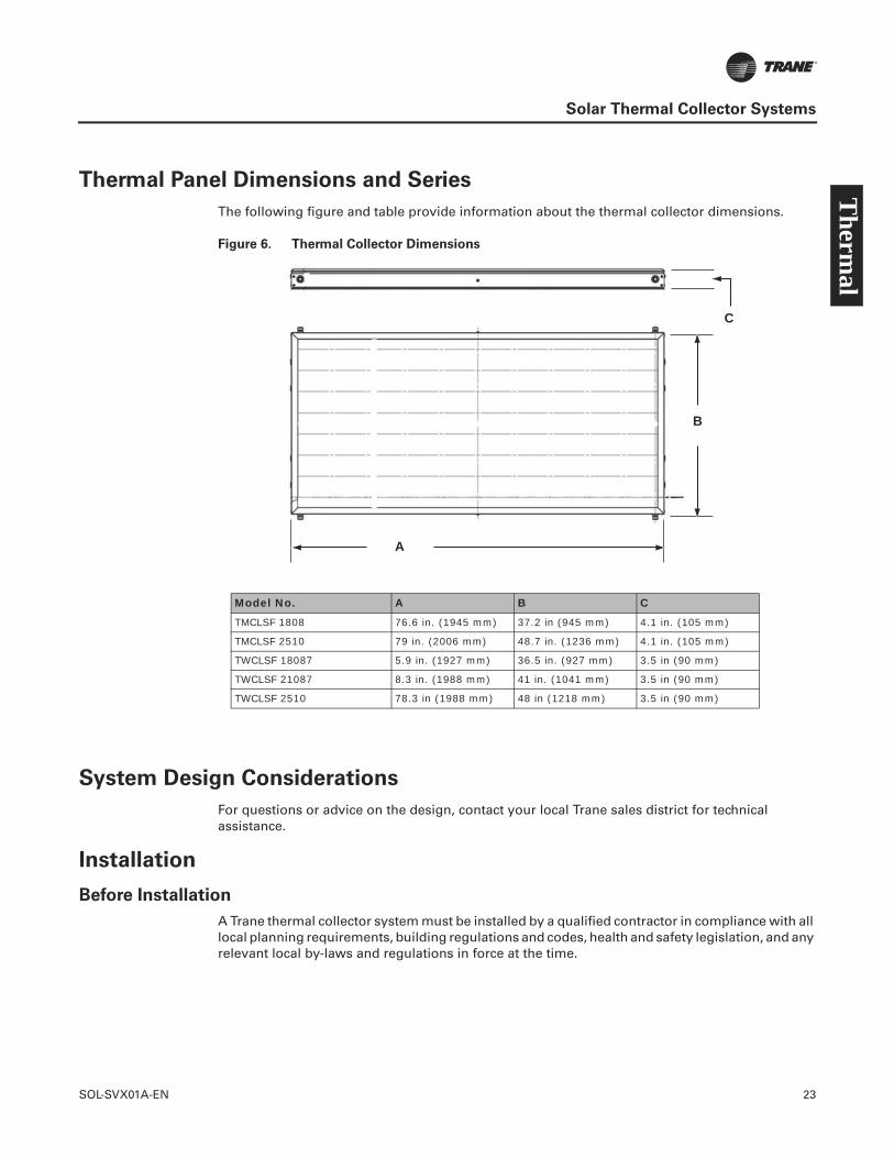
SOL-SVX01A-EN 23
Solar Thermal Collector Systems
Thermal Panel Dimensions and Series
The following figure and table provide information about the thermal collector dimensions.
Figure 6. Thermal Collector Dimensions
System Design Considerations
For questions or advice on the design, contact your local Trane sales district for technical assistance.
Installation
Before Installation
A Trane thermal collector system must be installed by a qualified contractor in compliance with all local planning requirements, building regulations and codes, health and safety legislation, and any relevant local by-laws and regulations in force at the time.
A
C
B
Model No. A B C
TMCLSF 1808 76.6 in. (1945 mm) 37.2 in (945 mm) 4.1 in. (105 mm)
TMCLSF 2510 79 in. (2006 mm) 48.7 in. (1236 mm) 4.1 in. (105 mm)
TWCLSF 18087 5.9 in. (1927 mm) 36.5 in. (927 mm) 3.5 in (90 mm)
TWCLSF 21087 8.3 in. (1988 mm) 41 in. (1041 mm) 3.5 in (90 mm)
TWCLSF 2510 78.3 in (1988 mm) 48 in (1218 mm) 3.5 in (90 mm)
Therm
al

24 SOL-SVX01A-EN
Solar Thermal Collector Systems
Mounting Solar Thermal Collectors
Roof Kits
“On-roof System Installation,” p. 25 and “In-roof System Installation,” p. 28 mounting kits are designed for use on roof slopes of between 20° and 65° and must be installed in accordance with these instructions. The “Flat-roof System Installation,” p. 28 mounting kit can be used on any flat surface capable of carrying the weight of the collectors and any dead weighting used.
If necessary, the installation can be modified to suit the site conditions. However, any changes must be approved by Trane and must meet building regulations, codes of practice, and any relevant local bylaws and regulations in force at the time. Failure to comply with this requirement will invalidate the product warranty.
Wind Uplift and Roof Safety
When installed, solar thermal collectors can experience uplift due to the wind. It is also important to consider the safety of servicing a roof-mounted solar installation. Therefore, collectors must be installed an appropriate distance from the edge of the roof to comply with applicable OSHA regulations and building codes.
Note: Applicable wind pressure and its impact on the structure are determined by the Licensed Professional Structural Engineer.
WARNING
Hazard Heights!
The on-roof installation of PVT panels requires working at hazardous heights, and should ONLY be carried out by technicians that have been trained to work in such conditions. ALWAYS wear appropriate fall restraint systems during installation and maintenance of these panels. NEVER attach fall restraint system to the installation system. Failure to follow these instructions could result in death or serious injury.
WARNING
Risk of Roof Collapse!
Confirm with a structural engineer that the roof structure is strong enough to support the combined weight of the panels, framework, and weights used to secure the collectors. Failure to ensure proper structural roof support could cause the roof to collapse, which could result in death or serious injury and property damage.
The
rmal
SOL-SVX01A-EN 25
Solar Thermal Collector Systems
Mounting Types
The following sections describe the installation of collectors in both the portrait and landscape format using all three mounting types:
• On-roof
• Flat-roof
• In-roof
Note: The connection to the hydraulic solar circuit is identical for all the mounting options and is covered elsewhere in this manual.
Important: Install components only on roofs with sufficient strength and capacity. Take into consideration the additional load per flat roof rack, including solar panels, wind and snow. All installations should be reviewed by a Registered Structural Engineer to ensure that the supporting structure is adequate for supporting the installed components and system.
Provide a suitable protective grill in the event that large snow quantities accumulate behind the panel towards the roof ridge.
On-roof System Installation
When using on-roof or in-roof mounting kits, refer to the manufacturer kit instructions. The instructions given here are only intended to be a typical guide. The illustrations that follow show the installation components and procedures that are suitable to a cement tile roof.
Note: Asphalt or fiberglass shingle type roofs will have similar procedures.
The standard installation kit allows panels to be fitted onto horizontal mounting rails. Each row of modules is held to the roof using two aluminium mounting rails. These are attached to the roof structure using appropriate brackets for the roof covering.
Roof Bracket and Rail Installation Guidelines
To ensure sufficient strength and resilience to wind loads, all the roof brackets supplied with the kit must be used. The brackets need careful positioning to ensure that the rails lie in the correct location as follows:
• Collectors should not be installed closer than 20 in. (500mm) (or according to the local Building Code) to the perimeter of the roof (including the ridge line and eaves).
• Each mounting rail needs a roof bracket no more than 12 inches (300mm) from the end of the rail.
• Intermediate brackets along the rail should be no more 47 inches (1200mm) apart. With rafters of 23.6 inches (600mm) spacing every other rafter is sufficient.
• Single rails should not be more than 56 feet (17m) in length (an expansion gap then needs to be allowed).
Therm
al
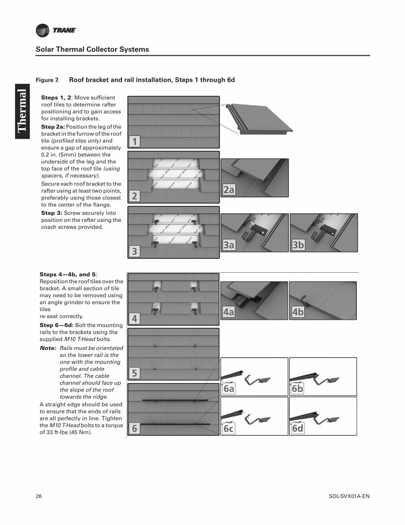
26 SOL-SVX01A-EN
Solar Thermal Collector Systems
Figure 7. Roof bracket and rail installation, Steps 1 through 6d
Steps 1, 2: Move sufficient roof tiles to determine rafter positioning and to gain access for installing brackets.Step 2a: Position the leg of the bracket in the furrow of the roof tile (profiled tiles only) and ensure a gap of approximately 0.2 in. (5mm) between the underside of the leg and the top face of the roof tile (using spacers, if necessary).Secure each roof bracket to the rafter using at least two points, preferably using those closest to the center of the flange.Step 3: Screw securely into position on the rafter using the coach screws provided.
Steps 4—4b, and 5: Reposition the roof tiles over the bracket. A small section of tile may need to be removed using an angle grinder to ensure the tiles re-seat correctly.
Step 6—6d: Bolt the mounting rails to the brackets using the supplied M10 T-Head bolts.
Note: Rails must be orientated so the lower rail is the one with the mounting profile and cable channel. The cable channel should face up the slope of the roof towards the ridge.
A straight edge should be used to ensure that the ends of rails are all perfectly in line. Tighten the M10 T-Head bolts to a torque of 33 ft-lbs (45 Nm).
The
rmal
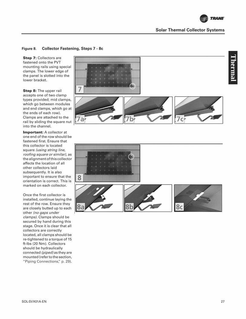
SOL-SVX01A-EN 27
Solar Thermal Collector Systems
Figure 8. Collector Fastening, Steps 7 - 8c
Step 7: Collectors are fastened onto the PVT mounting rails using special clamps. The lower edge of the panel is slotted into the lower bracket.
Step 8: The upper rail accepts one of two clamp types provided; mid clamps, which go between modules and end clamps, which go at the ends of each row). Clamps are attached to the rail by sliding the square nut into the channel.
Important: A collector at one end of the row should be fastened first. Ensure that this collector is located square (using string line, roofing square or similar), as the alignment of this collector affects the location of all other collectors laid subsequently. It is also important to ensure that the orientation is correct. This is marked on each collector.
Once the first collector is installed, continue laying the rest of the row. Ensure they are closely butted up to each other (no gaps under clamps). Clamps should be secured by hand during this stage. Once it is clear that all collectors are correctly located, all clamps should be re-tightened to a torque of 15 ft-lbs (20 Nm). Collectors should be hydraulically connected (piped) as they are mounted (refer to the section, “Piping Connections,” p. 29).
Therm
al
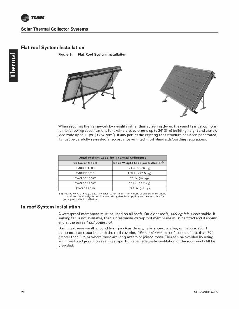
28 SOL-SVX01A-EN
Solar Thermal Collector Systems
Flat-roof System Installation
Figure 9. Flat-Roof System Installation
When securing the framework by weights rather than screwing down, the weights must conform to the following specifications for a wind pressure zone up to 26’ (8 m) building height and a snow load zone up to 11 psi (0.75k N/m2). If any part of the existing roof structure has been penetrated, it must be carefully re-sealed in accordance with technical standards/building regulations.
In-roof System Installation
A waterproof membrane must be used on all roofs. On older roofs, sarking felt is acceptable. If sarking felt is not available, then a breathable waterproof membrane must be fitted and it should end at the eaves (roof guttering).
During extreme weather conditions (such as driving rain, snow covering or ice formation) dampness can occur beneath the roof covering (tiles or slates) on roof slopes of less than 20°, greater than 65°, or where there are long rafters or joined roofs. This can be avoided by using additional wedge section sealing strips. However, adequate ventilation of the roof must still be provided.
Dead Weight Load for Thermal Collectors
Collector Model Dead Weight Load per Collector(a)
(a) Add approx. 2.9 lb.(1.3 kg) to each collector for the weight of the solar solution. In addition, add weights for the mounting structure, piping and accessories for your particular installation.
TMCLSF 1808 79.4 lb. (36 kg)
TMCLSF 2510 105 lb. (47.5 kg)
TWCLSF 18087 75 lb. (34 kg)
TWCLSF 21087 82 lb. (37.2 kg)
TWCLSF 2510 297 lb. (44 kg)
The
rmal
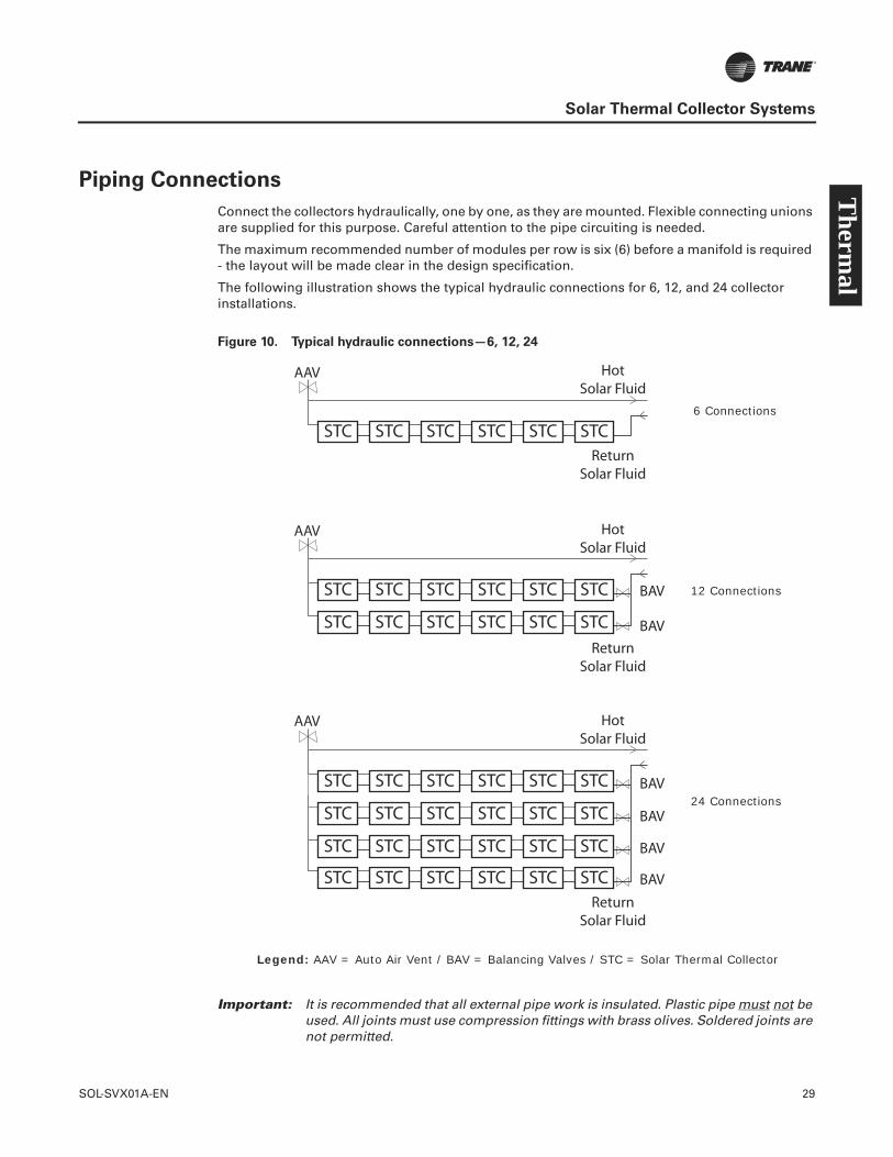
SOL-SVX01A-EN 29
Solar Thermal Collector Systems
Piping Connections
Connect the collectors hydraulically, one by one, as they are mounted. Flexible connecting unions are supplied for this purpose. Careful attention to the pipe circuiting is needed.
The maximum recommended number of modules per row is six (6) before a manifold is required - the layout will be made clear in the design specification.
The following illustration shows the typical hydraulic connections for 6, 12, and 24 collector installations.
Figure 10. Typical hydraulic connections—6, 12, 24
Important: It is recommended that all external pipe work is insulated. Plastic pipe must not be used. All joints must use compression fittings with brass olives. Soldered joints are not permitted.
STC STC STC STC STC STC
STC STC STC STC STC STC
STC STC STC STC STC STC
STC STC STC STC STC STC
STC STC STC STC STC STC
STC STC STC STC STC STC
STC STC STC STC STC STC
AAV
AAV
AAV
BAV
BAV
BAV
BAV
BAV
BAV
HotSolar Fluid
ReturnSolar Fluid
HotSolar Fluid
ReturnSolar Fluid
HotSolar Fluid
ReturnSolar Fluid
6 Connections
12 Connections
24 Connections
Legend: AAV = Auto Air Vent / BAV = Balancing Valves / STC = Solar Thermal Collector
Therm
al

30 SOL-SVX01A-EN
Solar Thermal Collector Systems
Roof Penetrations
Solar Pumping Stations
The pump selection is critical to the effectiveness of the system and is determined at the design stage. For installation details refer to the manufacturer manual that is supplied with the pumping station.
Panel connections are indicated in the submittals; this determines the minimum pipe size diameter and therefore minimum pump size. It is recommended that larger installations using pumps with higher flow rates use pipe and cylinder connections of the same size as the connections to the pump. In turn, this will determine the manifold sizes. The size of connections between the manifold and collectors should be determined by collector connection size. The following illustration shows the hydraulic schematics for a 1- or 2-tank system.
NOTICE:
Proper Sealing!
Ensure that all roof penetrations are weather tight. Off-the-shelf flashing kits are available, or these can be fabricated on site. Failure to proper seal penetrations could result in property damage.
1 Tank System
2 Tank System
The
rmal

SOL-SVX01A-EN 31
Solar Thermal Collector Systems
Solar Solution Controller (SSC)
There are many manufacturers of solar thermal controllers. Refer to the specific manufacturer manual. The following illustration shows (RESOL® controller) the wiring to the controller of a typical 2-tank system.
Figure 11. Wiring to controller, typical two tank system
S4
GN
D
S1 S2 S3 S4 S5 S6 S7 S8 V40
RP-A
RP-M
RP-R
R5 R4 R3 R2 R1CS1
0
VBus
L1 NL
store 2store 1
Sensors Bus
Floating RelayElectromech
RelaySemiconductor
Relay
S2
S3
S1
VA300
V1(R4)
P1(R1)
Therm
al
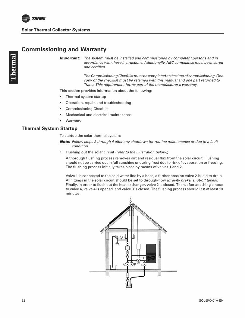
32 SOL-SVX01A-EN
Solar Thermal Collector Systems
Commissioning and Warranty
Important: The system must be installed and commissioned by competent persons and in accordance with these instructions. Additionally, NEC compliance must be ensured and certified.
The Commissioning Checklist must be completed at the time of commissioning. One copy of the checklist must be retained with this manual and one part returned to Trane. This requirement forms part of the manufacturer's warranty.
This section provides information about the following:
• Thermal system startup
• Operation, repair, and troubleshooting
• Commissioning Checklist
• Mechanical and electrical maintenance
• Warranty
Thermal System Startup
To startup the solar thermal system:
Note: Follow steps 2 through 4 after any shutdown for routine maintenance or due to a fault condition.
1. Flushing out the solar circuit (refer to the illustration below);
A thorough flushing process removes dirt and residual flux from the solar circuit. Flushing should not be carried out in full sunshine or during frost due to risk of evaporation or freezing. The flushing process initially takes place by means of valves 1 and 2.
Valve 1 is connected to the cold water line by a hose; a further hose on valve 2 is laid to drain. All fittings in the solar circuit should be set to through-flow (gravity brake, shut-off tapes). Finally, in order to flush out the heat exchanger, valve 2 is closed. Then, after attaching a hose to valve 4, valve 4 is opened, and valve 3 is closed. The flushing process should last at least 10 minutes.
The
rmal
SOL-SVX01A-EN 33
Solar Thermal Collector Systems
2. Leak testing;
The pressure test takes place after first flushing. For this purpose, valve 4 is closed and the system is filled with water through valve 1. The system pressure is then raised to a value just below the response pressure of the safety valve - as required by local codes. Then valve 1 is closed. If the system pressure is reduced due to bleeding, repeat the process of pressurizing the system by through valve 1 until the pressure stabilizes. The system is now ready to be visually observed for leaks.
A leak test (using the pressure gauge) is not possible because of irradiation-caused pressure variations over the course of the day. At the end of the leak test, the function of the safety valve can be tested by increasing the pressure further. The solar circuit should be fully emptied again by opening valves 1 and 2. By measuring the amount of water that runs out, it is possible to establish the amount of antifreeze required to make up a water-antifreeze mixture (for example 60:40). As some water always remains in the solar circuit, the measured amount of water should be correspondingly increased.
3. Filling with solar liquid.
After mixing the antifreeze concentrate with water to achieve the desired level of frost protection (or using pre-mixed antifreeze), the solar liquid is pumped into the solar circuit through valve 1. Purge air from the solar liquid as follows:
– When pumping the solar liquid in the system and the mixing container, a large part of the air is already removed. To be effective the ends of the hoses must be completely submerged in the liquid. When no more air bubbles are released, valve 4 can be closed.
– Reduce the pressure to system pressure (= static pressure + 7 psig [0.5 bar) plus an allowance for pressure loss through further bleeding.
– Switch on the circulating pump. Switch it on and off several times at 10 minute intervals.
– To bleed the circulating pump, unscrew the brass screw on the face.
If the pressure falls below the system pressure as a result of bleeding, solar liquid should be added accordingly.
4. Setting the pump and controller;
The volumetric flow in the system should be about 0.3 gal. (1.2 liters) per minute, per collector (medium flow operation). The pump should be capable of generating the pressure required in the medium performance range. With full irradiation, this leads to a temperature differential between the feed and return lines of about 20°F to 40°F (11°C to 22°C) in medium flow operation.
The switch-on temperature difference of 41°F to 50°F (5°C to 10°C) and the switch-off difference (hysteresis) of about 3.6°F (2°C), should be set on the controller. In this way, the heat generated in the collector is transferred to the storage tanks at a useful temperature level while no unnecessary pump energy is used. Refer to the specific system controller manufacturer manual for additional information.
Operation, Repair, and Troubleshooting
Solar thermal systems can consist of a variety of storage and drain-back tanks, solar solution feed stations, heat exchangers and pumps, and usually have a unique set of controls for the particular application. Solar thermal systems should be designed with redundant heating systems in the event that the sun does not help the system produce an adequate amount of heating for building heating or for one of the many applications for solar thermal systems. They need to be configured to supplement the heating supplied by the solar thermal system in the most efficient manner for maximum energy efficiency.
The system designer has intentionally configured the system to fulfill its intended purpose. It is highly recommended that:
Therm
al
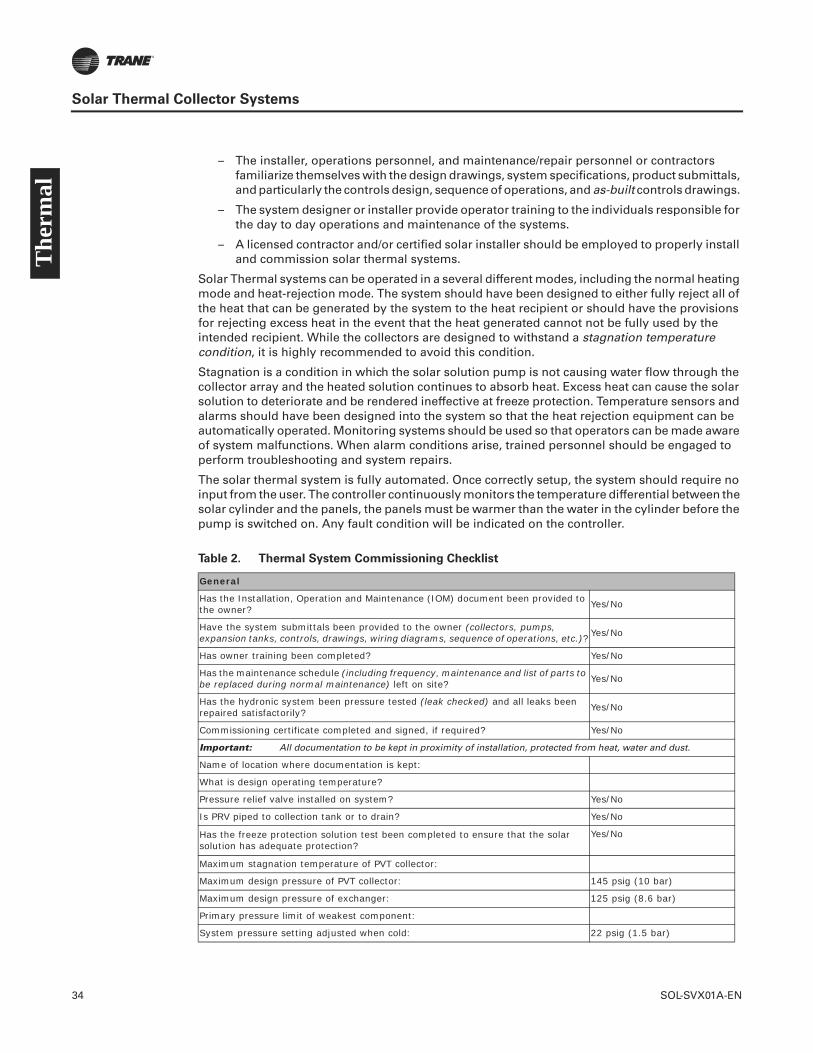
34 SOL-SVX01A-EN
Solar Thermal Collector Systems
– The installer, operations personnel, and maintenance/repair personnel or contractors familiarize themselves with the design drawings, system specifications, product submittals, and particularly the controls design, sequence of operations, and as-built controls drawings.
– The system designer or installer provide operator training to the individuals responsible for the day to day operations and maintenance of the systems.
– A licensed contractor and/or certified solar installer should be employed to properly install and commission solar thermal systems.
Solar Thermal systems can be operated in a several different modes, including the normal heating mode and heat-rejection mode. The system should have been designed to either fully reject all of the heat that can be generated by the system to the heat recipient or should have the provisions for rejecting excess heat in the event that the heat generated cannot not be fully used by the intended recipient. While the collectors are designed to withstand a stagnation temperature condition, it is highly recommended to avoid this condition.
Stagnation is a condition in which the solar solution pump is not causing water flow through the collector array and the heated solution continues to absorb heat. Excess heat can cause the solar solution to deteriorate and be rendered ineffective at freeze protection. Temperature sensors and alarms should have been designed into the system so that the heat rejection equipment can be automatically operated. Monitoring systems should be used so that operators can be made aware of system malfunctions. When alarm conditions arise, trained personnel should be engaged to perform troubleshooting and system repairs.
The solar thermal system is fully automated. Once correctly setup, the system should require no input from the user. The controller continuously monitors the temperature differential between the solar cylinder and the panels, the panels must be warmer than the water in the cylinder before the pump is switched on. Any fault condition will be indicated on the controller.
Table 2. Thermal System Commissioning Checklist
General
Has the Installation, Operation and Maintenance (IOM) document been provided to the owner? Yes/No
Have the system submittals been provided to the owner (collectors, pumps, expansion tanks, controls, drawings, wiring diagrams, sequence of operations, etc.)? Yes/No
Has owner training been completed? Yes/No
Has the maintenance schedule (including frequency, maintenance and list of parts to be replaced during normal maintenance) left on site? Yes/No
Has the hydronic system been pressure tested (leak checked) and all leaks been repaired satisfactorily? Yes/No
Commissioning certificate completed and signed, if required? Yes/No
Important: All documentation to be kept in proximity of installation, protected from heat, water and dust.
Name of location where documentation is kept:
What is design operating temperature?
Pressure relief valve installed on system? Yes/No
Is PRV piped to collection tank or to drain? Yes/No
Has the freeze protection solution test been completed to ensure that the solar solution has adequate protection?
Yes/No
Maximum stagnation temperature of PVT collector:
Maximum design pressure of PVT collector: 145 psig (10 bar)
Maximum design pressure of exchanger: 125 psig (8.6 bar)
Primary pressure limit of weakest component:
System pressure setting adjusted when cold: 22 psig (1.5 bar)
The
rmal
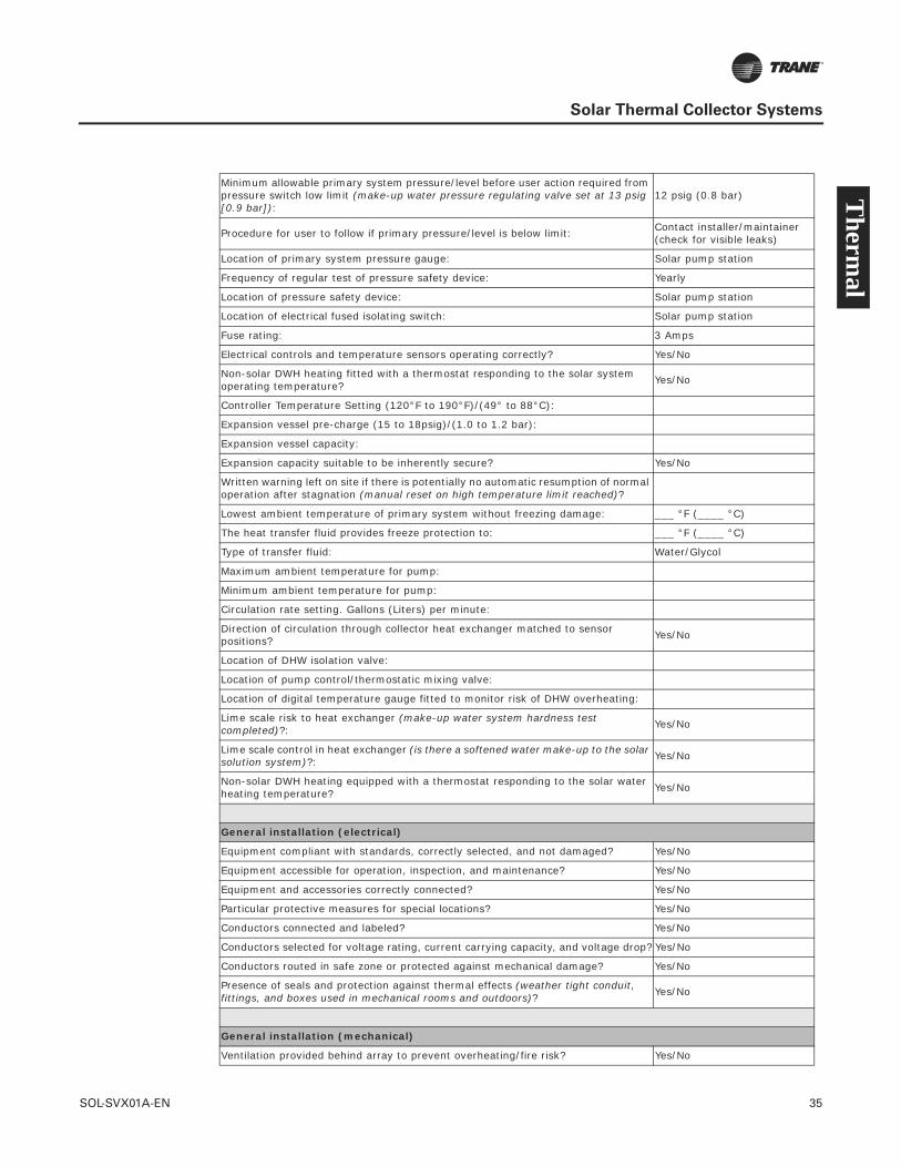
SOL-SVX01A-EN 35
Solar Thermal Collector Systems
Minimum allowable primary system pressure/level before user action required from pressure switch low limit (make-up water pressure regulating valve set at 13 psig [0.9 bar]):
12 psig (0.8 bar)
Procedure for user to follow if primary pressure/level is below limit: Contact installer/maintainer (check for visible leaks)
Location of primary system pressure gauge: Solar pump station
Frequency of regular test of pressure safety device: Yearly
Location of pressure safety device: Solar pump station
Location of electrical fused isolating switch: Solar pump station
Fuse rating: 3 Amps
Electrical controls and temperature sensors operating correctly? Yes/No
Non-solar DWH heating fitted with a thermostat responding to the solar system operating temperature? Yes/No
Controller Temperature Setting (120°F to 190°F)/(49° to 88°C):
Expansion vessel pre-charge (15 to 18psig)/(1.0 to 1.2 bar):
Expansion vessel capacity:
Expansion capacity suitable to be inherently secure? Yes/No
Written warning left on site if there is potentially no automatic resumption of normal operation after stagnation (manual reset on high temperature limit reached)?
Lowest ambient temperature of primary system without freezing damage: ___ °F (____ °C)
The heat transfer fluid provides freeze protection to: ___ °F (____ °C)
Type of transfer fluid: Water/Glycol
Maximum ambient temperature for pump:
Minimum ambient temperature for pump:
Circulation rate setting. Gallons (Liters) per minute:
Direction of circulation through collector heat exchanger matched to sensor positions? Yes/No
Location of DHW isolation valve:
Location of pump control/thermostatic mixing valve:
Location of digital temperature gauge fitted to monitor risk of DHW overheating:
Lime scale risk to heat exchanger (make-up water system hardness test completed)?: Yes/No
Lime scale control in heat exchanger (is there a softened water make-up to the solar solution system)?: Yes/No
Non-solar DWH heating equipped with a thermostat responding to the solar water heating temperature? Yes/No
General installation (electrical)
Equipment compliant with standards, correctly selected, and not damaged? Yes/No
Equipment accessible for operation, inspection, and maintenance? Yes/No
Equipment and accessories correctly connected? Yes/No
Particular protective measures for special locations? Yes/No
Conductors connected and labeled? Yes/No
Conductors selected for voltage rating, current carrying capacity, and voltage drop? Yes/No
Conductors routed in safe zone or protected against mechanical damage? Yes/No
Presence of seals and protection against thermal effects (weather tight conduit, fittings, and boxes used in mechanical rooms and outdoors)? Yes/No
General installation (mechanical)
Ventilation provided behind array to prevent overheating/fire risk? Yes/No
Therm
al

36 SOL-SVX01A-EN
Solar Thermal Collector Systems
Array frame & material corrosion proof? Yes/No
Array frame correctly fixed and stable? Roof penetrations weatherproof? Yes/No
Protection against overvoltage/electric shock
Live parts insulated, protected by barrier/enclosure, placed out of reach, or Class II as required? Yes/No
Array frame equipotential bonding present, if required? Yes/No
Surge protection devices present, if required? Yes/No
Remote Control Devices provided, if required? Yes/No
Frame correctly integrated with existing lightning protection system installation? Yes/No
Labelling & identification
General labelling of circuits, protective devices, switches, and terminals? Yes/No
Protection settings and installer details displayed on site? Yes/No
Emergency shutdown procedure displayed on site? Yes/No
Signs & labels suitably affixed and durable? Yes/No
Commissioning details
Expected annual delivered solar thermal energy to domestic hot water system/space heating:
Expected annual solar collector fraction of DHW:
Expected annual PVT fraction of DHW:
Method of performance calculation:
Daily DHW/space heating load assumption
Date of site visits for bacterial, water quality and access risk assessments:
Commissioned by
On behalf of:
Date system commissioned and handed over:
Signature of commissioning engineer (Electrical):
Signature of commissioning engineer (Solar Thermal):
Signature of user to confirm receipt and understanding (optional):
The
rmal
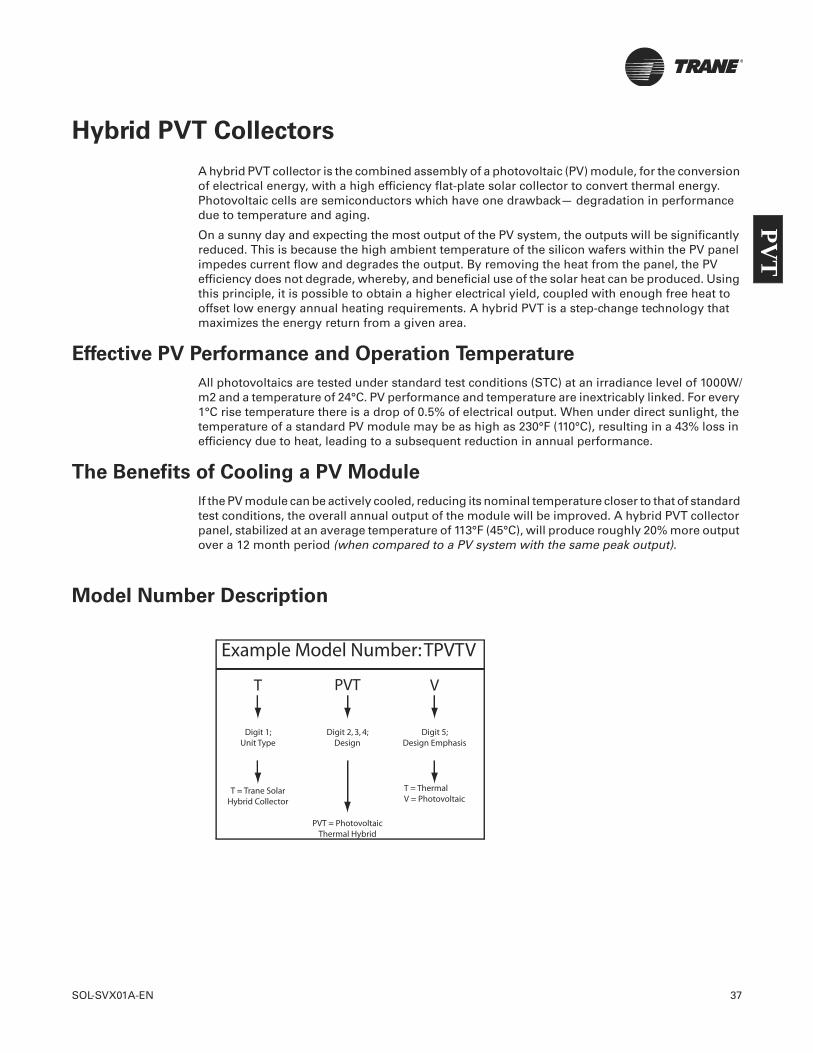
SOL-SVX01A-EN 37
Hybrid PVT Collectors
A hybrid PVT collector is the combined assembly of a photovoltaic (PV) module, for the conversion of electrical energy, with a high efficiency flat-plate solar collector to convert thermal energy. Photovoltaic cells are semiconductors which have one drawback— degradation in performance due to temperature and aging.
On a sunny day and expecting the most output of the PV system, the outputs will be significantly reduced. This is because the high ambient temperature of the silicon wafers within the PV panel impedes current flow and degrades the output. By removing the heat from the panel, the PV efficiency does not degrade, whereby, and beneficial use of the solar heat can be produced. Using this principle, it is possible to obtain a higher electrical yield, coupled with enough free heat to offset low energy annual heating requirements. A hybrid PVT is a step-change technology that maximizes the energy return from a given area.
Effective PV Performance and Operation Temperature
All photovoltaics are tested under standard test conditions (STC) at an irradiance level of 1000W/m2 and a temperature of 24°C. PV performance and temperature are inextricably linked. For every 1°C rise temperature there is a drop of 0.5% of electrical output. When under direct sunlight, the temperature of a standard PV module may be as high as 230°F (110°C), resulting in a 43% loss in efficiency due to heat, leading to a subsequent reduction in annual performance.
The Benefits of Cooling a PV Module
If the PV module can be actively cooled, reducing its nominal temperature closer to that of standard test conditions, the overall annual output of the module will be improved. A hybrid PVT collector panel, stabilized at an average temperature of 113°F (45°C), will produce roughly 20% more output over a 12 month period (when compared to a PV system with the same peak output).
Model Number Description
Example Model Number: TPVTV
T PVT V
Digit 1;Unit Type
T = Trane SolarHybrid Collector
PVT = PhotovoltaicThermal Hybrid
T = ThermalV = Photovoltaic
Digit 2, 3, 4;Design
Digit 5;Design Emphasis
PVT

38 SOL-SVX01A-EN
Hybrid PVT Collectors
Product Selection
There are two types of PVT collectors determined by the project:
• PVT- thermal (TPVT-T);
The TPVT-T collector is designed to maximize on the thermal return of the panel, making it an enhanced thermal collector capable of electrical production. The peak outputs of this panel are 170 electrical watts and 610 thermal watts (2321 BTUh). It will produce roughly 80% of the output of the equivalent area of solar thermal and it also produces electricity. This is an excellent solution if the project has restricted space while trying to maximize the energy return.
This system is ideal for use with swimming pools, whereby, the collector operates at lower temperatures. This supplies year-around heat to the pool and the electrical energy needed to offset the running of the pool equipment.
In conjunction with ground source heat pumps, excess summer energy is fed into the ground which is recovered during colder periods to heat a building. PVT can contribute to producing a zero-carbon building as part of an integrated solution.
• PVT - photovoltaic (TPVT-V)
The TPVT-V collector is designed to maximize on the electrical return of the panel, making it an enhanced PV collector, capable of producing a reasonable amount of heat production in the summer. The peak outputs of this panel are 170 electrical watts and 460 thermal watts (1,570 BTUh). When correctly installed, the collector will produce roughly 30% more electricity than conventional PVs and provide a contribution to the thermal requirements of a building.
This system is ideal for maximizing electrical energy returns from a given area. Any buildings with 175 feet or more of available south-facing roof area can use the TPVT- V collector to produce the equivalent annual output of 224 feet of conventional monocrystalline photovoltaic panels. The same area of TPVT-V collectors will offset around the same amount of thermal energy as 46feet of conventional solar thermal collectors. This means that separate systems over 270 feet of roof area would be required to produce the same thermal and electrical energy. In addition, the TPVT-V collector has numerous commercial applications and when actively cooled can produce impressive electrical energy outputs
PVT

SOL-SVX01A-EN 39
Hybrid PVT Collectors
TPVT-T and TPVT-V Panel Dimensions
.75 in. (19 mm)
,75 in. (19 mm)
4.0 in. (100 mm)
2.0 in. (50 mm)
30.6 in.(776 mm)
30.6 in.(776 mm)
34.3 in.(870 mm)
4.1 in. (105 mm)
4.1 in. (105 mm)
64.6 in.(1640 mm)
66.7.6 in.(1694 mm)
TPVT-T Dimensions
TPVT-V Dimensions
65.2 in.(1655 mm)
63 in.(1601 mm)
63 in.(1601 mm)
32.6 in.(828 mm)
29.6 in.(752 mm)
3.5 in.(90 mm)
PVT

40 SOL-SVX01A-EN
Hybrid PVT Collectors
Product Specifications
Description TPVT-V Hybrid Collectors TPVT-T Hybrid Collectors
Dimensions: 32.6 in. x 63 in. x 3.5 in. (82.8 cm x 160.0 cm x 8.9 cm)
34.3 in. x 64.6 in. x 4.1 in. (87.12 cm x 164.08 cm x 10.41 cm)
Weight: 53.8 lb. (24.4 kg) 75.8 lb. (34.4 kg)
Liquid content: 40.6 oz. (1.2 L) 40.6 oz. (1.2 L)
Cell efficiency (STC): 17.5% 17.5%
Module efficiency (STC): 14.88% 10.9%
Ratio (e/th) at 60C: 1:1 1:3
Absorber panel: Monocrystalline Monocrystalline
Number of cells: 72 72
Cell dimensions: 4.9 in. x 4.9 in. (12.45 cm x 12.45 cm) 4.9 in. x 4.9 in. (12.45 cm x 12.45 cm)
WP (W) nominal power: 190 175
Imp (A) normal current: 5.2 5.2
Isc (V) short circuit current: 5.6 5.6
Vmp (V) normal current: 36.5 32.7
Voc (V) open circuit voltage: 45.2 45.2
Heat exchanger: Copper strip Copper strip
Internal piping: Copper Copper
Flow: 17 gal/h (65L/h) 17 gal/h (65L/h)
Test pressure bar: 290 psig (20 bar) 290 psig (20 bar)
Operating pressure bar: 145 psig (10 bar) 145 psig (10 bar)
Cover glass: PV glass Extra solar glass
Sealing: EPDM & silicon EPDM & silicon
Maximum temperature: <230°F (110°C) <230°F (110°C)
Housing: Aluminum Aluminum
Rear side: Aluminum Aluminum
Product warranty: 10 years 10 years
Quality guarantee: 90% < 10 years 90% < 10 years
80% < 20 years 80% < 20 years
PVT
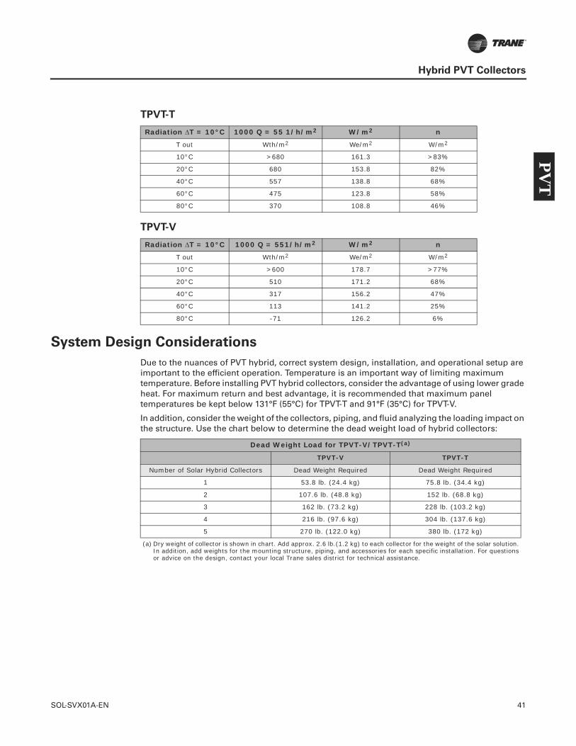
SOL-SVX01A-EN 41
Hybrid PVT Collectors
TPVT-T
TPVT-V
System Design Considerations
Due to the nuances of PVT hybrid, correct system design, installation, and operational setup are important to the efficient operation. Temperature is an important way of limiting maximum temperature. Before installing PVT hybrid collectors, consider the advantage of using lower grade heat. For maximum return and best advantage, it is recommended that maximum panel temperatures be kept below 131°F (55°C) for TPVT-T and 91°F (35°C) for TPVT-V.
In addition, consider the weight of the collectors, piping, and fluid analyzing the loading impact on the structure. Use the chart below to determine the dead weight load of hybrid collectors:
Radiation T = 10°C 1000 Q = 55 1/h/m2 W/m2 n
T out Wth/m2 We/m2 W/m2
10°C >680 161.3 >83%
20°C 680 153.8 82%
40°C 557 138.8 68%
60°C 475 123.8 58%
80°C 370 108.8 46%
Radiation T = 10°C 1000 Q = 551/h/m2 W/m2 n
T out Wth/m2 We/m2 W/m2
10°C >600 178.7 >77%
20°C 510 171.2 68%
40°C 317 156.2 47%
60°C 113 141.2 25%
80°C -71 126.2 6%
Dead Weight Load for TPVT-V/TPVT-T(a)
(a) Dry weight of collector is shown in chart. Add approx. 2.6 lb.(1.2 kg) to each collector for the weight of the solar solution. In addition, add weights for the mounting structure, piping, and accessories for each specific installation. For questions or advice on the design, contact your local Trane sales district for technical assistance.
TPVT-V TPVT-T
Number of Solar Hybrid Collectors Dead Weight Required Dead Weight Required
1 53.8 lb. (24.4 kg) 75.8 lb. (34.4 kg)
2 107.6 lb. (48.8 kg) 152 lb. (68.8 kg)
3 162 lb. (73.2 kg) 228 lb. (103.2 kg)
4 216 lb. (97.6 kg) 304 lb. (137.6 kg)
5 270 lb. (122.0 kg) 380 lb. (172 kg)
PVT
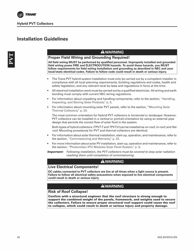
42 SOL-SVX01A-EN
Hybrid PVT Collectors
Installation Guidelines
• The Trane PVT hybrid system installation must only be carried out by a competent installer in compliance with all local planning requirements, building regulations and codes, health and safety legislation, and any relevant local by-laws and regulations in force at the time.
• All electrical installation work must be carried out by a qualified electrician. All wiring and earth bonding must comply with current NEC wiring regulations.
• For information about unpacking and handling components, refer to the section, “Handling, Inspecting, and Storing Solar Products,” p. 5.
• For information about mounting solar PVT panels, refer to the section, “Mounting Solar Thermal Collectors,” p. 24.
The most common orientation for Hybrid PVT collectors is horizontal or landscape. However, PVT collectors can be installed in a vertical or portrait orientation by using an external pipe design that permits the correct flow of solar fluid in the system.
Both types of hybrid collectors (TPVT-T and TPVT-V) can be installed as on-roof, in-roof, and flat-roof. Mounting procedures for PVT and thermal collectors are identical.
• For information about solar thermal installation, start-up, operation, and maintenance, refer to the section, “Commissioning and Warranty,” p. 32.
• For more information about solar PV installation, start-up, operation and maintenance, refer to the section, “Photovoltaic (PV) Modules Solar Panel System,” p. 9.
Important: Following installation, the PVT collectors must be covered to stop solar radiation reaching them until completion of commissioning.
WARNING
Proper Field Wiring and Grounding Required!
All field wiring MUST be performed by qualified personnel. Improperly installed and grounded field wiring poses FIRE and ELECTROCUTION hazards. To avoid these hazards, you MUST follow requirements for field wiring installation and grounding as described in NEC and your local/state electrical codes. Failure to follow code could result in death or serious injury.
WARNING
Live Electrical Components!
DC cables connected to PVT collectors are live at all times when a light source is present. Failure to follow all electrical safety precautions when exposed to live electrical components could result in death or serious injury.
WARNING
Risk of Roof Collapse!
Confirm with a structural engineer that the roof structure is strong enough to support the combined weight of the panels, framework, and weights used to secure the collectors. Failure to ensure proper structural roof support could cause the roof to collapse, which could result in death or serious injury and property damage.
PVT
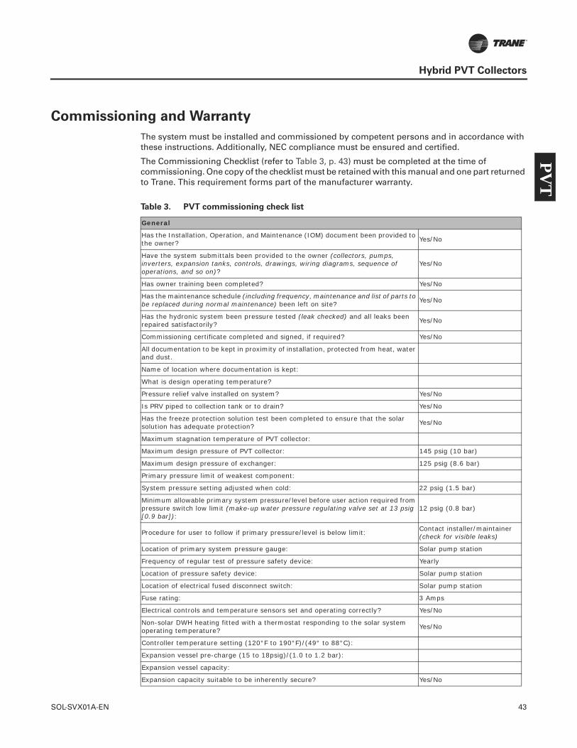
SOL-SVX01A-EN 43
Hybrid PVT Collectors
Commissioning and Warranty
The system must be installed and commissioned by competent persons and in accordance with these instructions. Additionally, NEC compliance must be ensured and certified.
The Commissioning Checklist (refer to Table 3, p. 43) must be completed at the time of commissioning. One copy of the checklist must be retained with this manual and one part returned to Trane. This requirement forms part of the manufacturer warranty.
Table 3. PVT commissioning check list
General
Has the Installation, Operation, and Maintenance (IOM) document been provided to the owner? Yes/No
Have the system submittals been provided to the owner (collectors, pumps, inverters, expansion tanks, controls, drawings, wiring diagrams, sequence of operations, and so on)?
Yes/No
Has owner training been completed? Yes/No
Has the maintenance schedule (including frequency, maintenance and list of parts to be replaced during normal maintenance) been left on site? Yes/No
Has the hydronic system been pressure tested (leak checked) and all leaks been repaired satisfactorily? Yes/No
Commissioning certificate completed and signed, if required? Yes/No
All documentation to be kept in proximity of installation, protected from heat, water and dust.
Name of location where documentation is kept:
What is design operating temperature?
Pressure relief valve installed on system? Yes/No
Is PRV piped to collection tank or to drain? Yes/No
Has the freeze protection solution test been completed to ensure that the solar solution has adequate protection? Yes/No
Maximum stagnation temperature of PVT collector:
Maximum design pressure of PVT collector: 145 psig (10 bar)
Maximum design pressure of exchanger: 125 psig (8.6 bar)
Primary pressure limit of weakest component:
System pressure setting adjusted when cold: 22 psig (1.5 bar)
Minimum allowable primary system pressure/level before user action required from pressure switch low limit (make-up water pressure regulating valve set at 13 psig [0.9 bar]):
12 psig (0.8 bar)
Procedure for user to follow if primary pressure/level is below limit: Contact installer/maintainer (check for visible leaks)
Location of primary system pressure gauge: Solar pump station
Frequency of regular test of pressure safety device: Yearly
Location of pressure safety device: Solar pump station
Location of electrical fused disconnect switch: Solar pump station
Fuse rating: 3 Amps
Electrical controls and temperature sensors set and operating correctly? Yes/No
Non-solar DWH heating fitted with a thermostat responding to the solar system operating temperature? Yes/No
Controller temperature setting (120°F to 190°F)/(49° to 88°C):
Expansion vessel pre-charge (15 to 18psig)/(1.0 to 1.2 bar):
Expansion vessel capacity:
Expansion capacity suitable to be inherently secure? Yes/No
PVT

44 SOL-SVX01A-EN
Hybrid PVT Collectors
Written warning left on site if there is potentially no automatic resumption of normal operation after stagnation (manual reset on high temperature limit reached)?
Lowest ambient temperature of primary system without freezing damage: ___ °F (____ °C)
The heat transfer fluid provides freeze protection to: ___ °F (____ °C)
Type of transfer fluid: Water/Propylene Glycol
Maximum ambient temperature for pump:
Minimum ambient temperature for pump:
Circulation rate setting. Gallons (Liters) per minute:
Direction of circulation through collector heat exchanger matched to sensor positions? Yes/No
Location of DHW isolation valve:
Location of pump control/Thermostatic mixing valve:
Location of digital temperature gauge fitted to monitor risk of DHW overheating:
Lime scale risk to heat exchanger (make-up water system hardness test completed)?: Yes/No
Lime scale control in heat exchanger (is there a softened water make-up to the solar solution system)?: Yes/No
General Installation (Electrical)
Equipment compliant with standards, correctly selected and not damaged? Yes/No
Equipment accessible for operation, inspection, and maintenance? Yes/No
Equipment and accessories correctly connected? Yes/No
Particular protective measures for special locations? Yes/No
Conductors connected and labeled? Yes/No
Conductors selected for voltage rating, current carrying capacity, and voltage drop? Yes/No
Conductors routed in safe zone or protected against mechanical damage? Yes/No
Presence of seals and protection against thermal effects (weather tight conduit, fittings, and boxes used in mechanical rooms and outdoors)? Yes/No
General Installation (Mechanical)
Ventilation provided behind array to prevent overheating/fire risk? Yes/No
Array frame and material corrosion proof? Yes/No
Array frame correctly installed and stable? Roof penetrations weatherproof? Yes/No
Cable entry weatherproof? Yes/No
Protection Against Overvoltage/Electric Shock
Live parts insulated, protected by barrier/enclosure, placed out of reach or Class II as required? Yes/No
Array frame equipotential bonding present, if required? Yes/No
Surge protection devices present, if required? Yes/No
Remote control devices provided, if required? Yes/No
Frame correctly integrated with existing lightning protection system installation? Yes/No
DC System
Physical separation of AC and DC cables? Yes/No
DC disconnect switch installed (per NEC and local codes)? Yes/No
Are the DC cables protective and reinforced insulation, if required? Yes/No
All DC components rated for operation at maximum DC system voltage (Voc STC x 1.25)? Yes/No
PVT

SOL-SVX01A-EN 45
Hybrid PVT Collectors
PVT System Start-up
Important: After any shutdown, it is important to restart the AC side of the installation before switching on the main DC disconnect switch.
To restart the system, in sequence:
1. Turn on the RCBOs connected to each phase.
2. Turn on the 3-phase rotary disconnect switch located next to the inverter.
3. Turn on the main DC disconnect switch.
Once all disconnect switches are in the ON position, the inverter will go into start mode.
PV array strings fused or blocking diodes fitted, if required? Yes/No
Non-solar DWH heating equipped with a thermostat responding to the solar water heating temperature? Yes/No
AC System
AC isolator lockable in OFF position only? Yes/No
Inverter protection settings to local regulations? Yes/No
Labeling and Identification
General labelling of circuits, protective devices, switches, and terminals? Yes/No
PV system schematic displayed on site? Yes/No
Protection settings & installer details displayed on site? Yes/No
Emergency shutdown procedure displayed on site? Yes/No
AC disconnect switch clearly labelled? Yes/No
DC disconnect switch/junction boxes suitably labelled? Yes/No
Signs & labels suitably affixed and durable? Yes/No
Commissioning Details
Expected annual delivered PVT thermal energy to domestic hot water system/space heating:
Expected annual delivered PVT electrical energy:
Expected annual PVT fraction of DHW:
Expected annual PVT fraction of electrical:
Method of performance calculation:
Daily DHW/space heating load assumption
Annual electrical load assumptions
Date of site visits for bacterial, water quality and access risk assessments:
Commissioned By
On behalf of:
Date system commissioned and handed over:
Signature of commissioning engineer (electrical):
Signature of commissioning engineer (solar thermal):
Signature of user to confirm receipt and understanding (optional):
PVT

Trane optimizes the performance of homes and buildings around the world. A business of Ingersoll Rand, the leader in creating and sustaining safe, comfortable and energy efficient environments, Trane offers a broad portfolio of advanced controls and HVAC systems, comprehensive building services, and parts. For more information, visit www.Trane.com.
Trane has a policy of continuous product and product data improvement and reserves the right to change design and specifications without notice.
We are committed to using environmentally
conscious print practices that reduce waste.
© 2011 Trane. All rights reserved.
SOL-SVX01A-EN 14 Dec 2011
NEW

FORM A
PRODUCTS & SERVICES
Renewable Energy: Detailed information is located in Installation, Operation and Maintenance Document
Type: Solar Panels…Photovoltaic Modules (PV), Thermal Collectors, and Hybrid Photovoltaic/ Thermal Collectors (PVT)
Brand Name: Photovoltaic Modules (PV), Thermal Collectors, and Hybrid Photovoltaic/ Thermal Collectors (PVT)
Capacity Range: See Installation, Operation and Maintenance Document
Heating Medium: See Installation, Operation and Maintenance Document
Cooling Medium: See Installation, Operation and Maintenance Document
Standard Warranty: PV Modules are guaranteed to be free of manufacturing defects for a period of 10 years from date of collector delivery.
Performance Guarantee: The electrical output performance will guarantee the following:
During the first ten (10) years from the date of sale, produce at least 92% of the minimum power output rating.
During the first twenty (20) years from the date of sale, produce at least 84% of the minimum power output rating.
During the first twenty-five (25) years from the date of sale, produce at least 80% of the minimum power output rating, where the minimum power output rating is the rated power minus the applicable tolerance.
Estimated Lead/Delivery time: Typical delivery ranges from 10 – 12 weeks with full submittal/shop drawings approval and appropriate purchase order whichever comes first. Expedited cycles are available upon request.
Location of Manufacturing City: Konya, Turkey Range of Efficiencies: See attached Installation, Operation and Maintenance Document Estimated market Share: Will be introduced into the North American market in 2Q, 2012 Detail Features and Benefits: Each type of Collector or Module addresses a specific solar need.

CenTraVac R’newal Process
Select chiller to be R’newed
Refrigerant samples sent to Charlotte Lab to be analyzed for continued use ability
Job Complete
Tear down compressor and rebuild according to the installation manual
(SRV-SVN01A-EN)
Complete start-up log - file at office
Use CenTraVac R’newal Field Task List to get the correct parts from your
local Trane Parts Center
Enter order in Lynx Include customer address & contact name in SOLD TO field or Sales Order Notes
2 or 5-year Service
Agreement?
Send Service Agreement to Extended Warranties Group
Lynx selection will only include: name plate, new serial
number and warranties
In Lynx remember to fill
in the serial number under performance
data
Service agreement is
required for all CTV R’newals

FORM A
PRODUCTS & SERVICES
R’newal Services Type: Chiller Upgrades
Description: Trane's R'newal Service programs are a comprehensive service that restores compressor performance by replacing worn materials. This service brings your existing chiller to the same level of reliability offered by a new Trane chiller. The program consists of inspection and enhancement services for Trane chillers and where component designs have been enhanced since original installation. Trane replaces those original components with the current upgraded parts. Each renewal includes a new compressor and a long-term compressor warranty.
CenTraVac® R'newal Service Program R'newal service program - RTAA
R'newal service program - RTHA/B/C/D
Personnel: Factory trained technicians Project References:
Santa Fe ISD, Santa Fe, TX
Dallas County, Dallas, TX
Tarrant College, Ft Worth, TX
Detailed Features and Benefits: • Reduces downtime • Extends the life of the chiller • Reduces maintenance costs

RTAA R’newal Process
Select chiller to be R’newed
1. Oil & Refrigerant samples sent to Charlotte Lab (label as R’newal)
2. Run Meg Ohm test – send results to Charlotte
3. Do Eddy Current test – not required, but recommended
Job Complete
Charlotte will request a Compressor Return
Authorization (CRA) and send it to the office
Send “old” compressor to Charlotte
Compressor shipped from Charlotte – kit shipped
from LaCrosse
Complete start-up log - file at office
Enter order in Lynx Include customer
address & contact name in SOLD TO field or Sales Order Notes
Samples pass?
Contact Charlotte Customer Service for options
1-800-837-7849
No
If job is a rush, contact Charlotte to ensure that
there is stock available.
5-year warranty?
Send Service Agreement to Extended Warranties Group
No
Yes
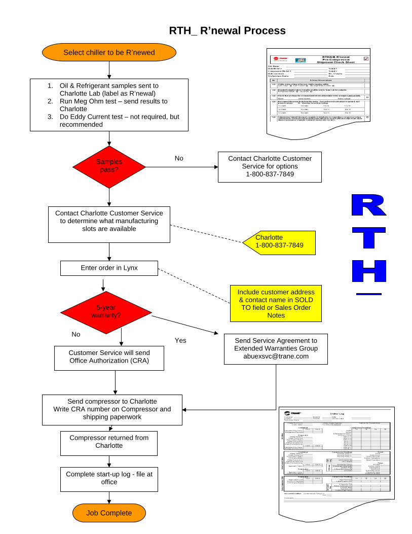
RTH_ R’newal Process
Select chiller to be R’newed
1. Oil & Refrigerant samples sent to Charlotte Lab (label as R’newal)
2. Run Meg Ohm test – send results to Charlotte
3. Do Eddy Current test – not required, but recommended
Job Complete
Send Service Agreement to Extended Warranties Group
Send compressor to Charlotte Write CRA number on Compressor and
shipping paperwork
Compressor returned from Charlotte
Complete start-up log - file at office
Contact Charlotte Customer Service to determine what manufacturing
slots are available
Enter order in Lynx
Charlotte 1-800-837-7849
Include customer address & contact name in SOLD TO field or Sales Order
Notes
Samples pass?
Contact Charlotte Customer Service for options
1-800-837-7849
No
5-year warranty?
No Yes
Customer Service will send Office Authorization (CRA)
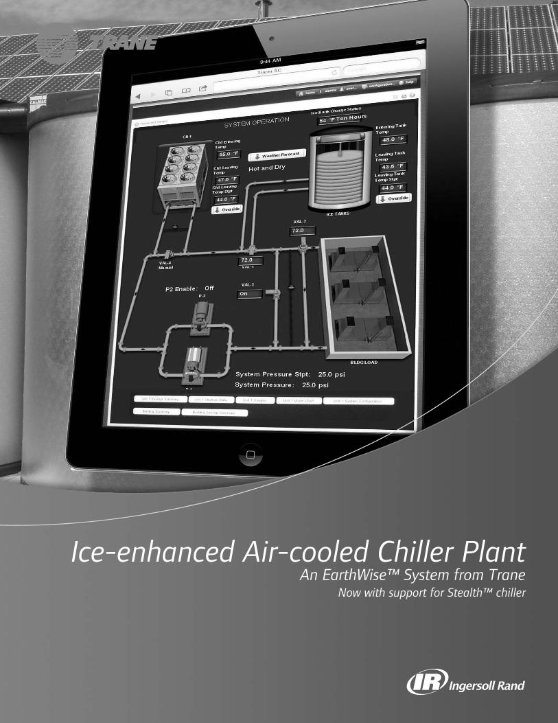
11
Ice-enhanced Air-cooled Chiller PlantAn EarthWise™ System from Trane
Now with support for Stealth™ chiller
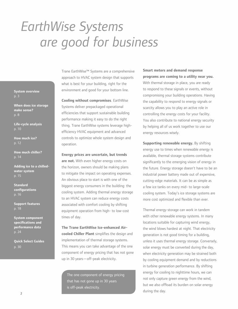
2
Trane EarthWise™ Systems are a comprehensive
approach to HVAC system design that supports
what is best for your building, right for the
environment and good for your bottom line.
Cooling without compromises. EarthWise
Systems deliver prepackaged operational
ef ciencies that support sustainable building
performance making it easy to do the right
thing. Trane EarthWise systems leverage high-
ef ciency HVAC equipment and advanced
controls to optimize whole system design and
operation.
Energy prices are uncertain, but trends
are not. With even higher energy costs on
the horizon, owners should be making plans
to mitigate the impact on operating expenses.
An obvious place to start is with one of the
biggest energy consumers in the building: the
cooling system. Adding thermal energy storage
to an HVAC system can reduce energy costs
associated with comfort cooling by shifting
equipment operation from high- to low-cost
times of day.
The Trane EarthWise Ice-enhanced Air-
cooled Chiller Plant simpli es the design and
implementation of thermal storage systems.
This means you can take advantage of the one
component of energy pricing that has not gone
up in 30 years—off-peak electricity.
EarthWise Systems are good for business
Smart meters and demand response
programs are coming to a utility near you.
With thermal storage in place, you are ready
to respond to these signals or events, without
compromising your building operations. Having
the capability to respond to energy signals or
scarcity allows you to play an active role in
controlling the energy costs for your facility.
You also contribute to national energy security
by helping all of us work together to use our
energy resources wisely.
Supporting renewable energy. By shifting
energy use to times when renewable energy is
available, thermal storage systems contribute
signi cantly to the emerging vision of energy in
the future. Energy storage doesn’t have to be an
industrial power battery made out of expensive,
cutting-edge materials. It can be as simple as
a few ice tanks on every mid- to large-scale
cooling system. Today’s ice storage systems are
more cost optimized and exible than ever.
Thermal energy storage can work in tandem
with other renewable energy systems. In many
locations suitable for capturing wind energy,
the wind blows hardest at night. That electricity
generation is not good timing for a building,
unless it uses thermal energy storage. Conversely,
solar energy must be converted during the day,
when electricity generation may be strained both
by cooling equipment demand and by reductions
in turbine generation performance. By shifting
energy for cooling to nighttime hours, we can
not only capture green energy from the wind,
but we also of oad its burden on solar energy
during the day.
The one component of energy pricing
that has not gone up in 30 years
is off-peak electricity.
System overview p. 3
When does ice storage make sense?p. 8
Life-cycle analysisp. 10
How much ice?p. 12
How much chiller?p. 14
Adding ice to a chilled-water systemp. 15
Standard con gurationsp. 16
Support featuresp. 18
System component speci cations and performance datap. 24
Quick Select Guides
p. 30

3
A little history …
Trane has been
educating the industry
for decades on chiller-
based thermal storage
systems. Refrigeration
itself began as an ice
storing and melting
application, which is
why cooling is rated in
tons. So it’s appropriate
that a natural element
such as frozen water and
its capacity for storing
thermal energy can
and should be tapped
again for Earth-friendlier
cooling.
System package benefits
Reduced risk and engineering costs
• Preprogrammed system controls
• Pre-engineered system packages
Repeatability
• Avoid installation and commissioning pitfalls
• Avoid or reduce custom programming
• Simplify maintenance with repeated elements
across many installed systems
Optimized components
• Least expensive rst-cost system
• Lowest total cost of ownership system
• System expansion in the most appropriate way
(more chiller, or more tank?)
Reliability
• CALMAC IceBank® tanks have no moving parts
• Ice provides partial system redundancy,
minimizing assets to maintain
The Trane EarthWise™ Ice-enhanced Air-
cooled Chiller Plant includes eight standard
con gurations for air-cooled chillers, ice tanks
and customizable system controls that provide
an advanced starting point for designing an ice
storage system.
Trane has engineered and developed this
prepackaged system based on previous
successes. Approximately 80 percent of the
installed ice storage projects use air-cooled
chillers and internal melt modular ice tanks. By
limiting the scope to a speci c style of chiller,
the appropriate type of ice storage system can be
readily identi ed.
Identifying the repeatable aspects of these
designs allows us to compress the time it takes
for the system to go from the idea phase to
the commissioning phase. System completion
packaged skids, preprogrammed control
sequences, operator graphics and drawings are
some of the new features developed to support
this system.
As with every EarthWise System, Trane provides,
supports, and deploys energy modeling during
the system design phase. Trane Air-conditioning
Economics (TRACE™) software can be used to
determine whether this system can be expected
to help your building earn high performance
designation.
EarthWise Ice-enhanced Air-cooled Chiller Plant

4
Air-cooled chillers t well with ice storage. This
EarthWise system delivers water-cooled, chilled-
water system performance without water-cooled
complexity while costing the same or only slightly
more than a traditional chilled-water system.
Ef ciency
• Air-cooled chillers use compressors well suited
for making ice, with a low performance penalty
when not making ice.
• Using cold uid and cold air reduces transfer
energy in fans and pumps, and sheet metal
and piping costs can be reduced.
• Electric grid ef ciency is improved by allowing
a utility to have less “spinning reserves” idling
and wasting energy.
• Natural gas turbines are more ef cient at night
than during the day, saving energy.
Cost
• By using ice as part of the system redundancy,
chiller size can be reduced, which offsets much
of the cost of adding ice storage tanks to a
partial storage project.
• By using cold uid and cold air, fans, pumps,
and ductwork can be right sized in a trade-off
with energy costs.
• In many climates, air-cooled chillers may use
glycol in the evaporator already to prevent
freezing during cold weather, so the cost of
glycol is already included.
• Ice storage is a lot less expensive per ton-hour
than chilled-water storage for small to medium
sized systems.
Flexibility
• Easy conversion to add ice-making capability
to existing air-cooled chillers.
• Chiller plants with ice storage allow for
operational exibility; the cooling is created
when it makes sense, not necessarily when it
is used.
Standardized system designs
• By making decisions about the system
design, the common options are easier to
accommodate in system controls. These
controls are then standardized to help reduce
opportunities for errors and reduce custom
control programming.
• The System Completion Module is a Trane-
designed, -built and functionally tested skid
that reduces design and installation time,
lowers the system complexity, and standardizes
maintenance with parts identi cation and
warranty by a single provider.
Better together for simplified off-peak cooling
1600
1200
800
400
06am 12pm 6pm
peakoff peak off peak
600 kW electric reduction
from peakcooling
pumpsfans
lighting
base load
1600
1200
800
400
06am 12pm 6pm
peakoff peak off peak
pumpsfans
lighting
base load
stored cooling
$$ $$
Typical electric load make-up Electric load pro le with thermal storage
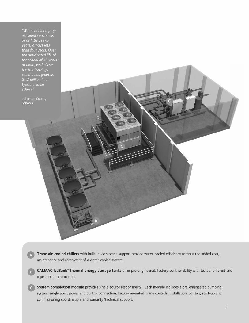
5
“We have found proj-ect simple paybacks of as little as two years, always less than four years. Over the anticipated life of the school of 40 years or more, we believe the total savings could be as great as $1.2 million in a typical middle school.” Johnston County Schools
Trane air-cooled chillers with built-in ice storage support provide water-cooled ef ciency without the added cost,
maintenance and complexity of a water-cooled system.
CALMAC IceBank® thermal energy storage tanks offer pre-engineered, factory-built reliability with tested, ef cient and
repeatable performance.
System completion module provides single-source responsibility. Each module includes a pre-engineered pumping
system, single point power and control connection, factory mounted Trane controls, installation logistics, start-up and
commissioning coordination, and warranty/technical support.
C
5
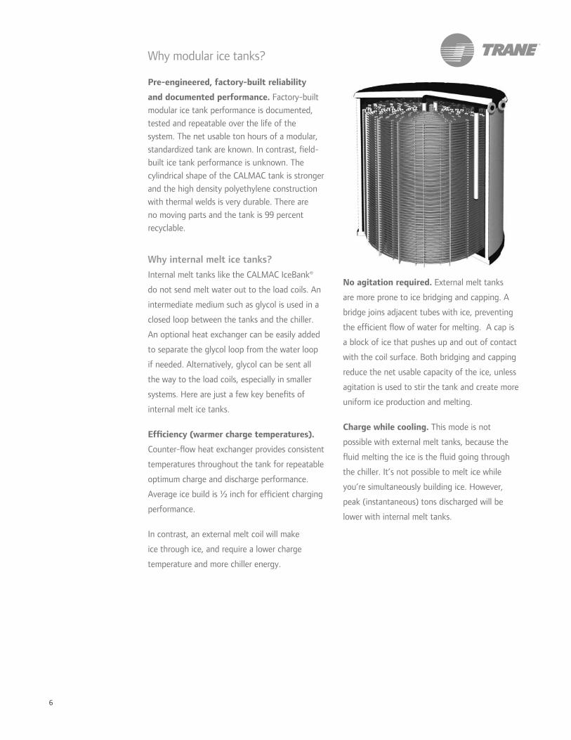
6
No agitation required. External melt tanks
are more prone to ice bridging and capping. A
bridge joins adjacent tubes with ice, preventing
the ef cient ow of water for melting. A cap is
a block of ice that pushes up and out of contact
with the coil surface. Both bridging and capping
reduce the net usable capacity of the ice, unless
agitation is used to stir the tank and create more
uniform ice production and melting.
Charge while cooling. This mode is not
possible with external melt tanks, because the
uid melting the ice is the uid going through
the chiller. It’s not possible to melt ice while
you’re simultaneously building ice. However,
peak (instantaneous) tons discharged will be
lower with internal melt tanks.
Why modular ice tanks?
Pre-engineered, factory-built reliability
and documented performance. Factory-built
modular ice tank performance is documented,
tested and repeatable over the life of the
system. The net usable ton hours of a modular,
standardized tank are known. In contrast, eld-
built ice tank performance is unknown. The
cylindrical shape of the CALMAC tank is stronger
and the high density polyethylene construction
with thermal welds is very durable. There are
no moving parts and the tank is 99 percent
recyclable.
Why internal melt ice tanks?
Internal melt tanks like the CALMAC IceBank®
do not send melt water out to the load coils. An
intermediate medium such as glycol is used in a
closed loop between the tanks and the chiller.
An optional heat exchanger can be easily added
to separate the glycol loop from the water loop
if needed. Alternatively, glycol can be sent all
the way to the load coils, especially in smaller
systems. Here are just a few key bene ts of
internal melt ice tanks.
Ef ciency (warmer charge temperatures).
Counter- ow heat exchanger provides consistent
temperatures throughout the tank for repeatable
optimum charge and discharge performance.
Average ice build is ½ inch for ef cient charging
performance.
In contrast, an external melt coil will make
ice through ice, and require a lower charge
temperature and more chiller energy.

7
Why air-cooled chillers?
Designed for ice-making ef ciency. With
few exceptions, air-cooled chillers use positive
displacement compressors: screw and scroll
technology. They are readily capable of creating
the extra head pressure required on ice storage
systems, and are especially ef cient at night
when the outdoor dry-bulb temperatures are
suppressed. The change in outdoor dry bulb
from day to night is typically more drastic than
the change in outdoor wet bulb, which gives air-
cooled equipment more ef ciency improvement
at night than water-cooled equipment.
Lower system cost. This system is simpler and
therefore costs less to engineer and install, with
lower cost components. Because an air-cooled
system is typically smaller, it’s also easier to
package and pre-engineer, with few options that
take extra time to properly consider. Air-cooled
chillers are often regularly selected to cool anti-
freeze solutions, to protect them while operating
in cold climates, so the cost of glycol may already
be included.
Simplicity. Smaller, air-cooled systems are not
as complex and require fewer maintenance tasks.
As the systems get larger, water-cooled systems
make more sense because water-cooled chillers
are available in higher capacities.
Why use the Stealth™ air-cooled chiller in an ice storage system?
Even better ef ciency. Stealth chillers with ice are 20-30% more ef cient during daytime operation than other air-cooled chillers with ice, leading to a further reduction in both energy and energy cost. For partial storage systems, even the most downsized chiller will not run fully loaded during the on-peak period, except on days with the maximum expected cooling load. Trane Stealth chillers have an ideal combination of ice making capability with ef ciency that does not diminish when operated at part-load during daytime operation.
Lower sound. Stealth chillers are quieter than other air-cooled chillers, so applying them in sound sensitive applications may mean the difference between wanting full storage (having the chillers off during certain parts of the day) and a less expensive partial storage system. In addition, the Stealth chiller can be asked to make ice while still having its premium sound option active.
All models of Trane air-cooled chillers can be deployed into an ice-enhanced air-cooled chiller plant, including the Stealth™ chiller model RTAE.

8
“Building projects shall contain automatic
systems, such as demand limiting or load shifting,
that are capable of reducing electric peak
demand of the building by not less than 10%
of the projected peak demand. Standby power
generation shall not be used to achieve the
reduction in peak demand.“
How much does it cost up front? It may cost
more to install than you think you can afford,
though you may be able to get the system cost
in budget by using the right design. It’s easier to
justify an ice storage system when improvements
to your system are planned, and if you already
have a chilled-water system in place or planned.
The incremental cost is the key.
Depending on the shape of your design-day load
pro le, a downsized chiller can be the right t
if you’re able to use the ice for a portion of the
customary system redundancy allowance. The
gure below shows a chiller sized to handle the
design-day peak load only when supplemented
with ice. The load pro le allows for tanks to be
charged after the coincident cooling loads have
diminished.
There are number of reasons to bring ice
storage into the system design discussion as we
previously addressed. The real question is: When
does it make sense? The answer should be: When
it has the lowest life-cycle cost compared to
alternative systems, and ts within the budget.
There are a number of economic analysis tools
readily available.
The easiest way to include ice storage and
stay within budget is to use air-cooled chillers,
not too many tanks, and a downsized chiller.
However, the lowest life-cycle cost system may
include more tanks and larger chillers and cost
more to install. Whether the preferred larger
system is affordable today can be determined by
the availability of incentives or rebates from one
or a number of sources.
Off-peak cooling using ice storage is not for
everyone. The following are key considerations.
Are you seeking green building
designation? High-performance building
designation steers the discussion toward systems
that have lower energy costs. How much can
an ice storage system reduce annual energy?
Ice storage systems can earn up to six LEED
points (depending on the baseline system and
local utility rates), as well as LEED Pilot Program
points (one or two). For projects following
ASHRAE 189.1 (the high performance green
building standard), ice storage can help satisfy
the prescriptive requirement in 7.4.5.1 Peak Load
Reduction:
When does ice storage make sense?
midnight 6 a.m. noon 6 p.m. midnight
meltice
chillermakeice
chiller capacity
0
25
50
75
cool
ing
load
, % o
f de
sign
100
125
For more information
on ice storage for LEED
projects, refer to Trane
Engineers Newsletter
volume 36-3 (2007).
Visit trane.com/EN.

9
What are the electric rates and are there
incentive programs? Electric rate structures in
many areas are suitable for ice storage. In some
cases, the electric rate structure necessary for
ice storage to reduce energy cost is one that
you’re not subscribed to right now. This can be
as simple as a call to the local utility company to
nd out what electricity rates are available, and if
there are rebates or other incentives in your area
for off-peak cooling.
Generally speaking, ice storage should be
considered when one or more of the following
exist in your electricity rate structure.
• Demand charges greater than $6 per kW
• Daytime energy is $0.06 per kWh more
expensive than night time energy
• Flat rate (“negotiated pricing”) accounts for
the load pro le during negotiations
• Load pro le penalties (i.e., stepped rates,
kWh/kW oating cutoffs, “Hours of Use
Demand”)
• Demand ratchet clauses (“larger of
monthly demand or 80 percent of previous
12-months’ demand”)
• Real time pricing (look ahead signal of
electricity costs, changes as often as every
15 minutes)
• Curtailment rates (agreeing to reduce power
use when a load reduction is requested)
What is the cooling load pro le? The hours
in the day when the chiller isn’t at full capacity
are used to recharge the ice tanks. You may
not have a cooling load that varies enough
throughout the day to accommodate storing
cooling energy. If the load-pro le is at, larger
chilled-water storage systems may become
attractive, especially if the system requires a high
degree of redundancy, such as a data center or a
manufacturing process. Life-cycle analysis should
account for year-round cooling loads. The graph
below shows a cooling load duration curve. The
shape of the curve tells you how many ton-hours
are setting your on-peak electricity costs. A
larger system would satisfy more of system peak
cooling requirements.
Do I have other reasons for storage such
as limited or unreliable electricity? Some
buildings are constrained by the consistent
availability of electricity. Examples include
buildings in areas that suffer from regular
brownouts and blackouts, facilities switching
from steam-driven to electric chillers, buildings
in formerly rural areas without adequate
infrastructure, or those with onsite power
generation. Ice storage can be part of the
solution because it requires less peak energy
generation and smaller emergency generators.
hours of occurrence
cool
ing
load
, % o
f de
sign
20
40
60
80
100
0
cooling load satisfied by melting a small amount of ice and uses a relatively small chiller
cooling load satisfied by melting a larger amount of ice and requires a larger chiller or more hours to charge tanks
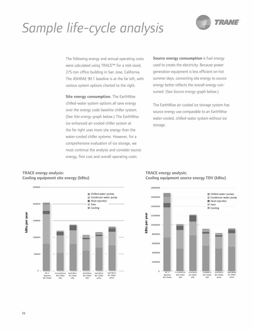
10
The following energy and annual operating costs
were calculated using TRACE™ for a mid-sized,
275-ton of ce building in San Jose, California.
The ASHRAE 90.1 baseline is at the far left, with
various system options charted to the right.
Site energy consumption. The EarthWise
chilled-water system options all save energy
over the energy code baseline chiller system.
(See Site energy graph below.) The EarthWise
ice-enhanced air-cooled chiller system at
the far right uses more site energy than the
water-cooled chiller systems. However, for a
comprehensive evaluation of ice storage, we
must continue the analysis and consider source
energy, rst cost and overall operating costs.
90.1 Baseline
WC Chiller
Convenonal WC Chiller
VAV
EarthWise AC Chiller
VAV
EarthWise WC Chiller
VAV
EarthWise WC Chiller
w/Ice
EarthWise AC Chiller
w/Ice
0
500000
1000000
1500000
2000000
2500000
Chilled-water pumpsCondenser water pumpHeat rejeconFansCooling
kBt
u pe
r yea
r
9900.11 Convenonal EarthhWise EarthWise EarthWise EarthhWWiise
Sample life-cycle analysis
TRACE energy analysis: Cooling equipment source energy TDV (kBtu)
Source energy consumption is fuel energy
used to create the electricity. Because power
generation equipment is less ef cient on hot
summer days, converting site energy to source
energy better re ects the overall energy con-
sumed. (See Source energy graph below.)
The EarthWise air-cooled ice storage system has
source energy use comparable to an EarthWise
water-cooled, chilled-water system without ice
storage.
TRACE energy analysis: Cooling equipment site energy (kBtu)
90.1 Baseline
WC Chiller
Convenonal WC Chiller
VAV
EarthWise AC Chiller
VAV
EarthWise WC Chiller
VAV
EarthWise WC Chiller
w/Ice
EarthWise AC Chiller
w/Ice
0
2000000
4000000
6000000
8000000
10000000
12000000
14000000
16000000
18000000
kBt
u pe
r yea
r
Chilled-water pumpsCondenser water pumpHeat rejeconFansCooling
9900.11 Coonnvveennoonnaal EaarrtthhWWiissee EEaarrtthhWWiisseehill
EEaarrtthhWWiissee EEaarrtthhWWiisseeAC Chill

11
90.1 Baseline
WC Chiller
Conventional WC Chiller
VAV
EarthWise AC Chiller
VAV
EarthWise WC Chiller
VAV
EarthWise WC Chiller
w/Ice
EarthWise AC Chiller
w/Ice
$10,325,891 $9,402,723 $8,709,196 $8,879,988 $8,594,794 $8,405,565 20-year life cycle cost
$13.92/ft2 $12.68/ft2 $10.52/ft2 $11.42/ft2 $11.35/ft2 $10.98/ft2 cooling installed cost per ft2
9900.11 CCoonnvveennttiioonnaal EEaarrtthhWWiissee EEaarrtthhWWiissee EEaarrtthhWWiissee EEaarrtthhWWiissee
$72,851 $64,279 $68,948 $62,048 $55,579 $56,637
$52,865 $48,653 $48,669
$48,658 $54,531 $55,524
$108,890
$96,695 $97,657 $94,788 $94,751 $96,829
$88,689
$83,606 $85,277
$80,063 $70,942 $69,052
$46,467
$47,305 $43,541 $45,386
$43,501 $42,953
$10,000
$60,000
$110,000
$160,000
$210,000
$260,000
$310,000
$360,000
$410,000 annual maintenancetower water consumponmid-peak demandon-peak demandmid-peak consumponoff-peak consumponon-peak consumpon
TRACE life-cycle analysis: Annual operating expense, full building
System costs. Annual operating costs include
energy, maintenance and water costs. (See
life-cycle graph below.) First costs include the
equipment and installation costs of the system.
Life-cycle costs include all revenue and cost
streams for 20 years, including economic factors
such as in ation and tax implications.
For this particular combination of building,
climate, and utility tariff, the EarthWise ice-
enhanced air-cooled chiller system had the lowest
rst cost and the lowest total cost of ownership
of all the alternatives.
For LEED® designation, this system would have
earned approximately two points for energy cost
savings and would help with water conservation
credits. In addition, a LEED 2009 pilot program
allows for an additional one to two points for ice-
storage systems, depending on how the building
automation system responds to utility signals.
Life-cycle analysis demonstrates 14 -20% energy cost savings.• Two to three LEED
points• One to two LEED
pilot points• Plus help on water
credits(for more points don’t downsize pipes or ducts)
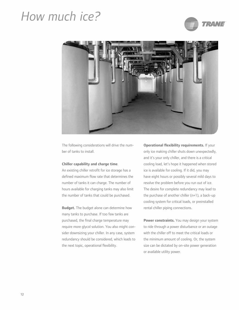
12
How much ice?
The following considerations will drive the num-
ber of tanks to install.
Chiller capability and charge time.
An existing chiller retro t for ice storage has a
de ned maximum ow rate that determines the
number of tanks it can charge. The number of
hours available for charging tanks may also limit
the number of tanks that could be purchased.
Budget. The budget alone can determine how
many tanks to purchase. If too few tanks are
purchased, the nal charge temperature may
require more glycol solution. You also might con-
sider downsizing your chiller. In any case, system
redundancy should be considered, which leads to
the next topic, operational exibility.
Operational exibility requirements. If your
only ice making chiller shuts down unexpectedly,
and it’s your only chiller, and there is a critical
cooling load, let’s hope it happened when stored
ice is available for cooling. If it did, you may
have eight hours or possibly several mild days to
resolve the problem before you run out of ice.
The desire for complete redundancy may lead to
the purchase of another chiller (n+1), a back-up
cooling system for critical loads, or preinstalled
rental chiller piping connections.
Power constraints. You may design your system
to ride through a power disturbance or an outage
with the chiller off to meet the critical loads or
the minimum amount of cooling. Or, the system
size can be dictated by on-site power generation
or available utility power.
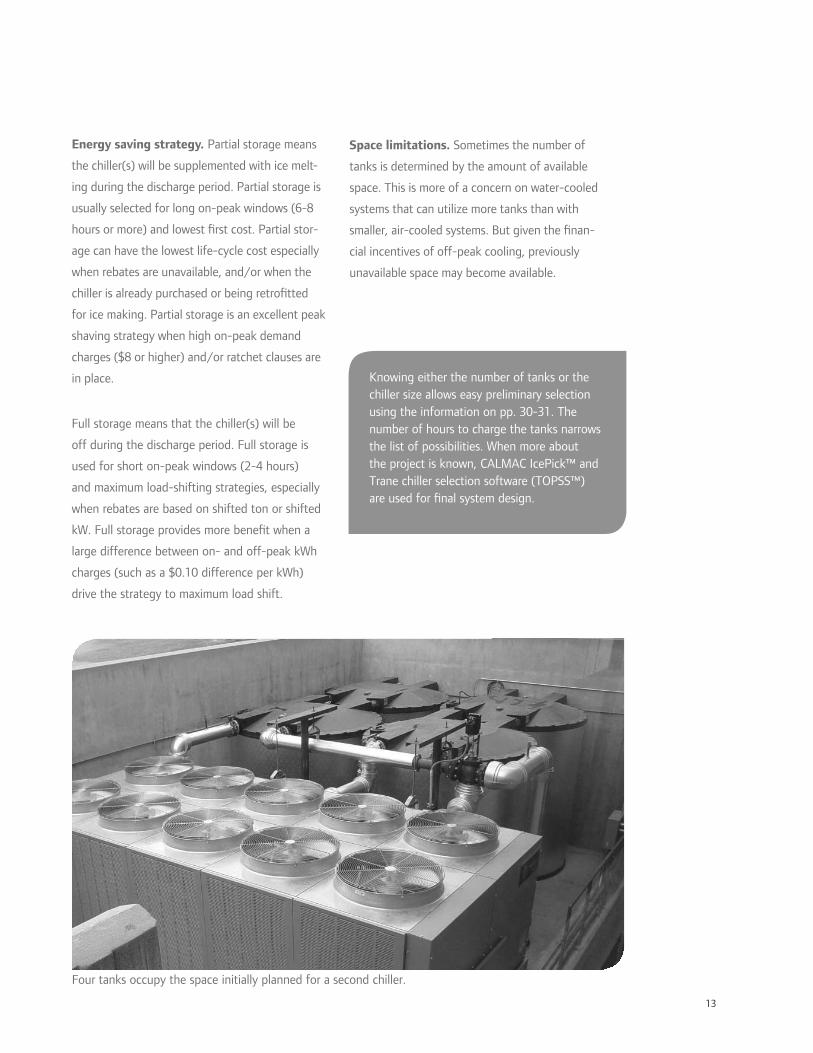
13
Energy saving strategy. Partial storage means
the chiller(s) will be supplemented with ice melt-
ing during the discharge period. Partial storage is
usually selected for long on-peak windows (6-8
hours or more) and lowest rst cost. Partial stor-
age can have the lowest life-cycle cost especially
when rebates are unavailable, and/or when the
chiller is already purchased or being retro tted
for ice making. Partial storage is an excellent peak
shaving strategy when high on-peak demand
charges ($8 or higher) and/or ratchet clauses are
in place.
Full storage means that the chiller(s) will be
off during the discharge period. Full storage is
used for short on-peak windows (2-4 hours)
and maximum load-shifting strategies, especially
when rebates are based on shifted ton or shifted
kW. Full storage provides more bene t when a
large difference between on- and off-peak kWh
charges (such as a $0.10 difference per kWh)
drive the strategy to maximum load shift.
Knowing either the number of tanks or the chiller size allows easy preliminary selection using the information on pp. 30-31. The number of hours to charge the tanks narrows the list of possibilities. When more about the project is known, CALMAC IcePick™ and Trane chiller selection software (TOPSS™) are used for nal system design.
Space limitations. Sometimes the number of
tanks is determined by the amount of available
space. This is more of a concern on water-cooled
systems that can utilize more tanks than with
smaller, air-cooled systems. But given the nan-
cial incentives of off-peak cooling, previously
unavailable space may become available.
Four tanks occupy the space initially planned for a second chiller.

14
How much chiller?Possible starting points:
• Maximum number of tanks your chiller can
charge in the amount of available hours
(maximum freeze time)
• Smallest chiller needed on a design
day, with or without an ice contribution
(minimum melt rate)
• Electrical constraint for the chiller on a
design day
• Maximum number of tanks you are
prepared to put on site
Visualize the options
The following two gures show a load pro le
and two different options for the amount of the
design day load that is to be met with the stored
ice.
Determining how much of the on-peak load
should be met with ice storage is arbitrary, and is
typically dictated by the cooling load pro le and
the objectives of the designer or building owner.
A common starting point is 30 to 40 percent
of the design day cooling load. As more of the
building load is served by ice storage, on-peak
chiller capacity and building electrical demand
are reduced. However, more ice needs a larger
chiller to charge the tanks in the same length of
time. There is a balance to be struck.
Greater ice storage capacity requires greater
chiller ice-building capacity. One solution that’s
easy to nd mathematically is the ice storage
capacity that results in a chiller working as hard
as it can during the day, while still being able to
charge all the tanks at night. While this selection
results in the smallest chiller net capacity, it does
not necessarily represent the best life-cycle cost
system. TRACE software can help you determine
if a larger system is economically justi ed.
midnight 6 a.m. noon 6 p.m. midnight
meltice
chillermakeice
chiller capacity
0
25
50
75
cool
ing
load
, % o
f de
sign
100
125
midnight 6 a.m. noon 6 p.m. midnight
meltice
chillermakeice
chiller capacity
0
25
50
75
cool
ing
load
, % o
f de
sign
100
125
conventional chiller sizing downsized chiller sizing

15
chillerpumps
existingchillers
coolingcoil
ice storagetanks
icepump
loadpump
VFD
icevalve
chiller
heatexchanger
Ice plant as a system component
Adding ice to a chilled-water system
While existing air-cooled chillers can often
be retro t for making ice, other types of
chilled-water systems can bene t by adding a
self-contained ice plant to the system. Below
is an example of an ice-enhanced air-cooled
chiller plant installed upstream of one of two
existing centrifugal chillers, separated by a heat
exchanger to isolate glycol. If the ows are
suitable, the new plant could be upstream of
both existing chillers.
Bene ts of adding ice to an existing chilled-
water system include redundancy for one or more
chillers, expansion of the system, maximum reuse
of existing components and better system ef-
ciency. Existing chillers do not need retro tting
and can handle cooling loads while the new ice
chiller charges the tanks.
Consider the location of the heat exchanger
to balance with ice plant ow rates and capacity.
Locating the heat exchanger upstream of exist-
ing chiller(s) provides easier load-shifting and
ice-priority control, while a downstream ice plant
location improves chiller ef ciency.

16
Standard con gurations
Variable flow cooling, constant flow charging
Features
• Lower pump energy than constant ow
• Load bypass during charge mode charges
tanks quickly
• Variable Frequency Drive (VFD) eliminates
need for triple duty valve for system
balancing
• VFD communicates with system controller for
power management and reporting
Considerations
• Cost of VFD on pump
• Building load during charge cycle should be
kept to a minimum either by:
• ignoring calls for cooling, or
• installing a separate cooling system for
critical spaces, or
• delaying charge until after loads diminish,
reducing the amount of time available for
charging tanks.

17
Decoupled with heat exchanger
Features
• Easier to plug into an existing decoupled
system, possibly with an existing air-cooled
chiller, reuse distribution pump
• Cost of glycol is lower with the shorter glycol
loop, a consideration as systems get larger
• Water in the coils rather than glycol
Considerations
• Cost of heat exchanger
• Cooling during charge mode is more
complicated and therefore not supported by
this phase of prepackaged system controls
• Care must be taken to avoid freezing water
on the load side of the heat exchanger – a
tempering loop may be preferred
18
The beauty of a prepackaged EarthWise
System is that it ef ciently passes knowledge
and expertise to the people who make it
happen. While this makes us choose speci c,
detailed con gurations, it also allows for an
advanced starting point—reducing the risk
and confusion of doing something for the
rst time.
Trane and CALMAC give you tools for
calculating system payback, optimizing
control algorithms, modeling system
performance, and provide BIM drawings to
support ef cient design practices.
Supports the way you workFor the Engineer
Making it all happen without blowing the budget
is critical. Trane and CALMAC worked together
to create system drawings and control sequences
to help you—whether you select one of our
packaged systems, or make a custom design of
your own.
For selecting the right size system, CALMAC
IcePick™ software takes you from a design
day load pro le to the smallest chiller, or other
combinations of ice and chiller to meet the
design day load with capacity to spare. Another
software tool, IceCycle from Trane, helps
determine the nal charge temperature based
on the chiller, the ow rate, and the number of
tanks. This tool can be used to determine:
• if the chiller and tanks operate within their
ow constraints during the charging mode,
• the nal charge temperature for a full
charge based on the ow rate, chiller and
tanks,
• the max discharge tons and stored ton-
hours, and
• if the tanks can be charged in the amount of
time available.
(Data on p. 24 provides information for the
chiller performance entries for IceCycle and
IcePick.)
Once you have IcePick and IceCycle results,
the chiller selection software will provide
performance at the average charge temperature
and allow you to test stability, performance, and
percent glycol required for the selected chiller at
the nal charge temperature.

19
IceCycle from Trane
Focuses on balancing ows between chiller(s) and tanks,
nal temperature, and time to charge.
CALMAC IcePick design day chiller size starting point
With the design day load pro le, this software nds
combinations of chiller and tanks.
Chiller selection software
Trane of cial product selection software (TOPSS™) provides
detailed capacity and ow information.
TRACE modeling software and support
TRACE energy analysis software can take your load design
entries and do what-if scenarios for several options.
BIM drawing les
Chillers, tanks and system completion skids available in
.dwg and Revit formats.
90.1 Baseline
WC Chiller
Conventional WC Chiller
VAV
EarthWise AC Chiller
VAV
EarthWise WC Chiller
VAV
EarthWise WC Chiller
w/Ice
EarthWise AC Chiller
w/Ice
$10,325,891 $9,402,723 $8,709,196 $8,879,988 $8,594,794 $8,405,565 20-year life cycle cost
$13.92/ft2 $12.68/ft2 $10.52/ft2 $11.42/ft2 $11.35/ft2 $10.98/ft2 cooling installed cost per ft2
9900.11 CCoonnvveennttiioonnaal EEaarrtthhWWiissee EEaarrtthhWWiissee EEaarrtthhWWiissee EEaarrtthhWWiissee
$72,851 $64,279 $68,948 $62,048 $55,579 $56,637
$52,865 $48,653 $48,669
$48,658 $54,531 $55,524
$108,890
$96,695 $97,657 $94,788 $94,751 $96,829
$88,689
$83,606 $85,277
$80,063 $70,942 $69,052
$46,467
$47,305 $43,541 $45,386
$43,501 $42,953
$10,000
$60,000
$110,000
$160,000
$210,000
$260,000
$310,000
$360,000
$410,000 annual maintenancetower water consumponmid-peak demandon-peak demandmid-peak consumponoff-peak consumponon-peak consumpon
Schematics with Bills of Material
Layouts of four sizes of completion skids, with and
without the optional heat exchanger, are available.
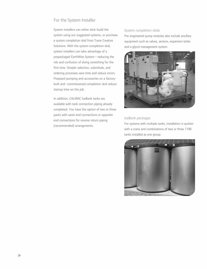
20
For the System Installer
System installers can either stick-build the
system using our suggested systems, or purchase
a system completion skid from Trane Creative
Solutions. With the system completion skid,
system installers can take advantage of a
prepackaged EarthWise System—reducing the
risk and confusion of doing something for the
rst time. Simpler selection, submittals, and
ordering processes save time and reduce errors.
Prepiped pumping and accessories on a factory-
built and -commissioned completion skid reduce
startup time on the job.
In addition, CALMAC IceBank tanks are
available with tank connection piping already
completed. You have the option of two or three
packs with same end connections or opposite
end connections for reverse return piping
(recommended) arrangements.
System completion skids
Pre-engineered pump modules also include ancillary
equipment such as valves, sensors, expansion tanks
and a glycol management system.
IceBank packages
For systems with multiple tanks, installation is quicker
with a crane and combinations of two or three 1190
tanks installed as one group.
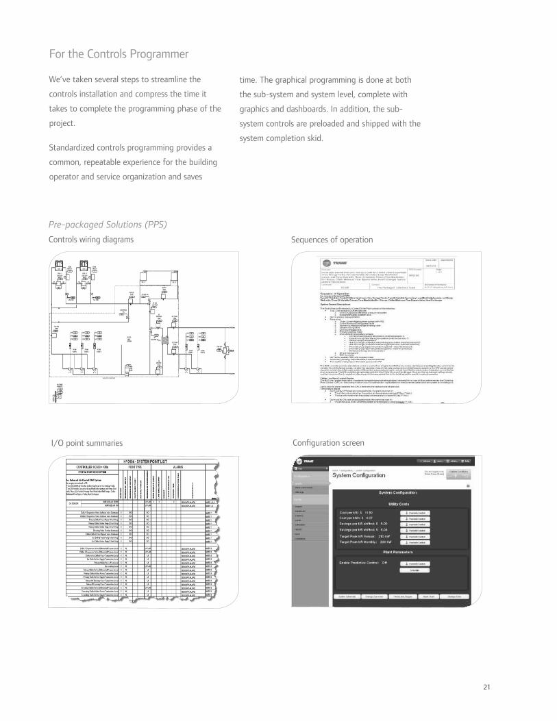
21
For the Controls Programmer
We’ve taken several steps to streamline the
controls installation and compress the time it
takes to complete the programming phase of the
project.
Standardized controls programming provides a
common, repeatable experience for the building
operator and service organization and saves
Pre-packaged Solutions (PPS)
Controls wiring diagrams Sequences of operation
I/O point summaries Con guration screen
time. The graphical programming is done at both
the sub-system and system level, complete with
graphics and dashboards. In addition, the sub-
system controls are preloaded and shipped with the
system completion skid.
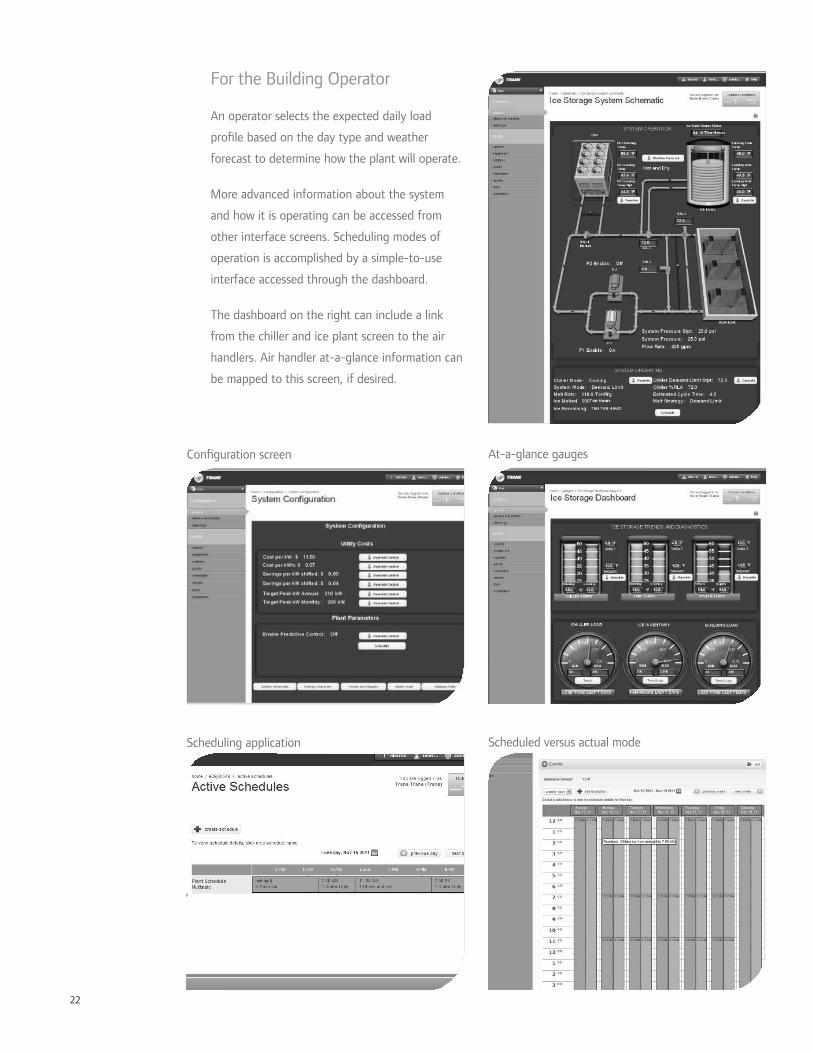
22
For the Building Operator
An operator selects the expected daily load
pro le based on the day type and weather
forecast to determine how the plant will operate.
More advanced information about the system
and how it is operating can be accessed from
other interface screens. Scheduling modes of
operation is accomplished by a simple-to-use
interface accessed through the dashboard.
The dashboard on the right can include a link
from the chiller and ice plant screen to the air
handlers. Air handler at-a-glance information can
be mapped to this screen, if desired.
Scheduling application Scheduled versus actual mode
Con guration screen At-a-glance gauges
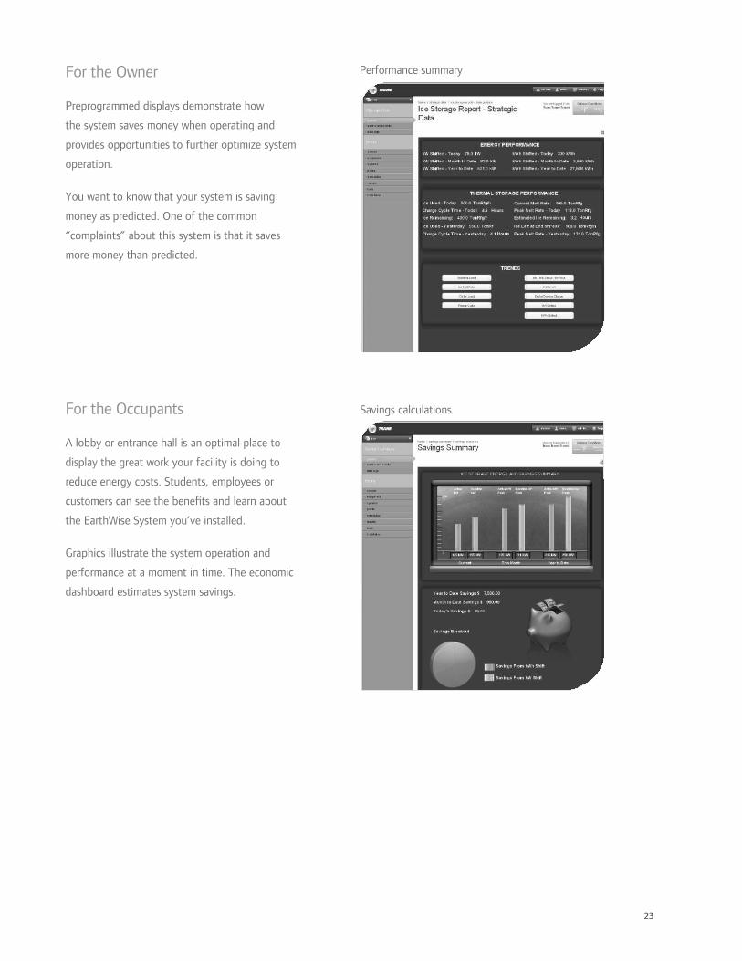
23
For the Owner
Preprogrammed displays demonstrate how
the system saves money when operating and
provides opportunities to further optimize system
operation.
You want to know that your system is saving
money as predicted. One of the common
“complaints” about this system is that it saves
more money than predicted.
For the Occupants
A lobby or entrance hall is an optimal place to
display the great work your facility is doing to
reduce energy costs. Students, employees or
customers can see the bene ts and learn about
the EarthWise System you’ve installed.
Graphics illustrate the system operation and
performance at a moment in time. The economic
dashboard estimates system savings.
Performance summary
Savings calculations

24
Air-cooled Chillers
Chiller performance data
operating conditions chiller ow and pressure drop combined capacity and ef ciency
evap. 40/54 °F95°F ent. air
evap 42/56 °F 95°F ent. air
evap 48/56 °F95°F ent. air
min ow
PD@min ow
ow @3x nom. tons
PD@3xnom. ton
ow
max ow
PD@ max ow
48-38 °F
56-48 °F
melt mode at 95°F ambient
tons kW tons kW tons kW gpmft of H2O gpm ft of H2O gpm
ft of H2O tanks
melt tons
chiller tons
kW/ton
Full load design
day EER
CGAM020 18.3 22.8 18.9 23.0 20.5 23.5 29.1 6.4 60.0 25.7 69.7 32.9 1 23.5 20.5 0.534 22.5
CGAM026 23.3 29.4 24.1 29.7 26.1 30.3 37.2 7.4 78.0 31.9 89.4 41.0 1 30.6 26.1 0.534 22.5
CGAM030 26.1 32.9 27.0 33.2 30.0 33.9 41.8 9.4 90.0 43.1 100.3 52.5 1 35.3 30.0 0.519 23.1
CGAM035 30.9 39.1 32.0 39.4 34.6 40.2 49.1 6.5 105.0 27.9 117.7 34.4 2 41.2 34.6 0.530 22.6
CGAM040 35.2 44.7 36.5 45.1 40.0 46.2 56.7 9.1 120.0 38.8 136.1 49.5 2 47.1 40.0 0.530 22.6
CGAM052 45.6 57.6 47.2 58.1 51.3 59.6 73.5 7.9 156.0 33.4 176.4 42.1 3 58.8 51.3 0.541 22.2
CGAM060 52.5 65.1 54.4 65.6 59.5 66.9 83.9 8.0 180.0 34.3 201.4 42.3 3 70.6 59.5 0.514 23.3
CGAM070 61.7 76.9 63.9 77.6 69.6 79.4 99.4 7.6 210.0 33.0 238.6 42.2 3 82.4 69.6 0.522 23.0
CGAM080 70.5 85.4 73.0 86.1 79.5 88.0 114.7 7.4 240.0 30.3 275.3 39.2 4 94.1 79.5 0.507 23.7
CGAM090 79.6 96.3 82.3 97.2 89.5 99.4 128.3 6.7 270.0 27.9 307.8 35.8 4 105.9 89.5 0.509 23.6
CGAM100 89.3 107.4 92.5 108.2 100.7 110.4 144.4 7.3 300.0 30.1 346.6 39.6 4 117.6 100.7 0.506 23.7
CGAM110 97.2 119.8 100.7 120.8 109.4 123.4 156.5 7.5 330.0 32.3 375.7 41.3 5 129.4 109.4 0.517 23.2
CGAM120 106.2 132.0 109.9 133.2 119.3 136.3 169.9 8.6 360.0 38.3 407.7 48.8 5 141.2 119.3 0.523 22.9
CGAM130 114.9 137.9 118.9 139.1 129.2 142.1 183.7 8.9 390.0 40.9 440.8 51.0 6 152.9 129.2 0.504 23.8
RTAC140S 122.3 160.6 128.1 164.1 146.4 175.5 193.0 3.8 420.0 18.4 709.0 51.9 6 164.7 146.4 0.564 21.3
RTAC140H 124.9 157.8 131.1 161.0 150.8 171.7 202.0 3.2 420.0 14.2 741.0 44.0 6 164.7 150.8 0.544 22.1
RTAC155S 134.2 174.7 140.5 178.5 160.8 191.0 215.0 4.0 465.0 19.1 785.0 54.1 7 182.4 160.8 0.557 21.6
RTAC155H 138.7 171.2 145.4 174.7 167.0 186.1 217.0 3.2 465.0 15.3 796.0 44.4 7 182.4 167.0 0.533 22.5
RTAC170S 148.7 190.4 155.3 194.4 175.9 206.9 202.0 3.2 510.0 21.2 741.0 43.9 7 200.0 175.9 0.550 21.8
RTAC170H 151.1 184.8 158.4 188.6 181.8 200.9 241.0 3.3 510.0 15.1 883.0 44.9 7 200.0 181.8 0.526 22.8
RTAC185S 163.3 210.7 170.3 215.2 192.6 229.5 226.0 3.5 555.0 21.9 796.0 44.3 8 217.6 192.6 0.559 21.4
RTAC185H 169.4 206.9 176.8 211.0 199.8 224.0 217.0 3.5 555.0 23.8 796.0 48.1 8 217.6 199.8 0.537 22.4
RTAC200S 178.6 231.8 186.3 236.8 210.4 253.0 241.0 3.3 600.0 21.1 883.0 44.9 9 235.3 210.4 0.568 21.1
RTAC200H 185.8 228.3 193.9 233.0 218.7 247.7 241.0 3.5 600.0 22.9 883.0 48.7 9 235.3 218.7 0.546 22.0
RTAC225S 199.0 256.8 207.0 262.1 231.4 278.9 223.0 3.7 675.0 35.1 796.0 48.1 10 294.1 231.4 0.531 22.6
RTAC225H 201.9 250.9 210.4 256.1 236.7 272.6 241.0 3.5 675.0 28.9 883.0 48.6 10 294.1 236.7 0.514 23.4
RTAC250S 218.6 281.3 227.4 287.3 254.1 306.0 241.0 3.5 750.0 35.6 883.0 48.6 11 323.5 254.1 0.530 22.7
RTAC250H 223.8 276.9 233.1 282.6 261.2 300.3 241.0 3.5 750.0 35.6 883.0 48.6 11 323.5 261.2 0.514 23.4
RTAC275S 240.4 309.1 250.6 315.5 281.9 335.6 309.0 3.4 825.0 25.2 1134.0 46.7 13 352.9 281.9 0.529 22.7
RTAC275H 245.4 299.3 256.7 305.6 292.3 325.6 375.0 3.5 825.0 17.3 1374.0 47.6 13 352.9 292.3 0.505 23.8
RTAC300S 270.8 352.1 282.0 359.7 316.1 383.0 339.0 3.4 900.0 25.1 1243.0 47.1 15 411.8 316.1 0.526 22.8
RTAC300H 277.8 342.7 290.0 350.0 327.3 372.7 375.0 3.4 900.0 20.7 1374.0 47.5 15 411.8 327.3 0.504 23.8
RTAC350S 308.4 401.5 321.1 410.4 359.5 437.8 375.0 3.4 1050.0 28.3 1374.0 47.5 17 441.2 359.5 0.547 21.9
RTAC350H 312.3 377.8 325.8 385.0 367.9 407.6 404.0 3.5 1050.0 24.8 1483.0 48.5 17 441.2 367.9 0.504 23.8
RTAC400S 365.9 474.1 380.4 484.0 424.3 514.3 404.0 3.5 1200.0 32.3 1483.0 48.5 19 470.6 424.3 0.575 20.9
RTAC400H 376.3 464.3 392.0 473.9 440.6 503.6 461.0 3.6 1200.0 25.3 1690.0 49.3 19 470.6 440.6 0.553 21.7
RTAC450S 403.8 523.9 419.6 535.0 466.9 568.7 422.0 3.5 1350.0 37.5 1548.0 48.7 21 529.4 466.9 0.571 21.0
RTAC500H 442.1 574.1 459.4 586.5 511.6 624.9 461.0 3.6 1500.0 39.3 1690.0 49.3 23 588.2 511.6 0.568 21.1
RTAE150 124.5 142.5 132.0 146.0 154.4 155.7 171.0 2.9 450.0 24.3 626.0 46.9 7 200.0 154.4 0.439 27.3
RTAE165 142.2 158.8 150.5 162.4 176.0 173.3 187.0 3.0 495.0 24.9 684.0 47.5 8 217.6 176.0 0.440 27.3
RTAE180 155.9 178.1 164.8 182.1 191.7 193.4 202.0 2.8 540.0 24.4 742.0 45.9 9 235.3 191.7 0.453 26.5
RTAE200 172.2 195.3 182.3 199.8 213.8 214.0 228.0 2.9 600.0 24.0 835.0 46.5 10 294.1 213.8 0.421 28.5
RTAE225 194.9 211.2 205.8 215.7 239.3 229.9 261.0 3.0 675.0 23.5 957.0 47.3 11 323.5 239.3 0.408 29.4
RTAE250 217.5 243.7 229.3 249.1 265.6 266.3 288.0 3.0 750.0 24.3 1055.0 48.0 12 340.0 265.6 0.440 27.3
RTAE275 238.3 264.4 251.8 270.5 292.2 288.8 318.0 2.8 825.0 22.8 1165.0 45.5 13 352.9 292.2 0.448 26.8
RTAE300 257.1 287.6 272.6 294.6 319.2 315.5 354.0 2.9 900.0 22.0 1299.0 46.0 14 375.0 319.2 0.454 26.4
all chiller and tank performance based on 25% ethylene glycol
System Components
RTAC CGAM
d i d f i
RTAE
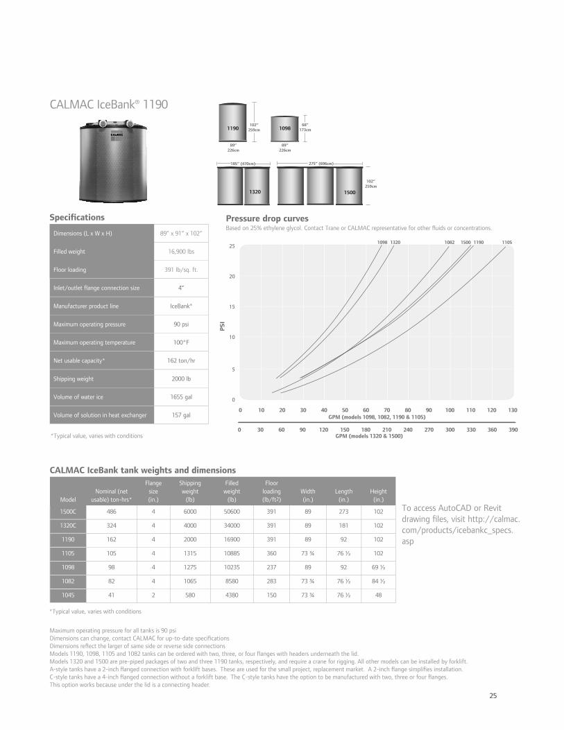
25
CALMAC IceBank® 1190
Speci cations Dimensions (L x W x H) 89” x 91” x 102”
Filled weight 16,900 lbs
Floor loading 391 lb/sq. ft.
Inlet/outlet ange connection size 4”
Manufacturer product line IceBank®
Maximum operating pressure 90 psi
Maximum operating temperature 100°F
Net usable capacity* 162 ton/hr
Shipping weight 2000 lb
Volume of water ice 1655 gal
Volume of solution in heat exchanger 157 gal
CALMAC IceBank tank weights and dimensions
ModelNominal (net
usable) ton-hrs*
Flange size(in.)
Shipping weight
(lb)
Filledweight
(lb)
Floor loading(lb/ft2)
Width(in.)
Length(in.)
Height(in.)
1500C 486 4 6000 50600 391 89 273 102
1320C 324 4 4000 34000 391 89 181 102
1190 162 4 2000 16900 391 89 92 102
1105 105 4 1315 10885 360 73 ¾ 76 ½ 102
1098 98 4 1275 10235 237 89 92 69 ½
1082 82 4 1065 8580 283 73 ¾ 76 ½ 84 ½
1045 41 2 580 4380 150 73 ¾ 76 ½ 48
Maximum operating pressure for all tanks is 90 psiDimensions can change, contact CALMAC for up-to-date speci cationsDimensions re ect the larger of same side or reverse side connectionsModels 1190, 1098, 1105 and 1082 tanks can be ordered with two, three, or four anges with headers underneath the lid.Models 1320 and 1500 are pre-piped packages of two and three 1190 tanks, respectively, and require a crane for rigging. All other models can be installed by forklift. A-style tanks have a 2-inch anged connection with forklift bases. These are used for the small project, replacement market. A 2-inch ange simpli es installation.C-style tanks have a 4-inch anged connection without a forklift base. The C-style tanks have the option to be manufactured with two, three or four anges. This option works because under the lid is a connecting header.
To access AutoCAD or Revit drawing les, visit http://calmac.com/products/icebankc_specs.asp
Pressure drop curves
25
20
15
10
5
0
1098 1320 1082 1500 1190 1105
PS
I
GPM (models 1320 & 1500)
GPM (models 1098, 1082, 1190 & 1105)0 8070605040302010 13012011010090
0 240210180150120906030 390360330300270
102”259cm
68”173cm
89”226cm
89”226cm
185” (470cm) 275” (696cm)
102”259cm
1190 1098
1320 1500
*Typical value, varies with conditions
Based on 25% ethylene glycol. Contact Trane or CALMAC representative for other uids or concentrations.
*Typical value, varies with conditions
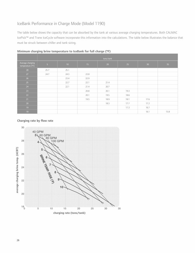
26
IceBank Performance in Charge Mode (Model 1190)
The table below shows the capacity that can be absorbed by the tank at various average charging temperatures. Both CALMAC
IcePick™ and Trane IceCycle software incorporate this information into the calculations. The table below illustrates the balance that
must be struck between chiller and tank sizing.
Minimum charging brine temperature to IceBank for full charge (ºF)
tons/tank
Average charging temperature (ºF)
5 10 15 20 25 30 35
28 25.7 25.1
27 24.7 24.3 23.8
26 23.4 22.9
25 22.7 22.1 21.4
24 22.1 21.4 20.7
23 20.8 20.1 19.3
22 20.1 19.5 18.6
21 19.5 18.9 18.1 17.6
20 18.3 17.7 17.2
19 17.3 16.7
18 16.1 15.8
charging rate (tons/tank)
aver
age
char
ging
bri
ne t
emp.
(A
CB
T)
Charging rate by ow rate
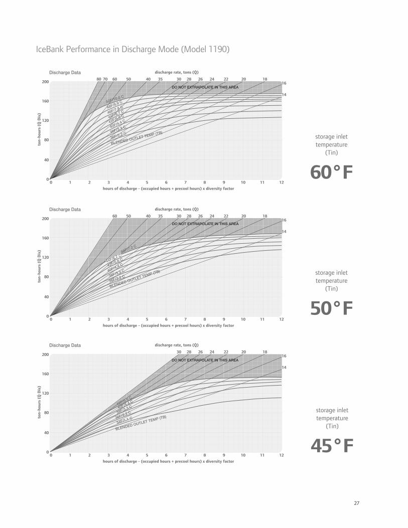
27
IceBank Performance in Discharge Mode (Model 1190)
0 7654321 12111098
hours of discharge - (occupied hours + precool hours) x diversity factor
160
120
80
40
0
20060 354050 262830 24 22 20 18
16
14
do not extrapolate in this area
7080
discharge rate, tons (Q)
ton-
hour
s (Q
Dis
)
storage inlettemperature
(Tin)
60°F
0 7654321 12111098
hours of discharge - (occupied hours + precool hours) x diversity factor
160
120
80
40
0
20060 354050 262830 24 22 20 18
16
14
do not extrapolate in this area
discharge rate, tons (Q)
ton-
hour
s (Q
Dis
)
0 7654321 12111098
hours of discharge - (occupied hours + precool hours) x diversity factor
160
120
80
40
0
200262830 24 22 20 18
16
14
do not extrapolate in this area
discharge rate, tons (Q)
ton-
hour
s (Q
Dis
)
storage inlettemperature
(Tin)
50°F
storage inlettemperature
(Tin)
45°F

28
System Completion Module
Electrical data pump FLA controls (amps) 208V 460V 575V
skid type
pumps run-ning
pump impeller
size HP 208V 460V 575V 208V 460V 575Vskid MCA RDE
skid MOP
skid MCA RDE
skid MOP
skid MCA RDE
skid MOP
No HEX, 1 Chiller 1 1.5x1x8 15 42 19 17.2 6.94 3.14 2.5 59.4 70 100 26.9 35 45 24.0 30 40
1 HEX, 1 Chiller 1 1.5x1x6 7.5 22 9.9 8.6 6.94 3.14 2.5 34.3 40 50 15.5 20 25 13.3 20 25
No HEX, 2 Chiller 2 1.5x1x8 15 42 19 17.2 6.94 3.14 2.5 101.4 125 125 45.9 60 60 41.2 50 50
1 HEX, 2 Chiller 2 1.5x1x6 7.5 22 9.9 8.6 6.94 3.14 2.5 56.4 70 70 25.4 30 35 21.9 25 30
No HEX, 1 Chiller 1 3x1.5x8 20 54 25 20.9 6.94 3.14 2.5 74.4 90 125 34.4 45 50 28.6 35 45
1 HEX, 1 Chiller 1 3x2x13 15 42 19 17.2 6.94 3.14 2.5 59.4 70 100 26.9 35 45 24.0 30 40
No HEX, 2 Chiller 2 3x1.5x8 20 54 25 20.9 6.94 3.14 2.5 128.4 150 175 59.4 70 80 49.5 60 70
1 HEX, 2 Chiller 2 3x2x13 15 42 19 17.2 6.94 3.14 2.5 101.4 125 125 45.9 60 60 41.2 50 50
No HEX, 1 Chiller 1 3x2.5x8 30 80 36 32.7 6.94 3.14 2.5 106.94 150 175 48.1 60 80 43.4 60 70
1 HEX, 1 Chiller 1 4x3x11.5 20 54 25 20.9 6.94 3.14 2.5 74.4 90 125 34.4 45 50 28.6 35 45
No HEX, 2 Chiller 2 3x2.5x8 30 80 36 32.7 6.94 3.14 2.5 186.9 225 250 84.1 100 110 76.1 90 100
1 HEX, 2 Chiller 2 4x3x11.5 20 54 25 20.9 6.94 3.14 2.5 128.4 150 175 59.4 70 80 49.5 60 70
No HEX, 1 Chiller 1 4x3x8 30 80 36 32.7 6.94 3.14 2.5 106.94 150 175 48.1 60 80 43.4 60 70
1 HEX, 1 Chiller 1 4x3x11.5 20 54 25 20.9 6.94 3.14 2.5 74.4 90 125 34.4 45 50 28.6 35 45
No HEX, 2 Chiller 2 4x3x8 30 80 36 32.7 6.94 3.14 2.5 186.9 225 250 84.1 100 110 76.1 90 100
1 HEX, 2 Chiller 2 4x3x11.5 20 54 25 20.9 6.94 3.14 2.5 128.4 150 175 59.4 70 80 49.5 60 70
No HEX, 1 Chiller 1 4x3x8 40 104 47 39 6.94 3.14 2.5 136.9 175 225 61.9 80 100 51.3 70.0 90
1 HEX, 1 Chiller 1 5x4x11.5 25 68 31 25.4 6.94 3.14 2.5 91.9 110 150 41.9 50 70 34.3 45.0 50
No HEX, 2 Chiller 2 4x3x8 40 104 47 39 6.94 3.14 2.5 240.9 300 300 108.9 125 150.0 90.3 100.0 125
1 HEX, 2 Chiller 2 5x4x11.5 25 68 31 25.4 6.94 3.14 2.5 159.9 200 225 72.9 90 100.0 59.7 70.0 80
No HEX, 1 Chiller 1 5x5x13H 75 210 95 76 6.94 3.14 2.5 269.4 350 450 121.9 150 200 97.5 125 150
1 HEX, 1 Chiller 1 6x5x11.5 40 104 47 39 6.94 3.14 2.5 136.9 175 225 61.9 80 100 51.3 70 90
No HEX, 2 Chiller 2 5x5x13H 75 210 95 76 6.94 3.14 2.5 479.4 600 600 216.9 250 300 173.5 200 225
1 HEX, 2 Chiller 2 6x5x11.5 40 104 47 39 6.94 3.14 2.5 240.9 300 300 108.9 125 150 90.3 100 125
No HEX, 1 Chiller 1 6x5x15L 100 261 118 95 6.94 3.14 2.5 333.2 400 500 150.6 200 250 121.3 150 200
1 HEX, 1 Chiller 1 8x6x12M 50 130 59 49 6.94 3.14 2.5 169.4 225 250 76.9 100 125 63.8 80 110
No HEX, 2 Chiller 2 6x5x15L 100 261 118 95 6.94 3.14 2.5 594.2 700 800 268.6 300 350 216.3 250 300
1 HEX, 2 Chiller 2 8x6x12M 50 130 59 49 6.94 3.14 2.5 299.4 350 400 135.9 175 175 112.8 125 150
Dimensions and performance data bypass skid
skid type
total head (ft)
skid head (ft)
external head (ft)
pipe mains size
system ow
(GPM)
pressure drop
(ft/100’)velocity (ft/sec)
line size
ow (GPM)
PD (ft/100’)
velocity (ft/sec)
pipe size length width height
dry weight (lb)
± 10%
operating weight (lb)
± 10%No HEX, 1 Chiller 166 86 80 3” 81 2.06 3.52 2.5” 41.8 1.82 2.81 2.5” 12’ 7’ 70” 5271 6156
1 HEX, 1 Chiller 109 109 N/A 3” 81 2.06 3.52 2.5” N/A N/A N/A N/A 17’ 7’ 83” 7394 8426
No HEX, 2 Chiller 166 86 80 4” 162 1.91 4.08 2.5” 41.8 1.82 2.81 2.5” 12’ 7’ 78” 6075 7102
1 HEX, 2 Chiller 109 109 N/A 4” 162 1.91 4.08 2.5” N/A N/A N/A N/A 17’ 7’ 83” 8391 9533
No HEX, 1 Chiller 166 86 80 4” 239 3.85 6.02 3” 80 2 3.47 3” 12’ 7’ 70” 5650 6677
1 HEX, 1 Chiller 109 109 N/A 4” 239 3.85 6.02 3” N/A N/A N/A N/A 17’ 7’ 86” 8647 10219
No HEX, 2 Chiller 166 86 80 6” 478 1.85 5.31 3” 80 2 3.47 3” 12’ 7’ 78” 7077 8617
1 HEX, 2 Chiller 109 109 N/A 6” 478 1.85 5.31 3” N/A N/A N/A N/A 17’ 7’ 86” 9846 11794
No HEX, 1 Chiller 167 87 80 5” 408 3.38 6.54 4” 136 1.39 3.43 4” 12’ 7’ 78” 6574 7859
1 HEX, 1 Chiller 110 110 N/A 5” 408 3.38 6.54 4” N/A N/A N/A N/A 17’ 7’ 100” 9678 11618
No HEX, 2 Chiller 167 87 80 8” 816 1.29 5.24 4” 136 1.39 3.43 4” 12’ 7’ 92” 9013 11573
1 HEX, 2 Chiller 110 110 N/A 8” 816 1.29 5.24 4” N/A N/A N/A N/A 17’ 7’ 100” 12251 15049
No HEX, 1 Chiller 161 81 80 6” 440 3.38 6.54 4” 263 4.58 6.63 4” 12’ 7’ 80” 7362 8865
1 HEX, 1 Chiller 104 104 N/A 6” 440 3.38 6.54 4” N/A N/A N/A N/A 17’ 7’ 100” 11433 13916
No HEX, 2 Chiller 161 81 80 8” 880 1.48 5.65 4” 263 4.58 6.63 4” 17’ 7’ 96” 9100 11660
1 HEX, 2 Chiller 104 104 N/A 8” 880 1.48 5.65 4” N/A N/A N/A N/A 17’ 7’ 100” 13406 16554
No HEX, 1 Chiller 161 81 80 6” 525 2.19 5.83 5” 314 2.1 5.03 5” 12’ 7’ 80” 7546 9085
1 HEX, 1 Chiller 104 104 N/A 6” 525 2.19 5.83 5” N/A N/A N/A N/A 17’ 7’ 100” 11994 14842
No HEX, 2 Chiller 161 81 80 8” 1050 2.04 6.74 5” 314 2.1 5.03 5” 17’ 7’ 100” 9430 11990
1 HEX, 2 Chiller 104 104 N/A 8” 1050 2.04 6.74 5” N/A N/A N/A N/A 17’ 7’ 105” 14027 17540
No HEX, 1 Chiller 159 79 80 8” 905 1.71 6.10 5” 375 2.93 6.01 5” 20’ 10’ 88” 12797 16310
1 HEX, 1 Chiller 102 102 N/A 8” 905 1.71 6.10 5” N/A N/A N/A N/A 25’ 10’ 116.5” 19697 24236
No HEX, 2 Chiller 159 79 80 10” 1810 1.79 7.36 5” 375 2.93 6.01 5” 22’ 10’ 96” 16589 20882
1 HEX, 2 Chiller 102 102 N/A 10” 1810 1.79 7.36 5” N/A N/A N/A N/A 27’ 10’ 116.5” 22441 28217
No HEX, 1 Chiller 165 85 80 8” 1293 3.01 8.30 6” 461 1.74 5.12 6” 26’ 11’ 88” 17600 21498
1 HEX, 1 Chiller 108 108 N/A 8” 1293 3.01 8.30 6” N/A N/A N/A N/A 31’ 11’ 116.5” 27348 34223
No HEX, 2 Chiller 165 85 80 12” 2586 1.5 7.41 6” 461 1.74 5.12 6” 28’ 11’ 105” 22469 28460
1 HEX, 2 Chiller 108 108 N/A 12” 2586 1.5 7.41 6” N/A N/A N/A N/A 33’ 11’ 116.5” 32151 40904
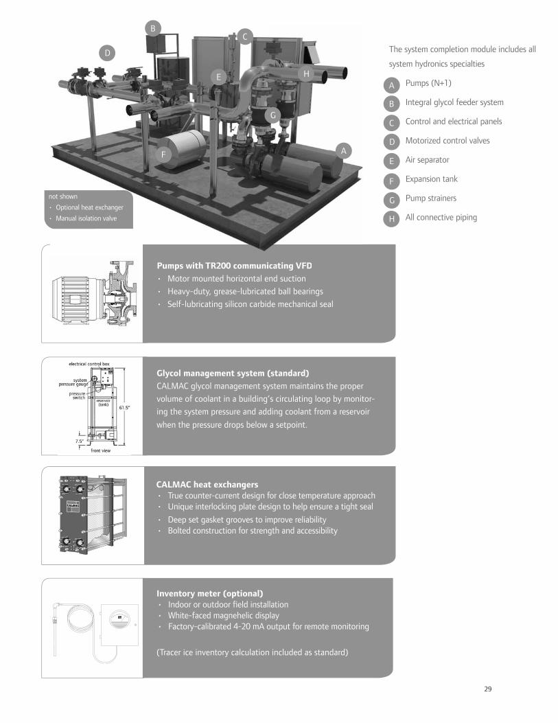
29
CALMAC heat exchangers• True counter-current design for close temperature approach • Unique interlocking plate design to help ensure a tight seal
• Deep set gasket grooves to improve reliability• Bolted construction for strength and accessibility
Inventory meter (optional)• Indoor or outdoor eld installation • White-faced magnehelic display• Factory-calibrated 4-20 mA output for remote monitoring
(Tracer ice inventory calculation included as standard)
Glycol management system (standard)
CALMAC glycol management system maintains the proper
volume of coolant in a building’s circulating loop by monitor-
ing the system pressure and adding coolant from a reservoir
when the pressure drops below a setpoint.
Pumps with TR200 communicating VFD
• Motor mounted horizontal end suction
• Heavy-duty, grease-lubricated ball bearings
• Self-lubricating silicon carbide mechanical seal
Pumps with TR200 communicating VFD
• Motor mounted horizontal end suction
D
E
F
G
H
not shown
• Optional heat exchanger
• Manual isolation valve
The system completion module includes all
system hydronics specialties
• Pumps (N+1)
• Integral glycol feeder system
• Control and electrical panels
• Motorized control valves
• Air separator
• Expansion tank
• Pump strainers
• All connective piping
D
E
F
G
H
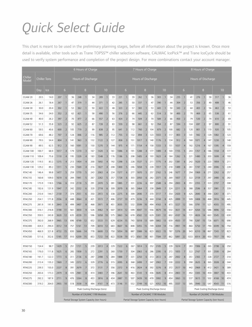
30
Quick Select GuideThis chart is meant to be used in the preliminary planning stages, before all information about the project is known. Once more
detail is available, other tools such as Trane TOPSS™ chiller selection software, CALMAC IcePick™ and Trane IceCycle should be
used to verify system performance and completion of the project design. For more combinations contact your account manager.
6 Hours of Charge 7 Hours of Charge 8 Hours of Charge
ChillerModel Chiller Tons Hours of Discharge Hours of Discharge Hours of Discharge
Day Ice 6 8 10 6 8 10 6 8 10
CGAM 20 20.5 14.0 207 1 36 248 1 34 289 1 33 221 1 39 262 1 36 303 1 34 235 1 41 276 1 38 317 1 36
CGAM 26 26.1 18.4 267 1 47 319 1 44 371 1 42 285 1 50 337 1 47 390 1 44 304 2 53 356 2 49 408 1 46
CGAM 30 30.0 20.4 302 1 53 362 1 50 422 1 48 323 2 57 383 1 53 443 1 50 343 2 60 403 2 56 463 2 53
CGAM 35 34.6 24.0 352 2 62 421 1 58 490 1 56 376 2 66 445 2 62 514 2 58 400 2 70 469 2 65 538 2 61
CGAM 40 40.0 26.2 397 2 70 477 2 66 557 2 63 424 2 74 504 2 70 584 2 66 450 2 79 530 2 74 610 2 69
CGAM 52 51.3 35.8 523 2 92 625 2 87 728 2 83 559 2 98 661 2 92 764 2 87 594 3 104 697 2 97 800 2 91
CGAM 60 59.5 40.6 600 2 105 719 2 99 838 2 95 641 3 112 760 2 104 879 2 100 682 3 120 801 3 110 920 3 105
CGAM 70 69.6 48.2 707 3 124 846 2 116 985 2 112 755 3 132 894 3 123 1033 3 117 803 3 141 942 3 129 1082 3 123
CGAM 80 79.5 54.4 804 3 141 963 3 132 1122 3 127 858 3 151 1017 3 140 1176 3 134 912 4 160 1071 4 147 1230 3 140
CGAM 90 89.5 62.5 912 3 160 1091 3 150 1270 3 144 975 4 171 1154 4 158 1333 3 151 1037 4 182 1216 4 167 1395 4 159
CGAM 100 100.7 68.9 1017 4 179 1219 3 167 1420 3 161 1086 4 191 1288 4 177 1489 4 169 1155 5 203 1357 4 186 1558 4 177
CGAM 110 109.4 75.6 1110 4 195 1329 4 183 1548 3 176 1186 5 208 1405 4 193 1623 4 184 1262 5 221 1480 5 203 1699 4 193
CGAM 120 119.3 83.2 1215 4 213 1454 4 200 1692 4 192 1298 5 228 1537 5 211 1775 4 202 1381 6 242 1620 5 223 1859 5 211
CGAM 130 129.2 89.2 1311 5 230 1569 4 216 1827 4 208 1400 5 246 1658 5 228 1917 5 218 1489 6 261 1747 5 240 2006 5 228
RTAC140 146.4 99.8 1477 5 259 1770 5 243 2063 4 234 1577 6 277 1870 5 257 2162 5 246 1677 7 294 1969 6 271 2262 6 257
RTAC155 160.8 109.0 1619 6 284 1941 5 267 2262 5 257 1728 6 303 2050 6 282 2371 6 269 1837 7 322 2159 7 297 2480 6 282
RTAC170 175.9 118.5 1766 6 310 2118 5 291 2470 5 281 1885 7 331 2236 6 307 2588 6 294 2003 8 351 2355 7 323 2707 7 308
RTAC185 192.6 131.9 1947 7 342 2332 6 320 2718 6 309 2079 8 365 2464 7 338 2849 7 324 2211 9 388 2596 8 357 2981 7 339
RTAC200 210.4 144.7 2130 7 374 2551 6 350 2972 6 338 2275 8 399 2696 7 370 3117 7 354 2420 9 425 2840 8 390 3261 8 371
RTAC250 254.1 171.8 2556 8 448 3064 8 421 3572 7 406 2727 10 479 3236 9 444 3744 8 425 2899 11 509 3408 10 468 3916 10 445
RTAC275 281.9 191.9 2843 9 499 3407 8 468 3971 8 451 3035 11 532 3599 10 494 4163 9 473 3227 12 566 3791 11 521 4355 11 495
RTAC300 316.1 216.8 3198 11 561 3830 9 526 4462 9 507 3414 12 599 4047 11 556 4679 10 532 3631 14 637 4264 12 586 4896 12 556
RTAC350 359.5 243.8 3620 12 635 4339 11 596 5058 10 575 3863 14 678 4582 12 629 5301 12 602 4107 16 721 4826 14 663 5545 13 630
RTAC375 392.0 268.9 3965 13 696 4749 12 652 5533 11 629 4234 15 743 5018 13 689 5802 13 659 4503 17 790 5287 15 726 6071 15 690
RTAC400 424.3 294.4 4312 14 757 5161 13 709 6010 12 683 4607 16 808 5455 15 749 6304 14 716 4901 19 860 5750 17 790 6599 16 750
RTAC450 466.9 321.8 4732 15 830 5666 14 778 6600 13 750 5054 18 887 5988 16 823 6922 15 787 5376 20 943 6310 18 867 7243 17 823
RTAC500 511.6 352.6 5185 17 910 6209 15 853 7232 14 822 5538 19 972 6561 18 901 7584 17 862 5891 22 1033 6914 20 950 7937 19 902
RTAE150 154.4 98.7 1429 5 251 1721 5 239 2013 4 229 1522 6 267 1814 5 252 2105 5 239 1614 7 283 1906 6 265 2198 6 250
RTAE165 176.0 111.8 1625 6 285 1958 5 272 2291 5 260 1730 7 304 2063 6 286 2395 6 272 1835 7 322 2167 7 301 2500 6 284
RTAE180 191.7 122.3 1773 6 311 2136 6 297 2498 5 284 1888 7 331 2250 6 313 2612 6 297 2002 8 351 2365 7 328 2727 7 310
RTAE200 213.4 135.2 1969 7 345 2372 6 329 2776 6 315 2095 8 368 2499 7 347 2902 7 330 2222 9 390 2625 8 365 3028 8 344
RTAE225 239.3 155.0 2227 8 391 2679 7 372 3131 7 356 2372 9 416 2824 8 392 3276 8 372 2517 10 442 2969 9 412 3421 9 389
RTAE250 265.6 173.3 2479 8 435 2981 8 414 3483 7 396 2641 10 463 3143 9 436 3645 8 414 2803 11 492 3305 10 459 3807 10 433
RTAE275 292.2 187.9 2711 9 476 3264 8 453 3816 8 434 2887 11 507 3439 10 478 3992 9 454 3063 12 537 3615 11 502 4168 10 474
RTAE300 319.2 204.0 2955 10 518 3558 9 494 4161 9 473 3146 11 552 3749 10 521 4352 10 495 3337 13 585 3940 12 547 4543 11 516
Peak Cooling Discharge (tons) Peak Cooling Discharge (tons) Peak Cooling Discharge (tons)
Number of CALMAC 1190 Modules Number of CALMAC 1190 Modules Number of CALMAC 1190 Modules
Partial Storage System Capacity (ton-hours) Partial Storage System Capacity (ton-hours) Partial Storage System Capacity (ton-hours)
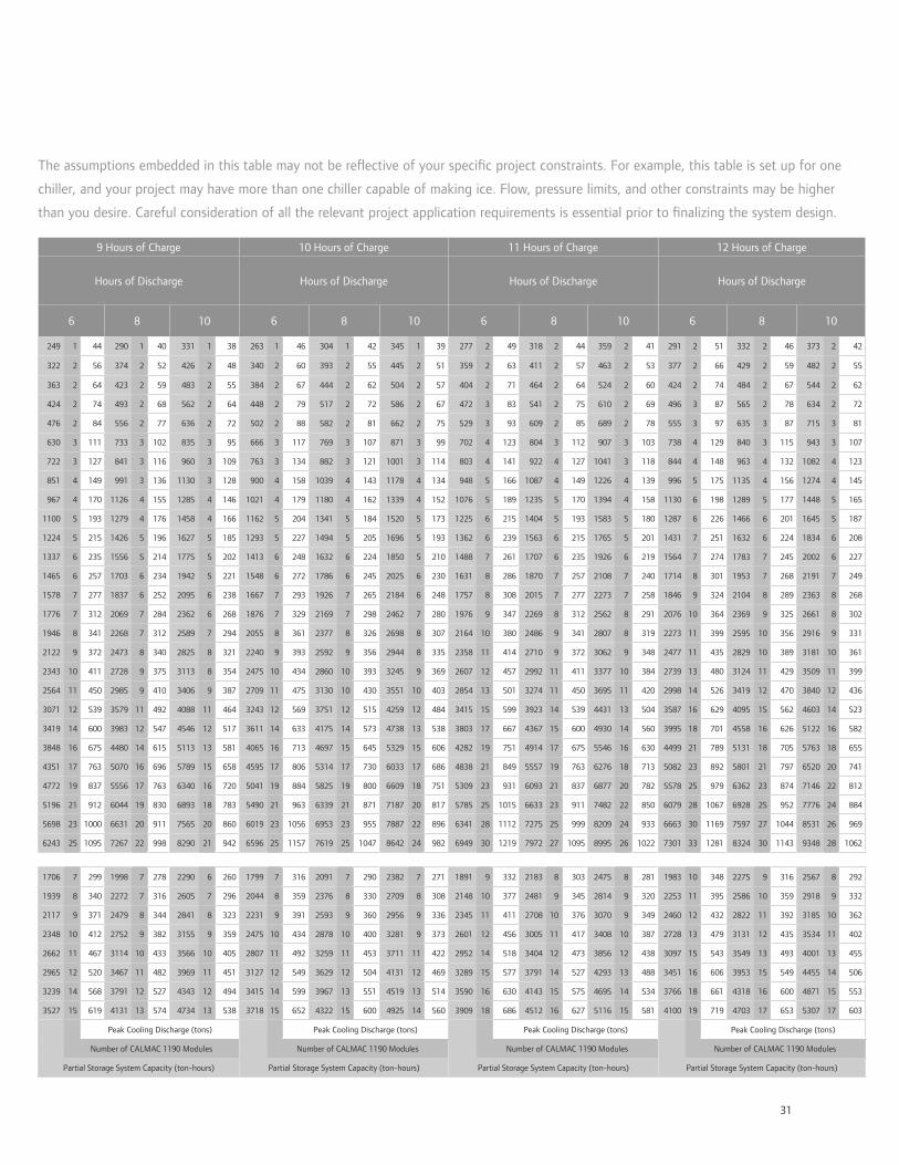
31
The assumptions embedded in this table may not be re ective of your speci c project constraints. For example, this table is set up for one
chiller, and your project may have more than one chiller capable of making ice. Flow, pressure limits, and other constraints may be higher
than you desire. Careful consideration of all the relevant project application requirements is essential prior to nalizing the system design.
9 Hours of Charge 10 Hours of Charge 11 Hours of Charge 12 Hours of Charge
Hours of Discharge Hours of Discharge Hours of Discharge Hours of Discharge
6 8 10 6 8 10 6 8 10 6 8 10
249 1 44 290 1 40 331 1 38 263 1 46 304 1 42 345 1 39 277 2 49 318 2 44 359 2 41 291 2 51 332 2 46 373 2 42
322 2 56 374 2 52 426 2 48 340 2 60 393 2 55 445 2 51 359 2 63 411 2 57 463 2 53 377 2 66 429 2 59 482 2 55
363 2 64 423 2 59 483 2 55 384 2 67 444 2 62 504 2 57 404 2 71 464 2 64 524 2 60 424 2 74 484 2 67 544 2 62
424 2 74 493 2 68 562 2 64 448 2 79 517 2 72 586 2 67 472 3 83 541 2 75 610 2 69 496 3 87 565 2 78 634 2 72
476 2 84 556 2 77 636 2 72 502 2 88 582 2 81 662 2 75 529 3 93 609 2 85 689 2 78 555 3 97 635 3 87 715 3 81
630 3 111 733 3 102 835 3 95 666 3 117 769 3 107 871 3 99 702 4 123 804 3 112 907 3 103 738 4 129 840 3 115 943 3 107
722 3 127 841 3 116 960 3 109 763 3 134 882 3 121 1001 3 114 803 4 141 922 4 127 1041 3 118 844 4 148 963 4 132 1082 4 123
851 4 149 991 3 136 1130 3 128 900 4 158 1039 4 143 1178 4 134 948 5 166 1087 4 149 1226 4 139 996 5 175 1135 4 156 1274 4 145
967 4 170 1126 4 155 1285 4 146 1021 4 179 1180 4 162 1339 4 152 1076 5 189 1235 5 170 1394 4 158 1130 6 198 1289 5 177 1448 5 165
1100 5 193 1279 4 176 1458 4 166 1162 5 204 1341 5 184 1520 5 173 1225 6 215 1404 5 193 1583 5 180 1287 6 226 1466 6 201 1645 5 187
1224 5 215 1426 5 196 1627 5 185 1293 5 227 1494 5 205 1696 5 193 1362 6 239 1563 6 215 1765 5 201 1431 7 251 1632 6 224 1834 6 208
1337 6 235 1556 5 214 1775 5 202 1413 6 248 1632 6 224 1850 5 210 1488 7 261 1707 6 235 1926 6 219 1564 7 274 1783 7 245 2002 6 227
1465 6 257 1703 6 234 1942 5 221 1548 6 272 1786 6 245 2025 6 230 1631 8 286 1870 7 257 2108 7 240 1714 8 301 1953 7 268 2191 7 249
1578 7 277 1837 6 252 2095 6 238 1667 7 293 1926 7 265 2184 6 248 1757 8 308 2015 7 277 2273 7 258 1846 9 324 2104 8 289 2363 8 268
1776 7 312 2069 7 284 2362 6 268 1876 7 329 2169 7 298 2462 7 280 1976 9 347 2269 8 312 2562 8 291 2076 10 364 2369 9 325 2661 8 302
1946 8 341 2268 7 312 2589 7 294 2055 8 361 2377 8 326 2698 8 307 2164 10 380 2486 9 341 2807 8 319 2273 11 399 2595 10 356 2916 9 331
2122 9 372 2473 8 340 2825 8 321 2240 9 393 2592 9 356 2944 8 335 2358 11 414 2710 9 372 3062 9 348 2477 11 435 2829 10 389 3181 10 361
2343 10 411 2728 9 375 3113 8 354 2475 10 434 2860 10 393 3245 9 369 2607 12 457 2992 11 411 3377 10 384 2739 13 480 3124 11 429 3509 11 399
2564 11 450 2985 9 410 3406 9 387 2709 11 475 3130 10 430 3551 10 403 2854 13 501 3274 11 450 3695 11 420 2998 14 526 3419 12 470 3840 12 436
3071 12 539 3579 11 492 4088 11 464 3243 12 569 3751 12 515 4259 12 484 3415 15 599 3923 14 539 4431 13 504 3587 16 629 4095 15 562 4603 14 523
3419 14 600 3983 12 547 4546 12 517 3611 14 633 4175 14 573 4738 13 538 3803 17 667 4367 15 600 4930 14 560 3995 18 701 4558 16 626 5122 16 582
3848 16 675 4480 14 615 5113 13 581 4065 16 713 4697 15 645 5329 15 606 4282 19 751 4914 17 675 5546 16 630 4499 21 789 5131 18 705 5763 18 655
4351 17 763 5070 16 696 5789 15 658 4595 17 806 5314 17 730 6033 17 686 4838 21 849 5557 19 763 6276 18 713 5082 23 892 5801 21 797 6520 20 741
4772 19 837 5556 17 763 6340 16 720 5041 19 884 5825 19 800 6609 18 751 5309 23 931 6093 21 837 6877 20 782 5578 25 979 6362 23 874 7146 22 812
5196 21 912 6044 19 830 6893 18 783 5490 21 963 6339 21 871 7187 20 817 5785 25 1015 6633 23 911 7482 22 850 6079 28 1067 6928 25 952 7776 24 884
5698 23 1000 6631 20 911 7565 20 860 6019 23 1056 6953 23 955 7887 22 896 6341 28 1112 7275 25 999 8209 24 933 6663 30 1169 7597 27 1044 8531 26 969
6243 25 1095 7267 22 998 8290 21 942 6596 25 1157 7619 25 1047 8642 24 982 6949 30 1219 7972 27 1095 8995 26 1022 7301 33 1281 8324 30 1143 9348 28 1062
1706 7 299 1998 7 278 2290 6 260 1799 7 316 2091 7 290 2382 7 271 1891 9 332 2183 8 303 2475 8 281 1983 10 348 2275 9 316 2567 8 292
1939 8 340 2272 7 316 2605 7 296 2044 8 359 2376 8 330 2709 8 308 2148 10 377 2481 9 345 2814 9 320 2253 11 395 2586 10 359 2918 9 332
2117 9 371 2479 8 344 2841 8 323 2231 9 391 2593 9 360 2956 9 336 2345 11 411 2708 10 376 3070 9 349 2460 12 432 2822 11 392 3185 10 362
2348 10 412 2752 9 382 3155 9 359 2475 10 434 2878 10 400 3281 9 373 2601 12 456 3005 11 417 3408 10 387 2728 13 479 3131 12 435 3534 11 402
2662 11 467 3114 10 433 3566 10 405 2807 11 492 3259 11 453 3711 11 422 2952 14 518 3404 12 473 3856 12 438 3097 15 543 3549 13 493 4001 13 455
2965 12 520 3467 11 482 3969 11 451 3127 12 549 3629 12 504 4131 12 469 3289 15 577 3791 14 527 4293 13 488 3451 16 606 3953 15 549 4455 14 506
3239 14 568 3791 12 527 4343 12 494 3415 14 599 3967 13 551 4519 13 514 3590 16 630 4143 15 575 4695 14 534 3766 18 661 4318 16 600 4871 15 553
3527 15 619 4131 13 574 4734 13 538 3718 15 652 4322 15 600 4925 14 560 3909 18 686 4512 16 627 5116 15 581 4100 19 719 4703 17 653 5307 17 603
Peak Cooling Discharge (tons) Peak Cooling Discharge (tons) Peak Cooling Discharge (tons) Peak Cooling Discharge (tons)
Number of CALMAC 1190 Modules Number of CALMAC 1190 Modules Number of CALMAC 1190 Modules Number of CALMAC 1190 Modules
Partial Storage System Capacity (ton-hours) Partial Storage System Capacity (ton-hours) Partial Storage System Capacity (ton-hours) Partial Storage System Capacity (ton-hours)
32
Ingersoll Rand (NYSE:IR) advances the quality of life by creating comfortable, sustainable and ef cient environments. Our people and our
family of brands—including Club Car®, Ingersoll Rand®, Thermo King® and Trane®—work together to enhance the quality and comfort of air in
homes and buildings; transport and protect food and perishables; and increase industrial productivity and ef ciency. We are a global business
committed to a world of sustainable progress and enduring results.
© 2014 Trane All rights reserved We are committed to using environmentally
APP-PRC001-EN 10 Jan 2014 conscious print practices. trane.com
Supersedes APP-PRC001-EN 02 Dec 2011 ingersollrand.com
ControlsIce-enhanced, Air-cooled Chiller Plant
EarthWise Systems include an optional system
completion module, preprogrammed control
sequences, operator graphics, reports, drawings
and guide speci cations.
BACnet communicating system
controller (Tracer SC) and sub-system
controller (UC600)
Preprogrammed sequences
• One chiller, no heat exchanger
• Two chillers, no heat exchanger
• One chiller with heat exchanger and two
distribution pumps
• Two chillers with heat exchanger and
two distribution pumps
Control functions
• System scheduling
• Six modes of operation
• Off
• Chiller only - single and multiple chiller
• Ice only
• Chiller and ice
• Make ice
• Make ice and cool
• System mode determination
• Chiller plant demand limiting
• Ice inventory management
• Chilled uid system control
• Chiller/ice sequencing and control
• Color graphic based chiller and plant
status screens
• System and chiller diagnostic messages
• System and chiller reporting
• Failure modes and recovery
• Heat exchanger sequencing and control
(option)
• Pump control for water loops (option)
Information displayed at sub-system con-
troller and at system controller
• Ton hours used last ice discharge cycle
• Ton hours stored last ice build cycle
• Peak kW
• Estimated savings
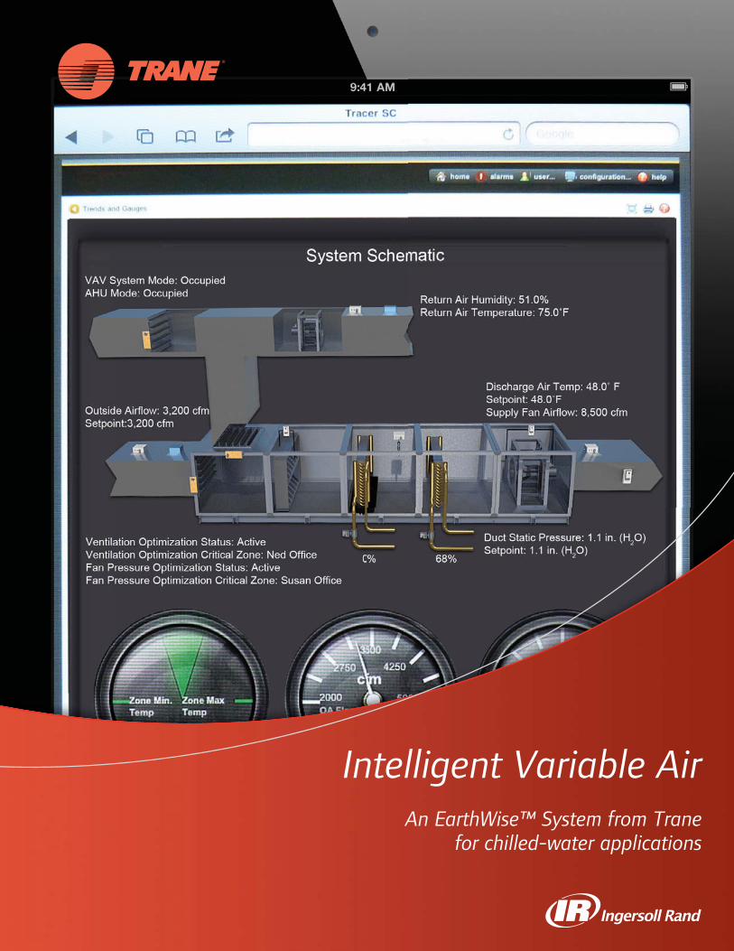
11111111
Intelligent Variable AirAn EarthWise™ System from Trane
for chilled-water applications
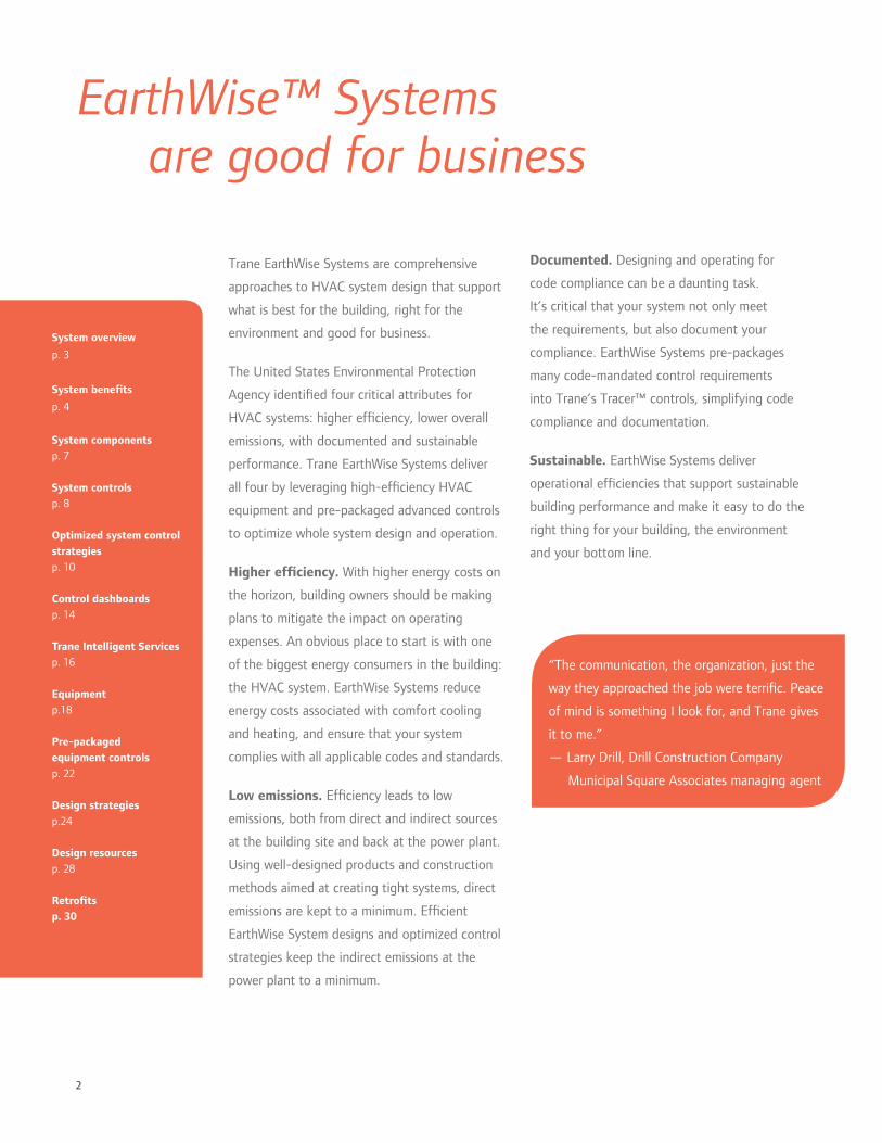
2
Trane EarthWise Systems are comprehensive
approaches to HVAC system design that support
what is best for the building, right for the
environment and good for business.
The United States Environmental Protection
Agency identi ed four critical attributes for
HVAC systems: higher ef ciency, lower overall
emissions, with documented and sustainable
performance. Trane EarthWise Systems deliver
all four by leveraging high-ef ciency HVAC
equipment and pre-packaged advanced controls
to optimize whole system design and operation.
Higher ef ciency. With higher energy costs on
the horizon, building owners should be making
plans to mitigate the impact on operating
expenses. An obvious place to start is with one
of the biggest energy consumers in the building:
the HVAC system. EarthWise Systems reduce
energy costs associated with comfort cooling
and heating, and ensure that your system
complies with all applicable codes and standards.
Low emissions. Ef ciency leads to low
emissions, both from direct and indirect sources
at the building site and back at the power plant.
Using well-designed products and construction
methods aimed at creating tight systems, direct
emissions are kept to a minimum. Ef cient
EarthWise System designs and optimized control
strategies keep the indirect emissions at the
power plant to a minimum.
EarthWise™ Systems are good for business
“The communication, the organization, just the
way they approached the job were terri c. Peace
of mind is something I look for, and Trane gives
it to me.”
— Larry Drill, Drill Construction Company
Municipal Square Associates managing agent
System overview
p. 3
System bene ts
p. 4
System componentsp. 7
System controlsp. 8
Optimized system control strategiesp. 10
Control dashboardsp. 14
Trane Intelligent Servicesp. 16
Equipmentp.18
Pre-packaged equipment controlsp. 22
Design strategiesp.24
Design resourcesp. 28
Retro tsp. 30
Documented. Designing and operating for
code compliance can be a daunting task.
It’s critical that your system not only meet
the requirements, but also document your
compliance. EarthWise Systems pre-packages
many code-mandated control requirements
into Trane’s Tracer™ controls, simplifying code
compliance and documentation.
Sustainable. EarthWise Systems deliver
operational ef ciencies that support sustainable
building performance and make it easy to do the
right thing for your building, the environment
and your bottom line.
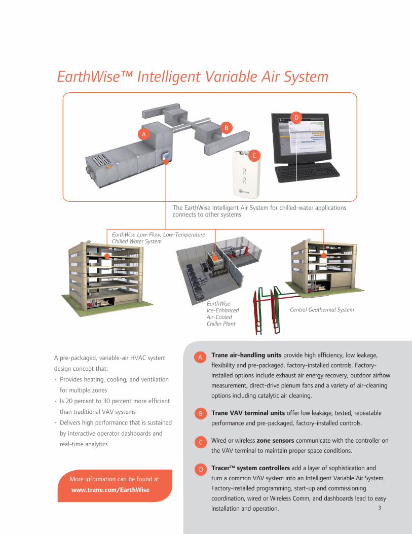
3
The EarthWise Intelligent Air System for chilled-water applications connects to other systems
EarthWise Low-Flow, Low-Temperature Chilled Water System
EarthWise Ice-Enhanced Air-Cooled Chiller Plant
Trane air-handling units provide high ef ciency, low leakage,
exibility and pre-packaged, factory-installed controls. Factory-
installed options include exhaust air energy recovery, outdoor air ow
measurement, direct-drive plenum fans and a variety of air-cleaning
options including catalytic air cleaning.
Trane VAV terminal units offer low leakage, tested, repeatable
performance and pre-packaged, factory-installed controls.
Wired or wireless zone sensors communicate with the controller on
the VAV terminal to maintain proper space conditions.
Tracer™ system controllers add a layer of sophistication and
turn a common VAV system into an Intelligent Variable Air System.
Factory-installed programming, start-up and commissioning
coordination, wired or Wireless Comm, and dashboards lead to easy
installation and operation.
A pre-packaged, variable-air HVAC system
design concept that:
• Provides heating, cooling, and ventilation
for multiple zones
• Is 20 percent to 30 percent more ef cient
than traditional VAV systems
• Delivers high performance that is sustained
by interactive operator dashboards and
real-time analytics
EarthWise™ Intelligent Variable Air System
D
D
Central Geothermal System
3
More information can be found at
www.trane.com/EarthWise

4
Established performance,
enhanced with new technology
commissioning, and avoid the inconsistencies
of custom programming — but still provide
on-site programming exibility for project-
speci c requirements. Standard apps and
operator dashboards, supported by thorough
documentation, take the mystery out of how
your system works, so that you and Trane can
keep it running optimally over the system’s
lifetime.
The applied version of the Intelligent Variable
Air System includes twenty-four standard
con gurations for air-handling units, air terminal
devices and system controls. Identifying the
repeatable aspects of these system designs
allows us to deploy standardized, pre-packaged
control sequences, drawings and operator
graphics and dashboards.
Comfort control. Variable air systems are
capable of controlling the temperature in
many zones with dissimilar cooling and heating
requirements. This is accomplished by providing
a VAV terminal unit and temperature sensor for
each independently controlled zone.
High indoor air quality. For most applications,
the foundation of good IAQ is proper
ventilation. The Intelligent Variable Air System
balances energy ef ciency and IAQ by bringing
in no more than the required amount of outdoor
air for ventilation, at all operating conditions,
through the use of optimized ventilation control
strategies and ow-measuring Traq™ outdoor-
air dampers. Building pressurization control not
only saves energy, it also reduces in ltration,
which can lead to moisture-related problems in
the building envelope.
Variable air systems have a proven track record
of reliable, ef cient performance. Using new
design strategies and advanced technologies,
Trane EarthWise™ Intelligent Variable Air
systems are more ef cient than traditional VAV
systems.
Twenty to thirty percent more ef cient.
Through advanced technologies— including
energy recovery and variable-speed equipment
— and optimized controls, Trane Intelligent
Variable Air systems can be 20 percent to 30
percent more ef cient than traditional VAV
systems. User-friendly dashboards allow you to
easily monitor that ef ciency to help maintain
peak performance for the life of the system.
Based on countless new buildings, retro ts
and recommissioning projects, we know that
properly designed and controlled VAV systems
are attainable, and can have lower installed and
operating costs than alternative systems.
As with every EarthWise System, Trane provides,
supports, and encourages energy modeling
during the system design phase. Trane Air-
conditioning Economics (TRACE™) software
can be used to determine how this system
can help your building earn high performance
designation, including earning LEED® points
under EAc1.
Ef ciencies in energy, cost and time.
Trane’s EarthWise Intelligent Variable Air
System was created to simplify the design
and implementation of a high-performing
HVAC system. The system’s controls are
baseline programmed at the factory to
contribute to smooth installation and

5
Low installation costs. Ventilating and cooling
or heating with the same system naturally costs
less to install—only one set of distribution
piping and/or ductwork is required.
Using a centralized system allows the system to
be sized for “block” load, that is, the highest
heating or cooling load observed at one time.
Individual zone-based systems will naturally have
more installed capacity because they are sized
on the “sum of the peaks.”
By using cold uid and cold air, fans, pumps,
and ductwork can be right sized in a modest
trade-off with energy costs.
Code compliant. Complying with codes and
documenting that compliance is easier when
using an engineered system from Trane. Code-
mandated system control requirements are
pre-packaged in the standard Trane Tracer™
controllers. These routines and their interfaces
are exible, yet standardized to help reduce
opportunities for errors and reduce the need for
custom programming.
1 2 3 1 2 3 1 2 3 1 2 3
1 Baseline Chilled-Water VAV 2 Active Chilled Beam 3 Intelligent Variable Air
6 million
Ann
ual H
VAC
Ener
gy U
se (
kBtu
/yr)
4 million
2 million
pumpsfans
heatingcooling
Houston Los Angeles Philadelphia St. Louis
High-performance building designation steers the
discussion toward systems that have lower energy
costs. The EarthWise Intelligent Variable Air
system, using the design and operation strategies
identi ed in this catalog, can help earn LEED
points under EAc1, depending on the baseline
system and local utility rates.
Annual energy use for a 268,500 ft² of ce building, estimated using Trane TRACE™ building energy analysis
software. The baseline chilled-water VAV system is modeled according to Appendix G in ASHRAE Standard
90.1-2007.

6
have zone dampers for reducing ventilation to
a minimum when the zone is unoccupied. See
sidebar for potential code issues.
Direct-drive plenum fans with integral variable
frequency drives eliminate belt losses and
maintenance. Larger, central fans have more
ef cient motors than smaller, distributed fans.
Ventilation ef ciency. VAV systems using
a single supply duct typically deliver a mixture
of recirculated air and outdoor air—the same
fraction of outdoor air is delivered to all
zones. While this may be suf cient ventilation
for some zones, depending on each zone’s
cooling or heating load, it may not be enough
for others. ASHRAE Standard 62.1 for indoor
air quality requires that the system bring in
more outdoor air in order to satisfy the zone
needing the highest fraction of ventilation air,
with compensation for overventilation in the
recirculated air. This leads to all other zones
being over-ventilated and extra energy to
condition the additional outdoor air.
System controls from Trane automatically solve
the equations found in ASHRAE Standard 62.1,
and allow the system to optimize ventilation by
dynamically changing outdoor air damper position
in response to the needs of the critical ventilation
zone(s). This can allow the system to ventilate to
mechanical code requirements without an unnec-
essarily high, xed outdoor air damper position.
A further re nement of this control allows the
system to automatically open the zone damper in
the critical ventilation zone(s), increasing reheat
slightly, in exchange for a reduction in outdoor
air at the system level. This is permitted by the
ASHRAE 90.1 energy code.
VAV systems have always been comfortable and
exible—adapting automatically to building load
changes over time. But beneath that comfort,
outdated controls and system components were
likely wasting energy. The Intelligent Variable Air
system makes it easy to keep the comfort while
minimizing energy waste.
Zone and system controls, simpli ed.
Controls for a high performance, multiple-
zone VAV system require more coordination
than controls for a single-zone system. This is
one of the driving forces behind the need for
repeatable, highly con gured yet standardized
system control. These controls ensure that the
inherent bene ts of the system do not come
at an energy cost or contribute to a poorly
performing system.
Reduced reheat. One of the traditional
complaints about multiple zone VAV systems
is that for some zones, they heat air that has
been previously cooled with mechanical cooling.
Judicious use of ventilation optimization, supply
air temperature reset and parallel fan powered
VAV terminals can keep this to a minimum.
Ef cient central fan operation. Another
opportunity to save energy is in the central
fan(s) delivering cooling and ventilation together.
The central fan(s) must continue to operate,
even when the spaces are unoccupied and do
not need to be ventilated. However, proper
scheduling, optimized ventilation control, and
an “occupied standby” mode minimize fan and
ventilation energy when some zones require
ventilation while others do not. A dedicated
ventilation system has to run when just one zone
needs ventilation, because it typically doesn’t
Efficient, flexible, comfortable,
and now, even better
Did you know?
A recent interpretation
from ASHRAE
Standard 62.1
clari es that zones
must continue to
receive the building
component ventilation
rate (Ra) whenever
they are expected
to be occupied,
even when they
are temporarily
unoccupied.
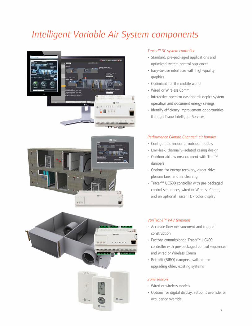
7
Tracer™ SC system controller
• Standard, pre-packaged applications and
optimized system control sequences
• Easy-to-use interfaces with high-quality
graphics
• Optimized for the mobile world
• Wired or Wireless Comm
• Interactive operator dashboards depict system
operation and document energy savings
• Identify ef ciency improvement opportunities
through Trane Intelligent Services
Intelligent Variable Air System components
VariTrane™ VAV terminals
• Accurate ow measurement and rugged
construction
• Factory-commissioned Tracer™ UC400
controller with pre-packaged control sequences
and wired or Wireless Comm
• Retro t (RIRO) dampers available for
upgrading older, existing systems
Zone sensors
• Wired or wireless models
• Options for digital display, setpoint override, or
occupancy override
Performance Climate Changer® air handler
• Con gurable indoor or outdoor models
• Low-leak, thermally-isolated casing design
• Outdoor air ow measurement with Traq™
dampers
• Options for energy recovery, direct-drive
plenum fans, and air cleaning
• Tracer™ UC600 controller with pre-packaged
control sequences, wired or Wireless Comm,
and an optional Tracer TD7 color display
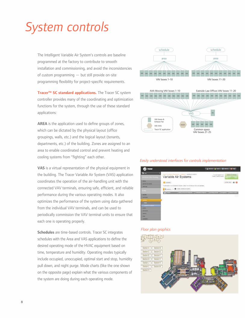
8
System controls
The Intelligent Variable Air System’s controls are baseline
programmed at the factory to contribute to smooth
installation and commissioning, and avoid the inconsistencies
of custom programming — but still provide on-site
programming exibility for project-speci c requirements.
Tracer™ SC standard applications. The Tracer SC system
controller provides many of the coordinating and optimization
functions for the system, through the use of these standard
applications:
AREA is the application used to de ne groups of zones,
which can be dictated by the physical layout (of ce
groupings, walls, etc.) and the logical layout (tenants,
departments, etc.) of the building. Zones are assigned to an
area to enable coordinated control and prevent heating and
cooling systems from “ ghting” each other.
VAS is a virtual representation of the physical equipment in
the building. The Tracer Variable Air System (VAS) application
coordinates the operation of the air-handling unit with the
connected VAV terminals, ensuring safe, ef cient, and reliable
performance during the various operating modes. It also
optimizes the performance of the system using data gathered
from the individual VAV terminals, and can be used to
periodically commission the VAV terminal units to ensure that
each one is operating properly.
Schedules are time-based controls. Tracer SC integrates
schedules with the Area and VAS applications to de ne the
desired operating mode of the HVAC equipment based on
time, temperature and humidity. Operating modes typically
include occupied, unoccupied, optimal start and stop, humidity
pull down, and night purge. Mode charts (like the one shown
on the opposite page) explain what the various components of
the system are doing during each operating mode.
Floor plan graphics
schedule
area
VAV VAVVAVVAVVAVVAVVAVVAV VAVVAVVAV
schedule
area
VAV VAVVAVVAVVAVVAVVAVVAV VAVVAVVAV
VAS
VAV VAVVAVVAVVAVVAVVAVVAV VAVVAVVAV VAV VAVVAVVAVVAVVAVVAVVAV VAVVAVVAV
VAV boxes 1-10 VAV boxes 11-20
AAA Moving VAV boxes 1-10 Eastside Law Offices VAV boxes 11-20
VAVVAVVAVVAV VAV
ER
Common space VAV boxes 21-25
AHU01VAV AHU
VAV boxes &Exhaust Fan
Tracer SC application
Easily understood interfaces for controls implementation

9
Mobility and accessibility of Tracer™ SC.
Tracer SC delivers the industry’s most intuitive
user interface, and provides you access to the
system no matter where you are, on any connected
device. And it is so much more than simple web
connectivity. We have optimized our interfaces for
the mobile world, so the intuitive and easy to use
nature of our systems translates seamlessly from a
workstation, to a tablet or smart phone.
Ease of implemention. Setting up schedules,
areas and VAS is accomplished through the
Tracer SC standard graphical interface using
setup “wizard” routines, autodiscovery, drop-
down selections and check boxes, not custom
programming.
The EarthWise Intelligent Air System makes the
controls setup even easier and more standardized,
with more programming installed at the factory.
Mode chart
Wireless controls. Trane Wireless Comm
eliminates the wire between equipment and
system controllers for Tracer™ building automation
systems supporting BACnet™ standard protocol,
and provides wireless connectivity to zone
temperature sensors. The bene ts include faster
project completion, less disruption to building
occupants, increased location exibility, and life-
cycle savings due to easier relocation when space
layout or use changes in the future.
Through use of self-healing wireless mesh,
extended signal range, and conformance to the
ZigBee™ Building Automation standard, Trane
Wireless Comm provides reliable, expandable
operation for the life of the building.
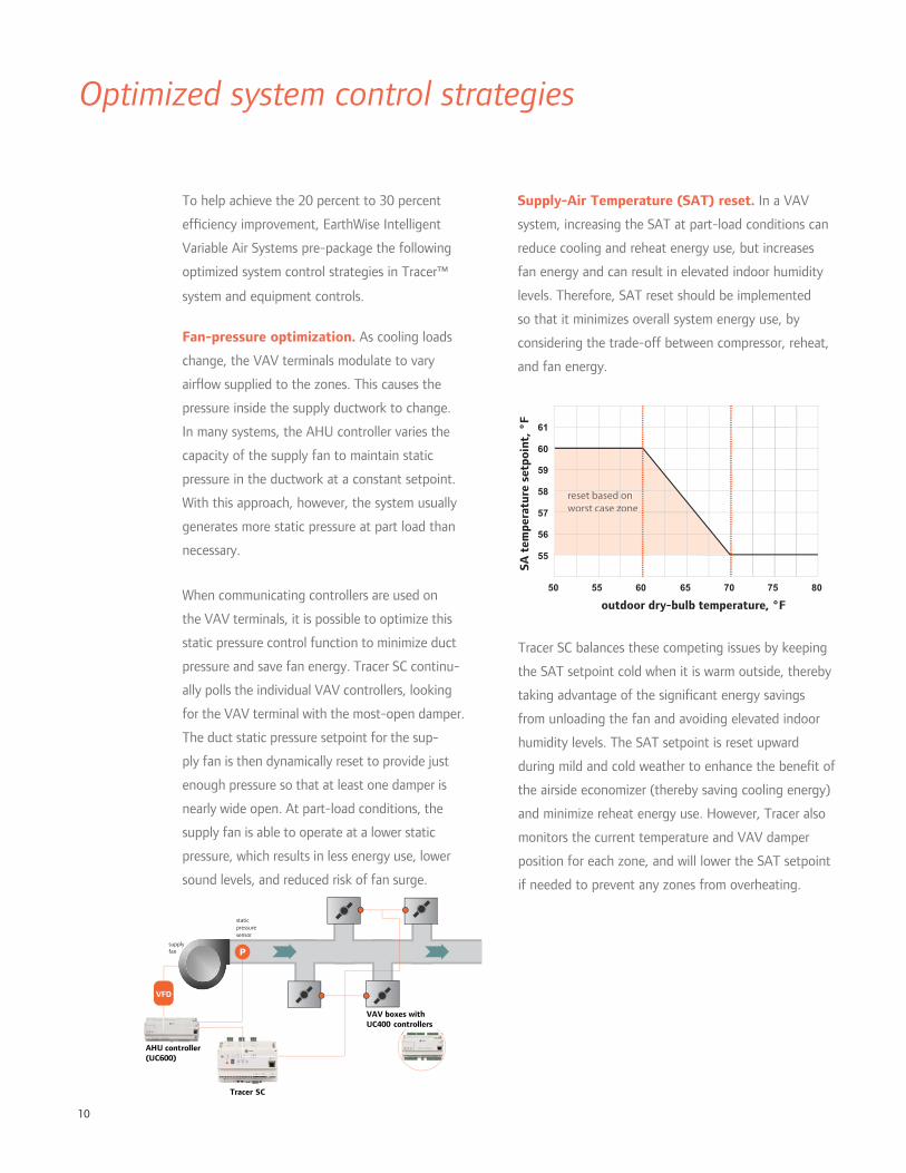
10
Optimized system control strategies
To help achieve the 20 percent to 30 percent
ef ciency improvement, EarthWise Intelligent
Variable Air Systems pre-package the following
optimized system control strategies in Tracer™
system and equipment controls.
Fan-pressure optimization. As cooling loads
change, the VAV terminals modulate to vary
air ow supplied to the zones. This causes the
pressure inside the supply ductwork to change.
In many systems, the AHU controller varies the
capacity of the supply fan to maintain static
pressure in the ductwork at a constant setpoint.
With this approach, however, the system usually
generates more static pressure at part load than
necessary.
When communicating controllers are used on
the VAV terminals, it is possible to optimize this
static pressure control function to minimize duct
pressure and save fan energy. Tracer SC continu-
ally polls the individual VAV controllers, looking
for the VAV terminal with the most-open damper.
The duct static pressure setpoint for the sup-
ply fan is then dynamically reset to provide just
enough pressure so that at least one damper is
nearly wide open. At part-load conditions, the
supply fan is able to operate at a lower static
pressure, which results in less energy use, lower
sound levels, and reduced risk of fan surge.
Supply-Air Temperature (SAT) reset. In a VAV
system, increasing the SAT at part-load conditions can
reduce cooling and reheat energy use, but increases
fan energy and can result in elevated indoor humidity
levels. Therefore, SAT reset should be implemented
so that it minimizes overall system energy use, by
considering the trade-off between compressor, reheat,
and fan energy.
Tracer SC balances these competing issues by keeping
the SAT setpoint cold when it is warm outside, thereby
taking advantage of the signi cant energy savings
from unloading the fan and avoiding elevated indoor
humidity levels. The SAT setpoint is reset upward
during mild and cold weather to enhance the bene t of
the airside economizer (thereby saving cooling energy)
and minimize reheat energy use. However, Tracer also
monitors the current temperature and VAV damper
position for each zone, and will lower the SAT setpoint
if needed to prevent any zones from overheating.
staticpressuresensor
Psupplyfan
AHU controller(UC600)
Tracer SC
VAV boxes withUC400 controllers
VFD
55 60 6550 807570
61
60
59
58
57
56
55
SA t
empe
ratu
re s
etpo
int,
°F
outdoor dry-bulb temperature, °F
reset based on s awoorst case zoneo c z

11
much outdoor air must be brought in at the air-
handling unit to satisfy all zones served. Finally, Tracer
sends this new outdoor air ow setpoint to the UC600
controller on the AHU, which then modulates a ow-
measuring (Traq™) outdoor-air damper to maintain this
new setpoint.
This strategy reduces the energy required to condition
outdoor air brought in for ventilation, while minimizing
installed cost and risk by installing CO2 sensors only in
those zones where the payback is the greatest.
Optimal start/stop. In some buildings, a simple time
clock or time-of-day schedule is used to start and stop
the HVAC system. During hours when the building
is expected to be unoccupied, the system is shut off
and the temperature is allowed to drift away from
the occupied setpoint. For most days of the year, the
system starts much earlier than needed.
Tracer SC uses a strategy called optimal start, which
determines the length of time required to bring each
zone from its current temperature to the occupied
setpoint temperature. Then, Tracer waits as long as
possible before starting, so that the temperature in
each zone reaches occupied setpoint just in time for
occupancy. This strategy reduces the number of system
operating hours and saves energy.
Ventilation optimization. In a VAV system, the air-
handling unit delivers fresh outdoor air to several individually
controlled zones. Demand-controlled ventilation (DCV)
involves resetting intake air ow in response to variations in
zone population. While commonly implemented using carbon
dioxide (CO2) sensors, occupancy sensors, or time-of-day
(TOD) schedules can also be used.
Tracer SC optimizes the amount of ventilation in a multiple-
zone VAV system by combining these various DCV strategies
at the zone level (using each where it best ts) with
ventilation reset at the system level. With this strategy,
CO2 sensors are installed only in those zones that are
densely occupied and experience widely varying patterns of
occupancy. Zones that are less densely occupied or have a
population that varies only a little are probably better suited
for occupancy sensors or a time-of-day schedule.
These various zone-level DCV strategies are used to reset
the ventilation requirement for their respective zones for any
given hour. In addition, the controller on each VAV terminal
continuously monitors primary air ow being delivered to the
zone and calculates the current OA fraction (Zpz).
Then, Tracer SC periodically gathers this data from all
VAV terminals and solves the ventilation reset equations
(prescribed by ASHRAE Standard 62.1) to determine how
OA
SA RA
VAV Controllers• Required outdoor airflow• Current primary airflow• Current OA fraction
Tracer SC• Find highest OA fraction• Calculate current system intake airflow (ASHRAE 62.1)
AHU controller• Reset intake airflow
optimal start
optimal stop(fan on, OA damper open)
systemon
systemoff
occupiedsetpoint
temperature
unoccupiedsetpoint
temperature
occupied hours
mid 6 AM noon 6 PM mid
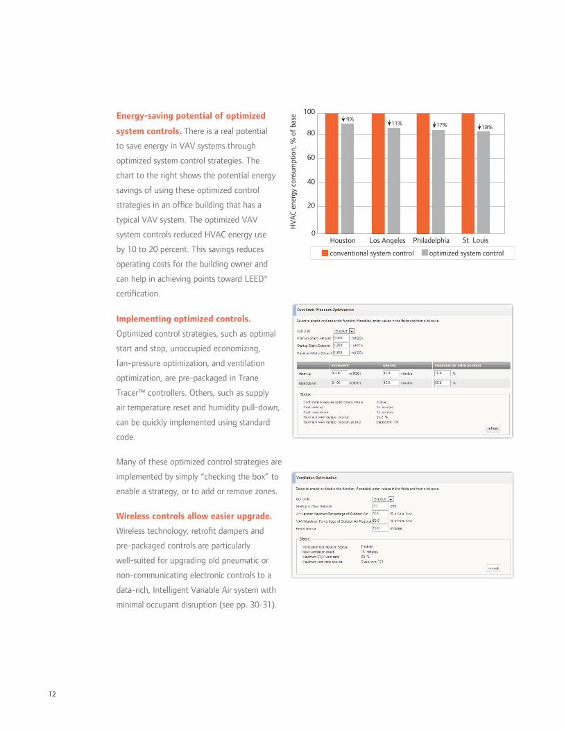
12
Energy-saving potential of optimized
system controls. There is a real potential
to save energy in VAV systems through
optimized system control strategies. The
chart to the right shows the potential energy
savings of using these optimized control
strategies in an of ce building that has a
typical VAV system. The optimized VAV
system controls reduced HVAC energy use
by 10 to 20 percent. This savings reduces
operating costs for the building owner and
can help in achieving points toward LEED®
certi cation.
Implementing optimized controls.
Optimized control strategies, such as optimal
start and stop, unoccupied economizing,
fan-pressure optimization, and ventilation
optimization, are pre-packaged in Trane
Tracer™ controllers. Others, such as supply
air temperature reset and humidity pull-down,
can be quickly implemented using standard
code.
Many of these optimized control strategies are
implemented by simply “checking the box” to
enable a strategy, or to add or remove zones.
Wireless controls allow easier upgrade.
Wireless technology, retro t dampers and
pre-packaged controls are particularly
well-suited for upgrading old pneumatic or
non-communicating electronic controls to a
data-rich, Intelligent Variable Air system with
minimal occupant disruption (see pp. 30-31).
PhiladelphiaLos AngelesHouston0
20
40
60
80
100
HV
AC
ener
gy c
onsu
mpt
ion,
% o
f ba
se
optimized system controlconventional system control
St. Louis
9%11% 17% 18%

13
Sustaining performance. Tracer SC presents data as
usable information with an intuitive user interface to
help operators sustain building ef ciency for the life of
the system.
Removing overrides. “Temporary” changes to
setpoints or operating schedules, when left in place
long after the triggering event or condition, are another
potential energy waste. Removing these overrides is
often essential for the system to operate at a sustained
high level of performance.
Tracer SC makes it easy to identify these overrides and
remove them to return the system to normal operation.
“Rogue” zones. A zone that is often overheating
or overcooling, due to either a faulty component
or a design error, can limit the energy savings
potential of using these optimized control strategies.
If left unresolved, these “rogue” zones can lead to
unnecessary cooling, heating, and fan energy use.
Tracer SC allows the operator to temporarily prevent
these rogue zones from impacting the optimized
control strategies, by simply unchecking a box in the
user interface.
Through the Trane Intelligent Services system, detailed
analytics help identify these “rogue” zones, and alert
the building owner of the potential energy savings that
would result from xing the problem.

14
At-a-glance gauges
Intuitive, accessible dashboards
It’s one thing for the controls installer to understand
how to set up the system, but it’s imperative that the
operator understand how the system works. Standard
apps and operator dashboards, supported by thorough
documentation, take the mystery out of how your
system works, so that you and Trane can keep it running
optimally over the system’s lifetime.
Dashboards are all about giving the operator information
that is actionable—gauges with min and max values
identi ed, warnings, alerts and error messages—helping
identify opportunities to optimize system operation.
Tracer™ SC provides access to your system from any
connected device: PCs, tablets, or even smart phones.
Strategic data
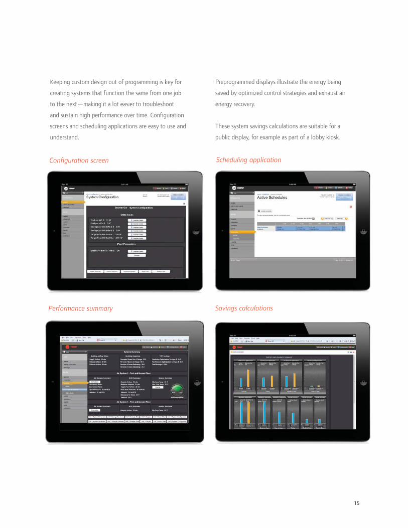
15
Scheduling applicationCon guration screen
Savings calculationsPerformance summary
Preprogrammed displays illustrate the energy being
saved by optimized control strategies and exhaust air
energy recovery.
These system savings calculations are suitable for a
public display, for example as part of a lobby kiosk.
Keeping custom design out of programming is key for
creating systems that function the same from one job
to the next—making it a lot easier to troubleshoot
and sustain high performance over time. Con guration
screens and scheduling applications are easy to use and
understand.
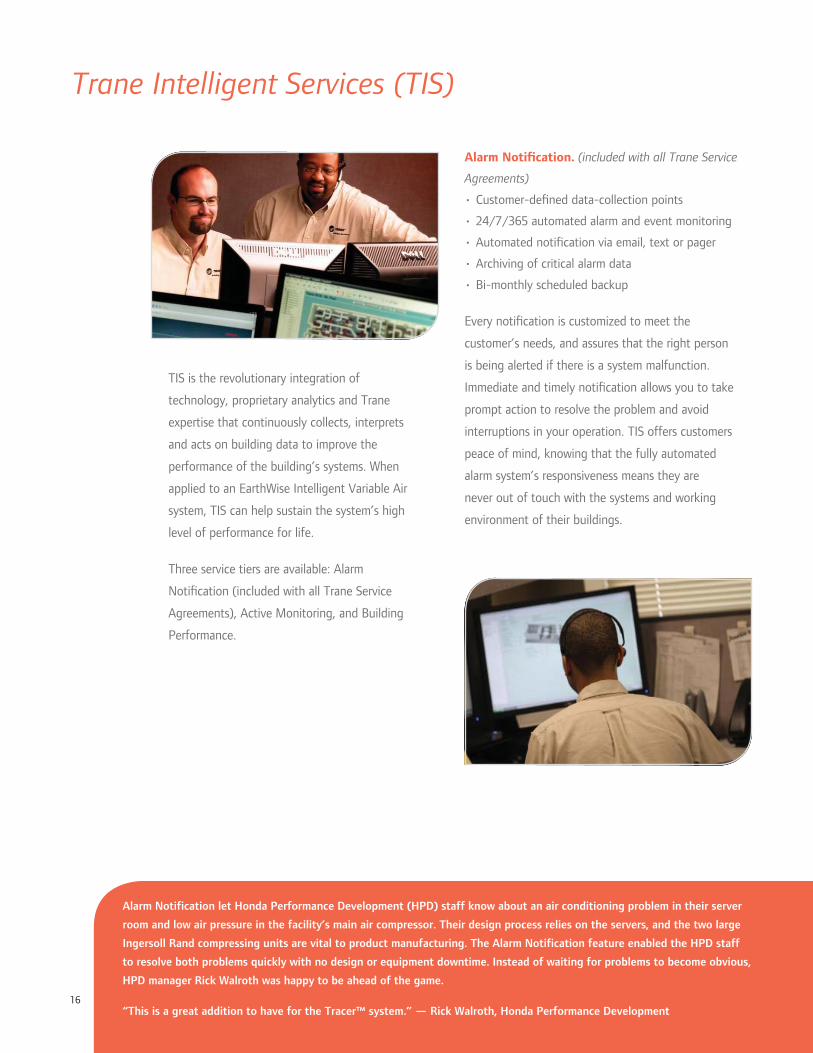
16
Trane Intelligent Services (TIS)
TIS is the revolutionary integration of
technology, proprietary analytics and Trane
expertise that continuously collects, interprets
and acts on building data to improve the
performance of the building’s systems. When
applied to an EarthWise Intelligent Variable Air
system, TIS can help sustain the system’s high
level of performance for life.
Three service tiers are available: Alarm
Noti cation (included with all Trane Service
Agreements), Active Monitoring, and Building
Performance.
Alarm Noti cation. (included with all Trane Service
Agreements)
• Customer-de ned data-collection points
• 24/7/365 automated alarm and event monitoring
• Automated noti cation via email, text or pager
• Archiving of critical alarm data
• Bi-monthly scheduled backup
Every noti cation is customized to meet the
customer’s needs, and assures that the right person
is being alerted if there is a system malfunction.
Immediate and timely noti cation allows you to take
prompt action to resolve the problem and avoid
interruptions in your operation. TIS offers customers
peace of mind, knowing that the fully automated
alarm system’s responsiveness means they are
never out of touch with the systems and working
environment of their buildings.
Alarm Notification let Honda Performance Development (HPD) staff know about an air conditioning problem in their server
room and low air pressure in the facility’s main air compressor. Their design process relies on the servers, and the two large
Ingersoll Rand compressing units are vital to product manufacturing. The Alarm Notification feature enabled the HPD staff
to resolve both problems quickly with no design or equipment downtime. Instead of waiting for problems to become obvious,
HPD manager Rick Walroth was happy to be ahead of the game.
“This is a great addition to have for the Tracer™ system.” — Rick Walroth, Honda Performance Development
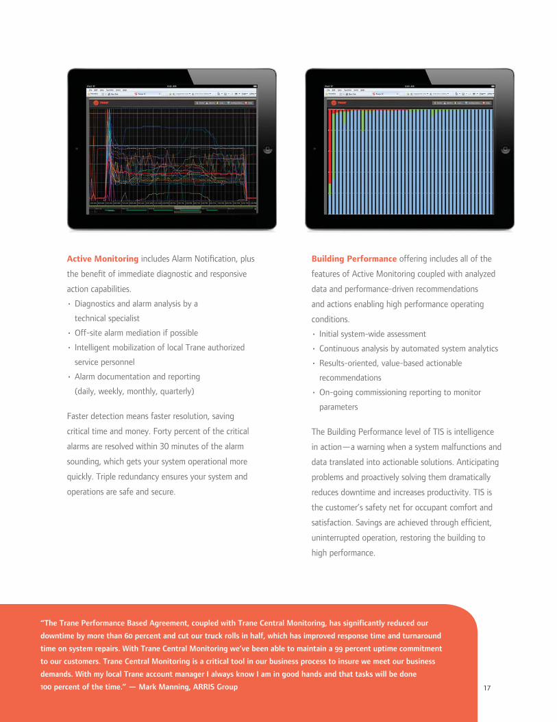
17
Active Monitoring includes Alarm Noti cation, plus
the bene t of immediate diagnostic and responsive
action capabilities.
• Diagnostics and alarm analysis by a
technical specialist
• Off-site alarm mediation if possible
• Intelligent mobilization of local Trane authorized
service personnel
• Alarm documentation and reporting
(daily, weekly, monthly, quarterly)
Faster detection means faster resolution, saving
critical time and money. Forty percent of the critical
alarms are resolved within 30 minutes of the alarm
sounding, which gets your system operational more
quickly. Triple redundancy ensures your system and
operations are safe and secure.
Building Performance offering includes all of the
features of Active Monitoring coupled with analyzed
data and performance-driven recommendations
and actions enabling high performance operating
conditions.
• Initial system-wide assessment
• Continuous analysis by automated system analytics
• Results-oriented, value-based actionable
recommendations
• On-going commissioning reporting to monitor
parameters
The Building Performance level of TIS is intelligence
in action—a warning when a system malfunctions and
data translated into actionable solutions. Anticipating
problems and proactively solving them dramatically
reduces downtime and increases productivity. TIS is
the customer’s safety net for occupant comfort and
satisfaction. Savings are achieved through ef cient,
uninterrupted operation, restoring the building to
high performance.
“The Trane Performance Based Agreement, coupled with Trane Central Monitoring, has significantly reduced our
downtime by more than 60 percent and cut our truck rolls in half, which has improved response time and turnaround
time on system repairs. With Trane Central Monitoring we’ve been able to maintain a 99 percent uptime commitment
to our customers. Trane Central Monitoring is a critical tool in our business process to insure we meet our business
demands. With my local Trane account manager I always know I am in good hands and that tasks will be done
100 percent of the time.” — Mark Manning, ARRIS Group

18
H
G
F
E
D
D
E
F
G
H
EquipmentPerformance Climate Changer™
Quick Reference
Performance Climate Changer Sizes
air ow (cfm) at face velocity (fpm)
350 fpm 400 fpm 450 fpm 500 fpm
3 1022 1168 1314 1460
4 1579 1804 2030 2255
6 2139 2444 2750 3055
8 2797 3196 3596 3995
10 3493 3992 4491 4990
12 4305 4920 5535 6150
14 4778 5460 6143 6825
17 5884 6724 7565 8405
21 7284 8324 9365 10405
25 8740 9988 11237 12485
30 10465 11960 13455 14950
35 12229 13976 15723 17470
40 13976 15972 17969 19965
50 17168 19620 22073 24525
57 19912 22756 25601 28445
66 22971 26252 29534 32815
80 27563 31500 35438 39375
100 34699 39656 44613 49570
120 41335 47240 53145 59050
Traq™ ow-measuring outdoor air measurement station: AMCA 611 certi ed, accurate even at low ow
MERV lters: Exceed LEED requirements and reduce pressure drop up to 50 percent over previous designs
Thermally isolated, rigid casing design: R-13 foam-injected panels and doors minimize heat transfer and withstand ± 8 in.w.g.
Factory-installed DDC controls. Pre-packaged sequences, wired or Wireless Comm, optional color display
Single-point power, quick connect wiring: Factory wiring minimizes installation cost and ensures wiring integrity between sections
Ef cient fan selections for all pressure requirements: Three to ve percent more ef cient than previous designs
Flexible discharge plenum con gurations: Minimize air pressure drop with the most ef cient opening sizes, types and locations
Low leak casing, rated and tested to ASHRAE Standard 111 Class 6: Achieves less than one percent leakage rate
Assumes full height unit coil with 1/2 in. coil tubes
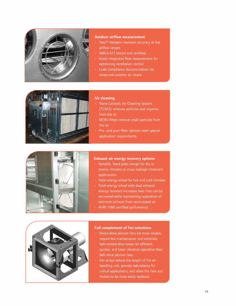
19
Outdoor air ow measurement
• Traq™ dampers maintain accuracy at low
air ow ranges
• AMCA 611 tested and certi ed
• Easily integrated ow measurement for
optimizing ventilation control
• Code compliance documentation via
measured outdoor air intake
Air cleaning
• Trane Catalytic Air Cleaning System
(TCACS) removes particles and organics
from the air
• MERV lters remove small particles from
the air
• Pre- and post- lter options meet special
application requirements
Exhaust-air energy recovery options
• Sensible, xed plate design for dry or
marine climates or cross-leakage intolerant
applications
• Total-energy wheel for hot and cold climates
• Total-energy wheel with dual exhaust
energy recovery increases heat that can be
recovered while maintaining separation of
restroom exhaust from recirculated air
• AHRI 1060 certi ed performance
Full complement of fan selections
• Direct-drive plenum fans are more reliable,
require less maintenance, and eliminate
belt-related drive losses for ef cient,
quieter, and lower vibration operation than
belt-drive plenum fans.
• Fan arrays reduce the length of the air-
handling unit, provide redundancy for
critical applications, and allow the fans and
motors to be more easily replaced.
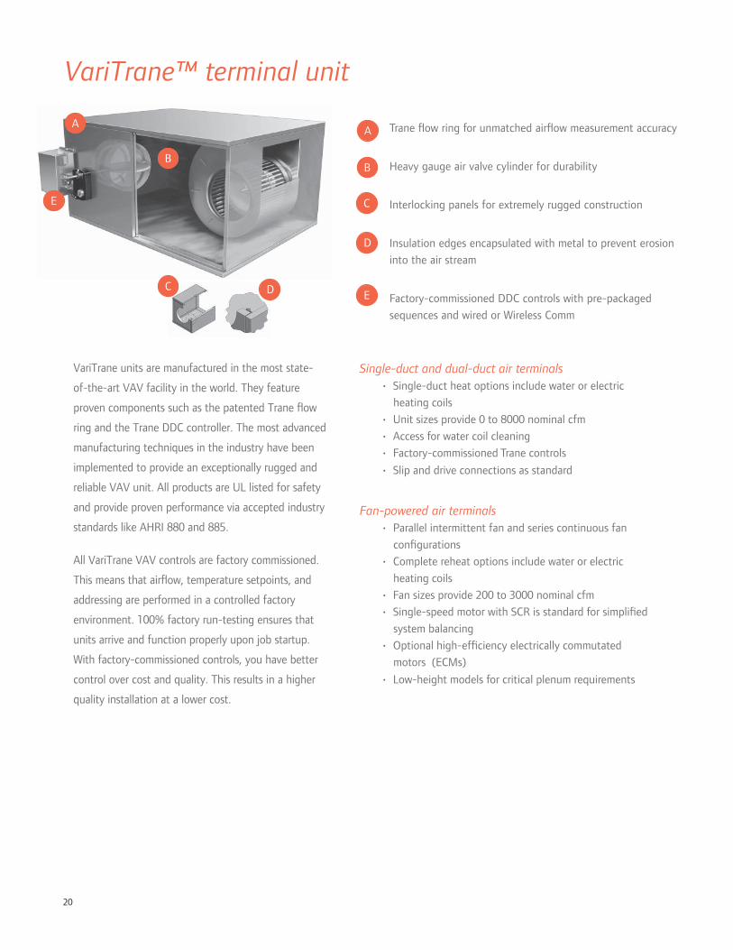
20
D
E
VariTrane units are manufactured in the most state-
of-the-art VAV facility in the world. They feature
proven components such as the patented Trane ow
ring and the Trane DDC controller. The most advanced
manufacturing techniques in the industry have been
implemented to provide an exceptionally rugged and
reliable VAV unit. All products are UL listed for safety
and provide proven performance via accepted industry
standards like AHRI 880 and 885.
All VariTrane VAV controls are factory commissioned.
This means that air ow, temperature setpoints, and
addressing are performed in a controlled factory
environment. 100% factory run-testing ensures that
units arrive and function properly upon job startup.
With factory-commissioned controls, you have better
control over cost and quality. This results in a higher
quality installation at a lower cost.
Single-duct and dual-duct air terminals• Single-duct heat options include water or electric
heating coils
• Unit sizes provide 0 to 8000 nominal cfm
• Access for water coil cleaning
• Factory-commissioned Trane controls
• Slip and drive connections as standard
Fan-powered air terminals• Parallel intermittent fan and series continuous fan
con gurations
• Complete reheat options include water or electric
heating coils
• Fan sizes provide 200 to 3000 nominal cfm
• Single-speed motor with SCR is standard for simpli ed
system balancing
• Optional high-ef ciency electrically commutated
motors (ECMs)
• Low-height models for critical plenum requirements
D
E
Trane ow ring for unmatched air ow measurement accuracy
Heavy gauge air valve cylinder for durability
Interlocking panels for extremely rugged construction
Insulation edges encapsulated with metal to prevent erosion
into the air stream
Factory-commissioned DDC controls with pre-packaged
sequences and wired or Wireless Comm
VariTrane™ terminal unit
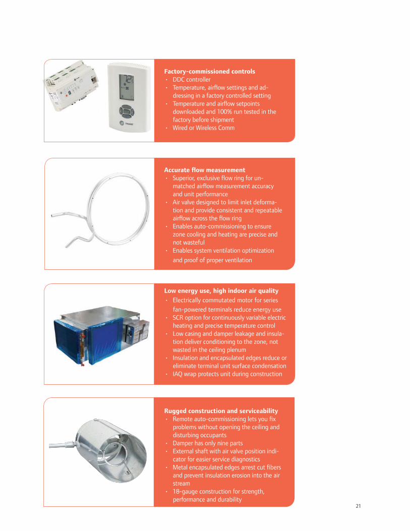
21
Factory-commissioned controls• DDC controller• Temperature, air ow settings and ad-
dressing in a factory controlled setting• Temperature and air ow setpoints
downloaded and 100% run tested in the factory before shipment
• Wired or Wireless Comm
Accurate ow measurement• Superior, exclusive ow ring for un-
matched air ow measurement accuracy and unit performance
• Air valve designed to limit inlet deforma-tion and provide consistent and repeatable air ow across the ow ring
• Enables auto-commissioning to ensure zone cooling and heating are precise and not wasteful
• Enables system ventilation optimization
and proof of proper ventilation
Low energy use, high indoor air quality
• Electrically commutated motor for series
fan-powered terminals reduce energy use• SCR option for continuously variable electric
heating and precise temperature control• Low casing and damper leakage and insula-
tion deliver conditioning to the zone, not wasted in the ceiling plenum
• Insulation and encapsulated edges reduce or eliminate terminal unit surface condensation
• IAQ wrap protects unit during construction
Rugged construction and serviceability • Remote auto-commissioning lets you x
problems without opening the ceiling and disturbing occupants
• Damper has only nine parts• External shaft with air valve position indi-
cator for easier service diagnostics• Metal encapsulated edges arrest cut bers
and prevent insulation erosion into the air stream
• 18-gauge construction for strength, performance and durability
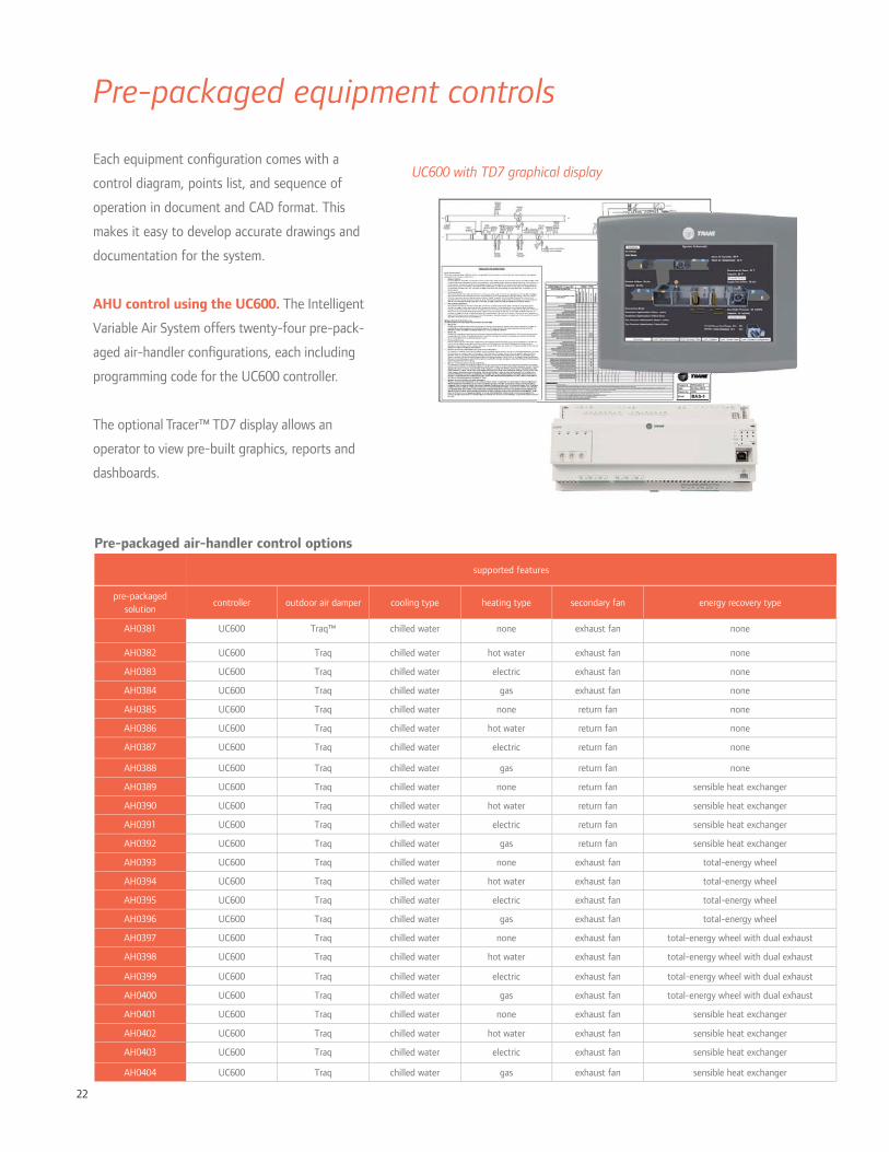
22
Pre-packaged equipment controls
Pre-packaged air-handler control options
supported features
pre-packaged solution
controller outdoor air damper cooling type heating type secondary fan energy recovery type
AH0381 UC600 Traq™ chilled water none exhaust fan none
AH0382 UC600 Traq chilled water hot water exhaust fan none
AH0383 UC600 Traq chilled water electric exhaust fan none
AH0384 UC600 Traq chilled water gas exhaust fan none
AH0385 UC600 Traq chilled water none return fan none
AH0386 UC600 Traq chilled water hot water return fan none
AH0387 UC600 Traq chilled water electric return fan none
AH0388 UC600 Traq chilled water gas return fan none
AH0389 UC600 Traq chilled water none return fan sensible heat exchanger
AH0390 UC600 Traq chilled water hot water return fan sensible heat exchanger
AH0391 UC600 Traq chilled water electric return fan sensible heat exchanger
AH0392 UC600 Traq chilled water gas return fan sensible heat exchanger
AH0393 UC600 Traq chilled water none exhaust fan total-energy wheel
AH0394 UC600 Traq chilled water hot water exhaust fan total-energy wheel
AH0395 UC600 Traq chilled water electric exhaust fan total-energy wheel
AH0396 UC600 Traq chilled water gas exhaust fan total-energy wheel
AH0397 UC600 Traq chilled water none exhaust fan total-energy wheel with dual exhaust
AH0398 UC600 Traq chilled water hot water exhaust fan total-energy wheel with dual exhaust
AH0399 UC600 Traq chilled water electric exhaust fan total-energy wheel with dual exhaust
AH0400 UC600 Traq chilled water gas exhaust fan total-energy wheel with dual exhaust
AH0401 UC600 Traq chilled water none exhaust fan sensible heat exchanger
AH0402 UC600 Traq chilled water hot water exhaust fan sensible heat exchanger
AH0403 UC600 Traq chilled water electric exhaust fan sensible heat exchanger
AH0404 UC600 Traq chilled water gas exhaust fan sensible heat exchanger
Each equipment con guration comes with a
control diagram, points list, and sequence of
operation in document and CAD format. This
makes it easy to develop accurate drawings and
documentation for the system.
AHU control using the UC600. The Intelligent
Variable Air System offers twenty-four pre-pack-
aged air-handler con gurations, each including
programming code for the UC600 controller.
The optional Tracer™ TD7 display allows an
operator to view pre-built graphics, reports and
dashboards.
UC600 with TD7 graphical display

23
VAV control using the UC400. The Intelligent
Variable Air System offers nine pre-packaged VAV
terminal con gurations, each including programming
code for the UC400 controller.
Space temperature control functions are further re ned,
based on:
• the presence of a fan and/or a heating coil in the
VAV terminal
• whether or not the zone is occupied
• whether the duct delivers cold or hot primary air
• whether or not the central unit is at minimum ow in
the heating mode
Wireless controls. Trane Wireless Comm eliminates
the wire between equipment and system controllers,
and provides wireless connectivity to zone temperature
sensors. The bene ts include faster project completion,
less disruption to building occupants, increased location
exibility, and life-cycle savings. Through use of self-
healing wireless mesh, extended signal range, and
conformance to the ZigBee™ Building Automation
standard, Trane Wireless Comm provides reliable,
expandable operation for the life of the building.
Pre-packaged VAV terminal control options
supported features
pre-packaged solution
controller terminal type heating type
TS0043 UC400 single duct none
TS0044 UC400 single duct electric
TS0045 UC400 single duct hot water
TS0046 UC400 parallel fan powered VAV none
TS0047 UC400 parallel fan powered VAV electric
TS0048 UC400 parallel fan powered VAV hot water
TS0049 UC400 series fan powered VAV none
TS0050 UC400 series fan powered VAV electric
TS0051 UC400 series fan powered VAV hot water
Tracer™ SC with WCI
Performance Climate Changer™ with UC600 and WCI
IntelliPak™ with BCI-I and WCI
VAV terminal with UC400 and WCI Wireless zone sensors
wireless signal

24
Design strategies
Air-to-air energy recovery refers to the transfer of
sensible heat, or sensible heat and moisture (latent
heat), between air streams. The most common
application is to recover energy from the exhaust-air
stream to precondition the outdoor air brought in for
ventilation.
Bene ts of outdoor-air preconditioning.
• Reduces cooling, dehumidi cation, heating and
humidi cation energy
• Allows downsizing of cooling, dehumidi cation,
heating and humidi cation equipment
Best practices.
• Properly size the energy-recovery device
• Strive for balanced air ows
• Select suitable technology (e.g. total or sensible
energy recovery)
• Integrate with airside economizer operation
• Provide a means to control the capacity of the device
at part load
• Provide a method for frost prevention in cold climates
• Decide what amount of cross leakage is acceptable
The importance of proper control.
Coordinating with airside economizer cycle.
In many climates, an airside economizer can provide
the bene ts of “free” cooling for much of the year.
While the economizer operates, air-to-air energy
recovery offers no additional bene t. In fact, unless
it is turned off, the energy-recovery device actually
increases the cooling load by transferring heat from
the exhaust air stream.
To accommodate economizer operation when the
energy-recovery device is idle, bypass dampers allow
full economizer air ow without signi cantly increasing
the airside pressure drop.
Preventing frost. Any air-to-air energy-recovery
device that preconditions outdoor air is subject to
frost buildup during very cold weather. If the surface
temperature of the device falls below the dew point
of the exhaust air, water vapor will condense on the
exhaust side of the device. If the exhaust-side surface
temperature falls below 32°F, this water freezes,
eventually blocking air ow. One of the bene ts
of total energy recovery over sensible-only energy
recovery is that frost forms at a much colder outdoor
temperature, which may even eliminate the need for
frost prevention.
Typical approaches to frost prevention:
• Modulating an outdoor air bypass damper to reduce
the heat-transfer capacity of the energy-recovery
device, or
• Preheating either the outdoor or exhaust air before it
enters the device, for applications with extremely cold
outdoor air and higher indoor humidity levels during
cold weather
In addition to optimized controls, many Intelligent Variable Air Systems make use of the following high-
performance system design strategies to achieve even greater energy savings.
Exhaust air energy recovery

25
Available technologies.
Total-energy wheel offers an excellent combination of high
(60 percent to 80 percent) total effectiveness ideally suited for
hot and cold climates, where latent energy recovery in both the
summer and winter seasons is desirable. Cross leakage is limited
by choosing the right locations for supply and return or exhaust
fans. In many applications and locations the total-energy
wheel’s higher levels of effectiveness may be required by the
energy code.
Total-energy wheel with dual exhaust energy recovery.
Provisions for recovering energy from two exhaust streams
increase the energy that can be recovered while maintaining
the separation of restroom exhaust from recirculated air. The
Performance Climate Changer™ air handler provides for this as
an option.
Fixed-plate (sensible) heat exchanger. Cross- ow aluminum
plates deliver 55 percent to 70 percent sensible effectiveness
with low pressure drop (0.25 to 1.0 in. w.g.). Capacity
modulation is accomplished using face-and-bypass dampers.
The advantage of this technology is little or no cross leakage;
however, of the available technologies, this unit is the most
susceptible to frost.
180
160
140
120
100
80
60
40
20
humidity ratio, grains/lb of dry air
11030 40 50 60 70 80 10090dry-bulb temperature, F
EA
20
Control of a total-energy wheel in a VAV system
wheel on (cooling)
bypass dampers closed
wheel off
both bypass dampers openDBTSA
wheel on (heating) modulate EA bypass damper to avoid overheating

26
Cold-air VAV systems typically deliver supply air
at a temperature of 45°F to 52°F. The appeal of
cold-air distribution lies in the reduction of the
air ow required to offset the sensible cooling loads
in the zones. Lowering the supply-air temperature
from 55°F to 48°F can reduce the supply-air
volume by nearly 30 percent. In addition, the lower
zone relative humidity that results from a cold-air
system often allows the zone dry-bulb temperature
to be slightly warmer than in a conventional
system, while still remaining comfortable. The
impact of these changes in the energy analysis
results is identi ed on page 5.
Bene ts of cold-air distribution. Reducing
supply air ow triggers a series of related bene ts:
• Smaller supply fan (and return or relief fan, if
equipped)
• Smaller air-handling units and vertical air shafts,
which can increase usable (or rentable) oor
space
• Smaller VAV terminals, which ease tight
installations, are less expensive, and may be
quieter
• Smaller ductwork, which requires less sheet
metal, simpli es installation, and leaves more
space above the ceiling for other services
• Shorter oor-to- oor height (attributable to
smaller ducts) may reduce the cost of glass and
steel in a multistory building
• Smaller fan(s) reduce the cost of the electrical
distribution system, lowers operating costs, and
may reduce fan-generated noise
• Potential for lower space humidity levels due to
the delivery of colder, drier air
Cold-air distribution
Many choices in the design of an HVAC system are “predeter-mined” by experience. System design engineers repeatedly choose to supply 55°F air because they know it has worked in the past. The supply air ows that result from this choice directly im-pact the size (and cost) of fans, air-handling units, VAV terminal units, diffusers and ductwork. The size of fan motors is also af-fected, which extends the cost impact to the electrical distribution system.
An EarthWise™ Intelli-gent Variable Air System reexamines these rules of thumb for optimizing system performance and cost.
Challenges of cold-air distribution.
Concerns that design engineers have about cold-air
distribution typically focus on the following three
issues:
• Effects of delivering cold air into the zone on
occupant comfort
• Avoiding condensation on components of the air
distribution system
• Impact on overall system energy consumption
The rst two challenges are overcome by selecting
high-aspiration diffusers and/or fan-powered VAV
terminals as air blenders, plenum returns, properly
sealed and insulated components, and fully integrat-
ed system controls like those for this system. Whole
building energy analysis quanti es the energy impact
of operating a cold-air system, including the impact
on airside economizer operation, cooling and heating
plants, and fan-powered VAV terminals when present.
Parallel or series fan-powered VAV?
For air-blender applications, series fan-powered
VAV terminals are often preferred for large confer-
ence rooms or other zones where constant air ow is
desirable. Parallel fan-powered VAV terminals (with
constant fan operation during occupied periods) are
well suited for zones where less air motion during off-
peak conditions is acceptable.
60%
70%
80%
90%
100%
HVA
C e
nerg
y co
nsum
ptio
n, %
of
base
55ºFsupply air
48ºFsupply air
smaller ducts
raisespace
setpointby 1ºF
SAT reset48ºF
to55 ºF
48ºFsupply air
same size ducts
raisespace
setpointby 1ºF
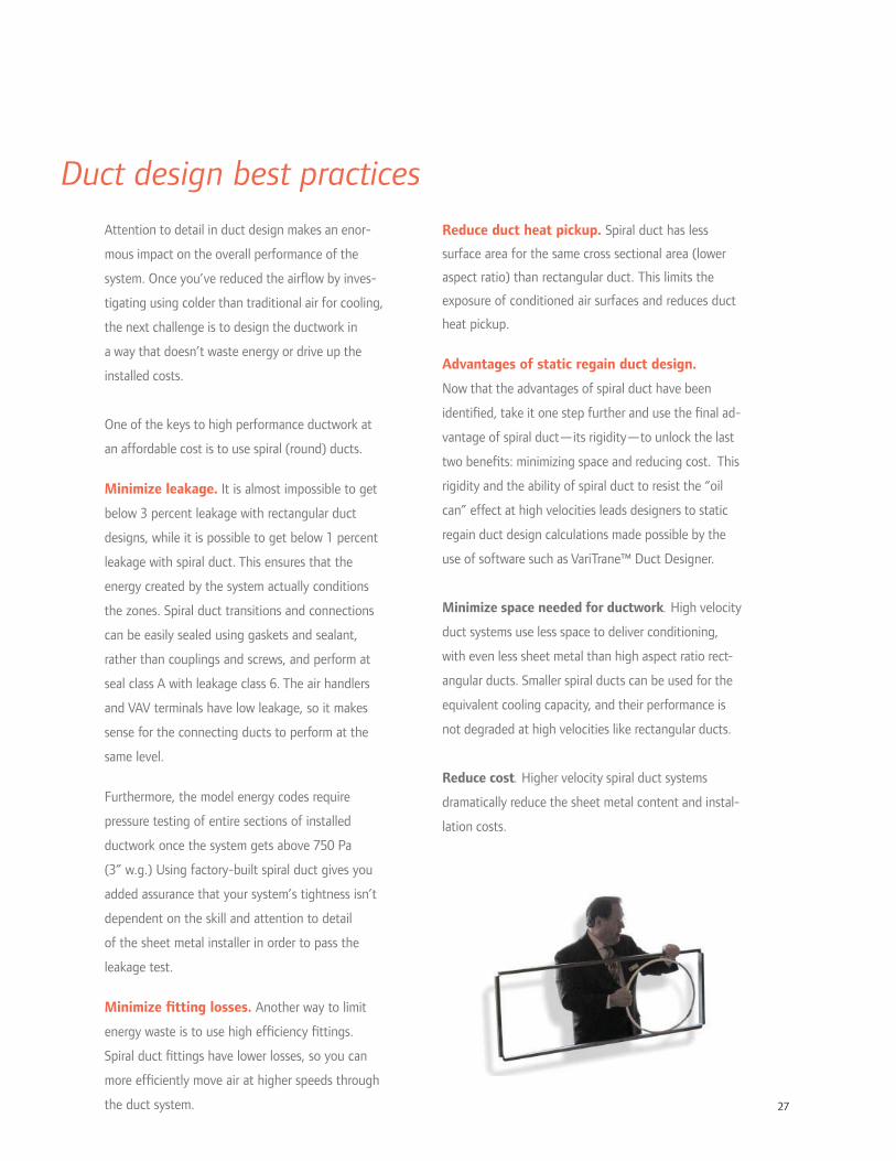
27
Attention to detail in duct design makes an enor-
mous impact on the overall performance of the
system. Once you’ve reduced the air ow by inves-
tigating using colder than traditional air for cooling,
the next challenge is to design the ductwork in
a way that doesn’t waste energy or drive up the
installed costs.
One of the keys to high performance ductwork at
an affordable cost is to use spiral (round) ducts.
Minimize leakage. It is almost impossible to get
below 3 percent leakage with rectangular duct
designs, while it is possible to get below 1 percent
leakage with spiral duct. This ensures that the
energy created by the system actually conditions
the zones. Spiral duct transitions and connections
can be easily sealed using gaskets and sealant,
rather than couplings and screws, and perform at
seal class A with leakage class 6. The air handlers
and VAV terminals have low leakage, so it makes
sense for the connecting ducts to perform at the
same level.
Furthermore, the model energy codes require
pressure testing of entire sections of installed
ductwork once the system gets above 750 Pa
(3” w.g.) Using factory-built spiral duct gives you
added assurance that your system’s tightness isn’t
dependent on the skill and attention to detail
of the sheet metal installer in order to pass the
leakage test.
Minimize tting losses. Another way to limit
energy waste is to use high ef ciency ttings.
Spiral duct ttings have lower losses, so you can
more ef ciently move air at higher speeds through
the duct system.
Reduce duct heat pickup. Spiral duct has less
surface area for the same cross sectional area (lower
aspect ratio) than rectangular duct. This limits the
exposure of conditioned air surfaces and reduces duct
heat pickup.
Advantages of static regain duct design.
Now that the advantages of spiral duct have been
identi ed, take it one step further and use the nal ad-
vantage of spiral duct—its rigidity—to unlock the last
two bene ts: minimizing space and reducing cost. This
rigidity and the ability of spiral duct to resist the “oil
can” effect at high velocities leads designers to static
regain duct design calculations made possible by the
use of software such as VariTrane™ Duct Designer.
Minimize space needed for ductwork. High velocity
duct systems use less space to deliver conditioning,
with even less sheet metal than high aspect ratio rect-
angular ducts. Smaller spiral ducts can be used for the
equivalent cooling capacity, and their performance is
not degraded at high velocities like rectangular ducts.
Reduce cost. Higher velocity spiral duct systems
dramatically reduce the sheet metal content and instal-
lation costs.
Duct design best practices

28
Sequences of operation
I/O point summaries
Each pre-packaged solution includes:
• Sequence of operation
• I/O summary (points list)
• Flow sketch
• Control drawing
• Controller wiring detail
• End device details
• Commissioning sheet
• Technician application notes
• Pre-built Tracer graphic
Control drawings
System control diagram for speci c con guration
Design resourcesPre-packaged Solutions (PPS)
Pre-built AHU graphics
PPS information can be found at
www.traneengineer.com
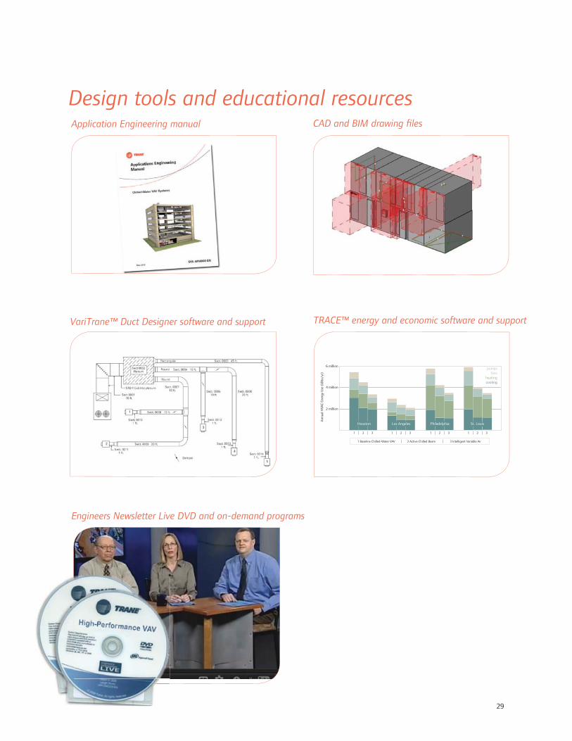
29
TRACE™ energy and economic software and support
CAD and BIM drawing les
1 2 3 1 2 3 1 2 3 1 2 3
1 Baseline Chilled-Water VAV 2 Active Chilled Beam 3 Intelligent Variable Air
6 million
Ann
ual H
VAC
Ener
gy U
se (
kBtu
/yr)
4 million
2 million
pumpsfans
heatingcooling
Houston Los Angeles Philadelphia St. Louis
VariTrane™ Duct Designer software and support
Engineers Newsletter Live DVD and on-demand programs
Design tools and educational resourcesApplication Engineering manual
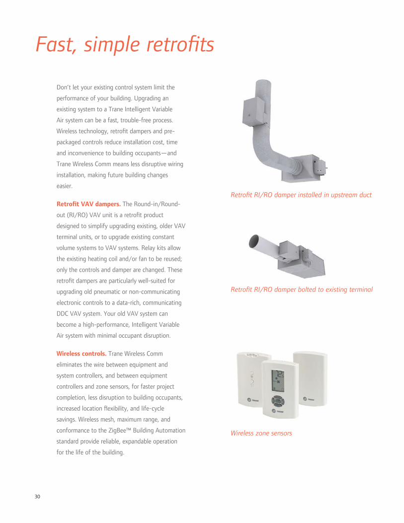
30
Fast, simple retro ts
Don’t let your existing control system limit the
performance of your building. Upgrading an
existing system to a Trane Intelligent Variable
Air system can be a fast, trouble-free process.
Wireless technology, retro t dampers and pre-
packaged controls reduce installation cost, time
and inconvenience to building occupants—and
Trane Wireless Comm means less disruptive wiring
installation, making future building changes
easier.
Retro t VAV dampers. The Round-in/Round-
out (RI/RO) VAV unit is a retro t product
designed to simplify upgrading existing, older VAV
terminal units, or to upgrade existing constant
volume systems to VAV systems. Relay kits allow
the existing heating coil and/or fan to be reused;
only the controls and damper are changed. These
retro t dampers are particularly well-suited for
upgrading old pneumatic or non-communicating
electronic controls to a data-rich, communicating
DDC VAV system. Your old VAV system can
become a high-performance, Intelligent Variable
Air system with minimal occupant disruption.
Wireless controls. Trane Wireless Comm
eliminates the wire between equipment and
system controllers, and between equipment
controllers and zone sensors, for faster project
completion, less disruption to building occupants,
increased location exibility, and life-cycle
savings. Wireless mesh, maximum range, and
conformance to the ZigBee™ Building Automation
standard provide reliable, expandable operation
for the life of the building.
Retro t RI/RO damper installed in upstream duct
Retro t RI/RO damper bolted to existing terminal
Wireless zone sensors
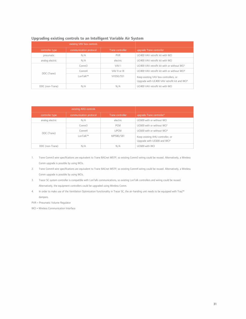
31
Upgrading existing controls to an Intelligent Variable Air Systemexisting VAV box controls
controller type communication protocol Trane controller upgrade Trane controller
pneumatic N/A PVR UC400 VAV retro t kit with WCI
analog electric N/A electric UC400 VAV retro t kit with WCI
DDC (Trane)
Comm3 VAV I UC400 VAV retro t kit with or without WCI¹
Comm4 VAV II or III UC400 VAV retro t kit with or without WCI²
LonTalk™ VV550/551 Keep existing VAV box controllers, or
Upgrade with UC400 VAV retro t kit and WCI³
DDC (non-Trane) N/A N/A UC400 VAV retro t kit with WCI
existing AHU controls
controller type communication protocol Trane controller upgrade Trane controller4
analog electric N/A electric UC600 with or without WCI
DDC (Trane)
Comm3 PCM UC600 with or without WCI¹
Comm4 UPCM UC600 with or without WCI²
LonTalk™ MP580/581 Keep existing AHU controller, or
Upgrade with UC600 and WCI³
DDC (non-Trane) N/A N/A UC600 with WCI
1. Trane Comm3 wire speci cations are equivalent to Trane BACnet MSTP, so existing Comm3 wiring could be reused. Alternatively, a Wireless
Comm upgrade is possible by using WCIs.
2. Trane Comm4 wire speci cations are equivalent to Trane BACnet MSTP, so existing Comm4 wiring could be reused. Alternatively, a Wireless
Comm upgrade is possible by using WCIs.
3. Tracer SC system controller is compatible with LonTalk communications, so existing LonTalk controllers and wiring could be reused.
Alternatively, the equipment controllers could be upgraded using Wireless Comm.
4. In order to make use of the Ventilation Optimization functionality in Tracer SC, the air-handing unit needs to be equipped with Traq™
dampers.
PVR = Pneumatic Volume Regulator
WCI = Wireless Communication Interface

32
Ingersoll Rand (NYSE:IR) is a world leader in creating and sustaining safe, comfortable and ef cient environments in commercial, residential
and industrial markets. Our people and our family of brands—including Club Car®, Ingersoll Rand®, Schlage®, Thermo King® and Trane®—work
together to enhance the quality and comfort of air in homes and buildings, transport and protect food and perishables, secure homes and
commercial properties, and increase industrial productivity and ef ciency. We are a $14 billion global business committed to sustainable business
practices within our company and for our customers. For more information, visit www.ingersollrand.com.
© 2012 Trane All rights reserved trane.com
APP-PRC002-EN 7 Dec 2012 ingersollrand.com
Produced on post-consumer recycled paper, using
environmentally friendly print practices that reduce waste.

11
Intelligent Variable AirAn EarthWise™ System from Trane
for packaged DX applications
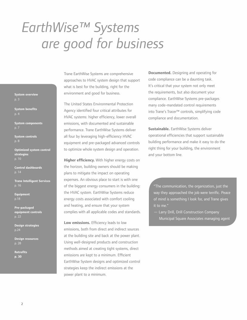
2
Trane EarthWise Systems are comprehensive
approaches to HVAC system design that support
what is best for the building, right for the
environment and good for business.
The United States Environmental Protection
Agency identi ed four critical attributes for
HVAC systems: higher ef ciency, lower overall
emissions, with documented and sustainable
performance. Trane EarthWise Systems deliver
all four by leveraging high-ef ciency HVAC
equipment and pre-packaged advanced controls
to optimize whole system design and operation.
Higher ef ciency. With higher energy costs on
the horizon, building owners should be making
plans to mitigate the impact on operating
expenses. An obvious place to start is with one
of the biggest energy consumers in the building:
the HVAC system. EarthWise Systems reduce
energy costs associated with comfort cooling
and heating, and ensure that your system
complies with all applicable codes and standards.
Low emissions. Ef ciency leads to low
emissions, both from direct and indirect sources
at the building site and back at the power plant.
Using well-designed products and construction
methods aimed at creating tight systems, direct
emissions are kept to a minimum. Ef cient
EarthWise System designs and optimized control
strategies keep the indirect emissions at the
power plant to a minimum.
EarthWise™ Systems are good for business
“The communication, the organization, just the
way they approached the job were terri c. Peace
of mind is something I look for, and Trane gives
it to me.”
— Larry Drill, Drill Construction Company
Municipal Square Associates managing agent
System overview
p. 3
System bene ts
p. 4
System componentsp. 7
System controlsp. 8
Optimized system control strategiesp. 10
Control dashboardsp. 14
Trane Intelligent Servicesp. 16
Equipmentp.18
Pre-packaged equipment controlsp. 22
Design strategiesp.24
Design resourcesp. 28
Retro tsp. 30
Documented. Designing and operating for
code compliance can be a daunting task.
It’s critical that your system not only meet
the requirements, but also document your
compliance. EarthWise Systems pre-packages
many code-mandated control requirements
into Trane’s Tracer™ controls, simplifying code
compliance and documentation.
Sustainable. EarthWise Systems deliver
operational ef ciencies that support sustainable
building performance and make it easy to do the
right thing for your building, the environment
and your bottom line.

3
The EarthWise Intelligent Air System for packaged DX applications
Trane IntelliPak™ rooftop units provide high ef ciency and cost
effectiveness with pre-packaged, factory-installed controls. Factory-
installed options include exhaust air energy recovery, outdoor air ow
measurement, evaporative condensing, variable-speed compressors
and fans, and a variety of lter options.
Tracer™ system controllers add a layer of sophistication and
turn a common VAV system into an Intelligent Variable Air System.
Factory-installed programming, start-up and commissioning
coordination, wired or Wireless Comm, and dashboards lead to easy
installation and operation.
Wired or wireless zone sensors communicate with the controller on
the VAV terminal to maintain proper space conditions.
Trane VAV terminal units offer low leakage, tested, repeatable
performance and pre-packaged, factory-installed controls.
A pre-packaged, variable-air HVAC system
design concept that:
• Provides heating, cooling, and ventilation
for multiple zones,
• Is 20 percent to 30 percent more ef cient
than traditional VAV systems, and
• Delivers high performance that is sustained
by interactive operator dashboards and
real-time analytics.
EarthWise™ Intelligent Variable Air System
D
D
3
More information can be found at
www.trane.com/EarthWise

4
Established performance,
enhanced with new technology
commissioning, and avoid the inconsistencies
of custom programming — but still provide
on-site programming exibility for project-
speci c requirements. Standard apps and
operator dashboards, supported by thorough
documentation, take the mystery out of how
your system works, so that you and Trane can
keep it running optimally over the system’s
lifetime.
The packaged version of the Intelligent
Variable Air System includes eighteen standard
con gurations for Trane IntelliPak™ units, air
terminal devices and system controls. Identifying
the repeatable aspects of these system designs
allows us to deploy standardized, pre-packaged
control sequences, drawings and operator
graphics and dashboards.
Comfort control. Variable air systems are
capable of controlling the temperature in
many zones with dissimilar cooling and heating
requirements. This is accomplished by providing
a VAV terminal unit and temperature sensor for
each independently controlled zone.
High indoor air quality. For most applications,
the foundation of good IAQ is proper ventilation.
The Intelligent Variable Air System balances
energy ef ciency and IAQ by bringing in no
more than the required amount of outdoor
air for ventilation, at all operating conditions,
through the use of optimized ventilation control
strategies and ow-measuring Traq™ outdoor-air
dampers. Building pressurization control not only
saves energy, it also reduces in ltration, which
can lead to moisture-related problems in the
building envelope.
Variable air systems have a proven track record
of reliable, ef cient performance. Using new
design strategies and advanced technologies,
Trane EarthWise™ Intelligent Variable Air
systems are more ef cient than traditional VAV
systems.
Twenty to thirty percent more ef cient.
Through advanced technologies— including
energy recovery and variable-speed equipment
— and optimized controls, Trane Intelligent
Variable Air systems can be 20 percent to 30
percent more ef cient than traditional VAV
systems. User-friendly dashboards allow you to
easily monitor that ef ciency to help maintain
peak performance for the life of the system.
Based on countless new buildings, retro ts
and recommissioning projects, we know that
properly designed and controlled VAV systems
are attainable, and can have lower installed and
operating costs than alternative systems.
As with every EarthWise System, Trane provides,
supports, and encourages energy modeling
during the system design phase. Trane Air-
conditioning Economics (TRACE™) software
can be used to determine how this system
can help your building earn high performance
designation, including earning LEED® points
under EAc1.
Ef ciencies in energy, cost and time.
Trane’s EarthWise Intelligent Variable Air
System was created to simplify the design
and implementation of a high-performing
HVAC system. The system’s controls are
baseline programmed at the factory to
contribute to smooth installation and

5
Low installation costs. Ventilating and cooling
or heating with the same system naturally costs
less to install—only one set of distribution
piping and/or ductwork is required.
Using a centralized system allows the system to
be sized for “block” load, that is, the highest
heating or cooling load observed at one time.
Individual zone-based systems will naturally have
more installed capacity because they are sized
on the “sum of the peaks.”
By using cold air, fans and ductwork can be right
sized in a modest trade-off with energy costs.
Code compliant. Complying with codes and
documenting that compliance is easier when
using an engineered system from Trane. Code-
mandated system control requirements are pre-
packaged in the standard Trane IntelliPak™ and
Tracer™ controllers. These routines and their
interfaces are exible, yet standardized to help
reduce opportunities for errors and reduce the
need for custom programming.
Annual energy use for an 89,000 ft² of ce building, estimated using Trane TRACE™ building energy
analysis software. The baseline rooftop VAV system is modeled according to Appendix G in ASHRAE
Standard 90.1-2007.
High-performance building designation steers the
discussion toward systems that have lower energy
costs. The EarthWise Intelligent Variable Air
system, using the design and operation strategies
identi ed in this catalog, can help earn LEED
points under EAc1, depending on the baseline
system and local utility rates.
4 million
3 million
2 million
3.5 million
2.5 million
1 2 3 1 2 3 1 2 3 1 2 3
1 Baseline Rooftop VAV 2 Variable Refrigerant Flow (VRF) 3 Intelligent Variable Air
Ann
ual B
uild
ing
Ener
gy U
se (
kBtu
/yr)
Houston Los Angeles Philadelphia St. Louis
fansheatingcooling
6
ventilation while others do not. A dedicated
ventilation system has to run when just one zone
needs ventilation, because it typically doesn’t
have zone dampers for reducing ventilation to
a minimum when the zone is unoccupied. See
sidebar for potential code issues.
Ventilation ef ciency. VAV systems using a
single supply duct typically deliver a mixture
of recirculated air and outdoor air—the same
fraction of outdoor air is delivered to all
zones. While this may be suf cient ventilation
for some zones, depending on each zone’s
cooling or heating load, it may not be enough
for others. ASHRAE Standard 62.1 for indoor
air quality requires that the system bring in
more outdoor air in order to satisfy the zone
needing the highest fraction of ventilation air,
with compensation for overventilation in the
recirculated air. This leads to all other zones being
over-ventilated and extra energy to condition the
additional outdoor air.
System controls from Trane automatically solve
the equations found in ASHRAE Standard 62.1,
and allow the system to optimize ventilation by
dynamically changing outdoor air damper position
in response to the needs of the critical ventilation
zone(s). This can allow the system to ventilate to
mechanical code requirements without an unnec-
essarily high, xed outdoor air damper position.
A further re nement of this control allows the
system to automatically open the zone damper in
the critical ventilation zone(s), increasing reheat
slightly, in exchange for a reduction in outdoor
air at the system level. This is permitted by the
ASHRAE 90.1 energy code.
VAV systems have always been comfortable and
exible—adapting automatically to building load
changes over time. But beneath that comfort,
outdated controls and system components were
likely wasting energy. The Intelligent Variable Air
system makes it easy to keep the comfort while
minimizing energy waste.
Zone and system controls, simpli ed.
Controls for a high performance, multiple-zone
VAV system require more coordination than
controls for a single-zone system. This is one
of the driving forces behind the need for a
repeatable, highly con gured yet standardized
system control. These controls ensure that the
inherent bene ts of the system do not come
at an energy cost or contribute to a poorly
performing system.
Reduced reheat. One of the traditional
complaints about multiple zone VAV systems
is that for some zones, they heat air that has
been previously cooled with mechanical cooling.
Judicious use of ventilation optimization, supply
air temperature reset and parallel fan powered
VAV terminals can keep this to a minimum.
Ef cient central fan operation. Another
opportunity to save energy is in the central
fan(s) delivering cooling and ventilation together.
The central fan(s) must continue to operate,
even when the spaces are unoccupied and do
not need to be ventilated. However, proper
scheduling, optimized ventilation control, and
an “occupied standby” mode minimize fan and
ventilation energy when some zones require
Efficient, flexible, comfortable,
and now, even better
Did you know?
A recent interpretation
from ASHRAE
Standard 62.1 clari es
that zones must
continue to receive the
building component
ventilation rate
(Ra) whenever they
are expected to be
occupied, even when
they are temporarily
unoccupied.
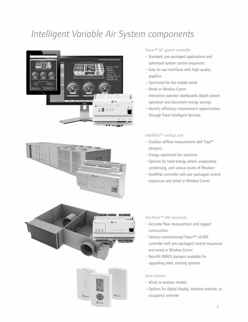
7
Tracer™ SC system controller
• Standard, pre-packaged applications and
optimized system control sequences
• Easy-to-use interfaces with high-quality
graphics
• Optimized for the mobile world
• Wired or Wireless Comm
• Interactive operator dashboards depict system
operation and document energy savings
• Identify ef ciency improvement opportunities
through Trane Intelligent Services
Intelligent Variable Air System components
VariTrane™ VAV terminals
• Accurate ow measurement and rugged
construction
• Factory-commissioned Tracer™ UC400
controller with pre-packaged control sequences
and wired or Wireless Comm
• Retro t (RIRO) dampers available for
upgrading older, existing systems
Zone sensors
• Wired or wireless models
• Options for digital display, setpoint override, or
occupancy override
IntelliPak™ rooftop unit
• Outdoor air ow measurement with Traq™
dampers
• Energy-optimized fan solutions
• Options for total-energy wheel, evaporative
condensing, and various levels of ltration
• IntelliPak controller with pre-packaged control
sequences and wired or Wireless Comm
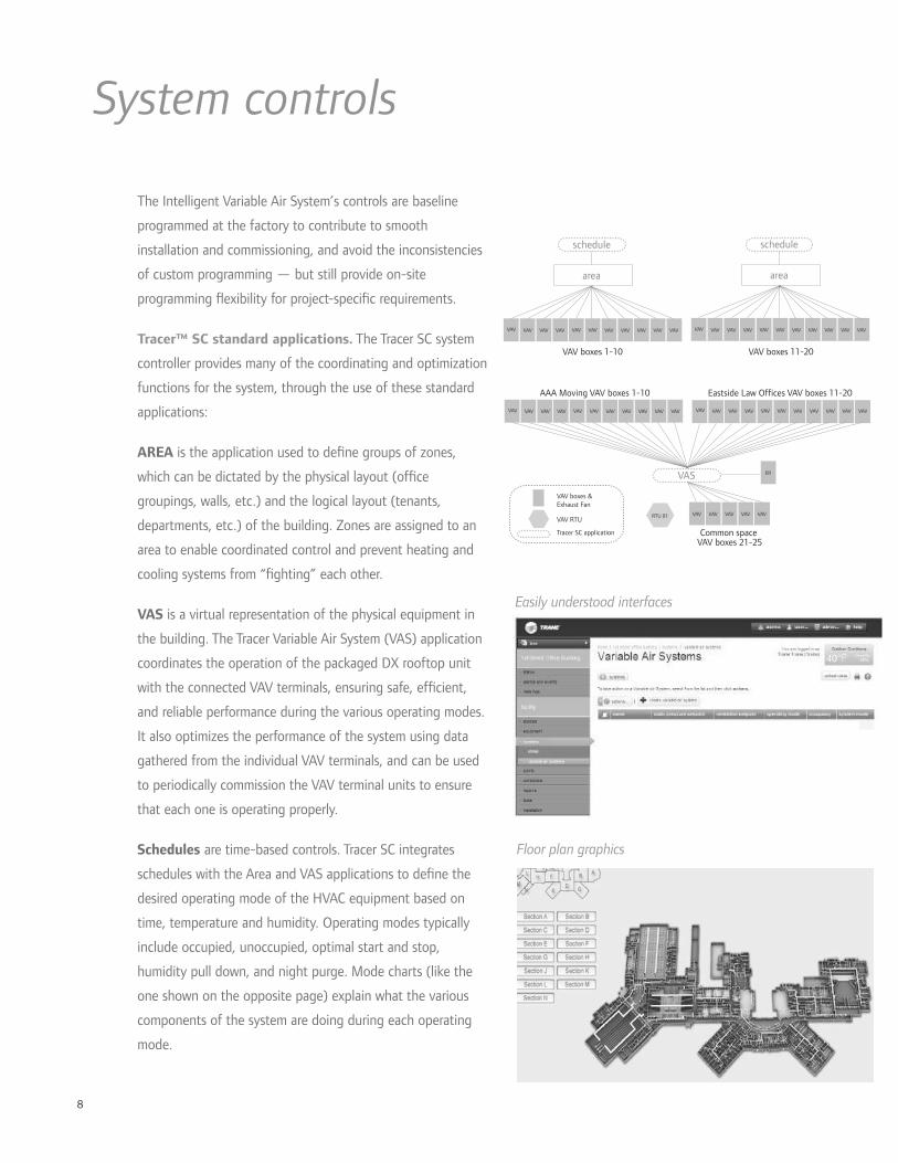
8
System controls
The Intelligent Variable Air System’s controls are baseline
programmed at the factory to contribute to smooth
installation and commissioning, and avoid the inconsistencies
of custom programming — but still provide on-site
programming exibility for project-speci c requirements.
Tracer™ SC standard applications. The Tracer SC system
controller provides many of the coordinating and optimization
functions for the system, through the use of these standard
applications:
AREA is the application used to de ne groups of zones,
which can be dictated by the physical layout (of ce
groupings, walls, etc.) and the logical layout (tenants,
departments, etc.) of the building. Zones are assigned to an
area to enable coordinated control and prevent heating and
cooling systems from “ ghting” each other.
VAS is a virtual representation of the physical equipment in
the building. The Tracer Variable Air System (VAS) application
coordinates the operation of the packaged DX rooftop unit
with the connected VAV terminals, ensuring safe, ef cient,
and reliable performance during the various operating modes.
It also optimizes the performance of the system using data
gathered from the individual VAV terminals, and can be used
to periodically commission the VAV terminal units to ensure
that each one is operating properly.
Schedules are time-based controls. Tracer SC integrates
schedules with the Area and VAS applications to de ne the
desired operating mode of the HVAC equipment based on
time, temperature and humidity. Operating modes typically
include occupied, unoccupied, optimal start and stop,
humidity pull down, and night purge. Mode charts (like the
one shown on the opposite page) explain what the various
components of the system are doing during each operating
mode.
schedule
area
VAV VAVVAVVAVVAVVAVVAVVAV VAVVAVVAV
schedule
area
VAV VAVVAVVAVVAVVAVVAVVAV VAVVAVVAV
VAS
VAV VAVVAVVAVVAVVAVVAVVAV VAVVAVVAV VAV VAVVAVVAVVAVVAVVAVVAV VAVVAVVAV
VAV boxes 1-10 VAV boxes 11-20
AAA Moving VAV boxes 1-10 Eastside Law Offices VAV boxes 11-20
VAVVAVVAVVAV VAV
ER
Common space VAV boxes 21-25
RTU 01VAV RTU
VAV boxes &Exhaust Fan
Tracer SC application
Floor plan graphics
Easily understood interfaces
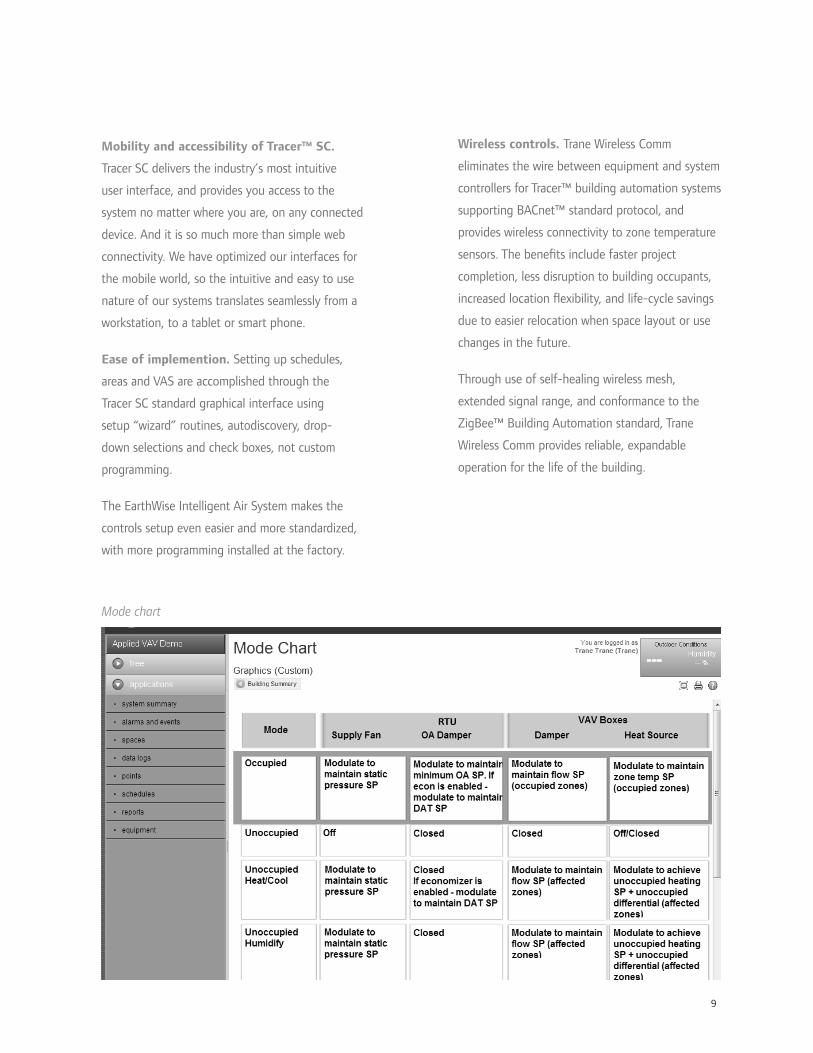
9
Mobility and accessibility of Tracer™ SC.
Tracer SC delivers the industry’s most intuitive
user interface, and provides you access to the
system no matter where you are, on any connected
device. And it is so much more than simple web
connectivity. We have optimized our interfaces for
the mobile world, so the intuitive and easy to use
nature of our systems translates seamlessly from a
workstation, to a tablet or smart phone.
Ease of implemention. Setting up schedules,
areas and VAS are accomplished through the
Tracer SC standard graphical interface using
setup “wizard” routines, autodiscovery, drop-
down selections and check boxes, not custom
programming.
The EarthWise Intelligent Air System makes the
controls setup even easier and more standardized,
with more programming installed at the factory.
Mode chart
Wireless controls. Trane Wireless Comm
eliminates the wire between equipment and system
controllers for Tracer™ building automation systems
supporting BACnet™ standard protocol, and
provides wireless connectivity to zone temperature
sensors. The bene ts include faster project
completion, less disruption to building occupants,
increased location exibility, and life-cycle savings
due to easier relocation when space layout or use
changes in the future.
Through use of self-healing wireless mesh,
extended signal range, and conformance to the
ZigBee™ Building Automation standard, Trane
Wireless Comm provides reliable, expandable
operation for the life of the building.

10
Optimized system control strategies
To help achieve the 20 percent to 30 percent
ef ciency improvement, EarthWise™ Intelligent
Variable Air Systems pre-package the following
optimized system control strategies in Tracer™
system and equipment controls.
Fan-pressure optimization. As cooling loads
change, the VAV terminals modulate to vary air ow
supplied to the zones. This causes the pressure inside
the supply ductwork to change. In many systems,
the RTU controller varies the capacity of the supply
fan to maintain static pressure in the ductwork at a
constant setpoint. With this approach, however, the
system usually generates more static pressure at part
load than necessary.
When communicating controllers are used on the
VAV terminals, it is possible to optimize this static
pressure control function to minimize duct pres-
sure and save fan energy. Tracer SC continually polls
the individual VAV controllers, looking for the VAV
terminal with the most-open damper. The duct static
pressure setpoint for the supply fan is then dynami-
cally reset to provide just enough pressure so that at
least one damper is nearly wide open. At part-load
conditions, the supply fan is able to operate at a
lower static pressure, which results in less energy use,
lower sound levels, and reduced risk of fan surge.
Supply-Air Temperature (SAT) reset. In a VAV
system, increasing the SAT at part-load conditions can
reduce cooling and reheat energy use, but increases
fan energy and can result in elevated indoor humidity
levels. Therefore, SAT reset should be implemented
so that it minimizes overall system energy use, by
considering the trade-off between compressor, reheat,
and fan energy.
Tracer SC balances these competing issues by keeping
the SAT setpoint cold when it is warm outside,
thereby taking advantage of the signi cant energy
savings from unloading the fan and avoiding elevated
indoor humidity levels. The SAT setpoint is reset
upward during mild and cold weather to enhance the
bene t of the airside economizer (thereby saving
cooling energy) and minimize reheat energy use.
However, Tracer also monitors the current temperature
and VAV damper position for each zone, and will
lower the SAT setpoint if needed to prevent any
zones from overheating.staticpressuresensor
Psupplyfan
RTU controller
Tracer SC
VAV boxes withUC400 controllers
VFD
55 60 6550 807570
61
60
59
58
57
56
55SA
tem
pera
ture
set
poin
t, °
F
outdoor dry-bulb temperature, °F
reset based on s awoorst case zoneo c z

11
much outdoor air must be brought in at the rooftop
unit to satisfy all zones served. Finally, Tracer sends this
new outdoor air ow setpoint to the controller on the
IntelliPak™ rooftop unit, which then modulates a ow-
measuring (Traq™) outdoor-air damper to maintain this
new setpoint.
This strategy reduces the energy required to condition
outdoor air brought in for ventilation, while minimizing
installed cost and risk by installing CO2 sensors only in
those zones where the payback is the greatest.
Optimal start/stop. In some buildings, a simple
time clock or time-of-day schedule is used to start and
stop the HVAC system. During hours when the building
is expected to be unoccupied, the system is shut off
and the temperature is allowed to drift away from
the occupied setpoint. For most days of the year, the
system starts much earlier than needed.
Tracer SC uses a strategy called optimal start, which
determines the length of time required to bring each
zone from current temperature to the occupied setpoint
temperature. Then, Tracer waits as long as possible
before starting, so that the temperature in each zone
reaches occupied setpoint just in time for occupancy.
This strategy reduces the number of system operating
hours and saves energy.
Ventilation optimization. In a VAV system, the rooftop
unit delivers fresh outdoor air to several, individually
controlled zones. Demand-controlled ventilation (DCV)
involves resetting intake air ow in response to variations in
zone population. While commonly implemented using carbon
dioxide (CO2) sensors, occupancy sensors, or time-of-day
(TOD) schedules can also be used.
Tracer SC optimizes the amount of ventilation in a multiple-
zone VAV system by combining these various DCV strategies
at the zone level (using each where it best ts) with
ventilation reset at the system level. With this strategy,
CO2 sensors are installed only in those zones that are
densely occupied and experience widely varying patterns of
occupancy. Zones that are less densely occupied or have a
population that varies only a little are probably better suited
for occupancy sensors or a time-of-day schedule.
These various zone-level DCV strategies are used to reset
the ventilation requirement for their respective zones for any
given hour. In addition, the controller on each VAV terminal
continuously monitors primary air ow being delivered to the
zone and calculates the current OA fraction (Zpz).
Then, Tracer SC periodically gathers this data from all
VAV terminals and solves the ventilation reset equations
(prescribed by ASHRAE Standard 62.1) to determine how
OA
SA RA
VAV Controllers• Required outdoor airflow• Current primary airflow• Current OA fraction
Tracer SC• Find highest OA fraction• Calculate current system intake airflow (ASHRAE 62.1)
RTU controller• Reset intake airflow
optimal start
optimal stop(fan on, OA damper open)
systemon
systemoff
occupiedsetpoint
temperature
unoccupiedsetpoint
temperature
occupied hours
mid 6 AM noon 6 PM mid

12
Energy-saving potential of optimized
system controls. There is a real potential to
save energy in VAV systems through optimized
system control strategies. The chart to the
right shows the potential energy savings of
using these optimized control strategies in an
of ce building that has a typical VAV system.
The optimized VAV system controls reduced
HVAC energy use by 10 to 20 percent. This
savings reduces operating costs for the
building owner and can help in achieving
points toward LEED® certi cation.
Implementing optimized controls.
Optimized control strategies, such as optimal
start and stop, unoccupied economizing,
fan-pressure optimization, and ventilation
optimization, are pre-packaged in the Trane
Tracer™ controllers. Others, such as supply air
temperature reset and humidity pull-down,
can be quickly implemented using standard
code.
Many of these optimized control strategies are
implemented by simply “checking the box” to
enable a strategy, or to add or remove zones.
Wireless controls allow easier upgrade.
Wireless technology, retro t dampers and
pre-packaged controls are particularly
well-suited for upgrading old pneumatic or
non-communicating electronic controls to a
data-rich, Intelligent Variable Air system with
minimal occupant disruption (see pp. 30-31).
PhiladelphiaLos AngelesHouston0
20
40
60
80
100
HV
AC
ener
gy c
onsu
mpt
ion,
% o
f ba
se
optimized system controlconventional system control
St. Louis
9%11% 17% 18%
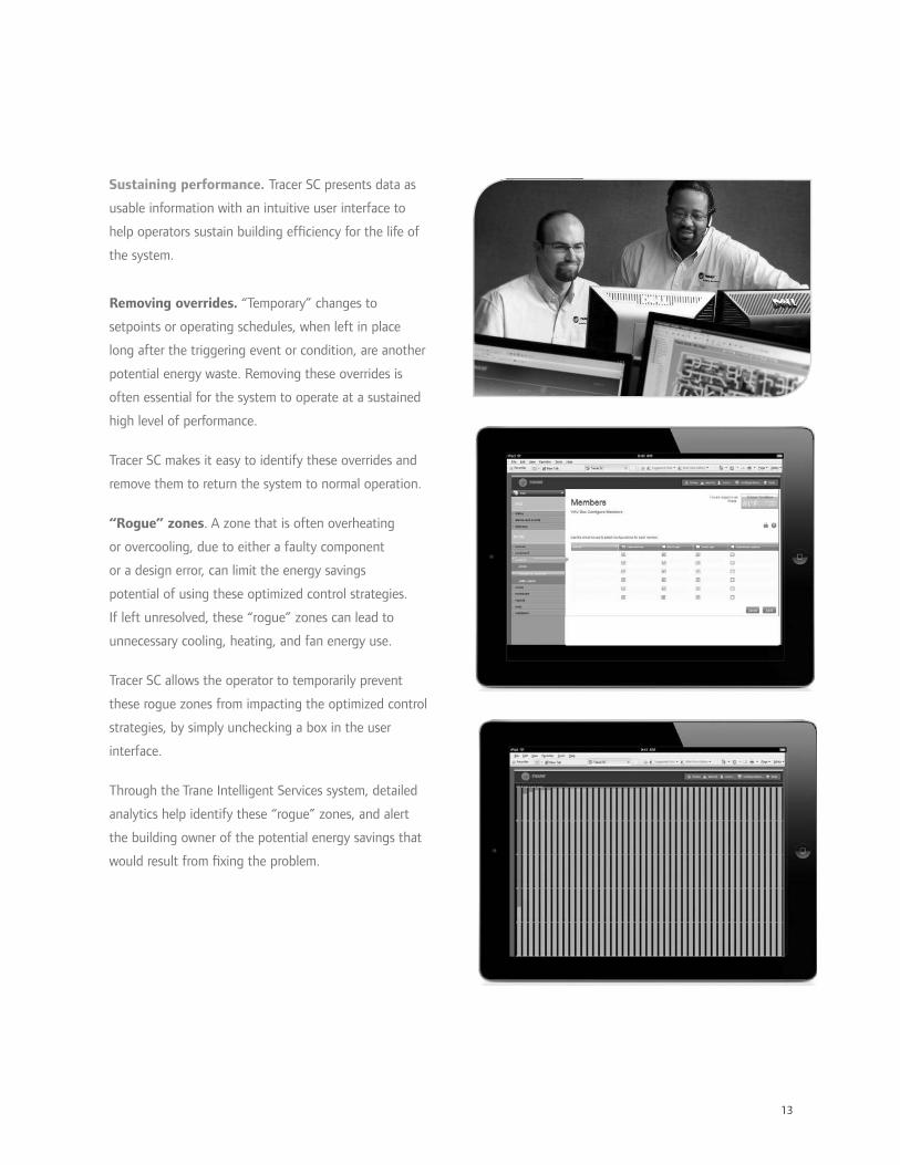
13
Sustaining performance. Tracer SC presents data as
usable information with an intuitive user interface to
help operators sustain building ef ciency for the life of
the system.
Removing overrides. “Temporary” changes to
setpoints or operating schedules, when left in place
long after the triggering event or condition, are another
potential energy waste. Removing these overrides is
often essential for the system to operate at a sustained
high level of performance.
Tracer SC makes it easy to identify these overrides and
remove them to return the system to normal operation.
“Rogue” zones. A zone that is often overheating
or overcooling, due to either a faulty component
or a design error, can limit the energy savings
potential of using these optimized control strategies.
If left unresolved, these “rogue” zones can lead to
unnecessary cooling, heating, and fan energy use.
Tracer SC allows the operator to temporarily prevent
these rogue zones from impacting the optimized control
strategies, by simply unchecking a box in the user
interface.
Through the Trane Intelligent Services system, detailed
analytics help identify these “rogue” zones, and alert
the building owner of the potential energy savings that
would result from xing the problem.

14
At-a-glance gauges
Intuitive, accessible dashboards
It’s one thing for the controls installer to understand
how to set up the system, but it’s imperative that the
operator understand how the system works. Standard
apps and operator dashboards, supported by thorough
documentation, take the mystery out of how your
system works, so that you and Trane can keep it running
optimally over the system’s lifetime.
Dashboards are all about giving the operator information
that is actionable—gauges with min and max values
identi ed, warnings, alerts and error messages—helping
identify opportunities to optimize system operation.
Tracer™ SC provides access to your system from any
connected device: PCs, tablets, even smart phones.
Strategic data

15
Scheduling applicationCon guration screen
Savings calculationsPerformance summary
Preprogrammed displays illustrate the energy being
saved by optimal system control strategies.
These system savings calculations are suitable for a
public display, for example as part of a lobby kiosk.
Keeping custom design out of programming is key for
creating systems that function the same from one job
to the next - making it a lot easier to troubleshoot and
sustain high performance over time. Con guration
screens and scheduling applications are easy to use and
understand.
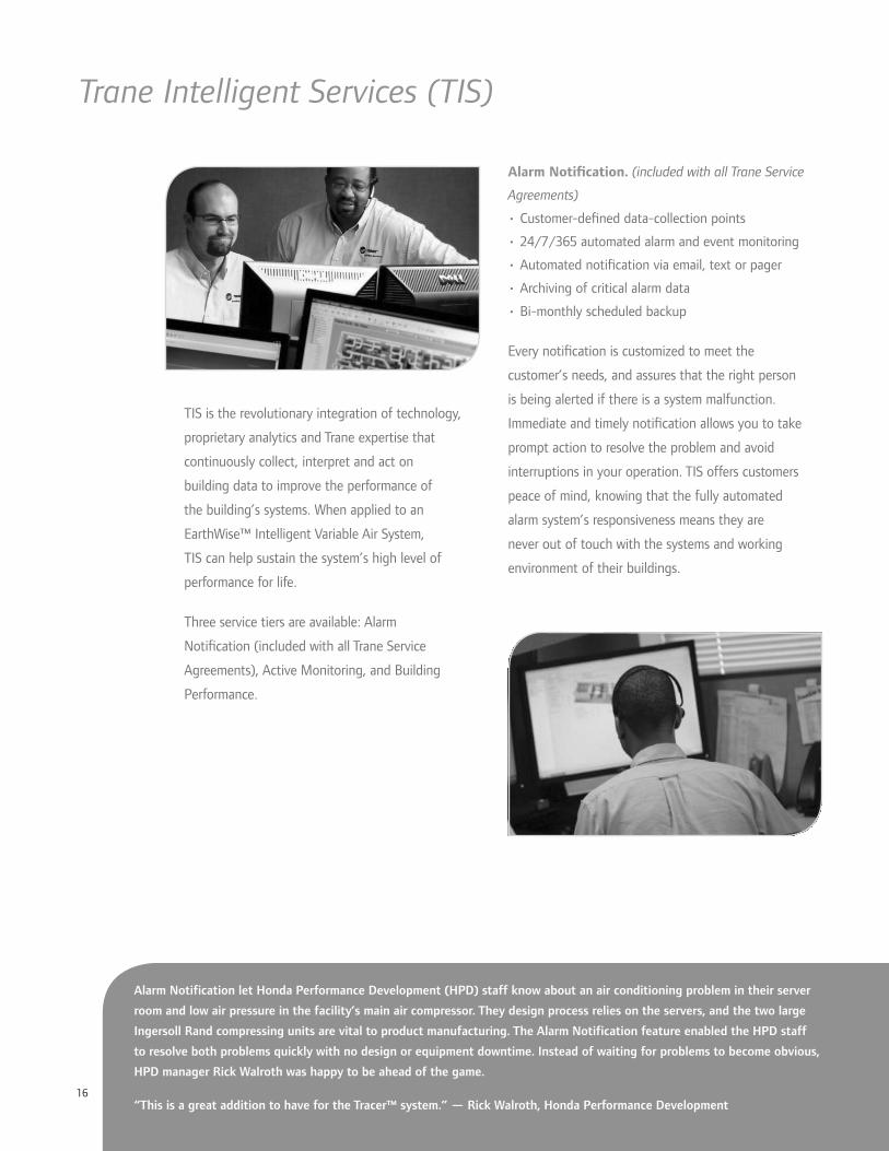
16
Trane Intelligent Services (TIS)
TIS is the revolutionary integration of technology,
proprietary analytics and Trane expertise that
continuously collect, interpret and act on
building data to improve the performance of
the building’s systems. When applied to an
EarthWise™ Intelligent Variable Air System,
TIS can help sustain the system’s high level of
performance for life.
Three service tiers are available: Alarm
Noti cation (included with all Trane Service
Agreements), Active Monitoring, and Building
Performance.
Alarm Noti cation. (included with all Trane Service
Agreements)
• Customer-de ned data-collection points
• 24/7/365 automated alarm and event monitoring
• Automated noti cation via email, text or pager
• Archiving of critical alarm data
• Bi-monthly scheduled backup
Every noti cation is customized to meet the
customer’s needs, and assures that the right person
is being alerted if there is a system malfunction.
Immediate and timely noti cation allows you to take
prompt action to resolve the problem and avoid
interruptions in your operation. TIS offers customers
peace of mind, knowing that the fully automated
alarm system’s responsiveness means they are
never out of touch with the systems and working
environment of their buildings.
Alarm Notification let Honda Performance Development (HPD) staff know about an air conditioning problem in their server
room and low air pressure in the facility’s main air compressor. They design process relies on the servers, and the two large
Ingersoll Rand compressing units are vital to product manufacturing. The Alarm Notification feature enabled the HPD staff
to resolve both problems quickly with no design or equipment downtime. Instead of waiting for problems to become obvious,
HPD manager Rick Walroth was happy to be ahead of the game.
“This is a great addition to have for the Tracer™ system.” — Rick Walroth, Honda Performance Development

17
Active Monitoring includes Alarm Noti cation, plus
the bene t of immediate diagnostic and responsive
action capabilities.
• Diagnostics and alarm analysis by a
technical specialist
• Off-site alarm mediation if possible
• Intelligent mobilization of local Trane authorized
service personnel
• Alarm documentation and reporting
(daily, weekly, monthly, quarterly)
Faster detection means faster resolution, saving
critical time and money. Forty percent of the critical
alarms are resolved within 30 minutes of the alarm
sounding, which gets your system operational more
quickly. Triple redundancy ensures your system and
operations are safe and secure.
Building performance offering includes all of the
features of Active Monitoring coupled with analyzed
data and performance-driven recommendations
and actions enabling high performance operating
conditions.
• Initial system-wide assessment
• Continuous analysis by automated system analytics
• Results-oriented, value-based actionable
recommendations
• On-going commissioning reporting to monitor
parameters
The Building Performance level of TIS is intelligence
in action—a warning when a system malfunctions and
data translated into actionable solutions. Anticipating
problems and proactively solving them dramatically
reduces downtime and increases productivity. TIS is
the customer’s safety net for occupant comfort and
satisfaction. Savings are achieved through ef cient,
uninterrupted operation, restoring the building to
high performance.
“The Trane Performance Based Agreement, coupled with Trane Central Monitoring, has significantly reduced our
downtime by more than 60 percent and cut our truck rolls in half, which has improved response time and turnaround
time on system repairs. With Trane Central Monitoring we’ve been able to maintain a 99 percent uptime commitment
to our customers. Trane Central Monitoring is a critical tool in our business process to insure we meet our business
demands. With my local Trane account manager I always know I am in good hands and that tasks will be done 100
percent of the time.” — Mark Manning, ARRIS Group
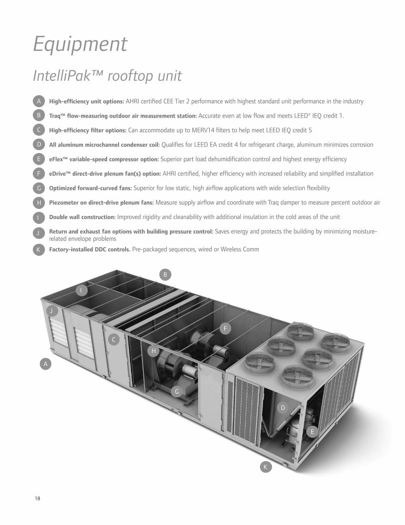
18
D
E
F
G
H
High-ef ciency unit options: AHRI certi ed CEE Tier 2 performance with highest standard unit performance in the industry
Traq™ ow-measuring outdoor air measurement station: Accurate even at low ow and meets LEED® IEQ credit 1.
High-ef ciency lter options: Can accommodate up to MERV14 lters to help meet LEED IEQ credit 5
All aluminum microchannel condenser coil: Quali es for LEED EA credit 4 for refrigerant charge, aluminum minimizes corrosion
eFlex™ variable-speed compressor option: Superior part load dehumidi cation control and highest energy ef ciency
eDrive™ direct-drive plenum fan(s) option: AHRI certi ed, higher ef ciency with increased reliability and simpli ed installation
Optimized forward-curved fans: Superior for low static, high air ow applications with wide selection exibility
Piezometer on direct-drive plenum fans: Measure supply air ow and coordinate with Traq damper to measure percent outdoor air
Double wall construction: Improved rigidity and cleanability with additional insulation in the cold areas of the unit
Return and exhaust fan options with building pressure control: Saves energy and protects the building by minimizing moisture-related envelope problems
Factory-installed DDC controls. Pre-packaged sequences, wired or Wireless Comm
EquipmentIntelliPak™ rooftop unit
I
J
D
E
F
G
H
I
J
K
K
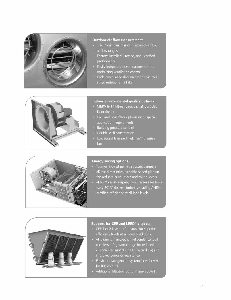
19
Outdoor air ow measurement
• Traq™ dampers maintain accuracy at low
air ow ranges
• Factory-installed, -tested, and -veri ed
performance
• Easily integrated ow measurement for
optimizing ventilation control
• Code compliance documentation via mea-
sured outdoor air intake
Indoor environmental quality options
• MERV 8-14 lters remove small particles
from the air
• Pre- and post- lter options meet special
application requirements
• Building pressure control
• Double-wall construction
• Low sound levels with eDrive™ plenum
fan
Energy saving options
• Total-energy wheel with bypass dampers
• eDrive direct-drive, variable-speed plenum
fan reduces drive losses and sound levels
• eFlex™ variable-speed compressor (available
early 2013) delivers industry-leading AHRI-
certi ed ef ciency at all load levels
Support for CEE and LEED® projects
• CEE Tier 2 level performance for superior
ef ciency levels at all load conditions
• All aluminum microchannel condenser coil
uses less refrigerant charge for reduced en-
vironmental impact (LEED EA credit 4) and
improved corrosion resistance
• Fresh air management system (see above)
for IEQ credit 1
• Additional ltration options (see above)

20
D
E
VariTrane units are manufactured in the most state-
of-the-art VAV facility in the world. They feature
proven components such as the patented Trane ow
ring and the Trane DDC controller. The most advanced
manufacturing techniques in the industry have been
implemented to provide an exceptionally rugged and
reliable VAV unit. All products are UL listed for safety
and provide proven performance via accepted industry
standards like AHRI 880 and 885.
All VariTrane VAV controls are factory commissioned.
This means that air ow, temperature setpoints, and
addressing are performed in a controlled factory
environment. 100% factory run-testing ensures that
units arrive and function properly upon job startup.
With factory commissioned controls, you have better
control over cost and quality. This results in a higher
quality installation at a lower cost.
Single-duct and dual-duct air terminals• Single-duct heat options include water or electric
heating coils
• Unit sizes provide 0 to 8000 nominal CFM
• Access for water coil cleaning
• Factory-commissioned Trane controls
• Slip and drive connections as standard
Fan-powered air terminals• Parallel intermittent fan and series continuous fan
con gurations
• Complete reheat options include water or electric
heating coils
• Fan sizes provide 200 to 3000 nominal cfm
• Single-speed motor with SCR is standard for simpli ed
system balancing
• Optional high-ef ciency electrically commutated mor-
tors (ECMs)
• Low-height models for critical plenum requirements
D
E
Trane ow ring for unmatched air ow measurement accuracy
Heavy gauge air valve cylinder for durability
Interlocking panels for extremely rugged construction
Insulation edges encapsulated with metal to prevent erosion into the air stream
Factory-commissioned DDC controls with pre-packaged sequences and wired or Wireless Comm
VariTrane™ terminal unit
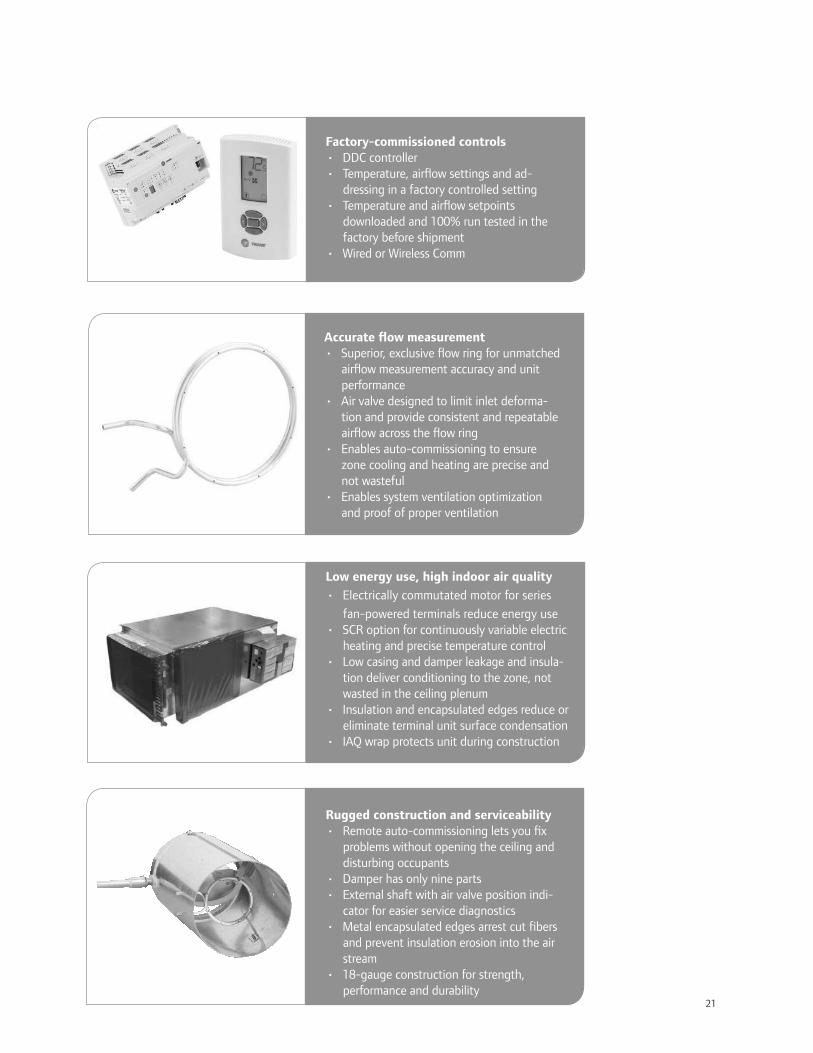
21
Factory-commissioned controls• DDC controller• Temperature, air ow settings and ad-
dressing in a factory controlled setting• Temperature and air ow setpoints
downloaded and 100% run tested in the factory before shipment
• Wired or Wireless Comm
Accurate ow measurement• Superior, exclusive ow ring for unmatched
air ow measurement accuracy and unit performance
• Air valve designed to limit inlet deforma-tion and provide consistent and repeatable air ow across the ow ring
• Enables auto-commissioning to ensure zone cooling and heating are precise and not wasteful
• Enables system ventilation optimization and proof of proper ventilation
Low energy use, high indoor air quality
• Electrically commutated motor for series
fan-powered terminals reduce energy use• SCR option for continuously variable electric
heating and precise temperature control• Low casing and damper leakage and insula-
tion deliver conditioning to the zone, not wasted in the ceiling plenum
• Insulation and encapsulated edges reduce or eliminate terminal unit surface condensation
• IAQ wrap protects unit during construction
Rugged construction and serviceability • Remote auto-commissioning lets you x
problems without opening the ceiling and disturbing occupants
• Damper has only nine parts• External shaft with air valve position indi-
cator for easier service diagnostics• Metal encapsulated edges arrest cut bers
and prevent insulation erosion into the air stream
• 18-gauge construction for strength, performance and durability
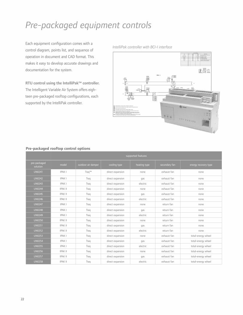
22
Pre-packaged equipment controls
Pre-packaged rooftop control options
supported features
pre-packaged solution
model outdoor air damper cooling type heating type secondary fan energy recovery type
UN0241 IPAK I Traq™ direct expansion none exhaust fan none
UN0242 IPAK I Traq direct expansion gas exhaust fan none
UN0243 IPAK I Traq direct expansion electric exhaust fan none
UN0244 IPAK II Traq direct expansion none exhaust fan none
UN0245 IPAK II Traq direct expansion gas exhaust fan none
UN0246 IPAK II Traq direct expansion electric exhaust fan none
UN0247 IPAK I Traq direct expansion none return fan none
UN0248 IPAK I Traq direct expansion gas return fan none
UN0249 IPAK I Traq direct expansion electric return fan none
UN0250 IPAK II Traq direct expansion none return fan none
UN0251 IPAK II Traq direct expansion gas return fan none
UN0252 IPAK II Traq direct expansion electric return fan none
UN0253 IPAK I Traq direct expansion none exhaust fan total-energy wheel
UN0254 IPAK I Traq direct expansion gas exhaust fan total-energy wheel
UN0255 IPAK I Traq direct expansion electric exhaust fan total-energy wheel
UN0256 IPAK II Traq direct expansion none exhaust fan total-energy wheel
UN0257 IPAK II Traq direct expansion gas exhaust fan total-energy wheel
UN0258 IPAK II Traq direct expansion electric exhaust fan total-energy wheel
Each equipment con guration comes with a
control diagram, points list, and sequence of
operation in document and CAD format. This
makes it easy to develop accurate drawings and
documentation for the system.
RTU control using the IntelliPak™ controller.
The Intelligent Variable Air System offers eigh-
teen pre-packaged rooftop con gurations, each
supported by the IntelliPak controller.
IntelliPak controller with BCI-I interface

23
VAV control using the UC400. The Intelligent
Variable Air System offers nine pre-packaged VAV
terminal con gurations, each including programming
code for the UC400 controller.
Space temperature control functions are further re ned,
based on:
• the presence of a fan and/or a heating coil in the
VAV terminal
• whether or not the zone is occupied
• whether the duct delivers cold or hot primary air
• whether or not the central unit is at minimum ow in
the heating mode
Wireless controls. Trane Wireless Comm eliminates
the wire between equipment and system controllers,
and provides wireless connectivity to zone temperature
sensors. The bene ts include faster project completion,
less disruption to building occupants, increased location
exibility, and life-cycle savings. Through use of self-
healing wireless mesh, extended signal range, and
conformance to the ZigBee™ Building Automation
standard, Trane Wireless Comm provides reliable,
expandable operation for the life of the building.
Pre-packaged VAV terminal control options
supported features
pre-packaged solution
controller terminal type heating type
TS0043 UC400 single duct none
TS0044 UC400 single duct electric
TS0045 UC400 single duct hot water
TS0046 UC400 parallel fan powered VAV none
TS0047 UC400 parallel fan powered VAV electric
TS0048 UC400 parallel fan powered VAV hot water
TS0049 UC400 series fan powered VAV none
TS0050 UC400 series fan powered VAV electric
TS0051 UC400 series fan powered VAV hot water
Tracer™ SC with WCI
Performance Climate Changer™ with UC600 and WCI
IntelliPak™ with BCI-I and WCI
VAV terminal with UC400 and WCI Wireless zone sensors
wireless signal

24
Design Strategies
Air-to-air energy recovery refers to the transfer of
sensible heat, or sensible heat and moisture (latent
heat), between air streams. A common location from
which to recover energy is the exhaust-air stream.
The most common use of the recovered energy is for
outdoor-air preconditioning.
Bene ts of outdoor-air preconditioning.
• Reduces cooling, dehumidi cation, heating and
humidi cation energy
• Allows downsizing of cooling, dehumidi cation,
heating and humidi cation equipment
Best practices.
• Properly size the energy-recovery device
• Strive for balanced air ows
• Integrate with airside economizer operation
• Provide a means to control the capacity of the device
at part load
• Provide a method for frost prevention in cold climates
The importance of proper control.
Coordinating with airside economizer cycle.
In many climates, an airside economizer can provide
the bene ts of “free” cooling for much of the year.
While the economizer operates, air-to-air energy
recovery offers no additional bene t. In fact, unless it
is turned off, the total-energy wheel actually increases
the cooling load by transferring heat from the exhaust
air air stream.
To accommodate economizer operation when the
total-energy wheel is idle, bypass dampers allow full
economizer air ow without signi cantly increasing the
airside pressure drop.
Preventing frost. Any air-to-air energy-recovery
device that preconditions outdoor air is subject to
frost buildup during very cold weather. If the surface
temperature of the device falls below the dew point
of the exhaust air, water vapor will condense on the
exhaust side of the device. If the exhaust-side surface
temperature falls below 32°F, this water freezes,
eventually blocking air ow. One of the bene ts
of total energy recovery over sensible-only energy
recovery is that frost forms at a much colder outdoor
temperature, which may even eliminate the need for
frost prevention.
Typical approaches to frost prevention:
• Modulating an outdoor air bypass damper to reduce
the heat-transfer capacity of the total-energy wheel, or
• Preheating either the outdoor or exhaust air before it
enters the wheel, for applications with extremely cold
outdoor air and higher indoor humidity levels during
cold weather
In addition to optimized controls, many intelligent Variable Air Systems make use of the following high-
performance system design strategies to achieve even greater energy savings.
Exhaust air energy recovery

25
Total-energy wheel offers an excellent combination of high (60 percent to 80 percent) total effectiveness ideally
suited for hot and cold climates, where latent energy recovery in both the summer and winter seasons is desirable.
Cross leakage is limited by choosing the right locations for supply and return or exhaust fans. In many applications
and locations the total-energy wheel’s higher levels of effectiveness may be required by the energy code.
180
160
140
120
100
80
60
40
20
humidity ratio, grains/lb of dry air
11030 40 50 60 70 80 10090dry-bulb temperature, F
EA
20
Control of a total-energy wheel in a VAV system
wheel on (cooling)
bypass dampers closed
wheel off
both bypass dampers openDBTSA
wheel on (heating)
modulate EA bypass damper
to avoid overheating
IntelliPak™ II with
total-energy wheel
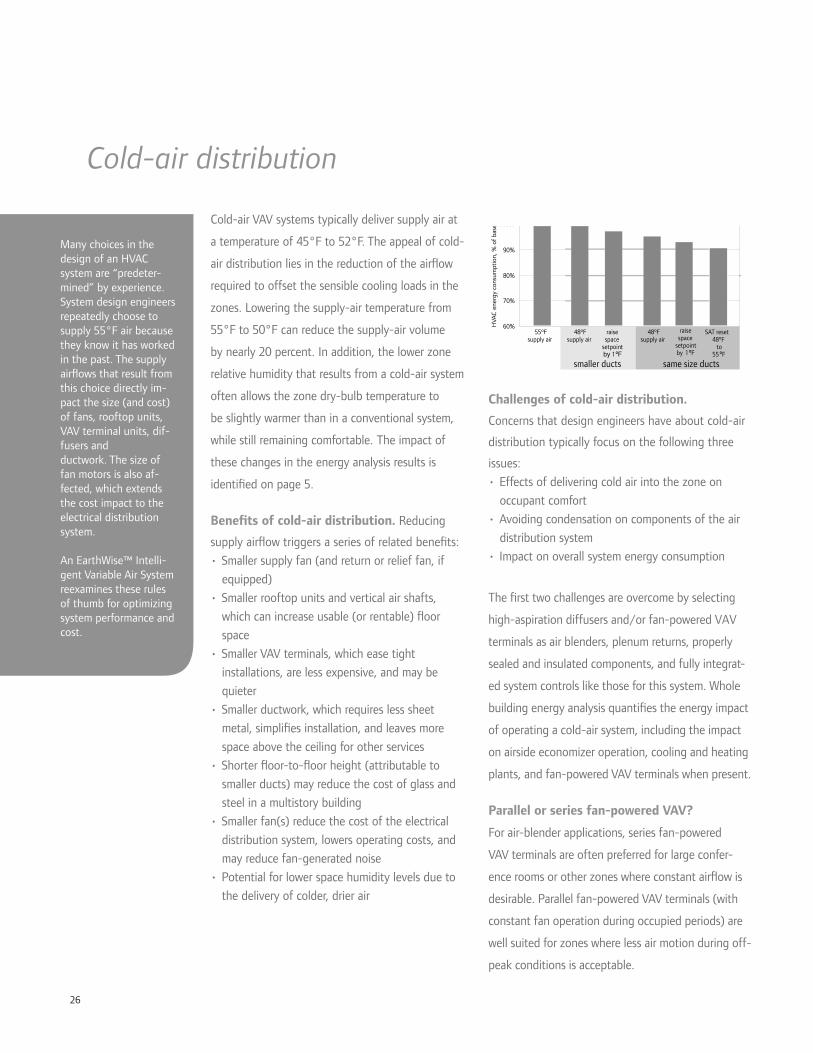
26
Cold-air VAV systems typically deliver supply air at
a temperature of 45°F to 52°F. The appeal of cold-
air distribution lies in the reduction of the air ow
required to offset the sensible cooling loads in the
zones. Lowering the supply-air temperature from
55°F to 50°F can reduce the supply-air volume
by nearly 20 percent. In addition, the lower zone
relative humidity that results from a cold-air system
often allows the zone dry-bulb temperature to
be slightly warmer than in a conventional system,
while still remaining comfortable. The impact of
these changes in the energy analysis results is
identi ed on page 5.
Bene ts of cold-air distribution. Reducing
supply air ow triggers a series of related bene ts:
• Smaller supply fan (and return or relief fan, if
equipped)
• Smaller rooftop units and vertical air shafts,
which can increase usable (or rentable) oor
space
• Smaller VAV terminals, which ease tight
installations, are less expensive, and may be
quieter
• Smaller ductwork, which requires less sheet
metal, simpli es installation, and leaves more
space above the ceiling for other services
• Shorter oor-to- oor height (attributable to
smaller ducts) may reduce the cost of glass and
steel in a multistory building
• Smaller fan(s) reduce the cost of the electrical
distribution system, lowers operating costs, and
may reduce fan-generated noise
• Potential for lower space humidity levels due to
the delivery of colder, drier air
Cold-air distribution
Many choices in the design of an HVAC system are “predeter-mined” by experience. System design engineers repeatedly choose to supply 55°F air because they know it has worked in the past. The supply air ows that result from this choice directly im-pact the size (and cost) of fans, rooftop units, VAV terminal units, dif-fusers and ductwork. The size of fan motors is also af-fected, which extends the cost impact to the electrical distribution system.
An EarthWise™ Intelli-gent Variable Air System reexamines these rules of thumb for optimizing system performance and cost.
Challenges of cold-air distribution.
Concerns that design engineers have about cold-air
distribution typically focus on the following three
issues:
• Effects of delivering cold air into the zone on
occupant comfort
• Avoiding condensation on components of the air
distribution system
• Impact on overall system energy consumption
The rst two challenges are overcome by selecting
high-aspiration diffusers and/or fan-powered VAV
terminals as air blenders, plenum returns, properly
sealed and insulated components, and fully integrat-
ed system controls like those for this system. Whole
building energy analysis quanti es the energy impact
of operating a cold-air system, including the impact
on airside economizer operation, cooling and heating
plants, and fan-powered VAV terminals when present.
Parallel or series fan-powered VAV?
For air-blender applications, series fan-powered
VAV terminals are often preferred for large confer-
ence rooms or other zones where constant air ow is
desirable. Parallel fan-powered VAV terminals (with
constant fan operation during occupied periods) are
well suited for zones where less air motion during off-
peak conditions is acceptable.
60%
70%
80%
90%
100%
HVA
C e
nerg
y co
nsum
ptio
n, %
of
base
55ºFsupply air
48ºFsupply air
smaller ducts
raisespace
setpointby 1ºF
SAT reset48ºF
to55 ºF
48ºFsupply air
same size ducts
raisespace
setpointby 1ºF
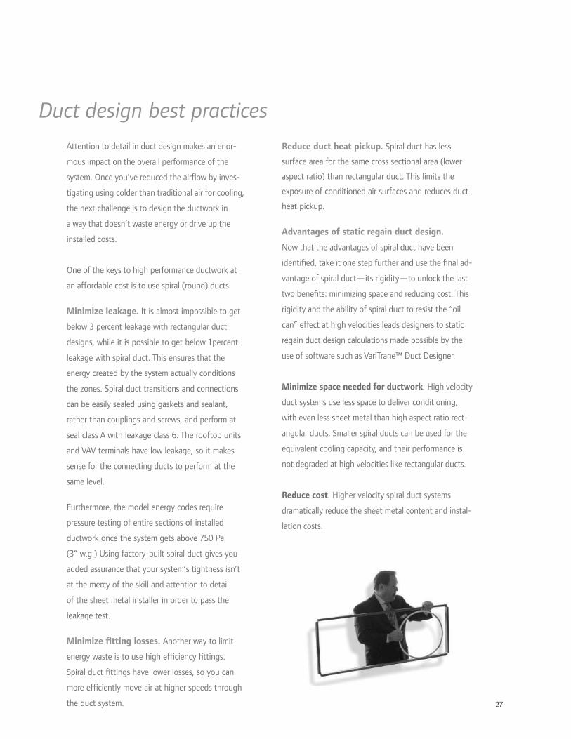
27
Attention to detail in duct design makes an enor-
mous impact on the overall performance of the
system. Once you’ve reduced the air ow by inves-
tigating using colder than traditional air for cooling,
the next challenge is to design the ductwork in
a way that doesn’t waste energy or drive up the
installed costs.
One of the keys to high performance ductwork at
an affordable cost is to use spiral (round) ducts.
Minimize leakage. It is almost impossible to get
below 3 percent leakage with rectangular duct
designs, while it is possible to get below 1percent
leakage with spiral duct. This ensures that the
energy created by the system actually conditions
the zones. Spiral duct transitions and connections
can be easily sealed using gaskets and sealant,
rather than couplings and screws, and perform at
seal class A with leakage class 6. The rooftop units
and VAV terminals have low leakage, so it makes
sense for the connecting ducts to perform at the
same level.
Furthermore, the model energy codes require
pressure testing of entire sections of installed
ductwork once the system gets above 750 Pa
(3” w.g.) Using factory-built spiral duct gives you
added assurance that your system’s tightness isn’t
at the mercy of the skill and attention to detail
of the sheet metal installer in order to pass the
leakage test.
Minimize tting losses. Another way to limit
energy waste is to use high ef ciency ttings.
Spiral duct ttings have lower losses, so you can
more ef ciently move air at higher speeds through
the duct system.
Reduce duct heat pickup. Spiral duct has less
surface area for the same cross sectional area (lower
aspect ratio) than rectangular duct. This limits the
exposure of conditioned air surfaces and reduces duct
heat pickup.
Advantages of static regain duct design.
Now that the advantages of spiral duct have been
identi ed, take it one step further and use the nal ad-
vantage of spiral duct—its rigidity—to unlock the last
two bene ts: minimizing space and reducing cost. This
rigidity and the ability of spiral duct to resist the “oil
can” effect at high velocities leads designers to static
regain duct design calculations made possible by the
use of software such as VariTrane™ Duct Designer.
Minimize space needed for ductwork. High velocity
duct systems use less space to deliver conditioning,
with even less sheet metal than high aspect ratio rect-
angular ducts. Smaller spiral ducts can be used for the
equivalent cooling capacity, and their performance is
not degraded at high velocities like rectangular ducts.
Reduce cost. Higher velocity spiral duct systems
dramatically reduce the sheet metal content and instal-
lation costs.
Duct design best practices
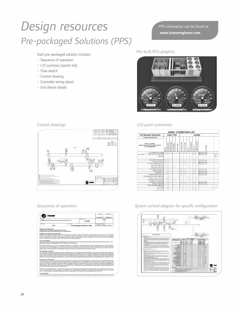
28
Sequences of operation
I/O point summaries
Each pre-packaged solution includes:
• Sequence of operation
• I/O summary (points list)
• Flow sketch
• Control drawing
• Controller wiring detail
• End device details
Control drawings
System control diagram for speci c con guration
Design resourcesPre-packaged Solutions (PPS)
Pre-built RTU graphics
PPS information can be found at
www.traneengineer.com

29
TRACE™ energy and economic software and support
CAD and BIM drawing les
4 million
3 million
2 million
3.5 million
2.5 million
1 2 3 1 2 3 1 2 3 1 2 3
1 Baseline Rooftop VAV 2 Variable Refrigerant Flow (VRF) 3 Intelligent Variable Air
Ann
ual B
uild
ing
Ener
gy U
se (
kBtu
/yr)
Houston Los Angeles Philadelphia St. Louis
fansheatingcooling
VariTrane™ Duct Designer software and support
Engineers Newsletter Live DVD and on-demand programs
Design tools and educational resourcesApplication Engineering manual

30
Fast, simple retro ts
Don’t let your existing control system limit the
performance of your building. Upgrading an
existing system to a Trane Intelligent Variable
Air system can be a fast, trouble-free process.
Wireless technology, retro t dampers and pre-
packaged controls reduce installation cost, time
and inconvenience to building occupants—and
Trane Wireless Comm means less disruptive wiring
installation, making future building changes easier.
Retro t VAV dampers. The Round-in/Round-
out (RI/RO) VAV unit is a retro t product
designed to simplify upgrading existing, older VAV
terminal units, or to upgrade existing constant
volume systems to VAV systems. Relay kits allow
the existing heating coil and/or fan to be reused;
only the controls and damper are changed. These
retro t dampers are particularly well-suited for
upgrading old pneumatic or non-communicating
electronic controls to a data-rich, communicating
DDC VAV system. Your old VAV system can
become a high-performance, Intelligent Variable
Air system with minimal occupant disruption.
Wireless controls. Trane Wireless Comm
eliminates the wire between equipment and
system controllers, and between equipment
controllers and zone sensors, for faster project
completion, less disruption to building occupants,
increased location exibility, and life-cycle savings.
Wireless mesh, maximum range, and conformance
to the ZigBee™ Building Automation standard
provide reliable, expandable operation for the life
of the building.
Retro t RI/RO damper installed in upstream duct
Retro t RI/RO damper bolted to existing terminal
Wireless zone sensors

31
Upgrading existing controls to an Intelligent Variable Air Systemexisting VAV box controls
controller type communication protocol Trane controller upgrade Trane controller
pneumatic N/A PVR UC400 VAV retro t kit with WCI
analog electric N/A electric UC400 VAV retro t kit with WCI
DDC (Trane)
Comm3 VAV I UC400 VAV retro t kit with or without WCI¹
Comm4 VAV II or III UC400 VAV retro t kit with or without WCI²
LonTalk™ VV550/551 Keep existing VAV box controllers, or
Upgrade with UC400 VAV retro t kit and WCI³
DDC (non-Trane) N/A N/A UC400 VAV retro t kit with WCI
existing RTU controls
controller type communication protocol Trane controller upgrade Trane controller 4
DDC (Trane)
Comm4 IntelliPak TCI IntelliPak BCI-I with or without WCI²
LonTalk™ IntelliPak LCI Keep existing RTU controller, or
Upgrade with IntelliPak BCI-I and WCI³
DDC (non-Trane) N/A N/A UC600 with WCI
1. Trane Comm3 wire speci cations are equivalent to Trane BACnet MSTP, so existing Comm3 wiring could be reused. Alternatively, a Wireless Comm upgrade is
possible by using WCIs.
2. Trane Comm4 wire speci cations are equivalent to Trane BACnet MSTP, so existing Comm4 wiring could be reused. Alternatively, a Wireless Comm upgrade is
possible by using WCIs.
3. Tracer SC system controller is compatible with LonTalk communications, so existing LonTalk controllers and wiring could be reused. Alternatively, the equipment
controllers could be upgraded using Wireless Comm.
4. In order to make use of the Ventilation Optimization functionality in Tracer SC, the IntelliPak rooftop unit needs to be equipped with Traq™ dampers.
BCI-I = BACnet™ Communication Interface for IntelliPak™
PVR = Pneumatic Volume Regulator
WCI = Wireless Communication Interface

32
Ingersoll Rand (NYSE:IR) is a world leader in creating and sustaining safe, comfortable and ef cient environments in commercial, residential
and industrial markets. Our people and our family of brands—including Club Car®, Ingersoll Rand®, Schlage®, Thermo King® and Trane®—work
together to enhance the quality and comfort of air in homes and buildings, transport and protect food and perishables, secure homes and
commercial properties, and increase industrial productivity and ef ciency. We are a $14 billion global business committed to sustainable business
practices within our company and for our customers. For more information, visit www.ingersollrand.com.
© 2012 Trane All rights reserved trane.com
APP-PRC003-EN 7 Dec 2012 ingersollrand.com
Produced on post-consumer recycled paper, using
environmentally friendly print practices that reduce waste.

FORM A
PRODUCTS & SERVICES
Scheduled Maintenance
Type: Intelligent Services
Description:
A Trane Intelligent Services Agreement is the next generation of innovation. In today’s energy-aware environment, Trane Intelligent Services (TIS) has broken the traditional building-service model. TIS is the revolutionary integration of technology, proprietary analytics and Trane expertise that continuously collect, interpret and act on building data to improve the performance of the building’s systems. The outcome is improved energy efficiency and reduced costs—the hallmarks of Trane High Performance Buildings. By definition, Trane High Performance Buildings provide year-over- year benefits for building owners. Achieving year-over-year benefits requires the kind of active intelligence produced by TIS. Trane’s Active Intelligence management system takes the data produced through building system information and converts it into meaningful knowledge to enhance and elevate the building’s performance. Active Intelligence is enabled by connectivity: the web-based linking of building controls to the Trane Intelligent Services Center, where imperative information is filtered by our exclusive software analytics and knowledgeable Technical Specialists and action is taken. Alarm Notification Alarm Notification is included with all Trane Service Agreements. Alarm Notification features: • Customer-defined data-collection points • 24/7/365 automated alarm and event monitoring • Automated notification via email, text or pager • Archiving of critical alarm data • Bi-monthly scheduled backup
Benefits to the customer: Every notification is customized to meet the customer’s needs, and assure that the right
person is being alerted if there is a system malfunction Immediate and timely notification allows you to take prompt action to resolve the problem
and avoid interruptions in your operation Trane Intelligent Services offers customers peace of mind, knowing that the fully
automated alarm system’s responsiveness means a customer is never out of touch with the systems and working environment of their building.
Active Monitoring Active Monitoring includes Alarm Notification, plus the benefits of immediate diagnostic and responsive action capabilities.

Active Monitoring features: • Diagnostics and alarm analysis by Technical Specialist • Off-site alarm mediation if possible • Intelligent Mobilization of local Trane authorized • service personnel Alarm documentation and reporting (daily, weekly, monthly, quarterly) • This performance-focused offer includes all of the features of Active Monitoring coupled with
analyzed data and performance driven recommendations and actions enabling high performance operating conditions.
Benefits to the customer: Faster detection means faster resolution saving critical time and money 40% of the critical alarms are resolved within 30 minutes of the alarm sounding, which gets
your system operational more quickly Triple redundancy ensures your system and operations are safe and secure
Building Performance Building Performance features: • Initial system-wide assessment • Continuous analysis by automated system analytics • Results-oriented, value-based actionable recommendations • On-going commissioning reporting to monitor parameters
Benefits to the customer: Alarm Notification and Active Monitoring now are performance-enhanced to interpret
everything occurring in your building at all times Intelligence in action - warning when a system malfunctions and translating data into
actionable solutions to enhance building performance Anticipating problems and proactively solving them dramatically reduces downtime and
increases productivity Trane Intelligent Services is the customer’s safety net for occupant comfort and satisfaction Savings can be measured through efficient operations, again making the building a
performance center rather than a loss leader.
Personnel:
Refer to TAB 3-Company Profile Question #4 for the list of factory technician per Zone. See Appendix #5 for Zone Maps.

Connectivity is established when your building automation
system (BAS) is connected to the intelligent services
center. This enables your business to take advantage of
the tremendous amount of data that is continuously being
generated by your HVAC and other critical building systems.
Trane uses this data to optimize and improve the performance
of these systems to provide operational cost savings,
productivity gains and other advantages for your business.
The connectivity module is a device that will reside on
your IT network. It leverages the existing, secure network
IT infrastructure at your site to provide secure access and
broadband performance to gather HVAC and other critical
building system information. The connectivity module is
designed to communicate with Trane Building Control Units
(BCUs) using BACNet over IP protocol in order to detect HVAC
and other critical building system alarm conditions, collect
performance data, and provide secure remote access to highly
trained technical support staff at the intelligent services center.
Once connectivity is established, Trane can begin to monitor
and analyze the operation and performance of HVAC and
other critical systems within your building.
This document provides a brief description of the
specifications and requirements for the connectivity module.
If more detail is required to qualify the connectivity module
to meet your IT requirements for security and remote access,
please contact your Trane Account Manager.
ConnectivityTechnical specifications and requirements for the connectivity module
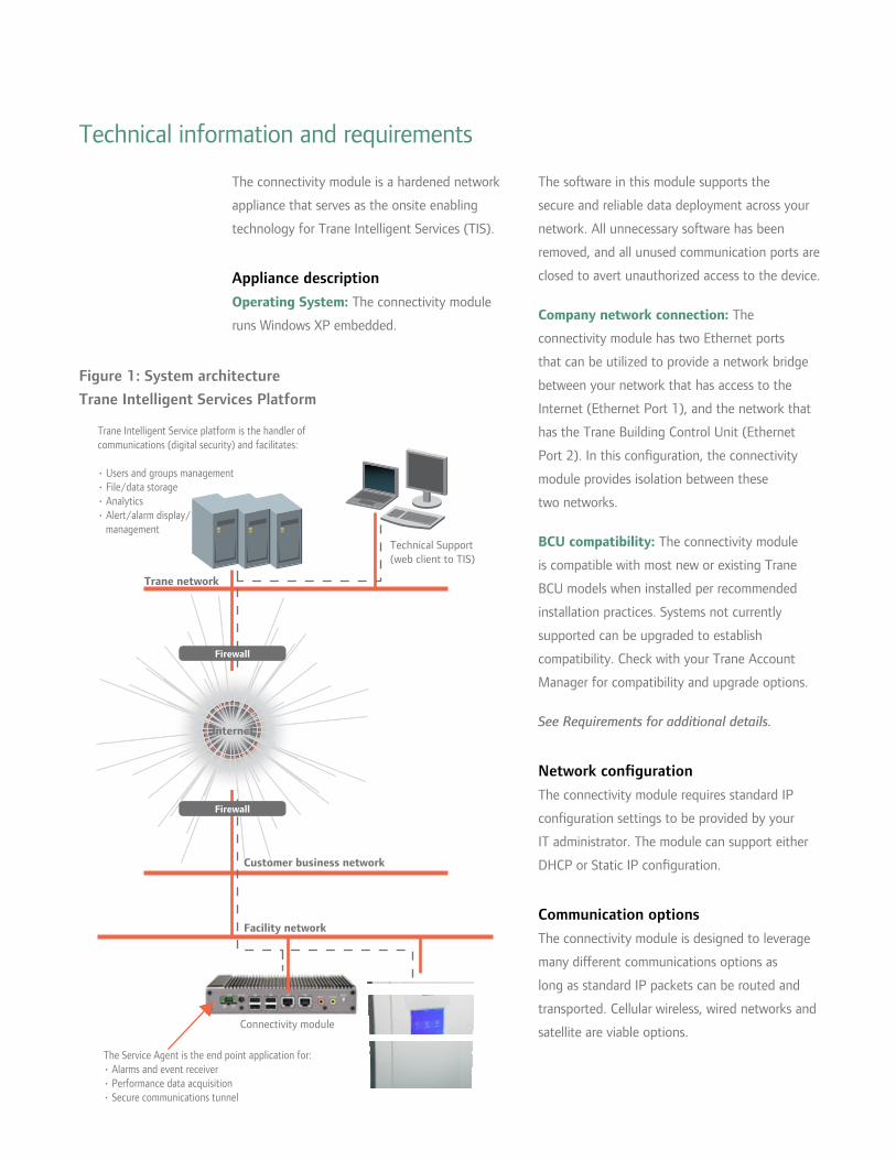
The connectivity module is a hardened network
appliance that serves as the onsite enabling
technology for Trane Intelligent Services (TIS).
Appliance description Operating System: The connectivity module
runs Windows XP embedded.
The software in this module supports the
secure and reliable data deployment across your
network. All unnecessary software has been
removed, and all unused communication ports are
closed to avert unauthorized access to the device.
Company network connection: The
connectivity module has two Ethernet ports
that can be utilized to provide a network bridge
between your network that has access to the
Internet (Ethernet Port 1), and the network that
has the Trane Building Control Unit (Ethernet
Port 2). In this configuration, the connectivity
module provides isolation between these
two networks.
BCU compatibility: The connectivity module
is compatible with most new or existing Trane
BCU models when installed per recommended
installation practices. Systems not currently
supported can be upgraded to establish
compatibility. Check with your Trane Account
Manager for compatibility and upgrade options.
See Requirements for additional details.
Network configurationThe connectivity module requires standard IP
configuration settings to be provided by your
IT administrator. The module can support either
DHCP or Static IP configuration.
Communication optionsThe connectivity module is designed to leverage
many different communications options as
long as standard IP packets can be routed and
transported. Cellular wireless, wired networks and
satellite are viable options.
Technical information and requirements
Figure 1: System architecture Trane Intelligent Services Platform
Trane network
Firewall
Firewall
Internet
Customer business network
Facility network
Connectivity module
Technical Support(web client to TIS)
Trane Intelligent Service platform is the handler of communications (digital security) and facilitates:
• Users and groups management• File/data storage• Analytics• Alert/alarm display/ management
The Service Agent is the end point application for:• Alarms and event receiver• Performance data acquisition• Secure communications tunnel

Security, authentication and encryptionThe connectivity module utilizes a user name
and complex password to authenticate back to
the Trane server to establish a connection. The
password is encrypted when it is sent to the
server. Trane rigorously manages the user names
and passwords for the devices (they are not user
editable or viewable) and audits unsuccessful
authentications for security risks.
Each connectivity module is also assigned a non-
sequential 128-bit unique identifier in the factory
to uniquely identify each device in the field.
The connectivity module has a web based setup
and status utility that is protected by a user
name and password. The configuration capability
through the page is restricted to only essential
network parameters.
The connectivity module uses Extensible
Messaging and Presence Protocol (XMPP)
communications technology with Transport Layer
Security (TLS) encryption for data and messages
sent to Trane communications servers.
Requirements checklist
Physical installation Local power source: 120 VAC or 12 VDC for Connectivity Module
Unoccupied Ethernet ports into customer network and into BAS network
Network cable connection to a local switch (6 ft cable included). A new switch may be needed. Include consideration for power source for new switch.
Location for wall mount (bracket/screws included) or foot pads available for surface-mount
Indoor climate specifications: Temperature -4°F to 122°F (-20°C to 50°C) and 10–95 percent relative humidity, non-condensing
Information system and communications Static or Dynamic IP Address. Confirm details of local network: Will the IP Address be assigned by the domain name server (DHCP) or must it be static? If static, what will be the IP Address, Subnet Mask, Default Gateway, and DNS Address?
Default name for connectivity module is “CM” (A new name can be configured during installation)
BCU BacNet Broadcast Management Device (BBMD) IP address required to preconfigure the connectivity module
The connectivity module communicates BACnet over IP with the BCU
Each connectivity module supports one (1) BBMD IP address
BCU reset required (Manual overrides must be saved and reconfigured into the BCU)
Compatible with Tracer Summit BCU Versions BMTW and BMTX
Presence of a BMTS makes the module incompatible

Communication ports Port 5222: Used for communication of performance data using XMPP over IP for out bound communications
Port 443: Used for communication of updates to the module using SSL
Port 80: Used for tunneling (uses UDP as primary, then TCP) to allow Tracer Summit software to communicate to the BCU from
the intelligent services monitoring center to perform diagnostics
Trane Intelligent Services server
IP address: The connectivity module communicates to: http://tracersp.trane.com (198.80.249.76).
Special considerationsService packs: Trane manages all Microsoft
Windows® service packs installed on the
connectivity module so we can pre-test and
qualify the service pack for any impact it may
have on the Trane software that is installed on
the module.
Anti-virus software: Trane does not
recommend the installation of anti-virus software
on the connectivity module because it may
interrupt its intended operation. Services not
in use have been turned off on the module to
mitigate susceptibility to viruses and malware.
Firewalls: If the existing network configuration
allows outbound communications to the Internet,
then no additional work may be required
(standard configuration). If outbound ports are
being restricted, then a TCP port 80 (HTTP),
443 (HTTPS) and 5222 (XMPP) must be
opened for the assigned IP address of the
connectivity module.
VPN Client access: Currently, the connectivity
module does not support VPN client
connections. Because data is continuously
collected and transferred it would require the
connection to be open at all times, which is not
an acceptable standard.
VPN LAN to LAN access: Trane may support
some LAN to LAN trusted network connections,
but prefers the secure tunneling methods
designed into the connectivity module. Please
inquire with your Trane Account Manager for
LAN to LAN connections.
Proxy servers: The current version (January
2011) of the software does not support
authenticating proxy servers for connection
to the Internet. Contact your Trane Account
Manager to determine if your specific proxy
server configuration is supported.
Software licensing: Trane reserves the rights
to all software installed on the connectivity
module and all software remains the property of
Trane. Reverse engineering, tampering, copying,
sublicensing or installing additional software is
prohibited.
For additional information about the technical
requirements for the connectivity module, please
contact your Trane Account Manager.
Ingersoll Rand (NYSE:IR) is a world leader in creating and sustaining safe, comfortable and efficient environments in commercial, residential and industrial markets. Our people and our family of brands—including Club Car®, Hussmann®, Ingersoll Rand®, Schlage®, Thermo King® and Trane®—work together to enhance the quality and comfort of air in homes and buildings, transport and protect food and perishables, secure homes and commercial properties, and increase industrial productivity and efficiency. We are a $13 billion global business committed to sustainable business practices within our company and for our customers.
© 2011 Trane All rights reserved trane.com SRV-PRC008-EN April 13, 2011 ingersollrand.com
Produced on post-consumer recycled paper, using environmentally friendly print practices that reduce waste.
lapcj
Blank Stamp

Modem Equipped Trane BCUsConnectivity between your building automation system (BAS) and the Trane Intelligent Services Center
enables your business to minimize operational costs, realize productivity gains, and optimize the
performance of your HVAC and critical building systems. Establishing this data connection engages
the knowledge and services network of Trane to watch over your building systems, notify you of critical
alarms, diagnose/repair issues before they become major problems, and recommend improvements
to achieve your high performance building objectives.
BCUsTrane Building Control Units (BCUs) can be equipped with modems that can connect your BAS network to Trane through a dedicated phone line. Through this connection Trane will gather HVAC and other critical building system alarm conditions, performance data, and provide secure remote access to highly trained technical support staff at the Trane Intelligent Services Center.
Existing BMTW and BMTX BCUs equipped with a modem can
Building Performance TIS offerings. Modem equipped BMTS
This document provides a brief description of the technical information for the establishing connectivity to Trane Intelligent Services. It will provide answers to many questions you and your IT team may have about security and other topics of a technical nature. As always your Trane Account Manager is available to assist you with questions and help identify your
information is necessary, your Trane Account Manager can enlist the support of Trane Intelligent Services professionals to work directly with you and your IT team.

Technical informationBuilding Control Units (BCU) coordinate control and monitoring of a buildings climate, lighting,
energy consumption, scheduling, and other controllable features through a single, integrated
system. Equipped with a modem and dedicated phone line
connection to the Trane secure cloud network, the BCU
is enabled to engage the expertise of the Intelligent
Services Center to manage alarms, actively monitor, and
report critical building performance information.
A dedicated telephone data line connection is required at the Building Control Unit (BCU) to enable Trane Intelligent Services (TIS).
provide the necessary connectivity to Trane Intelligent Services Center servers. BMTW and BMTX series BCUs are designed to enable current Intelligent Services Center capabilities. BMTS
currently supported can be upgraded to establish compatibility. Check with your Trane Account Manager for compatibility and upgrade options.
Installation Considerations
For additional information about the technical requirements for the connectivity module, please contact your Trane Account Manager.
markets. Our people and our family of brands—including Club Car®, Ingersoll Rand®, Schlage®, Thermo King® and Trane®—work together to enhance the quality and comfort of air in homes and buildings, transport and protect food and perishables, secure homes and commercial properties, and increase
customers. For more information, visit www.ingersollrand.com.
Trane.comIngersollrand.com
Produced on post-consumer recycled paper using environmentally friendly print practices that reduce waste.

returnaddresshereordeletebeforeprinting

February 2010 COM-PRC001-EN
R-410A Scroll Compressor7.3 - 14 Tons, Model CSHD
Compressor
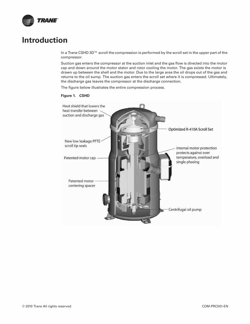
© 2010 Trane All rights reserved COM-PRC001-EN
Introduction
In a Trane CSHD 3D™ scroll the compression is performed by the scroll set in the upper part of the compressor.
Suction gas enters the compressor at the suction inlet and the gas flow is directed into the motor cap and down around the motor stator and rotor cooling the motor. The gas exists the motor is drawn up between the shell and the motor. Due to the large area the oil drops out of the gas and returns to the oil sump. The suction gas enters the scroll set where it is compressed. Ultimately, the discharge gas leaves the compressor at the discharge connection.
The figure below illustrates the entire compression process.
Figure 1. CSHD
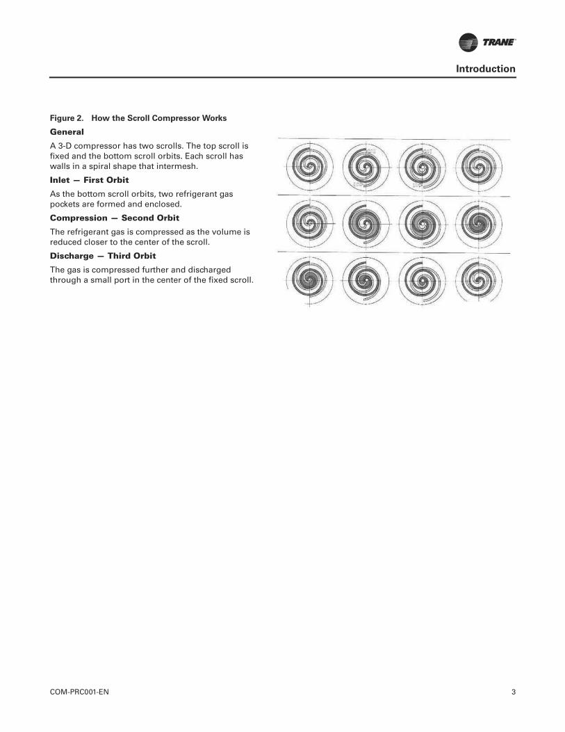
COM-PRC001-EN 3
Introduction
Figure 2. How the Scroll Compressor Works
General
A 3-D compressor has two scrolls. The top scroll is fixed and the bottom scroll orbits. Each scroll has walls in a spiral shape that intermesh.
Inlet — First Orbit
As the bottom scroll orbits, two refrigerant gas pockets are formed and enclosed.
Compression — Second Orbit
The refrigerant gas is compressed as the volume is reduced closer to the center of the scroll.
Discharge — Third Orbit
The gas is compressed further and discharged through a small port in the center of the fixed scroll.
4 COM-PRC001-EN
Table of Contents
Model Number Description . . . . . . . . . . . . . . . . . . . . . . . . . . . . . . . . . . . . . . . . . . . . . . 6
Operating Envelope . . . . . . . . . . . . . . . . . . . . . . . . . . . . . . . . . . . . . . . . . . . . . . . . . . . . . 7
CSHD089, 7.3 Ton, R-410A Scroll Compressor . . . . . . . . . . . . . . . . . . . . . . . . . . . . . 8General Data . . . . . . . . . . . . . . . . . . . . . . . . . . . . . . . . . . . . . . . . . . . . . . . . . 8CSHD089 (7.3 Tons), Voltage: 200-60-3 . . . . . . . . . . . . . . . . . . . . . . . . . . . 10CSHD089 (7.3 Tons), Voltage: 230-60-3 . . . . . . . . . . . . . . . . . . . . . . . . . . . 11CSHD089 (7.3 Tons), Voltage: 400-50-3 . . . . . . . . . . . . . . . . . . . . . . . . . . . 12CSHD089 (7.3 Tons), Voltage: 460-60-3 . . . . . . . . . . . . . . . . . . . . . . . . . . . 13CSHD089 (7.3 Tons), Voltage: 575-60-3 . . . . . . . . . . . . . . . . . . . . . . . . . . . 14
CSHD092, 8 Ton, R-410A Scroll Compressor . . . . . . . . . . . . . . . . . . . . . . . . . . . . . 16General Data . . . . . . . . . . . . . . . . . . . . . . . . . . . . . . . . . . . . . . . . . . . . . . . . 16CSHD092 (8 Tons), Voltage: 200-60-3 . . . . . . . . . . . . . . . . . . . . . . . . . . . . 18CSHD092 (8 Tons), Voltage: 230-60-3 . . . . . . . . . . . . . . . . . . . . . . . . . . . . 19CSHD092 (8 Tons), Voltage: 400-50-3 . . . . . . . . . . . . . . . . . . . . . . . . . . . . 20CSHD092 (8 Tons), Voltage: 460-60-3 . . . . . . . . . . . . . . . . . . . . . . . . . . . . 21CSHD092 (8 Tons), Voltage: 575-60-3 . . . . . . . . . . . . . . . . . . . . . . . . . . . . 22
CSHD105, 8.7 Ton, R-410A Scroll Compressor . . . . . . . . . . . . . . . . . . . . . . . . . . . . 24General Data . . . . . . . . . . . . . . . . . . . . . . . . . . . . . . . . . . . . . . . . . . . . . . . . 24CSHD105 (8.7 Tons), Voltage: 200-60-3 . . . . . . . . . . . . . . . . . . . . . . . . . . . 26CSHD105 (8.7 Tons), Voltage: 230-60-3 . . . . . . . . . . . . . . . . . . . . . . . . . . . 27CSHD105 (8.7 Tons), Voltage: 400-50-3 . . . . . . . . . . . . . . . . . . . . . . . . . . . 28CSHD105 (8.7 Tons), Voltage: 460-60-3 . . . . . . . . . . . . . . . . . . . . . . . . . . . 29CSHD105 (8.7 Tons), Voltage: 575-60-3 . . . . . . . . . . . . . . . . . . . . . . . . . . . 30
CSHD110, 9.3 Ton, R-410A Scroll Compressor . . . . . . . . . . . . . . . . . . . . . . . . . . . . 32General Data . . . . . . . . . . . . . . . . . . . . . . . . . . . . . . . . . . . . . . . . . . . . . . . . 32CSHD110 (9.3 Tons), Voltage: 200-60-3 . . . . . . . . . . . . . . . . . . . . . . . . . . . 34CSHD110 (9.3 Tons), Voltage: 230-60-3 . . . . . . . . . . . . . . . . . . . . . . . . . . . 35CSHD110 (9.3 Tons), Voltage: 400-50-3 . . . . . . . . . . . . . . . . . . . . . . . . . . . 36CSHD110 (9.3 Tons), Voltage: 460-60-3 . . . . . . . . . . . . . . . . . . . . . . . . . . . 37CSHD110 (9.3 Tons), Voltage: 575-60-3 . . . . . . . . . . . . . . . . . . . . . . . . . . . 38
CSHD125, 10.5 Ton, R-410A Scroll Compressor . . . . . . . . . . . . . . . . . . . . . . . . . . . 40General Data . . . . . . . . . . . . . . . . . . . . . . . . . . . . . . . . . . . . . . . . . . . . . . . . 40CSHD125 (10.5 Tons), Voltage: 200-60-3 . . . . . . . . . . . . . . . . . . . . . . . . . . 42CSHD125 (10.5 Tons), Voltage: 230-60-3 . . . . . . . . . . . . . . . . . . . . . . . . . . 43CSHD125 (10.5 Tons), Voltage: 400-50-3 . . . . . . . . . . . . . . . . . . . . . . . . . . 44CSHD125 (10.5 Tons), Voltage: 460-60-3 . . . . . . . . . . . . . . . . . . . . . . . . . . 45CSHD125 (10.5 Tons), Voltage: 575-60-3 . . . . . . . . . . . . . . . . . . . . . . . . . . 46
CSHD142, 12 Ton, R-410A Scroll Compressor . . . . . . . . . . . . . . . . . . . . . . . . . . . . 48General Data . . . . . . . . . . . . . . . . . . . . . . . . . . . . . . . . . . . . . . . . . . . . . . . . 48CSHD142 (12 Tons), Voltage: 200-60-3 . . . . . . . . . . . . . . . . . . . . . . . . . . . 50CSHD142 (12 Tons), Voltage: 230-60-3 . . . . . . . . . . . . . . . . . . . . . . . . . . . 51CSHD142 (12 Tons), Voltage: 400-50-3 . . . . . . . . . . . . . . . . . . . . . . . . . . . 52
COM-PRC001-EN 5
CSHD142 (12 Tons), Voltage: 460-60-3 . . . . . . . . . . . . . . . . . . . . . . . . . . . 53CSHD142 (12 Tons), Voltage: 575-60-3 . . . . . . . . . . . . . . . . . . . . . . . . . . . 54
CSHD161, 14 Ton, R-410A Scroll Compressor . . . . . . . . . . . . . . . . . . . . . . . . . . . . 56General Data . . . . . . . . . . . . . . . . . . . . . . . . . . . . . . . . . . . . . . . . . . . . . . . . 56CSHD161 (14 Tons), Voltage: 200-60-3 . . . . . . . . . . . . . . . . . . . . . . . . . . . 58CSHD161 (14 Tons), Voltage: 230-60-3 . . . . . . . . . . . . . . . . . . . . . . . . . . . 59CSHD161 (14 Tons), Voltage: 400-50-3 . . . . . . . . . . . . . . . . . . . . . . . . . . . 60CSHD161 (14 Tons), Voltage: 460-60-3 . . . . . . . . . . . . . . . . . . . . . . . . . . . 61CSHD161 (14 Tons), Voltage: 575-60-3 . . . . . . . . . . . . . . . . . . . . . . . . . . . 62

6 COM-PRC001-EN
Model Number Description
Digit 1-4 — Model
Digit 5-7 — Capacity @ 460 Hz ARI Btu/HR
Digit 8 — Voltage
Digit 9 — Unloading
Digit 10 — Design Sequence
Digit 11 — Protection Module
Digit 12 — Basic Compressor Variation
C S H D 1 2 5 K 0 A O M
1 2 3 4 5 6 7 8 9 10 11 12
CSHD
CSHD089 88,824CSHD092 93,362CSHD110 111,282CSHD125 125,211CSHD142 142,365CSHD161 164,022
J 200/230-60-3K 460-60-3/380-415-50-3D 575-60-3 / 500-50-3X 380-60-3
0 No unloading
A Current design
O Internal line break (CSHD)
M Suction & discharge brazed tubeOil sight glassOil charging valveOil equalizer with seal nut

COM-PRC001-EN 7
Operating Envelope
Figure 3. CSHD Scroll - R-410A Operating Envelope
50
60
70
80
90
100
110
120
130
140
150
160
170
180
190
-30 -20 -10 0 10 20 30 40 50 60 70
Evaporating temperature (°F)
Co
nd
en
sin
g t
em
pe
ratu
re (
°F)
Superheat 20°F
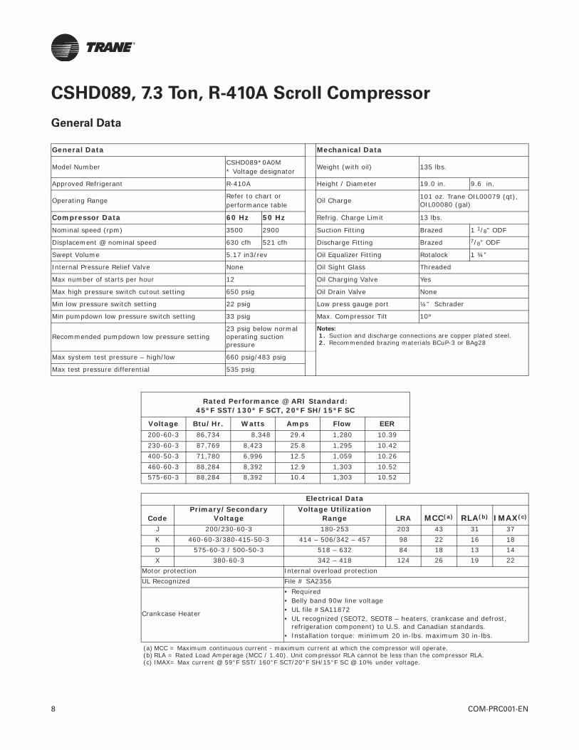
8 COM-PRC001-EN
CSHD089, 7.3 Ton, R-410A Scroll Compressor
General Data
General Data Mechanical Data
Model Number CSHD089*0A0M* Voltage designator
Weight (with oil) 135 lbs.
Approved Refrigerant R-410A Height / Diameter 19.0 in. 9.6 in.
Operating RangeRefer to chart or performance table
Oil Charge 101 oz. Trane OIL00079 (qt), OIL00080 (gal)
Compressor Data 60 Hz 50 Hz Refrig. Charge Limit 13 lbs.
Nominal speed (rpm) 3500 2900 Suction Fitting Brazed 1 1/8” ODF
Displacement @ nominal speed 630 cfh 521 cfh Discharge Fitting Brazed 7/8” ODF
Swept Volume 5.17 in3/rev Oil Equalizer Fitting Rotalock 1 ¾”
Internal Pressure Relief Valve None Oil Sight Glass Threaded
Max number of starts per hour 12 Oil Charging Valve Yes
Max high pressure switch cutout setting 650 psig Oil Drain Valve None
Min low pressure switch setting 22 psig Low press gauge port ¼” Schrader
Min pumpdown low pressure switch setting 33 psig Max. Compressor Tilt 10º
Recommended pumpdown low pressure setting23 psig below normal operating suction pressure
Notes:
1. Suction and discharge connections are copper plated steel. 2. Recommended brazing materials BCuP-3 or BAg28
Max system test pressure – high/low 660 psig/483 psig
Max test pressure differential 535 psig
Rated Performance @ ARI Standard:45ºF SST/130º F SCT, 20ºF SH/15ºF SC
Voltage Btu/Hr. Watts Amps Flow EER200-60-3 86,734 8,348 29.4 1,280 10.39230-60-3 87,769 8,423 25.8 1,295 10.42400-50-3 71,780 6,996 12.5 1,059 10.26460-60-3 88,284 8,392 12.9 1,303 10.52575-60-3 88,284 8,392 10.4 1,303 10.52
Electrical Data
CodePrimary/Secondary
VoltageVoltage Utilization
Range LRA MCC(a)
(a) MCC = Maximum continuous current - maximum current at which the compressor will operate.
RLA(b)
(b) RLA = Rated Load Amperage (MCC / 1.40). Unit compressor RLA cannot be less than the compressor RLA.
IMAX(c)
(c) IMAX= Max current @ 59°F SST/ 160°F SCT/20°F SH/15°F SC @ 10% under voltage.
J 200/230-60-3 180-253 203 43 31 37K 460-60-3/380-415-50-3 414 – 506/342 – 457 98 22 16 18D 575-60-3 / 500-50-3 518 – 632 84 18 13 14X 380-60-3 342 – 418 124 26 19 22
Motor protection Internal overload protectionUL Recognized File # SA2356
Crankcase Heater
• Required• Belly band 90w line voltage • UL file #SA11872• UL recognized (SEOT2, SEOT8 – heaters, crankcase and defrost,
refrigeration component) to U.S. and Canadian standards.• Installation torque: minimum 20 in-lbs. maximum 30 in-lbs.

COM-PRC001-EN 9
CSHD089, 7.3 Ton, R-410A Scroll Compressor
Figure 4. CSHD089 Dimensional Data
Dimensional Data
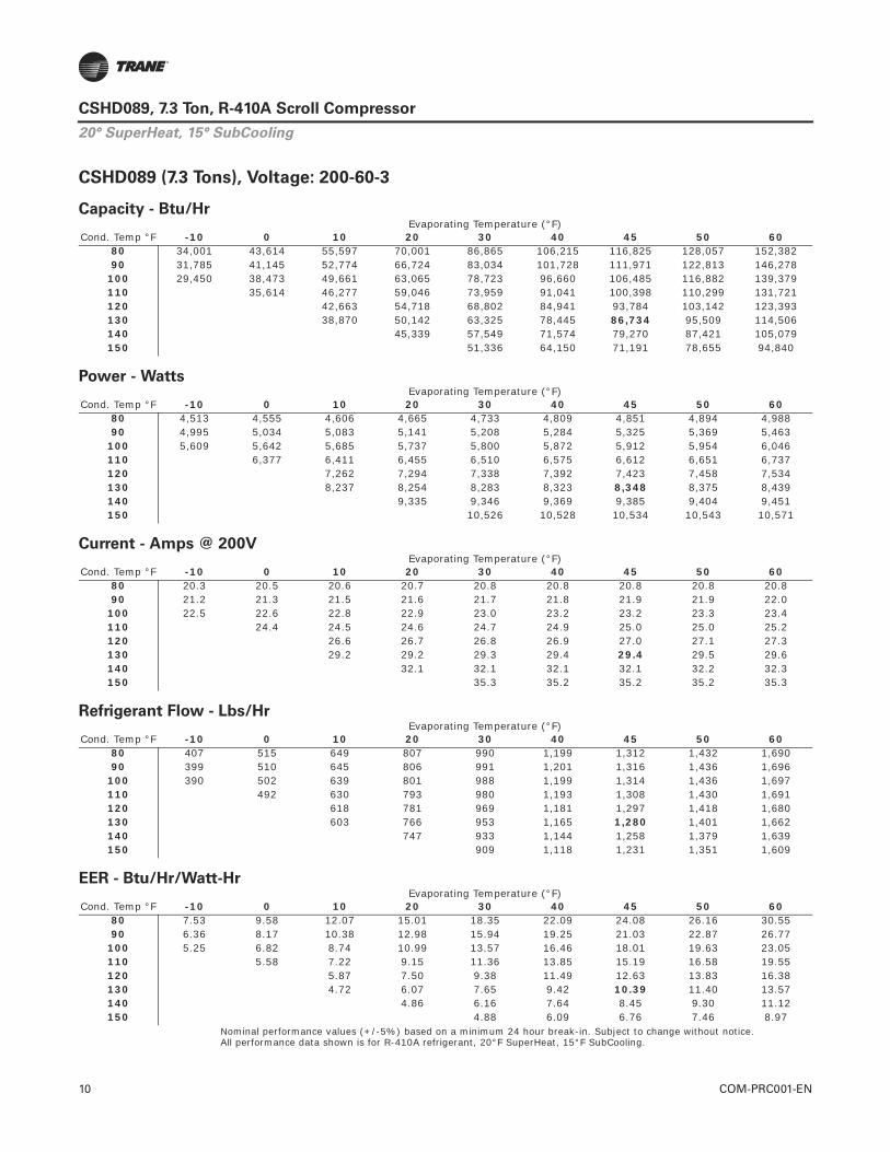
10 COM-PRC001-EN
CSHD089, 7.3 Ton, R-410A Scroll Compressor
CSHD089 (7.3 Tons), Voltage: 200-60-3
Nominal performance values (+/-5%) based on a minimum 24 hour break-in. Subject to change without notice.All performance data shown is for R-410A refrigerant, 20°F SuperHeat, 15°F SubCooling.
Capacity - Btu/Hr
Cond. Temp °FEvaporating Temperature (°F)
-10 0 10 20 30 40 45 50 6080 34,001 43,614 55,597 70,001 86,865 106,215 116,825 128,057 152,38290 31,785 41,145 52,774 66,724 83,034 101,728 111,971 122,813 146,278
100 29,450 38,473 49,661 63,065 78,723 96,660 106,485 116,882 139,379110 35,614 46,277 59,046 73,959 91,041 100,398 110,299 131,721120 42,663 54,718 68,802 84,941 93,784 103,142 123,393130 38,870 50,142 63,325 78,445 86,734 95,509 114,506140 45,339 57,549 71,574 79,270 87,421 105,079150 51,336 64,150 71,191 78,655 94,840
Power - Watts
Cond. Temp °FEvaporating Temperature (°F)
-10 0 10 20 30 40 45 50 6080 4,513 4,555 4,606 4,665 4,733 4,809 4,851 4,894 4,98890 4,995 5,034 5,083 5,141 5,208 5,284 5,325 5,369 5,463
100 5,609 5,642 5,685 5,737 5,800 5,872 5,912 5,954 6,046110 6,377 6,411 6,455 6,510 6,575 6,612 6,651 6,737120 7,262 7,294 7,338 7,392 7,423 7,458 7,534130 8,237 8,254 8,283 8,323 8,348 8,375 8,439140 9,335 9,346 9,369 9,385 9,404 9,451150 10,526 10,528 10,534 10,543 10,571
Current - Amps @ 200V
Cond. Temp °FEvaporating Temperature (°F)
-10 0 10 20 30 40 45 50 6080 20.3 20.5 20.6 20.7 20.8 20.8 20.8 20.8 20.890 21.2 21.3 21.5 21.6 21.7 21.8 21.9 21.9 22.0
100 22.5 22.6 22.8 22.9 23.0 23.2 23.2 23.3 23.4110 24.4 24.5 24.6 24.7 24.9 25.0 25.0 25.2120 26.6 26.7 26.8 26.9 27.0 27.1 27.3130 29.2 29.2 29.3 29.4 29.4 29.5 29.6140 32.1 32.1 32.1 32.1 32.2 32.3150 35.3 35.2 35.2 35.2 35.3
Refrigerant Flow - Lbs/Hr
Cond. Temp °FEvaporating Temperature (°F)
-10 0 10 20 30 40 45 50 6080 407 515 649 807 990 1,199 1,312 1,432 1,69090 399 510 645 806 991 1,201 1,316 1,436 1,696
100 390 502 639 801 988 1,199 1,314 1,436 1,697110 492 630 793 980 1,193 1,308 1,430 1,691120 618 781 969 1,181 1,297 1,418 1,680130 603 766 953 1,165 1,280 1,401 1,662140 747 933 1,144 1,258 1,379 1,639150 909 1,118 1,231 1,351 1,609
EER - Btu/Hr/Watt-Hr
Cond. Temp °FEvaporating Temperature (°F)
-10 0 10 20 30 40 45 50 6080 7.53 9.58 12.07 15.01 18.35 22.09 24.08 26.16 30.5590 6.36 8.17 10.38 12.98 15.94 19.25 21.03 22.87 26.77
100 5.25 6.82 8.74 10.99 13.57 16.46 18.01 19.63 23.05110 5.58 7.22 9.15 11.36 13.85 15.19 16.58 19.55120 5.87 7.50 9.38 11.49 12.63 13.83 16.38130 4.72 6.07 7.65 9.42 10.39 11.40 13.57140 4.86 6.16 7.64 8.45 9.30 11.12150 4.88 6.09 6.76 7.46 8.97
20° SuperHeat, 15° SubCooling
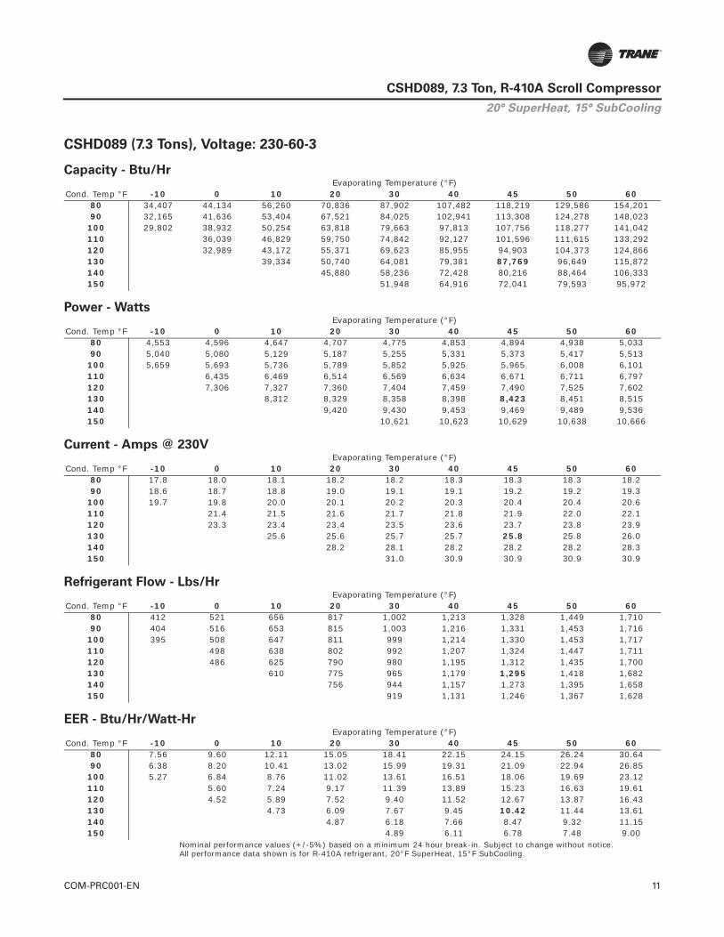
COM-PRC001-EN 11
CSHD089, 7.3 Ton, R-410A Scroll Compressor
CSHD089 (7.3 Tons), Voltage: 230-60-3
Nominal performance values (+/-5%) based on a minimum 24 hour break-in. Subject to change without notice.All performance data shown is for R-410A refrigerant, 20°F SuperHeat, 15°F SubCooling.
Capacity - Btu/Hr
Cond. Temp °FEvaporating Temperature (°F)
-10 0 10 20 30 40 45 50 6080 34,407 44,134 56,260 70,836 87,902 107,482 118,219 129,586 154,20190 32,165 41,636 53,404 67,521 84,025 102,941 113,308 124,278 148,023
100 29,802 38,932 50,254 63,818 79,663 97,813 107,756 118,277 141,042110 36,039 46,829 59,750 74,842 92,127 101,596 111,615 133,292120 32,989 43,172 55,371 69,623 85,955 94,903 104,373 124,866130 39,334 50,740 64,081 79,381 87,769 96,649 115,872140 45,880 58,236 72,428 80,216 88,464 106,333150 51,948 64,916 72,041 79,593 95,972
Power - Watts
Cond. Temp °FEvaporating Temperature (°F)
-10 0 10 20 30 40 45 50 6080 4,553 4,596 4,647 4,707 4,775 4,853 4,894 4,938 5,03390 5,040 5,080 5,129 5,187 5,255 5,331 5,373 5,417 5,513
100 5,659 5,693 5,736 5,789 5,852 5,925 5,965 6,008 6,101110 6,435 6,469 6,514 6,569 6,634 6,671 6,711 6,797120 7,306 7,327 7,360 7,404 7,459 7,490 7,525 7,602130 8,312 8,329 8,358 8,398 8,423 8,451 8,515140 9,420 9,430 9,453 9,469 9,489 9,536150 10,621 10,623 10,629 10,638 10,666
Current - Amps @ 230V
Cond. Temp °FEvaporating Temperature (°F)
-10 0 10 20 30 40 45 50 6080 17.8 18.0 18.1 18.2 18.2 18.3 18.3 18.3 18.290 18.6 18.7 18.8 19.0 19.1 19.1 19.2 19.2 19.3
100 19.7 19.8 20.0 20.1 20.2 20.3 20.4 20.4 20.6110 21.4 21.5 21.6 21.7 21.8 21.9 22.0 22.1120 23.3 23.4 23.4 23.5 23.6 23.7 23.8 23.9130 25.6 25.6 25.7 25.7 25.8 25.8 26.0140 28.2 28.1 28.2 28.2 28.2 28.3150 31.0 30.9 30.9 30.9 30.9
Refrigerant Flow - Lbs/Hr
Cond. Temp °FEvaporating Temperature (°F)
-10 0 10 20 30 40 45 50 6080 412 521 656 817 1,002 1,213 1,328 1,449 1,71090 404 516 653 815 1,003 1,216 1,331 1,453 1,716
100 395 508 647 811 999 1,214 1,330 1,453 1,717110 498 638 802 992 1,207 1,324 1,447 1,711120 486 625 790 980 1,195 1,312 1,435 1,700130 610 775 965 1,179 1,295 1,418 1,682140 756 944 1,157 1,273 1,395 1,658150 919 1,131 1,246 1,367 1,628
EER - Btu/Hr/Watt-Hr
Cond. Temp °FEvaporating Temperature (°F)
-10 0 10 20 30 40 45 50 6080 7.56 9.60 12.11 15.05 18.41 22.15 24.15 26.24 30.6490 6.38 8.20 10.41 13.02 15.99 19.31 21.09 22.94 26.85
100 5.27 6.84 8.76 11.02 13.61 16.51 18.06 19.69 23.12110 5.60 7.24 9.17 11.39 13.89 15.23 16.63 19.61120 4.52 5.89 7.52 9.40 11.52 12.67 13.87 16.43130 4.73 6.09 7.67 9.45 10.42 11.44 13.61140 4.87 6.18 7.66 8.47 9.32 11.15150 4.89 6.11 6.78 7.48 9.00
20° SuperHeat, 15° SubCooling

12 COM-PRC001-EN
CSHD089, 7.3 Ton, R-410A Scroll Compressor
CSHD089 (7.3 Tons), Voltage: 400-50-3
Nominal performance values (+/-5%) based on a minimum 24 hour break-in. Subject to change without notice.All performance data shown is for R-410A refrigerant, 20°F SuperHeat, 15°F SubCooling.
Capacity - Btu/Hr
Cond. Temp °FEvaporating Temperature (°F)
-10 0 10 20 30 40 45 50 6080 29,436 37,464 47,487 59,546 73,673 89,887 98,778 108,192 128,57790 27,451 35,177 44,803 56,369 69,907 85,435 93,947 102,958 122,465
100 25,394 32,780 41,968 52,998 65,902 80,698 88,808 97,391 115,969110 30,282 38,993 49,445 61,671 75,687 83,369 91,500 109,097120 27,706 35,904 45,741 57,248 70,443 77,676 85,331 101,901130 32,735 41,924 52,678 65,015 71,780 78,941 94,445140 37,997 47,961 59,401 65,677 72,323 86,716150 42,957 53,425 59,172 65,261 78,456
Power - Watts
Cond. Temp °FEvaporating Temperature (°F)
-10 0 10 20 30 40 45 50 6080 3,660 3,759 3,843 3,912 3,966 4,005 4,019 4,029 4,03790 4,054 4,149 4,233 4,307 4,371 4,425 4,448 4,468 4,501
100 4,562 4,647 4,726 4,800 4,868 4,931 4,960 4,988 5,040110 5,253 5,321 5,389 5,456 5,523 5,556 5,588 5,654120 5,967 6,019 6,075 6,136 6,200 6,234 6,269 6,342130 6,819 6,859 6,907 6,964 6,996 7,030 7,106140 7,739 7,770 7,814 7,841 7,872 7,944150 8,724 8,750 8,770 8,794 8,857
Current - Amps @ 400V
Cond. Temp °FEvaporating Temperature (°F)
-10 0 10 20 30 40 45 50 6080 8.9 8.9 9.0 9.0 9.1 9.1 9.1 9.1 9.290 9.2 9.3 9.3 9.4 9.5 9.5 9.5 9.6 9.6
100 9.7 9.8 9.9 9.9 10.0 10.1 10.1 10.1 10.2110 10.4 10.5 10.6 10.7 10.7 10.8 10.8 10.9120 11.2 11.3 11.4 11.5 11.5 11.6 11.6 11.7130 12.2 12.3 12.4 12.5 12.5 12.6 12.6140 13.4 13.5 13.6 13.6 13.6 13.7150 14.7 14.8 14.8 14.8 14.9
Refrigerant Flow - Lbs/Hr
Cond. Temp °FEvaporating Temperature (°F)
-10 0 10 20 30 40 45 50 6080 353 443 554 686 840 1,014 1,110 1,210 1,42690 345 436 548 681 834 1,009 1,104 1,204 1,420
100 336 428 540 673 827 1,001 1,096 1,196 1,412110 418 531 664 817 991 1,086 1,186 1,401120 408 520 653 806 980 1,074 1,173 1,387130 508 640 793 966 1,059 1,158 1,371140 626 778 949 1,043 1,141 1,352150 760 931 1,023 1,121 1,331
EER - Btu/Hr/Watt-Hr
Cond. Temp °FEvaporating Temperature (°F)
-10 0 10 20 30 40 45 50 6080 8.04 9.97 12.36 15.22 18.57 22.44 24.58 26.85 31.8590 6.77 8.48 10.58 13.09 15.99 19.31 21.12 23.04 27.21
100 5.57 7.05 8.88 11.04 13.54 16.37 17.90 19.52 23.01110 5.77 7.33 9.18 11.30 13.71 15.01 16.37 19.30120 4.64 5.97 7.53 9.33 11.36 12.46 13.61 16.07130 4.80 6.11 7.63 9.34 10.26 11.23 13.29140 4.91 6.17 7.60 8.38 9.19 10.92150 4.92 6.11 6.75 7.42 8.86
20° SuperHeat, 15° SubCooling
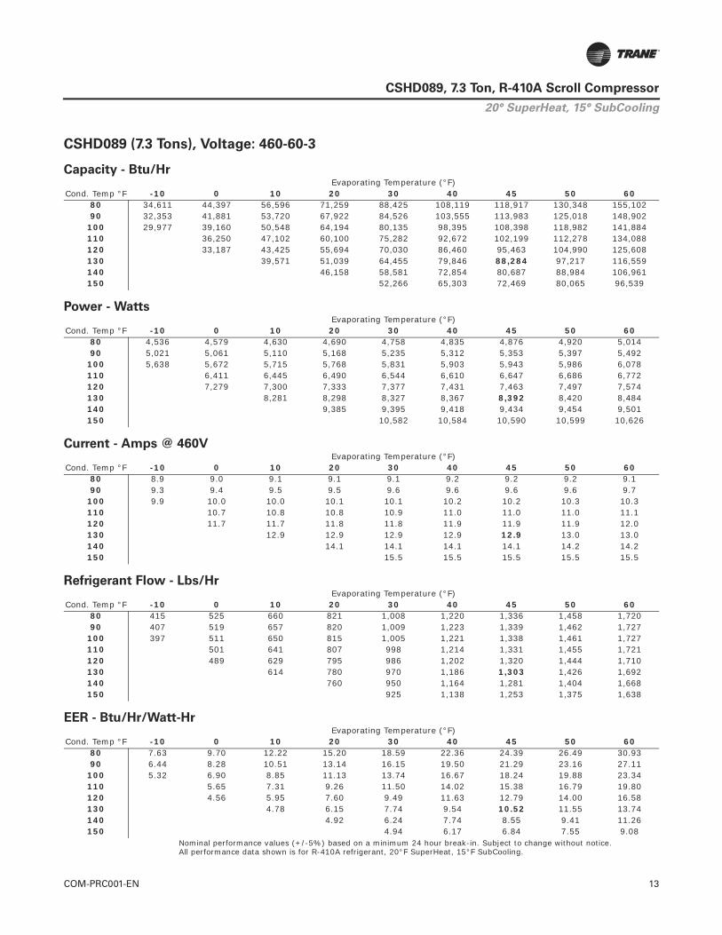
COM-PRC001-EN 13
CSHD089, 7.3 Ton, R-410A Scroll Compressor
CSHD089 (7.3 Tons), Voltage: 460-60-3
Nominal performance values (+/-5%) based on a minimum 24 hour break-in. Subject to change without notice.All performance data shown is for R-410A refrigerant, 20°F SuperHeat, 15°F SubCooling.
Capacity - Btu/Hr
Cond. Temp °FEvaporating Temperature (°F)
-10 0 10 20 30 40 45 50 6080 34,611 44,397 56,596 71,259 88,425 108,119 118,917 130,348 155,10290 32,353 41,881 53,720 67,922 84,526 103,555 113,983 125,018 148,902
100 29,977 39,160 50,548 64,194 80,135 98,395 108,398 118,982 141,884110 36,250 47,102 60,100 75,282 92,672 102,199 112,278 134,088120 33,187 43,425 55,694 70,030 86,460 95,463 104,990 125,608130 39,571 51,039 64,455 79,846 88,284 97,217 116,559140 46,158 58,581 72,854 80,687 88,984 106,961150 52,266 65,303 72,469 80,065 96,539
Power - Watts
Cond. Temp °FEvaporating Temperature (°F)
-10 0 10 20 30 40 45 50 6080 4,536 4,579 4,630 4,690 4,758 4,835 4,876 4,920 5,01490 5,021 5,061 5,110 5,168 5,235 5,312 5,353 5,397 5,492
100 5,638 5,672 5,715 5,768 5,831 5,903 5,943 5,986 6,078110 6,411 6,445 6,490 6,544 6,610 6,647 6,686 6,772120 7,279 7,300 7,333 7,377 7,431 7,463 7,497 7,574130 8,281 8,298 8,327 8,367 8,392 8,420 8,484140 9,385 9,395 9,418 9,434 9,454 9,501150 10,582 10,584 10,590 10,599 10,626
Current - Amps @ 460V
Cond. Temp °FEvaporating Temperature (°F)
-10 0 10 20 30 40 45 50 6080 8.9 9.0 9.1 9.1 9.1 9.2 9.2 9.2 9.190 9.3 9.4 9.5 9.5 9.6 9.6 9.6 9.6 9.7
100 9.9 10.0 10.0 10.1 10.1 10.2 10.2 10.3 10.3110 10.7 10.8 10.8 10.9 11.0 11.0 11.0 11.1120 11.7 11.7 11.8 11.8 11.9 11.9 11.9 12.0130 12.9 12.9 12.9 12.9 12.9 13.0 13.0140 14.1 14.1 14.1 14.1 14.2 14.2150 15.5 15.5 15.5 15.5 15.5
Refrigerant Flow - Lbs/Hr
Cond. Temp °FEvaporating Temperature (°F)
-10 0 10 20 30 40 45 50 6080 415 525 660 821 1,008 1,220 1,336 1,458 1,72090 407 519 657 820 1,009 1,223 1,339 1,462 1,727
100 397 511 650 815 1,005 1,221 1,338 1,461 1,727110 501 641 807 998 1,214 1,331 1,455 1,721120 489 629 795 986 1,202 1,320 1,444 1,710130 614 780 970 1,186 1,303 1,426 1,692140 760 950 1,164 1,281 1,404 1,668150 925 1,138 1,253 1,375 1,638
EER - Btu/Hr/Watt-Hr
Cond. Temp °FEvaporating Temperature (°F)
-10 0 10 20 30 40 45 50 6080 7.63 9.70 12.22 15.20 18.59 22.36 24.39 26.49 30.9390 6.44 8.28 10.51 13.14 16.15 19.50 21.29 23.16 27.11
100 5.32 6.90 8.85 11.13 13.74 16.67 18.24 19.88 23.34110 5.65 7.31 9.26 11.50 14.02 15.38 16.79 19.80120 4.56 5.95 7.60 9.49 11.63 12.79 14.00 16.58130 4.78 6.15 7.74 9.54 10.52 11.55 13.74140 4.92 6.24 7.74 8.55 9.41 11.26150 4.94 6.17 6.84 7.55 9.08
20° SuperHeat, 15° SubCooling
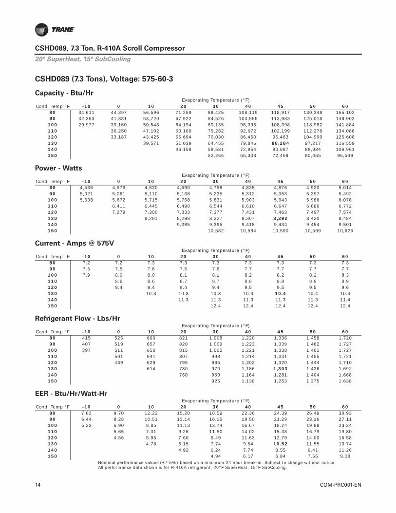
14 COM-PRC001-EN
CSHD089, 7.3 Ton, R-410A Scroll Compressor
CSHD089 (7.3 Tons), Voltage: 575-60-3
Nominal performance values (+/-5%) based on a minimum 24 hour break-in. Subject to change without notice.All performance data shown is for R-410A refrigerant, 20°F SuperHeat, 15°F SubCooling.
Capacity - Btu/Hr
Cond. Temp °FEvaporating Temperature (°F)
-10 0 10 20 30 40 45 50 6080 34,611 44,397 56,596 71,259 88,425 108,119 118,917 130,348 155,10290 32,353 41,881 53,720 67,922 84,526 103,555 113,983 125,018 148,902
100 29,977 39,160 50,548 64,194 80,135 98,395 108,398 118,982 141,884110 36,250 47,102 60,100 75,282 92,672 102,199 112,278 134,088120 33,187 43,425 55,694 70,030 86,460 95,463 104,990 125,608130 39,571 51,039 64,455 79,846 88,284 97,217 116,559140 46,158 58,581 72,854 80,687 88,984 106,961150 52,266 65,303 72,469 80,065 96,539
Power - Watts
Cond. Temp °FEvaporating Temperature (°F)
-10 0 10 20 30 40 45 50 6080 4,536 4,579 4,630 4,690 4,758 4,835 4,876 4,920 5,01490 5,021 5,061 5,110 5,168 5,235 5,312 5,353 5,397 5,492
100 5,638 5,672 5,715 5,768 5,831 5,903 5,943 5,986 6,078110 6,411 6,445 6,490 6,544 6,610 6,647 6,686 6,772120 7,279 7,300 7,333 7,377 7,431 7,463 7,497 7,574130 8,281 8,298 8,327 8,367 8,392 8,420 8,484140 9,385 9,395 9,418 9,434 9,454 9,501150 10,582 10,584 10,590 10,599 10,626
Current - Amps @ 575V
Cond. Temp °FEvaporating Temperature (°F)
-10 0 10 20 30 40 45 50 6080 7.2 7.2 7.3 7.3 7.3 7.3 7.3 7.3 7.390 7.5 7.5 7.6 7.6 7.6 7.7 7.7 7.7 7.7
100 7.9 8.0 8.0 8.1 8.1 8.2 8.2 8.2 8.3110 8.6 8.6 8.7 8.7 8.8 8.8 8.8 8.9120 9.4 9.4 9.4 9.4 9.5 9.5 9.5 9.6130 10.3 10.3 10.3 10.3 10.4 10.4 10.4140 11.3 11.3 11.3 11.3 11.3 11.4150 12.4 12.4 12.4 12.4 12.4
Refrigerant Flow - Lbs/Hr
Cond. Temp °FEvaporating Temperature (°F)
-10 0 10 20 30 40 45 50 6080 415 525 660 821 1,008 1,220 1,336 1,458 1,72090 407 519 657 820 1,009 1,223 1,339 1,462 1,727
100 397 511 650 815 1,005 1,221 1,338 1,461 1,727110 501 641 807 998 1,214 1,331 1,455 1,721120 489 629 795 986 1,202 1,320 1,444 1,710130 614 780 970 1,186 1,303 1,426 1,692140 760 950 1,164 1,281 1,404 1,668150 925 1,138 1,253 1,375 1,638
EER - Btu/Hr/Watt-Hr
Cond. Temp °FEvaporating Temperature (°F)
-10 0 10 20 30 40 45 50 6080 7.63 9.70 12.22 15.20 18.59 22.36 24.39 26.49 30.9390 6.44 8.28 10.51 13.14 16.15 19.50 21.29 23.16 27.11
100 5.32 6.90 8.85 11.13 13.74 16.67 18.24 19.88 23.34110 5.65 7.31 9.26 11.50 14.02 15.38 16.79 19.80120 4.56 5.95 7.60 9.49 11.63 12.79 14.00 16.58130 4.78 6.15 7.74 9.54 10.52 11.55 13.74140 4.92 6.24 7.74 8.55 9.41 11.26150 4.94 6.17 6.84 7.55 9.08
20° SuperHeat, 15° SubCooling

COM-PRC001-EN 15
CSHD089, 7.3 Ton, R-410A Scroll CompressorTab
le 1
.C
SH
D089,
R-4
10A
(A
RI 10 C
oeff
icie
nts
, -2
0°F
Su
perh
eat/
15°F
Su
bco
olin
g)(
a)(
b)
Ap
pli
ed V
olt
age:
20
0-6
0-3
Co
effi
cien
tsC
1C
2C
3C
4C
5C
6C
7C
8C
9C
10
Cap
acit
y5.
1323
96E+
049.
9767
08E+
027.
8351
86E+
011.
6414
83E+
014.
4957
85E+
00-2
.658
204E
+00
4.12
1659
E-03
-5.5
0740
4E-0
2-4
.347
679E
-02
5.87
1251
E-03
Po
wer
5.32
3016
E+03
-5.6
9918
0E+
00-6
.077
046E
+01
1.82
0757
E-02
2.66
6828
E-01
6.39
5900
E-01
-2.7
1881
1E-1
53.
0834
79E-
04-1
.716
986E
-03
5.46
7530
E-14
Am
ps
3.02
2828
E+01
-9.1
8259
1E-0
2-3
.045
797E
-01
-7.4
4098
3E-0
42.
3990
08E-
032.
2860
54E-
03-4
.717
814E
-17
7.32
1352
E-06
-1.3
3856
6E-0
5-6
.204
009E
-16
Flo
w4.
9391
49E+
028.
1641
68E+
008.
8168
33E-
011.
2909
45E-
017.
2788
44E-
02-6
.376
598E
-03
-1.0
9988
5E-0
5-4
.088
161E
-05
-2.9
9640
6E-0
4-1
.621
750E
-05
Ap
pli
ed V
olt
age:
23
0-6
0-3
Co
effi
cien
tsC
1C
2C
3C
4C
5C
6C
7C
8C
9C
10
Cap
acit
y5.
1936
42E+
041.
0095
76E+
037.
9286
83E+
011.
6610
71E+
014.
5494
34E+
00-2
.689
925E
+00
4.17
0843
E-03
-5.5
7312
4E-0
2-4
.399
560E
-02
5.94
1313
E-03
Po
wer
5.37
1027
E+03
-5.7
5058
5E+
00-6
.131
858E
+01
1.83
7180
E-02
2.69
0882
E-01
6.45
3589
E-01
-8.4
6532
7E-1
53.
1112
91E-
04-1
.732
472E
-03
-4.6
5438
8E-1
4
Am
ps
2.65
0756
E+01
-8.0
5233
0E-0
2-2
.670
898E
-01
-6.5
2509
2E-0
42.
1037
21E-
032.
0046
69E-
03-1
.235
086E
-17
6.42
0186
E-06
-1.1
7380
6E-0
55.
8415
04E-
16
Flo
w4.
9980
88E+
028.
2615
92E+
008.
9220
45E-
011.
3063
49E-
017.
3657
02E-
02-6
.452
690E
-03
-1.1
1301
0E-0
5-4
.136
945E
-05
-3.0
3216
2E-0
4-1
.641
102E
-05
Ap
pli
ed V
olt
age:
40
0-5
0-3
Co
effi
cien
tsC
1C
2C
3C
4C
5C
6C
7C
8C
9C
10
Cap
acit
y5.
1187
90E+
041.
0219
78E+
03-1
.075
966E
+02
1.41
4001
E+01
1.88
8660
E-01
-9.3
6828
7E-0
13.
2778
71E-
03-5
.057
697E
-02
-2.1
0724
4E-0
21.
6959
23E-
03
Po
wer
4.53
9534
E+03
-9.1
6578
9E+
00-5
.304
952E
+01
-2.6
8652
7E-0
14.
5156
86E-
015.
4119
20E-
01-2
.896
731E
-15
2.41
3534
E-03
-2.7
7935
2E-0
3-2
.404
387E
-13
Am
ps
1.08
7247
E+01
-7.5
7702
0E-0
3-7
.976
638E
-02
1.18
6936
E-05
2.09
6288
E-04
6.90
1177
E-04
7.24
2273
E-19
-2.0
1110
2E-0
7-6
.604
717E
-07
-1.4
5007
3E-1
6
Flo
w4.
5708
64E+
028.
8050
76E+
002.
2113
23E-
011.
1296
24E-
012.
4117
92E-
02-4
.523
634E
-03
-1.2
7503
9E-0
5-8
.647
658E
-05
-1.0
3324
2E-0
4-6
.162
573E
-06
Ap
pli
ed V
olt
age:
46
0-6
0-3
Co
effi
cien
tsC
1C
2C
3C
4C
5C
6C
7C
8C
9C
10
Cap
acit
y5.
2342
09E+
041.
0175
54E+
037.
5956
73E+
011.
6725
58E+
014.
5243
08E+
00-2
.660
581E
+00
4.22
8542
E-03
-5.6
2731
8E-0
2-4
.394
143E
-02
5.80
3796
E-03
Po
wer
5.35
1188
E+03
-5.7
2934
3E+
00-6
.109
208E
+01
1.83
0394
E-02
2.68
0942
E-01
6.42
9750
E-01
-6.9
9999
3E-1
53.
0997
98E-
04-1
.726
073E
-03
-1.2
4972
1E-1
4
Am
ps
1.33
0003
E+01
-4.0
4021
5E-0
2-1
.340
109E
-01
-3.2
7393
1E-0
41.
0555
31E-
031.
0058
32E-
032.
1719
09E-
183.
2212
95E-
06-5
.889
510E
-06
3.11
6375
E-16
Flo
w5.
0007
56E+
028.
2557
38E+
009.
9711
26E-
011.
3093
79E-
017.
5450
68E-
02-7
.674
025E
-03
-1.2
0721
6E-0
5-3
.592
339E
-05
-3.1
3179
6E-0
4-1
.198
542E
-05
Ap
pli
ed V
olt
age:
57
5-6
0-3
Co
effi
cien
tsC
1C
2C
3C
4C
5C
6C
7C
8C
9C
10
Cap
acit
y5.
2342
09E+
041.
0175
54E+
037.
5956
73E+
011.
6725
58E+
014.
5243
08E+
00-2
.660
581E
+00
4.22
8542
E-03
-5.6
2731
8E-0
2-4
.394
143E
-02
5.80
3796
E-03
Po
wer
5.35
1188
E+03
-5.7
2934
3E+
00-6
.109
208E
+01
1.83
0394
E-02
2.68
0942
E-01
6.42
9750
E-01
-6.9
9999
3E-1
53.
0997
98E-
04-1
.726
073E
-03
-1.2
4972
1E-1
4
Am
ps
1.06
4003
E+01
-3.2
3217
2E-0
2-1
.072
088E
-01
-2.6
1914
5E-0
48.
4442
48E-
048.
0466
60E-
041.
7375
27E-
182.
5770
36E-
06-4
.711
608E
-06
2.49
3100
E-16
Flo
w5.
0007
56E+
028.
2557
38E+
009.
9711
26E-
011.
3093
79E-
017.
5450
68E-
02-7
.674
025E
-03
-1.2
0721
6E-0
5-3
.592
339E
-05
-3.1
3179
6E-0
4-1
.198
542E
-05
(a)E
quat
ions
are
of
the
form
: Val
ue=
C1
+ C
2 *
Te +
C3
* Tc
+ C
4 *
Te^
2 +
C5
* Te
* T
c +
C6
* Tc
^2
+ C
7 *
Te^
3 +
C8
+ T
e^2
* Tc
+ C
9 *
Te *
Tc^
2 +
C10
*Tc
^3
(b)W
here
: Tc
= S
atur
ated
con
dens
ing
tem
pera
ture
(°F
) an
d Te
= S
atur
ated
con
dens
ing
tem
pera
ture
(°F
)

16 COM-PRC001-EN
CSHD092, 8 Ton, R-410A Scroll Compressor
General Data
General Data Mechanical Data
Model Number CSHD092*0A0M* Voltage designator
Weight (with oil) 135 lbs.
Approved Refrigerant R-410A Height / Diameter 19.0 in. 9.6 in.
Operating RangeRefer to chart or performance table
Oil Charge 101 oz. Trane OIL00079 (qt), OIL00080 (gal)
Compressor Data 60 Hz 50 Hz Refrig. Charge Limit 13 lbs.
Nominal speed (rpm) 3500 2900 Suction Fitting Brazed 1 1/8” ODF
Displacement @ nominal speed 656 cfh 543 cfh Discharge Fitting Brazed 7/8” ODF
Swept Volume 5.39 in3/rev Oil Equalizer Fitting Rotalock 1 ¾”
Internal Pressure Relief Valve None Oil Sight Glass Threaded
Max number of starts per hour 12 Oil Charging Valve Yes
Max high pressure switch cutout setting 650 psig Oil Drain Valve None
Min low pressure switch setting 22 psig Low press gauge port ¼” Schrader Min pumpdown low pressure switch setting 33 psig Max. Compressor Tilt 10º
Recommended pumpdown low pressure setting23 psig below normal operating suction pressure
Notes:
1. Suction and discharge connections are copper plated steel. 2. Recommended brazing materials BCuP-3 or BAg28
Max system test pressure – high/low 660 psig/483 psig
Max test pressure differential 535 psig
Rated Performance @ ARI Standard:45ºF SST/130º F SCT, 20ºF SH/15ºF SC
Voltage Btu/Hr. Watts Amps Flow EER200-60-3 91,775 8,707 30.7 1,355 10.54230-60-3 92,818 8,781 26.9 1,370 10.57400-50-3 75,909 7,292 13.1 1,120 10.41460-60-3 93,362 8,742 13.5 1,378 10.68575-60-3 93,362 8,742 10.8 1,378 10.68
Electrical Data
CodePrimary/Secondary
VoltageVoltage Utilization
Range LRA MCC(a) RLA(b) IMAX(c)
J 200/230-60-3 180-253 203 43 31 38
K 460-60-3/380-415-50-3414 – 506/342 – 457
98 20 14 19
D 575-60-3 / 500-50-3 518 – 632 84 18 13 14
X 380-60-3 342 – 418 124 26 19 23
Motor protection Internal overload protection
UL Recognized File # SA2356
Crankcase Heater
• Required• Belly band 90w line voltage • UL file #SA11872• UL recognized (SEOT2, SEOT8 – heaters, crankcase and defrost,
refrigeration component) to U.S. and Canadian standards.• Installation torque: minimum 20 in-lbs. maximum 30 in-lbs.
(a) MCC = Maximum continuous current - maximum current at which the compressor will operate.(b) RLA = Rated Load Amperage (MCC / 1.40). Unit compressor RLA cannot be less than the compressor RLA.(c) IMAX= Max current @ 59°F SST/ 160°F SCT/20°F SH/15°F SC @ 10% under voltage.
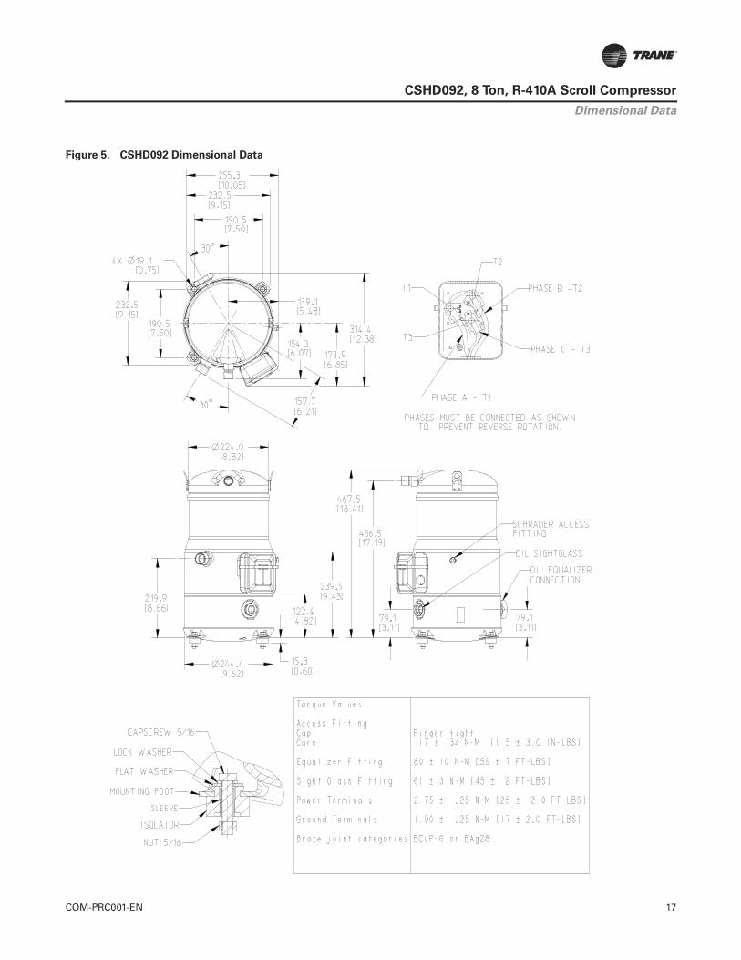
COM-PRC001-EN 17
CSHD092, 8 Ton, R-410A Scroll Compressor
Figure 5. CSHD092 Dimensional Data
Dimensional Data

18 COM-PRC001-EN
CSHD092, 8 Ton, R-410A Scroll Compressor
CSHD092 (8 Tons), Voltage: 200-60-3
Nominal performance values (+/-5%) based on a minimum 24 hour break-in. Subject to change without notice.All performance data shown is for R-410A refrigerant, 20°F SuperHeat, 15°F SubCooling.
Capacity - Btu/Hr
Cond. Temp °FEvaporating Temperature (°F)
-10 0 10 20 30 40 45 50 6080 35,979 46,153 58,834 74,077 91,921 112,394 123,619 135,503 161,23590 33,633 43,537 55,845 70,608 87,868 107,650 118,490 129,961 154,790
100 31,162 40,708 52,547 66,732 83,303 102,286 112,685 123,687 147,495110 37,683 48,965 62,476 78,259 96,337 106,240 116,718 139,390120 34,499 45,143 57,896 72,799 89,879 99,238 109,142 130,575130 41,135 53,057 67,004 83,003 91,775 101,062 121,168140 47,983 60,898 75,735 83,877 92,503 111,190150 54,332 67,886 75,334 83,231 100,357
Power - Watts
Cond. Temp °FEvaporating Temperature (°F)
-10 0 10 20 30 40 45 50 6080 4,707 4,751 4,804 4,866 4,937 5,016 5,060 5,105 5,20390 5,210 5,251 5,302 5,362 5,432 5,511 5,554 5,600 5,699
100 5,850 5,885 5,930 5,985 6,050 6,125 6,167 6,211 6,307110 6,652 6,687 6,733 6,790 6,858 6,896 6,937 7,027120 7,552 7,575 7,608 7,654 7,710 7,743 7,779 7,859130 8,592 8,610 8,640 8,682 8,707 8,736 8,802140 9,737 9,748 9,772 9,789 9,809 9,858150 10,980 10,982 10,988 10,997 11,026
Current - Amps @ 200V
Cond. Temp °FEvaporating Temperature (°F)
-10 0 10 20 30 40 45 50 6080 21.2 21.4 21.5 21.6 21.7 21.7 21.7 21.7 21.790 22.1 22.2 22.4 22.5 22.6 22.8 22.8 22.8 22.9
100 23.4 23.6 23.7 23.9 24.0 24.2 24.2 24.3 24.4110 25.4 25.5 25.7 25.8 25.9 26.0 26.1 26.3120 27.7 27.8 27.9 28.0 28.1 28.2 28.3 28.4130 30.5 30.5 30.5 30.6 30.7 30.7 30.9140 33.5 33.5 33.5 33.5 33.5 33.7150 36.8 36.7 36.7 36.7 36.8
Refrigerant Flow - Lbs/Hr
Cond. Temp °FEvaporating Temperature (°F)
-10 0 10 20 30 40 45 50 6080 431 545 686 854 1,048 1,268 1,389 1,515 1,78890 423 539 683 853 1,049 1,271 1,392 1,520 1,795
100 413 531 676 848 1,045 1,269 1,391 1,519 1,795110 521 667 839 1,037 1,262 1,384 1,513 1,790120 508 654 827 1,025 1,250 1,372 1,501 1,777130 638 810 1,009 1,233 1,355 1,483 1,759140 790 987 1,210 1,332 1,459 1,734150 962 1,183 1,303 1,430 1,702
EER - Btu/Hr/Watt-Hr
Cond. Temp °FEvaporating Temperature (°F)
-10 0 10 20 30 40 45 50 6080 7.64 9.71 12.25 15.22 18.62 22.41 24.43 26.54 30.9990 6.46 8.29 10.53 13.17 16.18 19.53 21.33 23.21 27.16
100 5.33 6.92 8.86 11.15 13.77 16.70 18.27 19.91 23.39110 5.67 7.32 9.28 11.52 14.05 15.41 16.83 19.84120 4.57 5.96 7.61 9.51 11.66 12.82 14.03 16.62130 4.79 6.16 7.76 9.56 10.54 11.57 13.77140 4.93 6.25 7.75 8.57 9.43 11.28150 4.95 6.18 6.86 7.57 9.10
20° SuperHeat, 15° SubCooling
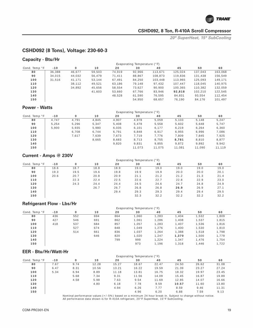
COM-PRC001-EN 19
CSHD092, 8 Ton, R-410A Scroll Compressor
CSHD092 (8 Tons), Voltage: 230-60-3
Nominal performance values (+/-5%) based on a minimum 24 hour break-in. Subject to change without notice.All performance data shown is for R-410A refrigerant, 20°F SuperHeat, 15°F SubCooling.
Capacity - Btu/Hr
Cond. Temp °FEvaporating Temperature (°F)
-10 0 10 20 30 40 45 50 6080 36,388 46,677 59,503 74,919 92,966 113,671 125,024 137,043 163,06890 34,015 44,032 56,479 71,411 88,867 108,873 119,836 131,438 156,549
100 31,516 41,171 53,144 67,491 84,250 103,448 113,965 125,093 149,171110 38,112 49,521 63,186 79,148 97,432 107,447 118,045 140,975120 34,892 45,656 58,554 73,627 90,900 100,365 110,382 132,059130 41,603 53,660 67,766 83,946 92,818 102,210 122,545140 48,528 61,590 76,595 84,831 93,554 112,454150 54,950 68,657 76,190 84,176 101,497
Power - Watts
Cond. Temp °FEvaporating Temperature (°F)
-10 0 10 20 30 40 45 50 6080 4,747 4,791 4,845 4,907 4,978 5,059 5,103 5,148 5,24790 5,254 5,296 5,347 5,408 5,478 5,558 5,602 5,648 5,747
100 5,900 5,935 5,980 6,035 6,101 6,177 6,219 6,264 6,360110 6,708 6,744 6,791 6,848 6,917 6,955 6,996 7,086120 7,617 7,639 7,673 7,719 7,776 7,809 7,845 7,925130 8,665 8,683 8,713 8,755 8,781 8,810 8,877140 9,820 9,831 9,855 9,872 9,892 9,942150 11,073 11,075 11,081 11,090 11,119
Current - Amps @ 230V
Cond. Temp °FEvaporating Temperature (°F)
-10 0 10 20 30 40 45 50 6080 18.6 18.7 18.8 18.9 19.0 19.0 19.0 19.0 19.090 19.3 19.5 19.6 19.8 19.9 19.9 20.0 20.0 20.1
100 20.6 20.7 20.8 20.9 21.1 21.2 21.2 21.3 21.4110 22.3 22.4 22.5 22.6 22.7 22.8 22.9 23.0120 24.3 24.4 24.4 24.5 24.6 24.7 24.8 24.9130 26.7 26.7 26.8 26.8 26.9 26.9 27.1140 29.4 29.3 29.3 29.4 29.4 29.5150 32.3 32.2 32.2 32.2 32.2
Refrigerant Flow - Lbs/Hr
Cond. Temp °FEvaporating Temperature (°F)
-10 0 10 20 30 40 45 50 6080 436 552 694 864 1,060 1,283 1,404 1,532 1,80990 427 546 691 862 1,061 1,286 1,408 1,537 1,815
100 418 537 684 857 1,057 1,283 1,407 1,536 1,816110 527 674 848 1,049 1,276 1,400 1,530 1,810120 514 661 836 1,037 1,264 1,388 1,518 1,798130 646 820 1,020 1,247 1,370 1,500 1,779140 799 999 1,224 1,347 1,476 1,754150 973 1,196 1,318 1,446 1,722
EER - Btu/Hr/Watt-Hr
Cond. Temp °FEvaporating Temperature (°F)
-10 0 10 20 30 40 45 50 6080 7.67 9.74 12.28 15.27 18.67 22.47 24.50 26.62 31.0890 6.47 8.31 10.56 13.21 16.22 19.59 21.39 23.27 27.24
100 5.34 6.94 8.89 11.18 13.81 16.75 18.32 19.97 23.45110 5.68 7.34 9.31 11.56 14.09 15.45 16.87 19.89120 4.58 5.98 7.63 9.54 11.69 12.85 14.07 16.66130 4.80 6.18 7.78 9.59 10.57 11.60 13.80140 4.94 6.26 7.77 8.59 9.46 11.31150 4.96 6.20 6.88 7.59 9.13
20° SuperHeat, 15° SubCooling

20 COM-PRC001-EN
CSHD092, 8 Ton, R-410A Scroll Compressor
CSHD092 (8 Tons), Voltage: 400-50-3
Nominal performance values (+/-5%) based on a minimum 24 hour break-in. Subject to change without notice.All performance data shown is for R-410A refrigerant, 20°F SuperHeat, 15°F SubCooling.
Capacity - Btu/Hr
Cond. Temp °FEvaporating Temperature (°F)
-10 0 10 20 30 40 45 50 6080 31,131 39,622 50,221 62,972 77,910 95,055 104,458 114,414 135,97690 29,030 37,203 47,382 59,612 73,927 90,348 99,350 108,880 129,513
100 26,852 34,666 44,384 56,048 69,693 85,339 93,915 102,993 122,642110 24,606 32,023 41,237 52,291 65,219 80,041 88,164 96,763 115,374120 29,298 37,970 48,374 60,542 74,495 82,144 90,239 107,764130 34,618 44,337 55,709 68,756 75,909 83,482 99,878140 40,184 50,721 62,818 69,455 76,483 91,704150 45,430 56,499 62,576 69,015 82,968
Power - Watts
Cond. Temp °FEvaporating Temperature (°F)
-10 0 10 20 30 40 45 50 6080 3,815 3,918 4,006 4,078 4,134 4,175 4,189 4,199 4,20890 4,225 4,324 4,412 4,490 4,556 4,612 4,636 4,657 4,692
100 4,755 4,843 4,926 5,002 5,074 5,139 5,170 5,199 5,253110 5,403 5,475 5,546 5,617 5,687 5,756 5,790 5,825 5,893120 6,219 6,273 6,332 6,395 6,462 6,498 6,534 6,610130 7,108 7,149 7,199 7,259 7,292 7,328 7,406140 8,066 8,098 8,144 8,173 8,205 8,280150 9,093 9,120 9,140 9,166 9,232
Current - Amps @ 400V
Cond. Temp °FEvaporating Temperature (°F)
-10 0 10 20 30 40 45 50 6080 9.2 9.3 9.3 9.4 9.4 9.5 9.5 9.5 9.690 9.6 9.7 9.7 9.8 9.9 9.9 9.9 10.0 10.0
100 10.1 10.2 10.3 10.3 10.4 10.5 10.5 10.5 10.6110 10.8 10.9 11.0 11.0 11.1 11.2 11.2 11.3 11.3120 11.7 11.8 11.9 12.0 12.0 12.1 12.1 12.2130 12.8 12.9 12.9 13.0 13.1 13.1 13.2140 14.0 14.1 14.1 14.2 14.2 14.3150 15.3 15.4 15.4 15.5 15.5
Refrigerant Flow - Lbs/Hr
Cond. Temp °FEvaporating Temperature (°F)
-10 0 10 20 30 40 45 50 6080 373 468 586 726 888 1,073 1,173 1,279 1,50890 365 461 579 720 882 1,067 1,167 1,273 1,502
100 356 452 571 712 874 1,059 1,159 1,265 1,493110 345 443 561 702 864 1,049 1,149 1,254 1,481120 431 550 691 853 1,036 1,136 1,241 1,467130 537 677 838 1,021 1,120 1,225 1,450140 662 822 1,004 1,103 1,206 1,430150 804 984 1,082 1,185 1,407
EER - Btu/Hr/Watt-Hr
Cond. Temp °FEvaporating Temperature (°F)
-10 0 10 20 30 40 45 50 6080 8.16 10.11 12.54 15.44 18.85 22.77 24.94 27.25 32.3190 6.87 8.60 10.74 13.28 16.23 19.59 21.43 23.38 27.60
100 5.65 7.16 9.01 11.20 13.74 16.61 18.17 19.81 23.35110 4.55 5.85 7.44 9.31 11.47 13.91 15.23 16.61 19.58120 4.71 6.05 7.64 9.47 11.53 12.64 13.81 16.30130 4.87 6.20 7.74 9.47 10.41 11.39 13.49140 4.98 6.26 7.71 8.50 9.32 11.08150 5.00 6.20 6.85 7.53 8.99
20° SuperHeat, 15° SubCooling

COM-PRC001-EN 21
CSHD092, 8 Ton, R-410A Scroll Compressor
CSHD092 (8 Tons), Voltage: 460-60-3
Nominal performance values (+/-5%) based on a minimum 24 hour break-in. Subject to change without notice.All performance data shown is for R-410A refrigerant, 20°F SuperHeat, 15°F SubCooling.
Capacity - Btu/Hr
Cond. Temp °FEvaporating Temperature (°F)
-10 0 10 20 30 40 45 50 6080 36,601 46,951 59,851 75,358 93,511 114,338 125,757 137,846 164,02390 34,214 44,290 56,810 71,829 89,388 109,512 120,539 132,209 157,466
100 31,701 41,412 53,456 67,886 84,744 104,055 114,633 125,826 150,045110 38,335 49,811 63,557 79,612 98,003 108,077 118,737 141,801120 35,097 45,923 58,897 74,058 91,433 100,954 111,029 132,833130 41,847 53,974 68,163 84,438 93,362 102,809 123,263140 48,813 61,950 77,044 85,328 94,102 113,113150 55,271 69,059 76,637 84,670 102,092
Power - Watts
Cond. Temp °FEvaporating Temperature (°F)
-10 0 10 20 30 40 45 50 6080 4,726 4,770 4,823 4,885 4,956 5,036 5,080 5,125 5,22390 5,231 5,272 5,323 5,383 5,453 5,533 5,576 5,622 5,721
100 5,873 5,908 5,953 6,008 6,074 6,149 6,191 6,235 6,332110 6,678 6,714 6,760 6,817 6,885 6,924 6,964 7,054120 7,582 7,605 7,639 7,684 7,741 7,774 7,810 7,890130 8,626 8,644 8,674 8,716 8,742 8,771 8,837140 9,776 9,787 9,811 9,828 9,847 9,897150 11,023 11,025 11,031 11,040 11,069
Current - Amps @ 460V
Cond. Temp °FEvaporating Temperature (°F)
-10 0 10 20 30 40 45 50 6080 9.3 9.4 9.5 9.5 9.5 9.5 9.6 9.5 9.590 9.7 9.8 9.9 9.9 10.0 10.0 10.0 10.0 10.1
100 10.3 10.4 10.4 10.5 10.6 10.6 10.7 10.7 10.8110 11.2 11.2 11.3 11.3 11.4 11.5 11.5 11.6120 12.2 12.2 12.3 12.3 12.4 12.4 12.4 12.5130 13.4 13.4 13.4 13.5 13.5 13.5 13.6140 14.7 14.7 14.7 14.7 14.8 14.8150 16.2 16.2 16.1 16.1 16.2
Refrigerant Flow - Lbs/Hr
Cond. Temp °FEvaporating Temperature (°F)
-10 0 10 20 30 40 45 50 6080 438 555 698 869 1,066 1,290 1,413 1,541 1,81990 430 549 695 867 1,067 1,293 1,416 1,546 1,826
100 420 540 688 862 1,063 1,291 1,415 1,545 1,826110 530 678 853 1,055 1,284 1,408 1,539 1,820120 517 665 841 1,043 1,272 1,396 1,527 1,808130 649 824 1,026 1,254 1,378 1,508 1,789140 804 1,004 1,231 1,355 1,484 1,764150 978 1,203 1,325 1,454 1,732
EER - Btu/Hr/Watt-Hr
Cond. Temp °FEvaporating Temperature (°F)
-10 0 10 20 30 40 45 50 6080 7.75 9.84 12.41 15.43 18.87 22.70 24.76 26.90 31.4090 6.54 8.40 10.67 13.34 16.39 19.79 21.62 23.51 27.52
100 5.40 7.01 8.98 11.30 13.95 16.92 18.52 20.18 23.70110 5.74 7.42 9.40 11.68 14.23 15.61 17.05 20.10120 4.63 6.04 7.71 9.64 11.81 12.99 14.22 16.84130 4.85 6.24 7.86 9.69 10.68 11.72 13.95140 4.99 6.33 7.85 8.68 9.56 11.43150 5.01 6.26 6.95 7.67 9.22
20° SuperHeat, 15° SubCooling
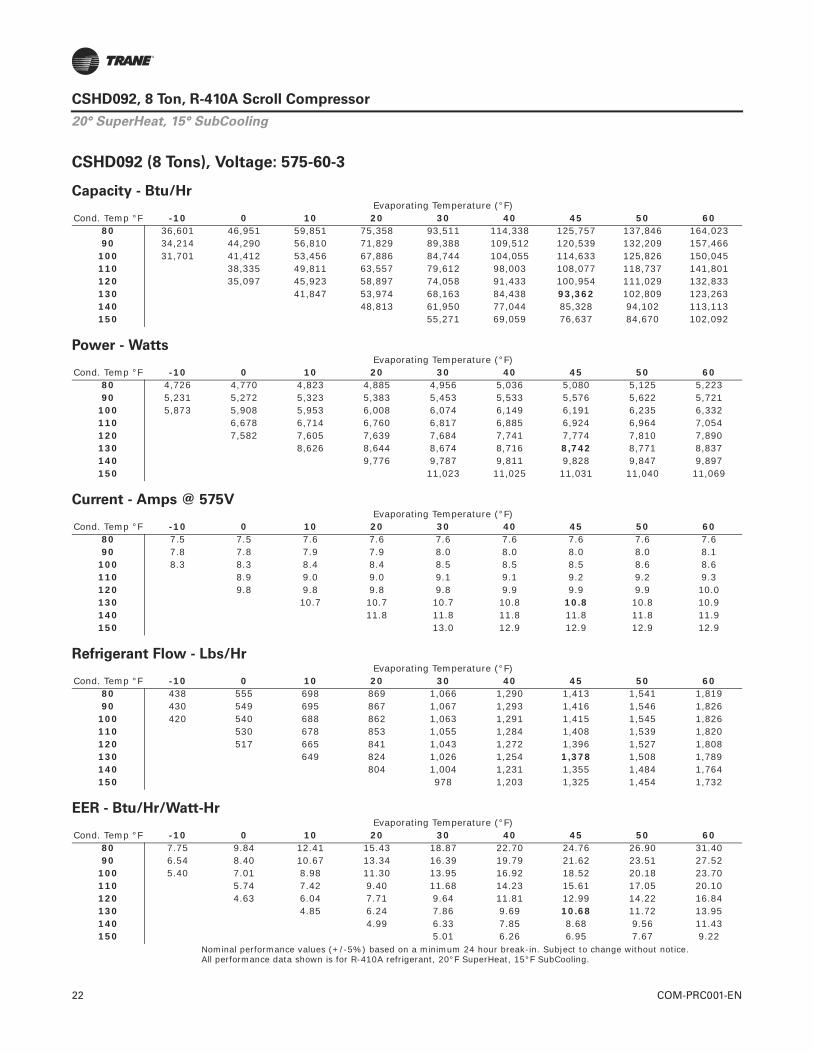
22 COM-PRC001-EN
CSHD092, 8 Ton, R-410A Scroll Compressor
CSHD092 (8 Tons), Voltage: 575-60-3
Nominal performance values (+/-5%) based on a minimum 24 hour break-in. Subject to change without notice.All performance data shown is for R-410A refrigerant, 20°F SuperHeat, 15°F SubCooling.
Capacity - Btu/Hr
Cond. Temp °FEvaporating Temperature (°F)
-10 0 10 20 30 40 45 50 6080 36,601 46,951 59,851 75,358 93,511 114,338 125,757 137,846 164,02390 34,214 44,290 56,810 71,829 89,388 109,512 120,539 132,209 157,466
100 31,701 41,412 53,456 67,886 84,744 104,055 114,633 125,826 150,045110 38,335 49,811 63,557 79,612 98,003 108,077 118,737 141,801120 35,097 45,923 58,897 74,058 91,433 100,954 111,029 132,833130 41,847 53,974 68,163 84,438 93,362 102,809 123,263140 48,813 61,950 77,044 85,328 94,102 113,113150 55,271 69,059 76,637 84,670 102,092
Power - Watts
Cond. Temp °FEvaporating Temperature (°F)
-10 0 10 20 30 40 45 50 6080 4,726 4,770 4,823 4,885 4,956 5,036 5,080 5,125 5,22390 5,231 5,272 5,323 5,383 5,453 5,533 5,576 5,622 5,721
100 5,873 5,908 5,953 6,008 6,074 6,149 6,191 6,235 6,332110 6,678 6,714 6,760 6,817 6,885 6,924 6,964 7,054120 7,582 7,605 7,639 7,684 7,741 7,774 7,810 7,890130 8,626 8,644 8,674 8,716 8,742 8,771 8,837140 9,776 9,787 9,811 9,828 9,847 9,897150 11,023 11,025 11,031 11,040 11,069
Current - Amps @ 575V
Cond. Temp °FEvaporating Temperature (°F)
-10 0 10 20 30 40 45 50 6080 7.5 7.5 7.6 7.6 7.6 7.6 7.6 7.6 7.690 7.8 7.8 7.9 7.9 8.0 8.0 8.0 8.0 8.1
100 8.3 8.3 8.4 8.4 8.5 8.5 8.5 8.6 8.6110 8.9 9.0 9.0 9.1 9.1 9.2 9.2 9.3120 9.8 9.8 9.8 9.8 9.9 9.9 9.9 10.0130 10.7 10.7 10.7 10.8 10.8 10.8 10.9140 11.8 11.8 11.8 11.8 11.8 11.9150 13.0 12.9 12.9 12.9 12.9
Refrigerant Flow - Lbs/Hr
Cond. Temp °FEvaporating Temperature (°F)
-10 0 10 20 30 40 45 50 6080 438 555 698 869 1,066 1,290 1,413 1,541 1,81990 430 549 695 867 1,067 1,293 1,416 1,546 1,826
100 420 540 688 862 1,063 1,291 1,415 1,545 1,826110 530 678 853 1,055 1,284 1,408 1,539 1,820120 517 665 841 1,043 1,272 1,396 1,527 1,808130 649 824 1,026 1,254 1,378 1,508 1,789140 804 1,004 1,231 1,355 1,484 1,764150 978 1,203 1,325 1,454 1,732
EER - Btu/Hr/Watt-Hr
Cond. Temp °FEvaporating Temperature (°F)
-10 0 10 20 30 40 45 50 6080 7.75 9.84 12.41 15.43 18.87 22.70 24.76 26.90 31.4090 6.54 8.40 10.67 13.34 16.39 19.79 21.62 23.51 27.52
100 5.40 7.01 8.98 11.30 13.95 16.92 18.52 20.18 23.70110 5.74 7.42 9.40 11.68 14.23 15.61 17.05 20.10120 4.63 6.04 7.71 9.64 11.81 12.99 14.22 16.84130 4.85 6.24 7.86 9.69 10.68 11.72 13.95140 4.99 6.33 7.85 8.68 9.56 11.43150 5.01 6.26 6.95 7.67 9.22
20° SuperHeat, 15° SubCooling
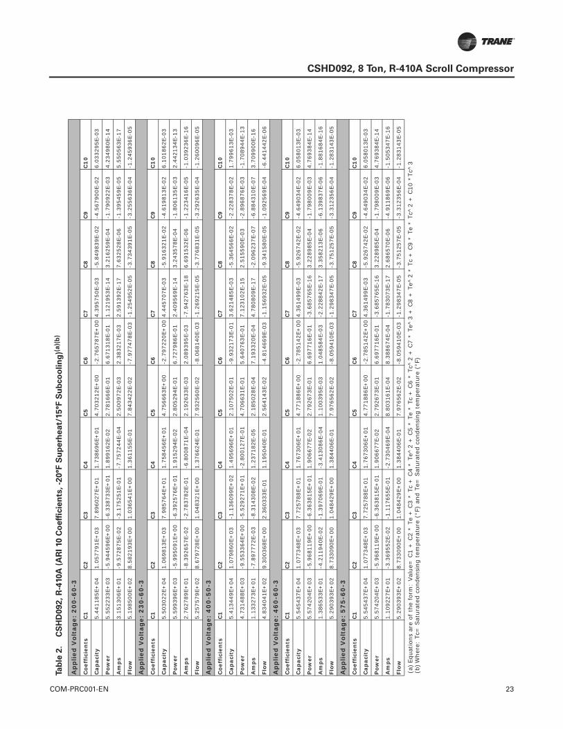
COM-PRC001-EN 23
CSHD092, 8 Ton, R-410A Scroll Compressor
Tab
le 2
.C
SH
D092,
R-4
10A
(A
RI 10 C
oeff
icie
nts
, -2
0°F
Su
perh
eat/
15°F
Su
bco
olin
g)(
a)(
b)
Ap
pli
ed V
olt
age:
20
0-6
0-3
Co
effi
cien
tsC
1C
2C
3C
4C
5C
6C
7C
8C
9C
10
Cap
acit
y5.
4411
85E+
041.
0577
91E+
037.
8960
27E+
011.
7386
96E+
014.
7032
12E+
00-2
.765
787E
+00
4.39
5750
E-03
-5.8
4983
9E-0
2-4
.567
900E
-02
6.03
3295
E-03
Po
wer
5.55
2233
E+03
-5.9
4459
6E+
00-6
.338
733E
+01
1.89
9162
E-02
2.78
1666
E-01
6.67
1318
E-01
1.12
1953
E-14
3.21
6259
E-04
-1.7
9092
2E-0
34.
2349
80E-
14
Am
ps
3.15
1306
E+01
-9.5
7287
5E-0
2-3
.175
251E
-01
-7.7
5724
4E-0
42.
5009
72E-
032.
3832
17E-
032.
5913
92E-
177.
6325
28E-
06-1
.395
459E
-05
5.55
0563
E-17
Flo
w5.
1985
00E+
028.
5821
93E+
001.
0365
41E+
001.
3611
55E-
017.
8434
22E-
02-7
.977
478E
-03
-1.2
5495
2E-0
5-3
.734
391E
-05
-3.2
5563
6E-0
4-1
.245
936E
-05
Ap
pli
ed V
olt
age:
23
0-6
0-3
Co
effi
cien
tsC
1C
2C
3C
4C
5C
6C
7C
8C
9C
10
Cap
acit
y5.
5030
22E+
041.
0698
13E+
037.
9857
64E+
011.
7584
56E+
014.
7566
63E+
00-2
.797
220E
+00
4.44
5707
E-03
-5.9
1632
1E-0
2-4
.619
813E
-02
6.10
1862
E-03
Po
wer
5.59
9396
E+03
-5.9
9509
1E+
00-6
.392
576E
+01
1.91
5294
E-02
2.80
5294
E-01
6.72
7986
E-01
2.40
9569
E-14
3.24
3578
E-04
-1.8
0613
5E-0
32.
4421
34E-
13
Am
ps
2.76
2789
E+01
-8.3
9265
7E-0
2-2
.783
782E
-01
-6.8
0087
1E-0
42.
1926
33E-
032.
0893
95E-
03-7
.942
763E
-18
6.69
1532
E-06
-1.2
2341
6E-0
5-1
.039
236E
-16
Flo
w5.
2575
79E+
028.
6797
28E+
001.
0483
21E+
001.
3766
24E-
017.
9325
60E-
02-8
.068
140E
-03
-1.2
6921
5E-0
5-3
.776
831E
-05
-3.2
9263
5E-0
4-1
.260
096E
-05
Ap
pli
ed V
olt
age:
40
0-5
0-3
Co
effi
cien
tsC
1C
2C
3C
4C
5C
6C
7C
8C
9C
10
Cap
acit
y5.
4134
49E+
041.
0798
60E+
03-1
.136
099E
+02
1.49
5696
E+01
2.10
7502
E-01
-9.9
3217
3E-0
13.
6214
85E-
03-5
.364
566E
-02
-2.2
2837
8E-0
21.
7996
13E-
03
Po
wer
4.73
1488
E+03
-9.5
5336
4E+
00-5
.529
271E
+01
-2.8
0012
7E-0
14.
7066
31E-
015.
6407
63E-
017.
1231
02E-
152.
5155
90E-
03-2
.896
876E
-03
-1.7
0894
4E-1
3
Am
ps
1.13
3273
E+01
-7.8
9777
2E-0
3-8
.314
308E
-02
1.23
7182
E-05
2.18
5028
E-04
7.19
3320
E-04
4.78
0809
E-17
-2.0
9623
7E-0
7-6
.884
310E
-07
3.70
9900
E-16
Flo
w4.
8340
41E+
029.
3003
68E+
002.
3603
33E-
011.
1950
40E-
012.
5641
43E-
02-4
.814
669E
-03
-1.1
5693
2E-0
5-9
.341
580E
-05
-1.0
9256
9E-0
4-6
.441
442E
-06
Ap
pli
ed V
olt
age:
46
0-6
0-3
Co
effi
cien
tsC
1C
2C
3C
4C
5C
6C
7C
8C
9C
10
Cap
acit
y5.
5454
37E+
041.
0773
48E+
037.
7257
88E+
011.
7673
06E+
014.
7718
86E+
00-2
.785
142E
+00
4.36
1499
E-03
-5.9
2674
2E-0
2-4
.649
034E
-02
6.05
8013
E-03
Po
wer
5.57
4204
E+03
-5.9
6811
9E+
00-6
.363
815E
+01
1.90
6677
E-02
2.79
2673
E-01
6.69
7716
E-01
-3.6
8576
5E-1
63.
2289
85E-
04-1
.798
009E
-03
4.76
9384
E-14
Am
ps
1.38
6533
E+01
-4.2
1194
0E-0
2-1
.397
069E
-01
-3.4
1308
6E-0
41.
1003
95E-
031.
0485
84E-
03-2
.228
842E
-17
3.35
8213
E-06
-6.1
3983
7E-0
6-1
.881
684E
-16
Flo
w5.
2903
93E+
028.
7330
90E+
001.
0484
29E+
001.
3844
06E-
017.
9765
62E-
02-8
.059
410E
-03
-1.2
9834
7E-0
5-3
.751
257E
-05
-3.3
1235
6E-0
4-1
.283
143E
-05
Ap
pli
ed V
olt
age:
57
5-6
0-3
Co
effi
cien
tsC
1C
2C
3C
4C
5C
6C
7C
8C
9C
10
Cap
acit
y5.
5454
37E+
041.
0773
48E+
037.
7257
88E+
011.
7673
06E+
014.
7718
86E+
00-2
.785
142E
+00
4.36
1499
E-03
-5.9
2674
2E-0
2-4
.649
034E
-02
6.05
8013
E-03
Po
wer
5.57
4204
E+03
-5.9
6811
9E+
00-6
.363
815E
+01
1.90
6677
E-02
2.79
2673
E-01
6.69
7716
E-01
-3.6
8576
5E-1
63.
2289
85E-
04-1
.798
009E
-03
4.76
9384
E-14
Am
ps
1.10
9227
E+01
-3.3
6955
2E-0
2-1
.117
655E
-01
-2.7
3046
9E-0
48.
8031
61E-
048.
3886
74E-
04-1
.783
073E
-17
2.68
6570
E-06
-4.9
1186
9E-0
6-1
.505
347E
-16
Flo
w5.
2903
93E+
028.
7330
90E+
001.
0484
29E+
001.
3844
06E-
017.
9765
62E-
02-8
.059
410E
-03
-1.2
9834
7E-0
5-3
.751
257E
-05
-3.3
1235
6E-0
4-1
.283
143E
-05
(a)E
quat
ions
are
of
the
form
: Val
ue=
C1
+ C
2 *
Te +
C3
* Tc
+ C
4 *
Te^
2 +
C5
* Te
* T
c +
C6
* Tc
^2
+ C
7 *
Te^
3 +
C8
+ T
e^2
* Tc
+ C
9 *
Te *
Tc^
2 +
C10
*Tc
^3
(b)W
here
: Tc
= S
atur
ated
con
dens
ing
tem
pera
ture
(°F
) an
d Te
= S
atur
ated
con
dens
ing
tem
pera
ture
(°F
)
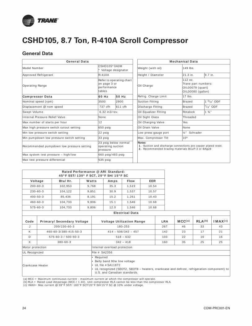
24 COM-PRC001-EN
CSHD105, 8.7 Ton, R-410A Scroll Compressor
General Data
General Data Mechanical Data
Model Number CSHD105*0A0M* Voltage designator
Weight (with oil) 149 lbs.
Approved Refrigerant R-410A Height / Diameter 21.3 in. 9.7 in.
Operating Range
Refer to operating chart on page 3 or performance tables
Oil Charge
112 oz. Trane part numbers:OIL00079 (quart)OIL00080 (gallon)
Compressor Data 60 Hz 50 Hz Refrig. Charge Limit 17 lbs.
Nominal speed (rpm) 3500 2900 Suction Fitting Brazed 1 3/8” ODF
Displacement @ nom speed 737 cfh 611 cfh Discharge Fitting Brazed 7/8” ODF
Swept Volume 6.32 in3/rev. Oil Equalizer Fitting Rotalock 1 ¾”
Internal Pressure Relief Valve None Oil Sight Glass Threaded
Max number of starts per hour 12 Oil Charging Valve Yes
Max high pressure switch cutout setting 650 psig Oil Drain Valve None
Min low pressure switch setting 22 psig Low press gauge port ¼” Schrader
Min pumpdown low pressure switch setting 33 psig Max. Compressor Tilt 10º
Recommended pumpdown low pressure setting23 psig below normal operating suction pressure
Notes:
1. Suction and discharge connections are copper plated steel. 2. Recommended brazing materials BCuP-3 or BAg28
Max system test pressure – high/low 660 psig/483 psig
Max test pressure differential 535 psig
Rated Performance @ ARI Standard:45ºF SST/130º F SCT, 20ºF SH/15ºF SC
Voltage Btu/Hr. Watts Amps Flow EER200-60-3 102,953 9,768 35.3 1,519 10.54
230-60-3 104,122 9,851 30.9 1,537 10.57
400-50-3 85,436 8,191 15.2 1,261 10.43
460-60-3 104,733 9,806 15.1 1,546 10.68
575-60-3 104,733 9,806 12.0 1,546 10.68
Electrical Data
Code Primary/Secondary Voltage Voltage Utilization Range LRA MCC(a) RLA(b) IMAX(c)
J 200/230-60-3 180-253 267 46 33 43
K 460-60-3/380-415-50-3 414 – 506/342 – 457 142 23 17 21
D 575-60-3 / 500-50-3 518 – 632 103 22 16 16
X 380-60-3 342 – 418 160 35 25 25
Motor protection Internal overload protection
UL Recognized File # SA2356
Crankcase Heater
• Required• Belly band 90w line voltage • UL file #SA11872• UL recognized (SEOT2, SEOT8 – heaters, crankcase and defrost, refrigeration component) to
U.S. and Canadian standards.
(a) MCC = Maximum continuous current - maximum current at which the compressor will operate.(b) RLA = Rated Load Amperage (MCC / 1.40). Unit compressor RLA cannot be less than the compressor RLA.(c) IMAX= Max current @ 59°F SST/ 160°F SCT/20°F SH/15°F SC @ 10% under voltage.

COM-PRC001-EN 25
CSHD105, 8.7 Ton, R-410A Scroll Compressor
Figure 6. CSHD105 Dimensional Data
Dimensional Data

26 COM-PRC001-EN
CSHD105, 8.7 Ton, R-410A Scroll Compressor
CSHD105 (8.7 Tons), Voltage: 200-60-3
Nominal performance values (+/-5%) based on a minimum 24 hour break-in. Subject to change without notice.All performance data shown is for R-410A refrigerant, 20°F SuperHeat, 15°F SubCooling.
Capacity - Btu/Hr
Cond. Temp °FEvaporating Temperature (°F)
-10 0 10 20 30 40 45 50 6080 42,205 53,078 66,608 82,856 101,867 123,671 135,625 148,279 175,68190 39,839 50,432 63,586 79,359 97,798 118,932 130,514 142,772 169,308
100 37,288 47,511 60,190 75,384 93,141 113,489 124,639 136,439 161,981110 34,562 44,328 56,440 70,956 87,923 107,371 118,030 129,311 153,733120 40,923 52,383 66,130 82,211 100,655 110,769 121,475 144,660130 48,076 60,974 76,083 93,433 102,953 113,036 134,882140 55,508 69,560 85,723 94,601 104,010 124,412150 62,462 77,300 85,462 94,119 112,912
Power - Watts
Cond. Temp °FEvaporating Temperature (°F)
-10 0 10 20 30 40 45 50 6080 5,448 5,558 5,649 5,721 5,775 5,809 5,820 5,826 5,82390 5,960 6,054 6,143 6,226 6,304 6,376 6,409 6,442 6,502
100 6,631 6,699 6,775 6,858 6,949 7,047 7,099 7,153 7,266110 7,461 7,492 7,544 7,617 7,710 7,824 7,889 7,958 8,113120 8,434 8,451 8,503 8,588 8,706 8,778 8,859 9,045130 9,495 9,515 9,581 9,694 9,768 9,854 10,060140 10,654 10,690 10,787 10,858 10,943 11,159150 11,916 11,985 12,047 12,128 12,343
Current - Amps @ 200V
Cond. Temp °FEvaporating Temperature (°F)
-10 0 10 20 30 40 45 50 6080 24.3 24.7 25.0 25.3 25.7 26.0 26.1 26.3 26.690 25.4 25.7 26.1 26.4 26.7 27.0 27.2 27.3 27.6
100 26.8 27.2 27.5 27.8 28.1 28.5 28.6 28.8 29.0110 28.7 29.0 29.4 29.7 30.0 30.3 30.4 30.6 30.9120 31.2 31.6 31.9 32.2 32.5 32.7 32.8 33.1130 34.2 34.5 34.9 35.2 35.3 35.4 35.7140 37.6 37.9 38.2 38.3 38.4 38.7150 41.3 41.6 41.7 41.9 42.1
Refrigerant Flow - Lbs/Hr
Cond. Temp °FEvaporating Temperature (°F)
-10 0 10 20 30 40 45 50 6080 505 627 777 955 1,161 1,396 1,523 1,658 1,94990 501 625 777 958 1,167 1,404 1,534 1,670 1,963
100 494 620 775 957 1,169 1,408 1,538 1,676 1,972110 485 613 768 953 1,165 1,407 1,538 1,676 1,974120 602 759 944 1,158 1,400 1,531 1,670 1,969130 746 931 1,145 1,388 1,519 1,659 1,958140 914 1,128 1,370 1,502 1,641 1,940150 1,105 1,347 1,478 1,617 1,915
EER - Btu/Hr/Watt-Hr
Cond. Temp °FEvaporating Temperature (°F)
-10 0 10 20 30 40 45 50 6080 7.75 9.55 11.79 14.48 17.64 21.29 23.30 25.45 30.1790 6.68 8.33 10.35 12.75 15.51 18.65 20.36 22.16 26.04
100 5.62 7.09 8.88 10.99 13.40 16.10 17.56 19.08 22.29110 4.63 5.92 7.48 9.32 11.40 13.72 14.96 16.25 18.95120 4.85 6.20 7.78 9.57 11.56 12.62 13.71 15.99130 5.06 6.41 7.94 9.64 10.54 11.47 13.41140 5.21 6.51 7.95 8.71 9.50 11.15150 5.24 6.45 7.09 7.76 9.15
20° SuperHeat, 15° SubCooling

COM-PRC001-EN 27
CSHD105, 8.7 Ton, R-410A Scroll Compressor
CSHD105 (8.7 Tons), Voltage: 230-60-3
Nominal performance values (+/-5%) based on a minimum 24 hour break-in. Subject to change without notice.All performance data shown is for R-410A refrigerant, 20°F SuperHeat, 15°F SubCooling.
Capacity - Btu/Hr
Cond. Temp °FEvaporating Temperature (°F)
-10 0 10 20 30 40 45 50 6080 42,685 53,681 67,365 83,797 103,024 125,075 137,165 149,963 177,67690 40,292 51,005 64,308 80,260 98,908 120,282 131,996 144,393 171,230
100 37,711 48,050 60,873 76,240 94,199 114,777 126,054 137,988 163,820110 34,954 44,832 57,081 71,762 88,922 108,591 119,370 130,780 155,478120 41,388 52,978 66,881 83,144 101,798 112,026 122,855 146,303130 48,622 61,666 76,947 94,494 104,122 114,320 136,414140 56,138 70,350 86,696 95,675 105,191 125,825150 63,171 78,177 86,432 95,188 114,194
Power - Watts
Cond. Temp °FEvaporating Temperature (°F)
-10 0 10 20 30 40 45 50 6080 5,494 5,605 5,697 5,770 5,824 5,859 5,869 5,875 5,87290 6,011 6,106 6,195 6,279 6,357 6,430 6,464 6,496 6,558
100 6,687 6,756 6,833 6,916 7,008 7,107 7,159 7,213 7,327110 7,524 7,556 7,608 7,682 7,776 7,890 7,955 8,026 8,182120 8,505 8,523 8,575 8,660 8,780 8,853 8,934 9,121130 9,576 9,595 9,662 9,776 9,851 9,937 10,145140 10,744 10,781 10,878 10,950 11,036 11,254150 12,017 12,087 12,149 12,230 12,448
Current - Amps @ 230V
Cond. Temp °FEvaporating Temperature (°F)
-10 0 10 20 30 40 45 50 6080 21.3 21.6 21.9 22.2 22.5 22.8 22.9 23.1 23.390 22.3 22.6 22.8 23.1 23.4 23.7 23.8 24.0 24.2
100 23.5 23.8 24.1 24.4 24.7 24.9 25.1 25.2 25.5110 25.1 25.4 25.7 26.0 26.3 26.6 26.7 26.8 27.0120 27.4 27.7 28.0 28.3 28.5 28.6 28.8 29.0130 30.0 30.3 30.6 30.8 30.9 31.1 31.3140 32.9 33.2 33.5 33.6 33.7 33.9150 36.2 36.5 36.6 36.7 36.9
Refrigerant Flow - Lbs/Hr
Cond. Temp °FEvaporating Temperature (°F)
-10 0 10 20 30 40 45 50 6080 511 634 786 966 1,175 1,412 1,541 1,677 1,97190 506 632 786 969 1,180 1,420 1,551 1,689 1,986
100 500 627 783 968 1,182 1,424 1,556 1,695 1,994110 491 620 777 964 1,179 1,423 1,555 1,695 1,996120 609 768 955 1,171 1,416 1,549 1,689 1,991130 754 942 1,158 1,403 1,537 1,677 1,980140 925 1,141 1,385 1,519 1,659 1,962150 1,118 1,362 1,495 1,635 1,937
EER - Btu/Hr/Watt-Hr
Cond. Temp °FEvaporating Temperature (°F)
-10 0 10 20 30 40 45 50 6080 7.77 9.58 11.83 14.52 17.69 21.35 23.37 25.53 30.2690 6.70 8.35 10.38 12.78 15.56 18.71 20.42 22.23 26.11
100 5.64 7.11 8.91 11.02 13.44 16.15 17.61 19.13 22.36110 4.65 5.93 7.50 9.34 11.44 13.76 15.00 16.29 19.00120 4.87 6.22 7.80 9.60 11.59 12.65 13.75 16.04130 5.08 6.43 7.96 9.67 10.57 11.50 13.45140 5.23 6.53 7.97 8.74 9.53 11.18150 5.26 6.47 7.11 7.78 9.17
20° SuperHeat, 15° SubCooling
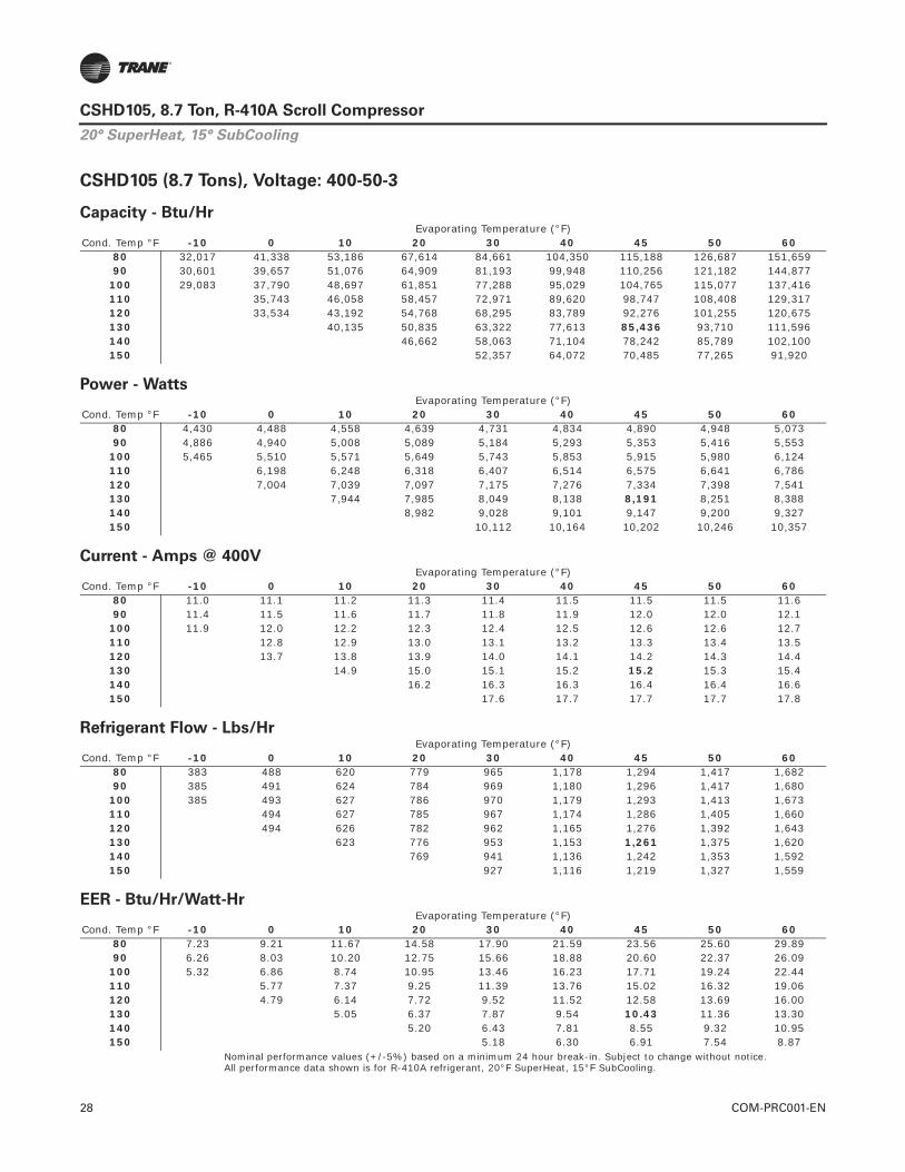
28 COM-PRC001-EN
CSHD105, 8.7 Ton, R-410A Scroll Compressor
CSHD105 (8.7 Tons), Voltage: 400-50-3
Nominal performance values (+/-5%) based on a minimum 24 hour break-in. Subject to change without notice.All performance data shown is for R-410A refrigerant, 20°F SuperHeat, 15°F SubCooling.
Capacity - Btu/Hr
Cond. Temp °FEvaporating Temperature (°F)
-10 0 10 20 30 40 45 50 6080 32,017 41,338 53,186 67,614 84,661 104,350 115,188 126,687 151,65990 30,601 39,657 51,076 64,909 81,193 99,948 110,256 121,182 144,877
100 29,083 37,790 48,697 61,851 77,288 95,029 104,765 115,077 137,416110 35,743 46,058 58,457 72,971 89,620 98,747 108,408 129,317120 33,534 43,192 54,768 68,295 83,789 92,276 101,255 120,675130 40,135 50,835 63,322 77,613 85,436 93,710 111,596140 46,662 58,063 71,104 78,242 85,789 102,100150 52,357 64,072 70,485 77,265 91,920
Power - Watts
Cond. Temp °FEvaporating Temperature (°F)
-10 0 10 20 30 40 45 50 6080 4,430 4,488 4,558 4,639 4,731 4,834 4,890 4,948 5,07390 4,886 4,940 5,008 5,089 5,184 5,293 5,353 5,416 5,553
100 5,465 5,510 5,571 5,649 5,743 5,853 5,915 5,980 6,124110 6,198 6,248 6,318 6,407 6,514 6,575 6,641 6,786120 7,004 7,039 7,097 7,175 7,276 7,334 7,398 7,541130 7,944 7,985 8,049 8,138 8,191 8,251 8,388140 8,982 9,028 9,101 9,147 9,200 9,327150 10,112 10,164 10,202 10,246 10,357
Current - Amps @ 400V
Cond. Temp °FEvaporating Temperature (°F)
-10 0 10 20 30 40 45 50 6080 11.0 11.1 11.2 11.3 11.4 11.5 11.5 11.5 11.690 11.4 11.5 11.6 11.7 11.8 11.9 12.0 12.0 12.1
100 11.9 12.0 12.2 12.3 12.4 12.5 12.6 12.6 12.7110 12.8 12.9 13.0 13.1 13.2 13.3 13.4 13.5120 13.7 13.8 13.9 14.0 14.1 14.2 14.3 14.4130 14.9 15.0 15.1 15.2 15.2 15.3 15.4140 16.2 16.3 16.3 16.4 16.4 16.6150 17.6 17.7 17.7 17.7 17.8
Refrigerant Flow - Lbs/Hr
Cond. Temp °FEvaporating Temperature (°F)
-10 0 10 20 30 40 45 50 6080 383 488 620 779 965 1,178 1,294 1,417 1,68290 385 491 624 784 969 1,180 1,296 1,417 1,680
100 385 493 627 786 970 1,179 1,293 1,413 1,673110 494 627 785 967 1,174 1,286 1,405 1,660120 494 626 782 962 1,165 1,276 1,392 1,643130 623 776 953 1,153 1,261 1,375 1,620140 769 941 1,136 1,242 1,353 1,592150 927 1,116 1,219 1,327 1,559
EER - Btu/Hr/Watt-Hr
Cond. Temp °FEvaporating Temperature (°F)
-10 0 10 20 30 40 45 50 6080 7.23 9.21 11.67 14.58 17.90 21.59 23.56 25.60 29.8990 6.26 8.03 10.20 12.75 15.66 18.88 20.60 22.37 26.09
100 5.32 6.86 8.74 10.95 13.46 16.23 17.71 19.24 22.44110 5.77 7.37 9.25 11.39 13.76 15.02 16.32 19.06120 4.79 6.14 7.72 9.52 11.52 12.58 13.69 16.00130 5.05 6.37 7.87 9.54 10.43 11.36 13.30140 5.20 6.43 7.81 8.55 9.32 10.95150 5.18 6.30 6.91 7.54 8.87
20° SuperHeat, 15° SubCooling

COM-PRC001-EN 29
CSHD105, 8.7 Ton, R-410A Scroll Compressor
CSHD105 (8.7 Tons), Voltage: 460-60-3
Nominal performance values (+/-5%) based on a minimum 24 hour break-in. Subject to change without notice.All performance data shown is for R-410A refrigerant, 20°F SuperHeat, 15°F SubCooling.
Capacity - Btu/Hr
Cond. Temp °FEvaporating Temperature (°F)
-10 0 10 20 30 40 45 50 6080 42,935 53,996 67,760 84,289 103,628 125,809 137,970 150,843 178,71890 40,528 51,304 64,685 80,731 99,489 120,988 132,770 145,241 172,235
100 37,933 48,332 61,230 76,688 94,751 115,451 126,794 138,798 164,781110 35,160 45,095 57,416 72,183 89,443 109,228 120,071 131,547 156,390120 41,631 53,289 67,273 83,632 102,396 112,684 123,576 147,161130 48,907 62,028 77,398 95,048 104,733 114,991 137,215140 56,468 70,762 87,205 96,237 105,808 126,563150 63,542 78,636 86,939 95,747 114,864
Power - Watts
Cond. Temp °FEvaporating Temperature (°F)
-10 0 10 20 30 40 45 50 6080 5,469 5,580 5,671 5,744 5,797 5,832 5,843 5,849 5,84690 5,984 6,078 6,167 6,251 6,329 6,401 6,435 6,467 6,528
100 6,657 6,726 6,802 6,885 6,976 7,075 7,127 7,181 7,295110 7,490 7,522 7,574 7,647 7,741 7,855 7,920 7,990 8,145120 8,467 8,485 8,536 8,621 8,741 8,813 8,894 9,080130 9,533 9,552 9,619 9,732 9,806 9,893 10,100140 10,696 10,733 10,829 10,900 10,986 11,204150 11,963 12,033 12,095 12,176 12,392
Current - Amps @ 460V
Cond. Temp °FEvaporating Temperature (°F)
-10 0 10 20 30 40 45 50 6080 10.4 10.5 10.7 10.8 10.9 11.1 11.2 11.2 11.490 10.8 11.0 11.1 11.3 11.4 11.5 11.6 11.7 11.8
100 11.5 11.6 11.7 11.9 12.0 12.1 12.2 12.3 12.4110 12.2 12.4 12.5 12.7 12.8 12.9 13.0 13.0 13.2120 13.3 13.5 13.6 13.8 13.9 13.9 14.0 14.1130 14.6 14.7 14.9 15.0 15.1 15.1 15.2140 16.0 16.2 16.3 16.4 16.4 16.5150 17.6 17.8 17.8 17.9 18.0
Refrigerant Flow - Lbs/Hr
Cond. Temp °FEvaporating Temperature (°F)
-10 0 10 20 30 40 45 50 6080 514 638 791 972 1,181 1,420 1,550 1,687 1,98290 509 636 791 975 1,187 1,429 1,560 1,699 1,997
100 503 631 788 974 1,189 1,432 1,565 1,705 2,006110 494 623 782 969 1,186 1,431 1,564 1,705 2,008120 613 772 960 1,178 1,424 1,558 1,699 2,003130 759 947 1,165 1,412 1,546 1,687 1,992140 930 1,147 1,394 1,528 1,669 1,974150 1,125 1,370 1,504 1,645 1,948
EER - Btu/Hr/Watt-Hr
Cond. Temp °FEvaporating Temperature (°F)
-10 0 10 20 30 40 45 50 6080 7.85 9.68 11.95 14.68 17.87 21.57 23.61 25.79 30.5790 6.77 8.44 10.49 12.92 15.72 18.90 20.63 22.46 26.38
100 5.70 7.19 9.00 11.14 13.58 16.32 17.79 19.33 22.59110 4.69 6.00 7.58 9.44 11.55 13.91 15.16 16.46 19.20120 4.92 6.28 7.88 9.70 11.71 12.79 13.89 16.21130 5.13 6.49 8.05 9.77 10.68 11.62 13.59140 5.28 6.59 8.05 8.83 9.63 11.30150 5.31 6.54 7.19 7.86 9.27
20° SuperHeat, 15° SubCooling

30 COM-PRC001-EN
CSHD105, 8.7 Ton, R-410A Scroll Compressor
CSHD105 (8.7 Tons), Voltage: 575-60-3
Nominal performance values (+/-5%) based on a minimum 24 hour break-in. Subject to change without notice.All performance data shown is for R-410A refrigerant, 20°F SuperHeat, 15°F SubCooling.
Capacity - Btu/Hr
Cond. Temp °FEvaporating Temperature (°F)
-10 0 10 20 30 40 45 50 6080 42,935 53,996 67,760 84,289 103,628 125,809 137,970 150,843 178,71890 40,528 51,304 64,685 80,731 99,489 120,988 132,770 145,241 172,235
100 37,933 48,332 61,230 76,688 94,751 115,451 126,794 138,798 164,781110 35,160 45,095 57,416 72,183 89,443 109,228 120,071 131,547 156,390120 41,631 53,289 67,273 83,632 102,396 112,684 123,576 147,161130 48,907 62,028 77,398 95,048 104,733 114,991 137,215140 56,468 70,762 87,205 96,237 105,808 126,563150 63,542 78,636 86,939 95,747 114,864
Power - Watts
Cond. Temp °FEvaporating Temperature (°F)
-10 0 10 20 30 40 45 50 6080 5,469 5,580 5,671 5,744 5,797 5,832 5,843 5,849 5,84690 5,984 6,078 6,167 6,251 6,329 6,401 6,435 6,467 6,528
100 6,657 6,726 6,802 6,885 6,976 7,075 7,127 7,181 7,295110 7,490 7,522 7,574 7,647 7,741 7,855 7,920 7,990 8,145120 8,467 8,485 8,536 8,621 8,741 8,813 8,894 9,080130 9,533 9,552 9,619 9,732 9,806 9,893 10,100140 10,696 10,733 10,829 10,900 10,986 11,204150 11,963 12,033 12,095 12,176 12,392
Current - Amps @ 575V
Cond. Temp °FEvaporating Temperature (°F)
-10 0 10 20 30 40 45 50 6080 8.3 8.4 8.5 8.6 8.8 8.9 8.9 9.0 9.190 8.7 8.8 8.9 9.0 9.1 9.2 9.3 9.3 9.4
100 9.2 9.3 9.4 9.5 9.6 9.7 9.8 9.8 9.9110 9.8 9.9 10.0 10.1 10.2 10.3 10.4 10.4 10.5120 10.7 10.8 10.9 11.0 11.1 11.2 11.2 11.3130 11.7 11.8 11.9 12.0 12.0 12.1 12.2140 12.8 12.9 13.0 13.1 13.1 13.2150 14.1 14.2 14.3 14.3 14.4
Refrigerant Flow - Lbs/Hr
Cond. Temp °FEvaporating Temperature (°F)
-10 0 10 20 30 40 45 50 6080 514 638 791 972 1,181 1,420 1,550 1,687 1,98290 509 636 791 975 1,187 1,429 1,560 1,699 1,997
100 503 631 788 974 1,189 1,432 1,565 1,705 2,006110 494 623 782 969 1,186 1,431 1,564 1,705 2,008120 613 772 960 1,178 1,424 1,558 1,699 2,003130 759 947 1,165 1,412 1,546 1,687 1,992140 930 1,147 1,394 1,528 1,669 1,974150 1,125 1,370 1,504 1,645 1,948
EER - Btu/Hr/Watt-Hr
Cond. Temp °FEvaporating Temperature (°F)
-10 0 10 20 30 40 45 50 6080 7.85 9.68 11.95 14.68 17.87 21.57 23.61 25.79 30.5790 6.77 8.44 10.49 12.92 15.72 18.90 20.63 22.46 26.38
100 5.70 7.19 9.00 11.14 13.58 16.32 17.79 19.33 22.59110 4.69 6.00 7.58 9.44 11.55 13.91 15.16 16.46 19.20120 4.92 6.28 7.88 9.70 11.71 12.79 13.89 16.21130 5.13 6.49 8.05 9.77 10.68 11.62 13.59140 5.28 6.59 8.05 8.83 9.63 11.30150 5.31 6.54 7.19 7.86 9.27
20° SuperHeat, 15° SubCooling

COM-PRC001-EN 31
CSHD105, 8.7 Ton, R-410A Scroll CompressorTab
le 3
.C
SH
D105,
R-4
10A
(A
RI 10 C
oeff
icie
nts
, -2
0°F
Su
perh
eat/
15°F
Su
bco
olin
g)(
a)(
b)
Ap
pli
ed V
olt
age:
20
0-6
0-3
Co
effi
cien
tsC
1C
2C
3C
4C
5C
6C
7C
8C
9C
10
Cap
acit
y5.
9950
74E+
041.
1016
76E+
031.
1102
44E+
021.
8018
28E+
015.
4364
48E+
00-2
.911
434E
+00
4.77
8103
E-03
-5.6
3851
7E-0
2-4
.977
583E
-02
5.53
8998
E-03
Po
wer
6.91
5495
E+03
-2.1
3295
9E+
01-7
.622
029E
+01
-6.1
7709
2E-0
18.
1953
82E-
017.
4059
03E-
01-4
.132
144E
-15
6.55
1046
E-03
-5.3
4275
5E-0
3-2
.644
661E
-13
Am
ps
3.01
3231
E+01
4.10
6178
E-02
-2.2
3830
4E-0
11.
1462
61E-
04-1
.829
040E
-04
1.94
2588
E-03
2.68
2209
E-17
-1.6
0627
8E-0
61.
1030
35E-
065.
9071
48E-
16
Flo
w5.
6715
31E+
029.
2532
37E+
001.
4940
49E+
001.
3755
19E-
017.
9350
03E-
02-7
.889
668E
-03
-8.0
0988
7E-0
64.
5574
94E-
05-3
.159
170E
-04
-1.7
6153
0E-0
5
Ap
pli
ed V
olt
age:
23
0-6
0-3
Co
effi
cien
tsC
1C
2C
3C
4C
5C
6C
7C
8C
9C
10
Cap
acit
y6.
0631
46E+
041.
1141
85E+
031.
1228
50E+
021.
8222
87E+
015.
4981
78E+
00-2
.944
493E
+00
4.83
2357
E-03
-5.7
0254
1E-0
2-5
.034
102E
-02
5.60
1892
E-03
Po
wer
6.97
4168
E+03
-2.1
5105
5E+
01-7
.686
696E
+01
-6.2
2950
0E-0
18.
2649
13E-
017.
4687
37E-
013.
3386
33E-
156.
6066
26E-
03-5
.388
084E
-03
2.24
5791
E-14
Am
ps
2.64
1807
E+01
3.60
0033
E-02
-1.9
6240
1E-0
11.
0049
68E-
04-1
.603
584E
-04
1.70
3136
E-03
-4.5
4816
2E-1
7-1
.408
281E
-06
9.67
0700
E-07
-5.4
9971
7E-1
6
Flo
w5.
7359
30E+
029.
3583
05E+
001.
5110
13E+
001.
3911
38E-
018.
0251
03E-
02-7
.979
253E
-03
-8.1
0083
6E-0
64.
6092
43E-
05-3
.195
041E
-04
-1.7
8153
2E-0
5
Ap
pli
ed V
olt
age:
40
0-5
0-3
Co
effi
cien
tsC
1C
2C
3C
4C
5C
6C
7C
8C
9C
10
Cap
acit
y4.
5137
47E+
041.
1307
42E+
037.
7768
94E+
011.
9335
08E+
011.
6714
96E+
00-1
.804
144E
+00
4.20
8277
E-03
-8.2
6268
8E-0
2-3
.177
343E
-02
2.91
0857
E-03
Po
wer
5.13
2030
E+03
-6.7
6709
3E+
00-5
.533
195E
+01
-4.8
7077
5E-0
23.
3991
32E-
015.
9108
15E-
011.
6974
38E-
141.
3056
42E-
03-2
.190
444E
-03
3.37
4063
E-13
Am
ps
1.43
2122
E+01
-2.2
8165
3E-0
2-1
.111
585E
-01
-1.6
8769
4E-0
47.
2714
07E-
048.
8348
57E-
04-3
.218
433E
-17
1.62
9634
E-06
-3.8
0775
9E-0
6-2
.760
465E
-16
Flo
w4.
2400
16E+
028.
2631
95E+
001.
2798
81E+
001.
6562
31E-
017.
2043
53E-
02-6
.127
807E
-03
-2.2
1487
5E-0
5-3
.783
502E
-04
-3.3
9740
1E-0
42.
4748
73E-
06
Ap
pli
ed V
olt
age:
46
0-6
0-3
Co
effi
cien
tsC
1C
2C
3C
4C
5C
6C
7C
8C
9C
10
Cap
acit
y6.
0987
26E+
041.
1207
23E+
031.
1294
39E+
021.
8329
80E+
015.
5304
41E+
00-2
.961
771E
+00
4.86
0713
E-03
-5.7
3600
4E-0
2-5
.063
642E
-02
5.63
4764
E-03
Po
wer
6.94
2840
E+03
-2.1
4139
3E+
01-7
.652
168E
+01
-6.2
0151
7E-0
18.
2277
88E-
017.
4351
87E-
01-6
.728
193E
-15
6.57
6950
E-03
-5.3
6388
1E-0
3-1
.991
600E
-14
Am
ps
1.28
5896
E+01
1.75
2311
E-02
-9.5
5195
9E-0
24.
8916
67E-
05-7
.805
424E
-05
8.28
9989
E-04
-1.7
4610
4E-1
7-6
.854
786E
-07
4.70
7199
E-07
-4.1
2546
8E-1
6
Flo
w5.
7695
89E+
029.
4132
20E+
001.
5198
80E+
001.
3993
01E-
018.
0721
95E-
02-8
.026
076E
-03
-8.1
4837
3E-0
64.
6362
90E-
05-3
.213
790E
-04
-1.7
9198
6E-0
5
Ap
pli
ed V
olt
age:
57
5-6
0-3
Co
effi
cien
tsC
1C
2C
3C
4C
5C
6C
7C
8C
9C
10
Cap
acit
y6.
0987
26E+
041.
1207
23E+
031.
1294
39E+
021.
8329
80E+
015.
5304
41E+
00-2
.961
771E
+00
4.86
0713
E-03
-5.7
3600
4E-0
2-5
.063
642E
-02
5.63
4764
E-03
Po
wer
6.94
2840
E+03
-2.1
4139
3E+
01-7
.652
168E
+01
-6.2
0151
7E-0
18.
2277
88E-
017.
4351
87E-
01-6
.728
193E
-15
6.57
6950
E-03
-5.3
6388
1E-0
3-1
.991
600E
-14
Am
ps
1.02
8716
E+01
1.40
1849
E-02
-7.6
4156
7E-0
23.
9133
34E-
05-6
.244
339E
-05
6.63
1991
E-04
-1.3
9688
3E-1
7-5
.483
829E
-07
3.76
5759
E-07
-3.3
0037
4E-1
6
Flo
w5.
7695
89E+
029.
4132
20E+
001.
5198
80E+
001.
3993
01E-
018.
0721
95E-
02-8
.026
076E
-03
-8.1
4837
3E-0
64.
6362
90E-
05-3
.213
790E
-04
-1.7
9198
6E-0
5
(a)E
quat
ions
are
of
the
form
: Val
ue=
C1
+ C
2 *
Te +
C3
* Tc
+ C
4 *
Te^
2 +
C5
* Te
* T
c +
C6
* Tc
^2
+ C
7 *
Te^
3 +
C8
+ T
e^2
* Tc
+ C
9 *
Te *
Tc^
2 +
C10
*Tc
^3
(b)W
here
: Tc
= S
atur
ated
con
dens
ing
tem
pera
ture
(°F
) an
d Te
= S
atur
ated
con
dens
ing
tem
pera
ture
(°F
)

32 COM-PRC001-EN
CSHD110, 9.3 Ton, R-410A Scroll Compressor
General Data
General Data Mechanical Data
Model Number CSHD110*0A0M* Voltage designator
Weight (with oil) 149 lbs.
Approved Refrigerant R-410A Height / Diameter 21.3 in. 9.7 in.
Operating Range
Refer to operating chart on page 3 or performance tables
Oil Charge
112 oz. Trane part numbers:OIL00079 (quart)OIL00080 (gallon)
Compressor Data 60 Hz 50 Hz Refrig. Charge Limit 17 lbs.Nominal speed (rpm) 3500 2900 Suction Fitting Brazed 1 3/8” ODF Displacement @ nom speed 768 cfh 636 cfh Discharge Fitting Brazed 7/8” ODF Swept Volume 6.32 in3/rev. Oil Equalizer Fitting Rotalock 1 ¾” Internal Pressure Relief Valve None Oil Sight Glass ThreadedMax number of starts per hour 12 Oil Charging Valve YesMax high pressure switch cutout setting 650 psig Oil Drain Valve NoneMin low pressure switch setting 22 psig Low press gauge port ¼” SchraderMin pumpdown low pressure switch setting 33 psig Max. Compressor Tilt 10º
Recommended pumpdown low pressure setting23 psig below normal operating suction pressure
Notes:
1. Suction and discharge connections are copper plated steel. 2. Recommended brazing materials BCuP-3 or BAg28
Max system test pressure – high/low 660 psig/483 psigMax test pressure differential 535 psig
Rated Performance @ ARI Standard:45ºF SST/130º F SCT, 20ºF SH/15ºF SC
Voltage Btu/Hr. Watts Amps Flow EER200-60-3 109,390 10,129 36.6 1,614 10.80230-60-3 110,633 10,206 32.1 1,633 10.84400-50-3 90,918 8,492 15.8 1,341 10.71460-60-3 111,282 10,163 15.6 1,642 10.95575-60-3 111,282 10,163 12.5 1,642 10.95
Electrical Data
CodePrimary/Secondary
Voltage Voltage Utilization Range LRA MCC(a) RLA(b) IMAX(c)
J 200/230-60-3 180-253 267 46 33 45K 460-60-3/380-415-50-3 414 – 506/342 – 457 142 23 17 22D 575-60-3 / 500-50-3 518 – 632 103 23 16 17X 380-60-3 342 – 418 160 30 22 26
Motor protection Internal overload protectionUL Recognized File # SA2356
Crankcase Heater
• Required• Belly band 90w line voltage • UL file #SA11872• UL recognized (SEOT2, SEOT8 – heaters, crankcase and defrost, refrigeration
component) to U.S. and Canadian standards.• Installation torque: minimum 20 in-lbs. maximum 30 in-lbs.
(a) MCC = Maximum continuous current - maximum current at which the compressor will operate.(b) RLA = Rated Load Amperage (MCC / 1.40). Unit compressor RLA cannot be less than the compressor RLA.(c) IMAX= Max current @ 59°F SST/ 160°F SCT/20°F SH/15°F SC @ 10% under voltage.
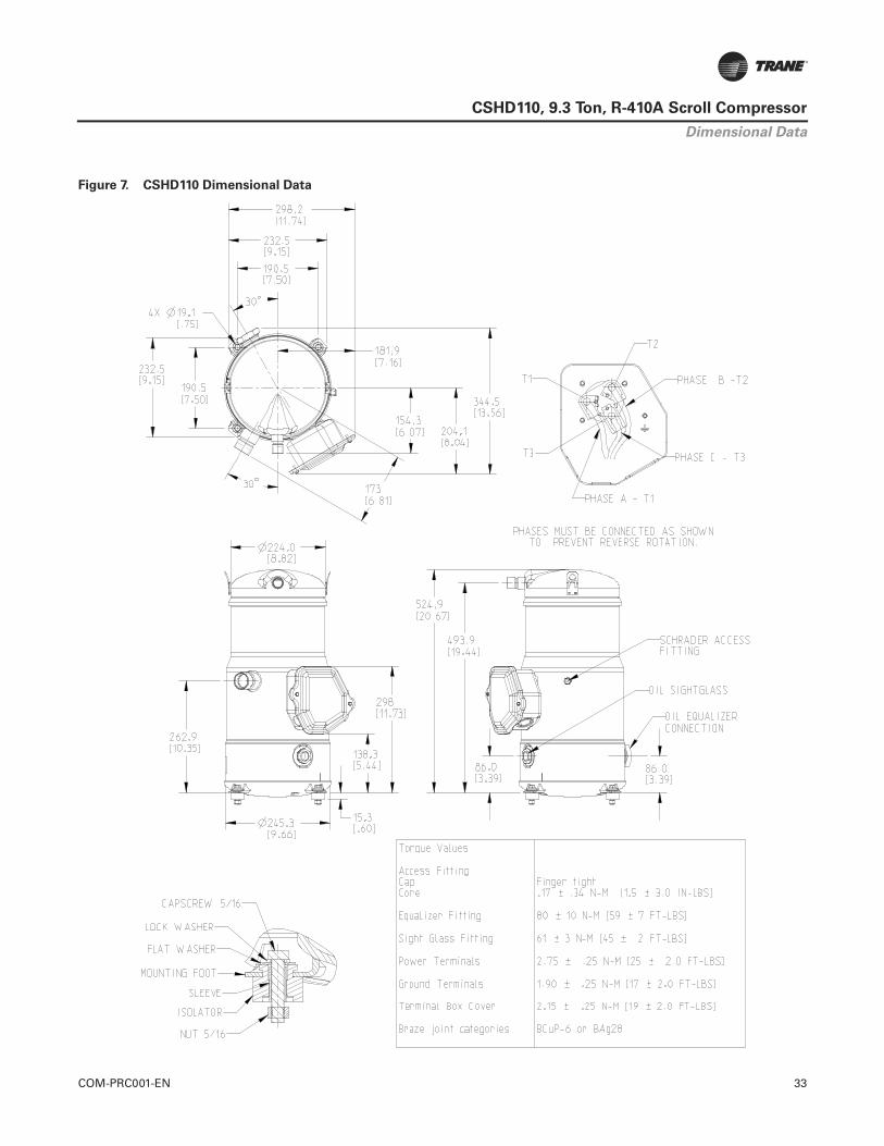
COM-PRC001-EN 33
CSHD110, 9.3 Ton, R-410A Scroll Compressor
Figure 7. CSHD110 Dimensional Data
Dimensional Data

34 COM-PRC001-EN
CSHD110, 9.3 Ton, R-410A Scroll Compressor
CSHD110 (9.3 Tons), Voltage: 200-60-3
Nominal performance values (+/-5%) based on a minimum 24 hour break-in. Subject to change without notice.All performance data shown is for R-410A refrigerant, 20°F SuperHeat, 15°F SubCooling.
Capacity - Btu/Hr
Cond. Temp °FEvaporating Temperature (°F)
-10 0 10 20 30 40 45 50 6080 44,844 56,397 70,773 88,037 108,236 131,403 144,104 157,550 186,66590 42,330 53,586 67,561 84,321 103,912 126,368 138,674 151,699 179,894
100 39,619 50,481 63,953 80,098 98,964 120,584 132,432 144,970 172,108110 36,723 47,100 59,969 75,393 93,421 114,085 125,410 137,396 163,344120 43,482 55,658 70,265 87,351 106,949 117,694 129,071 153,705130 51,082 64,786 80,840 99,275 109,390 120,104 143,316140 58,979 73,909 91,083 100,516 110,513 132,191150 66,367 82,133 90,805 100,004 119,971
Power - Watts
Cond. Temp °FEvaporating Temperature (°F)
-10 0 10 20 30 40 45 50 6080 5,649 5,763 5,857 5,932 5,988 6,024 6,035 6,041 6,03890 6,180 6,278 6,370 6,456 6,537 6,611 6,646 6,680 6,743
100 6,876 6,947 7,025 7,112 7,206 7,307 7,361 7,417 7,534110 7,737 7,769 7,823 7,898 7,995 8,113 8,180 8,252 8,413120 8,745 8,763 8,817 8,905 9,028 9,102 9,186 9,379130 9,846 9,866 9,935 10,052 10,129 10,218 10,432140 11,047 11,085 11,185 11,259 11,347 11,572150 12,356 12,428 12,492 12,576 12,799
Current - Amps @ 200V
Cond. Temp °FEvaporating Temperature (°F)
-10 0 10 20 30 40 45 50 6080 25.2 25.6 25.9 26.2 26.6 26.9 27.1 27.3 27.690 26.3 26.7 27.0 27.3 27.7 28.0 28.2 28.3 28.6
100 27.8 28.2 28.5 28.9 29.2 29.5 29.6 29.8 30.1110 29.7 30.1 30.4 30.8 31.1 31.4 31.5 31.7 32.0120 32.4 32.7 33.1 33.4 33.7 33.9 34.0 34.3130 35.5 35.8 36.1 36.4 36.6 36.7 37.0140 38.9 39.3 39.6 39.7 39.9 40.1150 42.8 43.1 43.3 43.4 43.7
Refrigerant Flow - Lbs/Hr
Cond. Temp °FEvaporating Temperature (°F)
-10 0 10 20 30 40 45 50 6080 537 666 826 1,015 1,234 1,483 1,619 1,762 2,07090 532 664 826 1,018 1,240 1,492 1,629 1,774 2,086
100 525 659 823 1,017 1,242 1,496 1,635 1,781 2,095110 516 651 816 1,012 1,238 1,494 1,634 1,781 2,097120 640 806 1,003 1,230 1,487 1,627 1,775 2,092130 793 989 1,217 1,474 1,614 1,762 2,080140 971 1,198 1,456 1,596 1,743 2,061150 1,175 1,431 1,571 1,718 2,035
EER - Btu/Hr/Watt-Hr
Cond. Temp °FEvaporating Temperature (°F)
-10 0 10 20 30 40 45 50 6080 7.94 9.79 12.08 14.84 18.08 21.81 23.88 26.08 30.9190 6.85 8.54 10.61 13.06 15.90 19.11 20.87 22.71 26.68
100 5.76 7.27 9.10 11.26 13.73 16.50 17.99 19.55 22.84110 4.75 6.06 7.67 9.55 11.68 14.06 15.33 16.65 19.42120 4.97 6.35 7.97 9.81 11.85 12.93 14.05 16.39130 5.19 6.57 8.14 9.88 10.80 11.75 13.74140 5.34 6.67 8.14 8.93 9.74 11.42150 5.37 6.61 7.27 7.95 9.37
20° SuperHeat, 15° SubCooling

COM-PRC001-EN 35
CSHD110, 9.3 Ton, R-410A Scroll Compressor
CSHD110 (9.3 Tons), Voltage: 230-60-3
Nominal performance values (+/-5%) based on a minimum 24 hour break-in. Subject to change without notice.All performance data shown is for R-410A refrigerant, 20°F SuperHeat, 15°F SubCooling.
Capacity - Btu/Hr
Cond. Temp °FEvaporating Temperature (°F)
-10 0 10 20 30 40 45 50 6080 45,354 57,037 71,577 89,037 109,466 132,897 145,742 159,340 188,78690 42,811 54,195 68,329 85,279 105,093 127,804 140,250 153,422 181,938
100 40,069 51,055 64,680 81,008 100,089 121,955 133,936 146,617 174,064110 37,140 47,635 60,650 76,249 94,482 115,381 126,835 138,958 165,201120 43,976 56,291 71,063 88,343 108,164 119,032 130,537 155,452130 51,662 65,523 81,758 100,403 110,633 121,468 144,944140 59,649 74,749 92,118 101,658 111,769 133,693150 67,121 83,066 91,837 101,140 121,335
Power - Watts
Cond. Temp °FEvaporating Temperature (°F)
-10 0 10 20 30 40 45 50 6080 5,692 5,807 5,902 5,978 6,034 6,070 6,081 6,087 6,08490 6,227 6,326 6,419 6,506 6,586 6,662 6,697 6,731 6,794
100 6,929 7,000 7,079 7,166 7,261 7,363 7,417 7,474 7,592110 7,796 7,828 7,883 7,959 8,056 8,175 8,242 8,315 8,477120 8,812 8,830 8,884 8,973 9,097 9,172 9,256 9,450130 9,921 9,942 10,011 10,129 10,206 10,296 10,511140 11,132 11,170 11,271 11,345 11,434 11,660150 12,450 12,523 12,588 12,672 12,897
Current - Amps @ 230V
Cond. Temp °FEvaporating Temperature (°F)
-10 0 10 20 30 40 45 50 6080 22.1 22.4 22.7 23.0 23.3 23.6 23.8 23.9 24.290 23.1 23.4 23.7 24.0 24.3 24.6 24.7 24.8 25.1
100 24.4 24.7 25.0 25.3 25.6 25.9 26.0 26.1 26.4110 26.1 26.4 26.7 27.0 27.3 27.5 27.7 27.8 28.0120 28.4 28.7 29.0 29.3 29.6 29.7 29.8 30.0130 31.1 31.4 31.7 31.9 32.1 32.2 32.4140 34.1 34.4 34.7 34.8 34.9 35.2150 37.5 37.8 37.9 38.1 38.3
Refrigerant Flow - Lbs/Hr
Cond. Temp °FEvaporating Temperature (°F)
-10 0 10 20 30 40 45 50 6080 543 674 835 1,026 1,248 1,500 1,637 1,782 2,09490 538 671 835 1,030 1,254 1,509 1,648 1,794 2,110
100 531 666 832 1,029 1,256 1,513 1,653 1,801 2,119110 521 658 826 1,024 1,252 1,511 1,652 1,801 2,121120 647 816 1,014 1,244 1,504 1,646 1,795 2,116130 802 1,001 1,231 1,491 1,633 1,782 2,104140 982 1,212 1,472 1,614 1,763 2,085150 1,188 1,447 1,588 1,737 2,058
EER - Btu/Hr/Watt-Hr
Cond. Temp °FEvaporating Temperature (°F)
-10 0 10 20 30 40 45 50 6080 7.97 9.82 12.13 14.90 18.14 21.89 23.97 26.18 31.0390 6.87 8.57 10.65 13.11 15.96 19.19 20.94 22.79 26.78
100 5.78 7.29 9.14 11.30 13.79 16.56 18.06 19.62 22.93110 4.76 6.08 7.69 9.58 11.73 14.11 15.39 16.71 19.49120 4.99 6.37 8.00 9.85 11.89 12.98 14.10 16.45130 5.21 6.59 8.17 9.91 10.84 11.80 13.79140 5.36 6.69 8.17 8.96 9.78 11.47150 5.39 6.63 7.30 7.98 9.41
20° SuperHeat, 15° SubCooling

36 COM-PRC001-EN
CSHD110, 9.3 Ton, R-410A Scroll Compressor
CSHD110 (9.3 Tons), Voltage: 400-50-3
Nominal performance values (+/-5%) based on a minimum 24 hour break-in. Subject to change without notice.All performance data shown is for R-410A refrigerant, 20°F SuperHeat, 15°F SubCooling.
Capacity - Btu/Hr
Cond. Temp °FEvaporating Temperature (°F)
-10 0 10 20 30 40 45 50 6080 33,788 43,720 56,423 71,896 90,138 111,151 122,696 134,934 161,48890 32,854 42,494 54,728 69,555 86,975 106,988 117,968 129,596 154,796
100 31,282 40,557 52,249 66,356 82,881 101,821 112,198 123,179 146,954110 38,137 49,213 62,528 78,083 95,878 105,615 115,912 138,187120 45,848 58,297 72,809 89,384 98,446 108,023 128,724130 53,891 67,287 82,569 90,918 99,738 118,793140 61,743 75,659 83,258 91,285 108,620150 68,882 75,695 82,892 98,434
Power - Watts
Cond. Temp °FEvaporating Temperature (°F)
-10 0 10 20 30 40 45 50 6080 4,593 4,653 4,725 4,809 4,905 5,011 5,069 5,130 5,26090 5,065 5,121 5,192 5,276 5,375 5,488 5,550 5,615 5,757
100 5,665 5,712 5,776 5,856 5,954 6,068 6,132 6,200 6,348110 6,425 6,478 6,550 6,642 6,754 6,817 6,885 7,036120 7,298 7,357 7,439 7,543 7,603 7,669 7,818130 8,278 8,345 8,437 8,492 8,554 8,696140 9,360 9,435 9,483 9,538 9,669150 10,538 10,576 10,623 10,738
Current - Amps @ 400V
Cond. Temp °FEvaporating Temperature (°F)
-10 0 10 20 30 40 45 50 6080 11.4 11.5 11.6 11.7 11.8 11.9 11.9 12.0 12.090 11.8 11.9 12.0 12.1 12.2 12.3 12.4 12.4 12.5
100 12.4 12.5 12.6 12.7 12.8 13.0 13.0 13.1 13.2110 13.2 13.4 13.5 13.6 13.7 13.8 13.8 14.0120 14.3 14.4 14.5 14.6 14.7 14.8 14.9130 15.5 15.6 15.7 15.8 15.8 16.0140 16.8 16.9 17.0 17.0 17.1150 18.3 18.3 18.4 18.5
Refrigerant Flow - Lbs/Hr
Cond. Temp °FEvaporating Temperature (°F)
-10 0 10 20 30 40 45 50 6080 405 516 658 828 1,027 1,254 1,378 1,508 1,79090 414 527 670 840 1,039 1,265 1,388 1,517 1,796
100 415 530 673 843 1,040 1,264 1,386 1,514 1,790110 527 670 839 1,034 1,256 1,376 1,502 1,773120 664 831 1,024 1,242 1,360 1,484 1,750130 823 1,012 1,226 1,341 1,463 1,723140 1,002 1,211 1,324 1,442 1,695150 1,200 1,309 1,424 1,670
EER - Btu/Hr/Watt-Hr
Cond. Temp °FEvaporating Temperature (°F)
-10 0 10 20 30 40 45 50 6080 7.36 9.40 11.94 14.95 18.38 22.18 24.20 26.30 30.7090 6.49 8.30 10.54 13.18 16.18 19.50 21.26 23.08 26.89
100 5.52 7.10 9.05 11.33 13.92 16.78 18.30 19.87 23.15110 5.94 7.60 9.55 11.76 14.20 15.49 16.84 19.64120 6.28 7.92 9.79 11.85 12.95 14.08 16.46130 6.51 8.06 9.79 10.71 11.66 13.66140 6.60 8.02 8.78 9.57 11.23150 6.54 7.16 7.80 9.17
20° SuperHeat, 15° SubCooling

COM-PRC001-EN 37
CSHD110, 9.3 Ton, R-410A Scroll Compressor
CSHD110 (9.3 Tons), Voltage: 460-60-3
Nominal performance values (+/-5%) based on a minimum 24 hour break-in. Subject to change without notice.All performance data shown is for R-410A refrigerant, 20°F SuperHeat, 15°F SubCooling.
Capacity - Btu/Hr
Cond. Temp °FEvaporating Temperature (°F)
-10 0 10 20 30 40 45 50 6080 45,620 57,372 71,997 89,559 110,108 133,676 146,597 160,275 189,89490 43,062 54,512 68,730 85,779 105,710 128,553 141,072 154,322 183,005
100 40,304 51,354 65,059 81,483 100,676 122,670 134,722 147,477 175,085110 37,358 47,915 61,006 76,696 95,036 116,058 127,579 139,773 166,170120 44,234 56,621 71,480 88,861 108,798 119,730 131,303 156,364130 51,965 65,907 82,238 100,992 111,282 122,181 145,795140 59,999 75,187 92,658 102,254 112,425 134,477150 53,604 67,515 83,553 92,376 101,734 122,046
Power - Watts
Cond. Temp °FEvaporating Temperature (°F)
-10 0 10 20 30 40 45 50 6080 5,668 5,782 5,877 5,952 6,008 6,044 6,055 6,061 6,05890 6,201 6,299 6,392 6,478 6,559 6,633 6,669 6,702 6,765
100 6,899 6,970 7,049 7,136 7,230 7,332 7,386 7,442 7,560110 7,763 7,795 7,849 7,925 8,022 8,140 8,207 8,280 8,441120 8,775 8,793 8,846 8,935 9,058 9,133 9,217 9,410130 9,879 9,899 9,968 10,086 10,163 10,252 10,467140 11,084 11,123 11,223 11,296 11,386 11,611150 12,401 12,398 12,470 12,534 12,618 12,842
Current - Amps @ 460V
Cond. Temp °FEvaporating Temperature (°F)
-10 0 10 20 30 40 45 50 6080 10.8 10.9 11.1 11.2 11.3 11.5 11.6 11.6 11.890 11.2 11.4 11.5 11.7 11.8 12.0 12.0 12.1 12.2
100 11.9 12.0 12.2 12.3 12.5 12.6 12.7 12.7 12.8110 12.7 12.8 13.0 13.1 13.3 13.4 13.5 13.5 13.6120 13.8 14.0 14.1 14.3 14.4 14.4 14.5 14.6130 15.1 15.3 15.4 15.5 15.6 15.7 15.8140 16.6 16.8 16.9 16.9 17.0 17.1150 18.1 18.3 18.4 18.5 18.5 18.6
Refrigerant Flow - Lbs/Hr
Cond. Temp °FEvaporating Temperature (°F)
-10 0 10 20 30 40 45 50 6080 546 678 840 1,032 1,255 1,509 1,647 1,792 2,10690 541 675 840 1,036 1,262 1,518 1,658 1,805 2,122
100 534 670 837 1,035 1,263 1,522 1,663 1,811 2,131110 525 662 831 1,030 1,260 1,520 1,662 1,812 2,133120 651 820 1,020 1,251 1,513 1,655 1,805 2,128130 806 1,007 1,238 1,500 1,642 1,793 2,116140 988 1,219 1,481 1,623 1,773 2,097150 965 1,195 1,456 1,598 1,747 2,070
EER - Btu/Hr/Watt-Hr
Cond. Temp °FEvaporating Temperature (°F)
-10 0 10 20 30 40 45 50 6080 8.05 9.92 12.25 15.05 18.33 22.12 24.21 26.44 31.3490 6.94 8.65 10.75 13.24 16.12 19.38 21.16 23.03 27.05
100 5.84 7.37 9.23 11.42 13.93 16.73 18.24 19.82 23.16110 4.81 6.15 7.77 9.68 11.85 14.26 15.54 16.88 19.69120 5.04 6.44 8.08 9.95 12.01 13.11 14.25 16.62130 5.26 6.66 8.25 10.01 10.95 11.92 13.93140 5.41 6.76 8.26 9.05 9.87 11.58150 4.32 5.45 6.70 7.37 8.06 9.50
20° SuperHeat, 15° SubCooling

38 COM-PRC001-EN
CSHD110, 9.3 Ton, R-410A Scroll Compressor
CSHD110 (9.3 Tons), Voltage: 575-60-3
Nominal performance values (+/-5%) based on a minimum 24 hour break-in. Subject to change without notice.All performance data shown is for R-410A refrigerant, 20°F SuperHeat, 15°F SubCooling.
Capacity - Btu/Hr
Cond. Temp °FEvaporating Temperature (°F)
-10 0 10 20 30 40 45 50 6080 45,620 57,372 71,997 89,559 110,108 133,676 146,597 160,275 189,89490 43,062 54,512 68,730 85,779 105,710 128,553 141,072 154,322 183,005
100 40,304 51,354 65,059 81,483 100,676 122,670 134,722 147,477 175,085110 37,358 47,915 61,006 76,696 95,036 116,058 127,579 139,773 166,170120 44,234 56,621 71,480 88,861 108,798 119,730 131,303 156,364130 51,965 65,907 82,238 100,992 111,282 122,181 145,795140 59,999 75,187 92,658 102,254 112,425 134,477150 53,604 67,515 83,553 92,376 101,734 122,046
Power - Watts
Cond. Temp °FEvaporating Temperature (°F)
-10 0 10 20 30 40 45 50 6080 5,668 5,782 5,877 5,952 6,008 6,044 6,055 6,061 6,05890 6,201 6,299 6,392 6,478 6,559 6,633 6,669 6,702 6,765
100 6,899 6,970 7,049 7,136 7,230 7,332 7,386 7,442 7,560110 7,763 7,795 7,849 7,925 8,022 8,140 8,207 8,280 8,441120 8,775 8,793 8,846 8,935 9,058 9,133 9,217 9,410130 9,879 9,899 9,968 10,086 10,163 10,252 10,467140 11,084 11,123 11,223 11,296 11,386 11,611150 12,401 12,398 12,470 12,534 12,618 12,842
Current - Amps @ 575V
Cond. Temp °FEvaporating Temperature (°F)
-10 0 10 20 30 40 45 50 6080 8.6 8.7 8.8 9.0 9.1 9.2 9.2 9.3 9.490 9.0 9.1 9.2 9.3 9.4 9.6 9.6 9.7 9.8
100 9.5 9.6 9.7 9.8 10.0 10.1 10.1 10.2 10.3110 10.1 10.3 10.4 10.5 10.6 10.7 10.8 10.8 10.9120 11.1 11.2 11.3 11.4 11.5 11.6 11.6 11.7130 12.1 12.2 12.3 12.4 12.5 12.5 12.6140 13.3 13.4 13.5 13.6 13.6 13.7150 14.5 14.6 14.7 14.8 14.8 14.9
Refrigerant Flow - Lbs/Hr
Cond. Temp °FEvaporating Temperature (°F)
-10 0 10 20 30 40 45 50 6080 546 678 840 1,032 1,255 1,509 1,647 1,792 2,10690 541 675 840 1,036 1,262 1,518 1,658 1,805 2,122
100 534 670 837 1,035 1,263 1,522 1,663 1,811 2,131110 525 662 831 1,030 1,260 1,520 1,662 1,812 2,133120 651 820 1,020 1,251 1,513 1,655 1,805 2,128130 806 1,007 1,238 1,500 1,642 1,793 2,116140 988 1,219 1,481 1,623 1,773 2,097150 965 1,195 1,456 1,598 1,747 2,070
EER - Btu/Hr/Watt-Hr
Cond. Temp °FEvaporating Temperature (°F)
-10 0 10 20 30 40 45 50 6080 8.05 9.92 12.25 15.05 18.33 22.12 24.21 26.44 31.3490 6.94 8.65 10.75 13.24 16.12 19.38 21.16 23.03 27.05
100 5.84 7.37 9.23 11.42 13.93 16.73 18.24 19.82 23.16110 4.81 6.15 7.77 9.68 11.85 14.26 15.54 16.88 19.69120 5.04 6.44 8.08 9.95 12.01 13.11 14.25 16.62130 5.26 6.66 8.25 10.01 10.95 11.92 13.93140 5.41 6.76 8.26 9.05 9.87 11.58150 4.32 5.45 6.70 7.37 8.06 9.50
20° SuperHeat, 15° SubCooling

COM-PRC001-EN 39
CSHD110, 9.3 Ton, R-410A Scroll CompressorTab
le 4
.C
SH
D110,
R-4
10A
(A
RI 10 C
oeff
icie
nts
, -2
0°F
Su
perh
eat/
15°F
Su
bco
olin
g)(
a)(
b)
Ap
pli
ed V
olt
age:
20
0-6
0-3
Co
effi
cien
tsC
1C
2C
3C
4C
5C
6C
7C
8C
9C
10
Cap
acit
y6.
3699
08E+
041.
1705
57E+
031.
1796
60E+
021.
9144
85E+
015.
7763
55E+
00-3
.093
468E
+00
5.07
6847
E-03
-5.9
9105
8E-0
2-5
.288
799E
-02
5.88
5317
E-03
Po
wer
7.17
0984
E+03
-2.2
1176
0E+
01-7
.903
620E
+01
-6.4
0530
1E-0
18.
4981
55E-
017.
6795
10E-
011.
3948
91E-
146.
7930
70E-
03-5
.540
140E
-03
1.82
8246
E-13
Am
ps
3.12
3377
E+01
4.25
6277
E-02
-2.3
2012
4E-0
11.
1881
62E-
04-1
.895
899E
-04
2.01
3598
E-03
-5.7
9400
8E-1
7-1
.664
994E
-06
1.14
3355
E-06
1.20
3310
E-16
Flo
w6.
0261
36E+
029.
8317
83E+
001.
5874
62E+
001.
4615
22E-
018.
4311
29E-
02-8
.382
959E
-03
-8.5
1069
4E-0
64.
8424
45E-
05-3
.356
693E
-04
-1.8
7166
7E-0
5
Ap
pli
ed V
olt
age:
23
0-6
0-3
Co
effi
cien
tsC
1C
2C
3C
4C
5C
6C
7C
8C
9C
10
Cap
acit
y6.
4422
90E+
041.
1838
58E+
031.
1930
65E+
021.
9362
39E+
015.
8419
92E+
00-3
.128
619E
+00
5.13
4536
E-03
-6.0
5913
4E-0
2-5
.348
896E
-02
5.95
2192
E-03
Po
wer
7.22
5706
E+03
-2.2
2863
8E+
01-7
.963
933E
+01
-6.4
5418
0E-0
18.
5630
05E-
017.
7381
12E-
01-3
.730
643E
-15
6.84
4908
E-03
-5.5
8241
7E-0
3-2
.765
664E
-13
Am
ps
2.73
8292
E+01
3.73
1514
E-02
-2.0
3407
2E-0
11.
0416
72E-
04-1
.662
151E
-04
1.76
5338
E-03
-3.4
8892
7E-1
7-1
.459
714E
-06
1.00
2390
E-06
-9.2
1845
9E-1
6
Flo
w6.
0946
12E+
029.
9435
02E+
001.
6055
01E+
001.
4781
29E-
018.
5269
32E-
02-8
.478
215E
-03
-8.6
0740
1E-0
64.
8974
70E-
05-3
.394
835E
-04
-1.8
9293
5E-0
5
Ap
pli
ed V
olt
age:
40
0-5
0-3
Co
effi
cien
tsC
1C
2C
3C
4C
5C
6C
7C
8C
9C
10
Cap
acit
y4.
7959
75E+
041.
2014
44E+
038.
2631
55E+
012.
0544
03E+
011.
7760
08E+
00-1
.916
951E
+00
4.47
1405
E-03
-8.7
7932
4E-0
2-3
.376
011E
-02
3.09
2862
E-03
Po
wer
5.32
0292
E+03
-7.0
1533
5E+
00-5
.736
174E
+01
-5.0
4945
4E-0
23.
5238
25E-
016.
1276
46E-
012.
2889
26E-
141.
3535
38E-
03-2
.270
798E
-03
4.40
7616
E-13
Am
ps
1.48
3874
E+01
-2.3
6410
4E-0
2-1
.151
754E
-01
-1.7
4868
2E-0
47.
5341
72E-
049.
1541
19E-
045.
5903
69E-
181.
6885
23E-
06-3
.945
359E
-06
1.07
2896
E-16
Flo
w4.
5051
28E+
028.
7798
62E+
001.
3599
07E+
001.
7597
89E-
017.
6548
15E-
02-6
.510
957E
-03
-2.3
5336
3E-0
5-4
.020
070E
-04
-3.6
0982
8E-0
42.
6296
18E-
06
Ap
pli
ed V
olt
age:
46
0-6
0-3
Co
effi
cien
tsC
1C
2C
3C
4C
5C
6C
7C
8C
9C
10
Cap
acit
y6.
4800
82E+
041.
1908
03E+
031.
2000
64E+
021.
9475
97E+
015.
8762
62E+
00-3
.146
972E
+00
5.16
4656
E-03
-6.0
9467
9E-0
2-5
.380
274E
-02
5.98
7109
E-03
Po
wer
7.19
5081
E+03
-2.2
1919
2E+
01-7
.930
179E
+01
-6.4
2682
5E-0
18.
5267
12E-
017.
7053
16E-
01-5
.005
591E
-15
6.81
5897
E-03
-5.5
5875
7E-0
32.
8381
09E-
13
Am
ps
1.33
2857
E+01
1.81
6306
E-02
-9.9
0080
2E-0
25.
0703
14E-
05-8
.090
482E
-05
8.59
2744
E-04
-1.2
2597
7E-1
8-7
.105
127E
-07
4.87
9109
E-07
4.32
9561
E-16
Flo
w6.
1303
64E+
021.
0001
83E+
011.
6149
19E+
001.
4868
00E-
018.
5769
53E-
02-8
.527
950E
-03
-8.6
5789
4E-0
64.
9261
99E-
05-3
.414
750E
-04
-1.9
0404
0E-0
5
Ap
pli
ed V
olt
age:
57
5-6
0-3
Co
effi
cien
tsC
1C
2C
3C
4C
5C
6C
7C
8C
9C
10
Cap
acit
y6.
4800
82E+
041.
1908
03E+
031.
2000
64E+
021.
9475
97E+
015.
8762
62E+
00-3
.146
972E
+00
5.16
4656
E-03
-6.0
9467
9E-0
2-5
.380
274E
-02
5.98
7109
E-03
Po
wer
7.19
5081
E+03
-2.2
1919
2E+
01-7
.930
179E
+01
-6.4
2682
5E-0
18.
5267
12E-
017.
7053
16E-
01-5
.005
591E
-15
6.81
5897
E-03
-5.5
5875
7E-0
32.
8381
09E-
13
Am
ps
1.06
6286
E+01
1.45
3045
E-02
-7.9
2064
1E-0
24.
0562
51E-
05-6
.472
386E
-05
6.87
4196
E-04
-9.8
0781
6E-1
9-5
.684
101E
-07
3.90
3287
E-07
3.46
3649
E-16
Flo
w6.
1303
64E+
021.
0001
83E+
011.
6149
19E+
001.
4868
00E-
018.
5769
53E-
02-8
.527
950E
-03
-8.6
5789
4E-0
64.
9261
99E-
05-3
.414
750E
-04
-1.9
0404
0E-0
5
(a)E
quat
ions
are
of
the
form
: Val
ue=
C1
+ C
2 *
Te +
C3
* Tc
+ C
4 *
Te^
2 +
C5
* Te
* T
c +
C6
* Tc
^2
+ C
7 *
Te^
3 +
C8
+ T
e^2
* Tc
+ C
9 *
Te *
Tc^
2 +
C10
*Tc
^3
(b)W
here
: Tc
= S
atur
ated
con
dens
ing
tem
pera
ture
(°F
) an
d Te
= S
atur
ated
con
dens
ing
tem
pera
ture
(°F
)
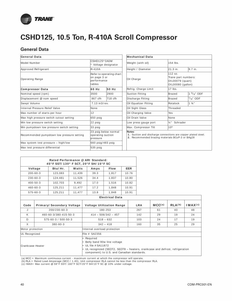
40 COM-PRC001-EN
CSHD125, 10.5 Ton, R-410A Scroll Compressor
General Data
General Data Mechanical Data
Model Number CSHD125*0A0M* Voltage designator
Weight (with oil) 154 lbs.
Approved Refrigerant R-410A Height / Diameter 21.3 in. 9.7 in.
Operating Range
Refer to operating chart on page 3 or performance tables
Oil Charge
112 oz. Trane part numbers:OIL00079 (quart)OIL00080 (gallon)
Compressor Data 60 Hz 50 Hz Refrig. Charge Limit 17 lbs.
Nominal speed (rpm) 3500 2900 Suction Fitting Brazed 1 3/8” ODF
Displacement @ nom speed 867 cfh 718 cfh Discharge Fitting Brazed 7/8” ODF
Swept Volume 7.13 in3/rev. Oil Equalizer Fitting Rotalock 1 ¾”
Internal Pressure Relief Valve None Oil Sight Glass Threaded
Max number of starts per hour 12 Oil Charging Valve Yes
Max high pressure switch cutout setting 650 psig Oil Drain Valve None
Min low pressure switch setting 22 psig Low press gauge port ¼” Schrader
Min pumpdown low pressure switch setting 33 psig Max. Compressor Tilt 10º
Recommended pumpdown low pressure setting23 psig below normal operating suction pressure
Notes:
1. Suction and discharge connections are copper plated steel. 2. Recommended brazing materials BCuP-3 or BAg28
Max system test pressure – high/low 660 psig/483 psig
Max test pressure differential 535 psig
Rated Performance @ ARI Standard:45ºF SST/130º F SCT, 20ºF SH/15ºF SC
Voltage Btu/Hr. Watts Amps Flow EER200-60-3 123,083 11,439 39.3 1,817 10.76
230-60-3 124,481 11,526 34.4 1,837 10.80
400-50-3 102,703 9,492 17.0 1,516 10.82
460-60-3 125,211 11,477 17.2 1,848 10.91
575-60-3 125,211 11,477 13.8 1,848 10.91
Electrical Data
Code Primary/Secondary Voltage Voltage Utilization Range LRA MCC(a) RLA(b) IMAX(c)
J 200/230-60-3 180-253 267 61 43 48
K 460-60-3/380-415-50-3 414 – 506/342 – 457 142 29 19 24
D 575-60-3 / 500-50-3 518 – 632 103 24 17 19
X 380-60-3 342 – 418 160 35 25 29
Motor protection Internal overload protection
UL Recognized File # SA2356
Crankcase Heater
• Required• Belly band 90w line voltage • UL file #SA11872• UL recognized (SEOT2, SEOT8 – heaters, crankcase and defrost, refrigeration
component) to U.S. and Canadian standards.
(a) MCC = Maximum continuous current - maximum current at which the compressor will operate.(b) RLA = Rated Load Amperage (MCC / 1.40). Unit compressor RLA cannot be less than the compressor RLA.(c) IMAX= Max current @ 59°F SST/ 160°F SCT/20°F SH/15°F SC @ 10% under voltage.

COM-PRC001-EN 41
CSHD125, 10.5 Ton, R-410A Scroll Compressor
Figure 8. CSHD125 Dimensional Data
Dimensional Data

42 COM-PRC001-EN
CSHD125, 10.5 Ton, R-410A Scroll Compressor
CSHD125 (10.5 Tons), Voltage: 200-60-3
Nominal performance values (+/-5%) based on a minimum 24 hour break-in. Subject to change without notice.All performance data shown is for R-410A refrigerant, 20°F SuperHeat, 15°F SubCooling.
Capacity - Btu/Hr
Cond. Temp °FEvaporating Temperature (°F)
-10 0 10 20 30 40 45 50 6080 49,594 63,016 79,794 99,997 123,673 150,851 165,756 181,537 215,70890 46,938 59,964 76,163 95,601 118,326 144,365 158,630 173,724 206,378
100 43,782 56,364 71,935 90,560 112,285 137,136 150,736 165,117 196,205110 40,192 52,278 67,168 84,926 105,596 129,204 142,112 155,753 185,218120 47,794 61,952 78,790 98,354 120,667 132,856 145,731 173,522130 56,385 72,256 90,665 111,636 123,083 135,169 161,241140 65,368 82,563 102,132 112,808 124,076 148,370150 73,844 91,885 101,723 112,105 134,480
Power - Watts
Cond. Temp °FEvaporating Temperature (°F)
-10 0 10 20 30 40 45 50 6080 6,096 6,211 6,350 6,512 6,699 6,910 7,025 7,145 7,40490 6,709 6,821 6,958 7,118 7,302 7,511 7,624 7,742 7,998
100 7,505 7,608 7,734 7,885 8,059 8,257 8,364 8,478 8,723110 8,484 8,570 8,679 8,812 8,969 9,149 9,247 9,352 9,579120 9,707 9,792 9,900 10,032 10,186 10,272 10,364 10,565130 11,073 11,149 11,248 11,369 11,439 11,514 11,682140 12,558 12,617 12,698 12,748 12,803 12,930150 14,139 14,173 14,198 14,229 14,308
Current - Amps @ 200V
Cond. Temp °FEvaporating Temperature (°F)
-10 0 10 20 30 40 45 50 6080 26.1 26.4 26.7 27.0 27.3 27.5 27.6 27.7 27.990 27.2 27.6 28.0 28.3 28.7 29.0 29.2 29.3 29.7
100 29.0 29.3 29.7 30.1 30.5 30.9 31.1 31.3 31.7110 31.3 31.7 32.0 32.4 32.8 33.2 33.4 33.6 34.1120 34.6 34.9 35.2 35.6 35.9 36.1 36.4 36.8130 38.2 38.5 38.7 39.1 39.3 39.4 39.9140 42.2 42.4 42.6 42.7 42.9 43.2150 46.5 46.6 46.6 46.7 46.9
Refrigerant Flow - Lbs/Hr
Cond. Temp °FEvaporating Temperature (°F)
-10 0 10 20 30 40 45 50 6080 594 745 931 1,153 1,410 1,702 1,862 2,030 2,39290 590 743 931 1,154 1,412 1,705 1,864 2,032 2,393
100 580 736 926 1,150 1,409 1,701 1,861 2,028 2,388110 564 722 914 1,140 1,400 1,693 1,851 2,019 2,378120 704 898 1,125 1,385 1,678 1,837 2,004 2,362130 875 1,104 1,365 1,658 1,817 1,983 2,341140 1,077 1,339 1,632 1,791 1,957 2,314150 1,307 1,601 1,759 1,926 2,281
EER - Btu/Hr/Watt-Hr
Cond. Temp °FEvaporating Temperature (°F)
-10 0 10 20 30 40 45 50 6080 8.14 10.15 12.57 15.36 18.46 21.83 23.60 25.41 29.1390 7.00 8.79 10.95 13.43 16.20 19.22 20.81 22.44 25.80
100 5.83 7.41 9.30 11.49 13.93 16.61 18.02 19.48 22.49110 4.74 6.10 7.74 9.64 11.77 14.12 15.37 16.65 19.34120 4.92 6.33 7.96 9.80 11.85 12.93 14.06 16.42130 5.09 6.48 8.06 9.82 10.76 11.74 13.80140 5.21 6.54 8.04 8.85 9.69 11.47150 5.22 6.48 7.16 7.88 9.40
20° SuperHeat, 15° SubCooling
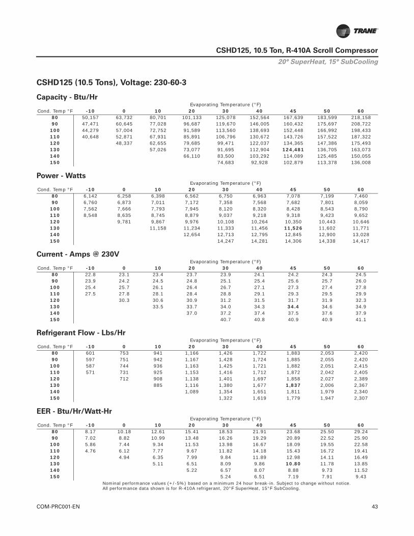
COM-PRC001-EN 43
CSHD125, 10.5 Ton, R-410A Scroll Compressor
CSHD125 (10.5 Tons), Voltage: 230-60-3
Nominal performance values (+/-5%) based on a minimum 24 hour break-in. Subject to change without notice.All performance data shown is for R-410A refrigerant, 20°F SuperHeat, 15°F SubCooling.
Capacity - Btu/Hr
Cond. Temp °FEvaporating Temperature (°F)
-10 0 10 20 30 40 45 50 6080 50,157 63,732 80,701 101,133 125,078 152,564 167,639 183,599 218,15890 47,471 60,645 77,028 96,687 119,670 146,005 160,432 175,697 208,722
100 44,279 57,004 72,752 91,589 113,560 138,693 152,448 166,992 198,433110 40,648 52,871 67,931 85,891 106,796 130,672 143,726 157,522 187,322120 48,337 62,655 79,685 99,471 122,037 134,365 147,386 175,493130 57,026 73,077 91,695 112,904 124,481 136,705 163,073140 66,110 83,500 103,292 114,089 125,485 150,055150 74,683 92,928 102,879 113,378 136,008
Power - Watts
Cond. Temp °FEvaporating Temperature (°F)
-10 0 10 20 30 40 45 50 6080 6,142 6,258 6,398 6,562 6,750 6,963 7,078 7,199 7,46090 6,760 6,873 7,011 7,172 7,358 7,568 7,682 7,801 8,059
100 7,562 7,666 7,793 7,945 8,120 8,320 8,428 8,543 8,790110 8,548 8,635 8,745 8,879 9,037 9,218 9,318 9,423 9,652120 9,781 9,867 9,976 10,108 10,264 10,350 10,443 10,646130 11,158 11,234 11,333 11,456 11,526 11,602 11,771140 12,654 12,713 12,795 12,845 12,900 13,028150 14,247 14,281 14,306 14,338 14,417
Current - Amps @ 230V
Cond. Temp °FEvaporating Temperature (°F)
-10 0 10 20 30 40 45 50 6080 22.8 23.1 23.4 23.7 23.9 24.1 24.2 24.3 24.590 23.9 24.2 24.5 24.8 25.1 25.4 25.6 25.7 26.0
100 25.4 25.7 26.1 26.4 26.7 27.1 27.3 27.4 27.8110 27.5 27.8 28.1 28.4 28.8 29.1 29.3 29.5 29.9120 30.3 30.6 30.9 31.2 31.5 31.7 31.9 32.3130 33.5 33.7 34.0 34.3 34.4 34.6 34.9140 37.0 37.2 37.4 37.5 37.6 37.9150 40.7 40.8 40.9 40.9 41.1
Refrigerant Flow - Lbs/Hr
Cond. Temp °FEvaporating Temperature (°F)
-10 0 10 20 30 40 45 50 6080 601 753 941 1,166 1,426 1,722 1,883 2,053 2,42090 597 751 942 1,167 1,428 1,724 1,885 2,055 2,420
100 587 744 936 1,163 1,425 1,721 1,882 2,051 2,415110 571 731 925 1,153 1,416 1,712 1,872 2,042 2,405120 712 908 1,138 1,401 1,697 1,858 2,027 2,389130 885 1,116 1,380 1,677 1,837 2,006 2,367140 1,089 1,354 1,651 1,811 1,979 2,340150 1,322 1,619 1,779 1,947 2,307
EER - Btu/Hr/Watt-Hr
Cond. Temp °FEvaporating Temperature (°F)
-10 0 10 20 30 40 45 50 6080 8.17 10.18 12.61 15.41 18.53 21.91 23.68 25.50 29.2490 7.02 8.82 10.99 13.48 16.26 19.29 20.89 22.52 25.90
100 5.86 7.44 9.34 11.53 13.98 16.67 18.09 19.55 22.58110 4.76 6.12 7.77 9.67 11.82 14.18 15.43 16.72 19.41120 4.94 6.35 7.99 9.84 11.89 12.98 14.11 16.49130 5.11 6.51 8.09 9.86 10.80 11.78 13.85140 5.22 6.57 8.07 8.88 9.73 11.52150 5.24 6.51 7.19 7.91 9.43
20° SuperHeat, 15° SubCooling

44 COM-PRC001-EN
CSHD125, 10.5 Ton, R-410A Scroll Compressor
CSHD125 (10.5 Tons), Voltage: 400-50-3
Nominal performance values (+/-5%) based on a minimum 24 hour break-in. Subject to change without notice.All performance data shown is for R-410A refrigerant, 20°F SuperHeat, 15°F SubCooling.
Capacity - Btu/Hr
Cond. Temp °FEvaporating Temperature (°F)
-10 0 10 20 30 40 45 50 6080 42,027 53,509 67,836 85,068 105,250 128,411 141,111 154,558 183,67690 39,223 50,297 64,079 80,628 99,989 122,190 134,359 147,238 175,119
100 36,304 46,906 60,076 75,872 94,338 115,502 127,099 139,372 165,932110 33,283 43,352 55,844 70,818 88,317 108,369 119,355 130,980 156,136120 39,672 51,427 65,517 81,983 100,854 111,194 122,137 145,816130 46,875 60,028 75,406 93,039 102,703 112,932 135,072140 54,360 68,593 84,925 93,882 103,365 123,898150 61,352 76,274 84,464 93,140 111,937
Power - Watts
Cond. Temp °FEvaporating Temperature (°F)
-10 0 10 20 30 40 45 50 6080 4,980 5,097 5,203 5,297 5,380 5,451 5,482 5,510 5,55790 5,515 5,633 5,742 5,842 5,933 6,014 6,052 6,087 6,150
100 6,191 6,305 6,413 6,514 6,608 6,696 6,737 6,777 6,852110 7,009 7,115 7,216 7,314 7,407 7,496 7,540 7,582 7,663120 8,061 8,152 8,241 8,329 8,415 8,458 8,500 8,583130 9,219 9,296 9,373 9,452 9,492 9,532 9,613140 10,478 10,541 10,608 10,642 10,678 10,752150 11,832 11,882 11,909 11,937 12,000
Current - Amps @ 400V
Cond. Temp °FEvaporating Temperature (°F)
-10 0 10 20 30 40 45 50 6080 12.0 12.1 12.1 12.2 12.3 12.3 12.4 12.4 12.590 12.5 12.6 12.7 12.7 12.8 12.9 12.9 13.0 13.0
100 13.2 13.3 13.4 13.5 13.6 13.6 13.7 13.7 13.8110 14.1 14.2 14.3 14.4 14.5 14.6 14.6 14.6 14.7120 15.2 15.3 15.5 15.6 15.7 15.7 15.7 15.8130 16.6 16.7 16.8 16.9 17.0 17.0 17.1140 18.2 18.3 18.4 18.4 18.5 18.6150 19.9 20.0 20.1 20.1 20.2
Refrigerant Flow - Lbs/Hr
Cond. Temp °FEvaporating Temperature (°F)
-10 0 10 20 30 40 45 50 6080 503 632 791 981 1,200 1,449 1,585 1,728 2,03790 493 623 783 974 1,193 1,443 1,579 1,722 2,031
100 481 612 773 964 1,184 1,433 1,569 1,712 2,020110 467 599 760 951 1,171 1,420 1,555 1,698 2,004120 584 745 935 1,154 1,403 1,537 1,679 1,985130 727 917 1,135 1,382 1,516 1,657 1,961140 895 1,112 1,357 1,490 1,631 1,932150 1,086 1,329 1,461 1,600 1,899
EER - Btu/Hr/Watt-Hr
Cond. Temp °FEvaporating Temperature (°F)
-10 0 10 20 30 40 45 50 6080 8.44 10.50 13.04 16.06 19.56 23.56 25.74 28.05 33.0590 7.11 8.93 11.16 13.80 16.85 20.32 22.20 24.19 28.48
100 5.86 7.44 9.37 11.65 14.28 17.25 18.86 20.56 24.22110 4.75 6.09 7.74 9.68 11.92 14.46 15.83 17.28 20.38120 4.92 6.31 7.95 9.84 11.98 13.15 14.37 16.99130 5.08 6.46 8.04 9.84 10.82 11.85 14.05140 5.19 6.51 8.01 8.82 9.68 11.52150 5.19 6.42 7.09 7.80 9.33
20° SuperHeat, 15° SubCooling

COM-PRC001-EN 45
CSHD125, 10.5 Ton, R-410A Scroll Compressor
CSHD125 (10.5 Tons), Voltage: 460-60-3
Nominal performance values (+/-5%) based on a minimum 24 hour break-in. Subject to change without notice.All performance data shown is for R-410A refrigerant, 20°F SuperHeat, 15°F SubCooling.
Capacity - Btu/Hr
Cond. Temp °FEvaporating Temperature (°F)
-10 0 10 20 30 40 45 50 6080 50,451 64,105 81,174 101,726 125,811 153,459 168,622 184,675 219,43790 47,750 61,001 77,480 97,254 120,372 146,861 161,373 176,727 209,946
100 44,539 57,338 73,179 92,126 114,226 139,507 153,342 167,972 199,597110 40,887 53,181 68,330 86,394 107,422 131,438 144,569 158,446 188,420120 48,620 63,023 80,152 100,054 122,753 135,153 148,251 176,522130 57,360 73,505 92,232 113,566 125,211 137,506 164,029140 66,498 83,990 103,898 114,758 126,221 150,935150 75,121 93,473 103,482 114,043 136,805
Power - Watts
Cond. Temp °FEvaporating Temperature (°F)
-10 0 10 20 30 40 45 50 6080 6,116 6,231 6,370 6,534 6,721 6,933 7,048 7,169 7,42890 6,731 6,844 6,981 7,142 7,327 7,535 7,649 7,768 8,025
100 7,529 7,633 7,760 7,911 8,086 8,284 8,392 8,506 8,752110 8,512 8,598 8,708 8,841 8,998 9,179 9,278 9,383 9,610120 9,739 9,824 9,933 10,065 10,220 10,306 10,398 10,600130 11,110 11,186 11,285 11,407 11,477 11,552 11,721140 12,600 12,659 12,740 12,790 12,845 12,973150 14,186 14,220 14,245 14,276 14,356
Current - Amps @ 460V
Cond. Temp °FEvaporating Temperature (°F)
-10 0 10 20 30 40 45 50 6080 11.4 11.6 11.7 11.9 12.0 12.1 12.1 12.2 12.390 11.9 12.1 12.3 12.4 12.6 12.7 12.8 12.9 13.0
100 12.7 12.9 13.1 13.2 13.4 13.6 13.7 13.7 13.9110 13.8 13.9 14.1 14.2 14.4 14.6 14.7 14.8 15.0120 15.2 15.3 15.4 15.6 15.8 15.9 16.0 16.2130 16.8 16.9 17.0 17.2 17.2 17.3 17.5140 18.5 18.6 18.7 18.8 18.8 19.0150 20.4 20.4 20.5 20.5 20.6
Refrigerant Flow - Lbs/Hr
Cond. Temp °FEvaporating Temperature (°F)
-10 0 10 20 30 40 45 50 6080 604 757 947 1,173 1,434 1,732 1,894 2,065 2,43490 600 756 947 1,174 1,437 1,734 1,896 2,067 2,434
100 590 748 942 1,170 1,433 1,731 1,893 2,063 2,430110 574 735 930 1,160 1,424 1,722 1,883 2,054 2,419120 716 913 1,144 1,409 1,707 1,869 2,038 2,403130 890 1,123 1,388 1,687 1,848 2,018 2,381140 1,095 1,362 1,660 1,822 1,991 2,354150 1,329 1,628 1,790 1,959 2,320
EER - Btu/Hr/Watt-Hr
Cond. Temp °FEvaporating Temperature (°F)
-10 0 10 20 30 40 45 50 6080 8.25 10.29 12.74 15.57 18.72 22.13 23.93 25.76 29.5490 7.09 8.91 11.10 13.62 16.43 19.49 21.10 22.75 26.16
100 5.92 7.51 9.43 11.65 14.13 16.84 18.27 19.75 22.81110 4.80 6.19 7.85 9.77 11.94 14.32 15.58 16.89 19.61120 4.99 6.41 8.07 9.94 12.01 13.11 14.26 16.65130 5.16 6.57 8.17 9.96 10.91 11.90 13.99140 5.28 6.64 8.16 8.97 9.83 11.63150 5.30 6.57 7.26 7.99 9.53
20° SuperHeat, 15° SubCooling

46 COM-PRC001-EN
CSHD125, 10.5 Ton, R-410A Scroll Compressor
CSHD125 (10.5 Tons), Voltage: 575-60-3
Nominal performance values (+/-5%) based on a minimum 24 hour break-in. Subject to change without notice.All performance data shown is for R-410A refrigerant, 20°F SuperHeat, 15°F SubCooling.
Capacity - Btu/Hr
Cond. Temp °FEvaporating Temperature (°F)
-10 0 10 20 30 40 45 50 6080 50,451 64,105 81,174 101,726 125,811 153,459 168,622 184,675 219,43790 47,750 61,001 77,480 97,254 120,372 146,861 161,373 176,727 209,946
100 44,539 57,338 73,179 92,126 114,226 139,507 153,342 167,972 199,597110 40,887 53,181 68,330 86,394 107,422 131,438 144,569 158,446 188,420120 48,620 63,023 80,152 100,054 122,753 135,153 148,251 176,522130 57,360 73,505 92,232 113,566 125,211 137,506 164,029140 66,498 83,990 103,898 114,758 126,221 150,935150 75,121 93,473 103,482 114,043 136,805
Power - Watts
Cond. Temp °FEvaporating Temperature (°F)
-10 0 10 20 30 40 45 50 6080 6,116 6,231 6,370 6,534 6,721 6,933 7,048 7,169 7,42890 6,731 6,844 6,981 7,142 7,327 7,535 7,649 7,768 8,025
100 7,529 7,633 7,760 7,911 8,086 8,284 8,392 8,506 8,752110 8,512 8,598 8,708 8,841 8,998 9,179 9,278 9,383 9,610120 9,739 9,824 9,933 10,065 10,220 10,306 10,398 10,600130 11,110 11,186 11,285 11,407 11,477 11,552 11,721140 12,600 12,659 12,740 12,790 12,845 12,973150 14,186 14,220 14,245 14,276 14,356
Current - Amps @ 575V
Cond. Temp °FEvaporating Temperature (°F)
-10 0 10 20 30 40 45 50 6080 9.2 9.3 9.4 9.5 9.6 9.7 9.7 9.7 9.890 9.6 9.7 9.8 9.9 10.1 10.2 10.2 10.3 10.4
100 10.2 10.3 10.4 10.6 10.7 10.9 10.9 11.0 11.1110 11.0 11.1 11.2 11.4 11.5 11.7 11.7 11.8 12.0120 12.1 12.2 12.4 12.5 12.6 12.7 12.8 12.9130 13.4 13.5 13.6 13.7 13.8 13.9 14.0140 14.8 14.9 15.0 15.0 15.1 15.2150 16.3 16.3 16.4 16.4 16.5
Refrigerant Flow - Lbs/Hr
Cond. Temp °FEvaporating Temperature (°F)
-10 0 10 20 30 40 45 50 6080 604 757 947 1,173 1,434 1,732 1,894 2,065 2,43490 600 756 947 1,174 1,437 1,734 1,896 2,067 2,434
100 590 748 942 1,170 1,433 1,731 1,893 2,063 2,430110 574 735 930 1,160 1,424 1,722 1,883 2,054 2,419120 716 913 1,144 1,409 1,707 1,869 2,038 2,403130 890 1,123 1,388 1,687 1,848 2,018 2,381140 1,095 1,362 1,660 1,822 1,991 2,354150 1,329 1,628 1,790 1,959 2,320
EER - Btu/Hr/Watt-Hr
Cond. Temp °FEvaporating Temperature (°F)
-10 0 10 20 30 40 45 50 6080 8.25 10.29 12.74 15.57 18.72 22.13 23.93 25.76 29.5490 7.09 8.91 11.10 13.62 16.43 19.49 21.10 22.75 26.16
100 5.92 7.51 9.43 11.65 14.13 16.84 18.27 19.75 22.81110 4.80 6.19 7.85 9.77 11.94 14.32 15.58 16.89 19.61120 4.99 6.41 8.07 9.94 12.01 13.11 14.26 16.65130 5.16 6.57 8.17 9.96 10.91 11.90 13.99140 5.28 6.64 8.16 8.97 9.83 11.63150 5.30 6.57 7.26 7.99 9.53
20° SuperHeat, 15° SubCooling

COM-PRC001-EN 47
CSHD125, 10.5 Ton, R-410A Scroll CompressorTab
le 5
.C
SH
D125,
R-4
10A
(A
RI 10 C
oeff
icie
nts
, -2
0°F
Su
perh
eat/
15°F
Su
bco
olin
g)(
a)(
b)
Ap
pli
ed V
olt
age:
20
0-6
0-3
Co
effi
cien
tsC
1C
2C
3C
4C
5C
6C
7C
8C
9C
10
Cap
acit
y6.
4343
20E+
041.
6896
71E+
033.
0298
48E+
022.
4456
04E+
012.
7878
98E-
03-4
.636
346E
+00
5.11
1052
E-03
-9.3
8612
1E-0
2-2
.800
268E
-02
8.04
2922
E-03
Po
wer
7.65
0862
E+03
-1.2
6063
6E+
01-8
.827
695E
+01
1.28
0649
E-01
6.15
8848
E-01
8.78
4485
E-01
1.63
4659
E-14
-9.7
5365
0E-0
5-3
.748
838E
-03
8.95
4964
E-15
Am
ps
3.71
9443
E+01
-1.4
8727
3E-0
1-3
.610
811E
-01
-6.2
0745
0E-0
43.
8280
74E-
032.
8261
68E-
03-6
.006
623E
-18
6.42
0609
E-06
-1.9
5935
0E-0
5-2
.274
260E
-16
Flo
w5.
5108
70E+
021.
5260
75E+
014.
7049
16E+
002.
0249
93E-
011.
8175
20E-
02-2
.848
629E
-02
-2.7
3548
8E-0
5-2
.990
063E
-04
2.08
4613
E-05
-1.1
2992
8E-0
6
Ap
pli
ed V
olt
age:
23
0-6
0-3
Co
effi
cien
tsC
1C
2C
3C
4C
5C
6C
7C
8C
9C
10
Cap
acit
y6.
5074
02E+
041.
7088
62E+
033.
0642
62E+
022.
4733
82E+
012.
8195
63E-
03-4
.689
006E
+00
5.16
9104
E-03
-9.4
9273
0E-0
2-2
.832
074E
-02
8.13
4275
E-03
Po
wer
7.70
9103
E+03
-1.2
7023
2E+
01-8
.894
895E
+01
1.29
0398
E-01
6.20
5731
E-01
8.85
1356
E-01
9.90
0803
E-15
-9.8
2789
9E-0
5-3
.777
375E
-03
8.49
8582
E-14
Am
ps
3.26
0791
E+01
-1.3
0387
5E-0
1-3
.165
554E
-01
-5.4
4199
6E-0
43.
3560
26E-
032.
4776
68E-
03-5
.915
811E
-17
5.62
8870
E-06
-1.7
1773
9E-0
5-1
.376
282E
-16
Flo
w5.
5734
63E+
021.
5434
08E+
014.
7583
56E+
002.
0479
93E-
011.
8381
63E-
02-2
.880
984E
-02
-2.7
6655
8E-0
5-3
.024
025E
-04
2.10
8290
E-05
-1.1
4276
2E-0
6
Ap
pli
ed V
olt
age:
40
0-5
0-3
Co
effi
cien
tsC
1C
2C
3C
4C
5C
6C
7C
8C
9C
10
Cap
acit
y7.
0775
45E+
041.
4192
31E+
03-9
.675
515E
+01
2.02
2252
E+01
1.07
8857
E+00
-1.7
6941
4E+
004.
8296
91E-
03-7
.285
972E
-02
-3.3
6623
4E-0
23.
4692
50E-
03
Po
wer
5.74
0001
E+03
-6.9
1004
1E+
00-6
.278
485E
+01
-1.6
1482
4E-0
14.
1085
38E-
016.
8437
90E-
011.
2438
49E-
141.
2854
56E-
03-2
.308
949E
-03
6.54
0633
E-14
Am
ps
1.47
4498
E+01
-1.0
2404
3E-0
2-1
.081
662E
-01
1.66
7520
E-05
2.83
2737
E-04
9.35
8544
E-04
-1.2
7247
5E-1
7-2
.792
995E
-07
-8.8
8748
5E-0
7-4
.720
925E
-16
Flo
w6.
4041
64E+
021.
2015
61E+
015.
4798
73E-
011.
6190
11E-
014.
5513
97E-
02-7
.401
258E
-03
-1.6
3547
7E-0
5-1
.339
557E
-04
-1.9
5858
7E-0
4-9
.046
494E
-06
Ap
pli
ed V
olt
age:
46
0-6
0-3
Co
effi
cien
tsC
1C
2C
3C
4C
5C
6C
7C
8C
9C
10
Cap
acit
y6.
5455
64E+
041.
7188
84E+
033.
0822
32E+
022.
4878
86E+
012.
8360
98E-
03-4
.716
504E
+00
5.19
9418
E-03
-9.5
4839
9E-0
2-2
.848
682E
-02
8.18
1977
E-03
Po
wer
7.67
6129
E+03
-1.2
6479
9E+
01-8
.856
850E
+01
1.28
4879
E-01
6.17
9188
E-01
8.81
3496
E-01
2.21
9296
E-15
-9.7
8586
2E-0
5-3
.761
219E
-03
-1.4
4646
5E-1
4
Am
ps
1.63
2765
E+01
-6.5
2884
6E-0
2-1
.585
077E
-01
-2.7
2495
2E-0
41.
6804
51E-
031.
2406
34E-
03-2
.591
263E
-17
2.81
8525
E-06
-8.6
0117
4E-0
6-1
.233
953E
-16
Flo
w5.
6061
48E+
021.
5524
60E+
014.
7862
60E+
002.
0600
04E-
011.
8489
43E-
02-2
.897
879E
-02
-2.7
8278
2E-0
5-3
.041
759E
-04
2.12
0654
E-05
-1.1
4946
4E-0
6
Ap
pli
ed V
olt
age:
57
5-6
0-3
Co
effi
cien
tsC
1C
2C
3C
4C
5C
6C
7C
8C
9C
10
Cap
acit
y6.
5455
64E+
041.
7188
84E+
033.
0822
32E+
022.
4878
86E+
012.
8360
98E-
03-4
.716
504E
+00
5.19
9418
E-03
-9.5
4839
9E-0
2-2
.848
682E
-02
8.18
1977
E-03
Po
wer
7.67
6129
E+03
-1.2
6479
9E+
01-8
.856
850E
+01
1.28
4879
E-01
6.17
9188
E-01
8.81
3496
E-01
2.21
9296
E-15
-9.7
8586
2E-0
5-3
.761
219E
-03
-1.4
4646
5E-1
4
Am
ps
1.30
6212
E+01
-5.2
2307
7E-0
2-1
.268
062E
-01
-2.1
7996
2E-0
41.
3443
61E-
039.
9250
72E-
04-2
.073
011E
-17
2.25
4820
E-06
-6.8
8093
9E-0
6-9
.871
621E
-17
Flo
w5.
6061
48E+
021.
5524
60E+
014.
7862
60E+
002.
0600
04E-
011.
8489
43E-
02-2
.897
879E
-02
-2.7
8278
2E-0
5-3
.041
759E
-04
2.12
0654
E-05
-1.1
4946
4E-0
6
(a)E
quat
ions
are
of
the
form
: Val
ue=
C1
+ C
2 *
Te +
C3
* Tc
+ C
4 *
Te^
2 +
C5
* Te
* T
c +
C6
* Tc
^2
+ C
7 *
Te^
3 +
C8
+ T
e^2
* Tc
+ C
9 *
Te *
Tc^
2 +
C10
*Tc
^3
(b)W
here
: Tc
= S
atur
ated
con
dens
ing
tem
pera
ture
(°F
) an
d Te
= S
atur
ated
con
dens
ing
tem
pera
ture
(°F
)

48 COM-PRC001-EN
CSHD142, 12 Ton, R-410A Scroll Compressor
General Data
General Data Mechanical Data
Model Number CSHD142*0A0M* Voltage designator
Weight (with oil) 155 lbs.
Approved Refrigerant R-410A Height / Diameter 21.3 in. 9.7 in.
Operating Range
Refer to operating chart on page 3 or performance tables
Oil Charge
112 oz. Trane part numbers:OIL00079 (quart)OIL00080 (gallon)
Compressor Data 60 Hz 50 Hz Refrig. Charge Limit 17 lbs.
Nominal speed (rpm) 3500 2900 Suction Fitting Brazed 1 3/8” ODF
Displacement @ nom speed 986 cfh 817 cfh Discharge Fitting Brazed 7/8” ODF
Swept Volume 8.11 in3/rev. Oil Equalizer Fitting Rotalock 1 ¾”
Internal Pressure Relief Valve None Oil Sight Glass Threaded
Max number of starts per hour 12 Oil Charging Valve Yes
Max high pressure switch cutout setting 650 psig Oil Drain Valve None
Min low pressure switch setting 22 psig Low press gauge port ¼” Schrader
Min pumpdown low pressure switch setting 33 psig Max. Compressor Tilt 10º
Recommended pumpdown low pressure setting23 psig below normal operating suction pressure
Notes:
1. Suction and discharge connections are copper plated steel. 2. Recommended brazing materials BCuP-3 or BAg28
Max system test pressure – high/low 660 psig/483 psig
Max test pressure differential 535 psig
Rated Performance @ ARI Standard:45ºF SST/130º F SCT, 20ºF SH/15ºF SC
Voltage Btu/Hr. Watts Amps Flow EER200-60-3 139,945 12,982 44.7 2,065 10.78230-60-3 141,535 13,093 39.2 2,089 10.81400-50-3 115,623 10,857 19.2 1,706 10.65460-60-3 142,365 13,037 19.4 2,101 10.92575-60-3 142,365 13,037 15.5 2,101 10.92
Electrical Data
Code Primary/Secondary Voltage Voltage Utilization Range LRA MCC(a) RLA(b) IMAX(c)
J 200/230-60-3 180-253 304 64 45 56K 460-60-3/380-415-50-3 414 – 506/342 – 457 147 30 21 28D 575-60-3 / 500-50-3 518 – 632 122 26 19 22X 380-60-3 342 – 418 168 37 26 33
Motor protection Internal overload protectionUL Recognized File # SA2356
Crankcase Heater
• Required• Belly band 90w line voltage • UL file #SA11872• UL recognized (SEOT2, SEOT8 – heaters, crankcase and defrost, refrigeration
component) to U.S. and Canadian standards.• Installation torque: minimum 20 in-lbs. maximum 30 in-lbs.
(a) MCC = Maximum continuous current - maximum current at which the compressor will operate.(b) RLA = Rated Load Amperage (MCC / 1.40). Unit compressor RLA cannot be less than the compressor RLA.(c) IMAX= Max current @ 59°F SST/ 160°F SCT/20°F SH/15°F SC @ 10% under voltage.

COM-PRC001-EN 49
CSHD142, 12 Ton, R-410A Scroll Compressor
Figure 9. CSHD142 Dimensional Data
Dimensional Data

50 COM-PRC001-EN
CSHD142, 12 Ton, R-410A Scroll Compressor
CSHD142 (12 Tons), Voltage: 200-60-3
Nominal performance values (+/-5%) based on a minimum 24 hour break-in. Subject to change without notice.All performance data shown is for R-410A refrigerant, 20°F SuperHeat, 15°F SubCooling.
Capacity - Btu/Hr
Cond. Temp °FEvaporating Temperature (°F)
-10 0 10 20 30 40 45 50 6080 58,822 73,542 91,905 113,993 139,866 169,566 185,857 203,108 240,47590 55,558 69,832 87,615 108,986 134,008 162,721 178,467 195,140 231,250
100 52,106 65,815 82,886 103,402 127,425 154,995 170,116 186,127 220,807110 48,467 61,498 77,736 97,265 120,146 146,422 160,839 176,108 209,188120 56,921 72,217 90,640 112,253 137,098 150,739 165,192 196,520130 66,395 83,611 103,845 127,142 139,945 153,518 182,960140 76,193 94,941 116,571 128,474 141,101 168,520150 68,183 85,286 105,072 115,978 127,560 152,742
Power - Watts
Cond. Temp °FEvaporating Temperature (°F)
-10 0 10 20 30 40 45 50 6080 7,067 7,212 7,352 7,487 7,616 7,740 7,800 7,859 7,97290 7,743 7,883 8,026 8,171 8,319 8,469 8,545 8,621 8,776
100 8,617 8,743 8,880 9,026 9,182 9,349 9,436 9,525 9,712110 9,691 9,793 9,913 10,050 10,206 10,379 10,472 10,570 10,778120 11,032 11,126 11,245 11,389 11,559 11,654 11,755 11,976130 12,518 12,609 12,733 12,891 12,982 13,081 13,305140 14,143 14,238 14,373 14,455 14,548 14,765150 15,848 15,902 16,005 16,075 16,156 16,356
Current - Amps @ 200V
Cond. Temp °FEvaporating Temperature (°F)
-10 0 10 20 30 40 45 50 6080 29.6 29.7 29.9 30.2 30.5 30.8 31.0 31.3 31.790 31.0 31.2 31.5 31.8 32.2 32.6 32.9 33.1 33.6
100 33.0 33.3 33.6 34.0 34.4 34.9 35.1 35.4 35.9110 35.6 35.9 36.3 36.7 37.2 37.6 37.9 38.1 38.7120 39.1 39.5 39.9 40.4 40.8 41.1 41.3 41.8130 43.2 43.6 44.1 44.5 44.7 44.9 45.4140 47.9 48.2 48.6 48.8 49.0 49.4150 52.6 52.9 53.2 53.3 53.5 53.8
Refrigerant Flow - Lbs/Hr
Cond. Temp °FEvaporating Temperature (°F)
-10 0 10 20 30 40 45 50 6080 705 869 1,072 1,314 1,595 1,914 2,088 2,271 2,66790 698 865 1,071 1,316 1,599 1,922 2,097 2,282 2,681
100 690 859 1,067 1,313 1,599 1,923 2,100 2,286 2,688110 680 850 1,058 1,306 1,593 1,918 2,095 2,282 2,686120 838 1,046 1,294 1,581 1,907 2,084 2,271 2,675130 1,030 1,277 1,563 1,888 2,065 2,252 2,656140 1,255 1,539 1,863 2,039 2,226 2,628150 1,228 1,509 1,831 2,006 2,191 2,591
EER - Btu/Hr/Watt-Hr
Cond. Temp °FEvaporating Temperature (°F)
-10 0 10 20 30 40 45 50 6080 8.32 10.20 12.50 15.23 18.37 21.91 23.83 25.85 30.1690 7.18 8.86 10.92 13.34 16.11 19.21 20.89 22.63 26.35
100 6.05 7.53 9.33 11.46 13.88 16.58 18.03 19.54 22.74110 5.00 6.28 7.84 9.68 11.77 14.11 15.36 16.66 19.41120 5.16 6.49 8.06 9.86 11.86 12.93 14.05 16.41130 5.30 6.63 8.16 9.86 10.78 11.74 13.75140 5.39 6.67 8.11 8.89 9.70 11.41150 4.30 5.36 6.56 7.21 7.90 9.34
20° SuperHeat, 15° SubCooling

COM-PRC001-EN 51
CSHD142, 12 Ton, R-410A Scroll Compressor
CSHD142 (12 Tons), Voltage: 230-60-3
Nominal performance values (+/-5%) based on a minimum 24 hour break-in. Subject to change without notice.All performance data shown is for R-410A refrigerant, 20°F SuperHeat, 15°F SubCooling.
Capacity - Btu/Hr
Cond. Temp °FEvaporating Temperature (°F)
-10 0 10 20 30 40 45 50 6080 59,490 74,377 92,949 115,288 141,455 171,493 187,969 205,415 243,20790 56,189 70,626 88,610 110,224 135,530 164,570 180,495 197,357 233,877
100 52,698 66,562 83,828 104,577 128,873 156,756 172,049 188,242 223,316110 49,018 62,197 78,619 98,370 121,511 148,086 162,666 178,108 211,565120 57,568 73,038 91,670 113,528 138,656 152,452 167,069 198,753130 67,150 84,561 105,025 128,586 141,535 155,262 185,038140 77,059 96,020 117,895 129,933 142,704 170,435150 68,958 86,255 106,265 117,296 129,010 154,477
Power - Watts
Cond. Temp °FEvaporating Temperature (°F)
-10 0 10 20 30 40 45 50 6080 7,128 7,274 7,415 7,551 7,681 7,806 7,867 7,926 8,04090 7,809 7,951 8,095 8,241 8,390 8,541 8,618 8,695 8,851
100 8,691 8,818 8,955 9,103 9,261 9,428 9,516 9,607 9,795110 9,774 9,877 9,998 10,136 10,293 10,468 10,562 10,660 10,870120 11,126 11,221 11,341 11,487 11,658 11,754 11,856 12,078130 12,625 12,717 12,842 13,001 13,093 13,193 13,419140 14,264 14,359 14,496 14,579 14,673 14,891150 15,983 16,038 16,142 16,212 16,295 16,496
Current - Amps @ 230V
Cond. Temp °FEvaporating Temperature (°F)
-10 0 10 20 30 40 45 50 6080 25.9 26.0 26.2 26.4 26.7 27.0 27.2 27.4 27.890 27.2 27.4 27.6 27.9 28.2 28.6 28.8 29.0 29.5
100 28.9 29.2 29.5 29.8 30.2 30.6 30.8 31.0 31.5110 31.2 31.5 31.8 32.2 32.6 33.0 33.2 33.4 33.9120 34.3 34.6 35.0 35.4 35.8 36.0 36.2 36.7130 37.9 38.3 38.6 39.0 39.2 39.4 39.8140 42.0 42.3 42.6 42.8 43.0 43.3150 46.1 46.4 46.6 46.8 46.9 47.1
Refrigerant Flow - Lbs/Hr
Cond. Temp °FEvaporating Temperature (°F)
-10 0 10 20 30 40 45 50 6080 713 879 1,084 1,329 1,613 1,935 2,111 2,297 2,69790 706 875 1,083 1,331 1,618 1,943 2,121 2,308 2,712
100 698 869 1,079 1,328 1,617 1,945 2,124 2,312 2,718110 688 860 1,070 1,321 1,611 1,940 2,119 2,308 2,716120 847 1,058 1,309 1,599 1,928 2,108 2,297 2,705130 1,042 1,292 1,581 1,910 2,089 2,278 2,686140 1,269 1,557 1,884 2,063 2,251 2,658150 1,242 1,527 1,851 2,029 2,216 2,620
EER - Btu/Hr/Watt-Hr
Cond. Temp °FEvaporating Temperature (°F)
-10 0 10 20 30 40 45 50 6080 8.35 10.23 12.54 15.27 18.42 21.97 23.89 25.92 30.2590 7.20 8.88 10.95 13.37 16.15 19.27 20.94 22.70 26.42
100 6.06 7.55 9.36 11.49 13.92 16.63 18.08 19.60 22.80110 5.02 6.30 7.86 9.70 11.81 14.15 15.40 16.71 19.46120 5.17 6.51 8.08 9.88 11.89 12.97 14.09 16.46130 5.32 6.65 8.18 9.89 10.81 11.77 13.79140 5.40 6.69 8.13 8.91 9.73 11.45150 4.31 5.38 6.58 7.23 7.92 9.36
20° SuperHeat, 15° SubCooling

52 COM-PRC001-EN
CSHD142, 12 Ton, R-410A Scroll Compressor
CSHD142 (12 Tons), Voltage: 400-50-3
Nominal performance values (+/-5%) based on a minimum 24 hour break-in. Subject to change without notice.All performance data shown is for R-410A refrigerant, 20°F SuperHeat, 15°F SubCooling.
Capacity - Btu/Hr
Cond. Temp °FEvaporating Temperature (°F)
-10 0 10 20 30 40 45 50 6080 49,160 61,527 76,899 95,339 116,899 141,611 155,153 169,485 200,50990 46,187 58,167 73,034 90,852 111,674 135,530 148,600 162,431 192,364
100 42,978 54,495 68,774 85,883 105,871 128,771 141,317 154,594 183,326110 39,556 50,535 64,147 80,459 99,521 121,365 133,334 146,002 173,420120 46,339 59,210 74,645 92,694 113,390 124,735 136,744 162,744130 54,031 68,519 85,479 104,946 115,623 126,930 151,418140 62,103 77,895 96,044 106,009 116,565 139,444150 69,736 86,427 95,602 105,328 126,427
Power - Watts
Cond. Temp °FEvaporating Temperature (°F)
-10 0 10 20 30 40 45 50 6080 5,874 5,988 6,080 6,150 6,197 6,221 6,225 6,223 6,20390 6,459 6,577 6,677 6,759 6,824 6,871 6,888 6,901 6,912
100 7,207 7,323 7,426 7,515 7,592 7,656 7,683 7,707 7,745110 8,120 8,227 8,326 8,417 8,500 8,575 8,609 8,641 8,700120 9,289 9,379 9,466 9,549 9,628 9,667 9,705 9,778130 10,584 10,660 10,738 10,817 10,857 10,897 10,979140 12,001 12,067 12,139 12,178 12,218 12,302150 13,537 13,597 13,631 13,667 13,749
Current - Amps @ 400V
Cond. Temp °FEvaporating Temperature (°F)
-10 0 10 20 30 40 45 50 6080 13.3 13.4 13.4 13.5 13.6 13.7 13.7 13.8 13.990 13.9 14.0 14.1 14.2 14.3 14.4 14.4 14.5 14.6
100 14.7 14.8 14.9 15.0 15.1 15.2 15.3 15.3 15.4110 15.7 15.8 16.0 16.1 16.2 16.3 16.4 16.4 16.5120 17.1 17.3 17.4 17.5 17.6 17.7 17.7 17.8130 18.7 18.9 19.1 19.2 19.2 19.2 19.3140 20.6 20.8 20.9 20.9 21.0 21.0150 22.7 22.9 22.9 22.9 22.9
Refrigerant Flow - Lbs/Hr
Cond. Temp °FEvaporating Temperature (°F)
-10 0 10 20 30 40 45 50 6080 589 727 897 1,099 1,333 1,598 1,743 1,895 2,22490 580 721 893 1,097 1,333 1,600 1,746 1,900 2,231
100 569 711 885 1,091 1,328 1,598 1,744 1,899 2,231110 555 698 873 1,080 1,319 1,590 1,737 1,892 2,226120 682 858 1,066 1,305 1,577 1,725 1,880 2,215130 838 1,046 1,287 1,559 1,706 1,862 2,198140 1,023 1,263 1,535 1,683 1,839 2,174150 1,234 1,506 1,653 1,809 2,144
EER - Btu/Hr/Watt-Hr
Cond. Temp °FEvaporating Temperature (°F)
-10 0 10 20 30 40 45 50 6080 8.37 10.27 12.65 15.50 18.86 22.76 24.92 27.23 32.3290 7.15 8.84 10.94 13.44 16.36 19.72 21.57 23.54 27.83
100 5.96 7.44 9.26 11.43 13.95 16.82 18.39 20.06 23.67110 4.87 6.14 7.70 9.56 11.71 14.15 15.49 16.90 19.93120 4.99 6.31 7.89 9.71 11.78 12.90 14.09 16.64130 5.10 6.43 7.96 9.70 10.65 11.65 13.79140 5.17 6.46 7.91 8.71 9.54 11.33150 5.15 6.36 7.01 7.71 9.20
20° SuperHeat, 15° SubCooling

COM-PRC001-EN 53
CSHD142, 12 Ton, R-410A Scroll Compressor
CSHD142 (12 Tons), Voltage: 460-60-3
Nominal performance values (+/-5%) based on a minimum 24 hour break-in. Subject to change without notice.All performance data shown is for R-410A refrigerant, 20°F SuperHeat, 15°F SubCooling.
Capacity - Btu/Hr
Cond. Temp °FEvaporating Temperature (°F)
-10 0 10 20 30 40 45 50 6080 59,839 74,813 93,494 115,964 142,285 172,499 189,071 206,620 244,63390 56,518 71,040 89,130 110,870 136,325 165,535 181,553 198,514 235,248
100 53,007 66,953 84,319 105,190 129,628 157,675 173,058 189,346 224,625110 49,305 62,561 79,080 98,947 122,224 148,954 163,620 179,153 212,805120 57,905 73,466 92,207 114,194 139,469 153,346 168,049 199,918130 67,544 85,057 105,641 129,341 142,365 156,172 186,123140 61,326 77,511 96,583 118,587 130,695 143,541 171,434150 69,362 86,761 106,888 117,984 129,766 155,383
Power - Watts
Cond. Temp °FEvaporating Temperature (°F)
-10 0 10 20 30 40 45 50 6080 7,097 7,243 7,383 7,518 7,648 7,773 7,833 7,892 8,00690 7,776 7,917 8,060 8,206 8,354 8,505 8,581 8,658 8,814
100 8,654 8,781 8,917 9,064 9,221 9,388 9,476 9,566 9,753110 9,732 9,835 9,955 10,093 10,249 10,423 10,516 10,615 10,824120 11,079 11,173 11,293 11,438 11,609 11,704 11,805 12,027130 12,571 12,663 12,788 12,946 13,037 13,137 13,361140 14,150 14,204 14,298 14,434 14,517 14,610 14,828150 15,915 15,970 16,073 16,143 16,225 16,426
Current - Amps @ 460V
Cond. Temp °FEvaporating Temperature (°F)
-10 0 10 20 30 40 45 50 6080 12.8 12.9 13.0 13.1 13.2 13.4 13.4 13.5 13.790 13.4 13.5 13.6 13.8 14.0 14.1 14.2 14.3 14.6
100 14.3 14.4 14.6 14.7 14.9 15.1 15.2 15.3 15.6110 15.4 15.6 15.7 15.9 16.1 16.3 16.4 16.5 16.7120 16.9 17.1 17.3 17.5 17.7 17.8 17.9 18.1130 18.7 18.9 19.1 19.3 19.4 19.5 19.7140 20.6 20.7 20.9 21.1 21.1 21.2 21.4150 22.8 22.9 23.0 23.1 23.2 23.3
Refrigerant Flow - Lbs/Hr
Cond. Temp °FEvaporating Temperature (°F)
-10 0 10 20 30 40 45 50 6080 717 884 1,091 1,337 1,622 1,947 2,124 2,311 2,71390 710 880 1,090 1,339 1,627 1,955 2,133 2,322 2,728
100 702 874 1,085 1,336 1,626 1,956 2,136 2,326 2,734110 692 865 1,077 1,329 1,620 1,951 2,132 2,322 2,732120 852 1,064 1,316 1,608 1,940 2,120 2,311 2,721130 1,048 1,299 1,590 1,921 2,101 2,291 2,702140 1,027 1,277 1,566 1,895 2,075 2,264 2,673150 1,249 1,535 1,862 2,041 2,229 2,636
EER - Btu/Hr/Watt-Hr
Cond. Temp °FEvaporating Temperature (°F)
-10 0 10 20 30 40 45 50 6080 8.43 10.33 12.66 15.42 18.60 22.19 24.14 26.18 30.5690 7.27 8.97 11.06 13.51 16.32 19.46 21.16 22.93 26.69
100 6.13 7.63 9.46 11.61 14.06 16.79 18.26 19.79 23.03110 5.07 6.36 7.94 9.80 11.93 14.29 15.56 16.88 19.66120 5.23 6.58 8.17 9.98 12.01 13.10 14.24 16.62130 5.37 6.72 8.26 9.99 10.92 11.89 13.93140 4.33 5.46 6.75 8.22 9.00 9.82 11.56150 4.36 5.43 6.65 7.31 8.00 9.46
20° SuperHeat, 15° SubCooling

54 COM-PRC001-EN
CSHD142, 12 Ton, R-410A Scroll Compressor
CSHD142 (12 Tons), Voltage: 575-60-3
Nominal performance values (+/-5%) based on a minimum 24 hour break-in. Subject to change without notice.All performance data shown is for R-410A refrigerant, 20°F SuperHeat, 15°F SubCooling.
Capacity - Btu/Hr
Cond. Temp °FEvaporating Temperature (°F)
-10 0 10 20 30 40 45 50 6080 59,839 74,813 93,494 115,964 142,285 172,499 189,071 206,620 244,63390 56,518 71,040 89,130 110,870 136,325 165,535 181,553 198,514 235,248
100 53,007 66,953 84,319 105,190 129,628 157,675 173,058 189,346 224,625110 49,305 62,561 79,080 98,947 122,224 148,954 163,620 179,153 212,805120 57,905 73,466 92,207 114,194 139,469 153,346 168,049 199,918130 67,544 85,057 105,641 129,341 142,365 156,172 186,123140 61,326 77,511 96,583 118,587 130,695 143,541 171,434150 69,362 86,761 106,888 117,984 129,766 155,383
Power - Watts
Cond. Temp °FEvaporating Temperature (°F)
-10 0 10 20 30 40 45 50 6080 7,097 7,243 7,383 7,518 7,648 7,773 7,833 7,892 8,00690 7,776 7,917 8,060 8,206 8,354 8,505 8,581 8,658 8,814
100 8,654 8,781 8,917 9,064 9,221 9,388 9,476 9,566 9,753110 9,732 9,835 9,955 10,093 10,249 10,423 10,516 10,615 10,824120 11,079 11,173 11,293 11,438 11,609 11,704 11,805 12,027130 12,571 12,663 12,788 12,946 13,037 13,137 13,361140 14,150 14,204 14,298 14,434 14,517 14,610 14,828150 15,915 15,970 16,073 16,143 16,225 16,426
Current - Amps @ 575V
Cond. Temp °FEvaporating Temperature (°F)
-10 0 10 20 30 40 45 50 6080 10.2 10.3 10.4 10.4 10.6 10.7 10.8 10.8 11.090 10.7 10.8 10.9 11.0 11.2 11.3 11.4 11.5 11.6
100 11.4 11.5 11.7 11.8 11.9 12.1 12.2 12.3 12.4110 12.3 12.4 12.6 12.7 12.9 13.0 13.1 13.2 13.4120 13.5 13.7 13.8 14.0 14.1 14.2 14.3 14.5130 15.0 15.1 15.3 15.4 15.5 15.6 15.7140 16.5 16.6 16.7 16.8 16.9 17.0 17.1150 18.2 18.3 18.4 18.5 18.5 18.6
Refrigerant Flow - Lbs/Hr
Cond. Temp °FEvaporating Temperature (°F)
-10 0 10 20 30 40 45 50 6080 717 884 1,091 1,337 1,622 1,947 2,124 2,311 2,71390 710 880 1,090 1,339 1,627 1,955 2,133 2,322 2,728
100 702 874 1,085 1,336 1,626 1,956 2,136 2,326 2,734110 692 865 1,077 1,329 1,620 1,951 2,132 2,322 2,732120 852 1,064 1,316 1,608 1,940 2,120 2,311 2,721130 1,048 1,299 1,590 1,921 2,101 2,291 2,702140 1,027 1,277 1,566 1,895 2,075 2,264 2,673150 1,249 1,535 1,862 2,041 2,229 2,636
EER - Btu/Hr/Watt-Hr
Cond. Temp °FEvaporating Temperature (°F)
-10 0 10 20 30 40 45 50 6080 8.43 10.33 12.66 15.42 18.60 22.19 24.14 26.18 30.5690 7.27 8.97 11.06 13.51 16.32 19.46 21.16 22.93 26.69
100 6.13 7.63 9.46 11.61 14.06 16.79 18.26 19.79 23.03110 5.07 6.36 7.94 9.80 11.93 14.29 15.56 16.88 19.66120 5.23 6.58 8.17 9.98 12.01 13.10 14.24 16.62130 5.37 6.72 8.26 9.99 10.92 11.89 13.93140 4.33 5.46 6.75 8.22 9.00 9.82 11.56150 4.36 5.43 6.65 7.31 8.00 9.46
20° SuperHeat, 15° SubCooling

COM-PRC001-EN 55
CSHD142, 12 Ton, R-410A Scroll Compressor
Tab
le 6
.C
SH
D142,
R-4
10A
(A
RI 10 C
oeff
icie
nts
, -2
0°F
Su
perh
eat/
15°F
Su
bco
olin
g)(
a)(
b)
Ap
pli
ed V
olt
age:
20
0-6
0-3
Co
effi
cien
tsC
1C
2C
3C
4C
5C
6C
7C
8C
9C
10
Cap
acit
y8.
6815
32E+
041.
5668
67E+
035.
7305
96E+
012.
4773
75E+
016.
2542
20E+
00-3
.291
011E
+00
6.64
7901
E-03
-7.8
3590
6E-0
2-6
.499
487E
-02
6.13
8276
E-03
Po
wer
8.66
0012
E+03
-1.9
9975
3E+
01-9
.382
113E
+01
-3.3
3021
7E-0
18.
1545
24E-
019.
4654
59E-
016.
5234
40E-
153.
8348
63E-
03-4
.843
717E
-03
-4.0
0193
6E-1
3
Am
ps
3.75
6018
E+01
-1.3
5196
8E-0
1-3
.203
959E
-01
6.00
3872
E-04
2.82
4805
E-03
2.77
7586
E-03
-3.0
5743
9E-1
7-4
.161
764E
-06
-1.1
4416
6E-0
55.
1936
48E-
16
Flo
w8.
2466
84E+
021.
2946
87E+
011.
1844
57E+
001.
8875
99E-
011.
0503
60E-
01-5
.747
540E
-03
-1.3
3338
6E-0
56.
4010
22E-
05-4
.632
553E
-04
-2.6
7149
4E-0
5
Ap
pli
ed V
olt
age:
23
0-6
0-3
Co
effi
cien
tsC
1C
2C
3C
4C
5C
6C
7C
8C
9C
10
Cap
acit
y8.
7801
68E+
041.
5846
69E+
035.
7957
04E+
012.
5055
22E+
016.
3252
78E+
00-3
.328
402E
+00
6.72
3432
E-03
-7.9
2493
5E-0
2-6
.573
332E
-02
6.20
8017
E-03
Po
wer
8.73
4097
E+03
-2.0
1686
1E+
01-9
.462
376E
+01
-3.3
5870
6E-0
18.
2242
85E-
019.
5464
35E-
01-8
.417
998E
-15
3.86
7670
E-03
-4.8
8515
5E-0
3-1
.944
538E
-13
Am
ps
3.29
3132
E+01
-1.1
8535
3E-0
1-2
.809
107E
-01
5.26
3963
E-04
2.47
6680
E-03
2.43
5280
E-03
4.64
3647
E-17
-3.6
4887
4E-0
6-1
.003
160E
-05
-3.9
8770
5E-1
7
Flo
w8.
3403
79E+
021.
3093
96E+
011.
1979
14E+
001.
9090
45E-
011.
0622
94E-
01-5
.812
841E
-03
-1.3
4853
5E-0
56.
4737
48E-
05-4
.685
186E
-04
-2.7
0184
6E-0
5
Ap
pli
ed V
olt
age:
40
0-5
0-3
Co
effi
cien
tsC
1C
2C
3C
4C
5C
6C
7C
8C
9C
10
Cap
acit
y7.
3522
09E+
041.
3948
36E+
035.
7803
64E+
012.
0513
49E+
013.
4554
09E+
00-3
.066
813E
+00
5.23
5361
E-03
-6.5
8055
4E-0
2-4
.476
425E
-02
5.81
8590
E-03
Po
wer
6.96
9421
E+03
-1.5
4488
2E+
01-7
.544
899E
+01
-3.0
3238
3E-0
15.
5613
92E-
017.
8983
79E-
01-1
.890
053E
-14
2.38
5074
E-03
-2.9
2534
5E-0
3-2
.894
940E
-14
Am
ps
1.60
9211
E+01
-2.2
7288
2E-0
2-1
.185
977E
-01
4.61
9810
E-04
3.37
8975
E-04
1.05
6648
E-03
3.95
2501
E-17
-4.8
9702
9E-0
61.
0253
03E-
073.
3920
98E-
17
Flo
w6.
7381
17E+
021.
2198
61E+
011.
6923
14E+
001.
5791
70E-
015.
7791
64E-
02-1
.147
500E
-02
-1.1
4347
0E-0
52.
0097
70E-
05-2
.194
272E
-04
-1.7
1005
4E-0
5
Ap
pli
ed V
olt
age:
46
0-6
0-3
Co
effi
cien
tsC
1C
2C
3C
4C
5C
6C
7C
8C
9C
10
Cap
acit
y8.
8316
57E+
041.
5939
62E+
035.
8296
92E+
012.
5202
15E+
016.
3623
71E+
00-3
.347
920E
+00
6.76
2860
E-03
-7.9
7140
9E-0
2-6
.611
880E
-02
6.24
4422
E-03
Po
wer
8.69
6820
E+03
-2.0
0825
3E+
01-9
.421
990E
+01
-3.3
4437
1E-0
18.
1891
83E-
019.
5056
90E-
01-3
.044
826E
-14
3.85
1162
E-03
-4.8
6430
5E-0
3-5
.451
562E
-13
Am
ps
1.62
6404
E+01
-5.8
5419
4E-0
2-1
.387
355E
-01
2.59
9753
E-04
1.22
3177
E-03
1.20
2730
E-03
-1.2
8279
5E-1
7-1
.802
097E
-06
-4.9
5438
3E-0
61.
2466
58E-
16
Flo
w8.
3892
89E+
021.
3170
75E+
011.
2049
39E+
001.
9202
40E-
011.
0685
24E-
01-5
.846
929E
-03
-1.3
5644
3E-0
56.
5117
12E-
05-4
.712
661E
-04
-2.7
1769
1E-0
5
Ap
pli
ed V
olt
age:
57
5-6
0-3
Co
effi
cien
tsC
1C
2C
3C
4C
5C
6C
7C
8C
9C
10
Cap
acit
y8.
8316
57E+
041.
5939
62E+
035.
8296
92E+
012.
5202
15E+
016.
3623
71E+
00-3
.347
920E
+00
6.76
2860
E-03
-7.9
7140
9E-0
2-6
.611
880E
-02
6.24
4422
E-03
Po
wer
8.69
6820
E+03
-2.0
0825
3E+
01-9
.421
990E
+01
-3.3
4437
1E-0
18.
1891
83E-
019.
5056
90E-
01-3
.044
826E
-14
3.85
1162
E-03
-4.8
6430
5E-0
3-5
.451
562E
-13
Am
ps
1.30
1123
E+01
-4.6
8335
5E-0
2-1
.109
884E
-01
2.07
9802
E-04
9.78
5412
E-04
9.62
1842
E-04
-1.0
2623
6E-1
7-1
.441
677E
-06
-3.9
6350
6E-0
69.
9732
65E-
17
Flo
w8.
3892
89E+
021.
3170
75E+
011.
2049
39E+
001.
9202
40E-
011.
0685
24E-
01-5
.846
929E
-03
-1.3
5644
3E-0
56.
5117
12E-
05-4
.712
661E
-04
-2.7
1769
1E-0
5
(a)E
quat
ions
are
of
the
form
: Val
ue=
C1
+ C
2 *
Te +
C3
* Tc
+ C
4 *
Te^
2 +
C5
* Te
* T
c +
C6
* Tc
^2
+ C
7 *
Te^
3 +
C8
+ T
e^2
* Tc
+ C
9 *
Te *
Tc^
2 +
C10
*Tc
^3
(b)W
here
: Tc
= S
atur
ated
con
dens
ing
tem
pera
ture
(°F
) an
d Te
= S
atur
ated
con
dens
ing
tem
pera
ture
(°F
)
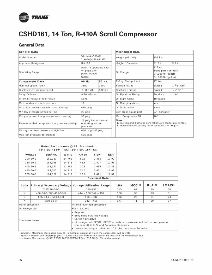
56 COM-PRC001-EN
CSHD161, 14 Ton, R-410A Scroll Compressor
General Data
General Data Mechanical Data
Model Number CSHD161*0A0M* Voltage designator
Weight (with oil) 159 lbs.
Approved Refrigerant R-410A Height / Diameter 21.3 in. 9.7 in.
Operating Range
Refer to operating chart on page 3 or performance tables
Oil Charge
112 oz. Trane part numbers:OIL00079 (quart)OIL00080 (gallon)
Compressor Data 60 Hz 50 Hz Refrig. Charge Limit 17 lbs.
Nominal speed (rpm) 3500 2900 Suction Fitting Brazed 1 3/8” ODF
Displacement @ nom speed 1,125 cfh 932 cfh Discharge Fitting Brazed 7/8” ODF
Swept Volume 9.26 in3/rev. Oil Equalizer Fitting Rotalock 1 ¾”
Internal Pressure Relief Valve None Oil Sight Glass Threaded
Max number of starts per hour 12 Oil Charging Valve Yes
Max high pressure switch cutout setting 650 psig Oil Drain Valve None
Min low pressure switch setting 22 psig Low press gauge port ¼” Schrader
Min pumpdown low pressure switch setting 33 psig Max. Compressor Tilt 10º
Recommended pumpdown low pressure setting23 psig below normal operating suction pressure
Notes:
1. Suction and discharge connections are copper plated steel. 2. Recommended brazing materials BCuP-3 or BAg28
Max system test pressure – high/low 660 psig/483 psig
Max test pressure differential 535 psig
Rated Performance @ ARI Standard:45ºF SST/130º F SCT, 20ºF SH/15ºF SC
Voltage Btu/Hr. Watts Amps Flow EER200-60-3 161,233 14,765 50.9 2,380 10.92230-60-3 163,065 14,878 44.6 2,407 10.96400-50-3 133,187 12,241 20.8 1,966 10.88460-60-3 164,022 14,817 21.3 2,421 11.07575-60-3 164,022 14,817 17.0 2,421 11.07
Electrical Data
Code Primary/Secondary Voltage Voltage Utilization Range LRA MCC(a) RLA(b) IMAX(c)
J 200/230-60-3 180-253 315 69 49 64K 460-60-3/380-415-50-3 414 – 506/342 – 457 158 33 23 31D 575-60-3 / 500-50-3 518 – 632 136 29 21 24X 380-60-3 342 – 418 177 41 29 37
Motor protection Internal overload protectionUL Recognized File # SA2356
Crankcase Heater
• Required• Belly band 90w line voltage • UL file #SA11872• UL recognized (SEOT2, SEOT8 – heaters, crankcase and defrost, refrigeration
component) to U.S. and Canadian standards.• Installation torque: minimum 20 in-lbs. maximum 30 in-lbs.
(a) MCC = Maximum continuous current - maximum current at which the compressor will operate.(b) RLA = Rated Load Amperage (MCC / 1.40). Unit compressor RLA cannot be less than the compressor RLA.(c) IMAX= Max current @ 59°F SST/ 160°F SCT/20°F SH/15°F SC @ 10% under voltage.
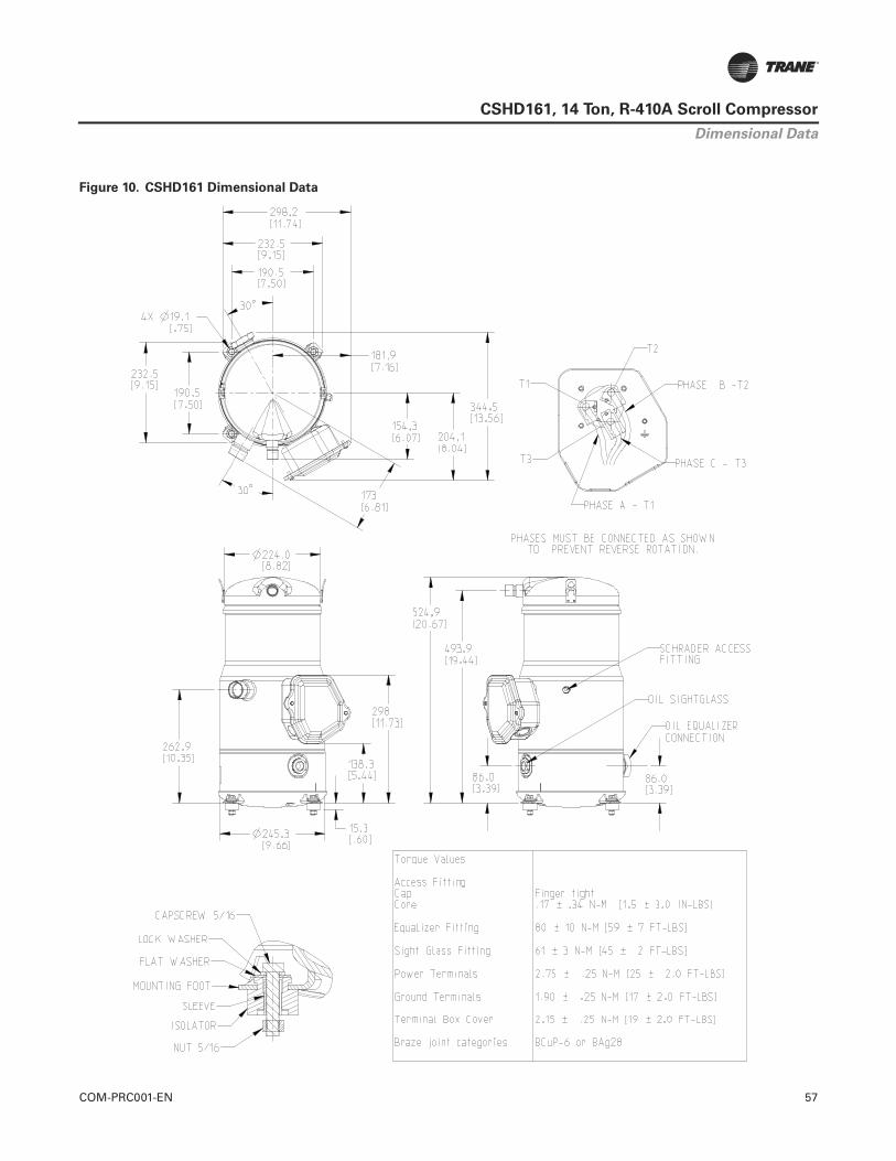
COM-PRC001-EN 57
CSHD161, 14 Ton, R-410A Scroll Compressor
Figure 10. CSHD161 Dimensional Data
Dimensional Data

58 COM-PRC001-EN
CSHD161, 14 Ton, R-410A Scroll Compressor
CSHD161 (14 Tons), Voltage: 200-60-3
Nominal performance values (+/-5%) based on a minimum 24 hour break-in. Subject to change without notice.All performance data shown is for R-410A refrigerant, 20°F SuperHeat, 15°F SubCooling.
Capacity - Btu/Hr
Cond. Temp °FEvaporating Temperature (°F)
-10 0 10 20 30 40 45 50 6080 68,555 85,891 107,473 133,395 163,727 198,514 217,585 237,773 281,48390 64,461 81,258 102,126 127,156 156,419 189,959 208,339 227,791 269,897
100 60,091 76,220 96,233 120,223 148,259 180,387 197,992 216,622 256,944110 55,469 70,804 89,829 112,636 139,296 169,853 186,598 204,322 242,684120 65,076 82,994 104,491 129,638 158,479 174,292 191,032 227,276130 75,820 95,898 119,415 146,418 161,233 176,923 210,912140 86,891 108,663 133,702 147,454 162,026 193,618150 97,107 119,987 132,571 145,916 174,880
Power - Watts
Cond. Temp °FEvaporating Temperature (°F)
-10 0 10 20 30 40 45 50 6080 7,929 8,070 8,223 8,390 8,571 8,764 8,866 8,971 9,19190 8,739 8,873 9,020 9,180 9,354 9,541 9,640 9,742 9,955
100 9,784 9,906 10,040 10,188 10,349 10,524 10,616 10,712 10,913110 11,064 11,167 11,284 11,413 11,556 11,713 11,796 11,883 12,066120 12,658 12,750 12,856 12,975 13,108 13,179 13,254 13,413130 14,440 14,516 14,606 14,708 14,765 14,825 14,955140 16,394 16,448 16,515 16,554 16,596 16,690150 18,502 18,528 18,546 18,567 18,620
Current - Amps @ 200V
Cond. Temp °FEvaporating Temperature (°F)
-10 0 10 20 30 40 45 50 6080 32.2 32.5 32.8 33.2 33.7 34.3 34.6 34.9 35.690 34.1 34.4 34.8 35.2 35.7 36.2 36.5 36.8 37.4
100 36.7 37.0 37.4 37.8 38.3 38.8 39.0 39.3 39.8110 40.0 40.4 40.8 41.2 41.6 42.1 42.3 42.5 43.0120 44.5 44.9 45.3 45.7 46.1 46.2 46.4 46.8130 49.7 50.1 50.4 50.7 50.9 51.0 51.3140 55.5 55.8 56.1 56.2 56.3 56.5150 62.0 62.2 62.2 62.3 62.4
Refrigerant Flow - Lbs/Hr
Cond. Temp °FEvaporating Temperature (°F)
-10 0 10 20 30 40 45 50 6080 821 1,015 1,254 1,538 1,867 2,240 2,444 2,659 3,12290 810 1,007 1,249 1,535 1,867 2,243 2,448 2,664 3,130
100 796 995 1,238 1,527 1,860 2,238 2,444 2,661 3,128110 779 978 1,223 1,512 1,846 2,225 2,431 2,648 3,116120 958 1,202 1,492 1,826 2,204 2,410 2,627 3,094130 1,176 1,465 1,797 2,174 2,380 2,596 3,062140 1,431 1,762 2,137 2,341 2,556 3,019150 1,719 2,090 2,293 2,506 2,966
EER - Btu/Hr/Watt-Hr
Cond. Temp °FEvaporating Temperature (°F)
-10 0 10 20 30 40 45 50 6080 8.65 10.64 13.07 15.90 19.10 22.65 24.54 26.50 30.6390 7.38 9.16 11.32 13.85 16.72 19.91 21.61 23.38 27.11
100 6.14 7.69 9.58 11.80 14.33 17.14 18.65 20.22 23.54110 5.01 6.34 7.96 9.87 12.05 14.50 15.82 17.19 20.11120 5.14 6.51 8.13 9.99 12.09 13.22 14.41 16.94130 5.25 6.61 8.18 9.95 10.92 11.93 14.10140 5.30 6.61 8.10 8.91 9.76 11.60150 5.25 6.48 7.15 7.86 9.39
20° SuperHeat, 15° SubCooling

COM-PRC001-EN 59
CSHD161, 14 Ton, R-410A Scroll Compressor
CSHD161 (14 Tons), Voltage: 230-60-3
Nominal performance values (+/-5%) based on a minimum 24 hour break-in. Subject to change without notice.All performance data shown is for R-410A refrigerant, 20°F SuperHeat, 15°F SubCooling.
Capacity - Btu/Hr
Cond. Temp °FEvaporating Temperature (°F)
-10 0 10 20 30 40 45 50 6080 69,334 86,867 108,694 134,910 165,587 200,770 220,057 240,475 284,68290 65,193 82,182 103,287 128,601 158,196 192,117 210,706 230,380 272,964
100 60,774 77,086 97,326 121,589 149,944 182,437 200,242 219,084 259,864110 56,099 71,609 90,850 113,916 140,879 171,783 188,719 206,643 245,442120 65,816 83,937 105,678 131,111 160,280 176,273 193,202 229,858130 76,682 96,988 120,772 148,082 163,065 178,933 213,308140 87,879 109,898 135,221 149,129 163,867 195,818150 98,210 121,350 134,077 147,574 176,867
Power - Watts
Cond. Temp °FEvaporating Temperature (°F)
-10 0 10 20 30 40 45 50 6080 7,990 8,132 8,286 8,455 8,636 8,831 8,934 9,040 9,26290 8,806 8,941 9,089 9,251 9,426 9,614 9,714 9,816 10,032
100 9,859 9,982 10,117 10,266 10,429 10,605 10,698 10,794 10,997110 11,149 11,253 11,370 11,501 11,645 11,803 11,887 11,974 12,159120 12,755 12,848 12,955 13,075 13,208 13,280 13,355 13,516130 14,551 14,628 14,718 14,821 14,878 14,938 15,069140 16,520 16,574 16,642 16,681 16,723 16,818150 18,644 18,670 18,688 18,710 18,763
Current - Amps @ 230V
Cond. Temp °FEvaporating Temperature (°F)
-10 0 10 20 30 40 45 50 6080 28.2 28.5 28.8 29.1 29.6 30.1 30.3 30.6 31.290 29.9 30.2 30.5 30.9 31.3 31.7 32.0 32.2 32.8
100 32.2 32.5 32.8 33.2 33.6 34.0 34.2 34.5 34.9110 35.1 35.4 35.8 36.1 36.5 36.9 37.1 37.3 37.7120 39.0 39.4 39.7 40.0 40.4 40.6 40.7 41.1130 43.6 43.9 44.2 44.5 44.6 44.8 45.0140 48.7 49.0 49.2 49.3 49.4 49.6150 54.3 54.5 54.6 54.6 54.7
Refrigerant Flow - Lbs/Hr
Cond. Temp °FEvaporating Temperature (°F)
-10 0 10 20 30 40 45 50 6080 830 1,026 1,268 1,555 1,888 2,266 2,472 2,689 3,15790 819 1,018 1,263 1,553 1,888 2,269 2,476 2,694 3,165
100 805 1,006 1,252 1,544 1,881 2,264 2,472 2,691 3,163110 788 990 1,237 1,530 1,867 2,250 2,459 2,678 3,151120 969 1,216 1,509 1,846 2,229 2,437 2,656 3,129130 1,190 1,481 1,818 2,199 2,407 2,625 3,096140 1,447 1,782 2,161 2,367 2,585 3,053150 1,738 2,114 2,319 2,535 3,000
EER - Btu/Hr/Watt-Hr
Cond. Temp °FEvaporating Temperature (°F)
-10 0 10 20 30 40 45 50 6080 8.68 10.68 13.12 15.96 19.17 22.73 24.63 26.60 30.7490 7.40 9.19 11.36 13.90 16.78 19.98 21.69 23.47 27.21
100 6.16 7.72 9.62 11.84 14.38 17.20 18.72 20.30 23.63110 5.03 6.36 7.99 9.91 12.10 14.55 15.88 17.26 20.19120 5.16 6.53 8.16 10.03 12.13 13.27 14.47 17.01130 5.27 6.63 8.21 9.99 10.96 11.98 14.16140 5.32 6.63 8.13 8.94 9.80 11.64150 5.27 6.50 7.17 7.89 9.43
20° SuperHeat, 15° SubCooling

60 COM-PRC001-EN
CSHD161, 14 Ton, R-410A Scroll Compressor
CSHD161 (14 Tons), Voltage: 400-50-3
Nominal performance values (+/-5%) based on a minimum 24 hour break-in. Subject to change without notice.All performance data shown is for R-410A refrigerant, 20°F SuperHeat, 15°F SubCooling.
Capacity - Btu/Hr
Cond. Temp °FEvaporating Temperature (°F)
-10 0 10 20 30 40 45 50 6080 55,726 70,300 88,453 110,261 135,782 165,051 181,096 198,080 234,85190 52,232 66,404 84,002 105,101 129,760 158,013 173,492 189,871 225,315
100 48,468 62,104 79,006 99,250 122,892 149,968 164,798 180,488 214,434110 44,464 57,439 73,513 92,760 115,239 140,984 155,086 170,006 202,286120 52,477 67,605 85,732 106,916 131,193 144,495 158,572 189,036130 61,378 78,279 98,055 120,745 133,187 146,359 174,880140 70,453 88,714 109,701 121,222 133,427 159,875150 78,699 97,813 108,322 119,465 143,641
Power - Watts
Cond. Temp °FEvaporating Temperature (°F)
-10 0 10 20 30 40 45 50 6080 6,597 6,664 6,731 6,799 6,867 6,936 6,971 7,006 7,07690 7,349 7,375 7,415 7,470 7,538 7,621 7,667 7,717 7,828
100 8,344 8,317 8,319 8,348 8,405 8,489 8,542 8,602 8,742110 9,581 9,491 9,442 9,434 9,468 9,543 9,596 9,660 9,818120 10,896 10,785 10,729 10,728 10,782 10,829 10,891 11,055130 12,347 12,231 12,184 12,205 12,241 12,295 12,454140 13,941 13,836 13,813 13,832 13,873 14,014150 15,685 15,606 15,603 15,623 15,736
Current - Amps @ 400V
Cond. Temp °FEvaporating Temperature (°F)
-10 0 10 20 30 40 45 50 6080 14.1 14.1 14.1 14.2 14.2 14.3 14.4 14.5 14.690 14.8 14.8 14.8 14.9 15.0 15.0 15.1 15.2 15.3
100 15.9 15.9 15.9 15.9 16.0 16.0 16.1 16.1 16.3110 17.2 17.2 17.2 17.2 17.3 17.3 17.4 17.4 17.5120 18.9 18.9 18.9 18.9 18.9 19.0 19.0 19.0130 20.9 20.8 20.8 20.8 20.8 20.8 20.9140 23.1 23.0 23.0 23.0 23.0 22.9150 25.6 25.5 25.4 25.4 25.3
Refrigerant Flow - Lbs/Hr
Cond. Temp °FEvaporating Temperature (°F)
-10 0 10 20 30 40 45 50 6080 667 831 1,032 1,271 1,548 1,863 2,034 2,215 2,60590 656 823 1,027 1,269 1,549 1,866 2,039 2,221 2,613
100 642 810 1,017 1,261 1,542 1,861 2,034 2,217 2,610110 624 794 1,001 1,246 1,528 1,847 2,020 2,203 2,597120 772 979 1,224 1,506 1,824 1,998 2,180 2,573130 952 1,196 1,476 1,793 1,966 2,147 2,539140 1,160 1,438 1,753 1,924 2,105 2,493150 1,393 1,704 1,873 2,052 2,436
EER - Btu/Hr/Watt-Hr
Cond. Temp °FEvaporating Temperature (°F)
-10 0 10 20 30 40 45 50 6080 8.45 10.55 13.14 16.22 19.77 23.79 25.98 28.27 33.1990 7.11 9.00 11.33 14.07 17.21 20.74 22.63 24.60 28.78
100 5.81 7.47 9.50 11.89 14.62 17.67 19.29 20.98 24.53110 4.64 6.05 7.79 9.83 12.17 14.77 16.16 17.60 20.60120 4.82 6.27 7.99 9.97 12.17 13.34 14.56 17.10130 4.97 6.40 8.05 9.89 10.88 11.90 14.04140 5.05 6.41 7.94 8.76 9.62 11.41150 5.02 6.27 6.94 7.65 9.13
20° SuperHeat, 15° SubCooling

COM-PRC001-EN 61
CSHD161, 14 Ton, R-410A Scroll Compressor
CSHD161 (14 Tons), Voltage: 460-60-3
Nominal performance values (+/-5%) based on a minimum 24 hour break-in. Subject to change without notice.All performance data shown is for R-410A refrigerant, 20°F SuperHeat, 15°F SubCooling.
Capacity - Btu/Hr
Cond. Temp °FEvaporating Temperature (°F)
-10 0 10 20 30 40 45 50 6080 69,737 87,375 109,334 135,708 166,567 201,956 221,354 241,888 286,34490 65,571 82,659 103,889 129,354 159,125 193,246 211,944 231,732 274,559
100 61,130 77,534 97,892 122,298 150,822 183,507 201,417 220,369 261,386110 56,436 72,029 91,380 114,581 141,703 172,790 189,826 207,857 246,883120 66,208 84,430 106,296 131,878 161,220 177,307 194,338 231,211130 77,136 97,556 121,479 148,950 164,022 179,985 214,565140 88,395 110,540 136,012 150,002 164,828 196,971150 98,782 122,057 134,858 148,436 177,904
Power - Watts
Cond. Temp °FEvaporating Temperature (°F)
-10 0 10 20 30 40 45 50 6080 7,957 8,098 8,252 8,420 8,601 8,795 8,897 9,003 9,22490 8,770 8,904 9,052 9,213 9,387 9,575 9,674 9,776 9,990
100 9,819 9,940 10,075 10,224 10,386 10,561 10,654 10,750 10,952110 11,103 11,206 11,323 11,453 11,597 11,754 11,838 11,925 12,109120 12,702 12,795 12,901 13,021 13,154 13,225 13,300 13,460130 14,491 14,567 14,657 14,760 14,817 14,877 15,007140 16,452 16,506 16,573 16,612 16,654 16,749150 18,567 18,593 18,611 18,633 18,686
Current - Amps @ 460V
Cond. Temp °FEvaporating Temperature (°F)
-10 0 10 20 30 40 45 50 6080 13.5 13.6 13.7 13.9 14.1 14.3 14.5 14.6 14.990 14.2 14.4 14.5 14.7 14.9 15.1 15.3 15.4 15.6
100 15.3 15.5 15.7 15.8 16.0 16.2 16.3 16.4 16.7110 16.7 16.9 17.1 17.2 17.4 17.6 17.7 17.8 18.0120 18.6 18.8 18.9 19.1 19.3 19.3 19.4 19.6130 20.8 20.9 21.1 21.2 21.3 21.4 21.5140 23.2 23.4 23.5 23.5 23.6 23.6150 25.9 26.0 26.0 26.1 26.1
Refrigerant Flow - Lbs/Hr
Cond. Temp °FEvaporating Temperature (°F)
-10 0 10 20 30 40 45 50 6080 835 1,032 1,276 1,564 1,899 2,279 2,486 2,705 3,17690 824 1,024 1,270 1,562 1,899 2,282 2,490 2,710 3,184
100 810 1,012 1,260 1,553 1,892 2,277 2,486 2,707 3,182110 792 995 1,244 1,538 1,878 2,264 2,473 2,694 3,170120 975 1,223 1,517 1,857 2,242 2,451 2,672 3,147130 1,197 1,490 1,828 2,212 2,421 2,641 3,115140 1,456 1,792 2,174 2,381 2,600 3,071150 1,748 2,126 2,332 2,550 3,018
EER - Btu/Hr/Watt-Hr
Cond. Temp °FEvaporating Temperature (°F)
-10 0 10 20 30 40 45 50 6080 8.76 10.79 13.25 16.12 19.37 22.96 24.88 26.87 31.0490 7.48 9.28 11.48 14.04 16.95 20.18 21.91 23.70 27.48
100 6.23 7.80 9.72 11.96 14.52 17.38 18.91 20.50 23.87110 5.08 6.43 8.07 10.00 12.22 14.70 16.04 17.43 20.39120 5.21 6.60 8.24 10.13 12.26 13.41 14.61 17.18130 5.32 6.70 8.29 10.09 11.07 12.10 14.30140 5.37 6.70 8.21 9.03 9.90 11.76150 5.32 6.56 7.25 7.97 9.52
20° SuperHeat, 15° SubCooling
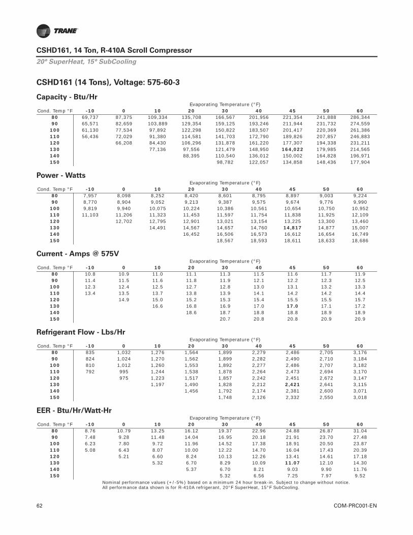
62 COM-PRC001-EN
CSHD161, 14 Ton, R-410A Scroll Compressor
CSHD161 (14 Tons), Voltage: 575-60-3
Nominal performance values (+/-5%) based on a minimum 24 hour break-in. Subject to change without notice.All performance data shown is for R-410A refrigerant, 20°F SuperHeat, 15°F SubCooling.
Capacity - Btu/Hr
Cond. Temp °FEvaporating Temperature (°F)
-10 0 10 20 30 40 45 50 6080 69,737 87,375 109,334 135,708 166,567 201,956 221,354 241,888 286,34490 65,571 82,659 103,889 129,354 159,125 193,246 211,944 231,732 274,559
100 61,130 77,534 97,892 122,298 150,822 183,507 201,417 220,369 261,386110 56,436 72,029 91,380 114,581 141,703 172,790 189,826 207,857 246,883120 66,208 84,430 106,296 131,878 161,220 177,307 194,338 231,211130 77,136 97,556 121,479 148,950 164,022 179,985 214,565140 88,395 110,540 136,012 150,002 164,828 196,971150 98,782 122,057 134,858 148,436 177,904
Power - Watts
Cond. Temp °FEvaporating Temperature (°F)
-10 0 10 20 30 40 45 50 6080 7,957 8,098 8,252 8,420 8,601 8,795 8,897 9,003 9,22490 8,770 8,904 9,052 9,213 9,387 9,575 9,674 9,776 9,990
100 9,819 9,940 10,075 10,224 10,386 10,561 10,654 10,750 10,952110 11,103 11,206 11,323 11,453 11,597 11,754 11,838 11,925 12,109120 12,702 12,795 12,901 13,021 13,154 13,225 13,300 13,460130 14,491 14,567 14,657 14,760 14,817 14,877 15,007140 16,452 16,506 16,573 16,612 16,654 16,749150 18,567 18,593 18,611 18,633 18,686
Current - Amps @ 575V
Cond. Temp °FEvaporating Temperature (°F)
-10 0 10 20 30 40 45 50 6080 10.8 10.9 11.0 11.1 11.3 11.5 11.6 11.7 11.990 11.4 11.5 11.6 11.8 11.9 12.1 12.2 12.3 12.5
100 12.3 12.4 12.5 12.7 12.8 13.0 13.1 13.2 13.3110 13.4 13.5 13.7 13.8 13.9 14.1 14.2 14.2 14.4120 14.9 15.0 15.2 15.3 15.4 15.5 15.5 15.7130 16.6 16.8 16.9 17.0 17.0 17.1 17.2140 18.6 18.7 18.8 18.8 18.9 18.9150 20.7 20.8 20.8 20.9 20.9
Refrigerant Flow - Lbs/Hr
Cond. Temp °FEvaporating Temperature (°F)
-10 0 10 20 30 40 45 50 6080 835 1,032 1,276 1,564 1,899 2,279 2,486 2,705 3,17690 824 1,024 1,270 1,562 1,899 2,282 2,490 2,710 3,184
100 810 1,012 1,260 1,553 1,892 2,277 2,486 2,707 3,182110 792 995 1,244 1,538 1,878 2,264 2,473 2,694 3,170120 975 1,223 1,517 1,857 2,242 2,451 2,672 3,147130 1,197 1,490 1,828 2,212 2,421 2,641 3,115140 1,456 1,792 2,174 2,381 2,600 3,071150 1,748 2,126 2,332 2,550 3,018
EER - Btu/Hr/Watt-Hr
Cond. Temp °FEvaporating Temperature (°F)
-10 0 10 20 30 40 45 50 6080 8.76 10.79 13.25 16.12 19.37 22.96 24.88 26.87 31.0490 7.48 9.28 11.48 14.04 16.95 20.18 21.91 23.70 27.48
100 6.23 7.80 9.72 11.96 14.52 17.38 18.91 20.50 23.87110 5.08 6.43 8.07 10.00 12.22 14.70 16.04 17.43 20.39120 5.21 6.60 8.24 10.13 12.26 13.41 14.61 17.18130 5.32 6.70 8.29 10.09 11.07 12.10 14.30140 5.37 6.70 8.21 9.03 9.90 11.76150 5.32 6.56 7.25 7.97 9.52
20° SuperHeat, 15° SubCooling

COM-PRC001-EN 63
CSHD161, 14 Ton, R-410A Scroll CompressorTab
le 7
.C
SH
D161,
R-4
10A
(A
RI 10 C
oeff
icie
nts
, -2
0°F
Su
perh
eat/
15°F
Su
bco
olin
g)(
a)(
b)
Ap
pli
ed V
olt
age:
20
0-6
0-3
Co
effi
cien
tsC
1C
2C
3C
4C
5C
6C
7C
8C
9C
10
Cap
acit
y1.
0108
51E+
051.
9237
19E+
031.
1716
16E+
022.
9406
98E+
015.
7927
73E+
00-4
.589
756E
+00
7.50
2481
E-03
-9.8
3597
3E-0
2-6
.926
497E
-02
9.26
9502
E-03
Po
wer
9.89
2119
E+03
-8.1
5094
4E-0
1-1
.144
381E
+02
6.50
4355
E-02
4.25
8249
E-01
1.14
5723
E+00
-3.6
6516
4E-1
51.
7802
78E-
05-2
.897
781E
-03
-2.1
7322
0E-1
3
Am
ps
4.29
3394
E+01
-1.1
5399
9E-0
2-4
.191
328E
-01
9.99
0897
E-04
8.13
6563
E-04
3.60
1850
E-03
-1.4
2529
2E-1
6-8
.368
239E
-06
-3.2
7250
6E-0
6-3
.030
375E
-15
Flo
w9.
5064
55E+
021.
5909
89E+
012.
0716
24E+
002.
2905
52E-
011.
0970
25E-
01-1
.405
954E
-02
-1.7
2915
3E-0
5-4
.167
078E
-05
-4.7
6368
9E-0
4-2
.249
259E
-05
Ap
pli
ed V
olt
age:
23
0-6
0-3
Co
effi
cien
tsC
1C
2C
3C
4C
5C
6C
7C
8C
9C
10
Cap
acit
y1.
0223
37E+
051.
9455
77E+
031.
1849
28E+
022.
9741
11E+
015.
8585
93E+
00-4
.641
907E
+00
7.58
7727
E-03
-9.9
4773
4E-0
2-7
.005
199E
-02
9.37
4826
E-03
Po
wer
9.96
8004
E+03
-8.2
1347
2E-0
1-1
.153
160E
+02
6.55
4252
E-02
4.29
0915
E-01
1.15
4513
E+00
-9.8
6063
4E-1
51.
7939
35E-
05-2
.920
011E
-03
5.17
6440
E-14
Am
ps
3.76
4418
E+01
-1.0
1181
9E-0
2-3
.674
928E
-01
8.75
9949
E-04
7.13
4082
E-04
3.15
8077
E-03
2.72
9284
E-18
-7.3
3721
4E-0
6-2
.869
311E
-06
1.46
8811
E-16
Flo
w9.
6144
72E+
021.
6090
67E+
012.
0951
63E+
002.
3165
78E-
011.
1094
90E-
01-1
.421
929E
-02
-1.7
4880
1E-0
5-4
.214
426E
-05
-4.8
1781
6E-0
4-2
.274
816E
-05
Ap
pli
ed V
olt
age:
40
0-5
0-3
Co
effi
cien
tsC
1C
2C
3C
4C
5C
6C
7C
8C
9C
10
Cap
acit
y7.
7110
58E+
041.
5280
38E+
032.
6666
01E+
022.
4888
60E+
016.
6552
98E+
00-5
.352
067E
+00
6.11
5962
E-03
-8.4
4563
7E-0
2-6
.642
477E
-02
1.18
1510
E-02
Po
wer
9.29
4545
E+03
-7.7
7639
4E+
00-1
.253
361E
+02
-5.4
2619
6E-0
16.
4459
33E-
011.
1556
48E+
009.
5588
50E-
156.
8147
76E-
03-5
.793
523E
-03
4.39
8667
E-13
Am
ps
1.96
4269
E+01
-1.6
6508
7E-0
2-1
.970
967E
-01
1.60
6282
E-04
4.84
0227
E-04
1.59
2175
E-03
-1.6
6194
2E-1
7-6
.712
659E
-07
-3.0
7519
6E-0
6-1
.957
386E
-17
Flo
w7.
4948
47E+
021.
2126
57E+
012.
4922
77E+
001.
9551
39E-
011.
1701
32E-
01-1
.706
345E
-02
-1.8
5913
3E-0
5-6
.694
266E
-05
-5.0
9634
6E-0
4-1
.758
514E
-05
Ap
pli
ed V
olt
age:
46
0-6
0-3
Co
effi
cien
tsC
1C
2C
3C
4C
5C
6C
7C
8C
9C
10
Cap
acit
y1.
0302
31E+
051.
9572
78E+
031.
1414
59E+
022.
9892
94E+
015.
9033
55E+
00-4
.627
579E
+00
7.51
8430
E-03
-9.9
7414
8E-0
2-7
.060
851E
-02
9.32
6481
E-03
Po
wer
9.92
6874
E+03
-8.1
7958
2E-0
1-1
.148
402E
+02
6.52
7207
E-02
4.27
3210
E-01
1.14
9749
E+00
-3.2
4299
4E-1
41.
7865
33E-
05-2
.907
962E
-03
-9.0
3128
4E-1
3
Am
ps
1.79
6156
E+01
-4.8
2779
4E-0
3-1
.753
456E
-01
4.17
9725
E-04
3.40
3958
E-04
1.50
6846
E-03
5.46
5023
E-18
-3.5
0088
0E-0
6-1
.369
064E
-06
-4.6
2639
7E-1
6
Flo
w9.
7132
80E+
021.
6191
47E+
011.
9946
51E+
002.
3250
95E-
011.
1183
23E-
01-1
.337
285E
-02
-2.0
1369
4E-0
5-3
.524
276E
-05
-4.8
7863
0E-0
4-2
.519
381E
-05
Ap
pli
ed V
olt
age:
57
5-6
0-3
Co
effi
cien
tsC
1C
2C
3C
4C
5C
6C
7C
8C
9C
10
Cap
acit
y1.
0302
31E+
051.
9572
78E+
031.
1414
59E+
022.
9892
94E+
015.
9033
55E+
00-4
.627
579E
+00
7.51
8430
E-03
-9.9
7414
8E-0
2-7
.060
851E
-02
9.32
6481
E-03
Po
wer
9.92
6874
E+03
-8.1
7958
2E-0
1-1
.148
402E
+02
6.52
7207
E-02
4.27
3210
E-01
1.14
9749
E+00
-3.2
4299
4E-1
41.
7865
33E-
05-2
.907
962E
-03
-9.0
3128
4E-1
3
Am
ps
1.43
6925
E+01
-3.8
6223
5E-0
3-1
.402
765E
-01
3.34
3780
E-04
2.72
3166
E-04
1.20
5477
E-03
4.37
2018
E-18
-2.8
0070
4E-0
6-1
.095
251E
-06
-3.7
0111
8E-1
6
Flow
9.71
3280
E+02
1.61
9147
E+01
1.99
4651
E+00
2.32
5095
E-01
1.11
8323
E-01
-1.3
3728
5E-0
2-2
.013
694E
-05
-3.5
2427
6E-0
5-4
.878
630E
-04
-2.5
1938
1E-0
5
(a)E
quat
ions
are
of
the
form
: Val
ue=
C1
+ C
2 *
Te +
C3
* Tc
+ C
4 *
Te^
2 +
C5
* Te
* T
c +
C6
* Tc
^2
+ C
7 *
Te^
3 +
C8
+ T
e^2
* Tc
+ C
9 *
Te *
Tc^
2 +
C10
*Tc
^3
(b)W
here
: Tc
= S
atur
ated
con
dens
ing
tem
pera
ture
(°F
) an
d Te
= S
atur
ated
con
dens
ing
tem
pera
ture
(°F
)

Trane and the Trane logo are trademarks of Trane in the United States and other countries. All trademarksreferenced in this document are the trademarks of their respective owners.
www.trane.com
For more information, contact your local Trane office or e-mail us at [email protected]
Literature Order Number COM-PRC001-EN
Date February 2010
Supersedes New
Trane has a policy of continuous product and product data improvement and reserves the right to change design and specifications without notice. Only qualified technicians should perform the installation and servicing of equipment referred to in this literature.

FORM A
PRODUCTS & SERVICES
Nationwide Parts program
Type: Manufactured Parts, Emergency Parts, Miscellaneous Material
Description: Many government entities have an inventory program, whereby they stock, on site, needed parts their maintenance department will use during the course of the year for potential repairs. Instead of ordering on an as-needed basis, these entities typically put together a yearly inventory of potential parts needs. This bill of material can exceed the threshold whereby the school district advertises to bid out this inventory. This adds cost to the bidding process as well as additional expenditure of time by the government entity.
This Part Inventory Pricing Program (PIPP) will eliminate this requirement with the same cooperative purchasing system we have for new equipment and labor based solutions. PIPP will work as follows:
All TCPN members can purchase parts for inventory on a one‐time basis per year. The amount of the parts order shall not require a minimum, but is administered by the local
district office. A proposal shall be generated identifying it as a PIPP order and noted on the proposal as such when registered with Trane. The Purchase Orders from the TCPN member will identify their P.O. as a PIPP order.
All subsequent parts orders will not be eligible for this program if bought during the current year. Each local district office will administer this.
All other procedures for completing the order will be handled by the local district office.
Personnel: Every district office has parts sales personnel who will administer this program. Project References:
Montgomery County, Conroe, TX Pearland ISD, Pearland, TX Hiawatha School district Kansas City, KS Garland ISD, Garland, TX
Detailed Features and Benefits:
This process allows government entities to receive the most consistent parts pricing and guarantees the customer that they will pay a consistent price for Trane parts. Potential future enhancements to the program:
Use of Education Comfortsite to order parts online Use of P-cards to access parts


RefTec Refrigerant Handling Equipment
• Refrigerant Recovery• Oil Recovery• Noncondensible Gas Purging• Chiller Pressurization• Refrigerant Management• RefTec Custom Designs
December 2010 RSP-PRC002-EN
Product Catalog

RSP-PRC002-EN©2010 Trane All rights reserved
3RSP-PRC002-EN
Table of Contents
Voltage Utilization 4
Refrigerant Recovery Overview 5
Product
Diablo Residential & Light Commercial 6HandiVac Light Commercial 7MityVac Light Commercial 8MityVac/ASME Packaged Recovery/Storage 9Lite Evac Commercial 10Evac Commercial High Pressure 11Evac ASME Packaged Recovery/Storage 12LoVac Low Pressure 13LoVac with Integrated Welch Vacuum Pump 14LoVac ASME Packaged Recovery/Storage 15Allvac Universal Refrigerant Recovery Unit 16Oil Recovery POD 17Refrigerant Liquid Pump 18MiniPurge 21HyperWatt Chiller Pressurizer 22RefTec Custom Designs 23
Miscellaneous Accessories
Refrigerant Recovery Cylinders and Storage Tanks 19Accessories 20
Compressor Kits
Compressor Kits/Compressor Demo Unit (MicroVac) 24Compressor Kits/Compressor Demo Unit (MicroVac II)
Platinum Plus - 1 25Platinum Plus - 2 26

4 RSP-PRC002-EN
Voltage UtilizationUnit Listed Nominal Voltages Voltage Utilization Range (VAC)60 hz115 104 - 127230 208 - 254460 416 - 508575 520 - 635230-460 (dual voltage) 208-254 / 416-508460-575 (dual voltage) 416-508 / 520-63550 hz110 99 - 121220 198 - 242415 373 - 457550 495 - 605220-415 (dual voltage) 198-242 / 373-457415-550 (dual voltage) 373-457 / 495-605380 342 - 418

5RSP-PRC002-EN
Refrigerant Recovery Overview
Refrigerant Recovery Systems: Oil-less Recovery Units,Commercial Recovery units• 6 Models Service Most Cooling Applications• Rapidly transfer hundreds or thousands of pounds of refrigerant• Service high or low pressure chillers
Accessories
Vapor Direct Liquid Push/Pull
Model Refrigerant (lbs/min) (lb/min) (lb/min)
Diablo R22 0.71 7.71 17.67HandiVac R502 0.62 7.8 25MityVac R22 1.56 n/a 55Lite Evac R22 2.14 n/a 81Evac Commercial R22 6.0 n/a 325Allvac R22 6.0 n/a 325
R11 0.66 n/a 100Lovac R11 0.66 n/a 100Lovac with Vacuum Pump R11 1.26 n/a 134
All recovery rates are certified throughtesting at AHRI official test centers
HANDIVAC• Dual 0.75-hp oil-less compressors• Services high pressure refrigerantsTwice the recovery capacity of typical oil-less recovery units.
MITYVAC• 2.0-hp open drive compressor• Services high pressure refrigerants
LITE EVAC• Portable 110V recovery for commercial
applications• 4 heavy duty casters for ease of
mobility• Highest recovery capacity of any 110V
unit
EVAC Commercial• 3-hp open drive compressor• All high pressure refrigerants
Blazing recovery rates to service chillersand other large cooling systems
LOVAC• 2-hp open drive compressor• Recovers R11, R123, R113• For all sizes of low pressure chillersLightweight, easy to use, high tolerancefor noncondensible gases
LOVAC with Vacuum Pump• Integrated with 10.6 CFM Welch
vacuum pump• Recovers R11, R123, R113 and other
low pressure refrigerants• For all sizes of low pressure chillersFastest recovery rates of low pressuregas on the market
ALLVACUniversal refrigerant recovery unit foruse with low (R123, R110 and high (R22,R134,R410a) pressure refrigerants
Oil RecoveryPortable Chiller Oil Recovery Unit:Chiller oil recovery and recharge systemdesigned to remove old oil from therefrigerant and replace it with new oil tothe chiller compressor.
Refrigerant Liquid PumpThe Refrigerant Liquid Pump is acommercial/industrial grade pump usedto transfer all Class I, II, III and IVrefrigerant at rates up to 20GPM.

6 RSP-PRC002-EN
Diablo Residential & LightCommercial Refrigerant RecoveryUnitThe Diablo meets the air conditioningcontractor's need for a fast, durable andeasy to service recovery unit.
• Compatible with all high-pressurerefrigerants, including R410a.
• Increase recovery rates up to 30%.• Patented 3/4 hp Platinum Plus
compressor capable of recoveringdirect liquid.
• 11/8" piston allows for movement ofgreater volumes of refrigerant,increased durability and longevity.
• Compact and light design offers easeof mobility.
• Low center of gravity design reducessliding in the truck.
• Injection mold design with internalchannels increases airflow across thecompressor head and motor.
• Simple operation. One-line-in, one-line-out technology easily self-evacuateslines to ensure air does not enter therecovery cylinder. Then switch thevalves to recover and go about yourwork. When recovery is done,evacuate the unit with a switch of thevalve to ensure refrigerants are notcross contaminated.
• After years of use, bring your Diabloback to new with a compressor repairkit. (KIT09209)
• Made in the USA.
Specifications
R-22 R410a
Push/Pull 17.67 lb/min 16.89-lb/minDirect Liquid 7.71 lb/min 7.24-lb/minVapor Rate .71 lb/min .65-lb/minHigh Temp. Vapor .74 lb/min .67Weight 34 lbs (15.42kg)Shipping weight 39 lbs (17.69kg)Motor 0.75HpConnections 1/4 in. FlareDimensions (LxWxH) 16 in. x 10 in. x 13 in.Recovers Class III, IV and V refrigerants: R12, R22, R134A, R401A, R401B, R401C, R402A, R402B, R404A,R406A, R407A, R407B, R407C, R407D, R408A, R409A, R410A, R411A, R411B, R412A, R500, R502, R507, R509.
ServiceFirst ServiceFirst RefTec ModelItem Number Model Number Number Power Options Features
TOL03083 RRWA111A0A0 Diablo-115V 115/60/1, 110/50/1, 0.75 Hp, 15A LP Shutoff
TOL03084 RRWA111B0A0 Diablo-240V 230/60/1, 220/50/1, 0.5 Hp, 15A LP ShutoffAccessories
ServiceFirst RefTec ModelItem Number Number Description
KIT09209 CPK079 Complete rebuild kit (contains all *)KIT09206 CPK076 O-Ring rebuilt kit* (#10)KIT09207 CPK077 Piston rebuild kit* (#9)KIT09208 CPK078 Head rebuild kit* (8)SEL00854 RSC019 Shaft Seal* (#5)KIT09560 RSC108 Compressor counter balance (#7)CYL00214 RSCP02 Compressor cylinder (#3)BLK01165 RSCP051 Compressor block (#2)COM09188 CPK500 Complete compressor w/o motorCOM09186 RCP090 Compressor with motor (115V)COM09187 RCP091 Compressor with motor (230V)KIT15102 KIT006 Low pressure cut-out kitKIT15103 KIT007 Optional float accessory kit 115VKIT15127 KIT008 Optional float accessory kit 240VGAG00956 RGA502 Low-pressure gaugeGAG00957 RGA802 High-pressure gaugeHSE01129 20' x 1/4 " hose with ball valvesHSE01348 6' x 1/4 " red hose with ball valvesHSE01347 6' x 1/4 " blue hose with ball valvesDHY00816 3 cu inch filter drier, 1/4" flare (one ships with unit)CYL00189 30# tank w/80% shut-off switchCYL00187 50# tank w/80% shut-off switch
Note: For additional tanks, see page 19

7RSP-PRC002-EN
HandiVac Light CommercialRefrigerant Recovery Unit
1.5-Hp Oil-less RefrigerantRecovery Unit
Tired of Slow Recovery Rates?
HandiVac Offers Twice the RecoveryCapacity of Typical Oil-less Units.
No oil-less unit recovers refrigerant asquickly as the 1.5hp Handivac. Its dual0.75hp compressors accelerate recoveryon larger cooling systems. Thecompressors are equipped with uniquedischarge ball valves that cannot bedamaged by heavy flow during directliquid recovery.
To further protect compressorcomponents, Handivac automaticallyhalts vapor recovery when the coolingsystem is under a 15-inch Hg vacuum.This feature allows the technician toperform other tasks with no worriesabout the unit pumping away against adeep vacuum and prematurely wearingout compressor components.
Dual fans and condensing coils removemore heat from recovered vapor toensure fast recovery on hotter days oron larger volume cooling systems.
• Dual 0.75hp GoldPlus oil-lesscompressors double recovery rates forservicing commercial cooling units.
• Built-in anti-slugging featureautomatically prevents liquid fromharming compressors during directliquid transfer.
• Oil-free compressors eliminatemaintenance hassles. Easily switchbetween R12, R22, R134a, R500, R502,R410a, R409, MP39 and other highpressure refrigerants & blends.
• Automatic low pressure shut off at15-in. Hg.
• Float cable connection with built-inbypass switch for convenience
Units ships with:• One 5 cubic inch in-line filter drier• 6 foot float cable, 3 pin connector• Two 3/8 -1/4" hose adapters• Power cord adapter (24V model only)
Accessories (see page 20 for partnumbers):• Recovery tanks 30 lb, 50 lb, 250 lb &
1000 lb• Internal float for recovery tanks• 3/8'' sight glass (GLS00879))• Five cubic inch 3/8" in-line filter drier
(DHY00139)• 6 ft, 10 ft and 20 ft hoses with ball
valves• Unit is equipped with a 3-prong
flanged inlet. Maximum length of 100 ft12-gauge power cord recommended.
Specifications
Push/Pull (R22) 25-lb/minDirect Liquid (R22) 7.80-lb/minVapor Rate (R22) 0.62-lb/minWeight 65-lbs (28.6 kg) (80 lb shipping)Motor (2) 0.75HpConnections 3/8-in. FlareDimensions (LxWxH) 18-in. x 10-in. x 16-in.Float Connection 3-pin BHLow Pressure Switch 15" HgCertifications Certified by ETL to UL-1963 standards Rated in
accordance with ARI Standard 740-1998
Recovers Class III, IV and V refrigerants: R12, R22, R134A, R401A, R401B, R401C, R402A, R402B, R404A,R406A, R407A, R407B, R407C, R407D, R408A, R409A, R410A, R411A, R411B, R412A, R500, R502, R507, R509.
ServiceFirst RefTec Model
Item Number Number Power Options
TOL01144 RTO-500-115-F 115/60/1, 110/50/1,0.75Hp (2),15ATOL01145 RTO-500-240-F 230/60/1, 220/50/1,0.75Hp (2), 10AHandiVac now equipped with two 0.75 Hp Platinum Plus II compressors.
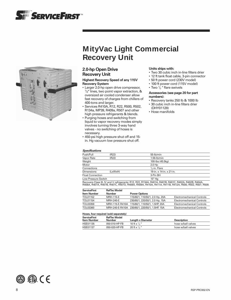
8 RSP-PRC002-EN
MityVac Light CommercialRecovery Unit2.0-hp Open DriveRecovery Unit
Highest Recovery Speed of any 115VRecovery System• Larger 2.0-hp open drive compressor,
1/2" lines, two point vapor extraction, &oversized air cooled condenser allowfast recovery of charges from chillers of400-tons and larger.
• Services R410A, R12, R22, R500, R502,R134a, MP39, R409a, R507 and otherhigh pressure refrigerants & blends.
• Purging hoses and switching fromliquid to vapor recovery modes simplyinvolves turning three 3-way handvalves - no switching of hoses isnecessary.
• 450-psi high pressure shut off and 15-in. Hg vacuum low pressure shut off.
Units ships with:• Two 30 cubic inch in-line filters drier• 12 ft tank float cable, 3-pin connector• 50 ft power cord (230V model)• 100 ft power cord (115V model)• Two 1/2 " flare swivels
Accessories (see page 20 for partnumbers):• Recovery tanks 250 lb & 1000 lb• 30 cubic inch in-line filters drier
(DHY01128)• Hose manifolds
Specifications
Push/Pull (R22) 55-lb/minVapor Rate (R22) 1.56-lb/minWeight 100-lbs (45.5kg)Motor 2.0 HpConnections 1/2-in. FlareDimensions (LxWxH) 19-in. x 14-in. x 21-in.Float Connection 3-Pin BHLow Pressure Switch 15" HgRecovers Class III, IV and V refrigerants: R12, R22, R134A, R401A, R401B, R401C, R402A, R402B, R404A,R406A, R407A, R407B, R407C, R407D, R408A, R409A, R410A, R411A, R411B, R412A, R500, R502, R507, R509.
ServiceFirst RefTec Model
Item Number Number Power Options
TOL01152 MRH-115-E 115/60/1, 110/50/1, 2.0 Hp, 20A Electromechanical ControlsTOL01154 MRH-240-E 230/60/1, 220/50/1, 2.0 Hp, 15A Electromechanical ControlsTOL03359 MRH-115-E-R410A 115/60/1, 110/50/1, 1.5HP, 20A Electromechanical ControlsTOL03360 MRH-240-E-R410A 230/60/1, 220/50/1, 1.5HP, 15A Electromechanical Controls
Hoses, four required (sold separately)
ServiceFirst RefTec ModelItem Number Number Length x Diameter Description
HSE01135 050-010-HP-FB 10 ft x 1/2 " hose w/ball valvesHSE01137 050-020-HP-FB 20 ft x 1/2 " hose w/ball valves
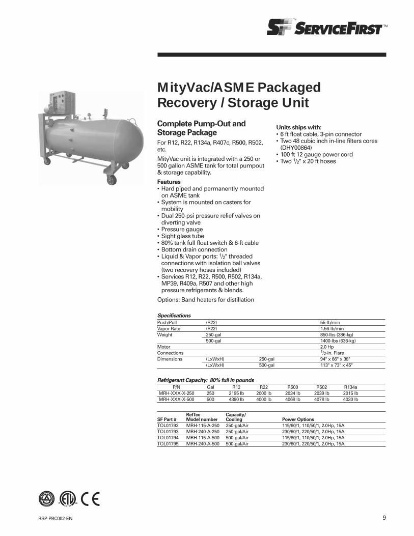
9RSP-PRC002-EN
Complete Pump-Out andStorage Package
For R12, R22, R134a, R407c, R500, R502,etc.
MityVac unit is integrated with a 250 or500 gallon ASME tank for total pumpout& storage capability.
Features• Hard piped and permanently mounted
on ASME tank• System is mounted on casters for
mobility• Dual 250-psi pressure relief valves on
diverting valve• Pressure gauge• Sight glass tube• 80% tank full float switch & 6-ft cable• Bottom drain connection• Liquid & Vapor ports: 1/2" threaded
connections with isolation ball valves(two recovery hoses included)
• Services R12, R22, R500, R502, R134a,MP39, R409a, R507 and other highpressure refrigerants & blends.
Options: Band heaters for distillation
MityVac/ASME PackagedRecovery / Storage Unit
Specifications
Push/Pull (R22) 55-lb/minVapor Rate (R22) 1.56-lb/minWeight 250-gal 850-lbs (386-kg)
500-gal 1400-lbs (636-kg)Motor 2.0 HpConnections 1/2-in. FlareDimensions (LxWxH) 250-gal 94" x 66" x 38"
(LxWxH) 500-gal 113" x 73" x 45"
Refrigerant Capacity: 80% full in pounds
P/N Gal R12 R22 R500 R502 R134aMRH-XXX-X-250 250 2195 lb 2000 lb 2034 lb 2039 lb 2015 lbMRH-XXX-X-500 500 4390 lb 4000 lb 4068 lb 4078 lb 4030 lb
RefTec Capacity/SF Part # Model number Cooling Power Options
TOL01792 MRH-115-A-250 250-gal/Air 115/60/1, 110/50/1, 2.0Hp, 15ATOL01793 MRH-240-A-250 250-gal/Air 230/60/1, 220/50/1, 2.0Hp, 15ATOL01794 MRH-115-A-500 500-gal/Air 115/60/1, 110/50/1, 2.0Hp, 15ATOL01795 MRH-240-A-500 500-gal/Air 230/60/1, 220/50/1, 2.0Hp, 15A
Units ships with:• 6 ft float cable, 3-pin connector• Two 48 cubic inch in-line filters cores
(DHY00864)• 100 ft 12 gauge power cord• Two 1/2" x 20 ft hoses
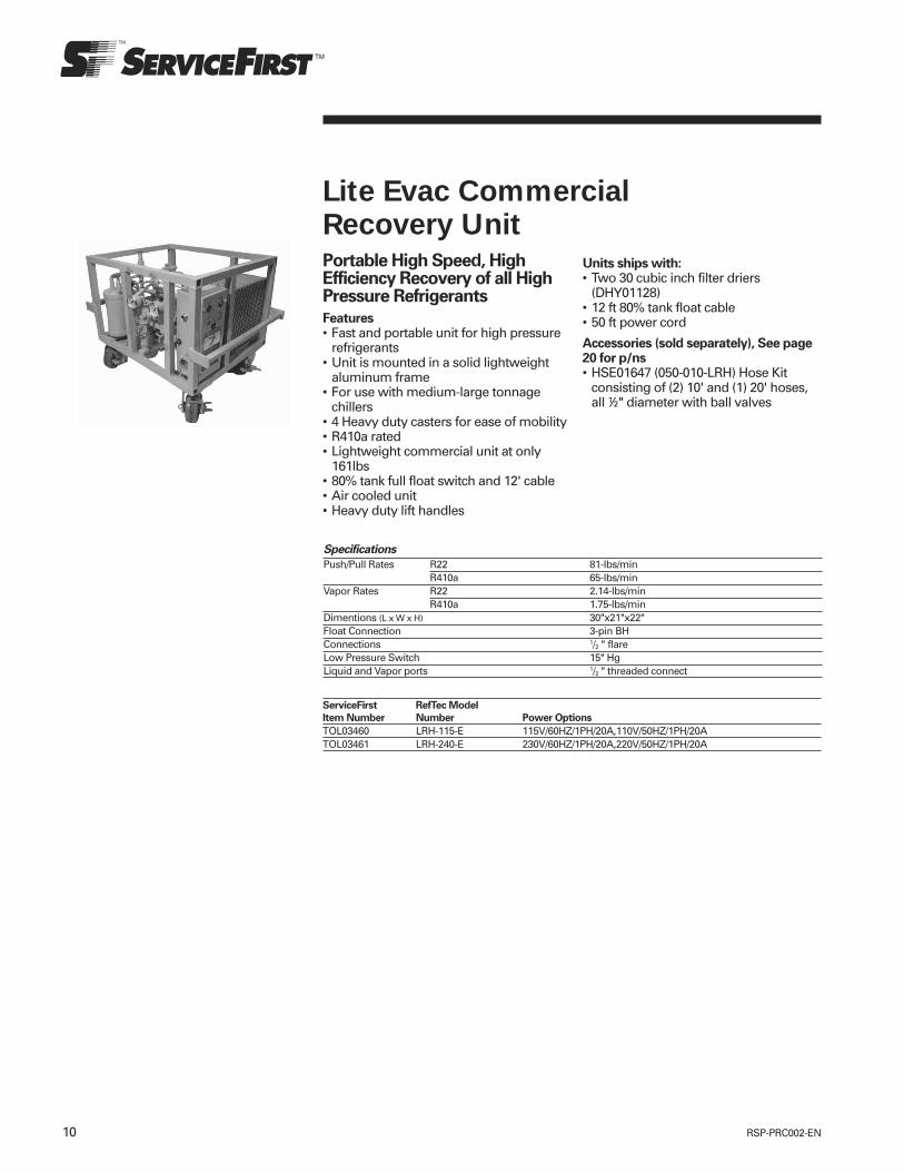
10 RSP-PRC002-EN
Lite Evac CommercialRecovery UnitPortable High Speed, HighEfficiency Recovery of all HighPressure Refrigerants
Features• Fast and portable unit for high pressure
refrigerants• Unit is mounted in a solid lightweight
aluminum frame• For use with medium-large tonnage
chillers• 4 Heavy duty casters for ease of mobility• R410a rated• Lightweight commercial unit at only
161lbs• 80% tank full float switch and 12' cable• Air cooled unit• Heavy duty lift handles
Units ships with:• Two 30 cubic inch filter driers
(DHY01128)• 12 ft 80% tank float cable• 50 ft power cord
Accessories (sold separately), See page20 for p/ns• HSE01647 (050-010-LRH) Hose Kit
consisting of (2) 10' and (1) 20' hoses,all ½" diameter with ball valves
Specifications
Push/Pull Rates R22 81-lbs/minR410a 65-lbs/min
Vapor Rates R22 2.14-lbs/minR410a 1.75-lbs/min
Dimentions (L x W x H) 30"x21"x22"Float Connection 3-pin BHConnections 1/2 " flareLow Pressure Switch 15" HgLiquid and Vapor ports 1/2 " threaded connect
ServiceFirst RefTec Model
Item Number Number Power Options
TOL03460 LRH-115-E 115V/60HZ/1PH/20A,110V/50HZ/1PH/20ATOL03461 LRH-240-E 230V/60HZ/1PH/20A,220V/50HZ/1PH/20A

11RSP-PRC002-EN
Evac Commercial High PressureRecovery UnitBlazing Recovery Rates toService Chillers & Other LargeCooling Systems
Features• Ideal for large tonnage centrifugal or
screw chillers.• Recovers a BLAZING 325-lb/min liquid &
6-lb/min vapor!• Rugged open drive compressor provides
years of reliable service, even onrefrigerants heavily contaminated with oil,air, moisture, & acids. Equipped with in-line oil separator.
• Services R12, R22, R134a, R502 & otherhigh pressure refrigerants.
Simple Operating Procedures• Purging lines and switching from liquid
to vapor recovery modes simplyinvolves switching a hose and turning 3vavles.
Safety Features• High pressure shut-off at 425-psi• Low pressure shut-off at 15-in. Hg
ServiceFirst RefTec Model
Item Number Number Power Options Controls/Cooling Weight
TOL01159 CRH-A-230-3-E 230/60/3, 220/50/3, 3Hp, 15A Electromechanical Controls, Air Cooled 275 lbTOL01161 CRH-A-240-1-E 230/60/1, 220/50/1, 3Hp, 20A Electromechanical Controls, Air Cooled 275 lbTOL01163 CRH-A-460-3-E 460/60/3, 415/50/3, 3Hp, 15A Electromechanical Controls, Air Cooled 275 lbTOL01167 CRH-A-575-3-E 575/60/3, 3Hp, 10A Electromechanical Controls, Air Cooled 275 lbTOL01165 CRH-A-D24-1-E 230-460/60/1, 220-415/50/1, 5HP, 30/20A Electromechanical Controls, Air Cooled 285 lbTOL01169 CRH-W-230-3-E 230/60/3, 220/50/3, 3PH, 3HP, 15A Electromechanical Controls, Air/Water Cooled 275 lbTOL01171 CRH-W-240-1-E 230/60/1, 220/50/1, 3HP, 20A Electromechanical Controls, Air/Water Cooled 275 lbTOL01173 CRH-W-460-3-E 460/60/3, 415/50/3, 3HP, 15A Electromechanical Controls, Air/Water Cooled 275 lbTOL01175 CRH-W-575-3-E 575/60/3, 3HP, 10A Electromechanical Controls, Air/Water Cooled 275 lbTOL01177 CRH-W-D24-1-E 230-460/60/1, 220-415/50/1, 5HP, 30/20A Electromechanical Controls, Air/Water Cooled 285 lbTOL03465 CRH-A-230-3-E-R410A 220-240V,50/60Hz,3Ph,3Hp,15A Electromechanical Controls, Air Cooled 275-lbTOL03466 CRH-A-240-I-E-R410A 220-240V,50/60Hz,1Ph,3Hp,20A Electromechanical Controls, Air Cooled 275-lbTOL03467 CRH-A-460-3-E-R410A 360-480V,50/60Hz,3Ph,3Hp,15A Electromechanical Controls, Air Cooled 275-lbTOL03468 CRH-A-575-3-E-R410A 575V,60Hz,3Ph,3Hp,10A Electromechanical Controls, Air Cooled 275-lbTOL03469 CRH-A-D24-1-E-R410A 230V,60Hz,1Ph,5Hp,30A Electromechanical Controls, Air Cooled 285-lbTOL03470 CRH-W-230-3-E-R410A 220-240V,50/60Hz,3Ph,3Hp,15A Electromechanical Controls, Air/Water Cooled 275-lbTOL03471 CRH-W-240-I-E-R410A 220-240V,50/60Hz,1Ph,3Hp,20A Electromechanical Controls, Air/Water Cooled 275-lbTOL03472 CRH-W-460-3-E-R410A 360-480V,50/60Hz,3Ph,3Hp,15A Electromechanical Controls, Air/Water Cooled 275-lbTOL03473 CRH-W-575-3-E-R410A 575V,60Hz,3Ph,3Hp,10A Electromechanical Controls, Air/Water Cooled 275-lbTOL03474 CRH-W-D24-1-E-R410A 230V,60Hz,1Ph,5Hp,30A Electromechanical Controls, Air/Water Cooled 285-lb
Note: A separate cord for controls is provided with unit on 3 phase power.
Specifications
Push/Pull* R22 325-lb/minVapor Rate* R22 6-lb/minFinal Vacuum R22 15-in. HgConnections 3/4-in. flare with ball valvesPower: Controls 115/60/1, 110/50/1, 15ADimensions (L x W x H) 32" (813mm) x 29" (737mm) x 45" (1143mm)Certifications Certified by ETL to UL-1963 standards
Rated in accordance with ARI Standard 740-1998* Recovery rates on aircooled unit
• Tank float cable connection
Units ships with:• One 48 cubic inch drier core
(DHY00864)• 100 ft power cord for controls (3 phase
models only)• 50 ft power cord for recovery unit• Recovery hoses: (2) 3/4" x 10 ft &
(1) 3/4" x 20 ft• Reducing fittings: (2) 3/4-5/8"• 12 ft tank float switch cable
(3 pin connection)
Accessories (sold separately), See page20 for p/ns• 250 lb & 1000 lb recovery tanks• 250 & 500 gallon ASME tanks• 48 cubic inch drier core (DHY00864)• Hose manifolds

12 RSP-PRC002-EN
Evac/ASME PackagedRecovery / Storage UnitHigh Speed, High EfficiencyRecovery and storage of allHigh Pressure Refrigerants
Features• Packaged recovery/storage unit for
high pressure refrigerants• Unit is hard piped and permanently
mounted on ASME tank• For use with large tonnage chillers• Able to recover R22 at 325lbs/minute
push/pull, 6.0lbs/minute vapor• Capable of storing up to 6448lbs of
R134a at 80% capacity• Dual 250-psi relief valves on diverting
valve• Mounted on casters for mobility• 80% tank full float switch and 12' cable• Bottom drain connection• Liquid and Vapor ports: 3/4" threaded
connection with isolation ball valves• ETL certified
Specifications
Push/Pull Rates (R22) 325-lbs/min Vapor Rates (R22) 6.0-lbs/min Float Connection 3-pin BH Connections 3/4" flare Low Pressure Switch 15" HgCertifications Certified by ETL to UL-1963 standards
Rated in accordance with ARI Standard 740-1998
ServiceFirst RefTec Model
Item Number Number Power Options Tank/gal Weight Condensor
TOL03496 CRH-A-240-1-500 230/60/1, 220/50/1, 3hp, 15A 500 2050 AirTOL03497 CRH-A-230-3-500 230/60/3, 220/50/3, 3hp, 20a 500 2050 AirTOL03498 CRH-A-460-3-500 460/60/3, 415/50/3, 3hp, 15A 500 2050 AirTOL03499 CRH-W-240-1-500 230/60/1, 220/50/1, 3hp, 15A 500 2075 Air/WaterTOL03500 CRH-W-230-3-500 230/60/3, 220/50/3, 3hp, 20a 500 2075 Air/WaterTOL03501 CRH-W-460-3-500 460/60/3, 415/50/3, 3hp, 15A 500 2075 Air/WaterTOL03502 CRH-A-240-1-850 230/60/1, 220/50/1, 3hp, 15A 850 2275 AirTOL03503 CRH-A-230-3-850 230/60/3, 220/50/3, 3hp, 20a 850 2275 AirTOL03504 CRH-A-460-3-850 460/60/3, 415/50/3, 3hp, 15A 850 2275 AirTOL03505 CRH-W-240-1-850 230/60/1, 220/50/1, 3hp, 15A 850 2300 Air/WaterTOL03506 CRH-W-230-3-850 230/60/3, 220/50/3, 3hp, 20a 850 2300 Air/WaterTOL03507 CRH-W-460-3-850 460/60/3, 415/50/3, 3hp, 15A 850 2300 Air/Water
Ships with Unit:• One 48 cubic inch drier core
(DHY00864)• Two 10' x 3/4" diameter hoses• Two 20' x 3/4" diameter hoses• 100 ft power cord for controls• 50 ft power cord for unit• 12 ft tank float switch cable (3 pin
connection)• Reducing fittings: (2) 3/4-5/8" & 5/8"-1/2'
Accessories (sold separately), See page20 for p/ns.• 48 cubic inch drier core (DHY00864)• Hose manifolds
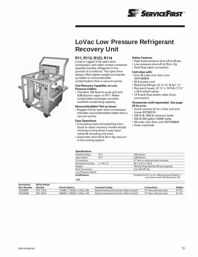
13RSP-PRC002-EN
LoVac Low Pressure RefrigerantRecovery UnitR11, R113, R123, R114Lovac's rugged 2-Hp open drivecompressor and water cooled condenserspeedily transfer refrigerant in thepoorest of conditions. The open drivedesign offers lighter weight and standsup better to noncondensiblecontamination than a vacuum pump.
Fast Recovery Capability on LowPressure Chillers• Transfers 100-lbs/min push pull and
0.66-lbs/min vapor on R11. Water-cooled plate exchanger providesexcellent condensing capacity.
Noncondensibles? Not an Issue!• Rugged 2.0-hp open drive compressor
tolerates noncondensibles better than avacuum pump.
Easy Operations• Evacuating lines and switching from
liquid to vapor recovery modes simplyinvolves turning three 3-way handvalves & rerouting one hose.
• Automatic shut-off at 29-in Hg vacuumin the cooling system
Specifications
Push/Pull Rates R11 100-lbs/minVapor Rates R11 0.66-lbs/minConnections ¾" flare or optional quick connectsDimensions-inches L x W x H 26 ½ x18 ½ x 35 ¾Weight 160-lbs/73-kg (350-lbs/159-kg shipping)Float Connection 3-pin BH 29" HgLow Pressure SwitchCertifications Certified by ETL to UL-1963 standards Rated in
accordance with ARI Standard 740-1998
ServiceFirst RefTec Model
Item Number Number Power Options Controls/Cooling Connections Weight
TOL02067 CRL-115-E 115/60/1, 110/50/1, 2.0Hp, 20A Electromechanical Controls, Water Cooled* ¾" Flare with ball valve 211-lbTOL02068 CRL-240-E 230/60/1, 220/50/1, 2.0Hp, 15A Electromechanical Controls, Water Cooled* ¾" Flare with ball valve 211-lb
Safety Features• High head pressure shut-off at 20-psi• Low pressure shut-off at 29-in. Hg• Tank float cable connection
Unit ships with:• One 48 cubic inch drier core
(DHY00864)• 50 ft power cord• Reducing fittings: (2) 3/4-5/8" & 5/8"-1/2"• Recovery hoses: (2) 3/4" x 10 ft & (1) 3/4"
x 20 ft w/ball valves• 12 ft tank float switch cable (3 pin
connection)
Accessories (sold separately), See page20 for p/ns.• Quick connect kit for LoVac unit and
hoses (KIT08374)• 250 lb & 1000 lb recovery tanks• 250 & 500 gallon ASME tanks• 48 cubic inch drier core (DHY00864)• Hose manifolds

14 RSP-PRC002-EN
LoVac Refrigerant Recovery UnitWith Welch 10.6 CFM VacuumPump
The Industries Fastest CertifiedLow Pressure RefrigerantRecovery Rates R11, R113,R123, R114, R245fa
Features• Transfers 134-lbs/min push pull• 1.26-lbs/min vapor on R11.• Water-cooled plate exchanger provides
excellent condensing capacity.• Easy Operations• Evacuating lines and switching from
liquid to vapor recovery modes simplyinvolves turning three 3-way handvalves & rerouting one hose
• 10.6 CFM Vacuum Pump• Pulls greater than 29Hg vacuum
Specifications
Push/Pull Rates (R11) 134-lbs/minVapor Rates (R11) 1.26-lbs/minConnections ¾" flare or optional quick connectsDimensions - Inches l x w x h 30 x 18 x 35 (shipping 48 x 40 x 42)Weight 225-lbs (shipping 300-lbs)Float Connection 3-pin BH 29" HgCertifications Certified by ETL to UL-1963 standards
Rated in accordance with ARI Standard 740-1998
RefTec Controls/SF Part # Model number Power Options Cooling Connections Weight
LoVac with Integrated Vacuum PumpTOL03398 CRL-V-115-E 110-120V,50/60Hz,1Ph,1Hp,15A Electromechanical, water cooled ¾" Flare with ball valvesTOL03399 CRL-V-240-E 220-240V,50/60Hz,1Ph,1Hp,15A Electromechanical, water cooled ¾" Flare with ball valvesTOL03409 CRL-A-V-115-E 110-120V,50/60Hz,1Ph,1Hp,15A Electromechanical, air cooled ¾" Flare with ball valvesTOL03400 CRL-A-V-240-E 220-240V,50/60Hz,1Ph,1Hp,15A Electromechanical, air cooled ¾" Flare with ball valves
Unit ships with:• One 48 cubic inch drier core
(DHY00864)• 50 ft power cord• Reducing fittings: (2) 3/4-5/4" &
(2) 5/8"-1/2'• Recovery hoses: (2) 3/4" x 10 ft &
(1) 3/4" x 20 ft w/ball valves• 12 ft tank float switch cable (3 pin
connection)
Accessories (sold separately), See page20 for p/ns.• Quick connect kit for LoVac unit and
hoses (KIT08374)• 250 lb & 1000 lb recovery tanks• 250 & 500 gallon ASME tanks• 48 cubic inch drier core (DHY00864)• Hose manifolds
RefTec Capacity/SF Part # Model number Power Options Cooling
LoVac/Vacuum Pump Packaged Tank MountTOL03488 CRL-V-115-A-250 115/60/1, 110/50/1, 2Hp,15A 250-gal/WaterTOL03489 CRL-V-115-A-500 115/60/1, 110/50/1, 2Hp,15A 500-gal/WaterTOL03490 CRL-V-115-A-850 115/60/1, 110/50/1, 2Hp,15A 850-gal/WaterTOL03491 CRL-V-115-A-1000 115/60/1, 110/50/1, 2Hp,15A 1000-gal/WaterTOL03492 CRL-V-240-A-250 230/60/1, 220/50/1, 2Hp,15A 250-gal/WaterTOL03493 CRL-V-240-A-500 230/60/1, 220/50/1, 2Hp,15A 500-gal/WaterTOL03494 CRL-V-240-A-850 230/60/1, 220/50/1, 2Hp,15A 850-gal/WaterTOL03495 CRL-V-240-A-1000 230/60/1, 220/50/1, 2Hp,15A 1000-gal/Water

15RSP-PRC002-EN
R11, R113, R123, R114Recovery Unit
Lovac/ASME Package Unit is integratedwith either a 250, 500, 850 or 1000 gallonASME tank for total pumpout andstorage capability. Multiple voltage andcondensing options are available.
Features• High Speed, High Efficiency Recovery
and storage of all Low PressureRefrigerants
• For use with large tonnage chillers• Unit is hard piped and permanently
mounted on ASME tank• Capable of storing up to 7868lbs of R11
at 80% capacity• Dual 250-psi relief valves on diverting
valve• Mounted on casters for mobility• 80% tank full float switch and 12' cable• Bottom drain connection• Liquid and Vapor ports: ¾" threaded
connection with isolation ball valves• ETL certified
LoVac/ASME Package UnitComplete Pump-Out and StoragePackage
Specifications
Push/Pull (R11) 100-lb/minVapor Rate (R11) .66-lb/minDry Weight 250-gal 2050-lbs (930-kg)
500-gal 2275-lbs (1032-kg)Motor 2.0 HpConnections 3/4 in. FlareDimensions (LxWxH) 250-gal 94" x 38" x 70"
(LxWxH) 500-gal 117.5" x 43" x 75"Certifications Certified by ETL to UL-1963 standards
Rated in accordance with ARI Standard 740-1998
Refrigerant Capacity: 80% full in pounds
Tank Gal R11 R123250 250 2459 2440500 500 4918 4880850 850 7868 78081000 1000 9836 9760
RefTec Capacity/SF Part # Model number Cooling Power Options
TOL03098 CRL-115-A-250 250-gal/Water 103-127V,50/60Hz,1Ph,2Hp,20ATOL03100 CRL-115-A-500 500-gal/Water 103-127V,50/60Hz,1Ph,2Hp,20ATOL03099 CRL-240-A-250 250-gal/Water 220-240V,60/60Hz,1Ph,2Hp,15ATOL03101 CRL-240-A-500 500-gal/Water 220-240V,50/60Hz,1Ph,2Hp,15ATOL03484 CRL-115-A-850 850-gal/Water 103-127V,50/60Hz,1Ph,2Hp,20ATOL03485 CRL-115-A-1000 1000-gal/Water 103-127V,50/60Hz,1Ph,2Hp,20ATOL03486 CRL-240-A-850 850-gal/Water 220-240V,50/60Hz,1Ph,2Hp,15ATOL03487 CRL-240-A-1000 1000-gal/Water 220-240V,50/60Hz,1Ph,2Hp,15A
Unit ships with:• One 48 cubic inch drier core
(DHY00864)• Two 10' x 3/4 " diameter hoses• Two 20' x 3/4 " diameter hoses• 100 ft power cord for controls• 50 ft power cord for unit• 12 ft tank float switch cable (3 pin
connection)• Reducing fittings: (2) 3/4-5/8" & 5/8"-1/2'
Accessories (sold separately), See page20 for p/ns.• Quick connect kit for LoVac unit and
hoses (KIT08374)• 48 cubic inch drier core (DHY00864)• Hose manifolds

16 RSP-PRC002-EN
Allvac Universal RefrigerantRecovery UnitFor use with low (R123, R11)and high (R22, R134, R410a)pressure refrigerants
Features• Combines capabilities of Evac
Commercial & Lovac systems to offergreat recovery rates on R11, R12, R22,R113, R123, R134a, R404, R500, R502,R410a & other high pressurerefrigerants or blends.
• Rugged open drive compressorprovides years of reliable service, evenon refrigerants heavily contaminatedwith oil, air, moisture, & acids.
• Switching between refrigerants simplyinvolves oil & filter changes along withevacuation of the unit.
• Air/water cooled option incorporates awater cooled plate exchanger in linewith the air cooled condenser. Thismodel may operate with or withoutcondensing water.
• This model may operate with orwithout condensing water.
Specifications
Push/Pull Rates (R22) 325-lbs/minVapor Rates (R22) 6.0-lbs/minPush/Pull Rates (R11) 100-lbs/minVapor Rates (R11) 0.66-lbs/minConnections ¾" flareDimensions l x w x h 32" x 32" x 44"Dimensions (shipping) 48" x 40" x 51"Float Connection 3-pin BHLow Pressure Switch 15" Hg or 29" HgCertifications Certified by ETL to UL-1963 standards
Rated in accordance with ARI Standard 740-1998
RefTec Controls/SF Part # Model number Power Options Cooling Weight
TOL01835 ARH-A-230-3-E 220-240V,50/60Hz,3Ph,3Hp,15A Electromechanical Controls, Air Cooled 260-lbTOL01836 ARH-A-240-1-E 220-240V,50/60Hz,1Ph,3Hp,20A Electromechanical Controls, Air Cooled 260-lbTOL01837 ARH-A-460-3-E 360-575V,50/60Hz,3Ph,3Hp,15A Electromechanical Controls, Air Cooled 260-lbTOL01839 ARH-A-D24-1-E 240/460V 50/60Hz,1PH,3Hp,30A Electromechanical Controls, Air Cooled 325-lbTOL01840 ARH-W-230-3-E 220-240V,50/60Hz,3Ph,3Hp,15A Electromechanical Controls, Air/Water Cooled 265-lbTOL01841 ARH-W-240-1-E 220-240V,50/60Hz,1Ph,3Hp,20A Electromechanical Controls, Air/Water Cooled 265-lbTOL01842 ARH-W-460-3-E 360-575V,50/60Hz,3Ph,3Hp,15A Electromechanical Controls, Air/Water Cooled 265-lbTOL01844 ARH-W-D24-1-E 240/460V,50/60Hz,1Ph,3Hp,30A Electromechanical Controls, Air/Water Cooled 330-lb
Unit ships with:• One 48 cubic inch drier core
(DHY00864)• 50 ft power cord for unit• 12 ft tank float switch cable (3 pin
connection)• 50 ft power cord for unit• Two ¾"-¾" & 5/8-1/2" fittings• Two ¾" x 10ft recovery hoses w/ ball
valvesvalves
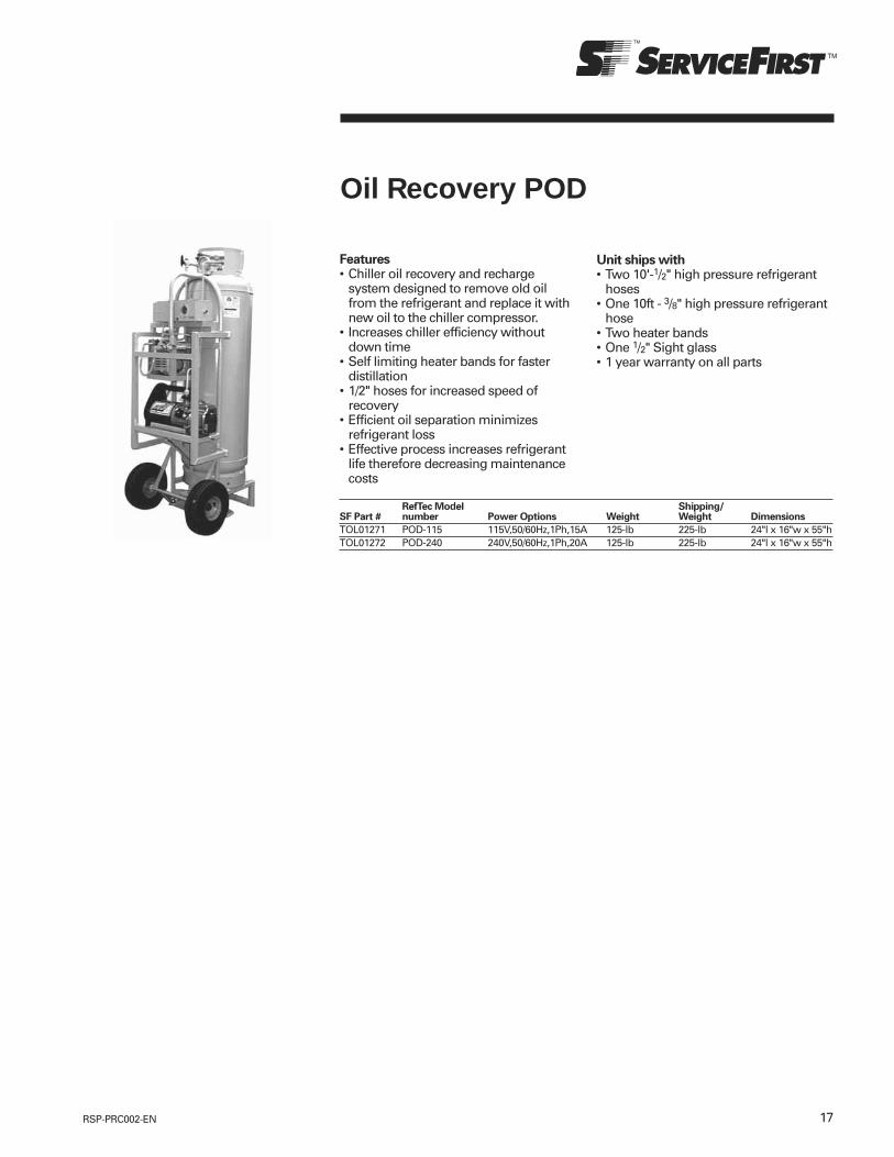
17RSP-PRC002-EN
Oil Recovery POD
Features• Chiller oil recovery and recharge
system designed to remove old oilfrom the refrigerant and replace it withnew oil to the chiller compressor.
• Increases chiller efficiency withoutdown time
• Self limiting heater bands for fasterdistillation
• 1/2" hoses for increased speed ofrecovery
• Efficient oil separation minimizesrefrigerant loss
• Effective process increases refrigerantlife therefore decreasing maintenancecosts
RefTec Model Shipping/SF Part # number Power Options Weight Weight Dimensions
TOL01271 POD-115 115V,50/60Hz,1Ph,15A 125-lb 225-lb 24"l x 16"w x 55"hTOL01272 POD-240 240V,50/60Hz,1Ph,20A 125-lb 225-lb 24"l x 16"w x 55"h
Unit ships with• Two 10'-1/2" high pressure refrigerant
hoses• One 10ft - 3/8" high pressure refrigerant
hose• Two heater bands• One 1/2" Sight glass• 1 year warranty on all parts

18 RSP-PRC002-EN
Refrigerant Liquid Pump
A commercial / industrialgrade pump used to transferall class I, II, III, and IVrefrigerant at rates up to20GPM.
Standard model has 3/4" male flareconnections with quick-connects as anoption.
RefTec Model TransferSF Part # number Power Options Weight Dimensions Weight
TOL03356 RLP-115 110/115V, 50/60HZ, 1PH 1.5 HP, 15 AMP 20GPM 12.0" high x 14.50" wide x 9.0" deep 55-lbTOL03357 RLP-240 220/230V, 50/60HZ, 1PH 1.5 HP, 15 AMP 20GPM 12.0" high x 14.50" wide x 9.0" deep 55-lb
Installation of the oil recovery systemshall be in accordance with all state andlocal, mechanical and electrical codes.
Unit ships with:• Power Cord
Options:• Filter Rack Cart: Single shell 192-Cu
Inch, and Dual shell 384-Cu inch with3/4" flare or quick connects.
• 3/4" hoses 10ft and 20ft.

19RSP-PRC002-EN
Refrigerant Recovery Cylindersand Storage Tanks• Typical recovery tanks have small
diameter ports that restrict refrigerantflow and slow your recoveryprocedures. 250 and 1000-lb D.O.T.tanks have been fitted with full port3/4" service valves and copper diptubes that eliminate restrictions andallow faster refrigerant transfer.
• For R11, R12, R22, R113, R114, R123,R134a, as well as additionalhigh pressure refrigerants and blends.
• Quick connects are available fortanks servicing low pressurerefrigerants only.
ServiceFirst RefTec Model Port Dry Dimensions Working Relief
Item Number Number Description Size Weight (O.D.x L) Pressure Setting
CYL00178 CYL-1000 1000# Tank only 3/4" 358-lbs 30" x 58" 260 psi 420-450 psiCYL00220 CYL-1000-410A 1000# Tank only, R410A approved 3/4" 358-lbs 30" x 58" 400 psi 600 psiCYL00179 CYL-1000-LS 1000# w/80% shut off switch 3/4" 359-lbs 30" x 58" 260 psi 420-450 psiCYL00221 CYL-1000-LS-410A 1000# w/80% shut-off switch, R410a approved 3/4" 359-lbs 30" x 58" 400 psi 600 psiCYL00180 CYL-1000-QC 1000# Tank w/quick connects 3/4" 359-lbs 30" x 58" 260 psi 420-450 psiCYL00181 CYL-1000-LS-QC 1000# Tank w/switch and quick connects 3/4" 360-lbs 30" x 58" 260 psi 420-450 psiCYL00182 CYL-0250 250# Tank only 3/4" 86-lbs 15" x 49" 260 psi 420-450 psiCYL00218 CYL-0250-410A 250# Tank only, R410A approved 3/4" 86-lbs 15" x 49" 400 psi 600 psiCYL00183 CYL-0250-LS 250# w/80% shut off switch 3/4" 87-lbs 15" x 49" 260 psi 420-450 psiCYL00219 CYL-0250-LS-410A 250# w/80% shut-off switch, R410a approved 3/4" 87-lbs 15" x 49" 400 psi 600 psiCYL00184 CYL-0250-QC 250# Tank w/quick connects 3/4" 87-lbs 15" x 49" 260 psi 420-450 psiCYL00185 CYL-0250-LS-QC 250# Tank w/switch and quick connects 3/4" 88-lbs 15" x 49" 260 psi 420-450 psiCYL00186 (1) — 50# Tank only, R410a approved 1/4" 28-lbs 12.5" x 19" 400 psi 600 psiCYL00187 (1) — 50# w/ 80% shut off switch, R410a approved 1/4" 28-lbs 12.5" x 19" 400 psi 600 psiCYL00188 — 30# Tank only, R410a approved 1/4" 16-lbs 9" x 18" 400 psi 600 psiCYL00189 — 30# w/ 80% shut off switch, R410a approved 1/4" 16-lbs 9" x 18" 400 psi 600 psi
• Mounted on casters• High pressure (-HP) tanks: Dual 250-psi relief valves on diverting valve.• Low pressure (-LP) tanks: 250-psi rupture disc & 250-psi relief (meets ASME section
VIII div 1 and ANSI specifications)• Pressure gauge• (3) Sight glass windows• 80% tank full float switch• Bottom drain connection• Liquid and Vapor ports: Threaded connections with isolation ball valves are supplied
standard. Ball valves may be substituted with quick connect fittings on LP tanksonly.
Options (see accessories page 20):• Cable for liquid level cut out switch (CAB00880)• Heating bands for distillation
ServicePart Reftec Model
Part Number Number Capacity Features
TNK00906 ASME-120-075-HP 120-Gallon 3/4" Flare with Ball ValvesTNK00907 ASME-120-075-LP 120-Gallon 3/4" Flare with Ball ValvesTNK00908 ASME-120-075-LP-QC 120-Gallon 3/4" Ports w/Quick ConnectsTNK00837 ASME-250-075-HP 250-Gallon 3/4" Flare with Ball ValvesTNK00838 ASME-250-075-LP 250-Gallon 3/4" Flare with Ball ValvesTNK00839 ASME-250-075-LP-QC 250-Gallon 3/4" Ports w/Quick ConnectsTNK00842 ASME-500-075-HP 500-Gallon 3/4" Flare with Ball ValvesTNK00843 ASME-500-075-LP 500-Gallon 3/4" Flare with Ball ValvesTNK00844 ASME-500-075-LP-QC 500-Gallon 3/4" Ports w/Quick ConnectsTNK00909 ASME-850-075-HP 850 Gallon 3/4" Flare with Ball ValvesTNK00910 ASME-850-075-LP 850 Gallon 3/4" Flare with Ball ValvesTNK00911 ASME-850-075-LP-QC 850 Gallon 3/4" Ports w/Quick Connects
ASME120 ASME250 ASME500 ASME850Length 851/2-in 94-in 113-in 1661/2-inDiameter 30-in 30-in 37-in 401/2-inHeight 39-in 42-in 49-in 41-in
Refrigerant Capacity at 80%
Tank Model Gal Dry Wgt R12 R22 R500 R502 R134a R11 R123ASME-120 120 350-lb 1,097 1,000 1,017 1,020 1,007 1,230 1,220ASME-250 250 650-lb 2,195 2,000 2,034 2,039 2,015 2,459 2,440ASME-500 500 1,200-lb 4,390 4,000 4,068 4,078 4,030 4,918 4,880ASME-850 850 7,320-lb 7,024 6,400 6,508 6,524 6,448 7,868 7,808
DOT RefrigerantStorage Tanks
ASME RefrigerantStorage Tanks

20 RSP-PRC002-EN
Accessories
Recovery Hoses
ServiceFirst RefTec Model
Item Number Number Diameter x Length Connection/Isolation
HSE01126 — 1/4" x 10-ft Flare with no isolationHSE01347 025-006-B-HP-FB 1/4" x 6-ft Flare with ball valves, redHSE01348 — 1/4" x 6-ft Flare with ball valves, blueHSE01128 025-020-HP 1/4" x 20-ft Flare with no isolationHSE01129 025-020-HP-FB 1/4" x 20-ft Flare with ball valvesHSE01130 — 3/8" x 10-ft Flare with no isolationHSE01131 038-010-HP-FB 3/8" x 10-ft Flare with ball valvesHSE01132 — 3/8" x 20-ft Flare with no isolationHSE01133 038-020-HP-FB 3/8" x 20-ft Flare with ball valvesHSE01214 — 1/2" x 10-ft Flare with no isolationHSE01135 050-010-HP-FB 1/2" x 10-ft Flare with ball valvesHSE01136 — 1/2" x 20-ft Flare with no isolationHSE01137 050-020-HP-FB 1/2" x 20-ft Flare with ball valvesHSE01252 — 3/4" x 10-ft Flare with no isolationHSE01647 050-010-LRH 1/2" x (2)10-ft & (1)20-ft Hose Kit with ball valvesHSE01139 075-010-HP-FB 3/4" x 10-ft Flare with ball valvesHSE01140 075-010-HP-QC 3/4" x 10-ft Quick connectsHSE01253 — 3/4" x 20-ft Flare with no isolationHSE01142 075-020-HP-FB 3/4" x 20-ft Flare with ball valvesHSE01143 075-020-HP-QC 3/4" x 20-ft Quick connects
Hoses are compatible with R11, R12,R22, R113, R123, R134a, R500, R502, andother high pressure refrigerants andblends. No hoses may be used on ultrahigh pressure types like R13 and R23.3/4-inch diameter hoses must not beused to recover R410a.
Connection options include flare fittings,ball valves, NPT, and quick connects.Hoses with quick connects are used onlyon low pressure hoses.
Recovery Unit Hose GuideDiablo: 1/4" hosesMicroVac: 1/4" hosesHandiVac 3/8" or 1/4" hosesMityVac: 1/2" hosesLite EVAC: 1/2" hosesEVAC Commercial 3/4" hosesLovac 3/4" hosesAllVac 3/4" hoses
Manifolds split lines to allow 6connections for simultaneous recoveryof multiple tanks or systems
Scale drawing of 3-pin connectorsupplied on RefTec equipment.
Low Pressure Cutout Kit
KIT15102 KIT006 Shuts unit off at 10 inches vacuum for Diablo 115V and240V
Quick Connects
CON00996 QC-075-M 3/4-inch male quick connect fittingCON00997 QC-075-F 3/4-inch female quick connect fitting
Recovery Manifolds
MFD00901 RM-075-6 Six 3/4-inch flare ports with ball valvesMFD00902 RM-050-6 Six 1/2-inch flare ports with ball valvesMFD00920 1/4-inch flare ports with ball valve, R410A
Float Cable
CAB00880 FVC-006 6-ft float cable with 3-pin Brad Harrison connectorsCAB00881 FVC-012 12-ft float cable with 3-pin Brad Harrison connectorsCAB00882 FVC-3T4 3-pin Brad Harrison to 4-pin AMP connector
Shoulder Strap
SRP00908 KIT004 Shoulder Strap for MicroVac
Filter Driers
DHY00816 — 3 cubic inch, 1/4" flare, in-lineDHY00139 — 5 cubic inch, 3/8" flare, in-lineDHY01128 — 30 cubic inch, 1/2" flare, in-lineDHY00864 — 48 cubic inch, replaceable core
Quick Connect Kit
KIT08374 KIT001 Quick Connect Kit
Optional Float Accessory Kit
KIT09188 KIT002 Optional Float Accessory Kit 115V for MicroVacKIT09189 KIT003 Optional Float Accessory Kit 240V for MicroVacKIT15103 KIT007 Optional Float Accessory Kit 115V for DiabloKIT15127 KIT008 Optional Float Accessory Kit 240V for DiabloField installed float kit includes 6-ft. cable (3-pin), tank full lamp and bypass switch. Easily hardwired to theMicrovac or Diablo.

21RSP-PRC002-EN
MiniPurge
MiniPurge portable purge unittemporarily connects to chillers andstorage tanks charged with high or lowpressure refrigerants and rapidlyeliminates noncondensibles. Unit is idealfor supplementing thermal purge unitsduring seasonal start ups onR11 or R123 chillers.
A 0.5 Hp compressor draws refrigerantvapor, pumps it through a condenser,and compresses it in a purge vessel.Condensed refrigerant is forced back tothe cooling system or recovery tank.When pressure rises to a certain point,noncondensibles are discharged withvirtually no loss of refrigerant.
Universal Compatibility• Eliminates air from high or low
pressure refrigerants.• Simply evacuate the unit when
switching to different refrigerants
Highly Portable• At just 65-lbs in weight, MiniPurge is
the lightest purge unit on the marketand is easily hand carried tocontaminated cooling systems.
Fast Purge Speed• Compressor drives the purge process
by actively drawing, processing, andreturning refrigerant to the coolingsystem.
Higher Efficiency for BetterRefrigerant Containment• Vapor passes through a high capacity
air cooled condenser and is thencompressed in the purge vessel tothoroughly condense refrigerant andseparate noncondensibles.Microprocessor controls calculatethe most efficient time todischarge noncondensibles.
Safeties• 300-psi relief on high pressure gases
and 100-psi pressure switch cut off onlow pressure gases.
ServiceFirst RefTec ModelItem Number Number Electrical RequirementsTOL01227 MPS-115 115/60/1, 110/50/1, 0.5Hp, 15ATOL01228 MPS-240 230/60/1, 220/50/1, 0.5Hp, 15ANote: Hoses and power cord not provided.
Specifications
Discharge Efficiency R134a 0.20 lb-refrigerant/lb-noncondensiblesR123 0.08 lb-refrigerant/lb-noncondensibles
Dimensions: LxWxH 36" x 10" x 16"Weight: 65-lbConnections: 3/8-in. FlareRecovers R11, R123, R12, R134a, R22, R507

22 RSP-PRC002-EN
HyperWatt Chiller Pressurizer
Faster Speed of Pressurization• Cycles chiller water at up to 20-gpm
through 30kW vessel.
Easy to Use• Microprocessor displays step-by-step
operating instructions.• When desired chiller pressure level is
reached, the pump shuts down.Automatically re-energizes to maintainstable pressure.
Safeguards Protect Chillerand Components• Microprocessor monitors chiller
pressure and preventsoverpressurization.
• Thermal sensors prevent heatingelement overload and burnout.
• Sensor halts operations should waterflow cease.
Portable and Permanent Mount Models• Handy 125-lb portable model easily
managed by one person andmaneuvered around tightmechanical rooms.
• Permanent mount unit is hard piped toa chiller. Maintains the chiller atslightly positive pressure duringseasonal shutdown.
Dual 230/460V unit: Heating capacitydecreases by about 50% on 230V service.
Included with purchase (Service Cartmodel only)• 100-ft power cord for controls• 50-ft power cord for heaters• 20-ft 1/4" refrigerant hose• Two 10-ft water hoses
On permanent mount model, customersupplies power cord, piping and fittings.
Specifications
Power controls and water pump: 115/60/1, 110/50/1, 15ADimensions (LxWxH) 22" D x 20" W x 51" HWeight: 125-lbDisplay 40 character, 2 row backlighted LCDPressure settings: 0 to 10-psiWarranty 1-year parts
ServiceFirst RefTec ModelItem Number Number Electrical Req. ModelsTOL01243 HPS-C-D24-3 230-460/60/3,220-415/50/3, 20/40A Service CartTOL01245 HPS-P-D24-3 230-460/60/3,220-415/50/3, 20/40A Permanent MountTOL01242 HPS-C-575-3 575/60/3 Service CartTOL01244 HPS-P-575-3 575/60/3 Permanent Mount
Portable Service Cart

23RSP-PRC002-EN
RefTec Custom DesignsLet Reftec design and build the custom units needed tocomplete those specialized jobs encountered in today’smarketplace.
• Caustic environment tools• NEMA 4 enclosures• NEMA 7 explosion proof enclosures• Remote control panels• Specific voltage requirements• Permanent mounts• Water cooled options• Vacuum pump options for recovery
units• ASME tank mounted recovery units• Refrigerant transfer stations
Evac commercial built to NEMA 7Code with explosion proof electricalbox, wiring, piping and motor housing
Ammonia Recovery Units
Custom ASME tanks featuring manwaycovers
• Specific government andenvironmental requirements
• Large tonnage storage of refrigerants• Ammonia recovery• Modified dimensions for tight chiller
rooms• Made to order refrigerant manifolds• R410a storage cylinders• Hard to find tools for specialized
refrigerants• And more!
Contact your local RefTec salesrepresentative and discuss yourapplication.
Examples:
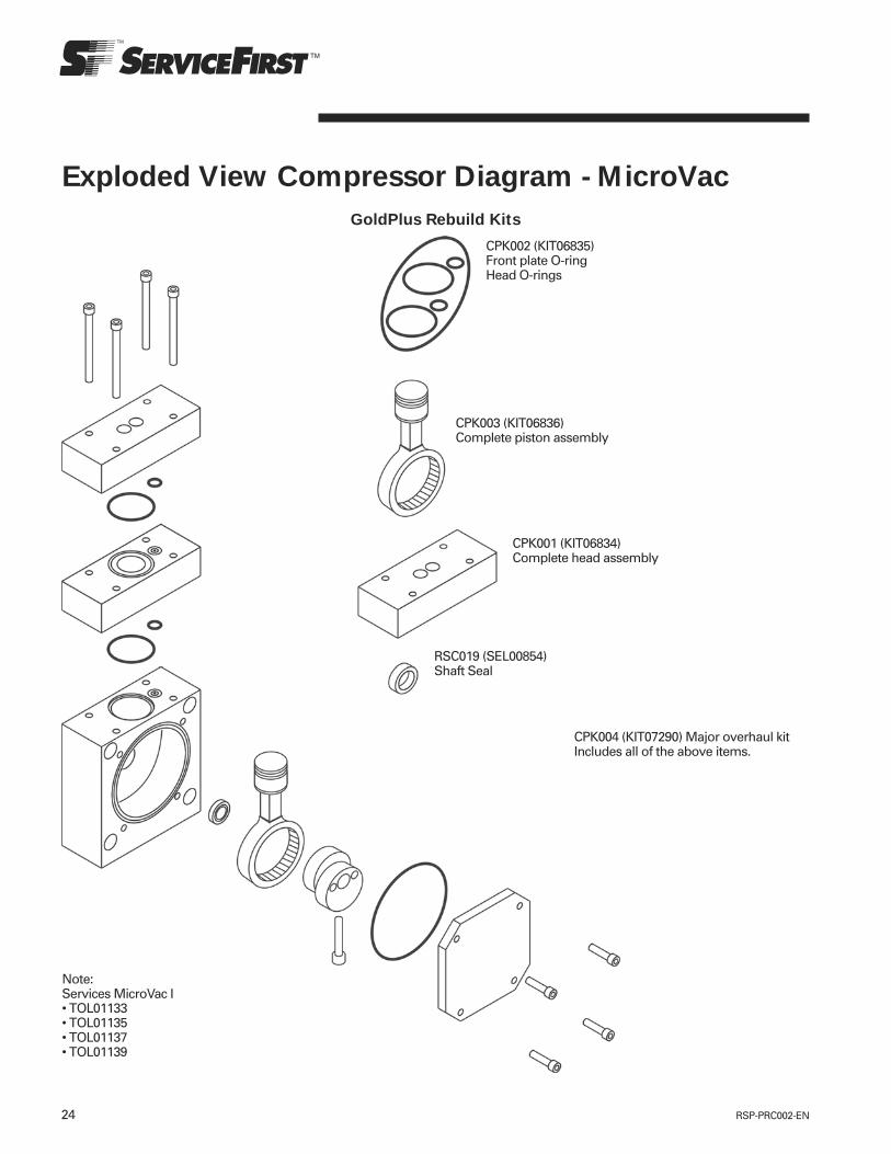
24 RSP-PRC002-EN
Exploded View Compressor Diagram - MicroVacGoldPlus Rebuild Kits
CPK002 (KIT06835)Front plate O-ringHead O-rings
CPK003 (KIT06836)Complete piston assembly
CPK001 (KIT06834)Complete head assembly
RSC019 (SEL00854)Shaft Seal
CPK004 (KIT07290) Major overhaul kitIncludes all of the above items.
Note:Services MicroVac I• TOL01133• TOL01135• TOL01137• TOL01139

25RSP-PRC002-EN
Exploded View Compressor Diagram - MicroVac II
CPK076 (KIT09206)Front plate O-ringHead O-rings
CPK077 (KIT09207)Complete piston assembly
CPK078 (KIT09208)Discharge ball & springSuction valve, spring & clip
RSC019 (SEL00854)Shaft Seal
CPK079 (KIT09209) Major overhaul kitIncludes all of the above items.
Note: For TOL02061 MicroVac II unitsthrough serial # A05C07545.
PlatinumPlus-I Oilless Compressor Rebuild Kits

26 RSP-PRC002-EN
Exploded View Compressor Diagram - MicroVac II
CPK006 (KIT09206)Front plate O-ringHead O-rings
CPK077 (KIT09207)Complete piston assembly
CPK078 (KIT09208)Discharge ball & springSuction valve, spring & clip
RSC019 (SEL00854)Shaft Seal
CPK007 (KIT12241) Major overhaul kitIncludes all of the above items.
Note: For TOL02061 MicroVac II unitswith serial # A05C07546 and higher.
PlatinumPlus-II Oilless Compressor Rebuild Kits


Trane optimizes the performance of homes and buildings around the world. A business of Ingersoll Rand, the leader in creating and sustaining safe, comfortable and energy efficient environments, Trane offers a broad portfolio of advanced controls and HVAC systems, comprehensive building services, and parts.For more information, visit www.Trane.com.
Trane has a policy of continuous product and product data improvement and reserves the right to change design and specifications without notice.
© 2010 Trane All rights reserved
RSP-PRC002-EN 20 Dec 2010
Supersedes RSP-PRC002-EN (09 Feb 2008)

Controls catalog
December 2010 RSP-PRC003-EN
Siemens and Furnas brands
contactors – starters,overload relays – control relays

2 RSP-PRC003-EN© 2003 American Standard Inc. All rights reserved.
3RSP-PRC003-EN
Contents
General Information . . . . . . . . . . . . . . . . . . . . . . . . . . . . . . . . . . . . . . . . . . 4Cross Reference Information . . . . . . . . . . . . . . . . . . . . . . . . . . . . . . . . 14
LOGO Programmable RelaysFeatures & Applications . . . . . . . . . . . . . . . . . . . . . . . . . . . . . . . . . . . . 19Selection Procedure . . . . . . . . . . . . . . . . . . . . . . . . . . . . . . . . . . . . . . . 20
AC DisconnectsFeatures & Benefits . . . . . . . . . . . . . . . . . . . . . . . . . . . . . . . . . . . . . . . 21
Definite Purpose Centurion 2000 Contactors:Features & Applications . . . . . . . . . . . . . . . . . . . . . . . . . . . . . . . . . . . . 22Selection Procedure . . . . . . . . . . . . . . . . . . . . . . . . . . . . . . . . . . . . . . . 25Accessories . . . . . . . . . . . . . . . . . . . . . . . . . . . . . . . . . . . . . . . . . . . . . 26Diagrams . . . . . . . . . . . . . . . . . . . . . . . . . . . . . . . . . . . . . . . . . . . . . . . 28
Definite Purpose Contactors Standard Line:Selection Procedure . . . . . . . . . . . . . . . . . . . . . . . . . . . . . . . . . . . . . . . 31Accessories . . . . . . . . . . . . . . . . . . . . . . . . . . . . . . . . . . . . . . . . . . . . . 32Diagrams . . . . . . . . . . . . . . . . . . . . . . . . . . . . . . . . . . . . . . . . . . . . . . . 33
NEMA Contactors:Features & Applications . . . . . . . . . . . . . . . . . . . . . . . . . . . . . . . . . . . . 34Heavy Duty Non-Reversing Contactors:Selection Procedure . . . . . . . . . . . . . . . . . . . . . . . . . . . . . . . . . . . . . . . 36Heavy Duty Reversing Contactors:Selections Procedure . . . . . . . . . . . . . . . . . . . . . . . . . . . . . . . . . . . . . . 38NEMA Contactors AccessoriesSelections Procedure . . . . . . . . . . . . . . . . . . . . . . . . . . . . . . . . . . . . . . 39NEMA ContactorsDiagrams . . . . . . . . . . . . . . . . . . . . . . . . . . . . . . . . . . . . . . . . . . . . . . . 42
Overload RelaysESP100 Solid StateFeatures & Applications . . . . . . . . . . . . . . . . . . . . . . . . . . . . . . . . . . . . 46Selection Procedure . . . . . . . . . . . . . . . . . . . . . . . . . . . . . . . . . . . . . . . 47Diagrams . . . . . . . . . . . . . . . . . . . . . . . . . . . . . . . . . . . . . . . . . . . . . . . 48Special Use Solid StateFeatures & Applications . . . . . . . . . . . . . . . . . . . . . . . . . . . . . . . . . . . . 49Selection Procedure . . . . . . . . . . . . . . . . . . . . . . . . . . . . . . . . . . . . . . . 52AccessoriesDiagrams . . . . . . . . . . . . . . . . . . . . . . . . . . . . . . . . . . . . . . . . . . . . . . . 53
NEMA Motor StartersHeavy Duty Reversing, Non-Reversing & Accessories . . . . . . . . . . . . 54Features & Applications . . . . . . . . . . . . . . . . . . . . . . . . . . . . . . . . . . . . 55Selection Procedure . . . . . . . . . . . . . . . . . . . . . . . . . . . . . . . . . . . . . . . 57Diagrams . . . . . . . . . . . . . . . . . . . . . . . . . . . . . . . . . . . . . . . . . . . . . . . 63
4 RSP-PRC003-EN
GeneralInformation
North American Approvals
Installation ConsiderationsThe control products described in thiscatalog have been designed, tested andmanufactured in accordance with a widevariety of standards including but notlimited to those issued by UL, CSA,NEMA and IEC. These standardstypically apply to the control product as acomponent and not the installation oruse of the product. It is the responsibilityof the end user of the control product tomake sure each installation complieswith all of the applicable safetyrequirements, laws, regulations, codesand standards (some examples of which
are the N.E.C., the C.E.C. and OSHAregulations). Note that local authoritiesmay impose further jurisdiction overeach installation. When in doubt, consultwith the local inspection authorities.
Unless otherwise specified, the controlproducts described in this catalog aredesigned to operate under “usualservice conditions” as defined in NEMAStandards Publication — Part ICS 1-108.Open type devices are intended forinstallation in enclosures that provideenvironmental protection as needed forthe specific application. See page 14 fordefinitions of the various enclosuretypes.
Performance DataWhere given in this catalog,performance data should only be usedas a guide to determine the suitability ofthe product for an application. The datamay be the result of accelerated testingor elevated stress levels undercontrolled conditions. The user musttake care in correlating this data to actualapplication or service conditions.
UL and CSA—File Numbers and GuideCard NumbersMost control equipment listed in thiscatalog is designed, manufactured andtested in accordance with the relevantUL and CSA standards as listed in thetable below.
Furnas Brand Devices
Class Guide No File No Guide No File No Guide No File No
14, 22, 30, 40, 43 Class 3211 LR 6535 NLDX E 14900 NLDX2 E 14900Starters and Contactors16, 41, 42, 45 Class 3211 LR 6535 — — NLDX2 E 14900Definite Purpose Controls48, 948, 958 Class 3211 LR 6535 NKCR E 22655 NKCR2 E 22655Overload Relays
5RSP-PRC003-EN
GeneralInformation
National Authorities for Standards and SpecificationsApproval
Abbreviation Identification Meaning
American National Standards Institute
ANSI Publishes specifications and standards in virtually all fields (not only electrical). For low-voltage switchgear,the ANSI has adopted the American NEMA and UL specifications to a large extent
AS Australian StandardsAlready partially adapted to IEC
BS British Standard
Already partially adapted to IECCE Communautés Européenes
European conformity marking. Certifies the conformance of a product with all the product related standards of theEuropean Union (EU)
CEE International Commission on Rules for the Approval of Electrical EquipmentPartially used by the Scandinavian countries as a basis for low-voltage switchgear with rated currents up to 63A
CEI Comitato Elettrotecnico Italiano
Italian electrotechnical committeeCEMA Canadian Electrical Manufacturers Association
CEN Comité Éuropéen de NormalisationEuropean committee for standardization
CENELEC Comité Éuropéen de Normalisation Electrotechnique
European committee for electrotechnical standardization (general secretariat in Brussels)CSA Canadian Standards Association
Responsible for publishing standards and granting approvalsDEMKO Danmarks Elektriske Materielkontrol
Danish board of control for electrotechnical products. Responsible for publishing standards and granting approvalsDIN Deutsches Institut für Normung e.V (German Industrial Standards)
EEMAC Electrical and Electronic Manufactures Association Canada
IEC International Electrotechnical Commission
(French: CEI) All the major industrialized countries are involved in the work of the International Electrotechnical Commission.The resulting IEC recommendations are to some extent either adopted directly into national specifications and standards, orthe national specifications and standards are adapted to harmonize with these recommendations
IEEE Institute of Electrical and Electronics Engineers
IS Indian Standard (Indische Bestimmungen)Already partially adapted to IEC
ISO International Organization for Standardization
JIS Japanese Industrial Standard
KEMA Keuring van Elektrotechnische Materialen
Dutch testing authority, which also performs CSA approval tests for European manufacturersNBN Normes de l’Institut Belge de Normalisation
Standards issued by the Belgian standards institute (already partially adapted to IEC)NEMA National Electrical Manufacturers Association
NEMKO Norges Elektriske MateriellkontrollNorwegian controls authority for electrotechnical products, responsible for publishing standards and granting approvals
NEN Nederlandse Norm
Dutch standardÖVE Österreichischer Verband für Elektrotechnik
Austrian association for electrotechnology. Conforms to a large extent with the DIN VDE and IEC specificationsRER Rafmagnseftrilit rikisins
Finnish testing authority for electrotechnical productsSABS South African Bureau of Standards
SASO Saudi Arabien Standard Organization
SEMKO Svenska Electriska Materielkontrollanstalten
Swedish controls authority for electrotechnical products, responsible for publishing standards and granting approvalsSEN Svenska Elektrotekniska Normer
Swedish electrotechnical standardsSETI Finnish electrotechnical testing authority
SEV Swiss electrotechnical association
UL Underwriters’ Laboratories Inc.:
Testing authority of the national fire insurance in the USA. Among other activities, it carries out testingon electrotechnical products, and issues the corresponding specifications and regulations
UTE Union Technique de l’Électricité:
French electrotechnical associationVDE Verband Deutscher Elektrotechniker e.V. (Association of German Electrical Engineers)
International Approvals
Siemens control is designed,manufactured and tested in accordancewith relevant IEC standards, CENELECAgreement Documents and DIN VDE
0660 requirements. This global designphilosophy assures that most allSiemens low-voltage equipment can beused worldwide. Occasionally, there maybe some restrictions on maximum
permitted voltages, currents and ratingsand, in others, special approval ormarkings may be necessary.
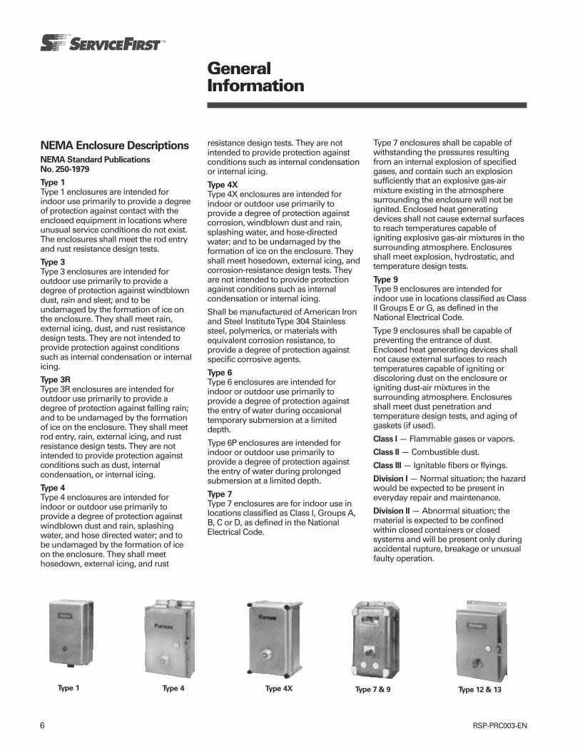
6 RSP-PRC003-EN
NEMA Enclosure Descriptions
NEMA Standard PublicationsNo. 250-1979
Type 1Type 1 enclosures are intended forindoor use primarily to provide a degreeof protection against contact with theenclosed equipment in locations whereunusual service conditions do not exist.The enclosures shall meet the rod entryand rust resistance design tests.
Type 3Type 3 enclosures are intended foroutdoor use primarily to provide adegree of protection against windblowndust, rain and sleet; and to beundamaged by the formation of ice onthe enclosure. They shall meet rain,external icing, dust, and rust resistancedesign tests. They are not intended toprovide protection against conditionssuch as internal condensation or internalicing.
Type 3RType 3R enclosures are intended foroutdoor use primarily to provide adegree of protection against falling rain;and to be undamaged by the formationof ice on the enclosure. They shall meetrod entry, rain, external icing, and rustresistance design tests. They are notintended to provide protection againstconditions such as dust, internalcondensation, or internal icing.
Type 4Type 4 enclosures are intended forindoor or outdoor use primarily toprovide a degree of protection againstwindblown dust and rain, splashingwater, and hose directed water; and tobe undamaged by the formation of iceon the enclosure. They shall meethosedown, external icing, and rust
GeneralInformation
resistance design tests. They are notintended to provide protection againstconditions such as internal condensationor internal icing.
Type 4XType 4X enclosures are intended forindoor or outdoor use primarily toprovide a degree of protection againstcorrosion, windblown dust and rain,splashing water, and hose-directedwater; and to be undamaged by theformation of ice on the enclosure. Theyshall meet hosedown, external icing, andcorrosion-resistance design tests. Theyare not intended to provide protectionagainst conditions such as internalcondensation or internal icing.
Shall be manufactured of American Ironand Steel Institute Type 304 Stainlesssteel, polymerics, or materials withequivalent corrosion resistance, toprovide a degree of protection againstspecific corrosive agents.
Type 6Type 6 enclosures are intended forindoor or outdoor use primarily toprovide a degree of protection againstthe entry of water during occasionaltemporary submersion at a limiteddepth.
Type 6P enclosures are intended forindoor or outdoor use primarily toprovide a degree of protection againstthe entry of water during prolongedsubmersion at a limited depth.
Type 7Type 7 enclosures are for indoor use inlocations classified as Class l, Groups A,B, C or D, as defined in the NationalElectrical Code.
Type 7 enclosures shall be capable ofwithstanding the pressures resultingfrom an internal explosion of specifiedgases, and contain such an explosionsufficiently that an explosive gas-airmixture existing in the atmospheresurrounding the enclosure will not beignited. Enclosed heat generatingdevices shall not cause external surfacesto reach temperatures capable ofigniting explosive gas-air mixtures in thesurrounding atmosphere. Enclosuresshall meet explosion, hydrostatic, andtemperature design tests.
Type 9Type 9 enclosures are intended forindoor use in locations classified as Classll Groups E or G, as defined in theNational Electrical Code.
Type 9 enclosures shall be capable ofpreventing the entrance of dust.Enclosed heat generating devices shallnot cause external surfaces to reachtemperatures capable of igniting ordiscoloring dust on the enclosure origniting dust-air mixtures in thesurrounding atmosphere. Enclosuresshall meet dust penetration andtemperature design tests, and aging ofgaskets (if used).
Class l — Flammable gases or vapors.
Class ll — Combustible dust.
Class lll — Ignitable fibers or flyings.
Division l — Normal situation; the hazardwould be expected to be present ineveryday repair and maintenance.
Division ll — Abnormal situation; thematerial is expected to be confinedwithin closed containers or closedsystems and will be present only duringaccidental rupture, breakage or unusualfaulty operation.
Type 4 Type 4X Type 7 & 9 Type 12 & 13Type 1
7RSP-PRC003-EN
GeneralInformation
GroupsClass l — Gases and vapors are brokeninto 4 groups, A, B, C, and D, dependingon the ignition temperature of thesubstance, its explosion pressure andother flammable characteristics.
Class ll — Dust locations are broken intogroups E, F, and G, according to theignition temperature and conductivity ofthe hazardous substance.
Type 12Type 12 enclosures are intended forindoor use primarily to provide a degreeof protection against dust, falling dirt,and dripping non-corrosive liquids. Theyshall meet drip, dust, and rust resistancedesign tests. They are not intended toprovide protection against conditionssuch as internal condensation.
Siemens-Furnas NEMA 12 may be fieldmodified for outdoor use. NEMA 3requires the use of watertight conduithubs. NEMA 3R requires the use ofwatertight conduit hubs at a level abovethe lowest live part and drain holes of1/8” diameter shall be added at thebottom of the enclosure.
Type 13Type 13 enclosures are intended forindoor use primarily to provide a degreeof protection against dust, spraying ofwater, oil, and non-corrosive coolant.They shall meet oil explosion and rustresistance design tests. They are notintended to provide protection againstconditions such as internalcondensation.
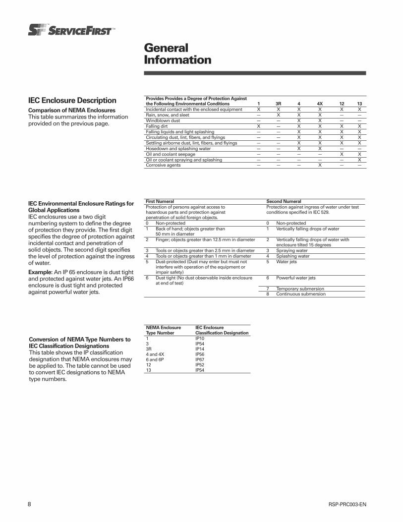
8 RSP-PRC003-EN
GeneralInformation
IEC Enclosure Description
Comparison of NEMA EnclosuresThis table summarizes the informationprovided on the previous page.
Provides Provides a Degree of Protection Againstthe Following Environmental Conditions 1 3R 4 4X 12 13
Incidental contact with the enclosed equipment X X X X X XRain, snow, and sleet — X X X — —Windblown dust — — X X — —Falling dirt X — X X X XFalling liquids and light splashing — — X X X XCirculating dust, lint, fibers, and flyings — — X X X XSettling airborne dust, lint, fibers, and flyings — — X X X XHosedown and splashing water — — X X — —Oil and coolant seepage — — — — X XOil or coolant spraying and splashing — — — — — XCorrosive agents — — — X — —
IEC Environmental Enclosure Ratings forGlobal ApplicationsIEC enclosures use a two digitnumbering system to define the degreeof protection they provide. The first digitspecifies the degree of protection againstincidental contact and penetration ofsolid objects. The second digit specifiesthe level of protection against the ingressof water.
Example: An IP 65 enclosure is dust tightand protected against water jets. An IP66enclosure is dust tight and protectedagainst powerful water jets.
First Numeral Second Numeral
Protection of persons against access to Protection against ingress of water under testhazardous parts and protection against conditions specified in IEC 529.penetration of solid foreign objects.0 Non-protected 0 Non-protected1 Back of hand; objects greater than 1 Vertically falling drops of water
50 mm in diameter2 Finger; objects greater than 12.5 mm in diameter 2 Vertically falling drops of water with
enclosure tilted 15 degrees3 Tools or objects greater than 2.5 mm in diameter 3 Spraying water4 Tools or objects greater than 1 mm in diameter 4 Splashing water5 Dust-protected (Dust may enter but must not 5 Water jets
interfere with operation of the equipment orimpair safety)
6 Dust tight (No dust observable inside enclosure 6 Powerful water jetsat end of test)
7 Temporary submersion8 Continuous submersion
Conversion of NEMA Type Numbers toIEC Classification DesignationsThis table shows the IP classificationdesignation that NEMA enclosures maybe applied to. The table cannot be usedto convert IEC designations to NEMAtype numbers.
NEMA Enclosure IEC Enclosure
Type Number Classification Designation
1 IP103 IP543R IP144 and 4X IP566 and 6P IP6712 IP5213 IP54
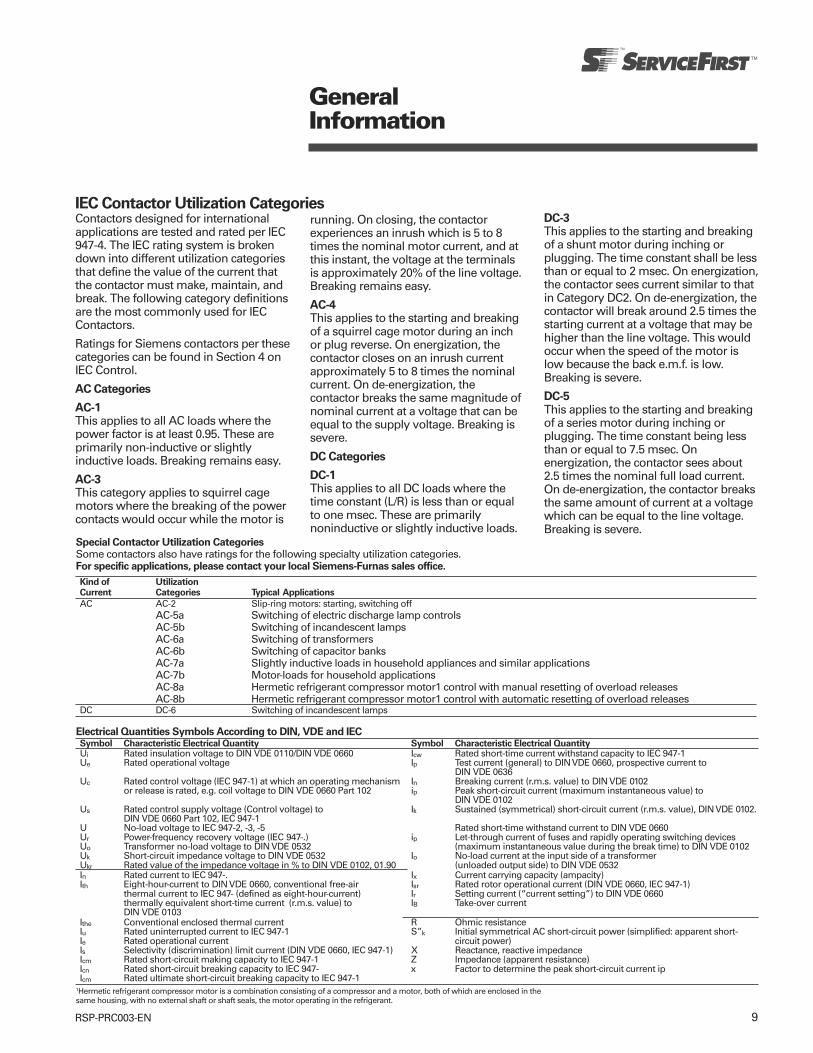
9RSP-PRC003-EN
GeneralInformation
IEC Contactor Utilization CategoriesContactors designed for internationalapplications are tested and rated per IEC947-4. The IEC rating system is brokendown into different utilization categoriesthat define the value of the current thatthe contactor must make, maintain, andbreak. The following category definitionsare the most commonly used for IECContactors.
Ratings for Siemens contactors per thesecategories can be found in Section 4 onIEC Control.
AC Categories
AC-1This applies to all AC loads where thepower factor is at least 0.95. These areprimarily non-inductive or slightlyinductive loads. Breaking remains easy.
AC-3This category applies to squirrel cagemotors where the breaking of the powercontacts would occur while the motor is
running. On closing, the contactorexperiences an inrush which is 5 to 8times the nominal motor current, and atthis instant, the voltage at the terminalsis approximately 20% of the line voltage.Breaking remains easy.
AC-4This applies to the starting and breakingof a squirrel cage motor during an inchor plug reverse. On energization, thecontactor closes on an inrush currentapproximately 5 to 8 times the nominalcurrent. On de-energization, thecontactor breaks the same magnitude ofnominal current at a voltage that can beequal to the supply voltage. Breaking issevere.
DC Categories
DC-1This applies to all DC loads where thetime constant (L/R) is less than or equalto one msec. These are primarilynoninductive or slightly inductive loads.
DC-3This applies to the starting and breakingof a shunt motor during inching orplugging. The time constant shall be lessthan or equal to 2 msec. On energization,the contactor sees current similar to thatin Category DC2. On de-energization, thecontactor will break around 2.5 times thestarting current at a voltage that may behigher than the line voltage. This wouldoccur when the speed of the motor islow because the back e.m.f. is low.Breaking is severe.
DC-5This applies to the starting and breakingof a series motor during inching orplugging. The time constant being lessthan or equal to 7.5 msec. Onenergization, the contactor sees about2.5 times the nominal full load current.On de-energization, the contactor breaksthe same amount of current at a voltagewhich can be equal to the line voltage.Breaking is severe.
Special Contactor Utilization CategoriesSome contactors also have ratings for the following specialty utilization categories.For specific applications, please contact your local Siemens-Furnas sales office.
Kind of UtilizationCurrent Categories Typical Applications
AC AC-2 Slip-ring motors: starting, switching offAC-5a Switching of electric discharge lamp controlsAC-5b Switching of incandescent lampsAC-6a Switching of transformersAC-6b Switching of capacitor banksAC-7a Slightly inductive loads in household appliances and similar applicationsAC-7b Motor-loads for household applicationsAC-8a Hermetic refrigerant compressor motor1 control with manual resetting of overload releasesAC-8b Hermetic refrigerant compressor motor1 control with automatic resetting of overload releases
DC DC-6 Switching of incandescent lamps
Electrical Quantities Symbols According to DIN, VDE and IECSymbol Characteristic Electrical Quantity Symbol Characteristic Electrical QuantityUi Rated insulation voltage to DIN VDE 0110/DIN VDE 0660 Icw Rated short-time current withstand capacity to IEC 947-1Ue Rated operational voltage Ip Test current (general) to DIN VDE 0660, prospective current to
DIN VDE 0636Uc Rated control voltage (IEC 947-1) at which an operating mechanism In Breaking current (r.m.s. value) to DIN VDE 0102
or release is rated, e.g. coil voltage to DIN VDE 0660 Part 102 ip Peak short-circuit current (maximum instantaneous value) toDIN VDE 0102
Us Rated control supply voltage (Control voltage) to Ik Sustained (symmetrical) short-circuit current (r.m.s. value), DIN VDE 0102.DIN VDE 0660 Part 102, IEC 947-1
U No-load voltage to IEC 947-2, -3, -5 Rated short-time withstand current to DIN VDE 0660Ur Power-frequency recovery voltage (IEC 947-.) ip Let-through current of fuses and rapidly operating switching devicesUo Transformer no-load voltage to DIN VDE 0532 (maximum instantaneous value during the break time) to DIN VDE 0102Uk Short-circuit impedance voltage to DIN VDE 0532 Io No-load current at the input side of a transformerUkr Rated value of the impedance voltage in % to DIN VDE 0102, 01.90 (unloaded output side) to DIN VDE 0532In Rated current to IEC 947-. Ix Current carrying capacity (ampacity)Ith Eight-hour-current to DIN VDE 0660, conventional free-air Isr Rated rotor operational current (DIN VDE 0660, IEC 947-1)
thermal current to IEC 947- (defined as eight-hour-current) Ir Setting current (“current setting”) to DIN VDE 0660thermally equivalent short-time current (r.m.s. value) to IB Take-over currentDIN VDE 0103
Ithe Conventional enclosed thermal current R Ohmic resistanceIu Rated uninterrupted current to IEC 947-1 S”k Initial symmetrical AC short-circuit power (simplified: apparent short-Ie Rated operational current circuit power)Is Selectivity (discrimination) limit current (DIN VDE 0660, IEC 947-1) X Reactance, reactive impedanceIcm Rated short-circuit making capacity to IEC 947-1 Z Impedance (apparent resistance)Icn Rated short-circuit breaking capacity to IEC 947- x Factor to determine the peak short-circuit current ipIcm Rated ultimate short-circuit breaking capacity to IEC 947-1
1Hermetic refrigerant compressor motor is a combination consisting of a compressor and a motor, both of which are enclosed in thesame housing, with no external shaft or shaft seals, the motor operating in the refrigerant.
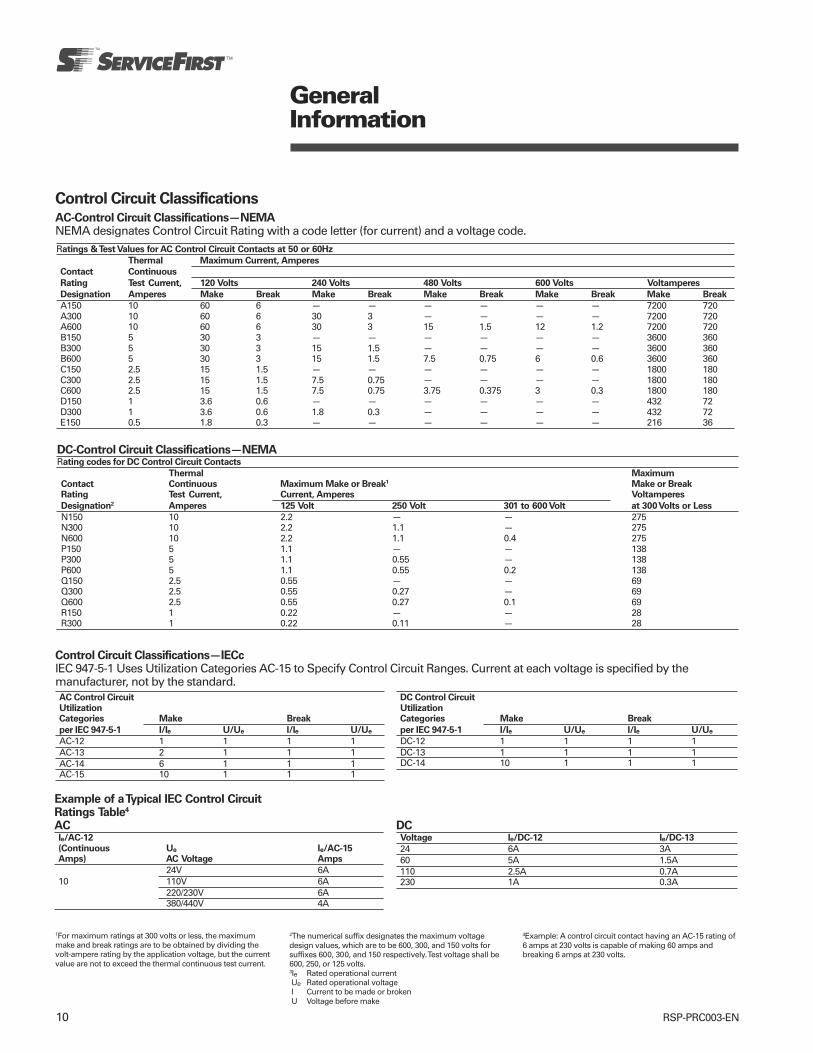
10 RSP-PRC003-EN
GeneralInformation
Control Circuit ClassificationsAC-Control Circuit Classifications—NEMANEMA designates Control Circuit Rating with a code letter (for current) and a voltage code.Ratings & Test Values for AC Control Circuit Contacts at 50 or 60Hz
Thermal Maximum Current, Amperes
Contact Continuous
Rating Test Current, 120 Volts 240 Volts 480 Volts 600 Volts Voltamperes
Designation Amperes Make Break Make Break Make Break Make Break Make Break
A150 10 60 6 — — — — — — 7200 720A300 10 60 6 30 3 — — — — 7200 720A600 10 60 6 30 3 15 1.5 12 1.2 7200 720B150 5 30 3 — — — — — — 3600 360B300 5 30 3 15 1.5 — — — — 3600 360B600 5 30 3 15 1.5 7.5 0.75 6 0.6 3600 360C150 2.5 15 1.5 — — — — — — 1800 180C300 2.5 15 1.5 7.5 0.75 — — — — 1800 180C600 2.5 15 1.5 7.5 0.75 3.75 0.375 3 0.3 1800 180D150 1 3.6 0.6 — — — — — — 432 72D300 1 3.6 0.6 1.8 0.3 — — — — 432 72E150 0.5 1.8 0.3 — — — — — — 216 36
DC-Control Circuit Classifications—NEMARating codes for DC Control Circuit Contacts
Thermal Maximum
Contact Continuous Maximum Make or Break1 Make or BreakRating Test Current, Current, Amperes Voltamperes
Designation2 Amperes 125 Volt 250 Volt 301 to 600 Volt at 300 Volts or Less
N150 10 2.2 — — 275N300 10 2.2 1.1 — 275N600 10 2.2 1.1 0.4 275P150 5 1.1 — — 138P300 5 1.1 0.55 — 138P600 5 1.1 0.55 0.2 138Q150 2.5 0.55 — — 69Q300 2.5 0.55 0.27 — 69Q600 2.5 0.55 0.27 0.1 69R150 1 0.22 — — 28R300 1 0.22 0.11 — 28
Control Circuit Classifications—IECcIEC 947-5-1 Uses Utilization Categories AC-15 to Specify Control Circuit Ranges. Current at each voltage is specified by themanufacturer, not by the standard.AC Control Circuit
UtilizationCategories Make Break
per IEC 947-5-1 I/Ie U/Ue I/Ie U/Ue
AC-12 1 1 1 1AC-13 2 1 1 1AC-14 6 1 1 1AC-15 10 1 1 1
DC Control Circuit
UtilizationCategories Make Break
per IEC 947-5-1 I/Ie U/Ue I/Ie U/Ue
DC-12 1 1 1 1DC-13 1 1 1 1DC-14 10 1 1 1
Example of a Typical IEC Control CircuitRatings Table4
ACIe/AC-12
(Continuous Ue Ie/AC-15Amps) AC Voltage Amps
24V 6A10 110V 6A
220/230V 6A380/440V 4A
DCVoltage Ie/DC-12 Ie/DC-13
24 6A 3A60 5A 1.5A110 2.5A 0.7A230 1A 0.3A
1For maximum ratings at 300 volts or less, the maximummake and break ratings are to be obtained by dividing thevolt-ampere rating by the application voltage, but the currentvalue are not to exceed the thermal continuous test current.
2The numerical suffix designates the maximum voltagedesign values, which are to be 600, 300, and 150 volts forsuffixes 600, 300, and 150 respectively. Test voltage shall be600, 250, or 125 volts.3Ie Rated operational current Ue Rated operational voltage I Current to be made or broken U Voltage before make
4Example: A control circuit contact having an AC-15 rating of6 amps at 230 volts is capable of making 60 amps andbreaking 6 amps at 230 volts.
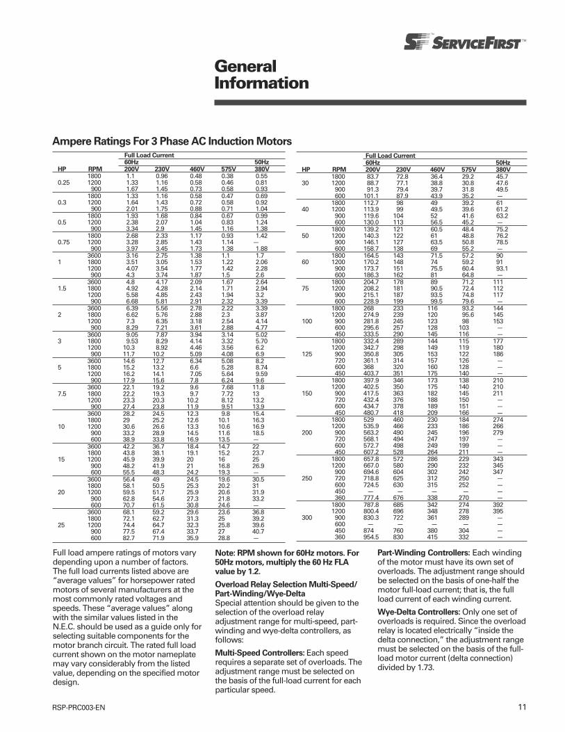
11RSP-PRC003-EN
GeneralInformation
Ampere Ratings For 3 Phase AC Induction MotorsFull Load Current60Hz 50Hz
HP RPM 200V 230V 460V 575V 380V1800 1.1 0.96 0.48 0.38 0.55
0.25 1200 1.33 1.16 0.58 0.46 0.81900 1.67 1.45 0.73 0.58 0.93
1800 1.33 1.16 0.58 0.47 0.690.3 1200 1.64 1.43 0.72 0.58 0.92
900 2.01 1.75 0.88 0.71 1.041800 1.93 1.68 0.84 0.67 0.99
0.5 1200 2.38 2.07 1.04 0.83 1.24900 3.34 2.9 1.45 1.16 1.38
1800 2.68 2.33 1.17 0.93 1.420.75 1200 3.28 2.85 1.43 1.14 —
900 3.97 3.45 1.73 1.38 1.883600 3.16 2.75 1.38 1.1 1.7
1 1800 3.51 3.05 1.53 1.22 2.061200 4.07 3.54 1.77 1.42 2.28900 4.3 3.74 1.87 1.5 2.6
3600 4.8 4.17 2.09 1.67 2.641.5 1800 4.92 4.28 2.14 1.71 2.94
1200 5.58 4.85 2.43 1.94 3.2900 6.68 5.81 2.91 2.32 3.39
3600 6.39 5.56 2.78 2.22 3.392 1800 6.62 5.76 2.88 2.3 3.87
1200 7.3 6.35 3.18 2.54 4.14900 8.29 7.21 3.61 2.88 4.77
3600 9.05 7.87 3.94 3.14 5.023 1800 9.53 8.29 4.14 3.32 5.70
1200 10.3 8.92 4.46 3.56 6.2900 11.7 10.2 5.09 4.08 6.9
3600 14.6 12.7 6.34 5.08 8.25 1800 15.2 13.2 6.6 5.28 8.74
1200 16.2 14.1 7.05 5.64 9.59900 17.9 15.6 7.8 6.24 9.6
3600 22.1 19.2 9.6 7.68 11.87.5 1800 22.2 19.3 9.7 7.72 13
1200 23.3 20.3 10.2 8.12 13.2900 27.4 23.8 11.9 9.51 13.9
3600 28.2 24.5 12.3 9.8 15.41800 29 25.2 12.6 10.1 16.3
10 1200 30.6 26.6 13.3 10.6 16.9900 33.2 28.9 14.5 11.6 18.5600 38.9 33.8 16.9 13.5 —
3600 42.2 36.7 18.4 14.7 221800 43.8 38.1 19.1 15.2 23.7
15 1200 45.9 39.9 20 16 25900 48.2 41.9 21 16.8 26.9600 55.5 48.3 24.2 19.3 —
3600 56.4 49 24.5 19.6 30.51800 58.1 50.5 25.3 20.2 31
20 1200 59.5 51.7 25.9 20.6 31.9900 62.8 54.6 27.3 21.8 33.2600 70.7 61.5 30.8 24.6 —
3600 68.1 59.2 29.6 23.6 36.81800 72.1 62.7 31.3 25 39.2
25 1200 74.4 64.7 32.3 25.8 39.6900 77.5 67.4 33.7 27 40.7600 82.7 71.9 35.9 28.8 —
Full Load Current60Hz 50Hz
HP RPM 200V 230V 460V 575V 380V1800 83.7 72.8 36.4 29.2 45.7
30 1200 88.7 77.1 38.8 30.8 47.6900 91.3 79.4 39.7 31.8 49.5600 101.1 87.9 43.9 35.2 —
1800 112.7 98 49 39.2 6140 1200 113.9 99 49.5 39.6 61.2
900 119.6 104 52 41.6 63.2600 130.0 113 56.5 45.2 —
1800 139.2 121 60.5 48.4 75.250 1200 140.3 122 61 48.8 76.2
900 146.1 127 63.5 50.8 78.5600 158.7 138 69 55.2 —
1800 164.5 143 71.5 57.2 9060 1200 170.2 148 74 59.2 91
900 173.7 151 75.5 60.4 93.1600 186.3 162 81 64.8 —
1800 204.7 178 89 71.2 11175 1200 208.2 181 90.5 72.4 112
900 215.1 187 93.5 74.8 117600 228.9 199 99.5 79.6 —
1800 268 233 116 93.2 1441200 274.9 239 120 95.6 145
100 900 281.8 245 123 98 153600 295.6 257 128 103 —450 333.5 290 145 116 —
1800 332.4 289 144 115 1771200 342.7 298 149 119 180
125 900 350.8 305 153 122 186720 361.1 314 157 126 —600 368 320 160 128 —450 403.7 351 175 140 —
1800 397.9 346 173 138 2101200 402.5 350 175 140 210
150 900 417.5 363 182 145 211720 432.4 376 188 150 —600 434.7 378 189 151 —450 480.7 418 209 166 —
1800 529 460 230 184 2741200 535.9 466 233 186 266
200 900 563.2 490 245 196 279720 568.1 494 247 197 —600 572.7 498 249 199 —450 607.2 528 264 211 —
1800 657.8 572 286 229 3431200 667.0 580 290 232 345900 694.6 604 302 242 347
250 720 718.8 625 312 250 —600 724.5 630 315 252 —450 — — — — —360 777.4 676 338 270 —
1800 787.8 685 342 274 3921200 800.4 696 348 278 395
300 900 830.3 722 361 289 —600 — — — — —450 874 760 380 304 —360 954.5 830 415 332 —
Full load ampere ratings of motors varydepending upon a number of factors.The full load currents listed above are“average values” for horsepower ratedmotors of several manufacturers at themost commonly rated voltages andspeeds. These “average values” alongwith the similar values listed in theN.E.C. should be used as a guide only forselecting suitable components for themotor branch circuit. The rated full loadcurrent shown on the motor nameplatemay vary considerably from the listedvalue, depending on the specified motordesign.
Note: RPM shown for 60Hz motors. For50Hz motors, multiply the 60 Hz FLAvalue by 1.2.
Overload Relay Selection Multi-Speed/Part-Winding/Wye-DeltaSpecial attention should be given to theselection of the overload relayadjustment range for multi-speed, part-winding and wye-delta controllers, asfollows:
Multi-Speed Controllers: Each speedrequires a separate set of overloads. Theadjustment range must be selected onthe basis of the full-load current for eachparticular speed.
Part-Winding Controllers: Each windingof the motor must have its own set ofoverloads. The adjustment range shouldbe selected on the basis of one-half themotor full-load current; that is, the fullload current of each winding current.
Wye-Delta Controllers: Only one set ofoverloads is required. Since the overloadrelay is located electrically “inside thedelta connection,” the adjustment rangemust be selected on the basis of the full-load motor current (delta connection)divided by 1.73.
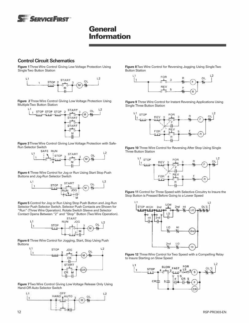
12 RSP-PRC003-EN
Control Circuit Schematics
GeneralInformation
Figure 1 Three Wire Control Giving Low Voltage Protection UsingSingle Two Button Station
Figure 2 Three Wire Control Giving Low Voltage Protection UsingMultiple Two Button Station
Figure 3 Three Wire Control Giving Low Voltage Protection with Safe-Run Selector Switch
Figure 4 Three Wire Control for Jog or Run Using Start Stop PushButtons and Jog-Run Selector Switch
Figure 5 Control for Jog or Run Using Stop Push Button and Jog-RunSelector Push Selector Switch. Selector Push Contacts are Shown for“Run” (Three Wire Operation). Rotate Switch Sleeve and SelectorContact Opens Between “2” and “Stop” Button (Two Wire Operation).
Figure 6 Three Wire Control for Jogging, Start, Stop Using PushButtons
Figure 7 Two Wire Control Giving Low Voltage Release Only UsingHand-Off-Auto Selector Switch
Figure 8 Two Wire Control for Reversing Jogging Using Single TwoButton Station
Figure 9 Three Wire Control for Instant Reversing Applications UsingSingle Three Button Station
Figure 10 Three Wire Control for Reversing After Stop Using SingleThree Button Station
Figure 11 Control for Three Speed with Selective Circuitry to Insure theStop Button is Pressed Before Going to a Lower Speed
Figure 12 Three Wire Control for Two Speed with a Compelling Relayto Insure Starting on Slow Speed
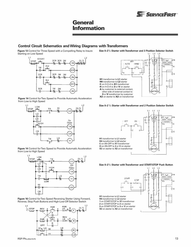
13RSP-PRC003-EN
GeneralInformation
Control Circuit Schematics and Wiring Diagrams with Transformers
Figure 13 Control for Three Speed with a Compelling Relay to InsureStarting on Low Speed
Figure 14 Control for Two Speed to Provide Automatic Accelerationfrom Low to High Speed
Figure 14 Control for Two Speed to Provide Automatic Accelerationfrom Low to High Speed
Figure 16 Control for Two Speed Reversing Starter Using Forward,Reverse, Stop Push Buttons and High-Low-Off Selector Switch
Size 0–21/2 Starter with Transformer and 3 Position Selector Switch
H1 transformer to L1 starterH4 transformer to L2 starterC on H-O-A to X1 transformerH on H-O-A to 3 or V on starterA by customer to external contact,
other side of external contact to3 or V transformer by customer
X2 on starter to X2 on transformer
Size 0–2 1/2 Starter with Transformer and 2 Position Selector Switch
H1 transformer to L1 starterH4 transformer to L2 starterC on 0N-OFF to X1 transformerO on 0N-OFF to 3 or V on starterX2 on starter to X2 on transformer
Size 0–21/2 Starter with Transformer and START-STOP Push Button
H1 transformer to L1 starterH4 transformer to L2 starter1 on START-STOP to X1 transformer2 on START-STOP to 2 on starter3 on START-STOP to 3 or V on starterX2 on starter to X2 on transformer
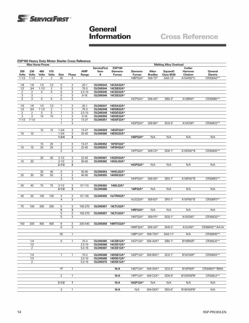
14 RSP-PRC003-EN
GeneralInformation
ESP100 Heavy Duty Motor Starter Cross ReferenceMax Horse Power Melting Alloy Overload
ServiceFirst ESP100 Cutler-200 230 460 575 AMP Item Siemens- Siemens- Allen- SquareD Hammer General
Volts Volts Volts Volts Size Phase Range # Furnas Furnas Bradley Class 8536 Citation Electric
1-1/2 1-1/2 2 2 00 3 14BP32A* 509-T0* SA0-122 A10AN0*C CR306A0**
1/8 1/8 1/3 1/2 0 3 .25-1 OLD00343 14CSA32A*
1/2 3/4 1-1/2 2 0 3 .75-3 OLD00344 14CSB32A*
2 2 5 5 0 3 2.5-10 OLD00345 14CSD32A*
3 3 - - 0 3 9-18 OLD00346 14CSE32A*
3 3 5 5 0 3 14CP32A* 509-A0* SB0-22 A10BN0* CR306B0**
1/6 1/6 1/3 1/2 1 3 .25-1 OLD00347 14DSA32A*
1/2 3/4 1-1/2 2 1 3 .75-3 OLD00348 14DSB32A*
2 2 5 5 1 3 2.5-10 OLD00349 14DSD32A*
3 3 10 10 1 3 9-18 OLD00350 14DSE32A*
7-1/2 7-1/2 - - 1 3 13-27 OLD00351 14DSF32A*
1 3 14DP32A* 509-B0* SC0-32 A10CN0* CR306C0**
- - 15 15 1-3/4 3 13-27 OLD00359 14ESF32A*
10 10 - - 1-3/4 3 20-40 OLD00360 14ESG32A*
1-3/4 3 14EP32A* N/A N/A N/A N/A
- - 15 20 2 3 13-27 OLD00352 14FSF32A*
10 15 25 25 2 3 22-45 OLD00353 14FSH32A*
2 3 14FP32A* 509-C0* SD0-12 A10DN0*B CR306D0**
- - 30 40 2-1/2 3 22-45 OLD00361 14GSH32A*
15 20 - - 2-1/2 3 30-60 OLD00362 14GSJ32A*
2-1/2 3 14GP32A* N/A N/A N/A N/A
- - 30 40 3 3 30-60 OLD00354 14HSJ32A*
25 30 50 50 3 3 45-90 OLD00355 14HSK32A*
3 3 14HP32A* 509-D0* SE0-12 A10EN0*B CR306E0**
30 40 75 75 3-1/2 3 57-115 OLD00363 14ISL32A*
3-1/2 3 OLD00366 14IP32A* N/A N/A N/A N/A
40 50 100 100 4 3 67-135 OLD00356 14JTM32A*
4 3 14JG32A* 509-E0* SF0-12 A10FN0*B CR306F0**
75 100 200 200 5 3 100-270 OLD00357 14LTU32A*
5 3 14RF32A* N/A N/A N/A N/A5 3 100-270 OLD00357 14LTU32A*
5 3 14KF32A* 509-F0* SG0-12 A10GN0* CR306G0**
150 200 400 400 6 3 200-540 OLD00358 14MTX32A*
6 3 14MF32A* 509-G0* SH0-22 A10JN0* CR386H0**AA1A
00 1 14BP12A* 509-T0X* SA0-112 N/A CR306H0**
1/4 0 1 .75-3 OLD00365 14CSB12A* 14CP12A* 509-A0X* SB0-12 B10BN0F3 CR306J0**1/2 2.5-10 OLD00366 14CSD12A*
2 5.0-16 OLD00367 14CSE12A*
1/4 1 1 .75-3 OLD00368 14DSB12A* 14DP12A* 509-B0X* SC0-12 B10CN0F3 CR306K0**1/2 2.5-10 OLD00369 14DSD12A*
2 5.0-16 OLD00370 14DSE12A*
1P 1 N/A 14EP12A* 509-X0X* SC0-22 B10PN0F3 CR306K0**BMA
2 1 N/A 14FP12A* 509-C0X* SD0-62 B10DN0FB3 CR306L0**
2-1/2 1 N/A 14GP12A* N/A N/A N/A N/A
3 1 N/A N/A 509-D0X* SE0-62 B10EN0FB3 N/A
Cross Reference
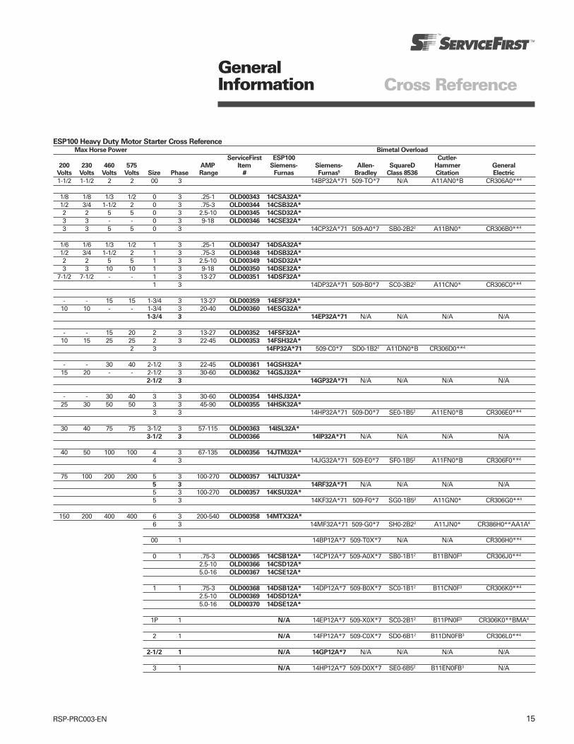
15RSP-PRC003-EN
GeneralInformation
ESP100 Heavy Duty Motor Starter Cross ReferenceMax Horse Power Bimetal Overload
ServiceFirst ESP100 Cutler-
200 230 460 575 AMP Item Siemens- Siemens- Allen- SquareD Hammer GeneralVolts Volts Volts Volts Size Phase Range # Furnas Furnas5 Bradley Class 8536 Citation Electric
1-1/2 1-1/2 2 2 00 3 14BP32A*71 509-TO*7 N/A A11AN0*B CR306A0**4
1/8 1/8 1/3 1/2 0 3 .25-1 OLD00343 14CSA32A*
1/2 3/4 1-1/2 2 0 3 .75-3 OLD00344 14CSB32A*
2 2 5 5 0 3 2.5-10 OLD00345 14CSD32A*
3 3 - - 0 3 9-18 OLD00346 14CSE32A*
3 3 5 5 0 3 14CP32A*71 509-A0*7 SB0-2B22 A11BN0* CR306B0**4
1/6 1/6 1/3 1/2 1 3 .25-1 OLD00347 14DSA32A*
1/2 3/4 1-1/2 2 1 3 .75-3 OLD00348 14DSB32A*
2 2 5 5 1 3 2.5-10 OLD00349 14DSD32A*
3 3 10 10 1 3 9-18 OLD00350 14DSE32A*
7-1/2 7-1/2 - - 1 3 13-27 OLD00351 14DSF32A*
1 3 14DP32A*71 509-B0*7 SC0-3B22 A11CN0* CR306C0**4
- - 15 15 1-3/4 3 13-27 OLD00359 14ESF32A*
10 10 - - 1-3/4 3 20-40 OLD00360 14ESG32A*
1-3/4 3 14EP32A*71 N/A N/A N/A N/A
- - 15 20 2 3 13-27 OLD00352 14FSF32A*
10 15 25 25 2 3 22-45 OLD00353 14FSH32A*
2 3 14FP32A*71 509-C0*7 SD0-1B22 A11DN0*B CR306D0**4
- - 30 40 2-1/2 3 22-45 OLD00361 14GSH32A*
15 20 - - 2-1/2 3 30-60 OLD00362 14GSJ32A*
2-1/2 3 14GP32A*71 N/A N/A N/A N/A
- - 30 40 3 3 30-60 OLD00354 14HSJ32A*
25 30 50 50 3 3 45-90 OLD00355 14HSK32A*
3 3 14HP32A*71 509-D0*7 SE0-1B52 A11EN0*B CR306E0**4
30 40 75 75 3-1/2 3 57-115 OLD00363 14ISL32A*
3-1/2 3 OLD00366 14IP32A*71 N/A N/A N/A N/A
40 50 100 100 4 3 67-135 OLD00356 14JTM32A*
4 3 14JG32A*71 509-E0*7 SF0-1B52 A11FN0*B CR306F0**4
75 100 200 200 5 3 100-270 OLD00357 14LTU32A*
5 3 14RF32A*71 N/A N/A N/A N/A5 3 100-270 OLD00357 14KSU32A*
5 3 14KF32A*71 509-F0*7 SG0-1B52 A11GN0* CR306G0**4
150 200 400 400 6 3 200-540 OLD00358 14MTX32A*
6 3 14MF32A*71 509-G0*7 SH0-2B22 A11JN0* CR386H0**AA1A4
00 1 14BP12A*7 509-T0X*7 N/A N/A CR306H0**4
0 1 .75-3 OLD00365 14CSB12A* 14CP12A*7 509-A0X*7 SB0-1B12 B11BN0F3 CR306J0**4
2.5-10 OLD00366 14CSD12A*
5.0-16 OLD00367 14CSE12A*
1 1 .75-3 OLD00368 14DSB12A* 14DP12A*7 509-B0X*7 SC0-1B12 B11CN0F3 CR306K0**4
2.5-10 OLD00369 14DSD12A*
5.0-16 OLD00370 14DSE12A*
1P 1 N/A 14EP12A*7 509-X0X*7 SC0-2B12 B11PN0F3 CR306K0**BMA4
2 1 N/A 14FP12A*7 509-C0X*7 SD0-6B12 B11DN0FB3 CR306L0**4
2-1/2 1 N/A 14GP12A*7 N/A N/A N/A N/A
3 1 N/A 14HP12A*7 509-D0X*7 SE0-6B52 B11EN0FB3 N/A
Cross Reference

16 RSP-PRC003-EN
GeneralInformation
ESP100 Heavy Duty Motor Starter Cross ReferenceMax Horse Power Ambient Compensated Bimetal Overload
ServiceFirst ESP100 Cutler-
200 230 460 575 AMP Item Siemens- Siemens- Allen- SquareD Hammer General WestinghouseVolts Volts Volts Volts Size Phase Range # Furnas Furnas5 Bradley Class 8536 Citation Electric A200
1-1/2 1-1/2 2 2 00 3 14BP32A*81 N/A N/A AN16AN0* CR306A0**4 A200MAC*
1/8 1/8 1/3 1/2 0 3 .25-1 OLD00343 14CSA32A*
1/2 3/4 1-1/2 2 0 3 .75-3 OLD00344 14CSB32A*
2 2 5 5 0 3 2.5-10 OLD00345 14CSD32A*
3 3 - - 0 3 9-18 OLD00346 14CSE32A*
3 3 5 5 0 3 14CP32A*81 509-A0*6 SB0-2B2 AN16BN0* CR306B0**4 A200MOC*
1/6 1/6 1/3 1/2 1 3 .25-1 OLD00347 14DSA32A*
1/2 3/4 1-1/2 2 1 3 .75-3 OLD00348 14DSB32A*
2 2 5 5 1 3 2.5-10 OLD00349 14DSD32A*
3 3 10 10 1 3 9-18 OLD00350 14DSE32A*
7-1/2 7-1/2 - - 1 3 13-27 OLD00351 14DSF32A*
1 3 14DP32A*81 509-B0*6 SC0-3B2 AN16DN0* CR306C0**4 A200MIC*
- - 15 15 1-3/4 3 13-27 OLD00359 14ESF32A*
10 10 - - 1-3/4 3 20-40 OLD00360 14ESG32A*
1-3/4 3 14EP32A*81 N/A N/A N/A N/A N/A
- - 15 20 2 3 13-27 OLD00352 14FSF32A*
10 15 25 25 2 3 22-45 OLD00353 14FSH32A*
2 3 14FP32A*81 509-C0*6 SD0-1B2 AN16GN0* CR306D0**4 A200M2C*
- - 30 40 2-1/2 3 22-45 OLD00361 14GSH32A*
15 20 - - 2-1/2 3 30-60 OLD00362 14GSJ32A*
2-1/2 3 14GP32A*81 N/A N/A N/A N/A N/A
- - 30 40 3 3 30-60 OLD00354 14HSJ32A*
25 30 50 50 3 3 45-90 OLD00355 14HSK32A*
3 3 14HP32A*81 509-D0*6 SE0-1Y592 AN16KN0* CR306E0**4 A200M3C*
30 40 75 75 3-1/2 3 57-115 OLD00363 14ISL32A*
3-1/2 3 OLD00366 14IP32A*81 N/A N/A N/A N/A N/A
40 50 100 100 4 3 67-135 OLD00356 14JTM32A*
4 3 14JG32A*81 509-E0*6 SF0-1Y592 AN16NN0* CR306F0**4 A200M4C*
75 100 200 200 5 3 100-270 OLD00357 14LTU32A*
5 3 14RF32A*81 N/A N/A N/A N/A N/A5 3 100-270 OLD00357 14KSU32A*
5 3 14KF32A*81 509-F0*6 SG0-1B2 AN16SN0* CR306G0**4 A200M5C*
150 200 400 400 6 3 200-540 OLD00358 14MTX32A*
6 3 14MF32A*81 N/A SH0-2B2 AN16TN0* CR386H0**AA1A4 A200M6C*
00 1 14BP12A*8 N/A N/A N/A CR306H0**4 N/A
1/4 0 1 .75-3 OLD00365 14CSB12A* 14CP12A*8 509-A0X*6 N/A N/A CR306J0**4 N/A1/2 2.5-10 OLD00366 14CSD12A*
2 5.0-16 OLD00367 14CSE12A*
1/4 1 1 .75-3 OLD00368 14DSB12A* 14DP12A*8 509-B0X*6 N/A N/A CR306K0**4 N/A1/2 2.5-10 OLD00369 14DSD12A*
2 5.0-16 OLD00370 14DSE12A*
1P 1 N/A 14EP12A*8 509-X0X*6 N/A N/A CR306K0**BMA4 N/A
2 1 N/A 14FP12A*8 509-C0X*6 N/A N/A CR306L0**4 N/A
2-1/2 1 N/A 14GP12A*8 N/A N/A N/A N/A N/A
3 1 N/A 14HP12A*8 509-D0X*6 N/A N/A N/A N/A
Cross Reference

17RSP-PRC003-EN
Definite Purpose Contactor Cross ReferenceServiceFirst Cutler Arrow Honeywell DP-Series Joselyn
Poles Amps Volts Item # Siemens-Furnas Hammer Hart PowerPro Economy Clark
1-1/2 25 24 CTR01057 45DG10AJD8A C25CNB125T C251NU10 DP1025A5005 - A77-306654A-3- 25 120 CTR01144 45DG10AFD8A C25CNB125A C251NU20 DP1025B5046 - A77306654A-1- 25 208/240 CTR01145 45DG10AGA C25CNB125B C251NU30 DP1025C5045 - A77-306654A-2
1-1/2 30 24 CTR01143 45EG10AJA C25CNB130T C301NU10 DP1030A5013 - A77-306653A-3- 30 120 CTR01144 45EG10AFA C25CNB130A C301NU20 DP1030B5020 - A77-306653A-1- 30 208/240 CTR01145 45EG10AGA C25CNB130B C301NU30 DP1030C5029 - A77-3066531-2
1-1/2 40 24 CTR01152 45GG10AJA - - DP1040A5004 - -- 40 120 CTR01153 45GG10AFA - - DP1040B5003 - -- 40 208/240 CTR01154 45GG10AGA - - DP1040C5002 - -2 20 24 CTR01137 45CG20AJ C25BNB22OT C202U10 DP2020A5021 - A77-306680A-3- 20 120 CTR01138 45CG20AF C25BNB22OA C202U20 DP2020B5038 - A77-306680A-1- 20 208/240 CTR01139 45CG20AG C25BNB22OB C202U30 DP2020C5037 - A77-306680A-2- 20 277 CTR01359 45CG20AL - - DP2020D5028 - -2 30 24 CTR01146 45EG20AJ C25BNB23OT C302U10 DP2030A5004 DP2030A1003 A77-306657A-3- 30 120 CTR01147 45EG20AF C25BNB23OA C302U20 DP2030B5003 DP2030B1002 A77-306657A-1- 30 208/240 CTR01148 45EG20AG C25BNB23OB C302U30 DP2030C5002 DP2030C1001 A77-306657A-2- 30 277 CTR01360 45EG20AL - C302050 DP2030D5001 - -2 40 24 CTR01155 45GG20AJ C25BNF240T CA01NU10 DP2040A5003 - -- 40 120 CTR01156 45GG20AF C25BNF240A CA01NU20 DP2040B5002 - -- 40 208/240 CTR01157 45GG20AG C25BNF240B CA01NU30 DP2040C5001 - -3 25 24 CTR01140 42AF35AJ C25DND325T ACC230UM10 DP3025A5003 DP3025A1002 -- 25 120 CTR01141 42AF35AF C25DND325A ACC230UM20 DP3025B5002 DP3025B1001 -- 25 208/240 CTR01142 42AF35AG C25DND325B ACC230UM30 DP3025C5001 DP3025C1000 -3 30 24 CTR01149 42BE35AJ06 C25DND330T ACC330UM10 DP3030A5003 DP3030A1002 A77-309044A-3- 30 120 CTR01150 42BF35AF C25DND330A ACC330UM20 DP3030B5002 DP3030B1001 A77-309044A-1- 30 208/240 CTR01151 42BF35AG C25DND330B ACC330UM30 DP3030B5001 DP3030C1000 A77-309044A-23 40 24 CTR01164 42CF35AJ C25DNF340T ACC430UM10 DP3040A5002 DP3040A1001 A77-309046A-3- 40 120 CTR01165 42CF35AF C25DNF340A ACC430UM20 AP3040B5001 DP3040B1000 A77-309046A-1- 40 208/240 CTR01166 42CF35AG C25DNF340B ACC430UM30 D[3040C5000 DP3040C1009 A77-309046A-23 50 24 CTR01167 42DF35AJ C25FNF350T ACC530U10 DP3050A5001 DP3050A1000 A77-288514A-3- 50 120 CTR01168 42DF35AF C25FNF350A ACC530U20 DP3050B5000 DP3050B1009 A77-288514A-1- 50 208/240 CTR01169 42DF35AG C25FNF350B ACC530U30 DP3050C5009 DP3050C1008 A77-288514A-23 60 24 CTR01170 42EF35AJ C25FNF360T ACC630U10 DP3060A5000 DP3060A1009 A77-288517A-3- 60 120 CTR01171 42EF35AF C25FNF360A ACC630U20 DP3060B5009 DP3060B1008 A77-288517A-1- 60 208/240 CTR01172 42EF35AG C25FNF360B ACC630U30 DP3060C5008 DP3060C1007 A77-288517A-23 75 24 CTR00934 42FE35AJ C25FNF375T ACC730U10 DP3075A5008 DP3075A1007 A77-288520A-3- 75 120 CTR00535 42FE35AF C25FNF375A ACC730U20 DP3075B5007 DP3075B1006 A77-288520A-1- 75 208/240 CTR00536 42FE35AG106 C25FNF375B ACC730U30 DP3075C5006 DP3075C1005 A77-288520A-23 90 24 CTR01325 42GE35AJ106 - - - DP3090A1006 -- 90 120 CTR00538 42GE35AF106 C25GNF390A ACC930U20 - DP3090B1005 -- 90 208/240 CTR00539 42GE35AG106 C25GNF390B ACC930U30 - DP3090C1004 -3 120 24 N/A 42HF35AJ - - - DP3120A1001 -- 120 120 CTR00540 42HF35AF C25HNF3120A ACC1230U20 - DP3120B1000 -- 120 220/240 CTR00545 42HF35AG C25HNF3120B ACC1230U20 - DP3120C1009 -4 40 24 CTR01164 42CF25AJ C25ENF440T ACC440UM10 - DP4040A1000 -- 40 120 CTR01165 42CF25AF C25ENF440A ACC440UM20 - DP4040B1009 -- 40 208/240 CTR01166 42CF25AG C25ENF440B ACC440UM30 - DP4040C1008 -
(See following page for additional manufacturers)
GeneralInformation Cross Reference
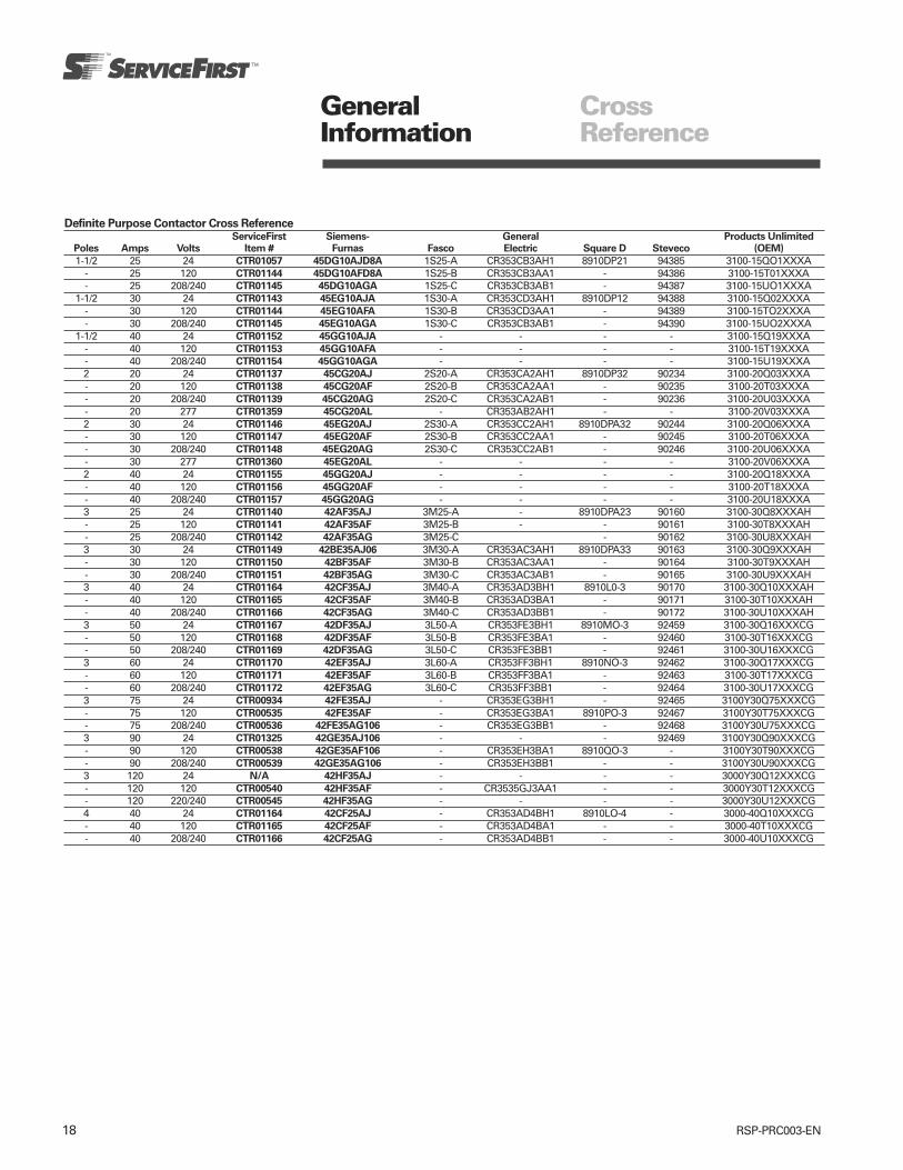
18 RSP-PRC003-EN
Definite Purpose Contactor Cross ReferenceServiceFirst Siemens- General Products Unlimited
Poles Amps Volts Item # Furnas Fasco Electric Square D Steveco (OEM)
1-1/2 25 24 CTR01057 45DG10AJD8A 1S25-A CR353CB3AH1 8910DP21 94385 3100-15QO1XXXA- 25 120 CTR01144 45DG10AFD8A 1S25-B CR353CB3AA1 - 94386 3100-15T01XXXA- 25 208/240 CTR01145 45DG10AGA 1S25-C CR353CB3AB1 - 94387 3100-15UO1XXXA
1-1/2 30 24 CTR01143 45EG10AJA 1S30-A CR353CD3AH1 8910DP12 94388 3100-15Q02XXXA- 30 120 CTR01144 45EG10AFA 1S30-B CR353CD3AA1 - 94389 3100-15TO2XXXA- 30 208/240 CTR01145 45EG10AGA 1S30-C CR353CB3AB1 - 94390 3100-15UO2XXXA
1-1/2 40 24 CTR01152 45GG10AJA - - - - 3100-15Q19XXXA- 40 120 CTR01153 45GG10AFA - - - - 3100-15T19XXXA- 40 208/240 CTR01154 45GG10AGA - - - - 3100-15U19XXXA2 20 24 CTR01137 45CG20AJ 2S20-A CR353CA2AH1 8910DP32 90234 3100-20Q03XXXA- 20 120 CTR01138 45CG20AF 2S20-B CR353CA2AA1 - 90235 3100-20T03XXXA- 20 208/240 CTR01139 45CG20AG 2S20-C CR353CA2AB1 - 90236 3100-20U03XXXA- 20 277 CTR01359 45CG20AL - CR353AB2AH1 - - 3100-20V03XXXA2 30 24 CTR01146 45EG20AJ 2S30-A CR353CC2AH1 8910DPA32 90244 3100-20Q06XXXA- 30 120 CTR01147 45EG20AF 2S30-B CR353CC2AA1 - 90245 3100-20T06XXXA- 30 208/240 CTR01148 45EG20AG 2S30-C CR353CC2AB1 - 90246 3100-20U06XXXA- 30 277 CTR01360 45EG20AL - - - - 3100-20V06XXXA2 40 24 CTR01155 45GG20AJ - - - - 3100-20Q18XXXA- 40 120 CTR01156 45GG20AF - - - - 3100-20T18XXXA- 40 208/240 CTR01157 45GG20AG - - - - 3100-20U18XXXA3 25 24 CTR01140 42AF35AJ 3M25-A - 8910DPA23 90160 3100-30Q8XXXAH- 25 120 CTR01141 42AF35AF 3M25-B - - 90161 3100-30T8XXXAH- 25 208/240 CTR01142 42AF35AG 3M25-C - 90162 3100-30U8XXXAH3 30 24 CTR01149 42BE35AJ06 3M30-A CR353AC3AH1 8910DPA33 90163 3100-30Q9XXXAH- 30 120 CTR01150 42BF35AF 3M30-B CR353AC3AA1 - 90164 3100-30T9XXXAH- 30 208/240 CTR01151 42BF35AG 3M30-C CR353AC3AB1 - 90165 3100-30U9XXXAH3 40 24 CTR01164 42CF35AJ 3M40-A CR353AD3BH1 8910L0-3 90170 3100-30Q10XXXAH- 40 120 CTR01165 42CF35AF 3M40-B CR353AD3BA1 - 90171 3100-30T10XXXAH- 40 208/240 CTR01166 42CF35AG 3M40-C CR353AD3BB1 - 90172 3100-30U10XXXAH3 50 24 CTR01167 42DF35AJ 3L50-A CR353FE3BH1 8910MO-3 92459 3100-30Q16XXXCG- 50 120 CTR01168 42DF35AF 3L50-B CR353FE3BA1 - 92460 3100-30T16XXXCG- 50 208/240 CTR01169 42DF35AG 3L50-C CR353FE3BB1 - 92461 3100-30U16XXXCG3 60 24 CTR01170 42EF35AJ 3L60-A CR353FF3BH1 8910NO-3 92462 3100-30Q17XXXCG- 60 120 CTR01171 42EF35AF 3L60-B CR353FF3BA1 - 92463 3100-30T17XXXCG- 60 208/240 CTR01172 42EF35AG 3L60-C CR353FF3BB1 - 92464 3100-30U17XXXCG3 75 24 CTR00934 42FE35AJ - CR353EG3BH1 - 92465 3100Y30Q75XXXCG- 75 120 CTR00535 42FE35AF - CR353EG3BA1 8910PO-3 92467 3100Y30T75XXXCG- 75 208/240 CTR00536 42FE35AG106 - CR353EG3BB1 - 92468 3100Y30U75XXXCG3 90 24 CTR01325 42GE35AJ106 - - - 92469 3100Y30Q90XXXCG- 90 120 CTR00538 42GE35AF106 - CR353EH3BA1 8910QO-3 - 3100Y30T90XXXCG- 90 208/240 CTR00539 42GE35AG106 - CR353EH3BB1 - - 3100Y30U90XXXCG3 120 24 N/A 42HF35AJ - - - - 3000Y30Q12XXXCG- 120 120 CTR00540 42HF35AF - CR3535GJ3AA1 - - 3000Y30T12XXXCG- 120 220/240 CTR00545 42HF35AG - - - - 3000Y30U12XXXCG4 40 24 CTR01164 42CF25AJ - CR353AD4BH1 8910LO-4 - 3000-40Q10XXXCG- 40 120 CTR01165 42CF25AF - CR353AD4BA1 - - 3000-40T10XXXCG- 40 208/240 CTR01166 42CF25AG - CR353AD4BB1 - - 3000-40U10XXXCG
GeneralInformation
CrossReference
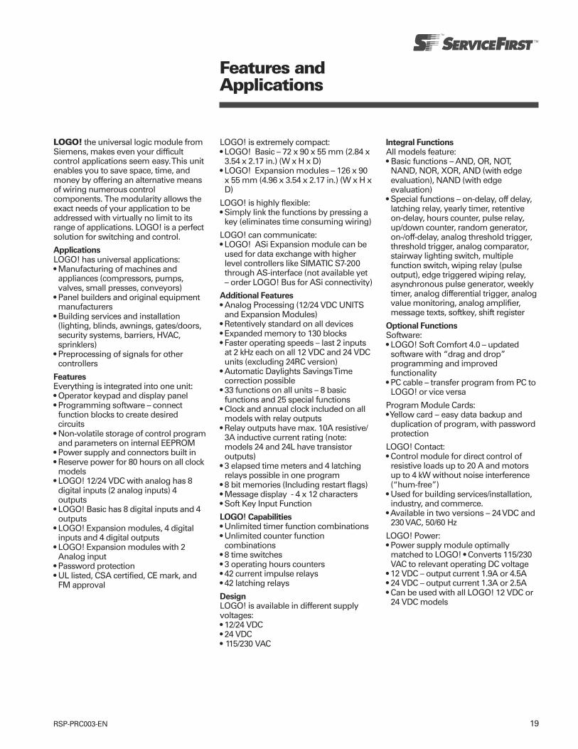
19RSP-PRC003-EN
LOGO! the universal logic module fromSiemens, makes even your difficultcontrol applications seem easy. This unitenables you to save space, time, andmoney by offering an alternative meansof wiring numerous controlcomponents. The modularity allows theexact needs of your application to beaddressed with virtually no limit to itsrange of applications. LOGO! is a perfectsolution for switching and control.
ApplicationsLOGO! has universal applications:• Manufacturing of machines andappliances (compressors, pumps,valves, small presses, conveyors)
• Panel builders and original equipmentmanufacturers
• Building services and installation(lighting, blinds, awnings, gates/doors,security systems, barriers, HVAC,sprinklers)
• Preprocessing of signals for othercontrollers
FeaturesEverything is integrated into one unit:• Operator keypad and display panel• Programming software – connectfunction blocks to create desiredcircuits
• Non-volatile storage of control programand parameters on internal EEPROM
• Power supply and connectors built in• Reserve power for 80 hours on all clockmodels
• LOGO! 12/24 VDC with analog has 8digital inputs (2 analog inputs) 4outputs
• LOGO! Basic has 8 digital inputs and 4outputs
• LOGO! Expansion modules, 4 digitalinputs and 4 digital outputs
• LOGO! Expansion modules with 2Analog input
• Password protection• UL listed, CSA certified, CE mark, andFM approval
LOGO! is extremely compact:• LOGO! Basic – 72 x 90 x 55 mm (2.84 x
3.54 x 2.17 in.) (W x H x D)• LOGO! Expansion modules – 126 x 90
x 55 mm (4.96 x 3.54 x 2.17 in.) (W x H xD)
LOGO! is highly flexible:• Simply link the functions by pressing a
key (eliminates time consuming wiring)
LOGO! can communicate:• LOGO! ASi Expansion module can be
used for data exchange with higherlevel controllers like SIMATIC S7-200through AS-interface (not available yet– order LOGO! Bus for ASi connectivity)
Additional Features• Analog Processing (12/24 VDC UNITS
and Expansion Modules)• Retentively standard on all devices• Expanded memory to 130 blocks• Faster operating speeds – last 2 inputs
at 2 kHz each on all 12 VDC and 24 VDCunits (excluding 24RC version)
• Automatic Daylights Savings Timecorrection possible
• 33 functions on all units – 8 basicfunctions and 25 special functions
• Clock and annual clock included on allmodels with relay outputs
• Relay outputs have max. 10A resistive/3A inductive current rating (note:models 24 and 24L have transistoroutputs)
• 3 elapsed time meters and 4 latchingrelays possible in one program
• 8 bit memories (Including restart flags)• Message display - 4 x 12 characters• Soft Key Input Function
LOGO! Capabilities• Unlimited timer function combinations• Unlimited counter function
combinations• 8 time switches• 3 operating hours counters• 42 current impulse relays• 42 latching relays
DesignLOGO! is available in different supplyvoltages:• 12/24 VDC• 24 VDC• 115/230 VAC
Integral FunctionsAll models feature:• Basic functions – AND, OR, NOT,
NAND, NOR, XOR, AND (with edgeevaluation), NAND (with edgeevaluation)
• Special functions – on-delay, off delay,latching relay, yearly timer, retentiveon-delay, hours counter, pulse relay,up/down counter, random generator,on-/off-delay, analog threshold trigger,threshold trigger, analog comparator,stairway lighting switch, multiplefunction switch, wiping relay (pulseoutput), edge triggered wiping relay,asynchronous pulse generator, weeklytimer, analog differential trigger, analogvalue monitoring, analog amplifier,message texts, softkey, shift register
Optional FunctionsSoftware:• LOGO! Soft Comfort 4.0 – updated
software with “drag and drop”programming and improvedfunctionality
• PC cable – transfer program from PC toLOGO! or vice versa
Program Module Cards:• Yellow card – easy data backup and
duplication of program, with passwordprotection
LOGO! Contact:• Control module for direct control of
resistive loads up to 20 A and motorsup to 4 kW without noise interference(“hum-free”)
• Used for building services/installation,industry, and commerce.
• Available in two versions – 24 VDC and230 VAC, 50/60 Hz
LOGO! Power:• Power supply module optimally
matched to LOGO! • Converts 115/230VAC to relevant operating DC voltage
• 12 VDC – output current 1.9A or 4.5A• 24 VDC – output current 1.3A or 2.5A• Can be used with all LOGO! 12 VDC or
24 VDC models
Features andApplications
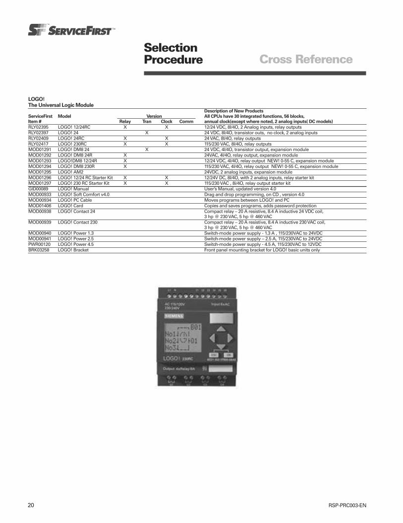
20 RSP-PRC003-EN
SelectionProcedure
LOGO!The Universal Logic Module
Description of New Products
ServiceFirst Model Version All CPUs have 30 integrated functions, 56 blocks,Item # Relay Tran Clock Comm annual clock(except where noted, 2 analog inputs( DC models)
RLY02395 LOGO! 12/24RC X X 12/24 VDC, 8I/4O, 2 Analog inputs, relay outputsRLY02397 LOGO! 24 X 24 VDC, 8I/4O, transistor outs, no clock, 2 analog inputsRLY02409 LOGO! 24RC X X 24 VAC, 8I/4O, relay outputsRLY02417 LOGO! 230RC X X 115/230 VAC, 8I/4O, relay outputsMOD01291 LOGO! DM8 24 X 24 VDC, 4I/4O, transistor output, expansion moduleMOD01292 LOGO! DM8 24R X 24VAC, 4I/4O, relay output, expansion moduleMOD01293 LOGO!DM8 12/24R X 12/24 VDC, 4I/4O, relay output NEW! 0-55 C, expansion moduleMOD01294 LOGO! DM8 230R X 115/230 VAC, 4I/4O, relay output NEW! 0-55 C, expansion moduleMOD01295 LOGO! AM2 24VDC, 2 analog inputs, expansion moduleMOD01296 LOGO! 12/24 RC Starter Kit X X 12/24V DC, 8I/4O, with 2 analog inputs, relay starter kitMOD01297 LOGO! 230 RC Starter Kit X X 115/230 VAC , 8i/4O, relay output starter kitGID00089 LOGO! Manual User’s Manual, updated version 4.0MOD00933 LOGO! Soft Comfort v4.0 Drag and drop programming, on CD , version 4.0MOD00934 LOGO! PC Cable Moves programs between LOGO! and PCMOD01406 LOGO! Card Copies and saves programs, adds password protectionMOD00938 LOGO! Contact 24 Compact relay – 20 A resistive, 8.4 A inductive 24 VDC coil,
3 hp @ 230 VAC, 5 hp @ 460 VACMOD00939 LOGO! Contact 230 Compact relay – 20 A resistive, 8.4 A inductive 230 VAC coil,
3 hp @ 230 VAC, 5 hp @ 460 VACMOD00940 LOGO! Power 1.3 Switch-mode power supply - 1.3 A , 115/230VAC to 24VDCMOD00941 LOGO! Power 2.5 Switch-mode power supply – 2.5 A, 115/230VAC to 24VDCPWR00120 LOGO! Power 4.5 Switch-mode power supply - 4.5 A, 115/230VAC to 12VDCBRK03258 LOGO! Bracket Front panel mounting bracket for LOGO! basic units only
Cross Reference

21RSP-PRC003-EN
Disconnects by Siemens
UL Listed, NEMA Type 3R Enclosure 240 Volts
ServiceFirst Catalog Ampere Maximum Disconnect Std.
Item # Number Rating Horsepower Type Pkg.SWT02385 WN2060TR 60 10 Non-Fusible Pullout 6
Features• Ample wiring space• Rugged design• Numerous knockouts• Raised mounting embosses• Copper conductors• Pullout switch*• Fuse holder**• Removable door• Meets national electrical code
requirements
Benefits• The larger enclosure allows for ample
wiring space.• Manufactured with powder coated G90
galvanized steel for fade, scratch andcorrosion resistance.
• All (6) knockouts are easy to remove.The sidewall knockouts provide accessfrom the sides of the device. Everyknockout has 1/2”, 3/4” and 1”provisions.
• (4) Raised mounting embosses keepthe unit away from the wall, preventingdirt build-up. The upper mounting holeis shaped to be used as a hanger.
• Copper current carrying part allows fora cooler, longer lasting operation.
• The pullout switch design allows youto safely and easily de-energize theload terminals.*
• The easily removable door makes itpossible to wire the device withabsolutely no interference.
• The easy to remove pullout securelyholds the fuses in place. The fuseholder design allows you to safely andeasily de-energize the load terminalswithout the need to remove thefuses.**
• Siemens air conditioning disconnectsprovide the ideal means to comply toarticles 440-14 and 110-3(b) of the 1999National Electrical Code.
*Non-fused only**Fused only
Fused Disconnect
Non-FusedDisconnect
UL Listed, NEMA Type 3R Enclosure 240 Volts
ServiceFirst Catalog Ampere Maximum Fuse1 Std.
Item # Number Rating Horsepower Class Pkg.
SWT02386 WF2030TR2 30 3 H 6SWT02387 WF2060TR2 60 10 H 6
1. Fuses not included.2. Service Entrance rated.
AC Disconnects

22 RSP-PRC003-EN
Definite Purpose Contactors
Centurion 2000, Premium Line
• 25-210A• 210 FLA 60 Hz 600VAC Max• Compact Size• Interchangeable Mounting• Snap-On Electrical/Mechanical
Interlocks• Oversize Lugs Available on 25A and
30A• Sems Screws Available on 25A, 30A
and 40A• Binding Head Screws Optional on
40-60A• Class H Coil Insulation• Optional Electronic Timers, Surge
Suppressors and Step Down DC CoilDrivers Built into Coils
• Snap-On Electronic Accessories• Meets ARI-780, UL and CSA Standards
Features andApplications
ApplicationThe Furnas Centurion 2000 offers a highnew standard in definite purpose control.The largest, most complete line ofdefinite purpose motor controls in theindustry, it is ideal for many applicationsincluding:
HVAC Welding
Refrigeration Lighting
Elevators Pools & Spas
Hoists & Cranes
Food Processing
Data Processing
Pumps & Compressors
When used with an appropriate pilotdevice they can provide either lowvoltage protection or low voltagerelease. These controls have beendesigned with a low drop out voltagemaking them ideal for air conditioning,heating and refrigeration applications.
ConstructionThe Centurion 2000 was designed to bea tougher, more compact, more versatileand quieter contactor than ever before.Product features include:
Tougher Materials – The housing and allother non-metal body parts are made ofbulk molding compound for greaterstrength and durability.
Compact – Space saving dimensionsallow for smaller panels and morewiring room.
Straight Thru Wiring – Line terminalsare located at the top and load terminalsat the bottom. This constructioneliminates looping wires around thecontrol and reduces wiring costs.
Interchangeable Mounting – Thecombination of multiple mounting holesand slots allows these contactors to befastened onto panels and provideinterchangeable mounting with manycompetitive contactors.
Definite PurposeContactors
25A, 30A, 40A 50A, 60A 75A, 90A

23RSP-PRC003-EN
Features andApplications
Definite PurposeContactors
Definite Purpose Contactors
Centurion 2000, Premium Line
• 25-210A• 210 FLA 60 Hz 600VAC Max
Terminals – Line and load terminals aresupplied with pressure connectors. Pilotcontrol wires can attach to the lineterminals by using integral auxiliaryconnections. Oversize lugs are standardon 40A and optional on 25A and 30A.You also have a choice of three terminalstyles – box lug, binding head screws, orsems clamp.
Coils – Class H high temperatureinsulated coils are standard on 25A-60Acontactors. Vibration has beenminimized by cushioning the coil and theenclosed construction reduces thepossibility of failure due tocontaminants. Coils on 25-60A areequipped with combination pressureand quick connect terminals. Electronictimers, surge suppressors or DC coildrivers are available built into the coils.This option simplifies wiring and allowsless panel space to be used.
Coils on 75A-210A contactors areencapsulated in a moisture proof epoxy.
Some coils are equipped withcombination pressure and quick connectterminals. Connections are made byinserting the stripped wire under thescrew head and tightening or bypressing on a quick connector.
Single voltage coils are standard for allpopular voltages and frequencies. Dualvoltage, 120/240 or 240/480 volts, 50-60Hz coils are available at an additionalcost. Dual voltage coils are standard onthe 120A - 210A contactors.
The 75A and 90A devices are alsoavailable with DC magnet and coil as anoptional feature. Magnet and coilassemblies are available for 6, 12, 24, 32,115 and 230VDC.
Magnet – The magnet is constructed oflaminations of silicon steel. A shadingcoil insures a positive sealing of thearmature.
Snap-On Accessories – Two snap-onelectrical interlocks provide up to fourSPST or SPDT circuits. Interlocks snapon each side and are optional. Anoptional mechanical interlock is alsoavailable. Other accessories such astimers, coil snubbers, coil drivers andothers provide versatile, expandablecontrol.
Auxiliary Electrical Interlocks – Furnassupplies one or two interlocks as afactory modification or for fieldinstallation on 75A and 90A contactors.Four auxiliary interlocks can accept120A-210A contactors.
Available with either normally open ornormally closed contacts, they aremounted in a molded guide and held inplace with a single screw.
Arc Box – Molded of a glass filledthermoset material, it withstandstracking and prevents flash over.
Cross Arm – This rugged, molded partresists the stresses of high temperaturesand impacts.
Contacts – Made of silver cadmiumoxide that resists welding, arc erosionand mechanical wear, these criticalcomponents are bonded to ruggedbacking material.
120A, 150A210
REFERENCE LITERATUREInstruction Sheets and Replacement PartsSize Instruction Replacement
FLA Sheet Parts
25, 30, 40 PM-60.1 42-GBF50,60 PM-60.1 42-GDF75, 90 PM-60.1 42-GFE120, 150 PM-60.1 16-GHF210 PM-60.1 42-GJB

24 RSP-PRC003-EN
Features andApplications
Definite PurposeContactors
Definite Purpose Contactors
Standard Line
• 20-40 FLA 60 Hz 600VAC Max• For Contactors Thru 210 FLA, see
Centurion 2000 Premium line.
• Compact Size• Straight Thru Wiring• Long Life• Non Tracking Contact Board• Interchangeable Mounting Base• Quick Connect Terminals• Weld Resistant Contacts• UL File E14900• CSA File LR6535 and 42531• TUV/VDE Approved – Contact Factory
ApplicationFurnas compact definite purposecontactors are designed for controllingair conditioning, heating, welding, dataprocessing and refrigeration equipment.They provide reliable full voltage controlof compressor motors and electricheating loads. When used with anappropriate pilot device they can provideeither low voltage protection or lowvoltage release. These controls havebeen designed with a low drop outvoltage making them ideal for airconditioning, heating and refrigerationapplications.
ConstructionCompact – Space saving dimensionsallow for smaller panels and more wiringroom.
Straight Thru Wiring – Line terminals arelocated at the top and load terminals atthe bottom. This construction eliminateslooping wires around the control andreduces wiring costs.
Mounting – Contactors are designed formounting on a vertical service. Side byside grouping is possible since allterminals are front accessible andisolated from adjacent controls bymolded barriers.
Interchangeable Mounting – Thecombination of multiple mounting holesand slots allows these contactors to befastened onto panels and provideinterchangeable mounting with manycompetitive contactors.
Terminals – Line and load terminals aresupplied with pressure connectors. Pilotcontrol wires attach to the line terminalsby using integral auxiliary connections.
Single Pole
2 Pole

25RSP-PRC003-EN
SelectionProcedure
Definite PurposeContactors
Definite Purpose Contactors
Centurion 2000, Premium Line
• 25-210A• 210 FLA 60 Hz 600VAC Max
Non
ServiceFirst120V 240V 277V 480V 600V Inductive Poles Coil
Item # Mfg. # FLA Hp LRA Hp LRA Hp LRA Hp LRA Hp Amps Phase Voltage
60 FLA 60 Hz 600VAC Max
CTR01140 42AF35AJ 25 - 150 5 - - 125 7-1/2 100 7-1/2 35 3,3 Ph 24CTR01362 42AF35AJ w/lugsCTR01141 42AF35AF 110-120CTR01363 42AF35AF w/lugsCTR01142 42AF35AG 200-208CTR01364 42AF35AG w/lugsCTR01730 42BF15AJ 30 2 180 5 - - 150 - 120 - 40 2,1 Ph 24CTR01731 42BF15AF 110-120CTR01732 42BF15AG 200-208CTR01149 42BF35AJ 30 - 180 7-1/2 - - 150 10 120 10 40 3,3 Ph 24CTR01365 42BF35AJ w/lugsCTR01150 42BF35AF 110-120CTR01366 42BF35AF w/lugsCTR01151 42BF35AG 200-208CTR01367 42BF35AG w/lugsCTR01158 42CF15AJ 40 3 240 7-1/2 - - 200 - 160 - 50 2,1 Ph 24CTR01159 42CF15AF 110-120CTR01160 42CF15AG 200-208CTR01161 42CF35AJ 40 - 240 10 - - 200 15 160 15 50 3,3 Ph 24CTR01162 42CF35AF 110-120CTR01163 42CF35AG 200-208CTR01164 42CF25AJ 40 - 240 10 - - 200 15 160 15 50 4,3 Ph 24CTR01165 42CF25AF 110-120CTR01166 42CF25AG 200-208CTR01167 42DF35AJ 50 - 300 15 - - 250 25 200 25 63 3,3 Ph 24CTR01168 42DF35AF 110-120CTR01169 42DF35AG 200-208CTR01170 42EF35AJ 60 - 360 20 - - 300 30 240 30 75 3,3 Ph 24CTR01171 42EF35AF 110-120CTR01172 42EF35AG 200-208
150 FLA 60Hz 600VAC Max
CTR00534 42FE35AJ106 75 - 450 25 - - 375 40 300 40 93 3,3 Ph 24CTR00535 42FE35AF106 110-120CTR00536 42FE35AG106 200-208CTR00538 42GE35AF106 90 - 540 30 - - 450 50 360 50 120 3,3 Ph 110-120CTR00539 42GE35AG106 200-208CTR00540 42HF35AA 120 - 720 - - - 600 - 480 - 150 3,3 Ph 110-120/220-240CTR00541 42HF35AC 220-240/440-480CTR00542 42IF35AA 150 - 900 - - - 750 - 600 - 160 3,3 Ph 110-120/220-240CTR00543 42IF35AC 208-240/480
210 FLA 60Hz 600VAC Max
CTR01843 3RT1064-6AF36 225 75 150 3,3 pH 120CTR01844 3RT1064-6AP36 225 75 150 3,3 pH 240CTR01845 3RT1064-6AR36 225 75 150 3,3 pH 480
*Terminal Kit for 3RT106 225 A contactor - use TER01072 (3RT1966-4G). Kit includes 3 terminals for line or load. 2 required per 3RT106 contactor.
25A, 30A, 40A 50A, 60A 75A, 90A

26 RSP-PRC003-EN
SelectionProcedure
Definite PurposeContactors
Definite Purpose Contactors
Centurion 2000 Accessories• Field Modification Kits• Snap-On Side Mounted Auxiliary Interlocks
ServiceFirst Contactor Interlock
Item # Mfg. # Description Class FLA Contacts
SWT01730 49D36098001 42 25-60 1 SPDTSWT01732 49ACRO 1NOSWT01733 49ACRC Auxiliary 1NCSWT01731 49D36098003 Interlocks 2 SPDTSWT00531 49D22125001 Auxiliary 42 75-90 NOSWT00532 49D22125002 Interlocks NCSWT00529 49CE42SPDT SPDTSWT00533 49D54682NO Auxiliary 42 120-150 NOSWT00534 49D54682NC Interlocks NCSWT00535 3RH1921-1EA11 Auxiliary 3RT106 225 NO & NC (First Side)SWT00536 3RH1921-1KA11 Interlocks NO & NC (Second Side)
Mechanical Interlock
KIT01048 49D70035001 Mech. Interlock 42 25-60
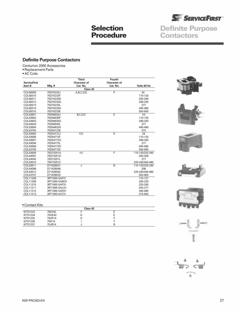
27RSP-PRC003-EN
SelectionProcedure
Definite PurposeContactors
Third Fourth
ServiceFirst Character of Character of
Item # Mfg. # Cat. No. Cat. No. Volts 60 Hz
Class 42
COL08309 75D70233J A,B,C,D,E F 24COL08310 75D70233F 110-120COL08311 75D70233D 200-208COL08312 75D70233G 208-240COL08313 75D70233L 277COL08314 75D70233H 440-480COL08315 75D70233E 550-600COL03601 75D56630J B,C,D,E E 24COL03602 75D56630F 110-120COL03603 75D56630G 208-240COL04043 75D56630L 277COL03604 75D54822H 440-480COL03705 75D55123E 575COL03605 75D54772J F,G E 24COL03606 75D54772F 110-120COL03607 75D54772G 208-240COL04094 75D54772L 277COL03608 75D54772H 440-480COL03706 75D54772E 550-600COL03609 75D73251A H,I F 110-120/220-240COL04097 75D73251D 200-208COL04045 75D73251L 277COL03610 75D73251C 220-240/440-480COL03611 D71628031 J B 110-120/220-240COL04098 D71628048 208COL03612 D71628032 220-240/440-480COL03707 D71628033 550-600COL11208 3RT1065-5AF31 110-127COL11209 3RT1065-5AM31 200-220COL11210 3RT1065-5AP31 220-240COL11211 3RT1065-5AU31 240-277COL11212 3RT1065-5AR31 440-480COL11213 3RT1065-5AT31 575-600
• Contact KitsClass 42
KIT01223 75EF42 F EKIT01234 75GE42 G EKIT01235 75HF14 H FKIT01236 75IF14 I FKIT01237 75JB14 J B
Definite Purpose Contactors
Centurion 2000 Accessories• Replacement Parts• AC Coils
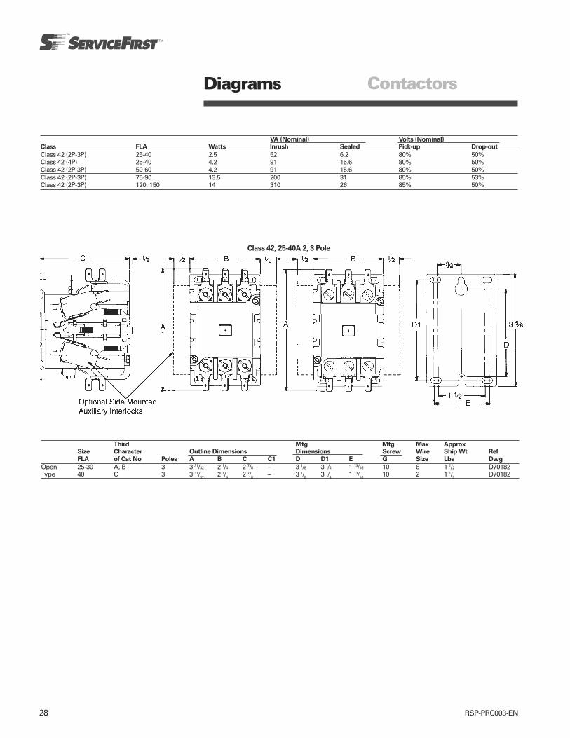
28 RSP-PRC003-EN
VA (Nominal) Volts (Nominal)Class FLA Watts Inrush Sealed Pick-up Drop-out
Class 42 (2P-3P) 25-40 2.5 52 6.2 80% 50%Class 42 (4P) 25-40 4.2 91 15.6 80% 50%Class 42 (2P-3P) 50-60 4.2 91 15.6 80% 50%Class 42 (2P-3P) 75-90 13.5 200 31 85% 53%Class 42 (2P-3P) 120, 150 14 310 26 85% 50%
Third Mtg Mtg Max ApproxSize Character Outline Dimensions Dimensions Screw Wire Ship Wt Ref
FLA of Cat No Poles A B C C1 D D1 E G Size Lbs Dwg
Open 25-30 A, B 3 3 31/32 2 1/4 2 7/8 – 3 1/8 3 1/4 1 13/16 10 8 1 1/2 D70182Type 40 C 3 3 31/32 2 1/4 2 7/8 – 3 1/8 3 1/4 1 13/16 10 2 1 1/2 D70182
Diagrams Contactors
Class 42, 25-40A 2, 3 Pole

29RSP-PRC003-EN
Class 42, 25-40A 4 Pole
35/8
Class 42, 50A, 60A 3 Pole
Third Mtg Mtg Max ApproxSize Character Outline Dimensions Dimensions Screw Wire Ship Wt Ref
FLA of Cat No Poles A B C D D1 E G Size Lbs Dwg
Open 25-30 A, B 4 3 31/32 2 7/8 2 7/8 3 1/8 3 1/4 2 1/4 10 8 1 1/2 D70184Type 40 C 4 3 31/32 2 7/8 2 7/8 3 1/8 3 1/4 2 1/4 10 2 2 D70184
50-60 D, E 3 4 1/16 2 7/8 3 1/16 3 1/8 3 1/4 2 1/4 10 2 1 1/2 D70183
Diagrams Contactors
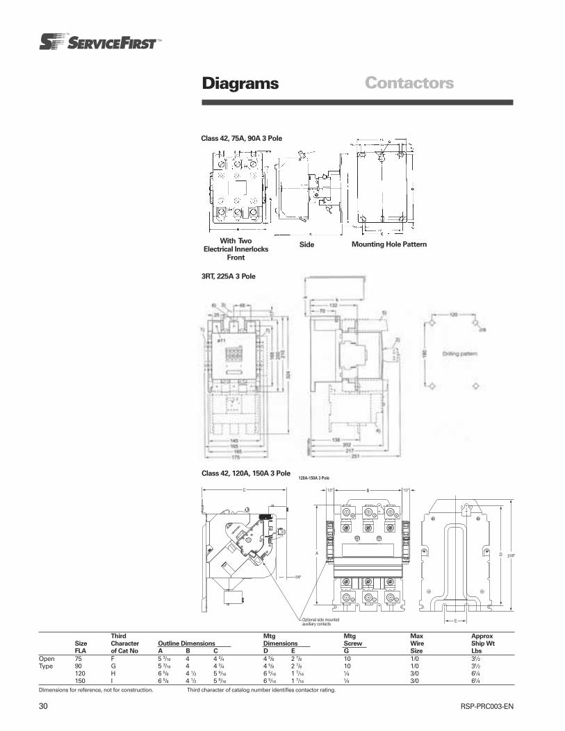
30 RSP-PRC003-EN
Third Mtg Mtg Max Approx
Size Character Outline Dimensions Dimensions Screw Wire Ship Wt
FLA of Cat No A B C D E G Size Lbs
Open 75 F 5 3/16 4 4 3/4 4 5/8 2 7/8 10 1/0 3½Type 90 G 5 3/16 4 4 3/4 4 5/8 2 7/8 10 1/0 3½
120 H 6 5/8 4 1/2 5 9/16 6 5/16 1 7/16 ¼ 3/0 6¼150 I 6 5/8 4 1/2 5 9/16 6 5/16 1 7/16 ¼ 3/0 6¼
Dimensions for reference, not for construction. Third character of catalog number identifies contactor rating.
Class 42, 120A, 150A 3 Pole
Class 42, 75A, 90A 3 Pole
With TwoElectrical Innerlocks
Front
Side Mounting Hole Pattern
Diagrams Contactors
3RT, 225A 3 Pole

31RSP-PRC003-EN
SelectionProcedure Contactors
Non
ServiceFirst 120V 240V 277V 480V 600V Inductive Poles Coil
Item # Mfg. # FLA Hp LRA Hp LRA Hp LRA Hp LRA Hp Amps Poles Voltage
40 FLA 60 Hz 600VAC Max
CTR01134 45CG10AJA 20 - 120 - 110 - 100 - 80 - 25 1 24CTR01135 45CG10AFA 110-120CTR01136 45CG10AGA 208-240CTR01137 45CG20AJ 20 - - - 120 - 100 - 80 - 30 2 24CTR01138 45CG20AF 110-120CTR01139 45CG20AG 208-240CTR01359 45CG20AL 277CTR01143 45EG10AJA 30 - 180 - 180 - 150 - 120 - 40 1 24CTR01144 45EG10AFA 110-120CTR01145 45EG10AGA 208-240CTR01146 45EG20AJ 30 - - - 180 - 135 - 110 - 40 2 24CTR01147 45EG20AF 110-120CTR01148 45EG20AG 208-240CTR01360 45EG20AL 277CTR00736 45FG10ALA 35 - 180 - 180 - 150 - 120 - 50 1 277CTR01152 45GG10AJA 40 - 200 - 200 - 160 - 140 - 55 1 24CTR01153 45GG10AFA 110-120CTR01154 45GG10AGA 208-240CTR01155 45GG20AJ 40 - - - 200 - 135 - 110 - 55 2 24CTR01156 45GG20AF 110-120CTR01157 45GG20AG 208-240CTR01361 45GG20AL 277
Definite Purpose Contactors
Standard Line
• Class 45
Single Pole 2 Pole
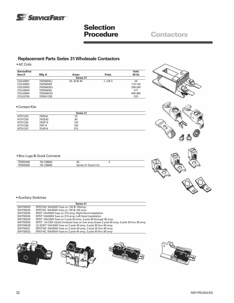
32 RSP-PRC003-EN
ContactorsSelectionProcedure
Replacement Parts Series 31 Wholesale Contactors
• AC Coils
ServiceFirst Volts
Item # Mfg. # Amps Poles 60 Hz
Series 31
COL03601 75D56630J 25, 30 & 40 1, 2 & 3 24COL03602 75D56630F 110-120COL03603 75D56630G 208-240COL04043 75D56630L 277COL03604 75D54822H 440-480COL03705 75D55123E 575
• Contact Kits
Series 31
KIT01223 75FE42 75KIT01234 75GE42 90KIT01235 75HF14 120KIT01236 75IF14 150KIT01237 75JB14 210
• Auxiliary Switches
Series 31
SWT00533 SPST-NO 10A/600V fuse on 120 & 150ampSWT00534 SPST-NC 10A/600V fuse on 120 & 150 ampSWT00535 SPDT 10A/600V fuse on 210 amp; Right Hand installationSWT00536 SPDT 10A/600V fuse on 210 amp; Left Hand installationSWT00529 SPDT 10A/250V fuse on 2 pole 40 amp, 3 pole 30 through 90 ampSWT00530 SPDT .1A/125V (Gold Contacts) fuse on low amp draws 2 pole 40 amp, 3 pole 30 thru 90 ampSWT00528 (2) SODT 10A/250V fuse on 2 pole 40 amp, 3 pole 30 thru 90 ampSWT00531 SPST-NO 10A/600V fuse on 2 pole 40 amp, 3 pole 30 thru 90 ampSWT00532 SPST-NC 10A/600V fuse on 2 pole 40 amp, 3 pole 30 thru 90 amp
• Box Lugs & Quick Connects
TER00268 75L108694 30 3TER00269 75L108695 Series 31 Quick Cnt
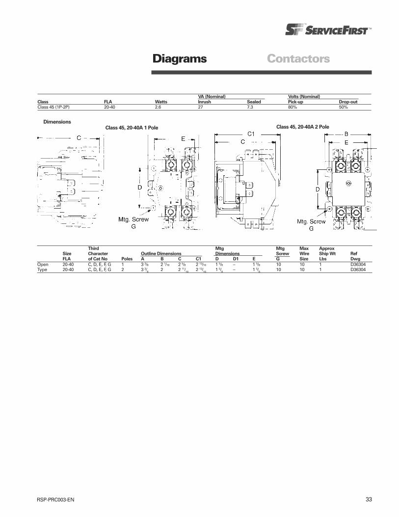
33RSP-PRC003-EN
ContactorsDiagrams
Class 45, 20-40A 1 Pole Class 45, 20-40A 2 PoleDimensions
VA (Nominal) Volts (Nominal)
Class FLA Watts Inrush Sealed Pick-up Drop-out
Class 45 (1P-2P) 20-40 2.6 27 7.3 80% 50%
Third Mtg Mtg Max ApproxSize Character Outline Dimensions Dimensions Screw Wire Ship Wt Ref
FLA of Cat No Poles A B C C1 D D1 E G Size Lbs Dwg
Open 20-40 C, D, E, F, G 1 3 3/8 2 1/16 2 5/8 2 13/16 1 5/8 – 1 5/8 10 10 1 D36304Type 20-40 C, D, E, F, G 2 3 3/8 2 2 11/16 2 13/16 1 5/8 – 1 5/8 10 10 1 D36304

34 RSP-PRC003-EN
Features andApplications Contactors
Magnetic Contactors
Full Voltage
• Rugged Industrial Design• Dual Voltage, Dual Frequency Coils• Front Removable Auxiliary Interlocks• Easy Coil Access• Horsepower Rating• Resistance Heating kW Ratings• Lighting Ampere Ratings• Capacitor and Transformer Switching
Applications• Motor Matched Sizes• Straight Thru Wiring• Gravity Dropout• UL Listed 508 File #E14900• CSA Certified File #LR6535
ApplicationsClass 40 industrial magnetic contactorsare designed for electrical loads such asheating, lighting, transformer andcapacitor switching and AC motorstarting. They control motors alreadyprotected by inherent or other types ofoverload devices. Used with appropriatepilot control, a contactor provides achoice of undervoltage protection orrelease.
Class 40 contactors size 0 thru 6 featurecarefully wound coils encapsulated toseal out moisture. Encapsulation alsopromotes heat transfer and resistselectrical, mechanical and thermalstresses.
Auxiliary Equipment• Field modifications such as auxiliary
electrical interlocks, pilot lights, pushbuttons, selector switches and fuseblocks for low voltage pilot control areavailable to meet particular applicationrequirements.
• Normally open or normally closedpower pole kits are available for sizes0 through 1¾.
• A full line of replacement parts isavailable including contact kits, coilsand overload relays.
Coil DataInrush Normal
Class 14 Volts (Open Magnet) (Sealed Magnet)
Size Watts 60Hz Amps VA Amps VA
24 2.63 .37120 .59 .08208 .34 .05
00 13.3 240 .305 70 .045 10277 .25 .03480 1.49 .02600 .121 .0224 9.08 1.04
120 1.82 .210 208 1.05 .12thru 8.6 240 .91 218 .105 252½ 27 .79 .090
480 .45 .052600 .36 .04224 12.9 1.08
120 2.58 .217208 1.49 .125
3, 3½ 14 240 1.29 210 .108 26277 1.12 .094480 .646 .054600 .516 .043120 4.25 .425208 2.45 .245240 2.15 .215
4 22 277 1.77 510 .183 51480 1.08 .112600 .85 .085120 12.65 .96240 6.32 .48
5 63 480 3.16 1518 .24 116600 2.53 .193240 1.45 .25
6 40 480 .73 350 .12 60600 .58 .10
FeaturesHorsepower rated contactors areavailable in NEMA sizes 00 through 6,plus three Furnas M-M motor matchedsizes: 1¾, 2½, and 3½. These contactorscan also be used on capacitor andtransformer switching applications. SeeApplication Data Section for ratinginformation.

35RSP-PRC003-EN
Features andApplications Contactors
Magnetic ReversingContactors
Full Voltage
• Rugged Industrial Design• Dual Voltage, Dual Frequency Coils• Compact Design• Front Removable Auxiliary Interlocks• Easy Coil Access• Straight Thru Wiring• Gravity Dropout• UL Listed 508 File #E14900• CSA Certified File #LR6535
ApplicationClass 43 industrial magnetic reversingcontactors are designed for across theline starting of single phase andpolyphase motors which do not requireoverload protection.
These controls are available in NEMAsizes 00 through 6. In addition to theusual NEMA starter sizes Furnas offersfour exclusive Motor Matched M•Msizes; 1¾, 2½, 3½ and 4½. These halfsizes offer the same rugged, industrialconstruction as our NEMA sizes andensure efficient operating performance.Furnas M•M sizes provide a real costsavings by cutting down on wastefulover capacity when NEMA sizes exceedthe motor ratings.
Typical applications include use withmachine tools, material handlingequipment, hoists and variousproduction and industrial equipment aswell as demanding automotiveapplications. These controls may also beused as changeover contactors onemergency power panels to transferfrom commercial to standby power.
FeaturesFurnas reversing contactors size 0-6include the following as standard.
Molded Coil — Magnet coils are carefullywound and then sealed in epoxy. Encap-sulation helps seal out moisture,promotes heat transfer and resistselectrical, mechanical and thermalstresses.
Dual Voltage/Frequency — Furnascontactors size 0-6 are available withdual voltage, dual frequency coils andare designed to operate on 50/60 Hz.
Field Modifications Kits/Accessories —All reversing contactors can be modifiedin the field with a complete range ofaccessories. These include push buttons,selector switches, pilot lights, auxiliaryelectrical interlocks and surgesuppressors.
Size 0 through 4Reversing ContactorsThe following features are characteristicof size 0 through 4.
Gravity Dropout — For added reliability,the gravity drop out of the armature andcontacts is assisted by stainless steelsprings which help provide quick,precise opening of the contacts.
45 Degree, Wedge Action — The 45degree, wedge action contacts reducetracking and provide faster arcquenching. The resulting self cleaningand reduced contact bounce meancooler operation and longer life for thesilver cadamium oxide contacts.
Terminal Design — Control terminals areself rising pressure type. Power terminalpoints are provided for use with powerfactor correction capacitors.
Interlocks — Cross electrical interlocksprevent the simultaneous energization ofboth contactors.
Mechanical Interlock — A mechanicalinterlock is provided to prevent bothcontactors from closing at the sametime.
Size 5 through 6Reversing ContactorsIn addition to the standard features, size5 through 6 reversing contactorsincorporate many of the additionalfeatures listed for size 0 through 4including side mounting auxiliaryinterlocks. Furnas size 5 through 6reversing contactors use the reliablevertical lift magnetic action which hasproven long life and trouble freeperformance.
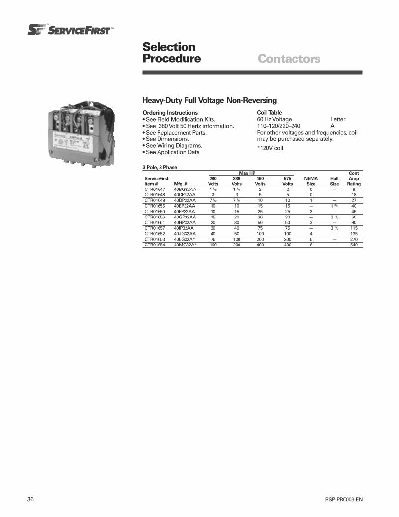
36 RSP-PRC003-EN
SelectionProcedure Contactors
Heavy-Duty Full Voltage Non-Reversing
Ordering Instructions• See Field Modification Kits.• See 380 Volt 50 Hertz information.• See Replacement Parts.• See Dimensions.• See Wiring Diagrams.• See Application Data
Coil Table60 Hz Voltage Letter110–120/220–240 AFor other voltages and frequencies, coilmay be purchased separately.
*120V coil
3 Pole, 3 Phase Max HP Cont
ServiceFirst 200 230 460 575 NEMA Half Amp
Item # Mfg. # Volts Volts Volts Volts Size Size Rating
CTR01647 40BG32AA 1 1/2 1 1/2 2 2 0 — 9CTR01648 40CP32AA 3 3 5 5 0 — 18CTR01649 40DP32AA 7 1/2 7 1/2 10 10 1 — 27CTR01655 40EP32AA 10 10 15 15 — 1 3/4 40CTR01650 40FP32AA 10 15 25 25 2 — 45CTR01656 40GP32AA 15 20 30 30 — 2 1/2 60CTR01651 40HP32AA 20 30 50 50 3 — 90CTR01657 40IP32AA 30 40 75 75 — 3 1/2 115CTR01652 40JG32AA 40 50 100 100 4 — 135CTR01653 40LG32A* 75 100 200 200 5 — 270CTR01654 40MG32A* 150 200 400 400 6 — 540

37RSP-PRC003-EN
Heavy-Duty Full Voltage Non-Reversing
Ordering Instructions• See Field Modification Kits.• For 380 Volt 50 Hertz information, see
Application Data Section.• See Replacement Parts.• Other information see Application Data
Section.• See Dimensions.• See Wiring Diagrams.• See Application Data
Coil Table60 Hz Voltage Letter110–120/220–240 AFor other voltages and frequencies, coilmay be purchased separately.
SelectionProcedure Contactors
2 Pole, 1 Phase Max. HP Cont
ServiceFirst 200 230 NEMA Half Amp
Item # Mfg. # Volts Volts Size Size Rating
CTR01658 40BG12AA 1/3 1 00 — 9CTR01691 40CP12AA 1 2 0 — 18CTR01660 40DP12AA 2 3 1 — 27CTR01661 40EP12AA 3 5 1P — 35CTR01662 40FP12AA 3 7 1/2 2 — 45CTR01667 40GP12AA 5 10 — 2 1/2 60CTR01689 40HP12AA 7 1/3 15 3 — 90CTR01668 40IP12AA — — — 3 1/2 115CTR01664 40JG12AA — — 4 — 135

38 RSP-PRC003-EN
Heavy-Duty Full Voltage Reversing
SelectionProcedure Contactors
Ordering Instructions• See Field Modification Kits.• For 380 Volt 50 Hertz information, see
Application Data Section.• See Dimensions.• See Wiring Diagrams.
Coil Table60 Hz Voltage Letter110–120/220–240 A120 FFor other voltages and frequencies, coilmay be purchased separately.
Max. HP Cont
ServiceFirst 200 230 460 575 NEMA Half Amp
Item # Mfg. # Volts Volts Volts Volts Size Size Rating
CTR01669 43BG32AA 1 1/2 1 1/2 2 2 00 — 9CTR01670 43CP32AA 3 3 5 5 0 — 18CTR01671 43DP32AA 7 1/2 7 1/2 10 10 1 — 27CTR01677 43EP32AA 10 10 15 15 — 1 3/4 40CTR01672 43FP32AA 10 15 25 25 2 — 45CTR01678 43GP32AA 15 20 30 30 — 2 1/2 60CTR01673 43HP32AA 25 30 50 50 3 — 90CTR01679 43IP32AA 30 40 75 75 — 3 1/2 115CTR01674 43JG32AA 40 50 100 100 4 — 135CTR01675 43LG32AF 75 100 200 200 5 — 270CTR01676 43MG32AF 100 200 400 400 6 — 540

39RSP-PRC003-EN
SelectionProcedure Contactors
Heavy Duty Controls Modifications
Field Modification Kits
Auxiliary Contact KitsServiceFirst Controller Enclosure
Item # Mfg. # Description Class Size Type
CTR01626 49AB10 Auxiliary Contact NEMA A600 NO 0–4CTR01627 49AB01 Front Mtg NC 14,22 All
SPST 40,43CTR01932 49AB11 1 NO, 1 NCCTR01933 49AB20 2 NO
CTR01628 3TY7561-1K4 1-NO/1-NC Auxiliary 4 1/2, 5 —Cont Block-Left 14,22
CTR01629 3TY7561-1L4 1-NO/1-NC Auxiliary 40,43Cont Block-Right
Heavy Duty Controls ModificationsNon-Combination Enclosure Kits
Type 1
Non-Reversing ContactorsServiceFirst
Item # Mfg. # Size
KIT06558 49EC14EB110705R 00-1¾KIT06559 49EC14GB140807R 2-2½KIT06560 49EC14IB201208R 3-3½KIT06561 49EC14JB251409R 4
Reversing ContactorsServiceFirst
Item # Mfg. # Size
KIT06560 49EC14IB201208R 00-2½KIT06561 49EC14JB251409R 3-4
Pilot DevicesServiceFirst Controller EnclosureItem # Mfg. # Description Class Size Type
Push Buttons SWT02666 49SAPB5 Start, Stop 14, 40 00-3 1/2 1SWT02667 49SAP05 14, 40 4-8 1
Selector Switches SWT02542 49SASB1 Hand-Off-Auto 14, 40 00-3 1/2 1SWT02668 49SAS01 14, 40 4-8 1
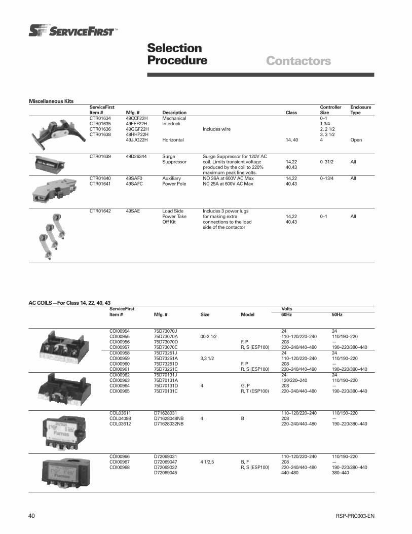
40 RSP-PRC003-EN
Miscellaneous KitsServiceFirst Controller Enclosure
Item # Mfg. # Description Class Size Type
CTR01634 49CCF22H Mechanical 0–1CTR01635 49EEF22H Interlock 1 3/4CTR01636 49GGF22H Includes wire 2, 2 1/2CTR01638 49HHP22H 3, 3 1/2
49JJG22H Horizontal 14, 40 4 Open
CTR01639 49D26344 Surge Surge Suppressor for 120V ACSuppressor coil. Limits transient voltage 14,22 0–31/2 All
produced by the coil to 220% 40,43maximum peak line volts.
CTR01640 49SAF0 Auxiliary NO 36A at 600V AC Max 14,22 0–13/4 AllCTR01641 49SAFC Power Pole NC 25A at 600V AC Max 40,43
CTR01642 49SAE Load Side Includes 3 power lugsPower Take for making extra 14,22 0–1 AllOff Kit connections to the load 40,43
side of the contactor
SelectionProcedure Contactors
AC COILS—For Class 14, 22, 40, 43ServiceFirst Volts
Item # Mfg. # Size Model 60Hz 50Hz
COI00954 75D73070J 24 24COI00955 75D73070A 00-2 1/2 110–120/220–240 110/190–220COI00956 75D73070D F, P 208 —COI00957 75D73070C R, S (ESP100) 220–240/440–480 190–220/380–440COI00958 75D73251J 24 24COI00959 75D73251A 3,3 1/2 110–120/220–240 110/190–220COI00960 75D73251D F, P 208 —COI00961 75D73251C R, S (ESP100) 220–240/440–480 190–220/380–440COI00962 75D70131J 24 24COI00963 75D70131A 120/220–240 110/190–220COI00964 75D70131D 4 G, P 208 —COI00965 75D70131C R, T (ESP100) 220–240/440–480 190–220/380–440
COL03611 D71628031 110–120/220–240 110/190–220COL04098 D71628048NB 4 B 208 —COL03612 D71628032NB 220–240/440–480 190–220/380–440
COI00966 D72069031 110–120/220–240 110/190–220COI00967 D72069047 4 1/2,5 B, F 208 —COI00968 D72069032 R, S (ESP100) 220–240/440–480 190–220/380–440
D72069045 440–480 380–440

41RSP-PRC003-EN
SelectionProcedure Contactors
Contact Kits—Single Pole Stationary and Movable Contacts, Contact Spring1
ServiceFirst Model
Description Item # Mfg. # Size No of Poles in Kit (4th position in part number)
KIT06542 75AF14 InterlockN/A (replace contactor) 0 1 G
KIT06543 75BF14 0 F, PKIT06544 75CF14 0 F, P, SKIT06545 75DF14 1 1 F, P, SKIT06546 75EF14 1 3/4–1P F, P, SKIT06547 75FF14 2 1 FKIT06548 75FP14 P, SKIT06549 75GF14 2 1/2 1 FKIT06550 75GP14 P, S
Class 14, 40, 43 KIT06551 75HF14 3 F, P, SKIT06552 75IF14 3 1/2 1 F, P, SKIT06553 75JG14 4 1 G, P, TKIT06554, KIT01237 75JB14 4 BKIT06555 75RB14 4 1/2 1 B, F, SKIT06556 75KB14 5 1 B, F, SKIT06557 75MB14 6 1 B, F, S
1On 3 phase controls, all 3 poles should be replaced— 3 kits required.

42 RSP-PRC003-EN
Diagrams Contactors
Full Voltage Open Type NEMA Contactor Size 00-6
Figure 1 Figure 2 Figure 3
Open TypeMtg Mtg Max Approx
3rd Character Outline Dimensions Dimensions 1Screw Wire Ship Wt Ref
Size of Catlog No Fig A B B1 B2 C D D1 E G Size Lbs (Kg) Dwg
00 B 1 3.75 (95) 2.25 (57) 4.50 (114) 5.50 (140) 3.19 (81) 2.38 (60) 2.75 (70) 1.38 (35) 8 (203) 12 2 (1) D293400–1 C, D 2 4.31 (110) 3.94 (100) 4.25 (108) 4.75 (121) 3.75 (70) 3.94 (100) 0.19 (5) 1.00 (25) 10 (254) 8 4 (2) D562731 3/4 E 2 4.31 (110) 3.94 (100) 4.25 (108) 4.75 (121) 3.75 (70) 3.94 (100) 0.19 (5) 1.00 (25) 10 (254) 6 4 (2) D562732 F 2 4.88 (124) 3.94 (100) 4.25 (108) — 4.00 (102) 4.50 (114) 0.19 (5) 1.00 (25) 10 (254) 4 11 (5) D562742 1/2 G 2 4.88 (124) 3.94 (100) 4.50 (114) — 4.00 (102) 4.50 (114) 0.19 (5) 1.00 (25) 10 (254) 2 11 (5) D562743 H 2 6.13 (156) 5.13 (130) 5.50 (140) — 5.06 (129) 5.63 (143) 0.25 (6) 0.75 (19) 0.25 (6) 0 14 (6) D562753 1/2 I 2 6.13 (156) 5.13 (130) 5.50 (140) — 5.06 (129) 5.63 (143) 0.25 (6) 0.75 (19) 0.25 (6) 00 14 (6) D562754 J 2 7.81 (198) 5.19 (132) 5.50 (140) — 5.75 (146) 6.56 (167) 0.81 (21) 0.75 (19) 0.5 (13) 250 MCM 15 (7) D700974, 5 K,L 3 7.89 (200) 6.30 (160) — — 8.74 (222) 7.09 (180) — 5.12 (130) — 1–500 MCM or — —
2–300 MCM6 M 3 8.78 (223) 8.62 (219) — — 8.90 (226) 7.87 (200) — 6.69 (170) — 2–500 MCM — —
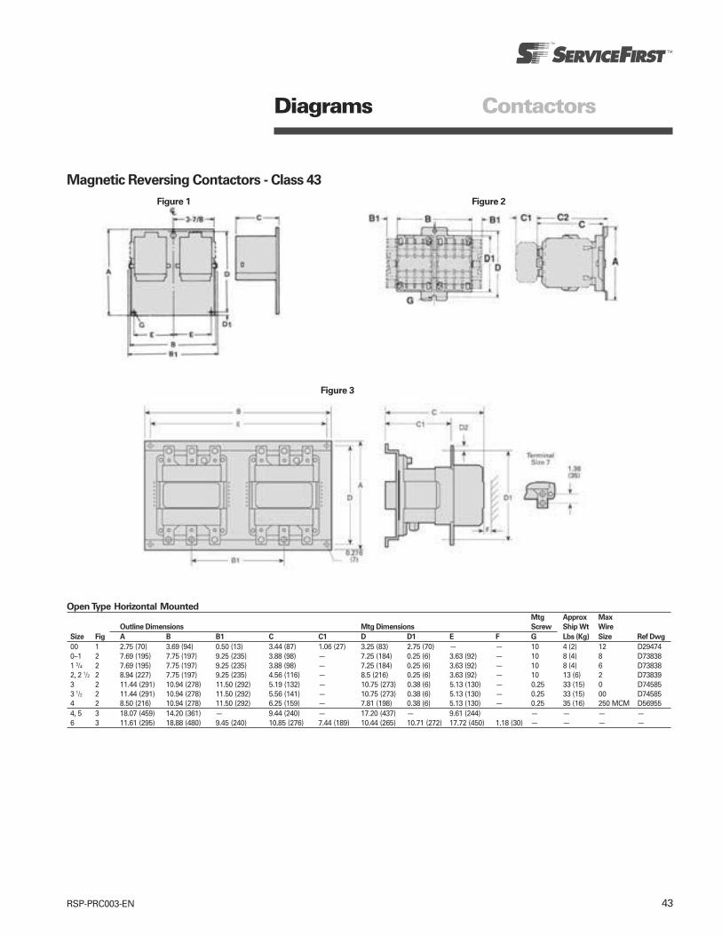
43RSP-PRC003-EN
Diagrams Contactors
Magnetic Reversing Contactors - Class 43
Figure 1 Figure 2
Figure 3
Open Type Horizontal MountedMtg Approx Max
Outline Dimensions Mtg Dimensions Screw Ship Wt Wire
Size Fig A B B1 C C1 D D1 E F G Lbs (Kg) Size Ref Dwg
00 1 2.75 (70) 3.69 (94) 0.50 (13) 3.44 (87) 1.06 (27) 3.25 (83) 2.75 (70) — — 10 4 (2) 12 D294740–1 2 7.69 (195) 7.75 (197) 9.25 (235) 3.88 (98) — 7.25 (184) 0.25 (6) 3.63 (92) — 10 8 (4) 8 D738381 3/4 2 7.69 (195) 7.75 (197) 9.25 (235) 3.88 (98) — 7.25 (184) 0.25 (6) 3.63 (92) — 10 8 (4) 6 D738382, 2 1/2 2 8.94 (227) 7.75 (197) 9.25 (235) 4.56 (116) — 8.5 (216) 0.25 (6) 3.63 (92) — 10 13 (6) 2 D738393 2 11.44 (291) 10.94 (278) 11.50 (292) 5.19 (132) — 10.75 (273) 0.38 (6) 5.13 (130) — 0.25 33 (15) 0 D745853 1/2 2 11.44 (291) 10.94 (278) 11.50 (292) 5.56 (141) — 10.75 (273) 0.38 (6) 5.13 (130) — 0.25 33 (15) 00 D745854 2 8.50 (216) 10.94 (278) 11.50 (292) 6.25 (159) — 7.81 (198) 0.38 (6) 5.13 (130) — 0.25 35 (16) 250 MCM D569554, 5 3 18.07 (459) 14.20 (361) — 9.44 (240) — 17.20 (437) — 9.61 (244) — — — —6 3 11.61 (295) 18.88 (480) 9.45 (240) 10.85 (276) 7.44 (189) 10.44 (265) 10.71 (272) 17.72 (450) 1.18 (30) — — — —

44 RSP-PRC003-EN
Diagrams Contactors
Heavy Duty Motor Starters and ContactorsDimensions/Enclosures Class 14, 22, 40, 43
Figure 4
NEMA 1 General Purpose EnclosuresMtg Approx
Outline Dimensions Mtg Dimensions Screw Conduit Size Ship Wt
Size Fig A B C D E G K1 K2 K3 K4 K5 Lbs (Kg) Ref Dwg
00-1¾ 1 1031/32 (279) 613/32 (163) 51/32 (128) 87/32 (209) 45/8 (117) ¼ ½ ½- ¾ ¾-1 — — 10 (5) D688702-2½ 2 1317/32 (344) 731/32 (202) 63/8 (162) 10¼ (260) 6 (152) ¼ ½-¾ ¾–1 1-1¼ — — 15 (7) D688703-3½ 3 191/8 (486) 113/8 (289) 711/16 (195) 155/8 (397) 8¼ (210) ¼ ½-¾ 1-1¼ 1½- 2 — — 26 (12) D68870
4 4 247/8 (632) 133/8 (340) 81/8 (206) 21¾ (552) 9 (229) ¼ ½-¾ 1¼-1½ 2-2½ — — 37 (17) D68870
Figure 3Figure 2Figure 1
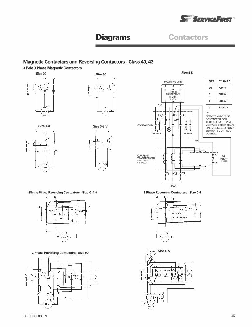
45RSP-PRC003-EN
Diagrams Contactors
Magnetic Contactors and Reversing Contactors - Class 40, 43
3 Pole 3 Phase Magnetic Contactors
Size 00 Size 4-5Size 00
Size 0-4 Size 0-3 1/2
Single Phase Reversing Contactors - Size 0- 1¾ 3 Phase Reversing Contactors - Size 0-4
3 Phase Reversing Contactors - Size 00Size 4, 5
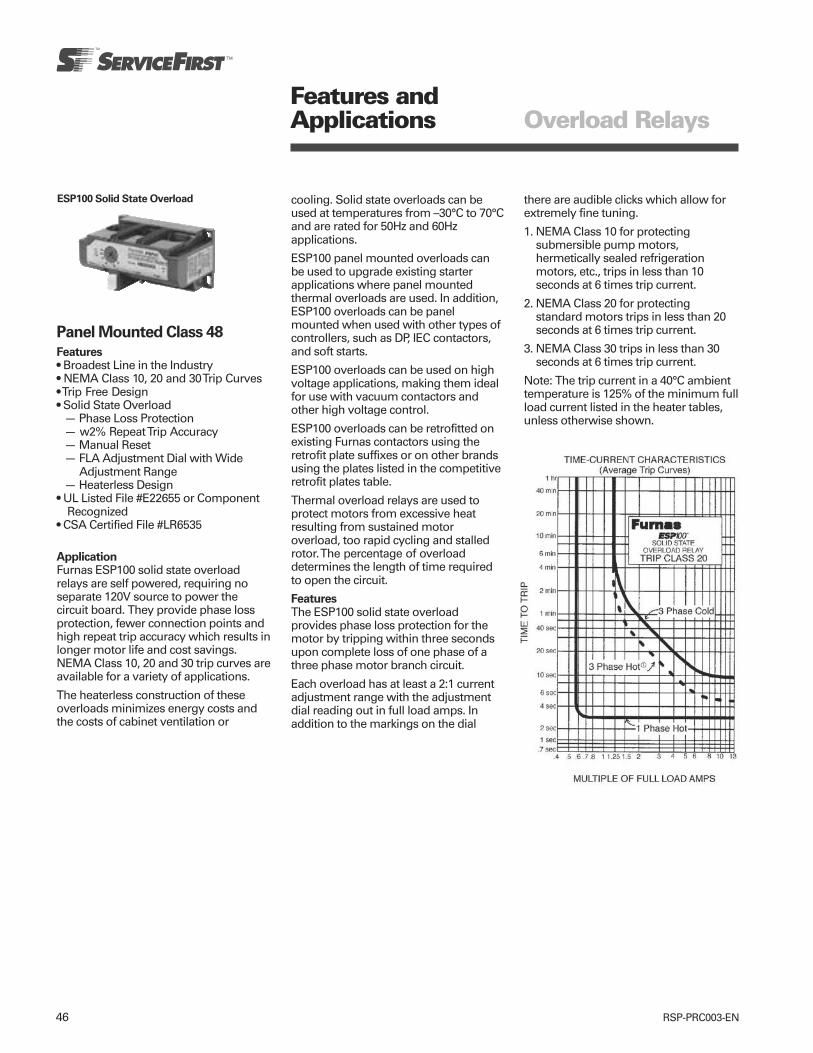
46 RSP-PRC003-EN
Features andApplications Overload Relays
Panel Mounted Class 48
Features• Broadest Line in the Industry• NEMA Class 10, 20 and 30 Trip Curves• Trip Free Design• Solid State Overload
— Phase Loss Protection— w2% Repeat Trip Accuracy— Manual Reset— FLA Adjustment Dial with Wide
Adjustment Range— Heaterless Design
• UL Listed File #E22655 or ComponentRecognized
• CSA Certified File #LR6535
ApplicationFurnas ESP100 solid state overloadrelays are self powered, requiring noseparate 120V source to power thecircuit board. They provide phase lossprotection, fewer connection points andhigh repeat trip accuracy which results inlonger motor life and cost savings.NEMA Class 10, 20 and 30 trip curves areavailable for a variety of applications.
The heaterless construction of theseoverloads minimizes energy costs andthe costs of cabinet ventilation or
cooling. Solid state overloads can beused at temperatures from –30°C to 70°Cand are rated for 50Hz and 60Hzapplications.
ESP100 panel mounted overloads canbe used to upgrade existing starterapplications where panel mountedthermal overloads are used. In addition,ESP100 overloads can be panelmounted when used with other types ofcontrollers, such as DP, IEC contactors,and soft starts.
ESP100 overloads can be used on highvoltage applications, making them idealfor use with vacuum contactors andother high voltage control.
ESP100 overloads can be retrofitted onexisting Furnas contactors using theretrofit plate suffixes or on other brandsusing the plates listed in the competitiveretrofit plates table.
Thermal overload relays are used toprotect motors from excessive heatresulting from sustained motoroverload, too rapid cycling and stalledrotor. The percentage of overloaddetermines the length of time requiredto open the circuit.
FeaturesThe ESP100 solid state overloadprovides phase loss protection for themotor by tripping within three secondsupon complete loss of one phase of athree phase motor branch circuit.
Each overload has at least a 2:1 currentadjustment range with the adjustmentdial reading out in full load amps. Inaddition to the markings on the dial
ESP100 Solid State Overload there are audible clicks which allow forextremely fine tuning.
1. NEMA Class 10 for protectingsubmersible pump motors,hermetically sealed refrigerationmotors, etc., trips in less than 10seconds at 6 times trip current.
2. NEMA Class 20 for protectingstandard motors trips in less than 20seconds at 6 times trip current.
3. NEMA Class 30 trips in less than 30seconds at 6 times trip current.
Note: The trip current in a 40°C ambienttemperature is 125% of the minimum fullload current listed in the heater tables,unless otherwise shown.
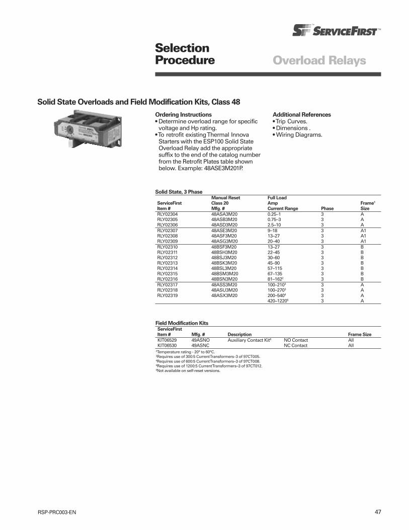
47RSP-PRC003-EN
SelectionProcedure Overload Relays
Solid State Overloads and Field Modification Kits, Class 48
Ordering Instructions• Determine overload range for specific
voltage and Hp rating.• To retrofit existing Thermal Innova
Starters with the ESP100 Solid StateOverload Relay add the appropriatesuffix to the end of the catalog numberfrom the Retrofit Plates table shownbelow. Example: 48ASE3M201P.
Additional References• Trip Curves.• Dimensions .• Wiring Diagrams.
Solid State, 3 PhaseManual Reset Full Load
ServiceFirst Class 20 Amp Frame1
Item # Mfg. # Current Range Phase Size
RLY02304 48ASA3M20 0.25–1 3 ARLY02305 48ASB3M20 0.75–3 3 ARLY02306 48ASD3M20 2.5–10 3 ARLY02307 48ASE3M20 9–18 3 A1RLY02308 48ASF3M20 13–27 3 A1RLY02309 48ASG3M20 20–40 3 A1RLY02310 48BSF3M20 13–27 3 BRLY02311 48BSH3M20 22–45 3 BRLY02312 48BSJ3M20 30–60 3 BRLY02313 48BSK3M20 45–90 3 BRLY02314 48BSL3M20 57–115 3 BRLY02315 48BSM3M20 67–135 3 BRLY02316 48BSN3M20 81–1622 3 BRLY02317 48ASS3M20 100–2103 3 ARLY02318 48ASU3M20 100–2703 3 ARLY02319 48ASX3M20 200–5404 3 A
420–12205 3 A
Field Modification KitsServiceFirst
Item # Mfg. # Description Frame Size
KIT06529 49ASNO Auxiliary Contact Kit6 NO Contact AllKIT06530 49ASNC NC Contact All
2Temperature rating - 20° to 60°C.3Requires use of 300:5 Current Transformers–3 of 97CT005.4Requires use of 600:5 Current Transformers–3 of 97CT008.5Requires use of 1200:5 Current Transformers–3 of 97CT012.6Not available on self-reset versions.

48 RSP-PRC003-EN
Diagrams Overload Relays
Solid State Overload Manual Reset Version
Dimensions “A” Frame—ESP100 Solid State Overload (0.25–10 Amps & 100–1000 Amps 3 Phase, 0.25–16 Amps Single Phase)
Dimensions “A1” Frame—ESP100 Solid State Overload (9–40 Amps), 958 (15–44 Amps), 958L (5.6–40 Amps, 84–528 Amps)
ESP100 OverloadMotor lead Windows
Dimensions “B” Frame—ESP100 Solid State Overload (13–162 Amps), 958 (33–180 Amps), 958L (18–150 Amps)
ESP100 OverloadMotor lead Windows
Manual Reset Wiring Diagram

49RSP-PRC003-EN
Features andApplications Overload Relays
Special Use Solid State Overloads, Class 958
Features• Hermetically Sealed Compressor MotorApplications
• Phase Loss Protection—Trips Within 3Seconds
• w/2% Repeat Trip Accuracy• Manual Reset• “Must Hold Amps” Adjustment Dial• Wide Adjustment Range• Self Powered Overload• Heaterless Design• Rated 50/60Hz• –22°F to 159°F (-30°C to 70°C)• Output Contact Rated NEMA A600,P600 (10 Amps 600VAC Max, 5 Amps600VDC Max)
• Self-Reset Output Contact Rated NEMAB300, P150 (5 Amps, 300VAC Max, 5Amps, 150VDC Max)
• UL Listed File #E22655• CSA Certified File #LR6535
ApplicationFurnas special use solid state overloadrelays are self powered requiring noseparate source to power the circuitboard. They provide excellent protectionof hermetically sealed compressors andartificially cooled motors which requireambient insensitivity and quick tripresponse times. Combined with a serieslockout relay, they can provideunsurpassed protection for hermeticallysealed compressor motors in airconditioning applications. Thecombination of high trip speed, currentadjustment, and ease of installationmakes it suitable for these applications.The trip curves have been customtailored to provide proper overloadprotection on such loads withoutnuisance tripping.
A1 Frame 958 Series B Frame 958 Series
Figure 1
FeaturesThe overload provides phase lossprotection for the motor by tripping inthree seconds upon complete loss ofone phase of a three phase motorbranch circuit.
The heaterless construction of theseoverloads minimizes energy costs andthe costs of cabinet ventilation orcooling. While thermal overloads requirea heater selection based on a relativelywide range, these overloads have manyclicks covering the same ampere range(see Figure 1 below).
Each overload has a 4:1 or 2:1 currentadjustment range with the adjustmentdial reading out must hold amps. Musttrip amps are 112% of the must holdsetting. In addition to the markings onthe dial there are audible clicks whichallow for extremely fine tuning.
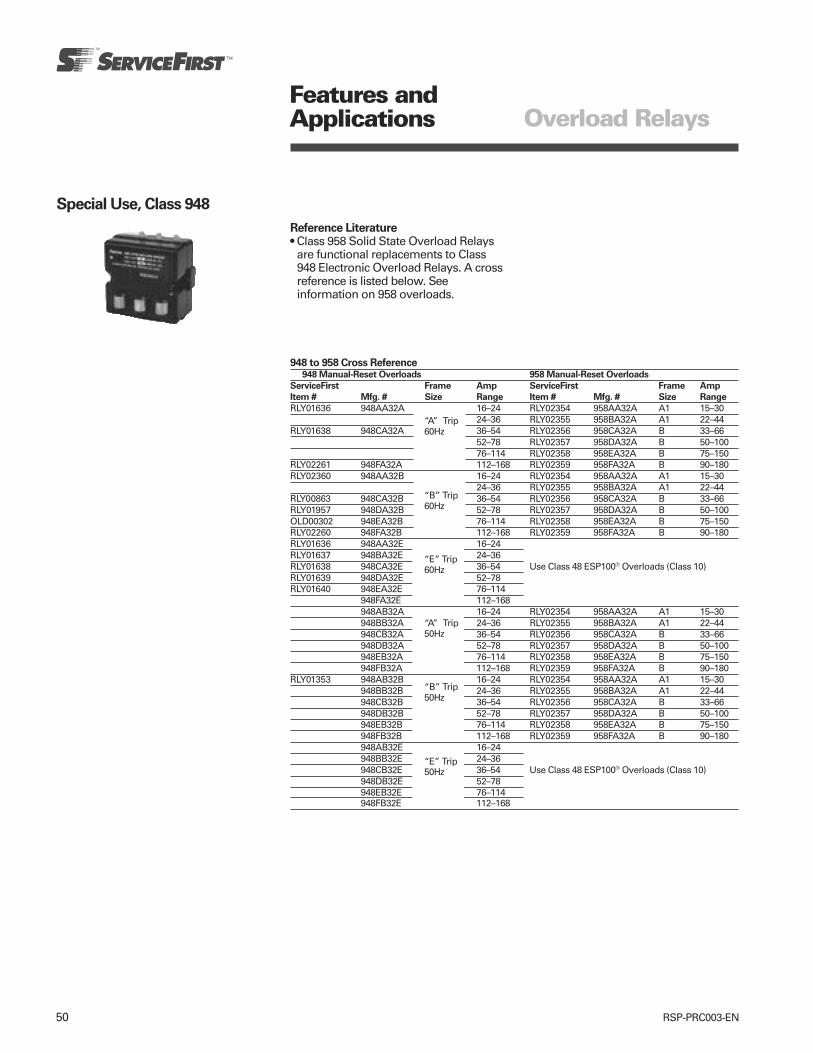
50 RSP-PRC003-EN
Features andApplications Overload Relays
Special Use, Class 948
Reference Literature• Class 958 Solid State Overload Relays
are functional replacements to Class948 Electronic Overload Relays. A crossreference is listed below. Seeinformation on 958 overloads.
948 to 958 Cross Reference948 Manual-Reset Overloads 958 Manual-Reset Overloads
ServiceFirst Frame Amp ServiceFirst Frame Amp
Item # Mfg. # Size Range Item # Mfg. # Size Range
RLY01636 948AA32A 16–24 RLY02354 958AA32A A1 15–3024–36 RLY02355 958BA32A A1 22–44
RLY01638 948CA32A “A” Trip 36–54 RLY02356 958CA32A B 33–6660Hz 52–78 RLY02357 958DA32A B 50–100
76–114 RLY02358 958EA32A B 75–150RLY02261 948FA32A 112–168 RLY02359 958FA32A B 90–180RLY02360 948AA32B 16–24 RLY02354 958AA32A A1 15–30
24–36 RLY02355 958BA32A A1 22–44RLY00863 948CA32B “B” Trip 36–54 RLY02356 958CA32A B 33–66RLY01957 948DA32B 60Hz 52–78 RLY02357 958DA32A B 50–100OLD00302 948EA32B 76–114 RLY02358 958EA32A B 75–150RLY02260 948FA32B 112–168 RLY02359 958FA32A B 90–180RLY01636 948AA32E 16–24RLY01637 948BA32E 24–36RLY01638 948CA32E “E” Trip 36–54 Use Class 48 ESP100® Overloads (Class 10)RLY01639 948DA32E 60Hz 52–78RLY01640 948EA32E 76–114
948FA32E 112–168948AB32A 16–24 RLY02354 958AA32A A1 15–30948BB32A 24–36 RLY02355 958BA32A A1 22–44948CB32A “A” Trip 36–54 RLY02356 958CA32A B 33–66948DB32A 50Hz 52–78 RLY02357 958DA32A B 50–100948EB32A 76–114 RLY02358 958EA32A B 75–150948FB32A 112–168 RLY02359 958FA32A B 90–180
RLY01353 948AB32B 16–24 RLY02354 958AA32A A1 15–30948BB32B 24–36 RLY02355 958BA32A A1 22–44948CB32B “B” Trip 36–54 RLY02356 958CA32A B 33–66948DB32B 50Hz 52–78 RLY02357 958DA32A B 50–100948EB32B 76–114 RLY02358 958EA32A B 75–150948FB32B 112–168 RLY02359 958FA32A B 90–180948AB32E 16–24948BB32E 24–36948CB32E “E” Trip 36–54 Use Class 48 ESP100® Overloads (Class 10)948DB32E 50Hz 52–78948EB32E 76–114948FB32E 112–168
“A” Trip60Hz
“B” Trip60Hz
“E” Trip60Hz
“A” Trip50Hz
“B” Trip50Hz
“E” Trip50Hz
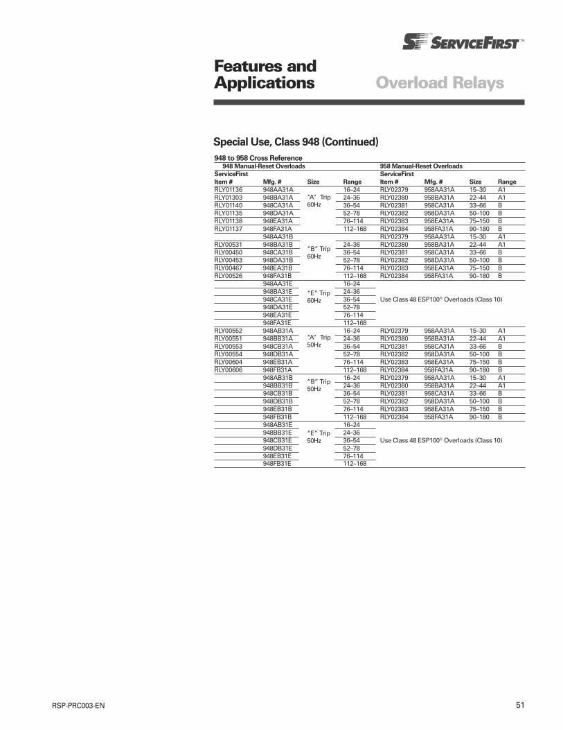
51RSP-PRC003-EN
Features andApplications Overload Relays
Special Use, Class 948 (Continued)
948 to 958 Cross Reference948 Manual-Reset Overloads 958 Manual-Reset Overloads
ServiceFirst ServiceFirst
Item # Mfg. # Size Range Item # Mfg. # Size Range
RLY01136 948AA31A 16–24 RLY02379 958AA31A 15–30 A1RLY01303 948BA31A 24–36 RLY02380 958BA31A 22–44 A1RLY01140 948CA31A 36–54 RLY02381 958CA31A 33–66 BRLY01135 948DA31A 52–78 RLY02382 958DA31A 50–100 BRLY01138 948EA31A 76–114 RLY02383 958EA31A 75–150 BRLY01137 948FA31A 112–168 RLY02384 958FA31A 90–180 B
948AA31B RLY02379 958AA31A 15–30 A1RLY00531 948BA31B 24–36 RLY02380 958BA31A 22–44 A1RLY00450 948CA31B 36–54 RLY02381 958CA31A 33–66 BRLY00453 948DA31B 52–78 RLY02382 958DA31A 50–100 BRLY00467 948EA31B 76–114 RLY02383 958EA31A 75–150 BRLY00526 948FA31B 112–168 RLY02384 958FA31A 90–180 B
948AA31E 16–24948BA31E 24–36948CA31E 36–54 Use Class 48 ESP100® Overloads (Class 10)948DA31E 52–78948EA31E 76–114948FA31E 112–168
RLY00552 948AB31A 16–24 RLY02379 958AA31A 15–30 A1RLY00551 948BB31A 24–36 RLY02380 958BA31A 22–44 A1RLY00553 948CB31A 36–54 RLY02381 958CA31A 33–66 BRLY00554 948DB31A 52–78 RLY02382 958DA31A 50–100 BRLY00604 948EB31A 76–114 RLY02383 958EA31A 75–150 BRLY00606 948FB31A 112–168 RLY02384 958FA31A 90–180 B
948AB31B 16–24 RLY02379 958AA31A 15–30 A1948BB31B 24–36 RLY02380 958BA31A 22–44 A1948CB31B 36–54 RLY02381 958CA31A 33–66 B948DB31B 52–78 RLY02382 958DA31A 50–100 B948EB31B 76–114 RLY02383 958EA31A 75–150 B948FB31B 112–168 RLY02384 958FA31A 90–180 B948AB31E 16–24948BB31E 24–36948CB31E 36–54 Use Class 48 ESP100® Overloads (Class 10)948DB31E 52–78948EB31E 76–114948FB31E 112–168
“A” Trip60Hz
“B” Trip60Hz
“E” Trip60Hz
“A” Trip50Hz
“B” Trip50Hz
“E” Trip50Hz
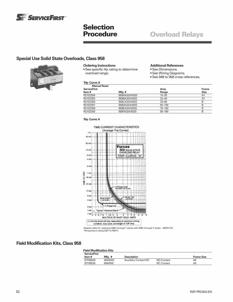
52 RSP-PRC003-EN
SelectionProcedure Overload Relays
Special Use Solid State Overloads, Class 958
Ordering Instructions• See specific Hp rating to determine
overload range.
Additional References• See Dimensions.• See Wiring Diagrams.• See 948 to 958 cross references.
Trip Curve AManual Reset
ServiceFirst Amp FrameItem # Mfg. # Range Size
RLY02354 958AA32AX625 15–30 A1RLY02355 958BA32AX625 22–44 A1RLY02356 958CA32AX625 33–66 BRLY02357 958DA32AX625 50–100 BRLY02358 958EA32AX625 75–150 BRLY02359 958FA32AX625 90–180 B
Trip Curve A
Adapter plate for replacing 948C through F styles with 958C through F styles – 49D571241Temperature rating S20° to R60°C.
Field Modification Kits, Class 958
Field Modification KitsServiceFirstItem # Mfg. # Description Frame Size
KIT06529 49ASNO Auxiliary Contact Kit6 NO Contact AllKIT06530 49ASNC NC Contact All

53RSP-PRC003-EN
Diagrams Overload Relays
Solid State Overload Manual Reset Version
Dimensions “A” Frame—ESP100 Solid State Overload (0.25–10 Amps & 100–1000 Amps 3 Phase, 0.25–16 Amps Single Phase)
Dimensions “A1” Frame—ESP100 Solid State Overload (9–40 Amps), 958 (15–44 Amps), 958L (5.6–40 Amps, 84–528 Amps)
ESP100 OverloadMotor Lead Windows
Dimensions “B” Frame—ESP100 Solid State Overload (13–162 Amps), 958 (33–180 Amps), 958L (18–150 Amps)
ESP100 OverloadMotor Lead Windows
Manual Reset Wiring Diagram

54 RSP-PRC003-EN
Heavy Duty Starters
Size 0–4 Starter Features,Application
Features andApplications
Standard FeaturesSize 0–4 magnetic starters include thefollowing standard features:• Rugged Industrial Design• Dual Voltage, Dual Frequency Coils• Overload Test Feature• Front Removable Auxiliary Contacts• Wide Range of Accessories• Easy Coil Access• Solid State or Bimetal AmbientCompensated Overload Protection
• Half Sizes for Costs and Space Savings• Straight Thru Wiring• Gravity Dropout• Large Silver Cadmium Contacts
Application
These controls are available in NEMASizes 00 through 8. In addition to theusual NEMA Starter Sizes, Siemens-Furnas offers four exclusive Half Sizes;13/4, 21/2, 31/2 and 41/2. These integral sizesoffer the same rugged, industrialconstruction as our NEMA Sizes andensure efficient operating performance.Half Sizes provide a real cost savings bycutting down on over capacity whenNEMA Sizes exceed the motor ratings.All Innova controls, including ourpopular Half Sizes comply withapplicable NEMA and UL tests.
Furnas magnetic starters are ideal forapplications requiring dependability anddurability. Typical applications includeuse with machine tools, air conditioningequipment, material handlingequipment, compressors, hoists andvarious production and industrialequipment as well as in demandingautomotive applications.
Starters are available as an open type orin NEMA 1, 3, 4, 4X, 7 & 9, and 12enclosures.
Size 00 starters are intended for motorsrated at 2 Hp or less. These controls offerthe same rugged, dependable quality as0–8, in a compact panel saving design.
Gravity DropoutFor added reliability, the gravity dropoutof the armature and contacts is assistedby stainless steel springs which helpprovide quick, precise opening of thecontacts. Also provides straight throughwiring.
45 Degree, Wedge Action ContactsThe 45 degree, wedge action contactsreduce tracking and provide faster arcquenching. The resulting self-cleaningand reduced contact bounce meancooler operation and longer life for thelarge silver cadmium oxide contacts.
Terminal DesignControl terminals are self rising pressuretype.
Molded CoilMagnetic coils are carefully wound andthen sealed in epoxy. Encapsulationhelps seal out moisture, promotes heattransfer and resists electrical, mechanicaland thermal stresses.
Dual Voltage/Frequency CoilStarters are available with dual voltage,dual frequency coils. They are designedto operate on either 50 or 60 Hertz.
Molded Stationary Contact BlockThermoset materials resist arc trackingand the stresses of heat and severeimpact.
Field Modification KitsAll starters can be modified in the fieldwith a complete range of accessories.These include pushbuttons, selectorswitches, pilot lights, auxiliary contactsand surge suppressors.
Auxiliary Equipment• Furnas starters are available with built-
in START-STOP push buttons for 3 wirecontrol or a HAND-OFF-AUTO selectorswitch for 2 wire control.
• Field modifications such as auxiliarycontacts, pilot lights, push buttons,selector switches, and fuse blocks areavailable to meet particular applicationrequirements.
• Normally open or normally closedauxiliary power pole kits are availablefor Sizes 0 through 1¾.
• Transformers and pneumatic timerscan be ordered as either factory or fieldmodifications. In some cases thesemay require a larger enclosure.
• A full line of replacement parts areavailable including contact kits, coils,and overload relays.
Part No.49D70084
The Furnas FVNR Sizes 0–13/4 have asstandard, universal mounting which fitsthe following:
Cutler Hammer — Citation Series— Freedom Series
GE — 300 Line
Square D — Type S
The Starter with its existing backplatemounts onto the piggyback mountingplate and is secured in place with threemounting screws. The piggybackmounting plate fits the following:
Allen-Bradley — Bulletin 509— Bulletin 709
Westinghouse— Series A200
Motor Starters

55RSP-PRC003-EN
Heavy Duty Starters
Size 0–4 Starter Features,Application
Size 0–1¾ESP100 Solid State Starter
ESP100 Solid State Overload RelaysThese standard features of the ESP100provide Extra Starter Performance.• True phase loss protection; trips within
3 seconds.• High accuracy trip curves; ± 2% repeat
trip accuracy.• Ease of use. Mount, wire, and set FLA.• Overload is self protected against short
circuits.• Overload is self powered and requires
no hard wiring or separate powersource.
• Simple, versatile adjustment; minimumof 2:1 FLA adjustment range. (4:1 inlower FLA ranges.)
• Heaterless construction minimizesenergy costs and the costs of cabinetventilation or cooling.
• Class 20 protection is standard. Class10 and 30 protection are available.
• Provides motor protection for 50/60Hertz.
ESP100 starters combine the ruggedcharacteristics of a NEMA ratedcontactor with a solid state overloadwhich provides phase loss protection. Itoffers the industrial user greaterprotection and added life for motors inheavy duty applications. The inherentbenefits of the ESP100 result in costsavings as well.
ESP100 FLA Adjustment Dial—Set the adjustment dial on the overload to the FLA of the motor.
Figure 1
Typical Solid-State OverloadAdjustment Dial Markings
Each overload is precisely calibrated andlabels are individually laser printed andthen custom applied for each particularcalibration.
Typical Number of Heater ElementsNeeded for Alloy Overloads
• No need for heater coil selection or installation.• No heater elements to stock.• More precision.
Features andApplications Motor Starters
Heavy Duty StartersHalf-Size Heavy Duty Starters
Furnas Half-Size starters feature all therugged performance characteristics ofour NEMA rated starter sizes, but arefractionally sized to more closely matchyour exact motor rating. As a result,significant economic savings are made
possible, without sacrificing thereliability you expect from a heavy dutystarter.
These additional starter sizes have thereserve capacity to handle occasionalplugging and jogging applicationswithout derating. Superior operatingperformance in heavy duty applicationsis assured by the large current carryingparts, not by derating the device.
Savings for Innova “Half-Size” Starters in NEMA 1 Enclosures, FVNR“Half-Size”
Motor Size Starter Half Savings Over230V 460V Size Size Next Full Size71/2 10 1 — —10 15 — 13/4 31%15 25 2 — —20 30 — 21/2 20%30 50 3 — —40 75 — 31/2 13%50 100 4 — —
100 200 5 — —
Exclusive “half-sizes” save potentiallyhundreds, even thousands of dollars perproject.
Simply match the specific size starter tothe horsepower rating of your motor.Every half-size starter saves youmoney—up to 31%.
Innova starters, including our exclusive“half-sizes,” comply to applicable NEMAand UL standards.
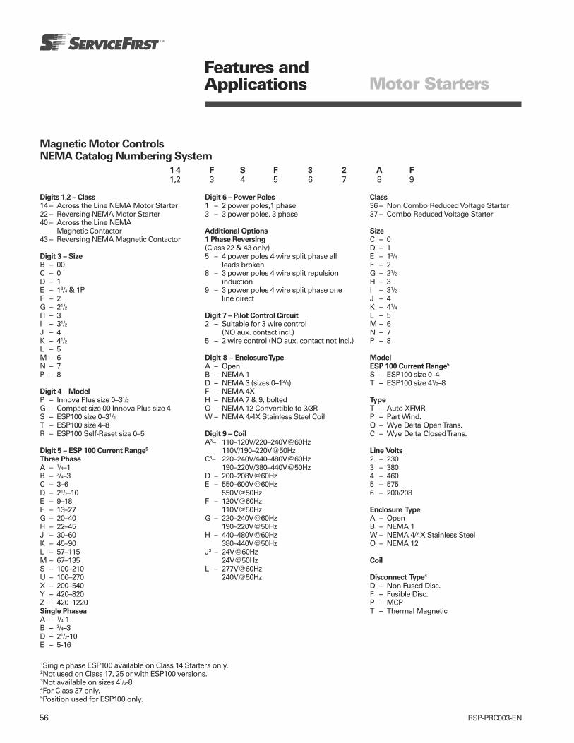
56 RSP-PRC003-EN
Features andApplications Motor Starters
Digits 1,2 – Class14 – Across the Line NEMA Motor Starter22 – Reversing NEMA Motor Starter40 – Across the Line NEMA
Magnetic Contactor43 – Reversing NEMA Magnetic Contactor
Digit 3 – SizeB – 00C – 0D – 1E – 13/4 & 1PF – 2G – 21/2H – 3I – 31/2J – 4K – 41/2L – 5M – 6N – 7P – 8
Digit 4 – ModelP – Innova Plus size 0–31/2G – Compact size 00 Innova Plus size 4S – ESP100 size 0–31/2T – ESP100 size 4–8R – ESP100 Self-Reset size 0–5
Digit 5 – ESP 100 Current Range5
Three PhaseA – 1/4–1B – 3/4–3C – 3–6D – 21/2–10E – 9–18F – 13–27G – 20–40H – 22–45J – 30–60K – 45–90L – 57–115M – 67–135S – 100–210U – 100–270X – 200–540Y – 420–820Z – 420–1220Single PhaseaA – 1/4-1B – 3/4–3D – 21/2-10E – 5-16
Digit 6 – Power Poles1 – 2 power poles,1 phase3 – 3 power poles, 3 phase
Additional Options1 Phase Reversing(Class 22 & 43 only)5 – 4 power poles 4 wire split phase all
leads broken8 – 3 power poles 4 wire split repulsion
induction9 – 3 power poles 4 wire split phase one
line direct
Digit 7 – Pilot Control Circuit2 – Suitable for 3 wire control
(NO aux. contact incl.)5 – 2 wire control (NO aux. contact not Incl.)
Digit 8 – Enclosure TypeA – OpenB – NEMA 1D – NEMA 3 (sizes 0–13/4)F – NEMA 4XH – NEMA 7 & 9, boltedO – NEMA 12 Convertible to 3/3RW – NEMA 4/4X Stainless Steel Coil
Digit 9 – CoilA3– 110–120V/220–240V@60Hz
110V/190–220V@50HzC3– 220–240V/440–480V@60Hz
190–220V/380–440V@50HzD – 200–208V@60HzE – 550–600V@60Hz
550V@50HzF – 120V@60Hz
110V@50HzG – 220–240V@60Hz
190–220V@50HzH – 440–480V@60Hz
380–440V@50HzJ3 – 24V@60Hz
24V@50HzL – 277V@60Hz
240V@50Hz
1Single phase ESP100 available on Class 14 Starters only.2Not used on Class 17, 25 or with ESP100 versions.3Not available on sizes 41/2-8.4For Class 37 only.5Position used for ESP100 only.
Magnetic Motor ControlsNEMA Catalog Numbering System
1 4 F S F 3 2 A F1,2 3 4 5 6 7 8 9
Class36 – Non Combo Reduced Voltage Starter37 – Combo Reduced Voltage Starter
SizeC – 0D – 1E – 13/4F – 2G – 21/2H – 3I – 31/2J – 4K – 41/4L – 5M – 6N – 7P – 8
ModelESP 100 Current Range5
S – ESP100 size 0–4T – ESP100 size 41/2–8
TypeT – Auto XFMRP – Part Wind.O – Wye Delta Open Trans.C – Wye Delta Closed Trans.
Line Volts2 – 2303 – 3804 – 4605 – 5756 – 200/208
Enclosure TypeA – OpenB – NEMA 1W – NEMA 4/4X Stainless SteelO – NEMA 12
Coil
Disconnect Type4
D – Non Fused Disc.F – Fusible Disc.P – MCPT – Thermal Magnetic

57RSP-PRC003-EN
SelectionProcedure Motor Starters
Heavy Duty Motor StartersSolid State Overload, Manual Reset Class 14
Ordering Instructions• See Field Modification Kits• See 380V, 50 HZ information• See Dimensions• See Wiring Diagrams
Coil Table
60 HZ Voltage Letter110-120/220-2401 A120 F
For other voltages and frequencies, coilmay be purchased separately.
3 Phase, 3 PoleMax Hp Overload
ServiceFirst 200 230 460 575 NEMA Half Amp
Item # Mfg. # Volts Volts Volts Volts Size Size Range
OLD00343 14CSA32AA 1/6 1/6 1/3 1/2 0 — 0.25–1OLD00344 14CSB32AA 1/2 3/4 1 1/2 2 0 — 0.75–3OLD00345 14CSD32AA 2 2 5 5 0 — 2.5–10OLD00346 14CSE32AA 3 3 — — 0 — 9–18OLD00347 14DSA32AA 1/6 1/6 1/3 1/2 1 — 0.25–1OLD00348 14DSB32AA 1/2 3/4 1 1/2 2 1 — 0.75–3OLD00349 14DSD32AA 2 2 5 5 1 — 2.5–10OLD00350 14DSE32AA 3 3 10 10 1 — 9–18OLD00351 14DSF32AA 71/2 71/2 — — 1 — 13–27OLD00359 14ESF32AA — — 15 15 — 13/4 13–27OLD00360 14ESG32AA 10 10 — — — 13/4 20–40OLD00352 14FSF32AA — — 15 20 2 — 13–27OLD00353 14FSH32AA 10 15 25 25 2 — 22–45OLD00361 14GSH32AA — — 30 30 — 21/2 22–45OLD00362 14GSJ32A* 15 20 — — — 21/2 30–60OLD00354 14HSJ32AA — — 30 40 3 — 30–60OLD00355 14HSK32AA 25 30 50 50 3 — 45–90OLD00363 14ISL32AA 30 40 75 75 — 31/2 57–115OLD00356 14JTM32AA 40 50 100 100 4 — 67–135OLD00357 14LTU32AF 75 100 200 200 5 — 100–270OLD00358 14MTX32AF 150 200 400 400 6 — 200–540
Single Phase, 2 PoleMax Hp Overload
ServiceFirst 115 230 NEMA AmpItem # Mfg. # Volts Volts Size Range
OLD00365 14CSB12AA 1/8 1/4 0 0.75–3OLD00366 14CSD12AA 1/4 1/2 0 2.5–10OLD00367 14CSE12AA 1 2 0 5.0–16OLD00368 14DSB12AA 1/8 1/4 1 0.75–3OLD00369 14DSD12AA 1/4 1/2 1 2.5–10OLD00370 14DSE12AA 1 2 1 5.0–16Note:Hp’s shown above are based on the overload amp range for the FLA’s (per the National Electric Code) oftypical industrial motors. All Starter Sizes carry one maximum Hp rating. For higher Hp single phase motors,use 3 phase starters, wire and set per diagram.124V and dual voltage coils not available on size 41/2–5 Starters.
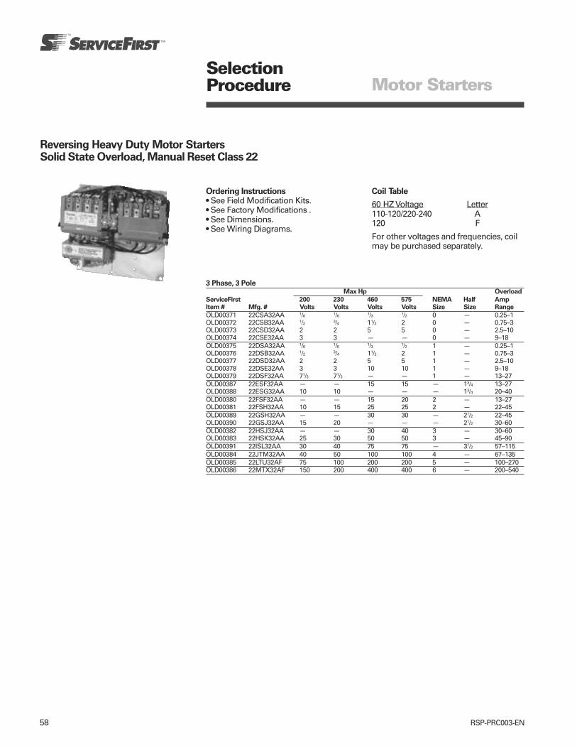
58 RSP-PRC003-EN
SelectionProcedure Motor Starters
Reversing Heavy Duty Motor StartersSolid State Overload, Manual Reset Class 22
Ordering Instructions• See Field Modification Kits.• See Factory Modifications .• See Dimensions.• See Wiring Diagrams.
Coil Table
60 HZ Voltage Letter110-120/220-240 A120 F
For other voltages and frequencies, coilmay be purchased separately.
3 Phase, 3 PoleMax Hp Overload
ServiceFirst 200 230 460 575 NEMA Half AmpItem # Mfg. # Volts Volts Volts Volts Size Size Range
OLD00371 22CSA32AA 1/6 1/6 1/3 1/2 0 — 0.25–1OLD00372 22CSB32AA 1/2 3/4 11/2 2 0 — 0.75–3OLD00373 22CSD32AA 2 2 5 5 0 — 2.5–10OLD00374 22CSE32AA 3 3 — — 0 — 9–18OLD00375 22DSA32AA 1/6 1/6 1/3 1/2 1 — 0.25–1OLD00376 22DSB32AA 1/2 3/4 11/2 2 1 — 0.75–3OLD00377 22DSD32AA 2 2 5 5 1 — 2.5–10OLD00378 22DSE32AA 3 3 10 10 1 — 9–18OLD00379 22DSF32AA 71/2 71/2 — — 1 — 13–27OLD00387 22ESF32AA — — 15 15 — 13/4 13–27OLD00388 22ESG32AA 10 10 — — — 13/4 20–40OLD00380 22FSF32AA — — 15 20 2 — 13–27OLD00381 22FSH32AA 10 15 25 25 2 — 22–45OLD00389 22GSH32AA — — 30 30 — 21/2 22–45OLD00390 22GSJ32AA 15 20 — — — 21/2 30–60OLD00382 22HSJ32AA — — 30 40 3 — 30–60OLD00383 22HSK32AA 25 30 50 50 3 — 45–90OLD00391 22ISL32AA 30 40 75 75 — 31/2 57–115OLD00384 22JTM32AA 40 50 100 100 4 — 67–135OLD00385 22LTU32AF 75 100 200 200 5 — 100–270OLD00386 22MTX32AF 150 200 400 400 6 — 200–540

59RSP-PRC003-EN
SelectionProcedure Motor Starters
Heavy Duty Controls ModificationsNon-Combination Enclosure Kits
Type 1
Non-Reversing ContactorsServiceFirstItem # Mfg. # Size
KIT06558 49EC14EB110705R 00-1¾KIT06559 49EC14GB140807R 2-2½KIT06560 49EC14IB201208R 3-3½KIT06561 49EC14JB251409R 4
Reversing ContactorsServiceFirstItem # Mfg. # Size
KIT06560 49EC14IB201208R 00-2½KIT06561 49EC14JB251409R 3-4
Pilot DevicesServiceFirst Controller Enclosure
Item # Mfg. # Description Class Size Type
Push Buttons SWT02666 49SAPB5 Start, Stop 14, 40 00-3 1/2 1SWT02667 49SAP05 14, 40 4-8 1
Selector Switches SWT02542 49SASB1 Hand-Off-Auto 14, 40 00-3 1/2 1SWT02668 49SAS01 14, 40 4-8 1

60 RSP-PRC003-EN
Miscellaneous KitsServiceFirst Controller Enclosure
Item # Mfg. # Description Class Size Type
CTR01632 49D70084 Mounting Westinghouse A200 14 0-1 OpenAdapter Plate Allen Bradley 509, 709
CTR01633 49ASLE Overload Includes terminal block and stabsLug Extender for connection to contactor terminals — 0–1 All
to provide connections at 9–40A Rangesbottom of ESP100
CTR01634 49CCF22H Mechanical 0–1CTR01635 49EEF22H Interlock 1 3/4CTR01636 49GGF22H Includes wire 2, 2 1/2CTR01637 49HHF22HP 3, 3 1/2CTR01638 49JJG22H Horizontal 14, 40 4 Open
CTR01639 49D26344 Surge Surge Suppressor for 120V ACSuppressor coil. Limits transient voltage 14,22 0–31/2 All
produced by the coil to 220% 40,43maximum peak line volts.
CTR01640 49SAF0 Auxiliary NO 36A at 600V AC Max 14,22 0–13/4 AllCTR01641 49SAFC Power Pole NC 25A at 600V AC Max 40,43
CTR01642 49SAE Load Side Includes 3 power lugsPower Take for making extra 14,22 0–1 AllOff Kit connections to the load 40,43
side of the contactor
SelectionProcedure Motor Starters
Heavy Duty Controls Modifications
Field Modification Kits
Auxiliary Contact KitsServiceFirst Controller EnclosureItem # Mfg. # Description Class Size Type
CTR01626 49AB10 Auxiliary Contact NEMA A600 NO 14,22,40 0–4CTR01627 49AB10 For maximum Front Mtg NC 43 All
additional contacts, SPST49AB11 see page 126. 1 NO, 1 NC49AB20 2 NO
CTR01628 3T47561-1K4 1-NO/1-NC Auxiliary 14,22 41/2, 5 —CTR01629 3T47561-1L4 Cont Block-Left 40,43
1-NO/1-NC AuxiliaryCont Block-Right
CTR06529 49ASNO No Contact Kits NEMA A600 ESP100 0–8CTR06530 49ASNC Overload 0–8 All
Relay
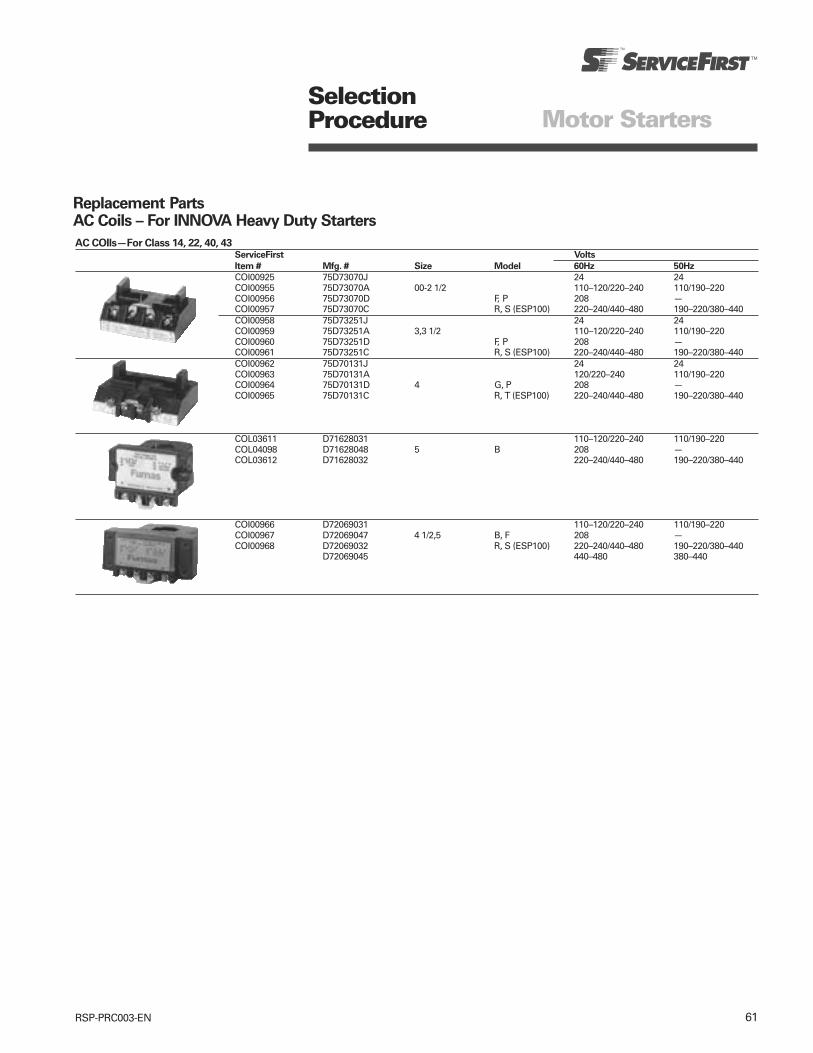
61RSP-PRC003-EN
SelectionProcedure Motor Starters
Replacement PartsAC Coils – For INNOVA Heavy Duty Starters
AC COIls—For Class 14, 22, 40, 43ServiceFirst Volts
Item # Mfg. # Size Model 60Hz 50Hz
COI00925 75D73070J 24 24COI00955 75D73070A 00-2 1/2 110–120/220–240 110/190–220COI00956 75D73070D F, P 208 —COI00957 75D73070C R, S (ESP100) 220–240/440–480 190–220/380–440COI00958 75D73251J 24 24COI00959 75D73251A 3,3 1/2 110–120/220–240 110/190–220COI00960 75D73251D F, P 208 —COI00961 75D73251C R, S (ESP100) 220–240/440–480 190–220/380–440COI00962 75D70131J 24 24COI00963 75D70131A 120/220–240 110/190–220COI00964 75D70131D 4 G, P 208 —COI00965 75D70131C R, T (ESP100) 220–240/440–480 190–220/380–440
COL03611 D71628031 110–120/220–240 110/190–220COL04098 D71628048 5 B 208 —COL03612 D71628032 220–240/440–480 190–220/380–440
COI00966 D72069031 110–120/220–240 110/190–220COI00967 D72069047 4 1/2,5 B, F 208 —COI00968 D72069032 R, S (ESP100) 220–240/440–480 190–220/380–440
D72069045 440–480 380–440
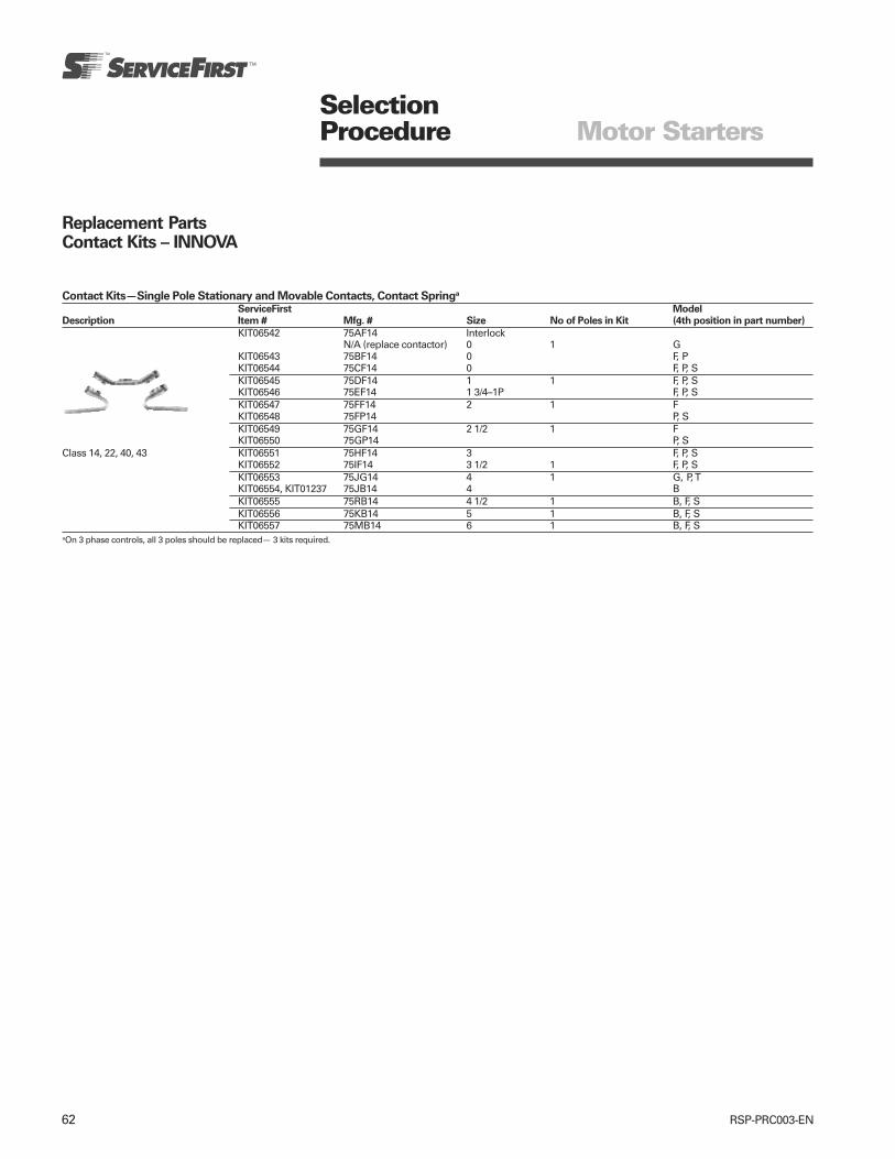
62 RSP-PRC003-EN
Contact Kits—Single Pole Stationary and Movable Contacts, Contact Springa
ServiceFirst Model
Description Item # Mfg. # Size No of Poles in Kit (4th position in part number)
KIT06542 75AF14 InterlockN/A (replace contactor) 0 1 G
KIT06543 75BF14 0 F, PKIT06544 75CF14 0 F, P, SKIT06545 75DF14 1 1 F, P, SKIT06546 75EF14 1 3/4–1P F, P, SKIT06547 75FF14 2 1 FKIT06548 75FP14 P, SKIT06549 75GF14 2 1/2 1 FKIT06550 75GP14 P, S
Class 14, 22, 40, 43 KIT06551 75HF14 3 F, P, SKIT06552 75IF14 3 1/2 1 F, P, SKIT06553 75JG14 4 1 G, P, TKIT06554, KIT01237 75JB14 4 BKIT06555 75RB14 4 1/2 1 B, F, SKIT06556 75KB14 5 1 B, F, SKIT06557 75MB14 6 1 B, F, S
aOn 3 phase controls, all 3 poles should be replaced— 3 kits required.
SelectionProcedure Motor Starters
Replacement PartsContact Kits – INNOVA

63RSP-PRC003-EN
Dimensions with Solid State Overload Class 14
Diagrams Motor Starters
Figure 1 Figure 2 Figure 3
Figure 4 Figure 5 Figure 6
Open Type Solid State OverloadMtg Max Approx
Outline Dimensions Mtg Dimensions Screw Reset Dimensions Wire Ship Wt Ref
Size Fig A B B1 B2 C C1 D D1 D2 E E1 E2 G J K L M M1 Size Lbs (Kg) Dwg
0–1 1 7 31/2 41/2 — 31/2 33/4 61/2 2 7/16 61/4 1 — 10 59/16 — 1/4 31/16 31/4 8 4(2) D56839(178) (89) (114) (89) (95) (191) (51) (11) (184) (25) (254) (141) (6) (78) (83)
13/4 1 7 31/2 41/2 — 31/2 33/4 61/2 2 7/16 61/4 1 — 10 59/16 — 1/4 31/16 31/4 6 4(2) D56840(178) (89) (114) (89) (95) (191) (51) (11) (184) (25) (254) (141) (6) (78) (83)
2 2 81/8 31/2 41/2 45/8 33/4 311/16 73/4 2 3/16 73/8 1/2 — 10 611/16 5/8 1/4 35/16 31/2 4 5(2) D56841(206) (89) (114) (117) (95) (94) (197) (51) (5) (187) (13) (254) (170) (16) (6) (84) (89)
21/2 2 81/8 31/2 41/2 45/8 33/4 311/16 73/4 2 3/16 73/8 1/2 — 10 611/16 5/8 1/4 35/16 3//2 2 5(2) D56841(206) (89) (114) (117) (95) (94) (197) (51) (5) (187) (13) (254) (170) (16) (6) (84) (89)
3 3 93/4 41/2 51/2 — 53/16 49/16 91/4 11/2 1/4 — — — 1/4 83/16 5/8 1/4 37/16 35/8 0 8(4) D70119(248) (114) (140) (132) (116) (235) (38) (6) (6) (208) (16) (6) (87) (92)
31/2 3 93/4 41/2 51/2 — 53/16 49/16 91/4 11/2 1/4 — — — 1/4 83/16 5/8 1/4 37/16 35/8 00 8(4) D70119(248) (114) (140) (132) (116) (235) (38) (6) (6) (208) (16) (6) (87) (92)
4 4 111/16 41/2 51/2 — 53/4 45/8 103/8 11/2 7/16 — — 3/4 1/4 93/16 5/8 1/4 37/16 35/8 250MCM 11(5) D70100(281) (114) (140) (146) (117) (266) (38) (11) (19) (6) (233) (16) (6) (87) (92)
5 5 181/16 7 — — 81/2 — 173/16 47/16 — — — — 3/8 47/16 31/16 — — 77/16 1-500MCM or — —(459) (178) (216) (437) (113) (10) (113) (78) (189) 2-300MCM
6 6 263/8 131/16 — — 95/8 — 251/2 35/8 — — — — — 65/16 73/16 — — 9 2-500MCM — —(670) (332) (244) (648) (92) (160) (183) (229)

64 RSP-PRC003-EN
Figure 1 Figure 2
Figure 3 Figure 4 Figure 5
Diagrams Motor Starters
Reversing and Multispeed Heavy Duty Motor StartersDimensions with Solid State Overload Class 22, 30
Open Type Solid State Overload/Melting AlloyMtg Max Approx
Outline Dimensions Mtg Dimensions Screw Reset Dimensions Wire Ship Wt Ref
Size Fig A B B1 B2 B3 C D D1 E G J K L M Size Lbs (Kg) Dwg
0-1 1 711/16 85/16 95/16 35/8 — 37/8 71/4 1/4 71/4 10 53/4 23/8 1/4 33/8 8 9 D70125(195) (211) (237) (92) — (98) (184) (6) (184) (254) (146) (60) (6) (86) (4)
13/4 1 711/16 85/16 95/16 35/8 — 37/8 71/4 1/4 71/4 10 53/4 23/8 1/4 33/8 6 9 D70125(195) (211) (237) (92) — (98) (184) (6) (184) (254) (146) (60) (6) (86) (4)
2-21/2 2 815/16 85/16 95/16 35/8 93/8 315/16 81/2 1/4 71/4 10 67/8 3 1/16 1/4 311/16 2 13 D70126(227) (211) (237) (92) (238) (100) (216) (6) (184) (254) (175) (78) (6) (94) (6)
3 3 117/16 1015/16 111/2 — — 511/16 103/4 3/8 101/4 1/4 815/16 1 1/2 1/4 41/8 0 33 D70127(291) (278) (292) — — (144) (273) (10) (260) (6) (227) (38) (6) (105) (15)
31/2 3 117/16 1015/16 111/2 — — 511/16 103/4 3/8 101/4 1/4 815/16 1 1/2 1/4 41/8 00 33 D70127(291) (278) (292) — — (144) (273) (10) (260) (6) (227) (38) (6) (105) (15)
4 4 1115/16 1015/16 111/2 — — 61/4 111/4 3/8 91/4 1/4 93/8 1/2 1/4 41/8 250MCM 59 D74686(303) (278) (292) — — (159) (286) (10) (235) (6) (238) (13) (6) (105) (27)
5 5 181/16 143/16 121/16 25/8 27/16 97/16 173/16 3/8 95/8 — — — — — 1-500MCM — —(459) (361) (306) (67) (62) (240) (437) (10) (244) — — — — — 2-300MCM
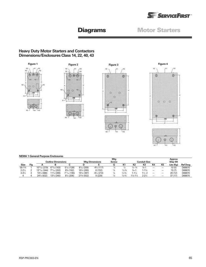
65RSP-PRC003-EN
Diagrams Motor Starters
Heavy Duty Motor Starters and ContactorsDimensions/Enclosures Class 14, 22, 40, 43
Figure 4
NEMA 1 General Purpose EnclosuresMtg Approx
Outline Dimensions Mtg Dimensions Screw Conduit Size Ship Wt
Size Fig A B C D E G K1 K2 K3 K4 K5 Lbs (Kg) Ref Dwg
00-1¾ 1 1031/32 (279) 613/32 (163) 51/32 (128) 87/32 (209) 45/8 (117) ¼ ½ ½- ¾ ¾-1 — — 10 (5) D688702-2½ 2 1317/32 (344) 731/32 (202) 63/8 (162) 10¼ (260) 6 (152) ¼ ½-¾ ¾–1 1-1¼ — — 15 (7) D688703-3½ 3 191/8 (486) 113/8 (289) 711/16 (195) 155/8 (397) 8¼ (210) ¼ ½-¾ 1-1¼ 1½- 2 — — 26 (12) D68870
4 4 247/8 (632) 133/8 (340) 81/8 (206) 21¾ (552) 9 (229) ¼ ½-¾ 1¼-1½ 2-2½ — — 37 (17) D68870
Figure 3Figure 2Figure 1

66 RSP-PRC003-EN
Diagrams Motor Starters
Reversing Heavy Duty StartersClass 22
Three Phase Solid State Overload
Sizes 0–1¾
Sizes 2-4
Size 5

Ingersoll Rand (NYSE:IR) is a world leader in creating and sustaining safe, comfortable and efficient environments in commercial, residential and
industrial markets. Our people and our family of brands—including Club Car®, Hussmann®, Ingersoll Rand®, Schlage®, Thermo King® and Trane®—
work together to enhance the quality and comfort of air in homes and buildings, transport and protect food and perishables, secure homes and
commercial properties, and increase industrial productivity and efficiency. We are a $13 billion global business committed to sustainable business
practices within our company and for our customers.
© 2010 Trane All rights reserved
RSP-PRC003-EN December 13, 2010
ingersollrand.com
Produced on post-consumer recycled paper, using
environmentally friendly print practices that reduce waste.

Sheet Metal Accessories by McDaniel Metals
December 2010 RSP-PRC004-EN
www.mcdanielmetals.com
Product Catalog

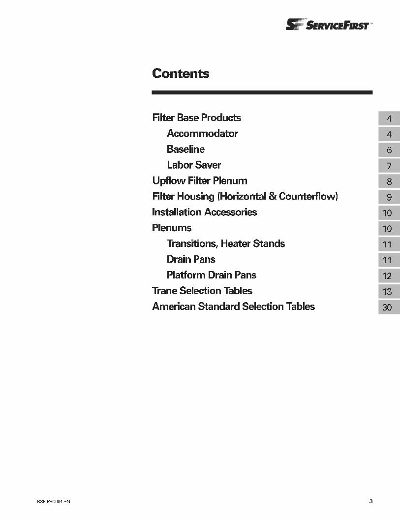
!
"
#$
%
%
##
#
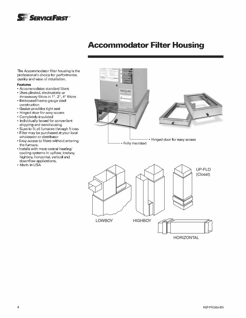
!"#$
%& # ' ( )#"* #
+, - . " "
!
) /"" ,#
0+
' .

!!" #" "
$
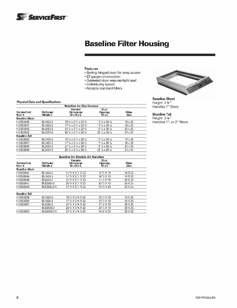
! "!
# ! "!$!
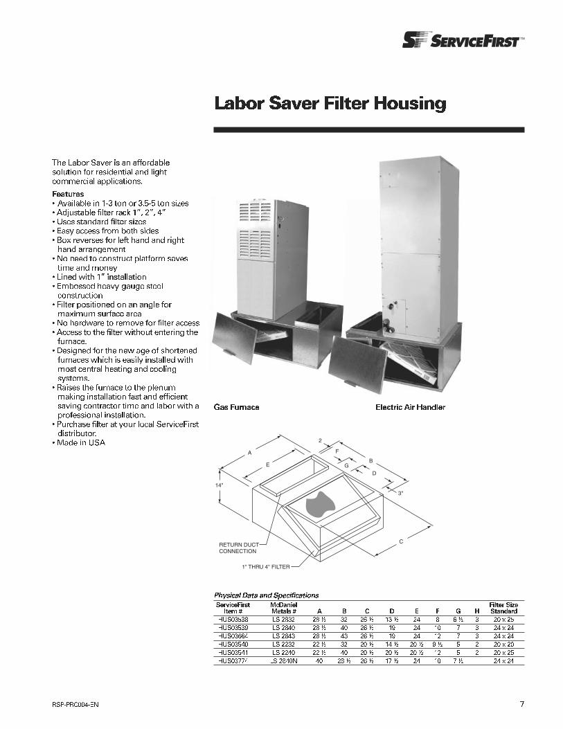
! "#$%#$&#' () *+
, )
- # ()
. +
,- -
/ -- ) - )
0 " -
1 ) .
2 '
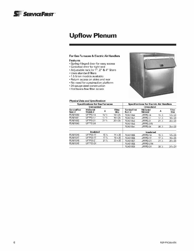
!" #$$% &' ( %!) *
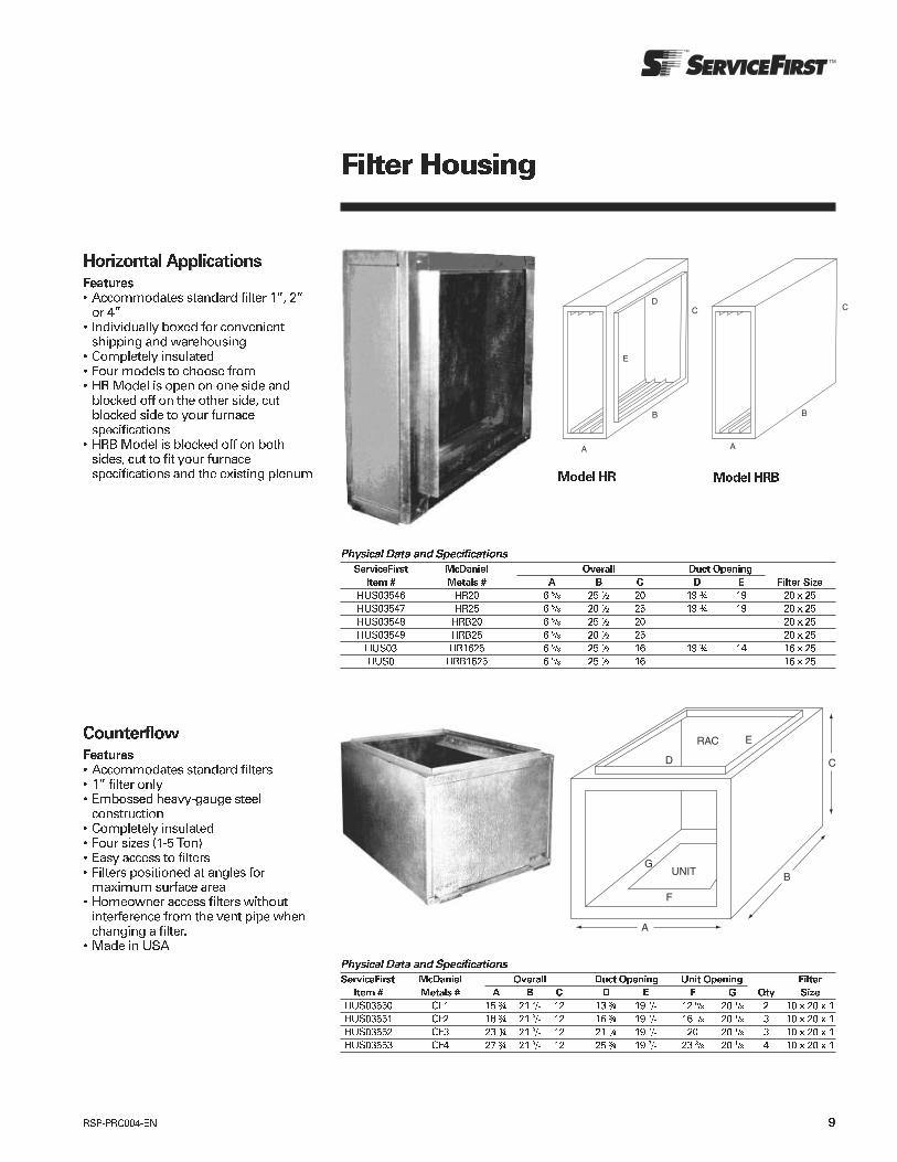
! " #$% & & #$'%&
() ! "*+),- . ( " # / % 01

!
!
!
!
!
!
!
!
!
!
!
!
!
!
!
!
!
!
!
!
!
!
!
!
!
!
!
!
!
!
!
!
!
!
!
!
!
!
!
!
"
"
"
"
!"#
!"
# $$!!# % &'()*&'+$$)*&',
# -*.' # / # 01# 2!! # 3! 4)# 2 # 2 # 21# 3 ! ' # 0 !

!
"
# $$ # %&' ()*&'+$$)*&',
# - # -.# / # 0 # /# /# /.# 1 '# -

!"#$%%&'()!*+
!"#
&%!,-. !"*/0#$%%&'()!*+
& %!,-. !"#$%%&'()!*+
! "#
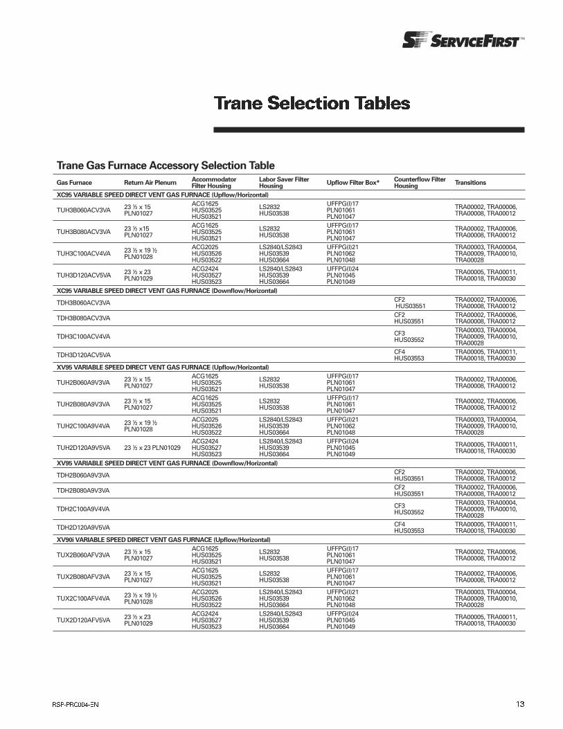
Trane Gas Furnace Accessory Selection Table
Gas Furnace Return Air PlenumAccommodator Filter Housing
Labor Saver Filter Housing
Upflow Filter Box*Counterflow Filter Housing
Transitions
XC95 VARIABLE SPEED DIRECT VENT GAS FURNACE (Upflow/Horizontal)
TUH3B060ACV3VA 23 ½ x 15 PLN01027
ACG1625 HUS03525 HUS03521
LS2832 HUS03538
UFFPG(I)17 PLN01061 PLN01047
TRA00002, TRA00006, TRA00008, TRA00012
TUH3B080ACV3VA 23 ½ x15 PLN01027
ACG1625 HUS03525 HUS03521
LS2832 HUS03538
UFFPG(I)17 PLN01061 PLN01047
TRA00002, TRA00006, TRA00008, TRA00012
TUH3C100ACV4VA 23 ½ x 19 ½ PLN01028
ACG2025 HUS03526 HUS03522
LS2840/LS2843 HUS03539 HUS03664
UFFPG(I)21 PLN01062 PLN01048
TRA00003, TRA00004, TRA00009, TRA00010, TRA00028
TUH3D120ACV5VA 23 ½ x 23 PLN01029
ACG2424 HUS03527 HUS03523
LS2840/LS2843 HUS03539 HUS03664
UFFPG(I)24 PLN01045 PLN01049
TRA00005, TRA00011, TRA00018, TRA00030
XC95 VARIABLE SPEED DIRECT VENT GAS FURNACE (Downflow/Horizontal)
TDH3B060ACV3VA CF2 HUS03551
TRA00002, TRA00006, TRA00008, TRA00012
TDH3B080ACV3VA CF2 HUS03551
TRA00002, TRA00006, TRA00008, TRA00012
TDH3C100ACV4VA CF3 HUS03552
TRA00003, TRA00004, TRA00009, TRA00010, TRA00028
TDH3D120ACV5VA CF4 HUS03553
TRA00005, TRA00011, TRA00018, TRA00030
XV95 VARIABLE SPEED DIRECT VENT GAS FURNACE (Upflow/Horizontal)
TUH2B060A9V3VA 23 ½ x 15 PLN01027
ACG1625 HUS03525 HUS03521
LS2832 HUS03538
UFFPG(I)17 PLN01061 PLN01047
TRA00002, TRA00006, TRA00008, TRA00012
TUH2B080A9V3VA 23 ½ x 15 PLN01027
ACG1625 HUS03525 HUS03521
LS2832 HUS03538
UFFPG(I)17 PLN01061 PLN01047
TRA00002, TRA00006, TRA00008, TRA00012
TUH2C100A9V4VA 23 ½ x 19 ½ PLN01028
ACG2025 HUS03526 HUS03522
LS2840/LS2843 HUS03539 HUS03664
UFFPG(I)21 PLN01062 PLN01048
TRA00003, TRA00004, TRA00009, TRA00010, TRA00028
TUH2D120A9V5VA 23 ½ x 23 PLN01029ACG2424 HUS03527 HUS03523
LS2840/LS2843 HUS03539 HUS03664
UFFPG(I)24 PLN01045 PLN01049
TRA00005, TRA00011, TRA00018, TRA00030
XV95 VARIABLE SPEED DIRECT VENT GAS FURNACE (Downflow/Horizontal)
TDH2B060A9V3VA CF2 HUS03551
TRA00002, TRA00006, TRA00008, TRA00012
TDH2B080A9V3VA CF2 HUS03551
TRA00002, TRA00006, TRA00008, TRA00012
TDH2C100A9V4VA CF3 HUS03552
TRA00003, TRA00004, TRA00009, TRA00010, TRA00028
TDH2D120A9V5VA CF4 HUS03553
TRA00005, TRA00011, TRA00018, TRA00030
XV90i VARIABLE SPEED DIRECT VENT GAS FURNACE (Upflow/Horizontal)
TUX2B060AFV3VA 23 ½ x 15 PLN01027
ACG1625 HUS03525 HUS03521
LS2832 HUS03538
UFFPG(I)17 PLN01061 PLN01047
TRA00002, TRA00006, TRA00008, TRA00012
TUX2B080AFV3VA 23 ½ x 15 PLN01027
ACG1625 HUS03525 HUS03521
LS2832 HUS03538
UFFPG(I)17 PLN01061 PLN01047
TRA00002, TRA00006, TRA00008, TRA00012
TUX2C100AFV4VA 23 ½ x 19 ½ PLN01028
ACG2025 HUS03526 HUS03522
LS2840/LS2843 HUS03539 HUS03664
UFFPG(I)21 PLN01062 PLN01048
TRA00003, TRA00004, TRA00009, TRA00010, TRA00028
TUX2D120AFV5VA 23 ½ x 23 PLN01029
ACG2424 HUS03527 HUS03523
LS2840/LS2843 HUS03539 HUS03664
UFFPG(I)24 PLN01045 PLN01049
TRA00005, TRA00011, TRA00018, TRA00030
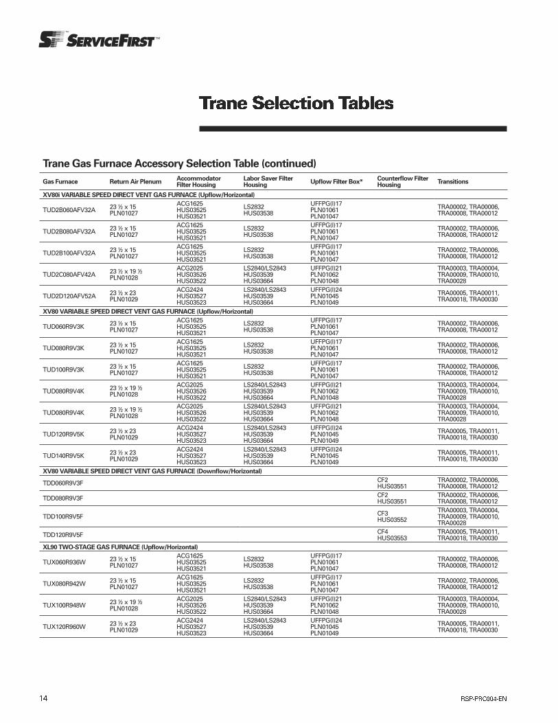
Trane Gas Furnace Accessory Selection Table (continued)
Gas Furnace Return Air PlenumAccommodator Filter Housing
Labor Saver Filter Housing
Upflow Filter Box*Counterflow Filter Housing
Transitions
XV80i VARIABLE SPEED DIRECT VENT GAS FURNACE (Upflow/Horizontal)
TUD2B060AFV32A 23 ½ x 15 PLN01027
ACG1625 HUS03525 HUS03521
LS2832 HUS03538
UFFPG(I)17 PLN01061 PLN01047
TRA00002, TRA00006, TRA00008, TRA00012
TUD2B080AFV32A 23 ½ x 15 PLN01027
ACG1625 HUS03525 HUS03521
LS2832 HUS03538
UFFPG(I)17 PLN01061 PLN01047
TRA00002, TRA00006, TRA00008, TRA00012
TUD2B100AFV32A 23 ½ x 15 PLN01027
ACG1625 HUS03525 HUS03521
LS2832 HUS03538
UFFPG(I)17 PLN01061 PLN01047
TRA00002, TRA00006, TRA00008, TRA00012
TUD2C080AFV42A 23 ½ x 19 ½ PLN01028
ACG2025 HUS03526 HUS03522
LS2840/LS2843 HUS03539 HUS03664
UFFPG(I)21 PLN01062 PLN01048
TRA00003, TRA00004, TRA00009, TRA00010, TRA00028
TUD2D120AFV52A 23 ½ x 23 PLN01029
ACG2424 HUS03527 HUS03523
LS2840/LS2843 HUS03539 HUS03664
UFFPG(I)24 PLN01045 PLN01049
TRA00005, TRA00011, TRA00018, TRA00030
XV80 VARIABLE SPEED DIRECT VENT GAS FURNACE (Upflow/Horizontal)
TUD060R9V3K 23 ½ x 15 PLN01027
ACG1625 HUS03525 HUS03521
LS2832 HUS03538
UFFPG(I)17 PLN01061 PLN01047
TRA00002, TRA00006, TRA00008, TRA00012
TUD080R9V3K 23 ½ x 15 PLN01027
ACG1625 HUS03525 HUS03521
LS2832 HUS03538
UFFPG(I)17 PLN01061 PLN01047
TRA00002, TRA00006, TRA00008, TRA00012
TUD100R9V3K 23 ½ x 15 PLN01027
ACG1625 HUS03525 HUS03521
LS2832 HUS03538
UFFPG(I)17 PLN01061 PLN01047
TRA00002, TRA00006, TRA00008, TRA00012
TUD080R9V4K 23 ½ x 19 ½ PLN01028
ACG2025 HUS03526 HUS03522
LS2840/LS2843 HUS03539 HUS03664
UFFPG(I)21 PLN01062 PLN01048
TRA00003, TRA00004, TRA00009, TRA00010, TRA00028
TUD080R9V4K 23 ½ x 19 ½ PLN01028
ACG2025 HUS03526 HUS03522
LS2840/LS2843 HUS03539 HUS03664
UFFPG(I)21 PLN01062 PLN01048
TRA00003, TRA00004, TRA00009, TRA00010, TRA00028
TUD120R9V5K 23 ½ x 23 PLN01029
ACG2424 HUS03527 HUS03523
LS2840/LS2843 HUS03539 HUS03664
UFFPG(I)24 PLN01045 PLN01049
TRA00005, TRA00011, TRA00018, TRA00030
TUD140R9V5K 23 ½ x 23 PLN01029
ACG2424 HUS03527 HUS03523
LS2840/LS2843 HUS03539 HUS03664
UFFPG(I)24 PLN01045 PLN01049
TRA00005, TRA00011, TRA00018, TRA00030
XV80 VARIABLE SPEED DIRECT VENT GAS FURNACE (Downflow/Horizontal)
TDD060R9V3F CF2 HUS03551
TRA00002, TRA00006, TRA00008, TRA00012
TDD080R9V3F CF2 HUS03551
TRA00002, TRA00006, TRA00008, TRA00012
TDD100R9V5F CF3 HUS03552
TRA00003, TRA00004, TRA00009, TRA00010, TRA00028
TDD120R9V5F CF4 HUS03553
TRA00005, TRA00011, TRA00018, TRA00030
XL90 TWO-STAGE GAS FURNACE (Upflow/Horizontal)
TUX060R936W 23 ½ x 15 PLN01027
ACG1625 HUS03525 HUS03521
LS2832 HUS03538
UFFPG(I)17 PLN01061 PLN01047
TRA00002, TRA00006, TRA00008, TRA00012
TUX080R942W 23 ½ x 15 PLN01027
ACG1625 HUS03525 HUS03521
LS2832 HUS03538
UFFPG(I)17 PLN01061 PLN01047
TRA00002, TRA00006, TRA00008, TRA00012
TUX100R948W 23 ½ x 19 ½ PLN01028
ACG2025 HUS03526 HUS03522
LS2840/LS2843 HUS03539 HUS03664
UFFPG(I)21 PLN01062 PLN01048
TRA00003, TRA00004, TRA00009, TRA00010, TRA00028
TUX120R960W 23 ½ x 23 PLN01029
ACG2424 HUS03527 HUS03523
LS2840/LS2843 HUS03539 HUS03664
UFFPG(I)24 PLN01045 PLN01049
TRA00005, TRA00011, TRA00018, TRA00030

Trane Gas Furnace Accessory Selection Table (continued)
Gas Furnace Return Air PlenumAccommodator Filter Housing
Labor Saver Filter Housing
Upflow Filter Box*Counterflow Filter Housing
Transitions
XL90 TWO-STAGE GAS FURNACE (Downflow/Horizontal)
TDX060R936W CF2 HUS03551
TRA00002, TRA00006, TRA00008, TRA00012
TDX080R942W CF2 HUS03551
TRA00002, TRA00006, TRA00008, TRA00012
TDX100R948W CF3 HUS03552
TRA00003, TRA00004, TRA00009, TRA00010, TRA00028
TDX120R960W CF4 HUS03553
TRA00005, TRA00011, TRA00018, TRA00030
XL80 TWO-STAGE GAS FURNACE (Upflow/Horizontal)
TUD2A040A9242A 23 ½ x 13 PLN01026
ACG1425 HUS03524 HUS03520
LS2832 HUS03538
UFFPG(I)14 PLN01060 PLN01046
TRA00001, TRA00016, TRA00007, TRA00017
TUD2A060A9362A 23 ½ x 13 PLN01026
ACG1425 HUS03524 HUS03520
LS2832 HUS03538
UFFPG(I)14 PLN01060 PLN01046
TRA00001, TRA00016, TRA00007, TRA00017
TUD2B060A9362A 23 ½ x 15 PLN01027
ACG1625 HUS03525 HUS03521
LS2832 HUS03538
UFFPG(I)17 PLN01061 PLN01047
TRA00002, TRA00006, TRA00008, TRA00012
TUD2B080A9362A 23 ½ x 15 PLN01027
ACG1625 HUS03525 HUS03521
LS2832 HUS03538
UFFPG(I)17 PLN01061 PLN01047
TRA00002, TRA00006, TRA00008, TRA00012
TUD2B080A9482A 23 ½ x 15 PLN01027
ACG1625 HUS03525 HUS03521
LS2832 HUS03538
UFFPG(I)17 PLN01061 PLN01047
TRA00002, TRA00006, TRA00008, TRA00012
TUD2B100A9362A 23 ½ x 15 PLN01027ACG1625 HUS03525 HUS03521
LS2832 HUS03538
UFFPG(I)17 PLN01061 PLN01047
TRA00002, TRA00006, TRA00008, TRA00012
TUD2C100A9482A 23 ½ x 19 ½ PLN01028
ACG2025 HUS03526 HUS03522
LS2840/LS2843 HUS03539 HUS03664
UFFPG(I)21 PLN01062 PLN01048
TRA00003, TRA00004, TRA00009, TRA00010, TRA00028
TUD2C100A9602A 23 ½ x 19 ½ PLN01028
ACG2025 HUS03526 HUS03522
LS2840/LS2843 HUS03539 HUS03664
UFFPG(I)21 PLN01062 PLN01048
TRA00003, TRA00004, TRA00009, TRA00010, TRA00028
TUD2D100A9602A 23 ½ x 23 PLN01029
ACG2424 HUS03527 HUS03523
LS2840/LS2843 HUS03539 HUS03664
UFFPG(I)24 PLN01045 PLN01049
TRA00005, TRA00011, TRA00018, TRA00030
TUD2C120A9542A 23 ½ x 19 ½ PLN01028
ACG2025 HUS03526 HUS03522
LS2840/LS2843 HUS03539 HUS03664
UFFPG(I)21 PLN01062 PLN01048
TRA00003, TRA00004, TRA00009, TRA00010, TRA00028
TUD2D120A9602A 23 ½ x 23 PLN01029
ACG2424 HUS03527 HUS03523
LS2840/LS2843 HUS03539 HUS03664
UFFPG(I)24 PLN01045 PLN01049
TRA00005, TRA00011, TRA00018, TRA00030
TUD2D140A9602A 23 ½ x 23 PLN01029
ACG2424 HUS03527 HUS03523
LS2840/LS2843 HUS03539 HUS03664
UFFPG(I)24 PLN01045 PLN01049
TRA00005, TRA00011, TRA00018, TRA00030
XL80 TWO-STAGE GAS FURNACE (Downflow/Horizontal)
TDD2A040A9242A CF1 HUS03550
TRA00001, TRA00016, TRA00007, TRA00017
TDD2A060A9362A CF1 HUS03550
TRA00001, TRA00016, TRA00007, TRA00017
TDD2B060A9362A CF2 HUS03551
TRA00002, TRA00006, TRA00008, TRA00012
TDD2B080A9362A CF2 HUS03551
TRA00002, TRA00006, TRA00008, TRA00012
TDD2B100A9482A CF2 HUS03551
TRA00002, TRA00006, TRA00008, TRA00012
TDD2C100A9482A CF3 HUS03552
TRA00003, TRA00004, TRA00009, TRA00010, TRA00028
TDD2C100A9602A CF3 HUS03552
TRA00003, TRA00004, TRA00009, TRA00010, TRA00028
TDD2D120A9602A CF4 HUS03553
TRA00005, TRA00011, TRA00018, TRA00030
TDD2D140A9602A CF4 HUS03553
TRA00005, TRA00011, TRA00018, TRA00030

Trane Gas Furnace Accessory Selection Table (continued)
Gas Furnace Return Air PlenumAccommodator Filter Housing
Labor Saver Filter Housing
Upflow Filter Box*Counterflow Filter Housing
Transitions
XT90 GAS FURNACE High-Efficiency, Upflow, Horizontal Left
TUX1B040A9H21B 23 ½ x 15 PLN01027
ACG1625 HUS03525 HUS03521
LS2832 HUS03538
UFFPG(I)17 PLN01061 PLN01047
TRA00002, TRA00006, TRA00008, TRA00012
TUX1B060A9H31B 23 ½ x 15 PLN01027
ACG1625 HUS03525 HUS03521
LS2832 HUS03538
UFFPG(I)17 PLN01061 PLN01047
TRA00002, TRA00006, TRA00008, TRA00012
TUX1B080A9H31B 23 ½ x 15 PLN01027
ACG1625 HUS03525 HUS03521
LS2832 HUS03538
UFFPG(I)17 PLN01061 PLN01047
TRA00002, TRA00006, TRA00008, TRA00012
TUX1C100A9H41B 23 ½ x 19 ½ PLN01028
ACG2025 HUS03526 HUS03522
LS2840/LS2843 HUS03539 HUS03664
UFFPG(I)21 PLN01062 PLN01048
TRA00003, TRA00004, TRA00009, TRA00010, TRA00028
TUX1D120A9H51B 23 ½ x 23 PLN01029
ACG2424 HUS03527 HUS03523
LS2840/LS2843 HUS03539 HUS03664
UFFPG(I)24 PLN01045 PLN01049
TRA00005, TRA00011, TRA00018, TRA00030
XT90 GAS FURNACE High-Efficiency, Downflow, Horizontal Right
TDX1B040A9H31B CF2 HUS03551
TRA00002, TRA00006, TRA00008, TRA00012
TDX1B060A9H31B CF2 HUS03551
TRA00002, TRA00006, TRA00008, TRA00012
TDX1B080A9H31B CF2 HUS03551
TRA00002, TRA00006, TRA00008, TRA00012
TDX1C100A9H41B CF3 HUS03552
TRA00003, TRA00004, TRA00009, TRA00010, TRA00028
TDX1D120A9H51B CF4 HUS03553
TRA00005, TRA00011, TRA00018, TRA00030
XT80 GAS FURNACE High-Efficiency (Upflow/Horizontal Left)
TUD1A040A9H21B 23 ½ x 13 PLN01026
ACG1425 HUS03524 HUS03520
LS2832 HUS03538
UFFPG(I)14 PLN01060 PLN01046
TRA00001, TRA00016, TRA00007, TRA00017
TUD1B060A9H31B 23 ½ x 15 PLN01027
ACG1625 HUS03525 HUS03521
LS2832 HUS03538
UFFPG(I)17 PLN01061 PLN01047
TRA00002, TRA00006, TRA00008, TRA00012
TUD1B080A9H31B 23 ½ x 15 PLN01027
ACG1625 HUS03525 HUS03521
LS2832 HUS03538
UFFPG(I)17 PLN01061 PLN01047
TRA00002, TRA00006, TRA00008, TRA00012
TUD1C080A9H41B 23 ½ x 19 ½ PLN01028
ACG2025 HUS03526 HUS03522
LS2840/LS2843 HUS03539 HUS03664
UFFPG(I)21 PLN01062 PLN01048
TRA00003, TRA00004, TRA00009, TRA00010, TRA00028
TUD1B100A9H31B 23 ½ x 15 PLN01027
ACG1625 HUS03525 HUS03521
LS2832 HUS03538
UFFPG(I)17 PLN01061 PLN01047
TRA00002, TRA00006, TRA00008, TRA00012
TUD1C100A9H51B 23 ½ x 19 ½ PLN01028
ACG2025 HUS03526 HUS03522
LS2840/LS2843 HUS03539 HUS03664
UFFPG(I)21 PLN01062 PLN01048
TRA00003, TRA00004, TRA00009, TRA00010, TRA00028
TUD1D120A9H51B 23 ½ x 23 PLN01029
ACG2424 HUS03527 HUS03523
LS2840/LS2843 HUS03539 HUS03664
UFFPG(I)24 PLN01045 PLN01049
TRA00005, TRA00011, TRA00018, TRA00030
TUD1D140A9H51B 23 ½ x 23 PLN01029
ACG2424 HUS03527 HUS03523
LS2840/LS2843 HUS03539 HUS03664
UFFPG(I)24 PLN01045 PLN01049
TRA00005, TRA00011, TRA00018, TRA00030
XT80 GAS FURNACE High-Efficiency (Downflow/Horizontal Right)
TDD1B060A9H31B CF2 HUS03551
TRA00002, TRA00006, TRA00008, TRA00012
TDD1B080A9H31B CF2 HUS03551
TRA00002, TRA00006, TRA00008, TRA00012
TDD1C100A9H51B CF2 HUS03551
TRA00002, TRA00006, TRA00008, TRA00012
TDD1D120A9H51B CF3 HUS03552
TRA00003, TRA00004, TRA00009, TRA00010, TRA00028

Trane Gas Furnace Accessory Selection Table (continued)
Gas Furnace Return Air PlenumAccommodator Filter Housing
Labor Saver Filter Housing
Upflow Filter Box*Counterflow Filter Housing
Transitions
XR95 GAS FURNACE (Upflow/Horizontal)
TUH1B040A9241A 23 ½ x 15 PLN01027
ACG1625 HUS03525 HUS03521
LS2832 HUS03538
UFFPG(I)17 PLN01061 PLN01047
TRA00002, TRA00006, TRA00008, TRA00012
TUH1B060A9361A 23 ½ x 15 PLN01027
ACG1625 HUS03525 HUS03521
LS2832 HUS03538
UFFPG(I)17 PLN01061 PLN01047
TRA00002, TRA00006, TRA00008, TRA00012
TUH1B080A9421A 23 ½ x 15 PLN01027
ACG1625 HUS03525 HUS03521
LS2832 HUS03538
UFFPG(I)17 PLN01061 PLN01047
TRA00002, TRA00006, TRA00008, TRA00012
TUH1C100A9481A 23 ½ x 19 ½ PLN01028
ACG2025 HUS03526 HUS03522
LS2840/LS2843 HUS03539 HUS03664
UFFPG(I)21 PLN01062 PLN01048
TRA00003, TRA00004, TRA00009, TRA00010, TRA00028
TUH1D100A9601A 23 ½ x 19 ½ PLN01028
ACG2025 HUS03526 HUS03522
LS2840/LS2843 HUS03539 HUS03664
UFFPG(I)21 PLN01062 PLN01048
TRA00003, TRA00004, TRA00009, TRA00010, TRA00028
TUH1D120A9601A 23 ½ x 23 PLN01029
ACG2424 HUS03527 HUS03523
LS2840/LS2843 HUS03539 HUS03664
UFFPG(I)24 PLN01045 PLN01049
TRA00005, TRA00011, TRA00018, TRA00030
XR90 GAS FURNACE (Upflow/Horizontal)
TUX1B040A9241A 23 ½ x 15 PLN01027
ACG1625 HUS03525 HUS03521
LS2832 HUS03538
UFFPG(I)17 PLN01061 PLN01047
TRA00002, TRA00006, TRA00008, TRA00012
TUX1B060A9361A 23 ½ x 15 PLN01027
ACG1625 HUS03525 HUS03521 LS2832 HUS03538
UFFPG(I)17 PLN01061 PLN01047
TRA00002, TRA00006, TRA00008, TRA00012
TUX1B080A9421A 23 ½ x 15 PLN01027
ACG1625 HUS03525 HUS03521
LS2832 HUS03538
UFFPG(I)17 PLN01061 PLN01047
TRA00002, TRA00006, TRA00008, TRA00012
TUX1C080A9601A 23 ½ x 19 ½ PLN01028
ACG2025 HUS03526 HUS03522
LS2840/LS2843 HUS03539 HUS03664
UFFPG(I)21 PLN01062 PLN01048
TRA00003, TRA00004, TRA00009, TRA00010, TRA00028
TUX1C100A9481A 23 ½ x 19 ½ PLN01028
ACG2025 HUS03526 HUS03522
LS2840/LS2843 HUS03539 HUS03664
UFFPG(I)21 PLN01062 PLN01048
TRA00003, TRA00004, TRA00009, TRA00010, TRA00028
TUX1D100A9601A 23 ½ x 23 PLN01029
ACG2424 HUS03527 HUS03523
LS2840/LS2843 HUS03539 HUS03664
UFFPG(I)24 PLN01045 PLN01049
TRA00005, TRA00011, TRA00018, TRA00030
TUX1D120A9601A 23 ½ x 23 PLN01029
ACG2424 HUS03527 HUS03523
LS2840/LS2843 HUS03539 HUS03664
UFFPG(I)24 PLN01045 PLN01049
TRA00005, TRA00011, TRA00018, TRA00030
XR90 GAS FURNACE (Downflow/Horizontal)
TDX1B040A9241A CF2 HUS03551
TRA00002, TRA00006, TRA00008, TRA00012
TDX1B060A9361A CF2 HUS03551
TRA00002, TRA00006, TRA00008, TRA00012
TDX1B080A9421A CF2 HUS03551
TRA00002, TRA00006, TRA00008, TRA00012
TDX1C100A9481A CF3 HUS03552
TRA00003, TRA00004, TRA00009, TRA00010, TRA00028
TDX1D120A9601A CF4 HUS03553
TRA00005, TRA00011, TRA00018, TRA00030
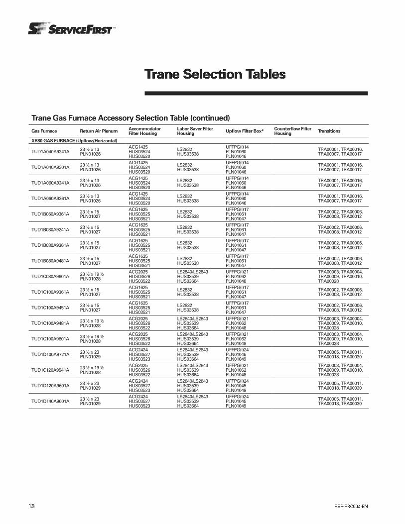
Trane Gas Furnace Accessory Selection Table (continued)
Gas Furnace Return Air PlenumAccommodator Filter Housing
Labor Saver Filter Housing
Upflow Filter Box*Counterflow Filter Housing
Transitions
XR80 GAS FURNACE (Upflow/Horizontal)
TUD1A040A9241A 23 ½ x 13 PLN01026
ACG1425 HUS03524 HUS03520
LS2832 HUS03538
UFFPG(I)14 PLN01060 PLN01046
TRA00001, TRA00016, TRA00007, TRA00017
TUD1A040A9301A 23 ½ x 13 PLN01026
ACG1425 HUS03524 HUS03520
LS2832 HUS03538
UFFPG(I)14 PLN01060 PLN01046
TRA00001, TRA00016, TRA00007, TRA00017
TUD1A060A9241A 23 ½ x 13 PLN01026
ACG1425 HUS03524 HUS03520
LS2832 HUS03538
UFFPG(I)14 PLN01060 PLN01046
TRA00001, TRA00016, TRA00007, TRA00017
TUD1A060A9361A 23 ½ x 13 PLN01026
ACG1425 HUS03524 HUS03520
LS2832 HUS03538
UFFPG(I)14 PLN01060 PLN01046
TRA00001, TRA00016, TRA00007, TRA00017
TUD1B060A9361A 23 ½ x 15 PLN01027
ACG1625 HUS03525 HUS03521
LS2832 HUS03538
UFFPG(I)17 PLN01061 PLN01047
TRA00002, TRA00006, TRA00008, TRA00012
TUD1B080A9241A 23 ½ x 15 PLN01027
ACG1625 HUS03525 HUS03521
LS2832 HUS03538
UFFPG(I)17 PLN01061 PLN01047
TRA00002, TRA00006, TRA00008, TRA00012
TUD1B080A9361A 23 ½ x 15 PLN01027
ACG1625 HUS03525 HUS03521
LS2832 HUS03538
UFFPG(I)17 PLN01061 PLN01047
TRA00002, TRA00006, TRA00008, TRA00012
TUD1B080A9481A 23 ½ x 15 PLN01027
ACG1625 HUS03525 HUS03521
LS2832 HUS03538
UFFPG(I)17 PLN01061 PLN01047
TRA00002, TRA00006, TRA00008, TRA00012
TUD1C080A9601A 23 ½ x 19 ½ PLN01028
ACG2025 HUS03526 HUS03522
LS2840/LS2843 HUS03539 HUS03664
UFFPG(I)21 PLN01062 PLN01048
TRA00003, TRA00004, TRA00009, TRA00010, TRA00028
TUD1C100A9361A 23 ½ x 15 PLN01027
ACG1625 HUS03525 HUS03521
LS2832 HUS03538
UFFPG(I)17 PLN01061 PLN01047
TRA00002, TRA00006, TRA00008, TRA00012
TUD1C100A9451A 23 ½ x 15 PLN01027
ACG1625 HUS03525 HUS03521
LS2832 HUS03538
UFFPG(I)17 PLN01061 PLN01047
TRA00002, TRA00006, TRA00008, TRA00012
TUD1C100A9481A 23 ½ x 19 ½ PLN01028
ACG2025 HUS03526 HUS03522
LS2840/LS2843 HUS03539 HUS03664
UFFPG(I)21 PLN01062 PLN01048
TRA00003, TRA00004, TRA00009, TRA00010, TRA00028
TUD1C100A9601A 23 ½ x 19 ½ PLN01028
ACG2025 HUS03526 HUS03522
LS2840/LS2843 HUS03539 HUS03664
UFFPG(I)21 PLN01062 PLN01048
TRA00003, TRA00004, TRA00009, TRA00010, TRA00028
TUD1D100A9721A 23 ½ x 23 PLN01029
ACG2424 HUS03527 HUS03523
LS2840/LS2843 HUS03539 HUS03664
UFFPG(I)24 PLN01045 PLN01049
TRA00005, TRA00011, TRA00018, TRA00030
TUD1C120A9541A 23 ½ x 19 ½ PLN01028
ACG2025 HUS03526 HUS03522
LS2840/LS2843 HUS03539 HUS03664
UFFPG(I)21 PLN01062 PLN01048
TRA00003, TRA00004, TRA00009, TRA00010, TRA00028
TUD1D120A9601A 23 ½ x 23 PLN01029
ACG2424 HUS03527 HUS03523
LS2840/LS2843 HUS03539 HUS03664
UFFPG(I)24 PLN01045 PLN01049
TRA00005, TRA00011, TRA00018, TRA00030
TUD1D140A9601A 23 ½ x 23 PLN01029
ACG2424 HUS03527 HUS03523
LS2840/LS2843 HUS03539 HUS03664
UFFPG(I)24 PLN01045 PLN01049
TRA00005, TRA00011, TRA00018, TRA00030

Trane Gas Furnace Accessory Selection Table (continued)
Gas Furnace Return Air PlenumAccommodator Filter Housing
Labor Saver Filter Housing
Upflow Filter Box*Counterflow Filter Housing
Transitions
XR80 GAS FURNACE (Downflow/Horizontal)
TDD1A040A9241A CF1 HUS03550
TRA00001, TRA00016, TRA00007, TRA00017
TDD1A060A9241A CF1 HUS03550
TRA00001, TRA00016, TRA00007, TRA00017
TDD1A060A9361A CF1 HUS03550
TRA00001, TRA00016, TRA00007, TRA00017
TDD1B060A9361A CF2 HUS03551
TRA00002, TRA00006, TRA00008, TRA00012
TDD1B080A9361A CF HUS03551
TRA00002, TRA00006, TRA00008, TRA00012
TDD1B080A9451A CF2 HUS03551
TRA00002, TRA00006, TRA00008, TRA00012
TDD1B100A9451A CF2 HUS03551
TRA00002, TRA00006, TRA00008, TRA00012
TDD1C100A9481A CF3 HUS03552
TRA00003, TRA00004, TRA00009, TRA00010, TRA00028
TDD1C100A9541A CF3 HUS03552
TRA00003, TRA00004, TRA00009, TRA00010, TRA00028
TDD1C120A9541A CF3 HUS03552
TRA00003, TRA00004, TRA00009, TRA00010, TRA00028
TDD1D120A9601A CF4 HUS03553
TRA00005, TRA00011, TRA00018, TRA00030
TDD1D140A9601A CF4 HUS03553
TRA00005, TRA00011, TRA00018, TRA00030
XB90 NONDIRECT VENT GAS FURNACE (Upflow/Horizontal)
TUC1B040A9241A 23 ½ x 15 PLN01027
ACG1625 HUS03525 HUS03521
LS2832 HUS03538
UFFPG(I)17 PLN01061 PLN01047
TRA00002, TRA00006, TRA00008, TRA00012
TUC1B060A9361A 23 ½ x 15 PLN01027
ACG1625 HUS03525 HUS03521
LS2832 HUS03538
UFFPG(I)17 PLN01061 PLN01047
TRA00002, TRA00006, TRA00008, TRA00012
TUC1B080A9421A 23 ½ x 15 PLN01027
ACG1625 HUS03525 HUS03521
LS2832 HUS03538
UFFPG(I)17 PLN01061 PLN01047
TRA00002, TRA00006, TRA00008, TRA00012
TUC1C100A9481A 23 ½ x 19 ½ PLN01028
ACG2025 HUS03526 HUS03522
LS2840/LS2843 HUS03539 HUS03664
UFFPG(I)21 PLN01062 PLN01048
TRA00003, TRA00004, TRA00009, TRA00010, TRA00028
TUC1D100A9601A 23 ½ x 23 PLN01029
ACG2424 HUS03527 HUS03523
LS2840/LS2843 HUS03539 HUS03664
UFFPG(I)24 PLN01045 PLN01049
TRA00005, TRA00011, TRA00018, TRA00030
TUC1D120A9601A 23 ½ x 23 PLN01029
ACG2424 HUS03527 HUS03523
LS2840/LS2843 HUS03539 HUS03664
UFFPG(I)24 PLN01045 PLN01049
TRA00005, TRA00011, TRA00018, TRA00030
XB90 NONDIRECT VENT GAS FURNACE (Downflow/Horizontal)
TDC1B040A9241A CF2 HUS03551
TRA00002, TRA00006, TRA00008, TRA00012
TDC1B060A9361A CF2 HUS03551
TRA00002, TRA00006, TRA00008, TRA00012
TDC1B080A9421A CF2 HUS03551
TRA00002, TRA00006, TRA00008, TRA00012
TDC1C100A9481A CF3 HUS03552
TRA00003, TRA00004, TRA00009, TRA00010, TRA00028
TDC1D120A9601A CF4 HUS03553
TRA00005, TRA00011, TRA00018, TRA00030
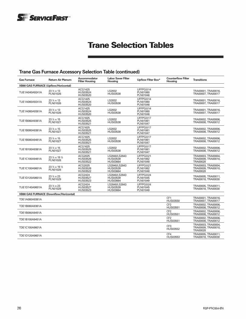
Trane Gas Furnace Accessory Selection Table (continued)
Gas Furnace Return Air PlenumAccommodator Filter Housing
Labor Saver Filter Housing
Upflow Filter Box*Counterflow Filter Housing
Transitions
XB80 GAS FURNACE (Upflow/Horizontal)
TUE1A040A9241A 23 ½ x 13 PLN01026
ACG1425 HUS03524 HUS03520
LS2832 HUS03538
UFFPG(I)14 PLN01060 PLN01046
TRA00001, TRA00016, TRA00007, TRA00017
TUE1A060A9241A 23 ½ x 13 PLN01026
ACG1425 HUS03524 HUS03520
LS2832 HUS03538
UFFPG(I)14 PLN01060 PLN01046
TRA00001, TRA00016, TRA00007, TRA00017
TUE1A060A9361A 23 ½ x 13 PLN01026
ACG1425 HUS03524 HUS03520
LS2832 HUS03538
UFFPG(I)14 PLN01060 PLN01046
TRA00001, TRA00016, TRA00007, TRA00017
TUE1B060A9361A 23 ½ x 15 PLN01027
ACG1625 HUS03525 HUS03521
LS2832 HUS03538
UFFPG(I)17 PLN01061 PLN01047
TRA00002, TRA00006, TRA00008, TRA00012
TUE1B080A9361A 23 ½ x 15 PLN01027
ACG1625 HUS03525 HUS03521
LS2832 HUS03538
UFFPG(I)17 PLN01061 PLN01047
TRA00002, TRA00006, TRA00008, TRA00012
TUE1B080A9481A 23 ½ x 15 PLN01027
ACG1625 HUS03525 HUS03521
LS2832 HUS03538
UFFPG(I)17 PLN01061 PLN01047
TRA00002, TRA00006, TRA00008, TRA00012
TUE1B100A9361A 23 ½ x 15 PLN01027
ACG1625 HUS03525 HUS03521
LS2832 HUS03538
UFFPG(I)17 PLN01061 PLN01047
TRA00002, TRA00006, TRA00008, TRA00012
TUE1C100A9481A 23 ½ x 19 ½ PLN01028
ACG2025 HUS03526 HUS03522
LS2840/LS2843 HUS03539 HUS03664
UFFPG(I)21 PLN01062 PLN01048
TRA00003, TRA00004, TRA00009, TRA00010, TRA00028
TUE1C100A9601A 23 ½ x 19 ½ PLN01028
ACG2025 HUS03526 HUS03522
LS2840/LS2843 HUS03539 HUS03664
UFFPG(I)21 PLN01062 PLN01048
TRA00003, TRA00004, TRA00009, TRA00010, TRA00028
TUE1D120A9601A 23 ½ x 23 PLN01029
ACG2424 HUS03527 HUS03523
LS2840/LS2843 HUS03539 HUS03664
UFFPG(I)24 PLN01045 PLN01049
TRA00005, TRA00011, TRA00018, TRA00030
TUE1D140A9601A 23 ½ x 23 PLN01029
ACG2424 HUS03527 HUS03523
LS2840/LS2843 HUS03539 HUS03664
UFFPG(I)24 PLN01045 PLN01049
TRA00005, TRA00011, TRA00018, TRA00030
XB80 GAS FURNACE (Downflow/Horizontal)
TDE1A060A9361A CF1 HUS03550
TRA00001, TRA00016, TRA00007, TRA00017
TDE1B060A9361A CF2 HUS03551
TRA00002, TRA00006, TRA00008, TRA00012
TDE1B080A9451A CF2 HUS03551
TRA00002, TRA00006, TRA00008, TRA00012
TDE1B100A9451A CF2 HUS03551
TRA00002, TRA00006, TRA00008, TRA00012
TDE1C100A9601A CF3 HUS03552
TRA00003, TRA00004, TRA00009, TRA00010, TRA00028
TDE1D120A9601A CF4 HUS03553
TRA00005, TRA00011, TRA00018, TRA00030

Trane Evaporator Coil Accessory Selection Table
Evaporator Coil Supply Plenum Dimensions Horizontal Drain PanService First Plenum Part Numbers
Service First Transitions
2/4CXC EVAPORATOR COILS
2CXCA018AC3CUAA 19 3/8 x 12 ¾ 32 x 36 PAN02211
PLN00856, PLN00866, PLN00923, PLN00938
4CXCA018AC3CUAA 19 3/8 x 12 ¾ 32 x 36 PAN02211
PLN00856, PLN00866, PLN00923, PLN00938
2CXCA024AC3CUAA 19 3/8 x 12 ¾ 32 x 36 PAN02211
PLN00856, PLN00866, PLN00923, PLN00938
4CXCA024AC3CUAA 19 3/8 x 12 ¾ 32 x 36 PAN02211
PLN00856, PLN00866, PLN00923, PLN00938
2CXCB025AC3CUAA 19 3/8 x 15 ¾ 32 x 36 PAN02211
PLN00859, PLN00869, PLN00926, PLN00941
4CXCA024AC3CUAA 19 3/8 x 15 ¾ 32 x 36 PAN02211
PLN00859, PLN00869, PLN00926, PLN00941
2CXCB031AC3CUAA 19 3/8 x 15 ¾ 32 x 36 PAN02211
PLN00859, PLN00869, PLN00926, PLN00941
4CXCB031AC3CUAA 19 3/8 x 15 ¾ 32 x 36 PAN02211
PLN00859, PLN00869, PLN00926, PLN00941
2CXCB036AC3CUAA 19 3/8 x 15 ¾ 32 x 36 PAN02211
PLN00859, PLN00869, PLN00926, PLN00941
4CXCB036AC3CUAA 19 3/8 x 15 ¾ 32 x 36 PAN02211
PLN00859, PLN00869, PLN00926, PLN00941
2CXCC042AC3CUAA 19 3/8 x 15 ¾ 32 x 36 PAN02211
PLN00859, PLN00869, PLN00926, PLN00941
4CXCC042AC3CUAA 19 3/8 x 15 ¾ 32 x 36 PAN02211
PLN00859, PLN00869, PLN00926, PLN00941
2CXCB048AC3CUAA 19 3/8 x 15 ¾ 32 x 36 PAN02211
PLN00859, PLN00869, PLN00926, PLN00941
4CXCB048AC3CUAA 19 3/8 x 15 ¾ 32 x 36 PAN02211
PLN00859, PLN00869, PLN00926, PLN00941
2CXCC037AC3CUAA 19 3/8 x 19 ¼ 32 x 36 PAN02211
PLN00860, PLN00870, PLN00927, PLN00942
4CXCC037AC3CUAA 19 3/8 x 19 ¼ 32 x 36 PAN02211
PLN00860, PLN00870, PLN00927, PLN00942
2CXCC043AC3CUAA 19 3/8 x 19 ¼ 32 x 36 PAN02211
PLN00860, PLN00870, PLN00927, PLN00942
4CXCC043AC3CUAA 19 3/8 x 19 ¼ 32 x 36 PAN02211
PLN00860, PLN00870, PLN00927, PLN00942
2CXCC049AC3CUAA 19 3/8 x 19 ¼ 32 x 36 PAN02211
PLN00860, PLN00870, PLN00927, PLN00942
4CXCC049AC3CUAA 19 3/8 x 19 ¼ 32 x 36 PAN02211
PLN00860, PLN00870, PLN00927, PLN00942
2CXCC060AC3CUAA 19 3/8 x 19 ¼ 32 x 36 PAN02211
PLN00860, PLN00870, PLN00927, PLN00942
4CXCC060AC3CUAA 19 3/8 x 19 ¼ 32 x 36 PAN02211
PLN00860, PLN00870, PLN00927, PLN00942
2CXCD050AC3CUAA 19 3/8 x 22 ¾ 32 x 36 PAN02211
PLN00861, PLN00871, PLN00928, PLN00943
4CXCD050AC3CUAA 19 3/8 x 22 ¾ 32 x 36 PAN02211
PLN00861, PLN00871, PLN00928, PLN00943
2CXCD061AC3CUAA 19 3/8 x 22 ¾ 32 x 36 PAN02211
PLN00861, PLN00871, PLN00928, PLN00943
4CXCD061AC3CUAA 19 3/8 x 22 ¾ 32 x 36 PAN02211
PLN00861, PLN00871, PLN00928, PLN00943
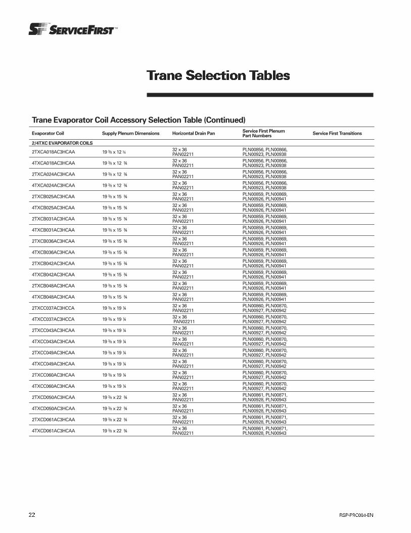
Trane Evaporator Coil Accessory Selection Table (Continued)
Evaporator Coil Supply Plenum Dimensions Horizontal Drain PanService First Plenum Part Numbers
Service First Transitions
2/4TXC EVAPORATOR COILS
2TXCA018AC3HCAA 19 3/8 x 12 ¾ 32 x 36 PAN02211
PLN00856, PLN00866, PLN00923, PLN00938
4TXCA018AC3HCAA 19 3/8 x 12 ¾ 32 x 36 PAN02211
PLN00856, PLN00866, PLN00923, PLN00938
2TXCA024AC3HCAA 19 3/8 x 12 ¾ 32 x 36 PAN02211
PLN00856, PLN00866, PLN00923, PLN00938
4TXCA024AC3HCAA 19 3/8 x 12 ¾ 32 x 36 PAN02211
PLN00856, PLN00866, PLN00923, PLN00938
2TXCB025AC3HCAA 19 3/8 x 15 ¾ 32 x 36 PAN02211
PLN00859, PLN00869, PLN00926, PLN00941
4TXCB025AC3HCAA 19 3/8 x 15 ¾ 32 x 36 PAN02211
PLN00859, PLN00869, PLN00926, PLN00941
2TXCB031AC3HCAA 19 3/8 x 15 ¾ 32 x 36 PAN02211
PLN00859, PLN00869, PLN00926, PLN00941
4TXCB031AC3HCAA 19 3/8 x 15 ¾ 32 x 36 PAN02211
PLN00859, PLN00869, PLN00926, PLN00941
2TXCB036AC3HCAA 19 3/8 x 15 ¾ 32 x 36 PAN02211
PLN00859, PLN00869, PLN00926, PLN00941
4TXCB036AC3HCAA 19 3/8 x 15 ¾ 32 x 36 PAN02211
PLN00859, PLN00869, PLN00926, PLN00941
2TXCB042AC3HCAA 19 3/8 x 15 ¾ 32 x 36 PAN02211
PLN00859, PLN00869, PLN00926, PLN00941
4TXCB042AC3HCAA 19 3/8 x 15 ¾ 32 x 36 PAN02211
PLN00859, PLN00869, PLN00926, PLN00941
2TXCB048AC3HCAA 19 3/8 x 15 ¾ 32 x 36 PAN02211
PLN00859, PLN00869, PLN00926, PLN00941
4TXCB048AC3HCAA 19 3/8 x 15 ¾ 32 x 36 PAN02211
PLN00859, PLN00869, PLN00926, PLN00941
2TXCC037AC3HCCA 19 3/8 x 19 ¼ 32 x 36 PAN02211
PLN00860, PLN00870, PLN00927, PLN00942
4TXCC037AC3HCCA 19 3/8 x 19 ¼ 32 x 36 PAN02211
PLN00860, PLN00870, PLN00927, PLN00942
2TXCC043AC3HCAA 19 3/8 x 19 ¼ 32 x 36 PAN02211
PLN00860, PLN00870, PLN00927, PLN00942
4TXCC043AC3HCAA 19 3/8 x 19 ¼ 32 x 36 PAN02211
PLN00860, PLN00870, PLN00927, PLN00942
2TXCC049AC3HCAA 19 3/8 x 19 ¼ 32 x 36 PAN02211
PLN00860, PLN00870, PLN00927, PLN00942
4TXCC049AC3HCAA 19 3/8 x 19 ¼ 32 x 36 PAN02211
PLN00860, PLN00870, PLN00927, PLN00942
2TXCC060AC3HCAA 19 3/8 x 19 ¼ 32 x 36 PAN02211
PLN00860, PLN00870, PLN00927, PLN00942
4TXCC060AC3HCAA 19 3/8 x 19 ¼ 32 x 36 PAN02211
PLN00860, PLN00870, PLN00927, PLN00942
2TXCD050AC3HCAA 19 3/8 x 22 ¾ 32 x 36 PAN02211
PLN00861, PLN00871, PLN00928, PLN00943
4TXCD050AC3HCAA 19 3/8 x 22 ¾ 32 x 36 PAN02211
PLN00861, PLN00871, PLN00928, PLN00943
2TXCD061AC3HCAA 19 3/8 x 22 ¾ 32 x 36 PAN02211
PLN00861, PLN00871, PLN00928, PLN00943
4TXCD061AC3HCAA 19 3/8 x 22 ¾ 32 x 36 PAN02211
PLN00861, PLN00871, PLN00928, PLN00943
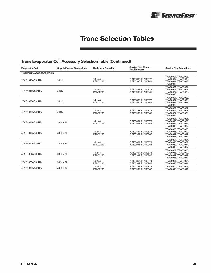
Trane Evaporator Coil Accessory Selection Table (Continued)
Evaporator Coil Supply Plenum Dimensions Horizontal Drain PanService First Plenum Part Numbers
Service First Transitions
2/4TXFH EVAPORATOR COILS
2TXFH018AS3HHA 24 x 21 14 x 44 PAN02213
PLN00863, PLN00872, PLN00930, PLN00945
TRA00001, TRA00002, TRA00007, TRA00008, TRA00027, TRA00028, TRA00030
4TXFH018AS3HHA 24 x 21 14 x 44 PAN02213
PLN00863, PLN00872, PLN00930, PLN00945
TRA00001, TRA00002, TRA00007, TRA00008, TRA00027, TRA00028, TRA00030
2TXFH033AS3HHA 24 x 21 14 x 44 PAN02213
PLN00863, PLN00872, PLN00930, PLN00945
TRA00001, TRA00002, TRA00007, TRA00008, TRA00027, TRA00028, TRA00030
4TXFH033AS3HHA 24 x 21 14 x 44 PAN02213
PLN00863, PLN00872, PLN00930, PLN00945
TRA00001, TRA00002, TRA00007, TRA00008, TRA00027, TRA00028, TRA00030
2TXFH041AS3HHA 33 ¼ x 21 14 x 44 PAN02213
PLN00864, PLN00873, PLN00931, PLN00946
TRA00003, TRA00006, TRA00016, TRA00009, TRA00012, TRA00017, TRA00018, TRA00032
4TXFH041AS3HHA 33 ¼ x 21 14 x 44 PAN02213
PLN00864, PLN00873, PLN00931, PLN00946
TRA00003, TRA00006, TRA00016, TRA00009, TRA00012, TRA00017, TRA00018, TRA00032
2TXFH054AS3HHA 33 ¼ x 21 14 x 44 PAN02213
PLN00864, PLN00873, PLN00931, PLN00946
TRA00003, TRA00006, TRA00016, TRA00009, TRA00012, TRA00017, TRA00018, TRA00032
4TXFH054AS3HHA 33 ¼ x 21 14 x 44 PAN02213
PLN00864, PLN00873, PLN00931, PLN00946
TRA00003, TRA00006, TRA00016, TRA00009, TRA00012, TRA00017, TRA00018, TRA00032
2TXFH063AS3HHA 33 ¼ x 27 14 x 44 PAN02213
PLN00865, PLN00874, PLN00932, PLN00947
TRA00004, TRA00005, TRA00010, TRA00011
4TXFH063AS3HHA 33 ¼ x 27 14 x 44 PAN02213
PLN00865, PLN00874, PLN00932, PLN00947
TRA00004, TRA00005, TRA00010, TRA00011
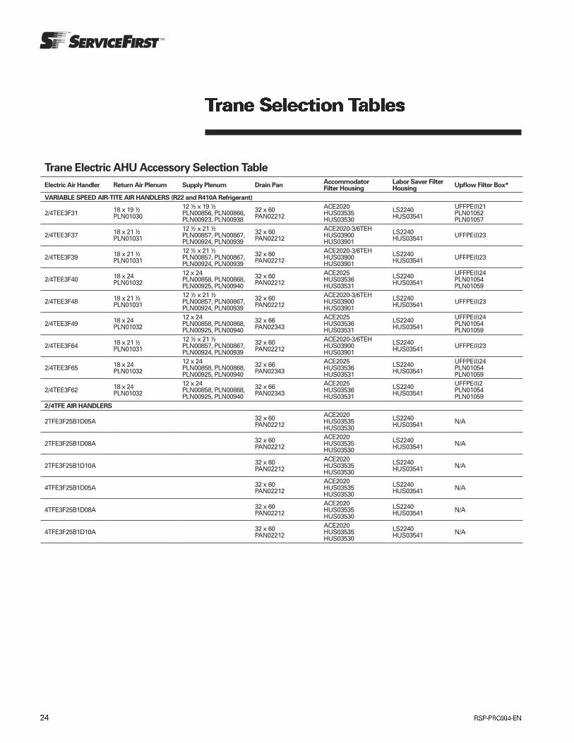
Trane Electric AHU Accessory Selection Table
Electric Air Handler Return Air Plenum Supply Plenum Drain PanAccommodator Filter Housing
Labor Saver Filter Housing
Upflow Filter Box*
VARIABLE SPEED AIR-TITE AIR HANDLERS (R22 and R410A Refrigerant)
2/4TEE3F31 18 x 19 ½ PLN01030
12 ½ x 19 ½ PLN00856, PLN00866, PLN00923, PLN00938
32 x 60 PAN02212
ACE2020 HUS03535 HUS03530
LS2240 HUS03541
UFFPE(I)21 PLN01052 PLN01057
2/4TEE3F37 18 x 21 ½ PLN01031
12 ½ x 21 ½ PLN00857, PLN00867, PLN00924, PLN00939
32 x 60 PAN02212
ACE2020-3/6TEHHUS03900HUS03901
LS2240 HUS03541 UFFPE(I)23
2/4TEE3F39 18 x 21 ½ PLN01031
12 ½ x 21 ½ PLN00857, PLN00867, PLN00924, PLN00939
32 x 60 PAN02212
ACE2020-3/6TEHHUS03900HUS03901
LS2240 HUS03541 UFFPE(I)23
2/4TEE3F40 18 x 24 PLN01032
12 x 24 PLN00858, PLN00868, PLN00925, PLN00940
32 x 60 PAN02212
ACE2025 HUS03536 HUS03531
LS2240 HUS03541
UFFPE(I)24 PLN01054 PLN01059
2/4TEE3F48 18 x 21 ½ PLN01031
12 ½ x 21 ½ PLN00857, PLN00867, PLN00924, PLN00939
32 x 60 PAN02212
ACE2020-3/6TEHHUS03900HUS03901
LS2240 HUS03541 UFFPE(I)23
2/4TEE3F49 18 x 24 PLN01032
12 x 24 PLN00858, PLN00868, PLN00925, PLN00940
32 x 66 PAN02343
ACE2025 HUS03536 HUS03531
LS2240 HUS03541
UFFPE(I)24 PLN01054 PLN01059
2/4TEE3F64 18 x 21 ½ PLN01031
12 ½ x 21 ½ PLN00857, PLN00867, PLN00924, PLN00939
32 x 60 PAN02212
ACE2020-3/6TEHHUS03900HUS03901
LS2240 HUS03541 UFFPE(I)23
2/4TEE3F65 18 x 24 PLN01032
12 x 24 PLN00858, PLN00868, PLN00925, PLN00940
32 x 66 PAN02343
ACE2025 HUS03536 HUS03531
LS2240 HUS03541
UFFPE(I)24 PLN01054 PLN01059
2/4TEE3F62 18 x 24 PLN01032
12 x 24 PLN00858, PLN00868, PLN00925, PLN00940
32 x 66 PAN02343
ACE2025 HUS03536 HUS03531
LS2240 HUS03541
UFFPE(I)2 PLN01054 PLN01059
2/4TFE AIR HANDLERS
2TFE3F25B1D05A 32 x 60 PAN02212
ACE2020 HUS03535 HUS03530
LS2240 HUS03541 N/A
2TFE3F25B1D08A 32 x 60 PAN02212
ACE2020 HUS03535 HUS03530
LS2240 HUS03541 N/A
2TFE3F25B1D10A 32 x 60 PAN02212
ACE2020 HUS03535 HUS03530
LS2240 HUS03541 N/A
4TFE3F25B1D05A 32 x 60 PAN02212
ACE2020 HUS03535 HUS03530
LS2240 HUS03541 N/A
4TFE3F25B1D08A 32 x 60 PAN02212
ACE2020 HUS03535 HUS03530
LS2240 HUS03541 N/A
4TFE3F25B1D10A 32 x 60 PAN02212
ACE2020 HUS03535 HUS03530
LS2240 HUS03541 N/A
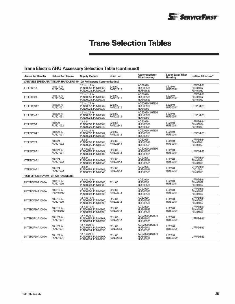
Trane Electric AHU Accessory Selection Table (continued)
Electric Air Handler Return Air Plenum Supply Plenum Drain PanAccommodator Filter Housing
Labor Saver Filter Housing
Upflow Filter Box*
VARIABLE SPEED AIR-TITE AIR HANDLERS (R410A Refrigerant, Communicating)
4TEE3C01A 18 x 19 ½ PLN01030
12 ½ x 19 ½ PLN00856, PLN00866, PLN00923, PLN00938
32 x 60 PAN02212
ACE2020 HUS03535 HUS03530
LS2240 HUS03541
UFFPE(I)21 PLN01052 PLN01057
4TEE3C02A 18 x 19 ½ PLN01030
12 ½ x 19 ½ PLN00856, PLN00866, PLN00923, PLN00938
32 x 60 PAN02212
ACE2020 HUS03535 HUS03530
LS2240 HUS03541
UFFPE(I)21 PLN01052 PLN01057
4TEE3C03A* 18 x 21 ½ PLN01031
12 ½ x 21 ½ PLN00857, PLN00867, PLN00924, PLN00939
32 x 60 PAN02212
ACE2020-3/6TEHHUS03900HUS03901
LS2240 HUS03541 UFFPE(I)23
4TEE3C04A* 18 x 21 ½ PLN01031
12 ½ x 21 ½ PLN00857, PLN00867, PLN00924, PLN00939
32 x 60 PAN02212
ACE2020-3/6TEHHUS03900HUS03901
LS2240 HUS03541 UFFPE(I)23
4TEE3C05A 18 x 24 PLN01032
12 x 24 PLN00858, PLN00868, PLN00925, PLN00940
32 x 66 PAN02343
ACE2025 HUS03536 HUS03531
LS2240 HUS03541
UFFPE(I)24 PLN01054 PLN01059
4TEE3C06A* 18 x 21 ½ PLN01031
12 ½ x 21 ½ PLN00857, PLN00867, PLN00924, PLN00939
32 x 60 PAN02212
ACE2020-3/6TEHHUS03900HUS03901
LS2240 HUS03541 UFFPE(I)23
4TEE3C07A 18 x 24 PLN01032
12 x 24 PLN00858, PLN00868, PLN00925, PLN00940
32 x 66 PAN02343
ACE2025 HUS03536 HUS03531
LS2240 HUS03541
UFFPE(I)24 PLN01054 PLN01059
4TEE3C08A* 18 x 21 ½ PLN01031
12 ½ x 21 ½ PLN00857, PLN00867, PLN00924, PLN00939
32 x 60 PAN02212
ACE2020-3/6TEHHUS03900HUS03901
LS2240 HUS03541 UFFPE(I)23
4TEE3C09A* 18 x 24 PLN01032
12 x 24 PLN00858, PLN00868, PLN00925, PLN00940
32 x 66 PAN02343
ACE2025 HUS03536 HUS03531
LS2240 HUS03541
UFFPE(I)24 PLN01054 PLN01059
4TEE3C10A* 18 x 24 PLN01032
12 x 24 PLN00858, PLN00868, PLN00925, PLN00940
32 x 66 PAN02343
ACE2025 HUS03536 HUS03531
LS2240 HUS03541
UFFPE(I)24 LN01054 PLN01059
HIGH EFFICIENCY 2/4TEH AIR HANDLERS
2/4TEH3F18A1000A 18 x 19 ½ PLN01030
12 ½ x 19 ½ PLN00856, PLN00866, PLN00923, PLN00938
32 x 60ACE2020 HUS0353 HUS03530
LS2240 HUS03541
UFFPE(I)21 PLN01052 PLN01057
2/4TEH3F24A1000A 18 x 19 ½ PLN01030
12 ½ x 19 ½ PLN00856, PLN00866, PLN00923, PLN00938
32 x 60 PAN02212
ACE2020 HUS03535 HUS03530
LS2240 HUS03541
UFFPE(I)21 PLN01052 PLN01057
2/4TEH3F30A1000A 18 x 19 ½ PLN01030
12 ½ x 19 ½ PLN00856, PLN00866, PLN00923, PLN00938
32 x 60 PAN02212
ACE2020 HUS03535 HUS03530
LS2240 HUS03541
UFFPE(I)21 PLN01052 PLN01057
2/4TEH3F36A1000A 18 x 19 ½ PLN01030
12 ½ x 19 ½ PLN00856, PLN00866, PLN00923, PLN00938
32 x 60 PAN02212
ACE2020 HUS03535 HUS03530
LS2240 HUS03541
UFFPE(I)21 PLN01052 PLN01057
2/4TEH3F42A1000A 18 x 21 ½ PLN01031
12 ½ x 21 ½ PLN00857, PLN00867, PLN00924, PLN00939
32 x 60 PAN02212
ACE2020-3/6TEHHUS03900HUS03901
LS2240 HUS03541 UFFPE(I)23
2/4TEH3F48A1000A 18 x 21 ½ PLN01031
12 ½ x 21 ½ PLN00857, PLN00867, PLN00924, PLN00939
32 x 66 PAN02343
ACE2020-3/6TEHHUS03900HUS03901
LS2240 HUS03541 UFFPE(I)23
2/4TEH3F60A1000A 18 x 21 ½ PLN01031
12 ½ x 21 ½ PLN00857, PLN00867, PLN00924, PLN00939
32 x 66 PAN02343
ACE2020-3/6TEHHUS03900HUS03901
LS2240 HUS03541 UFFPE(I)23

Trane Electric AHU Accessory Selection Table (continued)
Electric Air Handler Return Air Plenum Supply Plenum Drain PanAccommodator Filter Housing
Labor Saver Filter Housing
Upflow Filter Box*
2TEC AIR HANDLERS
2TEC3F18 18 x 19 ½ PLN01030
12 ½ x 19 ½ PLN00856, PLN00866, PLN00923, PLN00938
32 x 60 PAN02212
ACE2020 HUS03535 HUS03530
LS2240 HUS03541
UFFPE(I)21 PLN01052 PLN01057
2TEC3F24 18 x 19 ½ PLN01030
12 ½ x 19 ½ PLN00856, PLN00866, PLN00923, PLN00938
32 x 60 PAN02212
ACE2020 HUS03535 HUS03530
LS2240 HUS03541
UFFPE(I)21 PLN01052 PLN01057
2TEC3F30 18 x 19 ½ PLN01030
12 ½ x 19 ½ PLN00856, PLN00866, PLN00923, PLN00938
32 x 60 PAN02212
ACE2020 HUS03535 HUS03530
LS2240 HUS03541
UFFPE(I)21 PLN01052 PLN01057
2TEC3F36 18 x 19 ½ PLN01030
12 ½ x 19 ½ PLN00856, PLN00866, PLN00923, PLN00938
32 x 60 PAN02212
ACE2020 HUS03535 HUS03530
LS2240 HUS03541
UFFPE(I)21 PLN01052 PLN01057
2TEC3F42 18 x 21 ½ PLN01031
12 ½ x 21 ½ PLN00857, PLN00867, PLN00924, PLN00939
32 x 60 PAN02212
ACE2020-3/6TEHHUS03900HUS03901
LS2240 HUS03541 UFFPE(I)23
* 2TEC3F48 18 x 21 ½ PLN01031
12 ½ x 21 ½ PLN00857, PLN00867, PLN00924, PLN00939
32 x 66 PAN02343
ACE2020-3/6TEHHUS03900HUS03901
LS2240 HUS03541 UFFPE(I)23
2TEC3F55 18 x 24 PLN01032
12 x 24 PLN00858, PLN00868, PLN00925, PLN00940
32 x 66 PAN02343
ACE2025 HUS03536 HUS03531
LS2240 HUS03541
UFFPE(I)24 PLN01054 PLN01059
* 2TEC3F60 18 x 21 ½ PLN01031
12 ½ x 21 ½ PLN00857, PLN00867, PLN00924, PLN00939
32 x 66 PAN02343
ACE2020-3/6TEHHUS03900HUS03901
LS2240 HUS03541 UFFPE(I)23
4TEC (High Efficiency Motors) AIR HANDLERS
4TEC3F18 18 x 19 ½ PLN01030
12 ½ x 19 ½ PLN00856, PLN00866, PLN00923, PLN00938
32 x 60 PAN02212
ACE2020 HUS03535 HUS03530
LS2240 HUS03541
UFFPE(I)21 PLN01052 PLN01057
4TEC3F24 18 x 19 ½ PLN01030
12 ½ x 19 ½ PLN00856, PLN00866, PLN00923, PLN00938
32 x 60 PAN02212
ACE2020 HUS03535 HUS03530
LS2240 HUS03541
UFFPE(I)21 PLN01052 PLN01057
4TEC3F30 18 x 19 ½ PLN01030
12 ½ x 19 ½ PLN00856, PLN00866, PLN00923, PLN00938
32 x 60 PAN02212
ACE2020 HUS03535 HUS03530
LS2240 HUS03541
UFFPE(I)21 PLN01052 PLN01057
4TEC3F36 18 x 19 ½ PLN01030
12 ½ x 19 ½ PLN00856, PLN00866, PLN00923, PLN00938
32 x 60 PAN02212
ACE2020 HUS03535 HUS03530
LS2240 HUS03541
UFFPE(I)21 PLN01052 PLN01057
4TEC3F42 18 x 21 ½ PLN01031
12 ½ x 21 ½ PLN00857, PLN00867, PLN00924, PLN00939
32 x 60 PAN02212
ACE2020-3/6TEHHUS03900HUS03901
LS2240 HUS03541 UFFPE(I)23
* 4TEC3F48 18 x 21 ½ PLN01031
12 ½ x 21 ½ PLN00857, PLN00867, PLN00924, PLN00939
32 x 66 PAN02343
ACE2020-3/6TEHHUS03900HUS03901
LS2240 HUS03541 UFFPE(I)23
4TEC3F55 18 x 21 ½ PLN01031
12 ½ x 21 ½ PLN00857, PLN00867, PLN00924, PLN00939
32 x 66 PAN02343
ACE2020-3/6TEHHUS03900HUS03901
LS2240 HUS03541 UFFPE(I)23
* 4TEC3F60 18 x 21 ½ PLN01031
12 ½ x 21 ½ PLN00857, PLN00867, PLN00924, PLN00939
32 x 66 PAN02343
ACE2020-3/6TEHHUS03900HUS03901
LS2240 HUS03541 UFFPE(I)23
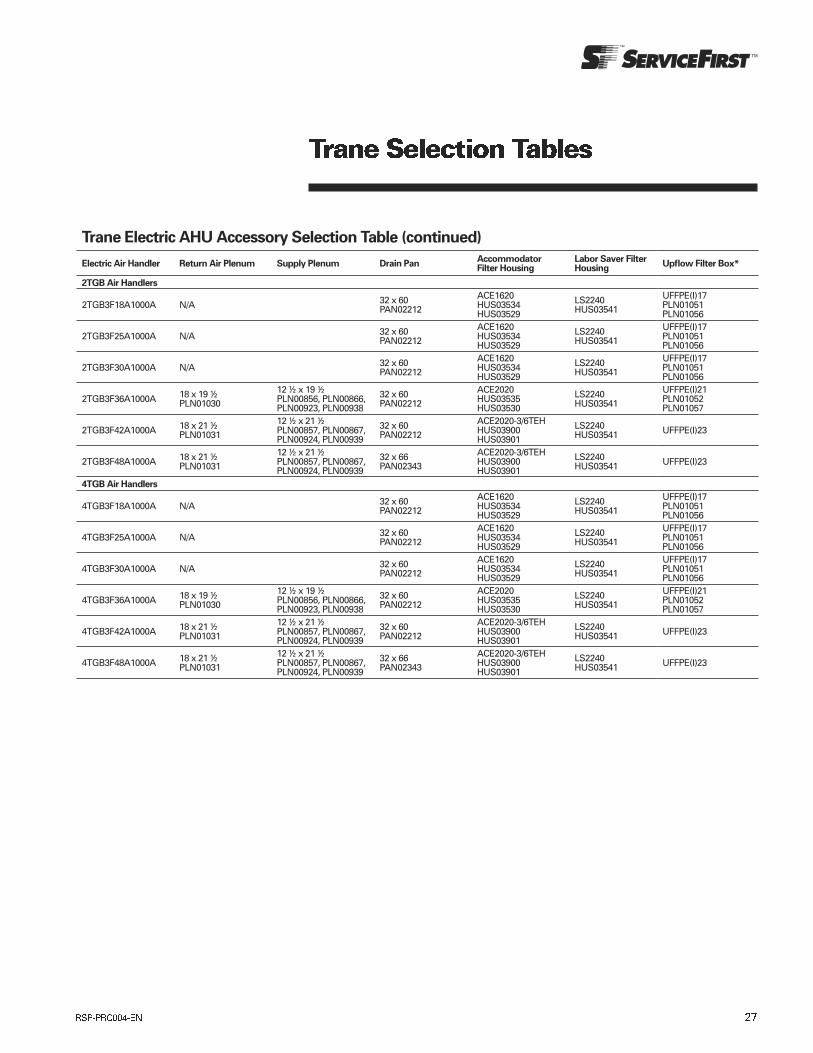
Trane Electric AHU Accessory Selection Table (continued)
Electric Air Handler Return Air Plenum Supply Plenum Drain PanAccommodator Filter Housing
Labor Saver Filter Housing
Upflow Filter Box*
2TGB Air Handlers
2TGB3F18A1000A N/A 32 x 60 PAN02212
ACE1620 HUS03534 HUS03529
LS2240 HUS03541
UFFPE(I)17 PLN01051 PLN01056
2TGB3F25A1000A N/A 32 x 60 PAN02212
ACE1620 HUS03534 HUS03529
LS2240 HUS03541
UFFPE(I)17 PLN01051 PLN01056
2TGB3F30A1000A N/A 32 x 60 PAN02212
ACE1620 HUS03534 HUS03529
LS2240 HUS03541
UFFPE(I)17 PLN01051 PLN01056
2TGB3F36A1000A 18 x 19 ½ PLN01030
12 ½ x 19 ½ PLN00856, PLN00866, PLN00923, PLN00938
32 x 60 PAN02212
ACE2020 HUS03535 HUS03530
LS2240 HUS03541
UFFPE(I)21 PLN01052 PLN01057
2TGB3F42A1000A 18 x 21 ½ PLN01031
12 ½ x 21 ½ PLN00857, PLN00867, PLN00924, PLN00939
32 x 60 PAN02212
ACE2020-3/6TEHHUS03900HUS03901
LS2240 HUS03541 UFFPE(I)23
2TGB3F48A1000A 18 x 21 ½ PLN01031
12 ½ x 21 ½ PLN00857, PLN00867, PLN00924, PLN00939
32 x 66 PAN02343
ACE2020-3/6TEHHUS03900HUS03901
LS2240 HUS03541 UFFPE(I)23
4TGB Air Handlers
4TGB3F18A1000A N/A 32 x 60 PAN02212
ACE1620 HUS03534 HUS03529
LS2240 HUS03541
UFFPE(I)17 PLN01051 PLN01056
4TGB3F25A1000A N/A 32 x 60 PAN02212
ACE1620 HUS03534 HUS03529
LS2240 HUS03541
UFFPE(I)17 PLN01051 PLN01056
4TGB3F30A1000A N/A 32 x 60 PAN02212
ACE1620 HUS03534 HUS03529
LS2240 HUS03541
UFFPE(I)17 PLN01051 PLN01056
4TGB3F36A1000A 18 x 19 ½ PLN01030
12 ½ x 19 ½ PLN00856, PLN00866, PLN00923, PLN00938
32 x 60 PAN02212
ACE2020 HUS03535 HUS03530
LS2240 HUS03541
UFFPE(I)21 PLN01052 PLN01057
4TGB3F42A1000A 18 x 21 ½ PLN01031
12 ½ x 21 ½ PLN00857, PLN00867, PLN00924, PLN00939
32 x 60 PAN02212
ACE2020-3/6TEHHUS03900HUS03901
LS2240 HUS03541 UFFPE(I)23
4TGB3F48A1000A 18 x 21 ½ PLN01031
12 ½ x 21 ½ PLN00857, PLN00867, PLN00924, PLN00939
32 x 66 PAN02343
ACE2020-3/6TEHHUS03900HUS03901
LS2240 HUS03541 UFFPE(I)23

Trane Electric AHU Accessory Selection Table (continued)
Electric Air Handler Return Air Plenum Supply Plenum Drain PanAccommodator Filter Housing
Labor Saver Filter Housing
Upflow Filter Box*
2TFB-B AIR HANDLERS
2TFB3F18B1D05A 32 x 60 PAN02212
ACE2020 HUS03535 HUS03530
LS2240 HUS03541 N/A
2TFB3F18B1D08A 32 x 60 PAN02212
ACE2020 HUS03535 HUS03530
LS2240 HUS03541 N/A
2TFB3F18B1D10A 32 x 60 PAN02212
ACE2020 HUS03535 HUS03530
LS2240 HUS03541 N/A
2TFB3F24B1D05A 32 x 60 PAN02212
ACE2020 HUS03535 HUS03530
LS2240 HUS03541 N/A
2TFB3F24B1D08A 32 x 60 PAN02212
ACE2020 HUS03535 HUS03530
LS2240 HUS03541 N/A
2TFB3F24B1D10A 32 x 60 PAN02212
ACE2020 HUS03535 HUS03530
LS2240 HUS03541 N/A
2TFB3F30B1D05A 32 x 60 PAN02212
ACE2020 HUS03535 HUS03530
LS2240 HUS03541 N/A
2TFB3F30B1D08A 32 x 60 PAN02212
ACE2020 HUS03535 HUS03530
LS2240 HUS03541 N/A
2TFB3F30B1D10A 32 x 60 PAN02212
ACE2020 HUS03535 HUS03530
LS2240 HUS03541 N/A
2TFB3F36B1D05A 32 x 60 PAN02212
ACE2020 HUS03535 HUS03530
LS2240 HUS03541 N/A
2TFB3F36B1D08A 32 x 60 PAN02212
ACE2020 HUS03535 HUS03530
LS2240 HUS03541 N/A
2TFB3F36B1D10A 32 x 60 PAN02212
ACE2020 HUS03535 HUS03530
LS2240 HUS03541 N/A
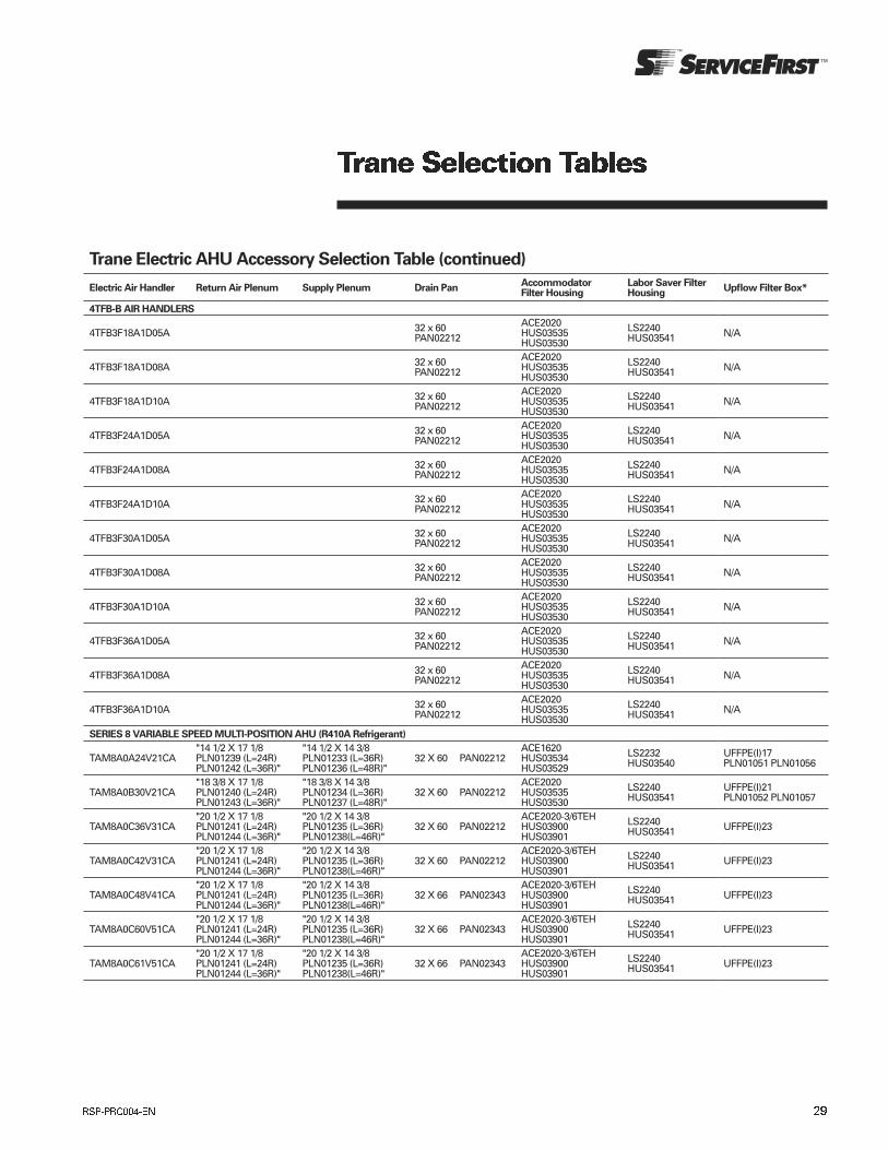
Trane Electric AHU Accessory Selection Table (continued)
Electric Air Handler Return Air Plenum Supply Plenum Drain PanAccommodator Filter Housing
Labor Saver Filter Housing
Upflow Filter Box*
4TFB-B AIR HANDLERS
4TFB3F18A1D05A 32 x 60 PAN02212
ACE2020 HUS03535 HUS03530
LS2240 HUS03541 N/A
4TFB3F18A1D08A 32 x 60 PAN02212
ACE2020 HUS03535 HUS03530
LS2240 HUS03541 N/A
4TFB3F18A1D10A 32 x 60 PAN02212
ACE2020 HUS03535 HUS03530
LS2240 HUS03541 N/A
4TFB3F24A1D05A 32 x 60 PAN02212
ACE2020 HUS03535 HUS03530
LS2240 HUS03541 N/A
4TFB3F24A1D08A 32 x 60 PAN02212
ACE2020 HUS03535 HUS03530
LS2240 HUS03541 N/A
4TFB3F24A1D10A 32 x 60 PAN02212
ACE2020 HUS03535 HUS03530
LS2240 HUS03541 N/A
4TFB3F30A1D05A 32 x 60 PAN02212
ACE2020 HUS03535 HUS03530
LS2240 HUS03541 N/A
4TFB3F30A1D08A 32 x 60 PAN02212
ACE2020 HUS03535 HUS03530
LS2240 HUS03541 N/A
4TFB3F30A1D10A 32 x 60 PAN02212
ACE2020 HUS03535 HUS03530
LS2240 HUS03541 N/A
4TFB3F36A1D05A 32 x 60 PAN02212
ACE2020 HUS03535 HUS03530
LS2240 HUS03541 N/A
4TFB3F36A1D08A 32 x 60 PAN02212
ACE2020 HUS03535 HUS03530
LS2240 HUS03541 N/A
4TFB3F36A1D10A 32 x 60 PAN02212
ACE2020 HUS03535 HUS03530
LS2240 HUS03541 N/A
SERIES 8 VARIABLE SPEED MULTI-POSITION AHU (R410A Refrigerant)
TAM8A0A24V21CA"14 1/2 X 17 1/8 PLN01239 (L=24R) PLN01242 (L=36R)"
"14 1/2 X 14 3/8 PLN01233 (L=36R) PLN01236 (L=48R)"
32 X 60 PAN02212ACE1620 HUS03534 HUS03529
LS2232 HUS03540
UFFPE(I)17 PLN01051 PLN01056
TAM8A0B30V21CA"18 3/8 X 17 1/8 PLN01240 (L=24R) PLN01243 (L=36R)"
"18 3/8 X 14 3/8 PLN01234 (L=36R) PLN01237 (L=48R)"
32 X 60 PAN02212ACE2020 HUS03535 HUS03530
LS2240 HUS03541
UFFPE(I)21 PLN01052 PLN01057
TAM8A0C36V31CA"20 1/2 X 17 1/8 PLN01241 (L=24R) PLN01244 (L=36R)"
"20 1/2 X 14 3/8 PLN01235 (L=36R) PLN01238(L=46R)"
32 X 60 PAN02212ACE2020-3/6TEHHUS03900HUS03901
LS2240 HUS03541 UFFPE(I)23
TAM8A0C42V31CA"20 1/2 X 17 1/8 PLN01241 (L=24R) PLN01244 (L=36R)"
"20 1/2 X 14 3/8 PLN01235 (L=36R) PLN01238(L=46R)"
32 X 60 PAN02212ACE2020-3/6TEHHUS03900HUS03901
LS2240 HUS03541 UFFPE(I)23
TAM8A0C48V41CA"20 1/2 X 17 1/8 PLN01241 (L=24R) PLN01244 (L=36R)"
"20 1/2 X 14 3/8 PLN01235 (L=36R) PLN01238(L=46R)"
32 X 66 PAN02343ACE2020-3/6TEHHUS03900HUS03901
LS2240 HUS03541 UFFPE(I)23
TAM8A0C60V51CA"20 1/2 X 17 1/8 PLN01241 (L=24R) PLN01244 (L=36R)"
"20 1/2 X 14 3/8 PLN01235 (L=36R) PLN01238(L=46R)"
32 X 66 PAN02343ACE2020-3/6TEHHUS03900HUS03901
LS2240 HUS03541 UFFPE(I)23
TAM8A0C61V51CA"20 1/2 X 17 1/8 PLN01241 (L=24R) PLN01244 (L=36R)"
"20 1/2 X 14 3/8 PLN01235 (L=36R) PLN01238(L=46R)"
32 X 66 PAN02343ACE2020-3/6TEHHUS03900HUS03901
LS2240 HUS03541 UFFPE(I)23
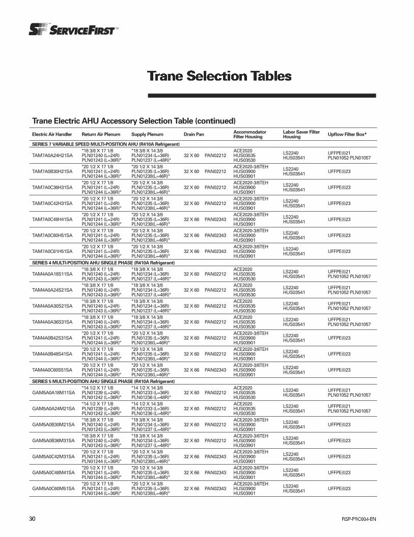
Trane Electric AHU Accessory Selection Table (continued)
Electric Air Handler Return Air Plenum Supply Plenum Drain PanAccommodator Filter Housing
Labor Saver Filter Housing
Upflow Filter Box*
SERIES 7 VARIABLE SPEED MULTI-POSITION AHU (R410A Refrigerant)
TAM7A0A24H21SA"18 3/8 X 17 1/8 PLN01240 (L=24R) PLN01243 (L=36R)"
"18 3/8 X 14 3/8 PLN01234 (L=36R) PLN01237 (L=48R)"
32 X 60 PAN02212ACE2020 HUS03535 HUS03530
LS2240 HUS03541
UFFPE(I)21 PLN01052 PLN01057
TAM7A0B30H21SA"20 1/2 X 17 1/8 PLN01241 (L=24R) PLN01244 (L=36R)"
"20 1/2 X 14 3/8 PLN01235 (L=36R) PLN01238(L=46R)"
32 X 60 PAN02212ACE2020-3/6TEHHUS03900HUS03901
LS2240 HUS03541 UFFPE(I)23
TAM7A0C36H31SA"20 1/2 X 17 1/8 PLN01241 (L=24R) PLN01244 (L=36R)"
"20 1/2 X 14 3/8 PLN01235 (L=36R) PLN01238(L=46R)"
32 X 60 PAN02212ACE2020-3/6TEHHUS03900HUS03901
LS2240 HUS03541 UFFPE(I)23
TAM7A0C42H31SA"20 1/2 X 17 1/8 PLN01241 (L=24R) PLN01244 (L=36R)"
"20 1/2 X 14 3/8 PLN01235 (L=36R) PLN01238(L=46R)"
32 X 60 PAN02212ACE2020-3/6TEHHUS03900HUS03901
LS2240 HUS03541 UFFPE(I)23
TAM7A0C48H41SA"20 1/2 X 17 1/8 PLN01241 (L=24R) PLN01244 (L=36R)"
"20 1/2 X 14 3/8 PLN01235 (L=36R) PLN01238(L=46R)"
32 X 66 PAN02343ACE2020-3/6TEHHUS03900HUS03901
LS2240 HUS03541 UFFPE(I)23
TAM7A0C60H51SA"20 1/2 X 17 1/8 PLN01241 (L=24R) PLN01244 (L=36R)"
"20 1/2 X 14 3/8 PLN01235 (L=36R) PLN01238(L=46R)"
32 X 66 PAN02343ACE2020-3/6TEHHUS03900HUS03901
LS2240 HUS03541 UFFPE(I)23
TAM7A0C61H51SA"20 1/2 X 17 1/8 PLN01241 (L=24R) PLN01244 (L=36R)"
"20 1/2 X 14 3/8 PLN01235 (L=36R) PLN01238(L=46R)"
32 X 66 PAN02343ACE2020-3/6TEHHUS03900HUS03901
LS2240 HUS03541 UFFPE(I)23
SERIES 4 MULTI-POSITION AHU SINGLE PHASE (R410A Refrigerant)
TAM4A0A18S11SA"18 3/8 X 17 1/8 PLN01240 (L=24R) PLN01243 (L=36R)"
"18 3/8 X 14 3/8 PLN01234 (L=36R) PLN01237 (L=48R)"
32 X 60 PAN02212ACE2020 HUS03535 HUS03530
LS2240 HUS03541
UFFPE(I)21 PLN01052 PLN01057
TAM4A0A24S21SA"18 3/8 X 17 1/8 PLN01240 (L=24R) PLN01243 (L=36R)"
"18 3/8 X 14 3/8 PLN01234 (L=36R) PLN01237 (L=48R)"
32 X 60 PAN02212ACE2020 HUS03535 HUS03530
LS2240 HUS03541
UFFPE(I)21 PLN01052 PLN01057
TAM4A0A30S21SA"18 3/8 X 17 1/8 PLN01240 (L=24R) PLN01243 (L=36R)"
"18 3/8 X 14 3/8 PLN01234 (L=36R) PLN01237 (L=48R)"
32 X 60 PAN02212ACE2020 HUS03535 HUS03530
LS2240 HUS03541
UFFPE(I)21 PLN01052 PLN01057
TAM4A0A36S31SA"18 3/8 X 17 1/8 PLN01240 (L=24R) PLN01243 (L=36R)"
"18 3/8 X 14 3/8 PLN01234 (L=36R) PLN01237 (L=48R)"
32 X 60 PAN02212ACE2020 HUS03535 HUS03530
LS2240 HUS03541
UFFPE(I)21 PLN01052 PLN01057
TAM4A0B42S31SA"20 1/2 X 17 1/8 PLN01241 (L=24R) PLN01244 (L=36R)"
"20 1/2 X 14 3/8 PLN01235 (L=36R) PLN01238(L=46R)"
32 X 60 PAN02212ACE2020-3/6TEHHUS03900HUS03901
LS2240 HUS03541 UFFPE(I)23
TAM4A0B48S41SA"20 1/2 X 17 1/8 PLN01241 (L=24R) PLN01244 (L=36R)"
"20 1/2 X 14 3/8 PLN01235 (L=36R) PLN01238(L=46R)"
32 X 60 PAN02212ACE2020-3/6TEHHUS03900HUS03901
LS2240 HUS03541 UFFPE(I)23
TAM4A0C60S51SA"20 1/2 X 17 1/8 PLN01241 (L=24R) PLN01244 (L=36R)"
"20 1/2 X 14 3/8 PLN01235 (L=36R) PLN01238(L=46R)"
32 X 66 PAN02343ACE2020-3/6TEHHUS03900HUS03901
LS2240 HUS03541 UFFPE(I)23
SERIES 5 MULTI-POSITION AHU SINGLE PHASE (R410A Refrigerant)
GAM5A0A18M11SA"14 1/2 X 17 1/8 PLN01239 (L=24R) PLN01242 (L=36R)"
"14 1/2 X 14 3/8 PLN01233 (L=36R) PLN01236 (L=48R)"
32 X 60 PAN02212ACE2020 HUS03535 HUS03530
LS2240 HUS03541
UFFPE(I)21 PLN01052 PLN01057
GAM5A0A24M21SA"14 1/2 X 17 1/8 PLN01239 (L=24R) PLN01242 (L=36R)"
"14 1/2 X 14 3/8 PLN01233 (L=36R) PLN01236 (L=48R)"
32 X 60 PAN02212ACE2020 HUS03535 HUS03530
LS2240 HUS03541
UFFPE(I)21 PLN01052 PLN01057
GAM5A0B30M21SA"18 3/8 X 17 1/8 PLN01240 (L=24R) PLN01243 (L=36R)"
"18 3/8 X 14 3/8 PLN01234 (L=36R) PLN01237 (L=48R)"
32 X 60 PAN02212ACE2020-3/6TEHHUS03900HUS03901
LS2240 HUS03541 UFFPE(I)23
GAM5A0B36M31SA"18 3/8 X 17 1/8 PLN01240 (L=24R) PLN01243 (L=36R)"
"18 3/8 X 14 3/8 PLN01234 (L=36R) PLN01237 (L=48R)"
32 X 60 PAN02212ACE2020-3/6TEHHUS03900HUS03901
LS2240 HUS03541 UFFPE(I)23
GAM5A0C42M31SA"20 1/2 X 17 1/8 PLN01241 (L=24R) PLN01244 (L=36R)"
"20 1/2 X 14 3/8 PLN01235 (L=36R) PLN01238(L=46R)"
32 X 66 PAN02343ACE2020-3/6TEHHUS03900HUS03901
LS2240 HUS03541 UFFPE(I)23
GAM5A0C48M41SA"20 1/2 X 17 1/8 PLN01241 (L=24R) PLN01244 (L=36R)"
"20 1/2 X 14 3/8 PLN01235 (L=36R) PLN01238(L=46R)"
32 X 66 PAN02343ACE2020-3/6TEHHUS03900HUS03901
LS2240 HUS03541 UFFPE(I)23
GAM5A0C60M51SA"20 1/2 X 17 1/8 PLN01241 (L=24R) PLN01244 (L=36R)"
"20 1/2 X 14 3/8 PLN01235 (L=36R) PLN01238(L=46R)"
32 X 66 PAN02343ACE2020-3/6TEHHUS03900HUS03901
LS2240 HUS03541 UFFPE(I)23
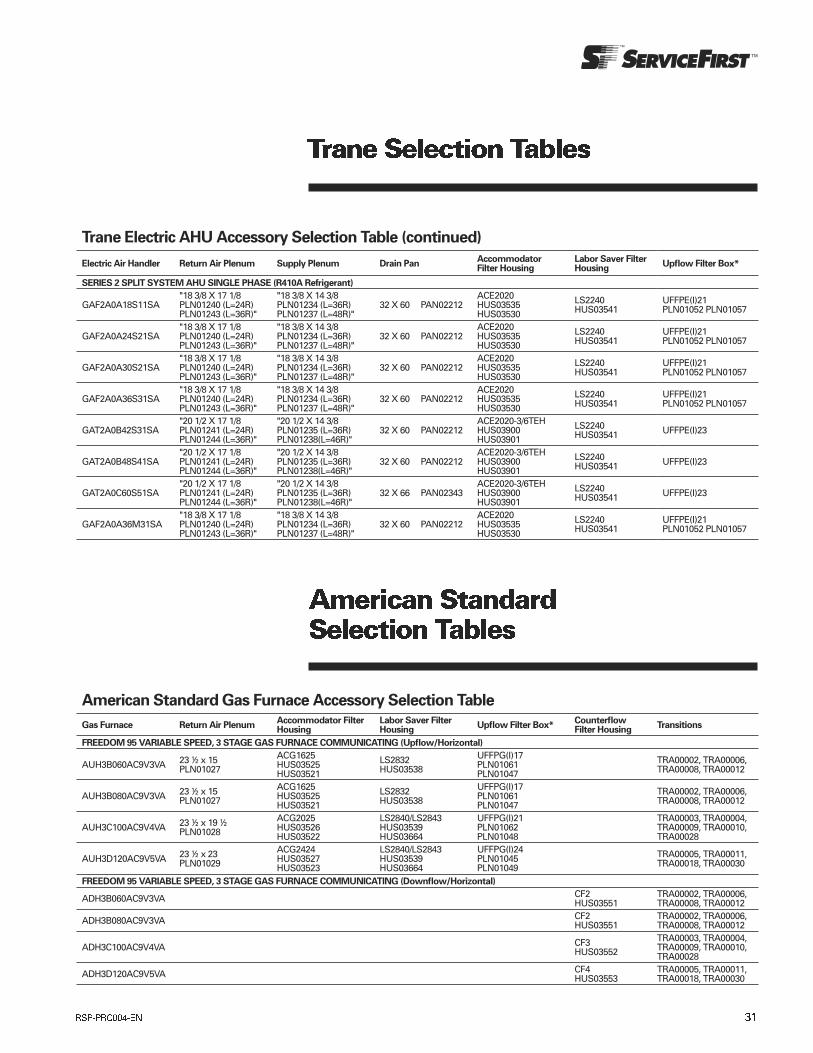
American Standard Gas Furnace Accessory Selection Table
Gas Furnace Return Air PlenumAccommodator Filter Housing
Labor Saver Filter Housing
Upflow Filter Box*Counterflow Filter Housing
Transitions
FREEDOM 95 VARIABLE SPEED, 3 STAGE GAS FURNACE COMMUNICATING (Upflow/Horizontal)
AUH3B060AC9V3VA 23 ½ x 15 PLN01027
ACG1625 HUS03525 HUS03521
LS2832 HUS03538
UFFPG(I)17 PLN01061 PLN01047
TRA00002, TRA00006, TRA00008, TRA00012
AUH3B080AC9V3VA 23 ½ x 15 PLN01027
ACG1625 HUS03525 HUS03521
LS2832 HUS03538
UFFPG(I)17 PLN01061 PLN01047
TRA00002, TRA00006, TRA00008, TRA00012
AUH3C100AC9V4VA 23 ½ x 19 ½ PLN01028
ACG2025 HUS03526 HUS03522
LS2840/LS2843 HUS03539 HUS03664
UFFPG(I)21 PLN01062 PLN01048
TRA00003, TRA00004, TRA00009, TRA00010, TRA00028
AUH3D120AC9V5VA 23 ½ x 23 PLN01029
ACG2424 HUS03527 HUS03523
LS2840/LS2843 HUS03539 HUS03664
UFFPG(I)24 PLN01045 PLN01049
TRA00005, TRA00011, TRA00018, TRA00030
FREEDOM 95 VARIABLE SPEED, 3 STAGE GAS FURNACE COMMUNICATING (Downflow/Horizontal)
ADH3B060AC9V3VA CF2 HUS03551
TRA00002, TRA00006, TRA00008, TRA00012
ADH3B080AC9V3VA CF2 HUS03551
TRA00002, TRA00006, TRA00008, TRA00012
ADH3C100AC9V4VA CF3 HUS03552
TRA00003, TRA00004, TRA00009, TRA00010, TRA00028
ADH3D120AC9V5VA CF4 HUS03553
TRA00005, TRA00011, TRA00018, TRA00030
Trane Electric AHU Accessory Selection Table (continued)
Electric Air Handler Return Air Plenum Supply Plenum Drain PanAccommodator Filter Housing
Labor Saver Filter Housing
Upflow Filter Box*
SERIES 2 SPLIT SYSTEM AHU SINGLE PHASE (R410A Refrigerant)
GAF2A0A18S11SA"18 3/8 X 17 1/8 PLN01240 (L=24R) PLN01243 (L=36R)"
"18 3/8 X 14 3/8 PLN01234 (L=36R) PLN01237 (L=48R)"
32 X 60 PAN02212ACE2020 HUS03535 HUS03530
LS2240 HUS03541
UFFPE(I)21 PLN01052 PLN01057
GAF2A0A24S21SA"18 3/8 X 17 1/8 PLN01240 (L=24R) PLN01243 (L=36R)"
"18 3/8 X 14 3/8 PLN01234 (L=36R) PLN01237 (L=48R)"
32 X 60 PAN02212ACE2020 HUS03535 HUS03530
LS2240 HUS03541
UFFPE(I)21 PLN01052 PLN01057
GAF2A0A30S21SA"18 3/8 X 17 1/8 PLN01240 (L=24R) PLN01243 (L=36R)"
"18 3/8 X 14 3/8 PLN01234 (L=36R) PLN01237 (L=48R)"
32 X 60 PAN02212ACE2020 HUS03535 HUS03530
LS2240 HUS03541
UFFPE(I)21 PLN01052 PLN01057
GAF2A0A36S31SA"18 3/8 X 17 1/8 PLN01240 (L=24R) PLN01243 (L=36R)"
"18 3/8 X 14 3/8 PLN01234 (L=36R) PLN01237 (L=48R)"
32 X 60 PAN02212ACE2020 HUS03535 HUS03530
LS2240 HUS03541
UFFPE(I)21 PLN01052 PLN01057
GAT2A0B42S31SA"20 1/2 X 17 1/8 PLN01241 (L=24R) PLN01244 (L=36R)"
"20 1/2 X 14 3/8 PLN01235 (L=36R) PLN01238(L=46R)"
32 X 60 PAN02212ACE2020-3/6TEHHUS03900HUS03901
LS2240 HUS03541 UFFPE(I)23
GAT2A0B48S41SA"20 1/2 X 17 1/8 PLN01241 (L=24R) PLN01244 (L=36R)"
"20 1/2 X 14 3/8 PLN01235 (L=36R) PLN01238(L=46R)"
32 X 60 PAN02212ACE2020-3/6TEHHUS03900HUS03901
LS2240 HUS03541 UFFPE(I)23
GAT2A0C60S51SA"20 1/2 X 17 1/8 PLN01241 (L=24R) PLN01244 (L=36R)"
"20 1/2 X 14 3/8 PLN01235 (L=36R) PLN01238(L=46R)"
32 X 66 PAN02343ACE2020-3/6TEHHUS03900HUS03901
LS2240 HUS03541 UFFPE(I)23
GAF2A0A36M31SA"18 3/8 X 17 1/8 PLN01240 (L=24R) PLN01243 (L=36R)"
"18 3/8 X 14 3/8 PLN01234 (L=36R) PLN01237 (L=48R)"
32 X 60 PAN02212ACE2020 HUS03535 HUS03530
LS2240 HUS03541
UFFPE(I)21 PLN01052 PLN01057

American Standard Gas Furnace Accessory Selection Table
Gas Furnace Return Air PlenumAccommodator Filter Housing
Labor Saver Filter Housing
Upflow Filter Box*Counterflow Filter Housing
Transitions
FREEDOM 95 VARIABLE SPEED, 3 STAGE GAS FURNACE COMMUNICATING (Upflow/Horizontal)
AUH3B060AC9V3VA 23 ½ x 15 PLN01027
ACG1625 HUS03525 HUS03521
LS2832 HUS03538
UFFPG(I)17 PLN01061 PLN01047
TRA00002, TRA00006, TRA00008, TRA00012
AUH3B080AC9V3VA 23 ½ x 15 PLN01027
ACG1625 HUS03525 HUS03521
LS2832 HUS03538
UFFPG(I)17 PLN01061 PLN01047
TRA00002, TRA00006, TRA00008, TRA00012
AUH3C100AC9V4VA 23 ½ x 19 ½ PLN01028
ACG2025 HUS03526 HUS03522
LS2840/LS2843 HUS03539 HUS03664
UFFPG(I)21 PLN01062 PLN01048
TRA00003, TRA00004, TRA00009, TRA00010, TRA00028
AUH3D120AC9V5VA 23 ½ x 23 PLN01029
ACG2424 HUS03527 HUS03523
LS2840/LS2843 HUS03539 HUS03664
UFFPG(I)24 PLN01045 PLN01049
TRA00005, TRA00011, TRA00018, TRA00030
FREEDOM 95 VARIABLE SPEED, 3 STAGE GAS FURNACE COMMUNICATING (Downflow/Horizontal)
ADH3B060AC9V3VA CF2 HUS03551
TRA00002, TRA00006, TRA00008, TRA00012
ADH3B080AC9V3VA CF2 HUS03551
TRA00002, TRA00006, TRA00008, TRA00012
ADH3C100AC9V4VA CF3 HUS03552
TRA00003, TRA00004, TRA00009, TRA00010, TRA00028
ADH3D120AC9V5VA CF4 HUS03553
TRA00005, TRA00011, TRA00018, TRA00030
FREEDOM 95 VARIABLE SPEED COMFORT-R GAS FURNACE (Upflow/Horizontal)
AUH2B060A9V3VA 23 ½ x 15 PLN01027
ACG1625 HUS03525 HUS03521
LS2832 HUS03538
UFFPG(I)17 PLN01061 PLN01047
TRA00002, TRA00006, TRA00008, TRA00012
AUH2B080A9V3VA 23 ½ x 15 PLN01027
ACG1625 HUS03525 HUS03521
LS2832 HUS03538
UFFPG(I)17 PLN01061 PLN01047
TRA00002, TRA00006, TRA00008, TRA00012
AUH2C100A9V4VA 23 ½ x 19 ½ PLN01028
ACG2025 HUS03526 HUS03522
LS2840/LS2843 HUS03539 HUS03664
UFFPG(I)21 PLN01062 PLN01048
TRA00003, TRA00004, TRA00009, TRA00010, TRA00028
AUH2D120A9V5VA 23 ½ x 23 PLN01029
ACG2424 HUS03527 HUS03523
LS2840/LS2843 HUS03539 HUS03664
UFFPG(I)24 PLN01045 PLN01049
TRA00005, TRA00011, TRA00018, TRA00030
FREEDOM 95 VARIABLE SPEED COMFORT-R GAS FURNACE (Downflow/Horizontal)
AUH2B060A9V3VA CF2 HUS03551
TRA00002, TRA00006, TRA00008, TRA00012
AUH2B080A9V3VA CF2 HUS03551
TRA00002, TRA00006, TRA00008, TRA00012
AUH2C100A9V4VA CF3 HUS03552
TRA00003, TRA00004, TRA00009, TRA00010, TRA00028
AUH2D120A9V5VA CF4 HUS03553
TRA00005, TRA00011, TRA00018, TRA00030
FREEDOM 90 VARIABLE SPEED COMFORT-R GAS FURNACE (Upflow/Horizontal)
AUx2B060AFV3VA 23 ½ x 15 PLN01027
ACG1625 HUS03525 HUS03521
LS2832 HUS03538
UFFPG(I)17 PLN01061 PLN01047
TRA00002, TRA00006, TRA00008, TRA00012
AUx2B080AFV3VA 23 ½ x 15 PLN01027
ACG1625 HUS03525 HUS03521
LS2832 HUS03538
UFFPG(I)17 PLN01061 PLN01047
TRA00002, TRA00006, TRA00008, TRA00012
AUx2B100AFV3VA 23 ½ x 19 ½ PLN01028
ACG2025 HUS03526 HUS03522
LS2840/LS2843 HUS03539 HUS03664
UFFPG(I)21 PLN01062 PLN01048
TRA00003, TRA00004, TRA00009, TRA00010, TRA00028
AUx2B120AFV3VA 23 ½ x 23 PLN01029
ACG2424 HUS03527 HUS03523
LS2840/LS2843 HUS03539 HUS03664
UFFPG(I)24 PLN01045 PLN01049
TRA00005, TRA00011, TRA00018, TRA00030
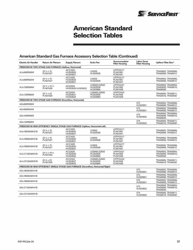
American Standard Gas Furnace Accessory Selection Table (Continued)
Electric Air Handler Return Air Plenum Supply Plenum Drain PanAccommodator Filter Housing
Labor Saver Filter Housing
Upflow Filter Box*
FREEDOM 90 TWO STAGE GAS FURNACE (Upflow, Horizontal)
AUx060R936W 23 ½ x 15 PLN01027
ACG1625 HUS03525 HUS03521
LS2832 HUS03538
UFFPG(I)17 PLN01061 PLN01047
TRA00002, TRA00006, TRA00008, TRA00012
AUx080R942W 23 ½ x 15 PLN01027
ACG1625 HUS03525 HUS03521
LS2832 HUS03538
UFFPG(I)17 PLN01061 PLN01047
TRA00002, TRA00006, TRA00008, TRA00012
AUx100R948W 23 ½ x 19 ½ PLN01028
ACG2025 HUS03526 HUS03522
LS2840/LS2843 HUS03539 HUS03664
UFFPG(I)21 PLN01062 PLN01048
TRA00003, TRA00004, TRA00009, TRA00010, TRA00028
AUx120R960W 23 ½ x 23 PLN01029
ACG2424 HUS03527 HUS03523
LS2840/LS2843 HUS03539 HUS03664
UFFPG(I)24 PLN01045 PLN01049
TRA00005, TRA00011, TRA00018, TRA00030
FREEDOM 90 TWO STAGE GAS FURNACE (Downflow, Horizontal)
ADx060R936W CF2 HUS03551
TRA00002, TRA00006, TRA00008, TRA00012
ADx080R942W CF2 HUS03551
TRA00002, TRA00006, TRA00008, TRA00012
ADx100R948W CF3 HUS03552
TRA00003, TRA00004, TRA00009, TRA00010, TRA00028
ADx120R960W CF4 HUS03553
TRA00005, TRA00011, TRA00018, TRA00030
FREEDOM 90 HIGH EFFICIENCY SINGLE STAGE GAS FURNACE (Upflow, Horizontal Left)
AUx1B040A9H21B 23 ½ x 15 PLN01027
ACG1625 HUS03525 HUS03521
LS2832 HUS03538
UFFPG(I)17 PLN01061 PLN01047
TRA00002, TRA00006, TRA00008, TRA00012
AUx1B060A9H31B 23 ½ x 15 PLN01027
ACG1625 HUS03525 HUS03521
LS2832 HUS03538
UFFPG(I)17 PLN01061 PLN01047
TRA00002, TRA00006, TRA00008, TRA00012
AUx1B080A9H31B 23 ½ x 15 PLN01027
ACG1625 HUS03525 HUS03521
LS2832 HUS03538
UFFPG(I)17 PLN01061 PLN01047
TRA00002, TRA00006, TRA00008, TRA00012
AUx1C100A9H41B 23 ½ x 19 ½ PLN01028
ACG2025 HUS03526 HUS03522
LS2840/LS2843 HUS03539 HUS03664
UFFPG(I)21 PLN01062 PLN01048
TRA00003, TRA00004, TRA00009, TRA00010, TRA00028
AUx1D120A9H51B 23 ½ x 23 PLN01029
ACG2424 HUS03527 HUS03523
LS2840/LS2843 HUS03539 HUS03664
UFFPG(I)24 PLN01045 PLN01049
TRA00005, TRA00011, TRA00018, TRA00030
FREEDOM 90 HIGH EFFICIENCY SINGLE STAGE GAS FURNACE (Downflow, Horizontal Right)
ADx1B040A9H31B CF2 HUS03551
TRA00002, TRA00006, TRA00008, TRA00012
ADx1B060A9H31B CF2 HUS03551
TRA00002, TRA00006, TRA00008, TRA00012
ADx1B080A9H31B CF2 HUS03551
TRA00002, TRA00006, TRA00008, TRA00012
ADx1C100A9H41B CF3 HUS03552
TRA00003, TRA00004, TRA00009, TRA00010, TRA00028
ADx1D120A9H51B CF4 HUS03553
TRA00005, TRA00011, TRA00018, TRA00030
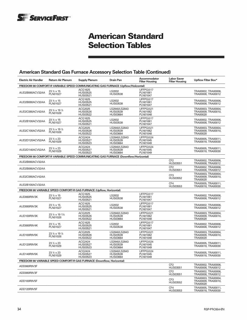
American Standard Gas Furnace Accessory Selection Table (Continued)
Electric Air Handler Return Air Plenum Supply Plenum Drain PanAccommodator Filter Housing
Labor Saver Filter Housing
Upflow Filter Box*
FREEDOM 80 COMFORT-R VARIABLE SPEED COMMUNICATING GAS FURNACE (Upflow/Hoiizontal)
AUD2B060ACV32AA 23 ½ x 15 PLN01027
ACG1625 HUS03525 HUS03521
LS2832 HUS03538
UFFPG(I)17 PLN01061 PLN01047
TRA00002, TRA00006, TRA00008, TRA00012
AUD2B080ACV32AA 23 ½ x 15 PLN01027
ACG1625 HUS03525 HUS03521
LS2832 HUS03538
UFFPG(I)17 PLN01061 PLN01047
TRA00002, TRA00006, TRA00008, TRA00012
AUD2C080ACV42AA 23 ½ x 19 ½ PLN01028
ACG2025 HUS03526 HUS03522
LS2840/LS2843 HUS03539 HUS03664
UFFPG(I)21 PLN01062 PLN01048
TRA00003, TRA00004, TRA00009, TRA00010, TRA00028
AUD2B100ACV32AA 23 ½ x 15 PLN01027
ACG1625 HUS03525 HUS03521
LS2832 HUS03538
UFFPG(I)17 PLN01061 PLN01047
TRA00002, TRA00006, TRA00008, TRA00012
AUD2C100ACV52AA 23 ½ x 19 ½ PLN01028
ACG2025 HUS03526 HUS03522
LS2840/LS2843 HUS03539 HUS03664
UFFPG(I)21 PLN01062 PLN01048
TRA00003, TRA00004, TRA00009, TRA00010, TRA00028
AUD2D120ACV52AA 23 ½ x 23 PLN01029
ACG2424 HUS03527 HUS03523
LS2840/LS2843 HUS03539 HUS03664
UFFPG(I)24 PLN01045 PLN01049
TRA00005, TRA00011, TRA00018, TRA00030
AUD2D140ACV52AA 23 ½ x 23 PLN01029
ACG2424 HUS03527 HUS03523
LS2840/LS2843 HUS03539 HUS03664
UFFPG(I)24 PLN01045 PLN01049
TRA00005, TRA00011, TRA00018, TRA00030
FREEDOM 80 COMFORT-R VARIABLE SPEED COMMUNICATING GAS FURNACE (Downflow/Horizontal)
AUD2B060ACV32AA CF2 HUS03551
TRA00002, TRA00006, TRA00008, TRA00012
AUD2B080ACV32AA CF2 HUS03551
TRA00002, TRA00006, TRA00008, TRA00012
AUD2C080ACV42AA CF3 HUS03552
TRA00003, TRA00004, TRA00009, TRA00010, TRA00028
AUD2B100ACV32AA CF4 HUS03553
TRA00005, TRA00011, TRA00018, TRA00030
FREEDOM 80 VARIABLE SPEED COMFORT-R GAS FURNACE (Upflow, Horizontal)
AUD060R9V3K 23 ½ x 15 PLN01027
ACG1625 HUS03525 HUS03521
LS2832 HUS03538
UFFPG(I)17 PLN01061 PLN01047
TRA00002, TRA00006, TRA00008, TRA00012
AUD080R9V3K 23 ½ x 15 PLN01027
ACG1625 HUS03525 HUS03521
LS2832 HUS03538
UFFPG(I)17 PLN01061 PLN01047
TRA00002, TRA00006, TRA00008, TRA00012
AUD100R9V3K 23 ½ x 19 1½ PLN01028
ACG2025 HUS03526 HUS03522
LS2840/LS2843 HUS03539 HUS03664
UFFPG(I)21 PLN01062 PLN01048
TRA00003, TRA00004, TRA00009, TRA00010, TRA00028
AUD080R9V4K 23 ½ x 15 PLN01027
ACG1625 HUS03525 HUS03521
LS2832 HUS03538
UFFPG(I)17 PLN01061 PLN01047
TRA00002, TRA00006, TRA00008, TRA00012
AUD100R9V5K 23 ½ x 19 ½ PLN01028
ACG2025 HUS03526 HUS03522
LS2840/LS2843 HUS03539 HUS03664
UFFPG(I)21 PLN01062 PLN01048
TRA00003, TRA00004, TRA00009, TRA00010, TRA00028
AUD120R9V5K 23 ½ x 23 PLN01029
ACG2424 HUS03527 HUS03523
LS2840/LS2843 HUS03539 HUS03664
UFFPG(I)24 PLN01045 PLN01049
TRA00005, TRA00011, TRA00018, TRA00030
AUD140R9V5K 23 ½ x 23 PLN01029
ACG2424 HUS03527 HUS03523
LS2840/LS2843 HUS03539 HUS03664
UFFPG(I)24 PLN01045 PLN01049
TRA00005, TRA00011, TRA00018, TRA00030
FREEDOM 80 VARIABLE SPEED COMFORT-R GAS FURNACE (Downflow, Horizontal)
ADD060R9V3F CF2 HUS03551
TRA00002, TRA00006, TRA00008, TRA00012
ADD080R9V3F CF2 HUS03551
TRA00002, TRA00006, TRA00008, TRA00012
ADD100R9V5F CF3 HUS03552
TRA00003, TRA00004, TRA00009, TRA00010, TRA00028
ADD120R9V5F CF4 HUS03553
TRA00005, TRA00011, TRA00018, TRA00030
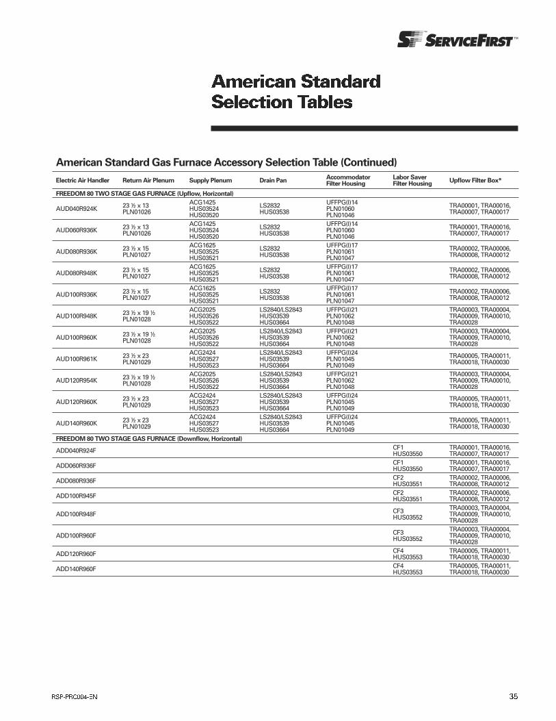
American Standard Gas Furnace Accessory Selection Table (Continued)
Electric Air Handler Return Air Plenum Supply Plenum Drain PanAccommodator Filter Housing
Labor Saver Filter Housing
Upflow Filter Box*
FREEDOM 80 TWO STAGE GAS FURNACE (Upflow, Horizontal)
AUD040R924K 23 ½ x 13 PLN01026
ACG1425 HUS03524 HUS03520
LS2832 HUS03538
UFFPG(I)14 PLN01060 PLN01046
TRA00001, TRA00016, TRA00007, TRA00017
AUD060R936K 23 ½ x 13 PLN01026
ACG1425 HUS03524 HUS03520
LS2832 HUS03538
UFFPG(I)14 PLN01060 PLN01046
TRA00001, TRA00016, TRA00007, TRA00017
AUD080R936K 23 ½ x 15 PLN01027
ACG1625 HUS03525 HUS03521
LS2832 HUS03538
UFFPG(I)17 PLN01061 PLN01047
TRA00002, TRA00006, TRA00008, TRA00012
AUD080R948K 23 ½ x 15 PLN01027
ACG1625 HUS03525 HUS03521
LS2832 HUS03538
UFFPG(I)17 PLN01061 PLN01047
TRA00002, TRA00006, TRA00008, TRA00012
AUD100R936K 23 ½ x 15 PLN01027
ACG1625 HUS03525 HUS03521
LS2832 HUS03538
UFFPG(I)17 PLN01061 PLN01047
TRA00002, TRA00006, TRA00008, TRA00012
AUD100R948K 23 ½ x 19 ½ PLN01028
ACG2025 HUS03526 HUS03522
LS2840/LS2843 HUS03539 HUS03664
UFFPG(I)21 PLN01062 PLN01048
TRA00003, TRA00004, TRA00009, TRA00010, TRA00028
AUD100R960K 23 ½ x 19 ½ PLN01028
ACG2025 HUS03526 HUS03522
LS2840/LS2843 HUS03539 HUS03664
UFFPG(I)21 PLN01062 PLN01048
TRA00003, TRA00004, TRA00009, TRA00010, TRA00028
AUD100R961K 23 ½ x 23 PLN01029
ACG2424 HUS03527 HUS03523
LS2840/LS2843 HUS03539 HUS03664
UFFPG(I)24 PLN01045 PLN01049
TRA00005, TRA00011, TRA00018, TRA00030
AUD120R954K 23 ½ x 19 ½ PLN01028
ACG2025 HUS03526 HUS03522
LS2840/LS2843 HUS03539 HUS03664
UFFPG(I)21 PLN01062 PLN01048
TRA00003, TRA00004, TRA00009, TRA00010, TRA00028
AUD120R960K 23 ½ x 23 PLN01029
ACG2424 HUS03527 HUS03523
LS2840/LS2843 HUS03539 HUS03664
UFFPG(I)24 PLN01045 PLN01049
TRA00005, TRA00011, TRA00018, TRA00030
AUD140R960K 23 ½ x 23 PLN01029
ACG2424 HUS03527 HUS03523
LS2840/LS2843 HUS03539 HUS03664
UFFPG(I)24 PLN01045 PLN01049
TRA00005, TRA00011, TRA00018, TRA00030
FREEDOM 80 TWO STAGE GAS FURNACE (Downflow, Horizontal)
ADD040R924F CF1 HUS03550
TRA00001, TRA00016, TRA00007, TRA00017
ADD060R936F CF1 HUS03550
TRA00001, TRA00016, TRA00007, TRA00017
ADD080R936F CF2 HUS03551
TRA00002, TRA00006, TRA00008, TRA00012
ADD100R945F CF2 HUS03551
TRA00002, TRA00006, TRA00008, TRA00012
ADD100R948F CF3 HUS03552
TRA00003, TRA00004, TRA00009, TRA00010, TRA00028
ADD100R960F CF3 HUS03552
TRA00003, TRA00004, TRA00009, TRA00010, TRA00028
ADD120R960F CF4 HUS03553
TRA00005, TRA00011, TRA00018, TRA00030
ADD140R960F CF4 HUS03553
TRA00005, TRA00011, TRA00018, TRA00030
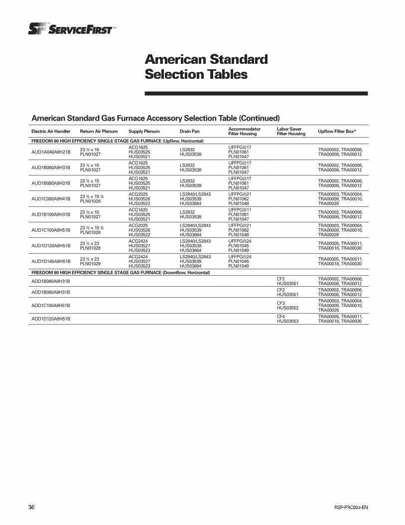
American Standard Gas Furnace Accessory Selection Table (Continued)
Electric Air Handler Return Air Plenum Supply Plenum Drain PanAccommodator Filter Housing
Labor Saver Filter Housing
Upflow Filter Box*
FREEDOM 80 HIGH EFFICIENCY SINGLE STAGE GAS FURNACE (Upflow, Horizontal)
AUD1A040A9H21B 23 ½ x 15 PLN01027
ACG1625 HUS03525 HUS03521
LS2832 HUS03538
UFFPG(I)17 PLN01061 PLN01047
TRA00002, TRA00006, TRA00008, TRA00012
AUD1B060A9H31B 23 ½ x 15 PLN01027
ACG1625 HUS03525 HUS03521
LS2832 HUS03538
UFFPG(I)17 PLN01061 PLN01047
TRA00002, TRA00006, TRA00008, TRA00012
AUD1B080A9H31B 23 ½ x 15 PLN01027
ACG1625 HUS03525 HUS03521
LS2832 HUS03538
UFFPG(I)17 PLN01061 PLN01047
TRA00002, TRA00006, TRA00008, TRA00012
AUD1C080A9H41B 23 ½ x 19 ½ PLN01028
ACG2025 HUS03526 HUS03522
LS2840/LS2843 HUS03539 HUS03664
UFFPG(I)21 PLN01062 PLN01048
TRA00003, TRA00004, TRA00009, TRA00010, TRA00028
AUD1B100A9H31B 23 ½ x 15 PLN01027
ACG1625 HUS03525 HUS03521
LS2832 HUS03538
UFFPG(I)17 PLN01061 PLN01047
TRA00002, TRA00006, TRA00008, TRA00012
AUD1C100A9H51B 23 ½ x 19 ½ PLN01028
ACG2025 HUS03526 HUS03522
LS2840/LS2843 HUS03539 HUS03664
UFFPG(I)21 PLN01062 PLN01048
TRA00003, TRA00004, TRA00009, TRA00010, TRA00028
AUD1D120A9H51B 23 ½ x 23 PLN01029
ACG2424 HUS03527 HUS03523
LS2840/LS2843 HUS03539 HUS03664
UFFPG(I)24 PLN01045 PLN01049
TRA00005, TRA00011, TRA00018, TRA00030
AUD1D140A9H51B 23 ½ x 23 PLN01029
ACG2424 HUS03527 HUS03523
LS2840/LS2843 HUS03539 HUS03664
UFFPG(I)24 PLN01045 PLN01049
TRA00005, TRA00011, TRA00018, TRA00030
FREEDOM 80 HIGH EFFICIENCY SINGLE STAGE GAS FURNACE (Downflow, Horizontal)
ADD1B060A9H31B CF2 HUS03551
TRA00002, TRA00006, TRA00008, TRA00012
ADD1B080A9H31B CF2 HUS03551
TRA00002, TRA00006, TRA00008, TRA00012
ADD1C100A9H51B CF3 HUS03552
TRA00003, TRA00004, TRA00009, TRA00010, TRA00028
ADD1D120A9H51B CF4 HUS03553
TRA00005, TRA00011, TRA00018, TRA00030
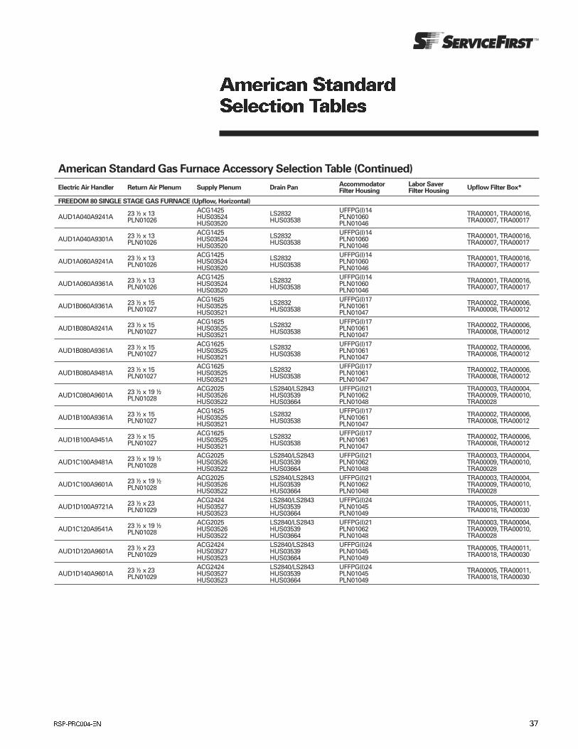
American Standard Gas Furnace Accessory Selection Table (Continued)
Electric Air Handler Return Air Plenum Supply Plenum Drain PanAccommodator Filter Housing
Labor Saver Filter Housing
Upflow Filter Box*
FREEDOM 80 SINGLE STAGE GAS FURNACE (Upflow, Horizontal)
AUD1A040A9241A 23 ½ x 13 PLN01026
ACG1425 HUS03524 HUS03520
LS2832 HUS03538
UFFPG(I)14 PLN01060 PLN01046
TRA00001, TRA00016, TRA00007, TRA00017
AUD1A040A9301A 23 ½ x 13 PLN01026
ACG1425 HUS03524 HUS03520
LS2832 HUS03538
UFFPG(I)14 PLN01060 PLN01046
TRA00001, TRA00016, TRA00007, TRA00017
AUD1A060A9241A 23 ½ x 13 PLN01026
ACG1425 HUS03524 HUS03520
LS2832 HUS03538
UFFPG(I)14 PLN01060 PLN01046
TRA00001, TRA00016, TRA00007, TRA00017
AUD1A060A9361A 23 ½ x 13 PLN01026
ACG1425 HUS03524 HUS03520
LS2832 HUS03538
UFFPG(I)14 PLN01060 PLN01046
TRA00001, TRA00016, TRA00007, TRA00017
AUD1B060A9361A 23 ½ x 15 PLN01027
ACG1625 HUS03525 HUS03521
LS2832 HUS03538
UFFPG(I)17 PLN01061 PLN01047
TRA00002, TRA00006, TRA00008, TRA00012
AUD1B080A9241A 23 ½ x 15 PLN01027
ACG1625 HUS03525 HUS03521
LS2832 HUS03538
UFFPG(I)17 PLN01061 PLN01047
TRA00002, TRA00006, TRA00008, TRA00012
AUD1B080A9361A 23 ½ x 15 PLN01027
ACG1625 HUS03525 HUS03521
LS2832 HUS03538
UFFPG(I)17 PLN01061 PLN01047
TRA00002, TRA00006, TRA00008, TRA00012
AUD1B080A9481A 23 ½ x 15 PLN01027
ACG1625 HUS03525 HUS03521
LS2832 HUS03538
UFFPG(I)17 PLN01061 PLN01047
TRA00002, TRA00006, TRA00008, TRA00012
AUD1C080A9601A 23 ½ x 19 ½ PLN01028
ACG2025 HUS03526 HUS03522
LS2840/LS2843 HUS03539 HUS03664
UFFPG(I)21 PLN01062 PLN01048
TRA00003, TRA00004, TRA00009, TRA00010, TRA00028
AUD1B100A9361A 23 ½ x 15 PLN01027
ACG1625 HUS03525 HUS03521
LS2832 HUS03538
UFFPG(I)17 PLN01061 PLN01047
TRA00002, TRA00006, TRA00008, TRA00012
AUD1B100A9451A 23 ½ x 15 PLN01027
ACG1625 HUS03525 HUS03521
LS2832 HUS03538
UFFPG(I)17 PLN01061 PLN01047
TRA00002, TRA00006, TRA00008, TRA00012
AUD1C100A9481A 23 ½ x 19 ½ PLN01028
ACG2025 HUS03526 HUS03522
LS2840/LS2843 HUS03539 HUS03664
UFFPG(I)21 PLN01062 PLN01048
TRA00003, TRA00004, TRA00009, TRA00010, TRA00028
AUD1C100A9601A 23 ½ x 19 ½ PLN01028
ACG2025 HUS03526 HUS03522
LS2840/LS2843 HUS03539 HUS03664
UFFPG(I)21 PLN01062 PLN01048
TRA00003, TRA00004, TRA00009, TRA00010, TRA00028
AUD1D100A9721A 23 ½ x 23 PLN01029
ACG2424 HUS03527 HUS03523
LS2840/LS2843 HUS03539 HUS03664
UFFPG(I)24 PLN01045 PLN01049
TRA00005, TRA00011, TRA00018, TRA00030
AUD1C120A9541A 23 ½ x 19 ½ PLN01028
ACG2025 HUS03526 HUS03522
LS2840/LS2843 HUS03539 HUS03664
UFFPG(I)21 PLN01062 PLN01048
TRA00003, TRA00004, TRA00009, TRA00010, TRA00028
AUD1D120A9601A 23 ½ x 23 PLN01029
ACG2424 HUS03527 HUS03523
LS2840/LS2843 HUS03539 HUS03664
UFFPG(I)24 PLN01045 PLN01049
TRA00005, TRA00011, TRA00018, TRA00030
AUD1D140A9601A 23 ½ x 23 PLN01029
ACG2424 HUS03527 HUS03523
LS2840/LS2843 HUS03539 HUS03664
UFFPG(I)24 PLN01045 PLN01049
TRA00005, TRA00011, TRA00018, TRA00030
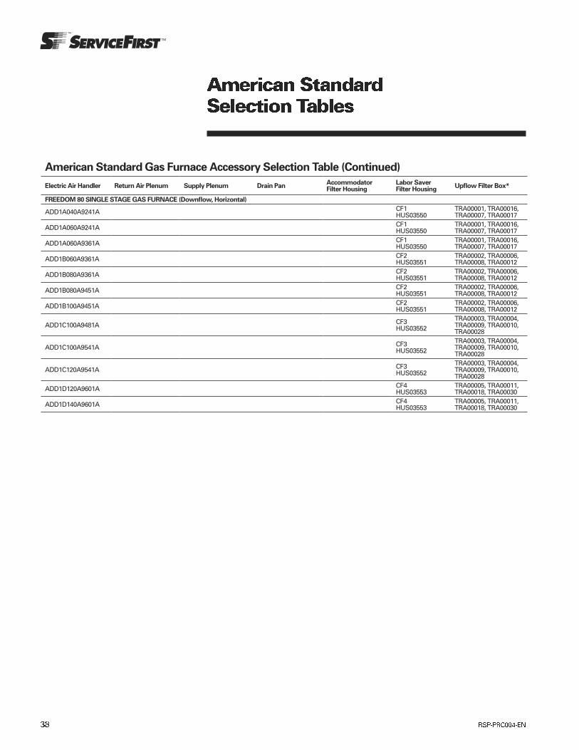
American Standard Gas Furnace Accessory Selection Table (Continued)
Electric Air Handler Return Air Plenum Supply Plenum Drain PanAccommodator Filter Housing
Labor Saver Filter Housing
Upflow Filter Box*
FREEDOM 80 SINGLE STAGE GAS FURNACE (Downflow, Horizontal)
ADD1A040A9241A CF1 HUS03550
TRA00001, TRA00016, TRA00007, TRA00017
ADD1A060A9241A CF1 HUS03550
TRA00001, TRA00016, TRA00007, TRA00017
ADD1A060A9361A CF1 HUS03550
TRA00001, TRA00016, TRA00007, TRA00017
ADD1B060A9361A CF2 HUS03551
TRA00002, TRA00006, TRA00008, TRA00012
ADD1B080A9361A CF2 HUS03551
TRA00002, TRA00006, TRA00008, TRA00012
ADD1B080A9451A CF2 HUS03551
TRA00002, TRA00006, TRA00008, TRA00012
ADD1B100A9451A CF2 HUS03551
TRA00002, TRA00006, TRA00008, TRA00012
ADD1C100A9481A CF3 HUS03552
TRA00003, TRA00004, TRA00009, TRA00010, TRA00028
ADD1C100A9541A CF3 HUS03552
TRA00003, TRA00004, TRA00009, TRA00010, TRA00028
ADD1C120A9541A CF3 HUS03552
TRA00003, TRA00004, TRA00009, TRA00010, TRA00028
ADD1D120A9601A CF4 HUS03553
TRA00005, TRA00011, TRA00018, TRA00030
ADD1D140A9601A CF4 HUS03553
TRA00005, TRA00011, TRA00018, TRA00030
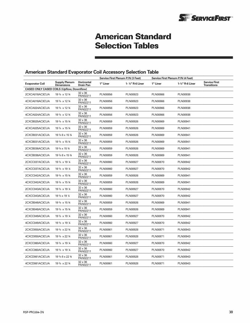
American Standard Evaporator Coil Accessory Selection TableService First Plenum P/N (3 Feet) Service First Plenum P/N (4 Feet)
Evaporator CoilSupply Plenum Dimensions
Horizontal Drain Pan
1" Liner 1- ½" R-6 Liner 1" Liner 1-½" R-6 LinerService First Transitions
CASED ONLY CASED COILS (Upflow, Downflow)
2CXCA018AC3CUA 19 3/8 x 12 ¾ 32 x 36 PAN02211 PLN00856 PLN00923 PLN00866 PLN00938
4CXCA018AC3CUA 19 3/8 x 12 ¾ 32 x 36 PAN02211 PLN00856 PLN00923 PLN00866 PLN00938
2CXCA024AC3CUA 19 3/8 x 12 ¾ 32 x 36 PAN02211 PLN00856 PLN00923 PLN00866 PLN00938
4CXCA024AC3CUA 19 3/8 x 12 ¾ 32 x 36 PAN02211 PLN00856 PLN00923 PLN00866 PLN00938
2CXCB025AC3CUA 19 3/8 x 15 ¾ 32 x 36 PAN02211 PLN00859 PLN00926 PLN00869 PLN00941
4CXCA025AC3CUA 19 3/8 x 15 ¾ 32 x 36 PAN02211 PLN00859 PLN00926 PLN00869 PLN00941
2CXCB031AC3CUA 19 3/8 8 x 15 ¾ 32 x 36 PAN02211 PLN00859 PLN00926 PLN00869 PLN00941
4CXCB031AC3CUA 19 3/8 x 15 ¾ 32 x 36 PAN02211 PLN00859 PLN00926 PLN00869 PLN00941
2CXCB036AC3CUA 19 3/8 x 15 ¾ 32 x 36 PAN02211 PLN00859 PLN00926 PLN00869 PLN00941
4CXCB036AC3CUA 19 3/8 8 x 15 ¾ 32 x 36 PAN02211 PLN00859 PLN00926 PLN00869 PLN00941
2CXCC037AC3CUA 19 3/8 x 19 ¼ 32 x 36 PAN02211 PLN00860 PLN00927 PLN00870 PLN00942
4CXCC037AC3CUA 19 3/8 x 19 ¼ 32 x 36 PAN02211 PLN00860 PLN00927 PLN00870 PLN00942
2CXCC042AC3CUA 19 3/8 x 15 ¾ 32 x 36 PAN02211 PLN00859 PLN00926 PLN00869 PLN00941
4CXCC042AC3CUA 19 3/8 x 15 ¾ 32 x 36 PAN02211 PLN00859 PLN00926 PLN00869 PLN00941
2CXCC043AC3CUA 19 3/8 x 19 ¼ 32 x 36 PAN02211 PLN00860 PLN00927 PLN00870 PLN00942
4CXCC043AC3CUA 19 3/8 x 19 ¼ 32 x 36 PAN02211 PLN00860 PLN00927 PLN00870 PLN00942
2CXCB048AC3CUA 19 3/8 x 15 ¾ 32 x 36 PAN02211 PLN00859 PLN00926 PLN00869 PLN00941
4CXCB048AC3CUA 19 3/8 x 15 ¾ 32 x 36 PAN02211 PLN00859 PLN00926 PLN00869 PLN00941
2CXCC049AC3CUA 19 3/8 x 19 ¼ 32 x 36 PAN02211 PLN00860 PLN00927 PLN00870 PLN00942
4CXCC049AC3CUA 19 3/8 x 19 ¼ 32 x 36 PAN02211 PLN00860 PLN00927 PLN00870 PLN00942
2CXCD050AC3CUA 19 3/8 x 22 ¾ 32 x 36 PAN02211 PLN00861 PLN00928 PLN00871 PLN00943
4CXCD050AC3CUA 19 3/8 x 22 ¾ 32 x 36 PAN02211 PLN00861 PLN00928 PLN00871 PLN00943
2CXCC060AC3CUA 19 3/8 x 19 ¼ 32 x 36 PAN02211 PLN00860 PLN00927 PLN00870 PLN00942
4CXCC060AC3CUA 19 3/8 x 19 ¼ 32 x 36 PAN02211 PLN00860 PLN00927 PLN00870 PLN00942
2CXCD061AC3CUA 19 3/8 8 x 22 ¾ 32 x 36 PAN02211 PLN00861 PLN00928 PLN00871 PLN00943
4CXCD061AC3CUA 19 3/8 x 22 ¾ 32 x 36 PAN02211 PLN00861 PLN00928 PLN00871 PLN00943

American Standard Evaporator Coil Accessory Selection Table (Continued)Service First Plenum P/N (3 Feet) Service First Plenum P/N (4 Feet)
Evaporator CoilSupply Plenum Dimensions
Horizontal Drain Pan
1" Liner 1- ½" R-6 Liner 1" Liner 1-½" R-6 LinerService First Transitions
CASED COIL CONVERTIBLE (Upflow, Downflow, Horizontal Left)
2TXCA018AC3HCA 19 3/8 x 12 ¾ 32 x 36 PAN02211 PLN00856 PLN00923 PLN00866 PLN00938
4TXCA018AC3HCA 19 3/8 x 12 ¾ 32 x 36 PAN02211 PLN00856 PLN00923 PLN00866 PLN00938
2TXCA024AC3HCA 19 3/8 x 12 ¾ 32 x 36 PAN02211 PLN00856 PLN00923 PLN00866 PLN00938
4TXCA024AC3HCA 19 3/8 x 12 ¾ 32 x 36 PAN02211 PLN00856 PLN00923 PLN00866 PLN00938
2TXCB025AC3HCA 19 3/8 x 15 ¾ 32 x 36 PAN02211 PLN00859 PLN00926 PLN00869 PLN00941
4TXCB025AC3HCA 19 3/8 x 15 ¾ 32 x 36 PAN02211 PLN00859 PLN00926 PLN00869 PLN00941
2TXCB031AC3HCA 19 3/8 x 15 ¾ 32 x 36 PAN02211 PLN00859 PLN00926 PLN00869 PLN00941
4TXCB031AC3HCA 19 3/8 x 15 ¾ 32 x 36 PAN02211 PLN00859 PLN00926 PLN00869 PLN00941
2TXCB036AC3HCA 19 3/8 x 15 ¾ 32 x 36 PAN02211 PLN00859 PLN00926 PLN00869 PLN00941
4TXCB036AC3HCA 19 3/8 x 15 ¾ 32 x 36 PAN02211 PLN00859 PLN00926 PLN00869 PLN00941
2TXCC037AC3HCC 19 3/8 x 19 ¼ 32 x 36 PAN02211 PLN00860 PLN00927 PLN00870 PLN00942
4TXCC037AC3HCC 19 3/8 x 19 ¼ 32 x 36 PAN02211 PLN00860 PLN00927 PLN00870 PLN00942
2TXCB042AC3HCA 19 3/8 x 15 ¾ 32 x 36 PAN02211 PLN00859 PLN00926 PLN00869 PLN00941
4TXCB042AC3HCA 19 3/8 x 15 ¾ 32 x 36 PAN02211 PLN00859 PLN00926 PLN00869 PLN00941
2TXCC043AC3HCA 19 3/8 x 19 ¼ 32 x 36 PAN02211 PLN00860 PLN00927 PLN00870 PLN00942
4TXCC043AC3HCA 19 3/8 x 19 ¼ 32 x 36 PAN02211 PLN00860 PLN00927 PLN00870 PLN00942
2TXCB048AC3HCA 19 3/8 x 15 ¾ 32 x 36 PAN02211 PLN00859 PLN00926 PLN00869 PLN00941
4TXCB048AC3HCA 19 3/8 x 15 ¾ 32 x 36 PAN02211 PLN00859 PLN00926 PLN00869 PLN00941
2TXCC049AC3HCA 19 3/8 x 19 ¼ 32 x 36 PAN02211 PLN00860 PLN00927 PLN00870 PLN00942
4TXCC049AC3HCA 19 3/8 x 19 ¼ 32 x 36 PAN02211 PLN00860 PLN00927 PLN00870 PLN00942
2TXCD050AC3HCA 19 3/8 x 22 ¾ 32 x 36 PAN02211 PLN00861 PLN00928 PLN00871 PLN00943
4TXCD050AC3HCA 19 3/8 x 22 ¾ 32 x 36 PAN02211 PLN00861 PLN00928 PLN00871 PLN00943
2TXCC060AC3HCA 19 3/8 x 19 ¼ 32 x 36 PAN02211 PLN00860 PLN00927 PLN00870 PLN00942
4TXCC060AC3HCA 19 3/8 x 19 ¼ 32 x 36 PAN02211 PLN00860 PLN00927 PLN00870 PLN00942
2TXCD061AC3HCA 19 3/8 x 22 ¾ 32 x 36 PAN02211 PLN00861 PLN00928 PLN00871 PLN00943
4TXCD061AC3HCA 19 3/8 x 22 ¾ 32 x 36 PAN02211 PLN00861 PLN00928 PLN00871 PLN00943

American Standard Evaporator Coil Accessory Selection Table (Continued)Service First Plenum P/N (3 Feet) Service First Plenum P/N (4 Feet)
Evaporator CoilSupply Plenum Dimensions
Horizontal Drain Pan
1" Liner 1- ½" R-6 Liner 1" Liner 1-½" R-6 LinerService First Transitions
CASED HORIZONTAL FLAT COILS (R-22 and R410-A)
2TXFH018AS3HHA 24 x 21 14 x 44 PAN02213 PLN00863 PLN00930 PLN00872 PLN00945
TRA00001, TRA00002, TRA00007, TRA00008, TRA00027, TRA00028, TRA00030
4TXFH018AS3HHA 24 x 21 14 x 44 PAN02213 PLN00863 PLN00930 PLN00872 PLN00945
TRA00001, TRA00002, TRA00007, TRA00008, TRA00027, TRA00028, TRA00030
2TXFH033AS3HHA 24 x 21 14 x 44 PAN02213 PLN00863 PLN00930 PLN00872 PLN00945
TRA00001, TRA00002, TRA00007, TRA00008, TRA00027, TRA00028, TRA00030
4TXFH033AS3HHA 24 x 21 14 x 44 PAN02213 PLN00863 PLN00930 PLN00872 PLN00945
TRA00001, TRA00002, TRA00007, TRA00008, TRA00027, TRA00028, TRA00030
2TXFH041AS3HHA 33 ¼ x 21 14 x 44 PAN02213 PLN00864 PLN00931 PLN00873 PLN00946
TRA00003, TRA00006, TRA00016, TRA00009, TRA00012, TRA00017, TRA00018, TRA00032
4TXFH041AS3HHA 33 ¼ x 21 14 x 44 PAN02213 PLN00864 PLN00931 PLN00873 PLN00946
TRA00003, TRA00006, TRA00016, TRA00009, TRA00012, TRA00017, TRA00018, TRA00032
2TXFH054AS3HHA 33 ¼ x 21 14 x 44 PAN02213 PLN00864 PLN00931 PLN00873 PLN00946
TRA00003, TRA00006, TRA00016, TRA00009, TRA00012, TRA00017, TRA00018, TRA00032
4TXFH054AS3HHA 33 ¼ x 21 14 x 44 PAN02213 PLN00864 PLN00931 PLN00873 PLN00946
TRA00003, TRA00006, TRA00016, TRA00009, TRA00012, TRA00017, TRA00018, TRA00032
2TXFH063AS3HHA 33 ¼ x 27 14 x 44 PAN02213 PLN00865 PLN00932 PLN00874 PLN00947 TRA00004, TRA00005,
TRA00010, TRA00011
4TXFH063AS3HHA 33 ¼ x 27 14 x 44 PAN02213 PLN00865 PLN00932 PLN00874 PLN00947 TRA00004, TRA00005,
TRA00010, TRA00011CASED ONLY CASED COILS (Upflow, Downflow)
2TXCA024AC3HMA 19 3/8 x 12 ¾ 32 x 36 PAN02211 PLN00856 PLN00923 PLN00866 PLN00938
2TXCA036AC3HMA 19 3/8 x 15 ¾ 32 x 36 PAN02211 PLN00859 PLN00926 PLN00869 PLN00941
HIGH EFFICIENCY CASED COILS (Upflow, Downflow, Horizontal Left R-22)
TXC031S3HPC 19 3/8 x 15 ¾ 32 x 36 PAN02211 PLN00859 PLN00926 PLN00869 PLN00941
TXC036S3HPD 19 3/8 x 15 ¾ 32 x 36 PAN02211 PLN00859 PLN00926 PLN00869 PLN00941
TXC037S3HPD 19 3/8 x 19 ¼ 32 x 36 PAN02211 PLN00860 PLN00927 PLN00870 PLN00942
TXC054S3HPC 19 3/8 x 19 ¼ 32 x 36 PAN02211 PLN00860 PLN00927 PLN00870 PLN00942
TXC065S3HPC 19 3/8 x 22 ¾ 32 x 36 PAN02211 PLN00861 PLN00928 PLN00871 PLN00943
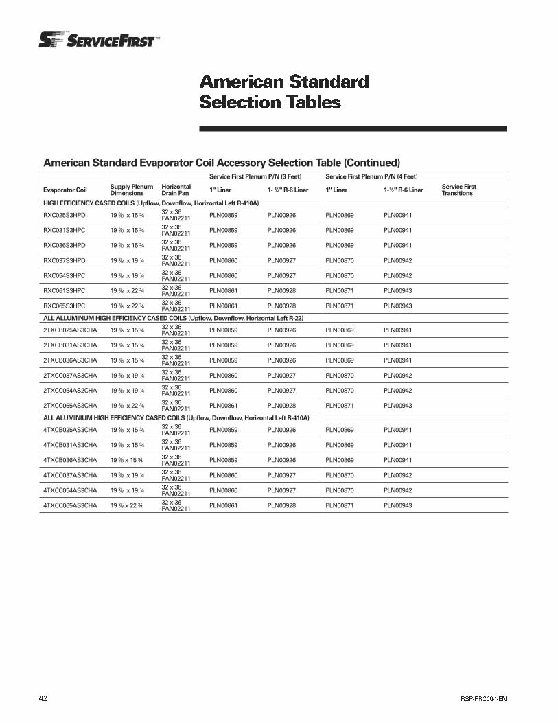
American Standard Evaporator Coil Accessory Selection Table (Continued)Service First Plenum P/N (3 Feet) Service First Plenum P/N (4 Feet)
Evaporator CoilSupply Plenum Dimensions
Horizontal Drain Pan
1" Liner 1- ½" R-6 Liner 1" Liner 1-½" R-6 LinerService First Transitions
HIGH EFFICIENCY CASED COILS (Upflow, Downflow, Horizontal Left R-410A)
RXC025S3HPD 19 3/8 x 15 ¾ 32 x 36 PAN02211 PLN00859 PLN00926 PLN00869 PLN00941
RXC031S3HPC 19 3/8 x 15 ¾ 32 x 36 PAN02211 PLN00859 PLN00926 PLN00869 PLN00941
RXC036S3HPD 19 3/8 x 15 ¾ 32 x 36 PAN02211 PLN00859 PLN00926 PLN00869 PLN00941
RXC037S3HPD 19 3/8 x 19 ¼ 32 x 36 PAN02211 PLN00860 PLN00927 PLN00870 PLN00942
RXC054S3HPC 19 3/8 x 19 ¼ 32 x 36 PAN02211 PLN00860 PLN00927 PLN00870 PLN00942
RXC061S3HPC 19 3/8 x 22 ¾ 32 x 36 PAN02211 PLN00861 PLN00928 PLN00871 PLN00943
RXC065S3HPC 19 3/8 x 22 ¾ 32 x 36 PAN02211 PLN00861 PLN00928 PLN00871 PLN00943
ALL ALLUMINUM HIGH EFFICIENCY CASED COILS (Upflow, Downflow, Horizontal Left R-22)
2TXCB025AS3CHA 19 3/8 x 15 ¾ 32 x 36 PAN02211 PLN00859 PLN00926 PLN00869 PLN00941
2TXCB031AS3CHA 19 3/8 x 15 ¾ 32 x 36 PAN02211 PLN00859 PLN00926 PLN00869 PLN00941
2TXCB036AS3CHA 19 3/8 x 15 ¾ 32 x 36 PAN02211 PLN00859 PLN00926 PLN00869 PLN00941
2TXCC037AS3CHA 19 3/8 x 19 ¼ 32 x 36 PAN02211 PLN00860 PLN00927 PLN00870 PLN00942
2TXCC054AS2CHA 19 3/8 x 19 ¼ 32 x 36 PAN02211 PLN00860 PLN00927 PLN00870 PLN00942
2TXCC065AS3CHA 19 3/8 x 22 ¾ 32 x 36 PAN02211 PLN00861 PLN00928 PLN00871 PLN00943
ALL ALUMINIUM HIGH EFFICIENCY CASED COILS (Upflow, Downflow, Horizontal Left R-410A)
4TXCB025AS3CHA 19 3/8 x 15 ¾ 32 x 36 PAN02211 PLN00859 PLN00926 PLN00869 PLN00941
4TXCB031AS3CHA 19 3/8 x 15 ¾ 32 x 36 PAN02211 PLN00859 PLN00926 PLN00869 PLN00941
4TXCB036AS3CHA 19 3/8 x 15 ¾ 32 x 36 PAN02211 PLN00859 PLN00926 PLN00869 PLN00941
4TXCC037AS3CHA 19 3/8 x 19 ¼ 32 x 36 PAN02211 PLN00860 PLN00927 PLN00870 PLN00942
4TXCC054AS3CHA 19 3/8 x 19 ¼ 32 x 36 PAN02211 PLN00860 PLN00927 PLN00870 PLN00942
4TXCC065AS3CHA 19 3/8 x 22 ¾ 32 x 36 PAN02211 PLN00861 PLN00928 PLN00871 PLN00943
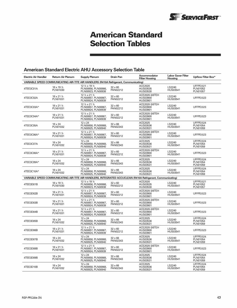
American Standard Electric AHU Accessory Selection Table
Electric Air Handler Return Air Plenum Supply Plenum Drain PanAccommodator Filter Housing
Labor Saver Filter Housing
Upflow Filter Box*
VARIABLE SPEED COMMUNICATING AIR-TITE AIR HANDLERS (R410A Refrigerant, Communicating)
4TEE3C01A 18 x 19 ½ PLN01030
12 ½ x 19 ½ PLN00856, PLN00866, PLN00923, PLN00938
32 x 60 PAN02212
ACE2020 HUS03535 HUS03530
LS2240 HUS03541
UFFPE(I)21 PLN01052 PLN01057
4TEE3C02A 18 x 21 ½ PLN01031
12 ½ x 21 ½ PLN00857, PLN00867, PLN00924, PLN00939
32 x 60 PAN02212
ACE2020-3/6TEHHUS03900HUS03901
LS2240 HUS03541 UFFPE(I)23
4TEE3C03A* 18 x 21 ½ PLN01031
12 ½ x 21 ½ PLN00857, PLN00867, PLN00924, PLN00939
32 x 60 PAN02212
ACE2020-3/6TEHHUS03900HUS03901
LS2240 HUS03541 UFFPE(I)23
4TEE3C04A* 18 x 21 ½ PLN01031
12 ½ x 21 ½ PLN00857, PLN00867, PLN00924, PLN00939
32 x 60 PAN02212
ACE2020-3/6TEHHUS03900HUS03901
LS2240 HUS03541 UFFPE(I)23
4TEE3C05A 18 x 24 PLN01032
12 x 24 PLN00858, PLN00868, PLN00925, PLN00940
32 x 66 PAN02343
ACE2025 HUS03536 HUS03531
LS2240 HUS03541
UFFPE(I)24 PLN01054 PLN01059
4TEE3C06A* 18 x 21 ½ PLN01031
12 ½ x 21 ½ PLN00857, PLN00867, PLN00924, PLN00939
32 x 60 PAN02212
ACE2020-3/6TEHHUS03900HUS03901
LS2240 HUS03541 UFFPE(I)23
4TEE3C07A 18 x 24 PLN01032
12 x 24 PLN00858, PLN00868, PLN00925, PLN00940
32 x 66 PAN02343
ACE2025 HUS03536 HUS03531
LS2240 HUS03541
UFFPE(I)24 PLN01054 PLN01059
4TEE3C08A* 18 x 21 ½ PLN01031
12 ½ x 21 ½ PLN00857, PLN00867, PLN00924, PLN00939
32 x 60 PAN02212
ACE2020-3/6TEHHUS03900HUS03901
LS2240 HUS03541 UFFPE(I)23
4TEE3C09A* 18 x 24 PLN01032
12 x 24 PLN00858, PLN00868, PLN00925, PLN00940
32 x 66 PAN02343
ACE2025 HUS03536 HUS03531
LS2240 HUS03541
UFFPE(I)24 PLN01054 PLN01059
4TEE3C10A* 18 x 24 PLN01032
12 x 24 PLN00858, PLN00868, PLN00925, PLN00940
32 x 66 PAN02343
ACE2025 HUS03536 HUS03531
LS2240 HUS03541
UFFPE(I)24 PLN01054 PLN01059
VARIABLE SPEED COMMUNICATING AIR-TITE AIR HANDLERS, INTEGRATED ACCUCLEAN (R410A Refrigerant, Communicating)
4TEE3D01B 18 x 19 ½ PLN01030
12 ½ x 19 ½ PLN00856, PLN00866, PLN00923, PLN00938
32 x 60 PAN02212
ACE2020 HUS03535 HUS03530
LS2240 HUS03541
UFFPE(I)21 PLN01052 PLN01057
4TEE3D02B 18 x 21 ½ PLN01031
12 ½ x 21 ½ PLN00857, PLN00867, PLN00924, PLN00939
32 x 60 PAN02212
ACE2020-3/6TEHHUS03900HUS03901
LS2240 HUS03541 UFFPE(I)23
4TEE3D03B 18 x 21 ½ PLN01031
12 ½ x 21 ½ PLN00857, PLN00867, PLN00924, PLN00939
32 x 60 PAN02212
ACE2020-3/6TEHHUS03900HUS03901
LS2240 HUS03541 UFFPE(I)23
4TEE3D04B 18 x 21 ½ PLN01031
12 ½ x 21 ½ PLN00857, PLN00867, PLN00924, PLN00939
32 x 60 PAN02212
ACE2020-3/6TEHHUS03900HUS03901
LS2240 HUS03541 UFFPE(I)23
4TEE3D05B 18 x 24 PLN01032
12 x 24 PLN00858, PLN00868, PLN00925, PLN00940
32 x 66 PAN02343
ACE2025 HUS03536 HUS03531
LS2240 HUS03541
UFFPE(I)24 PLN01054 PLN01059
4TEE3D06B 18 x 21 ½ PLN01031
12 ½ x 21 ½ PLN00857, PLN00867, PLN00924, PLN00939
32 x 60 PAN02212
ACE2020-3/6TEHHUS03900HUS03901
LS2240 HUS03541 UFFPE(I)23
4TEE3D07B 18 x 24 PLN01032
12 x 24 PLN00858, PLN00868, PLN00925, PLN00940
32 x 66 PAN02343
ACE2025 HUS03536 HUS03531
LS2240 HUS03541
UFFPE(I)24 PLN01054 PLN01059
4TEE3D08B 18 x 21 ½ PLN01031
12 ½ x 21 ½ PLN00857, PLN00867, PLN00924, PLN00939
32 x 60 PAN02212
ACE2020-3/6TEHHUS03900HUS03901
LS2240 HUS03541 UFFPE(I)23
4TEE3D09B 18 x 24 PLN01032
12 x 24 PLN00858, PLN00868, PLN00925, PLN00940
32 x 66 PAN02343
ACE2025 HUS03536 HUS03531
LS2240 HUS03541
UFFPE(I)24 PLN01054 PLN01059
4TEE3D10B 18 x 24 PLN01032
12 x 24 PLN00858, PLN00868, PLN00925, PLN00940
32 x 66 PAN02343
ACE2025 HUS03536 HUS03531
LS2240 HUS03541
UFFPE(I)24 PLN01054 PLN01059
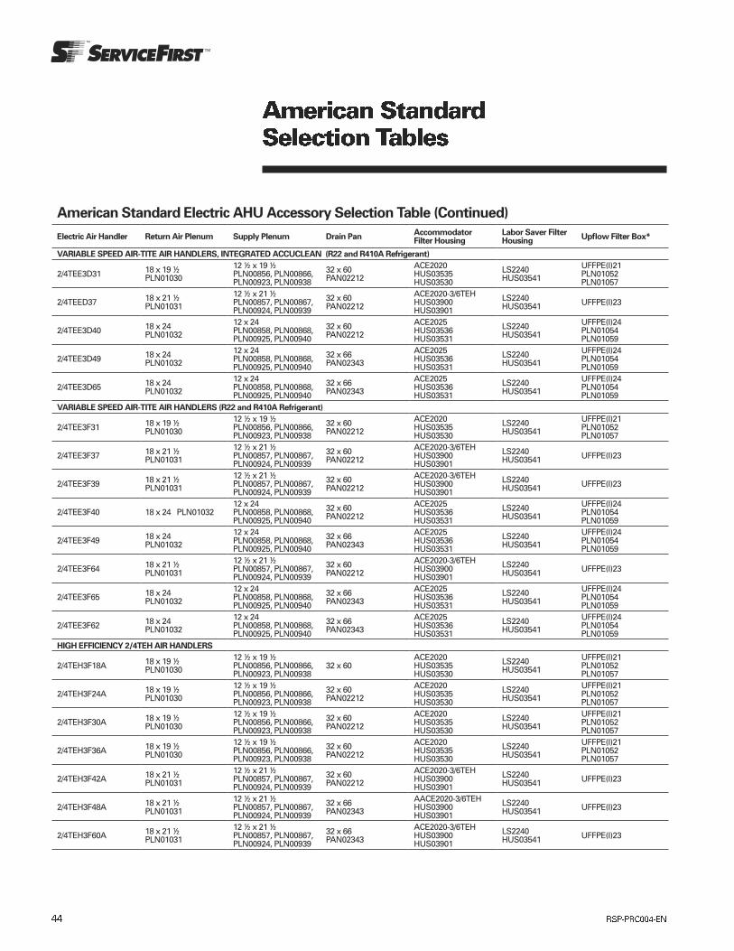
American Standard Electric AHU Accessory Selection Table (Continued)
Electric Air Handler Return Air Plenum Supply Plenum Drain PanAccommodator Filter Housing
Labor Saver Filter Housing
Upflow Filter Box*
VARIABLE SPEED AIR-TITE AIR HANDLERS, INTEGRATED ACCUCLEAN (R22 and R410A Refrigerant)
2/4TEE3D31 18 x 19 ½ PLN01030
12 ½ x 19 ½ PLN00856, PLN00866, PLN00923, PLN00938
32 x 60 PAN02212
ACE2020 HUS03535 HUS03530
LS2240 HUS03541
UFFPE(I)21 PLN01052 PLN01057
2/4TEED37 18 x 21 ½ PLN01031
12 ½ x 21 ½ PLN00857, PLN00867, PLN00924, PLN00939
32 x 60 PAN02212
ACE2020-3/6TEHHUS03900HUS03901
LS2240 HUS03541 UFFPE(I)23
2/4TEE3D40 18 x 24 PLN01032
12 x 24 PLN00858, PLN00868, PLN00925, PLN00940
32 x 60 PAN02212
ACE2025 HUS03536 HUS03531
LS2240 HUS03541
UFFPE(I)24 PLN01054 PLN01059
2/4TEE3D49 18 x 24 PLN01032
12 x 24 PLN00858, PLN00868, PLN00925, PLN00940
32 x 66 PAN02343
ACE2025 HUS03536 HUS03531
LS2240 HUS03541
UFFPE(I)24 PLN01054 PLN01059
2/4TEE3D65 18 x 24 PLN01032
12 x 24 PLN00858, PLN00868, PLN00925, PLN00940
32 x 66 PAN02343
ACE2025 HUS03536 HUS03531
LS2240 HUS03541
UFFPE(I)24 PLN01054 PLN01059
VARIABLE SPEED AIR-TITE AIR HANDLERS (R22 and R410A Refrigerant)
2/4TEE3F31 18 x 19 ½ PLN01030
12 ½ x 19 ½ PLN00856, PLN00866, PLN00923, PLN00938
32 x 60 PAN02212
ACE2020 HUS03535 HUS03530
LS2240 HUS03541
UFFPE(I)21 PLN01052 PLN01057
2/4TEE3F37 18 x 21 ½ PLN01031
12 ½ x 21 ½ PLN00857, PLN00867, PLN00924, PLN00939
32 x 60 PAN02212
ACE2020-3/6TEHHUS03900HUS03901
LS2240 HUS03541 UFFPE(I)23
2/4TEE3F39 18 x 21 ½ PLN01031
12 ½ x 21 ½ PLN00857, PLN00867, PLN00924, PLN00939
32 x 60 PAN02212
ACE2020-3/6TEHHUS03900HUS03901
LS2240 HUS03541 UFFPE(I)23
2/4TEE3F40 18 x 24 PLN0103212 x 24 PLN00858, PLN00868, PLN00925, PLN00940
32 x 60 PAN02212
ACE2025 HUS03536 HUS03531
LS2240 HUS03541
UFFPE(I)24 PLN01054 PLN01059
2/4TEE3F49 18 x 24 PLN01032
12 x 24 PLN00858, PLN00868, PLN00925, PLN00940
32 x 66 PAN02343
ACE2025 HUS03536 HUS03531
LS2240 HUS03541
UFFPE(I)24 PLN01054 PLN01059
2/4TEE3F64 18 x 21 ½ PLN01031
12 ½ x 21 ½ PLN00857, PLN00867, PLN00924, PLN00939
32 x 60 PAN02212
ACE2020-3/6TEHHUS03900HUS03901
LS2240 HUS03541 UFFPE(I)23
2/4TEE3F65 18 x 24 PLN01032
12 x 24 PLN00858, PLN00868, PLN00925, PLN00940
32 x 66 PAN02343
ACE2025 HUS03536 HUS03531
LS2240 HUS03541
UFFPE(I)24 PLN01054 PLN01059
2/4TEE3F62 18 x 24 PLN01032
12 x 24 PLN00858, PLN00868, PLN00925, PLN00940
32 x 66 PAN02343
ACE2025 HUS03536 HUS03531
LS2240 HUS03541
UFFPE(I)24 PLN01054 PLN01059
HIGH EFFICIENCY 2/4TEH AIR HANDLERS
2/4TEH3F18A 18 x 19 ½ PLN01030
12 ½ x 19 ½ PLN00856, PLN00866, PLN00923, PLN00938
32 x 60ACE2020 HUS03535 HUS03530
LS2240 HUS03541
UFFPE(I)21 PLN01052 PLN01057
2/4TEH3F24A 18 x 19 ½ PLN01030
12 ½ x 19 ½ PLN00856, PLN00866, PLN00923, PLN00938
32 x 60 PAN02212
ACE2020 HUS03535 HUS03530
LS2240 HUS03541
UFFPE(I)21 PLN01052 PLN01057
2/4TEH3F30A 18 x 19 ½ PLN01030
12 ½ x 19 ½ PLN00856, PLN00866, PLN00923, PLN00938
32 x 60 PAN02212
ACE2020 HUS03535 HUS03530
LS2240 HUS03541
UFFPE(I)21 PLN01052 PLN01057
2/4TEH3F36A 18 x 19 ½ PLN01030
12 ½ x 19 ½ PLN00856, PLN00866, PLN00923, PLN00938
32 x 60 PAN02212
ACE2020 HUS03535 HUS03530
LS2240 HUS03541
UFFPE(I)21 PLN01052 PLN01057
2/4TEH3F42A 18 x 21 ½ PLN01031
12 ½ x 21 ½ PLN00857, PLN00867, PLN00924, PLN00939
32 x 60 PAN02212
ACE2020-3/6TEHHUS03900HUS03901
LS2240 HUS03541 UFFPE(I)23
2/4TEH3F48A 18 x 21 ½ PLN01031
12 ½ x 21 ½ PLN00857, PLN00867, PLN00924, PLN00939
32 x 66 PAN02343
AACE2020-3/6TEHHUS03900HUS03901
LS2240 HUS03541 UFFPE(I)23
2/4TEH3F60A 18 x 21 ½ PLN01031
12 ½ x 21 ½ PLN00857, PLN00867, PLN00924, PLN00939
32 x 66 PAN02343
ACE2020-3/6TEHHUS03900HUS03901
LS2240 HUS03541 UFFPE(I)23

American Standard Electric AHU Accessory Selection Table (Continued)
Electric Air Handler Return Air Plenum Supply Plenum Drain PanAccommodator Filter Housing
Labor Saver Filter Housing
Upflow Filter Box*
2TGB AIR HANDLERS
2TGB3F18A1000A N/A 32 x 60 PAN02212
ACE1620 HUS03534 HUS03529
LS2240 HUS03541
UFFPE(I)17 PLN01051 PLN01056
2TGB3F25A1000A N/A 32 x 60 PAN02212
ACE1620 HUS03534 HUS03529
LS2240 HUS03541
UFFPE(I)17 PLN01051 PLN01056
2TGB3F30A1000A N/A 32 x 60 PAN02212
ACE1620 HUS03534 HUS03529
LS2240 HUS03541
UFFPE(I)17 PLN01051 PLN01056
2TGB3F36A1000A 18 x 19 ½ PLN01030
12 ½ x 19 ½ PLN00856, PLN00866, PLN00923, PLN00938
32 x 60 PAN02212
ACE2020 HUS03535 HUS03530
LS2240 HUS03541
UFFPE(I)21 PLN01052 PLN01057
2TGB3F42A1000A 18 x 21 ½ PLN01031
12 ½ x 21 ½ PLN00857, PLN00867, PLN00924, PLN00939
32 x 60 PAN02212
ACE2020-3/6TEHHUS03900HUS03901
LS2240 HUS03541 UFFPE(I)23
2TGB3F48A1000A 18 x 21 ½ PLN01031
12 ½ x 21 ½ PLN00857, PLN00867, PLN00924, PLN00939
32 x 66 PAN02343
ACE2020-3/6TEHHUS03900HUS03901
LS2240 HUS03541 UFFPE(I)23
2TFB-B AIR HANDLERS
2TFB3F18B1D05A 32 x 60 PAN02212
ACE2020 HUS03535 HUS03530
LS2240 HUS03541 N/A
2TFB3F18B1D08A 32 x 60 PAN02212
ACE2020 HUS03535 HUS03530
LS2240 HUS03541 N/A
2TFB3F18B1D10A 32 x 60 PAN02212
ACE2020 HUS03535 HUS03530
LS2240 HUS03541 N/A
2TFB3F24B1D05A 32 x 60 PAN02212
ACE2020 HUS03535 HUS03530
LS2240 HUS03541 N/A
2TFB3F24B1D08A 32 x 60 PAN02212
ACE2020 HUS03535 HUS03530
LS2240 HUS03541 N/A
2TFB3F24B1D10A 32 x 60 PAN02212
ACE2020 HUS03535 HUS03530
LS2240 HUS03541 N/A
2TFB3F30B1D05A 32 x 60 PAN02212
ACE2020 HUS03535 HUS03530
LS2240 HUS03541 N/A
2TFB3F30B1D08A 32 x 60 PAN02212
ACE2020 HUS03535 HUS03530
LS2240 HUS03541 N/A
2TFB3F30B1D10A 32 x 60 PAN02212
ACE2020 HUS03535 HUS03530
LS2240 HUS03541 N/A
2TFB3F36B1D05A 32 x 60 PAN02212
ACE2020 HUS03535 HUS03530
LS2240 HUS03541 N/A
2TFB3F36B1D08A 32 x 60 PAN02212
ACE2020 HUS03535 HUS03530
LS2240 HUS03541 N/A
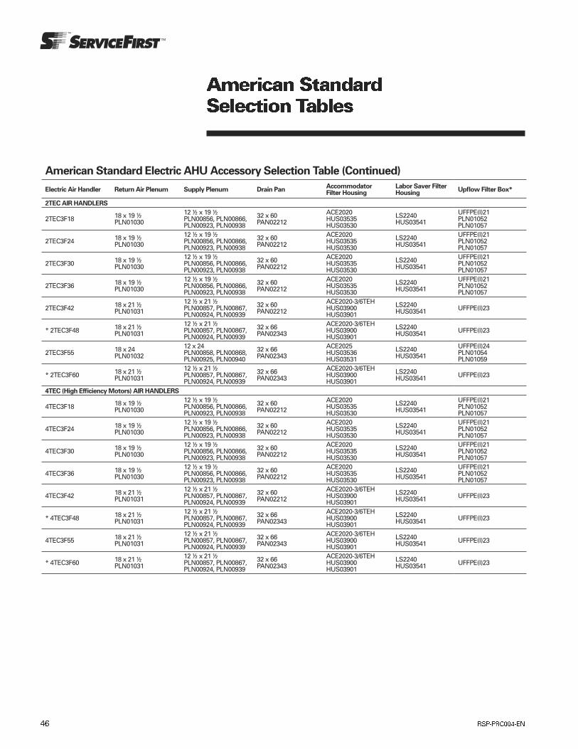
American Standard Electric AHU Accessory Selection Table (Continued)
Electric Air Handler Return Air Plenum Supply Plenum Drain PanAccommodator Filter Housing
Labor Saver Filter Housing
Upflow Filter Box*
2TEC AIR HANDLERS
2TEC3F18 18 x 19 ½ PLN01030
12 ½ x 19 ½ PLN00856, PLN00866, PLN00923, PLN00938
32 x 60 PAN02212
ACE2020 HUS03535 HUS03530
LS2240 HUS03541
UFFPE(I)21 PLN01052 PLN01057
2TEC3F24 18 x 19 ½ PLN01030
12 ½ x 19 ½ PLN00856, PLN00866, PLN00923, PLN00938
32 x 60 PAN02212
ACE2020 HUS03535 HUS03530
LS2240 HUS03541
UFFPE(I)21 PLN01052 PLN01057
2TEC3F30 18 x 19 ½ PLN01030
12 ½ x 19 ½ PLN00856, PLN00866, PLN00923, PLN00938
32 x 60 PAN02212
ACE2020 HUS03535 HUS03530
LS2240 HUS03541
UFFPE(I)21 PLN01052 PLN01057
2TEC3F36 18 x 19 ½ PLN01030
12 ½ x 19 ½ PLN00856, PLN00866, PLN00923, PLN00938
32 x 60 PAN02212
ACE2020 HUS03535 HUS03530
LS2240 HUS03541
UFFPE(I)21 PLN01052 PLN01057
2TEC3F42 18 x 21 ½ PLN01031
12 ½ x 21 ½ PLN00857, PLN00867, PLN00924, PLN00939
32 x 60 PAN02212
ACE2020-3/6TEHHUS03900HUS03901
LS2240 HUS03541 UFFPE(I)23
* 2TEC3F48 18 x 21 ½ PLN01031
12 ½ x 21 ½ PLN00857, PLN00867, PLN00924, PLN00939
32 x 66 PAN02343
ACE2020-3/6TEHHUS03900HUS03901
LS2240 HUS03541 UFFPE(I)23
2TEC3F55 18 x 24 PLN01032
12 x 24 PLN00858, PLN00868, PLN00925, PLN00940
32 x 66 PAN02343
ACE2025 HUS03536 HUS03531
LS2240 HUS03541
UFFPE(I)24 PLN01054 PLN01059
* 2TEC3F60 18 x 21 ½ PLN01031
12 ½ x 21 ½ PLN00857, PLN00867, PLN00924, PLN00939
32 x 66 PAN02343
ACE2020-3/6TEHHUS03900HUS03901
LS2240 HUS03541 UFFPE(I)23
4TEC (High Efficiency Motors) AIR HANDLERS
4TEC3F18 18 x 19 ½ PLN01030
12 ½ x 19 ½ PLN00856, PLN00866, PLN00923, PLN00938
32 x 60 PAN02212
ACE2020 HUS03535 HUS03530
LS2240 HUS03541
UFFPE(I)21 PLN01052 PLN01057
4TEC3F24 18 x 19 ½ PLN01030
12 ½ x 19 ½ PLN00856, PLN00866, PLN00923, PLN00938
32 x 60 PAN02212
ACE2020 HUS03535 HUS03530
LS2240 HUS03541
UFFPE(I)21 PLN01052 PLN01057
4TEC3F30 18 x 19 ½ PLN01030
12 ½ x 19 ½ PLN00856, PLN00866, PLN00923, PLN00938
32 x 60 PAN02212
ACE2020 HUS03535 HUS03530
LS2240 HUS03541
UFFPE(I)21 PLN01052 PLN01057
4TEC3F36 18 x 19 ½ PLN01030
12 ½ x 19 ½ PLN00856, PLN00866, PLN00923, PLN00938
32 x 60 PAN02212
ACE2020 HUS03535 HUS03530
LS2240 HUS03541
UFFPE(I)21 PLN01052 PLN01057
4TEC3F42 18 x 21 ½ PLN01031
12 ½ x 21 ½ PLN00857, PLN00867, PLN00924, PLN00939
32 x 60 PAN02212
ACE2020-3/6TEHHUS03900HUS03901
LS2240 HUS03541 UFFPE(I)23
* 4TEC3F48 18 x 21 ½ PLN01031
12 ½ x 21 ½ PLN00857, PLN00867, PLN00924, PLN00939
32 x 66 PAN02343
ACE2020-3/6TEHHUS03900HUS03901
LS2240 HUS03541 UFFPE(I)23
4TEC3F55 18 x 21 ½ PLN01031
12 ½ x 21 ½ PLN00857, PLN00867, PLN00924, PLN00939
32 x 66 PAN02343
ACE2020-3/6TEHHUS03900HUS03901
LS2240 HUS03541 UFFPE(I)23
* 4TEC3F60 18 x 21 ½ PLN01031
12 ½ x 21 ½ PLN00857, PLN00867, PLN00924, PLN00939
32 x 66 PAN02343
ACE2020-3/6TEHHUS03900HUS03901
LS2240 HUS03541 UFFPE(I)23


Trane optimizes the performance of homes and buildings around the world. A business of Ingersoll Rand, the leader in creating and sustaining safe, comfortable and energy efficient environments, Trane offers a broad portfolio of advanced controls and HVAC systems, comprehensive building services, and parts.For more information, visit www.Trane.com.
Trane has a policy of continuous product and product data improvement and reserves the right to change design and specifications without notice.
© 2010 Trane All rights reserved
RSP-PRC004-EN 13 Dec 2010
Supersedes RSP-PRC004-EN (13 Mar 2002)

Goodway® Tube CleaningEquipment
RSP-PRC014-ENJanuary 2010

RSP-PRC014-EN©2010 Trane All rights reserved
3RSP-PRC014-EN
Table of Contents
General Data – Cross-Reference – Machines 4
Tube Cleaners – Machines, Parts & Accessories 6RAM-4-60 (Ream-A-Matic®) 6RAM-5SF-60-3 (Speed-Feed Ream-A-Matic®) 7RAM-6-60 (High Flow Ream-A-Matic®) 8Chiller Bib Bags 9Flexible Shafts and Brushes 10Adjustable Buffing Tool and Scraper Tool 17Flex Hone Abrasive Tools 17Cup Brush 18Carbide Drills 18Two Directional Foot Switch 19Flexible Shaft Maintenance and Repair 19
Pressure Washers/Vapor Steam Cleaner -Machines, Parts & Accessories 20GPW-1000-60 (Pressure washer – 1000 psi) 20GPW-1200-60 (Pressure washer – 1200 psi) 20Pressure Washer Accessories 21GVC-1500 (Vapor Steam Cleaner) 22
Vacuums - Machines, Parts & Accessories 23EV-30-H (Commercial H.E.P.A. Vacuum) 23EV-60-P (Commercial Pump-Out Vacuum) 23EV-30 (Commercial Wet-dry Vacuum) 24CTV-1500-60 (Cooling Tower Vacuum) 25Cooling Tower Vacuum Accessories 27
Coil Cleaner - Machines, Parts & Accessories 28CC-140 (CoilPro Coil Cleaner) 28CC-600 (CoilPro Coil Cleaner) 28CC-100, CC-100-D (CoilPro Coil Cleaner) 28CC-JR (CoilPro Jr. Coil Cleaner) 29FS-10 Fiberscope 30FS-5G Fiberscope 30

4 RSP-PRC014-EN
General Data – Cross-ReferenceTable 1. Goodway Ream-A-Matic Tube Cleaners
ServiceFirst GoodwayItem Number PN Description Voltage Standard FeaturesTOL01659 RAM-4-60 Ream-A-Matic Tube Cleaner 1/2 HP, 115V, 60 Hz Mobile dolly, tool storage box and foot switchTOL01747 RAM-4-60-C Ream-A-Matic Tube Cleaner 1/2 HP, 115V, 60 Hz, Includes tool storage box, single direction foot
w/contractor dolly switch and heavy duty contractor dolly.TOL01746 RAM-4-60-R Ream-A-Matic Tube Cleaner 1/2 HP, 115V, 60 Hz Includes mobile dolly, tool storage box and two-
w/two-way foot switch directional foot switch.TOL01787 RAM-4-60-R-C Ream-A-Matic Tube Cleanerw/two-way 1/2 HP 115V, 60 Hz Includes tool storage box, two-directional foot
foot switch & contractor dolly switch and contractor dolly.TOL01741 RAM-4A-50 Ream-A-Matic Tube Cleaner 1/2 HP, 220V, 50 Hz Includes mobile dolly, tool storage box and
foot switch.TOL01860 RAM-4-BASE-60 Ream-A-Matic Tube Cleaner W/O Dolly 1/2 HP, 115V, 60 Hz, Includes tool storage box, and single directional
foot switch.TOL01861 RAM-4-BASE-60-R Ream-A-Matic Tube Cleaner W/O Dolly 1/2 HP, 115V, 60 Hz Includes tool storage box and double directional
foot switch.TOL01734 RAM-4X-60-2 Ream-A Matic Heavy Duty Tube Cleaner 1 HP, 115V, 60Hz Includes mobile dolly, tool storage box, foot switch
and 2:1 drive ratioTOL03254 RAM-5SF-60-3 Ream-A-Matic Tube Cleaner 3/4 HP, 115V, 60 Hz Speed-Feed gun, 15' (4.6m) guide hose, one set of
shaft feeder gears for GTC-703 series flexible shafts,mobile dolly, tool storage box and foot switch.
TOL03256 RAM-5SF-60-3-C Ream-A-Matic Speed Feed Tube Cleaner 3/4 HP, 115V, 60 Hz, Includes speed-feed gun 15 ft. guide hose, one setw/contractor dolly of shaft feeder gears forGTC703 series flexible shafts, tool storage box,foot switch and heavy-duty contractor dolly.
TOL01661 RAM-6-60 Ream-A-Matic Tube Cleaner 1 1/2 HP, 115V, 60 Hz Contractor dolly, tool storage box and footswitch.
TOL01745 RAM-PTC-60 Port-A-Ram Tube Cleaner 1/2 HP, 115V, 60 Hz Single Direction, Direct Drive, 1725 RPMTOL03255 RAM-5SF-60-3-BASE Ream-A-Matic Tube cleaner 3/4 HP, 115V Includes speed-feed gun 15 FT. guide hose,
one set of shaft feeder gears for GTC703 seriesflexible shafts, tool storage box and singledirection foot switch.
TOL02045 AQ-R1500 Duct Cleaner 1 HP, 115V, 60 Hz Includes belt switch with forward/reverse adjustablespeed control, mobile dolly and tool storage box
Table 2. Goodway CoilPro Coil Cleaners
ServiceFirst GoodwayItem Number PN Description Voltage Standard FeaturesTOL02707 CC-140 Battery Powered or 115V Coil Cleaning 0.2 HP, 12VDC or 115AC Includes 25’ hose spray gun with 18” wand, 3
Machine, Variable Pressure 40-140 psi nozzles, 1 Gallon of CoilShineTOL02708 CC-600 High Pressure CoilPro Cleaning Machine 1.3HP, 115V Includes 25’ hose spray gun with 18” wand, 3
600 psi @ 1.6 gpm nozzles, 1 Gallon of CoilShineTOL02798 CC-100 Back Pack CoilPro 0.1 HP, 12VDC Includes 10’ self coiling hose spray gun with
Variable Pressure 40-100 psi 18” wand, 3 nozzles, 1 Gallon of CoilShineTOL03291 CC-100D Back Pack CoilPro 0.1 HP, 12VDC Includes 10’ self coiling hose spray gun with
Variable Pressure 40-100 psi 18” wand, 3 nozzles, 1 Gallon of CoilShineTOL03253 CC-JR CoilPro, Jr Cleaning Machine 0.2 HP, 12VDC Includes 10’ self coiling hose spray gun with
125 psi @ 0.6 gpm 3’ sectional wand, 2 nozzles, 1 Gallon of CoilShine
Table 3. Goodway Pressure Washers/Goodway Vapor-Steam Cleaner
ServiceFirst GoodwayItem Number PN Description Voltage Standard FeaturesTOL01726 GPW-1000-60 Hi-Pressure Washer 1000 psi @ 2.2 gpm 1/2 HP, 115V, 60 Hz Includes 3' wand, 25' high pressure hose,
5 quick disconnect nozzles, soap container anddolly
TOL01679 GPW-1200-60 Portable Hi-Pressure Washer 1.7 HP, 115V, 60 Hz Includes 3" wand, 25' hi-pressure hose, variable1200 psi @ 1.8 gpm pressure nozzle and soap container
TOL02131 GVC-1500 Vapor Steam Cleaner, 1500 W 115V, 60 Hz Includes 10' hose, two-piece 38" wand, 11" floorbrush, 5" triangular brush, 3" triangular brush,9" squeegee tool, 14" curved lance, 8" curved lance,3" detail lance, 2" round brush with spare nylon andbrass bristles, soap container and one gallon ofhigh temperature cleaner degreaser
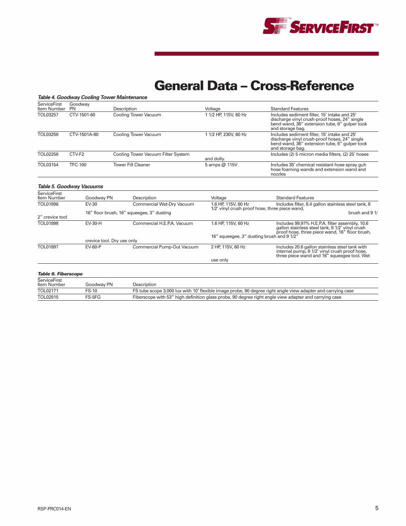
5RSP-PRC014-EN
Table 5. Goodway Vacuums
ServiceFirstItem Number Goodway PN Description Voltage Standard FeaturesTOL01896 EV-30 Commercial Wet-Dry Vacuum 1.6 HP, 115V, 60 Hz Includes filter, 8.4 gallon stainless steel tank, 8
1/2’ vinyl crush proof hose, three piece wand,16” floor brush, 16” squeegee, 3” dusting brush and 9 1/
2” crevice toolTOL01898 EV-30-H Commercial H.E.P.A. Vacuum 1.6 HP, 115V, 60 Hz Includes 99.97% H.E.P.A. filter assembly, 10.6
gallon stainless steel tank, 8 1/2’ vinyl crushproof hose, three piece wand, 16” floor brush,
16” squeegee, 3” dusting brush and 9 1/2”crevice tool. Dry use only
TOL01897 EV-60-P Commercial Pump-Out Vacuum 2 HP, 115V, 60 Hz Includes 20.6 gallon stainless steel tank withinternal pump, 8 1/2’ vinyl crush proof hose,three piece wand and 16” squeegee tool. Wet
use only
Table 6. FiberscopeServiceFirstItem Number Goodway PN DescriptionTOL02171 FS-10 FS tube scope 3,000 lux with 10’ flexible image probe, 90 degree right angle view adapter and carrying caseTOL02815 FS-5FG Fiberscope with 53” high definition glass probe, 90 degree right angle view adapter and carrying case
General Data – Cross-ReferenceTable 4. Goodway Cooling Tower Maintenance
ServiceFirst GoodwayItem Number PN Description Voltage Standard FeaturesTOL03257 CTV-1501-60 Cooling Tower Vacuum 1 1/2 HP, 115V, 60 Hz Includes sediment filter, 15’ intake and 25’
discharge vinyl crush-proof hoses, 24” singlebend wand, 36” extension tube, 6” gulper tookand storage bag.
TOL03258 CTV-1501A-60 Cooling Tower Vacuum 1 1/2 HP, 230V, 60 Hz Includes sediment filter, 15’ intake and 25’discharge vinyl crush-proof hoses, 24” singlebend wand, 36” extension tube, 6” gulper tookand storage bag.
TOL02258 CTV-F2 Cooling Tower Vacuum Filter System Includes (2) 5 micron media filters, (2) 25’ hosesand dolly.
TOL03154 TFC-100 Tower Fill Cleaner 5 amps @ 115V Includes 35’ chemical resistant hose spray guhhose foaming wands and extension wand andnozzles
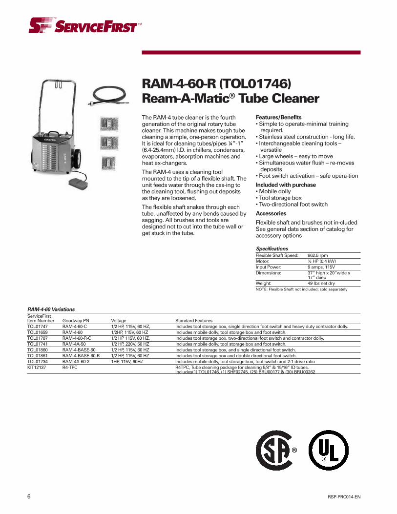
6 RSP-PRC014-EN
The RAM-4 tube cleaner is the fourthgeneration of the original rotary tubecleaner. This machine makes tough tubecleaning a simple, one-person operation.It is ideal for cleaning tubes/pipes ¼”-1”(6.4-25.4mm) I.D. in chillers, condensers,evaporators, absorption machines andheat ex-changers.
The RAM-4 uses a cleaning toolmounted to the tip of a flexible shaft. Theunit feeds water through the cas-ing tothe cleaning tool, flushing out depositsas they are loosened.
The flexible shaft snakes through eachtube, unaffected by any bends caused bysagging. All brushes and tools aredesigned not to cut into the tube wall orget stuck in the tube.
RAM-4-60-R (TOL01746)Ream-A-Matic® Tube Cleaner
Features/Benefits• Simple to operate-minimal training
required.• Stainless steel construction - long life.• Interchangeable cleaning tools –
versatile• Large wheels – easy to move• Simultaneous water flush – re-moves
deposits• Foot switch activation – safe opera-tion
Included with purchase• Mobile dolly• Tool storage box• Two-directional foot switch
Accessories
Flexible shaft and brushes not in-cludedSee general data section of catalog foraccessory options
Specifications
Flexible Shaft Speed: 862.5 rpmMotor: ½ HP (0.4 kW)Input Power: 9 amps, 115VDimensions: 37” high x 20”wide x
17” deepWeight: 49 lbs net dryNOTE: Flexible Shaft not included; sold separately
RAM-4-60 Variations
ServiceFirstItem Number Goodway PN Voltage Standard FeaturesTOL01747 RAM-4-60-C 1/2 HP, 115V, 60 HZ, Includes tool storage box, single direction foot switch and heavy duty contractor dolly.TOL01659 RAM-4-60 1/2HP, 115V, 60 HZ Includes mobile dolly, tool storage box and foot switch.TOL01787 RAM-4-60-R-C 1/2 HP 115V, 60 HZ, Includes tool storage box, two-directional foot switch and contractor dolly.TOL01741 RAM-4A-50 1/2 HP, 220V, 50 HZ Includes mobile dolly, tool storage box and foot switch.TOL01860 RAM-4-BASE-60 1/2 HP, 115V, 60 HZ Includes tool storage box, and single directional foot switch.TOL01861 RAM-4-BASE-60-R 1/2 HP, 115V, 60 HZ Includes tool storage box and double directional foot switch.TOL01734 RAM-4X-60-2 1HP, 115V, 60HZ Includes mobile dolly, tool storage box, foot switch and 2:1 drive ratioKIT12137 R4-TPC R4TPC, Tube cleaning package for cleaning 5/8” & 15/16” ID tubes.
Includes(1) TOL01746, (1) SHF02745, (25) BRU00177 & (30) BRU00262

7RSP-PRC014-EN
The RAM-5SF speed-feed tube cleanermakes tube cleaning quick and easy withits revolutionary speed-feed gun. It is themachine of choice among contractorsand managers of buildings and facilitieswith large tube bundles. It will cleantubes up to four times faster than anyother rotary tube cleaner.
Flexible shafts and Goodway blue nylonbrushes are available for use with thespeed-feed gun for removing softdeposits in straight tubes/pipes 9/16”-1”I.D. Other flexible shafts and accessoriesare available for use without the speed-feed gun for removing a variety ofdeposits in straight and curved tubes/pipes ¼”-1” I.D.
The RAM-5SF uses a cleaning toolmounted to the tip of a flexible shaft. Theunit feeds water through the casing tothe cleaning tool, flushing out depositsas they are loosened.
A gun controls shaft rotation andwaterflow. Simply push the top of thetrigger to rotate the flexible shaft in aclockwise direction and enter the tube.Push the bottom of the trigger to reversethe rotation and exit the tube. Shaft feedautomatically stops at a preset distancewhen the brush reaches the end of thetube.
RAM-5SFVS-60-3 (TOL03254)Variable Speed-FeedReam-A-Matic®
Features/Benefits:• 3’ per second – reduced labor• Simple to operate – minimal training
required.• Stainless steel construction – long life.• Interchangeable cleaning tools –
versatile• Large wheels – easy to move.• Simultaneous water flush –removes
deposits.• Trigger controlled operation – increased
productivity.
Included with purchase:• Speed-feed gun• 15’ guide hose• One set of shaft feeder gears for GTC-
703 series flexible shafts• Mobile dolly• Tool storage box• Foot switch
Accessories:See general data section of catalog foraccessory options
NOTE: Flexible Shaft sold separately
Specifications
Flexible Shaft Speed: 862.5 rpmSpeed-Feed Gun Rate: 3’ per secondSpeed-Feed Gun Push/Pull Force: 50 lbsMotor: 1 hpInput Power: 11 amps, 115V,Dimension (1) 37” high x 20” wide x 17” deepWeight: 75 lbs net dry1. Dimensions exclude gun and guide hose.
RAM-5SF-60-3 Variations
ServiceFirstItem Number Goodway PN Voltage Standard FeaturesTOL03256 RAM-5SFVS-60-3-C 3/4 HP, 115V, 60 HZ Includes speed-feed gun 15 ft. guide hose,
one set of shaft feeder gears for GTC703series flexible shafts, tool storage box, foot
switch and heavy-duty contractor dolly.TOL03255 RAM-5SFVS-60-3-BASE 3/4 HP, 115V, 60 HZ Includes speed-feed gun 15 ft. guide hose,
one set of shaft feeder gears for GTC703series flexible shafts, tool storage box andsingle direction foot switch.

8 RSP-PRC014-EN
The RAM-6 tube cleaner is the ultimaterotary tube cleaning machine. Whenused with a dual diameter nylon or brassbrush, the advanced features of thismachine allow it to thoroughly cleaneven the most fouled internallyenhanced tubes. This versatile unitfeatures a full 1 1/2 hp (1.1 kW), variablespeed drive motor, a cleaning solutioninjection system and a separate 500 psi(35 BAR) pump that delivers a 2.2 GPM(8.3 LPM) power flush. When cleaninginternally enhanced tubes, the operatorcan adjust the shaft speed to match theinternal spiral of the tube, causing thebrush to be “self” propelled through thetube. It is ideal for removing both softand hard deposits from internallyenhanced as well as smooth bore tubes/pipes ¼” – 1” (6.4-25.4 mm) I.D.
The RAM-6 uses a cleaning toolmounted to the tip of a flexible shaft. Theunit feeds high pressure water throughthe casing to the cleaning tool, powerflushing out deposits as they areloosened.
If the cleaning solution injection systemis activated, the unit automatically feedsa mixture of cleaning solution and waterthrough the casing to the cleaning toolas the shaft is fed into the tube. Whenthe shaft direction is reversed, the unitswitches to a water only power flush,leaving the tubes thoroughly cleaned.
Cleaning Internally Enhanced Tubes:The RAM-6 is equipped with a reversiblemotor for cleaning internally enhancedtubes. The two-direction foot switchpermits forward rotation for entering thetubes and reverse rotation for exiting.While the design of the brush and thespiral in the tube cause the brush to beself propelled through the tube, thevariable speed feature of the RAM-6allows the operator to set the flexibleshaft speed to match the natural feedrate of the spiral in the tube, preventingslip and allowing the brush tothoroughly clean both the lands and thegroove of the tube.
Features/Benefits• Simple to operate – minimal training
required• Stainless Steel construction – long life• Speed control – set shaft rotation of
optimum speed for each application• Interchangeable cleaning tools –
versatile.• Large pneumatic tires and heavy-duty
contractor dolly – easy to move• Simultaneous cleaning solution
injection and water power flush up to500 PSI at 2.2 GPM (35 BAR at 8.3 LPM)– removes deposits
• Foot switch activation – safe operation
Included with purchase:• Contractor dolly• Tool storage box• Two directional foot switch
Accessories:
See general data section of catalog foraccessory options.
RAM-6-60 (TOL01661) – High FlowTube Cleaner
Specifications
Flexible Shaft Speed: Variable, 200-800 rpmMotor: 1 ½ hp (1.1 kW)Input Power: 15 amps, 115VWater Requirements: Minimum 25 PSI at 2.2 GPM (1.7 BAR at 8.3 LPM)Output Water Pressure: Up to 500 PSI at 2.2 GPM (35 BAR at 8.3 LPM)Dimensions: 23” high x 16” wide x 10” deepWeight: 103 lbs. net dry
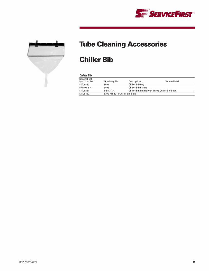
9RSP-PRC014-EN
Tube Cleaning Accessories
Chiller Bib
Chiller Bib
ServiceFirstItem Number Goodway PN Description Where UsedKIT09420 9401 Chiller Bib BagFRM01483 9402 Chiller Bib FrameKIT09421 BIB-KIT-3 Chiller Bib Frame with Three Chiller Bib BagsKIT09422 BAG-KIT-1010 Chiller Bib Bags
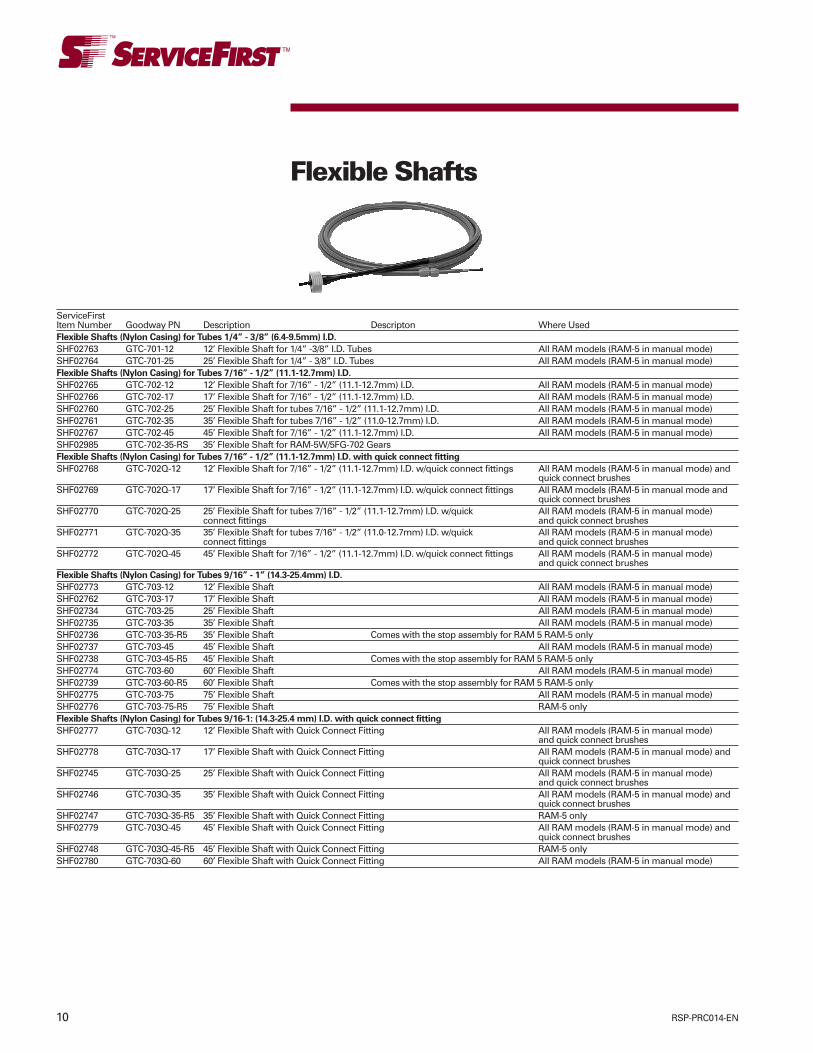
10 RSP-PRC014-EN
Flexible Shafts
ServiceFirstItem Number Goodway PN Description Descripton Where UsedFlexible Shafts (Nylon Casing) for Tubes 1/4” - 3/8” (6.4-9.5mm) I.D.
SHF02763 GTC-701-12 12’ Flexible Shaft for 1/4” -3/8” I.D. Tubes All RAM models (RAM-5 in manual mode)SHF02764 GTC-701-25 25’ Flexible Shaft for 1/4” - 3/8” I.D. Tubes All RAM models (RAM-5 in manual mode)Flexible Shafts (Nylon Casing) for Tubes 7/16” - 1/2” (11.1-12.7mm) I.D.
SHF02765 GTC-702-12 12’ Flexible Shaft for 7/16” - 1/2” (11.1-12.7mm) I.D. All RAM models (RAM-5 in manual mode)SHF02766 GTC-702-17 17’ Flexible Shaft for 7/16” - 1/2” (11.1-12.7mm) I.D. All RAM models (RAM-5 in manual mode)SHF02760 GTC-702-25 25’ Flexible Shaft for tubes 7/16” - 1/2” (11.1-12.7mm) I.D. All RAM models (RAM-5 in manual mode)SHF02761 GTC-702-35 35’ Flexible Shaft for tubes 7/16” - 1/2” (11.0-12.7mm) I.D. All RAM models (RAM-5 in manual mode)SHF02767 GTC-702-45 45’ Flexible Shaft for 7/16” - 1/2” (11.1-12.7mm) I.D. All RAM models (RAM-5 in manual mode)SHF02985 GTC-702-35-RS 35’ Flexible Shaft for RAM-5W/5FG-702 GearsFlexible Shafts (Nylon Casing) for Tubes 7/16” - 1/2” (11.1-12.7mm) I.D. with quick connect fitting
SHF02768 GTC-702Q-12 12’ Flexible Shaft for 7/16” - 1/2” (11.1-12.7mm) I.D. w/quick connect fittings All RAM models (RAM-5 in manual mode) andquick connect brushes
SHF02769 GTC-702Q-17 17’ Flexible Shaft for 7/16” - 1/2” (11.1-12.7mm) I.D. w/quick connect fittings All RAM models (RAM-5 in manual mode andquick connect brushes
SHF02770 GTC-702Q-25 25’ Flexible Shaft for tubes 7/16” - 1/2” (11.1-12.7mm) I.D. w/quick All RAM models (RAM-5 in manual mode)connect fittings and quick connect brushes
SHF02771 GTC-702Q-35 35’ Flexible Shaft for tubes 7/16” - 1/2” (11.0-12.7mm) I.D. w/quick All RAM models (RAM-5 in manual mode)connect fittings and quick connect brushes
SHF02772 GTC-702Q-45 45’ Flexible Shaft for 7/16” - 1/2” (11.1-12.7mm) I.D. w/quick connect fittings All RAM models (RAM-5 in manual mode)and quick connect brushes
Flexible Shafts (Nylon Casing) for Tubes 9/16” - 1” (14.3-25.4mm) I.D.
SHF02773 GTC-703-12 12’ Flexible Shaft All RAM models (RAM-5 in manual mode)SHF02762 GTC-703-17 17’ Flexible Shaft All RAM models (RAM-5 in manual mode)SHF02734 GTC-703-25 25’ Flexible Shaft All RAM models (RAM-5 in manual mode)SHF02735 GTC-703-35 35’ Flexible Shaft All RAM models (RAM-5 in manual mode)SHF02736 GTC-703-35-R5 35’ Flexible Shaft Comes with the stop assembly for RAM 5 RAM-5 onlySHF02737 GTC-703-45 45’ Flexible Shaft All RAM models (RAM-5 in manual mode)SHF02738 GTC-703-45-R5 45’ Flexible Shaft Comes with the stop assembly for RAM 5 RAM-5 onlySHF02774 GTC-703-60 60’ Flexible Shaft All RAM models (RAM-5 in manual mode)SHF02739 GTC-703-60-R5 60’ Flexible Shaft Comes with the stop assembly for RAM 5 RAM-5 onlySHF02775 GTC-703-75 75’ Flexible Shaft All RAM models (RAM-5 in manual mode)SHF02776 GTC-703-75-R5 75’ Flexible Shaft RAM-5 onlyFlexible Shafts (Nylon Casing) for Tubes 9/16-1: (14.3-25.4 mm) I.D. with quick connect fitting
SHF02777 GTC-703Q-12 12’ Flexible Shaft with Quick Connect Fitting All RAM models (RAM-5 in manual mode)and quick connect brushes
SHF02778 GTC-703Q-17 17’ Flexible Shaft with Quick Connect Fitting All RAM models (RAM-5 in manual mode) andquick connect brushes
SHF02745 GTC-703Q-25 25’ Flexible Shaft with Quick Connect Fitting All RAM models (RAM-5 in manual mode)and quick connect brushes
SHF02746 GTC-703Q-35 35’ Flexible Shaft with Quick Connect Fitting All RAM models (RAM-5 in manual mode) andquick connect brushes
SHF02747 GTC-703Q-35-R5 35’ Flexible Shaft with Quick Connect Fitting RAM-5 onlySHF02779 GTC-703Q-45 45’ Flexible Shaft with Quick Connect Fitting All RAM models (RAM-5 in manual mode) and
quick connect brushesSHF02748 GTC-703Q-45-R5 45’ Flexible Shaft with Quick Connect Fitting RAM-5 onlySHF02780 GTC-703Q-60 60’ Flexible Shaft with Quick Connect Fitting All RAM models (RAM-5 in manual mode)
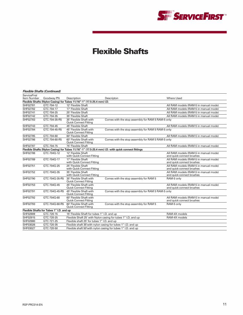
11RSP-PRC014-EN
Flexible Shafts
Flexible Shafts (Continued)
ServiceFirstItem Number Goodway PN Description Descripton Where UsedFlexible Shafts (Nylon Casing) for Tubes 11/16”-1” (17.5-25.4 mm) I.D.
SHF02781 GTC-704-12 12’ Flexible Shaft All RAM models (RAM-5 in manual mode)SHF02782 GTC-704-17 17’ Flexible Shaft All RAM models (RAM-5 in manual mode)SHF02741 GTC-704-25 25’ Flexible Shaft All RAM models (RAM-5 in manual mode)SHF02742 GTC-704-35 35’ Flexible Shaft All RAM models (RAM-5 in manual mode)SHF02783 GTC-704-35-R5 35’ Flexible Shaft with Comes with the stop assembly for RAM 5 RAM-5 only
Quick Connect FittingSHF02743 GTC-704-45 45’ Flexible Shaft All RAM models (RAM-5 in manual mode)SHF02784 GTC-704-45-R5 45’ Flexible Shaft with Comes with the stop assembly for RAM 5 RAM-5 only
Quick Connect FittingSHF02785 GTC-704-60 60’ Flexible Shaft All RAM models (RAM-5 in manual mode)SHF02786 GTC-704-60-R5 60’ Flexible Shaft with Comes with the stop assembly for RAM 5 RAM-5 only
Quick Connect FittingSHF02787 GTC-704-75 75’ Flexible Shaft All RAM models (RAM-5 in manual mode)Flexible Shafts (Nylon Casing) for Tubes 11/16”-1” (17.5-25.4 mm) I.D. with quick connect fittings
SHF02788 GTC-704Q-12 12’ Flexible Shaft All RAM models (RAM-5 in manual mode)with Quick Connect Fitting and quick connect brushes
SHF02789 GTC-704Q-17 17’ Flexible Shaft All RAM models (RAM-5 in manual mode)with Quick Connect Fitting and quick connect brushes
SHF02751 GTC-704Q-25 25’ Flexible Shaft All RAM models (RAM-5 in manual mode)with Quick Connect Fitting and quick connect brushes
SHF02752 GTC-704Q-35 35’ Flexible Shaft All RAM models (RAM-5 in manual mode)with Quick Connect Fitting and quick connect brushes
SHF02790 GTC-704Q-35-R5 35’ Flexible Shaft with Comes with the stop assembly for RAM 5 RAM-5 onlyQuick Connect Fitting
SHF02753 GTC-704Q-45 45’ Flexible Shaft with All RAM models (RAM-5 in manual mode)Quick Connect Fitting and quick connect brushes
SHF02791 GTC-704Q-45-R5 45’ Flexible Shaft with Comes with the stop assembly for RAM 5 RAM-5 onlyQuick Connect Fitting
SHF02792 GTC-704Q-60 60’ Flexible Shaft with All RAM models (RAM-5 in manual mode)Quick Connect Fitting and quick connect brushes
SHF02793 GTC-704Q-60-R5 60’ Flexible Shaft with Comes with the stop assembly for RAM 5 RAM-5 onlyQuick Connect Fitting
Flexible Shafts for Tubes 1” I.D. and up
SHF02909 GTC-720-15 15’ Flexible Shaft for tubes 1” I.D. and up RAM-4X modelsSHF02915 GTC-720-25 Flexible Shaft 25’ with Nylon casing for tubes 1” I.D. and up RAM-4X modelsSHF02980 GTC-721-25 Flexible shaft 25’ for tubes 1” I.D. and upSHF03026 GTC-720-35 Flexible shaft 35’with nylon casing for tubes 1” I.D. and upSHF03027 GTC-720-50 Flexible shaft 50’with nylon casing for tubes 1” I.D. and up
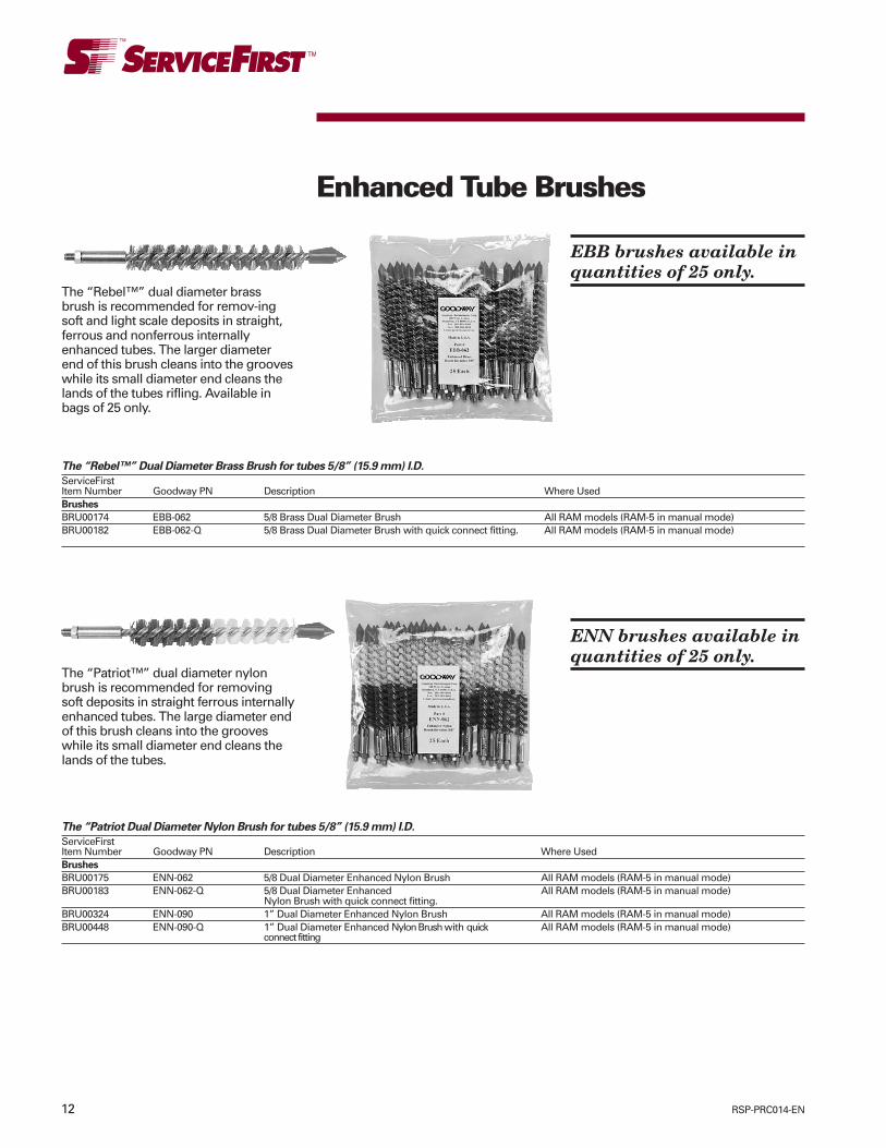
12 RSP-PRC014-EN
The “Rebel™” dual diameter brassbrush is recommended for remov-ingsoft and light scale deposits in straight,ferrous and nonferrous internallyenhanced tubes. The larger diameterend of this brush cleans into the grooveswhile its small diameter end cleans thelands of the tubes rifling. Available inbags of 25 only.
Enhanced Tube Brushes
The “Rebel™” Dual Diameter Brass Brush for tubes 5/8” (15.9 mm) I.D.
ServiceFirstItem Number Goodway PN Description Where UsedBrushes
BRU00174 EBB-062 5/8 Brass Dual Diameter Brush All RAM models (RAM-5 in manual mode)BRU00182 EBB-062-Q 5/8 Brass Dual Diameter Brush with quick connect fitting. All RAM models (RAM-5 in manual mode)
The “Patriot™” dual diameter nylonbrush is recommended for removingsoft deposits in straight ferrous internallyenhanced tubes. The large diameter endof this brush cleans into the grooveswhile its small diameter end cleans thelands of the tubes.
The “Patriot Dual Diameter Nylon Brush for tubes 5/8” (15.9 mm) I.D.
ServiceFirstItem Number Goodway PN Description Where UsedBrushes
BRU00175 ENN-062 5/8 Dual Diameter Enhanced Nylon Brush All RAM models (RAM-5 in manual mode)BRU00183 ENN-062-Q 5/8 Dual Diameter Enhanced All RAM models (RAM-5 in manual mode)
Nylon Brush with quick connect fitting.BRU00324 ENN-090 1” Dual Diameter Enhanced Nylon Brush All RAM models (RAM-5 in manual mode)BRU00448 ENN-090-Q 1” Dual Diameter Enhanced Nylon Brush with quick All RAM models (RAM-5 in manual mode)
connect fitting
EBB brushes available inquantities of 25 only.
ENN brushes available inquantities of 25 only.

13RSP-PRC014-EN
The “GTC” blue nylon brushes arerecommended for removing softdeposits (mud, algae, etc.) in straight,ferrous and nonferrous tubes. Brushshould be equal to or 1/16” (1.6 mm)smaller than the tube I.D.
Nylon Brushes
“GTC” brushes for smooth bore tubes
ServiceFirstItem Number Min. Req’d Goodway PN Description Where UsedBrushes - Nylon Under 1”
BRU00189 15 GTC-211-1 1” Blue Nylon Brush All RAM modelsBRU00188 15 GTC-211-1/2” 1/2” Blue Nylon Brush All RAM modelsBRU00202 15 GTC-211-1/4 1/4” Blue Nylon Brush All RAM modelsBRU00170 25 GTC-211-11/16 11/16 Blue Nylon Brush All RAM modelsBRU00203 15 GTC-211-13/16 13/16” Blue Nylon Brush All RAM modelsBRU00204 15 GTC-211-15/16 15/16” Blue Nylon Brush All RAM modelsBRU00171 25 GTC-211-3/4 3/4” Blue Nylon Brush All RAM modelsBRU00186 15 GTC-211-3/8 3/8” Blue Nylon Brush All RAM modelsBRU00259 15 GTC-211-5/16 5/16” Blue Nylon Brush All RAM modelsBRU00169 25 GTC-211-5/8 5/8” Blue Nylon Brush All RAM modelsBRU00205 15 GTC-211-7/16 7/16” Blue Nylon Brush All RAM modelsBRU00206 15 GTC-211-7/8 7/8” Blue Nylon Brush All RAM modelsBRU00168 25 GTC-211-9/16 9/16” Blue Nylon Brush All RAM modelsBRU00187 15 GTC-211Q-1 1” Blue Nylon Brush with quick connect fittings. All RAM models with quick connect flexible shaftBRU00260 15 GTC-211Q-1/2 1/2” Blue Nylon Brush with quick connects fittings All RAM models with quick connect flexible shaftBRU00178 25 GTC-211Q-11/16 1 1/16” Blue Nylon Brush with quick connect fittings All RAM models with quick connect flexible shaftBRU00261 15 GTC-211Q-13/16 13/16” Blue Nylon Brush with quick connect fittings All RAM models with quick connect flexible shaftBRU00262 15 GTC-211Q-15/16 15/16” Blue Nylon Brush with quick connect fittings All RAM models with quick connect flexible shaftBRU00179 25 GTC-211Q-3/4 3/4” Blue Nylon Brush with quick connect fittings All RAM models with quick connect flexible shaftBRU00177 25 GTC-211Q-5/8 5/8” Blue Nylon Brush with quick connect fittings All RAM models with quick connect flexible shaftBRU00263 15 GTC-211Q-7/16 7/16” Blue Nylon Brush with quick connect fittings All RAM models with quick connect flexible shaftBRU00264 15 GTC-211Q-7/8 7/8” Blue Nylon Brush with quick connect fittings All RAM models with quick connect flexible shaftBRU00176 25 GTC-211Q-9/16 9/16” Blue Nylon Brush with quick connect fittings All RAM models with quick connect flexible shaft
GTC-211 brushesavailable in quantities of15 or 25 only. See tablebelow.

14 RSP-PRC014-EN
The (Spin-Grit) brushes arerecommended for removing soft andlight scale deposits in straight, ferrousand nonferrous tubes. The abrasiveimpregnated nylon bristles of the brushclean and polish tubes in one step.Unlike regular spiral brushes, Spin-Grit isdesigned to be oversized in the tube sothat the bristles lay over, putting theabrasive in contact.
Spin Grit Brushes
“SGB and ESGB” Spin-grit Brushes
ServiceFirst Min.Item Number Req’d Goodway PN Description Where UsedBRU00193 15 ESGB-050 Dual Diameter Spin-Grit Brush for tubes 1/2” (12.7mm) I.D. All RAM models (RAM-5 in manual mode)BRU00184 15 ESGB062 Dual Diameter Spin-Grit Brush for tubes 5/8” I.D. All RAM models (RAM-5 in manual mode)BRU00194 15 ESGB-075 Dual Diameter Spin-Grit Brush for tubes 3/4” (19.1mm) I.D. All RAM models (RAM-5 in manual mode)BRU00190 15 ESGB-100 Dual Diameter Spin-Grit Brush for tubes 1” (2.4mm) I.D. All RAM models (RAM-5 in manual mode)BRU00213 15 ESGB-125 Spin-Grit Brush enhanced for 1 1/4” I.D. tubes All RAM models (RAM-5 in manual mode)BRU00214 15 ESGB-Q-050 Spin-Grit Brush enhanced for 1/2” I.D. tubes All RAM models (RAM-5 in manual mode)
w/quick connect fittings and quick connect brushesBRU00215 15 ESGB-Q-062 Spin-Grit Brush enhanced for 5/8” I.D. tubes All RAM models (RAM-5 in manual mode)
w/quick connect fittings and quick connect brushesBRU00216 15 ESGB-Q-075 Spin-Grit Brush enhanced for 3/4” I.D. tubes All RAM models (RAM-5 in manual mode)
and w/ quick connect fittings quick connect brushesBRU00217 15 ESGB-Q-100 Spin-Grit Brush enhanced for 1” I.D. tubes All RAM models (RAM-5 in manual mode)
w/quick connect fittings and quick connect brushesBRU00218 15 ESGB-Q-125 Spin-Grit Brush enhanced for 1 1/4” I.D. tubes All RAM models (RAM-5 in manual mode)
w/quick connect fittings and quick connect brushesBRU00207 15 SGB-050 Spin-Grit Brush for tubes 1/4” - 3/8” (6.4-9.5mm) I. D. All RAM models (RAM-5 in manual mode)BRU00172 15 SGB-075 Spin-Grit Brush for tubes 7/16” - 5/8” I.D. All RAM models (RAM-5 in manual mode)BRU00173 15 SGB-100 Spin-Grit Brush for tubes 11/16” - 3/4” I.D. All RAM models (RAM-5 in manual mode)BRU00191 15 SGB-125 Spin-Grit Brush for tubes 13/16”-1”(20.6-25.4MM) I.D. All RAM models (RAM-5 in manual mode)BRU00180 15 SGB-Q-075 Spin-Grit Brush for tubes 7/16” - 5/8” I.D. with All RAM models (RAM-5 in manual mode)
quick connect fittings and quick connect brushesBRU00181 15 SGB-Q-100 Spin-Grit Brush for tubes 11/16”-3/4” I.D. with All RAM models (RAM-5 in manual mode)
quick connect fittings and quick connect brushesBRU00266 15 SGB-Q-125 Spin-Grit Brush for 13/16” tubes w/quick connect fittings All RAM models (RAM-5 in manual mode)
and quick connect brushes
ESGB and SGB brushesavailable in quantities of15 only.

15RSP-PRC014-EN
Brass brushes are recommended forremoving soft and light scale depositsin straight, ferrous and nonferrous tubes.Brush should be equal to or1/16” smaller than tube I.D.
Brass Brushes
Brushes - Brass
ServiceFirst Min.Item Number Req’d Goodway PN Description Where UsedBRU00219 15 GTC-200B-1 Brass brush for 1” tubes All RAM models (RAM-5 in manual mode)BRU00220 15 GTC-200B-1/2 Brass brush for 1/2” tubes All RAM models (RAM-5 in manual mode)BRU00221 15 GTC-200B-1/4 Brass brush for 1/4” tubes All RAM models (RAM-5 in manual mode)BRU00197 15 GTC-200B-11/16 Brass brush for 11/16” tubes All RAM models (RAM-5 in manual mode)BRU00198 15 GTC-200B-13/16 Brass brush for 13/16” tubes All RAM models (RAM-5 in manual mode)BRU00199 15 GTC-200B-15/16 Brass brush for 15/16” tubes All RAM models (RAM-5 in manual mode)BRU00222 15 GTC-200B-3/4 Brass brush for 3/4” tubes All RAM models (RAM-5 in manual mode)BRU00223 15 GTC-200B-3/8 Brass brush for 3/8” tubes All RAM models (RAM-5 in manual mode)BRU00224 15 GTC-200B-5/16 Brass brush for 5/16” tubes All RAM models (RAM-5 in manual mode)BRU00192 15 GTC-200B-5/8” Brass brush for 5/8” tubes All RAM models (RAM-5 in manual mode)BRU00225 15 GTC-200B-7/16 Brass brush for 7/16” tubes All RAM models (RAM-5 in manual mode)BRU00200 15 GTC-200B-7/8 Brass brush for 7/8” tubes All RAM models (RAM-5 in manual mode)BRU00201 15 GTC-200B-9/16 Brass brush for 9/16” tubes All RAM models (RAM-5 in manual mode)BRU00226 15 GTC-200BQ-1 Brass brush for 1” tubes w/quick connect fittings All RAM models (RAM-5 in manual mode) with
quick connect flexible shaftBRU00227 15 GTC-200BQ-1/2 Brass brush for 1/2” tubes w/ quick connect fittings All RAM models (RAM-5 in manual mode) with
quick connect flexible shaftBRU00228 15 GTC-200BQ-11/16 Brass brush for 11/16” tubes w/quick connect fittings All RAM models (RAM-5 in manual mode) with
quick connect flexible shaftBRU00229 15 GTC-200BQ-13/16 Brass brush for 13/16” tubes w/ quick connect fittings All RAM models (RAM-5 in manual mode) with
quick connect flexible shaftBRU00230 15 GTC-200BQ-15/16 Brass brush for 15/16” tubes w/ quick connect fittings All RAM models (RAM-5 in manual mode) with
quick connect flexible shaftBRU00231 15 GTC-200BQ-3/4 Brass brush for 3/4” tubes w/quick connect fittings All RAM models (RAM-5 in manual mode) with
quick connect flexible shaftBRU00232 15 GTC-200BQ-5/8 Brass brush for 5/8” tubes w/quick connect fittings All RAM models (RAM-5 in manual mode) wit
quick connect flexible shaftBRU00233 15 GTC-200BQ-7/16 Brass brush for 7/16” tubes w/quick connect fittings All RAM models (RAM-5 in manual mode) with
quick connect flexible shaftBRU00234 15 GTC-200BQ-7/8 Brass brush for 7/8” tubes w/ quick connect fittings All RAM models (RAM-5 in manual mode) with
quick connect flexible shaftBRU00235 15 GTC-200BQ-9/16 Brass brush for 9/16” tube w/quick connect fittings All RAM models (RAM-5 in manual mode) with
quick connect flexible shaft
GTC-200B brushesavailable in quantities of15 only.

16 RSP-PRC014-EN
Stainless Brushes
Stainless Steel Brushes
ServiceFirstItem Number Min Req’d Goodway PN DescriptionBRU00236 15 GTC-210-1 Stainless steel brush for 1” tubesBRU00237 15 GTC-210-1/2 Stainless steel brush for 1/2” tubesBRU00238 15 GTC-210-1/4 Stainless steel brush for 1/4” tubesBRU00239 15 GTC-210-11/16 Stainless steel brush for 11/16” tubesBRU00240 15 GTC-210-13/16 Stainless steel brush for 13/16” tubesBRU00241 15 GTC-210-15/16 Stainless steel brush for 15/16” tubesBRU00242 15 GTC-210-3/4 Stainless steel brush for 3/4” tubesBRU00243 15 GTC-210-3/8 Stainless steel brush for 3/8” tubesBRU00244 15 GTC-210-5/16 Stainless steel brush for 5/16” tubesBRU00245 15 GTC-210-5/8 Stainless steel brush for 5/8” tubesBRU00246 15 GTC-210-7/16 Stainless steel brush for 7/16” tubesBRU00247 15 GTC-210-7/8 Stainless steel brush for 7/8” tubesBRU00248 15 GTC-210-9/16 Stainless steel brush for 9/16” tubesBRU00249 15 GTC-210Q-1 Stainless steel brush for 1” tubes w/quick connect fittingsBRU00250 15 GTC-210Q-1/2 Stainless steel brush for 1/2” tubes w/quick connect fittingsBRU00251 15 GTC-210Q-11/16 Stainless steel brush for 11/16” tubes w/quick connect fittingsBRU00252 15 GTC-210Q-13/16 Stainless steel brush for 13/16” tubes w/quick connect fittingsBRU00253 15 GTC-210Q-15/16 Stainless steel brush for 15/16” tubes w/quick connect fittingsBRU00254 15 GTC-210Q-3/4 Stainless steel brush for 3/4” tubes w/quick connect fittingsBRU00255 15 GTC-210Q-5/8 Stainless steel brush for 5/8” tubes w/quick connect fittingsBRU00256 15 GTC-210Q-7/16 Stainless steel brush for 7/16” tubes w/quick connect fittingsBRU00257 15 GTC-210Q-7/8 Stainless steel brush for 7/8” tubes w/quick connect fittingsBRU00258 15 GTC-210Q-9/16 Stainless steel brush for 9/16” tubes w/quick connect fittings
Stainless Steel Brushes arerecommended for removing soft andlight scale deposits in straight ferroustubes. Brush should be equal to or1/16” smaller than the tube I.D.
GTC-210 brushesavailable in quantities of15 only.

17RSP-PRC014-EN
MiscellaneousCleaning ToolsStainless steel wire buffing tools areused for removing light to medium scaledeposits or for finishing tubes previously“roughed out” with other cleaning tools.They can be used in straight, ferrous andnonferrous tubes. Buffing tools can onlybe used in a clockwise direction andcannot be used in internally enhancedtubes.
Adjustable Buffing Tool and Scraper Tool
ServiceFirstItem Number Goodway PN Description Where UsedTOL01710 GTC-203 Cutting/Buffing Tool 5/16” - 3/8” I.D. tubes All RAM models (RAM-5 in manual mode)TOL01711 GTC-203DT Cutting/Buffing tool 5/16” - 3/8” I.D. tubes All RAM models (RAM-5 in manual mode)TOL01680 GTC-204 Stainless Steel Wire buffing tool for tubes - 3/8” - 1/2” (9.5-12.7mm) I. D. All RAM models (RAM-5 in manual mode)TOL01664 GTC-204-DT Buffing Tool for tubes 3/8”-1/2” (I.D.) with drill tip All RAM models (RAM-5 in manual mode)TOL01712 GTC-204Q Cutting/Buffing tool 3/8” - 1/2” I.D. tubes w/quick connect fittings All RAM models (RAM-5 in manual mode)TOL01681 GTC-205 Stainless Steel Wire buffing tool for tubes - 1/2” - 9/16” (12.7-14.3) I.D. All RAM models (RAM-5 in manual mode)TOL01665 GTC-205-DT Buffing Tool for tubes 1/2”-9/16” (I.D.) with drill tip All RAM models (RAM-5 in manual mode)TOL01713 GTC-205Q Cutting/Buffing tool 1/2” - 9/16” I.D. tubes w/quick connect fittings All RAM models (RAM-5 in manual mode)TOL01714 GTC-205Q-DT Cutting/Buffing tool 1/2” - 9/16” I.D. tubes w/quick connect fittings & drill tip All RAM models (RAM-5 in manual mode)TOL01682 GTC-206 Stainless Steel Wire buffing tool for tubes - 5/8” - 1” (15.9-25.4mm) I.D. All RAM models (RAM-5 in manual mode)TOL01667 GTC-206-DT Buffing Tool for tubes 5/8”-1”(I.D.) with drill tip All RAM models (RAM-5 in manual mode)TOL01715 GTC-206Q Cutting/Buffing tool for 5/8” - 1” I.D. tubes w/quick connect fittings All RAM models (RAM-5 in manual mode)TOL01716 GTC-206Q-DT Cutting/Buffing tools for 5/8” - 1” I.D. tubes w/quick connect fittings and drill tip All RAM models (RAM-5 in manual mode)BLD01014 GTC-207 Replacement blades for GTC-203 and GTC-204 All GTC-203 and GTC-204 Buffing toolsBLD01015 GTC-208A Replacement blades for GTC-205 All GTC-205 Buffing ToolsBLD01016 GTC-208B Replacement blades for GTC-206 All GTC-206 Buffing ToolsTOL01717 GTC-209 Adjusting jig for GTC-203(DT) and GTC-204(DT) All GTC-203 and GTC-204 Buffing toolsTOL01666 TST-500 Triangular Scraper Tool 5/8-1” I.D. All RAM models (RAM-5 in manual mode)TOL03333 TST-750 Rotary Scraper Tool 3/4-1” I.D. All RAM models (RAM-5 in manual mode)
Triangular scraper tools are used forremoving heavy scale deposits instraight, ferrous tubes. They can only beused in a clockwise direction and cannotbe used in internally enhanced tubes.
Flex-hone abrasive tools are lightpressure, soft application honing devicesfor cleaning straight, ferrous tubes. Theyconsist of 180 grit silicon carbideabrasive globules (stones) bonded to
Flex Hone Abrasive Tools
ServiceFirstItem Number Goodway PN Description Where UsedTOL01700 FHT-025 1/4”flex hone All RAM models (RAM-5 in manual mode)TOL01701 FHT-031 5/16” flex hone All RAM models (RAM-5 in manual mode)TOL01702 FHT-037 3/8” flex hone All RAM models (RAM-5 in manual mode)TOL01703 FHT-043 7/16” flex hone All RAM models (RAM-5 in manual mode)TOL01704 FHT-050 1/2”flex hone All RAM models (RAM-5 in manual mode)TOL01705 FHT-056 9/16” flex hone All RAM models (RAM-5 in manual mode)TOL01698 FHT-062 5/8”flex hone All RAM models (RAM-5 in manual mode)TOL01706 FHT-068 11/16” flex hone All RAM models (RAM-5 in manual mode)TOL01707 FHT-075 3/4” flex hone All RAM models (RAM-5 in manual mode)TOL01708 FHT-087 7/8” flex hone All RAM models (RAM-5 in manual mode)TOL01709 FHT-100 1” flex hone All RAM models (RAM-5 in manual mode)TOL01924 FHT-043-Q 7/16” flex hone with quick connect All RAM models (RAM-5 in manual mode)TOL01925 FHT-050-Q 1/2” flex hone with quick connect All RAM models (RAM-5 in manual mode)TOL01926 FHT-056-Q 9/16” flex hone with quick connect All RAM models (RAM-5 in manual mode)TOL01927 FHT-062-Q 5/8” flex hone with quick connect All RAM models (RAM-5 in manual mode)TOL01928 FHT-068-Q 11/16” flex hone with quick connect All RAM models (RAM-5 in manual mode)TOL01929 FHT-075-Q 3/4” flex hone with quick connect All RAM models (RAM-5 in manual mode)TOL01930 FHT-087-Q 7/8” flex hone with quick connect All RAM models (RAM-5 in manual mode)TOL01931 FHT-100-Q 1” flex hone with quick connect All RAM models (RAM-5 in manual mode)
high density nylon filaments. Order toolto correspond to tube I.D. Note: Flex-Hone abrasive tools are normally usedwith a water flush for maximum life.
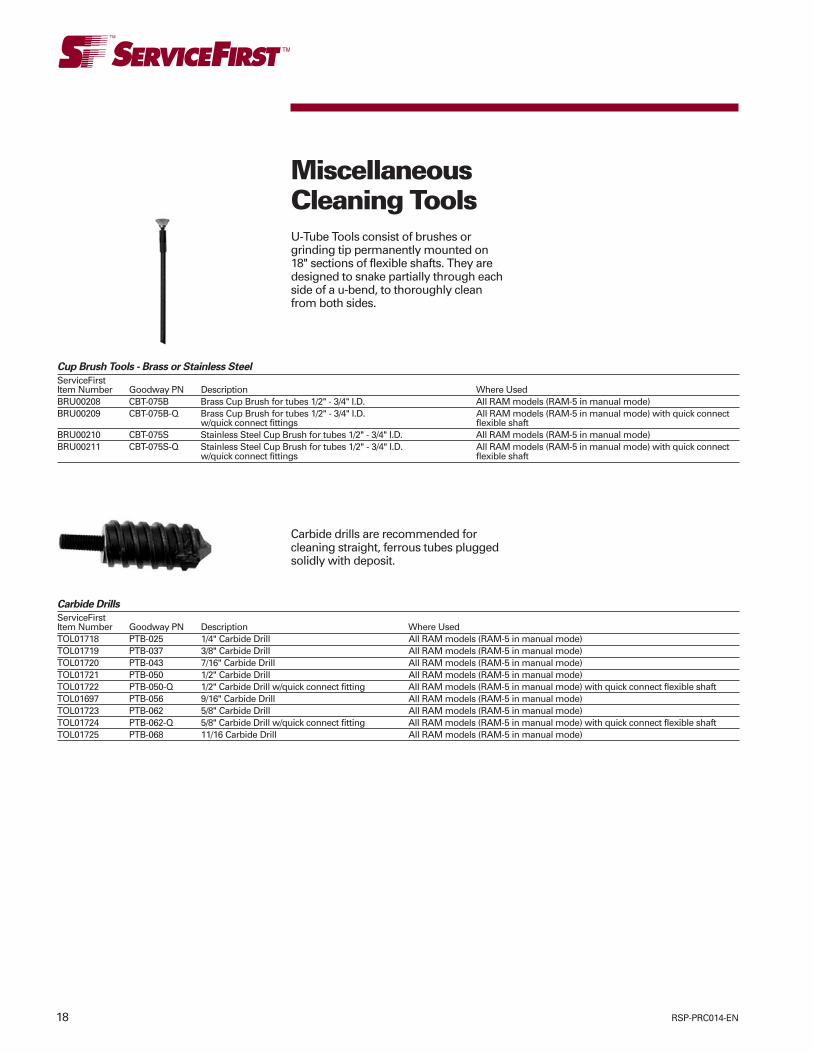
18 RSP-PRC014-EN
MiscellaneousCleaning Tools
Cup Brush Tools - Brass or Stainless Steel
ServiceFirstItem Number Goodway PN Description Where UsedBRU00208 CBT-075B Brass Cup Brush for tubes 1/2" - 3/4" I.D. All RAM models (RAM-5 in manual mode)BRU00209 CBT-075B-Q Brass Cup Brush for tubes 1/2" - 3/4" I.D. All RAM models (RAM-5 in manual mode) with quick connect
w/quick connect fittings flexible shaftBRU00210 CBT-075S Stainless Steel Cup Brush for tubes 1/2" - 3/4" I.D. All RAM models (RAM-5 in manual mode)BRU00211 CBT-075S-Q Stainless Steel Cup Brush for tubes 1/2" - 3/4" I.D. All RAM models (RAM-5 in manual mode) with quick connect
w/quick connect fittings flexible shaft
U-Tube Tools consist of brushes orgrinding tip permanently mounted on18" sections of flexible shafts. They aredesigned to snake partially through eachside of a u-bend, to thoroughly cleanfrom both sides.
Carbide drills are recommended forcleaning straight, ferrous tubes pluggedsolidly with deposit.
Carbide Drills
ServiceFirstItem Number Goodway PN Description Where UsedTOL01718 PTB-025 1/4" Carbide Drill All RAM models (RAM-5 in manual mode)TOL01719 PTB-037 3/8" Carbide Drill All RAM models (RAM-5 in manual mode)TOL01720 PTB-043 7/16" Carbide Drill All RAM models (RAM-5 in manual mode)TOL01721 PTB-050 1/2" Carbide Drill All RAM models (RAM-5 in manual mode)TOL01722 PTB-050-Q 1/2" Carbide Drill w/quick connect fitting All RAM models (RAM-5 in manual mode) with quick connect flexible shaftTOL01697 PTB-056 9/16" Carbide Drill All RAM models (RAM-5 in manual mode)TOL01723 PTB-062 5/8" Carbide Drill All RAM models (RAM-5 in manual mode)TOL01724 PTB-062-Q 5/8" Carbide Drill w/quick connect fitting All RAM models (RAM-5 in manual mode) with quick connect flexible shaftTOL01725 PTB-068 11/16 Carbide Drill All RAM models (RAM-5 in manual mode)

19RSP-PRC014-EN
Miscellaneous
Two-direction foot switch
ServiceFirstItem Number Goodway PN DESCRIPTION Where UsedSWT02435 834R Two-direction foot switch for RAM-4-60 RAM-4-60SWT02455 834R-SF Two-directional foot switch for use with RAM-5 RAM-5SF VSNote: Foot switch allows user to clean internally enhanced tubes
Flexible shaft repair kits include 4 driveend repair couplings, 4 thrust washers, 4tool end repair couplings, 1 crimpingtool with punch, 1 flexible shaftlubricator with quick disconnect, and 2bottles (16 ounces) [0.5 liter] each oflubricant for flexible shaft lubricator.
Flexible Shaft Maintenance and Repair
ServiceFirstItem Number Goodway PN Description Where UsedRepair Kits
KIT07643 REP-701-KIT Repair Kit for GTC701 Shafts GTC-701 series flexible shaftsKIT07644 REP-702-KIT Repair Kit for GTC702 Shafts GTC-702 series flexible shaftsKIT07646 REP-702Q-KIT Repair Kit for GTC702 Shafts w/quick connect fittings GTC-702Q series flexible shaftsSHF02740 REP-703-KIT Repair Kit for GTC-703 shafts GTC-703 series flexible shaftsSHF02750 REP-703Q-KIT Repair Kit for GTC703 Shafts w/quick connect fittings GTC-703Q series flexible shaftsSHF02744 REP-704-KIT Repair Kit for GTC-704 shafts GTC-704 series flexible shaftsSHF02754 REP-704Q-KIT Repair Kit for GTC704 Shafts w/quick connect fittings GTC-704Q series flexible shaftsRepair Couplings & Tools
CPL00982 713-1 Drive End Repair Crimp Coupling for GTC-701 shafts GTC-701 series flexible shaftsCPL00983 713-2 Drive End Repair Crimp Coupling for GTC-702 shafts GTC-702 series flexible shaftsCPL00975 713-3 Crimp Coupling, drive-end for GTC-703 Shafts GTC-703 series flexible shaftsCPL00984 713-4 Drive End Repair Clamp Coupling for GTC-720, GTC-721,
GTC-721G and GTC-821 Shafts GTC-720 and 820 series flexible shaftsCPL00976 713-5 Crimp Coupling, drive-end for GTC-704 Shafts GTC-704 series flexible shaftsWAS01026 715-1 Thrust washer for GTC-701, 702 & 703 Shafts GTC-701, 702 and 703 series flexible shaftsWAS01027 715-6 Thrust washer for GTC-704 shafts GTC-704 series flexible shaftsCPL00985 717-1 Tool End Repair Crimp Coupling for GTC-701 shafts GTC-701 series flexible shaftsCPL00986 717-2 Tool End Repair Crimp Coupling for GTC-702 shafts GTC-702 series flexible shaftsCPL00990 717-2Q Crimp Coupling for GTC-702 quick connect shafts GTC-702Q series flexible shaftsCPL00977 717-3 Crimp Coupling, tool-end for GTC-703 Shafts GTC-703 series flexible shaftsCPL00978 717-3Q Crimp Coupling for GTC-703 quick connect shafts GTC-703Q series flexible shaftsCPL00987 717-4 Tool End Repair Crimp Coupling for GTC-720, GTC-721,
GTC-721G and GTC-821 Shafts GTC-720 and 820 series flexible shaftsCPL00979 717-6 Crimp Coupling, tool-end for GTC-704 Shafts GTC-704 series flexible shaftsCPL00980 717-6Q Crimp Coupling for GTC-704 quick connect shafts GTC-704Q series flexible shaftsTOL01684 GTC-CT5 Crimping Tool with punch for flexible shaft repair Fits all flexible shaftsTOL01696 GTC-CTP Replacement punch for GTC-CT5 For use with GTC-CT5Shaft Maintenance
TOL01699 GSL-705 Flexible Shaft Lubricator GTC-701, 702, 703 and 704 series flexible shaftsLUB00039 GSL-LU1 16 oz. bottle of Flexible Shaft lubricator fluid For use with GSL-705PLU00923 GTC-705-8 Sight glass plug for GSL-705 lubricator For use with GSL-705

20 RSP-PRC014-EN
Specifications
Motor: 1.7 hp, 15 amps, 115VOutput Water Pressure: 1,200 psi @ 1.8 GPMPump: Triplex plunger running in oil bathDimensions: 10 1/2" high x 15" wide x 9" deepWeight: 41 lbs net dry
The GPW-1200 portable pressure washeris designed to be carried easily upladders and into tight locations. The unitis ideal for a wide range of applications,from cleaning HVAC drip pans in ceilingsto delicate air conditioning coils onrooftops.
Pressure washing is an efficient andcost-effective method of cleaning avariety of surfaces and equipment foundin most facilities. High-pressure washingshould be considered as a viablecleaning option since it is a fast, easyand effective way to remove unwantedsoil, oil, grease, gun, mildew, mold,debris and discoloration from mostsurfaces.
When comparing pressure washers, lookat the following:
Pounds Per Square Inch (PSI), themeasurement of water pressure. The
GPW-1200 – (TOL01679) – PortablePressure Washer 1200 psi @ 1.8 gpm
greater the psi, the better the cleaningefficiency.
Gallons Per Minute (GPM) which refersto the water flow rate.
Cleaning Units (CU) is the waterpressure multiplied by the water flow. Ahigher number means more power.
Features/Benefits:• Stainless steel construction – long life• Steel reinforced hose – rugged• Stainless steel want – durable• Variable pressure nozzle – matches
application• Can use hot water – additional cleaning
power• Soap container – easy injection of
chemicals
Included with Purchase:• 3’ wand• 25’ hi-pressure hose• Variable pressure nozzle• Soap container
The GPW-1000 pressure washer replacesinefficient cleaning methods witheconomical pressure washing. The unitsaves labor, decreases downtime andreduces costs. Designed for easyhandling, transport and storage, it is thebest compact pressure washer in itsclass.
Features/Benefits:• Stainless steel construction – long life• Steel reinforced hose – rugged• Stainless steel wand – durable
Specifications
Motor: 1 1/2 hp, 15 amps, 115VOutput Water Pressure: 1,000 psi @ 2.2 GPMPump: Twin-piston cast ironDimensions: 37" high x 20" wide x 17" deepWeight: 83 lbs net dry
GPW-1000-60 – (TOL01726) –Pressure Washer 1000 psi@ 2.2 gpm
• Five quick disconnect nozzles –matches application
• Can use hot water – additional cleaningpower
• Soap container – easy injection ofchemicals
Included with Purchase:• 3’ wand• 25’ high pressure hote• Five (5) quick disconnect nozzles• Soap container• Dolly
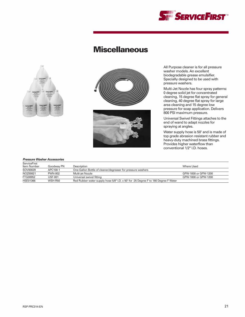
21RSP-PRC014-EN
Miscellaneous
Pressure Washer Accessories
ServiceFirstItem Number Goodway PN Description Where UsedSOV00029 APC100-1 One-Gallon Bottle of cleaner/degreaser for pressure washersNOZ00821 PWN-002 Multi-jet Nozzle GPW-1000 or GPW-1200FTG00952 USF-001 Universal swivel fitting GPW-1000 or GPW-1200HSE01366 WSH-R50 Red Rubber water supply hose 5/8" I.D. x 50' for -25 Degree F to 180 Degree F Water
All Purpose cleaner is for all pressurewasher models. An excellentbiodegradable grease emulsifier.Specially designed to be used withpressure washers.
Multi-Jet Nozzle has four spray patterns:0 degree solid jet for concentratedcleaning, 15 degree flat spray for generalcleaning, 40 degree flat spray for largearea cleaning and 15 degree lowpressure for soap application. Delivers800 PSI maximum pressure.
Universal Swivel Fittings attaches to theend of wand to adapt nozzles forspraying at angles.
Water supply hose is 50' and is made oftop grade abrasion resistant rubber andheavy-duty machined brass fittings.Provides higher waterflow thanconventional 1/2" I.D. hoses.
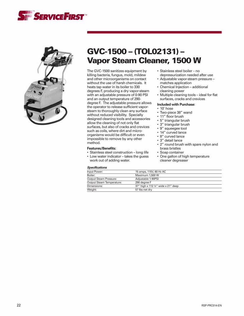
22 RSP-PRC014-EN
The GVC-1500 sanitizes equipment bykilling bacteria, fungus, mold, mildewand other microorganisms on contactwithout the use of harsh chemicals. Itheats tap water in its boiler to 330degrees F, producing a dry vapor-steamwith an adjustable pressure of 0-90 PSIand an output temperature of 290-degree F. The adjustable pressure allowsthe operator to release sufficient vapor-steam to thoroughly clean any surfacewithout reduced visibility. Speciallydesigned cleaning tools and accessoriesallow the cleaning of not only flatsurfaces, but also of cracks and crevicessuch as coils, where dirt and micro-organisms would be difficult or evenimpossible to remove by any othermethod.
Features/Benefits:• Stainless steel construction – long life• Low water indicator – takes the guess
work out of adding water.
GVC-1500 – (TOL02131) –Vapor Steam Cleaner, 1500 W
• Stainless steel boiler – nodepressurization needed after use
• Adjustable vapor-steam pressure –matches application
• Chemical Injection – additionalcleaning power
• Multiple cleaning tools – ideal for flatsurfaces, cracks and crevices
Included with Purchase:• 10’ hose• Two-piece 38” wand• 11” floor brush• 5” triangular brush• 3” triangular brush• 9” squeegee tool• 14” curved lance• 8” curved lance• 3” detail lance• 2” round brush with spare nylon and
brass bristles• Soap container• One gallon of high temperature
cleaner degreaser
Specifications
Input Power: 15 amps, 115V, 60 Hz ACBoiler: Maximum 1,500 WOutput Steam Pressure: Adjustable 1-90PSIOutput Steam Temperature: 290 degree FDimensions: 37” high x 112 ½” wide x 21” deepWeight: 57 lbs net dry

23RSP-PRC014-EN
The EV-60-P twin motor wet vacuum isequipped with an internal pump forcontrolled discharge of recoveredliquids. It has two independent motorswitches, as well as an independent plugfor the pump. Recovered liquids can bedischarged while vacuuming or pumpedout later. With both motors on, thevacuum produces a static water lift of82” and an air displacement of 120 CFM.The unit comes with a hose, three-section wand and a squeegee floor toolto cover a wide variety of wetapplications.
EV-60-P – (TOL01897) –Commercial Pump-Out Vacuum
Features/Benefits:• Internal pump – controlled discharge of
liquids• Two heavy duty motors – strong
suction• Independent motor switches – can run
on one of both motors• Stainless steel tank – fits any
application• Liquid shut-off – prevents overflow• Reusable filter – saves money• Cord hook – easy storage of power
supply cord
Included with purchase:• 20.6 gallon stainless steel tank with
internal pump• Handle• Wheels and casters• 8 ½’ vinyl crush proof hose• Three-piece 52’ wand• 16” squeegee floor tool
Specifications
Motor: 2 hp, 16 amps, 115VPower Supply Cord: 27'Static Water Lift 82"Air Displacement: 120 cfmDimensions: 17" diameter tank, 41" high overallWeight: 69 lbs.
Specifications
Motor: 1.6 hp, 10 amps, 115VPower Supply Cord 27'Static Water Lift 90"Air Displacement: 115 CFMDimensions: 13" diameter tank, 32" high overallWeight: 26 lbsDry Capacity: 3.2 gallonsHEPA Filter Certified 99.97% efficient @ 0.3 microns
The EV-30H dry HEPA vacuum is the unitof choice for commercial dry-only fineparticle recovery applications. Itproduces a static water lift of 90” and anair displacement of 115 CFM. It featuresa three-stage filtration system and a fullassortment of accessories to tackle awide range of applications.
When recovering debris, a disposablepaper filter collection bag traps themajority of materials – capacity 3.2gallons. Fine particles are filtered to 0.3microns by a filter protector and a HEPAfilter. Only “clean” safe air passesthrough vacuum dust.
Features/Benefits:• HEPA filter 99.97% efficient at 0.3
microns – superior filtration• Large HEPA filter – long life
EV-30H – (TOL01898) –Commercial HEPA Vacuum
• 3.2 gallon paper filter collection bag –large capacity
• Plastic bag tank liner – safe disposal ofdebris
• Heavy – duty motor - strong suction• Stainless steel tank – fits any
application• Cord hook – easy storage of power
supply cord
Included with purchase:• Filters• 10.6 gallon stainless steel tank with
casters• 8 ½‘ vinyl crush proof hose• Three piece, 52” wand• 16” floor brush• 3” dusting brush• 9 ½” crevice tool

24 RSP-PRC014-EN
Specifications
Motor: 1.6 hp, 10 amps, 115VPower Supply Cord: 27'Static Water Lift 85"Air Displacement: 90 cfmDimensions: 13" diameter tank, 28" high overallWeight: 22 lbs
The EV-30 is the economical choice forcommercial use. It features a 1.6 HPmotor, an 8.4 gallon stainless steel tankand a full assortment of accessories. Itproduces a static water lift of 85” and anair displacement of 90 CFM. The unit isideal for both liquid recovery and drydebris pickup applications.
Features/Benefits• Heavy-duty motor – strong suction• Stainless steel tank – fits any
application• Liquid shut-off – prevents overflow
EV-30 – (TOL01896) –Commercial Wet-Dry Vacuum
• Reusable filter – saves money• Cord hook – easy storage of power
supply cord
Included with purchase:• Filter• 8.4 gallon stainless steel tank with
casters• 8 ½’ vinyl crush proof hose• Three piece 52” wand• 16” floor brush• 16” squeegee floor tool• 3” dusting brush• 9 ½” crevice tool
Vacuum Accessories
ServiceFirstItem Number Goodway PN Description Where UsedFLR04835 8050 HEPA Filter for model EV-30H EV-30HFLR04836 8051-12 Paper filter collection bag with plastic tank liner (12 pack) EV-30HFLR04837 8052 Filter Protector EV-30HFLR04838 EV-30-FILTER Replacement Polyester Filter for EV-30 EV-30

25RSP-PRC014-EN
Dirty water in your cooling tower foulschillers, robs heat exchanger efficiencyand drives up energy costs. Cleaner,more efficient cooling towers can bemaintained by using the CTV-1500Cooling Tower Vacuum. This powerfulunit will quickly remove slime, algae,mud and other contaminants from thesides and floor of any cooling towerbasin or sump without the need to drainthe system. This not only helps tocontrol costly chemical and water waste,but also eliminates the direct handling ofdangerous bacteria and othermicroorganisms found in cooling towerwater. Featuring an adjustable flowcontrol of up to 50 GPM, the CTV-1500allows you to vacuum while the coolingtower is in operation, eliminatingsystem downtime.
CTV-1501-60 (TOL03257) –Cooling Tower Vacuum
Features/Benefits• Simple to operate – minimal training
required• Stainless steel construction – long life• Heavy duty motor – removes up to 50
gallons of water and debris per minute• Semi-automatic pump priming system
– simple startup• Adjustable flow control – work at
desired speed• In-line sediment filter – screens out
large debris• Quick connect hoses and tools – adjust
to any tower configuration
SpecificationsMotor 1.5 HP (1.1kW)Input Power 15 amps, 115VStatic Water Lift 25'(7.6m)Water Displacement 50 GPMPump CentrifugalDimensions 35"high X 22" wide
X 21" deepWeight 125 lbs net dry
CTV-1500-60 Variations
ServiceFirstItem Number Goodway PN Voltage Standard FeaturesTOL03258 CTV-1501A-60 1.5 hp, 230V 60 HZ Includes sediment filter, 15’ intake and
25’ discharge vinyl crush-proof hoses,24” single bend wand, 36” extension tube,6” gulper tool and storage bag.

26 RSP-PRC014-EN
CTV-F2 (TOL02258)Cooling Tower Vacuum FilterThe CTV-F2 Filtration system isspecifically designed to work withGoodway’s cooling tower vacuums. Insituations where the cooling tower waterneeds to be cleaned, filtered andreturned to the basis, using the CTV-F2 inconjunction with the CTV-1501.
This carefully engineered unit canhandle the high flow and small micronfiltration requirements typicallyencountered when cleaning coolingtowers. A pair of reusable filtercartridges allows the operator to cleancooling tower water down to 5 microns.
With quick lock lids, filters can bechanged out in a matter of seconds.The integrated dolly enables the user toconveniently place filters, with thecooling tower vacuum, alongside thebasin. Clean, filtered water can then bedischarged back into the tower basin atup to 50 gallons per minute.
Features/Benefits:• Simple to operate – Minimal training
required• Heavy-duty aluminum filter housing –
long life• Integrated dolly – Easy move• Reusable filters(up to three times) –
Saves money• Quick lock lids – Rapid filter change
Included with Purchase:• (2) 5 and 60 micron media filters• 25’ connection hose• 25’ outlet hose• Mobile dolly
Specifications:Input Water Maximum 30 PSIPressure @ 50 GPMFilters: (2) Reusable synthetic,
40 square footMicron media
Dimensions: 38” high x 20” widex 20 “ deep
Weight: 70 lbs net dry
TFC-100 (TOL03154)Tower Fill CleanerTFC-100 – Penetrating Cleaning Power
The expanding foam action of the TFC-100 is one of the most powerfulweapons you can use against the dirtand biological build up on coolingtowers. Although it will make depositsdisappear right before your eyes, thesecret behind this unit’s penetratingcleaning power is not magic. It’s theintegrated continuous-duty aircompressor that enhances theexpansion of Goodway’senvironmentally sensitive cleaningsolution, to loosen and rinse awaydeposits from the tightest crevices. Theunit’s powerful spray gun and customextension wands and nozzles allow youto penetrate all the hard-to-reach areas
of your cooling tower. This enables youto apply 100% Goodway cleaningsolution, a combination of solution andwater, or just water for powerful rinsingaction.
Features:• Integrated continuous duty air
compressor for enhanced foamproduction
• Custom wand extensions and nozzles• Heavy-duty, chemical resistant
components and dolly• Platform to hold one standard• 5 gallon chemical container• Water hose connection to dilute
cleaning solution or provide a cleanwater rinse
• Hose, wand and tool holdersbasin atup to 50 gallons per minute.
TOWERSHINE
TowerShine is an environmentallyfriendly, biodegradable, expanding foamdetergent specifically formulated for usewith the TowerWash. TOWERSHINE-5Cooling Tower Fill Cleaning Solution, 5gallon bucket
SPECIFICATIONS
Compressor Output: 60 PSI at 1 CFMInput Power: 5 amps, 115 V, 60 Hz ACOptional: 5 amps, 115 V, 50 Hz; 2.5 amps, 230 V, 60 Hz; or 2.5 amps, 230 V, 50 HzOutput Foaming Volume: 20 GPMOutput Water Pressure: Same as suppliedPump: DiaphragmDimensions: 48" high x 19" wide x 26" deepWeight: 50 lbs net dry

27RSP-PRC014-EN
Cooling Towner Vacuum Accessories
ServiceFirstItem Number Goodway PN Description Where UsedKIT15387 CTV-KIT-1501 Cooling Tower Vacuum accessory kit includes a 25’ extension hose, CTV-1500-60 AND CTV-1500A-60
36” extension tube, 20” floor brush, 12” paddle tool, 18” bulk pick-up tooland 6” utility brush.
HSE01451 CTV-EH-25 1 1/2” x 25’ crush proof extension hose with quick connect fittings CTV-1500-60 AND CTV-1500A-60HSE01452 CTV-EH 1 1/2” x 50’ crush proof extension hose with quick connect fittings CTV-1500-60 AND CTV-1500A-60HSE01453 6220 1 1/2” x 15’ crush proof intake hose with 6220-3 single bend wand and CTV-1500-60 AND CTV-1500A-60
quick connect fittingsHSE01454 6221 1 1/2 “ x 25’ crush proof discharge hose with quick connect fittings CTV-1500-60 AND CTV-1500A-60HED00763 6220-3 24” single bend wand CTV-1500-60 AND CTV-1500A-60TUB11136 6225 36” extension tube CTV-1500-60 AND CTV-1500A-60TOL02135 6225-3 12” paddle tool CTV-1500-60 AND CTV-1500A-60TOL02136 6225-4 6” gulper tool CTV-1500-60 AND CTV-1500A-60TOL02137 6228 18” bulk pick-up tool CTV-1500-60 AND CTV-1500A-60BRU00212 6229 20” floor brush CTV-1500-60 AND CTV-1500A-60BRU00353 6230 6” utility brush CTV-1500-60 AND CTV-1500A-60
Miscellaneous

28 RSP-PRC014-EN
The CC-140 Coil Pro is the solution foryour coil cleaning applications. Spraybottles and pump sprayers are simplynot effective in penetrating most coilbeds. In addition, many “coil cleaner”chemicals can actually damage coils orcreate noxious fumes.
The CC-140 is designed to be flexible.The unit can be used for just about anycoil cleaning application. It can operateon AC power, or on its integratedrechargeable battery. In addition, the unitcan connect to a ¾” water line for
CC-140 (TOL02707)Coil Pro Coil Cleaner(600 PSI model available –CC-600 (TOL02708)continuous operation, or can draw fromit’s own 4 gallon tank.
Features/Benefits:• Simple to operate – Minimal training
required• Stainless steel want – Durable• Flexible extension – Clear hard to reach
areas• Four custom nozzles – Matches
application• Integrated water tank – No hose
required• Integrated soap container – Easy
injection of chemicals• 12V rechargeable battery – Spray up to
90 gallons (150 gallons open flow) onone charge
Included with Purchase:• 12V rechargeable battery with 3 amp
smart charger• 18” wand
• 12” flexible extension• 25’ hose• Four nozzles• Integrated water tank and soap
container
SpecificationsMotor Power: 0.2 HPInput Power: 3 amps, 115V, 60 Hz
AC or 12 amps,12V, DC rechargeableSLA battery
Input WaterPressure: Maximum 125 PSIOutput WaterPressure: Variable 40-150 PSI
@.25-1 GPMPump: Positive displacement
diaphram pumpWater Tank: 4 GallonsSoap Container: 2 GallonsDimension: 32” H x 30” W x 11’ DWeight: 76 lbs net dry
CC-100 – Flexible and Fully Integrated
It’s no wonder why the CC-100 CoilPro®has every feature you’re looking for in aportable backpack cleaner. The reason isbecause it was designed with inputdirectly from customers like you. Get thefull cleaning power of larger units pluscomplete freedom of motion thanks to arechargeable battery and an on-boardwater reservoir. Chemical cleaning is aseasy as pushing a button with anintegrated chemical tank and controlwand. A gallon of CoilShine™ cleaning
CC-100 (TOL02798)Coil Pro Coil CleanerCC-100D (TOL03291)solution is included for tough, fume-freecleaning. An optional dolly makes theCC-100 ready to roll at a moment’snotice.
Features:• Deep cycle 12 V rechargeable battery• Integrated 5 gallon water tank and 3
quart chemical tank• Button to inject chemicals at 6:1 ratio
(can be factory adjusted)• 18” wand and three custom nozzles• Optional wheel and dolly kit• Wide variety of custom attachments
Specifications:Motor Power: 0.1 HPInput Power: 4 amps, 12 V, DCrechargeable VRLA batteryRecharge Power: 0.3 amp, 115 V,
50/60 Hz AC
Optional: 0.15 amp, 230 V,50/60 Hz
Output WaterPressure: Variable, 40-100 PSI
at 0.25-0.5 GPMPump: Positive displacement
diaphragm pumpWater Tank: 5 gallonsSoap Container: 3 quartsDimensions: 24” high x 19” wide
x 14” deepWeight: 25 lbs net dry; 50 lbs
at 21/2 gallons waterand 11/2 quartschemical (maximumfor backpack use);75 lbs fully loaded(for dolly use only)

29RSP-PRC014-EN
CC-JR – Compact
The CoilPro® line of coil cleaners hasbecome the industry standard for HVACmaintenance professionals. In a constanteffort to provide our customers withproducts designed for their specificapplication, the CoilPro Jr. was created.The CC-JR has all of the unique featuresyou would expect, with a few extra forgood measure: including a powerful 125PSI pump, long lasting deep cyclebattery, operator controlled chemical
CC-JR (TOL03253)CoilPro Coil Cleanerinjection and custom accessories. It’s allpacked into a portable ergonomic designmaking it easy to tranport from job tojob. You’ll find the CoilPro Jr. perfect forsmaller roof top units, hard to reach airhandlers, and refrigeration condensercoils.
Features:• Deep cycle 12 V rechargeable battery• Integrated 3.3 gallon water tank and
1.75 quart chemical tank• Adjustable control valve to inject
chemicals from a 30:1 to 6:1 ratio• 3’ sectional 3/8” diameter stainless
steel condenser wand• Heavy duty adjustable carrying strap
with shoulder pad• Wide variety of custom attachments
Specifications:Motor Power: 0.2 HPInput Power: 12 amps, 12 V, DC
rechargeable VRLAbattery
Recharge Power: 0.3 amp, 115 V,50/60 Hz AC
Optional: 0.2 amp, 230 V,50/60 Hz
Output WaterPressure: 125 PSI at 0.6 GPMPump: Positive displacement
diaphragm pumpWater Tank: 3.3 gallonsSoap Container: 1.75 quartsDimensions: 19” high x 18” wide
x 10” deepWeight: 20 lbs net dry; 55 lbs
at 3.3 gallons waterand 1.75 quartschemical
COILSHINE™
CoilShine is an environmentally friendly,biodegradable, expanding foamdetergent specifically formulated for usewith the CoilPro. This unique solutionpenetrates deep into coil beds forthorough cleaning. It is user friendly,non-acidic, and non-fuming, allowing itto be used in occupied areas and safelywashed down drains.
COILSHINE Coil Cleaning Solution Chem772, one case (four 1 gallon bottles)
CoilPro Accessories
Specifications:Water Tank: 4 GallonsSoap Container: 2 GallonsDimension: 32” H x 30” W x 11’ DWeight: 76 lbs net dry
ServiceFirstItem Number Goodway PN Description Where UsedCoilPro & Coil Pro Jr Parts & Accessories
NOZ00855 9655 18” EXTENSION WAND FOR COILPRO All CoilPro Coil CleanersNOZ00856 9656 24” EXTENSION WAND.FOR COILPRO All CoilPro Coil CleanersHSE01524 9650 10” FLEXIBLE EXTENSION WAND HOSE FOR COIL PRO All CoilPro Coil CleanersCHG0057 8944 VEHICLE ADAPTER FOR BATTERY CHARGER All CoilPro JR Coil CleanersNOZ00863 8945 36” LONG 90-DEGREE SPRAY WAND All CoilPro JR Coil CleanersHED00859 8945-48 48” LONG 90-DEGREE SPRAY WAND All CoilPro JR Coil CleanersKIT15185 9619 FOAMING NOZZLE ASSEMBLY All CoilPro JR Coil CleanersNOZ00857 9657 36” EXTENSION LANCE ASSEMBLY All CoilPro JR Coil CleanersNOZ00858 9658 48” EXTENSION LANCE ASSEMBLY All CoilPro JR Coil CleanersNOZ00859 9659 60” EXTENSION LANCE ASSEMBLY All CoilPro JR Coil Cleaners
ServiceFirstItem Number Goodway PN Description Where UsedCHM00772 COILSHINE Non-Acidic, odorless, biodegradable expanding foam
Case of 4-1 gallon bottles

30 RSP-PRC014-EN
FS-10 (TOL02171) - Fiberscope
The FS-10 Tube Scope is ideal forinspecting the interior walls of boiler,chiller and condenser tubes. It can alsobe used to view the interior of ventilationshafts and ductwork, examine cloggeddrain lines, locate blockages in processpipes and identify hidden obstructions inwalls. The unit comes equipped with apowerful battery powered halogen light,a flexible 10’ (3m) fiber image probe witha 55 degree field of view, a 90 degreeright angle view adapter and a durablecarrying case.
Features/Benefits:• Simple to operate – minimal training
required• Stainless steel construction – long life• Adjustable focus eyepiece-sharp
picture• 3000 lux Halogen light – bright
illumination• Flexible 10’ (3m) fiber image probe –
snakes through bends and aroundcorners
• 55 degree field of view – wide viewingangle
• 90 degree right angle mirror adapter –side viewing
• Waterproof probe and optics – can beused for wet applications
Included with Purchase:• Tube scope with flexible 10’ image
probe• 90 degree right angle view adapter• Carrying case
Specifications:Battery Power: Three 1.5V, C cellRunning Time: 3.5 hoursIllumination: Halogen bulb 3.5V,
approximately3,000 lux
Focal Length: 10mm – infinityViewing Angle: 55 degreesViewing Direction: Standard 0 degrees
or 90 degreesOperatingTemperature: -4 degrees –140
degrees FProbeDimensions: 10’ (3m) long xless
than 3/8” diameterWeight: 1.3 lbs (0.6kg)
FS-5G (TOL02171) - FiberscopeThe FS-10 Tube Scope is ideal forinspecting the interior walls of boiler,chiller and condenser tubes. It can alsobe used to view the interior of ventilationshafts and ductwork, examine cloggeddrain lines, locate blockages in processpipes and identify hidden obstructions inwalls. The unit comes equipped with apowerful battery powered halogen light,a flexible 10’ (3m) fiber image probe witha 55 degree field of view, a 90 degreeright angle view adapter and a durablecarrying case.
Features/Benefits:• Simple to operate – minimal training
required• Stainless steel construction – long life• Adjustable focus eyepiece-sharp
picture• 3000 lux Halogen light – bright
illumination• Flexible 10’ (3m) fiber image probe –
snakes through bends and aroundcorners
• 55 degree field of view – wide viewingangle
• 90 degree right angle mirror adapter– side viewing
• Waterproof probe and optics – can beused for wet applications
Included with Purchase:• Tube scope with flexible 10’ image
probe

31RSP-PRC014-EN

Trane has a policy of continuous product and product data improvement and reserves the right to changedesign and specifications without notice.
Literature Order Number
Filing Hierarchy
Date
Supersedes
Stocking Location
RSP-PRC014-EN
Service Products/Tool and Test Equipment
January 2010
RSP-PRC014-EN 0705
Print on Demand
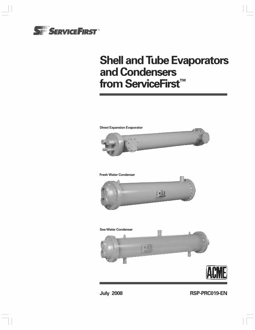
Shell and Tube Evaporatorsand Condensersfrom ServiceFirst™
RSP-PRC019-ENJuly 2008
Direct Expansion Evaporator
Fresh Water Condenser
Sea-Water Condenser
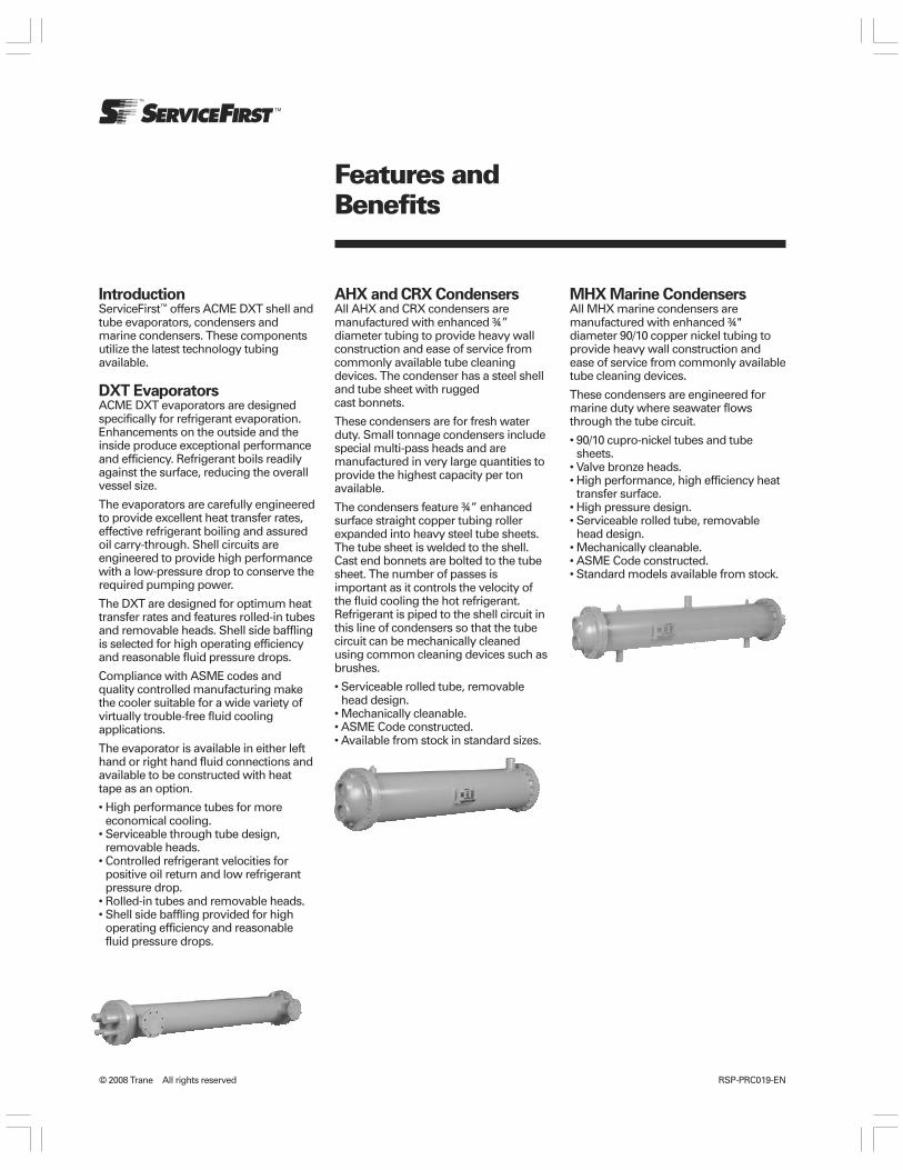
RSP-PRC019-EN© 2008 Trane All rights reserved
Features andBenefits
IntroductionServiceFirst™ offers ACME DXT shell andtube evaporators, condensers andmarine condensers. These componentsutilize the latest technology tubingavailable.
DXT EvaporatorsACME DXT evaporators are designedspecifically for refrigerant evaporation.Enhancements on the outside and theinside produce exceptional performanceand efficiency. Refrigerant boils readilyagainst the surface, reducing the overallvessel size.
The evaporators are carefully engineeredto provide excellent heat transfer rates,effective refrigerant boiling and assuredoil carry-through. Shell circuits areengineered to provide high performancewith a low-pressure drop to conserve therequired pumping power.
The DXT are designed for optimum heattransfer rates and features rolled-in tubesand removable heads. Shell side bafflingis selected for high operating efficiencyand reasonable fluid pressure drops.
Compliance with ASME codes andquality controlled manufacturing makethe cooler suitable for a wide variety ofvirtually trouble-free fluid coolingapplications.
The evaporator is available in either lefthand or right hand fluid connections andavailable to be constructed with heattape as an option.
• High performance tubes for moreeconomical cooling.
• Serviceable through tube design,removable heads.
• Controlled refrigerant velocities forpositive oil return and low refrigerantpressure drop.
• Rolled-in tubes and removable heads.• Shell side baffling provided for high
operating efficiency and reasonablefluid pressure drops.
MHX Marine CondensersAll MHX marine condensers aremanufactured with enhanced ¾"diameter 90/10 copper nickel tubing toprovide heavy wall construction andease of service from commonly availabletube cleaning devices.
These condensers are engineered formarine duty where seawater flowsthrough the tube circuit.
• 90/10 cupro-nickel tubes and tubesheets.
• Valve bronze heads.• High performance, high efficiency heat
transfer surface.• High pressure design.• Serviceable rolled tube, removable
head design.• Mechanically cleanable.• ASME Code constructed.• Standard models available from stock.
AHX and CRX CondensersAll AHX and CRX condensers aremanufactured with enhanced ¾”diameter tubing to provide heavy wallconstruction and ease of service fromcommonly available tube cleaningdevices. The condenser has a steel shelland tube sheet with ruggedcast bonnets.
These condensers are for fresh waterduty. Small tonnage condensers includespecial multi-pass heads and aremanufactured in very large quantities toprovide the highest capacity per tonavailable.
The condensers feature ¾” enhancedsurface straight copper tubing rollerexpanded into heavy steel tube sheets.The tube sheet is welded to the shell.Cast end bonnets are bolted to the tubesheet. The number of passes isimportant as it controls the velocity ofthe fluid cooling the hot refrigerant.Refrigerant is piped to the shell circuit inthis line of condensers so that the tubecircuit can be mechanically cleanedusing common cleaning devices such asbrushes.
• Serviceable rolled tube, removablehead design.
• Mechanically cleanable.• ASME Code constructed.• Available from stock in standard sizes.
3RSP-PRC019-EN
Contents
Features and Benefits
Model Number Description
General Data
Performance Data
Dimensional Data
Weights
Construction Specifications
2
4
5
8
10
15
17

4 RSP-PRC019-EN
ModelNumberDescription
Digits 1-3 – Unit ModelShell and Tube Heat Exchanger
Digit 4 – Development SequenceA = 1st development sequence
Digits 5-7 – Nominal Tons003 = 3 Tons005 = 5 Tons006 = 6 Tons008 = 7.5 Tons009 = 9 Tons010 = 10 Tons015 = 15 Tons020 = 20 Tons025 = 25 Tons026 = 26 Tons030 = 30 Tons040 = 40 Tons045 = 45 Tons050 = 50 Tons060 = 60 Tons065 = 65 T0ns070 = 70 Tons075 = 75 Tons090 = 90 Tons100 = 100 Tons110 = 110 Tons125 = 125 Tons140 = 140 Tons150 = 150 Tons200 = 200 Tons250 = 250 Tons
Digit 8G = Generic Design
Digit 9 – TypeA = Evaporator – R.H. w/InsulationB = Evaporator – L.H. w/InsulationC = Evaporator – R.H. w/Insulation and
Heat TapeD = Evaporator – L.H. w/Insulation and
Heat TapeE = CondenserF = Marine Condenser
Digits 10-11 – Design SequenceBO = 2nd Design
Digit 12 – Agency0 = None
Digit 13 – Nominal Shell Diameter (In.)A = 5 In.B = 6 In.C = 8 In.D = 10 In.E = 12 In.F = 14 In.G= 16 In.H = 18 In.J = 20 In.
Digits 14-15 – Nominal Shell Length (Ft)02 = 2 Ft.03 = 3 Ft.04 = 4 Ft.05 = 5 Ft.06 = 6 Ft.07 = 7 Ft.08 = 8 Ft.09 = 9 Ft.10 = 10 Ft.
Digit 16 – Passes1 = 1 Pass2 = 2 Pass4 = 4 Pass6 = 6 Pass
Digit 17 – Circuits1 = One Circuit2 = Two Circuit
Digit 18 – Tube MaterialA = CopperB = 90/10 CUNI
Evaporator and Condenser Model Number
STX A 005 G A BO 0 A 02 1 1 A1,2,3 4 5,6,7 8 9 10,11 12 13 14,15 16 17 18
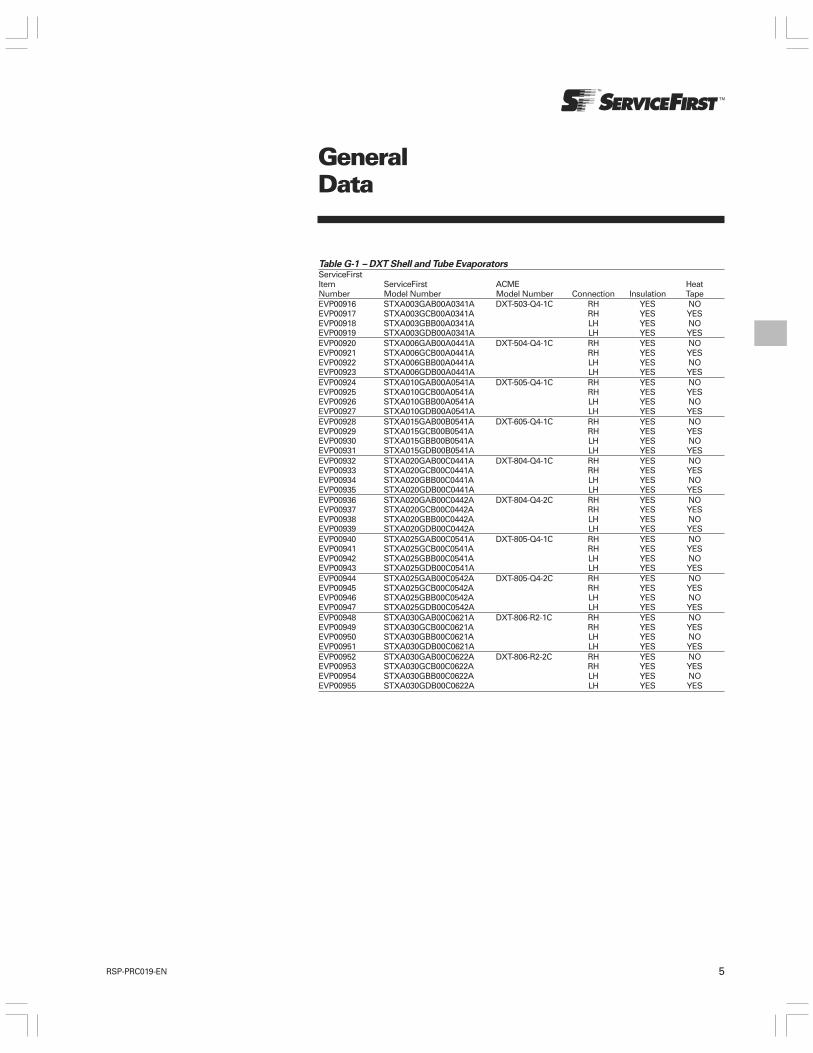
5RSP-PRC019-EN
GeneralData
Table G-1 – DXT Shell and Tube EvaporatorsServiceFirstItem ServiceFirst ACME HeatNumber Model Number Model Number Connection Insulation TapeEVP00916 STXA003GAB00A0341A DXT-503-Q4-1C RH YES NOEVP00917 STXA003GCB00A0341A RH YES YESEVP00918 STXA003GBB00A0341A LH YES NOEVP00919 STXA003GDB00A0341A LH YES YESEVP00920 STXA006GAB00A0441A DXT-504-Q4-1C RH YES NOEVP00921 STXA006GCB00A0441A RH YES YESEVP00922 STXA006GBB00A0441A LH YES NOEVP00923 STXA006GDB00A0441A LH YES YESEVP00924 STXA010GAB00A0541A DXT-505-Q4-1C RH YES NOEVP00925 STXA010GCB00A0541A RH YES YESEVP00926 STXA010GBB00A0541A LH YES NOEVP00927 STXA010GDB00A0541A LH YES YESEVP00928 STXA015GAB00B0541A DXT-605-Q4-1C RH YES NOEVP00929 STXA015GCB00B0541A RH YES YESEVP00930 STXA015GBB00B0541A LH YES NOEVP00931 STXA015GDB00B0541A LH YES YESEVP00932 STXA020GAB00C0441A DXT-804-Q4-1C RH YES NOEVP00933 STXA020GCB00C0441A RH YES YESEVP00934 STXA020GBB00C0441A LH YES NOEVP00935 STXA020GDB00C0441A LH YES YESEVP00936 STXA020GAB00C0442A DXT-804-Q4-2C RH YES NOEVP00937 STXA020GCB00C0442A RH YES YESEVP00938 STXA020GBB00C0442A LH YES NOEVP00939 STXA020GDB00C0442A LH YES YESEVP00940 STXA025GAB00C0541A DXT-805-Q4-1C RH YES NOEVP00941 STXA025GCB00C0541A RH YES YESEVP00942 STXA025GBB00C0541A LH YES NOEVP00943 STXA025GDB00C0541A LH YES YESEVP00944 STXA025GAB00C0542A DXT-805-Q4-2C RH YES NOEVP00945 STXA025GCB00C0542A RH YES YESEVP00946 STXA025GBB00C0542A LH YES NOEVP00947 STXA025GDB00C0542A LH YES YESEVP00948 STXA030GAB00C0621A DXT-806-R2-1C RH YES NOEVP00949 STXA030GCB00C0621A RH YES YESEVP00950 STXA030GBB00C0621A LH YES NOEVP00951 STXA030GDB00C0621A LH YES YESEVP00952 STXA030GAB00C0622A DXT-806-R2-2C RH YES NOEVP00953 STXA030GCB00C0622A RH YES YESEVP00954 STXA030GBB00C0622A LH YES NOEVP00955 STXA030GDB00C0622A LH YES YES

6 RSP-PRC019-EN
GeneralData
Table G-1 (Continued) – DXT Shell and Tube EvaporatorsServiceFirstItem ServiceFirst ACME HeatNumber Model Number Model Number Connection Insulation TapeEVP00956 STXA040GAB00C0721A DXT-807-R2-1C RH YES NOEVP00957 STXA040GCB00C0721A RH YES YESEVP00958 STXA040GBB00C0721A LH YES NOEVP00959 STXA040GDB00C0721A LH YES YESEVP00960 STXA040GAB00C0722A DXT-807-R2-2C RH YES NOEVP00961 STXA040GCB00C0722A RH YES YESEVP00962 STXA040GBB00C0722A LH YES NOEVP00963 STXA040GDB00C0722A LH YES YESEVP00964 STXA050GAB00D0722A DXT-1007-S2-2C RH YES NOEVP00965 STXA050GCB00D0722A RH YES YESEVP00966 STXA050GBB00D0722A LH YES NOEVP00967 STXA050GDB00D0722A LH YES YESEVP00968 STXA060GAB00D0822A DXT-1008-S2-2C RH YES NOEVP00969 STXA060GCB00D0822A RH YES YESEVP00970 STXA060GBB00D0822A LH YES NOEVP00971 STXA060GDB00D0822A LH YES YESEVP00972 STXA075GAB00D0922A DXT-1009-S2-2C RH YES NOEVP00973 STXA075GCB00D0922A RH YES YESEVP00974 STXA075GBB00D0922A LH YES NOEVP00975 STXA075GDB00D0922A LH YES YESEVP00976 STXA100GAB00E1022A DXT-1208-S2-2C RH YES NOEVP00977 STXA100GCB00E1022A RH YES YESEVP00978 STXA100GBB00E1022A LH YES NOEVP00979 STXA100GDB00E1022A LH YES YESEVP00980 STXA125GAB00F1022A DXT-1410-S2-2C RH YES NOEVP00981 STXA125GCB00F1022A RH YES YESEVP00982 STXA125GBB00F1022A LH YES NOEVP00983 STXA125GDB00F1022A LH YES YESEVP00984 STXA150GAB00G1022A DXT-1610-S2-2C RH YES NOEVP00985 STXA150GCB00G1022A RH YES YESEVP00986 STXA150GBB00G1022A LH YES NOEVP00987 STXA150GDB00G1022A LH YES YESEVP00988 STXA200GAB00H1022A DXT-1810-RS2-2C RH YES NOEVP00989 STXA200GCB00H1022A RH YES YESEVP00990 STXA200GBB00H1022A LH YES NOEVP00991 STXA200GDB00H1022A LH YES YESEVP00992 STXA250GAB00J1022A DXT-2010-RS2-2C RH YES NOEVP00993 STXA250GCB00J1022A RH YES YESEVP00994 STXA250GBB00J1022A LH YES NOEVP00995 STXA250GDB00J1022A LH YES YES
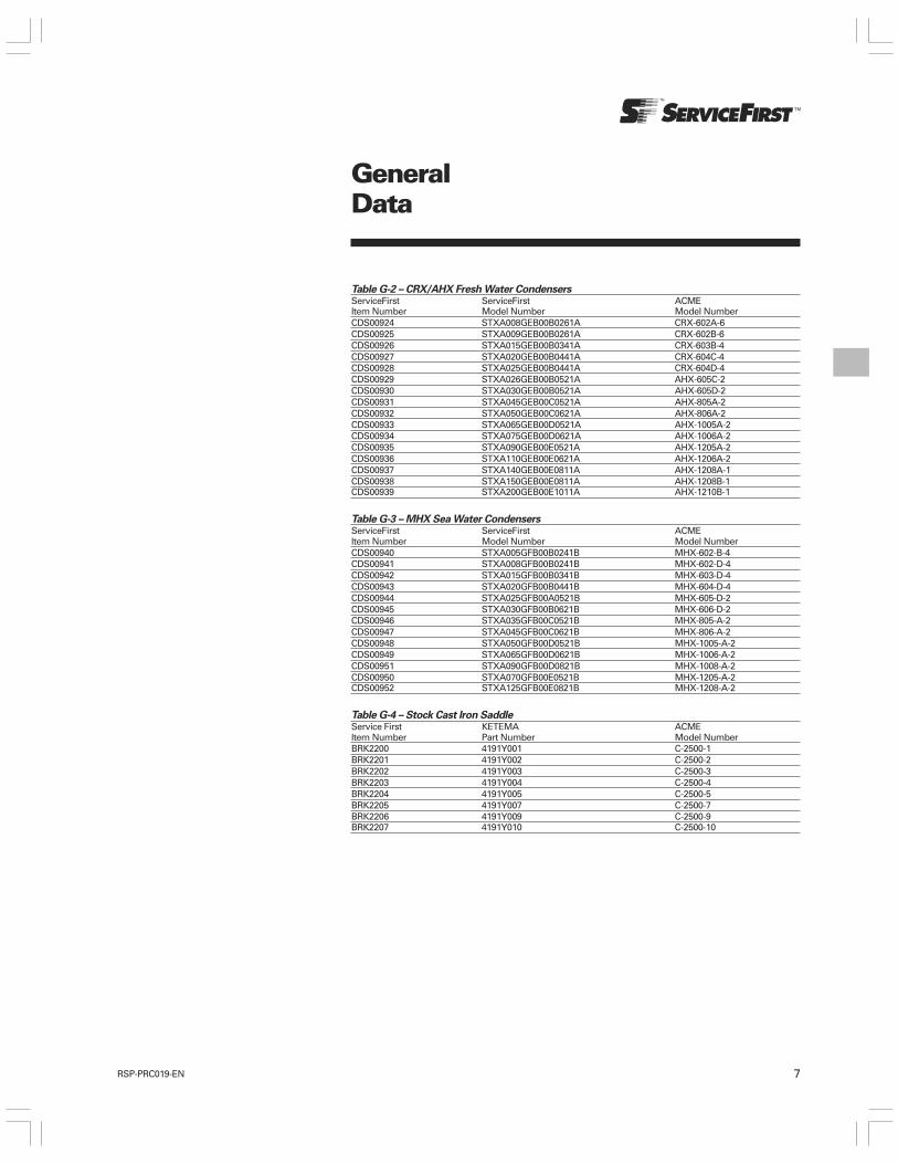
7RSP-PRC019-EN
GeneralData
Table G-2 – CRX/AHX Fresh Water CondensersServiceFirst ServiceFirst ACMEItem Number Model Number Model NumberCDS00924 STXA008GEB00B0261A CRX-602A-6CDS00925 STXA009GEB00B0261A CRX-602B-6CDS00926 STXA015GEB00B0341A CRX-603B-4CDS00927 STXA020GEB00B0441A CRX-604C-4CDS00928 STXA025GEB00B0441A CRX-604D-4CDS00929 STXA026GEB00B0521A AHX-605C-2CDS00930 STXA030GEB00B0521A AHX-605D-2CDS00931 STXA045GEB00C0521A AHX-805A-2CDS00932 STXA050GEB00C0621A AHX-806A-2CDS00933 STXA065GEB00D0521A AHX-1005A-2CDS00934 STXA075GEB00D0621A AHX-1006A-2CDS00935 STXA090GEB00E0521A AHX-1205A-2CDS00936 STXA110GEB00E0621A AHX-1206A-2CDS00937 STXA140GEB00E0811A AHX-1208A-1CDS00938 STXA150GEB00E0811A AHX-1208B-1CDS00939 STXA200GEB00E1011A AHX-1210B-1
Table G-3 – MHX Sea Water CondensersServiceFirst ServiceFirst ACMEItem Number Model Number Model NumberCDS00940 STXA005GFB00B0241B MHX-602-B-4CDS00941 STXA008GFB00B0241B MHX-602-D-4CDS00942 STXA015GFB00B0341B MHX-603-D-4CDS00943 STXA020GFB00B0441B MHX-604-D-4CDS00944 STXA025GFB00A0521B MHX-605-D-2CDS00945 STXA030GFB00B0621B MHX-606-D-2CDS00946 STXA035GFB00C0521B MHX-805-A-2CDS00947 STXA045GFB00C0621B MHX-806-A-2CDS00948 STXA050GFB00D0521B MHX-1005-A-2CDS00949 STXA065GFB00D0621B MHX-1006-A-2CDS00951 STXA090GFB00D0821B MHX-1008-A-2CDS00950 STXA070GFB00E0521B MHX-1205-A-2CDS00952 STXA125GFB00E0821B MHX-1208-A-2
Table G-4 – Stock Cast Iron SaddleService First KETEMA ACMEItem Number Part Number Model NumberBRK2200 4191Y001 C-2500-1BRK2201 4191Y002 C-2500-2BRK2202 4191Y003 C-2500-3BRK2203 4191Y004 C-2500-4BRK2204 4191Y005 C-2500-5BRK2205 4191Y007 C-2500-7BRK2206 4191Y009 C-2500-9BRK2207 4191Y010 C-2500-10

8 RSP-PRC019-EN
PerformanceData
Table PD-1 – ACME DXT EvaporatorsServiceFirstItem Number ACME Rated No. Water PressureRH RH w/HT LH LH w/HT Model Number Tons Refrig Circuits GPM Drop (PSI)EVP00916 EVP00917 EVP00918 EVP00919 DXT-503-Q-4P-1C 2.9 1 6.9 0.7EVP00920 EVP00921 EVP00922 EVP00923 DXT-504-Q-4P-1C 6.6 1 15.8 2.1EVP00924 EVP00925 EVP00926 EVP00927 DXT-505-Q-4P-1C 9.6 1 22.9 5.5EVP00928 EVP00929 EVP00930 EVP00931 DXT-605-Q-4P-1C 14 1 33.4 5EVP00932 EVP00933 EVP00934 EVP00935 DXT-804-Q-4P-1C 19 1 44.9 2.4EVP00936 EVP00937 EVP00938 EVP00939 DXT-804-Q-4P-2C 19 2 44.9 2.4EVP00940 EVP00941 EVP00942 EVP00943 DXT-805-Q-4P-1C 26 1 62.9 5.8EVP00944 EVP00945 EVP00946 EVP00947 DXT-805-Q-4P-2C 26 2 62.9 5.8EVP00948 EVP00949 EVP00950 EVP00951 DXT-806-R-2P-1C 28 1 66 4EVP00952 EVP00953 EVP00954 EVP00955 DXT-806-R-2P-2C 28 2 66 4EVP00956 EVP00957 EVP00958 EVP00959 DXT-807-R-2P-1C 38 1 89.9 8.4EVP00960 EVP00961 EVP00962 EVP00963 DXT-807-R-2P-2C 38 2 89.9 8.4EVP00964 EVP00965 EVP00966 EVP00967 DXT1007-S-2P-2C 48 2 114.4 2.6EVP00968 EVP00969 EVP00970 EVP00971 DXT-1008-S-2P-2C 64 2 153.4 5.3EVP00972 EVP00973 EVP00974 EVP00975 DXT-1009-S-2P-2C 76 2 181.6 8.8EVP00976 EVP00977 EVP00978 EVP00979 DXT-1208-S-2P-2C 98 2 234.6 7.3EVP00980 EVP00981 EVP00982 EVP00983 DXT-1410-S-2P-2C 127 2 301.8 6.7EVP00984 EVP00985 EVP00986 EVP00987 DXT-1610-S-2P-2C 156 2 370.4 6EVP00988 EVP00989 EVP00990 EVP00991 DXT-1810-RS-2P-2C 210 2 502.7 8.9EVP00992 EVP00993 EVP00994 EVP00995 DXT-2010-RS-2P-2C 266 2 636.5 8.3Notesa) R22 refrigerant, water on the fluid side, 12000 BTUH per ton.b) .00025 additive fouling factor, .0005 total fouling factor.c) 44°F leaving water temperature, 54°F entering water temperature.d) 100°F entering refrig temp, 35°F saturated suction temperature, 8°F superheat.
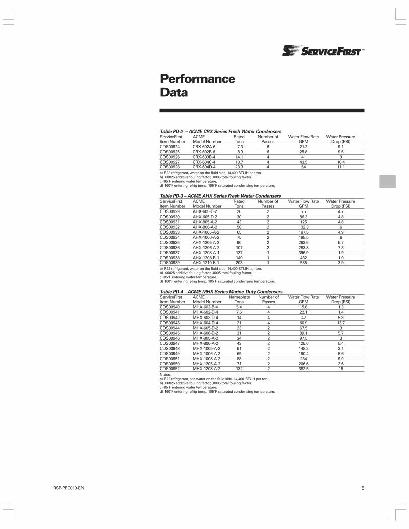
9RSP-PRC019-EN
Table PD-2 – ACME CRX Series Fresh Water CondensersServiceFirst ACME Rated Number of Water Flow Rate Water PressureItem Number Model Number Tons Passes GPM Drop (PSI)CDS00924 CRX-602A-6 7.3 6 21.2 9.1CDS00925 CRX-602B-6 8.9 6 25.8 9.5CDS00926 CRX-603B-4 14.1 4 41 9CDS00927 CRX-604C-4 18.7 4 43.5 10.4CDS00928 CRX-604D-4 23.3 4 54 11.1a) R22 refrigerant, water on the fluid side, 14,400 BTUH per ton.b) .00025 additive fouling factor, .0005 total fouling factor.c) 85°F entering water temperature.d) 160°F entering refrig temp, 105°F saturated condensing temperature.
Table PD-3 – ACME AHX Series Fresh Water CondensersServiceFirst ACME Rated Number of Water Flow Rate Water PressureItem Number Model Number Tons Passes GPM Drop (PSI)CDS00929 AHX-605-C-2 26 2 75 4.7CDS00930 AHX-605-D-2 30 2 86.3 4.8CDS00931 AHX-805-A-2 43 2 125 4.8CDS00932 AHX-806-A-2 50 2 132.3 6CDS00933 AHX-1005-A-2 65 2 187.5 4.9CDS00934 AHX-1006-A-2 75 2 198.5 6CDS00935 AHX-1205-A-2 90 2 262.5 5.7CDS00936 AHX-1206-A-2 107 2 283.8 7.3CDS00937 AHX-1208-A-1 137 1 396.9 1.9CDS00938 AHX-1208-B-1 149 1 432 1.9CDS00939 AHX-1210-B-1 203 1 585 3.9a) R22 refrigerant, water on the fluid side, 14,400 BTUH per ton.b) .00025 additive fouling factor, .0005 total fouling factor.c) 85°F entering water temperature.d) 160°F entering refrig temp, 105°F saturated condensing temperature.
Table PD-4 – ACME MHX Series Marine Duty CondensersServiceFirst ACME Nameplate Number of Water Flow Rate Water PressureItem Number Model Number Tons Passes GPM Drop (PSI)CDS00940 MHX-602-B-4 5.4 4 15.8 1.3CDS00941 MHX-602-D-4 7.6 4 22.1 1.4CDS00942 MHX-603-D-4 14 4 42 5.8CDS00943 MHX-604-D-4 21 4 60.9 13.7CDS00944 MHX-605-D-2 23 2 67.5 3CDS00945 MHX-606-D-2 31 2 89.1 5.7CDS00946 MHX-805-A-2 34 2 97.5 3CDS00947 MHX-806-A-2 43 2 125.6 5.4CDS00948 MHX-1005-A-2 51 2 148.2 3.1CDS00949 MHX-1006-A-2 65 2 190.4 5.6CDS00951 MHX-1008-A-2 88 2 234 9.9CDS00950 MHX-1205-A-2 71 2 206.6 3.6CDS00952 MHX-1208-A-2 132 2 382.5 15Notes:a) R22 refrigerant, sea water on the fluid side, 14,400 BTUH per ton.b) .00025 additive fouling factor, .0005 total fouling factor.c) 85°F entering water temperature.d) 160°F entering refrig temp, 105°F saturated condensing temperature.
PerformanceData

10 RSP-PRC019-EN
DimensionalData
Dimensional Data – InchesServiceFirstItemNumber ACME A J KRH RH w/HT LH LH w/Ht Model Number (O.A.L.) B C D E F G H (O.D.F.) (O.D.F.) L M N P QEVP00916 EVP00917 EVP00918 EVP00919 DXT-503-Q4-1C 445/8 51/2 355/8 2 79/16 17/16 33/16 85/8 5/8 11/8 13/4 13/4 — — 81/2EVP00920 EVP00921 EVP00922 EVP00923 DXT-504-Q4-1C 565/8 51/2 475/8 2 79/16 17/16 33/16 85/8 5/8 11/8 13/4 13/4 — — 81/2EVP00924 EVP00925 EVP00926 EVP00927 DXT-505-Q4-1C 685/8 51/2 595/8 2 79/16 17/16 33/16 85/8 5/8 11/8 13/4 13/4 — —- 81/2EVP00928 EVP00929 EVP00930 EVP00931 DXT-605-Q4-1C 68 65/8 595/8 21/2 615/16 17/16 37/16 93/16 7/8 13/8 21/8 21/8 — — 93/4EVP00932 EVP00933 EVP00934 EVP00935 DXT-804-Q-4P-1C 567/8 85/8 475/8 3 711/16 19/16 37/8 103/16 11/8 15/8 35/32 35/32 — — 113/4EVP00936 EVP00937 EVP00938 EVP00939 DXT-804-Q4-2C 567/8 85/8 475/8 3 711/16 19/16 37/8 103/16 11/8 13/8 3 3 17/16 17/16 113/4EVP00940 EVP00941 EVP00942 EVP00943 DXT-805-Q-4P-1C 687/8 85/8 595/8 3 711/16 19/16 37/8 103/16 11/8 15/8 35/32 35/32 — — 113/4EVP00944 EVP00945 EVP00946 EVP00947 DXT-805-Q4-2C 687/8 85/8 595/8 3 711/16 19/16 37/8 103/16 11/8 13/8 3 3 17/16 17/16 113/4EVP00948 EVP00949 EVP00950 EVP00951 DXT-806-R-2P-1C 801/4 85/8 715/8 3 711/16 19/16 37/8 103/16 13/8 25/8 21/4 17/8 — — 113/4EVP00952 EVP00953 EVP00954 EVP00955 DXT-806-R2-2C 801/4 85/8 715/8 3 711/16 19/16 37/8 103/16 13/8 21/8 2 15/8 13/4 21/8 113/4EVP00956 EVP00957 EVP00958 EVP00959 DXT-807-R-2P-1C 921/4 85/8 835/8 3 711/16 19/16 37/8 103/16 13/8 25/8 21/4 17/8 — — 113/4EVP00960 EVP00961 EVP00962 EVP00963 DXT-807-R2-2C 921/4 85/8 835/8 3 711/16 19/16 37/8 103/16 13/8 21/8 2 15/8 13/4 21/8 113/4EVP00964 EVP00965 EVP00966 EVP00967 DXT-1007-S2-2C 93 103/4 835/8 4 77/16 115/16 41/2 115/8 13/8 25/8 23/4 13/4 2 211/16 143/8EVP00968 EVP00969 EVP00970 EVP00971 DXT-1008-S2-2C 105 103/4 955/8 4 77/16 115/16 41/2 115/8 13/8 25/8 23/4 13/4 2 211/16 143/8EVP00972 EVP00973 EVP00974 EVP00975 DXT-1009-S2-2C 117 103/4 1075/8 5 77/16 115/16 51/16 115/8 13/8 25/8 23/4 13/4 2 211/16 143/8EVP00976 EVP00977 EVP00978 EVP00979 DXT-1208-S2-2C 1053/8 123/4 955/8 5 73/4 23/16 53/4 125/8 15/8 25/8 31/4 13/4 21/2 23/4 163/8EVP00980 EVP00981 EVP00982 EVP00983 DXT-1410-S2-2C 1301/2 14 1195/8 6 81/4 211/16 53/4 131/4 15/8 31/8 33/4 3 25/8 31/8 171/2EVP00984 EVP00985 EVP00986 EVP00987 DXT-1610-S2-2C 1311/2 16 1195/8 8 87/8 33/16 71/16 141/4 21/8 31/8 4 3 3 31/4 191/2EVP00988 EVP00989 EVP00990 EVP00991 DXT-1810-RS2-2C 1311/2 18 1195/8 8 811/16 33/16 71/16 151/4 21/8 35/8 43/4 31/2 31/4 37/8 211/2EVP00992 EVP00993 EVP00994 EVP00995 DXT-2010-RS2-2C 1321/2 20 1195/8 8 93/16 311/16 83/8 161/4 21/8 35/8 5 41/4 31/2 43/8 231/2
DXT Shell and Tube Evaporators
CONSTRUCTION NOTES:1. CONNECTIONS J & K ARE STEEL, WELDED TO HEAD AND BORED TO ODS OF COPPER TUBING.2. FLUID CONNECTIONS ARE MPT THRU 3” PIPE SIZE, 4” AND LARGER TERMINATE IN 150 LB. ANSI RAISED FACE STEEL FLANGES.3. BOTTOM CONNECTION ONLY ON 3” MPT AND SMALLER FLUID CONNECTION MODELS.4. EXTERNAL EQUALIZER CONNECTION.5. UNIT WITH 3/4” ARMAFLEX INSULATION, ADD 1 1/2” TO “B”, 3/4” TO “F” AND “A”, AND 1 1/2” TO “Q”.6. RIGHT HAND CONNECTION SHOWN – LEFT AND RIGHT HAND CONNECTIONS ARE DETERMINED BY VIEWING THE REFRIGERANT CONNECTION END.
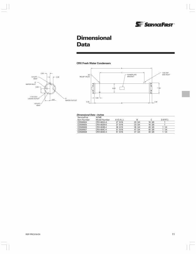
11RSP-PRC019-EN
DimensionalData
Dimensional Data – InchesServiceFirst ACMEItem Number Model Number A (O.A.L.) B C D (F.P.T.)CDS00924 CRX-602A-6 27 9/16 23 3/4 16 3/8 1CDS00925 CRX-602B-6 27 9/16 23 3/4 16 3/8 1CDS00926 CRX-603B-4 39 9/16 35 3/4 28 3/8 1 1/4CDS00927 CRX-604C-4 51 9/16 47 3/4 40 3/8 1 1/4CDS00928 CRX-604D-4 51 9/16 47 3/4 40 3/8 1 1/4
CRX Fresh Water Condensers
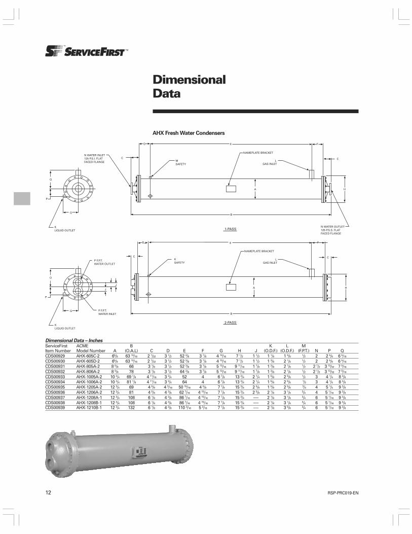
12 RSP-PRC019-EN
Dimensional Data – InchesServiceFirst ACME B K L MItem Number Model Number A (O.A.L) C D E F G H J (O.D.F.) (O.D.F.) (F.P.T.) N P QCDS00929 AHX-605C-2 65/8 63 13/16 2 1/32 3 1/2 52 3/8 3 7/8 4 13/16 7 1/2 1 1/2 1 1/8 1 5/8 1/2 2 2 5/8 6 5/16
CDS00930 AHX-605D-2 65/8 63 13/16 2 1/32 3 1/2 52 3/8 3 7/8 4 13/16 7 1/2 1 1/2 1 3/8 2 1/8 1/2 2 2 5/8 6 5/16
CDS00931 AHX-805A-2 8 5/8 66 3 1/8 3 1/2 52 3/8 3 7/8 5 13/16 9 11/16 1 7/8 1 3/8 2 1/8 1/2 2 1/2 3 13/32 7 5/16
CDS00932 AHX-806A-2 8 5/8 78 3 1/8 3 1/2 64 3/8 3 7/8 5 13/16 9 11/16 1 7/8 1 3/8 2 1/8 1/2 2 1/2 3 13/32 7 5/16
CDS00933 AHX-1005A-2 10 3/4 69 1/8 4 11/16 3 3/4 52 4 6 7/8 13 3/4 2 1/4 1 5/8 2 5/8 1/2 3 4 1/4 8 3/8CDS00934 AHX-1006A-2 10 3/4 81 1/8 4 11/16 3 3/4 64 4 6 7/8 13 3/4 2 1/4 1 5/8 2 5/8 1/2 3 4 1/4 8 3/8CDS00935 AHX-1205A-2 12 3/4 69 4 5/8 4 3/16 50 15/16 4 5/8 7 7/8 15 3/4 2 5/8 1 5/8 2 5/8 3/4 4 5 1/4 9 3/8CDS00936 AHX-1206A-2 12 3/4 81 4 5/8 4 3/8 62 7/16 4 15/16 7 7/8 15 3/4 2 5/8 2 1/8 3 1/8 3/4 4 5 1/16 9 3/8CDS00937 AHX-1208A-1 12 3/4 108 6 1/8 4 3/8 86 7/16 4 15/16 7 7/8 15 3/4 —- 2 1/8 3 1/8 3/4 6 5 1/16 9 3/8CDS00938 AHX-1208B-1 12 3/4 108 6 1/8 4 3/8 86 7/16 4 15/16 7 7/8 15 3/4 —- 2 1/8 3 1/8 3/4 6 5 1/16 9 3/8CDS00939 AHX-1210B-1 12 3/4 132 6 1/8 4 3/8 110 3/16 5 3/16 7 7/8 15 3/4 —- 2 1/8 3 5/8 3/4 6 5 1/16 9 3/8
AHX Fresh Water Condensers
DimensionalData

13RSP-PRC019-EN
Dimensional Data – InchesServiceFirst ACME K M NItem Number Model Number A B C D E F G H J (F.T.P.) L (O.D.F.) (O.D.F.) PCDS00940 MHX-602B-4 6 5/8 27 13/16 2 1/32 5 7/8 12 5 7/8 7 1/2 1 7/16 6 5/16 1/2 6 5/16 1 3/8 5/8 1 1/2CDS00941 MHX-602D-4 6 5/8 27 13/16 2 1/32 5 7/8 12 5 7/8 7 1/2 1 7/16 6 5/16 1/2 6 5/16 1 3/8 5/8 1 1/2CDS00942 MHX-603D-4 6 5/8 39 13/16 2 1/32 5 7/8 24 5 7/8 7 1/2 1 7/16 6 5/16 1/2 6 5/16 1 3/8 7/8 1 1/2CDS00943 MHX-604D-4 6 5/8 51 13/16 2 1/32 5 7/8 36 5 7/8 7 1/2 1 7/16 6 5/16 1/2 6 5/16 1 3/8 7/8 1 1/2CDS00944 MHX-605D-2 6 5/8 63 13/16 2 1/32 5 7/8 48 5 7/8 7 1/2 1 1/2 6 5/16 1/2 6 5/16 1 5/8 1 1/8 2CDS00945 MHX-606D-2 6 5/8 75 13/16 2 1/32 5 7/8 60 5 7/8 7 1/2 1 1/2 6 5/16 1/2 6 5/16 1 5/8 1 5/8 2CDS00946 MHX-805A-2 8 5/8 66 3 1/8 7 7/8 44 7 7/8 9 11/16 1 7/8 7 5/16 1/2 7 5/16 2 1/8 1 1/8 2 1/2CDS00947 MHX-806A-2 8 5/8 78 3 1/8 7 7/8 56 7 7/8 9 11/16 1 7/8 7 5/16 1/2 7 5/16 2 1/8 1 3/8 2 1/2CDS00948 MHX-1005A-2 10 3/4 69 4 11/16 7 7/8 44 7 7/8 13 3/4 2 1/4 8 3/8 3/4 8 3/8 2 1/8 1 5/8 3CDS00949 MHX-1006A-2 10 3/4 81 4 11/16 7 7/8 56 7 7/8 13 3/4 2 1/4 8 3/8 3/4 8 3/8 2 5/8 1 5/8 3CDS00951 MHX-1008A-2 10 3/4 105 1/8 4 11/16 7 7/8 80 7 7/8 13 3/4 2 1/4 8 3/8 3/4 8 3/8 2 5/8 1 5/8 3CDS00950 MHX-1205A-2 12 3/4 69 4 5/8 7 7/8 44 7 7/8 15 3/4 2 5/8 9 3/8 1 9 3/8 2 5/8 1 5/8 3CDS00952 MHX-1208A-2 12 3/4 105 4 5/8 7 7/8 80 7 7/8 15 3/4 2 5/8 9 3/8 1 9 3/8 3 1/8 2 1/8 3*All refrigerant gas inlet and liquid outlet connections are ODF sweat.**Purge an safety connections are FPT.Note: All vessels will have a 3/8'’ drain plug in either the front or rear head.
MHX Marine Duty Condensers
DimensionalData
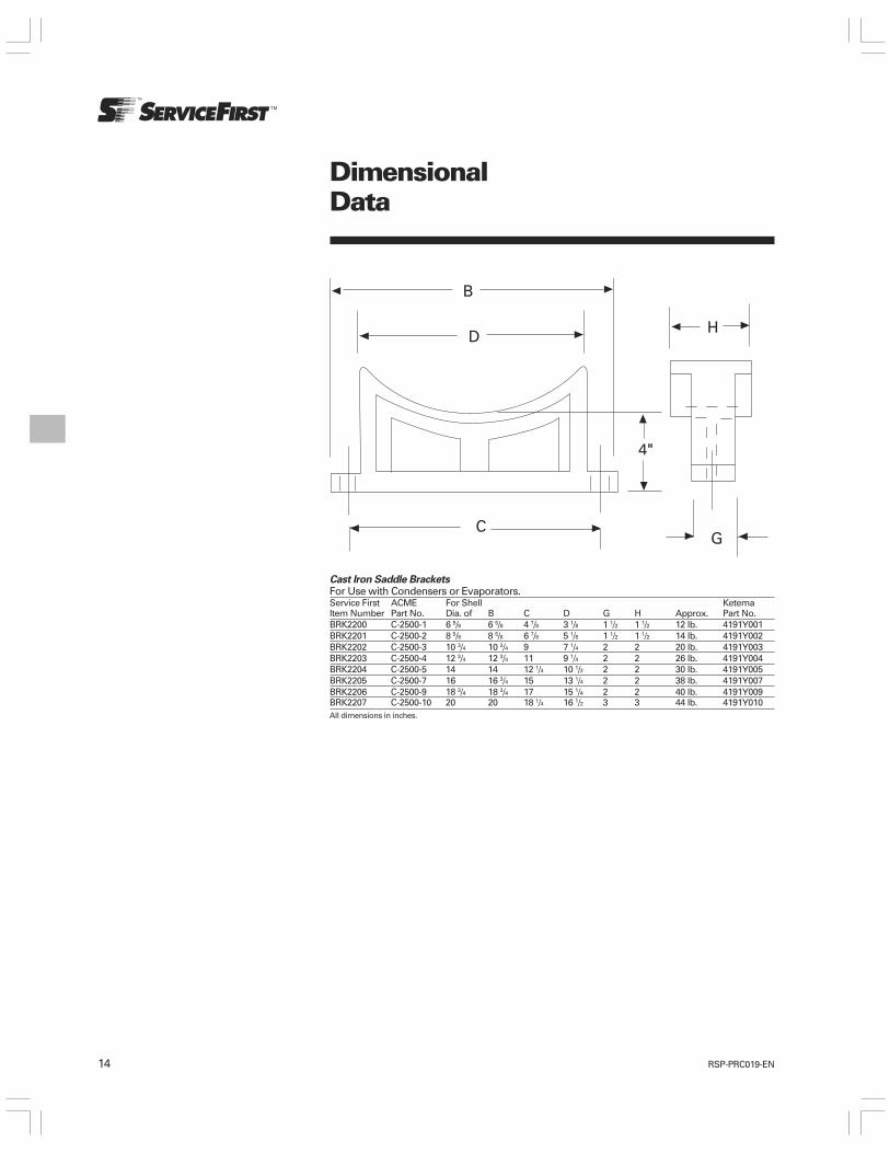
14 RSP-PRC019-EN
Cast Iron Saddle BracketsFor Use with Condensers or Evaporators.Service First ACME For Shell KetemaItem Number Part No. Dia. of B C D G H Approx. Part No.BRK2200 C-2500-1 6 5/8 6 5/8 4 7/8 3 1/8 1 1/2 1 1/2 12 lb. 4191Y001BRK2201 C-2500-2 8 5/8 8 5/8 6 7/8 5 1/8 1 1/2 1 1/2 14 lb. 4191Y002BRK2202 C-2500-3 10 3/4 10 3/4 9 7 1/4 2 2 20 lb. 4191Y003BRK2203 C-2500-4 12 3/4 12 3/4 11 9 1/4 2 2 26 lb. 4191Y004BRK2204 C-2500-5 14 14 12 1/4 10 1/2 2 2 30 lb. 4191Y005BRK2205 C-2500-7 16 16 3/4 15 13 1/4 2 2 38 lb. 4191Y007BRK2206 C-2500-9 18 3/4 18 3/4 17 15 1/4 2 2 40 lb. 4191Y009BRK2207 C-2500-10 20 20 18 1/4 16 1/2 3 3 44 lb. 4191Y010All dimensions in inches.
DimensionalData
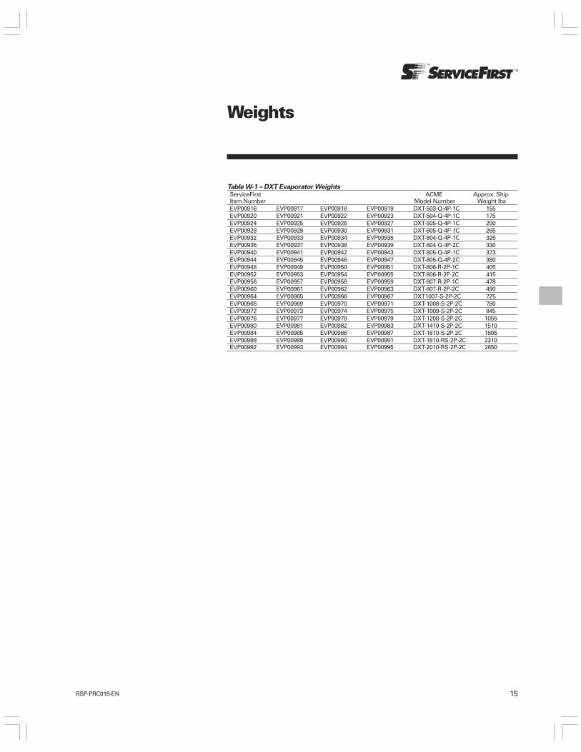
15RSP-PRC019-EN
Table W-1 – DXT Evaporator WeightsServiceFirst ACME Approx. ShipItem Number Model Number Weight lbsEVP00916 EVP00917 EVP00918 EVP00919 DXT-503-Q-4P-1C 155EVP00920 EVP00921 EVP00922 EVP00923 DXT-504-Q-4P-1C 175EVP00924 EVP00925 EVP00926 EVP00927 DXT-505-Q-4P-1C 200EVP00928 EVP00929 EVP00930 EVP00931 DXT-605-Q-4P-1C 265EVP00932 EVP00933 EVP00934 EVP00935 DXT-804-Q-4P-1C 325EVP00936 EVP00937 EVP00938 EVP00939 DXT-804-Q-4P-2C 330EVP00940 EVP00941 EVP00942 EVP00943 DXT-805-Q-4P-1C 373EVP00944 EVP00945 EVP00946 EVP00947 DXT-805-Q-4P-2C 380EVP00948 EVP00949 EVP00950 EVP00951 DXT-806-R-2P-1C 405EVP00952 EVP00953 EVP00954 EVP00955 DXT-806-R-2P-2C 415EVP00956 EVP00957 EVP00958 EVP00959 DXT-807-R-2P-1C 478EVP00960 EVP00961 EVP00962 EVP00963 DXT-807-R-2P-2C 490EVP00964 EVP00965 EVP00966 EVP00967 DXT1007-S-2P-2C 725EVP00968 EVP00969 EVP00970 EVP00971 DXT-1008-S-2P-2C 780EVP00972 EVP00973 EVP00974 EVP00975 DXT-1009-S-2P-2C 845EVP00976 EVP00977 EVP00978 EVP00979 DXT-1208-S-2P-2C 1055EVP00980 EVP00981 EVP00982 EVP00983 DXT-1410-S-2P-2C 1510EVP00984 EVP00985 EVP00986 EVP00987 DXT-1610-S-2P-2C 1805EVP00988 EVP00989 EVP00990 EVP00991 DXT-1810-RS-2P-2C 2310EVP00992 EVP00993 EVP00994 EVP00995 DXT-2010-RS-2P-2C 2850
Weights

16 RSP-PRC019-EN
Table W-2 – CRX Condenser WeightsServiceFirst ACME Approx. ShipItem Number Model Number Wt. Lbs.CDS00924 CRX-602A-6 100CDS00925 CRX-602B-6 105CDS00926 CRX-603B-4 130CDS00927 CRX-604C-4 160CDS00928 CRX-604D-4 170
Table W-3 – AHX Condenser WeightsServiceFirst ACME Approx.Item Model ShippingNumber Number Weight (lbs.)CDS00929 AHX-605-C-2 170CDS00930 AHX-605-D-2 195CDS00931 AHX-805-A-2 300CDS00932 AHX-806-A-2 340CDS00933 AHX-1005-A-2 460CDS00934 AHX-1006-A-2 475CDS00935 AHX-1205-A-2 590CDS00936 AHX-1206-A-2 665CDS00937 AHX-1208-A-1 855CDS00938 AHX-1208-B-1 890CDS00939 AHX-1210-B-1 1060
Table W-4 – MHX Marine Duty CondenserWeights
Approx.ServiceFirst ACME ShippingItem Model WeightNumber Number (lbs.)CDS00940 MHX-602-B-4 100CDS00941 MHX-602-D-4 107CDS00942 MHX-603-D-4 142CDS00943 MHX-604-D-4 175CDS00944 MHX-605-D-2 210CDS00945 MHX-606-D-2 244CDS00946 MHX-805-A-2 310CDS00947 MHX-806-A-2 357CDS00948 MHX-1005-A-2 480CDS00949 MHX-1006-A-2 550CDS00951 MHX-1008-A-2 695CDS00950 MHX-1205-A-2 670CDS00952 MHX-1208-A-2 960
Table W-5 – Cast Iron Saddle BracketsWeights
ServiceFirst ACME Ketema Approx.Item Part Part ShippingNumber Number Number Wt. (lbs.)BRK2200 C-2500-1 4191Y001 12BRK2201 C-2500-2 4191Y002 14BRK2202 C-2500-3 4191Y003 20BRK2203 C-2500-4 4191Y004 20BRK2204 C-2500-5 4191Y005 26BRK2205 C-2500-7 4191Y007 30BRK2206 C-2500-9 4191Y009 40BRK2207 C2500-10 4191Y010 44
Weights
17RSP-PRC019-EN
Shell and Tube EvaporatorsThe DXT evaporator is a direct expansionliquid cooler. The heat exchangers aredesigned with removable heads and“rolled-in” tubes for use with refrigerantsR-22, R-134a and R-404a. The tube sideof the heat exchangers are designed andtested according to ASME code.
ShellsSteel pipe shells. Shells are shot blastedand cleaned before assembly.
TubesTubes shall be ¾" on DXT internally/externally enhanced copper tubesfabricated to ASME specification SB359-122. Tubes shall be roller expandedinto multiple grooved tube sheet holes.
Tube SheetsTube sheets shall be flanged, carbonsteel, fabricated to ASME specificationsSA 516-GR 70.
BafflesHot rolled steel, galvanized plated forreduced corrosion.
HeadsFabricated ring and cover type steelheads, to ASME specificationsSA516-GR 70.
GasketsDie-cut medium density elastomercompatible with the above refrigerantsand typical oils used with theserefrigerants. Gasketed joints to beadequate for pressure application andshall not leak (using an underwater leaktest procedure) at established testpressure of 1¼ times design workingpressure.
Codes and Design Pressures
The refrigerant side is constructed inaccordance with the latest edition ofSection VIII, Division I of ASME Code forpressure vessels and stampedaccordingly. Tube Side (refrigerant side)design pressure is 250 psig at100°F. Shell side (fluid side) designpressure is 150 psig at 120°F.
Test PressureBoth shell and tube sides of all DXTcoolers are pneumatically tested at 1¼times the design working pressure tocomply with ASME Code and to assurereliable service.
FinishExterior surfaces are painted with grayenamel paint. The surface shall beadequate to prevent rusting, can be usedas a base for insulation adhesive or canbe used as a primer.
Insulation¾” thick insulation.
Heat TapeThe heat tape, when ordered, will protectthe unit down to -20°F when the unit andheat tape is covered with a single layer of¾“ insulation material. The heat tapewill operate on a 120 VAC supply.
ConstructionSpecifications
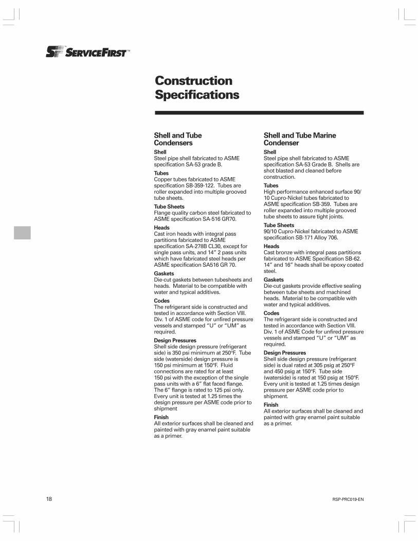
18 RSP-PRC019-EN
ConstructionSpecifications
Shell and Tube MarineCondenser
ShellSteel pipe shell fabricated to ASMEspecification SA-53 Grade B. Shells areshot blasted and cleaned beforeconstruction.
TubesHigh performance enhanced surface 90/10 Cupro-Nickel tubes fabricated toASME specification SB-359. Tubes areroller expanded into multiple groovedtube sheets to assure tight joints.
Tube Sheets90/10 Cupro-Nickel fabricated to ASMEspecification SB-171 Alloy 706.
HeadsCast bronze with integral pass partitionsfabricated to ASME Specification SB-62.14” and 16” heads shall be epoxy coatedsteel.
GasketsDie-cut gaskets provide effective sealingbetween tube sheets and machinedheads. Material to be compatible withwater and typical additives.
CodesThe refrigerant side is constructed andtested in accordance with Section VIII.Div. 1 of ASME Code for unfired pressurevessels and stamped “U” or “UM” asrequired.
Design PressuresShell side design pressure (refrigerantside) is dual rated at 305 psig at 250°Fand 450 psig at 150°F. Tube side(waterside) is rated at 150 psig at 150°F.Every unit is tested at 1.25 times designpressure per ASME code prior toshipment.
FinishAll exterior surfaces shall be cleaned andpainted with gray enamel paint suitableas a primer.
Shell and TubeCondensers
ShellSteel pipe shell fabricated to ASMEspecification SA-53 grade B.
TubesCopper tubes fabricated to ASMEspecification SB-359-122. Tubes areroller expanded into multiple groovedtube sheets.
Tube SheetsFlange quality carbon steel fabricated toASME specification SA-516 GR70.
HeadsCast iron heads with integral passpartitions fabricated to ASMEspecification SA-278B CL30, except forsingle pass units, and 14” 2 pass unitswhich have fabricated steel heads perASME specification SA516 GR 70.
GasketsDie-cut gaskets between tubesheets andheads. Material to be compatible withwater and typical additives.
CodesThe refrigerant side is constructed andtested in accordance with Section VIII.Div. 1 of ASME code for unfired pressurevessels and stamped “U” or “UM” asrequired.
Design PressuresShell side design pressure (refrigerantside) is 350 psi minimum at 250°F. Tubeside (waterside) design pressure is150 psi minimum at 150°F. Fluidconnections are rated for at least150 psi with the exception of the singlepass units with a 6” flat faced flange.The 6” flange is rated to 125 psi only.Every unit is tested at 1.25 times thedesign pressure per ASME code prior toshipment
FinishAll exterior surfaces shall be cleaned andpainted with gray enamel paint suitableas a primer.

Fax to: 972-641-1518Industrial Refrigeration Quote Request Form
To: ______________________________________________ Customer: _____________________________________
From: ____________________________________________ Contact: _______________________________________
Date: ____________________________________________ Phone/Fax:_____________________________________
Subject: __________________________________________ Address:_______________________________________
Evaporator – Chiller Barrel
Heat Load:________________________________________ Application: ____________________________________
Fluid to be cooled: _________________________________ Solution %: ____________________________________
Fluid entering temperature: _________________________ Flow rate: ______________________________________
Fluid leaving temperature: __________________________
Refrigerant: _______________________________________ Evap. temp: ____________________________________
Fluid fouling factor: ________________________________
Dimensional limitations: ____________________________ Circuits required: _______________________________
Design working pressure: Shell side: _________________ Tube side: _____________________________________
Maximum pressure drop: ___________________________ Design operating temperature:____________________
Other conditions: ____________________________________________________________________________________
Optional features Insulation ____________ Mounting Brackets _________________ Heat Tape _________________
Orientation of shell side connections (top, left, right when viewing from front) ________________________________
Original manufacturer and model number: ______________________________________________________________
Condenser
Load – Total Heat of Rejection: _______________________
Refrigerant: _______________________________________ Condensing temp: ______________________________
Entering water temperature: ________________________ Leaving water temperature: ______________________
GPM of cooling water: _____________________________ Fouling factor: __________________________________
Max. water pressure drop: __________________________ Fresh or Sea Water: _____________________________
Design working pressure: Shell side: _________________ Tube side: _____________________________________
Design operating temperature: ______________________
Dimensional limitations: ______________________________________________________________________________
Other conditions: ____________________________________________________________________________________
Orientation of connections: ___________________________________________________________________________
Original manufacturer and model number: ______________________________________________________________
Note: When making a quote, always confirm basis of offering (tons, performance details, dimensions, etc.).
Don Holderbaugh
Please photocopy this form as needed.Do not remove the original form from this catalog.

Trane has a policy of continuous product and product data improvement and reserves the right tochange design and specifications without notice.
Literature Order Number
Date
Supersedes
RSP-PRC019-EN
July 2008
RSP-PRC019-EN-0605
Coil Cleaners 2-4
Sprayers 5
IAQ Assurance Program 6
Refrigeration Oil & Vacuum Pump Oil 7-8
Total System Protection 9-11
Scale Remover/Descaling 12
Water Treatment 13-14
Closed System & Glycol Water Treatment 15
Insulation Products 16
Gas Leak Detectors 17
Specialty Products 18
Aerosol Products 19-20
Aerosol Products (cont.) 19-20
Plumbing Products & Water Test Kits 21
Nu-Plus® E Series by Everpure Filtration 22-26
Water Filtration 27-28
Water Filtration Maintenance 29
Nu-Calgon Training Seminars 30Part Number Index 31-34

Increase the efficiency of air conditioning and heating systems ith the industry s highest uality coil cleaning products.
Coil Cleaners

Coil Cleaners

Coil Cleaners
Nu-Calgon s Coil Cleaner Selection Guide
Green Select

Sprayers
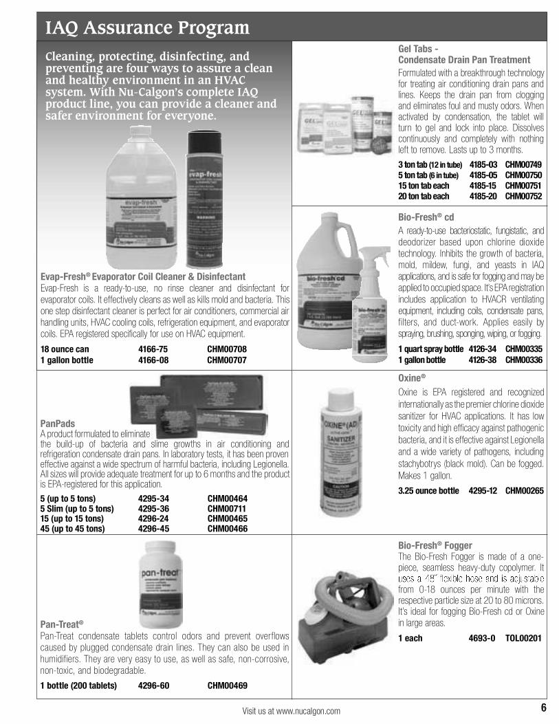
Cleaning, protecting, disinfecting, and preventing are four ways to assure a clean and healthy environment in an HVAC system. With Nu-Calgon s complete IAQ product line, you can provide a cleaner and safer environment for everyone.
IAQ Assurance Program

Refrigeration Oil & Vacuum Pump Oil
Refrigeration Oil & Vacuum Pump Oil

Whether it is cleanup after a burnout, flushing line sets, regular maintenance, component changeout or retrofitting, Nu-Calgon s Total System Protection offers the tools and procedures to successfully maintain air conditioning and refrigeration systems.
Total System Protection
York®, Goodman®, Nordyne®, Coleman®
and Daikin® Endorsed
Total System Protection

A tremendous 1-2 punch for every system...
Total System Protection
Both great brands are available! Visit www.acrenew.com.
Prevent leaks and revitalize the air conditioning system with A/C EasySeal and A/C Re-New.
+
Quiets noisy air conditioning systems and reduces energy consumption.
Removing scale from cooling towers is easy with Nu-Calgon products.
Scale Removal/Descaling

Water Treatment
Water Treatment
Closed System & Glycol Water Treatment
A complete line of quality insulation products for the air conditioning, refrigeration and heating industries.
Insulation Products

A complete family of gas leak detectors from the leaders in gas leak detection technology.
Specialty Products - Gas Leak Detectors
Specialty Products

Nu-Calgon s Cal-Spray family of products is an extensive line of aerosols for all HVAC industrial needs.
Cal-Spray® Aerosol Products

Cal-Spray® Aerosol Products
Plumbing Products & Test Kits

&
Ice Machine Maintenance
Water and Beverage Filtration
Water Filtration - Nu-Plus® E Series by Everpure®

Water Filtration - Nu-Plus® E Series by Everpure®

Water Filtration - Everpure® OEM Replacements
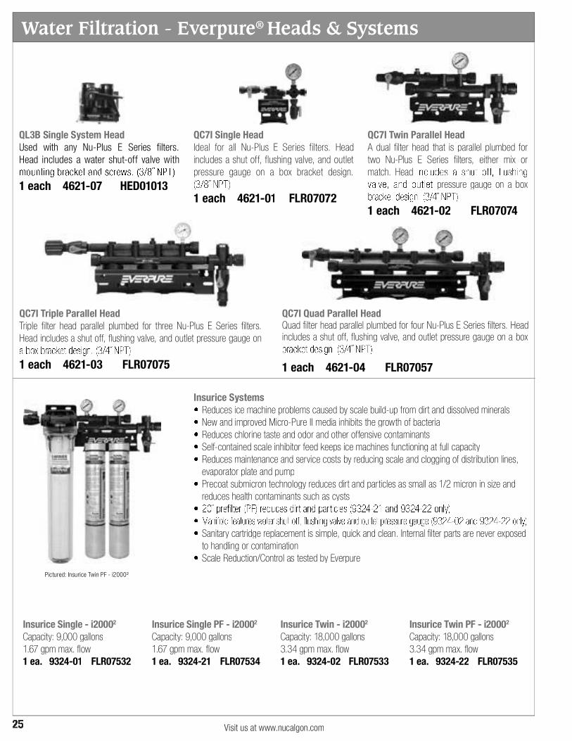
Water Filtration - Everpure® Heads & Systems
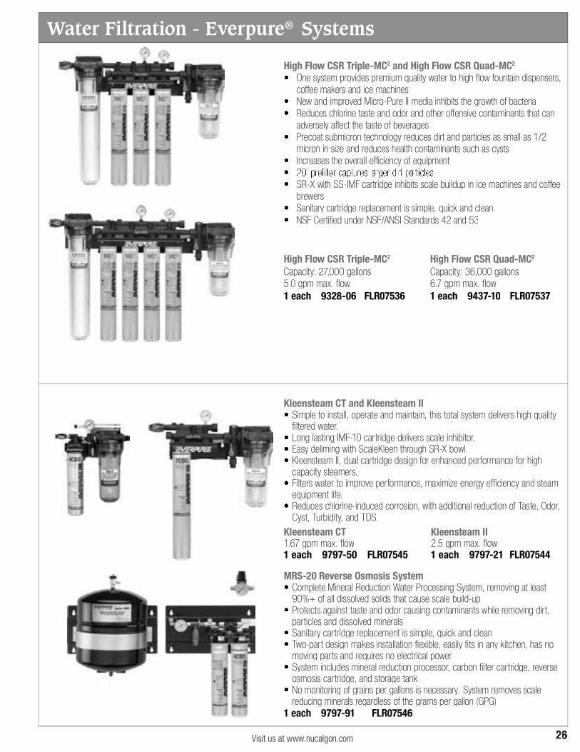
Water Filtration - Everpure® Systems
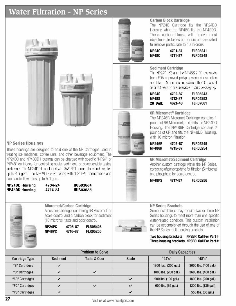
Water Filtration - NP Series

Water Filtration
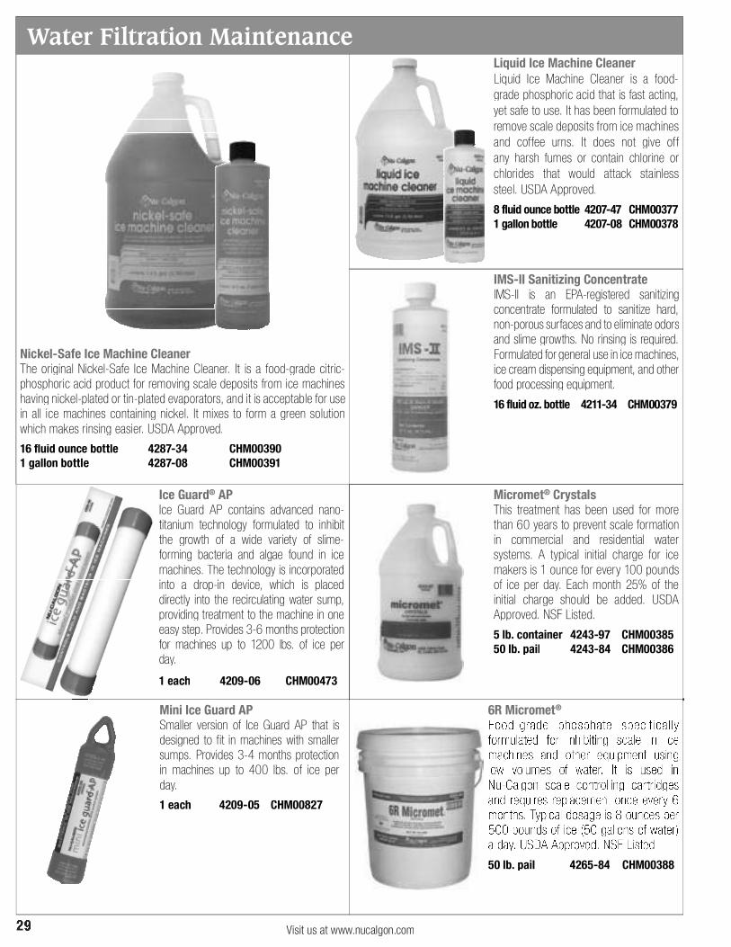
Water Filtration Maintenance

Nu-Calgon has a 60+ year history of leadership and innovation in the air conditioning, refrigeration, plumbing, heating and food service market. Over this span of time, we have introduced:
Nu-Calgon Seminars and Training Classes:
Take advantage of one of Nu-Calgon s free seminars and training classes.
Nu-Calgon

ServiceFirst Nu-Calgon Page # ServiceFirst Nu-Calgon Page # ServiceFirst Nu-Calgon Page #
ServiceFirst Part Number Index

ServiceFirst Nu-Calgon Page # ServiceFirst Nu-Calgon Page # ServiceFirst Nu-Calgon Page #
ServiceFirst Part Number Index

Nu-Calgon Mnemonic Page # Nu-Calgon Mnemonic Page # Nu-Calgon Mnemonic Page #
Nu-Calgon Part Number Index
Nu-Calgon Mnemonic Page # Nu-Calgon Mnemonic Page # Nu-Calgon Mnemonic Page #
Nu-Calgon Part Number Index


Refrigeration Specialties
By Emerson Climate Technologies –
Flow Controls Division
RSP-PRC022-ENJune 2005
Thermo ExpansionValves
System Protectors
Solenoids
Regulators
Storage Devices
Oil Controls
Coils
TemperaturePressure Controls
Ball Valves

© 2005 American Standard All rights reserved RSP-PRC022-EN
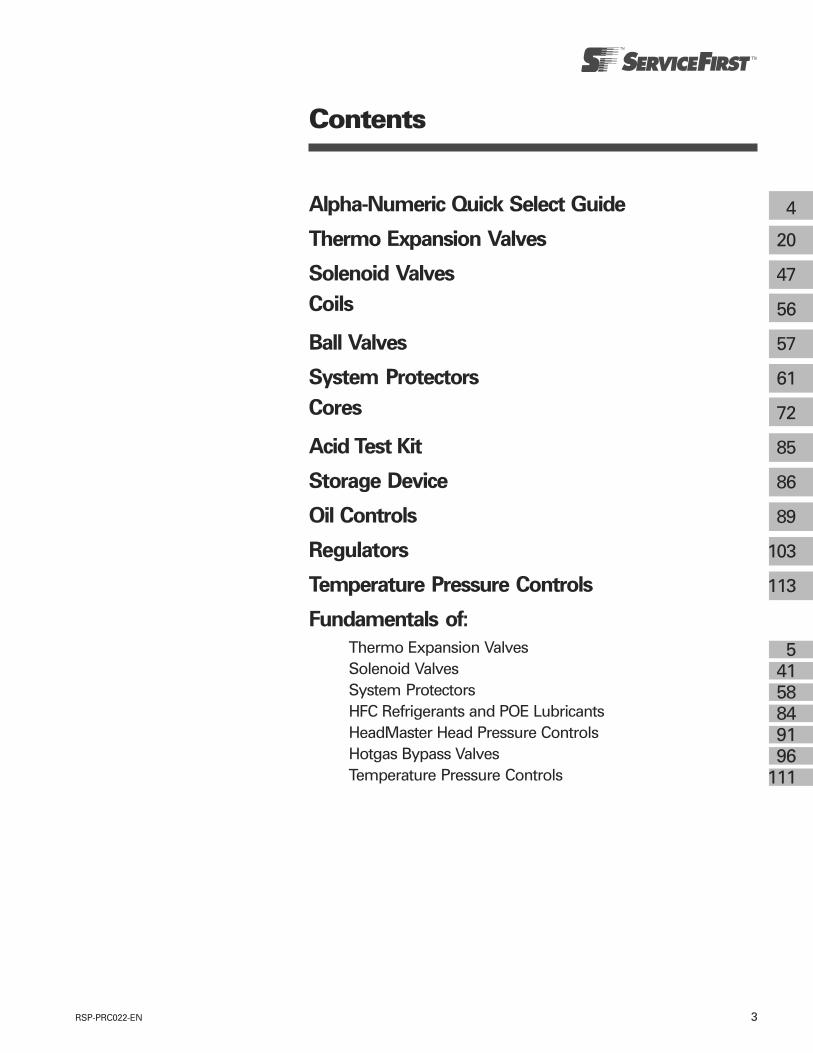
3RSP-PRC022-EN
Alpha-Numeric Quick Select Guide
Thermo Expansion Valves
Solenoid Valves
Coils
Ball Valves
System Protectors
Cores
Acid Test Kit
Storage Device
Oil Controls
Regulators
Temperature Pressure Controls
Fundamentals of:
Thermo Expansion ValvesSolenoid ValvesSystem ProtectorsHFC Refrigerants and POE LubricantsHeadMaster Head Pressure ControlsHotgas Bypass ValvesTemperature Pressure Controls
4
20
47
56
57
61
72
85
86
89
103
113
54158849196
111
Contents

RSP-PRC022-EN4
Quick Select - Alpha and Numeric by Product
Alpha PageProduct Number
FD113-ZU (K) 121
FD113-ZU-S 122
HF 22
HFK 24
HMI 80
HP/HPC 108
LCL 39
PS1 116
PS2 118
RV 53
SFD 76
STAS 68
TRAE 29
TRAE+ 28
TS1 113
T-SERIES 31
100RB 47
200RB 49
240RA 51
704RB/RC 54
708RA 55
Alpha PageProduct Number
A-AS 86
AA 20
AACE 21
AAU 85
ABV 57
ADK 62
ADKS 70
ALF 66
ALM 83
AMI 81
AN 20
AOF 90
ASD 75
ASF 79
ASK-HH 78
AVR 88
A-W 89
BFK 63
BLOCKS 72
BOK 65
BTAS 73
COILS 56
CORES 72
CPH(E) 105
CSFD 77
CU 67
DGR(E) 104
EBF 63
EGR(E) 103
EK 61
Quick Select
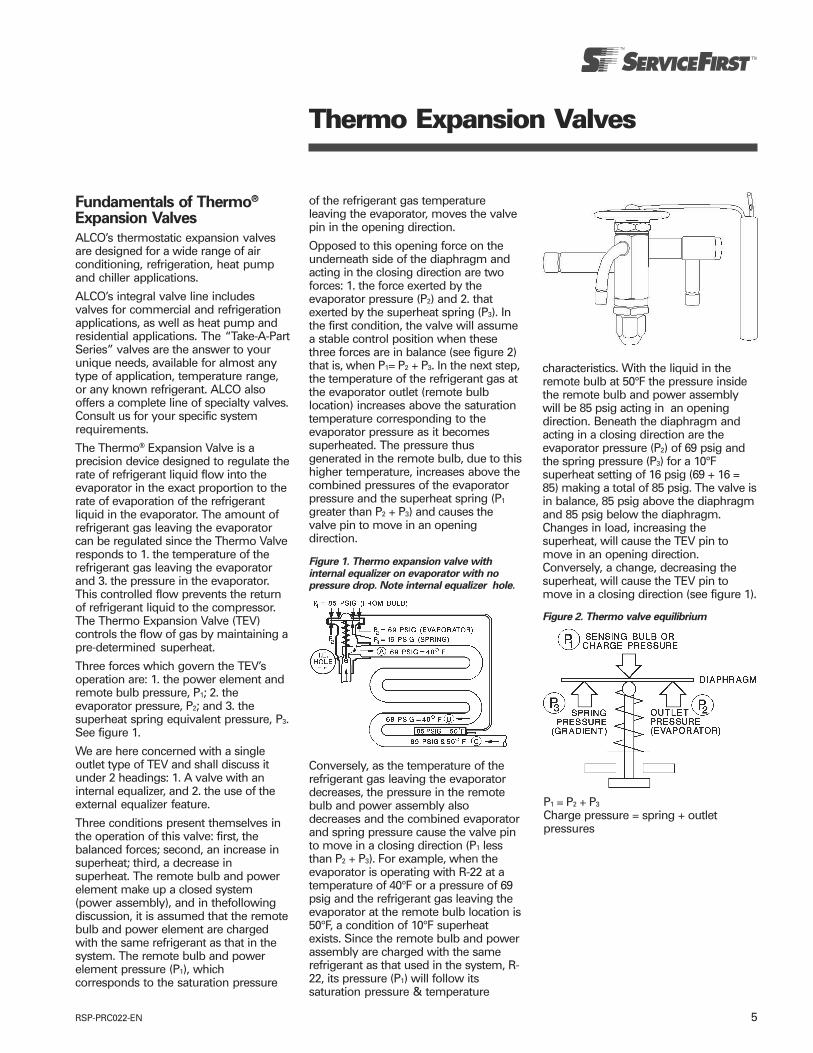
5RSP-PRC022-EN
Fundamentals of Thermo®
Expansion Valves
ALCO’s thermostatic expansion valvesare designed for a wide range of airconditioning, refrigeration, heat pumpand chiller applications.
ALCO’s integral valve line includesvalves for commercial and refrigerationapplications, as well as heat pump andresidential applications. The “Take-A-PartSeries” valves are the answer to yourunique needs, available for almost anytype of application, temperature range,or any known refrigerant. ALCO alsooffers a complete line of specialty valves.Consult us for your specific systemrequirements.
The Thermo® Expansion Valve is aprecision device designed to regulate therate of refrigerant liquid flow into theevaporator in the exact proportion to therate of evaporation of the refrigerantliquid in the evaporator. The amount ofrefrigerant gas leaving the evaporatorcan be regulated since the Thermo Valveresponds to 1. the temperature of therefrigerant gas leaving the evaporatorand 3. the pressure in the evaporator.This controlled flow prevents the returnof refrigerant liquid to the compressor.The Thermo Expansion Valve (TEV)controls the flow of gas by maintaining apre-determined superheat.
Three forces which govern the TEV’soperation are: 1. the power element andremote bulb pressure, P1; 2. theevaporator pressure, P2; and 3. thesuperheat spring equivalent pressure, P3.See figure 1.
We are here concerned with a singleoutlet type of TEV and shall discuss itunder 2 headings: 1. A valve with aninternal equalizer, and 2. the use of theexternal equalizer feature.
Three conditions present themselves inthe operation of this valve: first, thebalanced forces; second, an increase insuperheat; third, a decrease insuperheat. The remote bulb and powerelement make up a closed system(power assembly), and in thefollowingdiscussion, it is assumed that the remotebulb and power element are chargedwith the same refrigerant as that in thesystem. The remote bulb and powerelement pressure (P1), whichcorresponds to the saturation pressure
Thermo Expansion Valves
of the refrigerant gas temperatureleaving the evaporator, moves the valvepin in the opening direction.
Opposed to this opening force on theunderneath side of the diaphragm andacting in the closing direction are twoforces: 1. the force exerted by theevaporator pressure (P2) and 2. thatexerted by the superheat spring (P3). Inthe first condition, the valve will assumea stable control position when thesethree forces are in balance (see figure 2)that is, when P1= P2 + P3. In the next step,the temperature of the refrigerant gas atthe evaporator outlet (remote bulblocation) increases above the saturationtemperature corresponding to theevaporator pressure as it becomessuperheated. The pressure thusgenerated in the remote bulb, due to thishigher temperature, increases above thecombined pressures of the evaporatorpressure and the superheat spring (P1
greater than P2 + P3) and causes thevalve pin to move in an openingdirection.
Figure 1. Thermo expansion valve withinternal equalizer on evaporator with nopressure drop. Note internal equalizer hole.
Conversely, as the temperature of therefrigerant gas leaving the evaporatordecreases, the pressure in the remotebulb and power assembly alsodecreases and the combined evaporatorand spring pressure cause the valve pinto move in a closing direction (P1 lessthan P2 + P3). For example, when theevaporator is operating with R-22 at atemperature of 40°F or a pressure of 69psig and the refrigerant gas leaving theevaporator at the remote bulb location is50°F, a condition of 10°F superheatexists. Since the remote bulb and powerassembly are charged with the samerefrigerant as that used in the system, R-22, its pressure (P1) will follow itssaturation pressure & temperature
characteristics. With the liquid in theremote bulb at 50°F the pressure insidethe remote bulb and power assemblywill be 85 psig acting in an openingdirection. Beneath the diaphragm andacting in a closing direction are theevaporator pressure (P2) of 69 psig andthe spring pressure (P3) for a 10°Fsuperheat setting of 16 psig (69 + 16 =85) making a total of 85 psig. The valve isin balance, 85 psig above the diaphragmand 85 psig below the diaphragm.Changes in load, increasing thesuperheat, will cause the TEV pin tomove in an opening direction.Conversely, a change, decreasing thesuperheat, will cause the TEV pin tomove in a closing direction (see figure 1).
Figure 2. Thermo valve equilibrium
P1 = P2 + P3
Charge pressure = spring + outletpressures
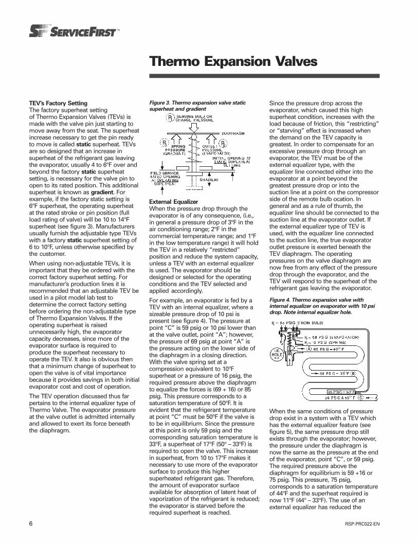
RSP-PRC022-EN6
TEV’s Factory SettingThe factory superheat settingof Thermo Expansion Valves (TEVs) ismade with the valve pin just starting tomove away from the seat. The superheatincrease necessary to get the pin readyto move is called static superheat. TEVsare so designed that an increase insuperheat of the refrigerant gas leavingthe evaporator, usually 4 to 6°F over andbeyond the factory static superheatsetting, is necessary for the valve pin toopen to its rated position. This additionalsuperheat is known as gradient. Forexample, if the factory static setting is6°F superheat, the operating superheatat the rated stroke or pin position (fullload rating of valve) will be 10 to 14°Fsuperheat (see figure 3). Manufacturersusually furnish the adjustable type TEVswith a factory static superheat setting of6 to 10°F, unless otherwise specified bythe customer.
When using non-adjustable TEVs, it isimportant that they be ordered with thecorrect factory superheat setting. Formanufacturer’s production lines it isrecommended that an adjustable TEV beused in a pilot model lab test todetermine the correct factory settingbefore ordering the non-adjustable typeof Thermo Expansion Valves. If theoperating superheat is raisedunnecessarily high, the evaporatorcapacity decreases, since more of theevaporator surface is required toproduce the superheat necessary tooperate the TEV. It also is obvious thenthat a minimum change of superheat toopen the valve is of vital importancebecause it provides savings in both initialevaporator cost and cost of operation.
The TEV operation discussed thus farpertains to the internal equalizer type ofThermo Valve. The evaporator pressureat the valve outlet is admitted internallyand allowed to exert its force beneaththe diaphragm.
Thermo Expansion Valves
Figure 3. Thermo expansion valve staticsuperheat and gradient
External EqualizerWhen the pressure drop through theevaporator is of any consequence, (i.e.,in general a pressure drop of 3°F in theair conditioning range; 2°F in thecommercial temperature range; and 1°Fin the low temperature range) it will holdthe TEV in a relatively “restricted”position and reduce the system capacity,unless a TEV with an external equalizeris used. The evaporator should bedesigned or selected for the operatingconditions and the TEV selected andapplied accordingly.
For example, an evaporator is fed by aTEV with an internal equalizer, where asizeable pressure drop of 10 psi ispresent (see figure 4). The pressure atpoint “C” is 59 psig or 10 psi lower thanat the valve outlet, point “A”; however,the pressure of 69 psig at point “A” isthe pressure acting on the lower side ofthe diaphragm in a closing direction.With the valve spring set at acompression equivalent to 10°Fsuperheat or a pressure of 16 psig, therequired pressure above the diaphragmto equalize the forces is (69 + 16) or 85psig. This pressure corresponds to asaturation temperature of 50°F. It isevident that the refrigerant temperatureat point “C” must be 50°F if the valve isto be in equilibrium. Since the pressureat this point is only 59 psig and thecorresponding saturation temperature is33°F, a superheat of 17°F (50° – 33°F) isrequired to open the valve. This increasein superheat, from 10 to 17°F makes itnecessary to use more of the evaporatorsurface to produce this highersuperheated refrigerant gas. Therefore,the amount of evaporator surfaceavailable for absorption of latent heat ofvaporization of the refrigerant is reduced;the evaporator is starved before therequired superheat is reached.
Since the pressure drop across theevaporator, which caused this highsuperheat condition, increases with theload because of friction, this “restricting”or “starving” effect is increased whenthe demand on the TEV capacity isgreatest. In order to compensate for anexcessive pressure drop through anevaporator, the TEV must be of theexternal equalizer type, with theequalizer line connected either into theevaporator at a point beyond thegreatest pressure drop or into thesuction line at a point on the compressorside of the remote bulb ocation. Ingeneral and as a rule of thumb, theequalizer line should be connected to thesuction line at the evaporator outlet. Ifthe external equalizer type of TEV isused, with the equalizer line connectedto the suction line, the true evaporatoroutlet pressure is exerted beneath theTEV diaphragm. The operatingpressures on the valve diaphragm arenow free from any effect of the pressuredrop through the evaporator, and theTEV will respond to the superheat of therefrigerant gas leaving the evaporator.
Figure 4. Thermo expansion valve withinternal equalizer on evaporator with 10 psidrop. Note internal equalizer hole.
When the same conditions of pressuredrop exist in a system with a TEV whichhas the external equalizer feature (seefigure 5), the same pressure drop stillexists through the evaporator; however,the pressure under the diaphragm isnow the same as the pressure at the endof the evaporator, point “C”, or 59 psig.The required pressure above thediaphragm for equilibrium is 59 +16 or75 psig. This pressure, 75 psig,corresponds to a saturation temperatureof 44°F and the superheat required isnow 11°F (44° – 33°F). The use of anexternal equalizer has reduced the

7RSP-PRC022-EN
Thermo Expansion Valves
superheat from 17 to 11°F. Thus, thecapacity of a system, having anevaporator with a sizable pressure drop,will be increased by the use of a TEVwith the external equalizer as comparedto the use of an internally equalizedvalve.When the pressure drop through anevaporator is in excess of the limitspreviously defined, or when a refrigerantdistributor is used at the evaporatorinlet, the TEV must have the externalequalizer feature for best performance.
The diagrams used thus far have shownthe single outlet type of TEV. Although amulti-circuit evaporator in itself may nothave an excessive pressure drop, thedevice used to obtain liquid distributionwill introduce a pressure drop that willlimit the action of the TEV withoutexternal equalizer, because thedistributor is installed between the valveoutlet and the evaporator inlet (seefigure 6).
Figure 5. Thermo expansion valve withexternal equalizer on evaporator with 10 psidrop.
Installation Location of ExternalEqualizerAs pointed out earlier, the externalequalizer line must be installed beyondthe point of greatest pressure drop.Since it may be difficult to determine thispoint, as a general rule it is safest toconnect the equalizer line to the suctionline at the evaporator outlet on the com-pressor side of the remote bulb location(see figures 5 and 6). When the externalequalizer is connected to a horizontalline, always make the connection at thetop of the line in order to avoid oillogging in the equalizer line.
Figure 6. Single outlet thermo expansionvalve and distributor.
On a multi-evaporator system includingtwo or more evaporators each fed by aseparate Thermo Expansion Valve (TEV),the external equalizer lines must belocated so that they will be free from theeffect of pressure changes in theevaporators fed by the other TEVs. At notime should the equalizer lines be joinedtogether in one common line to the mainsuction line. If individual suction linesfrom the separate evaporator outlets tothe common suction line are short, theninstall the external equalizer lines intothe separate evaporator suction headers,or as described in the precedingparagraph.
Do not under any circumstances cap orplug the external equalizer connectionon a TEV, as it will not operate. If the TEVis furnished with the external equalizerfeature, the external equalizer line mustbe installed (see figures 5 and 6).
SuperheatA vapor is superheated whenever itstemperature is higher than the saturationtemperature corresponding to itspressure. The amount of the superheatequals the amount of temperatureincrease above the saturationtemperature at the existing pressure.
For example, a refrigeration evaporatoris operating with Refrigerant 22 at 69psig suction pressure (see figure 7). TheRefrigerant 22 saturation temperature at69 psig is 40°F. As long as any liquidexists at this pressure, the refrigeranttemperature will remain 40°F, as itevaporates or boils off in the evaporator.
As the refrigerant moves along in thecoil, the liquid boils off into a vapor,causing the amount of liquid present todecrease. All of the liquid is finallyevaporated at point B because it hasabsorbed sufficient heat from thesurrounding atmosphere to change therefrigerant liquid to a vapor. Therefrigerant gas continues along the coiland remains at the same pressure (69psig); however, its temperature increasesdue to continued absorption of heatfrom the surrounding atmosphere.When the refrigerant gas reaches theend of the evaporator (point C), itstemperature is 50°F. This refrigerant gasis now superheated and the amount ofsuperheat is 10°F (50 – 40). The degree towhich the refrigerant gas is superheateddepends on (1) the amount of refrigerantbeing fed to the evaporator by the TEVand (2) the heat load to which theevaporator is exposed.
Adjustment of SuperheatThe function of a TEV is to control thesuperheat of the suction gas leaving theevaporator in accordance with the valvesetting.
A TEV which is performing this functionwithin reasonable limits can be said tobe operating in a satisfactory manner.
Good superheat control is the criterion ofTEV performance. It is important thatthis function be measured as accuratelyas possible, or in the absence ofaccuracy, to be aware of the magnitudeand direction of whatever error ispresent.
When the pressure drop thru theevaporator is known to be within thelimits defined on page 6, it is permissibleto install the external equalizerconnection at one of the return bendsmidway through the evaporator. Such anequalizer location will provide smoothervalve control particularly when the TEVis used in conjunction with anEvaporator Pressure Regulator. However,in all cases where any type of controlvalve is installed in the suction line, theexternal equalizer line for the TEV mustalways be connected on the evaporatorside of such a control valve or regulator.
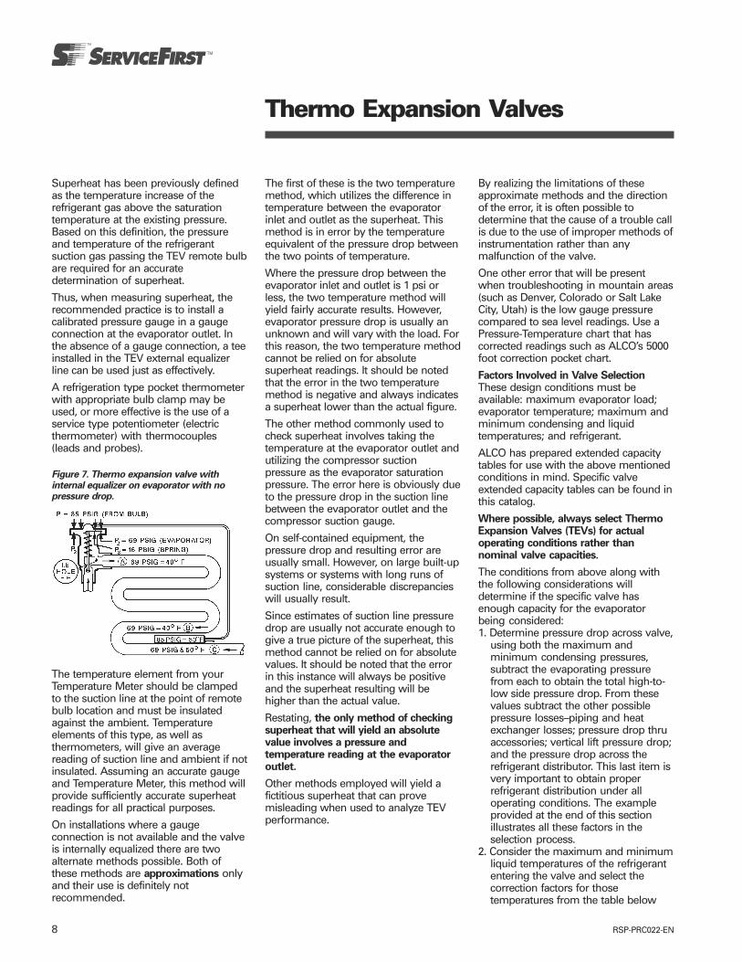
RSP-PRC022-EN8
Thermo Expansion Valves
Superheat has been previously definedas the temperature increase of therefrigerant gas above the saturationtemperature at the existing pressure.Based on this definition, the pressureand temperature of the refrigerantsuction gas passing the TEV remote bulbare required for an accuratedetermination of superheat.
Thus, when measuring superheat, therecommended practice is to install acalibrated pressure gauge in a gaugeconnection at the evaporator outlet. Inthe absence of a gauge connection, a teeinstalled in the TEV external equalizerline can be used just as effectively.
A refrigeration type pocket thermometerwith appropriate bulb clamp may beused, or more effective is the use of aservice type potentiometer (electricthermometer) with thermocouples(leads and probes).
Figure 7. Thermo expansion valve withinternal equalizer on evaporator with nopressure drop.
The temperature element from yourTemperature Meter should be clampedto the suction line at the point of remotebulb location and must be insulatedagainst the ambient. Temperatureelements of this type, as well asthermometers, will give an averagereading of suction line and ambient if notinsulated. Assuming an accurate gaugeand Temperature Meter, this method willprovide sufficiently accurate superheatreadings for all practical purposes.
On installations where a gaugeconnection is not available and the valveis internally equalized there are twoalternate methods possible. Both ofthese methods are approximations onlyand their use is definitely notrecommended.
The first of these is the two temperaturemethod, which utilizes the difference intemperature between the evaporatorinlet and outlet as the superheat. Thismethod is in error by the temperatureequivalent of the pressure drop betweenthe two points of temperature.
Where the pressure drop between theevaporator inlet and outlet is 1 psi orless, the two temperature method willyield fairly accurate results. However,evaporator pressure drop is usually anunknown and will vary with the load. Forthis reason, the two temperature methodcannot be relied on for absolutesuperheat readings. It should be notedthat the error in the two temperaturemethod is negative and always indicatesa superheat lower than the actual figure.
The other method commonly used tocheck superheat involves taking thetemperature at the evaporator outlet andutilizing the compressor suctionpressure as the evaporator saturationpressure. The error here is obviously dueto the pressure drop in the suction linebetween the evaporator outlet and thecompressor suction gauge.
On self-contained equipment, thepressure drop and resulting error areusually small. However, on large built-upsystems or systems with long runs ofsuction line, considerable discrepancieswill usually result.
Since estimates of suction line pressuredrop are usually not accurate enough togive a true picture of the superheat, thismethod cannot be relied on for absolutevalues. It should be noted that the errorin this instance will always be positiveand the superheat resulting will behigher than the actual value.
Restating, the only method of checkingsuperheat that will yield an absolutevalue involves a pressure andtemperature reading at the evaporatoroutlet.
Other methods employed will yield afictitious superheat that can provemisleading when used to analyze TEVperformance.
By realizing the limitations of theseapproximate methods and the directionof the error, it is often possible todetermine that the cause of a trouble callis due to the use of improper methods ofinstrumentation rather than anymalfunction of the valve.
One other error that will be presentwhen troubleshooting in mountain areas(such as Denver, Colorado or Salt LakeCity, Utah) is the low gauge pressurecompared to sea level readings. Use aPressure-Temperature chart that hascorrected readings such as ALCO’s 5000foot correction pocket chart.
Factors Involved in Valve SelectionThese design conditions must beavailable: maximum evaporator load;evaporator temperature; maximum andminimum condensing and liquidtemperatures; and refrigerant.
ALCO has prepared extended capacitytables for use with the above mentionedconditions in mind. Specific valveextended capacity tables can be found inthis catalog.
Where possible, always select ThermoExpansion Valves (TEVs) for actualoperating conditions rather thannominal valve capacities.
The conditions from above along withthe following considerations willdetermine if the specific valve hasenough capacity for the evaporatorbeing considered:1. Determine pressure drop across valve,
using both the maximum andminimum condensing pressures,subtract the evaporating pressurefrom each to obtain the total high-to-low side pressure drop. From thesevalues subtract the other possiblepressure losses–piping and heatexchanger losses; pressure drop thruaccessories; vertical lift pressure drop;and the pressure drop across therefrigerant distributor. This last item isvery important to obtain properrefrigerant distribution under alloperating conditions. The exampleprovided at the end of this sectionillustrates all these factors in theselection process.
2. Consider the maximum and minimumliquid temperatures of the refrigerantentering the valve and select thecorrection factors for thosetemperatures from the table below

9RSP-PRC022-EN
Thermo Expansion Valves
the capacity ratings. Determine thecorrected capacity requirement bydividing the maximum evaporatorload in tons by the liquid correctionfactors. These values will allow thefinal selection to be made.
3. Select the valve size from theappropriate capacity table for theevaporator temperature, pressuredrop available, and corrected capacityrequirement. If the valve has lesscapacity than required, contact yourALCO Sales Engineer or Alco Controlsfor assistance.
4. Select the proper thermostatic chargebased on the evaporator temperature,refrigerant, and whether a MOP typecharge is needed.
5. Appropriate connections and whetheran externally equalized model isrequired completes the selection.Always use an externally equalizedvalve when a distributor is used.
Since the capacity and the performanceof the TEV is based on solid liquidentering the valve, careful considerationmust be given to the total pressure dropin the liquid line to determine if therewill be sufficient subcooling of the liquidrefrigerant to prevent the formation offlash gas. If the subcooling of the liquidrefrigerant from the condenser is notadequate, then a heat exchanger, liquidsubcooler, or some other means must beused to obtain enough subcooling of theliquid refrigerant to insure solid liquidentering the TEV at all times.
Thermo Valve ChargesOver the years, or more precisely, sinceALCO produced the first valve forammonia in 1925, the matter of a propercharge in the thermal sensing elementhas been of major concern. Liquidcharges, gas charges, cross liquidcharges, cross vapor charges, hightemperature charges, ultralowtemperature charges, commercialcharges, etc., all have been tried withvarying degrees of success.
M.O.P.Maximum Operating Pressure (or MotorOverload Protection) is the ability of theTEV to close down, starve, or completelyshut off if the suction pressure shouldapproach a dangerously highpredetermined limit condition. Acondition such as to cause overheating a
suction cooled compressor, or loadingthe crankcase with too dense a vaporpressure.
With the TEV in a closed condition dueto MOP, the compressor has a chance togain on the excess low side pressure andpull the suction back down tosatisfactory operating conditions. At thispoint (below the MOP) the TEV will re-open and feed in a standard manner oruntil such time as there is an overloadagain.
Certain bulb charges can be suppliedwith this MOP feature. One of the mostcommon is the “G” (gas) charge. It isalways supplied with “MOP”.
The ALCO “W” charge can be suppliedwith the MOP feature if needed forsystem protection. This need rarelyoccurs in modern day refrigerationexcept such conditions as immediatelyafter defrost or on gasoline drivencompressors such as truck refrigeration.
CAUTION: Any bulb charge with MOPwill be affected by extreme crossambient conditions. If this conditionshould exist, install an electric stripheater around the top part of the TEV.
Power Element ChargesFor many years ALCO used a variety ofbulb charges in their expansion valves.Letters such as L, G, W, C, X, Z, A, Q andothers designated a particular chemicalor mixture of ingredients that gave aspecific curve or line on a graph tomatch a definite pattern of a refrigerantcondition.
In 1978, ALCO introduced a new bulbcharge (BA) to assist the outside coil ofair-to-air heat pumps using R-22 inproviding 0°F superheat, or “wet gas”,back to the windings of hermetic heatpump compressors during very lowoutdoor temperatures.
At 40°F ambients (or higher) this chargeoperates the same as any regular airconditioning bulb charge with a standardsuperheat. In 1983, the charge wasimproved and given the designation CA.
C = +50°F to –20°FZ = +10°F to –50°F
W-(MOP) = MOP to –50°FL = +50°F to –50°F
G-(MOP) = Depends on therefrigerant.Some, such asR-14 to –200°F
CA = Heat pump chargeoutside coil
When G charges, and any other type ofMOP charge (i.e. W-MOP) is used for lowtemperature applications (–40°F andlower) a small heater strip should bewrapped around the head of the TEV. Forspecial applications, other charges maybe used from time to time.
For assistance in selecting a charge withMotor Overload Protection (if requiredby compressor manufacturer) see thetable below and the TEV Charge Selectoron page 9.
Table 1. Maximum dehydration temperature (in °F)
Thermostatic ChargeRefrigerant L C Z G WMOP/CA X
R134a 195 190 250 250 250 N/AR22 160 160 185 250 250 N/A
R404A/R507 150 150 170 250 250 N/AR717 N/A N/A 150 N/A N/A 200
The table above refers to the maximumdehydration temperatures when thebulb and valve body are subjected to thesame temperature. On L, C, Z, and Xcharges, 250°F maximum valve bodytemperature is permissible (if the bulbtemperature) does not exceed thoseshown in the table.
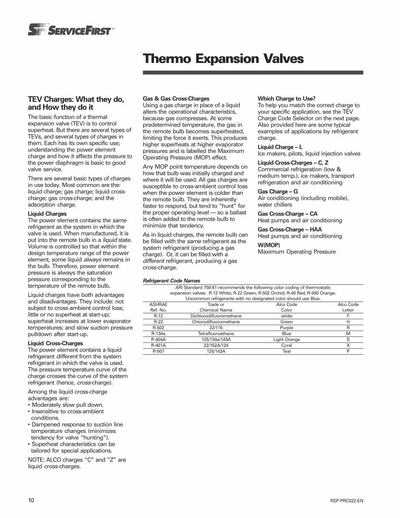
RSP-PRC022-EN10
Thermo Expansion Valves
TEV Charges: What they do,and How they do it
The basic function of a thermalexpansion valve (TEV) is to controlsuperheat. But there are several types ofTEVs, and several types of charges inthem. Each has its own specific use;understanding the power elementcharge and how it affects the pressure tothe power diaphragm is basic to goodvalve service.
There are several basic types of chargesin use today. Most common are the:liquid charge; gas charge; liquid cross-charge; gas cross-charge; and theadsorption charge.
Liquid ChargesThe power element contains the samerefrigerant as the system in which thevalve is used. When manufactured, it isput into the remote bulb in a liquid state.Volume is controlled so that within thedesign temperature range of the powerelement, some liquid always remains inthe bulb. Therefore, power elementpressure is always the saturationpressure corresponding to thetemperature of the remote bulb.
Liquid charges have both advantagesand disadvantages. They include: notsubject to cross-ambient control loss;little or no superheat at start-up;superheat increases at lower evaporatortemperatures; and slow suction pressurepulldown after start-up.
Liquid Cross-ChargesThe power element contains a liquidrefrigerant different from the systemrefrigerant in which the valve is used.The pressure temperature curve of thecharge crosses the curve of the systemrefrigerant (hence, cross-charge).
Among the liquid cross-chargeadvantages are:• Moderately slow pull down.• Insensitive to cross-ambient
conditions.• Dampened response to suction line
temperature changes (minimizestendency for valve “hunting”).
• Superheat characteristics can betailored for special applications.
NOTE: ALCO charges “C” and “Z” areliquid cross-charges.
Gas & Gas Cross-ChargesUsing a gas charge in place of a liquidalters the operational characteristics,because gas compresses. At somepredetermined temperature, the gas inthe remote bulb becomes superheated,limiting the force it exerts. This produceshigher superheats at higher evaporatorpressures and is labelled the MaximumOperating Pressure (MOP) effect.
Any MOP point temperature depends onhow that bulb was initially charged andwhere it will be used. All gas charges aresusceptible to cross-ambient control losswhen the power element is colder thanthe remote bulb. They are inherentlyfaster to respond, but tend to “hunt” forthe proper operating level — so a ballastis often added to the remote bulb tominimize that tendency.
As in liquid charges, the remote bulb canbe filled with the same refrigerant as thesystem refrigerant (producing a gascharge). Or, it can be filled with adifferent refrigerant, producing a gascross-charge.
Which Charge to Use?To help you match the correct charge toyour specific application, see the TEVCharge Code Selector on the next page.Also provided here are some typicalexamples of applications by refrigerantcharge.
Liquid Charge – LIce makers, pilots, liquid injection valves
Liquid Cross-Charges – C, ZCommercial refrigeration (low &medium temp.), ice makers, transportrefrigeration and air conditioning
Gas Charge – GAir conditioning (including mobile),water chillers
Gas Cross-Charge – CAHeat pumps and air conditioning
Gas Cross-Charge – HAAHeat pumps and air conditioning
W(MOP)Maximum Operating Pressure
Refrigerant Code Names
ARI Standard 750-81 recommends the following color coding of thermostaticexpansion valves: R-12 White; R-22 Green; R-502 Orchid; R-40 Red; R-500 Orange.
Uncommon refrigerants with no designated color should use Blue.ASHRAE Trade or Alco Code Alco CodeRef. No. Chemical Name Color Letter
R-12 Dichlorodifluoromethane white FR-22 Chlorodifluoromethane Green HR-502 22/115 Purple RR-134a Tetrafluoroethane Blue MR-404A 125/134a/143A Light Orange SR-401A 22/152A/124 Coral XR-507 125/143A Teal P
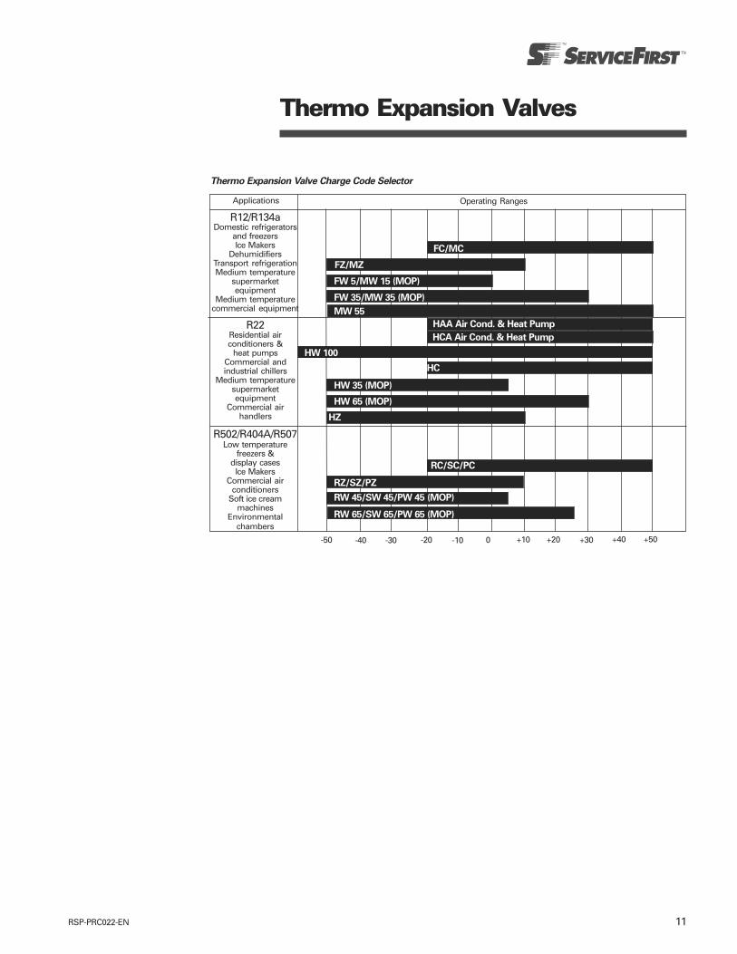
11RSP-PRC022-EN
Thermo Expansion Valve Charge Code Selector
Thermo Expansion Valves
Applications Operating Ranges
R12/R134aDomestic refrigerators
and freezersIce Makers
DehumidifiersTransport refrigerationMedium temperature
supermarketequipment
Medium temperaturecommercial equipment
R22Residential airconditioners &
heat pumpsCommercial andindustrial chillers
Medium temperaturesupermarketequipment
Commercial airhandlers
R502/R404A/R507Low temperature
freezers &display cases
Ice MakersCommercial air
conditionersSoft ice cream
machinesEnvironmental
chambers
FC/MC
FZ/MZ
FW 5/MW 15 (MOP)
FW 35/MW 35 (MOP)
MW 55
HCA Air Cond. & Heat Pump
HAA Air Cond. & Heat Pump
HW 100
HC
HW 35 (MOP)
HW 65 (MOP)
HZ
RC/SC/PC
RZ/SZ/PZ
RW 45/SW 45/PW 45 (MOP)
RW 65/SW 65/PW 65 (MOP)
-50 -40 -30 -20 -10 0 +10 +20 +30 +40 +50

RSP-PRC022-EN12
TEV Replacement Charge Symbols Cross ReferenceOld Bulb Charges vs. New Replacement Bulb Charge
Air Conditioning Commercial Refrigeration Low TemperatureOld Charge Replacement Old Charge Replacement Old Charge Replacement
Refrigerant R12/R134aF or FL — —
FC FC —FW FW FWZ
FG55 FC FG35 — —FW55 FW35 FW35 FW15FQ55 FQ35 FW15FGAFLA — —FGS FGS35 FGS35
FWS FWS FWSFWS FWS FWS FZ/MZ FZ/MZ
FX FXRefrigerant R22
H or HL — —HC HC —
HW HCA HW HWZHG100 HG65 — —HW100 HW65 HW65 HW35HQ100 HC HQ65 HQ35HGAHLA — —
HW85 HW85 — —HGS HGS65 HGS65
HWS HWSHWS HWS HWS HWS HZ HZ
HX HXRefrigerant R502/R404A/R507
RL — —RW RC/SC/PC RW RWZ RZ
RW110 RW65 RW65 RW35 RW45/SW45RWS RWS
RWS RWS RWS RWS RZ RZ/SZ/PZ
Thermo Expansion Valves
FC
FWS
HC
HWS
HC
RC/SC/PC
FC
FW35
FZ
—— —
FW15/MW15
HZ
— —
RC/SC/PC
HWS
HC
HW65
— —
HWS
Note: All other charge symbols must be replaced with an identical model or at the option of the Alco technical service department who may make engineering authorized substitutionof equivalent type to provide equivalent operation and performance.Note: For field replacement purposes, hc can be used to replace hca.

13RSP-PRC022-EN
Thermo Expansion Valves
Thermo Valve ApplicationIn general, for best evaporatorperformance, the Thermo ExpansionValve (TEV) should be applied as close tothe evaporator as possible and in such alocation as to make it easily accessiblefor adjustment and servicing. Onpressure drop and centrifugal typedistributors, apply the valve as close tothe distributor as possible. (See figure 8.)
Figure 8. Thermo expansion valve andpressure drop type distributor feeding anevaporator.
All expansion valves [with the exceptionof the W-(MOP), G-(MOP), or GS-(MOP)gas charged types] may be installed inany location in the system. The gascharged type must always be installed insuch a manner that the power assemblywill be warmer than the remote bulb.The remote bulb tubing must not beallowed to touch a surface colder thanthe remote bulb location. If the powerassembly or remote bulb tubingbecomes colder than the remote bulb,the vapor change will condense at thecoldest point and the remote bulb willlose control.
Remote Bulb Location
Strap-on Type Remote BulbSince evaporator performance dependslargely upon good TEV control, andgood valve control depends uponresponse to temperature change of therefrigerant gas leaving the evaporator,considerable care must be given to typesof remote bulbs and their locations. Ingeneral, the external remote bulb meetsthe requirements of most installations. Itshould be clamped to the suction linenear the evaporator outlet, and on ahorizontal run. If more than one TEV isused on adjacent evaporators orevaporator sections, make sure that theremote bulb of each valve is applied tothe suction line of the evaporator fed bythat valve.
Clean the suction line thoroughly beforeclamping the remote bulb in place.When a steel suction line is used, it isadvisable to paint the line withaluminum paint to minimize futurecorrosion and faulty remote bulb contactwith the line. On lines over 7/8" OD theremote bulb should be installed at theposition of about 4 or 8 o’clock. Seefigure 9.
If it is necessary to protect the remotebulb from the effect of an air stream,after it is clamped to the line, usematerial that will not absorb water withevaporator temperatures above 32°F.Below 32°F, cork or similar materialsealed against moisture is suggested toprevent ice logging at the remote bulblocation. The use of hair felt is notrecommended. When the remote bulblocation is below the water or brine levelof a submerged coil, use a waterproofingmaterial or pitch, that does not requireheating above 120°F in applying it, toprotect the remote bulb tubing andremote bulb.
Remote Bulb WellWhen it becomes desirable to increasethe sensitivity of the remote bulb to achange in the refrigerant gastemperature leaving the evaporator, itmay be necessary to use a remote bulbwell. This is particularly true for shortcoupled installations and installationswith large suction lines (2-1/8" OD orlarger). Remote bulb wells should beused (1) when very low super-heats aredesired and (2) where convected heatfrom a warm room can influence theremote bulb (see figure 10).
Do not under any circumstances locateeither type of remote bulb in a locationwhere the suction line is trapped (seefigure 11). If the liquid refrigerantcollects at the point of remote bulblocation, the TEV operation will be erraticand possibly the valve thought to bedefective. Large fluctuations in superheatin the suction gas are usually the resultof trapped liquid at the remote bulblocation. Even on properly designedsuction lines, it is sometimes necessaryto move the remote bulb a few incheseither way from the original location toobtain best valve action. Always locatethe remote bulb on the evaporator sideof any heat exchanger.
On multi-circuit evaporators fed by onevalve, locate the remote bulb away fromimmediate suction outlet at point wherethe suction gas from the several parallelcircuits has had an opportunity to mix inthe suction header.
Be sure to pull up tight on clamps so thatthe remote bulb makes good contactwith the suction line. Never apply heatnear the remote bulb location withoutfirst removing the remote bulb.
Figure 10.
Figure 9.
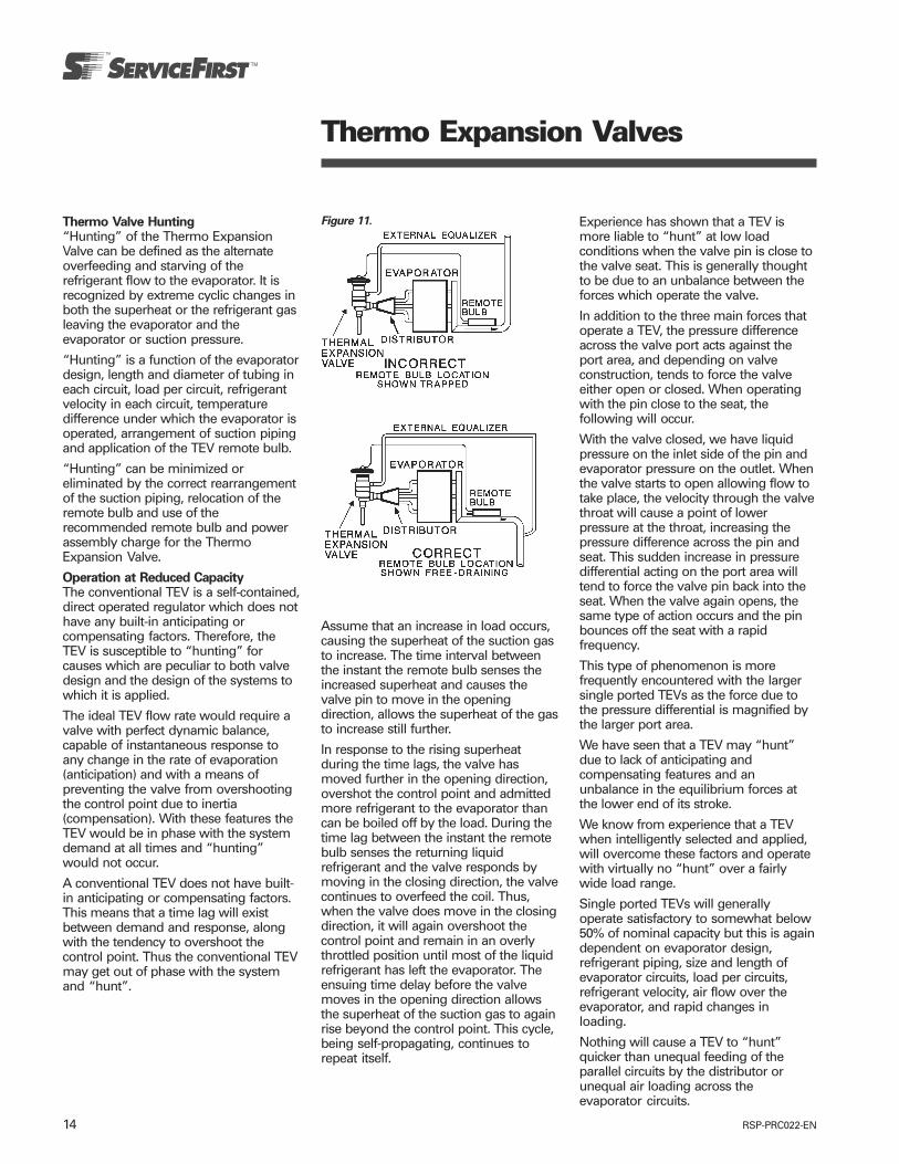
RSP-PRC022-EN14
Thermo Expansion Valves
Thermo Valve Hunting“Hunting” of the Thermo ExpansionValve can be defined as the alternateoverfeeding and starving of therefrigerant flow to the evaporator. It isrecognized by extreme cyclic changes inboth the superheat or the refrigerant gasleaving the evaporator and theevaporator or suction pressure.
“Hunting” is a function of the evaporatordesign, length and diameter of tubing ineach circuit, load per circuit, refrigerantvelocity in each circuit, temperaturedifference under which the evaporator isoperated, arrangement of suction pipingand application of the TEV remote bulb.
“Hunting” can be minimized oreliminated by the correct rearrangementof the suction piping, relocation of theremote bulb and use of therecommended remote bulb and powerassembly charge for the ThermoExpansion Valve.
Operation at Reduced CapacityThe conventional TEV is a self-contained,direct operated regulator which does nothave any built-in anticipating orcompensating factors. Therefore, theTEV is susceptible to “hunting” forcauses which are peculiar to both valvedesign and the design of the systems towhich it is applied.
The ideal TEV flow rate would require avalve with perfect dynamic balance,capable of instantaneous response toany change in the rate of evaporation(anticipation) and with a means ofpreventing the valve from overshootingthe control point due to inertia(compensation). With these features theTEV would be in phase with the systemdemand at all times and “hunting”would not occur.
A conventional TEV does not have built-in anticipating or compensating factors.This means that a time lag will existbetween demand and response, alongwith the tendency to overshoot thecontrol point. Thus the conventional TEVmay get out of phase with the systemand “hunt”.
Figure 11.
Assume that an increase in load occurs,causing the superheat of the suction gasto increase. The time interval betweenthe instant the remote bulb senses theincreased superheat and causes thevalve pin to move in the openingdirection, allows the superheat of the gasto increase still further.
In response to the rising superheatduring the time lags, the valve hasmoved further in the opening direction,overshot the control point and admittedmore refrigerant to the evaporator thancan be boiled off by the load. During thetime lag between the instant the remotebulb senses the returning liquidrefrigerant and the valve responds bymoving in the closing direction, the valvecontinues to overfeed the coil. Thus,when the valve does move in the closingdirection, it will again overshoot thecontrol point and remain in an overlythrottled position until most of the liquidrefrigerant has left the evaporator. Theensuing time delay before the valvemoves in the opening direction allowsthe superheat of the suction gas to againrise beyond the control point. This cycle,being self-propagating, continues torepeat itself.
Experience has shown that a TEV ismore liable to “hunt” at low loadconditions when the valve pin is close tothe valve seat. This is generally thoughtto be due to an unbalance between theforces which operate the valve.
In addition to the three main forces thatoperate a TEV, the pressure differenceacross the valve port acts against theport area, and depending on valveconstruction, tends to force the valveeither open or closed. When operatingwith the pin close to the seat, thefollowing will occur.
With the valve closed, we have liquidpressure on the inlet side of the pin andevaporator pressure on the outlet. Whenthe valve starts to open allowing flow totake place, the velocity through the valvethroat will cause a point of lowerpressure at the throat, increasing thepressure difference across the pin andseat. This sudden increase in pressuredifferential acting on the port area willtend to force the valve pin back into theseat. When the valve again opens, thesame type of action occurs and the pinbounces off the seat with a rapidfrequency.
This type of phenomenon is morefrequently encountered with the largersingle ported TEVs as the force due tothe pressure differential is magnified bythe larger port area.
We have seen that a TEV may “hunt”due to lack of anticipating andcompensating features and anunbalance in the equilibrium forces atthe lower end of its stroke.
We know from experience that a TEVwhen intelligently selected and applied,will overcome these factors and operatewith virtually no “hunt” over a fairlywide load range.
Single ported TEVs will generallyoperate satisfactory to somewhat below50% of nominal capacity but this is againdependent on evaporator design,refrigerant piping, size and length ofevaporator circuits, load per circuits,refrigerant velocity, air flow over theevaporator, and rapid changes inloading.
Nothing will cause a TEV to “hunt”quicker than unequal feeding of theparallel circuits by the distributor orunequal air loading across theevaporator circuits.

15RSP-PRC022-EN
Thermo Expansion Valves
Balanced Port Thermo Valve OperationIn conventional expansion valves, as thepressure drop across the valve portchanges due to changes in headpressure and/or suction pressure; theoperating superheat of the expansionvalve varies due to this “unbalance”.
Depending on the operating conditionsunder which the superheat wasoriginally set, this “unbalance” can insome situations result in compressorflooding or evaporator starvation. Anunique design concept called “BalancedPort” cancels the effect of this pressureunbalance, permitting the expansionvalve to operate at a relatively constantsuperheat over a wide range ofoperating conditions.
Any refrigeration system whichexperiences changes in operatingpressures due to varying ambients, gasdefrost, heat reclaim, or swings inevaporator load will benefit from usingALCO’s Super HF Balanced Port ThermoExpansion Valve.
Double Ported Balanced Ported TEVsThe flow pattern of the single ported TEVcan cause difficulties at low loadconditions. The larger the port area(larger tonnages) the more prone is thevalve to “hunt”. Certain type ALCOThermo Valves have been designed withtwo ports or “double ported”. The inletis so designed as to create a“counterflow” against the double portedbalance ported valves and thus eliminateany unbalance across the two ports. Seefigure 13.
Flow through the upper port enters theupper radial holes of the cage seatassembly, moves upward and across theupper seat, down through the internalpassage of the spool and out the holes inthe bottom of the spool. The pressuredrop across this port exerts a force in aclosing (upward) direction.
Flow through the bottom port enters thelower radial holes of the cage seatassembly and moves downwardthrough the port formed by the cage seatand the valve spool. High pressure liquidacts downward on the spool and thepressure drop across the spool and seatexerts a force in an opening direction.
Since the effective port area of both theupper and lower cage ports is verynearly the same, the net forceunbalanced across them is negligible.
Figure 12. Cutaway view of Alco’s super HFbalanced port and thermo expansion valve.
This feature makes it possible for thenew double ported cage assemblies tomodulate over a much wider load rangethan was possible with the old style,single port valves. The reverse-flowvalves provide satisfactory control atloads less than 15% of nominal valvecapacity. Their performance is superiorto any competitive product available.Actual field performance has proven thesuperiority of double ported ALCOThermo Valves and their ability to reduce“hunting” to a very minimum.
Figure 13.
Bleed Holes for System PressureEqualizationWhen a permanent split-capacitor motoris used to drive a refrigerationcompressor, it is necessary to providesome means of equalizing the high andlow side pressures during the “off” cycleso that the motor can start withminimum torque.
Note: An external equalizer feature onTEVs does not perform this function; aseparate internal bleed hole is required.
The letter “B” is used after the valveseries number to denote a valve withbleed hole construction. For example:TCLEBHC. The body flange is stampedwith the letter “B” followed by the bleedhole diameter, for example: B036. Seefigure 14.
The required bleed hole size for aparticular system is a function of thehigh side and low side volumes, thepressure difference across the valve attime of shut-down, the equalization timerequired and quantity of refrigerantcharge. Due to the many variables, eachapplication must be tested to determinethe correct size required. It should beremembered that bleed hole size adds tothe total effective port area of the TEVand may affect size selection. Finalselection of bleed hole size should bemade ONLY after thorough testing.

RSP-PRC022-EN16
Thermo Expansion Valves
Ammonia Expansion ValveThe same Take-A-Part construction anddesign principles found in ALCO ThermoValves for the common halocarbonrefrigerants are also found in the ALCOTG line of Ammonia Thermo Valves.
Except for a built-in Y-type strainer andbody construction of high grade steelalloy, the approach to application ofammonia TEVs is the same as the brasshalocarbon TEVs.
The internal cage construction of the TGammonia expansion valve is the sameas its brass counterpart, except in someinstances a small discharge tube ororifice is used for the refrigerant outlet ofthe cage.
The function of this discharge tube is toprovide a secondary restriction toprovide more accurate tonnagerequirements, and to slow down thevelocity of the liquid ammonia acrossthe primary orifice.
Figure 14. Bleed hole for sysem equalization.
** Bleed hole size stamped on body here
Any vapor present (flash gas) in theliquid line will cause the ammonia toenter the primary orifice at exceptionallyhigh velocities thereby causing erosionof the pin and seat. The discharge tubeor secondary orifice helps to reduce thisvelocity and increase the life of the pinand seat.
CAUTION: Should an ALCO TGammonia Thermo Valve be used on anevaporator with a refrigerant distributoremploying an orifice plate, the dischargetube in the cage must be removed priorto installation.
The combination of the discharge tubeand distributor orifice plate will createtoo much pressure drop and a starvingcondition will probably be noted.
Solder Bodies Take-A-Part Style ThermoValvesWhen soldering, remove powerassembly, cage assembly, and allgaskets. Keep heat away from all valveparts, except body flange. Use a brazingalloy or low temperature solder. Becareful to retain all the solder in theconnection. For integral (one-piece) bodytypes, be sure to use plenty of wet ragsor chill blocks and direct the flame awayfrom the valve body.
For external adjustment of ALCO Take-A-Part Valves–Types TCL, TJL, TJR, TER,TIR and THR: To adjust, remove seal capon side of valve and turn adjusting stem.Turning stem to right decreases flow andraises superheat. Turning stem to leftincreases flow and lowers superheat.Adjust all “T” series 2 turns (1°F) at atime.
Adjust each valve separately and waitbetween each adjustment to observe allresults. Always tighten any loosenedconnections and replace seal cap.
It should be noted that superheatadjustment of “W–MOP”, “G”, and“GS” charged valves will change theMOP point. An increase in superheatsetting will lower the MOP point and adecrease in superheat setting will raisethe MOP.
Direction of FlowAlways be sure the flow of refrigerant isin the direction indicated by the arrow onthe valve body.
Installation and ServiceALCO “T” Series Thermo Valves havethree component parts: the powerassembly, cage assembly, and bodyflange. There are no working parts in thebody flange. It is never necessary tobreak the line connections to service thevalve.
ALCO types HF, AFA and other hermeticintegral Thermo Valves are assembledunits which cannot be taken apart in thefield, except that the strainer may beeasily removed for inspection andcleaning by disconnecting the valve fromthe liquid line and removing the inletflare connection.
Servicing
WARNING
Before opening any system forservicing, use EPA approved methods tobring the system to atmosphericpressure. Failure to comply may result insystem damage and/or personal injury.
To inspect, clean, or replace parts on allTake-A-Part Valves, remove the two capscrews—lift off the power assembly—and remove cage assembly. Be suregaskets are replaced in proper placeswhen reassembling valve (see figure 15).When assembling external adjustmentvalves (TCL, TJL, TER, TIR, or THR) besure the two lugs on the cage assemblyfit into the grooves provided for them inthe power assembly (see figure 16).Don’t force valve together—make thecage fit properly before tightening bodyflange.
Solenoid Liquid Stop ValvesThe TEV, while produced as a tightseating device, cannot be depended onfor positive shut-off since the seatingsurfaces are exposed to dirt, moisture,corrosion, and erosion. In addition, if theremote bulb is installed in a locationwhere during the “off” cycle it isinfluenced by a higher ambienttemperature than the evaporator, thevalve will open during a portion of the“off” cycle, and admit liquid to theevaporator. For these reasons theinstallation of a Solenoid Liquid StopValve ahead of any Thermo ExpansionValve (TEV) is highly recommended.
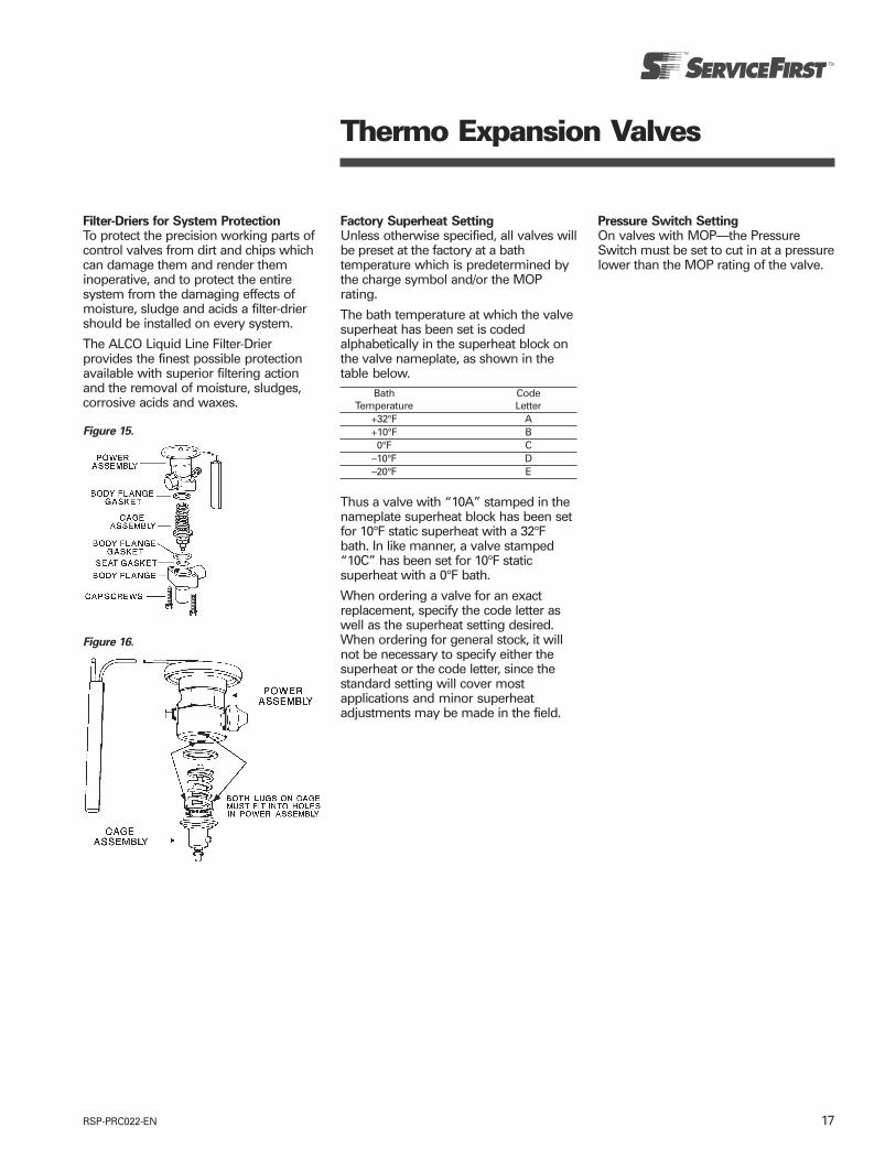
17RSP-PRC022-EN
Thermo Expansion Valves
Filter-Driers for System ProtectionTo protect the precision working parts ofcontrol valves from dirt and chips whichcan damage them and render theminoperative, and to protect the entiresystem from the damaging effects ofmoisture, sludge and acids a filter-driershould be installed on every system.
The ALCO Liquid Line Filter-Drierprovides the finest possible protectionavailable with superior filtering actionand the removal of moisture, sludges,corrosive acids and waxes.
Figure 15.
Figure 16.
Factory Superheat SettingUnless otherwise specified, all valves willbe preset at the factory at a bathtemperature which is predetermined bythe charge symbol and/or the MOPrating.
The bath temperature at which the valvesuperheat has been set is codedalphabetically in the superheat block onthe valve nameplate, as shown in thetable below.
Bath CodeTemperature Letter
+32°F A+10°F B0°F C
–10°F D–20°F E
Thus a valve with “10A” stamped in thenameplate superheat block has been setfor 10°F static superheat with a 32°Fbath. In like manner, a valve stamped“10C” has been set for 10°F staticsuperheat with a 0°F bath.
When ordering a valve for an exactreplacement, specify the code letter aswell as the superheat setting desired.When ordering for general stock, it willnot be necessary to specify either thesuperheat or the code letter, since thestandard setting will cover mostapplications and minor superheatadjustments may be made in the field.
Pressure Switch SettingOn valves with MOP—the PressureSwitch must be set to cut in at a pressurelower than the MOP rating of the valve.
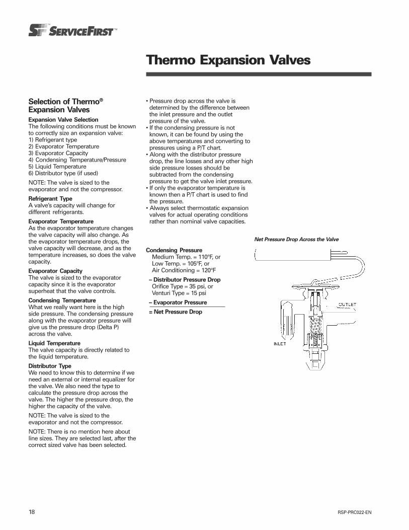
RSP-PRC022-EN18
Thermo Expansion Valves
Selection of Thermo®
Expansion Valves
Expansion Valve SelectionThe following conditions must be knownto correctly size an expansion valve:1) Refrigerant type2) Evaporator Temperature3) Evaporator Capacity4) Condensing Temperature/Pressure5) Liquid Temperature6) Distributor type (if used)
NOTE: The valve is sized to theevaporator and not the compressor.
Refrigerant TypeA valve’s capacity will change fordifferent refrigerants.
Evaporator TemperatureAs the evaporator temperature changesthe valve capacity will also change. Asthe evaporator temperature drops, thevalve capacity will decrease, and as thetemperature increases, so does the valvecapacity.
Evaporator CapacityThe valve is sized to the evaporatorcapacity since it is the evaporatorsuperheat that the valve controls.
Condensing TemperatureWhat we really want here is the highside pressure. The condensing pressurealong with the evaporator pressure willgive us the pressure drop (Delta P)across the valve.
Liquid TemperatureThe valve capacity is directly related tothe liquid temperature.
Distributor TypeWe need to know this to determine if weneed an external or internal equalizer forthe valve. We also need the type tocalculate the pressure drop across thevalve. The higher the pressure drop, thehigher the capacity of the valve.
NOTE: The valve is sized to theevaporator and not the compressor.
NOTE: There is no mention here aboutline sizes. They are selected last, after thecorrect sized valve has been selected.
• Pressure drop across the valve isdetermined by the difference betweenthe inlet pressure and the outletpressure of the valve.
• If the condensing pressure is notknown, it can be found by using theabove temperatures and converting topressures using a P/T chart.
• Along with the distributor pressuredrop, the line losses and any other highside pressure losses should besubtracted from the condensingpressure to get the valve inlet pressure.
• If only the evaporator temperature isknown then a P/T chart is used to findthe pressure.
• Always select thermostatic expansionvalves for actual operating conditionsrather than nominal valve capacities.
Net Pressure Drop Across the Valve
Condensing PressureMedium Temp. = 110°F, orLow Temp. = 105°F, orAir Conditioning = 120°F
– Distributor Pressure DropOrifice Type = 35 psi, orVenturi Type = 15 psi
– Evaporator Pressure
= Net Pressure Drop
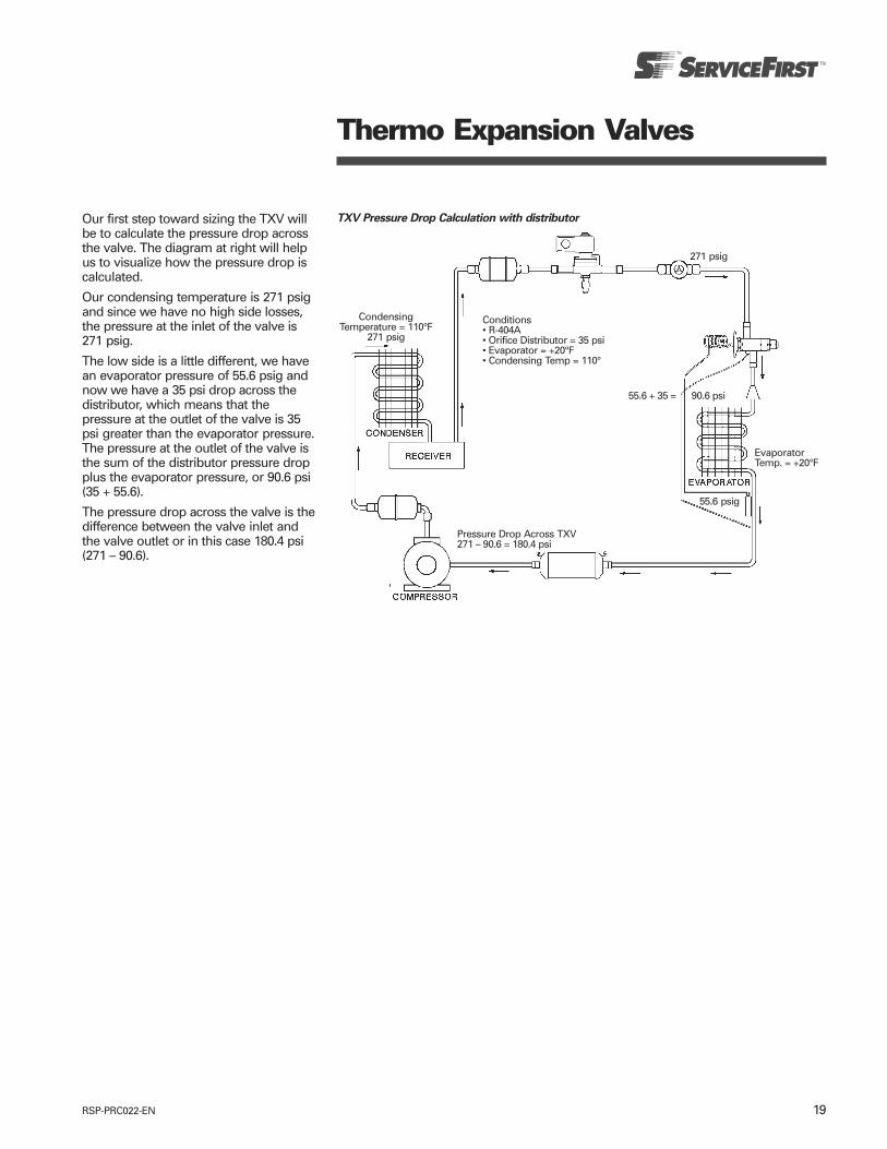
19RSP-PRC022-EN
Thermo Expansion Valves
Our first step toward sizing the TXV willbe to calculate the pressure drop acrossthe valve. The diagram at right will helpus to visualize how the pressure drop iscalculated.
Our condensing temperature is 271 psigand since we have no high side losses,the pressure at the inlet of the valve is271 psig.
The low side is a little different, we havean evaporator pressure of 55.6 psig andnow we have a 35 psi drop across thedistributor, which means that thepressure at the outlet of the valve is 35psi greater than the evaporator pressure.The pressure at the outlet of the valve isthe sum of the distributor pressure dropplus the evaporator pressure, or 90.6 psi(35 + 55.6).
The pressure drop across the valve is thedifference between the valve inlet andthe valve outlet or in this case 180.4 psi(271 – 90.6).
TXV Pressure Drop Calculation with distributor
CondensingTemperature = 110°F
271 psig
271 psig
EvaporatorTemp. = +20°F
Conditions• R-404A• Orifice Distributor = 35 psi• Evaporator = +20°F• Condensing Temp = 110°
55.6 + 35 = 90.6 psi
Pressure Drop Across TXV271 – 90.6 = 180.4 psi
55.6 psig
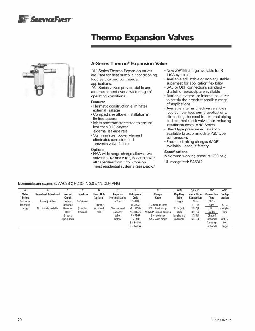
RSP-PRC022-EN20
Thermo Expansion Valves
A-Series Thermo® Expansion Valve
“A” Series Thermo Expansion Valvesare used for heat pump, air conditioning,food service and commercialapplications.“A” Series valves provide stable andaccurate control over a wide range ofoperating conditions.
Features• Hermetic construction eliminatesexternal leakage
• Compact size allows installation inlimited spaces
• Mass spectrometer tested to ensureless than 0.10 oz/yearexternal leakage rate
• Stainless steel power elementeliminates corrosion andprevents valve failure
Options• HAA wide range charge allows twovalves ( 2 1/2 and 5 ton, R-22) to coverall capacities from 1 to 5 tons onmost residential systems (see below)
• New ZW155 charge available for R-410A systems
• Available adjustable or non-adjustablesuperheat for application flexibility
• SAE or ODF connections standard –chatleff or aeroquip are available
• Available external or internal equalizerto satisfy the broadest possible rangeof applications
• Available internal check valve allowsreverse flow heat pump applications,eliminating the need for external pipingand external check valve, thus reducinginstallation costs (ANC Series)
• Bleed type pressure equalizationavailable to accommodate PSC typecompressors
• Pressure limiting charges (MOP)available – consult factory
SpecificationsMaximum working pressure: 700 psig
UL recognized: SA5312
Nomenclature example: AACEB 2 HC 30 IN 3/8 X 1/2 ODF ANG
A A C E B 2 H C 30 IN 3/8 x 1/2 ODF ANGValve Superheat Adjustment Internal Equalizer Bleed Hole Capacity Refrigerant Charge Capillary Inlet x Outlet Connection Config-Series Check (optional) Nominal Rating Code Code Tube Connection Type uration
Economy, A = Adjustable Valve E=External in Tons F = R12 Length Sizes SAE =Hermetic (optional) Omit for H = R22 C = medium temp I O flare S/T =Design N = Non-Adjustable Reverse (Omit for no bleed See nominal M = R134a CA = heat pump 30 IN (std) 1/4 3/8 ODF = straight-
Flow Internal) hole capacity N = R407C W(MOP)=press. limiting other 3/8 1/2 solder thruBypass table P = R507 Z = low temp lengths are 1/2 5/8 Chatleff
Application below R = R502 AA = wide range available 5/8 7/8 (optional) ANG =S = R404A Aeroquip 90°Z = R410A (optional) angle

21RSP-PRC022-EN
Valve Capacity ServiceFirst CapSeries Tons Connections Part Number TubeAAE 3 3/8" x 1/2" ODF S/T VAL08238 30" Cap
5 1/2" x 5/8" ODF S/T VAL08239 30" CapAAEB 1 3/8" x 1/2" ODF S/T VAL02368 5’ Cap
1 1/2 3/8" x 1/2" ODF S/T VAL02369 5’ Cap2 3/8" x 1/2" ODF S/T VAL02370 5’ Cap
2 1/2 3/8" x 1/2" ODF S/T VAL02371 5’ Cap2 1/2 3/8" x 1/2" ODF S/T VAL00889 30" Cap
3 3/8" x 1/2" ODF S/T VAL02372 5’ Cap3 3/8" x 5/8" ODF S/T VAL00891 30" Cap4 3/8" x 1/2" ODF S/T VAL02373 5’ Cap4 3/8" x 5/8" ODF S/T VAL02374 5’ Cap4 1/2" x 7/8" ODF S/T VAL02375 5’ Cap5 3/8" x 1/2" ODF S/T VAL02376 5’ Cap5 1/2" x 5/8" ODF S/T VAL02377 5’ Cap5 1/2" x 7/8" ODF S/T VAL02378 5’ Cap
Thermo Expansion Valves
Ordering Information for A-Series Valves (15% Bleed), HCA Charge
Universal Replacement
HAA Wide Range Charge for HVACApplications• The AACE wide range valve allowsseveral TXV to replace the majority ofresidential air conditioning and heatpump applications.
• The new HAA charge is a special highstability charge designed for R-22 HVACapplications and is used by leadingoriginal equipment manufacturers.
• The HAA is a wide range chargeproviding greater superheat stability,allowing in most cases two valves tocover a wide range of capacities from 1to 5 tons.
Table 1
ServiceFirst R-22 CapacityPart Number Description Range
VAL07065 AACE 2 1/2 HAA ODF EE 30” 3/8 x 1/2 ODF S/T 6A 1 to 3 TonsVAL07066 AACE 5 HAA ODF EE 30” 3/8 x 1/2 ODF S/T 6A 3 1/2 to 5 TonsVAL07067 AACE 2 1/2 HAA Cap Tube EE w/Nut
30” Chatleff x Chatleff S/T 6A 1 to 3 TonsVAL07068 AACE 5 HAA Cap Tube EE w/Nut
30” Chatleff x Chatleff S/T 6A 3 1/2 to 5 Tons
• The HAA charge also offers customersthe benefit of inventory reduction byreplacing several valves with two HAAwide range valves, while continuing tomeet system performance needs.
• The HAA charge is now available for“A” series expansion valves for R-22applications. With the addition of anintegral check valve, four expansionvalves can meet the majority ofresidential HVAC, light commercial andheat pump applications as shown inTable 1.

RSP-PRC022-EN22
Thermo Expansion Valves
HF Balanced Port Thermo® Expansion Valve
Features• Large, removable power element• Balanced port constructioncompensates for changes in operatingpressures due to varying ambients, gasdefrost, heat reclaim, or widely varyingevaporator loads
• Two body sizes provide capacities from1/4 to 20 tons
• Bi-Flow capability up to 5-1/2 tons R22allows one valve to control thesuperheat in both cooling and heatingmodes for package unit heat pumpapplications
• Wrench flats on inlets and outlets (SAEonly) for easy installation
• Stainless steel power element formaximum corrosion resistance
Options• Bleed type pressure equalizationavailable to accomodate PSC typecompressors
• ODF or SAE connections• Removable strainer• Adjustable or non-adjustable superheat
Specifications• Maximum Working Pressure: 450 psig• Operating Temperature: -40°F to 50°F• 5' capillary tube length (standard)• Use with R-22, R134a, R-404A, R-507,R-12, R-502
For Ordering Information, see followingpage.
Replacement Screen KitKIT04955
HFESCODF Connections
Nomenclature example: HFNESCB 2 HC 5 FT 3/8 X 1/2 ODF S/THF N E S C B 2 H C 5 FT 3/8 x 1/2 ODF S/T
Valve Superheat Equalizer Connection Removable Bleed Hole Capacity Refrigerant Charge Capillary Inlet x Outlet Connection Config-Series Adjustment Type Inlet (optional) Nominal Rating Code Code Tube Connection Type uration
E=External S=Solder Strainer in Tons F = R12 Length SizesN = Non- (optional) Omit for H = R22 C = medium temp I O SAE = S/T =
Adjustable (Omit for (Omit for no bleed See nominal M = R134a CA = heat pump 5 FT (std) 1/4 3/8 flare straight-Internal) SAE C=Inlet hole capacity *P = R507 W(MOP)=press. limiting other 3/8 1/2 thru
Omit for Flare) Strainer table *R = R502 Z = low temp lengths are 1/2 5/8 ODF =Adjustable (ODF only) (on page 17) *S = R404A available 5/8 7/8 solder ANG =
90°angle
* P, R and S charges are interchangeable
Replacement Power Assemblies
R12 POWER ASSEMBLY R22 POWER ASSEMBLY R502 POWER ASSEMBLY
ServiceFirst ServiceFirst ServiceFirstDescription Part Number Description Part Number Description Part Number
X26300-FC-1 HED00344 X26300-HC-1 HED00348 X26300-RC-1 HED00355X26300-FZ-1 HED00347 X26300-HZ-1 HED00351 X26300-RZ-1 HED00358
X26300-FW15-1 HED00345 X26300-HW35-1 HED00349 X26300-RW45-1 HED00357X26300-FW35-1 HED00346 X26300-HW65-1 HED00350
Torque Power Element 300-360 inch pounds.
Tailored Bulb ChargesThe use of ALCO tailored charges makesthe HF valve reliable for HVAC,refrigerated display cases, walk-incoolers, reach-in coolers, and all othersmall refrigeration systems — both lowand medium temperature.
The thermostatic charge is selected onthe basis of the evaporator temperatureonly, as indicated in Table 2.
Table 2
RefrigerantR502,
Evaporator R12 R134a R22 R404A,Temperature R507
Med temp (– 20 to +50°F) FC MC HC *CLow temp (–50 to +10°F) FZ MZ HZ *Z
MOP low temp (–50 to 0°F) FW15 MW15 HW35 *W45MOP med temp (0 to +25°F) – MW35 HW65 *W65
* Add refrigerant code: “R” for R502, “S” for R404A, “P” for R507.
Replacement parts - HFSC & HFESC only
ServiceFirstPart Number DescriptionKIT04955 Repair Kit (KT20264) includes seal cap, gasket, o-ring, screen, spring
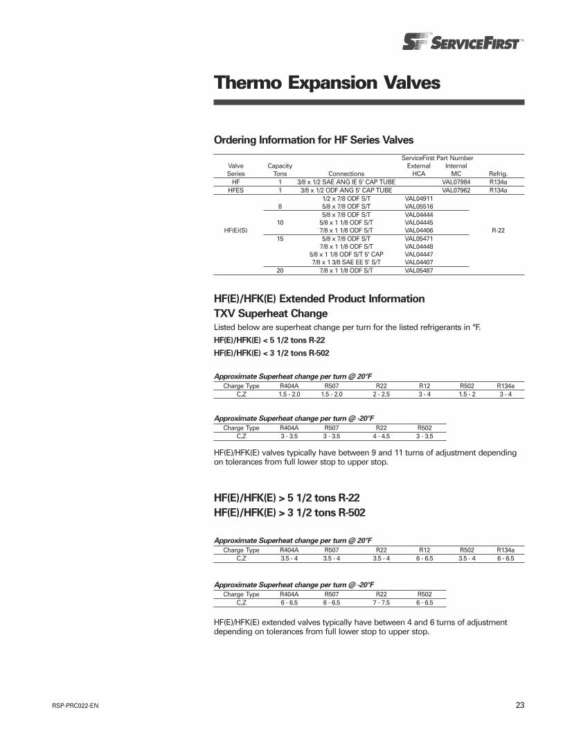
23RSP-PRC022-EN
Thermo Expansion Valves
HF(E)/HFK(E) Extended Product Information
TXV Superheat Change
Listed below are superheat change per turn for the listed refrigerants in °F.
HF(E)/HFK(E) < 5 1/2 tons R-22
HF(E)/HFK(E) < 3 1/2 tons R-502
Approximate Superheat change per turn @ 20°F
Charge Type R404A R507 R22 R12 R502 R134aC,Z 1.5 - 2.0 1.5 - 2.0 2 - 2.5 3 - 4 1.5 - 2 3 - 4
Approximate Superheat change per turn @ -20°F
Charge Type R404A R507 R22 R502C,Z 3 - 3.5 3 - 3.5 4 - 4.5 3 - 3.5
HF(E)/HFK(E) valves typically have between 9 and 11 turns of adjustment dependingon tolerances from full lower stop to upper stop.
HF(E)/HFK(E) > 5 1/2 tons R-22
HF(E)/HFK(E) > 3 1/2 tons R-502
Approximate Superheat change per turn @ 20°F
Charge Type R404A R507 R22 R12 R502 R134aC,Z 3.5 - 4 3.5 - 4 3.5 - 4 6 - 6.5 3.5 - 4 6 - 6.5
Approximate Superheat change per turn @ -20°F
Charge Type R404A R507 R22 R502C,Z 6 - 6.5 6 - 6.5 7 - 7.5 6 - 6.5
HF(E)/HFK(E) extended valves typically have between 4 and 6 turns of adjustmentdepending on tolerances from full lower stop to upper stop.
Ordering Information for HF Series Valves
ServiceFirst Part NumberValve Capacity External InternalSeries Tons Connections HCA MC Refrig.
HF 1 3/8 x 1/2 SAE ANG IE 5' CAP TUBE VAL07984 R134aHFES 1 3/8 x 1/2 ODF ANG 5' CAP TUBE VAL07962 R134a
1/2 x 7/8 ODF S/T VAL049118 5/8 x 7/8 ODF S/T VAL05516
5/8 x 7/8 ODF S/T VAL0444410 5/8 x 1 1/8 ODF S/T VAL04445
HF(E)(S) 7/8 x 1 1/8 ODF S/T VAL04406 R-2215 5/8 x 7/8 ODF S/T VAL05471
7/8 x 1 1/8 ODF S/T VAL044485/8 x 1 1/8 ODF S/T 5' CAP VAL044477/8 x 1 3/8 SAE EE 5' S/T VAL04407
20 7/8 x 1 1/8 ODF S/T VAL05487

RSP-PRC022-EN24
HFK Balanced Port Thermo® Expansion Valve
Thermo Expansion Valves
Features• The new HFK features interchangeablebodies, cages, and power elementsproviding maximum flexibility for ¼ to5½ ton applications (nom. R-22).
• The HFK is offered several ways:— Pre-packaged service kits – Include a
mix of bodies and power elementswith a complete set of cages toserve the most applications with aminimum of parts.
— Individual components - Bodies,cages, & power elements may beordered separately and can be usedto build personalized service kits orreplenish pre-packaged kits.
— Finished valves – Assembled valvesready for immediate installation.
• All HFK valves use a balanced port cagedesign that compensates for changesin operating pressures due to varyingambients, gas defrost, heat reclaim, orwidely varying evaporator loads.
• The HFK offers the following additionalfeatures:— Bi-Flow capability— Stainless steel power element— Adjustable superheat— Solid copper connections
Options• ODF or SAE connections• Straight-through or angle flowconfigurations
• Removable inlet strainer available (ODFonly)
• Internal or external equalizer
Specifications• Maximum working pressure: 450 psig• Operating Temperature: -40°F to 50°F• Use with R-22, R-134a, R-404A, R-507,R-12, R-502
Note: HFK cages are not interchangeablewith HF valve bodies. Power elementscan be interchanged.
Nomenclature example: HFKESC 2 HC 5 FT 3/8 X 1/2 ODF S/THFK E S C 2 H C 5 FT 3/8 x 1/2 ODF S/T
Valve Equalizer Connection Removable Capacity Refrigerant Charge Capillary Inlet x Outlet Connection Config-Series Type Inlet Nominal Rating Code Code Tube Connection Type uration
E=External S=Solder Strainer in Tons F = R12 Length Sizes(optional) H = R22 C = medium temp See Body SAE = S/T =
(Omit for (Omit for See nominal M = R134a CA = heat pump 5 FT (std) Table on flare straight-Internal) SAE C=Inlet capacity N = R407C W(MOP)=press. limiting other page 23 thru
Flare) Strainer table P = R507 Z = low temp lengths are ODF =(ODF only) (on page 23) R = R502 available solder ANG =
S = R404A 90°Z = R410A angle
Replacement Screen KitKIT04955
HFKESCODF Connections
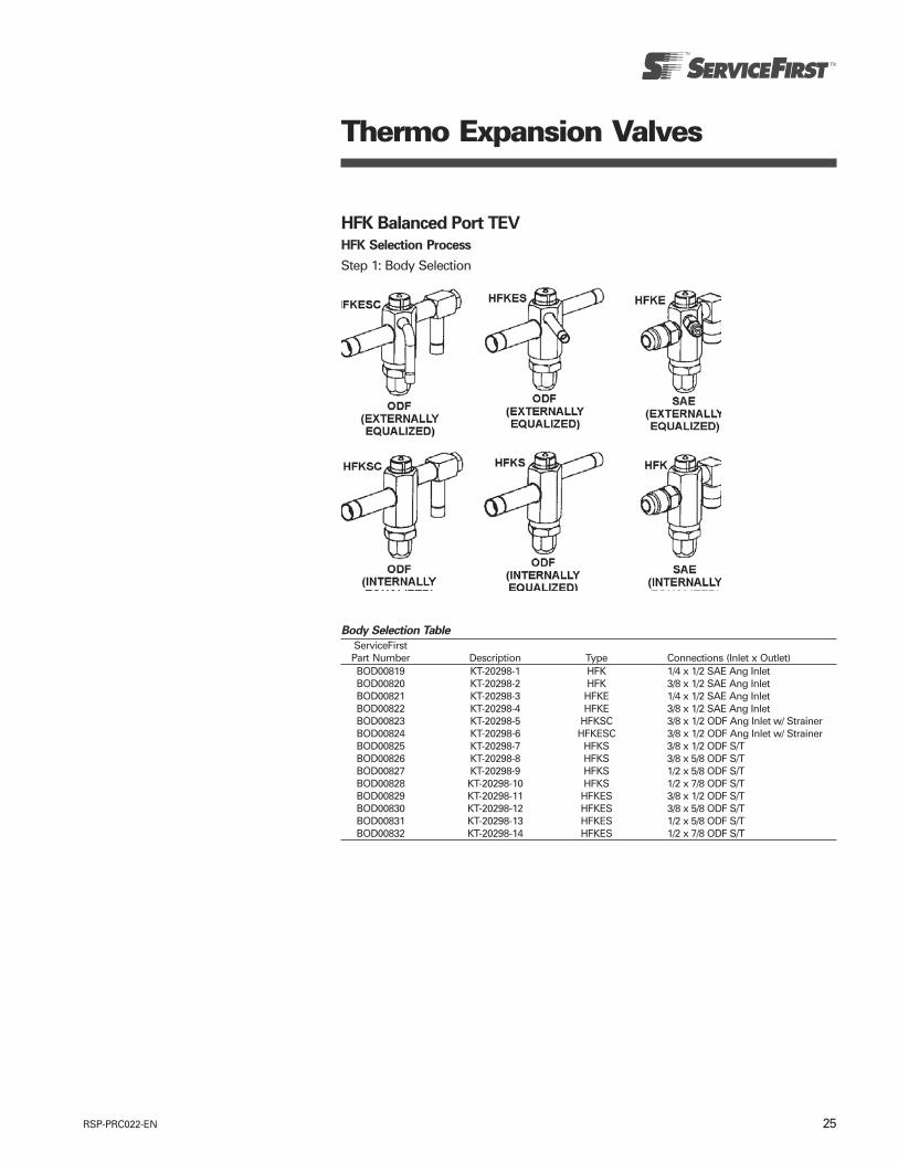
25RSP-PRC022-EN
Thermo Expansion Valves
HFK Balanced Port TEV
HFK Selection Process
Step 1: Body Selection
Body Selection Table
ServiceFirstPart Number Description Type Connections (Inlet x Outlet)BOD00819 KT-20298-1 HFK 1/4 x 1/2 SAE Ang InletBOD00820 KT-20298-2 HFK 3/8 x 1/2 SAE Ang InletBOD00821 KT-20298-3 HFKE 1/4 x 1/2 SAE Ang InletBOD00822 KT-20298-4 HFKE 3/8 x 1/2 SAE Ang InletBOD00823 KT-20298-5 HFKSC 3/8 x 1/2 ODF Ang Inlet w/ StrainerBOD00824 KT-20298-6 HFKESC 3/8 x 1/2 ODF Ang Inlet w/ StrainerBOD00825 KT-20298-7 HFKS 3/8 x 1/2 ODF S/TBOD00826 KT-20298-8 HFKS 3/8 x 5/8 ODF S/TBOD00827 KT-20298-9 HFKS 1/2 x 5/8 ODF S/TBOD00828 KT-20298-10 HFKS 1/2 x 7/8 ODF S/TBOD00829 KT-20298-11 HFKES 3/8 x 1/2 ODF S/TBOD00830 KT-20298-12 HFKES 3/8 x 5/8 ODF S/TBOD00831 KT-20298-13 HFKES 1/2 x 5/8 ODF S/TBOD00832 KT-20298-14 HFKES 1/2 x 7/8 ODF S/T
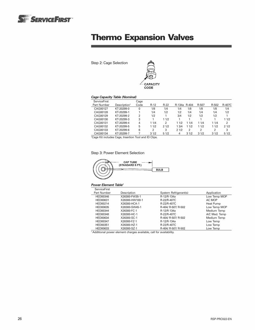
RSP-PRC022-EN26
Thermo Expansion Valves
Step 3: Power Element Selection
Power Element Table1
ServiceFirstPart Number Description System Refrigerant(s) Application
HED00346 X26300-FW35-1 R-12/R-134a Low Temp MOPHED00631 X26300-HW100-1 R-22/R-407C AC MOPHED00214 X26300-HCA-1 R-22/R-407C Heat PumpHED00635 X26300-SW45-1 R-404/ R-507/ R-502 Low Temp MOPHED00344 X26300-FC-1 R-12/R-134a Medium TempHED00348 X26300-HC-1 R-22/R-407C A/C Med. TempHED00634 X26300-SC-1 R-404/ R-507/ R-502 Medium TempHED00347 X26300-FZ-1 R-12/R-134a Low TempHED00351 X26300-HZ-1 R-22/R-407C Low TempHED00633 X26300-SZ-1 R-404/ R-507/ R-502 Low Temp
1 Additional power element charges available, call for availability.
Step 2: Cage Selection
Cage Capacity Table (Nominal)
ServiceFirst CagePart Number Description1 Code R-12 R-22 R-134a R-404 R-507 R-502 R-407CCAG00127 KT-20299-0 0 1/8 1/4 1/4 1/8 1/8 1/8 1/4CAG00128 KT-20299-1 1 1/4 1/2 1/2 1/4 1/4 1/4 1/2CAG00129 KT-20299-2 2 1/2 1 3/4 1/2 1/2 1/2 1CAG00130 KT-20299-3 3 1 1 1/2 1 1 1 1 1 1/2CAG00131 KT-20299-4 4 1 1/4 2 1 1/2 1 1/4 1 1/4 1 1/4 2CAG00132 KT-20299-5 5 1 1/2 2 1/2 1 3/4 1 1/2 1 1/2 1 1/2 2 1/2CAG00133 KT-20299-6 6 2 3 2 1/2 2 2 2 3CAG00134 KT-20299-7 7 3 1/2 5 1/2 4 3 1/2 3 1/2 3 1/2 5 1/2
1Cage Kit includes Cage, Insertion Tool and ID Clips.

27RSP-PRC022-EN
Thermo Expansion Valves
HFK Balanced Port TEV
HFK Assembly Procedure
(see 6 assembly steps & diagramsbelow)
1. Remove adjusting stem from body.2. Lubricate o-rings on cage.3. Place cage into insertion tool (using
¼” nut driver) and insert into body (donot over tighten).
4. Screw adjusting stem into bottom ofbody and hand tighten plus onewrench flat.(300-360 inch lbs. – Do not overtighten.)
5. Attach cage identification clip onpower element cap tube.
6. Screw power element onto top ofbody and hand tighten plus onewrench flat.(300-360 inch lbs. – Do not overtighten.)
HFK Pre-Packaged KitsThe HFK is available in a pre-packagedkit consisting of a mix of popular bodiesand power elements with a completeselection of cages. These kits providegreat flexibility allowing valves to beassembled as needed for eachapplication. Three kits are provided asshown below. In addition, custom kitscan be assembled by stocking an emptykit case with desired components.
Cage Kit – KIT07524
ServiceFirst
Item # Description Qty
CAG00127 Size 0 cage (1/4 ton R-22) 2CAG00128 Size 1 cage (1/2 ton R-22) 2CAG00129 Size 2 cage (1 ton R-22) 2CAG00130 Size 3 cage (1-1/2 ton R-22) 2CAG00131 Size 4 cage (2 ton R-22) 2CAG00132 Size 5 cage (2-1/2 ton R-22) 2CAG00133 Size 6 cage (3 ton R-22) 2CAG00134 Size 7 cage (5-1/2 ton R-22) 2TOL01494 Insertion tool 1BOT00009 Oil Bottle 1
Cage ID tags —
R-22 Kit – KIT07555
ServiceFirst
Item # Description Qty
BOD00825 HFKS 3/8 x 1/2 body 1BOD00829 HFKES 3/8 x 1/2 body 3BOD00830 HFKES 3/8 x 5/8 body 1BOD00831 HFKES 1/2 x 5/8 body 1HED00631 HW power element 1HED00214 HCA power element 2HED00348 HC power element 1KIT07524 Cage Kit 1
Kit Accessories
ServiceFirst
Item # Mfg. # Description
BOX01428 KT-20302-1 HFK Replacement Service Box (Empty)
BOX01429 KT-20303 HFK Replacement Boxfor Cage Kit (Empty)
TOL01494 KT-20304 HFK Insertion ToolBOT00009 Oil Bottle HFK Oil Bottle
SAE Kit – KIT07521
ServiceFirst
Item # Description Qty
BOD00819 HFK 1/4 x 1/2 body 1BOD00820 HFK 3/8 x 1/2 body 1BOD00822 HFKE 3/8 x 1/2 body 2HED00344 FC power element 2HED00348 HC power element 1HED00351 HZ power element 1HED00633 SZ power element 2KIT07524 Cage Kit 1
ODF Kit – KIT07522
ServiceFirst
Item # Description Qty
BOD00823 HFKSC 3/8 x 1/2 body 1BOD00829 HFKES 3/8 x 1/2 body 1BOD00824 HFKESC 3/8 x 1/2 body 2HED00344 FC power element 2HED00348 HC power element 1HED00351 HZ power element 1HED00633 SZ power element 2KIT07524 Cage Kit 1
ODF/SAE Mix Kit – KIT07523
ServiceFirst
Item # Description Qty
BOD00820 HFK 3/8 x 1/2 body 1BOD00822 HFKE 3/8 x 1/2 body 1BOD00823 HFKSC 3/8 x 1/2 body 1BOD00824 HFKESC 3/8 x 1/2 body 1HED00344 FC power element 2HED00348 HC power element 1HED00351 HZ power element 1HED00633 SZ power element 2KIT07524 Cage Kit 1
1. Remove adjusting stemfrom body.
3. Place cage intoinsertion tool(using 1/4” square nutdriver) and insert intobody (do not overtighten).
2. Lubricate O-rings on cage.
4. Screw adjustingstem into bottom ofbody and handtighten plus onewrench flat. (300-360inch lbs. – Do notover tighten.)
5. Attach cageidentification clip onpower element captube.
6. Screw powerelement onto top ofbody and handtighten plus onewrench flat. (300-360inch lbs. – Do notover tighten.)
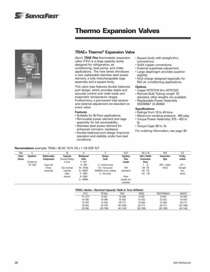
RSP-PRC022-EN28
Thermo Expansion Valves
TRAE+ Thermo® Expansion Valve
Alco’s TRAE Plus thermostatic expansionvalve (TXV) is a large capacity seriesdesigned for refrigeration, airconditioning, heat pump, and chillerapplications. The new series introducesa new replaceable stainless steel powerelement, a fully interchangeable cageassembly and a square body.
This valve type features double balancedport design, which provides stable andaccurate control over wide loads andevaporator temperature ranges.Furthermore, a permanent inlet strainerand external adjustment are standard onevery valve.
Features• Suitable for Bi-Flow applications.• Removable power element and cageassembly for full serviceability.
• Stainless steel power element forenhanced corrosion resistance
• Double balanced port design improvesoperation and stability under low loadconditions.
• Square body with straight-thruconnections.
• Solid copper connections.• External superheat adjustment.• Large diaphragm provides superiorstability
• HCA charge designed especially forR22 air conditioning applications.
Options• Cages KIT07318 thru KIT07322• Remote Bulb Tubing Length 10’standard, other lengths are available
• Replaceable Power AssemblyHED00567 (X-28458)
Specifications• Ratings from 10 to 40 tons.• Maximum working pressure: 450 psig• Torque Power Assembly: 375 - 425 in.lb.
• Torque Cage: 60 in. lb.
For ordering information, see page 30.
Nomenclature example: TRAE+ 30 HC 10 Ft 7/8 X 1 1/8 ODF S/TTRA E + 30 H C 10 FT 7/8 x 11/8 ODF S/T
Valve Equalizer Replaceable Capacity Refrigerant Charge Capillary Inlet x Outlet Connection Config-Series Components Nominal Rating Code Code Tube Connection Type uration
E=External in Tons F = R12 Length Sizes1/4” SAE Cage and H = R22 C = medium temp I O ODF = solder S/T =
Power See nominal M = R134a CA = heat pump 10 Ft 5/8 7/8 (Only) Straight-Assembly capacity N = R407C W(MOP)=press. limiting (standard) 7/8 11/8 thru
table P = R507 Z = low temp 11/8 13/8 (Only)(below) R = R502 Other
S = R404A lengths areavailable
TRAE+ Series – Nominal Capacity Table in Tons (kWatts)
R12 R134a R22 R502 R507/R404A R407C7½ (27) 9 (32) 10 (35) 8 (28) 8 (28) 10 (35)10 (35) 13 (46) 15 (53) 12 (42) 12 (42) 15 (53)12 (42) 14 (50) 20 (71) 14 (50) 14 (50) 20 (71)18 (64) 22 (78) 30 (106) 20 (71) 20 (71) 30 (106)25 (88) 30 (106) 40 (142) 30 (106) 30 (106) 40 (142)

29RSP-PRC022-EN
Thermo Expansion Valves
TRAE Thermo® Expansion ValveTRAE Thermo Valves are a large capacityseries for chiller, heat pump,refrigeration, and air conditioningapplications. Its balanced port designprovides stable and accurate controlover wide load and evaporatortemperature ranges.
Features• Suitable for Bi-Flow applications.• External superheat adjustment.• Integral body with straight-thruconnections.
• TRAE’s balanced port design improvesvalve operation & stability under lowload conditions.
Seal Nut27676-1
• Solid copper connections.• Large diaphragm provides superior
stability.• Stainless steel power element for
maximum corrosion resistance
Options• HCA charge designed especially for
R22 air conditioning applications.
Specifications• Ratings from 50 to 70 tons.• Maximum Working Pressure: 450 psig
For ordering information, see page 30.
Nomenclature example: TRAE 50 HC 10 Ft 7/8 X 1 1/8 ODF S/T
TRA E 50 H C 10 FtT 7/8 x 1 1/8 ODF S/TValve Equalizer Capacity Refrigerant Charge Capillary Inlet x Outlet Connection Configuration
Series Nominal Rating Code Code Tube Connection Type
Hermetic E=External in Tons F = R12 Length Sizes S/T =Design, 1/4” SAE H = R22 C = medium temp I O ODF = solder Straight-Solder See nominal M = R134a CA = heat pump/AC 10 FT 1/4 3/8 (Only) thru
Connections, capacity N = R407C W(MOP)=press. limiting (standard) 3/8 1/2 (Only)Balanced table P = R507 Z = low temp other lengths
Port, (below) R = R502 are availableLarger S = R404A
Tonnages

RSP-PRC022-EN30
Thermo Expansion Valves
Ordering Information for TRAE/TRAE+ Series ValvesServiceFirst Valve PCN Cap Tube
Item # Series Charge Length ConnectionsVAL06618 TRAE+ 10 HCA 10 Ft. 7/8 x 1 1/8 ODF S/TVAL06619 TRAE+ 15 HCA 10 Ft. 7/8 x 1 1/8 ODF S/TVAL06605 TRAE+ 10 HCA 5 Ft. 1/2 x 7/8 ODF S/TVAL06606 TRAE+ 10 HCA 5 Ft. 5/8 x 7/8 ODF S/TVAL06607 TRAE+ 15 HCA 5 Ft. 5/8 x 7/8 ODF S/TVAL06608 TRAE+ 15 HCA 5 Ft. 5/8 x 1 1/8 ODF S/TVAL06609 TRAE+ 20 HCA 5 Ft. 5/8 x 1 1/8 ODF S/TVAL06610 TRAE+ 20 HCA 5 Ft. 7/8 x 1 1/8 ODF S/TVAL06611 TRAE+ 20 HCA 5 Ft. 7/8 x 1 3/8 ODF S/TVAL06612 TRAE+ 30 HCA 5 Ft. 7/8 x 1 1/8 ODF S/TVAL06613 TRAE+ 30 HCA 5 Ft. 7/8 x 1 3/8 ODF S/TVAL06614 TRAE+ 40 HCA 5 Ft. 7/8 x 1 1/8 ODF S/TVAL06615 TRAE+ 40 HCA 5 Ft. 1 1/8 x 1 3/8 ODF S/TVAL07765 TRAE 50 HC 10 Ft. 1 1/8 x 1 3/8 ODF S/TVAL07766 TRAE 60 HC 10 Ft. 1 1/8 x 1 3/8 ODF S/TVAL07767 TRAE 70 HC 10 Ft. 1 1/8 x 1 3/8 ODF S/T
Cage Replacement Kits for TRAE+ SeriesValvesReplacement cage assemblies for TRAE+are available as separate sale items.Cage kits are cross referenced bycapacity and tonnage in the table to theright. Each cage kit consists of areplacement cage and cage removalwrench. In addition, the cage removalwrench (KIT07323) can be ordered as aseparate item.
Nominal Capacity - TonsServiceFirst
Item # TRAE+ Kit R-22 R-12/R-134a R-507/R-404A R-502KIT07318 KT-20289 Cage Kit 10 9 8 8KIT07319 KT-20290 Cage Kit 15 13 12 12KIT07320 KT-20291 Cage Kit 20 14 14 14KIT07321 KT-20292 Cage Kit 30 22 20 20KIT07322 KT-20293 Cage Kit 40 30 30 30KIT07323 KT-20294 Cage Wrench Kit
Power Assembly Replacement: HED00567
31RSP-PRC022-EN
Thermo Expansion Valves
T-Series Take-A-Part Thermo®
ValveALCO Take-A-Part Series TEVs, withadjustable superheat and replaceable,interchangeable components are idealfor original equipment and fieldreplacements in air conditioning, heatpump, and refrigeration applications.
Features• Take-A-Part construction for easy fieldservice
• External superheat adjustment• Bi-Flo capability• Stainless steel power assembly up to20 ton
Options• Interchangeable, replaceable cages for
TEV versatility (1/4 to 100 tons capacity)• Interchangeable body flanges for any
connection you need• Interchangeable power heads for
refrigerants listed• Charges for other applications available
(consult Alco Application Engineering)
Specifications• Maximum working pressure: 450 psig• Torque Bolts: 300 in. lb.
Nomenclature Example: TCLEB 5 HC 5 Ft 3/8 X 1/2 SAE ANG
TCL E B 5 H C 5 FT 3/8 x 1/2 SAE ANGValve Equalizer Bleed Hole Capacity Refrigerant Charge Capillary Inlet x Outlet Connection Config-
Series* (optional) Nominal Rating CodeCodeCodeCodeCode CodeCodeCodeCodeCode TTTTTubeubeubeubeube ConnectionConnectionConnectionConnectionConnection TTTTTypeypeypeypeype urationurationurationurationurationTake- E=External in Tons F = R12 LengthLengthLengthLengthLength SizesSizesSizesSizesSizesA-Part B = Bleed Hole H = R22 C = medium temp SAE = flare ANG =
Adjustable Omit for Internal See Cage M = R134a CA = heat pump Various Various sizes are 90° AngleOmit for Assembly N = R407C W(MOP)=press. limiting lengths are available ODF = solder
*See p. 30 no bleed hole Interchangeability P = R507 Z = low temp available (see p.32-33) S/T =for other Tables R = R502 (see p.34-35) also, valve is Straight-T-Series (pages 32-33) S = R404A available thrufamilies less flange
Bolt TorqueThe cap screws on all ALCO Take-A-PartTEVs require 300 inch pound bolt torque.
Field Replacement of Valve Types TL(E),TLXFor field replacement of valve types TLX& TL(E), substitute a valve type TCL(E) ofequivalent tonnage and re-use the oldbody flange. This substitution provides avalve equal in performance withprovision for external superheatadjustment and eliminates the need toremove the old flange.
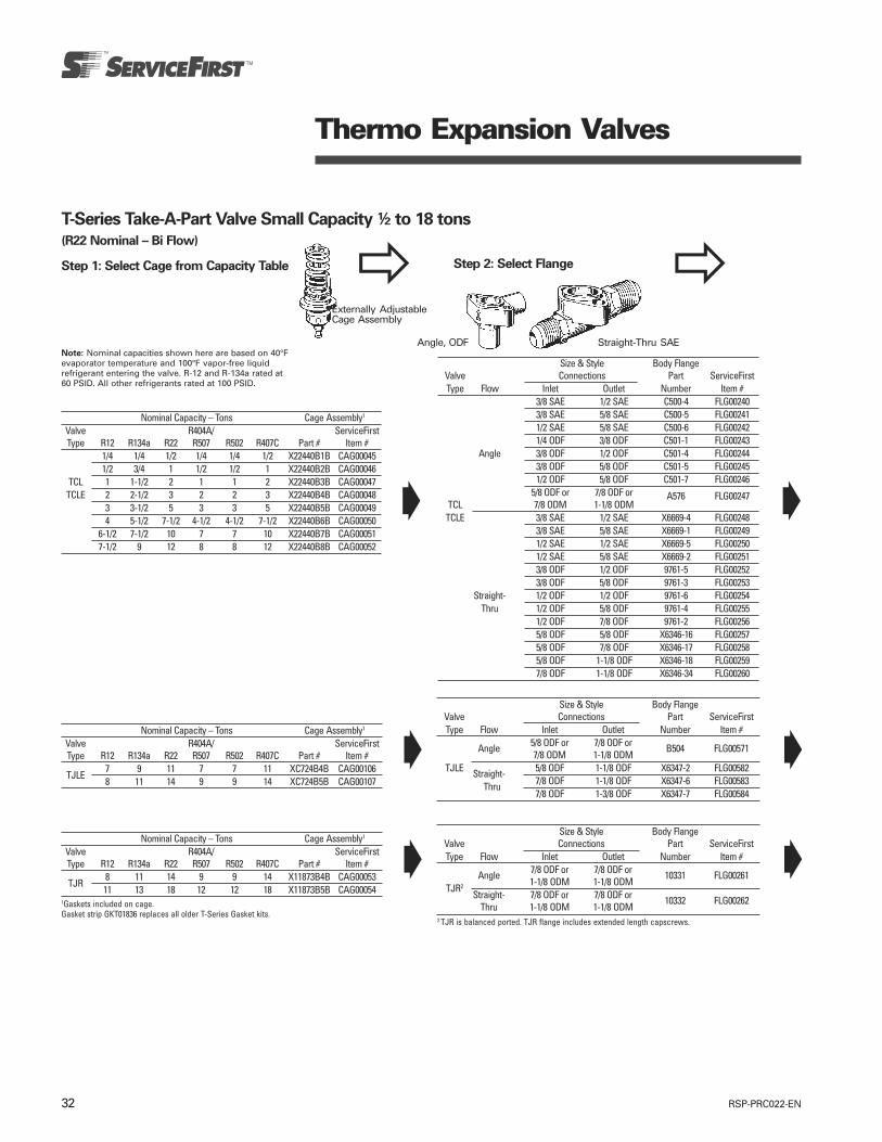
RSP-PRC022-EN32
Size & Style Body FlangeValve Connections Part ServiceFirstType Flow Inlet Outlet Number Item #
3/8 SAE 1/2 SAE C500-4 FLG002403/8 SAE 5/8 SAE C500-5 FLG002411/2 SAE 5/8 SAE C500-6 FLG002421/4 ODF 3/8 ODF C501-1 FLG00243
Angle 3/8 ODF 1/2 ODF C501-4 FLG002443/8 ODF 5/8 ODF C501-5 FLG002451/2 ODF 5/8 ODF C501-7 FLG00246
5/8 ODF or 7/8 ODF or A576 FLG00247TCL 7/8 ODM 1-1/8 ODM
TCLE 3/8 SAE 1/2 SAE X6669-4 FLG002483/8 SAE 5/8 SAE X6669-1 FLG002491/2 SAE 1/2 SAE X6669-5 FLG002501/2 SAE 5/8 SAE X6669-2 FLG002513/8 ODF 1/2 ODF 9761-5 FLG002523/8 ODF 5/8 ODF 9761-3 FLG00253
Straight- 1/2 ODF 1/2 ODF 9761-6 FLG00254Thru 1/2 ODF 5/8 ODF 9761-4 FLG00255
1/2 ODF 7/8 ODF 9761-2 FLG002565/8 ODF 5/8 ODF X6346-16 FLG002575/8 ODF 7/8 ODF X6346-17 FLG002585/8 ODF 1-1/8 ODF X6346-18 FLG002597/8 ODF 1-1/8 ODF X6346-34 FLG00260
Thermo Expansion Valves
T-Series Take-A-Part Valve Small Capacity ½ to 18 tons
(R22 Nominal – Bi Flow)
Step 1: Select Cage from Capacity Table
Externally AdjustableCage Assembly
Note: Nominal capacities shown here are based on 40°Fevaporator temperature and 100°F vapor-free liquidrefrigerant entering the valve. R-12 and R-134a rated at60 PSID. All other refrigerants rated at 100 PSID.
Nominal Capacity – Tons Cage Assembly1
Valve R404A/ ServiceFirstType R12 R134a R22 R507 R502 R407C Part # Item #
1/4 1/4 1/2 1/4 1/4 1/2 X22440B1B CAG000451/2 3/4 1 1/2 1/2 1 X22440B2B CAG00046
TCL 1 1-1/2 2 1 1 2 X22440B3B CAG00047TCLE 2 2-1/2 3 2 2 3 X22440B4B CAG00048
3 3-1/2 5 3 3 5 X22440B5B CAG000494 5-1/2 7-1/2 4-1/2 4-1/2 7-1/2 X22440B6B CAG00050
6-1/2 7-1/2 10 7 7 10 X22440B7B CAG000517-1/2 9 12 8 8 12 X22440B8B CAG00052
Step 2: Select Flange
Angle, ODF Straight-Thru SAE
Nominal Capacity – Tons Cage Assembly1
Valve R404A/ ServiceFirstType R12 R134a R22 R507 R502 R407C Part # Item #
7 9 11 7 7 11 XC724B4B CAG00106TJLE
8 11 14 9 9 14 XC724B5B CAG00107
Nominal Capacity – Tons Cage Assembly1
Valve R404A/ ServiceFirstType R12 R134a R22 R507 R502 R407C Part # Item #
8 11 14 9 9 14 X11873B4B CAG00053TJR
11 13 18 12 12 18 X11873B5B CAG000541Gaskets included on cage.Gasket strip GKT01836 replaces all older T-Series Gasket kits.
Size & Style Body FlangeValve Connections Part ServiceFirstType Flow Inlet Outlet Number Item #
5/8 ODF or 7/8 ODF orAngle7/8 ODM 1-1/8 ODM
B504 FLG00571
TJLE Straight- 5/8 ODF 1-1/8 ODF X6347-2 FLG00582 Thru 7/8 ODF 1-1/8 ODF X6347-6 FLG00583
7/8 ODF 1-3/8 ODF X6347-7 FLG00584
Size & Style Body FlangeValve Connections Part ServiceFirstType Flow Inlet Outlet Number Item #
7/8 ODF or 7/8 ODF orAngle1-1/8 ODM 1-1/8 ODM
10331 FLG00261TJR2
Straight- 7/8 ODF or 7/8 ODF orThru 1-1/8 ODM 1-1/8 ODM
10332 FLG00262
2 TJR is balanced ported. TJR flange includes extended length capscrews.

33RSP-PRC022-EN
Thermo Expansion Valves
Step 3: Select Power Assembly
TCL-TCLE-TJLE-TJR Power Assemblies 3
Refrig- Equalizer Cap Tube Application Power ServiceFirsterant Type Length Temp Range MOP 4 (psi) Assembly Item #
Internal 5 Ft. -20 to +50 None XB-1019 FC 1A¼ SAE 5 Ft. -20 to +50 None XB-1019 FC 1BInternal 10 Ft. -20 to +50 None XB-1019 FC 2A¼ SAE 10 Ft. -20 to +50 None XB-1019 FC 2B
R12 ¼ SAE 15 Ft. -20 to +50 None XB-1019 FC 3B¼ SAE 5 Ft. -50 to +30 35 XB-1019 FW 35 1B¼ SAE 5 Ft. -50 to +50 55 XB-1019 FW 55 1B¼ SAE 10 Ft. -50 to +50 55 XB-1019 FW 55 2B¼ SAE 5 Ft. -50 to +10 None XB-1019 FZ 1BInternal 5 Ft. -20 to +50 None XB-1019 HC 1A¼ SAE 5 Ft. -20 to +50 None XB-1019 HC 1B HED00371¼ SAE 5 Ft. -20 to +50 None XB-1019 HW 1B HED00013¼ SAE 10 Ft. -20 to +50 None XB-1019 HC 2B HED00782¼ SAE 5 Ft. -50 to +5 35 XB-1019 HW35 1B
R22 ¼ SAE 5 Ft. -50 to +20 55 XB-1019 HW55 1B¼ SAE 5 Ft. -50 to +30 65 XB-1019 HW65 1B HED00374¼ SAE 5 Ft. -20 to +50 100 XB-1019 HW100 1B HED00373¼ SAE 10 Ft. -20 to +50 100 XB-1019 HW100 2B¼ SAE 5 Ft. -50 to +10 None XB-1019 HZ 1B HED00376¼ SAE 10 Ft. -50 to +10 None XB-1019 HZ 2B¼ SAE 5 Ft. -20 to +50 None XB-1019 MC 1B¼ SAE 10 Ft. -20 to +50 None XB-1019 MC 2B¼ SAE 10 Ft. -50 to +30 35 XB-1019 MW35 2B
R134a ¼ SAE 5 Ft. -50 to +50 55 XB-1019 MW55 1B HED00331¼ SAE 10 Ft. -50 to +50 55 XB-1019 MW55 2B¼ SAE 5 Ft. -50 to +10 None XB-1019 MZ 1B¼ SAE 10 Ft. -50 to +10 None XB-1019 MZ 2B¼ SAE 5 Ft. -20 to +50 None XB-1019 NC 1B
R407C¼ SAE 5 Ft. -20 to +50 100 XB-1019 NW100 1B¼ SAE 5 Ft. -20 to +50 None XB-1019 SC 1B¼ SAE 5 Ft. -50 to 0 40 XB-1019 SW40 1B
R404A¼ SAE 5 Ft. -50 to +25 65 XB-1019 SW65 1B¼ SAE 10 Ft. -50 to +10 None XB-1019 SZ 2B
Capscrews included with Power Assembly4 Maximum Operating Pressure Limit to prevent motor overload
(Old) X13826-1 (ODF)(New) X28124-1 (ODM)
Capscrews
Power Assembly Cap

RSP-PRC022-EN34
Thermo Expansion Valves
T-Series Take-A-Part Valve Large Capacity 22 to 100 tons
(R22 Nominal – Balanced Ported and Bi Flow)
Note: Nominal capacities shown here are based on 40°Fevaporator temperature and 100°F vapor-free liquid refrigerantentering the valve. R-12 and R-134a rated at 60 PSID. All otherrefrigerants rated at 100 PSID.
Step 1: Select Cage from Capacity Table
Externally AdjustableDouble PortedCage Assembly
Nominal Capacity – Tons Cage Assembly1
Valve R404A/ ServiceFirstType R12 R134a R22 R507 R502 R407C Part # Item #
13 16 22 14 14 22 X9117B6B CAG0005515 19 26 16 16 26 X9117B7B CAG00056
TER 20 25 35 21 21 35 X9117B8B CAG0005725 31 45 27 27 45 X9117B9B CAG00058
Nominal Capacity – Tons Cage Assembly1
Valve R404A/ ServiceFirstType R12 R134a R22 R507 R502 R407C Part # Item #TIR 35 45 55 37 37 55 X9166B10B CAG00059
Nominal Capacity – Tons Cage Assembly1
Valve R404A/ ServiceFirstType R12 R134a R22 R507 R502 R407C Part # Item #
45 55 70 48 48 70 X9144B11B CAG00060THR
55 68 85 60 60 85 X9144B13B CAG000611Gaskets included on cage.Gasket strip GKT01836 replaces all older T-Series Gasket kits.
Step 2: Select Flange
Angle, ODF Straight-ThruODF
Size & Style Body FlangeValve Connections Part ServiceFirstType Flow Inlet Outlet Number Item #
7/8 ODF or 7/8 ODF orAngle 1-1/8 ODM 1-1/8 ODM
9153 FLG00263TER2
Straight- 7/8 ODF or 7/8 ODF orThru 1-1/8 ODM 1-1/8 ODM
9152 FLG00264
Size & Style Body FlangeValve Connections Part ServiceFirstType Flow Inlet Outlet Number Item #
7/8 ODF or 7/8 ODF orAngle 1-1/8 ODM 1-1/8 ODM
9151 FLG00265TIR
Straight- 7/8 ODF or 7/8 ODF orThru 1-1/8 ODM 1-1/8 ODM
9150 FLG00266
Size & Style Body FlangeValve Connections Part ServiceFirstType Flow Inlet Outlet Number Item #
ANGLE 1-1/8 ODM 1-1/8 ODM 9149 FLG00267THR
Straight-Thru 1-1/8 ODM 1-1/8 ODM 9148 FLG002682 TER flange includes extended length capscrews.

35RSP-PRC022-EN
Thermo Expansion Valves
Step 3: Select Power Assembly Power Assembly
Capscrews
Cap(Old) X13826-1 (ODF)
(New) X28124-1 (ODM)
TER-TIR-THR-TMR Power Assemblies 3
Refrig- Equalizer Cap Tube Application Power ServiceFirsterant Type Length Temp Range MOP 4 (psi) Assembly Item #
¼ SAE 10 Ft. -20 to +40 None XC-726 FC 2B HED00387¼ SAE 10 Ft. -50 to 0 15 XC-726 FW15 2B
R12¼ SAE 10 Ft. -50 to +50 55 XC-726 FW55 2B HED00389¼ SAE 10 Ft. -50 to 0 None XC-726 FZ 2B¼ SAE 10 Ft. -20 to +50 None XC-726 HC 2B HED00779¼ SAE 20 Ft. -20 to +50 XC-726 HC 4B HED00753¼ SAE 10 Ft. -20 to +50 None XC-726 HW 2B HED00015¼ SAE 10 Ft. -50 to +5 35 XC-726 HW35 2B HED00393
R22 ¼ SAE 10 Ft. -50 to +30 65 XC-726 HW65 2B¼ SAE 15 Ft. -20 to +50 85 XC-726HW85 3B HED00679¼ SAE 10 Ft. -20 to +50 100 XC-726 HW100 2B HED00392¼ SAE 10 Ft. -50 to +10 None XC-726 HZ 2B HED00394¼ SAE 10 Ft. -20 to +50 None XC-726 MC 2B
R134a ¼ SAE 10 Ft. -50 to +50 55 XC-726 MW55 2B¼ SAE 10 Ft. -50 to +10 None XC-726 MZ 2B¼ SAE 10 Ft. -20 to +50 None XC-726 RC 2B HED00395¼ SAE 10 Ft. -50 to -20 15 XC-726 RW15 2B
R502 ¼ SAE 10 Ft. -50 to +5 35 XC-726 RW35 2B HED00396¼ SAE 10 Ft. -50 to +25 65 XC-726 RW65 2B HED00397¼ SAE 10 Ft. -50 to +10 None XC-726 RZ 2B¼ SAE 10 Ft. -20 to +50 None XC-726 SC 2B¼ SAE 10 Ft. -50 to +10 40 XC-726 SW40 2B
R404A¼ SAE 10 Ft. -50 to +25 65 XC-726 SW65 2B¼ SAE 10 Ft. -50 to +10 None XC-726 SZ 2B
Capscrews included with Power Assembly4 Maximum Operating Pressure Limit to prevent motor overload
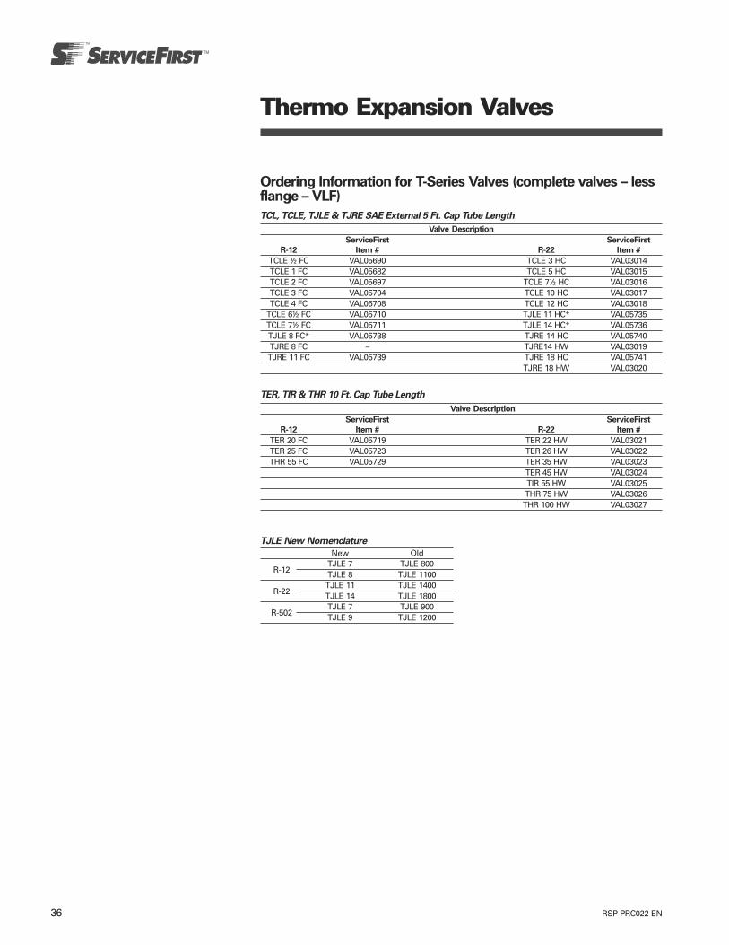
RSP-PRC022-EN36
Thermo Expansion Valves
Ordering Information for T-Series Valves (complete valves – lessflange – VLF)
TCL, TCLE, TJLE & TJRE SAE External 5 Ft. Cap Tube Length
Valve Description
ServiceFirst ServiceFirst
R-12 Item # R-22 Item #
TCLE ½ FC VAL05690 TCLE 3 HC VAL03014TCLE 1 FC VAL05682 TCLE 5 HC VAL03015TCLE 2 FC VAL05697 TCLE 7½ HC VAL03016TCLE 3 FC VAL05704 TCLE 10 HC VAL03017TCLE 4 FC VAL05708 TCLE 12 HC VAL03018
TCLE 6½ FC VAL05710 TJLE 11 HC* VAL05735TCLE 7½ FC VAL05711 TJLE 14 HC* VAL05736TJLE 8 FC* VAL05738 TJRE 14 HC VAL05740TJRE 8 FC – TJRE14 HW VAL03019TJRE 11 FC VAL05739 TJRE 18 HC VAL05741
TJRE 18 HW VAL03020
TER, TIR & THR 10 Ft. Cap Tube Length
Valve Description
ServiceFirst ServiceFirst
R-12 Item # R-22 Item #
TER 20 FC VAL05719 TER 22 HW VAL03021TER 25 FC VAL05723 TER 26 HW VAL03022THR 55 FC VAL05729 TER 35 HW VAL03023
TER 45 HW VAL03024TIR 55 HW VAL03025THR 75 HW VAL03026THR 100 HW VAL03027
TJLE New Nomenclature
New OldTJLE 7 TJLE 800
R-12 TJLE 8 TJLE 1100TJLE 11 TJLE 1400
R-22 TJLE 14 TJLE 1800TJLE 7 TJLE 900
R-502 TJLE 9 TJLE 1200
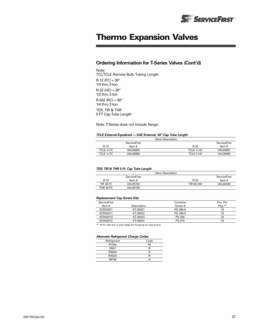
37RSP-PRC022-EN
Thermo Expansion Valves
Ordering Information for T-Series Valves (Cont’d)
Note:TCL/TCLE Remote Bulb Tubing Length
R-12 (FC) = 30’’1/4 thru 3 ton
R-22 (HC) = 30’’1/2 thru 3 ton
R-502 (RC) = 30’’1/4 thru 3 ton
TER, TIR & THR5 FT Cap Tube Length
TCLE External Equalized — SAE External, 30’’ Cap Tube Length
Valve DescriptionServiceFirst ServiceFirst
R-12 Item # R-22 Item #TCLE ¼ FC VAL05694 TCLE ½ HC VAL05687TCLE ½ FC VAL05689 TCLE 2 HC VAL05695
Note: T-Series does not include flange.
TER, TIR & THR 5 Ft. Cap Tube Length
Valve DescriptionServiceFirst ServiceFirst
R-12 Item # R-22 Item #TIR 35 FC VAL05732 TIR 55 HW VAL00339THR 45 FC VAL05729
Alternate Refrigerant Charge Codes
Refrigerant CodeR134a MR507 R
R404A RR402A RMP39 X
Replacement Cap Screw Kits
ServiceFirst Contains Pcs. PerItem # Description Screw # Pkg.**
SCR02021 KT-30021 PS-286-5 10SCR02011 KT-30022 PS-168-5 10SCR02013 KT-30023 PS-259 10SCR02012 KT-30024 PS-370 10
** 10 Pc. kits are in poly bags for hanging on peg board.
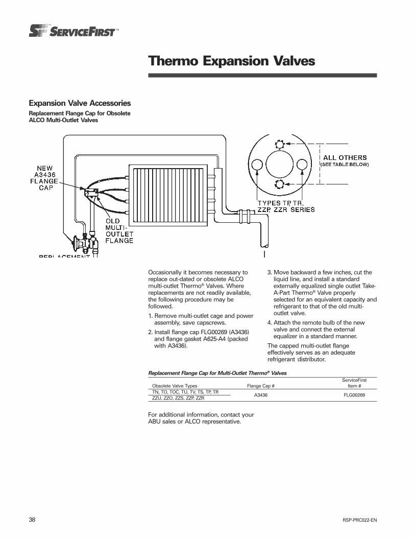
RSP-PRC022-EN38
Thermo Expansion Valves
Expansion Valve Accessories
Replacement Flange Cap for ObsoleteALCO Multi-Outlet Valves
Occasionally it becomes necessary toreplace out-dated or obsolete ALCOmulti-outlet Thermo® Valves. Wherereplacements are not readily available,the following procedure may befollowed.
1. Remove multi-outlet cage and powerassembly, save capscrews.
2. Install flange cap FLG00269 (A3436)and flange gasket A625-A4 (packedwith A3436).
Replacement Flange Cap for Multi-Outlet Thermo® Valves
ServiceFirstObsolete Valve Types Flange Cap # Item #TN, TO, TOC, TU, TV, TS, TP, TRZZU, ZZO, ZZS, ZZP, ZZR
A3436 FLG00269
For additional information, contact yourABU sales or ALCO representative.
3. Move backward a few inches, cut theliquid line, and install a standardexternally equalized single outlet Take-A-Part Thermo® Valve properlyselected for an equivalent capacity andrefrigerant to that of the old multi-outlet valve.
4. Attach the remote bulb of the newvalve and connect the externalequalizer in a standard manner.
The capped multi-outlet flangeeffectively serves as an adequaterefrigerant distributor.
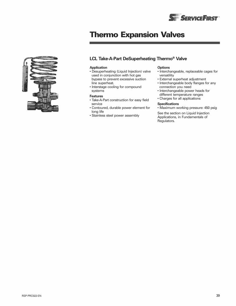
39RSP-PRC022-EN
Thermo Expansion Valves
LCL Take-A-Part DeSuperheating Thermo® Valve
Application• Desuperheating (Liquid Injection) valveused in conjunction with hot gasbypass to prevent excessive suctionline superheat.
• Interstage cooling for compoundsystems
Features• Take-A-Part construction for easy fieldservice
• Contoured, durable power element forlong life
• Stainless steel power assembly
Options• Interchangeable, replaceable cages forversatility
• External superheat adjustment• Interchangeable body flanges for anyconnection you need
• Interchangeable power heads fordifferent temperature ranges
• Charges for all applications
Specifications• Maximum working pressure: 450 psig
See the section on Liquid InjectionApplications, in Fundamentals ofRegulators.

RSP-PRC022-EN40
Thermo Expansion Valves
LCL DeSuperheating Thermo® Valves
NomenclatureLCL E 2 B 5 Ft. 3/8 x 1/2 ODF S/T
Valve Equalizer Capacity Charge Capillary Inlet x Outlet Connection ConfigurationSeries Note: This is not Code Tube Length Connection Type
DeSuperheating E = External system capacity. See Hot Gas Bypass Sizes ANG = 90° angleLiquid Injection See hot gas bypass charts for selection 5 Ft. SAE = flare
Take-A-Part (omit for Internal) charts for valve sizing (p. 97) (standard) S/T = straight-thru(p. 97) and chart below ODF = solder
For new applications, consult the factoryfor proper selection and sizing. For fieldreplacement, select a LCL/LCLE valvewith the exact same capacity and charge.
Ordering Information for LCL Valves
PCN* By ChargeEqualizer Select fromTable Below
Description Type A B C ConnectionsLCL 11 VAL05847 VAL05848LCL 21 Internal VAL05850 VAL05851 VAL05852 Same asLCL 31 VAL05853 VAL05854 TCL &LCL 61 VAL05858 – TCLE
LCLE 11 VAL05859LCLE 21 ¼" SAE VAL05861 VAL05862 –LCLE 31 External VAL05863 VAL05864 –LCLE 41 VAL05865LCLE 71 VAL05867
1 Note: Add charge suffix symbol “A”, “B” or “C” based on the following table.Example: LCLE 4-A
Note: Standard remote bulb tubing is 5'.
LCL (LA) Charge Codes
RefrigerantSat’d R-134a R-22 R-404A/R-507
Suction Required Suction Gas Temp Required Suction Gas Required Suction GasTemp. 45°F 65°F 45°F 65°F 45°F 65°F40°F — B (GL) — A (CL) — —30°F B (GL) B (GL) — A (CL) — A (CL)20°F B (GL) C (UL) A (CL) B (GL) — A (CL)10°F B (GL) C (UL) B (GL) B (GL) A (CL) B (GL)0°F C (UL) C (UL) B (GL) B (GL) A (CL) B (GL)
– 10°F C (UL) C (UL) B (GL) C (UL) B (GL) B (GL)– 20°F C (UL) C (UL) B (GL) C (UL) B (GL) C (UL)– 30°F C (UL) C (UL) C (UL) C (UL) B (GL) C (UL)– 40°F C (UL) C (UL) C (UL) C (UL) B (GL) C (UL)
( ) Denotes LA Series Valve Charge Code

41RSP-PRC022-EN
Solenoid Valves
Fundamentals of SolenoidValves
IntroductionIn most refrigeration applications, inorder to automatically control the flow offluids in a system, it is necessary to beable to start or stop the flow in therefrigerant circuit. An electricallyoperated solenoid valve is usually usedfor this purpose. Its basic function is thesame as a manually operated shutoffvalve, but it can be positioned in remotelocations, and may be convenientlycontrolled by simple electrical switches.Solenoid valves can be operated by athermostatic switch (the most commonin refrigeration systems), float switches,low pressure switches, high pressureswitches or any other device used formaking or breaking an electric circuit.
What are Solenoid Valves?A solenoid valve consists of two distinct,but integral acting parts, a solenoid anda valve. The solenoid is nothing morethan electrical wire wound in a spiralaround the surface of a cylindrical form,usually of circular cross section. Whenan electric current is sent through thewindings, they act as an electro-magnet.The force field created in the center ofthe solenoid is the driving force foropening the valve. Inside is a moveablemagnetic iron plunger that is drawntoward the center of the coil whenenergized. See figure 1.
Figure 1. Solenoid operation – coil energized
Principles of Solenoid OperationThe valve contains an orifice throughwhich fluid flows when open. A needleor rod is seated on or in the orifice, andis attached directly to the lower part ofthe plunger. When the coil is energized,the plunger is forced toward the centerof the coil, lifting the needle valve off theorifice and allowing flow. When the coilis de-energized, the weight of theplunger, and in some designs a spring,causes it to fall and close off the orifice,stopping the flow through the valve. Seefigure 2.
Types of SolenoidsSolenoids are either direct acting or pilotoperated. The application determines thetype of solenoid used. The direct actingsolenoid is used on valves with lowcapacities and small port sizes. The pilotoperated solenoid is used on largervalves, eliminating the need for largercoils and plungers.
Direct Acting SolenoidsIn the direct acting valve, the plunger ismechanically connected to the needlevalve or poppet. When the coil isenergized, the plunger pulling the needleoff the orifice is raised into the center ofthe coil. This type of valve will operatefrom zero pressure differential to itsmaximum operating pressuredifferential (MOPD), regardless of theline pressure. See figure 2.
The following forces act on a solenoidvalve to keep it closed, or to keep it openand flowing.
When closed:A. Inlet pressure pushes the plunger or
poppet down onto the orifice.B. Gravity pulls the plunger down on the
orifice.C. Difference between high inlet and
lower outlet pressure holds theplunger on the orifice.
Note: The greater the pressuredifferential between inlet and outletpressure, the more difficult it is to openthe valve.
When open:A. Inlet flow passing through the orifice
tends to help hold the plunger up oropen.
B. Magnetic attraction holds the plungerup.
Forces available for opening or closing asolenoid valve:1. Inlet pressure2. Outlet pressure3. Weight of plunger on the orifice4. Spring force applied to the plunger5. Magnetic attraction of the plunger
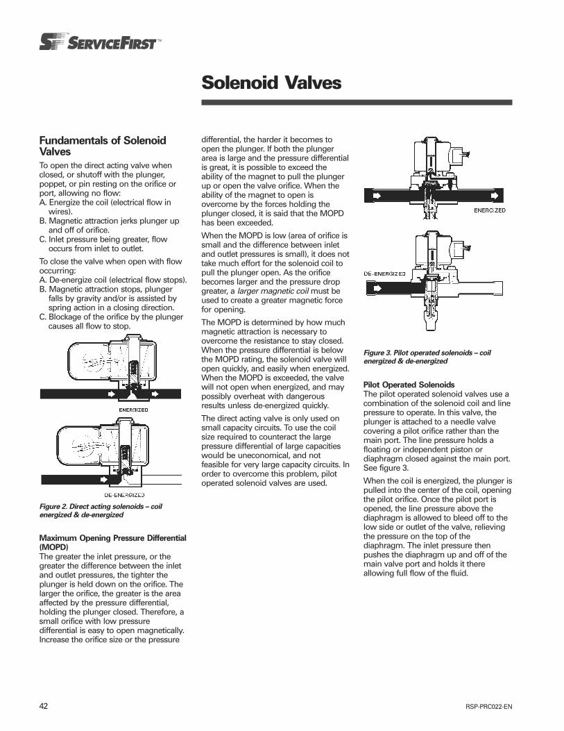
RSP-PRC022-EN42
Solenoid Valves
Fundamentals of SolenoidValves
To open the direct acting valve whenclosed, or shutoff with the plunger,poppet, or pin resting on the orifice orport, allowing no flow:A. Energize the coil (electrical flow in
wires).B. Magnetic attraction jerks plunger up
and off of orifice.C. Inlet pressure being greater, flow
occurs from inlet to outlet.
To close the valve when open with flowoccurring:A. De-energize coil (electrical flow stops).B. Magnetic attraction stops, plunger
falls by gravity and/or is assisted byspring action in a closing direction.
C. Blockage of the orifice by the plungercauses all flow to stop.
Maximum Opening Pressure Differential(MOPD)The greater the inlet pressure, or thegreater the difference between the inletand outlet pressures, the tighter theplunger is held down on the orifice. Thelarger the orifice, the greater is the areaaffected by the pressure differential,holding the plunger closed. Therefore, asmall orifice with low pressuredifferential is easy to open magnetically.Increase the orifice size or the pressure
differential, the harder it becomes toopen the plunger. If both the plungerarea is large and the pressure differentialis great, it is possible to exceed theability of the magnet to pull the plungerup or open the valve orifice. When theability of the magnet to open isovercome by the forces holding theplunger closed, it is said that the MOPDhas been exceeded.
When the MOPD is low (area of orifice issmall and the difference between inletand outlet pressures is small), it does nottake much effort for the solenoid coil topull the plunger open. As the orificebecomes larger and the pressure dropgreater, a larger magnetic coil must beused to create a greater magnetic forcefor opening.
The MOPD is determined by how muchmagnetic attraction is necessary toovercome the resistance to stay closed.When the pressure differential is belowthe MOPD rating, the solenoid valve willopen quickly, and easily when energized.When the MOPD is exceeded, the valvewill not open when energized, and maypossibly overheat with dangerousresults unless de-energized quickly.
The direct acting valve is only used onsmall capacity circuits. To use the coilsize required to counteract the largepressure differential of large capacitieswould be uneconomical, and notfeasible for very large capacity circuits. Inorder to overcome this problem, pilotoperated solenoid valves are used.
Figure 3. Pilot operated solenoids – coilenergized & de-energized
Figure 2. Direct acting solenoids – coilenergized & de-energized
Pilot Operated SolenoidsThe pilot operated solenoid valves use acombination of the solenoid coil and linepressure to operate. In this valve, theplunger is attached to a needle valvecovering a pilot orifice rather than themain port. The line pressure holds afloating or independent piston ordiaphragm closed against the main port.See figure 3.
When the coil is energized, the plunger ispulled into the center of the coil, openingthe pilot orifice. Once the pilot port isopened, the line pressure above thediaphragm is allowed to bleed off to thelow side or outlet of the valve, relievingthe pressure on the top of thediaphragm. The inlet pressure thenpushes the diaphragm up and off of themain valve port and holds it thereallowing full flow of the fluid.

43RSP-PRC022-EN
Solenoid Valves
Fundamentals of SolenoidValves
When the coil is de-energized, theplunger drops and closes the pilotorifice. Pressure begins to build upabove the diaphragm by means of ableed hole in the piston or diaphragmuntil it, plus the diaphragm’s weight andspring, cause it to close on the mainvalve port. The pilot operated solenoidvalve requires a minimum openingpressure differential, between the inletand outlet, in order to open the mainport.
Minimum Opening Pressure Differential(MinOPD)As previously explained, the directoperated solenoid valve must notexceed its MOPD or it will not openwhen energized. If pressure differential istoo great or orifices are too large indiameter, it would take a very large andvery expensive coil to overcome thelarge MOPD. Therefore, the pilotoperated valve is used on larger sizesolenoid valves. The main idea is toopen the pilot orifice with as little effortas possible. However, a certain amountof pressure differential is required tofloat the piston or diaphragm off of themain orifice after the pilot orifice hasallowed both the inlet and outletpressure to equalize. This small amountof required pressure is called theminimum opening pressure differential(MinOPD).
All pilot operated solenoids require aMinOPD to raise the main poppet orfloating piston or diaphragm off of themain orifice. Direct operated solenoidsdo not require a MinOPD, but both directoperated and pilot operated have toavoid exceeding their MOPD in order toflow properly.
The manual stem shown in figure 3 isused to manually open the valve if theline current is not available, or forflushing in cleanup, or other servicemaintenance functions.
Figure 4. Two-way solenoid: 200RB
The above basic principles of operationhold true for all refrigerant solenoidvalves, although certain mechanicalvariations in construction can be found.Examples of these variations are:1. Short stroke plungers, which arerigidly connected to the valve or poppet(these will always be the “direct acting”type).2. Long stroke lost motion plungers,which during opening, impart a“hammer blow” to the valve.3. Mechanically interlinked piston toplunger construction, which is usedwhere no pressure differential is avail-able to float the piston. This constructionenables a large solenoid valve to openand remain in an open position with aminimum pressure drop across thevalve. It is used primarily for suction lineduty.4. Pilot operated spring loaded valvesused in large port sizes.5. Condenser pressure powered stopvalves which use a high pressure pilotconnection.
Solenoid valves having a spring loadedplunger may be installed and operated inany position. These valves include mostall modern day refrigeration solenoids.
Different Types of ValvesSo far we have explained how asolenoid valve operates. Now we willdiscuss the many types of valves andtheir respective applications. The threemain types of valves are: two-way, three-way, and four-way.
Two–Way ValvesThe two-way valve, which is the mostcommon type of solenoid valve, controlsfluid flow in one line. It has an inlet andan outlet connection. This valve can be adirect acting or pilot operated valve,depending on the need. When the coil isde-energized, the two-way valve is“normally closed.” Although normally-closed is the most widely used, two-wayvalves are also manufactured to be“normally-open” when the coil is de-energized. See figure 4.
Select Two-way valves can be convertedto reverse flow operation by theaddition of a bi-flow kit.
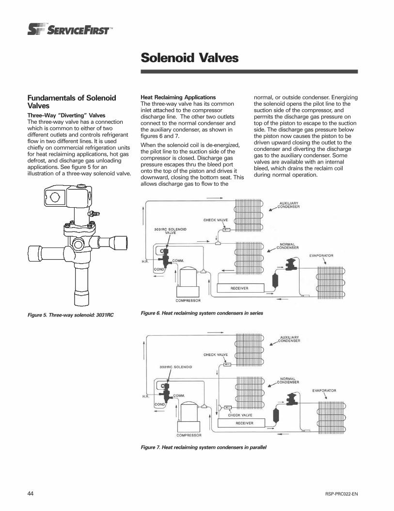
RSP-PRC022-EN44
Solenoid Valves
Figure 5. Three-way solenoid: 3031RC
Fundamentals of SolenoidValves
Three–Way “Diverting” ValvesThe three-way valve has a connectionwhich is common to either of twodifferent outlets and controls refrigerantflow in two different lines. It is usedchiefly on commercial refrigeration unitsfor heat reclaiming applications, hot gasdefrost, and discharge gas unloadingapplications. See figure 5 for anillustration of a three-way solenoid valve.
Heat Reclaiming ApplicationsThe three-way valve has its commoninlet attached to the compressordischarge line. The other two outletsconnect to the normal condenser andthe auxiliary condenser, as shown infigures 6 and 7.
When the solenoid coil is de-energized,the pilot line to the suction side of thecompressor is closed. Discharge gaspressure escapes thru the bleed portonto the top of the piston and drives itdownward, closing the bottom seat. Thisallows discharge gas to flow to the
Figure 6. Heat reclaiming system condensers in series
Figure 7. Heat reclaiming system condensers in parallel
normal, or outside condenser. Energizingthe solenoid opens the pilot line to thesuction side of the compressor, andpermits the discharge gas pressure ontop of the piston to escape to the suctionside. The discharge gas pressure belowthe piston now causes the piston to bedriven upward closing the outlet to thecondenser and diverting the dischargegas to the auxiliary condenser. Somevalves are available with an internalbleed, which drains the reclaim coilduring normal operation.
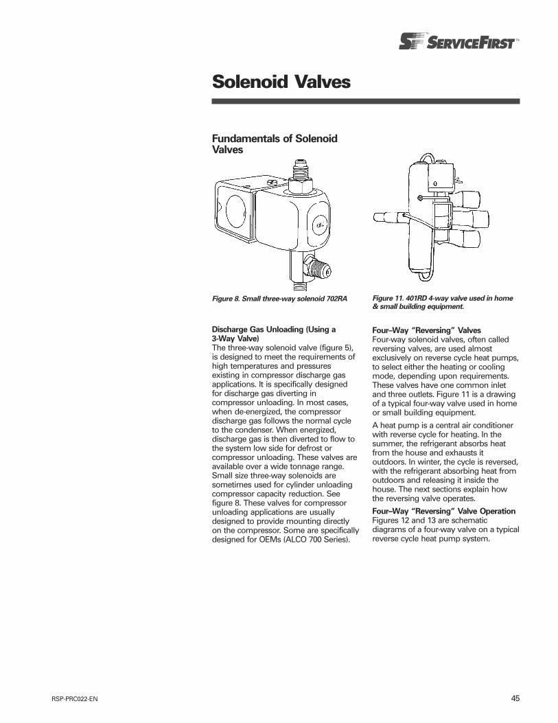
45RSP-PRC022-EN
Solenoid Valves
Fundamentals of SolenoidValves
Discharge Gas Unloading (Using a3-Way Valve)The three-way solenoid valve (figure 5),is designed to meet the requirements ofhigh temperatures and pressuresexisting in compressor discharge gasapplications. It is specifically designedfor discharge gas diverting incompressor unloading. In most cases,when de-energized, the compressordischarge gas follows the normal cycleto the condenser. When energized,discharge gas is then diverted to flow tothe system low side for defrost orcompressor unloading. These valves areavailable over a wide tonnage range.Small size three-way solenoids aresometimes used for cylinder unloadingcompressor capacity reduction. Seefigure 8. These valves for compressorunloading applications are usuallydesigned to provide mounting directlyon the compressor. Some are specificallydesigned for OEMs (ALCO 700 Series).
Figure 8. Small three-way solenoid 702RA Figure 11. 401RD 4-way valve used in home& small building equipment.
Four–Way “Reversing” ValvesFour-way solenoid valves, often calledreversing valves, are used almostexclusively on reverse cycle heat pumps,to select either the heating or coolingmode, depending upon requirements.These valves have one common inletand three outlets. Figure 11 is a drawingof a typical four-way valve used in homeor small building equipment.
A heat pump is a central air conditionerwith reverse cycle for heating. In thesummer, the refrigerant absorbs heatfrom the house and exhausts itoutdoors. In winter, the cycle is reversed,with the refrigerant absorbing heat fromoutdoors and releasing it inside thehouse. The next sections explain howthe reversing valve operates.
Four–Way “Reversing” Valve OperationFigures 12 and 13 are schematicdiagrams of a four-way valve on a typicalreverse cycle heat pump system.
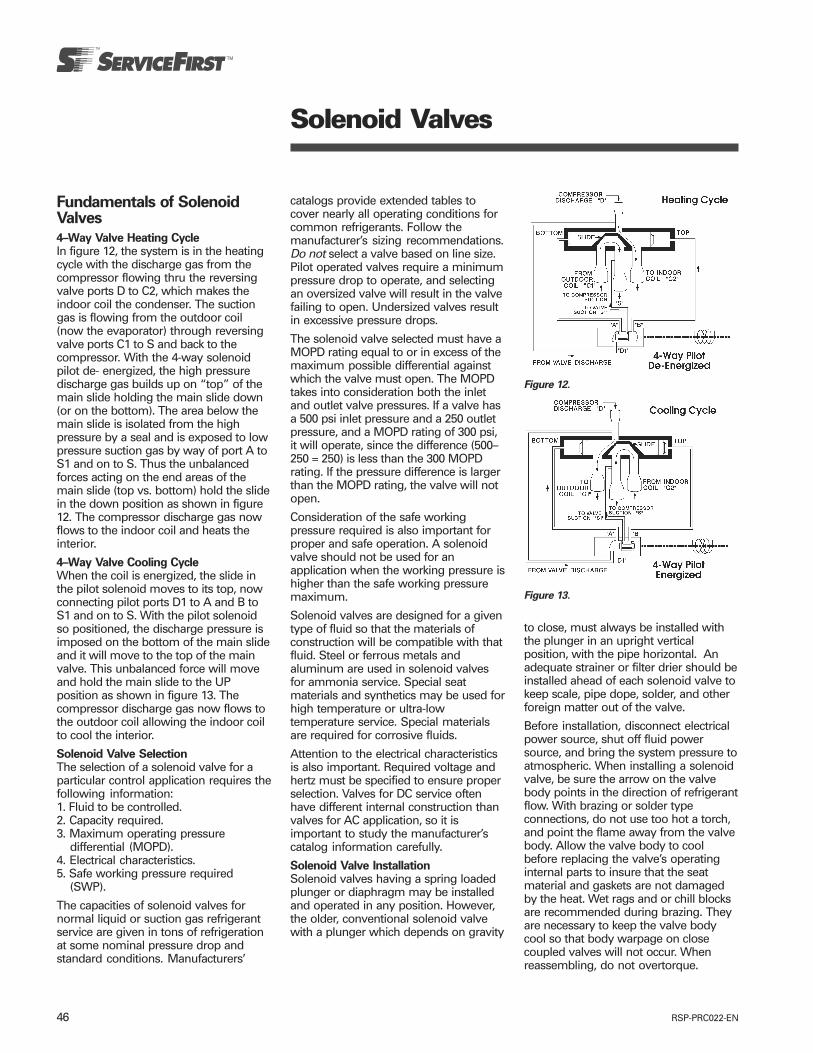
RSP-PRC022-EN46
Solenoid Valves
Fundamentals of SolenoidValves
4–Way Valve Heating CycleIn figure 12, the system is in the heatingcycle with the discharge gas from thecompressor flowing thru the reversingvalve ports D to C2, which makes theindoor coil the condenser. The suctiongas is flowing from the outdoor coil(now the evaporator) through reversingvalve ports C1 to S and back to thecompressor. With the 4-way solenoidpilot de- energized, the high pressuredischarge gas builds up on “top” of themain slide holding the main slide down(or on the bottom). The area below themain slide is isolated from the highpressure by a seal and is exposed to lowpressure suction gas by way of port A toS1 and on to S. Thus the unbalancedforces acting on the end areas of themain slide (top vs. bottom) hold the slidein the down position as shown in figure12. The compressor discharge gas nowflows to the indoor coil and heats theinterior.
4–Way Valve Cooling CycleWhen the coil is energized, the slide inthe pilot solenoid moves to its top, nowconnecting pilot ports D1 to A and B toS1 and on to S. With the pilot solenoidso positioned, the discharge pressure isimposed on the bottom of the main slideand it will move to the top of the mainvalve. This unbalanced force will moveand hold the main slide to the UPposition as shown in figure 13. Thecompressor discharge gas now flows tothe outdoor coil allowing the indoor coilto cool the interior.
Solenoid Valve SelectionThe selection of a solenoid valve for aparticular control application requires thefollowing information:1. Fluid to be controlled.2. Capacity required.3. Maximum operating pressure
differential (MOPD).4. Electrical characteristics.5. Safe working pressure required
(SWP).
The capacities of solenoid valves fornormal liquid or suction gas refrigerantservice are given in tons of refrigerationat some nominal pressure drop andstandard conditions. Manufacturers’
Figure 13.
Figure 12.
catalogs provide extended tables tocover nearly all operating conditions forcommon refrigerants. Follow themanufacturer’s sizing recommendations.Do not select a valve based on line size.Pilot operated valves require a minimumpressure drop to operate, and selectingan oversized valve will result in the valvefailing to open. Undersized valves resultin excessive pressure drops.
The solenoid valve selected must have aMOPD rating equal to or in excess of themaximum possible differential againstwhich the valve must open. The MOPDtakes into consideration both the inletand outlet valve pressures. If a valve hasa 500 psi inlet pressure and a 250 outletpressure, and a MOPD rating of 300 psi,it will operate, since the difference (500–250 = 250) is less than the 300 MOPDrating. If the pressure difference is largerthan the MOPD rating, the valve will notopen.
Consideration of the safe workingpressure required is also important forproper and safe operation. A solenoidvalve should not be used for anapplication when the working pressure ishigher than the safe working pressuremaximum.
Solenoid valves are designed for a giventype of fluid so that the materials ofconstruction will be compatible with thatfluid. Steel or ferrous metals andaluminum are used in solenoid valvesfor ammonia service. Special seatmaterials and synthetics may be used forhigh temperature or ultra-lowtemperature service. Special materialsare required for corrosive fluids.
Attention to the electrical characteristicsis also important. Required voltage andhertz must be specified to ensure properselection. Valves for DC service oftenhave different internal construction thanvalves for AC application, so it isimportant to study the manufacturer’scatalog information carefully.
Solenoid Valve InstallationSolenoid valves having a spring loadedplunger or diaphragm may be installedand operated in any position. However,the older, conventional solenoid valvewith a plunger which depends on gravity
to close, must always be installed withthe plunger in an upright verticalposition, with the pipe horizontal. Anadequate strainer or filter drier should beinstalled ahead of each solenoid valve tokeep scale, pipe dope, solder, and otherforeign matter out of the valve.
Before installation, disconnect electricalpower source, shut off fluid powersource, and bring the system pressure toatmospheric. When installing a solenoidvalve, be sure the arrow on the valvebody points in the direction of refrigerantflow. With brazing or solder typeconnections, do not use too hot a torch,and point the flame away from the valvebody. Allow the valve body to coolbefore replacing the valve’s operatinginternal parts to insure that the seatmaterial and gaskets are not damagedby the heat. Wet rags and or chill blocksare recommended during brazing. Theyare necessary to keep the valve bodycool so that body warpage on closecoupled valves will not occur. Whenreassembling, do not overtorque.
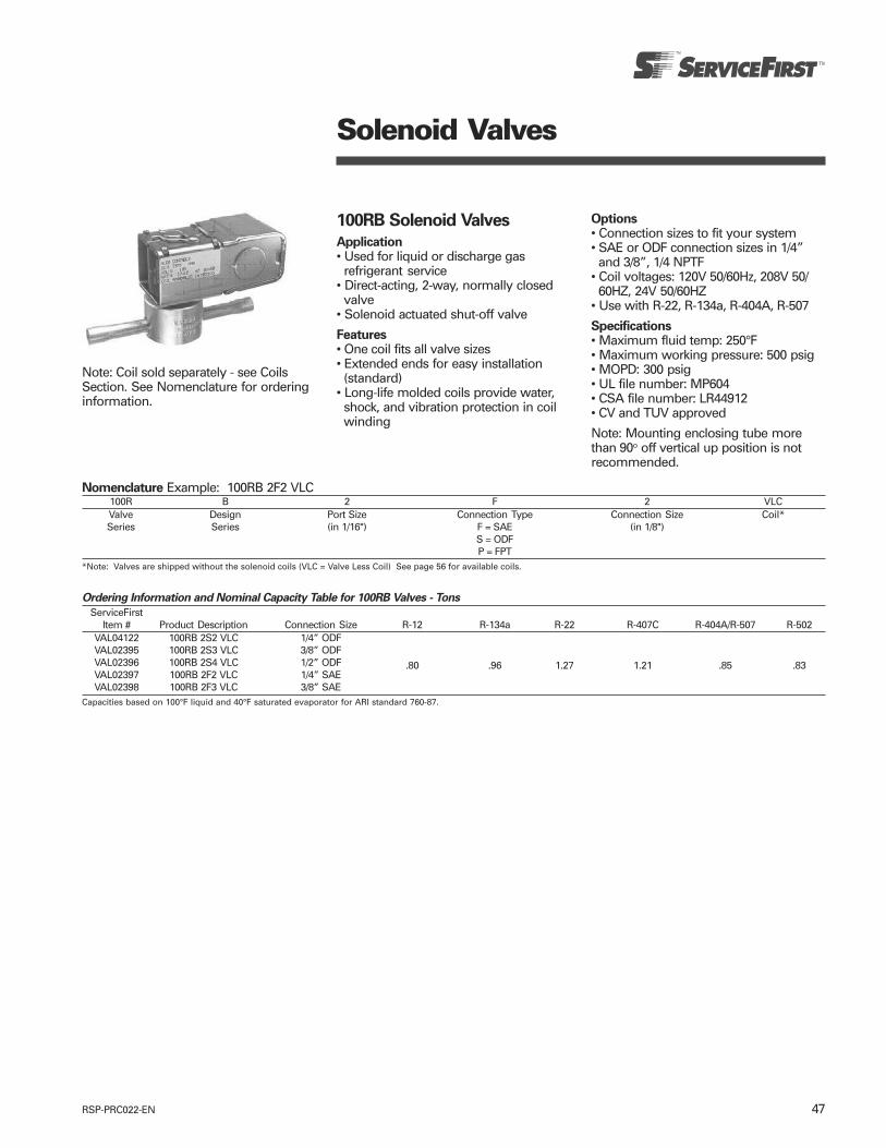
47RSP-PRC022-EN
Solenoid Valves
100RB Solenoid Valves
Application• Used for liquid or discharge gasrefrigerant service
• Direct-acting, 2-way, normally closedvalve
• Solenoid actuated shut-off valve
Features• One coil fits all valve sizes• Extended ends for easy installation(standard)
• Long-life molded coils provide water,shock, and vibration protection in coilwinding
Note: Coil sold separately - see CoilsSection. See Nomenclature for orderinginformation.
Options• Connection sizes to fit your system• SAE or ODF connection sizes in 1/4”
and 3/8”, 1/4 NPTF• Coil voltages: 120V 50/60Hz, 208V 50/
60HZ, 24V 50/60HZ• Use with R-22, R-134a, R-404A, R-507
Specifications• Maximum fluid temp: 250°F• Maximum working pressure: 500 psig• MOPD: 300 psig• UL file number: MP604• CSA file number: LR44912• CV and TUV approved
Note: Mounting enclosing tube morethan 90o off vertical up position is notrecommended.
Nomenclature Example: 100RB 2F2 VLC100R B 2 F 2 VLCValve Design Port Size Connection Type Connection Size Coil*Series Series (in 1/16") F = SAE (in 1/8")
S = ODFP = FPT
*Note: Valves are shipped without the solenoid coils (VLC = Valve Less Coil) See page 56 for available coils.
Ordering Information and Nominal Capacity Table for 100RB Valves - Tons
ServiceFirstItem # Product Description Connection Size R-12 R-134a R-22 R-407C R-404A/R-507 R-502
VAL04122 100RB 2S2 VLC 1/4” ODFVAL02395 100RB 2S3 VLC 3/8” ODFVAL02396 100RB 2S4 VLC 1/2” ODFVAL02397 100RB 2F2 VLC 1/4” SAE
.80 .96 1.27 1.21 .85 .83
VAL02398 100RB 2F3 VLC 3/8” SAECapacities based on 100°F liquid and 40°F saturated evaporator for ARI standard 760-87.

RSP-PRC022-EN48
Solenoid Valves
100RB Exploded View & Parts Kit Data
Valve Kit: “K” indicates part is suppliedin valve repair kit KIT04959 (KS30112).
Note: Spanner wrench X11981-1included in complete valve kit.
KIT04959
Coil AssemblyConsists of coil, coil nameplate, andconversion spacer (AMG). For voltagesand frequencies available see the tableson page 56.
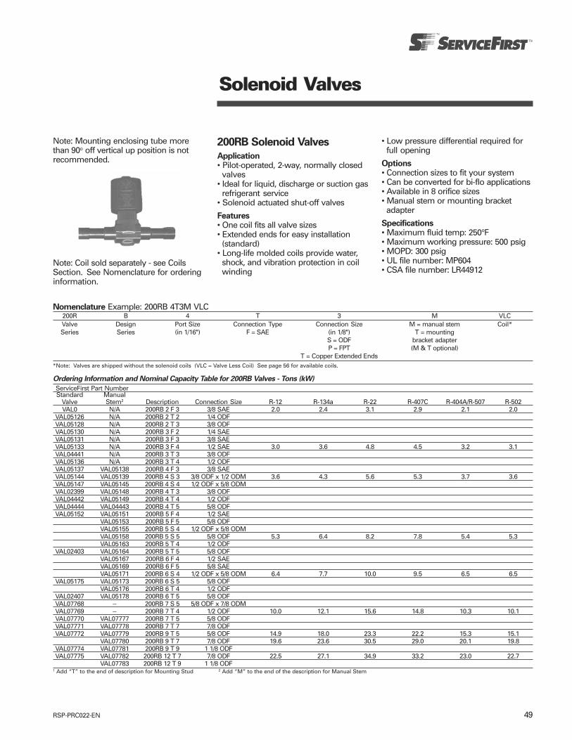
49RSP-PRC022-EN
Solenoid Valves
200RB Solenoid Valves
Application• Pilot-operated, 2-way, normally closedvalves
• Ideal for liquid, discharge or suction gasrefrigerant service
• Solenoid actuated shut-off valves
Features• One coil fits all valve sizes• Extended ends for easy installation(standard)
• Long-life molded coils provide water,shock, and vibration protection in coilwinding
Note: Coil sold separately - see CoilsSection. See Nomenclature for orderinginformation.
• Low pressure differential required forfull opening
Options• Connection sizes to fit your system• Can be converted for bi-flo applications• Available in 8 orifice sizes• Manual stem or mounting bracket
adapter
Specifications• Maximum fluid temp: 250°F• Maximum working pressure: 500 psig• MOPD: 300 psig• UL file number: MP604• CSA file number: LR44912
Nomenclature Example: 200RB 4T3M VLC200R B 4 T 3 M VLCValve Design Port Size Connection Type Connection Size M = manual stem Coil*Series Series (in 1/16") F = SAE (in 1/8") T = mounting
S = ODF bracket adapterP = FPT (M & T optional)
T = Copper Extended Ends*Note: Valves are shipped without the solenoid coils (VLC = Valve Less Coil) See page 56 for available coils.
Ordering Information and Nominal Capacity Table for 200RB Valves - Tons (kW)
ServiceFirst Part NumberStandard Manual
Valve Stem2 Description Connection Size R-12 R-134a R-22 R-407C R-404A/R-507 R-502VAL0 N/A 200RB 2 F 3 3/8 SAE 2.0 2.4 3.1 2.9 2.1 2.0
VAL05126 N/A 200RB 2 T 2 1/4 ODFVAL05128 N/A 200RB 2 T 3 3/8 ODFVAL05130 N/A 200RB 3 F 2 1/4 SAEVAL05131 N/A 200RB 3 F 3 3/8 SAEVAL05133 N/A 200RB 3 F 4 1/2 SAE 3.0 3.6 4.8 4.5 3.2 3.1VAL04441 N/A 200RB 3 T 3 3/8 ODFVAL05136 N/A 200RB 3 T 4 1/2 ODFVAL05137 VAL05138 200RB 4 F 3 3/8 SAEVAL05144 VAL05139 200RB 4 S 3 3/8 ODF x 1/2 ODM 3.6 4.3 5.6 5.3 3.7 3.6VAL05147 VAL05145 200RB 4 S 4 1/2 ODF x 5/8 ODMVAL02399 VAL05148 200RB 4 T 3 3/8 ODFVAL04442 VAL05149 200RB 4 T 4 1/2 ODFVAL04444 VAL04443 200RB 4 T 5 5/8 ODFVAL05152 VAL05151 200RB 5 F 4 1/2 SAE
VAL05153 200RB 5 F 5 5/8 ODFVAL05155 200RB 5 S 4 1/2 ODF x 5/8 ODMVAL05158 200RB 5 S 5 5/8 ODF 5.3 6.4 8.2 7.8 5.4 5.3VAL05163 200RB 5 T 4 1/2 ODF
VAL02403 VAL05164 200RB 5 T 5 5/8 ODFVAL05167 200RB 6 F 4 1/2 SAEVAL05169 200RB 6 F 5 5/8 SAEVAL05171 200RB 6 S 4 1/2 ODF x 5/8 ODM 6.4 7.7 10.0 9.5 6.5 6.5
VAL05175 VAL05173 200RB 6 S 5 5/8 ODFVAL05176 200RB 6 T 4 1/2 ODF
VAL02407 VAL05178 200RB 6 T 5 5/8 ODFVAL07768 -- 200RB 7 S 5 5/8 ODF x 7/8 ODMVAL07769 -- 200RB 7 T 4 1/2 ODF 10.0 12.1 15.6 14.8 10.3 10.1VAL07770 VAL07777 200RB 7 T 5 5/8 ODFVAL07771 VAL07778 200RB 7 T 7 7/8 ODFVAL07772 VAL07779 200RB 9 T 5 5/8 ODF 14.9 18.0 23.3 22.2 15.3 15.1
VAL07780 200RB 9 T 7 7/8 ODF 19.6 23.6 30.5 29.0 20.1 19.8VAL07774 VAL07781 200RB 9 T 9 1 1/8 ODFVAL07775 VAL07782 200RB 12 T 7 7/8 ODF 22.5 27.1 34.9 33.2 23.0 22.7
VAL07783 200RB 12 T 9 1 1/8 ODF1 Add “T” to the end of description for Mounting Stud 2 Add “M” to the end of the description for Manual Stem
Note: Mounting enclosing tube morethan 90o off vertical up position is notrecommended.
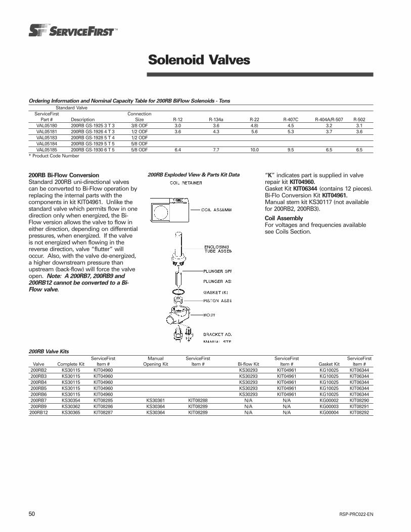
RSP-PRC022-EN50
Solenoid Valves
200RB Bi-Flow ConversionStandard 200RB uni-directional valvescan be converted to Bi-Flow operation byreplacing the internal parts with thecomponents in kit KIT04961. Unlike thestandard valve which permits flow in onedirection only when energized, the Bi-Flow version allows the valve to flow ineither direction, depending on differentialpressures, when energized. If the valveis not energized when flowing in thereverse direction, valve “flutter” willoccur. Also, with the valve de-energized,a higher downstream pressure thanupstream (back-flow) will force the valveopen. Note: A 200RB7, 200RB9 and200RB12 cannot be converted to a Bi-Flow valve.
“K” indicates part is supplied in valverepair kit KIT04960.Gasket Kit KIT06344 (contains 12 pieces).Bi-Flo Conversion Kit KIT04961.Manual stem kit KS30117 (not availablefor 200RB2, 200RB3).
Coil AssemblyFor voltages and frequencies availablesee Coils Section.
200RB Exploded View & Parts Kit Data
200RB Valve Kits
ServiceFirst Manual ServiceFirst ServiceFirst ServiceFirstValve Complete Kit Item # Opening Kit Item # Bi-flow Kit Item # Gasket Kit Item #
200RB2 KS30115 KIT04960 KS30293 KIT04961 KG10025 KIT06344200RB3 KS30115 KIT04960 KS30293 KIT04961 KG10025 KIT06344200RB4 KS30115 KIT04960 KS30293 KIT04961 KG10025 KIT06344200RB5 KS30115 KIT04960 KS30293 KIT04961 KG10025 KIT06344200RB6 KS30115 KIT04960 KS30293 KIT04961 KG10025 KIT06344200RB7 KS30354 KIT08285 KS30361 KIT08288 N/A N/A KG00002 KIT08290200RB9 KS30362 KIT08286 KS30364 KIT08289 N/A N/A KG00003 KIT08291200RB12 KS30365 KIT08287 KS30364 KIT08289 N/A N/A KG00004 KIT08292
Ordering Information and Nominal Capacity Table for 200RB BiFlow Solenoids - Tons
Standard ValveServiceFirst Connection
Part # Description Size R-12 R-134a R-22 R-407C R-404A/R-507 R-502VAL05180 200RB GS-1925 3 T 3 3/8 ODF 3.0 3.6 4.8) 4.5 3.2 3.1VAL05181 200RB GS-1926 4 T 3 1/2 ODF 3.6 4.3 5.6 5.3 3.7 3.6VAL05183 200RB GS-1928 5 T 4 1/2 ODFVAL05184 200RB GS-1929 5 T 5 5/8 ODFVAL05185 200RB GS-1930 6 T 5 5/8 ODF 6.4 7.7 10.0 9.5 6.5 6.5
* Product Code Number

51RSP-PRC022-EN
Solenoid Valves
240RA Solenoid Valves
Application• 2-way, normally closed diaphragmvalves
• Ideal for liquid, suction and hot gasservice
• Solenoid actuated shut-off valve
Features• One coil fits all valve sizes• Can be brazed into the line withoutdisassembly
• Reinforced Teflon diaphragm withwoven fiberglass for superior control
• Durable, stainless enclosing tube• Extended ends for easy installation(standard)
• Long-life molded coils provide water,shock, and vibration protection in coilwinding
• Low pressure differential required forfull opening
• Mounting stud models can be fieldconverted to manual lift stem
Options• Connection sizes to fit your system• Manual stem or mounting bracket
adapter
Specifications• Maximum fluid temp: 250°F• Maximum working pressure: 500 psig• MOPD: 300 psig• UL file number: MP604• CSA file number: LR44912
Note: Mounting enclosing tube morethan 90o off vertical up position is notrecommended.
Nomenclature Example: 240RA 8T5M VLC240R A 8 T 5 M VLCValve Design Port Size Connection Type Connection Size M = manual stem Coil*Series Series (in 1/16") T = copper (in 1/8") (optional)
extended ends T = mounting bracketadapter (optional)
*Note: Valves are shipped without the solenoid coils (VLC = Valve Less Coil). See page 56 for available coils.
Ordering Information and Nominal Liquid Capacity Table for 240RA Valves - Tons
ServiceFirst Part NumberStandard Manual
Valve Stem1 Description Connection Size R-12 R-134a R-22 R-407C R-404A/R-507 R-502VAL05199 VAL05198 240RA 8 T 5 5/8 ODFVAL05201 VAL05200 240RA 8 T 7 7/8 ODF
10.0 12.1 15.6 14.8 10.3 10.1
VAL05203 VAL05202 240RA 9 T 5 5/8 ODF 14.9 18.0 23.3 22.1 15.3 15.1VAL05205 240RA 9 T 7 7/8 ODFVAL05207 VAL05206 240RA 9 T 9 1 1/8 ODF
19.6 23.6 30.5 29.0 21.0) 19.8
VAL05186 VAL05909 240RA 12 T 7 7/8 ODFVAL05187 VAL05910 240RA 12 T 9 1 1/8 ODF
22.5 27.1 34.9 33.2 23.0 22.7
VAL05191 VAL05190 240RA 16 T 9 1 1/8 ODFVAL05189 VAL05188 240RA 16 T 11 1 3/8 ODF
37.3 45.0 58.0 55.2 38.3 37.7
VAL05193 VAL05192 240RA 20 T 11 1 3/58 ODFVAL05194 240RA 20 T 13 1 5/8 ODF 58.8 70.9 95.4 90.8 65.7 62.0
VAL05196 VAL05195 240RA 20 T 17 2 1/8 ODF1 Add “M” to the end of the description for Manual Stem
Note: Coil sold separately - see CoilsSection. See Nomenclature for orderinginformation.

RSP-PRC022-EN52
Solenoid Valves
240RA Valve Kits
ServiceFirst Manual ServiceFirstValve Complete Kit Item # Opener Kit Item #
240RA8 KS30321 KIT04979 KS30066 KIT04963240RA9 KS30322 KIT04980 KS30067 KIT04964240RA12 KS30323 KIT04981 KS30067 KIT04964240RA16 KS30324 KIT04982 KS30068 KIT04965240RA20 KS30325 KIT04983 KS30098 KIT04969
Gasket Kit all 240RA valves is KIT05054 (KG10028)
“K” indicates part is supplied incomplete valve repair kit.“M” indicates part is supplied in manualopener kit.“G” indicates gasket is supplied ingasket kit.Note: Spanner wrench (X11981-1 servicetool) included in complete valve kit.
Coil AssemblyFor voltages and frequencies availablesee the tables on page 56.
240RA Exploded View & Parts Kit Data