System catalogue SBC
301
www. saia-pcd. com www . saia-pcd . com 2016 | 2017 System catalogue SBC Electronic instrumentation, control and automation technology for machines, facilities and real estate
-
Upload
khangminh22 -
Category
Documents
-
view
0 -
download
0
Transcript of System catalogue SBC

www.saia-pcd.comwww.saia-pcd.com
2016 | 2017System catalogueSBC
Electronic instrumentation, control and automation technology for machines, facilities and real estate


saia-pcd.com
Contents
Contents
Products
A1 Automation stations: Saia PCD3, Saia PCD2, Saia PCD1, E-Line, Standby System
A2 HMI Visualization and operating
A3 Dedicated room controllers
A4 Consumption data capture
A5 Accessories for automation technology
Basic systems
B1 SBC Software
B2 Communication & Interaction
B3 SBC S-Web: Visualisation, Trending, Alarming
B4 Room control
Appendix
C1 Status: Product launch
C2 Abbreviations
C3 Type listing
7
97
113
129
155
177
219
251
271
279
281
283

Saia PCD®
Technology
saia-pcd.com
SSaia PCD®TeT chnology
This catalogue presents the current product range for the automation of technical
infrastructure. It includes facilities for energy production and distribution, water supply,
telecommunications, transport networks and HVAC facilities in buildings.
The catalogue provides an introduction on how to understand and be able to assess for yourself the qualities and properties of the ICA/automation technology you have integrated and/or planned. You can see which technical capabilities exist for operating infrastructure objects more cost-effectively and with less effort. You can recognize how you can avoid dependencies which are disadvantageous to your business. You can find products “Made for Lean Automation Technology” which are designed to give you more peace of mind.
You can find the technical basis for consulting, engineering and invitations to tenders. You can recognize how Saia PCD® technology can help you to achieve maximum flexibility in project implementation and the following optimization phase. Maximum flexibility helps you to deal with the 2 basic constants of the project business better and more easily. These include: a) You are lacking important information and requirements in the planning phase. b) The actual construction design deviates from your plan. Despite this, everything should be finished on time and within
budget.
Here you can find the general technical principles for mounting and cabling SBC device technology. You can un-derstand how applications are created with SBC S-Engineering software tools and how they can be changed in the lifecycle. You can recognize which device, which software tools and application modules are suited to an invitation to tender or project description.
You invest, operate, manage…
You plan, advise, calculate…
You install, implement and provide service…
How can the SBC
System Catalogue
help you?
Our catalogue does not feature products with a lifecycle likely to end in a few years’ time. We no longer recommend these “end of life” products when planning new projects. They will therefore no longer be listed in the manual. A list of all the available SBC products can only be found in the current price list. Here you will also find products which are specially designed for the automation of industrial production machines
SBC S-Monitoring Systems
This catalogue does not cover all the products supplied by Saia Burgess Controls. An aware choice based on relevance was made for as many of our customers as possible.
This resulted in the following focus topics:
Instrumentation, control and automation (ICA) technology of primary installations Increased efficiency when using natural resources Technical integration and automation of buildings
Electricity, water, gas, heating Electricity, water, gas, heating
Strategic focus on primary systems with SBC technology
Long lifecycle, adaptable, expandable
Strategic focus on resource efficiency
Record, display and control the consump-tion of electricity, water, gas, heating, etc. with SBC S-Monitoring Systems. Suitable
for use everywhere where technology has to be easily and reliably integrated into operations but is to remain flexible and
expandable – from residential homes to industrial facilities.
Our Saia PCD® te
chn
olo
gy
Your installatio
n

saia-pcd.com
Technical cornerstones
In order to achieve the shared objectives of operators and owners of automation systems, we need a suitable stable technical foundation. This foundation comprises 4 basic properties which are common to all Saia PCD® controllers.
1 Modularity in hardware and function enables high flexibility and adaptability at any time during the lifecycle of 15…20 years.
2 Maximum portability: The project’s application software can be ported over all device classes and device generations throughout the lifecycle; even by the owner/operator alone.
3 Complete openness in communication. All device functions and data can be seen from the outside and used. Complete openness also in licensing the SBC software tools, because SBC software tools are available to anyone.
4 Standard technology only: The ICA functions of Saia PCD® devices are implemented using standardized technology that is in common use and is recognized around the world (web + IT). We do not use proprietary technologies. Saia PCD® S-Bus is the exception. We need this in order to get right into the core of the Saia PCD® devices, e.g. debugging.
Shared objectives
Being able to understand and assess products and their integration into systems is essential. Knowing what objectives they were created to achieve helps accomplish this. These objectives should largely be identical to those of operators, planners and integrators of ICA systems.
Shared objectives bring everyone together – just as the shared methods and values of the companies involved make collaboration easier and ensure success. The following two pages provide a short overview of this.
Bus technology usable with Saia PCD® control devices:other protocols can also be implemented later as a PLC program

1950
1978
1990
2006
2003
2010
2015
saia-pcd.com
SBCAbout us …
IEC EN 61131-2
This standard defines in 150 pages how electronic items should be developed and produced to satisfy PLC quality requirements. It ensures, among other things, that service is possible even without specialists. Look out for the exten-sion “-2”. Many suppliers work only to PLC standard 61131-3. But that standard only defines the programming method type, regardless of the hardware/design quality. In addition, standard 61131-3 does not specify the portability of application software from one device series to another, nor from one hardware version to the next.
Control systems “Swiss made”
Saia-Burgess Controls AG, or SBC, is based in a bilingual (German and French) part of western Switzerland – the locality which is home to companies with a global reputa-tion and to leading schools and universi-ties in the field of technology. Saia Burgess Controls is a wholly-owned subsidiary of Honeywell International Inc. and operates according to the “bottom up” principle: the needs of the grassroots are defined and inte-grated into the development and manufac-turing process. The company has developed and marketed electronic components and
Key corporate data70 million euro annual sales
340 employees 2 million I/O points per year
40,000 CPUs per year 700,000 small devices/year
Development, production and sale of industrial-grade electronic components and systems for control/automation engineering.
measurement and control systems since 1950. The products are distinguished by an extremely long service life. They are used in heating, ventilation and climate control, energy management and water systems. A further important pillar of the company is OEM production. SBC products are always fit for pur-pose and are guarantors of technological progress.
Our mission
At the end of the seventies, Saia Burgess Controls became a pio-neer in the field of programmable logic controllers (PLCs), known and used long-term under the Saia® brand name. In parallel with the component business, Saia Burgess Controls grew to become a supplier of measurement and control technology systems.
In 2010, with the complete redesign of the Saia PCD1, the smallest device series joined the Saia PCD3 and Saia PCD2 in being fully modernised. The 3rd generation of Saia PCD® control devices is now complete. This is char-acterised by the following equation:Saia PCD® = PLC + IT + Web
Seamless integration of world renowned open technologies for web and IT on freely programmable, industrial electronics with the same quality and life cycle as the robust, industrial PLC.
In the early days, Saia Burgess Controls manufactured mainly electronic timers. The spec-trum of use extended from house installations to machine technology.
The year 2006 saw the start of the product line for fully integrated bus compatible electronic energy meters.
In the same year, Saia Burgess Controls launched the world’s first completely web- based touch- panel for automation.
Value and culture of a PLC company
When they use our products customers gain value added in the form of sustainable earnings. For this reason, we develop products with a long life cycle of problem-free, reliable opera-tion. Installed products can be adapted to changing needs at any time. Investments made by the customer are lasting and not constantly subject to incompatibilities or forced and unwanted innovations. This is why we develop PLC-based technology, with its sustained customer benefit and ease of upgrade. For more than 50 years, our company has remained true to these values.
Since application settings all too often fail to behave in accordance with the standards, we have made Saia PCD1, 2, 3 control technology more robust against interference than the CE standard requires. We set high standards for our-selves. This gives our customers greater security and peace of mind
Alongside the strict IEC 61131-2 PLC hardware standard, Saia PCD® control technology also meets the stringent requirements of various testing authori-ties for marine engineering.
Murten
Zurich
Geneva
Bern
Basel

saia-pcd.com
From bid phase to production and far beyond:
All in-house
Control and measurement electronics should have the same life cycle as the installa-tion plant technology. During this cycle the technology must remain adaptable and expandable at all times; it should therefore be modular and in PLC quality.
The compatibility and free portability of system/machine software is safeguarded over an entire product generation of 18 to 25 years. This can only be achieved if we develop all the engineering soft-ware ourselves, and systematically use “interpreted program code”. This approach requires rather more hardware resources, but allows user software to be portable across several controller generations.
View of lifecycle for Saia PCD® control equipment
Product care phase>10 years
Service phase>5 years
18 years Saia PCD® control device lifecycle < 25 years
Changeover phase
Program-compatible subsequent generation
Introduction phase3–5 years
Our customer base
The spread of our customers is a distinctive feature of our company. More than 50% of our corporate turnover is achieved with “small” system integrators, who carry out infrastructure automation projects. At the other end of the scale, we also develop and manufacture products for well-known international companies in electrical automation. Midway between the two are the production machine builders. Many of these supply HeaVAC and “energy” machines for infrastructure. In process technology, Saia PCD® controllers are found in machines for stoneworking, textiles, printing, assembly, etc. In the case of machine controllers, we have no specific industry focus but rather a customer focus. Target customers are manufacturers of production machines who value an economical and innovative controller technology that offers them ample room for their own added value and product differentia-tion. We provide our customers with individual adaptations to achieve maximum efficiency for their needs.
Our Saia PCD® te
chn
olo
gy
Your installatio
n
Product Development
Software, firmware and hard-ware developed in-house
Guaranteed product life cycle and compatibility for over 15 years
Faster and more reliable pro-duction of custom orders
Production
Two modern SMD lines with 560 feeder positions in the fac-tory at Murten (Switzerland)
Effective mounting capacity of 80,000 components per hour
Selective soldering machine for processing densely populated, critical boards
ICT, AOI and boundary scan test methods
Assembly
Production and assembly based on the “lean” principle
Direct final assembly in work cells downstream of the SMD line, no intermediate storage
A machine-assembled board becomes a finished product ready for dispatch, including packaging and documentation.
Logistics
75,000 order items
12,000 packages
1,000 sales items kept in stock
Delivery reliability: >96%
Delivery time: 80% of items within 48 hours
Training and Support
The aim is to achieve a high level of autonomy and ef-ficiency for our customers.
Product support and training centres at every sales support location
Practical basic and advanced training facilities at the factory in Switzerland

saia-pcd.com
12,3
R&D Support Team - Werk Reperaturservice im Werk
Our value contribution on the way to an installed and optimized ICA solution.
SBC
Support
Requirements profiles of operators/owners
Fully operational installations/systems
SBC
Components & Systems
System integrators
Engineering & ServiceSBC
Support
Lean automation support
The greatest benefits are achieved with mini-mum operating costs if the requirements profile of the user/operator is implemented as perfectly as possible in automation solutions. This profile only becomes clear in long-term operation and when there is good knowledge of the individual application. For this reason, people who imple-ment and maintain the operational automation/ICA solution should be as close to the application as possible. SBC support is thus fully focused on achieving maximum autonomy and independ-ence with high efficiency for system integrators, systems builders and operators.Saia Burgess Controls does not deal with the realization and maintenance of installed, fully operational automation/ICA solutions. A device manufacturer simply does not have the strategic starting position to be the best here.
Customer support
SBC support structure
The satisfaction and economic success of the oper-ator/user when using SBC technology is influenced by many groups of people. For this reason, SBC support specifically supports everyone involved in the planning, implementation and operation of fa-cility installations. Support engineers are available to the customer for advice and assistance. The field service support engineers are assigned to a sup-port center in the country/region. Their employees are available to all interested parties by phone, e-mail and NetMeeting. Where the scope and type of local resources is not sufficient, there is a further factory support level in the background. Large training facilities for HeaVAC technology are also provided here. Online help is available 24 hours a day, 7 days a week at www.sbc-support.com.
Support structure for SBC components and systems
Mission: The logistics support ensures that products from the factory can be delivered within a week to each (industrialized) place on earth.
We consider service to be an integral part of the sale price. As a result, our customers experience success and delight when using our products. For us, satisfaction is not an option or an “accessory”, but part of the basic product. As a system manufacturer, our support expertise goes far beyond one single device. Our products are components and systems.
www.sbc-support.com
Online help is available 24/7.
Quality and performance of SBC support
The quality and performance of our support deter-mines our success. We regularly have independent institutes assess our customers’ satisfaction with the support service. The results of the survey are checked for credibility by authorities such as the German company TÜV Süd before publication.
Breakdown of sales
Saia Burgess Controls : For us, revenue from service
is of virtually no significance. We derive no profit from
operator/owner problems and costs over the life cycle.
SBC support is free of charge, because every device
delivered includes support when needed.
So
ftw
are
< 3
%
Su
pp
ort
< 1
%
De
vic
es
Ha
rdw
are
> 9
5 %
$
Field service
Technical customer support
in the region/country
Logistics/catalogsupport
in the region/country
HVAC application support & training
at the factory
Technical customer support
Backup team
Logistics/catalog support
at the factory
R&D support team at the factory Repair service at the factory
Support eng.application/
product
Support eng.technical andcommercial

A
saia-pcd.com
Products
A1 Automation stations
A1.1 System description
A1.2 PCD3 – modular cartridge construction
A1.3 Standby System
A1.4 PCD2 – modular, expandable, compact CPU
A1.5 PCD1 – modular, expandable, compact CPU
A1.6 PCD1 E-Line – compact design for electrical distributors
A2 HMI Visualization and operating
A3 Dedicated room controller
A4 Consumption data acquisition
A5 Cabinet components
A – Products
8
19
45
53
67
77
97
113
129
155


7
saia-pcd.com
A1
5S
wit
ch c
ab
ine
t
com
po
ne
nts
4C
on
sum
er
d
ata
acq
uis
itio
n3
De
dic
ate
d
roo
m c
on
tro
lle
rs2
Op
era
tio
n
an
d m
on
ito
rin
g
Automation stations – the basics
1A
uto
ma
tio
n
sta
tio
nsProgrammable for measuring, regulation and control
devices. Modular series consisting of industrial quality CPU, I/O and communication modules with a service life that will last for decades. The application software can be simply and reliably adapted and expanded throughout its service life. It can be used for all device series (Saia PCD1, 2 and 3).
Automation stations
Presentation of the Saia PCD® COSinus control operating system – hardware structure – program execution – memory system and service capability.
Up to 1023 I/Os – up to 13 simultaneously operated communication interfaces.
18 basic I/Os which can be expanded to max. 50 I/Os with 2 optional I/O modules – up to 8 simultaneously operated communication interfaces.
External dimensions independent of the type and number of the integrated hardware modules. Expandable system up to 1023 I/Os – up to 15 simultaneously operated communication interfaces.
E-Line product line for specific applications in very confined spaces.
Programmable I/O modules I/O modules Communication modules and gateways
1.2 PCD3 – modular cartridge construction Page
1.5 PCD1 – modular, expandable, compact CPU Page
1.4 PCD2 – modular technology with a compact design Page
1.6 PCD1 E-Line – compact design for electrical distributors Page
1.1 Basic system properties Page
Saia PCD3.Mxx6x as high power CPU Saia PCD3.M5xxx as standard control device Saia PCD3.T66x remote I/O stations
Saia PCD3.M3xxx as the most compact base unit Saia PCD3.M2 with dedicated I/O level and function
Standby system for highly available automation solutions.
PCD3.M6880 standby controller PCD3.T688 smart RIO for standby system
1.3 Standby System Page
19
53
45
67
77
8

8
saia-pcd.com Automation stations – the basics
Saia PCDs combine PLC functionality with innovative web and IT technology in an industrial quality system. The basic equation Saia PCD® = PLC + (web + IT) means that the conventional automation pyramid is becoming an open, transparent structure.
The service life of Saia PCD®: Compatibility and portability guaranteed for all device types across generations.
The Saia PCD® system with its open technology stands for total transparency, combinability and openness. This applies between all the levels of the automation pyramid, the automation world and the actual operating environment of the user. To achieve this, all Saia PCD® control and regulation devices generally include comprehensive web + IT functions. These functions do not require additional hardware and form an integral part of every device. Machines and systems can therefore be very easily integrated into the existing IT infrastruc-ture.
We develop our products to provide customers with direct added value that enables them to generate sustainable revenue. This requires products with a long service life and flawless and reliable operation. Previously installed products must always be able to adapt to changing needs. Existing investments should not always be made obsolete by unwanted, forced innovations and incompatibilities. This is why we attach such great importance to PLC-based technology with its sustained customer benefit and ease of upgrade. Our company has remained true to these values for over 50 years. Moreover, we only use components that comply with industrial standards and which have a service life of at least 20 years.
1.1 Saia PCD® System descriptionPLC + (Web + IT ) = Saia PCD®
Management
level
Field level
Automation
level
Automation pyramid by definition: strictly separate levels; insulated from the outside world.
Automation pyramid Saia PCD® opens up through standard technology
Product maintenance phase
>10 years
Service phase
>5 years
18 years < Saia PCD® control device service life < 25 years
Changeover phase
Program-compatible subsequent generation
Introduction phase
3–5 years

9
saia-pcd.com
IIIIIIIIIIIIIIIIIIIIIII
IIIIIIIIIIIIIIIIIIIIIII
5S
wit
ch c
ab
ine
t
com
po
ne
nts
4C
on
sum
er
d
ata
acq
uis
itio
n3
De
dic
ate
d
roo
m c
on
tro
lle
rs2
Op
era
tio
n
an
d m
on
ito
rin
g1
Au
tom
ati
on
st
ati
on
s
Automation stations – the basics
Basic configuration of the Saia PCD® CPU modules
Standards
Saia PCD® controllers comply with the IEC EN 61131-2 standard in terms of design and production quality. This standard defines in 150 pages how electronic items should be developed and produced to meet PLC quality standards. All the important topics for the applications are covered: From the environmental conditions (temperature, humidity, vibration), to functionality (fluctuations in the power supply, interruptions) and electromagnetic compliance depending on the area of applica-tion.
As application settings often fail to behave in accordance with the standards, our SBC control technology is more robust against interference than required by the CE standard. The majority of Saia PCDs are also approved for maritime applications, where increased demands are made on the devices.
The quality and robustness of the Saia PCD® control technology is also evident in MTBF values, in the rates of returns from the field and in the feedback from our regular customer satisfaction surveys. See page 18 for more information on this topic.
Common properties
USB interface for configuration, programming and commissioning Ethernet interface with all the important web/IT protocols, including those for PG5 communication At least one onboard serial interface (Saia PCD3.M5/6: 3×) 24 VDC power supply Data remanence through battery and/or SuperCap Watchdog and fast interrupt inputs on the main CPU Slots for intelligent communication or memory modules Can be expanded in a modular way (except for Saia PCD1.M) up to 1023 data points
Saia PCD® hardware:
Overview of the core elements of a Saia PCD® controller
Watchdog
1…2 slots for PCD7.Rxxxx memory card
24 VDC power supply
USB interface
Ethernet interface
1…3 serial interfaces
Expansion with additional I/O modules (with the exception of PCD1.M2/expansions PCDx.C with PCDx.I/O/B/W) up to max. 1023 data points
Memory for user program 128 kB–2 MB
66–233 MHz Coldfire processor
Battery/SuperCap
Two slots for memory for PCD1.M2 / four slots for memory (PCDx.R), communication (PCDx.F) or I/O modules (PCDx.I/O/B/W)
Real time clock

10
saia-pcd.com Automation stations – the basics
We developed the core of the Saia PCD® operating systems between 2001 and 2003 as part of a European cooperation project with Philips and Nokia. We then expanded the core and focused on an operating system for advanced, industry-quality measuring, control and regulation devices. A dedicated operating system for ICA technology – a control operating system (COS). Developed in-house and with all aspects fully covered.
Saia PCD® COSinus – Control Operating System
Why COSinus?
The control operating system (COS) ensures that customers’ application software will always operate on all platforms, is portable across device generations and expandable over several decades. Hardware and the Windows® programming tools may change, but the customer will not have to modify the application code. The hardware, software tool and application software can be compared to the sides of a triangle. If hardware and/or software changes, the angles must adjust for the application software to remain unchanged. We expanded the abbreviation COS to the name COSinus due to the trigonometric relation-ships in triangles.
The COSinus operating system always provides the application with the same infrastructure, regardless of the underlying hardware and processor. The key to this is the Saia virtual machine. It ensures that an application program created with PG5 works on all PCDs across generations.
The main components of Saia PCD® COSinus
1 Multi-tasking kernel: Abstracts the hardware, incl. I/Os and communication interfaces, provides basic multi-tasking functionality on which the program processing of Saia PCD® programming is also based.
2 Virtual Saia PCD® machine: This is the logic machine that executes the PG5 programs. The virtual Saia PCD® code is interpreted and guarantees that programs are always executed in a consistent manner on different PCD controllers. The three hubs of the PG5 application program are the following:
Media: Memory of the virtual PCD machine such as registers, flags, meters, etc. Program execution: Program and organisation blocks, text, monitoring, error processing, memory management, etc. System functions: Access to the hardware, I/Os, interfaces and drivers
3 Automation Server: The Automation Server includes widely used web/IT technologies and ensures data exchange between users and automation solutions with no proprietary hardware or software required.
4 Communication protocols: Various field and automation protocols such as BACnet®, LON, Profibus, Modbus, DALI, M-Bus, and many others.
Saia PCD® COSinus connects user programs and various hardware
User application
Automation ServerCommunication
protocolsVirtual Saia PCD® machine
Kernel
COSinus
Hardware type A
User application
Automation serverCommunication
protocolsVirtual Saia PCD® machine
Kernel
COSinus
Hardware
User application
Automation ServerCommunication
protocolsVirtual Saia PCD® machine
Kernel
COSinus
Hardware type B

11
saia-pcd.com
t1 t3t2
t1 t2 t3
t1 t2 t3 t4
XOB XOBXOB XOBXOB
BACnet®
BACnet® BACnet®
BACnet® BACnet®
BACnet®
5S
wit
ch c
ab
ine
t
com
po
ne
nts
4C
on
sum
er
d
ata
acq
uis
itio
n3
De
dic
ate
d
roo
m c
on
tro
lle
rs2
Op
era
tio
n
an
d m
on
ito
rin
g1
Au
tom
ati
on
st
ati
on
s
Automation stations – the basics
The user program consists of one or more organisation blocks that are executed by the PCD Interpreter. Each user program has at least one cyclical organisation block, COB, the COB0. The PCDs are mono-processor systems. Saia PCD® 1, 2, 3 control and regulation devices have a main processor that processes all the tasks. The user program has a special role here and is processed as a core task. In addition to the user program, any communication tasks and server functions (web, FTP) are processed. The CPU capacity is allocated accordingly. The cycle time for the user program not only depends on the length of the program itself, but also on the simultaneous additional load.
Execution of the user program
Cycle time with no additional communication
Cycle time with BACnet® communication and interrupt (XOB)
Cycle time with BACnet® communication
Examples:
The COSinus operating system ensures that all tasks are processed. An intelligent load balance must be maintained between the user program and communication. This actually occurs in planning practice. It is only problematic if the contractor uses a lower performing Saia PCD® CPU than planned to save money or is “saving” on CPUs by concentrating tasks on one CPU.
Cold start Application ApplicationApplication Application
Application
Application Application Application
Application ApplicationCold start
Cold start
The more communication takes place, the longer the cycle time (tx), which may result in variations in the cycle time. If this variation in the cycle time is not required, for example because regulation must take place in a fixed time period and ideally without jitters, make sure that this part of the program is executed in an XOB. The priority of the XOBs is higher than that of the COBs and higher than many other operating system tasks. The above example shows that a periodic XOB interrupts the cyclic program and the execution of the BACnet® task.

12
saia-pcd.com
SNMP
. . . SNTP, DHCP, DNS . . .
Automation stations – the basics
Data types and program blocks*
Register (32 bit) 16,384Flags (1 bit): 16,384
Timers (31 bit) and meters (31 bit): 1600 (Partitioning configurable)
Cyclical organisation blocks COB: 0…31“Exception” organisation blocks (XOB): 0…31
Program blocks (PB): 1000Function blocks (FB): 2000Text/data blocks DB: 8192Sequential blocks (SB): 96
The main XOBs and their priority levels
Priority 4
XOB 0: Network out
Priority 3
XOB 7: System overload – displayed if the interrupt XOB queue is overflowing
XOB 13: Error flag – displayed in the event of communication or calculation errors or an invalid instruction
Priority 2
XOB 16: Cold start XOBs 14, 15: Periodic XOBs XOBs 20…25: Interrupts
Priority 1
XOB 2: Battery failure XOB 10: Nesting depth exceeded when PB/FBs are displayed XOB 12: Index register overflow
Saia PCD® Opcode
Saia PG5® generates a platform-independent opcode that is in-terpreted by the Saia PCD®. As a result, the same program runs on different platforms. This also enables the user program to be updated with a flash card as the operating system of the Saia PCD® performs the necessary actions to copy and execute the program from the flash card to the memory.Code that is generated (= compiled) and optimised for the specific platform will of course run faster. This compiler is not integrated into the PC tool (Saia PG5®). Saia PCD® COSinus knows how this code should be implemented into the relevant hardware most effectively. The program is compiled when it is loaded into the Saia PCD®.
Automation server
The Automation Server is part of the COSinus operating system. It includes widespread web/IT technologies and ensures data exchange between users and automation solutions with no pro-prietary hardware or software required. Specifically adjusted automation functions and objects form the relevant counterpart in the controller application. The web/IT functions can therefore be optimally and seamlessly integrated into the automation device and used efficiently.
Automation device
Electrician
Maintenance Supervisor
Operator Operations Manager
Programmer
Service technician
Saia PG5® Software tool
Saia PCD® CPU
Editing
PCD opcode
Download
Compiler
Execution
Web server:
The system and process are visualised in the form of web pages and can be requested from the web server via browsers such as Internet Explorer, Firefox, etc.
File system:
Process data, records, etc. are stored in easy-to- access files. Standard formats make it easy to process them further, e.g. with Microsoft Excel
FTP server
Load files into the automation device over the network using FTP, or export files from it.
Email:
Critical system statuses, alarms and log data can be sent by email.
SNMP:
Messages and alarms are transmitted in accordance with IT standards. Access to automation data using the IT management system.
Automation Server components
You can find a full list in the PG5 help section.
* This information is dependent on the hardware and the COSinus version.
Target group-oriented data output
You can find a full list in the PG5 help section.
* This information is dependent on the hardware and the COSinus version.

13
saia-pcd.com
IIIIIIIIIIIIIIIIIIIIIII
IIIIIIIIIIIIIIIIIIIIIII
IIIIIIIIIIIIIIIIIIIIIII
IIIIIIIIIIIIIIIIIIIIIII
►
► ►
►
►
5S
wit
ch c
ab
ine
t
com
po
ne
nts
4C
on
sum
er
d
ata
acq
uis
itio
n3
De
dic
ate
d
roo
m c
on
tro
lle
rs2
Op
era
tio
n
an
d m
on
ito
rin
g1
Au
tom
ati
on
st
ati
on
s
Automation stations – the basics
A user program may contain various data types. This includes data that is relevant for a fast regulation process and data records that must be collected over a long period or saved permanently. All these data types have different requirements in terms of hardware. For example, a regulation-relevant process requires a fast memory to calculate and provide current values. However, historical data records require sufficient remanent mass memory to cover a long period of time.
Memory management in the Saia PCD® systems
If a user program function is placed in PG5, various memory areas are required in the system. These areas can basically be divided into 3 groups. The parameter group controls the behaviour of the FBox that is processed in the user program. Defined statuses of the parameters result in responses in the FBox. Using the example of the HDLog function, the log data of the associated parameters is written to the file system in an Excel-compatible file format. Various templates are provided in the Web Editor to visualise this file in the web application. These can be easily connected to the FBox using a range of parameters. As the visualisa-
Saia PG5® FBox shown as an object in the Saia PG5® Fupla engineering environment. To the right you can see which functions belong to the object.
This is how the functions of a memory area belonging to the Saia PG5® FBox are mapped.
Memory areas of the Saia PCD® systems
A distinction is made between two key memory areas.The user memory, which ensures fast access for reading and writing, contains time-criti-cal content such as media and the program code executed by the CPU. However, this memory is not a programmable read-only memory (PROM) and is buffered by a bat-tery. The flash memory, on the other hand, per-manently saves data and provides space for historical data records or data that will not change during the operation of the system. The backup of the user application can be stored in a file system, which means that the processing of teh program is guaranteed.
tion pages only change when the Saia PG5® project is created, these are stored in the file system.
Visualisation
Log data
CodeCode
Parameters
RAM Flash memory

14
saia-pcd.com
PCD1.M2xxxPCD3.Mxx6xPCD7.D4xxVT5F
PCD2.M5xxxPCD3.M3xxxPCD3.M554xPCD3.CompactPCD3.WAC
Automation stations – the basics
Automation devices with integrated μSD card
The automation devices Saia PCD3 Plus, Saia PCD1.M2 and the programmable panel are provided with an onboard μSD flash card. When loading a user application with Saia PG5®, all the necessary files in the internal flash memory are stored on the μSD card. If the operating voltage is connected to the automation device and there is no executable program in the user memory, COSinus attempts to load a valid program from the μSD card on startup.
Memory management of the Saia PCD® systems with COSinus operating system
Automation devices with no integrated onboard flash
In the case of automation devices with no integrated μSD card and which are equipped with the COSinus system, the user application is copied direct to the user memory from Saia PG5®. If no valid program is detected in the user program when the controller is started up, a search is executed for a backup program in the onboard flash or an optional memory module.
Saia PCD1.M2xxx
Saia PCD2.M554x
Saia PCD3.Mxx6x
Saia PCD3.Mxx4x
Saia PCD7.D4xxVT5F
Saia PCD3.M3xxx Saia PCD3.CompactSaia PCD3.Wide Area Controller
Loading of the user program from Saia PG5® onto Saia PCD® automation devices and allocation of different data between the storage media.
DRAM SRAM Media (R, T, F)
File systemConfiguration
SRAM data
User program
RIO application load as required
RAMMicroSD flash card
DRAM RAM TEXT/DB RAM TEXT/DB
SRAM SRAM
User programROM TEXT/DB
User programROM TEXT/DB
Media (R, T, F) Media (R, T, F)
Onboard flashRAM
Save if required
File system
Saia PCD1.M2220-C15

15
saia-pcd.com
Activity
Busy
Write
Diag
User
Activity
Busy
Write
Diag
User
5S
wit
ch c
ab
ine
t
com
po
ne
nts
4C
on
sum
er
d
ata
acq
uis
itio
n3
De
dic
ate
d
roo
m c
on
tro
lle
rs2
Op
era
tio
n
an
d m
on
ito
rin
g1
Au
tom
ati
on
st
ati
on
s
Automation stations – the basics
Memory expansion and resources of the Saia PCD® systems
User memory
User memory
Memory allocation of
PCD3.Mxxxx
RAM
User program and DB/text 1024 kbytes
Flash memory
Backup memory 1024 kbytes
Flash memory expansions
4 expansion modules
Memory allocation of
PCD2.M5xx0
RAM
User program and DB/text 1024 kbytes
Flash memory
Backup memory 1024 kbytes
Flash memory expansions
4 expansion modules
Memory allocation of
PCD1.M2xx0
RAM
User program: 512 kByte … 1 MByte DB/text: 128 kByte … 1 MByte
Flash memory
File system 8 … 128 Mbytes (maximum of 900 … 2,500 files or 225 … 625 directories)
Flash memory expansions
1 expansion module
Memory allocation of
PCD3.Mxx6x
RAM
User program: 2 Mbyte DB/text: 1 Mbyte
Flash memory
File system 128 Mbytes (maximum of 2,500 files or 625 directories)
Flash memory expansions
4 expansion modules
User memory
User memory
μSD flash
μSD flash
8–128 MBFile system
Flash ROM expansions
Flash ROM expansions
Expansion device(max. 1)
1024 kB
1024 kB
Flash ROM expansions
Flash ROM expansions
2048 kB 1024 kB
8–128 MBFile system
1024 kB 1024 kB

16
saia-pcd.com
Activity
Busy
Write
Diag
User
Activity
Busy
Write
Diag
User
512 MB1024 MB
Automation stations – the basics
PCD3.R600 and PCD2.R6000Module holder for SD flash memory cardswith 512 and 1024 MB
PCD7.R-SD512 / PCD7.R-SD1024SD flash memory cards with 512 MB / 1024 MB
PCD7.R10 with PCD7.R-MSD1024Basic module with Micro SD flash card with 1024 MB
PCD7.R582 LON over IP128 MB for file system and firmware expansion for LON over IP with LON configuration files
PCD7.R562 BACnet®128 MB for file system and firmware expansion for BACnet® configu-ration files with BACnet® applications
Expansion options of the user file system
Saia PCD® systems can be expanded by at least 1 to a maximum of 4 external memory modules that contain a user system. An external file system is ideal as a backup for the entire user application and enables users to save trend data, alarms and event lists, as well as log files defined by the user. An external file system may contain up to 900 files or 225 directories.
The application’s system backup contains all the vital information and data that must be available to process the application. This enables users to easily and securely reset the controller to a saved and known state.With the system backup function of the Saia PCD® COSinus operating sys-tem, it is also possible to fully duplicate a system and copy it to an identical piece of hardware with no additional adjustments required (copy/paste).The system backup can be created in the office on a Saia PCD® memory module using an automation device of identical construction. Any techni-cian (without training, a manual or software tools) can then perform a sys-tem restore or a system update direct on site should any changes be applied – totally within the meaning of lean automation.
Creating a system backup
A system backup can also be created by the licence-freeSaia PG5® software tool “Online Configurator”.The system can be backed up either on the internal flash memory module or on an optional memory module Saia PCD7.Rxxx.
Using a system backup
No dedicated software tools are required to restore a system backup. This only requires an optional Saia PCD7.Rxxx memory module that contains a system backup for the target controller.Press and hold the run/stop button for 3 seconds to restore the application contained in the backup memory module. The COSinus operating system automatically looks for a system backup of the application in all the storage media connected to the automation device. If a valid system backup of the operating system is found, it is “automati-cally” loaded into the user memory. The automation device restarts.
The system backup – entire automation project
Memory media for external backups
Content of a system backup created on an exter-nal module with a file system
Creation of a system backup with the Online Configurator
User memory (RAM)
File system backup
ConfigurationUser program
DB/textRIO applicationsMedia (R, C, T, F)
User file system
128 MB
128 MB
1024 MB

17
saia-pcd.com
5S
wit
ch c
ab
ine
t
com
po
ne
nts
4C
on
sum
er
d
ata
acq
uis
itio
n3
De
dic
ate
d
roo
m c
on
tro
lle
rs2
Op
era
tio
n
an
d m
on
ito
rin
g1
Au
tom
ati
on
st
ati
on
s
Automation stations – the basics
Can third-party local I/Os be connected via S-Bus? In the manual we have excluded these for the Saia PCD® controllers. SBC S-Bus is a proprietary protocol that is es-sentially designed for communication with engineering and debugging tools, to connect the management level or process control systems and for PCD to PCD commu-nication. It is not suitable or approved for the connec-tion of local I/Os from different manufacturers. I/Os from third-party manufacturers should be integrated profes-sionally and safely using one of the many manufacturer-independent field bus systems.
Can the Saia PCD controllers connect direct to the
Internet?
When Saia PCD controllers are connected direct to the Internet, they are also a potential target of cyber attacks. Appropriate protective measures must always be taken to guarantee secure operation.
PCD controllers include simple, integrated protection features. However, secure operation on the Internet is only ensured if external routers are used with a firewall and encrypted VPN connections. For more information, please refer to our support site: www.sbc-support.com/security
How do I connect a third-party device to the PCD if
the protocol is not supported in the PCD firmware
and there is not a corresponding FBox library either?
One of the greatest strengths of the Saia PCD® is that, in addition to the numerous “off the shelf” communication protocols available, users themselves can implement any protocol required in the user program. This is possible via a serial interface and also via Ethernet.You can find PG5 example programs on our support site on this topic.
FAQs for the design of automation systems
What is the difference between centralised and
decentralised I/Os?
When remote I/Os are accessed, a communications task always has to run. This task interrupts the process-ing of the actual ICA task, thus extending the cycle time (page 11). If cycle time is important and critical, it is more efficient to use central I/Os.
How many central I/Os per Saia PCD®?
The I/O capacity of a Saia PCD® automation station depends on the maximum number of pluggable I/O modules, i.e. 64 modules for the Saia PCD2 and Saia PCD3 series. Each module requires 16 bits. This gives a maximum of 1024 binary signals overall. Each Saia PCD® CPU in this system catalogue can read all 1024 binary signals in under 10 msec and make them available to the user program logic. For calculation purposes, assume a value of 0.01 msec per binary I/O and 0.03 msec per analogue value.
In practice, the number of I/Os is limited by the cycle time required for the user program (see explanation page 11). If the Saia PG5® IL Editor is used to write a resource-efficient user program in text form, the 64 I/O slots of the Saia PCD® automation station will be fully usable. The cycle time will certainly be well below 100 msec.
If the graphic software engineering tool Saia PG5® Fupla and prefabricated system templates (Saia PG5® DDC Suite) are used to create the application software, then only half the 64 possible I/O modules should be equipped for a cycle time of <100 msec. Additional communication and data processing tasks will further increase cycle time.
In the case of fully graphic software engineering for control-intensive applications combined with ad-ditional tasks (e.g., BACnet®, gateway, management functions), it is inadvisable to use more than 300 I/Os per automation station.

18
saia-pcd.com Automation stations – the basics
How does communication influence the application
cycle time? If the PCD is set as the server (master station), it has lit-tle or no control over its partner stations. Should these partner stations send large amounts of data simultane-ously, the PCD MUST receive them. The receiving/pro-cessing of these data packages will take priority over the application cycle time. The cycle time may conse-quently be increased depending on the workload. The PCD processing time may be significantly increased if several partner stations send large volumes of data simultaneously. The impact will be minimal if the PCD is set as client (slave station). The figures below are based on a PCD3.M5340 with a program cycle time of 100 ms, excluding additional communication. Web server Displaying a page on a micro browser pan-el or PC does not have a major impact. Loading a large file such as a Java applet or an offline trend during the transfer can increase cycle time by 40…50%. The same applies when large files are transferred via FTP. S-Bus or Modbus communication via Ethernet: Each partner station running under full load increases the cycle time by approx. 8%. Serial S-Bus: Each slave-type communication at 38.4 kbit/s increases the cycle time by 5% (port #2). In the case of PCDx.F2xx modules, the increase is approx. 17%. At 115 Kbits the cycle time is approximately 20% higher. Modbus RTU: A client at 115 kbit/s increases the cycle time by about 11% (port #2). In the case of PCDx.F2xx modules, the increase is approx. 45%.
What exactly does MTBF mean? Where can I find the
MTBF values for Saia PCD® controllers?
MTBF stands for Mean Time Between Failures. The time referred to is the period of operation between two consecutive failures of a unit (module, device or sys-tem). The higher the MTBF value, the more “reliable” the device. On average, a device with a MTBF of 100 hours will fail more often than a similar device with a MTBF of 1,000 hours. The MTBF value can be calculated in purely mathematical terms or based on empirical values. Please bear in mind that the MTBF value of the overall installation depends on the values of the individual switch cabinet components.An overview of the MTBF values of the PCD controllers is included on our support site.
The return rate is of greater relevance in practice. We analyse all the devices that return from the field. The return rates of the current PCD controllers during the warranty period (30 months) are as follows:
PCD2.M5xxx: 0.94% PCD3.M5xxx: 0.99% PCD3.M3xxx: 1.14%
What part of the memory will be lost if the battery
fails, and how does the PDC react?
In theory, the user memory of the PCD, which contains the content of the media such as registers, counters, meters, flags, and the writeable part of the DB and text elements, will be lost in the event of a failure of the power supply with a battery that is also weak or defective. We now have to distinguish between two different types of PCDs. Controllers equipped with an internal micro SD card store the user program and associated initial values of the media in a system partition. Should the user memory be lost with no backup, the data will be reloaded into the user memory and the program will be processed again with the parameters that were defined at the time of the download in PG5. Controllers with no internal file system require a backup containing the user program and associated media. This backup can be created using PG5 when downloading the application. As a general rule, there should be a backup of the PCD of the last download of an application to an external file system of the PCD to restore the program and media content in the event of an empty memory.If a backup of the application of a PCD is available and the content of the user memory is not feasible, the applica-tion will be restored from the point at which the backup was created.

19
saia-pcd.com
PCD3
Automation stations – Saia PCD3
5S
wit
ch c
ab
ine
t
com
po
ne
nts
4C
on
sum
er
d
ata
acq
uis
itio
n3
De
dic
ate
d
roo
m c
on
tro
lle
rs2
Op
era
tio
n
an
d m
on
ito
rin
g1
Au
tom
ati
on
st
ati
on
s
Saia PCD3.Mxxxx controllers Page
Base units with 4 slots for I/O modules
PCD3.Mxx60 High Power CPU PCD3.M5xxx Standard CPU PCD3.M3xxx Minimum Basic CPU
Up to 5 integrated communication interfaces that can be expanded by up to 13 communication interfaces using plug-in modules. Integrated Automation Server in all CPUs.
Saia PCD3.Txxx remote I/O stations RIOs Page
Remote peripheral nodes
PCD3.T66x Smart Ethernet RIO PCD3.T760 Profibus RIO
Saia PCD3.Cxxx module holder for I/O expansion Page
Module holder for I/O modules
PCD3.C100 4 I/O slots PCD3.C110 2 I/O slots PCD3.C200 4 I/O slots with 24 VDC power supply
Expandable up to 1023 I/Os
Saia PCD3 input/output modules in cassette design Page
Modules with various functions with plug-in terminals
PCD3.Axxx Digital output modules PCD3.Bxxx Combined digital input/output modules PCD3.Exxx Digital input modules PCD3.Wxxx Analogue input/output modules
Saia PCD3 interface modules Page
Plug-in modules to expand the communication interfaces (up to 4 modules or 8 interfaces)
PCD3.F1xx 1 serial interface RS-232, RS-422/485 PCD3.F2xx 2 serial interfaces RS-232, RS-422/RS-485 BACnet® MSTP, DALI,
M-Bus, Belimo MP-Bus
Saia PCD3 memory modules Page
Plug-in memory modules for data and program backup
PCD3.R5xx Flash memory module for slots 0…3 PCD3.R6xx Basic module for SD flash card for slots 0…3 PCD7.R-SD SD Flash cards for PCD3.R6xx PCD7.R5xx Flash memory module for slots M1 and M2 PCD7.R610 Basic module for micro SD flash card PCD7.R-MSD Micro SD flash cards for PCD7.R610
Consumables and accessories for Saia PCD3 controllers Page
Batteries, terminals, system cables, labelling accessories…
1.2 PCD3 – modular cartridge construction
1.2.1 Overview of fully programmable controllers Saia PCD3 device series
Design of the Saia PCD3 series Page
Description of the basic structure and general features of the modular Saia PCD3 series
20
22
35
21
26
31
32
33

20
saia-pcd.com
PCD3
180
28.5
63.8
125.8
139
67.3
100.
5
3532
.832
.7
130
5540Saia PCD3.M
Automation stations – Saia PCD3
With the left expansion, the Standard (PCD3.M5/M6xxx) and High Power (PCD3.Mxx60) CPU types have slots for a battery holder module with LED indicators, a run/stop switch, two slots for flash memory modules and two additional communication interfaces. The LED indicators on the battery module display the status of the CPU and battery and any errors in the application. The battery also protects the data in the event of an interruption to the power supply. It can be replaced during operation while under power. The configuration, programs and data can be transferred from one controller to another using the plug-in flash memory modules. No programming tool is required for this.
Design of Saia PCD3 controllers
PCD3.Mxxxxx base unit
Base unit with CPU and 4 slots for I/O modules, communication or other specific modules (e.g. PCD3.Hxxx counter modules)
Dimensions
Standard and High Power CPU with slots for battery and memory modules, run/stop switch and additional interfaces
PCD3.M5xx0/M6xx0 PCD3.M3xx0 without left expansion
Minimum Basic CPU without battery module. PCD3.Rxxx memory modules are plugged into an I/O slot.
Expansion connection for I/O module holder
24 VDC power supply, RS-485 interface (Port 2),Watchdog
relay, interrupt inputs
Earth connection
USB connection
Ethernetconnection
RUN/STOP switch
4 slots for I/O modules, communication modules or other intelligent modules
Battery module
Memory modules
RUN/STOP LED indicator
RS-232 PGU (Port 0)
RS-422/485 (Port 3 or 10)
The CPU has been incorporated into the back panel of the device, unlike comparable systems. Its capacity can be increased individually with plug-in communication modules and/or intelligent I/O modules. These have a direct, very fast bus connection to the CPU.
The CPU is incorporated into the back panel. An additional 4 I/O modules can therefore be inserted into the same area.
I/O bus for standard modules
Fast serial bus (SPI) for running up to 4 intel-ligent modules
Ground con-nection for I/O modules
180 × 100.5 × 139 mm (W × H × D) 130 × 100.5 × 139 mm (W × H × D)
Device design
21
saia-pcd.com
PCD3
66130
200 Saia PCD3.C
3
1
2
4
5540
E110
E110
E110
E500
100
B100
B100
B100
A200
Saia PCD3.M Saia PCD3.C
200
B100
B100
E110
A200
C110
H110
W745
Saia PCD3.CSaia PCD3.C
Automation stations – Saia PCD3
5S
wit
ch c
ab
ine
t
com
po
ne
nts
4C
on
sum
er
d
ata
acq
uis
itio
n3
De
dic
ate
d
roo
m c
on
tro
lle
rs2
Op
era
tio
n
an
d m
on
ito
rin
g1
Au
tom
ati
on
st
ati
on
s
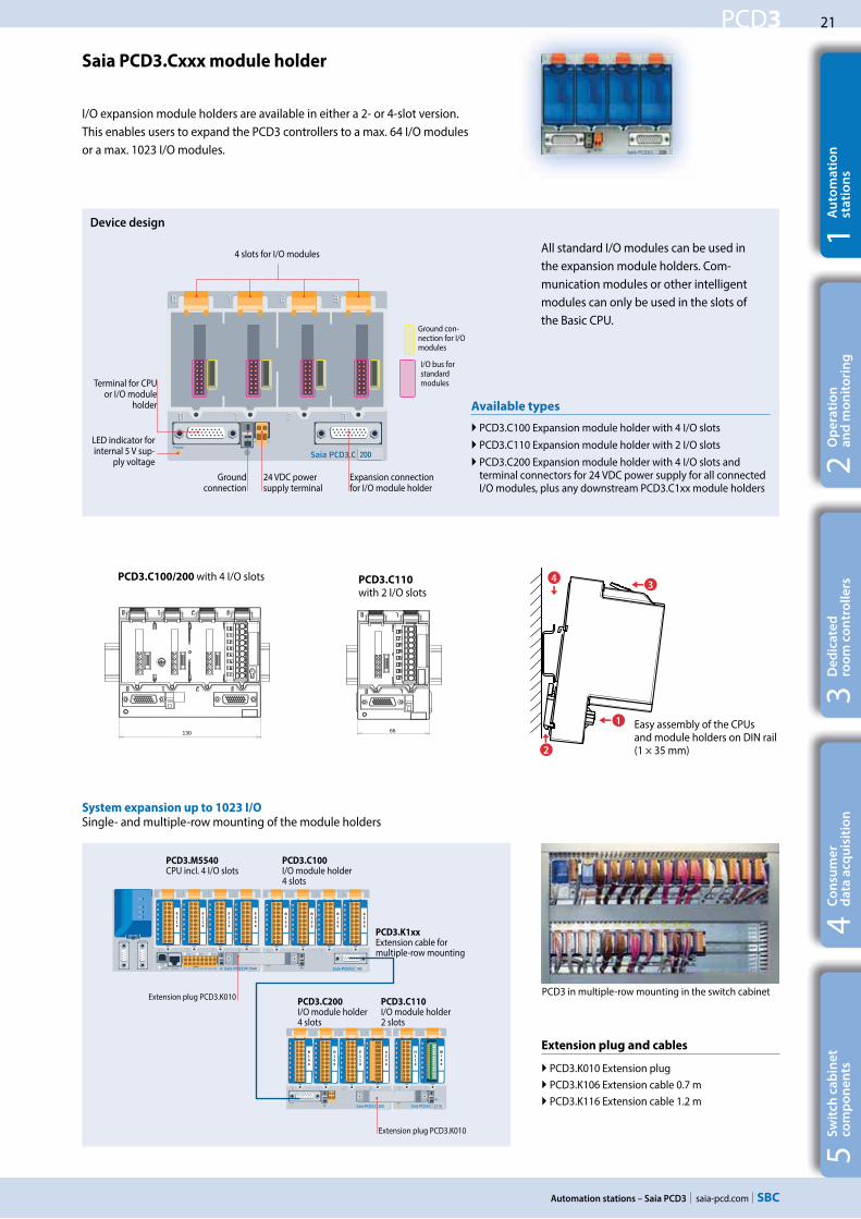
Saia PCD3.Cxxx module holder
All standard I/O modules can be used in the expansion module holders. Com-munication modules or other intelligent modules can only be used in the slots of the Basic CPU.
Extension plug and cables
PCD3.K010 Extension plug PCD3.K106 Extension cable 0.7 m PCD3.K116 Extension cable 1.2 m
PCD3.C110
with 2 I/O slotsPCD3.C100/200 with 4 I/O slots
Easy assembly of the CPUs and module holders on DIN rail (1 × 35 mm)
System expansion up to 1023 I/OSingle- and multiple-row mounting of the module holders
I/O expansion module holders are available in either a 2- or 4-slot version. This enables users to expand the PCD3 controllers to a max. 64 I/O modules or a max. 1023 I/O modules.
4 slots for I/O modules
Expansion connection for I/O module holder
24 VDC power supply terminal
Ground connection
LED indicator for internal 5 V sup-
ply voltage
Terminal for CPU or I/O module
holder
PCD3.K1xxExtension cable for multiple-row mounting
PCD3.C110 I/O module holder 2 slots
PCD3.M5540 CPU incl. 4 I/O slots
PCD3.C100 I/O module holder 4 slots
Extension plug PCD3.K010
PCD3.C200 I/O module holder 4 slots
Extension plug PCD3.K010
Available types
PCD3.C100 Expansion module holder with 4 I/O slots PCD3.C110 Expansion module holder with 2 I/O slots PCD3.C200 Expansion module holder with 4 I/O slots and terminal connectors for 24 VDC power supply for all connected I/O modules, plus any downstream PCD3.C1xx module holders
PCD3 in multiple-row mounting in the switch cabinet
Ground con-nection for I/O modules
I/O bus for standard modules
Device design

22
saia-pcd.com
PCD3
12,3 12,3
5560Saia PCD3.C
SNMP
Automation stations – Saia PCD3
Saia PCD3.Mxx60 controllers
High-performance CPU for any requirement
The Saia PCD3 Power CPU has sufficient system re-sources to operate up to 13 communication interfaces in the same device. Even the most demanding tasks, such as simultaneous communication via BACnet® and Lon IP, are handled reliably.
Types
PCD3.M5360 CPU basic module with Ethernet TCP/IP, 2 MB of program memory
PCD3.M5560 CPU basic module with Ethernet TCP/IP, 2 MB of program memory, Profibus-DP-Slave
PCD3.M6560 CPU basic module with Ethernet TCP/IP and Profibus-DP Master 12 Mbits, 2 MB of program memory
PCD3.M6860 CPU basic module with 2 Ethernet TCP/IP, 2 MB of program memory
The generous memory resources (4 GB) of the new PCD3 Power CPU enable users to record/monitor, archive and control the data and statuses of all plants in the Saia PCD®, even with no computer equipment and control system software. Applications for the various plants (HVAC) can be created easily using the graphic PG5 engineering tool and application-specific software libraries.
The fast processor and increased system resources provide the High Power CPU with sufficient power reserves to process the most demanding control and communication tasks.
System properties
Up to 1023 inputs/outputs Can be expanded remotely with RIO PCD3.T66x or PCD3.T76x
Up to 13 communication interfaces
Onboard USB and Ethernet interface
2 Ethernet interfaces (PCD3.M6860 only)
Fast program processing (0.1μs for bit operations)
Large onboard memory for programs (2 MB) and data (128 MB file system)
Memory with SD flash cards can be expanded up to 4 GB
Automation Server for integration in Web/IT systems
Automation Server integrated in the base
unit
Management level
Automation level
Field level
LON IP
CAN
EnOceanMP Bus
KNX-EIBDALI
M-Bus
Modbus
Profibus
BACnet®
Tele
com
Inte
rnet
Ethe
rnet
Management level
Automation level
Field levelHeating – ventilation – air conditioning – plumbing – electrical

23
saia-pcd.com
PCD3
Automation stations – Saia PCD3
5S
wit
ch c
ab
ine
t
com
po
ne
nts
4C
on
sum
er
d
ata
acq
uis
itio
n3
De
dic
ate
d
roo
m c
on
tro
lle
rs2
Op
era
tio
n
an
d m
on
ito
rin
g1
Au
tom
ati
on
st
ati
on
s
PCD3.M5360* PCD3.M5560 PCD3.M6560 PCD3.M6860
Technical Data Power Power DP Slave
PowerDP Master
Power2 × Ethernet
Number of inputs/outputs 1023
or I/O module slots 64
I/O expansion connection for PCD3.Cxxx module holder Yes
Processing time [μs] bit operation word operation
0.1…0.8 μs 0.3 μs
Real-time clock (RTC) Yes
Onboard memory
Program memory, DB/text (flash) 2 MB
User memory, DB/text (RAM) 1 MB
Flash memory (S-RIO, configuration and backup) 128 MB
User flash file system (INTFLASH) 128 MB
Data backup 1…3 years with lithium battery
Onboard interfaces
USB 1.1 Yes
Ethernet 10/100 Mbits, full-duplex, auto-sensing/auto-crossing Yes 2 ×
RS-232 on D-Sub connector (PGU/Port 0) up to 115 kbits No
RS-485 on terminal block (Port 2) or RS-485 Profibus-DP Slave, Profi S-Net on terminal block (Port 2)
up to 115 kbits up to 187.5 kbits
up to 115 kbits No
up to 115 kbits up to 187.5 kbits
RS-485 on D-Sub connector (Port 3)* or Profibus-DP Slave, Profi S-Net on D-Sub connector (Port 10)* or Profibus-DP Master on D-Sub connector (Port 10)*
Up to 115 kbits 1) No No
Up to 115 kbits 2) Up to 1.5 Mbits 2)
No
No No
up to 12 Mbits 2)
No No No
* can be used as an alternative 1) electrically connected 2) electrically isolated
Saia PCD3.Mxx60 controllers
High-performance CPU
Options
The data memory can be expanded to 4 GB with flash memory modules (with file system).
Optional data interfaces
I/O slot 0 PCD3.F1xx modules for RS-232, RS-422, RS-485 and Belimo MP-Bus
I/O slot 0…3 up to 4 modules or 8 interfaces: PCD3.F2xx modules for RS-232, RS-422, RS-485, BACnet® MS/TP, Belimo MP-Bus, DALI and M-Bus
General specifications
Supply voltage (in accordance with EN/IEC 61131-2)
24 VDC, –20/+25% max. incl. 5% ripple or 19 VAC ±15% two-way rectified (18 VDC)
Power consumption typically 15 W for 64 I/Os
Capacity 5 V/+V (24 V) internal max. 600 mA/100 mA
1023
up to 4.2 GB
2 MB
0.1/0.3 μs bit/word
I/O
File system
Program
CPU speed
*) In preparation, see section C1 Product status

24
saia-pcd.com
PCD3
SNMPSNMPSNMP
Automation stations – Saia PCD3
PCD3.M5340 PCD3.M5540
Technical Data Standard Standard
Number of inputs/outputs 1023or I/O module slots 64
I/O expansion connection for PCD3.Cxxx module holder Yes
Processing time [μs] bit operation word operation0.3…1.5 μs
0.9 μsReal-time clock (RTC) Yes
Onboard memory
Main memory (RAM) for program and DB/TEXT 1 MB
Flash memory (S-RIO, configuration and backup) 2 MB
User flash file system (INTFLASH) No
Data backup 1…3 years with lithium battery
Onboard interfaces
USB 1.1 Yes
Ethernet 10/100 Mbits, full-duplex, auto-sensing/auto-crossing Yes
RS-232 on D-Sub connector (PGU/Port 0) up to 115 kbits
RS-485 on terminal block (Port 2) or RS-485 Profibus-DP Slave, Profi S-Net on terminal block (Port 2)
up to 115 kbitsup to 187.5 kbits up to 115 kbits No
RS-422/485 (electrically connected) on D-Sub connector (Port 3) *RS-485 (electrically isolated) on D-Sub connector (Port 3) *Profibus-DP Slave, Profi S-Net on D-Sub connector (Port 10) *
up to 115 kbitsNoNo
Noup to 115 kbitsup to 1.5 Mbits
* can be used as an alternative
1023
up to 4 GB
1 MB
0.3/0.9 μs bit/word
I/O
File system
Program
CPU speed
Saia PCD3.M5x40 controllers
The standard CPU for many applications
Types
PCD3.M5340 CPU basic module with Ethernet TCP/IP, 1 MB program memory
PCD3.M5540 CPU basic module with Ethernet TCP/IP and Profibus-DP Slave 1.5 Mbits, 1 MB program memory
Options
The data memory can be expanded to 4 GB with flash memory modules (with file system).
Optional data interfaces
I/O slot 0 PCD3.F1xx modules for RS-232, RS-422, RS-485 and Belimo MP-Bus
I/O slot 0…3 up to 4 modules or 8 interfaces: PCD3.F2xx modules for RS-232, RS-422, RS-485, BACnet® MS/TP, Belimo MP-Bus, DALI and M-Bus
General specifications
Supply voltage (in accordance with EN/IEC 131-2) 24 VDC, –20/+25% max. incl. 5% ripple or 19 VAC ±15% two-way rectified (18 VDC)
Power consumption typically 15 W for 64 I/Os
Capacity 5 V/+V (24 V) internal max. 600 mA/100 mA
Automation Server integrated in the base
unit

25
saia-pcd.com
PCD3
SNMPSNMPSNMP
Automation stations – Saia PCD3
5S
wit
ch c
ab
ine
t
com
po
ne
nts
4C
on
sum
er
d
ata
acq
uis
itio
n3
De
dic
ate
d
roo
m c
on
tro
lle
rs2
Op
era
tio
n
an
d m
on
ito
rin
g1
Au
tom
ati
on
st
ati
on
s
1023
up to 4 GB
512 kByte
0.3/0.9 μs 0.1/0.3 μs bit/word
I/O
File system
Program
CPU speed
PCD3.M3120 PCD3.M3160* PCD3.M3330 PCD3.M3360*
Technical Data Basic Basic Power Basic Basic Power
Number of inputs/outputs 64 1023
or I/O module slots 4 64
I/O expansion connection for PCD3.Cxxx module holder No Yes
Processing times [μs] bit operation word operation
0.3…1.5 μs 0.9 μs
0.1…0.8 μs 0.3 μs
0.3…1.5 μs 0.9 μs
0.1…0.8 μs 0.3 μs
Real-time clock (RTC) Yes
Onboard memory
Main memory (RAM) for program and DB/text 128 kByte 512 kByte
Flash memory (S-RIO, configuration and backup) 2 MByte
User flash file system (INTFLASH) No 8 MByte No 8 MByte
Data backup 4 hours with SuperCap
Onboard interfaces
USB 1.1 Yes
Ethernet 10/100 Mbits, full-duplex, auto-sensing/auto-crossing Yes
RS-485 on terminal block (Port 2) or RS-485 Profibus-DP Slave, Profi-S-Net on terminal block (Port 2)
up to 115 kbitsup to 187.5 kbits
Saia PCD3.M3xx0 controllers
The base CPU for simple applications
Options
The data memory can be expanded to 4 GB with flash memory modules (with file system).
Optional data interfaces
I/O slot 0 PCD3.F1xx modules for RS-232, RS-422, RS-485 and Belimo MP-Bus
I/O slot 0…3 up to 4 modules or 8 interfaces: PCD3.F2xx modules for RS-232, RS-422, RS-485, BACnet® MS/TP, Belimo MP-Bus, DALI and M-Bus
General specifications
Supply voltage (in accordance with EN/IEC 61131-2) 24 VDC, –20/+25% max. incl. 5% ripple or 19 VAC ±15% two-way rectified (18 VDC)
Power consumption typically 15 W for 64 I/Os
Capacity 5 V/+V (24 V) internal max. 600 mA/100 mA
Types
PCD3.M3120 CPU basic module with Ethernet TCP/IP, 64 I/Os, 128 kByte of program memory
PCD3.M3160 CPU basic module with Ethernet TCP/IP, 64 I/Os, 512 kByte of program memory
PCD3.M3330 CPU basic module with Ethernet TCP/IP, 1023 I/Os, 512 kByte of program memory
PCD3.M3360 CPU basic module with Ethernet TCP/IP, 1023 I/Os, 512 kByte of program memory
Automation Server integrated in the base
unit
*) In preparation, see section C1 Product status

26
saia-pcd.com
PCD3
A810
A866
B160
E111
E165
W325
W800
E160
E161
A460
Automation stations – Saia PCD3
Saia PCD3 input and output modules in cassette design
The functions of the Saia PCD3 can be expanded as required using a wide range of plug-in I/O modules and can be adapted to specific requirements. This not only ensures that a project can be implemented quickly, but also provides the option of expanding or modifying the system at any time.
System properties
Numerous variants available
Slot direct in the Saia PCD3 basic CPU or in the module holder
Full integration in the Saia PCD3 housing
Stable cartridge construction
Connection to the I/O level via plug-in spring terminal blocks or ribbon cables and adapters
I/O terminal blocks are supplied as standard
No tools required for replacing modules
Insertion of I/O modules
Type A10-pin
2.5 mm2
Connecting plugs/terminals
Type D
Connecting plug for ribbon cable (not supplied with the module)
Type K
10-pin 1.0 mm2
Type J
8-pin 1.5 mm2
Type G + H
4- + 6-pin 2.5 + 1.5 mm2
Type F
12-pin 1.5 mm2
Type E
14-pin 1.5 mm2
Type C
24-pin 1.0 mm2
Clips
Additional safeguard
with screw
Guideway
PCD3 with 4 module
positions
Label holder
Plug-in terminals
Nameplate with connection description
LED for status indication
Simple exchange of I/O modules
� Spare terminals, ribbon connectors with system cables and separate terminals are ordered as accessories.
Types
PCD3.Axxx Digital output modules PCD3.Bxxx Combined digital input/output modules PCD3.Exxx Digital input modules PCD3.Fxxx Communication modules PCD3.Hxxx Fast counter modules PCD3.Rxxx Memory modules PCD3.Wxxx Analogue input/output modules
Over 50 modules available with different functionalities
Module type
Label holder

27
saia-pcd.com
PCD3
Automation stations – Saia PCD3
5S
wit
ch c
ab
ine
t
com
po
ne
nts
4C
on
sum
er
d
ata
acq
uis
itio
n3
De
dic
ate
d
roo
m c
on
tro
lle
rs2
Op
era
tio
n
an
d m
on
ito
rin
g1
Au
tom
ati
on
st
ati
on
s
Saia PCD3 digital input and output modules
The digital I/O modules can be easily plugged into the Saia PCD3 Basis CPU or an appropriate module holder. In addition to inputs for various voltage levels, digital outputs are provided with both transistor construction and as mechanical relays. This means that electrical isolation from the switching electrical circuit can be achieved easily and reliably.
Digital input modules
Type Number of inputs Input voltage Output switching capacityDC AC
Input delay Electrical isolation
Internal current draw
5 V-Bus 1) + V-Bus 2)
I/O connectortype 3)
PCD3.E110PCD3.E111
8 8
15…30 VDC15…30 VDC --- --- 8 ms
0.2 ms --- 24 mA24 mA --- A
A
PCD3.E160PCD3.E161
1616
15…30 VDC15…30 VDC --- --- 8 ms
0.2 ms --- 10 mA10 mA --- D
D
PCD3.E165PCD3.E166
1616
15…30 VDC15…30 VDC --- --- 8 ms
0.2 ms --- 10 mA10 mA --- C
C
PCD3.E500 6 80…250 VAC --- --- 20 ms 1 mA --- A
PCD3.E610PCD3.E613
8 8
15…30 VDC30…60 VDC --- --- 10 ms
9 ms24 mA24 mA --- A
A
Digital output modules
Type Number of outputs Input voltage Output switching capacityDC AC
Input delay Electrical isolation
Internal current draw
5 V-Bus 1) + V-Bus 2)
I/O connectortype 3)
PCD3.A200 PCD3.A210
4, relay (make)* 4 A, relay (break)* --- 2 A/50 VDC
2 A/50 VDC2 A/250 VAC 2 A/250 VAC --- 15 mA
15 mA --- A A
PCD3.A220 6, relay (make) --- 2 A/50 VDC 2 A/250 VAC --- 20 mA --- A
PCD3.A251 8, relay (6 changeover + 2 make) --- 2 A/50 VDC 2 A/48 VAC --- 25 mA --- C
PCD3.A300 6, transistor --- 2 A/10…32 VDC --- --- --- 20 mA --- A
PCD3.A400 8, transistor --- 0.5 A/5…32 VDC --- --- --- 25 mA --- A
PCD3.A410 8, transistor --- 0.5 A/5…32 VDC --- --- 24 mA --- A
PCD3.A460PCD3.A465
16, transistor16, transistor --- 0.5 A/10…32 VDC
0.5 A/10…32 VDC --- --- --- 10 mA10 mA --- D
C
PCD3.A810Manual operation
4, relay (2 changeover + 2 make) --- 2 A/50 VDC
2 A/50 VDC5 A/250 VAC6 A/250 VAC --- 40 mA --- F
* with contact protection Digital input/output modules
Type Number of I/Os Input voltage Output switching capacityDC AC
Input delay Electrical isolation
Internal current draw
5 V-Bus 1) + V-Bus 2)
I/O connectortype 3)
PCD3.A860 Light and shade 2 Out, relay (make) 2 In 15…30 VDC --- 12 A/250 VAC 8 ms 18 mA --- G
H
PCD3.B100 2 In + 2 Out + 4 selectable In or Out I: 15…32 VDC 0.5 A/5…32 VDC --- 8 ms --- 25 mA --- A
PCD3.B160 16 I/O (configurable) I: 24 VDC 0.25 A/18…30 VDC --- 8 ms or 0.2 ms --- 120 mA --- 2× K
3) Plug-in terminal blocks are included with I/O modules. Spare terminals, ribbon connectors with system cables and separate terminals are ordered as accessories (see pages 34 and 172).
Fast counter modules
Type Number
of counters
Inputs per counter Outputs per
counter
Counting range Selectable digital
filter
Current draw 5 V-
Bus 1) + V-Bus 2)
I/O connector
type 3)
PCD3.H112 2 2 I n+ 1 configurable In 1 CCO 0…16 777 215 (24 Bit) 10 kHz … 150 kHz 50 mA 4 mA K
PCD3.H114 4 2 In + 1 configurable In 1 CCO 0…16 777 215 (24 Bit) 10 kHz … 150 kHz 50 mA 4 mA 2× K
Overview of the internal bus capacity of the module holders
Capacity PCD3.Mxxx0 PCD3.Txxx PCD3.C200
1) Internal 5V 600 mA 600 mA 1500 mA2) Internal +V (24 V) 100 mA 100 mA 200 mA
The electrical requirement of the internal +5V and +V bus for the I/O modules is calculated in the PG5 2.0 Device Configurator.

28
saia-pcd.com
PCD3
Automation stations – Saia PCD3
Saia PCD3 analogue input and output modules
The numerous analogue modules allow complex control tasks or measurements to be performed. The resolution is between 8 and 16 bits, depending on the speed of the AD converter. The digitised values can be further processed direct in the project in the Saia PCD3. The large number of different modules means that suitable modules are available for almost any requirement.
Manual control modules
Analogue input modules
Type Total
Channels
Signal ranges/description Resolution Electrical
isolation
Internal current draw
5 V-Bus 1) + V-Bus 2)
I/O connec-
tor type 3)
PCD3.W200PCD3.W210PCD3.W220PCD3.W220Z03PCD3.W220Z12
8 In 8 In 8 In 8 In 4 In+4 In
0…+10 V0…20 mA 4) Pt1000: –50 °C…400 °C/Ni1000: –50 °C…+200 °CNTC 10 temperature sensor4 In: 0…10 V 4 In: Pt1000: –50 °C…400 °C/Ni1000: –50 °C…+200 °C
10 Bit10 Bit10 Bit10 Bit10 Bit
---
8 mA8 mA8 mA8 mA8 mA
5 mA5 mA
16 mA16 mA11 mA
AAAAA
PCD3.W300PCD3.W310PCD3.W340
PCD3.W350PCD3.W360PCD3.W380
8 In8 In8 In
8 In8 In8 In
0…+10 V0…20 mA 4) 0…+10 V/0…20 mA 4) Pt1000: –50 °C…400 °C/Ni1000: –50 °C…+200 °CPt100: –50 °C…+600 °C/Ni100: –50 °C…+250 °CPt1000: –50 °C…+150 °C–10 V…+10 V, –20 mA…+20 mA, Pt/Ni1000, Ni1000 L&S, NTC10k/NTC20k (configuration using software)
12 Bit12 Bit12 Bit
12 Bit12 Bit13 Bit
---
8 mA8 mA8 mA
8 mA8 mA
25 mA
5 mA5 mA
20 mA
30 mA20 mA25 mA
AAA
AA
2× K
PCD3.W305PCD3.W315PCD3.W325
7 In7 In7 In
0…+10 V0…20 mA 4) –10 V…+10 V
12 Bit12 Bit12 Bit
60 mA60 mA60 mA
0 mA0 mA0 mA
III
PCD3.W720 2 In Weighing module with 2 systems for up to 6 weighing cells ≤18 Bit --- 60 mA 100 mA I
PCD3.W745 4 In Temperature module for TC type J, K and 4-wire Pt/Ni
100/1000 16 Bit 200 mA 0 mA6)
Analogue output modules
Type Number of
channels
Signal ranges/description Resolution Electrical
isolation
Internal current draw
5 V-Bus 1) + V-Bus 2)
I/O connec-
tor type 3)
PCD3.W400PCD3.W410
4 Out4 Out
0…+10 V0…+10 V/0…20 mA/4…20 mA jumper-selectable
8 Bit8 Bit --- 1 mA
1 mA30 mA30 mA
AA
PCD3.W600PCD3.W610
4 Out4 Out
0…+10 V0…+10 V/–10 V…+10 V/0…20 mA/4…20 mA jumper-selectable
12 Bit12 Bit ---
4 mA110 mA
20 mA0 mA
AA
PCD3.W605PCD3.W615PCD3.W625
6 Out4 Out6 Out
0…+10 V0…20 mA/4…20 mA parameters can be set–10 V…+10 V
10 Bit10 Bit10 Bit
110 mA55 mA
110 mA
0 mA0 mA0 mA
III
PCD3.W800 4 Out, 3 of which are manually
operated
0…+10 V, short circuit-proofed 10 Bit --- 45 mA 35 mA 5) J
Analogue input/output modules
Type Number of
channels
Signal ranges/description Resolution Electrical
isolation
Internal current draw
5 V-Bus 1) + V-Bus 2)
I/O connec-
tor type 3)
PCD3.W525 4 In +
2 Out
In: 0…10 V, 0(4)…20 mA, Pt1000, Pt500 or Ni1000 (selectable via DIP switch)
Out: 0…10 V or 0(4)…20 mA (selectable via software)
In: 14 Bit
Out: 12 Bit
40 mA 0 mA I
PCD3.A810
Relay outputs, 2 change-over and 2 make
PCD3.A860
Light and shade 2 relay outputs and 2 inputs
PCD3.W800
4 analogue outputs (3 of these operable)
3) Plug-in I/O terminal blocks are included with I/O modules. Spare terminals, ribbon connectors with system cables and separate terminals are ordered as accessories (see pages 34 and 172).
4) 4 … 20 mA via user program5) At 100% output value and 3 kΩ load6) With soldered spring terminal block
Overview of the internal bus capacity of the module holders
Capacity PCD3.Mxxx0 PCD3.Txxx PCD3.C200
1) Internal 5V 600 mA 600 mA 1500 mA2) Internal +V (24 V) 100 mA 100 mA 200 mA
The electrical requirement of the internal +5V and +V bus for the I/O modules is calculated in the PG5 Device Configurator.

29
saia-pcd.com
PCD3
5540
F261
F210
F261
F281
W340
100
W340
W340
W610
E160
100
W340
W340
W610
E160
E160
E160
E160
Saia PCD3.M Saia PCD3.C Saia PCD3.C
100
A460
A460
A460
200
A860
A810
A810
A200
W380
Saia PCD3.C Saia PCD3.C
Automation stations – Saia PCD3
5S
wit
ch c
ab
ine
t
com
po
ne
nts
4C
on
sum
er
d
ata
acq
uis
itio
n3
De
dic
ate
d
roo
m c
on
tro
lle
rs2
Op
era
tio
n
an
d m
on
ito
rin
g1
Au
tom
ati
on
st
ati
on
s
Information for project planning with PCD3 module holders
The internal load current taken by the I/O modules from the +5V and +V (24V) supply must not exceed the maximum supply current specified for the CPUs, RIOs or PCD3.C200 module holders.
Example calculation for the current consumption of the internal +5V and +V (24V) bus of the I/O modules
The calculation example shows that internal capacity is maintained in the CPU basic mod-ule PCD3.M5540 and the holder module PCD3.C200. The CPU basic module has a sufficient reserve to receive an additional communication module in the empty slot 0. The holder module PCD3.C200 also has sufficient reserves to connect an additional PCD3.C100 or PCD3.C110 holder module. The power consumption of the internal +5V and +V (24 V) bus for the I/O modules is automatically calculated in the PG5 2.0 Device Configurator.
The following aspects should be considered when planning PCD3 applications:
PCD3.M5540 CPU incl. 4 I/O slots
PCD3.C100 I/O module holder 4 slots
Extension plugPCD3.K010
PCD3.C100 I/O module holder 4 slots
PCD3.C100 I/O module holder 4 slots
PCD3.C200 I/O module holder 4 slots
Exte
nsio
n ca
ble
PCD
3.K1
06
Extension plug PCD3.K010
Consumption C200 + C100
Module Internal 5V Internal +V (24V)
A200 15 mAA810 40 mAA810 40 mAA860 18 mATotal C200 113 mA
A460 10 mAA460 10 mAA460 10 mAW380 25 mA 25 mATotal C100 55 mA 25 mA
Total C200 168 mA 25 mA
Capacity PCD3.M5540 PCD3.C200
Internal 5V 600 mA 1500 mAInternal +V (24V) 100 mA 200 mA
Consumption M5540 + C100 + C100
Module Internal 5V Internal +V (24V)
Not used F210 110 mA F281 90 mA 15 mAW340 8 mA 20 mATotal M5540 208 mA 35 mA
W340 8 mA 20 mAW340 8 mA 20 mAW610 110 mA 0 mAE160 10 mA Total C100 136 mA 40 mA
E160 10 mA E160 10 mA E160 10 mA E160 10 mA Total C100 40 mA 0
Total M5540 384 mA 75 mA
In keeping with lean automation, it is recommended to leave the first slot in the CPU basic module free for any subsequent expansions. Both single I/O modules and communication modules can be used in this slot.
The total length of the I/O bus is limited by technical factors; the shorter, the better.
The PCD3.C200 is used to extend the I/O bus or for the internal
power supply (+5V and +V (24V)) to a module segment.
Please note the following rules:
Do not use more than six PCD3.C200s in a single configuration, or the time delay will exceed the I/O access time.
Use a maximum of five PCD3.K106/116 cables.
Insert a PCD3.C200 after each cable (at the start of a row). Exception: In a small configuration with no more than 3 PCD3.C1xxs, these can be supplied from the PCD3.Mxxx. A PCD3.C200 is not required.
If an application is mounted in a single row (max. 15 module holders), then after five PCD3.C100 a PCD3.C200 must be used to amplify the bus signal (unless the configuration ends with the fifth PCD3.C100).
If the application is mounted in multiple rows, the restricted length of cable means that only three module holders (1× PCD3.C200 and 2× PCD3.C100) may be mounted in one row.

30
saia-pcd.com
PCD3
Automation stations – Saia PCD3
+18 V
0V
GND
+24 V =
0V
L N
L
N
±15%
±20%24 VDC
19 VAC
Grounding and connection plan
Grounding and connection concept analogue inputs that are not electrically isolated (PCD3.W2x0, PCD3.W3x0)
Saia PCD3 power supply and connection concept
It is generally recommended to use robust and interference-resistant SBC power supply units with 24 VDC output. See Chapter 5.1 for available types.
Connection concept for PCD3.W2x0
The reference potential of signal sources must be wired to a common GND distributor at the “–” terminal
External power supply
A two-way rectified supply can be used for most modules.The following modules must be connected to smoothed 24 VDC: PCD3. H1xx, H2xx, H3xx, PCD7.D2xx
Connection concept for PCD3.W3x0 The reference potential of voltage and current inputs must be wired to a common GND distributor at the “–” terminal. Tempera-ture sensors must be wired to a common GND distributor at the “COM” terminal. The module PCD3.W380 has a 2-wire connection for the inputs and requires no external GND distributor.
Signal sources (such as temperature sensors) should be connected direct to the input module wherever possible.
To obtain optimum measurement results, avoid connection to a ground bar. Additional external GND connections to the sensor signals may result in equalising currents which distort the measurement.
If shielded cables are used, the shielding should be continued to a ground bar.
The zero potential (GND) of the 24 V supply is connected to the GND and the controller’s grounding terminal. If possible, this should be connected to the ground bar with a short wire (<25 cm) with a cross section of 1.5 mm2. The same applies to the negative connection to the PCD3.F1xx or the interrupt terminal.
Any shielding of analogue signals or communication cables should also be brought to the same grounding potential, either via a negative terminal or via the ground bar.
All negative connections are linked internally. For flawless operation, these connections should be reinforced externally by short wires with a cross section of 1.5 mm2.
Transformer min. 50 VA
CONTROLLERS
2.5 mm22.5 mm2
W...
A...
E...
0 V +24 VDC
Erdungsschiene
max
. 25
cmm
in. 2
.5 m
m2
0...10 V Pt/Ni 1000
Erdungsschiene
Masseanschluss PCD
Verteiler„V“ und „C“
Verteiler„Temp.“
Sign
alqu
elle
Sign
alqu
elle
Mes
s-w
ider
stan
dM
ess-
wid
erst
and
9 8 7 6 5 4 3 2 1 0
- E7 E6 E5 E4 E3 E2 E1 E0
-
PGND COM
0...10 V Pt/Ni 1000
max
. 25
cmm
in. 2
.5 m
m2
Erdungsschiene
AbgeschirmteKabel
Sign
alqu
elle
Sign
alqu
elle
Masseanschluss PCD
Mes
s-w
ider
stan
dM
ess-
wid
erst
and
Verteiler
-
PGND
9 8 7 6 5 4 3 2 1 0
- E7 E6 E5 E4 E3 E2 E1 E0

31
saia-pcd.com
PCD3
5540
F121
Saia PCD3.M
F121
F210
Read Int Indref:Modbus
Enable Error
NumberAdd R 500
FuncRemAdd
Automation stations – Saia PCD3
5S
wit
ch c
ab
ine
t
com
po
ne
nts
4C
on
sum
er
d
ata
acq
uis
itio
n3
De
dic
ate
d
roo
m c
on
tro
lle
rs2
Op
era
tio
n
an
d m
on
ito
rin
g1
Au
tom
ati
on
st
ati
on
s
Communication interfaces of Saia PCD3.Mxxxx controllers
In addition to the interfaces that the Saia PCD3 has onboard, the interface functions can also be expanded using various slots. Numerous protocols are therefore supported by the PCD3. For the majority of protocols, the physical bus specifications are offered as a plug-in module. If this is not the case, the bus can be connected via an external converter.
Modem communication with the PCD
S-Bus Modbus JCI N2-Bus KNX® S-Mode/EIB (with external converter)
Physical interfaces for specific protocols
Module Specifications Slot Electrical
isolationInternal current draw
5V +V (24 V)I/O connec-tor type 1)
PCD3.F180 Belimo MP-Bus, for connecting up to 8 drives on one line I/O 0 --- 15 mA 15 mA A
PCD3.F215 BACnet® MS/TP or freely programmable I/O 0…3 --- 110 mA --- 2× K
PCD3.F240 LONWORKS® interface module exclusively for PCD3.M5x6x I/O 0…3 --- 90 mA --- A9
PCD3.F261 DALI I/O 0…3 --- 90 mA --- A
PCD3.F270 M-Bus 240 nodes I/O 0…3 --- 70 mA 8 mA A
PCD3.F271 M-Bus 20 nodes I/O 0…3 --- 70 mA 8 mA A
PCD3.F272 M-Bus 60 nodes I/O 0…3 --- 70 mA 8 mA A
PCD3.F273 M-Bus 120 nodes I/O 0…3 --- 70 mA 8 mA A
PCD3.F281 Belimo MP-Bus with slot for PCD7.F1xxS modules I/O 0…3 --- 90 mA 15 mA 2× K1) Plug-in I/O terminal blocks are included with I/O modules. Spare terminals, ribbon connectors with system cables and separate terminals are ordered as accessories
(see pages 34 and 172).
Fully programmable physical interfaces
Module Specifications Slot Electrical
isolationInternal current draw
5V +V (24 V)I/O connec-tor type 1)
PCD3.F110 RS-422 with RTS/CTS or RS-485, with line termination resistors that can be activated I/O 0 --- 40 mA --- A
PCD3.F121 RS-232 with RTS/CTS, DTR/DSR, DCD I/O 0 --- 15 mA --- A
PCD3.F150 RS-485 with termination resistors that can be activated I/O 0 130 mA --- A
PCD3.F210 RS-422/RS-485 plus PCD7.F1xxS as option I/O 0…3 --- 110 mA --- 2× K
PCD3.F221 RS-232 plus PCD7.F1xxS as option I/O 0…3 --- 90 mA --- 2× K
System properties required for PCD3.Fxxx modules:
The PCD3 system has a processor that serves both the application and the serial ports. To determine the maximum communication capacity for each PCD3.M5xx0 system, consult the infor-mation and examples provided in the manual 26-789 for PCD3.M5xx0.
Interface modules for optional insertion in PCD3.F2xx modules
Module Specifications
PCD7.F110S RS-422 with RTS/CTS or RS-485 (electrically connected), with terminating resistors that can be activated.
PCD7.F121S RS-232 with RTS/CTS, DTR/DSR, DCD suitable for modem, EIB connectionPCD7.F150S RS-485 (electrically isolated),
with line termination resistors that can be activatedPCD7.F180S Belimo® MP-Bus for connecting up to 8 drives on one line
DALI EnOcean (with external converter) M-Bus BACnet® MS/TP HMI editor applications with PCD7.Dxxx text terminals (RS-232 only)
Protocols supported by PCD3.Mxxxx via FBoxes PCD3.F1xx for slot 0
Port 1 RS-232 or RS-422 or RS-485 or MP-Bus
PCD3.F2xx for slot no. 0…3
PCD3.F221 RS-232 PCD3.F210 RS-422/RS-485 PCD3.F281 MP-Bus PCD3.F215 BACnet®-MS/TPPCD3.F261 DALI PCD3.F27x M-Bus

32
saia-pcd.com
PCD3
3330Saia PCD3.M
Activity
Busy
Write
Diag
User
5540Saia PCD3.M
Activity
Busy
Write
Diag
User
PCD7.R55xM04 PCD7.R56xPCD7.R58x
PCD7.R610
Automation stations – Saia PCD3
Memory modules of Saia PCD3.Mxxxx controllers
In addition to the onboard memory contained in the base units, PCD3 controllers can also be expanded in a modular way with various flash memory modules for programs and data. The various communication protocols where the firmware is installed on the flash cards can also be used by simply inserting the relevant card. More information on memory management and construction can be found in Chapter 1.1 Saia PCD® System description.
System properties
Configuration, programs and data can be transferred from one CPU to another Two slots (M1 and M2) for memory cards Additional memory cards can be inserted in the I/O slots using I/O adapters Memory can be expanded by up to 4 GB
Flash memory with file system, program and data backup, BACnet® for M1/M2 slot
Type Description Slot
PCD7.R550M04 4 MB flash card with file system M1 & M2
PCD7.R560 Flash card with BACnet® M1 & M2
PCD7.R562 Flash card with BACnet® and 128 MB file system M1 & M2
PCD7.R580 Flash card with Lon IP M1 & M2
PCD7.R582 Flash card with Lon IP and 128 MB file system M1 & M2PCD7.R610 Basic module for Micro SD flash cards M1 & M2PCD7.R-MSD1024 Micro SD flash card 1024 MB, PCD formatted PCD7.R610
Plug-in flash modules for I/O module slots for all PCD3.Mxxx0s
Type Description Slot
PCD3.R550M04 4 MB flash card with file system I/O 0…3
PCD3.R560 Flash card with BACnet® I/O 0…3
PCD3.R562 Flash card with BACnet® and 128 MB file system I/O 0…3
PCD3.R580 Flash card with Lon IP I/O 0…3
PCD3.R582 Flash card with Lon IP and 128 MB file system I/O 0…3
Saia PCD3 basic module for SD flash cards with file system
Type Description Slot
PCD3.R600 Basic module with slot for SD flash cards(Up to 4 modules in I/O slots 0 to 3 on a CPU)
I/O 0…3
PCD7.R-SD512 SD flash card, 512 MB with file system ---
PCD7.R-SD1024 SD flash card, 1024 MB with file system ---
Spare parts (battery and battery holder module) see consumables and accessories PCD3.R600
PCD3.R55xM04PCD3.R56xPCD3.R58x
PCD3.M3xxx
PCD3.R55xM04PCD3.R56x PCD3.R58x PCD3.R600
PCD3.M5xxx / PCD3.M6xxx
PCD3.R55xM04PCD3.R56x PCD3.R58x PCD3.R600
PCD7.R55xM04 PCD7.R56xPCD7.R58xPCD7.R610
Slot
Battery holder module
M2M1

33
saia-pcd.com
PCD3
(4 329 4819 1) (4 310 8686 0)
(4 310 8723 0)
Downloadbereich:www.sbc-support.comDownload area:www.sbc-support.comEspace de téléchargement:www.sbc-support.com
l db hhh::::::::::::::DDD lll dddbbb iiDDD lll dddp gg ccccccccccchhh:h:h:h:h:h:h:h:h:h:h:ccccccccc ::h:h:h:h:h:h:h:h:h:DDDoDoDoDoDoDoDoDoDoDoDownwnwnwnwnwnwnwnwnwnwnlllololololololololololo ddadadadadadadadadadadadbbbebebebebebebebebebebererererererererererereiiicicicicicicicicicicicDDDoDoDoDoDoDoDoDoDoDoDownwnwnwnwnwnwnwnwnwnwnlllololololololololololo ddadadadadadadadadadadadbebebebebebebebebebebererererererererererereiciciciciciciicicicicDDDDDoDoDoDoDoDoDoDoDo nnwnwnwnwnwnwnwnwnwnllololololololololololo ddadadadadadadadadadadadbbbbbebebebebebebebebererererererererereicicicicicicicicicDDDoDoDoDoDoDoDoDoDownwnwnwnwnwnwnwnwn oolololololololololoadadadadadadadadadadadbebebebebebebebebererererererererereicicicicicicic ::::::::::::::::::::::::::::::ppppppppppppppppppppppppppppppppwwwwwwwwwwwwwwwwwwwwwwwwwwww.w.w.w.w.w.sbsbsbsbsbsbsbsbsbccc-c-c-cccccc sususususususususususuppppppppppppppppppppppppororororororororororortttttt.t.t.t.t.t.cocoooooocoococoooocococcocococooooommmmmmmmmmmmmmmmmmmmmmmmmmmmmmmmmmmmmmmmmmmmmmmmmmmmmmmmmmmmmwwwwwwwwwwwwwwwwwwwwwwwwwwww.w.w.w.w.w.sbsbsbsbsbsbsbsbsbccc-c-c-cccccc sususususususususususuppppppppppppppppppppppppororororororororororortttttt.t.t.t.t.t.cocooooocoococoooocococcocococooooommmmmmmmmmmmmmmmmmmmmmmmmmmmmmmmmmmmmmmmmmmmmmmmmmmmmmmmmmmmwwwwwwwwwwwwwwwwwwwwwwwwwwww.w.w.w.w.w.sbsbsbsbsbsbsbsbsbccc-c-c-cccccc sususususususususususuppppppppppppppppppppppppororororororororororortttttt.t.t.t.t.t.cocooooocoococoooocococcocococooooommmmmmmmmmmmmmmmmmmmmmmmmmmmmmmmmmmmmmmmmmmmmmmmmmmmmmmmmmmmwwwwwwwwwwwwwwwwwwwwwwwwwwww.w.w.w.w.w.sbsbsbsbsbsbsbsbsbccc-c-c-cccccc sususususususususususuppppppppppppppppppppppppororororororororororortttttt.t.t.t.t.t.cocooooocoococoooocococcocococooooommmmmmmmmmmmmmmmmmmmmmmmmmmmmmmmmmmmmmmmmmmmmmmmmmmmmmmmmmmmppppppbbbbbb
DDDDDDEEEEEEEEEEEEEDDDDDDDDDDDDDDDDDDDDDDDDDDDDDDDDDDDDDDDDDDDDDDDDDDDDwwwwwwwwwwwwwwwwwwwwwwwwwwwwwwwwwwwwwwwwwwwwwwwwwwwww
Automation stations – Saia PCD3
5S
wit
ch c
ab
ine
t
com
po
ne
nts
4C
on
sum
er
d
ata
acq
uis
itio
n3
De
dic
ate
d
roo
m c
on
tro
lle
rs2
Op
era
tio
n
an
d m
on
ito
rin
g1
Au
tom
ati
on
st
ati
on
s
Addressing and labelling of I/O modules and
module holders
I/O module slots in the module holder are labelled with numbers:
� 0…3 (PCD3.Mxxxx /T66x/C100, C200) � 0…1 (PCD3.C110)
The provided inscription labels can either be used for additional labelling of the module holders or for the I/O modules themselves. They are blank and, depending on requirements, may either be labelled by hand or by using pre-printed adhesive strips .The circuit diagram printed on the side of each I/O module makes wiring easier and also helps during commissioning. Sufficient space is available on the other side of the cassette for the user to add custom-ised labelling with the self-adhesive labels supplied.
Additional labelling on the front
The PCD3 modules can also be labelled on the front panel. Neutral labels with a snap-on cover (clip) are available for this purpose.
Consumables and accessories for Saia PCD3 controllers
Fast labelling of I/O modules with the LabelEditor
The LabelEditor is included in the PG5 Controls Suite Device Configurator.This software tool is used to label PCD3 label clips efficiently.
Labelling accessories
Order type
Without clip With clip
The EPLAN® electric P8 macros are available on the support site. The macros and article data are also provided on the EPLAN® data portal.
EPLAN macros
EPLAN macros are available for project planning and engineering
Download:www.sbc-support.com
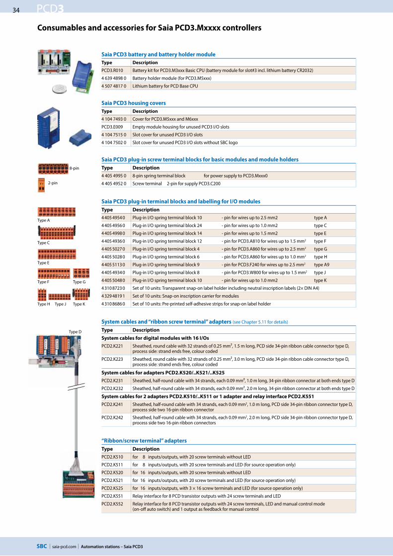
34
saia-pcd.com
PCD3
Automation stations – Saia PCD3
Saia PCD3 battery and battery holder module
Type Description
PCD3.R010 Battery kit for PCD3.M3xxx Basic CPU (battery module for slot#3 incl. lithium battery CR2032)
4 639 4898 0 Battery holder module (for PCD3.M5xxx)
4 507 4817 0 Lithium battery for PCD Base CPU
Saia PCD3 housing covers
Type Description
4 104 7493 0 Cover for PCD3.M5xxx and M6xxx
PCD3.E009 Empty module housing for unused PCD3 I/O slots
4 104 7515 0 Slot cover for unused PCD3 I/O slots
4 104 7502 0 Slot cover for unused PCD3 I/O slots without SBC logo
Saia PCD3 plug-in screw terminal blocks for basic modules and module holders
Type Description
4 405 4995 0 8-pin spring terminal block for power supply to PCD3.Mxxx0
4 405 4952 0 Screw terminal 2-pin for supply PCD3.C200
Saia PCD3 plug-in terminal blocks and labelling for I/O modules
Type Description
4 405 4954 0 Plug-in I/O spring terminal block 10 - pin for wires up to 2.5 mm2 type A
4 405 4956 0 Plug-in I/O spring terminal block 24 - pin for wires up to 1.0 mm2 type C
4 405 4998 0 Plug-in I/O spring terminal block 14 - pin for wires up to 1.5 mm2 type E
4 405 4936 0 Plug-in I/O spring terminal block 12 - pin for PCD3.A810 for wires up to 1.5 mm2 type F
4 405 5027 0 Plug-in I/O spring terminal block 4 - pin for PCD3.A860 for wires up to 2.5 mm2 type G
4 405 5028 0 Plug-in I/O spring terminal block 6 - pin for PCD3.A860 for wires up to 1.0 mm2 type H
4 405 5113 0 Plug-in I/O spring terminal block 9 - pin for PCD3.F240 for wires up to 2.5 mm2 type A9
4 405 4934 0 Plug-in I/O spring terminal block 8 - pin for PCD3.W800 for wires up to 1.5 mm2 type J
4 405 5048 0 Plug-in I/O spring terminal block 10 - pin for wires up to 1.0 mm2 type K
4 310 8723 0 Set of 10 units: Transparent snap-on label holder including neutral inscription labels (2× DIN A4)
4 329 4819 1 Set of 10 units: Snap-on inscription carrier for modules
4 310 8686 0 Set of 10 units: Pre-printed self-adhesive strips for snap-on label holder
System cables and “ribbon screw terminal” adapters (see Chapter 5.11 for details)
Type Description
System cables for digital modules with 16 I/Os
PCD2.K221 Sheathed, round cable with 32 strands of 0.25 mm², 1.5 m long, PCD side 34-pin ribbon cable connector type D, process side: strand ends free, colour coded
PCD2.K223 Sheathed, round cable with 32 strands of 0.25 mm², 3.0 m long, PCD side 34-pin ribbon cable connector type D, process side: strand ends free, colour coded
System cables for adapters PCD2.K520/..K521/..K525
PCD2.K231 Sheathed, half-round cable with 34 strands, each 0.09 mm², 1.0 m long, 34-pin ribbon connector at both ends type D
PCD2.K232 Sheathed, half-round cable with 34 strands, each 0.09 mm², 2.0 m long, 34-pin ribbon connector at both ends type D
System cables for 2 adapters PCD2.K510/..K511 or 1 adapter and relay interface PCD2.K551
PCD2.K241 Sheathed, half-round cable with 34 strands, each 0.09 mm2, 1.0 m long, PCD side 34-pin ribbon connector type D, process side two 16-pin ribbon connector
PCD2.K242 Sheathed, half-round cable with 34 strands, each 0.09 mm2, 2.0 m long, PCD side 34-pin ribbon connector type D, process side two 16-pin ribbon connectors
“Ribbon/screw terminal” adapters
Type Description
PCD2.K510 for 8 inputs/outputs, with 20 screw terminals without LED
PCD2.K511 for 8 inputs/outputs, with 20 screw terminals and LED (for source operation only)
PCD2.K520 for 16 inputs/outputs, with 20 screw terminals without LED
PCD2.K521 for 16 inputs/outputs, with 20 screw terminals and LED (for source operation only)
PCD2.K525 for 16 inputs/outputs, with 3 × 16 screw terminals and LED (for source operation only)
PCD2.K551 Relay interface for 8 PCD transistor outputs with 24 screw terminals and LED
PCD2.K552 Relay interface for 8 PCD transistor outputs with 24 screw terminals, LED and manual control mode (on-off auto switch) and 1 output as feedback for manual control
Consumables and accessories for Saia PCD3.Mxxxx controllers
Type J
Type F
Type A
Type C
Type E
Type G
Type H Type K
8-pin
2-pin
Type D

35
saia-pcd.com
PCD3
28.563.8
125.8
139
67.3
100.
535
32.8
32.7
665Saia PCD3.T
100
W340
W340
W610
E160
660
E110
E110
E110
E110
C110
A200
A200
O448
O449
O450
O451
Slot #28
A220
O464
O465
O466
O467
O468
O469
Slot #29
Saia PCD3.T Saia PCD3.C Saia PCD3.C 110
130
Automation stations – Saia PCD3
5S
wit
ch c
ab
ine
t
com
po
ne
nts
4C
on
sum
er
d
ata
acq
uis
itio
n3
De
dic
ate
d
roo
m c
on
tro
lle
rs2
Op
era
tio
n
an
d m
on
ito
rin
g1
Au
tom
ati
on
st
ati
on
s
1.2.2 Saia PCD3.T66x remote I/O stations
The Smart RIOs are more than just another Ethernet remote I/O system. They can be programmed like a PLC and are therefore the ideal solution for distributed automation in line with the lean philosophy. Smart RIOs can be equipped with PCD3 I/O modules and expanded with PCD3 I/O module holders up to 256 I/Os per RIO station.
Dimensions
Order details
Design of Saia PCD3.T66x: Smart RIO head station with 4 slots for I/O modules
System properties
Can be used as a simple remote I/O station or an intelligent programmable I/O station.
Can be programmed with PG5. Important or time-critical tasks can be processed direct in the RIO.
The RIO user programs are managed centrally in the Smart RIO Manager (PCD) and distribut-ed to the RIOs automatically.
Smart RIO
PCD3.T665 Smart-RIO, Ether S-IO data exchange, programmable, 32 kByte program memory
PCD3.T666 Smart RIO, Ether S-IO data exchange, programmable, 128 kByte program memory, serial interfaces
I/O module holder
PCD3.C100 Expansion module holder with 4 I/O slotsPCD3.C110 Expansion module holder with 2 I/O slotsPCD3.C200 Expansion module holder with 4 I/O slots and terminals for 24 VDC power supply
Data exchange with efficient Ether S-IO protocol. Simple configuration with the RIO network configurator. Cross-communication with other PCD systems using Ether S-Bus (FBoxes). Intelligent communication modules (M-Bus, DALI) are supported with PCD3.T666.
Other communication protocols (e.g. Modbus) via Ethernet TCP/IP and with PCD3.T666, also via the onboard RS-485 interface. Integrated Automation Server
Expansion connection for I/O module holder
Supply 24 VDC RS-485 interface
Earth connectionUSBconnection
Ethernet
4 slots for I/O modules and communi- cation modules
RUN/STOP LED indicator
I/O bus for standard modules
Fast serial bus (SPI) for operating up to 4 intelligent modules (PCD3.T666 only)
Ground connection for I/O modules
The standard I/O modules of the PCD3 series can be used. For more information and types, see Chapter “PCD3 input/output modules”.
I/O modules I/O extensions up to 256 I/O per RIO station
Extension plug PCD3.K010
PCD3.T66x
CPU incl.4 I/O slots
PCD3.C100
I/O module holder4 slots
PCD3.C110
I/O module holder2 slots

36
saia-pcd.com
PCD3
M + S1, S2, S3, S4
M
Ethernet
S1 S2 S3 S4
Program & Configuration
M + S1, S2, S3, S4
Configuration & user program
Smart Automation Manager
Smart Automation Stations
5560
E110
E110
E110
E110
665
E110
E110
E110
E110
665
E110
E110
E110
E110
665
E110
E110
E110
E110
665
E110
E110
E110
E110
Saia PCD3.T Saia PCD3.T Saia PCD3.T Saia PCD3.T
Saia PCD3.M
Automation stations – Saia PCD3
The exchange of data can be easily configured in PG5 with the RIO network configurator. The configured exchange of data between RIO and the Manager is processed automatically by the operating system. No user program is required for this. The Manager sends the data to the Smart RIOs on a cyclical basis with broadcast or unicast telegrams. The RIOs also send their data or statuses of their inputs to the RIO Manager on a cyclical basis.
2 different transfer cycle times can be set per RIO station:
– Short cycle time for high-priority data– Normal cycle time for low-priority or slow data
The Smart RIOs can be used both as simple remote I/O stations and as intelligent programmable RIO stations.
The application programs are centrally managed by the Smart Automation Manager and distributed to the Smart RIOs. If hardware is replaced, the programs and the con-figuration are reloaded automatically. The Manager must have sufficient memory resources to save the RIO programs. The onboard program memory and the plug-in flash memory modules PCD7.Rxxx and PCD3.Rxxx can be used for this.
Data transfer with Ether S-IO protocol
Number of RIOsMinimum data transfer cycle
time
10 50 ms20 100 ms40 200 ms80 400 ms
128 800 ms
Data transfer cycle times
Simple configuration of the data transfer in the RIO network configurator
Distributed automation system design with Smart RIO
As Smart Automation Managers, PCD1.M21x0, PCD2.M5, PCD3.M2/3/5 CPUs and the programmable micro browser panel PCD7.D4xxxT5F can be used
Standard network components (e.g. Q.NET-5TX / 8TX) can be used to set up the Ethernet network
The maximum number of RIOs per Manager depends on the type of Manager used
Smart Automation
Manager
Smart RIOs PCD3.T66x
Central program management in the Manager

37
saia-pcd.com
PCD3
Automation stations – Saia PCD3
5S
wit
ch c
ab
ine
t
com
po
ne
nts
4C
on
sum
er
d
ata
acq
uis
itio
n3
De
dic
ate
d
roo
m c
on
tro
lle
rs2
Op
era
tio
n
an
d m
on
ito
rin
g1
Au
tom
ati
on
st
ati
on
s
Property PCD3.T665 PCD3.T666
Number of inputs/outputs 64 in base unit, expandable to 256I/O module slots 4 in base unit, expandable to 16I/O modules supported PCD3.Exxx, PCD3.Axxx, PCD3.Bxxx, PCD3.Wxxxmax. number of RIO stations 128Protocol for data transfer Ether S-IOEthernet connection 10/100 Mbits, full-duplex, auto-sensing, auto-crossingDefault IP configuration IP address: 192.168.10.100
Subnet mask: 255.255.255.0 Default gateway: 0.0.0.0
USB interface for configuration and diagnostics YesProgram memory 32 kByte 128 kByteWeb server for configuration and diagnostics YesWeb server for user pages YesOnboard file system for web pages and data 512 kByteBACnet® or LONWORKS® No NoOnboard interrupt inputs 2Onboard RS-485 interface No YesSpecial modules for I/O slot 0 only --- PCD3.F1xx
for I/O slots 0…3 (up to 4 modules)
PCD3.H1xx------
PCD3.H1xx counterPCD3.F26x DALI
PCD3.F27x M-BusS-Web alarming/trending No NoWatchdog No Real-time clock No Software clock (not battery-powered) yes, synchronised by the Manager Battery No
Technical Data
General data
Supply voltage 24 VDC ±20% smoothed or 19 VAC ±15% two-way rectified Capacity of 5 V bus / +V bus (24 V) max. 600 mA/100 mA Ambient temperature 0…+55 °C or 0…+40 °C (depending on mounting position) Storage temperature –20…+70 °C Relative humidity 30…95% RH with no condensation Mechanical strength in accordance with EN/IEC 61131-2
In the case of lean automation, it is inefficient to exploit the specified limits or max. number of stations per Manager and
max. number of I/Os per RIO. The following points should be considered:
The load on the RIO Manager increases with the rising number of RIO stations. This has an impact on the overall application in the RIO Manager.
If there is a large number of RIOs, a sufficiently large volume of PCD media must be reserved on the Manager for the data transfer.
With the increased number of RIO stations, the build and download process in PG5 is extended accordingly. Likewise, the start-up behaviour of the Manager or the entire RIO network is proportionately longer.
Recommendation: 20 Smart RIOs per Manager is an effective configuration for efficient and flawless operation and easy commissioning and support.The Smart RIOs do not have a battery. In the event of an interruption to the power supply, all the data in the RAM memory (registers, flags, DBs/text) will be lost. Data and parameters that are remanent must either be transferred by the Manager or stored in the RIO’s flash file system. If this is not possible, it is recommended to use a normal controller instead of a Smart RIO. The user programs are stored in the flash memory of the RIOs and are retained in the event of an interruption to the power supply.
System properties/limits and recommendations for lean automation
Smart Automation Manager (master station)
max. 16 RIO stations PCD3.M2130, PCD3.M2330max. 32 RIO stations PCD1.M212x, PCD3.M3330,max. 64 RIO stations PCD1.M2160, PCD3.M5340, PCD3.M5540, PCD3.M6x40, PCD7.D457VT5F, PCD7.D410VT5F, PCD7.D412DT5Fmax. 128 RIO stations PCD3.M5560, PCD3.M6560, PCD3.M6860

38
saia-pcd.com
PCD3
Automation stations – Saia PCD3
1.2.3 Saia PCD3.T760 Profibus RIO
The PCD3.T760 head station serves as a remote peripheral node. These compact PCD3 RIOs snap onto a 35 mm DIN rail and can be equipped with PCD3 I/O modules. Up to 3 PCD3.Cxxx module holders can be connected to the PCD3.T760. Users can therefore connect a maximum of 16 I/O modules or 256 inputs/outputs per RIO node.
Web server for commissioning, diagnostics and service
The integrated web server in the PCD3.T760 provides the user with the greatest usage for commissioning, diagnosis and service. Access is via a popular, easy- to-operate standard web browser. Using RS-232 or Profi S-Net, users can access the predefined equipment and specific system HTML pages and all the informa-tion data in the RIOs. This facilitates the checking of the states of all I/O signals (digital/analogue/counters) and specifically input/output states can be modified with a mouse click.
Technical Data PCD3.T760
Number of inputs/outputs or
I/O module slots
256 1) 16 2)
Expansion connection Yes Profibus-DP < 1.5 Mbits DPV0 User web server memory 128 kByte flash number of RIO stations 128 per master station
General
Supply voltage 24 VDC ±20% smoothed or 19 VAC ±15% two-way rectified Capacity 5 V/24 V bus max. 650 mA/100 mA
Ordering information for PCD3.T76x accessories
Type Description
PCD3.K225 Accessories for the configuration of the PCD3 RIO interface cable PCD3.T760 web server to PC (2.5 m); RIO configuration cable
1) When using digital I/O modules with 16 I/Os each.2) With PCD3.Cxxx module holders.
Dimensions Identical to PCD3.T66x, see 1.2.2 Saia PCD3.T66x remote I/O stations
PCD3.M5540
Expansion with PCD3.T760 RIOs
via Profibus or Profi S-Net
up to 256 remote digital I/Os per RIO nodePr
ofi S
-Net
PCD3.C110PCD3.T760
PCD2.M5540
up to 256 remote digital I/Os per RIO node
Profi
S-N
et
PCD3.C110PCD3.T760
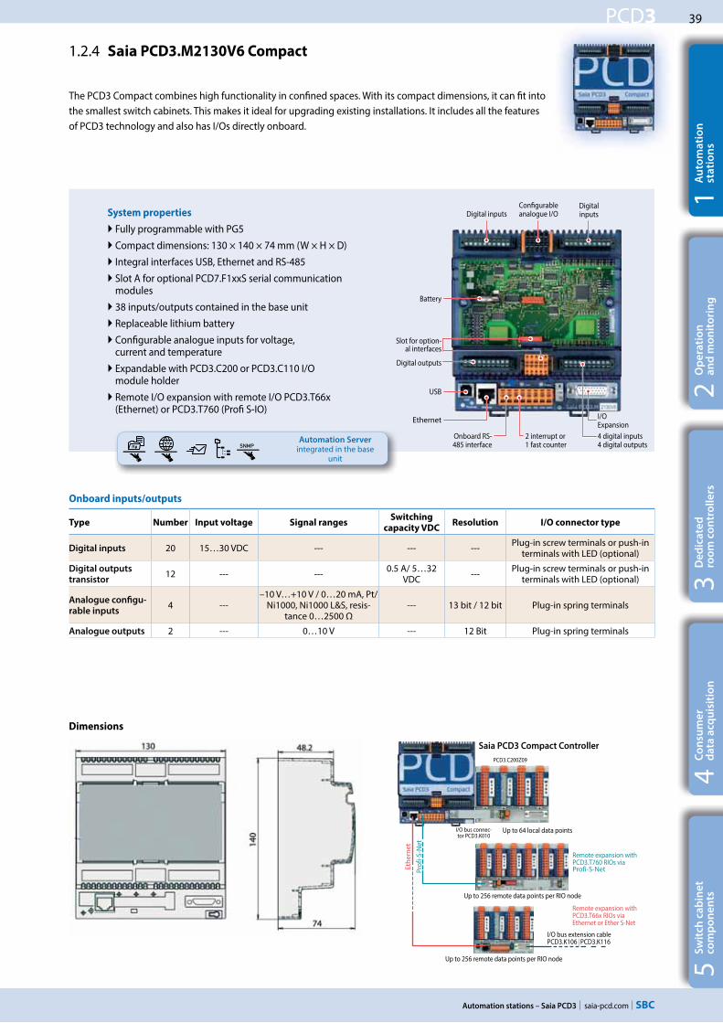
39
saia-pcd.com
PCD3
Prof
i-S-N
et
Ethe
rnet
PCD3.C200Z09
SNMP
Automation stations – Saia PCD3
5S
wit
ch c
ab
ine
t
com
po
ne
nts
4C
on
sum
er
d
ata
acq
uis
itio
n3
De
dic
ate
d
roo
m c
on
tro
lle
rs2
Op
era
tio
n
an
d m
on
ito
rin
g1
Au
tom
ati
on
st
ati
on
s
1.2.4 Saia PCD3.M2130V6 Compact
The PCD3 Compact combines high functionality in confined spaces. With its compact dimensions, it can fit into the smallest switch cabinets. This makes it ideal for upgrading existing installations. It includes all the features of PCD3 technology and also has I/Os directly onboard.
System properties
Fully programmable with PG5
Compact dimensions: 130 × 140 × 74 mm (W × H × D)
Integral interfaces USB, Ethernet and RS-485
Slot A for optional PCD7.F1xxS serial communication modules
38 inputs/outputs contained in the base unit
Replaceable lithium battery
Configurable analogue inputs for voltage, current and temperature
Expandable with PCD3.C200 or PCD3.C110 I/O module holder
Remote I/O expansion with remote I/O PCD3.T66x (Ethernet) or PCD3.T760 (Profi S-IO)
Dimensions
Up to 256 remote data points per RIO node
Saia PCD3 Compact Controller
Onboard inputs/outputs
Type Number Input voltage Signal ranges Switching
capacity VDC Resolution I/O connector type
Digital inputs 20 15…30 VDC --- --- --- Plug-in screw terminals or push-in terminals with LED (optional)
Digital outputs
transistor 12 --- --- 0.5 A/ 5…32
VDC --- Plug-in screw terminals or push-in terminals with LED (optional)
Analogue configu-
rable inputs4 ---
–10 V…+10 V / 0…20 mA, Pt/Ni1000, Ni1000 L&S, resis-
tance 0…2500 Ω--- 13 bit / 12 bit Plug-in spring terminals
Analogue outputs 2 --- 0…10 V --- 12 Bit Plug-in spring terminals
Digital inputs
Configurable analogue I/O
4 digital inputs4 digital outputs
I/OExpansion
2 interrupt or 1 fast counter
Ethernet
USB
Digital outputs
Slot for option-al interfaces
Battery
Digital inputs
Onboard RS-485 interface
Remote expansion with PCD3.T66x RIOs via Ethernet or Ether S-Net
Up to 256 remote data points per RIO node
Up to 64 local data points
I/O bus extension cable PCD3.K106 | PCD3.K116
I/O bus connec-tor PCD3.K010
Remote expansion with PCD3.T760 RIOs via Profi-S-Net
Automation Server integrated in the base
unit

40
saia-pcd.com
PCD3
Automation stations – Saia PCD3
Performance overview and accessories
Power supply
Type Description
Supply voltage
(in accordance with EN/IEC 61131-2)
24 VDC –20 / +25% incl. 5% ripple
Current draw / input power Type 175 mA / 4.2 W max. 500 mA / 12 W
Capacity 5 V/+V internal max. 600 mA / 100 mA
Reclosing
(in accordance with EN / IEC 61131-2)
≤ 10 ms for interval ≥ 1 s
Watchdog relay, make contact 48 VAC or VDC, 1 A
Communication interfaces to field level options in slot A
PCD7.F110S RS-422 with RTS/CTS or RS-485 electrically connected, with line termination resistors that can be activated. Suitable for Modbus, S-Bus, EnOcean, etc.
PCD7.F121S RS-232 with RTS/CTS, DTR/DSR, DCD, suitable for modem, EIB, DALI connection.
PCD7.F150S RS-485 (electrically isolated), with line termination resistors that can be activated
PCD7.F180S Belimo® MP-Bus, for connecting up to 8 drives on one line
I/O expansions
Type Description Capacity
PCD3.C110Z09 2 module slots (connection with PCD3.K010 connector or with PCD3.K106/K116 cable)
0 mA
PCD3.C200Z09 4 module slots, with 24 VDC supply (connection with PCD3.K010 connector or with PCD3.K106/K116 cable)
1500 mA / 200 mA (5 V / +V)
PCD3.C110 2 module slots (connection with PCD3.K106/K116 cable only)
0 mA
PCD3.C200 4 module slots, with 24 VDC supply (connection with PCD3.K106/K116 cable only)
1500 mA / 200 mA (5 V / +V)
I/O modules see pages 27 and 28
Order details
Type Description
PCD3.M2130V6 Base units with 38 I/Os (supplied with plug-in screw terminals) CPU with 512 kByte user program, backup with onboard flash memory, 1 MB file system, USB port for programming with PG5, RS-485 interface, 2 interrupt inputs, integrated web and FTP server, 1 port (slot A) for PCD7.F1xxS communication modules, lithium battery for data backup for 1…3 years, Ethernet TCP/IP interface
4 405 5066 0 Optional: Pluggable 10-pin “push-in” terminal block with LEDs for digital I/Os

41
saia-pcd.com
PCD3
FTP- Client
SMS
SNMP
Prof
i-S-N
et
Ethe
rnet
PCD3.T66x
PCD3.C110PCD3.T760
PCD3.C200Z09
SNMP
Automation stations – Saia PCD3
5S
wit
ch c
ab
ine
t
com
po
ne
nts
4C
on
sum
er
d
ata
acq
uis
itio
n3
De
dic
ate
d
roo
m c
on
tro
lle
rs2
Op
era
tio
n
an
d m
on
ito
rin
g1
Au
tom
ati
on
st
ati
on
s
Saia PCD3 Wide Area Controllers are fully programmable, industrial control and automation devices with web, IT and telecommunications functions. Its potential uses therefore extend much further than those of classic RTU stations, which are normally only suitable for alarm monitoring with remote alarms and data logging. The PCD3 Wide Area Controller is also suitable for sophisticated control tasks.
System properties
Fully programmable with PG5
Compact dimensions: 130 × 140 × 74 mm (W × H × D) (without antenna)
Management of historical data with up to 1 GB flash memory
Integral telecommunications interface (PSTN, GSM/GPRS)
Constantly accessible owing to redundant communication
14 inputs/outputs contained in the base unit
Onboard inputs/outputs
I/O data points Properties
8 digital inputs + 2 interrupts 15…30 VDC
2 relay outputs DC 2 A/50 V, AC 6 A/250 V
4 configurable analogue inputs –10…+10 VDC, 0…±20 mA, Pt/Ni1000, Ni1000 L&S,
0…2500 Ω
Onboard interfaces
Interface Transmission rate
RS-485 (serial) on terminal block for free
protocols or Profi S-Net / Profibus-DP Slave
≤ 115.2 kbits ≤ 187.5 kbits
Ethernet TCP/IP 10/100 Mbits
USB 1.1 (PGU)
1.2.5 Saia PCD3.M2330A4Tx Wide Area Controller
Dimensions
SIM card holder
Expandable memory
AntennaConfigurable
analogue inputs
Ethernet
USB
Slot for optional interfaces
Digital inputs
LED status display
I/O expansionOnboard RS-485 interface
2 relay outputs + 2 interrupts
Battery
2 interrupt or 1 fast counter
InternetTelecom
GSM / GPRS
FTP client SMS
Up to 256 remote data points per RIO node
Saia PCD3.WAC Controller
PCD3.T760 RIOs via Profibus/Profi S-Net
PCD3.T66x Ethernet RIOs via Ethernet/Ether S-Net
Up to 256 remote data points per RIO node
Up to 64 local data points
I/O bus extension cable PCD3.K106 | PCD3.K116
I/O bus connector PCD3.K010
Web browserMail server
Automation Server integrated in the base
unit

42
saia-pcd.com
PCD3
FTP- Client
FTP- Client
FTP- Client
SAIA BURGESS CONTROLS
PCD7.R-SD512
FTP- Client
Automation stations – Saia PCD3
Examples of applications
PCD3.WAC as an RTU controller
Send SMS messages and emails through the GSM/GPRS network. Use the PCD3.WAC with local I/Os to send messages, statuses or alarms to the SCADA system or to the end user via email and SMS. Via integrated web and FTP servers can link external stations easily over Intranet and Internet. The integrated web server also permits access to external stations via standard web browsers.
Permanently available owing to redundant communication
Bridging geographical distances is often a requirement for systems with a large number of distributed stations. With integrated telecommunications interfaces (GSM/GPRS, PSTN or ISDN) and an Ethernet interface, the Wide Area Control-ler is permanently available via its telecommunications interface and Ethernet port. Redundant communication paths (telecommunications or Ethernet inter-face) increase the reliability and availability of the system.
Ready for data management:
With up to 1 GB of memory, the Saia PCD3.WAC has enough memory to store data received from the field level over a long period. These data can be processed directly by the Saia PCD® and then transferred to the management or upstream monitoring systems by email, FTP, HTTP or data communication. This makes the Saia PCD3 Wide Area Controller independent of management stations and there-fore suitable as a data concentrator. Remote operation and control have various applications for taking measurements, monitoring the status of systems and the relevant transfer of data.
WAC communications gateway
The Saia PCD3.WAC can be used for non-SBC systems as a communications gateway to Internet or Intranet applications with integrated protocols such as FTP, HTTP or using open data modes, Ethernet or a serial interface.Many field bus protocols are supported at the field level, such as Modbus TCP/RTU/ASCII, EIB, M-Bus, etc.
Internet / Intranet GSM / GPRS
SCADAWeb browser
FTP client Email SMS
Telecom interface
GSM / GPRSInternet / Intranet
SCADAWeb browser
FTP client Email SMS
Telecom interface
Field bus protocols of PLCs, frequency converters, etc.
GSM / GPRSInternet / Intranet
SCADAWeb browser
FTP client Email SMS
Telecom interface
Devices with field bus protocols
SD flash cardwith up to 1 GB
GSM / GPRSInternet / Intranet
SCADAWeb browser
FTP client
Devices with field bus protocols
Telecom interface

43
saia-pcd.com
PCD3
SAIA BURGESS CONTROLS
PCD7.R-SD512
Automation stations – Saia PCD3
5S
wit
ch c
ab
ine
t
com
po
ne
nts
4C
on
sum
er
d
ata
acq
uis
itio
n3
De
dic
ate
d
roo
m c
on
tro
lle
rs2
Op
era
tio
n
an
d m
on
ito
rin
g1
Au
tom
ati
on
st
ati
on
s
Performance overview, ordering information and accessories
Order type
PCD3.M2330A4T1 with PSTN modem
PCD3.M2330A4T5 with GSM/GPRS modem (without antenna)
Processor technology
RAM as program memory 512 kByte
Backup memory (flash) 512 kByte
Memory for file system (flash) 1 MB (onboard)
PCD media 8192 flags, 16,384 × 32-bit register
Additional data storage
Slot for SD flash cards SBC SD card with up to 1 GB file system
Data files up to 900 files with file system Download and upload via ftp
PCD7.R-SD512 SBC SD flash card, 512 MB with file system
PCD7.R-SD1024 SBC SD flash card, 1024 MB with file system
Internet and Intranet protocols
HTTP server Visualisation with web browser and web panel
FTP Server Easy data exchange
TCP/IP-PPP point-to-point protocol Efficient communication
SMTP client Sending emails with files (e.g. log files) as attachments
DHCP and DNS client Easy integration in IP networks
SNTP client Synchronisation of the internal clock
SNMP agent Network management
Telecom communication interface (alternatively integrated interfaces)
GSM / GPRS / PSTN / ISDN / SMS – sending and receiving
Communication interfaces for slot A
PCD7.F110S RS-422 with RTS/CTS or RS-485 electrically connected, with line termination resistors that can be activated. Suitable for Modbus, S-Bus, EnOcean, etc.
PCD7.F121S RS-232 with RTS/CTS, DTR/DSR, DCD, suitable for modem, EIB, DALI connection.
PCD7.F150S RS-485 (electrically isolated), with line termination resistors that can be activated
PCD7.F180S Belimo® MP-Bus, for connecting up to 8 drives on one line
Field level protocols
Serial S-Bus, Ether S-Bus and Profi S-Bus
MODBUS RTU or TCP EIB M-Bus IEC 870-5-101/103/104
For other protocols please refer to Chapter B2
I/O expansions
PCD3.C110Z09 2 module slots (connection with PCD3.K010 connector or with PCD3.K106/K116 cable)
0 mA
PCD3.C200Z09 4 module slots, with 24 VDC supply (connection with PCD3.K010 connector or with PCD3.K106/K116 cable)
1500 mA / 200 mA (5 V / +V)
PCD3.C110 2 module slots (connection with PCD3.K106/K116 cable only) 0 mA
PCD3.C200 4 module slots, with 24 VDC supply (connection with PCD3.K106/K116 cable only)
1500 mA / 200 mA (5 V / +V)
I/O modules see pages 27 and 28

44
saia-pcd.com
PCD3
Automation stations – Saia PCD3

45
saia-pcd.comStandby Controller
5S
wit
ch c
ab
ine
t
com
po
ne
nts
4C
on
sum
er
d
ata
acq
uis
itio
n3
De
dic
ate
d
roo
m c
on
tro
lle
rs2
Op
era
tio
n
an
d m
on
ito
rin
g1
Au
tom
ati
on
st
ati
on
s
1.3 Standby System
1.3.2 PCD3.T668 Seite
Smart RIO for standby system, for connection to the PCD3.M6880 CPU1.
1.3.1 PCD3.M6880 Seite
Modular PCD3 standby controller with 2 Ethernet TCP/IP ports and a coprocessor for standby operation.
51
49
With the PCD3.M6880 standby controllers, redundant automation solutions can be achieved. This helps to ensure uninterrupted operation of systems and processes.
Standby ControllerStandby Controller

46
saia-pcd.com
Ethernet
SCADA 1 SCADA 2SCADA 1 SCADA 2
Standby Controller
Standby System Overview
Introduction
The PCD3.M6880 Standby Controllers are for creating redundant automation solutions, to ensure the uninterrupted operation of sys-tems and processes.
Standby (redundant automation) systems from SBC have the
following characteristics:
Based on the modular and robust PCD3 family, using standard modules.
Simple system architecture to reduce costs.
Standby processors with shared Ethernet Remote I/Os avoids the duplication of the inputs/outputs and the sensors/actuators.
Programmable remote I/Os create intelligent decentralized nodes to provide additional reliability.
The network uses standard Ethernet components, and can run over a standard Ethernet TCP/IP network along with other services.
Easy engineering and commissioning, using the PG5 Project Manager to automatically generate the project.
Uninterrupted switching from Standby to Active device.
Standby controllers contain two processors. One processor runs the redundant program and monitors the active PCD. The second independent processor runs other non-redundant processes. This significantly increases the performance and flexibility of the system.
Comprehensive diagnostic features to aid commissioning and fault finding.
Terminology
The following definitions will provide a better understanding of the properties and operating principles:
Standby Controller The PCD3.M6880 controller which supports the standby feature.
Primary PCD The PCD which becomes the active device by default when the system is powered up, depending on the configuration.
Secondary PCD The PCD which becomes the standby device on power up, and only takes over active control in the event of a fault on the active device.
Active PCD The PCD whose CPU1 is in Active Mode, running the redundant program and controlling the inputs/outputs (PCD3.T668 RIOs).
Standby PCD The PCD whose CPU1 is in Standby mode. It does not run the redundant program and the outputs (PCD3.T668 RIOs) are not controlled by this device.
Main CPU CPU0 of the Primary or the Secondary PCD, which runs the non-redundant program. This program may be different on the Primary and Secondary devices.
Redundant CPU CPU1 of the Primary or Secondary PCD, which contains the Redundant program. This program must be the same on the primary and Secondary devices. This CPU is either in Active mode and running the Redundant program, or in Standby mode and monitoring the Active PCD.
IP network
with fibre optic ring
Typical layout of a redundancy system with two PCD3.M6880 Standby devices and PCD3.T668 Ethernet Smart RIOs.
SecondaryPrimary
Process I/O Process I/O
SCADA system
Standby Controllers PCD3.M6880
Smart RIOs PCD3.T668
Standby ControllerStandby Controller

47
saia-pcd.comStandby Controller
5S
wit
ch c
ab
ine
t
com
po
ne
nts
4C
on
sum
er
d
ata
acq
uis
itio
n3
De
dic
ate
d
roo
m c
on
tro
lle
rs2
Op
era
tio
n
an
d m
on
ito
rin
g1
Au
tom
ati
on
st
ati
on
s
Redundant control solutions are created using two PCD3.M6880 Standby Controllers. The input/outputs (process signals) are con-nected and controlled via PCD3.T668 Ethernet smart RIOs. The RIO stations are connected to both controllers via an Ethernet con-nection. This means there is no need to have duplicate inputs, outputs, sensors and actuators. The two PCDs (primary and second-ary) monitor each other. If the active PCD fails, the standby PCD takes over processing and control of the connected RIO stations. The process image (I/O) and the internal PCD media (F, R, T, C, DB) - the synchronization data - are continuously transferred from the active PCD to the standby PCD via the Ethernet connection. This ensures uninterrupted switching from the active to the standby PCD.
Ordering Information
PCD3.M6880 Modular PCD3 standby controller with 2 Ethernet TCP/IP ports and a coprocessor for standby operation.
PCD3.T668 Smart RIO for standby system, for connection to the PCD3.M6880 CPU1.
The Redundant CPU1 has two independent Ethernet interfaces. The ETH 2.x inter-face is reserved exclusively for operating the PCD3.T668 RIO stations. The PCDs also synchronize their process data via the same interface. For security reasons, we rec-ommend setting up this network as a ring structure with specific network compo-nents from third-party providers. We have had good experiences with the industrial Ethernet switches from Hirschmann.
The ETH 1 interface on CPU0 is available for connecting and operating other sys-tems and devices. For example, SCADA systems can be connected via this interface. SBC does not provide its own SCADA system for redundant automation solutions, but almost any system can be used. A single SCADA system, or an additional redundant SCADA system can be used if it supports redundant controllers. The PCD3. M6880 controllers provide detailed status and diagnostic information which can be evaluated by the SCADA systems.
Ethernet 2 (2 port switch)
Ethernet 1
Standby ControllerStandby Controller

48
saia-pcd.com
Ethernet
SCADA 1 SCADA 2
Ethernet
Ethernet
SCADA 1 SCADA 2
Ethernet
Standby CPU
PCD3.M6880
Standby CPU
PCD3.M6880
SCADA 1 SCADA 2
SCADA 1 SCADA 2 SCADA 1 SCADA 2
SCADA 1 SCADA 2
Standby Controller
Designing the System
Redundant automation solutions can be achieved with various network topologies.
Physically separating the management network (SCADA systems) and the network for the remote I/Os is recommended. We also rec-ommend setting up the remote I/O network in a ring structure using fibre-optic network components. This significantly increases the performance, security and, above all, the network availability and thus the system reliability. Standard devices from third-party provid-ers can be used for the network components (switches). We have had good experiences with the switches (RS30) from Hirschmann. However, the networks can also be set up with standard components in a star structure. A shared physical network for the remote I/Os and management systems is also possible, but availability of the system will be reduced accordingly.
Network redundancy
with fiber optical ring
Shared physical network in a star topology with standard components
Recommended network topology with physically separate networks and a fibre-optic ring
Physically separate networks in a star topology with standard components
SecondaryPrimary SecondaryPrimary
SecondaryPrimary
Process I/OProcess I/O Process I/OProcess I/O
Process I/OProcess I/O
Standby Controller
PCD3.M6880
Standby Controller
PCD3.M6880
Smart RIOs
PCD3.T668
SCADA-System SCADA-System
Smart RIOs
PCD3.T668
SCADA-System
Smart RIOs
PCD3.T668
Standby ControllerStandby Controller

49
saia-pcd.com
PCD3.M6880
Eth 2.2 Eth 2.1 USB Eth1
Standby Controller
5S
wit
ch c
ab
ine
t
com
po
ne
nts
4C
on
sum
er
d
ata
acq
uis
itio
n3
De
dic
ate
d
roo
m c
on
tro
lle
rs2
Op
era
tio
n
an
d m
on
ito
rin
g1
Au
tom
ati
on
st
ati
on
s
The PCD3.M6880 standby controller has two independent processors (CPU0 and CPU1). Both processors have their own independent PCD media (F, R, T, C, DB/TX).
The redundant CPU1 runs the redundant user program and controls the shared inputs/outputs of the PCD3.T668 remote I/Os. The redundant programs in the primary and secondary PCD3.M6880s are identical. During normal operation, only the active PCD runs the redundant program. CPU1‘s internal used PCD media (F, R, T, C, DB/TX) are transferred from the active to the standby PCD via the Ethernet interface 2 (ETH2.x). In the event of a fault, the standby PCD takes over operation without interruption, and runs the redundant program using the last process image from the active PCD.
Depending on requirements, the user programs of the main CPU0 can be different in the primary and secondary PCD3.M6880. CPU0 has the same capabilities as a standard PCD (e.g. PCD3.M5560). Local I/Os in the PCD‘s slots, and the I/O expansion modules, are controlled by CPU0. External systems and devices (SCADA systems, web browsers and other external devices) communicate only with CPU0. CPU0‘s internal PCD media (F, R, T, C, DB) are not synchronized between the active and standby PCD.
CPU1‘s program cannot directly access the local IOs or CPU0‘s media (and vice versa). Data is exchanged between CPU0 and CPU1 using a data exchange mechanism. The data to be exchanged (PCD media) are define in global symbol files. This data is automatically exchanged between CPU0 and CPU1 on each program cycle.
1.3.1 PCD3.M6880 Standby Controller
Architecture of the PCD3.M6880
1 Data Media Transfer (Exchange Range or/and CSF/FBox)2 S-Bus GWY CPU0 to CPU1 (2 different S-Bus address)3 Redundant program on CPU1 runs only if active. Same program on both PCDs.4 Non-redundant program can be different in both PCDs.
Ethernet RIO
PCD3.T668
SCADA and/or
other systems
Standby controller PCD3.M6880
Redundant (CPU1)
4 Non Red. Program
IO Flash
BACnet LON Com
3Red. Program
1Media2S-Bus
Main (CPU0)
Standby ControllerStandby Controller

50
saia-pcd.com Standby Controller
Saia PCD3.M6880 controllers
High Power Standby Controller
1.023
up to 4.2 GB
2 MB
0.1/0.3 μs bit/word
I/O
File system
Program
CPU speed
PCD3.M6880
Property/function Main CPU0 Redundant CPU1
Number of inputs/outputs 1023 ––
or I/O-module slots 64 ––
I/O expansion connection for PCD3.C module holder Yes ––
Processing time [μs] bit operation
word operation
0.1…0.8 μs 0.3 μs
Real time clock (RTC) Yes
On-Board memory
Program memory, DB/TEXT (Flash) 2 MByte
User memory, DB/TEXT (RAM) 1 MByte 128 KByte
Flash memory (Program, S-RIO and configuration) 128 MByte
User flash file system (INTFLASH) 128 MByte ––
PCD media:
Register
Flag
DB/TEXT
16384163848192
16384163848192
On-Board interfaces
USB 1.1 Yes No
Ethernet 10/100 Mbit/s, full-duplex, auto-sensing/auto-crossing ETH1 ETH2.x (2 port switch)
RS-485 on terminal block (Port 2) or
RS-485 Profibus-DP Slave, Profi-S-Net on terminal block (Port 2)
up to 115 kbit/s up to 187.5 kbit/s ––
Optional communication interfaces
I/O slot 0:PCD3.F1xx modules for RS-232, RS-422, RS-485 and Belimo MP-Bus
Yes No
I/O slot 0…3 up to 4 modules or 8 interfaces:PCD3.F2xx modules for RS-232, RS-422, RS-485, BACnet® MS/TP, Belimo MP-Bus, DALI and M-Bus
Yes No
Other features
Communication protocols/systems (BACnet, Modbus, LONWORKS®, DALI, M-Bus…) As PCD3.M6860 without 2nd Ethernet No
Automation server (web server, FTP server, e-mail, SNMP, flash file system…) Yes No
Connection and operation of PCD3.T668 remote I/O
Number of supported RIO stations
No––
Yes64
Connection and operation of PCD3.T665/T666 remote I/O
Number of supported RIO stations
Yes64
No––
Access to the I/O slots in the basic housing as well as to the PCD3.Cxxx I/O terminal bases Yes No
Standby ControllerStandby Controller

51
saia-pcd.comStandby Controller
5S
wit
ch c
ab
ine
t
com
po
ne
nts
4C
on
sum
er
d
ata
acq
uis
itio
n3
De
dic
ate
d
roo
m c
on
tro
lle
rs2
Op
era
tio
n
an
d m
on
ito
rin
g1
Au
tom
ati
on
st
ati
on
s
Switchover Criteria
Each of the Standby PCDs (CPU1) sends a „Keep Alive“ telegram to its partner for supervision.
The STANDBY PCD switches to ACTIVE when:
No Keep Alive telegram has been received within the „Keep alive timeout“ period defined with the Redundant CPU‘s Device Configu-rator. The “Keep Alive Timeout” can be adjusted between 100…500 ms. By this the max. switchover latency is <100…500 ms.
The ACTIVE PCD‘s state is not RUN or STOP (stops sending Keep Alive).
A manual Switchover command is executed. This is only possible if the Primary device does not have priority, the „Primary device has priority“ option must be „No“.
1.3.2 PCD3.T668 Standby RIO
Architecture of the PCD3.T668
The PCD3.T668 remote I/Os are exclusively for use with the PCD3.M6880 Standby Controllers. With the exception of the redundancy function, they support the same properties/functions as the PCD3.T666 remote I/O station. The PCD.T665 and PCD3.T666 standard remote I/Os cannot be used with Standby Controllers.
Can be used as a simple local I/O station or an intelligent programmable I/O station
Can be programmed with the PG5. Important or timecritical tasks can be processed directly in the RIO
The RIO‘s user programs are managed centrally by the Smart RIO Manager (PCD) and downloaded to the RIOs automatically
Data exchange uses the efficient Ether-S-IO protocol. Simple configuration with the RIO Network Configurator
Cross-communication with other PCD systems using Ether-S-Bus (FBoxes)
Intelligent communication modules (e.g. M-Bus, DALI) are supported
Other communication protocols (e.g. Modbus) via Ethernet TCP/IP and also by the onboard RS-485 interface
Integrated Web Server
Data Synchronization and Supervision (Keep Alive)
Data Synchronisation and Program Cycle:
The used PCD medias (R, F, T/C, DB/TX) in the redundant CPU1 are cyclically synchronized between the active and the standby PCD. The synchronization time for all PCD media is normally less than 200 ms. This time is reduced accordingly if only a part of the PCD media is used. The total program cycle time is calculated as follows:
Total cycle time = program execution time + data synchronization time
The max. value for a large application can be calculated as follows: 100 ms + 200 ms = 300 ms max.For smaller applications where less PCD media are used the cycle time is reduced correspondingly.
Standby ControllerStandby Controller

52
saia-pcd.com Standby Controller
Property PCD3.T668
Number of inputs/outputs 64 in base unit, extensible to 256
I/O-module slots 4 in base unit, extensible to 16
I/O-modules supported PCD3.Exxx, PCD3.Axxx, PCD3.Bxxx, PCD3.Wxxx
Max. number of RIO stations 128
Protocol for data transfer Ether-S-IO
Ethernet connection 10/100 Mbit/s, full-duplex, auto-sensing, auto-crossing
Default IP configuration IP address: 192.168.10.100Subnet mask: 255.255.255.0
Default gateway: 0.0.0.0
USB port for configuration and diagnostics yes
Program memory 128 kByte
Web server for configuration and diagnostics yes
Web server for user pages yes
On-Board file system for web pages and data 512 kByte
BACnet® or LONWORKS® no
On-Board interrupt inputs 2
On-Board RS-485 interface yes
Special modules for I/O-slot 0 only PCD3.F1xx
for I/O-slots 0…3 (up to 4 modules)
PCD3.H1xx counterPCD3.F26x DALI
PCD3.F27x M-Bus
S-Web alarming/trending no
Watchdog no
Real-time clock no
Software clock (not battery-powered) yes, synchronized by the Manager
Battery no
Technical data
General data
Supply voltage 24 VDC ±20 % smoothed or 19 VAC ±15 % full-wave rectified
Capacity of 5 V bus / 24 V bus max. 650 mA/100 mA
Ambient temperature 0…+55 °C or 0…+40 °C (depending on mounting position)
Storage temperature –20…+70 °C
Relative humidity 30…95 % RH with no condensation
Mechanical strength according to EN/IEC 61131-2
With lean automation, it is not recommended to make full use of the specified limits with regard to the maximum number of stations per Manager and the maximum number of I/Os per RIO. The following points should be taken into account:
The load on the RIO Manager increases with the rising number of RIO stations. This has an impact on the overall application in the RIO Manager.
If there is a large number of RIOs, a sufficiently large amount of PCD media must be reserved on the Manager for the data transfer.
With a rising number of RIO stations, the build and download process in PG5 is lengthened accordingly. Likewise, the start-up behavior of the Manager or the entire RIO network is proportionately longer.
Recommendations: 20 Smart RIOs per Manager is a sensible configuration for efficient and problem-free operation, and simple commissioning and support.The Smart RIOs do not have a battery. In the event of an interruption to the power supply, all the data in the RAM memory (registers, flags, DBs/text) will be lost. Data and parameters that are to remain must either be transferred by the Manager or stored in the RIO’s flash file system. If this is not possible, the use of a normal controller in place of a Smart RIO is recommended. The user programs are stored in the flash memory of the RIOs and are retained in the event of an interruption to the power supply.
System properties/limits and recommendations for lean automation
Standby ControllerStandby Controller

53
saia-pcd.com
PCD2
Automation stations – Saia PCD2
5S
wit
ch c
ab
ine
t
com
po
ne
nts
4C
on
sum
er
d
ata
acq
uis
itio
n3
De
dic
ate
d
roo
m c
on
tro
lle
rs2
Op
era
tio
n
an
d m
on
ito
rin
g1
Au
tom
ati
on
st
ati
on
s
Saia PCD2 controllers Page
Base unit with 4 slots for I/O modules
PCD2.M4160 Basic 64 I/Os PCD2.M4560 Extended 1023 I/Os
Base unit with 8 slots for I/O modules
PCD2.M5540 Expanded with Ethernet switch
Up to 4 integrated communication interfaces. With plug-in modules expandable up to max.15 communication interfaces. Integrated Automation Server in all CPUs.
Saia PCD2 module holder for I/O expansion Page
Module holder for I/O modules
PCD2.C1000 4 I/O slots PCD2.C2000 8 I/O slots
Expandable up to 1023 I/Os
Saia PCD2 input/output modules Page
Modules with various functions with plug-in terminals
PCD2.Exxx Digital input modules PCD2.Axxx Digital output modules PCD2.Bxxx Digital input/output modules PCD2.Wxxx Analogue input/output modules PCD2.Gxxx Combined input/output modules
Saia PCD2 interface modules Page
Plug-in modules to expand the communication interfaces (up to 4 modules or 8 interfaces)
PCD7.F1xxS 1 serial interface RS-232, RS-422/485, Belimo MP-Bus PCD2.F2xxx 2 serial interfaces RS-232, RS-422/RS-485 PCD2.F2150 BACnet® MSTP PCD2.F2400 LONWORKS® PCD2.F2610 DALI PCD2.F27x0 M-Bus PCD2.F2180 Belimo MP-Bus
Saia PCD2 memory modules Page
Plug-in memory modules for data and program backup
PCD2.R6xx Basic module for SD flash cards for slots 0…3 PCD7.R-SD SD flash cards for PCD3.R6xx PCD7.R5xx Flash memory modules for slots M1 & M2 PCD7.R610 Flash memory modules for slot M1 & M2
Consumables and accessories for Saia PCD2 controllers Page
Housing covers, plug-in screw terminal blocks, I/O bus connection, battery, system cables and adapters
1.4 PCD2 – modular, expandable, compact CPU
Overview of fully programmable controllers Saia PCD2 device series
54
58
59
62
63
65

54
saia-pcd.com
PCD2
X2X9
X3
I/O BUS
Run
Halt
Error
X4
X5
01
09
19
S1O
C
X7
X6
ET
H2
ET
H1
US
B
S2
X1
X8
20
25
BATM1
Supply 24V PCD2.M4_
70
213
142
Automation stations – Saia PCD2
Dimensions
Compact mass: 142 × 236 × 49 mm
Mounting
Saia PCD2.M4xx controllers
The PCD2.M4x60 controller is based on a flat, space-saving housing design that has already been successfully used in the OEM and project business for many years. This modular, fully programmable CPU is suitable for both small and large applications, for example in machine controllers, building automation and infrastructure automation. The modular CPU is powerful, compact and can be expanded with up to 1,023 local data points Generous memory resources and sufficient CPU power for demanding communication tasks with up to 14 interfaces (BACnet, LONWORKS®, Profibus, M-Bus, Modbus, DALI, etc.).
System properties
Up to 14 communication interfaces 4 slots for PCD2 I/O modules in base unit Up to 64 inputs/outputs in base unit, can be expanded locally to up to 1,023 I/O Automation Server onboard Large onboard memory for programs (2 MB) and data (128 MB) Memory with SD flash cards can be expanded up to 4 GB Battery-free with FRAM technology – protects PCD media (R, F, DB/TEXT) from loss even in a de-energised state
2 I/O module slots
Connector for I/O expansion housing
Connector for interface module PCD7.F1xx
2-port Ethernet switch
Connector for 24 VDC voltage supply and RS-485 interface
LEDs
Slot C for PCD7.F7 MODULE (Profibus)
USB interface
Onboard RS-485 interface (electrically isolated)
Slot for optional battery module
Slot for memory module PCD7.Rxxx
PCD2.M4xxx
Connector for interrupt inputs
2 I/O module slots
Slot for PCD7.F1xx interface modules
SNMPAutomation Server
integrated in base unit
Dimensions Mounting
I/O 0 I/O 1
I/O 3 I/O 2
I/O bus for standard modules
Fast serial bus (SPI) for running up to 4 intelligent modules
Ground connection for I/O modules

55
saia-pcd.com
PCD2
Automation stations – Saia PCD2
5S
wit
ch c
ab
ine
t
com
po
ne
nts
4C
on
sum
er
d
ata
acq
uis
itio
n3
De
dic
ate
d
roo
m c
on
tro
lle
rs2
Op
era
tio
n
an
d m
on
ito
rin
g1
Au
tom
ati
on
st
ati
on
sC
on
tro
l ca
bin
et
co
mp
on
en
tsC
on
sum
pti
on
d
ata
ca
ptu
reD
ed
ica
ted
ro
om
co
ntr
oll
ers
Technical data and ordering information for PCD2.M4xxx controllers
Accessories, e.g. connectors, covers, etc. are described in the last page of this chapter.
Ordering information
Type Description
PCD2.M4160* PCD2 processor unit with Ethernet TCP/IP, 512 kbytes program memory, 64 I/Os
PCD2.M4560* PCD2 processor unit with Ethernet TCP/IP, 2 MB program memory, 1,023 I/Os
Technical overview
Technical data PCD2.M4160 PCD1.M4560
Number of digital inputs onboard 4 digital inputs (24 V, 4 × interrupt)
Number of digital inputs/outputs in the base unit 64
resp. I/O module slots in the base unit 4
Number of digital inputs/outputs expandable with PCD2.C2000 and PCD2.C1000 module holders
1,023
resp. I/O module slots 60
Processing time [μs] Bit operation 0.1…0.8 μsWord operation 0.3 μs
Real-time clock (RTC) Yes
Supercap to support real-time clock > 10 days
Slot for optional battery holder module Order number 4 639 4898 0
Yes, to support real-time clock for > 3 years
Onboard memory
Program memory, DB/text (flash) 512 kB 2 MB
User memory, DB/text (RAM) 128 KB 1 MB
Flash memory (S-RIO, configuration and backup) 128 MB 128 MB
User flash file system (INTFLASH) 8 MB 128 MB
Data backup with FRAM technology (the data is retained in a de-energised state) for R, F, DB, TEXT for R, F, DB, TEXT
Onboard interfaces
USB 1.1 ≤ 12 Mbit/s
Ethernet, 2-port switch ≤ 10/100 Mbit/s, full duplex, auto-sensing/auto-crossing
RS-485 on terminal block (port 0) ≤ 115.2 kbit/s
RS-485 free protocols on D-Sub connector (port 2) or RS-485 Profibus-DP Slave, Profi-S-Net on D-Sub connector (port 10)
No ≤ 115.2 Kbit/s ≤ 1.5 Mbit/s (elec. isolated)
Additional interfaces
PCD2.F2xxx modules for RS-232, RS-422, RS-485, BACnet MS/TP, Belimo MP-Bus, DALI and M-Bus
I/O slot 0…1 2 modules
I/O slot 0…3 4 modules
Slot A for PCD7.F1xxx modules Yes
Slot C for Profibus module PCD7.F7500 No Yes
General data
Supply voltage (in accordance with EN/IEC 61131-2) 24 VDC, –20/+25% max. incl. 5% ripple
Power consumption typically 15 W for 64 I/Os
Load capacity 5 V/+ V internal max. 800 mA/250 mA
*) In preparation, see section C1 Product status

56
saia-pcd.com
PCD2
PGU X2
X8
X5
16 32 48
112 6496 80
O C
Error
Run
Halt
WD
24 VDC
Battery
X7
X6
X4
X3
Slot A #1
Slot A #2
PC
D2
.M5
54
0
S1
X1 MPI
X9
0
RUN
HALT
PCD7.F7500
X10
X1 X2
X3
X4
24 VDC
Battery
WD
Run
Halt
Error
010
919
X5
X6
2030
2939
S1O
C
X8
X7
ETH2
ETH1
USB
S2
254 70
208
X1 X2
M1
Slot A1
X3
X4
M2
X6
X5
Slot A2
Slot C
Automation stations – Saia PCD2
Saia PCD2.M5xxx controllers
Due to its flat housing design, the Saia PCD2.M5xxx is ideal for space-saving applications. The powerful CPU enables the control and regulation functions of complex applications with up to 1023 central data points. This allows the PCD2 to be expanded for LON IP® or BACnet®-compatible controller using plug-in memory modules. The PCD2 has communication interfaces such as USB, Ethernet, RS-485 and onboard Automation Server.
System properties
Up to 15 communication interfaces (RS-232, RS-485, etc.) 8 I/O slots that can be expanded using module holders to max. 64 slots (1023 central data points)
Remote I/O expansion with RIO PCD3.T66x (Ethernet) or PCD3.T760 (Profi S-IO)
1 MB of program memory
Dimensions
Onboard interfaces of the Saia PCD2.M5xxx
Type Connection Port Transmission rate
RS-232 (serial) or RS-485 (serial)
X2 (D-Sub)X5 (terminal)
0 0
≤ 115.2 kbit/s ≤ 115.2 kbit/s
RS-485 (serial) for free protocols or Profi S-Net / Profibus DP Slave
X1 (D-Sub)X1 (D-Sub)
310
≤ 115.2 kbit/s≤ 1.5 Mbit/s
Ethernet (2-port switch) (PCD2.M5540 only) Ethernet 9 10/100 Mbit/s
USB 1.1 (PGU) USB --- ≤ 12 Mbit/s
Mounting
Automation Server Onboard Data memory with flash memory modules that can be expanded to 4 GB 6 fast interrupt/counter inputs on the CPU Compatible with all PCD3 module holders
8 I/O-module slots 0…7
Connection for I/O expansion
I/O 7 I/O 6 I/O 5 I/O 4
I/O 0 I/O 1 I/O 2 I/O 3
Flash cardsUSB port2-port Ethernet switch (PCD2.M5540 only)
Interrupt inputs
Lithium battery
Onboard interface and power supply
Run/stop switch
LEDs
C slot for Profibus Master module
Connections for onboard interfaces
Slot for communication module with X3 connection
The same instructions apply as for the PCD3 in Chapter 1.2 and in the Manual 26-856 regarding the power supply and the grounding plan.
Slot for communication module with X4 connection
PCD2.M5xxx
Module slot
Module slot
I/O bus for standard modules
Fast serial bus (SPI) for running up to 4 intel-ligent modules
Ground con-nection for I/O modules

57
saia-pcd.com
PCD2
SNMP
Automation stations – Saia PCD2
5S
wit
ch c
ab
ine
t
com
po
ne
nts
4C
on
sum
er
d
ata
acq
uis
itio
n3
De
dic
ate
d
roo
m c
on
tro
lle
rs2
Op
era
tio
n
an
d m
on
ito
rin
g1
Au
tom
ati
on
st
ati
on
s
Technical data and ordering information for PCD2.M5xxx controllers
Additional accessories, e.g. connectors, covers, etc. are described on the last page of this Chapter.
Order details
Saia PCD2
Type Description
PCD2.M5540 Programmable controller, 1024 kByte of RAM, Ethernet interface
Technical overview
Technical data
Number of onboard digital inputs/outputs 6 digital inputs (24 V, 4 × interrupt) 2 digital outputs (2 × PWM, 24 V 100 mA)
Number of digital inputs/outputs in the base unit 128
or I/O module slots in the base unit 8
Number of digital inputs/outputs with 7 PCD2.C2000 module holders 896
or I/O module slots 56
Processing times [μs] bit operation 0.3…1.5 μsword operation 0.9 μs
Real-time clock (RTC) Yes
Onboard memory
Main memory (RAM) for program and DB/Text 1 MB
Flash memory (S-RIO, configuration and backup) 2 MB
User flash file system (INTFLASH) No
Data backup 1…3 years with lithium battery
Onboard communication interfaces
RS-232, RS-485 / PGU ≤ 115 kbit/s
RS-485 Profibus DP–Slave, Profi S-Net (S-IO, S-Bus) ≤ 1.5 Mbit/s
USB 1.1 (PGU) ≤ 12 Mbit/s
Ethernet, 2-port switch (PCD2.M5540 only) ≤ 10/100 Mbit/s (full duplex, auto-sensing/auto-crossing)
General specifications
Supply voltage (in accordance with EN/IEC 61131-2) 24 VDC, –20/+25% max. incl. 5% ripple
Load capacity 5 V / + V internal max. 1400 mA / 800 mA
Automation Server Flash memory, file system, FTP and web server, email, SNMP
Automation Server integrated
into the base unit

58
saia-pcd.com
PCD2
254 70
208
208
142 70
Automation stations – Saia PCD2
Saia PCD2.Cxxxx module holder
Up to 8 Saia PCD2.C1000 or Saia PCD2.C2000 module holders can be connected to the Saia PCD2.M4x60 (7 with PCD2.M5xxx). This makes it possible to connect up to 64 I/O modules or 1023 digital I/Os. A module holder has space for 4/8 I/O modules. In addition to Saia PCD2.Cxxxx module holders, all Saia PCD3 module holders can also be connected.
System properties
Up to 1023 central data points Numerous module variants can be plugged in
Mounting is quick and easy Can be combined with Saia PCD3.Cxxx module holders
Connections for a power supply on each module holder
Can be connected below or next to each other
Dimensions PCD2.C2000
Dimensions PCD2.C1000
No more than 5 extension cables may be used for this.
PCD3.Kxxx cables are required for the connection between two module holders!
8 I/O-module slots 0…7
Power supply
I/O bus
4 I/O-module slots 0…3
PCD2.C2000 PCD2.C1000I/O bus for standard modules
Ground con-nection for I/O modules
I/O 7 I/O 6 I/O 5 I/O 4
I/O 0 I/O 1 I/O 2 I/O 3 I/O 0 I/O 1
I/O 3 I/O 2
I/O bus extension cable PCD2.K106
I/O bus connectionsPCD2.K010
or extension cable PCD3.K106
PCD3.K116
Saia PCD2 I/O module holder
Type Description
PCD2.C1000 Expansion module holder with 4 I/O slots
PCD2.C2000 Expansion module holder with 8 I/O slots
PCD2.K010 I/O bus connector
PCD2.K106 I/O bus extension cable length 0.9 m (connection between PCD2.M5xxx and PCD2.Cxxxx)
PCD3.K106 I/O bus extension cable length 0.7 m (connection between two module holders)
PCD3.K116 I/O bus extension cable length 1.2 m (connection between two module holders)
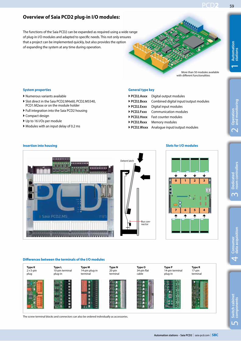
59
saia-pcd.com
PCD2
0 1 2 3
7 6 5 4
Automation stations – Saia PCD2
5S
wit
ch c
ab
ine
t
com
po
ne
nts
4C
on
sum
er
d
ata
acq
uis
itio
n3
De
dic
ate
d
roo
m c
on
tro
lle
rs2
Op
era
tio
n
an
d m
on
ito
rin
g1
Au
tom
ati
on
st
ati
on
s
Overview of Saia PCD2 plug-in I/O modules:
The functions of the Saia PCD2 can be expanded as required using a wide range of plug-in I/O modules and adapted to specific needs. This not only ensures that a project can be implemented quickly, but also provides the option of expanding the system at any time during operation.
General type key
PCD2.Axxx Digital output modules PCD2.Bxxx Combined digital input/output modules PCD2.Exxx Digital input modules PCD2.Fxxx Communication modules PCD2.Hxxx Fast counter modules PCD2.Rxxx Memory modules PCD2.Wxxx Analogue input/output modules
System properties
Numerous variants available Slot direct in the Saia PCD2.M4x60, PCD2.M5540, PCD1.M2xxx or on the module holder
Full integration into the Saia PCD2 housing Compact design Up to 16 I/Os per module Modules with an input delay of 0.2 ms
Insertion into housing Slots for I/O modules
Differences between the terminals of the I/O modules
The screw terminal blocks and connectors can also be ordered individually as accessories.
Type K
2 × 5-pin plug
Type L
10-pin terminalplug-in
Type M
14-pin plug-in terminal
Type N
20-pin terminal
Type O
34-pin flat cable
Type P
14-pin terminalplug-in
Type R
17-pin terminal
More than 50 modules available with different functionalities
Detent latch
Bus con-nector

60
saia-pcd.com
PCD2
Automation stations – Saia PCD2
Saia PCD2 digital input and output modules
The digital I/O modules can be easily plugged into Saia PCD2 and Saia PCD1 base units or a suitable I/O module holder. In addition to inputs for various voltage levels, digital outputs are provided with both transistor construction and as mechanical relays. This means that electrical isolation from the switching electrical circuit can be achieved easily and reliably.
Digital input modules
Type Number of inputs Input voltage Switching capacity
DC AC
Input filter Electrical
isolationCurrent draw
5V-Bus 1) +V-Bus 2)
I/O connec-
tor type 3)
PCD2.E110PCD2.E111
8 8
15…30 VDC15…30 VDC
--- --- 8 ms0.2 ms
--- 24 mA24 mA
--- LL
PCD2.E160 PCD2.E161PCD2.E165PCD2.E166
16161616
15…30 VDC15…30 VDC15…30 VDC15…30 VDC
--- --- 8 ms0.2 ms8 ms
0.2 ms
--- 72 mA72 mA72 mA72 mA
--- OONN
PCD2.E500 6 80…250 VAC --- --- 20 ms 1 mA --- L
PCD2.E610PCD2.E611PCD2.E613
8 8 8
15…30 VDC15…30 VDC30…60 VDC
--- --- 10 ms0.2 ms9 ms
24 mA24 mA24 mA
--- LLL
Digital output modules
Type Number of outputs Input voltage Switching capacity
DC AC
Input filter Electrical
isolationCurrent draw
5V-Bus 1) +V-Bus 2)
I/O connec-
tor type 3)
PCD2.A200
PCD2.A210
4, relay (make with contact protection)4, relay (break with contact protection)
--- 2 A/50 VDC
2 A/50 VDC
2 A/250 VAC
2 A/250 VAC
--- 15 mA
15 mA
--- L
L
PCD2.A220 6, relay (make) --- 2 A/50 VDC 2 A/250 VAC --- 20 mA --- L
PCD2.A250 8, relay (make) --- 2 A/50 VDC 2 A/48 VAC --- 25 mA --- M
PCD2.A300 6, transistor --- 2 A/10…32 VDC --- --- --- 20 mA --- L
PCD2.A400 8, transistor --- 0.5 A/5…32 VDC --- --- --- 25 mA --- L
PCD2.A410 8, transistor --- 0.5 A/5…32 VDC --- --- 24 mA --- L
PCD2.A460
PCD2.A465
16, transistor (with short circuit protection)
16, transistor (with short circuit protection)
---
---
0.5 A/10…32 VDC
0.5 A/10…32 VDC
---
---
---
---
---
---
74 mA
74 mA
---
---
O
N
Digital input/output modules
Type Number of I/Os Input voltage Switching capacity
DC AC
Input filter Electrical
isolationCurrent draw
5V-Bus 1) +V-Bus 2)
I/O connec-
tor type 3)
PCD2.B100 2 In + 2 Out + 4 selectable In or Out 15…32 VDC 0.5 A/5…32 VDC --- 8 ms --- 25 mA --- L
PCD2.B160 16 I/O (in blocks of 4 (configurable) 24 VDC 0.25 A/18…30 VDC --- 8 ms or
0.2 ms --- 120 mA --- 2× K
Fast counter modules
Type Number of
counters
Inputs per counter Outputs per
counter
Counting range Selectable
digital filter
Current draw
5V-Bus 1) +V-Bus 2)
I/O connec-
tor type 3)
PCD2.H112 2 2 In + 1 configurable In 1 CCO 0…16 777 215 (24 bit) 10 kHz … 150 kHz 50 mA 4 mA K
PCD2.H114 4 2 In + 1 configurable In 1 CCO 0…16 777 215 (24 bit) 10 kHz … 150 kHz 50 mA 4 mA 2 × K
The internal load current drawn by the I/O modules from the +5V and +V bus supply must not exceed the maximum supply current specified for the PCD2.M4x60, PCD2.M5540, PCD2.Cxxxx and PCD1.M2xxx.
3) P lug-in I/O terminal blocks are supplied with I/O modules. Spare terminals, ribbon connectors with system cables and separate terminals are ordered as accessories (see pages 65 and 172).
Overview of the internal bus capacity of the module holders
Capacity PCD1.M2xxx PCD2.M4x60 PCD2.M5540 PCD2.C1000 PCD2.C2000
1) Internal 5V bus 500 mA 800 mA 1400 mA 1400 mA 1400 mA
2) Internal +V (24 V) 200 mA 250 mA 800 mA 800 mA 800 mA
The electrical requirement of the internal +5V and +V bus for the I/O modules is calculated in the PG5 2.1 Device Confi-gurator.
More information on counting modules, stepper motor control and positioning modules

61
saia-pcd.com
PCD2
Automation stations – Saia PCD2
5S
wit
ch c
ab
ine
t
com
po
ne
nts
4C
on
sum
er
d
ata
acq
uis
itio
n3
De
dic
ate
d
roo
m c
on
tro
lle
rs2
Op
era
tio
n
an
d m
on
ito
rin
g1
Au
tom
ati
on
st
ati
on
s
Saia PCD2 analogue input and output modules
The numerous analogue modules allow complex control tasks or measurements. Depending on the speed of the AD converter, the resolution is between 8 and 16 bits. The digitised values can be processed further direct in the project in the PCD2 and PCD1. The large number of different modules means that the most suitable module is available for almost any requirement.
Analogue input modules
Type / Order
no.
Number of
channels
Signal range Resolution Electrical
isolation
Current draw
5V-Bus 1) +V-Bus 2)
I/O connec-
tor type 3)
PCD2.W200PCD2.W210PCD2.W220PCD2.W220Z02PCD2.W220Z12
8 In8 In8 In8 In4 In
+ 4 In
0…+10 V0…20 mA (4…20 mA via user program)Pt1000: –50 °C…400 °C/Ni1000: –50 °C…+200 °CNTC 10 temperature sensor4 I: 0…10 V and 4 I: Pt1000: –50 °C…400 °C/Ni1000: –50 °C…+200 °C
10 bits10 bits10 bits10 bits10 bits
--- 8 mA8 mA8 mA8 mA8 mA
5 mA5 mA
16 mA16 mA11 mA
LLLLL
PCD2.W300PCD2.W310PCD2.W340
PCD2.W350PCD2.W360PCD2.W380
8 In8 In8 In
8 In8 In8 In
0…+10 V0…20 mA (4…20 mA via user program)0…+10 V/0…20 mA (4…20 mA via user program)Pt1000: –50 °C…400 °C/Ni1000: –50 °C…+200 °CPt100: –50 °C…+600 °C/Ni100: –50 °C…+250 °CPt1000: –50 °C…+150 °C0–10 V…+10 V, –20 mA…+20 mA, Pt/Ni1000, Ni1000 L&S, NTC10k/NTC20k (configuration via software)
12 bits12 bits12 bits
12 bits12 bits13 bits
--- 8 mA8 mA8 mA
8 mA8 mA
25 mA
5 mA5 mA
20 mA
30 mA20 mA25 mA
LLL
LL
2× K
PCD2.W305PCD2.W315PCD2.W325
7 In7 In7 In
0…+10 V0…20 mA (4…20 mA via user program)–10 V…+10 V
12 bits12 bits12 bits
60 mA60 mA60 mA
0 mA0 mA0 mA
PPP
PCD2.W720 2 In Weighing module with 2 systems for up to 6 weighing cells ≤ 18 bits --- 60 mA 100 mA P
PCD2.W745 4 In Temperature module for TC type J, K and 4-wire Pt/Ni 100/1000 16 bits 200 mA 0 mA R
Analogue output modules
Type
Order no.
Number of
channels
Signal range Resolution Electrical
isolation
Current draw
5V-Bus 1) +V-Bus 2)
I/O connec-
tor type 3)
PCD2.W400PCD2.W410
4 Out4 Out
0…+10 V0…+10 V/0…20 mA/4…20 mA jumper-selectable
8 bits8 bits
--- 1 mA1 mA
30 mA30 mA
LL
PCD2.W600PCD2.W610
4 Out4 Out
0…+10 V0…+10 V/–10 V…+10 V/0…20 mA/4…20 mA selectable with jumper
12 bits12 bits
--- 4 mA110 mA
20 mA0 mA
LL
PCD2.W605PCD2.W615PCD2.W625
6 Out4 Out6 Out
0…+10 V0…20 mA/4…20 mA, configurable–10 V…+10 V
10 bits10 bits10 bits
110 mA55 mA
110 mA
0 mA0 mA0 mA
PPP
Analogue input/output modules
Type /
Order no.
Number of
channels
Signal range Resolution Electrical
isolation
Current draw
5V-Bus 1) +V-Bus 2)
I/O connec-
tor type 3)
PCD2.W525 4 In +
2 Out
I: I:0…10 V, 0(4)…20 mA, Pt 1000, Pt 500 or Ni 1000 (selectable by DIP switch)
O: 0…10 V or 0(4)…20 mA (selectable by software)
In: 14 bits
Out: 12 bits
40 mA 0 mA P
Saia PCD2 mixed digital and analogue input and output modules
With the multi-function I/O module PCD2.G200 a total of 24 digital and analogue inputs and outputs is achieved. Thus, the need for additional module holders can be avoided, and sophisticated small applications can be implemented cost-effectively.
Multifunctional input/output modules
Type /
Order no.
Number of
channels
Signal range Resolution Input filter Electrical
isolation
Current draw 5V-Bus 1) +V-Bus 2)
I/O connec-
tor type 3)
PCD2.G200 4 In Digital: 15…30 VDC 8 ms --- 12 mA 35 mA KB black
4 Out Digital: 0.5 A/10…32 VDC --- KB black
2 In 2 In 4 In
Analogue: 0…10 VAnalogue: Pt1000 or Ni1000Analogue: Universal, 0…10 V, 0…20 mA, Ni/Pt1000
(selectable via DIP switch)
12 bits 12 bits 12 bits
10 ms 20 ms 10 ms
Ni/Pt 20 ms
--- K orange
8 Out Analogue: 0…10 V 10 bits --- K orange
1) 2) 3) See page 60

62
saia-pcd.com
PCD2
Modbus Stationref:PSBChannel
En BsyConSConL
PAddStn
0210
0 1 2 3
A2
A1
C
0 1
PCD2.M5540PCD2.M4x60
3 2
Automation stations – Saia PCD2
In addition to the onboard interfaces of Saia PCD2, the interface functions can also be expanded in a modular way with various slots. The PCD2 series therefore supports numerous protocols. The physical bus specifications are available for most protocols as a plug-in module. If this is not the case, the bus can be connected via an external converter.
Protocols supported by the PCD2.M4x60, PCD2.M5540 via FBoxes
Modem communication with the PCD HMI editor applications with PCD7.Dxxx text terminals Serial S-Net (S-Bus) Modbus JCI N2-Bus KNX® S-Mode/EIB (with external converter) DALI EnOcean (with external converter) M-Bus BACnet®
Communication interfaces of the Saia PCD2 controllers
Physical interfaces that can be fully programmed
Module Specifications Electrical isolation
Current draw 5V-Bus +V-Bus
Slot I/O connector
type 1)
PCD7.F110S RS-422 with RTS/CTS or RS-485, with line termination resistors capable of activation.
--- 40 mA --- A1 / A2
PCD7.F121S RS-232 with RTS/CTS, DTR/DSR, DCD --- 15 mA --- A1 / A2 PCD7.F150S RS-485 with line termination resistors that can be activated 130 mA --- A1 / A2
PCD2.F2100 RS-422 / RS-485 plus PCD7.F1xxS as an option --- 110 mA --- I/O 0-3 2× K
PCD2.F2210 RS-232 plus PCD7.F1xxS as option --- 90 mA --- I/O 0-3 2× K
Physical interfaces for specific protocols
Module Specifications Electrical isolation
Current draw 5V-Bus +V-Bus
Slot I/O connector
type 1)
PCD7.F180S Belimo MP-Bus, for connecting up to 8 drives on one line --- 15 mA 15 mA A1 / A2 PCD2.F2150 BACnet® MS/TP or fully programmable --- 110 mA --- I/O 0-3 2× K
PCD2.F2400 LONWORKS® interface module 2) --- 90 mA --- I/O 0-3 L9
PCD2.F2610 DALI --- 90 mA --- I/O 0-3 L
PCD2.F2700 M-Bus 240 nodes --- 70 mA 8 mA I/O 0-3 L
PCD2.F2710 M-Bus 20 nodes --- 70 mA 8 mA I/O 0-3 L
PCD2.F2720 M-Bus 60 nodes --- 70 mA 8 mA I/O 0-3 L
PCD2.F2730 M-Bus 120 nodes --- 70 mA 8 mA I/O 0-3 L
PCD2.F2810 Belimo MP-Bus with base for PCD7.F1xxS modules --- 90 mA 15 mA I/O 0-3 2× K
PCD7.F7500 Profibus DP Master --- 200 mA --- C
PCD2.T814 Analogue modem 33.6 kbit/s (RS-232 and TTL interface) --- 250 mA --- I/O 4 + A11) Plug-in I/O terminal blocks are included with I/O modules. Spare terminals, ribbon connectors with system cables and separate terminals are ordered as
accessories (see pages 65 and 172). 2) For 254 network variables, with base for PCD7.F1xxS modules
System properties of PCD2.F2xxx modules
The following points must be noted when using the PCD2.F2xxx interface modules: Up to 4 PCD2.F2xxx modules (8 interfaces) can be used in slots 0…3 for each PCD2 system. The PCD2 system has a processor to process both the application and the serial interfaces. Processing of the interface modules requires the appropriate CPU capacity. Consult the information and examples provided in the Manual 26-856 for PCD2.M5 to determine the maximum communication capacity for each PCD2.M5 system.
Saia FBoxes for Modbus
Slots for interface modules
PCD2.F2210
PCD2.F2150
PCD2.F2810
PCD7.F150S
PCD2.F2150 with PCD7.F150S
Slot no.
max. 4 PCD2.F2xxxmax. 2 PCD2.F2xxx
max. 2 PCD2.F2xxx additional at PCD2.M4560

63
saia-pcd.com
PCD2
PGU X2
X8
X5
16 32 48
112 6496 80
O C
Error
Run
Halt
WD
24 VDC
Battery
X7
X6
X4
X3
Slot A #1
Slot A #2
PC
D2
.M5
54
0
S1
X1 MPI
X9
0
RUN
HALT
PCD7.F7500
X10
M2M1
0 321
SAIA BURGESS CONTROLS
PCD7.R-SD512
SAIA BURGESS CONTROLS
PCD7.R-SD512SAIA BURGESS CONTROLS
PCD7.R-SD512
SAIA BURGESS CONTROLS
PCD7.R-SD512
PCD7.R55xM04
PCD7.R610
PCD2.M5540PCD2.M4x60
0 1
M1
Automation stations – Saia PCD2
5S
wit
ch c
ab
ine
t
com
po
ne
nts
4C
on
sum
er
d
ata
acq
uis
itio
n3
De
dic
ate
d
roo
m c
on
tro
lle
rs2
Op
era
tio
n
an
d m
on
ito
rin
g1
Au
tom
ati
on
st
ati
on
s
The functions of the Saia PCD2 can be expanded using flash memory. Memory cards with file systems and data backup are available for this task. The various protocols whose firmware is installed on the flash cards can also be used by simply inserting the relevant card. The controller therefore becomes BACnet® or LON IP compatible. More information to memory management and structure is contained in Chapter 1.1 Saia PCD® System Description.
System properties
Onboard user memory:
1024 kByte RAM for program + DB/text 2 MB flash memory (S-RIO, configuration and backup)
Expansion options:
Two slots (M1 and M2) for memory cards integrated into the CPU Additional SD memory cards can be inserted in the I/O slots 0 to 3 using adapters
Memory modules of the Saia PCD2 controllers
Flash memory with file system, program and data backup, BACnet®
Type Description Slot
PCD7.R550M04 4 MB flash card with file system M1 & M2PCD7.R560 Flash card with BACnet® M1 & M2PCD7.R562 Flash card with BACnet® and 128 MB file system M1 & M2PCD7.R580 Flash card with LON IP M1 & M2PCD7.R582 Flash card with LON IP and 128 MB file system M1 & M2PCD7.R610 Holder module for micro SD card M1 & M2PCD7.R-MSD1024 MicroSD memory card 1 GB, PCD formatted PCD7.R610
SlotsM1 and M2PCD7.R55xM04 PCD7.R56xPCD7.R58x PCD7.R610
Slot no.
Battery for data backup
Type Description
4 639 4898 0 Battery holder module for PCD2. M4x604 507 4817 0 Lithium battery for PCD processor unit (RENATA button battery type CR 2032)
System properties of PCD7.R5xx modules
Only one BACnet® or one LON IP module can be operated per PCD2.M5xxx.
Slots for memory modules
max. 4 PCD2.R6000max. 2 PCD2.R6000
max. 2 PCD2.R6000 additional at PCD2.M4560
PCD2 SD flash memory cards for I/O slots PCD2.M4160PCD2.M4560 PCD2.M5540
Type Description Slot Slot
PCD2.R6000 Basic module with slot for SD flash memory cards (up to 4 modules in I/O slots 0 to 3 on a CPU)
E/A 0–1 E/A 0–3
PCD7.R-SD512 SD flash memory card, 512 MB with file system --- ---
PCD7.R-SD1024 SD flash memory card, 1024 MB with file system --- ---

64
saia-pcd.com
PCD2
I1 I2 I3 I4 I5 I6 I7 I16
I17
I18
I19
I20
I21
I22
I23
I32
I33
I34
I35
I36
I37
I38
I39
I48
I49
I50
I51
I52
I53
I54
I55
0 Slot#0 E110 Slot#1 E110 Slot#2 E110 Slot#3
O64O65O66O67O68O69O70O71
O80O81O82O83O84O85O86O87
O96O97O98O99O100O101O102O103
O112O113O114O115O116O117O118
0 Slot#7 A400 Slot#6 A400 Slot#5 A400 Slot#4
Automation stations – Saia PCD2
Consumables and accessories for Saia PCD2 controllers
Fast labelling of I/O modules with the Saia LabelEditor
The software tool efficiently labels the PCD2 labelling strip. The user can enter the unique data point text in the tool. This can then be printed out on A4 paper. The user selects appropriate distance formats for the various types of PCD2 modules. The text entered can be saved as templates and reused.
SBC Label Editor is delivered with the PG5 Controls Suite.
Download area:www.sbc-support.com
The EPLAN® electric P8 macros are available on the support site. The macros and article data are also available on the EPLAN® data portal.
EPLAN macros
EPLAN macros are available for project planning and engineering

65
saia-pcd.com
PCD2
Automation stations – Saia PCD2
5S
wit
ch c
ab
ine
t
com
po
ne
nts
4C
on
sum
er
d
ata
acq
uis
itio
n3
De
dic
ate
d
roo
m c
on
tro
lle
rs2
Op
era
tio
n
an
d m
on
ito
rin
g1
Au
tom
ati
on
st
ati
on
s
Saia PCD2 housing covers
Type Description
4 104 7719 0 Cover for PCD2.M5x40 without logo (neutral housing cover)
4 104 7758 0 Cover for PCD2.C1000 without logo (neutral housing cover)
4 104 7720 0 Cover for PCD2.C2000 without logo (neutral housing cover)
Saia PCD2 plug-in screw terminal blocks for onboard I/Os
Type Description
4 405 4916 0 Plug-in screw terminal block, 10-pin, labelling 0… 9
4 405 4917 0 Plug-in screw terminal block, 10-pin, labelling 10…19
4 405 4918 0 Plug-in screw terminal block, 10-pole, labelling 20…29
4 405 4919 0 Plug-in screw terminal block, 10-pole, labelling 30…39
4 405 4920 0 Plug-in screw terminal block, 10-pin, labelling 40…49
Plug-in screw terminal blocks and connectors for Saia PCD2 I/O modules
Type Description
4 405 5109 0 Plug-in screw terminal block, 9-pin (type L9) for PCD2.F2400, for wires up to 1.5 mm2
4 405 4847 0 Plug-in screw terminal block, 10-pin (type L) for wires up to 1.5 mm2, labelling 0…9
4 405 4869 0 Plug-in screw terminal block, 14-pin (type M) for wires up to 0.6 mm2
4 405 5048 0 Plug-in spring terminal block 2 × 5-pin (type K) for wires up to 1.0 mm2, orange
4 405 5054 0 Plug-in spring terminal block 2 × 5-pin (type KB) for wires up to 1.0 mm2, black
I/O bus connection
Type Description
PCD2.K010 I/O bus connector
PCD2.K106 I/O bus extension cable
Battery
Type Description
4 639 4898 0 Battery carrier module for PCD2. M4x60
4 507 4817 0 Lithium battery for PCD2.M5540
System cables for digital modules with 16 I/Os1)
PCD2.K221 Sheathed, round cable with 32 strands, each 0.25 mm², 1.5 m long, PCD side: 34-pin ribbon connector type D, process side: strand ends free, colour coded
PCD2.K223 Sheathed, round cable with 32 strands, each 0.25 mm², 3.0 m long, PCD side: 34-pin ribbon connector type D, process side: strand ends free, colour coded
System cables for adapters PCD2.K520/…K521/…K5251)
PCD2.K231 Sheathed, half-round cable with 34 strands, each 0.09 mm², 1.0 m long, with 34-pin ribbon connector type D at both ends
PCD2.K232 Sheathed, half-round cable with 34 strands, each 0.09 mm², 2.0 m long,with 34-pin ribbon connector type D at both ends
System cables for 2 adapters PCD2.K510/…K511 or 1 adapter and relay interface PCD2.K5511)
PCD2.K241 Sheathed, half-round cable with 34 strands, each 0.09 mm², 1.0 m long, PCD side 34-pin ribbon connector type D, process side: two 16-pin ribbon connectors
PCD2.K242 Sheathed, half-round cable with 34 strands, each 0.09 mm², 2.0 m long, PCD side 34-pin ribbon connector type D, process side: two 16-pin ribbon connectors
“Ribbon connector screw terminal” adapters
PCD2.K510 for 8 inputs/outputs, with 20 screw terminals, without LED
PCD2.K511 for 8 inputs/outputs, with 20 screw terminals and LED (for source operation only)
PCD2.K520 for 16 inputs/outputs, with 20 screw terminals, without LED
PCD2.K521 for 16 inputs/outputs, with 20 screw terminals and LED (for source operation only)
PCD2.K525 for 16 inputs/outputs, with 3 × 16 screw terminals and LED (for source operation only)
PCD2.K551 Relay interface for 8 PCD transistor outputs with 24 screw terminals and LED
PCD2.K552 Relay interface for 8 PCD transistor outputs with 24 screw terminals, LED and manual control mode (switch on-off-auto) and 1 output as feedback for the manual control mode
Consumables and accessories for Saia PCD2 controllers
1) For details, see Chapter 5.11

66
saia-pcd.com
PCD2
Automation stations – Saia PCD2
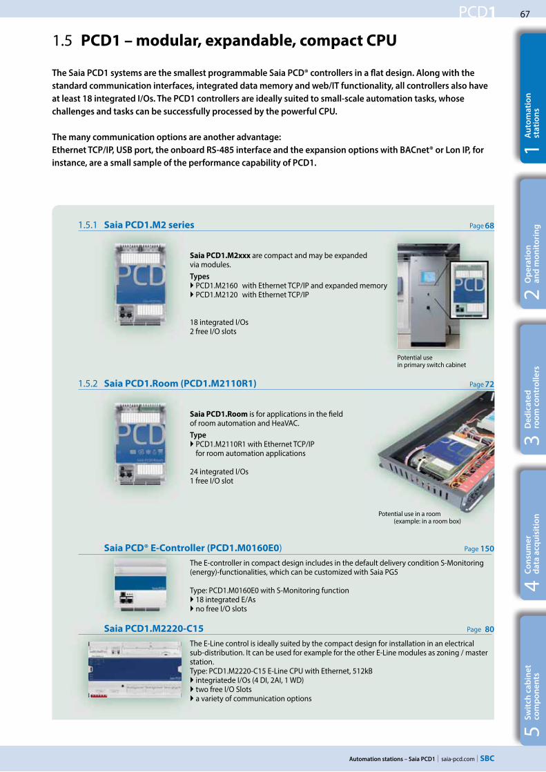
67
saia-pcd.com
PCD1
Automation stations – Saia PCD1
5S
wit
ch c
ab
ine
t
com
po
ne
nts
4C
on
sum
er
d
ata
acq
uis
itio
n3
De
dic
ate
d
roo
m c
on
tro
lle
rs2
Op
era
tio
n
an
d m
on
ito
rin
g1
Au
tom
ati
on
st
ati
on
s
Saia PCD® E-Controller (PCD1.M0160E0) Page
The E-controller in compact design includes in the default delivery condition S-Monitoring (energy)-functionalities, which can be customized with Saia PG5
Type: PCD1.M0160E0 with S-Monitoring function 18 integrated E/As no free I/O slots
The Saia PCD1 systems are the smallest programmable Saia PCD® controllers in a flat design. Along with the
standard communication interfaces, integrated data memory and web/IT functionality, all controllers also have
at least 18 integrated I/Os. The PCD1 controllers are ideally suited to small-scale automation tasks, whose
challenges and tasks can be successfully processed by the powerful CPU.
The many communication options are another advantage:
Ethernet TCP/IP, USB port, the onboard RS-485 interface and the expansion options with BACnet® or Lon IP, for
instance, are a small sample of the performance capability of PCD1.
1.5 PCD1 – modular, expandable, compact CPU
1.5.2 Saia PCD1.Room (PCD1.M2110R1) Page
Saia PCD1.Room is for applications in the field of room automation and HeaVAC.Type
PCD1.M2110R1 with Ethernet TCP/IP for room automation applications
24 integrated I/Os 1 free I/O slot
1.5.1 Saia PCD1.M2 series Page
Saia PCD1.M2xxx are compact and may be expanded via modules.Types
PCD1.M2160 with Ethernet TCP/IP and expanded memory PCD1.M2120 with Ethernet TCP/IP
18 integrated I/Os2 free I/O slots
Potential use in primary switch cabinet
Potential use in a room (example: in a room box)
Saia PCD1.M2220-C15 Page
The E-Line control is ideally suited by the compact design for installation in an electrical sub-distribution. It can be used for example for the other E-Line modules as zoning / master station. Type: PCD1.M2220-C15 E-Line CPU with Ethernet, 512kB
integriatede I/Os (4 DI, 2AI, 1 WD) two free I/O Slots a variety of communication options
72
68
150
80

68
saia-pcd.com
PCD1
M1
Slot A
X2 X1 X0
X3
142 49
226
Automation stations – Saia PCD1
1.5.1 Saia PCD1.M2xxx controller
The Saia PCD1.M2xxx series is a compact controller with onboard I/Os and in addition two free I/O slots for plug-in or communication interface modules. The Web/IT functionality, the onboard memory, the range of standard communication interfaces and the expansion options offer ideal solutions for small to medium systems.
Device design
Mounting Dimensions Power supply and connection concept
Additional information is provided in the Chapter Saia PCD3 power supply and connection concept, and in the Manual 26-875.
on a level surface on two DIN rails (2 × 35 mm in accord-ance with DIN EN 60715 TH35)
Compact mass: 142 × 236 × 49 mm
Types
PCD1.M2160 with Ethernet TCP/IP and expanded memory PCD1.M2120 with Ethernet TCP/IP PCD1.M2020 without Ethernet TCP/IP
System properties
Up to 50 inputs/outputs May be expanded remotely with RIO PCD3.T66x or PCD3.T76x
Up to 8 communication interfaces
USB and Ethernet interface onboard
Large onboard memory for programs (up to 1 MB) and data (up to 128 MB file system)
Automation Server for integration into Web/IT systems
SNMPAutomation Server
integrated in the base unitSlot for
memory modules
Terminals for integrated inputs and outputs
Terminals for optional connection (slot A)
2 free slots with SPI (high-speed serial Bus) for I/O or communication modules
Voltage supply 24 VDC Watchdog relay
RS-485 interface
Ethernet connection (2-port switch)
USB port
Operating LEDs
Slot for communication
interfaces
Battery
RUN/STOP button
Supply
Ground bar
1.5mm2 / max. 25 cm
IO0 IO1

69
saia-pcd.com
PCD1
Automation stations – Saia PCD1
5S
wit
ch c
ab
ine
t
com
po
ne
nts
4C
on
sum
er
d
ata
acq
uis
itio
n3
De
dic
ate
d
roo
m c
on
tro
lle
rs2
Op
era
tio
n
an
d m
on
ito
rin
g1
Au
tom
ati
on
st
ati
on
s
Memory and file system Types: PCD1.M2160 PCD1.M2120
Program memory, DB/Text (Flash) 1 MB 512 kByte
User memory, DB/Text (RAM) 1 MB 128 kByte
Onboard user flash file system 128 MB 8 MB
Integrated communication
Ethernet connection (2-port switch) 10/100 Mbit/s, full-duplex, auto-sensing, auto-crossing
Yes Yes
USB port USB 1.1 device 12 Mbit/s
Yes Yes
RS-485 (terminal X3), up to 115 kbit/s
Yes Yes
Overview Saia PCD1.M2xxx
Onboard inputs/outputs
Inputs:
6 Digital inputs (4 + 2 interrupts) 15…30 VDC, 3 ms input filter (0.2 ms for the interrupts) Terminal X12 Analogue inputs, selectable via DIP switch –10…+10 VDC, 0…±20 mA, Pt1000, Ni1000, Ni1000 L&S, 0…2.5 kΩ,
12 bit resolution Terminal X1
Outputs:
4 Digital outputs 24 VDC / 0.5 A Terminal X01 PWM output 24 VDC / 0.2 A Terminal X0
selectable/configurable via PG5
4 Digital inputs or outputs 24 VDC / data as digital inputs or outputs Outputs: Terminal X01 Watchdog relay or make contact 48 VAC or VDC, 1 A With DC switching voltage a free-wheeling diode should be
connected in parallel to the load Terminal X3
General specifications
Operating voltage 24 VDC, –20/+25 % max. inkl. 5% ripple (in accordance with EN/IEC 61131-2)Battery for data backup (replaceable) Lithium battery with a service life of 1 to 3 yearsOperating temperature: 0…55 °CDimensions (W × H × D) 142 × 226 × 49 mmMounting location 2× DIN rails in accordance with DIN EN60715 TH35 (2 × 35 mm) or on a flat surfaceProtection type IP 20Capacity 5 V/+V (24 V) internal max. 500 mA/200 mAPower consumption typically 12 W
Plug-in I/O modules for slots I/O 0 and I/O 1
The modules listed in the PCD2.M5 series (Chapter 1.4) are also used for the Saia PCD1 series.
Detent latch Bus connector
I/O 0 I/O 1
Technical data
Analogue output module Saia PCD7.W600
This module has 4 analogue outputs 0 to +10 V with a 12-bit resolution and has been specifically developed for the new PCD1 CPUs (PCD1.M2xxx, PCD1.M0160E0, PCD1.M2110R1). It can be plugged into slot A of the PCD1 CPU like the PCD7.F1xxS communication module.

70
saia-pcd.com
PCD1
M1
Slot A
X2 X1 X0
X3
PCD7.R55xM04
PCD7.R610
Automation stations – Saia PCD1
Communication
Electrical isolation
Internal current con-sumption 5V +V (24 V)
SlotI/O
connector type 1)
PCD7.F110S RS-485/RS-422 --- 40 mA – Slot A
PCD7.F121S RS-232 with RTC/CTS, DTR/DSR, DCD suitable for modem, EIB connection --- 15 mA – Slot A
PCD7.F150S RS-485 with termination resistors that can be activated 130 mA – Slot A
PCD7.F180S Belimo MP-Bus, for connecting up to 8 drives on one line --- 15 mA 15 mA Slot A
PCD2.F2100 RS-422/RS-485 plus PCD7.F1xxS as option --- 110 mA – IO 0/1 2× K
PCD2.F2150 BACnet® MS/TP RS-485 plus PCD7.F1xxS as an option --- 110 mA – IO 0/1 2× K
PCD2.F2210 RS-232 plus PCD7.F1xxS as an option --- 90 Ma – IO 0/1 2× K
PCD2.F2400 LONWORKS® interface module --- 90 Ma – IO 0/1 L9
PCD2.F2610 DALI Master for up to 64 DALI devices --- 90 Ma – IO 0/1 L
PCD2.F27x0 M-Bus master with 2 M-Bus interfaces --- 70 mA 8 mA IO 0/1 L
PCD2.F2810 Belimo MP-Bus plus PCD7.F1xxS as an option --- 90 Ma 15 mA IO 0/1 2× K
1) Plug-in I/O terminal blocks are included with I/O modules. � Spare terminals, ribbon connectors with system cables and separate terminals are ordered as accessories.
In addition to the onboard interfaces, the interface functions can also be expanded in a modular way using the various slots. Numerous protocols are therefore supported by the Saia PCD1.M2 series. Detailed information and an overview is contained in the Chapter BA communication systems.
Saia PCD1.M2xxx interface options
System properties of PCD2.F2xxx modules
The following points must be noted when using the PCD2.F2xxx interface modules:
Max. 2 modules PCD2.F2xxx (4 interfaces) can be used in slots I/O 0/1 per PCD1.M2 system. Consult the information and examples provided in the Manual 26-875 for PCD1.M2 to determine the maximum communication capacity for each PCD1.M2 system.
Memory expansion and communication
PCD7.R550M04 Flash memory module with a 4 MB file system (for user program backup, web pages, etc.) M1
PCD7.R560 Flash memory module for BACnet® firmware M1
PCD7.R562 Flash memory module for BACnet® firmware with 128 MB file system M1
PCD7.R580 Flash memory module for LON IP firmware M1
PCD7.R582 Flash memory module for LON IP firmware with 128 MB file system M1
PCD7.R610 Basic module for Micro SD flash card M1
PCD7.R-MSD1024 Micro SD flash card 1024 MB, PCD formatted PCD7.R610
The onboard memory of the Saia PCD1.M2xxx can be expanded using a Saia PCD7.Rxxx module in slot M1. In addition, the Saia PCD1.M21x0 can be expanded with BACnet® IP or LON IP. Additional information about the memory management and structure is contained in the Chapter Saia PCD® System Description.
The use of external modem modules such as Q.M716-KS1 is recommended. The PCD2.T8xx modem modules can only be used with a PCD7.F121S module. External wiring is therefore required.
Memory modules
IO0 IO 1

71
saia-pcd.com
PCD1
Automation stations – Saia PCD1
5S
wit
ch c
ab
ine
t
com
po
ne
nts
4C
on
sum
er
d
ata
acq
uis
itio
n3
De
dic
ate
d
roo
m c
on
tro
lle
rs2
Op
era
tio
n
an
d m
on
ito
rin
g1
Au
tom
ati
on
st
ati
on
s
Accessories and consumables for Saia PCD1.M2xxx
For small and medium systems Modernisation and expansion of existing systems through, for example, the compact construction Versatile interface options, including to existing systems as a gateway, for example: optimisation of a cooling system by setting all the free parameters
Battery for data backup
Type Description
4 507 4817 0 Lithium battery for PCD processor unit (RENATA button battery type CR 2032)
Plug-in screw terminal block
4 405 5089 0 Plug-in screw terminal block, 11-pin, labelling 0…10 Terminal X04 405 5087 0 Plug-in screw terminal block, 9-pin, labelling 11…19 Terminal X14 405 5088 0 Plug-in screw terminal block, 10-pin, labelling 20…29 Terminal X24 405 4919 0 Plug-in screw terminal block, 10-pin, labelling 30…39 Terminal X3
Cover
4 104 7759 0 Housing cover for PCD1.M2xxx without logo on-site with an overlay that can be individually designed
Labelling
The self-adhesive labels can be printed direct with the SBC LabelEditor from the PG5 Device Configurator
Use as communication interface with M-Bus in a district heating network
Range of uses
Connection to an existing EIB/KNX installation providing conference rooms with a web connection
The EPLAN® electric P8 macros are available on the support site. The macros and article data are also provided on the EPLAN® data portal.
EPLAN macros
EPLAN macros are available for project planning and engineering.

72
saia-pcd.com
PCD1
142 49
226
Automation stations – Saia PCD1
1.5.2 Saia PCD1.Room (PCD1.M2110R1)
Saia PCD1.Room (PCD1.M2110R1) is a programmable room controller for complex solutions with many commu-nication options. In addition to the I/Os that are already integrated, the controller has a free I/O slot for individual expansion with inputs/outputs or communication options. Web/IT functions for mobile operation, for instance, are also already onboard. Furthermore, Saia PCD1.Room offers various possibilities for integrating other systems in the room using standard communication interfaces. (Energy) efficient and individual room automation can be easily implemented as a result. The controller also provides a good basis for achieving the energy efficiency classes in accordance with EN 15232:2012.
Lighting, sun protection and individual room regulation can be optimally coordinated with one another with this controller. This example showing possible assignments was compiled based on applications in accordance with the VDI 3813 list of room automation functions and the DIN EN 15232 list of building automation functions.
1×serial communication RS-485: e.g. connec-tion external receiver EnOcean
1× make contact 48 VAC e.g. switching contact
Power supply 24 VDC
USB port
Ethernet connection (2-port switch) e.g. to the Internet (remote control via browser is possible as a result)
1×optional terminals for serial communication depending on the PCD7.F1xxS modulee.g. – MP-Bus (with PCD7.
F180S) for Belimo actuating drives.
2× analogue inputs: – 10…+10 VDC, 0…+/–20 mA,
Pt1000, Ni1000, Ni1000 L&S, 0…2.5 kΩ
e.g. – Brightness measurement– Air temperature measure-ment
6× digital inputs: 15…30 VDCe.g.– Presence detection– Window monitoring
4× Digital inputs/outputs (selectable)24 VDCe.g.– Dewpoint monitoring– Time switch program
5× digital outputs: 24 VDCe.g.– Signal presence– Switch/set binary output
2× analogue outputs: 0…10 VDC, 0(4)…20 mAe.g.– Volume flow control– Adjust temperature setpoint
4× analogue inputs: 0…10 VDC, 0(4)…20 mA, Pt500, Pt1000, Ni1000e.g.– Air quality measurement– Precipitation detection
Expansion options I/O or com-munication module e.g. DALI (PCD2.F2610)
Device design with connection example
The Smart RIO Manager function is not supported!
Mounting Dimensions Power supply and connection concept
Further information is provided in the Chapter Saia PCD3 power supply and connection concept, and in the Manual 26-875.
on two DIN rails (2 × 35 mm in accordance with DIN EN 60715 TH35)
on a level surface
Supply
Ground bar
1.5mm2 / max. 25 cm
Compact mass:142 × 236 × 49 mm
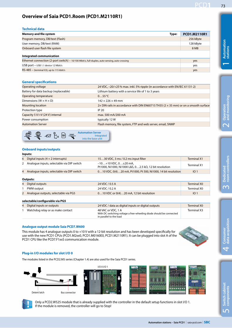
73
saia-pcd.com
PCD1
SNMP
Automation stations – Saia PCD1
5S
wit
ch c
ab
ine
t
com
po
ne
nts
4C
on
sum
er
d
ata
acq
uis
itio
n3
De
dic
ate
d
roo
m c
on
tro
lle
rs2
Op
era
tio
n
an
d m
on
ito
rin
g1
Au
tom
ati
on
st
ati
on
s
Overview of Saia PCD1.Room (PCD1.M2110R1)
Onboard inputs/outputs
Inputs:
6 Digital inputs (4 + 2 interrupts) 15…30 VDC, 3 ms / 0.2 ms input filter Terminal X12 Analogue inputs, selectable via DIP switch –10…+10 VDC, 0…±20 mA,
Pt1000, Ni1000, Ni1000 L&S, 0…2.5 kΩ, 12 bit resolution Terminal X1
4 Analogue inputs, selectable via DIP switch 0…10 VDC, 0(4)…20 mA, Pt1000, Pt 500, Ni1000, 14 bit resolution IO 1
Outputs:
4 Digital outputs 24 VDC / 0.5 A Terminal X01 PWM output 24 VDC / 0.2 A Terminal X02 Analogue outputs, selectable via PG5 0…10 VDC or 0(4)…20 mA, 12 bit resolution IO 1
selectable/configurable via PG5
4 Digital inputs or outputs 24 VDC / data as digital inputs or digital outputs Terminal X01 Watchdog relay or as make contact 48 VAC or VDC, 1 A
With DC switching voltage a free-wheeling diode should be connected in parallel to the load
Terminal X3
General specifications
Operating voltage 24 VDC, –20/+25 % max. inkl. 5% ripple (in accordance with EN/IEC 61131-2)Battery for data backup (replaceable) Lithium battery with a service life of 1 to 3 yearsOperating temperature: 0…55 °CDimensions (W × H × D) 142 × 226 × 49 mmMounting location 2× DIN rails in accordance with DIN EN60715 TH35 (2 × 35 mm) or on a smooth surfaceProtection type IP 20Capacity 5 V/+V (24 V) internal max. 500 mA/200 mAPower consumption typically 12 WAutomation Server Flash memory, file system, FTP and web server, email, SNMP
Only a PCD2.W525 module that is already supplied with the controller in the default setup functions in slot I/O 1. If the module is removed, the controller will go to Stop!
Plug-in I/O modules for slot I/O 0
The modules listed in the PCD2.M5 series (Chapter 1.4) are also used for the Saia PCD1 series.
Memory and file system Type: PCD1.M2110R1
Program memory, DB/text (Flash) 256 kByte
User memory, DB/text (RAM) 128 kByte
Onboard user flash file system 8 MB Integrated communication
Ethernet connection (2-port switch) – 10/100 Mbit/s, full-duplex, auto-sensing, auto-crossing yesUSB port – USB 1.1 device 12 Mbit/s yesRS-485 – (terminal X3), up to 115 kbit/s yes
Technical data
Automation Server Integrated
into the base unit
Detent latch Bus connector
I/O 0 I/O 1
Analogue output module Saia PCD7.W600
This module has 4 analogue outputs 0 to +10 V with a 12-bit resolution and has been developed specifically for use with the new PCD1 CPUs (PCD1.M2xx0, PCD1.M0160E0, PCD1.M2110R1). It can be plugged into slot A of the PCD1 CPU like the PCD7.F1xxS communication module.

74
saia-pcd.com
PCD1
W
Modul
M1
Slot A
X2 X1 X0
X3
PCD7.R55xM04
PCD7.R610
Automation stations – Saia PCD1
In addition to the onboard interfaces, the interface functions can also be expanded in a modular way using the various slots. Numerous protocols are therefore supported by the Saia PCD1.M2110R1. A detailed list of all the protocols can be found in the Chapter BA communication systems.
Saia PCD1.Room (PCD1.M2110R1) interface options
System properties of PCD2.F2xxx modules
The following points must be noted when using the PCD2.F2xxx interface modules:
Per PCD1.M2110R1 Room Edition a max. of 1 module PCD2.F2xxx (2 interfaces) can be used with slot I/O0. Consult the information and examples provided in the Manual 27-619 for PCD1.M2110R1 to determine the maximum communication capacity for each PCD1.M2 system.
The onboard memory can be expanded using a PCD7.Rxxx module in slot M1. In addition, BACnet® IP or LON IP can be activated.Additional information about the memory management and structure is contained in the Chapter Saia PCD® System description.
Memory modules
IO 0
Memory expansion and communication
PCD7.R550M04 Flash memory module with a 4 MB file system (for user program backup, web pages, etc.) M1
PCD7.R560 Flash memory module for BACnet® firmware, M1
PCD7.R562 Flash memory module for BACnet® firmware with 128 MB file system M1
PCD7.R580 Flash memory module for LON IP firmware M1
PCD7.R582 Flash memory module for LON IP firmware with 128 MB file system M1
PCD7.R610 Basic module for Micro SD flash card M1
PCD7.R-MSD1024 Micro SD flash card 1024 MB, PCD formatted PCD7.R610
Communication
Electrical isolation
Internal current con-sumption 5V +V (24 V)
SlotI/O
connector type 1)
PCD7.F110S RS-485/RS-422 not electrically isolated --- 40 mA – Slot A
PCD7.F121S RS-232 with RTC/CTS, DTR/DSR, DCD suitable for modem or EIB connection --- 15 mA – Slot A
PCD7.F150S RS-485 electrically isolated, with termination resistors that can be activated 130 mA – Slot A
PCD7.F180S Belimo MP-Bus, for connecting up to 8 drives on one line --- 15 mA 15 mA Slot A
PCD2.F2100 RS-422/RS-485 (not electrically isolated) plus PCD7.F1xxS as an option --- 110 mA – IO 0/1 2× K
PCD2.F2150 BACnet® MS/TP RS-485 plus PCD7.F1xxS as an option --- 110 mA – IO 0/1 2× K
PCD2.F2210 RS-232 plus PCD7.F1xxS as an option --- 90 Ma – IO 0/1 2× K
PCD2.F2400 LONWORKS® interface module --- 90 Ma – IO 0/1 L9
PCD2.F2610 DALI master for up to 64 DALI devices --- 90 Ma – IO 0/1 L
PCD2.F27x0 M-Bus master with 2 M-Bus interfaces --- 70 mA 8 mA IO 0/1 L
PCD2.F2810 Belimo MP-Bus plus PCD7.F1xxS as an option --- 90 Ma 15 mA IO 0/1 2× K
1) Plug-in I/O terminal blocks are supplied with I/O modules. Spare terminals, ribbon connectors with system cables and separate terminals are ordered as accessories.

75
saia-pcd.com
PCD1
Automation stations – Saia PCD1
5S
wit
ch c
ab
ine
t
com
po
ne
nts
4C
on
sum
er
d
ata
acq
uis
itio
n3
De
dic
ate
d
roo
m c
on
tro
lle
rs2
Op
era
tio
n
an
d m
on
ito
rin
g1
Au
tom
ati
on
st
ati
on
s
Accessories and consumables for Saia PCD1.Room (PCD1.M2110R1)
Applications must take the exact number of I/Os into account. Coupling relays (e.g.: PCD7.L252) or S-Bus RIOs (PCD7.L200/L210) required. The S-Bus stations are limited to a maximum of 10 units per PCD1.Room. The same applies to Modbus stations (total of 10 units).
The EPLAN® electric P8 macros are available on the support site. The macros and article data are also provided on the EPLAN® data portal.
EPLAN macros
EPLAN macros are available for project planning and engineering
Battery for data backup
Type Description
4 507 4817 0 Lithium battery for PCD processor unit (RENATA button battery type CR 2032)
Plug-in screw terminal block
4 405 5089 0 Plug-in screw terminal block, 11-pin, labelling 0…10 Terminal X04 405 5087 0 Plug-in screw terminal block, 9-pin, labelling 11…19 Terminal X14 405 5088 0 Plug-in screw terminal block, 10-pin, labelling 20…29 Terminal X2
Cover
4 104 7759 0 Housing cover for PCD1.M2xxx without SBC logo on-site with an overlay that can be individually designed
Range of uses:
Labelling
The self-adhesive labels can be printed direct with the SBC LabelEditor from the PG5 Device Configurator
Options for programmable applications:
Radiators Fan coil applications Cooling ceiling VAV – variable air volume Air quality control Signal contacts (occupancy control, presence detection, window monitoring)
Lighting control Blind control etc.
Connection options via the following:
Analogue signals (onboard) S-Bus (onboard) Modbus (onboard) Internet access, web server (onboard) BACnet® with PCD7.R56x (slot M1) BACnet® MS/TP with PCD2.F2150 (slot I/O 0) LON IP with PCD7.R58x (slot M1)
LON FTT 10 with PCD2.F2400 (slot I/O 0) KNX over IP (IP onboard) KNX TP with an external coupler EnOcean with external receiver
Applications Room control units

76
saia-pcd.com
PCD1
Automation stations – Saia PCD1

77
saia-pcd.com
PCD1 E-Linee
Automation stations – E-Line
5S
wit
ch c
ab
ine
t
com
po
ne
nts
4C
on
sum
er
d
ata
acq
uis
itio
n3
De
dic
ate
d
roo
m c
on
tro
lle
rs2
Op
era
tio
n
an
d m
on
ito
rin
g1
Au
tom
ati
on
st
ati
on
s
Overview of Saia PCD E-Line device series
1.6 PCD1 E-Line – compact design for electrical distributors
1.6.1 PCD1 E-Line system overview Page
Description of the basic structure and system of the PCD1 E-Line series
1.6.2 PCD1 controller for E-Line Page
The E-Controller for installation in electrical distributors is the ideal
controller as a master and Ethernet interface for the Saia PCD1 E-Line
PCD1.M2220-C15 additional Saia PCD® controllers
1.6.3 PCD1 E-Line full programmable modules Page
Programmable modules for specific applications
PCD1.G1100-C15 Light and shade module PCD1.G360x-C15 Room module PCD1.F2611-C15 DALI module and add. RS-485 PCD1.W5300-C15 Analogue module
1.6.4 PCD1 E-Line input and output modules page
I/O modules with override operating level
PCD1.Bxxxx-A20 Digital modules PCD1.Gxxxx-A20 Combined modules
1.6.5 E-Line system components page
Extension of the communication options
PCD7.T4850-RF RF modem, RS-485 Power supplies PQA Power Quality Manager
1.6.6.22 PCPCD1D1 cconontrtrololleler r for E-Lin
The
con
PCad
1.6.3 PCD1 E-Line full prog-Line fu
1.6.4 PCD1 E-Line in
1.6.5 E-Lin
78
80
83
90
92

78
saia-pcd.com
PCD1 E-LineE
the
rne
tR
S-4
85
Visi.Plus
Automation stations – E-Line
1.6.1 PCD1 E-Line system overview
The Saia PCD1 E-Line series was specifically developed for installation in electrical sub-distributors. The compact design enables automation in confined spaces. The two-wire bus connection between individual modules enables both centralised and decentralised automation over a distance of up to 1000 m. The modules are designed and produced in accordance with IEC 61131-2 to industrial quality. The extensive programmability and integration of Web+IT technologies enables effective automation over the entire service life of plants and properties.
Control system
Visualisation and control of the connected components is an important aspect of automation. The web server can directly undertake the tasks of the control system for this purpose for small applications. For more complex projects, data is transferred to a control system via standard communication protocols such as BACnet. The Saia Visi.Plus® control system is suitable for this.
Controller
The Saia PCD® controller functions as a master for the attached modules. Here it can undertake more complex controls and form the interface to the control level. The integrated automation server and the Web+IT functions can be directly used here to visualise the control via a web panel or browser. Saia PCD® is the ideal interface for other plants thanks to the support of numerous protocols such as BACnet, LON, Modbus, etc.
Programmable I/O modules
The programmable I/O modules of the Saia PCD1 E-Line series with Saia PG5® enable the autonomous and safe operation of the modules even if communication to the master station is interrupted. The local function of a room, for example, is therefore guaranteed at any time. The modules are programmed with Saia PG5® via the master controller or directly via USB.
I/O modules
The PCD1 E-Line I/O modules enable centralised automation in the control cabinet and the decentralised distribution of the components through the bus connection. They can be commis-sioned quickly using the implemented override operation.
Communication modules and gateways
Modules from different manufacturers are integrated into the system via communication mod-ules. The RS-485 radio gateway allows modules to be connected wirelessly.

79
saia-pcd.com
PCD1 E-Line
45
110
33
90
4
62
48
35 105
62
Automation stations – E-Line
5S
wit
ch c
ab
ine
t
com
po
ne
nts
4C
on
sum
er
d
ata
acq
uis
itio
n3
De
dic
ate
d
roo
m c
on
tro
lle
rs2
Op
era
tio
n
an
d m
on
ito
rin
g1
Au
tom
ati
on
st
ati
on
s
General properties of the Saia PCD1 E-Line modules
Mounting in the sub-distributor
The E-Line design enables the modules to be mounted in standard electrical sub-distributors. This signifi-cantly reduces the complexity of the mounting compared to automation control cabinets.
Bus topology
Communication with the S-Bus protocol is optimised for speed and creates a reliable connection up to 1000 m. The modules can be used as local or remote modules.
Bus wiring
DB- and /DA+ terminals must be used for exchang-ing data between the modules. The bus is through-wired to a terminal to ensure the exchange between modules to avoid an interruption in the bus con-nection.
Product number key (ASN key)
Some main features of the E-Line mod-ules can be identified immediately using the product number key. For example, if a module is fully programmable (5 at the end) or suitable for RIO mode (a 0).
Flexible cables with a cross section of no more than 0.75 mm² are
permissible for bus wiring. 1.5 mm² on maximum applies for the overall terminal.
Example:
PCD1.Gxxxx-C150: not programmable 5: programmable
1: with LED for I/O 2: with LED and man.
override op.3: with LED and display
A: 24 VDC C: 24 VDC / VAC F: 230 VAC J: 110…230 VAC
Mounting
Dimensions
on DIN rails 35 mm(in accordance with DIN EN 60715) TH35
Compatible with electrical control cabinets (in accordance with DIN 43880, size 2 × 55 mm)
Housing width2 HP (35 mm)
2 module wide
Housing width6 HP (105 mm) 6 module wide
Up to 1000 m
Accessories and consumables*
EPLAN macros
EPLAN macros are available for project planning and engineering
The EPLAN® electric P8 macros are available on the support site. The macros and article data are also provided on the EPLAN® data portal.
*In preparation, see Chapter C1 “Product status”
Housing width10 HP (175 mm) 10 module wide
xxx
A: 2C: 2F: 23J: 11
ww
vw
1: w2: w
o3: w
xxorp
x-C150: n5: p
1

80
saia-pcd.com
PCD1 E-Line
45 110
33
90
4
62
48
Automation stations – E-Line
Device design
2 × RS-485 interface
Terminals for integrated inputs and outputs and the watchdog relay
Bus termination
RS-485
Ethernet connection
(2 port switch)
USB connection
Operation LEDs
RUN / STOP button
Slot for memory modules
1.6.2 PCD1 E-Line controller
The Saia PCD1 E-Line CPU series was specifically developed for installation in electrical sub-distributors. The compact design enables automation in confined spaces. The E-Line CPU is designed and produced to industrial quality in accordance with IEC 61131-2. The extensive programmability and integration of web+IT technologies enables effective automation over the entire service life of plants and properties. The Saia PCD® E-Line CPU is the ideal interface for other plants owing to the support of numerous protocols such as BACnet, LON, Modbus, etc. It is also ideal to achieve (energy-) efficient and individual room automation. It also provides a good basis to achieve the energy efficiency classes in accordance with EN 15232:2012.
4 digital inputs 2 analogue inputs, individually configurable via software 1 Watchdog relay/changeover contact Electrical isolation between supply, bus and I/Os Pluggable terminal blocks protected by flaps Status LEDs on the front Ethernet switch, 2× RS-485, USB and NFC interface Large onboard memory for data (up to 128 MByte file
system) Automation server for integration in web+IT systems Freely programmable with Saia PG5®
Features
on DIN rails 35 mm(in accordance with DIN EN 60715 TH35)
Housing width 10 HP (175 mm) Compatible with electrical control cabinets (in accordance with DIN 43880, size 2 × 55 mm)
Dimensions and installation
The device is supplied by a 24 VDC or AC voltage supply.
Connection concept
2 free slots with SPI (high-speed serial Bus) for I/O or communication modules
Voltage supply 24 VDC
Status LEDs
Automation Server integrated in the base
unit

81
saia-pcd.com
PCD1 E-Line
Automation stations – E-Line
5S
wit
ch c
ab
ine
t
com
po
ne
nts
4C
on
sum
er
d
ata
acq
uis
itio
n3
De
dic
ate
d
roo
m c
on
tro
lle
rs2
Op
era
tio
n
an
d m
on
ito
rin
g1
Au
tom
ati
on
st
ati
on
s
Memory and file system Types: PCD1.M2120
Program memory, DB/Text (Flash) 512 kByte
User memory, DB/Text (RAM) 128 kByte
Onboard user flash file system 128 MB
Integrated communication
Ethernet connection (2-port switch) 10/100 Mbit/s, full-duplex, auto-sensing, auto-crossing
Yes
Service interface: Micro USB, NFC (near field communication)
Yes
RS-485, up to 115 kbit/s Yes
Overview Saia PCD1.M2220-C15
Onboard inputs/outputs
Inputs:
4 Digital inputs 24 VAC / VDC source operation (positive switching) or sink operation Terminal X14 + X18
2 Analogue inputs, selectable via DIP switch –10…+10 VDC, Pt1000, Ni1000, Ni1000 L&S, 0…2.5 kΩ, 12 bit resolution Terminal X10
Outputs:
1 Watchdog relay or change-over contakt 48 VAC or VDC, 1 A With DC switching voltage a free-wheeling diode should be connected in parallel to the load Terminal X18
General specifications
Operating voltage Nominal 24 VAC (50 Hz) or DC, 24 VDC, -20/+25 % incl. 5% ripple, 24 VAC, -15 %/+15% (in accordance with EN/IEC 61131-2)
Operating temperature: 0…55 °CDimensions (W × H × D) 175 × 110 × 62 mmMounting location 2 × DIN rails in accordance with DIN EN60715 TH35 (2 × 35 mm) or on a flat surfacePower consumption typically 6.5 W
Plug-in I/O modules for slots I/O 0 and I/O 1
The modules listed in the PCD2.M4 and PCD2.M5 series (Chapter 1.4) are also used for the E-Line CPUs.
Detent latch Bus connector
I/O 1 I/O 0
Technical data

82
saia-pcd.com
PCD1 E-Line
PCD7.R55xM04
PCD7.R610
Automation stations – E-Line
Communication
Electrical isolation
Internal current con-sumption 5V +V (24 V)
SlotI/O
connector type 1)
PCD2.F2100 RS-422/RS-485 plus PCD7.F1xxS as option --- 110 mA – IO 0/1 2× K
PCD2.F2150 BACnet® MS/TP RS-485 plus PCD7.F1xxS as an option --- 110 mA – IO 0/1 2× K
PCD2.F2210 RS-232 plus PCD7.F1xxS as an option --- 90 Ma – IO 0/1 2× K
PCD2.F2400 LONWORKS® interface module --- 90 Ma – IO 0/1 L9
PCD2.F2610 DALI Master for up to 64 DALI devices --- 90 Ma – IO 0/1 L
PCD2.F27x0 M-Bus master with 2 M-Bus interfaces --- 70 mA 8 mA IO 0/1 L
PCD2.F2810 Belimo MP-Bus plus PCD7.F1xxS as an option --- 90 Ma 15 mA IO 0/1 2× K
PCD7.F110S RS-485/RS-422 --- 40 mA – Slot A 2)
PCD7.F121S RS-232 with RTC/CTS, DTR/DSR, DCD suitable for modem, EIB connection --- 15 mA – Slot A 2)
PCD7.F150S RS-485 with termination resistors that can be activated 130 mA – Slot A 2)
PCD7.F180S Belimo MP-Bus, for connecting up to 8 drives on one line --- 15 mA 15 mA Slot A 2)
1) Plug-in I/O terminal blocks are included with I/O modules. Spare terminals, ribbon connectors with system cables and separate terminals are ordered as accessories.
2) On slot A of the PCD2 communication cards PCD2.Fxxxx.
In addition to the onboard interfaces, the interface functions can also be expanded in a modular way using the various slots. Numerous protocols are therefore supported by the Saia PCD1.M2220-C15. Detailed information and an overview is contained in the Chapter BA communication systems.
PCD1.M2220-C15 interface options
System properties of PCD2.F2xxx modules
The following points must be noted when using the PCD2.F2xxx interface modules:
Max. 2 modules PCD2.F2xxx (4 interfaces) can be used in slots I/O 0/1 per PCD1.M2220-C15.
Memory expansion and communication
PCD7.R550M04 Flash memory module with a 4 MB file system (for user program backup, web pages, etc.) M1
PCD7.R560 Flash memory module for BACnet® firmware M1
PCD7.R562 Flash memory module for BACnet® firmware with 128 MB file system M1
PCD7.R580 Flash memory module for LON IP firmware M1
PCD7.R582 Flash memory module for LON IP firmware with 128 MB file system M1
PCD7.R610 Basic module for Micro SD flash card M1
PCD7.R-MSD1024 Micro SD flash card 1024 MB, PCD formatted PCD7.R610
The onboard memory of the E-Line CPU can be expanded using a Saia PCD7.Rxxx module in slot M1. In addition, the controller can be expanded with BACnet® IP or LON IP. Additional information about the memory management and structure is contained in the chapter Saia PCD® System Description.
Memory modules
The PCD1.M0/PCD1.M2 controllers and PCD2.M5-, PCD3.M3/5/6 CPUs as well as the programmable Micro Browser panel PCD7.D4xxxT5F can be used as head-end stations.Here, the controller can process higher-level control processes and gather, process and visualise data and form the interface to the control level.
System design with PCD1 E-Line modules and Saia PCD® controllers

83
saia-pcd.com
PCD1 E-Line
NFC
USB USB
E-Li
ne A
pp
NFC
USB
pp
USB
RS-485
Back
bone
ckbo
ne
1 eE Line
Automation stations – E-Line
5S
wit
ch c
ab
ine
t
com
po
ne
nts
4C
on
sum
er
d
ata
acq
uis
itio
n3
De
dic
ate
d
roo
m c
on
tro
lle
rs2
Op
era
tio
n
an
d m
on
ito
rin
g1
Au
tom
ati
on
st
ati
on
s
1.6.3 PCD1 E-Line fully programmable modules
The Saia PCD1 E-Line fully programmable modules are for specific applications. For example for room auto-mation, zone control and decentralised automation. The modules are freely programmed using the Saia PG5® tool. The Saia PCD1 E-Line series enables autonomous and safe operation of the modules even if communica-tion to the master station is interrupted. The local function of a room, for example, is therefore guaranteed at any time.
System properties
Freely programmable modules for specific applications Galvanic isolation between supply, bus and I/Os Pluggable terminal blocks protected by covers Status LEDs on the front RS-485, USB and NFC interface Industrial quality Each wire is a connection
Bus topology and applications
All the modules are freely programmable and can be operated as “standalone”. Data is exchanged between them via the RS-485 connection and a terminal, e.g. a level controller.
Thanks to the options with the autonomous functions, the modules are ideally suitable for:
Room automation Zone control Decentralised automation
LED
The currently active statuses are displayed on the respective LEDs for the inputs and outputs. The same applies to the voltage supply, communication and errors.
Commissioning with the smartphone
More details on which end devices are supported by this technology and app can be found on our support page at www.sbc-support.com.A USB OTG (on to go) cable is required for connecting via USB.
Connection concept
The modules are supplied with a 24 VDC or AC voltage supply. Supply to the modules is below.
SBC E-Line app (in preparation) and NFC interface
The E-Line modules have a Micro-USB and an NFC interface. Various services for commissioning and service are available using a suitable end device (for example, Samsung Galaxy S4) and the SBC E-Line app. For example, the connections can be tested without a loaded program.The E-Line app can also be used without an NFC connection using a link via the Micro-USB connection to the module with the end device.
Level controllers for all rooms on the same floor

84
saia-pcd.com
PCD1 E-Line
USBUUSBPG5
PG5
RS-485
Out Blind- En Err- Sync Busy- Set Up-- Pos Down-- IUp LastCmd-- IDown- Cmd0
In PuhButton 1- En Cmd- In LastCmd-
Automation stations – E-Line
In addition to these libraries, a new “E-Suite*” library is available for specific applications that can be created with the Saia PCD1 E-Line modules. An example for the electrical plant: Shade control, light dimming…
Program blocks
COB COB 0
XOB XOB 10, 12, 13 and 16
PB / FB 100 with maximum hierarchy of 8
Data types
ROM Text / DB 50
Memory
Program memory 64 kBytes
More details on which FBoxes are supported is available on our support page www.saia-support.com
Program
Non-volatile memory (Flash memory)The media
Volatile memory (RAM) without battery backup
Not all functions are available compared to a PCDx.Mxxxx controller. These modules do not have an automation server for exam-ple.
Programming
The modules are programmed with Saia PG5® via a master controller or directly via Micro-USB. The modules are also equipped with NFC. This enables additional options for commissioning and during operation.
Programming direct via USB
E-Line modules have a Micro-USB connection at the front of the module. For example, the user program for the related module or a firmware update for the module can be loaded via the direct connection of the PC to the module via USB.
Programming via a master controller (PCDx.Mxxxx)
The master controller connected to the freely programmable E-Line modules uses the RS-485 bus (S-Bus), to load the user program or a firmware update on the corresponding modules. Here the master controller is used as a gateway.
Binary Blinker Block Control (no SB) Buffers Com.Text (not interpreted) Converter Counter DALI E-Line Driver (new) Data Block Data Buffer EIB Driver (partly) EnOcean (partly)
List of libraries that are supported:
The modules are programmed with Saia PG5® using Fboxes or IL. A range of FBoxes is therefore available to simplify engineer-ing.
Flip-Flop Floating Point (IEEE only) HVC (partly) Indirect Integer Ladder Move In / Out MP-Bus Regulation (partly) Special, sys Info (partly) Timer
Data types
Register 2000
Flag 2000
Timer / Counter 200
Memory
Memory (RAM) for 50 Text / DB 5k Byte
Memory (EEPROM) for parameter (media) backup 256 Byte
Cyclic synchronisation with PCD controller Real-time clock (RTC)
*In preparation, see Chapter C1 “Product status”
Controller PCD
PG5 standard FBox libraries

85
saia-pcd.com
PCD1 E-Line1 eE Line
Automation stations – E-Line
5S
wit
ch c
ab
ine
t
com
po
ne
nts
4C
on
sum
er
d
ata
acq
uis
itio
n3
De
dic
ate
d
roo
m c
on
tro
lle
rs2
Op
era
tio
n
an
d m
on
ito
rin
g1
Au
tom
ati
on
st
ati
on
s
The freely programmable module with a housing width of 35 mm (2 HP) can be controlled via RS-485 and enables light and shade control. It has two analogue and two relay outputs and four digital inputs. The user can optionally use the relay for the direct switching of two light groups or control of window shading. The blinds or shading can be positioned and defects localised via the integrated load current measurement. The user can use the digital inputs to connect electrical sensors.
Technical Data
Interfaces
Communication interface RS-485 with galvanic isolation Baud rate: 9,600, 19,200, 38,400, 57,600, 115,200 bps (autobauding)
Address switch for S-Bus address Two rotary switches 0…9
Service interface USB (Micro-USB) / NFC (near field communication)
General specifications
Supply voltage Nominal 24 VAC (50 Hz) or VDC (in accordance with EN / IEC 61131-2) 24 VDC, –15 / +20% max., incl. 5% ripple24 VAC, –15 / +10%
Electrically isolated 500 VDC between power supply and RS-485 and between current supply and inputs/outputs
Dimensions Housing width 2 HP (35 mm), compatible with electrical control cabinet (in accordance with DIN 43880, size 2 × 55 mm)
Mounting type DIN rail in accordance with DIN EN 60715 TH35 (1 × 35 mm)
Ambient temperature Operation: 0…+55°C, without forced ventilation Storage: −40…+70°C
Power consumption Typical 2 W
System properties
4 digital inputs 2 relays incl. current detection 2 analogue outputs Galvanic isolation between supply, bus and I/Os Pluggable terminal blocks protected by covers Status LEDs on the front RS-485, USB and NFC interface Freely programmable with Saia PG5®
Device design
Inputs and outputs
Inputs
4 digital inputs 24 VAC / VDC
Outputs
2 analogue outputs 0…10 VDC, 12 bit resolution
2 relays (inrush) 250 VAC / 30 VDC8 AAC (AC1) / 8 ADC (resistive load)Max. inrush current 15 ACurrent measurement ≥ 200 mA, resolution 100 mA
PCD1.G1100-C15 (light and shade module)
RS-485 interface
USB interface
2 relay outputs
2 analogue outputs
Address switch
Supply
4 digital inputs
System LEDs
Status LEDs

86
saia-pcd.com
PCD1 E-Line
Automation stations – E-Line
The programmableroom module with a housing width of 105 mm (6 HP) can be con-trolled via RS-485. For example, it allows individual room control with commonly found room automation components. It allows controller tasks from the HVAC and electrical plant areas to be combined. All relevant sensors for measuring temperature, humidity, CO2, VOC and digi-tal 24 VAC / VDC signals are detected via the diverse inputs. The Triac and 0…10 V out-puts enable the silent setting of valves. Fan coil devices can also be directly controlled.
System properties
8 digital inputs 4 analogue inputs, individually configurable via software 4 analogue outputs 4 Triac outputs 4 relay outputs Galvanic isolation between supply, bus and I/Os Pluggable terminal blocks protected by covers Status LEDs at the front RS-485, USB and NFC interface (for PCD1.G3601-C15 also 1× RS-485) Freely programmable with Saia PG5®
PCD1.G360x-C15 (room module)
Device design
RS-485 interface
USB interface
4 relay outputs4 analogue outputs
Address switch
Supply
4 digital inputs
System LEDs
Status LEDs
4 digital inputs
4 analogue inputs
4 Triac outputs

87
saia-pcd.com
PCD1 E-Line
Automation stations – E-Line
5S
wit
ch c
ab
ine
t
com
po
ne
nts
4C
on
sum
er
d
ata
acq
uis
itio
n3
De
dic
ate
d
roo
m c
on
tro
lle
rs2
Op
era
tio
n
an
d m
on
ito
rin
g1
Au
tom
ati
on
st
ati
on
s
Technical Data
Interfaces
Communication interface RS-485 with galvanic isolation Baud rate: 9,600, 19,200, 38,400, 57,600, 115,200 bps (autobauding)
Address switch for S-Bus address Two rotary switches 0…9
Service interface USB (Micro-USB) NFC (near field communication)
Additional interface RS-485 in SASI Mode C for PCD1.G3601-C15
General specifications
Supply voltage Nominal 24 VAC (50 Hz) or VDC (in accordance with EN / IEC 61131-2) 24 VDC, –15 / +20% max., incl. 5% ripple24 VAC, –15 / +10%
Electrically isolated 500 VDC between current supply and RS-485 and between current supply and inputs/outputs
Dimensions Housing width 6 HP (105 mm), compatible with electrical control cabinet (in accordance with DIN 43880, size 2 × 55 mm)
Mounting type DIN rail in accordance with DIN EN 60715 TH35 (1 × 35 mm)
Ambient temperature Operation: 0…+55°C without forced ventilation Storage: −40…+70°C
Power consumption Typical 2 W
Inputs and outputs
Inputs
8 digital inputs 24 VAC / VDC, 8 ms / 0.2 ms input filter
4 analogue inputs (adjustable via software)
0…10 V, ±10 V, ±20 mA (0…20 mA, 4…20 mA), Pt/Ni1000, Ni1000 L&S, 0…2,500 Ω, 0…7,500 Ω, 0 Ω…300 kΩ 12/13 bit resolution, depending on the measured values
Outputs
4 analogue outputs 0…10 VDC, ±10 V, 12 bit resolution
1 relay (inrush) 250 VAC / 30 VDC 10 AAC (AC1) / 10 ADC (resistive load)Max. inrush current 65 A
3 relays 250 VAC / 30 VDC 6 AAC (AC1) / 6 ADC (resistive load)Max. inrush current 15 A
4 Triacs 24 VAC / 230 VAC, current load rating 1 A (AC)
Order details
Type Description
PCD1.G3600-C15 E-Line room control module
PCD1.G3601-C15 E-Line room control module + aux. RS-485
Accessories
Type Description
PCD1.K0206-005 E-Line cover and labeling set consisting of 5× covers (6HP=105mm) and Labelling sheets for installation in automation control cabinets

88
saia-pcd.com
PCD1 E-Line
Automation stations – E-Line
The programmable analogue module with a housing width of 35 mm (2 HP) has four inputs and outputs. Each input and output is electrically separated and can be configured separately. Small and purely analogue tasks such as recording the room temperature and subsequent control of 0–10 V drives can therefore be realised.
Technical Data
Interfaces
Communication interface RS-485 with galvanic isolation Baud rate: 9,600, 19,200, 38,400, 57,600, 115,200 bps (autobauding)
Address switch for S-Bus address Two rotary switches 0…9
Service interface USB (Micro-USB) / NFC (near field communication)
General specifications
Supply voltage Nominal 24 VAC (50 Hz) or VDC (in accordance with EN / IEC 61131-2) 24 VDC, –15 / +20% max., incl. 5% ripple24 VAC, –15 / +10%
Electrically isolated 500 VDC between power supply and RS-485 as well as between current supply and inputs/outputs
Dimensions Housing width 2 HP (35 mm), compatible with electrical control cabinet (in accordance with DIN 43880, size 2 × 55 mm)
Mounting type DIN rail in accordance with DIN EN 60715 TH35 (1 × 35 mm)
Ambient temperature Operation: 0…+55°C, without forced ventilation Storage: −40…+70°C
Power consumption Typical 2 W
System properties
4 analogue inputs 4 analogue outputs Galvanic isolation between supply, bus and I/Os Pluggable terminal blocks protected by covers Status LEDs at the front RS-485, USB and NFC interface Freely programmable with Saia PG5®
Device design
Inputs and outputs
Inputs
4 analogue inputs (adjustable via software)
0…10 V, ±10 V, ±20 mA (0…20 mA, 4…20 mA),Pt/Ni1000, Ni1000 L&S, 0…2500 Ω, 0…7500 Ω, 0 Ω…300 kΩ12/13 bit resolution, depending on the measured values
Outputs
4 analogue outputs 0…10 VDC, ±10 V, 12 bit resolution
PCD1.W5300-C15 (analogue module)
4 analogue outputs
2 analogue inputs
Status LEDs
RS-485 interface
USB interface
Address switch
Supply
System LEDs
2 analogue inputs

89
saia-pcd.com
PCD1 E-Line1 eE Line
DALI ballast
DALI ballast
DALI switch
DALI ballast
DALI PIR
st
DAal
I ALItstllas
DALIballas switch D
LILI
PCD1.F2611-C15
230 VAC
DALI
155PCD1.F2611-CC 51551 F2611 CC
DALIIDALII
Automation stations – E-Line
5S
wit
ch c
ab
ine
t
com
po
ne
nts
4C
on
sum
er
d
ata
acq
uis
itio
n3
De
dic
ate
d
roo
m c
on
tro
lle
rs2
Op
era
tio
n
an
d m
on
ito
rin
g1
Au
tom
ati
on
st
ati
on
s
The freely programmable module with a housing width of 35 mm (2 HP) can be controlled via RS-485 and enable the direct control of 64 DALI subscribers. It has the DALI line as well as four digital inputs. The user can implement the digital inputs to connect electrical sensors. The module is freely programmable and can also be used as a “standalone” DALI small controller. For example, smaller DALI lighting systems for enhanced individual rooms can therefore be implemented and subsequent linking to a higher level controller is no longer an obstacle.
System properties
S-Bus (RS-485) / DALI interface incl. DALI voltage supply (can be deactivated) Up to 64 DALI ballasts 4 digital inputs Galvanic isolation between supply, bus and I/Os Pluggable terminal blocks protected by covers Status LEDs on the front RS-485, USB and NFC interface Freely programmable with Saia PG5®
Connection example
Inputs
Inputs
4 digital inputs 24 VAC / VDC
PCD1.F2611-C15 (DALI module + add. RS-485)
Device design
2× RS-485 interface
USB interface
Address switch
Supply
4 digital inputs
System LEDs
Status LEDs
Technical Data
Interfaces
Communication interface RS-485 with galvanic isolation Baud rate: 9,600, 19,200, 38,400, 57,600, 115,200 bps (autobauding)
Address switch for S-Bus address Two rotary switches 0…9
Service interface USB (Micro-USB) NFC (near field communication)
DALI incl. DALI voltage supply (can be deactivated) for up to 64 DALI subscribers160 mA max. Output currentbasic insulation (1350 VAC)
Additional interface RS-485 in SASI mode C
General specifications
Supply voltage Nominal 24 VAC (50 Hz) or VDC (in accordance with EN / IEC 61131-2) 24 VDC, –15 / +20% max., incl. 5% ripple24 VAC, –15 / +10%
Electrically isolated 500 VDC between current supply and RS-485 and between current supply and inputs/outputs
Dimensions Housing width 2 HP (35 mm), compatible with electrical cabinet (in accordance with DIN 43880, size 2 × 55 mm)
Mounting type DIN rail in accordance with DIN EN 60715 TH35 (1 × 35 mm)
Ambient temperature Operation: 0…+55°C without forced ventilation Storage: −40…+70°C
Power consumption Typical 2 W
DALI interface

90
saia-pcd.com
PCD1 E-Line
ref:Channel -En Error--Man Diag-
Heating 1 Lock
Heating 2 Auto
Heating 3 Lock
Heating 4 Lock
Automation stations – E-Line
The remote I/O modules are controlled via RS-485 and enable decentralised automation using industrial quality components. The data point mix is specifically designed for applications in the HVAC sector. Moreover, the compact design enables the use of electrical distribution boxes alongside installations even in confined spaces. Commissioning and servicing are facilitated due to the local override operating level for each output. Remote maintenance is also possible using the optional access to the override operating level via the web interface in the Saia PCD® controller. Programming is also very efficient and fast using a comprehensive FBox library with web templates.
System properties
Optimised S-Bus protocol for faster communication (4 × faster)
Local override operating level via web panel or buttons on the module
Specific I/O mix suitable for HVAC systems
Convenient programming using the FBox library and web templates
Industrial quality in accordance with IEC EN 61131-2
Pluggable terminal blocks protected by covers
Electrically isolated RS-485 interface
Device design
1.6.4 PCD1 E-Line input and output modules
Manual or remote override operating level
For modules with a manual override operating level, commis-sioning can occur independent of the master station. The manual operating level can also be controlled remotely from a touch panel. If the bus line is disconnected, the module retains the manually set values. Traditional manual operat-ing levels in the control cabinet door via potentiometers and switches can therefore be completely replaced.
Five security levels can be defined for the manual
operating level:
1. Manual operation completely deactivted
2. Operation permitted only from the module
3. Operation permitted from the module and limited opera-tion from the panel. If manual operation is activated at the module, it cannot be reset from the panel.
4. Unlimited operation from the panel and module.
5. Operation permitted only from “remote”.
Depending on the application, manually set values may not be reset from the panel. This can therefore be deactivated or limited.
Programming
The modules are addressed and programmed via FBoxes.
Bus wiring
Most modules are equipped with integrated terminating resistors that enable wiring without additional external components.
RS-485 interface 4 normally open relays
4 analogue outputs
Address switch
Supply
System LEDs
Status LEDs and operating levels
16 digital inputs
8 analogue inputs
Communication FBox:
Data exchange for I/O via optimised S-Bus Configurable fall back state for bus interruption or timeout Direct generation of the symbols
Reading and writing of the status of the override operating level Direct compatibility for web macros
Web templates:
Web templates are available for the operation and visualisation of the override operating level
4 changeover relays

91
saia-pcd.com
PCD1 E-Line
Automation stations – E-Line
5S
wit
ch c
ab
ine
t
com
po
ne
nts
4C
on
sum
er
d
ata
acq
uis
itio
n3
De
dic
ate
d
roo
m c
on
tro
lle
rs2
Op
era
tio
n
an
d m
on
ito
rin
g1
Au
tom
ati
on
st
ati
on
s
Mounting and labelling in the automation control cabinet
The modules can be mounted in the standard automation control cabinet as well as mounting in the electrical sub-distributor. Covers are available for this for easy labelling. They also serve as contact protection for the buttons and terminals to prevent faulty operation.
General technical data
Power supply
Supply voltage 24 VDC, −15 / +20% max., incl. 5% ripple (in accordance with EN / IEC 61131-2)
Electrically isolated 500 VDC between power supply and RS-485 and between inputs/outputs and RS-485
Power consumption max. 3 W
Interfaces
Communication RS-485 with galvanic isolation / baud rate: 9,600, 19,200, 38,400, 57,600, 115,200 bps (autobauding)
Address switch for S-Bus Two rotary switches 0…9
Terminating resistor Integrated, can be activated via a wire jumper
General specifications
Ambient temperature Operation: 0…+55°C without forced ventilation / storage: –40…+70 °C
Terminals Push-in spring-loaded terminals – max. 1.5 mm².
Technical data for inputs and outputs
Digital inputs
Input voltage 24 VDC, high active
Relay outputs
Switching voltage max. 250 VAC / 30 VDC
Switching current max. 4 A (resistive load)
Contact protection n/a
Analogue inputs
Resolution Résolution 13 bit, dépendamment de la configuration d‘entrée
Measured values 0…10 V, Pt/Ni1000, Ni1000 L&S, NTC, 0…2,500 Ω, 0…7,500 Ω, 0 Ω…300 kΩ can be set via FBoxes
Precision 0.3% at 25°C
Analogue outputs
Resolution 10 bits
Signal range 0…10 V (10 mA max.)
Man. Override operation Operation via buttons and potentiometer
Digital input/output modules
Type DI Relays (normally open/changeover)
AI AO Man. override op. Width Power supply
PCD1.B1000-A20 4 10 (6 / 4) - - Yes 6 HP 24 VDC
PCD1.B1010-A20 24 10 (6 / 4) - - Yes 6 HP 24 VDC
PCD1.B1020-A20 16 4 (0 / 4) - - Yes 6 HP 24 VDC
Combined input / output modules
Type DI Relay (normally open / changeover)
AI AO Man. override op. Width Power supply
PCD1.G5000-A20 16 8 (4 / 4) 8 4 Yes 6 HP 24 VDC
PCD1.G5010-A20 12 4 (0 / 4) 12 8 Yes 6 HP 24 VDC
PCD1.G5020-A20 8 4 (0 / 4) 16 4 Yes 6 HP 24 VDC
Accessories
ASN Short text Description
PCD1.K0206-005 E-Line Cover Set 5×6 HP E-Line cover and labeling set consisting of 5× covers (6HP=105mm) and Labelling sheets for installation in automation control cabinets
PCD1.K0206-025 E-Line Cover Set 5×6 HP w.h.
E-Line cover and labeling set w.h. consisting of 5× covers (6HP =105mm) with holes for the manual priority operating level and Labelling sheets for installation in automation control cabinets

92
saia-pcd.com
PCD1 E-Line
Automation stations – E-Line
1.6.4 E-Line system components
System properties
Short-circuit protection and constant overload limiter Protection class II (in closed switch cabinet) -> dual isolation Power failure bypass up to 100 ms LED for output voltage OK display Stabilised and adjustable output voltage for the conductor resistance compensation
Parallel operation possible to increase max. output current IP20 housing for mounting on DIN rail
The compact Q.PS-PEL-240x power units with 24 VDC output voltage can be installed in a very restricted space and therefore the installation in cost-effective electrical distributor boxes in accordance with DIN 43880 is possible. They are therefore ideally suited for combining with the E-Line family. Modern push-in terminals enable efficient and fast wiring without the use of tools.
Mounting in the sub-distributor
The design of the Q.PS-PEL2-40x power units complies with the required standard dimensions according to DIN 43880. The power units can therefore be easily integrated in electrical distribution boxes and are ideally suited to supply the components of the E-Line family with voltage
Input terminals
Output terminals
Output voltage OK LED
Setting of the output voltage
Power unit overview
Single phase 110/230 VAC
Q.PS-PEL-2401: 24 VDC / up to 1.3 A Q.PS-PEL-2403: 24 VDC / up to 4.0 A
Standards and certifications
Compliant certifications
CE DNV GL (shipping approval) UL (cURus, cULus) EAC
EMC
EN61204-3 Immunity pursuant to EN61000-6-2 (for the industrial sector) Emitted interference in accordance with EN61000-6-4 (for the domestic sector)
Dimensions
Model Q.PS-PEL-2401 Q.PS-PEL-2403Width (W) 54 mm 90 mm
Terminal technology
Push-in terminals for efficient and fast wiring without tools for single wire conductors with a cross section of up to 2.5 mm² or fine wire ferrules up to 1.5 mm². However fine wire
conductors up to 2.5 mm² can also be connected directly by simply applying pressure (screwdriver).
Installation information
Distance to adjacent parts: Right/left: no minimum distance
required Top/bottom: min. 50 mm
Electrical safety
EN61558 EN60950 (SELV)
L N
+ + - -
89 mm
54 mm
59 mm
B

93
saia-pcd.com
PCD1 E-Line
Automation stations – E-Line
5S
wit
ch c
ab
ine
t
com
po
ne
nts
4C
on
sum
er
d
ata
acq
uis
itio
n3
De
dic
ate
d
roo
m c
on
tro
lle
rs2
Op
era
tio
n
an
d m
on
ito
rin
g1
Au
tom
ati
on
st
ati
on
s
Output derating curve
Q.PS-PEL-2401
0.5
1
1.3
–25 –10 0 10 20 30 40 50 60–20
0.9
045
1.5
100
70
55
Last [A] Last [%]
Temp [°C]
Eingangspannung: 230 VAC
Q.PS-PEL-2403
1
3
4
–25 –10 0 10 20 30 40 50 60–20
2.8
045
100
70
55
2
Last [A] Last [%]Eingangspannung: 230 VAC
Output characteristics
Voltage/current characteristic curve for
short-circuit and overload protectionOutput characteristic curve (U/I characteristic curve)
U Aus (V)
Iaus(A)1,1× INNI
The current overload protection limits the current to a constant value of 1.1 × nominal current
Input data Q.PS-PEL-2401 Q.PS-PEL-2403
Input voltage 100…240 VAC
Permitted input voltage range 85…264 VAC
Nominal frequency range 44…66 Hz
Nominal input current for nominal load (110 / 230 VAC) 0.7 / 0.5 A 1.6 / 0.9 A
Internal input fuse 2 AT 4 AT
Recommended external pre-fuse 6 A, 10 A, 16 A, characteristics B, C
Power failure bypass for nominal load (110 / 230 VAC) 10 / 80 ms 15 / 100 ms
Output data
Output voltage (VN) 24 VDC ± 2%
Output voltage range (VADJ) 22.8…26.4 VDC
Output current (IN) at ≤ 45°C 1.3 A 4 A
Output current (IN) at ≤ 55°C 0.9 A 2.8 A
Current load rating for any installation system max. 0.9 A max. 2.4 A
Efficiency typical 82% typical 88%
Residual ripple (for nominal load) ≤ 100 mVpp
Overload behaviour Constant current (U/I characteristic curve)
Short-circuit protection Yes
Overvoltage output protection Yes (max. 30 VDC)
Parallel connection Yes
Status
Operating indicator LED green
Environment
Ambient temperature (operation) –25°C to +55°C (load reduction >45°C, 3%/°C)
Storage temperature –25°C to +80°C
Permitted humidity 30–85% relative humidity, no condensation permitted
Areas of use Use in areas with contamination level 2
Connection terminals
Connections Push-in
Input/output terminals Single wire and fine wire conductors up to max. 2.5 mm²/ conductors with wire ferrules up to max. 1.5 mm²
Technical data

94
saia-pcd.com
PCD1 E-Line
Automation stations – E-Line
System properties
Radio transmission of RS-485 interfaces (Modbus and S-Bus)
869 MHz band
Can be used in Europe with no approval required
Can be used as Point to Point, multipoint or repeater
Internal or external antenna
Galvanic isolation between supply and bus
Pluggable terminal blocks protected by covers
Status LEDs at the front
NFC interface
Configuration and control using FBoxes
PCD7.T4850-RF (RF modem, RS-485)
The PCD7.T4850-RF RF modem transparently transfers the connected RS-485 interface (Modbus and S-Bus) via radio. The frequency range of 869 MHz can be used in Europe. The devices can therefore be operated using the self-declaration with no additional approval required. The modules have an integrated antenna that enables data to be transferred with no additional hardware required. If an external antenna is required, it can be connected via a connector on the front plate. The classic hat-shape enables the 35 mm wide housing to fit into an electrical control cabinet. The device has rotary switches for parameter configuration that allows the speed of RF-data transmission and radio channel to be selected.
Technical Data
Interfaces
Wire-connected communication interface
RS-485 with galvanic isolation Baud rate: 2,400, 4,800, 9,600, 19,200, 38,400, 57,600, 115,200 bps (autobauding, parity detection)
Radio communication 2,400, 9,600, 38,400, 57,600 bps, selected with rotary knob
Frequency band 869.475…869.6 MHz
Frequency channels (sub-bands) 4 channels, selected with rotary knob
Radio range (line of sight) Internal antenna: 1000 m @2400 bpsExternal antenna: 6000 m @2400 bps
Service interface NFC (near field communication)
General specifications
Supply voltage 230 VAC, −20 / +15%, (50 Hz)
Electrically isolated 2.3 kVDC between current supply and RS-485
Dimensions Housing width 2 HP (35 mm), compatible with electrical cabinet (in accordance with DIN 43880, size 2 × 55 mm)
Mounting type DIN rail in accordance with DIN EN 60715 TH35 (1 × 35 mm)
Ambient temperature Operation: 0…+55°C without forced ventilation Storage: −40…+70°C
Power consumption < 4 W
Adapter for external antenna An adapter is supplied to connect an external SMA antenna to the radio module
Accessories
PCD7.K840 External antenna Antenna with SMA connection plug
The PCD7.T4850-RF device may be used in all EU countries including Switzerland and Norway. Approvals for other countries are listed in the clarification. The limitation of broadcasting time must be limited in accordance with standard ERC 70-03 to 10%.
Device design
RS-485 interface
Antenna connection
Address switch
Supply
System LEDs
Connection example

95
saia-pcd.com
PCD1 E-Line
Automation stations – E-Line
5S
wit
ch c
ab
ine
t
com
po
ne
nts
4C
on
sum
er
d
ata
acq
uis
itio
n3
De
dic
ate
d
roo
m c
on
tro
lle
rs2
Op
era
tio
n
an
d m
on
ito
rin
g1
Au
tom
ati
on
st
ati
on
s
PCD1.P1001-J30
(Power Quality Analyzer)
System properties
Network analyser with 0.5% measurement accuracy Measurement of the 3 phases and neutral conductor Current measurement inputs for current converter connection Measurement data storage (event/cyclic) in internal memory 1.9 inch LCD Electrically isolated measuring inputs Temperature measuring input Electrically isolated RS-485 interface for S-Bus/Modbus (switchable) 105 mm wide DIN rail devices (6 modules)
Device design
RS-485 interface
Voltage measuring inputs
Current measuring inputs
USB port
Supply 110–230 VAC
The Power Quality Analyser (PQA) is a device to measure and check the quality of the power supply and is manufactured as an industrial grade DIN rail device. The compact E-Line design enables installation in restricted spaces in electrical distributor boxes. The extensive measurement options enable an analysis of any disturbances with cyclic/event-oriented data capture and automatic messaging if a measured variable is outside the tolerance limits. The integrated RS-485 interface is available in the S-Bus/Modbus and enables communication with a Saia PCD® controller or other master devices. Programming is also very efficient and fast using a comprehensive FBox library with web templates.
1 digital input1 digital output1 analogue input (PT1000/NI1000)
2 normally open relays
Power supply
Supply voltage 110–230 VAC, +15% –20%, 50/60 Hz
Electrically isolated 4,000 VAC between power supply and RS-485
Power consumption Max.: 6 W typically: 1.5 W
Interface
Communications interface RS-485 with electrical isolation Baud rate: 4,800, 9,600, 19,200, 38,400, 57,600, 115,200 bps
Bus protocol S-Bus or Modbus interface: Selectable via LCD
Configuration Parity: Selectable via LCD
Address Address range: S-Bus: 0 … 255 Modbus: 1 … 253 Selectable via LCD
Terminating resistor Integrated, can be activated via the display and interface
General data
Ambient temperature Operation: –25°C … +55°CStorage: –30°C … +70°C
Mounting type Top-hat rail pursuant to DIN EN 60715 TH35 (1 × 35 mm)
Measurement accuracy
Active energy/power Resistive load: ± 0.5% (5 A CT); ± 1.0% (1 A CT)Inductive load: ± 0.6% (5 A CT); ± 1.0% (1 A CT)
Reactive energy/power Resistive load: ± 1.0% (5 A CT); ± 1.0% (1 A CT)Inductive load: ± 1.0% (5 A CT); ± 1.0% (1 A CT)
General technical data
s/Modbub s andd en bablles

96
saia-pcd.com
PCD1 E-Line
Automation stations – E-Line

Saia PCD® COSinus
97
saia-pcd.com
A2
5S
wit
ch c
ab
ine
t
com
po
ne
nts
4C
on
sum
er
d
ata
acq
uis
itio
n3
De
dic
ate
d
roo
m c
on
tro
lle
rs2
Op
era
tio
n
an
d m
on
ito
rin
g1
Au
tom
ati
on
st
ati
on
s
Operation and monitoring
SBC microbrowser devices form the core and main part of the HMI range. Windows-based systems and semi-graphic text panels with a classic keypad complete the range from top to bottom.
Operation and monitoring
Device series from 5 to 12”es. SBC microbrowser and standard IT interfaces with onboard. Firmware and hardware "Made in Switzerland" – Saia Burgess Controls Murten.
Trending, alarming and system images for the operator. Specific websites for maintenance and service. Local data storage in Excel-compatible CSV format with FTP access for monitoring and logging functions. Saia PCD® COSinus dedicated operating system for automation/MSR technology developed by Saia Burgess Controls.
In addition to the functions of the standard MB panel, a fully programmable logic controller is integrated. It can be used to realize specific, complex operating and local data processing logic. It can be used as a manage-ment/control station for large and distributed systems. Accessories for the device series Chapter 2.6 – Page 106
Attractively designed and fully programmable, the panels will fit beautifully into any room. Autonomous room applications with the integrated logic controller enable users to control the room functions without a head-end station.
Control panel for web visualisations with Windows®: Saia PCD® Web Panels are specially based on the require-ments of web visualisations and are preconfigured with all the applications and software tools needed. No complicated installation and software updates. Saia PCD® Web Panels are ready to use.
The operation of HMI applications is also possible from multiple connected Saia PCD ® automation stations. The applications are created using the Saia PG5® Web Editor and made available in webserver of Saia PCD® auto-mation devices for the web panel microbrowser (MB). Device series accessories Chapter 2.6 – Page 106
2.2 Web Panel MB | Web technology Page
2.4 pWeb Panel MB Page
2.5 Room Panels Page
2.7 Web Panel with Windows® operating system Page
2.3 Web Panel MB | Standard device Page
2.1 Overview of types, demensions and resources Page
99
102
104
110
100
98

98
saia-pcd.com
PCD7D
12" 15" 21"
5.7“
10.4“
12.1“
+
+
5.7“
10.4“
12.1122 1“
5,0“
5.7“
10.4“
12.1“
7“
12.1“
WindowsEmbedded CE
WindowsEmbedded CE
WindowsEmbedded Standard 7
Operation and monitoring
Saia PCD® pWeb Panel MB | with programmable logic controller
Saia PCD® Web Panel MB – Functional HMI|Visualisation and operation with ready-to-use functions
Saia PCD® Web Panel MB – room
Devices with Windows® operating system
Industrial Web Panel with the Windows® operating system
Functions can be expanded for complex visualisations using JAVA or .Net components. Access to standard websites
Display sizes 12” / 15” / 21”
Visualisation using microbrowser technology 2× Ethernet, USB and serial 500 MHz and 1.6 GHz CPU Web, FTP and VNC server Windows® CE 6.0 and Windows® 7
Saia PCD® Web Panel MB|Standard devices
Robust control panel for displaying web visualisations created with the Saia PG5® Web Editor.Ready to use with no software installation required.
Display sizes 5.0" / 5.7" / 7.0" / 10.4" / 12.1"
Ethernet, USB and serial FTP server File system
Win
do
ws®
De
vic
es
wit
h S
aia
PC
D®
CO
Sin
us
– c
on
tro
l o
pe
rati
ng
sy
ste
m
Saia PCD® pWeb Panel MB|with programmable logic controller
The programmable Web Panels combine an automation server for visualisation with control and management functions in a single device.
Display sizes 5.7" / 10.4" / 12.1"
2× Ethernet (switch), USB and RS-485 Integrated logic controller Programmable with Saia PG5® Automation server 128 MB of flash memory
One step closer to the application
Functional HMI systems provide functions that support the user in the implementation of complex applications such as recording and visualis-ing data records. The devices come with a preinstalled application. This application can be modified or expanded.
For more information, see Chapter 4
2.1 Overview of types, sizes and resources
Saia PCD® Web Panel MB|Standard devices
+ Function
Fully programmable devices in a high-quality design for use in room applications. The visualisation can be custom-designed with the web editor.
Display size 4.3" 1 × Ethernet, 1 × RS-485, USB PCAP touch technology User file system 4…128 MB Temperature and ambient sensors

99
saia-pcd.com
PCD7D
Ethernet
COSinus
Operation and monitoring
5S
wit
ch c
ab
ine
t
com
po
ne
nts
4C
on
sum
er
d
ata
acq
uis
itio
n3
De
dic
ate
d
roo
m c
on
tro
lle
rs2
Op
era
tio
n
an
d m
on
ito
rin
g1
Au
tom
ati
on
st
ati
on
s
2.2 Web Panel MB | Web technology Combination of openness, international standards and universality
The operation/monitoring project is created once using the Saia PG5® Web Editor and saved to the associated Saia PCD® web server. Each browser can freely access any web server of the automation devices recognised in the network and run its web HMI application. A web server can handle multiple browsers simultaneously. Web HMI eliminates complex engineering, duplication of project expenses, software licensing problems and system breaks during operation/monitoring.
The web pages generated in Saia PG5® Web Editor are saved in a binary file format. This reduces communication costs to allow efficient visualisation even for lower power connections. Therefore, only the process points of the current view be-tween the Web Panel and the automation server are cyclically exchanged via a CGI interface.
Visualisation of different parts of the system at one location
The control devices and servers can be connected across the globe via any
physical connection, which the http protocol can transport.
Systems are often expanded or equipped with new functions and must be main-tained throughout their entire service life. The Saia PCD® COSinus operating system was specifically developed from scratch in-house for use in automation
environments. It is therefore possible to ensure the industrial service life without being pressurised by large companies that influence the market. The top priority for Saia PCD® COSinus is a reliable and continuous operation.The SBC microbrowser Panel series are essentially based on this reliable system which has been expanded with the microbrowser application. This allows the visualisation and operation of web projects which have been created with Saia PG5® Web Editor. Here, the visualisation project can be saved locally or on a remote server.
Saia PCD® COSinus
A system for operation/monitoring with web technology consists of essentially just two functional elements: a web server and a browser. The protocol linking them is http. These two functional elements can be combined in the same automation device or located on opposite sides of the globe.
User application
Automation ServerCommunication
protocolsVirtual Saia PCD® machine
Kernel
Hardware

100
saia-pcd.com
PCD7D
5.7“ / 10.4“
PS/2 Ethernet
RS-485
USBRS-232
Operation and monitoring
2.3 Web Panel MB | Standard devices
The microbrowser standard device series is the visualisation and control interface for automations with Saia PCD® controllers. The panels – finished to industrial quality – are available in various sizes to handle various requirements. The internal memory allows all devices to display data trending and alarm history so that dynamic visualisation can be implemented. An application saved in the controller can be displayed on the panel without any additional configuration tool.
Main features
Large selection of display sizes, colour TFT display, in VGA or SVGA resolution
Fast and easy commissioning without additional applications with an internal setup menu
Connection to the web server via Ethernet
Setup menu
The panel is configured in two stages via the setup menu directly on the panel. No additional software or a connection to a laptop is required for commissioning.
1st Stage: Network configuration 2nd Stage: Web server configuration
12.1"
5.0“
Device design
EPLAN macros
EPLAN macros are available for project planning and engineering
Device installation
24 VDC USB 2 × Ethernet(switch)
Earth24 VDC
SBC MB App
Operation and monitoring on iPhone, iPad and Android
Ethernet
USB
24 VDC
The eplan® electric P8 macros are available on the support page. The macros and article data are also provided on the eplan® data portal.

101
saia-pcd.com
PCD7D
42 6
60 6
56 6
40 5.6
PCD7.D410VTCF
PCD7.D412DTPF
PCD7.D450WTPF
PCD7.D457VTCF
49 5
PCD7.D470WTPF
Operation and monitoring
5S
wit
ch c
ab
ine
t
com
po
ne
nts
4C
on
sum
er
d
ata
acq
uis
itio
n3
De
dic
ate
d
roo
m c
on
tro
lle
rs2
Op
era
tio
n
an
d m
on
ito
rin
g1
Au
tom
ati
on
st
ati
on
s
Technical Data PCD7.D450WTPF PCD7.D457VTCF PCD7.D470WTPF PCD7.D410VTCF PCD7.D412DTPF
Display size 5.0" TFT 5.7" TFT 7.0" TFT 10.4" TFT 12.1" TFT
Resolution (pixels) WVGA 800 × 480 VGA 640 × 480 WVGA 800 × 480 VGA 640 × 480 SVGA 800 × 600
Touch screen Resistive touch screen Resistive touch screen Resistive touch screen Resistive touch screen Resistive touch screen
Background lighting LED LED LED LED LED
Colours: 65,536 65,536 65,536 65,536 65,536
Onboard file system 128 MB 4 MB 128 MB 4 MB 128 MB
Processor 240 MHz 66 MHz 240 MHz 66 MHz 240 MHz
Interfaces USB 1.1/2.0 Device Ethernet 10/100 M
RS-232, RS-485USB 1.1 Device
Ethernet 10/100 M
USB 1.1/2.0 Device Ethernet 10/100 M
RS-232, RS-485USB 1.1 Device
Ethernet 10/100 M
USB 1.1/2.0 DeviceEthernet 10/100 M
Current requirements approx. 350 mA approx. 500 mA approx. 400 mA approx. 500 mA approx. 600 mA
Real-time clock (RTC) Yes (Supercap) No Yes (Supercap) No Yes (Supercap)
Dimensions (W × H × D) and cut-out (W × H) mm
Front panel W × H, 202 × 156Display 5.7" W × H, 117 × 88
Cut-out W × H, 189 × 142
Front panel W × H, 319 × 264Display 12.1" W × H, 245 × 185
Cut-out W × H, 300 × 244
Front panel W × H, 281 × 221 Display 10.4" W × H, 211 × 150
Cut-out W × H, 262 × 202Front panel W × H, 166 × 126 Display 5.0" W × H, 109.4 × 66.2
Cut-out W × H, 157 × 117
General specifications
Operating system Saia PCD® COSinus with microbrowser expansion
Protection type (front) IP 65
Temperature range Operation 0 … +50 °C (7.0“ –25 … +70 °C) Storage –25 … +70 °C
Humidity Operation 10 … 80 % Storage 10 … 80 % non-condensing
Contrast adjustment Yes
FTP server Yes
Supply voltage 24 VDC ±20 %
Front panel W × H, 204 × 157 Display 7.0" W × H, 152 × 91.44
Cut-out W × H, 189 × 142

102
saia-pcd.com
PCD7D
USB
kWh kWh
A + B + C
Operation and monitoring
2.4 pWeb Panel MB
Data concentrator
The logic enables users to collect and link the data and status of multiple connected Saia PCD® control-lers and to visualise the data at a higher level.
Acquire and visualise data
Values of any type can be counted and displayed by loading the S-monitoring application. Each system’s consumption is thereby made transparent. For more information, see chapter 4 "Acquisition of Consumption Data"
The high priority given to visualisation in the program workflow offers the best basis for displaying data from various devices. Simple control tasks can also be implemented directly in the panel. It is not advisable to use pWeb panels when constructing closed control loops or utilising HVAC and DDC Suite controllers. In these cases, a Saia PCD® controller is recommended.
In addition to the functions of the standard MB panel, a programmable logic controller is integrated into the pWeb Panels. Based on the COSinus operating system of the Saia PCD®, specific, complex control logic and local data processing logic can be implemented in one device. The priority here are the operating and visualisation functions that enable small control systems to be implemented. The control functions have a lower priority.
Main features
Ethernet interfaces (2 port switch) RS-485 interface 240 MHz processing power Expandable via PCD7.F1xxS modules Can be used as a RIO Master
Application examples
Device installation
Supply voltageEthernet
(2 port switch)Earth
connectionRS-485PCD7.F1xxS Reset
switch
Data
A
Data
B
Data
C

103
saia-pcd.com
PCD7D
50 6
62 6
62 6
PCD7.D410VT5F
PCD7.D412DT5F
PCD7.D457VT5F
Operation and monitoring
5S
wit
ch c
ab
ine
t
com
po
ne
nts
4C
on
sum
er
d
ata
acq
uis
itio
n3
De
dic
ate
d
roo
m c
on
tro
lle
rs2
Op
era
tio
n
an
d m
on
ito
rin
g1
Au
tom
ati
on
st
ati
on
s
Dimensions (W × H × D) and cut-out (W × H) mm
General specifications
Operating system Saia PCD® COSinus with microbrowser extensions
Protection class IP65
User program, ROM/DB/
Text
1 MB
RAM/DB/Text 1 MB
Media 16,384 flags / 16,384 registers
Backup for users The user program is saved on the integrated microSD card
File system for users 128 MB onboard
Program cycle time 10 cycles/sec. maximum
Field level protocols Serial S-Bus, Ether S-Bus, Ether S-IO, Modbus RTU or TCP
Internet services SBC microbrowser, automation server
Interfaces
Ethernet 2 × RJ45 (Switch)
USB 1 × (1.1 / 2.0)
Serial interfaces RS-485 1 slot for PCD7.F1xxS
Temperature range Operation: 0 … 50°C typicallyStorage: –25 …70°C
Humidity Operation 10 … 80 % Storage 10 … 80 % non-condensing
Processor Coldfire CF5373L, 240 MHz
Battery Lithium Renata CR 2032 (service life of 1…3 years)
Real-time clock (RTC) with battery buffer
Technical Data PCD7.D457VT5F PCD7.D410VT5F PCD7.D412DT5F
Display size 5.7" TFT 10.4" TFT 12.1" TFT
Resolution / pixels VGA 640 × 480 VGA 640 × 480 SVGA 800 × 600
Touch screen Resistive touch screen Resistive touch screen Resistive touch screen
Contrast adjustment Yes Yes Yes
Background lighting LED LED LED
Power supply 24 VDC ±20% 24 VDC ±20% 24 VDC ±20%
Current draw approx. 500 mA approx. 500 mA approx. 600 mA
Status front LED –– –– Yes
Communication
The Saia PCD® pWeb Panel MB units can be expanded with one slot for PCD7.Fxxx modules or PCD7.Rxxx modules with various communication and memory modules. The modules are described in the section Saia PCD1.
Front panel W × H, 202 × 156Display 5.7" W × H, 117 × 88
Cut-out W × H, 189 × 142
Front panel W × H, 319 × 264Display W × H, 245 × 185
Cut-out W × H, 300 × 244
Front panel W × H, 281 × 221Display W × H, 211 × 150
Cut-out W × H, 262 × 202

104
saia-pcd.com
PCD7D
Operation and monitoring
2.5 Room Panels
Attractively designed and fully programmable, the panels will fit beautifully into any room. Autonomous room applications with the integrated logic controller enable users to control the room functions without a head-end station and therefore the associated delays through long communication channels.
Main features
Fully programmable visualisation with the Web Editor 8 Fully programmable logic controller for autonomous room applications Mounting in standard wall boxes Onboard temperature and ambient sensors Fast Coldfire CPU with 240 MHz TFT colours with a colour depth of 65,000 Capacitive touch screen technology for a very sensitive response
Temperature sensor
Ambient sensor
RS-485Ethernet
Supply voltage
Mounting
The installation of the panels is carried out using an adapter included in the package on standardised, double wall boxes.
E.g. electrical material Art. No. L 8102HSB Weibel AG 372 104 026HSB Weibel AG 372 502 509HSB Weibel AG 372 104 747
The panel is anchored in the adapter, and can only be removed with the use of tools.
Application examples
Operation and regulation of autono-mous room applications. Imple-mentation using the programmable microbrowser room panel and the fully programmable E-Line modules. Connection based on the RS-485 interface to the E-line modules in the room, and Ethernet connection to the floor controller.
You will find more examples in Chapter B4 "Room Automation"
Ethernet RS-485

105
saia-pcd.com
PCD7D
+
18
PCD7.D443WTPR
Operation and monitoring
5S
wit
ch c
ab
ine
t
com
po
ne
nts
4C
on
sum
er
d
ata
acq
uis
itio
n3
De
dic
ate
d
roo
m c
on
tro
lle
rs2
Op
era
tio
n
an
d m
on
ito
rin
g1
Au
tom
ati
on
st
ati
on
s
Dimensions (W × H × D) and cut-out (W × H) mm
The panel can also be mounted transversely.
Ensure that the ventilation slots are not closed for the internal sensor.A location in the room with an airflow and with no direct light will produce a better result in the sensor measurements.
General technical data PCD7.D443WTxR
Operating system Saia PCD® COSinus with microbrowser expansion
Display
Resolution (pixels) WQVGA / 480 × 272 pixels
Contrast adjustment Yes
Background lighting LED (can be dimmed using 20 settings)
Touch screen PCAP technology
Interfaces
USB 1 × (1.1 / 2.0)
Serial interfaces RS-485
Ethernet Ethernet 10/100 Mbit/s, full-duplex, auto-sensing/auto-crossing
Temperature range Operation 0 … +50 °C typ Storage –25 … +70 °C
Humidity Operation 10 … 80 % Storage 10 … 80 % non-condensing
Sensors
Temperature sensor Resolution ± –0.1 °CPrecision ± 3 % of RH
Ambient sensor LUX area 0 … 2000
Protection class IP20
Weight approx. 200 g
Technical Data PCD7.D443WTPR PCD7.D443WT5R
Display size (inch) 4.3" 4.3"
Power supply 24 VDC ±20 %
Current draw approx. 4 Watt / 160 mA
File system 4 MB 128 MB
Logic controller (no remanence) No Yes
User program, ROM/DB/Text No 128 KB
RAM/DB/Text No 128 KB
Media No 16,384 flags / 16,384 registers *
Memory for parameter (media) backup No 1000 non-volatile Registers
Real-time clock Yes (Supercap)
Operating temperature / operating humidity 0…50 °C / 95 % non-condensing
Dimensions / Cut-out 90 × 150 mm / 60 × 120 mm
Housing colour RAL7035 (light grey) / Front black glossy
* To restrict the maintenance there is no internal battery on the devices and therefore the Me-dia are non-retentive. However, the “EL Backup Restore Media” FBox from the E-Suite Library allows to easily backup in the non-volatile registers the values which has to be stored, like the adjust parameters.
Front panel W × H, 90 × 152Display 4.3"
Cut-out W × H, 60 × 120

106
saia-pcd.com
PCD7D
Operation and monitoring
The correct mounting kit for all Web HMI devices
The microbrowser panel series not only fits in a switch cabinet, but also enables this modern technology to be easily and correctly integrated into the area in close proximity to the user using industrial in-wall and off-wall mounting kits. The mounting kits therefore enable simple wall mounting, which is consistently available for all panels. These kits minimise logistics and mounting costs.
2.6 Accessories for microbrowser panels
Cut-out W × H, 309 × 245Minimum depth For solid walls 75 mmFor cavity walls 65 mm
In-wall PCD7.D457 IWS2
On-wall PCD7.D457 OWS2
In-wall PCD7.D410-IWS
On-wall PCD7.D410-OWS
In-wall PCD7.D412-IWS
On-wall PCD7.D412-OWS
Cut-out W × H, 270 × 211Minimum depth For solid walls 75 mmFor cavity walls 65 mm
Cut-out W × H, 270 × 211Minimum depth For solid walls 75 mmFor cavity walls 65 mm
5.7” / 7”
10.4”
12.1”
2.6.1 Installation systems for the microbrowser family

107
saia-pcd.com
PCD7D
PCD7.D457-OWS1
+
255 mm
75 m
m30
4 m
m
73,5 mm
219
mm
266 mm
Operation and monitoring
5S
wit
ch c
ab
ine
t
com
po
ne
nts
4C
on
sum
er
d
ata
acq
uis
itio
n3
De
dic
ate
d
roo
m c
on
tro
lle
rs2
Op
era
tio
n
an
d m
on
ito
rin
g1
Au
tom
ati
on
st
ati
on
s
On-wall mounting kit 5.7” / 7”
on-wall PCD7.D457 OWS
Wall mounting kit 5.7” / 7”
OEM or proprietary design
The standard 5.7” microbrowser panel without a front panel offers the potential for individual creativity. Whether it’s for modern rooms or rustic spaces with customer-specific fronts in aluminium, black or wood, this modern technology can be easily and seam-lessly integrated in accordance with the room requirements.
Panel with aluminium front PCD7.D457VTCZ33Panel with black front PCD7.D457VTCZ35Panel with mirror-effect front PCD7.D457VTCZ36Panel with neutral front PCD7.D457VTCZ11
Width 266 mmHeight 219 mmDepth 73.5 mm
Order details
Type Description
3 230 9178-001 Fixation set (4 pieces)
3 230 9178-002 Fixation set (6 pieces)
2.6.2 Fixation sets for Web Panel MB

108
saia-pcd.com
PCD7D
Operation and monitoring
2.6.2.1 SBC Micro-Browser App for Apple and Android
Technical Data SBC MB LITE SBC MB SBC MB LITE SBC MB
Operating system version
> iOS Version 3.2
> Android V.2.2
Resolution / pixels Depending on the devices used
Update management AppStore Google Play
Restrictions No station listNo URL skipping
No limitations
No station listNo URL skipping
No limitations
The SBC microbrowser apps overcome the limitations of the industrial world. Most tablets or smartphones are optimised for a long mobile runtime with high performance. The microbrowser app is therefore the ideal way to plug the gap between stationary and mobile areas of use. This provides the foundation for 24-hour monitoring and direct intervention in system operation.
2.6.2 SBC Micro-Browser App
The SBC Micro Browser App is a small browser application that allows to display and operate web based applications created with the Saia PG5® Web Editor5/Web Editor8 and stored on a Saia PCD® Device. The Micro Browser App behaves like a browser using Java (IMas-ter.jar). The “look and feel” of the visualisation is similar to Micro-Browser panels PCD7.D4xx.Of course, web based Alarming and Trending functionality’s are included. The integrated station list makes it easy to navigate fast between different web servers, or allows to create user specific access on one overview page to different parts in an application, system or device.
2.6.2.2 SBC Micro-Browser App for Windows
The SBC Micro Browser App for Windows runs on Windows based operating systems (W7, W8, W10, …). The Micro Browser App for Windows includes following specific additional features.
Print of the current visible window content
Screen Capture of the current visible window content
Different scaling modes “Auto resize”, “Best fit” and “Fixed size”

109
saia-pcd.com
PCD7D
Operation and monitoring
5S
wit
ch c
ab
ine
t
com
po
ne
nts
4C
on
sum
er
d
ata
acq
uis
itio
n3
De
dic
ate
d
roo
m c
on
tro
lle
rs2
Op
era
tio
n
an
d m
on
ito
rin
g1
Au
tom
ati
on
st
ati
on
s
Using S-Web technology combined with the microbrowser panel systems, operation can be transparent and clear for all users. Each individual operating side has a fully flexible design and can be created using the standard objects or existing function templates.
� My HMI: Web pages created with Saia PG5® Web Editor 8 For further information, see the chapter "S-Web technology"
2.6.3 Ways of using the Web Panels with S-Web technology
� DDC Suite / HVAC templates created with Saia PG5® Web Editor 8
The Windows operating system allows users to confront the constant challenges of the world of automation. This is made possible by the vast application landscape (apps) which provides quick solutions for any application. Should you find no application on the market for your purposes, you can create a high-level language quickly and effectively based on .Net.
2.6.4 Extensive visualisation options with Windows-based devices
However, please exercise caution when using Windows-based systems. Development of the Windows operating systems is constantly progressing to meet the variety of different requirements. As a result, applications may have to be constantly adjusted for changes in the system. The maintenance requirements of Windows-based systems are greater compared to microbrowser devices, but provide increased functionality.
High maintenance costs
High maintenance
Low service life
Extensive functional-
ity options
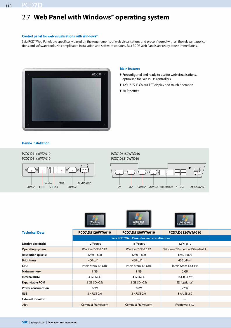
110
saia-pcd.com
PCD7D
PCD7.D51xxWTA010 PCD7.D61xxWTA010
PCD7.D6150WTC010PCD7.D6210WTI010
2 × USBAudio
ETH1COM3/4 DVIETH2
COM1/2 VGA COM3/4 COM1/2 2 × Ethernet 4 × USB
WindowsEmbedded CE
WindowsEmbedded CE
WindowsEmbedded Standard 7
Operation and monitoring
2.7 Web Panel with Windows® operating system
Control panel for web visualisations with Windows®:
Saia PCD® Web Panels are specifically based on the requirements of web visualisations and preconfigured with all the relevant applica-tions and software tools. No complicated installation and software updates. Saia PCD® Web Panels are ready to use immediately.
Main features
Preconfigured and ready to use for web visualisations, optimised for Saia PCD® controllers
12"/15"/21" Colour TFT display and touch operation
2× Ethernet
Technical Data PCD7.D5120WTA010 PCD7.D5150WTA010 PCD7.D6120WTA010
Saia PCD® Web Panels for web visualisations
Display size (inch) 12"/16:10 15"/16:10 12"/16:10
Operating system Windows® CE 6.0 R3 Windows® CE 6.0 R3 Windows® Embedded Standard 7
Resolution (pixels) 1280 × 800 1280 × 800 1280 × 800
Brightness 400 cd/m2 450 cd/m2 400 cd/m2
CPU Intel® Atom 1.6 GHz Intel® Atom 1.6 GHz Intel® Atom 1.6 GHz
Main memory 1 GB 1 GB 2 GB
Internal ROM 4 GB MLC 4 GB MLC 16 GB CFast
Expandable ROM 2 GB SD (OS) 2 GB SD (OS) SD (optional)
Power consumption 22 W 24 W 22 W
USB 3 × USB 2.0 3 × USB 2.0 3 × USB 2.0
External monitor –– –– ––
.Net Compact Framework Compact Framework Framework 4.0
Device installation
24 VDC/GND24 VDC/GND

111
saia-pcd.com
PCD7D
242.
2 m
m
340 mm 72
324 × 226 mm
261.12 mm163.
2 m
m
7 100 mm
12" Web Panel PCD7.D5120WTA010 PCD7.D6120WTA010
286
mm
410 mm
394 × 270 mm
331.2 mm
207
mm
767 100 mm
15" Web Panel PCD7.D5150WTA010 PCD7.D6150WTA010
286
mm
410 mm
394 × 270 mm
331.2 mm
207
mm
767 100 mm
15" Panel PC PCD7.D6150WTC010
347
mm
556 mm 798 100 mm
476.64 mm268.
11 m
m 539 × 331 mm
21" Panel PC PCD7.D6210WTI010
WindowsEmbedded Standard 7
WindowsEmbedded Standard 7
WindowsEmbedded Standard 7
Operation and monitoring
5S
wit
ch c
ab
ine
t
com
po
ne
nts
4C
on
sum
er
d
ata
acq
uis
itio
n3
De
dic
ate
d
roo
m c
on
tro
lle
rs2
Op
era
tio
n
an
d m
on
ito
rin
g1
Au
tom
ati
on
st
ati
on
s
PCD7.D6150WTA010 PCD7.D6150WTC010 PCD7.D6210WTI010
Saia PCD® Web Panels for web visualisations Saia PCD® Panel PCs designed for the high requirements of applications
15"/16:10 15"/16:10 21"/16:10
Windows® Embedded Standard 7 Windows® Embedded Standard 7 Windows® Embedded Standard 7
1280 × 800 1280 × 800 1920 × 1080
450 cd/m2 450 cd/m2 250 cd/m2
Intel® Atom 1.6 GHz Intel® Celeron® 8810E 2 × 1.6 GHz 2.1 GHz Intel® I7-2715QE
2 GB 2 GB 4 GB
16 GB CFast 100 GB HDD 100 GB HDD
SD (optional) via USB via USB
24 W 114 W 125 W
3 × USB 2.0 4 × USB 2.0 4 × USB 2.0
–– DVI/VGA DVI/VGA
Framework 4.0 Framework 4.0 Framework 4.0
General specifications
Protection type (front) IP 65
Web/FPT/VNC/File Server Yes
Supply voltage 24 VDC ±20%
Ethernet 2× Ethernet Ports RJ45
Serial RS-232 D-Sub 9-pin
Applications JAVA Runtime, microbrowser
Temperature range Operation: 0…50 °C, storage: –20…70 °C
Humidity Operation: 10…75%, storage: 10…95% non-condensing
Touch screen Resistive touch screen
Dimensions (W × H × D) and cut-out (W × H) mm
Cut-out:
Cut-out:
Cut-out:
Cut-out:
Clearance: Clearance:
Clearance: Clearance:

112
saia-pcd.com
PCD7D
Operation and monitoring

113
saia-pcd.com
A3
5S
wit
ch c
ab
ine
t
com
po
ne
nts
4C
on
sum
er
d
ata
acq
uis
itio
n3
De
dic
ate
d
roo
m c
on
tro
lle
rs2
Op
era
tio
n
an
d m
on
ito
rin
g1
Au
tom
ati
on
st
ati
on
s
Dedicated room controllers
Room controllers with a preconfigured regulation and control program which can be comprehensively parameterised via network communication and tailored to meet individual needs. Fully independent functionality is guaranteed even without a bus connection.
Dedicated room controller
Saia PG5 FBoxes, SBC S-Web Efficiency in project realisation Multiple application possibilities
Heating/cooling Integrated operation and temperature measurement
Wired (analogue, digital, touch screen) Wireless (infrared, radio, EnOcean receiver) Standard interfaces (e.g. web-based or LONWORKS® from external manufacturers)
Heating/cooling Fan coil Air quality control Light and shade
3.2 Compact room controller with S-Bus PCD7.L79xN Page
3.4 Operation systems for combinable room control systems PCD7.L6xx Page
3.3 Combinable room control system with S-Bus and LONWORKS® PCD7.L6XX Page
3.1 Project planning and engineering Page
118
124
120
114

saia-pcd.com
114 PCD7L
NL220
PG5
Dedicated room controllers
3.1 Project planning and engineering
In addition to the freely programmable controllers, the range of products for room-specific applications also includes dedicated SBC room controllers.
Engineering information
Commissioning the SBC S-Bus and LON room controller
If the room controller is used as part of a SBC S-Bus network, addressing and configuration is carried out by the Saia PCD Master using the Saia PG5 Controls Suite. Practical FBoxes simplify commissioning.
The FBox setup and room controller service pin are used for the addressing process. It is recommended pre-addressing the room controller in the office.
If the room controller is used in an LON network, the configuration is performed with a LONWORKS® tool such as the NL220 or LONMAKER®.
Integrating the SBC S-Bus room control system with
S-Engineering using function modules (FBoxes)
Programming and debugging environments are combined in the same tool.
Complex user programs are created by simply placing and linking FBoxes with no extensive programming knowledge required.
Online visualisation of the process values and online parame-ter adjustment directly at the FBoxes simplify the commissio-ning process.
Parameterised via bus with Saia PG5 Controls Suite
Main features
Application software included on delivery The room control-lers can be parameterised via network communication and fully independent functionality is still guaranteed without a bus connection.
Efficient integration for suitable applications Use of HVAC applications in zones and room automation systems which adjust the I/O mix and integrated applications precisely to the specific application. As the room controllers are not fully programmable, unsuitable applications should be implemented with a solution which includes the “E-Line”.
S-Bus room controllers are integrated into the Saia world
The Saia FUPLA (FBoxes) enable engineering in the standard SBC environment and exploit the benefits of the Saia PG5 Controls Suite.
The parameter windows of each FBox can be used to display online and directly adjust all setpoint values, actual values and statuses of the controller.
Detailed, context-sensitive FBox information, clear descrip-tions and graphic representations in the function chart editor (FUPLA) provide clear, easy to read programs.
It is possible to switch all control parameters to a control sys-tem using the PCD controller and thus reduce running costs.
Online visualisation of the HVAC room FBox.

saia-pcd.com
115PCD7L
S-Bus
Dedicated room controllers
5S
wit
ch c
ab
ine
t
com
po
ne
nts
4C
on
sum
er
d
ata
acq
uis
itio
n3
De
dic
ate
d
roo
m c
on
tro
lle
rs2
Op
era
tio
n
an
d m
on
ito
rin
g1
Au
tom
ati
on
st
ati
on
s
Efficiency in project realisation
The FBoxes shorten the “Engineering time” and simplify the com-missioning process, as the configuration data can be sent via the communication interface to up to 250 controllers in a single step.The automatic detection of the communication speed also simpli-fies the commissioning process.
This makes local operation using a PC workstation possible. The password protected control screens are loaded direct from the web server integrated in the automation station and displayed.
SBC S-Web
S-Web Editor macros simplify the efficient setup process of web-based commissioning, operation and service operating concepts.
Serial S-Net, LONWORKS®
Integrated web server
Visualisation and operation of the room parameters using the web server
Parameterisable application program
If the application supplied does not match the project require-ments, the application program for different system types can be activated and parameterised via PG5 FBoxes or S-Web. The application software already contains several user programs for systems such as combined radiators/cooling ceiling systems. The control parameters (PI) for the specific applications can be adjusted
and optimised.
Multiple application possibilities
Application programs for various types of systems are already pre-programmed in the controller and can be activated using the parameterisation.
Configurable using the PG5 Controls Suite
Fully independent functionality guaranteed even with no
bus connection
Once the application programs in the controller have been pa-rameterised, it is possible to run a fully independent operation without a PCD.The controller will therefore continue to operate uninterrupted even if communication with the Saia PCD automation station is disrupted.All the set configuration parameters are written to the EEPROM and remain stored there even with no operating voltage.
Functionality is also guaranteed in the event of a bus fault.
Local user prompts from PC workstation.
Local PC workplaces

saia-pcd.com
116 PCD7L
Dedicated room controllers
Project planning information
Maximum number of room controllers
The maximum number of room controllers that can be managed by a PCD system depends on the maximum electrical load of the serial S-Net, the bus system cycle time and the resources used by the functional objects.
Types of use and modes of operation
The function of the room controller is based on various types of use or modes of operation. Each of the selectable modes of operation can be assigned different control parameters.
Bus terminating resistor and bus cable for serial S-Net
(S-Bus/RS-485)
S-Bus cables must be installed as a line. Stub lines are not per-mitted and both ends of the cable must be terminated with a resistor (approx. 120 Ω) between the D and /D cables. The best signal quality is achieved using an active bus connection with a resistor to +5V and GND.
Use/comfort
The room is used and should be brought to the comfort temperature. This state can be reached by pressing the presence button, reacting to an external presence detector or a parameter on the network side.
Window contact openPresence detectionRoom use time program
Comfort
Standby
Reduced
Frost protection
0 h
2 h
4 h
6 h
8 h
10 h
12 h
14 h
16 h
18 h
20 h
22 h
24 h
Example: Operating mode switchover
Schematic illustration of an S-Bus/ RS-485 bus
Safety mode/Frost protection
No heating or cooling energy is fed into the room. This state is desirable if a window is open. The room controller keeps the room temperature above the preset frost line of 8° C.
Non-use/reduced
Reduced operation mode which is used when the room is unoccupied for long periods. The specified setpoint value offset is not active in this operation mode.
Standby
The room is prepared for use but no presence has yet been registered in the room. As long as the room is not classified as occupied by the presence function, the room controller maintains the room temperature within the specified limits at the standby temperature.
With S-Bus controllers, the 111 configuration register can be used to activate the integrated active bus terminating resistor or an
external PCD7.T161/2 termination box can be used.
Bus cable: A 2-strand twisted and shielded bus cable with cable strands of at least 0.5 mm2 must be used.
Bus shielding: The shielding of each S-Bus segment may only be connected with the electrical system ground at one point.
To avoid problems with large potential differences between the room controllers, the shielding of the S-Bus cable should be
connected with the GND of the room controller.
For more information, see S-Bus manual 26-739 (at www.sbc-support.com).
Recommendation: max. 4 S-Bus interfaces with up to 25 room controllers per interface so that resources are sufficient in most
cases and the communication cycle time remains < 2 seconds
At a communication speed of 38,400 baud, the communication time for a controller is approx. 15 ms or 80 ms. If the PCD program requires longer than 15 ms or 80 ms per PCD cycle, this value must be used as the basis of the calculation used to estimate the commu-nication cycle. For additional information please refer to chapter 1.1.Communication cycle = “15 ms or 80 ms per controller” × “Number of controllers”.
PCD7.L79xN
Resources: approx. 2 kB (Program memory,) per controller, max. 40 registers per controller, max. 16 flags per controller Bus cycle time per controller: approx. 15 ms
PCD7.L60x-1 (when using all FBoxes)
Resources: approx. 10 kB (Program memory,) per controller, max. 95 registers per controller, max. 36 flags per controller Bus cycle time per controller: approx. 80 ms
Start station End stationIntermediate
stations
Pull down Pull down
Terminating resistor
Terminating resistor
Pull up Pull up
RS-485S-Bus
+5V +5V/D D /D D /D D /D D
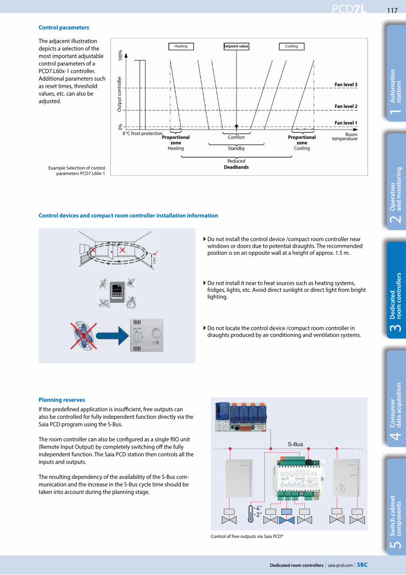
saia-pcd.com
117PCD7L
S-Bus
Dedicated room controllers
5S
wit
ch c
ab
ine
t
com
po
ne
nts
4C
on
sum
er
d
ata
acq
uis
itio
n3
De
dic
ate
d
roo
m c
on
tro
lle
rs2
Op
era
tio
n
an
d m
on
ito
rin
g1
Au
tom
ati
on
st
ati
on
s
Control parameters
Planning reserves
If the predefined application is insufficient, free outputs can also be controlled for fully independent function directly via the Saia PCD program using the S-Bus.
The room controller can also be configured as a single RIO unit (Remote Input Output) by completely switching off the fully independent function. The Saia PCD station then controls all the inputs and outputs.
The resulting dependency of the availability of the S-Bus com-munication and the increase in the S-Bus cycle time should be taken into account during the planning stage.
Do not install the control device /compact room controller near windows or doors due to potential draughts. The recommended position is on an opposite wall at a height of approx. 1.5 m.
Control of free outputs via Saia PCD®
Do not locate the control device /compact room controller in draughts produced by air conditioning and ventilation systems.
Do not install it near to heat sources such as heating systems, fridges, lights, etc. Avoid direct sunlight or direct light from bright lighting.
Control devices and compact room controller installation information
The adjacent illustration depicts a selection of the most important adjustable control parameters of a PCD7.L60x-1 controller. Additional parameters such as reset times, threshold values, etc. can also be adjusted.
Example Selection of control parameters PCD7.L60x-1
Heating Setpoint value Cooling
Comfort
Standby
ReducedDeadbands
8 °C frost protection Roomtemperature
Fan level 3
Fan level 2
Fan level 1O
utpu
t con
trol
ler
Proportional zone
Cooling
Proportional zone
Heating
0%10
0%

saia-pcd.com
118 PCD7L
S-BusRS485
ServicePin
/D D E1 E2
AuxInput
WindowContact
Y1 24V
24V 800 mA
PCD7.L793N
31 2
6
4 5 6 7 8
8 7 5 24 3 1
Power Supply24VAC
Y2 Y4Y3
E3
0-10V 2mA
Aux.0-10V
Y2YY Y3 Y4YY
E3
A
B
- +
24VAC
Serial S- Net RS485
PWM
N
3-PointOpen Close
0-10V 0-10VPWM
0-10
VSe
nsor
117
mm
84 mm
Dedicated room controllers
3.2 Compact room controller PCD7.L79xN
The series of compact room controllers is particularly suitable for simple systems which involve heating and/or cooling. The PCD7.L79xN series room controllers include the control of presence and setpoint values, the room temperature sensor and the valve or flap control in a single housing. The preconfigured regulation and control program is part of the basic software and can be parameterised via the network communication and adjusted to the individual requirements.
Efficient installation
The compact room controller can be installed directly onto a wall or in a flush-mounted box. A junction box is not required, which also simplifies the installation process.The plug-in housing (electronics) on the mounting plate with the terminals enables an easy exchange of the device with no complex and fault-prone rewiring required.
Mounting plate
Parameterised via bus with S-Engineering tools
Terminal assignment (example PCD7.L793N)
Connection terminals
Cable entry
Power supply 24 VAC
2 × Triac outputs 24 VAC
Serial S-Net
Button for configuring the S-Bus addresses
1 × analogue input 0…10 VDC
2× analogue outputs 0…10 VDC
2× digital inputs for isolated contacts– E1 window contact– E2 parameterisable function
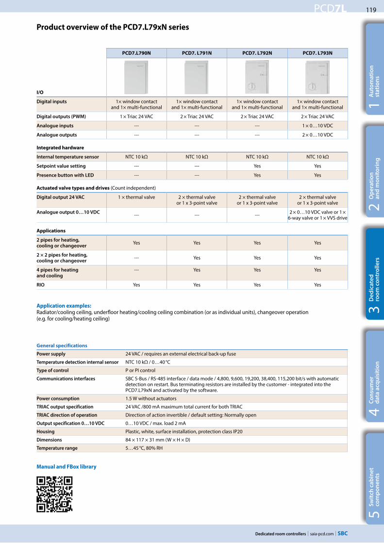
saia-pcd.com
119PCD7L
Dedicated room controllers
5S
wit
ch c
ab
ine
t
com
po
ne
nts
4C
on
sum
er
d
ata
acq
uis
itio
n3
De
dic
ate
d
roo
m c
on
tro
lle
rs2
Op
era
tio
n
an
d m
on
ito
rin
g1
Au
tom
ati
on
st
ati
on
s
General specifications
Power supply 24 VAC / requires an external electrical back-up fuse
Temperature detection internal sensor NTC 10 kΩ / 0…40 °C
Type of control P or PI control
Communications interfaces SBC S-Bus / RS-485 interface / data mode / 4,800, 9,600, 19,200, 38,400, 115,200 bit/s with automatic detection on restart. Bus terminating resistors are installed by the customer - integrated into the PCD7.L79xN and activated by the software.
Power consumption 1.5 W without actuators
TRIAC output specification 24 VAC /800 mA maximum total current for both TRIAC
TRIAC direction of operation Direction of action invertible / default setting: Normally open
Output specification 0…10 VDC 0…10 VDC / max. load 2 mA
Housing Plastic, white, surface installation, protection class IP20
Dimensions 84 × 117 × 31 mm (W × H × D)
Temperature range 5…45 °C, 80% RH
Product overview of the PCD7.L79xN series
Application examples:Radiator/cooling ceiling, underfloor heating/cooling ceiling combination (or as individual units), changeover operation (e.g. for cooling/heating ceiling)
PCD7.L790N PCD7. L791N PCD7. L792N PCD7. L793N
I/O
Digital inputs 1× window contact and 1× multi-functional
1× window contact and 1× multi-functional
1× window contact and 1× multi-functional
1× window contact and 1× multi-functional
Digital outputs (PWM) 1 × Triac 24 VAC 2 × Triac 24 VAC 2 × Triac 24 VAC 2 × Triac 24 VAC
Analogue inputs --- --- --- 1 × 0…10 VDC
Analogue outputs --- --- --- 2 × 0…10 VDC
Integrated hardware
Internal temperature sensor NTC 10 kΩ NTC 10 kΩ NTC 10 kΩ NTC 10 kΩ
Setpoint value setting --- --- Yes Yes
Presence button with LED --- --- Yes Yes
Actuated valve types and drives (Count independent)
Digital output 24 VAC 1 × thermal valve 2 × thermal valve or 1 x 3-point valve
2 × thermal valve or 1 x 3-point valve
2 × thermal valve or 1 x 3-point valve
Analogue output 0…10 VDC --- --- --- 2 × 0…10 VDC valve or 1 × 6-way valve or 1 × VVS drive
Applications
2 pipes for heating,
cooling or changeoverYes Yes Yes Yes
2 × 2 pipes for heating,
cooling or changeover--- Yes Yes Yes
4 pipes for heating
and cooling
--- Yes Yes Yes
RIO Yes Yes Yes Yes
Manual and FBox library

saia-pcd.com
120 PCD7L
LONWORKS
PCD7.L660PCD7.L665
PCD7.L645
PCD7.L644
Dedicated room controllers
3.3 Combinable room control system with S-Bus and LONWORKS® PCD7.L6xx
For multi-section room automation including air quality control and light/shade.
THE PCD7.L6XX COMBINABLE ROOM CONTROL SYSTEM BASED ON SERIAL S-NET OR LONWorks® networks is used for HVAC applications primarily in fan coil devices, radiator/cooing ceiling combinations and variable air volume systems (VAV). The extension module for light and shade allows the electrical system to be efficiently integrated into the room automation solution. The various room control unit options enable users to create individual operating concepts.
Features
Comprehensive range of applications possible using parameterisable application programs Room controller for communication via serial S-Net or LonWorks® Extension module for the electrical system Can be combined with various room control unit options The Lon room controllers fulfil the “Fan Coil Unit Object (8020)” application profile of LonMark®.
Control accuracy eu.bac certified
This “European building automation controls association” certificate certifies that the PCD7.L616 room controller saves more energy than required by the European standards.This certification has been issued for a 2- and 4-pipe fan coil application and certifies the controller has a tempera-ture control accuracy (CA) of at least 0.2 K, which is a very accurate value compared to the room controllers of other manufacturers.
homepage
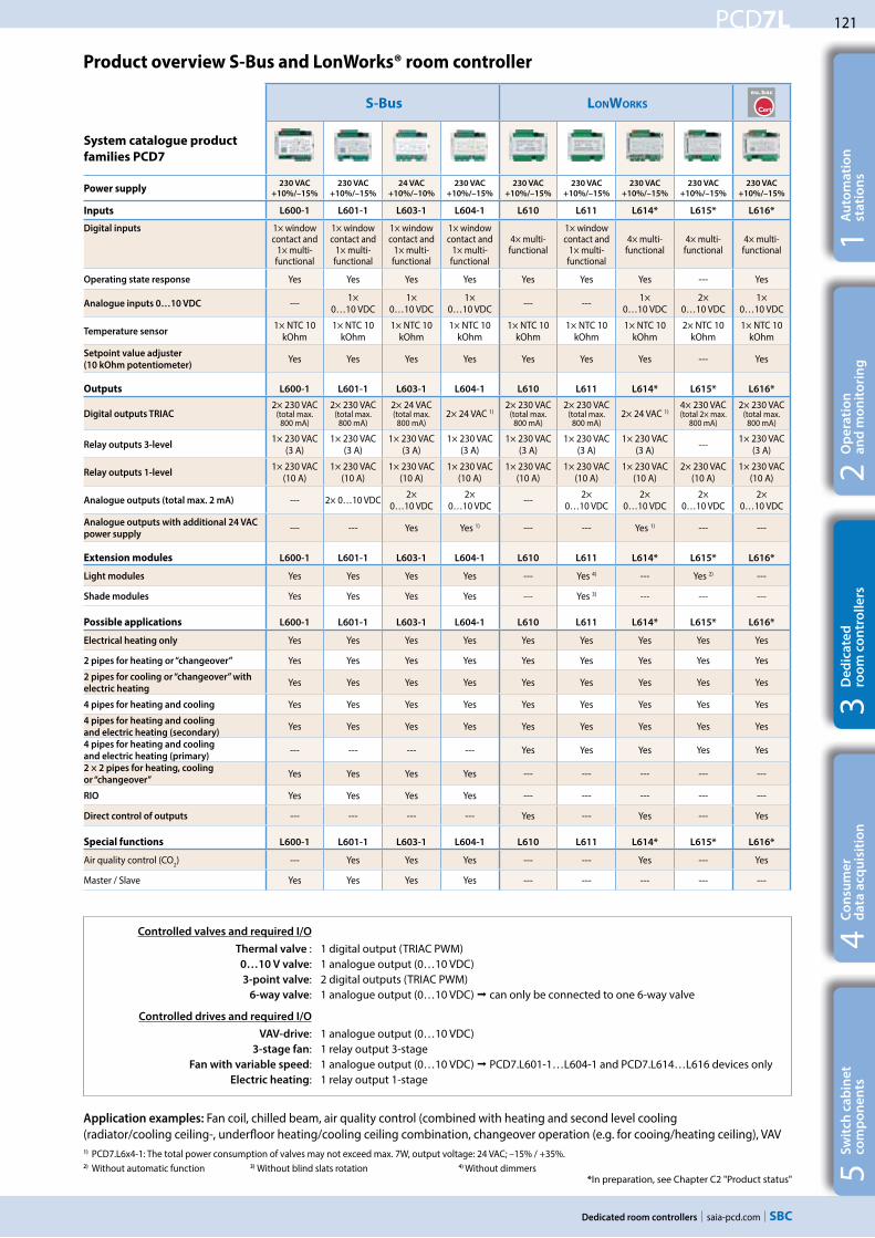
saia-pcd.com
121PCD7L
Dedicated room controllers
5S
wit
ch c
ab
ine
t
com
po
ne
nts
4C
on
sum
er
d
ata
acq
uis
itio
n3
De
dic
ate
d
roo
m c
on
tro
lle
rs2
Op
era
tio
n
an
d m
on
ito
rin
g1
Au
tom
ati
on
st
ati
on
s
Product overview S-Bus and LonWorks® room controller
S-Bus LONWORKS
System catalogue product
families PCD7
Power supply230 VAC
+10%/–15%
230 VAC
+10%/–15%
24 VAC
+10%/–10%
230 VAC
+10%/–15%
230 VAC
+10%/–15%
230 VAC
+10%/–15%
230 VAC
+10%/–15%
230 VAC
+10%/–15%
230 VAC
+10%/–15%
Inputs L600-1 L601-1 L603-1 L604-1 L610 L611 L614* L615* L616*
Digital inputs 1× window contact and
1× multi-functional
1× window contact and
1× multi-functional
1× window contact and
1× multi-functional
1× window contact and
1× multi-functional
4× multi-functional
1× window contact and
1× multi-functional
4× multi-functional
4× multi-functional
4× multi-functional
Operating state response Yes Yes Yes Yes Yes Yes Yes --- Yes
Analogue inputs 0…10 VDC --- 1× 0…10 VDC
1× 0…10 VDC
1× 0…10 VDC --- --- 1×
0…10 VDC2×
0…10 VDC1×
0…10 VDC
Temperature sensor1× NTC 10
kOhm1× NTC 10
kOhm1× NTC 10
kOhm1× NTC 10
kOhm1× NTC 10
kOhm1× NTC 10
kOhm1× NTC 10
kOhm2× NTC 10
kOhm1× NTC 10
kOhm
Setpoint value adjuster
(10 kOhm potentiometer)Yes Yes Yes Yes Yes Yes Yes --- Yes
Outputs L600-1 L601-1 L603-1 L604-1 L610 L611 L614* L615* L616*
Digital outputs TRIAC 2× 230 VAC
(total max. 800 mA)
2× 230 VAC (total max.
800 mA)
2× 24 VAC (total max.
800 mA)2× 24 VAC 1)
2× 230 VAC (total max.
800 mA)
2× 230 VAC (total max.
800 mA)2× 24 VAC 1)
4× 230 VAC (total 2× max.
800 mA)
2× 230 VAC (total max.
800 mA)
Relay outputs 3-level1× 230 VAC
(3 A)1× 230 VAC
(3 A)1× 230 VAC
(3 A)1× 230 VAC
(3 A)1× 230 VAC
(3 A)1× 230 VAC
(3 A)1× 230 VAC
(3 A) --- 1× 230 VAC (3 A)
Relay outputs 1-level1× 230 VAC
(10 A)1× 230 VAC
(10 A)1× 230 VAC
(10 A)1× 230 VAC
(10 A)1× 230 VAC
(10 A)1× 230 VAC
(10 A)1× 230 VAC
(10 A)2× 230 VAC
(10 A)1× 230 VAC
(10 A)
Analogue outputs (total max. 2 mA) --- 2× 0…10 VDC 2× 0…10 VDC
2× 0…10 VDC --- 2×
0…10 VDC2×
0…10 VDC2×
0…10 VDC2×
0…10 VDC
Analogue outputs with additional 24 VAC
power supply--- --- Yes Yes 1) --- --- Yes 1) --- ---
Extension modules L600-1 L601-1 L603-1 L604-1 L610 L611 L614* L615* L616*
Light modules Yes Yes Yes Yes --- Yes 4) --- Yes 2) ---
Shade modules Yes Yes Yes Yes --- Yes 3) --- --- ---
Possible applications L600-1 L601-1 L603-1 L604-1 L610 L611 L614* L615* L616*
Electrical heating only Yes Yes Yes Yes Yes Yes Yes Yes Yes
2 pipes for heating or “changeover” Yes Yes Yes Yes Yes Yes Yes Yes Yes
2 pipes for cooling or “changeover” with
electric heatingYes Yes Yes Yes Yes Yes Yes Yes Yes
4 pipes for heating and cooling Yes Yes Yes Yes Yes Yes Yes Yes Yes
4 pipes for heating and cooling
and electric heating (secondary)Yes Yes Yes Yes Yes Yes Yes Yes Yes
4 pipes for heating and cooling
and electric heating (primary)--- --- --- --- Yes Yes Yes Yes Yes
2 × 2 pipes for heating, cooling
or “changeover”Yes Yes Yes Yes --- --- --- --- ---
RIO Yes Yes Yes Yes --- --- --- --- ---
Direct control of outputs --- --- --- --- Yes --- Yes --- Yes
Special functions L600-1 L601-1 L603-1 L604-1 L610 L611 L614* L615* L616*
Air quality control (CO2) --- Yes Yes Yes --- --- Yes --- Yes
Master / Slave Yes Yes Yes Yes --- --- --- --- ---
Application examples: Fan coil, chilled beam, air quality control (combined with heating and second level cooling (radiator/cooling ceiling-, underfloor heating/cooling ceiling combination, changeover operation (e.g. for cooing/heating ceiling), VAV 1) PCD7.L6x4-1: The total power consumption of valves may not exceed max. 7W, output voltage: 24 VAC; –15% / +35%. 2) Without automatic function 3) Without blind slats rotation 4) Without dimmers
Controlled valves and required I/O
Thermal valve : 1 digital output (TRIAC PWM) 0…10 V valve: 1 analogue output (0…10 VDC) 3-point valve: 2 digital outputs (TRIAC PWM) 6-way valve: 1 analogue output (0…10 VDC) can only be connected to one 6-way valve
Controlled drives and required I/O
VAV-drive: 1 analogue output (0…10 VDC) 3-stage fan: 1 relay output 3-stage Fan with variable speed: 1 analogue output (0…10 VDC) PCD7.L601-1…L604-1 and PCD7.L614…L616 devices only Electric heating: 1 relay output 1-stage
*In preparation, see Chapter C2 "Product status"

saia-pcd.com
122 PCD7L
1 2 3 4 5 76
Y1 N Y2
1 2 3
Y30-10 V 2 mA
Y4 K1 K2 N V1 V3V2
NL
NL
ValveOption
A B 10 9 8 7 6 5 4 3 12
/D D E2 E1 S P1 E3 R5V SerialBusNetwork Aux.
InputWindowContact
Temp.Sensor
Pot. Aux.0-10 V
LED
RC
ServicePin
230 V 800 mA
Made in EU
Power Supply230 V
230 V 3 A
Valve1/2
Fanspeed3 steps
Dedicated room controllers
Terminal assignment (example PCD7.L601-1)
Technical Data
TRIAC output specification 10 mA…800 mA, maximum total current of both TRIACs
Current draw Without actuator approx. 10 mA to 100 mA requires an external electrical back-up fuse
Protection The module has to be installed in a locked box with aerations – minimum size: 240 × 145 × 100 mm
Dimensions W x H x D 132 × 95 × 45 mm
Temperature range 5…45 °C, 80 % RH
Communication with S-Bus
Interface RS-485, max. cable length of bus cable depends on baud rate, under ideal conditions up to max. 1200 m
Transmission rate 4,800, 9,600, 19,200, 38,400, 115,200 bit/s with automatic detection on restart
Log SBC S-Bus data mode (slave)Bus terminating resistors must be installed by the customer – with integrated L60x these can be activated by software.
Communication with LONWORKS®
Interface FTT 10a
Transmission rate 78 kBit/s
Topology Free topology max. 500 m, bus topology max. 2700 m
Number of LON nodes Max. 64 per segment, over 32,000 in one domain / in accordance with LONMARK® 8020 profile
Dimensions for
PCD7.L60x-1 PCD7.L61x PCD7.L62x
Mounting
On 35 mm DIN rail Or with min. 2 × Ø 3 mm screws on an even surface
Manuals and FBox library
Supply voltage 230 VAC
2 × TRIAC outputs 230 VAC
Serial S-Net
2× analogue outputs 0…10 VDC
1× relay output
2× digital inputs for isolated contacts– E1 window contact– E2 parameterisable function
Analogue room control unit or additional temperature sensor
NTC 10 kOhm
Internal data bus to con-nect digital room control
devices or extension modules
Button for configuring the S-Bus addresses
Outputs for 3-stage fan 230 VAC
1 × analogue input 0…10 VDC

saia-pcd.com
123PCD7L
Dedicated room controllers
5S
wit
ch c
ab
ine
t
com
po
ne
nts
4C
on
sum
er
d
ata
acq
uis
itio
n3
De
dic
ate
d
roo
m c
on
tro
lle
rs2
Op
era
tio
n
an
d m
on
ito
rin
g1
Au
tom
ati
on
st
ati
on
s
PCD7.L620N PCD7.L621N PCD7.L622N PCD7.L624N
Where there are several extension modules of the same type,
the same outputs can be controlled in similar groups for each
room controller.
On/Off light outputs, 1 relay 230 VAC/2 A per output 1) 3×: L1, L2, L3 Dimmable light outputs, 1 relay 230 VAC/2 A 1) and output 1…10 V max. 3 mA 2×: L3, L4 3×: L1, L2, L3
Motor outputs, 2 relays 230 VAC/2 A per output 2) 1×: S4 3×: S1, S2, S3Power supply 230 VACMax. current consumption via supply terminal 6 AIsolated contact inputs --- --- --- ---RC-Bus connection • • • •Protection type IP 20 Dimensions 132 × 95 × 45 mm Temperature range 5…45 °C, 80 % RH 1) Start current < 60 A during < 2 ms2) Peal current < 4 A during < 20 ms Supply with no connection plug. Information regarding Wieland item numbers is available from www.sbc-support.com.
Light and shade modules for expanding room controllers
Light and shade in groups
The light and shade extension modules are controlled using group commands. Four independent groups for light and shade are avail-able per controller. Each output can be assigned to one or more groups. The light groups can be switched on/off together or separately. The shade groups can also operate independently to control the blinds.
Example of the assignment of the module output to the group
Accessories
PCD7.L672 Room controller connection cable / extension module RJ-11 / RJ9, 0.3 m
PCD7.L672-10 Room controller connection cable / extension module RJ-11 / RJ9, 10 m
PCD7.L672-50 Room controller connection cable / extension module RJ-11 / RJ9, 50 m
Lighting groups
Switching commands for lights
Groups 1…4 – On/Off Only Group 1 – On/Off Only Group 2 – On/Off Only Group 3 – On/Off Only Group 4 – On/Off
Switching commands for blinds
Groups 1…4 – Open / Close Only group 1 – Open / Close Only group 2 – Open / Close Only group 3 – Open / Close Only group 4 – Open / Close
Shade groups
Blind 2
Group 4
Blind 1
Group 1
Blind 3
Group 2
Blind 4
Group 3
Lights 1
Group 1
Lights 3
Group 2
Light 2
Group 3
Light 4
Group 4
Room controllers L2
PCD7.L620NL1 / L3
L3
PCD7.L621N L4 / S4
S2
PCD7.L622N S1 / S3
Lights, dimmable lighting and blinds can controlled on/off with the extension module PCD7.L62xN in conjunction with a PCD7.L60x-1 room controller. FBoxes enable, among other things, a reconfiguration of the dimming ramp or of the rotation time for window blind slats. Control instructions may be executed either manually from a room control unit or automatically via the PCD7.L665/6 presence sensor or via S-Bus from the PG5 program. This enables savings in room automation energy costs across plant systems.
Note re. light outputs:
When the PCD7.L621N expansion module is operating in conjunction with the PCD7.L620N or PCD7.L624N expansion module on a single controller, the L3 output can only be switched within the same group. The same behaviour also applies to the outputs L1, L2 and L3 if the PCD7.L620N and PCD7.L624N expansion module is operated on the same controller.

saia-pcd.com
124 PCD7L
26
85,3 18 55,8
4
ø3,1
ø6,2
120,
3
84 66,8 60
7
Dedicated room controllers
3.4 Operation systems for combinable room control system PCD7.L6xx
Individual operating concepts can be implemented using the combination room control system:
Simple connection via the internal RC-Bus to the RJ-9 connector
LONWORKS® room control unit of external manufacturers via LON-Bus Web-based room control units via HTTP
PCD7. L630 PCD7. L631 PCD7. L632
Analogue room control units
Terminals
max. 10 m cable length
Temperature sensor NTC 10 kΩSetpoint value adjuster --- Poti 10 kΩ | linearPresence sensor --- --- Contact to GNDResponse --- --- LED
PCD7. L640 PCD7. L641 PCD7. L642 PCD7. L644
Digital room devices
RC-Bus
max. 50 m cable length
Temperature sensor • • • •Setpoint value adjuster • • • •Presence sensor --- • • •Response --- • • •Fan control --- --- • •Display menu for: HVAC functions --- --- --- Parameterisable Light and shade --- --- --- Parameterisable
PCD7.L645W/B Dimensions and installation options
3.2“ touch screen room
control unit PCD7.
L645W/B
RC-Bus
max. 10 m cable length
Control for: setpoint value, fan, light, shade and presence
If, for example, a function is no longer to be displayed, access to specific menus can be prohibited with a password and hidden.
Automatic adjustment of the dimmable backlight depending on the actual brightness in the room ensures optimum reading comfort
Screen standby timer for setting the time after which the screen will dim following the last action
Star keys to define user settings and to call them up at a push of a button if required (up to 4 predefined scenarios can be saved)
PCD7.L645W: White housing (Pantone Q 716-3-5), 1 white and 1 aluminium front panel
PCD7.L645B: Black housing (RAL 9011), 1 black and 1 aluminium front panel
Some projects require individual design in terms of shape and colour.The PCD7.L645W/B offers the option of replacing the front panel.The scale drawing for production on page 8-1 of the 27-605 manual is provided for manufacturing customised front panels.
Dimensions and installation options
PCD7.L63x, PCD7.L64x, PCD7.L651, PCD7.L663Housing colour: RAL 9016
Mounting plate

saia-pcd.com
125PCD7L
IP FTT10
SAIA BURGESS CONTROLSSAIA BURGESS CONTROLS
Dedicated room controllers
5S
wit
ch c
ab
ine
t
com
po
ne
nts
4C
on
sum
er
d
ata
acq
uis
itio
n3
De
dic
ate
d
roo
m c
on
tro
lle
rs2
Op
era
tio
n
an
d m
on
ito
rin
g1
Au
tom
ati
on
st
ati
on
s
Control devices PCD7. L660 PCD7. L662
Receivers PCD7. L661 PCD7. L663 PCD7. L665*
max. 50 m cable length
Wall mounted control device Including for fixed installation ---
Communication / IR (infrared) Unidirectional •Communication / radio Bidirectional ---
Temperature sensor • • ---
Setpoint value adjustment • • • Presence control • • Movement sensor
Fan control • • •Light and shade • • • Brightness sensor --- •Supply voltage control device 2 × AAA 1.5 V Micro ---Temperature range +5…45 °C, 80% RH
Portable room control units with display and function keys
Direct connection of the room control units from the external supplier via LONWorks®
System requirements:
Room controller with LONWORKS® interface. For making additional connections to the automation station, the – PCD3.M – PCD2.M5 – PCD1.M2 can be connected via the LON over IP
or via an external FTT10/IP router.
EnOcean radio receiver PCD7.L651* for connecting Thermokon room control devices and EnOcean wireless switches
More detailed information on the compatibility of the EnOcean receivers can be found in the PCD7.L651 manualmax. 50 m cable length
Example of EnOcean wireless switch for controlling lights and Venetian blinds (compatible with various control programs of various manufacturers)
Example of EnOcean room control devices for controlling HVAC
Individual solutions using web-based room control units
System requirements:
Room controller with communication to PCD via S-Net, LONWORKS® for HVAC control. PCD with corresponding interface and interface for connecting to the desired control device, e.g. web panel, PC, iPhone, etc.
Communicative room control units
*In preparation, see Chapter C1 "Product status"
LONWORKS®
Room
Router
Serial S-Net
HTTP direct
Room
RC-Bus

saia-pcd.com
126 PCD7L
PCD7.L644
Dedicated room controllers
Example of system structure for touch panel and extension module
Room controllers: Basic types PCD7.L600-1, PCD7.L601-1, PCD7.L603-1, PCD7.L604-1 and PCD7.L611 The room control units and extension modules are connected to the room controller as required (the extension modules can only be operated if connected to a room controller) A maximum of 4 groups each of light and shade functions can be configured
3 options for controlling extension modules:
Accessories
PCD7.L670 Connection cable for digital room control units RJ9 / RJ9, 10 m
PCD7.L670-30 Connection cable for digital room control units RJ9 / RJ9, 30 m
PCD7.L670-50 Connection cable for digital room control units RJ9 / RJ9, 50 m
PCD7.L671 Connection cable for analogue room control units RJ11 / open cable strand, 10 m
PCD7.L673 Connecting cable set for digital room control units, 3 x RJ9 and 1 x RJ11, length 11 m
Room controller with extension module, input module and portable room control unit PCD7.L66x
Room controller +
3 × On/Off lights PCD7.L620N
2 × dimmers 1 × blind motor
PCD7.L621N
3 × blind motors PCD7.L622N
3 × dimming lights PCD7.L624N
Room controller with two extension modules and digital room control unit
Extension modules of the same type cannot be controlled separately per room controller!
Room controller +
3 × On/Off lights3 × blind motors
PCD7.L620N PCD7.L622N
3 × dimmers3 × blind motors
PCD7.L624N PCD7.L622N
2 × dimmers4 × blind motors
PCD7.L621N PCD7.L622N
4 × dimming lights1 × blind motor
PCD7.L621N PCD7.L624N
Room controller with three extension modules and touch screen room control unit PCD7.L645B
Extension modules of the same type cannot be controlled separately per room controller!
Room controller +
4 × dimmers 4 × blind motors
PCD7.L621N PCD7.L622N PCD7.L624N
digital: max. 50 m, PCD7.L670-xx
digital: max. 10 m, PCD7.L670
max. 50 m PCD7.L672-xx
max. 50 m, PCD7.L672-xx max. 50 m, PCD7.L672-xx
max. 50 mPCD7.L672-xx
max. 50 m PCD7.L672-xx
max. 50 m, PCD7.L672-xx
max. 50 mPCD7.L670-xx
PCD7.L661 or
S-Bu
s, LO
NW
ORK
S®
PCD7.L660
PCD7.L665
PCD7.L645B

saia-pcd.com
127PCD7L
A
B
C
D
COCO22
M
T
M
Dedicated room controllers
5S
wit
ch c
ab
ine
t
com
po
ne
nts
4C
on
sum
er
d
ata
acq
uis
itio
n3
De
dic
ate
d
roo
m c
on
tro
lle
rs2
Op
era
tio
n
an
d m
on
ito
rin
g1
Au
tom
ati
on
st
ati
on
s
Networked room automation for an optimum synergy between the sections Temperature control based on demand control Combined air quality and temperature control
Cross-plant room automation
The combinable room control system can be used for multi-section room automation whereby the demand-based control and communication to the primary system can achieve the highest energy efficiency classes in accordance with DIN EN 15232 for the entire building automation system.
Energy efficiency of building energy efficiency classes in accordance with EN 15232
Class A: – High energy efficiency room automation
and cross-linked plants
Class B: – Optimised solutions for each plant,
partially cross-linked
Class C:– Standard room automation,
reference document
Class D:– No room automation,
not energy efficient
Light and shade
Extension module
PCD7.L62x
Control devicesPresence detection
Brightness measurement PCD7.L665
PCD7.L600-1 … 604-1
SERIAL S-NET
PCD7.L600-1 … 604-1
SERIAL S-Net
PCD3.M5560
PCD7.L610 … 616
LONWORKS ®
Internal RC-Bus
PCD7.L645
PCD7.L644
PCD7.L660

saia-pcd.com
128 PCD7L
Dedicated room controllers

129
saia-pcd.com
A4
www.s-monitoring.com
5S
wit
ch c
ab
ine
t
com
po
ne
nts
4C
on
sum
er
d
ata
acq
uis
itio
n3
De
dic
ate
d
roo
m c
on
tro
lle
rs2
Op
era
tio
n
an
d m
on
ito
rin
g1
Au
tom
ati
on
st
ati
on
s
Consumption data collection
With the field devices of the S-Monitoring system, electri-cal energy is measured and signals from water, gas and heating meters are captured. The S-Monitoring application processes and visualises data automatically in a clearly arranged manner. Thus, the system generates a high degree of transparency regarding resource consumption. This functions from just a few measuring points up to thousands of measuring points in distributed properties.
Collect, visualise and process consumption data
S-Monitoring makes it easy to manage energy and consumption. Ready-to-use directly from the packaging and it does not require any complicated configuration and programming. It can also be customised to meet your specific requirements – it is a system, that grows with you.
4.1 System overview Page
Collect, convert and transmit S0 pulses: With the PCD7.H104 pulse counter modules, non-bus-capable meters can also be integrated into an S-Monitoring system.
4.2 Saia PCD® S0 pulse counter Page
The Power Quality Analyzer (PQA) is a device for measuring and checking the quality of the electricity system, manufactured as a DIN rail unit in industrial quality.
4.5 Saia PCD® Quality Analyzer Page
Saia Burgess Controls, is a European market leader in bus-capable energy meters for sub metering of ectrical energy data: for machines, plants and building components.
4.4 Energy meters ALD, ALE and AWD Page
The E-Monitor combines data capture, visualisation and logging in one compact control panel. It is delivered pre-programmed with the S-Monitoring application.
4.7 Saia PCD® E-Monitor Page
The E-Controller with S-Monitoring function combines data capture, visualisation and logging of energy consumption in one compact device. Users can use the inputs and outputs to intervene in processes for regulation.
4.8 Saia PCD® E-Controller Page
S-Monitoring is an integral part of the COSinus operating system and is integrated into all controls with the extension xx60 and the pWeb panels. It enables consumption data to be acquired automatically without time-consuming programming and saves it on the file system.
4.6 S-Monitoring application Page
Wireless transmission of RS-485 interfaces. Use as a wireless transponder or repeater.
4.3 Saia PCD® Radio Modem Page
130
132
142
134
148
150
144
133

130
saia-pcd.comSBC Consumption data collection
4.1 System overview
S-Monitoring makes it easy to manage energy and consumption. Ready-to-use directly from the packaging and it does not require any complicated configuration and programming. It can also be customised to meet your specific requirements – it is a system, that grows with you.The system includes devices and components for capturing, recording and displaying consumption. With the Web Panel installed on-site, analysis can be carried out on the office PC or remotely via the Internet web browser. The open IT interfaces make it possible to connect the system to a superordinate data management system at any time. There is no need to replace the hardware to do this.
Ready for use immediately on delivery Ready for use immediately on delivery
Example of external software

131
saia-pcd.comConsumption data collection
5S
wit
ch c
ab
ine
t
com
po
ne
nts
4C
on
sum
er
d
ata
acq
uis
itio
n3
De
dic
ate
d
roo
m c
on
tro
lle
rs2
Op
era
tio
n
an
d m
on
ito
rin
g1
Au
tom
ati
on
st
ati
on
s
Remote visualisation and evaluation of consumption
Reading and operating via LAN/Internet with web browser and mobile devices
Integration into other systems via standard interfaces
If the Web Panel and controller are connected to a network (LAN), meter readings and operation can be carried out using commercially available PCs with standard browsers. Special software installations are not required and apps are available for mobile devices. This can even be carried out across locations if there is an Internet connection.Databases, energy management software or control systems can be connected via standard interfaces (e.g. FTP, CGI, HTTP, etc.).
With step-by-step introduction, findings from the learning curve are incorporated and lead to optimum results
Record consumption
Wide range of single and 3-phase energy meters and network analyzers
S0 interface for the integration of commercially available meters for gas, water, oil, etc.
Saia PCD® energy meters and network analyzers follow established installation technology and are suitable for DIN rails of commercially available distribution boxes. Integrated into a bus system covering a distance of up to 1 km, the measured values are transmitted to the Web Panel and controllers for the purpose of analysis and logging. Via pulse counters with an interface, commercial available meters with S0 output can be connected to the bus system.
Logging consumption
Historical consumption readings (Day / Week / Month / Year)
Logging in Excel-readable files
The Web Panel and controllers read consumption values of the connected meters and display them in the form of a web visualisation. This can be called up either directly on the Web Panel or via the controller’s web server with a web browser. Consumption and costs can be called up in meaningful diagrams via an intuitive user interface. In addition, the Web Panel and controllers record captured values in Excel-readable CSV files, which can be easily transferred to a PC via FTP. The function can be activated on any new controller. The E-Controller and E-Monitor are already pre-installed in the factory and are ready for use without further programming.
Continuous optimisation in calculable steps:
Sustainable resource management means a continuous gain in knowledge in a changing environment. The optimum solution is different for each business, and must be developed with careful consideration. S-Monitoring supports a cautious approach in small, controllable steps and starts with the basics. It is possible to start resource management without external help using cost-effec-tive, easy-to-install components. Even after just a few days, initial results are set and point the way for further optimisation steps. The investment risk is negligible and remains limited to each individual development step.
Effect
Cost
Risk
Time

132
saia-pcd.comSBC
kWh
kWh
58
85 45
35
28
43
1)
Consumption data collection
4.2 S0 impulse counter PCD7.H104 S0 Collect, convert and transmit pulses
If already installed meters, which are not bus-capable, are to be integrated into an automation system, the Saia PCD7.H104 S0 pulse counter is the easiest way. This is the case for refurbishments, for example, if the existing meter infrastructure has to be made bus-capable and there is no question of buying new meters. With this S0 pulse counter, meters (electricity, water, heat, etc.) with an S0 pulse output from any manufacturer can be connected directly using a serial RS-485 S-Bus or Modbus connection to the Saia PCD, the E-Monitor or any controller. This enables efficient transfer, evaluation and forwarding of energy data without additional complicated coupler modules. For connection to Saia PCD® systems, there are ready-made FBoxes. Via the interfaces, the number or valence of pulses can be transmitted.
1) Chapter 4.7 "E-Monitor" contains more information ON THIS TOPIC
FBoxes for integration into FUPLA
General technical data
Operating voltage 230 VAC (–20/+15 %)
Current draw < 12 mA
Power consumption < 3 W
Number of S0 inputs 4, in accordance with S0 IEC 62053-31
Frequency max. 17 Hz
Pulse low/high Min. 30 ms
S-Bus version
Order number PCD7.H104SE
Log S-Bus data mode
Bus system Serial RS-485 interface
Transmission rate 2,400, 4,800, 9,600, 19,200, 38,400, 57,600, 115,200The transmission rate is detected automatically
Bus length (max.) 1,200 m (without amplifier)
Response time Write: 30 ms
System response time Read: 20 ms
Modbus version
Order number PCD7.H104D
Log Modbus RTU as per IDA specification
Bus system Serial RS-485 interface
Transmission rate
(bit/s)
2,400, 4,800, 9,600, 19,200, 38,400, 57,600, 115,200The transmission rate is detected automatically
Bit settings 8 databit, even parity, 1 stop bit8 databit, odd parity, 1 stop bit8 databit, no parity, 2 stop bit
Maximum bus length 1,200 m (without amplifier)
Response time Type 5 characters
System response time max. 60 ms
S0 pulses
S0 pulses
Size
Device PCD7.H104DZ44 must be used for parity 8N1!

133
saia-pcd.comConsumption data collection
5S
wit
ch c
ab
ine
t
com
po
ne
nts
4C
on
sum
er
d
ata
acq
uis
itio
n3
De
dic
ate
d
roo
m c
on
tro
lle
rs2
Op
era
tio
n
an
d m
on
ito
rin
g1
Au
tom
ati
on
st
ati
on
s
System properties
Radio transmission of RS-485 interfaces (Modbus and S-Bus)
869 MHz band
Can be used in Europe with no approval required
Can be used as Point to Point, multipoint or repeater
Internal or external antenna
Galvanic isolation between supply and bus
Status LEDs at the front
NFC interface
Configuration using FBoxes
The PCD7.T4850-RF RF modem transparently transfers the connected RS-485 interface (Modbus and S-Bus) via radio. The frequency range of 869 MHz can be used in Europe. The devices can therefore be operated using the self-declaration with no additional approval required. The modules have an integrated antenna that enables data to be transferred with no additional hardware required. If an external antenna is required, it can be connected via a connector on the front plate. The classic hat-shape enables the 35 mm wide housing to fit into an electri-cal control cabinet. The device has rotary switches for parameter configuration that allows the speed of RF-data transmission and radio channel to be selected.
Technical Data
Interfaces
Wire-connected communication interface
RS-485 with galvanic isolation Baud rate: 2,400, 4,800, 9,600, 19,200, 38,400, 57,600, 115,200 bps (autobauding, parity detection)
Radio communication 2,400, 9,600, 38,400, 57,600 bps, selected with rotary knob
Frequency band 869.475…869.6 MHz
Frequency channels (sub-bands) 4 channels, selected with rotary knob
Radio range (line of sight) Internal antenna: 1000 m @2400 bpsExternal antenna: 6000 m @2400 bps
Service interface NFC (near field communication)
General specifications
Supply voltage 230 VAC, −20 / +15%, (50 Hz)
Electrically isolated 2.3 kVDC between current supply and RS-485
Dimensions Housing width 2 HP (35 mm), compatible with electrical cabinet (in accordance with DIN 43880, size 2 × 55 mm)
Mounting type DIN rail in accordance with DIN EN 60715 TH35 (1 × 35 mm)
Ambient temperature Operation: 0…+55°C without forced ventilation Storage: −40…+70°C
Power consumption < 4 W
Adapter for external antenna An adapter is supplied to connect an external SMA antenna to the radio module
Accessories
PCD7.K840 External antenna Antenna with SMA connection plug
The PCD7.T4850-RF device may be used in all EU countries including Switzerland and Norway. Approvals for other countries are listed in the clarification. The limitation of broadcasting time must be limited in accordance with standard ERC 70-03 to 10%.
Device design
RS-485 interface
Antenna connection
Address switch
Supply
System LEDs
Connection example
4.3 Radiomodem PCD7.T4850-RF (RF modem, RS-485)

134
saia-pcd.comSBC
82
27
62
4,5
6
70
65 x 11,7 = (58,5)
768
4,5930,5 9
11
57,7
22,7
35
69,5
3162
70
9
57.7
30.5
22.7
4.5
1135
5 x 11.7 = [58.5] 6
4.5
27
31
458269.5
768
6
9
CT Select
Consumption data collection
Many energy meters in the smallest space
4.4 Energy meters ALD, ALE and AWD small, robust, reliable and accurate
The very compact design makes the SBC energy meters ideally suited to ac-commodate a large number of measuring instruments in the smallest space. The small size means the meters can also be fitted in existing switch cabinets without having to install new switch cabinets. The robust design has certainly proven itself under tough industrial conditions. The design of the energy meters is specifically designed for such applications, as is shown by a high level of reliability and durability. Production at the Swiss site in Murten means the high quality of the energy meters is guaranteed. The display shows energy, current, voltage and active output.
Single-phase Saia PCD® energy meters
3-phase Saia PCD® energy meters
Single-phase
Direct measurement 0.25…32 A
Interface Unidirectional Bidirectional
ALD1D5FM00A3A00 –
ALD1D5FD00A3A00 ALD1B5FD00A3A00
ALD1D5FS00A3A00 ALD1B5FS00A3A00
S0 interfaceALD1D5F10KA3A00
EMD1L5F1KA00 ALD1B5F10KA3A00
3-phase
Direct measurement Converter connection…65 A up to 1500:5 A
Interface Unidirectional Bidirectional Unidirectional Bidirectional
ALE3D5FM10C3A00 ALE3B5FM00C3A00 AWD3D5WM00C3A00 –
ALE3D5FD10C3A00 ALE3B5FD00C3A00 AWD3D5WD00C3A00 –
ALE3D5FS10C3A00 ALE3B5FS00C3A00 AWD3D5WS00C3A00 AWD3B5WS00C3A00
S0 interface ALE3D5F11KC3A00 ALE3B5F10KC3A00 AWD3D5W10MC3A00 AWD3B5W10MC3A00

135
saia-pcd.com
M15
L1L2L3N
(PEN)
Consumption data collection
5S
wit
ch c
ab
ine
t
com
po
ne
nts
4C
on
sum
er
d
ata
acq
uis
itio
n3
De
dic
ate
d
roo
m c
on
tro
lle
rs2
Op
era
tio
n
an
d m
on
ito
rin
g1
Au
tom
ati
on
st
ati
on
s
4.4.1 General information on energy meters
Reliable directly from the factory. The design and production of energy meters in Murten are such that the meters also exhibit high levels of reliability and durability even under extreme industrial conditions. The high quality standards of the Swiss produc-tion site guarantee high accuracy and enable the production of MID-approved energy meters, which have a guaranteed accuracy immediately following delivery and for their entire calibration period. This approval means that the measured values are consid-ered totally accurate and can be used throughout Europe for billing purposes.
Production cell for energy meters in Murten
Meters for converter connection
The use of current converters makes costly shutdowns of entire machines for meter installation a thing of the past. The replace-ment of an energy meter or current converter while the system is running is possible with the consistent use of flap current converters, since the faulty parts can be replaced easily without disconnecting the entire system from the power supply.
Three-phase energy meters – secondary current 5 A
5:5 50:5 100:5 150:5
200:5 250:5 300:5 400:5
500:5 600:5 750:5 1000:5
1250:5 1500:5 --- ---
Available converter ratios in Saia PCD® energy meters
Energy meters in tough industrial environment
Connected converters Current converter in switch cabinet
Built-in current converter directly in the cable duct
MTBF values at 25 °C
Energy meters without communication interface: 410 years
Energy meters with communication interface: 200 years
MTBF values for Saia PCD® energy meters
The quality, robustness and reliability of the energy meters is also shown by the MTBF values, which have been calculated in accordance with the Siemens standard SN 29500.
Marking on an MID meter

136
saia-pcd.comSBC
Saia PCD®
kWh
L1L2L3N
(PEN)
D /D
Consumption data collection
Measuring energy in both directions
With the bidirectional energy meters, energy can be measured in both directions of flow. The energy counters work in a balancing out fashion (mode 2), which means that they form the sum of all measured phase outputs analogue to the old Ferraris meters with a rotating disc. The main area of use of bidirectional meters is wherever both energy flow directions occur (energy consump-tion and feed), such as in photovoltaic systems. FBoxes are installed for connection to the PCD world to capture the measured values. Connection to the E-Monitor is possible directly, without additional manipulation.
Integrating the energy meter as a component in an existing, external system
The M-Bus energy meters can be integrated into any M-Bus system and can be read out with any M-Bus Master. This enables use in existing systems with an existing M-Bus infrastructure or even in new projects with various other M-Bus components. The energy meters with integrated serial Modbus RTU interface enable fast and secure communication with superordinate systems. The market offers many components for data transfer, backup and visualiation of the measured data. Simple integration via various transmission channels is possible owing to the wide variety. With Modbus, existing equipment can be used without making costly new acquisitions.
EPLAN macros are available for
project planning and engineering
Energy measurement of both current directions with one Saia PCD® for further processing of the measured values
Level converter/ M-Bus Master
Electrical energy meter3-phase
HeatMeter
Gas meter
Water meter
PC
Single-phase
Electrical energy meter
Energy meterwith Modbus
RS-485 RF modem
HMI with Modbus Master
Modbus
Modbus
S-Bus, twisted wire pair
Backup: T 250 mA (3×)
3 ×
230/
400
VAC The eplan® electric P8 macros are
available on the support page. The macros and article data are also provided on the eplan® data portal.
max. 1200 m
RF modem see Page 94

137
saia-pcd.com
ALD1
ALE3
AWD3
Saia PCD®
L1L2L3N
(PEN)
D /D
N
L
L1L2L3N
(PEN)
Consumption data collection
5S
wit
ch c
ab
ine
t
com
po
ne
nts
4C
on
sum
er
d
ata
acq
uis
itio
n3
De
dic
ate
d
roo
m c
on
tro
lle
rs2
Op
era
tio
n
an
d m
on
ito
rin
g1
Au
tom
ati
on
st
ati
on
s
4.4.2 Energy meters with SBC S-Bus interface
The energy meters with integrated S-Bus interface offer all relevant data such as energy, current, voltage, out-put (active and reactive) and cosφ, which can be read out through the bus connection. The serial S-Bus interface (based on RS-485) can be connected directly to the Saia PCD® range of devices. There are ready-made FBoxes for every meter type for this connection, which are available free of charge. The S-Bus energy meters are also available in a 2-way design (bidirectional). The bus address can be set on the display and the energy, current, voltage and active output can be read directly.
ALD1 ALE3 AWD3
AL
D1
D5F
S00A
3A00
AL
D1
B5FS
00A
3A00
AL
E3
D5F
S10C
3A00
AL
E3
B5FS
00C3
A00
AW
D3
D5W
S00C
3A00
AW
D3
B5W
S00C
3A00
Tariff 1 tariff –
2 tariffs – – – – –
Meter type Unidirectional design – – –
Bidirectional design – – –
Approvals With MID
Rated/max. current Current
Imin = 0.05 A, IN = 5 A, Imax = 6 A – – – –
Imin = 0.25 A, IN = 5 A, Imax = 32 A – – – –
Imin = 0.5 A, IN = 10 A, Imax = 65 A – – – –
Measurement type Direct measurement – –
Conversion up to 1500 A – – – –
Operating voltage 230 VAC, 50 Hz – – – –
3 × 230/400 VAC, 50 Hz – –
Partial meter Resettable – –
FBoxes available for every S-Bus meter type
SBC S-Bus
Bus system Serial RS-485 interface
Log S-Bus data mode
Transmission
rate4,800, 9,600, 19,200, 38,400, 57,600, 115,200 baud. The transmission rate is detected automatically.
Bus cable Twisted, shielded, 2 × 0.5 mm2, max. 1200 m
Response
time
Write: up to 60 msRead: up to 60 ms
Technical Data
Converter meter 3-phase AWD3
Direct measurement 3-phase ALE3
Connection diagram for M-Bus energy meters
Direct measurement single-phase ALD1

138
saia-pcd.comSBC
ALE T1tot
T1part T2tot
T2partTariff
AWD T1tot
T1part
ALD Ttot
TpartPaPrUI
AWD/ALE U_L1
U_L2U_L3
I_L1I_L2I_L3
Pa_L1Pa_L2Pa_L3Pr_L1Pr_L2Pr_L3
CTratio
Saia PCD®
L1L2L3N
(PEN)
L1L2L3N
(PEN)
N
L
Consumption data collection
4.4.3 Energy meter with M-Bus interface
The M-Bus interface enables the connection and reading of measured data through any Saia PCD® or any M-Bus Master. The meters correspond to M-Bus standard EN 13757. For connection to Saia PCD® systems, prefabricated FBoxes are available free of charge for Saia PCD® energy meters. The relevant measurement data, such as energy, current, voltage and output (active and reactive) can be read out via the M-Bus interface. On the display, the bus primary address can be set and the energy, current, voltage and active output can be read directly.
ALD1 ALE3 AWD3
AL
D1
D5F
M00
A3A
00
AL
E3
D5F
M10
C3A
00
AL
E3
B5FM
00C3
A00
AW
D3
D5W
M00
C3A
00
Tariff 1 tariff –
2 tariffs – – –
Meter type Unidirectional design –
Bidirectional design – – –
Approvals With MID
Rated/max. current
Current
Imin = 0.05 A, IN = 5 A, Imax = 6 A – – –
Imin = 0.25 A, IN = 5 A, Imax = 32 A – – –
Imin = 0.5 A, IN = 10 A, Imax = 65 A – –
Measurement type Direct measurement –
Conversion up to 1500 A – – –
Operating voltage 230 VAC, 50 Hz – – –
3 × 230/400 VAC, 50 Hz –
Partial meter Resettable
FBoxes available for every M-Bus meter type
Technical Data
Connection diagram for M-Bus energy meters
Converter meter 3-phase AWD3
Direct measurement 3-phase ALE3
Direct measurement single-phase ALD1
M-Bus
Bus system M-Bus
Transmission rates 300, 2,400, 9,600 Baud. The transmission rate is detected automatically
Addressing Primary and secondary
Bus length (max.) In accordance with M-Bus specifications
Response time Write: up to 60 msRead: up to 60 ms

139
saia-pcd.com
ALE3 T1
T1part T2
T2part
ALD1 Total
Partial
AWD3 Ttot
PartialCRatio
Saia PCD®
L1L2L3N
(PEN)
D /D
L1L2L3N
(PEN)
N
L
Consumption data collection
5S
wit
ch c
ab
ine
t
com
po
ne
nts
4C
on
sum
er
d
ata
acq
uis
itio
n3
De
dic
ate
d
roo
m c
on
tro
lle
rs2
Op
era
tio
n
an
d m
on
ito
rin
g1
Au
tom
ati
on
st
ati
on
s
4.4.4 Energy meter with Modbus interface
ALD1 ALE3 AWD3
AL
D1
D5F
D00
A3A0
0
AL
D1
B5FD
00A3
A00
AL
E3
D5F
D10C
3A00
AL
E3
B5FD
00C3
A00
AW
D3
D5W
D00
C3A0
0
Tariff 1 tariff –
2 tariffs – – – –
Meter type Unidirectional design – –
Bidirectional design – – –
Approvals With MID
Rated/max. current
Current
Imin = 0.05 A, IN = 5 A, Imax = 6 A – – – –
Imin = 0.25 A, IN = 5 A, Imax = 32 A – – –
Imin = 0.5 A, IN = 10 A, Imax = 65 A – – –
Measurement type Direct measurement –
Conversion up to 1500 A – – – –
Operating voltage 230 VAC, 50 Hz – – –
3 × 230/400 VAC, 50 Hz – –
Partial meter Resettable –
The integrated Modbus RTU interface complies with the IDA specification and is based on an RS-485 interface. The measurement data from the energy meter can be connected to any Modbus Master to read out the measured values. The relevant measurement data, such as energy, current, voltage, output (active and reactive) and cosφ can be read out via the interface. The bus address can be set and the energy, current, voltage and active output can be read direct on the display. Prefabricated FBoxes are available to connect the energy meters to Saia PCD® systems, which are supplied free of charge.
FBoxes available for every M-Bus meter type
Technical Data
Connection diagram for Modbus energy meters
Converter meter 3-phase AWD3
Direct measurement 3-phase ALE3
Direct measurement single-phase ALD1
The following devices are available for Modbus parity 8N1:
ALD1D5FD00A3A44 ALD3D5FD10C3A44 AWD3D5WD00C3A44 Modbus
Bus system Serial RS-485 interface
Log Modbus RTU as per IDA specification
Transmission rates 4,800, 9,600, 19,200, 38,400, 57,600, 115,200 baud. The transmission rate is detected automatically
Bit settings 8 databit, even parity, 1 stop bit 8 databit, odd parity, 1 stop bit 8 databit, no parity, 2 stop bit
The parity is automatically detected
Bus cable Twisted, shielded, 2 × 0.5 mm2, max. 1200 m
Response time Write: up to 60 msRead: up to 60 ms

140
saia-pcd.comSBC
L1L2L3N
(PEN)
NN
LL
L1L2L3N
(PEN)
S0+ S0–
Consumption data collection
4.4.5 Energy meter with S0 pulse output
Energy meters with integrated S0 interface enable the transfer of measured energy to the devices of the Saia PCD® family and the E-Monitor via pulses. With the S0 pulse counter PCD7.H104, the pulses can be requested via the RS-485 interface (S-Bus or Modbus).
EMD1 ALD1 AAE1 ALE3 AWD3
EM
D1
L5F1
KA00
AL
D1
D5F
10KA
3A00
AL
D1
B5F1
0KA3
A00
AA
E1
D5F
10KR
3A00
AL
E3
D5F
11KC
3A00
AL
E3
B5F1
0KC3
A00
AW
D3
D5W
10M
C3A0
0
AW
D3
B5W
10M
C3A0
0 Tariff 1 tariff
2 tariffs – – – – – – –
Meter type Unidirectional design – – –
Bidirectional design – – – – –
Approvals With MID –
Without MID – – – – – – –
Rated/max.
current Current
Imin = 0.05 A, IN = 5 A, Imax = 6 A – – – – – –
Imin = 0.25 A, IN = 5 A, Imax = 32 A – – – – –
Imin = 0.5 A, IN = 10 A, Imax = 65 A – – – – –
Measurement type Direct measurement – –
Conversion up to 1500 A – – – – – –
Operating
voltage
230 VAC, 50 Hz – – – –
3 × 230/400 VAC, 50 Hz – – – –
S0 output 1000 Imp./kWh – –
10 Imp./kWh – – – – – –
Partial meter Resettable – – – –
Converter meter 3-phase AWD3
Direct measurement 3-phase ALE3
Direct measurement single-phase ALD1
Direct measurement single-phase AAE1
Connection diagram of S0 pulse energy meters, with
S-Bus connection via PCD7.H104SE

141
saia-pcd.comConsumption data collection
5S
wit
ch c
ab
ine
t
com
po
ne
nts
4C
on
sum
er
d
ata
acq
uis
itio
n3
De
dic
ate
d
roo
m c
on
tro
lle
rs2
Op
era
tio
n
an
d m
on
ito
rin
g1
Au
tom
ati
on
st
ati
on
s
Accessories Order no.
Sealing cover for single-phase Saia PCD® energy meter EMD1 and ALD1
2 units are recommended for contact protection.
(Also for termination boxes PCD7.T161 and PCD7.T162, see Section 5.5)
4 104 7420 0
ALD1 with assembled sealing cover
Sealing cover for– Single-phase Saia PCD® energy meter AAE1 – 3-phase Saia PCD® energy meter ALE3,
and AWD3
2 units are recommended for contact protection on AAE1.
4 units are recommended for contact protection on ALE3 and AWD3.
4 104 7485 0
ALE3 or AWD3 with sealing cover
Mounting frame for 3-ph energy meters of the families ALE3/AWD3
PMK-EEM400
ALE3 or AWD3 mounted in panel kit
4.4.6 Energy meter – sealing cover
4.4.7 Application notes
Application notes on the subject of "energy" can be found on the support page (www.sbc-support.com) under the section "energy meters".

142
saia-pcd.comSBC
45 110
33
90
4
62
48
Consumption data collection
4.5 Power Quality Analyzer PCD1.P1001-J30
System properties
Network analyser with 0.5% measurement accuracy Measurement of the 3 phases and neutral conductor Current measurement inputs for current converter connection Measurement data storage (event/cyclic) in internal memory 1.9 inch LCD Electrically isolated measuring inputs Temperature measuring input Electrically isolated RS-485 interface for S-Bus/Modbus (switchable) 105 mm wide DIN rail devices (6 modules)
Device design
Dimensions and installation
Mounting on a 35 mm top-hat rail (in accordance with DIN EN 60715 TH35)
RS-485 interface
Voltage measuring inputs
Current measuring inputs
USB port
Supply 110–230 VAC
The Power Quality Analyser (PQA) is a device to measure and check the quality of the power supply and is manufactured as an industrial grade DIN rail device. The compact E-Line design enables installation in restricted spaces in electrical distributor boxes. The extensive measurement options enable an analysis of any disturbances with cyclic/event-oriented data capture and automatic messaging if a measured variable is outside the tolerance limits. The integrated RS-485 interface is available in the S-Bus/Modbus and enables communication with a Saia PCD® controller or other master devices. Programming is also very efficient and fast using a comprehensive FBox library with web templates.
1 digital input1 digital output1 analogue input (PT1000/NI1000)
2 normally open relays
Housing width 6 modules (105 mm) Compatible with electrical control cabinets (in accordance with DIN 43880, size 2 × 55 mm)
s/Modbub s andd en bablles

143
saia-pcd.comConsumption data collection
5S
wit
ch c
ab
ine
t
com
po
ne
nts
4C
on
sum
er
d
ata
acq
uis
itio
n3
De
dic
ate
d
roo
m c
on
tro
lle
rs2
Op
era
tio
n
an
d m
on
ito
rin
g1
Au
tom
ati
on
st
ati
on
s
Power supply
Supply voltage 110–230 VAC, +15% –20%, 50/60 Hz
Electrically isolated 4,000 VAC between power supply and RS-485
Power consumption Max.: 6 W typically: 1.5 W
Interface
Communications interface RS-485 with electrical isolation Baud rate: 4,800, 9,600, 19,200, 38,400, 57,600, 115,200 bps
Bus protocol S-Bus or Modbus interface: Selectable via LCD
Configuration Parity: Selectable via LCD
Address Address range: S-Bus: 0 … 255 Modbus: 1 … 253 Selectable via LCD
Terminating resistor Integrated, can be activated via the display and interface
General data
Ambient temperature Operation: –25°C … +55°CStorage: –30°C … +70°C
Mounting type Top-hat rail pursuant to DIN EN 60715 TH35 (1 × 35 mm)
Measurement accuracy
Active energy/power Resistive load: ± 0.5% (5 A CT); ± 1.0% (1 A CT)Inductive load: ± 0.6% (5 A CT); ± 1.0% (1 A CT)
Reactive energy/power Resistive load: ± 1.0% (5 A CT); ± 1.0% (1 A CT)Inductive load: ± 1.0% (5 A CT); ± 1.0% (1 A CT)
General technical data
Measured values
Voltage, current, effective power, reactive power, apparent power, real energy, reactive energy and apparent energy, THD, TDD, harmonics (1–40 order), frequency, low, high and peak detection for voltage and current, power factor, phase sequence, phase angle
Voltage measuring inputs
Number 4 (L1, L2, L3, N)
Input voltage L-N: Nom. 285 VAC, max. 700 VACL-L: Nom. 480 VAC, max. 1,200 VAC
Input impedance 2 MOhm per input
Measurement frequency 45 … 65 Hz
Isolation 4,000 VAC
Current measuring inputs
Number 8 (each 2 per phase and neutral conductor)
Input current 1 A / 5 A (switchable)
Current range Max. 6 A
Input impedance 15 mΩ
Isolation 4,000 VAC
Inputs
1 digital input 5 … 30 VDC, source operation (positive switching)
1 analogue input Pt1000: –50°C … +400°C Ni1000: –50°C … +210°C
Outputs
1 digital output 5 … 30 VDC; max. 500 mA
2 relays Make contact; 250 VAC / 24 VDC; 5 A / 1.5 A, 250 VAC (AC15) / 1 A, 24 VDC (DC13) pursuant to IEC60947-5-1
Inputs/outputs
*optional for N-measurement
Star connection 3-phase with neutral conductor
3-phase, 4 wire triangular measurement
3-phase, 3 wire triangular measurementL1 L2 L3 N
*
PE
L1 L2 L3 N PE L1 L2 L3 N PE

144
saia-pcd.comSBC Consumption data collection
The S-Monitoring COSinus function comprises the following three parts:
1. Autoscan of S-Bus energy meters and pulse counters
If the S-Bus Autoscan is activated, meters connected to the RS-485 interface are automatically detected and read. By permanently requesting the meter data, remote diagnosis of the S-Bus meters and bus connection is possible.
S-Monitoring COSinus function
S-Monitoring is an integral part of the COSinus operating system and is integrated into all Saia PCD® controllers ending with xx60 and having the pWeb Panel MB. It is activated in the PG5 Device Configurator and it scans connected meters automatically. The data is saved on the file system. In addition to connected S-Bus meters, any meter values available in the program can also be integrated.
The S-Monitoring function can read three different types of meters:
Connected S-Bus energy meters and S0pulse counters (PCD7.H104SE)
Other incremental meter values (M-Bus, Modbus, etc. are referred to as "custom meters" and captured via FBoxes in the Fupla program)
Groups of meters
Excel Report Tool
When the COSinus function is activated, the data can simply be imported into Excel without programming.
Download: www.sbc-support.com
4.6 Basic functions of the S-Monitoring application Function for automatic capturing and saving of energy meter values – integrated into the operating system of the Saia PCD®
The S-Monitoring application works on all controllers ending in xx60 and on the pWeb Panels. The applica-tion consists of a COSinus function and an associated Web Editor project. This makes it possible to capture, save and visualise data without significant programming effort. With S-Bus meters, this works without any program in the controller.
3. Saving the meter values in CSV files
The values of the energy meters connected are saved once a day at midnight in a CSV file on the internal file system of the PCD. The daily, weekly and monthly consumption can be calculated from this data. If an additional memory card is inserted, the values can be saved at 5-60 minute intervals. This makes it possible to visualise consumption over a day.
2. Provision of meter values via NT-EM tags (CGI interface)
All data and basic functions can be called up via CGI tags. These functions can therefore be accessed via the web interface or by other programs (e.g. Excel). The controller does not need a Fupla or IL program (see document 27-623).
NT-EM tag (CGI command) in the web browser:
Command Value

145
saia-pcd.com
Navigation
www.s-monitoring.com
see back
Main Menu
Energy meter Consumption TODAY
Energy meter extended Consumption WEEK
Trend
Energy meter Display
Consumption MONTH
Consumption YEAR
Functions
Setup
1
Cost TODAY
Cost WEEK
Cost MONTH
Cost YEAR
Advanced Functions need to be enabledin Setup!
Basic Function
Saia-Burgess Controls AGBahnhofstrasse 18 | 3280 Murten, Switzerland T +41 26 580 30 00 | F +41 26 580 34 99 [email protected] | [email protected] | www.sbc-support.com
PP26-582 EN05 03. 2015 Subject to changes to technical details and figures.
NavigationMain Menusee front
Setup
Setup System
Energy meter
Setup TCP / IP address
Setup Security
Name
Setup Info
Groups
Setup Memory Setup Unit Setup Mode
Meter unit Faktor
Setup User Setup Time and Date
Scan S-Bus
Setup Language
Selection
2 Setup
Navigation
Main Menu
Digital I/O
Alarm Email
Interval
Analog Inputs Log data Email Peak
Outputs 1/2
Load profile parameter
Load profil
Outputs 2/2
Functions
E-Mail Mail-Server
Advanced Function
3Advanced Functions need to be enabledin Setup!
Consumption data collection
5S
wit
ch c
ab
ine
t
com
po
ne
nts
4C
on
sum
er
d
ata
acq
uis
itio
n3
De
dic
ate
d
roo
m c
on
tro
lle
rs2
Op
era
tio
n
an
d m
on
ito
rin
g1
Au
tom
ati
on
st
ati
on
s
S-Monitoring web project
SBC delivers a PG5 project, which also includes a web visualisation. The project is based on the COSinus functions and enables saved data to be visualised on the PC immediately. As only the S-Monitoring COSinus function is accessed in the web project, it does not need a PG5 program. It can therefore be easily integrated into existing projects. In addition, the most important websites are available as macros in Web Editor 8.
In the PG5 application for the E-Controller and
E-Monitor products supplied ready for use on delivery
from the factory, additional "Advanced" functions are
programmed in PG5. These cannot therefore be used
without the program.
S-Monitoring is also supported by pWeb Panel PCD7.DxxxxT5F, PCD1.M2160 and PCD3.Mxx60
Complete overview of the basic application
Advanced
Setup
Representation of historical energy consumption Overview of the live values

146
saia-pcd.comSBC Consumption data collection
Technical data for SBC S-Monitoring
SBC S-Monitoring COSinus function integrated in
PCD1.M0160E0 (E-Controller) PCD3.Mxx60 PCD7.D457VT5E (E-Monitor)PCD1.M2160 PCD7.DxxxxT5F (pWeb Panel MB)
Supported meters – Saia PCD®S-Bus energy meters, PCD7.H104SE S0 pulse counters– Incremental meter values (M-Bus, Modbus, etc. are referred to as "custom meters" and captured via FBoxes in the Fupla program)– Meter groups
Maximum number of meters 128 Saia PCD® S-Bus meters* / 256 custom meters* / 32 groups* *in total max. 256
Data storage time 4 years maximum; a recording per day
saved data max. 4 meter values with 4 tariffs per meter are saved once a day (at midnight)
Recording of energy values
Plug & countug & countuguggg gug &ugug & countcou& cco& c Automatic detection of connected energy
meters Display of the energy meter status
Grouping of energy meters Comparison between meter and periods
Connection of bidirectional meters Connection PCD7.H104SE S0 impulse counter (for S0 meters)
Display and analysis of energy values
Current meter values such as consumption, voltage, current, active and reactive power and cosφ
Evaluation and presentation of the costs
Visualisation in bar charts and trend charts Consumption and costs presentation per day/week/month/year1)
Data storage in Excel-readable CSV files
Remote access via network and Internet
Operation at the PC with standard browser (IE, Chrome, Firefox) Operation via smartphone and tablet
Access to log data and web project with FTP Integrated USB port for update and maintenance
User support
User administration ?
!. . . Control interface in several languages
1) Daily view only available if memory extension is plugged in
Basic functions of the S-Monitoring application

147
saia-pcd.comConsumption data collection
5S
wit
ch c
ab
ine
t
com
po
ne
nts
4C
on
sum
er
d
ata
acq
uis
itio
n3
De
dic
ate
d
roo
m c
on
tro
lle
rs2
Op
era
tio
n
an
d m
on
ito
rin
g1
Au
tom
ati
on
st
ati
on
s
4.6.1 S-Monitoring Web Editor 8 Templates
High initial costs for energy management are one of the largest barriers against investment, and the S-Monitoring application was developed as a door-opener to minimise these costs as far as possible. The basic functions of this S-Monitoring application were integrated in Web Editor 8. The programmer can therefore extend his project in accordance with individual requirements with energy monitoring functions. Improved and faster engineering enables added value that delivers a significant competitive advantage. For system integrators who want to visualise the energy consumption, the free S-Monitoring templates provide a saving of up to 2 weeks of engineering time.
Name of the library in Web Editor 8: S-Monitoring
Available templates:
Barograph day, week, month, year Navigation counter and period Live values of the energy counter Setup configuration
Monthly consumption Comparison of weekly consumption
Counter information Overview of energy consumption

148
saia-pcd.comSBC
S-Bus
kWhkWh
Consumption data collection
4.7 Saia PCD® E-Monitor
Summary of functions
The E-Monitor is an SBC functions HMI, which can be used immediately on delivery with no additional programming. It combines data capture, visualisation and logging in one compact device. Energy meters and pulse counters connected via the S-Bus interface are automatically detected and read. Historical data and the web visualisation can be accessed from anywhere via the integrated automation server using FTP and HTTP. This is also possible with mobile devices using SBC apps.In addition to the basic functions described in Chapter 4.6, simple control functions are already implemented on the E-Monitor (i.e. sending of data messages or the parallel recording of multiple load profiles).The pre-installed S-Monitoring application can be adjusted, extended or replaced as required using PG5 and Web Editor. Additional protocols and data (e.g. from an M-Bus meter) can therefore be integrated using the optional communication interfaces.
Supply voltageEthernet
(2-port switch)Ground connection
RS-485PCD7.F1xxS Reset
switchUSB
S-Monitoring
application
loaded
Load profile measurement of 8 consumption values
Sending of data email to up to 5 email addresses
Advanced functions
In addition to the basic functions of the S-Monitoring application (4.6), the E-Monitor Web Panel includes the following functions, which are programmed in Saia PG5®:
Load profile measurement
Saia PG5®
fully programmable
and expandable
Optional interface (programming required)
InternetIntranet
Optio(programm

149
saia-pcd.com
50 6
RS-232
RS-485
M-Bus
M-Bus
Consumption data collection
5S
wit
ch c
ab
ine
t
com
po
ne
nts
4C
on
sum
er
d
ata
acq
uis
itio
n3
De
dic
ate
d
roo
m c
on
tro
lle
rs2
Op
era
tio
n
an
d m
on
ito
rin
g1
Au
tom
ati
on
st
ati
on
s
Dimensions (W xH×D) and cut-out (W×H), [mm]
PCD7.D457VT5E0
Front panel W × H, 202 × 156Display 5.7" W × H, 117 × 88
Cut-out W × H, 189 × 142
General specifications
Operating system Saia PCD® COSinus with Micro-Browser expansions
Protection class IP65
User program, ROM/DB/Text
1 Mbyte
RAM/DB/Text 1 Mbyte
Media 16,384 flags / 16,384 registers
Backup for users The user program is saved on the integrated microSD card
File system for users 128 MB onboard
Program cycle time 10 cycles/sec. maximum
Field level protocols Serial SBC S-Bus, Ether SBC S-Bus, Ether S-IO, Modbus RTU or TCP
Internet services SBC Micro Browser, Automation Server
Memory expansion (supplied with device)
Carrier module PCD7.R610
Memory card PCD7.R-MSD1024 Micro-SD, 1GB, PCD formatted
Interfaces
Ethernet 2 × RJ45 (switch)
USB 1 × (1.1/2.0)
Serial interfaces RS-485 1 slot for PCD7.F1xxS
Temperature range Operation: 0 … 50°C typicallyStorage: –25 … 70°C
Humidity Operation: 10 … 80%, Storage: 10… 98%, non-condensing
Processor Coldfire CF5373L, 240 MHz
Battery Lithium Renata CR 2032 (service life of 1…3 years)
Real-time clock (RTC) with battery buffer
Display
Size 5.7 inch TFT
Resolution / pixels VGA 640 × 480
Touch screen Resistive touch screen
Contrast adjustment Yes
Background lighting LED
Power supply 24 VDC ±20%
Current draw max. 500 mA
Protection class (front) IP 65
1) programming required
E-Monitor wall mounting set
5.7"
Q.OWSD457VT5E0
The package includes: Wall mounting kit with 5.7" PCD7.D457-OWS1 E-Monitor 5.7" PCD7.D457VT5E0 with memory expansion Power supply 24 VDC Q.PS-AD2-2402F Cabling and AC power adapter CH/EU
Overview of PCD7.D457VT5E0
SBC MB App
Operation and moni-toring on iPhone, iPad and Android
Connection example of M-Bus with external interface1)

150
saia-pcd.comSBC
M1
Slot A
X2 X1 X0
X3
142 61
142
Consumption data collection
The E-Controller is an SBC functions PCD, which can be used immediately on delivery with no additional programming. It combines data capture, decentralised visualisation and logging in one compact device. Energy meters and pulse counters connected via the S-Bus interface are automatically detected and read. Historical data and the web visualisation can be accessed from anywhere via the integrated automation server using FTP and HTTP. This is also possible with mobile devices using SBC apps. In addition to the basic functions described in Section 4.6, simple control functions are already realised on the E-Controller. These include sending alarm emails and the parameterisation of outputs according to the meter values. The pre-installed S-Monitoring application can be adjusted, extended or replaced as required using PG5 and Web Editor. Additional protocols and data (e.g. from an M-Bus meter) can therefore be integrated using the optional communication interfaces. The design of the controller is suitable for installation in the distribution board next to the energy meters.
Device installation
Power supply and connection plan
For more information, please see Chapter 1.2.1 Saia PCD3 power supply and connection plan, and in Manual 26-875.
Power supply 24 VDC Watchdog relay
RS-485 interface
Terminals for integral inputs and outputs
Terminals for optional connection (slot A)
Ethernet connection (2-port switch)
USB port
Operating LEDs
Slot for communication
interfaces
Battery
RUN/STOP button
Slot for memory modules
Supply
earth rail
1.5mm2 / max. 25 cm
4.8 Saia PCD® E-Controller Operational on delivery with local IOs
S-Monitoring
application
loaded
Load profile measurement of 8 consumption values
Sending of alarm and data emails to up to 5 email addresses
Parameterisation of outputs via min. and max. values
Advanced functions
In addition to the basic functions of the web application (4.6), the E-Controller includes the following functions, which are programmed with Saia PG5®:
Load profile measurement
Mounting Dimensions
on a level surface on a 35-mm top-hat rail (in accordance with DIN EN 60715 TH35)
compact dimensions:142 × 142 × 61 mm

151
saia-pcd.com
RS-232
M-Bus
RS-485
M-Bus
S-Bus
kWhkWh
Consumption data collection
5S
wit
ch c
ab
ine
t
com
po
ne
nts
4C
on
sum
er
d
ata
acq
uis
itio
n3
De
dic
ate
d
roo
m c
on
tro
lle
rs2
Op
era
tio
n
an
d m
on
ito
rin
g1
Au
tom
ati
on
st
ati
on
s
Summary of E-Controller functions
1) programming required
Both the automatic detection of the meters and the E-Monitoring functionality can be switched off in the PG5 Device Configurator for unrestricted use of PCD1.M0160E0.
Connection example of M-Bus with external interface1)
Additional memory
Enables logs in 5–60 min. Interval and daily figures are illustrated for all meters in a bar chart.
PCD7.R610Holder module for microSD card
PCD7.R-MSD1024 MicroSD memory card 1 GB, PCD formatted
Optional interface (programming required)
Saia PG5®Fully programmable
and extendable
SBC MB App
Operation and monitoring on iPhone, iPad and Android
InternetIntranet

152
saia-pcd.comSBC Consumption data collection
Onboard inputs/outputs
Inputs:
6 Digital inputs (4 + 2 interrupts) 15…30 VDC, 8 ms / 0.2 ms input filter Terminal X12 Analogue inputs, selectable via DIP switch,
preconfigured for Ni1000 in the default setup–10…+10 VDC, 0…±20 mA, Pt1000, Ni1000, Ni1000 L&S, 0…2.5 kΩ, 12 bit resolution Terminal X1
Outputs:
4 digital outputs 24 VDC / 0.5 A Terminal X01 PWM output 24 VDC / 0.2 A Terminal X0
selectable/configurable via PG5
4 Digital inputs or outputs, preconfigured for digital inputs in the default setup
24 VDC/data such as digital inputs or digital outputs Terminal X0
1 Watchdog relay or as a make contact 48 VAC or VDC, 1 A mount a freewheeling diode over the load when switching DC tension Terminal X3
General specifications
Operating voltage 24 VDC, –20/+25% max. incl. 5% ripple (as defined by EN/IEC 61131-2)Battery for data backup (replaceable) Lithium battery with a service life of 1 to 3 yearsOperating temperature: 0…55 °CDimensions (W x H × D) 142 × 142 × 60 mmMounting type Top-hat rail in accordance with DIN EN 60715 TH35 (1 x 35 mm) or on a level surfaceProtection type IP 20Capacity 5 V/+V (24 V) internal max. 500 mA/200 mAPower consumption typically 12 WAutomation server Flash memory, file system, FTP and web server, email, SNMP
Installation notes and recommendations
Assembly in the distribution board
The Saia PCD1.M0160E0 has the dimensions 142 x 142 × 60 mm excluding terminals and connections. For easy assembly, a gap of 55 mm above the DIN rail and 75 mm below it is recommended.
Ethernet cable
For installation in the sub-distributor, an angled or flexible network cable (e.g. SlimWire PRO) is recommended. The installation of a conventional network cable cannot guarantee the assembly of the sub-distributor cover.
Technical Data PCD1.M0160E0
Memory and file system
Program memory, DB/text (Flash) 1 MbyteUser memory, DB/text (RAM) 1 Mbyte
User flash file system onboard 128 Mbyte
Integrated communication
Ethernet connection (2-port switch) 10/100 Mbit/s, full-duplex, auto-sensing, auto-crossing
Yes
USB connection USB 1.1 device, 12 Mbit/s Yes
RS-485 (terminal X3), up to 115 kbit/s Yes
Overview of Saia PCD® E-Controller
Automation server integrated
into base unit

153
saia-pcd.comConsumption data collection
5S
wit
ch c
ab
ine
t
com
po
ne
nts
4C
on
sum
er
d
ata
acq
uis
itio
n3
De
dic
ate
d
roo
m c
on
tro
lle
rs2
Op
era
tio
n
an
d m
on
ito
rin
g1
Au
tom
ati
on
st
ati
on
s
Plug-in screw terminal block
4 405 5089 0 Plug-in screw terminal block, 11-pin, labelling 0…10 Terminal X04 405 5087 0 Plug-in screw terminal block, 9-pin, labelling 11…19 Terminal X14 405 5088 0 Plug-in screw terminal block, 10-pin, labelling 20…29 Terminal X24 405 4919 0 Plug-in screw terminal block, 10-pin, labelling 30…39 Terminal X3
Battery for data backup
Type Description
4 507 4817 0 Lithium battery for PCD processor unit (RENATA button battery type CR 2032)
Accessories and consumables
Memory modules
The onboard memory can be expanded with a PCD7.Rxxx module in slot M1. The E-Controller can also be expanded with BACnet® or LON IP.For more information on memory management and structure, see the Chapter Saia PCD® System Description.
For the parallel operation of S-Monitoring and BACnet® or LON IP, please note the instructions on the support site (www.sbc-support.com).
Communication
Current con-
sumption at 5V
bus
Current con-
sumption at +V
bus (24 V)
PCD7.F110S RS-485/RS-422 not electrically isolated 40 mA --- Slot APCD7.F121S RS-232 with RTC/CTS, DTR/DSR, DCD suitable for modem
or EIB connection 15 mA --- Slot A
PCD7.F150S RS-485 electrically isolated, with termination resistors that can be activated 130 mA --- Slot A
PCD7.F180S Belimo MP-Bus, for connecting up to 8 drives on one line 15 mA 15 mA Slot A
In addition to the onboard interfaces, modular expansion of interface functions is possible using slot A. For this purpose, the Saia PCD1.M0160E0 supports numerous protocols. A detailed list of all protocols is contained in Chapter B2 "Communication & Interaction".
Interface options Saia PCD® E-Controller (PCD1.M0160E0) M1
Slot A
X0X1X2
X3
EPLAN macros
EPLAN macros are available for project planning and engineering
The EPLAN® electric P8 macros are available on the support site. The macros and article data are also provided on the EPLAN® data portal.
Memory expansion and communication
PCD7.R550M04 Flash memory module with a 4 MB file system (for user program backup, web pages, etc.) M1
PCD7.R560 Flash memory module for BACnet® firmware, M1
PCD7.R562 Flash memory module for BACnet® firmware with 128 MB file system M1
PCD7.R580 Flash memory module for LON IP firmware M1
PCD7.R582 Flash memory module for LON IP firmware with a 128 MB file system M1
PCD7.R610 Basic module for Micro SD flash card M1
PCD7.R-MSD1024 Micro SD flash card 1024 MB, PCD formatted PCD7.R610
Analogue output module Saia PCD7.W600
This module has 4 analogue outputs 0 to +10 V with a 12-bit resolution and has been specifically developed to use with the new PCD1 CPUs (PCD1.M2xxx, PCD1.M0160E0, PCD1.M2110R1). It can be plugged into slot A of the PCD1 CPU like the PCD7.F1xxS communication module.
M1
Slot A
X0X0X0X0X0XX0X0XXX00X0X0X0X0X0X0XXX0XXX0XX0XXX000X1X1X1X1X1X1XX1X1XX1X1X1X1X1XXXX1XXX1X1XXX1XXX111X2X2X2X2X2X2X2XX2XXXX22X2X2XXX22XX22X2X2XX22
XXXXXXXXXXXXX33X3XXXXXXXXXXXXXXXXXXXXXXXXXXXXXXXXXXXXXXXXXXXXXXXXXXXXXXXXXXXXXXXXXXXXXXX3XXXXXXXXXXXXXXXXXXXXXXXXXXXX
PCD7.R55xM04
PCD7.R610

154
saia-pcd.comSBC Consumption data collection

155
saia-pcd.com
A5
5S
wit
ch c
ab
ine
t
com
po
ne
nts
4C
on
sum
er
d
ata
acq
uis
itio
n3
De
dic
ate
d
roo
m c
on
tro
lle
rs2
Op
era
tio
n
an
d m
on
ito
rin
g1
Au
tom
ati
on
st
ati
on
s
Switch cabinet components
The comprehensive range of accessories for automa-tion technology from Saia Burgess Controls (SBC) ensures a reliable operation of the systems. Modules such as S-Bus RIO modules, isolating amplifiers, coupler modules and relays are available in addition to power supplies and Ethernet switches.
Switch cabinet components
5.1 Power units for installation in control cabinets Page
5.3 Industrial VPN Routers Page
5.5 RS-485 bus termination box PCD7.T16x Page
5.6 Isolating amplifiers DC/DC KFD1x Page
Different types of 24 VDC power supplies with diverse output power
LAN and 3G/HSPA industrial router for DIN rail mounting
Termination box for the termination of RS-485 networks for DIN rail mounting with a 24 V or 230 V power supply
Isolating amplifiers for electrical isolation of analogue input signals from the switch cabinet potential
Overview of section 5.7 to 5.12 see following page
5.2 Power supplies for installation in electric distributor boxes Page
24 VDC power supplies for installation in electrical sub-distribution
5.4 Industrial Ethernet switchs Page
Industry-quality compact switches for DIN rail mounting with 5 or 8 ports
162
165
166
157
160
164

156
saia-pcd.com Switch cabinet components
5.9 Timer delay relay Page
5.10 Monitoring relays Page
5.11 I/O module integration into the switch cabinet Page
5.12 Upgrade kit PCD4.U100 Page
SBC timer delay relays for the setting up of switch-on or switch-off delays for the safe operation of systems
Voltage, current and symmetry monitoring, and short-circuit and cable-break monitoring of motors
Pre-assembled system cables and terminal adapter modules support the fast integration of the integration of the Saia PCD® I/O modules into the switch cabinet.
The Saia PCD4.U100 module enables users to connect existing Saia PCD4 I/O modules to the latest Saia PCD3 and PCD2.M5 systems.
5.8 S-Bus RIO modules Page
Decentralised I/O capture with local override for DIN rail mounting
5.7 Interface modules with local override Page
Coupler modules to control drives, valves or flap systems
P
170
172
174
171
168
167

157
saia-pcd.comSwitch cabinet components
5S
wit
ch c
ab
ine
t
com
po
ne
nts
4C
on
sum
er
d
ata
acq
uis
itio
n3
De
dic
ate
d
roo
m c
on
tro
lle
rs2
Op
era
tio
n
an
d m
on
ito
rin
g1
Au
tom
ati
on
st
ati
on
s
5.1 Power units for installation in control cabinets
SBC power units with 24 VDC output provide an ideal power supply for automation solutions owing to their high level of resis-tance to interference. They can also be used to operate high-output loads, as they can be heavily overloaded for short periods. The full extent of their flexibility is demonstrated by the option to connect multiple devices in parallel to increase the maximum output current or to connect them in series to achieve different voltage levels.
Power unit overview
SBC Power Flex single-phase 110/230 VAC
Q.PS-AD2-2402F (up to 3 A) Q.PS-AD2-2405F (up to 7.5 A) Q.PS-AD2-2410F (up to 14 A)
SBC Power Flex single-phase or double-phase 230/400 VAC
Q.PS-AD3-2405F (up to 7.5 A)
Uninterruptible power unit single-phase 110/230 VAC with
intelligent battery charger
Q.PS-ADB-2405-1 (5 A)
SBC CC single-phase 28 VAC/40 VDC
Q.PS-AD1-2403 (3 A) Q.PS-AD1-2405 (5 A)
System properties in general
Short-circuit protection Overload protection IP 20 housing for mounting on DIN rail
Properties of Flex types 24xxF
Power boost: +40% additional output current up to 60 °C for at least 3 minutes
With AD2/3-2405F and 2410F, a range of short-circuit modes available “Power good” relay for status display With 2410F, simple parallel connection (via jumper) to increase max. output current Output voltage up to 150 VDC possible in serial mode Extremely compact AD3-2405F can be used as either a single-phase or double-phase power unit
Properties of the uninterruptible power
unit
3-stage automatic charging curve to compensate the self-discharge of the battery Automatic real-time diagnostics of the battery status and test function for the battery service life Any battery fault can be easily identified via blinking codes of the diagnostics LED Option of status and battery fault reporting in the control system via 2 potential-free contacts Adjustable charging current 1…5 A
Standards and certifications
In accordance with – CE – cULus Listed 508 Industrial Control Equipment
Electrical safety:
For the assembly devices in accordance with IEC/EN 60950 (VDE 0805) and EN 50178 (VDE0160). The unit must be installed in accordance with IEC/EN 60950.EMC Generic
Immunity in accordance with EN 61000-6-2 Noise emission in accordance with EN 61000-6-4
From left to right: Q.PS-ADB, Q.PS-AD2, Q.PS-AD1
Dimensions Q.P
S-A
D2
-24
02
F
Q.P
S-A
D2
-24
05
F
Q.P
S-A
D2
-24
10
F
Q.P
S-A
D3
-24
05
F
Q.P
S-A
DB
-24
05
-1
Q.P
S-A
D1
-24
03
Q.P
S-A
D1
-24
05
Width (W) 50 mm 55 mm 72 mm 55 mm 65 mm 50 mm 50 mmHeight (H) 120 mm 110 mm 115 mm 110 mm 115 mm 95 mm 95 mmDepth (D) 50 mm 105 mm 135 mm 105 mm 135 mm 61 mm 61 mmWeight 0.3 kg 0.6 kg 0.6 kg 0.6 kg 0.6 kg 0.2 kg 0.2 kg
W D
H

158
saia-pcd.com Switch cabinet components
Technical Data
Overload protection
Input dataQ.PS-AD2-2402F Q.PS-AD2-2405F Q.PS-AD2-2410F
Input voltage 115…230 VAC
Permitted voltage range: 90…264 VAC 90…135 / 180…264 VAC
Inrush current (at Vn and I
n) ≤ 7 A ≤ 5 ms ≤ 11 A ≤ 5 ms ≤ 16 A ≤ 5 ms
Frequency range 47…63 Hz (± 6%)
Input current (for operating voltage 110 / 230 VAC) 1.0 / 0.7 A 2.8 / 1.0 A 3.3 / 2.2 A
Internal input fuse 4 A 6.3 A
External preliminary fuse recommended Fast-acting 6 A Fast-acting 10 A Fast-acting 14 A
Output data
Output voltage (Vn) / nominal current (I
n) 24 VDC ± 3% / 2.5 A 24 VDC ± 3% / 5 A 24 VDC ± 3% / 10 A
Adjustment range (Vadj
) 22…27 VDC
Switch-on delay 2 s (max.) 1 s (max.)
Startup with capacitive load ≤ 50,000 μF
Continuous running at ≤ 40 °C 3 A (230 VAC)/2 A (115 VAC) 7.5 A 14 A
Continuous running at ≤ 50 °C 2.5 A (230 VAC)/1.5 A (115 VAC) 6.0 A 12 A
Continuous running at ≤ 60 °C --- 5.0 A 10 A
Maximum continuous current --- --- ---
Reserve out current (within 3 minutes at ≤60 °C) 3.5 A 7.5 A 14 A
Short-circuit current (Icc
) 7 A 16 A 30 A
Residual ripple ≤ 80 mVpp
Efficiency (at 50% In) ≥ 88% ≥ 91%
Short-circuit protection Yes Yes + 3 modes
Overload protection Yes
Overvoltage output protection Yes (max. 35 VDC)
Parallel connection Yes Yes – simple
Signal output (floating switch contacts)Switching capacity --- 1 A / 30 VDC
Voltage drop > 10% --- Yes
Climate data
Ambient temperature (operation) –25…+70 °C (load reduction >50 °C, 2.5%/°C)
–25…+70 °C (load reduction >60 °C, 2.5%/°C)
Ambient temperature (storage) –40…+85 °C
Permissible humidity 95% at +25 °C; no moisture condensation permitted
Mode Jumper Characteristics
Hiccup mode Automatic restart (default setting) Attempts to switch on the output volta-ge again every 2 seconds.
HICCUPMODE
24
16
8
4 0 2 6 8 10 12
20
4
12
28
Icc
In × 1.5
In (60 °C)
4 0 2 6 8 10 12
Ausgangsspannung [V]
Last [A]
Zeit [sek.]
Zeit [sek.]
I Überlast
Manual reset modeFor a restart, it is ne-cessary to switch off the input voltage for approx. 1 minute.
MANUALRESET
24
16
8
4 0 2 6 8 10 12
20
4
12
28
Icc
In × 1.5
In (60 °C)
4 0 2 6 8 10 12
1 Min.
Ausgangsspannung [V]
Last [A]Zeit [sek.]
Zeit [sek.]
Mode Jumper Characteristics
Continuous out modeThe output current remains at a high value and the output voltage is almost 0 volts.
CONTINUOUSOUT MODE
24
16
8
40 2 6 8 10 12
20
4
12
28
Icc
In × 1.5
In (60 °C)
40 2 6 8 10 12
Ausgangsspannung [V]
Last [A]
Zeit [sek.]
Zeit [sek.]
I Überlast

159
saia-pcd.comSwitch cabinet components
5S
wit
ch c
ab
ine
t
com
po
ne
nts
4C
on
sum
er
d
ata
acq
uis
itio
n3
De
dic
ate
d
roo
m c
on
tro
lle
rs2
Op
era
tio
n
an
d m
on
ito
rin
g1
Au
tom
ati
on
st
ati
on
s
Output characteristics
Battery output (battery type 3 … 50 Ah) Boost charge (25 °C) (at In) 28.8 VDC
Trickle charge (25 °C) (at In) 27.5 VDC
Output 2: Battery charging current max. IBatt
5 A ± 5%
Setting range of charging current 20…100% of In
Recovery charge after deep discharge Yes
Configuration jumper: Battery type Yes
Reverse polarity protection Yes
Monitoring of the sulfation of the battery cells Yes
Detection of an element in short-circuit Yes
Load output
Output voltage (at In) 22…28.8 VDC
Max. nominal current In= Iload + Ibatt (120 W) 1.1 × 5 A ± 5%
Output 1: Load current (main) Iload 15 A max.
Output 1: Load current (backup) Iload 10 A max.
Signal output (floating switch contacts)Switching capacity 1 A / 30 VDC
Main or backup power unit Yes
Defective battery/low battery Yes
Output derating curveQ.PS-AD2-2402F
Output derating curveQ.PS-ADB-2405-1
3.5 A
3 A
2 A
1 A
–10 Temp.
(°C) –25–20
100 %
0 10 20 30 40 50 60 70
2.5 A
50 %1.25 A
Power boost (3 min.)
Bei Eingangsspannung 230 VAC Last [%]Last [A]
100 %
50 %
–10 Temp.
(°C) 0 10 20 30 40 50 60 70
Last [%]
Output derating curveQ.PS-AD2-2405F Q.PS-AD3-2405F
Output derating curveQ.PS-AD2-2410F
7,5 A
6 A
4 A
2 A
–10 Temp.
(°C) –25–20
100 %
0 10 20 30 40 50 60 70
5 A
75 %
1 A
Power boost (3 min.)
3 A
7 A
Last [A] Last [%]
12 A
8 A
4 A
–10 Temp.
(°C) –25–20
100 %
0 10 20 30 40 50 60 70
10 A
75 %
2 A
Power boost (3 min.)
6 A
14 A
Bei Eingangsspannung 230 VACLast [A] Last [%]
Q.PS-AD3-2405FQ.PS-ADB-2405-1
Battery typeQ.PS-AD1-2403 Q.PS-AD1-2405
230 VAC / 400…500 VAC 115…230 VAC 28 VA / 40 VDC
187…264 VAC / 330…550 VAC 93…264 VAC 24…32 VAC / 33…45 VDC
≤ 17 A ≤ 5 ms ≤ 14 A ≤ 5 ms
47…63 Hz (± 6%)
1.5 / 0.8 A 1.5 / 0.9 A
4 A ---
Fast-acting 10 A Fast-acting 6 A Fast-acting 4 A Fast-acting 6 A
24 VDC ± 3% / 5 A 24 VDC / 5 A 24 VDC ± 2% / 3 A 24 VDC ± 2% / 5 A
22…27 VDC ---
1 s (max.) 2.5 s (max.) ≤ 100 ms
≤ 50,000 μF ≤ 30,000 μF ≤ 30,000 μF / 1.5 A ≤ 30,000 μF / 2 A
7.5 A ---
6.0 A --- 3 A 3.5 A
5.0 A ---
--- 1.1 × In ± 5% 1.05 × In ± 7%
7.5 A ---
16 A ---
≤ 80 mVpp ≤ 60 mVpp
≥ 91% ≥ 81% ≥ 88%
Yes + 3 modes Yes
Yes
Yes (max. 35 VDC) Yes ---
Yes ---
1 A / 30 VDC 1 A / 30 VDC
Yes ---
–25…+70 °C (load reduction >60 °C, 2.5%/°C)
–25…+70 °C (load reduction >50 °C,
2.5%/°C)
–0…+50 °C
–40…+85 °C –25…+85 °C
95% at +25 °C; no moisture condensation permitted
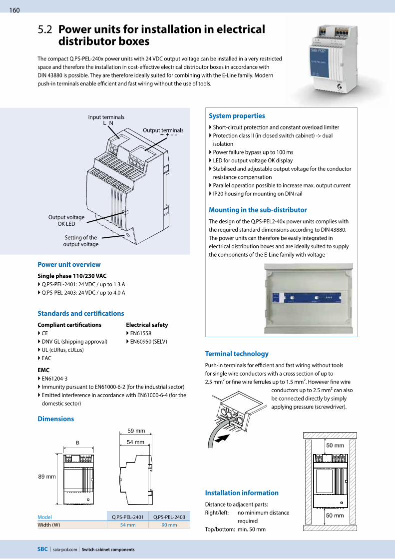
160
saia-pcd.com
L N
+ + - -
Switch cabinet components
5.2 Power units for installation in electrical distributor boxes
System properties
Short-circuit protection and constant overload limiter Protection class II (in closed switch cabinet) -> dual isolation Power failure bypass up to 100 ms LED for output voltage OK display Stabilised and adjustable output voltage for the conductor resistance compensation
Parallel operation possible to increase max. output current IP20 housing for mounting on DIN rail
The compact Q.PS-PEL-240x power units with 24 VDC output voltage can be installed in a very restricted space and therefore the installation in cost-effective electrical distributor boxes in accordance with DIN 43880 is possible. They are therefore ideally suited for combining with the E-Line family. Modern push-in terminals enable efficient and fast wiring without the use of tools.
Mounting in the sub-distributor
The design of the Q.PS-PEL2-40x power units complies with the required standard dimensions according to DIN 43880. The power units can therefore be easily integrated in electrical distribution boxes and are ideally suited to supply the components of the E-Line family with voltage
Input terminals
Output terminals
Output voltage OK LED
Setting of the output voltage
Power unit overview
Single phase 110/230 VAC
Q.PS-PEL-2401: 24 VDC / up to 1.3 A Q.PS-PEL-2403: 24 VDC / up to 4.0 A
Standards and certifications
Compliant certifications
CE DNV GL (shipping approval) UL (cURus, cULus) EAC
EMC
EN61204-3 Immunity pursuant to EN61000-6-2 (for the industrial sector) Emitted interference in accordance with EN61000-6-4 (for the domestic sector)
Dimensions
Model Q.PS-PEL-2401 Q.PS-PEL-2403Width (W) 54 mm 90 mm
Terminal technology
Push-in terminals for efficient and fast wiring without tools for single wire conductors with a cross section of up to 2.5 mm² or fine wire ferrules up to 1.5 mm². However fine wire
conductors up to 2.5 mm² can also be connected directly by simply applying pressure (screwdriver).
Installation information
Distance to adjacent parts: Right/left: no minimum distance
required Top/bottom: min. 50 mm
Electrical safety
EN61558 EN60950 (SELV)
89 mm
54 mm
59 mm
B

161
saia-pcd.comSwitch cabinet components
5S
wit
ch c
ab
ine
t
com
po
ne
nts
4C
on
sum
er
d
ata
acq
uis
itio
n3
De
dic
ate
d
roo
m c
on
tro
lle
rs2
Op
era
tio
n
an
d m
on
ito
rin
g1
Au
tom
ati
on
st
ati
on
s
Output derating curve
Q.PS-PEL-2401
0.5
1
1.3
–25 –10 0 10 20 30 40 50 60–20
0.9
045
1.5
100
70
55
Last [A] Last [%]
Temp [°C]
Eingangspannung: 230 VAC
Q.PS-PEL-2403
1
3
4
–25 –10 0 10 20 30 40 50 60–20
2.8
045
100
70
55
2
Last [A] Last [%]Eingangspannung: 230 VAC
Output characteristics
Voltage/current characteristic curve for
short-circuit and overload protection
Output characteristic curve (U/I characteristic curve)
U Aus (V)
Iaus(A)1,1× INNI
The current overload protection limits the current to a constant value of 1.1 × nominal current
Input data Q.PS-PEL-2401* Q.PS-PEL-2403*
Input voltage 100…240 VAC
Permitted input voltage range 85…264 VAC
Nominal frequency range 44…66 Hz
Nominal input current for nominal load (110 / 230 VAC) 0.7 / 0.5 A 1.6 / 0.9 A
Internal input fuse 2 AT 4 AT
Recommended external pre-fuse 6 A, 10 A, 16 A, characteristics B, C
Power failure bypass for nominal load (110 / 230 VAC) 10 / 80 ms 15 / 100 ms
Output data
Output voltage (VN) 24 VDC ± 2 %
Output voltage range (VADJ) 22.8…26.4 VDC
Output current (IN) at ≤ 45°C 1.3 A 4 A
Output current (IN) at ≤ 55°C 0.9 A 2.8 A
Current load rating for any installation system max. 0.9 A max. 2.4 A
Efficiency typical 82% typical 88%
Residual ripple (for nominal load) ≤ 100 mVpp
Overload behaviour Constant current (U/I characteristic curve)
Short-circuit protection Yes
Overvoltage output protection Yes (max. 30 VDC)
Parallel connection Yes
Status
Operating indicator LED green
Environment
Ambient temperature (operation) –25°C to +55°C (load reduction >45°C, 3%/°C)
Storage temperature –25°C to +80°C
Permitted humidity 30–85% relative humidity, no condensation permitted
Areas of use Use in areas with contamination level 2
Connection terminals
Connections Push-in
Input/output terminals Single wire and fine wire conductors up to max. 2.5 mm²/ conductors with wire ferrules up to max. 1.5 mm²
Technical data
*In preparation, see Chapter C1 “Product status”

162
saia-pcd.com Switch cabinet components
5.3 Industrial VPN Routers
The EBW industrial routers allows you an easy, reliable and secure connection of different applications located on different sites. Using the quick start wizard, the EBW routers can be quickly and easily integrated in the “SBC Connectivity service” VPN network.
Theses industrial routers enable professional IP routing and provide highest-possible IT security.
Features
Broadband 3G/HSPA Dial-in and dial-out router VPN security Two local Ethernet ports Prepared for INSYS Connectivity Service
The industrial high speed router EBW-H100 combines a modem and a router in one device. It connects to the internet over mobile networks (3G/HSPA, GPRS/EDGE).The dial-in and dial-out functionality enables remote maintenance and operation of devices in an Ethernet network. A firewall and integrated VPNs (openVPN, IPsec) care about data security.
Typical applications
Access to control network with PLC, HMI, data logger Modem substitute for devices with Ethernet interface Remote desktop Video monitoring Displays
Technical data EBW-H100*
5.3.1 Industrial 3G/HSPA router for VPN connection
Physical features
Dimensions (L × W × H) 110 × 45 × 70 mm
Operating temperature -30 … +70 °C -30 … +85 °C under limited conditions (refer to www.insys-icom.com/restricted)
Humidity 0 … 95 % (non-condensing)
Supply
Connections 10 … 48 V DC (± 20 %)
Input/output terminals Approx. 2 W (logged in), max. 5 W (during communication)
Additional features
Update of firmware and configuration (local and remote), daily auto update
Messages
Hardware watchdog, system messages via e-mail, SNMP traps, SNMP V1 / V2c / V3
LAN
Ports 2 × RJ45
Operating mode 10 / 100 MBit/s for full and half duplex operation
Function Automatic detection of patch cable / cross-over cable, Automatic speed adjustment; MDI/MDI-X
Mobile Communication
Networks 2G: 900/1,800 MHz; CSD, GPRS/EDGE Class 123G: 850/800, 900, 1.900, 2.100 MHz; UMTS, HSDPA, HSUPA
Antenna SMA connection
SIM 1 slot for Mini-SIM card
Router
Function Dial-In, dial-out, callback, connection management, DHCP server and client, full NAT (port forwarding, netmapping), DNS relay, dynDNS support, SNMP, NTP client and server, buffered real-time clock
Security OpenVPN (client and server), IPsec, PPTP, MAC firewall, 10 user for dial-in, authentication over PAP/CHAP/MS-CHAP/MS-CHAP 2, dial fi lter for dial-out, linkloss detection, failed login detection, GRE
Redundancy 2 dial-out targets, 2 OpenVPN server targets
*In preparation, see Chapter C1 “Product status”

163
saia-pcd.comSwitch cabinet components
5S
wit
ch c
ab
ine
t
com
po
ne
nts
4C
on
sum
er
d
ata
acq
uis
itio
n3
De
dic
ate
d
roo
m c
on
tro
lle
rs2
Op
era
tio
n
an
d m
on
ito
rin
g1
Au
tom
ati
on
st
ati
on
s
Features
LAN-to-LAN industrial router (1x LAN int., 1x LAN ext.) Professional IP routing Comprehensive security: Firewall, VPN, SNMP Easy consistent concept of operation Quick start for SBC Connectivity Service (VPN service
The industrial high-speed router EBW-E100 allows secure connections between local and remote networks.EBW-E100 decouples manufacturing cells with remote access from the surrounding company IT for example. Also many subnetworks with identical local IP addresses can be distinguished and addressed targeted.The firewall and VPN via OpenVPN and IPsec provide data security..
Typical applications
Manufacturing cell decoupling Secure remote maintenance in customer network Access to a control network from PLC, HMI, data logger Remote desktop Video monitoring Displays
Technical data EBW-E100*
5.3.2 Industrial LAN router for VPN connection
Physical features
Dimensions (L × W × H) 110 × 45 × 70 mm
Operating temperature -30 … +70 °C -30 … +85 °C under limited conditions (refer to www.insys-icom.com/restricted)
Humidity 0 … 95 % (non-condensing)
Supply
Connections 10 … 48 V DC (± 20 %)
Input/output terminals Approx. 2 W
Additional features
Update of firmware and configuration (local and remote), daily auto update
Messages
Hardware watchdog, system messages via e-mail, SNMP traps, SNMP V1 / V2c / V3
LAN
Ports 2 × RJ45
Operating mode 10 / 100 MBit/s for full and half duplex operation
Function Automatic detection of patch cable / cross-over cable, Automatic speed adjustment; MDI/MDI-X
Router
Function Connection management, DHCP server and client, full NAT (port forwarding, netmapping), DNS relay, dynDNS support, PPPoE client for ADSL, SNMP, NTP client and server, buffered real-time clock
Security OpenVPN (client and server), IPsec, PPTP, MAC firewall, linkloss detection, failed login detection, GRE
Redundancy 2 OpenVPN server targets
Order details
Q.NET-EBW-E100 Industrial LAN router for VPN connectionQ.NET-EBW-H100 Industrial 3G/HSPA router for VPN connectionQ.NET-CON Annual license for the “SBC Connectivity Service” portalPCD7.K840 GSM/UMTS (850/900/1800/1900/2100 MHz) antenna with magnetic foot and SMA connector
*In preparation, see Chapter C1 “Product status”

164
saia-pcd.com
13,7
70
63,3
23
8,5
100
36,4
P xP x
25
Switch cabinet components
System properties
DIN rail mounting and 24 VDC supply for flawless operation in infrastructure automation and in harsh industrial environments
Fast network diagnosis, due to integral LEDs at TCP ports Entry level industrial Ethernet rail switch, with store-and- forward switching mode
Allows construction of Ethernet networks in accordance with IEEE 802.3 with copper technology
The device has five or eight 10/100 Mbit/s twisted pair ports (RJ45 connections) Up to five or eight end devices or additional TCP segments can be connected to the TCP ports using twisted pair
Extremely light, compact construction with IP 30 protection level
Simple commissioning with ‘plug-and-work’ via auto- negotiation, auto-polarity and auto-crossing
Technical data Q.NET-5TX and Q.NET-8TX
Operation
Port type and number
Network line lengths Network cascade depth Operating voltage Current draw at 24 VDC Displays/diagnostics
Ethernet 10/100 MBit/s, 5× RJ45 (Q.NET-5TX) or 8× RJ45 (Q.NET-8TX)Twisted pair (TP), 0…100 mLinear/star structure – any depth9.6 VDC…32.0 VDCmax. 100 mA1× green LED; power5× / 8× yellow LED; data rate5× / 8× green LED; data, link status
Environmental conditions
Operating temperature Storage temperature Humidity
0 °C … +60 °C –40 °C … +70 °Cup to 95% (non-condensing)
Standards/approvals
EMC noise immunity: EMC noise emission:
Safety for Industrial Control Equipment
Mechanical stability
Protection type
EN 61000-4EN 55022 Class A, FCC CFR47 Part 15 Class A
cUL508, CSA22.2 No. 142, E 175531
IEC 60068-2 (shock, vibration)
IP30
Order details
Q.NET-5TX
Q.NET-8TX
5-port rail switch, terminal block, patch cable and operating instructions8-port rail switch, terminal block, patch cable and operating instructions
Dimensions
Connection options
Status LED for power Plug-in terminal block, 3-pin
Q.NET-5TX Q.NET-8TX
Status LEDsEthernet port
DIN rail mounting
5.4 Industrial Ethernet switchs
This compact, unmanaged switch operates based on the plug-and-work principle. The mounted switch is equal in height to Saia PCD3 systems, which saves space when it is snapped onto the DIN rail. The PCD controller is connected with the patch cable provided. With its robust construction, this switch is suitable for use in harsh industrial environments and in infrastructure automation.
Linear structure
Star structure

165
saia-pcd.com
0 V
L
N
RS-485
Switch cabinet components
5S
wit
ch c
ab
ine
t
com
po
ne
nts
4C
on
sum
er
d
ata
acq
uis
itio
n3
De
dic
ate
d
roo
m c
on
tro
lle
rs2
Op
era
tio
n
an
d m
on
ito
rin
g1
Au
tom
ati
on
st
ati
on
s
5.5 RS-485 bus termination box PCD7.T16x
The PCD7.T16x termination boxes are used for RS-485 network termination. Each RS-485 network segment must be terminated at the end of the network. The PCD7.T16x termination boxes ensure that the RS-485 signals are set at the correct signal level and the integrat-ed 120 Ohm resistor prevents signal reflection in the RS-485 cable. With their robust and compact construction and electrically isolated power supply with either 230 VAC or 24 VAC/DC, the PCD7.T16x termination boxes are suitable for use in harsh industrial environments and in infrastructure automation. An LED indicates the presence of the supply voltage of the PCD7.T16x termination box.
System properties
35 mm DIN rail mounting 17.5 mm wide housing 230 VAC +15% /–20% for PDC7.T161 24 VAC / DC –15% /+15% for PDC7.T162 Current consumption of 0.4 W Electrically isolated power supply Fixed-line terminator resistance of 120 Ω LED operating indicator
Dimensions Connection diagram PCD7.T161 PCD7.T162
Connection example
RS485
3N
4N
1L
2L
+5V
0V
/D
D
L
N
230
VAC
RS485
3N
4N
1L
2L
+5V
0V
/D
D
L/0VDC
N/24VDC
24 V
AC/D
C
230 VAC
PCD7.T161 PCD7.T162 Comments
Power supply 230 VAC 24 VAC / DC
Housing 17.5 × 85 × 64 mm 17.5 × 85 × 64 mmPCD7.T161 and PCD7.T162 comply with the standards for switch cabinets
Terminating resistor Fixed 120 Ω Fixed 120 Ω
Display LED for 230 VAC LED for 24 V
Lead sealing cap as an accessory, see section 4.4.6 (ALD1)
24 VAC
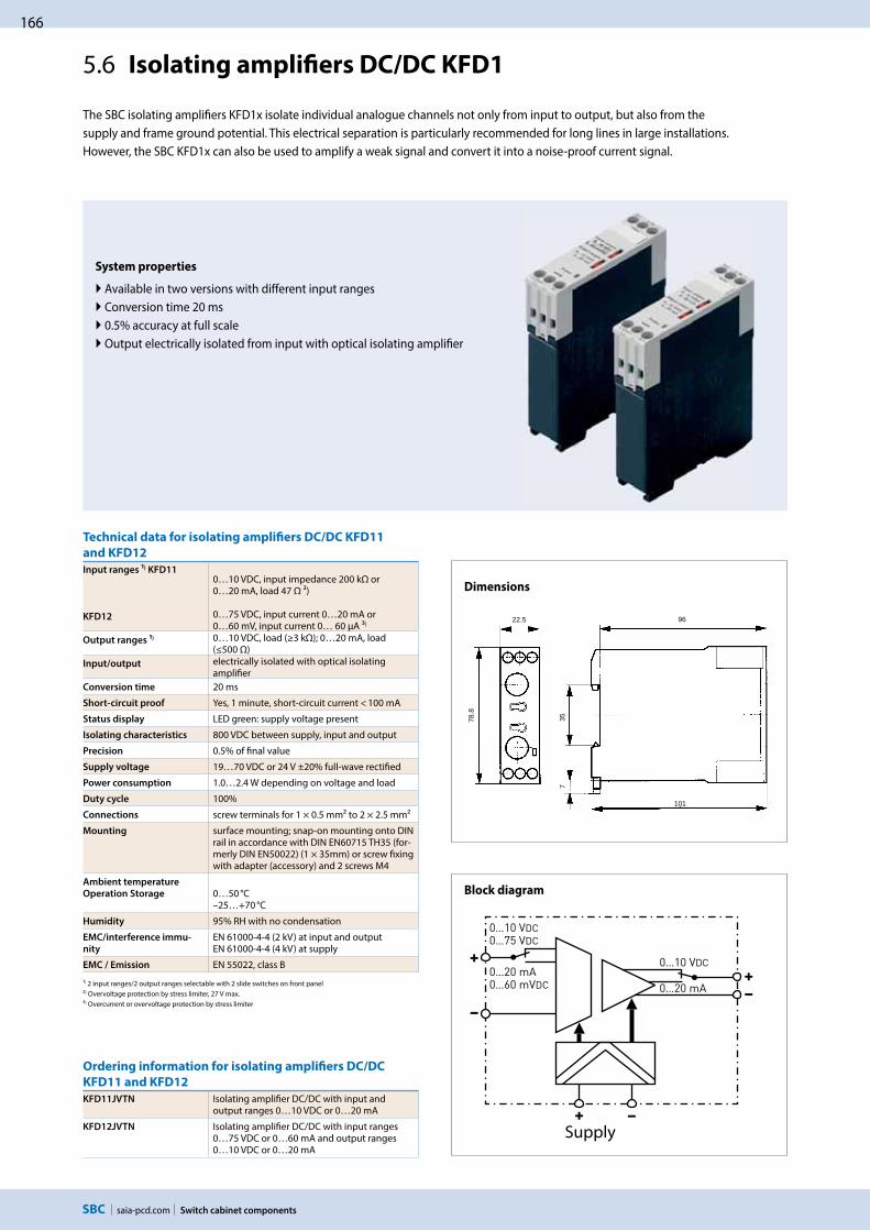
166
saia-pcd.com Switch cabinet components
System properties
Available in two versions with different input ranges Conversion time 20 ms 0.5% accuracy at full scale Output electrically isolated from input with optical isolating amplifier
Technical data for isolating amplifiers DC/DC KFD11
and KFD12
Input ranges ¹) KFD11
KFD12
0…10 VDC, input impedance 200 kΩ or0…20 mA, load 47 Ω ²)
0…75 VDC, input current 0…20 mA or0…60 mV, input current 0… 60 μA ³)
Output ranges ¹) 0…10 VDC, load (≥3 kΩ); 0…20 mA, load (≤500 Ω)
Input/output electrically isolated with optical isolating amplifier
Conversion time 20 ms
Short-circuit proof Yes, 1 minute, short-circuit current < 100 mA
Status display LED green: supply voltage present
Isolating characteristics 800 VDC between supply, input and output
Precision 0.5% of final value
Supply voltage 19…70 VDC or 24 V ±20% full-wave rectified
Power consumption 1.0…2.4 W depending on voltage and load
Duty cycle 100%
Connections screw terminals for 1 × 0.5 mm² to 2 × 2.5 mm²
Mounting surface mounting; snap-on mounting onto DIN rail in accordance with DIN EN60715 TH35 (for-merly DIN EN50022) (1 × 35mm) or screw fixing with adapter (accessory) and 2 screws M4
Ambient temperature
Operation Storage 0…50 °C–25…+70 °C
Humidity 95% RH with no condensation
EMC/interference immu-
nity
EN 61000-4-4 (2 kV) at input and outputEN 61000-4-4 (4 kV) at supply
EMC / Emission EN 55022, class B
¹) 2 input ranges/2 output ranges selectable with 2 slide switches on front panel²) Overvoltage protection by stress limiter, 27 V max.³) Overcurrent or overvoltage protection by stress limiter
Dimensions
Block diagram
Ordering information for isolating amplifiers DC/DC
KFD11 and KFD12
KFD11JVTN Isolating amplifier DC/DC with input and output ranges 0…10 VDC or 0…20 mA
KFD12JVTN Isolating amplifier DC/DC with input ranges 0…75 VDC or 0…60 mA and output ranges 0…10 VDC or 0…20 mA
5.6 Isolating amplifiers DC/DC KFD1
The SBC isolating amplifiers KFD1x isolate individual analogue channels not only from input to output, but also from the supply and frame ground potential. This electrical separation is particularly recommended for long lines in large installations. However, the SBC KFD1x can also be used to amplify a weak signal and convert it into a noise-proof current signal.
22.5
78.8
357
96
101
++
––
0…20 mA0…20 mA
+ –
0…10 VDC0…75 VDC
0…60 mVDC
0…10 VDC
Supply

167
saia-pcd.com
PCD7.L291
PCD7.L490 / PCD7.L290
Switch cabinet components
5S
wit
ch c
ab
ine
t
com
po
ne
nts
4C
on
sum
er
d
ata
acq
uis
itio
n3
De
dic
ate
d
roo
m c
on
tro
lle
rs2
Op
era
tio
n
an
d m
on
ito
rin
g1
Au
tom
ati
on
st
ati
on
s
PCD7.L252:
Coupler modules with manual operating level Auto/OFF/ON
PCD7.L452:
Analogue value transmitter for manual correcting variables
PCD7.L260:
Coupler module for two-stage motor control
1 changeover contact Local override operation Auto acknowledge LED display Test contacts for each terminal Spring terminals (push-in)
Potentiometer 0…10 V Local override operation Auto acknowledge LED brightness in proportion to control variable
Test contacts for each terminal Spring terminals (push-in)
Interlocked relay Local override operation Auto acknowledge LED display Screw terminals
Single-stage coupler component with local override operation, ack-nowledgement of switch position and an LED for status indication. Coupler modules are used for safe potential isolation between logic and load.Spring terminals allow for quick and easy wire connection. The supply voltage can be connected across jumpers using additional terminals with no wiring or additional time required.
The analogue data encoder is used as a variable encoder for manual variable specification, e. g. mixing valves, valve posi-tions, temperature values, etc. It has three operating modes: ON, OFF and AUTO. In switch position AUTO, the control variable will be looped unchanged via the YR ter-minal to the control variable out-put Y. In switch position ON, the control variable can be set using the potentiometer on the front of the device. The output signal will be available at terminal Y.
This coupler module is used for switching units, pumps, fans, etc. When switching back from stage 2 to stage 1, stage 2 is first switched off and stage 1 is switched on after a delay of < 60 ms. A manual control level has been integrated for service purposes. The time function is operational here too.
Input side PCD7.L252 PCD7.L452 PCD7.L260
Supply voltage 24 VDC / VAC, –15% / +10% 24 VDC / VAC, –15% / +20% 24 VDC / VAC, ±10%
Current draw 13 mA, protection wiring with recovery diode
19 mA at 24 VDC 30 mA at 24 VAC
30 mA
Input current --- 2 mA at 10 VDC (input YR) max. 4 mA, terminal B1 / B2
Response / release time 10 ms / 5 ms --- / --- 20 ms / 20 ms
Input voltage 24 VDC / VAC 0…10 VDC 24 VDC / VAC
Operating indicator Green LED to indicate relay state Red LED (brightness in proportion to control variable)
Two red LEDs to indicate relay state
Output side
Output contact 1 changeover --- 1 changeover with 0 position
Turn-on voltage max. 250 VDC / VAC --- Max. 250 VDC / VAC
On/off switching current max. 8 A --- / --- Max. 6 A
Output voltage --- 0…10 VDC, 10 mA, output Y in switch position Auto/ON
---
Continuous current 8 A --- 4 A
Breaking capacity (ohmic load) 24 VDC / 180 W 50 VDC / 65 W 230 VDC / 50 W 250 VAC / 2000 VA
--- --- --- —
24 VDC / 150 W 50 VDC / 25 W 230 VDC / 50 W 230 VAC / 1500 VA
Breaking capacity min. 24 VDC / 20 mA — 24 VDC / 20 mA
Service life
mechanical
electrical (at maximum switching load)
2 × 10⁷ switch cycles 1 × 10⁵ hystereses
--- ---
1 × 10⁷ switch cycles 1 × 10⁵ hystereses
Switching frequency MAX: 300 hystereses / h at max. current
--- MAX: 1,200 hystereses / h at max. current
5.7 Interface modules with local override to control drives, valves or flap systems
Accessories
PCD7.L291 Jumper for connection of the supply voltage of up to 10 PCD7.L252 and PCD7.L452 modules
PCD7.L490 Labelling plate for PCD7.L452 (in packs of 10)
PCD7.L290 Labelling plate for PCD7.L252 (in packs of 10)
22.5 60
60
30
60
11.2
88
44
43
67.3
PCD7.L252/452
PCD7.L260
Dimensions
ntrol

168
saia-pcd.com Switch cabinet components
5.8 S-Bus RIO modules
The RAIL module is easy to install and uninstall. The bridge quickly and easily plugs the connect bus and supply voltage between the modules. Their compact construction allows small units to be built up on site to create an optimum system. Thus these devices save much work and space while being more useful and efficient. These small field bus modules are very well suited for being built into switch cabinets, sub-distributors and surface-mounted housings.
Dimensions:System properties
S-Bus connection via simple two-wire bus line
Autom. recognition of operating mode/baud rate Bit rates: 1,200, 2,400, 4,800, 9,600, 19,200, 38,400 bps
RAIL modules: Switch cabinet design for mounting on 35 mm DIN rail
SAFE modules: Protected model for surface mounting with protection class IP 65
Manual operating level with status feedback via the bus
Status indication using an LED
Simple setting of the S-Bus address using a rotary switch
Serial S-Net RAIL (DIN rail mounting)
Type Description W × H × D [mm]
PCD7.L100 Input module with 4 digital inputs 24 VDC/VAC, with local override 35 × 68 × 60PCD7.L110 Input module with 4 digital inputs 24 VDC/VAC, without local override 35 × 68 × 60PCD7.L120 Input/output module with 2 relays 250 VAC and 4 digital inputs 24 VDC/VAC, with
local override and integrated functionality for lighting and shade 50 × 68 × 60
PCD7.L130 Input module with 10 digital inputs 24 VDC/VAC 35 × 68 × 60PCD7.L200 Output module with 4 relays 250 VAC, 6 A, with local override 35 × 68 × 60PCD7.L210 Output module with 4 Triacs 24…250 VAC, 0.8 A, with local override 35 × 68 × 60PCD7.L320 Analog input module with 8 universally individually via software configurable
inputs for 0... 10 VDC or various passive and active temperature sensors such as E.g. Pt1000, Ni1000, NTC10K, and 10 additional temperature sensor characteristics. In addition, other types of sensors can be connected using an interpolation table
35 × 68 × 60
PCD7.L410 Analogue output module with 4 outputs 0…10 VDC, with local override 35 × 68 × 60
Bus termination
Type Description W × H × D [mm]
PCD7.T161 Termination box RS-485 (line terminating resistor), electrically isolated, 230 VAC 17.5 × 89.2 × 63.4 PCD7.T162 Termination box RS-485 (line terminating resistor), electrically isolated, 24 VAC/DC 17.5 × 89.2 × 63.4
RAIL module SAFE module
Serial S-Net SAFE (surface mounted)
Type Description W × H × D [mm]
PCD7.L121 Input/output module with 2 relays 250 VAC and 4 digital inputs 24 VDC/VAC. Range of uses: Light and shade applications.
159 × 41.5 × 120
Power supply 230 VAC/24 VDC
Type Description W × H × D [mm]
PCD7.L500 For supply of all RAIL and SAFE modules, 240 VAC | 24 VDC/700 mA, max. 15 modules 50 × 68 × 60
Serial S-Net SAFE (surface mounted)
Serial S-Net RAIL (DIN rail mounting)
Power supply 230 VAC/24 VDC
Bus termination
B T
H

169
saia-pcd.com
Terminaison de ligne PCD7.T162
Switch cabinet components
5S
wit
ch c
ab
ine
t
com
po
ne
nts
4C
on
sum
er
d
ata
acq
uis
itio
n3
De
dic
ate
d
roo
m c
on
tro
lle
rs2
Op
era
tio
n
an
d m
on
ito
rin
g1
Au
tom
ati
on
st
ati
on
sUse of slaves in the serial S-Net
Slaves can be decentralised input/output modules (RIO = Remote Inputs and Outputs), external devices (e.g. electronic power meters) or PCD stations.
Bear in mind here the electrical load of the Serial S-Net. RAIL and SAFE remote input/output modules have high impedance and load the Serial S-Net only slightly. Up to 100 slaves can therefore be used in one segment. If the bus cycle time is critical, fewer than 30 slaves should be
operated in one segment.
Example system design
The RAIL modules can also be mount-ed in series in an IP 66 housing for decentralised field assembly. Further information can be obtained from the manufacturer Spelsberg, for example. Limitation owing to the electrical load on the Serial S-Net:
Total PCD systems (incl. master PCD) and RIOs on one serial S-Net branch
Number Number
PCD RIO
0…7 100 8 96 9 92 10 88 11 84 12 80 13 76
Number Number
PCD RIO
14 72 15 68 16 64 17 60 18 56 19 52 20 48
Number Number
PCD RIO
21 44 22 40 23 36 24 32 25 28 26 24 27 20
Number Number
PCD RIO
28 16 29 12 30 8 31 4 32 0
RAIL modules with Serial S-Net connection, power pack PCD7.L500 and termination box PCD7.T162
RAIL modules with Serial S-Net connection, separate module supply and termination box PCD7.T162
SAFE modules with Serial S-Net connection and separate module supply and termination box PCD7.T162
Enable PCD terminating resistor
After 15 modules the maximum power consumption must be restarted with an external power supply
24 VDC/ACTermination box PCD7.T162
Serial S-Net Serial S-Net
Serial S-Net
24 VDC output voltage
Termination box PCD7.T162
PCD7.L500 power supply (operating voltage 110 … 240 VAC)
Serial S-Net
Enable PCD terminat-ing resistor
Supply 24 VAC/VDC
PCD Enable terminating resistor
Termination box PCD7.T162
Serial S-Net
After 15 modules or after reaching the maximum power consumption must be approached with a new external power supply

170
saia-pcd.com Switch cabinet components
Series KOL2 KOL3xxH... KOP1xx.J... KOPxxx.K...
Ord
er n
umbe
r
KOL2
51H
7MKV
PN00
KOL3
60H
7MRV
PN00
KOP1
60J7
MW
VPN
00
KOP1
70J7
MW
VPN
00
KOP2
19K7
MW
VAN
00
KOP5
60K7
MW
VPN
00Functions
Delayed operation --- --- ---
Delayed release --- --- ---
Power off delayed release --- --- --- --- ---
Delayed operation and release --- --- --- ---
Fleeting-on delay timer --- --- ---
Fleeting-off delay timer --- --- --- ---
Flasher relay --- --- --- --- ---
Star delta timer --- --- --- --- ---
Pulse converter --- --- --- ---
Pulse generator --- --- --- ---
Flasher relay with pulse starting --- --- --- ---
Asymmetrical pulse generator --- --- --- --- ---
On/off function for startup and maintenance --- --- --- ---
Time ranges
0.15 s…10 min --- --- --- ---
0.05 s…10 h --- --- --- --- ---
0.05 s…60 h --- --- ---
Operating voltage
24…48 VDC and 24…240 VAC ---
24…240 VDC or 24…240 VAC --- --- --- --- ---
Contacts
2 make contacts with a joint connection --- --- --- --- ---
1 changeover --- --- ---
2 changeovers --- --- --- --- ---
2 changeovers, instantaneous and/or timed contacts --- --- --- --- ---
KOL2 and KOL3 KOP.J KOP.K
Multi-function or mono function 4 time ranges (KOL 251) 6 time ranges (KOL 3) 17.5 mm width for DIN rail 24…48 VDC and 24…240 VAC 2 make contacts (KOL 251) 1 changeover (KOL 3)
Multi-function or mono function 10 time ranges 22.5 mm width for DIN rail 24…48 VDC and 24…240 VAC 1 changeover contact
Multi-function or mono function Up to 10 time ranges 22.5 mm width for DIN rail 24…48 VDC and 24…240 VAC, 50/60 Hz 24…240 VAC/DC 1 or 2 changeover contacts, instantaneous and/or timed contacts
KOL251H... KOL360H... KOP160J... KOP170J... KOP219K... KOP560K...
5.9 Timer delay relays KOL/KOP
Dimensions KOL251 and KOL260 KOP160 and KOP170 KOP219 and KOPP560
22.5
78.8
357
96
101
43
66
80 45
7017.5
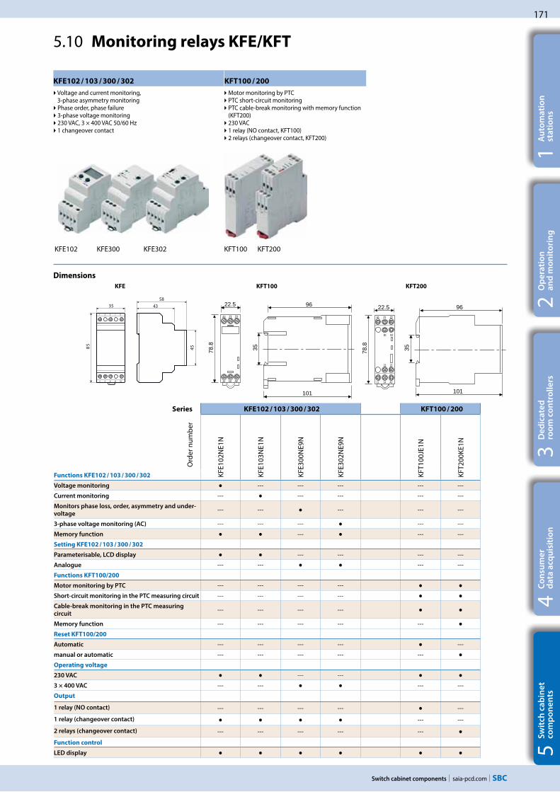
171
saia-pcd.com
A1 Z1 Z2
11 14 A2
96
101
35
22.5
78.8
A1 Z1 Z2
B1 B2
11 14 A2
21 22
22.5
78.8
96
35
101
35
1 3 5 7 9
2 4 6 8 10
45
4358
85
Switch cabinet components
5S
wit
ch c
ab
ine
t
com
po
ne
nts
4C
on
sum
er
d
ata
acq
uis
itio
n3
De
dic
ate
d
roo
m c
on
tro
lle
rs2
Op
era
tio
n
an
d m
on
ito
rin
g1
Au
tom
ati
on
st
ati
on
s
KFE102 / 103 / 300 / 302 KFT100 / 200
Voltage and current monitoring, 3-phase asymmetry monitoring Phase order, phase failure 3-phase voltage monitoring 230 VAC, 3 × 400 VAC 50/60 Hz 1 changeover contact
Motor monitoring by PTC PTC short-circuit monitoring PTC cable-break monitoring with memory function (KFT200)
230 VAC 1 relay (NO contact, KFT100) 2 relays (changeover contact, KFT200)
5.10 Monitoring relays KFE/KFT
KFE102 KFE300 KFE302 KFT100 KFT200
Series KFE102 / 103 / 300 / 302 KFT100 / 200
Ord
er n
umbe
r
KFE1
02N
E1N
KFE1
03N
E1N
KFE3
00N
E9N
KFE3
02N
E9N
KFT1
00JE
1N
KFT2
00KE
1N
Functions KFE102 / 103 / 300 / 302
Voltage monitoring --- --- --- --- ---
Current monitoring --- --- --- --- ---
Monitors phase loss, order, asymmetry and under-
voltage--- --- --- --- ---
3-phase voltage monitoring (AC) --- --- --- --- ---
Memory function --- --- ---
Setting KFE102 / 103 / 300 / 302
Parameterisable, LCD display --- --- --- ---
Analogue --- --- --- ---
Functions KFT100/200
Motor monitoring by PTC --- --- --- ---
Short-circuit monitoring in the PTC measuring circuit --- --- --- ---
Cable-break monitoring in the PTC measuring
circuit--- --- --- ---
Memory function --- --- --- --- ---
Reset KFT100/200
Automatic --- --- --- --- ---
manual or automatic --- --- --- --- ---
Operating voltage
230 VAC --- ---
3 × 400 VAC --- --- --- ---
Output
1 relay (NO contact) --- --- --- --- ---
1 relay (changeover contact) --- ---
2 relays (changeover contact) --- --- --- --- ---
Function control
LED display
Dimensions KFE KFT100 KFT200

172
saia-pcd.com
..E16x
..A46x
100 mm50 mm
..E16x
..A46x
50 mm50 mm
..E16x
..A46x
300 mm50 mm
Switch cabinet components
5.11 I/O module integration into switch cabinet
Pre-assembled system cables and terminal adapter modules support the fast integration of the integration of the Saia PCD® I/O modules into the switch cabinet. I/O modules with ribbon connections, in particular, can be installed quickly and easily in the switch cabinet. The modules with terminals can also be connected to the adapters using traditional stranded wires. The adapters either are available for galvanic separation of the outputs with relays or as simple I/O adapters with voltage distribution.
System properties
Available as I/O terminal adapter or relay interface
Relay interface with manual mode
Compatible with Saia PCD2 and PCD3 systems
For connection with system cable or stranded wire
For DIN rail mounting
PCD2.K241 / K242 cable
Sheathed, round ribbon cable with 34 strands of 0.09 mm², 34-pin ribbon connector at the PCD endProcess end divided into 2 branches, each 300 mm in length, leading to 16-pin ribbon connectorsCable length PCD2.K241 = 1.0 m PCD2.K242 = 2.0 m
PCD2.K221 / K223 cable
Sheathed, round cable with 32 strands of 0.25 mm² (AWG 24), 34-pin ribbon connector at the PCD end Free, unsheathed 100 mm ends at the process endStranded wires, colour-codedCable length PCD2.K221 = 1.5 m PCD2.K223 = 3.0 m
Pluggable ribbon cables with connector at the Saia PCD® end
PCD2.K231 / K232 cable
Sheathed, round ribbon cable with 34 strands of 0.09 mm², 34-pin ribbon connector at both endsCable length PCD2.K231 = 1.0 m PCD2.K232 = 2.0 m
Cable for the digital modules with 16 inputs/outputs
Terminal adapter for digital inputs/outputs
Length
Diameter = 11 mm
Length
Diameter = 11 mm
Length
Diameter = 11 mm

173
saia-pcd.comSwitch cabinet components
5S
wit
ch c
ab
ine
t
com
po
ne
nts
4C
on
sum
er
d
ata
acq
uis
itio
n3
De
dic
ate
d
roo
m c
on
tro
lle
rs2
Op
era
tio
n
an
d m
on
ito
rin
g1
Au
tom
ati
on
st
ati
on
sRelay interface PCD2.K551
for 8 PCD transistor outputs with 24 screw terminals and LEDSwitching capacity of the changeover contacts 10 A / 250 VAC or 10 A / 24 VDC (ohmic), 24 VDC spool 16-pin ribbon connector or screw terminals at the PCD end24 screw terminals 0.5…1.5 mm² at the process endMechanical data
Diameter of the screw terminals: M 2.6 mm Starting torque: 0.4 Nm
Terminal adapter
PCD2.K520 / K521 34-pin ribbon connector at the PCD endProcess end 2 × 10 screw termi-nals 0.5…1.5 mm² PCD2.K520 without LEDs PCD2.K521 with LEDs (source operation)
Terminal adapter for 16 inputs/outputs
Terminal adapter PCD2.K525 34-pin ribbon connector at the PCD endProcess end 3 × 16 Screw terminals 0.5…1.5 mm² with LEDs (source operation)
Terminal adapter for 16 inputs/outputs
Relay interface PCD2.K552 for 8 PCD transistor outputs with 24 screw terminals, LED and manual operation mode (switch on-off-auto) and 1 out-put as feedback for the manual mode Switching capacity of the changeover contacts 10 A / 250 VAC or 10 A / 24 VDC (ohmic), 24 VDC spool 16-pin ribbon connector or screw terminals at the PCD end24 screw terminals 0.5…1.5 mm² at the process endMechanical data
Diameter of the screw terminals: M 2.6 mm Starting torque: 0.4 Nm
To facilitate and speed up the installation of controllers, various adapters are available that can be connected direct to the Saia PCD® I/O modules via system cables. Apart from terminal adapters, there are also relay interfaces available which enable simple galvanic separation. The relay interfaces can be connected with ribbon cables or with stranded wires.
Terminal adapter PCD2.K51x
16-pin ribbon connector at the PCD endProcess end 2 × 6 Screw terminals 0.5…1.5 mm² PCD2.K510 without LEDs PCD2.K511with LEDs (source operation)
Terminal adapter for 8 inputs/outputs
Terminator adapter for I/O modules with ribbon connection
Screw terminals on process side
Ribbon connector (to the PCD) LED status
Adapter relay interface Adapter relay interface with manual operation
Mechanical design
Dimensions: 42 × 82 × 60 mm (W × H × D)
Dimensions: 94 × 82 × 72 mm (W × H × D)Dimensions: 65 × 82 × 60 mm (W × H × D)
Dimensions: 128 × 82 × 55 mm (W × H × D) Dimensions: 128 × 82 × 44 mm (W × H × D)
H
W
For DIN rail mounting

174
saia-pcd.com
PCD2.M5_
PCD2.K106
PCD3.M_ PCD3.C200
PCD3.K1x6
PCD4.U100 PCD4 E/As
Switch cabinet components
5.12 Upgrade kit PCD4.U100
The Saia PCD4.U100 module makes it possible to connect existing Saia PCD4 I/O modules to the latest Saia PCD3 and PCD2.M5 systems. By upgrading to the latest Saia PCD® system, you can increase the availability and reliability of the system. It is also possible to enhance systems with Automation Server functions and thus prepare them for the future. Installation is easy: Replace Saia PCD4 CPU with PCD4.U100, install Saia PCD3 or PCD2 CPU, connect new or existing PCD4 I/Os and you’re ready to go. Regardless of whether IL or FUPLA programming is used, the user programs can be directly transferred to new CPUs with small program adjustments in PG5, i.e., with minimum programming effort.
System properties
Supports Saia PCD3.Mxxx0 and Saia PCD2.M5xx0
Program can be easily transferred
Existing I/Os can still be used
System overview
Technical overview
Supported PCD types PCD3.Mxxx0 All PCDs with I/O bus connection PCD2.M5xx0 (no extension PCD2.C1000/C2000)
Supported PCD4 I/O modules All PCD4 I/O modules except PCD4.Hx are supported
Number of PCD4 I/O modules See technical documentation of the PCD4 systems
Max. number of PCD2/3 I/O modules 8 (only PCD3.C200 module carriers can be used in combination with the PCD3.M system)
Features
Increase system availability with a minimum of effort: Replace old PCD4 CPUs that are no longer available with the latest Saia PCD® CPUs. The reliability and availability of an existing system or controller can be increased in a time-saving manner and cost-efficiently by using a new CPU.
Benefits of the automation server functions: New Web/IT functions can also be made available in existing systems with PCD4 systems. Existing program structures can be copied across with small program adjustments and can still be used. Expand PCD4 systems with new PCD2/3 I/O modules. Up to 8 additional PCD2/3 I/O modules can be integrated into existing systems by replacing the CPUs.
Retaining the wiring: The system can be upgraded without costly rewiring of the I/Os.
Short upgrade period: The CPU is replaced quickly and the system is available again in a very short period of time. This way the wiring effort can be delayed to a later point in time.
Order details
Type Description
PCD4.U100 PCD4 upgrade kit basic module (without I/O bus cable)
PCD3.K106 I/O bus extension cable for Saia PCD3
PCD2.K106 I/O bus extension cable for Saia PCD2

175
saia-pcd.comSwitch cabinet components
5S
wit
ch c
ab
ine
t
com
po
ne
nts
4C
on
sum
er
d
ata
acq
uis
itio
n3
De
dic
ate
d
roo
m c
on
tro
lle
rs2
Op
era
tio
n
an
d m
on
ito
rin
g1
Au
tom
ati
on
st
ati
on
s
Saia PCD4.U100 upgrade kit
Once it has been clarified whether all I/O modules are suitable for upgrading, installation is really easy: Replace Saia PCD4 CPU with PCD4.U100, install Saia PCD3 or PCD2 CPU, connect existing PCD4 I/Os.
1. Insert PCD4.U100 module The existing PCD4 CPU is completely removed. To continue to ensure I/O bus supply, the PCD4 supply module is still used. The new PCD4.U100 module is used instead of the PCD4 CPU. The existing power supply module PCD4.N2x0 must have at least the hardware version “B”.
4. Programming with PG5 Transfer user program to PG5, adjust programs, download and you’re done. Detailed descriptions of the individual steps are listed in the PCD4.U100 manual.
3. Serial interfaces None of the PCD4 serial interfaces are supported. They must all be replaced with new PCD2/3 interfaces. Maximum of 3 integrated serial interfaces on the PCD3. Maximum of 4 integrated serial interfaces on the PCD2. Additional expansion option with PCD3.F1xx or PCD3.F2xx/PCD2.F2xxx*.
2. Connect PCD2.M5_ or PCD3.M_ The new PCD CPU is connected to the PCD4.U100 module with the I/O bus cable. For PCD2.M5xxx: PCD2.K106. For PCD3.Mxxxx: PCD3.K116 or PCD3.K106.
* Additional serial interfaces can be implemented via SPI I/O slots. However, the I/O address range will shift as a result. See the manual 26-888 for further details.
PCD4.U100PCD4 I/Os
PCD4.U100
PCD2.M5xxx
PCD3.Mxxxx
PGU RS-232S-Net/MPI
2 × PCD7.F1xxS
PGU RS-232
S-Net MPI
RS-485

176
saia-pcd.com Switch cabinet components

B
saia-pcd.com
Basic systems
B1 SBC Software
B2 Communication & Interaction
B3 SBC S-Web
B4 Room control
B – Basic systems
177
219
251
271

177
saia-pcd.com
B1
SBC Software
3S
BC
S-W
eb
te
chn
olo
gy
2C
om
mu
nic
ati
on
&
Inte
rac
tio
n1
SB
C S
oft
wa
re4
Ro
om
au
tom
ati
on
Saia PG5® Controls Suite contains everything required to realise and operate automation solutions with MSR devices. This includes programming and engineering tools as well as libraries and turnkey logic, regulation and automation modules. It also comes with an application software for Windows PCs.
SBC Software
1.1 Saia PG5® Controls Suite: Engineering & programming Page
1.2 Application software for Windows PCs Page
1.2.1 Saia Visi.Plus | Classic control/management system Page For the optimisation of complex, distributed systems
and properties with a large number of Saia PCD® automation stations.
1.2.2 SBC OPC Server Page Industrial bus systems and protocols provide universal communication capabilities.
1.2.3 SBC Network tools Seite BACnet explorer software for professional analysis and diagnostics of building automation networks.
1.1.1 Saia PG5® Core – everything you need, available at all times
1.1.1.1 Saia PG5® Core | Basic properties Page Functions and applications of the Saia PG5® Core. What is the licence policy and what about software maintenance
1.1.1.2 Saia PG5® Core | Components Page Presentation of the individual components and overview of the Saia PG5® Core.
1.1.1.3 Saia PG5® Core | Sample application Page The Saia PG5® Core is displayed using a simple logic. All basic functions of Saia PCD® Automation Server can be used.
1.1.2 Saia PG5® HVAC modules and use
1.1.2.1 HVAC modules Page The HVAC library simplifies the engineering of technical systems for buildings.
1.1.2.2 Sample application of the HVAC libraryPage Page Programming a ventilation system in individual steps.
1.1.3 Increase in engineering efficiency through SBC system templates
1.1.3.1 DDC Suite Page Reduce engineering time with DDC Suite and web templates.
1.1.3.2 Sample application of DDC Suite Page The sample demonstrates the advantage of the DDC Suite from an engineering point of view.
1.1.4 Saia PG5® Controls Suite
1.1.4.1 My Controls Suite Page Create your own templates or FBoxes with Saia PG5® FBox Builder for a perfect fit with your applications and workflow.
1.1.4.2 Web Editor as standalone tool Page The Web Editor is integrated into Saia PG5® Core but it can also be used as a standalone tool.
1.1.4.3 Overview of the tools and licence packages Page Better understanding and overview of the engineering and programming tools. From a wide range of software combinations, 3 packages are defined for the global standard.
178
178
182
191
195
196
200
204
205
207
208
211
211
217
218

178
saia-pcd.com
132
131
11
Saia® PG5 Core
0 %
100 %
Saia PG5 Controls SuiteArt-Nr: 4 717 4882 0
VersionV 2.1.210
Saia-Burgess Controls AG © 2013www.saia-pcd.com
www.sbc-support.com
SSSSSaiaSaiaSaiSaiSSaiaaiaaiaiaSSSSSSSaiaiaSSSSaiaSSSSS iaaaaaaaSSSS iiaaaaaSaiiiaaaaaiiaaaaaiaaaaaaaaaaa®®®®®®®®®®®®®®®®®®® PPPPPG5PPG5G5G5G5GG5G5G5 5PPPG5 PG5 G5G5G5G5PGPPPG5P 5PGGGG55G55G5PPGG55PPGGPG5P 555 CCCCCCCCoreCoreCoreCoreCoCorreCoreCoreCCCCCCoreCoreCoreCCCCoreCCCorereCoreCC eCCCCC rrreeCoreeeCCCCoreCo eeCoreeeCCC eeCCCCoreeeCC e
V 2.1.210
Saia-Burgess Controls AGia-Burgess Controls AG ©© 201320www.saia-pcd.com
www.sbc-support.com
SBC Software
Wide range for large and complex projects
Saia PG5® Project Manager enables users to manage projects with a single set of controls or very large networks.OEM manufacturers can use it with just one Saia PCD® per machine, just as it can be used for large properties such as tunnels with over a thousand installed Saia PCD® controllers.
Saia PG5® Core provides to all groups of persons involved in MSR and automation technology suitable functions for performing tasks reliably and well.As an application engineering tool, users can also implement the most demanding automation projects using graphic application modules in the Fupla Editor without requiring programming in IL, Graftec or Kopla, etc. As a development tool, dedicated control and logic functions, communication drivers and IT functions can be programmed in the Instructions List.
Saia PG5® offers a wide range of solutions, the right product for everyone
1.1 Saia PG5® Controls Suite: Engineering & programming
1.1.1 Saia PG5® Core – everything you need at all times
1.1.1.1 Saia PG5® Core | Basic properties
The Saia PG5® Project Manager for individual devices and large control networks.
The time required to achieve solution competence
Software tool with broad user profile – all users can quickly master it
1 day is sufficient for basic, simple monitoring and control tasks and the adaptation of services, as well as service adjustments
3 additional days to implement a primary system, for example
With a learning period of 7 days, special applications can be implemented from graphic automation modules and/or large and distributed properties can be fully automated
Process engineering/
MSR technician
Software engineering/
MSR specialist
Software developer and/or
automation specialist incl.
SCADA/management level
Small projects Large projects
My
ex
pe
rtis
e
Process engineer Software developer
The training program 1+3+3 by Saia-Burgess Controls AG
Le
ve
l of
ex
pe
rtis
e
The Saia PG5® Core is central key element of Saia PG5® Controls Suite. It is used to create Saia PCD® projects. The Saia PG5® Core is included in every software package and it is identical throughout.
Learning process

179
saia-pcd.com
PCD4 PCD3.M3/5
PCD3.Mx6x
PCD2.M5PCD2
PCD1 PCD1.M2
1990 1994 1996 2005 2007 2010
Einführungsphase3-5 Jahre
Servicephase> 5 Jahre
Produktpflegephase> 10 Jahre
Umstiegsphase
Programm-Kompatible Nachfolgegeneration
18 Jahre < Lebenszyklus Saia® PCD Steuergerät < 25 Jahre
3S
BC
S-W
eb
te
chn
olo
gy
SBC Software
2C
om
mu
nic
ati
on
&
Inte
rac
tio
n1
SB
C S
oft
wa
re4
Ro
om
au
tom
ati
on
A standardised software – for all device types – now and in the future
Applications can be ported over long periods and across all product lines.Virtualisation is the key to reusable program code. This is how Java and Microsoft.Net do it. Hardware-dependent compilation of applications, e.g. as is usual for soft PLC systems, is obsolete.
Saia PG5® Core A tool for all platforms
The control electronics should have the same service life as the systems technology. It must be possible to adapt and expand at any point in this cycle. The compatibility and free portability of systems/machine software is guaran-teed for 18–25 years across the entire product generation. This can only be achieved if we develop all the engineer-ing software ourselves and systemati-cally use "interpreted program code". This requires more hardware resources, but enables the portability of user software across multiple generations of controllers.
Old application programs can be used with new Saia PCD® controllers and further edited with Saia PG5® Core
Programming tool/software development tool
Java Virtual Machine
Java bytecode
Virtual Machine
Instructions List
Common Language Runtime.NET
Common Intermedia Language
Service life planning of Saia PCD® control devices. Enables maximum profitability of your investment in expertise and systems. Long service life without expensive reinvestment and no high service costs.
Changeover phase
Product maintenance phase > 10 years
Service phase > 5 years
Introduction phase 3–5 years
CPU hardware level
We supply our devices with a virtual MSR machine. This "machine" always remains the same even if the hardware behind it changes. Your application will always run on all device platforms – now and in the future.
18 years < service life of Saia PCD® control device < 25 years
The next generation is compatible with the program

180
saia-pcd.com
2016 2017
Patrick Marti André Gross
Direktor Corporate Sales Verkaufsleiter Schweiz und Österreich
SBC
Bahnhofstrasse 18 | 3280 Murten, Schweiz | T +41 26 580 30 00 | F +41 26 580 34 99 | www.saia-pcd.com
SBC Software
In principle, any company can acquire the licence for Saia PG5®. There are no market-related exclusions as is the case with other providers. The only requirement is the ability to implement the products professionally.
With the acquisition of a Saia PG5® licence, a company can register any number of its employees as users. There are no costs per place or per user. However, a company must at least have verifiably one qualified Saia PG5® programmer. The qualification can be obtained via training by SBC.
There is a special end user licence for operators of Saia PCD® automation systems. This includes all SBC software tools and SBC application libraries which an external service provider or OEM has used in a system/property to create an automation system. The end user licence only applies to the Saia PCD® devices installed by the operator and cannot be used to develop automation solutions for third parties.
This certification as Saia PCD® system integrator demonstrates that a company can verifiably implement automation solutions in a reliable and professional manner with Saia PCD®. We recommend that operators, investors and planners consider certification when selecting service providers.
Licensing procedure
The Saia PG5® licence mechanism offers more flexibility and simplicity when installing licence expansions. The licence is distributed as a "user key" file which defines the user's permission for the software applications. A licence expansion can be quickly assigned by sending the customer an e-mail with a "user key" file or a password. SBC can create customer-specific user keys using the licence manager. The keys can be tailored to any requests. It is possible to define editors or libraries which the customer is authorised to use. The scope, number and size of the projects are irrelevant here.
90-day test licence: All Saia PG5® Controls Suite components can be tested free for 90 days. There are no functional limitations and all the applications developed during the trial period can be used 1:1 in the licensed version.
Saia PG5® Controls Suite trial licence
Licence as a "user key"
Make sure that your systems are configured with the correct licences to ensure warranty and support.
Licence policy for maximum security, flexibility and independence
for Sample Company SA
as System Integrator Saia PCD®
This certificate proves the good technical expertise and experience in the use
of SBC products.
Certificat

181
saia-pcd.com
2005 2007 2008 2010 20112006 200920022001 20122003 2004
PG5 1.3 PG5 1.4 PG5 2.0 PG5 2.1 PG5 1.2 PG5 1.1PG5 1.0
2013 2014 2015
PG5 2.2
2016
3S
BC
S-W
eb
te
chn
olo
gy
SBC Software
2C
om
mu
nic
ati
on
&
Inte
rac
tio
n1
SB
C S
oft
wa
re4
Ro
om
au
tom
ati
on
Software maintenance
We are continually advancing our software in logical and easy-to-manage innovation steps. The following diagram shows the major version changes over the past 15 years. Patches are used to manage identified errors. Version changes are not required. New functions are first tested in beta versions before the sum of all the new functions is made official in a major new version. A moderate fee is charged for major version steps with substantial additional functions. This happens every 2 to 3 years.
Milestones in software development and maintenance

182
saia-pcd.com
Saia PG5®
Web Editor
Saia PG5®
S-Edit
Saia PG5®
Fupla
Saia PG5®
Graftec
SBC Software
Saia PG5® Core contains the following components:
Project Manager (manages complex installations of networked Saia PCD® controllers including documentation)
Network Configurator (integrated network editors for the configuration of devices and communications networks)
Device Configurator (configuration of hardware parameters on the controller)
Symbol Editor (manages all local, global and network symbols and symbol groups. Thanks to the automatic allocation, no fixed addressing is needed)
The following pages illustrate Saia PG5® Core and explain the components individually in detail.
1.1.1.2 Saia PG5® Core | Components
Programming methods (integrated programming environ-ments: Fupla [function block diagram], S-Edit [instruction list IL] and Graftec [flowchart] )
Libs (standard libraries which quickly and easily enable all the core functions of the MSR/automation technology)
Web Editor (for WebSCADA functions in each controller)
Saia PG5® Core in a nutshell
Saia PG5®
Project Manager
Library
Library Library
Saia PG5® Symbol Editor

183
saia-pcd.com
3S
BC
S-W
eb
te
chn
olo
gy
SBC Software
2C
om
mu
nic
ati
on
&
Inte
rac
tio
n1
SB
C S
oft
wa
re4
Ro
om
au
tom
ati
on
Saia PG5® Project Manager
Project Tree
The layout and structure largely correspond to Windows Explorer. The "Project Tree" window allows direct access to all Saia PCD®s used in the project and their relevant settings, program files and documents. Program organisa-tion by files (containing one or more program blocks) simplifies the shared use of program files in multiple Saia PCD®s.
The "Program Files" folder can consist of different data types. Therefore, it is possible to save all types of program-ming in one folder.
Messages and Error List
Error and status messages are displayed in this window along with the assembly protocol. Errors in the program code are listed here after assembly, and can be located directly by clicking.
Window of Saia PG5® Project Manager
Network Configuration
Network configuration is used for the configuration of devices and communications networks. There are three different basic configura-tions:
1.) Ethernet RIO Network Configurator
Smart RIO – PCD3.T665 and PCD3.T666.
2.) BACnet Network Configurator
BACnet Configuration Files (*.bnt)
3.) S-Net Network Configurator
Profibus DP Network File (*.dp) Profi S-IO Network File (*.sio) LONNetwork File (*.lon)
Network configurator in use – Profi S-IO Network
The configurations and applications are created, changed and managed in Saia PG5® Project Manager. Saia PG5® Project Manager is pivotal for all tasks with Saia PCD® controllers.
The following window appears on the left edge of the screen as soon as Saia PG5® Project Manager is opened. With desktop docking, there is still enough space on the right of the screen for additional windows.

184
saia-pcd.com SBC Software
Device Configurator
The hardware and physical functions of the controller are defined in the Device Configurator; e.g. device type, memory modules, communication channels, associated modules and I/Os. The I/O configuration, parameterisation and designation, as well as the configuration of the Ethernet protocols, e.g. DNS, DHCP, etc. takes place here. The Device Configurator also controls the use of input/output modules in the internal power supply of PCDs and prints the labels which are placed on the I/O modules.
Selection of the Device Configurator in Saia PG5® Project Manager
All parameters and modules can be viewed at a glance and printed out as system documentation in the Device Configurator
Symbol Editor The Symbol Editor is the heart of Saia PG5® Core. It defines and documents all the symbols used by the program. The various editors are connected with the Symbol Editor. New symbols used in the program code are incorporated directly by the Symbol Editor.
The import/export function allows the reuse of pre-defined I/O lists in electrical diagrams and visualisation tools.
Symbols can be grouped together. All the symbols required for a function form one group. This makes it easier to use functions and recognise symbols in the program code, and also gives a clearer overview in the Symbol Editor.
Overview of all symbols used in the Symbol Editor

185
saia-pcd.com
3S
BC
S-W
eb
te
chn
olo
gy
SBC Software
2C
om
mu
nic
ati
on
&
Inte
rac
tio
n1
SB
C S
oft
wa
re4
Ro
om
au
tom
ati
on
Saia PG5® Fupla (function block diagram)
Fupla is the SBC proprietary function block diagram editor. It differs in many respects from other graphic programming interfaces:
One Fupla file may contain several program blocks. This means that one file can encompass an entire machine function. In symbolic programming, each program block is given an individual symbol name. This prevents collisions during the build.
Fupla blocks are organised into pages. Each page can produce several outputs so that entire functions can be viewed at a glance on one page.
Graphic functions (FBoxes) not only have inputs and outputs, but also parameter windows for configuration and online modification.
Saia PG5® Fupla (function block diagram)
Comment: The Kopla Editor (contact plan) is an integral part of Saia PG5® Fupla Editor. Unlike conventional graphic programming environments, FBoxes and contact plan elements can be combined in a single graphic.
Saia PG5® S-Edit (instruction list IL)
Saia PG5® S-Edit (instruction list IL)
The editor for the strong instruction set of Saia PCD®. S-Edit combines an editor and online debugger in one interface.
The colour syntax function detects valid instructions and applies a colour to them. The program code is thus much easier to read and typographic errors are detected immediately.
The "Bookmarks", "Goto Line", "Find and Replace" editor functions make it easier to navigate through extensive programs.
The code built can be displayed directly in the original code. The function is also used by the integrated debugger.
Complete functions can be copied from a library using drag & drop.
Saia PG5® Graftec (sequential function chart)
Saia PG5® Graftec (sequential function chart)
Graftec (sequential function chart) is particularly suited to sequential processes. Sequential blocks are a fixed component of the PCD firmware and are processed by it efficiently.
Steps and transitions can be programmed in IL and graphically in Fupla.
To also ensure a good overview with extensive sequential processes, division into sub-pages is possible.
In online mode, the active transition is permanently displayed.
Option to process the code step-by-step in step mode.
Programming methods in the Saia PG5® Core

186
saia-pcd.com SBC Software
Structure of the Fupla Editor
The Saia PG5® Fupla Editor is the quickest and most reliable method of implementing applications. This editor can also be easily used by those with no software programming experience. It is the right tool for optimising and modifying systems. All complex functions have been implemented by specialists in Saia PG5® S-Edit or Saia PG5® Graftec and packaged into graphic function blocks (FBoxes). "Ready and simple to use" also by service technicians and process engineers.> 95% of all applications can be implemented in the automation infrastructure through engineering using Saia PG5® Fupla alone. No line of code is written here.
Programming is facilitated with pre-programmed function blocks (FBoxes) for all standard functions
Creation of complex user programs by simply positioning and linking FBoxes without requiring extensive programming knowledge.
Extensive and high-performance FBox families for communi-cation and building automation tasks
Features of the libraries
The clearly arranged tree structure simplifies FBox selection. Parameters are conveniently entered via adjust windows in the Fupla editor, without losing the program overview
Detailed context-sensitive FBox information, clear parameter descriptions and graphic presentation in the function block diagram editor (Fupla) make user programs easy to read and understand Online display of process values and parameter adjustment makes commissioning considerably easier and saves maintenance costs
Obvious differentiation between data types by using different colours
Library selection
Process input values
Page overview
Process output values
Process values used
Benefits of using the Fupla Editor
Saia PG5® Fupla
Each data type is identified by a colour. This makes programs easier to read.Binary data Purple
Integer data Blue
Floating point data Yellow
Texts (TX) and data blocks (DB) Green

187
saia-pcd.com
3S
BC
S-W
eb
te
chn
olo
gy
SBC Software
2C
om
mu
nic
ati
on
&
Inte
rac
tio
n1
SB
C S
oft
wa
re4
Ro
om
au
tom
ati
on
Clear grouping into families
All FBoxes (function boxes) are grouped into families. This provides a better overview and makes it easier to find individual FBoxes. A distinction is also made between standard, application and user FBox:
Standard: Shows the FBox libraries of the basic application components
Application: Shows the FBox libraries of the engineering application components
User: Only shows the FBox libraries which the user himself has created
All: Shows all available FBox libraries
Favourites: On this page the user can group together the most frequently used FBoxes (from all libraries). This means that it is no longer necessary to search for FBoxes or to switch between library tabs.
FBoxes in the Saia PG5® Core
The standard and application FBoxes are readily available for users in the Saia PG5® Core.
The standard FBox libraries are basic families which offer normal logical and arithmetic operations and numerous useful system functions. The available FBox families are displayed in the "Standard FBox libraries" diagram.
In addition to the standard FBoxes, the Saia PG5® Core contains additional FBoxes. These include application FBox libraries which comprise engineering families. These are listed in the adjacent "Application FBox libraries" diagram.
The search function (Filter) in the Selector enables a specific FBox to be found quickly.
So that Engineering can access the correct FBoxes, their function and parameters must be known. The online user manual integrated into the PG5 Core is the ideal way to get a quick overview of the relevant FBoxes.Clicking on the FBox makes information such as a brief description of the FBox, an explanation of inputs and outputs, information on the parameter settings and a function description of the FBox accessible to all.
HVAC online user manual
Application FBox libraries
Standard FBox libraries

188
saia-pcd.com SBC Software
FBox with stretch function
Various FBoxes can be expanded, i.e. the number of input or output connections for the FBox can be defined by moving the mouse vertically. Extendable FBoxes can be compressed or stretched further at any time.
FBox with no additional function
There are no additional functionalities for these FBoxes.
Download in run mode
These FBoxes can be downloaded during run mode. The PCD does not therefore need to be set to HALT mode first.
Selecting a FBox from the FBox Selector
The functions required for writing a program may be selected in the FBox selector, and then added to the Fupla program using drag & drop. Assembling a program is therefore quick and easy.
Each FBox in the FBox selector has an icon. The meaning of this icon is explained below:
FBox with adjust functions
Some FBoxes have additional adjust parameters. These are shown by a black triangle in the bottom left. Specific properties of the FBox can be configured using the parameters.
Offline processing of adjust parameters Adjust parameters can be processed offline via the Properties window. The values of the parameters are saved in the Fupla file. Before the PCD uses the new parameters, the program must be downloaded.
Online processing of adjust parametersAdjust parameters can be edited online via the "View, Adjust Window" instruc-tion, which opens the window for online adjustment which displays both the actual and the edited values. The processed values are written directly to the memory of the PCD and not updated in the Fupla output file.
A selected FBox is placed into the program by dragging and dropping.
Adjust Window
Adjust Parameters
Drag & drop

189
saia-pcd.com
3S
BC
S-W
eb
te
chn
olo
gy
SBC Software
2C
om
mu
nic
ati
on
&
Inte
rac
tio
n1
SB
C S
oft
wa
re4
Ro
om
au
tom
ati
on
Web Editor – a powerful software tool
The production of web-based visualisation and control interfaces is an essential element of the engineering effort. Appealing, functionally designed web pages are the public face of the system, supporting operational efficiency and safety. A powerful tool for generating the web pages is therefore crucial.
Saia PG5® Web Editor: simple, intuitive and efficient
Designing dynamic web pages with a normal HTML editor is laborious and requires specific expertise (in-depth HTML and Java programming knowledge). With the Saia PG5® Web Editor, SBC provides the user with an easy-to-use software tool for generating web pages to ensure that this innovative technology does not remain the preserve of a small number of specialists. The Web Editor is used to create Java-based web pages simply and efficiently by placing and parameterising objects specifically tailored to the PCD web server. Operation of the editor is intuitive, and rquires no HTML or Java programming knowledge. With optimum integration into the Saia PG5® Controls Suite and the associated direct access to all symbols, powerful macro management to generate your own reusable macros and many other useful functions for efficient generation of web pages, the engineering costs are significantly reduced compared to other editors.
The tool is designed for the automation environment. Applications include system visualisations, alarming and trending functions, or just one service page. The full integration into the Saia PG5® Core combined with Saia PCD® controllers guarantees a particularly efficient working method.
The Saia PG5® Web Editor produces appealing web visualisations with no web designer skills required.
Start screen for Saia PG5® Web Editor 8
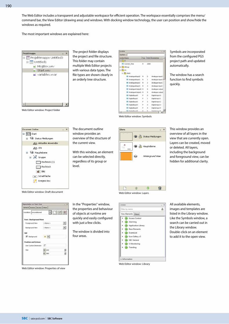
190
saia-pcd.com SBC Software
Web Editor window: Draft document
Web Editor window: Properties of view
The Web Editor includes a transparent and adjustable workspace for efficient operation. The workspace essentially comprises the menu/command bar, the View Editor (drawing area) and windows. With docking window technology, the user can position and show/hide the windows as required.
The most important windows are explained here:
Web Editor window: Project folder
The project folder displays the project and file structure. This folder may contain multiple Web Editor projects with various data types. The file types are shown clearly in an orderly tree structure.
The document outline window provides an overview of the structure of the current view.
With this window, an element can be selected directly, regardless of its group or level.
Web Editor window: Symbols
Web Editor window: Layers
Symbols are incorporated from the configured PG5 project path and updated automatically.
The window has a search function to find symbols quickly.
This window provides an overview of all layers in the view that are currently open. Layers can be created, moved or deleted. All layers, including the background and foreground view, can be hidden for additional clarity.
In the "Properties" window, the properties and behaviour of objects at runtime are quickly and easily configured with just a few clicks.
The window is divided into four areas.
Web Editor window: Library
All available elements, images and templates are listed in the Library window. Like the Symbols window, a search can be carried out in the Library window. Double-click on an element to add it to the open view.
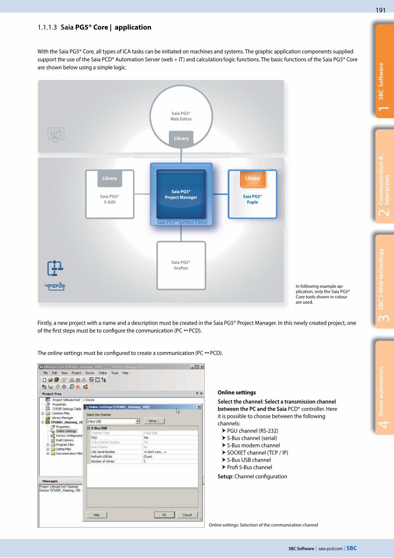
191
saia-pcd.com
Saia PG5®
Web Editor
Saia PG5®
S-Edit
Saia PG5®
Fupla
Saia PG5®
Graftec
3S
BC
S-W
eb
te
chn
olo
gy
SBC Software
2C
om
mu
nic
ati
on
&
Inte
rac
tio
n1
SB
C S
oft
wa
re4
Ro
om
au
tom
ati
on
In following example ap-plication, only the Saia PG5® Core tools shown in colour are used.
1.1.1.3 Saia PG5® Core | application
With the Saia PG5® Core, all types of ICA tasks can be initiated on machines and systems. The graphic application components supplied support the use of the Saia PCD® Automation Server (web + IT) and calculation/logic functions. The basic functions of the Saia PG5® Core are shown below using a simple logic.
Online settings: Selection of the communication channel
Online settings
Select the channel: Select a transmission channel
between the PC and the Saia PCD® controller. Here it is possible to choose between the following channels:
PGU channel (RS-232) S-Bus channel (serial) S-Bus modem channel SOCKET channel (TCP / IP) S-Bus USB channel Profi S-Bus channel
Setup: Channel configuration
The online settings must be configured to create a communication (PC PCD).
Firstly, a new project with a name and a description must be created in the Saia PG5® Project Manager. In this newly created project, one of the first steps must be to configure the communication (PC PCD).
Saia PG5®
Project Manager
Library Library
Library
Saia PG5® Symbol Editor
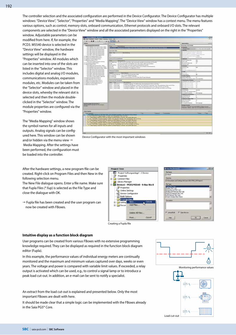
192
saia-pcd.com
No 123
SBC Software
Intuitive display as a function block diagram
User programs can be created from various FBoxes with no extensive programming knowledge required. They can be displayed as required in the function block diagram editor (Fupla).
In this example, the performance values of individual energy meters are continually monitored and the maximum and minimum values captured over days, weeks or even years. The voltage and power is compared with variable limit values. If exceeded, a relay output is activated which can be used, e.g., to control a signal lamp or to introduce a peak load cut-out. In addition, an e-mail can be sent to notify a specialist.
Load cut-out
After the hardware settings, a new program file can be created. Right-click on Program Files and then New in the following selection menu.The New File dialogue opens. Enter a file name. Make sure that Fupla Files (*.fup) is selected as the File Type and close the dialogue with OK.
Fupla file has been created and the user program can now be created with FBoxes.
Creating a Fupla file
Device Configurator with the most important windows
An extract from the load cut-out is explained and presented below. Only the most important FBoxes are dealt with here.
It should be made clear that a simple logic can be implemented with the FBoxes already in the Saia PG5® Core.
Monitoring performance values
The controller selection and the associated configuration are performed in the Device Configurator. The Device Configurator has multiple windows: "Device View", "Selector", "Properties" and "Media Mapping". The "Device View" window has a context menu. The menu features various options, such as control, memory slots, onboard communication, Ethernet protocols and onboard I/O slots. The relevant components are selected in the "Device View" window and all the associated parameters displayed on the right in the "Properties" window. Adjustable parameters can be modified from here. If, for example, the PCD3. M5540 device is selected in the "Device View" window, the hardware settings will be displayed in the "Properties" window. All modules which can be inserted into one of the slots are listed in the "Selector" window. This includes digital and analog I/O modules, communications modules, expansion modules, etc. Modules can be taken from the "Selector" window and placed in the device slots, whereby the relevant slot is selected and then the module double-clicked in the "Selector" window. The module properties are configured via the "Properties" window.
The "Media Mapping" window shows the symbol names for all inputs and outputs. Analog signals can be config-ured here. This window can be shown and/or hidden via the menu view Media Mapping. After the settings have been performed, the configuration must be loaded into the controller.

193
saia-pcd.com
3S
BC
S-W
eb
te
chn
olo
gy
SBC Software
2C
om
mu
nic
ati
on
&
Inte
rac
tio
n1
SB
C S
oft
wa
re4
Ro
om
au
tom
ati
on
Data capture
The HDLog FBox records up to 10 values for a historical data evaluation. The values are first saved in a buffer (RAM DB) and written to a CSV file depending on the parameterisation. The resulting files can therefore for example be forwarded via e-mail (see below, FBox family communication e-mail), read via FTP access or read and displayed via a web application.
In our example application, the energy data evaluation is performed with this FBox.
The e-mail function and integral SMTP (Simple Mail Transfer Protocol) client enable PCD controllers to send process and system information to an e-mail server via the Ethernet interface. Alarm, service and status messages – or any process information required – can therefore be sent by e-mail to a management centre and/or to service personnel. The data saved previously is sent as an attach-ment. Convenient Fupla FBoxes are provided in order to use the e-mail functions.
Thus in our example, a limit value being exceeded can be reported directly to the responsible member of staff.
HDLog FBox
The FBoxes named above must now be positioned in the Fupla program, configured and linked with each other.
And so we have a finished Fupla program.
Sending e-mails with the PCD
S-Bus energy meters
This FBox is used to read the energy meter using the S-Bus interface.
The energy meter supplies the current power consumption values of the consumers connected. For the example above, the power and voltage are used.
In the Symbol Editor it can be seen which tabs and flags can be used.
Arithmetic FBoxes – comparison
Value greater or equal to: Binary output is set if the top input is greater than or the same as the bottom input. Otherwise the binary output is not activated. Signal if limit value is exceeded
Symbol Editor
FBox – energy meter S-Bus
FBox – Integer comparison

194
saia-pcd.com SBC Software
Once a system function is implemented with FBoxes and has been downloaded to the controller, the current project values can be displayed using "Go online/offline".
Rebuild all files
Generating a program (Build)
To enable the finished edited program to be read and run by the PCD, it must be generated in the Project Manager via Menu Device Rebuild All Files or using the Rebuild All Files button in the Fupla Editor or in the Project Manager (compile, assemble and link).
The results of the various program preparation steps (Compiler, Assembler, Linker) are shown in the Messages window.
If the program has been edited correctly, the build function is completed with the message: Build successful. Total errors 0 Total warnings 0
Any errors which have occurred are shown as error messages. By double-clicking on the error message, the error concerned can easily be localised in the user program.
DownloadProgram
Transferring the program to the PCD (download)
The user program is now ready and just needs to be transferred from the PC to the Saia PCD®. This is carried out using the Download Program key or the online "Download Program" menu command in the Project Manager.
Should any communications problems arise, check the configuration settings (online settings) and the PC PCD connec-tion with the USB cable.
Via the Watch window, it is possible to show selected online data such as the status of inputs/outputs or the content of variables of various Fupla pages over a specific time. Data can be displayed and changed here.
Data can be entered manually or imported using copy/paste or drag & drop. A successful build of the PG5 program automatically updates the symbols with their new address. This also works with the Watch window open.
Fupla program – "Go online"
Watch window
"Go online" displays the current project values.
If "Go online" is activated, all binary connections show the current status using the line thickness:
Thin "purple" line: Status = 0 Thick "purple" line: Status = 1
Click the connection to display the current value. This also applies to analog values.

195
saia-pcd.com
3S
BC
S-W
eb
te
chn
olo
gy
SBC Software
2C
om
mu
nic
ati
on
&
Inte
rac
tio
n1
SB
C S
oft
wa
re4
Ro
om
au
tom
ati
on
Saia PG5® Core + HVAC library. The visualisation is created using the Web Editor.
The majority of the program functions can be implemented using the FBoxes included the Saia PG5® Core Package. In addition, additional libraries for specific applications are available. The HVAC library, for example, has an efficient collection of complex control modules (FBoxes) for the heating, ventilation and air conditioning systems area. These functions simplify the engineering of the technical systems of buildings.
The HVAC library contains the following FBox groups
General: FBoxes for numeric functions, binary functions, alarms, monitoring, motor, blocking and frost protection, process states, switches and the conversion of data types
Analog: Function blocks for individual scaling of each individual analog input or output
Electrical: FBoxes for lighting control, window blind control and step switches
Energy: Energy meters, pulse counters, monthly statement, enthalpy, switching heating on/off, load cut-out
Filters: Filter, limitation, ramp limitation, average of measurement values, dead zone, dead range with delay, zero zone, hysteresis
Init: Initialisation of the sub-functions for the HVAC library
Controllers: Two-point controller, three-point controller, boiler loading, P, PZ, PI, PID, P-PI, P-PID controllers, incoming air mixers, controller sequences, mixer sequences
Setpoint: Heat curve, heating demand, setpoint device, setpoint ramp, setpoint adjustment
Test: Simulation of values and states
Clocks: Daily program, weekly program, annual program, clock with multiple switching periods in one FBox, national holidays, monthly switch-offs or switching periods one after the other on the same day, as well as FBoxes for reading and writing clock data
1.1.2.1 HVAC modules
1.1.2 Saia PG5® HVAC modules and use
Saia PG5® Web Editor
Saia PG5® S-Edit Saia PG5® Fupla
Saia PG5® Graftec
Saia PG5®
Project Manager
Saia PG5® Symbol Editor
Sa
ia P
G5
® H
VA
C L
ib
Library Library
Library

196
saia-pcd.com SBC Software
Creating a Fupla file and assigning a name
Application of the HVAC modules – HVAC system
To start, a new project must be created in the Saia PG®5 Project Manager. No adjustment is made on the Device Configurator in this example. This example is merely intended to show the use and application of HVAC FBoxes.
An appropriate name and a description is assigned to the project.
After creating the project, a new program file must be created.
To do this, right-click on Program Files and then New in the following selection menu.
The New File dialogue opens. Enter "Ventilation" as the file name, for exam-ple. Make sure that Fupla Files (*.fup) is selected as the File Type and close the dialogue with OK.
Now open the Fupla program by double-clicking on the file created.
Entering a project name
1.1.2.2 Application of the HVAC library
The HVAC FBox library is used in order to implement an HVAC system in the following example. The following system should be controlled and regulated by a PCD. The implementation of the Fupla program is shown clearly on the next few pages in step-by-step instructions.

197
saia-pcd.com
3S
BC
S-W
eb
te
chn
olo
gy
SBC Software
2C
om
mu
nic
ati
on
&
Inte
rac
tio
n1
SB
C S
oft
wa
re4
Ro
om
au
tom
ati
on
Page navigator
Initialising FBoxes
Capturing analog values
The project requires 2 COBs with a total of 9 Fupla pages.
Right-clicking on the COB opens the Properties window opposite. Here there are instructions with which new pages are created ("Insert Page") or a name assigned ("Properties").
Initialisation
If users need to use FBoxes from the HVAC library, they must place an FBox HVAC Initialisation at the start of the Fupla file.
Various common properties of the HVAC FBoxes are set with this initialisation FBox, e.g. the behaviour of the FBox after loading or the start-up behaviour when switching on the PCD.
Capturing analog values
The temperature values for exterior, supply and exhaust air and the return flow are to be captured. To do this, place the FBox Conversion2 in the HVAC General FBox family on the page four times, and place the FBox Filter T1 in the FBox family HVAC Filter next to each one.
The FBoxes and connectors must be connected.
Give FBoxes a name (double click on FBox – Properties Name).
Create icons in the Symbol Editor and use drag & drop to drag them to the connector.
Symbol Editor

198
saia-pcd.com SBC Software
Digital messages
Motor controller
System release
Capturing reports
The seven reports for filter, frost protection and motors are to be captured.
Place the FBox Binary Editor in the FBox family HVAC Test (Application tab) on the page as shown, connect-ing the FBox XOR 2–10 inputs in the FBox family Binary functions (Standard tab) and drag to two inputs.
Add symbols from Symbol Editor as before.
Motor controllers
Place the FBox Motor in the FBox family HVAC General (Application tab) on the page three times in a single stage + Quit as shown.
Place inputs/outputs on the FBox using the button from the Connector menu as shown.
Display the Symbol Editor using F5.
Create a new sub-group. We can now create symbols in the sub-group. Then use drag & drop to drag the newly created icons into the connector on the Fulpa page.
System release
The system should be connected via a clock and the pump via the external temperature.
Place the FBox 7-day clock program in the FBox family HVAC Clocks (Application tab) and the FBox Override Stage 1 in the FBox family HVAC General on the page four times as shown. Place the FBox Anti-block-ing pump from the FBox family HVAC General and the FBoxes Controller 2 points and sequence 2 points in the FBox family HVAC Controllers as shown on the page.
Place the FBox Set H, the FBox OR 2-10 inputs and the FBox AND 2–10 inputs from the FBox family Binary functions on the page as shown. Place connectors as shown opposite on the page and connect the elements.

199
saia-pcd.com
3S
BC
S-W
eb
te
chn
olo
gy
SBC Software
2C
om
mu
nic
ati
on
&
Inte
rac
tio
n1
SB
C S
oft
wa
re4
Ro
om
au
tom
ati
on
Control
Alarms
Analog card
Digital values
Physical inputs and outputs for the test
Select the HVAC Analog family in the All or Application in the FBox Selector tab. Place the FBox PCD2.W4 FBox and drag it to two inputs. Place the FBox PCD2.W2 FBox and drag it to four inputs. Connect all FBox inputs or outputs. Enter O 112 in the PCD2.W4 FBox. There must be a space behind O so that the exact output can be identified. The same applies to I, F, R, etc. Enter I 96 in the FBox PCD2.W2. Use drag & drop to drag the relevant icons from the Symbol Editor into the connectors on the FBoxes.
Place the FBox Override binary from the FBox family HVAC General on the page as shown. Set the connectors and connect all elements as shown. In the Symbol Editor, add the symbol name I0 and 0 as the address.
Return to the symbol name and enter ..7 after the address I0 and press Enter. The Symbol Editor will automatically create the symbols I1 to I7 with the relevant address. Repeat this for the digital outputs O16…23 with address 112 to 119. Now use drag & drop to drag the available symbols into the connectors on the Fupla page.
The symbols are now linked to inputs and outputs and can be tested.
The Fupla program shown is a summary of a sample exercise from the basic course from the building automation workshop.
Alarm processing
We still need to process messages as alarms. Place the FBox Alarm inhibit 1–10 with two inputs from the FBox family HVAC General FBox Alarm on the page as shown. Then place the FBox OR 2-10 inputs with 4 inputs in the FBox family Binary Arithmetic, attach connectors and connect all the elements as shown. The FBox RLT1_Alarm saves the alarm until it is acknowl-edged. As the motor alarms are already saved in the FBox Motor, these can be connected via FBox OR to FBox RLT_Alarm_SSM. The FBox RLT_Alarm_SSM is designed to provide a visual and audible alarm notification. The S1 output is reset once acknowledged and the S2 output switches from flashing to being permanently on. Only once the alarm is deactivated will S2 also go out.
Control
The system should receive a supply/exhaust air temperature cascade as a control.
Place the FBox W/Room temperature from the FBox family HVAC Setpoint, and the FBox Controller PI and the FBox Sequence Master HC in the FBox family HVAC Controllers on the page as shown. Place the FBox Maximum and connectors in the FBox family Integer Arithmet-ics on the page as shown. Connect the elements. Now a few basic settings still need to be made in the FBoxes. Click the FBox to open the Properties window. All values are experience values which can be used to control temperature as a basis for adjustment. These values must be adjusted in accordance with the control behaviour during operation.

200
saia-pcd.com
Saia PG5®
Web Editor
Saia PG5®
S-Edit
Saia PG5®
Fupla
Saia PG5®
Graftec
Sa
ia P
G5
® D
DC
Su
ite
SBC Software
Saia PG5® Core + DDC Suite library
Using the Saia PG5® DDC Suite library and templates makes the creation of HVAC applications even simpler. Complex program structures and application elements such as complete pump controllers, incl. hour meters or entire control tasks for ventilation systems are grouped together as templates in individual function boxes and optimally add to the current HVAC library. This means that projects can be implemented efficiently.
Total pump control with HVAC library
Total pump control with DDC Suite library
We can already see a number of benefits when comparing the two Fupla pages (HVAC and DDC Suite). It is easier to read and understand the Fupla program – fewer FBoxes and links on one page. Clear and transparent layout – easier to handle, e.g. for new colleagues in the developer or service team Easy to maintain
1.1.3 Increasing engineering efficiency through installation templates
1.1.3.1 DDC Suite
Saia PG5®
Project Manager
Sa
ia P
G5
® H
VA
C L
ib
Library Library
Library
Saia PG5® Symbol Editor

201
saia-pcd.com
3S
BC
S-W
eb
te
chn
olo
gy
SBC Software
2C
om
mu
nic
ati
on
&
Inte
rac
tio
n1
SB
C S
oft
wa
re4
Ro
om
au
tom
ati
on
The following FBox families are available to the DDC Suite library user:
DDC general: general FBoxes such as manual information, media access
DDC analog values: FBoxes for capturing measurement values
DDC BACnet: Scheduler, Trendlog, Loop, Notification Class
DDC Releases: clocks, systems and aggregate switches
DDC Initialisation: modules which must be inserted once into a Fupla and which provide basic functions.
DDC controllers: control modules for components such as coolers, heat recovery systems and heaters
DDC setpoints: conversions, setpoints
DDC Controls: Triggering of motors, pumps, covers and drives
DDC Fault: Fault modules for motors, fire protection and various components
This FBox library with highly integrated FBoxes uses individual data points and creates groups and symbols automatically.
1. Integrated trending (offline history) If data has to be recorded along with the actual control and regulation of a system, this is easily implemented with Saia PG5® DDC Suite. Data acquisition for trending can be initiated by defining the memory size in the object parameter window. When the automation system is in operation, data will be constantly saved in the Saia PCD® and available for evaluation. In addition, documentation (.txt) will be created in the Saia PG5® Project Manager of all the measured historical data. A list of the trend settings can be seen in this file. There is one entry for each trend with all the details.
The unique features of the DDC Suite are listed in 5 points:
Trending
Object parameter window

202
saia-pcd.com SBC Software
2. The principle of the trend function also applies to alarm functions.
By defining the alarm number in the object parameter window, the alarms are listed in a CSV file with numbers and text. With Version 2.5 of the DDC Suite, the system identification key can be created completely freely directly from Fupla. The aim is to create the system identification key for the S-Web alarm texts and BACnet® completely freely according to the specifications from the Fupla program. The system identification key can have up to 12 levels. The general section (levels 1-10) is specified conveniently from a central FBox. The FBoxes can be placed multiple times. Within the FBox you can select what the key is to be used for. Thus, for example, various system identification keys can be created for S-Web alarming, the BACnet® Object Names and the BACnet® Description. Simply place another FBox if other levels are to be used on certain Fupla pages, e.g. for different systems. These FBoxes can be used as often as required, and the changes to the identifica-tion keys will be valid until the next FBox of this type. Thus a different name key can be used for each system.
3. Automatic generation of BACnet® configurations For BACnet® projects, the BACnet® object list is created automatically, which saves a great deal of error-prone manual work. The automatic generation of the BACnet® objects is the main reason why so many customers use the DDC Suite. In building automation, it is normal for all systems to map relevant hardware and software data points to BACnet® objects. This may mean that multiple data points are used in a BACnet® object. Thus, for example, a binary output could receive exactly the same return message and be monitored via intrinsic alarming. The control templates for the DDC Suite already contain all BACnet® definitions which can be activated by clicking, Thus BACnet® originates at the click of a button.
4. The engineering documentation can be created quickly at the click
of a button.
The documentation on all DDC Suite FBoxes is created as an HTML file. This file contains a general description with all parameters and settings. The documentation can be saved in the PCD and, for example, be used for viewing via the web. It is, however, also possible to post-edit the documen-tation using a text processing tool and to add images from the SCADA/web application.
Alarming
BACnet configurator
HTML document

203
saia-pcd.com
3S
BC
S-W
eb
te
chn
olo
gy
SBC Software
2C
om
mu
nic
ati
on
&
Inte
rac
tio
n1
SB
C S
oft
wa
re4
Ro
om
au
tom
ati
on
5. Templates for Fupla, Web Editor and Visi.PlusThe Saia PG5® DDC Suite largely comprises a highly integrated FBox library which is supplemented by a growing number of ready-made, tested and ready-to-use Fupla pages which fully map the typical parts of the system in terms of function. The Saia PG5® DDC Suite also provides the control and visualisation function for each FBox. Operation and visualisation using the web browser or Visi.Plus is already integrated and ready for use.
Fupla templates
In order to reduce the system programming time, entire applications (heating circuit, water heating, ventilation systems, etc.), including the calendar and control tasks, are fully integrated for free selection. Some suggestions for control settings and for system control can thus be freely added, changed or integrated.
Visi.Plus templates
When importing data from Fupla to Visi.Plus, FBoxes are identified and then handled by the Visi.Plus database as FBoxes. Not only are the data points imported, but the alarms and historical trends are automatically created upon import. In addition, the Visi.Plus user is provided with the same template objects as in Web Editor.
Web Editor templates
The DDC Suite is also includes template objects for S-Web applications. Graphic and control objects are available for every FBox. There are also S-Web system templates for predefined systems.
All official macros can be found in the "Li-brary" Web Editor window.
Template: Ventilation system
System display

204
saia-pcd.com SBC Software
Adjust the template pages
Most functions, settings and parameters can be set online. In the event of a function change therefore, the program does not normally ned to be recompiled and loaded into the controller. For example the setpoint adjuster can simply be deactivated if required ("External speficiation inactive"), if required by the operator, or the setpoint should be used without summer compensation. This reduces the commissioning time.
The template pages can also be adjusted with further FBoxes if required.
Fupla selector
1.1.3.2 Application of the DDC Suite
In the previous example it was made clear how quickly and easily a HVAC system can be implemented with the correct engineering tool. The engineering time can, however, be further reduced using the DDC Suite.
Engineering start
After the hardware settings (Device Configurator), a new program file (Fupla file) is created. The imple-mentation of a system can now begin. Various templates are provided to eliminate the need to create a new HVAC system from scratch.After clicking on the "Template" symbol in the Fupla Selector, the available templates are listed.
Selecting templates: In this example, the template AirCond_T1 is used.
The AirCond_T1 template contains the FBoxes and links shown here.
Generating a program
Once the program is created, information is automatically generated. BACnet configuration has been created (BACnet.bnt) Alarms with numbers and text are listed in a CSV file (DDC_Alarming.CSV) Documentation as an HTML file with settings is created (DDC_Dokumentation.htm) List of all parameterised historical data (DDC_HDLog.txt)
Visualisation
In the Web Editor, the template is linked to the Fupla page with just a few clicks.
Unlike the standard HVAC FBoxes, the parameter assignment symbols in the FBoxes are not defined as arrays: Individual parameters can and/or must be allocated their own symbolic assignment if a connection to a display or a building automation system is required. This assignment is no longer needed for the DDC Suite library, as all parameters already contain symbolic assignments. Thus the assignment to an image in the Web Editor is very quick.
Project Tree with Program Files
Link symbols

205
saia-pcd.com
Saia PG5®
Web Editor
Saia PG5®
S-Edit
Saia PG5®
Fupla
Saia PG5®
Graftec
Sa
ia P
G5
® D
DC
Su
ite
My
Su
ite
3S
BC
S-W
eb
te
chn
olo
gy
SBC Software
2C
om
mu
nic
ati
on
&
Inte
rac
tio
n1
SB
C S
oft
wa
re4
Ro
om
au
tom
ati
on
1.1.4 Saia PG5® Controls Suite
1.1.4.1 My Controls Suite
In addition to the templates which can be easily created and reused, you can also create your own FBoxes and/or FBox library (My FBox Lib). The FBox Builder, contained in the Saia PG5® Core, is used for this.
Create templates
Use template pages
The use of predefined FBoxes and/or templates is not mandatory. Saia PG5® Core enables users to create individual templates and even define the templates with purely graphic engineering, with no IL programming required.
Create templates
Using templates significantly simplifies processes and reduces engineering time. To implement projects more efficiently, users can not only implement existing templates, but also incorporate user-specific engineering projects as templates. Users who have built their standard Fupla pages can export and save them as .fxp files (a .fxp file includes any number of Fupla pages). To reuse the pages, the .fxp files must be located and then imported.
Saia PG5® Core – My Controls Suite
Saia PG5®
Project Manager
Sa
ia P
G5
® H
VA
C L
ib
Library Library
Library
Saia PG5® Symbol Editor

206
saia-pcd.com
Saia PG5®
S-Edit
Saia PG5®
Fupla
Saia PG5®
FBox Builder
Saia PG5®
Graftec
My
FBox
Libs
Saia PG5®
S-Edit
Saia PG5®
Fupla
Saia PG5®
Graftec
My
FBox
Libs
Saia PG5®
FBox Builder
SBC Software
The Saia PG5® FBox Builder has additional functions that enable programmers to develop totally new FBoxes and to maintain them in their own library. The FBox Builder advanced version is required if the user wishes to integrate existing IL functions, modify existing FBoxes or even create totally new FBoxes. In addition to importing export pages (1), this version enables extensive functions such as:
Importing existing FBoxes (2) Creating FBoxes "from scratch" (3)
Importing IL code (4)
The advanced FBox Builder is suitable for experienced Saia PG5® IL programmers who have attended a workshop and own a licence for the FBox Builder Advanced add-on tools.
Using the Saia PG5® FBox Builder in projects with the Saia PG5® software technology
Create FBoxes
The process of exporting Fupla pages and then reimporting them is simplified by the Saia PG5® FBox Builder. Users can import their .fxp files into the FBox Builder and then archive them as FBoxes. This function (importing Fupla export pages/files) enables a structured group of FBoxes to be assembled into one large macro FBox. The Saia PG5® FBox Builder can then be used to document, maintain and export the new macro FBox as a new "product". This capability allows users to build customised libraries for any other application. The FBox Builder enables users to develop their own FBoxes without writing a single line of instruction list code.
Creating your own FBoxes with the FBox Builder
Saia PG5®
Project Manager
Saia PG5®
Project Manager
4: IL Code1: Export pages2: existing FBoxes
3: New FBox
Library Library
Saia PG5® Symbol Editor
Saia PG5® Symbol Editor

207
saia-pcd.com
3S
BC
S-W
eb
te
chn
olo
gy
SBC Software
2C
om
mu
nic
ati
on
&
Inte
rac
tio
n1
SB
C S
oft
wa
re4
Ro
om
au
tom
ati
on
Saia PG5® Web Editor – Web visualisation for automation
The Saia PG5® Web Editor produces appealing web visualisations with no web designer skills required.The tool is designed for the automation environment. Applications include system/machine visualisations, alarming and trending functions or a service page. The full integration into the Saia PG5® Core combined with Saia PCD® controllers guarantees a particularly efficient working method.
A standalone variant is also provided for applications independent of Saia PCD® controllers.
Standalone variant
The Web Editor is independent software which can be used without the Saia PG5® Core.
Using the standalone variant
The standalone variant of the Web Editor can, for example, be used to individually design the S-Monitoring Application. The functionality of the turnkey solution (S-Energy Monitor) is based on standard SBC technologies, in the form of a Saia PG5® Web Editor project. In practical terms, the user interface for the S-Monitoring application can be flexibly customised using the Saia PG5® Web Editor. The look and functionality can then be tailored to the individual user, e.g. to include the company design/logo.
User interface S-Monitoring application – predefined web pages created using Saia PG5® Web Editor.
1.1.4.2 Web Editor as a standalone tool

208
saia-pcd.com
G5 Controls Suite82 0
ort.comort.como
SBC Software
The combined platform of the SBC software is the Saia PG5® Controls Suite DVD. It contains software tools for project management, engineering, programming and service. The DVD also includes application components with which you can increase your productivity when using Saia PCD® products. There is also a wide range of system software on the Saia PG5® Controls Suite DVD. This software is predominantly driver software to ensure easy and secure integration into a system environment.
Saia PG5® Controls Suite contains everything you need for automation
PC tools
Saia PG5® Core Project Manager
Application Programming Application Engineering Network Management Service
Saia PG5® Web Editor
Tool for creating web pages for the Saia PCD® Web Server
Saia Visi.Plus
Visualisation and management soft- ware for applications in infrastructure automation
Saia PG5® HMI Editor
Tool for Saia PCD® Text Panels
Saia PG5® FBox Builder
Tool for creating and managing Saia PG5® Fupla FBoxes
Saia PG5® Online-Tools
Downloading PG5 programs without installing the Saia PG5® Core
Application components
Standard FBoxes
Program modules for Saia PG5® Fupla, the graphic engineering tool
Arithmetic and logical FBoxes Analog FBoxes Communication FBoxes
Application FBoxes
Program modules for Saia PG5® Fupla, the graphic engineering tool.FBoxes Alarm, DALI, DDC Suite, EIB, Energy Meter, EnOcean, Historical Data Capture, HVAC, Blinds/Lighting, JCI N2-Bus, e-mail Communication, LON, Modbus, Modem, MP-Bus, Room Controller
IL libraries
Function blocks for counter modules, drive modules and analog modules can be integrated into IL programs
List of tools in the Saia PG5® Controls Suite
Application software
SBC Web Connect
The PC program enables access to the PCD WebServer via any communication interface (RS-232, RS-485, Profibus, Ethernet, etc.)
Saia PG5® SD Flash Explorer
With SD Flash Explorer, the content of the SBC file system can be extracted to the PC.
Everything on one DVD!
Application software for Saia PCD® projects can be run on PCs, panels, PDAs, etc.
Application compo-nents for Saia PCD® Projects
PC tools for creating Saia PCD® projects
1.1.4.3 Overview of the tools and licence packages
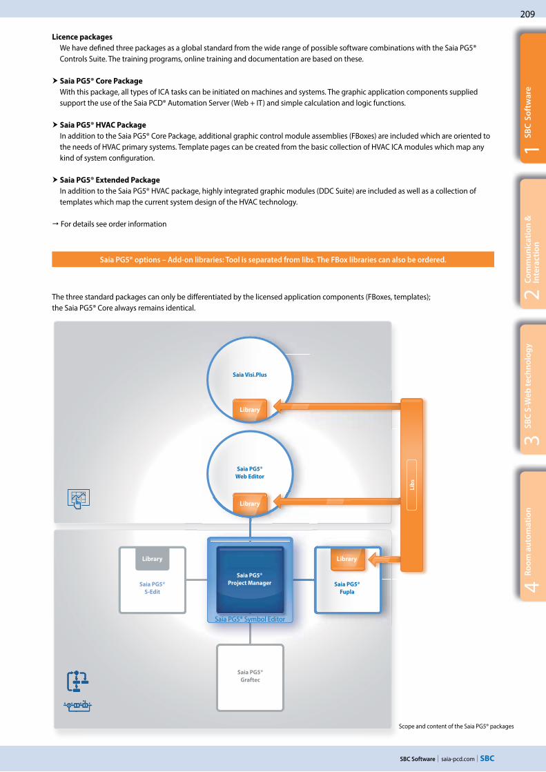
209
saia-pcd.com
Saia® PG5Saia PG5®
S-Edit
Saia PG5®
Fupla
Saia PG5®
Graftec
Saia PG5®
Web Editor
Saia Visi.Plus
Lib
s
3S
BC
S-W
eb
te
chn
olo
gy
SBC Software
2C
om
mu
nic
ati
on
&
Inte
rac
tio
n1
SB
C S
oft
wa
re4
Ro
om
au
tom
ati
on
Saia PG5® options – Add-on libraries: Tool is separated from libs. The FBox libraries can also be ordered.
Licence packages
We have defined three packages as a global standard from the wide range of possible software combinations with the Saia PG5® Controls Suite. The training programs, online training and documentation are based on these.
Saia PG5® Core Package
With this package, all types of ICA tasks can be initiated on machines and systems. The graphic application components supplied support the use of the Saia PCD® Automation Server (Web + IT) and simple calculation and logic functions.
Saia PG5® HVAC Package
In addition to the Saia PG5® Core Package, additional graphic control module assemblies (FBoxes) are included which are oriented to the needs of HVAC primary systems. Template pages can be created from the basic collection of HVAC ICA modules which map any kind of system configuration.
Saia PG5® Extended Package
In addition to the Saia PG5® HVAC package, highly integrated graphic modules (DDC Suite) are included as well as a collection of templates which map the current system design of the HVAC technology.
For details see order information
The three standard packages can only be differentiated by the licensed application components (FBoxes, templates); the Saia PG5® Core always remains identical.
Scope and content of the Saia PG5® packages
Saia PG5®
Project Manager
Library Library
Library
Library
Saia PG5® Symbol Editor

210
saia-pcd.com SBC Software
Saia PG5® Programming Tool
PG5 – Demo version with all functions. Runtime limited to 90 days PCD8.PG5–DEMO
Saia PG5® Core Package
Programming software with editors (IL, Fupla, Graftec), network configurators,standard libraries (Analog, Communication, Arithmetic & Logic), application libraries (Alarming, Blinds-Lighting, e-mail, Trending [HDLog], Energy Meter, DALI, Modbus, EIB, EnOcean, JCI N2-Bus), Web Editor and FBox Builder (basic version)
PCD8.PG5–CORE
Saia PG5® HVAC Package
Similar to Saia PG5® Core Package and associated libraries (HVAC, BELIMO MP-BUS, LonWorks, room controllers and modem), BACnet
PCD8.PG5–HVAC
Saia PG5® Extended Package
Same as Saia PG5® HVAC Package and associated DDC Suite libraryPCD8.PG5–EXTENDED
Software upgrade
Upgrade – in accordance with the customer keyPCD8.PG5–UPGRADE
End user licence for Saia PG5®
End user licence for PG5. The customer is supported by the requisitioner (in accordance with the customer key)
PCD8.PG5–ENDUSER
Saia PG5® options – Add-on libraries
PG5 – Modem Library
Modem base library incl. data buffer, DTMF, pager & SMS librariesPCD8.PG5-LIBMODEM
PG5 – HVAC Library
HVAC Library for building automationPCD8.PG5-LIBHVAC
PG5 – DDC Suite Library
DDC suite library for building automationPCD8.PG5-LIBDDC
PG5 – Belimo MP-Bus Library PCD8.PG5-LIBMPBUS
PG5 – Room Controller
Library for room control unitsPCD8.PG5-LIBROOM
PG5 – LONLibrary for LONWORKS®
PCD8.PG5-LIBLON
Saia PG5® options – Add-on tools
PG5 – Web Editor
Software package for Saia PG5® Web Editor as a standalone toolPCD8.PG5-WEB8-SA
PG5 – FBox Builder ("advanced version") Software package for Saia PG5® FBox Builder. I
L knowledge needed and 1 day’s training included
PCD8.PG5-FBOXBLD
Order information | Saia PG5® Controls Suite

211
saia-pcd.com
Visi.Plus
3S
BC
S-W
eb
te
chn
olo
gy
SBC Software
2C
om
mu
nic
ati
on
&
Inte
rac
tio
n1
SB
C S
oft
wa
re4
Ro
om
au
tom
ati
on
1.2 Application software for Windows PCs
1.2.1 Saia Visi.Plus | Classic control/management system
Software package for visualisation and management tasks – for reliable, efficient and cost-effective project implementation in connection with SBC automation systems and DDC Suite.
Main characteristics of Saia Visi.Plus
Optimally integrated and adjusted to Saia PG5® and Saia PCD®, successfully used worldwide since 2001
Clear operation and a fully available Engineering edition reduces commissioning and maintenance costs
The integrated web server allows all process data to be displayed with a web browser at no additional cost
The open philosophy of the Saia PCD® is also consistently implemented in Visi.Plus. Interfaces to all cur-rent applications are either already integrated or accessible at a later date.
Building technology
Visi.Plus is represented in buildings for
all uses:
Shopping malls Hospitals Office buildings
Traffic engineering
Visi.Plus is designed for traffic tasks:
Tunnels (train/car) Airports Point heating
Power engineering
Visi.Plus distributes and reliably measures
heating and energy data:
Combined heat and power plants Energy measuring servers Solar plants
The Visi.Plus man-
agement system
can be successfully
implemented into a
wide range of
applications

212
saia-pcd.com SBC Software
Visi.Plus
Visi.Plus
Manageementlevel
Automationlevel
Field levvel
Visi.Plus provides support at the start of the project and performs valuable services which save time and money. The engineering edition is included in PG5 and may be used for commissioning and optimisation. The runtime management system is unlocked when purchasing a licence and all control displays and settings are automatically implemented. With the DDC Suite and a few mouse clicks the following functions are available immediately:
Engineering Edition – Saia Visi.Plus
Alarming
Alarm list incl. history History Forwarding via e-mail or SMS Control for end customers
Trends
Record closed loops Control optimisations Confirmation for end users
Control panels
Complete system overview Simple configuration Optimisation through visualisation
Web
Remote access possible immediately Support in accordance with the commissioning Control by planner/end customer
Benefits of Visi.Plus to assist commissioning/optimisation
Instant overview of trend and alarming data Development environment included in Saia PG5® and fully functional Easy control of all parameters and regulation systems
A small step for the integrator – immense benefits for the operator
Visi.Plus as a tool for commissioning and optimisation
Visi.Plus as a completemanagement system
Advantages of Visi.Plus as a management system
Open structure for connecting to standard systems (OPC, BACnet, Modbus, SQL, MS Office) Scalable architecture, for price optimisation across a broad spectrum of use Optimally integrated and dedicated to Saia PG5® and Saia PCD®
Manageementlevel
Automaationlevel
Field levvel

213
saia-pcd.com
3S
BC
S-W
eb
te
chn
olo
gy
SBC Software
2C
om
mu
nic
ati
on
&
Inte
rac
tio
n1
SB
C S
oft
wa
re4
Ro
om
au
tom
ati
on
Visualisation and graphic editor
All the relevant parts of the system can be displayed to the user in the most appropriate way with the powerful graphic editor. The use of vector and bitmap graphics allows both overviews and detailed information to be displayed. The graphic editor also helps with visualisation in runtime mode. This means that users can switch to editor mode at any time (via password) to make corrections and changes.
Operator programs
Web Server
All graphics pages generated are automatically saved as web pages. All generated pages and functions can be displayed and operated using a browser, by activating the Visi.Plus web server.
Logging
This module logs and stores all events in a file at user level. With its integral filter functions, the log viewer allows all important events to be displayed in the most appropriate way to the user.
Alarm management
Alarm management is an essential constituent of any building management system. With Saia Visi.Plus it is possible, by observing limit values, to display all relevant data points for the user in a plain-text alarm window. Two separate alarm lists provide a better overview. The first gives an overview of all alarms; the second enables all current alarms to be examined.
Trend display With this module you can, for example, receive a monthly summary energy bal-ance sheet for all consumers in a building. Whether monitoring the consump-tion of water, electricity or heat, this trend analysis provides you with an overview that enables you to initiate the appropriate measures.

214
saia-pcd.com SBC Software
Runtime database system (DMS)
The data management system is the central database of the entire system. All process data is managed in the DMS and is available at all times. Communication with the individual program parts (e.g. the graphic editor) is event-oriented.
Long-term database system (PDBS)
The database system stores and manages history data, alarms and logs. This module also allows data to be exported to other databases, enabling process data to be collected in real time and stored in different databases.
Process Engineering Tool (PET)
The PET provides a clear and easy display of all data from the data manage-ment system in table form. All data (incl. communication, alarming, logging, functions, etc.) belonging to a project can therefore be created and managed in the process engineering tool.
Database systems
The S-Driver
The S-Driver is used for communication with SBC automation stations based on the S-Bus protocol. The driver supports all types of communication, e.g. serial interface, modem, USB and TCP/IP. Because the S-Driver is based on the SBC proprietary SCOMM-DLL, all PG5 tools can be used in parallel with it. The S-Driver has a mechanism to optimise data traffic using automatically generated telegram packets. A further optimisation is achieved by prioritis-ing telegrams according to categories, such as alarms, actual values, or setpoints.
Visi.Plus as OPC client
To enable the neutral integration of automation systems even from other manufacturers, Visi.Plus offers an OPC client that reads data from the OPC Server of a third-party supplier and automatically enters it in the Visi.Plus DMS database. The user can then access it for further processing in the Graphic Editor or Alarm Manager, or for storage in the historical database.
Communication drivers
BACnet Driver
This driver has been developed completely independent of the system, this allows the scanning and the preparation of any objects. Optimal integration is achieved however, with Saia PCD® products.
This driver enables communication between one or several BACnet-capable devices and the Visi.Plus.

215
saia-pcd.com
3S
BC
S-W
eb
te
chn
olo
gy
SBC Software
2C
om
mu
nic
ati
on
&
Inte
rac
tio
n1
SB
C S
oft
wa
re4
Ro
om
au
tom
ati
on
Analysis of trend data (PChart)
If the user wishes to display or export trends, however they have been compiled, PChart is the tool to use. The trend data can be displayed in a variety of colours and different scales.
MALM ESPA 4.4.4
With this module, alarms can be forwarded to telecommunica-tions systems with an ESPA 4.4.4 interface (serial, type RS-232), to be output to the display of a telephone within the local telephone network.
pSMS
With a GSM-compatible modem (not included), SMS messages can be received and their content assessed according to a specification (e.g. to acknowledge alarms or modify values).
SNMP Manager
Driver to monitor network components that provide SNMP services, such as routers or controllers. The values polled (depending on parameters set) are integrated into the Visi.Plus database, where they can be processed further (e.g. for history data or alarms).
Add-on programs
MALM Voice
When an alarm occurs, a voice message (sound file in WAV format) will play via phone. The person called can then use the same call to acknowledge the alarm by entering a sequence of numbers (requires a DTMF-enabled telephone).
ESPA 4.4.4 (RCV)
Messages transmitted by telecommunications systems with an ESPA 4.4.4 interface (serial, type RS-232) can be implemented as alarm messages by Visi.Plus and used for further processing and logging.
pCalc
Calculations for energy analysis and system monitoring, up to 1,000 formulas with 16 variables each.
Mobile Alarm (MALM)
Remote alarms via e-mail/SMS
When monitoring technical building installations it is necessary to guarantee that, in the absence of service personnel, fault messages are forwarded quickly and safely. Direct diagnosis of the fault message is also possible via remote dial-in, thus avoiding unnecessary journeys by service personnel. The alarm is sent via SMS or e-mail.
System requirements
Visi.Plus requires the following minimum configuration: Windows 7, Windows 8, Windows 8.1, Windows 10 Windows Server 2008 R2, Windows Server 22012
Processor Core 2 Duo 1024 MB RAM (the higher the number of DMS data points,
the more memory is required) Hard disk with at least 1 GB free memory CD-ROM drive (poss. external data backup (CD writer))

216
saia-pcd.com SBC Software
Type Saia Visi.Plus packages in German and English (1 licence per project)
Visi.Plus Engineering Edition (Engineering edition is part of each PG5 licence)
PCD8.VP-DEMO Visi.Plus Demo - demo package
PCD8.VP-MINI Visi.Plus Mini - Mini package
Data management system, database system, graphic editor, engineering tool, scheduler program, trend and alarm capture and S-driver for 1,000 data points (approx. 65 hardware data points)
PCD8.VP-BASIC Visi.Plus Basic - basic package
Data management system, database system, graphic editor, engineering tool, scheduler program, trend and alarm capture, MALM remote alarms via pager/SMS/e-mail, PRT access logging and S-driver for 10,000 data points (approx. 650 hardware data points)
PCD8.VP-STD Visi.Plus Standard - standard package
Data management system, database system, graphic editor, engineering tool, scheduler program, trend and alarm capture, MALM remote alarms via pager/SMS/e-mail, PRT access logging, pChart trend displays, Web Server 2 and S-driver for 100,000 data points (approx. 6,500 hardware data points)
PCD8.VP-UPGRADE Visi.Plus Update – Version update (according to customer Visi.Plus package)
PCD8.VP-SWDONGLE Software Dongle – a software dongle is a computer file that can be used in place of the hardware dongle. The software dongle is bound to a project license and the computer (IP address and local disk)
S-Driver options – Add-on for Visi.Plus packages
PPCD8.VP-SBUS10K Option for Visi.Plus packages S-Driver for 10,000 additional data points (approx. 650 hardware data points)
PCD8.VP-SBUS25K Option for Visi.Plus packages
S-Driver for 25,000 additional data points (approx. 1,625 hardware data points), not possible with the Mini package
PCD8.VP-SBUS50K Option for Visi.Plus packages
S-Driver for 50,000 additional data points (approx. 3,250 hardware data points), not possible with the Mini package
PCD8.VP-SBUSUL Option for Visi.Plus packages
S-Driver for unlimited data points, not possible with the Mini package
Module options – Add-on for Visi.Plus packages
PCD8.VP-GE2 GE2 – Graphic editor runtime system, two additional operator stations
PCD8.VP-GE5 GE5 – Graphic editor runtime system, five additional operator stations
PCD8.VP-GE10 GE10 – Graphic editor runtime system, ten additional operator stations
PCD8.VP-GEUL GEUL – Graphic editor runtime system, unlimited operator stations
PCD8.VP-PRT PRT – Access logging (included in Basic and Standard package)
PCD8.VP-PCHART pChart – Trend display tool Each user (1…10) costs one full pChart licence (one user included in the Standard package)
PCD8.VP-PCALC pCalc – Calculations for energy analysis and system monitoring, up to 1,000 formulas with 16 variables each
PCD8.VP-MALM MALM – Remote alarms via pager/SMS/e-mail (included in Basic and Standard package)
PCD8.VP-MALMVOICE MALM Voice – Transmission of voice mail with acknowledgement via DTMF (add-on option for MALM)
PCD8.VP-MALMESPA MALM ESPA 4.4.4 – Remote alarms (sending) via ESPA protocol (add-on option for MALM)
PCD8.VP-ESPA ESPA 4.4.4 – Receive alarms and messages via ESPA protocol to Visi.Plus
PCD8.VP-PSMS pSMS – Receive and evaluate SMS via GSM modem (GSM modem is not included in the scope of delivery)
PCD8.VP-SNMP SNMP driver to monitor network components with SNMP polling
PCD8.VP-WEB2 Web Server 2 – for 2 additional simultaneous connections
PCD8.VP-WEB5 Web Server 5 – for 5 additional simultaneous connections
PCD8.VP-WEB20 Web Server 20 – for a maximum of 20 simultaneous connections
Other drivers
PCD8.VP-OPC1 OPC1 – OPC client Client for 250 data points
PCD8.VP-OPC2 OPC2 – OPC client Client for 1,000 data points
PCD8.VP-OPC3 OPC3 – OPC Client client for 10,000 data points
PCD8.VP-BACNET BACnet – driver for up to 2500 BACnet objects
PCD8.VP-BACNET10 BACnet – driver for up to 10,000 BACnet objects
Order information | Saia Visi.Plus
Three basic Visi.Plus versions are available to system integrators. The appropriate package can be implemented for the client and expanded with add-on modules depending on the task requirements and the complexity of the systems.

217
saia-pcd.com
3S
BC
S-W
eb
te
chn
olo
gy
SBC Software
2C
om
mu
nic
ati
on
&
Inte
rac
tio
n1
SB
C S
oft
wa
re4
Ro
om
au
tom
ati
on
Order information | Saia OPC Server for SBC S-Bus
SBC OPC Server – Demo version, limited duration of 1 hour (free download at www.sbc-support.com) PCD8.OPC DEMO
SBC OPC Server – Full version, for one PC and one application PCD8.OPC-1
SBC OPC Server – Full version, for 3 PCs with the same application PCD8.OPC-3
SBC OPC Server – Full version, for 5 PCs with the same application PCD8.OPC-5
SBC OPC Server – Full version, for an unlimited number of PCs with the same application PCD8.OPC-UL
SBC OPC Server – Full version, unlimited number of licences for OEM PCD8.OPC-OEM
Presentation of devices with various software drivers Solving the software driver problem
The standardised OPC interface eliminates the need for specialist knowledge of the manufacturer-specific protocols. This results in significantly lower costs and effort for development, commissioning and maintenance.
OPC servers in combination with the SBC S-Bus
OPC project: All OPC data for networked controllers is brought together in a single project. This produces a clear data structure and simplifies the proper definition of data points
Import of PLC variables: Symbols and data points previously defined for the PLC program with the Saia PG5® Controls Suite software tool can be carried over and used unmodified by the OPC Server. Data formats for import functions include: *.src (PG3, PG4), *.pcd (PG4, PG5), *.sy5 (PG5), *.csv (comma separated values; e.g. from Excel)
OPC Server / Saia PCD®: Visualisation and management systems with OPC client interfaces can be connected to any Saia PCD® controller via the OPC Server. This enables every OPC client, via the OPC Server, to read data from the PCD or write data to the PCD. PLC data that can be displayed in OPC Server includes: Inputs, outputs, flags, registers, data blocks, texts, timers, counters, date-time, firmware version
1.2.2 SBC OPC Server
Providers of various automation systems trigger the communication between the user and automation through dedicated manufactur-er-specific protocols. Each device requires its own software installation on the operator’s computers/end devices. If several different devices are to be accessed with one end device, this generally requires a very complex PC installation. With the following consequences: Complex systems, high costs for investment and maintenance as well as limited flexibility for changes/enhancements.
Supported OPC data access standards
1.01a, 2.05a
Supported PC operating systems Windows Server 2008, Windows Server 2012, Windows 7, Windows 8, Windows 8.1, Windows 10
Communication by all routes
Communication between the OPC Server and the Saia PCD® can take place via RS-232, RS-485, modem, TCP/IP, Profibus or USB. Several OPC clients can access the OPC Server simultaneously via multiple PC interfaces
Supported protocols
S-Bus Data, Parity and Break mode, S-Bus via UDP/IP (Ether-S-Bus), S-Bus via Profibus (Profi-S-Bus), PGU-Mode
OPC OPCOPCOP
C c
lie
nts
OP
C s
erv
ers
Display application
Display application
Trend application
Trend application
Report application
Report application
Software driverSoftware driver Software driverSoftware driver Software driverSoftware driver Software driverSoftware driver
OPC OPCOPC OPC

218
saia-pcd.com SBC Software
Ordering information BACnet explorer software tool for professional analysis and diagnostics of building automation networks. License valid for 1 user
PCD8.BACnet-Eye-1
1.2.3 BACnet Explorer
BACeye provides an overview in a BACnet network. BACeye can be connected to any BACnet network for easy analysis and switching and for testing events and alarms.
Monitoring list
The monitoring list displays the most important properties of the selected objects. The objects can be compiled from the same or from different devices.
Alarms
All objects are displayed together with their status information (Status_Flags). Users can of course filter and search for status functions at any time.
BACnet networks
With the BACnet Who-Is/I-Am services, devices in the network can be conveniently identified and an image of the device properties and objects can be read in BACeye.A detailed display of all objects allows access to the object properties.
EDE files
Generate EDE files quickly and easily. The EDE file (Engineering Data Exchange) is a format for a BACnet data point list specified by BACnet Interest Group Europe (BIG-EU).
Schedules
BACnet calendar and schedule objects can be conveniently displayed and edited with BACeye.The weekly program (Weekly Schedule) and the Exception Schedule can be edited separately. The combined display enables an overview of the actual effective value.The Weekly Schedule and Exception Schedule can be edited separately. The combined display enables an overview of the actual effective schedules.

219
saia-pcd.com
B2HTTP
FTPSNMP
SNTPBACnet®
ModbusLONWORKS®
Profibus
MP-BusKNX
DALIEnOcean
M-Bus USBEthernet
SMTP
HTTP
FTPSNMP
SNTPBACnetetett®®®®
MoMoModbdbdbdbusLONWORKS®
PrPrPrPrPPrPPrPPPPrPrPrPrProfiofiofiofiofiofiofiofiofiofiofiofiofiofiofiofifibububububububububbbbubububus
MP-BusKNX
DALIEnOcean
MM-M-BuBuBuBuBuBuBuBuBuBuBuBuBuBuBus USBEthernet
SMTP
3S
BC
S-W
eb
te
chn
olo
gy
2C
om
mu
nic
ati
on
&
Inte
rac
tio
n1
SB
C S
oft
wa
re4
Ro
om
au
tom
ati
on
Communication & Interaction
Communication & Interaction
Onboard protocols, communications options for expanding operating systems, communication drivers in the application program, IP-based protocols, serial protocols with stand-ard interfaces, dedicated communication systems
An overview of Saia PCD® controllers with onboard interfaces and modular expansion capabilities
Protocols and services for the integration of a Saia PCD® into public networks. Internet, ADSL, GSM, GPRS, UMTS, modem, … security
Web and IT protocols for easy integration into the following IT architectures: DHCP, DNS, SNTP, SMTP, SNMP, FTP, HTTP, …
S-Net for communicating between SBC devices
2.5.1 The basic features of S-Net 2.5.2 Ether S-Net: Ether S-Bus, Ether S-IO 2.5.3 Serial S-Net: S-Bus on serial RSxxx interfaces 2.5.4 Profi S-Net: Profi S-Bus, Profi S-IO2.5.5 Profibus
2.2 Overview of Saia PCD® communication systems Page
2.4 Wide Area Automation with Saia PCD® Page
2.6 BA communication systems Page
2.3 Saia Web/IT protocols Page
2.5 S-Net Page
2.1 The basic features of Saia PCD® communication systems Page
With Saia PCD® devices, all common communication channels in properties are open. Interaction within a Saia PCD® system is inherently guaranteed (S-Net). Interacting with external devices is easy. This enables total integration with all systems and building services. It is the basis on which the full optimisation of operational efficiency and reliability is built.
Communication standards for all building services
2.6.1 BACnet 2.6.2 LON 2.6.3 Modbus2.6.4 KNX/EIB2.6.5 EnOcean
2.6.6 M-Bus 2.6.7 DALI2.6.8 MP Bus2.6.9 Additional communication drivers
for connecting to external systems
Serial | Wireless
222
230
238
224
234
220

220
saia-pcd.com
KNX
KNX
S-N
et
S-Bus
S-I
O
Communication & Interaction
Serial protocols with standard interfaces
IP-based protocols
Dedicated communication systems
Saia PCD® systems provide communication protocols suitable for all levels of the automation pyramid to integrate a PCD into the communication infrastructure of a building. In addition to performing regulation and control tasks, the PCD is often used for connecting different systems from different building services. Regardless of the type of interface, it is recommended to use only standardised communication systems for heterogeneous systems. From experience, compatibility and sustainability are better solved using standard technologies rather than closed solutions from a single manufacturer. The following diagram il-lustrates the essential differences between communication systems, from the field to the management level.
IP-based protocols are mainly used for connecting controllers to management systems. IP protocols are also used to exchange data between automation devices and with local control devices. For example, BACnet is very good for communicating between automation devices and the management system. Web and IT services such as DHCP, DNS, SNTP, SNMP and SMTP (emails) are reliable tools in the integration of automation devices into the IT infrastructure. Web-based visualisations with suitable web servers and a CGI-bin interface in the automation device also provide a sustainable basis for operation and service over the entire service life of a system.
Field components mainly use serial protocols equipped with standardised interfaces such as RS-232, RS-485 or RS-422. Despite the low baud rate, these interfaces have the advantage over Ethernet as they are easy to install. Cable and infrastructure components such as repeaters are cheaper than a complete IT infrastructure. Field bus systems are also easier to service and maintain.
It is practical to use a dedicated hardware interface for certain field devices. These systems are optimised for particular tasks. DALI is suitable for controlling lighting for example, and M-Bus is designed for connecting meters. However, these systems should not be used for communica-tion between automation stations.
Numerous protocols can be used simultaneously across all levels.
Management level
Automation level
Field level
2.1 The basic features of Saia PCD® communication systems

saia-pcd.com
221
KNX
1S
BC
so
ftw
are
3S
BC
S-W
eb
te
chn
olo
gy
2C
om
mu
nic
ati
on
&
Inte
rac
tio
n
Communication & Interaction
4R
oo
m a
uto
ma
tio
n
Saia PCD® systems
Onboard protocols
Saia PCD® systems are based on SBC's proprietary Saia PCD® COSinus operating system. The operating system makes certain protocols directly available, in particular Web and IT services as well as S-Net. These protocols can be used on every Saia PCD® controller. Depending on the protocol, FBox libraries are available in the application program.
Communication drivers in the application program
At the core of every Saia PCD® is a PLC controller. The application program can be fully configured to enable numerous infrastructure automation protocols to be integrated direct into the applica-tion program. This provides almost limitless flexibility.
Communication options as an operating system expansion
For many protocols it is worth offering them as an option, particularly if the protocols are not required globally in every application and require a large amount of memory in the controller. For example, BACnet® and LonWorks® are available to expand the operating system. These are software components which are used as integral components of the operating system, which differentiates them from gateways.
Saia PCD® systems offer solutions for almost all conventional building automation system protocols. Depending on the protocol and interface, they are supplied with the Saia PCD® operating system or can be installed in the application program. Saia PCD® controllers can therefore also be used as gateways between building services and plant which would otherwise remain separate.
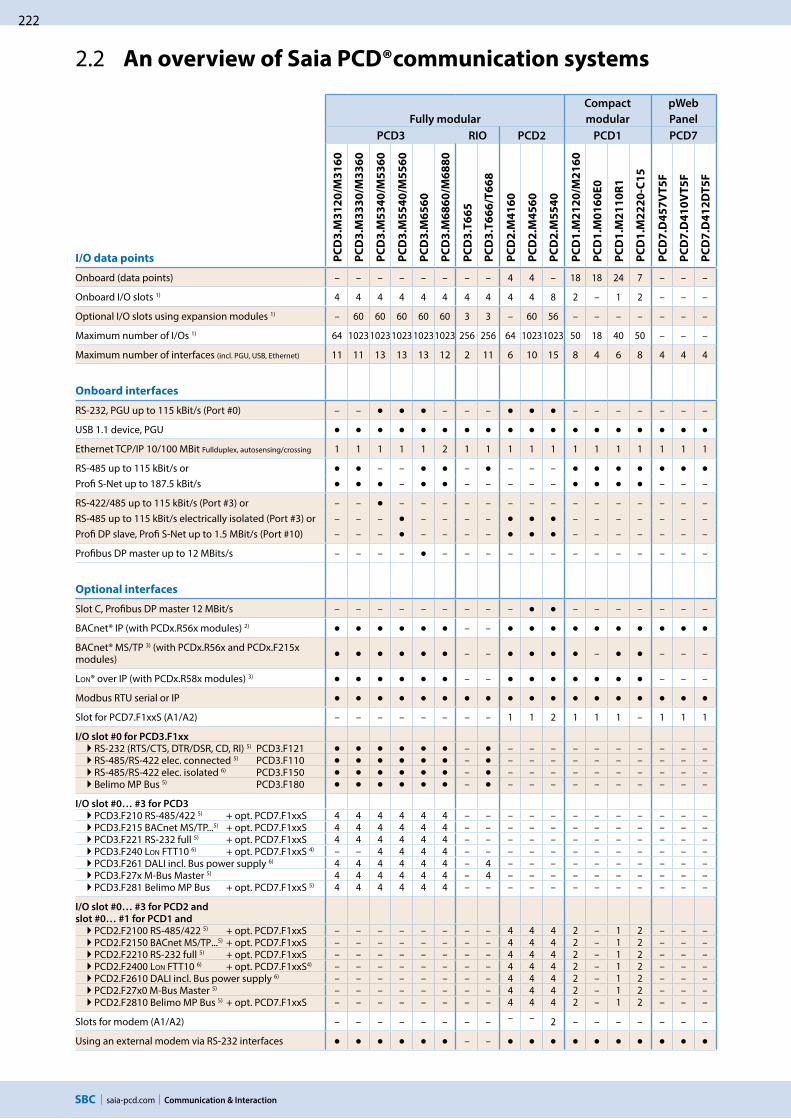
222
saia-pcd.com Communication & Interaction
Fully modular
Compact
modular
pWeb
Panel
PCD3 RIO PCD2 PCD1 PCD7
I/O data points PC
D3
.M3
12
0/M
31
60
PC
D3
.M3
33
0/M
33
60
PC
D3
.M5
34
0/M
53
60
PC
D3
.M5
54
0/M
55
60
PC
D3
.M6
56
0
PC
D3
.M6
86
0/M
68
80
PC
D3
.T6
65
PC
D3
.T6
66
/T6
68
PC
D2
.M4
16
0
PC
D2
.M4
56
0
PC
D2
.M5
54
0
PC
D1
.M2
12
0/M
21
60
PC
D1
.M0
16
0E
0
PC
D1
.M2
11
0R
1
PC
D1
.M2
22
0-C
15
PC
D7
.D4
57
VT
5F
PC
D7
.D4
10
VT
5F
PC
D7
.D4
12
DT
5F
Onboard (data points) – – – – – – – – 4 4 – 18 18 24 7 – – –
Onboard I/O slots 1) 4 4 4 4 4 4 4 4 4 4 8 2 – 1 2 – – –
Optional I/O slots using expansion modules 1) – 60 60 60 60 60 3 3 – 60 56 – – – – – – –
Maximum number of I/Os 1) 64 10231023102310231023 256 256 64 10231023 50 18 40 50 – – –
Maximum number of interfaces (incl. PGU, USB, Ethernet) 11 11 13 13 13 12 2 11 6 10 15 8 4 6 8 4 4 4
Onboard interfaces
RS-232, PGU up to 115 kBit/s (Port #0) – – – – – – – – – – – –
USB 1.1 device, PGU
Ethernet TCP/IP 10/100 MBit Fullduplex, autosensing/crossing 1 1 1 1 1 2 1 1 1 1 1 1 1 1 1 1 1 1
RS-485 up to 115 kBit/s or – – – – – –Profi S-Net up to 187.5 kBit/s – – – – – – – – –
RS-422/485 up to 115 kBit/s (Port #3) or – – – – – – – – – – – – – – – – –RS-485 up to 115 kBit/s electrically isolated (Port #3) or – – – – – – – – – – – – – –Profi DP slave, Profi S-Net up to 1.5 MBit/s (Port #10) – – – – – – – – – – – – – –
Profibus DP master up to 12 MBits/s – – – – – – – – – – – – – – – – –
Optional interfaces
Slot C, Profibus DP master 12 MBit/s – – – – – – – – – – – – – – – –
BACnet® IP (with PCDx.R56x modules) 2) – –
BACnet® MS/TP 3) (with PCDx.R56x and PCDx.F215x modules) – – – – – –
LON® over IP (with PCDx.R58x modules) 3) – – – – –
Modbus RTU serial or IP
Slot for PCD7.F1xxS (A1/A2) – – – – – – – – 1 1 2 1 1 1 – 1 1 1
I/O slot #0 for PCD3.F1xx
RS-232 (RTS/CTS, DTR/DSR, CD, RI) 5) PCD3.F121 – – – – – – – – – – – RS-485/RS-422 elec. connected 5) PCD3.F110 – – – – – – – – – – – RS-485/RS-422 elec. isolated 6) PCD3.F150 – – – – – – – – – – – Belimo MP Bus 5) PCD3.F180 – – – – – – – – – – –
I/O slot #0… #3 for PCD3 PCD3.F210 RS-485/422 5) + opt. PCD7.F1xxS 4 4 4 4 4 4 – – – – – – – – – – – – PCD3.F215 BACnet MS/TP...5) + opt. PCD7.F1xxS 4 4 4 4 4 4 – – – – – – – – – – – – PCD3.F221 RS-232 full 5) + opt. PCD7.F1xxS 4 4 4 4 4 4 – – – – – – – – – – – – PCD3.F240 LON FTT10 6) + opt. PCD7.F1xxS 4) – – 4 4 4 4 – – – – – – – – – – – – PCD3.F261 DALI incl. Bus power supply 6) 4 4 4 4 4 4 – 4 – – – – – – – – – – PCD3.F27x M-Bus Master 5) 4 4 4 4 4 4 – 4 – – – – – – – – – – PCD3.F281 Belimo MP Bus + opt. PCD7.F1xxS 5) 4 4 4 4 4 4 – – – – – – – – – – – –
I/O slot #0… #3 for PCD2 and
slot #0… #1 for PCD1 and
PCD2.F2100 RS-485/422 5) + opt. PCD7.F1xxS – – – – – – – – 4 4 4 2 – 1 2 – – – PCD2.F2150 BACnet MS/TP...5) + opt. PCD7.F1xxS – – – – – – – – 4 4 4 2 – 1 2 – – – PCD2.F2210 RS-232 full 5) + opt. PCD7.F1xxS – – – – – – – – 4 4 4 2 – 1 2 – – – PCD2.F2400 LON FTT10 6) + opt. PCD7.F1xxS4) – – – – – – – – 4 4 4 2 – 1 2 – – – PCD2.F2610 DALI incl. Bus power supply 6) – – – – – – – – 4 4 4 2 – 1 2 – – – PCD2.F27x0 M-Bus Master 5) – – – – – – – – 4 4 4 2 – 1 2 – – – PCD2.F2810 Belimo MP Bus 5) + opt. PCD7.F1xxS – – – – – – – – 4 4 4 2 – 1 2 – – –
Slots for modem (A1/A2) – – – – – – – – – – 2 – – – – – – –
Using an external modem via RS-232 interfaces – –
2.2 An overview of Saia PCD®communication systems
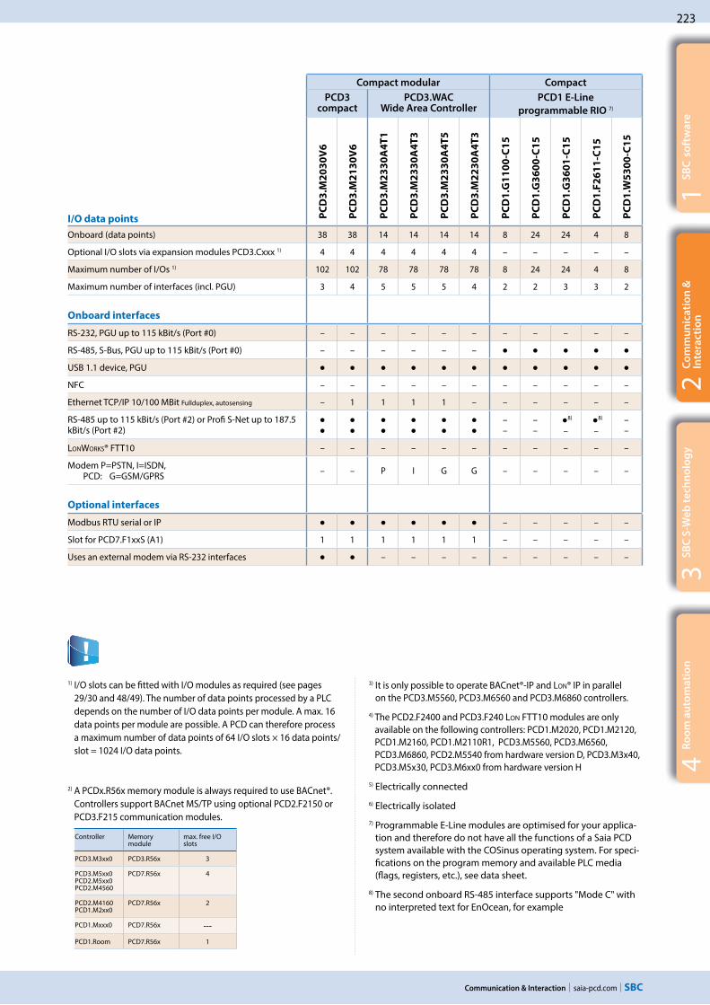
saia-pcd.com
223
1S
BC
so
ftw
are
3S
BC
S-W
eb
te
chn
olo
gy
2C
om
mu
nic
ati
on
&
Inte
rac
tio
n
Communication & Interaction
4R
oo
m a
uto
ma
tio
n
Compact modular Compact
PCD3 compact
PCD3.WAC Wide Area Controller
PCD1 E-Line
programmable RIO 7)
I/O data points PC
D3
.M2
03
0V
6
PC
D3
.M2
13
0V
6
PC
D3
.M2
33
0A
4T
1
PC
D3
.M2
33
0A
4T
3
PC
D3
.M2
33
0A
4T
5
PC
D3
.M2
23
0A
4T
3
PC
D1
.G1
10
0-C
15
PC
D1
.G3
60
0-C
15
PC
D1
.G3
60
1-C
15
PC
D1
.F2
61
1-C
15
PC
D1
.W5
30
0-C
15
Onboard (data points) 38 38 14 14 14 14 8 24 24 4 8
Optional I/O slots via expansion modules PCD3.Cxxx 1) 4 4 4 4 4 4 – – – – –
Maximum number of I/Os 1) 102 102 78 78 78 78 8 24 24 4 8
Maximum number of interfaces (incl. PGU) 3 4 5 5 5 4 2 2 3 3 2
Onboard interfaces
RS-232, PGU up to 115 kBit/s (Port #0) – – – – – – – – – – –
RS-485, S-Bus, PGU up to 115 kBit/s (Port #0) – – – – – –
USB 1.1 device, PGU
NFC – – – – – – – – – – –
Ethernet TCP/IP 10/100 MBit Fullduplex, autosensing – 1 1 1 1 – – – – – –
RS-485 up to 115 kBit/s (Port #2) or Profi S-Net up to 187.5 kBit/s (Port #2)
––
––
8)
–8)
–––
LONWORKS® FTT10 – – – – – – – – – – –
Modem P=PSTN, I=ISDN, PCD: G=GSM/GPRS – – P I G G – – – – –
Optional interfaces
Modbus RTU serial or IP – – – – –
Slot for PCD7.F1xxS (A1) 1 1 1 1 1 1 – – – – –
Uses an external modem via RS-232 interfaces – – – – – – – – –
1) I/O slots can be fitted with I/O modules as required (see pages 29/30 and 48/49). The number of data points processed by a PLC depends on the number of I/O data points per module. A max. 16 data points per module are possible. A PCD can therefore process a maximum number of data points of 64 I/O slots × 16 data points/slot = 1024 I/O data points.
2) A PCDx.R56x memory module is always required to use BACnet®. Controllers support BACnet MS/TP using optional PCD2.F2150 or PCD3.F215 communication modules.
Controller Memory module
max. free I/O slots
PCD3.M3xx0 PCD3.R56x 3
PCD3.M5xx0 PCD2.M5xx0 PCD2.M4560
PCD7.R56x 4
PCD2.M4160 PCD1.M2xx0
PCD7.R56x 2
PCD1.Mxxx0 PCD7.R56x ---
PCD1.Room PCD7.R56x 1
3) It is only possible to operate BACnet®-IP and LON® IP in parallel on the PCD3.M5560, PCD3.M6560 and PCD3.M6860 controllers.
4) The PCD2.F2400 and PCD3.F240 LON FTT10 modules are only available on the following controllers: PCD1.M2020, PCD1.M2120, PCD1.M2160, PCD1.M2110R1, PCD3.M5560, PCD3.M6560, PCD3.M6860, PCD2.M5540 from hardware version D, PCD3.M3x40, PCD3.M5x30, PCD3.M6xx0 from hardware version H
5) Electrically connected
6) Electrically isolated
7) Programmable E-Line modules are optimised for your applica-tion and therefore do not have all the functions of a Saia PCD system available with the COSinus operating system. For speci-fications on the program memory and available PLC media (flags, registers, etc.), see data sheet.
8) The second onboard RS-485 interface supports "Mode C" with no interpreted text for EnOcean, for example

224
saia-pcd.com
12,3
DHCP-Server
InternetIntranet
Telecom
Saia PCD3.M5
Saia PCD2.M5
DHCP DNS HTTP FTP SMTP SNTP SNMP
Ethernet RS-232
PPP
Communication & Interaction
❶
❷
2.3 Web and IT protocols for integration into IT infrastructures
The standard Web/IT protocols enable Saia PCD® systems to be universally integrated across all levels in existing IT infra-structures with no additional outlay required.
An overview of Web/IT protocols supported by the automation server. Access is provided via the Ethernet interface or via serial interfaces using the PPP protocol.
All Saia PCD® controllers have an integrated automation server with open standard Web/IT interfaces. Saia PCD® are easy to integrate into existing software infrastructures with no additional outlay required using the standard communication protocols. Specific drivers or systems are not required. Standard tools such as web browsers, FTP clients and SNMP managers, etc., are used to access the data in the PCD controllers.
DHCP: Dynamic Host Configuration Protocol Protocols for automatically configuring the Ethernet communication. It is no longer necessary to enter the communication parameters manually as they are assigned directly from a central server.A DHCP client automatically receives the IP address, subnet mask, gateway and DNS address parameters on request. The devices in the existing network are integrated automatically.The devices are integrated in the existing network with no knowledge of the network parameters. Service personnel can also exchange devices with no technical background or knowledge of the specific network data required.
Standard RFC-2131Port UDP 68 for clientAssigned attributes IP address subnet mask standard
gateway (optional) DNS address (optional)
IP protocols
Web browser FTP Client Mailbox PG5 / SCADA
IP addressSubnet maskGatewayDNS address
Query

saia-pcd.com
225
Name IPPCD_01.sbc.com 192.163.22.1PCD_02.sbc.com 192.163.22.2PCD_03.sbc.com 192.163.22.3PCD_04.sbc.com 192.163.22.4PCD_05.sbc.com 192.163.22.5
http://PCD_02.sbc.com?❶
❷
192.163.22.2
Sa
ia P
CD
®
PCD_04
Sa
ia P
CD
®
PCD_01
Sa
ia P
CD
®
PCD_03
Sa
ia P
CD
®
Ethernet
PCD_02.sbc.com192.163.22.2
PCD_02
DNS-Server
PC
Sa
ia P
CD
®
A_PCD_01.sbc.com192.163.22.134
Sa
ia P
CD
®S
aia
PC
D®
A_PCD_02.sbc.com192.163.22.122
A_PCD_03.sbc.com192.163.22.116
Sa
ia P
CD
®
B_PCD_01.sbc.com192.163.22.90
Sa
ia P
CD
®
B_PCD_02.sbc.com192.163.22.138
Sa
ia P
CD
®
B_PCD_03.sbc.com
❶
❷❸
❶
❷
PingStart
Abort RErr
Query IP-Name Query
Name ???
1S
BC
so
ftw
are
3S
BC
S-W
eb
te
chn
olo
gy
2C
om
mu
nic
ati
on
&
Inte
rac
tio
n
Communication & Interaction
4R
oo
m a
uto
ma
tio
n
Configuration
Basic activation and configura-tion of DHCP/DNS in the PG5 device configurator.
FBoxes
Specific network administration FBoxes can be used to distribute the DNS names of other stations via the application program and verify communication with the PING FBox.
DNS: Domain Name System
Access to the controllers using set naming conventions. When establishing communication between two controllers, there is no need to know the IP address of the target controller, only its name. The IP address can be requested from a DNS server using this name. Devices are no longer controlled using meaningless IP addresses. The structure and availability of individual networks is specified once, and need not be constantly adjusted in accordance with the available IP addresses. This makes the systems easier and more intuitive to use. Networks involving several participants can be documented more clearly.
Examples using DHCP and DNS
Integrating devices into networks is easy. A DHCP client automatically receives the network parameters from a DHCP server. This means that controllers can be integrated into existing networks with no knowledge of the network parameters required. The controller is simply accessed using the name.
❶. IP address request to http://A_PCD_01.sbc.com
❷. Response with IP address 192.168.22.134
❸. Communication
❶. Request IP address❷. Response with IP address,
subnet mask, standard gateway, DNS server
DNS Server
DHCP ServerDNS Server
Standard RFC-1035Port UDP 53
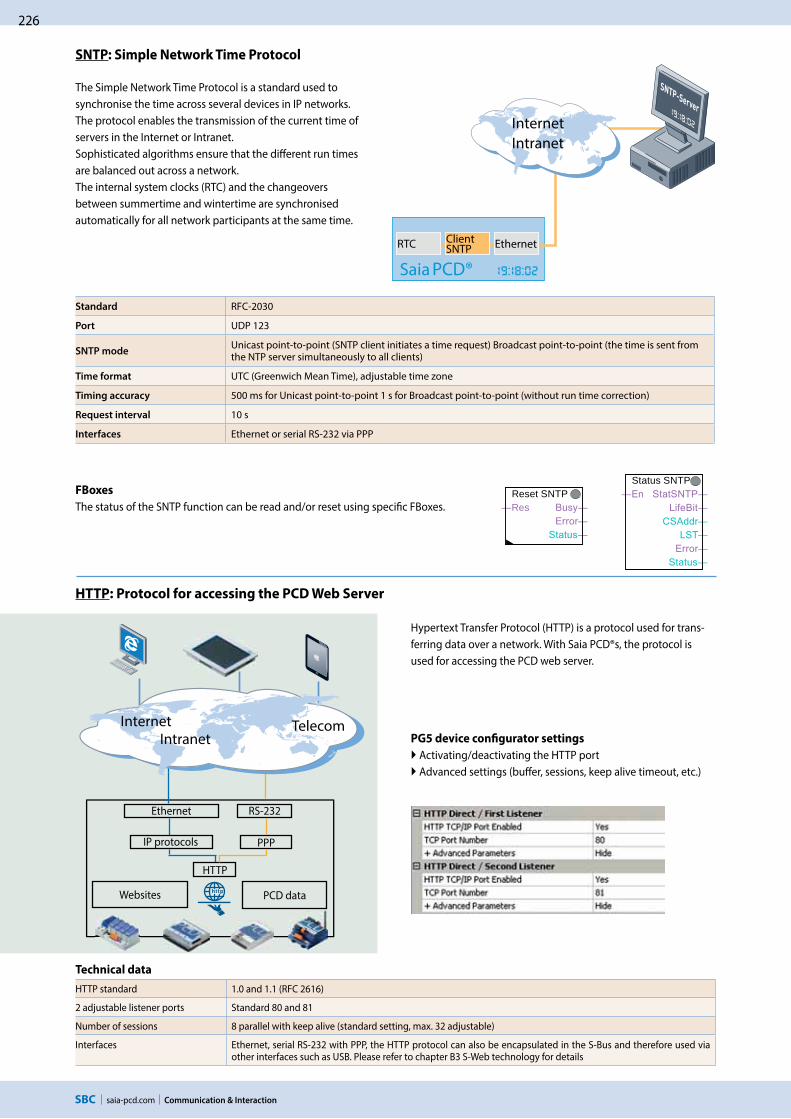
226
saia-pcd.com
SNTP-Server
EthernetClient SNTPRTC
Saia PCD®
Reset SNTPRes
Status SNTP
Ethernet
PPP
HTTP
RS-232
Communication & Interaction
FBoxes
The status of the SNTP function can be read and/or reset using specific FBoxes.
HTTP: Protocol for accessing the PCD Web Server
PG5 device configurator settings
Activating/deactivating the HTTP port Advanced settings (buffer, sessions, keep alive timeout, etc.)
Technical data
HTTP standard 1.0 and 1.1 (RFC 2616)
2 adjustable listener ports Standard 80 and 81
Number of sessions 8 parallel with keep alive (standard setting, max. 32 adjustable)
Interfaces Ethernet, serial RS-232 with PPP, the HTTP protocol can also be encapsulated in the S-Bus and therefore used via other interfaces such as USB. Please refer to chapter B3 S-Web technology for details
Hypertext Transfer Protocol (HTTP) is a protocol used for trans-ferring data over a network. With Saia PCD®s, the protocol is used for accessing the PCD web server.
SNTP: Simple Network Time Protocol
The Simple Network Time Protocol is a standard used to synchronise the time across several devices in IP networks. The protocol enables the transmission of the current time of servers in the Internet or Intranet.Sophisticated algorithms ensure that the different run times are balanced out across a network.The internal system clocks (RTC) and the changeovers between summertime and wintertime are synchronised automatically for all network participants at the same time.
Standard RFC-2030
Port UDP 123
SNTP modeUnicast point-to-point (SNTP client initiates a time request) Broadcast point-to-point (the time is sent from the NTP server simultaneously to all clients)
Time format UTC (Greenwich Mean Time), adjustable time zone
Timing accuracy 500 ms for Unicast point-to-point 1 s for Broadcast point-to-point (without run time correction)
Request interval 10 s
Interfaces Ethernet or serial RS-232 via PPP
Websites PCD data
IP protocols
InternetIntranet
Telecom
InternetIntranet

saia-pcd.com
227
Server Client
20Data
21Cmd
1026Cmd
1027Data
1
2
3
4
FTP
RS-232Ethernet
PPP
1S
BC
so
ftw
are
3S
BC
S-W
eb
te
chn
olo
gy
2C
om
mu
nic
ati
on
&
Inte
rac
tio
n
Communication & Interaction
4R
oo
m a
uto
ma
tio
n
The File Transfer Protocol (FTP) is used to load files into or read files from PCD devices via the network. Files (websites, log data, documents, etc.) are saved in the file system of the PCD devices. User groups and passwords can be set up to protect access to the FTP server and individual files (e.g. read only).
PG5 device configurator settings
Activating/deactivating the FTP server Configuring port numbers (standard port: 21), user and access rights Advanced settings (no. of connections, timeout, etc.)
Active/passive FTP mode
PCD devices only support the active connection mode! The client establishes a connection to server port 21 and
provides the server with the port number for the data channel. Unlike in passive mode (here the port for the data channel is always 20), this port number is not specified and can be in the range > 1023. This often causes problems with firewalls, as these port numbers are not approved.
Another means of transferring files is to use FTP CGI (Common Gate-way Interface) interfaces in the web server. If the respective syntax is known, it is also possible to transfer data between a web client and PCD devices via this interface. For more information on this please refer to Chapter B3 S-Web.
Technical data
FTP standard RFC 959
Standard port number 21 (can be set) plus dynamic port (> 1023) for data
Connection mode PCD devices only support the active FTP mode
Number of FTP connections per PCD Standard 3 (max. 5 adjustable)
Interfaces Ethernet, serial RS-232 with PPP
FTP: Protocol for transferring files
IP protocols
Flash cards File system
InternetIntranet
Telecom

228
saia-pcd.com
SNMP-GET/SET
SNMP-GET/SET
SNMP-GET/SET
SNMP-GET/SET
Ethernet-TCP / IP
Send Trap Text Send Trap Int
Send Trap Bool Send
DB ???? Text ????
Communication & Interaction
Configuration
Simple activation and configuration of the SNMP functionality in the PG5 device configurator. Up to 3 SNMP trap receivers can be configured. The data fields to which the SNMP manager has access are also configured here.
FBoxes
Trap messages with integer or Boolean data or text information can be conveni-ently sent to the trap receivers using FBoxes.
SBC MIB File Generator
The MIB file contains pre-defined SNMP strings for accessing the PCD data (register, flag, DB, etc.) with the SNMP manager. The MIB files can be generated with project-specific symbol names using the MIB file generator (available with PG5 V2.1).
Technical Data
SNMP Standard V1 and V2c (RFC 1157)
MIB II standard in accordance with RFC 1213 is supported
Standard Ports #161 and #162
SNMP: Simple Network Management Protocol
SNMP Manager
SNMP trap
Transmission of messages and alarms
Request and respond to
SNMP GET / SET commands
Printer
The Simple Network Management Protocol was developed to be able to monitor and control network elements such as routers, servers, switches or even Saia PCD® (agents) from a central stati-on. The SNMP manager software generally runs on a server. It mo-nitors and controls the SNMP agents. The SNMP manager reads and sends data from agents using SET and GET commands. The SNMP agent can also send "trap" messages to the SNMP manager unrequested. This allows faults to be reported immediately, for example.
The Saia PCD® MIB has been specified for Saia PCD® with SNMP support. It includes all resources which can be requested and changed using SNMP. It is possible to access all PCD media (inputs/outputs, registers, flags, DBs, etc.). In the MIB file, the pro-grammer is able to restrict access to selected areas only. The MIB II standards for managing the TCP/IP functions defined in accordance with RFC1213 are also supported.
SNMP agent SNMP agent SNMP agent SNMP agent
MIBTable
PCD dataR/T/F/I/O …
SNMPTrap
MIBTable
SNMPTrap
MIBTable
SNMPTrap
MIBTable
Router Server
SNMPTrap

saia-pcd.com
229
PPP
RS-232
SMTP
WebCMailAMail Init
SMTP ????Name ????Pwd ????Sender ????To1 ????To2 ????To3 ????To4 ????To5 ????
AMail Send
Send Subject ????Text ????File ????
Saia
PCD
®
1S
BC
so
ftw
are
3S
BC
S-W
eb
te
chn
olo
gy
2C
om
mu
nic
ati
on
&
Inte
rac
tio
n
Communication & Interaction
4R
oo
m a
uto
ma
tio
n
Ethernet
IP protocols PPP
The email function and integrated SMTP client (Simple Mail Transfer Protocol) can be used to send PCD device process and system information to an email server. This enables alarm, service and status messages, log data or any form of process information to be sent via email to a control centre or service personnel.
FBoxes
FBoxes are available for sending emails using the application program. The email function is configured (mail server, port number, user and password, etc.) via these F boxes. It is also possible to send file attachments (e.g. log data) of up to 1 MByte.
Technical Data
SMTP Standard RFC 821, 822
Standard port number 25 (adjustable) + 587
Server authentication "AUTH LOGIN" or "AUTH PLAIN" in accordance with RFC 2595 (unencrypted transmission of password)
Email format Text or HTML
Interfaces Ethernet, serial RS-232 with PPP
SMTP: Protocol for sending emails
PLC data and file system
Web browser post box PCD2.M5
FTP client PG5/SCADA PCD3.M
Email client
Files from file system
PCD media text messages
Email serverEmail client
RS-232
InternetIntranet
Telecom
PPP: Point-to-point protocol
This is a protocol established along a communication route from one point (location) to another. PPP is a protocol that is mainly used to transport TCP/IP protocols via a serial cable or modem connection. CHAP (Challenge Authentication Protocol) was introduced to meet the greater security requirements when dialling into company networks or systems with critical tasks.The user has access to the web and FTP server via a telecom interface (PSTN, ISDN, GSM/GPRS) in the Saia PCD® controller. This also applies to applications with more economical devices and no Ethernet connection.
Standard RFC-1661
Authentication PAP, CHAP and MS CHAP
Simultaneous PPP connections Only one PPP connection (client or server) can be active per Saia PCD® controller.
PPP via Ethernet No
Ethernet
IP protocols
TelecomInternetIntranet

230
saia-pcd.com
PG5
RS-485
Ethe
rnet
Ethe
rnet
RS-485
Visi.Plus
Communication & Interaction
Networks for Wide Area Automated Systems
PCD controllers support the connection to the WAN (Wide Area Network) via all established telecommunication technologies. The IP-based protocols (automation servers) are used to connect direct to the Internet either wired via Ethernet interfaces and DSL broadband routers or wirelessly with GPRS/UMTS routers. Non-IP based connections with analogue, digital (ISDN) or GSM modems are also sup-ported. The PCD3.WAC (Wide Area Controller) allows a direct connection via the integrated analogue, ISDN or GPRS/GSM modems.
Protocols and services
The WEB/IT protocols are used to support access to the automation server functions (web/FTP server, email, SNMP, etc.). The S-Bus protocol enables communication with the PG5 programming device, the SBC OPC server or Visi.Plus. S-Bus is also used to exchange data between PCD controllers via the WAN. Other IP-based protocols such as Modbus TCP and BACnet® are also supported.
Local infrastructure
2.4 Wide Area Automation with Saia PCD®
Spanning geographical distances with a larger number of substations often places significant demands on a system. The integrated automation server can be used to combine geographically distributed systems easily using the Internet and Intranet. This allows the systems to be monitored and controlled remotely. It is possible to access the controllers directly during commissioning or servicing.
Management level
Connection of Saia PCD® controllers to the Internet
When Saia PCD® controllers are connected directly to the internet, they are also a potential target of cyber attacks. Appropriate protective measures must always be taken to ensure secure operation.Saia PCD® PCD controllers include simple, integrated protection features. However, secure operation on the internet is only ensured if external routers, like the industrial Routers EBW-E100 and EBW-H100 are used with a firewall and encrypt-ed VPN connections.For more information, please refer to our support site: www.sbc-support.com/security
EBW-E100 EBW-E100 EBW-H100
VPN

saia-pcd.com
231
1S
BC
so
ftw
are
3S
BC
S-W
eb
te
chn
olo
gy
2C
om
mu
nic
ati
on
&
Inte
rac
tio
n
Communication & Interaction
4R
oo
m a
uto
ma
tio
n
Saia® PCD secure on Internet with VPN-Routers and “SBC Connectivity Portal”
With the „SBC Connectivity Service“, you will get your own encrypted VPN. In just a few steps, you’ll integrate locally connected PCD controllers, Web panels MB as well as PCs, tablets or smartphones. All your devices can be accessed across all networks and addressed at any time with this.
The necessary certificates are generated and assigned to the EBW router by the “SBC Connectivity Portal” directly. The routers get the complete VPN con-figuration transmitted automatically using a quick start wizard. It couldn›t be simpler and more comfortable! With the “SBC Connectivity service” you have your VPN under complete con-trol - with minimum investment. It starts to pay off with the first device alrea-dy. Furthermore, the new web proxy enables secure access to web services in your VPN without a licence.
Keys features: Allows a M2M communication between systems located on different sites Provides a secure data transmission No needs of public IP address Doesn’t require deep IT knowledge
Of course, the EBW industry routers could also be used independently of «SBC Connectivity Portal», for example for a point to point connection.
Produkte für Wide Area Automation
Q.NET-CON* Annual license for one VPN connection on the “SBC Connectivity Service” portal
Q.NET-EBW-E100* Industrial LAN router for VPN connection
Q.NET-EBW-H100* Industrial 3G/HSPA Router for VPN connection
PCD3.M2330A4T1Wide Area Controller with integrated PSTN modem (See detail chap. A1.2.5 Wide Area Controller)
PCD3.M2330A4T5Wide Area Controller with integrated GSM/GPRS modem (See details chap. A1.2.5 Wide Area Controller)
PCD7.K840GSM/UMTS (850/900/1800/1900/2100 MHz) antenna with magnetic foot and SMA connector
Communication via GSM, PSTN or ISDN modems is supported via a comprehensive FBox library.SMS messages can be sent and received. Send SMS
Cal Msg ????
FBoxes are available for sending emails using the application program. Alarm, status andtext messages can be sent. Sending file attachments (e.g. log data) is also supported.
WebCMailAMail Init
SMTP ????Name ????Pwd ????Sender ????To1 ????To2 ????To3 ????To4 ????To5 ????
FBoxes for modem communication and sending emails
*In preparation, see Chapter C1 “Product status”

232
saia-pcd.com
PG5
SCADA
PG5
SCADA
S-IO
Communication & Interaction
2.5 S-Net for communicating between Saia PCD® devices
2.5.1 The basic features of S-Net
S-Net incorporates the S-Bus and S-I/O system protocols for commu-nicating between SBC devices. Both protocols are optimised for SBC devices and compared to other standard protocols (e.g. Modbus) offer more functionality and can be used more simply and efficiently in the application.
S-Bus supports all services and functions regarding the exchange of data, programming, commissioning and service of Saia PCD® control-lers. The S-Bus protocol does not depend on the physical aspects and can be used on Ethernet, USB, Profibus-FDL and serial interfaces (RS-232, RS-422, RS-485).
The S-IO protocol supports the operation of SBC remote I/O stations with Ethernet (PCD3.T66x) and Profibus (PCD3.T760)
Management level
S-Net for communication between SBC devices across all levels
Services and functions using S-Bus
Programming and commissioning
S-Bus is the programming device system protocol. It supports all programming, commissioning and diagnostic functions.
Access with the programming device via Ethernet, USB or serial interface
Exchanging data between PCD controllers via Ether-net, Profibus or serial interfaces
Connecting to SCADA systems via Ethernet, USB, Profibus or serial interfaces
Access to the PCD web server is also possible via USB and Serial interfaces
Visualisation with web browsers
S-Bus supports HTTP protocol transmission. This also allows websites to be transmitted together with “SBC Web.Connect” via USB and serial interfaces and displayed on a Windows PC with the standard web browser or a micro browser web panel.
Visualisation with OPC servers and SCADA systems
S-Bus together with an OPC Server or the SBC.Net-Suite supports access (reading and writing) to all PCD data with a Windows SCADA system.
Exchanging data between PCD controllers
S-Bus supports the transmission of all PCD media (register, flags, timer/counter, database and text) and is optimised for the exchange of data between PCD controllers, whereby Ethernet and Profibus allow multi-master operation. Serial interfaces (RS-232, RS-422, RS-485) enable “single”-master slave mode or S-Bus master multiple slave mode.
Automation level
Field level

saia-pcd.com
233
PG5
IPChannel S-Bus Master IP
Cir
SEND
InternetIntranet
PCD3.M6860
1S
BC
so
ftw
are
3S
BC
S-W
eb
te
chn
olo
gy
2C
om
mu
nic
ati
on
&
Inte
rac
tio
n
Communication & Interaction
4R
oo
m a
uto
ma
tio
n
The Ether S-Bus and Ether S-IO protocols support the operation of Saia PCD® controllers and Smart RIOs on Ethernet. The PCD devices can be integrated and operated in a standard Ethernet network (along with other devices). Multi-protocol operation is supported on the same connector and cable. That means that all IP protocols (e.g. access to the automation server) can be used in parallel with S-Bus and/or S-IO.
Ether S-Bus for operating PCD controllers with Ethernet
Ethernet 2
PG5, SCADA, OPC, web browser
Ether S-BusEthernet
Properties, functions
Ether S-Bus supports communication between PCD controllers in multi-master operation a PCD controller and the PG5 programming device a PCD controller and the OPC server or SCADA system with Ether S-Bus drivers a PCD controller (PCD WebServer) and web browser with Web Connect software
Programming the data transfer between PCD controllers with FBoxes for cyclic or event-controlled data transfer
Multi-protocol operation on the same Ethernet connection (e.g. Ether S-Bus, Ether S-IO and other protocols such as Modbus TCP)
Gateway function for gateways (Ether S-Net Serial S-Net, Ether S-Net 1 Ether S-Net 2, Ether S-Net Profi S-Net)
The PCD3.M6860 CPU can be used to construct separate networks or redundant Ethernet networks The network can be constructed using standard Ethernet components IP protocol: UDP Port number: 5050 (a firewall may require this port to be activated)
Smart RIO Manager
Smart RIOsPCD3.T66x
Ether S-IO protocol for operating Smart RIOs with Ethernet
Ethernet Ether S-IO
Ether S-Bus protocol in the multi-master operation on a standard Ethernet network
Ether S-IO for operating Smart RIOs PCD3.T66x
Properties, functions
Ether S-IO supports the exchange of data between Smart RIO Manager and the Smart RIOs. Ether S-Bus is used to transfer the configuration and all programs
It uses broadcast or unicast telegrams (adjustable) The data transfer is configured by the RIO network configura-tor Multi-protocol operation is supported The network can be constructed using standard Ethernet components IP protocol: UDP Port number: 6060
PG5,SCADA,OPC,Web browser
2.5.2 Ether S-Net: S-Bus and S-IO protocol with Ethernet
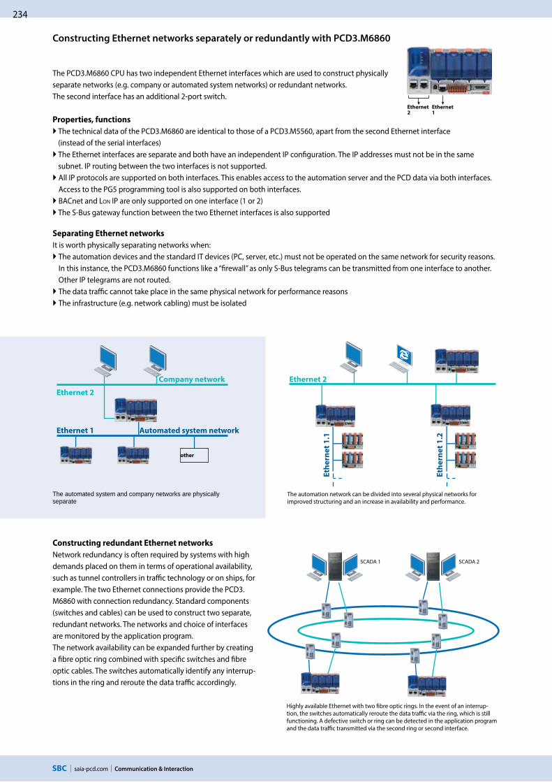
234
saia-pcd.com
Ethernet 2
Eth
ern
et
1.1
Eth
ern
et
1.2
SCADA 1 SCADA 2
➤ ➤Ethernet2
Ethernet1
other
Communication & Interaction
Constructing redundant Ethernet networks
Network redundancy is often required by systems with high demands placed on them in terms of operational availability, such as tunnel controllers in traffic technology or on ships, for example. The two Ethernet connections provide the PCD3.M6860 with connection redundancy. Standard components (switches and cables) can be used to construct two separate, redundant networks. The networks and choice of interfaces are monitored by the application program. The network availability can be expanded further by creating a fibre optic ring combined with specific switches and fibre optic cables. The switches automatically identify any interrup-tions in the ring and reroute the data traffic accordingly.
The automation network can be divided into several physical networks for improved structuring and an increase in availability and performance.
Highly available Ethernet with two fibre optic rings. In the event of an interrup-tion, the switches automatically reroute the data traffic via the ring, which is still functioning. A defective switch or ring can be detected in the application program and the data traffic transmitted via the second ring or second interface.
Constructing Ethernet networks separately or redundantly with PCD3.M6860
The PCD3.M6860 CPU has two independent Ethernet interfaces which are used to construct physically separate networks (e.g. company or automated system networks) or redundant networks. The second interface has an additional 2-port switch.
Properties, functions
The technical data of the PCD3.M6860 are identical to those of a PCD3.M5560, apart from the second Ethernet interface (instead of the serial interfaces) The Ethernet interfaces are separate and both have an independent IP configuration. The IP addresses must not be in the same subnet. IP routing between the two interfaces is not supported. All IP protocols are supported on both interfaces. This enables access to the automation server and the PCD data via both interfaces. Access to the PG5 programming tool is also supported on both interfaces.
BACnet and LON IP are only supported on one interface (1 or 2) The S-Bus gateway function between the two Ethernet interfaces is also supported
Separating Ethernet networks
It is worth physically separating networks when: The automation devices and the standard IT devices (PC, server, etc.) must not be operated on the same network for security reasons. In this instance, the PCD3.M6860 functions like a “firewall” as only S-Bus telegrams can be transmitted from one interface to another. Other IP telegrams are not routed.
The data traffic cannot take place in the same physical network for performance reasons
The infrastructure (e.g. network cabling) must be isolated
The automated system and company networks are physically separate
Company network
Ethernet 2
Ethernet 1 Automated system network

saia-pcd.com
235
1S
BC
so
ftw
are
3S
BC
S-W
eb
te
chn
olo
gy
2C
om
mu
nic
ati
on
&
Inte
rac
tio
n
Communication & Interaction
4R
oo
m a
uto
ma
tio
n
The S-Bus protocol can be used on the USB and serial interfaces for communicating with Saia PCD® controllers. This makes it possible to construct very simple, economical communication links and networks. Point-to-point (USB, RS-232) and 1:n communication relation-ships are supported in the RS-485 network in the master-slave operation. S-Bus supports communication between
PCD controllers in the master-slave (1:n) operation a PCD controller and the PG5 programming device PCD control and OPC server or SCADA system with S-Bus drivers a PCD controller (PCD WebServer) and web browser with Web Connect software
Point-to-point communication relationship with S-Bus
S-Bus with
USB (host only with PC), RS-232, RS-422, RS-485
1 slave station
Properties, functions
Interfaces: USB, RS-232, RS-422, RS-485 (can be used simultaneously on several interfaces) Baud rate: up to 12 MBit/s (USB standard 1.1) Communication relationship: Master-slave Exchange of data with a SCADA system with the SBC OPC server or an S-Bus driver Supports communication via modem (PSTN, ISDN, GSM) to RS-232 interface
1:n master-slave communication relationships in the RS-485 network with S-Bus
1 master station
Properties, functions
Interfaces: RS-485 (can be used simultaneously on several interfaces) Baud rate: up to 115 kBit/s Bus cable: 2-wire, twisted and shielded (min. 2 × 0.5 mm2) Bus length: max. 1200 m per segment Number of stations: max. 32 per segment, total max. 255 Number of segments: max. 8, connected to each other via RS-485 Communication relationship: Master-slave (only 1 master) Programming the data transfer between PCD controllers with FBoxes for cyclic or event-controlled data transfer Exchange of data with a SCADA system along with the SBC OPC server or an S-Bus driver
Note
The S-Bus protocol is also suitable for constructing multi-point wireless networks with external wireless modems. The wireless modems are connected to the RS-232 interface. The control cables can be used to control the wireless modem transmitters. Further information on this is contained in reference manual 26-739.
The proprietary S-Bus is designed for communicating with the Saia PG5® engineering tool, connecting to the management level/process control systems and for PCD ↔ PCD communication. It is not suitable or approved for connecting the field devices of other manufacturers. An open, manufacturer-independent field bus (e.g. Profibus, Modbus, etc.) is the correct solution for this.
PG5, SCADA, OPC,Web browser
1 master station
S-Bus with RS-485
n slave stations
PG5, SCADA,OPC,Web browser
2.5.3 Serial S-Net: S-Bus on USB and serial interfaces, RS-232, RS-422/485

236
saia-pcd.com
6560
PCD3.M
760
PCD3.T760
PCD3.T760
PCD3.T
PAdd ????
PAdd ???? Stn ???? Send
En Err
6560
PCD3.M
Communication & Interaction
The Profi S-Bus and Profi S-IO protocols support the operation of Saia PCD® controllers and Saia PCD3.T760 RIOs on the Profibus FDL network. The protocols can be operated up to 1.5 MBit/s via the RS-485 interfaces integrated in the base unit. This enables economic and fast communication networks in multi-master operation. Multi-protocol operation is supported on the same connector and cable. The same selection of the bus parameters (baud rate, timing, etc.) enables the PCD devices to be operated along with devices from other manufacturers on one Profibus DP network.
Profi S-Bus for operating PCD controllers on Profibus FDL networks
Properties, functions
Profi S-Bus supports the communication between PCD controllers in multi-master operation a PCD controller and the PG5 programming device (via Profi S-Link) PCD control and OPC server or SCADA system with Profi S-Bus driver (via Profi S-Link) a PCD controller (PCD Web Server) and web browser with Web Connect software (via Profi S-Link)
Multi-protocol operation on the same Profibus network (e.g. Profi S-Bus mixed with other Profibus DP devices) Gateway function for gateways (Profi S-Bus Serial S-Bus, Profi S-Bus Ether S-Bus) Programming the exchange of data between PCD controllers with FBoxes for cyclic or event-controlled data transfer – baud rate: up to 1.5 MBit/s Network infrastructure and topology: in accordance with the Profibus specification Profi S-Link adapter: PCD8.K120
Properties, functions
Profi S-IO supports the data transfer between a PCD.RIO master and PCD3.T760 RIOs.
The data transfer is configured by the Profi S-IO network configu-rator Multi-protocol operation is supported (e.g. Profi S-Bus and Profi S-IO)
Baud rate: up to 1.5 MBit/s Network infrastructure and topology in accordance with Profibus specification
Profi S-IO Profibus
RIO Master
RIOsPCD3.T760
Profi S-IO protocol for operating PCD3.T760 RIOs on the Profibus
Profi S-Bus protocol in multi-master operation on a standard Profibus network.
PG5, SCADA, OPC, web browser
Ethernet
ProfibusProfi S-Bus
Profi S-link adapter
2.5.4 Profi S-Net: S-Bus and S-IO protocols on Profibus FDL
Profi S-IO for operating PCD3.T760 RIOs on the Profibus

saia-pcd.com
237
1S
BC
so
ftw
are
3S
BC
S-W
eb
te
chn
olo
gy
2C
om
mu
nic
ati
on
&
Inte
rac
tio
n
Communication & Interaction
4R
oo
m a
uto
ma
tio
n
2.5.5 Profibus DP Integrating machines
and industrial environments
Saia PCD® systems with Profibus DP master 12 MBit/s connection
Baud rate Connection PortElectrically iso-
latedSystem
Up to 12 MBit/s D-sub connector # 10 Yes PCD3.M6560
Up to 12 MBit/s D-sub connector # 10 Yes PCD2.M5540 with PCD7.F7500 module
Saia PCD® systems with Profibus DP slave, onboard interface
Baud rate Connection PortElectrically iso-
latedSystem
Up to 187.5 kBit/s Terminal block # 2 No
PCD3.M6560, PCD3.M6860,PCD3.M5340, PCD3.M3xxx,PCD3.M2130V6,PCD3.M2330A4Tx, PCD3.M2230A4T5,PCD1.M2xxx, PCD1.M0160E0
Up to 1.5 MBit/s D-sub connector # 10 YesPCD3.M5560, PCD3.M5540, PCD3.M5440, PCD2.M5540, PCD3.T760 (RIO)
Profibus in building automation systems
In accordance with EN 50170, Profibus is the internationally standardised bus for industry and building automation systems. Profibus opens up the world of standardised network com-munication for a wide range of applications between different manufacturers:
Network configurators for Profibus
The PG5 programming tool contains convenient network configuration tools for all types of network. The user defines his variables, objects and network parameters with it.
Profibus DP with Saia PCD®
Saia PCD® controllers are available with Profibus DP master and slave connections. Version DP V0 is supported. Remote data points under the designation PCD3.T760 supplement the Profibus range and enable the creation of remote automation solutions.The diverse communication properties of Saia PCD® controllers makes them ideal for use as communication gateways, e.g. Ethernet Profibus, BACnet – Profibus, etc.
Profibus is open and not bound to a specific manufacturer PNO, the Profibus user organisation, maintains a qualified
certification system and assesses Profibus products in terms of compliance with standards and interoperability
Profibus DP, the up to 12 MBit/s network protocol for the field level in automated production is also used in building automation systems owing to the wide range of accessories

238
saia-pcd.com
PCD2.M5PPCPPPPPPPPPPP D2 M
BACnet MS/TP
BACnet® / IP
PCD3PCD3PCD3
Communication & Interaction
2.6 BA communication systems
2.6.1 BACnet®
Recommendations/system limits
Type Option Interface PG5 configuration, system limits
PCD3.M5560 1× PCD7.R56x 4× PCD3.F215
IPMS/TP
Recommended for configurations of up to 1000 BACnet objectsSuitable for BACnet® and LONWORKS® in parallel operation
PCD3.M5540PCD3.M5340/M5360
1× PCD7.R56x 4× PCD3.F215
IPMS/TP Recommended for configurations of up to 800 BACnet objects
PCD3.M3330/M3360PCD3.M3120/M3160
1× PCD3.R56x 3× PCD3.F215
IPMS/TP Recommended for configurations of up to 500 BACnet objects
PCD2.M4160 1× PCD7.R56x 2× PCD2.F2150
IPMS/TP Recommended for configurations of up to 800 BACnet objects
PCD2.M4560 PCD2.M5540
1× PCD7.R56x 4× PCD2.F2150
IPMS/TP Recommended for configurations of up to 800 BACnet objects
PCD1.M0160 1× PCD7.R56x IP Recommended for configurations of up to 800 BACnet objects
PCD1.M2xx0PCD1.M2220-C15
1× PCD7.R56x 2× PCD2.F2150
IPMS/TP Recommended for configurations of up to 800 BACnet objects
PCD7.D457VT5F PCD7.D410VT5F PCD7.D412DT5F
1× PCD7.R56x IP Recommended for configurations of up to 250 BACnet objects
Typical applications of a BACnet infrastructure
Heating, climate and ventilation control Room automation Networking dispersed sites Recording energy data
The standard for building services
BACnet is a manufacturer-independent, globally standardised communication protocol which is well-established in building automation systems. BACnet is particularly suitable for hetero-geneous structures involving automation stations of various manufacturers. The server/client architecture allows each of the BACnet devices to exchange data with one another without hav-ing to adjust to the parameterisation of the other devices. BACnet is far more than a protocol for merely transferring data; BACnet itself defines important building automation functions, such as the recording of historic trends or the monitoring of values against set limit values, for example. Communication services (BIBBs, BACnet Interoperable Building Blocks), such as those for reading and writing content, event-controlled trans-mission following changes and the handling of alarms/informa-tion (events) are available.
PCD systems
BACnet is available for all classic PCD systems with the Saia PCD® COSinus operating system as a communication option. The con-nection is usually direct via BACnet IP (Ethernet). BACnet MS/TP (RS-485) is also possible via a communication module.BACnet always requires a BACnet option module for firmware expansion. A PCD7.R56x is used for memory slots M1 and M2 for PCD3.M5, PCD2.M5, PCD1.M2 and PCD1.M0 controllers. The PCD3.R56x module is available for I/O slots 0…3 for PCD3.M3 controllers with no M1/2 slots.PCD2.M5 and PCD1.M2 controllers also require a PCD2.F2150 for connecting BACnet MS/TP, and PCD3 controllers require a PCD3.F215 communication interface. This module also provides controllers with no Ethernet with a BACnet interface. Controllers with Ethernet also take on the function of a BACnet IP MS/TP router. External gateways for connecting MS/TP devices direct to the management system or other BACnet IP devices, for exam-ple, are therefore no longer required.
BACnet certificates for PCD1, PCD2, PCD3 controllers; see www.sbc-support.com, Certificates, PCD
Third party system

saia-pcd.com
239
BACnet®
1S
BC
so
ftw
are
3S
BC
S-W
eb
te
chn
olo
gy
2C
om
mu
nic
ati
on
&
Inte
rac
tio
n
Communication & Interaction
4R
oo
m a
uto
ma
tio
n
BACnet®
Order details
Type Description
PCD7.R560 BACnet® optional module for PCD1.M0, PCD1.M2, PCD2.M5, PCD3.M5 and PCD3.M6For the M1 or M2 slot
PCD7.R562 BACnet® optional module for PCD1.M0, PCD1.M2, PCD2.M5, PCD3.M5 and PCD3.M6for M1 or M2 slots incl. 128 MB for program backup and file system
PCD3.R560 BACnet® optional module for PCD3.M3, PCD3.M5 and PCD3.M6 for I/O slot 0…3
PCD3.R562 BACnet® optional module for PCD3.M3, PCD3.M5 and PCD3.M6 for I/O slot 0…3incl. 128 MB for program backup and file system
Efficient engineering through automatic generation
The application FBox libraries from DDC Suite v2.0 and Room Controller v2.0 and above make the system integrator even more efficient. An FBox parameter can be used to automatically generate a suitable BACnet® configuration when creating the application program. All the relevant settings are implemented within the application FBoxes.
Fully programmable BACnet configuration
The application can be created as normal using the Saia PG5® Controls Suite.The BACnet® configurator it contains allows the completely free parameterisation of all BACnet® objects. This makes it possible to solve all conceivable tasks.Clearly structured dialogues make the parameterisation of schedules, trends and alarms easy to understand.
BACnet® configurator in the Saia PG5® Controls SuitePG5 FUPLA Editor
BACnet® Adjust Window
Automatic creation of BACnet® objects and PCD resources using FBoxes and templates.
EDE file export for connecting the PCD to master SCADA systems.
EDE file import for the simple creation of BACnet® clients
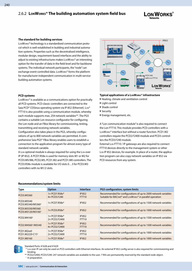
240
saia-pcd.com
IP852
RouterLON FTT10
IP / FTT10 Router
Communication & Interaction
2.6.2 LONWORKS® The building automation system field bus
Recommendations/system limits
Standard Ports: #1628 and #1629 * LON over IP can only be used on PCD controllers with Ethernet interfaces. An external IP 852 config server is also required for commissioning and
binding.** PCD2.F2400, PCD3.F240: 247 network variables are available to the user. 7 NVs are permanently reserved by the standard node object. + In preparation.
Type Option Interface PG5 configuration, system limits
PCD3.M5560 1× PCD7.R58x*4× PCD3.F240
IP 852 FTT10
Recommended for configurations of up to 2000 network variables Suitable for BACnet® and LONWORKS® in parallel operation
PCD3.M5540 PCD3.M5340/M5360+ 1× PCD7.R58x* IP 852 Recommended for configurations of up to 1500 network variables
PCD3.M3330/M5560 PCD3.M3120/M3160+ 1× PCD3.R58x* IP 852 Recommended for configurations of up to 1000 network variables
PCD2.M4160+ 1× PCD7.R58x* 2× PCD2.F2400
IP 852 FTT10 Recommended for configurations of up to 1500 network variables
PCD2.M4560+/M5540 1× PCD7.R58x* 4× PCD2.F2400
IP 852 FTT10 Recommended for configurations of up to 1500 network variables
PCD1.M2xx0PCD1.M2220-C15+
1× PCD7.R58x* 2× PCD2.F2400
IP 852 FTT10 Recommended for configurations of up to 1000 network variables
PCD1.M0160 1× PCD7.R58x* IP 852 Recommended for configurations of up to 1000 network variables
The standard for building services
LONWORKS® technology is a standardised communication proto-col which is well-established in building and industrial automa-tion systems. Properties such as the decentralised intelligence, modular design, requirement-based interfaces and the ability to adjust to existing infrastructures makes LONWORKS® an interesting option for the transfer of data in the field level and for backbone systems. The individual network participants, the “node” can exchange event-controlled data. LONWORKS® forms the platform for manufacturer-independent communication in multi-service building automation systems.
PCD systems
LONWORKS® is available as a communications option for practically all PCD systems. PCD classic controllers are connected to the Saia PCD® COSinus operating system via IP 852 (Ethernet). LON® FTT10 is also possible using a communication module, whereby each module supports max. 254 network variables**. The PG5 contains a suitable Lon resource configurator for configuring the Lon node and an FBox library for commissioning, testing, transmitting and receiving network variables.Configuration also takes place in the PG5, whereby configu-rations of up to 800 network variables are permitted. A com-prehensive Saia PG5® FBox library enables users to establish a connection to the application program for almost every type of standard network variable. A LON optional module is always required for using the LON over IP (IP 852). A PCD7.R58x is used for memory slots M1 or M2 for PCD3.M5/M6, PCD2.M5, PCD1.M2 and PCD1.M0 controllers. The PCD3.R58x module is available for I/O slots 0…3 for PCD3.M3 controllers with no M1/2 slots.
A “Lon communication module” is also required to connect the Lon FTT10. This module provides PCD controllers with a LONWORKS® interface but without a router function. PCD1.M2 controllers require the PCD2.F2400 module and PCD3 control-lers the PCD3.F240 module. External LON FTT10 / IP gateways are also required to connect FTT10 devices directly to the management system or other LON IP 852 devices, for example. In place of a router, the applica-tion program can also copy network variables on IP 852 via PCD resources from any system.
Typical applications of a LONWORKS® infrastructure
Heating, climate and ventilation control Light control Shade control Security Energy management, etc.
PCD1.M2 with LON FTT10
Node
NodeNode
Node
Node
NodeNode

saia-pcd.com
241
1S
BC
so
ftw
are
3S
BC
S-W
eb
te
chn
olo
gy
2C
om
mu
nic
ati
on
&
Inte
rac
tio
n
Communication & Interaction
4R
oo
m a
uto
ma
tio
n
LONWORKS®
Order details
Type Description
LON over IP for PCD3.M3xxx | PCD3.M5xxx and PCD3.M6xxx
PCD3.R580 Flash memory module with LON over IP firmware for PCD3.M3120 and ..M3330, can plug in to I/O slots 0…3
PCD3.R582 Flash memory module with LON over IP firmware for PCD3.M3120 and ..M3330, incl. 128 MByte for user program backup and 1 MByte with file system, can plug in to I/O slots 0…3
LON over IP for PCD3.M5xxx | PCD3.M6xxx | PCD2.M5xxx | PCD1.M2xxx and PCD1.M0xxx
PCD7.R580 FLASH MEMORY MODULE WITH Lon over IP firmware for PCD1.M2xxx, PCD1.M0xx, PCD2.M5xxx and PCD3.M5xxx/..M6xxx, can plug in to slot M1 or M2
PCD7.R582 Flash memory module with LON over IP firmware for PCD1.M2xxx, PCD1.M0xx, PCD2.M5xxx and PCD3.M5xxx/..M6xxx, incl. 128 MByte for user program backup and file system, to plug in to slot M1 or M2
LON FTT10 for PCD1.M2xxx | PCD3.M5x6x | PCD3.M6xxx
PCD2.F2400 LONWORKS® interface module for up to 254 network variables with slot for PCD7.F110S, F121S, F150S, F180SPCD3.F240 LONWORKS® interface module for up to 254 network variables with slot for PCD7.F110S, F121S, F150S, F180S
Configurations
Configuring a PCD host node can be extensive depending on the size of the project. With very little input, the system integrator is able to use the proven template concept to derive many hundreds of identical nodes from a single definition and automatically create PCD resources. Templates created by the device manufacturer and self-genera-ted XML templates can be used. LONWORKS® standard templates can be supplemented in the LON IP configurator with additional information such as resources used, scaling, etc., and saved as separate templates. Templates created this way can be com-
bined in any configuration and reprocessed to create the Lon node.This increased level of reusability of the templates makes engineering a decisive competitive advantage.
Standard network variables SNVT
Being implemented as an IP stack for the Saia PCD® COSinus operating system allows a single PCD substation to define up to 2000 SNVTs (standard network variable types) and link to other PCDs or third party systems. Almost all of the SNVTs currently specified in LONMARK® are supported by the PCD systems.
LON IP and FFT10, efficient engineering with templates
LON configurator
LON devices manufacturer
FPS UNVT UCPT
LON standard FPS SNVT SCPT
LON resource files (V13 XML)
PG5 resources
LON resource templates
User-defined tem-plates
PCD LON node
PCD resources (automati-cally generated)

242
saia-pcd.com
3330
PCD3.M
Modbus-ASCII / RTU
Communication & Interaction
2.6.3 Modbus
Modbus is a communication protocol based on a master/slave or client/server architecture. It is widespread and supported by many manufacturers and devices. In many cases, Modbus is therefore the common denominator for transferring data between different devices and systems.
Modbus with Saia PCD®
Modbus comes in three forms: Modbus ASCII data are transmitted in ASCII format via serial
interfaces (RS-232, RS-485).
Modbus RTU data are transmitted in binary format via serial interfaces (RS-232, RS-485).
Modbus TCP data are transferred in TCP/IP or UDP/IP packets via Ethernet.
Supported Modbus function codes
1 Read Coils2 Read Discrete Inputs3 Read Holding Registers4 Read Input Registers5 Write Single Coil6 Write Multiple Coils7 Write Single Holding Register8 Write Multiple Holding Registers
Convenient Fulpa FBoxes or CSF commands are available for configuring and programming the exchange of data.
With the integrated automation server, external systems can also be easily linked to master Web+IT automation environments via Modbus.
Application example
The Modbus protocol is supported in the Saia PCD® COSi-nus operating system by all Saia PCD1.M0_, Saia PCD1.M2_, Saia PCD2.M5_ and Saia PCD3 controllers. Client and server functionalities are available for all types of protocol.Ethernet interfaces and serial interfaces (RS-232 and/or RS-485) are already included in the PCD controller basic devices. Additional plug-in interface modules can be used to operate up to 9 serial Modbus interfaces per PCD system.
Number of connections
Each Saia PCD® system is able to establish up to a maximum of 26 connections. Of these, the Saia PCD® controller is able to use a maximum of 10 for client connections. The remain-ing connections can be used as server connections to the same Saia PCD® controller.
Media Mapping: adjustable by the userMapping Areas: max. 10 per UIDNumber of servers: max. 4 per PCD systemNumber of unit IDs: max. 10 per PCD systemNumber of channels: max. 10 per PCD system
Modbus TCP Ethernet
PCD2PCD1 PCD3

saia-pcd.com
243
Saia PCD3
Saia PCD1
Ethernet UDP / IP
KNX IP Tunneling
RS-232
KNX
KNX
Clr IniSnd IniPol
EIBNet/IPClr
IniPol
1S
BC
so
ftw
are
3S
BC
S-W
eb
te
chn
olo
gy
2C
om
mu
nic
ati
on
&
Inte
rac
tio
n
Communication & Interaction
4R
oo
m a
uto
ma
tio
n
2.6.4 KNX
Communication drivers for electrical systems and room automation
Ethernet Gateways
When planning, it is important to bear in mind that some Ethernet gateways only support one communication channel.Every PCD or service tool, ETS for example, therefore requires its own interface to the KNX Bus.
Serial converter
However, it is inadvisable to connect using BCU-1 protocols. The BCU-1 protocol can cause telegrams to be lost between the gate-way and the controller.
Communication drivers
An efficient networking of building services requires multi- service functions and components for communicating with external devices. The KNX communication driver is a PG5 FUPLA library with comprehensive function modules (FBoxes) for sending and receiving almost all KNX data types (DPT). Depending on which interface is available for accessing the KNX network (RS-232 or Ethernet), the selected components can be linked to Saia PCD® systems.The direct connection via Ethernet makes access to KNX data even quicker and more powerful.
Features
Use of drivers for all SBC automation stations
Simple communication connection with FUPLA modules
Comprehensive support of KNX Data Point Types (DPT)
The drivers support the simple restructuring of existing systems with KNX BCU1 on the KNX BCU2 interface
Standard UDP/IP port: #3671
Communication drivers for:
Serial KNX BCU-1 interfaces via RS-232 (not recommended for new products)
Serial KNX BCU-2 interfaces via RS-232
KNXnet/IP (EIBnet/IP) communication
Order details
Type Description
PG5 EIBPG5 KNX/EIB (KNX standard) communication library for Saia PCD® controllers for serial and IP-based communication
Components of other providers
Weinzierl KNX IP Interface 730 (www.weinzierl.de) KNXnet/IP GatewayWeinzierl KNX IP Router 750 (www.weinzierl.de) KNXnet/IP incl. router useABB IPS/S2.1 EIB/KNX IP Interface (www.abb.com) KNXnet/IP GatewayABB IPS/R2.1 EIB/KNX IP Router (www.abb.com) KNXnet/IP incl. router useWeinzierl KNX BAOS 870 (www.weinzierl.de) Serial (RS-232) KNX interface with BCU-2 protocol
Euro
pean
Inst
alla
tion
Bus K
NX
RS-232/BCU 2 function box KNX/IP function box

244
saia-pcd.com
RS-485
5540
F150
E110
E110
E110
Saia PCD3.C
Communication & Interaction
2.6.5 EnOcean
Communication driver for wireless sensors and actuators
The number of required wireless gateways depends heavily on the structural conditions. Pillars and furniture can create “dead spots” and walls can dampen the wireless signal depending on their design. Additional information and a brief planning guide are contained in the EnOcean manual (see www.sbc-support.com) EnOcean V3 is the latest version. The FBox library "EnOcean bidirec-tional" is only to be used for existing projects.
EnOcean is the inventor and manufacturer of the patented basic “self-powered wireless sensor technology”. EnOcean was recognised as the first ISO/IEC wireless standard (ISO/IEC 14543-3-10) for optimised solutions with low energy consumption. The “EnOcean alliance” is a manufacturers’ interest group which, over time, has developed a wide range of self-powered components for building automation systems based on EnOcean technology, such as switches, sensors, actuators and gateways.
Connection diagram for the RS-485 wireless receiver
Order details
Type Description
PG5 – EnOcean V3PG5 – EnOcean communication library for Saia PCD® controllers for serial (EVC mode) and IP-based communication.
Components from PEHA recommended (www.peha.de)
D450ANT EnOcean wireless receiver with RS-485 interface (bidirectional), IP 20 casing with internal aerialOther EnOcean components such as switches, hotel card switches, window contacts, radiator actuators… are recommended by PEHA.
Components from Thermokon (www.thermokon.ch)
SRC65-RS-485E EnOcean wireless receiver with RS-485 interface (unidirectional), IP65 casing with external antenna
STC65-RS-485E EnOcean wireless receiver/transmitter with RS-485 interface (bidirectional), IP65 casing with external antenna
Sensortec components (www.sensortec.ch)
EOR700EVC EnOcean wireless receiver with RS-485 interface (unidirectional), IP20 casing with internal antenna
EOR710EVC EnOcean wireless receiver/transmitter with RS-485 interface (bidirectional), IP 20 casing with internal antenna
Communication drivers
The EnOcean components are connected to the Saia PCD® controllers via external wireless gateways via serial RS-485 or IP interfaces. The FBox library provides communication modules for transmitting and receiving EnOcean telegrams. Generic FBoxes are available for standard EnOcean devices. Device-specific FBoxes are available for a selection of manufacturer-specific devices such as room control units (PEHA Sensortec, Thermokon, etc.). Universal communication FBoxes also offer the option of processing any EnOcean telegram in the PLC program.
Wireless
max. 64 receivers
The number of transmitters per receiver is limited only by the distance and the reception quality.

saia-pcd.com
245
PCD2.F27x0 PCD3.F27x
M-Bus
kWh1
SB
C s
oft
wa
re3
SB
C S
-We
b t
ech
no
log
y2
Co
mm
un
ica
tio
n &
In
tera
cti
on
Communication & Interaction
4R
oo
m a
uto
ma
tio
n
2.6.6 M-Bus
field bus module for capturing consumption data
M-Bus master interface module
M-Bus (EN 1434-3) is an international standard for remote meter reading. The M-Bus connection is formed using the PCD2.F27x0 / PCD3.F27x communication modules in slots 0…1 on the PCD1.M2* and 0…3 on the PCD2.M5 and PCD3. This enables all volumes of water, heat or energy to be captured in an automa-tion station. The measurement data is subsequently processed in an FBox library in the Saia PCD® FUPLA. The interface modules are fitted with a power supply and two separate M-Bus interfaces. Depending on the design, the inte-grated power supply is sufficient for up to 240 M-Bus standard slave modules whereby it can be distributed as required across the two ports. The PCD2.F2710…F2730 and PCD3.F271…F273 master mod-ules require the Engiby M-Bus library.FBoxes for SBC energy meters with M-Bus are supported by the Engiby library.
PCD1/PCD2 ordering information
Type Description Weight
PCD2.F2700 M-Bus master interface for up to 240 slaves 60 g
PCD2.F2710 M-Bus master interface for up to 20 slaves 60 g
PCD2.F2720 M-Bus master interface for up to 60 slaves 60 g
PCD2.F2730 M-Bus master interface for up to 120 slaves 60 g
PCD3 ordering information
Type Description Weight
PCD3.F270 M-Bus master interface for up to 240 slaves 80 g
PCD3.F271 M-Bus master interface for up to 20 slaves 80 g
PCD3.F272 M-Bus master interface for up to 60 slaves 80 g
PCD3.F273 M-Bus master interface for up to 120 slaves 80 g
M-Bus via serial interface
In PCD controllers, M-Bus is connected with no slot for M-Bus master modules via an external signal converter. RS-232 or RS-485 interfaces are used depending on the converter.
Driver settings
The respective PCD communication interface is specified in the M-Bus driver FBox in the Engiby library. Note the converter interface parameters such as baud rate, timeout, etc.
Secondary addressing
Secondary addressing is supported from Library Version 2.7.200 or higher for SBC energy meters and generic FBoxes. Primary addressing must be used for the product-specific FBoxes.
Application example: PCD1.M2120 with M-Bus activation.* PCD1.M2110R1 slot 0 only
M-Bus Port 1M-Bus Port 2 a total of up to 240 slaves
up to 4 modules
Driver licence free
Saia Energy Meters licence free
Engiby M-Bus Library, licence required

246
saia-pcd.com
PCD1.M2xx0
PCD3.F261 PCD2.F2610 PCD1.F2611-C15
Communication & Interaction
2.6.7 DALI
field bus module for lighting systems
Please observe the information for the PCD firmware version and the PG5 version on the support page.
DALI master interface module
DALI is a communication system for lighting control, standard-ised in accordance with IEC 62386-101/102. Installation is easy. The DALI Bus simply needs 2 unshielded wires which can be threaded through the same cable along with the power supply, generally 230 V. The light parameters are standardised. All upstream devices therefore have the same parameters for dimming, grouping and scenes, irrespective of the type of lighting.
The DALI master module includes the Bus power supply for up to 64 DALI participants. The extensive PG5 FBox library has func-tion modules for commissioning, operating and servicing with the PLC program. External software tools or other components are not required.
Smaller DALI controls can be implemented with the PCD1.F2611-C15 E-Line DALI module. Detailed information about this small controller can be found in the E-Line chapter.
Order details
Type Description Application note Weight
PG5 – DALI F26xPG5 – DALI communication library for connecting DALI lighting control systems
– –
PCD3.F261DALI master interface for up to 64 DALI participants incl. bus power supply (200 mA/12…13.5 V)
PCD3.Mxxx0: I/O slot 0-3 PCD3.T666: I/O slot 0-3
80 g
PCD2.F2610DALI master interface for up to 64 DALI participants incl. bus power supply (200 mA/12…13.5 V)
PCD1.M2110R1: I/O slot 0 PCD1.M2xx0: I/O slot 0-1 PCD2.M4160: I/O slot 0-1PCD2.M4560: I/O slot 0-3PCD2.M5xx0: I/O slot 0-3
60 g
PCD1.F2611-C15DALI master interface for up to 64 DALI participants incl. bus power supply (200 mA/13…15.5 V)
– 130 g
PG5 – DALI F26x FBox library
Incl. DALI Bus
Power supply

saia-pcd.com
247
1S
BC
so
ftw
are
3S
BC
S-W
eb
te
chn
olo
gy
2C
om
mu
nic
ati
on
&
Inte
rac
tio
n
Communication & Interaction
4R
oo
m a
uto
ma
tio
n
DALI communication library
The current DALI standard does not guarantee a genuine multi-master function. Multi-master capable products such as those of Tridonic, Osram or Zumtobel are either based on the new draft DALI extension E DIN 62386-103 (2011-08) or accept the loss of telegrams in bus collisions. Permanent polling, e.g. of the status, should therefore be avoided in “multi-master” projects. The maximum number of DALI master devices can be restricted to 8 units, for example, depending on the product and hardware manufacturer.
Commissioning and servicing made easy
When initialising, the “DALI F26x Driver” FBox is positioned once only when the program starts. The “Configuration Manager” FBox then parameterises all the DALI participants on the bus. The FBox also provides predefined symbols for further use, e.g. in S-Web. The parameters can also be used securely in the PCD file system. The “Backup to Flash” FBox stores all DALI para- meters in parallel in two files. This guarantees the retention of data in PCD systems with no batteries, e.g. in the Smart RIO PCD3.T666, required.
When commissioning DALI systems, it is usual to install all DALI participants then issue the ad-dresses and set the parameters via the DALI commissioning software. The "Random addressing" and "Exchange addresses" modules are in the Saia PG5® – DALI library.
Parameterisation takes place after the addressing process using the “Configuration manager” FBox. Group and scene parameters can alternatively be set using the “Edit Groups” and “Edit Scene Levels” FBoxes to provide a better overview.
Web visualisation for commissioning
Operation
The “Send Command Inputs”, “Send Command Online”, “Send Power Control” and “Send Scene” FBoxes are available for transmitting DALI commands. These FBoxes cover all standard DALI commands.
The receipt of master telegrams is also supported by the “Receive Commands” and “Receive Raw” FBoxes. “Receive Raw” is useful for receiving non-standard telegrams. The raw data can then be processed further in the application program.
The lamp status can be requested using the “Read Status” FBox. The “Query numeric” FBox pro-vides the application program with access to a further 21 DALI standard data points such as the current light level.
The “Read Memory” FBox is used to read any data from a DALI device. It is therefore possible to request brightness and presence information from one sensor, which would not be accessible with the DALI standard methods.
DALI controller with PCD1.F2611-C15:
There are also different FBoxes within the "DALI E-Line Driver" rubric for commissioning and operation for this interface.
Driver module
Status monitoring
Lighting control on/off, dimmable
Direct lighting control
Scene controller
E-Line gateway driver

248
saia-pcd.com
p t tp
t
t t tp
Communication & Interaction
2.6.8 MP Bus
field bus module for Belimo MP Bus devices
MP Bus master interface module
MP Bus is a Belimo communication system used to connect Belimo MP* field devices such as valve and shutter position drives or VAV controllers and room air sensors in building automation systems. Installation is easy. In addition to the 24V AC/DC power supply, the MP Bus needs just one unshielded wire which can be run through the same cable.Up to 8 drives can be attached to one communication channel. The total length of the mains cable depends on the diameter of the selected cable and the number and output of the connected drives**. A total length of approx. 100 m is usually reached. Since the length of the connection and the number of drives is limited, no other demands such as termination resistors or shield-ed cable are placed on the bus topology. In addition to the connected drives, sensors can be connected direct via a drive or MP Bus add-on modules. The extensive Saia PG5® FBox library has function modules for communicating with the PLC program. The drives are addressed using the communi-cation driver FBox and can then exchange data with the application program via the respective FBoxes. The Belimo components are generally commissioned from the application program using the SBC FBoxes. Only a few components such as VAV controllers require additional Belimo parameterisation tools to adjust their operational parameters.
* MP is a Belimo designation. MP = multi-point ** For further information on the system layout, see the Belimo documentation, www.belimo.com
Application example: HVAC system with a PCD3.M5 and up to 64 MP Bus drive units on 8 MP interfaces
Overview
PCD1, PCD2, PCD3 compact control-ler with MP Bus module
Fire dampers VAV boxes Air damp-ers
Globe valves Regulator ball valves
LONWORKS®, Ethernet TCP / IP, Profibus, etc.
Automation station
Onboard; Slot A, A1 and A2 I/O slot #0…#3
MP Bus module TotalNumber of MP Bus MP Bus
moduleTotal
Number of MP Bus
Cables Drives Cables Drives
PCD3.M3xxx / M5xxx – – – – PCD3.F21x, PCD3.F221, PCD3.F240
4 – –
+ PCD7.F180S 4 32
PCD3.F2814 4 32
+ PCD7.F180S 8 64
PCD3.Compact | PCD3.WAC PCD7.F180S 1 1 8 – – – –
PCD2.M5xxx PCD7.F180S 2 2 16 PCD2.F21x0, PCD2.F2210, PCD2.F2400
4 – –
+ PCD7.F180S 4 32
PCD2.F28104 4 32
+ PCD7.F180S 8 64
PCD1.M2x20 / PCD1.M2x60 PCD7.F180S 1 1 8 PCD2.F21x0, PCD2.F2210, PCD2.F2400
2 – –
+ PCD7.F180S 2 16
PCD2.F28102 2 16
+ PCD7.F180S 4 32
PCD1.Room PCD7.F180S 1 1 8 PCD2.F21x0, PCD2.F2210, PCD2.F2400
1 – –
+ PCD7.F180S 1 8
PCD2.F28101 1 8
+ PCD7.F180S 2 16
PCD1.M0160E0 PCD7.F180S 1 1 8 – – – –

saia-pcd.com
249
1S
BC
so
ftw
are
3S
BC
S-W
eb
te
chn
olo
gy
2C
om
mu
nic
ati
on
&
Inte
rac
tio
n
Communication & Interaction
4R
oo
m a
uto
ma
tio
n
MP Bus | Function modules (FBox)
All Belimo MP drives can exchange data with the PCD application program via a suitable FBox from the MP Bus FBox library. The master communication FBox must be positioned once at the start of the application program. It controls the communication and fault recogni-tion and creates ways of addressing the MP drives available for commissioning and service. Some MP drives also have an input for con-necting sensors. R: Temperature sensor NI1000, PT1000…, U:voltage 0–32 V or 0–10 V and DI: Potential-free contact.
* only active sensors and switches can be connected
Type/performance categories Sensors MP Bus FBox
Communication drivers MP Single
Ventilation applications
Damper drives with no safety function: LM24A-MP (5 Nm), NM24A-MP (10 Nm), SM24A-MP (20 Nm), GM24A-MP (40 Nm)
Damper drives with safety function: TF24-MFT (2 Nm), LF24-MFT2 (4 Nm), SF24A-MP (20 Nm)
Linear damper drives: LH24A-MP100 / 200 / 300 (150 N), SH24A-MP100 / 200 / 300 (450 N)
Damper drives rotary: LU24A-MP (3 Nm)
R, U, DI MP Air
Safety applications
Drives for fire dampers: BF24TL-T-ST (18 Nm), BFG24TL-T-ST (11 Nm)
Gateway for conventional fire damper drives: BKN230-24-C-MP
Thermo- element
MP BS
Room and system applications
VAV compact controller: LMV-D3-MP (5 Nm), NMV-D3-MP (10 Nm), SMV-D3-MP (20 Nm)
VAV compact controller linear: LHV-D3-MP (150 N)
VAV universal controller: VRP-M
R, U, DI MP VAV…
Water applications
Lift drives with no emergency function: LV24A-MP-TPC (500 N), LVC24A-MP-TPC (500 N), NV24A-MP-TPC (1000 N), NVC24A-MP-TPC (1000 N), SV24A-MP-TPC (1500 N), SVC24A-MP-TPC (1500 N), EV24A-MP-TPC (2500 N)
Lift drives with emergency function: NVK24A-MP-TPC (1000 N), NVKC24A-MP-TPC (1000 N), AVK24A-MP-TPC (2000 N), adjustable closing point, adjustable emergency setting
R, U, DI MP Linear
Drives for control ball valve with no emergency function: LR24A-MP (5 Nm), NR24A-MP (10 Nm), SR24A-MP (20 Nm)
Drives for control ball valve with emergency function: TRF24-MFT* (2 Nm), LRF24-MP (4 Nm), NRF24A-MP (10 Nm)
Drives for butterfly valves with no emergency function: SR24A-MP-5 (20 Nm), GR24A-MP-5/-7 (40 Nm)
R, U, DI MP Air
Drives for 6-way control ball valve: LR24A-MP (5 Nm), NR24A-MP (10 Nm) R, U, DI MP 6 Way
Electronic pressure-independent control ball valve (EPIV): P6…W…E-MP* U, DI MP EPIV…
Belimo EnergyValve: EV..R+BAC, P6..W..EV-BAC U, DI Energy Valve P6
Rotary actuator: CQ24A-MPL (MP-Bus light) — MP MPL
Room sensors
Room combi-sensor, depending on design with temperature, CO2, VOC and relative humidity: MS24A R… MPX
R, DL, U (0–10 V)
MP THC24MP THCV
Generic data transfer
For reading and transmitting data points not contained in the device-specific FBox. This FBox is used as a functional extension for MP Bus FBoxes and can only be used with a device FBox specific to that device or a generic device FBox.
MP GenericMP PEEKMP POKE
Third party devices
FBoxes are available for the following third party MP Bus devices: PTH sensor from wmag AG, Switzerland, UST-3, UST-5 from wmag AG, Switzerland.
Each MP Bus device can also be connected via generic devices and peek/poke FBoxes in PCD application programs.
MP PTHMP UST-3
MP GenericMP PEEKMP POKE

250
saia-pcd.com Communication & Interaction
2.6.9 Other drivers
Communication drivers from www.engiby.ch
Field bus, standard/universal interfaces
Modbus
(RTU/ASCII, TCP/IP, UDP/IP)
Schneider, Modicon and Telemecanique and many other devices via point-to-point connections – modem – RS-232 – RS-422 – RS-485 Bus – TCP/IP – UDP/IP
M-Bus
Heating cost meter, water meter, impulse meter, electricity meter. The driver supports F27xx modules as well as level converters for RS232/M-Bus, RS485/M-Bus and TCP/IP to M-Bus gateways
3964(R) / RK512 Siemens: Point-to-point and multi-point connection S-Bus for TCP/IP S-Bus driver for multi-master applications, for efficient configuration in MS Excel tables S-Bus for RS-xxx S-Bus driver for quick response time with priority, for efficient configuration in MS Excel tables ESPA 4.4.4 Send and receive Messages, forward and route Messages via SMS, pager or TAP IEC 60870-5-101 Power plant/energy management IEC 60870-5-103 Switching station controller IEC 60870-5-104 Power plant/energy management
Text output Configuration tool for transmitting formatted texts event triggered via serial interfaces, TCP/IP or UDP/IP. Also supports SMS
Text parser Configuration tool for reading and analyzing PCD text input
SNMP traps and PING Transmission of SNMP Alarms/notification (NMS) and Syslog messages, as well as efficiently in MS Excel tables configured PING of multiple IP hosts
EIB (KNX Configurator)
Configuration tool for the Saia EIB communication driver which allows the definition of the communication to KNX devices in MS Excel tables. Additionally supports scenarios (transmission of multiple values to multi-ple addresses with short interruptions between the transmissions)
Controller/energy
ExControl Light and shade functions with remote access via RS-232 or Ethernet TRSII WITnet concept, remote control COMSAB / York SABROE compressor control device: – PROSAB II – UNISAB S / R / RT / RTH – UNISAB II Luxmate Lighting controller BMS ZUMTOBEL
Alarm / messages / access
DMS 7000 Siemens-Cerberus alarm systems (reduced driver) Tyco MX Tyco MX 1000 and 4000 alarm systems Fidelio / FIAS Hotel management system TechTalk Access control system
Video / Audio
Grundig VAZ Video matrix Commend Interphone system
Others
Wilo / EMB Pump controller Grundfos pump control Genibus via RS-485 ebmBUS ebmPapst motor controller
Clock and GPS Time signals received from DCF77 - Time and position received via GPS. Time and meteo data received from Elsner station
Marksman Road traffic counter
For German-speaking customers: Communication drivers from Kindler Gebäudeautomation GmbH, www.kga.de
Danfoss
KGA.DanfossFBox library for communicating with VLT 6000 / FC100 Danfoss® frequency inverters with the standard FC communication protocol
Saia Burgess Controls communication drivers
P-Bus Communication driver to Siemens P-Bus I/O levelN2-Bus Communication driver to JCI-N2 bus for connecting JCI master or slave systems

251
saia-pcd.com
B3
3S
BC
S-W
eb
te
chn
olo
gy
2C
om
mu
nic
ati
on
&
Inte
rac
tio
n1
SB
C S
oft
wa
re4
Ro
om
au
tom
ati
on
SBC S-Web Technology
Automation systems with sophisticated SCADA functions “embedded” in every device.
Alarming Trending Visualisation Standard web browser as service interface software
SBC S-Web technology
No need to continue using proprietary SCADA/management PC software. Each interest group gets exactly what it needs and no extraneous elements will confuse the user. Current end devices and existing technology used on site will be sufficient.
The functional basic structure of a single automation device is used to illustrate how SBC S-Web systems are designed for machines, plants and distributed properties.
What should you bear in mind when implementing and integrating SBC S-Web systems? How do they differ from conventional PC-based SCADA / HMI solutions?
What is available from SBC? How are system components of other manufacturers incorporated? What software tools are available for creating projects?
Automation Server functions in every SBC device are the technical requirements for SBC S-Web systems. What sort of functions are they? What benefits do they provide?
Practical example of Web HMI pages created using Saia PG5® Web Editor
Four projects illustrate how thousands of S-Web systems have been implemented in the field. They explain how the systems progress from design to implementation and operation.
The typical tender for automation / ICA systems still involves the current strict separation of control engineering and process control and management functions on separate levels. SBC S-Web combines different functions in a single device. This can also be seen in the tenders.
3.2 The S-Web system architecture: SCADA in every automation device Page
3.4 Engineering Information Page
3.6 SBC S-Web system tools and products Page
3.7 Using Automation Server as a technical basis Page
3.3 Real-life examples of SBC S-Web Page
3.5 Tender information – what changes with S-Web Page
3.1 The aim of S-Web: To use what you know and what already exists Page
253
257
265
269
255
261
252

252
saia-pcd.com SBC S-Web Technology
As a company, we focus on being as lean as possible. The aim of being lean is to achieve ever more using less. That is only possible by exploiting what you already have. As little as possible should be added to this. SBC S-Web is dedicated to this principle.
3.1 The objective of S-Web using the known and existing components. Use fewer unknown and complex elements.
It is worth exploiting what already exists on-site.
SBC S-Web systems
Make special SCADA software unnecessary Reduce the need for trained personnel in the operation Make an investment project simpler and more cost-effective
SBC S-Web optimises use of
Existing software Existing human resources Existing infrastructure and end devices
Software: Management functions can be performed using dedicated software. This has to be purchased, installed, configured, maintained and personnel must receive training. It can usually perform far more functions than it is actu-ally used for, and is therefore complex. SBC S-Web makes this dedicated management/SCADA software unnecessary. It simply uses the software which is already available everywhere.
Human resources: Monitoring, control and management functions are possible for all interest groups/individuals. Users can optimise their area of responsibility in a way that is tailored to their requirements. No users have to be an automation specialist, no specific tools are required, and there is no waiting time to carry out analysis or improve-ments.
Infrastructure and end devices: SBC S-Web can be integrated simply and safely into existing LAN/WAN infrastruc-tures. Practically all the existing end devices can be used. This increases acceptance and reduces costs. This is because each control unit has sophisticated SCADA functions via many globally recognised technical standards.
In order to implement SCADA/management/operating functions using SBC S-Web, only technologies that are used and already exist have been implemented on site. They are globally recognised, non-proprietary Web+IT standards. The required functions can be flexibly adapted over the entire service life of a system and kept simple to master. This is possible because the basic characteristics of the classic PLC technology are also integrated into the S-Web systems. A unique combination!
Use as few new, unknown and complex elements as possible
Using what already exists?
WAN Uplink
Electrician
Maintenance Supervisor
Operator Operations Manager
Programmer
Service Engineer
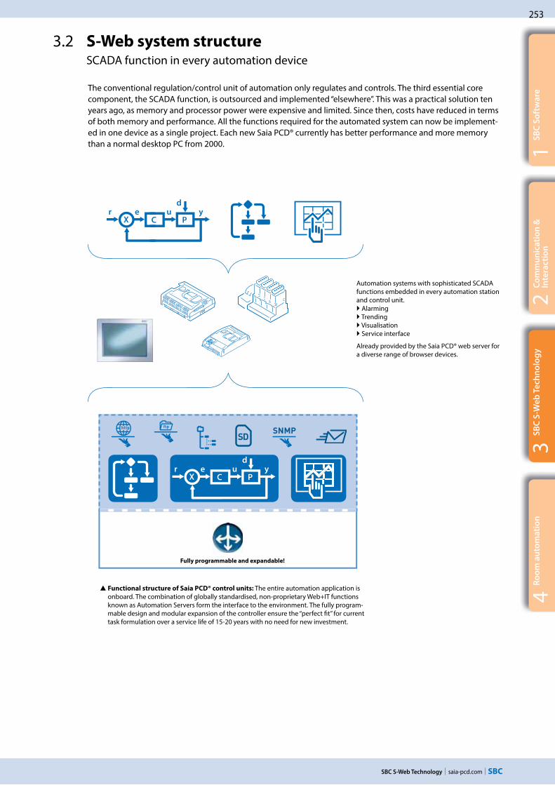
253
saia-pcd.com
2C
om
mu
nic
ati
on
&
Inte
rac
tio
n
SBC S-Web Technology
1S
BC
So
ftw
are
3S
BC
S-W
eb
Te
chn
olo
gy
4R
oo
m a
uto
ma
tio
n
3.2 S-Web system structure SCADA function in every automation device
The conventional regulation/control unit of automation only regulates and controls. The third essential core component, the SCADA function, is outsourced and implemented “elsewhere”. This was a practical solution ten years ago, as memory and processor power were expensive and limited. Since then, costs have reduced in terms of both memory and performance. All the functions required for the automated system can now be implement-ed in one device as a single project. Each new Saia PCD® currently has better performance and more memory than a normal desktop PC from 2000.
Automation systems with sophisticated SCADA functions embedded in every automation station and control unit.
Alarming Trending Visualisation Service interface
Already provided by the Saia PCD® web server for a diverse range of browser devices.
Functional structure of Saia PCD® control units: The entire automation application is onboard. The combination of globally standardised, non-proprietary Web+IT functions known as Automation Servers form the interface to the environment. The fully program-mable design and modular expansion of the controller ensure the “perfect fit” for current task formulation over a service life of 15-20 years with no need for new investment.
Fully programmable and expandable!

254
saia-pcd.com SBC S-Web Technology
To the benefit of the users and operators of plants / properties
Technological advancement creates massive structural changes in the automation pyramid
Previously only PCs had the necessary resources for management/control func-tions. The SCADA/management software was loaded onto them. The automation/field levels were closely linked using bus systems. This is now outdated.
Today with SBC S-Web: Each unit has its own fully integrated automation function. Even simple field installations now have their own SCADA function which guarantees local optimisation and reliable operation. There are short paths and direct influ-ence on processes. Control/management func-tions need not be laborious and expensive through the data transfer running through the automation level to the management level and back.
BACnet has a comparable system model: BACnet is the only globally recognised and widely spread standard for building automation systems. It is based on exactly the same system model as Saia PCD® units. However, SBC S-Web implements the management/control function in buildings with the combination of the known = PLC+Web+IT; without introducing another standard to the building.
SBC S-Web Trending SBC S-Web System Visualisation SBC S-Web Alarming SBC S-Web Service Interface
Management level
Field level
Automation level
Saia
PCD
® de
vice
s ca
n be
fully
pro
gram
med
and
exp
ande
d w
ith S
aia
PG5
acro
ss a
ll le
vels
and
thro
ugho
ut th
e en
tire
serv
ice
life.
All automation functions (control and management functions) are
integrated into every device
SBC S-Web standard application in live operation:www.pcd-demo.com

255
saia-pcd.com
Internet
Saia PCD3.M5560
2C
om
mu
nic
ati
on
&
Inte
rac
tio
n
SBC S-Web Technology
1S
BC
So
ftw
are
3S
BC
S-W
eb
Te
chn
olo
gy
4R
oo
m a
uto
ma
tio
n
Marc Cain Building Bodelhausen/GermanyPOM-certified (peace of mind) HVAC system and room control technology for the head office of this international fashion company provides a better climate and low energy consumption.
The performance requirements for the automation of the building were set at a high level right from the beginning to achieve “peace of mind” certification from the German standards authority, TÜV. Using this approach, the design study integrated all the HVAC aspects of the building into a single, flexible control project. The thermal energy, for example, is produced by various sources and its distribution is controlled to minimise energy consumption. In a complex installation, this is only possible because the control system can seamlessly integrate all devices independent of their communication capabilities.
Lucerne Conference Centre Lucerne/Switzerland
The renovation and expansion of the Lucerne Conference Centre achieved the Minergie Standard and revitalised this important meeting place.
The 13,000 m2 of the four halls of the Lucerne Conference Centre provide the most modern technological exhibition area, in order to be able to meet all usage requirements. The range of different events also require a flexible architecture for lighting, ventilation and air conditioning in order to comply with the energy efficiency requirements of "Minergie" certified conference centres. The extensive use of bus technology in the planned building services, such as DALI for the lighting and MP Bus for the HVAC, ena-bles it to be integrated into the Saia PCD® controller with little effort and operated us-ing web technology. The very high level of flexibility of our programmable controllers and a design based on open-web technology, which made high levels of investment in expensive visualisation systems superfluous, were crucial to the award.
8 PCD3.M3330 automation devices
3.3 Real-life examples of SBC S-Web
The Marc Cain system comprises 25 automation devices. 24 Saia PCD3.M5x40 cover the individual system components/sub-sections. One Saia PCD3.M5x60 forms a master
control/management level for the entire property. Any browser device in the network (LAN/WAN) can now be used to access the local operator application of each individual
system or even directly access the control/management application of the master Saia PCD3.M5x60. Complex system schematics naturally require adequate display sizes;
a PDA/mobile phone is not large enough for this.
The Lucerne Conference Centre operating and monitoring concept is based entirely on SBC S-Web. It does not require a PC/Windows-based control or management system. Trend
data are recorded directly in the automation device and visualised using the available web templates. The system comprises 2000 physical data points distributed among eight PCD3.M3330 automation devices. There are eight 10” micro browser devices installed per
system component for operational purposes. There are three 15” web panels with the Windows CE operating system for providing a global overview.
Server: control/manage-ment functions implemented with Saia PCD3.M5x60; no PC and no Windows!
VPN
Remote maintenance
Client: Touch panel with micro browser
24 Saia PCD3.M5 for systems/sub-sections
8 touch panels (10" ) with micro browser
3 touch panels (15" ) with micro browser

256
saia-pcd.com
Internet Portal
39
PCD
1.M
2xxx
254
PC
D2.
M5x
xx17
PC
D3.
M5x
xx
SBC S-Web Technology
AMC wanted to refurbish and expand the control systems gradually over a period of several years without incurring costs and problems arising from potential changes in automation station generation. They started using Saia PCD® controllers in their buildings, processes and utilities in 2000. More than 10 years later, the choice is still considered as the correct one. This is supported by the transparent integration of the newest Saia PCD® generation, the general use of Ethernet, data capture on the Flash memory and the reliability of the installed base. The communication capabili-ties of Saia PCDs enable users to connect to all systems and make the life of the system integrator simpler.
Academic Medical Centre Amsterdam/NetherlandsOne of the top ten academic hospitals in the world relies on Saia PCD® controllers for improved air-conditioning and reduced energy consumption
European Research Centre CERN Geneva/SwitzerlandThe entire enormous CERN site consisting of 430 operational buildings relies entirely on SBC S-Web. The Web+IT standards mean it needs no dedicated central office or master control/management level.
Around 10,000 people work in the 430 buildings at CERN. Each building is fully independent. SBC S-Web forms their control/management level. There is no need for dedicated SCADA software/PC hardware. The existing and already mastered CERN Web+IT technology is sufficient for integrating the consumption data across the site and for monitoring purposes. Operation of the building technology does not require the purchase of, installation of or training on, dedicated Windows software. Automation projects are awarded by CERN throughout Europe. Thanks to SBC S-Web, system integrators all over Europe are able to implement autonomous projects for CERN or improve existing systems. There is no need to involve or reintegrate a central BMS application.
With S-Web, CERN benefits from a technology it invented itself in 1989. Source: Wikipedia
The local conditions in the individual parts of the system and building were resolved in this application using S-Web. A total of
310 automation stations (Saia PCD®) are integrated into the prop-erty automation system. The entire clinic is operated, controlled and managed as a functional unit. In hospitals, the high volume of visitors and the ventilation/cooling system are “mission criti-
cal”. In this respect, it is therefore preferable to operate a central iFIX 4.0 PC/Windows-based control/management system parallel
to SBC S-Web. In this instance, SBC S-Web cannot make the classic SCADA software totally superfluous.
20 touch panels with micro browser
iFix 4.0

257
saia-pcd.com
Client Server
KNXProfibus
N
W
S
E
NW
SW
SE
NE
http://yourautomation-station1.com/
5" … 15" 2C
om
mu
nic
ati
on
&
Inte
rac
tio
n
SBC S-Web Technology
1S
BC
So
ftw
are
3S
BC
S-W
eb
Te
chn
olo
gy
4R
oo
m a
uto
ma
tio
n
The basic structure of an operational S-Web system
The basic structure is simple. Enter the device addresses in the client. The Automation Server of the Saia PCD® devices provides the application/data of the Saia PCD®. How large and comprehensive can this be in the various types of Saia PCD® devices?
The browser device is usually determined by the mounting/installation location and the requirements in terms of display size and resolution.
The type of controller is determined by the number of required inputs/outputs, the range of functions and the memory requirements.
Basic orientation: Device selection
Every fully independent functional automation system can be illustrated as a hierarchy in the classic form of a pyramid. The differences between systems lie in the scope/power of the respective applications. In other words, the range of required functions and connected field levels.Pyramids with 2-3 hierarchy levels can be created in the case of large, complex properties. The resources must be designed in accordance with the size of the pyramid and the position at which a Saia PCD® automation device is used. The ability to move Saia PCD® applications to all three basic platforms and the high modularity even in terms of expanding the memory capacity means that SBC S-Web systems can be continuously expanded even after commissioning. The following illustrates a good basic orientation to ensure the initial installation is compatible.
Basic applications
Up to 50 I/Os Up to 20 trends Up to 100 alarms Up to 30 web pages
The Saia PCD® controls and visualises a machine, a simple building with a ventilation system, a heating circuit or a complex room, etc.
3.4 Engineering information Which resources does a Saia PCD® require for SBC S-Web?
Browser device Which display size?Which display resolution?Which device type?
Saia PCD® controller
application server
How many data points?
How many trends?How many images/elements?
Saia PCD® cont-
roller
Max
I/O
Program
memory
Onboard flash
memoryAdditional memory
PCD1.M2120 50 128 kByte 8 MB1) 1× PCD7.R550M041) 1× 4 MB
PCD1.M2160 50 1 MB 128 MB2) 1× PCD7.R550M041) 1× 4 MB
PCD3.M2130V6 102 512 kByte 1 MB1) --- ---
PCD3.M2230A4Tx 78 512 kByte 1 MB1) 1× PCD7.R-SDxxxx1) 1× 1 GB
PCD3.M3xxx 1023 512 kByte --- 4× PCD3.R550M041)
4× PCD7.R-SDxxxx1)4× 4 MB 4× 1 GB
1) 900 files per memory module 2) 2400 files per onboard memory
BACnet
Interface
Interface
Field level
Generic Web IT Interface
MB PanelMB Panel
MB Panel
PC Browser
Fully programmable

258
saia-pcd.com
+ + =
BACnet
Interface
Interface
Feldebene
frei programmierbar
Generic Web IT Interface
KNX
Profibus
SBC S-Web Technology
Mid-level applications
Up to 500 I/Os Up to 60 trends Up to 1000 alarms Up to 100 web pages
Die Saia PCD® controls several system components and includes the SCADA/ visualisation functions of the entire system/all parts of the building
Top-level applications
Up to 2500 I/O (entire system) Up to 120 trends Up to 2000 alarms Up to 300 web pages
The Saia PCD® contains the master control and management functions for many distributed systems or large integrated buildings.
Client and server in one device: The Saia PCD7.D4xxxT5F micro browser panels are simultaneously server and client. The demanding control function can be implemented using the Saia PG5® software tool.
Saia PCD® cont-
roller
Max
I/O
Program
memory
Onboard flash
memoryAdditional memory
PCD3.M5xxx 1023 1 MB --- 2× PCD7.R550M041) 4× PCD3.R550M041) 4× PCD7.R-SDxxxx1)
2× 4 MB4× 4 MB4× 1 GB
PCD2.M5xxx 1023 1 MB --- 2× PCD7.R550M041) 4× PCD3.R550M041) 4× PCD7.R-SDxxxx1)
2× 4 MB4× 4 MB4× 1 GB
1) 900 files per memory module
Saia PCD® cont-
roller
Max
I/O
Program
memory
Onboard flash
memoryAdditional memory
PCD3.Mxx60 1023 2 MB 128 MB2) 2× PCD7.R550M041) 4× PCD3.R550M041) 4× PCD7.R-SDxxxx1)
2× 4 MB4× 4 MB4× 1 GB
PCD7.D4xxxT5F --- 1 MB 128 MB2) --- ---1) 900 files per memory module2) 2400 files per onboard memory
Dimensioning the data storage for S-Web applications
The dimensioning of the data storage must take into consideration the size of the web project and the historical data (trend data) that needs to be stored. The following reference values can be used as a guideline to provide a rough estimate.
Memory requirement for S-Web pages:
The calculation of the memory requirements for web pages is based on the number of web pages, number of GIF graphics used and the IMaster Java applets. The following reference values can be used as a guideline to provide a rough estimate.
S-Web page approx. 10 kByte/page
GIF graphics 1…10 kByte Java Applet approx. 350 kByte
A project with 30 HMI pages will therefore need approx. the following memory requirement:(30 × 10 kByte) + (100 × 5 KByte GIF graphics) + 350 kByte = memory requirement for web project approx. 1150 kByte
Memory require-ment for web projects

259
saia-pcd.com
Val5 Val6 Val7
– Store – WrFile– DelFile Dir ????
2C
om
mu
nic
ati
on
&
Inte
rac
tio
n
SBC S-Web Technology
1S
BC
So
ftw
are
3S
BC
S-W
eb
Te
chn
olo
gy
4R
oo
m a
uto
ma
tio
n
Memory requirement for trend data
Recorded using CSV files in flash file system
The trend data are saved in groups of max. 10 data points per Saia PG5® Fupla FBox and CSV file.
Saia PG5® Fupla FBox records and saves up to 10 data points
A CSV file is generated for each FBox with max. 10 data point values per entry. The memory requirement for one entry: approx. 30 Byte (time stamp) + 10 Byte/data point
Trend display in the web browser. A max. of 10 trend curves can be displayed per window
In the following sample calculation, 20 data points are recorded for visualisation in trend curves. 10 data points should be recorded for the optimisation phase at intervals of 1 minute and a further 10 data points should be recorded for long-term monitoring at intervals of 15 minutes.
The memory requirement for 10 data points at 1 minute intervals in one day:
60 (mins) × 24 (hours) × [30 Byte (timestamp) + 10 (data points) × 10 Byte] = 187.2 kByte per day
With this quantity of data it is worth creating a new file every day. The data should be stored in the controller for a month. This produces a memory requirement of approx. 30 × 187.2 kByte = 5.616 MB per month divided among 30 files.
The memory requirement for 10 data points at 15 minute intervals in one day:
4 (15 min.) × 24 (hours) × [30 Byte (timestamp) + 10 (data points) × 10 Byte] = 12.48 kByte per day
With this quantity of data, a new file can be created each week 7 × 12.48 = 87.36 kByte per week
The data should be stored in the PCD for a year.This produces a memory requirement of approx. 52 (weeks)× 87.36 kByte = 4.53 MB per year divided among 52 files.
A Saia PCD3.Mxx60 CPU can record 10 data points for up to 6 years for long-term monitor-ing in the 128 MB onboard flash memory. The programmable PCD7.D4xxxT5F micro-browser panel and the PCD1.M2160 both also have a large onboard flash memory and are ideal for monitoring tasks. The plug-in PCD7.R-SDxxxx SD flash card with a memory capacity of up to 1 GB lasts even longer and can store data for decades in a Saia PCD® controller.
Onboard memory for 6 years of data moni-toring
What type of memory modules should be used?
Web pages and log data can be stored in the onboard flash memory and/or the plug-in flash cards.
The web projects and basic data logging with small quanti-ties of data can be stored on the onboard flash memory (de-pending on the type of CPU) or the plug-in PCD7.R55xM04 flash memory module. Unlike the onboard memory, flash cards can be exchanged and replaced with new cards. It is therefore easy to archive data or transfer it from one control-ler to another.
Only the PCD7.R-SDxxxx SD flash card module should be used for intensive data logging.
PCD7.R-SDxxxx
PCD7.R55xM04
Important information for using the flash memory module
A max. 900 files are supported in a memory module.S-Web uses up to 70% of the nominal physical memory.
The size of a single file should not exceed 1 MB. This guarantees that all the files can be sent via the Saia PCD® as email attachments.
The calculation examples are reference values without BACnet or LON communication.

260
saia-pcd.com
N
W
S
E
NW
SW
SE
NE
N
W
S
E
NW
SW
SE
NE
W
SSW
W
SSW
W
SSW
SBC S-Web Technology
SBC Web Connect can also be used to access the PCD Web Server in the local network even without public IP addresses. The user interface is always the same whether it is operated locally or remotely.
Local or “remote” operation
The same user interface with the same current data from the remote PCD Web Servers is available anytime, everywhere. The remote operation of the data and functions considerably reduces the cost of developing the application, administration and support.
The S-Web operation and monitoring interface is
partially independent of the ICA application
The Saia PG5® Web Editor and the Saia PG5® are two independent, autonomous applications. However, the Saia PG5® Web Editor 8 can access the Saia PG5® defined symbols/names direct in the background. Symbols/names that are only used locally can also be defined in the Web Editor application. The ICA application created in the Saia PG5® does not have to be modified or recreated if the visualisation ap-plication is modified. The Web Editor automatically links the defined symbols to the physical addresses used on the automation device.
If the ICA application is modified so that the physical addresses change (which is the case if Clean All Files is activated, for example), the web application does not have to be adjusted. However, a download is required to link the new symbolic addresses.
Internet access without public IP addresses and reducing the load times
The S-Web concept with the SBC Web connect software (part of Saia PG5® Controls Suite) enables access to all web servers, even with no public IP addresses. This is achieved by installing the SBC Web Connect software on a local frontend PC. In this case, the frontend PC simply requires a registered IP address. This provides all browser PCs (without additional software) on the Intranet and Internet access to the web servers in all PCD devices, and the gateway function also enables this over several network levels. This makes the SBC Web Connect software fully transparent for the user. The connection is established in the browser as usual by entering the URL (e.g. www.frontend.com/PCD-controller/web-page.html). Large files such as images or summary pages can also be stored on the frontend PC to unburden the memory in the PCD controller and to optimise download times. If required, OPC servers or a SCADA system can also be operated on the frontend PC in addition to the web application.
Browser
Browser
Internet
System 1 System 2 System 3
Web panel PCD3.Mxxxx Web panel PCD3.Mxxxx Web panel PCD3.Mxxxx
SBC Web Connect software as
local "address manager" and
website cache
Web Server Web Server Web Server
Libs
Saia PG5® FUPLA
Saia PG5®
Project Manager
Saia PG5 SymbolEditor
Saia PG5® S-Web
Editor
Libs
ICA and Web HMI applications can be loaded independent of one another in the PCD controller
Dow
nloa
d
Dow
nloa
d

261
saia-pcd.com
N
S
E
NW
NE
E
N
E
NW
NE
+ + =
2C
om
mu
nic
ati
on
&
Inte
rac
tio
n
SBC S-Web Technology
1S
BC
So
ftw
are
3S
BC
S-W
eb
Te
chn
olo
gy
4R
oo
m a
uto
ma
tio
n
3.5 Tender information What changes with S-Web?
Management level
Field level
Automation level
The on-site technology is mainly determined by the planning and tender specification processes. In single incremental develop-ments, it is enough to continue maintaining existing planning and design specification standards. However, if the technological development results in large structural changes, the planning process also requires significant changes that can then affect the resulting tender specification. This chapter is a guide for planners who want to further develop their tender specification stand-ard in this sense.
Technical basis of the “old”
automation pyramid
Replacement of the analogue control technology
Master Slave MHz/MB PC technology Proprietary/closed technology
Functional structure of “old” automation
pyramids
Core functions of the automation are distrib-uted to various levels and different devices
Proprietary bus diversity, gateways and expensive integration.“Total integration” is propagated as an “emergency” solution by large manufacturers.
Total integrated system pyramid
Everything from a single source. Single operator. Opposite of lean.
Functional structure of “lean” automation
pyramids
All core functions of the automation together in one unit is possible.Interaction of all devices via Web+IT standards. Integration from field to control level provided via LAN/WAN.
Technical basis of “lean” auto-
mation pyramids:
Replacement of dedicated control/management PCs
Client Server/local remote GHz/GByte technology in auto-
mation device Web + IT technology/open
to all
SBC S-Web is an innovative system comprising a combination of technical innovations and non-proprietary, globally recognised technologies. It has therefore been steadily developing for more than 10 years.SBC S-Web is causing a paradigm change in automation technology in terms of operation, monitoring and management. It makes the boundaries of the classic automation pyramids transparent and integrated, both internally and externally.
Structure of lean automa-
tion systems
All the measuring, regulat-ing and control devices of this structure have the same functional structure and capabilities = SPS + Web + IT
Each automation device can be included in the client and server relationship with any other automation device and other web/IT technology in the property.
This makes it possible to maximise use, reduce opera-tional expenses and create a highly flexible service life. But how does this impact on tender specifications?
Lean automation system: all core functions of the automation
(PLC+Web+IT) integrated into that automation device enable the
integration and interaction of all devices from the field level to the
control level.

262
saia-pcd.com SBC S-Web Technology
1. Should the PC be included in the automation pyramid? Specifically designed control PC (Windows PC) and control/management software are no longer required for recording and for the regular operation of the ICA technology of a property/site. Each device and system already has its own integrated control/management function.
2. Local versus central – bottom-up versus top-down In the individual systems, the control/management function is already de-signed as part of the “automation levels”. This is implemented in the form of SCADA web pages which are loaded via the automation device web servers and displayed in the browser. This allows the maintenance, optimisation and monitoring of a system and all connected devices/equipment. The historical operating data and alarms are stored locally in the automation devices.Analogy: As with SBC S-Web, with BACnet the “SCADA” function is integrated as an object in the BACnet automation device!
3. The end of extremes:
Text displays in the field - 21” system images in the control centre
A single text display on the system does not meet the operator’s needs. A large screen in the remote control centre is also of little help: its complexity is also slightly daunting for non-specialists. S-Web provides usable, practical system conditions “on site” and anywhere a network connection is available. Depending on the complexity of the application, a 5…10“ touch panel with web browser is designed for the system control cabinet. A text display is not suitable for the web technology. The local browser panel works only as a client and loads its applications from the control devices (server) as required. Each browser device connected to the LAN/WLAN (PC/mobile device) also has access to the plant operating/monitoring.
S-Web requires fewer fixed on-site panels compared to classic technology. This reduces costs and saves space.
Example of a real design specification for lean automation: Each system already has a SCADA function embedded.
This separate item is no longer required with SBC S-Web. Browser touch panels require no dedicated software.
What changes for Lean Automation tender specifications with S-Web?
Extract: Structure of a conventional tender specification
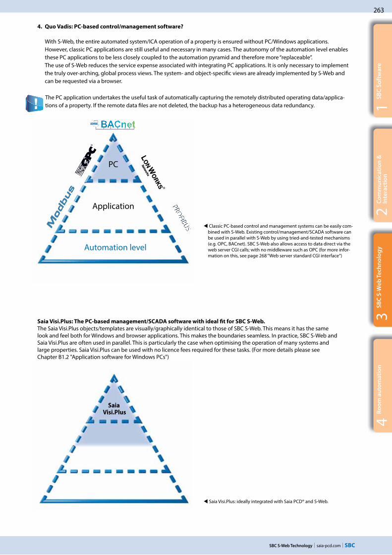
263
saia-pcd.com
2C
om
mu
nic
ati
on
&
Inte
rac
tio
n
SBC S-Web Technology
1S
BC
So
ftw
are
3S
BC
S-W
eb
Te
chn
olo
gy
4R
oo
m a
uto
ma
tio
n
Saia Visi.Plus: The PC-based management/SCADA software with ideal fit for SBC S-Web. The Saia Visi.Plus objects/templates are visually/graphically identical to those of SBC S-Web. This means it has the same look and feel both for Windows and browser applications. This makes the boundaries seamless. In practice, SBC S-Web and Saia Visi.Plus are often used in parallel. This is particularly the case when optimising the operation of many systems and large properties. Saia Visi.Plus can be used with no licence fees required for these tasks. (For more details please see Chapter B1.2 "Application software for Windows PCs")
The PC application undertakes the useful task of automatically capturing the remotely distributed operating data/applica-tions of a property. If the remote data files are not deleted, the backup has a heterogeneous data redundancy.
Classic PC-based control and management systems can be easily com-bined with S-Web. Existing control/management/SCADA software can be used in parallel with S-Web by using tried-and-tested mechanisms (e.g. OPC, BACnet). SBC S-Web also allows access to data direct via the web server CGI calls; with no middleware such as OPC (for more infor-mation on this, see page 268 “Web server standard CGI interface“)
Saia Visi.Plus: ideally integrated with Saia PCD® and S-Web.
4. Quo Vadis: PC-based control/management software?
With S-Web, the entire automated system/ICA operation of a property is ensured without PC/Windows applications. However, classic PC applications are still useful and necessary in many cases. The autonomy of the automation level enables
these PC applications to be less closely coupled to the automation pyramid and therefore more “replaceable”. The use of S-Web reduces the service expense associated with integrating PC applications. It is only necessary to implement
the truly over-arching, global process views. The system- and object-specific views are already implemented by S-Web and can be requested via a browser.
PC
Application
Automation level
Saia Visi.Plus

264
saia-pcd.com
N
S
E
NW
NE
E
N
E
NW
NE
+ + =
Saia PG5 Controls SuiteArt-Nr: 4 717 4882 0
VersionV 2.1.210
Saia-Burgess Controls AG © 2013www.saia-pcd.com
www.sbc-support.com
V 2.1.210
Saia-Burgess Controls AG © 2013www.saia-pcd.com
www.sbc-support.com
Saia PG5 Controls SuiteArt-Nr: 4 717 4882 0
VersionV 2.1.210
Saia-Burgess Controls AG © 2013www.saia-pcd.com
www.sbc-support.com
V 2.1.210
Saia-Burgess Controls AG © 2013www.saia-pcd.com
www.sbc-support.com
SBC S-Web Technology
Management/control system software
Communication middleware e.g. OPC/BACnet stack etc.
Windows version xxxx
Management/control system hardware PC
Local operating unit
ICA unit automation station
Local operating unit
ICA unit automation station
ICA unit automation station
ICA unit automation station
Software operating unit
Software automation station
Software operating unit
Software automation station
Software automation station
Software automation station
System 1
System 1
System 2
System 2
System 3
System 3
System X
System X
The results of lean automation system design specifications with S-Web:
The control/management function will be used where it is required. The automated system uses minimal additional software/hardware. Direct coupling of all devices via Web+IT standards – without middleware/special products.
Superior standard systems and operating stations have access to the system data via special drivers and middleware.
The results of classic tenders:
This technology is installed in properties and then has to be maintained and expanded over the subsequent 15–20 year service life!
Superior standard systems and operating stations have direct access to the system data anytime, anywhere.
Lean automation with slimline structures: Web/IT interfaces and SCADA functions integrated into the ICA device high degree of flexibility and easy to maintain and expand.
Optional local control panel
� Conventional structure with complex hierarchies � consuming installation, inflexible and expensive in maintenance and care.

265
saia-pcd.com
+ + =N
S
E
NW
NE
E
N
E
NW
NE
5"
5.7"
10.4"
15"
12.1"
Éditeur
S-Web SBC
2C
om
mu
nic
ati
on
&
Inte
rac
tio
n
SBC S-Web Technology
1S
BC
So
ftw
are
3S
BC
S-W
eb
Te
chn
olo
gy
4R
oo
m a
uto
ma
tio
n
3.6 Products/tools
Using a SBC S-Web system with devices belonging to the existing infrastructure
Each PC can be used to visualise the Saia PG5® Web HMI pages. The web HMI pages created using the Web Editor are interpreted by a Java applet in the browser on the PC.
Office PC with browser and Java on board
Operating system Browser Java Virtual Machine JVM
Any device made available by an operating system with the support of a browser and Java engine can be used with SBC S-Web.
PC Software
Saia PG5® Web Editor Efficient engineering of graphic interaction interfaces
SBC Micro Browser Dedicated web browser for automation with SBC S-Web. Integrated into Saia PCD® Web Panel MB
SBC micro browser apps for “third-party hardware”
Apple App Android AppSBC.Net Gateway and proxy server functions
Detailed information in Chapter B1 Software Detailed information
in Chapter A2 Operation and monitoring
Detailed information in Chapter A1.1 Saia PCD® System Description
S-Web accessoriesMemory for the automa- tion station to store historical data. Base module for the SD flash memory
PCD3.R600
PCD2.R6000
SD flash memory
512 MBPCD7.R-SD512
1024 MBPCD7.R-SD1024
Memory modulePCD7.R5xx
Industrial web panel with Windows operating system
Immediately operational without software installation
Specifically designed for use with SBC S-Web technology for automated systems.
SBC.Net is pre-installed Ideal for linking Windows applications or proprietary
Microsoft .Net applications to the automation world.
Detailed information can be found in Chapter A2 "Operation and monitoring ".

266
saia-pcd.com SBC S-Web Technology
S-Web pages and S-Web projects are created using Saia PG5® Web Editor
The Saia PG5® Web Editor is designed with simplicity and efficiency in mind. Suitable using web technology. The Web Editor also places no limitation on the number of pages and allows maximum freedom in terms of function and design. If that is what you want and need. A large standard library with graphic objects and templates is provided for normal users.
No specifications for the placement of visible elements. Free graphic design possible.
Create once, use on many devices
An S-Web project which has been created using the Saia PG5® Web Editor can be used simultaneously by various browser devices.The appearance of the page and the operating philosophy do not change. The S-Web application is executed using a standard web browser and Java applet. With Saia PCD® Web Panel the application runs in the SBC Micro Browser, which has been developed specifically for ICA technology/automation.
Projects created using the Web Editor can be used across various devices.
Implementing management and optimisation functions
The trending and alarming functions are stored as templates in the libraries of the Web Editor and can be used direct in this form.Various templates are available for displaying trend curves. All the media in the automation device can be historically recorded and visualised in an online trend curve.The alarming function records and stores alarms and events and visualises current and historical alarms with different template objects.The templates consist of a collection of standard elements. They can be adjusted at any time as required to the applica-tion conditions using Saia PG5® Web Editor. They can also be used as a basis for creating your own collection of templates.
Trending template adjusted to meet the specific needs of the customer
Historical trending with the default template
Alarming with the default template
In Web Editor you are not bound to a fixed grid and are free to structure the design and structure of the web HMI pages. Visualisation elements can be arranged freely. System images can aid the user during operation. The entire application can be split into smaller sectional views across several pages.

267
saia-pcd.com
2C
om
mu
nic
ati
on
&
Inte
rac
tio
n
SBC S-Web Technology
1S
BC
So
ftw
are
3S
BC
S-W
eb
Te
chn
olo
gy
4R
oo
m a
uto
ma
tio
n
Adjustment of S-Web projects after acceptance
The S-Web applications of a Saia PCD® automation station can be adjusted and expanded independently of the local regulation/logic project. The core ICA functions are implemented using the Saia PG5 software tool and loaded into the Saia PCD®. The Saia PG5® Web Editor can also be used to load new S-Web applications into the Saia PCD®. It is also possible for several S-Web projects to work on the same automation device in parallel. This enables users to create sub-projects for specific user groups (e.g. for service or operators). It is therefore possible to influence the diversity of the browser devices being used.
Several HMI applications adjusted/optimised to the respective user groups are possible on one controller.
Using Saia PCD® HVAC Lib and Saia PG5® DDC Suite templates
The Saia PCD® HVAC and Saia PG5® DDC Suite library provide the user with a collection of pre-assembled function and system objects with graphic templates. They are designed for primary HVAC technologies and general building automation systems. The templates can be transferred unmodified and adjusted to the requirements of the application if necessary. A detailed de-scription of the libraries can be found in Chapter B1 Software.
Templates
The Web Editor provides the programmer with a comprehensive template and graphics library for efficient engineering. It is also possible to create your own templates.
Minimal time required to create a successful result
Saia PG5® Web Editor makes it possible to achieve a “basic fit” quickly and efficiently. This means that the basic necessary functions for acceptance are implemented.
The SBC S-Web application can be adjusted at any time during the initial optimisation phase of the system, and subsequently during continuous op-eration to meet actual, individual requirements. The way to good fit and perfect is always open, nothing is installed and nothing is closed off.
Maintenance supervisor
in the officeMobile service
engineerICA
specialist
Graphic icon library
My Templates
HVAC Lib DDC_Suite
Libs
SBC S-Web Editor
The maximum degree of engineering freedom is provided over the entire service life for optimisation and adjustment; for operators, installers and service providers.
15–20 years
Operation requirement
Automation solution
Basic Fit
Automation solution
Good Fit
Operation requirement
Automation solution
Perfect Fit
Operation requirement
Ex Works
Plan Implement Optimise Operate

268
saia-pcd.com
CGI Interface
CGI Interface
kWh
SBC Micro Browser
SBC S-Web Technology
Standard PCD Web Server CGI interface
The COSinus integrated HTTP web server has a standardised Common Gateway Interface (CGI). The CGI interface supports the direct access (reading and writing) to all PCD media (register, flags, DB/texts, I/Os, etc.) as well as on the file system (up/download, delete, …)A client (browser, Java or MS.Net application) can then access the data on a PCD controller by entering the URL and corresponding CGI command direct (with no specific drivers required).
The Saia PCD® Web Server pro-cesses requests/orders via the CGI interface and sends the client the relevant information.
Microsoft.Net or Java already have the categories “WebRequest” and “WebResponse” available for re-quests made to a web server.
Java, .Net Application URL command in web browser
PCD data File system
The Saia PCD® Web Server provides an open CGI interface in addition to the HTTP server.
SBC.Net Suite
The SBC.Net Suite includes components and class libraries for communicating via S-Bus (master and slave) or the CGI interface. It enables the basic integration of Saia PCD® data in a Windows application without worrying about communication drivers (middleware) or CGI syntax. Further information is contained in Chapter B1 Software.
Accessing the Saia PCD® Web Server with MS Office applications
Microsoft Office products support the integration of external web sources. This makes it very easy to visualise the data of a Saia PCD® controller in an MS Office application. The MS Office products can also access via the CGI interface of a Saia PCD® Web Server to read or write data using the VBA programming language.
Saia PCD® data can be linked to a cell using Micro-soft Excel. The data in the linked Saia PCD® will be permanently updated while the Excel application
is running. All this with no specific driver software/middleware required by other systems.
R, F, DB/Text, etc.
PCD data File system
R, F, DB/Text, etc.
Energy 2
Energy 1
DayMonday Tuesday Wednesday Thursday Friday Saturday Sunday
Weekly consumption
Connect

269
saia-pcd.com
SNMP
2C
om
mu
nic
ati
on
&
Inte
rac
tio
n
SBC S-Web Technology
1S
BC
So
ftw
are
3S
BC
S-W
eb
Te
chn
olo
gy
4R
oo
m a
uto
ma
tio
n
3.7 Using an Automation Server as a technical basis for S-Web
Electrician
Maintenance Supervisor
Operator Operations Manager
Programmer
Service Engineer
Users are able to access theautomation device direct for operation and maintenance purposes . There is no need for any extra software, as it simply uses your standard software tools.
Ideally, every automation device will have an Automation Server: each device can be accessed equally, and complex communication hierarchies are unnecessary.
Web Server
The system and process are visualised in the form of web pages and can be requested from the web server using browsers such as Internet Explorer, Firefox, etc.
File system Process data, records, etc. are stored in easy-to-access files. Standard formats make it easy to process them further, e.g. with Microsoft Excel
Flash memory Their large storage capacity means Saia PCD® controllers do not rely on a master PC system, even over a long period. The data storage capac-ity of the Saia PCD® controller can be expanded to up to 4 GB by installing a SD flash card.
FTP Server
Load files into or select files in the automation device over the network using a standard FTP client (e.g. Filezilla).
Critical system statuses, alarms and log data can be sent by email.
SNMP agent
Messages and alarms are transmitted in accord-ance with IT standards. Access to automation data using the IT management system.
SNTP, DHCP, DNS, etc.
Other standard protocols for simple integration into existing IT infrastructures
Automation Server components
An Automation Server is part of the COSinus operating system and is therefore integrated into all Saia PCD® controllers. It com-prises common web/IT technologies and guarantees the exchange of data between the operator/user and automation without any proprietary hardware or software. Specifically adjusted automation functions and objects form the relevant counterpiece in the controller application. The IT/web functions are therefore seamlessly and optimally integrated into the automation device and can be used efficiently.
Automation Server
Fully programmable and expandable
Automation Server
Fully programmable and expandable
Automation Server
Fully programmable and expandable

270
saia-pcd.com SBC S-Web Technology

A
B
C
D
271
B4
saia-pcd.comRoom automation
1S
BC
So
ftw
are
3S
-We
b S
BC
te
chn
olo
gy
2C
om
mu
nic
ati
on
&
Inte
rac
tio
n4
Ro
om
au
tom
ati
on
Room automation
The objective is to maintain a comfortable interior temperature for the user, which should be achieved by consuming a minimal amount of energy. The optimisation potential of occupancy and changes of use can therefore be exploited.
All the SBC components suitable for room automation will be displayed. They will be assigned to various segments and areas of use for a better overview.
The various practical examples of application clearly demonstrate the versatility and efficiency of SBC room automation.
4.2 Room automation with SBC components Page
4.3 Examples of application Page
4.1 The objective of room automation Page
Room automation is a crucial component for room comfort and also reduces operating costs to efficient levels. Energy efficiency therefore plays a vital role along with a comfortable interior temperature and the intuitive operation of the various room functions. This can be achieved by room automation from SBC.
Co
mm
un
ica
tio
n c
ap
ab
ilit
y
CPU
bas
ed S
RC
Co
nfi
gu
rati
on
or
pro
gra
mm
ing
Prog
ram
mab
le S
RCCo
nfigu
rabl
e SR
C
HVAC HVAC + Light & Shade HVAC + Web + IT
Application diversity and area of application
1
2
3
1
2
333
1
2
3
274
276
272

272
saia-pcd.com Room automation
Save building operating costs, lower CO2 emissions and increase user comfort
The objective is to maintain a comfortable interior temperature for the user, which should be achieved by consuming a minimal amount of energy. The optimisation potential of occupancy and changes of use can therefore be exploited. Energy efficiency and conserving resourc-es will become increasingly important in the future and play a decisive role in the implementation of projects. New standards, regulations and laws are constantly being introduced to increase awareness of this.
4.1 Objectives of room automation
The existing potential is also demonstrated through a study by the University of Hannover for Applied Science and Art. In air-conditioning technology, energy savings of over 30% can be achieved and this figure rises to 60% for lighting. Further investi-gations and studies also demonstrate an immense potential for savings.
Standards and regulations
The challenges of changing energy policies and increasingly strict CO2 constraints have resulted in new guidelines. One example is the EPBD, which stipulates the improvement of the overall energy efficiency of new buildings.
European Energy Performance of Buildings Directive –
EPBD
The latest European Directives (2010/31/EU and 2012/27/EU) required Member States to introduce, implement and monitor the quality of building energy efficiency in various areas. The guidelines include a method of calculating overall energy efficiency. Calculation of the energy requirement with additional specifications for heating, ventilation, cooling and electrical energy.
Extract: Technical building systems, such as heating systems, warm water systems, air-conditioning and large ventilation systems, must meet the requirements for overall energy efficiency, regardless of whether they involve new systems or the replacement or modernisation of such systems.
Certain regulations and recommendations exist for room automation in various countries. A brief extract:– DIN EN 15232 “Energy Performance of Buildings: Impact
of Building Automation and Building Management”– VDI 3813-1 “Fundamentals of Room Control”– DIN V 18599 “Energy Efficiency of Buildings”– EnEV Energy Saving RegulationThis topic is described in greater detail based on the following example.
Objectives of room automation
Ensure a reasonable level of comfort during occupancy Cut the cost of energy required for operation Protect the environment and conserve energy resources
A crucial factor here is monitoring, and the user's ability to intervene.
Comfort with room automation
We spend most of our time in closed rooms. This is why the quality of the temperature and conditions in the room is vital for our health and wellbeing and, for functional buildings, the environment also influences productivity at work. In this case, the factors are influenced by various services. These are, for example, the HVAC services (pleasant room temperature and good air quality) and the electrical services (e.g. light for sufficient brightness or blinds to pre-vent glare, the effects of daylight and thermal radiation). An interdisciplinary cooperation of various services and plants is required to control these influencing factors. This can be achieved using cross-plant automation functions and the appropriate components.
Energy and room automation
The building sector accounts for 40% of overall energy consumption in the European Union (EU). Of this, 85% is for room heating and cooling and 15% for electrical energy (particularly lighting).There is enormous potential for energy optimisation here.
Building automation plays a decisive role in this, along with thermal isolation and the use of energy-efficient devices.The complete networking of heating, cooling, ventilation, lighting, shade and additional systems make the building intelligent. This is the key to energy efficiency and optimises the operating costs of a building. The operating phase of a building is crucial, as 80% of the service life costs are accumu-lated in the operating phase. 50% of this figure is energy costs that could be reduced with intelligent building automation.
Operating costs per annum in % of the construction costs
Source: Helbing Study
Administration building
Production building
Traffic facilities
Open-air swimming pools
Indoor sports centres
Indoor swimming pools
Hospitals
Schools / Nursery schools
Administration building
Production building
Traffic facilities
Open-air swimming pools
Indoor sports centres
Indoor swimming pools
Hospitals
Schools / Nursery schools
9%
10%
10%
15%
17%
21%
26%
31%
0% 5% 10% 15% 20% 25% 30% 35%

saia-pcd.com
273
A
B
C
D
0.87
0.93
1
1.10
0.86
0.93
1
1.07
0.90
0.95
1
1.07
A
B
C
D
0.70
0.80
1
1.51
0.80
0.88
1
1.20
0.68
0.85
1
1.31
24h22h20h18h16h14h12h10h8h6h4h2h0h
1.0
0.9
0.8
0.7
0.6
0.5
0.4
0.3
0.2
0.1
0.0
t
24h22h20h18h16h14h12h10h8h6h4h2h0h
1.0
0.9
0.8
0.7
0.6
0.5
0.4
0.3
0.2
0.1
0.0
t
A
B
C
D
A COCO22
1S
BC
So
ftw
are
3S
-We
b S
BC
te
chn
olo
gy
2C
om
mu
nic
ati
on
&
Inte
rac
tio
n
Room automation
4R
oo
m a
uto
ma
tio
n
EN 15232 “Energy Performance of Buildings – Impact of Building Automation and Building Management”
The EU Directive EPBD includes the standard EN15232, which contains the following: A structured list of the control, BA and TGM functions that influence the energy efficiency of buildings. A simplified method to obtain an initial assessment of the influence of these functions on the energy efficiency in typical buildings.
Energy efficiency classes of building automation
Class A: High-energy efficiency room automation and networked plants and services
Class B: Optimal solutions for each plant or service, partially networked Class C: Standard room automation, reference documentClass D: No room automation, not energy efficient
Room automation and its implementation is an important aspect of the assessment!
21%30% 20%20% 16%32%
Office build-ing
Office build-ing SchoolSchool HotelHotel
Energy-saving potentialSavings with electrical energy (lighting/sun protection)
Energy-saving potentialSavings with thermal energy (heating/cooling)
Saving potential by retrofitting Class D in accordance with ASaving potential by retrofitting Class C in accordance with A
Examples of essential measures for the EN 15232 rating:
Class C:
Central control of the room temperature Lighting with manual setting/dimming Simple sun-protection automation
Energy-saving potential
The EN 15232 clearly shows for the first time and in a standardised form the enormous energy-saving potential that exists when managing building technology systems. The amount of energy saved can vary for different building types using a range of user profiles (EN 15217):
Class A:
Networked temperature control for individual rooms Light control in accordance with requirements Networking of blinds and light control with heating, ventilation and air-conditioning systems For VAV: Load-dependent control via an air quality sensor in the room
HotelOffice
Occ
up
an
cy
Occ
up
an
cy

274
saia-pcd.com Room automation
SBC has various products available for room automation. Depending on the task, various components are used for this that were de-scribed in section A. The product groups will be briefly presented again below, and subsequently subdivided. The objective is to assess as quickly as possible when and where certain products can be used to meet the relevant requirements.
4.2 Room automation with SBC components
The products in section A, which lists their technical specifications, will be split into controllers and control units for room automation, and will be described briefly.
4.2.1 Product overview for room automation applications
Controllers:
PCD7.L79xN Compact room controller
PCD7.L6xx Combinable room controller system
PCD1 E-Line Programmable E-Line modules
PCD1 Room PCD1 with Ethernet TCP/IP for room automation applications
PCD controllers all additional Saia PCD automation stations
Control units:
PCD7.L6xx Room control units for the combinable room controller system
PEHA Room control units from PEHA (EnOcean, PHC) or other manufacturers
PCD7.D443 Room Panel
PCD7.D4xx Web Panel MB and PWeb Panel MB
Controllers
PCD7.L79xN Compact room controllers
The series of compact room controllers is particularly suitable for simple systems which involve heating and/or cooling. The PCD7.L79xN series room controllers include the control of presence and setpoint values, the room temperature sensor and the valve or flap control in a single housing. The integrated regulation and control program is a component of the basic software and can be configured and parameterised using network com-munication via Saia PG5. Fully independent functionality is guaranteed, even with no bus connection.
PCD7.L6xx Combinable room control system
A combinable control system can be used to automate systems with a higher requirements profile, such as fan coil applications or the integration of light and shade. The PCD7.L6xx series comprises several base controllers, the expansion modules for the activation of light and shade and a range of room control units. This series also has an integrated regulation and control program as a component of the basic software and can be extensively configured and parameterised using network communication. Fully independent functionality is guaranteed, even with no bus connection.
PCD1 E-Line (PCD1.Xxxx-C15)
E-Line modules for room automation are fully programmable with Saia PG5. The inputs, outputs and interfaces are tailored to the demands of modern room automation. The I/O mix is, for example, optimally adjusted for light and shade functions. The programmable PCD1 E-Line series enables separate and secure operation of the modu-les, even if communication to the master station is interrupted. This ensures the local function at all times, i.e. of a room. The requirements in the room automation, zone controls or remote tasks are constantly increasing. The E-Line series provides the greatest reliability and can be used flexibly throughout its entire service life.
PCD1.Room
Saia PCD1.Room (PCD1.M2110R1) is a programmable room controller for complex solutions with many commu-nication options. In addition, Saia PCD1.Room offers numerous options for integrating additional systems in the room via standard communication interfaces, such as BACnet, for example. (Energy-) efficient and individu-al room automation can therefore be easily implemented. The controller also provides a good basis to achieve the energy efficiency classes in accordance with EN 15232:2012.

saia-pcd.com
275
1S
BC
So
ftw
are
3S
-We
b S
BC
te
chn
olo
gy
2C
om
mu
nic
ati
on
&
Inte
rac
tio
n
Room automation
4R
oo
m a
uto
ma
tio
n
Saia PCD® controllers
Saia PCD controllers have sufficient system resources to operate up to 13 communication interfaces in the same device. Even the most demanding tasks, such as simultaneous commu-nication via BACnet® and LON IP, can be managed reliably. Any challenge can be met with a Saia PCD owing to its flexible operation and high level of reliability.
PCD7.L6xx control units for the combinable room control system
Control units are available for the Saia PCD7.L6xx combinable room controller that can be con-nected direct to the reader via the RC-Bus or the input terminals. A range of room controllers with analogue, digital or wireless connections are available for this. This enables the operation for temperature values, ventilation, light, shade and presence. This product family portfolio is rounded off by a high-quality 3.2” touch screen room controller.
Room controllers from PEHA
Control units from the PEHA are an outstanding addition to the Saia PCD controllers. The room control units using EnOcean or PEHA PHC connection (RS-485) combined with the fully programmable PCD1 E-Line products for example, are ideally suited for room automation ap-plications. A wide range of control units is available which are easy to operate.
PCD7.D443WTxR Room Panels
The programmable panels have an attractive design. Independent room applications with the integrated logic controller enable the control of room functions without a head station. Delays through long communication channels associated with this are eliminated. The temperature of the room or zone can also be determined and transmitted to another controller. The graph-ics can be customised and therefore adjusted for any requirement.
PCD7.D4xx Web Panels MB and pWeb Panels MB
The Saia PCD7.D4xx Web Panel MB and pWeb Panel MB are equally suitable for room auto-mation. This is particularly true when executing and displaying tasks of greater complexity. The use of the S-Web technology combined with the micro browser panel systems is a great advantage. The operation can be displayed transparently and clearly for every user. Each indi-vidual control side has a flexible design and can be created with Saia PG5 using the standard objects or existing function templates.
Control units

276
saia-pcd.com Room automation
4.2.2 Segmentation of the room componentsC
om
mu
nic
ati
on
ca
pa
bil
ity
CPU
bas
ed S
RC*
Co
nfi
gu
rati
on
or
pro
gra
mm
ing
Prog
ram
mab
le S
RC*
Confi
gura
ble
SRC*
HVAC HVAC + Light & Shade HVAC + Web + IT
Application diversity and area of application
There are three main areas. The classifi- cation of the products is based on the following main points and features:
Application diversity and area of
application Is only a single light, a single heating circuit controlled in one room, or are additional tasks to be performed and other influences?
Configuration or programming Pure configurations or flexible program-ming throughout the entire service life?
Communication capability S-Bus and other communications protocols such as DALI, EnOcean,… or web functionalities are supported.
Configurable room controllers with S-Bus or LON are required to implement an HVAC application.The main applications that can be implemented with these SBC components are heating and/or cooling, fan coil or variable flow regulation with air quality control.
Configurable or programmable room controllers are required to implement an HVAC, light and/or shade application. Configurable room controllers (PCD7.L6) are recom-mended for standard applications. Programmable E-Line modules are preferable where applications require greater flexibility. These components enable cross-plant room automation with control in accordance with need and communication with the primary system. The highest energy efficiency class in accordance with DIN EN 15232 can there-fore be achieved.
The greatest communication diversity, Web-/+IT-functionalities and total flexibility are required for the programming. An example would be a Saia PCD1 with DALI interface, EnOcean connection, BACnet and web operation.
Se
gm
en
t /
Fie
ld 1
Se
gm
en
t /
Fie
ld 2
Se
gm
en
t /
Fie
ld 3
*SRC: Single Room Controller
1
2
3
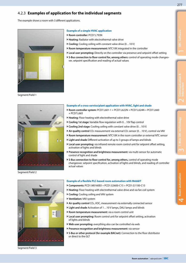
saia-pcd.com
277
1S
BC
So
ftw
are
3S
-We
b S
BC
te
chn
olo
gy
2C
om
mu
nic
ati
on
&
Inte
rac
tio
n
Room automation
4R
oo
m a
uto
ma
tio
n
The example shows a room with 3 different applications.
4.2.3 Examples of application for the individual segments
Example of a simple HVAC application
Room controller: PCD7.L793N
Heating: Radiator with electrothermal valve drive
Cooling: Cooling ceiling with constant valve drive (0…10 V)
Room temperature measurement: NTC10K integrated in the controller
Local user prompting: Directly on the controller via presence and setpoint offset setting
S-Bus connection to floor control for, among others: control of operating mode changeo-ver, setpoint specification and reading of actual values
Example of a cross-service/plant application with HVAC, light and shade
Room controller system: PCD7.L601-1 + PCD7.L622N + PCD7.L624N + PCD7.L660 + PCD7.L665
Heating: Floor heating with electrothermal valve drive
Cooling 1st stage: Variable flow regulation with 0…10V flap control
Cooling 2nd stage: Cooling ceiling with constant valve drive (0…10 V)
Air quality control CO2 measurement via external CO2 sensor (0…10 V), control via VAV
Room temperature measurement: NTC10K in the room controller or external NTC sensor
Light and shade Different activation of up to 3 groups of lamps and blinds
Local user prompting: via infrared remote room control unit for setpoint offset setting, activation of lights and blinds
Presence recognition and brightness measurement: via multi-sensor for automatic control of light and shade
S-Bus connection to floor control for, among others, control of operating mode changeover, setpoint specification, activation of lights and blinds, and reading of controller actual values
Example of a flexible PLC-based room automation with Web&IT
Components: PCD1.M0160E0 + PCD1.G3600-C15 + PCD1.G1100-C15
Heating: Floor heating with electrothermal valve drive and via fan coil system
Cooling: Cooling ceiling and VAV system
Ventilation: VAV system
Air quality control CO2, VOC, measurement via externally connected sensor
Light and shade Activation of 1…10 V lamps, DALI lamps and blinds
Room temperature measurement: via a room control unit
Local user prompting: Room control unit for setpoint offset setting, activation of lights and blinds
Web user prompting: everything also can be controlled via web
Presence recognition and brightness measurement: via sensor
S-Bus or other protocol (for example BACnet): Connection to the floor distributor or direct to the GLT
Segment/Field 1
Segment/Field 2
Segment/Field 3

278
saia-pcd.com
5540
Saia PCD3.M
5540
Saia PCD3.M
5540
Saia PCD3.M
Room automation
4.3 Examples of application
In addition to the right selection of components, the architectural structure and the basic concept play a decisive role. There are many possibilities and approaches for implementing room automation. However, there is no “single” solution for all areas of application. Depending on the purpose, the choice of the best concept will vary. Some approaches and features:
Example of a room box for hotel rooms:
Fully pre-assembled, easy commissioning and replaceable if defective.
For example the operation of a conference room:
Each browser and every mobile device can now serve as a control station. Each room is thereby represented accurately and shows each user group only what it requires.
Networked room automation
Full networking of all plants and services is increasingly required. One example of application is that the cooling requirement (HVAC service) in summer can be reduced with controlled blinds (electrical plant). All plants also only require a single control unit rather than several different devices. A web-based control concept can be created using Saia PCD including Web + IT functionalities. This can be used subsequently for commissioning, operation and service.
Room boxes
These are ideal if the rooms or their applications are largely identical and/or are numerous, i.e. in hotels and office rooms. The boxes are manufactured and tested prior to installation in accordance with the requirements. The commissioning can thereby be 100% planned and controlled based on the installation time. Only the mounting, connection (usually with finished cable), testing, etc. is carried out on site. …The simple and efficient maintenance and servicing of the system is also possible. The plug-in system of box A ensures quick and seamless “plug & play” installation and replacement. Servicing is less time-consuming. POM for commissioning and servicing.
Room automation with distributed intelligence
Components are distributed throughout the floor or room. These are also installed where they are needed, i.e. the controller for the shade system located near the blinds. The cabling takes less time, the devices also function independently (= secure operation).
Room automation from a central point
A sub-distribution per floor or section supplies several rooms. The control of lighting with DALI for several rooms would be a practical example of application. More cabling is involved with this variant. However, all components are located at a central point, which makes maintenance work more efficient.

C
saia-pcd.com
Annex
C1 Status: Product launch and availability
C2 Abbreviations
C3 Type Index
C – Annex
279
281
283


279
saia-pcd.com
C1
1 2 3 4 5
%100 %
70 %
33 %
95 %
1P
rod
uc
t L
au
nch
2A
bb
rev
iati
on
s
3T
yp
e I
nd
ex
Product status and availability
Release status of products
Product maturation is an evolutionary process and follows a maturation and learning curve. It starts with a product idea, which many people and divisions within the company then work on for a long time to reach all the new prod-uct’s various targets. These targets represent the function and design of the product. The manufacturer’s perfor-mance and quality standards must also be achieved.
At Saia Burgess Controls the product maturation process is represented with colour codes. These are described in the table below. These colour codes are used on a dedicated web-page: http://www.sbc-support.com/en/services/product-status. They document the actual status of all products currently in field trials or market launch. Please consult the web-page if you wish to use a roduct marked in this catalogue as „* Not released at time of printing“.
Function/design Logistics/availability Support
blue Series production improvements have been incorporated. Final polish applied to design and function.
Product quantities have reached tar-get volume and flow smoothly even when demand surges.
Training for product is standard-ized. Online support and FAQs established.
green Products are available in series production quality and may be used with no particular technical constraints or risks.
Unrestricted sale. Products from our own production are available ex stock. Shipping volume is on the rise.
All SBC sales and support organiza-tions have the necessary product skills. Its use can be fully supported.
orange Products are available in series pro-duction quality. In the pilot phase, any deficits of function or design are found and corrected.
Products for ‘restricted’ sale. Delivery not yet ex stock. Quantity limited. Customers are informed about pilot status of product.
Product is known throughout organization. Support capability is still limited to a few individuals.
red Laboratory and functional models are available for laboratory and field trials. Not for sale. Not for use in customer production setting.
No product orders accepted. Sched-uling in a new key project may well be possible. Inquire about delivery dates!
Developers and product managers advise on function and look after laboratory and field trials.
Meaning of product status colour codes
Natural learning curve when introducing products into manufacturing, logistics, support, documentation and function
Target delivery performance– 80 % of deliveries in 2 working days– 95 % of deliveries in < 1 week– On-time delivery > 98.5 %
Target level
Delivery time in days
Functional scope
Freedom from errors
Advisory performance
Delivery performance
Status: Product launch and availability
Time
* Not released at time of printing. For information about product status, see page XXX.

280
saia-pcd.com Product status and availability

281
saia-pcd.com
C2
1P
rod
uc
t L
au
nch
2A
bb
rev
iati
on
s
3T
yp
e I
nd
ex
Abbreviations
Abbreviations
Abbreviation Written out / Explanation
3G Third generation of mobile telecommunications technology
ADSL Asymmetric digital subscriber line (ADSL)
ASCII The American Standard Code for Information Interchange, is a 7 bit character-encoding scheme
CCFLCold cathode fluorescent lamp (CCFL) are used for backlighting of LCDs, for example computer monitors and television screens
CGICommon Gateway Interface (CGI) is a standard method used to generate dynamic content on Web pages and Web applications
CO2 / CO2
Carbon dioxide (chemical formula CO2) is a naturally occurring chemical compound composed of 2 oxygen atoms each covalently double bonded to a single carbon atom.
COB
A Saia PCD program is a tree-like structure of organization blocks which contain the application‘s code. Each block provides a particular service: cyclical programming (COB), sequential programming (SB), sub-programs (PB), functions with parameters (FB), and exception routines (XOB)
CPUA central processing unit (CPU) is the electronic circuitry within a computer that carries out the instructions of a computer program by performing the basic arithmetic
CSVA comma-separated values (CSV) (also sometimes called character-separated values, because the separator character does not have to be a comma) file stores tabular data (numbers and text) in plain-text form
DHCP
The Dynamic Host Configuration Protocol (DHCP) is a standardized network protocol used on Internet Protocol (IP) networks for dynamically distributing network configuration parameters, such as IP addresses for interfaces and services
DINDeutsches Institut für Normung e.V. (DIN; in English, the German Institute for Standardization) is the German national organization for standardization and is the German ISO member body
DSLDigital subscriber line (DSL; originally digital subscriber loop) is a family of technologies that provide internet access by transmitting digital data using a local telephone network which uses the public switched telephone network
DTMFDual-tone multi-frequency signaling (DTMF) is used for telecommunication signaling over analog telephone lines in the voice-frequency band between telephone handsets and other communications devices and the switching center
FB
A Saia PCD program is a tree-like structure of organization blocks which contain the application‘s code. Each block provides a particular service: cyclical programming (COB), sequential programming (SB), sub-programs (PB), functions with parameters (FB), and exception routines (XOB)
FBox
The graphical function boxes (FBoxes) have inputs and outputs, and can also have configurable properties using parameter windows which can also be modified online. Around 250 FBoxes are already provided in the basic PG5 package. The range of functions goes far beyond the normal binary and arithmetic functions.
EHA Exhaust air
FTPThe File Transfer Protocol (FTP) is a standard network protocol used to transfer computer files from one host to another host over a TCP-based network, such as the Internet
FUPLA FUPLA is SBC’s own function block diagram editor
FW Firmware
BA Building Automation
BMS Building management system
HVAC HVAC (heating, ventilating, and air conditioning) is the technology of indoor and vehicular environmental comfort
HVACSE Heating, ventilating, air conditioning, sanitary and electric
HMI Human Machine Interface
HPA horizontal pitch, short HP, is a unit of measurement to describe the width of assemblies. Electrical installation switchboards corresponds a HP to 17,5 mm according to DIN 43880
HTML HTML or HyperText Markup Language is the standard markup language used to create Web pages
HTTPThe Hypertext Transfer Protocol (HTTP) is an application protocol for distributed, collaborative, hypermedia information systems
HW Hardware
ICA technology Instrumentation, Control and Automation technology
IL Instruction List

282
saia-pcd.com Abbreviations
Abbreviation Written out / Explanation
IR Infrared
LDLadder diagram a method of drawing electrical logic schematics. A ladder diagram represents a program in ladder logic
MBThe Micro-Browser application allows the visualization and operation of web projects which have been created with Saia PG5® Web Editor
MID Measurement Instrument Directive
MTBF Mean time between failure
OEMOriginal equipment manufacturer (OEM) is a term used when one company makes a part or subsystem that is used in another company‘s end product
OPCOLE for Process Control (OPC), which stands for Object Linking and Embedding (OLE) for Process Control. The standard specifies the communication of real-time plant data between control devices from different manufacturers
PB
A Saia PCD program is a tree-like structure of organization blocks which contain the application‘s code. Each block provides a particular service: cyclical programming (COB), sequential programming (SB), sub-programs (PB), functions with parameters (FB), and exception routines (XOB)
PGU
ProGramming Unit This term designates the programming console, but also by extension the port where the console must be connected. The PGU designates also the protocol used by the programming console.
RC-bus Internal data bus to connect digital room control devices or extension modules (Remote Control Bus)
RIO Remote Inout/Output
RTU Remote Terminal Unit or Remote Telemetry Unit, a microprocessor controlled electronic device
SCADA Supervisory Control and Data Acquisition
S-IO The S-IO protocol supports the operation of SBC remote I/O stations
SMTP Simple Mail Transfer Protocol (SMTP) is an Internet standard for electronic mail (e-mail) transmission
SNMP Simple Network Management Protocol (SNMP) is an „Internet-standard protocol for managing devices on IP networks“.
SNTPIs known as the Simple Network Time Protocol (SNTP). It is used in some embedded devices and in applications where high accuracy timing is not required
SNVT
One of the keys to the interoperability of the system is the standardisation of the variables used to describe physical things to LonWorks. This standards list is maintained by LonMark International and each standard is known as Stan-dard Network Variable Types (SNVTs, pronounced „sniv-its“)
PLC
A programmable logic controller, PLC or programmable controller is a digital computer used for automation of typical-ly industrial electromechanical processes, such as control of machinery on factory assembly lines, amusement rides, or light fixtures
SRC Single Room Controller
STN A super-twisted nematic display (STN) is a type of monochrome passive-matrix liquid crystal display (LCD)
SUP Supply air
SW Software
TCP/IP
The Internet protocol suite is the computer networking model and set of communications protocols used on the Internet and similar computer networks. It is commonly known as TCP/IP, because its most important protocols, the Transmission Control Protocol (TCP) and the Internet Protocol (IP)
TFTA thin-film-transistor liquid-crystal display (TFT LCD) is a variant of a liquid-crystal display (LCD) that uses thin-film transistor (TFT) technology to improve image qualities such as addressability and contrast
URLA uniform resource locator (abbreviated URL; also known as a web address, particularly when used with HTTP) is a specific character string that constitutes a reference to a resource
VAV Variable Air Volume (VAV) is a type of heating, ventilating, and/or air-conditioning (HVAC) system
VOC Volatile Organic Compounds
VPN A virtual private network (VPN) extends a private network across a public network, such as the Internet
WANA wide area network (WAN) is a network that covers a broad area (i.e., any telecommunications network that links across metropolitan, regional, national or international boundaries) using leased telecommunication lines
XOB
A Saia PCD program is a tree-like structure of organization blocks which contain the application‘s code. Each block provides a particular service: cyclical programming (COB), sequential programming (SB), sub-programs (PB), functions with parameters (FB), and exception routines (XOB)
Sources: our manuals and www.wikipedia.org

283
saia-pcd.com
C3
1P
rod
uc
t L
au
nch
2A
bb
rev
iati
on
s
3T
yp
e I
nd
ex
Type Index
Type Index
Art
icle
We
igh
t
[g]
Ca
talo
gu
e
pa
ge
3 230 9178-001 24 107
3 230 9178-002 36 107
4 104 7420 0 1 141
4 104 7485 0 4 141
4 104 7493 0 10 34
4 104 7502 0 8 34
4 104 7515 0 8 34
4 104 7719 0 189 65
4 104 7720 0 189 65
4 104 7758 0 106 65
4 104 7759 0 56 71, 75
4 121 4910 0 70 ---
4 310 8686 0 2 33, 34
4 310 8723 0 100 33, 34
4 310 8750 0 61 ---
4 310 8755 0 21 ---
4 310 8756 0 21 ---
4 329 4819 1 1 33, 34
4 405 4847 0 17 65
4 405 4869 0 9 65
4 405 4916 0 20 65
4 405 4917 0 20 65
4 405 4918 0 20 65
4 405 4919 0 20 65, 71, 153
4 405 4920 0 20 65
4 405 4921 0 9 ---
4 405 4933 0 7 ---
4 405 4934 0 8 34
4 405 4936 0 11 34
4 405 4952 0 15 34
4 405 4954 0 15 34
4 405 4955 0 16 ---
4 405 4956 0 15 34
Art
icle
We
igh
t
[g]
Ca
talo
gu
e
pa
ge
4 405 4995 0 12 34
4 405 4998 0 13 34
4 405 5027 0 6 34
4 405 5028 0 4 34
4 405 5048 0 6 34, 65
4 405 5054 0 9 65
4 405 5055 0 9 ---
4 405 5056 0 9 ---
4 405 5057 0 9 ---
4 405 5066 0 11 40
4 405 5079 0 5 ---
4 405 5087 0 8 71, 75, 153
4 405 5088 0 9 71, 75, 153
4 405 5089 0 10 71, 75, 153
4 507 4817 0 334, 63, 65,
71, 75, 153
4 639 4898 0 10 34, 55, 65
AAD1D5D10KR2A01 87 ---
AAD1D5F10KR2A00 90 ---
AAD1D5F10KR3A00 93 ---
AAE1D5F10KR2A00 115 ---
AAE1D5F10KR3A00 130 140
AAE3D5F10PR2A00 209 ---
AAE3D5F10PR3A00 208 ---
AAE3D5F11PR2A00 115 ---
AAE3D5F11PR3A00 220 ---
ALD1B5F10KA2A00 75 ---
ALD1B5F10KA3A00 75 134, 140
ALD1B5FD00A3A00 80 134, 140
ALD1B5FS00A2A00 97 ---
ALD1B5FS00A3A00 97 134, 137
ALD1D5F10KA2A00 89 ---
ALD1D5F10KA3A00 89 134, 140
ALD1D5F10KB2A00 89 ---
Art
icle
We
igh
t
[g]
Ca
talo
gu
e
pa
ge
ALD1D5F10KB3A00 89 ---
ALD1D5FD00A3A00 80 134, 139
ALD1D5FD00A3A44 80 139
ALD1D5FM00A3A00 98 134, 138
ALD1D5FS00A2A00 80 ---
ALD1D5FS00A3A00 80 134, 137
ALE3B5F10KC2A00 215 ---
ALE3B5F10KC3A00 215 134, 140
ALE3B5FD00C3A00 230 134, 139
ALE3B5FM00C3A00 190 134, 138
ALE3B5FS00C2A00 230 ---
ALE3B5FS00C3A00 230 134, 137
ALE3D5F10KA2A00 212 ---
ALE3D5F10KA3A00 212 134
ALE3D5F10KB2A00 214 ---
ALE3D5F10KB3A00 212 ---
ALE3D5F11KC3A00 219 140
ALE3D5FD10C3A00 230 134, 139
ALE3D5FD10C3A44 230 139
ALE3D5FM10C3A00 224 134, 138
ALE3D5FS10C2A00 228 ---
ALE3D5FS10C3A00 230 134, 137
AWC3D5WS00C2A00 190 ---
AWD1D5WS00A2A00 97 ---
AWD3B5W10MC2A00 190 ---
AWD3B5W10MC3A00 217 134, 140
AWD3B5WS00C2A00 190 ---
AWD3B5WS00C3A00 190 134, 137
AWD3D5W10MC2A00 213 ---
AWD3D5W10MC3A00 216 134, 140
AWD3D5W10ND3A00 216 ---
AWD3D5WD00C3A00 224 134, 139
AWD3D5WD00C3A44 224 139

284
saia-pcd.com Type Index
Art
icle
We
igh
t
[g]
Ca
talo
gu
e
pa
ge
AWD3D5WM00C3A00 221 134, 139
AWD3D5WS00C2A00 226 ---
AWD3D5WS00C3A00 226 134, 137
AWD3D5WS00D2A00 226 ---
CJ211 52 ---
CJ250 40 ---
EMD1L5F1KA00 --- 134, 140
KFD11JVTN 117 166
KFD12JVTN 116 167
KFE102NE1N 200 171
KFE103NE1N 200 171
KFE300NE9N 200 171
KFE302NE9N 200 171
KFT100JE1N 160 171
KFT200KE1N 200 171
KOL111H7MRR1N00 60 ---
KOL112H7MRR1N00 60 ---
KOL121H7MRR1N00 60 ---
KOL142H7MRR1N00 60 ---
KOL160H7MRR1N00 60 ---
KOL251H7MKVPN00 60 170
KOL311H7MRVPN00 60 ---
KOL312H7MRVPN00 60 ---
KOL321H7MRVPN00 60 ---
KOL342H7MRVPN00 60 ---
KOL360H7MRVPN00 60 170
KOP111J7MWVPN00 120 ---
KOP112J7MWVPN00 124 ---
KOP119K7MWVAN00 120 ---
KOP128J7BAVPN00 120 ---
KOP128J7CAVPN00 120 ---
KOP128J7EAVPN00 120 ---
KOP160J7MWVAN00 120 ---
KOP160J7MWVPN00 120 170
KOP170J7MWVPN00 120 170
KOP219K7MWVAN00 120 170
KOP260F0MWVAN00 120 ---
Art
icle
We
igh
t
[g]
Ca
talo
gu
e
pa
ge
KOP511K7MWVPN00 140 ---
KOP512K7MWVPN00 140 ---
KOP560K7MWVAN00 160 ---
KOP560K7MWVPN00 160 170
PCD1.B1000-A20 385 91
PCD1.B1010-A20 385 91
PCD1.B1020-A20 353 91
PCD1.F2611-C15 129 89, 223, 246
PCD1.G1100-C15 140 85, 223, 277
PCD1.G3600-C15 325 87, 223, 277
PCD1.G3601-C15 332 87, 223
PCD1.G5000-A20 389 91
PCD1.G5010-A20 362 91
PCD1.G5020-A20 360 91
PCD1.K0206-005 365 87, 91
PCD1.K0206-025 365 91
PCD1.M0160E0 300150, 222, 237, 248,
277
PCD1.M2020 400 68
PCD1.M2110R1 45072, 222,
245, 246, 274
PCD1.M2120 400 68, 222, 245, 257
PCD1.M2160 40068, 145,
222, 245, 257
PCD1.M2220-C15 55014, 81,
222, 238, 240
PCD1.W5300-C15 120 88, 223
PCD2.A200 60 60
PCD2.A210 60 60
PCD2.A220 65 60
PCD2.A250 65 60
PCD2.A300 45 60
PCD2.A400 40 60
PCD2.A410 40 60
PCD2.A460 40 60
PCD2.A465 35 60
PCD2.B100 45 60
PCD2.B160 50 60
Art
icle
We
igh
t
[g]
Ca
talo
gu
e
pa
ge
PCD2.C1000 500 55, 58, 60, 65, 174
PCD2.C2000 1040 55, 58, 60, 65, 174
PCD2.E110 35 60
PCD2.E111 35 60
PCD2.E112 35 60
PCD2.E116 35 60
PCD2.E160 40 60
PCD2.E161 40 60
PCD2.E165 40 60
PCD2.E166 40 60
PCD2.E500 55 60
PCD2.E610 40 60
PCD2.E611 40 60
PCD2.E613 50 60
PCD2.E616 50 ---
PCD2.F2100 60 62, 70, 74, 82, 222
PCD2.F2150 6062, 70, 74,
82, 222, 238
PCD2.F2210 6062, 70, 74,
82, 222, 248
PCD2.F2400 6062, 70, 74,
82, 222, 240, 248
PCD2.F2610 4062, 70, 74,
82, 222, 246
PCD2.F2700 4062, 70, 74,
82, 222, 245
PCD2.F2710 4062, 70, 74,
82, 222, 245
PCD2.F2720 4062, 70, 74,
82, 222, 245
PCD2.F2730 4062, 70, 74,
82, 222, 245
PCD2.F2810 6062, 70, 74,
82, 222, 248
PCD2.G200 80 61
PCD2.H112 24 60
PCD2.H114 27 60
PCD2.H150 20 ---
PCD2.H222 25 ---
PCD2.H310 33 ---

285
saia-pcd.comType Index
1P
rod
uc
t L
au
nch
2A
bb
rev
iati
on
3T
yp
e I
nd
ex
Art
icle
We
igh
t
[g]
Ca
talo
gu
e
pa
ge
PCD2.H311 20 ---
PCD2.K010 40 58, 65
PCD2.K106 100 58, 65, 174
PCD2.K221 240 34, 65, 172
PCD2.K223 330 34, 65, 172
PCD2.K231 140 34, 65, 172
PCD2.K232 220 34, 65, 172
PCD2.K241 120 34, 65, 172
PCD2.K242 200 34, 65, 172
PCD2.K261 100 ---
PCD2.K263 445 ---
PCD2.K271 100 ---
PCD2.K273 290 ---
PCD2.K281 200 ---
PCD2.K283 650 ---
PCD2.K510 100 34, 65, 173
PCD2.K511 100 34, 65, 173
PCD2.K520 150 34, 65, 173
PCD2.K521 150 34, 65, 173
PCD2.K525 280 34, 65, 173
PCD2.K551 340 34, 65, 173
PCD2.K552 400 34, 65, 173
PCD2.M4160 89055, 65,
222, 238, 240
PCD2.M4560 92055, 65,
222, 238, 240
PCD2.M5440 1000 ---
PCD2.M5540 146057, 65,
222, 237, 238
PCD2.R6000 120 16, 63, 265
PCD2.T814 120 62
PCD2.W200 35 61
PCD2.W210 35 61
PCD2.W220 40 61
PCD2.W220Z02 45 61
PCD2.W220Z12 45 61
PCD2.W300 40 61
PCD2.W305 45 61
Art
icle
We
igh
t
[g]
Ca
talo
gu
e
pa
ge
PCD2.W310 40 61
PCD2.W315 45 61
PCD2.W325 45 61
PCD2.W340 40 61
PCD2.W350 40 61
PCD2.W360 40 61
PCD2.W380 40 61
PCD2.W400 40 61
PCD2.W410 45 61
PCD2.W525 50 61, 73
PCD2.W600 40 61
PCD2.W605 45 61
PCD2.W610 45 61
PCD2.W615 45 61
PCD2.W625 45 61
PCD2.W720 40 61
PCD2.W745 40 61
PCD3.A200 100 27
PCD3.A210 120 27
PCD3.A220 100 27
PCD3.A251 120 27
PCD3.A300 100 27
PCD3.A400 100 27
PCD3.A410 100 27
PCD3.A460 80 27
PCD3.A465 80 27
PCD3.A810 100 27
PCD3.A860 120 27
PCD3.B100 100 27
PCD3.B160 100 27
PCD3.C100 420 21, 29, 33, 35
PCD3.C110 260 21, 29, 33, 35, 40, 43
PCD3.C110Z09 260 40, 43
PCD3.C200 44021, 29, 33, 34, 35, 40,
43, 174
PCD3.C200Z09 440 40, 43
PCD3.E009 40 34
Art
icle
We
igh
t
[g]
Ca
talo
gu
e
pa
ge
PCD3.E110 80 27
PCD3.E111 80 27
PCD3.E112 100 ---
PCD3.E116 80 ---
PCD3.E160 80 27
PCD3.E161 80 27
PCD3.E165 100 27
PCD3.E166 100 27
PCD3.E500 100 27
PCD3.E610 80 27
PCD3.E613 80 27
PCD3.F110 100 31, 222
PCD3.F121 100 31, 222
PCD3.F150 100 31, 222
PCD3.F180 100 31, 222
PCD3.F210 100 31, 222, 248
PCD3.F215 100 31, 222, 238
PCD3.F221 100 31, 222, 248
PCD3.F240 10031, 34,
222, 240, 248
PCD3.F261 100 31, 37, 52, 222, 246
PCD3.F270 80 31, 37, 52, 222, 245
PCD3.F271 80 31, 37, 52, 222, 245
PCD3.F272 80 31, 37, 52, 222, 245
PCD3.F273 80 31, 37, 52, 222, 245
PCD3.F281 100 31, 222, 248
PCD3.H112 80 27
PCD3.H114 100 27
PCD3.H150 100 ---
PCD3.H222 100 ---
PCD3.H310 100 ---
PCD3.H311 100 ---
PCD3.K010 40 21, 29, 35, 40, 43
PCD3.K106 140 21, 29, 35, 40, 43
PCD3.K116 180 21, 29, 35, 40, 43
PCD3.K225 180 38

286
saia-pcd.com Type Index
Art
icle
We
igh
t
[g]
Ca
talo
gu
e
pa
ge
PCD3.K261 140 ---
PCD3.K263 260 ---
PCD3.K281 220 ---
PCD3.K283 380 ---
PCD3.K800 280 ---
PCD3.K810 440 ---
PCD3.M2030V6 920 223
PCD3.M2130V6 920 39, 223
PCD3.M2230A4T5 920 223
PCD3.M2330A4T1 940 41, 223
PCD3.M2330A4T3 960 41, 223
PCD3.M2330A4T5 920 41, 223
PCD3.M3020 640 ---
PCD3.M3120 820 25, 222, 238
PCD3.M3160 820 25, 222, 238, 240
PCD3.M3230 640 ---
PCD3.M3330 64025, 37,
222, 238, 240
PCD3.M3360 640 25, 222, 238, 240
PCD3.M5340 80018, 24, 37, 222, 237, 238, 240
PCD3.M5360 800 22, 222, 238, 240
PCD3.M5440 820 237
PCD3.M5540 82024, 222,
237, 238, 240
PCD3.M5560 820
23, 37, 49, 222, 234, 237, 238,
240
PCD3.M6560 820 23, 37, 222, 237
PCD3.M6860 82023, 37, 50, 222, 234,
237
PCD3.M6880 820 45, 47, 49, 50, 222
PCD3.R010 60 34
PCD3.R550M04 60 32, 257, 258
PCD3.R551M04 60 ---
PCD3.R560 80 32, 239
PCD3.R562 80 32, 239
PCD3.R580 60 32, 241
PCD3.R582 60 32, 241
Art
icle
We
igh
t
[g]
Ca
talo
gu
e
pa
ge
PCD3.R600 80 16, 32, 265
PCD3.S100 180 ---
PCD3.T665 460 35, 37, 183, 222
PCD3.T666 48035, 37,
183, 222, 246
PCD3.T668 480 45, 47, 51, 52
PCD3.T760 460 19, 38, 232, 236
PCD3.W200 100 28
PCD3.W210 80 28
PCD3.W220 80 28
PCD3.W220Z03 80 28
PCD3.W220Z12 80 28
PCD3.W300 100 28
PCD3.W305 100 28
PCD3.W310 80 28
PCD3.W315 100 28
PCD3.W325 100 28
PCD3.W340 80 28
PCD3.W350 80 28
PCD3.W360 80 28
PCD3.W380 80 28
PCD3.W400 80 28
PCD3.W410 100 28
PCD3.W525 100 28
PCD3.W600 80 28
PCD3.W605 80 28
PCD3.W610 100 28
PCD3.W615 100 28
PCD3.W625 100 28
PCD3.W720 80 28
PCD3.W745 100 28
PCD3.W800 80 28
PCD7.D170 260 ---
PCD7.D230 380 ---
PCD7.D230Z11 380 ---
PCD7.D231 380 ---
PCD7.D231Z11 380 ---
Art
icle
We
igh
t
[g]
Ca
talo
gu
e
pa
ge
PCD7.D232 390 ---
PCD7.D232Z11 390 ---
PCD7.D3100E 40 ---
PCD7.D410-IWS 850 106
PCD7.D410-OWS 1300 106
PCD7.D410VT5F 2000 37, 103, 222, 238
PCD7.D410VT5Z11 2000 ---
PCD7.D410VTCF 2000 101
PCD7.D410VTCZ11 2000 ---
PCD7.D412DT5F 2700 37, 103, 222, 238
PCD7.D412DT5Z11 2700 ---
PCD7.D412DTPF 2700 101
PCD7.D412DTPZ11 2700 ---
PCD7.D412-IWS 1200 106
PCD7.D412-OWS 1600 106
PCD7.D443WT5R 250 105
PCD7.D443WTPR 250 105
PCD7.D450WTPF 475 101
PCD7.D450WTPZ11 475 ---
PCD7.D457-IWS2 1500 106
PCD7.D457-OWS 2420 106
PCD7.D457-OWS1 1500 107, 149
PCD7.D457-OWS2 1500 106
PCD7.D457VMCF 1000 ---
PCD7.D457VMCZ11 1000 ---
PCD7.D457VT5E0 2000 129, 148
PCD7.D457VT5F 1000 37, 103, 222, 238
PCD7.D457VT5Z11 1000 ---
PCD7.D457VTCF 1000 101
PCD7.D457VTCZ11 1000 107
PCD7.D457VTCZ33 1000 107
PCD7.D457VTCZ34 1000 ---
PCD7.D457VTCZ35 1000 107
PCD7.D457VTCZ36 1000 107
PCD7.D470WTPF 750 101
PCD7.D470WTPZ11 750 ---

287
saia-pcd.comType Index
1P
rod
uc
t L
au
nch
2A
bb
rev
iati
on
3T
yp
e I
nd
ex
Art
icle
We
igh
t
[g]
Ca
talo
gu
e
pa
ge
PCD7.D5120WTA010 2500 110
PCD7.D5150WTA010 3600 110
PCD7.D6120WTA010 2600 110
PCD7.D6150WTA010 3850 111
PCD7.D6150WTC010 5400 111
PCD7.D6210WTI010 8100 111
PCD7.F110S 7
31, 40, 43, 62, 70, 74,
82, 153, 222, 241
PCD7.F121S 7
31, 40, 43, 62, 70, 74,
82, 153, 222, 241
PCD7.F150S 7
31, 40, 43, 62, 70, 74,
82, 153, 222, 241
PCD7.F180S 7
31, 40, 43, 62, 70, 74,
82, 153, 22, 241,
248
PCD7.F7500 100 55, 56, 62, 237
PCD7.H104D 180 132
PCD7.H104DZ44 180 132
PCD7.H104SE 183 132, 140, 144, 146
PCD7.K412 146 ---
PCD7.K413 180 ---
PCD7.K422 104 –
PCD7.K423 160 ---
PCD7.K456 180 ---
PCD7.K830 380 ---
PCD7.K840 60 94, 133
PCD7.L100 95 168
PCD7.L110 97 168
PCD7.L120 120 168
PCD7.L121 368 168
PCD7.L130 80 168
PCD7.L200 95 75, 168
PCD7.L210 95 168
PCD7.L252 100 75, 167
PCD7.L260 50 167
PCD7.L290 25 167
PCD7.L291 25 167
Art
icle
We
igh
t
[g]
Ca
talo
gu
e
pa
ge
PCD7.L300 95 ---
PCD7.L310 95 ---
PCD7.L320 150 168
PCD7.L400 95 ---
PCD7.L410 150 168
PCD7.L452 250 167
PCD7.L490 20 167
PCD7.L500 90 168
PCD7.L600-1 360 121, 126
PCD7.L601-1 360 121, 126
PCD7.L603-1 260 121, 126
PCD7.L604-1 500 121, 126
PCD7.L610 500 121
PCD7.L611 500 121, 126
PCD7.L614 500 121
PCD7.L615 380 121
PCD7.L616 250 121
PCD7.L620N 390 123, 126
PCD7.L621N 390 123, 126
PCD7.L622N 500 123, 126, 277
PCD7.L624N 390 123, 126, 277
PCD7.L630 250 124
PCD7.L631 250 124
PCD7.L632 250 124
PCD7.L640 80 124
PCD7.L641 80 124
PCD7.L642 100 124
PCD7.L644 250 120, 124, 126
PCD7.L645B 200 124, 126
PCD7.L645W 200 124, 126
PCD7.L650 180 ---
PCD7.L651 100 124, 125
PCD7.L660 250 120, 125, 126, 277
PCD7.L661 100 125, 126
PCD7.L662 250 125
PCD7.L662-CT 150 ---
Art
icle
We
igh
t
[g]
Ca
talo
gu
e
pa
ge
PCD7.L663 250 124, 125
PCD7.L665 100120, 123, 125, 126,
277
PCD7.L666 100 ---
PCD7.L670 100 126
PCD7.L670-30 300 126
PCD7.L670-50 500 126
PCD7.L671 100 126
PCD7.L672 50 123
PCD7.L672-10 100 123
PCD7.L672-50 500 123
PCD7.L673 200 126
PCD7.L679 250 ---
PCD7.L790N 250 119
PCD7.L791N 250 119
PCD7.L792N 250 119
PCD7.L793N 250 118, 119, 277
PCD7.R550M04 10
32, 63, 70, 74, 82,
153, 257, 258
PCD7.R551M04 10 ---
PCD7.R560 1032, 63, 70,
74, 82, 153, 239
PCD7.R562 1016, 32, 63, 70, 74, 82, 153, 239
PCD7.R580 1032, 63, 70,
74, 82, 153, 241
PCD7.R582 1516, 32, 63, 70, 74, 82, 153, 241
PCD7.R610 ---
16, 19, 32, 53, 63, 70,
74, 82, 149, 151,
153
PCD7.RD4-SD 35 ---
PCD7.R-MSD1024 10
16, 32, 63, 70, 74, 82, 149, 151,
153
PCD7.R-SD1024 10 16, 32, 43, 63, 265
PCD7.R-SD512 10 16, 32, 43, 63, 265
PCD7.T161 80 116, 141, 165, 168
PCD7.T162 80 116, 141, 165, 168
PCD7.T4850-RF 150 77, 94, 129, 133

288
saia-pcd.com Type Index
Art
icle
We
igh
t
[g]
Ca
talo
gu
e
pa
ge
PCD7.W600 10 69, 73, 153
PCD8.BACnet-Eye-1 --- 218
PCD8.OPC-1 300 217
PCD8.OPC-3 300 217
PCD8.OPC-5 300 217
PCD8.OPC-DEMO 300 217
PCD8.OPC-OEM 300 217
PCD8.OPC-UL 300 217
PCD8.PG5-CORE 300 210
PCD8.PG5-DEMO 300 210
PCD8.PG5-ENDUSER 300 210
PCD8.PG5-EXTENDED 300 210
PCD8.PG5-FBOXBLD --- 210
PCD8.PG5-HVAC 300 210
PCD8.PG5-LIBDDC --- 210
PCD8.PG5-LIBHVAC --- 210
PCD8.PG5-LIBLON --- 210
PCD8.PG5-LIBMODEM --- 210
PCD8.PG5-LIBMPBUS --- 210
PCD8.PG5-LIBROOM --- 210
PCD8.PG5-UPGRADE 300 210
PCD8.PG5-UPGR-EXTD 300 ---
PCD8.PG5-UPGR-HVAC 300 ---
PCD8.PG5-WEB8-SA --- 210
PCD8.VP-BACNET --- 216
PCD8.VP-BACNET10 --- 216
PCD8.VP-BASIC 300 216
PCD8.VP-DEMO 300 216
PCD8.VP-ESPA --- 216
Art
icle
We
igh
t
[g]
Ca
talo
gu
e
pa
ge
PCD8.VP-GE10 --- 216
PCD8.VP-GE2 --- 216
PCD8.VP-GE5 --- 216
PCD8.VP-GEUL --- 216
PCD8.VP-MALM --- 216
PCD8.VP-MALMESPA --- 216
PCD8.VP-MALMVOICE --- 216
PCD8.VP-MINI 300 216
PCD8.VP-OPC1 --- 216
PCD8.VP-OPC2 --- 216
PCD8.VP-OPC3 --- 216
PCD8.VP-PCALC --- 216
PCD8.VP-PCHART --- 216
PCD8.VP-PRT --- 216
PCD8.VP-PSMS --- 216
PCD8.VP-SBUS10K --- 216
PCD8.VP-SBUS25K --- 216
PCD8.VP-SBUS50K --- 216
PCD8.VP-SBUSUL --- 216
PCD8.VP-SNMP --- 216
PCD8.VP-STD 300 216
PCD8.VP-SWDONGLE --- 216
PCD8.VP-UPGRADE 300 216
PCD8.VP-WEB2 --- 216
PCD8.VP-WEB20 --- 216
PCD8.VP-WEB5 --- 216
PMK-EEM400 --- 141
Q.G736-AS2 200 ---
Q.M716-KS1 260 70, 230
Art
icle
We
igh
t
[g]
Ca
talo
gu
e
pa
ge
Q.NET-5TX 230 36, 164
Q.NET-8TX --- 36, 164
Q.NET-CON 1 162, 163, 231
Q.NET-EBW-E100 130 162, 163, 231
Q.NET-EBW-H100 135 162, 163, 231
Q.OWSD457VT5E0 2900 149
Q.PS-AD1-2403 200 157, 159
Q.PS-AD1-2405 200 157, 159
Q.PS-AD2-2402F 300 149, 157, 158
Q.PS-AD2-2405F 600 157, 158
Q.PS-AD2-2410F 600 157, 158
Q.PS-AD3-2405F 600 157, 159
Q.PS-ADB-2405-1 700 157, 159
Q.PS-BL2-2401CH 300 ---
Q.PS-BL2-2401EU 300 ---
Q.PS-PEL-2401 --- 92, 93, 160, 161
Q.PS-PEL-2403 --- 92, 93, 160, 161
Q.T726-RS1 240 ---
Q.VM-09SAS/18 80 ---

289
saia-pcd.com
1P
rod
uc
t L
au
nch
2A
bb
rev
iati
on
3T
yp
e I
nd
ex
Your notes

290
saia-pcd.com
Your notes

saia-pcd.com
A Products
A 1.1 PCD – Basics Kostas Kafandaris
A 1.2 PCD3 Urs Jäggi / Jonas Affolter
A 1.3 PCD2 Urs Jäggi
A 1.4 PCD1 Daniel Keinath / Oliver Greune
A 1.5 PCD E-Line Daniel Keinath / Oliver Greune
A 1.6 Standby system Urs Jäggi
A 2 HMI Visualisation operating Roland Beck
A 3 Dedicated room controllers Bernhard Portner
A 4 Consumption data acquisition Pascal Hurni / Jonas Affolter
A 5 Cabinet components Bernhard Portner / Urs Jäggi
B Basic systems
B 1 SBC Software Jürg Beyeler
B 2 Communication & interaction Urs Jäggi / Oliver Greune
B 3 S-Web Roland Beck / Urs Jäggi
B 4 Room control Daniel Keinath / Bernhard Portner
Publisher
Saia-Burgess Controls AG Bahnhofstrasse 18 | 3280 Murten, Switzerland T +41 26 580 30 00 | F +41 26 580 34 99 www.saia-pcd.com | [email protected]
Subject to change without notice. The latest version is available at: www.sbc-support.com
Imprint
Index of authors
List of authors / Imprint
Saia-Burgess Controls AG
Bahnhofstrasse 18 3280 Murten, Switzerland T +41 26 580 30 00 F +41 26 580 34 99 www.saia-pcd.com [email protected]
PP 26-215 ENG13 11.2015

PP 26
-215
EN
G13
Sy
ste
m C
ata
log
ue
2
01
6 /
20
17