Synthesis and characterization of plasma spray formed carbon ...
10
Materials Science and Engineering A 381 (2004) 249–258 Synthesis and characterization of plasma spray formed carbon nanotube reinforced aluminum composite T. Laha a , A. Agarwal a,∗ , Tim McKechnie b , S. Seal c a Mechanical and Materials Engineering, Florida International University, 1055 W. Flagler Street, 3400, Miami, FL 33174, USA b Plasma Processes Inc., Huntsville, AL, USA c Mechanical, Materials and Aerospace Engineering, University of Central Florida, Orlando, FL, USA Received 10 February 2004; received in revised form 6 April 2004 Abstract A trend has been perceived in the field of composite materials to employ carbon nanotubes as reinforcement in synthesizing composites of unique properties. In this endeavor, free standing structures of Al-based nanostructured composite with carbon nanotubes as second phase particles has been synthesized by plasma spray forming technique. Optical microscopy, scanning electron microscopy, X-ray diffraction, transmission electron microscopy has been carried out to analyze the composite structure and to verify the retention of carbon nanotubes. Besides, density and microhardness measurements have been performed to understand the effect of carbon nanotube reinforcement on the mechanical properties of the composite. The characterization affirms the presence of unmelted and chemically unreacted carbon nanotubes in the composite. Moreover, the composite experienced an increase in relative microhardness due to the presence of carbon nanotube. © 2004 Elsevier B.V. All rights reserved. Keywords: Al-based nanocomposite; Carbon nanotubes reinforcement; Plasma spray forming 1. Introduction Carbon nanotubes (CNTs) have evolved tremendous amazement and experience several discriminating appli- cations by virtue of its remarkable mechanical, electrical and thermal properties [1–5]. Depending on their length and diameter, chirality and orientations, carbon nanotubes exhibit almost five times elastic modulus (∼1 TPa) and closely 100 times tensile strength (∼150 GPa) than those of high strength steels [6–9]. The unimaginable high strength of CNTs makes them potential reinforcement for the com- posite materials. Besides, the nanosized carbon tubes also provide superior dispersion strengthening to the composite structures. A larger portion of the research on CNT based com- posites has been focused on polymer–matrix composites (PMCs) in order to improve their electrical conductiv- ity along with the enhancement in mechanical strength [10–12]. Carbon nanotubes reinforced PMCs are largely ∗ Corresponding author: Tel.: +1-305-348-1701; fax: +1-305-348-1932. E-mail address: [email protected] (A. Agarwal). prepared by repeated stirring, solution-evaporation with high-energy sonication, surfactant-assisted processing and interfacial covalent functionalization [10–17]. However, the research on CNT reinforced metal matrix and ce- ramic matrix composites has been rather limited. CNTs reinforced ceramic matrix composites (CMCs) have been synthesized by sonication and dry pressing, hot pressing and high temperature extrusion and in situ production to achieve homogenized dispersion of carbon nanotubes [18–22]. A very limited research has been done in the field of CNT reinforced metal matrix composites (MMCs) because of the complexity associated with the interfacial reaction between CNTs and metal matrices, and lack of a suitable synthesis technique. Increase in fracture toughness, wear resistance and hardness for CNT reinforced Cu composite has been reported by Dong et al. after synthesizing the composite by hot pressing and sintering [23,24]. Chen et al. observed the feasibility of electroless plating in synthesizing Ni and Co based composites with CNT [25,26]. Furthermore, Kuzu- maki et al. confirmed increase in hardness and effective elas- tic modulus with chemical stability of CNT in Ti matrix after sintering at 1200 K [27]. 0921-5093/$ – see front matter © 2004 Elsevier B.V. All rights reserved. doi:10.1016/j.msea.2004.04.014
-
Upload
khangminh22 -
Category
Documents
-
view
1 -
download
0
Transcript of Synthesis and characterization of plasma spray formed carbon ...

Materials Science and Engineering A 381 (2004) 249–258
Synthesis and characterization of plasma spray formed carbonnanotube reinforced aluminum composite
T. Lahaa, A. Agarwala,∗, Tim McKechnieb, S. Sealc
a Mechanical and Materials Engineering, Florida International University, 1055 W. Flagler Street, 3400, Miami, FL 33174, USAb Plasma Processes Inc., Huntsville, AL, USA
c Mechanical, Materials and Aerospace Engineering, University of Central Florida, Orlando, FL, USA
Received 10 February 2004; received in revised form 6 April 2004
Abstract
A trend has been perceived in the field of composite materials to employ carbon nanotubes as reinforcement in synthesizing compositesof unique properties. In this endeavor, free standing structures of Al-based nanostructured composite with carbon nanotubes as second phaseparticles has been synthesized by plasma spray forming technique. Optical microscopy, scanning electron microscopy, X-ray diffraction,transmission electron microscopy has been carried out to analyze the composite structure and to verify the retention of carbon nanotubes.Besides, density and microhardness measurements have been performed to understand the effect of carbon nanotube reinforcement on themechanical properties of the composite. The characterization affirms the presence of unmelted and chemically unreacted carbon nanotubesin the composite. Moreover, the composite experienced an increase in relative microhardness due to the presence of carbon nanotube.© 2004 Elsevier B.V. All rights reserved.
Keywords: Al-based nanocomposite; Carbon nanotubes reinforcement; Plasma spray forming
1. Introduction
Carbon nanotubes (CNTs) have evolved tremendousamazement and experience several discriminating appli-cations by virtue of its remarkable mechanical, electricaland thermal properties[1–5]. Depending on their lengthand diameter, chirality and orientations, carbon nanotubesexhibit almost five times elastic modulus (∼1 TPa) andclosely 100 times tensile strength (∼150 GPa) than those ofhigh strength steels[6–9]. The unimaginable high strengthof CNTs makes them potential reinforcement for the com-posite materials. Besides, the nanosized carbon tubes alsoprovide superior dispersion strengthening to the compositestructures.
A larger portion of the research on CNT based com-posites has been focused on polymer–matrix composites(PMCs) in order to improve their electrical conductiv-ity along with the enhancement in mechanical strength[10–12]. Carbon nanotubes reinforced PMCs are largely
∗ Corresponding author: Tel.:+1-305-348-1701;fax: +1-305-348-1932.
E-mail address: [email protected] (A. Agarwal).
prepared by repeated stirring, solution-evaporation withhigh-energy sonication, surfactant-assisted processing andinterfacial covalent functionalization[10–17]. However,the research on CNT reinforced metal matrix and ce-ramic matrix composites has been rather limited. CNTsreinforced ceramic matrix composites (CMCs) have beensynthesized by sonication and dry pressing, hot pressingand high temperature extrusion and in situ productionto achieve homogenized dispersion of carbon nanotubes[18–22].
A very limited research has been done in the field of CNTreinforced metal matrix composites (MMCs) because of thecomplexity associated with the interfacial reaction betweenCNTs and metal matrices, and lack of a suitable synthesistechnique. Increase in fracture toughness, wear resistanceand hardness for CNT reinforced Cu composite has beenreported by Dong et al. after synthesizing the composite byhot pressing and sintering[23,24]. Chen et al. observed thefeasibility of electroless plating in synthesizing Ni and Cobased composites with CNT[25,26]. Furthermore, Kuzu-maki et al. confirmed increase in hardness and effective elas-tic modulus with chemical stability of CNT in Ti matrixafter sintering at 1200 K[27].
0921-5093/$ – see front matter © 2004 Elsevier B.V. All rights reserved.doi:10.1016/j.msea.2004.04.014

250 T. Laha et al. / Materials Science and Engineering A 381 (2004) 249–258
Several efforts have been endeavored in order to em-ploy graphite (allotrope of carbon) as reinforcement forAl-based composites[28,29]. However, formation of brit-tle and hygroscopic carbides (e.g. Al4C3) during the pro-cessing deteriorates the mechanical properties of these com-posites[27]. Despite, carbon nanotubes are suitable con-stituent as reinforcement in Al-based composite due to theirchemical stability in aluminum[27,30]. CNT reinforcedAl-based composites are being synthesized by hot pressingtechnique, where the strength and overall hardness of thecomposites were improved[30–32]. The wettability and theinterfacial-bonding phenomenon between nanotubes and Almatrix play a significant role in this context[33]. In addition,the bonding strength between the different concentric car-bon nanotubes is poor, as a very weak van der Waals forcesexist to link the individual graphene sheets. Thus, the effec-tiveness of multi-walled tubes for using it as reinforcementin composite is also a critical issue[34].
In this attempt, a novel processing approach has been un-dertaken to synthesize a CNT–Al nanostructured compos-ite by plasma spray forming technique. Hereof, it must bementioned that the exercise of plasma spray process to syn-thesize CNT reinforced Al-based composite has never beenreported in the literature[30]. Microstructural evaluation ofthe composite has also been carried out in order to charac-terize the composite and to validate the retention of carbonnanotubes in plasma sprayed deposit.
2. Experimental details
2.1. Materials
Al–Si alloys are widely used in aerospace and automobileindustries due to their high strength to weight ratio, highspecific stiffness and superior wear and corrosion resistance[34,35]. Gas atomized, spherical hypereutectic Al–23wt.%
Fig. 1. SEM images of the spherical Al–23wt.% Si powders: (a) as the matrix and the nanotubes; (b) as the reinforcement in the composite.
Si (density of 2.61 g/cm3), prealloyed powder (Fig. 1a),was used as the matrix constituent. An optimum size range(15–45�m) and spherical morphology has been selectedto achieve the best flowability of powders during plasmaspraying. Coarser powder particles often remain unmeltedor partially melted which subsequently results in porosityand weak bonding in the spray deposited structure. Like-wise, the irregular shaped, fine particles tend to restrict theconsistent powder flow by clogging the plasma gun. 10 wt.%carbon nanotube of 95% purity (Fig. 1b) was used as the re-inforcements for synthesizing the composite structure. Thebulk density of the CNTs was 1.3–1.5 g/cm3 with a dimen-sion of 40–70 nm diameter, and 0.5–2.0�m length.
2.2. Powder treatment
Proper blending of the powders and CNT in specific pro-portion is required to ensure homogenous distribution ofreinforcement in the matrix during synthesizing a compos-ite. Al–Si powders and carbon nanotubes were blended andmixed in a ball mill for 48 h to promote homogeneous mix-ing. It is envisaged that blending will assist in unrestrictedflow of the nanosized carbon tubes during the plasma sprayforming. It is a difficult task to spray individual nanopar-ticles/nanotube because of their low mass and the resul-tant inability to be carried in a moving gas stream and tobe deposited on a substrate[36]. The comparatively largermicron-size Al–Si powders will act as carrier of the nano-sized carbon tubes during the spraying. A similar philos-ophy was successfully adopted for plasma spray formingnanostructured Al2O3 components[37]. Fig. 2illustrates ho-mogeneously blended Al–Si powders and carbon nanotubes(Fig. 2a). It can be clearly noticed that CNTs are also resid-ing on the surface of Al–Si powders (Fig. 2b and d). Biggeragglomerates or knotted lumps were also found to be formedduring blending due to entanglement of carbon nanotubeswith Al–Si powders (Fig 2a and d).

T. Laha et al. / Materials Science and Engineering A 381 (2004) 249–258 251
Fig. 2. SEM micrograph of homogeneously blended Al–Si powders and carbon nanotubes (a), showing CNTs residing on the surface of Al–Si powder(b and d) and bundles of entangled CNTs (c).
2.3. Plasma spray forming
Plasma spray is a thermal spray method that has beenused extensively for depositing metallic and ceramic coat-ings to serve different purpose[37,38]. Plasma spray form-ing (PSF) is the modified technique for the near net shapearchitecture of wide range of alloys, intermetallics, ceram-
Fig. 3. Schematic of plasma spray forming of blended powders.
ics, composites and functional gradient materials[39,40].The molten particles are directed toward a rotating man-drel where they deposit and rapidly cool forming the desiredshape. The plasma gun and the mandrel are computer con-trolled allowing fabrication of complex shapes. The processresults in the fabrication of parts sprayed to the near netshape.

252 T. Laha et al. / Materials Science and Engineering A 381 (2004) 249–258
The blended powder was plasma sprayed using an SG100 gun (Praxair Surface Technologies, Indianapolis, IN)on a cryogenically cooled, rotating, smooth, tapered 6061Al mandrel. Argon and helium gases were used as primaryand secondary gases, respectively. The processing detailsof the plasma spray forming have been elucidated in ourearlier work [37]. The degree of melting of powder par-ticles and agglomerates during the spraying is a compli-cated phenomenon concerning the size and the trajectories.A schematic of the trajectory of the blended powder parti-cles is shown inFig. 3. A larger fraction of fine particles in-cluding carbon nanotubes does not flow through the hot coreof the plasma due to their smaller size. Thus in the processof deposition, there is a great potentiality that an apprecia-ble amount of carbon nanotubes gets entrapped within thedeposition, although a part of the loosely bound carbon nan-otubes with the agglomerates flies away with the high ve-locity career gas or experiences phase transformation due tohigh temperature of the plasma. Optimization of gun voltageand current (35 V, 800 A) were achieved in order to promotehigher densification of the composite structure during thesolidification process of the molten powders. The depositedconoid structures as inFig. 4 (62 mm diameter, 100 mmlength and 0.3 mm wall thickness) were removed from themandrel by applying the concept of mismatch in thermalexpansion coefficient of 6061 Al (mandrel) and the sprayformed composite material. Heavy quenching of the man-drel with the spray deposited composite structure was donein liquid CO2 environment to separate the conoids from themandrel. The polished surface (roughness index of 0.5�m)of the mandrel also aided in separation of the spray formedstructure.
2.4. Microstructural characterization
A comprehensive evaluation of the plasma spray formedAl–CNT composite structure was carried out using opticalmicroscopy, scanning electron microscopy (SEM), X-raydiffraction (XRD) and transmission electron microscopy
Fig. 4. Photograph of cone-shaped Al–CNT composite structure.
(TEM). Phase analysis of the composite was executed byusing a Siemens 500D X-ray diffractometer with Cu K� ra-diation operating at 40 kV and 20 mA. A JEOL, JSM-633OFFiled Emission Scanning Electron Microscope was engagedto perform the microstructural evaluation and to verify thedistribution andretention of carbon nanotubes in the sprayformed composite structure. Besides, Raman spectroscopyof the composite was carried out to validate the presenceof carbon nanotubes in the composite. Ti-sapphire crys-tal target with a laser wavelength of 785 nm was used forthis purpose. Elemental analysis of the composite was alsodetermined by performing energy dispersive spectroscopy(EDS). TEM investigations were carried out using an FEITechnai F30 high-resolution transmission electron micro-scope operated at 300 kV in order to understand the detailedmorphology and formation of nanostructure. A FEI (Hills-boro, OR) 200 TEM-FIB (focused ion beam) equipped witha 25–50 kV gallium liquid metal ion source (LMIS) wasemployed for preparing TEM samples from the compositestructure. The microhardness measurement of the sprayformed Al–CNT composite was done using a LECO DM400 Microhardness Tester. The microhardness indentationswere made by a Vickers diamond indenter operating at aload of 300 g and dwell time of 15 s.
3. Results and discussions
3.1. Microstructural evaluation
Fig. 4 shows plasma spray formed hollow cone-shapedAl–CNT composite structures (62 mm diameter, 100 mmlength and 0.3 mm wall thickness). The rough outer sur-face of spray formed conoids is due to the inconsistent andpulsed powder flow during the spray forming, which wascaused by large bundles of powder as seen inFig. 2. Theblack spots on the grayish surface signify the presence of
Fig. 5. Optical micrograph of the polished and etched composite showingthe grayish-black phase of carbon allotropes.

T. Laha et al. / Materials Science and Engineering A 381 (2004) 249–258 253
Fig. 6. SEM micrograph of spray formed unpolished outer plane of Al–CNT composite structure, showing the splating of both individual Al–Si powderparticles and powder–CNT agglomerates.
carbon in the composite structure. The existence of carbonas grayish-black phase is further distinct in the optical mi-crograph (Fig. 5) of the polished and etched deposit struc-ture. The grayish-black carbon phase is evenly distributedthroughout the Al–Si matrix with a wide range of size distri-bution. The pores are not visible apparently, however someof the black spots may denote some degree of porosity inthe composite structure.
The SEM micrographs of as-sprayed outer (Fig. 6) and in-ner wall (Fig. 7) of the conoids depict the morphological de-
Fig. 7. SEM micrograph of spray formed unpolished inner plane composite structure, showing the Al–Si splat zone and powder–CNT agglomerates withpores.
tails of the composite structure. The outer surface distinctlyexhibited splat formation for both the individual Al–Si pow-ders and the powder–carbon nanotube agglomerates (Fig. 6).The agglomerates of Al–Si powders and carbon nanotubes(melting point 3773 K) did not melt fully during the sprayprocess due to their larger volume, inconsistent and pulsedflow through the plasma, and presence of high melting pointcarbon nanotubes. Partially melted and unmelted agglom-erates collided on the substrate at high velocity and thusconstructed fragmented splat structure (Fig. 6). Hence, the

254 T. Laha et al. / Materials Science and Engineering A 381 (2004) 249–258
Fig. 8. XRD spectrum of Al–CNT composite, showing the presence of Al, Si, Al–Si alloy and graphite.
probability of carbon nanotubes retention in the spray de-posited composite was increased. However, CNTs cannot beobserved on the outer surface. No pores or cracks are visi-ble on the outer surface. The inner wall delineated smoothersurface due to the replication of well-polished surface ofthe mandrel (Fig. 7). A few pores (5–20�m) were also ob-served at the inner wall, which is attributed to the large un-melted and partially melted agglomerates caused by incon-sistent flow during the plasma spraying. It can be noticedthat maximum amount of pores are formed at the agglom-erate splats, which is ascribed to the partial melting of theagglomerates. An effort will be initiated in our future workto employ spray-dried agglomerates of the Al–Si powders
Fig. 9. Raman spectroscopy of plasma spray formed Al–CNT composite, showing the multi-walled CNT peaks in the spectrum.
and carbon nanotubes in order to overcome the difficulty ofclogging.
3.2. Phase analysis and thermodynamic consideration
Retention of the carbon nanotubes in the plasma sprayformed structure is the critical issue in this present study.The XRD spectrum (Fig. 8) of the spray formed compos-ite showed the presence of graphite (carbon allotrope), alu-minum, silicon and Al–Si phase and traces of metastablemonoclinic alumina (θ). Raman spectroscopy performed onthe composite distinctly exhibits the peaks for multi-walledcarbon nanotubes along with the Si peak from prealloyed

T. Laha et al. / Materials Science and Engineering A 381 (2004) 249–258 255
Fig. 10. EDS analysis (b) of one of the black spots observed in SEM image (a) of the composite, showing higher presence of carbon and oxygen.
aluminum powder (Fig. 9). The D-line in the spectrum repre-sents the structure defect or amorphous carbon whereas thepresence of G-line authenticates the presence of graphenestructure[40].
The temperature associated with the plasma spray form-ing (10,000–15,000 K) is considerably higher than the melt-ing point (3773 K) and boiling point (5100 K) of graphite.Thus, there was a possibility of meting or sublimation ofcarbon nanotubes during the plasma spray forming. How-ever, controlled plasma parameters and partial melting oflarger agglomerates of Al–Si powders and carbon nanotubes
Fig. 11. Low magnification SEM image of fractured surface of composite cone structure, showing the retention of carbon nanotubes.
due to their larger volume and inconsistent flow through theplasma insinuates the retention of CNTs in the composite.The transformation of carbon nanotubes into other carbonallotrope such as graphite and/or diamond is also likely athigher temperature and at high pressure achieved due to theheavy impact of the agglomerates at extremely high velocityexperienced during plasma spray forming[41–43]. There isalso a possibility of oxidation of carbon nanotubes to car-bon monoxide (�G = −145 kJ at 298 K) and carbon diox-ide (�G = −395 kJ at 298 K) gases at high temperature ofplasma spray forming. However it is clear from the Elling-
256 T. Laha et al. / Materials Science and Engineering A 381 (2004) 249–258
ham Diagram, that the formation of aluminum oxide (�G =−1590 kJ at 298 K) and silicon oxide (�G = −860 kJ at298 K) is thermodynamically more feasible than oxidationof carbon[44]. The XRD pattern confirms the presence ofgraphite phase in the composite structure.
The formation of aluminum carbides (Al4C3) is also cru-cial in this regard as the carbides depreciate the mechani-cal properties of the composite[27,30]. Formation and epi-taxial growth of carbides along the reactive prism planesin graphitic structure (zigzag planes i.e.{1 0 0} or arm-chair planes i.e.{1 1 0}) deteriorates the mechanical prop-erties of composites[27]. The preferred carbide formationand growth on the prism planes rather than on the graphiticbasal planes is attributed to the higher availability of sur-face free energy at the prism planes. On the other hand, car-bon nanotubes are thermodynamically stable in Al matrix athigh temperature due to their cylindrical graphitic structure,which ensures the absence of the prism planes and consistsof only a rolled up graphene basal plane[27,30]. Due tothis reason, Al4C3 phase formation was suppressed duringplasma spray forming. The XRD spectrum does not exhibitany carbide peak, which validates the chemical stability ofcarbon nanotubes in Al matrix. Kuzumaki et al. also con-firmed thermal and chemical stability of CNT in Al matrix[30].
Formation of aluminum oxide (metastable monoclinicθ
alumina) was also noticed in the XRD spectrum, which isattributed to the high temperature processing of the preal-loyed Al–Si powder in air. As the entire deposition was avery rapid process, formation of metastable aluminum ox-ide was exhibited instead of stable rhombohedral�-alumina[45]. However, the contribution of the metastable aluminum
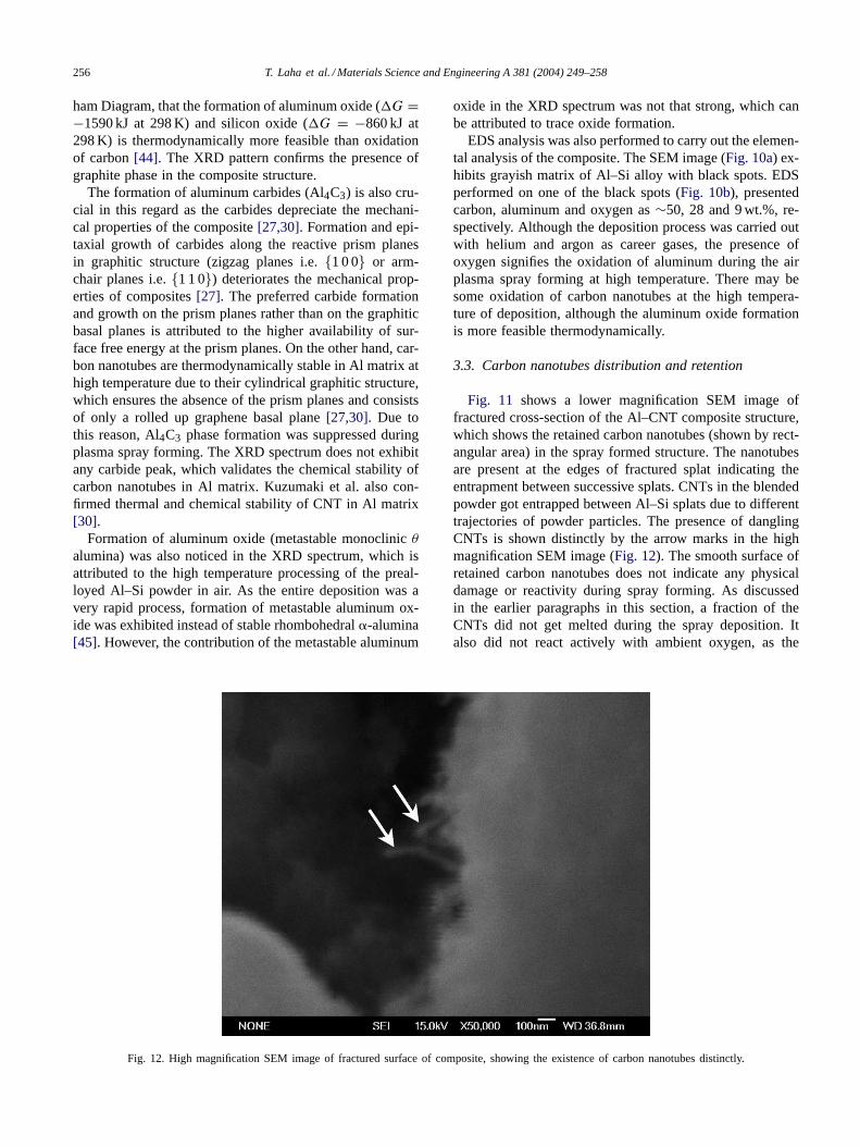
Fig. 12. High magnification SEM image of fractured surface of composite, showing the existence of carbon nanotubes distinctly.
oxide in the XRD spectrum was not that strong, which canbe attributed to trace oxide formation.
EDS analysis was also performed to carry out the elemen-tal analysis of the composite. The SEM image (Fig. 10a) ex-hibits grayish matrix of Al–Si alloy with black spots. EDSperformed on one of the black spots (Fig. 10b), presentedcarbon, aluminum and oxygen as∼50, 28 and 9 wt.%, re-spectively. Although the deposition process was carried outwith helium and argon as career gases, the presence ofoxygen signifies the oxidation of aluminum during the airplasma spray forming at high temperature. There may besome oxidation of carbon nanotubes at the high tempera-ture of deposition, although the aluminum oxide formationis more feasible thermodynamically.
3.3. Carbon nanotubes distribution and retention
Fig. 11 shows a lower magnification SEM image offractured cross-section of the Al–CNT composite structure,which shows the retained carbon nanotubes (shown by rect-angular area) in the spray formed structure. The nanotubesare present at the edges of fractured splat indicating theentrapment between successive splats. CNTs in the blendedpowder got entrapped between Al–Si splats due to differenttrajectories of powder particles. The presence of danglingCNTs is shown distinctly by the arrow marks in the highmagnification SEM image (Fig. 12). The smooth surface ofretained carbon nanotubes does not indicate any physicaldamage or reactivity during spray forming. As discussedin the earlier paragraphs in this section, a fraction of theCNTs did not get melted during the spray deposition. Italso did not react actively with ambient oxygen, as the
T. Laha et al. / Materials Science and Engineering A 381 (2004) 249–258 257
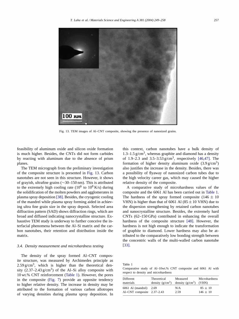
Fig. 13. TEM images of Al–CNT composite, showing the presence of nanosized grains.
feasibility of aluminum oxide and silicon oxide formationis much higher. Besides, the CNTs did not form carbidesby reacting with aluminum due to the absence of prismplanes.
The TEM micrograph from the preliminary investigationof the composite structure is presented inFig. 13. Carbonnanotubes are not seen in this structure. However, it showsof grayish, ultrafine grains (∼30–150 nm). This is attributedto the extremely high cooling rate (106 to 108 K/s) duringthe solidification of the molten powders and agglomerates inplasma spray deposition[38]. Besides, the cryogenic coolingof the mandrel while plasma spray forming aided in achiev-ing ultra fine grain size in the spray deposit. Selected areadiffraction pattern (SAD) shows diffraction rings, which arebroad and diffused indicating nanocrystalline structure. Ex-haustive TEM study is underway to further conceive the in-terfacial phenomena between the Al–Si matrix and the car-bon nanotubes, their retention and distribution inside thematrix.
3.4. Density measurement and microhardness testing
The density of the spray formed Al–CNT compos-ite structure, was measured by Archimedes principle as2.59 g/cm3, which is higher than the theoretical den-sity (2.37–2.43 g/cm3) of the Al–Si alloy composite with10 wt.% CNT reinforcement (Table 1). However, the poresin the composite (Fig. 7) provide an opposite tendencyto higher relative density. The increase in density may beattributed to the formation of various carbon allotropesof varying densities during plasma spray deposition. In
this context, carbon nanotubes have a bulk density of1.3–1.5 g/cm3, whereas graphite and diamond has a densityof 1.9–2.3 and 3.5–3.53 g/cm3, respectively[46,47]. Theformation of higher density aluminum oxide (3.9 g/cm3)also justifies the increase in the density. Besides, there wasa possibility of flyaway of nanosized carbon tubes due tothe high velocity career gas, which may caused the higherrelative density of the composite.
A comparative study of microhardness values of thecomposite and the 6061 Al has been carried out inTable 1.The hardness of the spray formed composite (146± 10VHN) is higher than that of 6061 Al (85± 10 VHN) due tothe dispersion strengthening by retained carbon nanotubesand nanocrystalline structure. Besides, the extremely hardCNTs (62–150 GPa) contributed in enhancing the overallhardness of the composite structure[48]. However, thehardness is not high enough to indicate the transformationof graphite to diamond. Lower hardness may also be at-tributed to the comparatively low bonding strength betweenthe concentric walls of the multi-walled carbon nanotube[33].
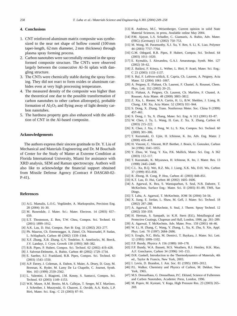
Table 1Comparative study of Al–10wt.% CNT composite and 6061 Al withrespect to density and microhardness
Differentmaterials
Theoreticaldensity (g/cm3)
Measureddensity (g/cm3)
Microhardness(VHN)
6061 Al (mandrel) 2.69 N/A 85± 10Al–CNT composite 2.37–2.43 2.59 146± 10
258 T. Laha et al. / Materials Science and Engineering A 381 (2004) 249–258
4. Conclusions
1. CNT reinforced aluminum matrix composite was synthe-sized to the near net shape of hollow conoid (100 mmtaper-length, 62 mm diameter, 2 mm thickness) throughplasma spray forming process.
2. Carbon nanotubes were successfully retained in the sprayformed composite structure. The CNTs were observedlargely between the consecutive Al–Si splats with dan-gling structure.
3. The CNTs were chemically stable during the spray form-ing. They did not react to form oxides or aluminum car-bides even at very high processing temperature.
4. The measured density of the composite was higher thanthe theoretical one due to the possible transformation ofcarbon nanotubes to other carbon allotrope(s), probableformation of Al2O3 and flying away of light density car-bon nanotubes.
5. The hardness property gets also enhanced with the addi-tion of CNT in the Al-based composite.
Acknowledgements
The authors express their sincere gratitude to Dr. Y. Liu ofMechanical and Materials Engineering and Dr. M Bouchaibof Center for the Study of Matter at Extreme Condition atFlorida International University, Miami for assistance withXRD analysis, SEM and Raman spectroscopy. Authors willalso like to acknowledge the financial support obtainedfrom Missile Defense Agency (Contract # DASG60-02-P-41).
References
[1] A.G. Mamalis, L.O.G. Vogtländer, A. Markopoulos, Precision Eng.28 (2004) 16–30.
[2] M. Baxendale, J. Mater. Sci.: Mater. Electron. 14 (2003) 657–659.
[3] E.T. Thostenson, Z. Ren, T.W. Chou, Compos. Sci. Technol. 61(2001) 1899–1912.
[4] A.K. Lau, D. Hui, Compos. Part B: Eng. 33 (2002) 263–277.[5] Ph. Mauron, Ch. Emmenegger, A. Züttel, Ch. Nützenadel, P. Sudan,
L. Schlapbach, Carbon 40 (2002) 1339–1344.[6] X.F. Zhang, X.B. Zhang, G.V. Tendeloo, S. Amelinckx, M. Beeck,
J.V. Landuyt, J. Cryst. Growth 130 (1993) 368–382.[7] R.B. Pipes, P. Hubert, Compos. Sci. Technol. 62 (2002) 419–428.[8] J. Salvetat-Delmotte, A. Rubio, Carbon 40 (2002) 1729–1734.[9] E. Saether, S.J. Frankland, R.B. Pipes, Compos. Sci. Technol. 63
(2003) 1543–1550.[10] A.P. Davey, J. Coleman, A. Dalton, S. Maier, A. Drury, D. Gray, M.
Brennan, K. Ryder, M. Lamy De La Chapelle, C. Journet, Synth.Met. 103 (1999) 2559–2562.
[11] L. Valentini, J. Biagiotti, J.M. Kenny, S. Santucci, Compos. Sci.Technol. 63 (2003) 1149–1153.
[12] W.K. Maser, A.M. Benito, M.A. Callejas, T. Seeger, M.T. Martı́nez,J. Schreiber, J. Muszynski, O. Chauvet, Z. Osváth, A.A. Koós, L.P.Biró, Mater. Sci. Eng.: C 23 (2003) 87–91.
[13] R. Andrews, M.C. Weisenberger, Current opinion in solid StateMaterial Sciences, in press, Available online May 2004.
[14] P.M. Ajayan, L.S. Schadler, C. Giannaris, A. Rubio, Adv. Mater.(FRG) (Germany) 12 (2002) 750–753.
[15] M. Wong, M. Paramsothy, X.J. Xu, Y. Ren, S. Li, K. Liao, Polymer44 (2003) 7757–7764.
[16] G.M. Odegard, R.B. Pipes, P. Hubert, Compos. Sci. Technol. 64(2003) 1011–1020.
[17] E. Kymakis, I. Alexandou, G.A.J. Amaratunga, Synth. Met. 127(2002) 59–62.
[18] Z. Balázsi, F. Kónya, L. Wéber, L. Biró, P. Arató, Mater. Sci. Eng.:C 23 (2003) 1133–1137.
[19] S. Rul, F. Lefèvre-schlick, E. Capria, Ch. Laurent, A. Peigney, ActaMater. 52 (2004) 1061–1067.
[20] A. Peigney, E. Flahaut, Ch. Laurent, F. Chastel, A. Rousset, Chem.Phys. Lett. 352 (2002) 20–25.
[21] E. Flahaut, A. Peigney, Ch. Laurent, Ch. Marlière, F. Chastel, A.Rousset, Acta Mater. 48 (2000) 3803–3812.
[22] Z. Xia, L. Riester, W.A. Curtin, H. Li, B.W. Sheldon, J. Liang, B.Chang, J.M. Xu, Acta Mater. 52 (2003) 931–944.
[23] S. Dong, X. Zhang, Trans. Nonferrous Meter. Soc. China 9 (1999)457–461.
[24] S. Dong, J. Tu, X. Zhang, Mater. Sci. Eng. A 313 (2001) 83–87.[25] W. Chen, J. Tu, L. Wang, H. Gan, Z. Xu, X. Zhang, Carbon 41
(2003) 215–222.[26] X. Chen, J. Xia, J. Peng, W. Li, S. Xie, Compos. Sci. Technol. 60
(2000) 301–306.[27] T. Kuzumaki, O. Ujiie, H. Ichinose, K. Ito, Adv. Eng. Mater. 2
(2000) 416–418.[28] H. Vincent, C. Vincent, M.P. Berthet, J. Bouix, G. Gonzalez, Carbon
34 (1996) 1041–1055.[29] Y. Zhou, W. Yang, Y. Xia, P.K. Mallick, Mater. Sci. Eng. A 362
(2003) 112–117.[30] T. Kuzumaki, K. Miyazawa, H. Ichinose, K. Ito, J. Mater. Res. 13
(1998) 2445–2449.[31] C.L. Xu, B.Q. Wei, R.Z. Ma, J. Liang, X.K. Ma, D.H. Wu, Carbon
37 (1999) 855–858.[32] R. Zhong, H. Cong, P. Hou, Carbon 41 (2003) 848–851.[33] K.T. Lau, D. Hui, Carbon 40 (2002) 1605–1606.[34] A. Agarwal, K. Rea, S. Wannaparhun, S. Seal, N.B. Dahotre, T.
McKechnie, Surface Eng.: Mater. Sci. II (2003) 81–89, TMS, SanDiego.
[35] T. Laha, A. Agarwal, T. McKechnie, JOM 56 (2004) 54–56.[36] X. Jiang, E. Jordan, L. Shaw, M. Gell, J. Mater. Sci. Technol. 18
(2002) 287–288.[37] A. Agarwal, T. McKechnie, S. Seal, J. Therm. Spray Technol. 12
(2002) 350–359.[38] H. Herman, S. Sampath, in: K.H. Stern (Ed.), Metallurgical and
Protective Coatings, Chapman and Hall, London, 1996, pp. 261–289.[39] A. Agarwal, T. McKechnie, Adv. Mater. Proc. 159 (2001) 44–46.[40] W. Li, H. Zhang, C. Wang, Y. Zhang, L. Xu, K. Zhu, S. Xie, Appl.
Phys. Lett. 70 (1997) 2684–2686.[41] S. Eroglu, N.C. Birla, M. Demirci, T. Baykara, J. Mater. Sci. Lett.
12 (1993) 1099–1102.[42] F.P. Bundy, Physica A 156 (1989) 169–178.[43] F.P. Bundy, W.A. Bassett, M.S. Weathers, R.J. Hemley, H.K. Mao,
A.F. Goncharov, Carbon 34 (1996) 141–153.[44] D.R. Gaskell, Introduction to the Thermodynamics of Materials, 4th
ed., Taylor & Francis, New York, 2003.[45] I. Levin, D. Brandon, J. Am. Soc. 81 (1995) 1995–2012.[46] P.L. Walker, Chemistry and Physics of Carbon, M. Dekker, New
York, 1965.[47] M.S. Dresselhaus, G. Dresselhaus, P.C. Eklund, Science of Fullerenes
and Carbon Nanotubes, Academic Press, London, 1996.[48] M. Popov, M. Kyotani, Y. Koga, High Pressure Res. 23 (2003) 265–
269.