Swansea University Open Access Repository - Cronfa
33
Cronfa - Swansea University Open Access Repository _____________________________________________________________ This is an author produced version of a paper published in : Surface and Coatings Technology Cronfa URL for this paper: http://cronfa.swan.ac.uk/Record/cronfa26470 _____________________________________________________________ Paper: Berry, L., Phillips, C. & Penney, D. (2016). Understanding the role of snout contamination in the formation of an oxide based defect in hot dip galvanised coating. Surface and Coatings Technology http://dx.doi.org/10.1016/j.surfcoat.2016.02.009 _____________________________________________________________ This article is brought to you by Swansea University. Any person downloading material is agreeing to abide by the terms of the repository licence. Authors are personally responsible for adhering to publisher restrictions or conditions. When uploading content they are required to comply with their publisher agreement and the SHERPA RoMEO database to judge whether or not it is copyright safe to add this version of the paper to this repository. http://www.swansea.ac.uk/iss/researchsupport/cronfa-support/
-
Upload
khangminh22 -
Category
Documents
-
view
1 -
download
0
Transcript of Swansea University Open Access Repository - Cronfa

Cronfa - Swansea University Open Access Repository
_____________________________________________________________
This is an author produced version of a paper published in :
Surface and Coatings Technology
Cronfa URL for this paper:
http://cronfa.swan.ac.uk/Record/cronfa26470
_____________________________________________________________
Paper:
Berry, L., Phillips, C. & Penney, D. (2016). Understanding the role of snout contamination in the formation of an oxide
based defect in hot dip galvanised coating. Surface and Coatings Technology
http://dx.doi.org/10.1016/j.surfcoat.2016.02.009
_____________________________________________________________ This article is brought to you by Swansea University. Any person downloading material is agreeing to abide by the
terms of the repository licence. Authors are personally responsible for adhering to publisher restrictions or conditions.
When uploading content they are required to comply with their publisher agreement and the SHERPA RoMEO
database to judge whether or not it is copyright safe to add this version of the paper to this repository.
http://www.swansea.ac.uk/iss/researchsupport/cronfa-support/

�������� ����� ��
Understanding the role of snout contamination in the formation of an oxidebased defect in hot dip galvanised coating
Lewis J. Berry, Craig H. Phillips, David J. Penney
PII: S0257-8972(16)30071-8DOI: doi: 10.1016/j.surfcoat.2016.02.009Reference: SCT 20916
To appear in: Surface & Coatings Technology
Received date: 31 October 2015Revised date: 29 January 2016Accepted date: 2 February 2016
Please cite this article as: Lewis J. Berry, Craig H. Phillips, David J. Penney,Understanding the role of snout contamination in the formation of an oxide baseddefect in hot dip galvanised coating, Surface & Coatings Technology (2016), doi:10.1016/j.surfcoat.2016.02.009
This is a PDF file of an unedited manuscript that has been accepted for publication.As a service to our customers we are providing this early version of the manuscript.The manuscript will undergo copyediting, typesetting, and review of the resulting proofbefore it is published in its final form. Please note that during the production processerrors may be discovered which could affect the content, and all legal disclaimers thatapply to the journal pertain.
ACC
EPTE
D M
ANU
SCR
IPT
ACCEPTED MANUSCRIPT
1
Understanding the role of snout contamination in the formation of an oxide based defect in hot
dip galvanised coating
Lewis J. Berry1, Craig H. Phillips
2, David J. Penney
3
1,3 The Materials and Manufacturing Academy, College of Engineering, Swansea University,
Bay Campus, Swansea SA1 8QQ, UK
Phone: +44 (0) 7885826063 Email: [email protected]; [email protected]
Phone: +44 (0) 1792 606706 Email: [email protected]
2 ZODIAC, Tata Steel Llanwern
Tata Steel Strip Products, Newport NP19 4QZ, UK
Phone: +44 (0) 01633 290011 Email: [email protected];
ABSTRACT
Due to increased demand for defect free, quality critical outer panel material for the
automotive sector, continued focus on zinc coating quality is required. The snout area of a
continuous galvanizing line is often a major source of coating issues with various surface
defects arising from poorly understood and uncontrolled snout practices. This paper
investigates the formation of a snout defect termed „the arrowhead defect‟, named after its
characteristic arrowhead shape. Defective samples have been characterised with use of
SEM/EDX and XRD and compared with contamination sources collected from within the
continuous galvanising line snout. It is common practice to inject wet HNx into the snout in
order to inhibit the production of zinc vapour. The wet HNx promotes the formation of a ZnO
layer on the surface of the liquid zinc bath, preventing vaporisation and thereby reduces zinc
dust contamination. The presence of ZnO, deliberately formed through the injection of wet
HNx into the snout was observed within the arrowhead defect and can be identified as the root
cause of this defect. Discrete contamination particles were entrained within the tail of the
defect. XRD patterns of both the defect & snout contamination have been presented to discern
the nature of the contamination entrained within the zinc coating. Characteristic ZnO peaks

ACC
EPTE
D M
ANU
SCR
IPT
ACCEPTED MANUSCRIPT
2
were observed at θ=32o for both surface contamination and at increasing penetration depths
within the coating in the region of the arrowhead defect. The inclusion of the arrowhead defect
in Full finish material led to an increase in the rate of corrosion 2.5x that of the corrosion rate
on non-defective material, highlighting the need to produce defect free galvanized steel for
both aesthetic and corrosion purposes. Whilst the injection of wet HNx as a method of
suppressing the formation of zinc vapour is a long standing process for automotive Full Finish
production, due to the nature of these oxide based defects, this process is in fact a “double
edged sword” in that it solves one problem but can create another. Alternative techniques to
supress zinc vapour formation should be investigated to further drive up the quality of zinc
coatings for automotive applications.
Keywords: Zinc, XRD, WLI, GI Full Finish, Coating Quality, Continuous Hot dip
Galvanizing
1. INTRODUCTION
The increased usage of GI full finish galvanized coated steel sheet for exposed outer body
automotive panels has led to the need for improved surface quality. The coating section
(from extension chamber to the gas knives) of a Continuous Galvanizing Line (CGL) [1] is
the source of numerous defects and various processes have been introduced in order to
improve surface quality. The study of defective galvanized coatings has been paramount in
understanding of defect formation and in developing strategies to improve surface quality [2,
3]. Due to an ever increasing need to improve surface quality of the GI Full Finish products,
further comprehensive characterisation of defective zinc coatings have been undertaken [4-6]
acting as a basis for quality centred process improvement. The production of zinc vapour
under a reducing HNx atmosphere within the snout [7] along with the formation of
intermetallic dross [8] are two of the primary origins of coating defects. Whilst the formation
of intermetallic dross particles are still a major source of defective coatings, the introduction

ACC
EPTE
D M
ANU
SCR
IPT
ACCEPTED MANUSCRIPT
3
of wet HNx snout atmospheres have all but eradicated defects that originate from zinc
evaporation [7]. Zinc evaporation is undesirable since gaseous zinc will condense in the
snout area and contaminate the incoming steel strip. The subsequent zinc particles alloy with
the steel surface, forming FeZn intermetallics that are not readily wetted by the liquid zinc
[7]. The dew point, typically around -24oC, within the snout is a result of the injection of wet
HNx which promotes the formation of a barrier layer of zinc oxide on the surface of the zinc
bath within the snout, as indicated in Fig. 1, supressing zinc evaporation. The introduction of
wet HNx into the snout and the subsequent decrease in zinc evaporation to very low levels
has been previously described [7, 9]. The relationship between the injected dew point of wet
HNx and the formation of bare spots was investigated by Arnold and Kim et al. The
formation of bare spots was found to be due to the development of localised surface
intermetallics formed through interactions between the moving steel and zinc vapour. Saint-
Raymond et al [10] defined the relationship between exposed surface area of molten zinc and
the rate of formation of zinc vapour (eqn. 1).
(eqn. 1)
Where JZn = Zinc evaporation rate
Sevap = Evaporation surface area
Tbath = Bath temperature
Pzn = Zinc pressure
PZnSat
= Zn saturation vapour pressure
α = Boundary layer diffusion constant
Upon the introduction of wet HNx, the Sevap term reduces to zero as does the theoretical Zn
evaporation rate. However, the vaporisation of molten zinc may still be possible through
breaks in the oxide barrier and needs to be further investigated in order to determine optimum
snout conditions for the production of GI full finish. Whilst the introduction of wet HNx does
act as a method of reducing zinc vapour formation, the uncontrolled formation of barrier

ACC
EPTE
D M
ANU
SCR
IPT
ACCEPTED MANUSCRIPT
4
oxides can themselves induce coating quality issues. If the zinc oxide barrier layer within the
snout becomes unstable, zinc oxide particles break away and become entrained within the
coating through the action of the rapidly moving steel strip, as shown in Fig. 1b. It is therefore
necessary to control the size and thickness of the zinc oxide layer through the use of extraction
techniques that remove the zinc and a portion of the oxide barrier layer from within the snout.
The use of pumps in the continuous removal of surface oxides formed produced through the
introduction of wet HNx atmospheres was introduced by Becherer [11] and resulted in the
elimination of zinc dust related defects. The Push/Pull surface cleanliness system was
optimised by Phillips et al [12] utilizing water modelling to discern optimum settings for the
removal of surface contamination. However, the use of a centrifugal snout pump Push/Pull
type configuration can cause turbulence within the snout leading to interactions between the
strip surface and the oxide layer, and as such new on line industrial techniques have been
designed to continuously remove the surface dross layer [13].
1.1 Mechanism of Defect Formation
The mechanism of formation of the arrowhead defect can be observed with use of the snout
camera. The attraction of surface oxides to the moving strip due to liquid zinc turbulence
causes oxide entrainment within the galvanized coating as observed in Fig. 2 which shows the
zinc bath surface inside the snout. Surface contamination is present at the extremities of the
molten zinc surface. The movement of this contamination towards the moving strip can be
observed readily, leading to the entrainment of this contamination in the coating. The
uncontrolled formation and entrainment of surface oxides results in the creation of the
arrowhead defect as observed by the Continuous Galvanizing Line surface quality camera
system as highlighted in Fig. 3. The arrowhead defects are linked to the insufficient removal
of barrier oxides from the snout surface. Achieving the correct balance between removing
excess surface oxide and maintaining an inhibiting surface layer is complex. If the rate of
removal drastically exceeds the rate of formation of the barrier oxide then an exposed surface

ACC
EPTE
D M
ANU
SCR
IPT
ACCEPTED MANUSCRIPT
5
of molten zinc will, increase the rate of formation of zinc vapour. This was described in detail
by Arnold et al [7].
Contamination originating from around the snout area has been previously characterised [14]
with a consideration for the effects on coating quality [15], whereby the inclusion of mixed
ZnAl2-xFeyO4 spinel oxide by-products into the coating resulted in the formation of outbursts
of intermetallics. However, the contamination characterised were limited to oxidic, bottom
and blowing dross with no consideration of by-products formed within the snout. Furthermore,
no characterisation has been achieved on a microscopic scale. This paper presents an overview
of individual microscopic phenomena comprising snout surface oxides and how their presence
can lead to defective galvanized coatings.
1.2 GI Full Finish Sample collection
Arrowhead defective samples were collected from rejected GI Full Finish production material
produced with a bath composition as shown in table 1, where Al wt.% bath content was
measured with disposable Alzin probes and cross checked with spark Spectroscopy using an
Ametek SPECTROMAXx Optical Emission Spectrometer. Control samples were obtained
from non-defective material produced during the same shift of GI Full Finish material for
direct comparison. The defective and non-defective material collected were both typical low
carbon steels (3013 steel grade) with 7-10µm coating thickness.
1.3 Snout surface oxide sample collection
Snout surface oxides were collected upon removal of the dross pumps. Powdered samples
with different morphologies, including the white surface oxide powder described later within
this paper, were observed at the inlets to the pumps. The pump inlets are situated within the
snout and set at the level of the molten zinc during production.

ACC
EPTE
D M
ANU
SCR
IPT
ACCEPTED MANUSCRIPT
6
2. EXPERIMENTAL
2.1 Cross Sectional Analysis
Cross sections of both arrowhead defective and non-defective samples were taken to
investigate the presence of coating contamination that may give rise to irregular surface
topography. Samples were cross sectioned using a Beuhler IsoMet 5000 linear precision saw
and polished to a 0.3μm finish using a 0.3μm Beuhler diamond based polishing suspension
and Kemet Chem H polishing cloth on a Beuhler AutoMet 300 grinding/polishing machine.
2.2 Incremental etching
Arrowhead defective samples were incrementally etched in order to investigate the position of
contamination within the thickness of the galvanized coating. The region of coating
surrounding the arrowhead defect was indented with a Vickers hardness indenter as a method
of coating weight determination and incrementally etched with 5% Nital (Nitric acid in
Ethanol) at 2 second intervals as described by Penney et al [16]. The region of coating
surrounding the arrowhead defect was indented with a Vickers hardness indenter in order to
identify known regions of the sample that can be compared pre and post etch.
2.3 Scanning Electron Microscopy and Energy Dispersive X-ray Spectroscopy
Arrowhead defective samples were analysed using a Hitachi S-4800 Field Emission Gun
Scanning Electron Microscope (FEG SEM) with an Oxford instruments Silicon Drift X-Max
EDX Detector (SDD) and Inca EDX software to determine microstructure, morphology of
arrowhead defective samples and to chemically characterise the nature of the galvanized
coating.
For surface and cross sectional SEM imaging of arrowhead and non-defective samples, the
detector settings were set to 15kV accelerating voltage and 20µA emission current to produce

ACC
EPTE
D M
ANU
SCR
IPT
ACCEPTED MANUSCRIPT
7
even contrast surface images of coating surface topography at a working distance of 8mm
using the lower detector.
With use of BSE detector for backscatter SEM imaging of arrowhead defective samples to
determine position of contamination relative to surface phenomena, the detector settings were
set to 15kV accelerating voltage and 20µA emission current to produce high contrast bulk
images of coating and contamination at a working distance of 5mm using the upper detector.
For EDX chemical characterisation of both surface and cross sectional arrowhead defective
samples, the detector settings were set at 15kV accelerating voltage and 20µA emission
current at a working distance of 15mm to maximise data acquisition for high quality EDX
analysis.
2.4 White Light interferometry
Samples were analysed using a Bruker Wyko NT 9300 Optical Profiling System and subjected
to a stitched scan with a scan length of 80μm and a back scan length of 40μm at 5x optical
magnification. Samples were subjected to White Light Interferometry in order to quantify the
nature of surface roughness and produce qualitative topographical maps for both arrowhead
defective and non-defective samples.
2.5 X-Ray Diffraction
Samples were analysed with a Bruker D8 Discover Diffractomer using a Cu Kα radiation (λ =
0.15406nm) source in order to determine the chemical nature of the coating through non-
destructive means. Both fixed and variable primary optic testing methods were employed in
order to compare chemical surface and depth profiles of the GI Full Finish coating. For a
variable primary optic testing, samples were subjected to an hour 11000 step D cycle with step
parameters of 0.5 seconds per step and 0.0006o increment per step between 5 and 80
o. For a
fixed primary optic testing, the primary optic arm was fixed at 5o intervals between 5-25
o and
secondary optic arm varied from the initial primary arm setting to 80o in order to give coating
depth profiles at increasing penetration depths. The same time and incremental step profiles

ACC
EPTE
D M
ANU
SCR
IPT
ACCEPTED MANUSCRIPT
8
were used for both fixed and variable optic testing. XRD peak identification was carried out
through use of the Open Crystallography Database.
2.6 Scanning Vibrating Electrode Technique (SVET)
The electrochemical characteristics of arrowhead defective and non-defective GI full finish
were investigated with use of the SVET technique to determine the impact of the arrowhead
defective on the corrosion performance of GI Full Finish material. Samples were immersed in
0.1% NaCl solution for 48 hours whilst subjected to surface corrosion mapping using the
Swansea University SVET at hourly intervals. The principles of the technique, calibration of
the SVET prior to scanning, post scan data manipulation to produce qualitative current density
maps, the derivation of semi quantitative coating mass loss data [17] and possible applications
to determine the nature of the corrosion of galvanized coating systems have been described
elsewhere [18].

ACC
EPTE
D M
ANU
SCR
IPT
ACCEPTED MANUSCRIPT
9
3. RESULTS & DISCUSSION
3.1 Physical characteristics of the defect
The characteristic microscopic topography of the defect under SEM analysis can be shown to
be a consequence of microfolding of the zinc coating, Fig. 4. This is consistent with that
observed for the entrainment of other forms of contamination present during gas wiping [9].
The folding of the surface suggests the contamination present within the coating provides an
obstacle to ideal coating weight control during wiping.
It is postulated that the mechanism for the formation of the arrowhead defect is formed by the
wiping action of the gas knives. The high velocity gas impinges on the moving strip, wiping
excess liquid zinc back down into the bath. When an entrained oxide passes through the gas
wiping jet it prevents uniform flow of the liquid zinc back into the bath. Instead, liquid zinc is
forced to flow around the particle, forming the characteristic arrow head shape. Furthermore,
larger oxide particles can break up under the action of the wiping force and become entrained
along the arrowhead contours resulting in the micro folding seen in Fig. 5. White light
Interferometry was used to map the topography of the defective surface. The average surface
roughness Ra for defective (2.01µm) and non-defective material (1.22µm) can be directly
compared, however, consideration of Ra alone is not enough to determine the relationship
between the entrainment of surface contamination and topographical effects. The comparison
of the characteristic surface topography of the arrowhead defect with non-defective
galvanized material is shown in Fig. 6. For the defective material an arrowhead like region of
low surface roughness (Ra = 0.5µm) surrounds a region of greater surfae roughness
throughout the body of the defect (Ra = 1.93µm). Regions of non-defective coating
surrounding the defective region of the sample are comparable to defect free samples (Ra =

ACC
EPTE
D M
ANU
SCR
IPT
ACCEPTED MANUSCRIPT
10
1.24µm). It can be concluded that the increase in surface roughness within the body of the
defect is due to greater temper roll roughness transfer bought about by differences in zinc
coating thickness [19]. Furthermore, the interface between the zinc coating of normal surface
roughness and regions of reduced roughness around the extremities of the defect have been
linked to the presence of contamination within the coating.
3.2 Metallographic cross sections
In order to discern root cause of the arrowhead, defective and non-defective material were
cross sectioned and polished to a 0.3μm finish before being subjected to SEM/EDX analysis.
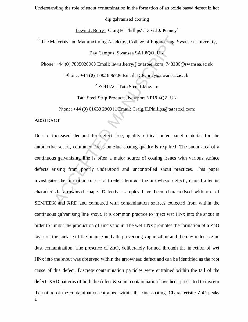
The substrate / Zn coating interface regions of non-defective material, Fig. 7, and arrowhead
defective material, Fig. 7, were compared. Contamination at the interface between the
substrate and Zn coating was clearly observed within the defective samples but not within the
non-defective samples. EDX analysis of the contamination indicated regions of high
concentrations of zinc and oxygen. The presence of zinc and oxygen containing species
adjacent to the expected position of the Fe2Al5 interfacial layer suggests the entrainment of
surface oxides from inside the snout. Previous instances of oxide containing defective coatings
were investigated by Vlot [19] but associated with the entrainment of oxidized zinc vapour as
opposed to the entrainment of zinc oxide material from the bath surface. No appreciable
amount of aluminium was observed suggesting the formation of a ZnO barrier layer rather
than ZnAl2O4, both of which would be possible given the typical dew point of injected wet
HNx systems during galvanizing.
3.3 Incremental etching for contamination observation
The preferential dissolution of the Zn coating with retention of ceramic type species during
etching has previously been observed and is a controllable method for the observation of oxide
based contamination within a galvanized coating. Initial SEM/EDX was carried out over the
arrowhead defect in order to compare the same region of the defect pre and post etch. Initial
benchmarking of the defect showed regions of increased concentration of iron due to

ACC
EPTE
D M
ANU
SCR
IPT
ACCEPTED MANUSCRIPT
11
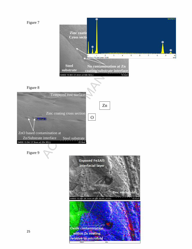
decreased zinc coating thickness and reduced surface roughness [19]. Regions of oxide
associated with microfolding of the zinc coating can also be seen in Fig. 9, where green = Al,
red = O, blue = Zn. After 8 seconds of incremental etching, particles of intermetallic top dross
were observed dross within the body of the defect. EDX was used to confirm its chemical
composition, as indicated in Fig 10. Whilst the majority of the sample was still covered by a
thick zinc coating, at the head end of the defect the interfacial Fe2Al5 was exposed after a
relatively short etching period. This is in agreement with phenomena described by Vlot et al
[19] which showed regions of decreased surface roughness due to localised lower coating
thicknesses. This suggests that the presence of the zinc oxide based contamination found at the
coating substrate interface promotes micro folding and localised inhomogeneous coating
thickness.
3.4 XRD characterisation of the arrowhead defect
The nature of the contamination observed within the zinc coating can be characterised with the
use of X-Ray Diffraction (XRD). XRD analysis of the arrowhead defect containing Full Finish
sample produced the X-ray diffractogram highlighted in Fig. 11.
The majority of the peaks observed within the arrowhead XRD spectra are associated with the
zinc coating which dominate over the peaks associated with the contamination. Small
contamination peaks have been characterised through comparison with known XRD scattering
patterns of the types of contamination that would be observed around the snout of a
galvanizing line [20-23], including the Fe2Al5 interfacial layer, intermetallic Fe2Al5Znx top
dross, zinc oxide (ZnO), alumina (Al2O3) and zinc aluminate (ZnAl2O4).
The smaller peaks were used to characterise the presence of the Fe2Al5 interfacial layer, zinc
oxide and intermetallic dross within the tail of the arrowhead defect. Zinc oxide can be formed
through two different mechanisms as indicated previously within the snout, through oxidation

ACC
EPTE
D M
ANU
SCR
IPT
ACCEPTED MANUSCRIPT
12
of the molten zinc surface with wet HNx or oxidation of zinc vapour, with only physical
characteristics used to differentiate the nature of the contamination.
Through observation of the entrainment of snout surface oxides during production of material
associated with the arrowhead defect, the investigation was focused on the characterisation of
these oxides.
3.5 Electrochemical characterisation of the arrowhead defect
To determine the effect of the arrowhead defective coating on the corrosion resistance of the
galvanized coating, a calibration factor (1.29x10⁵
Am-2
V-1
) was obtained during calibration of
the SVET and the microtip was scanned at a constant height of 100μm across the exposed
corroding sample to directly compare post scan data for defective and non-defective material,
whilst submerged in 0.1%NaCl electrolyte. Current density maps, indicating relative position
and intensity of electrochemical phenomena occurring at the galvanized surface, were
generated with use of cartography software (SurferTM
from golden Software) which show
regions of localised anodic (shown in red) and general cathodic activity (shown in blue) across
the period of immersion in electrolyte, Fig 12. For the duration of the immersion the non-
defective regions of the coating afforded cathodic protection to the substrate. Increased anodic
activity was observed around the position of the arrowhead defect. As the scan progressed,
long lived anodic sites were observed around the extremities of the arrowhead defect due to
decreased coating thickness at positions associated the microfolding of the zinc surface, in
comparison with thicker coatings for the non-defective portions of the sample and roughened
body of the defect.
Semi quantitative mass loss calculations have been compared for both defective and non-
defective GI full finish. It is important to recognise that spatially resolved peak voltages are
dependent upon scan height, and as such both arrowhead defective and non-defective samples
were scanned at a constant height of 100µm to allow for direct comparison. Cumulative mass

ACC
EPTE
D M
ANU
SCR
IPT
ACCEPTED MANUSCRIPT
13
loss across the period of immersion indicated in Fig. 13, with arrowhead defective samples
clearly showing an increase in corrosion rate, 2.5x that of normal GI full finish material. As
such, the inclusion of arrowhead defective material in exposed automotive panels would lead
to irregularity in the corrosion protection afforded by the metallic system and highlights the
need to produce defect free GI Full Finish material.
3.6 Snout surface oxide characterisation
Whilst characterisation of various Zn dust by products from the coating area of the
galvanizing process has been undertaken both on pilot and production scale [7,9], little work
has been undertaken to characterise the nature of production snout contamination on a
microscopic level. Various complex morphologies comprising the snout surface oxide barrier
formed as a result of wet HNx injection at the continuous galvanizing line were observed as
indicated in Fig. 14 - 16. Previous characterisation of snout contamination was undertaken by
Kim et al [9] on different zinc and oxygen containing compounds using ICP/XRD to
determine stoichiometric composition. EDX was used to discern chemical composition of the
white surface oxide. Fig. 15, where green = Al, red = O, blue = Zn, indicates the presence of
large amounts of Zn and O in accordance with previous results. Furthermore, the observation
of nanoscale ZnO rods/wires/flowers was observed. ZnO nanowire synthesis is of great
interest due to the photo catalytic properties associated with the nanostructures. The properties
of ZnO nanostructures have been well studied
[24, 25]. It can be suggested that the
nanostructures associated with the surface oxide forming via adsorption of Zn vapour onto the
solid ZnO, although a more definitive mechanism of formation for the formation of flower like
ZnO structures is provided by Pung et al [26]. Pung states that the formation of desirable ZnO
geometries require carefully controlled reaction conditions. Under laboratory conditions, the
reaction time, amount of the reactant present, and the choice of a suitable complexing agent
are all crucial in the formation of desirable geometries. It is possible that local variation of

ACC
EPTE
D M
ANU
SCR
IPT
ACCEPTED MANUSCRIPT
14
parameters such as dew point, the amount of wet HNx present, atmospheric temperature,
residency time of the injected gas relative to the exposed molten zinc surface and cooling
regime contribute to the formation of different ZnO morphologies with the snout of the
galvanizing line, but is beyond the scope of this work and will form the basis of a separate
study. The XRD diffractogram for the snout surface oxide contamination is presented in Fig.
17 as a direct comparison for the XRD spectra generated via analysis of the arrowhead defect,
Fig 11.
The entrainment of the surface oxide type contamination was observed with use of the snout
camera as indicated in Fig. 2 and with consideration of the XRD patterns produced by the
arrowhead defect and the contamination collected from the snout, a consistent and distinct
ZnO peak is observed at θ = 32 at increased penetration depths, Fig. 18. Whilst the intensity of
the ZnO peaks associated with other crystal planes are masked by the intensity of the zinc
peaks, this distinct ZnO [ ,0,0] crystal plane is readily observed and confirms the presence of
particles from the ZnO barrier layer within the arrowhead defect. This assignment is
confirmed with analysis of the SEM/EDX cross sections and incrementally etched samples
whereby discrete ZnO particles are observed within the zinc coating.

ACC
EPTE
D M
ANU
SCR
IPT
ACCEPTED MANUSCRIPT
15
4. METHODS OF DEFECT ELIMINATION
The formation of the arrowhead and other surface oxide based defects which manifest with
different surface topography, can be minimised through the optimisation of snout pump
process technology designed to attain control of over the cleanliness of the exposed molten
zinc surface inside of the snout [12]. However, due to the nature of the wet HNx injection
process on the continuous galvanizing line, if pumping methods were to fail during production
this would results in increased occurrences of surface oxides based coating defects. Several
methods have been developed to obviate the need for wet HNx injection as a method of zinc
vapour suppression or to reduce the impact of zinc vapour that is formed during the process on
the quality of the material produced.
A novel method of removing snout contamination, including both Fe2Al5Znx intermetallic top
dross and zinc oxide has been developed by POSCO [27]. The POSCO snout process
technology utilizes a contact free inducer to apply a drag and levitation force to a snout
contaminant to guide contamination away from the production material and towards a
collection chamber. The use of an alternating current applied to electromagnets or a rotating
permanent magnet to interact with snout surface oxides as a diamagnetic substance would
minimise any contamination entrainment within the coating during production and eliminate
the arrowhead defect. Furthermore, optimisation of this system to include homogeneous

ACC
EPTE
D M
ANU
SCR
IPT
ACCEPTED MANUSCRIPT
16
formation of barrier surface oxides on the exposed surface in a wet HNx snout atmosphere
would minimise any defects resulting from formation of zinc vapour.
Methods of reducing the impact on surface quality of Zn vapour in a dry HNx snout
environment, thus eliminating the requirement for wet HNx injection have been developed
[28]. The continuous galvanizing line snout equipped with protective gas exchange system,
whereby a series of extraction openings are located adjacent to injection openings on both
faces to replace contaminated snout atmosphere with fresh uncontaminated HNx gas. The
apparatus is designed with a characteristic injection angle to control the impact between
injected gas and the metal substrate and minimise entrainment of the injection gas towards the
motel zinc surface. The introduction of this process would obviate the need for wet HNx
injection and eliminate the fundamental cause of surface oxide based coating defects.

ACC
EPTE
D M
ANU
SCR
IPT
ACCEPTED MANUSCRIPT
17
5. CONCLUSION
Whilst the use of wet HNx reduces the formation of zinc dust related defects during
continuous galvanizing, the formation of surface barrier oxides can induce other quality
concerns. The entrainment of the surface barrier oxide into the zinc coating has resulted in the
formation of the arrowhead defect. SEM/EDX characterisation coupled with incremental
etching using Nital revealed the presence of the surface contamination within the zinc coating
relative to the microfolding which is characteristic of the arrowhead defect. If optimum
settings for wet HNx injection/oxide removal are not continually in operation, increased
occurrences of coating defects will be observed and result in poor quality full finish material.
The presence of the arrowhead defect was shown to reduce the coatings‟ corrosion resistance
by a factor of 2.5. This was illustrated through the use of the Scanning Vibrating Electrode
Technique (SVET) which was able to compare zinc mass loss on samples with and without
defects. The increase in corrosion rate is due to localised reduction in coating thickness
exposing areas of iron which act as sites for cathodic oxygen reduction. This demonstrates that
coating defects such as these are more than just aesthetic and lead reductions in coating
corrosion resistance. The injection of wet HNx as a method of eliminating the formation of
zinc vapour is therefore a “double edged sword” and with the recent development of

ACC
EPTE
D M
ANU
SCR
IPT
ACCEPTED MANUSCRIPT
18
innovative alternatives to wet HNx injection, coating defects which originate from the
formation of zinc vapour and surface barrier oxide can be virtually eliminated.
6. ACKNOWLEDGEMENTS
We thank Tata Steel Strip Products and the EPSRC for funding this research under the
MATTER Engineering Doctorate Scheme.

ACC
EPTE
D M
ANU
SCR
IPT
ACCEPTED MANUSCRIPT
19
7. REFERENCES
[1] A.R. Marder, “The metallurgy of zinc-coated steel”, Prog. Mater. Sci., 45 (2000), 198
[2] F. Dunbar, “Defects of the 80‟s – A closer look at the critical requirements for today‟s hot
dip galvanized” Proc. of Galvanizer's association (1988),
[3] Y. W. Kim, S. C. Kung, W. C. Sievert, R. Patil, “Surface defects in exposed quality hot-
dip galvanized steel”, Conf. Proc. Galvatech 1989, 120-129
[4] N. Y. Tang and F. E. Goodwin, “A study of defects in galvanized coatings”, Conf. Proc.
Galvatech (2001), 49-55
[5] F. Chen, R Patil, "An In depth Analysis of Various Subtle Coating Defects of the 2000's",
Conf. Proc. Galvatech, (2004)
[6] A. Azimi, F. Ashrafizadeh, M. R. Toroghinejad, F. Shahriari, “Metallurgical assessment of
critical defects in continuous hot dip galvanized steel sheets”, Surf. and Coat. Technol., 206
(21), (2012), 4376-4383
[7] J. L. Arnold, S. L. Boston, F. Caudill, "Control of defects caused by zinc vaporisation in
the snout", Conf. Proc. Galvatech, (1989), 130
[8] H. Yamaguchi, T. Hisamatsu, “Reaction Mechanism of the Sheet Galavanizing” Journ. Of
the Iron and Steel. Inst. of Japan, 60, 1974, 96.
[9] H. Y. Kim, J.S. Kim, S.J. Lee, "On Decreasing Zinc Dust in Snout equipped CGL", Proc.
of Galvanizer's association (2012)
[10] H. Saint-Raymond, S. Gauthier, A. Lamande, “Modelling of zinc vaporisation in snout”
Proc. of Galvanizer's association, (2012)

ACC
EPTE
D M
ANU
SCR
IPT
ACCEPTED MANUSCRIPT
20
[11] G. C. Becherer, "Utilizing pumps to continuously remove dross from inside the inlet
snout", Proc. of Galvanizer's association, (2001)
[12] C. Phillips, N. Staples, M. Bright, "Cleanliness Enhancement of the Bath Surface within a
CGL snout", Proc. of Galvanizer's association, (2005)
[13] D. Dauchelle, H. Baudin, L. Gacher, Y. Prigent: Method & installation for dip coating of
a metal strip, U. S. Patent No. 6,936307 (Aug. 30, 2005)
[14] G. Vourlias, N. Pistofidis, G. Stergioudis, E. Polychroniadis, "An overview of the solid
byproducts of the galvanizing kettle", Optoelectron. and Adv. Mat., 1, (2007), 77-85
[15] G. Vourlias, K. Pistofidis, G. Stergioudis. E. Polychroniadis, “A negative effect of
insoluble particles of dross on the quality of the galvanized coatings” Solid State Sci., 7
(2005), 465 – 474
[16] D. Penney, J. Sullivan, D. Worsley, “Investigation into the effects of metallic coating
thickness on the corrosion properties of ZnAl alloy galvanizing coatings” Corr. Sci, 49, 3,
(2007), 1321 – 1339
[17] H. McMurray, D. Worsley, "Scanning techniques for Monitoring Localised Corrosion
Phenomena", Rev. Chem. Kin. 4, (1997), 149
[18] J. Sullivan, C. Weirman, J. Kennedy, D. Penney, "Influence of Steel Gauge on the
Microstructure and Corrosion Performance of Zinc Alloy Coated Steels", Corr. Sci, 52 (2010)
1853-1862
[19] M. Vlot, C. Price, M. Zuijderwijk, B. Van Veldhuizen, "Full Finish GI Manufacturing for
the automotive industry", Conf. Proc. Galvatech, (2004)
[20] M. Zelechower, J. Klis, E. Augustyn, J. Grzonka, D. Stroz, T. Rzychon H. Woznica, "The
mircostructure of annealed galfan coating on steel substrate", Arch. of Metall. and Mater., 57,
(2012), 517-523
[21] S. Alam, M. Poloju, S. Sahu, M. Kumar, A. Singh, "SEM, EDX & XRD of Zinc Oxide
Nanostructures synthesized by Zinc oxidation", Microsc. and Anal., 06, (2012), 11-14
[22] E. M. A. Jamal, D. S. Kumar, M. R. Anatharaman, "On structural, optical and dielectric
properties of zinc aluminate nanoparticles" Bull. of Mater. Sci., 34, (2007), 251-259
[23] G. Ragul, S. Sumathi, "Synthesis, Characterisation and Photocatalytic study of Zinc
Aluminate Nanopowders against Rhodamine -B and Crystal Violet Dyes" Int. J. of Appl. Eng.
Res., 8, (2013), 2175-2178
[24] C. Cheng, H. J. Fan, “Branched nanowires: Synthesis and energy applications”, Nano
Today, 7, (2012). 327-343
[25] S. Xu, Z. L. Wang, “One-Dimensional ZnO Nanostructures: Solution Growth and
functional properties” Nano Res., 4, (2011), 1013-1098
[26] S Y. Pung, W P. Lei, A. Aziz, “Kinetics of organic dye degradation usuing ZnO particles
with different morphologies as a photocatalyst”, Int. Journ. Inorg. Chem., 2012 (2012), 1-9

ACC
EPTE
D M
ANU
SCR
IPT
ACCEPTED MANUSCRIPT
21
[27] T. I. Jang, Y. H. Kweon, J. K. Kim, C. W. Jee, “Apparatus for removing pollutant source
from snout of galvanizing line”, U. S. Patent No. 9133540 (September 15, 2015)
[28] N. Schaffrath, S. Zeizinger, M. Peters, G. Nothacker, K. Peters: “Method and device for
avoiding surface defects caused by zinc dust in a continuous strip galvanising process patent”,
U. S. Patent No. 0167138 (Jun 18, 2015)
8. FIGURE CAPTIONS
Table 1 – Elemental bath composition during GI Full Finish production and associated
production parameters
Figure 1 – Schematic of the Continuous galvanizing line snout indicating the relationship
between a dry & wet HNx atmosphere & the formation of Zn vapour
Figure 2 – Time-lapse image from snout camera highlighting the entrainment of surface
oxides into the zinc coating. Central light and dark regions are uncontaminated molten zinc
with surface contamination present at the extremities of the snout, which are seen to be
moving towards the steel substrate resulting in entrainment of contamination into the coating
Figure 3 – Arrowhead defect image taken from Galvanizing line quality inspection system
Figure 4 – Backscatter image highlighting compositional variation within coating relative to
characteristic zinc microfolding
Figure 5 - Schematic illustrating the formation of the arrowhead defect indicating the
entrainment of snout surface oxide and its break up when subject to high velocity wiping
Figure 6 – White light interferometry 3d surface map indicating surface topography with
associated Ra for arrowhead defective and non-defective material
Figure 7 – SEM image of GI Full Finish steel cross section highlighting a contamination free
Fe2Al5 interfacial layer
Figure 8 – SEM image of GI Full Finish steel cross section/EDX spectra highlighting the
presence of oxide based contamination relative to Zn coating/substrate interface
Figure 9 – SEM image of etched GI Full Finish surface/EDX mix colour map highlighting
presence of oxide contamination within coating relative to microfold Where Green = Al, Red
= O, Blue = Zn

ACC
EPTE
D M
ANU
SCR
IPT
ACCEPTED MANUSCRIPT
22
Figure 10 – SEM image of etched GI Full Finish surface/EDX surface colour mapping of
individual chemical constituents highlighting presence of intermetallic Fe2Al5Znx top dross
particle entrained with tail of the defect
Figure 11 – XRD diffractogram comparing head end and tail end chemical composition of the
arrowhead defect
Figure 12 – Cumulative Zn mass loss of arrowhead v non defective GI Full Finish material
Figure 13 – SVET Current density mapping of arrowhead defective material, where red =
anodic activity (zinc oxidation), blue = cathodic activity (oxygen reduction)
Figure 14 – SEM image of complex morphologies comprising white snout surface oxide
produced on a molten zinc surface through the injection of wet HNx
Figure 15 – SEM image of microstructural phenomena of snout contamination/EDX mix
colour map highlighting presence of Zn & O. Where Green = Al, Red = O, Blue = Zn
Figure 16 – SEM image of ZnO based coarse and fine nanorods formed though injection of
wet HNx
Figure 17 – XRD diffractogram of white ZnO surface oxide snout contamination
Figure 18 – XRD diffractogram of Arrowhead defective and non-defective GI Full Finish at a
25 Primary optic incidence angle
Figure 19 – Monthly % rejection chart for arrowhead defective material pre and post
modification of snout cleanliness control practice

ACC
EPTE
D M
ANU
SCR
IPT
ACCEPTED MANUSCRIPT
23
9. FIGURES
Table 1
Figure 1
Figure 2
Element Bath Composition
(wt%) Bath temperature
(oC) Line speed
(m/min) Strip entry
temperature (oC)
Zn 99.7
465 1.5 475 Al 0.3
Aleff 0.3
Fe 0.008
Dry HNx snout
atmosphere Galvanizing snout
Wet HNx snout
atmosphere Galvanizing snout
Zinc vapour formation
Molten zinc
Limited zinc vapour due to
oxide barrier formation
X X X X Oxide
barrie
r Molten zinc
Clean molten
zinc surface
Surface oxide
contamination entrained
Steel substrate
Snout width
(2274mm)

ACC
EPTE
D M
ANU
SCR
IPT
ACCEPTED MANUSCRIPT
24
Figure 3
Figure 4
Figure 5
Figure 6
Microfolding of zinc coating
Contamination relative to microfolding
Arrowhead Ra – 2.01µm 10
5
0
-5
-15
-10
Arrowhead like
zinc 0.5µm
Body of defect
1.93µm
Normal 1.24µm Normal non defective Ra – 1.19µm
20mm
Head Tail
Body
ACC
EPTE
D M
ANU
SCR
IPT
ACCEPTED MANUSCRIPT
25
Figure 7
Figure 8
Figure 9
Tempered
zinc surface
Steel
substrate
Zinc coating
Cross section
ZnO based contamination at
Zn/Substrate interface
Tempered zinc surface
Zinc coating cross section
Steel substrate
Zn
O
No contamination at Zn
coating/substrate interface

ACC
EPTE
D M
ANU
SCR
IPT
ACCEPTED MANUSCRIPT
26
Figure 10
Figure 11

ACC
EPTE
D M
ANU
SCR
IPT
ACCEPTED MANUSCRIPT
27
Figure 12
Figure 13
Steel
Cathodic activity (Blue) Steel
Anodic activity (Red)

ACC
EPTE
D M
ANU
SCR
IPT
ACCEPTED MANUSCRIPT
28
Figure 14
Figure 15
Figure 16

ACC
EPTE
D M
ANU
SCR
IPT
ACCEPTED MANUSCRIPT
29
Figure 17

ACC
EPTE
D M
ANU
SCR
IPT
ACCEPTED MANUSCRIPT
30
Figure 18

ACC
EPTE
D M
ANU
SCR
IPT
ACCEPTED MANUSCRIPT
31
Highlights
Metallographic and chemical characterisation of novel arrowhead oxide defect
Fixed incidence diffractograms highlight the presence of ZnO within defective regions
of the coating
Mechanism of formation deduced based on chemical characteristics and surface
topography of defect
Novel nanowire ZnO formation as by-product of continuous hot dip galvanizing
Methods of eliminating the use of wet HNx injection as a method for suppressing Zn
vapour formation presented