SURVEY SERVICES - Gulf Cobla
75
Gulf Cobla L.L.C. Dredging, Survey & Reclamation SURVEY SERVICES
-
Upload
khangminh22 -
Category
Documents
-
view
4 -
download
0
Transcript of SURVEY SERVICES - Gulf Cobla

Gulf Cobla L.L.C.
Dredging, Survey & Reclamation
SURVEY SERVICES

1. INTRODUCTION
Gulf Cobla (Limited Liability Company) is specialized in dredging & reclamation works and survey services. Formed in 1977, it has undertaken numerous challenging ventures in the Middle East region.
Our main scope of operations is to provide dredging and discharging services such as capital dredging, reclamation, stockpiling, maintenance dredging, trench dredging and backfilling activities. Other main services that we provide are, survey activities (hydrographic and topographic), hire out of plant & equipment (long term as well as short term) and hire out of personnel.
Gulf Cobla’s offices have been established in the United Arab Emirates (Abu Dhabi, Dubai), and the Netherlands. The head office, as well as a support yard depot is located at Al Jadaf Dockyard, Dubai. A services branch is maintained in the Netherlands.
Gulf Cobla and its predecessor have, since 1965, played a key role as a contractor in some of the significant transformations at the land-water interfaces in the U.A.E. and other regional countries.
In line with the changing global and regional market developments, Gulf Cobla LLC has documented their operations to suit with requirements as set out by the International Organization for Standardization.
Lloyds Register, via their Dubai office, performed the certification audit and in May 2000 Gulf Cobla LLC received accreditation for ISO 9002 - 1994. During 2000 Gulf Cobla LLC upgraded their Quality Management System to the latest internationally recognized Standard. Subsequently, upon their satisfactory audits, Lloyds Register accredited Gulf Cobla with ISO 9001 : 2000.
Gulf Cobla LLC, as a dredging, survey and reclamation company has established a control system, which can be easily adapted to suit specific requirements from Client’s or to dovetail with a Main Contractor’s established Quality Management System.
Our experience with the implementation of a documented system, including frequent review of all its elements, has been very good. Although the quality of our products has historically always been satisfactory, the inclusion of recorded control points and frequent execution of root cause review of intermediate results has increased overall efficiency, production, and ease of operations.
These improvements naturally go hand in hand with an increased level of quality. By promoting internal commitment, awareness and dedication of all employees within the organization the established system is continuously being reviewed in our ongoing hunt for continuous improvement. The procedures and processes are constantly evolving because of increased experience, upgraded / more modern equipment and a better perception of our Clients.

2. RESOURCES
It is important for any (contracting) company to be well equipped with apt resources and to be able to meet the challenges of diverse projects. Subject to client requirements, site conditions and other several project factors, the allocated and available resources, be it human or equipment should enable the contractor to execute his/her project with time and cost effective means.
2.1 Resources - Human
A nucleus of key personnel oversees the main operations with Gulf Cobla and several senior employees have been with the company since its inception. Furthermore a team of well-trained and committed employees is available to assist in fulfilling contractual requirements. Additional personnel are acquired as needed and in accordance with contract circumstances and any special requirements of the Client. It has been common for such additional personnel to rejoin the company on several occasions. All of our employees have received appropriate discipline orientated training towards maintenance and improvement of our Quality Management System. We are very proud that all operational divisions within the organization are included, and satisfactory maintained in our ISO-9001 scope. The United Arab Emirates has, as first GCC-country, recently been included in the “white list” for the STCW regulations and we are very pleased to state that all our registration and licenses for both crew and plant are fully compliant with this international standard.
In addition to externally supplied training, Gulf Cobla has a vast library of internal course material and training subjects. Training requirements and achievements for all personnel are recorded and appropriate training subjects are presented to the individuals when appropriate. Gulf Cobla has an excellent Survey Department with the latest survey equipment and qualified and well-experienced personnel. Most of the survey team members have been working with the Company for an extended period and have proven their capabilities in many of our (major) dredging projects and hydrographic survey contracts. Advancement in technology has always been changing the working methods of the surveyors. New equipment like the Global Positioning System (GPS), a satellite system that precisely locates points on the earth, facilitates ease of work increasing efficiency and accuracy.

Deployment of such advanced technology requires appropriate training to be imparted to relevant personnel. Internal and external training given to all Gulf Cobla employees in their area of work to keep them selves updated with the latest trends to improve the quality of services provided by us.
2.2 Resources – Equipment & Instrumentation
Gulf Cobla is completely self-proficient with equipment & instrumentation related to hydrographic and land surveys, which also include latest Differential Global Positioning Systems, high precision echo sounders, and total positioning theodolite stations. Efficient and effective availability of machinery and equipment is very important to maintain a high level of timely completed projects. Maintenance of machinery and equipment, and direct related logistic activities are therefore part and partial of our Quality Management System.
GC ID Equipment Model / Accuracy
Type & make Serial Nr. Equipment
DIFF. GLOBAL POSITIONING SYSTEM
M153 GPX PRO G 12 < 1 mtr.
M125 Novatel Dredger < 0.2 mtr.
Hydro surveyor
M157 CSI wireless 133-8759-0004 < 1 mtr.
M154 LEICA SR 530 Rover, Reference < 0.05 mtr.
M170 LEICA SR 530 Rover, Reference < 0.05 mtr.
M159 Aquarius 5001 Reference station < 0.1 mtr.
M160 Aquarius 5001 Mobile
M161 Aquarius 5001 Reference station < 0.1 mtr.
M162 Aquarius 5001 Mobile
GC ID Equipment Model / Accuracy
Type & make Serial Nr. Equipment
ECHO SOUNDERS
M152 Knudsen 320M - dual freq. High = 0.01 m ,Low = 0.1 m
M124 Navisound MS 2000 - dual freq. High = 0.01 m ,Low = 0.1 m
M158 Navisound MS210 - single freq. High = 0.01 m ,Low = 0.1 m
M156 Navisound MS210 - single freq. High = 0.01 m ,Low = 0.1 m
M163 Navisound MS210 - single freq. High = 0.01 m ,Low = 0.1 m
M169 Navisound MS215 - single freq. High = 0.01 m ,Low = 0.1 m

GC ID Equipment Model / Accuracy
Type & make Serial Nr. Equipment
TIDE GAUGES
M126 Vyner Receiver RX MK2 ± 5 cm
Vyner Transmitter TX MK2 ± 5 cm
M128 Vyner Receiver RX MK2 ± 5 cm
Vyner Transmitter TX MK2 ± 5 cm
M166 Vyner Transmitter TX MK2 ± 5 cm
Vyner Receiver RX MK2 ± 5 cm
M167 Vyner Receiver RX MK2 ± 5 cm
GC ID Equipment Model / Accuracy
Type & make Serial Nr. Equipment
LEVEL INSTRUMENTS
M136 Wild NA2 370479 1 mm / 30 mtr.
M109 Wild NA2 365743 1 mm / 30 mtr.
MICRO RANGER
M145 Vyner 910724 0.1% of dist.
M164 Esprit 880203 0.1% of dist.
SEXTANTS
M133 DSR 790204 ± 0.1°
M134 DSR 783059 ± 0.1°
M131 Tamaya 69189 ± 0.1°

GC ID Equipment Model / Accuracy
Type & make Serial Nr. Equipment
TOTAL POSITIONING STATIONS
M127 LEICA TC1800 angle: 0.1 mgon
413062 dist: 2 mm+2ppm*D
M120 SOKKIA Set 2c angle: 0.6 mgon
28744 dist: 3 mm+2ppm*D

3. A GENERAL VIEW ON HYDROGRAPHIC & TOPOGRAPHIC SURVEY Land and hydrographic survey is a key part of dredging and reclamation operations. We have always been a self-provider for the pre-dredge, intermediate and post-dredge surveys, associated with our work. Gulf Cobla have also undertaken numerous land and hydrographic surveys since its formation.
Over the last few years, we have expanded our survey standalone activities to serve the market needs and our Clients for the relevant survey needs by meeting their requirements and exceeding their expectations on numerous occasions. Survey practices have evolved since the past 2 decades from hand sounding leads (which are still being used widely) to single/dual frequency echosounders for water depth measurements and from sextants/theodolites to total positioning systems and state of the art differential global positioning systems (GPS/DGPS/RTK) which give instant position with centimeter accuracy. Our valuable motivated staff is the key ingredients to our successful survey projects. Our surveyors have gained extensive experience using the above instrumentation, in sometimes demanding circumstances, and we continue to upgrade and update our survey assets on a regular basis.
3.1 Geodetic Datum
The most straightforward way to describe a position in three-dimensional space is by means of a Cartesian coordinate system. Such a coordinate system is generally known as a geodetic datum. The coordinates x, y, z are defined with respect to some reference point. Although the reference point can be arbitrarily selected, for a global coordinate system usually the center of the Earth is chosen. Instead of using a Cartesian system it is often more convenient to use a curvilinear system, with coordinates latitude Ø, longitude ג and height h. This allows for a separation between “horizontal” position (Ø, ג) and its vertical component h.

3.2 Map Projection The Earth is approximately an ellipsoid. This ellipsoid can never be projected onto a flat surface, like a map, without distortion. A large number of map projections have been developed to map the Earth o parts of it. Each of them has its own characteristics with regard to distortion. For geodetic purposes, only conformal mapping functions are of interest, since these mapping functions preserve the angle of intersection between any two curves. The surface of projection can be a cylinder, a cone o a plane. For hydrographic applications the cylindrical Mercator or Transverse Mercator projections are the most widely used. The reason for this popularity is that the Mercator projection is the only projection for which rhumblines are mapped onto straight lines (a rhumbline or loxodrome is a curve intersecting the meridians at a constant azimuth).

4. HYDROGRAPHIC SURVEY Hydrography is the precise determination of navigational information, and the provision of charts and other navigational products for use by the mariner and those with a responsibility for conservancy.
4.1 Position Survey data must be positioned relative to a geographical co-ordinate reference frame. Our survey vessels are fitted with a Differential GPS Positioning System
4.1.1 GPS = Global Positioning System The Global Positioning System is a constellation of satellites that orbit the earth twice a day, transmitting precise time and position (latitude, longitude and altitude) information. With a GPS receiver, users can determine their location anywhere on the Earth. Position and navigation information is vital to a broad range of professional and personal activities, including hiking, hunting, camping, boating, surveying, aviation, national defense, vehicle tracking, navigation and more.
The complete system consists of 24 satellites orbiting about 12,000 miles above the Earth, and five ground stations to monitor and manage the satellite constellation. These satellites provide 24-hour-a-day coverage for both two-and three- dimensional positioning anywhere on Earth.
4.1.2 How Does GPS Works? The basis of GPS technology is precise time and position information. Using atomic clocks and location data, each satellite continuously broadcast the time and its position. A GPS receiver receives these signals, listening to three or more satellites at once, to determine the users position on earth. By measuring the time interval between the transmission and the reception of a satellite signal, the GPS receiver calculates the user and each satellite. Using the distance measurements of at least three satellites in an algorithm computation, the GPS receiver arrives at an accurate position fix. Information must be received from three satellites in order to obtain two-dimensional fixes (latitude and longitude), and four satellites are required for three-dimensional positioning (latitude, longitude and altitude).

Under normal conditions, the GPS signal will provide a civilian user an accuracy of better than 15 meters (50 feet). However, using a technique called differential GPS (DGPS), the user can increase the overall accuracy of the GPS receiver to approximately 1-3 meters. With DGPS, one GPS receiver unit is placed in a known location and the position information from that receiver is used to calculate correction in the position data transmitted to other GPS receivers in the area. Depending on “base station” accuracy, data collection method and calculation, the resulting real-time accuracy can be within centimeters (both horizontally & vertically).
4.1.3 System-Wide GPS Error Sources GPS error sources which are systematic, and which can be partially or wholly removed by differential correction, are summarized in the chart. As can be seen, the major systematic error source is S/A, or Selective Availability, which is a programme administered by the United States Department of Defense, to deny availability of high accuracy GPS to civilian users of the system.
A 1996 U.S. Presidential directive announced that Selective Availability would be disabled by the turn of the century, enabling civilian users of GPS to enjoy autonomous accuracy of 12-15m. However, even with the removal of S/A, accuracies of better than 12-15m will still be achievable only using differential correction techniques.
4.1.4 Local GPS Error Sources
There are a variety of GPS error sources, which are local to a particular operating environment, or specific to a particular GPS receiver design. Environmental error sources include:
Multipath, which occurs when a GPS signal travels through two separate paths before reaching a GPS antenna on the ground. In this case, the reflected signal arrives at the antenna later than the direct signal, and unless the receiver architecture can eliminate the reflected signal the receiver will compute an erroneous satellite pseudo-range measurement, leading to an inaccurate GPS position.
Satellite geometry (PDOP). When satellites are spread evenly across the sky, a set of pseudo-range measurements to these satellites has a good geometry for trilateration, the mathematical operation of computing a position on the ground given the position of the satellites and the pseudo-range distances to these satellites. When satellites are close together in the sky, the trilateration geometry is not so good, and measurement errors tend to compound, leading to a poor computed GPS position.
Receiver-related error factors can include: a- Receiver channel noise b- Receiver clock errors The best GPS receivers are internally 'clean', with respect to radio-frequency interference, and are also resistant to external RF interference or jamming.

Noise error: Noise errors are the combined effect of PRN code noise (around 1 meter) and noise within the receiver noise (around 1 meter).
1
Bias errors result from Selective Availability and other factors:
1- Selective Availability (SA)
SA is the intentional degradation of the SPS signals by a time varying bias. SA is controlled by the DOD to limit accuracy for non-U. S. military and government users. The potential accuracy of the C/A code of around 30 meters is reduced to 100 meters (two standard deviations).
The SA bias on each satellite signal is different, and so the resulting position solution is a function of the combined SA bias from each SV used in the navigation solution. Because SA is a changing bias with low frequency terms in excess of a few hours, position solutions or individual SV pseudo-ranges cannot be effectively averaged over periods shorter than a few hours. Differential corrections must be updated at a rate less than the correlation time of SA (and other bias errors).
2- Other Bias Error sources;
SV clock errors uncorrected by Control Segment can result in one meter errors. Ephemeris data errors: 1 meter Tropospheric delays: 1 meter. The troposphere is the lower part (ground level to from 8
to 13 km) of the atmosphere that experiences the changes in temperature, pressure, and humidity associated with weather changes. Complex models of tropospheric delay require estimates or measurements of these parameters.
Unmodeled ionosphere delays: 10 meters. The ionosphere is the layer of the atmosphere from 50 to 500 km that consists of ionized air. The transmitted model can only remove about half of the possible 70 ns of delay leaving a ten meter un-modeled residual.
Multipath: 0.5 meters. Multipath is caused by reflected signals from surfaces near the receiver that can either interfere with or be mistaken for the signal that follows the straight-line path from the satellite. Multipath is difficult to detect and sometime hard to avoid.

Blunders can result in errors of hundred of kilometers:
Control segment mistakes due to computer or human error can cause errors from one meter to hundreds of kilometers.
User mistakes, including incorrect geodetic datum selection, can cause errors from 1 to hundreds of meters.
Receiver errors from software or hardware failures can cause blunder error s of any size.
4.1.4 Differential GPS (DGPS) Positioning
In differential GPS (DGPS) positioning mode, two or more GPS receivers operate simultaneously, with at least one receiver serving as reference, usually in static mode. By differencing observations collected by at least two receivers, a number of substantial errors affecting GPS measurements eliminated, or at least significantly reduced. The product of differential positioning is a relative position of one station with respect to the reference station expressed in terms of coordinate differences. There are several advantages achieved through differential positioning. The following errors are reduced/eliminated: Orbital errors (reduction) Ionospheric and tropospheric propagation errors (reduction) Errors caused by Selective Availability (reduction/elimination) Satellite and receiver clock errors (reduction/elimination)
4.1.5 Real-Time DGPS Real-time DGPS is used to obtain differential GPS positions in real-time. A reference station equipped with a GPS receiver collects GPS data and transmits it to users using a radio link. The remote receivers use the data transmitted from the reference station to correct their GPS observations for ranging errors, which are correlated with those at the reference station, thereby, improving substantially the DGPS positioning accuracy. The distance over which the corrections may be sent is a function of the data link frequency used. In practice, more than one reference receiver may be used to improve reliability.

There are an increasing number of real-time differential correction sources, including: Commercial Real-time DGPS providers, both Terrestrial (e.g. RDS) and Satellite-based (e.g.
Omnistar, Landstar). Governmental providers, such as Coast Guard beacons. Custom systems, which require you to have a source of DGPS correction in RTCM SC 104
format (i.e. a Base Station), and a data link, for example, a data radio (modem and transmitter) or GSM cellular telephone.
Almost all commercial sources of differential corrections provide code-phase corrections only. The operational range of carrier-phase differential corrections is currently quite limited (50km at most, and more typically 20km), so most RTK installations require you to establish your own base station network.
4.2 Depth of seabed Echo sounders measure depth using timed pulse technology. Essentially the echo sounder generates an acoustic pulse into the water column through the transducer. All soundings must be reduced to Chart or contract Datum by applying observed tidal heights. Observations of the rise and fall of the tide should be made both to reduce soundings to a common datum as well as to enable analysis of the predictions in the tide tables produced by the UK Hydrographic Office.
4.2.1 Echo Sounder Operation In bathymetry, the object to be positioned is frequently the seabed. Usually, the horizontal position of a surface vessel is obtained first, and then the distance between the vessel and the seabed. Depth is calculated from the measured travel time ΔT
Depth = c ( ΔT / 2 ) Where c is the speed of sound in water. A basic echo sounder, used to measure the pulse’s two-way travel time through the water column.
The transmitter is equipped with a quartz clock that oscillates in the range of 1-10 MHz, whose frequency is divided down to obtain the operating frequency of the transducer. The quartz clock is also used to measure time intervals between the transmission and the reception of acoustic signals. Modern echo sounders usually offer a choice of two to three transmitting frequencies, namely:

Low frequency – effective for deep water because the attenuation is lower, but it required a large transducer.
High frequency – the transducer can be compact but the range is more limited due to a higher attenuation.
The resolution of an echosounder can define either its measuring precision or detection capabilities. It is a function of the following factors
Pulse duration Angle of incidence of the acoustic wave front on the target Nature of the target Beamwidth of the transmission
4.2.2 Single Beam Echo Sounder The beam width of conventional single beam echo sounders (SBES) is usually of the order of 16°. Operation of a narrow beam echo sounder requires the transducer to be mechanically or electronically stabilized for roll and pitch motion of the vessel. Narrow beam echo sounders are used to:
Obtain depths directly under the vessel, thus avoiding wide beam biases caused by underwater slopes. This depth is used either for safety of navigation or for sea floor mapping.
Improve the quality of the data in terms of both resolution and accuracy. For instance, in order to meet the IHO Special and Order 1 requirement, a narrow or array of narrow beam echo sounders can b used.

4.3 Tide
4.3.1 The Astronomical Tide-Producing Forces: General Considerations
At the surface of the earth, the earth's force of gravitational attraction acts in a direction inward toward its center of mass, and thus holds the ocean water confined to this surface. However, the gravitational forces of the moon and sun also act externally upon the earth's ocean waters. These external forces are exerted as tide-producing, or so-called "tractive" forces. Their effects are superimposed upon the earth's gravitational force and act to draw the ocean waters to positions on the earth's surface directly beneath these respective celestial bodies (i.e., towards the "sublunar" and "subsolar" points).
High tides are produced in the ocean waters by the "heaping" action resulting from the horizontal flow of water toward two regions of the earth representing positions of maximum attraction of combined lunar and solar gravitational forces. Low tides are created by a compensating maximum withdrawal of water from regions around the earth midway between these two humps. The alternation of high and low tides is caused by the daily (or diurnal) rotation of the earth with respect to these two tidal humps and two tidal depressions. The changing arrival time of any two successive high or low tides at any one location is the result of numerous factors later to be discussed.
The word "tides" is a generic term used to define the alternating rise and fall in sea level with respect to the land, produced by the gravitational attraction of the moon and the sun. To a much smaller extent, tides also occur in large lakes, the atmosphere, and within the solid crust of the earth, acted upon by these same gravitational forces of the moon and sun. Additional nonastronomical factors such as configuration of the coastline, local depth of the water, ocean-floor topography, and other hydrographic and meteorological influences may play an important role in altering the range, interval between high and low water, an times of arrival of the tides.

We measure water level for water level data range from hydrographic purposes for making nautical charts to absolute global sea level monitoring for better understanding the circulation of the ocean and its role in world climate.
Uses for water level data range from hydrographic purposes for making nautical charts to absolute global sea level monitoring for better understanding the circulation of the ocean and its role in world climate. National Ocean Service's modern water level measurement system allows for a variety of real-time, near real-time, and long-term applications. Real-time applications include hydrography, nautical charting, maritime navigation, and tsunami warnings. Near real-time applications include circulation surveys as well as hydrography and storm surge warnings. Long-term applications include marine boundary determinations, tide predictions, monitoring long-term sea level trends, coastal construction, oceanographic research, climate research and absolute sea level monitoring. In our discussion here we will concentrate on these three types of applications.

4.3.2 Vertical Datum The elevation of a point can only be expressed with respect to the elevation of another point. It could be related to the center of the Earth, the mean surface of the ocean, the orbit of a satellite or simply a benchmark. The chosen reference to which elevations are referred to is called a vertical datum. Currently there are about 100-200 vertical datums in the world. Orthomeric heights are defined with respect to the geoid which is an equipotential surface approximated by Mean Sea Level (MSL). The elevation of MSL could only be determined by fitting a level surface to observations of the mean level of the sea surface over the oceans. The mean elevation of the sea surface at a particular location is thus not necessarily the same as the elevation of MSL. MSL experiences long-term variations due to isostatic and eustatic phenomenae. It is useful to define various average tidal elevations that can be used in comparing tidal characteristics from place to place. MWL:Mean Water Level is an average of all hourly water levels over the available period of record. MSL: Mean Sea Level is the ideal equipotential surface that could be obtained by fitting a level surface to observations of the mean level of the sea surface. HHWLT: Higher High Water, Large Tide is the average of the highest high waters, one from each of 19 years (period of regression of lunar nodes) of prediction. HHWMT: Higher High Water, Mean Tide is the average of all the higher high waters from 19 years of prediction. LLWMT: Lower Low Water, Mean Tide is the average of all the lower low waters from 19 years of prediction. LLWLT: Lower Low Water, Large Tide is the average of the lowest low waters, one from each of 19 years of prediction. LNT: Lowest Normal Tide is currently synonymous with LLWLT; on older charts, it may refer to a variety of low water Chart Datums. MLLWS: Mean Lower Low Water Spring, the average of the lower low water heights over a period. It is so low that during average meteorological conditions the occurring depth will seldom be less than charted. LAT: Lowest Astronomical Tide is not observed tide, but the lowest tide that can be expected to occur under average meteorological conditions and under any combination of astronomical conditions.


5. TOPOGRAPHIC SURVEY
A topographic survey results in a detailed map of parcel of property showing elevation contours, surface features, and improvements such as utilities, buildings, and roadways. Several different technologies are used in creating a topographic survey depending on the terrain, the size of the parcel, and the type of information required. The most common approach is to use aerial mapping via photogramatry to develop the actual contours and to augment the results of the aerial mapping with direct observations on the ground. Ground measurements are necessary to control the horizontal and vertical scale of the photographs. In some cases it may be more cost effective to gather all of the required information via direct observations on the ground using traditional stadia means, laser measurements, GPS. Topographic surveying has been made possible using GPS techniques since portable base stations are linked to rover stations creating a network of GPS receivers linked by radio modem. A fast processing receiver is also needed for differential GPS to achieve calculation of real time co-ordinates. This is known as Real Time Kinematic (RTK) surveying and reduces observation times without any loss of accuracy. A constellation of eight satellites locked simultaneously to both the base station receiver and the rover receiver via radio is required for fast acquisition of highly accurate positions.

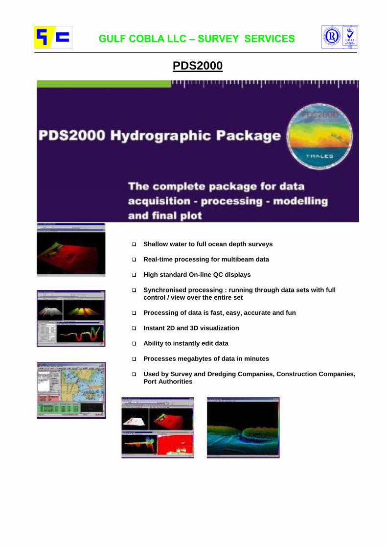
6. SURVEY PROCESS
The surveying process is divided into five major stages with each stage divided into a number of groups of instructions or procedures.
Five stages of the surveying process
Stage Group Instruction or Procedure
Preparation
Planning To extract current survey data from existing sources and plan observations.
Calibration To eliminate systematic errors from survey instruments prior to observations.
Data Gathering
Verifications To ensure that instruments are gathering data to the correct standard during survey operations by comparison with other instruments.
Observation To make observations and check them on the Gathering line or in the field.
Data Logging
To store observed data and transfer to a data processing system.
Data Processing
Editing To ensure the removal of invalid data.
Selection To select values from valid data for further processing or rendering.
Data storage To store selected processed data in analogue or digital formats.
Data Analysis
Quality To determine the quality of surveyed data and compare to the required standard.
Coverage To determine that sufficient valid data has been surveyed.
Data Rendering
Reports To report dangers before the completed survey is rendered.
Plots To render data as graphics.
ROS Digital To write the report of survey.
Data Field To render digital data
Record To render field records

7. QUALITY CONTROL Gulf Cobla LLC is ISO 9002 certified for its entire operations, which also includes its survey services.
7.1 Ensuring Accuracy in Survey Equipment/Instrument is calibrated/checked as required prior to any survey execution. Calibration is done according to Equipment/Instrument instructions. Required Accuracy is maintained. Results of calibration are recorded using appropriate forms. Forms clearly indicate the details of calibration and the achieved accuracies. Results of calibration are agreed to the Client's Satisfaction. Reports are produced with detailed information.
7.2 Survey Execution Surveys are executed as planned. (Subject to natural influences) The Client is generally present while the surveys are executed, if required. Data is recorded in electronic format. Drawings are provided in required format, and produced in appropriate scale as requested. As executed survey details are handed over to Client on the spot, if required.
7.3 Customer Satisfaction Our Clients are provided with complete survey details: Survey Execution Report comprising of
The executed scope of works. The Survey Execution Report form of the actual execution on site. Drawings (to scale, as required) Survey Data As executed Survey Soundings Attachments of all Equipment/Instrument Calibration Sheets, (Detailing the calibration values and accuracy's as executed on site) All Drawings & Data are provided in Electronic format as required/requested. Specifications of used Equipment/Instrument.

Attachment -1
CURRICULUM VITAE OF KEY PERSONNEL

___________________________ Mohammed Akram Butt ______________________________
Personal Details : Position in firm Chief Surveyor Contact e-mail [email protected] Date of Birth 14th March 1952 Marital Status Married Nationality Pakistani Years in dredging industry since 1975 Years with firm since 1975 ________________________________________________________________________________
Education : 1969 - 1972 Diploma of Associate Engineer Civil Technology of Government Polytechnic Institute, Pakistan ________________________________________________________________________________
Other Qualifications:
Certification Survey Training Courses by Thales Geo Solutions
Training course on GPS techniques, geodetic datums and projection method
Well experienced with dredging and reclamation projects and specialized in survey.
Equipment specific training for: Leica DGPS-530 Total station TC-1800 Total station Sokkia Set 2C
________________________________________________________________________________
Languages : Urdu: Mother tongue English: Fluent Arabic: Basic knowledge ________________________________________________________________________________
Business Experience : 2000 - present GULF COBLA (L.L.C.), DUBAI, U.A.E. Chief Surveyor
Responsible for all dredger positioning control systems and supervision of all survey related activities.
1992 - 2000 Chief Surveyor
Several projects in U.A.E., Oman, K.S.A. and Bahrain. 1977 - 1992 Surveyor
Jebel Ali Harbour Project - Dubai
South Peripheral Channel - Abu Dhabi
Various small projects - Dubai and Abu Dhabi 1975 - 1977 Asst. Surveyor
Creek Project - Dubai 1972 - 1975 Surveyor, Pakistan

__________________________________Tareq Alobied _________________________________
Personal Details : Position in firm Project Manager Contact e-mail [email protected] Date of Birth 17 September 1976 Marital Status Married Nationality Syrian Years in dredging industry since 2000 Years with firm since 2000
________________________________________________________________________________
Education : 1999 Diploma in Civil Engineering from Al Bath University, Homs, Syria
(Faculty of Civil Engineering) ________________________________________________________________________________
Other qualifications:
Certification Survey Training Courses by Thales Geo Solutions
Quality Management System Training Courses by Lloyds
Advanced user of Auto Cad and survey data software ________________________________________________________________________________
Languages: Arabic: Mother tongue English: Fluent ________________________________________________________________________________
Business Experience : 2002 – present GULF COBLA (L.L.C.), DUBAI, U.A.E.
Project Manager
Amwaj School Island Project, Bahrain
Fujairah Naval Base, Fujairah
Hamriyah Offshore Dredging Inner Habour Project, Sharjah 2001 - 2002 Asst. Project Manager
Amwaj Island Development - Dredging and Reclamation, Bahrain.
Development of Al Shamaliah Island, Abu Dhabi.
Extension of Dhow Harbour & Marine Police Unit Berths, Abu Dhabi.
Qarin Al Aysh project, Abu Dhabi
Independent execution of surveys using specialized software in the UAE, Bahrain, Oman and Eritrea.
Involved with production optimalization/calculations
2001 - 2002 Asst. QA / QC Manager
Assisting in maintaining the company’s QMS system 2000 - 2001 Project Engineer
Involved with the preparation/execution of various dredging and survey projects, pre-post dredging surveys, quantity calculations.

__________________________ Bram Boot __________________________ Personal details:
Position in firm Project Control Engineer Contact e-mail [email protected] Date of Birth 18th November 1978 Marital Status Single Nationality Dutch Years in dredging industry One Years with firm since 2005
____________________________________________________________________________ Education:
1998 - 2003 B.Sc. Civil Engineering, Higher Institute of Technology, Velp, The Netherlands
____________________________________________________________________________ Other qualifications:
Experienced with computer hardware and software
Attended training course on survey equipment and software
Certification of Safety Awareness for Operational Executives ____________________________________________________________________________ Languages: Dutch: mother tongue English: fluent German: moderate Spanish/French: basic knowledge ____________________________________________________________________________ Business Experience: 2005 - Present GULF COBLA (L.L.C.), DUBAI, U.A.E.
Project Control Engineer
Involved with the preparation/execution of all Dredging, Reclamation and Survey projects, dealing with cut-fill plans, pre-post dredging surveys, quantity calculations and control by using specialized software, CAD programs and spread sheets.

________________________________ Soman Anil _____________________________________
Personal Details : Position in firm Assistant Surveyor Date of Birth 30th April 1957 Marital Status Married Nationality Indian Years in dredging industry since 1979 Years with firm since 1980
________________________________________________________________________________
Education : 1974 Secondary School Leaving Certificate from Board of Public
Examination, Kerala, India. ________________________________________________________________________________
Other qualifications:
Well experienced with Hydrographic and Topographic Survey works
Able to handle all type of survey equipment, survey boat and other survey computer.
________________________________________________________________________________
Languages : Malayalam : Mother tongue English : Fluent ________________________________________________________________________________
Business Experience : 1998 - present GULF COBLA (L.L.C.), DUBAI, U.A.E.
Assistant Surveyor
Involved independently with the various Dredging and Survey projects. Military Basin Works, Abu Dhabi Jetty Basin for Oilfield Supplies, Abu Dhabi Abu Dhabi Ship Building Dredging Works, Abu Dhabi Dredging Project at Sitra, Bahrain Bel Ghaylam Channel Project, Abu Dhabi Amwaj Projects in Bahrain
1992 - 1998 Chainman
Responsible for day to day survey works on various sites such as: Mamzar Project Qarin Al Aysh Project
and many other small projects.
1981 - 1992 Chainman
Dubai Creek
Farasan, Saudi Arabia
Abu Dhabi
1980 - 1981 Joined as a Deckhand
Worked as Deckhand on various dredgers at Jebel Ali Project.
________________________________ Mohammad Anwar ______________________________
Personal Details : Position in firm Chainman Date of Birth 1st September 1957 Marital Status Married Nationality Pakistani Years in dredging industry since 1976 Years with firm since 1998
________________________________________________________________________________
Education : 1974 Secondary.
________________________________________________________________________________
Other qualifications:
Well experienced and knowledge of Hydrographic Survey and independently handle Topographic Survey.
Able to handle all various of survey equipment and survey boat. ________________________________________________________________________________
Languages : Urdu : Mother tongue English : Fair ________________________________________________________________________________
Business Experience : 1998 - present GULF COBLA (L.L.C.), DUBAI, U.A.E.
Chainman
Involved independently with various Dredging projects: MIS Quay Expansion Project, Sharjah. Al Yasat Dredging, Abu Dhabi. Fujairah Desalination & Power plant project. Fujairah Naval Port Project.
1995 - 1998 Chainman
Worked with Dutco Earth Works Division on their various projects in Dubai, U.A.E.
1992 - 1995 Chainman
Gulf Cobla recalled for their new project Dubai, U.A.E.
1982 - 1992 Chainman
Worked in Costain International Ltd., Saudi Arabia
1976 - 1982 Joined as a Chainman
Worked as Chainman with Jebel Ali Project and transferred to Saudi Arabia to their Farazan Project.

___________________________________ R. Gupta ____________________________________
Personal Details : Position in firm Chainman Date of Birth 15th September 1968 Marital Status Married Nationality Indian Years in dredging industry since 1992 Years with firm since 1992
________________________________________________________________________________
Education : 1985 Secondary.
________________________________________________________________________________
Other qualifications:
Well experienced in the field of Hydrographic Survey and able to handle various type of survey equipment and survey boat.
________________________________________________________________________________
Languages : Hindi : Mother tongue English : Fair ________________________________________________________________________________
Business Experience : 1992 - present GULF COBLA (L.L.C.), DUBAI, U.A.E.
Chainman-cum-Survey Launch Driver
Involved with the various Dredging and Survey projects: Hydrographic Survey off Musnouah Island, Abu Dhabi for Hyder
Consulting Bin Suroor Survey, Mussafah, for Halcrow International Partnership Survey for Fujairah Port Authorities Survey at Al Shahama Palace, Abu Dhabi
Worked as a Helper/Launch Driver/Chainman with almost all small-scale survey contracts with Gulf Cobla all over Middle East.

Attachment -2
LIST OF SURVEY EQUIPMENT
Survey Vessels & navigation licenses Satellite position instrument for hydrographic survey purpose Other position for navigation / research purpose Echo sounders Transducers Heave Pitch and Roll compensator Total station Others

Survey Vessels
Mercator Bay
Hondius Bay
Specification Mercator Bay Hondius Bay Dolphin Bay
Power 180 Hp 150 Hp 180 Hp
Length o.a. 7.00 m 6.40 m -- m
Breadth o.a. 2.80 m 2.45 m -- m
Depth 1.40 m 2.30 m -- m
Draught 0.38 m 0.40 m 0.40 m
Navigation License Yes No Yes

Navigation licenses


Navigation / research


General Navigation / Research
With the Garmin GPSMAP 176C, you'll get a clear picture of where you are and where you're going. This chartplotter takes up a small footprint, yet features a large, 16-color transflective screen. The Garmin GPSMAP 176C offers excellent map detail and accepts additional data from MapSource CD-ROMs* including BlueChart* marine cartography and MetroGuide* for address level city street detail.
Map Page
Load enhanced map detail with optional BlueChart and other MapSource CD-ROMS and data cards.
Tide Tables
Built-in U.S. tide data provides tide information by date and location
Navigation Page
Shows direction to destination, speed, distance and much more.
Trip Computer
Displays navigation information for your travels on land or sea

Truly a small wonder, the eTrex takes the best features of a 12 parallel channel GPS receiver and put them into a six ounce package that is only four inches high and two inches wide. The result is a unit that will literally fit in the palm of your hand.
Inside the eTrex, you will find the proven performance of a 12 parallel channel GPS receiver that will run for 18 hours on just two AA batteries. No need to worry about dense tree canopy with this unit, the eTrex will continue to maintain a tight satellite lock even while operating in forest-like conditions. The eTrex will store up to 500 user waypoints with graphic icons.
Garmin e-Trex Features
Receiver:Differential-ready, 12 parallel channel GPS receiver continuously tracks and uses up to 12 satellites to compute and update your position
Acquisition Times Warm: approx. 15 seconds Cold: approx. 45 seconds AutolocateTM: approx. 2 minutes
Update Rate: 1 second, continuous
Accuracy:Position, 15 meters (49 feet) RMS*
Velocity: 0.1 knot RMS steady state
Dynamics: 6g's
Interfaces: RS232 with NMEA 0183, RTCM 104 DGPS data format.
Antenna: Built-in patch (does not support external antenna)
Display: 1.1"W x 2.1"H, high-contrast LCD with bright backlighting
Waypoints: 500 with name and graphic symbol
Track Log: Automatic track log; 10 saved tracks
Route: 1 reversible route with up to 50 waypoints
TracBackª: Navigate saved tracks
Map Datums: More than 100 Position format: Lat/Lon, UTM/UPS, Maidenhead, MGRS, and other grids.

Echosounder Navisound 200 Series
Portable, highly compact, lightweight unit Broadband frequency agile Multiple bottom digitizing with single frequency for sediment and vegetation surveys Supports single or alternating channel operations High-performance, easy-to-operate, and very reliable
RESON's NaviSound 200 Series are highly portable, single-beam echosounders that offer a range of high-performance features. With a selection of models, the NaviSound 200 Series supports a wide range of hydrographic survey applications.
NaviSound 200 echosounders provide reliable depth measurements in a convenient, easy-to-operate unit. Advanced features include multiple bottoms digitizing with a single frequency for sediment and vegetation surveys. Besides its compact size and low weight, the Navisound 200 enclosure provides the highest possible water resistance.
An affordable side-looking sonar (SLS) option that records dual-sided imagery is also available for selected NaviSound 200 models.
Individual NaviSound 200 models are as follows:
NaviSound 215: Enhanced single-beam echosounder that uses one receiver channel to operate two transducers in true real-time, alternating frequency operation
NaviSound210: Basic, one-channel, single-beam echosounder for hydrographic survey operations

TECHNICAL DETAILS
Frequencies: User-selectable frequencies from 15-600 kHz. Standard 28-35 and 190-225 kHz.
Sound velocity calibration
1350-1600m/sec in 1m/sec steps
Impedance: 100 Ohm (others on request) Transducer draft comp:
0-99.99m
Max power: 300 W Graphics:
Power control: Manual or automatic Recording: 11 cm wide thermal paper recorder
Pulse length: Manual, 5 steps Resolution: 800 pixels (gray shades)
Units: Meters and feet Transfer speed :
20 lines/sec
Resolution: 1 cm (NaviSound 210 and 215)
Serial interfaces:
1: Communication,
1 dm (NaviSound 205) 2: Heave input,
Accuracy:
1 cm at 210 kHz (1 sigma), 3: Auxiliary input (DGPS)
7 cm at 33 kHz (1 sigma) 4: Repeater output
(assuming correct sound velocity and transducer draft)
Dimensions 273 x 278 x 115mm (11 x 11 x 4.5 inches)
TVC detection level:
20 Log (depth) Weight: 5.5 kg (12 lbs)
Additional feature:
Built-in barcheck utility Supply voltage: 10-28 VDC (external AC converter available)
EMC radio noise:
CE approved
MODEL COMPARISON
NaviSound 205 210 215
Output resolution: dm cm cm
Depth ranges: 0.5-100m 0.2-600m 0.2-600m
Channels/transducers: 1/1 1/1 1/2
Max sounding rate (PRF): 5 Hz 20 Hz 02/10 Hz
Heave input: - X X
NMEA output: X X X
DESOxx output protocol: - X X
Supports SLS option: - X X
AC converter option X X X

Navisound 2000
Depth Range: 0 – 650 m Channels : 1 or 2 Operating Frequency : 30 kHz band and 210 kHz band (tunable) Depth Display : 2 x 4 digits numeric LCD display Transmission Power : 300 W, 600 W and 1000 W Impedance : 100 Ohm Resolution : 1 cm Accuracy : Better than 10 cm at 30 kHz Better than 1 cm at 210 kHz Sound Velocity Compensation : 1400 – 1600 m/s, resolution 1 m/s Trans. Draft Compensation : 0-9999 cm Pulse Reception Frequency : 1-20 Hz Recorder Type : Thermal, 1400 pixels per line in a 4 step gray scale
(8 steps possible) Paper Width : 20.0 cm (7.9 in) Control : Recorder range Depth range
Time gate Approval Normal/Decreased Recorder Mode Single multifunction rotary control of all other
parameters Display of Settings : 2 x 16 character alpha numeric LCD display Additional Features : Bar check External Marker Annotation : RS-232C, RS-422 or GP-IB (IEEE 488) Repeater Output : RS-232C, RS-422 Interfacing : RS-232C, RS-422 or GP-IB (IEEE 488) Consumption : Less than 100 VA Operating Temperature : 0 – 50° C, 32 – 122° F Humidity : 5 – 90% relative non condensing Dimensions : Height : 312 mm 12.3 in (7PU) Width : 485 mm 19.0 in Depth : 335 mm 13.2 in Installation : 19 inch rack mountable or free standing

Navisound 420


Knudsen 320M
Operational Parameters
Phased Ranges: Multiple 50% overlapped phases of each range, (20% overlap optional), manual or automatic selection.
Depth Display: Two LCD (backlit) 4-digit displays for High and Low frequency.
Sound Velocity: 1300 - 1700 m/s Resolution 1 m/s, 4265 - 5577 ft/s Resolution 1 ft/s, 710 - 929 fm/s Resolution 1 fm/s
Depth Resolution: 1 cm (0-99.99), 1 dm (100-999.9), 1 m (>1000 )
Pulse Length: Automatically selected, with operator override.
Gain Controls: AGC, TVG and manual receive gain for each frequency.
Draft: 0 - 100 m Resolution 1 cm, 0 - 328.08 ft Resolution 0.01 ft 0 - 54.68 fm Resolution 0.01 fm
TX Blanking: Manually Controlled 0 - 300 m. Resolution: 0.1 m, 0 - 984.3 ft. Resolution: 0.1ft, 0 - 164.0 fm Resolution 0.1 fm
Interfaces / Connections
Frequencies: 3.5 KHz to 250 KHz Standard frequencies Include:3.5, 12, 24, 28, 30, 33, 50, 200, 210
Clock: Internal battery backed time and date clock.
Heave: TSS and Seatex compatible.
Position: Compatible with all popular GPS receivers.

Multibeam SeaBat 8101


Transducer TC2024
ff

Transducer PE4/33 – D1/210

Transducer B203

Heave Pitch and Roll Compensator


Total Station Leica TC 1800
Angle measurement 1'', 0.3 mgon
Distance measurement 1mm + 2ppm
Measuring time 3 s
Built-in programs Orientation and height transfer, Resection, Tie-distance, Stakeout
Range* 2.5 / 3.5 km
Magnification 30 x
Laser plummet
Located in alidade, turning with the instrument,
Accuracy 1.0 mm at 1.7 m

Others Tide Gauge
Tide Gauge Transducer/ Receiver Unit
Outputs.
Display of Tidal Data Range -9.99 mtrs thru 25.00 metres
Resolution 00.01m
Accuracy +/- 0.25%
LCD 0.5" High, 7 Segment, Back lit Tidal Data
LCD 4 line * 16 Alpha-Numeric Operator Parameters, Tide, Date & Time
Inputs.
Water Pressure Sensor Types 4 to 20 ma or 0 v to +5 volt
Battery Power +10v thru +30v, Nominal 10 Watts
Notes: 1. Tide Height always measured at 1 second Interval. 2. The Date, Time, S, A, R and Channel # are Recorded at Log Start and are Downloaded at RS 232 Data download.
Pressure Sensor Transducer
Maximum measuring span. 0-2.5 bar
Characteristic linear
Non-linear hysteresis & non-repeatability +/- 0.2 5%fro
Long term drift (per annum) < 0.1%
Atmospheric correction vented cable
Combined thermal zero & sensitivity error +/- 0.02% fro per deg C
Temperature operable -55 C to 120 C
Overload rating x5 pressure range
Wetted parts Iconel 625 seawater compatible
Connection cable conforms to IP68

Others: Micro Ranger
Vyner M2500 MICRORANGER Laser Rangefinders
SPECIFICATION
Model: Range: - prisms: Range: - diffuse targets Resolution: Accuracy: Measuring time: Wavelength: Peak power output: Pulse length: Pulse repetition rate: Beamwidth: Display: Power input: Consumption: Battery (12v 3Amp/hr): Dimensions: Weight: Eye safety:
M2500 MicroRanger 2500 meters 100 meters 0.1 meters ± 0.5 meters or 0.1% of range 0.2 seconds 904nm nominal 30w 25ns 400pps 8mrads LCD 5 digits 11-32vdc nominal 5w 4 hrs continuous ranging 105 x 72 x 200 (H x W x L) 1.2 kgs conforms to Class 3 BS7192:1989

Attachment-3
LIST OF SPECIALIZED SURVEY SOFTWARE

PDS1000
System Overview
PDS1000 is a PC based software package for Hydrographic Survey and Dredge Operations. The program comprises data collection, vessel guidance and data processing. The package was designed to assist a surveyor in carrying out a complete survey from planning to final charting, including preparation of dredge guidance data to support dredge operations if applicable.
The package supports a wide range of sensors and is permanently updated for new sensor types when these become available. It can be configured for simple survey-only applications up to extensive multi-beam surveys with ROV support and complex dredge projects. Special attention has been given to the user interface, which is consistent throughout all modules and easy to learn.
The package is modular by design. A separate module performs each main task of the survey or dredge operation. This makes the use of PDS1000 very flexible. Those who use only a part of PDS1000 can concentrate on the appropriate module.
PDS1000 in its current appearance was put on the market as early as 1989. At that time it was already based on Thales GeoSolutions’s lengthy experience with earlier hydrographic software systems. Since 1989, the system has been improved, adjusted and extended in order to keep up with contemporary survey requirements. It makes it an effective and flexible tool for hydrographic survey and dredge operations.
Applications
Over 450 users have used PDS1000 in many different applications. Some of these are named here:
1- Hydrographic Surveys 2- Multibeam echosounder surveys 3- Maintenance dredging 4- Land reclamation projects 5- Pipeline/trench construction 6- Harbour maintenance and construction 7- Environmental dredging.
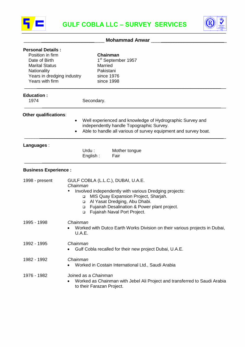
PDS2000
Shallow water to full ocean depth surveys
Real-time processing for multibeam data
High standard On-line QC displays
Synchronised processing : running through data sets with full control / view over the entire set
Processing of data is fast, easy, accurate and fun
Instant 2D and 3D visualization
Ability to instantly edit data
Processes megabytes of data in minutes
Used by Survey and Dredging Companies, Construction Companies, Port Authorities


Attachment-4
INFORMATION & CALIBRATION SHEETS


D.G.P.SClient/Empolyer:
Consultant:
Main Contractor:
Project:
Date of Survey:
Type of Survey: Predredge Intermediate Check Postdredge
Type: Accuracy:1 NOVATEL 0.20 m
2 GBX PRO 0.50 m
3 LEICA 530 0.05 m
Instructions:
A. Agree 3 established stations with Easting, Northing and Elevation.
Easting Northing Elevation
Station No. 1
Station No. 2
Station No. 3
B. Setup GPS fix (shore) station on station No 1.
C. Setup GPS mobile station on the survey vessel and establish radio data link
between shore and mobile station.
D. Establish a healthy satelite reception and a differential global position.
E. Sail survey vessel near agreed station No. 2 and monitor output position.
F. Measure distance from satelite antenna to station No. 2.
G. 'Calculate position and check with station coordinates.
System output coordinates Actual distance Observed distance
Easting [m]
Northing [m]
'* For details on equipment accuracy refer to user manual.
'Approval for calibration of satelite positioning sytstem and further use:
For Client/Consultant For Main Contractor For Gulf Cobla
SUR.P.920 Rev.03 19/01/06

TOTAL STATIONClient/Empolyer:
Consultant:
Main Contractor:
Project:
Date of Survey:
Type of Survey: Predredge Intermediate Check Postdredge
Type: Accuracy:1 LEICA TC 1800 0.05 m
2 SOKKIA SET 2C 0.05 m
Instructions:
A. Agree 3 established stations with Easting, Northing and Elevation.
Easting Northing Elevation
Station No. 1
Station No. 2
Station No. 3
B. Setup total station on station No. 1.
C. Measure distance from 1 to 2, 1 to 3 and check with calculated distance.
D. Set up base bearing 1 - 2.
E. Measure bearing 1 - 3 and check with calculated bearing.
Actual Observed
calculations readings
Distance 1 - 2 [m]
Distance 1 - 3 [m]
Bearing 1 - 3 [degr.]
* For details on equipment calibration refer to user manual or QMS.P.110
Approval for calibration of total station and further use:
For Client/Consultant For Main Contractor For Gulf Cobla
SUR.P.920 Rev.03 19/01/06

ECHO SOUNDERClient/Empolyer:
Consultant:
Main Contractor:
Project:
Date of Survey:
Type of Survey: Predredge Intermediate Check Postdredge
Type: Accuracy: Frequency:1 Navisound 210 0.05 m 210 kHz
2 Navisound 215 0.05 m 210 kHz/ 33kW
3 Navisound 2000 0.05 m 210 kHz/ 33kW
4 Navisound 420 0.05 m 210 kHz/ 33kW
5 Knudsen 320M 0.05 m 210 kHz/ 33kW
Instructions:
A. Installation of echo sounder, transducer and cable connections.
B. Setup software settings.
C. Barcheck plate will be lowered at below mentioned depths.
D. Echosounder readings are being monitored.
E. Settings adjusted to confirm the echosounder readings with the physical
depths of the barcheck plate.
Calibrate barcheck lead [m]. Measurement starts from top of bar plate.
Actual Measured Actual Measured
1 7
2 8
3 9
4 10
5 11
6 12
No. Depth barcheck Observed depth No. Depth barcheck Observed depth
plat [m] reading [m] plat [m] reading [m]
1 7
2 8
3 9
4 10
5 11
6 12
* For details on equipment calibration refer to user manual or QMS.P.110
Approval for calibration of total station and further use:
For Client/Consultant For Main Contractor For Gulf Cobla
SUR.P.920 Rev.03 19/01/06

TIDE READINGSClient/Empolyer:
Consultant:
Main Contractor:
Project:
Date of Survey:
Type of Survey: Predredge Intermediate Check Postdredge
- Depth calibration by means of standard barcheck procedure with barcheck plate.
- Position calibration by means of satellite position output and coordinates provided
by Consultant or as set up by Gulf Cobla.
- Tide readings taken on the spot are related to Datum
Time Tide Time Tide
For Client/Consultant For Main Contractor For Gulf Cobla
SUR.P.920 Rev.03 19/01/06

Attachment-5
PROJECT EXECUTION CHART


Attachment-6
LIST OF RECENT WORKS

GULF COBLA (L.L.C.) Survey List of Projects Executed
HS= Hydrographic Survey TS= Topographic Survey
GC Name Location Country Client Type Consulting Engineers Date
Vopak Fujairah Terminal Fujairah U.A.E Vopak Horizon Fujairah HS N/A Jun-07
Design survey Djibouti Djibouty City Djibouti Al Boom Holdings HS Style Consultants Jun-07
Al Raha Beach survey Abu Dhabi
U.A.E. Soletanche Bachy & NSCC
HS/TS N/A Mar-07
Survey at Qaffay Island Abu Dhabi U.A.E. Dutco Balfour Beatty LLC HS N/A Jan-07
Dubai Festival City Project Dubai U.A.E.
Dutco Balfour Beatty LLC HS N/A Dec-06
Dubai Marina at Mina Seyahi Dubai U.A.E. Dutco Balfour Beatty LLC HS N/A Nov-06
Dubai Drydocks Safina Project Dubai
U.A.E.
N.S.C.C.
HS N/A Sep-06
Palm Jumirah Monorail Jumeirah U.A.E. Palm Jumeirah Monorail HS N/A Aug-06
Sohar Port Sohar Port Oman
Van Oord FZE
HS N/A Jul-06
Dubai Drydock Safina Project Dubai U.A.E. N.S.C.C. HS N/A Jun-06
Al Ygalat Fishing Harbour Fujairah U.A.E. Port of Fujairah HS N/A Feb-06
Dry Dock Safina Project Dubai U.A.E NSCC HS/TS N/A Nov, Dec - 05
Vopak Fujairah Terminal Fujairah U.A.E Vopak Horizon Fujairah HS N/A Oct- 05
Fujairah Port & Naval Base Fujairah U.A.E Fujairah Port Autorities HS N/A Oct- 05
Palm jumairah Island Survey Dubai U.A.E Taisee HS Parson Aug- 04
Khasab Valuation Survey Khasab port Oman Dharti dredging & contracting Ltd.
HS W.S.Atkins International & Co.
May, Apr, Mar / 04
Survey Service DUBAL Dubal, Dubai U.A.E. Dubai Aluminum Co. Ltd HS Halcrow International Partnership
Apr- 04
MQE Survey Rental MIS Project, Sharjah
U.A.E. N.S.C.C. Survey services
Halcrow International Partnership
Dec- 03
Setting Out Survey Mussafah, Abu Dhabi
U.A.E. Arab Contractors Setting out survey
Halcrow International Partnership
Aug- 03
Survey Mussafah Bridge Abu Dhabi U.A.E. Arab Contractors HS Halcrow International Partnership
Aug- 03
Musnouah Island Abu Dhabi U.A.E. Hyder Consulting Limited HS Hyder Consulting Limited
May- 03
Mina Manama Survey Manama Bahrain Al Matrook Enterprises HS N/A May- 03
Bin Suroor Survey Mussaffah Abu Dhabi U.A.E. Bin Suroor International Contracting
HS & TS Abu Dhabi Municipality Mar- 03
Survey at Sharm Fujairah U.A.E. Port of Fujairah HS & TS N/A Feb- 03
Survey at Al Yasat Aali Island Abu Dhabi - Sila U.A.E. Dubai Municipality HS Halcrow International Partnership
Jan- 03
Sharm Survey Fujairah U.A.E. Port of Fujairah HS & TS N/A Jan- 03
Survey in Dubai Marina Dubai U.A.E. Dutco Construction Company L.L.C
HS Hyder Consulting Limited
Dec- 02

Survey Al Mamzar Dubai U.A.E. Dubai Municipality HS & TS Maunsel Consultancy Dec- 02
Al Shahama Palace Survey Abu Dhabi U.A.E. Al Shahama Palace HS N/A Oct- 02
Survey at NMDC Basin Abu Dhabi U.A.E. China Harbour Engineering Co. LLC
HS Frederic R. Harris, Inc. Sep- 02
Survey Shuweihat Power Station
Abu Dhabi U.A.E. Six Construct Co. Ltd HS N/A Jul-02
Survey at Port Khalid Sharjah U.A..E Dutco Balfour Beatty HS Halcrow International Partnership
Apr- 02
Hydrographic Survey for rehabilitation of Port of Massawa
Massawa Eritria United Nations HS Keangnam Enterprises Ltd
Feb- 02 May- 02
Survey at Al Yasat Island Abu Dhabi U.A.E Dutco Balfour Beatty HS & TS Halcrow International Partnership
May- 02
Bathymetric Survey Fujairah Port of' Fujairah U.A.E Port of Fujairah HS & TS N/A Feb- 02
Bathymetric Survey Umm Al Nar
Abu Dhabi - Umm Al Nar
U.A.E SIX Construct Ltd. HS Render Palmer & Tritton Jan- 02
Survey NMDC Facilities Abu Dhabi - Mussaffah
U.A.E China Harbour Engineering Co. LLC
HS Frederic R. Harris, Inc. May- 01
Invest. Survey Khalid Lagoon Sharjah U.A.E Halcrow International Partnership
HS Halcrow International Partnership
Jan- 01
Survey at U.A.N Refinary Abu Dhabi - Umm Al Nar
U.A.E Abnormal Load Engineering
HS N/A Jan- 01
Offshore Fish Hides Survey Abu Dhabi - Qarin Al Aysh
U.A.E Public Works Department
HS Halcrow International Partnership
Dec- 00
Survey at Al Seef and Al Shamal
Dubai Creek U.A.E Overseas AST CO. LLC. HS & TS Maunsell Sep- 00
Hydrographic Survey at Taweelah
Abu Dhabi - Taweelah
U.A.E Square General LTD HS N/A Jun- 00
Offshore Fish Hides Survey Abu Dhabi - Qarin Al Aysh
U.A.E Public Works Department
HS Halcrow International Partnership
Jun- 00
Survey at Al Mamzar Dubai - Al Mamzar Corniche
U.A.E The Arab Contractors HS Maunsell Apr- 00
FAL Shipping Sharjah Port U.A.E FAL SHIPPING CO. LTD HS N/A Nov- 99
Khussifa Channel Dredging Abu Dhabi - Khussifa
U.A.E HAM Dredging Company HS & TS Halcrow International Partnership
Sep- 99
Survey at East Coat Fujairah - Dibba U.A.E Dutco Construction Co. LLC
HS N/A Sep- 99