Surgical and Interventional Robotics Core Concepts, Technology, and Design
19
Surgical and Interventional Robotics: Core Concepts, Technology, and Design PETER KAZANZIDES, GABOR FICHTINGER, GREGORY D. HAGER, ALLISON M. OKAMURA, LOUIS L. WHITCOMB, and RUSSELL H. TAYLOR Keywords Surgical robots; medical robots; robot safety Two decades after the first reported robotic surgical procedure [1], surgical robots are just beginning to be widely used in the operating room or interventional suite. The da Vinci telerobotic system (Intuitive Surgical, Inc.), for example, has recently become more widely employed for minimally invasive surgery [2]. This article, the first in a three-part series, examines the core concepts underlying surgical and interventional robots, including the potential benefits and technical approaches, followed by a summary of the technical challenges in sensing, manipulation, user interfaces, and system design. The article concludes with a review of key design aspects, particularly in the areas of risk analysis and safety design. Note that medical care can be delivered in a surgical suite (operating room) or an interventional suite, but for convenience, we will henceforth use the term surgical to refer to both the surgical and interventional domains. Core Concepts This section describes some of the potential benefits of surgical robots, followed by an overview of the two technical paradigms, surgical computer-aided design and computer-aided manufacturing (CAD/CAM) and surgical assistance, which will be the subjects of the second and third articles in this series. Potential Benefits The development of surgical robots is motivated primarily by the desire to enhance the effectiveness of a procedure by coupling information to action in the operating room or interventional suite. This is in contrast to industrial robots, which were developed primarily to automate dirty, dull, and dangerous tasks. There is an obvious reason for this dichotomy: medical care requires human judgment and reasoning to handle the variety and complexity of human anatomy and disease processes. Medical actions are chosen based on information from a number of sources, including patient-specific data (e.g., vital signs and images), general medical knowledge (e.g., atlases of human anatomy), and physician experience. Computer- assisted interventional systems can gather and present information to the physician in a more meaningful way and, via the use of robots, enable this information to influence the performance of an intervention, thereby potentially improving the consistency and quality of the clinical result. It is, therefore, not surprising that surgical robots were introduced in the 1980s, after the dawn of the information age, whereas the first industrial robot was used in 1961. Address for Correspondence: Peter Kazanzides, Department of Computer Science, CSEB 120, Johns Hopkins University, 3400 North Charles Street, Baltimore, MD 21218, USA. [email protected]. NIH Public Access Author Manuscript IEEE Robot Autom Mag. Author manuscript; available in PMC 2010 April 27. Published in final edited form as: IEEE Robot Autom Mag. 2008 June 1; 15(2): 122–130. doi:10.1109/MRA.2008.926390. NIH-PA Author Manuscript NIH-PA Author Manuscript NIH-PA Author Manuscript
-
Upload
independent -
Category
Documents
-
view
2 -
download
0
Transcript of Surgical and Interventional Robotics Core Concepts, Technology, and Design

Surgical and Interventional Robotics:Core Concepts, Technology, and Design
PETER KAZANZIDES, GABOR FICHTINGER, GREGORY D. HAGER, ALLISON M.OKAMURA, LOUIS L. WHITCOMB, and RUSSELL H. TAYLOR
KeywordsSurgical robots; medical robots; robot safety
Two decades after the first reported robotic surgical procedure [1], surgical robots are justbeginning to be widely used in the operating room or interventional suite. The da Vincitelerobotic system (Intuitive Surgical, Inc.), for example, has recently become more widelyemployed for minimally invasive surgery [2]. This article, the first in a three-part series,examines the core concepts underlying surgical and interventional robots, including thepotential benefits and technical approaches, followed by a summary of the technical challengesin sensing, manipulation, user interfaces, and system design. The article concludes with areview of key design aspects, particularly in the areas of risk analysis and safety design. Notethat medical care can be delivered in a surgical suite (operating room) or an interventionalsuite, but for convenience, we will henceforth use the term surgical to refer to both the surgicaland interventional domains.
Core ConceptsThis section describes some of the potential benefits of surgical robots, followed by anoverview of the two technical paradigms, surgical computer-aided design and computer-aidedmanufacturing (CAD/CAM) and surgical assistance, which will be the subjects of the secondand third articles in this series.
Potential BenefitsThe development of surgical robots is motivated primarily by the desire to enhance theeffectiveness of a procedure by coupling information to action in the operating room orinterventional suite. This is in contrast to industrial robots, which were developed primarily toautomate dirty, dull, and dangerous tasks. There is an obvious reason for this dichotomy:medical care requires human judgment and reasoning to handle the variety and complexity ofhuman anatomy and disease processes. Medical actions are chosen based on information froma number of sources, including patient-specific data (e.g., vital signs and images), generalmedical knowledge (e.g., atlases of human anatomy), and physician experience. Computer-assisted interventional systems can gather and present information to the physician in a moremeaningful way and, via the use of robots, enable this information to influence the performanceof an intervention, thereby potentially improving the consistency and quality of the clinicalresult. It is, therefore, not surprising that surgical robots were introduced in the 1980s, afterthe dawn of the information age, whereas the first industrial robot was used in 1961.
Address for Correspondence: Peter Kazanzides, Department of Computer Science, CSEB 120, Johns Hopkins University, 3400 NorthCharles Street, Baltimore, MD 21218, USA. [email protected].
NIH Public AccessAuthor ManuscriptIEEE Robot Autom Mag. Author manuscript; available in PMC 2010 April 27.
Published in final edited form as:IEEE Robot Autom Mag. 2008 June 1; 15(2): 122–130. doi:10.1109/MRA.2008.926390.
NIH
-PA Author Manuscript
NIH
-PA Author Manuscript
NIH
-PA Author Manuscript
There are, however, cases where surgical robots share potential benefits with industrial robotsand teleoperators. First, a robot can usually perform a task more accurately than a human; thisprovides the primary motivation for surgical CAD/CAM systems, which are described later inthe “Surgical CAD/CAM” section. Second, industrial robots and teleoperators can work inareas that are not human friendly (e.g., toxic fumes, radioactivity, or low-oxygen environments)or not easily accessible to humans (e.g., inside pipes, the surface of a distant planet, or the seafloor). In the medical domain, inhospitable environments include radiation (e.g., X-rays) andinaccessible environments include space-constrained areas such as the inside of a patient orimaging system. This also motivates the development of surgical CAD/CAM systems and isone of the primary motivations for surgical assistant systems, described in the “SurgicalAssistance” section.
In contrast to industrial robots, surgical robots are rarely designed to replace a member of thesurgical or interventional team. Rather, they are intended to augment the medical staff byimparting superhuman capabilities, such as high motion accuracy, or to enable interventionsthat would otherwise be physically impossible. Therefore, methods for effective human-robotcooperation are one of the unique and central aspects of medical robotics.
Technical ParadigmsIn our research, we find it useful to categorize surgical robots as surgical CAD/CAM or surgicalassistance systems, based on their primary mode of operation [3]. Note, however, that thesecategories are not mutually exclusive and some surgical robots may exhibit characteristics fromboth categories. The following sections briefly describe these categories, with representativeexamples.
Surgical CAD/CAM—The basic tenet of CAD/CAM is that the use of a computer to designa part creates a digital blueprint of the part, and so it is natural to use a computer-controlledsystem to manufacture it, i.e., to translate the digital blueprint into physical reality. In themedical domain, the planning that is often performed prior to, or during, an interventioncorresponds to CAD, whereas the intervention represents CAM. To take the analogy further,postoperative assessment corresponds to total quality management (TQM). We refer to theclosed-loop process of 1) constructing a patient-specific model and interventional plan; 2)registering the model and plan to the patient; 3) using technology to assist in carrying out theplan; and 4) assessing the result, as surgical CAD/CAM, again emphasizing the analogybetween computer-integrated medicine and computer-integrated manufacturing (Figure 1).
The most well-known example of a surgical CAD/CAM system is ROBODOC (ROBODOC,a Curexo Technology Company; formerly Integrated Surgical Systems, Inc.) [4], [5].ROBODOC was developed for total hip and total knee replacement surgeries (Figure 2). Inthese surgeries, the patient’s joint is replaced by artificial prostheses: for hip surgery, oneprosthesis is installed in the femur and another in the acetabulum (pelvis) to create a ball andsocket joint; for knee surgery, one prosthesis is installed in the femur and the other in the tibiato create a sliding hinge joint. Research on ROBODOC began in the mid-1980s as a jointproject between IBM and the University of California, Davis. At that time, the conventionaltechnique for hip and knee replacement surgery consisted of two-dimensional (2-D) planning(using X-rays) and manual methods (handheld reamers and broaches) for preparing the bone.The motivation for introducing a robot was to improve the accuracy of this procedure—boththe placement accuracy (to put the prostheses in the correct places) and the dimensionalaccuracy (to get a good fit to the bones). The technical approach of the system is to usecomputed tomography (CT) for three-dimensional (3-D) planning and a robot for automatedbone milling. The planning (surgical CAD) is performed on the ORTHODOC workstation,which enables the surgeon to graphically position a 3-D model of the prosthesis (or prostheses)
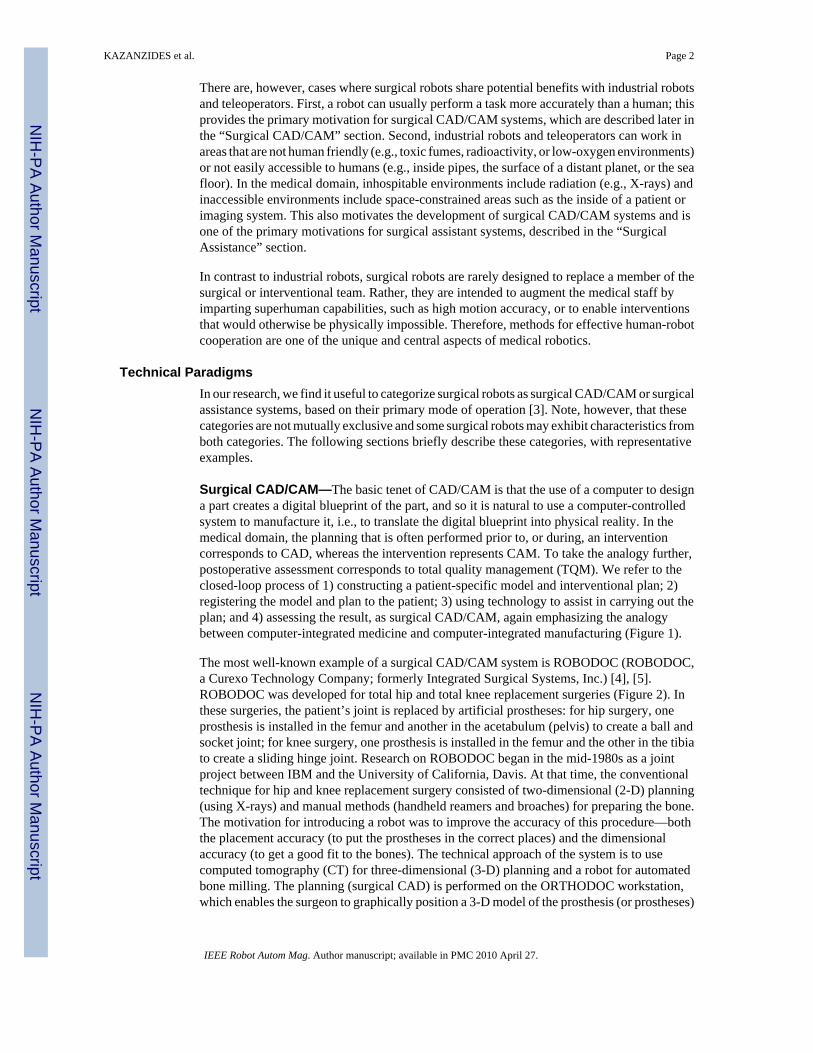
KAZANZIDES et al. Page 2
IEEE Robot Autom Mag. Author manuscript; available in PMC 2010 April 27.
NIH
-PA Author Manuscript
NIH
-PA Author Manuscript
NIH
-PA Author Manuscript

with respect to the CT image, thereby creating a surgical plan. In the operating room (SurgicalCAM), the robot is registered to the CT image so that the surgical plan can be transformedfrom the CT coordinate system to the robot coordinate system. The robot then machines thebone according to the plan, using a high-speed milling tool.
Surgical Assistance—Medical interventions are highly interactive processes, and manycritical decisions are made in the operating room and executed immediately. The goal ofcomputer-assisted medical systems, including surgical robots, is not to replace the physicianwith a machine but, rather, to provide intelligent, versatile tools that augment the physician’sability to treat patients. There are many forms of technological assistance. In this section, wefocus on robotic assistance. Some nonrobotic technologies are reviewed in the “OtherTechnologies” section.
There are two basic augmentation strategies: 1) improving the physician’s existing sensingand/or manipulation, and 2) increasing the number of sensors and manipulators available tothe physician (e.g., more eyes and hands). In the first case, the system can give even averagephysicians superhuman capabilities such as X-ray vision, elimination of hand tremor, or theability to perform dexterous operations inside the patient’s body. A special subclass is remotetelesurgery systems, which permit the physician to operate on patients at distances rangingfrom a few meters to several thousand kilometers. In the second case, the robot operates sideby side with the physician and performs functions such as endoscope holding, tissue retraction,or limb positioning. These systems typically provide one or more direct control interfaces suchas joysticks, head trackers, or voice control but could also include intelligence to demand lessof the physician’s attention during use.
The da Vinci system (Intuitive Surgical, Inc.) is a telesurgery system that demonstrates bothof these augmentation approaches [2]. As shown in Figure 3, the system consists of a patient-side slave robot and a master control console. The slave robot has three or four robotic armsthat manipulate a stereo endoscope and dexterous surgical instruments such as scissors,grippers, and needle holders. The surgeon sits at the master control console and grasps handlesattached to two dexterous master manipulator arms, which are capable of exerting limitedamounts of force feedback to the surgeon. The surgeon’s hand motions are sensed by the mastermanipulators, and these motions are replicated by the slave manipulators. A variety of controlmodes may be selected via foot pedals on the master console and used for such purposes asdetermining which slave arms are associated with the hand controllers. Stereo video istransmitted from the endoscope to a pair of high-quality video monitors in the master controlconsole, thus providing high-fidelity stereo visualization of the surgical site. The display andmaster manipulators are arranged so that it appears to the surgeon that the surgical instruments(inside the patient) are in the same position as his or her hands inside the master control console.Thus, the da Vinci system improves the surgeon’s eyes and hands by enabling them to(remotely) see and manipulate tissue inside the patient through incisions that are too small fordirect visualization and manipulation. By providing three or four slave robot arms, the da Vincisystem also endows the surgeon with more than two hands.
Other TechnologiesRobotics is not the only manner in which computers can be used to assist medical procedures.One important, and widely used, alternative is a navigation system, which consists of a sensor(tracker) that can measure the position and orientation of instruments in 3-D space (typically,the instruments contain special tracker targets). If the tracker coordinate system is registeredto a preoperative or intraoperative image (see the “Registration” section), the navigation systemcan display the position and orientation of the instrument with respect to the image. Thisimproves the physician’s visualization by enabling him or her to see the internal structure,
KAZANZIDES et al. Page 3
IEEE Robot Autom Mag. Author manuscript; available in PMC 2010 April 27.
NIH
-PA Author Manuscript
NIH
-PA Author Manuscript
NIH
-PA Author Manuscript

molecular information, and/or functional data, depending on the type of image. This can alsoenable the physician to execute a preoperative plan (surgical CAD/CAM), e.g., by aligning aninstrument with respect to a target defined in the preoperative image. Currently, the most widelyused tracking technology is optical because of its relatively high accuracy, predictableperformance, and insensitivity to environmental variations. The primary limitation of opticaltrackers is that they require a clear line of sight between the camera and the instruments beingtracked. This precludes their use for instruments inside the body. Electromagnetic trackingsystems are free from line-of-sight constraints but are generally less accurate, especially dueto field distortions caused by metallic objects.
Technology and ChallengesSurgical robots present a unique set of design challenges due to the requirements forminiaturization, safety, sterility, and adaptation to changing conditions. This section reviewscurrent practices and challenges in manipulation, sensing, registration, user interfaces, andsystem design.
ManipulationSurgical robots must satisfy requirements not found in industrial robotics. They must operatesafely in a workspace shared with humans; they generally must operate in a sterile environment;and they often require high dexterity in small spaces. An additional challenge occurs when therobot must operate in the proximity of a magnetic resonance imaging (MRI) scanner, whosehigh magnetic field precludes the use of many conventional robotic components.
The topic of safety design is covered in detail in the “Safety Design” section. There are,however, certain safety factors that should be considered during the design of a surgicalmanipulator. First, unlike industrial robots, where speed and strength are desirable attributes,a surgical robot should only be as fast and strong as needed for its intended use. In most cases,the robot should not be capable of moving faster or with more force than the physician. Anobvious exception could occur for a robot that operates on a rapidly moving organ, such as abeating heart. Even in this case, there are innovative solutions that do not require rapid motion,such as Heartlander [6], which is designed to attach to a beating heart using suction and movealong it with inchworm locomotion. Another safety-related design parameter is the robot’sworkspace, which ideally should only be as large as needed. This is difficult to achieve inpractice, given the high variability between patients and the differences in the way thatphysicians perform procedures. Some researchers have reported parallel manipulators, whichhave smaller workspaces (and higher rigidity) than serial robots [7]–[10].
Sterility is a major design challenge. It is not easy to design reusable devices that can withstandmultiple sterilization cycles. One common solution is to create a disposable device that onlyneeds to be sterilized once, usually by the manufacturer. This is practical for low-cost parts.Another issue with a reusable device is that it must be cleaned between procedures. Thus,crevices that can trap blood or other debris should be avoided. The most common approach isto design the surgical robot so that its end effector (or tool) can be removed and sterilized,while the rest of the robot is covered with a disposable sterile drape or bag (e.g., as illustratedfor ROBODOC in Figure 2). This is particularly difficult when the end effector or tool includeselectromechanical components.
Size matters for surgical robots. Operating rooms and interventional suites are usually small,and, thus, a large robot can take too much space. This has been a complaint for manycommercially available systems, such as daVinci and ROBODOC, which are large floor-standing robots. In orthopedics, there have been recent examples of smaller, bone-mountedrobots [7]–[9]. Size is especially critical when the robot, or part of it, must work inside the
KAZANZIDES et al. Page 4
IEEE Robot Autom Mag. Author manuscript; available in PMC 2010 April 27.
NIH
-PA Author Manuscript
NIH
-PA Author Manuscript
NIH
-PA Author Manuscript

body. For example, although the da Vinci system is large, its robotic EndoWrist tools, withdiameters from 5–8 mm, are a marvel of miniaturization and can pass into the body via smallentry ports.
The design of MRI-compatible robots is especially challenging because MRI relies on a strongmagnetic field and radio frequency (RF) pulses, and so it is not possible to use componentsthat can interfere with, or be susceptible to, these physical effects. This rules out mostcomponents used for robots, such as electric motors and ferromagnetic materials. Thus, MRI-compatible robots typically use nonmetallic links and piezo-electric, pneumatic, or hydraulicmotors. This topic will be discussed in greater detail in a subsequent part of this tutorial.
SensingBesides internal sensors, such as joint encoders, a surgical robot often needs external sensorsto enable it to adapt to its relatively unstructured and changing environment. Commonexamples are force sensors and vision systems, which translate naturally into the human sensesof touch and sight. For this reason, they are often used for surgical assistants. For example, theda Vinci system provides exquisite stereo video feedback, although it is often criticized for notproviding force feedback (a component of haptic feedback). Without force feedback, thesurgeon must use visual cues, such as the tautness of a suture or the deflection of tissue, toestimate the forces. If these cues are misread, the likely outcome is a broken suture or damagedtissue [11].
Real-time imaging such as ultrasound, spectroscopy, and optical coherence tomography (OCT)can provide significant benefits when they enable the physician to see subsurface structuresand/or tissue properties. For example, when resecting a brain tumor, this type of sensing canalert the surgeon before he or she accidentally cuts a major vessel that is obscured by the tumor.Preoperative images, when registered to the robot, can potentially provide this information,but only if the anatomy does not change significantly during the procedure. This is rarely thecase, except when working with rigid structures such as bones. Once again, it is necessary toovercome challenges in sterility and miniaturization to provide this sensing where it is needed,which is usually at or near the instrument tip.
Sensors that directly measure physiologic properties, such as tissue oxygenation, are alsouseful. For example, a smart retractor that uses pulse oxymetry principles to measure theoxygenation of blood can detect the onset of ischemia (insufficient blood flow) before it causesa clinical complication [12].
RegistrationGeometric relationships between portions of the patient’s anatomy, images, robots, sensors,and equipment are fundamental to all areas of computer-integrated medicine. There is anextensive literature on techniques for determining the transformations between the associatedcoordinate systems [13], [14]. Given two coordinates v⃗A = [xA, yA, zA] and v⃗B = [xB, yB, zB]corresponding to comparable features in two coordinate systems Ref A and Ref B, the processof registration is simply that of finding a function TAB(⋯) such that
Although nonrigid registrations are becoming more common, TAB(⋯) is still usually a rigidbody transformation of the form
KAZANZIDES et al. Page 5
IEEE Robot Autom Mag. Author manuscript; available in PMC 2010 April 27.
NIH
-PA Author Manuscript
NIH
-PA Author Manuscript
NIH
-PA Author Manuscript
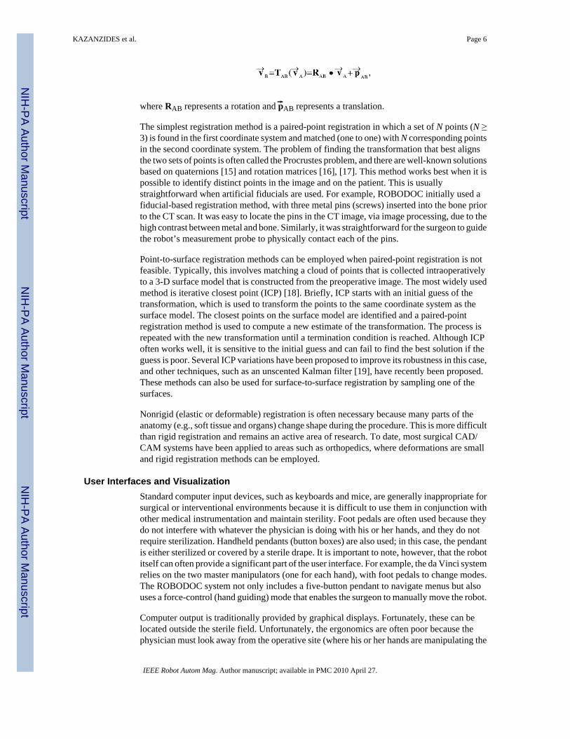
where RAB represents a rotation and p ⃗AB represents a translation.
The simplest registration method is a paired-point registration in which a set of N points (N ≥3) is found in the first coordinate system and matched (one to one) with N corresponding pointsin the second coordinate system. The problem of finding the transformation that best alignsthe two sets of points is often called the Procrustes problem, and there are well-known solutionsbased on quaternions [15] and rotation matrices [16], [17]. This method works best when it ispossible to identify distinct points in the image and on the patient. This is usuallystraightforward when artificial fiducials are used. For example, ROBODOC initially used afiducial-based registration method, with three metal pins (screws) inserted into the bone priorto the CT scan. It was easy to locate the pins in the CT image, via image processing, due to thehigh contrast between metal and bone. Similarly, it was straightforward for the surgeon to guidethe robot’s measurement probe to physically contact each of the pins.
Point-to-surface registration methods can be employed when paired-point registration is notfeasible. Typically, this involves matching a cloud of points that is collected intraoperativelyto a 3-D surface model that is constructed from the preoperative image. The most widely usedmethod is iterative closest point (ICP) [18]. Briefly, ICP starts with an initial guess of thetransformation, which is used to transform the points to the same coordinate system as thesurface model. The closest points on the surface model are identified and a paired-pointregistration method is used to compute a new estimate of the transformation. The process isrepeated with the new transformation until a termination condition is reached. Although ICPoften works well, it is sensitive to the initial guess and can fail to find the best solution if theguess is poor. Several ICP variations have been proposed to improve its robustness in this case,and other techniques, such as an unscented Kalman filter [19], have recently been proposed.These methods can also be used for surface-to-surface registration by sampling one of thesurfaces.
Nonrigid (elastic or deformable) registration is often necessary because many parts of theanatomy (e.g., soft tissue and organs) change shape during the procedure. This is more difficultthan rigid registration and remains an active area of research. To date, most surgical CAD/CAM systems have been applied to areas such as orthopedics, where deformations are smalland rigid registration methods can be employed.
User Interfaces and VisualizationStandard computer input devices, such as keyboards and mice, are generally inappropriate forsurgical or interventional environments because it is difficult to use them in conjunction withother medical instrumentation and maintain sterility. Foot pedals are often used because theydo not interfere with whatever the physician is doing with his or her hands, and they do notrequire sterilization. Handheld pendants (button boxes) are also used; in this case, the pendantis either sterilized or covered by a sterile drape. It is important to note, however, that the robotitself can often provide a significant part of the user interface. For example, the da Vinci systemrelies on the two master manipulators (one for each hand), with foot pedals to change modes.The ROBODOC system not only includes a five-button pendant to navigate menus but alsouses a force-control (hand guiding) mode that enables the surgeon to manually move the robot.
Computer output is traditionally provided by graphical displays. Fortunately, these can belocated outside the sterile field. Unfortunately, the ergonomics are often poor because thephysician must look away from the operative site (where his or her hands are manipulating the
KAZANZIDES et al. Page 6
IEEE Robot Autom Mag. Author manuscript; available in PMC 2010 April 27.
NIH
-PA Author Manuscript
NIH
-PA Author Manuscript
NIH
-PA Author Manuscript

instruments) to see the computer display. Some proposed solutions include heads-up displays,image overlay systems [20], [21], and lasers, which project information onto the operative field[22].
Surgical Robot System DesignA surgical robot includes many components, and it is difficult to design one from scratch. Thereis no off-the-shelf surgical robot for research, and it is unlikely that one robot or family ofrobots will ever satisfy the requirements of the diaspora of medical procedures. In the softwarerealm, however, there are open source software packages that can help. The most maturepackages are for medical image visualization and processing, particularly the VisualizationToolkit (VTK, www.vtk.org) and the Insight Toolkit (ITK, www.itk.org). Customizableapplications, such as 3-D Slicer (www.slicer.org), package VTK, ITK, and a plethora ofresearch modules.
Few packages exist for computer-assisted interventions. The Image Guided Surgery Toolkit(IGSTK, www.igstk.org) enables researchers to create a navigation system by connecting atracking system to a computer. At Johns Hopkins University, we are creating a softwareframework for a surgical assistant workstation (SAW), based on our Computer-IntegratedSurgical Systems and Technology (CISST) libraries [23] (www.cisst.org), which focus on theintegration of robot control and real-time sensing with the image processing and visualizationtoolkits described previously.
Surgical Robot Design ProcessThis section presents a detailed discussion of the risk analysis, safety design, and validationphases of the design process. Although these topics are not unique to surgical robots, they areobviously of extreme importance.
Risk AnalysisSafety is an important consideration for both industrial and surgical robots [24]. In an industrialsetting, safety can often be achieved by keeping people out of the robot’s workspace or byshutting down the system if a person comes too close. In contrast, for surgical robots it isgenerally necessary for human beings, including the patient and the medical staff, to be insidethe robot’s workspace. Furthermore, the robot may be holding a potentially dangerous device,such as a cutting instrument, that is supposed to actually contact the patient (in the correctplace, of course). If the patient is anesthetized, it is not possible for him or her to actively avoidinjury.
Proper safety design begins with a risk (or hazard) analysis. A failure modes effects analysis(FMEA) or failure modes effects and criticality analysis (FMECA) are the most commonmethods [25]. These are bottom-up analyses, where potential component failures are identifiedand traced to determine their effect on the system. Methods of control are devised to mitigatethe hazards associated with these failures. The information is generally presented in a tabularformat (see Table 1). The FMECA adds the criticality assessment, which consists of threenumerical parameters: the severity (S), occurrence (O), and detectability (D) of the failure. Arisk priority number (RPN) is computed from the product of these parameters, whichdetermines whether additional methods of control are required. The FMEA/FMECA is aproactive analysis that should begin early in the design phase and evolve as hazards areidentified and methods of control are developed. Another popular method is a fault tree analysis(FTA), which is a top-down analysis and is generally more appropriate for analyzing a systemfailure after the fact.
KAZANZIDES et al. Page 7
IEEE Robot Autom Mag. Author manuscript; available in PMC 2010 April 27.
NIH
-PA Author Manuscript
NIH
-PA Author Manuscript
NIH
-PA Author Manuscript

Safety DesignAs an illustrative example of how to apply these methods in the design phase, consider amultilink robot system where each link is driven by a feedback-controlled motor, as shown inFigure 4. The error, e(t), between the desired position xd(t) and the measured position xa(t) iscomputed and used to determine the control output u(t) that drives the motor. An encoder failurewill cause the system to measure a persistent steady-state error and therefore continue to drivethe motor to attempt to reduce this error. An amplifier failure can cause it to apply an arbitraryvoltage to the motor that is independent of the control signal u(t). The controller will sense theincreasing error and adjust u(t) to attempt to compensate, but this will have no effect.
These failure modes are shown in the FMEA presented in Table 1. The result in both thesecases is that the robot will move until it hits something (typically, the effect on system is moredescriptive and includes application-specific information, such as the potential harm to thepatient). This is clearly unacceptable for a surgical robot, and so methods of control arenecessary. One obvious solution, shown in Table 1, is to allow the control software to disablethe motor power, via a relay, whenever the error, e(t), exceeds a specified threshold. This willprevent a catastrophic, headline-grabbing runaway robot scenario, but is the robot safe enoughfor surgical use? The answer is that it depends on the application and on the physical parametersof the system. To illustrate this, consider the case where the power amplifier fails and appliesmaximum voltage to the motor. As shown in Figure 5, if E is the error threshold (i.e., the pointat which the control software disables motor power via the relay), the final joint position error,ΔPmax, is given by E + Vmax × ΔT + ΔPoff, where ΔT is the control period, Vmax is the maximumjoint velocity (assuming the robot had sufficient time to accelerate), and ΔPoff is the distancethe robot travels after power off due to inertia or external forces. The actual value of ΔPmaxdepends on the robot design, but it is not uncommon for this to be several millimeters. Althougha one-time glitch of this magnitude may be tolerable for some surgical procedures, it is clearlynot acceptable in others. In those cases, it is necessary to make design modifications to decreaseΔPmax, e.g., by decreasing Vmax, or to forgo the use of an active robot. This safety analysiswas a prime motivation for researchers who developed passive robots such as Cobots [26] andPADyC [27].
There are safety issues that must be considered regardless of whether a robot is active or passive.One example occurs when the robot’s task is to accurately position an instrument or instrumentguide. The position of a robot-held tool is typically determined by applying the robot’s forwardkinematic equations to the measured joint positions. An inaccurate joint sensor (e.g., anincremental encoder that intermittently gains or loses counts) can cause a large position error.One method of control is to introduce a redundant sensor and use software to verify whetherboth sensors agree within a specified tolerance. Practical considerations dictate the need for atolerance to account for factors such as mechanical compliance between the sensors anddifferences in sensor resolution and time of data acquisition. This limits the degree with whichaccuracy can be assured. Note also that although redundant sensors remove one single pointof failure (i.e., sensor failure), it is necessary to avoid a single point of failure in theimplementation. For example, if both sensors are placed on the motor shaft, they cannot accountfor errors in the joint transmission, e.g., due to a slipped belt.
A final point is that redundancy is not sufficient if failure of one component cannot be detected.For example, consider the case where the robot is holding a pneumatic cutting tool, and asolenoid is used to turn the tool on and off. If the solenoid fails in the open (on) state, the cuttingtool may be activated at an unsafe time. It is tempting to address this hazard by putting a secondsolenoid in series with the first, as shown in Figure 6. This is not an acceptable solution,however, because if one solenoid fails in the open state, the system will appear to operatecorrectly (i.e., the software can still turn the cutter on or off ). Therefore, this system once againhas a single point of failure. This is not a hypothetical scenario—it actually appeared in the
KAZANZIDES et al. Page 8
IEEE Robot Autom Mag. Author manuscript; available in PMC 2010 April 27.
NIH
-PA Author Manuscript
NIH
-PA Author Manuscript
NIH
-PA Author Manuscript

risk analysis for the ROBODOC system, which uses a pneumatic cutting tool. The concernwas that a failed solenoid could cause injury to the surgeon if the failure occurred while thesurgeon was inserting or removing the cutting bit. ROBODOC adopted a simple method ofcontrol, which was to display a screen instructing the surgeon to physically disconnect thepneumatic supply prior to any cutting tool change.
ValidationValidation of computer-integrated systems is challenging because the key measure is how wellthe system performs in an operating room or interventional suite with a real patient. Clearly,for both ethical and regulatory reasons, it is not possible to defer validation until a system isused with patients. Furthermore, it is difficult to quantify intraoperative performance becausethere are limited opportunities for accurate postoperative assessment. For example, CT scansmay not provide sufficient contrast for measuring the postoperative result, and they expose thepatient to additional radiation. For these reasons, most computer-integrated systems arevalidated using phantoms, which are objects that are designed to mimic (often very crudely)the relevant features of the patient.
One of the key drivers of surgical CAD/CAM is the higher level of accuracy that can beachieved using some combination of computers, sensors, and robots. Therefore, it is critical toevaluate the overall accuracy of such a system. One common technique is to create a phantomwith a number of features (e.g., fiducials) whose locations are accurately known, either byprecise manufacturing or measurement. Some of these features should be used for registration,whereas others should correspond to targets. The basic technique is to image the phantom,perform the registration, and then locate the target features. By convention, the following typesof error are defined [28] as follows:
• fiducial localization error (FLE): the error in locating a fiducial in a particularcoordinate system (i.e., imaging system or robot system)
• fiducial registration error (FRE): the root mean square (RMS) residual error at theregistration fiducials, i.e.,
where T is the registration transform and (a⃗k, b ⃗k) are matched pairs of homologousfiducials (k = 1,…,N)
• target registration error (TRE): the error in locating a feature or fiducial that was notused for the registration; if multiple targets are available, the mean error is oftenreported as the TRE.
Although it is necessary to validate that a surgical robot meets its requirements, including thoserelated to accuracy, it is important to realize that higher accuracy may not lead to a clinicalbenefit. Validation of clinical utility is often possible only via clinical trials.
SummaryThis article presents the first of a three-part tutorial on surgical and interventional robotics.The core concept is that a surgical robot couples information to action in the operating roomor interventional suite. This leads to several potential benefits, including increased accuracyand the ability to intervene in areas that are not accessible with conventional instrumentation.
KAZANZIDES et al. Page 9
IEEE Robot Autom Mag. Author manuscript; available in PMC 2010 April 27.
NIH
-PA Author Manuscript
NIH
-PA Author Manuscript
NIH
-PA Author Manuscript

We defined the categories of surgical CAD/CAM and surgical assistance. The former isintended to accurately execute a defined plan. The latter is focused on providing augmentedcapabilities to the physician, such as superhuman or auxiliary (additional) eyes and hands.These categories will be the focus of the final two parts of this tutorial.
There are numerous challenges in surgical manipulation, sensing, registration, user interfaces,and system design. Many of these challenges result from the requirements for safety, sterility,small size, and adaptation to a relatively unstructured (and changing) environment. Somesoftware toolkits are available to facilitate the design of surgical robotics systems.
The design of a surgical robot should include a risk analysis. Established methodologies suchas FMEA/FMECA can be used to identify potential hazards. Safety design should considerand eliminate single points of failure whenever possible. Validation of system performance iscritical but is complicated by the difficulty of simulating realistic clinical conditions.
Surgical robotics is a challenging field, but it is rewarding because the ultimate goal is toimprove the health and quality of human life.
AcknowledgmentsThe authors gratefully acknowledge the National Science Foundation for supporting our work in this field through theEngineering Research Center for Computer-Integrated Surgical Systems and Technology (CISST ERC), NSF GrantEEC 9731748. Related projects have also been supported by Johns Hopkins University, the National Institutes ofHealth, the Whitaker Foundation, the Department of Defense, and our CISST ERC industrial affiliates.
BiographiesPeter Kazanzides received the B.S., M.S., and Ph.D. degrees in electrical engineering fromBrown University in 1983, 1985, and 1988, respectively. He worked on surgical robotics inMarch 1989 as a postdoctoral researcher at the International Business Machines (IBM) T.J.Watson Research Center. He cofounded Integrated Surgical Systems (ISS) in November 1990to commercialize the robotic hip replacement research performed at IBM and the Universityof California, Davis. As the director of robotics and software, he was responsible for the design,implementation, validation and support of the ROBODOC System. He joined the EngineeringResearch Center for Computer-Integrated Surgical Systems and Technology (CISST ERC) inDecember 2002, and currently, he is an assistant research professor of computer science atJohns Hopkins University.
Gabor Fichtinger received his B.S. and M.S. degrees in electrical engineering and his Ph.D.degree in computer science from the Technical University of Budapest, Hungary, in 1986,1988, and 1990, respectively. He has developed image-guided surgical interventional systems.He specializes in robot-assisted image-guided needle-placement procedures, primarily forcancer diagnosis and therapy. He is an associate professor of computer science, electricalengineering, mechanical engineering, and surgery at Queen’s University, Canada, with adjunctappointments at the Johns Hopkins University.
Gregory D. Hager is a professor of computer science at Johns Hopkins University. He receivedthe B.A. degree, summa cum laude, in computer science and mathematics from Luther College,in 1983, and the M.S. and Ph.D. degrees in computer science from the University ofPennsylvania in 1985 and 1988, respectively. From 1988 to 1990, he was a Fulbright juniorresearch fellow at the University of Karlsruhe and the Fraunhofer Institute IITB in Karlsruhe,Germany. From 1991 to 1999, he was with the Computer Science Department at YaleUniversity. In 1999, he joined the Computer Science Department at Johns Hopkins University,where he is the deputy director of the Center for Computer Integrated Surgical Systems and
KAZANZIDES et al. Page 10
IEEE Robot Autom Mag. Author manuscript; available in PMC 2010 April 27.
NIH
-PA Author Manuscript
NIH
-PA Author Manuscript
NIH
-PA Author Manuscript

Technology. He has authored more than 180 research articles and books in the area of roboticsand computer vision. His current research interests include visual tracking, vision-basedcontrol, medical robotics, and human-computer interaction. He is a Fellow of the IEEE.
Allison M. Okamura received the B.S. degree from the University of California at Berkeley,in 1994, and the M.S. and Ph.D. degrees from Stanford University in 1996 and 2000,respectively, all in mechanical engineering. She is currently an associate professor ofmechanical engineering and the Decker Faculty Scholar at Johns Hopkins University. She isthe associate director of the Laboratory for Computational Sensing and Robotics and a thrustleader of the National Science Foundation Engineering Research Center for Computer-Integrated Surgical Systems and Technology. Her awards include the 2005 IEEE RoboticsAutomation Society Early Academic Career Award, the 2004 National Science FoundationCareer Award, the 2004 Johns Hopkins University George E. Owen Teaching Award, and the2003 Johns Hopkins University Diversity Recognition Award. Her research interests includehaptics, teleoperation, medical robotics, virtual environments and simulators, prosthetics,rehabilitation engineering, and engineering education.
Louis L. Whitcomb completed his B.S. and Ph.D. degrees at Yale University in 1984 and1992, respectively. His research focuses on the design, dynamics, navigation, and control ofrobot systems. He has numerous patents in the field of robotics, and he is a Senior Member ofthe IEEE. He is the founding director of the Johns Hopkins University Laboratory forComputational Sensing and Robotics. He is a professor at the Department of MechanicalEngineering, with joint appointment in the Department of Computer Science, at the JohnsHopkins University.
Russell H. Taylor received his Ph.D. degree in computer science from Stanford in 1976. Hejoined IBM Research in 1976, where he developed the AML robot language and managed theAutomation Technology Department and (later) the Computer-Assisted Surgery Group beforemoving in 1995 to Johns Hopkins University, where he is a professor of computer science,with joint appointments in mechanical engineering, radiology and surgery. He is the Directorof the NSF Engineering Research Center for Computer-Integrated Surgical Systems andTechnology. He is the author of more than 200 refereed publications. He is a Fellow of theIEEE and AIMB and is a recipient of the Maurice Müller award for excellence in computer-assisted orthopedic surgery.
References1. Kwoh YS, Hou J, Jonckheere EA, Hayati S. A robot with improved absolute positioning accuracy for
CT-guided stereotactic brain surgery. IEEE Trans Biomed Eng 1988;35(2):153–160. [PubMed:3280462]
2. Guthart, GS.; Salisbury, JK. The intuitive telesurgery system: Overview and application. Proc. IEEEInt. Conf. Robotics and Automation (ICRA 2000); San Francisco. p. 618-621.
3. Taylor RH, Stoianovici D. Medical robotics in computer-integrated surgery. IEEE Trans RobotAutomat 2003;19(3):765–781.
4. Taylor RH, Mittelstadt BD, Paul HA, Hanson W, Kazanzides P, Zuhars JF, Williamson B, Musits BL,Glassman E, Bargar WL. An image-directed robotic system for precise orthopaedic surgery. IEEETrans Robot Automat Jun;1994 10(3)
5. Kazanzides, P. Robot assisted surgery: The ROBODOC experience. Proc. 30th Int. Symp. Robotics(ISR); Tokyo, Japan. Nov. 1999; p. 261-286.
6. Patronik N, Riviere C, Qarra SE, Zenati MA. The HeartLander: A novel epicardial crawling robot formyocardial injections. Proc 19th Int Congr Computer Assisted Radiology and Surgery 2005;1281C:735–739.
KAZANZIDES et al. Page 11
IEEE Robot Autom Mag. Author manuscript; available in PMC 2010 April 27.
NIH
-PA Author Manuscript
NIH
-PA Author Manuscript
NIH
-PA Author Manuscript

7. Shoham M, Burman M, Zehavi E, Joskowicz L, Batkilin E, Kunicher Y. Bone-mounted miniaturerobot for surgical procedures: Concept and clinical applications. IEEE Trans Robot Automat Oct;200319(5):893–901.
8. Wolf A, Jaramaz B, Lisien B, DiGioia AM. MBARS: Mini bone-attached robotic system for jointarthroplasty. Int J Med Robot Comp Assist Surg Jan;2005 1(2):101–121.
9. Chung JH, Ko SY, Kwon DS, Lee JJ, Yoon YS, Won CH. Robot-assisted femoral stem implantationusing an intramedulla gauge. IEEE Trans Robot Automat Oct;2003 19(5):885–892.
10. Brandt G, Zimolong A, Carrat L, Merloz P, Staudte HW, Lavallee S, Radermacher K, Rau G.CRIGOS: A compact robot for image-guided orthopedic surgery. IEEE Trans Inform TechnolBiomed Dec;1999 3(4):252–260.
11. Okamura AM. Methods for haptic feedback in teleoperated robot-assisted surgery. Ind Robot 2004;31(6):499–508.
12. Fischer, G.; Akinbiyi, T.; Saha, S.; Zand, J.; Talamini, M.; Marohn, M.; Taylor, RH. Ischemia andforce sensing surgical instruments for augmenting available surgeon information. Proc. IEEE Int.Conf. Biomedical Robotics and Biomechatronics (BioRob 2006); Pisa, Italy. 2006. p. 1030-1035.
13. Maintz JB, Viergever MA. A survey of medical image registration. Med Image Anal 1998;2(1):1–37. [PubMed: 10638851]
14. Lavallee, S. Registration for computer-integrated surgery: methodology, state of the art. In: Taylor,RH.; Lavallee, S.; Burdea, G.; Mosges, R., editors. Computer-Integrated Surgery. Cambridge, MA:MIT Press; 1996. p. 77-98.
15. Horn BKP. Closed-form solution of absolute orientation using unit quaternions. J Opt Soc Am A1987;4(4):629–642.
16. Arun K, Huang T, Blostein S. Least-squares fitting of two 3-D point sets. IEEE Trans Pattern AnalMachine Intell 1987;9(5):698–700.
17. Umeyama S. Least-squares estimation of transformation parameters between two point patterns. IEEETrans Pattern Anal Machine Intell 1991;13(4):376–380.
18. Besl PJ, McKay ND. A method for registration of 3-D shapes. IEEE Trans Pattern Anal MachineIntell 1992;14(2):239–256.
19. Moghari MH, Abolmaesumi P. Point-based rigid-body registration using an unscented Kalman filter.IEEE Trans Med Imag Dec;2007 26(12):1708–1728.
20. Blackwell M, Nikou C, DiGioia AM, Kanade T. An image overlay system for medical datavisualization. Med Image Anal 2000;4(1):67–72. [PubMed: 10972322]
21. Fichtinger G, Deguet A, Masamune K, Balogh E, Fischer GS, Mathieu H, Taylor RH, Zinreich SJ,Fayad LM. Image overlay guidance for needle insertion on CT scanner. IEEE Trans Biomed EngAug;2005 52(8):1415–1424. [PubMed: 16119237]
22. Sasama T, Sugano N, Sato Y, Momoi Y, Koyama T, Nakajima Y, Sakuma I, Fujie MG, YonenobuK, Ochi T, Tamura S. A novel laser guidance system for alignment of linear surgical tools: Itsprinciples and performance evaluation as a man-machine system. Proc 5th Int Conf Medical ImageComputing and Computer-Assisted Intervention 2002;2489:125–132.
23. Kapoor, A.; Deguet, A.; Kazanzides, P. Software components and frameworks for medical robotcontrol. Proc. IEEE Conf. Robotics and Automation (ICRA); Orlando, FL. May 2006; p. 3813-3818.
24. Davies, B. A discussion of safety issues for medical robots. In: Taylor, R.; Lavallee, S.; Burdea, G.;Moesges, R., editors. Computer-Integrated Surgery. Cambridge, MA: MIT Press; 1996. p. 287-296.
25. McDermott, RE.; Mikulak, RJ.; Beauregard, MR. The Basics of FMEA. New York: QualityResources; 1996.
26. Peshkin MA, Colgate JE, Wannasuphoprasit W, Moore CA, Gillespie RB, Akella P. Cobotarchitecture. IEEE Trans Robot Automat Aug;2001 17(4):377–390.
27. Schneider O, Troccaz J. A six-degree-of-freedom passive arm with dynamic constraints (PADyC)for cardiac surgery applications: Preliminary experiments. Comput Aided Surg 2001;6(6):340–351.[PubMed: 11954065]
28. Maurer C, Fitzpatrick J, Wang M, Galloway R, Maciunas R, Allen G. Registration of head volumeimages using implantable fiducial markers. IEEE Trans Med Imag Aug;1997 16(4):447–462.
KAZANZIDES et al. Page 12
IEEE Robot Autom Mag. Author manuscript; available in PMC 2010 April 27.
NIH
-PA Author Manuscript
NIH
-PA Author Manuscript
NIH
-PA Author Manuscript
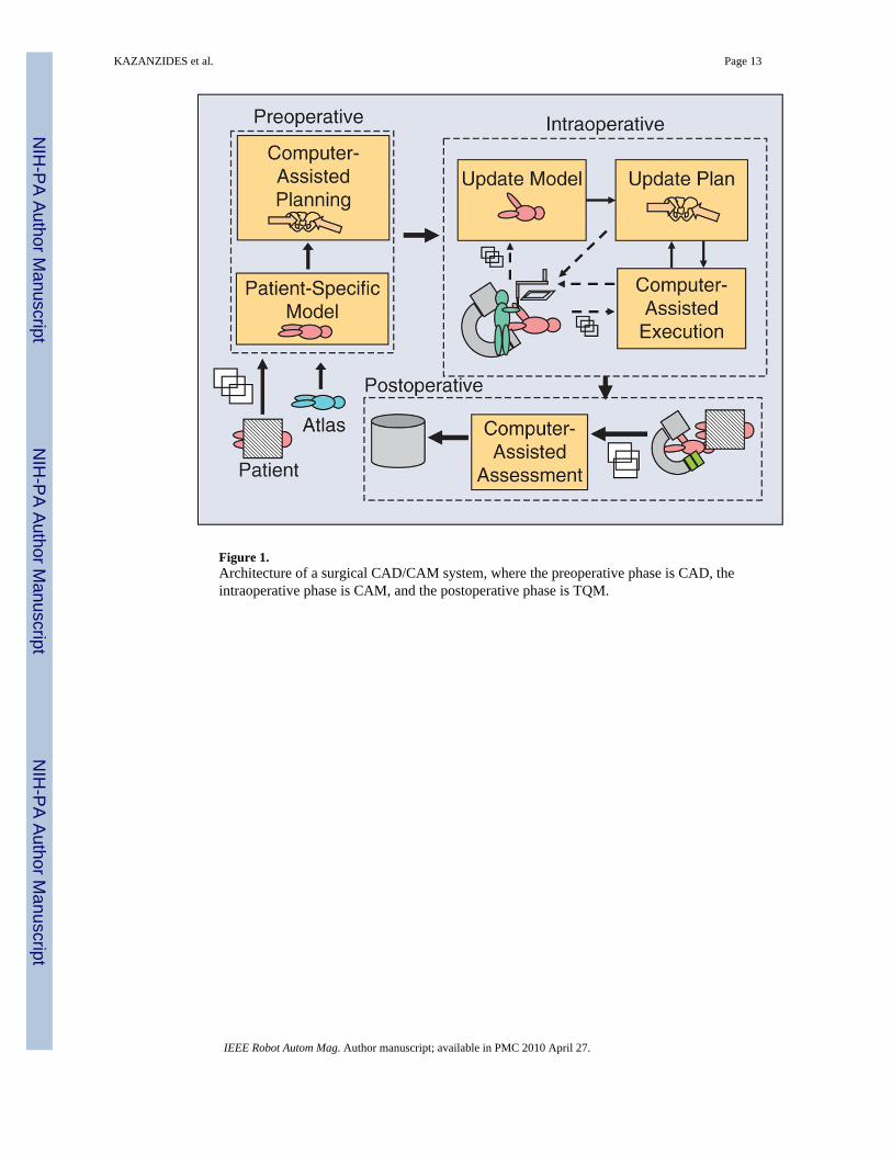
Figure 1.Architecture of a surgical CAD/CAM system, where the preoperative phase is CAD, theintraoperative phase is CAM, and the postoperative phase is TQM.
KAZANZIDES et al. Page 13
IEEE Robot Autom Mag. Author manuscript; available in PMC 2010 April 27.
NIH
-PA Author Manuscript
NIH
-PA Author Manuscript
NIH
-PA Author Manuscript
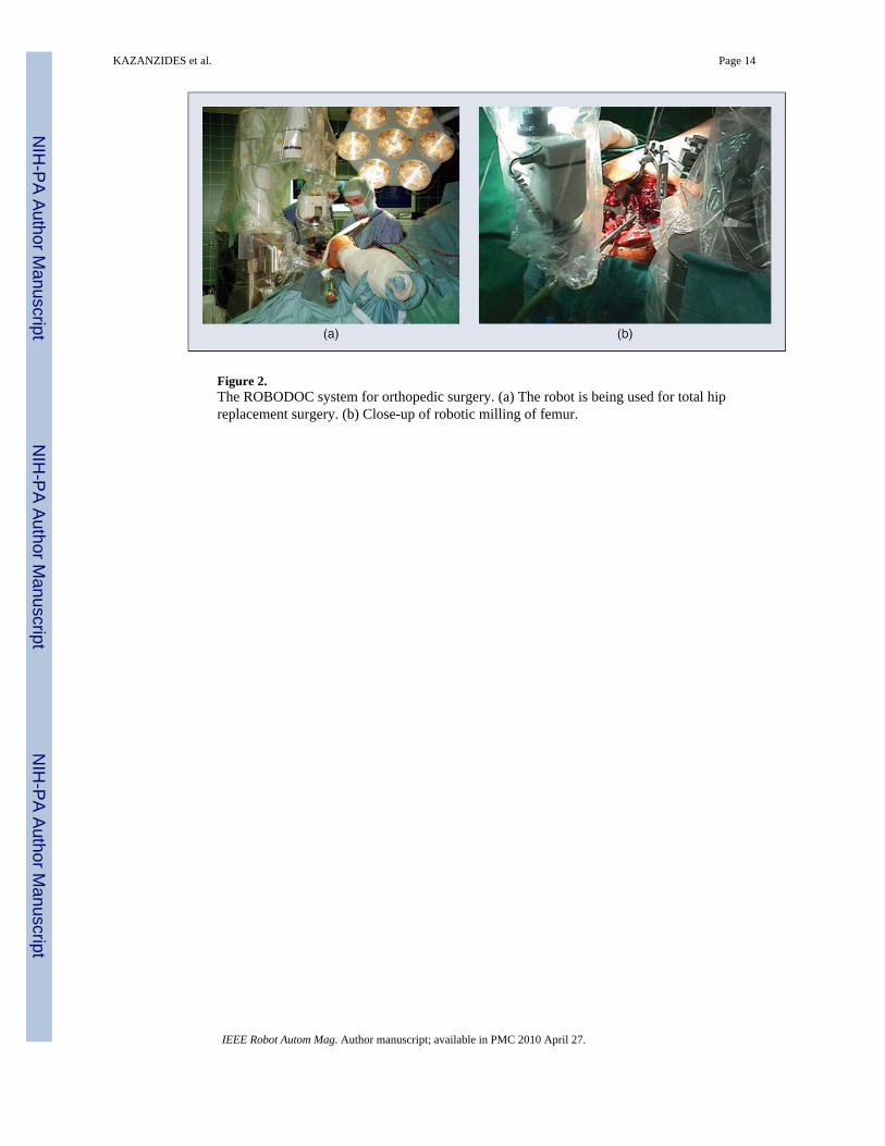
Figure 2.The ROBODOC system for orthopedic surgery. (a) The robot is being used for total hipreplacement surgery. (b) Close-up of robotic milling of femur.
KAZANZIDES et al. Page 14
IEEE Robot Autom Mag. Author manuscript; available in PMC 2010 April 27.
NIH
-PA Author Manuscript
NIH
-PA Author Manuscript
NIH
-PA Author Manuscript

Figure 3.The da Vinci surgical system (courtesy Intuitive Surgical, Inc.).
KAZANZIDES et al. Page 15
IEEE Robot Autom Mag. Author manuscript; available in PMC 2010 April 27.
NIH
-PA Author Manuscript
NIH
-PA Author Manuscript
NIH
-PA Author Manuscript

Figure 4.Computer control of a robot joint, showing the motor (M), encoder (E), and power amplifier(Amp).
KAZANZIDES et al. Page 16
IEEE Robot Autom Mag. Author manuscript; available in PMC 2010 April 27.
NIH
-PA Author Manuscript
NIH
-PA Author Manuscript
NIH
-PA Author Manuscript

Figure 5.Illustration of maximum possible error: E is the error threshold, Vmax is the maximum velocity,ΔT is the control period, and ΔPoff is the robot stopping distance.
KAZANZIDES et al. Page 17
IEEE Robot Autom Mag. Author manuscript; available in PMC 2010 April 27.
NIH
-PA Author Manuscript
NIH
-PA Author Manuscript
NIH
-PA Author Manuscript

Figure 6.Example of poorly designed redundant system. The second solenoid does not provide sufficientsafety because the system cannot detect when either solenoid has failed in the open state.
KAZANZIDES et al. Page 18
IEEE Robot Autom Mag. Author manuscript; available in PMC 2010 April 27.
NIH
-PA Author Manuscript
NIH
-PA Author Manuscript
NIH
-PA Author Manuscript

NIH
-PA Author Manuscript
NIH
-PA Author Manuscript
NIH
-PA Author Manuscript
KAZANZIDES et al. Page 19
Table 1
Excerpt from a sample FMEA.
Failure Mode Effect on System Causes Methods of Control*
Robot out of control Robot may hit something Encoder failure, broken wire Trip relay when error tolerance exceeded
Robot out of control Robot may hit something Amplifier failure Trip relay when error tolerance exceeded
*Methods of control can initially be empty and then populated during the design phase.
IEEE Robot Autom Mag. Author manuscript; available in PMC 2010 April 27.