Surface spin-flop and discommensuration transitions in antiferromagnets
17
arXiv:cond-mat/9809174v1 [cond-mat.stat-mech] 11 Sep 1998 Surface spin-flop and discommensuration transitions in antiferromagnets C. Micheletti, 1 R. B. Griffiths 2 and J. M. Yeomans 3 (1) International School for Advanced Studies (S.I.S.S.A.) - INFM, Via Beirut 2-4, 34014 Trieste, Italy and The Abdus Salam Centre for Theoretical Physics - Trieste, Italy (2) Physics Department, Carnegie-Mellon University, Pittsburgh, PA 15213 (3) Theoretical Physics, Oxford University, 1 Keble Road, Oxford OX1 3NP, UK (March 17, 2009) Phase diagrams as a function of anisotropy D and magnetic field H are obtained for discom- mensurations and surface states for an antiferromagnet in which H is parallel to the easy axis, by modeling it using the ground states of a one-dimensional chain of classical XY spins. A surface spin-flop phase exists for all D, but the interval in H over which it is stable becomes extremely small as D goes to zero. First-order transitions, separating different surface states and ending in critical points, exist inside the surface spin-flop region. They accumulate at a field H ′ (depending on D) significantly less than the value HSF for a bulk spin-flop transition. For H ′ <H<HSF there is no surface spin-flop phase in the strict sense; instead, the surface restructures by, in effect, producing a discommensuration infinitely far away in the bulk. The results are used to explain in detail the phase transitions occurring in systems consisting of a finite, even number of layers. I. INTRODUCTION It has been known for a long time that if an antiferromagnet with suitable anisotropy is placed in an external magnetic field H parallel to the easy axis (the axis along which the spins are aligned, in opposite directions on different sublattices, in zero magnetic field) and the field strength is increased, a first-order transition will occur 1 in which the spins are realigned in directions (approximately) perpendicular to the applied field, but with a component along the field direction. The transition to this spin flop phase occurs when H is equal to a spin-flop field H SF , whose value depends on the exchange energy and the anisotropy. As H continues to increase beyond H SF , the spins on the two sublattices rotate towards the field direction till eventually, if the field is sufficiently large, they are parallel to each other in a ferromagnet structure. In 1968 Mills 2 proposed that in an antiferromagnet with a free surface, spins near the surface could rotate into a flopped state at a field H ′ SF significantly less than H SF . This surface spin-flop (SSF) problem was later studied by Keffer and Chow 3 , who found a transition at H ′ SF , but to a state having a character rather different than that proposed by Mills. Interest in this problem was recently rekindled through experimental work on layered structures consisting of Fe/Cr(211) superlattices 4,5 . If the thickness of the Cr layers is chosen appropriately, adjacent Fe blocks are coupled antiferromagnetically, and thus in zero magnetic field they exhibit an antiferromagnetic structure in which the magnetization of each layer is opposite to that of the adjoining layers. Applying an external magnetic field parallel to the layers can give rise to phase transitions in which the magnetization in certain layers rotates or reverses its direction, and the results found experimentally depend upon whether the number of Fe layers is even or odd. The experimental work has motivated a number of theoretical and numerical studies of finite and semi-infinite systems 4–9 . Most of these have found evidence for the existence of SSF states. In the present paper we address the issue of the existence of SSF phases and some related topics by studying the properties of the ground states of chains of antiferromagnetically coupled classical XY spins, each spin variable represented by an angle θ between 0 and 2π, subject to a uniaxial anisotropy D as well as to an external magnetic field H , as a function of D and H . One can think of θ as the direction of the magnetization in an Fe layer in a superlattice, or of the average magnetization in a layer of an antiferromagnet containing spins belonging to one type of sublattice. Minimizing the energy of a one-dimensional model then corresponds to minimizing the free energy of a three-dimensional layered system, provided fluctuations inside the layers do not have a drastic effect. This means that the model we consider here is, in its essentials, equivalent to those used in previous studies. It allows us to come to some fairly definite conclusions about SSF phases in semi-infinite systems, and about the behavior of systems containing a finite number of layers. Our principal conclusions were published previously in a short report 10 ; the present paper contains the complete argument, and supplies a number of additional details. In order to understand the properties of finite and semi-infinite chains, it is helpful to begin with an infinite chain and a defect structure known as a “discommensuration” (or “soliton” or “kink”), which can occur in both the antiferromagnetic and the spin-flop phases. In Sec. II we work out the properties of the discommensurations of 1
Transcript of Surface spin-flop and discommensuration transitions in antiferromagnets

arX
iv:c
ond-
mat
/980
9174
v1 [
cond
-mat
.sta
t-m
ech]
11
Sep
1998
Surface spin-flop and discommensuration transitions in antiferromagnets
C. Micheletti,1 R. B. Griffiths2 and J. M. Yeomans3
(1) International School for Advanced Studies (S.I.S.S.A.) - INFM, Via Beirut 2-4, 34014 Trieste, Italy andThe Abdus Salam Centre for Theoretical Physics - Trieste, Italy
(2) Physics Department, Carnegie-Mellon University, Pittsburgh, PA 15213(3) Theoretical Physics, Oxford University, 1 Keble Road, Oxford OX1 3NP, UK
(March 17, 2009)
Phase diagrams as a function of anisotropy D and magnetic field H are obtained for discom-mensurations and surface states for an antiferromagnet in which H is parallel to the easy axis, bymodeling it using the ground states of a one-dimensional chain of classical XY spins. A surfacespin-flop phase exists for all D, but the interval in H over which it is stable becomes extremely smallas D goes to zero. First-order transitions, separating different surface states and ending in criticalpoints, exist inside the surface spin-flop region. They accumulate at a field H ′ (depending on D)significantly less than the value HSF for a bulk spin-flop transition. For H ′ < H < HSF there is nosurface spin-flop phase in the strict sense; instead, the surface restructures by, in effect, producinga discommensuration infinitely far away in the bulk. The results are used to explain in detail thephase transitions occurring in systems consisting of a finite, even number of layers.
I. INTRODUCTION
It has been known for a long time that if an antiferromagnet with suitable anisotropy is placed in an externalmagnetic field H parallel to the easy axis (the axis along which the spins are aligned, in opposite directions ondifferent sublattices, in zero magnetic field) and the field strength is increased, a first-order transition will occur1 inwhich the spins are realigned in directions (approximately) perpendicular to the applied field, but with a componentalong the field direction. The transition to this spin flop phase occurs when H is equal to a spin-flop field HSF , whosevalue depends on the exchange energy and the anisotropy. As H continues to increase beyond HSF , the spins on thetwo sublattices rotate towards the field direction till eventually, if the field is sufficiently large, they are parallel toeach other in a ferromagnet structure.
In 1968 Mills2 proposed that in an antiferromagnet with a free surface, spins near the surface could rotate intoa flopped state at a field H ′
SF significantly less than HSF . This surface spin-flop (SSF) problem was later studiedby Keffer and Chow3, who found a transition at H ′
SF , but to a state having a character rather different than thatproposed by Mills. Interest in this problem was recently rekindled through experimental work on layered structuresconsisting of Fe/Cr(211) superlattices4,5. If the thickness of the Cr layers is chosen appropriately, adjacent Fe blocksare coupled antiferromagnetically, and thus in zero magnetic field they exhibit an antiferromagnetic structure inwhich the magnetization of each layer is opposite to that of the adjoining layers. Applying an external magnetic fieldparallel to the layers can give rise to phase transitions in which the magnetization in certain layers rotates or reversesits direction, and the results found experimentally depend upon whether the number of Fe layers is even or odd. Theexperimental work has motivated a number of theoretical and numerical studies of finite and semi-infinite systems4–9.Most of these have found evidence for the existence of SSF states.
In the present paper we address the issue of the existence of SSF phases and some related topics by studyingthe properties of the ground states of chains of antiferromagnetically coupled classical XY spins, each spin variablerepresented by an angle θ between 0 and 2π, subject to a uniaxial anisotropy D as well as to an external magneticfield H , as a function of D and H . One can think of θ as the direction of the magnetization in an Fe layer in asuperlattice, or of the average magnetization in a layer of an antiferromagnet containing spins belonging to one typeof sublattice. Minimizing the energy of a one-dimensional model then corresponds to minimizing the free energy ofa three-dimensional layered system, provided fluctuations inside the layers do not have a drastic effect. This meansthat the model we consider here is, in its essentials, equivalent to those used in previous studies. It allows us tocome to some fairly definite conclusions about SSF phases in semi-infinite systems, and about the behavior of systemscontaining a finite number of layers. Our principal conclusions were published previously in a short report10; thepresent paper contains the complete argument, and supplies a number of additional details.
In order to understand the properties of finite and semi-infinite chains, it is helpful to begin with an infinitechain and a defect structure known as a “discommensuration” (or “soliton” or “kink”), which can occur in boththe antiferromagnetic and the spin-flop phases. In Sec. II we work out the properties of the discommensurations of
1

minimum energy in the antiferromagnetic ground state of the XY chain. Using these results, we obtain, in Sec. III,a phase diagram for surface phase transitions in a semi-infinite chain. Both discommensurations and surface phasetransitions are essential for understanding the properties of finite chains. These are discussed in Sec. IV, where weprovide a comprehensive and detailed explanation of the complicated series of transitions found in chains containingan even number of spins.
The numerical procedures we used to study the phase diagram are described in Secs. II and III, and a certainnumber of analytic results are derived in Sec. V. The concluding Sec. VI provides a summary, and notes some topicswhich still need to be studied.
II. INFINITE CHAIN
We consider an infinite chain of classical XY spins described by the Hamiltonian
H =
∞∑
i=−∞
{
cos(θi − θi+1) − H cos θi +D
4[1 − cos(2θi)]
}
, (1)
where the antiferromagnetic exchange coefficient has been taken as the unit of energy, θi is the angle between thedirection of the ith spin and the external magnetic field H , and D is a two-fold spin anisotropy. Our aim is to identifythe zero-temperature phases of this system, that is, those which minimize the energy. Minimizing the energy of aone-dimensional system corresponds to minimizing the free energy of a layered three-dimensional system when thefluctuations within each individual layer are not playing an important role, as is the case for the Fe/Cr superlatticesmentioned in Sec. I.
The phase diagram of the system consists of three separate regions, as shown in Fig. 1. For D > 2, the line H = 2separates the ferromagnetic (F) configuration, with all the spins parallel to the field, from the antiferromagnetic (AF)one with the spins alternating between 0 and π, parallel and anti-parallel to the field. Along the AF:F boundary theground state is infinitely degenerate since it is possible to flip any number of non-adjacent spins in the F chain withno change in energy.
For D < 2 and intermediate values of H , the ground state no longer corresponds to spins in the Ising positions, θi
equal 0 or π, but is a spin-flop (SF) phase in which the spins alternate between +φ and −φ, where
cosφ = H/(4 − D) . (2)
The spin-flop region extends between the boundaries H =√
D(4 − D) and H = 4 − D which are first and secondorder, respectively11.
We now consider the case when an infinite chain is constrained by suitable boundary conditions to include a discom-mensuration (for detailed studies of discommensurations in Frenkel-Kontorova models see, for example, references [12–15]). The study of the discommensuration phase diagram is important because it helps to understand the minimalenergy configurations observed both in semi-infinite and finite systems. A discommensuration is a defect which canarise in a periodic phase whose period is two or greater. In particular, the AF ground state has period two and isdegenerate: for one ground state θi = 0 for i even and π for i odd; for the other, θi = π for i even and 0 for i odd.A discommensuration results if one requires that a single configuration {θi} approach one of these ground states as itends to −∞ and the other as i tends to +∞; for instance,
θ2n → 0, θ2n+1 → π as n → +∞θ2n → π, θ2n+1 → 0 as n → −∞. (3)
The defect energy of a discommensuration is the difference between the energy of the configuration containing thediscommensuration and the energy of the corresponding ground state. Since both of these energies are infinite for aninfinite chain, a proper definition requires some care; see, e.g., [ 16]. We are interested in discommensurations which,for a given D and H , minimize this energy; they constitute what we call the discommensuration phase diagram. Itis convenient to start by considering the limiting case D = ∞, where the spins are constrained to lie along the Isingpositions. For 0 < H < 2 the discommensuration of minimum energy is a configuration in which two successive spinssomeplace in the middle of the chain are parallel to the field H :
. . . , 0, π, 0, π, 0, 0, π, 0, π, . . . . (4)
In the following we will use the notation AF′ to label this phase. When H = 2, due to the absence of further-than-nearest-neighbor interactions, there is not a unique minimum-energy discommensuration associated with the AF
2

phase. One can have any arbitrary even number of spins aligned with the field, not just two, as in (4), and other, morecomplicated defects are possible. The ferromagnetic ground state for H ≥ 2 has period one and is non-degenerate, sothere are no discommensurations.
As the spin anisotropy D decreases from infinity, lower energies may occur if in a discommensuration the spins arenot limited to the Ising values 0 and π. For these cases it is difficult to find an explicit analytic form for the minimumenergy discommensuration, and one has to use numerical techniques to tackle the problem. The numerical procedurethat we have adopted relies on the method of effective potentials [ 17,18], which is very efficient for obtaining theground state of models with short range interactions and discretized variables. The main advantage of this methodis that it yields the true ground state, rather than some metastable one. The main disadvantage for our problem isthat it requires the spin variables to be discretized: they can take on only a finite number of values. We generallyused a discretization grid in which each θi is an integer times 2π/1400. To overcome the effects of the discretizationwe first fixed the anisotropy at some intermediate value, typically D ≈ 0.6, then used the Chou-Griffiths algorithm17
to identify minimal energy states of different phases for the system of discretized spins, and, finally, employed theequilibrium equations,
∂H∂θi
= 0, (5)
for continuous spins in order to refine the configurations obtained using discretized spins. The phase boundaries locatedby comparing the energies of neighboring phases, calculated using the refined configurations, were then followed as thevalue of D was changed in small steps, while the spin configurations were updated using (5). The location of the phaseboundaries was then checked against those obtained starting with finer discretization grids. We established that, usinga discretization of 2π/1400, the error in the location of the boundary, ∆H , was in the range of 10−8−10−9 throughoutthe range of D values we studied. The procedure just described was used to find minimum energy configurations ofa ring of spins (periodic boundary conditions) of length L with L odd, so as to produce a configuration containinga discommensuration. When L is large (we used L ≤ 31) compared to the size of the discommensuration, this ispractically the same as studying the minimal energy discommensuration in an infinite chain.
The numerical results are summarized in the discommensuration phase diagram in Fig. 2. There are, of course,no discommensurations in the F phase. As for the SF phase, our numerical results showed a smooth variation ofspin angles with D and H , and consequently no phase transitions. However, various phase transitions were identifiedfor AF phase discommensurations. In the AF′ region, Fig. 2, the spins in the minimum energy discommensurationstay locked in their D = ∞ positions. The persistence of this Ising spin locking for finite values of the anisotropyis a rather common feature in models with two-fold spin anisotropy [ 19–21]. Here it has the consequence that themultiphase degeneracy encountered at the point (H = 2, D = ∞) persists throughout the locus (D ≥ 2, H = 2).
For values of D lying below the lower boundary of AF′, but still inside the AF region in Fig. 2, “flopped” discommen-surations of different length have lower energies than the Ising discommensuration (4). A flopped discommensurationof type 〈2m〉 consists of a “core” of 2m spins in which the spin configuration resembles that in a bulk spin-flopphase, located between “tails”, each of which rapidly reverts to the configuration of the corresponding AF phasewith increasing distance from the core (see Fig. 3). One can think of the region where the core changes into the tailas an “interface” between the AF phase out in the tail and the SF phase in the core. From this perspective, thediscommensuration consists of a pair of interfaces, AF-SF and SF-AF, bounding the SF core. As D decreases, theseinterfaces broaden, making the distinction between the “tails” and the “core” less clear, but we continue to use thesame label 〈2m〉 for the discommensuration which evolves continuously from the one with a clearly-defined core ofsize 2m at larger D.
An analytic calculation, see Sec. V, shows that the equation for the second-order transition between AF′ and 〈2〉in Fig. 2 is
(D + H − 1)−1 = 5/3 + D − H, (6)
in good agreement with our numerical calculations, and those in [ 22] when H = 0. At low values of H , thediscommensuration 〈2〉 has the lowest energy, but upon approaching the bulk AF:SF phase boundary, one finds asequence of phase transitions to 〈4〉, 〈6〉, . . . as H increases, as shown in Fig 2. Our numerical procedures foundvalues of 2m up to 14, and we were able to trace the first-order lines separating the different 〈2m〉 phases down to avalue of D between 0.1 and 0.4. For smaller values of D, the difference ∆ of the energy derivatives ∂E/∂H in twoneighboring phases was no longer sufficient to allow us to distinguish the phases numerically and locate the phaseboundary. See the example in Fig. 4. However, we found no evidence that these lines terminate in critical points.The smooth decrease of ∆ shown in the inset of Fig. 4 contrasts with what one might expect at a critical point (asin Fig. 8). Therefore, it seems plausible to assume that the 〈2m〉 : 〈2m + 2〉 boundaries persist all the way down toD = 0.
3
The sequence of transitions associated with a broadening of the discommensuration can be understood in thefollowing way. The defect energy of a discommensuration can be thought of as the sum of the energy required toproduce a pair of AF-SF and SF-AF interfaces infinitely far apart, an interaction energy between the interfaces whichwe assume is positive and rises rapidly as they approach each other, and a “bulk” contribution proportional to thesize of the core, arising from the fact that in the AF part of the phase diagram, the SF phase is metastable. Interms of which discommensuration has the lowest energy, the interface repulsion obviously favors a large core, andthe metastable “penalty” a small core. The actual size will represent some compromise between the two. Uponapproaching the AF:SF boundary, the metastable penalty goes to zero, so the discommensuration of minimum energyshould become larger and larger. Hence one expects the 〈2m〉 : 〈2m + 2〉 boundary to approach the AF:SF transitionline as m → ∞. This is consistent with our numerical calculations, and in agreement with the predictions ofPapanicolaou [ 22]. (Note, however, that these transitions reflect the discrete nature of the spin chain and thereforeare absent in the continuum approximation employed in [ 22] for small spin anisotropy.) The triple points at whichthe phases AF′, 〈2m〉 and 〈2m + 2〉 meet tend to an accumulation point, Q, located at H ≈ 1.58, D ≈ 0.78. Thisshould be the point at which the energy to create a pair of AF-SF and SF-AF interfaces infinitely far apart is equalto the energy of an Ising discommensuration.
III. SEMI-INFINITE CHAINS
We now consider the surface states of a semi-infinite chain. The Hamiltonian for the system is the same as (1) butwith the sum extending only over non-negative values of i (i = 0 denotes the surface site):
H =
∞∑
i=0
{
cos(θi − θi+1) − H cos θi +D
4[1 − cos(2θi)]
}
. (7)
It is useful to think of semi-infinite chains as obtained by cutting an infinite chain in two. Removing a bond in theinfinite chain without allowing the spins to move will give two semi-infinite chains that we shall term unreconstructed.If the spins of the unreconstructed chains are then allowed to relax, a rearrangement of the spins near the surfacemay take place, as illustrated in Fig. 5, which lowers the energy. Notice that even though the total energy of thesemi-infinite chain is infinite, changes in the energy when a configuration is modified near the surface (or in a way suchthat the modifications decrease sufficiently rapidly with increasing distance from the surface) are well defined. Wewant to consider surface states which minimize the energy in the sense that no local modifications of the configurationnear the surface can decrease the energy.
The task of finding the reconstructed surface of minimum energy is, in general, not simple (except when all thespins in the chain are subject to the Ising locking). To identify the minimal energy surface states we used numericalalgorithms based on effective potential methods that, as mentioned earlier, require a discretization of the spin variablesat each site. It is important to notice that, since the θi’s are constrained to take on only discrete values, after a finitedistance, or “penetration depth” l from the surface the spins will be exactly in the discretized positions correspondingto a doubly-infinite chain or an unreconstructed surface. Configurations for the infinite chain were obtained usingthe Floria-Griffiths algorithm23 which, within the limits of the discretization, yields the exact ground state. Next,the Chou-Griffiths algorithm17 with its successive iterations was used to generate reconstructed surface configurations{θ0, θ1, ..., θl}. This should give the exact configuration minimizing the surface energy for the discrete spins. However,in practice we had to limit l to a maximum value lmax no larger than 50; thus the method could not yield the correctconfiguration for a larger penetration depth. The phase boundaries were then identified as explained in the previoussection.
The resulting phase diagram is shown in Fig. 6. Throughout the F region the minimum energy surface states aresimply the unreconstructed surfaces; it is easy to see that making any changes will increase the energy. In the SFregion, since the ground state of the infinite chain has period two, there are two unreconstructed surfaces. Each ofthem undergoes a reconstruction in which the spins nearest the surface tilt towards the magnetic field direction, asin Fig. 5(c). However, this change in spin direction occurs continuously as a function of H and D, and so no surfacephase transitions are observed inside the SF region.
Next consider the AF part of the phase diagram. Again there exist two possible surface states, A and B, whoseunreconstructed versions, Au and Bu, have surface spins parallel (θ0 = 0) or opposite (θ0 = π) to the field direction:
Au = {0, π, 0, π, 0, π, ...}, (8)
Bu = {π, 0, π, 0, π, 0, ...}. (9)
A surface will be said to be of type A (B) if the spin configuration tends to that of Au (Bu) far from the surface.
4

Throughout the AF region of the phase diagram, the minimum energy surface of type A is the unreconstructed Au.However, the B-type surface shows a number of different structures in different parts of the AF region, as indicatedin Figs. 6 and 7. In region AF1 the unreconstructed surface Bu has the lowest energy. In region AF2, which meetsAF1 along a line H = 1 for D larger than the value at O, it is energetically favorable to flip the surface spin so thatit points along the field direction, and there is a set of degenerate (equal minimum energy) reconstructed surfaces
[0〉 = 0, 0, π, 0, π, 0, π . . . , [2〉 = 0, π, 0, 0, π, 0, π . . . , (10)
and so forth, where [2n〉 consists of 2n spins 0, π, . . . in an antiferromagnetic arrangement, followed by two spinsparallel to the field, and then the bulk antiferromagnetic phase. One can think of this reconstructed surface as anIsing discommensuration, whose core consists of two adjacent spins with θi = 0, located a distance 2n from the surface.Because the “tails” of this discommensuration have zero length, it does not interact with the surface, and its energyis independent of its distance from the surface. While this degeneracy persists throughout the AF2 region, along theline D ≥ 2, H = 2 the degeneracy is even greater: the set of minimum energy surface states includes cases wherethe number of consecutive spins pointing along the field is not limited to 2 but can attain any even number, e.g.,{0, 0, 0, 0, π, 0, π...} or {0, π, 0, π, 0, 0, 0, 0, 0, 0, π, 0, π...}. Incidentally, we note that these degeneracies are somewhatartificial in that they would be lifted by introducing weak longer-range interactions in the Hamiltonian (7).
In the AF3 region of Fig. 6 the B-type surface again reconstructs, but the spin anisotropy is sufficiently low thatthe spins unlock from the Ising angles. As in the AF2 region, one can think of the surface state as consisting of adiscommensuration located a finite distance from the surface, but now this discommensuration is of the flopped typewith a core of length two, and tails extending out on either side of the core. We again employ the notation [2n〉for the surface state with 2n spins to the left of the core, that is, in the tail extending to the surface. Because ofthis tail, the discommensuration interacts with the surface, and the minimum surface energy occurs for a specificvalue of 2n, depending upon D and H . Thus, in AF3, one finds genuine spin-flop surface states. As H increases, thediscommensuration moves further from the surface. It does this, at least when D is large, discontinuously in steps of2, via a series of first-order phase transitions, some of which are shown in Fig. 7, where they extend leftwards fromthe point P . For smaller values of D, the edges of the core are not as well defined, and it is more difficult to associatethe [2n〉 → [2n+2〉 transitions with a discontinuous jump of the discommensuration. Numerically we have seen stateswith 2n up to 14, and our results are consistent with n tending to infinity at the right side of the AF3 region, whichour analytic calculations (Sec. V), in agreement with [ 6], show to be the line
D =√
1 + H2 − 1. (11)
The upper boundary of the AF3 region extending from O to P is a continuous (second-order) transition. One canthink of it as the limit of stability of the Ising surface phase [0〉 as D decreases inside AF2. An analytic calculation,Sec. V, shows that the implicit equation for the boundary is:
(2 + D − H − 1/a)−1 = 2 + D + H − a,
a := H + D + 1/(1 − H − D). (12)
Thus the point P , where all the phases [2n〉 come together, lies at H = 4/3, D = 2/3, the intersection of (11) and(12). Both (11) and (12) agree with our numerical results.
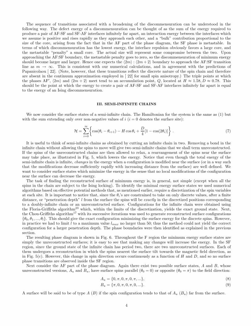
We find that the first-order lines extending downwards and leftwards from P in Fig. 7, separating phases [2n〉 from[2n+2〉, end in critical points as D decreases. This is clearly visible in the example in Fig. 8, which shows the typicalbehavior of the energy derivatives of two neighboring phases along their coexistence line. Near a critical point D = Dc
one expects ∆ to vary as√
D − Dc, in qualitative agreement with what we observed. The larger the value of n, thefurther the first-order line extends towards the origin of the H, D plane, but presumably for any finite value of n thedifference between the phases [2n〉 and [2n + 2〉 eventually disappears at some finite value of D. Because this valuedecreases with increasing n, it is plausible that the corresponding critical points accumulate at the origin.
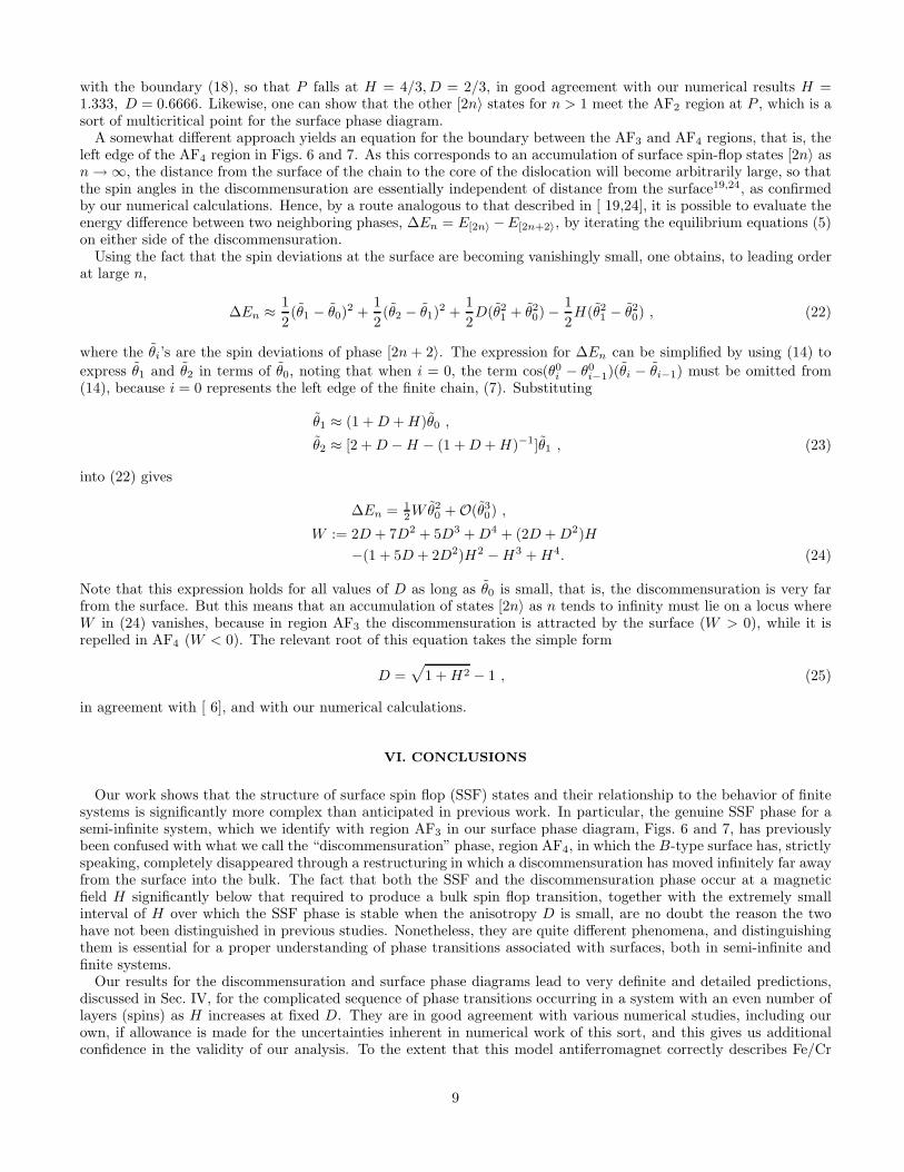
As is evident in Fig. 6, the region AF3 becomes extremely narrow as D decreases. The left boundary approachesa parabola D = 0.5H2 to within numerical precision, which is asymptotically the same as (11). We nonethelessbelieve that the width of AF3 remains finite as long as D > 0. Numerical evidence for this is shown in Fig. 9 wherethe value of the surface spin, θ0, at the left edge of the AF3 region (that is for H just large enough to produce thesurface spin-flop phase) is plotted as a function of D. The results are for lmax = 34 spins in the surface layer (see thedescription of the numerical approach given above). Below D = 0.05 the results become unreliable because lmax istoo small, as we can tell by carrying out calculations for different values of lmax. However, extrapolating from largervalues of D indicates that as D goes to zero, θ0 tends to a value near π/3 or 60◦, showing that even for very small Dthe discommensuration at the threshold field is still a finite distance from the surface. This situation is quite distinctfrom that in region AF1, where θ0 = π, and in AF4, discussed below, where θ0 = 0.
5

Between AF3 and the AF:SF bulk phase boundary lies region AF4, see Figs. 6 and 7, in which the flopped dis-commensuration is repelled by the surface, so that its minimum energy location is in the bulk infinitely far awayfrom the surface, as noted in6. Thus there is no minimum-energy reconstructed B surface, or, properly speaking, a“surface spin-flop phase” in region AF4. It seems better to identify AF4, thought of as part of the B-type surfacephase diagram, as a “discommensuration phase”, since the minimum energy surface will always be of the A-type, withthe surface spin θ0 = 0.
In Fig. 10 the discommensuration phase diagram for the infinite chain (Fig. 2), represented by dashed lines, issuperimposed on the B-type surface diagram for the semi-infinite chain, represented by solid lines, in the vicinity ofpoints P and Q, which are common to both diagrams, as is the broken line (shown dashed) from P to Q. Note thatthe OP line of the surface diagram, Fig. 7, lies above the lower boundary of the AF’ region of the discommensurationphase diagram in Fig. 2. Thus to the left of P , for H < 4/3, as D decreases the reconstructed B-type surfacephase changes from Ising to a flopped form before the corresponding change is energetically favorable for the bulkdiscommensuration.
In addition, Fig. 10 shows that the part of the H, D plane corresponding to 〈2m〉 in the discommensuration phasediagram, Fig. 2, for 2m ≥ 4 lies entirely inside the AF4 region of Fig. 6 (and 7) for the surface phase diagram. Thisis consistent with our observation that as long as the discommensuration is a finite distance from the surface, in theAF3 region, it is always of the type 2m = 2. Thus as H increases, it is only after the discommensuration has movedinfinitely far from the surface, and thus has no influence on the surface phase diagram, that its core begins to broaden.
In retrospect it seems likely that the broadening of the SSF transition mentioned in the abstract of [ 3] actually refersto broadening of the bulk discommensuration which, as noted above, occurs as H approaches the AF:SF boundaryinside region AF4. It appears that no work prior to ours has correctly identified the stable SSF phase at small valuesof D, characterized when it first appears with increasing H by a surface spin with a value very near 60◦ (Fig. 9). Thenarrowness of the AF3 region for small D may be why it was overlooked.
IV. FINITE CHAIN
We now move on to consider the case of a chain of finite length L. Since a surface reconstruction can occur at bothends of the chain, and it is also possible for a discommensuration to be present in the interior of the chain, we writeits total energy in the form
EL = Lǫ + ELs + ER
s + Ed, (13)
where ǫ is the bulk energy, the ground-state energy per spin for an infinite chain, ELs and ER
s are the energies of theleft and right surfaces respectively, and Ed is the energy of a discommensuration in the chain (if present). Minimizingthe total energy for fixed L is equivalent to finding the spin configuration that minimizes EL
s + ERs + Ed.
In writing (13), L was assumed to be sufficiently large that the interaction between the two ends of the chain, andbetween each end and the discommensuration, if present, can be neglected. For any given L this condition can alwaysbe satisfied by choosing a large enough value for the spin anisotropy. Outside the range of D for which (13) holds,the behavior of the system will depend strongly on the actual length of the chain. Since we are not interested inL-dependent features of the phase diagram, apart from whether L is even or odd, we shall assume that L is sufficientlylarge to justify the use of (13).
From the discussion presented in the previous sections one can predict that a finite chain will not undergo anyphase transition for values of D and H inside the SF and F regions. On the other hand it can also be anticipatedthat the behavior of the chain in the AF region will be rather complicated. As noted in [ 4,5,7], the behavior of thechain for values of D and H in the AF region changes dramatically according to whether the length of the chain iseven or odd.
If L is odd, both ends of the chain have to be of the same type, A or B, unless a discommensuration is present. Havingtwo A-type surfaces gives a lower energy than two B-type surfaces, because the former results in a net magnetizationin the direction of the field, and the latter a net magnetization opposite to the field. Similar considerations showthat throughout the AF region it is energetically unfavorable to insert a dislocation, thus producing one A-type andone B-type surface. Hence for odd L, the minimum energy corresponds to two (unreconstructed) A-type surfaces ateither end of the chain, and no discommensurations.
On the other hand, when L is even, the two surfaces have to be of different types, unless a discommensuration ispresent. The analysis of Sec. II has shown that discommensurations are not favored energetically outside region AF4.Thus, for D and H falling in region AF1 or AF3, one expects one surface of type A and the other of type B. Moreover,from the results of Sec. III, we expect that in region AF1 the B surface remains unreconstructed, whereas surfacespin-flop states should be observed in AF3 owing to the reconstruction of the B-type end of the chain. The A-type
6

end of the chain remains, of course, in its unreconstructed state. Next, in region AF4 the energy is minimized usingtwo A-type surfaces and a discommensuration, which lies at the center of the finite chain because it is repelled byboth surfaces. Finally, in AF2, because of the degeneracy due to the Ising spin locking, one has either a reconstructedB-type surface or a discommensuration, depending upon what one wants to call it, and an A-type surface at the otherend of the chain.
Consequently, if D is smaller than the value corresponding to point P in Fig. 7, we expect a finite system witheven L to undergo the following set of transitions with increasing H . At H = 0, Fig. 11(a), there are unreconstructedsurfaces of types A and B at opposite ends of the chain. When H reaches the threshold for the formation of an SSFphase, the B-type surface restructures discontinuously, (b) to form a type 〈2〉 discommensuration which then, as Hincreases, moves towards the center of the chain in a series of discontinuous steps, (c) and (d), some of which may becontinuous if D is smaller than the value for the corresponding critical point, see Sec. III.
The discommensuration will reach the center of the chain, Fig. 11(d), when H is close to the threshold for the AF4
or discommensuration region in Fig. 6. Further increases of H will lead to a broadening of the discommensuration,with 〈2m〉 going through the sequence 〈2〉, 〈4〉, 〈6〉, . . . of Fig. 2; see Fig. 11(d) to (g). While these transitions are likelyto be discontinuous for larger values of D, it may be hard to see the discontinuities when D is small. The center ofthe 〈2m〉 discommensuration in Fig. 11 does not fall at the precise center of the chain when m is even; the offset isneeded so that the surface spins can both be (approximately) parallel, rather than antiparallel, to the field direction.(For L = 12 the offset occurs when m is odd.)
The AF-SF and SF-AF interfaces on either side of the core move outwards as the discommensuration expands,and eventually they reach the surfaces of the chain, Fig. 11(g), at a field very close to that required to produce thebulk spin-flop transition. At still higher fields the entire chain can be thought of as being in the bulk spin-flop phase,with appropriate (reconstructed) surface configurations corresponding to this phase. Sufficiently large values of Hwill eventually force all of the spins into the ferromagnetic configuration θi = 0.
The scenario just described is basically consistent with previous numerical studies, including two that have appearedquite recently8,9, and our own numerical work. Thus Fig. 12 shows the magnetic susceptibility χ = ∂M/∂H , M themagnetization, for a chain of L = 22 spins when D = 0.5. The spikes appearing in Fig. 12 should be Dirac deltafunctions. Here they appear to have a finite height because of the finite incremental step δH chosen for the numericalcalculation. The first spike in Fig. 12 (for H ≈ 0.9) signals the transition from the AF1 region into the surface spin-flopAF2, phase [0〉. The first series of spikes, for H between 0.9 and 1.13, is associated with first-order spin-flop transitions,in agreement with7,9. For H between 1.13 and 1.32, one observes a second series of transitions associated with thebroadening of the discommensuration. Figure 13 shows the susceptibility for the same length of chain (L = 22) witha smaller anisotropy, D = 0.3. The spikes are smaller than in Fig. 12 due to decrease in anisotropy, and some ofthe surface spin-flop peaks have disappeared, which is what one would expect in view of the critical points along the[2n〉 : [2n + 2〉 phase boundaries noted in Sec. III.
A recent study by Papanicolaou8 of the dynamics of a model similar to (1), but with three-dimensional (classical)spins, shows evidence for metastability and hysteresis as the magnetic field H is varied, as one would expect for afirst-order SSF transition. Additional hysteresis is seen as the field is increased beyond the SSF transition, consistentwith additional first-order transitions of the sort discussed above. Small differences in detail between these results andours can probably be explained in terms of hysteresis effects, or possibly as due to the fact that the models are notidentical. A numerical study of (1) by Trallori9, using an area-preserving map, is also in very good agreement withall of our results, except that certain transitions which we would expect to be first order as the discommensurationmoves to the center of the chain and broadens are found to be continuous when D is very small. But this difference isprobably not important, since the discontinuities will in any case be very small when D is small, and could be absentbecause L is finite.
V. ANALYTICAL RESULTS
In this last section we give a detailed derivation of the analytical results presented earlier in the paper. As alreadynoted, analytical solutions to the problem of minimizing the energy are, in general, only available when the spins arein Ising position, θ = 0 or π. However, when deviations from these values are small, systematic approximations arepossible. Throughout this section we shall use θ0
i to indicate Ising or “locked” spin values, θi for the actual canted
values, and θi ≡ θi − θ0i for the deviations of the latter from the locked values.
To obtain an analytic expression for a second-order boundary separating locked and canted versions of a spinconfiguration, we start by expanding (5) to first order in the spin deviations, assuming that they are small,
cos(θ0i − θ0
i−1)(θi − θi−1) + cos(θ0i+1 − θ0
i )(θi − θi+1) = (H cos(θ0i ) + D)θi , (14)
7

and then solving these equations self-consistently.We first apply this strategy to find the boundary separating phases AF′ and 〈2〉, Fig. 2, using the labels for sites
in the flopped discommensuration 〈2〉 given in Fig. 14. The equations (14) can be written as recursion relations, in
terms of ratios xi = θi/θi−1 of successive spin deviations, in the form:
x−12j + x2j+1 = 2 + D + H for j ≤ −1 ,
x−12j+1 + x2j+2 = 2 + D − H for j ≤ −1 ,
x−10 − x1 = D + H ,
−x−11 + x2 = D + H ,
x−12j + x2j+1 = 2 + D − H for j ≥ 1 ,
x−12j+1 + x2j+2 = 2 + D + H for j ≥ 1, (15)
with a solution
x2j = s2 for j ≥ 1,
x2j+1 = s1 for j ≥ 1.
x−10 − x1 = D + H,
−x−11 + x2 = D + H,
x2j+2 = s−12 for j ≤ −1,
x2j+1 = s−11 for j ≤ −1. (16)
obtained using techniques of continued fractions. Here s1 and s2 are given by
s1 = 2[2 + D − H ] [(2 + D + H)(2 + D − H) + t]−1 ,
s2 = (1/2) [2 + D + H + t/(2 + D − H)] ,
t :=√
(2 + D + H)2(2 + D − H)2 − 4(2 + D + H)(2 + D − H). (17)
The only set of values (H, D) for which equations (16) can be simultaneously satisfied under the constraint that themodulus of s1 and s2 cannot exceed 1 (so that the spin deviations decay to zero infinitely far from the discommensu-ration core) has to satisfy the relation
(D + H − 1)−1 = 5/3 + D − H , (18)
which is the same as (6). Equation (18) identifies the locus of points where the spin deviations for phase 〈2〉 becomevanishingly small, which is the second-order boundary AF′ : 〈2〉.
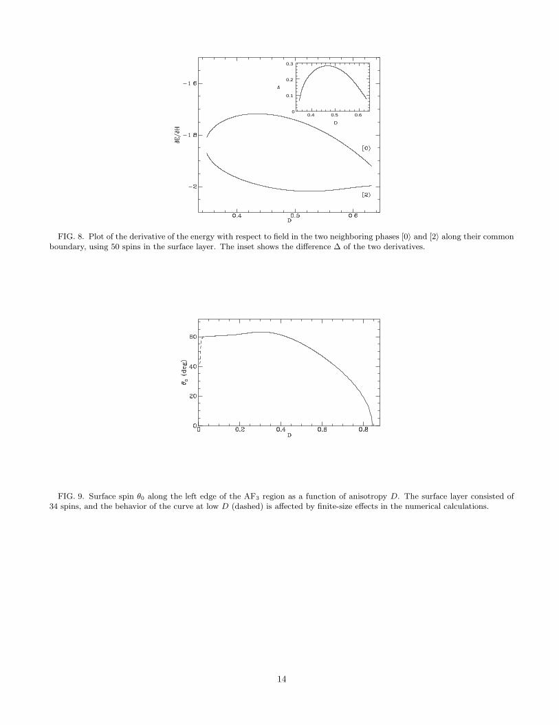
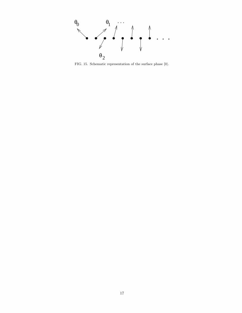
The same method can be used to find the second-order boundary OP between AF2 and AF3 in Fig. 6 or 7. In the [0〉phase close to the border, with the spins labeled as in Fig. 15, deviations from the corresponding Ising configuration,(10), will be small, and the solution to (14) takes the form
x2j = s2 for j ≥ 1 ,
x2j+1 = s1 for j ≥ 1 ,
x1 = 1 − H − D ,
−x−11 + s2 = H + D , (19)
using the same notation introduced previously, with s1 and s2 again defined by (17). These equations yield anadditional relation for s2,
s2 = H + D + [1 − H − D]−1, (20)
which can be satisfied together with (17) only on the locus of points Γ defined by equation (12).A similar analysis assuming small deviations from Ising values for the state [2〉 shows that the point P on Γ, Fig. 7,
occurs at the intersection of the curve
1 + D + H = (1 + D − H)−1, (21)
8
with the boundary (18), so that P falls at H = 4/3, D = 2/3, in good agreement with our numerical results H =1.333, D = 0.6666. Likewise, one can show that the other [2n〉 states for n > 1 meet the AF2 region at P , which is asort of multicritical point for the surface phase diagram.
A somewhat different approach yields an equation for the boundary between the AF3 and AF4 regions, that is, theleft edge of the AF4 region in Figs. 6 and 7. As this corresponds to an accumulation of surface spin-flop states [2n〉 asn → ∞, the distance from the surface of the chain to the core of the dislocation will become arbitrarily large, so thatthe spin angles in the discommensuration are essentially independent of distance from the surface19,24, as confirmedby our numerical calculations. Hence, by a route analogous to that described in [ 19,24], it is possible to evaluate theenergy difference between two neighboring phases, ∆En = E[2n〉 −E[2n+2〉, by iterating the equilibrium equations (5)on either side of the discommensuration.
Using the fact that the spin deviations at the surface are becoming vanishingly small, one obtains, to leading orderat large n,
∆En ≈ 1
2(θ1 − θ0)
2 +1
2(θ2 − θ1)
2 +1
2D(θ2
1 + θ20) −
1
2H(θ2
1 − θ20) , (22)
where the θi’s are the spin deviations of phase [2n + 2〉. The expression for ∆En can be simplified by using (14) to
express θ1 and θ2 in terms of θ0, noting that when i = 0, the term cos(θ0i − θ0
i−1)(θi − θi−1) must be omitted from(14), because i = 0 represents the left edge of the finite chain, (7). Substituting
θ1 ≈ (1 + D + H)θ0 ,
θ2 ≈ [2 + D − H − (1 + D + H)−1]θ1 , (23)
into (22) gives
∆En = 12Wθ2
0 + O(θ30) ,
W := 2D + 7D2 + 5D3 + D4 + (2D + D2)H
−(1 + 5D + 2D2)H2 − H3 + H4. (24)
Note that this expression holds for all values of D as long as θ0 is small, that is, the discommensuration is very farfrom the surface. But this means that an accumulation of states [2n〉 as n tends to infinity must lie on a locus whereW in (24) vanishes, because in region AF3 the discommensuration is attracted by the surface (W > 0), while it isrepelled in AF4 (W < 0). The relevant root of this equation takes the simple form
D =√
1 + H2 − 1 , (25)
in agreement with [ 6], and with our numerical calculations.
VI. CONCLUSIONS
Our work shows that the structure of surface spin flop (SSF) states and their relationship to the behavior of finitesystems is significantly more complex than anticipated in previous work. In particular, the genuine SSF phase for asemi-infinite system, which we identify with region AF3 in our surface phase diagram, Figs. 6 and 7, has previouslybeen confused with what we call the “discommensuration” phase, region AF4, in which the B-type surface has, strictlyspeaking, completely disappeared through a restructuring in which a discommensuration has moved infinitely far awayfrom the surface into the bulk. The fact that both the SSF and the discommensuration phase occur at a magneticfield H significantly below that required to produce a bulk spin flop transition, together with the extremely smallinterval of H over which the SSF phase is stable when the anisotropy D is small, are no doubt the reason the twohave not been distinguished in previous studies. Nonetheless, they are quite different phenomena, and distinguishingthem is essential for a proper understanding of phase transitions associated with surfaces, both in semi-infinite andfinite systems.
Our results for the discommensuration and surface phase diagrams lead to very definite and detailed predictions,discussed in Sec. IV, for the complicated sequence of phase transitions occurring in a system with an even number oflayers (spins) as H increases at fixed D. They are in good agreement with various numerical studies, including ourown, if allowance is made for the uncertainties inherent in numerical work of this sort, and this gives us additionalconfidence in the validity of our analysis. To the extent that this model antiferromagnet correctly describes Fe/Cr
9

superlattices, we can also claim to have achieved a basic understanding of the processes giving rise to the phasetransitions observed experimentally in the latter.
That does not, of course, mean that our model is adequate for understanding SSF phases and other surface phasetransitions in more traditional antiferromagnets, such as MnF2. However, as noted in Sec. I, minimizing the energy ofa one-dimensional model is the analog of minimizing the free energy of a three-dimensional layered system, whenevereach layer can be described, using mean-field theory or in a purely phenomenological way, by means of a totalmagnetization serving as a sort of order parameter. To be sure, the parameters which enter the Hamiltonian for theone-dimensional chain may not be those appropriate for three-dimensional system. But one can still expect qualitativesimilarities in the phase diagrams, even if certain quantitative aspects are different.
In that connection, it is appropriate to ask whether certain features of the discommensuration and surface phasediagrams of the one-dimensional model depend in a sensitive way upon the particular form of the Hamiltonian (1).For example, it contains no spin coupling beyond nearest neighbors, whereas it would be physically more realisticto assume, at the very least, some sort of exchange coupling of further neighbors, decreasing rapidly with distance.Would introducing such interactions lead to significant changes in the phase diagram? Could they, for example, makethe SSF phase disappear entirely at low values of the anisotropy?
This is one of many questions which cannot be answered definitively in advance of appropriate calculations. It isworth pointing out that our physical picture of the SSF phase as due to a discommensuration finding its minimumenergy at a finite distance from the surface does not seem to depend on the absence of further-neighbor exchange(or possibly other types of) interaction, so we can well imagine that the phenomenon persists with a more realisticHamiltonian. Nonetheless, this is one respect in which our work remains incomplete. While our numerical results,especially the apparent existence of a non-zero limit for θ0 as D goes to zero, Fig. 9, support our description in termsof a discommensuration, an appropriate analytic calculation in the limit of small D, of the sort which might (amongother things) give the value of this limiting angle, has not been carried out. Such a study would probably provideinsight into whether weak further-neighbor interactions simply change the quantitative values of various parameters,or lead to a qualitatively different result, such as the absence of the AF3 region when D is sufficiently small.
It seems unlikely that weak further-neighbor interactions would remove the first-order transitions between thesurface phases [2n〉 and [2n + 2〉, or change the fact that these transitions terminate in critical points as D decreases.On the other hand, such a modification of the Hamiltonian would surely remove the degeneracy of the surface states inthe AF2 region of Figs. 6 and 7. Thus one would not be surprised to find significant modifications in the phase diagramnear the multicritical point P . Indeed, P which might well disappear, to be replaced by some other, more complicated,structure allowing the different [2n〉 phases to disappear as H increases. Also, sufficiently strong further-neighborinteractions of the proper kind might result in the infinite-chain discommensurations undergoing their broadeningtransitions at significantly smaller values of the magnetic field H . This could lead to a complicated surface phasediagram in which the minimum energy discommensurations broaden while they are still a finite distance from thesurface. How this might effect the [2n〉 to [2n + 2〉 transitions and their critical points is hard to guess in advance ofactually doing a calculation.
Hence there is much which remains to be understood about surface spin-flop transitions in antiferromagnets.Nonetheless, we believe that the calculations, numerical and analytical, presented in this paper have served to sortout some important physical effects, and in this sense our results provide a solid foundation for future work.
1 L. Neel, Ann. Phys. (Paris) 5, 232 (1936)2 D. L. Mills, Phys. Rev. Lett. 20, 18 (1968).3 F. Keffer and H. Chow, Phys. Rev. Lett. 31, 1061 (1973).4 R. W. Wang, D. L. Mills, E. E. Fullerton, J. E. Mattson and S. D. Bader, Phys. Rev. Lett. 72, 920 (1994).5 R. W. Wang and D. L. Mills, Phys. Rev. B 50 3931 (1994).6 L. Trallori, P. Politi, A. Rettori, M. G. Pini and J. Villain, Phys. Rev. Lett. 72, 1925 (1994).7 L. Trallori, P. Politi, A. Rettori, M. G. Pini and J. Villain, J. Phys. C 7, L451 (1995).8 N. Papanicolaou, J. Phys. Cond. Mat 10, L131 (1998).9 L. Trallori, Phys. Rev. B 57, 5923 (1998).
10 C. Micheletti, R. B. Griffiths and J. M. Yeomans, J. Phys. A 30, L233 (1997).11 F. B. Anderson and H. B. Callen, Phys. Rev. A, 136, 1068 (1964)12 S. Aubry, in Solitons and Condensed Matter Physics, edited by A. R. Bishop and T. Schneider (Springer Verlag, Berlin,
1981).
10

13 S. Aubry, J. Phys. (Paris) 44, 147 (1983).14 S. Aubry, Physica D 7, 240 (1983).15 R. B. Griffiths, in Fundamental Problems in Statistical Mechanics VII, edited by H. van Beijeren (Elsevier, Amsterdam,
1990).16 L. H. Tang and R. B. Griffiths, J. Stat. Phys. 53 853 (1988).17 W. Chou and R. B. Griffiths, Phys. Rev. B 34, 6219 (1986).18 K. Hood, J. Comput. Phys. 89, 187 (1990).19 C. Micheletti and J. M. Yeomans, Europhys. Lett. 28, 465 (1994).20 A.B. Harris, C. Micheletti and J. M. Yeomans, Phys. Rev. Lett. 74, 3045 (1995).21 A.B. Harris, C. Micheletti and J. M. Yeomans, Phys. Rev. B 52, 6684 (1995).22 N. Papanicolaou, Phys. Rev. B 51, 15062 (1995).23 L. M. Floria and R. B. Griffiths, Numer. Math. 55, 565 (1989).24 F. Seno and J. M. Yeomans. Phys. Rev. B 50, 10385 (1994).
FIG. 1. Phase diagram for an infinite chain. The AF, F and SF regions are occupied by the antiferromagnetic, ferromagneticand spin-flop phases respectively.
FIG. 2. Discommensuration phase diagram for an infinite chain. The dashed phase boundaries correspond to phase transitionsin the discommensuration-free chain, the solid lines in Fig. 1.
11

SF
AF AFFIG. 3. Schematic representation of phase 〈4〉 for moderate values of the spin anisotropy. The phase can be regarded as
resulting from merging a portion of the spin-flop phase (SF) with two semi-infinite antiferromagnetic chains (AF). The spinsnearest the AF-SF and SF-AF interfaces are expected to relax from their ideal AF or SF angles.
D
0.3 0.4 0.5 0.60
0.2
0.4
0.6
0.8
FIG. 4. Plot of the derivative of the energy with respect to field in the two neighboring phases, 〈2〉, 〈4〉 along their commonboundary, for a ring of 17 spins. The inset shows the difference ∆ of the two derivatives.
. . . . . .
. . .. . .
. . .
A)
B)
C) . . .FIG. 5. Cutting an infinite chain in two (a) while keeping the spins “frozen” results in two semi-infinite chains with unre-
constructed surfaces (b). Allowing the spins to relax to positions which minimize the energy typically results in reconstructionof the surface (c), a re-arrangement of the spins nearest the surface.
12

2
1 3
FIG. 6. Phase diagram for a semi-infinite chain with a B-type surface. More details of the AF3 region are visible in Fig. 7.
2
1 3
4
FIG. 7. Detail of the phase diagram for a semi-infinite chain with a B-type surface.
13
D
0.4 0.5 0.60
0.1
0.2
0.3
FIG. 8. Plot of the derivative of the energy with respect to field in the two neighboring phases [0〉 and [2〉 along their commonboundary, using 50 spins in the surface layer. The inset shows the difference ∆ of the two derivatives.
FIG. 9. Surface spin θ0 along the left edge of the AF3 region as a function of anisotropy D. The surface layer consisted of34 spins, and the behavior of the curve at low D (dashed) is affected by finite-size effects in the numerical calculations.
14

FIG. 10. Discommensuration phase diagram (Fig. 2), using dashed lines, superimposed on the phase diagram for asemi-infinite chain with a B-type surface (Fig. 7), using solid lines, in the vicinity of the point P . The broken line connectingP with Q is part of both phase diagrams.
<4>
<8>
AF
[2>C)
E)
G)
A)
D) [4> <2>
F)
H) <10> SF
<6>
B) [0>
FIG. 11. Schematic representation of the series of different phases encountered in a chain of 10 spins for increasing values ofH .
15

FIG. 12. Plot of the susceptibility (in arbitrary units) for a chain of 22 spins for D = 0.5.
FIG. 13. Plot of the susceptibility (in arbitrary units) for a chain of 22 spins for D = 0.3.
-1θ
1θ0θ
θ2
. . .. . .
. . . . . .
FIG. 14. Schematic representation of the canted discommensuration phase 〈2〉.
16
1θ0θ
θ2
. . .
. . .
FIG. 15. Schematic representation of the surface phase [0〉.
17