Supported Transmission Numerology - Ntiprit
83
5G Air Interface Part 1 Ashok Kumar Director WA (I and II)
-
Upload
khangminh22 -
Category
Documents
-
view
0 -
download
0
Transcript of Supported Transmission Numerology - Ntiprit
5G Air InterfacePart 1
Ashok Kumar
Director WA (I and II)
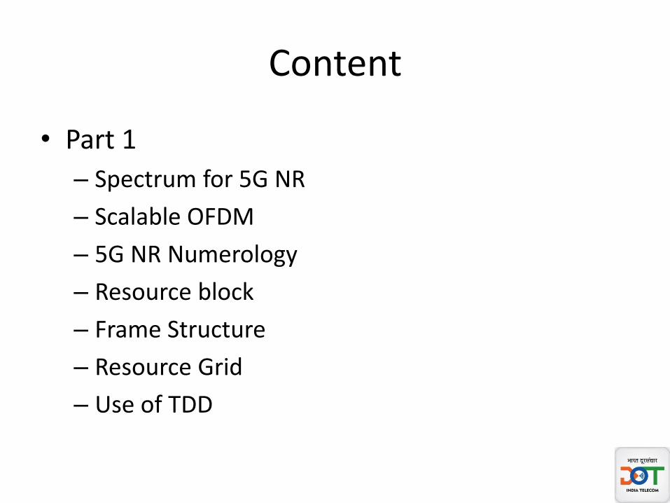
Content
• Part 1
– Spectrum for 5G NR
– Scalable OFDM
– 5G NR Numerology
– Resource block
– Frame Structure
– Resource Grid
– Use of TDD

Content
• Part 2
– BWP
– Carrier Aggregation
– 5G NR Physical Channels and Signals
– SS block
– 5G NR Synchronisation Procedure

Spectrum in FR1 and FR2 and Channel BW
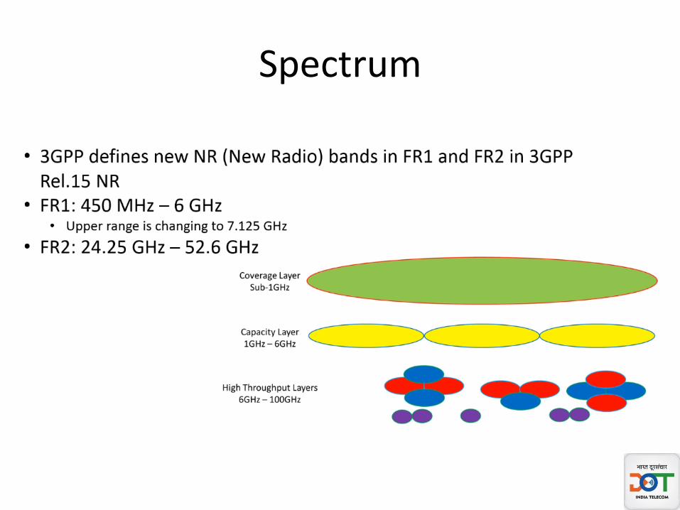
Spectrum
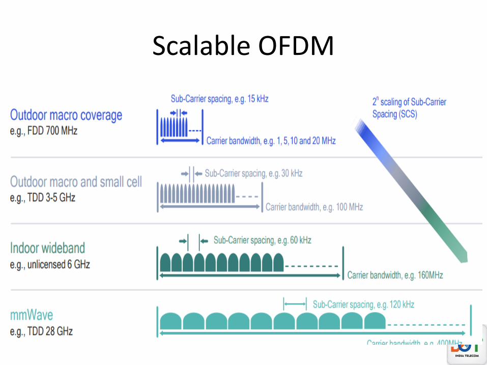
Scalable OFDM

Sub Carrier Spacing

Supported Transmission Numerology
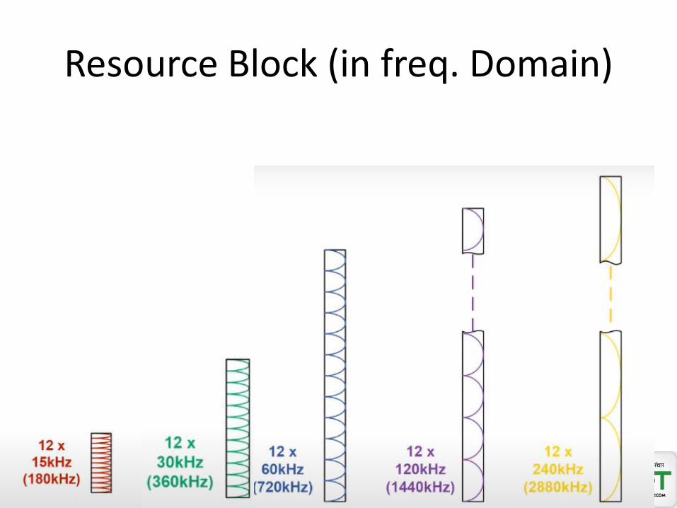
Resource Block (in freq. Domain)
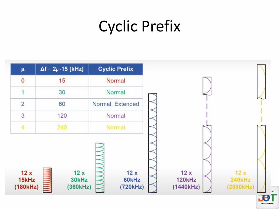
Cyclic Prefix

Radio Frame
• Frame duration = 10msec
• Subframe duration = 1msec
• Slot Duration : Varies according to sub carrier spacing used.
• OFDM Symbols per slot = 14
• Symbol duration : Varies according to sub carrier spacing used.
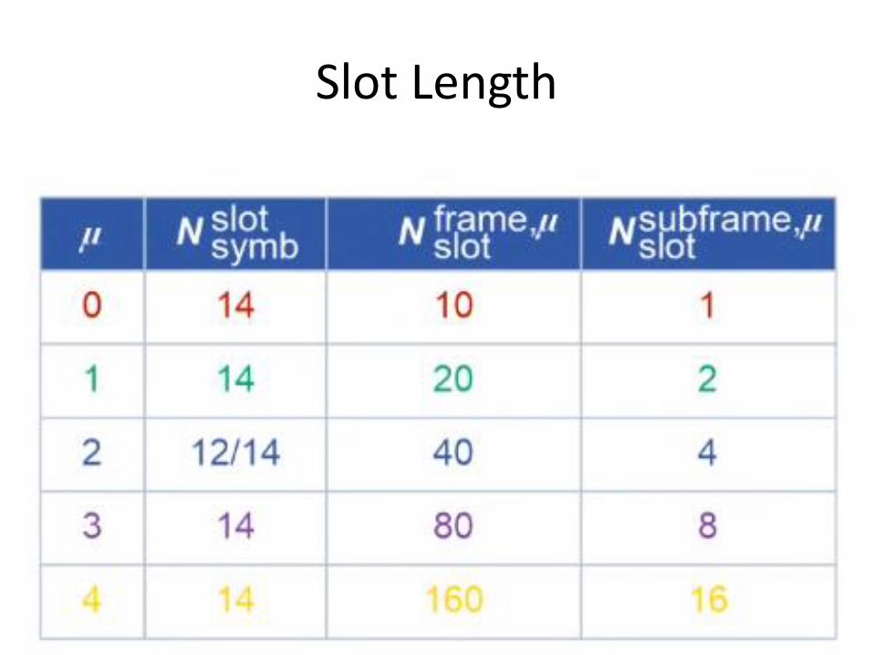
Slot Length
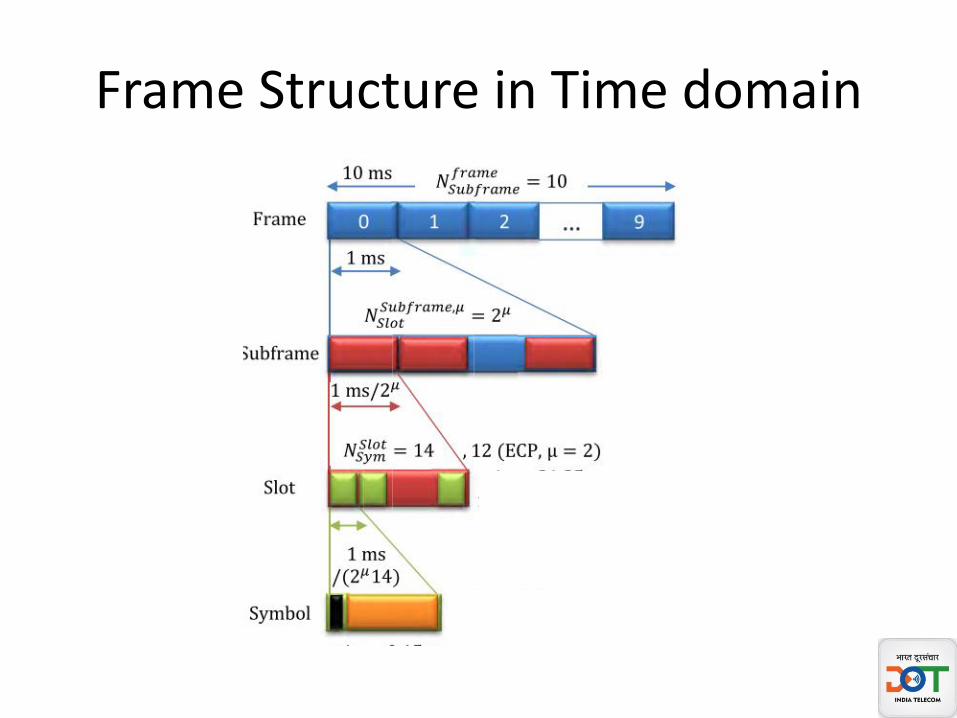
Frame Structure in Time domain
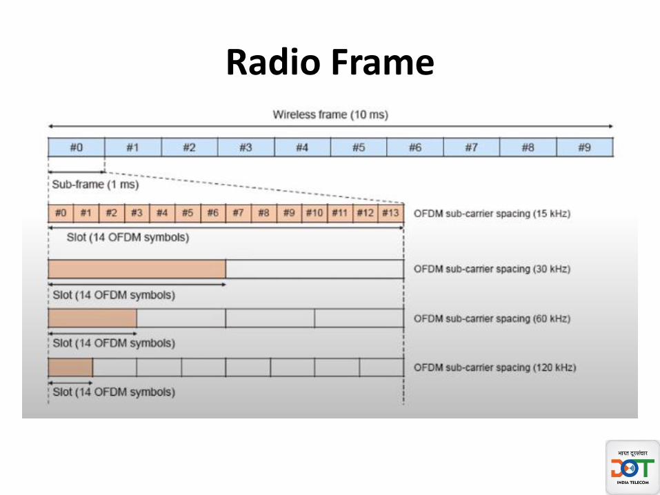
Radio Frame

15 KHz sub carrier
• Frame duration = 10 mSec• Sub frame duration = 1 msec• 1 subframe = 1 slot • Slot duration = 1msec• 1 slot = 14 symbols
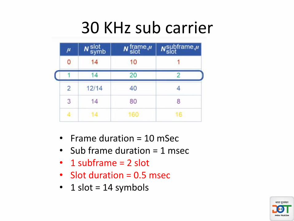
30 KHz sub carrier
• Frame duration = 10 mSec• Sub frame duration = 1 msec• 1 subframe = 2 slot • Slot duration = 0.5 msec• 1 slot = 14 symbols
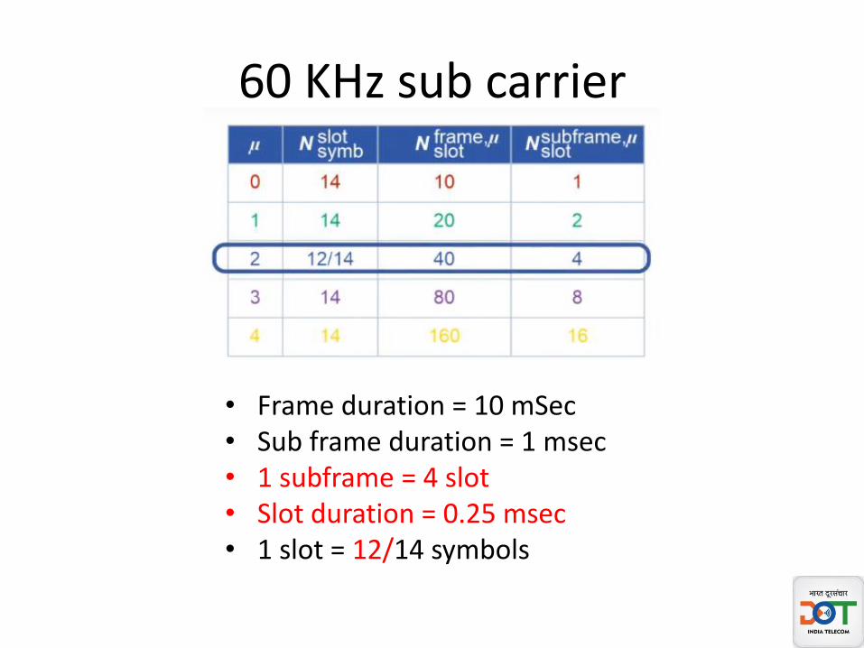
60 KHz sub carrier
• Frame duration = 10 mSec• Sub frame duration = 1 msec• 1 subframe = 4 slot • Slot duration = 0.25 msec• 1 slot = 12/14 symbols

120 KHz sub carrier
• Frame duration = 10 mSec• Sub frame duration = 1 msec• 1 subframe = 8 slot • Slot duration = 0.125 msec• 1 slot = 14 symbols
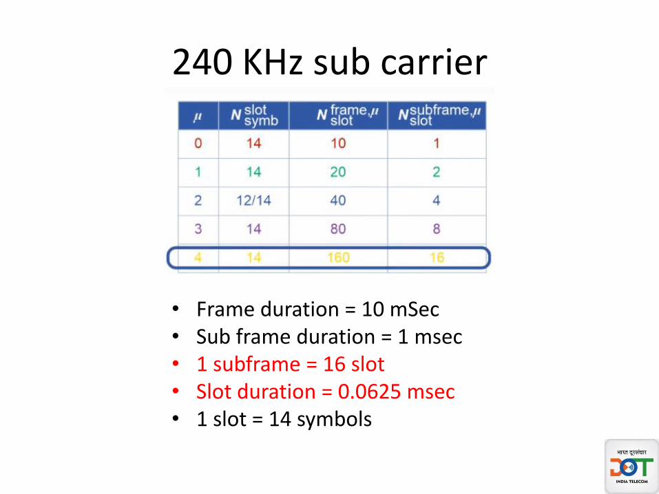
240 KHz sub carrier
• Frame duration = 10 mSec• Sub frame duration = 1 msec• 1 subframe = 16 slot • Slot duration = 0.0625 msec• 1 slot = 14 symbols
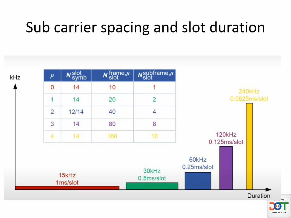
Sub carrier spacing and slot duration

Frame Structure

Symbol Visualisation in a slot
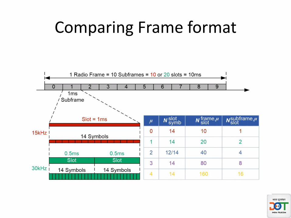
Comparing Frame format

5G NR time Unit
• NR time time unit (Tc) = 1/ (∆fmax * Nf) Where
• ∆fmax = max sub carrier spacing 480 KHz= 480000Hz
• Nf=FFT size =4096
• Tc = 0.509 nano second
• LTE time unit = Ts
• Constant k =Ts/TC=64
• Ts ( LTE time unit) = 1/(15KHz*2048)=32.55 nanosecond
3GPP TS38.211

NR Cyclic Prefix

Normal Cyclic Prefix
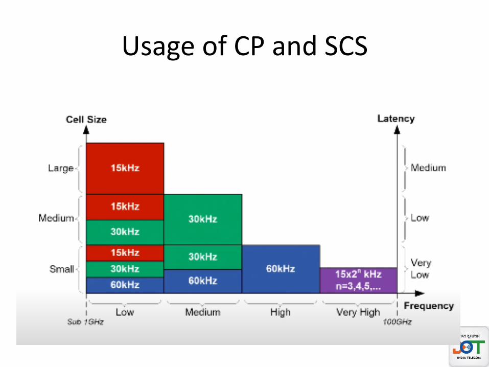
Usage of CP and SCS

NR Channel bandwidth
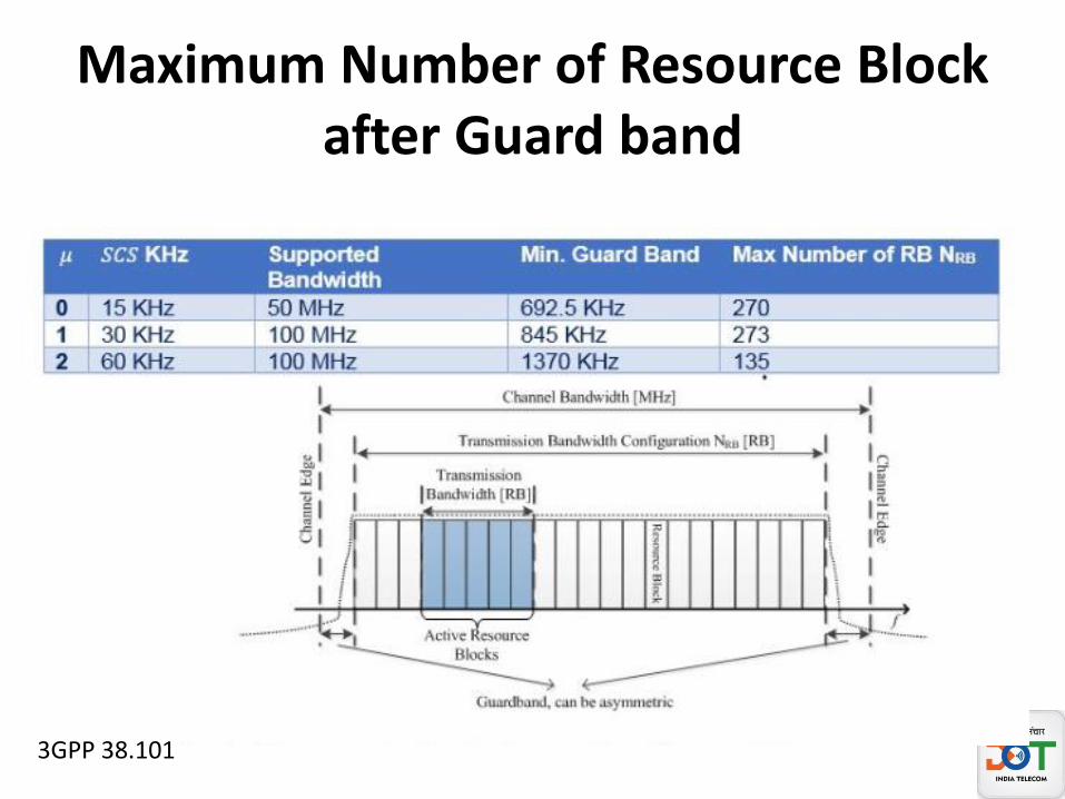
Maximum Number of Resource Block after Guard band
3GPP 38.101
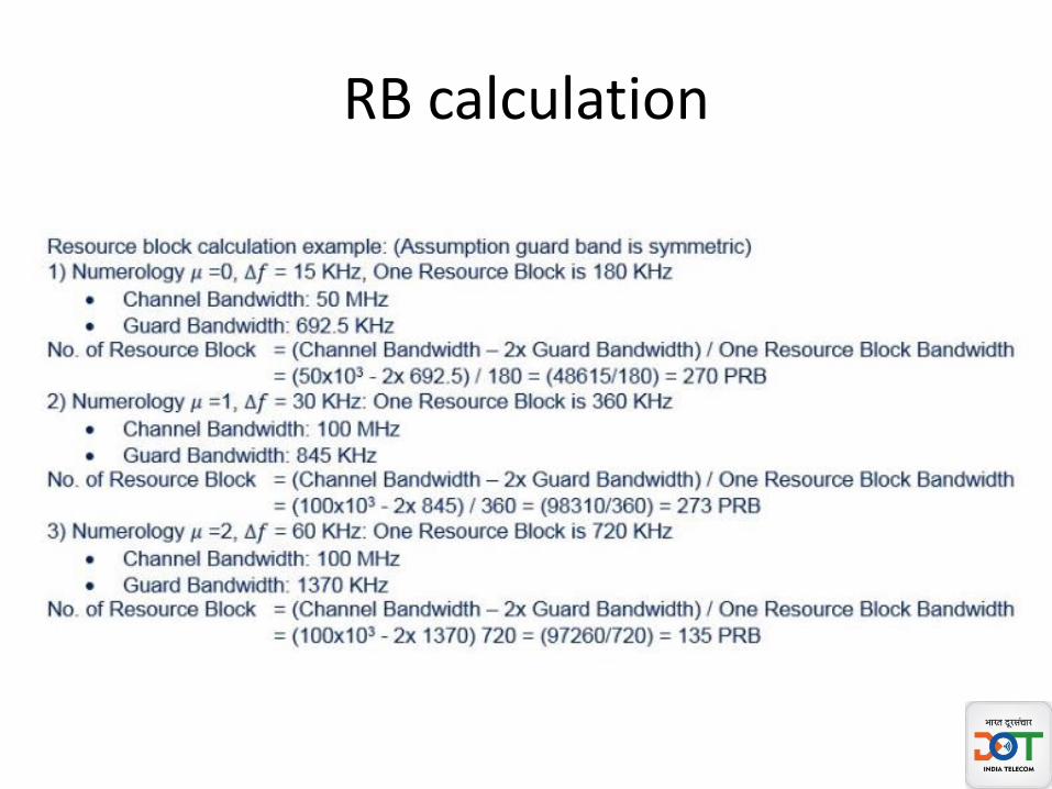
RB calculation
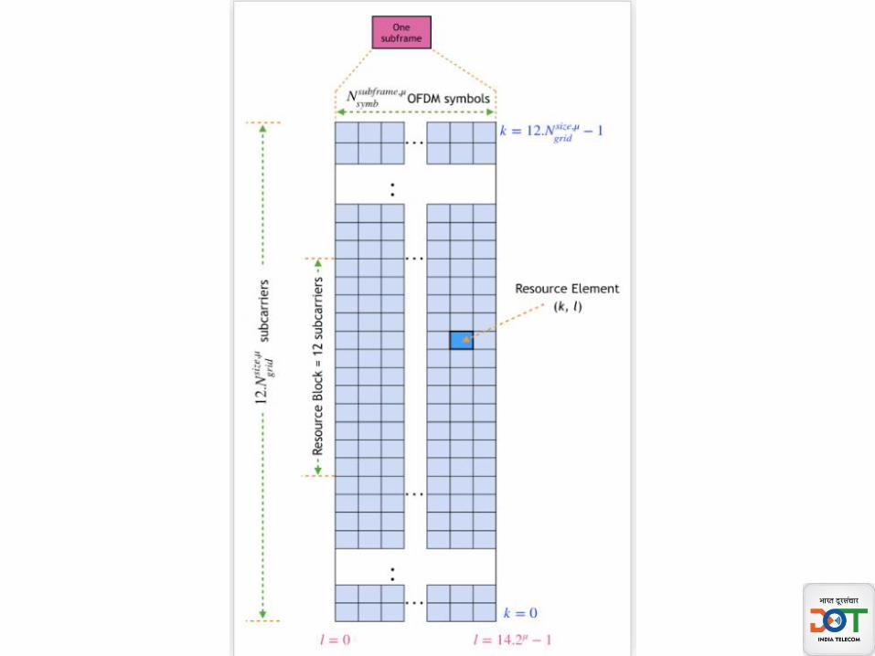
5G NR: Resource Grid
• -A resource grid is characterized by– one subframe in time domain
– and full carrier bandwidth in the frequency domain.
• There are a set of resource grids per transmission direction (uplink or downlink).
• There is one resource grid for a given antenna port p, subcarrier spacing configuration µ, and transmission direction (downlink or uplink).

5G NR: Resource Grid
• Resource Element (RE): – It is the smallest physical resource in NR and it
consists of one subcarrier during one OFDM symbol. It is uniquely identified by (k, l) where k is the index in the frequency domain and l refers to the symbol position in the time domain relative to some reference point.
• Resource Block (RB): – An RB is defined as 12 number of consecutive
subcarriers in frequency domain.
Reference: 3GPP TS 38.211
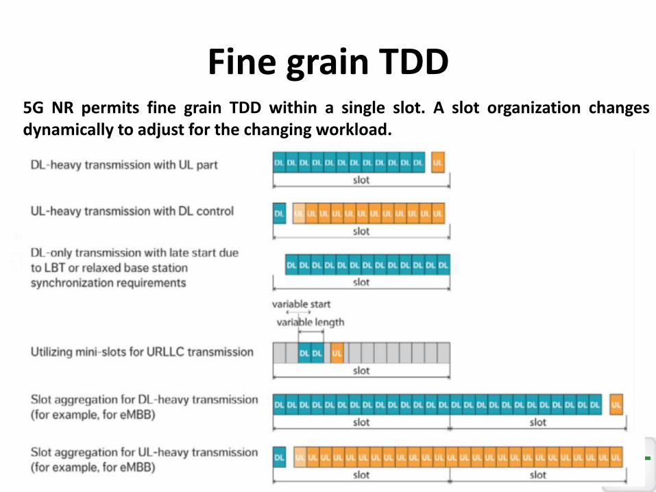
Fine grain TDD5G NR permits fine grain TDD within a single slot. A slot organization changesdynamically to adjust for the changing workload.
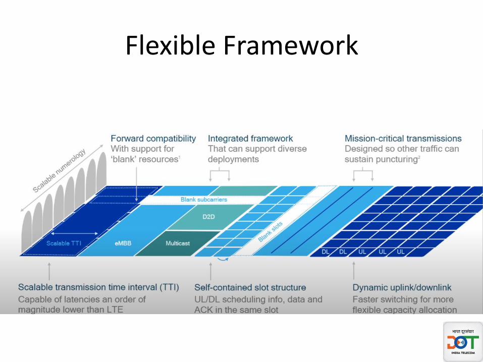
Flexible Framework
Summary
• Spectrum for 5G NR
• Scalable OFDM
• 5G NR Numerology
• Resource block
• Frame Structure
• Resource Grid
• Use of TDD

Thank YouQuestions !
Connect with me @
https://twitter.com/ashokumar100
9818655056

5G Air InterfacePart 2
Ashok Kumar
Director WA (I and II)

Content
• Part 1
– Spectrum for 5G NR
– Scalable OFDM
– 5G NR Numerology
– Resource block
– Frame Structure
– Resource Grid
– Use of TDD
Content
• Part 2
– BWP
– Carrier Aggregation
– 5G NR Physical Channels and Signals
– SS block
– 5G NR Synchronisation Procedure
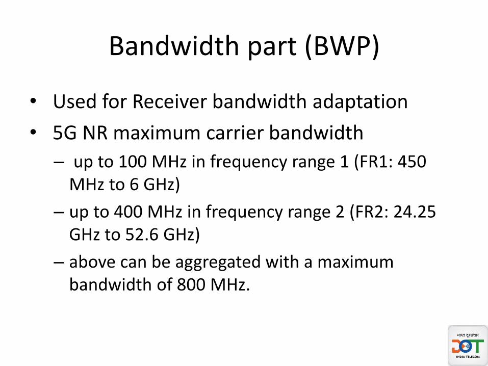
Bandwidth part (BWP)
• Used for Receiver bandwidth adaptation
• 5G NR maximum carrier bandwidth
– up to 100 MHz in frequency range 1 (FR1: 450 MHz to 6 GHz)
– up to 400 MHz in frequency range 2 (FR2: 24.25 GHz to 52.6 GHz)
– above can be aggregated with a maximum bandwidth of 800 MHz.
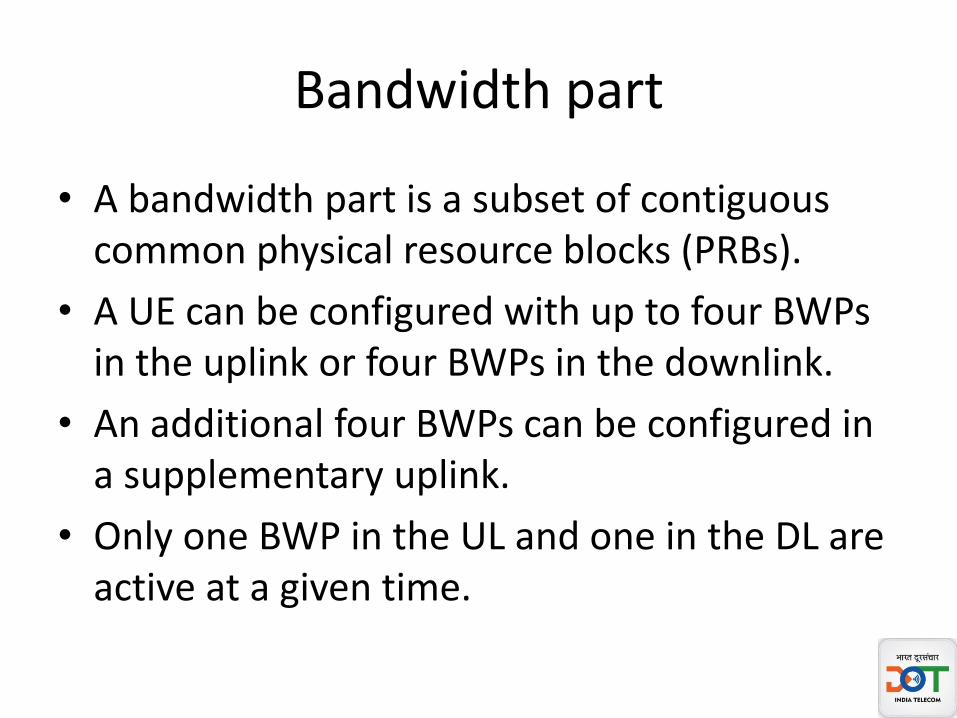
Bandwidth part
• A bandwidth part is a subset of contiguous common physical resource blocks (PRBs).
• A UE can be configured with up to four BWPs in the uplink or four BWPs in the downlink.
• An additional four BWPs can be configured in a supplementary uplink.
• Only one BWP in the UL and one in the DL are active at a given time.
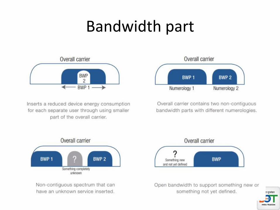
Bandwidth part

Bandwidth part
• Support reduced UE BW• Supporting UE reduced Energy Consumption• Support FDM of Different Numerology• Support non contiguous spectrum• Support Forward Compatibility
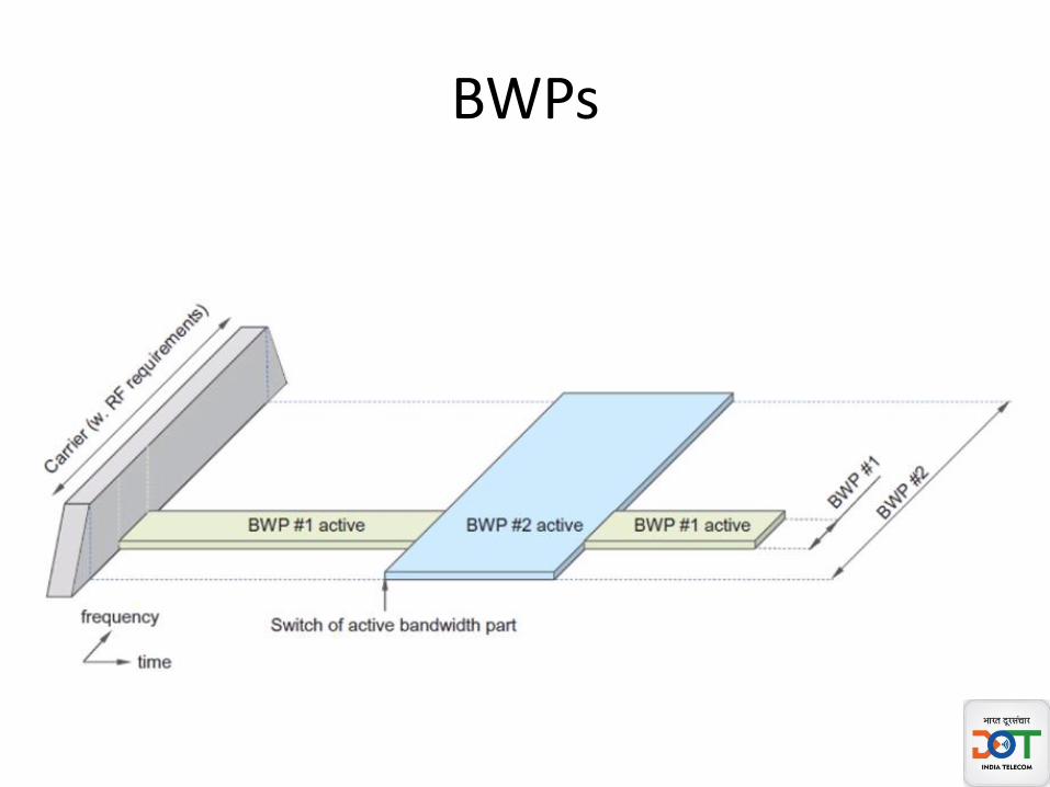
BWPs

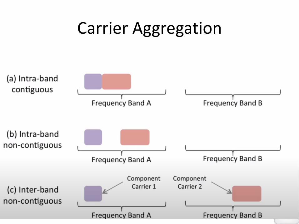
Carrier Aggregation
• Multiple carrier can be aggregated and used enabling overall higher bandwidth and high data rates
• Non contiguous carrier in same band or different band can also be aggregated
• Max 16 carrier can be aggregated
• Max Bandwidth possible=16x400MHz=6.4GHz
Carrier Aggregation
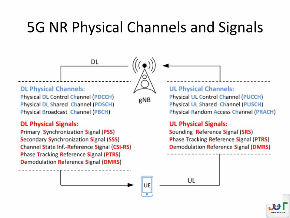
5G NR Physical Channels and Signals
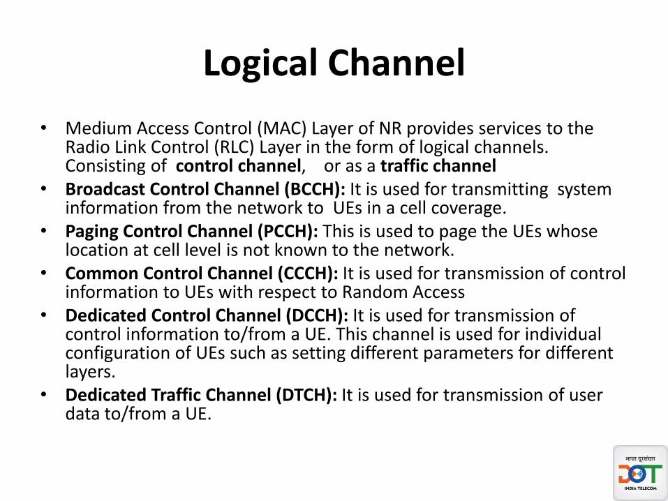
Logical Channel
• Medium Access Control (MAC) Layer of NR provides services to the Radio Link Control (RLC) Layer in the form of logical channels. Consisting of control channel, or as a traffic channel
• Broadcast Control Channel (BCCH): It is used for transmitting system information from the network to UEs in a cell coverage.
• Paging Control Channel (PCCH): This is used to page the UEs whose location at cell level is not known to the network.
• Common Control Channel (CCCH): It is used for transmission of control information to UEs with respect to Random Access
• Dedicated Control Channel (DCCH): It is used for transmission of control information to/from a UE. This channel is used for individual configuration of UEs such as setting different parameters for different layers.
• Dedicated Traffic Channel (DTCH): It is used for transmission of user data to/from a UE.
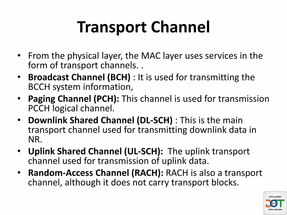
Transport Channel
• From the physical layer, the MAC layer uses services in the form of transport channels. .
• Broadcast Channel (BCH) : It is used for transmitting the BCCH system information,
• Paging Channel (PCH): This channel is used for transmission PCCH logical channel.
• Downlink Shared Channel (DL-SCH) : This is the main transport channel used for transmitting downlink data in NR.
• Uplink Shared Channel (UL-SCH): The uplink transport channel used for transmission of uplink data.
• Random-Access Channel (RACH): RACH is also a transport channel, although it does not carry transport blocks.

5G NR Downlink Physical Channels
• Physical downlink shared channel, PDSCH:– carries data sharing the capacity on a time and frequency basis
• Physical downlink control channel, PDCCH:– carries downlink control data. Its primary function is scheduling
the downlink transmissions on the PDSCH and also the uplink data transmissions on the PUSCH.
• Physical broadcast channel, PBCH:– Its function is to provide UEs with the Master Information Block,
MIB. A further function of the PBCH in conjunction with the control channel is to support the synchronisation of time and frequency. This aids with cell acquisition, selection and re-selection
5G NR Uplink Physical Channels
• Physical random access channel, PRACH– This 5G channel - the physical random access channel,
PRACH, is used for channel access. It transmits an initial random access pre-amble consisting of sequences
• Physical uplink shared channel, PUSCH – . It is used to carry data from the UL-SCH and its
higher mapped channels on a frequency and time-shared basis.
• Physical uplink control channel, PUCCH– carries the uplink control data
Physical Signal
• DL Physical Signals – Demodulation Ref (DMRS)
– Phase-tracking Ref (PT-RS)
– Ch State Inf Ref (CSI-RS)
– Primary Sync (PSS)
– Secondary Sync (SSS)
• UL Physical Signals • Demodulation Ref (DMRS)
• Phase-tracking Ref (PTRS)
• Sounding Ref (SRS)
5G NR Reference Signals (DMRS, PTRS,SRS and CSI-RS)
• DL/UL Demodulation Ref (DMRS)– used by a receiver for radio channel estimation for demodulation of
associated physical channel – for specific UE, and transmitted on demand– Multiple orthogonal DMRSs can be allocated to support MIMO
transmission.
• DL / Up Phase-tracking Ref (PT-RS)– track phase of the Local Oscillator at transmitter and receiver
• DL Channel State Information Reference Signal (CSI-RS)– used to estimate the channel quality and report information back to
the gNB
• Sounding Ref (SRS)– transmitted by the UE to help the gNB obtain the channel state
information (CSI) for each user.
Synchronization Signals
• Like LTE, 5G NR also has synchronization signal and known as – Primary Synchronization signal (PSS) and – Secondary Synchronization signal (SSS). – These signals are specific to NR physical layer
• PSS and SSS provides following to UE for downlink synchronization– PSS provides Radio Frame Boundary ( Position of 1st Symbol in a
Radio frame)– SSS provides Subframe Boundary (Position of 1st Symbol in a
Subframe)– Physical Layer Cell ID (PCI) information using both PSS and SSS
Synchronization Signals
• In 5G NR systems, each radio cell is identified by a cell ID from 1008 IDs that are arranged into 336 different groups.
• Each group is identified by the cell ID group, N (1) ID ∈ {0, . . . , 335}, and consists of three different sectors, which are specified by the cell ID sector, N (2) ID ∈ {0, 1, 2}.
• The UE can detect the value of N (2) ID from the PSS, and the value of N (1) ID from the SSS.
• Based on that, the UE computes the serving cell ID as follows: N cell ID = 3 N (1) ID + N (2) ID .
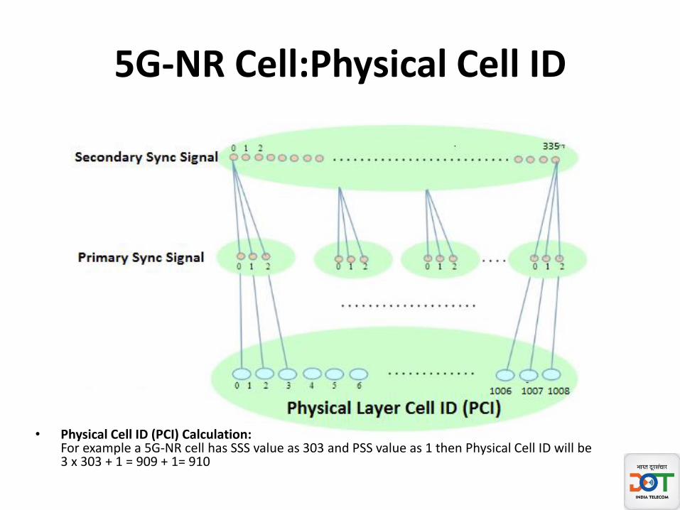
5G-NR Cell:Physical Cell ID
• Physical Cell ID (PCI) Calculation:For example a 5G-NR cell has SSS value as 303 and PSS value as 1 then Physical Cell ID will be3 x 303 + 1 = 909 + 1= 910
NR-Primary Synchronization Signal (PSS)
• It is used by UE for Downlink Frame Synchronization and provides Radio Frame Boundary i.e. Position of 1st Symbol in a Radio frame
• PSS is mapped to 127 active sub carriers around the lower end of the system bandwidth
• It is a critical factors determining Physical Layer Cell ID and provides N (2)
ID value for calculation
NR-Secondary Synchronization Signal (SSS)
• It is used by UE for Downlink Frame Synchronization and provides Subframe Boundary i.e. Position of 1st Symbol in a Subframe
• SSS is mapped to 127 active sub carriers around the lower end of the system bandwidth
• It is a critical factors determining Physical Layer Cell ID and provides N (1)
ID value for calculation
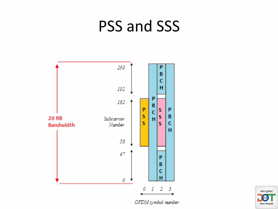
PSS and SSS

Size of SS Block

One SS Burst Set
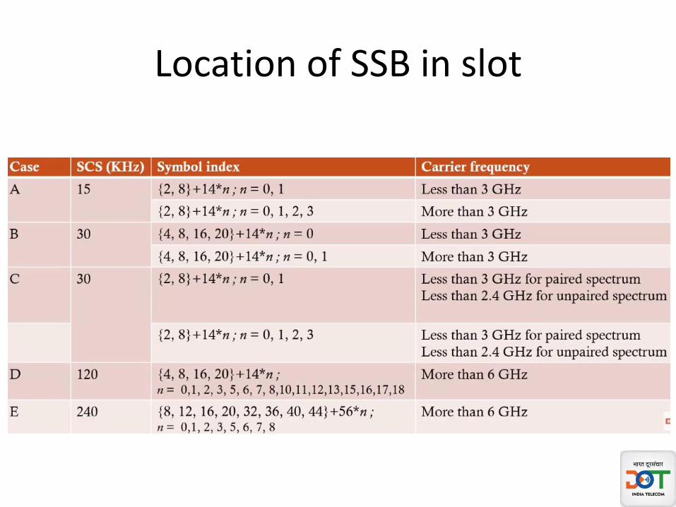
Location of SSB in slot
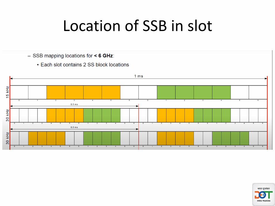
Location of SSB in slot

Reference Signals Mapping physical channel

5G NR synchronization procedure
Summary
• Spectrum for 5G NR• Scalable OFDM• 5G NR Numerology• Resource block• Frame Structure• Resource Grid• Use of TDD• BWP• Carrier Aggregation• 5G NR Physical Channels and Signals• 5G NR Synchronisation Procedure

Thank You
Questions !
Phase Tracking Reference Signal (PTRS)
• The phase noise of a transmitter increases as the frequency of operation increases. The PTRS plays a crucial role especially at mmWave frequencies to minimize the effect of the oscillator phase noise on system performance. One of the main problems that phase noise introduces into an OFDM signal appears as a common phase rotation of all the sub-carriers, known as common phase error (CPE).
• PTRS stands for Phase Tracking Reference signal• It’s main function is to track phase of the Local Oscillator at transmitter and receiver.• PTRS enables suppression of phase noise and common phase error specially at higher mmwave
frequencies.• It is present both in uplink (in NR-PUSCH) and downlink (in NR-PDSCH) channels.• Due to phase noise properties, PTRS has low density in frequency domain and high density in time
domain.• PTRS is associated with one DMRS port during transmission. Moreover it is confined to scheduled
BW and duration used for NR-PDSCH/NR-PUSCH• The NR system typically maps the PTRS information to a few subcarriers per symbol because the
phase rotation affects all sub-carriers within an OFDM symbol equally but shows low correlation from symbol to symbol
• The system configures the PTRS depending on the quality of the oscillators, carrier frequency, Sub Carrier Spacing, and modulation and coding schemes that the transmission uses
Backup slides for reference

Sounding Reference Signal (SRS)
• As a UL-only signal, the SRS is transmitted by the UE to help the gNB obtain the channel state information (CSI) for each user. Channel State Information describes how the NR signal propagates from the UE to the gNB and represents the combined effect of scattering, fading, and power decay with distance. The system uses the SRS for resource scheduling, link adaptation, Massive MIMO, and beam management.
• SRS refers to Sounding Reference signal and uplink only signal.• It is configured specific to UE• In time domain, it spans 1/2/4 consecutive symbols which are
mapped within last six symbols of the slot• Multiple SRS symbols allow coverage extension and increased
sounding capacity• The design of SRS and its frequency hopping mechanism is same as
used in LTE.
Demodulation Reference Signal (DMRS)
• The DMRS is specific for specific UE, and used to estimate the radio channel. The system can beamform the DMRS, keep it within a scheduled resource, and transmit it only when necessary in either DL or UL. Additionally, multiple orthogonal DMRSs can be allocated to support MIMO transmission. The network presents users with DMRS information early on for the initial decoding requirement that low-latency applications need, but it only occasionally presents this information for low-speed scenarios in which the channel shows little change. In high-mobility scenarios to track fast changes in channel , it might increase the rate of transmission of DMRS signal (called “additional DMRS”).
• DMRS refers to demodulation reference signal• It is used by a receiver for radio channel estimation for demodulation of associated
physical channel• DMRS design and mapping is specific to each Downlink and Uplink NR channels
vize NR-PBCH, NR-PDCCH, NR-PDSCH, NR-PUSCH , NR- PUSCH• DMRS is specific for specific UE, and transmitted on demand• DMRS can be beamform the DMRS, kept within a scheduled resource, and transmit
it only when necessary in either DL or UL• Multiple orthogonal DMRSs can be allocated to support MIMO transmission.
Channel State Information Reference Signal (CSI-RS)
• As a DL-only signal, the CSI-RS the UE receives is used to estimate the channel and report channel quality information back to the gNB. During MIMO operations, NR uses different antenna approaches based on the carrier frequency. At lower frequencies, the system uses a modest number of active antennas for MU-MIMO and adds FDD operations. In this case, the UE needs the CSI-RS to calculate the CSI and report it back in the UL direction.
• CSI-RS refers to channel state information reference signal and these signals are downlink only signal.
• It is used for DL CSI acquisition.• Used for RSRP measurements used during mobility and beam management• Also used for frequency/time tracking, demodulation and UL reciprocity based pre-coding• CSI-RS is configured specific to UE, but multiple users can also share the same resource• 5G NR standard allows high level of flexibility in CSI-RS configurations, a resource can be configured
with up to 32 ports.• CSI-RS resource may start at any OFDM symbol of the slot and it usually occupies 1/2/4 OFDM
symbols depending upon configured number of ports.• CSI-RS can be periodic, semi-persistent or aperiodic (due to DCI triggering)• For time/frequency tracking, CSI-RS can either be periodic or aperiodic. It is transmitted in bursts of
two or four symbols which are spread across one or two slots

PSS Sequence Generation

NR PSS and LTE PSS Comparison
• LTE PSS use Zadoff-Chu sequence while NR PSS use m-Sequence.
• LTE PSS is mapped to center 72 sub-carriers whereas NR PSS is mapped to 127 active sub-carriers.

SSS Sequence Generation
NR SSS and LTE SSS Comparison
• NR SSS and LTE SSS are very much similar as both are generated using m-Sequence
• LTE SSS generation is much complicated than NR SSS asLTE SSS gets different sequence depending on the subframe in which it is being transmitted.
• NR SSS sequence does not depend on the subframe.
• LTE SSS is mapped to center 72 sub-carriers whereas NR SSS is mapped to 127 active subcarriers.
5G-NR Cell:Physical Cell ID
• Like LTE, 5G NR also has synchronization signal and known as – Primary Synchronization signal (PSS) and – Secondary Synchronization signal (SSS). – These signals are specific to NR physical layer
• PSS and SSS provides following to UE for downlink synchronization– PSS provides Radio Frame Boundary ( Position of 1st Symbol in a
Radio frame)– SSS provides Subframe Boundary (Position of 1st Symbol in a
Subframe)– Physical Layer Cell ID (PCI) information using both PSS and SSS
Physical Layer Cell ID Calculation
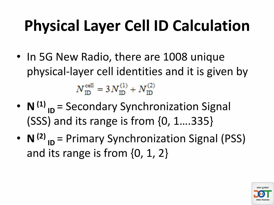
• In 5G New Radio, there are 1008 unique physical-layer cell identities and it is given by
• N (1)ID = Secondary Synchronization Signal
(SSS) and its range is from {0, 1….335}
• N (2)ID = Primary Synchronization Signal (PSS)
and its range is from {0, 1, 2}
5G NR Sounding Reference Signal (NR-SRS)
• In NR following Reference Signal in UL gives information about the channel quality.– DMRS:- Demodulation Reference Signal– SRS:- Sounding Reference Signal
• With the help of above two RS, gNB takes smart decisions for resource allocation for uplink transmission, link adaptation and to decode transmitted data from UE.
• SRS is a UL reference signal which is transmitted by UE to Base station.
• SRS gives information about the combined effect of multipath fading, scattering, Doppler and power loss of transmitted signal.

5G NR Sounding Reference Signal (NR-SRS)
• Base Station estimates the channel quality using this reference signal and manages further resource scheduling, Beam management, and power control of signal.
• SRS provides information to gNB about the channel over full bandwidth and using this information gNB takes decision for resource allocation which has better channel quality comparing to other Bandwidth regions.

5G NR Sounding Reference Signal (NR-SRS)
• DMRS provides information about the frequency region which is being used by PUSCH/PUCCH specifically.
• If gNB assigns resources over full bandwidth region for a UE then there is no choice left for UE to select specific frequency region Hence SRS is optional.
• BUT DMRS will always be transmitted with PUSCH/PUCCH for coherent demodulation and channel estimation.

Difference Between Sounding Reference Signal (SRS) of 4G-LTE and 5G-NR