Supply of 765kV Isolator to Fatehgarh - Bharat Heavy ...
102
-
Upload
khangminh22 -
Category
Documents
-
view
0 -
download
0
Transcript of Supply of 765kV Isolator to Fatehgarh - Bharat Heavy ...
Substation Package - SS02 for (i) 765kV Fatehgarh-2 (PG) S/S Extension and (ii)765kV Bhadla-2 (PG) S/s Extension under Transmission System
Associated With LTA applications from Rajasthan SEZ Part-B (Rajasthan SEZ Part-B Project) through Tariff
Based Competitive Bidding (TBCB) Route. 765kV Isolators and Earth Switches
Doc. No. : TB-409-316-004 Rev 00
Page 2 of 25
SECTION-1
Scope, Bill of Quantity, Specific Technical Requirements 1.1 Scope
This technical specification covers the requirements of design, manufacture, testing at works, packing, dispatch and supervision of erection and commissioning of 765kV Isolators (double break/Vertical Knee type) and earth switches complete with accessories. Isolators shall be supplied along with operating rod insulators but without post insulators, structures and terminal connectors. The equipment is required for the following project: Name of the customer : POWERGRID FATEHGARH TRANSMISSION LIMITED- A 100%
wholly owned subsidiary of Power Grid Corporation of India Limited
Name of the project : Substation Package - SS02 for (i) 765kV Fatehgarh-2 (PG) S/S
Extension and (ii) 765kV Bhadla-2 (PG) S/s Extension under Transmission System Associated With LTA applications from Rajasthan SEZ Part-B (Rajasthan SEZ Part-B Project) through Tariff Based Competitive Bidding (TBCB) Route
Site : Bhadla-II, Rajasthan & Fatehgarh-II, Rajasthan *Note: The terms used in this specification namely, “Employer” refers to PowerGrid , “POWERGRID” refers to BHEL/POWERGRID, “Contractor” refers to Bidder, “GTR” refers to “section-3”. In case of any conflict among the various sections of this specification, the order of precedence shall be section 1, section 2 & the section 3.
Substation Package - SS02 for (i) 765kV Fatehgarh-2 (PG) S/S Extension and (ii)765kV Bhadla-2 (PG) S/s Extension under Transmission System
Associated With LTA applications from Rajasthan SEZ Part-B (Rajasthan SEZ Part-B Project) through Tariff
Based Competitive Bidding (TBCB) Route. 765kV Isolators and Earth Switches
Doc. No. : TB-409-316-004 Rev 00
Page 3 of 25
1.2 Bill of Quantities 1.2.1 Main Supply:
S. No. Item Description Unit Quantity
Bhadla II
Fatehgarh II 1
SUPPLY- ISOLATOR : 765KV, 3150A, 40KA FOR 1S, THREE PHASE, DOUBLE BREAK / VERTICAL KNEE TYPE INDIVIDUAL POLE MOTOR OPERATED, ELECTRICALLY GANGED ISOLATOR WITH ONE EARTH SWITCH, INDIVIDUAL POLE MOTOR OPERATED, ELECTRICALLY GANGED, ALONG WITH OPERATING MECHANISM, OPERATING ROD INSULATORS & OTHER ACCESSORIES, BUT WITHOUT INSULATOR, STRUCTURE & TERMINAL CONNECTOR ETC.
Nos 8 8
2 SUPPLY- ISOLATOR : 765KV, 3150A, 40KA FOR 1S, THREE PHASE, DOUBLE BREAK / VERTICAL KNEE TYPE INDIVIDUAL POLE MOTOR OPERATED, ELECTRICALLY GANGED ISOLATOR WITH TWO EARTH SWITCH, INDIVIDUAL POLE MOTOR OPERATED, ELECTRICALLY GANGED, ALONG WITH OPERATING MECHANISM, OPERATING ROD INSULATORS & OTHER ACCESSORIES, BUT WITHOUT INSULATOR, STRUCTURE & TERMINAL CONNECTOR ETC.
Nos 2 2
3 SUPPLY- ISOLATOR : 765KV, 2000A, 40KA FOR 1S, SINGLE PHASE, DOUBLE BREAK / VERTICAL KNEE TYPE ISOLATOR MOTOR OPERATED WITH ONE EARTH SWITCH MOTOR OPERATED ALONG WITH OPERATING MECHANISM, OPERATING ROD INSULATORS & OTHER ACCESSORIES, BUT WITHOUT INSULATOR, STRUCTURE & TERMINAL CONNECTOR ETC.
Nos 0 6
4 SUPPLY- ISOLATOR : 765KV, 2000A, 40KA FOR 1S, SINGLE PHASE, DOUBLE BREAK / VERTICAL KNEE TYPE ISOLATOR MOTOR OPERATED WITHOUT EARTH SWITCH ALONG WITH OPERATING MECHANISM, OPERATING ROD INSULATORS & OTHER ACCESSORIES, BUT WITHOUT INSULATOR, STRUCTURE & TERMINAL CONNECTOR ETC.
Nos 0 12
5* SERVICES- ISOLATOR : 765KV, SUPERVISION OF ERECTION TESTING AND COMMISSIONING INCLUDING ALIGNMENT CHECK OF DOUBLE BREAK / VERTICAL KNEE TYPE ISOLATOR & EARTHSWITCH
Lot 1 1

Substation Package - SS02 for (i) 765kV Fatehgarh-2 (PG) S/S Extension and (ii)765kV Bhadla-2 (PG) S/s Extension under Transmission System
Associated With LTA applications from Rajasthan SEZ Part-B (Rajasthan SEZ Part-B Project) through Tariff
Based Competitive Bidding (TBCB) Route. 765kV Isolators and Earth Switches
Doc. No. : TB-409-316-004 Rev 00
Page 4 of 25
Notes – 1. The above quantities may vary ± 30%. 2. Prices for all applicable accessories of isolators and earth switches shall be included in
the equipment prices. 3. Erection, testing and commissioning of all 765kV Isolators and earth switches shall be
carried out under the supervision of the Isolator manufacturer's representative. The commissioning report shall be prepared and signed by the manufacturer’s representative. However required unskilled men power/labour, tools (other than special tools and tackles which shall be in bidder’s scope) shall be provided by BHEL.
4. Respective dates for the commencement of erection, testing and commissioning activities of Isolators shall be communicated to manufacturers from time to time as per the readiness of respective sites.
5. *For Bhadla II: For item at sl. No. 5, lot is defined as the total quantity required for successful completion of 4 no. Isolators with One Earth Switch (refer description item at Sl. No.1).
6. *For Fatehgarh II: For item at sl. No. 5, lot is defined as the total quantity required for successful completion of 4 no. Isolators with One Earth Switch (refer description item at Sl. No.1) & Complete quantity at Sl. No. 3 & 4.
7. Single Phase Isolators of BOQ may or may not be required for the simultaneous operation of two 1 Phase Isolators in series, therefore they should have foolproof scheme of Master and follower operation. There should be sufficient TBs in MASTER MOM box to wire up and formation of series/parallel contacts of Master and Follower Isolators. In addition to these TBs, 20% extra TBs should be provided for owner’s future use.
8. Bidder shall furnish separate schematic drawings for series operation of two, 1 Phase Isolators and independent operation of 1 Phase Isolator for approval during detailed engineering stage.
1.3 Specific Technical Requirements 1.3.1 Technical Parameters - 765kV Isolator
Sl. No. Description Unit 800kV ISO 1 Rated voltage kVrms 800 2 Rated frequency Hz 50 3 No. of poles Nos. 3 4 Design ambient temperature °C 50 5 Type Outdoor
6 Rated current at 50oC ambient temperature A 3150/2000
Substation Package - SS02 for (i) 765kV Fatehgarh-2 (PG) S/S Extension and (ii)765kV Bhadla-2 (PG) S/s Extension under Transmission System
Associated With LTA applications from Rajasthan SEZ Part-B (Rajasthan SEZ Part-B Project) through Tariff
Based Competitive Bidding (TBCB) Route. 765kV Isolators and Earth Switches
Doc. No. : TB-409-316-004 Rev 00
Page 5 of 25
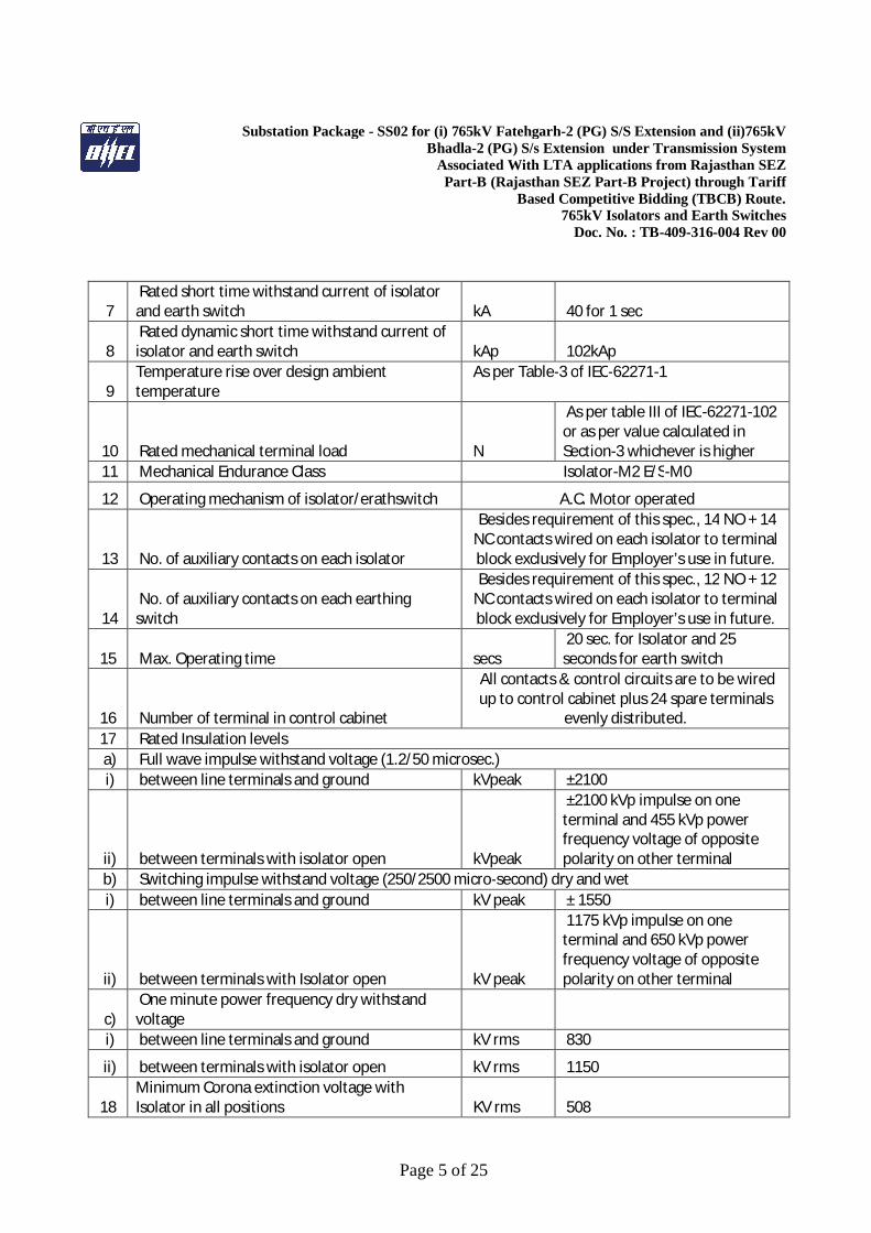
7 Rated short time withstand current of isolator and earth switch kA 40 for 1 sec
8 Rated dynamic short time withstand current of isolator and earth switch kAp 102kAp
9 Temperature rise over design ambient temperature
As per Table-3 of IEC-62271-1
10 Rated mechanical terminal load N
As per table III of IEC-62271-102 or as per value calculated in Section-3 whichever is higher
11 Mechanical Endurance Class Isolator-M2 E/S-M0
12 Operating mechanism of isolator/erathswitch A.C. Motor operated
13 No. of auxiliary contacts on each isolator
Besides requirement of this spec., 14 NO + 14 NC contacts wired on each isolator to terminal block exclusively for Employer’s use in future.
14 No. of auxiliary contacts on each earthing switch
Besides requirement of this spec., 12 NO + 12 NC contacts wired on each isolator to terminal block exclusively for Employer’s use in future.
15 Max. Operating time secs 20 sec. for Isolator and 25 seconds for earth switch
16 Number of terminal in control cabinet
All contacts & control circuits are to be wired up to control cabinet plus 24 spare terminals
evenly distributed. 17 Rated Insulation levels a) Full wave impulse withstand voltage (1.2/50 microsec.) i) between line terminals and ground kVpeak ±2100
ii) between terminals with isolator open kVpeak
±2100 kVp impulse on one terminal and 455 kVp power frequency voltage of opposite polarity on other terminal
b) Switching impulse withstand voltage (250/2500 micro-second) dry and wet i) between line terminals and ground kV peak ± 1550
ii) between terminals with Isolator open kV peak
1175 kVp impulse on one terminal and 650 kVp power frequency voltage of opposite polarity on other terminal
c) One minute power frequency dry withstand voltage
i) between line terminals and ground kV rms 830
ii) between terminals with isolator open kV rms 1150
18 Minimum Corona extinction voltage with Isolator in all positions KV rms 508
Substation Package - SS02 for (i) 765kV Fatehgarh-2 (PG) S/S Extension and (ii)765kV Bhadla-2 (PG) S/s Extension under Transmission System
Associated With LTA applications from Rajasthan SEZ Part-B (Rajasthan SEZ Part-B Project) through Tariff
Based Competitive Bidding (TBCB) Route. 765kV Isolators and Earth Switches
Doc. No. : TB-409-316-004 Rev 00
Page 6 of 25
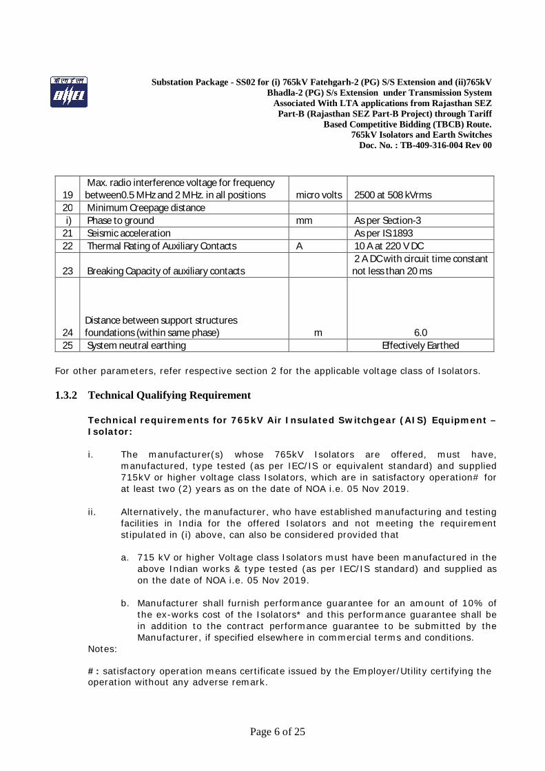
19 Max. radio interference voltage for frequency between0.5 MHz and 2 MHz. in all positions micro volts 2500 at 508 kVrms
20 Minimum Creepage distance i) Phase to ground mm As per Section-3 21 Seismic acceleration As per IS:1893 22 Thermal Rating of Auxiliary Contacts A 10 A at 220 V DC
23 Breaking Capacity of auxiliary contacts 2 A DC with circuit time constant not less than 20 ms
24
Distance between support structures foundations (within same phase)
m
6.0
25 System neutral earthing
Effectively Earthed For other parameters, refer respective section 2 for the applicable voltage class of Isolators. 1.3.2 Technical Qualifying Requirement
Technical requirements for 765kV Air Insulated Switchgear (AIS) Equipment – Isolator: i. The manufacturer(s) whose 765kV Isolators are offered, must have,
manufactured, type tested (as per IEC/IS or equivalent standard) and supplied 715kV or higher voltage class Isolators, which are in satisfactory operation# for at least two (2) years as on the date of NOA i.e. 05 Nov 2019.
ii. Alternatively, the manufacturer, who have established manufacturing and testing facilities in India for the offered Isolators and not meeting the requirement stipulated in (i) above, can also be considered provided that
a. 715 kV or higher Voltage class Isolators must have been manufactured in the
above Indian works & type tested (as per IEC/IS standard) and supplied as on the date of NOA i.e. 05 Nov 2019.
b. Manufacturer shall furnish performance guarantee for an amount of 10% of the ex-works cost of the Isolators* and this performance guarantee shall be in addition to the contract performance guarantee to be submitted by the Manufacturer, if specified elsewhere in commercial terms and conditions.
Notes: #: satisfactory operation means certificate issued by the Employer/Utility certifying the operation without any adverse remark.
Substation Package - SS02 for (i) 765kV Fatehgarh-2 (PG) S/S Extension and (ii)765kV Bhadla-2 (PG) S/s Extension under Transmission System
Associated With LTA applications from Rajasthan SEZ Part-B (Rajasthan SEZ Part-B Project) through Tariff
Based Competitive Bidding (TBCB) Route. 765kV Isolators and Earth Switches
Doc. No. : TB-409-316-004 Rev 00
Page 7 of 25
*: voltage class of respective equipment as applicable. 1.3.3 Type Tests
i. All equipment being supplied shall conform to type tests as per technical specification and shall be subject to routine tests in accordance with requirements stipulated under respective sections.
ii. The reports for all type tests as per technical specification shall be furnished by the Bidder along with equipment / material drawings. However, type test reports of similar equipments/ material already accepted in POWERGRID shall be applicable for all projects with similar requirement. The type tests conducted earlier should have either been conducted in accredited laboratory (accredited based on ISO / IEC Guide 25 / 17025 or EN 45001 by the national accreditation body of the country where laboratory is located) or witnessed by POWERGRID or representative authorized by POWERGRID or Utility or representative of accredited test lab. Unless otherwise specified elsewhere, the type test reports submitted shall be of the tests conducted on or after 05-Nov-2009. In case the test reports are of the test conducted earlier than 05-Nov-2009, the bidder shall repeat these test(s) at no extra cost to the BHEL/Employer. Further, in the event of any discrepancy in the test reports i.e. any test report not acceptable due to any design/manufacturing changes or due to non-compliance with the requirement stipulated in the Technical Specification or any/all type tests not carried out, same shall be carried out without any additional cost implication to the BHEL/Employer. The Bidder shall intimate the Employer/BHEL the detailed program about the type tests atleast two (2) weeks in advance in case of domestic supplies & six (6) weeks in advance in case of foreign supplies.
iii. The Employer reserves the right to witness any or all the type tests. The Employer shall bear all expenses for deputation of Employer’s representative(s) for witnessing the type tests.
iv. The list of makes of various items, for which Type test reports are not required to be submitted are specified in Compendium of Vendors (COV).
1.3.4 SUPERVISION OF ERECTION COMMISSIONING AND TESTING:
Erection, testing and commissioning of 765kV Isolators and earth switches as per BOQ Clause and Notes in clause 1.2.1 shall be carried out under the supervision of the Isolator manufacturer's representative. The commissioning report shall be prepared and

Substation Package - SS02 for (i) 765kV Fatehgarh-2 (PG) S/S Extension and (ii)765kV Bhadla-2 (PG) S/s Extension under Transmission System
Associated With LTA applications from Rajasthan SEZ Part-B (Rajasthan SEZ Part-B Project) through Tariff
Based Competitive Bidding (TBCB) Route. 765kV Isolators and Earth Switches
Doc. No. : TB-409-316-004 Rev 00
Page 8 of 25
signed by the manufacturer’s representative. However required unskilled men power/labour, tools (other than special tools and tackles which shall be in bidder’s scope) shall be provided by BHEL. The respective dates of commencement of erection, testing and commissioning activities by BHEL will be intimated to the equipment supplier from time to time, so that arrangements for supervising the activity can be made accordingly by the manufacturer.
1.3.5 Special Tools and Tackles
Bidder shall supply all special tools and tackle free of cost which are specifically required for the isolator and earth switches and are proprietary in nature. List of such special tools and tackle should be clearly listed along with the technical offer. Any special tool which is not listed in the list but required during the erection/commissioning of Isolator shall also be supplied free of cost by the supplier.
1.3.6 Quality Plan
Bidder should have POWERGRID approved and valid SMQP by the date of technical bid opening.
1.3.7 Deviations
The bidder shall list all the deviation from the specification separately. Offers without specific deviation will be deemed to be totally in compliance with the specification and NO DEVIATION on any account will be entertained at a later date.
Substation Package - SS02 for (i) 765kV Fatehgarh-2 (PG) S/S Extension and (ii)765kV Bhadla-2 (PG) S/s Extension under Transmission System
Associated With LTA applications from Rajasthan SEZ Part-B (Rajasthan SEZ Part-B Project) through Tariff
Based Competitive Bidding (TBCB) Route. 765kV Isolators and Earth Switches
Doc. No. : TB-409-316-004 Rev 00
Page 9 of 25
SECTION-2 Refer Technical Specification, Section: Switchgear – ISOLATOR C/ENGG/SPEC/SWGR/R11B, December 2018

Technical Specification, Section: Switchgear - ISOLATOR C/ENGG/SPEC/SWGR/R11B, December 2018 Page 1 of 18
MODEL TECHNICAL SPECIFICATION
SECTION-SWITCHGEAR - ISOLATOR
(REV. NO. 11B)
Technical Specification, Section: Switchgear - ISOLATOR C/ENGG/SPEC/SWGR/R11B, December 2018 Page 2 of 18
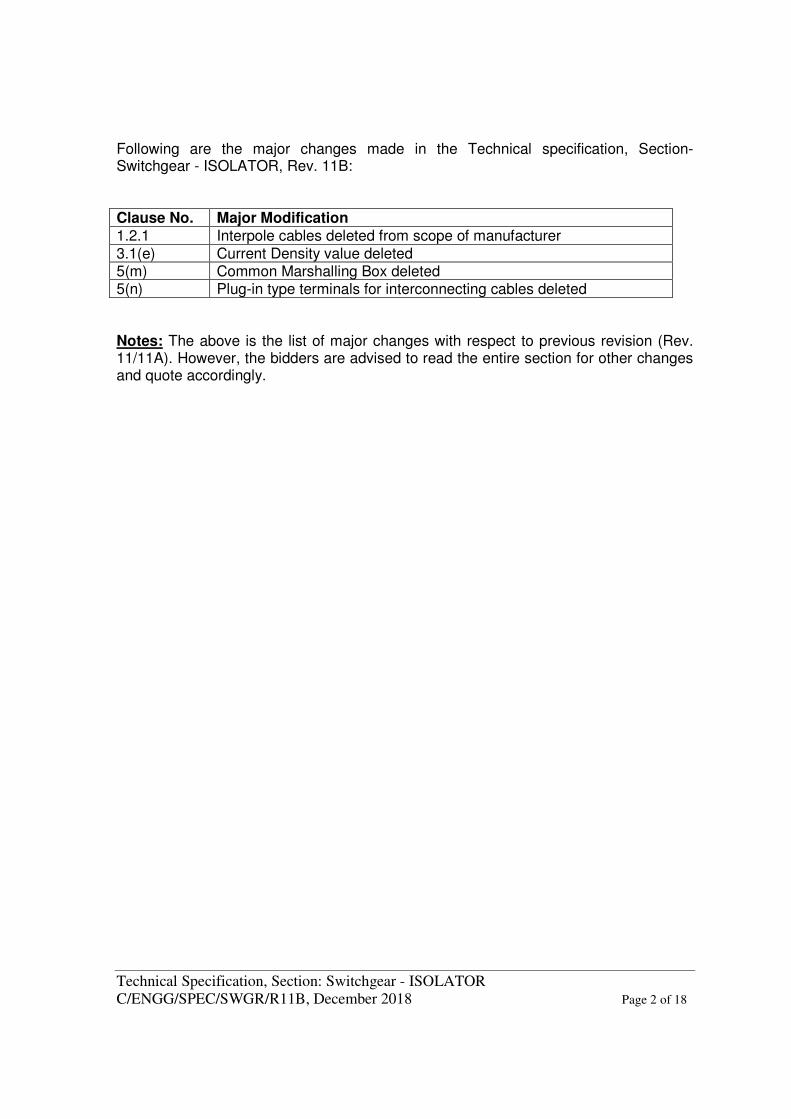
Following are the major changes made in the Technical specification, Section-Switchgear - ISOLATOR, Rev. 11B: Clause No. Major Modification 1.2.1 Interpole cables deleted from scope of manufacturer 3.1(e) Current Density value deleted 5(m) Common Marshalling Box deleted 5(n) Plug-in type terminals for interconnecting cables deleted Notes: The above is the list of major changes with respect to previous revision (Rev. 11/11A). However, the bidders are advised to read the entire section for other changes and quote accordingly.
Technical Specification, Section: Switchgear - ISOLATOR C/ENGG/SPEC/SWGR/R11B, December 2018 Page 3 of 18
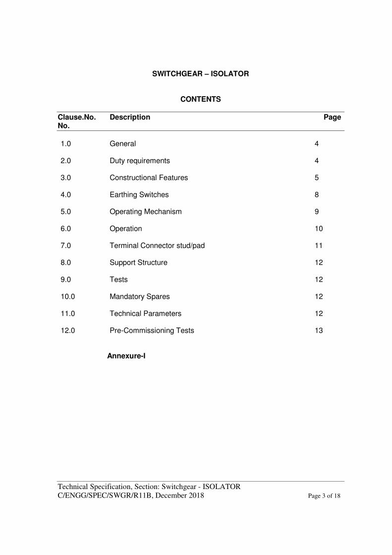
SWITCHGEAR – ISOLATOR
CONTENTS
Clause.No. Description Page No.
1.0 General 4
2.0 Duty requirements 4
3.0 Constructional Features 5 4.0 Earthing Switches 8 5.0 Operating Mechanism 9 6.0 Operation 10 7.0 Terminal Connector stud/pad 11 8.0 Support Structure 12 9.0 Tests 12 10.0 Mandatory Spares 12 11.0 Technical Parameters 12 12.0 Pre-Commissioning Tests 13
Annexure-I

Technical Specification, Section: Switchgear - ISOLATOR C/ENGG/SPEC/SWGR/R11B, December 2018 Page 4 of 18
SWITCHGEAR - ISOLATOR
1.0 GENERAL: 1.1 The Isolators and accessories shall conform in general to IEC: 62271-102/103
except to the extent explicitly modified in specification and shall be in accordance with requirement of Section-GTR.
1.2 Complete isolator with all the necessary items for successful operation shall be
supplied including but not limited to the following: 1.2.1 Isolator with complete Support Insulators, operating rod insulator, base frame,
linkages, operating mechanism, control cabinet, interlock etc. 1.2.2 All necessary parts to provide a complete and operable isolator installation,
control parts and other devices whether specifically called for herein or not. 1.2.3 The isolator shall be designed for use in the geographic and meteorological
conditions as given in Section-GTR and Section-Project. 2.0 DUTY REQUIREMENTS: a) Isolators and earth switches shall be capable of withstanding the dynamic
and thermal effects of the maximum possible short circuit current of the systems in their closed position. They shall be constructed such that they do not open under influence of short circuit current.
b) The earth switches, wherever provided, shall be constructionally interlocked so that the earth switches can be operated only when the isolator is open and vice versa. The constructional interlocks shall be built in construction of isolator and shall be in addition to the electrical interlocks. Suitable mechanical arrangement shall also be provided for delinking electrical drive for manual operation.
c) In addition to the constructional interlock, isolator and earth switches shall
have provision to prevent their electrical and manual operation unless the associated and other interlocking conditions are met. All these interlocks shall be of failsafe type. Suitable individual interlocking coil arrangements shall be provided. The interlocking coil shall be suitable for continuous operation from station DC supply and within a variation range as stipulated in Section-GTR.
d) The earthing switches shall be capable of discharging trapped charges of
the associated lines.
Technical Specification, Section: Switchgear - ISOLATOR C/ENGG/SPEC/SWGR/R11B, December 2018 Page 5 of 18
e) The isolator shall be capable of making/breaking normal currents when no significant change in voltage occurs across the terminals of each pole of isolator on account of make/break operation.
3.0 CONSTRUCTIONAL FEATURES:
Isolators shall be outdoor, off-load type. Earth switches shall be provided on isolators wherever called for, with possibility of being mounted on any side of the isolator. 800kV isolator design shall be double break or vertical break or knee-type. 420kV & below rated isolators shall be double break type, unless specified otherwise. Isolator design shall be such as to permit addition of earth switches at a future date. The features and constructional details of isolators, earth switches and accessories shall be in accordance with requirements stated hereunder:
3.1 Contacts:
a) The contacts shall be self aligning and self cleaning type and shall be so designed that binding cannot occur after remaining in closed position for prolonged period in a heavily polluted atmosphere.
b) No undue wear or scuffing shall be evident during the mechanical
endurance tests. Contacts and spring shall be designed so that readjustments in contact pressure shall not be necessary throughout the life of the isolator or earthing switch. Each contact or pair of contacts shall be independently sprung so that full pressure is maintained on all contacts at all time.
c) Contact springs shall not carry any current and shall not loose their
characteristics due to heating effects.
d) The moving contact of double break isolator shall have preferably turn-and-twist type or other suitable type of locking arrangement to ensure adequate contact pressure.
e) Flexible braided copper, where used, shall have corrosion resistant coating
such as tinning or silvering.
3.2 Base : Each single pole of the isolator shall be provided with a complete galvanised
steel base provided with holes and designed for mounting on a standard supporting structure. Common base frame shall be provided for 400/220/132kV isolators suitable for mounting on pipe structures.
Technical Specification, Section: Switchgear - ISOLATOR C/ENGG/SPEC/SWGR/R11B, December 2018 Page 6 of 18
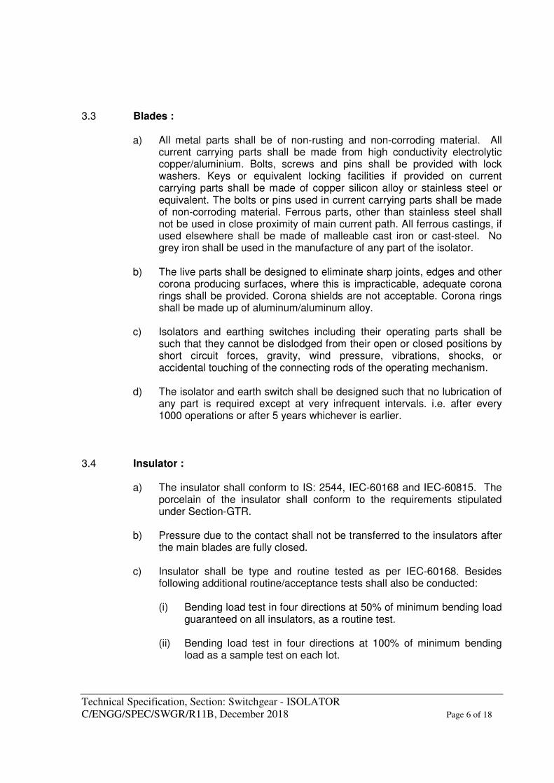
3.3 Blades : a) All metal parts shall be of non-rusting and non-corroding material. All
current carrying parts shall be made from high conductivity electrolytic copper/aluminium. Bolts, screws and pins shall be provided with lock washers. Keys or equivalent locking facilities if provided on current carrying parts shall be made of copper silicon alloy or stainless steel or equivalent. The bolts or pins used in current carrying parts shall be made of non-corroding material. Ferrous parts, other than stainless steel shall not be used in close proximity of main current path. All ferrous castings, if used elsewhere shall be made of malleable cast iron or cast-steel. No grey iron shall be used in the manufacture of any part of the isolator.
b) The live parts shall be designed to eliminate sharp joints, edges and other
corona producing surfaces, where this is impracticable, adequate corona rings shall be provided. Corona shields are not acceptable. Corona rings shall be made up of aluminum/aluminum alloy.
c) Isolators and earthing switches including their operating parts shall be
such that they cannot be dislodged from their open or closed positions by short circuit forces, gravity, wind pressure, vibrations, shocks, or accidental touching of the connecting rods of the operating mechanism.
d) The isolator and earth switch shall be designed such that no lubrication of
any part is required except at very infrequent intervals. i.e. after every 1000 operations or after 5 years whichever is earlier.
3.4 Insulator : a) The insulator shall conform to IS: 2544, IEC-60168 and IEC-60815. The
porcelain of the insulator shall conform to the requirements stipulated under Section-GTR.
b) Pressure due to the contact shall not be transferred to the insulators after
the main blades are fully closed. c) Insulator shall be type and routine tested as per IEC-60168. Besides
following additional routine/acceptance tests shall also be conducted: (i) Bending load test in four directions at 50% of minimum bending load
guaranteed on all insulators, as a routine test. (ii) Bending load test in four directions at 100% of minimum bending
load as a sample test on each lot.
Technical Specification, Section: Switchgear - ISOLATOR C/ENGG/SPEC/SWGR/R11B, December 2018 Page 7 of 18
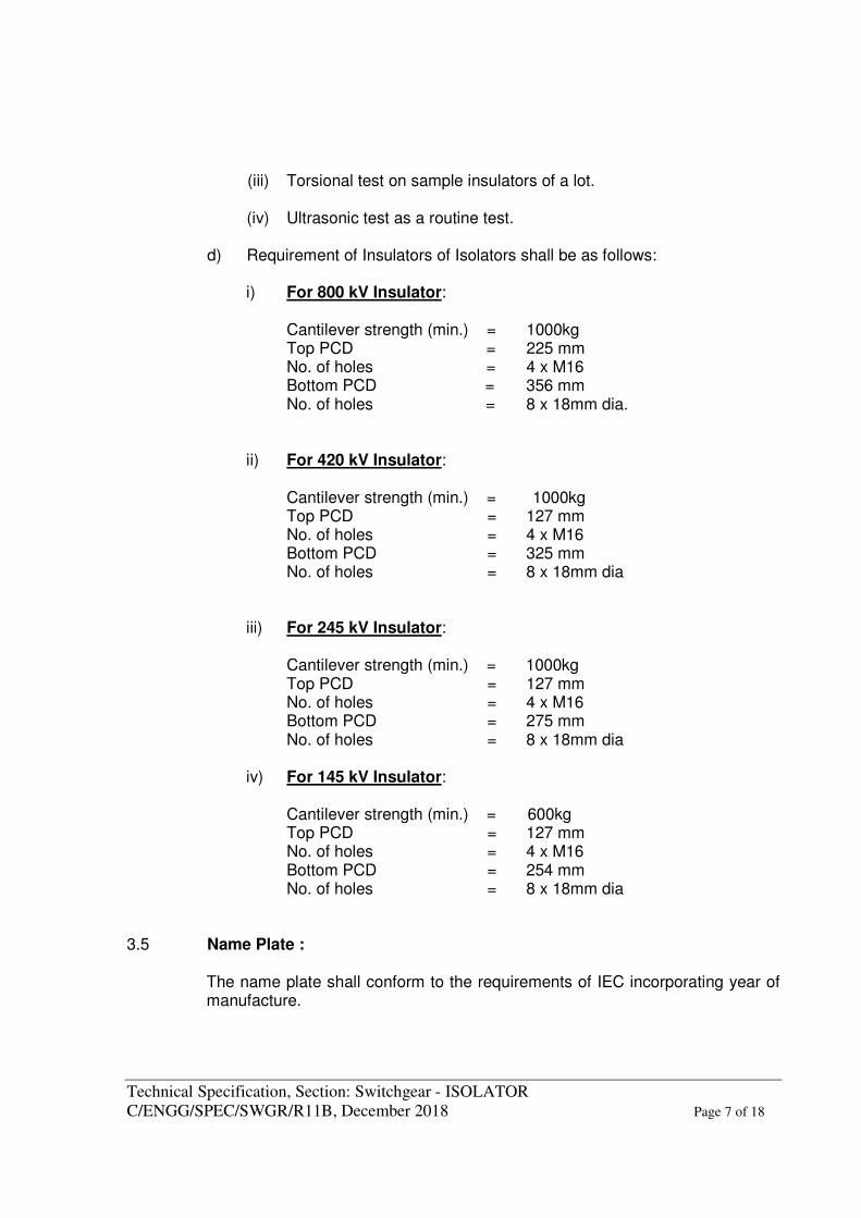
(iii) Torsional test on sample insulators of a lot.
(iv) Ultrasonic test as a routine test.
d) Requirement of Insulators of Isolators shall be as follows:
i) For 800 kV Insulator:
Cantilever strength (min.) = 1000kg Top PCD = 225 mm No. of holes = 4 x M16 Bottom PCD = 356 mm No. of holes = 8 x 18mm dia.
ii) For 420 kV Insulator:
Cantilever strength (min.) = 1000kg Top PCD = 127 mm No. of holes = 4 x M16 Bottom PCD = 325 mm No. of holes = 8 x 18mm dia
iii) For 245 kV Insulator:
Cantilever strength (min.) = 1000kg Top PCD = 127 mm No. of holes = 4 x M16 Bottom PCD = 275 mm No. of holes = 8 x 18mm dia
iv) For 145 kV Insulator:
Cantilever strength (min.) = 600kg Top PCD = 127 mm No. of holes = 4 x M16 Bottom PCD = 254 mm No. of holes = 8 x 18mm dia 3.5 Name Plate : The name plate shall conform to the requirements of IEC incorporating year of
manufacture.
Technical Specification, Section: Switchgear - ISOLATOR C/ENGG/SPEC/SWGR/R11B, December 2018 Page 8 of 18
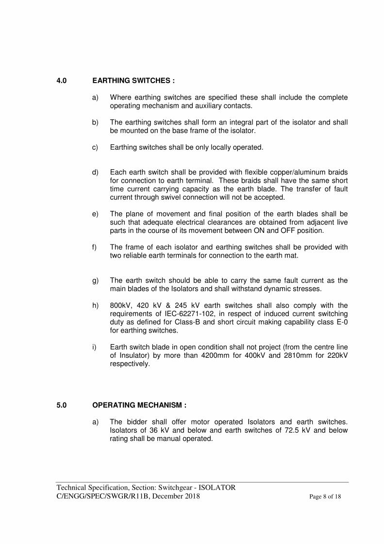
4.0 EARTHING SWITCHES : a) Where earthing switches are specified these shall include the complete
operating mechanism and auxiliary contacts. b) The earthing switches shall form an integral part of the isolator and shall
be mounted on the base frame of the isolator. c) Earthing switches shall be only locally operated. d) Each earth switch shall be provided with flexible copper/aluminum braids
for connection to earth terminal. These braids shall have the same short time current carrying capacity as the earth blade. The transfer of fault current through swivel connection will not be accepted.
e) The plane of movement and final position of the earth blades shall be
such that adequate electrical clearances are obtained from adjacent live parts in the course of its movement between ON and OFF position.
f) The frame of each isolator and earthing switches shall be provided with
two reliable earth terminals for connection to the earth mat.
g) The earth switch should be able to carry the same fault current as the main blades of the Isolators and shall withstand dynamic stresses.
h) 800kV, 420 kV & 245 kV earth switches shall also comply with the
requirements of IEC-62271-102, in respect of induced current switching duty as defined for Class-B and short circuit making capability class E-0 for earthing switches.
i) Earth switch blade in open condition shall not project (from the centre line
of Insulator) by more than 4200mm for 400kV and 2810mm for 220kV respectively.
5.0 OPERATING MECHANISM :
a) The bidder shall offer motor operated Isolators and earth switches. Isolators of 36 kV and below and earth switches of 72.5 kV and below rating shall be manual operated.

Technical Specification, Section: Switchgear - ISOLATOR C/ENGG/SPEC/SWGR/R11B, December 2018 Page 9 of 18
b) Control cabinet/operating mechanism box shall conform to the requirement stipulated in Section-GTR and shall be made of cast aluminium/aluminum sheet of adequate thickness (minimum 3 mm) or stainless steel (grade-304) of minimum thickness 2mm.
c) A “Local/Remote” selector switch and a set of open/ close push buttons
shall be provided on the control cabinet of the isolator to permit its operation through local or remote push buttons.
d) Provision shall be made in the control cabinet to disconnect power supply
to prevent local/remote power operation.
e) Motor shall be an AC motor and conform to the requirements of Section-GTR.
f) Suitable reduction gearing shall be provided between the motor and the
drive shaft of the isolator. The mechanism shall stop immediately when motor supply is switched off. If necessary a quick electro-mechanical brake shall be fitted on the higher speed shaft to effect rapid braking.
g) Manual operation facility (with handle) should be provided with necessary
interlock to disconnect motor. h) Gear should be of forged material suitably chosen to avoid
bending/jamming on operation after a prolonged period of non-operation. Also all gear and connected material should be so chosen/surface treated to avoid rusting.
i) Blocked rotor test of motor shall be conducted as a routine test. During
the blocked rotor test, overload protection relay should operate to prevent failure of motor.
j) Only stranded conductor shall be used for wiring. Minimum size of the
conductor for control circuit wiring shall be 1.5 sq.mm. (Copper). k) The operating mechanism shall be located such that it can be directly
mounted on any one of the support structure. l) Snap type limit/auxiliary switches shall be used with Factory set values.
No adjustment shall be required at site during commissioning.
Technical Specification, Section: Switchgear - ISOLATOR C/ENGG/SPEC/SWGR/R11B, December 2018 Page 10 of 18
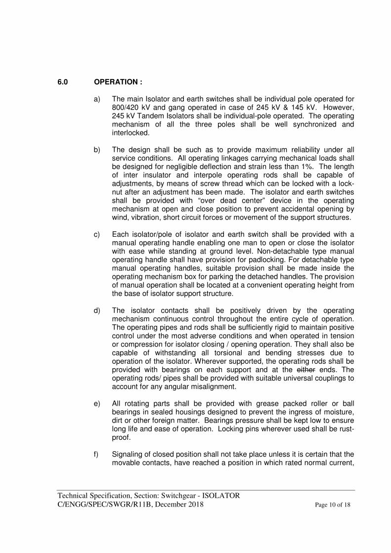
6.0 OPERATION : a) The main Isolator and earth switches shall be individual pole operated for
800/420 kV and gang operated in case of 245 kV & 145 kV. However, 245 kV Tandem Isolators shall be individual-pole operated. The operating mechanism of all the three poles shall be well synchronized and interlocked.
b) The design shall be such as to provide maximum reliability under all
service conditions. All operating linkages carrying mechanical loads shall be designed for negligible deflection and strain less than 1%. The length of inter insulator and interpole operating rods shall be capable of adjustments, by means of screw thread which can be locked with a lock-nut after an adjustment has been made. The isolator and earth switches shall be provided with “over dead center” device in the operating mechanism at open and close position to prevent accidental opening by wind, vibration, short circuit forces or movement of the support structures.
c) Each isolator/pole of isolator and earth switch shall be provided with a
manual operating handle enabling one man to open or close the isolator with ease while standing at ground level. Non-detachable type manual operating handle shall have provision for padlocking. For detachable type manual operating handles, suitable provision shall be made inside the operating mechanism box for parking the detached handles. The provision of manual operation shall be located at a convenient operating height from the base of isolator support structure.
d) The isolator contacts shall be positively driven by the operating
mechanism continuous control throughout the entire cycle of operation. The operating pipes and rods shall be sufficiently rigid to maintain positive control under the most adverse conditions and when operated in tension or compression for isolator closing / opening operation. They shall also be capable of withstanding all torsional and bending stresses due to operation of the isolator. Wherever supported, the operating rods shall be provided with bearings on each support and at the either ends. The operating rods/ pipes shall be provided with suitable universal couplings to account for any angular misalignment.
e) All rotating parts shall be provided with grease packed roller or ball
bearings in sealed housings designed to prevent the ingress of moisture, dirt or other foreign matter. Bearings pressure shall be kept low to ensure long life and ease of operation. Locking pins wherever used shall be rust-proof.
f) Signaling of closed position shall not take place unless it is certain that the
movable contacts, have reached a position in which rated normal current,
Technical Specification, Section: Switchgear - ISOLATOR C/ENGG/SPEC/SWGR/R11B, December 2018 Page 11 of 18
peak withstand current and short time withstand current can be carried safely. Signaling of open position shall not take place unless movable contacts have reached a position such that clearance between contacts is atleast 80% of the isolating distance.
g) The position of movable contact system (main blades) of each of the
Isolators and earthing switches shall be indicated by a mechanical indi-cator at the lower end of the vertical rod of shaft for the Isolators and earthing switch. The indicator shall be of metal and shall be visible from operating level.
h) The contractor shall furnish the following details alongwith quality norms,
during detailed engineering stage: (i) Current transfer arrangement from main blades of isolator alongwith
milli volt drop immediately across transfer point. (ii) Details to demonstrate smooth transfer of rotary motion from motor
shaft to the insulator alongwith stoppers to prevent over travel. 7.0 TERMINAL CONNECTOR STUD/PAD: The isolator terminal pads/studs shall be made of high quality copper or
aluminum and shall be conforming to Australian standard AS-2935 for rated current. The terminal pad shall have protective covers which shall be removed before interconnections. Only terminal pads shall be used for current ratings above 1250A. Terminal pads shall be mounted below the current transfer contacts so that the cantilever pull from the terminal connector is not transferred through the current transfer point to the support insulator. The terminal pad shall be suitable for horizontal plane connection with terminal connector. The terminal pads for all isolators with 3150A & above rating shall have six holes for terminal pad.
8.0 SUPPORT STRUCTURE: 800 kV/420 kV/245 kV/145 kV Isolators along with Earth switches shall be
suitable for mounting on standard support structures. 9.0 TESTS: 9.1 In continuation to the requirements stipulated under Section-GTR the isolator
alongwith its earthing switch and operating mechanism should have been type tested as per IEC/IS and shall be subjected to routine tests in accordance with IEC-62271-102. Minimum 1000 Nos. mechanical operations in line with mechanical endurance test, M0 duty, shall be carried out on 1 (one) isolator out
Technical Specification, Section: Switchgear - ISOLATOR C/ENGG/SPEC/SWGR/R11B, December 2018 Page 12 of 18
of every lot of Isolators, assembled completely with all accessories including insulators, as acceptance test for the lot. The travel characteristics measured at a suitable location in the base of insulator along with motor current/power drawn, during the entire travel duration are to be recorded at the start and completion and shall not vary by more than (+/-) 10% after completion of 1000 cycles of operation. After completion of test, mechanical interlock operation to be checked.
9.2 The test reports of the type tests as per IEC 62271-102 and the following
additional type tests (additional type tests are required for isolators rated above 72.5 kV only) shall also be submitted for the Employer’s review.
(i) Radio interference voltage test as per Annexure-A of Section-GTR.
(ii) Corona Extinction Voltage test as per Annexure-A of Section-GTR
(iii) Seismic withstand test on isolator mounted on Support structure as per Annexure-B of Section-GTR. The test shall be performed in the following position :
Isolator open E/S Closed Isolator open E/S Open Isolator Closed E/S Open 10.0 MANDATORY SPARES:
Bidder shall include in his proposal mandatory spares as mentioned in the Bidding Documents.
11.0 TECHNICAL PARAMETERS: As per table given at Annexure-I: 12.0 PRE-COMMISSIONING TESTS 12.1 Contractor shall perform any additional test based on specialties of the items as
per the field Q.P./Instructions of the equipment manufacturer or Employer without any extra cost to the Employer. The Contractor shall arrange all instruments required for conducting these tests alongwith calibration certificates at his own cost.
An indicative list of tests on isolator and earthswitch is given below. For pre-
commissioning procedures and formats for Isolators and Grounding switch, Doc.No.: CF/ISO/07/R-4, dtd-01.04.2013 under POWERGRID Document no. D-2-01-03-01-04 will be the reference document. This document will be available at respective sites and shall be referred by the contractor.
Technical Specification, Section: Switchgear - ISOLATOR C/ENGG/SPEC/SWGR/R11B, December 2018 Page 13 of 18
(a) Insulation resistance of each pole (b) Manual and electrical operation and interlocks (c) Insulation resistance of control circuits and motors (d) Ground connections (e) Contact resistance (f) Proper alignment so as to minimize vibration during operation (g) Measurement of operating Torque for isolator and Earth switch (h) Resistance of operating and interlocks coils
(i) Functional check of the control schematic and electrical & mechanical interlocks
(j) 50 operations test on isolator and earth switch
12. 2 The Contractor shall ensure that erection, testing and commissioning of
Isolators above 72.5 kV class shall be carried out under the supervision of the Isolator manufacturer's representative and the cost of the same shall be included in the erection price of the respective equipment.
Technical Specification, Section: Switchgear - ISOLATOR C/ENGG/SPEC/SWGR/R11B, December 2018 Page 14 of 18
Annexure-I
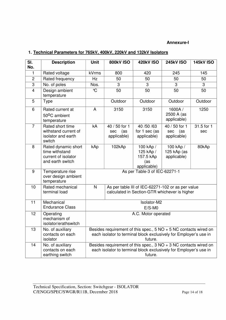
1. Technical Parameters for 765kV, 400kV, 220kV and 132kV Isolators
Sl. No.
Description Unit 800kV ISO 420kV ISO 245kV ISO 145kV ISO
1 Rated voltage kVrms 800 420 245 145
2 Rated frequency Hz 50 50 50 50
3 No. of poles Nos. 3 3 3 3
4 Design ambient temperature
°C 50 50 50 50
5 Type Outdoor Outdoor Outdoor Outdoor
6 Rated current at
50oC ambient temperature
A 3150 3150 1600A / 2500 A (as applicable)
1250
7 Rated short time withstand current of isolator and earth switch
kA 40 / 50 for 1 sec (as
applicable)
40 /50 /63 for 1 sec (as applicable)
40 / 50 for 1 sec (as
applicable)
31.5 for 1 sec
8 Rated dynamic short time withstand current of isolator and earth switch
kAp 102kAp 100 kAp / 125 kAp / 157.5 kAp
(as applicable)
100 kAp / 125 kAp (as applicable)
80kAp
9 Temperature rise over design ambient temperature
As per Table-3 of IEC-62271-1
10 Rated mechanical terminal load
N As per table III of IEC-62271-102 or as per value calculated in Section-GTR whichever is higher
11 Mechanical Endurance Class
Isolator-M2
E/S-M0
12 Operating mechanism of isolator/erathswitch
A.C. Motor operated
13 No. of auxiliary contacts on each isolator
Besides requirement of this spec., 5 NO + 5 NC contacts wired on each isolator to terminal block exclusively for Employer’s use in
future.
14 No. of auxiliary contacts on each earthing switch
Besides requirement of this spec., 3 NO + 3 NC contacts wired on each isolator to terminal block exclusively for Employer’s use in
future.
Technical Specification, Section: Switchgear - ISOLATOR C/ENGG/SPEC/SWGR/R11B, December 2018 Page 15 of 18
Sl. No.
Description Unit 800kV ISO 420kV ISO 245kV ISO 145kV ISO
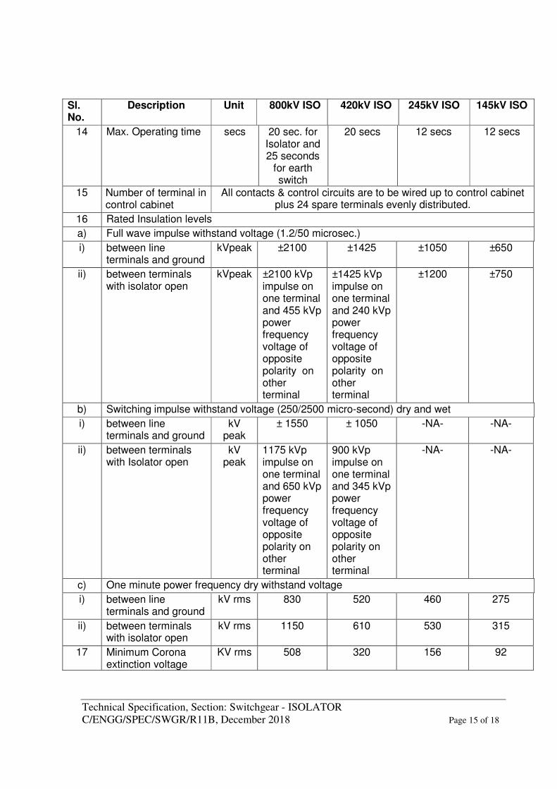
14 Max. Operating time secs 20 sec. for Isolator and 25 seconds
for earth switch
20 secs 12 secs 12 secs
15 Number of terminal in control cabinet
All contacts & control circuits are to be wired up to control cabinet plus 24 spare terminals evenly distributed.
16 Rated Insulation levels
a) Full wave impulse withstand voltage (1.2/50 microsec.)
i) between line terminals and ground
kVpeak ±2100 ±1425 ±1050 ±650
ii) between terminals with isolator open
kVpeak ±2100 kVp impulse on one terminal and 455 kVp power frequency voltage of opposite polarity on other terminal
±1425 kVp impulse on one terminal and 240 kVp power frequency voltage of opposite polarity on other terminal
±1200 ±750
b) Switching impulse withstand voltage (250/2500 micro-second) dry and wet
i) between line terminals and ground
kV peak
± 1550 ± 1050 -NA- -NA-
ii) between terminals with Isolator open
kV peak
1175 kVp impulse on one terminal and 650 kVp power frequency voltage of opposite polarity on other terminal
900 kVp impulse on one terminal and 345 kVp power frequency voltage of opposite polarity on other terminal
-NA- -NA-
c) One minute power frequency dry withstand voltage
i) between line terminals and ground
kV rms 830 520 460 275
ii) between terminals with isolator open
kV rms 1150 610 530 315
17 Minimum Corona extinction voltage
KV rms 508 320 156 92
Technical Specification, Section: Switchgear - ISOLATOR C/ENGG/SPEC/SWGR/R11B, December 2018 Page 16 of 18
Sl. No.
Description Unit 800kV ISO 420kV ISO 245kV ISO 145kV ISO
with Isolator in all positions
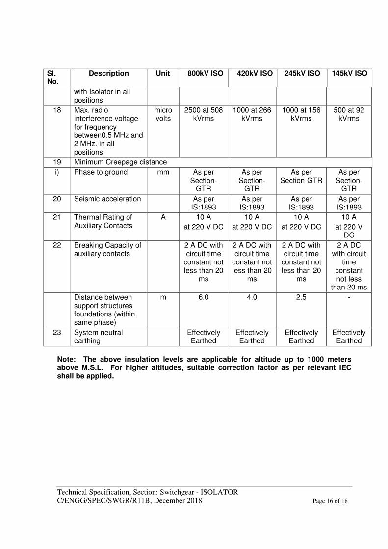
18 Max. radio interference voltage for frequency between0.5 MHz and 2 MHz. in all positions
micro volts
2500 at 508 kVrms
1000 at 266 kVrms
1000 at 156 kVrms
500 at 92 kVrms
19 Minimum Creepage distance
i) Phase to ground mm As per Section-
GTR
As per Section-
GTR
As per Section-GTR
As per Section-
GTR
20 Seismic acceleration As per IS:1893
As per IS:1893
As per IS:1893
As per IS:1893
21 Thermal Rating of Auxiliary Contacts
A 10 A
at 220 V DC
10 A
at 220 V DC
10 A
at 220 V DC
10 A
at 220 V DC
22 Breaking Capacity of auxiliary contacts
2 A DC with circuit time
constant not less than 20
ms
2 A DC with circuit time
constant not less than 20
ms
2 A DC with circuit time
constant not less than 20
ms
2 A DC with circuit
time constant not less
than 20 ms
Distance between support structures foundations (within same phase)
m 6.0 4.0 2.5 -
23 System neutral earthing
Effectively Earthed
Effectively Earthed
Effectively Earthed
Effectively Earthed
Note: The above insulation levels are applicable for altitude up to 1000 meters above M.S.L. For higher altitudes, suitable correction factor as per relevant IEC shall be applied.
Technical Specification, Section: Switchgear - ISOLATOR C/ENGG/SPEC/SWGR/R11B, December 2018 Page 17 of 18
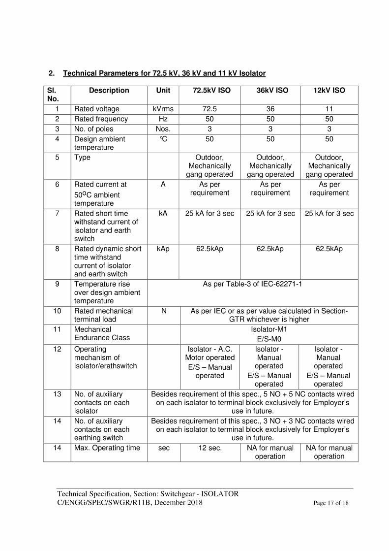
2. Technical Parameters for 72.5 kV, 36 kV and 11 kV Isolator
Sl. No.
Description Unit 72.5kV ISO 36kV ISO 12kV ISO
1 Rated voltage kVrms 72.5 36 11
2 Rated frequency Hz 50 50 50
3 No. of poles Nos. 3 3 3
4 Design ambient temperature
°C 50 50 50
5 Type Outdoor, Mechanically
gang operated
Outdoor, Mechanically
gang operated
Outdoor, Mechanically
gang operated
6 Rated current at
50oC ambient temperature
A As per requirement
As per requirement
As per requirement
7 Rated short time withstand current of isolator and earth switch
kA 25 kA for 3 sec 25 kA for 3 sec 25 kA for 3 sec
8 Rated dynamic short time withstand current of isolator and earth switch
kAp 62.5kAp 62.5kAp 62.5kAp
9 Temperature rise over design ambient temperature
As per Table-3 of IEC-62271-1
10 Rated mechanical terminal load
N As per IEC or as per value calculated in Section-GTR whichever is higher
11 Mechanical Endurance Class
Isolator-M1
E/S-M0
12 Operating mechanism of isolator/erathswitch
Isolator - A.C. Motor operated
E/S – Manual operated
Isolator - Manual
operated
E/S – Manual operated
Isolator - Manual
operated
E/S – Manual operated
13 No. of auxiliary contacts on each isolator
Besides requirement of this spec., 5 NO + 5 NC contacts wired on each isolator to terminal block exclusively for Employer’s
use in future.
14 No. of auxiliary contacts on each earthing switch
Besides requirement of this spec., 3 NO + 3 NC contacts wired on each isolator to terminal block exclusively for Employer’s
use in future.
14 Max. Operating time sec 12 sec. NA for manual operation
NA for manual operation
Technical Specification, Section: Switchgear - ISOLATOR C/ENGG/SPEC/SWGR/R11B, December 2018 Page 18 of 18
Sl. No.
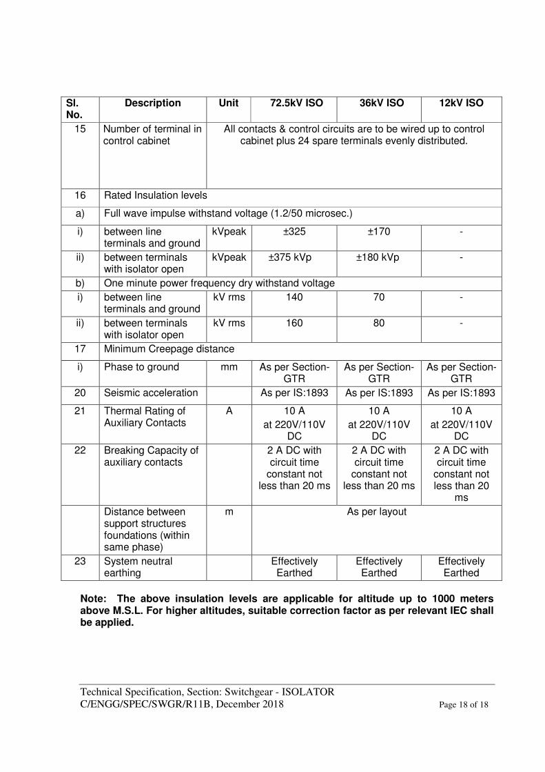
Description Unit 72.5kV ISO 36kV ISO 12kV ISO
15 Number of terminal in control cabinet
All contacts & control circuits are to be wired up to control cabinet plus 24 spare terminals evenly distributed.
16 Rated Insulation levels
a) Full wave impulse withstand voltage (1.2/50 microsec.)
i) between line terminals and ground
kVpeak ±325 ±170 -
ii) between terminals with isolator open
kVpeak ±375 kVp ±180 kVp -
b) One minute power frequency dry withstand voltage
i) between line terminals and ground
kV rms 140 70 -
ii) between terminals with isolator open
kV rms 160 80 -
17 Minimum Creepage distance
i) Phase to ground mm As per Section-GTR
As per Section-GTR
As per Section-GTR
20 Seismic acceleration As per IS:1893 As per IS:1893 As per IS:1893
21 Thermal Rating of Auxiliary Contacts
A 10 A
at 220V/110V DC
10 A
at 220V/110V DC
10 A
at 220V/110V DC
22 Breaking Capacity of auxiliary contacts
2 A DC with circuit time
constant not less than 20 ms
2 A DC with circuit time
constant not less than 20 ms
2 A DC with circuit time
constant not less than 20
ms
Distance between support structures foundations (within same phase)
m As per layout
23 System neutral earthing
Effectively Earthed
Effectively Earthed
Effectively Earthed
Note: The above insulation levels are applicable for altitude up to 1000 meters above M.S.L. For higher altitudes, suitable correction factor as per relevant IEC shall be applied.
Substation Package - SS02 for (i) 765kV Fatehgarh-2 (PG) S/S Extension and (ii)765kV Bhadla-2 (PG) S/s Extension under Transmission System
Associated With LTA applications from Rajasthan SEZ Part-B (Rajasthan SEZ Part-B Project) through Tariff
Based Competitive Bidding (TBCB) Route. 765kV Isolators and Earth Switches
Doc. No. : TB-409-316-004 Rev 00
Page 10 of 25
SECTION-3 Refer document
General Technical Requirements: TB-409-316-000 Rev 00.
Substation Package - SS02 for (i) 765kV Fatehgarh-2 (PG) S/S Extension and (ii) 765kV Bhadla-2 (PG) S/s Extension under Transmission System Associated With LTA
applications from Rajasthan SEZ Part-B (Rajasthan SEZ Part-B Project) through Tariff Based Competitive Bidding (TBCB) Route
General Technical Requirements- Section 3 Doc. No. : TB-409-316-000 Rev 00
Page 2 of 30
GENERAL TECHNICAL REQUIREMENTS-SECTION 3
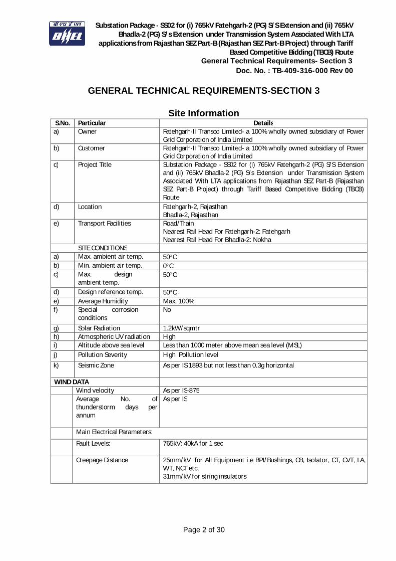
Site Information S.No. Particular Details
a) Owner Fatehgarh-II Transco Limited- a 100% wholly owned subsidiary of Power Grid Corporation of India Limited
b) Customer Fatehgarh-II Transco Limited- a 100% wholly owned subsidiary of Power Grid Corporation of India Limited
c) Project Title
Substation Package - SS02 for (i) 765kV Fatehgarh-2 (PG) S/S Extension and (ii) 765kV Bhadla-2 (PG) S/s Extension under Transmission System Associated With LTA applications from Rajasthan SEZ Part-B (Rajasthan SEZ Part-B Project) through Tariff Based Competitive Bidding (TBCB) Route
d) Location
Fatehgarh-2, Rajasthan Bhadla-2, Rajasthan
e) Transport Facilities
Road/Train Nearest Rail Head For Fatehgarh-2: Fatehgarh Nearest Rail Head For Bhadla-2: Nokha
SITE CONDITIONS a) Max. ambient air temp. 50C b) Min. ambient air temp. 0C c) Max. design
ambient temp. 50C
d) Design reference temp. 50C e) Average Humidity Max. 100% f) Special corrosion
conditions No
g) Solar Radiation 1.2kW/sqmtr h) Atmospheric UV radiation High i) Altitude above sea level Less than 1000 meter above mean sea level (MSL) j) Pollution Severity High Pollution level k) Seismic Zone
As per IS 1893 but not less than 0.3g horizontal
WIND DATA Wind velocity As per IS-875 Average No. of thunderstorm days per annum
As per IS
Main Electrical Parameters:
Fault Levels: 765kV: 40kA for 1 sec
Creepage Distance 25mm/kV for All Equipment i.e BPI/Bushings, CB, Isolator, CT, CVT, LA, WT, NCT etc. 31mm/kV for string insulators

Substation Package - SS02 for (i) 765kV Fatehgarh-2 (PG) S/S Extension and (ii) 765kV Bhadla-2 (PG) S/s Extension under Transmission System Associated With LTA
applications from Rajasthan SEZ Part-B (Rajasthan SEZ Part-B Project) through Tariff Based Competitive Bidding (TBCB) Route
General Technical Requirements- Section 3 Doc. No. : TB-409-316-000 Rev 00
Page 3 of 30
GENERAL TECHNICAL REQUIREMENTS-SECTION 3
INDEX
Clause No. Item Page No. 1.0 Foreword 4 2.0 General Requirement 4 3.0 Standards 5 4.0 Services to be performed by the Equipment being furnished 6 5.0 Engineering Data and Drawings 7 6.0 Material/Workmanship 10 7.0 Design Improvements/Coordination 12 8.0 Quality Assurance Programme 13 9.0 Type Testing & Clearance Certificates 19 10.0 Deleted. 20 11.0 Packaging & Protection 20 12.0 Finishing of Metal Surfaces 20 13.0 Deleted 22 14.0 Tools 22 15.0 Auxiliary Supply 23 16.0 Support Structure 23
17.0 Clamps and Connectors including Terminal Connectors 23 18.0 Control Cabinets, Junction Boxes, Terminal Boxes &
Marshalling Boxes for Outdoor Equipment 25
19.0 Deleted 26 20.0 Terminal Blocks and Wiring 26 21.0 Lamps and Sockets 27 22.0 Bushings, Hollow Column Insulators, Support Insulators 28 23.0 Motors 29
Annexure-A Corona and Radio Interference Voltage (RIV) Test 2 sheets Annexure-B Seismic Withstand Test Procedure 1 sheet Annexure-C List of General Standards and Codes 23 sheets Annexure-G MQP & Inspection Level Requirement 3 sheets

Substation Package - SS02 for (i) 765kV Fatehgarh-2 (PG) S/S Extension and (ii) 765kV Bhadla-2 (PG) S/s Extension under Transmission System Associated With LTA
applications from Rajasthan SEZ Part-B (Rajasthan SEZ Part-B Project) through Tariff Based Competitive Bidding (TBCB) Route
General Technical Requirements- Section 3 Doc. No. : TB-409-316-000 Rev 00
Page 4 of 30
GENERAL TECHNICAL REQUIREMENTS-SECTION 3
1.0 FOREWORD
The provisions under this section are intended to supplement requirements for the materials, equipments and services covered under other sections of tender documents and are not exclusive.
The Supplier shall note that the standards mentioned herein are not mutually exclusive or complete in themselves, but are intended to complement each other, with minimum repetition, to define the requirements of the Specification. In the event of a conflict between requirements of any two clauses of the Specification/ documents or requirements of different codes/ standards specified, the more stringent requirement as per the interpretation of the owner shall apply, unless confirmed otherwise by the owner in writing based on a written request from the Supplier. In case of conflicting requirements between this document (General Technical Requirement Section 3) and equipment specification (Section 1 & Section 2), equipment specification shall prevail. When specific requirements stipulated in the Specification exceed or change those required by the applicable standards, the stipulations of the Specification shall take precedence. Unless specifically agreed to by the Purchaser prior to Award of Contract, the Work shall be in accordance with the standards indicated and the requirements of the Specification. The Supplier shall be held responsible for any deviation. In case of conflict between the various standards, the decision of owner shall be binding & final.
2.0 GENERAL REQUIREMENT
The following words and expressions shall have the meanings hereby assigned to them throughout this document "Employer/Owner" means Power Grid Corporation of India Ltd. “Purchaser” means Bharat Heavy Electricals Limited "Supplier/Manufacturer/Bidder" means the person or persons, firm or company assigned to execute the works as defined by the scope of supply, described here.
Substation Package - SS02 for (i) 765kV Fatehgarh-2 (PG) S/S Extension and (ii) 765kV Bhadla-2 (PG) S/s Extension under Transmission System Associated With LTA
applications from Rajasthan SEZ Part-B (Rajasthan SEZ Part-B Project) through Tariff Based Competitive Bidding (TBCB) Route
General Technical Requirements- Section 3 Doc. No. : TB-409-316-000 Rev 00
Page 5 of 30
"Specification" refers to this document. The supplier should be approved by Power Grid. If not, it is the responsibility of the vendor to be assessed and approved by Power Grid, before placement of order by BHEL. Any cost involved in vendor assessment/approval must be borne by the vendor himself.
2.1 The Supplier/Manufacturer shall furnish catalogues, engineering data, technical information,
design documents, drawings etc., fully in conformity with the technical specification during detailed engineering.
2.2 It is recognised that the Bidder may have standardised on the use of certain components,
materials, processes or procedures different from those specified herein. Alternate proposals offering similar equipment based on the manufacturer’s standard practice will also be considered provided such proposals meet the specified designs, standard and performance requirements and are acceptable to Employer.
2.3 Wherever a material or article is specified or defined by the name of a particular brand,
Manufacturer or Vendor, the specific name mentioned shall be understood as establishing type, function and quality and not as limiting competition.
2.4 Equipment furnished shall be complete in every respect with all mountings, fittings, fixtures and
standard accessories normally provided with such equipment and/or needed for erection, completion and safe operation of the equipment as required by applicable codes though they may not have been specifically detailed in the Technical Specifications unless included in the list of exclusions. Materials and components which are minor in nature and incidental to the requirement but not specifically stated in the specification, which are necessary for commissioning and satisfactory operation of the switchyard/ substation unless specifically excluded shall be deemed to be included in the scope of the specification and shall be supplied without any extra cost. All similar standard components/parts of similar standard equipment provided, shall be inter-changeable with one another.
2.5 Deleted. 2.6 Deleted. 3.0 STANDARDS 3.1 The works covered by the specification shall be designed, engineered, manufactured, built, tested
and commissioned in accordance with the Acts, Rules, Laws and Regulations of India. 3.2 The equipment to be furnished under this specification shall conform to latest issue with all
amendments (as on the originally scheduled date of bid opening) of standard specified under Annexure-C of this section, unless specifically mentioned in the specification.
3.3 The Bidder shall note that standards mentioned in the specification are not mutually exclusive or
complete in themselves, but intended to compliment each other.
Substation Package - SS02 for (i) 765kV Fatehgarh-2 (PG) S/S Extension and (ii) 765kV Bhadla-2 (PG) S/s Extension under Transmission System Associated With LTA
applications from Rajasthan SEZ Part-B (Rajasthan SEZ Part-B Project) through Tariff Based Competitive Bidding (TBCB) Route
General Technical Requirements- Section 3 Doc. No. : TB-409-316-000 Rev 00
Page 6 of 30
3.4 The Bidder shall also note that list of standards presented in this specification is not complete. Whenever necessary the list of standards shall be considered in conjunction with specific IS/IEC.
3.5 When the specific requirements stipulated in the specifications exceed or differ than those
required by the applicable standards, the stipulation of the specification shall take precedence. 3.6 Other internationally accepted standards which ensure equivalent or better performance than
that specified in the standards specified under Annexure-C/individual sections for various equipments shall also, be accepted, however the salient points of difference shall be clearly brought out during detailed engineering along with English language version of such standard. The equipment conforming to standards other than specified under Annexure-C/ individual sections for various equipments shall be subject to Employer’s approval.
4.0 SERVICES TO BE PERFORMED BY THE EQUIPMENT BEING FURNISHED 4.1 The 800kV system is being designed to limit the switching surge over voltage of 1.9 p.u. and the
power frequency over voltage of 1.4 p.u. The equipment furnished under this specification shall perform all its functions and operate satisfactorily without showing undue strain, restrike etc under such over voltage conditions.
4.2 All equipments shall also perform satisfactorily under various other electrical, electromechanical
and meteorological conditions of the site of installation. 4.3 All equipment shall be able to withstand all external and internal mechanical, thermal and
electromechanical forces due to various factors like wind load, temperature variation, ice & snow, (wherever applicable) short circuit etc for the equipment.
4.4 The bidder shall design terminal connectors of the equipment taking into account various forces
that are required to withstand. 4.5 The equipment shall also comply to the following:
a) To facilitate erection of equipment, all items to be assembled at site shall be “match marked”. b) All piping, if any between equipment control cabinet/operating mechanism to marshalling box of the equipment, shall bear proper identification to facilitate the connection at site.
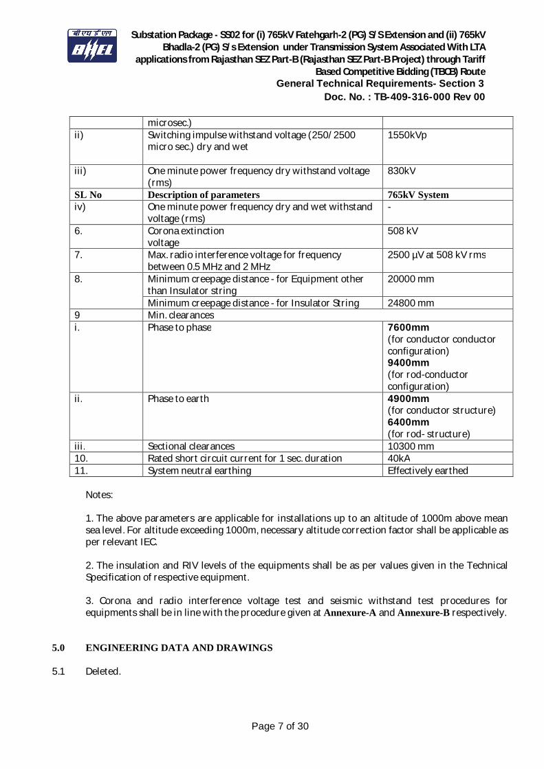
4.6 System Parameter
765kV, 400kV & 220kV System
SL No Description of parameters 765kV System 1. System operating voltage 765kV 2. Maximum operating voltage of the system (rms) 800kV 3. Rated frequency 50HZ 4. No. of phase 3 5. Rated Insulation levels i) Full wave impulse withstand voltage (1.2/50 2100kVp
Substation Package - SS02 for (i) 765kV Fatehgarh-2 (PG) S/S Extension and (ii) 765kV Bhadla-2 (PG) S/s Extension under Transmission System Associated With LTA
applications from Rajasthan SEZ Part-B (Rajasthan SEZ Part-B Project) through Tariff Based Competitive Bidding (TBCB) Route
General Technical Requirements- Section 3 Doc. No. : TB-409-316-000 Rev 00
Page 7 of 30
microsec.) ii) Switching impulse withstand voltage (250/2500
micro sec.) dry and wet
1550kVp
iii) One minute power frequency dry withstand voltage (rms)
830kV
SL No Description of parameters 765kV System iv) One minute power frequency dry and wet withstand
voltage (rms) -
6. Corona extinction voltage
508 kV
7. Max. radio interference voltage for frequency between 0.5 MHz and 2 MHz
2500 µV at 508 kV rms
8. Minimum creepage distance - for Equipment other than Insulator string
20000 mm
Minimum creepage distance - for Insulator String 24800 mm 9 Min. clearances i. Phase to phase 7600mm
(for conductor conductor configuration) 9400mm (for rod-conductor configuration)
ii. Phase to earth 4900mm (for conductor structure) 6400mm (for rod- structure)
iii. Sectional clearances 10300 mm 10. Rated short circuit current for 1 sec. duration 40kA 11. System neutral earthing Effectively earthed
Notes: 1. The above parameters are applicable for installations up to an altitude of 1000m above mean sea level. For altitude exceeding 1000m, necessary altitude correction factor shall be applicable as per relevant IEC. 2. The insulation and RIV levels of the equipments shall be as per values given in the Technical Specification of respective equipment. 3. Corona and radio interference voltage test and seismic withstand test procedures for equipments shall be in line with the procedure given at Annexure-A and Annexure-B respectively.
5.0 ENGINEERING DATA AND DRAWINGS 5.1 Deleted.
Substation Package - SS02 for (i) 765kV Fatehgarh-2 (PG) S/S Extension and (ii) 765kV Bhadla-2 (PG) S/s Extension under Transmission System Associated With LTA
applications from Rajasthan SEZ Part-B (Rajasthan SEZ Part-B Project) through Tariff Based Competitive Bidding (TBCB) Route
General Technical Requirements- Section 3 Doc. No. : TB-409-316-000 Rev 00
Page 8 of 30
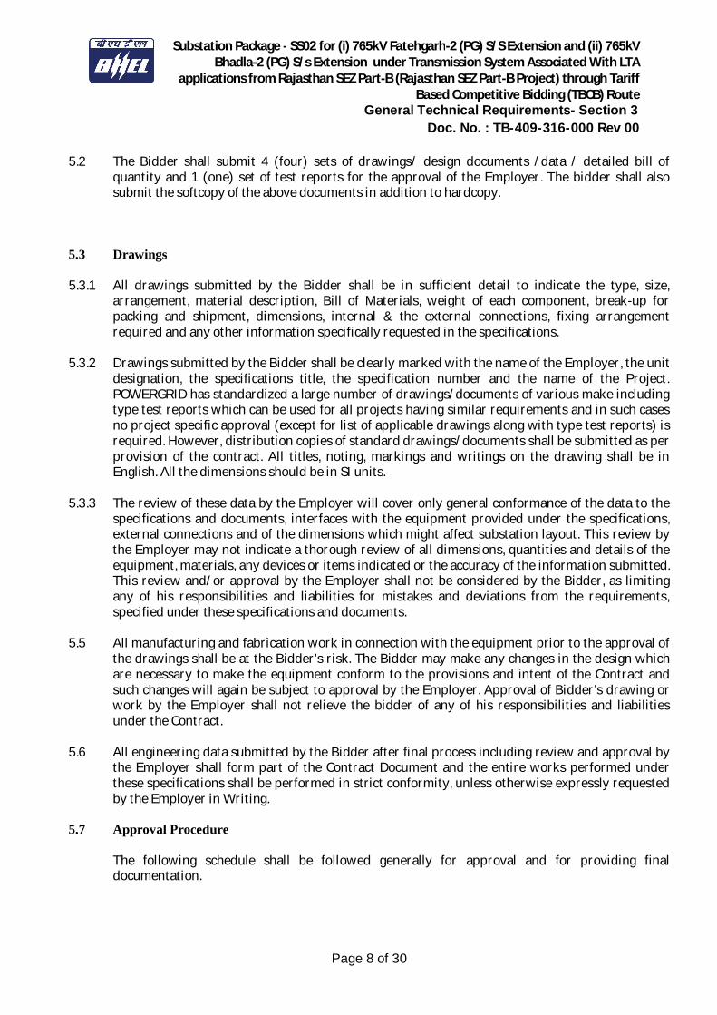
5.2 The Bidder shall submit 4 (four) sets of drawings/ design documents /data / detailed bill of quantity and 1 (one) set of test reports for the approval of the Employer. The bidder shall also submit the softcopy of the above documents in addition to hardcopy.
5.3 Drawings 5.3.1 All drawings submitted by the Bidder shall be in sufficient detail to indicate the type, size,
arrangement, material description, Bill of Materials, weight of each component, break-up for packing and shipment, dimensions, internal & the external connections, fixing arrangement required and any other information specifically requested in the specifications.
5.3.2 Drawings submitted by the Bidder shall be clearly marked with the name of the Employer, the unit
designation, the specifications title, the specification number and the name of the Project. POWERGRID has standardized a large number of drawings/documents of various make including type test reports which can be used for all projects having similar requirements and in such cases no project specific approval (except for list of applicable drawings along with type test reports) is required. However, distribution copies of standard drawings/documents shall be submitted as per provision of the contract. All titles, noting, markings and writings on the drawing shall be in English. All the dimensions should be in SI units.
5.3.3 The review of these data by the Employer will cover only general conformance of the data to the
specifications and documents, interfaces with the equipment provided under the specifications, external connections and of the dimensions which might affect substation layout. This review by the Employer may not indicate a thorough review of all dimensions, quantities and details of the equipment, materials, any devices or items indicated or the accuracy of the information submitted. This review and/or approval by the Employer shall not be considered by the Bidder, as limiting any of his responsibilities and liabilities for mistakes and deviations from the requirements, specified under these specifications and documents.
5.5 All manufacturing and fabrication work in connection with the equipment prior to the approval of
the drawings shall be at the Bidder’s risk. The Bidder may make any changes in the design which are necessary to make the equipment conform to the provisions and intent of the Contract and such changes will again be subject to approval by the Employer. Approval of Bidder’s drawing or work by the Employer shall not relieve the bidder of any of his responsibilities and liabilities under the Contract.
5.6 All engineering data submitted by the Bidder after final process including review and approval by
the Employer shall form part of the Contract Document and the entire works performed under these specifications shall be performed in strict conformity, unless otherwise expressly requested by the Employer in Writing.
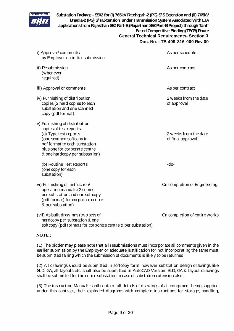
5.7 Approval Procedure
The following schedule shall be followed generally for approval and for providing final documentation.
Substation Package - SS02 for (i) 765kV Fatehgarh-2 (PG) S/S Extension and (ii) 765kV Bhadla-2 (PG) S/s Extension under Transmission System Associated With LTA
applications from Rajasthan SEZ Part-B (Rajasthan SEZ Part-B Project) through Tariff Based Competitive Bidding (TBCB) Route
General Technical Requirements- Section 3 Doc. No. : TB-409-316-000 Rev 00
Page 9 of 30
i) Approval/comments/ As per schedule by Employer on initial submission
ii) Resubmission As per contract
(whenever required)
iii) Approval or comments As per contract
iv) Furnishing of distribution 2 weeks from the date
copies (2 hard copies to each of approval substation and one scanned copy (pdf format)
v) Furnishing of distribution copies of test reports (a) Type test reports 2 weeks from the date (one scanned softcopy in of final approval pdf format to each substation plus one for corporate centre & one hardcopy per substation) (b) Routine Test Reports -do- (one copy for each substation)
vi) Furnishing of instruction/ On completion of Engineering operation manuals (2 copies per substation and one softcopy (pdf format) for corporate centre & per substation)
(vii) As built drawings (two sets of On completion of entire works
hardcopy per substation & one softcopy (pdf format) for corporate centre & per substation)
NOTE :
(1) The bidder may please note that all resubmissions must incorporate all comments given in the earlier submission by the Employer or adequate justification for not incorporating the same must be submitted failing which the submission of documents is likely to be returned. (2) All drawings should be submitted in softcopy form, however substation design drawings like SLD, GA, all layouts etc. shall also be submitted in AutoCAD Version. SLD, GA & layout drawings shall be submitted for the entire substation in case of substation extension also. (3) The instruction Manuals shall contain full details of drawings of all equipment being supplied under this contract, their exploded diagrams with complete instructions for storage, handling,
Substation Package - SS02 for (i) 765kV Fatehgarh-2 (PG) S/S Extension and (ii) 765kV Bhadla-2 (PG) S/s Extension under Transmission System Associated With LTA
applications from Rajasthan SEZ Part-B (Rajasthan SEZ Part-B Project) through Tariff Based Competitive Bidding (TBCB) Route
General Technical Requirements- Section 3 Doc. No. : TB-409-316-000 Rev 00
Page 10 of 30
erection, commissioning, testing, operation, trouble shooting, servicing and overhauling procedures. (4) If after the commissioning and initial operation of the substation, the instruction manuals require any modifications/additions/changes, the same shall be incorporated and the updated final instruction manuals shall be submitted by the Bidder to the Employer. (5) The Bidder shall furnish to the Employer catalogues of spare parts. (6) All As-built drawings/documents shall be certified by site indicating the changes before final submission.
6.0 MATERIAL/ WORKMANSHIP 6.1 General Requirement 6.1.1 Where the specification does not contain references to workmanship, equipment, materials and
components of the covered equipment, it is essential that the same must be new, of highest grade of the best quality of their kind, conforming to best engineering practice and suitable for the purpose for which they are intended.
6.1.2 In case where the equipment, materials or components are indicated in the specification as
“similar” to any special standard, the Employer shall decide upon the question of similarity. When required by the specification or when required by the Employer the Bidder shall submit, for approval, all the information concerning the materials or components to be used in manufacture. Machinery, equipment, materials and components supplied, installed or used without such approval shall run the risk of subsequent rejection, it is to be understood that the cost as well as the time delay associated with the rejection shall be borne by the Bidder.
6.1.3 The design of the Works shall be such that installation, future expansions, replacements and
general maintenance may be undertaken with a minimum of time and expenses. Each component shall be designed to be consistent with its duty and suitable factors of safety, subject to mutual agreements. All joints and fastenings shall be devised, constructed and documented so that the component parts shall be accurately positioned and restrained to fulfil their required function. In general, screw threads shall be standard metric threads. The use of other thread forms will only be permitted when prior approval has been obtained from the Employer.
6.1.4 Whenever possible, all similar part of the Works shall be made to gauge and shall also be made
interchangeable with similar parts. All spare parts shall also be interchangeable and shall be made of the same materials and workmanship as the corresponding parts of the Equipment supplied under the Specification. Where feasible, common component units shall be employed in different pieces of equipment in order to minimize spare parts stocking requirements. All equipment of the same type and rating shall be physically and electrically interchangeable.
6.1.5 Deleted. 6.1.6 The Bidder shall apply oil and grease of the proper specification to suit the machinery, as is
necessary for the installation of the equipment. Lubricants used for installation purposes shall be
Substation Package - SS02 for (i) 765kV Fatehgarh-2 (PG) S/S Extension and (ii) 765kV Bhadla-2 (PG) S/s Extension under Transmission System Associated With LTA
applications from Rajasthan SEZ Part-B (Rajasthan SEZ Part-B Project) through Tariff Based Competitive Bidding (TBCB) Route
General Technical Requirements- Section 3 Doc. No. : TB-409-316-000 Rev 00
Page 11 of 30
drained out and the system flushed through where necessary for applying the lubricant required for operation. The Bidder shall apply all operational lubricants to the equipment installed by him.
6.1.7 All oil, grease and other consumables used in the Works/Equipment shall be purchased in India
unless the Bidder has any special requirement for the specific application of a type of oil or grease not available in India. If such is the case, he shall declare in the proposal, where such oil or grease is available. He shall help Employer in establishing equivalent Indian make and Indian Bidder. The same shall be applicable to other consumables too.
6.2 Provisions For Exposure to Hot and Humid climate
Outdoor equipment supplied under the specification shall be suitable for service and storage under tropical conditions of high temperature, high humidity, heavy rainfall and environment favourable to the growth of fungi and mildew. The indoor equipments located in non-air conditioned areas shall also be of same type.
6.2.1 Space Heaters 6.2.1.1 The heaters shall be suitable for continuous operation at 240V as supply voltage. On-off switch
and fuse shall be provided. 6.2.1.2 One or more adequately rated thermostatically connected heaters shall be supplied to prevent
condensation in any compartment. The heaters shall be installed in the compartment and electrical connections shall be made sufficiently away from below the heaters to minimize deterioration of supply wire insulation. The heaters shall be suitable to maintain the compartment temperature to prevent condensation.
6.2.2 FUNGI STATIC VARNISH
Besides the space heaters, special moisture and fungus resistant varnish shall be applied on parts which may be subjected or predisposed to the formation of fungi due to the presence or deposit of nutrient substances. The varnish shall not be applied to any surface of part where the treatment will interfere with the operation or performance of the equipment. Such surfaces or parts shall be protected against the application of the varnish.
6.2.3 Ventilation opening
Wherever ventilation is provided, the compartments shall have ventilation openings with fine wire mesh of brass to prevent the entry of insects and to reduce to a minimum the entry of dirt and dust.
6.2.4 Degree of Protection The enclosures of the Control Cabinets, Junction boxes and Marshalling Boxes, panels etc. to be installed shall comply with following degree of protection as detailed here under: a) Installed out door: IP- 55 b) Installed indoor in air conditioned area: IP-31 c) Installed in covered area: IP-52
Substation Package - SS02 for (i) 765kV Fatehgarh-2 (PG) S/S Extension and (ii) 765kV Bhadla-2 (PG) S/s Extension under Transmission System Associated With LTA
applications from Rajasthan SEZ Part-B (Rajasthan SEZ Part-B Project) through Tariff Based Competitive Bidding (TBCB) Route
General Technical Requirements- Section 3 Doc. No. : TB-409-316-000 Rev 00
Page 12 of 30
d) Installed indoor in non-air conditioned area where possibility of entry of water is limited: IP-41. e) For LT Switchgear (AC & DC distribution Boards): IP-52
The degree of protection shall be in accordance with IS:13947 (Part-I)/IEC-60947 (Part-I)/IS 12063/IEC-60529. Type test report for IP-55 or higher degree of protection test, shall be submitted for approval.
6.3 RATING PLATES, NAME PLATES AND LABELS 6.3.1 Each main and auxiliary item of substation is to have permanently attached to it in a conspicuous
position a rating plate of non-corrosive material upon which is to be engraved manufacturer’s name, year of manufacture, equipment name, type or serial number together with details of the loading conditions under which the item of substation in question has been designed to operate, and such diagram plates as may be required by the Employer. The rating plate of each equipment shall be according to IEC requirement.
6.3.2 All such nameplates, instruction plates, rating plates of transformers, reactors, CB, CT, CVT, SA,
Isolators, C & R panels and PLCC equipments shall be bilingual with Hindi inscription first followed by English. Alternatively two separate plates one with Hindi and the other with English inscriptions may be provided.
6.4 FIRST FILL OF CONSUMABLES, OIL AND LUBRICANTS
All the first fill of consumables such as oils, lubricants, filling compounds, touch up paints, soldering/brazing material for all copper piping of circuit breakers and essential chemicals etc. which will be required to put the equipment covered under the scope of the specifications, into operation, shall be furnished by the Bidder unless specifically excluded under the exclusions in these specifications and documents.
7.0 DESIGN IMPROVEMENTS / COORDINATION 7.1 Deleted. 7.2 Deleted.
7.3 The Bidder shall be responsible for the selection and design of appropriate equipments to provide
the best co-ordinated performance of the entire system. The basic design requirements are detailed out in this Specification. The design of various components, sub-assemblies and assemblies shall be so done that it facilitates easy field assembly and maintenance.
7.4 The Bidder has to coordinate designs and terminations with the agencies (if any) who are
Consultants/Bidder for the Employer. The names of agencies shall be intimated to the successful bidders.
Substation Package - SS02 for (i) 765kV Fatehgarh-2 (PG) S/S Extension and (ii) 765kV Bhadla-2 (PG) S/s Extension under Transmission System Associated With LTA
applications from Rajasthan SEZ Part-B (Rajasthan SEZ Part-B Project) through Tariff Based Competitive Bidding (TBCB) Route
General Technical Requirements- Section 3 Doc. No. : TB-409-316-000 Rev 00
Page 13 of 30
7.5 The Bidder will be called upon to attend design co-ordination meetings with the Engineer, other Bidder’s and the Consultants of the Employer (if any) during the period of Contract. The Bidder shall attend such meetings at his own cost at POWERGRID Corporate Centre, Gurgaon (Haryana) or at mutually agreed venue as and when required and fully cooperate with such persons and agencies involved during those discussions.
8.0 QUALITY ASSURANCE PROGRAMME 8.1 To ensure that the equipment and services under the scope of this Contract, whether
manufactured or performed within the Bidder’s Works or at his Sub-Bidder’s premises or at the Employer’s site or at any other place of Work as applicable, are in accordance with the specifications, the Bidder shall ensure suitable quality assurance programme to control such activities at all points necessary. A quality assurance programme of the Bidder shall be in line with ISO requirements & shall generally cover the following:
a) The organisation structure for the management and implementation of the proposed quality assurance programme.
b) System for Document and Data Control. c) Qualification and Experience data of Bidder’s key personnel. d) The procedure for purchases of materials, parts, components and selection of sub- Bidder’s services including vendor analysis, source inspection, incoming raw material inspection, verification of material purchases etc. e) System for shop manufacturing and site erection controls including process controls, fabrication and assembly control. f) System for Control of non-conforming products including deviation dispositioning, if any and system for corrective and preventive actions based on the feedback received from the Customers and also internally documented system for Customer complaints. g) Inspection and test procedure both for manufacture and field activities. h) System for Control of calibration of testing and measuring equipment and the indication of calibration status on the instruments. i) System for indication and appraisal of inspection status. j)System of Internal Quality Audits, Management review and initiation of corrective and Preventive actions based on the above. k) System for authorising release of manufactured product to the Employer. l) System for maintenance of records.
Substation Package - SS02 for (i) 765kV Fatehgarh-2 (PG) S/S Extension and (ii) 765kV Bhadla-2 (PG) S/s Extension under Transmission System Associated With LTA
applications from Rajasthan SEZ Part-B (Rajasthan SEZ Part-B Project) through Tariff Based Competitive Bidding (TBCB) Route
General Technical Requirements- Section 3 Doc. No. : TB-409-316-000 Rev 00
Page 14 of 30
m) System for handling, storage and delivery. n) A quality plan detailing out the specific quality control measures and procedure adopted for controlling the quality characteristics relevant to each item of equipment furnished and /or service rendered. o) System for various field activities i.e. unloading, receipt at site, proper storage, erection, testing and commissioning of various equipment and maintenance of records. In this regard, the Employer has already prepared Standard Field Quality Plan for transmission line/substation equipments as applicable, Civil/erection Works which is required to be followed for associated works. The Employer or his duly authorised representative reserves the right to carry out quality audit and quality surveillance of the system and procedure of the Bidder/his vendor’s quality management and control activities.
8.2 Quality Assurance Documents
The Bidder shall ensure availability of the following Quality Assurance Documents: i) All Non-Destructive Examination procedures, stress relief and weld repair procedure actually used during fabrication, and reports including radiography interpretation reports. ii) Welder and welding operator qualification certificates. iii) Welder’s identification list, welding operator’s qualification procedure and welding identification symbols. iv) Raw Material test reports on components as specified by the specification and in the quality plan. v) The Manufacturing Quality Plan (MQP) indicating Customer Inspection Points (CIPs) at various stages of manufacturing and methods used to verify that the inspection and testing points in the quality plan were performed satisfactorily. vi) Factory test results for testing required as per applicable quality plan/technical specifications/GTP/Drawings etc. vii) Stress relief time temperature charts/oil impregnation time temperature charts, wherever applicable.
8.3 INSPECTION, TESTING & INSPECTION CERTIFICATE 8.3.1 Bidder shall procure bought out items from sub-vendors as per the list in “Compendium of
Vendors” available on POWERGRID web-site www.powergridindia.com after ensuring compliance to the requirements/conditions mentioned therein. Bidder shall explore first the possibilities of procuring the bought out items from POWERGRID approved existing vendors. In case of their
Substation Package - SS02 for (i) 765kV Fatehgarh-2 (PG) S/S Extension and (ii) 765kV Bhadla-2 (PG) S/s Extension under Transmission System Associated With LTA
applications from Rajasthan SEZ Part-B (Rajasthan SEZ Part-B Project) through Tariff Based Competitive Bidding (TBCB) Route
General Technical Requirements- Section 3 Doc. No. : TB-409-316-000 Rev 00
Page 15 of 30
unavailability / non-response, Bidder may approach POWERGRID for additional sub-vendor approval. In that case, the assessment report of proposed sub vendor by Bidder along with the enclosures as per Annexure-F shall be submitted within 60 days of the award. The proposal shall be reviewed and approval will be accorded based on the verification of the document submitted and/or after the physical assessment of the works as the case may be. The physical assessment conducted by POWERGRID, if required, shall be on chargeable basis. Charges shall be as per the POWERGRID norms prevailing at that time, which shall be intimated by POWERGRID separately. If proposal for sub-vendor is submitted after 60 days, the Bidder’s proposal normally will not be considered for current LOA. However, POWERGRID may process the case for developing more vendors for referred items, if found relevant. In all cases, It is the responsibility of the Bidder that Project activities do not suffer on account of delay in approval/non approval of a new sub-vendor.
The responsibility and the basis of inspection for various items & equipment is placed at Annexure-G along with the requirement of MQP (Manufacturing Quality Plan), ITP(Inspection & Test Plan), FAT(Factory Acceptance Test) which should be valid & POWERGRID approved and Level of inspection envisaged against each item. Bidder shall ensure that order for items where MQP/ITP/FAT is required will be placed only on vendors having valid MQP/ITP/FAT and where the supplier’s MQP/ITP/FAT is either not valid or has not been approved by POWERGRID, MQP shall be generally submitted as per POWERGRID format before placing order. Items not covered under MQP/ITP/FAT shall be offered for inspection as per POWERGRID LOA/technical Specifications/POWERGRID approved data sheets/POWERGRID approved drawings and relevant Indian/International standards. Inspection Levels: For implementation of projects in a time bound manner and to avoid any delay in deputation of POWERGRID or its authorized representative, involvement of POWERGRID for inspection of various items / equipment will be based on the level below: Level –I: Bidder to raise all inspection calls and review the report of tests carried out by the manufacturer, on his own, as per applicable standards/ POWERGRID specification, and submit to concerned POWERGRID inspection office/Inspection Engineer. CIP/MICC will be issued by POWERGRID based on review of test reports/certificates of manufacturers. Level – II: Bidder to raise all inspection calls and carry out the inspection on behalf of POWERGRID on the proposed date of inspection as per applicable standards/specification. However, in case POWERGRID wishes to associate itself during inspection, the same would be intimated to Bidder and CIP/MICC will be issued by POWERGRID. Else, Bidder would submit their test reports/certificates to POWERGRID. CIP/MICC will be issued by POWERGRID based on review of test reports/certificates. Level - III: Bidder to raise inspection calls for both, stage (as applicable) & final inspection and carry out the stage inspections (if applicable) on behalf of POWERGRID on the proposed date of inspection as per applicable standards/specification. However, in case POWERGRID wishes to associate itself during stage inspection, the same would be intimated to Bidder and CIP will be issued by POWERGRID. Else, Bidder would submit the test reports / certificates of stage inspection after their own review and CIP will be issued by POWERGRID based on review of test
Substation Package - SS02 for (i) 765kV Fatehgarh-2 (PG) S/S Extension and (ii) 765kV Bhadla-2 (PG) S/s Extension under Transmission System Associated With LTA
applications from Rajasthan SEZ Part-B (Rajasthan SEZ Part-B Project) through Tariff Based Competitive Bidding (TBCB) Route
General Technical Requirements- Section 3 Doc. No. : TB-409-316-000 Rev 00
Page 16 of 30
reports / certificates. Final inspection will be carried out by POWERGRID and CIP/MICC will be issued by POWERGRID. Level – IV: Bidder to raise inspection calls for both, stage (as applicable) & final inspections. POWERGRID will carry out the inspection for both stage & final inspection as per applicable standards/specification and CIP/MICC will be issued by POWERGRID.
8.3.2 Bidder shall ensure that to implement the above inspection levels, particularly for the quality control and inspection at sub-vendor’s works, they would depute sufficient qualified & experienced manpower in their Quality Control and Inspection department. Further, to assure quality of construction, Bidder shall have a separate workforce having appropriate qualification & experience and deploy suitable tools and plant for maintaining quality requirement during construction in line with applicable Field Quality Plan (FQP).
8.3.3 The Employer, his duly authorised representative and/or outside inspection agency acting on
behalf of the Employer shall have at all reasonable times access to the Bidder’s premises or Works and shall have the power at all reasonable times to ensure that proper Quality Management practices / norms are adhered to, inspect and examine the materials & workmanship of the Works, to carry out Quality/Surveillance Audit during manufacture or erection and if part of the Works is being manufactured or assembled at other premises or works. The Bidder shall obtain for the Employer and for his duly authorised representative permission to inspect as if the works were manufactured or assembled on the Bidder’s own premises or works. The item/equipment, if found unsatisfactory with respect to workmanship or material is liable to be rejected. The observations for improvements during product/ process inspection by POWERGRID shall be recorded in Quality Improvement Register (available & maintained at works) for review & timely compliance of observations.
8.3.4 Bidder shall submit inspection calls over internet through POWERGRID website. The required
vendor code and password to enable raising inspection call will be furnished to the main Bidder within 30 days of award of contract on submission of documents by Bidder. After raising the inspection calls, Bidder shall then proceed as per the message of that particular call which is available on the message board.
8.3.5 The Employer reserves the right to witness any or all type, acceptance and routine tests specified
for which the Bidder shall give the Employer/Inspector Twenty one (21) days written notice of any material being ready for testing for each stage of testing as identified in the approved quality plan as customer inspection point(CIP) for indigenous inspections. All inspection calls for overseas material shall be given at least forty five (45) days in advance. Such tests shall be to the Bidder’s account except for the expenses of the Inspection Engineer. The Employer/inspector, unless witnessing of the tests is waived by Employer, will attend such tests within Twenty one (21) days of the date of which the equipment is notified as being ready for test/inspection, failing which the Bidder may proceed with the test which shall be deemed to have been made in the Inspector’s presence and he shall forthwith forward to the Inspector three copies of tests, duly certified. Bidder shall ensure, before giving notice for type test, that all drawings and quality plans have been got approved. The equipment shall be dispatched to site only after approval of Routine and Acceptance test results and Issuance of Dispatch Clearance in writing by the Employer. CIP/Material Inspection clearance certificate (MICC) shall be issued by the Employer after inspection of the equipment or review of test reports as applicable. Employer may waive off the
Substation Package - SS02 for (i) 765kV Fatehgarh-2 (PG) S/S Extension and (ii) 765kV Bhadla-2 (PG) S/s Extension under Transmission System Associated With LTA
applications from Rajasthan SEZ Part-B (Rajasthan SEZ Part-B Project) through Tariff Based Competitive Bidding (TBCB) Route
General Technical Requirements- Section 3 Doc. No. : TB-409-316-000 Rev 00
Page 17 of 30
presence of Employer’s inspecting engineer. In that case test will be carried out as per approved QP and test certificate will be furnished by the supplier for approval. CIP/MICC will be issued only after review and approval of the test reports.
8.3.6 Bidder shall generally offer material for inspection as per supply bar chart approved by
POWERGRID and not before 30 days from schedule indicated in the bar chart. In case Bidder offers material(s) for inspection prior to 30 days from the scheduled date with necessary approval of POWERGRID, POWERGRID shall inspect the material and issue CIP only. However, in such an exceptional case, MICC shall be issued only as per provision of original / revised approved supply schedule.
8.3.7 Bidder shall minimize the number of inspection calls by offering optimum quantities in each
inspection call at the respective manufacturer’s works. 8.3.8 Bidder shall inspect the material themselves and only after they are fully convinced about the
Quality, they shall offer the material for POWERGRID inspection and shall also ensure that relevant portion of LOA/NOA, approved drawing and data sheets along with applicable Quality Plans are available at the works of Bidder or their Sub-vendor before the material is offered for inspection.
8.3.9 Bidder shall ensure that material which has been cleared for dispatch after inspection will be
dispatched within 30 days in case of domestic supplies and within 60 days in case of Off-shore supplies from the date of issuance of CIP. Material which is not dispatched within stipulated time as above will be reoffered for POWERGRID inspection or specific approval of POWERGRID QA&I shall be obtained for delayed dispatch.
8.3.10 The Employer or IE shall give notice in writing to the Bidder, of any objection either to
conformance to any drawings or to any equipment and workmanship which in his opinion is not in accordance with the Contract. The Bidder shall give due consideration to such objections and shall either make the modifications that may be necessary to meet the said objections or shall confirm in writing to the Employer/Inspection Engineer giving reasons therein, that no modifications are necessary to comply with the Contract.
8.3.11 All Test Reports and documents to be submitted in English during final inspection of equipment
by POWERGRID or as and when required for submission. 8.3.12 When the factory tests have been completed at the Bidder’s or Sub-Bidder’s works, the
Employer/Inspection Engineer (IE) shall issue a certificate to this effect within fifteen (15) days after completion of tests & submission of documents by Bidder/manufacturer but if the tests are not witnessed by the Employer/IE, the certificate shall be issued within fifteen (15) days of receipt of the Bidder’s Test certificate by the Employer/IE. Bidder shall, on completion of all tests, submit test reports within Ten (10) days to POWERGRID IE. Failure of the Employer/IE to issue such a certificate shall not prevent the Bidder from proceeding with the Works. The completion of these tests or the issue of the certificate shall not bind the Employer to accept the equipment should, it, on further tests after erection, be found not to comply with the Contract.
8.3.13 In all cases, where the Contract provides for tests whether at the premises or works of the Bidder
or of any Sub- Bidder, the Bidder, except where otherwise specified, shall provide free of charge
Substation Package - SS02 for (i) 765kV Fatehgarh-2 (PG) S/S Extension and (ii) 765kV Bhadla-2 (PG) S/s Extension under Transmission System Associated With LTA
applications from Rajasthan SEZ Part-B (Rajasthan SEZ Part-B Project) through Tariff Based Competitive Bidding (TBCB) Route
General Technical Requirements- Section 3 Doc. No. : TB-409-316-000 Rev 00
Page 18 of 30
such items as labour, materials, electricity, fuel, water, stores, apparatus and instruments as may be reasonably demanded by the Employer/Inspector or his authorised representative to carry out effectively such tests of the equipment in accordance with the Contract and shall give facilities to the Employer/Inspection Engineer or to his authorised representative to accomplish testing.
8.3.14 The inspection and acceptance by Employer and issue of Inspection Certificate thereon shall in no
way limit the liabilities and responsibilities of the Bidder in respect of the agreed quality assurance programme forming a part of the Contract, or if such equipment is found to be defective at a later stage.
8.3.15 The Employer will have the right of having at his own expenses any other test(s) of reasonable
nature carried out at Bidder’s premises or at site or in any other place in addition of aforesaid type and routine tests, to satisfy that the material comply with the specification.
8.3.16 The Employer reserves the right for getting any additional field tests conducted on the completely
assembled equipment at site to satisfy that material complies with specifications. 8.3.17 Rework/ Re-engineering, if any, on any item/equipment shall be carried out only after mutual
discussions and in accordance with mutually agreed procedure. Bidder shall submit Joint Inspection Report of equipments under Re-Work/Re-Engineering alongwith procedure for the same to POWERGRID for approval, before taking up the Re-Work/Re-Engineering, failing which POWERGRID reserves the right to reject the equipment.
8.3.18 Bidder may establish a field test Laboratory to execute Civil Construction testing requirements at
site with the condition that all testing equipment shall be calibrated from POWERGRID approved accredited Testing laboratories, with calibration certificates kept available at site and all testing personnel employed in the Field Testing Laboratories to be qualified and experienced Engineers or testing to be carried out at POWERGRID approved Third Party Laboratories.
8.3.19 Bidder shall ensure that all possible steps are taken to avoid damages to the equipment during
transport, storage and erection. 8.3.20 Bidder shall implement additional stringent quality checks and preparation during installation of
GIS at site (if applicable) as per POWERGRID approved guidelines/Technical specifications. 8.3.21 Bidder shall ensure commissioning of all CSDs along with Circuit Breakers wherever applicable. 8.3.22 For EHV transformers/reactors:
Insulation oil shall be as per POWERGRID Technical specifications and same grade shall be used for impregnation of the active part & testing at the works of Transformer/Reactor Manufacturer and as well as for filling the Transformer/Reactors at site. Bidder to ensure that windings for Transformer/Reactors are made in air conditioned environment. Core-coil assembly shall be performed in positive pressurized dust controlled environment. Dust measurements shall be monitored regularly at Transformer / Reactor Manufacturer works. Bidder shall ensure that respective civil foundations & Fire walls for Transformer/Reactors units to be commissioned, shall be made ready at concerned sites before receipt of Transformer/Reactors units. All the requisite material for Neutral & Delta Bus formation required for charging of complete bank of
Substation Package - SS02 for (i) 765kV Fatehgarh-2 (PG) S/S Extension and (ii) 765kV Bhadla-2 (PG) S/s Extension under Transmission System Associated With LTA
applications from Rajasthan SEZ Part-B (Rajasthan SEZ Part-B Project) through Tariff Based Competitive Bidding (TBCB) Route
General Technical Requirements- Section 3 Doc. No. : TB-409-316-000 Rev 00
Page 19 of 30
765KV class 1-ph Transformer/Reactor units shall be made available at the concerned sites before receipt of the Transformer/Reactor units at site.
8.3.23 The Employer reserves the right to increase or decrease their involvement in inspections at Bidder’s Works or at his Sub-Bidder’s premises or at the Employer’s site or at any other place of Work based on performance of Bidder/sub-Bidder.
9.0 TYPE TESTING & CLEARANCE CERTIFICATE 9.1 All equipment being supplied shall conform to type tests as per technical specification and shall be
subject to routine tests in accordance with requirements stipulated under respective sections. 9.2 The reports for all type tests as per technical specification shall be furnished by the Bidder
alongwith equipment / material drawings. However, type test reports of similar equipments/ material already accepted in POWERGRID shall be applicable for all projects with similar requirement. The type tests conducted earlier should have either been conducted in accredited laboratory (accredited based on ISO / IEC Guide 25 / 17025 or EN 45001 by the national accreditation body of the country where laboratory is located) or witnessed by POWERGRID or representative authorized by POWERGRID or Utility or representative of accredited test lab.
Unless otherwise specified elsewhere, the type test reports submitted shall be of the tests conducted on or after 05-Nov-2009. In case the test reports are of the test conducted earlier than 05-Nov-2009, the bidder shall repeat these test(s) at no extra cost to the BHEL/Employer. Further, in the event of any discrepancy in the test reports i.e. any test report not acceptable due to any design/manufacturing changes or due to non-compliance with the requirement stipulated in the Technical Specification or any/all type tests not carried out, same shall be carried out without any additional cost implication to the BHEL/Employer. The Bidder shall intimate the Employer the detailed program about the type tests atleast two (2) weeks in advance in case of domestic supplies & six (6) weeks in advance in case of foreign supplies.
9.3 The Employer intends to repeat those type tests which are indicated in the price schedule and the same shall be payable as per provision of contract. The price of conducting type tests shall be included in Bid price and break up of these shall be given in the relevant schedule of Bid Proposal Sheets. These Type test charges would be considered in bid evaluation. In case Bidder does not indicate charges for any of the type tests or does not mention the name of any test in the price schedules, it will be presumed that the particular test has been offered free of charge. Further, in case any Bidder indicates that he shall not carry out a particular test, his offer shall be considered incomplete and shall be liable to be rejected. The Employer reserves the right to waive the repeating of type tests partly or fully and in case of waival, test charges for the same shall not be payable.
9.4 The Employer reserves the right to witness any or all the type tests. The Employer shall bear all expenses for deputation of Employer’s representative(s) for witnessing the type tests.

Substation Package - SS02 for (i) 765kV Fatehgarh-2 (PG) S/S Extension and (ii) 765kV Bhadla-2 (PG) S/s Extension under Transmission System Associated With LTA
applications from Rajasthan SEZ Part-B (Rajasthan SEZ Part-B Project) through Tariff Based Competitive Bidding (TBCB) Route
General Technical Requirements- Section 3 Doc. No. : TB-409-316-000 Rev 00
Page 20 of 30
9.5 The list of makes of various items, for which Type test reports are not required to be submitted are specified in Compendium of Vendors (COV).
10.0 Deleted. 11.0 PACKAGING & PROTECTION 11.1 All the equipments shall be suitably protected, coated, covered or boxed and crated to prevent
damage or deterioration during transit, handling and storage at Site till the time of erection. On request of the Employer, the Bidder shall also submit packing details/associated drawing for any equipment/material under his scope of supply, to facilitate the Employer to repack any equipment/material at a later date, in case the need arises. While packing all the materials, the limitation from the point of view of availability of Railway wagon sizes in India should be taken into account. The Bidder shall be responsible for any loss or damage during transportation, handling and storage due to improper packing. Any demurrage, wharfage and other such charges claimed by the transporters, railways etc. shall be to the account of the Bidder. Employer takes no responsibility of the availability of the wagons.
11.2 All coated surfaces shall be protected against abrasion, impact, discolouration and any other
damages. All exposed threaded portions shall be suitably protected with either a metallic or a non-metallic protecting device. All ends of all valves and pipings and conduit equipment connections shall be properly sealed with suitable devices to protect them from damage.
12.0 FINISHING OF METAL SURFACES 12.1 All metal surfaces shall be subjected to treatment for anti-corrosion protection. All ferrous
surfaces for external use unless otherwise stated elsewhere in the specification or specifically agreed, shall be hot-dip galvanized after fabrication. All steel conductors including those used for earthing/grounding (above ground level) shall also be galvanized according to IS: 2629.
12.2 HOT DIP GALVANISING 12.2.1 The minimum weight of the zinc coating shall be 610 gm/sq.m and minimum average thickness of
coating shall be 86 microns for all items having thickness 6mm and above. For items lower than 6mm thickness requirement of coating thickness shall be as per relevant ASTM. For surface which shall be embedded in concrete, the zinc coating shall be 610 gm/sq.m minimum.
12.2.2 The galvanized surfaces shall consist of a continuous and uniform thick coating of zinc, firmly
adhering to the surface of steel. The finished surface shall be clean and smooth and shall be free from defects like discoloured patches, bare spots, unevenness of coating, spelter which is loosely attached to the steel globules, spiky deposits, blistered surface, flaking or peeling off, etc. The presence of any of these defects noticed on visual or microscopic inspection shall render the material liable to rejection.
12.2.3 After galvanizing, no drilling or welding shall be performed on the galvanized parts of the
equipment excepting that nuts may be threaded after galvanizing. Sodium dichromate or alternate approved treatment shall be provided to avoid formation of white rust after hot dip galvanization.
Substation Package - SS02 for (i) 765kV Fatehgarh-2 (PG) S/S Extension and (ii) 765kV Bhadla-2 (PG) S/s Extension under Transmission System Associated With LTA
applications from Rajasthan SEZ Part-B (Rajasthan SEZ Part-B Project) through Tariff Based Competitive Bidding (TBCB) Route
General Technical Requirements- Section 3 Doc. No. : TB-409-316-000 Rev 00
Page 21 of 30
12.2.4 The galvanized steel shall be subjected to four numbers of one minute dips in copper sulphate solution as per IS-2633.
12.2.5 Sharp edges with radii less than 2.5 mm shall be able to withstand four immersions of the
Standard Preece test. All other coatings shall withstand six immersions. The following galvanizing tests should essentially be performed as per relevant Indian Standards. - Coating thickness - Uniformity of zinc - Adhesion test - Mass of zinc coating
12.2.6 Galvanised material must be transported properly to ensure that galvanised surfaces are not damaged during transit. Application of touch-up zinc rich paint at site shall be allowed with approval of Engineer Incharge.
12.3 PAINTING 12.3.1 All sheet steel work shall be degreased, pickled, phosphated in accordance with the IS- 6005 “Code
of practice for phosphating iron and sheet”. All surfaces, which will not be easily accessible after shop assembly, shall beforehand be treated and protected for the life of the equipment. The surfaces, which are to be finished painted after installation or require corrosion protection until installation, shall be shop painted with at least two coats of primer. Oil, grease, dirt and swaf shall be thoroughly removed by emulsion cleaning. Rust and scale shall be removed by pickling with dilute acid followed by washing with running water, rinsing with slightly alkaline hot water and drying.
12.3.2 After phosphating, thorough rinsing shall be carried out with clean water followed by final rinsing
with dilute dichromate solution and oven drying. The phosphate coating shall be sealed with application of two coats of ready mixed, stoving type zinc chromate primer. The first coat may be “flash dried” while the second coat shall be stoved.
12.3.3 After application of the primer, two coats of finishing synthetic enamel paint shall be applied, each
coat followed by stoving. The second finishing coat shall be applied after inspection of first coat of painting.
12.3.4 The exterior and interior colour of the paint in case of new substations shall preferably be RAL
7032 for all equipment, marshalling boxes, junction boxes, control cabinets, panels etc. unless specifically mentioned under respective sections of the equipments. Glossy white colour inside the equipments /boards /panels/junction boxes is also acceptable. The exterior colour for panels shall be matching with the existing panels in case of extension of a substation. Each coat of primer and finishing paint shall be of slightly different shade to enable inspection of the painting. A small quantity of finishing paint shall be supplied for minor touching up required at site after installation of the equipments.
12.3.5 In case the bidder proposes to follow his own standard surface finish and protection procedures
or any other established painting procedures, like electrostatic painting etc., the procedure shall be submitted during detailed engineering for Employer’s review & approval.
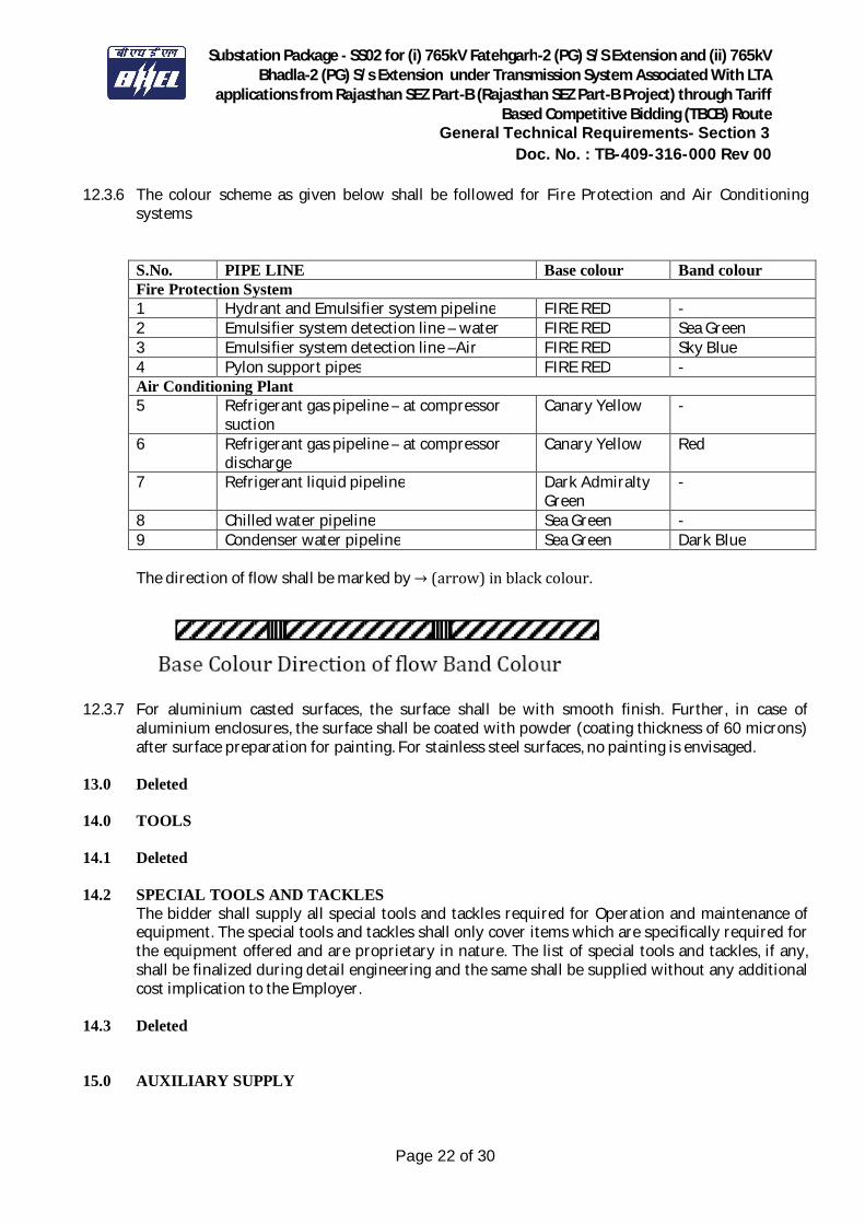
Substation Package - SS02 for (i) 765kV Fatehgarh-2 (PG) S/S Extension and (ii) 765kV Bhadla-2 (PG) S/s Extension under Transmission System Associated With LTA
applications from Rajasthan SEZ Part-B (Rajasthan SEZ Part-B Project) through Tariff Based Competitive Bidding (TBCB) Route
General Technical Requirements- Section 3 Doc. No. : TB-409-316-000 Rev 00
Page 22 of 30
12.3.6 The colour scheme as given below shall be followed for Fire Protection and Air Conditioning systems
S.No. PIPE LINE Base colour Band colour Fire Protection System 1 Hydrant and Emulsifier system pipeline FIRE RED - 2 Emulsifier system detection line – water FIRE RED Sea Green 3 Emulsifier system detection line –Air FIRE RED Sky Blue 4 Pylon support pipes FIRE RED - Air Conditioning Plant 5 Refrigerant gas pipeline – at compressor
suction Canary Yellow -
6 Refrigerant gas pipeline – at compressor discharge
Canary Yellow Red
7 Refrigerant liquid pipeline Dark Admiralty Green
-
8 Chilled water pipeline Sea Green - 9 Condenser water pipeline Sea Green Dark Blue
The direction of flow shall be marked by →(arrow)inblackcolour.
12.3.7 For aluminium casted surfaces, the surface shall be with smooth finish. Further, in case of aluminium enclosures, the surface shall be coated with powder (coating thickness of 60 microns) after surface preparation for painting. For stainless steel surfaces, no painting is envisaged.
13.0 Deleted 14.0 TOOLS 14.1 Deleted
14.2 SPECIAL TOOLS AND TACKLES
The bidder shall supply all special tools and tackles required for Operation and maintenance of equipment. The special tools and tackles shall only cover items which are specifically required for the equipment offered and are proprietary in nature. The list of special tools and tackles, if any, shall be finalized during detail engineering and the same shall be supplied without any additional cost implication to the Employer.
14.3 Deleted 15.0 AUXILIARY SUPPLY
Substation Package - SS02 for (i) 765kV Fatehgarh-2 (PG) S/S Extension and (ii) 765kV Bhadla-2 (PG) S/s Extension under Transmission System Associated With LTA
applications from Rajasthan SEZ Part-B (Rajasthan SEZ Part-B Project) through Tariff Based Competitive Bidding (TBCB) Route
General Technical Requirements- Section 3 Doc. No. : TB-409-316-000 Rev 00
Page 23 of 30
15.1 The auxiliary power for station supply, including the equipment drive, cooling system of any equipment, air-conditioning, lighting etc shall be designed for the specified Parameters as under. The DC supply for the instrumentation and PLCC system shall also conform the parameters as indicated in the following table: Normal Voltage
Variation in Voltage
Frequency in HZ
Phase/Wire Neutral connection
415V ±10% 50 ± 5% 3/4 Wire Solidly Earthed. 240V ±10% 50 ± 5% 1/2 Wire Solidly Earthed. 220V 190V to 240V DC Isolated 2
wire System -
110V 95V to 120V DC Isolated 2 wire System
-
48V -- DC 2 wire system (+) earthed
-
Combined variation of voltage and frequency shall be limited to + 10%.
16.0 SUPPORT STRUCTURE 16.1 The equipment support structures shall be suitable for equipment connections at the first level i.e
14.0 meter, 8.0 meter, 5.9 meter and 4.6 meter from plinth level for 765kV, 400kV, 220kV and 132kV substations respectively. All equipment support structures shall be supplied alongwith brackets, angles, stools etc. for attaching the operating mechanism, control cabinets & marshalling box (wherever applicable) etc.
16.2 The minimum vertical distance from the bottom of the lowest porcelain part of the bushing,
porcelain enclosures or supporting insulators to the bottom of the equipment base, where it rests on the foundation pad shall be 2.55 metres.
17.0 CLAMPS AND CONNECTORS INCLUDING TERMINAL CONNECTORS 17.1 All power clamps and connectors shall conform to IS: 5561 or other equivalent international
standard and shall be made of materials listed below: S.No. Description Materials
a) For connecting ACSR conductors/AAC conductors/ Aluminium tube
Aluminum alloy casting, conforming to designation A6 of IS:617 and all test shall conform to IS:617
b) For connecting equipment terminals mad of copper with ACSR conductors/AAC conductors/ Aluminium tube
Bimetallic connectors made from aluminum alloy casting, conforming to designation A6 of IS:617 with 2mm thick bimetallic liner/strip and all test shall conform to IS:617
c) For connecting G.I Galvanised mild steel shield wire d) Bolts, nuts & plain washers Electro-galvanised for sizes below
M12, for others hot dip galvanised. e) Spring washers Electro-galvanised mild steel suitable
for atleast service condition-3 as per IS:1573

Substation Package - SS02 for (i) 765kV Fatehgarh-2 (PG) S/S Extension and (ii) 765kV Bhadla-2 (PG) S/s Extension under Transmission System Associated With LTA
applications from Rajasthan SEZ Part-B (Rajasthan SEZ Part-B Project) through Tariff Based Competitive Bidding (TBCB) Route
General Technical Requirements- Section 3 Doc. No. : TB-409-316-000 Rev 00
Page 24 of 30
17.2 Necessary clamps and connectors shall be supplied for all equipment and connections. If corona rings are required to meet these requirements they shall be considered as part of that equipment and included in the scope of work.
17.3 Where copper to aluminum connections are required, bi-metallic clamps shall be used, which shall
be properly designed to ensure that any deterioration of the connection is kept to a minimum and restricted to parts which are not current carrying or subjected to stress.
17.4 Low voltage connectors, grounding connectors and accessories for grounding all equipment as
specified in each particular case, are also included in the scope of Work. 17.5 No current carrying part of any clamp shall be less than 10 mm thick. All ferrous parts shall be hot
dip galvanised. Copper alloy liner/strip of minimum 2 mm thickness shall be cast integral with aluminum body or 2 mm thick bi-metallic liner/strips shall be provided for Bi-metallic clamps.
17.6 All casting shall be free from blow holes, surface blisters, cracks and cavities. All sharp edges and corners shall be blurred and rounded off.
17.7 Flexible connectors, braids or laminated straps made for the terminal clamps for bus posts shall
be suitable for both expansion or through (fixed/sliding) type connection of IPS AL tube as required. In both the cases the clamp height (top of the mounting pad to centre line of the tube) should be same.
17.8 Current carrying parts (500A and above) of the clamp/connector shall be provided with minimum
four numbers of bolts preferably for 132kV & above. 17.9 All current carrying parts shall be designed and manufactured to have minimum contact
resistance. 17.10 Power Clamps and connectors shall be designed to control corona as per requirement. 17.11 Tests
Clamps and connectors should be type tested as per IS: 5561 and shall also be subjected to routine tests as per IS: 5561. Following type test reports shall be submitted for approval. Type test once conducted shall hold good. The requirement of test conducted within last ten years, shall not be applicable. i) Temperature rise test (maximum temperature rise allowed is 35°C over 50°C ambient) ii) Short time current test iii) Corona (dry) [for 400kV and above] and RIV (dry) test [for 132kV and above voltage level clamps] iv) Resistance test and tensile test
18.0 CONTROL CABINETS, JUNCTION BOXES, TERMINAL BOXES & MARSHALLING
BOXES FOR OUTDOOR EQUIPMENT
Substation Package - SS02 for (i) 765kV Fatehgarh-2 (PG) S/S Extension and (ii) 765kV Bhadla-2 (PG) S/s Extension under Transmission System Associated With LTA
applications from Rajasthan SEZ Part-B (Rajasthan SEZ Part-B Project) through Tariff Based Competitive Bidding (TBCB) Route
General Technical Requirements- Section 3 Doc. No. : TB-409-316-000 Rev 00
Page 25 of 30
18.1 All types of boxes, cabinets etc. shall generally conform to & be tested in accordance with IS-
5039/IS-8623, IEC-60439, as applicable, and the clauses given below: 18.2 Control cabinets, junction boxes, Marshalling boxes & terminal boxes shall be made of stainless
steel of atleast 1.5 mm thick or aluminum enclosure of atleast 1.6 mm thick and shall be dust, water and vermin proof. Stainless steel used shall be of grade SS304 or better. The box shall be properly braced to prevent wobbling. There shall be sufficient reinforcement to provide level surfaces, resistance to vibrations and rigidity during transportation and installation. In case of aluminium enclosed box the thickness of aluminum shall be such that it provides adequate rigidity and long life as comparable with sheet steel of specified thickness.
18.3 A canopy and sealing arrangements for operating rods shall be provided in marshalling boxes /
Control cabinets to prevent ingress of rain water. 18.4 Cabinet/boxes shall be provided with double hinged doors with padlocking arrangements. The
distance between two hinges shall be adequate to ensure uniform sealing pressure against atmosphere.
18.5 All doors, removable covers and plates shall be gasketed all around with suitably profiled
EPDM/Neoprene/PU gaskets. The gasket shall be tested in accordance with approved quality plan, IS:11149 and IS:3400. Ventilating Louvers, if provided, shall have screen and filters. The screen shall be fine wire mesh made of brass.
Further, the gasketing arrangement shall be such that gaskets are pasted in slots (in door fabrication/gasket itself) in order to prevent ingression of dust and moisture inside the panels so that no internal rusting occurs in panels during the operation of the equipment.
18.6 All boxes/cabinets shall be designed for the entry of cables by means of weather proof and dust-proof connections. Boxes and cabinets shall be designed with generous clearances to avoid interference between the wiring entering from below and any terminal blocks or accessories mounted within the box or cabinet. Suitable cable gland plate above the base of the marshalling kiosk/box shall be provided for this purpose along with the proper blanking plates. Necessary number of cable glands shall be supplied and fitted on this gland plate. Gland plate shall have provision for some future glands to be provided later, if required. The Nickel plated glands shall be dust proof, screw on & double compression type and made of brass. The gland shall have provision for securing armour of the cable separately and shall be provided with earthing tag. The glands shall conform to BS:6121.
18.7 A 240V, single phase, 50 Hz, 15 amp AC plug and socket shall be provided in the cabinet with ON-
OFF switch for connection of hand lamps. Plug and socket shall be of industrial grade. 18.8 LED based illumination of minimum 9 watts shall be provided. The switching of the fittings shall
be controlled by the door switch.
For junction boxes of smaller sizes such as lighting junction box, manual operated earth switch mechanism box etc., plug socket, heater and illumination is not required to be provided.
Substation Package - SS02 for (i) 765kV Fatehgarh-2 (PG) S/S Extension and (ii) 765kV Bhadla-2 (PG) S/s Extension under Transmission System Associated With LTA
applications from Rajasthan SEZ Part-B (Rajasthan SEZ Part-B Project) through Tariff Based Competitive Bidding (TBCB) Route
General Technical Requirements- Section 3 Doc. No. : TB-409-316-000 Rev 00
Page 26 of 30
18.9 All control switches shall be of MCB/rotary switch type and Toggle/piano switches shall not be accepted.
18.10 Earthing of the cabinet shall be ensured by providing two separate earthing pads. The earth wire
shall be terminated on to the earthing pad and secured by the use of self etching washer. Earthing of hinged door shall be done by using a separate earth wire.
18.11 The bay marshalling kiosks shall be provided with danger plate and a diagram showing the
numbering/connection/feruling by pasting the same on the inside of the door. 18.12 The following routine tests alongwith the routine tests as per IS:5039 shall also be conducted:
i) Check for wiring ii) Visual and dimension check
18.13 The enclosure of bay marshalling kiosk, junction box, terminal box and control cabinets shall conform to IP-55 as per IS:13947 including application of 2KV rms for 1 (one) minute, insulation resistance and functional test after IP-55 test.
19.0 DELETED 20.0 TERMINAL BLOCKS AND WIRING 20.1 Control and instrument leads from the switchboards or from other equipment will be brought to
terminal boxes or control cabinets in conduits. All interphase and external connections to equipment or to control cubicles will be made through terminal blocks.
20.2 Terminal blocks shall be 650V grade and have continuous rating to carry the maximum expected
current on the terminals and non-breakable type. These shall be of moulded piece, complete with insulated barriers, stud type terminals, washers, nuts and lock nuts. Screw clamp, overall insulated, insertion type, rail mounted terminals can be used in place of stud type terminals. But the terminal blocks shall be non-disconnecting stud type except for the secondary junction boxes of Current Transformer and Voltage Transformer.
20.3 Terminal blocks for current transformer and voltage transformer secondary leads shall be
provided with test links and isolating facilities. The current transformer secondary leads shall also be provided with short circuiting and earthing facilities.
20.4 The terminal shall be such that maximum contact area is achieved when a cable is terminated. The
terminal shall have a locking characteristic to prevent cable from escaping from the terminal clamp unless it is done intentionally.
20.5 The conducting part in contact with cable shall preferably be tinned or silver plated however
Nickel plated copper or zinc plated steel shall also be acceptable. 20.6 The terminal blocks shall be of extensible design, multilayer terminal arrangement is not allowed
in any junction box (Common MB, Individual MB, JB etc.). There should be sufficient space at both sides of terminals so that ferrule number of wires / TB numbers are clearly visible during wire removal or insertion.

Substation Package - SS02 for (i) 765kV Fatehgarh-2 (PG) S/S Extension and (ii) 765kV Bhadla-2 (PG) S/s Extension under Transmission System Associated With LTA
applications from Rajasthan SEZ Part-B (Rajasthan SEZ Part-B Project) through Tariff Based Competitive Bidding (TBCB) Route
General Technical Requirements- Section 3 Doc. No. : TB-409-316-000 Rev 00
Page 27 of 30
20.7 The terminal blocks shall have locking arrangement to prevent its escape from the mounting rails. 20.8 The terminal blocks shall be fully enclosed with removable covers of transparent, non-
deteriorating type plastic material. Insulating barriers shall be provided between the terminal blocks. These barriers shall not hinder the operator from carrying out the wiring without removing the barriers.
20.9 Unless otherwise specified terminal blocks shall be suitable for connecting the following
conductors on each side. a) All circuits except Minimum of two of 2.5 sq mm CT/PT circuits copper flexible. b) All CT/PT circuits Minimum of 4 nos. of 2.5 sq mm copper flexible.
20.10 The arrangements shall be in such a manner so that it is possible to safely connect or disconnect terminals on live circuits and replace fuse links when the cabinet is live.
20.11 Atleast 20 % spare terminals shall be provided on each panel/cubicle/box and these spare
terminals shall be uniformly distributed on all terminals rows. 20.12 There shall be a minimum clearance of 250 mm between the First/bottom row of terminal block
and the associated cable gland plate for outdoor ground mounted marshalling box and the clearance between two rows of terminal blocks shall be a minimum of 150 mm.
20.13 The Bidder shall furnish all wire, conduits and terminals for the necessary interphase electrical
connections (where applicable) as well as between phases and common terminal boxes or control cabinets. For equipments rated for 400 kV and above the wiring required in these items shall be run in metallic ducts or shielded cables in order to avoid surge over-voltages either transferred through the equipment or due to transients induced from the EHV circuits.
20.14 All input and output terminals of each control cubicle shall be tested for surge withstand
capability in accordance with the relevant IEC Publications, in both longitudinal and transverse modes. The Bidder shall also provide all necessary filtering, surge protection, interface relays and any other measures necessary to achieve an impulse withstand level at the cable interfaces of the equipment.
21.0 LAMPS & SOCKETS 21.1 Lamps & Sockets
All lamps shall use a socket base as per IS-1258, except in the case of signal lamps. All sockets (convenience outlets) shall be suitable to accept both 5 Amp & 15 Amp pin round Standard Indian plugs. They shall be switched sockets with shutters.
21.2 Hand Lamp: A 240 Volts, single Phase, 50 Hz AC plug point shall be provided in the interior of each cubicle with ON-OFF Switch for connection of hand lamps.
21.3 Switches and Fuses:
Substation Package - SS02 for (i) 765kV Fatehgarh-2 (PG) S/S Extension and (ii) 765kV Bhadla-2 (PG) S/s Extension under Transmission System Associated With LTA
applications from Rajasthan SEZ Part-B (Rajasthan SEZ Part-B Project) through Tariff Based Competitive Bidding (TBCB) Route
General Technical Requirements- Section 3 Doc. No. : TB-409-316-000 Rev 00
Page 28 of 30
21.3.1 Each panel shall be provided with necessary arrangements for receiving, distributing, isolating and fusing of DC and AC supplies for various control, signalling, lighting and space heater circuits. The incoming and sub-circuits shall be separately provided with miniature circuit breaker / switch fuse units. Selection of the main and Sub-circuit fuse ratings shall be such as to ensure selective clearance of sub-circuit faults. Potential circuits for relaying and metering shall be protected by HRC fuses.
21.3.2 All fuses shall be of HRC cartridge type conforming to IS: 9228 mounted on plug-in type fuse
bases. Miniature circuit breakers with thermal protection and alarm contacts will also be accepted. All accessible live connection to fuse bases shall be adequately shrouded. Fuses shall have operation indicators for indicating blown fuse condition. Fuse carrier base shall have imprints of the fuse rating and voltage.
22.0 Bushings, Hollow Column Insulators, Support Insulators: 22.1 Bushings shall be manufactured and tested in accordance with IS:2099 & IEC-60137 while hollow
column insulators shall be manufactured and tested in accordance with IEC-62155/IS:5621.The support insulators shall be manufactured and tested as per IS:2544/IEC-60168 and IEC-60273. The insulators shall also conform to IEC-60815 as applicable. The bidder may also offer composite hollow insulators, conforming to IEC-61462.
22.2 Support insulators, bushings and hollow column insulators shall be manufactured from high
quality porcelain. Porcelain used shall be homogeneous, free from laminations, cavities and other flaws or imperfections that might affect the mechanical or dielectric quality and shall be thoroughly vitrified tough and impervious to moisture.
22.3 Glazing of the porcelain shall be uniform brown in colour, free from blisters, burrs and similar
other defects. 22.4 Support insulators/bushings/hollow column insulators shall be designed to have ample
insulation, mechanical strength and rigidity for the conditions under which they will be used. 22.5 When operating at normal rated voltage there shall be no electric discharge between the
conductors and bushing which would cause corrosion or injury to conductors, insulators or supports by the formation of substances produced by chemical action. No radio interference shall be caused by the insulators/bushings when operating at the normal rated voltage.
22.6 Bushing porcelain shall be robust and capable of withstanding the internal pressures likely to
occur in service. The design and location of clamps and the shape and the strength of the porcelain flange securing the bushing to the tank shall be such that there is no risk of fracture. All portions of the assembled porcelain enclosures and supports other than gaskets, which may in any way be exposed to the atmosphere shall be composed of completely non hygroscopic material such as metal or glazed porcelain.
22.7 All iron parts shall be hot dip galvanised and all joints shall be air tight. Surface of joints shall be
trued up porcelain parts by grinding and metal parts by machining. Insulator/bushing design shall be such as to ensure a uniform compressive pressure on the joints.
Substation Package - SS02 for (i) 765kV Fatehgarh-2 (PG) S/S Extension and (ii) 765kV Bhadla-2 (PG) S/s Extension under Transmission System Associated With LTA
applications from Rajasthan SEZ Part-B (Rajasthan SEZ Part-B Project) through Tariff Based Competitive Bidding (TBCB) Route
General Technical Requirements- Section 3 Doc. No. : TB-409-316-000 Rev 00
Page 29 of 30
22.8 Tests In bushing, hollow column insulators and support insulators shall conform to type tests and shall be subjected to routine tests in accordance with IS:2099 & IS:2544 & IS:5621.
22.9 Deleted 23.0 MOTORS
Motors shall be “Squirrel Cage” three phase induction motors of sufficient size capable of satisfactory operation for the application and duty as required for the driven equipment and shall be subjected to routine tests as per applicable standards. The motors shall be of approved make.
23.1 Enclosures a) Motors to be installed outdoor without enclosure shall have hose proof enclosure equivalent to IP-55 as per IS: 4691. For motors to be installed indoor i.e. inside a box, the motor enclosure, shall be dust proof equivalent to IP-44 as per IS: 4691. b) Two independent earthing points shall be provided on opposite sides of the motor for bolted connection of earthing conductor. c) Motors shall have drain plugs so located that they will drain water resulting from condensation or other causes from all pockets in the motor casing. d) Motors weighing more than 25 Kg. shall be provided with eyebolts, lugs or other means to facilitate lifting.
23.2 Operational Features
a) Continuous motor rating (name plate rating) shall be at least ten (10) percent above the maximum load demand of the driven equipment at design duty point and the motor shall not be over loaded at any operating point of driven equipment that will rise in service. b) Motor shall be capable at giving rated output without reduction in the expected life span when operated continuously in the system having the particulars as given in Clause 15.0 of this Section.
23.3 Starting Requirements:
a) All induction motors shall be suitable for full voltage direct-on-line starting. These shall be capable of starting and accelerating to the rated speed alongwith the driven equipment without exceeding the acceptable winding temperature even when the supply voltage drops down to 80% of the rated voltage. b) Motors shall be capable of withstanding the electrodynamic stresses and heating imposed if it is started at a voltage of 110% of the rated value. c) The locked rotor current shall not exceed six (6) times the rated full load current for all motors, subject to tolerance as given in IS:325.
Substation Package - SS02 for (i) 765kV Fatehgarh-2 (PG) S/S Extension and (ii) 765kV Bhadla-2 (PG) S/s Extension under Transmission System Associated With LTA
applications from Rajasthan SEZ Part-B (Rajasthan SEZ Part-B Project) through Tariff Based Competitive Bidding (TBCB) Route
General Technical Requirements- Section 3 Doc. No. : TB-409-316-000 Rev 00
Page 30 of 30
d) Motors when started with the driven equipment imposing full starting torque under the supply voltage conditions specified under Clause 15.0 shall be capable of withstanding atleast two successive starts from cold condition at room temperature and one start from hot condition without injurious heating of winding. The motors shall also be suitable for three equally spread starts per hour under the above referred supply condition. e) The locked rotor withstand time under hot condition at 110% of rated voltage shall be more than starting time with the driven equipment of minimum permissible voltage by at least two seconds or 15% of the accelerating time whichever is greater. In case it is not possible to meet the above requirement, the Bidder shall offer centrifugal type speed switch mounted on the motor shaft which shall remain closed for speed lower than 20% and open for speeds above 20% of the rated speed. The speed switch shall be capable of withstanding 120% of the rated speed in either direction of rotation.
23.4 Running Requirements: a) The maximum permissible temperature rise over the ambient temperature of 50 degree C shall be within the limits specified in IS: 325 (for 3-phase induction motors) after adjustment due to increased ambient temperature specified. b) The double amplitude of motor vibration shall be within the limits specified in IS: 4729. Vibration shall also be within the limits specified by the relevant standard for the driven equipment when measured at the motor bearings. c) All the induction motors shall be capable of running at 80% of rated voltage for a period of 5 minutes with rated load commencing from hot condition.
23.5 TESTING AND COMMISSIONING An indicative list of tests is given below. Bidder shall perform any additional test based on specialities of the items as per the field Q.P./Instructions of the equipment Bidder or Employer without any extra cost to the Employer. The Bidder shall arrange all instruments required for conducting these tests along with calibration certificates and shall furnish the list of instruments to the Employer for approval. (a) Insulation resistance. (b) Phase sequence and proper direction of rotation. (c) Any motor operating incorrectly shall be checked to determine the cause and the conditions corrected.
SECTION-GENERAL TECHNICAL REQUIREMENTS (GTR)
ANNEXURE-A
____________________________________________________________________________ Technical Specification: GTR Page 1 of 2 (Annexure-A) C/ENGG/SPEC/GTR (Rev. No.:-14, Jan’17)
CORONA AND RADIO INTERFERENCE VOLTAGE (RIV) TEST
1. General
Unless otherwise stipulated, all equipment together with its associated connectors, where applicable, shall be tested for external corona (for 400kV & above) both by observing the voltage level for the extinction of visible corona under falling power frequency voltage and by measurement of radio interference voltage (RIV) for 132kV and above.
2. Test Levels:
The test voltage levels for measurement of external RIV and for corona extinction voltage are listed under the relevant clauses of the specification.
3. Test Methods for RIV:
3.1 RIV tests shall be made according to measuring circuit as per International Special-Committee on Radio Interference (CISPR) Publication 16-1(1993) Part -1. The measuring circuit shall preferably be tuned to frequency with 10% of 0.5 Mhz but other frequencies in the range of 0.5 MHz to 2 MHz may be used, the measuring frequency being recorded. The results shall be in microvolts.
3.2 Alternatively, RIV tests shall be carried out in accordance with relevant IEC of respective equipment or NEMA standard Publication No. 107-1964.
3.3 In measurement of, RIV, temporary additional external corona shielding may be provided. In measurements of RIV only standard fittings of identical type supplied with the equipment and a simulation of the connections as used in the actual installation will be permitted in the vicinity within 3.5 meters of terminals.
3.4 Ambient noise shall be measured before and after each series of tests to ensure that there is no variation in ambient noise level. If variation is present, the lowest ambient noise level will form basis for the measurements. RIV levels shall be measured at increasing and decreasing voltages of 85%, 100%, and 110% of the specified RIV test voltage for all equipment unless otherwise specified. The specified RIV test voltage for 765kV, 400 kV, 220 KV is listed in the detailed specification together with maximum permissible RIV level in microvolts.
3.5 The metering instruments shall be as per CISPR recommendation or equivalent device so long as it has been used by other testing authorities.
3.6 The RIV measurement may be made with a noise meter. A calibration procedure of the frequency to which noise meter shall be tuned shall establish the ratio of voltage at the high voltage terminal to voltage read by noise meter.
4. Test Methods for Visible Corona
The purpose of this test is to determine the corona extinction voltage of apparatus, connectors etc. The test shall be carried out in the same manner as RIV test described above with the exception that RIV measurements are not required during test and a search technique shall be used near the onset and extinction voltage, when the test voltage is raised and lowered to determine their precise values. The test voltage shall be raised to 110% of specified corona extinction voltage and maintained there for five minutes. In case corona inception does not take place at 110%, test shall be stopped, otherwise test shall be continued and the voltage will then be decreased slowly until
SECTION-GENERAL TECHNICAL REQUIREMENTS (GTR)
ANNEXURE-A
____________________________________________________________________________ Technical Specification: GTR Page 2 of 2 (Annexure-A) C/ENGG/SPEC/GTR (Rev. No.:-14, Jan’17)
all visible corona disappears. The procedure shall be repeated at least 4 times with corona inception and extinction voltage recorded each time. The corona extinction voltage for purposes of determining compliance with the specification shall be the lowest of the four values at which visible corona (negative or positive polarity) disappears. Photographs with laboratory in complete darkness shall be taken under test conditions, at all voltage steps i.e. 85%, 100%, and 110%. Additional photographs shall be taken at corona inception and extinction voltages. At least two views shall be photographed in each case using Panchromatic film with an ASA daylight rating of 400 with an exposure of two minutes at a lens aperture of f/5.6 or equivalent. The photographic process shall be such that prints are available for inspection and comparison with conditions as determined from direct observation. Photographs shall be taken from above and below the level of connector so as to show corona on bushing, insulators and all parts of energised connectors. The photographs shall be framed such that test object essentially, fills the frame with no cut-off.
For recording purpose, modern devices utilizing UV recording methods such as image intensifier may also be used.
4.1 The test shall be recorded on each photograph. Additional photograph shall be taken
from each camera position with lights on to show the relative position of test object to facilitate precise corona location from the photographic evidence.
4.2 In addition to photographs of the test object preferably four photographs shall be taken of the complete test assembly showing relative positions of all the test equipment and test objects. These four photographs shall be taken from four points equally spaced around the test arrangement to show its features from all sides. Drawings of the laboratory and test set up locations shall be provided to indicate camera positions and angles. The precise location of camera shall be approved by Employer’s inspector, after determining the best camera locations by trial energisation of test object at a voltage which results in corona.
4.3 The test to determine the visible corona extinction voltage need not be carried out simultaneously with test to determine RIV levels.
4.4 However, both test shall be carried out with the same test set up and as little time duration between tests as possible. No modification on treatment of the sample between tests will be allowed. Simultaneous RIV and visible corona extinction voltage testing may be permitted at the discretion of Employer’s inspector if, in his opinion, it will not prejudice other test.
5. Test Records:
In addition to the information previously mentioned and the requirements specified as per CISPR or NEMA 107-1964 the following data shall be included in test report:
a) Background noise before and after test.
b) Detailed procedure of application of test voltage.
c) Measurements of RIV levels expressed in micro volts at each level.
d) Results and observations with regard to location and type of interference sources detected at each step.
e) Test voltage shall be recorded when measured RIV passes through 100 microvolts in each direction.
f) Onset and extinction of visual corona for each of the four tests required shall be recorded.

SECTION-GENERAL TECHNICAL REQUIREMENTS (GTR)
ANNEXURE-B
____________________________________________________________________________________________ Technical Specification: GTR Page 1 of 1 (Annexure-B) C/ENGG/SPEC/GTR (Rev. No.:-14, Jan’17)
SEISMIC WITHSTAND TEST PROCEDURE
The seismic withstanding test on the complete equipment (for 132kV and above) shall be carried out alongwith supporting structure.
The Bidder shall arrange to transport the structure from his Contractor’s premises/ POWERGRID sites for the purpose of seismic withstand test only.
The seismic level specified shall be applied at the base of the structure. The accelerometers shall be provided at the Terminal Pad of the equipment and any other point as agreed by the Employer. The seismic test shall be carried out in all possible combinations of the equipment. The seismic test procedure shall be furnished for approval of the Employer.
The frequency range for the earthquake spectra shall be as per IEC–6227-300.
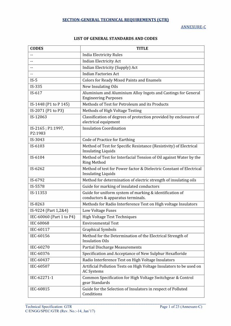
SECTION-GENERAL TECHNICAL REQUIREMENTS (GTR)
ANNEXURE-C
____________________________________________________________________________ Technical Specification: GTR Page 1 of 23 (Annexure-C) C/ENGG/SPEC/GTR (Rev. No.:-14, Jan’17)
LIST OF GENERAL STANDARDS AND CODES
CODES TITLE -- India Electricity Rules -- Indian Electricity Act -- Indian Electricity (Supply) Act -- Indian Factories Act IS-5 Colors for Ready Mixed Paints and Enamels IS-335 New Insulating Oils IS-617 Aluminium and Aluminium Alloy Ingots and Castings for General
Engineering Purposes IS-1448 (P1 to P 145) Methods of Test for Petroleum and its Products IS-2071 (P1 to P3) Methods of High Voltage Testing IS-12063 Classification of degrees of protection provided by enclosures of
electrical equipment IS-2165 ; P1:1997, P2:1983
Insulation Coordination
IS-3043 Code of Practice for Earthing IS-6103 Method of Test for Specific Resistance (Resistivity) of Electrical
Insulating Liquids IS-6104 Method of Test for Interfacial Tension of Oil against Water by the
Ring Method IS-6262 Method of test for Power factor & Dielectric Constant of Electrical
Insulating Liquids IS-6792 Method for determination of electric strength of insulating oils IS-5578 Guide for marking of insulated conductors IS-11353 Guide for uniform system of marking & identification of
conductors & apparatus terminals. IS-8263 Methods for Radio Interference Test on High voltage Insulators IS-9224 (Part 1,2&4) Low Voltage Fuses IEC-60060 (Part 1 to P4) High Voltage Test Techniques IEC 60068 Environmental Test IEC-60117 Graphical Symbols IEC-60156 Method for the Determination of the Electrical Strength of
Insulation Oils IEC-60270 Partial Discharge Measurements IEC-60376 Specification and Acceptance of New Sulphur Hexafloride IEC-60437 Radio Interference Test on High Voltage Insulators IEC-60507 Artificial Pollution Tests on High Voltage Insulators to be used on
AC Systems IEC-62271-1 Common Specification for High Voltage Switchgear & Control
gear Standards IEC-60815 Guide for the Selection of Insulators in respect of Polluted
Conditions

SECTION-GENERAL TECHNICAL REQUIREMENTS (GTR)
ANNEXURE-C
____________________________________________________________________________ Technical Specification: GTR Page 2 of 23 (Annexure-C) C/ENGG/SPEC/GTR (Rev. No.:-14, Jan’17)
CODES TITLE IEC-60865 (P1 & P2) Short Circuit Current - Calculation of effects ANSI-C.1/NFPA.70 National Electrical Code ANSI-C37.90A Guide for Surge Withstand Capability (SWC) Tests ANSI-C63.21, C63.3 Specification for Electromagnetic Noise and Field Strength
Instrumentation 10 KHz to 1 GHZ C36.4ANSI-C68.1 Techniquest for Dielectric Tests ANSI-C76.1/EEE21 Standard General Requirements and Test Procedure for Outdoor
Apparatus Bushings ANSI-SI-4 Specification for Sound Level Meters ANSI-Y32-2/C337.2 Drawing Symbols ANSI-Z55.11 Gray Finishes for Industrial Apparatus and Equipment No. 61
Light Gray NEMA-107T Methods of Measurements of RIV of High Voltage Apparatus NEMA-ICS-II General Standards for Industrial Control and Systems Part ICSI-
109 CISPR-1 Specification for CISPR Radio Interference Measuring Apparatus
for the frequency range 0.15 MHz to 30 MHz CSA-Z299.1-1978h Quality Assurance Program Requirements CSA-Z299.2-1979h Quality Control Program Requirements CSA-Z299.3-1979h Quality Verification Program Requirements CSA-Z299.4-1979h Inspection Program Requirements TRANSFORMERS AND REACTORS IS:10028 (Part 2 & 3) Code of practice for selection, installation & maintenance of
Transformers (P1:1993), (P2:1991), (P3:1991) IS-2026 (P1 to P4) Power Transformers IS-3347 (part 1 to Part 8) Dimensions for Porcelain transformer Bushings for use in lightly
polluted atmospheres IS-3639 Fittings and Accessories for Power Transformers IS-6600 Guide for Loading of oil immersed Transformers IEC-60076 (Part 1 to 5) Power Transformers IEC-60214 On-Load Tap-Changers IEC-60289 Reactors IEC- 60354 Loading Guide for Oil - Immersed power transformers IEC-60076-10 Determination of Transformer and Reactor Sound Levels ANSI-C571280 General requirements for Distribution, Power and Regulating
Transformers ANSI-C571290 Test Code for Distribution, Power and Regulation Transformers ANSI-C5716 Terminology & Test Code for Current Limiting Reactors ANSI-C5721 Requirements, Terminology and Test Code for Shunt Reactors
Rated Over 500 KVA ANSI-C5792 Guide for Loading Oil-Immersed Power Transformers upto and
including 100 MVA with 55 deg C or 65 deg C Winding Rise

SECTION-GENERAL TECHNICAL REQUIREMENTS (GTR)
ANNEXURE-C
____________________________________________________________________________ Technical Specification: GTR Page 3 of 23 (Annexure-C) C/ENGG/SPEC/GTR (Rev. No.:-14, Jan’17)
CODES TITLE ANSI-CG,1EEE-4 Standard Techniques for High Voltage Testing IEC 60076 Power transformers IEC 60076-1 Part 1: General IEC 60076-2 Part 2: Temperature rise IEC 60076-3 Part 3: Insulation levels, dielectric tests and external clearances
in air IEC 60076-4 Part 4: Guide to the lightning impulse and switching impulse
testing - Power transformers and reactors IEC 60076-3-1 Part 3-1: Insulation Levels and Dielectric Tests –External
Clearances in Air IEC 60076-5 Part 5: Ability to withstand short circuit IEC 60076-6 Part 6: Reactors IEC 60076-7 Part 7: Loading guide for oil-immersed power transformers IEC 60076-8 Part 8: Application guide IEC 60076-10 Part 10: Determination of sound levels IEC 60076-10-1 Part 10-1: Determination of sound levels - Application guide IEC 60076-11 Part 11: Dry-type transformers IEC 60076-12 Part 12: Loading guide for dry-type power transformers IEC 60076-13 Part 13: Self-protected liquid-filled transformers IEC 60076-14 Part 14: Design and application of liquid-immersed power
transformers using high-temperature insulation materials IEC 60076-15 Part 15: Gas-filled power transformers IEC 60076-16 Part 16: Transformers for wind turbine applications IEC 60076-18 Part 18: Measurement of frequency response IEC 60076-19 Part 19: Rules for the determination of uncertainties in the
measurement of losses in power transformers and reactors IEC 60076-21 Part 21: Standard requirements, terminology, and test code for
step-voltage regulators IEC 60044, BS 3938 Current transformers IEC 60050 International Electrotechnical Vocabulary IEC 60050(421) International Electrotechnical vocabulary- Chapter 421 : Power
Transformers and Reactors IEC 60060 High Voltage test techniques IEC 60060-1 General definitions and test requirements IEC 60060-2 Measuring systems IEC 60071 Insulation co-ordination IEC 60071-1 Part 1: Definitions, principles and rules IEC 60071-2 Part 2 : Application guide IEC 60137 Bushing for alternating voltage above 1000V IEC 60214 On-Load Tap changers IEC 255-21-3 Relays vibration
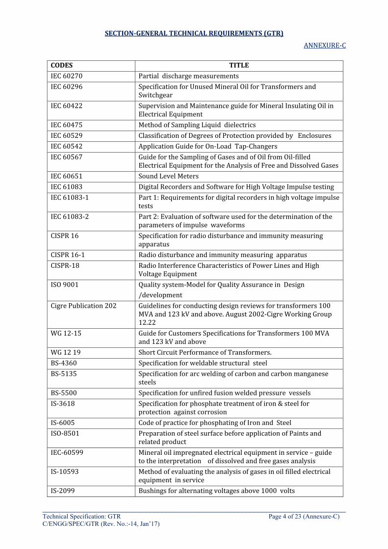
SECTION-GENERAL TECHNICAL REQUIREMENTS (GTR)
ANNEXURE-C
____________________________________________________________________________ Technical Specification: GTR Page 4 of 23 (Annexure-C) C/ENGG/SPEC/GTR (Rev. No.:-14, Jan’17)
CODES TITLE IEC 60270 Partial discharge measurements IEC 60296 Specification for Unused Mineral Oil for Transformers and
Switchgear IEC 60422 Supervision and Maintenance guide for Mineral Insulating Oil in
Electrical Equipment IEC 60475 Method of Sampling Liquid dielectrics IEC 60529 Classification of Degrees of Protection provided by Enclosures IEC 60542 Application Guide for On-Load Tap-Changers IEC 60567 Guide for the Sampling of Gases and of Oil from Oil-filled
Electrical Equipment for the Analysis of Free and Dissolved Gases IEC 60651 Sound Level Meters IEC 61083 Digital Recorders and Software for High Voltage Impulse testing IEC 61083-1 Part 1: Requirements for digital recorders in high voltage impulse
tests IEC 61083-2 Part 2: Evaluation of software used for the determination of the
parameters of impulse waveforms CISPR 16 Specification for radio disturbance and immunity measuring
apparatus CISPR 16-1 Radio disturbance and immunity measuring apparatus CISPR-18 Radio Interference Characteristics of Power Lines and High
Voltage Equipment ISO 9001 Quality system-Model for Quality Assurance in Design
/development Cigre Publication 202 Guidelines for conducting design reviews for transformers 100
MVA and 123 kV and above. August 2002-Cigre Working Group 12.22
WG 12-15 Guide for Customers Specifications for Transformers 100 MVA and 123 kV and above
WG 12 19 Short Circuit Performance of Transformers. BS-4360 Specification for weldable structural steel BS-5135 Specification for arc welding of carbon and carbon manganese
steels BS-5500 Specification for unfired fusion welded pressure vessels IS-3618 Specification for phosphate treatment of iron & steel for
protection against corrosion IS-6005 Code of practice for phosphating of Iron and Steel ISO-8501 Preparation of steel surface before application of Paints and
related product IEC-60599 Mineral oil impregnated electrical equipment in service – guide
to the interpretation of dissolved and free gases analysis IS-10593 Method of evaluating the analysis of gases in oil filled electrical
equipment in service IS-2099 Bushings for alternating voltages above 1000 volts
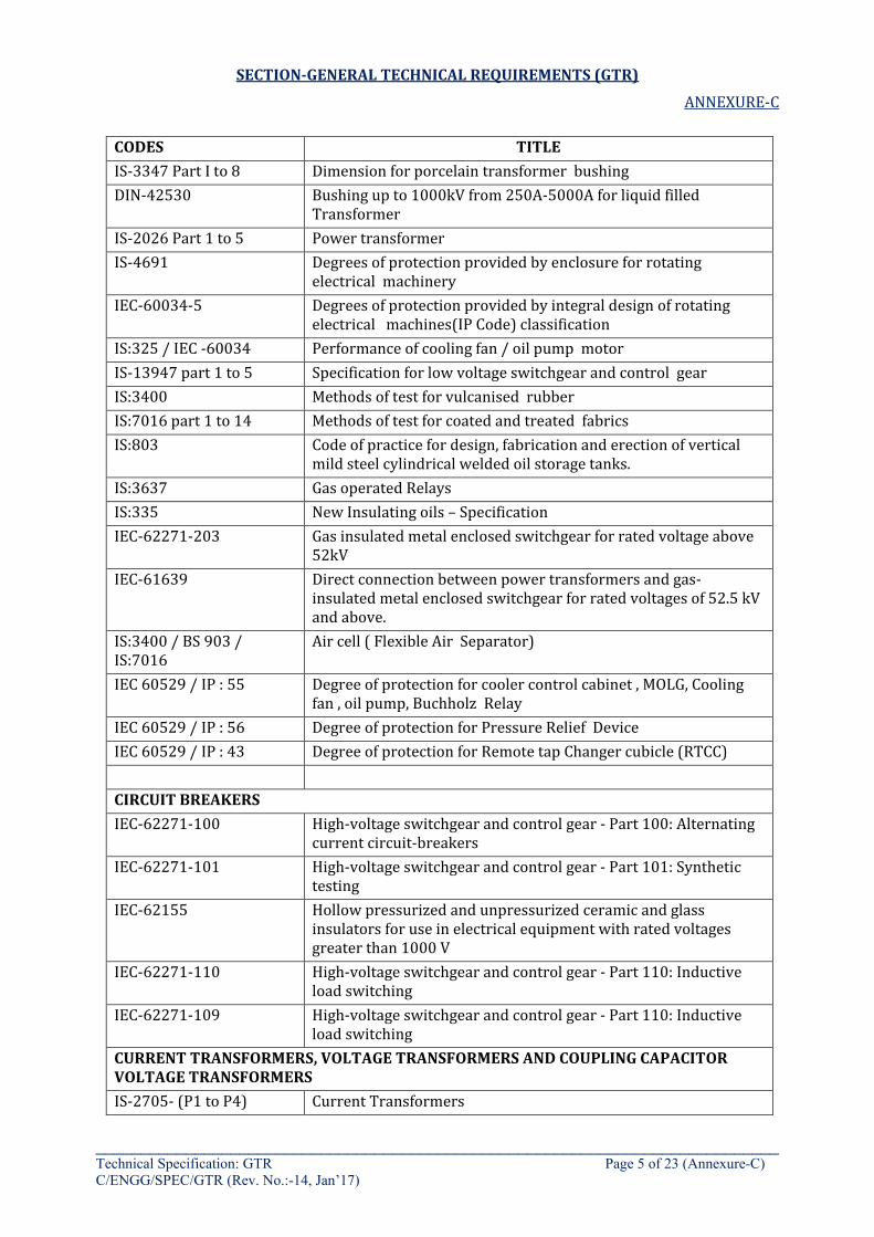
SECTION-GENERAL TECHNICAL REQUIREMENTS (GTR)
ANNEXURE-C
____________________________________________________________________________ Technical Specification: GTR Page 5 of 23 (Annexure-C) C/ENGG/SPEC/GTR (Rev. No.:-14, Jan’17)
CODES TITLE IS-3347 Part I to 8 Dimension for porcelain transformer bushing DIN-42530 Bushing up to 1000kV from 250A-5000A for liquid filled
Transformer IS-2026 Part 1 to 5 Power transformer IS-4691 Degrees of protection provided by enclosure for rotating
electrical machinery IEC-60034-5 Degrees of protection provided by integral design of rotating
electrical machines(IP Code) classification IS:325 / IEC -60034 Performance of cooling fan / oil pump motor IS-13947 part 1 to 5 Specification for low voltage switchgear and control gear IS:3400 Methods of test for vulcanised rubber IS:7016 part 1 to 14 Methods of test for coated and treated fabrics IS:803 Code of practice for design, fabrication and erection of vertical
mild steel cylindrical welded oil storage tanks. IS:3637 Gas operated Relays IS:335 New Insulating oils – Specification IEC-62271-203 Gas insulated metal enclosed switchgear for rated voltage above
52kV IEC-61639 Direct connection between power transformers and gas-
insulated metal enclosed switchgear for rated voltages of 52.5 kV and above.
IS:3400 / BS 903 / IS:7016
Air cell ( Flexible Air Separator)
IEC 60529 / IP : 55 Degree of protection for cooler control cabinet , MOLG, Cooling fan , oil pump, Buchholz Relay
IEC 60529 / IP : 56 Degree of protection for Pressure Relief Device IEC 60529 / IP : 43 Degree of protection for Remote tap Changer cubicle (RTCC) CIRCUIT BREAKERS IEC-62271-100 High-voltage switchgear and control gear - Part 100: Alternating
current circuit-breakers IEC-62271-101 High-voltage switchgear and control gear - Part 101: Synthetic
testing IEC-62155 Hollow pressurized and unpressurized ceramic and glass
insulators for use in electrical equipment with rated voltages greater than 1000 V
IEC-62271-110 High-voltage switchgear and control gear - Part 110: Inductive load switching
IEC-62271-109 High-voltage switchgear and control gear - Part 110: Inductive load switching
CURRENT TRANSFORMERS, VOLTAGE TRANSFORMERS AND COUPLING CAPACITOR VOLTAGE TRANSFORMERS IS-2705- (P1 to P4) Current Transformers
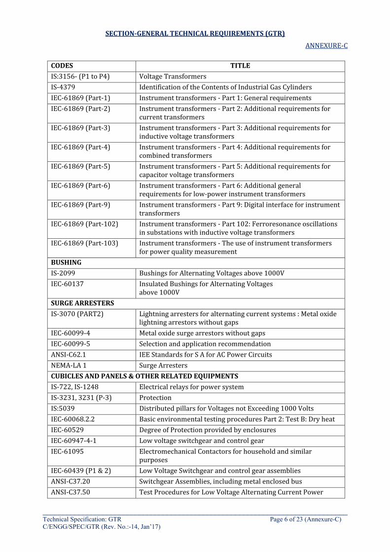
SECTION-GENERAL TECHNICAL REQUIREMENTS (GTR)
ANNEXURE-C
____________________________________________________________________________ Technical Specification: GTR Page 6 of 23 (Annexure-C) C/ENGG/SPEC/GTR (Rev. No.:-14, Jan’17)
CODES TITLE IS:3156- (P1 to P4) Voltage Transformers IS-4379 Identification of the Contents of Industrial Gas Cylinders IEC-61869 (Part-1) Instrument transformers - Part 1: General requirements IEC-61869 (Part-2) Instrument transformers - Part 2: Additional requirements for
current transformers IEC-61869 (Part-3) Instrument transformers - Part 3: Additional requirements for
inductive voltage transformers IEC-61869 (Part-4) Instrument transformers - Part 4: Additional requirements for
combined transformers IEC-61869 (Part-5) Instrument transformers - Part 5: Additional requirements for
capacitor voltage transformers IEC-61869 (Part-6) Instrument transformers - Part 6: Additional general
requirements for low-power instrument transformers IEC-61869 (Part-9) Instrument transformers - Part 9: Digital interface for instrument
transformers IEC-61869 (Part-102) Instrument transformers - Part 102: Ferroresonance oscillations
in substations with inductive voltage transformers IEC-61869 (Part-103) Instrument transformers - The use of instrument transformers
for power quality measurement BUSHING IS-2099 Bushings for Alternating Voltages above 1000V IEC-60137 Insulated Bushings for Alternating Voltages
above 1000V SURGE ARRESTERS IS-3070 (PART2) Lightning arresters for alternating current systems : Metal oxide
lightning arrestors without gaps IEC-60099-4 Metal oxide surge arrestors without gaps IEC-60099-5 Selection and application recommendation ANSI-C62.1 IEE Standards for S A for AC Power Circuits NEMA-LA 1 Surge Arresters CUBICLES AND PANELS & OTHER RELATED EQUIPMENTS IS-722, IS-1248 Electrical relays for power system IS-3231, 3231 (P-3) Protection IS:5039 Distributed pillars for Voltages not Exceeding 1000 Volts IEC-60068.2.2 Basic environmental testing procedures Part 2: Test B: Dry heat IEC-60529 Degree of Protection provided by enclosures IEC-60947-4-1 Low voltage switchgear and control gear IEC-61095 Electromechanical Contactors for household and similar
purposes IEC-60439 (P1 & 2) Low Voltage Switchgear and control gear assemblies ANSI-C37.20 Switchgear Assemblies, including metal enclosed bus ANSI-C37.50 Test Procedures for Low Voltage Alternating Current Power

SECTION-GENERAL TECHNICAL REQUIREMENTS (GTR)
ANNEXURE-C
____________________________________________________________________________ Technical Specification: GTR Page 7 of 23 (Annexure-C) C/ENGG/SPEC/GTR (Rev. No.:-14, Jan’17)
CODES TITLE Circuit Breakers
ANSI-C39 Electric Measuring instrument ANSI-C83 Components for Electric Equipment IS: 8623: (Part I to 3) Specification for Switchgear & Control Assemblies NEMA-AB Moulded Case Circuit and Systems NEMA-CS Industrial Controls and Systems NEMA-PB-1 Panel Boards NEMA-SG-5 Low voltage Power Circuit breakers NEMA-SG-3 Power Switchgear Assemblies NEMA-SG-6 Power switching Equipment NEMA-5E-3 Motor Control Centers 1248 (P1 to P9) Direct acting indicating analogue electrical measuring
instruments & their accessories Disconnecting switches IEC-62271-102 High-voltage switchgear and control gear - Part 102: Alternating
current disconnectors and earthing switches IEC-60265 (Part 1 & 2) High Voltage switches ANSI-C37.32 Schedule of preferred Ratings, Manufacturing Specifications and
Application Guide for high voltage Air Switches, Bus supports and switch accessories
ANSI-C37.34 Test Code for high voltage air switches NEMA-SG6 Power switching equipment PLCC and line traps IS-8792 Line traps for AC power system IS-8793 Methods of tests for line traps IS-8997 Coupling devices for PLC systems IS-8998 Methods of test for coupling devices for PLC systems IEC-60353 Line traps for A.C. power systems IEC-60481 Coupling Devices for power line carrier systems IEC-60495 Single sideboard power line carrier terminals IEC-60683 Planning of (single Side-Band) power line carrier systems CIGRE Teleprotection report by Committee 34 & 35 CIGRE Guide on power line carrier 1979 CCIR International Radio Consultative Committee CCITT International Telegraph & Telephone Consultative Committee EIA Electric Industries Association Protection and control equipment IEC-60051: (P1 to P9) Recommendations for Direct Acting indicating analogue electrical
measuring instruments and their accessories IEC-60255 (Part 1 to 23) Electrical relays IEC-60297 (P1 to P4) Dimensions of mechanical structures of the 482.6mm (19 inches)
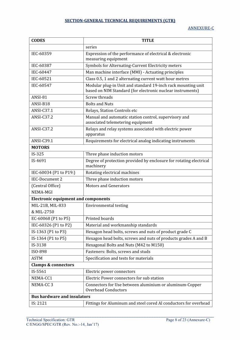
SECTION-GENERAL TECHNICAL REQUIREMENTS (GTR)
ANNEXURE-C
____________________________________________________________________________ Technical Specification: GTR Page 8 of 23 (Annexure-C) C/ENGG/SPEC/GTR (Rev. No.:-14, Jan’17)
CODES TITLE series
IEC-60359 Expression of the performance of electrical & electronic measuring equipment
IEC-60387 Symbols for Alternating-Current Electricity meters IEC-60447 Man machine interface (MMI) - Actuating principles IEC-60521 Class 0.5, 1 and 2 alternating current watt hour metres IEC-60547 Modular plug-in Unit and standard 19-inch rack mounting unit
based on NIM Standard (for electronic nuclear instruments) ANSI-81 Screw threads ANSI-B18 Bolts and Nuts ANSI-C37.1 Relays, Station Controls etc ANSI-C37.2 Manual and automatic station control, supervisory and
associated telemetering equipment ANSI-C37.2 Relays and relay systems associated with electric power
apparatus ANSI-C39.1 Requirements for electrical analog indicating instruments MOTORS IS-325 Three phase induction motors IS-4691 Degree of protection provided by enclosure for rotating electrical
machinery IEC-60034 (P1 to P19:) Rotating electrical machines IEC-Document 2 Three phase induction motors (Central Office) NEMA-MGI
Motors and Generators
Electronic equipment and components MIL-21B, MIL-833 & MIL-2750
Environmental testing
EC-60068 (P1 to P5) Printed boards IEC-60326 (P1 to P2) Material and workmanship standards IS-1363 (P1 to P3) Hexagon head bolts, screws and nuts of product grade C IS-1364 (P1 to P5) Hexagon head bolts, screws and nuts of products grades A and B IS-3138 Hexagonal Bolts and Nuts (M42 to M150) ISO-898 Fasteners: Bolts, screws and studs ASTM Specification and tests for materials Clamps & connectors IS-5561 Electric power connectors NEMA-CC1 Electric Power connectors for sub station NEMA-CC 3 Connectors for Use between aluminium or aluminum-Copper
Overhead Conductors Bus hardware and insulators IS: 2121 Fittings for Aluminum and steel cored Al conductors for overhead

SECTION-GENERAL TECHNICAL REQUIREMENTS (GTR)
ANNEXURE-C
____________________________________________________________________________ Technical Specification: GTR Page 9 of 23 (Annexure-C) C/ENGG/SPEC/GTR (Rev. No.:-14, Jan’17)
CODES TITLE power lines
IS-731 Porcelain insulators for overhead power lines with a nominal voltage greater than 1000 V
IS-2486 (P1 to P4) Insulator fittings for overhead power lines with a nominal voltage greater than 1000 V
IEC-60120 Dimensions of Ball and Socket Couplings of string insulator units IEC-60137 Insulated bushings for alternating voltages above 1000 V IEC-60168 Tests on indoor and outdoor post insulators of ceramic material
or glass for Systems with Nominal Voltages Greater than 1000 V IEC-62155 Hollow pressurized and unpressurized ceramic and glass
insulators for use in electrical equipment with rated voltages greater than 1 000 V
IEC-60273 Characteristics of indoor and outdoor post insulators for systems with nominal voltages greater than 1000V
IEC-61462 Pressurized and un-pressurized insulator for use in electrical equipment with rated voltage greater than 1000V – Definitions, Test methods, acceptance criteria and design recommendations
IEC-60305 Insulators for overhead lines with nominal voltage above 1000V-ceramic or glass insulator units for ac systems Characteristics of String Insulator Units of the cap and pin type
IEC-60372 (1984) Locking devices for ball and socket couplings of string insulator units : dimensions and tests
IEC-60383 (P1 and P2) Insulators for overhead lines with a nominal voltage above 1000 V
IEC-60433 Characteristics of string insulator units of the long rod type IEC-60471 Dimensions of Clevis and tongue couplings of string insulator
units ANSI-C29 Wet process porcelain insulators ANSI-C29.1 Test methods for electrical power insulators ANSI-C92.2 For insulators, wet-process porcelain and toughened glass
suspension type ANSI-C29.8 For wet-process porcelain insulators apparatus, post-type ANSI-G.8 Iron and steel hardware CISPR-7B Recommendations of the CISPR, tolerances of form and of
Position, Part 1 ASTM A-153 Zinc Coating (Hot-Dip) on iron and steel hardware Strain and rigid bus-conductor IS-2678 Dimensions & tolerances for Wrought Aluminum and Aluminum
Alloys drawn round tube IS-5082 Wrought Aluminum and Aluminum Alloy Bars. Rods, Tubes and
Sections for Electrical purposes ASTM-B 230-82 Aluminum 1350 H19 Wire for electrical purposes
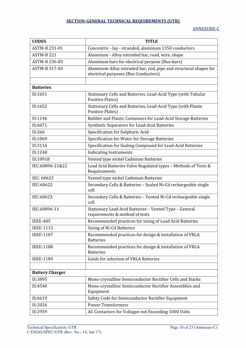
SECTION-GENERAL TECHNICAL REQUIREMENTS (GTR)
ANNEXURE-C
____________________________________________________________________________ Technical Specification: GTR Page 10 of 23 (Annexure-C) C/ENGG/SPEC/GTR (Rev. No.:-14, Jan’17)
CODES TITLE ASTM-B 231-81 Concentric - lay - stranded, aluminum 1350 conductors ASTM-B 221 Aluminum - Alloy extruded bar, road, wire, shape ASTM-B 236-83 Aluminum bars for electrical purpose (Bus-bars) ASTM-B 317-83 Aluminum-Alloy extruded bar, rod, pipe and structural shapes for
electrical purposes (Bus Conductors) Batteries IS:1651 Stationary Cells and Batteries, Lead-Acid Type (with Tubular
Positive Plates) IS:1652 Stationary Cells and Batteries, Lead-Acid Type (with Plante
Positive Plates) IS:1146 Rubber and Plastic Containers for Lead-Acid Storage Batteries IS:6071 Synthetic Separators for Lead-Acid Batteries IS:266 Specification for Sulphuric Acid IS:1069 Specification for Water for Storage Batteries IS:3116 Specification for Sealing Compound for Lead-Acid Batteries IS:1248 Indicating Instruments IS:10918 Vented type nickel Cadmium Batteries IEC:60896-21&22 Lead Acid Batteries Valve Regulated types – Methods of Tests &
Requirements IEC: 60623 Vented type nickel Cadmium Batteries IEC:60622 Secondary Cells & Batteries – Sealed Ni-Cd rechargeable single
cell IEC:60623 Secondary Cells & Batteries – Vented Ni-Cd rechargeable single
cell IEC:60896-11 Stationary Lead Acid Batteries – Vented Type – General
requirements & method of tests IEEE-485 Recommended practices for sizing of Lead Acid Batteries IEEE-1115 Sizing of Ni-Cd Batteries IEEE-1187 Recommended practices for design & installation of VRLA
Batteries IEEE-1188 Recommended practices for design & installation of VRLA
Batteries IEEE-1189 Guide for selection of VRLA Batteries Battery Charger IS:3895 Mono-crystalline Semiconductor Rectifier Cells and Stacks IS:4540 Mono-crystalline Semiconductor Rectifier Assemblies and
Equipment IS:6619 Safety Code for Semiconductor Rectifier Equipment IS:2026 Power Transformers IS:2959 AC Contactors for Voltages not Exceeding 1000 Volts
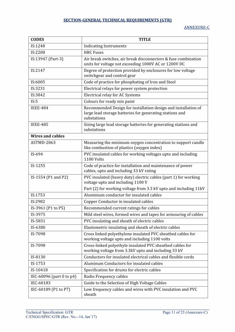
SECTION-GENERAL TECHNICAL REQUIREMENTS (GTR)
ANNEXURE-C
____________________________________________________________________________ Technical Specification: GTR Page 11 of 23 (Annexure-C) C/ENGG/SPEC/GTR (Rev. No.:-14, Jan’17)
CODES TITLE IS:1248 Indicating Instruments IS:2208 HRC Fuses IS:13947 (Part-3) Air break switches, air break disconnectors & fuse combination
units for voltage not exceeding 1000V AC or 1200V DC IS:2147 Degree of protection provided by enclosures for low voltage
switchgear and control gear IS:6005 Code of practice for phosphating of Iron and Steel IS:3231 Electrical relays for power system protection IS:3842 Electrical relay for AC Systems IS:5 Colours for ready mix paint IEEE-484 Recommended Design for installation design and installation of
large lead storage batteries for generating stations and substations
IEEE-485 Sizing large lead storage batteries for generating stations and substations
Wires and cables ASTMD-2863 Measuring the minimum oxygen concentration to support candle
like combustion of plastics (oxygen index) IS-694 PVC insulated cables for working voltages upto and including
1100 Volts IS-1255 Code of practice for installation and maintenance of power
cables, upto and including 33 kV rating IS-1554 (P1 and P2) PVC insulated (heavy duty) electric cables (part 1) for working
voltage upto and including 1100 V Part (2) for working voltage from 3.3 kV upto and including 11kV
IS:1753 Aluminium conductor for insulated cables IS:2982 Copper Conductor in insulated cables IS-3961 (P1 to P5) Recommended current ratings for cables IS-3975 Mild steel wires, formed wires and tapes for armouring of cables IS-5831 PVC insulating and sheath of electric cables IS-6380 Elastometric insulating and sheath of electric cables IS-7098 Cross linked polyethylene insulated PVC sheathed cables for
working voltage upto and including 1100 volts IS-7098 Cross-linked polyethyle insulated PVC sheathed cables for
working voltage from 3.3kV upto and including 33 kV IS-8130 Conductors for insulated electrical cables and flexible cords IS-1753 Aluminum Conductors for insulated cables IS-10418 Specification for drums for electric cables IEC-60096 (part 0 to p4) Radio Frequency cables IEC-60183 Guide to the Selection of High Voltage Cables IEC-60189 (P1 to P7) Low frequency cables and wires with PVC insulation and PVC
sheath

SECTION-GENERAL TECHNICAL REQUIREMENTS (GTR)
ANNEXURE-C
____________________________________________________________________________ Technical Specification: GTR Page 12 of 23 (Annexure-C) C/ENGG/SPEC/GTR (Rev. No.:-14, Jan’17)
CODES TITLE IEC-60227 (P1 to P7) Polyvinyl Chloride insulated cables of rated voltages up to and
including 450/750V IEC-60228 Conductors of insulated cables IEC-60230 Impulse tests on cables and their accessories IEC-60287 (P1 to P3) Calculation of the continuous current rating of cables (100% load
factor) IEC-60304 Standard colours for insulation for low-frequency cables and
wires IEC-60331 Fire resisting characteristics of Electric cables IEC-60332 (P1 to P3) Tests on electric cables under fire conditions IEC-60502 Extruded solid dielectric insulated power cables for rated
voltages from 1 kV upto to 30 kV IEC-754 (P1 and P2) Tests on gases evolved during combustion of electric cables AIR conditioning and ventilation IS-659 Safety code for air conditioning IS-660 Safety code for Mechanical Refrigeration ARI:520 Standard for Positive Displacement Refrigeration Compressor
and Condensing Units IS:4503 Shell and tube type heat exchanger ASHRAE-24 Method of testing for rating of liquid coolers ANSI-B-31.5 Refrigeration Piping IS:2062 Steel for general structural purposes IS:655 Specification for Metal Air Dust IS:277 Specification for Galvanised Steel Sheets IS-737 Specification for Wrought Aluminium and Aluminium Sheet &
Strip IS-1079 Hot rolled cast steel sheet & strip IS-3588 Specification for Electrical Axial Flow Fans IS-2312 Propeller Type AC Ventilation Fans BS-848 Methods of Performance Test for Fans BS-6540 Part-I Air Filters used in Air Conditioning and General Ventilation BS-3928 Sodium Flame Test for Air Filters (Other than for Air Supply to
I.C. Engines and Compressors) US-PED-2098 Method of cold DOP & hot DOP test MIL-STD-282 DOP smoke penetration method ASHRAE-52 Air cleaning device used in general ventilation for removing
particle matter IS:3069 Glossary of Terms, Symbols and Units Relating to Thermal
Insulation Materials IS:4671 Expanded Polystyrene for Thermal Insulation Purposes IS:8183 Bonded Mineral Wool IS:3346 Evaluation of Thermal Conductivity properties by means of
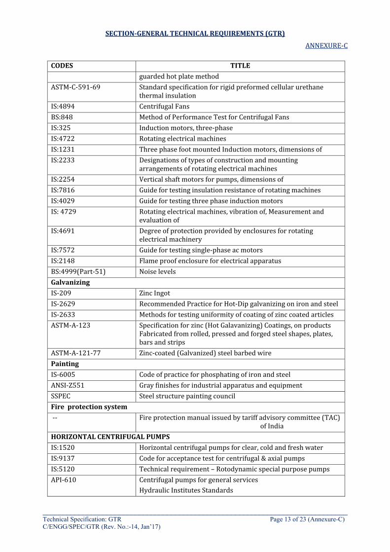
SECTION-GENERAL TECHNICAL REQUIREMENTS (GTR)
ANNEXURE-C
____________________________________________________________________________ Technical Specification: GTR Page 13 of 23 (Annexure-C) C/ENGG/SPEC/GTR (Rev. No.:-14, Jan’17)
CODES TITLE guarded hot plate method
ASTM-C-591-69 Standard specification for rigid preformed cellular urethane thermal insulation
IS:4894 Centrifugal Fans BS:848 Method of Performance Test for Centrifugal Fans IS:325 Induction motors, three-phase IS:4722 Rotating electrical machines IS:1231 Three phase foot mounted Induction motors, dimensions of IS:2233 Designations of types of construction and mounting
arrangements of rotating electrical machines IS:2254 Vertical shaft motors for pumps, dimensions of IS:7816 Guide for testing insulation resistance of rotating machines IS:4029 Guide for testing three phase induction motors IS: 4729 Rotating electrical machines, vibration of, Measurement and
evaluation of IS:4691 Degree of protection provided by enclosures for rotating
electrical machinery IS:7572 Guide for testing single-phase ac motors IS:2148 Flame proof enclosure for electrical apparatus BS:4999(Part-51) Noise levels Galvanizing IS-209 Zinc Ingot IS-2629 Recommended Practice for Hot-Dip galvanizing on iron and steel IS-2633 Methods for testing uniformity of coating of zinc coated articles ASTM-A-123 Specification for zinc (Hot Galavanizing) Coatings, on products
Fabricated from rolled, pressed and forged steel shapes, plates, bars and strips
ASTM-A-121-77 Zinc-coated (Galvanized) steel barbed wire Painting IS-6005 Code of practice for phosphating of iron and steel ANSI-Z551 Gray finishes for industrial apparatus and equipment SSPEC Steel structure painting council Fire protection system -- Fire protection manual issued by tariff advisory committee (TAC)
of India HORIZONTAL CENTRIFUGAL PUMPS IS:1520 Horizontal centrifugal pumps for clear, cold and fresh water IS:9137 Code for acceptance test for centrifugal & axial pumps IS:5120 Technical requirement – Rotodynamic special purpose pumps API-610 Centrifugal pumps for general services
Hydraulic Institutes Standards
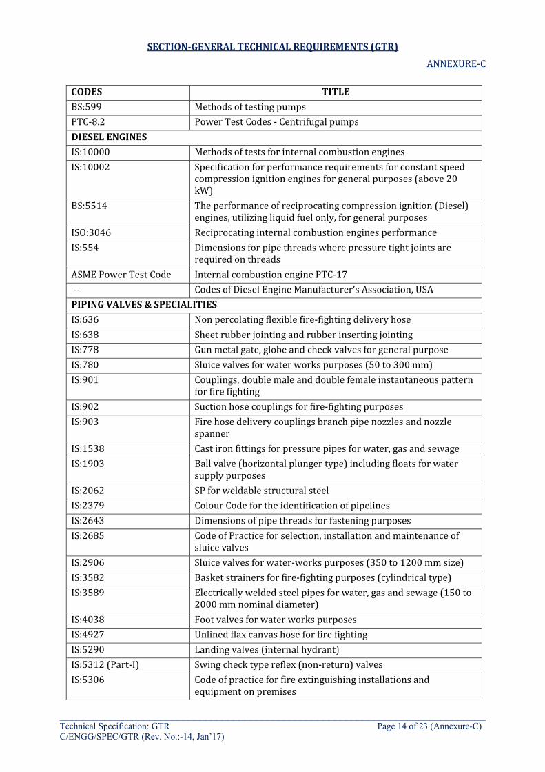
SECTION-GENERAL TECHNICAL REQUIREMENTS (GTR)
ANNEXURE-C
____________________________________________________________________________ Technical Specification: GTR Page 14 of 23 (Annexure-C) C/ENGG/SPEC/GTR (Rev. No.:-14, Jan’17)
CODES TITLE BS:599 Methods of testing pumps PTC-8.2 Power Test Codes - Centrifugal pumps DIESEL ENGINES IS:10000 Methods of tests for internal combustion engines IS:10002 Specification for performance requirements for constant speed
compression ignition engines for general purposes (above 20 kW)
BS:5514 The performance of reciprocating compression ignition (Diesel) engines, utilizing liquid fuel only, for general purposes
ISO:3046 Reciprocating internal combustion engines performance IS:554 Dimensions for pipe threads where pressure tight joints are
required on threads ASME Power Test Code Internal combustion engine PTC-17 -- Codes of Diesel Engine Manufacturer’s Association, USA PIPING VALVES & SPECIALITIES IS:636 Non percolating flexible fire-fighting delivery hose IS:638 Sheet rubber jointing and rubber inserting jointing IS:778 Gun metal gate, globe and check valves for general purpose IS:780 Sluice valves for water works purposes (50 to 300 mm) IS:901 Couplings, double male and double female instantaneous pattern
for fire fighting IS:902 Suction hose couplings for fire-fighting purposes IS:903 Fire hose delivery couplings branch pipe nozzles and nozzle
spanner IS:1538 Cast iron fittings for pressure pipes for water, gas and sewage IS:1903 Ball valve (horizontal plunger type) including floats for water
supply purposes IS:2062 SP for weldable structural steel IS:2379 Colour Code for the identification of pipelines IS:2643 Dimensions of pipe threads for fastening purposes IS:2685 Code of Practice for selection, installation and maintenance of
sluice valves IS:2906 Sluice valves for water-works purposes (350 to 1200 mm size) IS:3582 Basket strainers for fire-fighting purposes (cylindrical type) IS:3589 Electrically welded steel pipes for water, gas and sewage (150 to
2000 mm nominal diameter) IS:4038 Foot valves for water works purposes IS:4927 Unlined flax canvas hose for fire fighting IS:5290 Landing valves (internal hydrant) IS:5312 (Part-I) Swing check type reflex (non-return) valves IS:5306 Code of practice for fire extinguishing installations and
equipment on premises
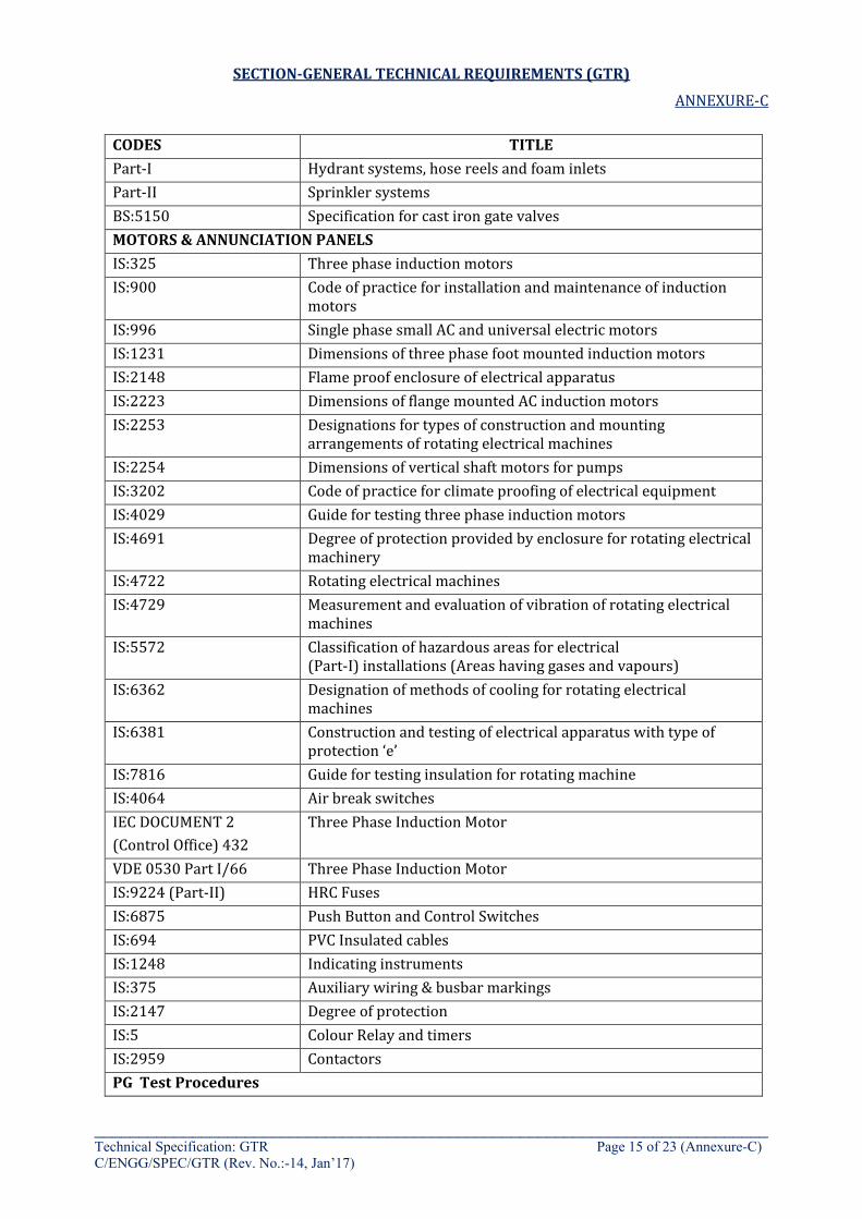
SECTION-GENERAL TECHNICAL REQUIREMENTS (GTR)
ANNEXURE-C
____________________________________________________________________________ Technical Specification: GTR Page 15 of 23 (Annexure-C) C/ENGG/SPEC/GTR (Rev. No.:-14, Jan’17)
CODES TITLE Part-I Hydrant systems, hose reels and foam inlets Part-II Sprinkler systems BS:5150 Specification for cast iron gate valves MOTORS & ANNUNCIATION PANELS IS:325 Three phase induction motors IS:900 Code of practice for installation and maintenance of induction
motors IS:996 Single phase small AC and universal electric motors IS:1231 Dimensions of three phase foot mounted induction motors IS:2148 Flame proof enclosure of electrical apparatus IS:2223 Dimensions of flange mounted AC induction motors IS:2253 Designations for types of construction and mounting
arrangements of rotating electrical machines IS:2254 Dimensions of vertical shaft motors for pumps IS:3202 Code of practice for climate proofing of electrical equipment IS:4029 Guide for testing three phase induction motors IS:4691 Degree of protection provided by enclosure for rotating electrical
machinery IS:4722 Rotating electrical machines IS:4729 Measurement and evaluation of vibration of rotating electrical
machines IS:5572 Classification of hazardous areas for electrical
(Part-I) installations (Areas having gases and vapours) IS:6362 Designation of methods of cooling for rotating electrical
machines IS:6381 Construction and testing of electrical apparatus with type of
protection ‘e’ IS:7816 Guide for testing insulation for rotating machine IS:4064 Air break switches IEC DOCUMENT 2 (Control Office) 432
Three Phase Induction Motor
VDE 0530 Part I/66 Three Phase Induction Motor IS:9224 (Part-II) HRC Fuses IS:6875 Push Button and Control Switches IS:694 PVC Insulated cables IS:1248 Indicating instruments IS:375 Auxiliary wiring & busbar markings IS:2147 Degree of protection IS:5 Colour Relay and timers IS:2959 Contactors PG Test Procedures
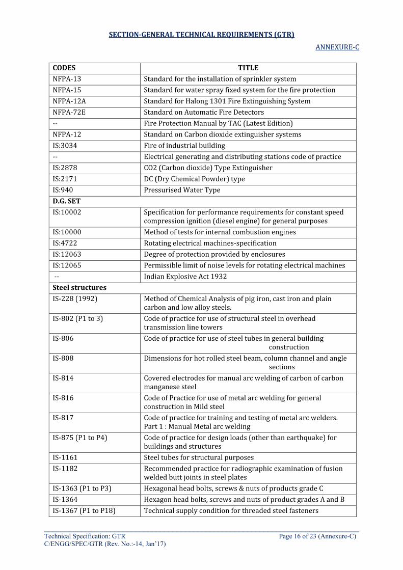
SECTION-GENERAL TECHNICAL REQUIREMENTS (GTR)
ANNEXURE-C
____________________________________________________________________________ Technical Specification: GTR Page 16 of 23 (Annexure-C) C/ENGG/SPEC/GTR (Rev. No.:-14, Jan’17)
CODES TITLE NFPA-13 Standard for the installation of sprinkler system NFPA-15 Standard for water spray fixed system for the fire protection NFPA-12A Standard for Halong 1301 Fire Extinguishing System NFPA-72E Standard on Automatic Fire Detectors -- Fire Protection Manual by TAC (Latest Edition) NFPA-12 Standard on Carbon dioxide extinguisher systems IS:3034 Fire of industrial building -- Electrical generating and distributing stations code of practice IS:2878 CO2 (Carbon dioxide) Type Extinguisher IS:2171 DC (Dry Chemical Powder) type IS:940 Pressurised Water Type D.G. SET IS:10002 Specification for performance requirements for constant speed
compression ignition (diesel engine) for general purposes IS:10000 Method of tests for internal combustion engines IS:4722 Rotating electrical machines-specification IS:12063 Degree of protection provided by enclosures IS:12065 Permissible limit of noise levels for rotating electrical machines -- Indian Explosive Act 1932 Steel structures IS-228 (1992) Method of Chemical Analysis of pig iron, cast iron and plain
carbon and low alloy steels. IS-802 (P1 to 3) Code of practice for use of structural steel in overhead
transmission line towers IS-806 Code of practice for use of steel tubes in general building
construction IS-808 Dimensions for hot rolled steel beam, column channel and angle
sections IS-814 Covered electrodes for manual arc welding of carbon of carbon
manganese steel IS-816 Code of Practice for use of metal arc welding for general
construction in Mild steel IS-817 Code of practice for training and testing of metal arc welders.
Part 1 : Manual Metal arc welding IS-875 (P1 to P4) Code of practice for design loads (other than earthquake) for
buildings and structures IS-1161 Steel tubes for structural purposes IS-1182 Recommended practice for radiographic examination of fusion
welded butt joints in steel plates IS-1363 (P1 to P3) Hexagonal head bolts, screws & nuts of products grade C IS-1364 Hexagon head bolts, screws and nuts of product grades A and B IS-1367 (P1 to P18) Technical supply condition for threaded steel fasteners
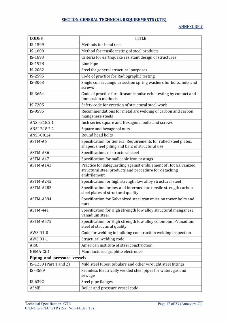
SECTION-GENERAL TECHNICAL REQUIREMENTS (GTR)
ANNEXURE-C
____________________________________________________________________________ Technical Specification: GTR Page 17 of 23 (Annexure-C) C/ENGG/SPEC/GTR (Rev. No.:-14, Jan’17)
CODES TITLE IS-1599 Methods for bend test IS-1608 Method for tensile testing of steel products IS-1893 Criteria for earthquake resistant design of structures IS-1978 Line Pipe IS-2062 Steel for general structural purposes IS-2595 Code of practice for Radiographic testing IS-3063 Single coil rectangular section spring washers for bolts, nuts and
screws IS-3664 Code of practice for ultrasonic pulse echo testing by contact and
immersion methods IS-7205 Safety code for erection of structural steel work IS-9595 Recommendations for metal arc welding of carbon and carbon
manganese steels ANSI-B18.2.1 Inch series square and Hexagonal bolts and screws ANSI-B18.2.2 Square and hexagonal nuts ANSI-G8.14 Round head bolts ASTM-A6 Specification for General Requirements for rolled steel plates,
shapes, sheet piling and bars of structural use ASTM-A36 Specifications of structural steel ASTM-A47 Specification for malleable iron castings ASTM-A143 Practice for safeguarding against embilement of Hot Galvanized
structural steel products and procedure for detaching embrilement
ASTM-A242 Specification for high strength low alloy structural steel ASTM-A283 Specification for low and intermediate tensile strength carbon
steel plates of structural quality ASTM-A394 Specification for Galvanized steel transmission tower bolts and
nuts ASTM-441 Specification for High strength low alloy structural manganese
vanadium steel ASTM-A572 Specification for High strength low alloy colombium-Vanadium
steel of structural quality AWS D1-0 Code for welding in building construction welding inspection AWS D1-1 Structural welding code AISC American institute of steel construction NEMA-CG1 Manufactured graphite electrodes Piping and pressure vessels IS-1239 (Part 1 and 2) Mild steel tubes, tubulars and other wrought steel fittings IS -3589 Seamless Electrically welded steel pipes for water, gas and
sewage IS-6392 Steel pipe flanges ASME Boiler and pressure vessel code
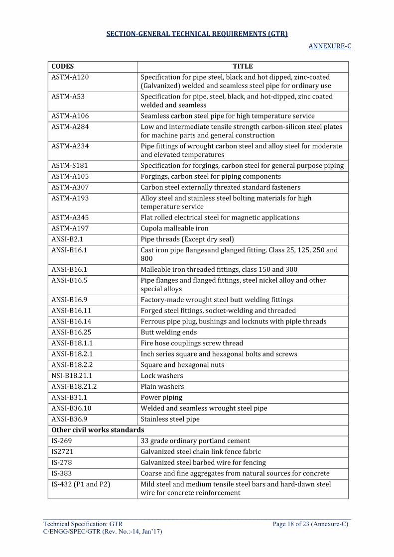
SECTION-GENERAL TECHNICAL REQUIREMENTS (GTR)
ANNEXURE-C
____________________________________________________________________________ Technical Specification: GTR Page 18 of 23 (Annexure-C) C/ENGG/SPEC/GTR (Rev. No.:-14, Jan’17)
CODES TITLE ASTM-A120 Specification for pipe steel, black and hot dipped, zinc-coated
(Galvanized) welded and seamless steel pipe for ordinary use ASTM-A53 Specification for pipe, steel, black, and hot-dipped, zinc coated
welded and seamless ASTM-A106 Seamless carbon steel pipe for high temperature service ASTM-A284 Low and intermediate tensile strength carbon-silicon steel plates
for machine parts and general construction ASTM-A234 Pipe fittings of wrought carbon steel and alloy steel for moderate
and elevated temperatures ASTM-S181 Specification for forgings, carbon steel for general purpose piping ASTM-A105 Forgings, carbon steel for piping components ASTM-A307 Carbon steel externally threated standard fasteners ASTM-A193 Alloy steel and stainless steel bolting materials for high
temperature service ASTM-A345 Flat rolled electrical steel for magnetic applications ASTM-A197 Cupola malleable iron ANSI-B2.1 Pipe threads (Except dry seal) ANSI-B16.1 Cast iron pipe flangesand glanged fitting. Class 25, 125, 250 and
800 ANSI-B16.1 Malleable iron threaded fittings, class 150 and 300 ANSI-B16.5 Pipe flanges and flanged fittings, steel nickel alloy and other
special alloys ANSI-B16.9 Factory-made wrought steel butt welding fittings ANSI-B16.11 Forged steel fittings, socket-welding and threaded ANSI-B16.14 Ferrous pipe plug, bushings and locknuts with piple threads ANSI-B16.25 Butt welding ends ANSI-B18.1.1 Fire hose couplings screw thread ANSI-B18.2.1 Inch series square and hexagonal bolts and screws ANSI-B18.2.2 Square and hexagonal nuts NSI-B18.21.1 Lock washers ANSI-B18.21.2 Plain washers ANSI-B31.1 Power piping ANSI-B36.10 Welded and seamless wrought steel pipe ANSI-B36.9 Stainless steel pipe Other civil works standards IS-269 33 grade ordinary portland cement IS2721 Galvanized steel chain link fence fabric IS-278 Galvanized steel barbed wire for fencing IS-383 Coarse and fine aggregates from natural sources for concrete IS-432 (P1 and P2) Mild steel and medium tensile steel bars and hard-dawn steel
wire for concrete reinforcement

SECTION-GENERAL TECHNICAL REQUIREMENTS (GTR)
ANNEXURE-C
____________________________________________________________________________ Technical Specification: GTR Page 19 of 23 (Annexure-C) C/ENGG/SPEC/GTR (Rev. No.:-14, Jan’17)
CODES TITLE IS-456 Code of practice for plain and reinforced concrete IS-516 Method of test for strength of concrete IS-800 Code of practice for general construction in steel IS-806 Steel tubes for structural purposes IS-1172 Basic requirements for water supply, drainage and sanitation IS-1199 Methods of sampling and analysis of concrete IS-1566 Hard-dawn steel wire fabric for concrete reinforcement IS-1742 Code of Practice for Building drainage IS-1785 Plain hard-drawn steel wire for pre-stressed concrete IS-1786 High strength deformed Steel Bars and wires for concrete
reinforcement IS-1811 Methods of sampling Foundry sands IS-1893 Criteria for earthquake resistant design of structures IS-2062 Steel for general structural purposes IS-2064 Selection, installation and maintenance of sanitary appliances-
code of practices IS-2065 Code of practice for water supply in buildings IS-2090 High tension steel bars used in pre-stressed concrete IS-2140 Standard Galvanized steel wire for fencing IS-2470 (P1 & P2) Code of practice for installation of septic tanks IS-2514 Concrete vibrating tables IS-2645 Integral cement waterproofing compounds IS-3025 (Part 1 to Part 48)
Methods of sampling and test (Physical and chemical) for water and waste water
IS-4091 Code of practice for design and construction of foundations for transmission line towers and poles
IS-4111 (Part 1 to P5) Code of practice for ancillary structures in sewerage system IS-4990 Plywood for concrete shuttering work IS-5600 Sewage and drainage pumps National building code of India 1970 USBR E12 Earth Manual by United States Department of the interior Bureau
of Reclamation ASTM-A392-81 Zinc/Coated steel chain link fence fabric ASTM-D1557-80 test for moisture-density relation of soils using 10-lb (4.5 kg)
rame land 18-in. (457 mm) Drop ASTM-D1586(1967) Penetration Test and Split-Barrel Sampling of Soils ASTM-D2049-69 Test Method for Relative Density of Cohesionless Soils ASTM-D2435 Test method for Unconsolidated, (1982)
Undrained Strengths of Cohesive Soils in Triaxial Compression BS-5075 Specification for accelerating Part I Admixtures, Retarding
Admixtures and Water Reducing Admixtures
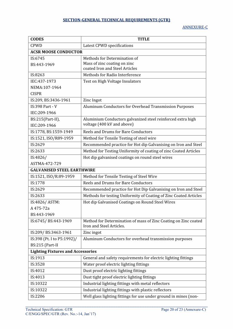
SECTION-GENERAL TECHNICAL REQUIREMENTS (GTR)
ANNEXURE-C
____________________________________________________________________________ Technical Specification: GTR Page 20 of 23 (Annexure-C) C/ENGG/SPEC/GTR (Rev. No.:-14, Jan’17)
CODES TITLE CPWD Latest CPWD specifications ACSR MOOSE CONDUCTOR IS:6745 BS:443-1969
Methods for Determination of Mass of zinc coating on zinc coated Iron and Steel Articles
IS:8263 Methods for Radio Interference IEC:437-1973 NEMA:107-1964 CISPR
Test on High Voltage Insulators
IS:209, BS:3436-1961 Zinc Ingot IS:398 Part - V IEC:209-1966
Aluminum Conductors for Overhead Transmission Purposes
BS:215(Part-II), IEC:209-1966
Aluminium Conductors galvanized steel reinforced extra high voltage (400 kV and above)
IS:1778, BS:1559-1949 Reels and Drums for Bare Conductors IS:1521, ISO/R89-1959 Method for Tensile Testing of steel wire IS:2629 Recommended practice for Hot dip Galvanising on Iron and Steel IS:2633 Method for Testing Uniformity of coating of zinc Coated Articles IS:4826/ ASTMA-472-729
Hot dip galvanised coatings on round steel wires
GALVANISED STEEL EARTHWIRE IS:1521, ISO/R:89-1959 Method for Tensile Testing of Steel Wire IS:1778 Reels and Drums for Bare Conductors IS:2629 Recommended practice for Hot Dip Galvanising on Iron and Steel IS:2633 Methods for testing Uniformity of Coating of Zinc Coated Articles IS:4826/ ASTM: A 475-72a BS:443-1969
Hot dip Galvanised Coatings on Round Steel Wires
IS:6745/ BS:443-1969 Method for Determination of mass of Zinc Coating on Zinc coated Iron and Steel Articles.
IS:209/ BS:3463-1961 Zinc ingot IS:398 (Pt. I to P5:1992)/ BS:215 (Part-II
Aluminum Conductors for overhead transmission purposes
Lighting Fixtures and Accessories IS:1913 General and safety requirements for electric lighting fittings IS:3528 Water proof electric lighting fittings IS:4012 Dust proof electric lighting fittings IS:4013 Dust tight proof electric lighting fittings IS:10322 Industrial lighting fittings with metal reflectors IS:10322 Industrial lighting fittings with plastic reflectors IS:2206 Well glass lighting fittings for use under ground in mines (non-
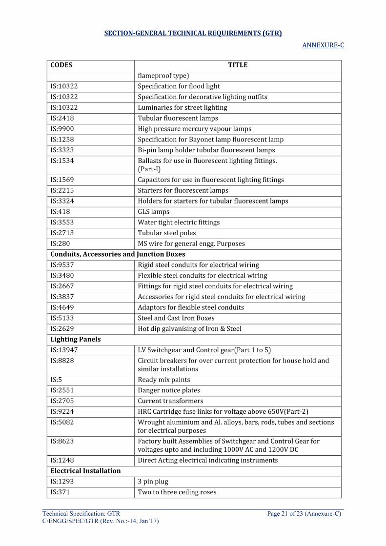
SECTION-GENERAL TECHNICAL REQUIREMENTS (GTR)
ANNEXURE-C
____________________________________________________________________________ Technical Specification: GTR Page 21 of 23 (Annexure-C) C/ENGG/SPEC/GTR (Rev. No.:-14, Jan’17)
CODES TITLE flameproof type)
IS:10322 Specification for flood light IS:10322 Specification for decorative lighting outfits IS:10322 Luminaries for street lighting IS:2418 Tubular fluorescent lamps IS:9900 High pressure mercury vapour lamps IS:1258 Specification for Bayonet lamp fluorescent lamp IS:3323 Bi-pin lamp holder tubular fluorescent lamps IS:1534 Ballasts for use in fluorescent lighting fittings.
(Part-I) IS:1569 Capacitors for use in fluorescent lighting fittings IS:2215 Starters for fluorescent lamps IS:3324 Holders for starters for tubular fluorescent lamps IS:418 GLS lamps IS:3553 Water tight electric fittings IS:2713 Tubular steel poles IS:280 MS wire for general engg. Purposes Conduits, Accessories and Junction Boxes IS:9537 Rigid steel conduits for electrical wiring IS:3480 Flexible steel conduits for electrical wiring IS:2667 Fittings for rigid steel conduits for electrical wiring IS:3837 Accessories for rigid steel conduits for electrical wiring IS:4649 Adaptors for flexible steel conduits IS:5133 Steel and Cast Iron Boxes IS:2629 Hot dip galvanising of Iron & Steel Lighting Panels IS:13947 LV Switchgear and Control gear(Part 1 to 5) IS:8828 Circuit breakers for over current protection for house hold and
similar installations IS:5 Ready mix paints IS:2551 Danger notice plates IS:2705 Current transformers IS:9224 HRC Cartridge fuse links for voltage above 650V(Part-2) IS:5082 Wrought aluminium and Al. alloys, bars, rods, tubes and sections
for electrical purposes IS:8623 Factory built Assemblies of Switchgear and Control Gear for
voltages upto and including 1000V AC and 1200V DC IS:1248 Direct Acting electrical indicating instruments Electrical Installation IS:1293 3 pin plug IS:371 Two to three ceiling roses
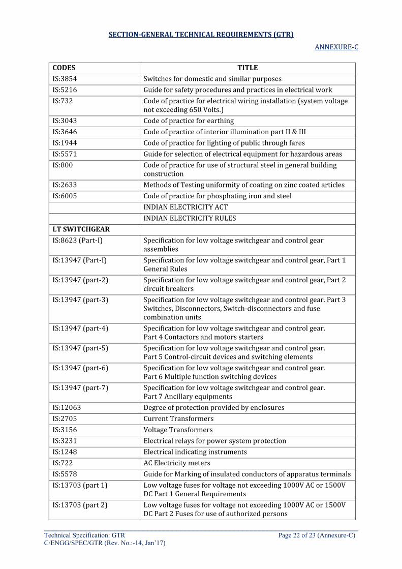
SECTION-GENERAL TECHNICAL REQUIREMENTS (GTR)
ANNEXURE-C
____________________________________________________________________________ Technical Specification: GTR Page 22 of 23 (Annexure-C) C/ENGG/SPEC/GTR (Rev. No.:-14, Jan’17)
CODES TITLE IS:3854 Switches for domestic and similar purposes IS:5216 Guide for safety procedures and practices in electrical work IS:732 Code of practice for electrical wiring installation (system voltage
not exceeding 650 Volts.) IS:3043 Code of practice for earthing IS:3646 Code of practice of interior illumination part II & III IS:1944 Code of practice for lighting of public through fares IS:5571 Guide for selection of electrical equipment for hazardous areas IS:800 Code of practice for use of structural steel in general building
construction IS:2633 Methods of Testing uniformity of coating on zinc coated articles IS:6005 Code of practice for phosphating iron and steel INDIAN ELECTRICITY ACT INDIAN ELECTRICITY RULES LT SWITCHGEAR IS:8623 (Part-I) Specification for low voltage switchgear and control gear
assemblies IS:13947 (Part-I) Specification for low voltage switchgear and control gear, Part 1
General Rules IS:13947 (part-2) Specification for low voltage switchgear and control gear, Part 2
circuit breakers IS:13947 (part-3) Specification for low voltage switchgear and control gear. Part 3
Switches, Disconnectors, Switch-disconnectors and fuse combination units
IS:13947 (part-4) Specification for low voltage switchgear and control gear. Part 4 Contactors and motors starters
IS:13947 (part-5) Specification for low voltage switchgear and control gear. Part 5 Control-circuit devices and switching elements
IS:13947 (part-6) Specification for low voltage switchgear and control gear. Part 6 Multiple function switching devices
IS:13947 (part-7) Specification for low voltage switchgear and control gear. Part 7 Ancillary equipments
IS:12063 Degree of protection provided by enclosures IS:2705 Current Transformers IS:3156 Voltage Transformers IS:3231 Electrical relays for power system protection IS:1248 Electrical indicating instruments IS:722 AC Electricity meters IS:5578 Guide for Marking of insulated conductors of apparatus terminals IS:13703 (part 1) Low voltage fuses for voltage not exceeding 1000V AC or 1500V
DC Part 1 General Requirements IS:13703 (part 2) Low voltage fuses for voltage not exceeding 1000V AC or 1500V
DC Part 2 Fuses for use of authorized persons
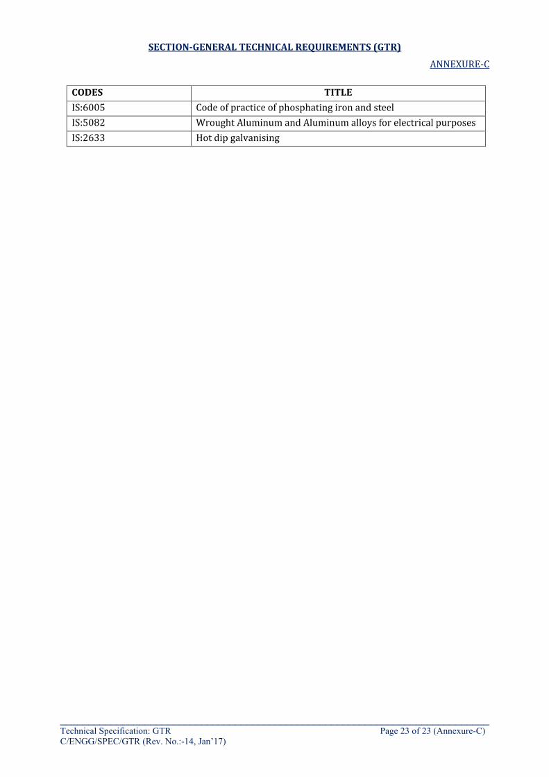
SECTION-GENERAL TECHNICAL REQUIREMENTS (GTR)
ANNEXURE-C
____________________________________________________________________________ Technical Specification: GTR Page 23 of 23 (Annexure-C) C/ENGG/SPEC/GTR (Rev. No.:-14, Jan’17)
CODES TITLE IS:6005 Code of practice of phosphating iron and steel IS:5082 Wrought Aluminum and Aluminum alloys for electrical purposes IS:2633 Hot dip galvanising
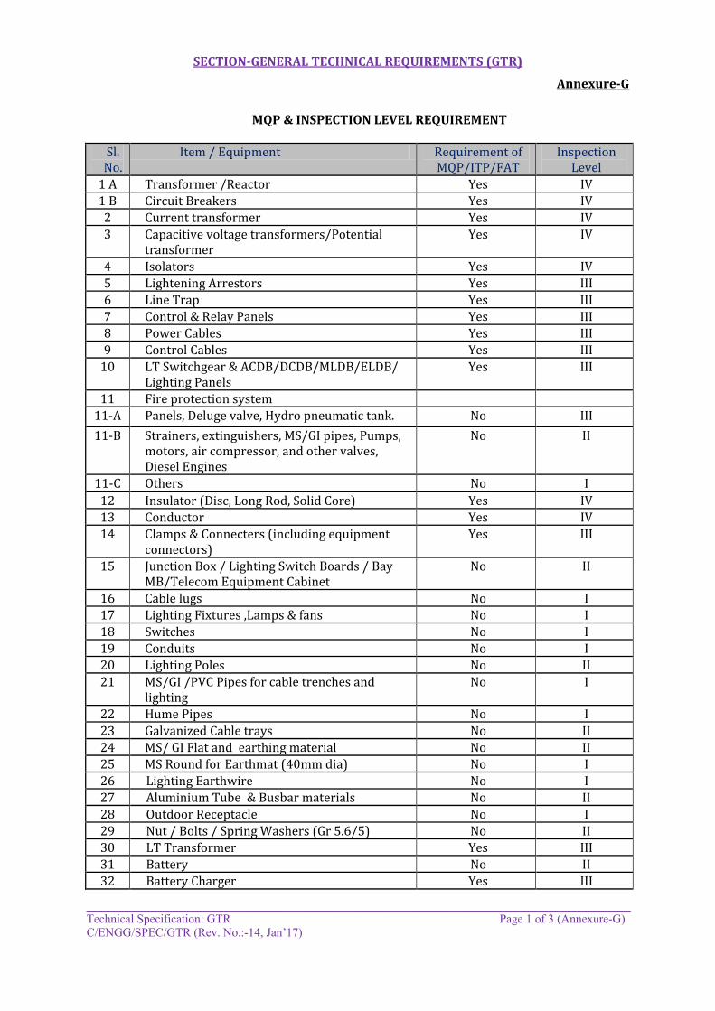
SECTION-GENERAL TECHNICAL REQUIREMENTS (GTR)
Annexure-G
__________________________________________________________________________ Technical Specification: GTR Page 1 of 3 (Annexure-G) C/ENGG/SPEC/GTR (Rev. No.:-14, Jan’17)
MQP & INSPECTION LEVEL REQUIREMENT
Sl. No.
Item / Equipment Requirement of MQP/ITP/FAT
Inspection Level
1 A Transformer /Reactor Yes IV 1 B Circuit Breakers Yes IV 2 Current transformer Yes IV 3 Capacitive voltage transformers/Potential
transformer Yes IV
4 Isolators Yes IV 5 Lightening Arrestors Yes III 6 Line Trap Yes III 7 Control & Relay Panels Yes III 8 Power Cables Yes III 9 Control Cables Yes III
10 LT Switchgear & ACDB/DCDB/MLDB/ELDB/ Lighting Panels
Yes III
11 Fire protection system 11-A Panels, Deluge valve, Hydro pneumatic tank. No III 11-B Strainers, extinguishers, MS/GI pipes, Pumps,
motors, air compressor, and other valves, Diesel Engines
No II
11-C Others No I 12 Insulator (Disc, Long Rod, Solid Core) Yes IV 13 Conductor Yes IV 14 Clamps & Connecters (including equipment
connectors) Yes III
15 Junction Box / Lighting Switch Boards / Bay MB/Telecom Equipment Cabinet
No II
16 Cable lugs No I 17 Lighting Fixtures ,Lamps & fans No I 18 Switches No I 19 Conduits No I 20 Lighting Poles No II 21 MS/GI /PVC Pipes for cable trenches and
lighting No I
22 Hume Pipes No I 23 Galvanized Cable trays No II 24 MS/ GI Flat and earthing material No II 25 MS Round for Earthmat (40mm dia) No I 26 Lighting Earthwire No I 27 Aluminium Tube & Busbar materials No II 28 Outdoor Receptacle No I 29 Nut / Bolts / Spring Washers (Gr 5.6/5) No II 30 LT Transformer Yes III 31 Battery No II 32 Battery Charger Yes III
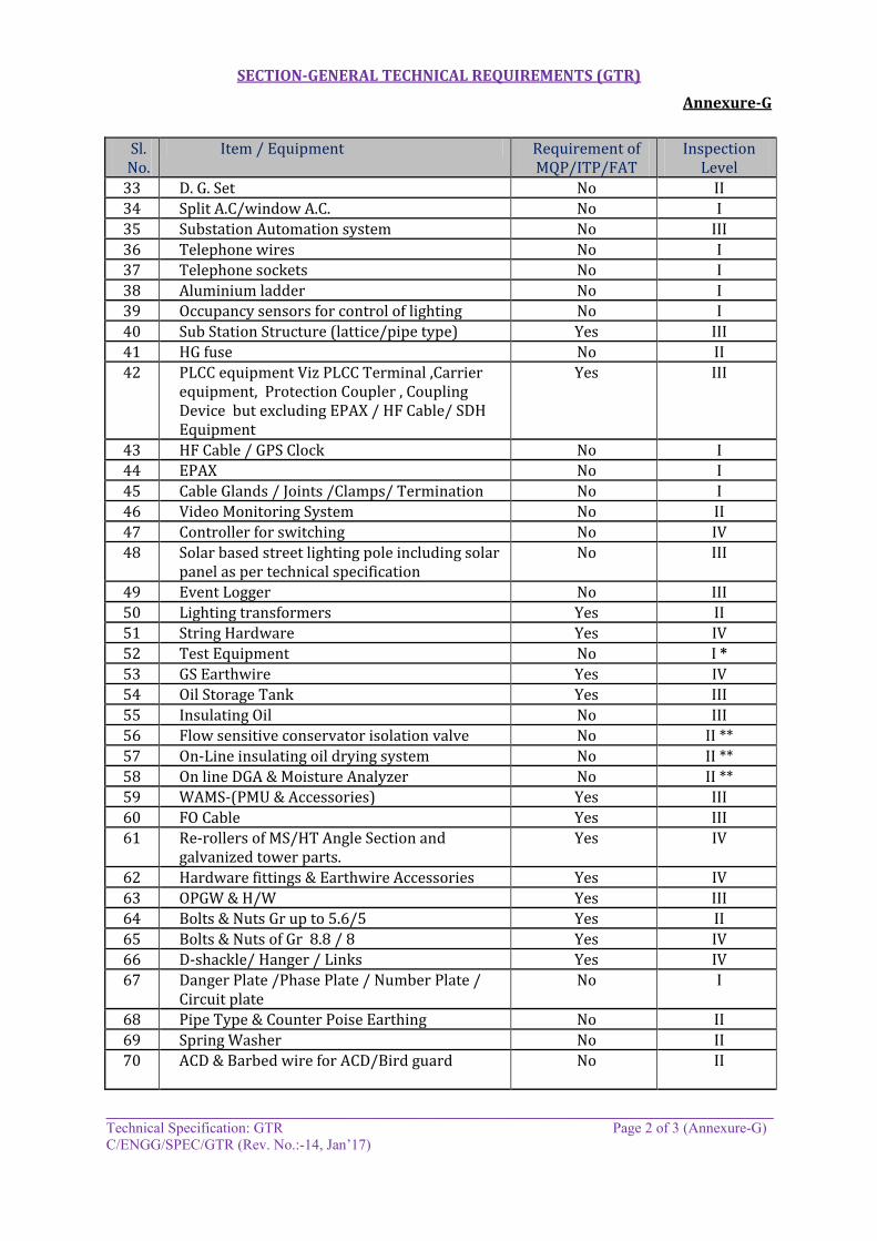
SECTION-GENERAL TECHNICAL REQUIREMENTS (GTR)
Annexure-G
__________________________________________________________________________ Technical Specification: GTR Page 2 of 3 (Annexure-G) C/ENGG/SPEC/GTR (Rev. No.:-14, Jan’17)
Sl. No.
Item / Equipment Requirement of MQP/ITP/FAT
Inspection Level
33 D. G. Set No II 34 Split A.C/window A.C. No I 35 Substation Automation system No III 36 Telephone wires No I 37 Telephone sockets No I 38 Aluminium ladder No I 39 Occupancy sensors for control of lighting No I 40 Sub Station Structure (lattice/pipe type) Yes III 41 HG fuse No II 42 PLCC equipment Viz PLCC Terminal ,Carrier
equipment, Protection Coupler , Coupling Device but excluding EPAX / HF Cable/ SDH Equipment
Yes III
43 HF Cable / GPS Clock No I 44 EPAX No I 45 Cable Glands / Joints /Clamps/ Termination No I 46 Video Monitoring System No II 47 Controller for switching No IV 48 Solar based street lighting pole including solar
panel as per technical specification No III
49 Event Logger No III 50 Lighting transformers Yes II 51 String Hardware Yes IV 52 Test Equipment No I * 53 GS Earthwire Yes IV 54 Oil Storage Tank Yes III 55 Insulating Oil No III 56 Flow sensitive conservator isolation valve No II ** 57 On-Line insulating oil drying system No II ** 58 On line DGA & Moisture Analyzer No II ** 59 WAMS-(PMU & Accessories) Yes III 60 FO Cable Yes III 61 Re-rollers of MS/HT Angle Section and
galvanized tower parts. Yes IV
62 Hardware fittings & Earthwire Accessories Yes IV 63 OPGW & H/W Yes III 64 Bolts & Nuts Gr up to 5.6/5 Yes II 65 Bolts & Nuts of Gr 8.8 / 8 Yes IV 66 D-shackle/ Hanger / Links Yes IV 67 Danger Plate /Phase Plate / Number Plate /
Circuit plate No I
68 Pipe Type & Counter Poise Earthing No II 69 Spring Washer No II 70 ACD & Barbed wire for ACD/Bird guard No II
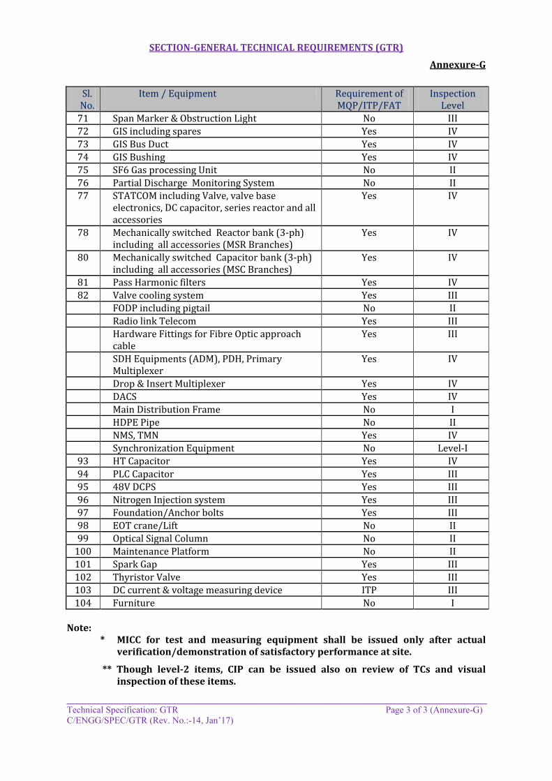
SECTION-GENERAL TECHNICAL REQUIREMENTS (GTR)
Annexure-G
__________________________________________________________________________ Technical Specification: GTR Page 3 of 3 (Annexure-G) C/ENGG/SPEC/GTR (Rev. No.:-14, Jan’17)
Sl. No.
Item / Equipment Requirement of MQP/ITP/FAT
Inspection Level
71 Span Marker & Obstruction Light No III 72 GIS including spares Yes IV 73 GIS Bus Duct Yes IV 74 GIS Bushing Yes IV 75 SF6 Gas processing Unit No II 76 Partial Discharge Monitoring System No II 77 STATCOM including Valve, valve base
electronics, DC capacitor, series reactor and all accessories
Yes IV
78 Mechanically switched Reactor bank (3-ph) including all accessories (MSR Branches)
Yes IV
80 Mechanically switched Capacitor bank (3-ph) including all accessories (MSC Branches)
Yes IV
81 Pass Harmonic filters Yes IV 82 Valve cooling system Yes III
FODP including pigtail No II Radio link Telecom Yes III Hardware Fittings for Fibre Optic approach
cable Yes III
SDH Equipments (ADM), PDH, Primary Multiplexer
Yes IV
Drop & Insert Multiplexer Yes IV DACS Yes IV Main Distribution Frame No I HDPE Pipe No II NMS, TMN Yes IV Synchronization Equipment No Level-I
93 HT Capacitor Yes IV 94 PLC Capacitor Yes III 95 48V DCPS Yes III 96 Nitrogen Injection system Yes III 97 Foundation/Anchor bolts Yes III 98 EOT crane/Lift No II 99 Optical Signal Column No II
100 Maintenance Platform No II 101 Spark Gap Yes III 102 Thyristor Valve Yes III 103 DC current & voltage measuring device ITP III 104 Furniture No I
Note:
* MICC for test and measuring equipment shall be issued only after actual verification/demonstration of satisfactory performance at site.
** Though level-2 items, CIP can be issued also on review of TCs and visual inspection of these items.

Substation Package - SS02 for (i) 765kV Fatehgarh-2 (PG) S/S Extension and (ii)765kV Bhadla-2 (PG) S/s Extension under Transmission System
Associated With LTA applications from Rajasthan SEZ Part-B (Rajasthan SEZ Part-B Project) through Tariff
Based Competitive Bidding (TBCB) Route. 765kV Isolators and Earth Switches
Doc. No. : TB-409-316-004 Rev 00
Page 11 of 25
SECTION-4 Guaranteed Technical Particulars
ISOLATORS / EARTH SWITCHES
1. General a) Name of the Manufacturer
b) Country of Manufacturer
c) Manufacturer's type designation
d) Standard applicable for isolators and earthing switches
e) Rated Voltage Ur (KV)
f) Rated Current Under site conditions (A) at 50° C
ambient
g) Rated frequency (Hz)
h) Number of poles
I) Whether all 3 poles are ganged Electrically
j) Phase to phase spacing k) Type of installation 2. Guaranteed Ratings a) Rated short time current of isolator for IS (KA) and
dynamic current (KAP)
Substation Package - SS02 for (i) 765kV Fatehgarh-2 (PG) S/S Extension and (ii)765kV Bhadla-2 (PG) S/s Extension under Transmission System
Associated With LTA applications from Rajasthan SEZ Part-B (Rajasthan SEZ Part-B Project) through Tariff
Based Competitive Bidding (TBCB) Route. 765kV Isolators and Earth Switches
Doc. No. : TB-409-316-004 Rev 00
Page 12 of 25
b) Opening time of isolator and earth switch (s)
c) Closing time of isolator
d) Temperature rise over 50° C ambient temperature
corresponding to maximum continuous current (°C)
3. Dielectric withstand capacity of completely assembled
isolator/isolator and earth switch
a) One minute dry power freq. Withstand test voltage(KV
rms) i. against ground (KV rms)
ii. Across isolating distance (KV rms.)
b) 1.2/50 micro's impulse withstand test voltage
i. Against ground (KVP) ii. Across isolating distance (KVP)
c) 250/2500 micro sec. switching surge withstand test
voltage (dry & wet)
i. Against ground (KVP) ii. Across isolating distance (KVP)
d) Corona extinction voltage (KV rms)
e) Radio interference level at 1.1 Ur/_/3
(in micro volts at 1.0 MHz)
Substation Package - SS02 for (i) 765kV Fatehgarh-2 (PG) S/S Extension and (ii)765kV Bhadla-2 (PG) S/s Extension under Transmission System
Associated With LTA applications from Rajasthan SEZ Part-B (Rajasthan SEZ Part-B Project) through Tariff
Based Competitive Bidding (TBCB) Route. 765kV Isolators and Earth Switches
Doc. No. : TB-409-316-004 Rev 00
Page 13 of 25
f) Total creepage distance to ground (mm)
4. Operating Mechanism A) For Main Blades a) Type of motor operating/manually driven mechanism
b) Manufacture's Type designation
c) Rated torque of the mechanism (Kg-m)
d) Type and rating of motor B) For Earth Switches
a) Type of motor operating /manually driven
mechanism b) Manufacturer's type mechanism
c) Rated torque of the mechanism
d) Type and rating of motor 4.1. Interlocks
a) Whether mechanical/constructional interlock between
isolator & earth switch provided
b) Details of electrical interlock enclosed for
i. Isolator
ii. Earth switch

Substation Package - SS02 for (i) 765kV Fatehgarh-2 (PG) S/S Extension and (ii)765kV Bhadla-2 (PG) S/s Extension under Transmission System
Associated With LTA applications from Rajasthan SEZ Part-B (Rajasthan SEZ Part-B Project) through Tariff
Based Competitive Bidding (TBCB) Route. 765kV Isolators and Earth Switches
Doc. No. : TB-409-316-004 Rev 00
Page 14 of 25
c) Arrangement provided to prevent electrical or manual operation unless interlock conditions are satisfied
d) Whether interlock coil is continuously rated
e) Rated DC control voltage and variation allowed
f) Power consumption (W) 4.2. Controls
a) Rated DC control voltage (V)
b) Limits of voltage
c) Power consumption of control coils (W)
5. Constructional Features a) Minimum clearance in air i. Between phases (mm) ii. Between live parts to earth (mm)
iii. Distance between terminals of same phase (mm)
b) Whether position of earth switch can be interchanged
at site to either side of pole
c) Minimum clearance between live part and earth switch
blade throughout the entire operation arc of earth switch (mm)
d) Terminal pad details
Substation Package - SS02 for (i) 765kV Fatehgarh-2 (PG) S/S Extension and (ii)765kV Bhadla-2 (PG) S/s Extension under Transmission System
Associated With LTA applications from Rajasthan SEZ Part-B (Rajasthan SEZ Part-B Project) through Tariff
Based Competitive Bidding (TBCB) Route. 765kV Isolators and Earth Switches
Doc. No. : TB-409-316-004 Rev 00
Page 15 of 25
i. Diameter & length ii. Material of pad e) Insulator data
i. Height ii. Type iii. No. of insulator Stacks/phase
iv. No. of insulators/ Stacks f) Main contacts i. Type of contacts ii. Contact area (cm2) iii. Material of contacts iv. Contact pressure (Kg/cm2) v. Maximum current density under normal current
carrying capacity (A/cm2)
vi. Thickness of silver plating
g) Number of auxiliary contacts on isolator/
pole for Owner's use
h) Number of auxiliary contacts on earth
switch/pole for Owner's use
I) Auxiliary contacts i. Rated voltage (V)
Substation Package - SS02 for (i) 765kV Fatehgarh-2 (PG) S/S Extension and (ii)765kV Bhadla-2 (PG) S/s Extension under Transmission System
Associated With LTA applications from Rajasthan SEZ Part-B (Rajasthan SEZ Part-B Project) through Tariff
Based Competitive Bidding (TBCB) Route. 765kV Isolators and Earth Switches
Doc. No. : TB-409-316-004 Rev 00
Page 16 of 25
ii. Rated continuous Current (A) iii. Rated DC breakin current with 20 rms time constant
(A)
j) Mounting dimensions isolators
i. Distance between supports
ii. Top dimensions o support
k) Height from mounting plane to top of terminal stud
6. Literature a) Type test reports as per IEC 129
b) OGA drawings for isolator with & without earth
switches
c) Operation manual for isolators
d) Details of motor operating/manually driven mechanism
e) Recommended drawing for mounting details for isolator
and drives
f) Leaflets & literature bringing out salient
features of equipment offered
g) Details of constructional interlock
Additional data to be filled in for Pantograph Isolators
Substation Package - SS02 for (i) 765kV Fatehgarh-2 (PG) S/S Extension and (ii)765kV Bhadla-2 (PG) S/s Extension under Transmission System
Associated With LTA applications from Rajasthan SEZ Part-B (Rajasthan SEZ Part-B Project) through Tariff
Based Competitive Bidding (TBCB) Route. 765kV Isolators and Earth Switches
Doc. No. : TB-409-316-004 Rev 00
Page 17 of 25
1. Limits of contact zone for Pantograph isolators
i. Horizontal deflection (mm) ii. Vertical deflection (mm) iii. Longitudinal (mm)
2. Whether details of ability of Pantograph isolators to
withstand forces due to windload and short circuit, enclosed
3. Whether OGA drawing of counter contact of
pantograph isolators enclosed
CONTROL CABINETS 1. Manufacturer's Name 2. Indoor/Outdoor application 3. Design ambient air temp (° C) 4. Standards applicable 5. Thickness of sheet steel (mm) and whether cold rolled
or hot rolled 6. Degree of protection provided 7. Bill of material for all the equipment mounted on
control cabinet giving the followingdetails :
a) Make and type
b) Applicable Standard
Substation Package - SS02 for (i) 765kV Fatehgarh-2 (PG) S/S Extension and (ii)765kV Bhadla-2 (PG) S/s Extension under Transmission System
Associated With LTA applications from Rajasthan SEZ Part-B (Rajasthan SEZ Part-B Project) through Tariff
Based Competitive Bidding (TBCB) Route. 765kV Isolators and Earth Switches
Doc. No. : TB-409-316-004 Rev 00
Page 18 of 25
c) Voltage rating d) Current rating
e) Duty class, if applicable f) Manufacturer's Catalogue No g) Total heat load of cabinet (for purpose of
ventilation requirement)
8. Colour of finish paint IS : 5 a) Outside b) Inside
9. Control Wiring a) Size of Conductor
i) for CT circuits ii) for other circuits b) Conductor Solid/Stranded c) Number of Strands / conductor
10. Terminal Blocks a) Make & type b) Current rating
i) Power terminals (A) ii) Other terminals (A)
Substation Package - SS02 for (i) 765kV Fatehgarh-2 (PG) S/S Extension and (ii)765kV Bhadla-2 (PG) S/s Extension under Transmission System
Associated With LTA applications from Rajasthan SEZ Part-B (Rajasthan SEZ Part-B Project) through Tariff
Based Competitive Bidding (TBCB) Route. 765kV Isolators and Earth Switches
Doc. No. : TB-409-316-004 Rev 00
Page 19 of 25
11. Space Heater Rating at 240 V AC
12. Control cabinet drawing showing the following
a) Outline dimensions floor openings floor/
wall/pedestal fixing arrangements weights etc. b) Front view, inside view showing the mounting
arrangement of various equipment
13. Schematic/wiring diagram of control cabinet enclosed
14. Interconnection drawing showing Owner's external
cable, connections to thecontrol cabinet enclosed
15. Type test report to verify degree of protection
enclosed. 16. Details of terminal rows : i) Whether arranged vertical or horizontal ii) Clearance from adjacent components
iii) Distance between rows
iv) Whether transparent protection cover provided
TERMINAL CLAMPS AND CONNECTORS (N/A) 1. Manufacturer's Name 2. Applicable Standards 3. Type
Substation Package - SS02 for (i) 765kV Fatehgarh-2 (PG) S/S Extension and (ii)765kV Bhadla-2 (PG) S/s Extension under Transmission System
Associated With LTA applications from Rajasthan SEZ Part-B (Rajasthan SEZ Part-B Project) through Tariff
Based Competitive Bidding (TBCB) Route. 765kV Isolators and Earth Switches
Doc. No. : TB-409-316-004 Rev 00
Page 20 of 25
4. Material of connector a) Clamp body
b) Bolts & Nuts
c) Spring washers
5. Rated terminal load (kg) 6. a) Rated terminal load (Kg)
b) Factor of safety
7. Minimum thickness of any part (mm)
8. Weight of clamp complete with hardware (Kg)
9. Type test reports as per IS enclosed
10. OGA drawing enclosed BUSHING/SUPPORT INSULATOR 1. Manufacturer's Name 2. Type 3. Applicable Standards
4. i) Height ii) Diameter (Top)
Substation Package - SS02 for (i) 765kV Fatehgarh-2 (PG) S/S Extension and (ii)765kV Bhadla-2 (PG) S/s Extension under Transmission System
Associated With LTA applications from Rajasthan SEZ Part-B (Rajasthan SEZ Part-B Project) through Tariff
Based Competitive Bidding (TBCB) Route. 765kV Isolators and Earth Switches
Doc. No. : TB-409-316-004 Rev 00
Page 21 of 25
iii) Diameter (Bottom) 5. Total Creepage distance (mm) 6. Rated voltage (KV) 7. Power frequency withstand voltage for 1 min. (KV rms)
dry and wet
8. 1.2/50 micro sec. Impulse withstand voltage (KVP)
9. 250/2500 micro sec. Switching impulse withstand
voltage (KVP) dry and wet
10. Corona Extinction voltage (KV) 11. Weight (Kg)
12. Max. allowable span (mm)
13. Cantilever Strength (Kg) 14. OGA drawing enclosed
Substation Package - SS02 for (i) 765kV Fatehgarh-2 (PG) S/S Extension and (ii)765kV Bhadla-2 (PG) S/s Extension under Transmission System
Associated With LTA applications from Rajasthan SEZ Part-B (Rajasthan SEZ Part-B Project) through Tariff
Based Competitive Bidding (TBCB) Route. 765kV Isolators and Earth Switches
Doc. No. : TB-409-316-004 Rev 00
Page 22 of 25
SECTION-5 Checklist
(INFORMATION TO BE FURNISHED WITH OFFER) BIDDERS ARE INSTRUCTED TO
WRITE ‘YES’ UNDER CLOUMN ‘2’, IF THE INFORMATION / SCHEDULE IS FURNISHED / ENCLOSED WITH THE OFFER, OR WRITE ‘NO’ UNDER CLOUMN ‘2’, IF THE INFORMATION / SCHEDULE IS NOT FURNISHED / ENCLOSED WITH THE OFFER, OR WRITE ‘NOT APPLICABLE (NA)’ UNDER CLOUMN ‘2’, IF THE INFORMATION / QUERY / SCHEDULE IS NOT RELEVANT TO THEM, AND RETURN THIS CHECKLIST AS THE PART OF THE OFFER DULY SIGNED BY THEM.
ISOLATORS / GROUNDING SWITCHES 1 2 3 S.No. Specified
Requirement Confirmation
Yes/No Comments, if
Col.2 is No 1. Rated Voltage (KV)
765
2. Type of Isolator
Vertical Knee
3. Standard applicable for isolators and Earthing switches
IEC: 62271-102/103
4. Rated Current Under site conditions (A) at 50° C ambient-
3150A
5. Rated short time withstand Current of Isolator and Earth switch for 1 Sec
40kA
6. Rated dynamic short circuit withstand Current of Isolator and Earth switch
102kAp
7. Rated frequency (Hz)
50
8. Number of poles
3
Substation Package - SS02 for (i) 765kV Fatehgarh-2 (PG) S/S Extension and (ii)765kV Bhadla-2 (PG) S/s Extension under Transmission System
Associated With LTA applications from Rajasthan SEZ Part-B (Rajasthan SEZ Part-B Project) through Tariff
Based Competitive Bidding (TBCB) Route. 765kV Isolators and Earth Switches
Doc. No. : TB-409-316-004 Rev 00
Page 23 of 25
ISOLATORS / GROUNDING SWITCHES 1 2 3 S.No. Specified
Requirement Confirmation
Yes/No Comments, if
Col.2 is No 9. Phase to phase spacing(mm)
10. Whether all 3 poles are ganged
Electrically
11.
Max. Operating Time (secs.) 20 sec. for Isolator and 25 seconds
for earth switch
12. Temperature rise over 50° C ambient temperature corresponding to maximum continuous current (°C)
As per Table-3 of IEC-62271-1
13. Seismic Acceleration
As per IS:1893
14. Dielectric withstand capacityof completely assembled isolator/isolator and earth switch
14.1 One minute dry &wet power freq. Withstand test voltage(KV rms)
i. against ground (KV rms)
830
ii. Across isolating distance (KV rms.)
1150
14.2 1.2/50 micro's impulse withstand test voltage
i. Against ground (KVP)
±2100
ii. Across isolating distance (KVP) - ±2100(455)
14.3 250/2500 micro sec. switching surge withstand test voltage (dry & wet)
i. Against ground (KVP) -
1550
ii. Across isolating distance (KVP)
1175(650)
Substation Package - SS02 for (i) 765kV Fatehgarh-2 (PG) S/S Extension and (ii)765kV Bhadla-2 (PG) S/s Extension under Transmission System
Associated With LTA applications from Rajasthan SEZ Part-B (Rajasthan SEZ Part-B Project) through Tariff
Based Competitive Bidding (TBCB) Route. 765kV Isolators and Earth Switches
Doc. No. : TB-409-316-004 Rev 00
Page 24 of 25
ISOLATORS / GROUNDING SWITCHES 1 2 3 S.No. Specified
Requirement Confirmation
Yes/No Comments, if
Col.2 is No 15. Corona extinction voltage (KV rms) –
508
16. Total creepage distance to ground (mm) – ( 25 mm/Kv )
20000
17. Operating Mechanism for Isolator
Motor
18. Operating Mechanism for Earth Switches
Motor
19. Whether constructional interlock between Isolator & Earth switch provided
YES
20. Whether interlock between Isolator & Earth switch provided
Mechanical & Electrical
21. Arrangement provided to prevent electrical or manual operation unless interlock conditions are satisfied
YES
22. Rated Mechanical Terminal Load As per Table -3 of IEC-62271-102
23. Whether interlock coil is continuously rated
YES
24. Rated DC control voltage and variation allowed
220V DC
25. Rating of Auxiliary contacts
10 A at 220 V DC
26. Breaking Capacity of auxiliary contacts
2 A DC with circuit time
constant not less than 20 ms
27. Material of Current carrying parts
Aluminium/ Copper
28. Insulator Cantilever strength 1000kG

Substation Package - SS02 for (i) 765kV Fatehgarh-2 (PG) S/S Extension and (ii)765kV Bhadla-2 (PG) S/s Extension under Transmission System
Associated With LTA applications from Rajasthan SEZ Part-B (Rajasthan SEZ Part-B Project) through Tariff
Based Competitive Bidding (TBCB) Route. 765kV Isolators and Earth Switches
Doc. No. : TB-409-316-004 Rev 00
Page 25 of 25
ISOLATORS / GROUNDING SWITCHES 1 2 3 S.No. Specified
Requirement Confirmation
Yes/No Comments, if
Col.2 is No 29. Bottom PCD of Insulators 356mm
30. Top PCD of Insulators 225mm
31. All valid Type test reports(as per IEC) not older than 10 years, available
Yes, available
32. List of special Tools & Tackle Yes /NA
CONTROL CABINETS
33. Application Outdoor
34. Degree of protection provided
IP55
35. Standard applicable for control cabinet
IS-5039/IS-8623, IEC-439
36. 20 % Spare Terminal Blocks provided in control cabinet
YES
Date:
Place: (Signature of the authorized representative of Bidder / Firm / Company)
Phone: Name: Fax: Designation: E-mail: Company Seal: Mobile: Website: