
SUPPLIER OF HEAVY MARINE EQUIPMENT SINCE 1983
396
SUPPLIER OF HEAVY MARINE EQUIPMENT SINCE 1983
-
Upload
khangminh22 -
Category
Documents
-
view
0 -
download
0
Transcript of SUPPLIER OF HEAVY MARINE EQUIPMENT SINCE 1983

SUPPLIER OF HEAVY MARINE EQUIPMENTSINCE 1983

WWW.ANCHORMARINEHOUSTON.COMTOLL FREE
1 (800) 233-8014HOUSTON
(713) 644-1183FAX
(713) 644-1185
A LETTER FROM THE PRESIDENT
As a recognized leader in the industry, Anchor Marine has a complete stock of anchors and anchor chain, buoys, towing gear, and oil booms as well as deck and dock hardware such as marine fendering, bollards, cleats, hatches and watertight doors. Our extensive inventory includes domestic and import products, along with new and used surplus equipment by maintaining a large inventory on the East, West, and Gulf Coast. We are prepared to meet the needs of our customers nationally and to expedite deliveries 24 hours a day, seven days a week. Our experienced import and export department is equally prepared to provide direct marketing services worldwide. If a rental agreement is needed, we have convenient long term, daily or weekly rental options available.
A catalog cannot cover all the products we sell, so if you need something not shown, please give one of our knowledgeable salespeople an opportunity to help you locate the equipment you need. We are here to be your source for marine equipment whenever and wherever you need it.
Sincerely,
D. David Tomasi, PresidentAnchor Marine & Industrial SupplyAn Anchor Marine & Waterman Supply Joint Venture

3EMAIL [email protected]
WWW.ANCHORMARINEHOUSTON.COMTOLL FREE
1 (800) 233-8014HOUSTON
(713) 644-1183FAX
(713) 644-1185
GENERAL INFORMATIONAccommodation LaddersAnchor BuoysAnchor ChainAnchorsAnchor FittingsAnodes
Barge CleatsBearings (Cutlass, Flanged)Bitts BlocksBollardsBolts Dome Head marine bolts anchor bolts Monel SS & Gal Stud bolts Monel SS & Gal Headed Bolts to any ASTM Spec. Eye Bolts SS & Gal Lag Screws Flat Head Lag Screws Threaded Rods U-Bolts Wedge Anchors (WEJ-IT)Boom, Oil ControlBridles, ChainBridles, TowingBumpersBuoysBuoy Hooks, Quick Release
Cable ClampsCapstansCar PullersCargo BlocksCargo HoistsCargo HooksCargo NetsCapenter StoppersCastingsChain-All Types SS, Long Link Dock Fender, Lashing, Studlink, Mooring, Buoy, Proof Coil, Hi-Test, Grade 28, 40, 43, 70, 80, BBBChain ConnectorsChain HooksChain LaddersChocksCleatsCordage
Deck FittingsDeck WinchesDock CleatsDock Fender TiresDock FittingsDocking LinesDog Bone ShacklesDoors, Steel Joiner Doors, Watertight
Dredge CurtainsEmbarkation Ladders
Fairleads, Bulkhead Fairleads, Deck FenderingFenders (Yokohama)Fishplates (A.B.S. Cert)FloatsGangwaysGuywireGypsy Heads
Hatches, Watertight Hardware, Marine HawsersHoists, HooksHoist BlocksHoist SlingsHoists – AllHooks, Quick ReleaseHose Floats
Jack ChainJacob’s Ladders
Kevels
LaddersLashing EquipLighted Buoys
Mampaey Release HooksManholesManila RopeMooring BuoysMooring Winches
Navigational LightsNavigational Aides
O.G. WashersOil SkimmersOil SorbentsOil Spill Boom
Pad EyesPanama ChocksPelican HooksPendent LinesPersonnel Transfer NetsPilot LaddersPolyform BuoysPortlightsPush-knees
Quick Act, HatchesQuick Release Mampaey Hooks
Rigging BlocksRig, Turnbuckles
Roller Chocks RopeRubber Dock BumpersRubber Bumper Sytems
ScuttlesShackles (Rated & Non-Rated)Shear Plates (Teco)SheavesSlingsSnatch BlocksSockets, Wire RopeSpike Grids (Teco)Stainless Steel Anchor Bolts Chain Eyebolts Fittings Shackles Smooth Snaps Swivels Turnbuckles Wire Rope Wire Rope StablesSubsurface BuoysSwivels
Tackle Block SheaveThimblesTowing BittsTowing BracketsTowing ShackesTowing PlatesTow RopesTow WiresTransportation Tie Down Equip Truck Winches Portable & Std. Ratchet Buckles Wide, Handle & Std. Nylon Slings & Straps Load Binders Transportation Chain-Grade 70-80Turnbuckles
Ullage HatchesUnderwater BuoysUrethane Capped Fenders
Watertight DoorsWelded ChainWinchesWindlassesWire RopeWire Rope StoppersWire Rope ClipsWire Rope SocketsWire Rope Staples SS & GalvWire Rope ThimblesYokohama Fenders

WWW.ANCHORMARINEHOUSTON.COMTOLL FREE
1 (800) 233-8014HOUSTON
(713) 644-1183FAX
(713) 644-1185
GENERAL CAUTIONS OR WARNINGS
Ratings shown in this literature are applicable only to new products.
Load limit ratings indicate the greatest force or load a product can carry under usual enviornmental conditions. Shock loading and extraordinary conditions must be taken into account when selecting products for use in a system.
The Working Load Limit or Design Factor of each product may be affected by wear, misuse, overloading, corrosion, deformation, intentional alteration and other use conditions. Regular inspection must be conducted to determine whether use can be continued at the catalog assigned work load limit, or withdrawn from service.
Side loading must be avoided, as it exerts additional force or loading which the product is not designed to accommodate.
Hook latches are made to retain loose slings or devices under slack conditions. they are not intended to be anti-fouling devices; therefore, the latch must be prevented from supporting and load. Regular latch inspection is recommended to ensure proper operation.
The information in this catalog was obtained from sources which we believe are reliable. The information, however, is provided without any representation or warranty, expressed or implied, regarding its accuracy or correctness.
Anchor Marine assumes no responsibility for the use or misapplication of any products sold by this firm. Our products are sold with the express understanding that the purchaser and/or user is thoroughly familiar with the correct application and proper use for which it is being purchased.
Note: Consult OSHA – Federal – Military – or State Regulations before using any product in this catalog.

5EMAIL [email protected]
WWW.ANCHORMARINEHOUSTON.COMTOLL FREE
1 (800) 233-8014HOUSTON
(713) 644-1183FAX
(713) 644-1185
TABLE OF CONTENTS
A Letter From The President ______________________________ 2
General Information ____________________________________ 3
General Cautions Or Warnings ___________________________ 4
Anchors ______________________________________________ 13
Chains _______________________________________________ 41
Fittings _______________________________________________ 67
Towing ______________________________________________ 99
Hardware ____________________________________________111
Wire Rope __________________________________________ 145
Cordage ____________________________________________ 175
Blocks ______________________________________________ 185
Dock _______________________________________________ 197
Fenders _____________________________________________ 249
Foam Filled Fenders ___________________________________ 271
Pneumatic Fenders ____________________________________ 283
Deck Fittings _________________________________________ 291
Doors/Hatches _______________________________________ 323
Buoys _______________________________________________ 355
Spill Boom __________________________________________ 383
Bearing Sleeves ______________________________________ 387
Conversion Tables ____________________________________ 392

WWW.ANCHORMARINEHOUSTON.COMTOLL FREE
1 (800) 233-8014HOUSTON
(713) 644-1183FAX
(713) 644-1185
Fender Inspection • Repair & Renetting
Sales & Rental • Foam Filled or Pneumatic

7EMAIL [email protected]
WWW.ANCHORMARINEHOUSTON.COMTOLL FREE
1 (800) 233-8014HOUSTON
(713) 644-1183FAX
(713) 644-1185
10 MILLION LBS IN STOCKNew & Used Anchor Chain • Buoy Chain • Long Link Dock Fender Chain• Lashing Chain • High Test
Alloy • Proof Coil Chain • Stainless Steel • Non-Magnetic – 1/8’’ Diameter — 5-1/2’’ Diameter
WWW.ANCHORMARINEHOUSTON.COMTOLL FREE
1 (800) 233-8014HOUSTON
(713) 644-1183FAX
(713) 644-1185
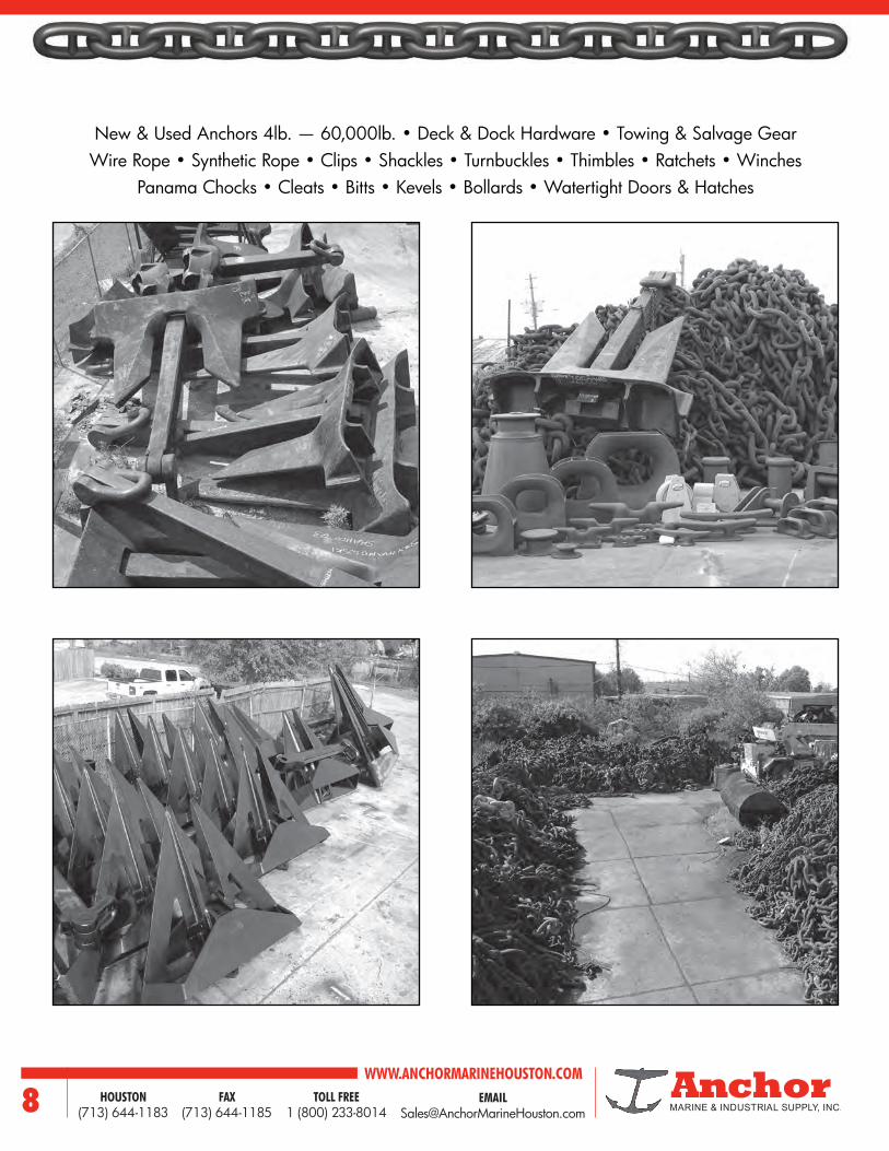
New & Used Anchors 4lb. — 60,000lb. • Deck & Dock Hardware • Towing & Salvage GearWire Rope • Synthetic Rope • Clips • Shackles • Turnbuckles • Thimbles • Ratchets • Winches
Panama Chocks • Cleats • Bitts • Kevels • Bollards • Watertight Doors & Hatches

9EMAIL [email protected]
WWW.ANCHORMARINEHOUSTON.COMTOLL FREE
1 (800) 233-8014HOUSTON
(713) 644-1183FAX
(713) 644-1185
ANCHOR MARINE

WWW.ANCHORMARINEHOUSTON.COMTOLL FREE
1 (800) 233-8014HOUSTON
(713) 644-1183FAX
(713) 644-1185
ANCHOR MARINE

11EMAIL [email protected]
WWW.ANCHORMARINEHOUSTON.COMTOLL FREE
1 (800) 233-8014HOUSTON
(713) 644-1183FAX
(713) 644-1185
ANCHOR MARINE

WWW.ANCHORMARINEHOUSTON.COMTOLL FREE
1 (800) 233-8014HOUSTON
(713) 644-1183FAX
(713) 644-1185
ANCHOR MARINE

13EMAIL [email protected]
WWW.ANCHORMARINEHOUSTON.COMTOLL FREE
1 (800) 233-8014HOUSTON
(713) 644-1183FAX
(713) 644-1185
ANCHORS
AnchorsGIGANTIC INVENTORY
USED AND NEW WITH CERTIFICATES(A.B.S. - LLOYDS - DNV - ETC.)
RENT OR SALEDOMESTIC – IMPORTED
ANCHORS L.W.T
WORKBOAT
STOCKLESS TYPE – HALL TYPE
MUSHROOM TYPE – EELLS KEDGE TYPE
NAVY PATTERN ANCHORS
AC-14 – SPEK TYPEHIGH HOLDING POWER
STOCKS IN THE WEST COASTEAST COAST GULF COAST
GIVE US A CALL800.233.8014

ANCHORS
ANCH
ORS
WWW.ANCHORMARINEHOUSTON.COMTOLL FREE
1 (800) 233-8014HOUSTON
(713) 644-1183FAX
(713) 644-1185
MUD
Holding Power Ratio2 3:1 5:1 9:1 9:1 9:1 9:1 32:1
Depth of Penetration (ft) 9-10 17-20 17-20 17-20 17-20 17-20 35-40
Breakout Force Ratio 2:1 3:1 5:1 5:1 5:1 5:1 6:1
Fluke-to-Shank Angle (degrees) 45° 43° 30° 30° 23° 34° 34°
SAND
Holding Power Ratio2 7:1 14:1 20:1 20:1 20:1 20:1 25:1
Depth of Penetration (ft) 3 6-8 6-8 6-8 6-8 6-8 10-15
Breakout Force Ratio 2:5:1 6:1 8:1 8:1 8:1 8:1 12:1
Fluke-to-Shank Angle (degrees) 45° 43° 30° 30° 34° 34° 34°
Optional Swivel Shackle3 X X X X
Padeye for Pendant Buoy Line X X X X X
Because the anchor is the key to effective mooring or anchoring it is essential to know what to expect from various types. Any anchor’s performance is dependent first upon its ability to bite into the bottom through the ploughing effect of its flukes and secondly upon its ability to maintain a continuous resistance to drag once it is implanted in the bottom.Therefore, the optimum design of an anchor is influenced primarily by the specific composition of the ocean floor, which is generally categorized into three groups: mud, sand, and rock or marl. Mud varies the most in consistency and offers little resistance to dragging forces. Sand is almost ideally consistent and anchors specifically designed for sand bottoms reach excellent holding efficiency. On the other hand rock or marl is very poor holding ground, where an anchor’s dead weight is its only asset. An anchor’s efficiency is expressed in holding-power ratio, that is the holding force per anchor weight. The proof test involves applying a static load to the assembled anchor to
test its structural design and material properties as related to the holding force.The holding power of an anchor is affected greatly by the angle of its flukes. In order for the flukes to enter the bottom of an angle that will allow the crown or head to penetrate to a depth producing maximum efficiency, the angle of the fluke to the shaft should approximate 50 degrees in the mud bottoms and 30 degrees in sand.
Anchor holding-power is also dependent upon other bottom conditions, the duration of drag and the ratio between the length of the mooring line and the water depth.
SELECTION
1 These recommendations are based upon usage practice. Deviations are acceptable.2 These are minimum values only; actual bottom conditions could increase holding power considerably.3 Swivel shackles can be used to replace anchor shackle, anchor connecting link, and swivel.
WE HAVE ONE OF THE LARGEST SELECTIONS OF NEW AND USED ANCHORS IN THE COUNTRY FOR IMMEDIATE DELIVERY. DIRECT FACTORY SHIPMENTS ALSO AVAILABLE AT NO EXTRA COST. WE KEEP OUR STOCKS OF PRODUCTS IN THE WEST COAST, GULF
COAST AND EAST COAST TO EXPEDITE DELIVERIES. GIVE US A CALL AT (800) 233-8014.
Recommended Applications 1Stockless Snug-
Stowing® Lightweight LWT® Danforth Stato® Moorfast® Boss
Offshore Rig Mooring X X X X X
Supply/Support Vessels X X
Pipelay Barges X X
Fixed Mooring X X X X X
Commercial Ships X X
Tugboats X X X
Supertankers X
Minimum Performance Characteristics
WE ARE DIRECT IMPORTERS AND FACTORY DISTRIBUTORS
Fluke-to-Shank-Angle

ANCHORS
ANCHORS
15EMAIL [email protected]
WWW.ANCHORMARINEHOUSTON.COMTOLL FREE
1 (800) 233-8014HOUSTON
(713) 644-1183FAX
(713) 644-1185
Optimum design of anchor is influenced by the specific composition of the ocean floor. Basically, we categorize the ocean bottoms into three groups:
1. Mud, or silt, which varies the most in consistency and offers little resistance to forces.
2. Sand, ideally the most consistent, and where anchors specifically designed, reach excellent holding efficiency.
3. Rock, or Marl, poor holding ground where an anchor’s dead weight is its only asset.
The efficiency of an anchor in a given test is expressed in terms of “Holding power” per pound of its own weight, not in “Proof test” which indicates physical properties of the material.The fluke angle of an anchor has a definite effect upon the “Holding Power”. The flukes should enter the bottom at an angle that will allow the crown, or head, to penetrate to a depth which can produce maximum efficiency. Additionally, we have determined the following:
1. The angle of fluke penetration in mud bottom should be approximately 50°.
2. In sand the penetration angle should be in the area of 30°.
3. For anchoring in various bottoms a compromise approximating 43° is desirable.
Other considerations in selecting an anchor should include:1. Convenience for handling and stowing.2. Aptitude for taking hold.3. Physical strength.4. Freedom from fouling, which all anchors do, but some
in lesser degrees.
5. Influence developed by the chain’s catenary, which absorbs shock loads, and lowers the angle of pull at the anchor by its weight.
The anchor is the key to effective anchoring or mooring. It is essential to know what to expect from various anchors. The resistance of an anchor being dragged through a soil has been considered as occurring in two stages: first, biting into the bottom due to the ploughing effect of the flukes, and secondly, maintaining a continuous resistance to drag after it is planted into the bottom.Holding power is directly proportional to projected fluke area, and shear strength of the bottom material, and inversely proportional to penetration-area resistance. In many cases, a smaller anchor with favorable fluke area to weight ratio is more dependable than a heavier anchor.Holding power for the two most widely used anchors are as follows:
1. Stockless Type anchors in sand develop a holding power to weight ratio of seven to one. In mud it develops three to one. The angle of penetration in both cases is 45°.
2. Lightweight Type anchors in sand develop a holding power to weight ratio of twenty to one, with the angle of penetration being 30°. In mud it develops nine to one with the angle of penetration being 50°.
The depth of penetration in all preceding cases is compiled from three to seven feet in sand, and from seventeen to twenty feet in mud. All calculations incorporate a 0° scope angle.
SELECTION

ANCHORS
ANCH
ORS
WWW.ANCHORMARINEHOUSTON.COMTOLL FREE
1 (800) 233-8014HOUSTON
(713) 644-1183FAX
(713) 644-1185
TYPES OF ANCHORS
Hall AC14 Spek Byers Danforth
LWT Moorfast Union Pool Navy
Norshore I Norshore II KLIP FOB ZY-6
Deepsy Mushroom Bruce Kedge Snug Stow
Anchor with identical holding power drawn at the same scale thus showing
the difference in weight.
Various anchor types with equal weight and scale.
8 tonsStockless
4.5 tonAC 14
4.5 tonLWT
4 tonDanforth
4 tonMoorfast
3 tonStato
Danforth Delta Anchor Stevin MK3
Bruce TSBruce FF
StevprisStevshark

ANCHORS
ANCHORS
17EMAIL [email protected]
WWW.ANCHORMARINEHOUSTON.COMTOLL FREE
1 (800) 233-8014HOUSTON
(713) 644-1183FAX
(713) 644-1185
TYPES OF ANCHORS FROM AROUND THE WORLDNo. 1
No. 2
No. 3
No. 4
No. 5
No. 6
No. 7-8
No. 9
No. 10
No. 11
No. 12
No. 13
No. 14
No. 15
No. 16
No. 17
WORKBOAT OR DANFORTH TYPE
L.W.T. OR LIGHTWEIGHT TYPE
BYERS TYPE STOCKLESS ANCHOR
SPEK TYPE ANCHOR
NAVY TYPE STOCKLESS
STANDARD STOCKLESS ANCHOR
MUSHROOM TYPE
BRUCE TYPE
KEDGE OR ADMIRALTY
AC-14 TYPE
STATO TYPE
DELTA ANCHOR
POOL TYPE ANCHOR
SNUG STOWING
HALL TYPE STOCKLESS ANCHOR
SINGLE FLUKE / KEDGE TYPE
1 2
3
45
6
87
9
1011
12
13
14
1516 17

ANCHORS
ANCH
ORS
WWW.ANCHORMARINEHOUSTON.COMTOLL FREE
1 (800) 233-8014HOUSTON
(713) 644-1183FAX
(713) 644-1185
ANCHORWT A B C D E F G H J PROOF
TEST300 28-5/8 22-1/8 13-3/4 20-5/16 6-7/16 6 1-1/8 4 3-1/2 11560400 31-1/2 24-5/8 15-1/8 22-3/8 6-15/16 6-13/16 1-1/4 4-3/8 3-7/8 13520500 34 26-1/4 16-1/4 24-3/32 7-1/2 6-5/16 1-5/16 4-11/16 4-1/8 15420600 36 27-29/32 17-9/32 25-5/8 7-13/16 6-5/8 1-7/16 5 4-3/8 17270800 39-11/16 30-11/16 19 28-3/16 8-3/4 7-5/16 1-9/16 5-9/16 4-7/8 209701000 42-3/16 33-1/8 20-1/2 30-3/8 9-13/32 7-15/16 1-11/16 6 5-1/4 247001200 45-3/8 35-1/8 21-3/4 32-1/4 10 8-3/16 1-7/8 6-3/8 5-1/2 283601300 46-5/8 36 22-3/8 33-1/8 10-9/32 8-11/16 1-3/4 6-3/8 5-11/16 302101500 49 37-7/8 23-1/2 34-3/4 10-3/4 9 2 6-7/8 6 338101800 52 40-1/4 24-15/16 36-15/16 11-7/16 9-9/16 2-1/16 7-5/16 6-3/8 390002000 54 41-11/16 25-13/16 38-1/4 11-7/8 9-15/16 2-1/8 7-9/16 6-1/2 424502200 54-5/8 43 26-5/8 39-1/2 12-1/4 10-1/4 2-3/16 7-13/16 6-3/4 457302500 58 44-7/8 27-13/16 41-1/4 12-3/4 10-3/4 2-1/4 8-3/16 7-3/16 506603000 63-1/2 50 30-1/2 44-1/2 13-7/8 11-1/4 2-3/8 8-1/2 7-1/2 587203500 64-7/8 50-1/8 31-1/16 46-3/32 14-9/32 12 2-1/2 8-15/16 7-7/8 662204000 67-7/8 52-1/2 32-9/16 48-7/32 14-15/16 12-1/2 2-11/16 9-9/16 8-13/16 737205000 73 56-9/16 35 51-15/16 16-1/16 13-1/2 2-7/8 10-1/4 9-1/8 873606000 77-3/4 60-3/16 37-5/16 55-1/4 17-1/8 14-5/16 3-1/16 10-15/16 9-5/8 997607000 82 63-1/4 39-1/4 58-1/16 18-1/32 15-1/8 3-3/16 11-1/2 9-15/16 1114408000 85-1/2 66-1/4 41 60-3/4 18-7/8 15-3/4 3-3/8 12 10-3/8 1218309000 88-7/8 68-3/4 42-5/8 63-1/8 19-5/8 16-3/8 3-1/2 12-1/2 10-13/16 13148010000 92 71-1/4 44-1/8 65-3/8 20-5/16 17 3-5/8 12-15/16 13-3/16 14083011000 95 73-9/16 45-5/8 67-1/2 20-29/32 17-1/2 3-3/4 13-3/8 11-3/4 14910012000 97-7/8 75-3/4 47 69-1/2 21-19/32 18 3-7/8 13-3/4 11-7/8 15660013000 100 77-3/8 46-5/8 71-1/16 22 18-3/8 3-15/16 14-1/8 12-5/16 16410014500 104 80-5/8 50 74 22-9/16 19-3/16 4-1/8 14-5/8 12-7/8 17410015000 105-1/2 82-1/4 51 73-1/4 23-1/8 19-5/8 4-1/4 15 13 17722016000 107-11/16 83-11/32 51-5/8 76-1/2 23-23/32 19-7/8 4-1/4 15-1/8 13-1/4 18350018000 112 86-5/8 53-3/4 79-9/16 24-5/8 20-5/8 4-3/8 15-3/4 13-13/16 19472020000 116 89-3/4 55-5/8 82-7/16 25-1/2 21-7/16 4-1/2 16-1/4 14-5/16 20472022500 120-1/2 93-5/16 57-13/16 85-11/16 26-17/32 22-1/4 4-3/4 17 14-7/8 21700025000 125 96-11/16 59-15/16 88-13/16 27-1/2 22-15/16 5 17-9/16 15-7/16 23210030000 132-3/4 102-11/16 63-5/8 94-1/4 29-7/32 24-7/16 5-1/4 18-11/16 16-3/8 25280035000 139-3/4 108 67-1/16 99-5/16 30-3/4 25-3/4 5-1/2 19-11/16 17-1/4 26990040000 146 113-1/6 70 103-1/8 32-1/4 27-1/8 5-5/8 20-1/2 17-3/4 28430045000 152 117-5/8 72-7/8 108 33-7/16 28 6 21-3/8 18-3/4 29640060000 188 125-3/4 87-5/16 132-7/8 38-11/16 29 7-1/2 24-1/2 20-1/2 372700
U.S. NAVY STOCKLESS ANCHOR
Intermediate sizes available upon request.Dimensions above are in inches, anchor weight in pounds.Certified drawings of anchors, listed above, and of intermediate and larger sizes may be furnished on request.
H
F
E
B
C
G
JJ
A
45D
E
D
A
0

ANCHORS
ANCHORS
19EMAIL [email protected]
WWW.ANCHORMARINEHOUSTON.COMTOLL FREE
1 (800) 233-8014HOUSTON
(713) 644-1183FAX
(713) 644-1185
ANCHOR WT A B C D E F G H J PROOF
TEST200 27 18 9-1/2 15-1/8 5-1/8 5-1/2 1 5 4 8300300 32 23-1/4 11-11/16 17-1/4 6-11/16 5-1/2 1 5 4-1/2 10900400 32 25-3/4 13 19 7 5-1/2 1 5 4-1/2 13000500 35 26-1/2 14 20 7 7 1-1/4 6 5-1/2 15000700 38 29-1/2 15-5/8 23-1/2 8-1/8 7 1-1/4 6 5-3/4 19600775 38 32 16-7/8 24-3/4 8-5/8 7 1-1/4 6 5-3/4 20050900 42 32 17 24 9 7-1/2 1-1/2 6-1/2 6-1/2 223001000 42 33-5/8 18 25-1/8 9-3/4 7-1/2 1-1/2 6-1/2 6-1/2 241001260 46 36-3/8 18-3/4 28-3/8 9-7/8 8-1/2 1-3/4 7-1/2 6-3/4 288001430 49 39 20 29-7/8 10-3/4 9-3/4 2 8-1/2 7 317001540 49 40 20-1/2 30-1/2 11 9-3/4 2 8-1/2 7 336001600 49 40 20-1/2 30-1/2 11 9-3/4 2 8-1/2 7 346001750 52 41-1/2 21 33-1/4 11-3/8 9-3/4 2 8-1/2 7-1/4 372001875 52 43 22 34-3/4 12 9-3/4 2 8-1/2 7-1/4 393001950 52 43 22 34-3/4 12 9-3/4 2 8-1/2 7-1/4 406002000 58 44-3/4 23 33-3/8 12-1/8 9-3/4 2 8-1/2 7-1/2 431002500 58 44-3/4 23-1/4 33-3/8 12-1/8 9-3/4 2 8-1/2 7-1/2 497002800 58 48 25 35-7/8 13 9-3/4 2 8-1/2 7-1/2 545003000 64 47 25-1/2 36 12-3/4 12 2-1/2 10 8-3/4 577003500 64 52-3/4 27-1/2 39-1/2 14-1/4 12 2-1/2 10 8-3/4 652004000 70-5/8 53-1/4 27-1/2 39-1/4 14-1/2 12 2-1/2 10 9-1/2 726004500 70-5/8 56-3/4 29 42 15 12 2-1/2 10 9-1/2 797005000 76 57-1/2 30 42 15-5/8 15 3 12 10-1/4 865006000 76 63-1/2 33-1/4 47 17-1/4 15 3 12 10-1/4 991006300 76 63-1/2 33-1/4 47 17-1/4 15 3 12 10-1/4 1025006500 82 63-1/2 33 47-5/8 17-1/4 15 3 12 10-3/4 1050006750 82 65 33-3/4 48-3/4 17-5/8 15 3 12 10-3/4 1080007000 82 66-5/8 34-3/4 49-3/4 18 15 3 12 10-3/4 1105007600 82 67-1/2 34-3/4 49-3/4 18-3/8 15 3 12 10-3/4 1170008100 93-1/2 66-1/4 34-1/4 48-7/8 18-1/4 17 3-1/2 13-1/4 11-1/2 1225008600 93-1/2 68-1/2 35-3/4 50-1/2 18-1/2 17 3-1/2 13-1/4 11-1/2 1275009000 96 70-1/4 36-3/8 51-3/4 19-1/8 17 3-1/2 13-1/4 11-1/2 13150010000 96 75-1/2 39 58 21 19 4 14-3/4 12 14050011000 96 75-1/2 39 58 21 19 4 14-3/4 12 14850012000 96 76-3/4 40 58 20-3/4 19 4 14-3/4 12 15600013000 98 76-3/4 40 58 20-3/4 19 4 14-3/4 12 16350014000 103 80-1/2 44 60 22-1/4 19 4 14-3/4 13 17050015000 103 86 46 65 24 19 4 14-3/4 13 17700016000 108 86 46 65 24 19 4 14-3/4 13 18500018000 112 88-1/4 48-1/4 65-5/8 24-3/4 22 4-1/2 16-3/4 13 20000018900 112 88-1/4 48-1/4 65-5/8 24-3/4 22 4-1/2 16-3/4 13 20720020000 112 96 50 72 26 22 4-1/2 16-3/4 14 21400025000 120 103 53-3/4 77-1/2 28 22 4-1/2 16-3/4 15 24300030000 128 110 57-1/4 82-1/2 29-7/8 24 5 18-3/4 16 26600035000 135 116 60 87 31-1/2 25 5 19 17 29200040000 140 121 63 91 32 26 5-1/2 20 17-1/2 32000045000 147 126 65 94 34 27 5-1/2 21 18 34550050000 152 131 68 99 35 28 6 21-1/2 19 371000
All specifications in pounds and inches.Intermediate sizes may be furnished on request.
STANDARD STOCKLESS ANCHOR
H
F
A
D
C
G
B
JJ
A
D 450
EE

ANCHORS
ANCH
ORS
WWW.ANCHORMARINEHOUSTON.COMTOLL FREE
1 (800) 233-8014HOUSTON
(713) 644-1183FAX
(713) 644-1185
SNUG STOWING ANCHORANCHOR
WT A B C D E F G H J PROOF TEST
200 30-7/8 29-11/16 12-1/16 20-1/8 16-3/16 3-3/4 1 3-11/16 2-3/4 10100250 33-5/16 32 13 21-11/16 17-7/16 3-3/4 1 3-11/16 3 11600300 35-3/16 34 13-3/4 23 18-1/2 3-3/4 1 3-11/16 3-1/8 13000350 37-3/16 35-3/4 14-1/2 24-1/4 19-1/2 3-3/4 1 3-11/16 3-3/8 14300400 38-7/8 37-3/8 15-1/4 25-3/8 20-3/8 3-3/4 1 3-11/16 3-1/2 15600450 40-3/8 38-7/8 15-3/4 26-3/8 21-1/8 3-3/4 1 3-11/16 3-5/8 16900500 41-3/4 40-1/4 16-3/8 27-1/4 21-7/8 4-5/8 1-1/4 4-17/32 3-3/4 18100750 48 46 18-3/4 31-1/4 25-1/8 4-5/8 1-1/4 5-3/8 4-3/8 24100
1000 52-3/4 50-3/4 20-5/8 34-3/8 27-5/8 5-11/16 1-1/2 5-3/8 4-3/4 300002000 66-1/2 64 26 43-1/4 34-7/8 7-7/8 2 7-1/4 6 523003000 76 73 29-5/8 49-1/2 39-3/4 9-3/8 2-1/2 9-1/8 6-7/8 725004000 83-3/4 80-1/2 32-3/4 54-1/2 43-7/8 9-3/8 2-1/2 9-1/8 7-1/2 907005000 90-3/8 86-3/4 35-1/4 58-3/4 47-1/4 10-1/8 3 11 8-1/8 1070006000 96 92-1/8 37-1/2 62-1/2 50-1/4 10-1/8 3 11 8-3/8 1213007000 101 97 39-1/2 65-3/4 52-7/8 10-1/8 3 11 9-1/8 1343008000 105-3/4 101-1/2 41-1/4 68 55-3/8 10-1/8 3 11 9-1/2 1456009000 110 105-1/2 43 71-1/2 57-1/2 12-3/8 3-1/2 12-1/4 10 15560010000 113-3/4 109-1/4 44-1/2 74 59-1/2 12-3/8 3-1/2 12-1/4 10-1/4 16560011000 117-1/2 112-7/8 45-3/4 76-1/2 61-1/2 19 4 13-3/4 10-1/2 17460012000 120-3/4 116 47-1/8 78-5/8 63-1/4 19 4 13-3/4 10-1/8 18470013000 124 119-1/8 48-3/8 80-3/4 64-7/8 19 4 13-3/4 11-1/8 19430014000 127-1/4 122-1/4 49-5/8 82-3/4 66-5/8 19 4 13-3/4 11-1/2 20500015000 130 125 50-3/4 84-5/8 68 19 4 13-3/4 11-3/4 21370016000 133-1/4 128 52 86-3/4 69-3/4 19 4 13-3/4 12 22270017000 136 130-1/2 53-1/8 88-1/2 71-1/8 19 4-1/2 13-3/4 12-1/4 23000018000 138-3/4 133-1/8 54-1/8 90-1/4 72-1/2 22 4-1/2 15-3/4 12-1/2 23800019000 141 135-1/2 55 91-7/8 73-7/8 22 4-1/2 15-3/4 12-3/4 24410020000 143-1/4 137-5/8 56 93-1/4 75 22 4-1/2 15-3/4 12-7/8 24940025000 154 148 60-1/4 100-1/2 80-3/4 22 4-1/2 15-3/4 13-7/8 28250030000 164 157-1/2 64-1/8 106-3/4 86 24 5 17-3/4 14-3/4 31940040000 180 173 70 117 94 26 5-1/2 19 16 38640050000 195 187 76 126 102 28 6 20 18 44830060000 206 197 80 134 108 30 6 22 19 50620070000 218 208 85 140 113 32 6-1/2 23 20 56140080000 227 218 89 146 120 33 6-1/2 24 21 61340090000 236 226 92 153 126 35 7 26 22 690000100000 244 234 95 158 130 36 7 27 23 767000
All specifications in pounds and inches.Intermediate sizes may be furnished on request.
H
F
EE
A
D
B
C
GJJ
A
D
C
450

ANCHORS
ANCHORS
21EMAIL [email protected]
WWW.ANCHORMARINEHOUSTON.COMTOLL FREE
1 (800) 233-8014HOUSTON
(713) 644-1183FAX
(713) 644-1185
HALL ANCHORWEIGHT
KGA
MMB
MMC
MMD
MM50 575 410 184 30075 660 480 210 340
100 723 510 230 375125 780 550 245 405150 835 580 264 430180 888 625 281 454200 915 645 290 470225 950 670 300 493240 985 694 312 510275 1020 710 322 527300 1050 738 330 543325 1075 758 338 557360 1190 778 346 570400 1150 810 360 595420 1175 826 368 607450 1200 845 373 620480 1220 860 380 630500 1240 875 386 640570 1280 904 400 660600 1320 930 410 680660 1360 955 420 700700 1390 980 430 715750 1425 1000 440 730780 1450 1030 450 750850 1480 1050 460 765900 1490 1053 480 772950 1520 1072 484 7871020 1545 1090 496 8001140 1600 1126 512 8251200 1650 1165 530 8551290 1670 1180 535 8651350 1700 1205 550 8901440 1800 1245 555 8951590 1890 1260 565 9001740 1910 1290 582 9451920 1930 1362 616 9992100 2020 1407 623 10202280 2040 1446 640 10332460 2120 1483 667 10762640 2170 1519 672 1085
2850 2200 1540 700 1140
WEIGHT KG
A MM
B MM
C MM
D MM
3060 2261 1596 720 11723300 2330 1636 734 11803540 2336 1650 674 12103780 2679 1844 733 12954050 2466 1740 712 12784320 2667 1790 763 12904590 2784 1889 780 13844890 2923 2011 804 14135250 2728 1910 846 13645510 2788 1952 864 13946000 3270 2033 829 15256450 2920 2048 906 14616900 2930 2064 932 15127350 3072 2150 950 15367800 3113 2179 965 15568300 3208 2246 995 16048700 3253 2270 1005 16268900 3268 2275 1012 16349300 3301 2311 1023 16509900 3330 2360 1045 168610200 3338 2372 1070 169410500 3438 2407 1075 171911100 3502 2452 1086 175111700 3565 2495 1105 178012300 3600 2520 1140 180012900 3681 2577 1141 184013500 3738 2616 1159 186914100 3793 2655 1176 189614700 3845 2690 1190 192515400 3880 2716 1210 194016100 3964 2775 1229 198216900 4030 2820 1250 201517800 4099 2869 1270 204918800 4175 2920 1295 208520000 4262 2985 1320 213021500 4365 3055 1355 218023000 4465 3125 1385 223024500 4560 3190 1415 228026000 4651 3255 1442 232527500 4720 3315 1470 237029000 4825 3375 1495 2410
A
D
B
Angle45
C
0

ANCHORS
ANCH
ORS
WWW.ANCHORMARINEHOUSTON.COMTOLL FREE
1 (800) 233-8014HOUSTON
(713) 644-1183FAX
(713) 644-1185
ANCHOR WT A B C D E F G H J PROOF
TEST100 41-1/2 39-1/2 12-3/46 24 15-5/8 3-3/4 7/8 3-3/8 2-1/4 5500150 46-3/4 44-1/2 13-11/16 27 17-3/8 5-1/2 1 4 2-3/8 6800200 47-1/2 45 14-3/16 29 18-7/8 5-1/2 1 4 3-1/8 10100250 47-1/2 45 14-9/16 29 18-7/8 5-1/2 1 4 3-1/8 11600300 53 50 16-5/16 32-1/2 21-1/4 7 1-1/4 5 3-1/4 13000350 53 50 16-11/16 32-1/2 21-1/4 7 1-1/4 5 3-1/4 14300400 57-1/2 54-1/4 17-3/4 35-1/4 23 7 1-1/4 5 3-1/2 15600450 60 56-1/2 18-3/8 36-3/4 24 7 1-1/4 5 3-3/4 16900500 61-1/2 58-1/2 19 37-1/2 24 7-1/2 1-1/2 6 4-1/4 18100750 69 64-1/2 21-1/8 42 28-7/16 7-1/2 1-1/2 6 4-7/8 24100
1000 75 71 24-1/2 46 29-1/4 9-3/4 2 8 5-1/4 300001500 86-1/2 58-1/2 27-5/8 53 31-7/8 12 2-1/2 9-1/2 6 414002000 92-1/2 85 30 56-1/2 37-1/4 12 2-1/2 9-1/2 7 523003000 108-1/2 104 34-3/4 66 40-3/8 15 3 11 7-3/4 725004000 116 110 37-1/2 71 44 15 3 11 9 907005000 118 112 38-3/4 72 44-3/4 17 3-1/2 12-1/4 9-1/2 1107006000 124 118 41 76 47-1/4 19 4 13-3/4 10-1/4 1213007000 124 118 41 76 47-1/4 19 4 13-3/4 10-1/4 1343008000 128 121 43-1/2 78 50-1/4 19 4 13-3/4 12 1456009000 133 126 45-1/4 81-1/8 52-1/4 19 4 13-3/4 12-1/2 15580010000 144 137 49 88 55-1/4 22 4-1/2 15-3/4 13 16580011000 144 137 49 88 55-1/4 22 4-1/2 15-3/4 13 17460012000 146 138-1/2 49-3/4 89-1/8 57-3/8 22 4-1/2 15-3/4 13-3/4 18470013000 154 146 52-1/2 94 60-1/2 24 5 17-1/2 14-1/2 19430014000 154 146 52-1/2 94 60-1/2 24 5 17-1/2 14-1/2 20300015000 157 149-1/4 53-5/8 96 61-7/8 24 5 17-1/2 14-7/8 21370016000 161 152-1/2 54-7/8 98-1/4 63-1/4 24 5 17-1/2 14-1/8 22270017000 164 155-1/2 56 100 64-1/2 24 5 17-1/2 15-1/2 23000018000 167 158-1/2 57 102 65-5/8 24 5 17-1/2 15-3/4 23860019000 170-1/2 161-3/8 58 104 66-3/4 25 5-1/2 20 16 24410020000 173 164 59 106 68 25 5-1/2 20 16-3/8 24940025000 191 178 67-1/4 116 75 26-1/2 5-1/2 20 16 28250030000 198 189 67-1/2 121 78 29 5-1/2 20 17 31940035000 208 199 71 127 82 30 1/2 6 21 18 35375040000 218 240 75 131 86 32 6 24 20-1/2 38640045000 227 250 78 136 89 33 6-1/4 26 22 41382550000 235 260 81 141 92 34 6-1/2 27 23 44830060000 250 278 86 150 97 36 6-1/2 29 24 50620070000 264 290 91 157 103 38 7 30 26 56140080000 275 304 95 165 107 40 7-1/2 31 27 61340090000 287 317 99 172 112 41 8 33 28 690000100000 296 328 102 178 116 43 8 34 29 767000
LIGHTWEIGHT (LWT) ANCHOR
All specifications in pounds and inches.Intermediate sizes may be furnished on request.
B
H
F
E
G
JJ
A
A
D
D 30 0
B
C

ANCHORS
ANCHORS
23EMAIL [email protected]
WWW.ANCHORMARINEHOUSTON.COMTOLL FREE
1 (800) 233-8014HOUSTON
(713) 644-1183FAX
(713) 644-1185
ANCHOR WEIGHT A B C D E F PROOF
TEST
25 31-3/4 27-3/8 19-3/8 3-7/16 3/8 11-5/8 1600
50 40 34-3/8 24-3/8 4-3/8 7/16 14-5/8 2900
75 45-3/4 39-1/2 27-7/8 5 1/2 16-13/16 5000
100 47-1/2 41-1/8 28-5/16 5-1/4 3/4 17-1/2 5972
150 49 42-1/2 29-7/8 5-5/8 3/4 18-7/8 8300
200 52-1/2 45-1/2 33 6-1/8 7/8 20-1/2 10100
300 56 48-1/2 35-1/4 13-1/2 1-1/8 23-1/4 13000
400 58 50 39-9/16 13-7/8 1-1/8 24-1/8 15600
500 63 54-1/2 39-3/4 15-1/8 1-1/2 26-1/4 18100
750 67-1/2 58-1/2 42-1/2 16-1/2 1-1/2 28-1/4 24100
1000 72 62 45-3/8 18-3/4 2 30 30000
1500 77 70-7/8 48-1/2 19-3/8 2 32 41400
2000 83 71-3/4 52 22-5/8 2-1/2 35-3/4 52300
2500 89 84-1/2 56 13-7/8 2-1/2 36-1/2 62270
3000 94 89 59 14-3/8 3 38-7/8 72500
3500 99 94 62-1/2 15-1/8 3 45-3/8 81800
4000 104 98-3/4 65-1/2 15-3/8 3 41-1/4 90700
5000 112 106-1/2 70-1/2 18 3-3/8 45-1/4 107000
6000 118 112 74 18-5/8 3-3/4 47-1/2 121300
8000 129 122-1/2 77-3/8 20-1/4 4-1/8 52-1/16 145600
10000 138 131 87 21-7/8 4-1/2 55-7/8 165600
12000 145 145 91 23 4-3/4 58-3/4 184700
14000 152 152 95-3/4 24 5 61-5/8 205000
16000 160 160 101 25-1/4 5-1/4 64-7/8 222700
20000 172 163 108-3/8 27-1/4 5-5/8 69-1/2 249400
30000 197 187 112 31-1/4 6-1/2 80-1/2 319400
WORKBOAT ANCHOR
All specifications in pounds and inches.Intermediate sizes may be furnished on request.
E
D
C
FB
A
C
A
300

ANCHORS
ANCH
ORS
WWW.ANCHORMARINEHOUSTON.COMTOLL FREE
1 (800) 233-8014HOUSTON
(713) 644-1183FAX
(713) 644-1185
MOORFAST ANCHORANCHOR
WT A B C D E F PROOF TEST
1000 61 75 37 25 19 2 30000
3000 88 109 54 37 27 3 72500
6000 101 143 61 42 31 3-1/2 121300
8000 122 153 75 51 38 3-1/2 145000
10000 131 157 80 55 41 4 165600
12000 139 167 85 58 43 4 184700
14000 147 177 90 61 45 4 205000
16000 153 187 94 64 48 4-1/2 222700
20000 164 196 102 69 51 4-1/2 249400
30000 189 217 118 79 59 5 319400
40000 215 248 127 86 63 5-1/2 386000
50000 222 257 132 89 66 6 448300
60000 232 271 140 95 70 6 506200
70000 244 274 147 100 73 6 561400
80000 255 298 154 105 77 6-1/2 613300
90000 266 310 160 109 80 6-1/2 661200
100000 275 320 166 113 83 7 706400
ANCHOR WT A B C D
200 42 59 26 3/4
3000 129 109 72 1-3/4
6000 144 143 92 2-1/4
9000 160 170 100 2-3/4
12000 186 197 113 3
15000 204 224 126 3-1/2
20000 210 230 129 3-3/4
25000 226 246 137 4
30000 235 257 145 5
35000 248 271 153 5-1/4
40000 258 283 160 5-1/2
45000 269 295 166 5-3/4
50000 277 303 171 6
STATO MOORINGANCHOR
All specifications in pounds and inches.Intermediate sizes may be furnished on request.
All specifications in pounds and inches.Intermediate sizes may be furnished on request.
E
A
C
DB
F
500340 or
A
C
B
D
50034 or0

ANCHORS
ANCHORS
25EMAIL [email protected]
WWW.ANCHORMARINEHOUSTON.COMTOLL FREE
1 (800) 233-8014HOUSTON
(713) 644-1183FAX
(713) 644-1185
ANCHOR WEIGHT
KG
DIMENSIONS IN MM
A B C D E G
454 1545 1900 920 1095 480 645
1360 2230 2770 1330 1580 690 930
2721 2570 3630 1530 1820 795 1071
3628 3095 3890 1840 2190 960 1290
4535 3335 4000 1985 2360 1032 1390
5443 3540 4250 2110 2505 1095 1475
6350 3730 4500 2220 2640 1155 1555
7256 3900 4750 2320 2760 1205 1625
9080 4200 5000 2500 2975 1300 1750
13606 4810 5335 2860 3405 1490 2005
HIGH HOLDING POWERAPPROX. WEIGHTS AND DIMENSIONS
OFFDRILL ANCHOR
MUSHROOM ANCHOR
WEIGHT LBS.
DIMENSIONS IN INCHES
BELL THICKNESS
BELL DIAM.
SHANK DIAM. EYE DIAM. O.A.
LENGTH
50 1/4 20 1-1/4 7/8 34
100 1/2 25-1/2 1-1/4 1 48
150 S. 1 26 1-1/2 1 24
150 L. 1/2 29-1/2 1-1/2 1 52
200 5/8 32 1-1/2 1-1/8 56
250 3/4 34-1/2 2-1/4 1-1/4 64
300 3/4 34-1/2 2-1/4 1-1/4 64
350 3/4 37 2-1/4 1-1/4 70
MOORING SIZES
34
60
0
0
D
A
GB
C
E

ANCHORS
ANCH
ORS
WWW.ANCHORMARINEHOUSTON.COMTOLL FREE
1 (800) 233-8014HOUSTON
(713) 644-1183FAX
(713) 644-1185
WEIGHT KG A B C D E F G
4 224 190 198 106 265 41 238 282 239 250 133 334 62 3712 323 274 286 153 382 80 5016 355 302 315 168 421 80 5020 383 325 339 181 453 90 6024 407 346 361 193 482 90 6032 448 380 397 212 530 100 8040 482 410 427 228 571 100 8048 512 435 454 243 607 120 9060 560 475 490 262 654 120 9075 595 505 526 282 704 120 9090 632 537 559 299 748 120 90105 665 565 588 315 788 142 105125 703 597 622 333 833 142 105135 723 615 640 343 857 142 105180 796 676 706 377 942 157 115225 858 728 760 406 1016 170 125270 911 774 807 432 1079 186 135315 960 815 850 455 1136 201 150360 1002 852 888 475 1188 201 150430 1062 902 940 503 1258 236 175495 1115 948 988 528 1320 236 175585 1180 1002 1045 558 1396 284 185675 1236 1050 1096 586 1465 284 185765 1290 1096 1144 610 1527 284 185855 1338 1138 1185 634 1585 306 225970 1395 1185 1236 660 1652 306 225
1080 1446 1230 1282 685 1714 306 2251195 1495 1270 1323 708 1771 306 2251305 1541 1309 1364 730 1825 306 2251440 1592 1352 1412 754 1886 306 2251575 1640 1386 1454 777 1942 361 2551710 1686 1433 1492 799 1997 361 2551845 1729 1469 1530 819 2048 361 2551980 1770 1504 1570 838 2098 361 2552140 1816 1543 1608 860 2151 361 2552295 1860 1580 1650 880 2202 361 2552475 1910 1620 1690 904 2260 400 2902655 1954 1664 1730 925 2312 400 2902835 1996 1700 1770 945 2364 400 2903040 2042 1735 1810 968 2418 400 2903240 2086 1773 1850 988 2471 400 2903445 2129 1809 1887 1009 2522 400 2903670 2174 1847 1928 1030 2575 450 3253940 2226 1892 1970 1055 2637 450 3254210 2276 1934 2018 1078 2696 450 3254500 2328 1978 2064 1103 2757 450 3254840 2385 2026 2114 1130 2824 500 3605175 2439 2072 2162 1155 2889 500 3605515 2491 2116 2208 1180 2950 500 3605850 2541 2159 2252 1204 3009 550 4006225 2594 2204 2299 1229 3072 550 4006525 2635 2239 2336 1248 3121 550 400
WEIGHT KG A B C D E F G
6975 2695 2290 2390 1276 3190 550 4007425 2750 2338 2439 1303 3258 600 4357875 2805 2384 2487 1329 3323 600 4358325 2858 2428 2533 1354 3385 650 4708775 2908 2471 2578 1378 3445 650 4709225 2958 2512 2622 1401 3502 650 4709675 3004 2553 2664 1423 3558 700 50010125 3050 2592 2704 1445 3613 700 50010575 3095 2630 2747 1466 3666 700 50012075 3235 2748 2868 1533 3831 750 54014100 3406 2894 3020 1614 4034 800 57017250 3643 3095 3230 1726 4315 870 62520625 3867 3285 3428 1832 4580 930 66524750 4109 3491 3643 1947 4867 930 66528875 4324 3675 3838 2049 5123 980 69534500 4590 3890 4070 2175 5437 1000 715
POOL “N” ANCHORTABLE OF MAIN DIMENSIONSHIGH HOLDING POWER
All specifications in kilograms and millimeters.Intermediate sizes may be furnished on request.
G
F
A
C
E
B
D
Y
420
570
ANCHORS
ANCHORS
27EMAIL [email protected]
WWW.ANCHORMARINEHOUSTON.COMTOLL FREE
1 (800) 233-8014HOUSTON
(713) 644-1183FAX
(713) 644-1185
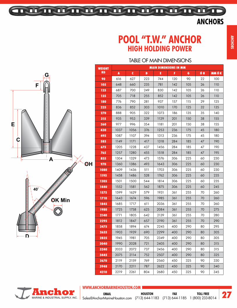
POOL “T.W.” ANCHOR
WEIGHT KG
MAIN DIMENSIONS IN MM
A C D E F G O H MM O K
90 616 627 223 744 120 90 22 100
105 648 660 235 781 142 105 26 110
125 687 700 249 830 142 105 26 110
135 705 718 255 852 142 105 26 110
180 776 790 281 937 157 115 29 125
225 836 852 303 1010 170 125 32 135
270 888 905 322 1073 186 135 35 140
315 935 953 339 1129 201 150 38 155
360 977 996 354 1181 201 150 38 155
430 1037 1056 376 1253 236 175 45 180
495 1087 1107 394 1313 236 175 45 180
585 1149 1171 417 1318 284 185 47 190
675 1205 1228 437 1456 284 185 47 190
765 1257 1280 455 1518 284 185 47 195
855 1304 1329 473 1576 306 225 60 230
970 1360 1386 493 1643 306 225 60 230
1080 1409 1436 511 1703 306 225 60 230
1195 1458 1486 528 1762 306 225 60 235
1305 1501 1500 544 1814 306 225 60 235
1440 1552 1581 562 1875 306 225 60 245
1575 1599 1629 579 1931 361 255 70 260
1710 1643 1674 596 1985 361 255 70 260
1845 1685 1717 611 2036 361 255 70 260
1980 1725 1758 625 2084 361 255 70 275
2140 1771 1805 642 2139 361 255 70 280
2295 1812 1847 657 2190 361 255 70 290
2475 1858 1894 674 2245 400 290 80 295
2655 1903 1939 690 2299 400 290 80 305
2835 1945 1981 705 2349 400 290 80 305
3040 1990 2028 721 2405 400 290 80 315
3240 2033 2072 737 2456 400 290 80 315
3445 2075 2114 752 2507 400 290 80 325
3670 2119 2159 769 2560 450 325 90 330
3948 2170 2211 787 2622 450 325 90 340
4210 2219 2261 804 2680 450 325 90 345
HIGH HOLDING POWERTABLE OF MAIN DIMENSIONS
G
F
C
OH
OK Min
D
E
400
A

ANCHORS
ANCH
ORS
WWW.ANCHORMARINEHOUSTON.COMTOLL FREE
1 (800) 233-8014HOUSTON
(713) 644-1183FAX
(713) 644-1185
WEIGHTKG
DIMENSIONS IN MM
A B C D E F G H I
180 904 811 251 157 550 434 138 135 36
225 974 874 270 169 593 468 149 145 39
340 1109 995 307 192 675 533 169 165 45
460 1227 1101 340 212 747 590 187 182 49
675 1398 1254 389 242 851 672 213 207 56
910 1540 1382 427 267 938 740 235 229 62
1140 1660 1490 460 287 1011 798 253 246 67
1360 1761 1580 488 305 1072 846 269 261 71
1590 1855 1665 514 321 1130 892 283 275 75
1820 1940 1741 538 336 1182 933 296 288 78
2440 2016 1809 559 349 1227 969 308 299 81
2270 2089 1874 579 362 1272 1004 319 310 84
2720 2218 1991 615 384 1351 1066 339 329 90
3040 2302 2066 638 399 1402 1107 351 342 93
3240 2352 2110 652 407 1432 1130 359 349 95
3445 2400 2154 665 415 1462 1154 366 356 97
3670 2451 2200 680 424 1493 1178 374 364 99
3940 2510 2252 696 434 1529 1207 383 373 101
4210 2566 2303 711 444 1563 1234 392 381 104
4500 2624 2355 727 454 1598 1261 401 389 106
4840 2688 2412 745 465 1637 1292 410 399 108
5175 2749 2467 762 476 1674 1321 420 408 111
5515 2808 2520 778 486 1710 1350 429 417 113
5850 2864 2570 794 496 1744 1376 437 425 116
6225 2923 2623 810 506 1780 1405 446 434 118
6525 2970 2665 823 514 1808 1428 453 441 120
6600 2981 2675 826 516 1815 1433 455 443 120
7015 3042 2730 843 527 1853 1462 464 452 123
AC-14 HIGHHOLDING POWERAPPROX. WEIGHTS AND DIMENSIONS
DB
AE
350
C
H
G
F
I
WEIGHTKG
DIMENSIONS IN MM
A B C D E F G H I
7425 3100 2782 859 537 1888 1490 473 460 125
7875 3162 2837 876 547 1925 1520 483 469 128
8325 3221 2890 893 558 1961 1548 492 478 130
8775 3278 2942 909 567 1996 1576 500 487 132
9225 3333 2991 924 577 2030 1602 509 495 134
9675 3386 3039 939 586 2062 1628 517 503 137
10125 3438 3085 953 595 2094 1653 525 511 139
10575 3488 3130 967 604 2124 1677 533 518 141
10690 3501 3141 970 606 2132 1683 535 519 141
11025 3537 3174 981 612 2154 1700 540 525 143
11250 3561 3196 987 616 2169 1712 544 529 144
11550 3592 3224 996 622 2188 1727 548 533 145
11850 3623 3251 1004 627 2206 1742 553 537 146
12075 3646 3272 1011 631 2220 1753 557 541 147
12525 3691 3312 1023 639 2248 1774 563 548 149
12675 3705 3325 1027 641 2256 1781 566 550 150
13200 3756 3370 1041 650 2287 1805 573 558 152
13350 3770 3383 1045 653 2296 1812 576 560 152
13875 3819 3426 1059 661 2326 1836 583 567 154
14100 3839 3445 1064 665 2338 1846 586 570 155
15000 3919 3517 1086 678 2387 1884 599 582 158
16125 4015 3603 1113 695 2445 1930 613 596 162
17250 4106 3685 1138 711 2501 1974 627 610 166
18375 4194 3763 1163 726 2554 2016 640 623 169
19500 4278 3839 1186 740 2605 2056 653 635 173
20625 4358 3811 1208 754 2654 2095 665 647 176
21750 4436 3980 1230 768 2701 2132 677 659 179

ANCHORS
ANCHORS
29EMAIL [email protected]
WWW.ANCHORMARINEHOUSTON.COMTOLL FREE
1 (800) 233-8014HOUSTON
(713) 644-1183FAX
(713) 644-1185
E
F
A
CB
500
320
D
ANCHOR WT IN KG
DIMENSIONS IN MM
A B C D E F SHACKLE DIA. EYE
1000 1960 1560 1755 740 45 2605 52 501500 2250 1800 2025 840 45 2660 60 502000 2470 2000 2250 930 50 2960 70 602500 2660 2130 2395 1005 52 3150 70 603000 2830 2285 2565 1070 55 3380 80 603500 3000 2400 2700 1120 55 3550 80 704000 3180 2560 2880 1190 65 3790 90 605000 3300 2660 2995 1260 75 3945 100 706000 3560 2870 3230 1345 75 4250 100 807000 3750 2995 3365 1405 78 4440 110 907500 3850 3080 3465 1435 85 4565 110 909000 4130 3320 3735 1550 85 4925 125 10010000 4270 3400 3825 1600 85 5040 125 10012000 4530 3600 4050 1705 90 5335 130 11013500 4670 3730 4195 1765 90 5535 140 11015000 4845 3875 4355 1830 90 5735 140 12018000 5265 4120 4635 1935 105 6110 150 12020000 5410 4320 4860 2010 105 6405 160 13022500 5490 4360 4905 2060 105 6470 170 14027500 5980 4785 5385 2245 120 7095 180 14032500 6200 4930 5540 2310 120 7320 165GP 15040000 6650 5290 5945 2480 120 7850 175GP 15050000 7150 5690 6390 2670 130 8440 195GP 18060000 7600 6040 6800 2830 140 9000 210GP 19075000 8200 6560 7380 3100 150 9430 220GP 220
DELTA ANCHORSUPERIOR HOLDING POWER
APPROXIMATE WEIGHTS AND DIMENSIONS

ANCHORS
ANCH
ORS
WWW.ANCHORMARINEHOUSTON.COMTOLL FREE
1 (800) 233-8014HOUSTON
(713) 644-1183FAX
(713) 644-1185
Sand/Hard Clay
50
41
0
0
320
C
A
F E
H
N
Mud
Intermediate
K D
FG
B
SJ
P
TYPE OF STEVPRIS - MAIN DIMENSIONS IN MM; ANCHOR WEIGHT IN KGS
WEIGHT IN KG 1500 3000 5000 8000 10000 12000 15000 18000 20000 22000 25000 30000 65000
A 2787 3511 4163 4869 5245 5574 6004 6381 6609 6822 7119 7565 9789
B 3034 3823 4533 5301 5711 6068 6537 6947 7195 7427 7750 8236 10657
C 1792 2258 2677 3131 3372 3584 3861 4102 4249 4386 4577 4864 6294
D 2666 3359 3983 4659 5018 5333 5745 6105 6323 6527 6811 7238 9366
E 1419 1788 2120 2480 2671 2839 3058 3250 3366 3474 3626 3853 4985
F 258 326 386 452 487 517 557 592 613 633 661 702 908
G 211 266 315 369 397 422 455 483 501 517 539 573 741
H 1097 1382 1639 1917 2065 2195 2364 2512 2602 2686 2803 2979 3854
J 212 223 282 329 376 400 423 447 482 505 505 552 752
K 1257 1584 1878 2196 2366 2514 2709 2878 2981 3077 3211 3413 4416
N 70 75 95 120 140 150 150 160 180 180 180 210 280
P 70 70 95 110 130 140 140 150 170 170 170 200 260
S 80 90 110 130 150 160 170 180 190 200 200 220 300
STEVPRIS
TYPICAL HIGH HOLDING POWER ANCHORS.
ANCHORS
ANCHORS
31EMAIL [email protected]
WWW.ANCHORMARINEHOUSTON.COMTOLL FREE
1 (800) 233-8014HOUSTON
(713) 644-1183FAX
(713) 644-1185
H
N
KD
FG
C
B
SJ
P
A
E F
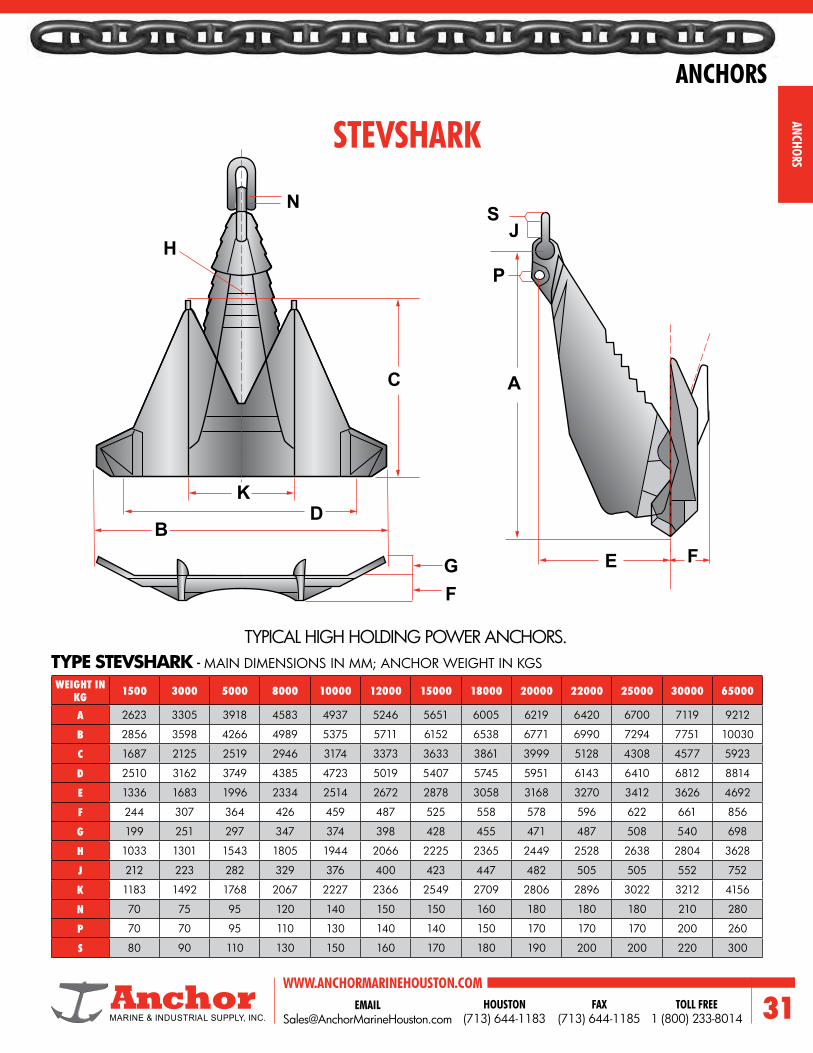
WEIGHT IN KG 1500 3000 5000 8000 10000 12000 15000 18000 20000 22000 25000 30000 65000
A 2623 3305 3918 4583 4937 5246 5651 6005 6219 6420 6700 7119 9212
B 2856 3598 4266 4989 5375 5711 6152 6538 6771 6990 7294 7751 10030
C 1687 2125 2519 2946 3174 3373 3633 3861 3999 5128 4308 4577 5923
D 2510 3162 3749 4385 4723 5019 5407 5745 5951 6143 6410 6812 8814
E 1336 1683 1996 2334 2514 2672 2878 3058 3168 3270 3412 3626 4692
F 244 307 364 426 459 487 525 558 578 596 622 661 856
G 199 251 297 347 374 398 428 455 471 487 508 540 698
H 1033 1301 1543 1805 1944 2066 2225 2365 2449 2528 2638 2804 3628
J 212 223 282 329 376 400 423 447 482 505 505 552 752
K 1183 1492 1768 2067 2227 2366 2549 2709 2806 2896 3022 3212 4156
N 70 75 95 120 140 150 150 160 180 180 180 210 280
P 70 70 95 110 130 140 140 150 170 170 170 200 260
S 80 90 110 130 150 160 170 180 190 200 200 220 300
STEVSHARK
TYPICAL HIGH HOLDING POWER ANCHORS.TYPE STEVSHARK - MAIN DIMENSIONS IN MM; ANCHOR WEIGHT IN KGS

ANCHORS
ANCH
ORS
WWW.ANCHORMARINEHOUSTON.COMTOLL FREE
1 (800) 233-8014HOUSTON
(713) 644-1183FAX
(713) 644-1185
WEIGHT 1 T 1.5 T 3 T 5 T 7 T 9 T 12 T 15 T 20 T 30 T
A 2,475 2,830 3,565 4,230 4,730 5,145 5,660 6,100 6,710 7,685
B 3,045 3,485 4,390 5,205 5,820 6,330 6,970 7,505 8,260 9,455
C 1,665 1,905 2,400 2,845 3,185 3,460 3,810 4,105 4,515 5,170
D 1,915 2,195 2,760 3,275 3,665 3,985 4,385 4,725 5,200 5,950
E1 750 835 1,050 1,245 1,390 1,515 1,665 1,795 1,975 2,260
E2 490 560 700 835 930 1,015 1,115 1,200 1,325 1,515
K1 1,235 1,410 1,780 2,110 2,355 2,565 2,825 3,040 3,345 3,830
L 590 680 850 1,010 1,130 1,230 1,355 1,455 1,605 1,835
OS 60 70 90 100 115 125 140 150 165 190
WEIGHT 10 T 12.5 T 15 T 20 T 25 T 30 T 35 T 40 T 50 T 60 T
A 5,945 6,040 6,805 7,490 8,065 8,570 9,025 9,435 10,165 10,800
B 5,465 5,885 6,255 6,885 7,420 7,885 8,300 8,675 9,345 9,935
C 3,940 4,240 4,510 4,960 5,345 5,680 4,980 6,250 6,735 7,160
D 4,635 4,990 5,305 5,840 6,290 6,685 7,035 7,380 7,925 8,425
E 1,285 1,380 1,470 1,615 1,740 1,850 1,950 2,040 2,195 2,335
OS 140 150 160 180 190 205 215 225 245 260
STEVFIX ANCHOR*
HOOK ANCHOR*
DIMENSIONS IN MM
DIMENSIONS IN MM
K1DB
A
A
K1 E2D E
L
C
E
L
C
S
S
B
K1DB
A
A
K1 E2D E
L
C
E
L
C
S
S
B

ANCHORS
ANCHORS
33EMAIL [email protected]
WWW.ANCHORMARINEHOUSTON.COMTOLL FREE
1 (800) 233-8014HOUSTON
(713) 644-1183FAX
(713) 644-1185
WT 1000 1500 3000 5000 7000 9000 12000 15000 20000 30000
A 2341 2680 3376 4003 4478 4869 5366 5780 6362 7283
B 2645 3038 3828 4538 5077 5521 5892 6347 6986 7997
C 1559 1785 2249 2667 2983 3244 3458 3725 4100 4694
D 2023 2316 2918 3460 3871 4209 4490 4837 5324 6094
E 737 843 1063 1260 1409 1533 1728 1861 2048 2345
K 1010 1156 1456 1727 1932 2100 2255 2430 2674 3061
L 412 471 594 704 788 857 914 984 1083 1240
OS 60 65 80 80 90 100 130 150 160 180
STEVIN ANCHOR*
BRUCE FFTS MK4 ANCHOR*
TYPE STEVIN MK3 - MAIN DIMENSIONS IN MM; ANCHOR WEIGHT IN KGS
TYPICAL HIGH HOLDING POWER ANCHORS.
WEIGHT KG
NOMINAL DIMENSIONS IN MM
A B C D E F
500 1827 1280 500 1303 606 2188
1500 2548 1854 723 1888 878 3172
3000 3409 2388 931 2431 1131 4085
5000 4029 2822 1100 2873 1336 4828
9000 4846 3394 1324 3456 1607 5806
12000 5437 3808 1486 3878 1803 6514
15000 5728 4012 1566 4085 1900 6864
20000 6319 4426 1726 4507 2096 7571
30000 7225 5060 1974 5153 2396 8656
40000 8034 5627 2195 5730 2664 9626
* No longer manufactured — surpassed by Stevpris Anchor.
The table gives nominal dimensions of certain sizes but since the anchors are fabricated from steel plate they can be supplied in any size to suit customer requirements, from 250kg up to 60,000kg.
A
BD
K1
E
C
S
L
F
AD
C
E
B
Sand 30’
Sand 50’

ANCHORS
ANCH
ORS
WWW.ANCHORMARINEHOUSTON.COMTOLL FREE
1 (800) 233-8014HOUSTON
(713) 644-1183FAX
(713) 644-1185
WEIGHT A B C D E F H J K L M N P240 - 310 500 690 160 342 220 150 650 100 120 900 26 54 270310 - 380 550 760 175 390 228 166 716 110 130 990 28 63 300380 - 480 600 827 190 412 258 180 780 120 135 1080 23 69 320480 - 610 650 908 205 442 280 196 846 130 160 1170 31 74 350610 - 735 700 960 221 472 302 210 910 140 170 1260 33 86 375735 - 880 750 1030 235 502 320 225 975 150 185 1350 34 77 400
880 - 1030 800 1100 251 542 340 240 1040 160 195 1440 38 80 4301030 - 1150 850 1170 270 568 362 252 1102 170 200 1530 31 76 4601150 - 1400 900 1240 286 587 328 268 1168 180 210 1620 38 87 4851400 - 1750 950 1299 295 644 420 279 1229 190 220 1710 44 99 5101750 - 2020 1000 1378 316 671 442 300 1300 200 235 1800 52 107 5402020 - 2360 1050 1454 330 706 460 312 1362 210 240 1890 52 123 5652360 - 2750 1100 1514 343 744 480 324 1424 220 265 1980 52 133 5902750 - 3000 1150 1584 362 788 492 352 1502 230 285 2070 68 141 6203000 - 3700 1200 1650 380 801 520 360 1560 245 300 2160 58 138 6453700 - 4000 1350 1850 418 890 580 393 1743 265 330 2430 58 138 7204000 - 5100 1400 1927 438 910 610 413 1813 280 340 2520 68 142 7505100 - 5800 1450 2000 451 954 626 414 1864 290 345 2610 65 161 7805800 - 6600 1500 2060 467 998 642 446 1946 300 355 2700 65 160 8106600 - 8000 1550 2138 490 1030 660 456 2006 310 370 2790 64 169 8358000 - 9600 1700 2333 533 1118 734 510 2210 330 410 3060 67 175 9209600 - 11700 1770 2440 559 1178 782 531 2301 350 435 3186 83 180 95511700 - 14100 1910 2632 603 1270 844 573 2483 380 470 3438 87 192 103014100 - 17000 2050 2825 648 1360 876 615 2665 410 500 3690 91 204 1105
SPEK ANCHOR
TABLE OF MAIN DIMENSIONS
All specifications in kilograms and millimeters. Intermediate sizes may be furnished on request.
H
B
U
E
A
CA
L
F
J P
K
N M
D14°
40°

ANCHORS
ANCHORS
35EMAIL [email protected]
WWW.ANCHORMARINEHOUSTON.COMTOLL FREE
1 (800) 233-8014HOUSTON
(713) 644-1183FAX
(713) 644-1185
ANCHOR WT
WEIGHT N-STOCK A B C D F H G PROOF
TEST100 81 36 27 9 6 5 5 1 6850150 119 41 31 11 8 5 5 1 7686200 156 45 34 12 8 5 5 1 8500250 199 49 38 13 9 7 6 1 9334300 236 51 40 14 10 7 6 1 10090350 274 54 42 15 10 7 6 1 10834400 316 56 43 15 11 7 6 1 11560450 354 58 45 16 11 7 6 1 12305500 391 60 56 17 11 7 6 1 13030550 429 63 49 17 12 7 6 1 13767600 466 64 50 17 12 7 6 1 14500650 504 66 52 18 13 7 6 1 15192700 554 68 53 18 13 8 7 1 15885750 592 71 54 19 13 8 7 1 16585800 629 71 55 19 13 8 7 1 17270850 667 73 57 20 14 8 7 1 17973900 704 74 58 20 14 8 7 1 18660950 742 76 59 21 14 8 7 1 19360
1000 779 77 60 21 15 8 7 1 200501050 831 78 61 21 15 8 8 2 207481100 868 79 61 21 15 9 8 2 214301150 906 80 62 22 15 9 8 2 221351200 943 81 63 22 15 9 8 2 278201250 981 83 64 23 16 9 8 2 235231300 1018 84 65 23 16 9 8 2 242051350 1056 85 66 23 16 9 8 2 249101400 1093 85 66 23 16 9 8 2 255901500 1168 88 68 24 17 9 8 2 269801600 1259 89 69 24 17 11 9 2 283601700 1334 91 71 25 17 11 9 2 297501800 1409 93 72 25 18 11 9 2 311401900 1484 94 73 26 18 11 9 2 325002000 1559 97 75 26 18 11 9 2 338102100 1634 98 76 27 19 11 9 2 351252200 1728 99 77 27 19 12 10 2 364402300 1803 101 78 27 19 12 10 2 377502400 1878 102 79 28 20 12 10 2 390802500 1953 103 81 28 20 12 10 2 403752600 2028 103 81 29 20 12 10 2 416302700 2103 106 83 29 20 12 10 2 428602800 2178 107 84 29 21 12 10 2 440902900 2253 109 85 30 21 12 10 2 453203000 2386 110 86 30 21 15 12 2 465503250 2374 113 88 31 22 15 12 2 496433500 2761 116 90 32 22 15 12 3 527103750 2949 119 93 33 23 15 12 3 557934000 3136 122 95 33 23 15 12 3 587204250 3324 124 96 34 24 15 12 3 615404500 3516 127 99 35 24 15 12 3 64420
ANCHOR WT
WEIGHT N-STOCK A B C D F H G PROOF
TEST4750 3699 129 101 35 25 15 12 3 671655000 3886 131 102 36 25 15 12 3 699705250 4145 133 103 36 26 17 13 3 727905500 4332 135 105 37 26 17 13 3 755115750 4520 137 107 38 26 17 13 3 780286000 4707 139 109 38 27 17 13 3 806006250 4895 141 110 39 27 17 13 3 831646500 5082 143 111 39 27 17 13 3 858246750 5270 144 112 40 28 17 13 3 861547000 5457 146 114 40 28 17 13 3 905107250 5645 148 115 40 28 17 13 3 928797500 5832 150 117 41 29 17 13 3 952837750 6020 151 118 41 29 17 13 3 974978000 6207 153 119 42 29 17 13 3 997608250 6327 154 120 42 30 19 14 4 1020338500 6714 156 122 43 30 19 14 4 1043108750 6902 157 123 43 30 19 14 4 1064139000 7089 159 124 43 31 19 14 4 1085639250 7277 160 125 44 31 19 14 4 1107279500 7464 162 126 44 31 19 14 4 1128319750 7652 163 127 45 31 19 14 4 114789
10000 7839 164 128 45 32 19 14 4 116730
OLD STYLE (KEDGE) ANCHOR
Intermediate sizes may be furnished on request.Dimensions above are in inches, anchor weight in pounds.
C
GH
F
A
D
B

ANCHORS
ANCH
ORS
WWW.ANCHORMARINEHOUSTON.COMTOLL FREE
1 (800) 233-8014HOUSTON
(713) 644-1183FAX
(713) 644-1185
HOT DIPPED GALVANIZED STAMPED STEELANCHOR HEIGHT
INCHESSTOCK LENGTH
INCHESFLUKE LENGTH
INCHESRECOMM. BOAT
LENGTH FEETWEIGHT
LBS
17’’ 14’’ 9’’ 8’ - 16’ 4.8 lb
20-1/2’’ 15’’ 10-1/2’’ 12’ - 22’ 7.8 lb
22-1/2’’ 16’’ 12’’ 16’ - 26’ 9.5 lb
25-1/2’’ 18’’ 13’’ 20’ - 32’ 12.1 lb
30’’ 18’’ 16’’ 28’ - 34’ 17.6 lb
34’’ 22’’ 17’’ 32’ - 40’ 21.4 lb
SH ANCHOR
HOT DIPPED GALVANIZED STAMPED STEELST ANCHOR
ANCHOR HEIGHTINCHES
STOCK LENGTHINCHES
FLUKE LENGTHINCHES
WEIGHTLBS.
34-1/2’’ 30’’ 18’’ 30.0 lb
40’’ 30’’ 21-1/2’’ 41.0 lb
46’’ 36’’ 24’’ 55.0 lb
54’’ 36’’ 26-1/2’’ 70.0 lb
54-1/2’’ 36’’ 26-1/2’’ 101.0 lb
54-1/2’’ 36’’ 26-1/2’’ 126.0 lb
HOT DIPPED GALVANIZED STAMPED STEELECONOMY SLIP RING ANCHORANCHOR HEIGHT
INCHESSTOCK LENGTH
INCHESFLUKE LENGTH
INCHESWEIGHT
LBS.
14’’ 12’’ 9’’ 4.0 lb
17’’ 13’’ 9-1/2’’ 5.0 lb
20’’ 16’’ 10’’ 6.0 lb
24’’ 22’’ 11-3/4’’ 8.0 lb
24-1/2’’ 22’’ 14-1/2’’ 9.0 lb

ANCHORS
ANCHORS
37EMAIL [email protected]
WWW.ANCHORMARINEHOUSTON.COMTOLL FREE
1 (800) 233-8014HOUSTON
(713) 644-1183FAX
(713) 644-1185
HOT DIPPED GALVANIZED STAMPED STEELBOAT LENGTH RECOMM. CHAIN / LENGTH RECOMM. LINE / LENGTH WEIGHT
5’ - 10’ 1/4’’ / 35’ 3/16’’ / 7-10’ 1.0 lb
5’ - 12’ 1/4’’ / 35’ 3/16’’ / 7-10’ 3.5 lb
5’ - 14’ 5/16’’ / 50’ 3/16’’ / 7-10’ 5.5 lb
5’ - 16’ 5/16’’ / 50’ 3/16’’ / 7-10’ 7.0 lb
5’ - 18’ 5/16’’ / 120’ 3/16’’ / 10-13’ 9.0 lb
14’ - 22’ 3/8’’ / 150’ 3/16’’ / 10-20’ 13.0 lb
18’ - 26’ 3/8’’ / 150’ 1/4’’ / 10-20’ 18.0 lb
22’ - 30’ 3/8’’ / 150’ 1/4’’ / 10-20’ 22.0 lb
24’ - 30’ 1/2’’ / 150’ 1/4’’ / 10-20’ 27.0 lb
26’ - 32’ 1/2’’ / 175’ 3/8’’ / 10-20’ 33.0 lb
HOT DIPPED GALVANIZED STAMPED STEELSEAHOOK STOCKLESS ANCHOR
FOLDING ANCHOR
ANCHOR HEIGHT WIDTH FLUKE LENGTH WEIGHT
24’’ 15-1/4’’ 10-1/4’’ 25.0 lb
28-1/2’’ 17-3/4’’ 13-1/4’’ 45.0 lb
32’’ 20’’ 15’’ 70.0 lb
38’’ 24’’ 18-1/2’’ 100.0 lb
40’’ 30’’ 24’’ 150.0 lb
40’’ 30’’ 24’’ 210.0 lb
50’’ 36’’ 27’’ 350.0 lb

ANCHORS
ANCH
ORS
WWW.ANCHORMARINEHOUSTON.COMTOLL FREE
1 (800) 233-8014HOUSTON
(713) 644-1183FAX
(713) 644-1185
ESTIMATING DOMESTIC ANCHOR WEIGHTSIn the field, with no anchor-charts available, the weight of an anchor
may be estimated within a few percent plus or minus as follows:
COMMERCIAL STOCKLESS
NAVY STANDARD STOCKLESS
STANDARD KEDGE ANCHOR
SNUG-STOWING ANCHOR
NAVY LWT ANCHOR
Weight = B3
40
Weight = B3
36
Weight = B3
212
Weight = E3
21
Weight = E3
16for Anchors 7000# & up
For LWT anchors of less than 7000# (when E is less than 47 inches) the above forumula does not apply.
B
B
E
E

ANCHORS
ANCHORS
39EMAIL [email protected]
WWW.ANCHORMARINEHOUSTON.COMTOLL FREE
1 (800) 233-8014HOUSTON
(713) 644-1183FAX
(713) 644-1185
CROWN ANCHOR SHACKLE
SHACKLE SIZEA
(MM)B
(MM)C
(MM)D
(MM)E
(MM)F
(MM)
WEIGHTPROOF LOAD
(LBS)MM INCHES KG LBS.
51 2 254.0 88.9 180.6 50.8 136.0 50.8 20 44 54,500
64 2-1/2 304.8 111.1 238.1 63.5 168.0 63.5 50 110 90,700
76 3 355.6 152 304 76.2 200.0 76.2 80 176 145,000
89 3-1/2 406.4 165.1 342.9 88.9 230.0 88.9 120 265 165,600
102 4 482.6 194.2 357.4 101.6 265.0 101.6 170 375 230,000
114 4-1/2 558.8 203.2 431.8 114.3 300.0 114.3 240 529 282,500
C
A
E
F
D
B
WITH ABS CERTIFICATION

ANCHORS
ANCH
ORS
WWW.ANCHORMARINEHOUSTON.COMTOLL FREE
1 (800) 233-8014HOUSTON
(713) 644-1183FAX
(713) 644-1185
NOTES

EMAIL [email protected]
WWW.ANCHORMARINEHOUSTON.COMTOLL FREE
1 (800) 233-8014HOUSTON
(713) 644-1183FAX
(713) 644-1185 41
CHAINS
GENERAL INFORMATION• OPEN LINK
• WELDLESS CHAIN
• PROOF COIL CHAIN
• HIGH TEST
• LASHING
• COAST GUARD BUOY CHAIN
• STAINLESS STEEL
• ALLOY
• DOCK FENDER CHAIN
GIVE US A CALLTOLL FREE 800.233.8014
NEW & USED CHAINAlways in Stock
RENTAL AVAILABLE
From 1/4’’ to 5-1/4’’ Diameter in the West Coast
East Coast and the Gulf Coast
We are DIRECT IMPORTERS and FACTORY DISTRIBUTORS.
• STUD LINK
• U.S. NAVY
• CAST STEEL
• O.R.Q
• GRADES 2, 3, 4 AND 5
DOMESTIC AND IMPORTED
ONE OF THE LARGEST INVENTORIES IN THE
COUNTRY
WITH or WITHOUT CERTIFICATES
(A.B.S., LLOYDS, D.N.V., ETC.)
CHAINS

WWW.ANCHORMARINEHOUSTON.COMTOLL FREE
1 (800) 233-8014HOUSTON
(713) 644-1183FAX
(713) 644-118542
CHAINS
CHAI
NS

EMAIL [email protected]
WWW.ANCHORMARINEHOUSTON.COMTOLL FREE
1 (800) 233-8014HOUSTON
(713) 644-1183FAX
(713) 644-1185 43
CHAINS
CHAINS
GENERAL INFORMATIONDIMENSION RATIOSFor many years, dimensions of stud link anchor chain have been standardized so that all chain manufacturers are required to furnish chain conforming to dimension charts published by various testing societies (Lloyds, American Bureau of Shipping, etc.), within their limiting tolerances. For estimating purposes it is often useful to note the following:
The inside length (“grip” or pitch) of one link is 4 wire diameters.
The outside length of one link is 6 wire-diameters.
The outside width of one link is 3.56 wire-diameters.
The gauge-test length is the outside length over 6 links and equals 26 wire-diameters.
The weight of one link is about 3-1/3 times its wire diameter cubed.
Doubling the wire-diameter of one link multiplies its weight by 8.
The weight of 1 linear foot of chain is 10 times its wire-diameter squared.
The length of a standard “shot” = 15 fathoms = 90 ft. = 1080”.
The weight of a 90 ft. shot = 900 times its wire-diameter squared.
Doubling the wire-diameter of a 90 ft. shot multiplies its weight by 4.
Doubling the size of a chain theoretically multiplies its strength by 4; in practice, by a trifle less than 4.
The safe working load of chain is ordinarily assumed as one half the proof test.
CHAIN LENGTHS REQUIREDIn determining amount of anchor chain to be used for a particular anchorage it is usual to allow 5 to 7 times the depth of water; dependent on such factors as nature of bottom, present and anticipated weather, tidal and current conditions, state of readiness of the ship’s powerplant, draft, amount of exposed hull and superstructure, and length of stay at anchor. (U.S. Coast Guard)
CHAIN AND LINK MAINTENANCEAnchor chain cable should be ranged at regular intervals and examined for damage and signs of excessive wear. It is considered good practice to occasionally shift the shots about in the chain to insure even wear. The chains may also be sprayed with a preservative such as fish oil at this time. (U.S. Coast Guard)
The U.S. Navy instructs that at least once every eighteen (18) months all anchor chain cable regardless of size, including detachable links, swivels and shackles should be examined, over-hauled and placed in a good state of preservation. Chain connecting links particularly should be disassembled and the interiors recoated with grease, and identification mark restored if necessary.

WWW.ANCHORMARINEHOUSTON.COMTOLL FREE
1 (800) 233-8014HOUSTON
(713) 644-1183FAX
(713) 644-118544
CHAINS
CHAI
NS
GENERAL INFORMATION
RATED LOAD VALUE
PROOF LOAD
PROOF TEST
ULTIMATE LOAD
SHOCK LOAD
SAFETY FACTOR
COMMERCIAL SURFACE QUALITY
The maximum recommended load that should be exerted on the item. The following terms are also used for the term Rated Load: “SWL”, “Safe Working Load”, “Working Load”, “Working Load Limit”, and the “Resultant Safe Working Load.” All rated load values, unless noted otherwise, are for in-line pull with respect to the centerline of the item.
The average load to which an item may be subjected before visual deformation occurs or a load that is applied in the performance of a proof test.
A term designating a tensile test applied to the item for the sole purpose of detecting injurious defects in the material or manufacture.
The average load at which the item being tested fails or no longer supports the load.
A resulting load from the rapid change of movement, such as impacting or jerking, of a static load. A Shock Load is generally significantly greater then the static load.
An industry term denoting theoretical reserve capability. Usually computed by dividing the catalog stated ultimate load by the catalog stated working load limit and generally expressed a a ratio, for example 5 to 1.
The surface condition associated with the normal methods of production of raw material and machined surfaces. The surface condition of the products shown in this catalog. More refined surface qualities are considered as special.
All ratings given in tons refer to short tons of 2,000 lbs.
NOTE: The right is reserved to make changes in product design, material and specifications without incurring obligations.
WARNING:Low and high carbon steel welded and weldless chain and attachments are not to be used for overhead lifting purposes or where its failure is likely to cause damage to property or persons.
DEFINITIONS

EMAIL [email protected]
WWW.ANCHORMARINEHOUSTON.COMTOLL FREE
1 (800) 233-8014HOUSTON
(713) 644-1183FAX
(713) 644-1185 45
CHAINS
CHAINS
To meet American Bureau of Shipping specifications, the length over any six consecutive links of stud link anchor chain should be 26 wire-diameters, with a plus tolerance of 45% of one wire-diameter, and a minus tolerance of 30% of one wire-diameter.To test the fit of a given chain on a given wildcat, it is suggested that a nine-link sample of the chain be used, consisting of five consecutive common links, one detachable link, and three consecutive common links.When the link at one end of the nine-link sample is held snugly seated in one of the pockets of the wildcat, the remainder of the sample, held taut, should wrap readily and snugly around the wildcat so that they grip measurement as calipered between the two end links should equal the inside
length of one link; namely, four wire-diameters.If the nine-link sample is within these tolerances, refusal to wrap readily and snugly to a four wire diameter closure will afford obvious indication as to whether the pitch of the wildcat be too great or too small, an obvious indication as to whether and where the whelps of the wildcat may need modification of contour.Newly-cast wildcats are not infrequently slightly over-size. This condition is correctable by chipping away excess metal where indicated by the above test.
SUGGESTIONS FOR CHECKING FIVE-POCKET WILDCATS
Pull
Critical Pitch Diameter
Strong Cord, or Flexible Wire
This Distance Should Not ExceedFour Wire Diameters
Four WireDiameters
Four WireDiameters
Well Greased.

WWW.ANCHORMARINEHOUSTON.COMTOLL FREE
1 (800) 233-8014HOUSTON
(713) 644-1183FAX
(713) 644-118546
CHAINS
CHAI
NS
APPROXIMATE VOLUMES FOR SELF TIERING CHAINBASED ON A COMBINATION OF TABLES INCLUDING NAVY FORMULA (V = )
VOLUME OF CHAIN LOCKER FOR SELF TIERING CHAIN USE (V = 1-1/2 X )Cu
bic
ft. r
eq’d
10
0 f
ath
oms
of s
tud li
nk c
hain
LD2—2
LD2—2
500
600
100
300
5/8 7/8 1-1/8 1-3/8 1-5/8 1-7/8 2-1/8 2-3/8 2-5/8 2-7/8 3-1/83/4 1 1-1/4 1-1/2 1-3/4 2 2-1/4 2-1/2 2-3/4 3
200
400

EMAIL [email protected]
WWW.ANCHORMARINEHOUSTON.COMTOLL FREE
1 (800) 233-8014HOUSTON
(713) 644-1183FAX
(713) 644-1185 47
CHAINS
CHAINS
OFFSHORE CHAIN DATA (OIL RIG)
Formulad= nominal chain diameter in mm
WEIGHT KG/MVOLUME M3/M
STUD CHAIN
0,0219 d2
1,095. 105 d2
App
roxi
mat
e w
eigh
t per
100
m. o
f cha
in
App
roxi
mat
e w
eigh
t per
100
m. o
f cha
in
DIAMETER OF CHAIN
Conversion1 LBS = 0,454 KG.1 CWT = 50,8 KG.1 TON (LONG) 1016 KG.1 KN = 98 KG.1 N = 0,98 KG1 INCH = 25,4 MM1 FOOT = 304,8 MM1 FATHOM = 1,828 MM
STUDLESS CHAIN
0,0202 d2
1,05. 105 d2
20
10.000 10
20
30
40M3
50
60
70
80
20.000
30.000
40.000
50.000
60.000
70.000
80.000KG
30 40 50 60 70 80 90 100 110 120 130 140 150 160 170 180
WEI
GHT
STUD
LESS
CHA
IN
WEI
GHT
STUD
CHA
IN
VOLUME STUD CHAIN
VOLUME STUDLESS

WWW.ANCHORMARINEHOUSTON.COMTOLL FREE
1 (800) 233-8014HOUSTON
(713) 644-1183FAX
(713) 644-118548
CHAINS
CHAI
NS
CHAIN SIZE LINK LENGTH
A
LINK WIDTH
B
LENGTH OVER 5 LINKS
C
GRIP
RADIUS
D
WEIGHT PER
15-FATHOM SHOT
(APPROX.)
NO OF LINKS PER
15-FATHOM SHOT
GRADE 1 GRADE 2 GRADE 3
INCHES MM PROOF TEST
BREAK TEST
PROOF TEST
BREAK TEST
PROOF TEST
BREAK TEST
1/2 13 3 1-13/16 13 21/64 225 535 10685 15275 15275 21930 21930 30555
5/8 16 3-3/4 2-1/4 13-3/4 3/8 365 432 16620 23745 23745 33220 33220 47465
11/16 17.5 4-1/8 2-7/16 15-1/8 7/16 415 391 – – 28663 40353 – –
3/4 19 4-1/2 2-5/8 16-1/2 1/2 480 357 23800 34000 34000 47600 47600 68000
13/16 20 4-7/8 2-7/8 17-7/8 17/32 570 329 27800 39800 39800 55700 55700 79500
7/8 22 5-1/4 3-1/8 19-1/4 37/64 660 305 32200 46000 46000 64400 64400 91800
15/16 24 5-5/8 3-5/16 20-5/8 5/8 760 285 36800 52600 52600 73700 73700 105000
1 25 6 3-9/16 22 21/32 860 267 41800 59700 59700 83600 83600 119500
1-1/16 27 6-3/8 3-3/4 23-3/8 11/16 970 251 47000 67200 67200 94100 94100 135000
1-1/8 28 6-3/4 4 24-3/4 25/32 1080 237 52600 75000 75000 105000 105000 150000
1-3/16 30 7-1/8 4-1/4 26-1/8 25/32 1220 225 58400 83400 83400 116500 116500 167000
1-1/4 32 7-1/2 4-1/2 27-1/2 25/32 1350 213 64500 92200 92200 129000 129000 184000
1-5/16 33 7-7/8 4-3/4 28-7/8 7/8 1490 203 70900 101500 101500 142000 142000 203000
1-3/8 34 8-1/4 4-15/16 30-1/4 7/8 1630 195 77500 111000 111000 155000 155000 222000
1-7/16 36 8-5/8 5-3/16 31-5/8 15/16 1780 187 84500 120500 120500 169000 169000 241000
1-1/2 38 9 5-3/8 33 63/64 1940 179 91700 131000 131000 183500 183500 262000
1-9/16 40 9-3/8 5-5/8 34-3/8 1-1/32 2090 171 99200 142000 142000 198500 198500 284000
1-5/8 42 9-3/4 5-7/8 35-3/4 1-1/16 2240 165 108000 153000 153000 214000 214000 306000
1-11/16 43 10-1/8 6-1/16 37-1/8 1-3/32 2410 159 115000 166500 166500 229000 229000 327000
1-3/4 44 10-1/2 6-5/16 38-1/2 1-5/32 2590 153 123500 176000 176000 247000 247000 352000
1-13/16 46 10-7/8 6-1/2 39-7/8 1-3/16 2790 147 132000 188500 188500 264000 264000 377000
1-7/8 48 11-1/4 6-3/4 41-1/4 1-1/4 2980 143 140500 201000 201000 281000 281000 402000
1-15/16 50 11-5/8 7 42-5/8 1-9/32 3180 139 149500 214000 214000 299000 299000 427000
2 51 12 7-3/16 44 1-5/16 3360 133 159000 227000 227000 318000 318000 454000
2-1/16 52 12-3/8 7-7/16 45-3/8 1-3/8 3570 129 168500 241000 241000 337000 337000 482000
2-1/8 54 12-3/4 7-5/8 46-3/4 1-27/64 3790 125 178500 255000 255000 357000 357000 510000
2-3/16 56 13-1/8 7-7/8 48-1/8 1-15/32 4020 123 188500 269000 269000 377000 377000 538000
2-1/4 58 13-1/2 8-1/8 49-1/2 1-1/2 4250 119 198500 284000 284000 396000 396000 570000
2-5/16 59 13-7/8 8-5/16 50-7/8 1-17/32 4490 117 209000 299000 299000 418000 418000 598000
2-3/8 60 14-1/4 8-9/16 52-1/4 1-9/16 4730 113 212000 314000 314000 440000 440000 628000
STUD LINK ANCHOR CHAIN
All specifications in pounds and inches, unless otherwise stated.
CA
B D

EMAIL [email protected]
WWW.ANCHORMARINEHOUSTON.COMTOLL FREE
1 (800) 233-8014HOUSTON
(713) 644-1183FAX
(713) 644-1185 49
CHAINS
CHAINS
CA
B D
CHAIN SIZE LINK LENGTH
A
LINKWIDTH
B
LENGTH OVER FIVE
LINKS
C
GRIP RADIUS
D
WEIGHT PER 15-FATHOM
SHOT (APPROX.)
NO. OF LINKS PER
15-FATHOM SHOT
GRADE 1 GRADE 2 GRADE 3
INCHES MM PROOF TEST
BREAK TEST
PROOF TEST
BREAK TEST
PROOF TEST
BREAKTEST
2-7/16 62 14-5/8 8-3/4 53-5/8 1-5/8 4960 111 231000 330000 330000 462000 462000 660000
2-1/2 64 15 9 55 1-5/8 5270 107 242000 346000 346000 484000 484000 692000
2-9/16 66 15-3/8 9-1/4 56-3/8 1-11/16 5540 105 254000 363000 363000 507000 507000 726000
2-5/8 67 15-3/4 9-7/16 57-3/4 1-11/16 5820 103 265000 379000 379000 530000 530000 758000
2-11/16 68 16-1/8 9-11/16 59-1/8 1-3/4 6110 99 277000 396000 396000 554000 554000 792000
2-3/4 70 16-1/2 9-7/8 60-1/2 1-13/16 6410 97 289000 413000 413000 578000 578000 826000
2-13/16 71 16-7/8 10-1/8 61-7/8 1-27/32 6710 95 301000 431000 431000 603000 603000 861000
2-7/8 73 17-1/4 10-3/8 63-1/4 1-7/8 7020 93 314000 449000 449000 628000 628000 897000
2-15/16 75 17-5/8 10-9/16 64-5/8 1-7/8 7330 91 327000 467000 467000 654000 654000 934000
3 76 18 10-13/16 66 2 7650 89 340000 485000 485000 679000 679000 970000
3-1/16 78 18-3/8 11 67-3/8 2 7980 87 353000 504000 504000 705000 705000 1008000
3-1/8 79 18-3/4 11-1/4 68-3/4 2-1/16 8320 85 366000 523000 523000 732000 732000 1046000
3-3/16 81 19-1/8 11-1/2 70-1/8 2-1/16 8660 85 380000 542000 542000 759000 759000 1084000
3-1/4 83 19-1/2 11-11/16 71-1/2 2-1/8 9010 83 393000 562000 562000 787000 787000 1124000
3-5/16 84 19-7/8 11-15/16 72-7/8 2-1/8 9360 81 407000 582000 582000 814000 814000 1163000
3-3/8 86 20-1/4 12-1/8 74-1/4 2-3/16 9730 79 421000 602000 602000 843000 843000 1204000
3-7/16 87 20-5/8 12-3/8 75-5/8 2-3/16 10100 77 435000 622000 622000 871000 871000 1244000
3-1/2 90 21 12-5/8 77 2-5/16 10500 77 450000 643000 643000 900000 900000 1285000
3-5/8 92 21-3/4 12-15/16 79-3/4 2-5/16 11300 73 479000 685000 685000 958000 958000 1369000
3-3/4 95 22-1/2 13-3/8 82-1/2 2-15/32 12000 71 509000 728000 728000 1019000 1019000 1455000
3-7/8 98 23-1/4 14 85-1/4 2-15/32 12900 69 540000 772000 772000 1080000 1080000 1543000
4 102 24 14-3/8 88 2-5/8 13700 67 571000 816000 816000 1143000 1143000 1673200
4-1/8 105 24-3/4 14-11/16 90-3/4 2-11/16 14560 65 603300 861800 861800 1206600 1206600 1732700
4-1/4 109 25-1/2 15-3/16 93-1/2 2-3/4 15350 63 635800 908300 908300 1271800 1271800 1816800
4-3/8 111 26-1/4 15-9/16 96-1/4 2-7/8 16200 61 669000 955700 955700 1338000 1338000 1911300
4-1/2 114 27 16 99 2-15/16 17100 59 702700 1003700 1003700 1405300 1405300 2007500
4-5/8 117 27-3/4 16-7/16 101-3/4 3 18000 57 736700 1052600 1052600 1473600 1473600 2105200
4-3/4 120 28-1/2 16-7/8 104-1/2 3-1/16 18900 57 771500 1102100 1102100 1542900 1542900 2204200
4-13/16 122 28-11/16 17 105-7/8 3-1/8 19400 57 789100 1127300 1127300 1578200 1578200 2254600
4-7/8 124 29-1/4 17-3/8 107-1/4 3-3/16 19900 55 806700 1152500 1152500 1613400 1613400 2304900
5 127 30 17-13/16 110 3-1/4 20900 53 842300 1203300 1203300 1684600 1684600 2406600
5-1/8 130 30-3/4 18-1/4 112-3/4 3-5/16 22000 52 878300 1254700 1254700 1756600 1756600 2509400
5-3/16 132 31-1/8 18-7/16 114-1/8 3-3/8 22500 51 896400 1280600 1280600 1792900 1792900 2561300
5-7/16 139 32-5/8 19-3/8 119-5/8 3-1/2 24500 49 970000 1385700 1385700 1940000 1940000 2771400
5-5/8 144 33-3/4 20 123-3/4 3-11/16 26100 47 1026000 1465800 1465800 2052100 2052100 2931500
5-13/16 148 34-15/16 20-3/4 127-7/8 3-3/4 27600 46 1082800 1546800 1546800 2165500 2165500 3093600
6 152 36 21-3/8 130 3-7/8 29100 45 1140100 1628700 1628700 2280200 2280200 3257400
All specifications in pounds and inches, unless otherwise stated.
STUD LINK ANCHOR CHAIN

WWW.ANCHORMARINEHOUSTON.COMTOLL FREE
1 (800) 233-8014HOUSTON
(713) 644-1183FAX
(713) 644-118550
CHAINS
CHAI
NS
ORQ* & GRADE 4** STUD-LINK CHAIN
CHAIN SIZE LINKLENGTH
A
LINKWIDTH
B
LENGTH OVER FIVE LINKS
C
WEIGHT PER 15-FATHOM
SHOT (APPROX.)
ORQ GRADE 4
INCHES MM PROOF TEST BREAK TEST PROOF TEST BREAK TEST
1 25 6 3-9/16 22 860 85000 1310001-1/8 28 6-3/4 4 24-3/4 1080 107000 1630001-1/4 32 7-1/2 4-1/2 27-1/2 1350 131000 2000001-3/8 34 8-1/4 4-15/16 30-1/4 1630 158000 2380001-1/2 38 9 5-3/8 33 1940 187000 2820001-5/8 42 9-3/4 5-7/8 35-3/4 2240 218000 3290001-3/4 44 10-1/2 6-5/16 38-1/2 2590 251000 3790001-7/8 48 11-1/4 6-3/4 41-1/4 2980 287000 432000
2 51 12 7-3/16 44 3360 324000 489000 485600 6160002-1/16 52 12-3/8 7-7/16 45-3/8 3570 344000 518500 523700 6654002-1/8 54 12-3/4 7-5/8 46-3/4 3790 364000 548000 562000 712600
2-3/16 56 13-1/8 7-7/8 48-1/8 4020 384500 579500 602400 7643002-1/4 58 13-1/2 8-1/8 49-1/2 4250 405000 611000 622600 790100
2-5/16 59 13-7/8 8-5/16 50-7/8 4490 427000 643500 642900 8160002-3/8 60 14-1/4 8-9/16 52-1/4 4730 449000 676000 685600 8700002-7/16 62 14-5/8 8-3/4 53-5/8 4960 471500 710000 728300 9262002-1/2 64 15 9 55 5270 494000 744000 773300 9824002-9/16 66 15-3/8 9-1/4 56-3/8 5540 517500 779500 818300 10408002-5/8 67 15-3/4 9-7/16 57-3/4 5820 541000 815000 865500 1099300
2-11/16 68 16-1/8 9-11/16 59-1/8 6110 565500 852000 889100 11296002-3/4 70 16-1/2 9-7/8 60-1/2 6410 590000 889000 912700 1159900
2-13/16 71 16 7/8 10 1/8 61-7/8 6710 615000 927000 949800 12072002-7/8 73 17-1/4 10-3/8 63-1/4 7020 640000 965000 986900 1254400
2-15/16 75 17-5/8 10-9/16 65-5/8 7330 666500 1004500 1025100 13027003 76 18 10-13/16 66 7650 693000 1044000 1063300 1351000
3-1/16 78 18-3/8 11 67-3/8 7980 720000 1084500 1115000 14162003-1/8 79 18-3/4 11-1/4 68-3/4 8320 747000 1125000 1155500 1466800
3-3/16 81 19-1/8 11-1/2 70-1/8 8660 774500 1167000 1195900 15174003-1/4 83 19-1/2 11-11/16 71-1/2 9010 802000 1209000 1236400 1570200
3-5/16 84 19-7/8 11-15/16 72-7/8 9360 830500 1252000 1278000 16280003-3/8 86 20-1/4 12-1/8 74-1/4 9730 859000 1295000 1323000 16840003-7/16 87 20-5/8 12-3/8 75-5/8 10100 888500 1339000 1368000 17400003-1/2 90 21 12-5/8 77 10500 918000 1383000 1412000 17970003-5/8 92 21-3/4 12-15/16 79-3/4 11300 977000 1473000 1504000 19160003-3/4 95 22-1/2 13-3/8 82-1/2 12000 1039000 1566000 1599000 20350003-7/8 98 23-1/4 14 82-1/4 12900 1101000 1660000 1696000 2159000
4 102 24 14-3/8 88 13700 1165000 1756000 1795000 2284000
All specifications in pounds and inches, unless otherwise stated.
CA
B

EMAIL [email protected]
WWW.ANCHORMARINEHOUSTON.COMTOLL FREE
1 (800) 233-8014HOUSTON
(713) 644-1183FAX
(713) 644-1185 51
CHAINS
CHAINS
U.S.N. STUD-LINK WELDED
OPEN-LINK CHAIN COAST GUARD BUOY CHAIN
CHAIN SIZELINK
LENGTH A
LENGTH OVER 6 LINKS D LINK
WIDTH B
GRIPRADIUS
C
NUMBER OF LINKS PER
15-FATHOM SHOT
PROOF TEST LOAD (LB.)
BREAK TEST LOAD (LB.)
NOMINAL WEIGHT PER 15-FATHOM SHOT (LB.)MINIMUM NOMINAL MAXIMUM
3/4 4-1/2 19-3/8 19-1/2 19-13/16 2-5/8 1/2 369 48,000 75,000 4307/8 5-1/4 22-5/8 22-3/4 22-1/16 3-1/8 37/64 305 64,000 98,000 6601 6 25-7/8 26 26-3/8 3-9/16 21/32 267 84,000 129,000 860
1-1/8 6-3/4 29-1/16 29-1/4 29-5/8 4 25/32 237 106,000 161,000 1,0801-1/4 7-1/2 32-5/16 32-1/2 32-15/16 4-1/2 25/32 213 130,000 196,000 1,3501-3/8 8-1/4 35-9/16 35-3/4 38-1/4 4-15/16 7/8 193 157,000 235,000 1,6301-1/2 9 38-13/16 39 39-1/2 5-3/8 63/64 177 185,000 280,000 1,9401-5/8 9-3/4 42 42-1/4 42-7/8 5-7/8 1-1/16 165 216,000 325,000 2,2401-3/4 10-1/2 45-1/4 45-1/2 46-1/8 6-5/6 1-5/32 153 249,000 380,000 2,5901-7/8 11-1/4 48-1/2 48-3/4 49-1/2 6-3/4 1-1/4 143 285,000 432,000 2,980
2 12 51-11/16 52 52-3/4 7-3/16 1-5/16 135 318,000 454,000 3,3602-1/8 12-3/4 54-15/16 55-1/4 56-1/8 7-5/8 1-27/64 125 357,000 510,000 3,7902-1/4 13-1/2 58-3/16 58-1/2 59-3/8 8-1/8 1-1/2 119 396,000 570,000 4,2502-3/8 14-1/4 61-7/16 61-3/4 62-3/4 8-9/16 1-9/16 113 440,000 628,000 4,7302-1/2 15 64-11/16 65 66 9 1-5/8 107 484,000 692,000 5,2702-5/8 15-3/4 67-7/8 68-1/4 69-1/4 9-7/16 1-11/16 101 530,000 758,000 5,8202-3/4 16-1/2 71-1/8 71-1/2 72-9/16 9-7/8 1-13/16 97 578,000 826,000 6,4102-7/8 17-1/4 74-3/8 74-3/4 75-7/8 10-3/8 1-7/8 93 628,000 897,000 7,020
3 18 77-5/8 78 79-3/16 10-13/16 2 89 679,000 970,000 7,6503-1/8 18-3/4 80-13/16 81-1/4 82-1/2 11-1/4 2-1/16 87 732,000 1,046,000 8,3203-1/4 19-1/2 84-1/16 84-1/2 85-3/4 11-11/16 2-1/8 83 787,000 1,124,000 9,0103-3/8 20-1/4 87-5/16 87-3/4 89 12-1/8 2-3/16 79 843,000 1,204,000 9,7303-1/2 21 90-9/16 91 92-5/16 12-5/8 2-5/16 77 900,000 1,285,000 10,5003-5/8 21-3/4 93-13/16 94-1/4 95-5/8 12-15/16 2-5/16 73 958,000 1,369,000 11,3003-3/4 22-1/2 97-1/16 97-1/2 98-7/8 13-3/8 2-15/32 71 1,019,000 1,455,000 12,0003-7/8 23-1/4 100-1/4 100-3/4 102-3/16 14 2-15/32 69 1,080,000 1,543,000 12,900
4 24 103-1/2 104 105-1/2 14-3/8 2-5/8 67 1,143,000 1,632,000 13,700
COMMON LINKS END LINKS LOADSWEIGHT PER
15-FATHOM SHOT (APPROX.)
WIRE DIAMETERA LINK
LENGTH B
LINKWIDTH
C
LENGTH OVER SIX LINKS D
WIRE DIAMETER
E
LINK LENGTH F
LINKWIDTH
GPROOF TEST BREAK TEST
INCHES MM
1/2 13 3 1-7/8 13 3/4 4-1/4 2-5/8 7500 15000 2105/8 16 3-3/4 2-1/4 16-1/4 3/4 4-1/2 2-5/8 11500 23000 3233/4 19 4-1/2 2-5/8 19-1/2 7/8 5-1/4 3-1/8 16000 32000 4427/8 22 5-1/4 3-1/8 22-3/4 1-1/8 6-3/4 3-7/8 22000 40000 6081 25 6 3-1/2 28 1-1/4 7-1/2 4-3/8 29000 58000 7601-1/8 28 6-3/4 3-7/8 29-1/4 1-1/4 7-1/2 4-3/8 38500 77000 9901-1/4 32 7-1/2 4-3/8 32-1/2 1-1/2 9 5-1/4 45500 91000 12451-1/2 38 9 5-1/4 39 1-7/8 11-1/4 6-1/2 65500 131000 17621-5/8 42 9-3/4 5-11/16 42-1/4 1-7/8 11-1/4 6-1/2 76500 153000 20401-3/4 44 10-1/2 6-1/16 45-1/2 2-1/8 12 7-3/16 86500 173000 23701-7/8 48 11-1/4 6-1/2 48-3/4 2-1/8 12 7-3/16 100000 200000 2640
All specifications in pounds and inches, unless otherwise stated.Per MIL-C-22521A.
All specifications in pounds and inches, unless otherwise stated.Per Military Spec MIL-C-24633.
DA
B C
D
B
C G
E
A F
Length over six links.

WWW.ANCHORMARINEHOUSTON.COMTOLL FREE
1 (800) 233-8014HOUSTON
(713) 644-1183FAX
(713) 644-118552
CHAINS
CHAI
NS
DIAR5 R4S R4 R3S R3
WEIGHTKG/MBREAK
LOAD KNPROOF
LOAD KNBREAK
LOAD KNPROOF
LOAD KNBREAK
LOAD KNPROOF
LOAD KNBREAK
LOAD KNPROOF
LOAD KNBREAK
LOAD KNPROOF
LOAD KN
68 5706 3976 4885 3798 4885 3423 4440 3102 3976 2782 92
70 6021 4196 5720 4008 5156 3613 4685 3274 4196 2935 98
73 6507 4535 6182 4331 5572 3904 5064 3538 4535 3172 107
76 7009 4884 6658 4665 6001 4205 5454 3811 4884 3417 116
78 7351 5123 6984 4893 6295 4411 5720 3997 5123 3584 122
81 7877 5490 7984 5243 6745 4726 6130 4283 5490 3840 131
84 8418 5866 7997 5603 7208 5051 6550 4577 5866 4104 141
87 8971 6252 8523 5972 7682 5383 6981 4878 6252 4374 151
90 9539 6647 9062 6349 8167 5723 7422 5187 6647 4650 162
92 9924 6916 9428 6606 8497 5954 7722 5396 6916 4838 169
95 10512 7326 9987 6997 9001 6307 8180 5716 7326 5125 181
97 10911 7604 10366 7263 9343 6547 8490 5933 7604 5319 188
100 11520 8028 10944 7668 9864 6912 8964 6264 8028 5616 200
102 11932 8315 11336 7942 10217 7159 9285 6488 8315 5817 208
105 12560 8753 11932 8360 10754 7536 9773 6829 8753 6123 221
107 12984 9048 12335 8643 11118 7790 10103 7060 9048 6330 229
111 13847 9650 13154 9217 11856 8308 10775 7529 9650 6750 246
114 14506 10109 13780 9665 12420 8703 11287 7887 10109 7071 260
117 15174 10574 14415 10100 12993 9104 11807 8521 10574 7397 274
120 15852 11047 15059 10551 13573 9511 12334 8619 11047 7728 288
122 16308 11365 15493 10855 13964 9785 12690 8868 11365 7950 298
124 16768 11686 15930 11161 14358 10061 13048 9118 11686 8175 308
127 17466 12171 16592 11626 14955 10479 13591 9497 12171 8515 323
130 18171 12663 17262 12095 15559 10903 14139 9880 12663 8858 338
132 18645 12993 17713 12411 15965 11187 14508 10138 12993 9089 348
137 19844 13829 18852 13209 16992 11906 15441 10790 13829 9674 375
142 21061 14677 20008 14019 18033 12637 16388 11452 14677 10267 403
147 22294 15536 21179 14839 19089 13376 17347 12122 15536 10868 432
152 23540 16405 22363 15669 20156 14124 18317 120800 16405 11476 462
157 24799 17282 23559 16507 21234 14879 19297 13484 17282 12089 493
162 26068 18166 24764 17351 22320 15641 20284 14174 18166 12708 525
165 26833 18699 25491 17861 22976 16100 20879 14590 18699 13081 545
168 27601 19234 26221 18372 23633 16560 21477 15008 19234 13455 564
171 128371 19771 26952 18884 24292 17022 22076 15427 19771 13831 585
175 29400 20488 27930 19569 25174 17640 22877 15986 20488 14333 613
178 30173 21027 28665 20084 25836 18104 23479 16407 21027 14709 634
180 30689 21387 29155 20428 26278 18414 23880 16687 21387 14961 648
185 31980 22286 30381 21287 27383 19188 24884 17389 22286 15590 685
188 32754 22825 31116 21802 28046 19652 25487 17810 22825 15968 707
191 33527 23364 31851 22317 28708 20116 26089 18231 22364 16345 730
194 34300 23903 32585 22831 29369 20580 26690 18651 23903 16721 753
197 35071 24440 33317 23344 30029 21043 27290 19070 24440 17097 776
200 35840 24976 34048 23856 30688 21504 27888 19488 24976 17472 800
205 37116 25866 35261 24706 31781 22270 28881 20182 25866 18094 841
STUDLESS CHAIN LOADS IN METRIC KN

EMAIL [email protected]
WWW.ANCHORMARINEHOUSTON.COMTOLL FREE
1 (800) 233-8014HOUSTON
(713) 644-1183FAX
(713) 644-1185 53
CHAINS
CHAINS
DIAR5 R4S R4 R3S R3
WEIGHTKG/MBREAK
LOAD KNPROOF
LOAD KNBREAK
LOAD KNPROOF
LOAD KNBREAK
LOAD KNPROOF
LOAD KNBREAK
LOAD KNPROOF
LOAD KNBREAK
LOAD KNPROOF
LOAD KN
68 5706 4475 5420 4279 4885 3851 4440 3209 3976 2782 101
70 6021 4723 5720 4516 5156 4064 4685 3387 4196 2935 107
73 6507 5104 6182 4881 5572 4392 5064 3660 4535 3172 117
76 7009 5498 6658 5257 6001 4731 5454 3942 4884 3417 126
78 7351 5766 6984 5514 6295 4962 5720 4135 5123 3584 133
81 7877 6179 7484 5908 6745 5317 6130 4431 5490 3840 144
84 8418 6602 7997 6313 7208 5682 6550 4735 5866 4104 155
87 8971 7037 8523 6729 7682 6056 6981 5046 6252 4374 166
90 9539 7482 9062 7154 8167 6439 7422 5365 6647 4650 177
92 9924 7784 9428 7443 8497 6699 7722 5582 6916 4838 185
95 10512 8246 9987 7884 9001 7096 8180 5913 7326 5125 198
97 10911 8559 10366 8184 9343 7365 8490 6138 7604 5319 206
100 11520 9036 10944 8640 9864 7776 8964 6480 8028 5616 219
102 11932 9359 11336 8949 10217 8054 9285 6712 8315 5817 228
105 12560 9851 11932 9420 10754 8478 9773 7065 8753 6123 241
107 12984 10184 12335 9738 11118 8764 10103 7304 9048 6330 251
111 13847 10861 13154 10385 11856 9347 10775 7789 9650 6750 270
114 14506 11378 13780 10879 12420 9791 11287 8159 10109 7071 285
117 15174 11902 14415 11380 12993 10242 11807 8535 10574 7397 300
120 15852 12434 15059 11889 13573 10700 12334 8916 11047 7728 315
122 16308 12792 15493 12231 13964 11008 12690 9173 11365 7950 326
124 16768 13153 15930 12576 14358 11319 13048 9432 11686 8175 337
127 17466 13700 16592 13099 14955 11789 13591 9824 12171 8515 353
130 18171 14253 17262 13628 15559 12265 14139 10221 12663 8858 370
132 18645 14625 17713 13984 15965 12585 14508 10488 12993 9089 382
137 19844 15565 18852 14883 16992 13395 15441 11162 13829 9674 311
142 21061 16520 20008 15796 18033 14216 16388 11847 14677 10267 442
147 22294 17487 21179 16720 19089 15048 17347 12540 15536 10868 473
152 23540 18464 22363 17655 20156 15890 18317 13241 16405 11476 506
157 24799 19452 23559 18599 21234 16739 19297 13949 17282 12089 540
162 26068 20447 24764 19551 22320 17596 20284 14663 18166 12708 575
165 26833 21047 25491 20125 22976 18112 20879 15094 18699 13081 596
168 27601 21649 26221 20701 23633 18631 21477 15525 19234 13455 618
171 28371 22253 26952 21278 24292 19150 22076 15959 19771 13831 640
175 29400 23061 27930 22050 25174 19845 22877 16538 20488 14333 671
178 30173 23667 28665 22630 25836 20367 23479 16972 21027 14709 694
180 30689 24072 29155 23017 26278 20715 23880 17263 21387 14961 710
185 31980 25084 30381 23985 27383 21586 24884 17989 22286 15590 750
188 32754 25691 31116 24565 28046 22109 25487 18424 22825 15968 774
191 33527 26298 31851 25146 28708 22631 26089 18859 22364 16345 799
194 34300 26904 32585 25725 29369 23152 26690 19294 23903 16721 824
197 35071 27609 33317 26303 30029 23673 27290 19727 24440 17097 850
200 35840 28112 34048 26880 30688 24192 27888 20160 24976 17472 876
205 37116 29113 35261 27837 31781 25054 28881 20878 25866 18094 920
STUD CHAIN LOADS IN METRIC KN

WWW.ANCHORMARINEHOUSTON.COMTOLL FREE
1 (800) 233-8014HOUSTON
(713) 644-1183FAX
(713) 644-118554
CHAINS
CHAI
NS
102
MOORING ROPE THIMBLE 50 M.M. PLATE
370 327 8 X 304 304 304 304 304 9 X 304 266 266
532
60
60
127
127 68
245 5873
89 76
114
7490
SUPPORTING BODY
97
82 140
178
89 76
53245
73
58
114
SWL 100 Tn
255 235 216 216 9 x 216 216 216
3295
120 230
TRIANGULAR SHACKLE PICK UP ROPE
102
100
6360 42
190
51
51
72
102
50
70
7050
72
51
51
102
190
53
CHAFE CHAIN ASSEMBLY
CHAFE CHAIN
“A” 76 mm. ORQ. - for vessels over 350.000 Tn DWT SWL 250 Tn – “B” 76 mm. - Grade 3 for vessels between 100.000 and 350.000 Tn DWT SWL 20
“C” 54 mm. - for vessels over 100.000 Tn DWT

EMAIL [email protected]
WWW.ANCHORMARINEHOUSTON.COMTOLL FREE
1 (800) 233-8014HOUSTON
(713) 644-1183FAX
(713) 644-1185 55
CHAINS
CHAINS
DIAPIN
DIAPIN
38
70
R=19
R=140
R=136R=140
R=105
R=105
DIAPIN
DIAPIN
247/257
DIA HOLE
DIA HOLE
DIA HOLE
398/406
R=76
R=28
R=28
76
38
70
127 127
203
127
95 130
210
90
5795
57
460
390
97
152
330304304304
2,631
327327330405
405 236 232 216
1,989
216 216 232 236
100
70
O
O
R=70R=55
R=70R=45
105
95 72
203
130
R 127PE
RFE
CTL
Y SM
OO
TH S
UR
FAC
E
PER
FEC
TLY
SMO
OTH
SU
RFA
CE
3870
38127
R=76
DIA HOLE
152
70

WWW.ANCHORMARINEHOUSTON.COMTOLL FREE
1 (800) 233-8014HOUSTON
(713) 644-1183FAX
(713) 644-118556
CHAINS
CHAI
NS
3.35 D
3.6 D
3.96 D
4 D
6 D
1 D
6 D
6.6 D
6.75 D
1 D
1.1 D
1.2 D
DIMENSIONSSTUDLESS COMMON LINK
COMMON LINK
ENLARGED LINK
END LINK

EMAIL [email protected]
WWW.ANCHORMARINEHOUSTON.COMTOLL FREE
1 (800) 233-8014HOUSTON
(713) 644-1183FAX
(713) 644-1185 57
CHAINS
CHAINS
PROOF COIL CHAIN GRADE 28 / GRADE 30
TRADE SIZE WORK LOAD LIMIT IN LBS FEET PER DRUM FEET PER 1/2 DRUM MIN. WEIGHT PER FOOT IN LBS MAX. LENGTH PER 100
LINKS
1/8’’ 375 — 1,000 .17 98.7’’
3/16’’ 750 1,500 750 .33 96.4’’
1/4’’ 1,250 800 400 .63 124’’
5/16’’ 1,900 550 275 .93 129.1’’
3/8’’ 2,650 400 200 1.41 137.8’’
7/16’’ 3,500 300 150 2.10 172.9’’
1/2’’ 4,500 200 100 2.40 179.1’’
5/8’’ 6,900 150 75 3.58 220.5’’
3/4’’ 9,750 100 50 5.48 275.6’’
7/8’’ 11,375 75 35 7.31 258.7’’
1’’ 13,950 60 30 9.41 287.8’’
CAUTION: NEVER EXCEED WORK LOAD LIMIT OF CHAIN. NEVER USE PROOF COIL CHAIN FOR OVERHEAD LIFTING OR WHERE IT’S FAILURE WILL CAUSE DAMAGE TO PROPERTY OR LIFE.
PROOF COIL CHAIN (GRADE 28) Self colored-zinc plated-hot galvanized
HIGH TEST CHAIN GRADE 43 / GRADE 40CAUTION: NEVER EXCEED WORK LOAD LIMIT OF CHAIN. NEVER USE GRADE 43 TEST CHAIN FOR OVERHEAD LIFTING OR WHERE IT’S FAILURE WILL CAUSE DAMAGE TO PROPERTY OR LIFE.
HIGH TEST CHAIN (GRADE 43) Self colored-hot galvanized
TRADE SIZE WORK LOAD LIMIT IN LBS FEET PER DRUM FEET PER 1/2 DRUM MIN. WEIGHT PER FOOT
IN LBSMAX. LENGTH PER
100 LINKS
1/4’’ 2,600 800 400 .63 124.0’’
5/16’’ 3,900 550 275 .93 129.1’’
3/8’’ 5,400 400 200 1.41 137.8’’
7/16’’ 7,200 300 150 2.10 172.9’’
1/2’’ 9,200 200 100 2.40 179.1’’
5/8’’ 11,500 150 75 3.58 220.5’’
3/4’’ 16,200 100 50 5.48 275.6’’

WWW.ANCHORMARINEHOUSTON.COMTOLL FREE
1 (800) 233-8014HOUSTON
(713) 644-1183FAX
(713) 644-118558
CHAINS
CHAI
NS
TRANSPORT CHAIN GRADE 70
ALLOY STEEL CHAIN GRADE 80
CAUTION: NEVER EXCEED WORK LOAD LIMIT OF CHAIN. NEVER USE GRADE 70 CHAIN FOR OVERHEAD LIFTING OR WHERE IT’S FAILURE WILL CAUSE DAMAGE TO PROPERTY OR LIFE.
TRADE SIZE WORK LOAD LIMIT IN LBS FEET PER DRUM FEET PER 1/2 DRUM MIN. WEIGHT PER FOOT IN LBS MAX. LENGTH PER 100
LINKS
1/14’’ 3,150 lbs. 800 400 0.63 lbs. 124.0’’
5/16’’ 4,700 550 275 0.93 129.1’’
3/8’’ 6,600 400 200 1.41 137.8’’
1/2’’ 11,300 200 100 2.40 179.1’’
MATERIAL DIAMETER DIAMETER LINK DIMENSIONS INSIDE WLL* LINKS WEIGHT PER
100’
NOMINAL IN. ACTUAL IN. ACTUAL MM. LENGTH IN. WIDTH IN. LBS PER FT. LBS.
1/4’’ .236 6 .70 .315 2,100 16.9 53
9/32’’ .275 7 .82 .394 3,500 14.5 74
5/16’’ .314 8 .94 .469 4,500 12.7 94
3/8’’ .393 10 1.18 .575 7,100 10.1 148
1/2’’ .512 13 1.53 .764 12,000 7.8 256
5/8’’ .629 16 1.89 .937 18,100 6.3 383
3/4’’ .787 20 2.36 1.142 28,300 5.1 605
7/8’’ .866 22 2.60 1.307 34,200 4.6 732
1’’ 1.020 26 3.07 1.379 47,700 3.9 1,020
1-1/4’’ 1.260 32 3.78 1.713 72,300 3.1 1,550
1-1/2’’ 1.490 38 4.48 2.000 99,000 2.6 2,090
Plated.

EMAIL [email protected]
WWW.ANCHORMARINEHOUSTON.COMTOLL FREE
1 (800) 233-8014HOUSTON
(713) 644-1183FAX
(713) 644-1185 59
CHAINS
CHAINS
ALLOY STEEL CHAIN GRADE 100
STAINLESS STEEL CHAIN
MATERIAL DIAMETER DIAMETER LINK DIMENSIONS INSIDE WLL LINKS WEIGHT PER
100’
NOMINAL IN. ACTUAL IN. ACTUAL MM. LENGTH IN. WIDTH IN. LBS PER FT. LBS.
9/32’’ .275 7 .82 .394 4,300 14.5 74
5/16’’’ .314 8 .94 .469 5,700 12.7 94
3/8’’ .393 10 1.18 .575 8,800 10.1 148
1/2’’ .512 13 1.53 .764 15,000 7.8 256
5/8’ .629 16 1.89 .937 22,600 6.3 383
The information on this page is to be used for comparison purposes only.Please consult reliable engineering texts when danger to life or property is possible.
TRADE SIZE DRUM WORKING LOAD LIMITS (LBS)
MATERIAL DIAMETER INSIDE LENGTH INSIDE WIDTH WEIGHT PER 100 FT
(LBS)
1/8’’ 1000’ 375 .156 .94 .25 17
3/16’’’ 1500’ 1,150 .217 .98 .30 38
1/4’’ 800’ 1,860 .275 1.24 .38 61
5/16’’ 550’ 2,425 .330 1.29 .44 84
3/8’’ 400’ 3,800 .394 1.38 .55 140
1/2’’ 200’ 6,425 .512 1.79 .72 234
5/8’’ 150’ 9,725 .630 2.20 .79 358
3/4’’ 60’ 15,175 .787 2.76 .98 551
DO NOT USE FOR OVERHEAD LIFTING. Do not exceed working load limit.

WWW.ANCHORMARINEHOUSTON.COMTOLL FREE
1 (800) 233-8014HOUSTON
(713) 644-1183FAX
(713) 644-118560
CHAINS
CHAI
NS
DOCK FENDER CHAIN
SIZE/DIA. 1/2 INCH 5/8 INCH 3/4 INCH 1 INCH 12.7 MM 15.9 MM 19.1 MM 25.4 MM
Proof test 15,000* 35,000* 55,000* 100,000* 6,804** 15,876** 24,948** 45,351**
Av. Ult. Strength 35,000* 58,000* 105,000* 160,000* 15,876** 26,308** 47,627** 72,562**
Max. elongation 15% 15% 15% 15% 15% 15% 15% 15%
Brinell hardness 229-277 229-277 331-388 331-388 229-277 229-277 229-277 331-388
Links per ft. (per m) nominal 3.2 3.2 3.2 2.9 10.5 10.5 10.5 9.54
Wt. per 100ft. (per m) 205* 320* 446* 814* 3.05 4.78 4.78 12.1
Max. link width 1.874 2.243 2.700 3.375 47.6 56.97 56.97 85.72
A (inside length) 3.25+.015-0
3.75+.015-0
3.7500 ± .025 4.125 95.25 95.25 95.15 104.78
B (inside width) .789 ± .031
.900 ± .031 1.125 ± .031 1.375 20.04 22.86 28.48 34.93
C (thickness) .531 .656 .750 ± .008 1.000 13.49 16.66 19.05 25.40
D (max. swell) .025 0.25 — — .064 .064 — —
Alloy safety anchor shackle 851A 852A 854A 854A 851A 852A 854A 854A
Shackle ultimate strength 60,000* 81,000* 135,000* 135,000* 27,216** 36,741** 61,235** 61,235**
** STRENGTHS AND WEIGHTS IN KG.* STRENGTHS AND WEIGHTS IN LBS.
HOT DIPPED GALVANIZED
A
Sect
.vi
ewC
Typical Link
B

EMAIL [email protected]
WWW.ANCHORMARINEHOUSTON.COMTOLL FREE
1 (800) 233-8014HOUSTON
(713) 644-1183FAX
(713) 644-1185 61
CHAINS
CHAINS
LONG LINK HIGH TEST CHAIN GRADE-43
NOMINAL CHAIN SIZE
INCHES
WEIGHTPER 100’
(LBS)
C(IN)
A(IN)
B(IN)
WORKING LOAD(LBS)
PROOF LOAD (LBS)
BREAKING STRENGTH
(LBS)
3/8’’ 117 3/8’’ 2-3/8’’ 5/8’’ 3,500 7,000 14,000
1/2’’ 186 1/2’’ 3-1/4’’ 3/4’’ 6,000 12,000 24,000
5/8’’ 290 5/8’’ 3-3/4’’ 7/8’’ 9,500 19,000 38,000
3/4’’ 460 3/4’’ 3-3/4’’ 1-1/4’’ 13,500 27,000 54,000
1’’ 832 1’’ 4-1/8’’ 1-3/8’’ 23,200 46,400 92,800
FINISH: HOT DIPPED GALVANIZED
ASe
ct.
view
C
Typical Link
B

WWW.ANCHORMARINEHOUSTON.COMTOLL FREE
1 (800) 233-8014HOUSTON
(713) 644-1183FAX
(713) 644-118562
CHAINS
CHAI
NS
LONG LINK LASHING CHAIN GRADE-70
LONG LINK LASHING CHAIN GRADE-80
FINISH: HOT DIPPED GALVANIZED
A
Sect
.vi
ew
C
Typical Link
B
NOMINAL CHAIN SIZE
INCHES
WEIGHTPER 100’
(LBS)
C(IN)
A(IN)
B(IN)
WORKING LOAD(LBS)
PROOF LOAD (LBS)
BREAKING STRENGTH
(LBS)
1/2’’ 202 1/2’’ 3-1/8’’ 1’’ 10,000 20,000 39,000
FINISH: HOT DIPPED GALVANIZED
NOMINAL CHAIN SIZE
INCHES
WEIGHTPER 100’
(LBS)
C(IN)
A(IN)
B(IN)
WORKING LOAD(LBS)
PROOF LOAD (LBS)
BREAKING STRENGTH
(LBS)
3/8’’ 143 3/8’’ 2-3/8’’ 1/2’’ 7,100 14,200 28,400
1/2’’ 231 1/2’’ 3-1/4’’ 3/4’’ 10,000 20,000 40,000
5/8’’ 290 5/8’’ 3-3/4’’ 7/8’’ 17,500 35,000 70,000
3/4’’ 506 3/4’’ 3-3/4’’ 1-1/4’’ 27,500 55,000 110,000
1’’ 902 1’’ 4-1/8’’ 1-3/8’’ 43,400 86,800 173,600

EMAIL [email protected]
WWW.ANCHORMARINEHOUSTON.COMTOLL FREE
1 (800) 233-8014HOUSTON
(713) 644-1183FAX
(713) 644-1185 63
CHAINS
CHAINS
LASHING CHAIN
L
W
DESCRIPTION MATERIALINSIDE LENGTH
DIAMETER‘‘L’’ (MM)
INSIDE WIDTHDIAMETER‘‘W’’ (MM)
BREAK LOAD(LBS.)
9 mm C Mn Si 53.0 14.07,700
3/8’’ Steel 2-1/16’’ 9/16’’
11 mm C Mn Si 63.0 18.010,800
7/16’’ Steel 2-7/16’’ 11/16’’
13 mm C Mn Si 80.0 23.014,500
1/2’’ Steel 3-1/8’’ 7/8’’
16 mm C Mn Si 90.0 24.023,150
5/8’’ Steel 3-3/4’’ 15/16’’
19 mm C Mn Si 90.0 29.033,000
3/4’’ Steel 3-3/4’’ 1-1/8’’
25 mm C Mn Si 105.0 34.061,500
1’’ Steel 4-1/8’’ 1-3/8’’
WEIGHT: For 9mm chain = 0.94 lbs./ft. For 11mm chain = 1.25 lbs./ft. For 13mm chain = 1.98 lbs./ft. For 16mm chain = 3.20 lbs./ft. For 19mm chain = 4.46 lbs./ft. For 25mm chain = 6.14 lbs./ft.

WWW.ANCHORMARINEHOUSTON.COMTOLL FREE
1 (800) 233-8014HOUSTON
(713) 644-1183FAX
(713) 644-118564
CHAINS
CHAI
NS
WELDLESS CHAIN
TRADE SIZE MATERIAL DIAMETER IN. INSIDE LENGTH IN. LINKS PER FT. WEIGHT PER 10
FT LBS.WORKING LOAD
LIMIT LBS.
DOUBLE LOOP CHAIN
5 .062 .92 12 3-1/2 554 .072 1.00 12 4-1/2 703 .080 1.09 11 5-1/4 902 .091 1.33 9 7-1/2 1151 .105 1.50 8 10 1551/0 .120 1.71 7 13 2002/0 .135 1.71 7 17 2553/0 .148 2.18 5.5 20 3054/0 .162 2.18 5.5 23 3658/0 .225 2.90 4.1 48 705
SINGLE LOOP CHAIN
2 .091 1.08 11.3 9 1551/0 .120 1.29 9.3 16 2652/0 .135 1.48 8.1 23 3403/0 .148 1.63 7.4 26 4054/0 .162 1.80 6.7 29 4855/0 .177 2.15 5.6 34 580
SINGLE JACK CHAIN
18 .047 .39 31 1-3/4 516 .062 .48 25 2-3/4 1114 .080 .63 19 5 1612 .105 .75 16 8-1/2 2910 .135 .92 13 13 488 .162 1.09 11 20 60
SPECIAL WELL CHAIN 1/0 .135 2.44 5.4 41 255Stock Thickness In.
SASH CHAIN
8 .035 .57 21 4 7525 .042 .57 21 5 9530 .028 .57 21 5-1/2 8035 .035 .57 21 7 10540 .042 .55 22 8 15045 .050 .55 22 9-1/2 17550 .062 .62 19-1/2 13 225
SAFETY CHAIN BRASS1/0 .018 .44 27 2 231/0 .023 .50 24 2-1/4 351 .028 .60 20 3 45
NOTE: The grades of chain on this page are not intended to use as sling or lifting chains.
Double Loop Chain
Single Loop Chain
Single Jack Chain
Special Well Chain
Sash Chain
Safety Chain Brass
*CAUTION: Working Load Limits Should Not Be Exceeded.All data approximate and subject to variation.

EMAIL [email protected]
WWW.ANCHORMARINEHOUSTON.COMTOLL FREE
1 (800) 233-8014HOUSTON
(713) 644-1183FAX
(713) 644-1185 65
CHAINS
CHAINS
WELDED CHAINCoil Chain Twist Link
Coil Chain Straight Link
Machine Chain Twist Link
Machine Chain Straight Link
TRADE SIZE 4 3 2 1/0 2/0 3/0 4/0 5/0 6/0 7/0 8/0 9/0 11/0Fractional - In. 1/8 9/64 5/32 11/64 3/16 13/64 7/32 1/4 9/32 5/16 11/32 3/8 7/16Decimal - In. 0.120 0.135 0.148 0.177 0.192 0.207 0.218 0.250 0.281 0.312 0.344 0.375 0.437
COIL CHAIN TWIST LINK
Inside Length - In. 1-3/32 1-9/64 1-9/64 1-15/64 1-15/64 1-3/8 1-15/32Inside Width - In. 15/64 15/64 17/64 19/64 21/64 11/32 3/8Links per Ft. 11 10-1/2 10-1/2 9-3/4 9-3/4 8-1/4 8-1/8Wt. Per 100 Ft. - Lbs. 10 13 16 24 29 36 48*Wkg. Load Limit - Lbs. 195 240 295 415 495 635 835
COIL CHAIN STRAIGHT
LINK
Inside Length - In. 1-9/24 1-11/64 1-11/64 1-15/64 1-19/64 1-13/32 1-33/64Inside Width - In. 15/64 9/32 9/32 5/16 11/32 3/8 7/16Links per Ft. 10-1/2 10-1/4 10-1/4 9-3/4 9-1/4 8-1/2 7-7/8Wt. Per 100 Ft. - Lbs. 10 15 15 23 27 35 46*Wkg. Load Limit - Lbs. 205 310 310 440 520 670 880
MACHINE CHAIN
TWIST LINK
Inside Length - In. 33/64 37/64 37/64 11/16 23/32 55/64 1Inside Width - In. 5/32 15/64 15/64 17/64 19/64 11/32 3/8Links per Ft. 23-1/2 21 21 17-1/2 16-1/2 14 12Wt. Per 100 Ft. - Lbs. 13 20 20 29 34 43 57*Wkg. Load Limit - Lbs. 205 310 310 440 520 670 880
MACHINE CHAIN
STRAIGHT LINK
Inside Length - In. 35/64 19/32 19/32 47/64 25/32 29/32 1-1/16Inside Width - In. 7/32 1/4 1/4 5/16 23/64 25/64 7/16Links per Ft. 22 20 20 16-1/2 15-1/4 13-1/4 11-1/4Wt. Per 100 Ft. - Lbs. 12 19 19 27 32 41 54*Wkg. Load Limit - Lbs. 215 325 325 465 545 700 925
CROSS CHAIN
Links per Ft. 11 9-3/4 9-1/2 7-1/2Wt. Per 100 Ft. - Lbs. 94 113 142 189
SIDE CHAIN
Inside Length - In. 1-13/16 1-59/64 1-15/16 1-15/16 2-3/16Inside Width - In. 31/64 17/32 17/32 17/32 21-32Links per Ft. 6-5/8 6-1/4 6-1/5 6-1/5 5-1/2Wt. Per 100 Ft. - Lbs. 58 72 88 112 153
PASSING LINK CHAIN
Inside Length - In. 7/8 7/8 7/8Inside Width - In. 15/32 15/32 15/32Links per Ft. 13-5/8 13-5/8 13-5/8Wt. Per 100 Ft. - Lbs. 33 38 43*Wkg. Load Limit - Lbs. 520 605 670
Cross Chain
Side Chain
Passing Link Chain

WWW.ANCHORMARINEHOUSTON.COMTOLL FREE
1 (800) 233-8014HOUSTON
(713) 644-1183FAX
(713) 644-118566
CHAINS
CHAI
NS
NOTES

EMAIL [email protected]
WWW.ANCHORMARINEHOUSTON.COMTOLL FREE
1 (800) 233-8014HOUSTON
(713) 644-1183FAX
(713) 644-1185 67
FITTINGS
• DETACHABLE CHAIN CONNECTING LINKS
• KENTER JOINING SHACKLES • JAW & JAW SWIVEL SHACKLES
• ROUND PIN ANCHOR SHACKLES
• DETACHABLE ANCHOR CONNECTING LINKS
• OVAL PIN JOINING SHACKLES • PAWL TYPE CHAIN STOPPER
• PELICAN HOOK CHAIN STOPPER ASSEMBLY
• DEVIL’S CLAW CHAIN STOPPER ASSEMBLY • END SHACKLES
• END LINKS • SWIVELS • HINGE LINKS
GIVE US A CALL
TOLL FREE 800.233.8014
713.644.1183
FAX 713.644.1185
We also maintain a large inventory of used and surplus, import and domestic, Anchor Chain Attachments.
Fittings

WWW.ANCHORMARINEHOUSTON.COMTOLL FREE
1 (800) 233-8014HOUSTON
(713) 644-1183FAX
(713) 644-118568
FITTINGS
FITT
INGS
F C B G B A D
F
F
C
C
B
G
G
B
B
A
C
D
F C G
F C B
B C
G B DA
A
E
F C B
H C B D
D
G B
H C B A D
B C E
E
A
A
COUPLING TO THE ANCHOR
A1
A2
A3
A4
A5
A6
A7
A8
A) COMMON LINK
B) ENLARGED LINK
C) END LINK
D) KENTER LINK
E) JOINING SHACKLE
F) END SHACKLE
G) SWIVEL ASSEMBLY
H) JAW & JAW SWIVEL SHACKLE
J) PEAR ANCHOR JOINING LINK
K) DETACHABLE CONNECTING LINK

EMAIL [email protected]
WWW.ANCHORMARINEHOUSTON.COMTOLL FREE
1 (800) 233-8014HOUSTON
(713) 644-1183FAX
(713) 644-1185 69
FITTINGS
FITTINGS
J A B B KG
J A G A KB
J A G KA
A
J A B B EG C
J A G CB
J
J
C B
C B A
B K
K
A
A
G
E
COUPLING TO THE ANCHOR
A9
A10
A11
A12
A13
A14
A15
A16
A) COMMON LINK
B) ENLARGED LINK
C) END LINK
D) KENTER LINK
E) JOINING SHACKLE
F) END SHACKLE
G) SWIVEL ASSEMBLY
H) JAW & JAW SWIVEL SHACKLE
J) PEAR ANCHOR JOINING LINK
K) DETACHABLE CONNECTING LINK
Normal adaptor piece

WWW.ANCHORMARINEHOUSTON.COMTOLL FREE
1 (800) 233-8014HOUSTON
(713) 644-1183FAX
(713) 644-118570
FITTINGS
FITT
INGS
COUPLING IN THE CHAIN LOCKER
B1
B2
B3
B4
B5
B6
B7
A) COMMON LINK
B) ENLARGED LINK
C) END LINK
D) KENTER LINK
E) JOINING SHACKLE
F) END SHACKLE
G) SWIVEL ASSEMBLY
H) JAW & JAW SWIVEL SHACKLE
J) PEAR ANCHOR JOINING LINK
K) DETACHABLE CONNECTING LINK
D A B C
BD C
B CE
D
D
C B
B C E
B C EE C B
D
A
A
A
A
A
A B C E

EMAIL [email protected]
WWW.ANCHORMARINEHOUSTON.COMTOLL FREE
1 (800) 233-8014HOUSTON
(713) 644-1183FAX
(713) 644-1185 71
FITTINGS
FITTINGS
TO CHAIN
TO ANCHOR
TO CHAIN
CHAIN CONNECTING LINK
SWIVEL ASSEMBLY
ANCHOR JOINING LINK (PEAR LINK)
TO ANCHOR

WWW.ANCHORMARINEHOUSTON.COMTOLL FREE
1 (800) 233-8014HOUSTON
(713) 644-1183FAX
(713) 644-118572
FITTINGS
FITT
INGS
SHACKLES AND FITTINGSAPPROXIMATE WEIGHTS OF SHACKLES AND FITTINGS
CHAIN DIAMETERØ
KENTER SHACKLE
JOINING SHACKLE
ANCHOR SHACKLE END SHACKLE SWIVEL COMPLETE
SWIVEL SWIVEL SHACKLE
INCHES MM KG LBS. KG LBS. KG LBS. KG LBS. KG LBS. KG LBS. KG LBS.3/4 19 1.1 2.4 1.7 3.7 2.5 5.5 1.6 3.5 2.8 6.2 6.4 14.1 9 19.8
13/16 20.5 1.3 2.9 2.2 4.9 3.1 6.9 1.9 4.2 3.5 7.8 7.8 17.2 11.3 24.9
7/8 22 1.6 3.5 2.7 5.9 3.8 8.4 2.4 5.3 4.4 9.7 9.8 21.6 13.9 30.8
15/16 24 2.1 4.6 3.5 7.7 5 11 3.1 6.8 5.6 12.3 12.8 28.3 18.1 39.9
1 25.5 2.6 5.7 4.2 9.3 6 13.3 3.8 8.4 6.8 15 15.4 33.9 20.9 46
1-1/16 27 3 6.6 5 11 7.1 16.7 4.5 9.9 8 17.9 18.2 40.2 25.8 56.8
1-1/8 28.5 3.5 7.7 5.8 12.8 8.4 18.6 5.2 11.5 9.4 20.7 21.9 48.4 30.6 67.6
1-3/16 30 4.2 9.2 6.8 15 9.8 21.6 6.1 13.5 11 24.3 24.9 54.9 35.4 78
1-1/4 31.5 4.8 10.6 7.8 17.2 11.3 25 7.1 15.7 12.7 28 28.4 62.5 40.9 90.3
1-5/16 33.5 5.8 12.8 9.4 20.7 13.6 30 8.5 18.8 15.3 33.7 34.7 76.6 49.2 108.6
1-3/8 35 6.5 14.3 10.8 23.8 15.5 34.2 9.8 21.6 17.5 38.6 39.6 87.4 56.2 123.8
1-7/16 36.5 7.5 16.5 12.2 26.9 17.6 38.8 11 24.3 19.8 43.7 44.8 98.8 63.7 140.4
1-1/2 38 8.4 18.5 13.8 30.4 19.8 43.7 12.4 27.4 22.5 49.6 50.7 111.8 71.9 158.5
1-9/16 39.5 9.5 21 15.5 34.2 22.3 49.2 14 30.9 25 55.2 56.5 124.7 80.7 178
1-5/8 41.5 11 24.2 17.9 39.5 25.8 56.9 16.2 35.7 29 64 65.4 144 93.6 206.4
1-11/16 43 12.3 27.1 20 44.1 28.7 63.3 18 39.7 32.5 71.6 72.3 159.4 104 230
1-3/4 44.5 13.5 29.8 22.1 48.7 31.9 70.3 20 44.1 36 79.4 81.4 179.5 115 254
1-13/16 46 15 33 24.4 53.8 35.2 77.6 22.1 48.7 39.5 87.1 89.2 196.6 128 281
1-7/8 47.5 16.5 36.4 26.9 59.3 38.8 85.5 24.3 53.6 43.5 117.9 99 218.2 140 309
1-15/16 49 18 39.7 29.5 65 42.5 93.7 26.7 58.9 48 105.8 109 240 154 340
2 51 20.5 45.2 33.3 73.4 48 105.8 30 66.1 54 119 122 270 174 383
2-1/16 52.5 22.3 49.2 36.3 80 52.3 115.3 32.8 72.3 59 130 134 295 190 418
2-1/8 54 24.2 53.4 39.5 87.5 57 125.7 35.7 78.7 64 141 147 324 206 455
2-3/16 55.5 26.3 58 43 94.8 61.8 136.2 38.8 85.6 69.5 153.2 158 349 224 494
2-1/4 57 28.5 62.8 46.5 102.5 67 144.7 42 92.6 75.5 166.4 173 381 243 535
2-5/16 58.5 30.8 67.9 50.3 110.9 72.4 159.6 45 99.2 81.5 179.7 185 408 262 578
2-3/8 60.5 34 75 55.6 122.6 80.1 176.6 50.2 110.7 90 198.4 204 450 290 640
2-7/16 62 36.7 80.9 59.8 131.8 86.2 190 54 119 97 213.8 220 485 312 688
2-1/2 63.5 39.4 86.8 64.3 141.8 92.6 204.2 58 127.9 104.5 230.4 237 523 335 739
2-9/16 65 42.3 93.3 69 152.1 99.3 219 62.4 137.6 112 247 254 560 360 793
2-5/8 66.5 45.3 99.9 73.8 162.7 106.4 234.6 66.7 147 120 265 272 600 385 849
2-11/16 68 48.3 106.5 78.9 174 113.6 250.5 71.3 157 128 282 292 644 412 908
2-3/4 69.5 51.6 113.8 84.3 185.8 121.4 267.7 76.1 167.7 137 302 311 685 440 969
2-13/16 71.5 56.2 123.9 91.8 202.4 132.2 291.5 82.9 182 149 328 338 745 479 1056
2-7/8 73 59.8 131.8 97.6 215.2 140.7 310 88.2 194 159 351 361 795 510 1123
2-15/16 74.5 63.6 140.2 103.8 229 149 328 93.8 207 169 373 383 845 542 1194

EMAIL [email protected]
WWW.ANCHORMARINEHOUSTON.COMTOLL FREE
1 (800) 233-8014HOUSTON
(713) 644-1183FAX
(713) 644-1185 73
FITTINGS
FITTINGS
CHAIN DIAMETERØ KENTER SHACKLE JOINING
SHACKLEANCHOR SHACKLE END SHACKLE SWIVEL COMPLETE
SWIVEL SWIVEL SHACKLE
INCHES MM. KG. LBS. KG. LBS. KG. LBS. KG. LBS. KG. LBS. KG. LBS. KG. LBS.3 76 67.5 148.8 110 243 159 351 100 220 179 395 406 895 575 1268
3-1/16 77.5 71.6 157.8 117 258 168 370 106 234 190 419 431 950 610 1344
3-1/8 79.5 77.3 170.4 126 278 182 401 114 251 205 452 465 1025 658 1451
3-3/16 81 81.8 180.3 133 293 192 423 121 267 217 478 492 1085 696 1535
3-1/4 82.5 66.4 190.5 141 311 203 448 128 282 229 505 520 1146 736 1622
3-5/16 84 91.2 201 149 328 214 472 135 298 242 534 548 1208 776 1712
3-3/8 86 97.5 215 159 351 230 507 144 317 259 571 588 1296 833 1837
3-7/16 87.5 103 227 168 370 242 534 152 335 273 602 619 1366 878 1935
3-1/2 89 108 238 177 390 255 562 160 353 287 633 651 1438 924 2036
3-9/16 90.5 114 251 186 410 268 591 168 370 302 666 685 1511 971 2141
3-5/8 92 119 262 195 430 281 619 177 390 317 699 719 1586 1020 2249
3-11/16 93.5 125 276 205 452 295 650 185 408 333 734 756 1666 1071 2361
3-3/4 95 131 289 215 474 310 683 195 430 349 769 792 1746 1123 2476
3-13/16 97 140 309 229 505 330 728 207 456 372 820 844 1861 1196 2636
3-7/8 98.5 147 324 240 529 3415 761 217 478 389 858 883 1946 1252 2760
3-15/16 100 154 340 251 553 361 796 227 500 407 897 923 2036 1310 2888
4 101.5 161 355 262 578 378 833 237 522 426 939 967 2131 1370 3020
4-1/8 105 179 395 291 642 418 922 263 580 471 1038 1069 2356 1516 3343
4-1/4 108 194 428 316 697 455 1003 286 631 513 1131 1164 2566 1650 3638
4-3/8 111 211 465 343 756 494 1089 311 686 557 1228 1264 2786 1792 3950
4-1/2 114.5 231 509 377 831 544 1199 341 752 611 1347 1386 3056 1966 4335
4-5/8 117.5 250 551 407 897 585 1292 369 813 660 1455 1498 3301 2125 4685
4-3/4 120.5 270 595 439 968 632 1393 397 875 712 1570 1516 3562 2292 5053
4-7/8 124 294 648 479 1056 688 1517 433 955 776 1711 1761 3882 2498 5506
5 127 316 697 514 1133 739 1629 465 1025 834 1839 1892 4172 2793 5916
5-1/8 130 339 745 551 1215 793 1748 499 1100 894 1971 2028 4472 2878 6345
5-1/4 133.5 367 809 597 1316 859 1894 540 1190 969 2135 2199 4847 3117 6871
5-3/8 136.5 392 864 638 1407 918 2024 577 1272 1035 2282 2348 5177 3332 7345
5-1/2 140 423 933 689 1519 991 2185 623 1373 1117 2463 2534 5587 3595 7925
5-5/8 143 451 994 734 1618 1056 2328 664 1464 1190 2623 2700 5953 3831 8445
5-3/4 146 480 1058 781 1722 1123 2476 706 1556 1267 2793 2875 6338 4077 8988
5-7/8 149.5 515 1135 839 1850 1206 2659 758 1671 1360 2998 3086 6803 4377 9650
6 152.5 546 1204 890 1962 1280 2822 805 1775 1443 3181 3274 7218 4646 10246
6-1/8 155.5 579 1276 944 2081 1357 2992 854 1883 1530 3373 3472 7654 4926 10859
6-1/4 159 619 1365 1009 2224 1451 3199 912 2011 1636 3607 3712 8183 5266 11609
6-3/8 162 655 1444 1067 2352 1535 3384 965 2128 1730 3814 3925 8653 5570 12278
6-1/2 165 692 1526 1128 2487 1622 3576 1020 2249 1828 4030 4148 9145 5885 12973
6-5/8 168 730 1609 1190 2623 1712 3774 1076 2372 1930 4255 4379 9654 6212 13694
6-3/4 171.5 777 1713 1265 2791 1821 4015 1145 2524 2053 4526 4658 10269 6608 14568
6-7/8 174.5 818 1803 1334 2803 1918 4228 1206 2659 2163 4769 4908 10820 6961 15346
7 178 869 1916 1416 2916 2036 4489 1280 2821 2295 5060 5207 11479 7388 16288

WWW.ANCHORMARINEHOUSTON.COMTOLL FREE
1 (800) 233-8014HOUSTON
(713) 644-1183FAX
(713) 644-118574
FITTINGS
FITT
INGS
KENTER JOINING SHACKLE
NOMINAL DIAMETERD A
(MM)B
(MM)C
(MM)WEIGHT PROOF TEST
KGFBREAK TEST
KGFMM INCHES KG. LBS.16 5/8 96 67 24 0.57 1.25 15100 2160019 3/4 120 84 30.5 1.09 2.40 21600 3090022 7/8 134 93 33 1.75 3.8 29300 4170024 15/16 144 101 36 2.1 4.6 34000 4850025 1 152 107 38 2.5 4.8 38000 5430029 1-1/18 174 122 44 4.8 10.5 49200 7040032 1-1/4 192 134 49 5.0 11.0 59500 8490034 1-3/8 210 146 54 6.5 14.3 70400 10090036 1-7/16 216 151 55 8.0 17.6 76700 10940038 1-1/2 228 160 58 9.0 19.8 83300 11890042 1-5/8 252 176 64 12.0 26.5 102000 14340044 1-3/4 264 185 67 14.0 30.9 111900 15990046 1-13/16 276 193 70 15.0 33.1 119800 17110048 1-7/8 288 202 73 18.0 39.7 130000 18510051 2 306 214 78 21.0 46.3 145400 20770054 2-1/8 324 227 82 24.0 52.9 162000 23150056 2-3/16 336 235 85 26.0 57.3 174000 24800058 2-1/4 348 244 88 31.0 68.3 185400 26500060 2-3/8 360 252 91 34.0 75.0 199600 28520062 2-7/16 372 260 94 36.0 79.4 210000 30000064 2-1/2 384 269 97 38.0 83.8 223000 31900067 2-5/8 402 281 102 41.0 90.4 242900 34700070 2-3/4 420 294 106 52.4 115.7 263500 37640073 2-7/8 438 307 111 60.0 132.3 285000 40700076 3 456 319 116 70.0 154.3 308200 44020078 3-1/16 468 328 119 71.0 156.5 322000 45900084 3-5/16 504 353 128 92.0 202.8 369300 52760087 3-7/16 522 365 132 103.0 227.1 395100 56430089 3-1/2 534 374 135 113.0 249.1 409000 58430092 3-5/8 552 386 140 115.0 253.5 434800 62120095 3-3/4 570 399 144 132.0 291.0 462300 660100102 4 612 428 155 163.0 359.4 522100 746000108 4-1/4 648 454 164 196.0 432.1 577000 825000111 4-3/8 666 466 169 213.0 469.6 607000 867200114 4-1/2 684 479 173 233.0 513.7 637300 910900
To convert to lbs., multiply by 2.2046
GRADE 3
B C
D
A

EMAIL [email protected]
WWW.ANCHORMARINEHOUSTON.COMTOLL FREE
1 (800) 233-8014HOUSTON
(713) 644-1183FAX
(713) 644-1185 75
FITTINGS
FITTINGS
KENTER JOINING LINK ASSEMBLYThe Kenter-type joining link contains three parts plus taper pin and lead plug. The two main halves have numbers to be matched and arrows to be lined up for ease of assembly with the third piece (stud). The two main parts are attached to the ends of the chain in a vertical position and then fitted together (1), and the stud is then slid into place (2), which locks the link. The stud is secured by hammering a tapered pin into the hole drilled diagonally (3) through all three parts of the joining link. This hole is tapered, and when the pin is driven home, a small conical recess (called the ‘‘dovetail chamber’’) is left clear above its head. A lead pellet is hammered broad end first into this chamber (4) so as to fill it completely and thereby keep the pin in place. Precaution
must be used to prevent flat, small pieces of lead from flying off the joining link into the face or eyes.Prior to assembly, the internal mating surfaces should be coated with molybdenum disulphide grease (MIL-G-23529) or an equivalent lithium based grease. When assembling and before inserting the new lead, any remaining lead must be reamed out.When dissassembling, the locking pin is driven out with a ‘‘drift.’’ To part the link, a top swage (shaped to the curvature of the link) must always be used between the hammer and link so as to avoid damaging the machined surfaces.
(2) The center stud is inserted.(1) After inserting the first half of the link through chain, the other link is inserted in the other and driven together.
(3) When the center chock is in correct position the taper pin can with out a hammer be inserted as shown on the figure which also shows the center chock in correct postion.
(4) The taper pin is driven in and is secured by the lead pellet which is inserted into place with a hammer.

WWW.ANCHORMARINEHOUSTON.COMTOLL FREE
1 (800) 233-8014HOUSTON
(713) 644-1183FAX
(713) 644-118576
FITTINGS
FITT
INGS
DETACHABLE CHAIN CONNECTING LINK
CHAIN SIZE A(MM)
B(MM)
C(MM)
D(MM)
E(MM)
F(MM)
G(MM)
WEIGHT PROOF TEST
BREAK TEST
MM INCHES KG. LBS. KGF KGF
13 - 16 1/2 - 5/8 95 63 22 16 19 21 12 0.5 1.0 14651 23668
19 3/4 114 74 24 19 22 24 13 1.0 2.0 21771 34020
21 - 22 13/16 - 7/8 133 86 28 22 25 28 16 1.5 3.5 29030 44452
24 - 25 15/16 - 1 152 102 35 25 29 31 17 2.3 5.1 38000 54300
27 - 29 1-1/16 - 1-1/8 172 114 40 29 32 35 19 3.3 7.3 49200 70400
30 - 32 1-3/16 - 1-1/4 191 127 44 32 36 39 21 4.6 10.1 59500 84900
33 - 35 1-5/16 - 1-3/8 210 140 48 35 40 43 23 6.2 13.7 70700 101300
36 - 38 1-7/16 - 1-1/2 229 152 53 38 43 47 26 7.9 17.4 83300 118900
40 - 42 1-9/16 - 1-5/8 248 165 57 42 47 50 28 10.0 22.0 102000 143400
43 - 44 1-11/16 - 1-3/4 267 178 62 44 50 56 30 12.5 27.6 111900 159900
46 - 48 1-13/16 - 1-7/8 286 191 64 48 55 60 32 14.5 32.0 130000 185100
50 - 51 1-15/16 - 2 305 197 64 51 59 64 34 16.3 35.9 145400 207700
52 - 54 2-1/16 - 2-1/8 324 209 67 54 63 68 36 20.0 44.1 162000 231500
56 - 58 2-3/16 - 2-1/4 343 222 71 58 66 71 38 23.6 52.0 185400 265000
59 - 60 2-5/16 - 2-3/8 364 235 78 60 70 76 41 28.0 61.7 199600 285200
62 - 64 2-7/16 - 2-1/2 381 246 79 64 74 79 43 32.2 71.0 223000 319000
66 - 67 2-9/16 - 2-5/8 400 259 83 67 77 83 45 37.0 81.6 242900 347000
68 - 70 2-11/16 - 2-3/4 419 271 87 70 81 87 47 45.0 99.2 263500 376400
71 - 73 2-13/16 - 2-7/8 438 283 91 73 85 91 49 49.0 108.0 285000 407000
75 - 76 2-15/16 - 3 457 296 95 76 88 95 51 55.0 121.0 308200 440200
78 - 79 3-1/16 - 3-1/8 476 308 99 79 92 99 53 63.0 139.0 332100 474500
81 - 83 3-3/16 - 3-1/4 495 320 103 83 96 103 55 73.0 161.0 360400 514800
84 - 86 3-5/16 - 3-3/8 514 333 107 86 99 107 57 80.0 176.0 384400 549100
87 - 89 3-7/16 - 3-1/2 533 345 111 89 103 111 60 93.0 205.0 409000 584300
90 - 92 3-9/16 - 3-5/8 553 357 115 92 107 115 62 97.6 215.0 434800 621200
94 - 95 3-11/16 - 3-3/4 572 370 119 95 111 119 64 116.2 256.0 462300 660100
97 - 98 3-13/16 - 3-7/8 591 382 128 98 114 123 66 123.0 271.0 490000 700000
100 - 102 3-15/16 - 4 610 394 132 102 118 127 68 131.0 289.0 522100 746000
105 4-1/8 629 419 147 105 127 132 70 175.0 386.0 550000 785000
111 4-3/8 667 456 167 111 138 140 75 208.0 459.0 607000 867200
114 4-1/2 686 480 190 114 147 144 77 227.0 500.0 637300 910900
GRADE 3
To convert to lbs., multiply by 2.2046
E
D
FC
B
A
G

EMAIL [email protected]
WWW.ANCHORMARINEHOUSTON.COMTOLL FREE
1 (800) 233-8014HOUSTON
(713) 644-1183FAX
(713) 644-1185 77
FITTINGS
FITTINGS
PEAR SHAPE ANCHOR JOINING LINK
N°CHAIN SIZE A
(MM)B
(MM)C
(MM)D
(MM)E
(MM) F
(MM)G
(MM)H
(MM)J
(MM)K
(MM)
WEIGHT PROOF TEST KGF
BREAK TEST KGFMM INCHES KG LBS
2 19-24 3/4 - 15/16 194 132 38 24 32 57 24 35 17 30 3.6 8 34000 48500
3 25-30 1 - 1-3/16 238 167 46 30 38 66 33 45 19 35 6.5 14 53000 75700
4 32-40 1-1/4 - 1-9/16 299 206 59 40 48 83 40x45 56 26 43 14.5 32 91400 131000
5 42-51 1-5/8 - 2 378 260 76 51 64 100 51x60 74 32 52 27.0 60 145400 207700
6 52-60 2-1/16 - 2-3/8 454 313 92 60 76 121 62x73 88 37 64 49.0 107 199600 285200
7 62-79 2-7/16 - 3-1/8 562 376 121 79 95 149 86x79 111 48 76 92.0 203 332100 474500
8 81-92 3-3/16 - 3-5/8 654 419 133 92 124 149 111x102 130x133 54 79 149.0 328 434800 621200
9 94-95 3-11/6 - 3-3/4 692 435 146 98 130 159 124x137 141 57 83 236.0 520 462300 660100
10 97-102 3-13/16 - 4 889 572 191 121 165 191 130x148 181 73 108 386.0 850 522100 746000
11 103-108 4-1/16 - 4-1/4 940 610 203 127 175 203 156 200 76 111 418.0 920 577000 825000
12 110-114 4-5/16 - 4-1/2 991 648 216 133 184 216 165x167 210x200 105 114 459.0 1010 637300 910900
GRADE 3
To convert to lbs., multiply by 2.2046
E
H
BJ K
A
C
DG
F
Pear Link
E
H
BJ K
A
C
DG
F
Pear Link

WWW.ANCHORMARINEHOUSTON.COMTOLL FREE
1 (800) 233-8014HOUSTON
(713) 644-1183FAX
(713) 644-118578
FITTINGS
FITT
INGS
SWIVEL ASSEMBLY
CHAIN SIZE A(MM)
B(MM)
C(MM)
D(MM)
E(MM)
F(MM)
G(MM)
L(MM)
WEIGHT (*) PROOF TEST KGF
BREAK TEST KGFMM INCHES KG LBS
13-16 1/2 - 5/8 137 62 62 20 52 12 16 240 1.35 3 15100 21600
17-19 11/16 - 3/4 173 76 76 27 66 19 19 290 2.25 5 21600 30900
21-22 13/16 - 7/8 198 90 90 30 75 22 22 335 3.20 7 29300 41700
24-29 15/16 - 1-1/8 258 102 102 44 94 25 25 445 6.5 14 49200 70400
30-35 1-3/16 - 1-3/8 290 160 124 116 46 25 36 499 21.0 46.3 70700 101300
36-42 1-7/16 - 1-5/8 373 202 146 145 63 32 46 622 39.5 87.1 102000 143400
43-48 1-11/16 - 1-7/8 430 230 165 183 73 36 50 709 66.0 145.5 130000 185100
49-58 1-15/16 - 2-1/4 516 278 200 212 84 39 65 851 104.0 229.3 185400 265000
59-67 2-5/16 - 2-5/8 575 307 230 235 93 46 68 972 142.0 313.1 242900 347000
68-73 2-11/16 - 2-7/8 650 345 260 256 102 50 79 1078 208.0 458.6 285000 407000
75-79 2-15/16 - 3-1/8 757 370 325 281 109 52 94 1209 276.0 608.5 332100 474500
81-86 3-3/16 - 3-3/8 760 420 372 310 122 57 95 1260 336.0 740.8 384400 549100
87-92 3-7/16 - 3-5/8 800 430 390 320 130 60 98 1343 376.0 828.9 434800 621200
94-98 3-11/16 - 3-7/8 882 460 433 354 142 66 118 1442 557.0 1228.0 490000 700000
100-102 3-15/16 - 4 918 480 448 368 148 69 122 1502 612.0 1349.0 522100 746000
105-111 4-1/8 - 4-3/8 1000 530 478 400 160 74 133 1635 797.0 1757.0 607000 867200
114 4-1/2 1026 542 490 417 165 76 137 1675 871.0 1920.0 637300 910900
Weight of assembly (swivel and 2 common links).To convert to lbs., multiply by 2.2046
ED
G
A
C
L
Br F
GRADE 3

EMAIL [email protected]
WWW.ANCHORMARINEHOUSTON.COMTOLL FREE
1 (800) 233-8014HOUSTON
(713) 644-1183FAX
(713) 644-1185 79
FITTINGS
FITTINGS
C-TYPE CHAIN CONNECTING LINK GRADE R4
CHAIN SIZE
NOMINAL DIA GRADE PL (KN) BL (KN)
DIMENSIONS (MM) WEIGHT(KG)A B C D E F
52-54 54 R4 2500 3171 216 324 70 54 76 59 20
62-64 64 R4 3440 4364 256 384 83 64 89 70 30
68-70 70 R4 4064 5156 280 420 91 70 98 77 46
74-76 76 R4 4731 6001 304 456 99 76 106 84 62
83-86 83 R4 5559 7052 344 516 111 86 120 95 81
87-89 89 R4 6310 8004 356 534 116 89 125 98 93
95-96 95 R4 7231 9172 384 576 125 96 134 106 116
All measurements may vary slightly due to production but shall be within allowable tolerances to class society specifications.
DATA SHEETS
NUMBER SIZE
A 4 D
B 6 D
C 1,3 D
D Ø D
E 1,4 D
F 1,1 D
C
A E
D
F
B

WWW.ANCHORMARINEHOUSTON.COMTOLL FREE
1 (800) 233-8014HOUSTON
(713) 644-1183FAX
(713) 644-118580
FITTINGS
FITT
INGS
KENTER JOINING SHACKLEGRADE R4
CHAIN SIZE GRADE PL (KN) BL (KN)
DIMENSIONS (MM) WEIGHT(KG)A B C D E F G
70 R4 4064 5156 280 420 293 70 106 87 77 52
76 R4 4731 6001 304 456 318 76 115 95 84 65
84 R4 5682 7208 336 504 351 84 128 105 92 88
89 R4 6310 8004 356 534 372 89 135 111 98 101
100 R4 7776 9864 400 600 418 100 152 125 110 150
105 R4 8478 10754 420 630 439 105 160 131 115 168
114 R4 9791 12420 456 681 134 114 173 142 125 200
All measurements may vary slightly due to production but shall be within allowable tolerances to class society specifications.
DATA SHEETS
NUMBER SIZE
A 4 D
B 6 D
C 4,18 D
D Ø D
E 1,52 D
F 1,25 D
G 1,2 D
B
G
CE
D
A
F

EMAIL [email protected]
WWW.ANCHORMARINEHOUSTON.COMTOLL FREE
1 (800) 233-8014HOUSTON
(713) 644-1183FAX
(713) 644-1185 81
FITTINGS
FITTINGS
PEAR SHAPE ANCHOR JOINING LINKS
GRADE ORQ & R4
NOGRADE R4 GRADE ORQ
PROOF LOAD (KN) BREAK LOAD (KN) PROOF LOAD (KN) BREAK LOAD (KN)4 1410 1789 914 13775 2243 2845 1454 21916 3048 3867 1976 29787 5079 6443 3292 49628 6699 8497 4342 65449 7096 9001 4599 693210 8054 10217 5220 7868
To convert to lbs., multiply by 225
NO. CHAIN SIZE(MM)
DIMENSIONS (MM)
A B C D E F G H J
4 32 - 40 298 207 89 41 50 45 60 83 52
5 42 - 51 380 264 100 52 65 60 84 109 65
6 52 - 60 480 337 125 66 83 81 103 142 86
7 62 - 79 570 370 155 85 96 92 113 140 98
8 81 - 92 655 430 162 99 129 119 131 162 115
10 97 - 102 900 580 192 127 168 151 181 207 150
D
F
HJ
C
A
G
B
E

WWW.ANCHORMARINEHOUSTON.COMTOLL FREE
1 (800) 233-8014HOUSTON
(713) 644-1183FAX
(713) 644-118582
FITTINGS
FITT
INGS
TRIDENT THIN KENTER(SLIMLINE) GRADE R4
All measurements may vary slightly due to production but shall be within allowable tolerances to class society specifications.
CHAIN SIZE GRADE PL (KN) BL (KN)
DIMENSIONS (MM) WEIGHT (KG)A B C D E F G
70 R4 4064 5156 420 293 280 70 91 80 77 52
76 R4 4731 6001 456 318 304 76 99 87 84 65
84 R4 5682 7208 504 351 336 84 109 96 92 88
89 R4 6310 8004 534 372 356 89 111 101 98 101
95 R4 7096 9001 570 379 380 95 124 108 104 150
102 R4 8054 10217 612 426 408 102 133 116 112 172
114 R4 9791 12420 684 476 456 114 148 130 125 190
DATA SHEETS
NUMBER SIZE
A 6 D
B 4,18 D
C 4 D
D Ø D
E 1,3 D
F 1,14 D
G 1,1 D
A
D
C
F
BE
G

EMAIL [email protected]
WWW.ANCHORMARINEHOUSTON.COMTOLL FREE
1 (800) 233-8014HOUSTON
(713) 644-1183FAX
(713) 644-1185 83
FITTINGS
FITTINGS
ANCHOR SHACKLETRIDENT + RAPTOR
CHAIN SIZE GRADE PL (KN) BL (KN)
DIMENSIONS (MM) WEIGHT(KG)A B C D1 D2 E F G H
76 R5 5498 7009 618 410 410 84 114 133 172 144 118 120
84 R5 6602 8418 683 454 454 92 126 147 190 160 130 150
89 R5 7332 9348 724 481 481 98 133 156 201 169 138 175
95 R5 8246 10512 772 513 513 105 142 166 215 180 147 228
All measurements may vary slightly due to production but shall be within allowable tolerances to class society specifications.
CHAIN SIZE GRADE PL (KN) BL (KN)
DIMENSIONS (MM) WEIGHT(KG)A B C D1 D2 E F G H
76 R4 4731 6001 618 410 410 84 114 133 172 144 118 120
84 R4 5682 7208 683 454 454 92 126 147 190 160 130 150
89 R4 6310 8004 724 481 481 98 133 156 201 169 138 175
95 R4 7096 9001 772 513 513 105 142 166 215 180 147 228
All measurements may vary slightly due to production but shall be within allowable tolerances to class society specifications.
TRIDENT R4
RAPTOR R5
G
H
A
C
D2
D1
E
FB
DATA SHEETS
NUMBER SIZE
A 8,13 D
B 5,4 D
C 5,4 D
D1 1,1 D
D2 1,5 D
E 1,75 D
F 2,26 D
G 1,9 D
H 1,55 D
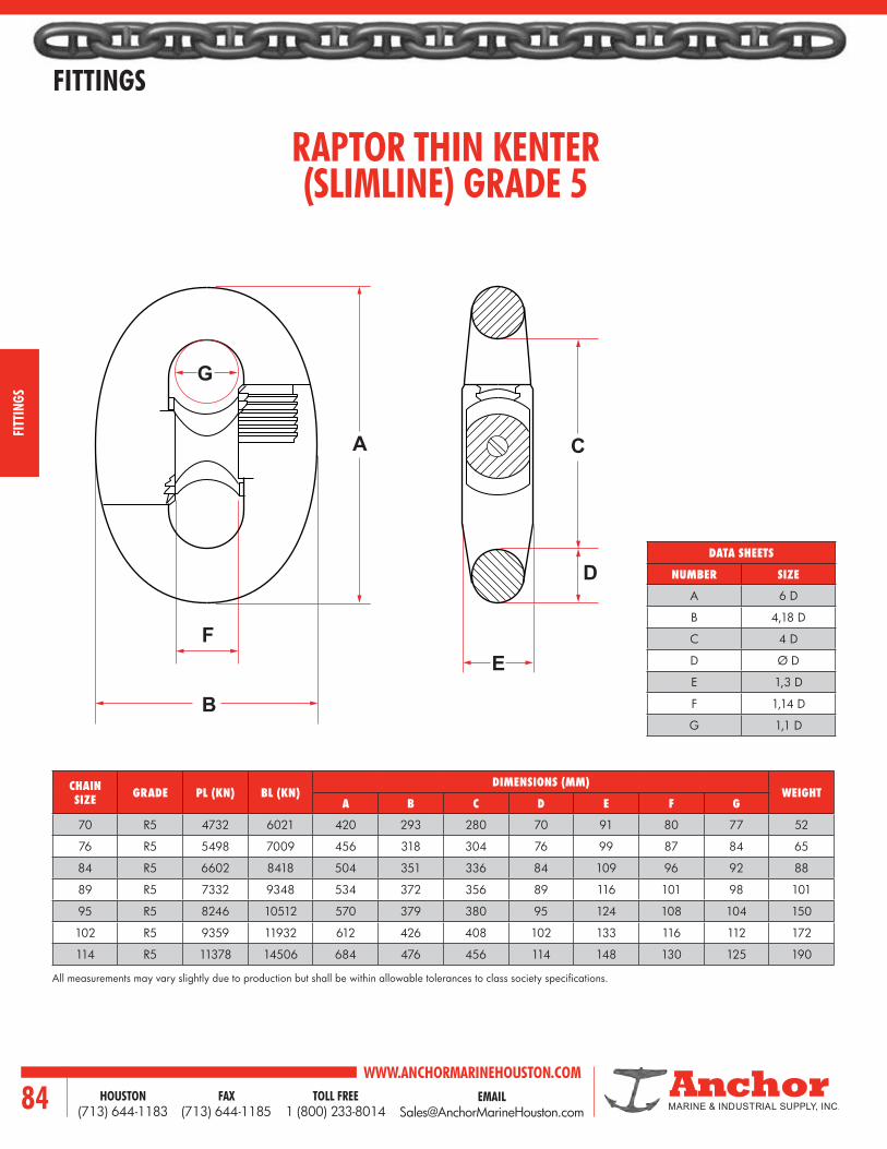
WWW.ANCHORMARINEHOUSTON.COMTOLL FREE
1 (800) 233-8014HOUSTON
(713) 644-1183FAX
(713) 644-118584
FITTINGS
FITT
INGS
RAPTOR THIN KENTER(SLIMLINE) GRADE 5
CHAIN SIZE GRADE PL (KN) BL (KN)
DIMENSIONS (MM)WEIGHT
A B C D E F G
70 R5 4732 6021 420 293 280 70 91 80 77 52
76 R5 5498 7009 456 318 304 76 99 87 84 65
84 R5 6602 8418 504 351 336 84 109 96 92 88
89 R5 7332 9348 534 372 356 89 116 101 98 101
95 R5 8246 10512 570 379 380 95 124 108 104 150
102 R5 9359 11932 612 426 408 102 133 116 112 172
114 R5 11378 14506 684 476 456 114 148 130 125 190
All measurements may vary slightly due to production but shall be within allowable tolerances to class society specifications.
DATA SHEETS
NUMBER SIZE
A 6 D
B 4,18 D
C 4 D
D Ø D
E 1,3 D
F 1,14 D
G 1,1 D
A
E
D
C
B
F
G

EMAIL [email protected]
WWW.ANCHORMARINEHOUSTON.COMTOLL FREE
1 (800) 233-8014HOUSTON
(713) 644-1183FAX
(713) 644-1185 85
FITTINGS
FITTINGS
CROWN ANCHOR SHACKLE
SHACKLE SIZEA
(MM)B
(MM)C
(MM)D
(MM)E
(MM)F
(MM)
WEIGHTPROOF LOAD
(LBS)MM INCHES KG LBS.
51 2 254.0 88.9 180.6 50.8 136.0 50.8 20 44 54,500
64 2-1/2 304.8 111.1 238.1 63.5 168.0 63.5 50 110 90,700
76 3 355.6 152 304 76.2 200.0 76.2 80 176 145,000
89 3-1/2 406.4 165.1 342.9 88.9 230.0 88.9 120 265 165,600
102 4 482.6 194.2 357.4 101.6 265.0 101.6 170 375 230,000
114 4-1/2 558.8 203.2 431.8 114.3 300.0 114.3 240 529 282,500
C
A
E
F
D
B
WITH ABS CERTIFICATION

WWW.ANCHORMARINEHOUSTON.COMTOLL FREE
1 (800) 233-8014HOUSTON
(713) 644-1183FAX
(713) 644-118586
FITTINGS
FITT
INGS
JAW & JAW SWIVEL SHACKLES
The Jaw & Jaw swivel shackle is designed to accept the shank of an anchor and the chain end is designed to accept a closed spelter socket or mooring chain. The applied proof load is dependent upon applicable design.
DIMENSIONS (INCHES)
A B C D E F G
29-1/8 13-5/8 15 3-5/8 7-1/4 4-1/8 2-5/8
29-1/8 13-5/8 15 3-3/4 7-1/4 4-1/2 3
30-3/8 18 17 4-1/4 9 5-1/2 3-1/2
30-3/8 21-1/2 19 4-1/4 10 6-1/2 4
30-3/8 21-1/2 19 6 10 7-1/2 4
Dimensions above are in inches, weight is in pounds. Other sizes available.
C
B
A
E
F G
DAnchor Chain End
Key OrWeldedWasher
End

EMAIL [email protected]
WWW.ANCHORMARINEHOUSTON.COMTOLL FREE
1 (800) 233-8014HOUSTON
(713) 644-1183FAX
(713) 644-1185 87
FITTINGS
FITTINGS
D-TYPE ANCHOR SHACKLE
Approximate dimensions shown. Contact us for specific dimensions, as they may differ between manufacturers.
All figures are factors which have to be multiplied with the nominal chain diameter.
SIZEINCHES MM
DIMENSIONS (INCHES) WEIGHT(LBS)
WEIGHT(KG)A B C D E F H P
3/4 19 6-1/2 3-7/8 2-3/8 1 1-3/8 1 1-3/4 3-1/2 5.5 2.5
7/8 22 7-5/8 4-1/2 2-3/4 1-1/4 1-5/8 1-1/4 2-1/8 4 8.4 3.8
1 25 8-3/4 5-1/4 3-1/8 1-3/8 1-3/4 1-3/8 2-3/8 4-5/8 13.2 6
1-1/8 29 9-3/4 5-7/8 3-1/2 1-5/8 2 1-5/8 2-3/4 5-1/8 18.5 8.4
1-1/4 32 10-7/8 6-1/2 3-7/8 1-3/4 2-1/4 1-3/4 3 5-3/4 24.9 11.3
1-3/8 35 12 7-1/8 4-1/4 1-7/8 2-1/2 1-7/8 3-1/4 6-3/8 34.2 15.5
1-1/2 38 13 7-3/4 4-5/8 2-1/8 2-3/4 2-1/8 3-5/8 6-7/8 43.7 19.8
1-5/8 41 14-1/8 8-1/2 5 2-1/4 2-7/8 2-1/4 3-7/8 7-1/2 56.9 25.8
1-3/4 44 15-1/4 9-1/8 5-3/8 2-1/2 3-1/8 2-1/2 4-1/4 8 70.3 31.9
1-7/8 48 16-3/8 9-3/4 5-7/8 2-5/8 3-3/8 2-5/8 4-1/2 8-5/8 85.5 38.8
2 51 17-3/8 10-3/8 6-1/4 2-3/4 3-5/8 2-3/4 4-3/4 9-1/4 105.8 48
2-1/8 54 18-1/2 11 6-5/8 3 3-7/8 3 5-1/8 9-3/4 125.7 57
2-1/4 57 19-5/8 11-3/4 7 3-1/8 4 3-1/8 5-3/8 10-3/8 147.7 67
2-3/8 60 20-5/8 12-3/8 7-3/8 3-3/8 4-1/4 3-3/8 5-3/4 10-7/8 176.6 80.1
2-1/2 64 21-3/4 13 7-3/4 3-1/2 4-1/2 3-1/2 6 11-1/2 204.1 92.6
2-5/8 67 22-7/8 13-5/8 8-1/8 3-5/8 4-3/4 3-5/8 6-1/4 12-1/8 234.6 106.4
2-3/4 70 23-7/8 14-1/4 8-1/2 3-7/8 5 3-7/8 6-5/8 12-5/8 267.6 121.4
2-7/8 73 25 15 8-7/8 4 5-1/8 4 6-7/8 13-1/4 310.2 140.7
3 76 26-1/8 15-5/8 9-1/4 4-1/4 5-3/8 4-1/4 7-1/4 13-3/4 350.5 159
A = 8.7DB = 5.2DC = 3.1DD = 1.4DE = 1.8DF = 1.4DH = 2.4DP = 4.6D
P
D H D
A
FC
E
B
D

WWW.ANCHORMARINEHOUSTON.COMTOLL FREE
1 (800) 233-8014HOUSTON
(713) 644-1183FAX
(713) 644-118588
FITTINGS
FITT
INGS
330.0Ø91.0
R61.0
R74.0
441.
0
Ø87.0
619.
0
R148.0
+3.80
+8.30
+3.80
+11.
40
(76MM) PEAR SHAPED RING
3» (76mm) Pear Shaped Ring ABS CertifiedNotes:1 Weight 160lbs2. Proof Load 3066.4 kN3. Break Load 4621.4 kN
WITH ABS CERTIFICATION

EMAIL [email protected]
WWW.ANCHORMARINEHOUSTON.COMTOLL FREE
1 (800) 233-8014HOUSTON
(713) 644-1183FAX
(713) 644-1185 89
FITTINGS
FITTINGS
C
C
C
A
A
A
B
B
B
D
PEAR RING
END LINK
MOORING RING
CHAIN SIZEDIMENSIONS
WEIGHTINCHES MM
A B C A B CMM INCHES KG LBS
42 1-5/8 10.97 6.50 1.95 279 165 50 9 20
44 1-3/4 11.81 6.91 2.10 300 176 53 11 24
51 2 13.50 7.90 2.40 343 201 61 17 37
58 2-1/4 15.19 8.89 2.70 386 226 69 24 53
64 2-1/2 16.88 9.88 3.00 429 251 76 32 71
70 2-3/4 18.56 10.86 3.30 471 276 84 43 95
76 3 20.25 11.85 3.60 514 301 91 55 122
89 3-1/2 23.65 13.83 4.20 601 351 107 90 197
102 4 27.00 15.80 4.80 686 401 122 133 292
CHAIN SIZEDIMENSIONS
WEIGHTINCHES MM
MM INCHES A B C D A B C D KG LBS
42 1-5/8 2.10 8.30 3.90 1.30 53 211 99 33 12 26
44 1-3/4 2.25 11.50 4.19 1.38 57 292 106 35 17 38
51 2 2.50 13.73 4.91 1.64 64 349 125 42 26 57
58 2-1/4 2.75 14.50 5.37 1.73 70 368 136 44 33 73
64 2-1/2 3.00 16.16 5.92 1.92 76 410 150 49 43 95
70 2-3/4 3.50 17.70 6.47 2.11 89 450 164 54 65 143
76 3 3.75 19.21 6.82 2.28 95 488 173 58 80 176
89 3-1/2 4.25 23.90 8.77 2.85 108 607 223 72 127 280
102 4 4.75 26.22 9.61 3.13 121 666 244 80 175 385
CHAIN SIZEDIMENSIONS
WEIGHT PROOF TESTINCHES MILLIMETERS
MM INCHES A B C A B C LBS KG LBS25 1 2.125 7.2 11.22 54 183 291 26 12 83,600
32 1-1/4 2.5 9.02 14.06 64 229 357 51 23 129,000
38 1-1/2 3 10.79 16.77 76 274 426 86 39 183,500
44 1-3/4 3.5 12.76 19.84 90 324 504 143 65 247,000
51 2 4 14.41 22.44 102 366 570 207 94 318,000
58 2-1/4 4.5 16.18 25.16 114 411 639 291 132 396,000
64 2-1/2 5 17.99 27.99 127 457 711 401 182 484,000
76 3 6 21.57 33.54 152 548 852 688 312 679,000
89 3-1/2 7 25.20 39.21 178 640 996 1107 502 900,000
102 4 8 28.90 44.96 204 734 1142 1664 755 1,143,000

WWW.ANCHORMARINEHOUSTON.COMTOLL FREE
1 (800) 233-8014HOUSTON
(713) 644-1183FAX
(713) 644-118590
FITTINGS
FITT
INGS
RETRIEVING HARDWARECHAIN CHASER AND GRAPNELUsed in the recovery of anchors and mooring lines, J-type chain chasers, permanent chain chasers, detachable permanent chain chasers, and grapnels are manufactured as one-piece units from special cast steel which is annealed for maximum unit strength.Retrieving hardware is designed for use with 2-3/4 to 3-1/2 in. mooring chain and anchors in the 30,000 to 45,000 lbs. class. All hardware is manufactured with rated testing loads which vary from 150 to 250 tons.All chasing equipment comes standard with welded hard-facing on contact areas to inhibit wear. Optional treatments include Rapid Solidification Plasma Deposition or R.S.P.D for superior wear and corrosion resistance isolated areas or entire castings can be treated.
J-TYPE CHAIN CHASERThe J-Type, chain chaser, complete with swivel shackle, is used to retrieve a rigs anchor when the pendant line is broken. It is a highly refined, stronger version of the conventional chain chaser originally developed for use in the North Sea. This unique design uses a sophisticated beam configuration in place of the usual T-type cross section to optimize quality and reliability.
PERMANENT CHAIN CHASERFor rigs requiring a permanent-type chain chaser, offers a stronger, better engineered version of the conventional chain chaser used in the North Sea. This type of anchor retrieval system eliminates the need for a pendant line buoy system. As with the J-type chaser, the permanent chaser incorporates a beam configuration that lessens the possibility of breaking with a significant decrease in eccentric bending.
DETACHABLE CHAIN CHASEREngineers have modified the conventional permanent chaser design to make the wear area detachable and replaceable. This innovative design allows the user to hook up easily and replace individual parts that are prone to wear, rather then replacing the entire chain chaser.
GRAPNELIn order to offer a total coverage for a variety of retrieving applications, we offer a four-prong grapnel. This unit is designed to recover lost anchors and mooring lines. The four-prong grapnel reduces the outfitting costs, since it is designed to accommodate the same connecting hardware as the permanent and J-type chain chasers.
Recommended Standard Swivel Shackle
Alternate 3’’ Safety-Type Anchor Shackle
J-Type Chain ChaserNotes:1. Weight - 3,200 lbs. (approx.)2. Test Load - 250 tons (500,000 lbs.) straight pull
Permanent Chain ChaserNotes:1. Weight - 2,600 lbs. (approx.)2. Test Load - 250 tons (500,000 lbs.) straight pull
Detachable Chain ChaserNotes:1. Weight - 2,610 lbs. (approx.)2. Test load - 250 tons (500,000 lbs.) straight pull3. Safe Working Load - 110 tons(220,000 lbs.)
Four-Prong GrapnelNotes:1. Weight - 4,000 lbs. (approx.)2. Test Load - 150 tons

EMAIL [email protected]
WWW.ANCHORMARINEHOUSTON.COMTOLL FREE
1 (800) 233-8014HOUSTON
(713) 644-1183FAX
(713) 644-1185 91
FITTINGS
FITTINGS
PAWL TYPE CHAIN STOPPER
NOMINAL NO. NOMINAL DIA. OF ANCHOR CHAIN
DIMENSIONS (MM)WEIGHT (KG.)
A B C D
42 36-42 530 494 357 422 210
46 42-46 620 538 404 480 396
51 48-51 680 599 438 520 429
56 52-56 730 638 472 560 465
60 58-60 780 670 506 600 480
64 62-64 835 710 538 630 500
68 66-68 885 750 568 660 567
73 70-73 950 801 604 700 682
78 76-78 1015 852 641 750 818
84 81-84 1095 911 686 800 1030
90 87-90 1170 969 732 850 1220
95 92-95 1235 1021 768 900 1420
102 97, 100, 102 1350 1090 816 950 1830
107 105-107 1400 1148 857 1000 2130
114 111-114 1480 1207 902 1050 2410
122 117-122 1585 1280 956 1120 2900
A
B
D
C

WWW.ANCHORMARINEHOUSTON.COMTOLL FREE
1 (800) 233-8014HOUSTON
(713) 644-1183FAX
(713) 644-118592
FITTINGS
FITT
INGS
PELICAN HOOK CHAIN STOPPER
CHAIN SIZEA
(MM)B
(MM)C
(MM)D
(MM)E
(MM)F
(MM)G
(MM)
LOADS WEIGHT
MM INCHESPROOFTESTKN
BREAKTESTKN
LBS
19 3/4 190 19 32 266 16 137 25 291.3 385 13
22 7/8 193 22 35 337 16 178 31 392.7 529.8 21
25-32 1 - 1-1/4 219 29 41 446 19 260 39 730.6 985.6 41
32-38 1-1/4 - 1-1/2 270 38 48 490 22 267 44 941.6 1,271.1 50
35-41 1-3/8 - 1-5/8 270 38 48 490 22 267 51 941.6 1,271.1 59
41-51 1-5/8 - 2 313 38 54 565 25 305 62 1,122 1,514.6 95
54-60 2-1/8 - 2-3/8 375 41 57 680 32 394 65 1,122 1,514.6 172
64-70 2-1/2 - 2-3/4 410 48 70 780 35 457 79 1,567.1 2,119.1 216
76-83 3 - 3-1/4 454 51 76 860 38 502 95 1,816.5 2,715.9 280
86-89 3-3/8 - 3-1/2 495 64 86 927 41 514 98 2,190.5 3,312.5 357
89-95 3-1/2- 3-3/4 568 73 108 997 44 533 114 3,137 4,746 440
121 4-3/4 568 73 108 1216 44 753 137 3,137 4,746 683
E
GB CA
F
D
WITH ABS CERTIFICATION

EMAIL [email protected]
WWW.ANCHORMARINEHOUSTON.COMTOLL FREE
1 (800) 233-8014HOUSTON
(713) 644-1183FAX
(713) 644-1185 93
FITTINGS
FITTINGS
305.4
63.5
39.7
127.0 188.4 215.9139.757.2 79.4
47.6
207.4
69.9
41.3
57.2
318.8 103.6
216.6R33.7
100.3
R32.5
DEVILS CLAW CHAIN STOPPER
DEVILS CLAW 46 - 60MM (1-11/16” - 2-3/8”)
70 LBS
DEVILS CLAW 33 - 41MM (1-5/16” - 1-5/8”)
44 LBS
Dimension in millimeter. Other sizes available upon request.
WITH ABS CERTIFICATION

WWW.ANCHORMARINEHOUSTON.COMTOLL FREE
1 (800) 233-8014HOUSTON
(713) 644-1183FAX
(713) 644-118594
FITTINGS
FITT
INGS
PELICAN HOOK TYPECHAIN STOPPERASSEMBLY
DEVIL’S CLAW TYPECHAIN STOPPERASSEMBLY
CHAIN SIZEINCHES DET.
LINK SIZE
PROOF LOAD LBS
BREAK LOAD LBSA B MIN. B MAX. C D E
INCHES MM3/4 19 16 33-1/4 40-1/2 1 11 7/8 3/4 67,500 91,100
7/8 22 17-1/4 38-7/16 45-9/16 1-7/32 11 1 7/8 88,200 119,000
1 - 1-1/8 25 - 29 19-1/2 46-7/8 55-1/2 1-17/32 13 1-1/8 1-1/8 145,000 195,000
1-1/4 32 19-5/8 48 56-5/8 1-17/32 13 1-1/4 1-1/4 178,200 240,600
1-1/4 HS - 1-1/2 32HS - 38 23-3/4 55-3/16 65-11/16 1-3/4 16 1-1/2 1-3/8 211,500 285,500
1-3/8HS - 1-5/8 34HS - 42 23-3/4 55-3/16 65-11/16 2 16 1-1/2 1-3/8 211,500 285,500
1-5/8HS - 2 42HS - 51 24-1/8 59-3/16 65-11/16 2-7/16 16 1-1/2 1-1/2 252,000 340,200
2-1/8 - 2-3/8 54 - 60 26-1/4 65-3/8 76-1/8 2-9/16 16 1-5/8 1-1/2 252,000 340,200
2-1/2 - 2-5/8 64 - 67 29-3/4 74-3/8 87-1/2 3-1/8 20 1-7/8 1-5/8 292,500 395,000
2-3/4 - 2-3/4HD 70 - 70HD 29-3/4 86-5/8 89-3/4 3-1/8 20 1-7/8 1-3/4 352,000 476,000
3HD - 3-1/4 76HD - 83 36 90-3/4 106-1/2 3-3/4 24 2-3/8 2-1/4 403,000 610,000
3-3/8 - 3-1/2 86 - 89 38-5/8 97-7/16 113-3/16 3-7/8 24 2-5/8 2-1/2 492,000 744,000
3-1/2HD- 3-3/4 89HD - 95 44-3/8 110 128-1/8 4-1/2 27-1/2 2-7/8 3 706,000 1,068,000
CHAIN SIZEINCHES DET.
LINK SIZE
PROOF LOAD LBS
BREAK LOAD LBSA B MIN. B MAX. C D E
INCHES MM3/4 - 3/4HS 19 - 19HS 16 35-1/2 42-3/4 10-1/2 11 7/8 3/4 67,500 91,100
7/8 - 7/8HS 22 - 22HS 17-1/4 38-1/4 45-3/8 10-1/2 11 1 7/8 88,200 119,000
1 - 1-1/8 25 - 29 19-1/2 43-1/16 51-11/16 10-1/2 13 1-1/8 1-1/8 145,000 195,000
1-1/4 32 19-5/8 44-3/16 52-13/16 10-1/2 13 1-1/4 1-1/4 178,200 240,600
1-1/4 HS - 1-1/2 32HS - 38 23-3/4 50-1/4 60-3/4 10-1/2 16 1-1/2 1-3/8 211,500 285,500
1-3/8HS - 1-5/8 34HS - 42 23-3/4 50-1/4 60-3/4 10-1/2 16 1-1/2 1-3/8 211,500 285,500
1-5/8HS - 2 42HS - 51 24-1/8 53-1/8 63-5/8 12 16 1-1/2 1-1/2 252,000 340,200
2-1/8 - 2-3/8 54 - 60 26-1/4 56-1/4 66-3/4 12-1/2 16 1-5/8 1-1/2 252,000 340,200
2-1/2 - 2-5/8 64 - 67 29-3/4 65 78-1/8 16 20 1-7/8 1-5/8 292,500 395,000
2-3/4 - 2-3/4HD 70 - 70HD 29-3/4 67-1/4 80-1/4 16 20 1-7/8 1-3/4 352,000 476,000
3HD - 3-1/4 76HD - 83 36 76-1/4 92-3/8 17-1/2 24 2-3/8 2-1/4 403,000 610,000
3-3/8 - 3-1/2 86 - 89 38-5/8 86-1/2 102-1/4 19 24 2-5/8 2-1/2 492,000 744,000
3-1/2HD- 3-3/4 89HD - 95 44-3/8 98-5/8 116-3/4 20-1/2 27-1/2 2-7/8 3 706,000 1,068,000
D
C
C
StopperChain Connecting LinkTurnbuckle
E
E
AB
Chain Connecting LinkTurnbuckle
DAB
D
C
C
StopperChain Connecting LinkTurnbuckle
E
E
AB
Chain Connecting LinkTurnbuckle
DAB

EMAIL [email protected]
WWW.ANCHORMARINEHOUSTON.COMTOLL FREE
1 (800) 233-8014HOUSTON
(713) 644-1183FAX
(713) 644-1185 95
FITTINGS
FITTINGS
ANCHOR LINE HOOK
SWL MBL(TON)
A(MM)
B(MM)
C(MM)
D(MM)
E(MM)
WEIGHT(KG)
15 60 38 58 343 32 45 8
20 80 40 74 343 32 60 13
25 100 52 86 440 38 65 22
50 200 80 112 618 45 90 100
80 320 90 130 709 62 100 145
Tolerance ± 5%
D
A
C
E
B

WWW.ANCHORMARINEHOUSTON.COMTOLL FREE
1 (800) 233-8014HOUSTON
(713) 644-1183FAX
(713) 644-118596
FITTINGS
FITT
INGS
22” 14-1/2”2” to 2-1/2” Closed
Spelter Socket
3”
Wire Rope Buoy Line
HINGE LINK
The 110-ton S.W.L. Hinge Link is specifically designed to provide a single, fast, easy connection to spelter sockets or thimbles that will hinge when passing over a wire rope drum. Hinge Link can be used to connect up to 3’’ wire rope closed spelter sockets and thimbles on anchor pendant lines.
PROOF LOAD: 440,000 LB.
Recommended above 2-3/16’’ chain
WITH ABS CERTIFICATION

EMAIL [email protected]
WWW.ANCHORMARINEHOUSTON.COMTOLL FREE
1 (800) 233-8014HOUSTON
(713) 644-1183FAX
(713) 644-1185 97
FITTINGS
FITTINGS
DETACHABLE LINK PUNCHES
ASSEMBLING PUNCHESPUNCH NO.
INCHESHANDLE
LINK SIZE E K H L
P-1A 5/8 - 3/4 3/4 15/64 5 1-1/8
P-2A 7/8 - 1 3/4 17/64 5 1-1/8
P-3A 1 - 1/8
1-1/4 - 1-3/8 1 3/8 6 1-3/8
P-4A 1-1/2 - 1-5/8 1 33/64 6-1/2 1-3/8
P-5A 1-3/4 - 2 1 21/32 6-1/2 1-1/2 X
P-6A 2-1/8 - 2-3/8 1 51/64 6-1/2 1-5/8 X
P-7A 2-1/2 - 2-7/8 1-1/8 61/64 6-1/2 1-5/8 X
P-8A 3 1-1/4 1-9/64 7 1-3/4 X
These punches are designed for the assembly and disassembly of detachable chain connecting links, kenter links, and anchor joining links. Sizes will vary for kenters and pear links made from steel, heat treated to 45-50 Rockwell C.
DISASSEMBLY PUNCHESPUNCH NO.
INCHESHANDLE
LINK SIZE E F H G
P-1D 5/8 - 3/4 3/4 13/64 5 1-1/4
P-2D 7/8 - 1 3/4 15/64 5 1-1/2
P-3D 1 - 1/8
1-1/4 - 1-3/8 1 5/16 6 2-1/2
P-4D 1-1/2 - 1-5/8 1 15/32 6-1/2 2-7/8
P-5D 1-3/4 - 2 1 9/16 6-1/2 3-1/4 X
P-6D 2-1/8 - 2-3/8 1 11/16 6-1/2 3-1/2 X
P-7D 2-1/2 - 2-7/8 1-1/8 13/16 6-1/2 3-1/2 X
P-8D 3 1-1/4 1 7 4 X
H
H
L
G
F
KE
E

WWW.ANCHORMARINEHOUSTON.COMTOLL FREE
1 (800) 233-8014HOUSTON
(713) 644-1183FAX
(713) 644-118598
FITTINGS
FITT
INGS
DASH NO.
SINKER CHAIN OR PAD EYE DIA RED DIM. A ± .12 DIM. B ± .12 RADIUS C ± .12 DIM. D ± .12
-1 1-3/4 - 2 12.06 3.03 2.56 1.88
-2 2-1/4 - 4 22.06 4.03 3.56 2.38
2 - 6 GRADE DH NUT, HEAVY, HEX, 2.250-SUN-2B ASTM A563 STEEL
- 2 5 GRADE DH NUT, HEAVY, HEX, 1.750-SUN-2B ASTM A563 STEEL
2 - 4 GRADE BD BOLT, HEX HD, 2.250-SUN-2B-2A X 9.25L ASTM A354 STEEL
- 2 3 GRADE BD BOLT, HEX HD, 1.750-SUN-2B-2A X 6.25L ASTM A354 STEEL
2 - 2 PLATE, 1.25 STE ASTM A36 STEEL
- 2 1 PLATE, 1.00 STE ASTM A36 STEEL
QTY REQD
QTY REQD
FIND NO.
PART OF IDENTIFYING NO. NOMENCLATURE OR DESCRIPTION SPECIFICATION MATERIAL
-2 -1 PARTS LIST
Note: Sinker shackle markings shall be as specified in Section 3.3.1
PLATE SINKER SHACKLE
A
D
C
B
2PL
2PL
4PLR. 1.0
5 or 6
1 or 2
1 or 2
2 or 4
Sinker Chain Of Pad Eye Ref
Fleet MooringChain Ref

EMAIL [email protected]
WWW.ANCHORMARINEHOUSTON.COMTOLL FREE
1 (800) 233-8014HOUSTON
(713) 644-1183FAX
(713) 644-1185 99
TOWING
WE’LL GIVE YOU SOMETHING TO HOLD ON TO… EQUIPMENT FOR EMERGENCY TOWING.
WE OFFER A COMPLETE STOCK OF EQUIPMENT FOR EMERGENCY TOWING ARRANGEMENTS, SUCH AS,
SMIT TOWING BRACKETS, PANAMA CHOCKS, CHAFING CHAINS, SEA-LINK TOWING SHACKLES AND
SEA-LINK TOWING PLATES.
SMIT BRACKET PANAMA CHOCK
CHAIN
Towing

WWW.ANCHORMARINEHOUSTON.COMTOLL FREE
1 (800) 233-8014HOUSTON
(713) 644-1183FAX
(713) 644-1185100
TOWING
TOW
ING
SMIT BRACKET
Hole In Plate
Pin
80
129125
84
30
3040 40
45
6
6
3015
40
12
KEY
SECTION A-A
28
32
50Ø25
Slot Welds75
15
210
525
20
290
100
120
PinØ75x30
30
30
6
3020
20
60
60
Ø40x12
Hole For Key
22015
10
28 30
2
8175
Min
60
Ø200
600
300
12550
45°
A A
45°
625
R=110
DECK UNDERNEATH TO BE REINFORCED IF NECESSARY STARBOARD CONNECTION IS DRAWN, PORT CONNECTION IS REFLECTED IMAGE.
APPROX. WEIGHT 195 KG EACH
AT LEAST THIS PART OF BOLT AND HOLES TO BE MACHINED
WITH ABS CERTIFICATION
SMALL SIZESWL 100 TON
CONNECTION FOR 2-3/4” - 3” TOWING CHAIN

EMAIL [email protected]
WWW.ANCHORMARINEHOUSTON.COMTOLL FREE
1 (800) 233-8014HOUSTON
(713) 644-1183FAX
(713) 644-1185 101
TOWING
TOWING
800
370
350
150
Ø25
DETAIL A DETAIL B
50
50 50
380
45
25120
150
295
100
225 25
15110
Det. B
Det. A50
30
75
2
55
90
200
160
6
3518
10
7
7
6 30 243
50
5050
30
25
35
35
35
650400
40x12
90
110
170
To Be Welded to Deck
Hole To FitKey Easily
3 35 5
A
SMIT BRACKET
DECK UNDERNEATH TO BE REINFORCED IF NECESSARY STARBOARD CONNECTION IS DRAWN, PORT CONNECTION IS REFLECTED IMAGE.
APPROX. WEIGHT 375 KG EACH
AT LEAST THIS PART OF BOLT AND HOLES TO BE MACHINED
LARGE SIZESWL 200 TON
CONNECTION FOR 3-1/4” TOWING CHAIN
WITH ABS CERTIFICATION

WWW.ANCHORMARINEHOUSTON.COMTOLL FREE
1 (800) 233-8014HOUSTON
(713) 644-1183FAX
(713) 644-1185102
TOWING
TOW
ING
SEA-LINK HEAVY LIFT INDUSTRIAL ANDMARINE TOWING SHACKLES
(MADE WITH PRIDE IN THE USA)
CHAIN PATTERN — REGULAR JAW
ANCHOR PATTERN — REGULAR JAW
SIZE (A)
WORKING LOAD
LIMIT IN TONS
PINDIAM. IN INCHES
(B)
JAW WIDTHINCHES
(C)
DIMENSIONS (INCHES) APPROX.
WT. EACH IN POUNDSD F
1-1/2 31 1-3/4 2-3/8 5-1/2 3-1/2 19
1-3/4 41 2 2-7/8 6-3/4 4-1/4 22
2 52 2-1/4 3-1/4 7-3/4 4-5/8 36
2-1/4 67 2-1/2 4-1/4 9-1/4 5 62
2-1/2 82 2-3/4 4-1/2 10-1/2 5-3/4 86
2-3/4 104 3 4-1/2 11 6-1/8 110
3 123 3-1/4 5 13 6-1/2 125
3-1/2 150 3-3/4 5-3/4 15 8-1/4 218
4 200 4-1/4 6-1/2 16 9-1/8 310
SIZE (A)
WORKING LOAD
LIMIT IN TONS
PINDIAM. IN INCHES
(B)
JAW WIDTHINCHES
(C)
DIMENSIONS (INCHES) APPROX. WT.
EACH IN POUNDSD E F
1-1/2 31 1-3/4 2-3/8 5-3/4 3-7/8 3-1/2 20
1-3/4 41 2 2-7/8 7 5 4-1/4 23
2 52 2-1/4 3-1/4 7-3/4 5-3/4 4-5/8 41
2-1/4 67 2-1/2 4-1/4 9-1/4 6-1/2 5 67
2-1/2 82 2-3/4 4-1/2 10-1/2 7-1/2 5-3/4 88
2-3/4 104 3 4-1/2 11 7-3/4 6-1/8 112
3 123 3-1/4 5 13 8-1/2 6-1/2 133
3-1/2 150 3-3/4 5-3/4 15 9 8-1/4 250
4 200 4-1/4 6-1/2 16 11 9-1/8 358
JAW TOLERANCE* Shackle Size 1-1/2 - 3 Inches = (+/-.125)* Shackle Size 3-1/2 - 4 Inches = (+/-.250)
REACH TOLERANCE* Shackle Size 1-1/2 - 2-1/2 Inches = (+/-.500)* Shackle Size 2-3/4 - 4 Inches = (+/-.750)
JAW TOLERANCE* Shackle Size 1-1/2 - 3 Inches = (+/-.125)* Shackle Size 3-1/2 - 4 Inches = (+/-.250)
REACH TOLERANCE* Shackle Size 1-1/2 - 2-1/2 Inches = (+/-.500)* Shackle Size 2-3/4 - 4 Inches = (+/-.750)
F
CB
A
D
A
F
D
C
E
BA
A
AVAILABLE IN SINGLE NUT OR DOUBLE NUT PINS.
SAFETY* 5:1 Safety Factor
SAFETY* 5:1 Safety Factor

EMAIL [email protected]
WWW.ANCHORMARINEHOUSTON.COMTOLL FREE
1 (800) 233-8014HOUSTON
(713) 644-1183FAX
(713) 644-1185 103
TOWING
TOWING
SEA-LINK HEAVY LIFT INDUSTRIAL ANDMARINE TOWING SHACKLES (WIDE JAW)
CHAIN PATTERN — WIDE JAW
ANCHOR PATTERN — WIDE JAW
(MADE WITH PRIDE IN THE USA)
SIZE (A)
WORKING LOAD
LIMIT IN TONS
PINDIAM. IN INCHES
(B)
JAWWIDTHINCHES
(C)
DIMENSIONS (INCHES) APPROX. WT.
EACH IN POUNDSD E F
1-1/2 22 1-3/4 4-3/16 8-1/8 6-1/4 3-1/2 28
1-3/4 30 2 5 9-3/8 6-7/8 4-1/4 40
2 40 2-1/4 5-3/4 10-1/2 8-1/8 4-5/8 55
2-1/4 48 2-1/2 6-1/4 11-1/2 8-7/8 5 75
2-1/2 55 2-3/4 6-1/2 12-3/8 9-3/8 5-3/4 106
2-3/4 68 3 7 12-3/4 9-3/4 6-1/8 138
3 80 3-1/4 7-1/4 13 10 6-1/2 157
3-1/2 120 3-3/4 9-1/4 15-1/2 12-1/4 8-1/4 274
SIZE (A)
WORKING LOAD
LIMIT IN TONS
PIN DIAM. IN INCHES
(B)
JAWWIDTHINCHES
(C)
DIMENSIONS (INCHES) APPROX. WT.
EACH IN POUNDSD F
1-1/2 22 1-3/4 4-3/16 8-1/8 3-1/2 28
1-3/4 30 2 5 9-3/8 4-1/4 45
2 40 2-1/4 5-3/4 10-1/2 4-5/8 60
2-1/4 48 2-1/2 6-1/4 11-1/2 5 71
2-1/2 55 2-3/4 6-1/2 12-3/8 5-3/4 112
2-3/4 68 3 7 12--3/4 6-1/8 127
3 80 3-1/4 7-1/4 13 6-1/2 165
3-1/2 120 3-3/4 9-1/4 15-1/2 8-1/4 278
JAW TOLERANCE* Shackle Size 1-1/2 - 3 Inches = (+/-.125)* Shackle Size 3-1/2 Inches = (+/-.250)
REACH TOLERANCE* Shackle Size 1-1/2 - 2-1/2 Inches = (+/-.500)* Shackle Size 2-3/4 - 3-1/2 Inches = (+/-.750)
JAW TOLERANCE* Shackle Size 1-1/2 - 3 Inches = (+/-.125)* Shackle Size 3-1/2 Inches = (+/-.250)
REACH TOLERANCE* Shackle Size 1-1/2 - 2-1/2 Inches = (+/-.500)* Shackle Size 2-3/4 - 3-1/2 Inches = (+/-.750)
D
CB
A
F
F
E
CB
A
D
A
A
AVAILABLE IN SINGLE NUT OR DOUBLE NUT PINS.
SAFETY* 5:1 Safety Factor
SAFETY* 5:1 Safety Factor

WWW.ANCHORMARINEHOUSTON.COMTOLL FREE
1 (800) 233-8014HOUSTON
(713) 644-1183FAX
(713) 644-1185104
TOWING
TOW
ING
6”
R 1”
5-1/2”
R 2-1/2”
R 6-7/32”
R4
R 4”3”
23”7” 7”
7”
R 2-1/2”
R 1-1/2”
R 1-1/2”
2-7/8”
2-3/8”3-1/4”
6-1/2”13-5/8”
22-1/2”
1-3/8”
1-1/8”
R 2-1/4”
2-1/4”
2”12”
10”
10”
4”
10” 31”
4”
3-5/8”4-5/16”
8-1/4”18-3/4”31”
R 6”
R 2”
R 2”
16”
17-1/2”
5-3/8”
3-1/2” 4-3/4”
TOW PLATE SPECIFICATIONS
NO. 1 NO. 2 NO. 3
SHACKLE SIZES 1-1/2” - 2” 2-1/4” - 3” 3-1/2” - 4”
DIMENSIONS 17-1/2” x 16” 22-1/2” x 23” 31” x 31”
WEIGHT 75 202 485
PROOF TEST 300,000 485,000 624,000
SEA-LINK TOW PLATES
All dimensions in inches and pounds unless otherwise indicated.
NUMBER 2 NUMBER 3
NUMBER 1
Approximate dimensions shown above. Contact us for specific dimensions, as they may differ between manufacturers.
WITH ABS CERTIFICATION

EMAIL [email protected]
WWW.ANCHORMARINEHOUSTON.COMTOLL FREE
1 (800) 233-8014HOUSTON
(713) 644-1183FAX
(713) 644-1185 105
TOWING
TOWING
330.0Ø91.0
R61.0
R74.0
441.
0
Ø87.0
619.
0
R148.0
+3.80
+8.30
+3.80
+11.
40
(76MM) PEAR SHAPED RING
3» (76mm) Pear Shaped Ring ABS CertifiedNotes:1 Weight 160lbs2. Proof Load 3066.4 kN3. Break Load 4621.4 kN
WITH ABS CERTIFICATION

WWW.ANCHORMARINEHOUSTON.COMTOLL FREE
1 (800) 233-8014HOUSTON
(713) 644-1183FAX
(713) 644-1185106
TOWING
TOW
ING
TOWING BRIDAL ASSEMBLY
1. SEA-LINK TOWING SHACKLE
2. SEA-LINK TOWING PLATE
3. STUD LINK ANCHOR CHAIN / G3
3. Stud Link Anchor Chain
1. Shackle
2. Tow Plate
1. Shackle
3. Stud Link Anchor Chain
3. Stud Link
Anchor Chain
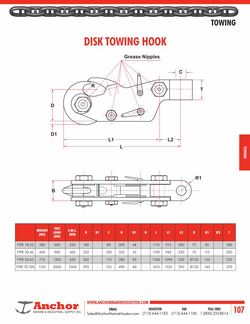
EMAIL [email protected]
WWW.ANCHORMARINEHOUSTON.COMTOLL FREE
1 (800) 233-8014HOUSTON
(713) 644-1183FAX
(713) 644-1185 107
TOWING
TOWING
DISK TOWING HOOK
WEIGHT (KG)
TESTLOAD(KN)
S.W.L. (KN) B B1 C D D1 H L L1 L2 R R1 R2 T
TYPE 18.25 380 500 250 182 - 80 309 48 - 1115 915 200 75 85 - 180
TYPE 30.45 450 900 450 232 - 100 323 35 - 1190 940 250 75 115 - 200
TYPE 50.65 715 1300 650 262 - 110 380 90 - 1340 1090 250 87.50 125 - 225
TYPE 70.100 1135 2000 1000 292 - 135 490 40 - 1615 1325 290 87.50 140 - 270
D1L1
D
R
Grease Nipples
L
C
T
L2
B
R1

WWW.ANCHORMARINEHOUSTON.COMTOLL FREE
1 (800) 233-8014HOUSTON
(713) 644-1183FAX
(713) 644-1185108
TOWING
TOW
ING
PUSH-PULL RATCHETSFOR CONSTRUCTION AND INDUSTRIAL
WORKBOATS… BARGES… CONTAINERSHIP LASHINGS

EMAIL [email protected]
WWW.ANCHORMARINEHOUSTON.COMTOLL FREE
1 (800) 233-8014HOUSTON
(713) 644-1183FAX
(713) 644-1185 109
TOWING
TOWING
B
KA
3 4
H J
7
VERTICAL & HORIZONTAL LASHINGS
ANGLE SHANK PELICAN HOOK ASSEMBLIES
SIZE (INCHES) DIMENSIONS (INCHES) MINIMUM
BREAKING STRENGTH
(TONS)A B H J K
1-1/8 6-1/2 3-5/8 1-5/8 7-1/2 3-3/8 25
1-3/8 8 4 1 6 3-1/4 45
This cutaway barrel picture explains one of the differences between the superior Anchor Marine Ratchet and the common. The Anchor Marine ratchet barrel is made from cold-drawn seamless steel tubing instead of welded pipe. It’s 50% stronger and provides a lighter ratchet. Anchor Marine ratchet barrels are made for adjustment ranges from 6’’ to 60’’, and for screw diameters (Acme or National Coarse) from 1/2’’ to 2-1/2’’.
The Anchor Marine Double-Acting Push-Pull Handles have a spring-loaded pawl that assures constant engagement of the pawl in the ratchet sheel (See cutaway illustration). This handle can be used overhead and the pawl will always be in position, which makes it ideal for construction and shipyard uses. Double-acting handles are available in the same sizes and styles as the other Anchor Marine Handles.
RATCHET BARREL
DOUBLE-ACTING HANDLES
ANGLE-SHANK PELICAN HOOK ASSEMBLY DIMENSIONS AND LOADING
3 - Pelican Hook 7 - Angle Shank Jaw
4 - Keeper Link

WWW.ANCHORMARINEHOUSTON.COMTOLL FREE
1 (800) 233-8014HOUSTON
(713) 644-1183FAX
(713) 644-1185110
TOWING
TOW
ING
CUSTOM DESIGN YOUR OWN PUSH-PULL RACHETS
ANGLE SHANK PELICAN HOOK ASSEMBLY
JAW WITH LOCKNUT
RATCHET AND BARREL
ONE PIECE SPRING LOADED HANDLE
WELDED LINK PELICAN HOOK ASSEMBLE
WELDED LINK AND HOOK
SWIVEL OR THREADED SHANK HOOK
EYE AND SHACKLE EYE AND LINK EYE STUB
HAND SHEEL VICE TYPE
3-PIECE HANDLEALL-STEEL HANDLE
SHACKLE-TYPE PELICAN HOOK ASSEMBLY
If any of the ratchets shown on previous pages do not meet your needs, here’s how you can tailor a ratchet for your own application.Beginning with the plain threaded barrel, choose the diameter to provide strength you need and the length for the takeup you require.Next, decide which of the five handles shown applies best. Then select by name the two end fittings from the eleven types shown.Select the amount of work load in pounds or tons you anticipate and the number of ratchets needed. We will send you a quotation promptly.
JAW

EMAIL [email protected]
WWW.ANCHORMARINEHOUSTON.COMTOLL FREE
1 (800) 233-8014HOUSTON
(713) 644-1183FAX
(713) 644-1185 111
HARDWARE
Hardware

WWW.ANCHORMARINEHOUSTON.COMTOLL FREE
1 (800) 233-8014HOUSTON
(713) 644-1183FAX
(713) 644-1185112
HARDWARE
HARD
WAR
E
ANCHOR PATTERN SHACKLES
Sizes 3/16’’ Thru 1’’ Available in Stainless Steel Safety TypeNOTES: Minimum breaking strength is six times rated working load. Furnishedingalvanizedorselfcoloredfinish.
HEAT-TREATED, DROP FORGED CARBON STEELANCHOR SHACKLE: SCREW PIN, ROUND PIN, SAFETY BOLT PIN
Pins are galvanized after threading.Shacklescanbefurnishedwithcompletetraceability,prooftestcertificates,and serial number at slight additional charge.
RATED LOAD TONS
DIMENSIONS (INCHES) WEIGHT IN POUNDS
A B C D E FSCREW PIN OR ROUND
PINSAFETY BOLT
1/3 3/16 1/4 7/8 3/8 9/16 19/32 0.05
1/2 1/4 5/16 1-1/8 1/2 3/4 3/4 0.12
3/4 5/16 3/8 1-1/4 9/16 7/8 1 0.18
1 3/8 7/16 1-7/16 11/16 1 1-1/8 0.3
1-1/2 7/16 1/2 1-11/16 3/4 1-1/8 1-1/4 0.5
2 1/2 5/8 1-7/8 13/16 1-3/16 1-5/16 0.75 0.8
3-1/4 5/8 3/4 2-7/16 1-1/16 1-9/16 1-11/16 1.5 1.6
4-3/4 3/4 7/8 3 1-1/4 1-7/8 2 2.16 3.0
6-1/2 7/8 1 3-5/16 1-7/16 2-1/8 2-1/4 3.37 4.0
8-1/2 1 1-1/8 3-3/4 1-11/16 2-3/8 2-5/8 5.3 5.5
9-1/2 1-1/8 1-1/4 4-1/4 1-7/8 2-5/8 3 7.0 8.0
12 1-1/4 1-3/8 4-1/2 2 2-15/16 3-3/8 9.6 11.0
13-1/2 1-3/8 1-1/2 5-1/4 2-1/4 3-5/16 3-5/8 12.6 15.0
17 1-1/2 1-5/8 5-3/4 2-3/8 3-5/8 3-7/8 17.3 19.5
21 1-5/8 1-3/4 6-1/4 2-5/8 3-3/16 4-3/8 21.0 23.0
25 1-3/4 2 7 2-7/8 4-5/16 5 27.8 31.5
35 2 2-1/4 7-3/4 3-1/4 5 5-3/4 41.0 42.0
42 2-1/4 2-1/2 8-3/4 3-7/8 5-1/2 6-1/2 65.0 69.0
55 2-1/2 2-3/4 10 4-1/8 6 7-1/4 83.5 94.0
60 2-3/4 3 11-1/4 4-1/2 6-1/4 8 118.0 121.0
85 3 3-1/4 13 5 6-3/4 9 140.0 146.0
120 3-1/2 3-3/4 15 5-3/4 8-1/2 10-1/8 250.0
150 4 4-1/4 17 6-1/2 9-3/8 10-1/2 360.0
175 4-1/2 4-3/4 19 7-1/4 10 12-1/2 445.0
F C
D
F F
D D E
B
A
C C

EMAIL [email protected]
WWW.ANCHORMARINEHOUSTON.COMTOLL FREE
1 (800) 233-8014HOUSTON
(713) 644-1183FAX
(713) 644-1185 113
HARDWARE
HARDWARE
CHAIN PATTERN SHACKLES
Sizes 3/16’’ Thru 1’’ Available in Stainless Steel Safety TypeNOTES: Minimum breaking strength is six times rated working load. Furnishedingalvanizedorselfcoloredfinish.
HEAT-TREATED, DROP FORGED CARBON STEELCHAIN SHACKLE: SCREW PIN, ROUND PIN, SAFETY BOLT PIN
Pins are galvanized after threading.Shacklescanbefurnishedwithcompletetraceability,prooftestcertificates,and serial number at slight additional charge.
RATED LOAD TONS
DIMENSIONS (INCHES) WEIGHT IN POUNDS
A B C D E SCREW PIN OR ROUND PIN SAFETY BOLT
1/3 3/16 1/4 7/8 3/8 9/16 0.05
1/2 1/4 5/16 1-1/8 1/2 3/4 0.1
3/4 5/16 3/8 1-1/4 9/16 7/8 0.18
1 3/8 7/16 1-7/16 11/16 1 0.25
1-1/2 7/16 1/2 1-11/16 3/4 1-1/8 0.41
2 1/2 5/8 1-7/8 13/16 1-3/16 0.61 0.8
3-1/4 5/8 3/4 2-7/16 1-1/16 1-9/16 1.2 1.4
4-3/4 3/4 7/8 3 1-1/4 1-7/8 2.12 2.5
6-1/2 7/8 1 3-5/16 1-7/16 2-1/8 3.28 3.8
8-1/2 1 1-1/8 3-3/4 1-11/16 2-3/8 4.6 5.5
9-1/2 1-1/8 1-1/4 4-1/4 1-7/8 2-5/8 6.3 7.5
12 1-1/4 1-3/8 4-1/2 2 2-15/16 9.25 10.8
13-1/2 1-3/8 1-1/2 5-1/4 2-1/4 3-5/16 12.19 14.3
17 1-1/2 1-5/8 5-3/4 2-3/8 3-5/8 16.15 19.0
21 1-5/8 1-3/4 6-1/4 2-5/8 3-13/16 21.0 23.0
25 1-3/4 2 7 2-7/8 4-5/16 27.0 30.5
35 2 2-1/4 7-3/4 3-1/4 5 39.5 45.0
42 2-1/4 2-1/2 8-3/4 3-7/8 5-1/2 65.0 69.0
55 2-1/2 2-3/4 10 4-1/8 6 72.0 82.0
60 2-3/4 3 11-1/4 4-1/2 6-1/4 98.0
85 3 3-1/4 13 5 6-3/4 135.0
120 3-1/2 3-3/4 15 5-3/4 8-1/2 187.0
150 4 4-1/4 17 6-1/2 9-3/8 360.0
175 4-1/2 4-3/4 19 7-1/4 10 445.0
E
B
A
C
D
C
D
C
D

WWW.ANCHORMARINEHOUSTON.COMTOLL FREE
1 (800) 233-8014HOUSTON
(713) 644-1183FAX
(713) 644-1185114
HARDWARE
HARD
WAR
E
SEA-LINK HEAVY LIFT INDUSTRIAL ANDMARINE TOWING SHACKLES
(MADE WITH PRIDE IN THE USA)
CHAIN PATTERN — REGULAR JAW
ANCHOR PATTERN — REGULAR JAW
SIZE (A)
WORKING LOAD
LIMIT IN TONS
PINDIAM. IN INCHES
(B)
JAW WIDTHINCHES
(C)
DIMENSIONS (INCHES) APPROX.
WT. EACH IN POUNDSD F
1-1/2 31 1-3/4 2-3/8 5-1/2 3-1/2 19
1-3/4 41 2 2-7/8 6-3/4 4-1/4 22
2 52 2-1/4 3-1/4 7-3/4 4-5/8 36
2-1/4 67 2-1/2 4-1/4 9-1/4 5 62
2-1/2 82 2-3/4 4-1/2 10-1/2 5-3/4 86
2-3/4 104 3 4-1/2 11 6-1/8 110
3 123 3-1/4 5 13 6-1/2 125
3-1/2 150 3-3/4 5-3/4 15 8-1/4 218
4 200 4-1/4 6-1/2 16 9-1/8 310
SIZE(A)
WORKING LOAD
LIMIT IN TONS
PINDIAM. IN INCHES
(B)
JAW WIDTHINCHES
(C)
DIMENSIONS (INCHES) APPROX. WT.
EACH IN POUNDSD E F
1-1/2 31 1-3/4 2-3/8 5-3/4 3-7/8 3-1/2 20
1-3/4 41 2 2-7/8 7 5 4-1/4 23
2 52 2-1/4 3-1/4 7-3/4 5-3/4 4-5/8 41
2-1/4 67 2-1/2 4-1/4 9-1/4 6-1/2 5 67
2-1/2 82 2-3/4 4-1/2 10-1/2 7-1/2 5-3/4 88
2-3/4 104 3 4-1/2 11 7-3/4 6-1/8 112
3 123 3-1/4 5 13 8-1/2 6-1/2 133
3-1/2 150 3-3/4 5-3/4 15 9 8-1/4 250
4 200 4-1/4 6-1/2 16 11 9-1/8 358
JAW TOLERANCE* Shackle Size 1-1/2 - 3 Inches = (+/-.125)* Shackle Size 3-1/2 - 4 Inches = (+/-.250)
REACH TOLERANCE* Shackle Size 1-1/2 - 2-1/2 Inches = (+/-.500)* Shackle Size 2-3/4 - 4 Inches = (+/-.750)
JAW TOLERANCE* Shackle Size 1-1/2 - 3 Inches = (+/-.125)* Shackle Size 3-1/2 - 4 Inches = (+/-.250)
REACH TOLERANCE* Shackle Size 1-1/2 - 2-1/2 Inches = (+/-.500)* Shackle Size 2-3/4 - 4 Inches = (+/-.750)
F
CB
A
D
A
F
D
C
E
BA
A
SAFETY* 5:1 Safety Factor
SAFETY* 5:1 Safety Factor
AVAILABLE IN SINGLE NUT OR DOUBLE NUT PINS.

EMAIL [email protected]
WWW.ANCHORMARINEHOUSTON.COMTOLL FREE
1 (800) 233-8014HOUSTON
(713) 644-1183FAX
(713) 644-1185 115
HARDWARE
HARDWARE
SEA-LINK HEAVY LIFT INDUSTRIAL ANDMARINE TOWING SHACKLES (WIDE JAW)
CHAIN PATTERN — WIDE JAW
ANCHOR PATTERN — WIDE JAW
(MADE WITH PRIDE IN THE USA)
SIZE(A)
WORKING LOAD
LIMIT IN TONS
PINDIAM. IN INCHES
(B)
JAWWIDTHINCHES
(C)
DIMENSIONS (INCHES) APPROX. WT.
EACH IN POUNDSD E F
1-1/2 22 1-3/4 4-3/16 8-1/8 6-1/4 3-1/2 28
1-3/4 30 2 5 9-3/8 6-7/8 4-1/4 40
2 40 2-1/4 5-3/4 10-1/2 8-1/8 4-5/8 55
2-1/4 48 2-1/2 6-1/4 11-1/2 8-7/8 5 75
2-1/2 55 2-3/4 6-1/2 12-3/8 9-3/8 5-3/4 106
2-3/4 68 3 7 12-3/4 9-3/4 6-1/8 138
3 80 3-1/4 7-1/4 13 10 6-1/2 157
3-1/2 120 3-3/4 9-1/4 15-1/2 12-1/4 8-1/4 274
SIZE (A)
WORKING LOAD
LIMIT IN TONS
PIN DIAM. IN INCHES
(B)
JAWWIDTHINCHES
(C)
DIMENSIONS (INCHES) APPROX. WT.
EACH IN POUNDSD F
1-1/2 22 1-3/4 4-3/16 8-1/8 3-1/2 28
1-3/4 30 2 5 9-3/8 4-1/4 45
2 40 2-1/4 5-3/4 10-1/2 4-5/8 60
2-1/4 48 2-1/2 6-1/4 11-1/2 5 71
2-1/2 55 2-3/4 6-1/2 12-3/8 5-3/4 112
2-3/4 68 3 7 12--3/4 6-1/8 127
3 80 3-1/4 7-1/4 13 6-1/2 165
3-1/2 120 3-3/4 9-1/4 15-1/2 8-1/4 278
JAW TOLERANCE* Shackle Size 1-1/2 - 3 Inches = (+/-.125)* Shackle Size 3-1/2 Inches = (+/-.250)
REACH TOLERANCE* Shackle Size 1-1/2 - 2-1/2 Inches = (+/-.500)* Shackle Size 2-3/4 - 3-1/2 Inches = (+/-.750)
JAW TOLERANCE* Shackle Size 1-1/2 - 3 Inches = (+/-.125)* Shackle Size 3-1/2 Inches = (+/-.250)
REACH TOLERANCE* Shackle Size 1-1/2 - 2-1/2 Inches = (+/-.500)* Shackle Size 2-3/4 - 3-1/2 Inches = (+/-.750)
D
CB
A
F
F
E
CB
A
D
A
A
SAFETY* 5:1 Safety Factor
SAFETY* 5:1 Safety Factor AVAILABLE IN SINGLE NUT OR
DOUBLE NUT PINS.

WWW.ANCHORMARINEHOUSTON.COMTOLL FREE
1 (800) 233-8014HOUSTON
(713) 644-1183FAX
(713) 644-1185116
HARDWARE
HARD
WAR
E
3’’ SEA-LINK TOWING SHACKLE(ELONGATED)
DIMENSIONS (INCHES)
A 3
B 3-1/4
C 5-1/2
D 16-1/4
SAFE WORKING LOAD 115 TONS
C
B
E
D
A

EMAIL [email protected]
WWW.ANCHORMARINEHOUSTON.COMTOLL FREE
1 (800) 233-8014HOUSTON
(713) 644-1183FAX
(713) 644-1185 117
HARDWARE
HARDWARE
HIGH STRENGTH ALLOY SHACKLES
HEAT-TREATED, DROP FORGED ALLOY STEEL ANCHOR AND
CHAIN SHACKLES: SCREW PIN AND SAFETY BOLT PIN
NOTES:Minimumbreakingstrengthisfivetimesratedworkingload.Furnishedingalvanizedorselfcoloredfinish.Pins are galvanized after threading. Shackles can be furnished with completetraceability,prooftestcertificates,andserialnumberat
slight additional charge.
* Available Size Options** Various Dimensional Options are available:Pleaseconfirmwhennecessary.Sizes 3/16’’ Thru 1’’ Available in Stainless Steel
RATED LOAD TONS
DIMENSIONS IN INCHESWEIGHT IN POUNDS
A BC
D E FANCHOR CHAIN SCREW PIN OR
ROUND PIN SAFETY BOLT
1-1/4 3/8 7/16 1-7/16 21/32 31/32 1-1/32 0.31-3/4 7/16 1/2 1-11/16 23/32 1-1/16 1-5/32 0.52-1/2 1/2 5/8 1-7/8 13/16 1-3/16 1-5/16 0.75 0.84
4 5/8 3/4 2-3/8 1-1/16 1-9/16 1-11/16 1.3 1.86 3/4 7/8 2-13/16 1-1/4 1-7/8 2 2.3 2.5
7-1/2 7/8 1 3-5/16 1-7/16 2-1/8 1-9/32 3.5 4.010 1 1-1/8 3-3/4 1-11/16 2-3/8 2-11/16 5.0 5.5
11-1/2 1-1/8 1-1/4 4-1/4 1-13/16 2-5/8 2-29/32 7.0 7.514 1-1/4 1-3/8 4-1/2 2-1/32 3 3-1/4 9.5 11.016 1-3/8 1-1/2 5-1/4 2-1/4 3-5/16 3-1/2 13.0 14.0
20* 1-1/2 1-5/8 3-3/4 2-3/8 3-5/8 3-7/8 17.0 19.030 1-1/2 1-5/8 5-3/4 5 2-3/8 3-5/8 3-7/8 19.0 21.024* 1-5/8 1-3/4 6-1/4 2-5/8 3-13/16 4-3/8 24.0 26.030* 1-3/4 2 7 2-7/8 4-5/16 5 28.0 31.040 1-3/4 2 7 5-3/4 2-7/8 4-5/16 5 30.0 34.040* 2 2-1/4 7-3/4 3-1/4 5 5-3/4 39.0 42.050 2 2-1/4 7-3/4 6-3/4 3-1/4 5 5-3/4 48.0 52.060 2-1/4 2-1/2 8-3/4 7-1/8 3-7/8 5-1/2 6-1/2 68.080 2-1/2 2-3/4 10-1/2 4-1/8 6 7-1/4 92.085* 2-1/2 2-3/4 10 8 4-1/8 6 7-1/4 94.095 2-3/4 3 11-1/4 8-1/2 4-1/2 6-1/4 8 121.0110 3 3-1/4 13 9 5 6-3/4 9 144.0
120* 3 3-1/4 13 5 6-1/2 9 146.0140 3-1/2 3-3/4 15 10-1/2 5-3/4 8-1/2 10-1/8 250.0175 4 4-1/4 17 12 6-1/2 9-3/8 10-1/2 360.0250 4-1/2 4-3/4 19 14-1/2 7-1/4 10 12-1/2 445.0250* 4-3/4 5-1/8 22-1/2 7-7/8 10-1/2 14-1/8 640.0300 5 5-1/4 21 21 8 12-1/2 14 620.0300* 5-1/8 5-3/4 25-1/2 8-1/4 11 15-3/4 810.0350 5-1/2 5-3/4 2-3 23 8-3/4 13-1/2 15-1/2 990.0
400* 5-3/4 6-1/8 28 8-7/8 12-1/2 17-3/4 1140.0400 6 6-3/4 26 26 10-1/4 15 17-1/2 1225.0500* 6-1/8 6-3/4 30-1/2 9-7/8 14 19-5/8 1380.0500 6-1/2 7-1/4 29 29 11 16 19 1710.0600 7 7-1/2 31 31 11-1/2 17 20 2030.0700 7-1/2 8 33 33 12-1/4 18 21-1/2 2605.0750* 8 8-1/2 32-1/2 13-3/8 17 23 3070.0800 8 8-1/2 36 36 13-1/2 19 23 2980.0
1000* 9-1/2 10 39 15-1/2 20 29-1/8 5150.0
F
D D E
B
C C
A

WWW.ANCHORMARINEHOUSTON.COMTOLL FREE
1 (800) 233-8014HOUSTON
(713) 644-1183FAX
(713) 644-1185118
HARDWARE
HARD
WAR
E
D
R
C
F
Y
X
LAA
B
E
G
D
R
C
F
Y
X
LAA
B
E
G
WIDE BODY SLING SAVER SHACKLE
WLLTON
A(MM)
B(MM)
C(MM)
D(MM)
E(MM)
F(MM)
G(MM)
L(MM)
R(MM)
X(MM)
Y(MM)
WEIGHT (*)
KGS
30 35 44 65 180 90 128 80 202 45 209 292 14
40 45 51 84 200 109 140 97 252 53 235 331 21
55 65 56 95 250 130 160 115 295 55 288 400 33
75 75 70 110 300 150 185 120 345 60 334 485 53
125 85 80 140 370 165 220 150 395 80 380 583 84
150 90 95 150 400 200 250 170 420 90 429 638 115
200 105 105 160 480 225 275 205 470 110 484 755 183
250 120 120 180 550 240 300 230 520 125 540 850 255
300 140 134 195 600 280 350 265 580 140 628 947 368
400 160 160 230 620 330 370 320 655 170 689 1035 571
500 170 180 265 680 350 450 340 710 180 779 1125 719
600 180 200 290 720 405 490 370 795 190 849 1213 960
700 210 215 320 780 465 540 400 880 215 957 1330 1350
800 220 230 345 800 465 555 420 925 220 975 1358 1400
900 235 250 370 850 480 585 440 1010 235 1060 1450 2100
1000 235 270 400 850 530 615 460 1050 240 1091 1490 2200
1250 275 300 455 960 570 645 560 1210 285 1205 1695 2800
1550 275 320 485 980 610 680 580 1240 290 1240 1745 3300
1750 310 360 500 1120 660 700 600 1330 310 1346 1860 4700
2000 320 385 520 1140 680 720 620 1350 320 1368 1932 4800
2500 330 400 520 1140 740 730 635 1380 330 1383 1995 5400
3000 340 420 530 1140 760 740 650 1410 340 1413 2025 5800
3500 350 440 540 1140 790 750 670 1480 350 1480 2068 6800
Tolerance ± 5%
Rounded wide body protectssling from damages.
Material : Alloy steel quenched and temperedSafety Facor : 5 timesFinish : PaintedCertificates :3.1BMaterialManufacturer Proofload.OnRequest :3.1CMaterialCertificate DNV, Loyds, ABS, BV etc. MPI & US Inspection

EMAIL [email protected]
WWW.ANCHORMARINEHOUSTON.COMTOLL FREE
1 (800) 233-8014HOUSTON
(713) 644-1183FAX
(713) 644-1185 119
HARDWARE
HARDWARE
BOW SAFTEY PIN SHACKLE
WLLTON
A(MM)
B(MM)
C(MM)
D(MM)
E(MM)
F(MM)
L(MM)
X(MM)
Y(MM)
WEIGHTKGS
120 89 95 150 380 200 238 420 416 617 110
150 102 108 170 400 230 275 475 479 671 160
200 120 125 180 500 260 290 520 530 813 235
250 125 140 205 540 260 305 560 555 865 285
300 130 150 205 600 305 305 570 565 958 340
400 165 175 230 680 350 326 665 655 1108 560
500 180 185 255 700 370 350 720 710 1158 685
600 195 205 285 700 405 375 815 765 1200 880
700 205 217 310 700 435 400 860 810 1231 980
800 210 217 310 700 435 400 870 820 1236 1100
900 220 230 330 700 465 420 910 860 1268 1280
1000 230 240 350 750 480 420 950 880 1290 1460
1250 278 270 370 780 590 450 1105 1010 1490 2320
1500 280 290 370 800 610 450 1105 1010 1530 2450
1750 300 330 430 950 660 540 1230 1140 1745 3280
2000 320 360 460 1050 680 560 1300 1200 1890 3920
Tolerance ± 5%
Material : Up to and including 120 T forged high tensile steel. Above 120 T forged high alloy steel.Safety Factor : 5 times. Generally to U.S. Federal Spec RR-271Finish : Painted / GalvanisedCertificates :3.1BMaterialManufacturerOnRequest :3.1CMaterialCertificate Proofloadcertificate DNV, Loyds, ABS, BV etc. MPI & US Inspection
A
D
C
F
Y
X
LAA
B
E

WWW.ANCHORMARINEHOUSTON.COMTOLL FREE
1 (800) 233-8014HOUSTON
(713) 644-1183FAX
(713) 644-1185120
HARDWARE
HARD
WAR
E
R
A
D
EB
C
R
A
FD
EB
C
MOORING SHACKLES SEA-LINK(MADE WITH PRIDE IN THE USA.)
TONSBERG TYPE
(ROLLER STYLE)MANDAL TYPE
ALL MODELS OF “SEA-LINK” MOORING SHACKLES ARE MADE
OF STAINLESS STEEL
FACTORY CERTIFICATES INCLUDED WITH EVERY “SEA-LINK”
MOORING SHACKLES
NO. SL 90 ST
A 11-3/8’’ 290mm
B 4-1/2’’ 115mm
C 5-1/2’’ 140mm
D 2-1/2’’ 65mm
E 3’’ 76mm
R 1-1/8’’ 28mm
NO. SL 120 SM
A 11-13/16’’ 300mm
B 5-3/8’’ 136mm
C 4-13/16’’ 125mm
D 2-3/4’’ 70mm
E 3-3/4’’ 95mm
F 5-7/16’’ 138mm
R 1-7/8’’ 48mm
Breaking Load 90 TonsWeight: 29 Lbs. 13Kg.
Breaking Load 120 TonsWeight: 37 Lbs. 16.8Kg.
Breaking Load 90 TonsWeight: 29 Lbs. 13Kg.
Breaking Load 120 TonsWeight: 37 Lbs. 16.8Kg.
NO. SL 120 ST
A 13-3/16’’ 335mm
B 5-3/16’ 135mm
C 5-3/4’’ 145mm
D 2-3/4’’ 70mm
E 3-7/8’ 98mm
R 1-1/8’’ 28mm
NO. SL 90 SM
A 11-3/8’’ 290mm
B 4-1/8’’ 105mm
C 4-3/4’’ 122mm
D 2-3/4’’ 70mm
E 2-3/4’’ 70mm
F 4-3/4’’ 121mm
R 1-1/4’’ 33mm
(PIN STYLE)R
A
D
EB
C
R
A
FD
EB
C

EMAIL [email protected]
WWW.ANCHORMARINEHOUSTON.COMTOLL FREE
1 (800) 233-8014HOUSTON
(713) 644-1183FAX
(713) 644-1185 121
HARDWARE
HARDWARE
HAMMERLOK COUPLING LINK
* Diameter of stock of largest link intended to be used with Hammerlok.** Caution: This working load limit should not be exceeded.
CHAIN SIZE (INCHES) ** 7/32 9/32 3/8 1/2 5/8 3/4 7/8 1 1-1/4
WORKING LOAD LIMIT (LBS.) * 2100 3500 7100 12000 18100 28300 34200 47700 72300
CODE NO. 664220 664228 664241 664250 664262 664275 664287 664300 664325
DIMENSIONS (INCHES)
A 1/4 5/16 1/2 11/16 13/16 15/16 1-3/64 1-1/4 1-17/32
B 1-13/32 1-13/16 2-13/32 3-3/8 4-1/16 4-25/32 5-1/8 5-3/4 6-13/16
C 31/64 5/8 53/64 1-7/32 1-1/2 1-51/64 1-29/32 2-3/16 2-5/8
E ** 13/32 1/2 3/4 1 1-1/4 1-1/2 1-3/4 2 2-1/4
MAX. WIDTH 1-5/16 1-11/16 2-7/32 3-1/8 3-11/16 4-5/16 5-5/16 6-3/16 7-3/4
WEIGHT EACH (LBS.) 0.12 0.23 0.65 1.50 2.60 3.80 6.30 9.30 17.30
Dependable and easy to use for fast, on-the-job assembly; for attaching chain to master links and eye-type hooks, and installing new body chain in old slings.
A
B
C
D
STUD ASSEMBLY1 - REQUIRED
LOAD PIN1 - REQUIRED
COUPLING PIN2 - REQUIRED

WWW.ANCHORMARINEHOUSTON.COMTOLL FREE
1 (800) 233-8014HOUSTON
(713) 644-1183FAX
(713) 644-1185122
HARDWARE
HARD
WAR
E
LOAD BINDERS
STANDARD LOAD BINDERS, LEVER TYPE
RATCHET LOAD BINDERS
• IMPROPER OPERATION OF LOAD BINDERS CAN RESULT IN SERIOUS INJURY OR DEATH.• Never exceed the Working Load Limit.• Read the following warnings, as well as the warnings on each page of this catalog.• Do not operate the binder while you or anyone else is on the load. You might slip or fall, risking serious injury or death.• When applying the binder, always position the load binder so the handle is tightened in a downward manner. Failure to
do so may result in a sudden snapping back of the lever which might result in serious injury or death.• Load binders are designed to be tightened to the approximate Working Load Limit by a substantial hand effort. Do not use
a hand extension. Extensions can severely damage the binder system and result in serious injury or death.• Theoperatorshouldatalltimesusetheloadbinderfromafirmstandingpositionthatwillensureprotectionforhimselfas
well as those in the immediate vicinity.• Load binders are a form of machinery and require periodic inspection and maintenance. Inspect for wear, deformation,
cracks, nicks or gouges before using. Replace if damaged.• Load binders should be periodically lubricated to give optimum performance and reduce friction losses.• ConsulttheU.S.GovernmentPrintingOfficefortheFederalMotorCarrierSafetyRegulationsforadditionalimportant
information, especially S 393.9 (relating to safe loading), S393.102 (relating to protection against shifting cargo) and S393.102 (relating to strength securement systems).
Forged steel, heat treated, painted red.
Forged steel, heat treated, painted red.
• In releasing lever type binders, be sure no one is positioned to be struck by the handle which may release suddenly.
• If there is a possibility for a relaxation of the chain when the binder is in the locked or ‘‘cover over’’ position, the handle should be secured to the binding chain by securely wrapping the loose end of the chain around the handle. Whenever possible, secure the handle down with a positive retaining method.
CAUTION: NEVER EXCEED THE WORKING LOAD LIMIT.FAILURE TO FOLLOW WARNINGS AND INSTRUCTIONS CAN RESULT IN SERIOUS INJURY OR DEATH. READ IMPORTANT WARNING AND INFORMATION PRECEDING FITTINGS SECTION.
SIZEWORKING
LOAD LIMIT (LBS.)
BREAKING STRENGTH
(LBS.)
APPROX. WT. EACH (LBS.) *
TAKE-UP
1-1/4’’ 2600 7750 3.1 2-1/2’’
5/16’’ - 3/8’’ 5400 19000 8.25 3-3/4’’
3/8’’ - 1/2’’ 9200 27600 11.5 4-1/4’’
SIZEWORKING
LOAD LIMIT (LBS.)
BREAKING STRENGTH
(LBS.)
APPROX. WT. EACH (LBS.) *
TAKE-UP
5/16’’ - 3/8’’ 5400 19000 11.25 8’’
3/8’’ - 1/2’’ 9200 27600 13.25 8’’
* Listed for comparison only. Never exceed the Working Load Limit.

EMAIL [email protected]
WWW.ANCHORMARINEHOUSTON.COMTOLL FREE
1 (800) 233-8014HOUSTON
(713) 644-1183FAX
(713) 644-1185 123
HARDWARE
HARDWARE
TURNBUCKLES
Larger sizes available per request.Lock nuts available per request.Jawendfittingssizes1/4’’through5/8’’haveboltsandnuts.Jawendfittingssizes3/4’’through2-3/4’’havepinsandcotters.Large jaw sizes available with bolts and nuts upon special request.
ACCORDING TO FEDERAL SPECIFICATION FF-T-79LB
When Ordering Be Sure to Specify:1st – Diameter of thread.2nd – Length of take-up.3rd – Self colored or galvanized.4th–Thetypeofendfittingsdesired.
EYE & EYE HOOK & EYE
HOOK & EYE
JAW & EYEJAW & JAW
DIAMETER (A) AND TAKEUP (B)
INCHES
AVERAGE OVERALL LENGTH
(C) IN CLOSED POSITION INCHES
WEIGHT POUNDS EACH
WITH EYE OR HOOKS JAW AND EYE JAW AND JAW
1/4 x 4 8-1/4 0.31 0.33 0.35
5/16 x 4-1/2 9-9/16 0.50 0.53 0.58
3/8 x 6 11-7/8 0.79 0.86 0.93
1/2 x 6 13-5/16 1.42 1.54 1.66
9 16-5/16 1.83 1.95 2.07
12 19-5/16 2.01 2.19 2.37
5/8 x 6 15-1/2 2.61 2.81 3.02
9 18-1/2 2.81 3.01 3.22
12 21-1/2 3.12 3.32 3.53
18 28-1/8 6.00 6.20 6.40
3/4 x 6 17-1/16 3.60 3.87 4.18
9 20-1/8 4.69 4.98 5.27
12 23-1/16 5.07 5.36 5.65
18 29-1/16 6.21 6.51 6.81
7/8 x 12 24-5/8 8.10 8.75 9.40
18 30-5/8 9.93 10.60 11.20
1 x 6 20-5/8 8.75 9.15 9.50
12 26-5/8 10.40 11.20 12.10
18 32-5/8 13.20 14.10 14.90
24 38-5/8 15.90 16.80 17.60
1-1/4 x 12 29-7/8 19.00 20.50 22.00
18 35-7/8 23.40 24.90 26.40
24 41-7/8 27.80 29.30 30.90
1-1/2 x 12 32-3/8 26.10 28.20 30.30
18 38-3/8 37.50 39.60 41.80
24 44-3/8 43.10 45.20 47.30
36 58-3/4 52.60 54.80 57.00
1-3/4 x 18 41-3/4 45.00 48.80 52.40
24 47-3/4 52.20 56.00 59.60
2 x 24 51-3/4 89.80 94.60 100.00
2-1/2 x 24 58-1/2 140.00 150.00 161.00
2-3/4 x 24 61-1/2 194.00 200.00 216.00
RATCHET LOAD BINDERS

WWW.ANCHORMARINEHOUSTON.COMTOLL FREE
1 (800) 233-8014HOUSTON
(713) 644-1183FAX
(713) 644-1185124
HARDWARE
HARD
WAR
E
TURNBUCKLES
HOOK
EYE
DIMENSIONS (INCHES) RATED LOAD (LBS.)A B C D E
1/4 1-5/8 7/16 3/8 1/4 400
5/16 1-29/32 1/2 7/16 5/16 700
3/8 2-9/32 9/16 17/32 3/8 1000
1/2 2-27/32 21/32 11/16 1/2 1500
5/8 3-17/32 27/32 27/32 5/8 2250
3/4 4-5/16 31/32 1 3/4 3000
7/8 5 1-1/8 1-3/16 7/8 4000
1 5-11/16 1-1/4 1-3/8 1 5000
1-1/4 6-29/32 1-1/2 1-1/2 1-1/16 6500
1-1/2 8-11/16 1-7/8 1-3/4 1-5/16 7500
DIMENSIONS (INCHES) RATED LOAD (LBS.)A B C D E
1/4 1-25/32 11/32 25/32 7/32 500
5/16 2-3/16 7/16 15/16 9/32 800
3/8 2-9/16 17/32 1-1/8 11/32 1200
1/2 3-7/32 23/32 1-7/16 7/16 2200
5/8 3-7/8 7/8 1-3/4 1/2 3500
3/4 4-11/16 1 2-1/8 5/8 5200
7/8 5-1/4 1-1/4 2-3/8 3/4 7200
1 6-3/8 1-7/16 3 7/8 10000
1-1/4 7-3/4 1-13/16 3-9/16 1-1/8 15200
1-1/2 8-5/8 2-1/8 4-1/8 1-1/4 21400
1-3/4 10 2-3/8 4-11/16 1-1/2 28000
2 12-1/8 2-11/16 5-3/4 1-3/4 37000
2-1/2 13-9/16 3-1/8 6-1/2 2 60000
2-3/4 15 3-1/4 7 2-1/4 75000
E
B
D
C
CE
DB
A
A

EMAIL [email protected]
WWW.ANCHORMARINEHOUSTON.COMTOLL FREE
1 (800) 233-8014HOUSTON
(713) 644-1183FAX
(713) 644-1185 125
HARDWARE
HARDWARE
JAW
DIMENSIONS (INCHES)RATED LOAD
(LBS.)A B C D E F G H
1/4 1-5/8 13/32 5/8 9/32 1/2 1/4 5/8 500
5/16 2 15/32 7/8 9/32 1/2 1/4 11/16 800
3/8 2-3/16 1/2 7/8 5/16 19/32 5/16 13/16 1200
1/2 2-3/4 5/8 1-1/16 13/32 3/4 3/8 1 2200
5/8 3-1/2 3/4 1-5/16 1/2 1-1/32 1/2 1-5/16 3500
3/4 4-1/8 15/16 1-1/2 9/16 1-9/32 5/8 1-5/8 5200
7/8 4-27/32 1-1/8 1-3/4 11/16 1-15/32 3/4 1-7/8 7200
1 5-17/32 1-3/16 2-1/16 25/32 1-21/32 7/8 2-1/8 10000
1-1/4 7-3/16 1-3/4 2-13/16 1 2-3/32 1-1/8 2-5/8 15200
1-1/2 7-7/8 2-1/16 2-13/16 1-1/16 2-15/32 1-3/8 3-1/8 21400
1-3/4 9-3/8 2-1/8 3-3/8 1-1/4 2-29/32 1-5/8 3-1/2 28000
2 10-7/8 2-1/2 3-11/16 1-9/16 3-17/32 2 4-3/16 37000
2-1/2 13-11/16 2-7/8 4-7/16 1-9/16 4-5/8 2-1/4 5-5/8 60000
2-3/4 15 3-1/2 4-3/16 1-5/8 5-3/8 2-3/4 6-1/2 75000
E
E
H
F
C D
B
A
A
G
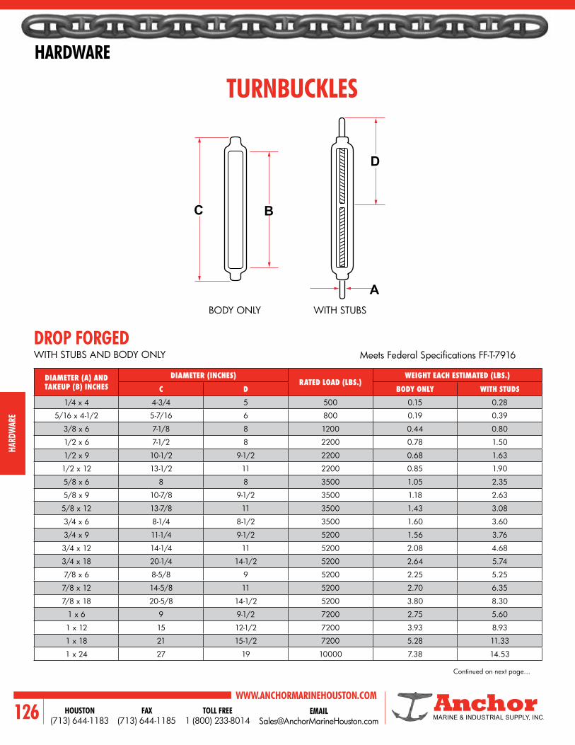
WWW.ANCHORMARINEHOUSTON.COMTOLL FREE
1 (800) 233-8014HOUSTON
(713) 644-1183FAX
(713) 644-1185126
HARDWARE
HARD
WAR
E
C B
A
D
TURNBUCKLES
DROP FORGEDWITH STUBS AND BODY ONLY MeetsFederalSpecificationsFF-T-7916
BODY ONLY WITH STUBS
DIAMETER (A) AND TAKEUP (B) INCHES
DIAMETER (INCHES)RATED LOAD (LBS.)
WEIGHT EACH ESTIMATED (LBS.)
C D BODY ONLY WITH STUDS
1/4 x 4 4-3/4 5 500 0.15 0.28
5/16 x 4-1/2 5-7/16 6 800 0.19 0.39
3/8 x 6 7-1/8 8 1200 0.44 0.80
1/2 x 6 7-1/2 8 2200 0.78 1.50
1/2 x 9 10-1/2 9-1/2 2200 0.68 1.63
1/2 x 12 13-1/2 11 2200 0.85 1.90
5/8 x 6 8 8 3500 1.05 2.35
5/8 x 9 10-7/8 9-1/2 3500 1.18 2.63
5/8 x 12 13-7/8 11 3500 1.43 3.08
3/4 x 6 8-1/4 8-1/2 3500 1.60 3.60
3/4 x 9 11-1/4 9-1/2 5200 1.56 3.76
3/4 x 12 14-1/4 11 5200 2.08 4.68
3/4 x 18 20-1/4 14-1/2 5200 2.64 5.74
7/8 x 6 8-5/8 9 5200 2.25 5.25
7/8 x 12 14-5/8 11 5200 2.70 6.35
7/8 x 18 20-5/8 14-1/2 5200 3.80 8.30
1 x 6 9 9-1/2 7200 2.75 5.60
1 x 12 15 12-1/2 7200 3.93 8.93
1 x 18 21 15-1/2 7200 5.28 11.33
1 x 24 27 19 10000 7.38 14.53
Continued on next page…
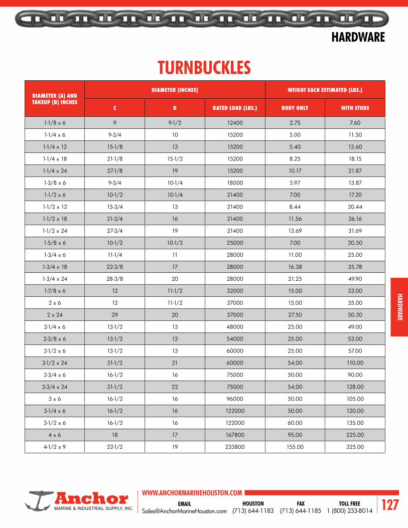
EMAIL [email protected]
WWW.ANCHORMARINEHOUSTON.COMTOLL FREE
1 (800) 233-8014HOUSTON
(713) 644-1183FAX
(713) 644-1185 127
HARDWARE
HARDWARE
TURNBUCKLESDIAMETER (A) AND TAKEUP (B) INCHES
DIAMETER (INCHES) WEIGHT EACH ESTIMATED (LBS.)
C D RATED LOAD (LBS.) BODY ONLY WITH STUDS
1-1/8 x 6 9 9-1/2 12400 2.75 7.60
1-1/4 x 6 9-3/4 10 15200 5.00 11.50
1-1/4 x 12 15-1/8 13 15200 5.40 13.60
1-1/4 x 18 21-1/8 15-1/2 15200 8.25 18.15
1-1/4 x 24 27-1/8 19 15200 10.17 21.87
1-3/8 x 6 9-3/4 10-1/4 18000 5.97 13.87
1-1/2 x 6 10-1/2 10-1/4 21400 7.00 17.20
1-1/2 x 12 15-3/4 13 21400 8.44 20.44
1-1/2 x 18 21-3/4 16 21400 11.56 26.16
1-1/2 x 24 27-3/4 19 21400 13.69 31.69
1-5/8 x 6 10-1/2 10-1/2 25000 7.00 20.50
1-3/4 x 6 11-1/4 11 28000 11.00 25.00
1-3/4 x 18 22-3/8 17 28000 16.38 35.78
1-3/4 x 24 28-3/8 20 28000 21.25 49.90
1-7/8 x 6 12 11-1/2 32000 15.00 33.00
2 x 6 12 11-1/2 37000 15.00 35.00
2 x 24 29 20 37000 27.50 50.30
2-1/4 x 6 13-1/2 13 48000 25.00 49.00
2-3/8 x 6 13-1/2 13 54000 25.00 53.00
2-1/2 x 6 13-1/2 13 60000 25.00 57.00
2-1/2 x 24 31-1/2 21 60000 54.00 110.00
2-3/4 x 6 16-1/2 16 75000 50.00 90.00
2-3/4 x 24 31-1/2 22 75000 54.00 128.00
3 x 6 16-1/2 16 96000 50.00 105.00
3-1/4 x 6 16-1/2 16 122000 50.00 120.00
3-1/2 x 6 16-1/2 16 122000 60.00 135.00
4 x 6 18 17 167800 95.00 225.00
4-1/2 x 9 22-1/2 19 233800 155.00 325.00

WWW.ANCHORMARINEHOUSTON.COMTOLL FREE
1 (800) 233-8014HOUSTON
(713) 644-1183FAX
(713) 644-1185128
HARDWARE
HARD
WAR
E
ALLOY PEAR SHAPE LINK
• Quenched & Tempered Alloy Steel• Unless noted otherwise, each link is individually prooftestedtovaluesshownonthecertificate.
• Eachlinkisshippedwithaprooftestcertificate.• Sizes 1’’ and under are drop forged. Sizes over 1’’
are welded and magnetic particle inspected.
Never Exceed Working Load Limit.
SIZE A (INCHES)
WORKING LOAD LIMIT
(LBS.)
PROOF LOAD (LBS.)
WEIGHT EACH (LBS.)
DIMENSIONS (INCHES)
B C D E F
1/2 7000 14000 0.55 1.50 1.00 4.00 3.00 0.50
5/8 9000 18000 1.10 1.88 1.25 5.00 3.75 0.63
3/4 12300 24600 1.76 2.25 1.50 6.00 4.50 0.75
7/8 14000 28000 2.82 2.63 1.75 7.00 5.25 0.88
1 24360 48700 4.22 3.00 2.00 8.00 6.00 1.00
1-1/8 30600 61200 6.25 3.38 2.25 8.75 6.75 1.13
1-1/4 36200 72400 8.25 3.75 2.50 10.00 7.50 1.25
1-3/8 43000 86000 11.25 4.13 2.75 11.00 8.25 1.38
1-1/2 54300 113200 14.25 4.50 3.00 12.00 9.00 1.50
1-5/8 62600 125200 18.50 4.88 3.25 13.00 9.75 1.63
1-3/4 84900 169800 22.50 5.25 3.50 14.00 10.50 1.75
1-7/8 95800 191600 29.00 5.63 3.75 15.00 11.25 1.88
2 102600 205200 34.00 6.00 4.00 16.00 12.00 2.00
2-1/4 143100 289200 48.00 6.75 4.50 18.00 13.50 2.25
2-1/2 160000 320000 66.00 7.50 5.00 20.00 15.00 2.50
2-3/4 216900 433800 88.00 8.25 5.50 22.00 16.50 2.75
3 228000 456000 114.00 9.00 6.00 24.00 18.00 3.00
3-1/4 262200 524400 146.00 9.75 6.50 26.00 19.50 3.25
3-1/2 279000 558000 181.00 10.50 7.00 28.00 21.00 3.50
4 373000 746000 271.00 12.00 8.00 32.00 24.00 4.00
AF
D
EC
B

EMAIL [email protected]
WWW.ANCHORMARINEHOUSTON.COMTOLL FREE
1 (800) 233-8014HOUSTON
(713) 644-1183FAX
(713) 644-1185 129
HARDWARE
HARDWARE
ALLOY MASTER LINK
• Quenched & Tempered Alloy Steel• Unless noted otherwise, each link is individually prooftestedtovaluesshownonthecertificate.Prooftested according to ASTM A952 to avoid localized point loading.
• Eachlinkisshippedwithaprooftestcertificate.• Sizes 2’’ and under are drop forged. Sizes over 2’’
are welded and magnetic particle inspected.
Never Exceed Working Load Limit.
SIZE A(INCHES)
WEIGHT (LBS.) DIMENSIONS (INCHES)
WORKING LOAD LIMIT PROOF LOAD WEIGHT EACH B C
1/2 7000 14000 0.82 2.50 5.00
5/8 9000 18000 1.52 3.00 6.00
3/4 12300 24600 2.07 2.75 5.50
1 24360 48700 4.85 3.50 7.00
1-1/4 36200 72400 9.57 4.38 8.75
1-1/2 54300 113200 16.22 5.25 10.50
1-3/4 84900 169800 25.22 6.00 12.00
2 102600 205200 37.04 7.00 14.00
2-1/4 143100 289200 54.10 8.00 16.00
2-1/2 160000 320000 67.75 8.00 16.00
2-3/4 216900 433800 87.70 9.50 16.00
3 228000 456000 115.00 9.00 18.00
3-1/4 262200 524400 145.00 10.00 20.00
3-1/2 279000 558000 200.00 12.00 24.00
3-3/4 336000 672000 198.00 10.00 20.00
4 373000 746000 228.00 10.00 20.00
4-1/4 354000 708000 302.00 12.00 24.00
4-1/2 360000 720000 345.00 14.00 28.00
4-3/4 389000 778000 436.00 14.00 28.00
5 395000 790000 516.00 15.00 30.00
A
C
B

WWW.ANCHORMARINEHOUSTON.COMTOLL FREE
1 (800) 233-8014HOUSTON
(713) 644-1183FAX
(713) 644-1185130
HARDWARE
HARD
WAR
E
SIZE OF CHAIN
(INCHES)
RATED LOAD (LBS.) APPROXIMATE DIMENSIONS (INCHES) WEIGHT POUNDS
EACHLOW
CARBON HIGH TEST LOW ALLOY C F G
1/4 1250 2600 3250 1-31/32 1/2 11/32 0.28
5/16 1900 3900 5000 2-1/4 9/16 7/16 0.45
3/8 2650 5400 6600 2-9/16 21/32 1/2 0.79
7/16 3500 7200 8750 2-15/16 3/4 9/16 1.19
1/2 4500 9200 11250 3-3/8 7/8 21/32 1.75
5/8 6900 11500 16500 4-3/32 1-1/16 25/32 3.25
3/4 18500 27000 5-5/32 1-3/8 15/16 5.94
7/8 24000 35000 5-29/32 1-9/16 1-1/16 9.17
1 30000 45000 6-23/32 1-13/16 1-3/16 13.83
CHAIN HOOKS
RATED LOAD SHOULD NOT BE EXCEEDED
EYE GRAB HOOK
EYE SLIP HOOKSIZE OF CHAIN
(INCHES)
RATED LOAD (LBS.) APPROXIMATE DIMENSIONS (INCHES) WEIGHT POUNDS
EACHLOW
CARBON HIGH TEST LOW ALLOY C F G
1/4 1250 2600 3250 2-17/32 1/2 15/16 0.40
5/16 1900 3900 5000 2-29/32 5/8 1-1/16 0.70
3/8 2650 5400 6600 3-5/16 23/32 1-5/16 1.00
7/16 3500 7200 8750 3-7/8 13/16 1-9/16 1.56
1/2 4500 9000 11250 4-9/32 15/16 1-11/16 2.31
5/8 6900 10000 15000 5-7/32 1-1/8 2 3.78
3/4 12500 19250 5-25/32 1-3/8 2-1/8 6.56
7/8 17250 26000 7-5/32 1-9/16 2-3/4 10.42
1 22700 34000 8-3/32 1-13/16 3 14.33
F
F
C
C
G
G

EMAIL [email protected]
WWW.ANCHORMARINEHOUSTON.COMTOLL FREE
1 (800) 233-8014HOUSTON
(713) 644-1183FAX
(713) 644-1185 131
HARDWARE
HARDWARE
SIZE OF CHAIN
(INCHES)
RATED LOAD (LBS.) APPROXIMATE DIMENSIONS (INCHES)WEIGHT POUNDS
EACHHIGH TEST TRANSPORT LOW ALLOY C E F G
1/4 2600 3150 3600 1-13/16 7/16 3/8 11/32 0.36
5/16 3900 4700 5400 2-5/32 1/2 7/16 7/16 0.60
3/8 5400 6600 7500 2-15/32 19/32 15/32 1/2 1.00
7/16 7200 8750 10000 2-25/32 21/32 9/16 9/16 1.31
1/2 9200 11300 12750 3-7/32 3/4 5/8 21/32 2.06
5/8 12750 16500 19000 4-3/32 29/32 3/4 25/32 4.25
3/4 18500 27000 4-5/8 15/16 7/8 15/16 7.19
CHAIN HOOKS
RATED LOAD SHOULD NOT BE EXCEEDED
CLEVIS GRAB HOOK
CLEVIS SLIP HOOKSIZE OF CHAIN
(INCHES)
RATED LOAD (LBS.) APPROXIMATE DIMENSIONS (INCHES) WEIGHT POUNDS
EACHHIGH TEST TRANSPORT LOW ALLOY C E F G
1/4 2600 3150 3250 2-9/16 7/16 3/8 15/16 0.44
5/16 3900 4700 5000 2-23/32 13/32 7/16 1-1/16 0.75
3/8 5400 6000 6600 3-1/4 19/32 15/32 1-5/16 1.13
7/16 7200 8700 8750 3-21/32 9/16 9/16 1-9/16 2.06
1/2 9200 11000 11300 4 3/4 5/8 1-11/16 2.75
5/8 11500 16000 16500 4-15/16 13/16 3/4 2 4.75
3/4 19250 6-3/32 1-5/16 1 2-1/2 11.28
E
E
F
F
C
C
G
G
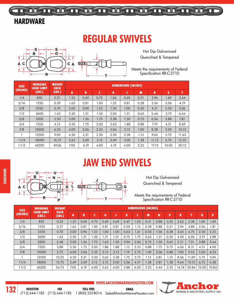
WWW.ANCHORMARINEHOUSTON.COMTOLL FREE
1 (800) 233-8014HOUSTON
(713) 644-1183FAX
(713) 644-1185132
HARDWARE
HARD
WAR
E
A C
R T
UB
C
R P
K G
T
J
A
VN
J
BS S
D
C AM SIZE
SIZELM
REGULAR SWIVELS
JAW END SWIVELS
SIZE (INCHES)
WORKING LOAD LIMIT
(LBS.)
WEIGHT EACH (LBS.)
DIMENSIONS (INCHES)
A B C D J M R S T1/4 850 0.21 1.25 0.69 0.75 1.06 0.69 0.31 2.94 1.69 3.44
5/16 1250 0.39 1.63 0.81 1.00 1.25 0.81 0.38 3.56 2.06 4.19
3/8 2250 0.75 2.00 0.94 1.25 1.50 1.00 0.50 4.31 2.50 5.06
1/2 3600 1.43 2.50 1.31 1.50 2.00 1.31 0.63 5.44 3.19 6.44
5/8 5200 2.50 3.00 1.56 1.75 2.38 1.50 0.75 6.56 3.88 7.81
3/4 7200 4.13 3.50 1.75 2.00 2.63 1.88 0.88 7.19 4.31 8.69
7/8 10000 6.25 4.00 2.06 2.25 3.06 2.13 1.00 8.38 5.00 10.13
1 12500 9.00 4.50 2.31 2.50 3.50 2.38 1.13 9.63 5.75 11.63
1-1/4 18000 16.37 5.63 2.69 3.13 3.69 3.00 1.38 11.13 6.75 13.35
1-1/2 45200 49.06 7.00 4.19 4.00 4.19 4.00 2.25 17.13 10.00 20.13
SIZE (INCHES)
WORKING LOAD LIMIT
(LBS.)
WEIGHT EACH (LBS.)
DIMENSIONS (INCHES)
A B C G J K L M N P R T U V
1/4 850 0.25 1.25 0.69 0.75 0.69 0.69 0.47 1.03 0.31 0.88 0.25 2.63 3.38 1.69 1.69
5/16 1250 0.37 1.63 0.81 1.00 0.81 0.81 0.50 1.13 0.38 0.88 0.31 2.94 3.88 2.06 1.81
3/8 2250 0.70 2.00 0.94 1.25 1.00 1.00 0.63 1.41 0.50 1.06 0.38 3.63 4.75 2.50 2.25
1/2 3600 1.43 2.50 1.31 1.50 1.31 1.31 0.75 1.75 0.63 1.31 0.50 4.50 6.06 3.19 2.88
5/8 5200 2.48 3.00 1.56 1.75 1.63 1.50 0.94 2.06 0.75 1.50 0.63 5.31 7.31 3.88 3.44
3/4 7200 3.88 3.50 1.75 2.00 1.88 1.88 1.13 2.53 0.88 1.75 0.75 6.06 8.31 4.31 4.00
7/8 10000 5.75 4.00 2.06 2.25 2.13 2.13 1.19 2.75 1.00 2.06 0.88 7.00 9.53 5.00 4.53
1 12500 10.25 4.50 2.31 2.50 2.63 2.38 1.75 3.72 1.13 2.81 1.13 8.56 11.69 5.75 5.94
1-1/4 18000 15.75 5.69 2.69 3.13 3.13 3.00 2.06 4.31 1.38 2.81 1.38 9.44 13.13 6.75 6.38
1-1/2 45200 54.75 7.00 4.19 4.00 5.63 4.00 2.88 6.00 2.25 4.44 2.25 14.74 20.84 10.00 10.84
Hot Dip GalvanizedQuenched & Tempered
Meets the requirements of Federal SpecificationRR-C-271D
Hot Dip GalvanizedQuenched & Tempered
Meets the requirements of Federal SpecificationRR-C-271D

EMAIL [email protected]
WWW.ANCHORMARINEHOUSTON.COMTOLL FREE
1 (800) 233-8014HOUSTON
(713) 644-1183FAX
(713) 644-1185 133
HARDWARE
HARDWARE
EYE HOOK (ROV)
HOOK NO.
WLL(TONS)
MBL (TONS)
DIMENSIONS (INCHES) WEIGHT KGA B C D E F G H I
27 8 32 2-1/8 2-11/16 2-3/32 1-7/8 8 1 1-31/32 1 1-1/2 8.2
29 12.5 50 2-13/16 3-3/8 2-11/16 2-13/32 9-31/32 1-1/4 2-1/2 1-1/4 1-7/8 17
30 16 64 3-3/16 3-25/32 3 2-11/16 11-3/16 1-13/32 2-27/32 1-13/32 2-3/32 22
31 20 80 3-19/32 4-7/32 3-3/8 3 12-9/16 1-9/16 3-3/16 1-9/16 2-13/32 29
32 28 112 2-13/16 4-13/32 3-25/32 3-1/4 13-15/16 1-1/2 3-3/4 1-1/2 2-15/32 37
33 31 125 3-3/16 4-15/16 4-3/16 3-5/8 15-5/16 1-11/16 3-15/16 1-11/16 2-3/4 51
34 40 160 3-21/32 5-1/2 4-9/16 4-1/16 18 1-7/8 5-1/8 1-7/8 3-5/32 75
35 50 200 4-3/16 6-7/32 5-5/16 4-9/16 19-1/2 2-1/8 5-1/8 2-1/8 3-1/2 108
36 63 250 4-11/16 6-15/16 5-15/16 5-1/8 22-1/4 2-3/8 5-29/32 2-3/8 3-29/32 139
37 80 320 5-5/32 7-13/16 6-5/8 5-23/32 27-5/32 2-5/8 6-11/16 2-5/8 4-5/16 218
38 100 400 5-15/16 8-7/8 7-11/16 6-25/32 28-9/16 3-1/8 6-7/8 3-1/8 4-15/16 353
39 150 600 6-13/16 9-27/32 8-7/8 7-27/32 30-1/8 3-3/8 5-1/8 3-3/8 6-5/16 573
40 200 800 7-7/8 10-13/16 10-1/4 9-5/16 33-15/32 4 5-29/32 4 7-3/32 919
41 250 1000 9-3/16 12-3/16 11-13/32 10-19/32 36-17/32 4-23/32 6-11/16 4-23/32 7-7/8 1270
42 300 1200 10-3/8 13-25/32 13 12-3/16 41-13/32 5-1/2 7-15/32 5-1/2 8-21/32 1808
43 400 1600 11-15/16 15-3/4 14-31/32 13-9/16 47-1/16 6-11/16 8-1/4 6-11/16 9-7/16 2480
44 500 2000 14-9/16 17-23/32 16-1/8 15-11/32 53-9/16 7-7/8 8-15/32 7-7/8 12-19/32 4057
Material : Grade 80Safety : 4 timesFinish : PaintedCertificate :Manufacturercertificate, proofloadonrequest.
STANDARD HOOK WITH SAFETY LATCH ROV HOOK
D
E
C B
FG A
I
H

WWW.ANCHORMARINEHOUSTON.COMTOLL FREE
1 (800) 233-8014HOUSTON
(713) 644-1183FAX
(713) 644-1185134
HARDWARE
HARD
WAR
E
DIMENSIONS (INCHES) WORKING LOAD LIMIT
(LBS.)
WEIGHT (LBS.)
SIZE (A) B C D
1/4 0.50 0.43 2.62 600 0.14
5/16 0.62 0.62 3.62 1100 0.33
3/8 0.75 0.87 4.62 1540 0.63
1/2 1.00 1.12 6.00 2640 1.40
5/8 1.25 1.37 7.37 4750 2.38
3/4 1.50 1.62 8.62 7000 3.93
S181 EYE AND JAW SWIVEL
S0182 JAW AND JAW SWIVEL
Stainless 316
Stainless 316
NOTE: COMMERCIAL TYPE
DIMENSIONS (INCHES) WORKING LOAD LIMIT
(LBS.)
WEIGHT (LBS.)
SIZE (A) B C D
1/4 0.50 0.43 2.50 600 0.15
5/16 0.62 0.62 3.50 1100 0.38
3/8 0.75 0.87 4.44 1540 0.74
1/2 1.00 1.12 5.88 2640 1.54
5/8 1.25 1.37 7.31 4750 2.63
3/4 1.50 1.62 8.63 7000 4.34
D
B
A
C
D
A
A
B
C

EMAIL [email protected]
WWW.ANCHORMARINEHOUSTON.COMTOLL FREE
1 (800) 233-8014HOUSTON
(713) 644-1183FAX
(713) 644-1185 135
HARDWARE
HARDWARE
DIMENSIONS (INCHES) BREAKING STRENGTH
(LBS.)
WEIGHT (LBS.)
A B C D
5/16 3-1/8 3/8 3/4 1400 0.15
3/8 4 1/2 7/8 2000 0.28
7/16 4-3/4 11/16 1-1/16 2500 0.41
SNAP HOOK OFFSET GATE
SNAP HOOK WITH EYE INSERT
AISI 316 Stainless
AISI 316 Stainless
SNAP HOOK
SNAP HOOK WITH EYE INSERT
AISI 316 Stainless
AISI 316 Stainless
DIMENSIONS (INCHES) BREAKING STRENGTH
(LBS.)
WEIGHT (LBS.)
A B C D
1/4 2-3/8 1/4 5/16 700 0.06
5/16 3-1/8 3/8 3/8 1400 0.15
3/8 3-15/16 7/16 1/2 2000 0.31
7/16 4-3/4 5/8 5/8 2500 0.43
DIMENSIONS (INCHES) BREAKING STRENGTH
(LBS.)
WEIGHT (LBS.)
A B C D
1/4 2-3/8 1/4 3/8 700 0.06
5/16 3-1/8 3/8 7/16 1400 0.14
3/8 4 7/16 9/16 2000 0.29
7/16 4-3/4 9/16 11/16 2500 0.46
DIMENSIONS (INCHES) BREAKING STRENGTH
(LBS.)
WEIGHT (LBS.)
A B C D
1/4 2-3/8 5/16 5/16 700 0.06
5/16 3-1/8 7/16 3/8 1400 0.14
3/8 3-15/16 9/16 1/2 2000 0.29
7/16 4-11/16 11/16 5/8 2500 0.46
AA
B
B
B
B
C
C
C
C
D
D
D
A
A
A

WWW.ANCHORMARINEHOUSTON.COMTOLL FREE
1 (800) 233-8014HOUSTON
(713) 644-1183FAX
(713) 644-1185136
HARDWARE
HARD
WAR
E
DB
C
DB
A
C
A
STAINLESS SCREW PIN ANCHOR SHACKLEDIMENSIONS (INCHES) LBS.
ASIZE B C D WORKING
LOAD LIMIT WEIGHT
3/16 0.26 0.41 0.83 650 0.05
1/4 0.31 0.47 1.11 1000 0.10
5/16 0.38 0.53 1.20 1300 0.17
3/8 0.44 0.66 1.41 1500 0.30
7/16 0.50 0.72 1.77 2000 0.50
1/2 0.63 0.82 1.83 3000 0.71
5/8 0.75 1.02 2.41 4000 1.39
3/4 0.88 1.25 2.84 6000 2.31
7/8 1.00 1.48 3.30 8000 3.64
1 1.13 1.70 3.80 10000 5.18
1-1/4 1.38 2.03 4.69 14000 9.88
DIMENSIONS (INCHES) LBS.
ASIZE B C D WORKING
LOAD LIMIT WEIGHT
1/4 0.31 0.47 1.11 1000 0.12
5/16 0.38 0.53 1.20 1300 0.18
3/8 0.44 0.66 1.41 1500 0.35
7/16 0.50 0.72 1.77 2000 0.57
1/2 0.63 0.82 1.83 3000 0.84
5/8 0.75 1.02 2.41 4000 1.64
3/4 0.88 1.25 2.84 6000 2.75
7/8 1.00 1.48 3.30 8000 4.18
1 1.13 1.70 3.80 10000 5.61
1-1/4 1.38 2.03 4.69 14000 9.88
STAINLESS SAFETY ANCHOR SHACKLE
SCREW PIN
SAFETY TYPE

EMAIL [email protected]
WWW.ANCHORMARINEHOUSTON.COMTOLL FREE
1 (800) 233-8014HOUSTON
(713) 644-1183FAX
(713) 644-1185 137
HARDWARE
HARDWARE
D
D
C
C
A
A
B
B
DIMENSIONS (INCHES) LBS
ASIZE B C D WORKING
LOAD LIMIT WEIGHT
5/32 0.17 0.32 0.55 200 0.02
3/16 0.19 0.37 0.69 500 0.03
1/4 0.23 0.47 0.82 750 0.05
5/16 0.31 0.62 1.10 1000 0.12
3/8 0.39 0.79 1.34 1200 0.23
1/2 0.47 0.95 1.65 1500 0.38
DIMENSIONS (INCHES) LBS.
ASIZE B C D WORKING
LOAD LIMIT WEIGHT
1/4 0.31 0.46 0.87 1000 0.11
5/16 0.38 0.52 1.02 1300 0.18
3/8 0.44 0.65 1.24 1500 0.31
7/16 0.50 0.75 1.43 2000 0.50
1/2 0.63 0.79 1.58 3000 0.74
5/8 0.75 1.05 1.94 4000 1.14
3/4 0.88 1.20 2.40 6000 2.36
7/8 1.01 1.45 2.88 8000 3.46
1 1.13 1.67 3.20 10000 4.85
STAINLESS SAFETY CHAIN SHACKLE
STAINLESS SCREW PIN CHAIN SHACKLE
SCREW PIN
SAFETY TYPE
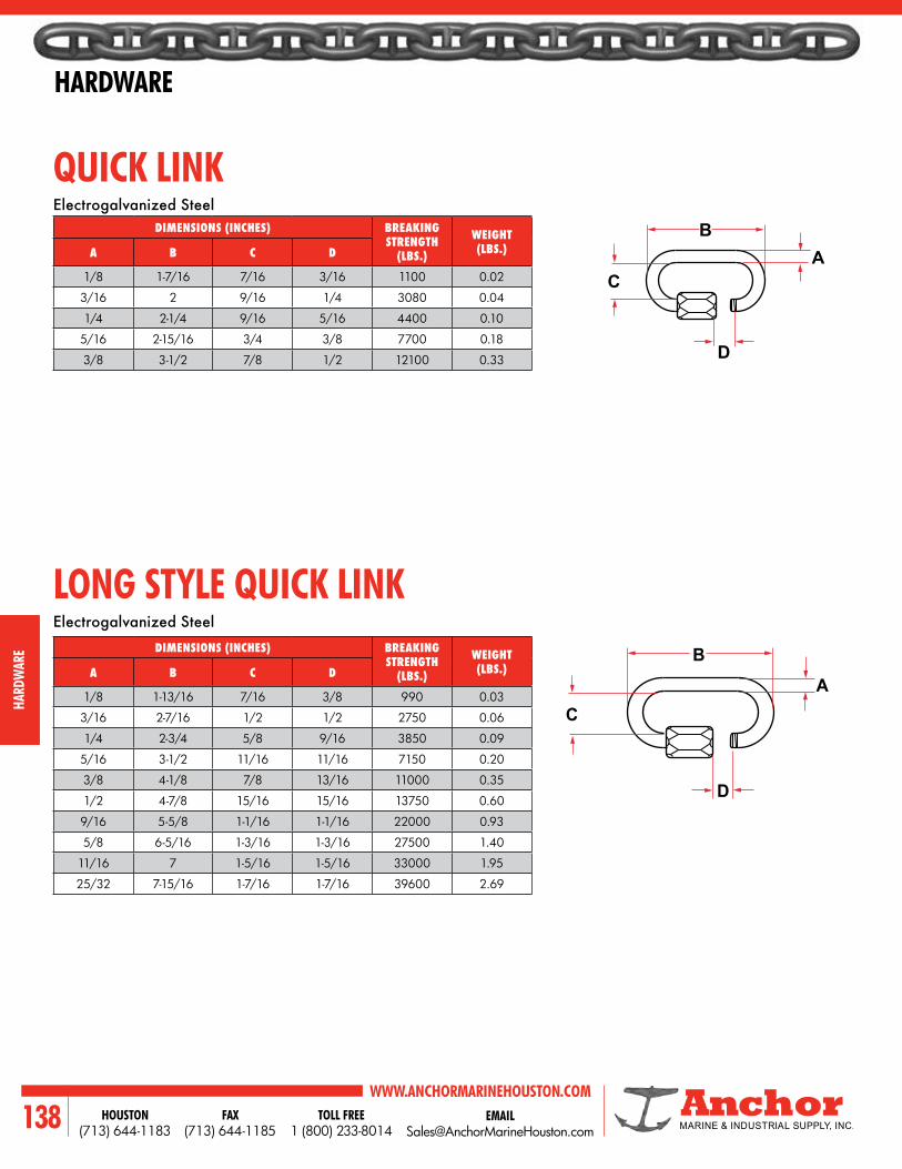
WWW.ANCHORMARINEHOUSTON.COMTOLL FREE
1 (800) 233-8014HOUSTON
(713) 644-1183FAX
(713) 644-1185138
HARDWARE
HARD
WAR
E
DIMENSIONS (INCHES) BREAKING STRENGTH
(LBS.)
WEIGHT (LBS.)A B C D
1/8 1-7/16 7/16 3/16 1100 0.02
3/16 2 9/16 1/4 3080 0.04
1/4 2-1/4 9/16 5/16 4400 0.10
5/16 2-15/16 3/4 3/8 7700 0.18
3/8 3-1/2 7/8 1/2 12100 0.33
QUICK LINK
LONG STYLE QUICK LINK
Electrogalvanized Steel
Electrogalvanized Steel
DIMENSIONS (INCHES) BREAKING STRENGTH
(LBS.)
WEIGHT (LBS.)A B C D
1/8 1-13/16 7/16 3/8 990 0.03
3/16 2-7/16 1/2 1/2 2750 0.06
1/4 2-3/4 5/8 9/16 3850 0.09
5/16 3-1/2 11/16 11/16 7150 0.20
3/8 4-1/8 7/8 13/16 11000 0.35
1/2 4-7/8 15/16 15/16 13750 0.60
9/16 5-5/8 1-1/16 1-1/16 22000 0.93
5/8 6-5/16 1-3/16 1-3/16 27500 1.40
11/16 7 1-5/16 1-5/16 33000 1.95
25/32 7-15/16 1-7/16 1-7/16 39600 2.69
D
AB
B
C
D
A
C

EMAIL [email protected]
WWW.ANCHORMARINEHOUSTON.COMTOLL FREE
1 (800) 233-8014HOUSTON
(713) 644-1183FAX
(713) 644-1185 139
HARDWARE
HARDWARE
QUICK LINKAISI 316 Stainless
DIMENSIONS (INCHES)BREAKING
STRENGTH (LBS.) WEIGHT (LBS.)A B C D
1/8 1-1/4 3/8 3/16 2420 0.02
5/32 1-9/16 7/8 7/32 2750 0.03
3/16 1-15/16 9/16 1/4 4950 0.05
1/4 2-1/4 5/8 5/16 7150 0.08
5/16 2-13/16 3/4 7/16 12000 0.18
3/8 3-7/16 13/16 1/2 19800 0.31
1/2 4-1/8 1 5/8 27500 0.51
9/16 4-3/4 1-1/8 5/8 38500 0.81
5/8 5-1/2 1-1/4 3/4 49500 1.25
B
D
CA

WWW.ANCHORMARINEHOUSTON.COMTOLL FREE
1 (800) 233-8014HOUSTON
(713) 644-1183FAX
(713) 644-1185140
HARDWARE
HARD
WAR
E
HEAVY DUTY WIRE ROPE THIMBLE REGULAR WIRE ROPE THIMBLE
AccordingtoFederalSpecificationFF-C-450,TypeIII,ClassI.
SIZE (INCHES)DIMENSIONS (INCHES) APPROX. WEIGHT
(LBS.)A B C D E
1/4 2.19 1.50 1.63 0.88 0.44 0.08
5/16 2.50 1.88 1.88 1.13 0.50 0.10
3/8 2.88 2.09 2.09 1.13 0.66 0.25
1/2 3.63 2.63 2.75 1.50 0.88 0.45
5/8 4.25 3.09 3.25 1.75 1.00 0.68
3/4 5.00 3.50 3.75 2.00 1.25 1.20
7/8 5.66 4.19 4.31 2.25 1.50 1.85
1 6.13 4.63 5.00 2.50 1.56 2.20
1-1/8 - 1-1/4 7.13 5.33 5.38 2.88 1.88 3.80
1-1/4 - 1-3/8 8.38 6.67 6.50 3.50 2.25 8.60
STAINLESS HEAVY DUTY WIRE ROPE THIMBLES - TYPE 304 & 316
STAINLESS REGULAR WIRE ROPE THIMBLES - TYPE 316
SIZE (INCHES)
DIMENSIONS (INCHES)
APPROX. WEIGHT (LBS.)A B C D E
1/8 1.88 1.06 1.25 0.69 0.16 0.02
3/16 1.88 1.06 1.25 0.69 0.22 0.02
1/4 1.94 1.06 1.31 0.69 0.28 0.03
5/16 2.13 1.25 1.50 0.81 0.38 0.05
3/8 2.38 1.47 1.63 0.94 0.44 0.06
1/2 2.75 1.75 1.88 1.13 0.56 0.12
5/8 3.50 2.38 2.25 1.38 0.69 0.24
BA
E
EAC
D BC
D

EMAIL [email protected]
WWW.ANCHORMARINEHOUSTON.COMTOLL FREE
1 (800) 233-8014HOUSTON
(713) 644-1183FAX
(713) 644-1185 141
HARDWARE
HARDWARE
45
90
WARNINGS1. Loads may slip or fall if proper eye bolt assembly and lifting procedures are not used.2. A failing load can seriously injure or kill.3. Read and understand both sides of these instructions, and follow all eye bolt safety information presented here.4. Read, understand and follow in diagrams and charts below before using eye bolt assemblies.
IMPORTANT SAFETY INFORMATION1. Always inspect eye bolt before use.2. Never use eye bolt that shows signs of wear or damage.3. Never use eye bolt if eye or shank is bent or elongated.4. Always be sure threads on shanks and receiving holes are clean.5. Never machine, grind, or cut eye bolt.
ASSEMBLY SAFETY1. NeverexceedloadlimitsspecifiedinTableI.2. Never use regular nut eye bolts for angular lifts.3. Always use shoulder nut eye bolts (or machinery eye bolts) for angular lifts.4. For angular lifts, adjust working load limits as follows:
Direction of Pull Adjusted Working Load45 degrees 30% of rated working load90 degrees 25% of rated working load
5. Never undercut eye bolt to seat shoulder against the load.6. Always countersink receiving hole or use washers to seat shoulder.7. Always screw eye bolt down completely for proper seating.8. Always tighten nuts securely against the load.
FORGED EYE BOLTS
REGULAR NUTEYE BOLT
Place washers or spacers between nut and load so that when the nut is tightened securely, the shoulder is secured flush against the load surface.
SHOULDER NUTEYE BOLT
MACHINERYEYE BOLT
SHOULDER NUT EYE BOLTIN-LINE LOAD
SIZE (INCHES) WORKING LOAD LIMIT
1/4 650
5/16 1200
3/8 1550
1/2 2600
5/8 5200
3/4 7200
7/8 10600
1 13300
1-1/4 21000
1-1/2 24000
SHOULDER NUT EYE BOLTInstallation for angular loading:The threaded shank must protrude through the load sufficientlytoallowfullengagementofthenut.If the eye bolt protrudes so far through the load that the nut can’t be tightened securely against the load, use properly sized washers to take up the excess space BETWEEN THE NUT AND THE LOAD.
Thickness of spacers must exceed the distance between the bottom of the load and the last thread of the eye bolt.

WWW.ANCHORMARINEHOUSTON.COMTOLL FREE
1 (800) 233-8014HOUSTON
(713) 644-1183FAX
(713) 644-1185142
HARDWARE
HARD
WAR
E
FORGED EYE BOLTS
EYE BOLT
SIZE LOAD LIMIT
SLIM THICKNESS REQ’D TO CHANGE
ROTATION 90 (DEGREES)
1/4 0.1250
5/16 0.1390
3/8 0.0156
1/2 0.0192
5/8 0.0227
3/4 0.0250
7/8 0.0278
1 0.0312
1-1/4 0.0357
1-1/2 0.0417
OPERATING SAFETY• Always stand clear of load.• Always lift load with steady, even pull — do not jerk.• Always apply load to eye bolt in the plane of the eye —
not at an angle.• Never exceed the capacity of the eye bolt (see Table 1)• When using lifting slings of two or more legs, make sure
the loads in the legs are calculated using the angle from the vertical to the leg and properly size the shoulder nut or machinery eye bolt for the angular load.
MACHINERY EYE BOLT - INSTALLATION FOR IN-LINE & ANGULAR LOADING1. After the loads on the eye bolts have been calculated, select
the proper size eye bolt for the job. For angular lifts, adjust working loads as follows:Direction of Pull Adjusted Working Load45° 30% of rated working load90° 25% of rated working load
2. Drill and tap the load to the correct sizes to a minimum depth of one-half the eye bolt size beyond the shank length of the machinery eye bolt.
3. Threadtheeyeboltintotheloaduntiltheshoulderisflushand securely tightened against the load.
4. If the plane of the machinery eye bolt is not aligned with the sling line, estimate the amount of unthreading rotation necessary to align the plane of the eye properly.
5. Remove the machinery eye bolt from the load and add shims (washers) of proper thickness to adjust the angle of the plane of the eye to match the sling line. Use Table II to estimate the required shim thickness for the amount of unthreading rotation required.
Do not reeve slings from one eye bolt to another. This will alter the load and angle of loading on the eye bolt.
After slings have been properly attached to the eye bolts, apply force slowly. Watch the load carefully and be prepared to stop applying force if the load starts buckling. Buckling may occur if the load is not stiff enough to resist the compressive forces which result from the angular loading.
Minimum tap depth is basic shank length plus one-half the nominal eye bolt diameter.
2x Diameter (minimum)
Tap Depth: 2.5 x
Diameter
READ AND UNDERSTAND THESE INSTRUCTIONS BEFORE USING EYE BOLTS. INSTALLATION FOR IN-LINE LOADING.
Resultant Load
One eye bolt diameter or less
Tighten hex nut securely against the
load
One eye bolt diameter of threads or less, use two (2) nuts.
More than one eye bolt diameter of threads, only (1) nut required.
RIGHTRIGHTRIGHT WRONG
TABLE II
Tighten hex nut securely against load
Tighten hex nut securely against load
Slim added to change eye alignment 90 .̊
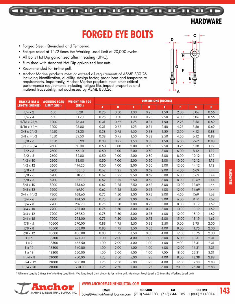
EMAIL [email protected]
WWW.ANCHORMARINEHOUSTON.COMTOLL FREE
1 (800) 233-8014HOUSTON
(713) 644-1183FAX
(713) 644-1185 143
HARDWARE
HARDWARE
SHACKLE DIA & LENGTH (INCHES)
WORKING LOAD LIMIT (LBS.)
WEIGHT PER 100 (LBS.)
DIMENSIONS (INCHES)
A B C D E F G H1/4 x 2 650 8.20 0.25 0.50 1.00 0.25 1.50 2.00 3.06 0.561/4 x 4 650 11.70 0.25 0.50 1.00 0.25 2.50 4.00 5.06 0.56
5/16 x 2-1/4 1200 13.30 0.31 0.62 1.25 0.31 1.50 2.25 3.56 0.695/16 x 4-1/4 1200 25.00 0.31 0.62 1.25 0.31 2.50 4.25 5.56 0.693/8 x 2-1/2 1550 23.30 0.38 0.75 1.50 0.38 1.50 2.50 4.12 0.883/8 x 4-1/2 1550 29.50 0.38 0.75 1.50 0.38 2.50 4.50 6.12 0.88
3/8 x 6 1550 35.20 0.38 0.75 1.50 0.38 1.50 6.00 7.62 0.881/2 x 3-1/4 2600 50.30 0.50 1.00 2.00 0.50 2.50 3.25 5.38 1.12
1/2 x 6 2600 66.10 0.50 1.00 2.00 0.50 3.00 6.00 8.12 1.121/2 x 8 2600 82.00 0.50 1.00 2.00 0.50 3.00 8.00 10.12 1.121/2 x 10 2600 88.00 0.50 1.00 2.00 0.50 3.00 10.00 12.12 1.121/2 x 12 2600 114.20 0.50 1.00 2.00 0.50 3.00 12.00 14.12 1.125/8 x 4 5200 103.10 0.62 1.25 2.50 0.62 2.00 4.00 6.69 1.445/8 x 6 5200 118.20 0.62 1.25 2.50 0.62 3.00 6.00 8.69 1.445/8 x 8 5200 135.10 0.62 1.25 2.50 0.62 3.00 8.00 10.69 1.445/8 x 10 5200 153.60 0.62 1.25 2.50 0.62 3.00 10.00 12.69 1.445/8 x 12 5200 167.10 0.62 1.25 2.50 0.62 4.00 12.00 14.69 1.44
3/4 x 4-1/2 7200 168.60 0.75 1.50 3.00 0.75 2.00 4.50 7.69 1.693/4 x 6 7200 184.50 0.75 1.50 3.00 0.75 3.00 6.00 9.19 1.693/4 x 8 7200 207.90 0.75 1.50 3.00 0.75 3.00 8.00 11.19 1.693/4 x 10 7200 235.00 0.75 1.50 3.00 0.75 3.00 10.00 13.19 1.693/4 x 12 7200 257.50 0.75 1.50 3.00 0.75 4.00 12.00 15.19 1.693/4 x 15 7200 298.00 0.75 1.50 3.00 0.75 5.00 15.00 18.19 1.697/8 x 5 10600 270.00 0.88 1.75 3.50 0.88 2.50 5.00 8.75 2.007/8 x 8 10600 308.00 0.88 1.75 3.50 0.88 4.00 8.00 11.75 2.007/8 x 12 10600 400.00 0.88 1.75 3.50 0.88 4.00 12.00 15.75 2.00
1 x 6 13300 421.00 1.00 2.00 4.00 1.00 3.00 6.00 10.31 2.311 x 9 13300 468.50 1.00 2.00 4.00 1.00 4.00 9.00 13.31 2.311 x 12 13300 540.00 1.00 2.00 4.00 1.00 4.00 12.00 16.31 2.311 x 18 13300 650.00 1.00 2.00 4.00 1.00 7.00 18.00 22.31 2.31
1-1/4 x 8 21000 750.00 1.25 2.50 5.00 1.25 4.00 8.00 13.38 2.881-1/4 x 12 21000 900.00 1.25 2.50 5.00 1.25 4.00 12.00 17.38 2.881-1/4 x 20 21000 1210.00 1.25 2.50 5.00 1.25 6.00 20.00 25.38 2.88
• Forged Steel - Quenched and Tempered• Fatigue rated at 1-1/2 times the Working Load Limit at 20,000 cycles.• All Bolts Hot Dip galvanized after threading (UNC).• Furnished with standard Hot Dip galvanized hex nuts.• Recommended for in-line pull.• Anchor Marine products meet or exceed all requirements of ASME B30.26 includingidentification,ductility,designfactor,proofloadandtemperaturerequirements. Importantly, Anchor Marine products meet other critical performance requirements including fatigue life, impact properties and material traceability, not addressed by ASME B30.26.
* Ultimate Load is 5 times the Working Load Limit. Working Load Limit shown is for in-line pull. Maximum Proof Load is 2 times the Working Load LImit.
FORGED EYE BOLTS
GF
E
A
H
B
CD

WWW.ANCHORMARINEHOUSTON.COMTOLL FREE
1 (800) 233-8014HOUSTON
(713) 644-1183FAX
(713) 644-1185144
HARDWARE
HARD
WAR
E
NOTES

EMAIL [email protected]
WWW.ANCHORMARINEHOUSTON.COMTOLL FREE
1 (800) 233-8014HOUSTON
(713) 644-1183FAX
(713) 644-1185 145
WIRE ROPE
Wire rope
6 X 19 SEALE 6 X 21 FILLER WIRE 6 X 19 WARRINGTON 6 X 25 FILLER WIRE
6 X 31 WARRINGTON SEALE
6 X 36 WARRINGTON SEALE
6 X 41 SFW SEALE FILLER WIRE
6 X 36 SEALE WARRINGTON SEALE
6 X 70 IWRC 6 X 64 IWRC

WWW.ANCHORMARINEHOUSTON.COMTOLL FREE
1 (800) 233-8014HOUSTON
(713) 644-1183FAX
(713) 644-1185146
WIRE ROPE
WIR
E RO
PE
USE SIZE (INCHES) CONSTRUCTION LAY CORE GRADECLAMSHELL
HOLDING & CLOSING LINES 1/2 - 1-1/4 6 x 25 FW or 6 x 36 WS RRL IWRC EIPS
BOTTOM HOIST LINE 1/2 & Up 6 X 25 FW RRL IWRC EIPS
TAG LINE 1/4 x 5/16 6 X 36 WS RRL FIBER EIPS
3/8 & Up 6 X 41 WS RRL FIBER EIPS
CRAWLER & TRUCK CRANES
HOIST LINE 1/2 - 1-1/4 6 x 25 FW or 19 x 7 NSNR RRL IWRC EIPS
BOTTOM HOIST LINE All 6 x 25 FW RRL IWRC EIPS
WHIP LINE 3/8 - 1-1/4 19 x NSNR RRL IWRC EIPS
CRANES & HOISTSOVERHEAD 1/4 - 7/16 6 x 19 S or 6 x 36 WS RRL IWRC EIPS
1/2 - 1 6 X 36 WS RRL IWRC EIPS
1-1/8 & Up 6 X 41 WS RRL IWRC EIPS
LADLE CRANE 1/2 - 1 6 X 36 WS RRL IWRC EIPS
1-1/8 & Up 6 X 41 WS RRL IWRC EIPS
DRAGLINE
HOIST LINE Up to 1-1/4 6 x 25 FW or 8 x 25 RRL IWRC EIPS
1-3/8 & Up 6 x 41 WS or 8 x 25, 8 x 36 RRL IWRC EIPS
DRAG LINE 3/4 - 1-1/2 6 x 21 FW or 8 x 25 RRL IWRC EIPS
1-5/8 - 3 6 x 25 FW or 8 x 36 RRL IWRC EIPS
3 & Up 6 x 41 FW or 8 x 36 RRL IWRC EIPS
BOOM HOIST 1/2 & Up 6 x 25 FW or 8 x 25 RRL IWRC EIPS
SHOVELS
HOIST LINE Up to 1-1/8 6 x 25 FW or 8 x 25 RRL IWRC EIPS
1/4 & Up 6 x 41 WS or 8 x 25 RRL IWRC EIPS
CROWD & RETRACT 3/4 & Up 6 x 41 WS or 8 x 25 RRL IWRC EIPS
BOTTOM HOIST 1/2 - 1-1/4 6 x 25 FW or 8 x 25 RRL IWRC EIPS
1-3/8 & Up 6 x 41 WS or 8 x 25 RRL IWRC EIPS
TRIP ROPE 3/8 - 1 6 x 36 WS or 8 x 25 RRL FIBER IPS
1 & Up 6 x 41 WS or 8 x 25 RRL FIBER IPS
LOGGING ROPES
CHOKERS All 6 x 26 WS or 6 x 25 FW RRL IWRC EIPS
WINCH LINES All 6 x 26 WS or 6 x 25 FW RRL IWRC EIPS
MININGSLOPE ROPE All 6 x 19 S or 6 x 21 FW RRL FIBER IPS
SHAFT HOIST ROPES All 6 x 19 S or 6 x 25 FW RLL or RRL FIBER IPS
SLUSHER ROPE All 3 x 19 S or 6 x 19 S RRL IWRC IPS
MINING MACHINE ROPE All 6 x 36 WS or 6 x 41 WS RRL IWRC EIPS
SUGGESTED WIRE ROPE FOR PARTICULAR USES
Preformed or Form-Set construction is used for all ropes shown.

EMAIL [email protected]
WWW.ANCHORMARINEHOUSTON.COMTOLL FREE
1 (800) 233-8014HOUSTON
(713) 644-1183FAX
(713) 644-1185 147
WIRE ROPE
WIRE ROPE
SUGGESTED WIRE ROPE FOR PARTICULAR USES
USE SIZE (INCHES) CONSTRUCTION LAY CORE GRADE
MARINE ROPES
TOWING HAWSER All 6 X 41 WS RRL F.C. or IWRC EIPS
MOORING LINES All 6 x 24 S or 6 x 41 WS RRL F.C. or IWRC EIPS
CARGO FALLS All 6 X 36 WS RRL IWRC EIPS
OIL FIELD
ROTARY DRILL LINES 3/4 - 1-1/2 6 x 19 S or 6 x 21 S RRL IWRC EIPS
SAND LINES All 6 x 7 RRL POLY IPS
TUBING LINES All 6 x 26 WS or 19 x 7 NSNR RRL or LRL IWRC EIPS
CABLE TOOL LINE All 6 X 21 WS LRL POLY IPS
OFFSHORE
ROTARY DRILL LINES 1 - 1-3/4 6 x 19 S RRL IWRC EIPS
RISER TENSIONER LINES 1-1/4 - 2 6 X 41 WS RLL IWRC IPS
GUIDE LINES 1/2 - 1 6 x 25 FW RRL IWRC IPS
SAND LINES 1/2 - 5/8 6 x 7 RRL FIBER IPS
PENDANT LINES 1-1/2 - 3 6 x 25 FW or 6 x 37 WS RRL IWRC EIPS
CRANE-MAIN HOIST 3/8 - 2 6 x 25 FW or 6 x 37 WS RRL F.C. or IWRC IPS or EIPS
CRANE-AUXILIARY HOIST 3/8 - 2-1/4 19 x 7 NSNR or 36 x 7 NSNR RRL IWRC EIPS
ANCHOR LINES 1-3/8 - 6 6 x 37 WS through 6 x 91 RRL IWRC EIPS
HEAVY LIFT SLINGS 1-1/2 - 4 6 X 37 WS RRL IWRC EIPS
CABLE LAID HEAVY LIFT SLINGS 3-1/2 - 10 7 x 6 x 41 RLL or LLL IWRC EIPS
Preformed or Form-Set construction is used for all ropes shown.
GRADE CONSTRUCTION LAY CORE
IPS - Improved Plow SteelFW - Fiber Wire
RRL - Right Regular Lay IWRC - Independent Wire Rope Core
WS - Warrington Seale
EIPS - Extra Improved Plow Steel
SFW - Seale Fiber WireRLL - Right Lang Lay FC - Fiber Core
NSNR - Non Spin Non Rotating
GIPS - Galvanized Improved Plow Steel
LRL - Left Regular Lay Fiber - Hemp or Poly CareW - Warrington
S - Seale LLL - Left Lang Lay Poly - Polypropylene Core
DEFINITION OF ABBREVIATIONS

WWW.ANCHORMARINEHOUSTON.COMTOLL FREE
1 (800) 233-8014HOUSTON
(713) 644-1183FAX
(713) 644-1185148
WIRE ROPE
WIR
E RO
PE
FIGURING REEL CAPACITY
DIAMETER (INCHES) K DIAMETER
(INCHES) K DIAMETER (INCHES) K
1/16 49.8 1/2 0.925 1-3/8 0.1270
3/32 23.4 9/16 0.741 1-1/2 0.1070
1/8 13.6 5/8 0.607 1-5/8 0.0886
5/32 8.72 11/16 0.506 1-3/4 0.0770
3/16 6.14 3/4 0.428 1-7/8 0.0675
7/32 4.59 13/16 0.354 2 0.0597
1/4 3.29 7/8 0.308 2-1/8 0.0532
5/16 2.21 1 0.239 2-1/4 0.0476
3/8 1.58 1-1/8 0.191 2-3/8 0.0419
7/16 1.19 1-1/4 0.152 2-1/2 0.0380
While it is virtually impossible to calculate the precise length of wire rope that can be spooled on a reel or drum, the following formula provides a sufficiently close approximation.
The formula* is:L = (A + D) A B K
Where: L = length of rope (ft.) A = depth of rope space on drum (inches) B = width of drum between flanges (inches) D = drum barrel diameter (inches) K = constant for given rope diameter (see table below) H = diameter of reel flanges (inches) X = clearance
SHIPPING REEL CAPACITY
* This formula is based on uniform rope winding on the reel.It will not give correct results if the winding is non-uniform. The formula also assumes that there will be the same number of wraps of rope in each layer. While this is not strictly correct, there is no appreciable error in the results unless the traverse of the reel is quite small relative to the flange diameter ‘‘H.’’
** The values given for ‘‘K’’ factors take normal rope oversize into account. Clearance (‘‘X’’) should be about two inches unless rope-end fittings require more.
‘‘K’’ FACTORS (0.2618 + ROPE DIAMETER2)
DH
AX
B

EMAIL [email protected]
WWW.ANCHORMARINEHOUSTON.COMTOLL FREE
1 (800) 233-8014HOUSTON
(713) 644-1183FAX
(713) 644-1185 149
WIRE ROPE
WIRE ROPE
WIRE ROPE: POPULAR CLASSIFICATIONS
LEFT LAY REGULAR LAY RIGHT LAY REGULAR LAY RIGHT LAY LANG LAY
LEFT LAY LANG LAY ALTERNATE LAY
CORE STRAND
WIRE
WIRE ROPE
When a center wire is replaced by a strand, it is considered as a single wire, and the rope classification remains unchanged. There are, of course, many other types of wire rope, but they are useful only in a limited number of applications, and, as such, are sold as specialties.
CLASSIFICATION DESCRIPTION
6 x 7 Containing 6 strands that are made up of 3 through 14 wires, of which no more than 9 are outside wires.
6 x 19 Containing 6 strands that are made up of 15 through 26 wires, of which no more than 12 are outside wires.
6 x 37 Containing 6 strands that are made up of 27 through 49 wires, of which no more than 18 are outside wires.
6 x 61 Containing 6 strands that are made up of 50 through 74 wires, of which no more than 24 are outside wires.
6 x 91 Containing 6 strands that are made up of 75 through 109 wires, of which no more than 30 are outside wires.
6 x 127 Containing 6 strands that are made up of 110 or more wires, of which no more than 36 are outside wires.
8 x 19 Containing 8 strands that are made up of 15 through 26 wires, of which no more than 12 are outside wires.
19 x 7and
18 x 7
Containing 19 strands, each strand is made up of 7 wires. It is manufactured by covering an inner rope of 7 x 7 left lang lay construction with 12 strands in right regular lay. (The rotation-resistant property that characterizes this highly specialized construction is a result of the counter torques developed by the two layers.) When the steel wire core strand is replaced by a fiber core, the description becomes 18 x 7.
BASED ON THE NOMINAL NUMBER OF WIRES IN EACH STRAND

WWW.ANCHORMARINEHOUSTON.COMTOLL FREE
1 (800) 233-8014HOUSTON
(713) 644-1183FAX
(713) 644-1185150
WIRE ROPE
WIR
E RO
PE
NOMINAL STRENGTHS OF WIRE ROPE
NOMINAL DIAMETER NOMINAL STRENGTH* APPROX.
MASS
INCHES MM
IMPROVED PLOW STEEL LBS./
FT. KG/M
TONS METRIC TONS
1/4 6.5 2.74 2.49 0.11 0.16
5/16 8.0 4.26 3.86 0.16 0.24
3/8 9.5 6.10 5.53 0.24 0.35
7/16 11.5 8.27 7.50 0.32 0.48
1/2 13.0 10.70 9.71 0.42 0.63
9/16 14.5 13.50 12.20 0.53 0.79
5/8 16.0 16.70 15.10 0.66 0.98
3/4 19.0 23.80 21.60 0.95 1.41
7/8 22.0 32.20 29.20 1.29 1.92
1 26.0 41.80 37.90 1.68 2.50
1-1/8 29.0 52.60 47.70 2.13 3.17
1-1/4 32.0 64.60 58.60 2.63 3.91
1-3/8 35.0 77.70 70.50 3.18 4.73
1-1/2 38.0 92.00 83.50 3.78 5.63
1-5/8 42.0 107.00 97.10 4.44 6.61
1-3/4 45.0 124.00 112.00 5.15 7.66
1-7/8 48.0 141.00 128.00 5.91 8.80
2 51.0 160.00 145.00 6.72 10.00
2-1/8 54.0 179.00 162.00 7.59 11.30
2-1/4 57.0 200.00 181.00 8.51 12.70
2-3/8 61.0 222.00 201.00 9.48 14.10
2-1/2 64.0 244.00 221.00 10.50 15.60
2-5/8 67.0 268.00 243.00 11.60 17.30
2-3/4 70.0 292.00 265.00 12.70 18.90
NOMINAL DIAMETER NOMINAL STRENGTH* APPROX.
MASS
INCHES MM
IMPROVED PLOW STEEL
EXTRA IMPROVED PLOW STEEL LBS./
FT. KG/M
TONS METRIC TONS TONS METRIC
TONS
1/4 6.5 2.94 2.67 3.40 3.08 0.12 0.17
5/16 8.0 4.58 4.16 5.27 4.78 0.18 0.27
3/8 9.5 6.56 5.95 7.55 6.85 0.26 0.39
7/16 11.5 8.89 8.07 10.20 9.25 0.35 0.52
1/2 13.0 11.50 10.40 13.30 12.10 0.46 0.68
9/16 14.5 14.50 13.20 16.80 15.20 0.59 0.88
5/8 16.0 17.70 16.20 20.60 18.70 0.72 1.70
3/4 19.0 25.60 23.20 29.40 26.70 1.04 1.55
7/8 22.0 34.60 31.40 39.80 36.10 1.42 2.11
1 26.0 44.90 40.70 51.70 46.90 1.85 2.75
1-1/8 29.0 56.50 51.30 65.00 59.00 2.34 3.48
1-1/4 32.0 69.40 63.00 79.90 72.50 2.89 4.30
1-3/8 35.0 83.50 75.70 96.00 87.10 3.50 5.21
1-1/2 38.0 98.90 89.70 114.00 103.00 4.16 6.19
1-5/8 42.0 115.00 104.00 132.00 120.00 4.88 7.26
1-3/4 45.0 133.00 121.00 153.00 139.00 5.67 8.44
1-7/8 48.0 152.00 138.00 174.00 158.00 6.50 9.67
2 51.0 172.00 156.00 198.00 180.00 7.39 11.00
2-1/8 54.0 192.00 174.00 221.00 200.00 8.35 12.40
2-1/4 57.0 215.00 195.00 247.00 224.00 9.36 13.90
2-3/8 61.0 239.00 217.00 274.00 249.00 10.40 15.50
2-1/2 64.0 262.00 238.00 302.00 274.00 11.60 17.30
2-5/8 67.0 288.00 261.00 331.00 300.00 12.80 19.00
2-3/4 70.0 314.00 285.00 361.00 327.00 14.00 20.80
6 X 19 SEALE 6 X 21 FILLER WIRE 6 X 19 WARRINGTON 6 X 25 FILLER WIRE
6 x 19 Classification/Bright (Uncoated), or Drawn-Galvanized, Fiber Core
6 x 19 Classification/Bright (Uncoated), or Drawn-Galvanized, IWRC

EMAIL [email protected]
WWW.ANCHORMARINEHOUSTON.COMTOLL FREE
1 (800) 233-8014HOUSTON
(713) 644-1183FAX
(713) 644-1185 151
WIRE ROPE
WIRE ROPE
NOMINAL DIAMETER NOMINAL STRENGTH* APPROX.
MASS
INCHES MM
IMPROVED PLOW STEEL LBS./FT. KG/M
TONS METRIC TONS
1/4 6.5 2.74 2.49 0.11 0.165/16 8.0 4.26 3.86 0.16 0.243/8 9.5 6.10 5.53 0.24 0.357/16 11.5 8.27 7.50 0.32 0.481/2 13.0 10.70 9.71 0.42 0.639/16 14.5 13.50 12.20 0.53 0.795/8 16.0 16.70 15.10 0.66 0.983/4 19.0 23.80 21.60 0.95 1.417/8 22.0 32.20 29.20 1.29 1.921 26.0 41.80 37.90 1.68 2.50
1-1/8 29.0 52.60 47.70 2.13 3.171-1/4 32.0 64.60 58.60 2.63 3.911-3/8 35.0 77.70 70.50 3.18 4.731-1/2 38.0 92.00 83.50 3.78 5.631-5/8 42.0 107.00 97.10 4.44 6.611-3/4 45.0 124.00 112.00 5.15 7.661-7/8 48.0 141.00 128.00 5.91 8.80
2 51.0 160.00 145.00 6.72 10.002-1/8 54.0 179.00 162.00 7.59 11.302-1/4 57.0 200.00 181.00 8.51 12.702-3/8 61.0 222.00 201.00 9.48 14.102-1/2 64.0 244.00 221.00 10.50 15.602-5/8 67.0 268.00 243.00 11.60 17.302-3/4 70.0 292.00 265.00 12.70 18.902-7/8 74.0 317.00 287.00 13.90 20.70
3 77.0 344.00 312.00 15.10 22.503-1/8 80.0 371.00 336.00 16.40 24.403-1/4 83.0 399.00 362.00 17.70 26.30
NOMINAL DIAMETER NOMINAL STRENGTH* APPROX.
MASS
INCHES MM
IMPROVED PLOW STEEL
EXTRA IMPROVED PLOW STEEL
LBS./FT. KG/MTONS METRIC
TONS TONS METRIC TONS
1/4 6.5 2.94 2.67 3.40 3.08 0.12 0.175/16 8.0 4.58 4.16 5.27 4.78 0.18 0.273/8 9.5 6.56 5.95 7.55 6.85 0.26 0.397/16 11.5 8.89 8.07 10.20 9.25 0.35 0.521/2 13.0 11.50 10.40 13.30 12.10 0.46 0.689/16 14.5 14.50 13.20 16.80 15.20 0.59 0.885/8 16.0 17.70 16.20 20.60 18.70 0.72 1.703/4 19.0 25.60 23.20 29.40 26.70 1.04 1.557/8 22.0 34.60 31.40 39.50 35.90 1.42 2.111 26.0 44.90 40.70 51.70 46.90 1.85 2.75
1-1/8 29.0 56.50 51.30 65.00 59.00 2.34 3.481-1/4 32.0 69.40 63.00 79.90 72.50 2.89 4.301-3/8 35.0 83.50 75.70 96.00 87.10 3.50 5.211-1/2 38.0 98.90 89.70 114.00 103.00 4.16 6.191-5/8 42.0 115.00 104.00 132.00 120.00 4.88 7.261-3/4 45.0 133.00 121.00 153.00 139.00 5.67 8.441-7/8 48.0 152.00 138.00 174.00 158.00 6.50 9.67
2 51.0 172.00 156.00 198.00 180.00 7.39 11.002-1/8 54.0 192.00 174.00 221.00 200.00 8.35 12.402-1/4 57.0 215.00 195.00 247.00 224.00 9.36 13.902-3/8 61.0 239.00 217.00 274.00 249.00 10.40 15.502-1/2 64.0 262.00 238.00 302.00 274.00 11.60 17.302-5/8 67.0 288.00 261.00 331.00 300.00 12.80 19.002-3/4 70.0 314.00 285.00 361.00 327.00 14.00 20.802-7/8 74.0 341.00 309.00 392.00 356.00 15.30 22.80
3 77.0 370.00 336.00 425.00 386.00 16.60 24.703-1/8 80.0 399.00 362.00 458.00 415.00 18.00 26.803-1/4 83.0 429.00 389.00 492.00 446.00 19.50 29.003-3/8 86.0 459.00 416.00 529.00 480.00 21.00 31.303-1/2 90.0 491.00 445.00 564.00 512.00 22.70 33.803-5/8 96.0 523.00 458.00 602.00 528.00 24.30 36.203-3/4 103.0 557.00 505.00 641.00 581.00 26.00 38.70
NOMINAL STRENGTHS OF WIRE ROPE
6 X 31 WARRINGTON SEALE
6 X 36 WARRINGTON SEALE
6 X 41 SFW SEALE FILLER WIRE
6 X 36 SEALE WARRINGTON SEALE
6 x 37 Classification/Bright (Uncoated), or Drawn-Galvanized, Fiber Core
6 x 37 Classification/Bright (Uncoated), or Drawn-Galvanized, IWRC

WWW.ANCHORMARINEHOUSTON.COMTOLL FREE
1 (800) 233-8014HOUSTON
(713) 644-1183FAX
(713) 644-1185152
WIRE ROPE
WIR
E RO
PE
NOMINAL DIAMETER NOMINAL STRENGTH* APPROX.
MASS
INCHES MM
IMPROVED PLOW STEEL
LBS./FT. KG/MTONS METRIC TONS
1 26.0 39.8 36.1 1.68 2.50
1-1/8 29.0 50.1 45.4 2.13 3.17
1-1/4 32.0 61.5 55.8 2.63 3.91
1-3/8 35.0 74.1 67.2 3.18 4.73
1-1/2 38.0 87.9 79.7 3.78 5.63
1-5/8 42.0 103.0 93.4 4.44 6.61
1-3/4 45.0 119.0 108.0 5.15 7.66
1-7/8 48.0 136.0 123.0 5.91 8.80
2 51.0 154.0 140.0 6.77 10.00
2-1/8 54.0 173.0 157.0 7.59 11.30
2-1/4 57.0 193.0 175.0 8.51 12.70
2-3/8 61.0 214.0 194.0 9.48 14.10
2-1/2 64.0 236.0 214.0 10.50 15.60
2-5/8 67.0 260.0 236.0 11.60 17.30
2-3/4 70.0 284.0 258.0 12.70 18.90
2-7/8 74.0 309.0 280.0 13.90 20.70
3 77.0 335.0 304.0 15.10 22.50
3-1/4 83.0 390.0 354.0 17.70 26.30
3-3/8 88.0 419.0 380.0 19.10 28.40
3-1/2 90.0 449.0 407.0 20.60 30.70
3-3/4 96.0 511.0 464.0 23.60 35.10
4 103.0 577.0 523.0 26.90 40.00
4-1/4 109.0 646.0 586.0 30.30 45.10
4-1/2 115.0 719.0 652.0 34.00 50.60
4-3/4 122.0 794.0 720.0 37.90 56.40
5 128.0 872.0 791.0 42.00 62.50
NOMINAL DIAMETER NOMINAL STRENGTH* APPROX.
MASS
INCHES MM
IMPROVED PLOW STEEL
EXTRA IMPROVED PLOW STEEL
LBS./FT. KG/MTONS METRIC
TONS TONS METRIC TONS
1 26.0 42.8 38.8 49.1 44.5 1.85 2.75
1-1/8 29.0 53.9 48.9 61.9 56.2 2.34 3.48
1-1/4 32.0 66.1 60.0 76.1 69.0 2.89 4.30
1-3/8 35.0 79.7 72.3 91.7 83.2 3.50 6.59
1-1/2 38.0 94.5 85.7 109.0 98.9 4.16 6.19
1-5/8 42.0 111.0 101.0 127.0 115.0 4.88 7.62
1-3/4 45.0 128.0 116.0 146.0 132.0 5.67 8.44
1-7/8 48.0 146.0 132.0 168.0 152.0 6.50 9.67
2 51.0 165.0 150.0 190.0 172.0 7.39 11.00
2-1/8 54.0 186.0 169.0 214.0 194.0 8.35 12.40
2-1/4 57.0 207.0 188.0 239.0 217.0 9.36 13.90
2-3/8 61.0 230.0 209.0 264.0 240.0 10.40 15.50
2-1/2 64.0 254.0 230.0 292.0 265.0 11.60 17.30
2-5/8 67.0 279.0 253.0 321.0 291.0 12.80 18.30
2-3/4 70.0 305.0 277.0 350.0 318.0 14.00 20.80
2-7/8 74.0 333.0 302.0 382.0 347.0 15.30 22.80
3 77.0 360.0 327.0 414.0 376.0 16.60 24.70
3-1/4 83.0 419.0 380.0 483.0 438.0 19.50 29.00
3-3/8 86.0 451.0 409.0 518.0 470.0 21.00 31.30
3-1/2 90.0 483.0 438.0 555.0 503.0 22.70 33.80
3-3/4 96.0 549.0 498.0 632.0 573.0 26.00 38.70
4 103.0 620.0 562.0 713.0 647.0 29.60 44.10
4-1/4 109.0 694.0 630.0 799.0 725.0 33.30 49.60
4-1/2 115.0 772.0 700.0 888.0 806.0 37.40 55.70
4-3/4 122.0 853.0 774.0 981.0 890.0 41.70 62.10
5 128.0 937.0 850.0 1078.0 978.0 46.20 68.80
NOMINAL STRENGTHS OF WIRE ROPE
6 X 70 IWRC
6 x 61 Classification/Bright (Uncoated), or Drawn-Galvanized, Fiber Core
6 x 61 Classification/Bright (Uncoated), or Drawn-Galvanized, IWRC
6 X 64 IWRC

EMAIL [email protected]
WWW.ANCHORMARINEHOUSTON.COMTOLL FREE
1 (800) 233-8014HOUSTON
(713) 644-1183FAX
(713) 644-1185 153
WIRE ROPE
WIRE ROPE
SPIN RESISTANT TYPESNOMINAL STRENGTHS OF WIRE ROPE
NOMINAL STRENGTHS OF WIRE ROPE
8 x 19 Classification/Bright (Uncoated), or Drawn-Galvanized, Fiber Core
8 x 19 Classification/Bright (Uncoated), or Drawn-Galvanized, IWRC
18 x 7 Classification/Bright (Uncoated), or Drawn-Galvanized Wire, Fiber Core
19 x 7 Classification/Bright (Uncoated), or Drawn-Galvanized Wire, Fiber Core
NOMINAL DIAMETER NOMINAL STRENGTH* APPROX.
MASS
INCHES MM
IMPROVED PLOW STEEL
LBS./FT. KG/MTONS METRIC TONS
1/4 6.5 2.35 2.13 0.10 0.15
5/16 8.0 3.65 3.31 0.15 0.22
3/8 9.5 5.24 4.75 0.22 0.33
7/16 11.5 7.09 6.43 0.30 0.45
1/2 13.0 9.23 8.37 0.39 0.58
9/16 14.5 11.60 10.50 0.50 0.74
5/8 16.0 14.30 13.00 0.61 0.91
3/4 19.0 20.50 18.60 0.88 1.31
7/8 22.0 27.70 25.10 1.20 1.79
1 26.0 36.60 32.70 1.57 2.34
1-1/8 29.0 45.30 41.10 1.99 2.96
1-1/4 32.0 55.70 50.50 2.45 3.65
1-3/8 35.0 67.10 60.70 2.97 4.42
1-1/2 38.0 79.40 72.00 3.53 5.25
NOMINAL DIAMETER NOMINAL STRENGTH* APPROX.
MASS
INCHES MM
IMPROVED PLOW STEEL
EXTRA IMPROVED PLOW STEEL
LBS./FT. KG/M
TONS METRIC TONS TONS METRIC
TONS
1/2 13.0 10.10 9.16 11.6 10.5 0.47 0.70
9/16 14.5 12.80 11.60 14.7 13.3 0.60 0.89
5/8 16.0 15.70 14.20 18.1 16.4 0.73 1.09
3/4 19.0 22.50 20.40 25.9 23.5 1.06 1.58
7/8 22.0 30.50 27.70 35.0 31.8 1.44 2.14
1 26.0 39.60 35.90 45.5 41.3 1.88 2.80
1-1/8 29.0 49.80 45.20 57.3 51.7 2.39 3.56
NOMINAL DIAMETER NOMINAL STRENGTH* APPROX.
MASS
INCHES MM
IMPROVED PLOW STEEL
EXTRA IMPROVED PLOW STEEL LBS./
FT. KG/M
TONS METRIC TONS TONS METRIC
TONS1/2 13.0 9.85 8.94 10.8 9.8 0.43 0.64
9/16 14.5 12.40 11.20 13.6 12.3 0.55 0.82
5/8 16.0 15.30 18.90 16.8 15.2 0.68 1.01
3/4 19.0 21.80 19.80 24.0 21.8 0.97 1.44
7/8 22.0 29.50 26.80 32.5 29.5 1.32 1.96
1 26.0 38.30 34.70 42.2 38.3 1.73 2.57
1-1/8 29.0 48.20 43.70 53.1 48.2 2.19 3.26
1-1/4 32.0 59.20 53.70 65.1 59.1 2.70 4.02
1-3/8 35.0 71.30 64.70 78.4 71.1 3.27 4.87
1-1/2 38.0 84.40 76.60 92.8 84.2 3.89 5.79
NOMINAL DIAMETER NOMINAL STRENGTH* APPROX.
MASS
INCHES MM
IMPROVED PLOW STEEL
EXTRA IMPROVED PLOW STEEL LBS./
FT. KG/M
TONS METRIC TONS TONS METRIC
TONS
1/2 13.0 9.85 8.94 10.8 9.8 0.45 0.67
9/16 14.5 12.40 11.20 13.6 12.3 0.58 0.86
5/8 16.0 15.30 18.90 16.8 15.2 0.71 1.06
3/4 19.0 21.80 19.80 24.0 21.8 1.02 1.52
7/8 22.0 29.50 26.80 32.5 29.5 1.39 2.07
1 26.0 38.30 34.70 42.2 38.3 1.82 2.71
1-1/8 29.0 48.20 43.70 53.1 48.2 2.30 3.42
1-1/4 32.0 59.20 53.70 65.1 59.1 2.84 4.23
1-3/8 35.0 71.30 64.70 78.4 71.1 3.43 5.10
1-1/2 38.0 84.40 76.60 92.8 84.2 4.08 6.07

WWW.ANCHORMARINEHOUSTON.COMTOLL FREE
1 (800) 233-8014HOUSTON
(713) 644-1183FAX
(713) 644-1185154
WIRE ROPE
WIR
E RO
PE
AIRCRAFT CABLES
CABLE DIAMETER (INCHES)
COATED TO (INCHES)
APPROX. WT. PER 1000 FT.
(LBS.)
BREAKING STRENGTH (LBS.) CONSTRUCTION
1/16 3/32 9.3 480 7 x 7
1/16 1/8 11.8 480 7 x 7
3/32 1/8 18.5 920 7 x 7
3/32 3/16 25.8 920 7 x 7
1/8 3/16 46.3 1700 7 x 7
3/32 1/8 19.9 1000 7 x 19
1/8 3/16 36.2 2000 7 x 19
3/16 1/4 77.5 4200 7 x 19
1/4 5/16 123.0 7000 7 x 19
5/16 3/8 197.0 9800 7 x 19
3/8 7/16 270.0 14400 7 x 19
Other sizes, constructions, metals and coating available upon request.
VINYL COATED (GALVANIZED)
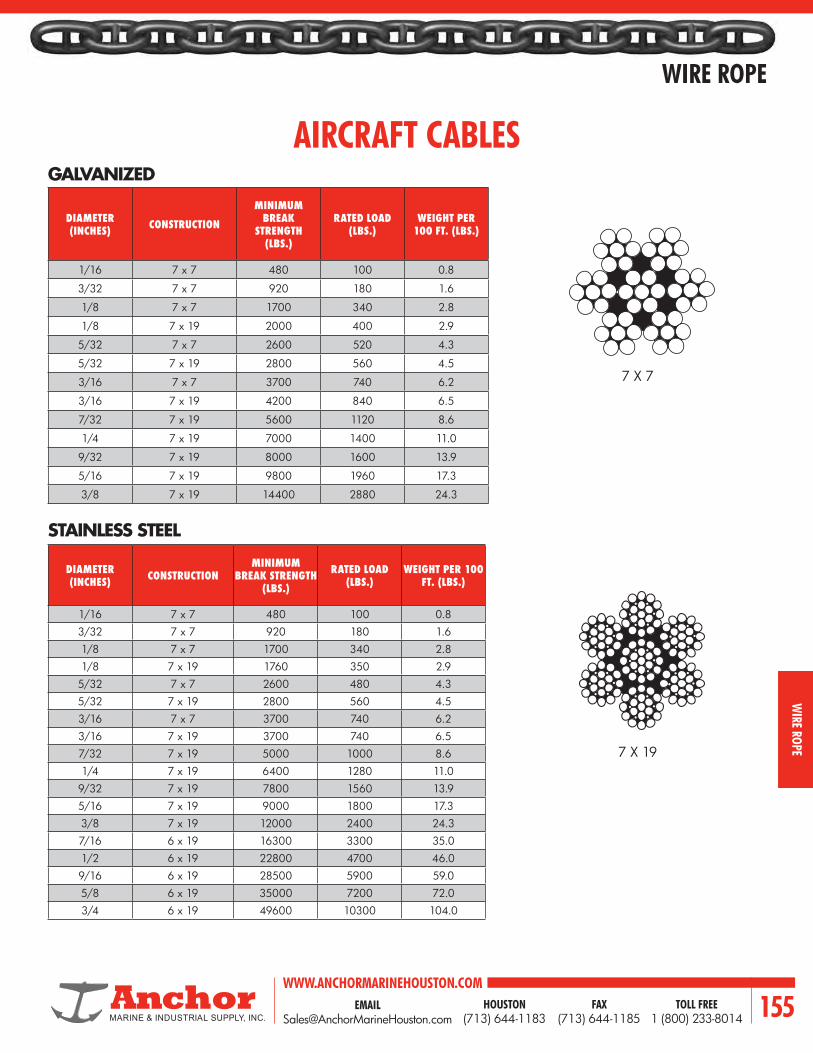
EMAIL [email protected]
WWW.ANCHORMARINEHOUSTON.COMTOLL FREE
1 (800) 233-8014HOUSTON
(713) 644-1183FAX
(713) 644-1185 155
WIRE ROPE
WIRE ROPE
GALVANIZED
STAINLESS STEEL
AIRCRAFT CABLES
DIAMETER (INCHES) CONSTRUCTION
MINIMUM BREAK
STRENGTH (LBS.)
RATED LOAD (LBS.)
WEIGHT PER 100 FT. (LBS.)
1/16 7 x 7 480 100 0.8
3/32 7 x 7 920 180 1.6
1/8 7 x 7 1700 340 2.8
1/8 7 x 19 2000 400 2.9
5/32 7 x 7 2600 520 4.3
5/32 7 x 19 2800 560 4.5
3/16 7 x 7 3700 740 6.2
3/16 7 x 19 4200 840 6.5
7/32 7 x 19 5600 1120 8.6
1/4 7 x 19 7000 1400 11.0
9/32 7 x 19 8000 1600 13.9
5/16 7 x 19 9800 1960 17.3
3/8 7 x 19 14400 2880 24.3
7 X 7
7 X 19
DIAMETER (INCHES) CONSTRUCTION
MINIMUM BREAK STRENGTH
(LBS.)
RATED LOAD (LBS.)
WEIGHT PER 100 FT. (LBS.)
1/16 7 x 7 480 100 0.83/32 7 x 7 920 180 1.61/8 7 x 7 1700 340 2.81/8 7 x 19 1760 350 2.9
5/32 7 x 7 2600 480 4.35/32 7 x 19 2800 560 4.53/16 7 x 7 3700 740 6.23/16 7 x 19 3700 740 6.57/32 7 x 19 5000 1000 8.61/4 7 x 19 6400 1280 11.0
9/32 7 x 19 7800 1560 13.95/16 7 x 19 9000 1800 17.33/8 7 x 19 12000 2400 24.37/16 6 x 19 16300 3300 35.01/2 6 x 19 22800 4700 46.09/16 6 x 19 28500 5900 59.05/8 6 x 19 35000 7200 72.03/4 6 x 19 49600 10300 104.0

WWW.ANCHORMARINEHOUSTON.COMTOLL FREE
1 (800) 233-8014HOUSTON
(713) 644-1183FAX
(713) 644-1185156
WIRE ROPE
WIR
E RO
PE
WIRE ROPE SOCKET - SPELTER (ZINC) OR RESIN ATTACHMENT.
End fittings, or attachments are available in many designs, some of which were developed for particular applications. The six shown are among the most commonly used.
WIRE ROPE SOCKET - SWAGED
MECHANICAL SPLICE - LOOP OR THIMBLE ATTACHMENT
WEDGE SOCKET
CLIPS - NUMBER OF CLIPS VARIES WITH ROPE SIZE
LOOP OR THIMBLE SPLICE - HAND TUCKED
FITTINGS ATTACHMENT

EMAIL [email protected]
WWW.ANCHORMARINEHOUSTON.COMTOLL FREE
1 (800) 233-8014HOUSTON
(713) 644-1183FAX
(713) 644-1185 157
WIRE ROPE
WIRE ROPE
RECOMMENDED METHOD OF APPLYING WIRE ROPE CLIPS
1. Turn back the specified amount of rope from the thimble. Apply the first clip one base width from the dead end of the wire rope (U-bolt over dead end—live end rests in clip saddle.) Tighten nuts evenly to recommended torque.
2. Apply the next clip as near the loop as possible. Turn on nuts firm but do not tighten.
3. Space additional clips if required equally between the first two. Turn on nuts (take up rope slack) tighten all nuts evenly on all clips to recommended torque.
4. NOTICE! Apply the initial load and retighten nuts to the recommended torque. Rope will stretch and shrink in diameter when loads are applied. Inspect periodically and retighten.
U-BOLT CLIPSRECOMMENDED METHOD OF APPLYING
U-BOLT WIRE ROPE CLIPS
RIGHT WAY FOR MAXIMUM ROPE STRENGTH
WRONG WAY — CLIPS STAGGERED
WRONG WAY — CLIPS REVERSED
TWIN BASE CLIPSRECOMMENDED METHOD OF APPLYING
TWIN BASE ROPE CLIPS
1. Turn back the specified amount of rope from the thimble. Apply the first clip one base width from the dead end of the wire rope tighten nuts evenly to recommended torque.
2. Apply the next clip as near the loop as possible. Turn on nuts firm but do not tighten.
3. Space additional clips if required equally between the first two. Turn on nuts (take up rope slack) tighten all nuts evenly on all clips to recommended torque.
4. NOTICE! Apply the initial load and retighten nuts to the recommended torque. Rope will stretch and shrink in diameter when loads are applied. Inspect periodically and retighten.
IMPORTANT: Failure to make a termination in accordance with aforementioned instructions or failure to periodically check and retighten to the recommended torque will cause a reduction in
aformentioned efficiency rating.
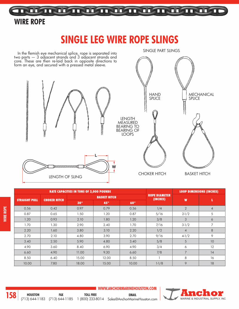
WWW.ANCHORMARINEHOUSTON.COMTOLL FREE
1 (800) 233-8014HOUSTON
(713) 644-1183FAX
(713) 644-1185158
WIRE ROPE
WIR
E RO
PE
L
W
In the flemish eye mechanical splice, rope is separated into two parts — 3 adjacent strands and 3 adjacent strands and core. These are then re-laid back in opposite directions to form an eye, and secured with a pressed metal sleeve.
SINGLE PART SLINGS
LENGTH MEASURED
BEARING TO BEARING OF
LOOPS
SINGLE LEG WIRE ROPE SLINGS
RATE CAPACITIES IN TONS OF 2,000 POUNDSROPE DIAMETER
(INCHES)
LOOP DIMENSIONS (INCHES)
STRAIGHT PULL CHOKER HITCHBASKET HITCH
W L30° 45° 60°
0.56 0.42 0.97 0.79 0.56 1/4 2 4
0.87 0.65 1.50 1.20 0.87 5/16 2-1/2 5
1.20 0.93 2.10 1.80 1.20 3/8 3 6
1.70 1.30 2.90 2.40 1.70 7/16 3-1/2 7
2.20 1.60 3.80 3.10 2.20 1/2 4 8
2.70 2.10 4.80 3.90 2.70 9/16 4-1/2 9
3.40 2.50 5.90 4.80 3.40 5/8 5 10
4.90 3.60 8.40 6.90 4.90 3/4 6 12
6.60 4.90 11.00 9.30 6.60 7/8 7 14
8.50 6.40 15.00 12.00 8.50 1 8 16
10.00 7.80 18.00 15.00 10.00 1-1/8 9 18
HAND SPLICE
MECHANICAL SPLICE
CHOKER HITCH BASKET HITCHLENGTH OF SLING

EMAIL [email protected]
WWW.ANCHORMARINEHOUSTON.COMTOLL FREE
1 (800) 233-8014HOUSTON
(713) 644-1183FAX
(713) 644-1185 159
WIRE ROPE
WIRE ROPE
BASKET HITCH
ROPE (INCHES)
EYE SIZE (INCHES)
RECOMMENDED MINIMUM LENGTH
RATED CAPACITY (TONS 2,000 LBS) *
W L STRAIGHT PULL
CHOKER HITCH
BASKET HITCH
VERTICAL 30° 45° 60°
1/4 3 6 1' 6'' 0.56 0.42 1.1 0.97 0.79 0.56
5/16 3 6 1' 10'' 0.87 0.65 1.7 1.5 1.2 0.87
3/8 3 6 1' 10'' 1.2 0.93 2.5 2.2 1.8 1.2
7/16 4 8 2' 4'' 1.7 1.3 3.4 2.9 2.4 1.7
1/2 4 8 2' 6'' 2.2 1.6 4.4 3.8 3.1 2.2
9/16 4 8 2' 8'' 2.8 2.1 5.5 4.8 3.9 2.8
5/8 5 10 3' 2'' 3.4 2.6 6.8 5.9 4.8 3.4
3/4 6 12 3' 8'' 4.9 3.6 9.7 8.4 6.9 4.9
7/8 7 14 4' 4'' 6.6 4.9 13.0 11.0 9.3 6.6
1 8 16 4' 10'' 8.5 6.4 17.0 15.0 12.0 8.5
1-1/8 9 18 5' 6'' 10.0 7.8 21.0 18.0 15.0 10.0
1-1/4 10 20 6' 2'' 13.0 9.6 26.0 22.0 18.0 13.0
1-3/8 11 22 6' 10'' 15.0 12.0 31.0 27.0 22.0 15.0
1-1/2 12 24 7' 4'' 18.0 14.0 37.0 32.0 26.0 18.0
1-3/4 14 28 8' 6'' 25.0 18.0 49.0 43.0 35.0 25.0
2 16 32 9' 10'' 32.0 24.0 64.0 55.0 45.0 32.0
6 x 19, 6 x 37 Type, I.P.S., IWRC

WWW.ANCHORMARINEHOUSTON.COMTOLL FREE
1 (800) 233-8014HOUSTON
(713) 644-1183FAX
(713) 644-1185160
WIRE ROPE
WIR
E RO
PE
TWO-LEGGED BRIDLE
Rated Capacity for two-legged bridles whether used as chokers or with hooks or other end fixures, is affected by rigging angles, the same as straight slings in basket hitches. Note reduction in rated capacity as legs spread to wider angles.
6 x 19, 6 x 37 Type, I.P.S., IWRC
ALLOY MASTER LINK
ROPE (INCHES) RECOMMENDED MINIMUM LENGTH
RATED CAPACITY (TONS 2,000 LBS) * FITTINGS
STRAIGHT PULL 30° 45° 60° HOOK SIZE (TONS)
ALLOY MASTER LINKS SIZE (INCHES)
1/4 1' 6'' 1.10 0.97 0.79 0.56 0.75 1/2
5/16 1' 8'' 1.70 1.50 1.20 0.87 1.00 5/8
3/8 1' 10'' 2.50 2.20 1.80 1.20 1.50 3/4
7/16 2' 4'' 3.40 2.90 2.40 1.70 2.00 7/16
1/2 2' 6'' 4.40 3.80 3.10 2.20 2.50 1
9/16 2' 10'' 5.50 4.80 3.90 2.80 3.00 1-1/4
5/8 3' 4'' 6.80 5.90 4.80 3.40 4.00 1-1/4
3/4 3' 8'' 9.70 8.40 6.90 4.90 5.00 1-1/4
7/8 4' 4'' 13.00 11.00 9.30 6.60 7.50 1-1/2
1 5' 17.00 15.00 12.00 8.50 10.00 1-3/4
1-1/8 5' 10'' 21.00 18.00 15.00 10.00 12.00 1-3/4
1-1/4 6' 6'' 26.00 22.00 18.00 13.00 15.00 1-7/8
1-3/8 7' 31.00 27.00 22.00 15.00 20.00 2-1/8
1-1/2 7' 6'' 37.00 32.00 26.00 18.00 20.00 2-1/4
1-3/4 9' 2'' 49.00 43.00 35.00 25.00 25.00 2-1/2
LENGTH

EMAIL [email protected]
WWW.ANCHORMARINEHOUSTON.COMTOLL FREE
1 (800) 233-8014HOUSTON
(713) 644-1183FAX
(713) 644-1185 161
WIRE ROPE
WIRE ROPE
ALLOY PEAR LINK
LENGTH
* Links in parentheses are needed for adequate space when thimbles are used in the slings eyes at the link.
THREE-LEGGED BRIDLE
ROPE (INCHES) RECOMMENDED MINIMUM LENGTH
RATED CAPACITY (TONS 2,000 LBS) * FITTINGS
STRAIGHT PULL 30° 45° 60° HOOK SIZE (TONS)
ALLOY PEAR LINKS SIZE (INCHES)
1/4 1' 6'' 1.70 1.50 1.20 0.84 0.75 5/8
5/16 1' 8'' 2.60 2.30 1.80 1.30 1.00 3/4
3/8 1' 10'' 3.70 3.20 2.60 1.90 1.50 7/8
7/16 2' 4'' 5.10 4.40 3.60 2.50 2.00 1
1/2 2' 6'' 6.60 5.70 4.60 3.30 2.50 1-1/4
9/16 2' 10'' 8.30 7.20 5.80 4.10 3.00 1-1/4
5/8 3' 4'' 10.00 8.80 7.20 5.10 4.00 1-1/4
3/4 3' 8'' 15.00 13.00 10.00 7.30 5.00 1-1/2
7/8 4' 4'' 20.00 17.00 14.00 9.90 7.50 1-3/4
1 5' 26.00 22.00 18.00 13.00 10.00 1-3/4
1-1/8 5' 10'' 31.00 27.00 22.00 16.00 12.00 2-1/8
1-1/4 6' 6'' 39.00 33.00 27.00 19.00 15.00 2-1/2
1-3/8 7' 46.00 40.00 33.00 23.00 20.00 2-1/2 (2-3/4)*
1-1/2 7' 6'' 55.00 48.00 39.00 27.00 20.00 2-3/4 (3)*
1-3/4 9' 2'' 74.00 64.00 52.00 37.00 25.00 3 (3-1/4)*
SINGLE PART BODY SLINGSMulti-legged bridles — with two, three or four straight legs — are offered with plain eyes, thimble eyes, open or closed sockets, shackles and turnbuckles. If required, rings or alloy oblong links can be supplied rather than the pear shaped links shown.Rated capacities for 3 and 4 bridle slings are based on equal leg slings with the sling angle being the greatest angle measured between any two of the sling legs.
6 x 19, 6 x 37 Type, I.P.S., IWRC

WWW.ANCHORMARINEHOUSTON.COMTOLL FREE
1 (800) 233-8014HOUSTON
(713) 644-1183FAX
(713) 644-1185162
WIRE ROPE
WIR
E RO
PE
FOUR-LEGGED BRIDLE ALLOY PEAR LINK
6 x 19, 6 x 37 Type, I.P.S., IWRC
ROPE (INCHES) RECOMMENDED MINIMUM LENGTH
RATED CAPACITY (TONS 2,000 LBS) * FITTINGS
STRAIGHT PULL 30° 45° 60° HOOK SIZE (TONS)
ALLOY PEAR LINKS SIZE (INCHES)
1/4 1' 6'' 2.20 1.90 1.60 1.10 0.75 3/4
5/16 1' 8'' 3.50 3.00 2.50 1.70 1.00 7/8
3/8 1' 10'' 5.00 4.30 3.50 2.50 1.50 1
7/16 2' 4'' 6.80 5.80 4.80 3.40 2.00 1-1/4 **
1/2 2' 6'' 8.70 7.60 6.20 4.40 2.50 1-1/4
9/16 2’ 10’’ 11.00 9.50 7.80 5.5 3.00 1-1/4 (1-3/8)
5/8 3' 4'' 14.00 12.00 9.60 6.80 4.00 1-1/2
3/4 3' 8'' 19.00 17.00 14.00 9.70 5.00 1-3/4
7/8 4' 4'' 26.00 23.00 19.00 13.00 7.50 1-7/16 (2)
1 5' 34.00 30.00 24.00 17.00 10.00 2-1/8 (2-1/4)
1-1/8 5' 10'' 42.00 36.00 30.00 21.00 12.00 2-1/2 (2-1/2)
1-1/4 6' 6'' 51.00 44.00 36.00 26.00 15.00 2-3/4 (3)***
1-3/8 7' 62.00 54.00 44.00 31.00 20.00 2-3/4 (3-1/4)
1-1/2 7' 6'' 73.00 63.00 52.00 37.00 20.00 3 (3-1/4)
* Links in parentheses are needed for adequate space when thimbles are used in the slings eyes at the link.** If thimbles are used, use 1/2’’ thimbles. *** If thimbles are used, use 1-3/8’’ thimbles.
LENGTH

EMAIL [email protected]
WWW.ANCHORMARINEHOUSTON.COMTOLL FREE
1 (800) 233-8014HOUSTON
(713) 644-1183FAX
(713) 644-1185 163
WIRE ROPE
WIRE ROPE
GROMMET SLINGS
6 x 19, 6 x 37 Classification, IPS, IWRC
ROPE GROMMETS
CABLE LAID GROMMETS
SIZE (INCHES)
RATED CAPACTIY (TONS 2,000 LBS)
STRAIGHT PULL CHOKER HITCHBASKET HITCH
VERTICAL 30° 45° 60°
1/4 0.85 0.64 1.7 1.5 1.2 0.8
3/8 1.9 1.4 3.8 3.3 2.7 1.9
1/2 3.3 2.5 6.7 5.8 4.7 3.4
5/8 5.2 3.9 10.0 8.6 7.1 5.0
3/4 7.4 5.6 15.0 13.0 11.0 7.5
7/8 10.0 7.5 20.0 17.0 14.0 10.0
1 13.0 9.7 26.0 23.0 18.0 13.0
1-1/8 16.0 12.0 32.0 28.0 23.0 16.0
1-1/4 19.0 15.0 39.0 34.0 27.0 19.0
1-3/8 23.0 18.0 47.0 40.0 33.0 23.0
1-1/2 28.0 21.0 55.0 48.0 39.0 28.0
SIZE (INCHES)
RATED CAPACTIY (TONS 2,000 LBS)
STRAIGHT PULL CHOKER HITCHBASKET HITCH
VERTICAL 30° 45° 60°
3/8 1.6 1.2 3.2 2.8 2.3 1.6
9/16 3.5 2.6 6.9 6.0 4.9 3.4
5/8 4.5 3.4 9.0 7.8 6.3 4.5
3/4 5.1 3.8 10.0 8.8 7.2 5.0
15/16 7.9 5.9 16.0 14.0 11.0 8.0
1-1/8 11.0 8.4 22.0 19.0 16.0 11.0
1-5/16 15.0 11.0 30.0 26.0 21.0 15.0
1-1/2 19.0 14.0 39.0 33.0 27.0 19.0
1-11/16 24.0 18.0 49.0 42.0 34.0 24.0
1-7/8 30.0 22.0 60.0 52.0 42.0 30.0
2-1/4 42.0 31.0 84.0 73.0 59.0 42.0
2-5/8 56.0 42.0 112.0 97.0 79.0 56.0
* Rated loads are based on a diameter of curvature of 5 times the individual rope diameter at points of sling contact with load.

WWW.ANCHORMARINEHOUSTON.COMTOLL FREE
1 (800) 233-8014HOUSTON
(713) 644-1183FAX
(713) 644-1185164
WIRE ROPE
WIR
E RO
PE
WIRE ROPE CLIPS
CLIP AND ROPE SIZE (INCHES)
DIMENSIONS (INCHES) MINIMUM NUMBER OF CLIPS
REQUIRED
TORQUE IN FT. (LBS.)
MINIMUM ROPE
TURNBACK (INCHES)
WEIGHT LBS. PER
100A B C D E F G
1/8 7/32 23/32 7/16 15/32 13/32 13/16 15/16 2 4.5 3-1/4 5
3/16 1/4 31/32 9/16 19/32 1/2 15/16 1-5/32 2 4.5 3-3/4 9
1/4 5/16 1-1/32 1/2 3/4 21/32 1-3/16 1-7/16 2 15 4-3/4 18
5/16 3/8 1-3/8 3/4 7/8 23/32 1-5/16 1-11/16 2 30 5-1/4 30
3/8 7/16 1-1/2 3/4 1 29/32 1-5/8 1-15/16 2 45 6-1/2 42
7/16 1/2 1-7/8 1 1-3/16 1-1/32 1-13/16 2-9/32 2 65 7 70
1/2 1/2 1-7/8 1 1-3/16 1-1/8 1-29/32 2-9/32 3 65 11-1/2 75
9/16 9/16 2-1/4 1-1/4 1-5/16 1-7/32 2-1/16 2-1/2 3 95 12 100
5/8 9/16 2-3/8 1-1/4 1-5/16 1-11/32 2-1/16 2-1/2 3 95 12 100
3/4 5/8 2-3/4 1-7/16 1-1/2 1-13/32 2-1/4 2-27/32 4 130 18 150
7/8 3/4 3-1/8 1-5/8 1-3/4 1-19/32 2-7/16 3-5/32 4 225 19 240
1 3/4 3-1/2 1-13/16 1-7/8 1-25/32 2-5/8 3-15/32 5 225 26 250
1-1/8 3/4 3-7/8 2 2 1-29/32 2-13/16 3-19/32 6 225 34 310
1-1/4 7/8 4-1/4 2-1/8 2-5/16 2-3/16 3-1/8 4-1/8 7 360 44 460
1-3/8 7/8 4-5/8 2-5/16 2-3/8 2-5/16 3-1/8 4-3/16 7 360 44 520
1-1/2 7/8 4-15/16 2-3/8 2-19/32 2-17/32 3-13/32 4-7/16 8 360 54 590
1-5/8 1 5-5/16 2-5/8 2-3/4 2-21/32 3-5/8 4-3/4 8 430 58 730
1-3/4 1-1/8 5-3/4 2-3/4 3-1/16 2-15/16 3-13/16 5-9/32 8 590 61 980
2 1-1/4 6-7/16 3 3-3/8 3-9/32 4-7/16 5-7/8 8 750 71 1340
2-1/4 1-1/4 7-1/8 3-3/16 3-7/8 3-15/16 4-9/16 6-3/8 8 750 73 1570
2-1/2 1-1/4 7-11/16 3-7/16 4-1/8 4-7/16 4-11/16 6-5/8 9 750 84 1790
2-3/4 1-1/4 8-5/16 3-9/16 4-3/8 4-7/8 5 6-7/8 10 750 100 2200
3 1-1/2 9-3/16 3-7/8 4-3/4 5-11/32 5-5/16 7-5/8 10 1200 106 3200
3-1/2 1-1/2 10-3/4 4-1/2 5-1/2 6 6-3-16 8-3/8 12 1200 149 4000
DROP FORGED U-BOLT TYPE
Furnished in galvanized finish. Also Available in stainless steel and bronze.
Meets Federal Specification FF-C-450 Type 1 Class-1.
DG
CB
E
A
F

EMAIL [email protected]
WWW.ANCHORMARINEHOUSTON.COMTOLL FREE
1 (800) 233-8014HOUSTON
(713) 644-1183FAX
(713) 644-1185 165
WIRE ROPE
WIRE ROPE
DROP FORGED TWIN BASE TYPE (FIST GRIP)
CLIP AND ROPE SIZE (INCHES)
DIMENSIONS (INCHES)MINIMUM NUMBER OF CLIPS
REQUIRED
TORQUE IN FT. (LBS.)
MINIMUM ROPE
TURNBACK (INCHES)
WEIGHT LBS. PER
100A B C D E F
3/16 3/8 1-5/8 1-1/4 1-15/32 15/16 11/16 2 30 4 21.00
1/4 3/8 1-5/8 1-1/4 1-15/32 15/16 11/16 2 30 4 21.00
5/16 3/8 1-15/16 1-11/32 1-9/16 1-1/16 11/16 2 30 5 27.08
3/8 7/16 2-3/8 1-19/32 1-7/8 1-1/16 3/4 2 45 5-1/2 45.00
7/16 1/2 2-3/4 1-7/8 2-3/16 1-1/4 7/8 2 65 6-1/2 65.00
1/2 1/2 2-3/4 1-7/8 2-3/16 1-1/4 7/8 3 65 11 65.00
9/16 5/8 3-1/2 2-9/32 2-5/8 1-1/2 1-1/16 3 130 12-3/4 112.50
5/8 5/8 3-1/2 2-9/32 2-5/8 1-1/2 1-1/16 3 130 13-1/2 112.50
3/4 3/4 3-3/4 2-11/16 3-1/16 1-13/16 1-1/4 3 225 16 143.75
7/8 3/4 4-1/8 2-31/32 3-1/8 2-1/8 1-1/4 4 225 26 200.60
1 3/4 4-5/8 3-1/16 3-17/32 2-1/4 1-1/4 5 225 37 260.00
1-1/8 7/8 5-1/4 3-7/16 3-29/32 2-3/8 1-7/16 5 360 41 325.00
1-1/4 7/8 5-1/4 3-9/16 4-1/32 2-1/2 1-7/16 6 360 55 425.00
1-3/8 1 7 4-1/8 4-21/32 3 1-5/8 6 500 62 700.00
1-1/2 1 7 4-1/8 4-21/32 3 1-5/8 7 500 78 700.00
Furnished in galvanized finish. Also Available in stainless steel and bronze.
Meets Federal Specification FF-C-450 Type III.
DC
A
B
E
F

WWW.ANCHORMARINEHOUSTON.COMTOLL FREE
1 (800) 233-8014HOUSTON
(713) 644-1183FAX
(713) 644-1185166
WIRE ROPE
WIR
E RO
PE
OPEN SPELTER SOCKET WITH PIN
ALLOY CAST STEEL
MODEL NO MBL (US TONS)
FOR WIRE Ø DIMENSIONS (INCHES) WEIGHT (LBS)MM INCHES A B C D P T TL TB W
OSS 196 P 9 6 - 7 1/4 1-15/16 1-9/16 3/4 1-15/16 5/16 5/8 3/8 4-5/16 2 3/4 1
OSS 197 P 13 8 - 10 3/8 2-1/4 1-3/4 7/8 1-5/8 1/2 13/16 7/16 4-7/8 2-1/2 13/16 2
OSS 198 P 22 11 - 13 7/16 - 1/2 2-1/2 2 1-1/16 1-15/16 9/16 1 1/2 5-9/16 2-5/8 1 2
OSS 199 P 28 14 - 16 9/16 - 5/8 3 2-1/2 1-1/4 2-5/16 11/16 1-3/16 9/16 6-3/4 3-3/8 1-1/4 4
OSS 100 P 44 18 - 19 3/4 3-1/2 3 1-9/16 2-3/4 13/16 1-3/8 5/8 8-1/16 3-3/4 1-1/2 7
OSS 104 P 61 20 - 22 7/8 4 3-1/2 1-3/4 3-1/8 15/16 1-5/8 3/4 9-1/4 4-5/16 1-3/4 10
OSS 108 P 83 23 - 26 1 4-1/2 4 2-3/8 4-1/8 1-1/8 2 7/8 10-13/16 5-1/16 2 18
OSS 111 P 99 27 - 30 1-1/8 5 4-1/2 2-9/16 4-1/2 1-1/4 2-1/4 1 12-1/16 5-9/16 2-1/4 26
OSS 115 P 138 31 - 36 1-1/4 - 1-3/8 5-1/2 5 2-13/16 4-15/16 1-1/2 2-1/2 1-1/8 13-5/16 6-1/8 2-1/2 35
OSS 118 P 165 37 - 39 1-1/2 6 6-3/8 3-1/8 5-9/16 1-5/8 2-3/4 1-3/16 15-1/2 6-15/16 3 51
OSS 120 P 187 40 - 42 1-5/8 6-1/2 6-1/2 3-7/16 6-1/8 1-3/4 3 1-5/16 16-7/16 7-3/8 3 60
OSS 125 P 248 43 - 48 1-3/4 - 1-7/8 7-1/2 7 3-15/16 6-15/16 2 3-1/2 1-9/16 18-7/16 8-7/16 3-1/2 90
OSS 128 P 309 49 - 54 2 - 2-1/8 8-1/2 9 4-1/4 7-5/8 2-1/4 3-3/4 1-13/16 21-3/4 9-5/8 4 128
OSS 130 P 397 55 - 60 2-1/4 - 2-3/8 9 9-13/16 4-3/4 8-1/4 2-1/2 4-1/4 2-1/16 23-9/16 10-13/16 4-7/16 187
OSS 132 P 468 61 - 68 2-1/2 - 2-5/8 9-3/4 10-3/4 5-1/4 9-5/16 2-7/8 4-3/4 2-3/8 25-3/4 11-13/16 5 260
OSS 135 P 507 69 - 75 2-3/4 - 2-7/8 11 11 5-7/16 9-7/16 3-1/8 5 2-7/8 27-3/8 13-3/16 5-1/4 342
OSS 138 P 617 76 - 80 3 - 3-1/8 12 11-1/4 5-3/4 9-15/16 3-3/8 5-1/4 3 29 14 5-3/4 381
OSS 140 P 689 81 - 86 3-1/4 - 3-3/8 13 11-3/4 6-5/16 11-7/16 3-5/8 5-1/2 3-1/8 31 14-3/4 6-1/4 507
OSS 142 P 794 87 - 93 3-1/2 - 3-5/8 14 12-1/2 7 12-5/8 3-7/8 6 3-1/4 33-9/16 15-3/4 6-3/4 584
OSS 144 P 965 94 - 102 3-3/4 - 4 15 13-1/2 7-1/2 13-3/4 4-1/4 7 3-1/2 36 17-1/8 7-1/2 816
OSS 146 P 1323 108 - 115 4-1/4 - 4-1/2 17-11/16 18-7/8 8-7/16 15-3/4 4-15/16 7-11/16 3-15/16 45-1/16 18-5/16 8-1/16 1157
OSS 150 P 1433 120 - 130 4-3/4 - 5 19-11/16 19-11/16 9-13/16 17-11/16 5-5/8 8-11/16 4-5/16 49-3/16 20-11/16 8-7/8 1620
MBL = Minimum Breaking LoadOur standard sockets are delivered in blue colour paint. Hot dipped galvanized is also available. All sockets can be provided with Declaration of compliance according EN 1024-2.1, Material certificate according EN 10204-3.1 and EC Declaration according machine directive 98/37/EC.
ØP
T WD
C
B
A
TL
ØH
TB

EMAIL [email protected]
WWW.ANCHORMARINEHOUSTON.COMTOLL FREE
1 (800) 233-8014HOUSTON
(713) 644-1183FAX
(713) 644-1185 167
WIRE ROPE
WIRE ROPE
CLOSED SPELTER SOCKET
ALLOY CAST STEEL
MODELNO.
MBL (US TONS)
FOR WIRE Ø DIMENSIONS (INCHES) WEIGHT (LBS)MM INCHES A B C ØH K T TA TL
CSS 296 9 6 - 7 1/4 1-15/16 1-9/16 7/16 5/16 7/8 1/2 1-7/16 4 1
CSS 297 13 8 - 10 3/8 2-1/4 1-7/8 9/16 1/2 1 11/16 1-11/16 4-11/16 1
CSS 298 22 11 - 13 7/16 - 1/2 2-1/2 2-5/16 11/16 9/16 1-3/16 7/8 2 5-1/2 2
CSS 299 28 14 - 16 9/16 - 5/8 3 2-9/16 13/16 11/16 1-7/16 1 2-5/8 6-3/8 3
CSS 200 44 18 - 19 3/4 3-1/2 3-1/16 1-1/16 13/16 1-5/8 1-1/4 3 7-5/8 5
CSS 201 61 20 - 22 7/8 4 3-9/16 1-5/16 15/16 1-7/8 1-1/2 3-5/8 8-13/16 8
CSS 204 83 23 - 26 1 4-1/2 4-1/16 1-7/16 1-1/8 2-1/4 1-3/4 4-1/8 9-15/16 12
CSS 207 99 27 - 30 1-1/8 5 4-9/16 1-9/16 1-1/4 2-1/2 2 4-1/2 11-1/8 15
CSS 212 138 31 - 36 1-1/4 - 1-3/8 5-1/2 5-1/8 1-11/16 1-1/2 2-3/4 2-1/4 5 12-5/16 21
CSS 215 165 37 - 39 1-1/2 6 6-1/8 2 1-5/8 3-1/8 2-1/2 5-3/8 14-1/8 29
CSS 217 187 40 - 42 1-5/8 6-1/2 6-3/4 2-1/8 1-3/4 3-1/4 2-3/4 5-3/4 15-3/8 37
CSS 219 248 43 - 48 1-3/4 - 1-7/8 7-1/2 7-13/16 2-3/16 2 3-11/16 3 6-3/4 17-7/16 57
CSS 222 309 49 - 54 2 - 2-1/8 8-1/2 8-13/16 2-7/16 2-1/4 3-15/16 3-1/4 7-5/8 19-3/4 83
CSS 224 397 55 - 60 2-1/4 - 2-3/8 9 9-3/4 2-7/8 2-1/2 4-7/16 3-5/8 8-1/2 21-9/16 110
CSS 226 468 61 - 68 2-1/2 - 2-5/8 9-3/4 10-5/8 3-1/8 2-7/8 5-1/2 4 9-1/2 23-1/2 143
CSS 227 507 69 - 75 2-3/4 - 2-7/8 11 11-1/4 3-1/8 3-1/8 6-1/4 4-7/8 10-3/4 25-3/8 207
CSS 228 617 76 - 80 3 - 3-1/8 12 11-3/4 3-1/4 3-3/8 6-3/4 5-1/4 11-1/2 27 243
CSS 229 689 81 - 86 3-1/4 - 3-3/8 13 12-1/4 4 3-5/8 7-1/4 5-3/4 12-1/4 29-1/4 320
CSS 230 794 87 - 93 3-1/2 - 3-5/8 14 13 4 3-7/8 7-3/4 6-1/4 13 31 401
CSS 231 965 94 - 102 3-3/4 - 4 15 14 4-1/4 4-1/4 8-1/2 7 14-1/4 33-1/4 463
CSS 233 1323 108 - 115 4-1/4 - 4-1/2 17-11/16 16-3/4 4-15/16 4-15/16 9-1/4 7-1/2 15-15/16 39-3/8 728
CSS 240 1433 120 - 130 4-3/4 - 5 19-11/16 20-11/16 4-15/16 5-5/8 10-1/4 7-7/8 17-11/16 45-1/4 1102
MBL = Minimum Breaking LoadOur standard sockets are delivered in blue colour paint. Hot dipped galvanized is also available. All sockets can be provided with Declaration of compliance according EN 1024-2.1, Material certificate according EN 10204-3.1 and EC Declaration according machine directive 98/37/EC.
TAK T
C
B
A
TL
ØH

WWW.ANCHORMARINEHOUSTON.COMTOLL FREE
1 (800) 233-8014HOUSTON
(713) 644-1183FAX
(713) 644-1185168
WIRE ROPE
WIR
E RO
PE
SHORT BOW SOCKETS
MODEL NO. MBL (US TONS)
FOR WIRE Ø DIMENSIONS (INCHES)WEIGHT (LBS)
MM INCHES A B C ØH K TA TL
SBS 517 176 37 - 42 1-1/2 - 1-5/8 6-3/8 4-1/16 1-1/2 1-3/4 3-5/8 5-13/16 11-13/16 24
SBS 519 220 43 - 48 1-3/4 - 1-7/8 7-3/8 4-3/4 1-5/8 2 4-7/16 7 13-11/16 33
SBS 522 276 49 - 54 2 - 2-1/8 8-1/16 5-3/16 2-1/8 2-1/4 4-3/4 7-7/8 15-3/8 49
SBS 524 353 55 - 60 2-1/4 - 2-3/8 9-1/16 5-3/16 2-7/16 2-1/2 5-5/16 8-11/16 17-5/16 60
SBS 526 441 61 - 68 2-1/2 - 2-5/8 9-1/4 6-1/2 2-11/16 2-7/8 5-7/8 9-13/16 18-7/16 88
SBS 527 551 69 - 75 2-3/4 - 2-7/8 11-5/16 6-7/8 2-15/16 3-1/8 6-7/16 10-13/16 21-1/4 119
SBS 528 661 76 - 80 3 - 3-5/8 12-3/8 7-11/16 3 3-3/8 6-7/8 11-5/8 23-1/16 165
SBS 529 772 81 - 86 3-1/4 - 3-3/8 12-7/8 8-1/2 3-1/4 3-5/8 7-5/8 12-5/8 24-5/8 179
SBS 530 882 87 - 93 3-1/2 - 3-5/8 10-3/16 8-11/16 3-5/8 3-7/8 7-15/16 13-3/4 26-3/8 254
SBS 531 992 94 - 102 3-3/4 - 4 14-3/8 9-1/4 3-15/16 4-1/8 8-7/16 14-3/4 27-9/16 287
SBS 533 1102 108 - 115 4-1/4 - 4-1/2 16-9/16 10-5/8 4-5/16 4-1/2 9-7/16 16-1/8 31-1/2 397
HIGH ALLOY CAST STEEL
MBL = Minimum Breaking LoadOur standard sockets are delivered in blue colour paint. Hot dipped galvanized is also available. All sockets can be provided with Declaration of compliance according EN 1024-2.1, Material certificate according EN 10204-3.1 and EC Declaration according machine directive 98/37/EC.
TAK
C
B
A
TL
ØH
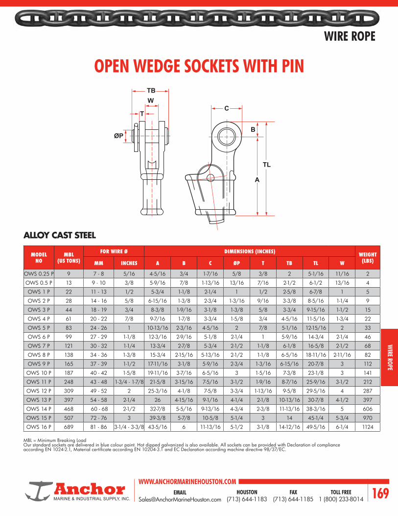
EMAIL [email protected]
WWW.ANCHORMARINEHOUSTON.COMTOLL FREE
1 (800) 233-8014HOUSTON
(713) 644-1183FAX
(713) 644-1185 169
WIRE ROPE
WIRE ROPE
OPEN WEDGE SOCKETS WITH PIN
ALLOY CAST STEEL
MBL = Minimum Breaking LoadOur standard sockets are delivered in blue colour paint. Hot dipped galvanized is also available. All sockets can be provided with Declaration of compliance according EN 1024-2.1, Material certificate according EN 10204-3.1 and EC Declaration according machine directive 98/37/EC.
MODEL NO
MBL (US TONS)
FOR WIRE Ø DIMENSIONS (INCHES) WEIGHT (LBS)MM INCHES A B C ØP T TB TL W
OWS 0.25 P 9 7 - 8 5/16 4-5/16 3/4 1-7/16 5/8 3/8 2 5-1/16 11/16 2
OWS 0.5 P 13 9 - 10 3/8 5-9/16 7/8 1-13/16 13/16 7/16 2-1/2 6-1/2 13/16 4
OWS 1 P 22 11 - 13 1/2 5-3/4 1-1/8 2-1/4 1 1/2 2-5/8 6-7/8 1 5
OWS 2 P 28 14 - 16 5/8 6-15/16 1-3/8 2-3/4 1-3/16 9/16 3-3/8 8-5/16 1-1/4 9
OWS 3 P 44 18 - 19 3/4 8-3/8 1-9/16 3-1/8 1-3/8 5/8 3-3/4 9-15/16 1-1/2 15
OWS 4 P 61 20 - 22 7/8 9-7/16 1-7/8 3-3/4 1-5/8 3/4 4-5/16 11-5/16 1-3/4 22
OWS 5 P 83 24 - 26 1 10-13/16 2-3/16 4-5/16 2 7/8 5-1/16 12-15/16 2 33
OWS 6 P 99 27 - 29 1-1/8 12-3/16 2-9/16 5-1/8 2-1/4 1 5-9/16 14-3/4 2-1/4 46
OWS 7 P 121 30 - 32 1-1/4 13-3/4 2-7/8 5-3/4 2-1/2 1-1/8 6-1/8 16-5/8 2-1/2 68
OWS 8 P 138 34 - 36 1-3/8 15-3/4 2-15/16 5-13/16 2-1/2 1-1/8 6-5/16 18-11/16 2-11/16 82
OWS 9 P 165 37 - 39 1-1/2 17-11/16 3-1/8 5-9/16 2-3/4 1-3/16 6-15/16 20-7/8 3 112
OWS 10 P 187 40 - 42 1-5/8 19-11/16 3-7/16 6-5/16 3 1-5/16 7-3/8 23-1/8 3 141
OWS 11 P 248 43 - 48 1-3/4 - 1-7/8 21-5/8 3-15/16 7-5/16 3-1/2 1-9/16 8-7/16 25-9/16 3-1/2 212
OWS 12 P 309 49 - 52 2 25-3/16 4-1/8 7-5/8 3-3/4 1-13/16 9-5/8 29-5/16 4 287
OWS 13 P 397 54 - 58 2-1/4 26 4-15/16 9-1/16 4-1/4 2-1/8 10-13/16 30-7/8 4-1/2 397
OWS 14 P 468 60 - 68 2-1/2 32-7/8 5-5/16 9-13/16 4-3/4 2-3/8 11-13/16 38-3/16 5 606
OWS 15 P 507 72 - 76 3 39-3/8 5-7/8 10-5/8 5-1/4 3 14 45-1/4 5-3/4 970
OWS 16 P 689 81 - 86 3-1/4 - 3-3/8 43-5/16 6 11-13/16 5-1/2 3-1/8 14-12/16 49-5/16 6-1/4 1124
TB
ØP
W
TC
B
A
TL

WWW.ANCHORMARINEHOUSTON.COMTOLL FREE
1 (800) 233-8014HOUSTON
(713) 644-1183FAX
(713) 644-1185170
WIRE ROPE
WIR
E RO
PE
HAWSER THIMBLES
HEAVY DUTY HAWSER THIMBLEGALVANIZED OR SELF-COLORED
Larger Sized Available Upon Application.Furnished with or without Reinforcement Plate (*Gusset). Cast Alloy Available upon Request.
CAST, 1035 S
DIMENSIONS (INCHES)WEIGHT (LBS.)ROPE DIAMETER M N O P R S
5/8 - 3/4 6-3/4 4-7/8 5 3 1-1/4 13/16 2-1/2
7/8 - 1 8-5/8 5-3/4 6-1/4 3-3/4 1-7/16 1-1/16 4-1/2
1-1/8 - 1-1/4 10-1/8 6-3/4 7-1/4 4-1/4 1-11/16 1-5/16 9
1-3/8 - 1-1/2 11-1/2 8 8-1/2 5 2-1/4 1-5/8 14
1-5/8 - 1-3/4 12-1/2 8 9-3/4 5 2-1/2 1-7/8 20
1-7/8 - 2 14-3/4 9-1/4 11-1/4 5-3/4 2-3/4 2-3/16 30
2-1/8 - 2-1/4 17 10-1/2 12-3/4 6-1/4 3-1/4 2-1/2 52
2-3/8 - 2-1/2 21 14-1/2 15-1/2 9-1/2 3-3/4 2-3/4 80
2-3/4 - 3 21 14-1/8 16 9 4-1/4 3-1/4 115
O R
S
P
NM
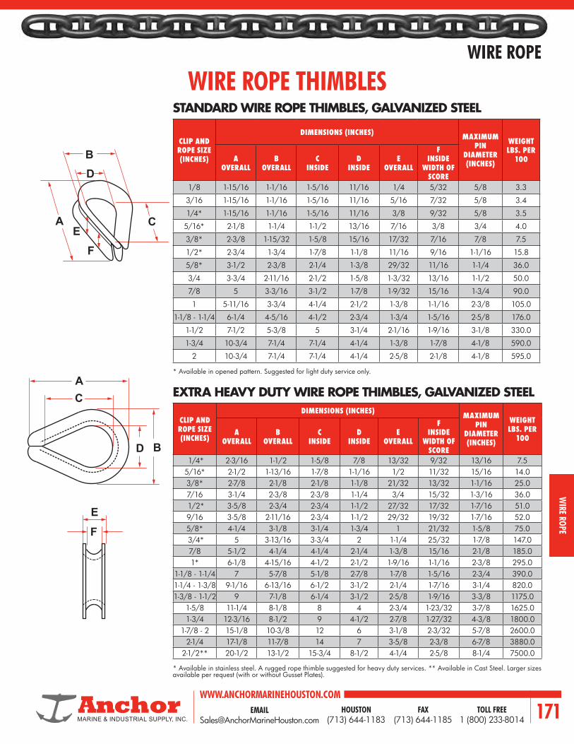
EMAIL [email protected]
WWW.ANCHORMARINEHOUSTON.COMTOLL FREE
1 (800) 233-8014HOUSTON
(713) 644-1183FAX
(713) 644-1185 171
WIRE ROPE
WIRE ROPE
WIRE ROPE THIMBLES
CLIP AND ROPE SIZE (INCHES)
DIMENSIONS (INCHES) MAXIMUM PIN
DIAMETER (INCHES)
WEIGHT LBS. PER
100A OVERALL
B OVERALL
C INSIDE
D INSIDE
E OVERALL
F INSIDE
WIDTH OF SCORE
1/8 1-15/16 1-1/16 1-5/16 11/16 1/4 5/32 5/8 3.3
3/16 1-15/16 1-1/16 1-5/16 11/16 5/16 7/32 5/8 3.4
1/4* 1-15/16 1-1/16 1-5/16 11/16 3/8 9/32 5/8 3.5
5/16* 2-1/8 1-1/4 1-1/2 13/16 7/16 3/8 3/4 4.0
3/8* 2-3/8 1-15/32 1-5/8 15/16 17/32 7/16 7/8 7.5
1/2* 2-3/4 1-3/4 1-7/8 1-1/8 11/16 9/16 1-1/16 15.8
5/8* 3-1/2 2-3/8 2-1/4 1-3/8 29/32 11/16 1-1/4 36.0
3/4 3-3/4 2-11/16 2-1/2 1-5/8 1-3/32 13/16 1-1/2 50.0
7/8 5 3-3/16 3-1/2 1-7/8 1-9/32 15/16 1-3/4 90.0
1 5-11/16 3-3/4 4-1/4 2-1/2 1-3/8 1-1/16 2-3/8 105.0
1-1/8 - 1-1/4 6-1/4 4-5/16 4-1/2 2-3/4 1-3/4 1-5/16 2-5/8 176.0
1-1/2 7-1/2 5-3/8 5 3-1/4 2-1/16 1-9/16 3-1/8 330.0
1-3/4 10-3/4 7-1/4 7-1/4 4-1/4 1-3/8 1-7/8 4-1/8 590.0
2 10-3/4 7-1/4 7-1/4 4-1/4 2-5/8 2-1/8 4-1/8 595.0
STANDARD WIRE ROPE THIMBLES, GALVANIZED STEEL
EXTRA HEAVY DUTY WIRE ROPE THIMBLES, GALVANIZED STEEL
CLIP AND ROPE SIZE (INCHES)
DIMENSIONS (INCHES) MAXIMUM PIN
DIAMETER (INCHES)
WEIGHT LBS. PER
100A
OVERALLB
OVERALLC
INSIDED
INSIDEE
OVERALL
F INSIDE
WIDTH OF SCORE
1/4* 2-3/16 1-1/2 1-5/8 7/8 13/32 9/32 13/16 7.55/16* 2-1/2 1-13/16 1-7/8 1-1/16 1/2 11/32 15/16 14.03/8* 2-7/8 2-1/8 2-1/8 1-1/8 21/32 13/32 1-1/16 25.07/16 3-1/4 2-3/8 2-3/8 1-1/4 3/4 15/32 1-3/16 36.0 1/2* 3-5/8 2-3/4 2-3/4 1-1/2 27/32 17/32 1-7/16 51.09/16 3-5/8 2-11/16 2-3/4 1-1/2 29/32 19/32 1-7/16 52.05/8* 4-1/4 3-1/8 3-1/4 1-3/4 1 21/32 1-5/8 75.0 3/4* 5 3-13/16 3-3/4 2 1-1/4 25/32 1-7/8 147.07/8 5-1/2 4-1/4 4-1/4 2-1/4 1-3/8 15/16 2-1/8 185.01* 6-1/8 4-15/16 4-1/2 2-1/2 1-9/16 1-1/16 2-3/8 295.0
1-1/8 - 1-1/4 7 5-7/8 5-1/8 2-7/8 1-7/8 1-5/16 2-3/4 390.01-1/4 - 1-3/8 9-1/16 6-13/16 6-1/2 3-1/2 2-1/4 1-7/16 3-1/4 820.01-3/8 - 1-1/2 9 7-1/8 6-1/4 3-1/2 2-5/8 1-9/16 3-3/8 1175.0
1-5/8 11-1/4 8-1/8 8 4 2-3/4 1-23/32 3-7/8 1625.01-3/4 12-3/16 8-1/2 9 4-1/2 2-7/8 1-27/32 4-3/8 1800.0
1-7/8 - 2 15-1/8 10-3/8 12 6 3-1/8 2-3/32 5-7/8 2600.02-1/4 17-1/8 11-7/8 14 7 3-5/8 2-3/8 6-7/8 3880.0
2-1/2** 20-1/2 13-1/2 15-3/4 8-1/2 4-1/4 2-5/8 8-1/4 7500.0
* Available in opened pattern. Suggested for light duty service only.
* Available in stainless steel. A rugged rope thimble suggested for heavy duty services. ** Available in Cast Steel. Larger sizes available per request (with or without Gusset Plates).
E
A
AE
F
BD
C
C
D B
F

WWW.ANCHORMARINEHOUSTON.COMTOLL FREE
1 (800) 233-8014HOUSTON
(713) 644-1183FAX
(713) 644-1185172
WIRE ROPE
WIR
E RO
PE
TIN PLATED COPPER OVAL SLEEVES FORSTAINLESS STEEL AIRCRAFT CABLE
STAINLESS STEEL OVAL SLEEVESFOR EYE SPLICING STAINLESS STEEL AIRCRAFT CABLE
CABLE SIZE(INCHES)
OVAL SLEEVE STOCK NO.
MULTI-GROOVE HAND TOOL STOCK
NO.
NUMBER 635 HYDRAULIC TOOL
DIE
APPROX. WEIGHT PER 1000 SLEEVES
(LBS.)
SLEEVE LENGTH BEFORE
COMPRESSED APPROX. (INCHES)
SLEEVE LENGTH AFTER COMPRESSED
APPROX.
3/64 428-1.5-VB4 51-B4-887 33V-CGB4 OVAL B4 3/8 7/16
1/16 428-2-VC 51-C-887 33V-CGF4 64-CGMP OVAL C 3/8 7/16
3/32 428-3-VG 51-G-887 33V-CGB4 64-CGMP OVAL G 3/8 7/16
1/8 428-4-VM 51-M-850 64-CGMP 63-XPM OVAL M 9/16 3/4
5/32 428-5-VP 51-P-850 64-CGMP 63-XPM OVAL P 5/8 7/8
3/16 428-6-VX 51-X-850 63-XPM OVAL X 15/16 1-3/16
7/32 428-7-VF2 51-F2-850 OVAL F2 7/8 1-1/16
1/4 428-8-VF6 51-F6-950 OVAL F6 1 1-3/8
5/16 428-10-VG9 3-G9-950 OVAL G9 1-1/16 1-3/8
3/8 428-12-VH5 OVAL H5 1-3/16 1-1/2
7/16 428-14-VJ8 OVAL JB 1-3/4 2-5/16
1/2 428-16-VK8 OVAL KB 1-7/8 2-9/16
9/16 428-18-VM1 OVAL M1 2 2-13/16
5/8 428-20-VN5 OVAL N5 2-3/8 3The 428 Series oval sleeves are made from special materials and are specifically designed for use with stainless steel aircraft cable. The tin plating gives this sleeve a distinctive appearance.
OVAL SLEEVES
CABLE SIZE(INCHES) SLEEVE STOCK NO.
APPROX. WEIGHT PER 1000
SLEEVES (LBS.)
APPROX. LENGTH BEFORE COMPRESSED
(INCHES)
HAND TOOL STOCK NO.
NUMBER 635 HYDRAULIC TOOL
DIE
1/32 168-1-VB 1/2 1/4 31-B
3/64 168-1.5-VB4 1-1/2 3/8 51-B4-887 OVAL B4
1/16 168-2-VB4 1-1/2 3/8 51-B4-887 OVAL B4
3/32 168-3-VC 2-1/4 3/8 51-C-887 OVAL C
1/8 168-4-VG 3-3/4 3/8 51-G-887 OVAL G
5/32 168-5-VM 14 23/32 51-M-850 OVAL M
3/16 168-6-VP 17 3/4 51-P-850 OVAL P
7/32 168-7-VX 31 7/8 OVAL X
1/4 168-8-VF2 44 1-1/8 OVAL F2
Conform to mililtary standard (MS-51844)

EMAIL [email protected]
WWW.ANCHORMARINEHOUSTON.COMTOLL FREE
1 (800) 233-8014HOUSTON
(713) 644-1183FAX
(713) 644-1185 173
WIRE ROPE
WIRE ROPE
COPPER OVAL SLEEVES
COPPER STOP SLEEVES
OVAL SLEEVE FINISHED EYE SPLICE STOP SLEEVE FINISHED STOP
CABLE SIZE(INCHES)
OVAL SLEEVE STOCK NOHAND TOOL STOCK
NOAPPROX WEIGHT PER 1000 SLEEVES (LBS.)
SLEEVE LENGTH BEFORE COMPRESSED
APPROX. (INCHES)
SLEEVE LENGTH AFTER COMPRESSED
APPROX.PLAIN COPPER ZINC-PLATED COPPER
1/32 17-1-B 27-1-B 17-BA 0.6 1/4 5/163/64 18-11-B4 28-11-B4 51-B4-887 2 3/8 7/161/16 18-1-C 28-1-C 51-C-887 3 3/8 7/163/32 18-2-G 28-2-G 51-G-887 5 3/8 7/161/8 18-3-M 28-3-M 51-M-850 17 9/16 3/4
5/32 18-4-P 28-4-P 51-P-850 23 5/8 7/83/16 18-6-X 28-6-X 51-X-850 49 15/16 1-3/167/32 18-8-F2 28-8-F2 51-F2-8950 56 7/8 1-1/161/4 18-10-F6 28-10-F6 3-F6-950 80 1-1/8 1-1/2
5/16 18-13-G9 28-13-G9 3-G9-950 114 1-1/16 1-3/8NO. 635 HYDRAULIC TOOL DIES
3/8 18-23-H5 28-23-H5 Oval H5 153 1-1/4 1-5/87/16 18-24-J8 28-24-J8 Oval J8 302 1-3/4 2-5/161/2 18-25-K8 28-25-K8 Oval K8 410 1-7/8 2-1/29/16 18-27-M1 28-27-M1 Oval M1 551 2 2-5/85/8 18-28-N5 28-28-N5 Oval N5 802 2-3/8 3-1/8
CABLE SIZE(INCHES)
STOCK SLEEVE STOCK NO.
HAND TOOL STOCK NO.
OUTSIDE DIAMETER OF SLEEVE
APPROX WEIGHT PER 1000 SLEEVES
(LBS.)
SLEEVE LENGTH BEFORE
COMPRESSED APPROX. (INCHES)
SLEEVE LENGTH AFTER COMPRESSED
APPROX.
1/32 871-32-B 17-BA 1/8 3/4 1/4 1203/64 871-12-B4 51-B4-887 11/64 1-1/2 7/32 2401/16 871-1-C 51-C-887 13/64 2 7/32 4301/16 871-1-Q 51-Q-929 1/4 2 5/32 4253/32 871-17-J (Yellow) 51-MJ 21/74 8 5/16 6003/32 871-3-Q 51-Q-929 1/4 2 5/16 5501/8 871-18-J (Red) 51-MJ 21/64 8 5/32 900
5/32 871-19-M 51-MJ 21/64 13 5/16 12003/16 871-20-M (Black) 51-MJ 27/64 12 5/16 16007/32 871-22-M 51-MJ 7/16 20 5/8 25001/4 871-23-F6 3-F6-950 21/32 60 11/16 3500
5/16 871-26-F6 3-F6-950 21/32 60 11/16 4000

WWW.ANCHORMARINEHOUSTON.COMTOLL FREE
1 (800) 233-8014HOUSTON
(713) 644-1183FAX
(713) 644-1185174
WIRE ROPE
WIR
E RO
PE
CARPENTER WIRE ROPE STOPPERS
MODEL NO.
STEEL WIRE ROPE DIAMETER
(MM)
SWL (TONS)
DIMENSIONS (MM)
MASS (KGS.)A B C D E F
RS-20 14 - 20 5 158 70 95 136 24 20 6
RS-28 22 - 28 10 218 95 133 191 33 27 16
RS-36 30 - 36 17 280 127 170 244 43 35 34
RS-44 38 - 44 25 342 156 208 298 53 43 63
RS-52 48 - 52 35 405 184 247 355 58 52 103
RS-56 54 - 56 40 436 198 266 382 66 56 129
RS-64 60 - 64 55 498 227 304 437 75 64 193
RS-76 72 - 76 75 592 268 361 518 90 76 324
RS-84 78 - 84 90 610 276 376 540 90 76 360
RS-90 86 - 90 105 630 288 392 572 96 86 395
Compact design cable grip for cable diameter 14 - 90mm. Safe working load factor exceeds that of matching cable size.Hinged body has fixed smooth groove on one sideMovable wedge, grooved with lay of cable, on the facing side.Movable wedge enables cable to be drawn tight.Cable can be released while under full tension by releasing latch on hinged lid. Lid is securely latched with pin while in use. Shackle holes are provided for rigging bridle to stopper. Bridles available with stopper if desired. Occasionally apply grease to ensure a long trouble free life.Optional class approval certificate as request.
Remark: 1. Proof Load = 2 x SWL 2. Breaking Load = 5 x SWL 3. Steel Wire Rope = RHL 6 Strand
DC
E B
A
ØF
GROOVED WEDGE:2 PIECES FOR EACH SIZE OF ROPE

EMAIL [email protected]
WWW.ANCHORMARINEHOUSTON.COMTOLL FREE
1 (800) 233-8014HOUSTON
(713) 644-1183FAX
(713) 644-1185 175
CORDAGE
CORDAGE

WWW.ANCHORMARINEHOUSTON.COMTOLL FREE
1 (800) 233-8014HOUSTON
(713) 644-1183FAX
(713) 644-1185176
CORDAGE
CORD
AGE
THREE STRAND & EIGHT STRAND – STANDARD LAY ROPES
MARINE LINES INDUSTRIAL LINES FISHING LINES
The information contained herein is descriptive only and is presented without warranty.These specifications are the result of tests made on new and unused rope of current manufacture in accordance with the Cordage Institute Standard Test Methods. They do not cover exceptional conditions such as shock load, sustained load, etc. Pounds per 100 feet are ‘‘average’’ for synthetics. The maximum weight is 5% above these figures. Manila approximately 95% of the strength of three standard Manila size for size. Specifications for other ropes, are available on request.
SIZE (INCHES) NYLON MANILA WORKING LOADS
DIA. CIRC. MIN. TENSILE STRENGTH
LBS. PER 600 FT.
MIN. TENSILESTRENGTH
LBS. PER600 FT.
MIN. TENSILE STRENGTH
LBS. PER600 FT.
MIN. TENSILE STRENGTH
LBS. PER600 FT.
SPLICEDWORKING LOAD
RATIO
3/16“ 5/8“ 650 4 880 6 – – 405 9 10.11/4“ 3/4“ 1,125 7 1,468 9 1,200 10 540 12 10.15/16“ 1“ 1,710 11 2,295 15 1,870 15 900 17 10.13/8“ 1 1/8“ 2,430 17 3,240 21 2,700 22 1,215 25 10.17/16“ 1 1/4“ 3,150 23 4,320 30 3,500 28.8 1,575 32 10.11/2“ 1 1/2“ 3,780 28 5,670 39 4,400 39 2,385 45 9.19/16“ 1 3/4“ 4,590 37 7,200 50 5,200 46 3,105 62 8.15/8“ 2“ 5,580 45 8,910 63 6,100 55 3,960 80 8.13/4“ 2 1/4“ 7,650 64 12,780 87 8,400 75 4,860 100 7.1
13/16“ 2 1/2“ 9,900 76 17,000 102 11,200 88 5,850 117 7.17/8“ 2 3/4“ 10,350 90 17,280 120 11,125 105 6,930 135 7.11“ 3“ 12,825 108 22,230 156 13,175 131 8,100 162 7.1
1 1/16“ 3 1/4“ 14,400 122 25,200 174 14,775 147 9,450 187 7.11 1/8“ 3 1/2“ 16,000 143 28,260 204 16,325 165 10,800 216 7.11 1/4“ 3 3/4“ 19,350 162 34,830 240 19,900 198 12,150 251 7.11 5/16“ 4“ 21,150 182 38,250 270 21,950 222 13,500 287 7.11 1/2“ 4 1/2“ 27,350 231 48,600 330 28,250 276 16,650 360 7.11 5/8“ 5“ 31,950 286 57,375 399 32,950 336 20,250 446 7.11 3/4“ 5 1/2“ 36,900 342 66,150 498 36,850 408 23,850 537 7.1
2“ 6“ 46,800 414 84,600 570 48,050 468 27,900 648 7.12 1/8“ 6 1/2“ 52,650 480 95,400 654 53,950 582 – – 7.12 1/4“ 7“ 59,400 552 107,100 774 59,950 648 – – 6.12 1/2“ 7 1/2“ 72,000 642 131,400 894 73,550 732 – – 6.12 5/8“ 8“ 80,500 720 144,000 1,008 80,650 828 – – 6.12 3/4“ 8 1/2“ 94,500 822 171,000 1,134 95,400 930 – – 6.1
3“ 9“ 102,600 918 185,400 1,260 102,900 1,074 57,500 1,380 6.13 1/4“ 10“ 121,500 1,140 224,100 1,584 122,800 1,290 – – 6.13 1/2“ 11“ 144,000 1,392 267,300 1,872 144,800 1,488 – – 6.1
4“ 12“ 171,900 1,656 324,000 2,280 171,000 1,740 – – 6.14 1/4“ 13“ 198,000 1,920 369,000 2,580 195,800 2,310 – – 6.14 5/8“ 14“ 252,000 2,190 510,000 3,000 224,800 2,682 – – 6.1
5“ 15“ 256,500 2,520 570,000 3,420 254,700 3,078 – – 6.1
SPECIFICATIONS
POLYPRO COMBO

EMAIL [email protected]
WWW.ANCHORMARINEHOUSTON.COMTOLL FREE
1 (800) 233-8014HOUSTON
(713) 644-1183FAX
(713) 644-1185 177
CORDAGE
CORDAGE
DOUBLE-BRAID NYLON
MANILA SAFETY LINE SPECIFICATIONS
DOUBLE-BRAID POLYESTER
This line is produced from 100% white nylon fibers in both the cover and core. In commercial fishing, Double-Braid Nylon is recommended for use as Towing Lines, Brailing Lines, Double and Single Falls, and for general all-purpose uses. For pleasure boating uses these ropes are excellent Mooring and Anchor Lines. In the utility industry they are used as Hand Lines and Bull Ropes. Double Braid Nylon is fully spliceable. Subject to +10%, –0% from these figures.
A line incorporating 100% polyester fibers in both the cover and the core. Double-Braid Polyester is the answer to rugged demands requiring a rope with high strength and low stretch. In the utility field this product has received excellent reception in overhead transmission work for pulling in new and replacement conductors. It is also replacing wire as a Winch Line. Commercial fishermen request it for Purse Lines. Sailing enthusiasts require it for all running rigging. Industry uses it for fabricating rope sling. As with other Double-Braid products, it is fully spliceable. *Subject to +10%, –0% from these figures.
MANILA SAFETY LINE is engineered for the job. It is a safety line used by tree toppers in lumbering, by high scalers in dam building and construction, and wherever there is an unusual hazard of damage to climbing rope. A BUILT-IN EXTRA MARGIN OF SAFETY makes it very different from regular manila rope. Not only is it a four-strand product, but in the center of the rope there is a heart of wire rope (performed super steel). If the Manila rope is accidentally damaged, the wire adds the margin of safety for the protection of life and limb.
SIZE (INCHES) APPROX. AVERAGE TENSILE
STRENGTH (LBS.)
NET WEIGHT * PER 100 FT. IN POUNDSDIAMETER CIRCUMFERENCE
3/8 1-1/8 4300 3.5
7/16 1-1/4 6000 5.0
1/2 1-1/2 8000 6.7
9/16 1-3/4 10000 8.3
5/8 2 13000 10.5
3/4 2-1/4 16500 14.5
7/8 2-3/4 24500 20.8
1 3 29000 25.8
1-1/16 3-1/4 35000 31.0
1-1/8 3-1/2 39000 35.0
1-1/4 3-3/4 44000 40.0
1-5/16 4 49000 45.0
1-1/2 4-1/2 61500 62.5
SIZE (INCHES)APPROX.
AVERAGE TENSILE STRENGTH (LBS.)
NET WEIGHT * PER 100 FT. IN POUNDSDIAMETER CIRCUMFERENCE
3/8 1-1/8 4300 4.5
7/16 1-1/4 6000 6.2
1/2 1-1/2 8000 8.0
9/16 1-3/4 10000 10.5
5/8 2 13000 13.0
3/4 2-1/4 16500 17.5
7/8 2-3/4 24500 25.0
1 3 29000 30.5
1-1/16 3-1/4 35000 36.0
1-1/8 3-1/2 39000 40.0
1-1/4 3-3/4 44000 47.0
1-5/16 4 49000 53.0
1-1/2 4-1/2 61500 67.0
DIAMETER SIZE (INCHES) WEIGHT PER 100 FT. MIMIMUM BREAKING STRENGTH (LBS.)
7/8 26.5 2700

WWW.ANCHORMARINEHOUSTON.COMTOLL FREE
1 (800) 233-8014HOUSTON
(713) 644-1183FAX
(713) 644-1185178
CORDAGE
CORD
AGE
PLASMA® 12 STRANDPlasma™ 12 strand is the highest strength synthetic rope available. Plasma™ 12 strand is manufactured from AlliedSignal Spectra® Fiber that has been enhanced by Puget Sound Rope’s patented recrystallization process. This process is especially effective in medium to large diameter ropes where strengths are over 50% higher and creep is significantly less than that of standard Spectra® 12 strand. Plasma™ 12 strand comes standard with a polyurethane finish and is easily spliced using a simple lockstitch type splice or 4-3-2 tuck splice. Its soft, torque free braided construction provides easy handling.Tensile Strengths are determined in accordance with ASTM test method D 4268-83.Weights are calculated at linear density under standard preload (200 d2) plus 4%.
Spectra® 12 strand provides very high strength, low stretch and excellent abrasion resistance in a single braid construction.For the equivalent weight rope it is over 3 times as strong as polyester and has less than one half the elongation.Spectra® 12 strand comes standard with a polyurethane finish and is easily spliced using a 4-3-2 tuck splice. Its soft, torque free braided constructions provides easy handling.Tensile Strengths are determined in accordance with ASTM test method 4268-83.Weights are calculated using the linear density under standard preload (200 d2) plus 4%.
SPECTRA® 12 STRAND
• Highest strength• Lowest stretch• Low creep• Soft hand• Torque free• Easy splicing• Floats
• Very Low stretch• Very High strength• Soft hand• Torque free• Easy splicing• Floats
Specify gravity..........................Melting point........................Critical temp...........................Coefficient of friction......Elongation at break...........Fiber water absorption...............UV resistance....................Wet abrasion......................Dry abrasion......................
0.98284° F150° F
0.09-0.124% - 5%
0%excellentsuperiorsuperior
Specify gravity..........................Melting point.........................Critical temp...........................Coefficient of friction......Elongation at break...........Fiber water absorption...............UV resistance....................Wet abrasion......................Dry abrasion.......................
0.98284° F150° F
0.09-0.126% - 8%
0%excellentsuperiorsuperior
® Plasma is a trademark of Puget Sound Rope Corp.® Spectra is a trademark of Allied Signal Corp.
NOMINAL DIAMETER (INCHES)
SIZE NUMBER (CIRC.)
APPROXIMATE WEIGHT
(LBS./100FT.)
MINIMUM TENSILE
STRENGTH (LBS.)
7/16 1-1/4 4.2 210001/2 1-1/2 6.4 313009/16 1-3/4 7.9 379005/8 2 10.6 514003/4 2-1/4 13.3 685007/8 2-3/4 19.6 926001 3 23.4 110000
1-1/8 3-1/2 31.9 1470001-1/4 3-3/4 36.2 165000
1-5/16 4 41.7 1960001-1/2 4-1/2 51.7 2210001-5/8 5 65.7 2910001-3/4 5-1/2 78.4 314000
2 6 91.4 3550002-1/8 6-1/2 109.0 4280002-1/4 7 122.0 4810002-5/8 8 167.0 560000
3 9 214.0 7800003-1/4 10 261.0 10000003-5/8 11 324.0 1250000
4 12 394.0 1520000
NOMINAL DIAMETER (INCHES)
SIZE NUMBER (CIRC.)
APPROXIMATE WEIGHT
(LBS./100FT.)
MINIMUM TENSILE STRENGTH
(LBS.)
7/16 1-1/4 4.2 148001/2 1-1/2 6.4 225009/16 1-3/4 7.9 277005/8 2 10.6 366003/4 2-1/4 13.3 432007/8 2-3/4 19.6 610001 3 23.4 72000
1-1/8 3-1/2 31.9 918001-1/4 3-3/4 36.2 102600
1-5/16 4 41.7 1143001-1/2 4-1/2 51.7 1413001-5/8 5 65.7 1674001-3/4 5-1/2 78.4 198000
2 6 91.4 2250002-1/8 6-1/2 109.0 2700002-1/4 7 122.0 3177002-1/2 7-1/2 148.0 3600002-5/8 8 167.0 3708002-3/4 8-1/2 187.0 405000
3 9 214.0 5085003-1/4 10 261.0 6165003-5/8 11 324.0 765000
4 12 394.0 900000

EMAIL [email protected]
WWW.ANCHORMARINEHOUSTON.COMTOLL FREE
1 (800) 233-8014HOUSTON
(713) 644-1183FAX
(713) 644-1185 179
CORDAGE
CORDAGE
POLYESTER 12 PLAIT
NYLON DOUBLE BRAID
Polyester 12 Plait provides high strength, low stretch and excellent abrasion resistance in a unique single braid construction.Polyester 12 Plait is easily spliced using a standard tuck splice and is 30% stronger than three strand or 8 plait polyester. It’s torque free braided construction provides easy handling and prevents kinks and hockles.Polyester 12 Plait comes standard with an overlay marine finish and is avilable on special order with a spliceable polyeurethane finish in clear or any of six colors.Tensile Strengths are determined in accordance with ASTM test Method D 4268-83.Weights are calculated at linear density under standard preload (200 d2) plus 5%.
Nylon Double Braid is the preferred choice for applications requiring high strength with excellent shock absorbing properties. Nylon Double Braid has good resistance to abrasion, unlight and chemicals. Due to its high elongation, nylon is almost always used in applications involving shock loading such as anchor lines and mooring lines.Nylon Double Braid comes standard with an overlay marine finish and is available on special order with a spliceable polyurethane finish in clear or any of six colors.
• Low Stretch• High Strength• Soft hand• Torque free• Easy splicing• Meets MIL-R-24750
• High Stretch• High Strength• Excellent shock
absorption• Soft hand• Torque free• Meets MIL-R-24050D
Specify gravity.............................Melting point...........................Critical temp...........................Coefficient of friction.........Elongation at break........Fiber water absorption.......UV resistance...........................Wet abrasion......................Dry abrasion.......................
NOMINAL DIAMETER (INCHES)
SIZE NUMBER (CIRC.)
APPROXIMATE WEIGHT
(LBS./100FT.)
MINIMUM TENSILE
STRENGTH (LBS.)
5/8 2 14.1 121003/4 2-1/4 18.7 158007/8 2-3/4 28.2 242001 3 35.1 27500
1-1/8 3-1/2 41.2 355001-1/4 3-3/4 45.9 42100
1-5/16 4 55.0 482001-1/2 4-1/2 71.1 596001-5/8 5 84.8 722001-3/4 5-1/2 98.6 84400
2 6 120.0 1010002-1/8 6-1/2 141.0 1190002-1/4 7 160.0 1370002-1/2 7-1/2 189.0 1630002-5/8 8 208.0 1790002-3/4 8-1/2 234.0 202000
3 9 273.0 2330003-1/4 10 338.0 2820003-5/8 11 402.0 340000
4 12 486.0 409000
Specify gravity............................Melting point...........................Critical temp...........................Coefficient of friction.........Elongation at break.........Fiber water absorption.......UV resistance.....................Wet abrasion......................Dry abrasion.......................
1.38482° F350° F
0.12-0.1515% - 20%
0% - 1%excellentexcellentexcellent
1.14414° F300° F
0.12-.01530% - 35%
3% - 5%good
excellentexcellent
SIZE (INCHES)
AVG. LBS./100FT.
STRENGTH
STANDARD PACKAGING
DIAME-TER CIRC. LENGTH
BULK CARTON APPROX.
WT.
600 FT. SPOOL
APPROX. WT.
5/8 2 12 14800 4800 576 723/4 2-1/4 15 19000 3600 540 907/8 2-3/4 22 28300 2400 528 1321 3 26 33500 2400 624 156
1-1/8 3-1/2 36 44900 1800 648 2161-1/4 3-3/4 41 52300 1200 492 246
1-5/16 4 47 58800 1200 564 2821-1/2 4-1/2 60 74000 600 360 3601-5/8 5 74 92400 600 444 4441-3/4 5-1/2 89 110900 600 534 534
2 6 106 131500 600 636 6362-1/8 6-1/2 124 152800 7442-1/4 7 144 177000 8642-1/2 7-1/2 165 201000 9902-5/8 8 188 231000 11282-3/4 8-1/2 212 254000 1272
3 9 238 283000 14283-1/4 10 294 319000 17643-5/8 11 356 381000 2136
4 12 423 447000 25384-1/4 13 497 522000 2982

WWW.ANCHORMARINEHOUSTON.COMTOLL FREE
1 (800) 233-8014HOUSTON
(713) 644-1183FAX
(713) 644-1185180
CORDAGE
CORD
AGE
DANLINE/MOORING LINES
• Low cost general purpose rope that floats and does not absorb water.• Specific Gravity 0.91.
DIAMETER (INCHES) CIRCUMFERENCE
WEIGHTPER 100 FEET
(LBS.)
BREAKING STRENGTH(LBS.)
COIL LENGTH(METERS)
1-5/8 5 41 43,477 2202 6 71 63,580 220
2-1/4 7 59.47 73,865 2202-1/2 7-1/2 69.60 85,085 2202-5/8 8 105.94 97,240 220
3 9 157 126,310 2203-1/4 10 190 158,000 220
4 12 280 233,750 220
FEATURES
8-STRAND, POLYPROPYLENE - BLUE
• General Marine, Mooring, Tie-Up Lines, Towing and Barge Lines.
Color: Blue with Yellow Tracer
APPLICATIONS

EMAIL [email protected]
WWW.ANCHORMARINEHOUSTON.COMTOLL FREE
1 (800) 233-8014HOUSTON
(713) 644-1183FAX
(713) 644-1185 181
CORDAGE
CORDAGE
Color: White with Red Tracer
MAXIFLEX
• We hereby confirm that our Maxiflex Ropes are made as per OCIMF Guidelines 2000.• With 6’ canvas covered eyes
MAXIFLEX(CIR)
DIAMETER (INCHES)
TENSILE(LBS) WEIGHT IN LBS.
5” X 720’ 1-5/8 66,000 4306” X 720’ 2 101,000 6217” X 720’ 2-1/4 138,000 832
7-1/2” X 720’ 2-1/2 158,000 9848” X 720’ 2-5/8 182,133 1,0909” X 720’ 3 224,910 1,38010” X 720’ 3-1/4 276,727 1,70512” X 720’ 4 407,000 2,900
FEATURES
8-STRAND, POLYESTER/POLYOLEFIN
• General Marine, Mooring, Tie-Up Lines, Towing and Barge Lines.1. Review of Rope Design Specification, Material Specification and Manufacturing Specification.2. Observing and inspecting the yarn/rope through all stages of manufacture and testing.3. Random witnessing of yarn twisting and rope through all stages of manufacturing machinery set-ups for the above sizes and production thereof.4. Witnessing the following tests as required by OMIMF Guidelines 11th edition 2000: a. New Dry and New Wet Break Strength Tests. b. Cyclic Load Tests (as applicable) c. Elongation and Extension Measurements, with respect to the rope, for both Dry & Wet conditions.5. Review and Endorsement of all Manufacturing & Test Data.
APPLICATIONS

WWW.ANCHORMARINEHOUSTON.COMTOLL FREE
1 (800) 233-8014HOUSTON
(713) 644-1183FAX
(713) 644-1185182
CORDAGE
CORD
AGE
AMSTEEL-BLUE
• Uses Dyneema® SK-75• A size-for-size strength replacement for
wire rope at only 1/7th the weight• Torque-free, very flexible, easy to
handle• Similar elastic elongation to wire rope• Easily inspected or field spliced• Floats
DIAMETER (INCHES)
SIZE CIRCUMFERENCE
(INCHES)
WEIGHT PER 100 FT. (LBS.)
SRT MBS*(LBS.)
SIZE DIAMETER(MM)
WEIGHT PER 100 M
(KILOGRAMS)
SRT MBS*(METRIC TONS)
ISO/BS EN919MBS
(METRIC TONS)3/16 9/16 1.0 4,900 5 1.5 2.2 2.41/4 3/4 1.6 7,700 6 2.4 3.5 3.9
5/16 1 2.7 12,300 8 4.0 5.6 6.23/8 1-1/8 3.6 17,600 9 5.4 8.0 8.97/16 1-1/4 4.2 21,500 11 6.2 9.8 10.81/2 1-1/2 6.4 30,600 12 9.5 13.9 15.49/16 1-3/4 7.9 36,500 14 11.8 16.5 18.45/8 2 10.2 47,500 16 15.2 21.5 23.93/4 2-1/4 13.3 58,000 18 19.8 26.3 29.27/8 2-3/4 19.6 81,700 22 29.2 37.1 41.21 3 21.8 98,100 24 32.4 44.5 49.4
1-1/16 3-1/4 27.5 118,000 26 40.9 53.6 59.61-1/8 3-1/2 31.9 133,000 28 47.5 60.4 67.11-1/4 3-3/4 36.2 149,000 30 53.9 67.5 75.0
1-5/16 4 41.8 166,000 32 62.2 75.2 83.61-3/8 4-1/8 45.0 185,000 34 67.0 83.9 93.21-1/2 4-1/2 51.7 205,000 36 76.9 93.0 103.01-5/8 5 65.2 255,000 40 97.0 116.0 128.01-3/4 5-1/2 78.4 302,000 44 117.0 137.0 152.0
2 6 87.0 343,000 48 129.0 155.0 173.02-1/8 6-1/2 109.0 411,000 52 162.0 186.0 207.02-1/4 7 116.0 484,000 56 173.0 219.0 244.02-1/2 7-1/2 148.0 529,000 60 220.0 240.0 267.02-5/8 8 167.0 595,000 64 248.0 270.0 300.02-3/4 8-1/2 187.0 662,000 68 278.0 300.0 333.0
3 9 206.0 748,000 72 307.0 339.0 377.03-1/4 10 240.0 906,000 80 357.0 411.0 457.03-5/8 11 340.0 1,313,000 88 506.0 596.0 662.0
4 12 380.0 1,637,000 96 566.0 743.0 825.04-1/4 13 430.0 1,826,000 104 640.0 828.0 920.04-5/8 14 525.0 2,216,000 112 781.0 1005.0 1117.0
5 15 580.0 2,421,000 120 863.0 1098.0 1220.05-1/4 16 635.0 2,637,000 128 945.0 1196.0 1329.05-1/2 17 695.0 2,865,000 136 1034.0 1300.0 1444.0
6 18 780.0 3,211,000 144 1161.0 1457.0 1618.06-1/4 19 880.0 3,581,000 158 1310.0 1624.0 1805.06-5/8 20 1015.0 4,104,000 168 1511.0 1862.0 2068.0
7 21 1090.0 4,370,000 178 1622.0 1982.0 2203.07-1/4 22 1170.0 4,658,000 184 1741.0 2113.0 2348.07-5/8 23 1325.0 5,243,000 194 1972.0 2378.0 2642.0
8 24 1400.0 5,540,000 203 2084.0 2513.0 2792.0
FEATURES• Winch lines, pull-in lines• Heavy lifting slings• Primary vessel mooring lines• Emergency and seismic tow lines• Rig tow lines• Grommets
APPLICATIONS• Specific Gravity: .98 (floats)• Elastic Elongation Percentage: At % of break strength 10% 0.46% 20% 0.70% 30% 0.96%
SPECIFICATIONS

EMAIL [email protected]
WWW.ANCHORMARINEHOUSTON.COMTOLL FREE
1 (800) 233-8014HOUSTON
(713) 644-1183FAX
(713) 644-1185 183
CORDAGE
CORDAGE
TYPES OF ROPESTWISTED. All Cordage products are available in the standard
three-strand twisted construction. Some specialty items of Manila rope are manufactured in a four-strand construction.
BRAIDED. Double-Braid was designed and engineered for advantageous use in the power companies and with the electrical contractors; on commercial fishing vessels; on pleasure crafts and in several industries. The Double-Braid construction is available in 100 percent Nylon, and 100 percent Polyester.
PLAITED. These unique hawsers are manufactured in eight-strand construction, having four left laid strands and four right laid strands, paired off, laid parallel and woven together. Plaited lines eliminate hidden stresses arising from kinking and hockling since they will not hockle. The vary nature of this construction is torque free and offers extreme flexibility wet or dry. Plaited ropes are available in 5’’ circumference and larger.
PROPERTIES OF ROPE MANILA NYLON POLYESTER POLYPROPYLENEStrength:Tenacity of dry fiber (in grams/denier): 5-6.0 9.0 8.5 6.5
Suggested maximum rope working load (percentage of Breaking Test):
Varies by diameter size (7% - 10%)
Varies by diameter size (9% - 12%)
Varies by diameter size (7% - 10%)
Varies by diameter size (7% - 10%)
Wet Strength compared to Dry Strength up to 120% 85-90% 100% 100%
Rope shock absorption ability: Poor Excellent Good Very GoodWeight:Specific gravity of fibers or filaments: 1.20 1.14 1.38 0.91
Abilty to float: No No No YesROPE STRENGTH/WEIGHT ROTATION (AVG.) 1.0 3.0 2.25 2.5
Elongation:Rope elongation at suggested max. working load.
Low Very High Moderately Low Moderate
Creep (extension-under sustained load): Very Low Moderate Low High
Water absorption of individual fibers: High Moderate Moderate LowResistance to rot, mildew, deterioration due to marine organisms: Poor Excellent Excellent Excellent
Chemical Resistance:Effect of acids:
Will disintegrate in hot dilute & cold concentrated
acids.
Decomposed by strong mineral acids; resistant to
weak acids.
Resistant to most mineral acids; disintegrated by
95% sulfuric acidGood resistance
Effect of alkalis: Little resistance Little or none.Little effect cold; slowly disintegrated by strong
alkalis at boilHigh resistance
Effect of organic solvents:Low resistance:
hydrocarbons will remove proactive lubricants on rope
Fair resistance: soluble in some phenotic compounds
& 90% formic acid
Generally unaffected: soluble in some phenolic
compounds
Soluble in chlorinated hydrocarbons at 160° F
Degradetion:Resistance to U.V. in sunlight: Fair Good Excellent Fair; Black is best
Resistance to aging. Good, but will lose strength as lubricants dry out. Excellent Excellent Excellent
Rope Abrasion Resistance:Surface: Good Very Good Best Good
Internal: Good Excellent Best Good
Melting Point of Rope: Not applicable 482° F 500° F 330° FAbility of rope to render, or ease out, smoothly over metal while under load: Excellent Poor Good Very Poor

WWW.ANCHORMARINEHOUSTON.COMTOLL FREE
1 (800) 233-8014HOUSTON
(713) 644-1183FAX
(713) 644-1185184
CORDAGE
CORD
AGE
SYNTHETIC ROPE THIMBLESINCREASES SLING LIFE, PROTECTS THE EYE, CUTS COST. LIGHT WEIGHT, HEAVY DUTY
DIMENSIONS AND DATA
ROPE DIA. ROPE CIRCUM. A B C D E F EST. WT. LBS.
3/8 - 7/16 1-1/8 - 1-1/4 7/8 2-1/16 1-1/2 2-7/16 9/16 3/4 .25
1/2 - 9/16 1-1/2 - 1-3/4 1 2-3/8 1-5/8 2-13/16 11/16 29/32 .45
5/8 - 3/4 2 - 2-1/4 1-1/8 3-1/8 2 3-1/2 7/8 1-1/8 .60
13/16 - 15/16 2-1/2 - 2-3/4 1-1/4 3-3/4 2-15/16 4-3/16 1-1/16 1-3/8 .90
1 - 1-13/16 3 - 3-3/4 2 5-5/16 3-1/2 5-3/8 1-1/2 1-9/16 6
1-1/4 - 1-1/2 4 - 5 3-3/8 7 5-1/8 7-7/8 1-3/4 1-27/32 8
1-7/8 - 2-1/4 6 - 7 3-3/4 9-7/32 5-3/4 9-3/8 2-5/8 3-15/32 11
2-1/2 8 4-1/4 10-7/8 6-1/2 11 3-5/32 3-3/4 18
2-7/8 9 4-3/4 11-5/8 7-5/8 12 3-1/4 4-1/4 26
3-1/4 10 4-7/8 12-1/4 8-1/2 13-9/16 3-1/2 4-3/4 33
3-3/8 - 4 11-12 5-5/8 14-3/4 9-1/2 15-3/4 4-5/8 5-29/32 44
4-1/4 - 4-5/8 13-14 6-1/8 16-1/4 10 16-15/16 5-5/16 6-11/16 57
5 - 5-1/4 15-16 6-1/2 17-3/8 10-1/2 18 5-3/4 7-1/4 68
5-3/8 - 5-3/4 17-18 9 21-13/16 13-1/8 20-1/8 6-1/2 7-7/8 137
6 - 6-3/8 19-20 12 26-3/4 16-1/4 27 7-3/4 9-1/8 231
6-3/4 - 7 21-22 13-7/8 30-3/8 19-3/4 33-3/4 8-1/2 10-1/4 359
A E
F
D
B
C

EMAIL [email protected]
WWW.ANCHORMARINEHOUSTON.COMTOLL FREE
1 (800) 233-8014HOUSTON
(713) 644-1183FAX
(713) 644-1185 185
BLOCKS
Blocks

WWW.ANCHORMARINEHOUSTON.COMTOLL FREE
1 (800) 233-8014HOUSTON
(713) 644-1183FAX
(713) 644-1185186
BLOCKS
BLOC
KS CONNECTIONS
Flatted Loose Latched Snap Hook
Connection F
Flatted Loose Swivel Latched Snap Hook
Connection G
Flatted Stiff Swivel Latched Snap Hook
Connection V
Bosloc Latched Connection X
Front Eye Flatted Loose Hook
Connection W
Flatted Stiff Swivel Hook Connection H
Loose Swivel Raymond Releasing Hook Connection XX
Drilled Swivel Eye Connection P
Drilled Swivel Eye and Shackle Connection Q
Oblong Swivel Eye Connection T
Oblong Swivel Eye and Shackle
Connection U
Pear Shaped Swivel Eye Connection EE
Jaw and Eye Swivel Connection NN
Chain Shackle Connection L Upset Shackle in
Shackle Connection LL
Upset Screw Pin Anchor Shackle
Connection AAA

EMAIL [email protected]
WWW.ANCHORMARINEHOUSTON.COMTOLL FREE
1 (800) 233-8014HOUSTON
(713) 644-1183FAX
(713) 644-1185 187
BLOCKS
BLOCKS
BLOCK REEVING
Some portion of a wire ropes strength—when operating over sheaves—is expended in turning the sheaves and in flexing. This lost strength is not available to lift the load, and in a multi-part tackle block system this loss factor can be significant.
This load on the lead line (fast line) under static (no-movement) conditions can be readily calculated if the load is divided by the number of parts of line as expressed in the following formula.
A. ONE-PART LINE B. TWO-PART LINE C. THREE-PART LINE D. FOUR-PART LINE E. FIVE-PART LINE
Fast line load = Total load (incl. slings, containers, etc.) No. of parts of line
For example, in a four-part system to lift 6000 lb. the lead line will equal: 6000 or 1500 lb. 4
WIRE ROPE EFFICIENCY OVER SHEAVES(TACKLE BLOCK SYSTEM)

WWW.ANCHORMARINEHOUSTON.COMTOLL FREE
1 (800) 233-8014HOUSTON
(713) 644-1183FAX
(713) 644-1185188
BLOCKS
BLOC
KS METHOD OF REEVING MANILA & WIRE ROPE BLOCKS
Methods of REEVING TACKLE BLOCKS vary with the application and purpose for which they are to be employed, especially on Heavy Lift Cargo Booms, Cranes, etc. where Block with 4 Sheaves or more are required, in which case a number of Lead Blocks have to be considered. We will be glad to consult with you on this matter.
PARTS OF LINE ‘‘E’’ FACTORS BRONZE BUSHED
‘‘E’’ FACTORS ROLLER BEARING
1 0.96 0.982 1.85 1.93 2.8 2.94 3.6 3.85 4.4 4.76 5.2 5.67 5.9 6.58 6.6 7.39 7.3 8.210 7.9 9.011 8.5 9.812 9.1 10.6
L = Load Lifted in Lbs.P = Line Pull in Lbs.E = Efficiency Factor
For Example: To figure ‘‘Parts of Line’’ required when Load Lifted ‘‘L,’’ and Line Pull ‘‘P’’ are known.
LP
= E
32,000 lbs (Load Lifted ‘‘L’’) 6,000 lbs (Line Pull ‘‘P’’)
= 5.3 (‘‘E’’)
‘‘E’’ factor 5.3 in table indicated 6 ‘‘Parts of Line’’ required.
METHOD OF FIGURING ‘‘PARTS OF LINE’’
3
1
2
4
3
1
2
4
3
5
1
2 6
4
2
5
1
3 3 7
2
5
4
1
6

EMAIL [email protected]
WWW.ANCHORMARINEHOUSTON.COMTOLL FREE
1 (800) 233-8014HOUSTON
(713) 644-1183FAX
(713) 644-1185 189
BLOCKS
BLOCKS
CARGO HOIST BLOCKS
SIZE MODEL NO. SHEAVE SIZE ROPE DIAMETER CENTER PIN SIZE WEIGHT WORKING LOAD LIMIT
INCHES MM INCHES MM INCHES MM INCHES MM LBS. KG. US TONS KG.
WITH DRILLED SWIVEL
EYE
12 305 SL561R-12DS 12 305 3/4 19.0 1.2 30 95 43.2 5 4540
14 356 SL561R-14DS 14 356 7/8 22.0 1.4 35 100 45.4 10 9080
16 406 SL561R-16DS 16 406 1 25.0 1.6 40 130 59.0 10 9080
WITH OBLONG EYE
12 305 SL561R-12OS 12 305 3/4 19.0 1.2 30 95 43.2 5 4540
14 356 SL561R-14OS 14 356 7/8 22.0 1.4 35 100 45.4 10 9080
16 406 SL561R-16OS 16 406 1 25.0 1.6 40 130 59.0 10 9080
CARGO BLOCK WITH SWIVEL EYE
CARGO BLOCK WITH OBLONG EYE
DO NOT EXCEED WORKING LOAD LIMIT
DRILLED SWIVEL EYE

WWW.ANCHORMARINEHOUSTON.COMTOLL FREE
1 (800) 233-8014HOUSTON
(713) 644-1183FAX
(713) 644-1185190
BLOCKS
BLOC
KS OVAL PATTERN REGULAR WIRE ROPE BLOCKS
NO.OF
SHEAVES
SIZE SHEAVE SIZE ROPE DIA. CENTER PIN
SIZE
WORKING LOAD LIMIT
WITH OBLONG SWIVEL EYE WITH SWIVEL HOOK WITH DRILLED SWIVEL EYE
AND SHACKLE
MODEL NO.WEIGHT
MODEL NO.WEIGHT
MODEL NO.WEIGHT
IN. MM IN. MM IN. MM IN. MM LBS. KG. LBS. KG. LBS. KG. LBS. KG.
SINGLE SHEAVE BLOCK
4 102 4 102 3/8 10.0 2200 1000 SL661B-40S 8.2 3.7 SL661B-4SH 8.2 3.7 SL661B-4DS 8.2 3.7
6 152 6 152 3/8 10.0 5/8 16.0 4400 2000 SL661B-60S 15.0 6.8 SL661B-6SH 15.0 6.8 SL661B-6DS 15.0 6.8
8 203 8 203 1/2 12.7 3/4 19.0 5500 2500 SL661B-80S 28.0 12.7 SL661B-8SH 28.0 12.7 SL661B-8DS 28.0 12.7
10 254 10 254 5/8 16.0 1 25.4 6600 3000 SL661B-100S 38.0 17.2 SL661B-10SH 38.0 17.2 SL661B-10DS 38.0 17.2
12 304 12 304 3/4 19.0 1-1/4 32.0 8800 4000 SL661B-120S 62.0 28.1 SL661B-12SH 62.0 28.1 SL661B-12DS 62.0 28.1
DOUBLE SHEAVE BLOCK
4 102 4 102 3/8 10.0 1-1/2 38.0 3300 1500 SL662B-40S 14.0 6.4 SL662B-4SH 14.0 6.4 SL662B-4DS 14.0 6.4
6 152 6 152 3/8 10.0 5/8 16.0 5500 2500 SL662B-60S 21.0 9.5 SL662B-6SH 21.0 9.5 SL662B-6DS 21.0 9.5
8 203 8 203 1/2 12.7 3/4 19.0 7700 3500 SL662B-80S 42.0 19.0 SL662B-8SH 42.0 19.0 SL662B-8DS 42.0 19.0
10 254 10 254 5/8 16.0 1 25.4 9900 4500 SL662B-100S 60.0 27.2 SL662B-10SH 60.0 27.2 SL662B-10DS 60.0 27.2
12 304 12 304 3/4 19.0 1-1/4 32.0 13200 6000 SL662B-120S 94.0 42.7 SL662B-12SH 94.0 42.7 SL662B-12DS 94.0 42.7
TRIPLE SHEAVE BLOCK
4 102 4 102 3/8 10.0 1-1/2 38.0 4400 2000 SL663B-40S 15.0 6.8 SL663B-4SH 15.0 6.8 SL663B-4DS 15.0 6.8
6 152 6 152 3/8 10.0 5/8 16.0 6600 3000 SL663B-60S 28.0 12.7 SL663B-6SH 28.0 12.7 SL663B-6DS 28.0 12.7
8 203 8 203 1/2 12.7 3/4 19.0 8800 4000 SL663B-80S 51.0 23.2 SL663B-8SH 51.0 23.2 SL663B-8DS 51.0 23.2
10 254 10 254 5/8 16.0 1 25.4 13200 6000 SL663B-100S 80.0 36.4 SL663B-10SH 80.0 36.4 SL663B-10DS 80.0 36.4
12 304 12 304 3/4 19.0 1-1/4 32.0 15400 7000 SL663B-120S 115.0 52.3 SL663B-12SH 115.0 52.3 SL663B-12DS 115.0 52.3
DO NOT EXCEED WORKING LOAD LIMIT
SINGLE SHEAVE BLOCK WITH OBLONG SWIVEL EYE
DOUBLE SHEAVE BLOCK WITH DRILLED SWIVEL EYE & SHACKLE
TRIPLE SHEAVE BLOCK WITH SWIVEL HOOK
STANDARD FITTINGS FITTINGS AVAILABLE ON SPECIAL ORDER.
• OBLONG SWIVEL EYE• SWIVEL HOOK• DRILLED SWIVEL EYE
• BOLT TYPE SHACKLE• FIXED HOOK• UPSET SHACKLE
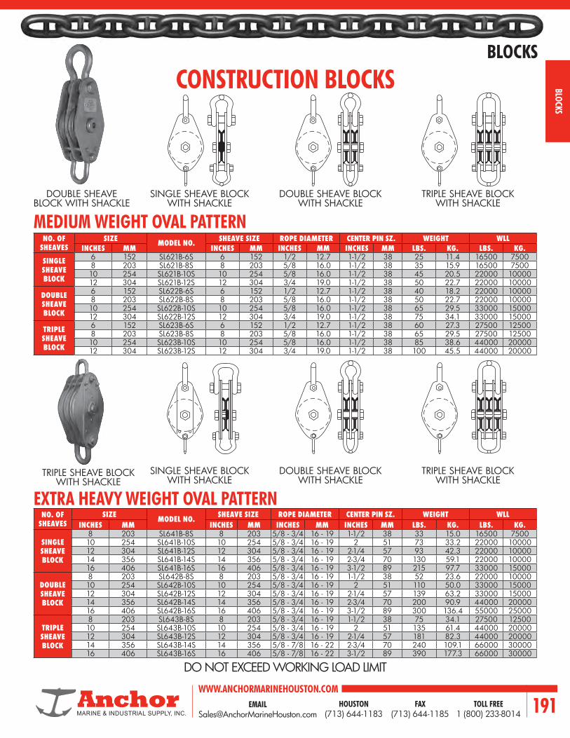
EMAIL [email protected]
WWW.ANCHORMARINEHOUSTON.COMTOLL FREE
1 (800) 233-8014HOUSTON
(713) 644-1183FAX
(713) 644-1185 191
BLOCKS
BLOCKS
CONSTRUCTION BLOCKS
NO. OFSHEAVES
SIZE MODEL NO. SHEAVE SIZE ROPE DIAMETER CENTER PIN SZ. WEIGHT WLLINCHES MM INCHES MM INCHES MM INCHES MM LBS. KG. LBS. KG.
SINGLE SHEAVE BLOCK
8 203 SL641B-8S 8 203 5/8 - 3/4 16 - 19 1-1/2 38 33 15.0 16500 750010 254 SL641B-10S 10 254 5/8 - 3/4 16 - 19 2 51 73 33.2 22000 1000012 304 SL641B-12S 12 304 5/8 - 3/4 16 - 19 2-1/4 57 93 42.3 22000 1000014 356 SL641B-14S 14 356 5/8 - 3/4 16 - 19 2-3/4 70 130 59.1 22000 1000016 406 SL641B-16S 16 406 5/8 - 3/4 16 - 19 3-1/2 89 215 97.7 33000 15000
DOUBLE SHEAVE BLOCK
8 203 SL642B-8S 8 203 5/8 - 3/4 16 - 19 1-1/2 38 52 23.6 22000 1000010 254 SL642B-10S 10 254 5/8 - 3/4 16 - 19 2 51 110 50.0 33000 1500012 304 SL642B-12S 12 304 5/8 - 3/4 16 - 19 2-1/4 57 139 63.2 33000 1500014 356 SL642B-14S 14 356 5/8 - 3/4 16 - 19 2-3/4 70 200 90.9 44000 2000016 406 SL642B-16S 16 406 5/8 - 3/4 16 - 19 3-1/2 89 300 136.4 55000 25000
TRIPLE SHEAVE BLOCK
8 203 SL643B-8S 8 203 5/8 - 3/4 16 - 19 1-1/2 38 75 34.1 27500 1250010 254 SL643B-10S 10 254 5/8 - 3/4 16 - 19 2 51 135 61.4 44000 2000012 304 SL643B-12S 12 304 5/8 - 3/4 16 - 19 2-1/4 57 181 82.3 44000 2000014 356 SL643B-14S 14 356 5/8 - 7/8 16 - 22 2-3/4 70 240 109.1 66000 3000016 406 SL643B-16S 16 406 5/8 - 7/8 16 - 22 3-1/2 89 390 177.3 66000 30000
SINGLE SHEAVE BLOCK WITH SHACKLE
DOUBLE SHEAVE BLOCK WITH SHACKLE
TRIPLE SHEAVE BLOCK WITH SHACKLE
MEDIUM WEIGHT OVAL PATTERN
DOUBLE SHEAVE BLOCK WITH SHACKLE
DO NOT EXCEED WORKING LOAD LIMIT
NO. OFSHEAVES
SIZE MODEL NO. SHEAVE SIZE ROPE DIAMETER CENTER PIN SZ. WEIGHT WLLINCHES MM INCHES MM INCHES MM INCHES MM LBS. KG. LBS. KG.
SINGLE SHEAVE BLOCK
6 152 SL621B-6S 6 152 1/2 12.7 1-1/2 38 25 11.4 16500 75008 203 SL621B-8S 8 203 5/8 16.0 1-1/2 38 35 15.9 16500 750010 254 SL621B-10S 10 254 5/8 16.0 1-1/2 38 45 20.5 22000 1000012 304 SL621B-12S 12 304 3/4 19.0 1-1/2 38 50 22.7 22000 10000
DOUBLE SHEAVE BLOCK
6 152 SL622B-6S 6 152 1/2 12.7 1-1/2 38 40 18.2 22000 100008 203 SL622B-8S 8 203 5/8 16.0 1-1/2 38 50 22.7 22000 1000010 254 SL622B-10S 10 254 5/8 16.0 1-1/2 38 65 29.5 33000 1500012 304 SL622B-12S 12 304 3/4 19.0 1-1/2 38 75 34.1 33000 15000
TRIPLE SHEAVE BLOCK
6 152 SL623B-6S 6 152 1/2 12.7 1-1/2 38 60 27.3 27500 125008 203 SL623B-8S 8 203 5/8 16.0 1-1/2 38 65 29.5 27500 1250010 254 SL623B-10S 10 254 5/8 16.0 1-1/2 38 85 38.6 44000 2000012 304 SL623B-12S 12 304 3/4 19.0 1-1/2 38 100 45.5 44000 20000
SINGLE SHEAVE BLOCK WITH SHACKLE
DOUBLE SHEAVE BLOCK WITH SHACKLE
TRIPLE SHEAVE BLOCK WITH SHACKLE
TRIPLE SHEAVE BLOCK WITH SHACKLE
EXTRA HEAVY WEIGHT OVAL PATTERN

WWW.ANCHORMARINEHOUSTON.COMTOLL FREE
1 (800) 233-8014HOUSTON
(713) 644-1183FAX
(713) 644-1185192
BLOCKS
BLOC
KS STANDARD WOOD SHELL BLOCKS FOR MANILA ROPE
NO.OF
SHEAVES
SIZE SHEAVE SIZE
ROPE DIA.
CENTER PIN SIZE
WORKING LOAD LIMIT
WITH FIXED HOOK WITH SWIVEL HOOK WITH SHACKLE
MODEL NO.WEIGHT
MODEL NO.WEIGHT
MODEL NO.WEIGHT
IN. MM IN. MM IN. MM IN. MM LBS. KG. LBS. KG. LBS. KG. LBS. KG.
SINGLE SHEAVE BLOCK
3 76 1-3/4 44 3/8 10 5/16 8 500 227 SL101B-3H 2.2 1.0 SL101B-3SH 2.6 1.2 SL101B-3S 1.9 0.94 102 2-1/4 57 1/2 13 3/8 10 1000 454 SL101B-4H 3.1 1.4 SL101B-4SH 3.5 1.6 SL101B-4S 2.9 1.35 127 3 76 5/8 16 1/2 13 1200 544 SL101B-5H 4.2 1.9 SL101B-5SH 4.6 2.1 SL101B-5S 4.7 2.16 152 3-1/2 89 3/4 19 1/2 13 1800 816 SL101B-6H 5.3 2.4 SL101B-6SH 5.7 2.6 SL101B-6S 5.8 2.68 203 4-3/4 121 1 25 5/8 16 2800 1270 SL101B-8H 9.9 4.5 SL101B-8SH 10.5 4.8 SL101B-8S 10.3 4.710 254 6 152 1-1/8 29 3/4 19 4000 1814 SL101B-10H 15.2 6.9 SL101B-10SH 15.7 7.1 SL101B-10S 18.0 8.212 304 8 204 1-1/2 38 3/4 19 5000 2268 SL101B-12H 26.0 11.8 SL101B-12SH 26.8 12.2 SL101B-12S 29.0 13.2
DOUBLE SHEAVE BLOCK
3 76 1-3/4 44 3/8 10 5/16 8 800 363 SL102B-3H 2.7 1.2 SL102B-3SH 3.1 1.4 SL102B-3S 2.5 1.14 102 2-1/4 57 1/2 13 3/8 10 1400 635 SL102B-4H 4.2 1.9 SL102B-4SH 4.6 2.1 SL102B-4S 4.0 1.85 127 3 76 5/8 16 1/2 13 1800 816 SL102B-5H 6.6 3.0 SL102B-5SH 7.2 3.3 SL102B-5S 7.0 3.26 152 3-1/2 89 3/4 19 1/2 13 2500 1134 SL102B-6H 9.4 4.3 SL102B-6SH 10.0 4.5 SL102B-6S 8.8 4.08 203 4-3/4 121 1 25 5/8 16 3800 1724 SL102B-8H 15.8 7.2 SL102B-8SH 16.5 7.5 SL102B-8S 16.2 7.410 254 6 152 1-1/8 29 3/4 19 5900 2682 SL102B-10H 31.1 14.1 SL102B-10SH 32.4 14.7 SL102B-10S 32.4 14.712 304 8 204 1-1/2 38 3/4 19 8000 3636 SL102B-12H 41.5 18.8 SL102B-12SH 45.0 20.5 SL102B-12S 41.8 19.0
TRIPLE SHEAVE BLOCK
3 76 1-3/4 44 3/8 10 5/16 8 1200 544 SL103B-3H 3.1 1.4 SL103B-3SH 3.5 1.6 SL103B-3S 2.9 1.34 102 2-1/4 57 1/2 13 3/8 10 1800 816 SL103B-4H 4.4 2.0 SL103B-4SH 4.9 2.2 SL103B-4S 4.2 1.95 127 3 76 5/8 16 1/2 13 2200 1000 SL103B-5H 6.6 3.0 SL103B-5SH 7.6 3.5 SL103B-5S 7.5 3.46 152 3-1/2 89 3/4 19 1/2 13 3200 1452 SL103B-6H 10.8 4.9 SL103B-6SH 11.4 5.2 SL103B-6S 11.2 5.18 203 4-3/4 121 1 25 5/8 16 4800 2177 SL103B-8H 21.2 9.6 SL103B-8SH 22.4 10.5 SL103B-8S 22.5 10.210 254 6 152 1-1/8 29 3/4 19 8000 3636 SL103B-10H 40.8 18.5 SL103B-10SH 44.4 20.2 SL103B-10S 41.2 18.712 304 8 204 1-1/2 38 3/4 19 9900 4500 SL103B-12H 68.3 31.0 SL103B-12SH 71.9 32.7 SL103B-12S 71.8 32.6
Do not exceed working load limits. Factory certification of conformance included with each block.
SINGLE SHEAVE BLOCK WITH FIXED HOOK
DOUBLE SHEAVE BLOCK WITH SWIVEL HOOK
TRIPLE SHEAVE BLOCK WITH SHACKLE
DO NOT EXCEED WORKING LOAD LIMIT

EMAIL [email protected]
WWW.ANCHORMARINEHOUSTON.COMTOLL FREE
1 (800) 233-8014HOUSTON
(713) 644-1183FAX
(713) 644-1185 193
BLOCKS
BLOCKS
SNATCH BLOCKS FOR MANILA ROPE WOOD SHELL AND STEEL SHELL
MANILA ROPE SNATCH BLOCKS -- WOOD SHELL (SINGLE-SHEAVE)
Wood Shell Block withSwivel Shackle
Wood Shell Block withOblong Swivel Eye
Wood Shell Block withSwivel Hook
Wood Shell Block withDrilled Swivel Eye & Shackle
MANILA ROPE SNATCH BLOCKS - STEEL SHELL (SINGLE-SHEAVE)
Steel Shell Block withOblong Swivel Eye
Steel Shell Block withSwivel Hook
Steel Shell Block withDrilled Swivel Eye & Shackle
Steel Shell Block withOblong Swivel Eye
SIZE SHEAVE SIZE ROPE DIA.
CENTER PIN SIZE
WITH SWIVELOBLONG EYE WITH SWIVEL HOOK WITH SWIVEL
SHACKLE WLL
MODEL NO.WEIGHT
MODEL NO.WEIGHT
MODEL NO.WEIGHT
IN. MM IN. MM IN. MM IN. MM LBS. KG. LBS. KG. LBS. KG. LBS. KG.4 102 2-1/2 70 3/4 19 1/2 13 SL386B-4OS 3 1.4 SL386B-4SH 3.5 1.6 SL386B-4DS 3.2 1.5 2700 1227
6 152 3 76 7/8 22 5/8 16 SL386B-6OS 7.5 3.4 SL386B-6SH 8.2 3.7 SL386B-6DS 8 3.6 3000 1364
8 203 4-1/2 114 1 25 3/4 19 SL386B-8OS 15 6.8 SL386B-8SH 15.5 7.0 SL386B-8DS 15.2 6.9 5000 227310 254 5-3/4 146 1-1/4 32 7/8 22 SL386B-10OS 28 12.7 SL386B-10SH 28.5 12.9 SL386B-10DS 28.2 12.8 8000 363612 304 6-3/4 171 1-1/2 38 1 25 SL386B-12OS 38 17.3 SL386B-12SH 39 17.7 SL386B-12DS 38.5 17.5 10000 4545
14 356 8 203 1-3/4 44 1-1/4 32 SL386B-14OS 50 22.7 SL386B-14SH 52 23.6 SL386B-14DS 51 23.2 12000 5454
16 406 9 229 2 50 1-1/4 32 SL386B-16OS 73 332 SL386B-16SH 75 34.1 SL386B-16DS 74 33.6 16000 7273
SIZE SHEAVE SIZE ROPE DIA.
CENTER PIN SIZE
WITH SWIVELOBLONG EYE WITH SWIVEL HOOK WITH SWIVEL
SHACKLE WLL
MODEL NO.WEIGHT
MODEL NO.WEIGHT
MODEL NO.WEIGHT
IN. MM IN. MM IN. MM IN. MM LBS. KG. LBS. KG. LBS. KG. LBS. KG.4 102 2-1/2 70 3/4 19 1/2 13 SL391B-4OS 3 1.4 SL391B-4SH 3.5 1.6 SL391B-4DS 3.2 1.5 2700 1227
6 152 3 76 7/8 22 5/8 16 SL391B-6OS 7.5 3.4 SL391B-6SH 8.2 3.7 SL391B-6DS 8 3.6 3000 1364
8 203 4-1/2 114 1 25 3/4 19 SL391B-8OS 15 6.8 SL391B-8SH 15.5 7.0 SL391B-8DS 15.2 6.9 5000 227310 254 5-3/4 146 1-1/4 32 7/8 22 SL391B-10OS 28 12.7 SL391B-10SH 28.5 12.9 SL391B-10DS 28.2 12.8 8000 363612 304 6-3/4 171 1-1/2 38 1 25 SL391B-12OS 38 17.3 SL391B-12SH 39 17.7 SL391B-12DS 38.5 17.5 10000 4545
14 356 8 203 1-3/4 44 1-1/4 32 SL391B-14OS 50 22.7 SL391B-14SH 52 23.6 SL391B-14DS 51 23.2 12000 5454
16 406 9 229 2 50 1-1/4 32 SL391B-16OS 73 332 SL391B-16SH 75 34.1 SL391B-16DS 74 33.6 16000 7273

WWW.ANCHORMARINEHOUSTON.COMTOLL FREE
1 (800) 233-8014HOUSTON
(713) 644-1183FAX
(713) 644-1185194
BLOCKS
BLOC
KS
WORKING LIMIT (TONS) WIRE ROPE SIZE
SHEAVE DIAMETER
WEIGHT (LBS.)DESIGN
FACTOR 4 TO 1
STD. MAX. ALLOW
8 TON3/8 - 1/2 3/4 4 26
3/8 - 1/2 3/4 6 34
12 TON
5/8 - 3/4 1 6 50
5/8 - 3/4 7/8 8 54
5/8 - 3/4 3/4 10 61
5/8 - 3/4 7/8 12 81
5/8 - 3/4 7/8 14 104
15 TON
3/4 - 7/8 1-1/8 6 61
3/4 - 7/8 1-1/8 8 82
7/8 - 1 1-1/8 10 94
7/8 - 1 1-1/8 12 123
7/8 - 1 1-1/8 14 150
22 TON
1 - 1-1/8 1-1/2 8 132
1 - 1-1/8 1-1/2 10 171
1 - 1-1/8 1-1/4 12 173
1 - 1-1/8 1-3/8 14 201
WORKING LIMIT
(TONS)WIRE ROPE SIZE
SHEAVE DIAMETER
WEIGHT (LBS.)DESIGN
FACTOR 4 TO 1
STD. MAX. ALLOW
3 TON
3/8 - 1/2 3/4 4 15
3/8 - 1/2 3/4 6 18
3/8 - 1/2 3/4 8 22
3/8 - 1/2 3/4 10 34
3/8 - 1/2 7/8 12 39
3/8 - 1/2 3/4 14 41
8 TON
5/8 - 3/4 1 6 29
5/8 - 3/4 7/8 8 36
5/8 - 3/4 3/4 10 31
5/8 - 3/4 7/8 12 46
5/8 - 3/4 7/8 14 58
12 TON
3/4 - 7/8 1-1/8 6 42
3/4 - 7/8 1-1/8 8 53
7/8 - 1 1-1/8 10 66
7/8 - 1 1-1/8 12 75
7/8 - 1 1-1/8 14 92
7/8 - 1 1-1/8 16 119
22 TON
1 - 1-1/8 1-1/2 8 102
1 - 1-1/8 1-1/2 10 125
1 - 1-1/8 1-1/4 12 131
1 - 1-1/8 1-3/8 14 149
1 - 1-1/8 1-1/4 16 178
1 - 1-1/8 1-3/8 18 214
30 TON1-1/8 - 1-1/4 1-3/8 20 341
1-1/8 - 1-1/4 1-3/8 24 461
CONSTRUCTIONDOUBLE SHEAVE DATA
SINGLE SHEAVE DATA
• Bronze brushed or roller bearing sheaves• Side opening feature for easy threading• Swivel hook, drilled eye, or swivel shackle• 4 to 1 design factor• Drop forged• Hooks and shackles quickly interchangeable• 2 tons thru 30 tons
ABOVE FEATURES
NOTE: Standard wire rope size furnished unless otherwise specified.
DOUBLE TRIPLE

EMAIL [email protected]
WWW.ANCHORMARINEHOUSTON.COMTOLL FREE
1 (800) 233-8014HOUSTON
(713) 644-1183FAX
(713) 644-1185 195
BLOCKS
BLOCKS
Nominal Outside Diameter
Nominal Tread Diameter
Nominal HubDiameter
Bore
ShaftSize
Rim Hub
NOMINAL OUTSIDE DIAMETER QUANTITY
+ Shaft Size =* Hub Width =Rim Width =Wire Rope Size =Nominal Thread Diameter (optional) = Nominal Hub Diameter (optional) =
+ Shaft Size is Bore Size on Plain Bore Sheaves* Hub Width is measured over the cone of Tapered Bearing Sheaves
BEARING TYPEBronze Bushing
‡ Roller BearingTapered Roller BearingsFinish / Plain BoreOther
‡ Requires hardened ground shaftMATERIAL TYPERolled Forged (Flame hardened 14’’ and larger)Forged SteelCast SteelOther
Special testing, required or certification: UT, MPI, Paint, ABS, Lloyd’s, DNV, etc.
Line Pull =Fleet Angle = Degree of Wrap = Line Speed =
CUSTOM SHEAVE FORM
BRONZE BUSHING SHEAVE SHOWN FOR REFERENCE

WWW.ANCHORMARINEHOUSTON.COMTOLL FREE
1 (800) 233-8014HOUSTON
(713) 644-1183FAX
(713) 644-1185196
BLOCKS
BLOC
KS
MATERIAL LIST
ITEM TYPE ITEM TYPE1 Swivel Eye 11 Spacer2 Yoke 12 Washer, Bronze3 Side Block 13 Washer, Bronze4 Sheave 14 Lug, Locking5 Pin Draw 15 Clip Spring6 Pin Sheave 16 Hex Head Bolt7 Nut Swivel Eye 17 Hex Nut8 Nut Sheave Pin 18 Cotter Pin9 Collar 19 Cotter Pin10 Bushing, Bronze 20 Grease Fitting
8”
8”11”
Tack Weld
2”-76 Ton Snatch Block
64”
35”
515
3-1/2”
13
12
18
10
20
11181716
14
1
2
7
3
6
49
8
2”-76 TON SNATCH BLOCK

EMAIL [email protected]
WWW.ANCHORMARINEHOUSTON.COMTOLL FREE
1 (800) 233-8014HOUSTON
(713) 644-1183FAX
(713) 644-1185 197
DOCK
DOCK

WWW.ANCHORMARINEHOUSTON.COMTOLL FREE
1 (800) 233-8014HOUSTON
(713) 644-1183FAX
(713) 644-1185198
DOCK
DOCK
CASTING INDEX
PART NUMBER DESCRIPTION ANCHOR BOLTS QTY. X SIZE MAXIMUM CAPACITY
AMB 20 BOLLARD, CAST STEEL 4 X 1-3/4'' 20 TONS
AMB 25 BOLLARD, CAST STEEL 4 X 2-1/4'' 25 TONS
AMB 30 BOLLARD, CAST STEEL 6 X 1-3/4'' 30 TONS
AMB 40 BOLLARD, CAST STEEL 8 X 1-1/2'' 40 TONS
AMB 40 A BOLLARD, CAST STEEL 4 X 1-1/2'' 40 TONS
AMB 45 BOLLARD, CAST STEEL 4 X 1-1/4'' 45 TONS
AMB 50 A BOLLARD, CAST STEEL 4 X 1-1/4'' 50 TONS
AMB 50 BOLLARD, CAST STEEL 4 X 1-3/4'' 50 TONS
AMB 55 BOLLARD, CAST STEEL 4 X 1-3/4'' 55 TONS
AMB 65 BOLLARD, CAST STEEL 4 X 1-3/4'' 65 TONS
AMB 70 BOLLARD, CAST STEEL 4 X 2'' 70 TONS
AMB 80 BOLLARD, CAST STEEL 4 X 2’’ 80 TONS
AMB 90 BOLLARD, CAST STEEL 6 X 2'' 90 TONS
AMB 100 BOLLARD, CAST STEEL 6 X 2-1/4'' 100 TONS
AMB 100 A BOLLARD, CAST STEEL 8 X 2-1/4'' 100 TONS
AMB 100 B BOLLARD, CAST STEEL 8 X 2-1/4" 100 TONS
AMB 125 BOLLARD, CAST STEEL 8 X 2'' 125 TONS
AMB 150 BOLLARD, CAST STEEL 8 X 2-3/4'' 150 TONS
AMB 225 BOLLARD, CAST STEEL 8 X 2-3/4'' 225 TONS

EMAIL [email protected]
WWW.ANCHORMARINEHOUSTON.COMTOLL FREE
1 (800) 233-8014HOUSTON
(713) 644-1183FAX
(713) 644-1185 199
DOCK
DOCK
21-1/2”
16-1/2”
23-1/2”
3-1/2”
1-1/2”
23”
20”
2”
4”
40-1/2”
10-1/2”
13-1/2”
1-1/2”
26”
21”
33”
25”
19” 27”
15-3/4”
2-1/2”
1-1/2”
3-1/2”
2-1/2”
1-1/4”
2-1/2”
1-1/2” 7-1/2”15-1/4”
29-1/4”
18-1/4”
10-1/2”
5”
2” 4”
2-3/8”
2-3/8” Ø CORE FOR2-1/4” Ø BOLT
2” Ø CORE FOR1-3/4” Ø BOLT 20 TON BOLLARD AMB 20
25 TON BOLLARD AMB 25

WWW.ANCHORMARINEHOUSTON.COMTOLL FREE
1 (800) 233-8014HOUSTON
(713) 644-1183FAX
(713) 644-1185200
DOCK
DOCK
30 TON BOLLARD AMB 30
24-3/4”
39-1/2”
18-1/2”
3-1/2”
1-1/2” 3-1/2”
1-3/4”
12” 12”
30”
30”24”
4-1/2”
1-3/4”
26”
9”
4”
2”
6”
2” Ø CORE FOR1-3/4” Ø BOLT

EMAIL [email protected]
WWW.ANCHORMARINEHOUSTON.COMTOLL FREE
1 (800) 233-8014HOUSTON
(713) 644-1183FAX
(713) 644-1185 201
DOCK
DOCK
26”
1-1/2”
3/4”
3”
2”
4”
12”
10 0
6ӯ
12”
1-1/2
2-1/4”
5-7/8”
15” Ø
7-1/2” 11-1/2”
2-1/4”
3-3/4”
1-3/4”
1-1/2”
4”
1” R
3-3/4” Ø
19”
3” 3”7”
4”
11”
7”
12” 19”
22”
21”
42”
15”Ø7-1/2”
3-1/2”
3-1/2”
11-1/2”
21”
1-3/4” Ø CORE FOR1-1/2” Ø BOLT
10ӯ
1-1/4”
40 TON BOLLARD AMB 40

WWW.ANCHORMARINEHOUSTON.COMTOLL FREE
1 (800) 233-8014HOUSTON
(713) 644-1183FAX
(713) 644-1185202
DOCK
DOCK
20”
20”
7”
7”
3-1/2” R
SQUARE27”
3-1/2”
3-1/2”
3-1/2”
4” Ø X 1-3/4” DEEP CORED
HOLE TYP.
3-1/2”
13-1/2”
25”
9”9”
1-1/2” Ø CORE FOR1-1/4” Ø BOLT
3”
26-1/2”
1-1/4”1-1/2”
5-5/8” 0
22-1/2”
11-1/2”
5-3/4”
6-1/2”
6-1/2”
3-1/4” R
16”
18”
8”
5”
1-3/4” Ø CORE FOR1-1/2” Ø BOLT
22”
12”
14” R
1-3/4” 1-1/4”
3/4” R7/8”
7”
2”
8” Ø3”
2-1/2 R
3-1/4”
3-3/4”
3-3/4”
1-3/4”
4” Ø
1-1/2”
3-1/4”
40 TON BOLLARD AMB 40-A
45 TON BOLLARD AMB 45

EMAIL [email protected]
WWW.ANCHORMARINEHOUSTON.COMTOLL FREE
1 (800) 233-8014HOUSTON
(713) 644-1183FAX
(713) 644-1185 203
DOCK
DOCK
39” Square
15”
2”
5ӯ
5-1/2” 5-1/2”28”
28”
5ӯ
1-3/4”
2”
30”
1-1/2”
4-1/4”
24”30”
24”
1”
8”
4”
13”
1-1/2”
21”
4”
3”
4” 3”
1-1/4”
R-4”
30”
R-2”
12”
2” Ø CORE FOR1-3/4” Ø BOLT
1-1/2” Ø CORE FOR1-1/4” Ø BOLT
24ӯ
44-1/2”
1-1/4”
1-3/4”
1-3/4”
17-3/4”5”
4”
A
A
1-1/4”6”Ø
12-1/2”
4-1/4”
1-1/2”
Ø
1-1/2”
50 TON BOLLARD AMB 50-A
50 TON BOLLARD AMB 50

WWW.ANCHORMARINEHOUSTON.COMTOLL FREE
1 (800) 233-8014HOUSTON
(713) 644-1183FAX
(713) 644-1185204
DOCK
DOCK
9-3/4”
7-1/4”
31-1/2”
15-3/4ӯ
4ӯ
10-1/2ӯ
3-1/2”
2-3/8”
2-1/2”
6-3/4”
2ӯ
4”12”
33”
8-3/4”12”Ø
14-1/2”
19-1/2”
6-1/2”
4” Ø
3-1/4” Ø
6-1/2”
26”
21”
30”
5”
2ӯ
1-3/4”
18ӯ
34-3/4”
7-1/4”
11-1/4”22-1/2”
30”
8-3/8”
16-3/4”
24”
7-1/4”
4”
5”
10-1/2”
2” Ø CORE FOR1-3/4” Ø BOLT
1-1/2”
1-3/4”
4”
2-3/4”4-1/2”
1-3/4”
1-3/4”
2”
4” Ø
4”
2”
2” Ø CORE FOR1-3/4” Ø BOLT
65 TON BOLLARD AMB 65
55 TON BOLLARD AMB 55

EMAIL [email protected]
WWW.ANCHORMARINEHOUSTON.COMTOLL FREE
1 (800) 233-8014HOUSTON
(713) 644-1183FAX
(713) 644-1185 205
DOCK
DOCK
T-HEAD BOLLARD MOORING LINE LOAD
45°
1’0”
4’0”
SECTION
PLAN
40°
TOP/WHARFEDGE OFCONCRETE
EDGE OFCONCRETE
69 TON
85 TON
DIRECTION OF LINE LOAD

WWW.ANCHORMARINEHOUSTON.COMTOLL FREE
1 (800) 233-8014HOUSTON
(713) 644-1183FAX
(713) 644-1185206
DOCK
DOCK
70 TON BOLLARD AMB 70
2’6”
26” 17-5/8”
12”
9”
3”
1-1/2”
7-1/2”
7-1/2”
27”
2”6”
2”R15”
3-1/4”
12”
1-1/2”
1-3/4”R
30”
4”
1-3/8”
1-1/4”
3-1/2”5-1/2” 11-3/4”R”
2-1/8” Ø HOLE - C BORE4” Ø 1-1/2” DP. 4 HOLES
22”
22”
4”
2-1/8”
2 1/8” Ø CORE FOR2” Ø BOLTS

EMAIL [email protected]
WWW.ANCHORMARINEHOUSTON.COMTOLL FREE
1 (800) 233-8014HOUSTON
(713) 644-1183FAX
(713) 644-1185 207
DOCK
DOCK
J
B
D
E
C
G
FHADIA.
APPROXIMATE DIMENSIONS (INCHES)
Load Tons Type No. A B C D E F G H J
50 X-5-A 11-3/4 31-1/2 25-1/2 19 22-1/2 9-1/2 3 8 23-1/2
75 X-9-A 13-1/2 31-1/2 28-1/4 20 24-1/4 10-1/4 3-1/2 8-3/4 25-1/2
100 X-10-A 14-3/4 39-1/4 32 23-1/2 28 12 4 10-3/4 29-1/2
150 X-15-A 17 42-1/2 35-1/2 26-1/4 32-3/4 13-3/4 4-3/8 11 31-1/2
TEE HEAD MOORING BOLLARD

WWW.ANCHORMARINEHOUSTON.COMTOLL FREE
1 (800) 233-8014HOUSTON
(713) 644-1183FAX
(713) 644-1185208
DOCK
DOCK
80 TON BOLLARD AMB 80
A A
4”
28”
1”
28”
9ӯ
4-1/2ӯ
6ӯ
1”1”2-1/4”3-1/2”
2-1/4”
39”
39”
5-1/2”
24”Ø4-1/2”
1”
48”
4”
4”RA
A
16”5”
1”
1-1/4”
3-1/4”
2-1/4”
4-1/2”
5-1/2” 5-1/2”
5-1/2”
24”R
9ӯ
1-3/4”
8-1/2”2-1/4” CORE HOLES FOR
2” Ø BOLTS

EMAIL [email protected]
WWW.ANCHORMARINEHOUSTON.COMTOLL FREE
1 (800) 233-8014HOUSTON
(713) 644-1183FAX
(713) 644-1185 209
DOCK
DOCK
90 TON BOLLARD AMB 90
4-1/2ӯ
2-1/4”
2”
5”
6” 6”7” 7”
7”
24”
9-1/2” 9-1/2”14-1/2” 14-1/2”
25-1/2”
48”
8”
17”
2-1/2”
1-1/2”
13”
6” 2”A
14”
33”
4”
12”
12”
12”
11” 11”
9”
2-1/4” Ø CORE FOR2” Ø BOLT

WWW.ANCHORMARINEHOUSTON.COMTOLL FREE
1 (800) 233-8014HOUSTON
(713) 644-1183FAX
(713) 644-1185210
DOCK
DOCK
100 TON BOLLARD AMB 100
6”
6”
A A
8”
8”
8”
4”
5”
18”
1-3/4”
1-1/4”
1-3/4”
3/4”R
15”
16”
28” BC
36” Ø
1-1/2” R
PLAN
13”
30”
4”1-1/2”
2-3/8”
2-3/8” Ø CORE FOR2-1/4” Ø BOLT
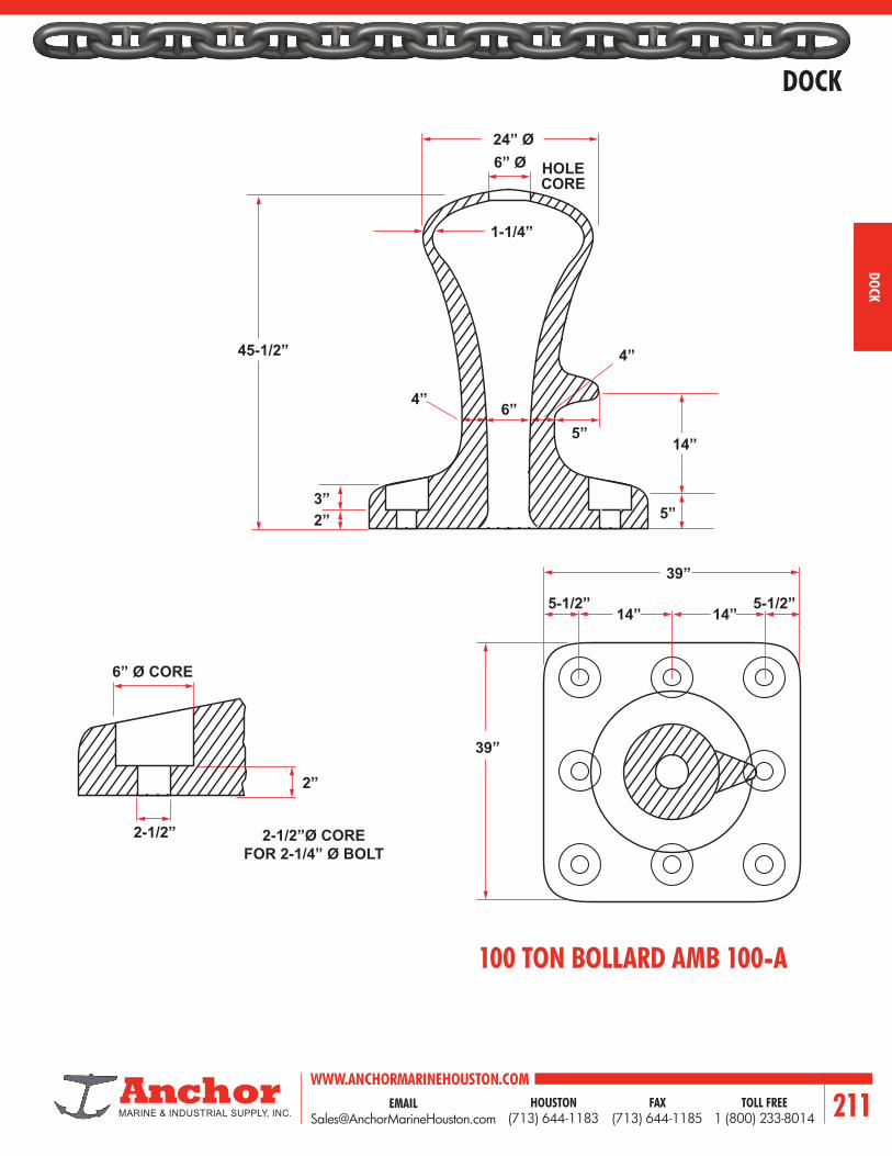
EMAIL [email protected]
WWW.ANCHORMARINEHOUSTON.COMTOLL FREE
1 (800) 233-8014HOUSTON
(713) 644-1183FAX
(713) 644-1185 211
DOCK
DOCK
100 TON BOLLARD AMB 100-A
45-1/2”
6” Ø
1-1/4”
6” Ø CORE
2-1/2”
24” Ø
HOLECORE
5”
4”
4”
3”2”
2”
39”
14” 14”
39”
5”
14”
5-1/2” 5-1/2”
6”
2-1/2”Ø COREFOR 2-1/4” Ø BOLT

WWW.ANCHORMARINEHOUSTON.COMTOLL FREE
1 (800) 233-8014HOUSTON
(713) 644-1183FAX
(713) 644-1185212
DOCK
DOCK
100 TON BOLLARD AMB 100-B
14”
39”
39”
2-1/2ӯ 5ӯ 6ӯ
2”
5ӯ
2-1/2”
14”5-1/2” 5-1/2”
2 1/2” Ø CORE FOR2-1/4” Ø BOLT
21-5/16” Ø6” Ø
42”
19”
39”
4-5/8”
2”2-3/4”
2”
14”

EMAIL [email protected]
WWW.ANCHORMARINEHOUSTON.COMTOLL FREE
1 (800) 233-8014HOUSTON
(713) 644-1183FAX
(713) 644-1185 213
DOCK
DOCK
125 TON BOLLARD AMB 125
18”
29”
15”
8”
5”
9”
21”
39”2”
7”
2-1/4”
1-3/4”
11-1/2”
4”2”
5”
TOP OFDECK
3”
9”
14”
1-1/2”
39”5-1/2” 5-1/2”
14”
A
A
2-1/4” Ø COREFOR 2’ Ø BOLT

WWW.ANCHORMARINEHOUSTON.COMTOLL FREE
1 (800) 233-8014HOUSTON
(713) 644-1183FAX
(713) 644-1185214
DOCK
DOCK
150 TON BOLLARD AMB 150
24” Ø6” Ø
14”
39”
39”
2”
3”
14”
45-1/2”
4”
4”
14”
39”
5”
5”2-3/4”2-1/4”
6”
1-1/4”
5-1/2” 5-1/2”
3” Ø CORE FOR2-3/4” Ø BOLT
6ӯ

EMAIL [email protected]
WWW.ANCHORMARINEHOUSTON.COMTOLL FREE
1 (800) 233-8014HOUSTON
(713) 644-1183FAX
(713) 644-1185 215
DOCK
DOCK
225 TON BOLLARD AMB 225
6”
6”
6”
6”
12”
12”
48”
R6 48”
18” 18”
3-1/8”
6”
6”
6”
3”
2”
48”
3” CORE ØFOR 2-3/4 BOLT
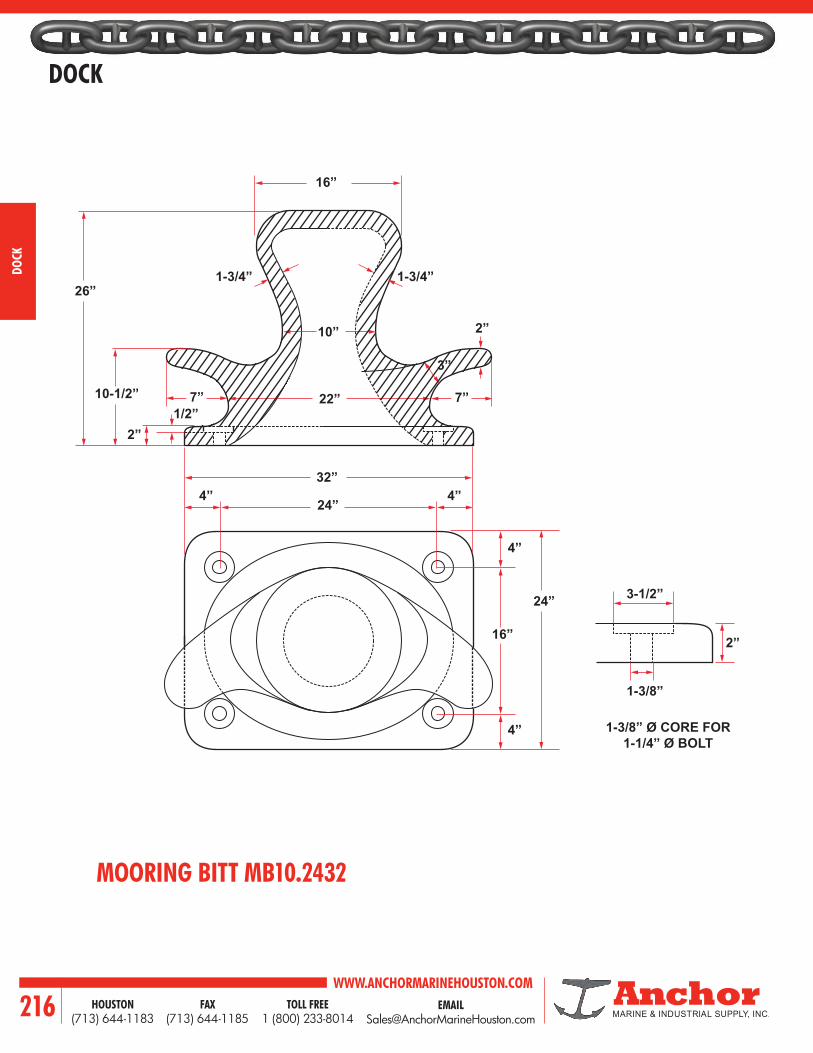
WWW.ANCHORMARINEHOUSTON.COMTOLL FREE
1 (800) 233-8014HOUSTON
(713) 644-1183FAX
(713) 644-1185216
DOCK
DOCK
MOORING BITT MB10.2432
16”
26”
22”
24”
32”
10”
1-3/4” 1-3/4”
2”
7”
4” 4”
4”
16”
24”
4”
10-1/2”1/2”
7”
3”
2”
1-3/8” Ø CORE FOR 1-1/4” Ø BOLT
3-1/2”
1-3/8”
2”

EMAIL [email protected]
WWW.ANCHORMARINEHOUSTON.COMTOLL FREE
1 (800) 233-8014HOUSTON
(713) 644-1183FAX
(713) 644-1185 217
DOCK
DOCK
QUICK RELEASE BUOY HOOKWITH ABS CERTIFICATION
R25.4
259.5
372.5
759.313
91 91
122.2
205.7
R 71.5237.5
119
43.5
76Ø 76Ø
76Ø
178
R25.4
13
91
255
237.5
195
91
R71.5
759.3
259.5372.5
171.2
43.5
178
400,000 LBS PROOF LOADWEIGHT: 410 LBS
300,000 LBS PROOF LOADWEIGHT: 357 LBS
631
292.1R134.2
13
9191178
R25.4
389.3
502.3
823.4
153.8
362.8
80
295.9
400,000 LBS PROOF LOAD WIDEMOUTHWEIGHT: 502 LBS
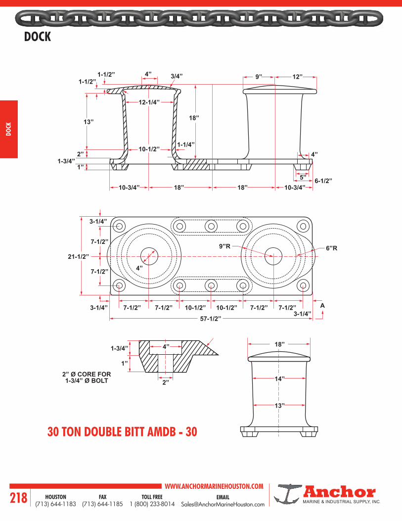
WWW.ANCHORMARINEHOUSTON.COMTOLL FREE
1 (800) 233-8014HOUSTON
(713) 644-1183FAX
(713) 644-1185218
DOCK
DOCK
30 TON DOUBLE BITT AMDB - 30
18”
21-1/2”
7-1/2”
3-1/4”
3-1/4”
4”
3-1/4”
7-1/2”
7-1/2” 10-1/2”57-1/2”
10-1/2”7-1/2” 7-1/2”7-1/2”
9”R
18”
12-1/4”
10-3/4”
1-1/2”1-1/2”
10-1/2”
4”
2”R
13”
18”
2”1-3/4”
1”
3/4”
1-1/4”
1-1/2”
6”R
1-3/4”
1”
2” 14”
13”
10-3/4”6-1/2”5”
4”
9” 12”
18”
4”
2” Ø CORE FOR1-3/4” Ø BOLT
A
12-1/4”
10-1/2”

EMAIL [email protected]
WWW.ANCHORMARINEHOUSTON.COMTOLL FREE
1 (800) 233-8014HOUSTON
(713) 644-1183FAX
(713) 644-1185 219
DOCK
DOCK
100 TON DOUBLE BITT AMDB - 100
23”
28”6”
10-3/4”
10-3/4”
10-3/4” 10-3/4”
3-1/4”
3-1/4”3-1/4”
73-1/2”
11-1/4” 11-1/4”11-1/2” 11-1/2”
11-1/2” R
2’3”
12-1/4”
14” 14”
1-1/2”1-1/2”
10-1/2”2”R
22-3/4” 22-3/4”
3”
2”
1-3/4”
1-1/2”
2”
7/8”1-5/8”
1-1/2”
1-1/2”
8”R
A
20”
19”
6-1/2”5”
4”
15-1/2”11-1/2”
1’6”
19”
1’4”3”R
4”
2”
2” 2” Ø CORE FOR1-3/4” Ø BOLT
4”1-3/4”
18”
16”

WWW.ANCHORMARINEHOUSTON.COMTOLL FREE
1 (800) 233-8014HOUSTON
(713) 644-1183FAX
(713) 644-1185220
DOCK
DOCK
16ӯ
10ӯ
1-1/2”3”R
13”
14” 14”12”
58”
12”
1-1/2” 1-1/2”
7” 6”
3”3”
7”
7”A A21”
3-1/2”
10”
5-1/2”
2-1/2” 2-1/2”
5-1/2”
2”3”
5”
21”
3”8”
3-1/2”
BB
3”R3”Ø
3ӯ HOLE FORCONCRETE FILL
HOLE
4”Ø 1-1/2” Ø BOLT1-5/8” Ø CORE FOR
HOLE
1-1/4”
3”
9” R
27”
100 TON DOUBLE BITT AMDB 100 - 58

EMAIL [email protected]
WWW.ANCHORMARINEHOUSTON.COMTOLL FREE
1 (800) 233-8014HOUSTON
(713) 644-1183FAX
(713) 644-1185 221
DOCK
DOCK
16” Ø
9”
5”
3030
10” 10”12” 12”
50”
1-1/2”15-7/8”
1-1/2”7” 6”
3” 3”
7-1/2”
7-1/2”
A A
C
21”
10”
5-1/2”
2-1/2” 2-1/2”
5-1/2”
2”3”
5”
21”
3”8”
3”
3”
1”
BB
3”R
3” Ø HOLE FORCONCRETE FILL
4” Ø1-1/2” Ø BOLT
1-5/8” Ø CORE FOR
HOLE
1-1/4” 3”R
10”
2’0”
24”R
24”R
1-1/2”
1-1/2”
1’9”R
3”R
3”R 3” DIAHOL
10” Ø3”R
21”R
24” 3” ØHOLE3”R
27”
100 TON DOUBLE BITT AMDB 100 - 50

WWW.ANCHORMARINEHOUSTON.COMTOLL FREE
1 (800) 233-8014HOUSTON
(713) 644-1183FAX
(713) 644-1185222
DOCK
DOCK
10 TON CLEAT AMC - 10A
6”
6”
3”
3”
3” 3”
5”
5”16”
1-1/2”
16”
5” 5”
6”9”
30”
9”
1”
12”
2”R
3-1/2”
1-1/2”
2-3/4”
9”
1” 1”3”
2”R
7-1/2”
1-1/4”
10-1/2”
1-1/2”
1-1/2”
1-1/2” Ø
1-1/4”2-3/4”
3-1/2” Ø
1-1/2”R
3” R
CORE
CORE
1-1/2” Ø CORE FOR1-1/4” Ø BOLT

EMAIL [email protected]
WWW.ANCHORMARINEHOUSTON.COMTOLL FREE
1 (800) 233-8014HOUSTON
(713) 644-1183FAX
(713) 644-1185 223
DOCK
DOCK
10 TON CLEAT AMC - 10
6”
6”
3”
3”
3” 3”
5”
5”16”
1-1/2” R
16”
5” 5”
6”9”
30”
9”
1”
12”
2”R1-1/2”
2-3/4”
9”1” 1”3”
2”R7-1/2”
1-1/4”
10-1/2”
1-1/2”
1-1/2” Ø
1-1/4”2-3/4”
3-1/2” Ø
1-1/2”R
1-1/2” Ø CORE FOR1-1/4” Ø BOLT

WWW.ANCHORMARINEHOUSTON.COMTOLL FREE
1 (800) 233-8014HOUSTON
(713) 644-1183FAX
(713) 644-1185224
DOCK
DOCK
B
B
10-1/2”
1-1/4”
1-1/4” 1-1/4”
2-1/2”
1-1/2”
9-1/2”
13”7/8”
7/8”
7/8”
5” 5”5”
6”
3ӯ
7”
10-1/2”2-1/2”
2-3/8”4-3/4”
2-1/2”
2-1/2”
14-1/4”
2-1/2”
4-5/8”
4-5/8”
26”
42”
10-1/2”
7”
6”7”
5”
1-3/8” Ø CORE FOR1-1/8” Ø BOLT
A
20 TON CLEAT AMC - 20
SECTION A-A SECTION B-B

EMAIL [email protected]
WWW.ANCHORMARINEHOUSTON.COMTOLL FREE
1 (800) 233-8014HOUSTON
(713) 644-1183FAX
(713) 644-1185 225
DOCK
DOCK
AMC-H-54
14-1/4”8-3/8”
2-1/2”
16-3/4”
9-1/2” 9-1/2” R1/2”
2-3/4”
1-3/8”
9-1/2”
33-1/2”
2-3/4” Ø CORE1-1/4” DEEP
1-3/8” Ø CORE FOR 1-1/4” Ø BOLT
23-1/2”
54”
16”

WWW.ANCHORMARINEHOUSTON.COMTOLL FREE
1 (800) 233-8014HOUSTON
(713) 644-1183FAX
(713) 644-1185226
DOCK
DOCK
DIMENSIONS (INCHES)A B C D E F G H I J K L M
AMC-H 16 10-1/2 7-1/2 5 8 2-3/4 3-3/4 1-1/2 7/8 3/4 1-3/4 3-3/4 4-1/2
AMC-H 24 15-1/2 9-1/2 7-1/4 12 4 5-1/4 1-3/4 1-1/8 7/8 2 6 6
AMC-H 30 19 11-1/4 8-7/8 15 5 6-3/8 2 1-1/4 1 2-1/4 7-1/2 7-1/4
K
L
A
L
M
I
B
L
C
H
K
J
DH
B
A
L
L
M C
H
DGE
GE
I
J BOLT Ø
F
K
L
A
L
M
I
B
L
C
H
K
J
DH
B
A
L
L
M C
H
DGE
GE
I
J BOLT Ø
FAMC-6 BOLT CLEAT
DIMENSIONS (INCHES)A B C D E F G H I J K L M
AMC-H 36 22-1/2 12-1/4 10-1/2 18 6 7-1/2 2 1-3/8 1 2-1/4 6-1/4 8-1/4
AMC-H 42 26 14-1/4 13 21 7 8-5/8 2 1-1/2 1 2-1/4 7-1/2 9-1/4
AMC-H 48 29-3/4 15-1/8 13-3/4 24 8 9-3/4 2-1/4 1-5/8 1-1/8 2-5/8 8-1/2 10-5/8
K
L
A
L
M
I
B
L
C
H
K
J
DH
B
A
L
L
M C
H
DGE
GE
I
J BOLT Ø
F
AMC-8 BOLT CLEAT

EMAIL [email protected]
WWW.ANCHORMARINEHOUSTON.COMTOLL FREE
1 (800) 233-8014HOUSTON
(713) 644-1183FAX
(713) 644-1185 227
DOCK
DOCK
B
C
K
G
N
KQ
TE
P
G
HA
C
R
U
U
M
M
K J
J
F
D
L
CLEAT AMC - 216 - 254
DIMENSIONS (INCHES)
A B C D E F G H J K L M N P Q R T U
16 9-1/2 3-5/8 4-1/8 8 1-1/2 2 5-1/4 1-3/4 7/8 5/8 3/4 2-3/4 1/2 7/16 1-3/8 2-1/2 3/4
20 11 4-1/2 5-3/8 10 2 2-1/2 6-5/8 2-1/4 1-1/8 3/4 7/8 3-3/8 3/4 9/16 1-9/16 3-1/4 7/8
24 13-1/2 5-3/8 6-3/8 12 2-1/2 3 8 2-3/4 1-3/8 7/8 1 4 1 11/16 1-3/4 4 1
27 15 6 7-3/8 13-1/2 3 3-3/8 9 3-1/8 1-9/16 1 1-1/8 4-1/2 1-1/4 13/16 1-15/16 4-1/2 1-1/8
30 17 6-3/4 8 15 3-1/2 3-3/4 10 3-1/2 1-3/4 1-1/8 1-1/4 5 1-1/2 7/8 2-1/8 5 1-1/4
33 19 7-3/8 9 16-1/2 4 4-7/8 11 3-3/4 1-7/8 1-1/4 1-3/8 5-1/2 1-3/4 15/16 2-3/8 5-1/2 1-3/8
36 21 8 9-7/8 18 4-1/2 4-1/2 12 4 2 1-3/8 1-1/2 6 2 1 2-5/8 6 1-1/2
42 24 9-3/8 11-5/8 21 5 5-1/4 14 4-3/4 2-3/8 1-1/2 1-3/4 7 2-1/4 1-3/16 2-7/8 7 1-3/4
48 27 10-3/4 13-1/8 24 5-1/2 6 16 5-1/2 2-3/4 1-5/8 2 8 2-1/2 1-3/8 3-3/8 8 2
54 30 12 14-3/4 27 6 6-3/4 18 6 3 1-3/4 2-1/4 9 2-3/4 1-1/2 3-3/4 9 2-1/4

WWW.ANCHORMARINEHOUSTON.COMTOLL FREE
1 (800) 233-8014HOUSTON
(713) 644-1183FAX
(713) 644-1185228
DOCK
DOCK
AMC-50 CLEAT
10-3/4”
10” 7-1/2”
6-1/2”
3”
4”
42”36”
24-1/4”
50”
BOLT HOLES COREDTO 1-3/8” DIA.
BOLT HOLES COREDTO 1-3/8” DIA.
1-1/4” RECESS X2-3/4” SQUARE
2” R
2-1/2”
3” 4” R 5” R
6”

EMAIL [email protected]
WWW.ANCHORMARINEHOUSTON.COMTOLL FREE
1 (800) 233-8014HOUSTON
(713) 644-1183FAX
(713) 644-1185 229
DOCK
DOCK1-7/8”
1-1/8”D
1-1/8”R
4-1/2”
12”
B
C
CB
3-9/16” 3/4”R
5-1/4”
3-3/8”
3/4” 1-7/8”5-5/8”
1-1/8”R
3/4”R
3/4”
7-1/2”
9/16”
3”
3/4”R
7/8” Ø CORE FOR1/2” Ø BOLT
1” Ø CORE FOR3/4” Ø BOLT
5” 7-3/15”8”3”
2”
1-1/2”
1-1/2”
8-1/4”
11-1/4” 5-1/4”
18”R8 1/4”
3/4”1”
Ø 2” Ø 3”
AMC-18 CLEAT
12’’ STD. NAVY CLEAT DETAIL

WWW.ANCHORMARINEHOUSTON.COMTOLL FREE
1 (800) 233-8014HOUSTON
(713) 644-1183FAX
(713) 644-1185230
DOCK
DOCK
OPEN BASE CLEAT - FLAT HEADHOT DIPPED GALVANIZED IRON
DIMENSIONS (INCHES) LBS.
CLEAT SIZE HOLE SPACING
LENGTH HEIGHT SPACING WEIGHT
8 2-1/8 1-11/16 1.51
10 2-1/2 2-3/8 2.13
12 2-7/8 3-3/8 3.64
14 3-1/2 4-1/4 6.03
DIMENSIONS (INCHES) LBS.
CLEAT SIZE HOLE SPACING
LENGTH HEIGHT SPACING WEIGHT
3-1/2 1 15/16 0.14
3-1/2 1 15/16 0.28
4 1-1/8 7/8 0.23
4 1-1/8 7/8 0.46
5 1-5/16 1-1/16 0.31
5 1-5/16 1-1/16 0.62
6 1-7/16 1-1/4 0.45
6 1-7/16 1-1/4 0.90
8 2-1/8 1-11/16 1.51
10 2-1/2 2-3/8 2.13
12 2-7/8 3-3/8 3.64
14 3-1/2 4-1/4 6.03
OPEN BASE CLEAT - HEX HEADHOT DIPPED GALVANIZED IRON

EMAIL [email protected]
WWW.ANCHORMARINEHOUSTON.COMTOLL FREE
1 (800) 233-8014HOUSTON
(713) 644-1183FAX
(713) 644-1185 231
DOCK
DOCK
DOCK CLEAT - RECESSEDHOT DIPPED GALVANIZED IRON
DOCK CLEAT - HEX HEADHOT DIPPED GALVANIZED IRON
DOCK CLEAT - FLAT HEADHOT DIPPED GALVANIZED IRON
DIMENSIONS (INCHES) LBS.
CLEAT SIZE HOLE SPACING
LENGTH HEIGHT SPACING WEIGHT
15 4-1/4 3-5/8 16.24
DIMENSIONS (INCHES) LBS.
CLEAT SIZE HOLE SPACING
LENGTH HEIGHT SPACING WEIGHT
8 2-3/4 2 3.04
10 3-1/2 2-1/2 6.21
12 3-3/4 3-7/16 10.85
15 4-1/2 3-1/2 12.93
18 5 3-7/8 21.28
24 5-5/8 6-5/16 32.97
DIMENSIONS (INCHES) LBS.
CLEAT SIZE HOLE SPACING
LENGTH HEIGHT SPACING WEIGHT
8 2-3/4 2 3.04
10 3-1/2 2-1/2 6.21
12 3-3/4 3-7/16 10.85
15 4-1/2 3-1/2 12.93
18 5 3-7/8 21.28
24 5-5/8 6-5/16 32.97

WWW.ANCHORMARINEHOUSTON.COMTOLL FREE
1 (800) 233-8014HOUSTON
(713) 644-1183FAX
(713) 644-1185232
DOCK
DOCK
C D
H
GL L
R
HL L F
MBOLTDIA
FG
CB
KD
H EEE
J
A
FFH
B
K
E
J
E
A
M BOLTDIA
MODELDIMENSIONS (INCHES)
A B C D E F G H J K L M14-H 12 28 27 39-1/4 9 2 31 13-1/2 22 2-1/2 2 1-1/2 16-H 12 28 29 39-1/4 9 2 31 13-1/2 22 2-1/2 2 1-1/2
MODELMOTOR HORSE POWER
ROPE SPEED
(F.P.M.)
PULLING CAPACTIY (LBS.)STARTING
PULL, 1ST LAYER
WIRE ROPE SIZE(IN.)
DRUM CAPACITY
(FT.)
WEIGHT (LBS.)
RUNNING ROPE PULLLAYER
1 6 814-H 10 45 5000 — 3730 10000 5/8 500 1800
16-H 15 56 7800 4730 — 15600 3/4 400 2000
MODELDIMENSIONS (INCHES)
A B C D E EE F G H J K L M R11-V 12 25-3/4 13-1/4 12-1/2 10-7/8 7 1-1/2 13-1/2 4-7/8 2-1/2 2 1-15/16 1-3/4 19 12-V 12 34-1/4 18-1/4 16 16-3/4 9 2 22 9 2-1/2 2-1/2 2 1-1/2 21
MODELPULLING CAPACITY AT 45 F.P.M. (LBS.) CAPSTAN
R.P.M
MOTOR HORSE POWER
MANILLA ROPE SIZE
(INCHES)
WEIGHT (LBS.)
STARTING RUNNING14-H 5000 2500 23 5 1-1/2 62016-H 10000 5000 13 10 2 1680
The roper is attached to the drum which eliminates the need for snubbing and reduces handling of the rope. Up to 500 feet of rope can be stored on the drum when properly wound. Both the 14-H and 16-H models feature a heavy-duty hand wheel clutch which releases the drum to pay out stored rope and engages to pull without manual rope tension. High starting torque TENV motors are standard equipment. Optional equipment includes ratchet holdbacks, special motors and fluid coupling motor.
CAR PULLERS / CAPSTANS
Designed for spotting rail cars, and adaptable to many moving jobs requiring one-direction pulling. Operator attaches hook to car and manually snubs rope on capstan with sufficient tension for proper operating pull. Pulling distance is only limited by the operator’s strength in handling the rope. Both models are equipped with high starting torque TENV motors. Optional equipment includes special motors and a ratchet holdback. Note: Puller should not be used to stop cars from coasting.
SPECIFICATIONS
SPECIFICATIONS
Note: Used certified drawings for installation.
Note: Used certified drawings for installation.

EMAIL [email protected]
WWW.ANCHORMARINEHOUSTON.COMTOLL FREE
1 (800) 233-8014HOUSTON
(713) 644-1183FAX
(713) 644-1185 233
DOCK
DOCK
QUICK RELEASE TOWING HOOK
A Release lever for manual operation
B Rotating intermediate part for locking or tripping of the hook
C Hook
D Side plate
E Connection swivel
F Return spring for integral locking pawl
G Hook stopper
H Horizontal swivel pin
I Keeper
J Locking pin keeper
K Safe locking device
L Locking lever for keeper
K
B A
E
DG
C
HF
I
JL

WWW.ANCHORMARINEHOUSTON.COMTOLL FREE
1 (800) 233-8014HOUSTON
(713) 644-1183FAX
(713) 644-1185234
DOCK
DOCK
SINGLE HOOK ASSEMBLYDIMENSIONS (MILLIMETERS)
SIZE CAP. WT. A B BB C D E EE F G H K P R X60 600 485 925 650 650 235 54 235 200 45 402 1465 150 250 90 6 x M 48
75 750 580 925 650 650 225 62 225 200 45 417 1515 150 250 100 6 x M 56
100 1000 795 1015 700 650 225 62 250 200 50 437 1645 150 275 100 6 x M 56
125 1250 825 1015 700 650 225 70 250 200 55 447 1645 150 275 100 6 x M 64
150 1500 1210 1260 700 650 225 78 250 195 55 490 1760 150 300 100 6 x M 72
200 2000 1550 1290 700 650 225 78 250 195 65 562 1760 150 300 100 6 x M 72
EXPLANATION:
Cap. = Capacity mounting base in kN
Wt. = Weight in kilograms
X = Number and size of HD Bolts
EE
90
90
D R
E
B
BB
E
EE C
C
P
AH
G
F
K

EMAIL [email protected]
WWW.ANCHORMARINEHOUSTON.COMTOLL FREE
1 (800) 233-8014HOUSTON
(713) 644-1183FAX
(713) 644-1185 235
DOCK
DOCK
P
AH
G
F
K
EE
E
B
4545
90
90
EE
E
C
O
C
D
M
R
BB
DOUBLE HOOK ASSEMBLY
DIMENSIONS (MILLIMETERS)
SIZE CAP. WT. A B BB C D E EE F G H K L M O P R X60 1200 850 850 750 780 290 62 275 290 45 402 1600 150 330 250 100 6 x M 56
75 1500 1040 900 750 850 325 70 275 325 45 417 1650 150 350 55 250 100 6 x M 64
100 2000 1450 980 750 925 363 78 275 363 50 437 1730 150 375 75 275 100 6 x M 72
125 2500 1500 980 750 925 363 86 275 363 55 447 1730 150 375 75 275 100 6 x M 80
150 3000 2360 1220 750 1000 400 78 275 400 55 490 1970 150 425 275 50 300 100 7 x M 72
200 4000 3000 1200 850 1000 380 96 305 380 65 562 2050 150 425 250 30 300 120 7 x M 90
EXPLANATION:
Cap. = Capacity mounting base in kN
Wt. = Weight in kilograms
X = Number and size of HD Bolts

WWW.ANCHORMARINEHOUSTON.COMTOLL FREE
1 (800) 233-8014HOUSTON
(713) 644-1183FAX
(713) 644-1185236
DOCK
DOCK
P
EEL
L
MB
45°45°
90°
AH
G
F
K
E
C
C
D R
BBEE
45°45°
90°
TRIPLE HOOK ASSEMBLY
DIMENSIONS (MILLIMETERS)
SIZE CAP. WT. A B BB C D E EE F G H K L M O P R X60 1800 1275 890 800 900 335 70 310 162 45 402 1690 150 325 310 65 250 100 6 x M 64
75 2250 1580 895 850 1000 375 78 325 175 45 417 1745 150 350 325 60 250 100 6 x M 72
100 3000 2165 980 900 1060 400 78 350 190 50 437 1880 150 380 322 55 275 100 7 x M 72
125 3750 2245 980 900 1060 400 86 350 190 55 447 1880 150 380 322 55 275 100 7 x M 80
150 4500 3530 1240 1020 1200 475 96 385 212 55 490 2260 150 425 385 115 300 125 7 x M 90
200 6000 4550 1240 1020 1220 475 106 400 212 65 562 2310 150 425 400 95 300 135 7 x M 100
EXPLANATION:
Cap. = Capacity mounting base in kN
Wt. = Weight in kilograms
X = Number and size of HD Bolts

EMAIL [email protected]
WWW.ANCHORMARINEHOUSTON.COMTOLL FREE
1 (800) 233-8014HOUSTON
(713) 644-1183FAX
(713) 644-1185 237
DOCK
DOCK
P
AH
G
F
K
EE
L
N
B
90
4545
55
55
90 E
C
CC
W
W
CC
BBC
D
ML
T
EE
35
35
QUADRUPLE HOOK ASSEMBLY
DIMENSIONS (MILLIMETERS)
SIZE CAP. WT. A B BB C CC D E EE F G H K L M N O P60 2400 1660 815 750 1185 115 445 78 275 330 45 402 1565 150 325 255 230 55
75 3000 2040 830 800 1300 150 505 86 290 355 45 417 1630 150 350 280 265 50
100 4000 2820 875 850 1365 125 520 96 300 395 50 437 1725 150 376 295 265 60
125 5000 2920 875 850 1365 125 520 96 300 395 55 447 1725 150 376 295 265 60
150 6000 4540 1120 925 1570 170 605 86 325 435 55 490 2045 150 426 325 280 60 80
200 8000 5900 1145 1000 1700 170 615 106 350 445 65 562 2145 150 426 350 305 50 80
R T W Z X100 320 55 7 x M 72
110 340 50 7 x M 80
125 362 60 7 x M 80
125 362 60 7 x M 90
135 415 655 80 9 x M 80
150 415 700 80 9 x M 100
EXPLANATION:
Cap. = Capacity mounting base in kN
Wt. = Weight in kilograms
X = Number and size of HD Bolts

WWW.ANCHORMARINEHOUSTON.COMTOLL FREE
1 (800) 233-8014HOUSTON
(713) 644-1183FAX
(713) 644-1185238
DOCK
DOCK
DIMENSIONS (INCHES)
A B C
3/8 4 1-1/4
3/8 5 1-1/4
TYPICAL WIRE ROPE CONSTRUCTION
CORE
WIRESTRAND
WIRE ROPE
WIRE ROPE STAPLESWIRE ROPE CLIPS
A
CB
HOT DIPPEDGALVANIZED
TYPICAL STRANDCORE (SC)
TYPICAL FIBERCORE (FC)
TYPICAL INDEPENDENTWIRE ROPE CORE (IWRC)

EMAIL [email protected]
WWW.ANCHORMARINEHOUSTON.COMTOLL FREE
1 (800) 233-8014HOUSTON
(713) 644-1183FAX
(713) 644-1185 239
DOCK
DOCK
ASTM STANDARDSA27 Steel Casting, Carbon, For General Application Standard Specification for Cast Steel Bollards and Cleats
A36 Structural Steel
A47 Malleable Iron Castings
A53 Pipe, Steel, Black and Hot-Dipped, Zinc-Coated, Welded and Seamless
A120 Pipe, Steel, Black and Hot-Dipped, Zinc-Coated (Galvanized) Welded and Seamless, for Ordinary Uses
A123 Zinc (Hot Dipped Galvanized) Coatings on Products Fabricated from Rolled, Pressed, & Forged Steel Shapes, Plates, Bars & Strip
A153 Zinc Coating (Hot Dipped Galvanized) on Iron and Steel Hardware
A164 Electrodeposited Coatings of Zinc on Steel Bolting Materials for High-Temperature Service
A165 Electrodeposited Coatings of Cadmium on Steel
A193 Alloy-Steel and Stainless Steel Bolting Materials for High-Temperature Service
A194 Carbon and Alloy Steel Nuts for Bolts for High-Pressure and High-Temperature Service
A240 Heat-Resisting Chronium and Chromium-Nickel, Stainless Steel Plate, Sheet and Strip for Fusion Welded Unfired Pressure Vessels
A242 High-Strength Low-Alloy Structural Steel
A307 Carbon Steel Externally Threaded Standard Fasteners
A325 High-Strength Bolts for Structural Steel Joints
A328 Steel Sheet Piling
A354 Quenched and Tempered Alloy Steel Bolts, Studs, and Other Externally Threaded Fasteners
A394 Galvanized Steel Transmission Tower Bolts
A441 High-Strenght Low-Alloy Structural Managanese Vandium Steel
A449 Quenched and Tempered Steel Bolts and Studs
A479 Stainless and Heat Resisting Steel Wire, Bars and Shapes for use in Boilers and Other Pressure Vessels
A489 Carbon Steel Eyebolts
A490 Quenched and Tempered Alloy Steel Bolts for Structural Steel Joints
A563 Carbon and Alloy Steel Nuts
A572 High-Strength Low-Alloy Columbium-Vandium Steel of Structural Quality
A588 High-Strength Low-Alloy Structural Steel with 50,000 psi Mimumum Yield point to 4 in. Thick
A668 Steel Forgings, Carbon and Alloy, For General Industrial Use
A690 High-Strength Low-Alloy Steel H-Piles and Sheet Piling for Use in Marine Environments
A722 Uncoated High-Strength Steel Bar for Prestressing Concrete
F844 Washers, Steel, Plain (Flat), Unhardened for General Use

WWW.ANCHORMARINEHOUSTON.COMTOLL FREE
1 (800) 233-8014HOUSTON
(713) 644-1183FAX
(713) 644-1185240
DOCK
DOCK
GRADE IDENTIFICATION
MARKINGSPECIFICATION MATERIAL
NOMINAL SIZE
(INCHES)
PROOF LOAD
STRESS (KSI)
TENSILE STRENGTH MIN
(KSI)
HARDNESS ROCKWELL SEENOTE
MIN MAX
SAE J429 - Grade 1
Low or MediumCarbon
Steel
1/4 thru 1-1/2 33 60 B70 B100 —
SAE J429 - Grade 2
1/4 thru 3/4over 3/4 thru
1-1/2
5533
7460
B80B70
B100B100 —
ASTM A307 - Grade A 1/4 thru 4 — 60 B69 B100 —
ASTM A307 - Grade B 1/4 thru 4 —
—60 min
100 max B69 B95 —
SAE J429 - Grade 5
MediumCarbonSteel,
Quenchedand
Tempered
1/4 thru 1over 1 thru
1-1/2
8574
120105
C25C19
C34C30 —
ASTM A449 - Type 1
over 1-1/2 thru 3 55 90 183 235 3
ASTM A325 - Type 1
1/2 thru 1over 1 to 1-1/2
8574
120105
C24C19
C35C31
5
ASTM A325 - Type 3
Atmospheric Corrosion
Resistant Steel, Quenched and
Tempered
6
FASTENER IDENTIFICATION MARKINGSTABLE 2. GRADE IDENTIFICATION MARKINGS FOR POPULAR GRADES OF CARBON STEEL
EXTERNALLY THREADED FASTENERS
A325
A325
A449
307B
307A
NO MARK
Table 2 Continued on page 222
NO MARK
NOTES:1. In addition to the indicated grade marking, all grades included in this table must be marked for manufacturer identification.2. While hex heads are shown, grade markings apply equally to products with other head configurations.3. Hardnesses are Brinell Hardness Numbers.4. Grade 5.1 is a popular grade for SEMS.5. A325 Type 1 bolts may also be marked with 3 radial lines 120’’ apart in addition to the A325 marking.6. The bolt manufacturer, at his option, may add other markings to indicate the use of atmospheric corrosion resistant steel.7. ASTM A354 Grade BD may have optionally six radial lines.

EMAIL [email protected]
WWW.ANCHORMARINEHOUSTON.COMTOLL FREE
1 (800) 233-8014HOUSTON
(713) 644-1183FAX
(713) 644-1185 241
DOCK
DOCK
FASTENER IDENTIFICATION MARKINGSTABLE 2. GRADE IDENTIFICATION MARKINGS FOR POPULAR GRADES OF CARBON STEEL
EXTERNALLY THREADED FASTENERS (CONTINUED)
GRADE IDENTIFICATION
MARKINGSPECIFICATION MATERIAL
NOMINAL SIZE
(INCHES)
PROOF LOAD
STRESS (KSI)
TENSILE STRENGTH MIN
(KSI)
HARDNESS ROCKWELL SEENOTE
MIN MAX
ASTM A354 - Grade BC
Medium CarbonAlloy Steel,Quenched
andTempered
1/4 thru 2-1/2over 2-1/2
thru 4
10595
125115
C26C22
C36C33 —
SAE J429 - Grade 8 1/4 thru 1-1/2 120 150 C33 C39 —
ASTM A354 - Grade BD
1/4 thru 2-1/2over 2-1/2
thru 4
120105
150140
C33C31
C39C39 7
SAE J429 - Grade 8.2
Low Carbon Martensite Steel, Quenched and
Tempered
1/4 thru 1 120 150 C33 C39 —
ASTM A490 - Type 1
Medium CarbonAlloy Steel,Quenched
andTempered
1/2 thru 1-1/2 120 150 min170 max C33 C38 —
ASTM A490 - Type 3
Atmospheric Corrosion
Resistant Steel, Quenched and
Tempered
1/2 thru 1-1/2 120 150 min170 max C33 C38 6
See Notes 1, 2 8
A490
A490
BD
8. Specifications — SAE J429 — Mechanical and Material Requirements for Externally Threaded Fasteners ASTM A307 — Carbon Steel Externally Threaded Standard Fasterners ASTM A449 — Quenched and Tempered Steel Bolts and Studs ASTM A325 — High Strength Bolts for Structural Steel Joints ASTM A354 — Quenched and Tempered Alloy Steel Bolts, Studs, and Other Externally Threaded Fasteners ASTM A490 — Heat Treated Steel Structural Bolts, 150 ksi Minimum Tensile Strength
BC

WWW.ANCHORMARINEHOUSTON.COMTOLL FREE
1 (800) 233-8014HOUSTON
(713) 644-1183FAX
(713) 644-1185242
DOCK
DOCK
F
H
B
D
B
T
D
C
C
A
C
E A
S
L
C
A
ANCHOR BOLT - TYPE IIDIMENSIONS (INCHES)
A = E =
B = T =
C = L =
D = S =
MATERIAL: SPECIFY
FINISH: SPECIFY
DIMENSIONS (INCHES)
A = D =
B = F =
C = H =
ANCHOR BOLT - TYPE X
MATERIAL: SPECIFY
FINISH: SPECIFY

EMAIL [email protected]
WWW.ANCHORMARINEHOUSTON.COMTOLL FREE
1 (800) 233-8014HOUSTON
(713) 644-1183FAX
(713) 644-1185 243
DOCK
DOCK
D
D
T
A
A
L
SB
AA
AA
C
E
C
E
BL
T1
T2
S
ANCHOR BOLT - TYPE IV
ANCHOR BOLT - TYPE IIIDIMENSIONS (INCHES)
A = E =
AA = T1 =
B = T2 =
C = L =
D = S =
DIMENSIONS (INCHES)
A = T =
B = L =
C = S =
D = AA =
E =
MATERIAL: SPECIFY
FINISH: SPECIFY
MATERIAL: SPECIFY
FINISH: SPECIFY

WWW.ANCHORMARINEHOUSTON.COMTOLL FREE
1 (800) 233-8014HOUSTON
(713) 644-1183FAX
(713) 644-1185244
DOCK
DOCK
C
E
A
D
FB
C
E
AB
DOME HEAD BOLTS
WEATHER-TUFF TIMBER BOLTSDIMENSIONS (INCHES)
A B C D E * F
5/8 2-1/4 5/16 5/8 6 1/4
3/4 2-5/8 7/16 3/4 6 1/4
7/8 3 7/16 7/8 6 9/32
1 3 1/2 1 6 5/16
* ON BOLTS OVER 12'' IN LENGTH
DIMENSIONS (INCHES)
A B C E *
5/8 2-1/4 5/16 6
3/4 2-5/8 7/16 6
7/8 3 7/16 6
1 3 1/2 6
* ON BOLTS OVER 15'' IN LENGTH

EMAIL [email protected]
WWW.ANCHORMARINEHOUSTON.COMTOLL FREE
1 (800) 233-8014HOUSTON
(713) 644-1183FAX
(713) 644-1185 245
DOCK
DOCK
DIMENSIONS (INCHES)
C = L =
D = T =
DIMENSIONS (INCHES)
A = D =
B = E =
C = T =
ANCHOR BOLT - TYPE VIII
ANCHOR BOLT - TYPE V
MATERIAL: SPECIFY
FINISH: SPECIFY
MATERIAL: SPECIFY
FINISH: SPECIFY
D
T
L
A
E
D
CT
B
C

WWW.ANCHORMARINEHOUSTON.COMTOLL FREE
1 (800) 233-8014HOUSTON
(713) 644-1183FAX
(713) 644-1185246
DOCK
DOCK
WEIGHTS OF GALVANIZED BOLTS WITHOUT NUTS
APPROXIMATE WEIGHT OF 100 STEEL BOLTS IN POUNDS
WEIGHTS OF GALVANIZED TIE RODSAPPROXIMATE WEIGHT PER EACH
LENGTH (INCHES)DIAMETER (INCHES)
1/2 5/8 3/4 7/8 1 1-1/8 1-1/4 1-1/22 14.1 24.1 37.2 55.4 76.0 103.03 19.5 32.5 49.3 71.2 95.9 128.0 167.0 258.04 24.9 40.9 61.4 87.7 117.0 155.0 200.0 306.05 30.2 49.2 73.4 104.0 139.0 182.0 234.0 356.06 35.6 57.6 85.5 121.0 160.0 209.0 267.0 406.07 40.7 65.6 97.1 137.0 181.0 235.0 300.0 454.08 46.1 74.0 109.0 153.0 203.0 263.0 333.0 504.09 51.5 82.4 121.0 170.0 224.0 290.0 367.0 554.010 56.9 90.8 133.0 186.0 246.0 317.0 400.0 604.011 62.3 99.2 145.0 202.0 267.0 344.0 434.0 654.012 67.6 108.0 158.0 219.0 288.0 371.0 468.0 704.013 73.0 116.0 170.0 235.0 310.0 399.0 501.0 754.014 78.4 124.0 182.0 252.0 331.0 426.0 535.0 804.015 83.8 133.0 194.0 268.0 353.0 453.0 568.0 854.016 89.2 141.0 206.0 285.0 374.0 480.0 602.0 904.017 94.5 149.0 218.0 301.0 396.0 507.0 635.0 954.018 99.9 158.0 230.0 318.0 417.0 535.0 669.0 1004.019 105.0 168.0 242.0 334.0 439.0 542.0 702.0 1054.020 111.0 175.0 254.0 351.0 460.0 589.0 736.0 1104.021 116.0 183.0 266.0 367.0 482.0 616.0 770.0 1154.022 121.0 191.0 278.0 384.0 503.0 643.0 803.0 1204.023 127.0 200.0 290.0 400.0 525.0 671.0 837.0 1254.024 132.0 208.0 303.0 417.0 546.0 698.0 870.0 1304.025 315.0 433.0 568.0 725.0 904.0 1354.026 327.0 450.0 589.0 752.0 937.0 1404.027 339.0 466.0 611.0 779.0 971.0 1454.028 351.0 483.0 632.0 807.0 1005.0 1504.029 363.0 499.0 654.0 834.0 1038.0 1544.030 375.0 516.0 675.0 861.0 1072.0 1604.032 399.0 549.0 718.0 915.0 1139.0 1704.034 423.0 582.0 761.0 1023.0 1273.0 1804.036 471.0 615.0 847.0 1131.0 1407.0 1904.0
LENGTH (INCHES)DIAMETER (INCHES)
1/2 5/8 3/4 1 1-1/4 1-1/2
10 6.7 10.5 15.0 26.7 41.7 60.1
12 8.1 12.6 18.0 32.1 50.1 72.1
15 10.0 15.7 22.6 40.1 62.6 90.1
16 10.7 16.7 24.0 42.7 66.8 96.0
20 13.4 21.0 30.0 54.4 83.4 120.2

EMAIL [email protected]
WWW.ANCHORMARINEHOUSTON.COMTOLL FREE
1 (800) 233-8014HOUSTON
(713) 644-1183FAX
(713) 644-1185 247
DOCK
DOCK
HARDWAREBOLT SIZE (INCHES)
OUTSIDE DIAMETER (INCHES)
HOLE DIAMETER (INCHES)
AMERICAN STANDARD
GAUGE
APPROX. LB. PER M PCS.
APPROX. NO./PCS. PER LB
1/4 3/4 5/16 16 (1/16) 6.7 149.0
3/8 1 7/16 14 (5/64) 14.9 67.0
1/2 1-3/8 9/16 12 (7/64) 38.5 26.0
5/8 1-3/4 11/16 10 (9/64) 77.0 13.0
3/4 2 13/16 9 (5/32) 110.0 9.1
7/8 2-1/4 15/16 8 (11/64) 153.0 6.5
1 2-1/2 1-1/16 8 (11/64) 188.0 5.3
1-1/8 2-3/4 1-1/4 8 (11/64) 220.0 4.5
1-1/4 3 1-3/8 8 (11/64) 260.0 3.8
1-3/8 3-1/4 1-1/2 7 (3/16) 333.0 3.0
1-1/2 3-1/2 1-5/8 7 (3/16) 385.0 2.6
1-5/8 3-3/4 1-3/4 7 (3/16) 448.0 2.3
1-3/4 4 1-7/8 7 (3/16) 500.0 2.0
1-7/8 4-1/4 3 7 (3/16) 569.0 1.8
2 4-1/2 2-1/8 7 (3/16) 630.0 1.6
2-1/4 4-3/4 2-3/8 5 (7/32) 826.0 1.2
2-1/2 5 2-5/8 4 (15/64) 961.0 1.0
2-3/4 5-1/4 2-7/8 3 (1/4) 1100.0 0.9
3 5-1/2 3-1/8 2 (9/32) 1300.0 0.8
BOLT SIZE (INCHES)
OUTSIDE DIAMETER (INCHES)
HOLE DIAMETER (INCHES)
THICKAPPROX. WT. PER CPCS.
APPROX. NO. PER CWT
5/8 3 11/16 1/4 48.8 205.0
3/4 3 13/16 1/4 48.1 208.0
7/8 3 15/16 1/4 46.5 215.0
1 3-1/4 1-1/16 1/4 54.1 185.0
1-1/8 3-5/8 1-1/4 3/8 106.0 94.0
1-1/4 4 1-3/8 1/2 161.0 62.0
BOLT SIZE (INCHES)
OUTSIDE DIAMETER (INCHES)
HOLE DIAMETER (INCHES)
THICK APPROX. WT. PER CPCS.
APPROX. NO. PER CWT
1/2 2-3/8 5/8 1/2 27.0 370.0
5/8 2-3/4 3/4 5/8 56.0 179.0
3/4 3 7/8 3/4 95.0 105.0
7/8 3-1/2 1 7/8 124.0 81.0
1 4 1-1/8 1 180.0 56.0
1-1/8 4-1/4 1-1/4 1-1/8 240.0 42.0
1-1/4 4-1/2 1-3/8 1-1/4 258.0 39.0
1-1/2 5-1/4 1-5/8 1-1/2 464.0 22.0
GALVANIZED DOCK WASHER
GALVANIZED O.G. WASHER
GALVANIZED FLAT WASHER (U.S.S.)

WWW.ANCHORMARINEHOUSTON.COMTOLL FREE
1 (800) 233-8014HOUSTON
(713) 644-1183FAX
(713) 644-1185248
DOCK
DOCK
NOTES

EMAIL [email protected]
WWW.ANCHORMARINEHOUSTON.COMTOLL FREE
1 (800) 233-8014HOUSTON
(713) 644-1183FAX
(713) 644-1185 249
Fenders
FENDERS
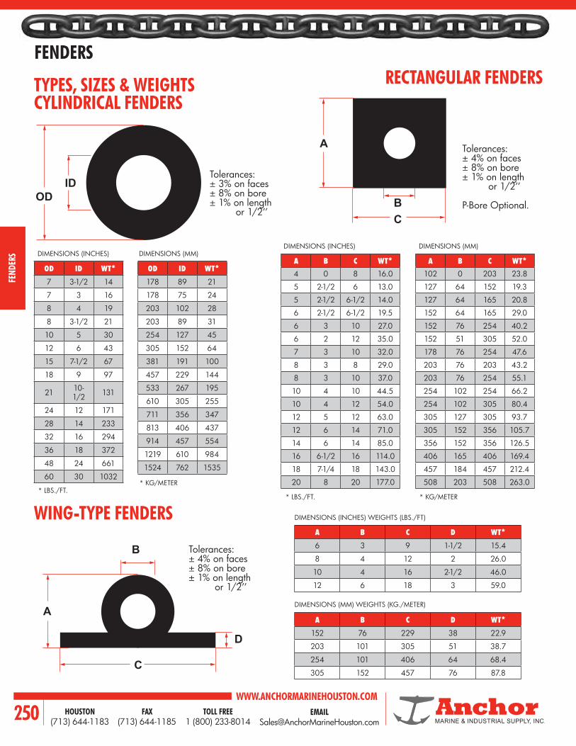
WWW.ANCHORMARINEHOUSTON.COMTOLL FREE
1 (800) 233-8014HOUSTON
(713) 644-1183FAX
(713) 644-1185250
FENDERS
FEND
ERS
ID
A
B
A
C
D
BC
OD
RECTANGULAR FENDERS
OD ID WT*
7 3-1/2 14
7 3 16
8 4 19
8 3-1/2 21
10 5 30
12 6 43
15 7-1/2 67
18 9 97
21 10-1/2 131
24 12 171
28 14 233
32 16 294
36 18 372
48 24 661
60 30 1032
A B C WT*102 0 203 23.8
127 64 152 19.3
127 64 165 20.8
152 64 165 29.0
152 76 254 40.2
152 51 305 52.0
178 76 254 47.6
203 76 203 43.2
203 76 254 55.1
254 102 254 66.2
254 102 305 80.4
305 127 305 93.7
305 152 356 105.7
356 152 356 126.5
406 165 406 169.4
457 184 457 212.4
508 203 508 263.0
A B C D WT*
6 3 9 1-1/2 15.4
8 4 12 2 26.0
10 4 16 2-1/2 46.0
12 6 18 3 59.0
Tolerances:± 4% on faces± 8% on bore± 1% on length or 1/2’’
P-Bore Optional.
Tolerances:± 3% on faces± 8% on bore± 1% on length or 1/2’’
Tolerances:± 4% on faces± 8% on bore± 1% on length or 1/2’’
CYLINDRICAL FENDERSTYPES, SIZES & WEIGHTS
WING-TYPE FENDERS
DIMENSIONS (INCHES) DIMENSIONS (MM) DIMENSIONS (INCHES) DIMENSIONS (MM)
DIMENSIONS (INCHES) WEIGHTS (LBS./FT)
DIMENSIONS (MM) WEIGHTS (KG./METER)
* LBS./FT.* KG/METER
* LBS./FT. * KG/METER
A B C D WT*
152 76 229 38 22.9
203 101 305 51 38.7
254 101 406 64 68.4
305 152 457 76 87.8
OD ID WT*
178 89 21
178 75 24
203 102 28
203 89 31
254 127 45
305 152 64
381 191 100
457 229 144
533 267 195
610 305 255
711 356 347
813 406 437
914 457 554
1219 610 984
1524 762 1535
A B C WT*4 0 8 16.0
5 2-1/2 6 13.0
5 2-1/2 6-1/2 14.0
6 2-1/2 6-1/2 19.5
6 3 10 27.0
6 2 12 35.0
7 3 10 32.0
8 3 8 29.0
8 3 10 37.0
10 4 10 44.5
10 4 12 54.0
12 5 12 63.0
12 6 14 71.0
14 6 14 85.0
16 6-1/2 16 114.0
18 7-1/4 18 143.0
20 8 20 177.0
ID
A
B
A
C
D
BC
OD

EMAIL [email protected]
WWW.ANCHORMARINEHOUSTON.COMTOLL FREE
1 (800) 233-8014HOUSTON
(713) 644-1183FAX
(713) 644-1185 251
FENDERS
FENDERS
A B C R WT*
6 2-1/2 5 2-1/2 11.5
8 3 8 4 25.5
10 3 8 4 34.5
10 4 10 5 39.0
10 4 12 6 46.0
12 5 12 6 55.0
14 6 14 7 75.0
14 3 18 7 104.0
ROUND BORE
A B C D E WT*6 3 6 3 1-1/2 12.5
8 4 8 4 2 22.0
10 5 10 5 2-1/2 34.0
12 6 12 6 3 49.0
14 7 14 7 3-1/2 66.0
16 8 16 8 4 86.0
18 9 18 9 4-1/2 109.0
20 10 20 10 5 135.0
A B C D E BR OR WT*
3-3/4 2 4-1/2 2-1/4 3/4 1-1/4 3/4 5.0
6 2-7/8 6-3/4 3 1-1/2 2-3/8 7/8 12.5
D-SHAPED BORE
“D” FENDERS TAPERED SIDES
DIMENSIONS (INCHES) WEIGHTS (LBS./FT) DIMENSIONS (MM) WEIGHTS (KG/METER)
DIMENSIONS (INCHES) WEIGHTS (LBS./FT) DIMENSIONS (MM) WEIGHTS (KG/METER)
Tolerances:± 4% on faces± 8% on bore± 1% on length or 1/2’’
Tolerances:± 4% on faces± 8% on bore± 1% on length or 1/2’’
Tolerances:± 4% on faces± 8% on bore± 1% on length or 1/2’’
DIMENSIONS (INCHES) WEIGHTS (LBS./FT)
A B C R WT*
152 64 127 64 17.1
203 76 203 102 37.9
254 76 203 102 51.3
254 102 254 127 58.0
254 102 305 152 68.4
305 127 305 152 81.8
356 152 356 178 112.0
356 76 457 178 155.0
A B C D E WT*152 76 152 79 38 18.6
203 101 203 101 51 32.7
254 127 254 127 64 50.6
305 152 305 152 76 72.9
356 178 356 178 89 98.2
406 203 406 203 102 128.0
457 229 457 229 114 162.2
508 254 508 254 127 200.9
A B C D E BR OR WT*
95 51 114 57 19 32 19 7.4
152 73 171 76 38 60 22 18.6
A
BR
B
D
E
C
A
D
EB
RRA
C
D
C
A
BR
B
D
E
C
A
D
EB
RRA
C
D
C

WWW.ANCHORMARINEHOUSTON.COMTOLL FREE
1 (800) 233-8014HOUSTON
(713) 644-1183FAX
(713) 644-1185252
FENDERS
FEND
ERS
DELTA “A” SERIES, EXTERNAL PLATE
MODEL A B C D E F
13A 305 191 330 165 432 508
20A 406 254 508 254 635 711
23A 508 305 584 305 737 838
Tolerances:± 4% on faces± 8% on bore± 1% on length or 1/2’’
* RUBBER/STEEL
Rubber options: EPDM/butyl, butyl, low-friction butyl and non-marking gray EPDM rubber compounds all are available.
Desiger’s note: Consult Anchor Marine for design/budgetary assistance on any special shape or profile. Our analysis can include load deflection/energy characteristics, as well as low/high temperature behavior, shape factor limitations, tear strength and other design criteria free of charge. Special compounds may be recommended for specific problem solutions.
* RUBBER/STEEL
MODEL A B C D E F
13A 12 7-1/2 13 6-1/2 17 20
20A 16 10 20 10 25 28
23A 20 12 23 12 29 33
DIMENSIONS (INCHES) WEIGHTS IN LBS./FT.
A
D
B
CEF

EMAIL [email protected]
WWW.ANCHORMARINEHOUSTON.COMTOLL FREE
1 (800) 233-8014HOUSTON
(713) 644-1183FAX
(713) 644-1185 253
FENDERS
FENDERS
COMMERCIAL BUMPERS
CODE NO. COLORDIMENSIONS (INCHES)
WT./FT. LBS. LENGTH UP TOBASE WIDTH (W)
HEIGHT (H)
WALL THNKS. (WT)
DB-50 Black 2-1/8 2 7/16 1.3 60 FT.
DB-50B Grey 2-1/8 2 7/16 1.6 60 FT.
DB-50C White 2-1/8 2 7/16 1.6 60 FT.
DB-75 Black 3-1/8 2-7/8 11/16 2.8 60 FT.
DB-75B Grey 3-1/8 2-7/8 11/16 3.4 60 FT.
DB-75C White 3-1/8 3-7/8 11/16 3.4 60 FT.
DB-100 Black 4-1/4 3-7/8 3/4 4.6 60 FT.
DB-100B Grey 4-1/4 3-7/8 3/4 5.3 60 FT.
DB-100C White 4-1/4 3-7/8 3/4 5.3 60 FT.
CODE NO. COLORDIMENSIONS (INCHES)
WT./FT. LBS. LENGTH UP TOBASE WIDTH (W)
HEIGHT (H)
WALL THNKS. (WT)
DB-101 Black 4-1/4 3-7/8 3/4 4.6 60 FT.
DB-115 Black 4-1/2 3-3/4 3/4 4.7 60 FT.
DB-125 Black 6-3/4 6 1-1/2 13.6 20 FT.
DB-150 Black 9-1/2 8 1-1/2 19.5 20 FT.
100 SERIES - “D” SHAPE
D SHAPE / D-BORE
W
WT
W
H
H
WT
W
WT
W
H
H
WT

WWW.ANCHORMARINEHOUSTON.COMTOLL FREE
1 (800) 233-8014HOUSTON
(713) 644-1183FAX
(713) 644-1185254
FENDERS
FEND
ERS
CODE NO.
DIMENSIONS (INCHES)
WT./FT. LBS. LENGTH UP TOOUTSIDE DIAMETER
(D)BORE (B)
DB-202 3 1 3.2 60 FT.
DB-203 3 1-1/2 2.7 60 FT.
DB-205 5 2-1/2 8.0 30 FT.
DB-206 7 3 16.0 20 FT.
DB-207 7 3-1/2 15.5 20 FT.
DB-208 8 4 18.2 20 FT.
DB-210 10 5 32 20 FT.
DB-212 12 6 46 20 FT.
DB-215 15 7-1/2 67 20 FT.
DB-218 18 9 96.7 10 FT.
200 SERIES - CYLINDRICAL FENDER
B D

EMAIL [email protected]
WWW.ANCHORMARINEHOUSTON.COMTOLL FREE
1 (800) 233-8014HOUSTON
(713) 644-1183FAX
(713) 644-1185 255
FENDERS
FENDERS
CODE NO.
DIMENSIONS (INCHES)WT./FT.
LBS.LENGTH UP
TOHEIGHT (H)
WIDTH (W)
BORE (B)
DB-302 2 4 SOLID 3.9 60 FT.
DB-303 3-1/2 4-1/2 1 8.0 60 FT.
DB-304 5 5 2-1/2 9.8 60 FT.
DB-305 5 6-1/2 2-1/2 13.0 40 FT.
DB-305A 5-1/2 6 2-1/2 13.9 40 FT.
DB-306 6 6-1/2 2-1/2 17.4 20 FT.
DB-306A 6 6 2-7/8 14.6 20 FT.
DB-306B 6 7 2-1/2 18.0 20 FT.
DB-307 7 10 3 34.1 20 FT.
DB-307A 7 10 3-1/2 30.0 20 FT.
DB-308 8 8 3 28.2 20 FT.
DB-309 8 10 3 39.5 20 FT.
DB-309A 9 10 SOLID 50.7 20 FT.
DB-310 10 10 4 42.4 20 FT.
DB-311 10 12 4 60.0 20 FT.
DB-312 12 12 5 68.0 20 FT.
DB-313 12 12 4 68.5 20 FT.
DB-314 14 14 6 83 20 FT.
300 SERIES - RECTANGULAR FENDER
H B
W

WWW.ANCHORMARINEHOUSTON.COMTOLL FREE
1 (800) 233-8014HOUSTON
(713) 644-1183FAX
(713) 644-1185256
FENDERS
FEND
ERS
CODE NO.DIMENSIONS (INCHES)
WT./FT. LBS. LENGTH UP TOBASE WIDTH
(W)BASE THICKNESS
(BT)OUTSIDE DIAMETER
(D)BORE (B)
DB-404 4 1/2 2-1/2 1 3.5 60 FT.DB-405 5 1/2 2-1/2 1 4.0 60 FT.DB-406 6 3/4 3 1 5.3 60 FT.DB-407 6-1/2 1 4 2 7.0 60 FT.DB-408 6-1/2 1 4 1 8.9 60 FT.DB-409 9 1-1/2 6 3 14.4 20 FT.DB-410 9-1/2 1-1/2 6 2 16.2 20 FT.DB-412 12 2 8 4 27.0 20 FT.DB-416 16 2-1/2 10 4 46.0 20 FT.DB-418 18 3 12 6 61.0 20 FT.
CODE NO.DIMENSIONS (INCHES)
WT./FT. LBS.
LENGTH UP TOBASE WIDTH
(W)BASE THICKNESS
(BT)RADIUS
(R)DB-460 10 1-1/4 4 14.6 20 FT.
CODE NO.DIMENSIONS (INCHES)
WT./FT. LBS. LENGTH UP TOBASE WIDTH
(W)BASE THICKNESS
(BT)OUTSIDE DIAMETER
(D)WALL THICKNESS
(WT)
DB-440 9-1/2 1-1/2 6 1 14.9 20 FT.
WING TYPE “O” BORE
WING TYPE SOLID BORE
WING TYPE “D” BORE
400 SERIES
D
B
W
BT
BT
BT
WT
W
W
B
D

EMAIL [email protected]
WWW.ANCHORMARINEHOUSTON.COMTOLL FREE
1 (800) 233-8014HOUSTON
(713) 644-1183FAX
(713) 644-1185 257
FENDERS
FENDERS
D
W
W
BT
X
Y
WT
BT
CODE NO.DIMENSIONS (INCHES)
WT./FT. LBS. WALL THICK. LENGTH UP TOBASE WIDTH
(W)BASE THICKNESS
(BT)OUTSIDE DIAMETER
(D) P
DB-503* 2-1/2 17/32 3 1/4 2.5 5/8 60 FT.
DB-504* 3-3/4 25/32 4-1/4 1/4 3.2 3/4 60 FT.
DB-506* 5-7/16 1 6 5/16 9.0 1 40 FT.
DB-508* 7-1/4 1-3/16 8 3/8 15.5 1-1/2 20 FT.
DB-510* 9-1/4 1-11/16 10 3/8 24.8 1-1/2 20 FT.
DB-512* 11 2 12 9/16 28.6 2 20 FT.
CODE NO.
DIMENSIONS (INCHES)WT./FT.
LBS.LENGTH UP
TOBASE WIDTH (W)
BASE THICKNESS (BT)
WING LENGTH(X)
OUTSIDE DIAMETER
(Y)
DB-809* 5-9/16 1-1/2 2 3 21.0 10 FT.
* WHITE OR GREY UPON REQUEST
* WHITE OR GREY UPON REQUEST
500 SERIES - FAN NOSE
800 SERIES - CORNER GUARD
CODE NO.DIMENSIONS (INCHES)
WT./FT. LBS. LENGTH UP TOBASE WIDTH
(W)BASE THICKNESS
(BT)OUTSIDE DIAMETER
(D)WALL THICKNESS
(WT)
DB-440 9-1/2 1-1/2 6 1 14.9 20 FT.

WWW.ANCHORMARINEHOUSTON.COMTOLL FREE
1 (800) 233-8014HOUSTON
(713) 644-1183FAX
(713) 644-1185258
FENDERS
FEND
ERS
CODE NO. PART NO. BASE WIDTH (W)
BASE HEIGHT (H)
BORE (B)
RADIUS (R) WT./FT. LENGTH
UP TO
DB-906 802090601 5" 6" 2-1/2" 2-1/2" 11.7 LBS. 20 FT.DB-906A 802090611 6" 6" 3" 3" 13 LBS. 20 FT.DB-908 802090801 8" 8" 3" 4" 26.2 LBS. 20 FT.DB-909 802090901 8" 10" 3" 4" 34 LBS. 20 FT.DB-909B 802090911 9-1/4" 10" 3" 5" 40 LBS. 20 FT.DB-910 802091001 10" 10" 3" 5" 43 LBS. 20 FT.DB-910A 802091011 10" 10" 4" 5" 41.7 LBS. 20 FT.DB-912 802091201 12" 12" 4" 6" 66 LBS. 20 FT.DB-912A 802091211 12" 12" 5" 6" 65 LBS. 20 FT.DB-912B 802090013 12" 14" 5" 6" 69.6 LBS. 20 FT.DB-912C 802091231 12" 14" 4" 6" 73.3 LBS. 20 FT.DB-914 802091401 14" 14" 6" 7" 76.8 LBS. 20 FT.DB-914B 802091421 14" 12" 6" 7" 60 LBS. 20 FT.DB-914C 802091431 13.5" 12" 6" 6.75" 60 LBS. 20 FT.
CODE NO. PART NO. BASE WIDTH (W)
BASE HEIGHT (H)
BORE (B) WT./FT. LENGTH
UP TO
DB-954 802090022 4" 4" 2" x 2" 6 LBS. 20 FT.DB-956 802090021 6" 6" 3" x 3" 12.5 LBS. 20 FT.DB-958 802090005 8" 8" 4" x 4" 22.5 LBS. 20 FT.DB-960 802090011 10" 10" 5" x 5" 35.1 LBS. 20 FT.DB-962 802090015 12" 12" 6" x 6" 50.5 LBS. 20 FT.DB-964 802090003 14" 14" 7" x 7" 72 LBS. 20 FT.
900 SERIES - D-SHAPED / O-BORE
900 SERIES - D-SHAPED / D-BORE
HB
W
B H
W HB
W
B H
W

EMAIL [email protected]
WWW.ANCHORMARINEHOUSTON.COMTOLL FREE
1 (800) 233-8014HOUSTON
(713) 644-1183FAX
(713) 644-1185 259
FENDERS
FENDERSCODE NO. BASE WIDTH (W)
BASE THKNS. (BT)
HEAD WIDTH (HW) HEIGHT BORE
(B) WT./FT. LENGTHS UP TO
DB-1006 6-1/2" 1-11/16" 7-3/8" 6" 1-3/4" 18.6 LBS. 30 FT.
DB-1009 9" 2-29/32" 9-7/16" 7-1/2" 3" 24 LBS. 30 FT.
CODE NO. BASE WIDTH (W)
HEIGHT(H)
WALL THKNS. (WT)
WT./FT. RUBBER
ONLYLENGTHS UP TO NOT SUPPLIED AS
STANDARD EQUIPMENT
DB-1103 3" 3-1/4" 1-9/32" 2.8 LBS. 60 FT.
REYNOLDS ALUMINUM
CHANNEL NO. 351 3" X .247 WEB 1/4" X
1-1/2" ALUM. BAR
DB-1104 4" 4-5/16" 3/4" 4.5 LBS. 40 FT
REYNOLDS ALUMINUM
CHANNEL NO. 2644 4" X .247 WEB 1/4" X
2" ALUM. BAR
1000 SERIES - FLAT HEAD
1000 SERIES - CHANNEL LOCK
HW
BT
W
H
H
WT
W
B
HW
BT
W
H
H
WT
W
B

WWW.ANCHORMARINEHOUSTON.COMTOLL FREE
1 (800) 233-8014HOUSTON
(713) 644-1183FAX
(713) 644-1185260
FENDERS
FEND
ERS
SIZE / DIA. 1/2 INCH 5/8 INCH 3/4 INCH 1 INCH 12.7 MM 15.9 MM 19.1 MM 25.4 MMPROOF TEST 15,000* 35,000* 55,000* 100,000* 6,804** 15,876** 24,948** 45,351**
AV. ULT. STRENGTH 35,000* 58,000* 105,000* 160,000* 15,876** 26,308** 47,627** 72,562**
MAX. ELONGATION 15% 15% 15% 15% 15% 15% 15% 15%
BRINELL HARNDESS 229-277 229-277 331-388 331-388 229-277 229-277 229-277 331-388
LINKS PER FT. (PER M) NOMINAL 3.2 3.2 3.2 2.9 10.5 10.5 10.5 9.54
WT. PER 100FT. (PER M) 205* 320* 446* 814* 3.05 4.78 4.78 12.1
MAX. LINK WIDTH 1.875 2.243 2.700 3.375 47.60 56.97 56.97 85.72
A (INSIDE LENGTH) 3.25 + .015-0 3.75 + .015-0 3.75 ± .025 4.125 95.25 95.25 95.15 104.78
B (INSIDE WIDTH) .789 ± .031 .900 ± .031 1.125 ± .031 1.375 20.04 22.86 28.48 34.93
C (THICKNESS) 0.531 0.656 .750 ± .008 1.000 13.49 16.66 19.05 25.40
D (MAX. SWELL) 0.025 0.025 - - 0.064 0.064 - -
ALLOY SAFETY ANCHOR SHACKLE 851A 852A 854A 854A 851A 852A 854A 854A
SHACKLE ULTIMATE STRENGTH 60,000* 81,000* 135,000 135,000 27,216** 36,741** 61,235** 61,235**
Chain or wire rope may be used to suspend either cylindrical or rectangular fenders. But chain is more corrosion resistant than wire rope. Chain provides more bearing surface on the I.D. of the fender, thus reducing tear potential at the ends of the fender.
Recommended chain for different sizes:1. 1/2’’ chain for cylindrical fenders up to and including 8’’ OD X 4’’ I.D.2. 5/8’’ chain used for 10’’ OD X 5’’ up to and including 18’’ x 9’’ size (some applications of 18’’ x 9’’ based on conditions will use heavier chain).3. 3/4’’ chain used for 18’’ x 9’’ to 24’’ x 12’’ fender.
The ‘’long link chain’’ shown in the specifications below does not restrict fender deflection as much as heavier, shorter link chain would. Experience indicates that ultimate breaking strength of chain is more important than its shock load ability.Mounting eyebolts so they do not project beyond the dock face will prevent restricting fender deflection. On old docks, pad eyes may be used to limit projection from the dock face.The shackle should be high strength, with a greater ultimate strength than that of the chain being used. We recommend a safety anchor pin shackle with an alloy pin, one size larger than the chain being used. These chain and alloy shackle selections permit the eye of the shackle to pass through the chain’s long link; simplifying installation.
CHAIN AND SHACKLE
* STRENGTHS AND WEIGHTS IN LBS. ** STRENGTHS AND WEIGHTS IN KG.
HOT DIPPED GALVANIZED
TYPICAL SHACKLE
DOCK FENDER CHAIN
A
Sect
.vi
ew
C
B
TYPICAL LINK

EMAIL [email protected]
WWW.ANCHORMARINEHOUSTON.COMTOLL FREE
1 (800) 233-8014HOUSTON
(713) 644-1183FAX
(713) 644-1185 261
FENDERS
FENDERS
Features:1. High energy absorption and low reaction force.2. Its arch shape serves well to reduce concentration of
stresses when the fender is compressed.3. Steel mounting plates at the fender bottom and open
legs make it easy to install fenders at any berthing facility.
4. A wide selection of sizes and energy capacities.5. Vulcanized sealing skin encapsulating metal parts.
AOV-TYPE FENDERS
Features:1. Increased energy absorption and lower load
transmitted.2. Self supporting: Spool-type fender can support
its own weight plus that of the frontal system. (Supporting limits are described later.)
3. By adjusting frontal system space, required hull pressure (face pressure) can be easily obtained.
4. A wide selection of fender types are available.
SPOOL-TYPE FENDERS
Features:1. The first buckling type.2. The most versatile fender in the world.3. The first fender reinforced by an embedded steel
plate at the entire bottom of fender.4. The first dynamically stable type against outer force
in various direction.5. Easy handling and maintenance.
ACV-TYPE FENDERS

WWW.ANCHORMARINEHOUSTON.COMTOLL FREE
1 (800) 233-8014HOUSTON
(713) 644-1183FAX
(713) 644-1185262
FENDERS
FEND
ERS
PART NO. WT. A B C
E4600125 LBS. 6 10 4-1/4
11.3Kg (152.4) (254) (108)
E4600235 LBS. 9 13 5-3/4
15.9Kg (228.6) (330.2) (146.1)
E4600345 LBS. 12 16 7-1/4
20.4 Kg (304.8) (406.4) (184.2)
E4600435 LBS. 9 13 5-3/4
15.9 Kg (228.6) (330.2) (146.1)
E4600550 LBS. 12 16 7-1/4
22.7 Kg (304.8) (406.4) (184.2)
.80 DIA. HOLES 3/4 DIA (19MM) BOLTS
MATERIALELASTOMER NEOLASTIC® RUBBER ASTM D-2000 3AA725, B33, C20, F17, K11, L14STEEL — ASTM A-36
NOTE: ALL DIMENSIONS IN PARENTHESES ARE IN MILLIMETERS
12’’ BUCKLING COLUMN PRODUCT DIMENSIONS
INCH CM
1/2 1.27
3/4 1.91
0.8 2.03
13/16 2.06
1-13/16 3.02
4-3/4 12.07
6-3/4 17.15
12
4-3/4”6-3/4”
13/16”
13/16”
3/4”B
A
C C1/2

EMAIL [email protected]
WWW.ANCHORMARINEHOUSTON.COMTOLL FREE
1 (800) 233-8014HOUSTON
(713) 644-1183FAX
(713) 644-1185 263
FENDERS
FENDERS
20-3/4”
10-3/4”
1-3/4”
3-3/4”
3-3/4”
BC
A
D1/2 1/2” D D
PART NO. WT. A B C D
E4600690 LBS. 10 16-5/16 1-19/32 4-3/8
40.8Kg (254) (414.3) (40.5) (111.1)
E46007115 LBS. 14 20-5/16 1-5/8 5-11/16
52.3 Kg (355.6) (515.9) (41.3) (144.5)
E46008145 LBS. 18 24-5/16 1-21/32 7
65.9 Kg (457.2) (617.5) (42.1) (177.8)
E46009175 LBS. 22 28-5/16 1-19/32 8-3/8
79.5 Kg. (558.8) (719.1) (40.5) (212.7)
E46010205 LBS. 26 32-5/16 1-5/8 9-11/16
93.2 Kg. (660.4) (820.7) (41.3) (246)
MATERIALELASTOMER NEOLASTIC® RUBBER ASTM D-2000 3AA725, B33, C20, F17, K11, L14STEEL — ASTM A-36
13/16 DIA. HOLES 3/4 DIA (19MM) BOLTS
NOTE: ALL DIMENSIONS IN PARENTHESES ARE IN MILLIMETERS
20’’ BUCKLING COLUMN PRODUCT DIMENSIONS
INCH CM
1/2 1.27
13/16 2.06
1-1/2 3.81
1-3/4 4.45
3-3/4 9.53
10-3/4 27.31
20-3/4 52.71

WWW.ANCHORMARINEHOUSTON.COMTOLL FREE
1 (800) 233-8014HOUSTON
(713) 644-1183FAX
(713) 644-1185264
FENDERS
FEND
ERS
MATERIALELASTOMER NEOLASTIC® RUBBER ASTM D-2000 3AA725, B33, C20, F17, K11, L14STEEL — ASTM A-36
1-1/8’’ DIA. HOLES FOR 1’’ DIA (24MM) BOLTS
PART NO. WT. A B C D
E46011235 LBS. 12 18-5/16 1-21/32 5
107 KG. (304.8) (465.1) (42.1) (127)
E46012345 LBS. 18 24-5/16 1-21/32 7
157 KG. (457.2) (617.5) (42.1) (177.8)
E46013 400 LBS. 22 28-5/16 1-19/32 8-3/8
181 KG. (558.8) (719.1) (40.5) (212.7)
E46014480 LBS. 26 32-5/16 1-5/8 9-11/16
218 KG. (660.4) (820.7) (41.3) (246.1)
E46015550 LBS. 30 36-5/16 1-21/32 11
250 KG. (762.0) (922.3) (42.1) (279.4)
E46016710 LBS. 34 40-5/16 1-19/32 12-3/8
322 KG. (865) (1023) (40.5) (314.3)
E46017790 LBS. 38 44-5/16 1-23/32 13-5/8
359 KG. (956.2) (1126) (44.0) (346.1)
NOTE: ALL DIMENSIONS IN PARENTHESES ARE IN MILLIMETERS
33’’ BUCKLING COLUMN PRODUCT DIMENSIONS
INCH CM
3/4 1.91
1-1/8 2.86
1-1/2 3.81
1-3/4 4.45
5-1/2 13.97
14-1/4 36.20
33 83.32
33”
14-1/4”
1-3/4”
5-1/2”
5-1/2”
BC
A
D3/4” 1-1/2” D D

EMAIL [email protected]
WWW.ANCHORMARINEHOUSTON.COMTOLL FREE
1 (800) 233-8014HOUSTON
(713) 644-1183FAX
(713) 644-1185 265
FENDERS
FENDERS
48-1/8”
E14”
7”
7”
BC
A
D1” 2” D D
B
MATERIALELASTOMER NEOLASTIC® RUBBER ASTM D-2000 3AA725, B33, C20, F17, K11, L14STEEL — ASTM A-36
1-1/8’’ DIA. HOLES FOR 1’’ DIA (24MM) BOLTS
PART NO. WT. A B C D E
E46018525 LBS. 14 20-5/16 1-29/32 5-1/2 19-1/2
238 KG. (355.6) (515.9) (48.4) (139.7) (4953)
E46019635 LBS. 17-1/2 23-13/16 1-13/32 7 20-1/2
288 KG. (444.5) (604.8) (35.7) (177.8) (5207)
E46020750 LBS. 21 27-5/16 1-21/32 8 20-1/2
340 KG. (533.4) (693.7) (42.1) (203.2) (5207)
E46021870 LBS 24-1/2 30-13/16 1-29/32 9 20-1/2
394 KG. (622.3) (782.6) (48.4) (228.6) (5207)
E46022990 LBS. 28 34-4/16 1-13/32 10-1/2 20-1/2
448 KG. (711.2) (871.5) (35.7) (266.7) (5207)
NOTE: ALL DIMENSIONS IN PARENTHESES ARE IN MILLIMETERS
48’’ BUCKLING COLUMN PRODUCT DIMENSIONS
INCH CM
1 2.54
1-1/8 2.86
2 5.08
3-1/2 8.89
48-1/8 122.24

WWW.ANCHORMARINEHOUSTON.COMTOLL FREE
1 (800) 233-8014HOUSTON
(713) 644-1183FAX
(713) 644-1185266
FENDERS
FEND
ERS
STEEL PLATE RUBBERAPPROX WT. PER
UNIT (LBS.)
PART NUMBER
DIMENSION (INCHES)
A (THICKNESS)
B(WIDTH)
C(LENGTH)
D(BASE
WIDTH)
E (SURFACE WIDTH)
DB-1408 3/4 10 36 8 7 90
DB-1409 1/2 10 36 8 7 65
DB-1410 1/4 10 36 8 7 50
DB-1508 3/4 13-1/2 36 11-1/4 10-1/4 130
DB-1509 1/2 13-1/2 36 11-1/4 10-1/4 90
DB-1510 1/4 13-1/2 36 11-1/4 10-1/4 70
PART NUMBER
STEEL PLATEAPPROX WT. PER
UNIT (LBS.)
DIMENSION (INCHES)
A (THICKNESS)
B(WIDTH)
C(LENGTH)
DB-1608 3/4 20 36 190
DB-1609 1/2 20 36 135
DB-1610 1/4 20 36 85
PART NUMBER
STEEL PLATEAPPROX WT.
PER UNIT (LBS.)
DIMENSION (INCHES)
R (RADIUS)
A (THICKNESS)
B (WIDTH)
C(LENGTH)
DB-1708 18 3/4 10 28-1/4 80
DB-1709 18-1/4 1/2 10 28-5/8 60
DB-1710 18-1/2 1/4 10 29-1/16 40
PART NUMBER
STEEL PLATEAPPROX WT. PER
UNIT (LBS.)
DIMENSION (INCHES)
R(RADIUS)
A (THICKNESS)
B (WIDTH)
C(LENGTH)
DB-1909 Variable 1/2 10 35-1/2 53
SINGLE TOW - KNEES
DOUBLE TOW - KNEES
PRE-CURVED TOW - KNEES
SEGMENTED TOW - KNEES
D
2”
2”
E
7” 2”
B
B
BA
C
4 Typ
Rubber
C
R 90
B
C
8”
B
B
C
A
A
2”
2”
7”8”
7”
8”
A
D
2”
2”
E
7” 2”
B
B
BA
C
4 Typ
Rubber
C
R 90
B
C
8”
B
B
C
A
A
2”
2”
7”8”
7”
8”
A
D
2”
2”
E
7” 2”
B
B
BA
C
4 Typ
Rubber
C
R 90
B
C
8”
B
B
C
A
A
2”
2”
7”8”
7”
8”
A
D
2”
2”
E
7” 2”
B
B
BA
C
4 Typ
Rubber
C
R 90
B
C
8”
B
B
C
A
A
2”
2”
7”8”
7”
8”
A
D
2”
2”
E
7” 2”
B
B
BA
C
4 Typ
Rubber
C
R 90
B
C
8”
B
B
C
A
A
2”
2”
7”8”
7”
8”
A
D
2”
2”
E
7” 2”
B
B
BA
C
4 Typ
Rubber
C
R 90
B
C
8”
B
B
C
A
A
2”
2”
7”8”
7”
8”
A

EMAIL [email protected]
WWW.ANCHORMARINEHOUSTON.COMTOLL FREE
1 (800) 233-8014HOUSTON
(713) 644-1183FAX
(713) 644-1185 267
FENDERS
FENDERS
BUMPER TIRESAIRCRAFT AND LCM/EARTHMOVER
FOR BOATS, BARGES, PLATFORMS, DOCKS, MOORING FACILITIES, BALLOON FENDERS, ETC.
O.D. – OUTSIDE DIAMETER OF TIRE.I.D. – INSIDE DIAMETER OF TIRE. VERY IMPORTANT WHEN FENDER STACKING ON PIPE.WIDTH – WIDTH WILL INDICATE DISTANCE BETWEEN SHIP AND DOCK, OR QUANTITY REQUIRED FOR FENDER STACKING ON PIPE.HOLD DIAMETER – DETERMINED BY THE SIZE OF CHAIN OR CABLE USED FOR MOUNTING TIRES. ADVISE DIAMETER AND POSITION.
COMMON EXAMPLE:
• ALL SIZES AVAILABLE• HEAVY NYLON PLY CONSTRUCTION• CUSTOM CHAIN HOLES DRILLED• LEAST EXPENSIVE YET MOST EFFECTIVE• FENDERS AVAILABLE• CALL FOR QUOTES• QUANTITY DISCOUNTS AVAILABLE
Two (2), 3“ holes in sidewall at 10 & 2 o’clock for chains
One (1), 3“ hole in tread at 6 o’clock for drain
Tread
Width
I.D. O.D.
Tread
Bead
Sidewall
Tread
Width
I.D. O.D.
Tread
Bead
Sidewall

WWW.ANCHORMARINEHOUSTON.COMTOLL FREE
1 (800) 233-8014HOUSTON
(713) 644-1183FAX
(713) 644-1185268
FENDERS
FEND
ERS
SIZE (INCHES) O.D. I.D. WIDTH PLY RATING WEIGHT APPROX.
18 X 5.5 16 8 5 12 – 16 20
20 X 5.5 18 10 5 20 25
22 X 6.6 20 10 6 20 30
24 X 7.7 22 10 7 16 30
26 X 6.6 24 14 6 12 – 14 30
25.5 X 8 – 14 24 14 7 20 – 22 35
27 X 7.75 – 15 25 15 7 12 – 14 35
27 X 8.75 – 14.5 25 14 8 24 – 26 50
30 X 11.5 – 14.5 28 14 11 26 70
31 X 13 – 12 30 12 12 22 – 24 70
34 X 9.75 – 18 32 18 9.5 26 80
37 X 14 – 14 34 14 13 22 – 26 100
40 X 14 36 16 13 20 – 26 120
40 X 14.5 – 19 37 19 14 26 – 28 135
40 X 15.5 – 16 37 16 15 26 – 28 135
41 X 15 – 18 40 18 14 24 – 28 140
44 X 16 42 18 15 26 – 28 150
44.5 X 16.5 – 20 43 20 16 28 – 30 170
46 X 18 – 20 45 20 17 28 – 30 180
46 X 16 – 23.5 45 23 16 30 200
49 X 17 48 20 17 26 – 30 200
49 X 19 – 22 48 22 19 32 275
50 X 20 – 20 49 20 20 32 – 34 300
52 X 20.5 – 20 51 20 20 32 – 36 325
52 X 20.5 – 23 51 23 20 32 – 36 325
54 X 21 – 24 53 24 20 36 350
56 X 16 55 28 16 32 – 38 350
COMMON AIRCRAFT TIRES
DIMENSIONS IN INCHESMANY OTHER SIZES AVAILABLE

EMAIL [email protected]
WWW.ANCHORMARINEHOUSTON.COMTOLL FREE
1 (800) 233-8014HOUSTON
(713) 644-1183FAX
(713) 644-1185 269
FENDERS
FENDERS
SIZE (INCHES) O.D. I.D. WIDTH PLY RATING WEIGHT APPROX.
14 – 24 52 24 13 20 – 24 200
16 – 25 56 25 16 24 – 28 300
20.5 – 25 56 25 20 16 – 20 300
18 – 25 60 25 18 28 – 32 450
23.5 – 25 60 25 23 16 – 20 375
26.5 – 25 67 25 26 20 – 24 500
18 – 33 67 33 18 32 – 36 600
29.5 – 25 70 25 29 22 – 28 700
21 – 35 72 35 21 32 – 40 800
29.5 – 29 72 29 29 22 – 28 800
33.5 – 33 82 33 33 32 – 44 1200
33.25 – 35 84 35 33 32 – 38 1200
37.5 – 33 84 33 37 32 – 40 1400
37.25 – 35 88 35 37 36 – 40 1500
37.5 – 39 96 39 37 36 –44 2000
24 – 49 99 49 24 38 – 42 2000
27 – 40 102 49 27 42 – 48 2500
30 – 51 110 51 30 44 – 52 3700
36 – 51 120 51 36 50 – 58 4800
40 – 57 138 57 40 60 7200
COMMON LCF/EARTHMOVER TIRES
DIMENSIONS IN INCHESMANY OTHER SIZES AVAILABLE

WWW.ANCHORMARINEHOUSTON.COMTOLL FREE
1 (800) 233-8014HOUSTON
(713) 644-1183FAX
(713) 644-1185270
FENDERS
FEND
ERS
MODEL SIZE (IN)(DIA X LENGTH)
EYEDIAMETER VOLUME PIECES
PER CARTON
A-0 8 x 11.5 in20.3 x 29.2 cm
0.6 in1.6 cm
1.6 gal5.9 liter 20
A-1 11 x 15 in27.9 x 38.1 cm
1.0 in2.5 cm
3.5 gal13.2 liter 10
A-2 14.5 x 19.5 in36.8 x 49.5 cm
1.0 in2.5 cm
8.2 gal30.8 liter 10
A-3 17 x 23 in43.2 x 58.4 cm
1.0 in2.5 cm
14.5 gal54.9 gal 10
A-4 20.5 x 27 in52.1 x 68.6 cm
1.0 in2.5 cm
22.5 gal84.8 liter 10
A-5 27 x 36 in68.6 x 91.4 cm
1.25 in3.0 cm
47.6 gal179.6 liter 5
A-6 34 x 44 in86.4 x 111.8 cm
1.5 in3.8 cm
95.1 gal359.2 liter 3
A-7 39 x 54 in99.1 x 137.2 cm
2 in50.8 mm
161.6 gal610.1 liter 2
A-SERIESTHROUGHOUT THE WORLD, MORE PEOPLE RELY ON OUR A SERIES THAN ALL OTHER BUOYS.The A Series is the product that launched the Polyform story. This all-purpose product, with the signature “blue ropehold,” has proven itself in the most adverse conditions. We’ve made a couple of changes to the legendary A-Series for 2001. There’s a new size – the A-7, with more buoyancy than any other buoy in its class, and a redesigned ropehold. The new ropehold has been incorporated into the A-5, A-6, and A-7 and features stronger ribs, a larger eye that accepts a standard shackle, and a new “dual valve” inflation-deflation system. Marking gear in heavy seas is no easy task. That’s why more fishermen use Polyform A Series than all other buoys combined. We’ve seen and heard the testimonials from our customers. You name the ocean, sea, or river, and the A Series has been there. Put your trust in Polyform’s most versatile and well-known product.
F-SERIESCLASSIC EUROPEAN TWIN-EYE STYLE FENDERS DESIGNED FOR THE MOST DEMANDING USE.Polyform has been producing this fender for over 40 years and there is no comparison when it comes to quality, range of sizes and protection offered. The F Series fender has offered protection to the finest yachts and fishing vessels all over the world. Why? Because the owners and the captains of these prestigious boats know that they can rely on Polyform’s F Series to offer the size, strength and dependability to protect their vessel from the rigors of the sea and weather. If you want the ultimate in protection for your boat, Polyform F Series is the only choice!
MODEL SIZE (IN)(DIA X LENGTH)
EYEDIAMETER
PIECESPER CARTON
F-1 6 x 24 in15.2 x 61 cm
0.7 in1.9 cm 10
F-02 7.5 x 26 in19.1 x 66 cm
0.7 in1.9 cm 10
F-2 8.2 x 25 in20.8 x 63.5 cm
0.9 in2.3 cm 10
F-3 8.2 x 30 in20.8 x 76.2 cm
0.9 in2.3 cm 10
F-4 8.5 x 40.5 in21.6 x 102.9 cm
0.9 in2.3 cm 5
F-5 11 x 30 in27.9 x 76.2 cm
1.0 in2.4 cm 5
F-6 11 x 42 in27.9 x 106.7 cm
1.0 in2.4 cm 5
F-7 15 x 41 in38.1 x 104.1 cm
1.0 in2.4 cm 5
F-8 15 x 58 in38.1 x 147.3 cm
1.0 in2.4 cm 4
F-10 18 X 50 in45.7 x 127 cm
1.0 in2.4 cm 2
F-11 21.2 x 57.5 in53.8 x 146.6 cm
1.1 in2.7 cm 3
F-13 29 x 76.5 in75.7 x 194.3 cm
1.2 in3.0 cm 2

EMAIL [email protected]
WWW.ANCHORMARINEHOUSTON.COMTOLL FREE
1 (800) 233-8014HOUSTON
(713) 644-1183FAX
(713) 644-1185 271
FOAM FILLED FENDERSOCEAN CUSHION
OCEAN GUARD
Foam Filled Fenders

WWW.ANCHORMARINEHOUSTON.COMTOLL FREE
1 (800) 233-8014HOUSTON
(713) 644-1183FAX
(713) 644-1185272
FOAM FILLED FENDERS
FOAM
FIL
LED
FEND
ERS
LOW MAINTENANCEThe design of the foam-filled Ocean Guard™ Netless Fender is highly resistant to environmental hazards such as extreme temperatures, hydrocarbons, fresh and salt water, ozone and ultraviolet radiation. The fender skin is even resistant to chemicals such as diesel fuels.Additionally, since the internal construction consists of a solid heat laminated foam core, there is no need to maintain air pressure, inflation or relief values, as with pneumatic fenders.
INSTALLATIONOcean Guard™ Netless Fenders are designed for easy installation. Their buoyant construction allows the option of a floating installation. The unique end fittings and ultra heavy duty internal chain are also ideal for a fixed hanging installation. Both installations can include a 2-point and 4-point mounting arrangement. Typical mounting hardware includes dock plate padeyes, anchor bolts, shackles, swivels and stud link chain.
floating 2-point mounting arrangement

EMAIL [email protected]
WWW.ANCHORMARINEHOUSTON.COMTOLL FREE
1 (800) 233-8014HOUSTON
(713) 644-1183FAX
(713) 644-1185 273
FOAM FILLED FENDERS
FOAM FILLED FENDERS
CONSTRUCTION FEATURESFOAM COREConstruction begins with a resilient energy absorbing closed cell cross-linked polyethylene foam core which is heat laminated into one piece solid foam core. This heat lamination process produces a thermal bond between the layers of foam which is stronger than the foam itself, which, will not delaminate even under the most abusive berthing conditions. This ensures that the foam core construction of the fender will provide years of quality service and performance.Because of this foam core, if punctured the fender will not experience a catastrophic failure as would pneumatic fenders.
REINFORCED ELASTROMERIC SKINThe energy absorbing foam core is protected by a tough thick filament nylon tire cord reinforced elastomer skin. This non-marking reinforced elastomer fender skin is the wear surface of the fender. The reinforcing filaments are continuously wound in a helix pattern through up to 90% of the elastomer skin and wrap around the fender swivel end fitting housings on each end of the fender. This continuous reinforcement of the elastomer skin not only increases the tensile and tear strength of the elastomer but also distributes loads through the fender skin.Our elastomer skin exemplifies the latest in urethane technology. This tough resilient material is specially formulated to withstand the worlds harshest environment conditions providing superior performance in extreme temperatures, toxic environments, against hydrocarbons, salt water, ozone, and ultraviolet radiation. Its smooth sleek construction is not prone to snagging on dock or hull protrusions.
Outer wear surface of UV resistant urethane skin
Continuous filament nylon tire cord
reinforcement in urethane skin
Heat laminated polyethylene
foam core layers
URETHANE SKIN AND ENERGY ABSORBING FOAM CORE CONSTRUCTION
Heavy duty stud-link chain internally connecting swivel
end fittings
Integral swivel end fittings
Heat laminated polyethylene
foam core layers
Outer wear surface of UV resistant urethane skin
Continuous filament nylon tire cord
reinforcement in urethane skin

WWW.ANCHORMARINEHOUSTON.COMTOLL FREE
1 (800) 233-8014HOUSTON
(713) 644-1183FAX
(713) 644-1185274
FOAM FILLED FENDERS
FOAM
FIL
LED
FEND
ERS
FENDERS LOW REACTION ENHANCED CAPACITY STANDARD CAPACITY ADVANCED CAPACITY HIGH CAPACITYSIZE ENERGY
ABSORPTIONREACTION
FORCE
ENERGY ABSORP-
TION
REACTION FORCE
ENERGY ABSORP-
TION
REACTION FORCE
ENERGY ABSORP-
TION
REACTION FORCE
ENERGY ABSORP-
TION
REACTION FORCEENGLISH METRIC
FT X FT M X M FT- KIPS
TON-M KIPS TONS FT-
KIPSTON-M KIPS TONS FT-
KIPSTON-M KIPS TONS FT-
KIPSTON-M KIPS TONS FT-
KIPSTON-M KIPS TONS
2 x 4 0.6 x 1.2 7 1 12 5 9 1 16 7 11 2 20 9 13 2 23 10 14 2 26 122 x 6 0.6 x 1.8 11 2 20 9 14 2 26 12 18 3 33 15 21 3 38 17 23 3 43 202 x 8 0.6 x 2.4 15 2 28 13 20 3 38 17 25 4 47 21 29 4 54 24 33 5 61 282 x 10 0.6 x 3.0 19 3 36 16 26 4 48 22 32 4 60 27 37 5 69 31 42 6 78 353 x 5 0.9 x 1.5 19 3 27 12 25 3 36 16 31 4 45 20 36 5 52 23 40 6 59 273 x 6 0.9 x 1.8 23 3 29 13 31 4 38 18 39 5 48 22 45 6 55 25 51 7 62 283 x 8 0.9 x 2.4 33 5 41 19 44 6 54 25 55 8 68 31 63 9 78 36 72 10 88 403 x 10 0.9 x 3.0 43 6 53 24 57 8 70 32 71 10 88 40 82 11 101 46 92 13 114 523 x 12 0.9 x 3.7 52 7 65 29 70 10 86 39 87 12 108 49 100 14 124 56 113 16 140 643 x 14 0.9 x 4.3 62 8 77 35 82 11 102 46 103 14 128 58 118 16 147 67 134 19 166 754 x 6 1.2x1.8 36 5 34 16 48 7 45 21 60 8 56 26 69 10 64 30 78 11 73 334 x 8 1.2 x 2.4 53 7 50 23 71 10 66 30 89 12 83 38 102 14 95 44 116 16 108 494 x 10 1.2 x 3.0 71 10 67 30 94 13 89 40 118 16 111 50 136 18 128 58 153 21 144 654 x 12 1.2 x 3.7 88 12 82 37 117 16 109 50 146 20 136 62 168 23 156 71 190 26 177 804 x 16 1.2 x 4.9 122 17 113 52 162 22 151 69 203 28 189 86 233 32 217 99 264 37 246 1124 x 20 1.2 x 6.1 156 22 145 66 208 29 194 88 260 36 242 110 299 41 278 127 338 47 315 1435 x 8 1.5 x 2.4 81 11 60 27 108 14 80 36 135 18 100 45 155 21 115 52 176 24 130 595 x 10 1.5 x 3.0 108 15 80 37 144 20 107 49 180 25 134 61 207 29 154 70 234 32 174 795 x 12 1.5 x 3.7 135 19 100 45 180 25 134 60 225 31 167 75 259 36 192 86 293 41 217 985 x 14 1.5 x 4.3 161 22 120 55 215 30 160 73 269 37 200 91 309 43 230 105 350 48 260 1185 x 16 1.5 x 4.9 188 26 140 64 250 34 186 85 313 43 233 106 360 49 268 122 407 56 303 1375 x 18 1.5 x 5.5 214 29 160 73 286 39 213 97 357 49 266 121 411 56 306 139 464 64 346 1576 x 12 1.8 x 3.7 180 25 112 50 240 33 149 67 300 41 186 84 345 47 214 97 390 54 242 1106 x 14 1.8 x 4.3 218 30 135 61 291 40 180 82 364 50 225 102 419 58 259 117 473 65 293 1336 x 16 1.8 x 4.9 256 35 159 72 342 47 212 96 427 59 265 120 491 68 305 138 555 77 345 1566 x 18 1.8 x 5.5 295 41 183 83 393 54 244 110 491 68 305 138 565 79 351 159 638 88 397 1806 x 20 1.8 x 6.1 332 46 206 94 443 62 275 125 554 77 344 156 637 89 396 179 720 100 447 2037 x 14 2.1 x 4.3 292 40 155 70 390 54 207 94 487 67 259 117 560 77 298 135 633 88 337 1537 x 16 2.1 x 4.9 344 47 183 83 459 63 244 110 574 79 305 138 660 91 351 159 746 103 397 1807 x 18 2.1 x 5.5 396 55 211 95 528 73 281 127 660 91 351 159 759 105 404 183 858 119 456 2077 x 20 2.1 x 6.1 448 62 238 108 598 82 318 144 474 103 397 180 859 118 457 207 971 134 516 2347 x 22 2.1 x 6.7 500 69 266 121 666 92 354 161 833 115 443 201 958 132 509 231 1083 150 576 2618 x 12 2.4 x 3.7 319 44 148 67 425 58 197 89 531 73 246 111 611 84 283 128 690 95 320 1458 x 14 2.4 x 4.3 371 51 173 78 495 68 230 104 619 85 288 130 712 98 331 150 805 111 374 1708 x 16 2.4 x 4.9 440 61 205 93 586 81 273 124 733 101 341 155 843 116 392 178 953 132 443 2018 x 18 2.4 x 5.5 508 70 236 107 678 94 315 143 847 117 394 179 974 135 453 206 1101 152 512 2328 x 20 2.4 x 6.1 577 80 268 122 769 106 358 162 961 133 447 203 1105 153 514 233 1249 173 581 2648 x 22 2.4 x 6.7 645 89 300 136 860 119 400 182 1075 149 50 227 1236 171 575 261 1398 193 650 2959 x 14 2.7 x 4.3 467 65 193 88 623 86 258 117 779 108 322 146 896 124 370 168 1012 140 418 1909 x 16 2.7 x 4.9 534 74 221 100 712 98 294 134 890 123 368 167 1024 141 423 192 1157 160 478 2179 x 18 2.7 x 5.5 619 86 256 116 826 114 342 155 1032 143 427 194 1187 164 491 223 1342 186 555 2529 x 20 2.7 x 6.1 705 98 292 132 940 130 389 176 1175 163 486 220 1351 187 559 252 1528 211 632 2879 x 22 2.7 x 6.7 791 109 327 148 1054 146 436 198 1318 182 545 247 1516 209 627 284 1713 237 709 32210 x 16 3.0 x 4.9 649 90 241 109 865 120 322 146 1081 150 402 182 1243 173 462 209 1405 194 523 23710 x 18 3.0 x 5.5 755 104 281 127 1006 139 374 170 1258 174 468 212 1447 200 538 244 1635 226 608 27610 x 20 3.0 x 6.1 861 119 320 145 1148 158 427 194 1435 198 534 242 1650 228 614 278 1866 258 694 31510 x 22 3.0 x 6.7 967 134 360 163 1290 178 480 218 1612 223 600 272 1854 256 690 313 2096 290 780 35410 x 24 3.0 x 7.3 1087 150 404 184 1449 200 539 245 1811 250 674 306 2083 288 775 352 2286 316 850 38611 x 18 3.4 x 5.5 889 131 301 159 1186 175 401 212 1482 219 501 265 1704 252 576 305 1927 267 651 29511 x 20 3.4 x 6.1 1018 145 344 167 1657 193 458 223 1696 241 573 279 1950 277 659 321 2141 296 745 33811 x 22 3.4 x 6.7 1146 158 388 176 1528 211 517 234 1910 264 646 293 2197 304 743 337 2483 343 840 38111 x 24 3.4 x 7.3 1250 173 422 191 1666 230 563 255 2083 288 704 319 2395 331 810 367 2709 375 916 41512 x 20 3.7 x 6.1 1298 179 425 193 1730 239 566 257 2163 299 708 321 2487 344 814 369 2812 389 920 41712 x 24 3.7 x 7.3 1557 215 510 231 2076 286 680 308 2595 358 850 385 2984 412 978 443 3374 467 1105 50113 x 26 4.0 x 7.9 1944 269 591 268 2592 358 788 358 3240 448 985 447 3726 515 1133 514 4212 583 1281 58114 x 28 4.3 x 8.5 2400 332 678 308 3200 442 904 410 4000 553 1130 513 4600 636 1300 590 5200 719 1469 665* Actual values for above sizes may vary +/- 15% due to variations in materials, speed of compression, temperatures and tolerances. Performance based on 60% compression.
OCEAN GUARD™ NETLESS

EMAIL [email protected]
WWW.ANCHORMARINEHOUSTON.COMTOLL FREE
1 (800) 233-8014HOUSTON
(713) 644-1183FAX
(713) 644-1185 275
FOAM FILLED FENDERS
FOAM FILLED FENDERS
* Actual values for above sizes may vary +/- 15% due to variations in materials, speed of compression, temperatures and tolerances. Performance based on 60% compression.
ADVANCED HIGH CAPACITY EXTRA HIGH CAPACITY ADVANCED EXTRA
HIGH CAPACITY SUPER HIGH CAPACITY ADVANCED SUPER HIGH CAPACITY ULTRA HIGH CAPACITY FENDER
ENERGY ABSORP-
TION
REACTION FORCE
ENERGY ABSORP-
TION
REACTION FORCE
ENERGY ABSORP-
TION
REACTION FORCE
ENERGY ABSORP-
TION
REACTION FORCE
ENERGY ABSORP-
TION
REACTION FORCE
ENERGY ABSORP-
TION
REACTION FORCE
SAFE WORKING END PULL
LOADFT - KIPS
TON-M KIPS TONS FT -
KIPSTON-M KIPS TONS FT -
KIPSTON-M KIPS TONS FT -
KIPSTON-M KIPS TONS FT -
KIPSTON-M KIPS TONS FT -
KIPSTON-M KIPS TONS KIPS KN
18 2 32 14 21 3 38 17 25 3 45 20 29 4 52 24 33 5 60 27 37 5 68 31 9.5 4229 4 53 24 34 5 63 29 41 6 74 34 47 7 86 39 54 8 99 45 61 9 112 51 9.5 4240 6 75 34 48 7 89 40 56 8 106 47 65 9 122 55 75 11 141 63 85 12 160 71 9.5 4251 7 96 43 61 9 114 52 72 10 135 61 83 11 156 71 96 13 180 81 109 15 204 92 9.5 4250 7 72 32 59 9 86 39 70 10 101 45 81 11 117 53 93 13 135 60 105 15 153 68 9.5 4262 9 77 35 71 10 91 41 88 12 108 50 101 14 125 57 117 16 144 66 133 18 163 75 9.5 4288 12 109 50 105 15 129 59 124 17 153 70 143 20 177 80 165 23 204 93 187 26 231 105 17.0 76114 16 141 64 135 19 167 76 160 22 198 90 185 26 229 104 213 29 264 120 241 33 299 136 17.0 76139 19 173 78 165 23 205 93 196 27 243 110 226 31 281 127 261 36 324 147 296 41 367 167 17.0 76165 22 205 93 196 27 243 110 232 32 288 131 268 37 333 151 309 42 384 174 350 48 435 197 17.0 7696 13 90 42 114 16 106 48 135 19 126 59 156 22 146 66 180 25 168 78 204 29 190 88 17.0 76142 19 133 61 169 23 158 72 200 27 187 86 231 32 216 98 267 36 249 114 303 41 282 129 17.0 76189 26 178 80 224 31 211 96 266 36 250 113 307 42 289 131 354 48 333 150 401 54 377 170 17.0 76234 32 218 99 277 38 258 117 329 45 306 140 380 53 354 161 438 60 408 186 496 68 462 211 24.0 107325 45 305 138 386 53 359 163 457 63 425 194 528 73 491 223 609 84 567 258 690 95 643 292 34.0 151416 58 387 176 494 68 460 209 585 81 545 248 676 93 629 285 780 108 726 330 884 122 823 374 34.0 151216 29 160 72 257 36 190 86 304 41 255 101 351 49 260 118 405 54 300 135 459 61 340 153 17.0 76288 40 214 98 342 47 255 116 405 56 302 137 468 65 348 158 540 75 402 183 612 85 456 207 24.0 107260 50 267 120 428 59 317 144 506 70 376 169 585 81 434 197 675 93 501 225 765 105 568 255 24.0 107430 59 320 146 511 71 380 172 605 83 450 205 699 97 520 236 807 111 600 273 915 126 680 309 34.0 151501 69 373 170 595 82 443 201 704 97 524 239 814 113 606 275 939 129 699 318 1064 146 792 360 34.0 151571 78 426 194 678 94 505 229 803 110 599 272 928 128 692 314 1071 147 798 363 1214 167 904 411 50.0 222480 66 298 134 570 79 353 160 675 92 419 189 780 108 484 220 900 123 558 252 1020 139 632 286 34.0 151582 80 360 163 690 96 428 194 819 113 506 230 946 131 585 265 1092 150 675 306 1238 170 765 347 34.0 151683 94 424 192 811 112 504 229 961 133 596 270 1110 154 689 313 1281 177 795 360 1452 201 901 408 50.0 222786 109 488 221 933 129 580 263 1105 153 686 311 1277 177 793 360 1473 204 915 414 1669 231 1037 469 70.0 311886 123 550 250 1053 146 654 297 1247 173 774 351 1440 199 894 406 1662 231 1032 468 1884 262 1170 530 70.0 311779 107 414 187 925 128 482 223 1096 151 583 263 1266 175 673 305 1461 201 777 351 1656 228 881 398 50.0 222918 126 488 221 1091 151 580 263 1292 178 686 311 1492 206 793 360 1722 237 915 414 1952 269 1037 469 50.0 222
1056 146 562 254 1254 173 667 303 1485 205 790 358 1716 237 913 414 1980 273 1053 477 2244 309 1193 541 70.0 3111195 165 635 288 1419 196 754 342 1681 232 893 405 1942 269 1032 468 2241 309 1191 540 2540 350 1350 612 70.0 3111333 184 709 322 1583 219 842 382 1874 259 997 452 2166 300 1152 523 2499 345 1329 603 2832 391 1506 683 70.0 311850 117 394 178 1008 139 468 212 1195 164 554 250 1379 191 642 291 1593 219 738 333 1805 248 836 377 70.0 311990 136 461 208 1176 163 547 248 1393 191 648 293 1609 233 749 340 1857 255 864 390 2105 289 979 442 70.0 3111173 162 546 248 1393 193 648 294 1649 277 767 349 1906 264 887 402 2199 303 1023 465 2492 343 1159 527 70.0 3111355 187 630 286 1609 223 749 340 1906 263 887 403 2202 305 1024 464 2541 351 1182 537 2880 398 1340 609 70.0 3111538 213 715 325 1826 253 849 385 2162 299 1006 457 2499 346 1162 527 2883 399 1341 609 3267 452 1520 690 70.0 3111720 138 800 363 2043 283 950 431 2419 335 1125 511 2795 387 1300 590 3225 447 1500 681 3655 507 1700 772 110.0 4891246 173 515 234 1480 205 611 277 1753 243 725 329 2025 280 837 380 2337 342 966 438 2649 367 1095 496 70.0 3111424 197 589 267 1691 234 688 317 2003 277 828 376 2314 320 957 434 2670 369 1104 501 3026 418 1251 568 70.0 3111651 229 683 310 1961 271 811 368 2322 322 961 437 2683 371 1110 503 3096 429 1281 582 3509 486 1452 660 70.0 3111880 261 778 352 2233 309 923 419 2644 367 1094 495 3055 423 1264 573 3525 489 1458 660 3995 554 1652 748 110.0 4892109 291 872 395 2504 346 1036 470 2966 410 1226 556 3427 474 1417 643 3954 546 1635 741 4481 619 1853 840 110.0 4891730 240 643 291 2054 284 764 347 2432 338 905 410 2811 389 1045 474 3243 450 1206 546 3675 510 1367 619 70.0 3112013 278 749 339 2390 331 889 403 2831 392 1053 477 3271 452 1217 552 3774 522 1404 636 4277 592 1591 721 70.0 3112296 317 854 387 2727 377 1015 460 3229 446 1202 545 3731 516 1388 630 4305 594 1602 726 4879 673 1816 823 110.0 4892579 357 960 436 3065 424 1140 517 3627 502 1350 612 4191 580 1560 708 4836 669 1800 816 5481 758 2040 925 110.0 4892898 400 1078 490 3341 462 1244 564 4075 563 1517 689 4572 632 1702 772 5433 750 2022 918 6157 850 2292 1040 110.0 4892371 350 802 424 2816 389 952 432 3335 493 1127 596 3853 533 1303 591 446 657 1503 795 5039 754 1703 901 110.0 4892714 386 917 446 3223 446 1090 494 3816 542 1289 628 4410 610 1491 676 5088 723 1719 837 5766 819 1948 949 110.0 4893056 422 1034 469 3629 502 1227 557 4298 594 1454 659 4966 687 1680 762 5730 792 1938 879 6494 898 2196 996 110.0 4893333 461 1126 510 3959 548 1338 607 4687 648 1584 718 5418 749 1832 831 6249 864 2112 957 7082 979 2394 1085 110.0 4893461 478 1133 514 4109 568 1346 611 4867 673 1593 722 5623 778 1841 835 6489 897 2124 963 7354 1017 2407 1091 110.0 4894152 573 1360 616 4931 682 1615 733 5839 806 1913 866 6747 933 2210 1002 7785 1074 2550 1155 8823 1217 2890 1309 110.0 4895184 717 1576 715 6156 815 1872 849 72901088 2216 1006 8424 1165 2561 1162 9720 1344 2955 1341 11016 1523 3349 1520 110.0 4896400 885 1808 821 7600 1051 2147 974 90001244 2543 1154 10400 1438 2938 1333 12000 1659 3390 1539 13600 1880 3842 1744 110.0 489
OCEAN GUARD™ NETLESS

WWW.ANCHORMARINEHOUSTON.COMTOLL FREE
1 (800) 233-8014HOUSTON
(713) 644-1183FAX
(713) 644-1185276
FOAM FILLED FENDERS
FOAM
FIL
LED
FEND
ERS
FENDERS LOW REACTION ENHANCED CAPACITY STANDARD CAPACITY ADVANCED CAPACITY HIGH CAPACITYSIZE ENERGY
ABSORP-TION
REACTION FORCE
ENERGY ABSORPTION
REACTION FORCE
ENERGY ABSORP-
TION
REACTION FORCE
ENERGYABSORP-
TION
REACTION FORCE
ENERGY ABSORPTION
REACTION FORCEMETRIC ENGLISH
M X M FT X FT FT- KIPS
TON-M KIPS TONS FT-
KIPSTON-M KIPS TONS FT-
KIPSTON-M KIPS TONS FT-
KIPSTON-M KIPS TONS FT-
KIPSTON-M KIPS TONS
0.7 x 1.5 2.3 x 4.9 11 2 18 8 15 2 24 11 19 3 30 14 22 3 35 16 25 3 39 180.7 x 2.0 2.3 x 6.5 17 2 27 12 23 3 35 16 28 4 44 20 22 5 51 23 33 5 52 240.7 x 3.0 2.3 x 9.8 29 4 46 21 39 5 61 28 49 7 77 35 33 8 88 40 50 7 78 351.0 x 1.5 3.3 x 4.9 21 3 18 8 28 4 31 14 35 5 39 18 56 6 45 20 46 6 51 231.0 x 2.0 3.3 x 6.5 30 4 34 15 40 6 46 21 50 7 57 26 40 8 66 30 65 9 74 341.0 x 3.0 3.3 x 9.8 53 7 58 26 71 10 78 35 89 12 97 44 58 14 112 51 75 10 86 741.2 x 2.0 3.9 x 6.5 40 6 38 17 54 7 50 23 67 9 63 29 102 11 72 33 87 12 82 371.2 x 2.5 3.9 x 8.2 56 8 52 23 75 10 69 31 94 13 86 39 77 15 99 45 109 15 103 461.35 x 2.5 4.4 x 8.2 67 9 56 25 90 12 75 34 112 15 94 43 108 18 108 49 146 20 122 551.35 x 3.0 4.4 x 9.8 86 12 71 32 115 16 94 43 144 20 118 54 166 23 136 62 175 24 146 661.5 x 3.0 4.9 x 9.8 103 14 78 35 137 19 104 47 171 24 130 59 197 27 150 68 222 31 169 771.7 x 3.0 5.6 x 9.8 125 17 83 38 166 23 111 50 208 29 139 63 239 33 160 73 270 37 181 821.7 x 4.5 5.6 x 14.7 212 29 139 63 283 39 186 84 354 49 232 105 407 56 267 121 360 50 241 1092.0 x 3.5 6.5 x 11.5 201 28 114 52 268 37 152 69 335 46 190 86 385 53 219 99 436 60 247 1122.0 x 4.0 6.5 x 13.1 239 33 136 62 318 44 181 82 398 55 226 103 458 63 260 118 517 72 294 1332.0 x 4.5 6.5 x 14.7 276 38 157 71 368 51 209 95 460 64 261 118 529 73 300 136 598 83 339 1542.5 x 4.0 8.2 x 13.1 335 46 161 73 473 65 215 98 591 82 269 122 680 94 309 140 768 106 350 1592.5 x 4.5 8.2 x 16.4 398 55 181 82 530 73 241 109 663 92 301 137 762 105 346 157 1046 145 475 2152.5 x 5.5 8.2 x 18.0 531 73 241 109 708 98 322 146 885 122 402 182 1018 141 462 210 1151 159 523 2373.0 x 4.9 9.8 x 16.0 633 88 239 108 844 117 271 123 1055 146 339 154 1213 168 390 177 1372 190 519 2353.0 x 6.0 9.8 x 19.7 819 113 310 141 1092 151 413 187 1365 189 516 234 1570 217 593 269 1775 245 671 3043.0 x 7.0 9.8 x 23.0 973 135 367 166 1297 179 489 222 1621 224 611 277 1864 258 703 319 1923 266 727 3303.3 x 4.5 10.8 x 14.7 663 92 228 103 884 122 304 138 1105 153 380 172 1271 176 437 198 1437 199 494 2243.3 x 6.5 10.8 x 21.3 1072 148 368 167 1429 198 491 223 1786 247 614 279 2054 284 706 320 2322 321 798 3623.3 x 8.5 10.8 x 27.9 1498 207 516 234 1997 276 688 312 2496 345 860 390 2870 397 989 449 2323 321 799 3623.3 x 10.6 10.8 x 34.8 1909 264 656 298 2545 352 875 397 3181 440 1094 496 3658 506 1258 571 4135 572 1422 645
FENDER PRESSURE AT 60% DEFLECTION
CAPACITY ENGLISH UNITS KIPS/SQ FT
METRIC UNITS TONS/SQ METER
METRIC UNITS KN/SQ METER
Low Reaction 2.2 10.6 104Enhanced 2.9 14.1 138Standard 3.6 17.6 172Advanced 4.1 20.2 198
High Capacity 4.7 22.9 224Advanced High 5.8 28.2 276
Extra High Capacity 6.8 33.4 327Advanced Extra High 8.1 39.6 388Super High Capacity 9.4 45.7 449Advanced Super High 10.8 52.7 517
Ultra High 12.2 59.7 586
* Actual values for above sizes may vary +/- 15% due to variations in materials, speed of compression, temperatures and tolerances. Performance based on 60% compression.
OCEAN GUARD™ NETLESS
120%
100%
80%
60%
40%
20%
0%
200%
150%
100%
50%
0%
GENERIC PERFORMANCE CURVEOCEAN GUARD FENDER
REA
CTI
ON
FO
RC
E
ENER
GY
AB
SOR
PTIO
N
PERCENT COMPRESSION REACTION ENERGY
0% 10% 20% 30% 40% 50% 60%

EMAIL [email protected]
WWW.ANCHORMARINEHOUSTON.COMTOLL FREE
1 (800) 233-8014HOUSTON
(713) 644-1183FAX
(713) 644-1185 277
FOAM FILLED FENDERS
FOAM FILLED FENDERS
ADVANCED HIGH CAPACITY EXTRA HIGH CAPACITY ADVANCED EXTRA
HIGH CAPACITY SUPER HIGH CAPACITY ADVANCED SUPER HIGH CAPACITY ULTRA HIGH CAPACITY FENDER
ENERGY ABSORP-
TION
REACTION FORCE
ENERGY ABSORP-
TION
REACTION FORCE
ENERGY ABSORP-
TION
REACTION FORCE
ENERGY ABSORP-
TION
REACTION FORCE
ENERGY ABSORP-
TION
REACTION FORCE
ENERGY ABSORPTION
REACTION FORCE
SAFE WORKING END PULL
LOADFT-
KIPSTON-M KIPS TONS FT-
KIPSTON-M KIPS TONS FT-
KIPSTON-M KIPS TONS FT-
KIPSTON-M KIPS TONS FT-
KIPSTON-M KIPS TONS FT-
KIPSTON-M KIPS TONS KIPS KN
30 4 48 22 36 5 57 26 43 6 68 31 49 7 78 35 57 8 90 41 65 9 102 46 10 4245 6 71 32 48 7 76 34 64 9 100 45 65 9 104 47 85 12 133 60 96 13 151 68 10 4279 11 123 56 72 10 114 52 110 15 173 78 98 14 156 71 147 20 230 105 167 23 261 118 10 4256 8 62 28 67 9 74 34 79 11 88 40 91 13 123 56 105 15 117 53 119 16 133 60 10 4280 11 91 41 95 13 108 49 113 16 128 58 130 18 148 67 150 21 17 78 170 24 194 88 10 42142 20 155 70 75 10 86 39 200 28 218 99 75 10 86 39 267 37 291 132 303 42 330 150 10 42107 15 101 46 127 18 120 54 151 21 142 64 174 24 164 74 201 28 189 86 228 32 214 97 17 76150 21 138 62 159 22 150 68 212 29 194 88 218 30 205 93 282 39 258 117 320 44 292 133 17 76179 25 150 68 213 29 179 81 252 35 212 96 291 40 244 111 336 46 282 128 381 53 320 145 17 76230 32 189 86 256 35 215 97 324 45 266 120 349 48 293 133 432 60 354 161 490 68 401 182 17 76274 38 208 91 325 45 247 112 385 53 293 133 445 62 338 153 513 71 390 177 581 80 442 200 24 107333 46 222 101 395 55 264 120 468 65 313 142 541 75 361 164 624 86 417 189 707 98 473 214 24 107566 78 371 168 527 73 352 160 797 110 522 237 721 100 481 218 1062 147 696 316 1204 166 789 358 24 107536 74 304 138 637 88 361 164 754 104 428 194 871 120 494 224 1005 139 570 259 1139 158 646 293 34 151637 88 362 164 756 105 429 195 896 124 509 231 1035 143 588 267 1194 165 678 308 1353 187 768 349 34 151736 102 418 189 874 121 496 225 1035 143 587 266 1196 165 679 308 1380 191 783 355 1564 216 887 403 50 222946 131 430 195 1123 155 511 232 1330 184 605 275 1573 213 699 317 1773 245 807 366 2009 278 915 415 70 3111061 148 482 218 1529 211 694 315 1492 206 677 307 2091 289 950 431 1989 275 903 410 2254 312 1023 464 70 3111416 196 643 292 1682 233 764 347 1991 275 905 410 2301 318 1045 474 2655 367 1206 547 3009 416 1367 620 70 3111688 233 542 246 2005 277 758 344 2374 328 763 346 2743 379 1037 470 3165 438 1017 461 3587 496 1153 523 70 3112184 302 826 374 2594 359 980 445 3071 425 1161 527 3549 491 1342 609 4095 566 1548 702 4641 642 1754 796 110 4892594 359 978 443 2810 389 1062 482 3647 504 1375 624 3845 532 1454 659 4863 673 1833 831 5511 762 2077 942 110 4891768 245 608 276 2100 290 722 327 2486 344 855 388 2873 397 988 448 3315 458 1140 517 3757 520 1292 586 110 4892858 395 982 446 3393 469 1167 529 4019 556 1382 627 4644 642 1596 724 5358 741 1842 836 6072 840 2088 947 110 4893994 552 1376 624 3394 469 1168 530 5616 777 1935 878 4645 642 1597 724 7488 1036 2580 1170 8486 1174 2924 1326 110 4895090 704 1750 794 6044 836 2079 943 7157 990 2462 1117 8271 1144 2844 1290 9543 1320 3282 1489 10815 1496 3720 1687 110 489
* Actual values for above sizes may vary +/- 15% due to variations in materials, speed of compression, temperatures and tolerances. Performance based on 60% compression.
OCEAN GUARD™ NETLESS

WWW.ANCHORMARINEHOUSTON.COMTOLL FREE
1 (800) 233-8014HOUSTON
(713) 644-1183FAX
(713) 644-1185278
FOAM FILLED FENDERS
FOAM
FIL
LED
FEND
ERS
ENGLISH SIZES
FENDERS STAND OFF STANDARD CAPACITY HIGH CAPACITY
SIZE DIAMETER UNCOMPRESSED
ENERGY ABSORPTION REACTION FORCE ENERGY
ABSORPTION REACTION FORCEENGLISH METRIC
FT X FT M X M FT M FT -KIPS TON-M KIPS TONS FT-KIPS TON-M KIPS TONS
3 x 6 0.92 x 1.83 4.1 1.2 36 5 55 25 52 7 79 364 x 6 1.22 x1.83 5.3 1.6 65 9 72 33 94 13 103 474 x 8 1.22 x 2.44 5.3 1.6 85 12 98 44 123 17 138 635 x 10 1.53 x 3.05 6.5 2.0 165 23 152 69 239 33 214 975 x 16 1.53 x 4.88 6.5 2.0 259 36 240 109 375 52 338 1536 x 12 1.83 x 3.66 7.5 2.3 295 41 217 98 428 59 306 1397 x 14 2.13 x 4.27 8.5 2.6 450 62 260 118 652 90 366 1668 x 12 2.44 x 3.66 9.8 3.0 465 64 268 122 674 93 377 1718 x 16 2.44 x 4.88 9.8 3.0 662 95 380 172 959 133 535 2439 x 14 2.75 x 4.27 10.8 3.3 730 101 373 169 1058 146 525 2389 x 18 2.75 x 5.49 10.8 3.3 937 130 480 218 1358 188 676 30710 x 16 3.05 x 4.88 11.8 3.6 976 135 450 204 1414 196 634 28710 x 20 3.05 x 6.10 11.8 3.6 1286 179 590 268 1864 258 831 37711 x 18 3.35 x 5.49 12.8 3.9 1386 192 581 264 2009 278 818 37111 x 22 3.35 x 6.71 12.8 3.9 1697 235 711 323 2459 340 1001 45412 x 24 3.70 x 7.30 13.8 4.2 2196 304 844 383 3183 440 1189 53913 x 26 3.96 x 7.90 14.8 4.5 2785 385 987 448 4036 558 1390 63114 x 28 4.27 x 8.53 15.8 4.8 3421 473 1128 512 4958 686 1589 721
ENGLISH SIZESFENDERS STAND OFF STANDARD CAPACITY HIGH CAPACITY
SIZE DIAMETER UNCOMPRESSED
ENERGY ABSORPTION REACTION FORCE ENERGY
ABSORPTION REACTION FORCEMETRIC ENGLISH
M X M FT X FT FT M FT-KIPS TON-M KIPS TONS FT-KIPS TON-M KIPS TONS1.00 x 1.50 3.3 x 4.9 4.4 1.3 35 5 50 23 50 7 71 321.00 x 2.00 3.3 x 6.6 4.4 1.3 49 7 67 30 71 10 96 431.20 x 2.00 3.9 x 6.6 5.3 1.6 64 9 76 34 93 13 107 491.20 x 2.50 3.9 x 8.2 5.3 1.6 80 11 94 43 116 16 132 601.35 x 2.50 4.4 x 8.2 5.9 1.8 103 14 108 49 150 21 152 691.35 x 4.00 4.4 x 13.1 5.9 1.8 165 23 172 478 239 33 242 1101.50 x 3.00 4.9 x 9.8 6.4 2.0 156 22 146 66 226 31 206 931.70 x 3.00 5.6 x 9.8 7.1 2.2 196 27 162 73 284 39 227 1031.70 x 4.50 5.6 x 14.8 7.1 2.2 297 41 244 111 430 60 344 1562.00 x 3.50 6.6 x 11.5 8.1 2.5 318 44 222 101 461 64 313 1422.00 x 4.00 6.6 x 13.1 8.1 2.5 371 51 259 117 538 74 365 1652.20 x 4.50 7.2 x 14.8 8.7 2.7 500 69 321 146 725 100 452 2052.20 x 5.50 7.2 x 18.0 8.7 2.7 609 84 390 177 883 122 549 2492.50 x 4.00 8.2 x 13.1 10.0 3.0 542 75 305 138 786 109 430 1952.50 x 5.50 8.2 x 18.0 10.0 3.0 793 110 447 203 1149 159 629 2853.00 x 6.00 9.8 x 19.7 11.6 3.5 1213 168 571 259 1758 243 804 3653.30 x 4.50 10.8 x 14.8 12.6 3.8 1010 140 430 195 1464 202 606 2753.30 x 6.50 10.8 x 21.3 12.6 3.8 1581 219 675 306 2291 317 9511 4313.30 x 10.6 10.8 x 34.8 12.6 3.8 2774 384 1185 538 4020 556 1669 7574.20 x 8.40 13.8 x 27.6 15.6 4.8 3325 460 1110 503 4819 666 1563 709
OCEAN CUSHION™ STANDARD CAPACITY FOAM FILLED FENDER
WITH CHAIN & AIRCRAFT TIRE NETS
PERFORMANCE AT 60% COMPRESSION
* Actual values for above sizes may vary +/- 15% due to variations in materials, speed of compression, temperatures and tolerances. Performance based on 60% compression.
Ocean Cushion foam filled fenders are also available in other sizes and capacity models, Low Reaction, High, Extra High, and Super High Capacity.
PERFORMANCE AT 60% COMPRESSION

EMAIL [email protected]
WWW.ANCHORMARINEHOUSTON.COMTOLL FREE
1 (800) 233-8014HOUSTON
(713) 644-1183FAX
(713) 644-1185 279
FOAM FILLED FENDERS
FOAM FILLED FENDERS
OverallDiameter
Fender Body
Diameter
OverallDiameter
Fender Body LengthOverall Length

WWW.ANCHORMARINEHOUSTON.COMTOLL FREE
1 (800) 233-8014HOUSTON
(713) 644-1183FAX
(713) 644-1185280
FOAM FILLED FENDERS
FOAM
FIL
LED
FEND
ERS
OCEAN GUARD™ SMALL STANDARD DUTY FOAM FILLED FENDEROcean GuardTM Small Standard Duty (SSD) & Ocean GuardTM Small Standard Duty with Hawse Pipe fitting (SSD-HP) foam filled marine fenders are designed for quick and convenient use. SSD fenders compact sizes are ideal for the limited storage space available on board of Naval and Commercial Vessels. Their lightweight allows for easy installation and can be handled by one or two people.
OCEAN GUARDTM SMALL STANDARD DUTY (SSD)SSD fenders are constructed in accordance with US Navy Technical Specifications. They are built with the same quality construction and materials as OCEAN GUARDTM fenders.• Lightweight heat laminated closed cell resilient energy absorbing foam core• Tough non-marking nylon Tire Cord reinforced urethane elastomeric skin• Integral end fittings either stainless steel or galvanized• Optional internal through chain

EMAIL [email protected]
WWW.ANCHORMARINEHOUSTON.COMTOLL FREE
1 (800) 233-8014HOUSTON
(713) 644-1183FAX
(713) 644-1185 281
FOAM FILLED FENDERS
FOAM FILLED FENDERS
OCEAN GUARD™ SMALL STANDARD DUTY WITH HAWSE PIPE (SSD-HP)
SSD-HP fenders are constructed equivalent to our OCEAN GUARD™ Small Standard Duty (SSD) foam filled fenders, with the exception that they are constructed with a heavy duty thru pipe – Hawse pipe instead of pad eye end fittings.
• Standard denser heat laminated closed cell resilient energy absorbing foam core
• Tough non-marking nylon Tire Cord reinforced urethane elastomeric skin
• Hawse pipe (thru pipe) construction
FENDERS LOW REACTION ENHANCED CAPACITY STANDARD CAPACITY HARDWARESIZE ENERGY
ABSORPTION REACTION FORCE ENERGY ABSORPTION REACTION FORCE ENERGY
ABSORPTION REACTION FORCE SHACKLE SIZEENGLISH METRICIN X IN MM X MM FT-KIPS TON-M KIPS TONS FT-KIPS TON-M KIPS TONS FT-KIPS TON-M KIPS TONS TONS INCHES16 x 24 400 x 600 1.7 0.2 10.8 4.9 2.2 0.3 14.4 6.5 2.8 0.4 18.0 8.2 0.5 1316 x 36 400 x 900 3.2 0.4 12.0 5.4 4.2 0.6 16.0 7.3 5.3 0.7 20.0 9.1 0.5 1318 x 36 457 x 900 4.1 0.6 12.4 5.6 5.4 0.8 16.6 7.5 6.8 0.9 20.7 9.4 0.5 1320 x 36 500 x 900 4.9 0.7 13.6 6.2 6.6 0.9 18.1 8.2 8.2 1.1 22.6 10.3 0.5 1320 x 39 500 x 1000 5.3 0.7 14.7 6.7 7.0 1.0 19.6 8.9 8.8 1.2 24.5 11.1 0.5 1320 x 48 500 x 1200 6.6 0.9 18.0 8.2 8.8 1.2 24.0 10.9 11.0 1.5 30.0 13.6 0.5 1322 x 48 558 x 1200 7.3 1.0 19.8 9.0 9.8 1.3 26.4 12.0 12.2 1.7 33.0 15.0 0.5 1324 x 36 600 x 900 6.3 0.9 14.7 6.7 8.4 1.2 19.6 8.9 10.5 1.5 24.5 11.1 0.5 1324 x 48 600 x 1200 8.4 1.2 19.2 8.7 11.2 1.5 25.6 11.6 14.0 1.9 32.0 14.5 0.5 1332 x 50 800 x 1270 16.8 2.3 64.8 29.1 22.4 3.1 86.4 38.8 28.0 3.9 108.0 48.5 0.625 1636 x 48 900 x 1200 20.4 2.8 31.2 14.2 27.2 3.8 41.6 18.9 34.0 4.7 52.0 23.6 0.625 1636 x 60 900 x 1500 25.0 3.5 39.0 17.7 33.3 4.6 52.0 23.6 41.6 5.8 65.0 29.5 0.625 1636 x 72 900 x 1828 32.0 4.4 50.0 22.7 42.6 5.9 66.6 30.2 53.3 7.4 83.3 37.8 0.625 1639 x 60 1000 x 1500 30.0 4.1 42.0 19.1 40.0 5.5 56.0 25.4 50.0 6.9 70.0 31.8 0.625 1640 x 60 1016 x 1500 31.2 4.3 43.7 19.8 41.6 5.8 58.2 26.4 52.0 7.2 72.8 33.0 0.625 16
OCEAN GUARD™ SSD FOAM FILLED FENDERS
* Actual values for above sizes may vary +/- 15% due to variations in materials, speed of compression, temperatures and tolerances.
Performance based on 60% compression.

WWW.ANCHORMARINEHOUSTON.COMTOLL FREE
1 (800) 233-8014HOUSTON
(713) 644-1183FAX
(713) 644-1185282
FOAM FILLED FENDERS
FOAM
FIL
LED
FEND
ERS
PROJECT DETAILS PROJECT STATUSPORT MFI REF:
PROJECT DETAILS o PRELIMINARY
CONSULTANT o DETAIL DESIGN
CONTRACTOR o TENDER
LARGEST VESSEL SMALLEST VESSELVESSEL TYPE VESSEL TYPE
DEAD WEIGHT TONNAGE (DWT) (t) DEAD WEIGHT TONNAGE (DWT) (t)
GROSS TONNAGE (GT) (t) GROSS TONNAGE (GT) (t)
DISPLACEMENT (DISP) (t) DISPLACEMENT (DISP) (t)
LENGTH OVERALL (LOA) (m) LENGTH OVERALL (LOA) (m)
LENGTHS BETWEEN PERPS (LBP) (m) LENGTHS BETWEEN PERPS (LBP) (m)
BEAM (B) (m) BEAM (B) (m)
DRAFT (D) (m) DRAFT (D) (m)
FREEBOARD (F) (m) FREEBOARD (F) (m)
HULL PRESSURE (P) (t/m2) HULL PRESSURE (P) (t/m2)
BERTH DETAILS
STRUCTURE TIDE LEVELSLENGTH OF BERTH (m) TIDAL RANGE (m)
FENDER / DOLPHIN SPACING (m) HIGHEST RECORDED TIDE (HRT) (m)
PERMITTED FENDER REACTION (kN/m) HIGHEST ASTRONOMIC TIDE (HAT) (m)
QUAY LEVEL (m) MEAN HIGH WATER SPRING (MHWS) (m)
COPE THICKNESS (m) MEAN SEA LEVEL (MSL) (m)
SEABED LEVEL (m) MEAN LOW WATER SPRING (MLWS) (m)
SEABED COMPOSITION LOWEST ASTRONOMIC TIDE (LAT) (m)
STANDOFF max min (m) LOWEST RECORDED TIDE (LRT) (m)
REFERENCES
1. BS 6349: Maritime Structures - Part 4 Code of practice for design of fendering and mooring systems2. PIANC: Guidelines for the design of fendering systems: 20023. United Facilities Guild Specification 023964. United Facilities Guild Specification 35 59 13.16 (August 2008)
LOALBP B
D
F
o SEMI-OPEN STRUCTURE o OPEN STRUCTURE
PROJECT REQUIREMENTS
o CLOSED STRUCTURE o CORNER PROTECTION/ TURNING DOLPHIN
Dock Sand Water Fender

EMAIL [email protected]
WWW.ANCHORMARINEHOUSTON.COMTOLL FREE
1 (800) 233-8014HOUSTON
(713) 644-1183FAX
(713) 644-1185 283
PNEUMATIC FENDERS
PNEUMATIC FENDER WITH CHAIN HARNESS
PNEUMATIC SLING TYPE FENDER
PNEUMATIC FENDERS

WWW.ANCHORMARINEHOUSTON.COMTOLL FREE
1 (800) 233-8014HOUSTON
(713) 644-1183FAX
(713) 644-1185284
PNEUMATIC FENDERS
PNEU
MAT
IC F
ENDE
RS

EMAIL [email protected]
WWW.ANCHORMARINEHOUSTON.COMTOLL FREE
1 (800) 233-8014HOUSTON
(713) 644-1183FAX
(713) 644-1185 285
PNEUMATIC FENDERS
PNEUMATIC FENDERS

WWW.ANCHORMARINEHOUSTON.COMTOLL FREE
1 (800) 233-8014HOUSTON
(713) 644-1183FAX
(713) 644-1185286
PNEUMATIC FENDERS
PNEU
MAT
IC F
ENDE
RS
Four large-size fenders are usually floated at the water line as primary fenders to absorb impact energy at berthing and keep proper stand-off distance between two ships. Two small-size fenders (secondary fenders) are hung high on the hull at both bow and stern of smaller ship to prevent contact from rolling of ships due to swell and wind. “STS Transfer Guide,” published by the International Chamber of Shipping is a good reference for further information.
SHIP-TO-SHIP APPLICATIONSINSTALLATION EXAMPLES
Tanker
Small Size Fender
Guy Rope
Pneumatic Rubber Fender
Small Size Fender
Guy Rope
Pneumatic Rubber Fender
(a) Fenders Rigged in a Continuous String
(b) Fenders Guyed Individually
Installation Method in case of Ship-to-Ship Transfer Operations.
Actual Installation Method in case of Ship-to-Ship Transfer Operations.

EMAIL [email protected]
WWW.ANCHORMARINEHOUSTON.COMTOLL FREE
1 (800) 233-8014HOUSTON
(713) 644-1183FAX
(713) 644-1185 287
PNEUMATIC FENDERS
PNEUMATIC FENDERS
SHIP-TO-JETTY APPLICATIONSINSTALLATION METHODS
At both ends of the fender, first shackles, then swivel joints, followed by a further shackle should be installed. A guy chain or guy rope is secured to the outer shackle. The swivel joint prevents twisting of the guy chain or wire.
Installation Methods for Ship-to-Jetty Applications.
(a) Dolphin
AnchorShackleEnd Link
Guy Chain
Rubber Sleeve
Swivel JointFirst ShackleTowing Ring
L.W.L
H.W.L
End LinkShackle
Floating-Type Pneumatic
Rubber Fender
L.W.L
H.W.L
(b) Continuous Quay

WWW.ANCHORMARINEHOUSTON.COMTOLL FREE
1 (800) 233-8014HOUSTON
(713) 644-1183FAX
(713) 644-1185288
PNEUMATIC FENDERS
PNEU
MAT
IC F
ENDE
RS
PNEUMATIC 50 (U.S. CUSTOMARY)
NOMINAL SIZEINITIAL
INTERNAL PRESSURE
GUARANTEED ENERGY
ABSORPTION (GEA)
REACTION FORCE AT
GEA
HULL PRESSURE
AT GEASAFETY VALUE
SETTING PRESSURE
TESTING PRESSURE
WEIGHT OF NET TYPE (TYPE I)WEIGHT OF
SLING TYPE (TYPE
II)
APPROX. FENDER BODY
WEIGHT
APPROXIMATE WEIGHT OF NET
DIAMETER X LENGTH E R P CHAIN NET WIRE NET SYNTHETIC
FIBER NET
(FT X FT) (MM X MM) (KIPS) (KIPS) (KIPS) (KIPS/FT 2) (PSI) (PSI) (LBS) (LBS) (LBS) (LBS) (LBS)
1.6 x 3 500 x 1000 7.3 4.4 14.4 2.72 - 29.0 49 243 66 44 712 x 3 600 x 1000 7.3 5.9 16.7 2.59 - 29.0 55 265 66 49 79
2.3 x 5 700 x 1500 7.3 12.5 30.8 2.78 - 29.0 99 331 88 82 1213 x 5 1000 x 1500 7.3 23.6 41.0 2.51 - 29.0 161 441 176 112 216
3 x 6.5 1000 x 2000 7.3 33.2 57.8 2.72 - 29.0 194 485 309 126 2494 x 6.5 1200 x 2000 7.3 46.5 66.8 2.59 - 29.0 289 706 419 150 3444.4 x 8 1350 x 2500 7.3 75.3 96.1 2.67 - 29.0 441 772 441 - 5295 x 10 1500 x 3000 7.3 113.0 130.0 2.72 - 29.0 551 1169 772 - 639
5.6 x 10 1700 x 3000 7.3 141.0 144.0 2.63 - 29.0 639 1279 970 - 7286.5 x 11.5 2000 x 3500 7.3 227.0 197.0 2.63 - 29.0 893 2117 1411 - 1025
8 x 13 2500 x 4000 7.3 489.0 311.0 2.82 25.4 36.3 1989 2734 2007 - 23818 x 18 2500 x 5500 7.3 696.0 454.0 3.04 25.4 36.3 2403 4079 2558 - 291111 x 15 3300 x 4500 7.3 867.0 424.0 2.67 25.4 36.3 3219 3771 2800 - 405711 x 21 3300 x 6500 7.3 1339.0 678.0 3.00 25.4 36.3 4123 5667 4212 - 496111 x 35 3300 x 10600 7.3 2264.0 1183.0 3.25 25.4 36.3 5645 10275 7277 - 674715 x 30 4500 x 9000 7.3 3507.0 1293.0 3.00 25.4 36.3 8688 11885 7762 - -15 x 40 4500 x 12000 7.3 4777.0 1796.0 3.17 25.4 36.3 10562 15413 11444 - -
PNEUMATIC 50 STANDARD SIZES
PNEUMATIC 50 POPULAR NON STANDARD SIZES
NOMINAL SIZEINITIAL
INTERNAL PRESSURE
GUARANTEED ENERGY
ABSORPTION (GEA)
REACTION FORCE AT
GEA
HULL PRESSURE
AT GEA SAFETY VALUE
SETTING PRESSURE
TESTING PRESSURE
WEIGHT OF NET TYPE (TYPE I)
WEIGHT OF SLING
TYPE (TYPE
II)
APPROX. FENDER BODY
WEIGHT
APPROXIMATE WEIGHT OF NET
DIAMETER X LENGTH E R P CHAIN NET
WIRE NET
SYNTHETIC FIBER NET
(FT X FT) (MM X MM) (KIPS) (KIPS) (KIPS) (KIPS/FT2) (PSI) (PSI) (LBS) (LBS) (LBS) (LBS) (LBS)1.3 x 5 400 x 1500 7.3 4.4 19.6 3.11 - 29.0 51 - - - 732 x 4 600 x 1200 7.3 7.4 20.9 2.72 - 29.0 62 - - - 86
2.6 x 4 800 x 1200 7.3 11.8 26.1 2.51 - 29.0 107 529 - - 1284 x 6 1200 x 1800 7.3 40.6 59.0 2.51 - 29.0 271 684 - - 326
4.4 x 11.5 1350 x 3500 7.3 112.0 144.0 2.90 - 29.0 562 1323 - - 6505 x 8 1500 x 2500 7.3 90.8 104.0 2.59 - 29.0 487 970 - - 576
6.5 x 10 2000 x 3000 7.3 188.0 164.0 2.51 - 29.0 809 1985 - - 9426.5 x 15 2000 x 4500 7.3 309.0 267.0 2.82 - 29.0 1058 2646 - - 11918 x 25 2500 x 7700 7.3 996.0 664.0 3.23 25.4 36.3 3021 6659 - - 352811 x 28 3300 x 8600 7.3 1803.0 931.0 3.17 25.4 36.3 4895 8181 - - 599815 x 21 4500 x 6400 7.3 2390.0 854.0 2.74 25.4 36.3 7497 8600 - - -

EMAIL [email protected]
WWW.ANCHORMARINEHOUSTON.COMTOLL FREE
1 (800) 233-8014HOUSTON
(713) 644-1183FAX
(713) 644-1185 289
PNEUMATIC FENDERS
PNEUMATIC FENDERS
PNEUMATIC 80 (U.S. CUSTOMARY)PNEUMATIC 80 STANDARD SIZES
PNEUMATIC 80 POPULAR NON STANDARD SIZES
NOMINAL SIZE INITIAL INTERNAL PRESSURE
GUARANTEED ENERGY
ABSORPTION (GEA)
REACTION FORCE AT
GEA
HULL PRESSURE
AT GEASAFETY VALUE
SETTING PRESSURE
TESTING PRESSURE
WEIGHT OF NET TYPE (TYPE I)WEIGHT
OF SLING TYPE (TYPE
II)
APPROX. FENDER BODY
WEIGHT
APPROXIMATE WEIGHT OF NET
DIAMETER X LENGTH E R P CHAIN NET WIRE NET SYNTHETIC FIBER NET
(FT X FT) (MM X MM) (KIPS) (KIPS) (KIPS) (KIPS/FT2) (PSI) (PSI) (LBS) (LBS) (LBS) (LBS) (LBS)1.6 x 3 500 x 1000 11.6 5.9 19.1 3.58 - 36.3 53 243 66 44 75
2 x 3 600 x 1000 11.6 8.1 22.1 3.41 - 36.3 60 265 66 49 84
2.3 x 5 700 x 1500 11.6 17.7 40.5 3.64 - 36.3 104 331 88 82 126
3 x 5 1000 x 1500 11.6 33.2 53.8 3.29 - 36.3 168 441 176 112 223
3 x 6.5 1000 x 2000 11.6 46.5 76.1 3.58 - 36.3 203 485 309 126 258
4 x 6.5 1200 x 2000 11.6 64.9 87.8 3.41 - 36.3 298 706 419 150 353
4.4 x 8 1350 x 2500 11.6 105.0 126.0 3.50 - 36.3 452 772 441 - 540
5 x 10 1500 x 3000 11.6 158.0 171.0 3.58 - 36.3 611 1169 772 - 699
5.6 x 10 1700 x 3000 11.6 197.0 189.0 3.46 - 36.3 697 1279 970 - 785
6.5 x 11.5 2000 x 3500 11.6 317.0 259.0 3.46 - 36.3 911 2139 1521 - 1043
8 x 13 2500 x 4000 11.6 683.0 408.0 3.70 33.4 43.5 2227 2756 2007 - 2624
8 x 18 2500 x 5500 11.6 972.0 597.0 4.01 33.4 43.5 2712 4101 2580 - 3219
11 x 15 3300 x 4500 11.6 1210.0 557.0 3.52 33.4 43.5 3793 3793 2822 - 4608
11 x 21 3300 x 6500 11.6 1869.0 891.0 3.93 33.4 43.5 4851 5689 4388 - 5667
11 x 35 3300 x 10600 11.6 3160.0 1554.0 4.28 33.4 43.5 6681 10275 7277 - 7762
15 x 30 4500 x 9000 11.6 4896.0 1699.0 3.95 33.4 43.5 9658 11995 7894 - -
15 x 40 4500 x 12000 11.6 6670.0 2360.0 4.16 33.4 43.5 11753 15501 11532 - -
NOMINAL SIZEINITIAL
INTERNAL PRESSURE
GUARANTEED ENERGY
ABSORPTION (GEA)
REACTION FORCE AT
GEA
HULL PRESSURE
AT GEASAFETY VALUE
SETTING PRESSURE
TESTING PRESSURE
WEIGHT OF NET TYPE (TYPE I)
WEIGHT OF SLING
TYPE (TYPE II)
APPROX. FENDER BODY
WEIGHT
APPROXIMATE WEIGHT OF NET
DIAMETER X LENGTH E R P CHAIN NET WIRE NET SYNTHETIC
FIBER NET
(FT X FT) (MM X MM) (KIPS) (KIPS) (KIPS) (KIPS/FT2) (PSI) (PSI) (LBS) (LBS) (LBS) (LBS) (LBS)1.3 x 5 400 x 1500 11.6 6.6 25.7 4.09 - 36.3 53 - - - 752 x 4 600 x 1200 11.6 10.3 27.5 3.58 - 36.3 66 - - - 90
2.6 x 4 800 x 1200 11.6 17.0 34.4 3.29 - 36.3 110 529 - - 1324 x 6 1200 x 1800 11.6 56.8 77.4 3.29 - 36.3 280 684 - - 335
4.4 x 11.5 1350 x 3500 11.6 157.0 189.0 3.81 - 36.3 576 1323 - - 6645 x 8 1500 x 2500 11.6 126.0 137.0 3.41 - 36.3 538 970 - - 626
6.5 x 10 2000 x 3000 11.6 263.0 215.0 3.29 - 36.3 827 1985 - - 9596.5 x 15 2000 x 4500 11.6 431.0 351.0 3.68 - 36.3 1076 2668 - - 12088 x 25 2500 x 7700 11.6 1391.0 872.0 4.24 33.4 43.5 3418 6681 - - 392511 x 28 3300 x 8600 11.6 2517.0 1223.0 4.16 33.4 43.5 5777 8181 - - 685815 x 21 4500 x 6400 11.6 3335.0 1122.0 3.58 33.4 43.5 8291 8622 - - -

WWW.ANCHORMARINEHOUSTON.COMTOLL FREE
1 (800) 233-8014HOUSTON
(713) 644-1183FAX
(713) 644-1185290
PNEUMATIC FENDERS
PNEU
MAT
IC F
ENDE
RS
SIZES AND PERFORMANCES
The Pneumatic Rubber Fenders are available in the following sizes, which are generally expressed in terms of diameter by length.
4500 x 12000 (15’ x 40’)4500 x 9000 (15’ x 30’)
3300 x 10600 (11’ x 35’)3300 x 6500 (11’ x 21’)3300 x 4500 (11’ x 15’)
2500 x 5500 (8’ x 18’)2500 x 4000 (8’ x 13’)
2000 x 3500 (7’ x 12’)
1700 x 3000 (5’-7’’ x 10’)
500 x 1000 (1’-8’’ x 3’)600 x 1000 (2’ x 3’)700 x 1500 (2’-4’’ x 5’)1000 x 1500 (3’ x 5’)1000 x 2000 (3’ x 7’)1200 x 2000 (4’ x 7’)1350 x 2500 (4’-5’’ x 8’)1500 x 3000 (5’ x 10’)
Standard Sizes of Pneumatic Rubber
Fender.
Ø4500 x 9000L - P80 Pneumatic Rubber Fender
OverallDiameter
Fender Body
Diameter
OverallDiameter
Fender Body LengthOverall Length

EMAIL [email protected]
WWW.ANCHORMARINEHOUSTON.COMTOLL FREE
1 (800) 233-8014HOUSTON
(713) 644-1183FAX
(713) 644-1185 291
DECK FITTINGS
THESE ARE ONLY A SAMPLE OF SOME TYPES AVAILABLE.MANY OTHERS IN STOCK.
LET US KNOW YOUR REQUIREMENTS!STOCKS IN THE WEST COAST AND THE GULF.
Deck Fittings

WWW.ANCHORMARINEHOUSTON.COMTOLL FREE
1 (800) 233-8014HOUSTON
(713) 644-1183FAX
(713) 644-1185292
DECK FITTINGS
DECK
FIT
TING
S

EMAIL [email protected]
WWW.ANCHORMARINEHOUSTON.COMTOLL FREE
1 (800) 233-8014HOUSTON
(713) 644-1183FAX
(713) 644-1185 293
DECK FITTINGS
DECK FITTINGS
These requirements are applicable to ships intended to utilize the fittings standardized for single point moorings and include the type, strength and location of the required fittings.A ship provided with mooring arrangements in accordance with the requirements of this will be eligible to be assigned the Class notation “SPM” (Single Point Mooring).
ARRANGEMENTSThe ship is to be fitted with bow chain stoppers and/or Smit Type Brackets, and bow fairleads. In addition, pedestal roller fairleads may be required for alignment purposes.
BOW CHAIN STOPPERSThe number, chain cable size, and minimum safe working load of bow chain stoppers should be as given in Table A. Bow chain stoppers should be located between 2.7 m and 3.7 m aft of the bow fairlead and should be positioned so as to give correct alignment with the bow fairlead and the pedestal fairlead or the drum end of the winch or capstan.The leading edge of the stopper base plate is to be suitably faired to allow unimpeded entry of the combination chafe chain into the stopper.Details of bow chain stoppers should be submitted for class approval.
SMIT TYPE BRACKETSSmit type brackets may be fitted in lieu of bow chain stoppers. The required number and safe working load is as given in Table A for bow chain stoppers.Where fitted, Smit Type Brackets should be located between 2.7 m and 3.7 m aft of the bow fairlead and should be positioned so as to give correct alignment with the bow fairlead and pedestal fairlead or drum end of the winch or capstan.Adjacent to each Smit Type Bracket a lug with a recommended safe working load of 490 kN (50 tons) should be attached to the doubler plate. The lug should be provided with a hole of sufficient size to accept the pin of a 490 kN (50 ton) SWL shackle and should be used as a securing point for the chafe chain holding stopper. Details of Smit Type Brackets should be submitted for class approval.
BOW FAIRLEADSOne centrally located bow fairlead should be provided for ships up to 150,000 tons deadweight (Groups I and II). Two bow fairleads should be provided for ships larger than 150,000 tons deadweight (Groups III and IV). Bow fairlead opening should be at least 600 x 450 mm for 76 mm chafe chain size. Where more than one bow fairlead is installed the spacing of centers should be between 2 m and 3 m. The fairlead should be a minimum radius equal to 7 times the chain radius.
PEDESTAL ROLLER FAIRLEADSPedestal roller fairleads should have a minimum radius equal to ten times the radius of wire mooring ropes with a fiber core, seven times of wire mooring ropes with a steel core or three times the radius of synthetic mooring ropes. The number of pedestal roller fairleads should correspond to the number of bow chain stoppers or Smit Type Brackets.
SINGLE POINT MOORING ARRANGEMENT FOR SHIPS
GROUP DEADWEIGHT IN TONS CHAIN SIZE (MM) NO. OF CHAIN STOPPERS SWL IN KN (TONS)
I < 100000 54 1 980 (100)
II 100000 < 150000 76 1 1960 (200)
III 150000 < 350000 76 2 1960 (200)
IV 350000 76 2 2450 (250)
TABLE A.

WWW.ANCHORMARINEHOUSTON.COMTOLL FREE
1 (800) 233-8014HOUSTON
(713) 644-1183FAX
(713) 644-1185294
DECK FITTINGS
DECK
FIT
TING
S
LOW-PROFILE MANUAL BARGE WINCH SPECIFICATIONS DRUM OPTIONS
MODEL NO.
RATED CAPACITIES (US TONS)
1ST PLAYER DRUMSHIPPING WEIGHT (LBS)
CUBIC
FEET
CAPACITY (US
TONS)
DIMENSIONS (IN.)
DOG HOLD- ING
TIGHTENING
GEAR RATIODIAMETER
(IN.)STANDARD
DRUMSWIDER DRUMS
HAND RATCHET
20 HL 20 3 5 7:1 8-5/8 600 18.0 20 ton 10 17, 24, 36, 48
25 HL 40 5 10 14:1 10-3/4 650 22.0 40 ton 9 17, 35, 51, 69
50 HL 65 7.5 15 20:1 12-3/4 1175 34.0 65 ton 11 20, 41, 61, 82
75 HL 90 10 20 31:1 16 1880 37.0 90 ton 10 20, 40, 61, 81
20 HL-8 5/8'' DRUM DIAMETER
25 HL-10 3/4'' DRUM DIAMETER
50 HL-12 3/4'' DRUM DIAMETER
75 HL-16'' DRUM DIAMETER
LENGTH (IN.)
DRUM CAPACITYLENGTH
(IN.)
DRUM CAPACITYLENGTH
(IN.)
DRUM CAPACITYLENGTH
(IN.)
DRUM CAPACITY
.5/8 IN.
.3/4 IN.
.7/8 IN.
1 IN..5/8 IN.
.3/4 IN.
.7/8 IN.
1 IN..5/8 IN.
.3/4 IN.
.7/8 IN.
1 IN..5/8 IN.
.3/4 IN.
.7/8 IN.
1 IN.
10* 380 275 194 132 9* 248 162 142 88 11* 194 174 110 100 10* 119 108 98 56
17 650 470 330 225 17 479 314 277 174 20 377 338 216 197 20 247 225 207 119
24 915 650 460 317 35 975 643 568 359 41 773 694 445 408 40 523 478 441 254
36 1370 975 690 476 51 1472 971 865 544 61 1168 1051 674 619 61 798 731 675 390
48 1830 1300 920 634 69 1969 1299 1151 729 82 1564 1407 903 830 81 1074 983 909 525
MANUAL LOW - PROFILE BARGE WINCH
Note: All models are shown with “L” designating left hand models; for right hand models, substitute “R” for “L” in
* standard length of drum (drum lengths) are rounded to the nearest inch. RULE OF THUMB: Right or left hand
models are determined by which side of the winch the handwheel is mounted on. As illustrated right, standing behind the winch, facing the cable take-off direction is the proper orientation for determining right or left hand requirements.
Left-Hand Model Right-Hand Model
Left-Side Frame
Right-Side Frame
Right-Side Frame
Left-Side Frame
Cable Take-Off
Top View Top View
STANDARD FEATURES• Additional tightening power from ratchet lever bar.• Quick release holding dog, automatically disengages when not in use.• Spinner knob on hand wheel for fast slack line take-up.• Steel gear guard provides operator protection; prevents slack cable from
fouling gears.• Foot brakes control and prevent overrunning and birdnesting of wire rope.
OPTIONAL FEATURES:• Wider drums, angle deck brackets, disengaging clutch.• Wintech Winch Cables
TAKING THE WINCH INDUSTRY BY STORMBUILT TO LAST LOW-PROFILE TO KEEP THE CABLE LOW ON THE
“BITTS” AND THE DECK
20 - 90 TON HOLDING CAPACITY

EMAIL [email protected]
WWW.ANCHORMARINEHOUSTON.COMTOLL FREE
1 (800) 233-8014HOUSTON
(713) 644-1183FAX
(713) 644-1185 295
DECK FITTINGS
DECK FITTINGS
MANUAL BARGE WINCH-LOW PROFILE DIMENSIONS
CAPACITY (US
TONS)
DIMENSIONS (INCHES)
A B C D E F G H J K L M N P Q R S T U V W X Y
20HL 10 6-1/2 15-7/8 25-7/8 8-5/8 6 23 11-1/2 11-3/4 24 35 32 9-3/8 38 4 3/4 1 1 1 3/8 53-1/2 13/16 8
25HL 9 7-3/8 17-7/8 27-7/8 10-3/4 3-5/8 28 12-1/4 21 21 34-1/2 32 9-3/8 37-1/2 4 3 1 2-1/8 1 1/2 53-1/2 13/16 10
50HL 11 8 20-7/8 30-7/8 12-3/4 4-3/8 33 15 12 25 42-1/2 40 9-1/8 43 4 2 1-3/8 3 1-7/8 3/4 59-1/2 1-1/8 12
75HL 10 8-1/8 21-7/8 31-1/4 1-6 4-1/2 41 16-1/2 14 29 50-1/2 48 9 50-1/2 4 2 1-1/2 3-1/2 1-1/2 1 65-1/2 1-1/8 16
MANUAL LOW - PROFILE BARGE WINCH
NOTE: Dimensions are subject to change. Please contact factory for certified prints.
SUPERIOR VALUE - RELIABILITY / QUALITYWINCH CABLES AVAILABLE ON ALL MODELS.
20 - 90 TON HOLDING CAPACITY
PG
H
Q Q
J
K
VB
EDia
NS
DC U
T
F
A
L
M
X DiaY Places
Q QR
W
R

WWW.ANCHORMARINEHOUSTON.COMTOLL FREE
1 (800) 233-8014HOUSTON
(713) 644-1183FAX
(713) 644-1185296
DECK FITTINGS
DECK
FIT
TING
S
ELECTRIC BARGE WINCH-STANDARD SPECIFICATIONS
MODEL NO.
DOG HOLDING CAPACITY (TONS)
CAPACITITES (LBS) HOLDING (LBS) LINE SPEED (FPM) VOLTS WEIGHT
RATED PULL
STALL PULL
HAND PULL
ELECTRIC BRAKE
NO LOAD
RATED PULL HP PHASE
CYCLENET
(LBS)SHIP (LBS) CU. FT.
301L-RC 40 3200 9000 20000 55000 50 42 5 230/460-3-60 728 785 27.0
311L-RC 40 4200 11500 20000 55000 35 31 5 230/460-3-60 728 785 27.0
321L-RC 40 4800 13000 20000 55000 50 42 7.5 230/460-3-60 859 922 27.0
331L-RC 40 6400 17500 20000 55000 23 21 5 230/460-3-60 728 791 27.0
341L-R 40 6400 17500 20000 55000 35 31 7.5 230/460-3-60 859 1038 27.0
351L-RC 40 8500 23500 20000 55000 17 15 5 230/460-3-60 728 1050 27.0
601L-RC 65 4500 1500 40000 70000 34 30 5 230/460-3-60 1290 1536 34.0
611L-RC 65 6500 22000 40000 70000 34 30 7.5 230/460-3-60 1331 1536 34.0
621L-RC 65 8500 28000 40000 70000 17 15 5 230/460-3-60 1331 1536 34.0
631L-RC 65 12000 40000 40000 70000 17 15 7.5 230/460-3-60 1361 1536 34.0
641L-RC 65 12000 40000 40000 70000 23 20 10 230/460-3-60 1361 1536 34.0
STANDARD UPRIGHT ELECTRIC 40 AND 65 US TON BARGE WINCH
Note: All models are shown with “L” designating left hand models; for right hand models, substitute “R” for “L” in model number.Capacities are rated on first layer.* Stall pull rate at specified voltage with holding dog engaged.
STANDARD FEATURES• Fully reversing crane and hoist duty motors that are totally enclosed.• Control from pilot house or deck.• Stall pulls to 40,000 lbs.• Improved brake holding capacity to 70,000 lbs.• Drum guard prevents slack cable from fouling gears.• Hand wheel for operation in the event of power loss.
OPTIONAL FEATURES:• Flange-mounted ball bearings for power shaft, factory installed.• Grooved drums• Drum flange divider• Remote control packages:
NEMA 1; General purpose enclosure NEMA 4; Watertight enclosure — NEMA 1 or 4 magnetic reversing starter — NEMA 1 or 4 push button station
• Wintech Winch Cables
TAKING THE WINCH INDUSTRY BY STORMLOW DOWNTIME AND MAINTENANCE
Wintech electric barge winches are designed to protect
operator profits by speeding up tow makeup and
breakdown.
Warning: Before installation see maintenance and operations manual for additional warnings and precautions. This equipment is not to be used for lifting, supporting, or transporting people, or lifting or supporting loads over people.

EMAIL [email protected]
WWW.ANCHORMARINEHOUSTON.COMTOLL FREE
1 (800) 233-8014HOUSTON
(713) 644-1183FAX
(713) 644-1185 297
DECK FITTINGS
DECK FITTINGS
STANDARD UPRIGHT ELECTRIC 40 AND 65 US TON BARGE WINCH
65 TO STD-14'' DRUM DIA.
LENGTH (INCHES)
DRUM CAPACITY (FT)
7/8 IN. 1 IN 1-1/8 IN. 1-1/4 IN.
11* 210 133 119 67
20 418 265 240 136
41 834 531 481 274
61 1271 810 734 418
82 1686 1075 975 556
40 TO STD-10'' DRUM DIA.
LENGTH (INCHES)
DRUM CAPACITY (FT)
5/8 IN. 3/4 IN. 7/8 IN. 1 IN
9* 286 196 130 116
17 559 386 258 232
35 1174 813 546 493
51 1755 1216 818 740
69 2326 1620 1090 986
18-1/2”
3-3/4”
20-3/4”
20-3/4”
29-15/16” 33-1/2”
20-1/4”17-1/4”
6-7/16”
9-3/4”10-1/4”
1/2”
13-1/2”
35-1/8”
3/4”
16”
13”
33”
14”
11”
26”
12”
32”
32”
4” 4”4” 4”
2” 2” 8”
25-3/4
14”
10”
28”3” 3”
4” 4”
4”
600 SERIES
300 SERIES

WWW.ANCHORMARINEHOUSTON.COMTOLL FREE
1 (800) 233-8014HOUSTON
(713) 644-1183FAX
(713) 644-1185298
DECK FITTINGS
DECK
FIT
TING
S
E
C
BD
F
A
MODEL NO.
MAX WIRE SIZE
WIRE BREAKING SHEAVE
TREAD DIA.
DIMENSIONS (INCHES)WEIGHT (LBS)
STRENGTH (LBS) A B C D E F
MD-610 3/4 58800 8-1/4 23-11/16 16 20-1/8 14-3/4 11 4-1/2 270
MD-612 1 103400 9-3/4 28-3/16 19-1/4 24-5/8 17-3/4 13-1/2 5-5/8 495
MD-614 1-1/4 159800 11-1/4 30-9/16 20 28-1/8 18-1/2 15-1/2 6-5/16 670
MD-618 1-1/2 228000 14-1/4 38-1/8 25-1/4 36-1/4 21 19-1/2 8-1/2 1450
MD-624 2 396000 20 50-1/8 30 44-13/16 27 25-1/2 12 2650
MD-630 2-1/4 494000 24-7/8 56-7/8 40-1/4 60-3/4 27-1/2 31-1/2 13 4800
MD-636 2-1/2 604000 30 63 40 70-1/4 27-1/2 36-1/4 14-1/2 6000
MD-652 3 850000 44 103-1/2 52-3/8 104 44 34-1/2 26-1/2 16500
MD-665 3 850000 55-1/2 115-5/8 52-3/8 117-1/2 44 34-1/2 26-1/2 18800
DECK-MOUNTED BALANCED HEAD FAIRLEADERS
STANDARD FEATURES• Designed for Breaking Strength of EIPS-IWRC
Wire Rope with 90° Wrap on the Sheave and 180° Rotation of Swivelhead
• Cast Steel Sheave with Hardened Rope Groove for Longer Life
• Sealed Grease Lubricated Tapered Roller Bearings in Sheave and Swivelhead
• Weld Down Mounting Base• Removable Guide Roller• Epoxy Primer Coating
600 SERIES
OPTIONAL FEATURES• Customized Design to Suit Your Application• Tail Sheaves / Tail Rollers• Stainless Steel or Nylon Sheaves• Bolt Down Mounting Base• Load Monitoring System• Three Coat Marine Paint System• Third Party Certification
*Dimensions subject to change without notice

EMAIL [email protected]
WWW.ANCHORMARINEHOUSTON.COMTOLL FREE
1 (800) 233-8014HOUSTON
(713) 644-1183FAX
(713) 644-1185 299
DECK FITTINGS
DECK FITTINGS
MODEL NO.MAX WIRE SIZE
WIRE BREAKING SHEAVE
TREAD DIA.
DIMENSIONS (INCHES)WEIGHT (LBS)STRENGTH
(LBS) A B C D E F
MD-2610 3/4 58800 8-1/4 24-11/16 16 22 14-3/4 11 4-1/2 280
MD-2612 1 103400 9-3/4 29-13/16 19-1/4 25 17-3/4 13-1/2 5-5/8 520
MD-2614 1-1/4 159800 11-1/4 31-9/16 20 29 18-1/2 15-1/2 6-5/16 700
MD-2618 1-1/2 228000 14-1/4 39-1/8 25-1/4 37-5/8 21 19-1/2 8-1/2 1500
MD-2624 2 396000 20 51-1/8 30 49-5/8 27 25-1/2 12 2800
MD-2630 2-1/4 494000 24-7/8 57-7/8 40-1/4 61-5/8 27-1/2 31-1/2 13 5020
MD-2636 2-1/2 604000 30 64 40 72-5/8 27-1/2 36-1/4 14-1/2 6270
MD-2652 3 850000 44 104 52-3/8 105-5/8 44 34-1/2 26-1/2 17200
MD-2665 3 850000 55-1/2 117 52-3/8 130-5/8 44 34-1/2 26-1/2 19650
DECK-MOUNTED DOUBLE SHEAVE FAIRLEADERS
2600 SERIES
STANDARD FEATURES• Designed for Breaking Strength of EIPS-IWRC
Wire Rope with 90° Wrap on the Sheave and 180° Rotation of Swivelhead
• Cast Steel Sheaves with Hardened Rope Grooves for Longer Life
• Sealed Grease Lubricated Tapered Roller Bearings in Sheaves and Swivelhead
• Weld Down Mounting Base• Removable Guide Roller• Epoxy Primer Coating
OPTIONAL FEATURES• Customized Design to Suit Your Application• Tail Sheaves / Tail Rollers• Stainless Steel or Nylon Sheaves• Bolt Down Mounting Base• Load Monitoring System• Three Coat Marine Paint System• Third Party Certification
C
BAD
E
F
*Dimensions subject to change without notice

WWW.ANCHORMARINEHOUSTON.COMTOLL FREE
1 (800) 233-8014HOUSTON
(713) 644-1183FAX
(713) 644-1185300
DECK FITTINGS
DECK
FIT
TING
S
MODEL NO.MAX WIRE
SIZE
WIRE BREAKING SHEAVE
TREAD DIA.
DIMENSIONS (INCHES)WEIGHT (LBS)
STRENGTH (LBS) A B C D
MD-1210 3/4 58800 8-1/2 17 11 5-1/2 2-3/16 85
MD-1212 1 89800 10 19 12 6-1/2 2-3/4 150
MD-1214 1-1/4 159800 11-7/16 21 14 7 2-3/4 200
MD-1218 1-1/2 228000 14-1/4 31-1/2 18 8 3-5/16 450
MD-1224 2 396000 20 43 25 8-1/2 3-5/8 975
MD-1230 2-1/4 494000 24-7/8 45 30-5/8 11-1/2 4-1/8 1500
MD-1236 2-1/2 604000 30 55 37 13 5-3/4 2800
MD-1252 3 850000 44 83-1/2 53 14 6-1/4 6000
MD-1268 3-1/4 1223775 59-1/16 100 70 17 7 8000
HORIZONTAL GUIDE SHEAVES
1200 SERIES
STANDARD FEATURES• Designed for Breaking Strength of EIPS-IWRC
Wire Rope with 90° Wrap on the Sheave• Cast Steel Sheave with Hardened Rope Groove
for Longer Life • Sealed Grease Lubricated Bronze Bearings in
Sheave• Weld Down Mounting Base• Epoxy Primer Coating
OPTIONAL FEATURES• Customized Design to Suit Your Application• Multiple Sheaves• Stainless Steel or Nylon Sheaves• Bolt Down Mounting Base• Load Monitoring System• Three Coat Marine Paint System• Third Party Certification
A
C
D B
*Dimensions subject to change without notice

EMAIL [email protected]
WWW.ANCHORMARINEHOUSTON.COMTOLL FREE
1 (800) 233-8014HOUSTON
(713) 644-1183FAX
(713) 644-1185 301
DECK FITTINGS
DECK FITTINGS
MODEL NO. MAX WIRE SIZE
WIRE BREAKING SHEAVE
TREADDIA.
DIMENSIONS (INCHES)WEIGHT (LBS)STRENGTH
(LBS)A B C D E
MD-1110 3/4 58800 8-1/4 11 9 20-1/8 10-1/4 4-1/2 65
MD-1112 1 103400 9-3/4 13 11-1/2 14-3/4 12-1/4 5-3/8 105
MD-1114 1-1/4 159800 11-1/4 16 12 17-1/2 14-1/2 6-1/4 185
MD-1118 1-1/2 228000 14-1/4 18 13-5/8 21-3/8 18-3/8 7-7/8 340
MD-1124 2 396000 20 24 18 29 25-1/4 11 625
MD-1130 2-1/4 494000 24-7/8 30 23 35-3/8 31-1/16 30-15/16 1250
MD-1136 2-1/2 604000 30 36 27 43-1/2 37-3/4 16-1/4 3100
MD-1152 3 850000 44 52 39 60 53 23-1/2 4900
MD-1168 3-1/4 1223775 59-1/16 78-1/16 46 73-5/8 70-3/8 31-1/16 6020
VERTICAL GUIDE SHEAVES
STANDARD FEATURES• Designed for Breaking Strength of EIPS-IWRC
Wire Rope with 90° Wrap on the Sheave• Cast Steel Sheave with Hardened Rope Groove
for Longer Life • Sealed Grease Lubricated Tapered Roller
Bearings in Sheave• Weld Down Mounting Base• Removable Guide Roller• Epoxy Primer Coating
OPTIONAL FEATURES• Customized Design to Suit Your Application• Multiple Sheaves• Stainless Steel or Nylon Sheaves• Bolt Down Mounting Base• Load Monitoring System• Three Coat Marine Paint System• Third Party Certification
EA
D
B
C
1100 SERIES
*Dimensions subject to change without notice

WWW.ANCHORMARINEHOUSTON.COMTOLL FREE
1 (800) 233-8014HOUSTON
(713) 644-1183FAX
(713) 644-1185302
DECK FITTINGS
DECK
FIT
TING
S SIZE(IN)
DIMENSIONS (MM)WEIGHT
(KG)A B C D E F G H I
1 531 100 275 127 129 129 365 365 679 1951-1/4 667 127 365 150 152.5 152.5 660 508 920 4951-1/2 867 178 459 205 205 205 760 760 1,280 1,080
DOUBLE SHEAVE BALANCED HEAD FAIRLEAD
A
B
D
F
E
C
G H
I

EMAIL [email protected]
WWW.ANCHORMARINEHOUSTON.COMTOLL FREE
1 (800) 233-8014HOUSTON
(713) 644-1183FAX
(713) 644-1185 303
DECK FITTINGS
DECK FITTINGS
AB
D
C
E
E
G DA
W
H
F
C
B
MODEL NO.MAX WIRE
SIZE
WIRE BREAKING DIMENSIONS (INCHES)
WEIGHT (LBS)STRENGTH (LBS) A B C D E
PFH-10 3/4 58800 14 10 18 16 15 300
PFH-12 1 103400 16 12 20 16 16 350
PFH-14 1-3/8 192000 19 14 23 16-3/4 19-5/16 480
PFH-16 1-3/8 192000 20-1/2 16 24 18-1/4 19-13/16 600
PFH-18 1-1/2 288000 24 18 28 19 21 890
PFH-24 2 396000 30 24 36 27 24-1/2 1700
MODEL NO.
DIMENSIONS (INCHES)NO. BOLT HOLES
LBS.WIRE ROPER SIZE
VERTICAL ROLLER
HORIZONTAL ROLLER
OPENING W X H A B C D E F G ROLLER
PIN
RF-0 5/16 to 3/8 2.25 x 6.50 2.25 x 6.50 2.25 x 2.25 12.000 5.250 8.188 10.250 3.875 0.500 25/32 1.000 4 52RF-1 1/2 to 7/8 4 x 11.375 4 x 11.375 2.75 x 2.75 17.500 10.500 13.125 15.000 8.000 0.750 1.063 1.375 4 235RF-2 1 to 1-1/4 6 x 15.375 5.00 x 11.00 5.00 x 4.00 26.000 17.000 18.500 22.000 12.500 1.125 1.531 1.500 4 700RF-3 1-3/4 8.00 x 22.50 8 x 22.50 6.5 x 6.5 36.750 23.000 27.125 31.000 8.000 1.500 1.813 3.000 6 2400
PEDESTAL FAIRLEADERS
ROLLER FAIRLEADERS
Larger sizes available upon request.
MODEL NO.
DIMENSIONS (MM) NO. BOLT HOLES
KGSWIRE ROPER SIZE
VERTICAL ROLLER
HORIZONTAL ROLLER
OPENING W X H A B C D E F G ROLLER
PIN
RF-0 8 to 10 57 x 165 57 x 165 57 x 57 305 133 208 260 98 13 20 25 4 24RF-1 12 to 22 102 x 289 102 x 289 70 x 70 444 267 333 381 203 19 27 35 4 107RF-2 25 to 32 152 x 391 127 x 279 127 x 102 660 432 470 559 318 29 39 38 4 318RF-3 44 203 x 572 203 x 572 165 x 165 933 584 689 787 203 38 46 76 6 1089

WWW.ANCHORMARINEHOUSTON.COMTOLL FREE
1 (800) 233-8014HOUSTON
(713) 644-1183FAX
(713) 644-1185304
DECK FITTINGS
DECK
FIT
TING
S
R
t1
l2
h1
h2
h
f
bb1
t2
t3
14 A
D
B B1
D1
f3 l3
ll1 l1
H
LL1
t
R30A
f
f1
t3
t
RibDeck
D32
5
f2
t410
D2
60x30
Half Round
Inboard
Steel Bar
4-ROLLER FAIRLEAD IMPORT
NOMINAL DIA.
FRAME LEG OF WELDWIRE ROPE DIA.
OPENING DIA. REFERENCE MASS (KG)I3 I4 R T T1 T2 T3 F F1 F2 F3 F4 LONG X WIDE
140 50 20 40 12 10 16 6 20 9 6 12 4 18 145 x 195 187160 50 20 45 14 10 18 9 22 9 7 12 6 22.4 150 x 220 277180 50 20 50 16 10 20 10 24 9 9 12 8 25 150 x 199 387200 50 20 60 18 12 22 10 26 10 10 14 8 28 152 x 204 510250 50 25 75 20 14 26 12 30 10 12 14 10 35.5 199 x 253 900315 50 25 90 22 16 30 14 34 12 14 16 10 42.5 253 x 302 1232
NOMINAL DIA.
FRAME SWL (TON)B B1 B B1 B2 D D1 D2 D3 H H H1 H2 L L1 I I1 I2
140 310 355 150 69 20 90 140 120 80 480 275 130 40 515 805 335 120 60 12160 360 405 175 82 22 110 160 140 90 515 290 145 45 570 890 365 135 65 14180 410 455 200 95 24 135 180 150 100 560 315 155 50 625 950 390 145 70 16200 460 505 225 108 26 160 200 150 110 590 330 170 60 675 1049 420 160 80 25250 565 510 280 133 30 200 250 200 130 715 415 195 75 820 1303 520 210 105 38315 670 715 330 159 34 240 300 200 150 870 520 220 90 980 1562 520 260 130 45
R
t1
l2
h1
h2
h
f
bb1
t2
t3
14 A
D
B B1
D1
f3 l3
ll1 l1
H
LL1
t
R30A
f
f1
t3
t
RibDeck
D32
5
f2
t410
D2
60x30
Half Round
Inboard
Steel Bar

EMAIL [email protected]
WWW.ANCHORMARINEHOUSTON.COMTOLL FREE
1 (800) 233-8014HOUSTON
(713) 644-1183FAX
(713) 644-1185 305
DECK FITTINGS
DECK FITTINGS
C
45
D
H
Ø 5.50
Ø 11.00
Ø 12.50
Ø 8.00
5.29
7.88
R78
R1.56
1.00
1.00
.083Ø 12.65
Ø 9.25
Ø 7.00
Ø 15.00
Ø 14.86
Ø 6.00
6.80R1.33
Ø 7.75Ø 12.50
A
B
HEIGHT : H 800 1000 1200 1400WALL THICKNESS
ROLLER DIA : D A A A A B C
300 715 800 900 1000 25 440 12
350 800 825 950 1120 30 500 12
400 1000 1020 1020 1150 35 560 16
450 1020 1022 1120 1180 35 630 16
500 1020 1120 1180 1250 40 710 16
560 1120 1180 1250 1380 40 800 16
FAIRLEADERS PEDESTAL TYPE
OTHER MODELSROLLER BUTTONS
MODEL 50MODEL 75
MODEL 100
These are the finest high-loaded carrying, free-rolling roller buttons that have ever been designed, and are manufactured in sizes to suit the needs of boats, seagoing tugs and ships. Precision machined parts have working parts coated with an extremely hard coating – 70 Rockwell C-Scale – which is corrosion resistant. The buttons will not freeze up as most do, because they are closed at the top. The air pocket formed on the inside, makes it practically impossible for water to enter the working parts. Before shipment, the roller buttons are completely lubricated and should need only occasional attention after installation and use.
ROLLER BUTTONSFREE ROLLING

WWW.ANCHORMARINEHOUSTON.COMTOLL FREE
1 (800) 233-8014HOUSTON
(713) 644-1183FAX
(713) 644-1185306
DECK FITTINGS
DECK
FIT
TING
S
A
B
EH
F
G
C
I
D
A
A
B
C
EG
H
DF
B
C
D
E
F
B
A
“A”
DE
F
G
C
GH
I
DIMENSIONS (INCHES) WEIGHT (LBS)SIZE A B C D E F G H I
10 17 15 10 8-1/2 5-3/4 5/8 1-1/8 1 1/2 138
DIMENSIONS (INCHES) WEIGHT (LBS)SIZE A B C D E F G H
6 12 8-1/2 6 4-1/8 1/2 3/4 1-1/2 3/4 38
DIMENSIONS (INCHES) WEIGHT (LBS)SIZE A B C D E F G
8 13 12-1/2 8-5/8 5-1/4 3-11/16 3/4 7/8 75
DIMENSIONS (INCHES) WEIGHT (LBS)SIZE A B C D E F G H I
9 20 15-1/2 9 9-1/2 3-1/2 5/8 2-1/2 3/4 1/2 158
CAST STEEL BUTTON CHOCKS

EMAIL [email protected]
WWW.ANCHORMARINEHOUSTON.COMTOLL FREE
1 (800) 233-8014HOUSTON
(713) 644-1183FAX
(713) 644-1185 307
DECK FITTINGS
DECK FITTINGS
D
D
E
E
A
G
F
F
K
B
I
I
CH
F
E
B
AG
D
J
J
BA
H
H
C
G
C
MODEL NO.
PART NO. SIZEDIMENSIONS (INCHES) WEIGHT
(LBS)A B C D E F G H
DF-SB10 20230 10 10 8 13-1/2 18 1 1 3/4 14 190
MODEL NO.
PART NO. SIZEDIMENSIONS (INCHES) WEIGHT
(LBS)A B C D E F G H I J K
DF-530 21555 8 8 10-1/2 12 16 11 1 1 1 10-1/4 14 3/4 260
MODEL NO.
PART NO. SIZEDIMENSIONS (INCHES) WEIGHT
(LBS)A B C D E F G H I J
DF-588 87971 8 8 7 11 14-3/4 1-1/4 1 3/4 1-1/2 14 14 160
CAST STEEL SINGLE BITT
CAST STEEL SINGLE BITT THRU DECK
CAST STEEL SINGLE BITT

WWW.ANCHORMARINEHOUSTON.COMTOLL FREE
1 (800) 233-8014HOUSTON
(713) 644-1183FAX
(713) 644-1185308
DECK FITTINGS
DECK
FIT
TING
S
MODEL NO.
SIZEDIMENSIONS (INCHES) WEIGHT
(LBS)A B C D E F G H I J K L
DF-2 840 8 12 2 1-1/4 16 2 11 5/8 7 5/8 14
320
DF-2A w/ Horn 330
DF-40 1045 9 13-1/2 2-1/4 1-1/4 18 2 13-1/2 3/4 9 1-1/4 15
545
DF-40A w/ Horn 560
MODEL NO.
SIZEDIMENSIONS (INCHES) WEIGHT
(LBS)A B C D E F G H I J K
DF-491 12 12 60 18 15 13-1/2 3 22-1/2 6 1 2 1-1/4 990
DF-498 14 14 66 21 17-1/2 13 3-1/2 26-1/4 7 1 2 1-1/2 1350
CAST STEEL DOUBLE BITTS
LARGER SIZES AND TYPES AVAILABLE UPON REQUEST
B
D
KA
F
KJ
H
K
KK K
KC
G
IF
EB
B L
G
F
E
H
KJ
I
C
D
Horn Optional
CA
D
E

EMAIL [email protected]
WWW.ANCHORMARINEHOUSTON.COMTOLL FREE
1 (800) 233-8014HOUSTON
(713) 644-1183FAX
(713) 644-1185 309
DECK FITTINGS
DECK FITTINGS
KK
P
P
O
N
L
F
M
C
H
A E
D
F
G
BJ
D
HB
G F
A
J C
DIMENSIONS (INCHES)PATTERN NO.
WEIGHT (LBS)A B C D F G H J K L M N O P
8 6 4-1/2 3 1-1/2 1-1/4 3 1-1/4 1/2 2 1/2 5/8 1/2 1/2 17002 12
10 6-3/4 5 3-1/4 1-3/4 1-3/8 3-1/2 1-3/8 5/8 2-1/4 1/2 5/8 1/2 1/2 17190 14
12 7-1/2 5-1/2 3-1/2 2 1-1/2 4-1/2 1-1/2 3/4 2-1/2 5/8 5/8 1/2 5/8 17295 16
16 10-1/2 7-1/8 5 2-1/2 2 5-1/4 2 7/8 3-1/2 1 7/8 9/16 5/8 17300 32
20 13 6-1/4 6 3-1/2 2-1/2 6-1/2 2-1/4 1-1/8 4-1/2 1-1/8 1 5/8 3/4 4740 48
24 15-1/2 9-1/2 7-1/4 4 3 8 3 1-3/8 5-1/4 1-1/4 1-1/8 11/16 7/8 5353 65
30 19 11-1/4 8 5 3-1/2 10 3-1/2 1-3/4 6-1/2 1-3/8 1-1/4 3/4 1 4732 120
36 22-1/2 12-1/4 10-1/2 6 4-1/2 12 4 2 7-1/2 1-1/2 1-3/8 13/16 1-1/8 4742 193
42 26 13-1/4 12 7 5-1/4 14 4-1/2 2-3/8 8-1/2 1-5/8 1-1/2 7/8 1-1/4 4733 285
48 29-1/2 15-1/4 14 8 6 17 5-1/2 2-3/4 9-1/2 1-3/4 1-5/8 15/16 1-3/8 16632 315
54 33-1/2 16-1/2 15-1/2 9 6-1/2 18 6 3 11 2 1-3/4 1 1-1/2 16690 500
DIMENSIONS (INCHES)A B C D E F G H J8 3 5 3 5/8 1-1/4 1/2 3 5/8
12 3-1/2 8 4 5/8 1-3/8 9/16 3-3/4 5/8
14 4 8 4-1/2 3/4 2 3/4 4-1/8 3/4
16 4-1/2 8 5 7/8 2-1/2 7/8 4-1/2 7/8
18 5 9 5-1/2 1 3 7/8 4-7/8 1
AMERICAN MARINE STANDARD CLEATS
CLEATS
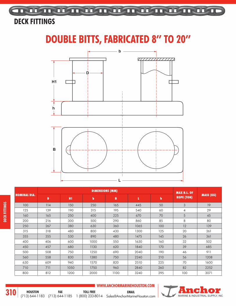
WWW.ANCHORMARINEHOUSTON.COMTOLL FREE
1 (800) 233-8014HOUSTON
(713) 644-1183FAX
(713) 644-1185310
DECK FITTINGS
DECK
FIT
TING
S
DOUBLE BITTS, FABRICATED 8’’ TO 20’’
NOMINAL DIA.DIMENSIONS (MM) MAX B.L. OF
ROPE (TON)MASS (KG)
D H1 b B L h
100 114 150 250 165 445 50 3 19
125 139 190 315 195 540 60 4 29
160 165 250 400 225 670 70 5 45
200 216 300 500 290 860 85 8 80
250 267 380 630 360 1065 100 12 139
315 318 480 800 430 1300 125 20 261
355 355 530 890 480 1475 145 26 361
400 406 600 1000 550 1630 160 32 502
450 457 680 1130 620 1840 170 39 685
500 508 750 1250 690 2040 190 46 911
560 558 830 1380 750 2240 210 56 1208
630 609 940 1570 820 2510 225 70 1600
710 711 1050 1750 960 2840 260 82 2252
800 812 1200 2000 1100 3240 295 100 3071
H1
D
L
b
h
B

EMAIL [email protected]
WWW.ANCHORMARINEHOUSTON.COMTOLL FREE
1 (800) 233-8014HOUSTON
(713) 644-1183FAX
(713) 644-1185 311
DECK FITTINGS
DECK FITTINGS
h1b1
h2
L1
L
d1
T2G
A B
F
C
H A
JE2
T1
TO
T1
T2
7/16”Typ
7/16”Typ
7/16”Typ
E
5/16”
7/16”
2-1/8” R
1” Snipe Typ 2” Snipe Typ
Grind Smooth Edges
DTO
T1
DIMENSIONS IN MM MAX. B.L. OF ROPE
TONMASS (KG)NOMINAL
DIA. B1 D1 H1 H2 L1 L
100 114 114 150 75 250 364 4 16
125 140 140 190 80 315 455 4 24
160 168 168 250 90 400 568 5 38
200 219 219 300 100 500 719 8 60
250 273 273 360 125 630 903 12 101
315 324 324 480 150 800 1124 20 197
400 406 406 600 175 1000 1406 32 371
500 508 508 750 200 1250 1758 46 635
630 610 610 940 225 1570 2180 70 1162
710 711 711 1050 250 1750 2461 82 1509
800 813 813 1200 275 2000 2813 100 2081
DIMENSIONS (INCHES)
DRAWING BARREL PIPE CHED. A B C D E F G H J
S 1051F 10 120 8-5/8 22 39-1/4 10-3/4 17-1/4 14 11 7 24
S 1052F 12 80 12-3/4 31-1/2 57 12-3/4 19 15-3/4 13 7 27
S 1123F 14 80 14-1/4 35-1/2 64 14 21-1/2 17 14-1/4 7-1/2 30
S 1124F 16 80 15-3/4 39-1/2 71 16 24 19 16-1/4 8 33
S 1128F 18 80 17-3/4 44-1/2 80 18 27 21-1/2 18-1/4 8-1/2 36
S 1345F 20 80 19-7/8 49-1/4 89 20 30 24 20-1/4 9 40
S 1346F 24 80 25 66 116 24 38 31 24-1/4 10 54
DECK BOLLARDS - DOUBLE BITTSBOLLARDS DB-138
The bollard suitable for wire or rope with breaking load (tons) when cross belayed on the bollard - for mooring. When belayed on one bitt only approximately 2xBL is valid - for towing. Bollard scantlings per ISO 3913.

WWW.ANCHORMARINEHOUSTON.COMTOLL FREE
1 (800) 233-8014HOUSTON
(713) 644-1183FAX
(713) 644-1185312
DECK FITTINGS
DECK
FIT
TING
S
E
H J
A
A
Size A
O
P N KD
B
C
L
S
K P
E
N A
B
O
M
F
A
R
AL L
L
LC
GH
D
G
J
J
F
KEVEL
DIMENSIONS (INCHES)A B C D E F G H I J K L M N O P S
30 4 5 6-1/8 10 4 2 1-1/4 3/4 1/2 3/8 1-3/4 3/4 1 4 2-1/4 18
36 5 5-7/8 7-1/8 12 5 2-1/2 1-1/2 1 9/16 1/2 2-1/8 7/8 1-1/2 5 2-3/4 22
42 6 7 8-1/2 14 6 3 1-7/8 1-1/4 5/8 5/8 2-1/2 1 2 6 3-1/4 26
48 7 9 10 16 7 3-1/2 2 1-1/2 3/4 3/4 4 1-1/4 2-1/2 7 4 30
60 7 9 13 20 9 4-1/2 2 1-3/4 3/4 3/4 4 1-1/4 2-1/2 9 4 38
DIMENSIONS (INCHES)A B C D E F G H K L M N O P R T24 3 4-1/2 17 6 1-1/2 5-1/2 11 1-1/2 1/2 8 2 1-1/2 1-1/8 1 3/4
30 4 5-5/8 20-1/4 7 2-3/8 6-7/8 14 3-1/4 1/2 9-1/2 2 2-3/8 1-1/4 1-3/8 7/8
36 5 6-3/4 23-1/2 8 3-1/4 8-1/4 17 4 9/16 11 2-1/2 3-1/4 1-1/2 1-3/4 1
42 6 7-7/8 26-3/4 9 4-1/8 9-5/8 20 4-3/4 5/8 12-1/2 2-3/4 4-1/8 1-7/8 2-1/8 1-1/8
48 7 9 30 10 5 11 23 5-1/2 3/4 14 4 5 2 2-1/2 1-1/4
KEVEL CHOCK
MATERIAL CAST STEEL

EMAIL [email protected]
WWW.ANCHORMARINEHOUSTON.COMTOLL FREE
1 (800) 233-8014HOUSTON
(713) 644-1183FAX
(713) 644-1185 313
DECK FITTINGS
DECK FITTINGS
SIZE DIMENSIONS (INCHES)
A B C D E F G H J K L M N P Q R S T
6 19-3/4 4 8 6-3/4 3 3/4 3-3/8 1 1-3/8 3/4 1 3-1/4 3-3/8 3-1/2 1-7/8 2-7/8 3/8
7 22-3/8 4-3/8 9-1/4 7-7/8 3-1/2 3/4 3-15/16 1-3/16 1-3/8 7/8 1-1/8 3-13/16 3-15/16 4-1/8 2-3/16 3-15/16 3/8
8 25-1/4 5-3/8 10-3/4 9 4 7/8 4-1/2 1-5/16 1-13/16 1 1-1/4 4-3/8 4-1/2 4-3/4 2-9/16 3-3/4 1/2
9 27-3/4 6 12 10-1/8 4-1/2 7/8 5-1/16 1-1/2 2-1/16 1-1/8 1-3/8 4-7/8 5-1/16 5-1/4 2-7/8 4-1/4 1/2
10 30-3/8 6-5/8 13-1/4 11-1/8 5 1 5-1/2 1-9/16 2-3/16 1-1/4 1-1/2 5-7/16 5-3/8 5-7/8 3-3/16 4-3/4 5/8
11 33-1/4 7-3/8 14-3/4 12-1/4 5-1/2 1 6-1/16 1-11/16 2-3/8 1-3/8 1-5/8 6 6-3/16 6-1/2 3-1/2 5-1/4 5/8
12 36 8 16 13-3/8 6 1-1/4 6-5/8 1-7/8 2-5/8 1-1/2 1-3/4 6-1/2 6-3/4 7 3-7/8 5-3/4 3/4
14 42 9-3/8 18-3/4 15-5/8 7 1-1/4 7-3/4 2-3/16 3-1/16 1-3/4 2 7-5/8 7-7/8 8-1/4 4-1/2 6-11/16 7/8
18 54 12 24 20 9 1-1/2 9-7/8 2-3/4 3-7/8 2-1/4 2-1/2 10-1/8 10-1/8 10-1/2 5-3/4 8-5/8 1-1/8
DECK MOUNT PLAIN CHOCK
B
30
D
G
QF
GA
C1
1
4
M
M C2
Open Closed
H
P P
N
L
J J
T
E
SF
F
F
M
L
K
2
3
32
4
Pads for Bolting to Wooden Dock Omitted Unless Specified on Order.
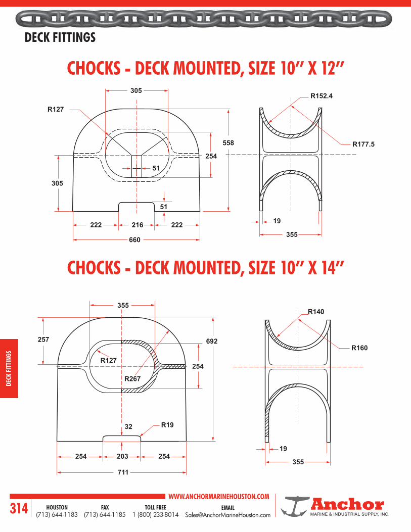
WWW.ANCHORMARINEHOUSTON.COMTOLL FREE
1 (800) 233-8014HOUSTON
(713) 644-1183FAX
(713) 644-1185314
DECK FITTINGS
DECK
FIT
TING
S
305
R127
254
355
R177.5
R152.4
19216
660
355
254 254
R19
R127
R140
R160
19
355
R267
254
692
203
711
257
32
222222
305
51
558
51
CHOCKS - DECK MOUNTED, SIZE 10’’ X 12’’
CHOCKS - DECK MOUNTED, SIZE 10’’ X 14’’

EMAIL [email protected]
WWW.ANCHORMARINEHOUSTON.COMTOLL FREE
1 (800) 233-8014HOUSTON
(713) 644-1183FAX
(713) 644-1185 315
DECK FITTINGS
DECK FITTINGS
304.8R152.4
R149.3
457.2
838.2
A
E
C
D B
H
355.6
28.7
800.1
DIMENSIONS (MM)MASS (KG)
NOMINAL SIZE A B C D E H315 x 250 315 250 815 620 365 380 230425 x 280 425 280 1075 785 450 500 378600 x 315 600 315 1360 865 507 560 598600 x 450 600 450 1360 1000 575 560 655600 x 450 600 450 1560 1200 675 760 780
CHOCKS - DECK MOUNTED, SIZE 12’’ X 18’’
CHOCKS - DECK MOUNTED, TYPE EU SIZES 10’’ X 12’’ - 18’’ X 24’’

WWW.ANCHORMARINEHOUSTON.COMTOLL FREE
1 (800) 233-8014HOUSTON
(713) 644-1183FAX
(713) 644-1185316
DECK FITTINGS
DECK
FIT
TING
S
DIMENSIONS (MM)
MASS (KG)
A X B C D E H K L N
315 X 250 695 630 432 342 22 168 497 198
425 X 280 925 780 516 450 26 224 661 358
600 X 315 1160 875 571 504 30 250 866 547
600 X 450 1160 1010 706 504 30 250 866 629
600 X 450 1360 1160 1060 504 30 250 1260 813
BULWARK MOUNTED PANAMA CHOCK
AH
E
LK
D
N
C
B

EMAIL [email protected]
WWW.ANCHORMARINEHOUSTON.COMTOLL FREE
1 (800) 233-8014HOUSTON
(713) 644-1183FAX
(713) 644-1185 317
DECK FITTINGS
DECK FITTINGS
DIMENSIONS (MM)
MASS (KG)
NOMINAL SIZE L L2 L3 H2 H3
310 310 734 652 684 462 276
360 360 788 701 688 464 305
400 400 832 750 692 470 344
450 450 888 802 696 474 385
500 500 940 854 700 478 422
BULWARK MOUNTED PANAMA CHOCK
H3H2
L
L3
L2
260
358

WWW.ANCHORMARINEHOUSTON.COMTOLL FREE
1 (800) 233-8014HOUSTON
(713) 644-1183FAX
(713) 644-1185318
DECK FITTINGS
DECK
FIT
TING
S
CLEAT SIZE (INCHES)
DIMENSIONS (MM)WEIGHT (LBS)
A B C D E F
8 8.00 4.40 0.35 1.70 1.25 2.14 3.00
10 10.00 5.13 0.40 2.24 1.42 2.53 4.30
12 12.00 5.55 0.55 2.75 1.70 3.50 8.00
14 14.00 7.00 0.53 3.20 2.13 4.00 13.00
16 16.00 8.25 0.75 3.50 2.13 4.50 17.00
18 18.00 9.25 0.85 4.26 2.63 4.75 24.00
WELD ON STEEL CLEATS
ASTM A27 GRADE 70-36 CAST STEEL
A
E
D
B
C
F

EMAIL [email protected]
WWW.ANCHORMARINEHOUSTON.COMTOLL FREE
1 (800) 233-8014HOUSTON
(713) 644-1183FAX
(713) 644-1185 319
DECK FITTINGS
DECK FITTINGS
DIMENSIONS (INCHES)
A B C D E F G H J K L M N P Q U
8 2 1 1/2 1-1/4 5/32 1-15/16 5/32 11/16 11/16 - 9/16 9/16 4 2 1/4
10 2-5/8 1-1/2 1/2 1-3/4 3/16 2-5/32 3/8 1-1/4 7/8 7/16 1-1/6 11/16 5-3/8 2-3/4 5/16
12 3-1/4 1-3/4 3/4 2 3/16 2-23/32 7/16 1-5/8 1-1/8 9/16 1-3/8 7/8 6-3/8 3-1/4 3/8
16 4 2-5/8 1 2-1/2 1/4 3-7/8 9/16 2 1-1/4 5/8 1-3/4 1 8-1/4 4 1/2
18 4-1/2 2-5/8 1-1/8 2-3/8 5/16 4-11/16 5/8 2-1/2 1-1/2 3/4 2-1/8 1-1/8 9-1/8 5 5/8
20 5 2-3/4 1-1/4 2-5/8 5/16 5-3/8 3/4 2-3/4 1-5/8 13/16 2-3/8 1-1/4 9-7/8 5-1/2 5/8
HORN CLEATS - STEEL
A
Weld
UD
E
N
G
F
B
K
Q
P
HMJ
C
L

WWW.ANCHORMARINEHOUSTON.COMTOLL FREE
1 (800) 233-8014HOUSTON
(713) 644-1183FAX
(713) 644-1185320
DECK FITTINGS
DECK
FIT
TING
S
F
J
LBore
HB
E
C
KDA
G
B
A
E
F
45
C
D
TOWING PAD EYE
D-RING
DIMENSIONS (INCHES)
Chain Size A B C D E F G H J K L
3/4 5 10 4-3/4 3/4 1 1-3/4 1-7/8 2-1/4 2-3/4 3/4 15/16
1 5 10 5-1/4 1-3/16 1-7/16 1-3/4 2-3/8 2-3/4 3 3/4 1-3/16
1-1/4 6 12 6 1-17/32 1-25/32 2-1/2 3 3-3/4 3-1/2 1 1-7/16
1-1/2 6 12 6-3/4 1-7/8 2-1/8 3 3-5/8 4-1/2 3-7/8 1 1-11/16
2 8 16 8-1/2 2-3/4 3 4-1/4 5 5-3/4 5 1-1/2 2-5/16
2-1/2 10 20 9-3/4 3-5/8 3-7/8 5 6 8 5-3/4 1-3/4 2-13/16
3 12 24 10-1/2 4-1/2 4-3/4 5-5/8 6-1/2 9 6 2 3-5/16
DIMENSIONS (MM)
Tons A B C D E F Weight(Kg)
7 12.7 44.5 60.3 95.3 22.4 6.5 .45
36 22 66 125 208 36 12 2.4
41 23 79.4 127 203.2 44.5 12.7 3.5
50 25.4 67.2 127 222.3 51.9 16 4.7

EMAIL [email protected]
WWW.ANCHORMARINEHOUSTON.COMTOLL FREE
1 (800) 233-8014HOUSTON
(713) 644-1183FAX
(713) 644-1185 321
DECK FITTINGS
DECK FITTINGS
F
AC
EB
B
EH
F
D
C
G
A
D
12
PIECE NO.
DESCRIPTIONPART NO.
MATERIAL
1 Ratchet Strap Ring 75736 Mild Steel
2 Ratchet Strap Plate 75744 Mild Steel
MODEL NO. A B C D E FWEIGHT (LBS)
DF-80 35-5/8 24 9-7/8 3/4 1-3/4 7 83
MODEL NO.
A B C D E F G HWEIGHT (LBS)
DF-196 20 8 6 7-5/8 4 1 2 2-1/8 55
RATCHET STRAP
CAST STEEL D-RING

WWW.ANCHORMARINEHOUSTON.COMTOLL FREE
1 (800) 233-8014HOUSTON
(713) 644-1183FAX
(713) 644-1185322
DECK FITTINGS
DECK
FIT
TING
S
MOORING FITTING ARRANGEMENT350 KDWT TANKER WITH 10 MOORING WIRES
ITEM DESCRIPTION1, 2 Combined Anchor Windlass/Mooring Winch
3 - 9 Single Drum Mooring Winch with Warping Head
10 Single Drum Mooring Winch without Warping Head
11 Panama type Fairlead, 500 x 350 mm opening deck mounted
12 Closed Fairlead, 400 x 250 mm opening deck mounted
13 Panama type Fairlead, 350 x 250 mm opening bulwark mounted
14 Panama type Fairlead, 600 x 450 mm opening bulwark mounted
15 Overhead Roller Fairlead
16 Vertical Bollard, 450 mm diameter
17 Vertical Bollard, 350 mm diameter
18 Cruciform Bollard, 300 mm diameter
19 Chain Stopper for Anchors
20 Bow Stopper
21 Pedestal Fairlead
4
6
3
10
6
11
11 11 11
11
15
1515
1513
131313
13 13
16
17
17 17 17 17 17 17
17
1717
1712121212 5
21
19
91420
16
111
127
164 pcs.
5 PCS.
FORECASTLE DECKAFT DECK
PRIMARY LINES
AUX. LINES

EMAIL [email protected]
WWW.ANCHORMARINEHOUSTON.COMTOLL FREE
1 (800) 233-8014HOUSTON
(713) 644-1183FAX
(713) 644-1185 323
DOORS/HATCHES
LET US KNOW YOUR REQUIREMENTS
WATERTIGHT
DOORS
HATCHES
SCUTTLES
PORT LIGHTS
Doors/HatcHes

WWW.ANCHORMARINEHOUSTON.COMTOLL FREE
1 (800) 233-8014HOUSTON
(713) 644-1183FAX
(713) 644-1185324
DOORS/HATCHES
DOOR
S/HA
TCHE
S
#100 2-DOGFUMELIGHT DOOR
#101 4-DOGWEATHERTIGHT DOOR
#102 6-DOGWATERTIGHT DOOR
#103 6-DOGSQUARE CORNER DOOR
#104 6-DOGQUICK ACTING DOOR
#105 6-DOGDUTCH DOOR
#106DOUBLE DOOR
#110QUICK ACTING LEVER
OPERATED DOOR
#200DROP BOLT HATCH
#201WATERTIGHT HATCH #202
QUICK ACTING SPRING BALANCED HATCH
#203QUICK ACTING OVAL
HATCH
#204QUICK ACTING FLUSH
OVAL HATCH
#207SPRING BALANCED DROP BOLT HATCH
#208OVAL DROP BOLT HATCH
#209OVAL DOGGED HATCH

EMAIL [email protected]
WWW.ANCHORMARINEHOUSTON.COMTOLL FREE
1 (800) 233-8014HOUSTON
(713) 644-1183FAX
(713) 644-1185 325
DOORS/HATCHES
DOORS/HATCHES
#210OIL CARGO HATCH #211
FLUSH HATCH
#212FLUSH OVAL
HATCH #213SPRING BALANCED FLUSH
HATCH
#214SPRING BALANCED DOGGED HATCH
#215SPRING BALANCED OVAL QUICK ACTING HATCH #300
BOLTED PLATE MANHOLE
#301SINGLE BOLT MANHOLE
#400SPRING BALANCED
QUICK ACTING SCUTTLE
#401QUICK ACTING FLUSH SCUTTLE
#402QUICK ACTING RAISED
SCUTTLE#403
QUICK ACTING SPRING BALANCED FLUSH
SCUTTLE
#403DROP BOLT
RAISED SCUTTLE
#405DOGGED RAISED SCUTTLE
#406FLUSH TOP
RAISED SCUTTLE
#407DOGGED
FLUSH SCUTTLE
#500 FIXED LIGHT

WWW.ANCHORMARINEHOUSTON.COMTOLL FREE
1 (800) 233-8014HOUSTON
(713) 644-1183FAX
(713) 644-1185326
DOORS/HATCHES
DOOR
S/HA
TCHE
S
WATERTIGHT DOOR WITH 2 DOGSDRAWING NO. 100
PC. NO. MATERIAL
1 Mild Steel
2 Do.
3 Do.
4 Do.
5 Do.
6 Brass
7 Do.
8 Do.
9 Mild Steel
10 Neoprene
11 Graphite
12 Delrin
13 Mild Steel
14 Frg. Stl.
15 Mild Steel
16 Frg. Stl.
17 Mild Steel
18 Do.
19 Do.
20 Do.
21 Steel
22 Do.
SCHEDULE OF MATERIAL
24
Dog 8” R
StopDog
(Open)
(Closed)
Hasp & EyeFor Padlock
CenteringWedge
Grab Handle
Panel Wedge
FIG “A” CLEAR OPNG.
Weld
FIG
“B
” C
LEA
R O
PNG
.
Hinge
17
18
18
19
20
Pin6
Washers
Cotter Pin
Hinge Pads
Slotted Hole
Gasket Retainer
In BladeBlade
Panel
Dog
Handle
Lock Nut
Grease Fitting
Shims
Bushings
Gasket
Angle
TeflonPacking
Frame
Wedge
Stop
Sleave
7
8
4
51
2
3
17
21
14
15
16
13
12
10
11
23
Shims23
9
22
DETAIL OF GRAB HANDLE
DETAIL OF HASP
DETAIL OF HINGE
SECTION LH RH
ELEVATIONRIGHT HAND DOOR SHOWN
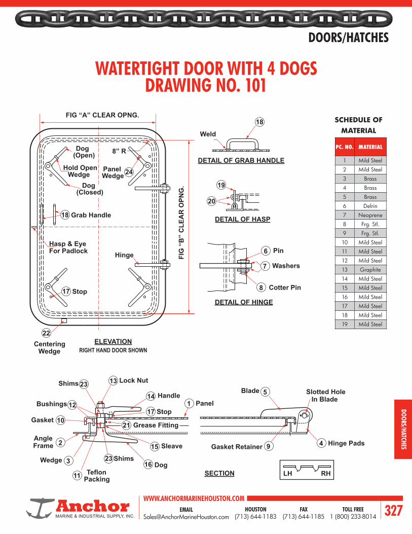
EMAIL [email protected]
WWW.ANCHORMARINEHOUSTON.COMTOLL FREE
1 (800) 233-8014HOUSTON
(713) 644-1183FAX
(713) 644-1185 327
DOORS/HATCHES
DOORS/HATCHES
Dog
Hold Open
8” R
Stop
Dog
(Open)
WedgePanelWedge
(Closed)
Hasp & EyeFor Padlock
CenteringWedge
Grab Handle
FIG “A” CLEAR OPNG.
FIG
“B
” C
LEA
R O
PNG
.
Hinge
24
18
17
Hinge Pads
Slotted Hole
Gasket Retainer
In BladeBlade
Panel
Dog
Handle
Lock Nut
Grease Fitting
Shims
Bushings
Gasket
Angle
TeflonPacking
Frame
Wedge
Stop
Sleave 4
51
2
3
17
21
14
15
16
13
12
10
11
23
Shims23
9
22
Weld
18
19
20
Pin6
Washers
Cotter Pin
7
8
DETAIL OF GRAB HANDLE
DETAIL OF HASP
DETAIL OF HINGE
SECTION LH RH
ELEVATIONRIGHT HAND DOOR SHOWN
WATERTIGHT DOOR WITH 4 DOGSDRAWING NO. 101
SCHEDULE OF MATERIAL
PC. NO. MATERIAL
1 Mild Steel
2 Mild Steel
3 Brass
4 Brass
5 Brass
6 Delrin
7 Neoprene
8 Frg. Stl.
9 Frg. Stl.
10 Mild Steel
11 Mild Steel
12 Mild Steel
13 Graphite
14 Mild Steel
15 Mild Steel
16 Mild Steel
17 Mild Steel
18 Mild Steel
19 Mild Steel
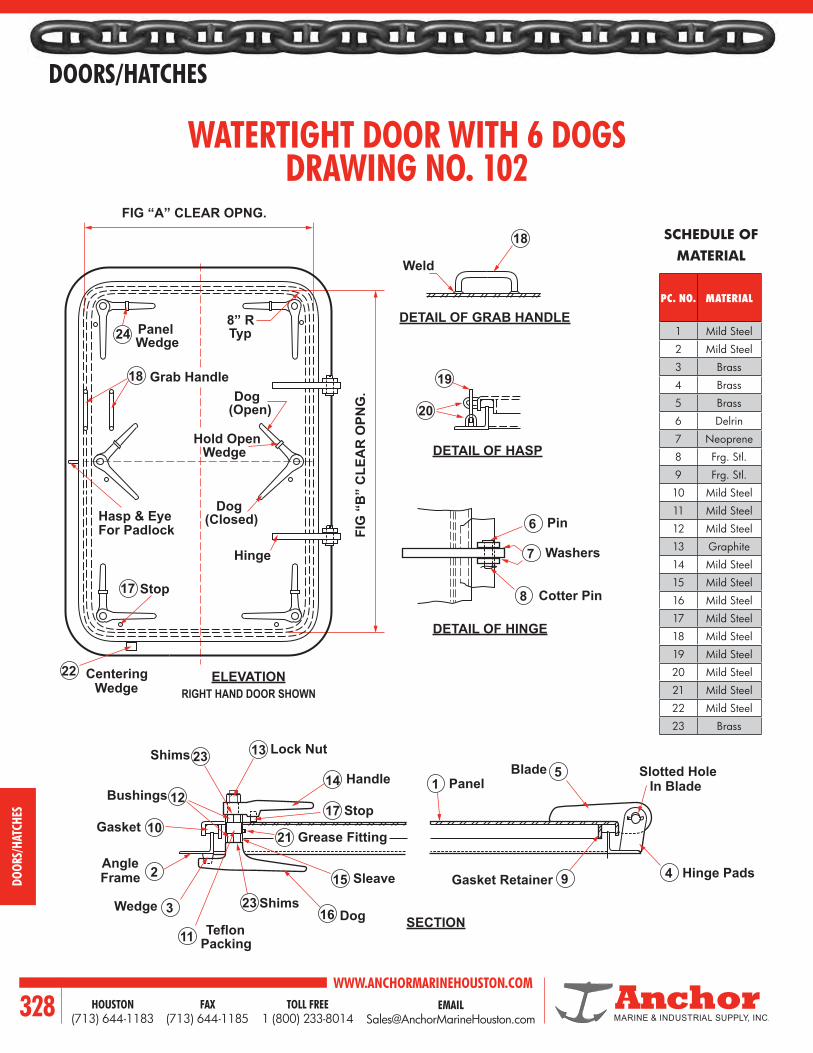
WWW.ANCHORMARINEHOUSTON.COMTOLL FREE
1 (800) 233-8014HOUSTON
(713) 644-1183FAX
(713) 644-1185328
DOORS/HATCHES
DOOR
S/HA
TCHE
S
Dog
Hold Open
8” RTyp
Stop
Dog
(Open)
Wedge
PanelWedge
(Closed)Hasp & EyeFor Padlock
CenteringWedge
Grab Handle
FIG “A” CLEAR OPNG.
Weld
FIG
“B
” C
LEA
R O
PNG
.
Hinge
24
18
17
18
Hinge Pads
Slotted Hole
Gasket Retainer
In BladeBlade
Panel
Dog
Handle
Lock Nut
Grease Fitting
Shims
Bushings
Gasket
Angle
TeflonPacking
Frame
Wedge
Stop
Sleave 4
51
2
3
17
21
14
15
16
13
12
10
11
23
Shims23
9
22
19
20
Pin6
Washers
Cotter Pin
7
8
DETAIL OF GRAB HANDLE
DETAIL OF HASP
DETAIL OF HINGE
SECTION
ELEVATIONRIGHT HAND DOOR SHOWN
WATERTIGHT DOOR WITH 6 DOGSDRAWING NO. 102
SCHEDULE OF MATERIAL
PC. NO. MATERIAL
1 Mild Steel
2 Mild Steel
3 Brass
4 Brass
5 Brass
6 Delrin
7 Neoprene
8 Frg. Stl.
9 Frg. Stl.
10 Mild Steel
11 Mild Steel
12 Mild Steel
13 Graphite
14 Mild Steel
15 Mild Steel
16 Mild Steel
17 Mild Steel
18 Mild Steel
19 Mild Steel
20 Mild Steel
21 Mild Steel
22 Mild Steel
23 Brass

EMAIL [email protected]
WWW.ANCHORMARINEHOUSTON.COMTOLL FREE
1 (800) 233-8014HOUSTON
(713) 644-1183FAX
(713) 644-1185 329
DOORS/HATCHES
DOORS/HATCHES
Dog
Hold Open
Stop
Dog
(Open)
Wedge
PanelWedge
(Closed)Hasp & EyeFor Padlock
CenteringWedge
Grab Handle
FIG “A” CLEAR OPNG.
Weld
FIG
“B
” C
LEA
R O
PNG
.
Hinge
24
18
17
18
19
20
Pin6
Washers
Cotter Pin
7
8
22
Hinge Pads
Slotted Hole
Gasket Retainer
In BladeBlade
Panel
Dog
Handle
Lock Nut
Grease Fitting
Shims
Bushings
Gasket
Angle
TeflonPacking
Frame
Wedge
Stop
Sleave 4
51
2
3
17
21
14
15
16
13
12
10
11
23
Shims23
9
DETAIL OF GRAB HANDLE
DETAIL OF HASP
DETAIL OF HINGE
SECTION
ELEVATIONRIGHT HAND DOOR SHOWN
WATERTIGHT DOOR WITH 6 DOGSDRAWING NO. 103
SCHEDULE OF MATERIAL
PC. NO. MATERIAL
1 Mild Steel
2 Mild Steel
3 Brass
4 Brass
5 Mild Steel
6 Delrin
7 Neoprene
8 Frg. Stl.
9 Frg. Stl.
10 Mild Steel
11 Mild Steel
12 Mild Steel
13 Graphite
14 Mild Steel
15 Mild Steel
16 Mild Steel
17 Mild Steel
18 Mild Steel
19 Mild Steel
20 Mild Steel
21 Mild Steel
22 Mild Steel
23 Brass
24 Mild Steel

WWW.ANCHORMARINEHOUSTON.COMTOLL FREE
1 (800) 233-8014HOUSTON
(713) 644-1183FAX
(713) 644-1185330
DOORS/HATCHES
DOOR
S/HA
TCHE
S
SCHEDULE OF MATERIAL
QUICK ACTING WATERTIGHT DOORDRAWING NO. 104
PC. NO. MATERIAL
1 Mild Steel
2 Mild Steel
3 Brass
4 Brass
5 Brass
6 Mild Steel
7 Neoprene
8 Mild Steel
9 Mild Steel
10 Mild Steel
11 Mild Steel
12 Mild Steel
13 Graphite
14 Mild Steel
15 Mild Steel
16 Mild Steel
17 Mild Steel
18 Mild Steel
19 Mild Steel
20 Mild Steel
21 Delrin
22 Brass
23 Mild Steel
24 Mild Steel
25 Mild Steel
26 Brass
27 Mild Steel
28 Mild Steel
29 Mild Steel
30 C.F. Steel
31 Mild Steel
18
19
20
Washers
Pin
Cotter Pin8
7
6
Weld
9
9
20
11
Dog Arm
FIG “A” CLEAR OPNG.
FIG
“B
” C
LEA
R O
PNG
.
Dog Arm
Grab
Hasp & Eye
CenteringWedge
For Padlock
8”R
Handle
15
2423
2114
3125
3230
2229
27 13
1819
2826
17 10
9
19
Slotted HoleIn Blade
Hinge Pad
HingeBlade
Cotter PinBolt & Nut
Shaft
Pin
LocknutBushingHandwheel
Grease
SleeveLocknut
Handwheel
BushingCoupling
Packing
Fitting
Dog Arm
Frame
FrameAngle
Panel
Spring
Wedge
Shims
HexSwivelGuide
Cover
Cover
Strap Gasket
GasketRetainer
Set Skrew5
8
8
2
1 6
7
DETAIL OF GRAB HANDLE
DETAIL OF HASP
DETAIL OF HINGE
SECTION
ELEVATIONRIGHT HAND DOOR SHOWN

EMAIL [email protected]
WWW.ANCHORMARINEHOUSTON.COMTOLL FREE
1 (800) 233-8014HOUSTON
(713) 644-1183FAX
(713) 644-1185 331
DOORS/HATCHES
DOORS/HATCHES
SCHEDULE OF MATERIAL
QUICK ACTING WATERTIGHT DOORDRAWING NO. 109
PC. NO. MATERIAL
1 Mild Steel
2 Mild Steel
3 Brass
4 Stainless
5 Stainless
6 Forged Stl
7 Neoprene
8 Forged Stl
9 Forged Stl
10 Oilite Bronze
11 Mild Steel
12 Mild Steel
13 Graphite
14 Mild Steel
15 Mild Steel
16 Mild Steel
17 Stainless
18 Mild Steel
19 Mild Steel
20 Mild Steel
21 Mild Steel
22 Mild Steel
23 Stainless
24 Mild Steel
25 Mild Steel
26 Mild Steel
27 Mild Steel
28 Mild Steel
29 Mild Steel
30 Oilite Bronze
31 Cold Finish
32 Cold Finish
33 Mild Steel
34 Stainless
35 Plated Stl
Weld
18
19
20
Washers
Pin
Cotter Pin
7
6
8
13
11
16
23
21
22
2526
29
30
31
2827
2417
Locknut
Dog
Stud
Rod
Wedge
Shims
Spindle
Spring
Flanged
Sleeve
Grease
TeflonPacking
Fitting
Bushing
StraightBushing
CollarSide Dog
Lever
Connecting
5
23
23
Hinge
Grab
CenteringWedge
Blade
Handle
5
4
2
1
9
332
12
10
13
17
11
21
14
17
15
16
Slotted Hole
Angle Frame
Hinge Pads
GasketRetainerGasket
Toggle Link
LocknutHandleFlanged
Teflon
GreaseFitting
Shaft Handle
Sleeve
Spring
Packing
Bushing
FlangedBushing
(w/ Link Pad)
In BladeBlade
Panel
DETAIL OF GRAB HANDLE
DETAIL OF HASP
DETAIL OF HINGE
SECTION
ELEVATIONRIGHT HAND DOOR SHOWN
FIG “A” CLEAR OPNG.
FIG
“B
” C
LEA
R O
PNG
.
DOG SECTION

WWW.ANCHORMARINEHOUSTON.COMTOLL FREE
1 (800) 233-8014HOUSTON
(713) 644-1183FAX
(713) 644-1185332
DOORS/HATCHES
DOOR
S/HA
TCHE
S
SCHEDULE OF MATERIAL
WATERTIGHT HATCHDRAWING NO. 201
PC. NO. MATERIAL
1 Mild Steel
2 Mild Steel
3 Brass
4 Brass
5 Brass
6 Brass
7 Brass
8 Neoprene
9 Steel
10 Mild Steel
11 Mild Steel
12 Frg. Stl.
13 Frg. Stl.
14 Steel
15 Steel
16 Steel
17 Steel
18 Delrin
19 Graphite
20 Mild Steel
1
PanelWedge
FIG “A”INSIDE COAMING
FIG
“A
”IN
SID
E C
OA
MIN
G
HandleGrab
Hasp
Eye
Pin
Pin
Cover
Coaming
Washers
Cover
Stop
Dog
Sleeve
GreaseFitting
Handle
Locknut
Bushing
Gasket
Packing
Frame
Dog
Wedge
GasketCoaming
RetainerGasket
Hinge Slotted HoleBlade In Blade
Hinge Pad
Cotter
1
1
2
5
6
7
1
3
4
82
20
15
14
8
18
13
16
22
21
17 19
12
23
10
11
9
DETAIL OF HINGE
DETAIL OF HASP & EYE
PLAN
SECTION
CO
AM
ING
HT
6” M
IN
FIG
“C
”

EMAIL [email protected]
WWW.ANCHORMARINEHOUSTON.COMTOLL FREE
1 (800) 233-8014HOUSTON
(713) 644-1183FAX
(713) 644-1185 333
DOORS/HATCHES
DOORS/HATCHES
SCHEDULE OF MATERIAL
SPRING BALANCE QUICK ACTING WATERTIGHT HATCHDRAWING NO. 202
PC. NO. MATERIAL
1 Mild Steel
2 Mild Steel
3 Brass
4 Brass
5 Brass
6 Neoprene
7 Mild Steel
8 Mild Steel
9 Mild Steel
10 Cold Finish
11 Mild Steel
12 Graphite
13 Mild Steel
14 Mild Steel
15 Mild Steel
16 Spring Steel
17 Mild Steel
18 Mild Steel
19 Brass
20 Derlin
21 Brass
22 Steel
23 Mild Steel
24 Mild Steel
25 Spring Steel
26 Brass
27 Mild Steel
28 Mild Steel
29 Mild Steel
30 Mild Steel
31 Mild Steel
32 Mild Steel
33 Mild Steel
Slotted Hole
Pipe Sleeve
Hinge Pad
Gasket
Gasket
Retainer
Hinge BladeHandwheel
Handwheel
Set Screw
Pipe Sleeve
Swivel Guide
Cover StrapCover
ShimsLocknut
Dog Box
Hex Bushing
Coupling
Bushing
Shaft
PackingSpring
Dog Arm
Wedge
Cover
Coaming
GreaseFitting Pin In Blade
Cotter Pin
3126
26
2117
16
10
11
23
24
1238
2022
37
18
19
34
1314
15
35
36
Hasp
Eye
Cover
Coaming
1
2
1
9
2
8
85
7
6
Hasp
Hasp
Grab
PipeSleeve
Handle
BladeCotter Pin
Washer
Spring
Pin
Sprocket
Washer
Stop
36
35
27
Cotter Pin27
26
15
30
32
31
33
14
Eye
FIG “A”CLEAR OPENING
FIG
“B
”C
LEA
R O
PEN
ING
2
3
4
14 30
2829
Spring
BoltPad
Sprocket
Sprocket
26
2928
30
SECTION
PLAN
DETAIL OFHASP & EYE
SECTION AT SPROCKET
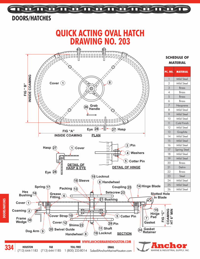
WWW.ANCHORMARINEHOUSTON.COMTOLL FREE
1 (800) 233-8014HOUSTON
(713) 644-1183FAX
(713) 644-1185334
DOORS/HATCHES
DOOR
S/HA
TCHE
S
GrabHandle
FIG “A”INSIDE COAMING
FIG
“ B
”IN
SID
E C
OA
MIN
G
26
81
Pin
Washers
Cotter Pin
3
4
5
27
28
1Hasp
Eye
Cover
Cover
Slotted HoleIn Blade
Hinge Pad
Gasket
Gasket
Hinge Blade
Bushing
SetscrewCoupling
Handwheel
Handwheel
Sleeve
Packing
Dog Arm
Cover Strap
Swivel Guide
Cover PinShims
Bushing Grease
FrameWedge
SpringHex
Coaming
CoverFitting
Cotter Pin
24
14
2325
15
75
8
8
6
2
1
9 Retainer
Locknut19
LocknutShaft
1911
29
18
1317
16
3010
12
2022
21
28Eye 27 Hasp
SECTION
DETAIL OFHASP & EYE DETAIL OF HINGE
CO
AM
ING
HT
6” M
IN
FIG
“C
”
PLAN
QUICK ACTING OVAL HATCHDRAWING NO. 203
SCHEDULE OF MATERIAL
PC. NO. MATERIAL
1 Mild Steel
2 Mild Steel
3 Brass
4 Brass
5 Brass
6 Brass
7 Neoprene
8 Mild Steel
9 Mild Steel
10 Mild Steel
11 Cold Finish
12 Mild Steel
13 Graphite
14 Mild Steel
15 Mild Steel
16 Mild Steel
17 Spring Steel
18 Mild Steel
19 Mild Steel
20 Brass
21 Delrin
22 Brass
23 Steel
24 Mild Steel
25 Mild Steel
26 Mild Steel

EMAIL [email protected]
WWW.ANCHORMARINEHOUSTON.COMTOLL FREE
1 (800) 233-8014HOUSTON
(713) 644-1183FAX
(713) 644-1185 335
DOORS/HATCHES
DOORS/HATCHES
GrabHandle
FIG “A”INSIDE COAMING
FIG
“ B
”IN
SID
E C
OA
MIN
G
26
81
Pin
Washers
Cotter Pin
3
4
5
27
28
1Hasp
Eye
Cover
Cover
Slotted HoleIn Blade
Hinge Pad
Gasket
Gasket
Hinge Blade
Bushing
SetscrewCoupling
Handwheel
Handwheel
Sleeve
Packing
Dog Arm
Cover Strap
Swivel Guide
Cover PinShims
Bushing Grease
FrameWedge
SpringHex
Coaming
CoverFitting
Cotter Pin
24
14
2325
15
75
8
8
6
2
1
9 Retainer
Locknut19
LocknutShaft
1911
29
18
1317
16
3010
12
2022
21
28Eye 27 Hasp
SECTION
DETAIL OFHASP & EYE DETAIL OF HINGE
CO
AM
ING
HT
6” M
IN
FIG
“C
”
PLAN
QUICK ACTING FLUSH OVAL HATCHDRAWING NO. 204
SCHEDULE OF MATERIAL
PC. NO. MATERIAL
1 Mild Steel
2 Mild Steel
3 Mild Steel
4 Mild Steel
5 Cold Finish
6 Brass
7 Neoprene
8 Mild Steel
9 Mild Steel
10 Mild Steel
11 Mild Steel
12 Brass
13 Brass
14 Mild Steel
15 Delrin
16 Graphite
17 Mild Steel
18 Brass
19 Mild Steel
20 Mild Steel
21 Brass
22 Mild Steel
23 Brass
24 Mild Steel
25 Mild Steel
26 Spring Steel
27 Mild Steel
1 CoverSpring26Gasket 7
Coaming 2
Angle Knife Edge
29
Frame Wedge
24
Dog Arm
11 Hex Bushing
27
SwivelGuide
21Locknut9 Hand Wheel10
Pin13Bushing15 Cotter Pin
12
Set Screw 20
Pipe Sleeve 17 Dog Stud23
Packing16Grease Fitting
22 Coupling19
Plug 6
Spiders14
Shim18
Grab Handle
8
Grab HandleBox
28
Grab Handle 8
Plug 6
Washer 4 Washer4
Threaded Coupling
3
Stop25
“T” Wrench Slot Hole
Hinge Pin
5
FIG “A”INSIDE COAMING
FIG
“ B
”C
LEA
R O
PEN
ING
SECTION
PLANSECTION X-X

WWW.ANCHORMARINEHOUSTON.COMTOLL FREE
1 (800) 233-8014HOUSTON
(713) 644-1183FAX
(713) 644-1185336
DOORS/HATCHES
DOOR
S/HA
TCHE
S
OIL CARGO HATCHDRAWING NO. 210
SCHEDULE OF MATERIAL
PC. NO. MATERIAL
1 Mild Steel
2 Mild Steel
3 Mild Steel
4 Mild Steel
5 Mild Steel
6 Brass
7 Steel
8 Mild Steel
9 Steel
10 Brass
11 Steel
12 Brass
13 Mild Steel
14 Mild Steel
15 Mild Steel
16Manganese
Bronze
17Manganese
Bronze18 Brass
19 Mild Steel
20 Neoprene
21 Mild Steel
22 Mild Steel
23 Steel
24 Steel
PivotShaft
1 Cover
Cable
Pad Brackets
Toggle Pin
3
28
27Pad 4
Fig. A - Inside Coaming
PivotShaft
25Pad 4
Locking Ring
26Washer 29
Locking Pin Pad
5
Grease Fitting
24Washer 6
25Nut 7
Bushing 30Grease Fitting
24Spindle 10Washer 12
Hex Nut 11
Screws 11
13 Handwheel23 Yoke
14 Spindle Pad Cap15 Spindle Pad
8 Yoke Arm
16 Drop Bolt
17 Wing Nut
18 Eye Pin
22 Cotter Pin
21 Drop Bolt Pad
2 Coaming
Key
RH
LH
Locking Ring
26
Locking Pad
5
19 Gasket Retainer
203/4”x1-3/4” Gasket
31Gasket Keeper
ULLAGEIF REQ’D.
SECTION
PLAN

EMAIL [email protected]
WWW.ANCHORMARINEHOUSTON.COMTOLL FREE
1 (800) 233-8014HOUSTON
(713) 644-1183FAX
(713) 644-1185 337
DOORS/HATCHES
DOORS/HATCHES
PIECE NO. DESCRIPTIONPART NUMBER
MATERIAL DF-430-18D DF-430-24
1 Cover Assembly 20389 20397 See Note 1 above
2 Deck Ring 6750 15334 Mild Steel
3 Strongback 6300 13870 Galvanized Steel
4 Tee Handle 16993 16993 Stainless Steel
5 Nut 507 507 Brass
6 Gasket 17256 6548 Neoprene
7 Washer 604 604 Brass
8 Washer 6556 6556 Neoprene
9 Pin 21636 21636 Stainless Steel
MODEL NO. PART NO. SIZE A B C D WT. (LBS)
DF-430-18D6297
18 20-3/4 18 5 3/870
6335 (Galvanized) 74
DF-430-246270
24 26-3/4 24 5 3/8116
6389 (Galvanized) 120
NOTE 1: INCLUDES ALL PIECESEXCEPT PC. NO. 2 - DECK RING
The specifications and detailsdescribed by drawings or textin this literature are subject tochange without notice
FLUSH WATERTIGHT HATCH
CBA
D 1
6 2
Deck
3
875
4 9

WWW.ANCHORMARINEHOUSTON.COMTOLL FREE
1 (800) 233-8014HOUSTON
(713) 644-1183FAX
(713) 644-1185338
DOORS/HATCHES
DOOR
S/HA
TCHE
S
PIECE NO. DESCRIPTIONPART NUMBER
MATERIALDF-174-5 DF-464-5
1 Cover Assembly** 77887 78484 Mild Steel
2 Coaming 74098 19550 Mild Steel
3 Gasket 74497 78530 Neoprene†
4 Tumble Bolt 10774 10774 Bronze
5 Dog Handle 74837 74837 Malleable Iron
Flame Screen* 17051 19445 Stainless Steel
MODEL NO. PART NO. SIZE A B C D E F G H WT. (LBS.)
DF-174-5 72451 15 x 23 23 15 7-1/2 5-1/4 8-1/2 5 5/16 3/8 96
DF-464-5 78514 18 x 24 24-1/4 18-1/4 9-1/8 5-1/4 8-1/2 5 5/16 3/8 106
*OPTIONAL EXTRA** Gasket included w/cover assembly† Other gasket material availableOther optional extras include galvanized finish, a flame screen and a variety of coaming heights.The specification and details described by drawings or text in this literature are subject to change without notice.
RAISED WATERTIGHT HATCH
A OPENING
Deck
C
G
G
G
D
H
“A”
“A” “B”
“B”
B O
PEN
ING
41
2
5
3
LOCKING HASP
SECTION “B-B”
SECTION “A-A”

EMAIL [email protected]
WWW.ANCHORMARINEHOUSTON.COMTOLL FREE
1 (800) 233-8014HOUSTON
(713) 644-1183FAX
(713) 644-1185 339
DOORS/HATCHES
DOORS/HATCHES
RAISED WATERTIGHT HATCH
PIECE NO. DESCRIPTION PART NUMBER MATERIAL
1 Cover Assembly** 77895 Mild Steel
2 Coaming 75027 Mild Steel
3 Gasket 74497 Neoprene†
4 Tumble Bolt 10774 Bronze
5 Dog Handle 74837 Malleable Iron
MODEL NO. PART NO. SIZE A B C D E F G H WT. (LBS.)
DF-343-5 74950 19 19 19-3/4 5 8-1/2 3/8 3/8 5/16 5/16 92
*OPTIONAL EXTRA** Gasket included w/cover assembly† Other gasket material availableOther optional extras include galvanized finish, a flame screen and a variety of coaming heights.The specification and details described by drawings or text in this literature are subject to change without notice.
1 5
32
4
C
BA OPENING
D
B
A
A
B
LOCKING HASP
SECTION “B-B”
SECTION “A-A”

WWW.ANCHORMARINEHOUSTON.COMTOLL FREE
1 (800) 233-8014HOUSTON
(713) 644-1183FAX
(713) 644-1185340
DOORS/HATCHES
DOOR
S/HA
TCHE
S
PIECE NO. DESCRIPTIONPART NUMBER
MATERIALDF-154-18 DF-154-14
1 HATCH COVER 77216 76767 MILD STEEL
2 COAMING 77232 76783 MILD STEEL
3 GASKET 77224 76775 NEOPRENE
4 5/8’’ BOLT 14613 14613 STEEL
5 5/8’’ BOLT 16179 16179 BRASS
MODEL NO. PART NO. SIZE A B C D E F WT. (LBS.)
DF-154-14 15407 14 19 14 3-1/4 2-1/2 3/8 3/8 60
DF-154-18 77240 18 23 18 3-1/4 2-1/2 3/8 3/8 78
The specification and details described by drawings or text in this literature are subject to change without notice.
CLEAN OUT HATCH
A A
A
C
E F
D
B OPENING
1
5
3 2
4
SECTION “A-A”

EMAIL [email protected]
WWW.ANCHORMARINEHOUSTON.COMTOLL FREE
1 (800) 233-8014HOUSTON
(713) 644-1183FAX
(713) 644-1185 341
DOORS/HATCHES
DOORS/HATCHES
PIECE NO. DESCRIPTIONPART NUMBER
MATERIALDF-501 DF-502
1 COVER PLATE 21342 21350 STEEL
2 WASHER 21237 21237 BRASS
3 HEX NUT 21245 21245 STAINLESS
4 HEX BOLT 14605 14605 STEEL
5 COAMING 21369 21377 STEEL
6 GASKET 21385 21393 NEOPRENE
MODEL NO. PART NO. SIZE A B C D E F G H WT. (LBS.)
DF-501 21091 15 X 23 15 23 20 28-3/4 3-5/8 2-1/2 2-1/2 3/8 85
DF-502 21105 18 X 24 18 24 23 29-3/4 3-1/4 2-1/2 2-1/2 3/8 106
RAISED BOLTED HATCH
The specification and details described by drawings or text in this literature are subject to change without notice.
3
1
6
45
2
B
A
F
H
HH
G
AE
A
C
D
SECTION “A-A”
(Holes Equally Spaced)

WWW.ANCHORMARINEHOUSTON.COMTOLL FREE
1 (800) 233-8014HOUSTON
(713) 644-1183FAX
(713) 644-1185342
DOORS/HATCHES
DOOR
S/HA
TCHE
S
PIECE NO. DESCRIPTIONPART NUMBER
MATERIALDF-503 DF-504
1 COVER 21229 21318 MILD STEEL
2 WASHER 21237 21237 BRASS
3 NUT 21245 21245 STAINLESS STEEL
4 BOLT 14613 14613 STEEL
5 DECK RING 21253 21326 MILD STEEL
6 HANDLE 21261 21261 MILD STEEL
7 HANDLE RETAINER 21288 21288 MILD STEEL
8 GASKET 21296 21334 NEOPRENE
MODEL NO. PART NO. SIZE A B C D E F G H I J K L WT. (LBS.)
DF-503 21113 15 X 23 15 23 24-1/4 26-1/2 29 16-1/4 18-1/2 21 9 3 3/4 3/8 95
DF-504 21121 18 X 24 18 24 25-1/4 27-1/2 30 19-1/4 21-1/2 24 9 3 3/4 3/8 112
The specification and details described by drawings or text in this literature are subject to change without notice.
FLUSH BOLTED HATCH
H G
D
F
C
A
E
B
L
K
J
“A”
“A”
I
6
8
45
7
32
1
SECTION “A-A”
(Holes Equally Spaced)
NOTE: Lampwick grommet furnished by others if required.

EMAIL [email protected]
WWW.ANCHORMARINEHOUSTON.COMTOLL FREE
1 (800) 233-8014HOUSTON
(713) 644-1183FAX
(713) 644-1185 343
DOORS/HATCHES
DOORS/HATCHES
PIECE NO. DESCRIPTION PART NUMBER MATERIAL
1 COVER 6637 CAST IRON
2 COAMING 75671 MILD STEEL
3 GASKET 17167 NEOPRENE
4 ARM 6831 MALLEABLE IRON
5 TUMBLE BOLT 10774 BRONZE
6 DOG HANDLE 74837 MALLEABLE IRON
7 FLAME SCREEN 6629 STAINLESS STEEL
8 HEX HEAD BOLT 20842 BRONZE
9 HEX HEAD BOLT 20850 BRONZE
10 ESNA NUT 20869 STAINLESS
MODEL NO. PART NO. SIZE A B C D E F G WT. (LBS.)
DF-144 6645 8 7-1/2 9-1/2 12 5-5/16 1-7/8 13/16 7/8 22
The specification and details described by drawings or text in this literature are subject to change without notice.
ULLAGE HATCH
5
1
7 32
64
98
10
CB
A
DF
G
Deck
E

WWW.ANCHORMARINEHOUSTON.COMTOLL FREE
1 (800) 233-8014HOUSTON
(713) 644-1183FAX
(713) 644-1185344
DOORS/HATCHES
DOOR
S/HA
TCHE
S
PIECE NO. DESCRIPTION PART NUMBER MATERIAL
1 COVER 83062 CAST IRON
2 COAMING 19526 MILD STEEL
3 GASKET 82449 NEOPRENE
4 ARM 19461 MALLEABLE IRON
5 TUMBLE BOLT 10774 BRONZE
6 DOG HANDLE 74837 MALLEABLE IRON
7 FLAME SCREEN 19496 STAINLESS STEEL
8 HEX HEAD BOLT 20842 BRONZE
9 HEX HEAD BOLT 20850 BRONZE
10 ESNA NUT 20869 STAINLESS STEEL
MODEL NO. PART NO. SIZE A B C D E F G WT. (LBS.)
DF-569 83097 10 9-1/2 13-1/2 14-3/4 9-5/8 4-3/8 3-1/2 3/4 42
The specification and details described by drawings or text in this literature are subject to change without notice.
ULLAGE HATCH
9
8
46
5
3 71
2
10
C
BG
A
E D
F

EMAIL [email protected]
WWW.ANCHORMARINEHOUSTON.COMTOLL FREE
1 (800) 233-8014HOUSTON
(713) 644-1183FAX
(713) 644-1185 345
DOORS/HATCHES
DOORS/HATCHES
PIECE NO. DESCRIPTIONPART NUMBER
MATERIALDF-470 DF-449
1 COAMING 76171 76171 MILD STEEL
2 COVER 76163 76163 MILD STEEL
3 RAISED HATCH W/ULLAGE HATCH 85316 8214 MILD STEEL
MODEL NO. PART NO. SIZE A B C WT. (LBS.)
DF-449 623824 H X 42 Dia
W/DF-14442 24 5/16 520
DF-470 8530824 H X 42 Dia
W/DF-56942 24 5/16 540
The specification and details described by drawings or text in this literature are subject to change without notice.
EXPANSION TRUNK
DF-569ULLAGE HATCH
SHOWN AS SECTION‘‘B-B’’
1
2
3
A
B
C
C
Deck
A A
B
B
SECTION “A-A”

WWW.ANCHORMARINEHOUSTON.COMTOLL FREE
1 (800) 233-8014HOUSTON
(713) 644-1183FAX
(713) 644-1185346
DOORS/HATCHES
DOOR
S/HA
TCHE
S
BILL OF MATERIAL
NO. DESC. MAT’L
1 Cover *
2 Yoke * 3 arms
3 Bolt Bronze
4 Gasket Neoprene
5 Washer St. Steel
6 Washer Neoprene
7 Rod-1/2’’ DIA. Steel
8 Deck Ring *
9 Wrench Galv. Steel
10 Hinge Pins St. Steel
11 Keeper *
MODEL NO.
SIZE. COVER RING A B C D E F G
AL. 22’’ 21 13 5-1/2 12-1/2 28-1/2 22 1/4 30-1/4 14
ST. 63 27 23-3/4
HINGED ROUND-DOGGED TYPECLEAR OPENING - 22’’, TYPE ‘‘C’’ POSITIVE LOCKING
WEIGHT ARE FOR ALUMINUM - FOR G. STEEL, MANUF. BY 3.0
Weight-lbs. Dimensions - inches
* Available 1 M corr. resist aluminum, gal. steel, or aluminum cover with gal. steel ring.
10
G
Gal. Steel
C-Dia. (St.)Clear OpeningD
B
AllenScrew
E
A
C-Dia. (Al.)
F
Cast Aluminum
5
2
1
4
16”
1” Dia.
8-1/2”
Wrench
1-3/4”
9
6
8
7
81-1/4 x 1-1/4 x 1/4L
1/8 I.P.SGR. FTG
SECT THRU HINGE

EMAIL [email protected]
WWW.ANCHORMARINEHOUSTON.COMTOLL FREE
1 (800) 233-8014HOUSTON
(713) 644-1183FAX
(713) 644-1185 347
DOORS/HATCHES
DOORS/HATCHES
BILL OF MATERIAL
NO. DESC. MAT’L
1 Cover *
2 Yoke *
3 Bolt Bronze
4 Gasket Neoprene
5 Washer St. Steel
6 Washer Neoprene
7 Rod-1/2’’ ø Steel
8 Deck Ring *
9 Wrench Galv. Steel
10 Hinge Pins St. Steel
HINGED FLUSH TYPEHINGED OVAL DOGGED TYPE
13-1/2’’ - 20-1/2 & 15 - 24 CLEAR OPENINGTYPE ‘‘C’’ POSITIVE LOCKING
HATCH SIZE A B C D E F
13-1/2 - 20-1/2 5-1/2 12-1/2 7-3/8 7 1/4 3/8
15 - 24 5-1/2 12-1/2 8-1/2 9 1/4 3/8
DIMENSIONSB
A
E
74
3
8
2
10
4
1
1/2” St. Steel
Weld Line
AP. 30-1/2” For 15 - 24 Hatch APP. 27” For 13-1/2”-20-1/2” HatchA
PP. 2
3-1/
4” F
or 1
5-24
Hat
chA
PP. 2
1-3/
4 Fo
r 13-
1/2
- 20-
1/2
Hat
ch
13-1/2” - 20-1/2” Or 15-24
1/8” I.P.S.
Allen Set Screw
Fitting
Clear Opening
D
C
Pins
SECT THRU HINGE

WWW.ANCHORMARINEHOUSTON.COMTOLL FREE
1 (800) 233-8014HOUSTON
(713) 644-1183FAX
(713) 644-1185348
DOORS/HATCHES
DOOR
S/HA
TCHE
S
DIMENSION SCHEDULE
A B C D E F10’’ 10-1/2’’ 11-1/16’’ 13-1/4’’ 12-1/4’’ 1-1/16’’
12’’ 12-1/2’’ 13’’ 15-3/16’’ 14-3/16 1-1/4’’
16’’ 16-1/2’’ 17’’ 19-1/2’’ 18-1/2’’ 1-3/8’’
PLAIN FIXED LIGHTDRAWING NO. 500
“A” Size Clear Dia.
“F”
‘A’ - Size Clear Dia.
‘E’ -
Bolt C
ircle
Dia.
‘D’ - Flange Dia.
Fastenings ToSpecifications
Glazing Compound“B”- Glazing Diameter“C”- Opening DiameterSlot For
Spanner WrenchRetaining Ring
Glass1/4”
5/16”
PLAN
SECTION

EMAIL [email protected]
WWW.ANCHORMARINEHOUSTON.COMTOLL FREE
1 (800) 233-8014HOUSTON
(713) 644-1183FAX
(713) 644-1185 349
DOORS/HATCHES
DOORS/HATCHES
DIMENSION SCHEDULE
A-SIZECLR. OP.
SPIGOTMAX. LT.
B-SIZEO.S. DIA
OVALDIA.
BOLTHOLE
10’’ 1/2’’ 11’’ 13-1/4’’ 5/16’’
12’’ 1/2’’ 13-1/8’’ 15-7/8’’ 3/8’’
16’’ 1/2’’ 17-1/4’’ 20-3/8’’ 1/2’’
REVERSE FIXED LIGHTDRAWING NO. 600
“A”- Size Clear Opening
“B”- Size Outside Diameter
1/4” Hole For Hook
Furnished With or Without Aluminum Cover
Plate Thickness
Retaining Ring
Glass
PLAN
Spigot Length to Specifications

WWW.ANCHORMARINEHOUSTON.COMTOLL FREE
1 (800) 233-8014HOUSTON
(713) 644-1183FAX
(713) 644-1185350
DOORS/HATCHES
DOOR
S/HA
TCHE
S
Glass Frame
Gasket1-3/8” 2-1/8”1/4”
3”
Cover
HingePin
Removable Screen
Dim. B-O.D. of Spigot
A-Clear View
Bell Nut
Screw
Groove Pin
Gasket
Groove Pin
Spigot Frame
3
4
6
8
11
10
7
9
5
2
1
ELEVATION
STEEL BACK PORTLIGHT - WELD ONDRAWING NO.700
DIMENSION SCHEDULE
SIZE 12 14 16 18A 12’’ 14’’ 16’’ 18’’
B 13-1/2’’ 15-1/2’’ 17-1/2’’ 19-1/2’’
SCHEDULEOF MATERIAL
PC. NO. MATERIAL
1 ALUMINUM
2 STEEL3 BRASS4 BRASS5 NEOPRENE6 NEOPRENE7 BRASS8 BRASS9 STAINLESS10 BRASS11 STAINLESS

EMAIL [email protected]
WWW.ANCHORMARINEHOUSTON.COMTOLL FREE
1 (800) 233-8014HOUSTON
(713) 644-1183FAX
(713) 644-1185 351
DOORS/HATCHES
DOORS/HATCHES
PORTLIGHT - BOLT ONDRAWING NO. 800
DIMENSION SCHEDULE
SIZE 10 12 14 16 18A 14-1/4’’ 16’’ 18’’ 20-3/8’’ 22-3/4’’
B 12-3/4’’ 14-3/4’’ 17’’ 18-7/8’’ 21-1/8’’
C 10’’ 12’’ 14’’ 16’’ 18’’
D 10-3/8’’ 12-3/8’’ 14-3/8’’ 16-1/2’’ 18-1/2’’
E 1/2’’ 1/2’’ 1/2’’ 1/2’’ 1/2’’
C
B
E
A
D
ELEVATION
SECTION
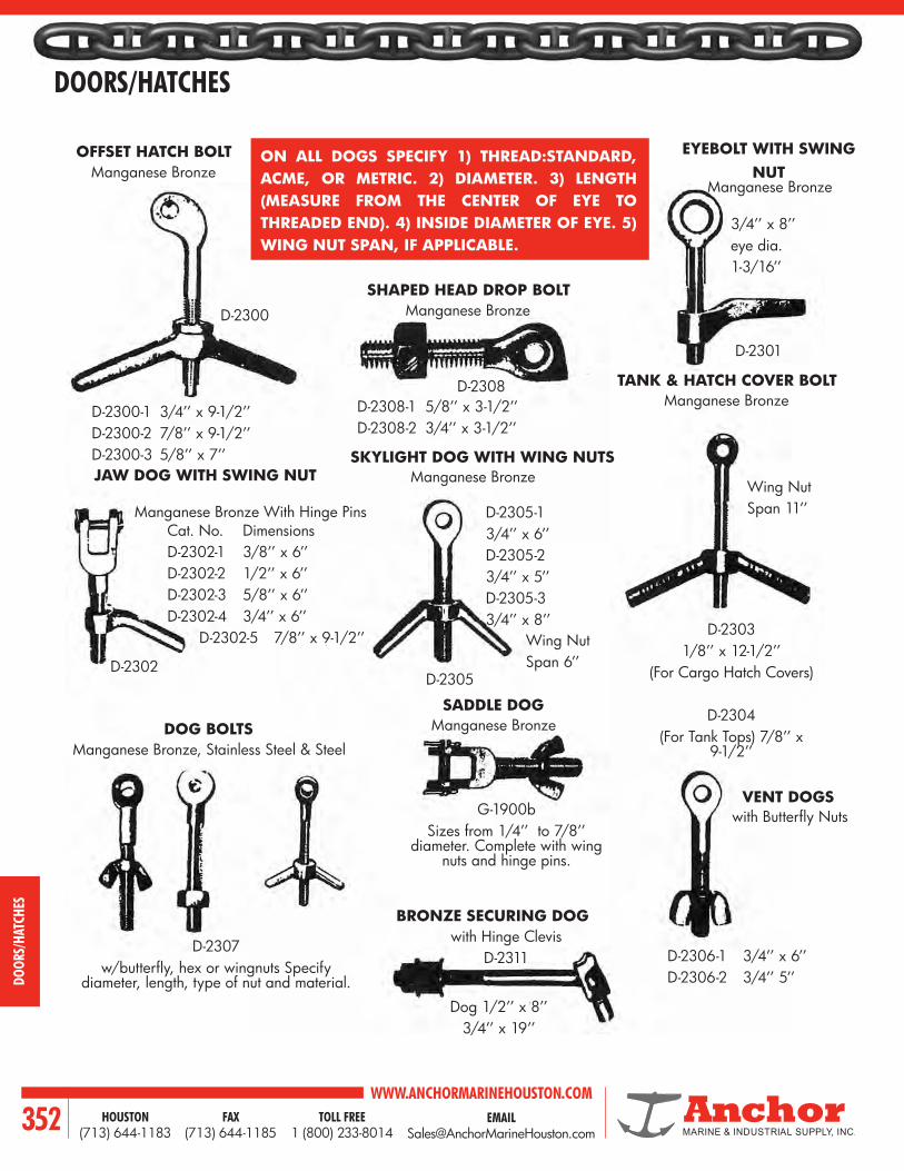
WWW.ANCHORMARINEHOUSTON.COMTOLL FREE
1 (800) 233-8014HOUSTON
(713) 644-1183FAX
(713) 644-1185352
DOORS/HATCHES
DOOR
S/HA
TCHE
S
ON ALL DOGS SPECIFY 1) THREAD:STANDARD, ACME, OR METRIC. 2) DIAMETER. 3) LENGTH (MEASURE FROM THE CENTER OF EYE TO THREADED END). 4) INSIDE DIAMETER OF EYE. 5) WING NUT SPAN, IF APPLICABLE.
OFFSET HATCH BOLT EYEBOLT WITH SWINGNUT
SHAPED HEAD DROP BOLT
JAW DOG WITH SWING NUTSKYLIGHT DOG WITH WING NUTS
TANK & HATCH COVER BOLT
DOG BOLTSSADDLE DOG
VENT DOGS
BRONZE SECURING DOG
Manganese BronzeManganese Bronze
Manganese Bronze
Manganese Bronze
Manganese Bronze
Manganese Bronze With Hinge Pins
Manganese Bronze, Stainless Steel & Steel
Manganese Bronze
with Butterfly Nuts
D-2300-1 3/4’’ x 9-1/2’’D-2300-2 7/8’’ x 9-1/2’’D-2300-3 5/8’’ x 7’’
D-2300
D-2308D-2308-1 5/8’’ x 3-1/2’’D-2308-2 3/4’’ x 3-1/2’’
3/4’’ x 8’’eye dia.1-3/16’’
Cat. No. DimensionsD-2302-1 3/8’’ x 6’’D-2302-2 1/2’’ x 6’’D-2302-3 5/8’’ x 6’’D-2302-4 3/4’’ x 6’’ D-2302-5 7/8’’ x 9-1/2’’
D-2302D-2305
D-2305-13/4’’ x 6’’D-2305-23/4’’ x 5’’D-2305-33/4’’ x 8’’
Wing NutSpan 6’’
Wing NutSpan 11’’
D-23031/8’’ x 12-1/2’’
(For Cargo Hatch Covers)
D-2304(For Tank Tops) 7/8’’ x
9-1/2’’
G-1900bSizes from 1/4’’ to 7/8’’
diameter. Complete with wing nuts and hinge pins.
D-2307w/butterfly, hex or wingnuts Specify
diameter, length, type of nut and material.
with Hinge ClevisD-2311
Dog 1/2’’ x 8’’3/4’’ x 19’’
D-2306-1 3/4’’ x 6’’D-2306-2 3/4’’ 5’’
D-2301

EMAIL [email protected]
WWW.ANCHORMARINEHOUSTON.COMTOLL FREE
1 (800) 233-8014HOUSTON
(713) 644-1183FAX
(713) 644-1185 353
DOORS/HATCHES
DOORS/HATCHES
VENT DOGS
WATERTIGHT DOOR DOGSSpecify Type Below: Right Hand, Left Hand or Neutral. Shaft Diameter ‘‘A’’, Shaft Length ‘‘B’’. Manganese
Bronze and Aluminum‘‘A’’ Dia.
‘‘B’’Length
WTD-3400Left, Right or Neutral
WTD-3401Neutral Only
WTD-3402Left, Right or Neutral
WTD-3403Left, Right or
Neutral
WTD-3404Neutral Only
WTD-3405Neutral Only
WTD-3406Neutral Only
WTD-3407Neutral Only
WTD-3408Neutral Only
WTD-3409Neutral Only
WTD-3410Neutral Only
WTD-3411Left, Right or Neutral
WTD-3412Neutral
WTD-3413Neutral
BRONZE DOOR WEDGESWATERTIGHTDOOR BUSHINGS Left or
Right
WTD-3402-8
WTD-3411Left, Right or
NeutralWTD-3405t WTD-3405u WTD-3405v WTD-3405w WTD-3405x WTD-3405y WTD-3405z
Leftor
Right

WWW.ANCHORMARINEHOUSTON.COMTOLL FREE
1 (800) 233-8014HOUSTON
(713) 644-1183FAX
(713) 644-1185354
DOORS/HATCHES
DOOR
S/HA
TCHE
S
WE PROUDLY SERVICE THE MARINE & OIL INDUSTRY WITH:
FABRICATION IN:• STEEL• ALUMINUM• STAINLESS
• SCUTTLES• HATCHES• SINGLE BOLT MANHOLES• INDIVIDUALLY DOGGED DOORS• QUICK ACTING DOORS• BOLTED PLATE MANHOLE• FIXED LIGHTS• PORTLIGHTS• LADDERS• PLATFORMS• HANDRAILS• STRUCTURAL FABRICATION

EMAIL [email protected]
WWW.ANCHORMARINEHOUSTON.COMTOLL FREE
1 (800) 233-8014HOUSTON
(713) 644-1183FAX
(713) 644-1185 355
BUOYS
BUOYS

WWW.ANCHORMARINEHOUSTON.COMTOLL FREE
1 (800) 233-8014HOUSTON
(713) 644-1183FAX
(713) 644-1185356
BUOYS
BUOY
S CYLINDRICAL TYPE BUOY
Dimensions: A=5’9” & B=12’0”Displacement of Seawater: 20,700 lbs.Total Buoyancy: 15,750 lbs.Total Liquid Capacity as container: 2,300 gallonsWeight: 4,950 lbs.Attachments: 1-3/4” mooring eyes top and bottomwooden rubbing strips 16” I.D. manways
TYPE 1 TYPE 2Dimensions: A=8’0” & B=14’0”Displacement of Seawater: 45,270 lbs.Total Buoyancy: 27,670 lbs.Total Liquid Capacity as container: 5,264 gallonsWeight: 8,960 lbs.Attachments: mooring eyes top and bottom wooden rubbing strips typical manways
A
B

EMAIL [email protected]
WWW.ANCHORMARINEHOUSTON.COMTOLL FREE
1 (800) 233-8014HOUSTON
(713) 644-1183FAX
(713) 644-1185 357
BUOYS
BUOYSPEG TOP BUOY
DIMENSIONS: 13’0” DIA. X 10’0” HIGHDISPLACEMENT OF SEAWATER: 48,100 LBS.TOTAL BUOYANCY: 35,300 LBS.WEIGHT: 12,800 LBS.ATTACHMENTS: WOODEN RUBBING STRIPS TYPICAL MANWAYS

WWW.ANCHORMARINEHOUSTON.COMTOLL FREE
1 (800) 233-8014HOUSTON
(713) 644-1183FAX
(713) 644-1185358
BUOYS
BUOY
S
SPHERICAL TYPE BUOY
30’’ 40’’ 58’’
Buoyancy 416 lbs. 987 lbs. 3,007 lbs.
Dry Weight 198 lbs. 312 lbs. 694 lbs.
Total Liquid Capacity 58 gal 140 gal 440 gal
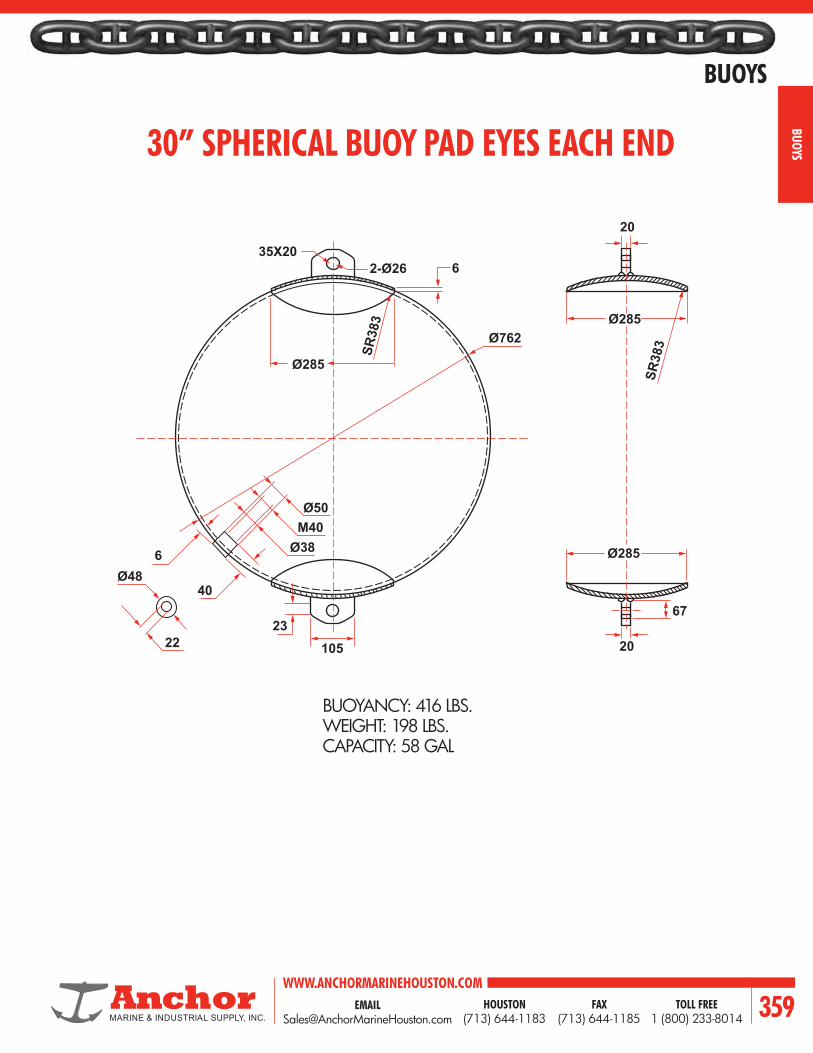
EMAIL [email protected]
WWW.ANCHORMARINEHOUSTON.COMTOLL FREE
1 (800) 233-8014HOUSTON
(713) 644-1183FAX
(713) 644-1185 359
BUOYS
BUOYS 30” SPHERICAL BUOY PAD EYES EACH END
BUOYANCY: 416 LBS.WEIGHT: 198 LBS.CAPACITY: 58 GAL
35X20
Ø762
2-Ø26
Ø285
Ø48
Ø38
105
Ø285
Ø285
SR38
3
67
20
20
23
Ø50M40
40
22
6
6
SR38
3

WWW.ANCHORMARINEHOUSTON.COMTOLL FREE
1 (800) 233-8014HOUSTON
(713) 644-1183FAX
(713) 644-1185360
BUOYS
BUOY
S 40” SPHERICAL BUOY PAD EYES EACH END
35X20
0762
2-Ø35
SØ1,016
Ø380
Ø48
Ø38
5
140
22
Ø380
Ø380
Ø380
SR51
0
87
25
25
Ø50M40
40
22
6
SR510
BUOYANCY: 987 LBS.WEIGHT: 312 LBS.CAPACITY: 140 GAL

EMAIL [email protected]
WWW.ANCHORMARINEHOUSTON.COMTOLL FREE
1 (800) 233-8014HOUSTON
(713) 644-1183FAX
(713) 644-1185 361
BUOYS
BUOYS58” SPHERICAL BUOY PAD EYES EACH END
BUOYANCY: 3007 LBS.WEIGHT: 679 LBS.CAPACITY: 440 GAL
R2019044
5
280
135
Ø48
Ø38
203
Ø51
Ø550
SØ1,49
3244
32
8
Ø50
SØ1,473M40
40
22
6

WWW.ANCHORMARINEHOUSTON.COMTOLL FREE
1 (800) 233-8014HOUSTON
(713) 644-1183FAX
(713) 644-1185362
BUOYS
BUOY
S 58” SPHERICAL BUOY WITH PIPE THROUGH
BUOYANCY: 3007 LBS.WEIGHT: 694 LBS.CAPACITY: 420 GAL
Ø50
54
8
Ø38
M40
SR746.5
SØ14732
Ø121
6
40
Ø48
22
Ø572

EMAIL [email protected]
WWW.ANCHORMARINEHOUSTON.COMTOLL FREE
1 (800) 233-8014HOUSTON
(713) 644-1183FAX
(713) 644-1185 363
BUOYS
BUOYSBAR RISER CHAIN TYPE MOORING BUOY
DIAMETER HEIGHT WEIGHT IN AIR NAVFAC DWG. NO.
9’-6’’ O.D. 5’-0’’ 7,700 lbs. 620659
10’-6’’ O.D. 6’-6’’ 9,600 lbs. 620659
10’-6’’ O.D. 7’-6’’ 10,100 lbs. 620659
Diameter
2-3/4”
2-3/4”
2-11/16”
2-3/8”R.
6”R.
6”R.2”R.
See Detail A
See Detail B
Hei
ght
DETAIL A DETAIL B

WWW.ANCHORMARINEHOUSTON.COMTOLL FREE
1 (800) 233-8014HOUSTON
(713) 644-1183FAX
(713) 644-1185364
BUOYS
BUOY
S CYLINDRICAL STEEL
MOORING BUOY SPECIFICATIONS
DESCRIPTION VOLUME(CUBIC FEET)
NETBUOYANCY(POUNDS)
SHIPPINGWEIGHT
(POUNDS)COMPARTMENTS
ADDITIONAL BUOYANCY
PER FOOT OF LENGTH (POUNDS)
5’ x 8’ x 1/4’’ Plate 157 7,300 2,600 two 1,030
7’ x 8’ x 3/4’’ Plate 308 13,600 5,600 two 2,000
7-1/2’ x 9-1/2’ x 3/8’’ Plate 419 19,300 6,800 two 2,300
8’ x 10’ x 3/8’’ Plate 502 22,800 8,500 three 2,600
10’ x 12’ x 3/8’’ Plate 942 45,300 13,500 three 4,500
10’ x 12’ x 1/2’’ Plate 942 42,000 16,800 three 4,100
10’ x 16’ x 3/8’’ Plate 1,257 59,000 17,750 three 5,800
10’ x 16’ x 1/2’’ Plate 1,257 56,000 20,750 three 5,500

EMAIL [email protected]
WWW.ANCHORMARINEHOUSTON.COMTOLL FREE
1 (800) 233-8014HOUSTON
(713) 644-1183FAX
(713) 644-1185 365
BUOYS
BUOYS
8’
4’ Dia.
8”
9”
18”
4” Sch. 80 Pipe
1”
18”
Flush Access Plug
DividerWatertight Compartment
4”
5/16”X6”O.D. Doubler
PENDANT LINE BUOYS
• 4’ dia. x 8’ long cylindrical buoys• Foam filled• Constructed of 5/16’’ plate• 2 Watertight compartments• Buoy to be sandblasted to white metal• 1 coat Dimetcote, 2 coats high build white epoxy.• Total buoyancy: 6400 lbs.• Total Weight: 2100 lbs.• Reserve buoyancy: 4300 lbs.
Other sizes available upon request.

WWW.ANCHORMARINEHOUSTON.COMTOLL FREE
1 (800) 233-8014HOUSTON
(713) 644-1183FAX
(713) 644-1185366
BUOYS
BUOY
S
DIAM.IN FEET
CIRCUMFERENCE AREA OF CIRCLE VOLUME OF CYLINDER PER FOOT OF HEIGHT DIAM.IN FEETFEET METERS SQ. FEET SQ. METERS U.S. GALS IMPERIAL GALS U.S. BBLS (42 GALS)
1 3.14 0.9576 0.785 .0730 5.9 4.9 0.140 12 6.28 1.9151 3.153 .2919 23.5 19.6 0.560 23 9.42 2.8727 7.069 .6567 52.9 44.0 1.259 34 12.57 3.8302 12.566 1.1675 94.0 78.3 2.238 45 15.71 4.7878 19.635 1.8241 146.9 122.3 3.497 56 18.85 5.7454 28.274 2.6268 211.5 176.1 5.04 67 21.99 6.7029 38.485 3.5753 287.9 239.7 6.85 78 25.13 7.6605 50.266 4.6698 376.0 313.1 8.95 89 28.27 8.6180 63.617 5.9102 475.9 396.3 11.33 910 31.42 9.5756 78.540 7.2966 587.5 489.2 13.99 1011 34.56 10.5331 95.033 8.8289 710.9 591.9 16.93 1112 37.70 11.4907 113.097 10.5071 846.0 704.5 20.14 1213 40.84 12.4482 132.732 12.3312 992.9 826.8 23.64 1314 43.98 13.4058 153.938 14.3013 1,151.5 958.9 27.42 1415 47.12 14.3634 176.715 16.4173 1,321.9 1,100.7 31.47 1516 50.27 15.3209 201.062 18.6793 1,504.0 1,252.4 35.81 1617 53.41 16.2785 226.980 21.0871 1,697.9 1,413.8 40.43 1718 56.55 17.2360 254.469 23.6409 1,903.6 1,585.1 45.32 1819 59.69 18.1936 283.529 26.3407 2,120.9 1,766.1 50.50 1920 62.83 19.1511 314.159 29.1864 2,350.1 1,956.9 55.95 2021 65.97 20.1087 346.361 32.1780 2,591.0 2,157.4 61.69 2122 69.12 21.0663 380.122 35.3155 2,843.6 2,367.8 67.70 2223 72.26 22.0238 415.476 38.5989 3,108.0 2,587.9 74.00 2324 75.40 22.9814 452.389 42.0283 3,384.1 2,817.9 80.57 2425 78.54 23.9389 490.874 45.6037 3,672.0 3,057.6 87.43 2526 81.68 24.8965 530.929 49.3249 3,971.6 3,307.1 94.56 2627 84.82 25.8541 572.555 53.1921 4,283.0 3,566.4 101.98 2728 87.97 26.8116 615.752 57.2052 4,606.1 3,835.4 109.67 2829 91.11 27.7692 660.520 61.3643 4,941.0 4,114.3 117.64 2930 94.25 28.7267 706.858 65.6693 5,287.7 4,402.9 125.90 3031 97.39 29.6843 754.768 70.1202 5,646.1 4,701.4 134.43 3132 100.53 30.6418 804.248 74.7171 6,016.2 5,009.6 143.24 3233 103.67 31.5994 855.299 79.4598 6,398.1 5,327.5 152.34 3334 106.81 32.5570 907.920 84.3486 6,791.7 5,655.3 161.71 3435 109.96 33.5145 962.113 89.3832 7,197.1 5,992.9 171.36 3536 113.10 34.4721 1,017.88 94.5638 7,614.2 6,340.2 181.29 3637 116.24 35.4269 1,075.21 99.8903 8,043.1 6,697.4 191.50 3738 119.38 36.3872 1,134.11 105.3627 8,483.8 7,064.3 201.99 3839 122.52 37.3447 1,194.59 110.9811 8,936.2 7,441.0 212.77 3940 125.66 38.3023 1,256.64 116.7454 9,400.3 7,827.4 223.82 4041 128.81 39.2599 1,320.25 122.6556 9,876.2 8,223.7 235.15 4142 131.95 40.2174 1,385.44 128.7118 10,363.8 8,629.7 246.76 4243 135.09 41.1750 1,452.20 134.9139 10,863.2 9,045.6 258.65 4344 138.23 42.1325 1,520.53 141.2619 11,374.4 9,471.2 270.82 44
CIRCUMFERENCE, AREA AND VOLUME OF CIRCLES AND CYLINDERS
NOTES:1.If diameters are assumed as meters, values in columns ‘‘Circumference Feet’’ and ‘‘Are of Circle Square Feet’’ will represent circumference in meters and area of circle in square meters respectively.2. If diameters are assumed as meters, values in column ‘‘Area of Circle Square Feet’’ will represent volume of cylinder in cubic meters per vertical meter of height. Formula to determine capacity per foot of vertical height of cylinder.
D = Diameter in Feet. 5.875185 D2 = U.S. Gallons per vertical foot. 0.022240 D2 = Cubic Meters per vertical foot. 0.1398854 D2 = Barrels of 42 U.S. Gallons per vertical foot. 4.892148 D2 = Imperial Gallons per vertical foot. 0.785398 D2 = aD = Diameter in Meters = Cubic meters per vertical meter.

EMAIL [email protected]
WWW.ANCHORMARINEHOUSTON.COMTOLL FREE
1 (800) 233-8014HOUSTON
(713) 644-1183FAX
(713) 644-1185 367
BUOYS
BUOYS
OCEAN GUARD™ RESILIENT FOAM FILLED BUOYSThe Ocean Guard™ Buoys resilient surfaces are constructed to withstand the toughest marine applications and environments the world can offer. The Ocean Guard™ Buoys constructed with the latest technology and materials exemplifies state-of-the-art technology in buoy design and functionality. Composite buoys are designed to absorb minor impacts without damaging the buoy body or vessel.
PERFORMANCE FEATURESUNSINKABLE CONSTRUCTIONThe Ocean Guard™ Buoys closed cell foam filled construction provides a buoy that is unsinkable even if it’s punctured.IMPACT ABSORBINGThe resilient outer foam layer and the reinforced elastomeric skin of the Ocean Guard™ Buoys are designed to absorb impacts of vessels without damaging the buoy or the impacting vessel.
SUPERIOR TO STEEL BUOYSThe Ocean Guard™ Buoys are designed and constructed to be lighter, more corrosion resistant, less maintenance and easier to handle than conventional steel buoys. The abrasion resistant urethane skin will resist the harshest environments without corroding.
NON MARKINGThe tough, thick, reinforced elastomeric urethane skin of Ocean Guard™ Buoys is non marking and available in different colors and will not wear off.
CUSTOM DESIGNSEngineers work closely with the customer to select or custom design an Ocean Guard™ Buoy to meet their specific requirements and needs.END FITTINGS
Ocean Guard™ Buoys end fittings are available in a variety of styles including mooring tees, padeyes, quick release hooks, swivel eyes, bails, forged eyes, hawse pipe with capture plates and navigational lights.

WWW.ANCHORMARINEHOUSTON.COMTOLL FREE
1 (800) 233-8014HOUSTON
(713) 644-1183FAX
(713) 644-1185368
BUOYS
BUOY
S
INTERNAL STEEL CENTRAL STRENGTH MEMBERSThe Ocean Guard™ Buoy’s construction begins with an Ultra heavy duty internal steel central strength member which provides excellent working load performance. The welded steel structure contains load distribution plates which provide outstanding pull through performance.
RIGID INNER CLOSED CELL URETHANE FOAM COREThe second layer in Ocean Guard™ Buoy construction consists of a US Coast Guard compliant rigid inner 100% closed cell urethane foam core. This strong foam core has excellent buoyancy and compression strength properties. The foam is molded directly onto the internal Steel Central Strength Member which provides an unsinkable buoy.
Ultra heavy duty central steel core load distribution construction
US Coast Guard approved inner closed cell rigid urethane buoyancy foam
Impact absorbing, resilient heat laminated cross-linked polyethylene foam core foam
Thick, tough filament nylon tire cord reinforced urethane skin
RESILIENT OUTER FOAM COREThe third layer in Ocean Guard™ Buoy construction consists of an impact absorbing closed cell cross-linked polyethylene foam core. The same heat lamination process used in our Ocean Guard™ fenders, produces a thermal bond between the layers of foam which is stronger than the foam itself which, will not delaminate even under the most abusive berthing conditions. This impact absorbing foam core is added to absorb vessel impacts without damaging the buoy or the impacting vessel.
REINFORCED ELASTOMERIC SKINThe final layer, impact absorbing foam core is protected by a tough thick filament nylon tire cord reinforced elastomer skin. This non-marking reinforced elastomer fender skin is the wear surface of the fender. The reinforcing filaments are continuously wound in a helix pattern through up to 90% of the elastomer skin and wrap around the buoys end fittings. This continuous reinforcement of the elastomer skin not only increases the tensile and tear strength of the elastomer but also distributes loads throughout the fender skin.
This tough resilient material is specially formulated to withstand the world’s harshest environmental conditions providing superior performance in extreme temperatures, toxic environments, against hydrocarbons, salt water, ozone and ultraviolet radiation.
CONSTRUCTION FEATURES

EMAIL [email protected]
WWW.ANCHORMARINEHOUSTON.COMTOLL FREE
1 (800) 233-8014HOUSTON
(713) 644-1183FAX
(713) 644-1185 369
BUOYS
BUOYS
BUOYMODEL
BUOYANCYNET
BUOYWEIGHT
DIAMETEROVERALL
HEIGHTBUOY BODY
HEIGHTOVERALL WORKING LOAD
LBS KG LBS KG FT M FT M FT M LBS TONSMB-25 5,512 2,500 1,756 797 6.1 1.9 3.6 1.1 7.6 2.3 100,000 45MB-35 7,716 3,500 2,340 1,061 7.0 2.1 4.3 1.3 8.5 2.6 150,000 68MB-50 11,023 5,000 2,371 1,075 7.5 2.3 4.9 1.5 8.6 2.6 150,000 68MB-70 15,432 7,000 2,938 1,333 8.5 2.6 5.0 1.5 8.6 2.6 200,000 91MB-90 19,842 9,000 4,657 2,112 10 3.0 5 1.5 8.6 2.6 200,000 91MB-115 25,353 11,500 5,109 2,317 10 3.0 6.1 1.9 9.5 2.9 200,000 91MB-135 29,762 13,500 6,017 2,729 10.5 3.2 6.5 2.0 10.0 3.0 300,000 136MB-160 35,274 16,000 6,333 2,873 11 3.4 6.8 2.1 11.75 3.6 300,000 136MB-185 40,785 18,500 6,836 3,101 11.1 3.4 7.8 2.4 12.7 3.9 300,000 136MB-225 49,604 22,500 8,491 3,852 12.0 3.7 8.1 2.5 12.9 3.9 300,000 136MB-250 55,116 25,000 9,469 4,295 12.5 3.8 8.3 2.5 13.1 4.0 300,000 136MB-275 60,627 27,500 9,965 4,520 12.6 3.8 8.9 2.7 13.7 4.2 300,000 136MB-340 74,957 34,000 11,841 5,371 13.83 4.2 9 2.7 13.8 4.2 300,000 136MB-455 100,310 45,500 14,599 6,622 15 4.6 10 3.0 14.8 4.5 300,000 136
BUOYMODEL
BUOYANCYNET
BUOYWEIGHT
DIAMETEROVERALL
HEIGHTOVERALL WORKING LOAD
LBS KG LBS KG FT M FT M LBS TONSSB-25 551 250 158 72 2.6 0.8 2.6 0.8 22,000 10SB-50 1,102 500 285 129 3.2 1.0 3.2 1.0 22,000 10SB-75 1,653 750 390 177 3.5 1.1 3.5 1.1 22,000 10SB-100 2,205 1,000 475 215 3.8 1.2 3.8 1.2 40,000 18SB-125 2,756 1,250 537 244 4.1 1.2 4.1 1.2 40,000 18SB-150 3,307 1,500 584 265 4.3 1.3 4.3 1.3 40,000 18SB-175 3,858 1,750 687 312 4.6 1.4 4.6 1.4 40,000 18SB-200 4,409 2,000 819 371 4.8 1.5 4.8 1.5 40,000 18SB-250 5,511 2,500 931 422 5.2 1.6 5.2 1.6 40,000 18SB-300 6,614 3,000 1,200 544 5.5 1.7 5.5 1.7 45,000 20SB-350 7,716 3,500 1,300 590 5.8 1.8 5.8 1.8 45,000 20SB-400 8,818 4,000 1,612 731 6.0 1.8 6.0 1.8 45,000 20SB-450 9,921 4,500 1,712 777 6.2 1.9 6.2 1.9 45,000 20SB-500 11,023 5,000 1,945 882 6.4 2.0 6.4 2.0 45,000 20SB-600 13,228 6,000 2,302 1,044 6.8 2.1 6.8 2.1 45,000 20SB-700 15,432 7,000 2,500 1,134 7.2 2.2 7.2 2.2 45,000 20
BUOYMODEL
BUOYANCYNET
BUOYWEIGHT
DIAMETEROVERALL BUOY HEIGHT
HEIGHTOVERALL WORKING LOAD
LBS KG LBS KG FT M FT M FT M LBS TONSCB-5 110 50 55 25 1.3 0.4 2 0.6 2.8 0.9 5,000 2.3CB-10 220 100 79 36 1.5 0.5 2.8 0.8 3.6 1.1 5,000 2.3CB-15 331 150 93 42 1.7 0.5 3.0 0.9 3.8 1.2 5,000 2.3CB-25 551 250 160 73 2.2 0.7 3.1 0.9 4.0 1.2 7,500 3.4CB-45 992 450 222 101 2.5 0.8 4.0 1.2 5.1 1.5 10,000 4.5CB-70 1,543 700 340 154 3.0 0.9 4.2 1.3 5.3 1.6 10,000 4.5CB-100 2,205 1,000 439 199 3.3 1.0 5 1.5 6.33 1.9 20,000 9.1CB-115 2,535 1,150 539 244 3.5 1.1 5.0 1.5 6.3 1.9 20,000 9.1CB-140 3,086 1,400 606 275 3.5 1.1 6.0 1.8 7.3 2.2 20,000 9.1CB-180 3,968 1,800 704 319 4.0 1.2 5.8 1.8 7.4 2.3 40,000 18.0CB-230 5,071 2,300 868 394 4.5 1.4 5.9 1.8 7.5 2.3 40,000 18.0CB-275 6,063 2,750 973 441 4.5 1.4 7.0 2.1 8.6 2.6 40,000 18.0
OCEAN GUARD MOORING BUOYS
* Actual values for above sizes may vary +/- 15% due to variations in materials and tolerances.
OCEAN GUARD SUPPORT BUOYS
* Actual values for above sizes may vary +/- 15% due to variations in materials and tolerances.
OCEAN GUARD UTILITY CYLINDRICAL BUOYS
* Actual values for above sizes may vary +/- 15% due to variations in materials and tolerances.

WWW.ANCHORMARINEHOUSTON.COMTOLL FREE
1 (800) 233-8014HOUSTON
(713) 644-1183FAX
(713) 644-1185370
BUOYS
BUOY
S BUOYMODEL
BUOYANCYNET
BUOYWEIGHT
DIAMETEROVERALL
BUOYLENGTH
HEIGHTOVERALL WORKING LOAD
LBS KG LBS KG FT M FT M FT M LBS TONSPB-25 5,511 2,500 1,223 555 4.5 1.4 6.8 2.1 7.3 2.2 150,000 68PB-50 11,023 5,000 2,123 963 6.0 1.8 7.2 2.2 8.7 2.7 150,000 68PB-75 16,534 7,500 3,184 1,444 6.5 2.0 9.2 2.8 9.2 2.8 150,000 68PB-100 22,046 10,000 2,735 1,241 6.5 2.0 11.0 3.4 9.3 2.8 150,000 68PB-150 33,069 15,000 4,020 1,823 8.0 2.4 11.5 3.5 10.9 3.3 150,000 68PB-200 44,092 20,000 4,922 2,233 8.5 2.6 13.5 4.1 11.5 3.5 200,000 91PB-250 55,115 25,000 5,827 2,643 9.0 2.7 15.0 4.6 11.8 3.6 200,000 91PB-300 66,138 30,000 6,688 3,034 9.5 2.9 16.0 4.9 12.8 3.9 200,000 91PB-350 77,160 35,000 10,581 4,800 10.3 3.1 16.8 5.1 14.5 4.4 250,000 114PB-400 88,183 40,000 11,449 5,193 10.5 3.2 18.0 5.5 16.3 5.0 250,000 114
BUOYMODEL
BUOYANCYNET
NUMBEROF MODULES
DIAMETEROVERALL
THROUGHPIPE DIAMETER
LBS KG FT M IN MMMAPB2-4 8,818 4,000 2 6.6 2.0 6.0 152MAPB4-8 17,637 8,000 4 6.6 2.0 6.0 152MAPB2-8 17,637 8,000 2 7.5 2.3 6.0 152MAPB4-16 35,273 16,000 4 7.5 2.3 6.0 152MAPB2-11 24,250 11,000 2 9.8 3.0 8.0 203MAPB4-22 48,501 22,000 4 9.8 3.0 8.0 203MAPB2-17 37,478 17,000 2 10.5 3.2 10.0 254MAPB4-34 74,956 34,000 4 10.5 3.2 10.0 254MAPB2-23 50,705 23,000 2 10.5 3.2 10.0 254MAPB4-46 101,411 46,000 4 10.5 3.2 10.0 254
BUOYMODEL
BUOYANCYNET
FLOTATIONWEIGHT
TOTALWEIGHT
DIAMETEROVERALL
DIAMETERINTERNAL
FLOTATIONHEIGHT
TOWERHEIGHT
LBS KG LBS KG LBS KG FT M FT M FT M FT MOG-10 2,205 1,000 60 27 513 233 5.4 1.6 2.2 0.7 2.3 0.7 5.6 1.7OG-15 3,307 1,500 72 33 606 275 6.1 1.9 2.3 0.7 2.4 0.7 5.6 1.7OG-20 4,409 2,000 99 45 752 341 6.5 2.0 2.5 0.8 2.6 0.8 6.1 1.9
ATALAS-3 5,000 2,268 130 59 1,200 544 7.4 2.3 3.2 1.0 3.2 1.0 7.0 2.1
BUOYMODEL
BUOYANCYNET
BUOYWEIGHT
BUOYDIAMETER
BUOY BODYHEIGHT
LBS KG LBS KG FT M FT MNAV-100 221 100 194 88 3.0 0.9 2.3 0.7NAV-200 441 200 399 181 3.8 1.2 3.0 0.9NAV-500 1,103 500 650 295 4.9 1.5 3.0 0.9NAV-750 1,654 750 981 445 6.7 2.0 3.3 1.0
NAV-1000 2,205 1,000 1,816 824 8.5 2.6 4.2 1.3NAV-3000 6,615 3,000 3,112 1,412 10.0 3.0 4.5 1.4NAV-5000 11.025 5,000 4,462 2,024 10.2 3.1 6.0 1.8NAV-7500 16,538 7,500 6,703 3,040 11.8 3.6 6.6 2.0
NAV-10000 22,050 10,000 7,845 3,558 13.2 4.0 6.0 1.8
OCEAN GUARD PENDANT BUOYS
* Actual values for above sizes may vary +/- 15% due to variations in materials and tolerances.
OCEAN GUARD MODULAR ANCHOR PENDANT BUOYS
* Actual values for above sizes may vary +/- 15% due to variations in materials and tolerances.
OCEAN GUARD OCEANOGRAPHIC BUOYS
* Actual values for above sizes may vary +/- 15% due to variations in materials and tolerances.
OCEAN GUARD NAVIGATIONAL AND MARKER BUOYS
* Actual values for above sizes may vary +/- 15% due to variations in materials and tolerances.

EMAIL [email protected]
WWW.ANCHORMARINEHOUSTON.COMTOLL FREE
1 (800) 233-8014HOUSTON
(713) 644-1183FAX
(713) 644-1185 371
BUOYS
BUOYS
BUOYMODEL
NETBUOYANCY
BUOYWEIGHT
BODYDIAMETER
BODYLENGTH
OVERALLLENGTH
THROUGHPIPE DIAMETER
LB KG LB KG FT M FT M FT M IN MMCTB-100 2,205 1000 1,170 570 3.6 1.1 5.8 1.7 7.0 2.1 13.0 330CTB-150 3,307 1,500 1,345 610 4.1 1.3 5.9 1.7 7.1 2.1 13.0 330CTB-200 4,409 2,000 1,488 675 4.5 1.4 6.2 1.9 7.7 2.4 13.0 330CTB-225 4,960 2,250 1,842 777 4.9 1.5 6.0 2.0 7.5 2.4 15.0 381CTB-275 6,063 2,750 2,023 840 5.1 1.6 6.6 2.1 8.0 2.6 15.0 381CTB-350 7,716 3,500 2,698 1,060 5.1 1.6 8.6 2.9 10.0 3.4 17.0 432CTB-400 8,818 4,000 2,791 1,159 5.3 1.7 9.0 2.6 10.3 3.1 17.0 432CTB-450 9,921 4,500 3,076 1,395 5.5 1.8 9.2 2.6 10.5 3.1 19.0 483CTB-550 12,125 5,500 3,440 1,560 5.8 1.8 9.8 3.2 11.0 3.7 19.0 483
BUOYMODEL
BUOYANCYNET
BUOYWEIGHT
BUOY DIMENSIONS WORKINGLOADLENGTH HEIGHT WIDTH OVERALL
HEIGHTLBS KG LBS KG FT M FT M FT M FT M LBS. TONS
RPB-10 2,200 1000 408 185 3.0 0.9 5.0 1.5 3.0 0.9 7.3 2.2 150,000 68RPB-20 4,400 2000 817 371 3.6 1.1 5.0 1.5 5.0 1.5 7.3 2.2 150,000 68RPB-40 8,800 4000 1,470 667 4.5 1.4 6.0 1.8 6.0 1.8 9.9 3.0 150,000 68RPB-60 13,200 6000 3,060 1,388 5.0 1.5 7.0 2.1 8.5 2.6 10.9 3.3 150,000 68RPB-80 17,600 8000 3,514 1,594 5.4 1.6 7.5 2.3 8.5 2.6 11.4 3.5 150,000 68RPB-100 22,000 10000 4,312 1,956 6.0 1.8 9.0 2.7 8.1 2.5 12.6 3.8 150,000 68RPB-120 26,400 12000 4,641 2,105 6.5 2.0 9.5 2.9 8.4 2.6 13.4 4.1 150,000 68RPB-140 30,800 14000 5,835 2,647 6.5 2.0 10.5 3.2 9.0 2.7 14.8 4.5 200,000 91RPB-160 35,200 16000 6,442 2,922 6.5 2.0 10.5 3.2 10.5 3.2 14.6 4.5 200,000 91RPB-180 39,600 18000 7,195 3,264 6.5 2.0 11.5 3.5 11.0 3.4 15.6 4.8 200,000 91RPB-200 44,000 20000 7,533 3,417 8.0 2.4 11.0 3.4 10.7 3.3 14.8 4.5 200,000 91RPB-250 55,000 25000 8,427 3,822 8.5 2.6 12.6 3.8 10.8 3.3 16.5 5.0 200,000 91RPB-300 66,000 30000 9,918 4,499 8.5 2.6 14.4 4.4 11.1 3.4 18.2 5.5 200,000 91
BUOYMODEL
NET BUOYANCY (MIN) BUOY WEIGHT BODY DIAMETER BODY HEIGHT OVERALL
HEIGHTLBS KG LBS KG FT M FT M FT M
UB-1500 1,500 680 710 322 4.2 1.3 2.5 0.8 4.3 1.3UB-2000 2,000 907 801 363 4.2 1.3 3.3 1.0 5.5 1.7UB-2500 2,500 1,134 689 313 5.0 1.5 2.9 0.9 5.0 1.5UB-3000 3,000 1,361 929 421 5.0 1.5 3.3 1.0 5.5 1.7UB-4000 4,000 1,814 1,488 675 6.0 1.8 3.3 1.0 5.5 1.7UB-5000 5,000 2,268 1,570 712 6.0 1.8 3.8 1.1 6.0 1.8
Bail Eye Pad Eye Pick-Up Tee Swivel Eye
UNIVERSAL BUOY END FITTINGS
OCEAN GUARD CHAIN THROUGH BUOYS
OCEAN GUARD RECTANGULAR ANCHOR PENDANT BUOYS
* Actual values for above sizes may vary +/- 15% due to variations in materials and tolerances.
* Actual values for above sizes may vary +/- 15% due to variations in materials and tolerances.
* Actual values for above sizes may vary +/- 15% due to variations in materials and tolerances.
OCEAN GUARD UNIVERSAL BUOYS

WWW.ANCHORMARINEHOUSTON.COMTOLL FREE
1 (800) 233-8014HOUSTON
(713) 644-1183FAX
(713) 644-1185372
BUOYS
BUOY
S
PROJECT DETAILS PROJECT STATUS PROJECT NAME MFI REF
LOCATION PRELIMINARY
CONSULTANT DETAIL DESIGN
CONTRACTOR TENDER
NAME POSITION TELEPHONE E-MAIL
OPERATIONAL DETAILS VESSEL TYPE VESSEL SIZE
LOCATION EXPOSED SHELTERED DURATION TEMPORARY PERMANENT
WATER DEPTH
TIDAL LEVEL (H.W.L.)
TIDAL LEVEL (L.W.L.)
BOTTOM MATERIAL MUD SAND ROCK
OPERATING TEMPERATURE MAX F C MIN F C
BUOY DETAILS NET BUOYANCY MIN MAX FREEBOARD MIN MAX
PULL-THROUGH CAPACITY WORKING LOAD
BUOY END FITTINGS TOP BOTTOM FORGED SWIVEL EYE
FABRICATED SWIVEL EYE
PADEYE
QUICK RELEASE HOOK
BAIL EYE
CRUCIFIX
HAWSE PIPE
HAWSE PIPE (WITH CAPTURE PLATE)
LIGHTS (TYPE)
BUOY REQUIREMENTS
MOORING BUOY MOORING BUOY-PEG BOTTOM PENDANT BUOY RECTANGULAR ANCHORPENDANT BUOY
MODULAR ANCHORPENDANT BUOY
SUPPORT BUOY CYLINDRICAL BUOY CHAIN THROUGH BUOY
NAVIGATIONAL BUOY MARKER BUOY OTHERRECTANGULAR CHAINTHROUGH BUOY

EMAIL [email protected]
WWW.ANCHORMARINEHOUSTON.COMTOLL FREE
1 (800) 233-8014HOUSTON
(713) 644-1183FAX
(713) 644-1185 373
BUOYS
BUOYS
Shown on the right is a typicalmooring system. However,individual components may beadded, deleted or rearranged to accomodate your specialrequirements. Applicationassistance is avaialable uponrequest.
BUOY
ANCHOR SHACKLE
SWIVEL
JOINING PIECE
JOINING SHACKLE
ANCHOR
ANCHOR SHACKLE
ANCHOR SHACKLE
RISER CHAIN
MAIN CHAIN
GROUND CHAIN
JOINING SHACKLE
MOORING SYSTEMS AND BUOYS

WWW.ANCHORMARINEHOUSTON.COMTOLL FREE
1 (800) 233-8014HOUSTON
(713) 644-1183FAX
(713) 644-1185374
BUOYS
BUOY
S
Shown on the right is a another typical mooring system. Again, individual components may be added, deleted or rearranged to accommodate your special requirements. Application assistance is available upon request.
HARP SHACKLE
MOORING SYSTEMS AND FITTINGS
BUOY
RUBBING CASTING
MAIN CHAIN
SWIVEL
LONG SHACKLE
SINKER
GROUND CHAIN
MOORING RING
JOINING SHACKLE
ANCHOR
MOORING SYSTEM COMPONENTS
ANCHORS ANCHOR CHAIN CONNECTING
LINK
ANCHOR
CONNECTING
LINK
CHAIN SWIVELS BOLT PIN ANCHOR
SHACKLEBOLT PIN CHAIN
SHACKLEWIRE
ROPE
FLOUNDER
PLATE

EMAIL [email protected]
WWW.ANCHORMARINEHOUSTON.COMTOLL FREE
1 (800) 233-8014HOUSTON
(713) 644-1183FAX
(713) 644-1185 375
BUOYS
BUOYS
FLOATS - UTILITY AND BARRIER• Foam filled and ultraviolet inhibited. -- COLORS: Orange or White• Yellow available on special order.• Sturdy ABS hull. Models 1830 are one piece high density
polyethylene.• Reflective bands available.
Barrier Floats are attached in series to restrictboating traffic or swimmers from specific danger areas such as around dams and spillways or anywhere that hazardous conditions exist.
UTILITYFLOATS
FOR SWIM AREASAND GENERAL
DIA. ANDLENGTH
DESCRIPTION - STANDARD COLORS ARE INTENTIONALORANGE AND WHITE - PLAIN SOLID COLOR (SPECIFY WHEN ORDERING)
SUBBUOYANCY NET WT.
B1130-AWB1130-AO
B1130-BWB1130-BO
12’’Sphere
A - 3/8’’ Dia. galvanized steel rod thru float with steel reinforcing washerson both ends. Large 3’’ dia. attachment hoop.
B - 1/2’’ Sch. 40 PVC pipe thru float. Anchored in foam to prevent movement.
30 lbs. 3 lbs.
BARRIERFLOATS
Combine with buoysin barrier systems
B1218-AWB1218-AD
B1218-BWB1218-BO
12’’ Dia.
18’’Length
A - 1/2’’ Dia. galvanized steel rod thru float. Galvanized eye nut swivelson both ends.
B - 1/2’’ Sch. 40 PVC pipe thru float. Anchored in foam to preventmovement.
55 lbs. 8 lbs.
B1830-AWB1830-AO
B1830-BWB1830-BO
B1830-CWB1830-CO
18’’ Dia.
30’’Length
A - 5/8’’ Dia. steel rod thru float. Galvanized swivel eye nuts on both ends.
B - 1’’ Sch. 40 galvanized steel pipe thru float. Anchored in foam toprevent movement.
C - 5/8’’ Dia. steel rods thru float and also across dia. in center. Eye nutswivels on both ends of float and lower center rod. Extended rod at
center-top for pick up eye.
200 lbs.
19 lbs.
19 lbs.
23 lbs.
B2436-AWB2436-AO
B2436-BWB2436-BO
B2436-CWB2436-CO
24’’ Dia.
36’’Length
A - 3/4’’ Dia. steel rod thru float. Galvanized eye nuts swivels on both ends.
B - 1’’ Sch. 40 galvanized steel pipe thru float. Anchored in foam toprevent movement.
C - 3/4’’ Dia. steel rods thru float and also across dia. at center. Eye nutswivels on both ends of float and lower center rod. Extender rod at
center-top for pick up eye.
400 lbs.
46 lbs.
46 lbs.
53 lbs.
B2400-AWB2400-AO
B2400-BWB2400-BO
24’’ Dia.
A - 1/2’’ Dia. galvanized steel rod thru float. with steel reinforcing washersboth ends. Large 3’’ dia. hoop. Completely foam filled.
B - 1’’ dia. galvanized steel pipe thru float. Anchored in foam to preventmovement.
240 lbs. 23 lbs.
B509-RWB509-BW
B139-3
B139-2
ROPE FLOATS
FLOAT CLIP
ROPE
2-1/2’’Dia.
5’’Length
3/8’’
3/8’’ Dia.
Plastic floats with 7/16’’ Dia. hole thru. Choice of red and white or blue andwhite.
Use with rope floats.
White polypropylene rope (use with rope floats). 600 Ft Reel
12 lbs.
.01 lbs.
16 lbs.
NOTE: Last letter of Model number indicated color (W-White, O-Orange)

WWW.ANCHORMARINEHOUSTON.COMTOLL FREE
1 (800) 233-8014HOUSTON
(713) 644-1183FAX
(713) 644-1185376
BUOYS
BUOY
S LARGE LIGHT-READY BUOYS AND CHANNEL MARKERS
• Internal radar reflectors• Non-standard messages• Agency and name identification• Hi-intenisty bands and symbols• Black and white or red and white
centerline markers
OPTIONS
FEATURES
• Easy reconditioning of weather-worn buoys with excellent adhesion of restoration materials.
• Excellent stability and visibility• Tough ABS exteriors• Completely urethane foam filled• Ultraviolet inhibited• Photo electric cell operated
ModelB2460L*B2460LG
ModelB1428NSWL
ModelB2460L*B2460LG
ModelB2460L*B2460LG
24’’ 14’’ Can diameter 14’’ 14’’
60’’ 30’’ Can height 30’’ 30’’
- 28’’ Float collar diameter 28’’ 28’’
116’’ 54’’ Overall height 96’’ 54’’
48’’ 42’’ Exp. w/light & batgteries 37’’ 42’’
59’’ 10’’ Draft 51’’ 7’’
780 lbs. 310 lbs. Submerged buoyancy 310 lbs. 280 lbs.
240 lbs. 117 lbs. Net Weight 135 lbs. 115 lbs.
330 lbs. 135 lbs. Shippine weight 145 lbs. 135 lbs.
Lights not included. Order separately.*Standard bands, symbols and messages included.
DraftBallast
ModelB2460L
ModelB2460LG
Model B1428NSWLSolid red nun buoy
Draft
Ballast
ModelB1428L
ModelB1428LG
ModelB1428SWL
ModelB1428SWLG
Internal ballast types are ideal for still, shallow anddeep water.
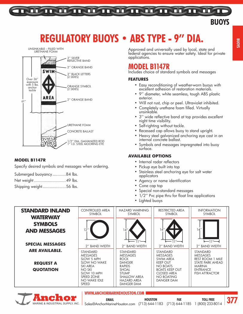
EMAIL [email protected]
WWW.ANCHORMARINEHOUSTON.COMTOLL FREE
1 (800) 233-8014HOUSTON
(713) 644-1183FAX
(713) 644-1185 377
BUOYS
BUOYS
REGULATORY BUOYS • ABS TYPE - 9’’ DIA.
FEATURES• Easy reconditioning of weather-worn buoys with
excellent adhesion of restoration materials.• 9’’ diameter, white seamless, tough ABS plastic
exterior.• Will not rust, chip or peel. Ultraviolet inhibited.• Completely urethane foam filled. Virtually
unsinkable.• 3’’ wide reflective band at top provides excellent
night time visibility.• Self-righting without tackle.• Recessed cap allows buoy to stand upright.• Heavy steel galvanized anchoring eye cast in an
internal concrete ballast.• Symbols and messages impregnated into buoy
surface.
AVAILABLE OPTIONS• Internal radar reflectors• Pickup eye built into top• Stainless steel anchoring eye for salt water
applicators• Agency or name identification• Cone cap top• Special non-standard messages• 1/2’’ Pvc pipe thru for float line applications• Lighted buoys
MODEL B1147RIncludes choice of standard symbols and messages
Approved and universally used by local, state and federal agencies to ensure water safety. Ideal for private applications.
MODEL B1147RSpecify desired symbols and messages when ordering.
Submerged buoyancy ...........84 lbs.Net weight ..........................49 lbs.Shipping weight ...................56 lbs.
STANDARD INLANDWATERWAYSYMBOLS
AND MESSAGES
SPECIAL MESSAGESARE AVAILABLE.
REQUEST AQUOTATION
CONTROLLED AREASYMBOL
HAZARD WARNINGSYMBOL
RESTRICTED AREASYMBOL
INFORMATIONSYMBOL
STANDARD MESSAGESSLOW 5 MPHSLOW NO WAKESKI AREANO SKISLOW 10 MPHSPEED ZONENO WAKE IDLE SPEED
STANDARD MESSAGESROCKDANGERRAPIDSSHOALSTUMPSHALLOW AREAHAZARD AREADANGER DAM
STANDARD MESSAGESSWIM AREA KEEP OUTNO BOATSBOATS KEEP OUTCLOSED AREANO BOATINGDANGER DAM
STANDARD MESSAGESREST ROOM 1 MILESTATE PARK AHEADMARINA ENTRANCEFISH ATTRACTOR
12’’
2’’ BAND WIDTH
14’’
2’’ BAND WIDTH11’’
14’’
2’’ BAND WIDTH11’’
14’’
2’’ BAND WIDTH11’’
UNSINKABLE -- FILLED WITH URETHANE FOAM
3’’ SILVERREFLECTIVE BAND
2’’ ORANGE BAND
3’’ BLACK LETTERS(2 SIDES)
ORANGE SYMBOL(2 SIDES)
2’’ ORANGE BAND
URETHANE FOAM
CONCRETE BALLAST
1/2’’ DIA. GALVANIZED ROD1’’ I.D. STEEL MOORING EYE
Over 36’’exposurewith 5 lbs.
anchortackle
61’’

WWW.ANCHORMARINEHOUSTON.COMTOLL FREE
1 (800) 233-8014HOUSTON
(713) 644-1183FAX
(713) 644-1185378
BUOYS
BUOY
S
SPAR BUOY • ABS TYPE - 5’’ DIA.
CONTROLLEDAREA
HAZARDWARNING
RESTRICTEDAREA INFORMATION
7’’ 9’’
7’’
9’’
7’’
9’’
7’’
FEATURES• Easy reconditioning of weather-worn buoys with excellent adhesion of
restoration materials.• 5’’ diameter, white, seamless, tough ABS plastic exterior. Ultraviolet inhibited,
will not rust, chip or peel.• Urethane foam filled. Virtually unsinkable.• 3’’ wide reflective band at top provides excellent night visibility.• Self-righting without tackle.• Recessed cap allows buoy to stand upright.• Heavy steel galvenized anchoring eye cast in an internal concrete ballast.• In waterway making symbols with standard messages.
AVAILABLE OPTIONS:• Internal radar reflectors• Stainless steel anchoring eye for salt water applicators• Special non-standard messages• Agency or name identification
LIGHTWEIGHT, EASY TO HANDLE - MINIMUM ANCHOR WEIGHT ALLOWS EASY REMOVAL.
STANDARDSYMBOLS*
*Sized for 5’’ Spar Buoys
MODEL B576SStandard symbols and messages included in price. Specify desired symbols and messages when ordering.
Submerged buoyancy .........................30 lbs.Net weight ........................................24 lbs.Shipping weight .................................28 lbs.
3’’ ORANGEREFLECTIVEBAND
2’’ VERTICALBLACK LETTERS(2 SIDES)
ORANGE SYMBOL(2 SIDES)
2’’ ORANGEBAND
URETHANEFOAM FILLED
CONCRETEBALLAST
1/2’’ DIA. 1’’ I.D.GALVANIZED STEELMOORING EYE
36’’EXPOSURE
WITH 5 LBS.ANCHORTACKLE
76’’
• Easy to recondition when necessary.
• Excellent adhesion of reconditioning materials.
• Excellent visibility.• 12’’ diameter white ABS plastic
exterior will not rust, chip or peel.• Ultraviolet inhibited.• Completely urethane foam filled.• 2’’ orange reflective band at top
and bottom provides excellent night time visibility.
• 3/8’’ glavanized attachment eyebolt.
• Choice of inland waterway marking symbols and standard messages. (2 sets).
• Special non-standard messages avaialble.
• Cable and attaching hardware available.
MODEL B1226Net weight ............. 12 lbs.Shipping weight ...... 18 lbs.
NOTE: The design and selection of a mooring system should be by a qualified professional engineer who is familiar with the specific application and local conditions. The illustrations shown are provided for informational purposes and are not intended to be suggested designs. Anchor assumes no responsibility for any mooring system based upon these illustrations.
CAN BUOY • ABS TYPE -- 12’’ DIA. HANGING CAN BUOY SYSTEM
BUOYS ARE SUSPENDED FROM ABOVEExcellent for short spans, swift water and areas
with minimum public use.
NO UNDERWATER ANCHORING PROBLEMSNO FAST WATER PROBLEMSNO DEBRIS PROBLEMS
3’’ DIA. ATTACHMENT HOOPWITH 3/8’’ BOLT THRU
2’’ ORANGEREFLECTIVEBAND2’’ BLACKLETTERS(2 SIDES)
11’’ X 14’’ORANGESYMBOL(2 SIDES)
2’’ ORANGEREFLECTIVEBAND
26’’
12’’

EMAIL [email protected]
WWW.ANCHORMARINEHOUSTON.COMTOLL FREE
1 (800) 233-8014HOUSTON
(713) 644-1183FAX
(713) 644-1185 379
BUOYS
BUOYSQUICK RELEASE BUOY HOOKWITH ABS CERTIFICATION
R25.4
259.5
372.5
759.313
91 91
122.2
205.7
R 71.5237.5
119
43.5
76Ø 76Ø
76Ø
178
R25.4
13
91
255
237.5
195
91
R71.5
759.3
259.5372.5
171.2
43.5
178
400,000 LBS PROOF LOADWEIGHT: 410 LBS
300,000 LBS PROOF LOADWEIGHT: 357 LBS
631
292.1R134.2
13
9191178
R25.4
389.3
502.3
823.4
153.8
362.8
80
295.9
400,000 LBS PROOF LOAD WIDEMOUTHWEIGHT: 502 LBS

WWW.ANCHORMARINEHOUSTON.COMTOLL FREE
1 (800) 233-8014HOUSTON
(713) 644-1183FAX
(713) 644-1185380
BUOYS
BUOY
S
Model Size (In)(Dia x Length)
EyeDiameter Volume Pieces
Per Carton
A-08 x 11.5 in20.3 x 29.2
cm
0.6 in1.6 cm
1.6 gal5.9 liter 20
A-1 11 x 15 in27.9 x 38.1 cm
1.0 in2.5 cm
3.5 gal13.2 liter 10
A-214.5 x 19.5 in36.8 x 49.5
cm
1.0 in2.5 cm
8.2 gal30.8 liter 10
A-317 x 23 in
43.2 x 58.4 cm
1.0 in2.5 cm
14.5 gal54.9 gal 10
A-420.5 x 27 in52.1 x 68.6
cm
1.0 in2.5 cm
22.5 gal84.8 liter 10
A-527 x 36 in68.6 x 91.4
cm
1.25 in3.0 cm
47.6 gal179.6 liter 5
A-634 x 44 in
86.4 x 111.8 cm
1.5 in3.8 cm
95.1 gal359.2 liter 3
A-739 x 54 in
99.1 x 137.2 cm
2 in50.8 mm
161.6 gal610.1 liter 2
A-SERIESTHROUGHOUT THE WORLD, MORE PEOPLE RELY ON OUR A SERIES THAN ALL OTHER BUOYS.The A Series is the product that launched the Polyform story. This all-purpose product, with the signature “blue ropehold,” has proven itself in the most adverse conditions. We’ve made a couple of changes to the legendary A-Series for 2001. There’s a new size – the A-7, with more buoyancy than any other buoy in its class, and a redesigned ropehold. The new ropehold has been incorporated into the A-5, A-6, and A-7 and features stronger ribs, a larger eye that accepts a standard shackle, and a new “dual valve” inflation-deflation system. Marking gear in heavy seas is no easy task. That’s why more fishermen use Polyform A Series than all other buoys combined. We’ve seen and heard the testimonials from our customers. You name the ocean, sea, or river, and the A Series has been there. Put your trust in Polyform’s most versatile and well-known product.
F-SERIESCLASSIC EUROPEAN TWIN-EYE STYLE FENDERS DESIGNED FOR THE MOST DEMANDING USE.Polyform has been producing this fender for over 40 years and there is no comparison when it comes to quality, range of sizes and protection offered. The F Series fender has offered protection to the finest yachts and fishing vessels all over the world. Why? Because the owners and the captains of these prestigious boats know that they can rely on Polyform’s F Series to offer the size, strength and dependability to protect their vessel from the rigors of the sea and weather. If you want the ultimate in protection for your boat, Polyform F Series is the only choice!
Model Size (In)(Dia x Length)
EyeDiameter
PiecesPer Carton
F-1 6 x 24 in15.2 x 61 cm
0.7 in1.9 cm 10
F-02 7.5 x 26 in19.1 x 66 cm
0.7 in1.9 cm 10
F-2 8.2 x 25 in20.8 x 63.5 cm
0.9 in2.3 cm 10
F-3 8.2 x 30 in20.8 x 76.2 cm
0.9 in2.3 cm 10
F-4 8.5 x 40.5 in21.6 x 102.9 cm
0.9 in2.3 cm 5
F-5 11 x 30 in27.9 x 76.2 cm
1.0 in2.4 cm 5
F-6 11 x 42 in27.9 x 106.7 cm
1.0 in2.4 cm 5
F-7 15 x 41 in38.1 x 104.1 cm
1.0 in2.4 cm 5
F-8 15 x 58 in38.1 x 147.3 cm
1.0 in2.4 cm 4
F-10 18 X 50 in45.7 x 127 cm
1.0 in2.4 cm 2
F-11 21.2 x 57.5 in53.8 x 146.6 cm
1.1 in2,7 cm 3
F-13 29 x 76.5 in75.7 x 194.3 cm
1.2 in3.0 cm 2

EMAIL [email protected]
WWW.ANCHORMARINEHOUSTON.COMTOLL FREE
1 (800) 233-8014HOUSTON
(713) 644-1183FAX
(713) 644-1185 381
BUOYS
BUOYS
Art.No.In. In. In. Lbs. Lbs.
BB 30 9 13 1-1/2 17.6 2.6
BB 40 13 16 1-1/2 39.7 3.5
BB 50 16 20 2 79.3 5.5
BB 60 19 22 2 136.6 7.3
BB 75 24 25 2 271.1 11.9
BB 100 32 33 2 588.5 19.6
BB-SERIESBB-Buoys have a flexible central tube. Available in 6 sizes, all moulded from tough, flexible vinyl. Applications from commercial fishing and aquaculture to geophysical survey.
Standard Color: red.
Art.No.In. In. In. Lbs. Lbs.
MR 30 9 11 11/16 16.5 4.4
MR 40 13 13 11/16 38.6 6.0
MR 50 16 18 13/16 74.9 9.9
MR 60 19 20 15/16 134.4 12.1
MR 75 24 24 15/16 264.5 19.0
MR 100 32 32 15/16 579.7 28.7
MG 40 13 13 11/16 38.6 6.4
MG 50 16 18 13/16 74.9 11.5
MG 60 19 20 15/16 134.4 16.1
MG 75 24 24 15/16 264.5 22.3
MG 100 32 32 15/16 579.7 32.2
MR/MG-SERIESMooring buoys are moulded from tough, flexible vinyl. The buoys are supplied with either short rod (MR) or long rod (MG), and all rods are hot dipped galvanized.
Standard colors: red, white and blue. (Special colors on request.)

WWW.ANCHORMARINEHOUSTON.COMTOLL FREE
1 (800) 233-8014HOUSTON
(713) 644-1183FAX
(713) 644-1185382
BUOYS
BUOY
S
NOTES

EMAIL [email protected]
WWW.ANCHORMARINEHOUSTON.COMTOLL FREE
1 (800) 233-8014HOUSTON
(713) 644-1183FAX
(713) 644-1185 383
SPILL BOOM
SPILL BOOM

WWW.ANCHORMARINEHOUSTON.COMTOLL FREE
1 (800) 233-8014HOUSTON
(713) 644-1183FAX
(713) 644-1185384
SPILL BOOM
SPIL
L BOO
M
BOOM SPECIFICATIONSSTANDARD STYLE HEAVY-DUTY STYLE
DIMENSIONS (INCHES) DIMENSIONS (INCHES)
4'' X 6'' 6'' X 12'' 12'' X 24'' (HB) 6'' X 12'' (TC) 12'' X 24'' (TC) (HB)
FREEBOARD 4 6 12 7 13
DRAFT 6 12 24 12 24
FLOTATION LOG DIAMETER 4 6 12 6 12
BUOYANCY POUNDS PER FOOT 5.2 11.8 47.3 11.8 47.3
FABRIC
BALLAST (GALVANIZED CHAIN) 1/4 1/4 3/8 1/4 3.8
TOP TENSION (GALVANIZED CABLE) N N N 5/16 5/16
FABRIC STRENGTH 9,000# 13,000# 25,000# 13,000# 25,000#
BOTTOM TENSION STRENGTH 4,700# 4,700# 9,800# 4,700# 9,800#
TOP TENSION STRENGTH N N N 9,800# 9,800#
WEIGHT PER FOOT 1.54# 1.96# 3.76# 2.16# 3.95#
STORAGE PER 100 FOOT (CU.FT.) 14 32 102 34 106

EMAIL [email protected]
WWW.ANCHORMARINEHOUSTON.COMTOLL FREE
1 (800) 233-8014HOUSTON
(713) 644-1183FAX
(713) 644-1185 385
SPILL BOOM
SPILL BOOM
CLOSED CELL, FLEXIBLE OIL RESISTANT FOAM FLOTATION LOG THERMALLY SEALED IN POCKET (STANDARD)
NYLON HANDHOLD (OPTIONAL) DOUBLE LAYER OF FABRIC IN LOG POCKET
FOR ADDED STRENGTH AND LONGEVITY (OPTIONAL)
GALVANIZED CHAIN BALLAST (STANDARD)
THERMALLY SEALED, DOUBLE COVERED CHAIN POCKET FOR ABRASION RESISTANCE (STANDARD)
#4 BRASS GROMMETS CENTERED UNDER EACH FLOTATION LOG FOR ATTACHING ANCHORS OR WEIGHTS (STANDARD)
ADD-ON LEAD WEIGHTS WITH STAINLESS BOLT (OPTIONAL)
6000# NYLON WEBBING AND #4 BRASS GROMMETED END
(STANDARD). QUICK-LATCH COUPLERS (OPTIONAL)
INTERNALLY SHACKLED CHAIN USING STEEL PLATE (STANDARD)
VARIOUS COMBINATIONS OF FLOTATION DIAMETERS, SKIRT LENGTHS, SIZES OF CHAIN BALLAST, AND SIZES OF TOP TENSION CABLE ARE AVAILABLE UPON REQUEST. ALL BOOMS CAN BE MANUFACTURED IN ANY LENGTHS TO FIT SPECIFIC REQUIREMENTS.
OPTIONAL FEATURES.• Jaton or Jaton Plus Fabric.• Extra grommets.• Stainless steel grommets instead of brass.• Lead bar ballast instead of chain.• Double layer of fabric in log pocket.• Short flotation logs for reel storage.• Section lengths 6’ to 300’.
OPTIONAL ACCESSORIES.• Quick-latch couplers.• Flex couplers.• Tow/tie-off bridles.• Bulkhead connectors.• Add-on lead ballast weights (3-1/4#).• Hand loops.• Quick-latch repair coupler.• Fabric repair kit.• Anchor systems.
FLOAT DIAMETER
SKIRT LENGTH

WWW.ANCHORMARINEHOUSTON.COMTOLL FREE
1 (800) 233-8014HOUSTON
(713) 644-1183FAX
(713) 644-1185386
SPILL BOOM
SPIL
L BOO
M
STANDARD BOOM5 FT. TO 6 FT. 5 FT. TO 6 FT.
FLOAT DIA.THERMAL SEAM UNICELLULAR FOAM LOGS
ENCASED IN THERMAL-SEALED ‘‘JATON®’’
QUICK-LATCH COUPLER SKIRT LENGTH THERMAL SEAM GALVANIZED CHAIN
BALLAST
CHAIN INTERNALLY SHACKLED TO END CONNECTOR
‘‘Quick-Latch’’ Coupling and Tow Bridle for fast boom section makeup.
‘‘Flexible’’ Coupling. For economical semipermanent application.
‘‘Hitching-Post’’ Bulkhead Connector, free floating to allow boom to rise and fall with water level.
‘‘Hitching-Post’’ Bulkhead Connector, as shown in engineering drawing at the left (Note lock design.)
ACCESSORIES AVAILABLE
22-OZ. JATON® FABRIC IS STANDARD

EMAIL [email protected]
WWW.ANCHORMARINEHOUSTON.COMTOLL FREE
1 (800) 233-8014HOUSTON
(713) 644-1183FAX
(713) 644-1185 387
BEARINGS
BEARINGS
CUTLASS BEARINGS & SLEEVES

WWW.ANCHORMARINEHOUSTON.COMTOLL FREE
1 (800) 233-8014HOUSTON
(713) 644-1183FAX
(713) 644-1185388
BEARINGS
BEAR
INGS
WATER LUBRICATED STANDARD RUBBER SLEEVE BEARINGS
FULL MOLDED TYPE
DIMENSIONS (INCHES)
JOHNSON CODE A SHAFT OR SLEEVE SIZE
B OUTSIDE DIAMETER
CLENGTH
D METAL WALL
SHIPPING WEIGHT (LBS.)
ABLE 3/4 1-1/4 3 1/8 1**ACID 7/8 1-1/4 3-1/2 3/64 1APEX 7/8 1-3/8 3-1/2 1/8 1ATOM 7/8 1-1/2 3-1/2 1/8 1
**BACK 1 1-1/4 4 3/64 1**BAIT 1 1-3/8 4 3/64 1BALE 1 1-1/2 4 1/8 1
*BAND 1 1-5/8 4 1/8 1BASE 1 2 4 1/8 2
**BEAM 1-1/8 1-1/2 4-1/2 3/64 1BELT 1-1/8 1-5/8 4-1/2 1/8 1
*BEND 1-1/8 1-3/4 4-1/2 1/8 2BILL 1-1/8 2 4-1/2 1/8 2
**BIND 1-1/4 1-1/2 5 3/64 1BIRD 1-1/4 1-3/4 5 1/8 2*BITE 1-1/4 2 5 1/8 2BLOW 1-1/4 2-1/8 5 1/8 2BOAT 1-3/8 1-7/8 5-1/2 1/8 2BOLD 1-3/8 2 5-1/2 1/8 2
*BOND 1-3/8 2-1/8 5-1/2 1/8 2BOOT 1-3/8 2-3/8 5-1/2 1/8 2BOSS 1-1/2 2 6 1/8 2*BRAD 1-1/2 2-3/8 6 1/8 3BREW 1-5/8 2-1/8 6-1/2 1/8 2BRIM 1-5/8 2-5/8 6-1/2 1/8 3
BROW 1-3/4 2-3/8 7 1/8 3*BUCK 1-3/4 2-5/8 7 1/8 3BULB 1-7/8 2-5/8 7-1/2 1/8 3BULL 1-7/8 2-15/16 7-1/2 1/8 4CALL 2 2-5/8 8 1/8 3
*CALM 2 3 8 1/8 4CAME 2-1/8 2-15/16 8-1/2 1/8 3CAPE 2-1/8 3-1/8 8-1/2 1/8 5
DURAMAX rubber-lined Naval Brass Sleeve Bearings adapt equally well to strut and stern-tube mounts, and are often used effectively as rudder-stock and pintle bushings. Bearing diameters are precision fitted to the designed shaft size with the correct clearance for efficient water lubrication. External brass shells are machined and polished to provide easy fitting. Specially formulated oil and chemical resistant nitrite rubber is securely bonded to the shell. Units with thin shells are available for the struts of small craft. Sleeve Bearings are usually installed by light press-fitting and locked in place with cone-pointed set screws.
APPROVED BEARINGS: Johnson-Duramax Naval Brass Flanged Bearings meet military specification MIL-B-17901A (Ships) Class II Full-Molded type.
PRECAUTION: When shrink fitting of the bearing is required, chilling must be achieved by gradual cooling to not more than minus 20° F (-28° C) using a freezer or regular ice (not Dry Ice).
NAVALBRASS
* Standard Sleeve for Stern Casting ** Slimline Bearing
NOTE: Pounding or shocking the bearing while in the chilled state could cause the rubber to separate from the shell.

EMAIL [email protected]
WWW.ANCHORMARINEHOUSTON.COMTOLL FREE
1 (800) 233-8014HOUSTON
(713) 644-1183FAX
(713) 644-1185 389
BEARINGS
BEARINGS
DIMENSIONS (INCHES)
JOHNSON CODE A SHAFT OR SLEEVE SIZE
B OUTSIDE DIAMETER
C LENGTH
D METAL WALL
SHIPPING WEIGHT (LBS.)
CARE 2-1/4 2-15/16 9 1/8 4*CART 2-1/4 3-1/8 9 1/8 5CASE 2-1/4 3-3/8 9 1/8 6COOK 2-3/8 3-3/8 9-1/2 1/8 6CORD 2-1/2 3-1/8 10 1/8 5
*CORN 2-1/2 3-3/8 10 1/8 6CRAB 2-5/8 3-3/8 10-1/2 1/8 6
CROW 2-3/4 3-3/8 11 1/8 6*CURD 2-3/4 3-3/4 11 1/8 7CURE 2-7/8 3-3/4 11-1/2 1/8 8DANE 3 3-3/4 12 1/8 7*DARE 3 4 12 1/8 8DARK 3-1/8 4-1/4 12-1/2 1/8 10DARN 3-1/4 4 13 1/8 8DELL 3-1/4 4-1/4 13 1/8 10DIKE 3-3/8 4-1/2 13-1/2 1/8 11DINE 3-1/2 4-1/4 14 1/8 10
*DOCK 3-1/2 4-1/2 14 1/8 11DOLE 3-5/8 4-1/2 14-1/2 1/8 11DONE 3-3/4 4-1/2 15 1/8 11DOVE 3-3/4 5 15 3/16 18DRAW 3-3/4 5-1/4 15 3/16 19DULL 3-7/8 5-1/4 15-1/2 3/16 20
*EARN 4 5 16 3/16 18EASE 4 5-1/4 16 3/16 20ECHO 4-1/8 5-1/4 16-1/2 3/16 20*EDIT 4-1/4 5-1/2 17 3/16 23ELSE 4-3/8 5-3/4 17-1/2 3/16 25*EPIC 4-1/2 5-1/2 18 3/16 23EDGE 4-1/2 5-3/4 18 3/16 25EVEN 4-5/8 6-1/8 18-1/2 1/4 41*EVER 4-3/4 6-1/8 19 1/4 40EVIL 4-7/8 6-1/8 19-1/2 1/4 42
*FACE 5 6-1/8 20 1/4 42FACT 5 6-1/2 20 1/4 47
*FADE 5-1/4 6-3/4 21 1/4 51FARE 5-1/4 7 21 1/4 57FEAR 5-3/8 6-3/4 21-1/2 1/4 52FELT 5-3/8 7 21-1/2 1/4 56
*FIND 5-1/2 7 22 1/4 55FLAT 5-5/8 7 22-1/2 1/4 56
*FORK 5-3/4 7 23 1/4 57FUEL 5-7/8 7-1/2 24 1/4 66
*GALE 6 7-1/2 24 1/4 65GOLD 6-1/2 8-3/8 30 7/16 150
C
Naval Brass
Rubber (Oil Resistant) B A
D
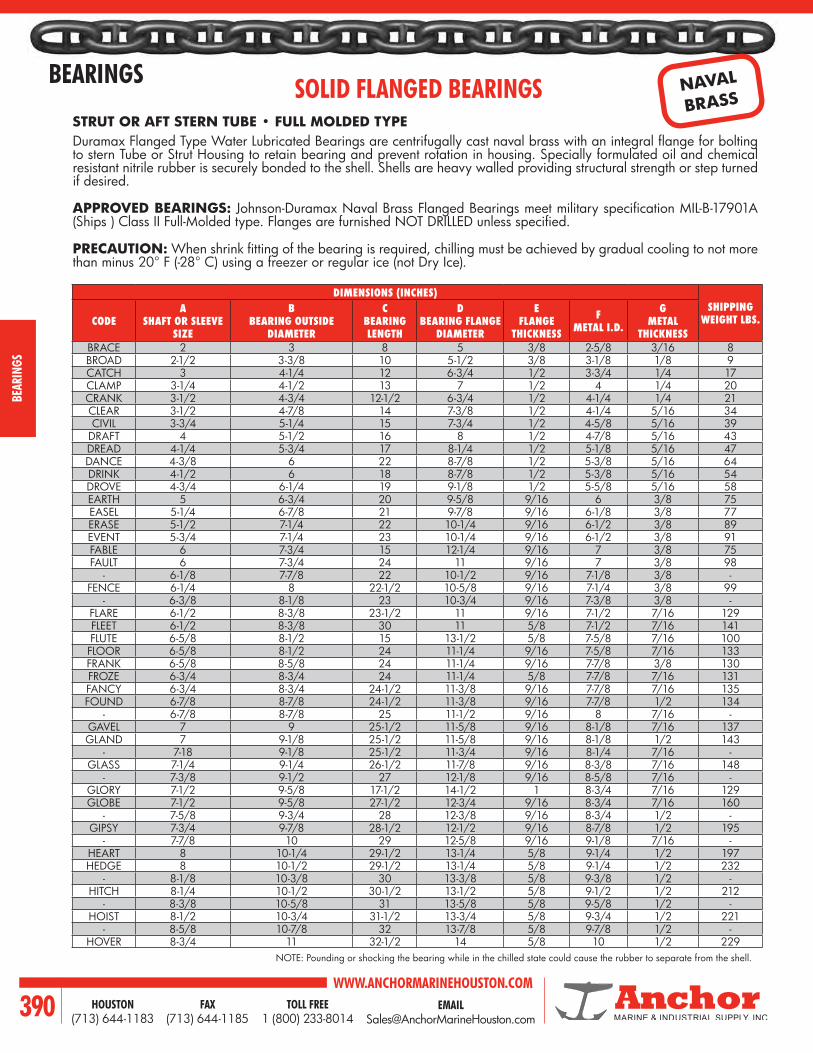
WWW.ANCHORMARINEHOUSTON.COMTOLL FREE
1 (800) 233-8014HOUSTON
(713) 644-1183FAX
(713) 644-1185390
BEARINGS
BEAR
INGS
SOLID FLANGED BEARINGSSTRUT OR AFT STERN TUBE • FULL MOLDED TYPEDuramax Flanged Type Water Lubricated Bearings are centrifugally cast naval brass with an integral flange for bolting to stern Tube or Strut Housing to retain bearing and prevent rotation in housing. Specially formulated oil and chemical resistant nitrile rubber is securely bonded to the shell. Shells are heavy walled providing structural strength or step turned if desired.
APPROVED BEARINGS: Johnson-Duramax Naval Brass Flanged Bearings meet military specification MIL-B-17901A (Ships ) Class II Full-Molded type. Flanges are furnished NOT DRILLED unless specified.
PRECAUTION: When shrink fitting of the bearing is required, chilling must be achieved by gradual cooling to not more than minus 20° F (-28° C) using a freezer or regular ice (not Dry Ice).
DIMENSIONS (INCHES)SHIPPING
WEIGHT LBS.CODEA
SHAFT OR SLEEVE SIZE
B BEARING OUTSIDE
DIAMETER
C BEARING LENGTH
D BEARING FLANGE
DIAMETER
E FLANGE
THICKNESS
F METAL I.D.
G METAL
THICKNESSBRACE 2 3 8 5 3/8 2-5/8 3/16 8BROAD 2-1/2 3-3/8 10 5-1/2 3/8 3-1/8 1/8 9CATCH 3 4-1/4 12 6-3/4 1/2 3-3/4 1/4 17CLAMP 3-1/4 4-1/2 13 7 1/2 4 1/4 20CRANK 3-1/2 4-3/4 12-1/2 6-3/4 1/2 4-1/4 1/4 21CLEAR 3-1/2 4-7/8 14 7-3/8 1/2 4-1/4 5/16 34CIVIL 3-3/4 5-1/4 15 7-3/4 1/2 4-5/8 5/16 39
DRAFT 4 5-1/2 16 8 1/2 4-7/8 5/16 43DREAD 4-1/4 5-3/4 17 8-1/4 1/2 5-1/8 5/16 47DANCE 4-3/8 6 22 8-7/8 1/2 5-3/8 5/16 64DRINK 4-1/2 6 18 8-7/8 1/2 5-3/8 5/16 54DROVE 4-3/4 6-1/4 19 9-1/8 1/2 5-5/8 5/16 58EARTH 5 6-3/4 20 9-5/8 9/16 6 3/8 75EASEL 5-1/4 6-7/8 21 9-7/8 9/16 6-1/8 3/8 77ERASE 5-1/2 7-1/4 22 10-1/4 9/16 6-1/2 3/8 89EVENT 5-3/4 7-1/4 23 10-1/4 9/16 6-1/2 3/8 91FABLE 6 7-3/4 15 12-1/4 9/16 7 3/8 75FAULT 6 7-3/4 24 11 9/16 7 3/8 98
- 6-1/8 7-7/8 22 10-1/2 9/16 7-1/8 3/8 -FENCE 6-1/4 8 22-1/2 10-5/8 9/16 7-1/4 3/8 99
- 6-3/8 8-1/8 23 10-3/4 9/16 7-3/8 3/8 -FLARE 6-1/2 8-3/8 23-1/2 11 9/16 7-1/2 7/16 129FLEET 6-1/2 8-3/8 30 11 5/8 7-1/2 7/16 141FLUTE 6-5/8 8-1/2 15 13-1/2 5/8 7-5/8 7/16 100FLOOR 6-5/8 8-1/2 24 11-1/4 9/16 7-5/8 7/16 133FRANK 6-5/8 8-5/8 24 11-1/4 9/16 7-7/8 3/8 130FROZE 6-3/4 8-3/4 24 11-1/4 5/8 7-7/8 7/16 131FANCY 6-3/4 8-3/4 24-1/2 11-3/8 9/16 7-7/8 7/16 135FOUND 6-7/8 8-7/8 24-1/2 11-3/8 9/16 7-7/8 1/2 134
- 6-7/8 8-7/8 25 11-1/2 9/16 8 7/16 -GAVEL 7 9 25-1/2 11-5/8 9/16 8-1/8 7/16 137GLAND 7 9-1/8 25-1/2 11-5/8 9/16 8-1/8 1/2 143
- 7-18 9-1/8 25-1/2 11-3/4 9/16 8-1/4 7/16 -GLASS 7-1/4 9-1/4 26-1/2 11-7/8 9/16 8-3/8 7/16 148
- 7-3/8 9-1/2 27 12-1/8 9/16 8-5/8 7/16 -GLORY 7-1/2 9-5/8 17-1/2 14-1/2 1 8-3/4 7/16 129GLOBE 7-1/2 9-5/8 27-1/2 12-3/4 9/16 8-3/4 7/16 160
- 7-5/8 9-3/4 28 12-3/8 9/16 8-3/4 1/2 -GIPSY 7-3/4 9-7/8 28-1/2 12-1/2 9/16 8-7/8 1/2 195
- 7-7/8 10 29 12-5/8 9/16 9-1/8 7/16 -HEART 8 10-1/4 29-1/2 13-1/4 5/8 9-1/4 1/2 197HEDGE 8 10-1/2 29-1/2 13-1/4 5/8 9-1/4 1/2 232
- 8-1/8 10-3/8 30 13-3/8 5/8 9-3/8 1/2 -HITCH 8-1/4 10-1/2 30-1/2 13-1/2 5/8 9-1/2 1/2 212
- 8-3/8 10-5/8 31 13-5/8 5/8 9-5/8 1/2 -HOIST 8-1/2 10-3/4 31-1/2 13-3/4 5/8 9-3/4 1/2 221
- 8-5/8 10-7/8 32 13-7/8 5/8 9-7/8 1/2 -HOVER 8-3/4 11 32-1/2 14 5/8 10 1/2 229
NOTE: Pounding or shocking the bearing while in the chilled state could cause the rubber to separate from the shell.
NAVAL
BRASS

EMAIL [email protected]
WWW.ANCHORMARINEHOUSTON.COMTOLL FREE
1 (800) 233-8014HOUSTON
(713) 644-1183FAX
(713) 644-1185 391
BEARINGS
BEARINGS
DIMENSIONS (INCHES)
CODEA
SHAFT OR SLEEVE SIZE
B BEARING OUTSIDE
DIAMETER
C BEARING LENGTH
D BEARING FLANGE
DIAMETER
E FLANGE
THICKNESS
F METAL
I.D.
G METAL
THICKNESS
SHIPPING WEIGHT LBS.
- 8-7/8 11-1/8 33 14-1/8 3/4 10-1/8 1/2 -INFRA 9 11-1/4 33-1/2 14-1/4 3/4 10-1/4 1/2 246IDEAL 9 11-1/2 33-3/8 15 3/4 10-1/4 5/8 275
- 9-1/8 11-3/8 34 14-1/2 3/4 10-3/8 1/2 287INNER 9-1/8 11-1/2 34-1/2 16-3/8 5/8 10-3/8 9/16 284IRISH 9-1/4 11-1/2 34-1/2 14-5/8 11/16 10-1/2 1/2 269
- 9-3/8 11-5/8 35 14-3/4 3/4 10-5/8 1/2 -INSET 9-1/2 11-3/4 35-1/2 14-7/8 3/4 10-3/4 1/2 274
- 9-5/8 11-7/8 36 15 3/4 10-7/8 1/2 -IVORY 9-3/4 12-1/8 36-1/2 15-1/4 3/4 11 9/16 295
- 9-7/8 12-1/4 37 15-3/8 3/4 11-1/8 9/16 -JEWEL 10 12-3/8 37-1/2 15-1/2 3/4 11-1/4 9/16 332
- 10-1/8 12-1/2 38 15-5/8 3/4 11-1/4 5/8 -JETTY 10-1/4 12-5/8 38-1/2 15-7/8 3/4 11-1/2 9/16 353
- 10-3/8 12-3/4 39 16 3/4 11-5/8 9/16 -JUMBO 10-1/2 12-7/8 39-1/2 16-1/8 3/4 11-3/4 9/16 369
- 10-5/8 13 40 16-1/4 3/4 11-7/8 9/16 -JUDGE 10-3/4 13-1/8 40-1/2 16-3/8 3/4 12 9/16 384
- 10-7/8 13-1/4 41 17 3/4 12-1/8 9/16 -KNOCK 11 13-1/2 41-1/2 17-1/4 3/4 12-3/8 9/16 424
- 11-1/8 13-5/8 42 17-3/8 3/4 12-1/2 9/16 -KRAFT 11-1/4 13-3/4 42-1/2 17-1/2 3/4 12-5/8 9/16 431
- 11-3/8 14 43 17-3/4 3/4 12-3/4 5/8 -KNEEL 11-1/2 14-1/8 43-1/2 17-7/8 3/4 12-7/8 5/8 490KNIFE 11-1/2 14-7/8 50-3/4 20-1/4 1-1/4 12-7/8 1 871
- 11-5/8 14-1/4 44 18 3/4 13 5/8 -KNOTS 11-3/4 14-3/8 44-1/2 18-1/8 3/4 13-1/8 5/8 497
- 11-7/8 14-1/2 45 18-1/4 3/4 13-1/4 5/8 -LABOR 12 14-3/4 45-1/2 18-1/2 3/4 13-1/2 5/8 524LOGAN 12-1/8 14-7/8 46 18-5/8 3/4 13-5/8 5/8 -LANCE 12-1/4 15 46-1/2 18-3/4 3/4 13-3/4 5/8 540LEASE 12-3/8 15-1/8 47 18-7/8 3/4 13-7/8 5/8 -LAYER 12-1/2 15-1/4 47-1/2 19 3/4 14 5/8 556LOGIC 12-5/8 15-3/8 48 19-1/8 3/4 14-1/8 5/8 545MILKY 12-3/4 15-1/2 48-1/2 19-1/4 3/4 14-1/4 5/8 -MUSIC 12-7/8 15-5/8 49 19-3/8 3/4 14-3/8 5/8 -MINCE 13 15-7/8 50 19-5/8 7/8 14-1/2 11/16 -MITTY 13-1/8 16 50-1/2 19-3/4 7/8 14-5/8 11/16 -MISTY 13-1/4 16-1/8 51 19-7/8 7/8 14-3/4 11/16 -NIFTY 13-3/8 16-1/4 51-1/2 20 7/8 14-7/8 11/16 716NIECE 13-1/2 16-3/8 52 20-1/8 7/8 15 11/16 718NOVEL 13-5/8 16-1/2 52-1/2 20-1/4 7/8 15-1/8 11/16 -ORTHA 13-3/4 16-5/8 53 20-3/8 7/8 15-1/4 11/16 -OGGLE 13-7/8 16-3/4 53-1/2 20-1/2 7/8 15-3/8 11/16 -OPERA 14 16-7/8 54 20-5/8 7/8 15-1/2 11/16 -PURSE 14-1/8 17 54-1/2 20-3/4 7/8 15-5/8 11/16 -POLAR 14-1/4 17-1/8 55 20-7/8 7/8 15-3/4 11/16 -POINT 14-3/8 17-1/4 55-1/2 21 7/8 15-7/8 11/16 -PRUNE 14-1/2 17-1/2 56 21-1/4 7/8 16 3/4 841PRICE 14-5/8 17-5/8 56-1/2 21-3/8 7/8 16-1/8 3/4 -
PUNCH 14-3/4 17-3/4 57 21-1/2 7/8 16-1/4 3/4 -QUAKE 14-7/8 17-7/8 57-1/2 21-5/8 7/8 16-3/8 3/4 -QUIET 15 18 58 21-3/4 7/8 16-1/2 3/4 -
C
Naval Brass
Rubber(Oil
Resistant)B
G
AD
E

WWW.ANCHORMARINEHOUSTON.COMTOLL FREE
1 (800) 233-8014HOUSTON
(713) 644-1183FAX
(713) 644-1185392
CONVERSION TABLES
CONV
ERSI
ON TA
BLES
CONVERSION FACTORS AND TABLES
INCHDECIMALS OF
AN INCHMILLIMETERS
-- .03937 1.0
1/16 .0625 1.587
-- .07874 2.0
3/32 .09375 2.381
-- .11811 3.0
1/8 .125 3.175
5/32 .15625 3.968
-- .15748 4.0
3/16 .187 4.762
-- .19685 5.0
7/32 .21875 5.556
-- .23622 6.0
1/4 .25 6.35
-- .275591 7.0
9/32 .28125 7.143
5/16 .3125 7.937
-- .314961 8.0
-- .354331 9.0
3/8 .375 9.525
-- .393701 10.0
-- .433071 11.0
7/16 .4375 11.112
-- .472441 12.0
1/2 .50 12.70
-- .511811 13.0
-- .551181 14.10
9/16 .5625 14.287
-- .590551 15.0
5/8 .625 15.875
-- .629921 16.0
-- .669291 17.0
INCHDECIMALS OF
AN INCHMILLIMETERS
-- .708661 18.0
-- .748031 19.0
3/4 .75 19.05
-- .787402 20.0
-- .826772 21.0
-- .866142 22.0
7/8 .875 22.225
-- .905512 23.0
15/16 .9375 23.812
-- .944882 24.0
-- .984252 25.0
1 1.00 25.4
-- 1.023622 26.0
-- 1.062992 27.0
-- 1.102362 28.0
1-1/8 1.125 28.575
-- 1.141732 29.0
-- 1.181102 30.0
-- 1.220472 31.0
1-1/4 1.25 31.75
-- 1.259843 32.0
-- 1.299213 33.0
-- 1.338583 34.0
1-3/8 1.375 34.925
-- 1.377953 35.0
-- 1.417323 36.0
-- 1.456693 37.0
-- 1.496063 38.0
1-1/2 1.50 38.10
-- 1.535433 39.0
-- 1.574803 40.0
INCHDECIMALS OF
AN INCHMILLIMETERS
-- 1.614173 41.0
1-5/8 1.625 41.275
-- 1.653543 42.0
-- 1.692913 43.0
-- 1.732283 44.0
1-3/4 1.75 44.45
-- 1.771654 45.0
-- 1.811024 46.0
-- 1.850394 47.0
1-7/8 1.875 47.625
-- 1.889764 48.0
-- 1.929134 49.0
-- 1.968504 50.0
2 2.00 50.80
-- 2.007874 51.0
-- 2.047244 52.0
-- 2.086614 53.0
2-1/8 2.125 53.975
-- 2.125984 54.0
-- 2.165354 55.0
-- 2.204724 56.0
-- 2.244094 57.0
2-1/4 2.25 57.15
-- 2.283465 58.0
-- 2.322835 59.0
-- 2.362236 60.0
2-3/8 2.375 60.325
-- 2.401575 61.0
-- 2.440945 62.0
-- 2.480315 63.0
2-1/2 2.50 63.5
1 lb. = .45359 kg (kilogram)
1 kg = 2.20462 lbs.
1 kN (kilonewton) = 101.972 kg = 224.809 lbs.
1 short ton = 2,000 lbs. = 907.185 kg
1 long ton = 2,240 lbs. = 1,016.05 kg
1 metric ton = 2,204.62 = 1,000 kg
1 ft = .3048 m (meter) 1 m = 3.28084 ft. = 39.3701 inches 1 inch = 25.4 mm (millimeter) 1 mm = 0.03937 inches 1 yard = 9144 m 1 m = 1.0936 yards 1 mile = 1.60934 km (kilometer) 1 km = .62137 mile
1 mile = 1,760 yards = 5,280 ft. 1 yard = 3 ft. = 36 inches 1 R. = 12 inches 1 fathom = 6 ft. 1 lb. = 16 ounces 1 kilometer = 1,000 meters 1 meter = 100 centimeters 1 centimeter = 10 millimeters 1 kilogram = 1,000 grams

EMAIL [email protected]
WWW.ANCHORMARINEHOUSTON.COMTOLL FREE
1 (800) 233-8014HOUSTON
(713) 644-1183FAX
(713) 644-1185 393
CONVERSION TABLES
CONVERSION TABLES
1 mm = 3/64’’ 14 mm = 9/16’’ 32 mm = 1-1/4’’ 95 mm = 3-3/4’’
1.5 mm = 1/16’’ 15 mm = 19/32’’ 33 mm = 1-5/16’’2 mm = 5/64’’ 16 mm = 5/8’’ 35 mm 1-3/8’’ 10 cm = 4’’
2.5 mm = 3/32’’ 17 mm = 11/16’’ 36 mm = 1-3/8’’ 10.8 cm = 4-1/4’’3 mm = 1/8’’ 18 mm = 23/32’’ 38 mm = 1-1/2’’ 11.5 cm = 4-1/2’’
4 mm = 5/32’’ 19 mm = 3/4’’ 40 mm = 1-9/16’’ 12 cm = 4-3/4’’5 mm = 3/16’’ 20 mm = 25/32’’ 45 mm = 1-3/4’’ 12.7 cm = 5’’6 mm = 1/4’’ 21 mm = 1/16’’ 50 mm = 2’’ 13 cm = 5-1/8’’
7 mm = 9/32’’ 22 mm = 7/8’’ 55 mm = 2-3/16’’ 13.5 cm = 5-1/4’’8 mm = 5/16’’ 23 mm = 29/32’’ 60 mm = 2-3/8’’ 14 cm = 5-1/2’’9 mm = 3/8’’ 24 mm = 15/16’’ 65 mm = 2-1/2’’ 14.7 cm = 5-3/4’’
10 mm = 13/32’’ 25 mm = 1’’ 70 mm = 2-3/4’’ 15.2 cm = 6’’11 mm = 7/16’’ 27 mm = 1-1/16’’ 75 mm = 3’’ 15.5 cm = 6-1/8’’
12 mm = 15/32’’ 28 mm = 1-1/8’’ 80 mm = 3-1/8’’ 16 cm = 6-3/8’’13 mm = 1/2’’ 30 mm = 1-3/16’’ 90 mm = 3-1/2’’
MM TO INCHES
WEIGHTS
MEASURES OF LENGTH
METRIC DENOMINATIONS AND VALUES EQUIVALENTS IN DENOMINATIONS IN USE
Names No. Grams Quantity of Water at Maximum Density Avoirdupois Weigh
Millier or tonneau = 1,000,000 = 1 cubic meter = 2204.6 pounds
Quintal = 100,000 = 1 hectoliter = 220.46 pounds
Myriagram = 10,000 = 10 liters = 22.046 pounds
Kilogram or Kilo = 1,000 = 1 liter = 2.2046 pounds
Hectogram = 100 = 1 deciliter = 3.5274 ounces
Dekagram = 10 = 10 c. centimeters = 0.3527 ounces
Gram = 1 = 1 c. centimeter = 15.432 grains
Decigram = .1 = 1c. centimeter = 1.5432 grains
Centigram = .01 = 10 c. centimeter = 0.1543 grain
Milligram = .001 = 1 c. millimeter = 0.0154 grain
THE METRIC SYSTEM
METRIC DENOMINATIONS AND VALUES EQUIVALENTS IN DENOMINATIONS IN USE
Myriameter = 10,000 meters = 6.2137 miles
Kilometer = 1,000 meters = 0.62137 mile, or 3,280 feet 10 inches
Hectometer = 100 meters = 328 feet and 1 inch
Dekamter = 10 meters = 393.7 inches
Meter = 1 meter = 39.37 inches
Decimeter = .1 meter = 3.937 inches
Centimeter = .01 meter = 0.3937 inches
Millimeter = .001 meter = 0.0394 inch

WWW.ANCHORMARINEHOUSTON.COMTOLL FREE
1 (800) 233-8014HOUSTON
(713) 644-1183FAX
(713) 644-1185394
CONVERSION TABLES
CONV
ERSI
ON TA
BLES
CONVERSION FACTORS
Cubic feet x 1728 .............. = cubic inchesCubic yards x 27 ............... = cubic feet1 U.S. Gallon .................... = 231 cubic inches = 8.336 pounds water1 cubic foot ....................... = 7.4805 U.S. gallons = 62.355 pounds at 62º F1 cubic foot per second ...... = 448.83 U.S. gallons per minute1 cubic foot per second ...... = 648,317 gallons per 24 hoursPressure of 1 pound per square inch ................ = 2.042 inches of mercury at 62º FPressure of 1 pound per square inch ................ = 2.309 feet of water at 62º FStandard atmospheric pressure .......................... = 14.7 pounds per square inch, = 29.92 inches mercury, = 33.9 feet waterHead of water of 1 foot ...... = 0.433 pounds per square inch1 horsepower .................... = 33,000 foot pounds per minute1 meter ............................. = 39.37 inches, = 3.281 feet1 kilogram ........................ = 2.205 pounds1 liter ............................... = 1,000 grams of water, = 1.0567 quarts, = 0.2642 gallons
AREAS AND VOLUMES
Circumference of circle ........................ = 3.1416 x diameter
Diameter of circle ............................... = 0.3183 x circumference
Side of a square of equal area............. = 0.8862 x diameter
Diameter of a circle of equal area ........ = 1.1284 x side of square
Area of a circle .................................. = 0.7854 x square of the
diameter
Diameter of a circle ............................ = 1.1284 x square root of
the area
Surface area of a sphere ..................... = 3.1416 x square of
the diameter
Volume of a sphere ............................. = 0.5236 x cube of
diameter
Volume of cylinder or prism ................. = area of base x height
Volume of cone or pyramid .................. = 1/3 x area of base x
height
Volume of the frustrum of
a cone or pyramid ............................ = 1/3 X height x (area of
upper base + area of upper base x area of lower base)
Doubling the diamter of a pipe increases volume four times:
generalizing, increasing the diamter “n” times increases the volume “n2”
or “n x n” times.
LINEAR MEASURE
12 inches ............................................................................... 1 foot
3 feet .................................................................................... 1 yard
5-1/2 yards ............................................................................1 rod
40 rods ..............................................................................1 furlong
320 rods ................................................................................1 mile
5,280 feet ..............................................................................1 mile
8 furlongs ...............................................................................1 mile
CUBIC MEASURE
1728 cubic inches ...........................................................1 cubic foot
27 cubic feet .................................................................1 cubic yard
128 cubic feet ....................................................................... 1 cord
24-3/4 x cubic feet ...............................................................1 perch
SURVEYOR’S MEASURE
7.92 inches .............................................................................1 link
100 links .............................................................................1 chain
4 rods ..................................................................................1 chain
20 chains ...........................................................................1/4 mile
40 chains ...........................................................................1/2 mile
80 chains ...............................................................................1 mile
SQUARE MEASURE
144 square inches ........................................................1 square foot
9 square feet ...............................................................1 square yard
30.25 square yards ....................................................... 1 square rod
160 square rods .......................................................... 1 square acre
640 acres ..............................................................................1 mile
640 acres ..........................................................................1 section
36 sections ...................................................................... 1 township

EMAIL [email protected]
WWW.ANCHORMARINEHOUSTON.COMTOLL FREE
1 (800) 233-8014HOUSTON
(713) 644-1183FAX
(713) 644-1185 395
CONVERSION TABLES
CONVERSION TABLES
DECIMAL EQUIVALENTS: INCH - MILLIMETER CONVERSION TABLE
INCH DECIMAL MILLIMETER
33/64 .515625 13.096875
17/32 .53125 13.493750
35/64 .546875 13.890625
9/16 .5625 14.287500
37/64 .578125 14.684375
19/32 .59375 15.081250
39/64 .609375 15.478125
5/8 .6250 15.875000
41/64 .640625 16.271875
21/32 .65625 16.668750
43/64 .71875 17.065625
11/16 .6875 17.462500
45/64 .703125 17.859375
23/32 .71875 18.265250
47/64 .734375 18.653125
3/4 .7500 19.050000
49/64 .765625 19.446875
25/32 .78125 19.843750
51/64 .796875 20.240625
13/16 .8125 20.637500
53/64 .828125 21.034375
27/32 .84375 21.431250
55/64 .859375 21.828175
7/8 .8750 22.225000
56/64 .890625 22.621875
29/32 .90625 23.018750
59/64 .921875 23.415625
15/16 .9375 23.812500
61/64 .953125 24.209375
31/32 .96875 24.606250
63/64 .984375 25.003125
1 1.000 25.40000
INCH DECIMAL MILLIMETER
1/64 .015625 .396875
1/32 .03125 .793750
3/64 .046875 1.190625
1/16 .0625 1.587500
5/64 .078125 1.984375
3/32 .09375 2.381250
7/64 .109375 2.778125
1/8 .1250 3.175000
9/64 .140625 3.571875
5/32 .15625 3.968750
11/64 .171875 4.365625
3/16 .1875 4.762500
13/64 .203125 5.159375
7/32 .21875 5.556250
15/64 .234375 5.953125
1/4 .2500 6.350000
17/64 .265625 6.746875
9/32 .28125 7.143750
19/64 .266875 7.540625
5/16 .3125 7.937500
21/64 .328125 8.334375
11/32 .34375 8.731250
23/64 .359375 9.128125
3/8 .3750 9.525000
25/64 .390625 9.921875
13/32 .40625 10.318750
27/64 .421875 10.715625
7/16 .4375 11.112500
29/64 .453125 11.509375
15/32 .46875 11.906250
31/64 .484375 12.303125
1/2 .5000 12.700000

WWW.ANCHORMARINEHOUSTON.COMTOLL FREE
1 (800) 233-8014HOUSTON
(713) 644-1183FAX
(713) 644-1185396
CONV
ERSI
ON TA
BLES
NOTES