Supplement No. AFS-AA109-IBF-FMS FAA APPROVED ...
17
Supplement No. AFS-AA109-IBF-FMS 17891 Chesterfield Airport Road Chesterfield, MO 63005 FAA APPROVED ROTORCRAFT FLIGHT MANUAL SUPPLEMENT TO THE AGUSTA S.p.A. A109 SERIES HELICOPTERS MODEL A109E, A109S & AW109SP ROTORCRAFT FLIGHT MANUAL FOR THE INLET BARRIER FILTER SYSTEM INSTALLATION Aircraft S/N Aircraft Reg. No. This supplement must be attached to applicable FAA Approved Rotorcraft Flight Manual, when the rotorcraft is modified by the installation of the AFS Inlet Barrier Filter (IBF) System in accordance with STC No. SR02988CH The information contained herein supplements or supersedes the basic manual only in those areas listed herein. For limitations, procedures, and performance information not
-
Upload
khangminh22 -
Category
Documents
-
view
0 -
download
0
Transcript of Supplement No. AFS-AA109-IBF-FMS FAA APPROVED ...
Supplement No. AFS-AA109-IBF-FMS
17891 Chesterfield Airport Road Chesterfield, MO 63005
FAA APPROVED ROTORCRAFT FLIGHT MANUAL SUPPLEMENT
TO THE
AGUSTA S.p.A. A109 SERIES HELICOPTERS
MODEL A109E, A109S & AW109SP ROTORCRAFT FLIGHT MANUAL
FOR THE INLET BARRIER FILTER SYSTEM
INSTALLATION
Aircraft S/N Aircraft Reg. No. This supplement must be attached to applicable FAA Approved Rotorcraft Flight Manual, when the rotorcraft is modified by the installation of the AFS Inlet Barrier Filter (IBF) System in accordance with STC No. SR02988CH The information contained herein supplements or supersedes the basic manual only in those areas listed herein. For limitations, procedures, and performance information not
Aerospace Filtration Systems RFM Supplement For 17891 Chesterfield Airport Road Agusta A109E, A109S & AW109SP Chesterfield, MO 63005 Rotorcraft
AFS-AA109-IBF-FMS Page 2 of 17 FAA Approval Date: OCT 11 2011 Rev.: A
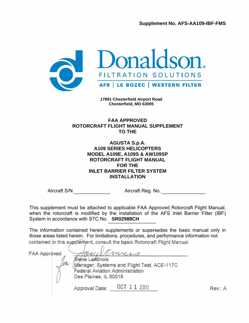
LOG OF REVISIONS
NOTE Revised text from previous revision is indicated by a black vertical line in the right border.
Aerospace Filtration Systems RFM Supplement For 17891 Chesterfield Airport Road Agusta A109E, A109S & AW109SP Chesterfield, MO 63005 Rotorcraft
AFS-AA109-IBF-FMS Page 3 of 17 FAA Approval Date: OCT 11 2011 Rev.: A
TABLE OF CONTENTS
GENERAL INFORMATION ................................................................................................. 4 LIMITATIONS ...................................................................................................................... 5 NORMAL PROCEDURES ................................................................................................... 6 EMERGENCY AND MALFUNCTIONS PROCEDURES ..................................................... 8 PERFORMANCE .............................................................................................................. 10 OPTIONAL EQUIPMENT .................................................................................................. 12 WEIGHT AND BALANCE .................................................................................................. 13 SYSTEM DESCRIPTION .................................................................................................. 14 HANDLING AND SERVICING .......................................................................................... 16 SUPPLEMENTAL PERFORMANCE INFORMATION ....................................................... 17
Aerospace Filtration Systems RFM Supplement For 17891 Chesterfield Airport Road Agusta A109E, A109S & AW109SP Chesterfield, MO 63005 Rotorcraft
AFS-AA109-IBF-FMS Page 4 of 17 FAA Approval Date: OCT 11 2011 Rev.: A
GENERAL INFORMATION It is responsibility of the flight crew to be familiar with the contents of this Flight Manual Supplement (FMS) including all revisions and any temporary revision which is applicable at the time of flight. TERMINOLOGY
WARNINGS, CAUTIONS AND NOTES Warnings, Cautions and Notes are used throughout this manual to emphasize important and critical instructions and are used as follows:
An operating procedure, practice, etc., which, if not correctly followed, could result in personal injury or loss of life.
An operating procedure, practice, etc., which, if not strictly observed, could result in damage to, or destruction of, equipment.
NOTE
An operating procedure, condition, etc., which is essential to highlight.
USE OF PROCEDURAL WORDS
The concept of procedural word usage and intended meaning which has been adhered to in preparing this RFM is as follows: ″Shall″ or ″Must″ are used to indicate a mandatory requirement. ″Should″ is used to indicate a non-mandatory but preferred method of accomplishment. ″May″ is used to indicate an acceptable method of accomplishment. ABBREVIATIONS
AFS – Aerospace Filtration Systems, Inc. CAT – Category A EAPS – Engine Air Particle Separator FAA – Federal Aviation Administration FMA – Filter Maintenance Aid FMS – Flight Manual Supplement IBF – Inlet Barrier Filter ICA – Instructions for Continued Airworthiness
IMC – Instrument Meteorological Conditions N1 – Gas Generator Turbine Speed OEM – Original Equipment Manufacturer PAC – Power Assurance Check RFM – Rotorcraft Flight Manual STC – Supplemental Type Certificate TOT – Turbine Outlet Temperature
WARNING
CAUTION
Aerospace Filtration Systems RFM Supplement For 17891 Chesterfield Airport Road Agusta A109E, A109S & AW109SP Chesterfield, MO 63005 Rotorcraft
AFS-AA109-IBF-FMS Page 5 of 17 FAA Approval Date: OCT 11 2011 Rev.: A
SECTION 1 LIMITATIONS
ALTITUDE LIMITATIONS
Maximum operating pressure altitude: 15000 ft. (4572 m) Bypass Doors - Open above pressure altitude: 10000 ft. (3048 m) in cruise flight. Closing the bypass doors above 10000 ft. for takeoff and landing is acceptable.
POWER ASSURANCE LIMITATIONS
When accomplishing a PAC with the IBF installed, a minimum of a +5°C TOT margin is required for all helicopter operations. This margin must be determined by a hover PAC only.
TYPE OF OPERATION
The installation of the IBF system does not change the existing operational restrictions listed in the basic Rotorcraft Flight Manual (RFM) or existing flight manual supplements. Refer to the Limitations Section of the RFM and/or supplements for Types of Operation. The installation of the IBF system does not restrict the aircraft from flight in falling and blowing snow conditions.
CATEGORY A OPERATIONS
CAT A operations with the IBF system installed is permitted. For CAT A operations, all CAT A Limitations, Restrictions, and Operations listed in the RFM and the applicable CATEGORY A Operations Supplement must be followed. For CAT A operations a daily PAC must be performed per the applicable RFM CATEGORY A Operations Supplement and the basic RFM Performance Section.
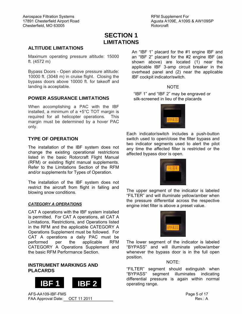
INSTRUMENT MARKINGS AND PLACARDS
An “IBF 1” placard for the #1 engine IBF and an “IBF 2” placard for the #2 engine IBF (as shown above) are located (1) near the applicable IBF 3-amp circuit breaker in the overhead panel and (2) near the applicable IBF cockpit indicator/switch.
NOTE
“IBF 1” and “IBF 2” may be engraved or silk-screened in lieu of the placards
Each indicator/switch includes a push-button switch used to open/close the filter bypass and two indicator segments used to alert the pilot any time the affected filter is restricted or the affected bypass door is open.
The upper segment of the indicator is labeled “FILTER” and will illuminate yellow/amber when the pressure differential across the respective engine inlet filter is above a preset value.
The lower segment of the indicator is labeled “BYPASS” and will illuminate yellow/amber whenever the bypass door is in the full open position.
NOTE:
“FILTER” segment should extinguish when “BYPASS” segment illuminates indicating differential pressure is again within normal operating range. IBF 1 IBF 2
Aerospace Filtration Systems RFM Supplement For 17891 Chesterfield Airport Road Agusta A109E, A109S & AW109SP Chesterfield, MO 63005 Rotorcraft
AFS-AA109-IBF-FMS Page 6 of 17 FAA Approval Date: OCT 11 2011 Rev.: A
SECTION 2 NORMAL PROCEDURES
PRE-FLIGHT CHECK FUSELAGE – RH/LH (Areas 2 & 6) Before each flight: 1. Ensure IBF environmental protective
covers are removed. 2. Perform a visual check to verify that filter
bypass doors are closed by opening the aft cowling louver doors.
3. Check IBF Filter Maintenance Aid (FMA)
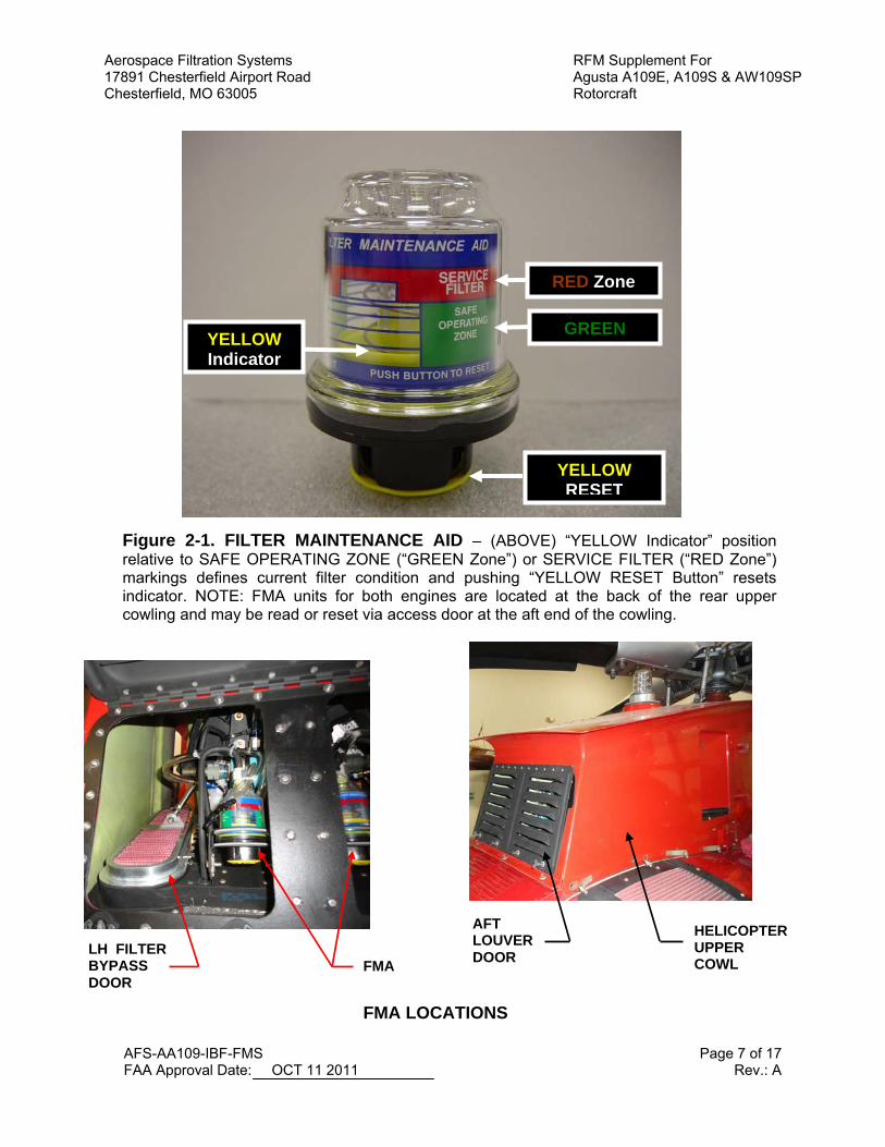
by opening the aft cowling louver doors, to determine condition of the filters. When indicator enters RED zone (See Figure 2-1 of this supplement), it is recommended filter be serviced per IBF Instructions for Continued Airworthiness, AFS-A109-IBF-ICA. The FMA gives the operator an idea of the filter condition and can be used to determine filter contamination trends in various environmental conditions. As filters become increasingly dirty, the yellow indicator will start moving toward the RED zone.
4. Check IBF filter element media (main
engine filters and bypass door filters) for security and condition. If any element is torn, has a hole, or the pleats are flat, contact maintenance for disposition per the IBF ICA.
NOTE: During high airspeeds (i.e. VH, VNE, etc.), it is possible that the FMA will show the indicator close to or into the RED zone. If this is the case, reset the FMA and check after the next flight.
BEFORE FLIGHT WHEN OPERATING IN SNOW CONDITIONS 1. Thoroughly check cabin roof,
transmission cowling, and filter areas. All areas checked shall be clean and free of accumulated snow, slush, and ice before each flight.
2. Ensure that all filters, bypass doors, and
intake cowling are thoroughly clear of snow, slush, or ice before each flight.
Aerospace Filtration Systems RFM Supplement For 17891 Chesterfield Airport Road Agusta A109E, A109S & AW109SP Chesterfield, MO 63005 Rotorcraft
AFS-AA109-IBF-FMS Page 7 of 17 FAA Approval Date: OCT 11 2011 Rev.: A
Figure 2-1. FILTER MAINTENANCE AID – (ABOVE) “YELLOW Indicator” position relative to SAFE OPERATING ZONE (“GREEN Zone”) or SERVICE FILTER (“RED Zone”) markings defines current filter condition and pushing “YELLOW RESET Button” resets indicator. NOTE: FMA units for both engines are located at the back of the rear upper cowling and may be read or reset via access door at the aft end of the cowling.
GREEN
YELLOW RESET
RED Zone
YELLOW Indicator
FMA LH FILTER BYPASS DOOR
AFT LOUVER DOOR
HELICOPTER UPPER COWL
FMA LOCATIONS
Aerospace Filtration Systems RFM Supplement For 17891 Chesterfield Airport Road Agusta A109E, A109S & AW109SP Chesterfield, MO 63005 Rotorcraft
AFS-AA109-IBF-FMS Page 8 of 17 FAA Approval Date: OCT 11 2011 Rev.: A
SECTION 3 EMERGENCY AND MALFUNCTIONS PROCEDURES
Caution Lights (YELLOW/AMBER)
Panel wording Fault condition Corrective action
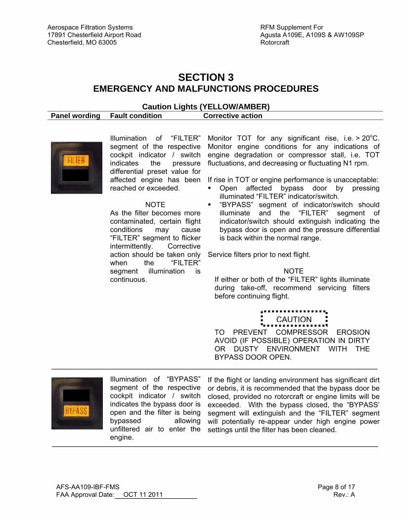
Illumination of “FILTER” segment of the respective cockpit indicator / switch indicates the pressure differential preset value for affected engine has been reached or exceeded.
NOTE As the filter becomes more contaminated, certain flight conditions may cause “FILTER” segment to flicker intermittently. Corrective action should be taken only when the “FILTER” segment illumination is continuous. Illumination of “BYPASS” segment of the respective cockpit indicator / switch indicates the bypass door is open and the filter is being bypassed allowing unfiltered air to enter the engine.
Monitor TOT for any significant rise, i.e. > 20oC. Monitor engine conditions for any indications of engine degradation or compressor stall, i.e. TOT fluctuations, and decreasing or fluctuating N1 rpm. If rise in TOT or engine performance is unacceptable: Open affected bypass door by pressing
illuminated “FILTER” indicator/switch. “BYPASS” segment of indicator/switch should
illuminate and the “FILTER” segment of indicator/switch should extinguish indicating the bypass door is open and the pressure differential is back within the normal range.
Service filters prior to next flight.
NOTE If either or both of the “FILTER” lights illuminate during take-off, recommend servicing filters before continuing flight.
TO PREVENT COMPRESSOR EROSION AVOID (IF POSSIBLE) OPERATION IN DIRTY OR DUSTY ENVIRONMENT WITH THE BYPASS DOOR OPEN.
If the flight or landing environment has significant dirt or debris, it is recommended that the bypass door be closed, provided no rotorcraft or engine limits will be exceeded. With the bypass closed, the “BYPASS’ segment will extinguish and the “FILTER” segment will potentially re-appear under high engine power settings until the filter has been cleaned.
CAUTION
Aerospace Filtration Systems RFM Supplement For 17891 Chesterfield Airport Road Agusta A109E, A109S & AW109SP Chesterfield, MO 63005 Rotorcraft
AFS-AA109-IBF-FMS Page 9 of 17 FAA Approval Date: OCT 11 2011 Rev.: A
ENVIRONMENTAL CONDITIONS Fault condition Corrective Action Inadvertent encounters with icing conditions
Exit condition as soon as practical.
ELECTRICAL Fault condition Corrective Action Tripped Circuit Breaker (Single)
Monitor TOT for any significant rise, i.e. > 20oC. Monitor engine conditions for any indications of engine degradation or compressor stall, i.e. TOT fluctuations, and decreasing or fluctuating N1 rpm. Contact maintenance after landing
If rise in TOT or engine performance is unacceptable, i.e. approaching engine limits: Land as soon as practicable
Tripped Circuit Breaker (Both) Monitor TOT for any significant rise, i.e. > 20oC. Monitor
engine conditions for any indications of engine degradation or compressor stall, i.e. TOT fluctuations, and decreasing or fluctuating N1 rpm. Land as soon as practicable
If rise in TOT or engine performance of either engine is unacceptable, i.e. approaching engine limits: Land as soon as possible
Aerospace Filtration Systems RFM Supplement For 17891 Chesterfield Airport Road Agusta A109E, A109S & AW109SP Chesterfield, MO 63005 Rotorcraft
AFS-AA109-IBF-FMS Page 10 of 17 FAA Approval Date: OCT 11 2011 Rev.: A
SECTION 4 PERFORMANCE
IBF PERFORMANCE DATA
Use the applicable RFM (A109E, A109S or AW109SP) performance data and or charts to determine the engine health. Only the hover PAC is to be used with the IBF installed. With all PAC results, a minimum of a +5°C TOT margin is required prior to all helicopter operations.
POWER ASSURANCE CHECKS All Aircraft (A109E, A109S and AW109SP) Use the basic Hover PAC charts to determine engine health. If the PAC is satisfactory (i.e. the recorded TOT with greater than +5°C TOT margin or N1 values are less than the maximum allowable values) then basic performance can be obtained and the basic performance data charts are applicable. If the basic PAC is not satisfactory (i.e. recorded TOT with less than +5°C TOT margin or N1 values are greater than the maximum allowable basic values) then published performance may not be achieved. If this is the case, clean the filters and recheck the engine health using the same basic PAC Hover chart. If engine health is found to be satisfactory then the charted helicopter performance may be obtained and the performance data charts are applicable. If the recorded PAC results after cleaning the filters are still not satisfactory (i.e. the recorded TOT with less than +5°C TOT margin or N1 values are greater than the maximum allowable basic values), then contact maintenance for troubleshooting.
HELICOPTER PERFORMANCE IS REDUCED AS THE IBF BECOMES CONTAMINATED WITH DIRT, DUST AND DEBRIS. PILOT / OPERATOR IS RESPONSIBLE TO UTILIZE PAC TO DETERMINE IF ENGINE CAN PRODUCE INSTALLED POWER.
NOTE
Ensure that the IBF “FILTER” and “BYPASS” caution lights are not illuminated during performance of the PAC, and verify that the bypass doors are closed.
The frequency at which the PACs are conducted is up to the discretion of the operator and may be based on the current or forecast operating environment, (i.e. temperature, altitude, airborne contaminate) and the requirements of the Flight Manual or applicable Flight Manual Supplement. If the engines do not pass PAC with a minimum of a +5°C TOT margin, published performance may not be achieved. Contact maintenance for appropriate trouble shooting procedures as outlined in the applicable Instructions for Continued Airworthiness or Maintenance Manuals.
CAUTION
Aerospace Filtration Systems RFM Supplement For 17891 Chesterfield Airport Road Agusta A109E, A109S & AW109SP Chesterfield, MO 63005 Rotorcraft
AFS-AA109-IBF-FMS Page 11 of 17 FAA Approval Date: OCT 11 2011 Rev.: A
CATEGORY A OPERATIONS All Aircraft (A109E, A109S and AW109SP) A daily Ground/Hover PAC per the applicable RFM CAT A Supplement must be performed prior to CAT A operations. Perform the Ground/Hover PAC as described in the applicable RFM CAT A Supplement and compare the TOT and N1 results to the Hover PAC Chart. If the recorded PAC results are satisfactory (i.e. the recorded TOT with greater than +5°C TOT margin or N1 values are less than the maximum allowable values), CAT A Operations may be performed using the CAT A charts. If either engine exceeds allowable TOT or N1 (i.e. recorded TOT with less than +5°C TOT margin or N1 values are greater than the maximum allowable basic values), published performance may not be achievable. If this is the case, clean the filters and recheck the engine health using PAC Ground/ Hover charts. If the PAC re-check is not satisfactory, CAT A take-off and landing performance cannot be achieved and CAT A operations and or maneuvers are prohibited. Contact maintenance for appropriate trouble shooting procedures as outlined in the applicable Maintenance Manuals.

Aerospace Filtration Systems RFM Supplement For 17891 Chesterfield Airport Road Agusta A109E, A109S & AW109SP Chesterfield, MO 63005 Rotorcraft
AFS-AA109-IBF-FMS Page 12 of 17 FAA Approval Date: OCT 11 2011 Rev.: A
SECTION 5 OPTIONAL EQUIPMENT
NOT APPLICABLE
Aerospace Filtration Systems RFM Supplement For 17891 Chesterfield Airport Road Agusta A109E, A109S & AW109SP Chesterfield, MO 63005 Rotorcraft
AFS-AA109-IBF-FMS Page 13 of 17 FAA Approval Date: OCT 11 2011 Rev.: A
SECTION 6 WEIGHT AND BALANCE
NO CHANGE

Aerospace Filtration Systems RFM Supplement For 17891 Chesterfield Airport Road Agusta A109E, A109S & AW109SP Chesterfield, MO 63005 Rotorcraft
AFS-AA109-IBF-FMS Page 14 of 17 FAA Approval Date: OCT 11 2011 Rev.: A
SECTION 7 SYSTEM DESCRIPTION
IBF STC kit (124000-101) installation consists of the following primary components: two main (LH and RH) filter assemblies, two cockpit indicator/switch assemblies, access door assembly, and bypass assembly. The bypass assembly includes for each engine inlet: a bypass filter door, electromechanical actuator, differential pressure switch, and FMA. The bypass system components for both engine inlets are mounted on a single base plate that spans the width of the central beam passing beneath the center web partition in the aft end of the rear upper cowling assembly. The access door added to the aft end of the rear upper cowling is louvered to prevent pressure from building up when the bypass doors are closed, and opens to allow reading of the FMA and access to the bypass system components. The IBF bypass system for each engine inlet also includes a 3-amp circuit breaker located in the overhead panel plus required installation hardware and wiring. The IBF system provides a means of monitoring the condition of all the filters both in-flight and on the ground, and a means to bypass all filters should any of them become restricted. In-flight, each differential pressure switch continuously measures the drop in pressure across the filter, and triggers a cockpit indication cautioning the pilot any time the differential pressure reaches or exceeds a preset limit. On the ground, the FMA for each engine can be read to determine the maximum differential pressure across each filter reached during the last flight. Each FMA is accessible only on the ground, providing the pilot or mechanic the ability to visually gauge the current condition of the filters and/or trend the change over time in order to forecast when the filters will require servicing. The bypass filter door can be opened to permit unfiltered air to enter the engine inlet chamber of the affected engine should the filter media become obstructed. The bypass
filter door for either engine can be opened or closed separately as required by depressing the respective cockpit indicator/ switch on the instrument panel which energizes the actuator. When the filters accumulate enough dirt/debris that the differential pressure reaches or exceeds a preset value, the “FILTER” segment of the indicator illuminates. Any time the “FILTER” indication is illuminated, the pilot shall monitor the engine conditions. If conditions warrant (i.e. TOT is approaching the temperature limit or the engine is showing signs of degradation such as stall or surge, etc.) the respective bypass door shall be opened. If the bypass filter door(s) are opened during flight, the pilot may close the doors prior to landing to prevent ingestion of dirt or debris, but the pilot must monitor the instruments to ensure the engine does not exceed limitations such as TOT or N1. Should opening the bypass be necessary, the “BYPASS” segment of the indicator will illuminate when the bypass door reaches the full open position, and the differential pressure will decrease back within the normal operating range causing the “FILTER” light to extinguish. Operation of the aircraft with the IBF system installed requires use of the same OEM performance data/charts provided in the applicable A109E, A109S or AW109SP RFM for the basic inlet as well as CAT A Operations for all operations. Therefore no new performance charts are required for installation and operation of the IBF system. Two circuit breakers are provided with the IBF system, one for LH and one for the RH system.
Aerospace Filtration Systems RFM Supplement For 17891 Chesterfield Airport Road Agusta A109E, A109S & AW109SP Chesterfield, MO 63005 Rotorcraft
AFS-AA109-IBF-FMS Page 15 of 17 FAA Approval Date: OCT 11 2011 Rev.: A
If a single circuit breaker, for either the LH or RH IBF system, is tripped or pulled, the actuator for the bypass is disabled and will remain in the current position. If the bypass is in the closed position when the breaker is tripped or pulled, the “Filter” light may still illuminate if the filter becomes clogged but the bypass will not be able to be opened. If the bypass is open at the time of the circuit breaker being tripped or pulled with the “Bypass” light illuminated, the “Bypass” light will extinguish. If both circuit breakers are tripped or pulled, both bypass actuators are disabled and no lights “Filter” or “Bypass”, from either LH or RH side, will illuminate. If any of the lights, “Filter” or “Bypass”, are illuminated at the time of the tripping or pulling, the lights will extinguish.
NOTE Circuit breakers should only be pulled for maintenance operations or in the event of an emergency.
Aerospace Filtration Systems RFM Supplement For 17891 Chesterfield Airport Road Agusta A109E, A109S & AW109SP Chesterfield, MO 63005 Rotorcraft
AFS-AA109-IBF-FMS Page 16 of 17 FAA Approval Date: OCT 11 2011 Rev.: A
SECTION 8 HANDLING AND SERVICING
Do not push on or step on the IBF filter elements, as this could damage the filter element pleats and affect the ability of the IBF system to filter dirt and debris from entering the engine(s). Do not place anything on the filter elements. Only the proper protective covers may be placed on/over the filters. Contact Maintenance for servicing instructions per the IBF ICA.
Aerospace Filtration Systems RFM Supplement For 17891 Chesterfield Airport Road Agusta A109E, A109S & AW109SP Chesterfield, MO 63005 Rotorcraft
AFS-AA109-IBF-FMS Page 17 of 17 FAA Approval Date: OCT 11 2011 Rev.: A
SECTION 9 SUPPLEMENTAL PERFORMANCE INFORMATION
NOT APPLICABLE


![AfS]ZT ecR_da`ce d``_+ 8RU\RcZ0RVW ZDQWHG +L]EXO](https://static.fdokumen.com/doc/165x107/631cd669b8a98572c10d156a/afszt-ecrdace-d-8rurcz0rvw-zdqwhg-lexo.jpg)