Study on Load Spectrum Extraction Method of Battery Pack ...
7
2018 3rd International Conference on Electrical, Control and Automation Engineering (ECAE 2018) ISBN: 978-1-60595-080-8 Study on Load Spectrum Extraction Method of Battery Pack Fixture Point in Frequency Domain Yun-kai GAO and Bo FENG * School of Automotive Studies, Tongji University, China, 201804 *Corresponding author Keywords: Load spectrum, Frequency domain method, Random vibration, Virtual iteration, Battery pack. Abstract. A method to obtain load spectrum of battery pack fixture point in frequency domain is proposed. The multi-body dynamics model of the vehicle is established, and virtual iteration is carried out with the road load spectrum collected on the proving ground test as the target signal, and the random load spectrum of the connection points between suspension system and body is obtained. The time domain signals of the connection points are converted into frequency domain signals, and random response analysis is carried out to obtain the acceleration PSD matrices of the body monitoring points and the battery pack fixture points. The PSD of monitoring point calculated by the frequency domain method is compared with the measured signal PSD. The results show that the calculated values are in good agreement with the measured values, therefore, this method is very effective to some extent. The proposed load spectrum extraction method in frequency domain also has reference value for the fatigue load spectrum extraction of other connecting parts of vehicle body. Introduction The vehicle is subjected to the random loads from road surface during driving because of the unevenness of the pavement [1]. In recent years, the electric vehicles are developing rapidly. As battery pack is the most important part of the energy supply system of electric vehicle, its fatigue performance under complex random loads affects the safety of the vehicle a lot. Therefore, the acquisition of the fatigue load spectrum of battery pack fixture point has important engineering significance. For the performance requirements of battery pack structure under random vibration, there are GB/T 31467.3-2015, SAE J2380 and other standards at home and abroad. Based on the SAE J2380 standard, Wang Wenwei et al. carried out fatigue analysis on the battery pack with the use of standard load spectrum [2]. However, the fatigue characteristics of the battery pack structure in real working condition cannot be obtained by the standard vibration test. At present, there are few studies on the fatigue characteristics of the battery pack under real road excitation, and most of them are carried out in time domain. Chen Qi obtained the driving force and driving displacement of battery pack through virtual iteration based on the measured load spectrum of the battery pack in urban road conditions, which were used as the excitation to the fatigue simulation [3]. The random load test can simulate the actual random load accurately. Power spectral density function is the basis for loading the random load test. Therefore, the acquisition of the frequency domain load spectrum of battery pack fixture point is significant. Youngwoo Choi et al. proposed a uniaxial vibration fatigue test method with weighted power spectral density as excitation, which proved that the method can reflect the real road conditions well and shorten the fatigue test cycle [4]. Based on the six-component force signals of the wheel spindle centers, Bishop et al. performed a random response analysis on the finite element truck model to obtain the frequency domain load spectrum of the spare wheel bracket and verified its effectiveness [5]. However, there are few studies on the methods of extracting the load spectrum of battery pack fixture point in frequency domain at home and abroad. 237
-
Upload
khangminh22 -
Category
Documents
-
view
1 -
download
0
Transcript of Study on Load Spectrum Extraction Method of Battery Pack ...
2018 3rd International Conference on Electrical, Control and Automation Engineering (ECAE 2018)
ISBN: 978-1-60595-080-8
Study on Load Spectrum Extraction Method of Battery Pack Fixture Point
in Frequency Domain
Yun-kai GAO and Bo FENG*
School of Automotive Studies, Tongji University, China, 201804
*Corresponding author
Keywords: Load spectrum, Frequency domain method, Random vibration, Virtual iteration, Battery pack.
Abstract. A method to obtain load spectrum of battery pack fixture point in frequency domain is
proposed. The multi-body dynamics model of the vehicle is established, and virtual iteration is carried
out with the road load spectrum collected on the proving ground test as the target signal, and the
random load spectrum of the connection points between suspension system and body is obtained. The
time domain signals of the connection points are converted into frequency domain signals, and
random response analysis is carried out to obtain the acceleration PSD matrices of the body
monitoring points and the battery pack fixture points. The PSD of monitoring point calculated by the
frequency domain method is compared with the measured signal PSD. The results show that the
calculated values are in good agreement with the measured values, therefore, this method is very
effective to some extent. The proposed load spectrum extraction method in frequency domain also has
reference value for the fatigue load spectrum extraction of other connecting parts of vehicle body.
Introduction
The vehicle is subjected to the random loads from road surface during driving because of the
unevenness of the pavement [1]. In recent years, the electric vehicles are developing rapidly. As
battery pack is the most important part of the energy supply system of electric vehicle, its fatigue
performance under complex random loads affects the safety of the vehicle a lot. Therefore, the
acquisition of the fatigue load spectrum of battery pack fixture point has important engineering
significance.
For the performance requirements of battery pack structure under random vibration, there are GB/T
31467.3-2015, SAE J2380 and other standards at home and abroad. Based on the SAE J2380
standard, Wang Wenwei et al. carried out fatigue analysis on the battery pack with the use of standard
load spectrum [2]. However, the fatigue characteristics of the battery pack structure in real working
condition cannot be obtained by the standard vibration test. At present, there are few studies on the
fatigue characteristics of the battery pack under real road excitation, and most of them are carried out
in time domain. Chen Qi obtained the driving force and driving displacement of battery pack through
virtual iteration based on the measured load spectrum of the battery pack in urban road conditions,
which were used as the excitation to the fatigue simulation [3].
The random load test can simulate the actual random load accurately. Power spectral density
function is the basis for loading the random load test. Therefore, the acquisition of the frequency
domain load spectrum of battery pack fixture point is significant. Youngwoo Choi et al. proposed a
uniaxial vibration fatigue test method with weighted power spectral density as excitation, which
proved that the method can reflect the real road conditions well and shorten the fatigue test cycle [4].
Based on the six-component force signals of the wheel spindle centers, Bishop et al. performed a
random response analysis on the finite element truck model to obtain the frequency domain load
spectrum of the spare wheel bracket and verified its effectiveness [5]. However, there are few studies
on the methods of extracting the load spectrum of battery pack fixture point in frequency domain at
home and abroad.
237
The objective of this paper is an electric vehicle. Based on the road spectrum collected on the
proving ground test, virtual iteration and the frequency domain load spectrum extraction method are
carried out to obtain the PSD matrices of the body monitoring points and the battery pack fixture
points. The effectiveness of the frequency domain load spectrum extraction method is verified by
comparing the PSD of the body monitoring point with the PSD of the measured signal. The calculated
PSD matrix at the battery pack fixture points can completely describe the loads cascading in
frequency domain, which provides a basis for the random vibration fatigue test of the battery pack
under the corresponding road conditions.
Acquisition of the Load Spectrum of Vehicle Body
Virtual Iteration
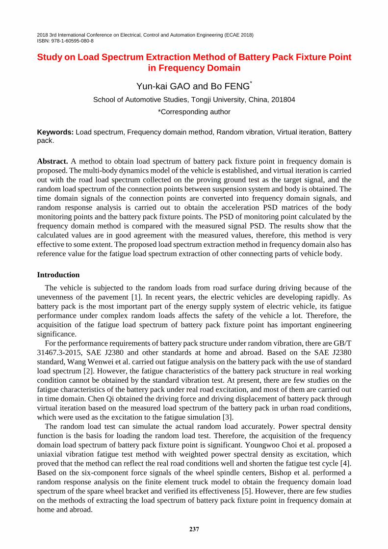
According to the connectivity of the suspension system as well as the geometric and mechanical
parameters of the vehicle, an accurate multi-body dynamics model of the vehicle is established. Then
the vehicle body is made flexible, and the rigid-flexible coupling model of the vehicle is shown as
Figure 1.
Figure 1. Rigid-flexible coupling model.
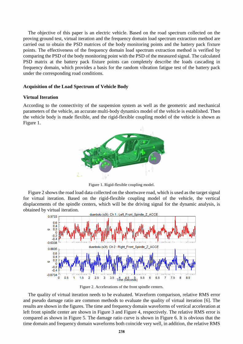
Figure 2 shows the road load data collected on the shortwave road, which is used as the target signal
for virtual iteration. Based on the rigid-flexible coupling model of the vehicle, the vertical
displacements of the spindle centers, which will be the driving signal for the dynamic analysis, is
obtained by virtual iteration.
Figure 2. Accelerations of the front spindle centers.
The quality of virtual iteration needs to be evaluated. Waveform comparison, relative RMS error
and pseudo damage ratio are common methods to evaluate the quality of virtual iteration [6]. The
results are shown in the figures. The time and frequency domain waveforms of vertical acceleration at
left front spindle center are shown in Figure 3 and Figure 4, respectively. The relative RMS error is
compared as shown in Figure 5. The damage ratio curve is shown in Figure 6. It is obvious that the
time domain and frequency domain waveforms both coincide very well, in addition, the relative RMS
238
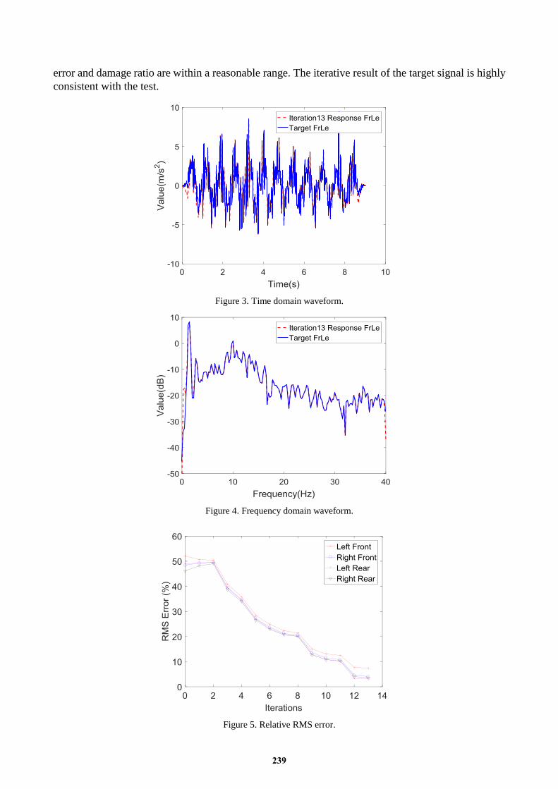
error and damage ratio are within a reasonable range. The iterative result of the target signal is highly
consistent with the test.
Figure 3. Time domain waveform.
Figure 4. Frequency domain waveform.
Figure 5. Relative RMS error.
239
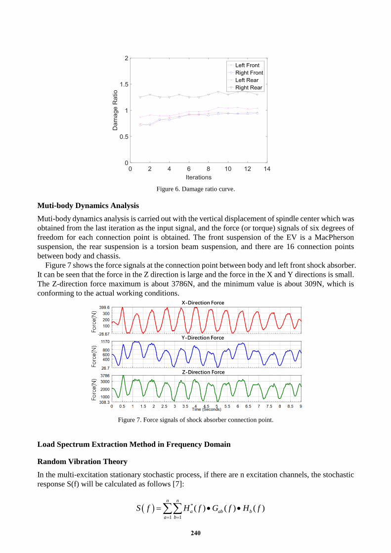
Figure 6. Damage ratio curve.
Muti-body Dynamics Analysis
Muti-body dynamics analysis is carried out with the vertical displacement of spindle center which was
obtained from the last iteration as the input signal, and the force (or torque) signals of six degrees of
freedom for each connection point is obtained. The front suspension of the EV is a MacPherson
suspension, the rear suspension is a torsion beam suspension, and there are 16 connection points
between body and chassis.
Figure 7 shows the force signals at the connection point between body and left front shock absorber.
It can be seen that the force in the Z direction is large and the force in the X and Y directions is small.
The Z-direction force maximum is about 3786N, and the minimum value is about 309N, which is
conforming to the actual working conditions.
Figure 7. Force signals of shock absorber connection point.
Load Spectrum Extraction Method in Frequency Domain
Random Vibration Theory
In the multi-excitation stationary stochastic process, if there are n excitation channels, the stochastic
response S(f) will be calculated as follows [7]:
*
1 1
( ) ( ) ( )n n
a ab b
a b
S f H f G f H f
240
Where, a and b: the ath
and the bth
excitation channels; Gab(f): the corresponding element in the
power spectral density function matrix; Hb(f): the transfer function corresponding to the bth
excitation
channel; H*
a (f): the conjugate complex of the transfer function.
S(f) can be displacement response, velocity response, acceleration response, or stress response. The
stress response can be further applied to vibration fatigue analysis, and the displacement, velocity or
acceleration response PSD matrix can be used for frequency domain load transfer calculation [5].
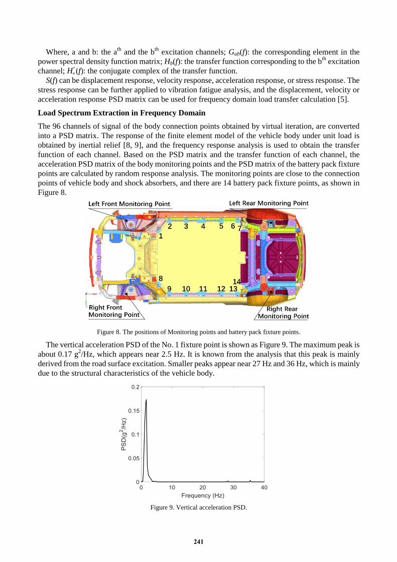
Load Spectrum Extraction in Frequency Domain
The 96 channels of signal of the body connection points obtained by virtual iteration, are converted
into a PSD matrix. The response of the finite element model of the vehicle body under unit load is
obtained by inertial relief [8, 9], and the frequency response analysis is used to obtain the transfer
function of each channel. Based on the PSD matrix and the transfer function of each channel, the
acceleration PSD matrix of the body monitoring points and the PSD matrix of the battery pack fixture
points are calculated by random response analysis. The monitoring points are close to the connection
points of vehicle body and shock absorbers, and there are 14 battery pack fixture points, as shown in
Figure 8.
Figure 8. The positions of Monitoring points and battery pack fixture points.
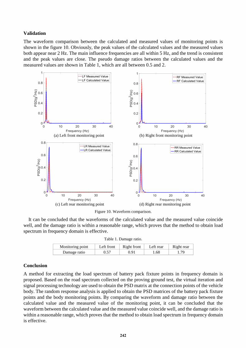
The vertical acceleration PSD of the No. 1 fixture point is shown as Figure 9. The maximum peak is
about 0.17 g2/Hz, which appears near 2.5 Hz. It is known from the analysis that this peak is mainly
derived from the road surface excitation. Smaller peaks appear near 27 Hz and 36 Hz, which is mainly
due to the structural characteristics of the vehicle body.
Figure 9. Vertical acceleration PSD.
241
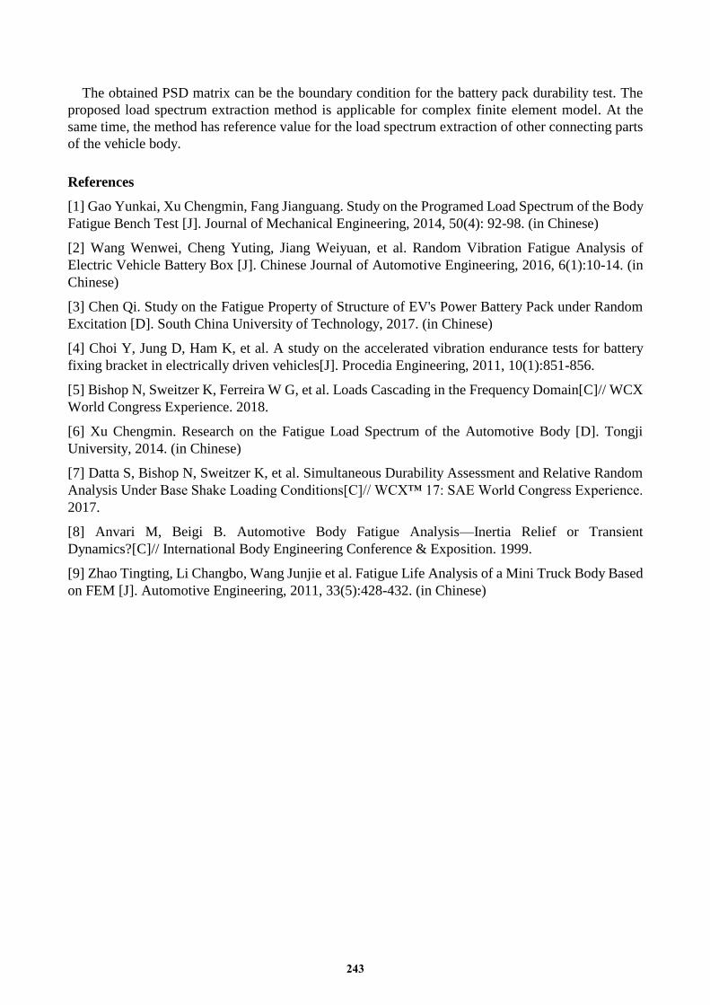
Validation
The waveform comparison between the calculated and measured values of monitoring points is
shown in the figure 10. Obviously, the peak values of the calculated values and the measured values
both appear near 2 Hz. The main influence frequencies are all within 5 Hz, and the trend is consistent
and the peak values are close. The pseudo damage ratios between the calculated values and the
measured values are shown in Table 1, which are all between 0.5 and 2.
(a) Left front monitoring point (b) Right front monitoring point
(c) Left rear monitoring point (d) Right rear monitoring point
Figure 10. Waveform comparison.
It can be concluded that the waveforms of the calculated value and the measured value coincide
well, and the damage ratio is within a reasonable range, which proves that the method to obtain load
spectrum in frequency domain is effective.
Table 1. Damage ratio.
Monitoring point Left front Right front Left rear Right rear
Damage ratio 0.57 0.91 1.68 1.79
Conclusion
A method for extracting the load spectrum of battery pack fixture points in frequency domain is
proposed. Based on the road spectrum collected on the proving ground test, the virtual iteration and
signal processing technology are used to obtain the PSD matrix at the connection points of the vehicle
body. The random response analysis is applied to obtain the PSD matrices of the battery pack fixture
points and the body monitoring points. By comparing the waveform and damage ratio between the
calculated value and the measured value of the monitoring point, it can be concluded that the
waveform between the calculated value and the measured value coincide well, and the damage ratio is
within a reasonable range, which proves that the method to obtain load spectrum in frequency domain
is effective.
242
The obtained PSD matrix can be the boundary condition for the battery pack durability test. The
proposed load spectrum extraction method is applicable for complex finite element model. At the
same time, the method has reference value for the load spectrum extraction of other connecting parts
of the vehicle body.
References
[1] Gao Yunkai, Xu Chengmin, Fang Jianguang. Study on the Programed Load Spectrum of the Body
Fatigue Bench Test [J]. Journal of Mechanical Engineering, 2014, 50(4): 92-98. (in Chinese)
[2] Wang Wenwei, Cheng Yuting, Jiang Weiyuan, et al. Random Vibration Fatigue Analysis of
Electric Vehicle Battery Box [J]. Chinese Journal of Automotive Engineering, 2016, 6(1):10-14. (in
Chinese)
[3] Chen Qi. Study on the Fatigue Property of Structure of EV's Power Battery Pack under Random
Excitation [D]. South China University of Technology, 2017. (in Chinese)
[4] Choi Y, Jung D, Ham K, et al. A study on the accelerated vibration endurance tests for battery
fixing bracket in electrically driven vehicles[J]. Procedia Engineering, 2011, 10(1):851-856.
[5] Bishop N, Sweitzer K, Ferreira W G, et al. Loads Cascading in the Frequency Domain[C]// WCX
World Congress Experience. 2018.
[6] Xu Chengmin. Research on the Fatigue Load Spectrum of the Automotive Body [D]. Tongji
University, 2014. (in Chinese)
[7] Datta S, Bishop N, Sweitzer K, et al. Simultaneous Durability Assessment and Relative Random
Analysis Under Base Shake Loading Conditions[C]// WCX™ 17: SAE World Congress Experience.
2017.
[8] Anvari M, Beigi B. Automotive Body Fatigue Analysis—Inertia Relief or Transient
Dynamics?[C]// International Body Engineering Conference & Exposition. 1999.
[9] Zhao Tingting, Li Changbo, Wang Junjie et al. Fatigue Life Analysis of a Mini Truck Body Based
on FEM [J]. Automotive Engineering, 2011, 33(5):428-432. (in Chinese)
243