students in natural sciences in Brazil - Optica Publishing Group
17
Some remarks of teaching "The Concepts in Experimental Optics" for students in natural sciences in Brazil Alberto Tufaile* a and Adriana P. B. Tufaile a a Soft Matter Lab., Escola de Artes, Ciências e Humanidades, Universidade de São Paulo, Av Arlindo Bettio 1000, Sao Paulo, SP, Brazil 03828-000 Abstract In Brazil, we’ve perceived that there is resistance to the learning of Optics by students who are not from the area of physics. The traditional way of teaching optics requires a prior knowledge of calculus that is not easy to students of the natural sciences. In order to solve this problem, we have developed an experimental optics discipline for undergraduate students in nature sciences: Concepts in Experimental Optics (Conceitos de Óptica Experimental, EACH-USP). This course is divided into three parts: (I) The Origin of Light, (II) The Path of Light and (III) The Light Destination. In the first part, we work with light emission spectra, continuum and ray spectra, using spectral lamps and everyday lamps. The second part presents the concepts and applications of Geometrical Optics and Wave Optics, including Geometrical Theory of Diffraction. The third part is about the absorption of light by matter with application in light detectors and photosynthesis. In the first lesson, we introduce the subject of human vision functioning, for interpretation of colors. The human vision is resumed in the third part. In Geometrical Optics we use images from works by artists such as René Magritte and M. C. Escher to encourage discussion about imaging. The emphasis of the discipline is to understand natural phenomena with as few calculations as possible and to encourage the demonstrations that can be made with everyday objects. We have taught this subject twice, 2017 and 2018, totaling 27 approved students with an average grade of approximately 87%. Keywords: practical activities, hands-on activities, conceptual optics, Geometrical Optics, Wave Optics, Geometrical Theory of Diffraction 1. INTRODUCTION Generally, Optics is presented to the students in the chronological order of the theory development. We choose an approach somehow like a narrative of the story of the light itself, dealing with the several possibilities of how "it is born", how it passes "its life" and how "it dies": origin, path and final destination of light. We find this approach more interesting because it avoids starting with Geometrical Optics which some students seem to identify with common sense. We are part of the faculty of a major in natural sciences. Our students will be science teachers for children and teenagers ages 6 to 18. They attend many disciplines in Biology, Physics, Chemistry, Geology, Mathematics, Education and Teaching. And a good part of them starts the professional life teaching Physics for adolescents, because there are many vacancies of this type in Brazil. Many of them begin the university course with great difficulty in Mathematics and with an aversion to Physics. The purpose of the discipline Concepts in Experimental Optics is to cover all major optical concepts, not limited to the subjects that future teachers will use in the classroom, with an attractive approach for the students, applying the optical concepts to understand effects of other sciences, common daily life and technology. We have used the book of P. G. Hewitt “Conceptual Physics” 1 and our “Da Física do Faraó ao Fóton” 2 (From Physics of Pharaoh to Photon), some papers like Berry 3 , Trikosko 4 , Kadri, Wei, Jaafar 5 , videos and applets online, but we also made videos showing natural phenomena that we could not replicate in the classroom and developed activities and demonstrations of our own. Part of the texts, images, videos and activities we created for this discipline are stored in digital media, using open social networks (Facebook, Twitter and YouTube) and part are in exclusive social networks of the university (Tidia-Ae). In previous work we have dealt with a similar interdisciplinary approach in teaching vibration and acoustics using Music and Geology 6,7 . This discipline has fifteen lessons, with four hours each. They happen from August to December. Every lesson starts with an introduction to the subject, presenting the main concepts, historical background and applications. In all lessons the students work in hands-on activities in small groups of three or two members and each group deliver a report at the end of the class, in which they write concepts, methods, simple analyzes, and conclusions. In the following sections, we describe each of the three parts of the course, and how learning is assessed. This is an elective discipline. *tufaile@usp.br; @Albertotufaile Fifteenth Conference on Education and Training in Optics and Photonics: ETOP 2019, edited by Anne-Sophie Poulin-Girard, Joseph A. Shaw, Proc. of SPIE Vol. 11143, 1114316 · © 2019 SPIE, ICO, IEEE, OSA · CCC code: 0277-786X/19/$18 · doi: 10.1117/12.2520615 Proc. of SPIE Vol. 11143 1114316-1
-
Upload
khangminh22 -
Category
Documents
-
view
1 -
download
0
Transcript of students in natural sciences in Brazil - Optica Publishing Group

Some remarks of teaching "The Concepts in Experimental Optics" for
students in natural sciences in Brazil
Alberto Tufaile*a and Adriana P. B. Tufailea
aSoft Matter Lab., Escola de Artes, Ciências e Humanidades, Universidade de São Paulo, Av Arlindo
Bettio 1000, Sao Paulo, SP, Brazil 03828-000
Abstract In Brazil, we’ve perceived that there is resistance to the learning of Optics by students who are not from the area of physics.
The traditional way of teaching optics requires a prior knowledge of calculus that is not easy to students of the natural
sciences. In order to solve this problem, we have developed an experimental optics discipline for undergraduate students
in nature sciences: Concepts in Experimental Optics (Conceitos de Óptica Experimental, EACH-USP). This course is
divided into three parts: (I) The Origin of Light, (II) The Path of Light and (III) The Light Destination. In the first
part, we work with light emission spectra, continuum and ray spectra, using spectral lamps and everyday lamps. The second
part presents the concepts and applications of Geometrical Optics and Wave Optics, including Geometrical Theory of
Diffraction. The third part is about the absorption of light by matter with application in light detectors and photosynthesis.
In the first lesson, we introduce the subject of human vision functioning, for interpretation of colors. The human vision is
resumed in the third part. In Geometrical Optics we use images from works by artists such as René Magritte and M. C.
Escher to encourage discussion about imaging. The emphasis of the discipline is to understand natural phenomena with as
few calculations as possible and to encourage the demonstrations that can be made with everyday objects. We have taught
this subject twice, 2017 and 2018, totaling 27 approved students with an average grade of approximately 87%.
Keywords: practical activities, hands-on activities, conceptual optics, Geometrical Optics, Wave Optics, Geometrical
Theory of Diffraction
1. INTRODUCTION
Generally, Optics is presented to the students in the chronological order of the theory development. We choose an approach
somehow like a narrative of the story of the light itself, dealing with the several possibilities of how "it is born", how it
passes "its life" and how "it dies": origin, path and final destination of light. We find this approach more interesting because
it avoids starting with Geometrical Optics which some students seem to identify with common sense.
We are part of the faculty of a major in natural sciences. Our students will be science teachers for children and teenagers
ages 6 to 18. They attend many disciplines in Biology, Physics, Chemistry, Geology, Mathematics, Education and
Teaching. And a good part of them starts the professional life teaching Physics for adolescents, because there are many
vacancies of this type in Brazil. Many of them begin the university course with great difficulty in Mathematics and with
an aversion to Physics. The purpose of the discipline Concepts in Experimental Optics is to cover all major optical concepts,
not limited to the subjects that future teachers will use in the classroom, with an attractive approach for the students,
applying the optical concepts to understand effects of other sciences, common daily life and technology.
We have used the book of P. G. Hewitt “Conceptual Physics”1 and our “Da Física do Faraó ao Fóton”2 (From Physics of
Pharaoh to Photon), some papers like Berry3, Trikosko4, Kadri, Wei, Jaafar5, videos and applets online, but we also made
videos showing natural phenomena that we could not replicate in the classroom and developed activities and
demonstrations of our own. Part of the texts, images, videos and activities we created for this discipline are stored in digital
media, using open social networks (Facebook, Twitter and YouTube) and part are in exclusive social networks of the
university (Tidia-Ae). In previous work we have dealt with a similar interdisciplinary approach in teaching vibration and
acoustics using Music and Geology6,7.
This discipline has fifteen lessons, with four hours each. They happen from August to December. Every lesson starts with
an introduction to the subject, presenting the main concepts, historical background and applications. In all lessons the
students work in hands-on activities in small groups of three or two members and each group deliver a report at the end of
the class, in which they write concepts, methods, simple analyzes, and conclusions. In the following sections, we describe
each of the three parts of the course, and how learning is assessed. This is an elective discipline.
*[email protected]; @Albertotufaile
Fifteenth Conference on Education and Training in Optics and Photonics: ETOP 2019, edited by Anne-Sophie Poulin-Girard, Joseph A. Shaw, Proc. of SPIE Vol. 11143, 1114316 · © 2019
SPIE, ICO, IEEE, OSA · CCC code: 0277-786X/19/$18 · doi: 10.1117/12.2520615
Proc. of SPIE Vol. 11143 1114316-1

2. METHODOLOGY
The teaching of Physics faces many problems and several proposals indicate the orientation of developing an education
aimed at full participation of students, who must be able to understand scientific and technological advances. Our
experience agrees with several reports pointing to the use of practical activities of various types in the teaching of Physics
allied to the methods that include the protagonism of the students2,8.
The first lesson begins with an introduction to the electromagnetic spectrum, locating visible light among other types. Then
we introduce the functioning of human vision to explain how we interpret the images, colors and movements we see. After
that, we enter the first part to deal with the emission of light. The class schedule is:
I. The Origin of Light 1st Introduction to spectral lamps. 2nd Measure of wavelengths of spectral lamps. 3rd Other light
sources (LEDs, common lamps, plasma globe, laser). Fluorescence and phosphorescence. 4th First Test, individual,
written, theoretical and practical (experiments). II. The Path of Light 5th Reflection, flat and curved mirrors,
kaleidoscopes. 6th Transformations of Moebius and Fractals. 7th Refraction in prisms, lenses and liquids, rainbow, total
internal reflection. 8th Apparatus with lenses (telescope, binoculars, cameras, etc.). 9th Second Test, oral presentation of
a demonstration, in small groups. 10th Diffraction and interference. 11th Structural Colors. 12th Geometrical Theory of
Diffraction. 13th Polarization and Birefringence. III. The Light Destination 14th Detectors, vision, photosynthesis. 15th
Third Test, individual, written, theoretical and practical (experiments).
The first part (The Origin of Light) and the last two classes (13th and 14th) are structured classes, where the objectives are
well defined and students need to verify or refute the validity of the theory presented through experimental methods, also
evaluating the proposal of the experiment. The second part of the course is based on the unstructured teaching technique,
in which the objectives of the subject studied need to be developed by the students after the presentation of the subject.
Students are encouraged to develop their own experimental methods and observation techniques within the laboratory's
capabilities, or other resources they have access to, such as science parks, their own resources, and materials from other
disciplines.
The evaluation process is done through tests, reports, oral presentations, homework. The two written tests are for individual
assessment, containing practical and theoretical activities, while the other activities are carried out by groups of two or
three students. The classroom activities involve the construction of equipment, data collection, analysis and comparison
with pre-established results, completion and reporting, evaluating all aspects of the class. Some activities may involve the
discussion of all students, such as the elaboration of the objectives of the lesson in the unstructured part of the discipline.
We are two professors responsible for all classes, activities and assessments. We are present throughout the class period.
While students are doing the practical activities, we are available to help them when they ask, or when we realize they
need help.
In the following sections we describe the methods used, putting more details on some procedures, for which we think there
has been some innovation in relation to the practical lessons of Optics, which are generally offered to physics students.
2.1 The Origin of Light
It covers several aspects of light emission. 1th and 2nd: We begin by presenting the electronic transitions inside the atoms
of a gas or a plasma, generating ray spectra characteristic of the chemical elements. And the almost infinite possible
electronic transitions between atoms or molecules of incandescent bodies generating a continuous spectrum1. Students
observe the light generated by spectral lamps with naked eye and with the help of diffraction grating. And they compare
with the light emitted by incandescent light bulbs. We discuss the color combination.
The students measure wavelengths of a ray spectrum, according to the method described in Fig. 1. a. One student is about
2 m away from de lamp, she or he is looking through a diffraction grade observing the colored rays over a ruler placed
beside the slit. This student using a diode laser point the position of a ray in the ruler. Another student, near the ruler, does
not see the ray, but see the position of the laser spot placed by the first student. So, they can measure x and y of the right
triangle, in order to discover the angle of the first order diffraction and use the expression of the wavelength:
= a sin (1)
Proc. of SPIE Vol. 11143 1114316-2

where a is the constant of the diffraction grating, this equation is valid for both sides first order diffraction images. This
method has been adapted from the instruction manual of the teaching apparatus9. We use a large right triangle (x ~ 2 m) to
have an acceptable experimental error in the wavelength result. The results obtained by the students agree with the values
tabulated within up to 5% difference, for the brightest rays of the Hg, Na and He lamps.
In the 3rd lesson, we discuss the emission of light in semiconductor materials with junction type N-P, to explain the
emission of light by light emitting diodes (LED)1,2,10, we also discuss the concepts of fluorescence and phosphorescence,
to explain the operation of the fluorescent lamps and the laser1. We used examples of the application of explanations to
other natural and artificial light sources, such as lightning, boreal and southern auroras, plasma globe, and various types of
illumination. The students measure the average wavelength of three monochromatic LEDs (red, green, blue). And they
play with LEDs arrays that you can choose the color using a remote control and observe the color components using
diffraction grating.
(a) (b)
Figure 1. (a) Method for measuring the wavelength of a spectral ray. A (blue) student about two meters from the spectral lamp
observes the light through the diffraction grating. She or he sees the slit through which the light from the lamp comes out
directly and sees the colored rays far horizontally from the slit. The colored rays are imagens of the slit and are superimposed
on the ruler, but only that (blue) student sees the rays over the ruler. The (red) student near the ruler does not see them, but
sees the location indicated by his colleague using a laser pointer. They use a measuring tape to find the length of the sides of
the right triangle (x and y) and determine the angle of the position of each ray. (b) Diffraction grating with a = 1.00 x 10⁻⁶ m.
In this part, we use diffraction gratings from the manufacturer Cidepe (Fig. 1. b) and peeled off CDs functioning as
transmissive diffraction gratings. We use peeled off CDs with the aim of encouraging the use of everyday objects.
We publish a video with translated name “Spectra of everyday lamps (with peeled off CD)”11. Where we show some of
the demonstrations and experiments used in this part of the course. In this video we use a peeled off CD to show the
continuous and ray spectra of natural and artificial light sources of students' daily life.
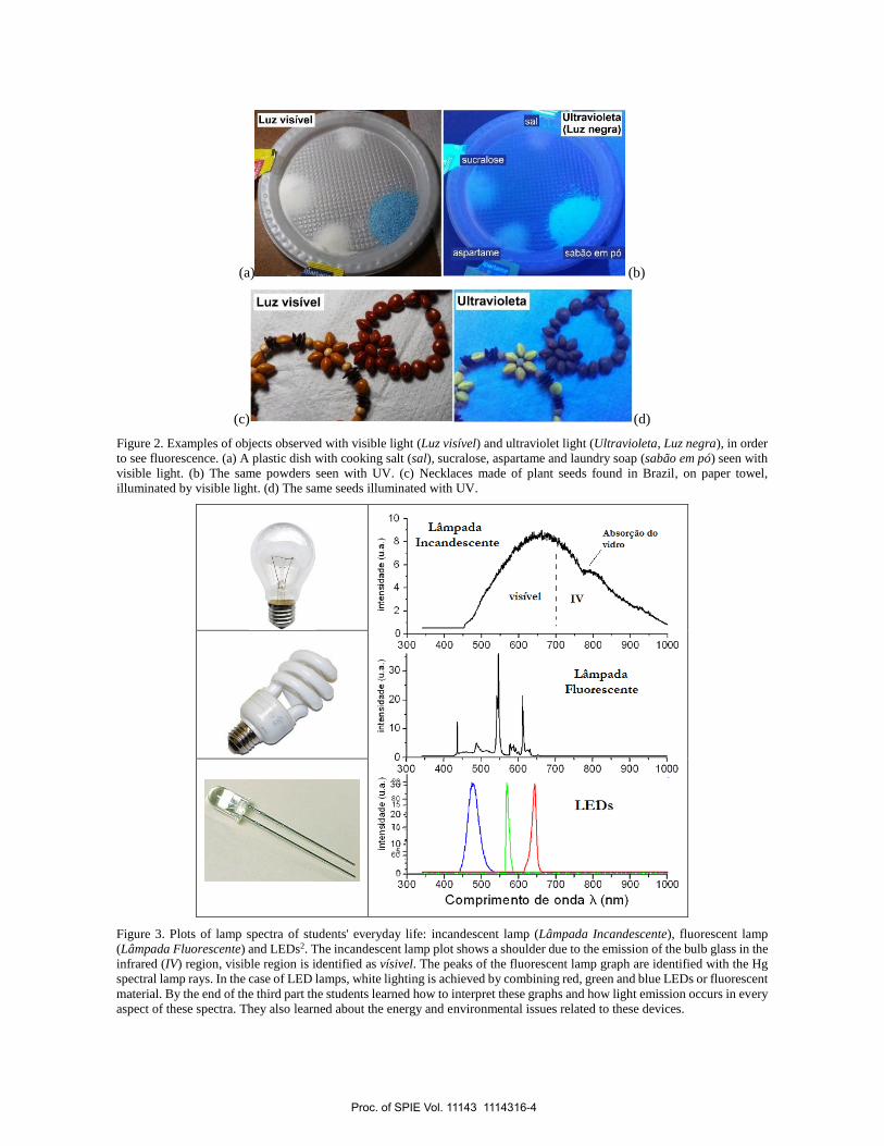
The students check the effects of fluorescence using UV lamps on fabrics such as cotton, money notes, sugar, salt and soap
powder and seeds (Fig. 2). They learn to use regular diffraction grating and parts of CDs (digital discs) to see the spectra.
They have written three group reports about the activities and they pass to a written individual test composed by theoretical
and experimental tasks. By the end of this first part, the students have learnt about natural and artificial light emission and
how ordinary lamps work, such as incandescent, fluorescent and LED bulb, so they are able to understand the spectra as
shown in Fig. 3. When we looked at the plots in Fig. 3, we discussed the energy efficiency issues of the three basic lamp
types. We also discuss issues related to the financial and environmental costs of manufacturing, operating and disposing
of these types of lamps. Several figures here have words in Portuguese, because they are part of the text we have written
for students. There are translations in the corresponding figure captions.
Proc. of SPIE Vol. 11143 1114316-3
(a) (b)
(c) (d)
Figure 2. Examples of objects observed with visible light (Luz visível) and ultraviolet light (Ultravioleta, Luz negra), in order
to see fluorescence. (a) A plastic dish with cooking salt (sal), sucralose, aspartame and laundry soap (sabão em pó) seen with
visible light. (b) The same powders seen with UV. (c) Necklaces made of plant seeds found in Brazil, on paper towel,
illuminated by visible light. (d) The same seeds illuminated with UV.
Figure 3. Plots of lamp spectra of students' everyday life: incandescent lamp (Lâmpada Incandescente), fluorescent lamp
(Lâmpada Fluorescente) and LEDs2. The incandescent lamp plot shows a shoulder due to the emission of the bulb glass in the
infrared (IV) region, visible region is identified as vísivel. The peaks of the fluorescent lamp graph are identified with the Hg
spectral lamp rays. In the case of LED lamps, white lighting is achieved by combining red, green and blue LEDs or fluorescent
material. By the end of the third part the students learned how to interpret these graphs and how light emission occurs in every
aspect of these spectra. They also learned about the energy and environmental issues related to these devices.
Proc. of SPIE Vol. 11143 1114316-4

2.2 The Path of Light
The second part of the course presents Geometrical Optics, Wave Optics, including polarization, and Geometrical Theory
of Diffraction. It begins with the concepts of reflection in flat and curved mirrors. In this part, the students learn how to
connect some concepts of topology and fractals with optics, using Möbius transformations in kaleidoscopes, Christmas
balls and of reflective spoons. Then they study the concept of refraction of light using prisms, lenses, liquids, applying to
the phenomenon of the rainbow and analyzing the effect of total internal reflection. Next, students come into contact with
the use of lenses in devices such as telescopes, binoculars and cameras. The students build demonstrations of devices such
as dark cameras, microscopes with webcams, they explore the use of optical fibers and the formation of image in the eye.
Next, we present the concepts of diffraction and light interference using single and double slits, hair, structural colors in
diffraction gratings, CD and soap films, Geometrical Theory of Diffraction and polarization of light. 3D cinema is one of
the applications of light polarization, among others, such as the partial polarization of light scattered across the sky,
polarization of the rainbow, displays of liquid crystals (LCD) and the phenomenon of birefringence of plastics and calcite.
2.2.1 Geometrical Optics
In the study of Geometrical Optics, we have used art works by René Magritte12 and M. C. Escher13, see Fig. 4. We presented
three objects (a glass ball and two Christmas tree balls) similarly to the work of M. C. Escher "Three Spheres II", 1946,
and we show an image of this work. We encourage a discussion about how light interacts with these bodies and what role
materials and surfaces play. At the conclusion of this discussion we turn off the light of the room to observe the effects of
a disco ball hanging from the ceiling and illuminated by the light of the projector. When students were encouraged to apply
the conclusions of the discussion to the disco ball phenomena. We used several other works by Escher, as he has explored
many optical phenomena, including when we did activities with kaleidoscopes and topology. We use several images of
Magritte works to stimulate a discussion of image formation and other phenomena such as illumination. These discussions
using the works of Escher and Magritte were especially stimulating for students, as it is a challenging approach to a subject
that is usually very simplistically treated in physics courses.
Practical activities with mirrors included flat and curved mirrors, kaleidoscopes, fractal images using kaleidoscopes of
Christmas tree balls and stainless-steel spoons3,14,15. We set up a Hall of Mirrors (Sala de espelhos), show in Fig. 5, which
is a kaleidoscope with six large flat mirrors (0.9 m x 1.8 m each one) forming a hollow prism of regular hexagonal cross-
section. This is a kaleidoscope in which people can get in, close the door and perceive the many different images of
themselves. The students had this experience and showed great enthusiasm, taking photos and videos with their
Smartphones. We discuss the Moebius transformations in the kaleidoscopes and topology aspects, which included the
projections of the sphere (with application in cartography), where we also use images of Escher works. Concluding the
discussion about topology the students constructed a tri-hexaflexagon using a sheet of paper, using the technique shown
in our video: “Topologia: de Moebius ao Flexágono”16 (“Topology: from Moebius to Flexagon”).
The 7th lesson is about light refraction, when we discussed how light crosses transparent media with a microscopic model1,
how propagation speed varies with wavelength and what happens when light changes medium. We speak of homogeneous
and non-homogeneous media17 and of total internal reflection. We use images, videos and demonstrations with prisms,
glass sphere and liquids, showing the change of light direction in refraction, total internal reflection and how it can be
frustrated. Before presenting rainbow images, we asked the students what details they could remember from their own
observations and knowledge about this phenomenon. Most cited only colored bow with seven stripes, some quoted the
possibility of two arcs but did not know about the inverted order of colors in the two arcs. Asked about the position of the
image in relation to the Sun, few could answer correctly. Inspired by W. Lewin "Rainbows and Blue Sky"18 and in the
work of H. M. Nussenzveig19, we present explanations of the details of the rainbow, describing this phenomenon as a
colored caustic. Still on the rainbow, we made a video showing that it is polarized light20, which in that lesson was shown
only as motivation for the study of light polarization. This part of the lesson was summarized in the video with translated
name as “Rainbow a colorful caustic”21.
On non-homogeneous media, where differential refraction occurs, we present videos showing the mirage effect, Fata
Morgana effect17 and the distortion of the Sun near the horizon, as can be seen in Fig. 6. We also did a video showing and
explaining the mirage effect happening in a hot road22. During the first time we taught this lesson, we used mirage-effect
videos available on YouTube, where the mirage is seen on a road by a camera that has fixed position on the ground. At the
end of the explanation and observation of the videos, a student asked, "There was water on the road, was not there?" Then
Proc. of SPIE Vol. 11143 1114316-5

we realized that it would be better to also show a video in which the camera travels along the road and shows that there is
no water at the site of the mirage, as we show in this video.
(a) (b)
(c) (d)
Figure 4. (a) Students were encouraged to discuss concepts of Geometrical Optics starting from questions about how light
interacts with three spheres portrayed by M. C. Escher. (b) Then they had to apply their conclusions to explain what they
observed with a disco ball hanging from the ceiling illuminated by the projector, see the small spots of light in the room. (c)
La condition humanaine, (d) L’empire des lumières are examples of images of René Magritte's works presented to stimulate
a discussion involving image formation and illumination.
Figure 5. Students inside the big kaleidoscope called Hall of Mirrors no Espaço Ciência, Cultura e Educação (ECCE), which
is a space for scientific dissemination in the EACH-USP.
Proc. of SPIE Vol. 11143 1114316-6

Figure 6. Example of differential refraction distorting the apparent format of the Sun during sunrise. Assembly made with
images extracted from our video translated as “Sun rising (differential refraction)”23.
During this lesson, the students did a quantitative practical activity by measuring the variation of the refractive index of
the water, when it dissolves salt. An intense green laser diode beam is refracted by an acrylic cuvette filled with water, the
incidence and refraction angles are measured, and the refractive index of the water is calculated. Without turning off the
laser, they mixed salt into the water and watched the beam move. The visual effect is great because we use great distance,
in this way, we are watching the refracted beam reach the wall on the other side of the room (about 5 meters away). The
students are surprised by the large displacement of the light spot on the wall. Measuring the new angle of exit they were
able to calculate the new refractive index and showed contentment by the understanding of the numbers, therefore, the
measured quantities make some sense to them because they observed the phenomenon. We did not give instructions on
how to measure the angles, an important part of the activity was that they planned and executed the measurements using
simple tools available, such as rulers and protractor.
The next lesson was about applying refraction to lenses and devices with lenses. We start by putting the example of
correction glasses and what is the relation between the focal distance and the diopter, called degree of glasses in Brazil,
that is the magnitude of everyday life. Next, we discussed and demonstrated imaging effects with spherical and thin lenses,
and students manipulated various devices with lenses. The practical activity was to set up a camera using a common
magnifying glass, a cardboard box and a sheet of translucid paper as screen.
2.2.2 Introduction to Wave Optics
The 9th was the Second Test described in section 2.4 Evaluation. In the 10th and 11th lessons, we present Wave Optics or
Physical Optics discussing the phenomena of diffraction, interference and structural colors. Practical activities were both
qualitative and quantitative. We made demonstrations using cheap laser pointers and objects such as wires and hair of
different thicknesses, razor blades borders, handmade slits, color observation in soap films, diffraction gratings and CDs.
For the quantitative experiments the students used diffraction and interference kits from Pasco, to measure the width of a
slit. And they measured the wavelength of a laser beam using the diffraction grating shown in Fig. 1, using the method
very similar to that used in the Light Origin, as described in Fig. 7.
We also used peeled off CDs as a transmissive diffraction grating and DVDs as reflective diffraction grating, as shown in
Fig. 8. The distances between the grooves are a = 1.6 x 10⁻⁶ m for CD and a = 7.4 x 10⁻⁷ m for DVD24. In these experiments
we used diode laser found in laser light projector for decorations, that has a good light intensity. Regarding the use of these
discs as diffraction gratings, it should be noticed that grooves are curved in this case, which causes differences and
asymmetries when compared to experiments using standard gratings. But students soon find the best positions the beam
should reach the disc, to have more symmetry between the two-sided images and less distortion. The experimental results
are as good as the ones reached by using standard gratings.
Proc. of SPIE Vol. 11143 1114316-7

Figure 7. Method for finding the wavelength of a laser beam using diffraction grating (grade de difração) and tape measure
(trena). This method is very similar to the one described in Fig. 1. We can compare the distances between the first order spots
(1ª ordem) and the zero order spot, to improve alignment and achieve a right triangle. We measure the legs (cateto oposto,
cateto adjacente) with the tape measure, to calculate the hypotenuse and the sine of the angle corresponding to the first order
of diffraction.
(a) (b)
Figure 8. To show that we can do Wave Optics experiments with everyday objects, students also used peeled off CDs (a) and
DVDs (b) as transmissive and reflective diffraction gratings. The class of 2018 used the standard diffraction grating to find
the wavelength of the laser. They exchanged the standard grid for the peeled off CD and found the CD constant.
2.2.3 Geometrical Theory of Diffraction
We started the 12th lesson showing the divisions of Optics (see Fig. 9) and the position of the Geometrical Theory of
Diffraction (GTD) developed by Keller25. We discuss the models used throughout the history of Optics and in every
branches of that science: concepts such as particles, rays, waves, wave-particle duality.
Keller's theory is applied in Engineering, in systems involving acoustics and high-frequency radio waves. Keller
reinterpreted the Huygens principle using Young's principle, emphasizing the directionality of the wave and works well in
the interface between Geometrical Optics and Wave Optics because he writes the electric field of light as a linear
combination of wave and geometric models:
EGTD = EGeomOpt + EWaveOpt (2)
where and are adjusted as required25. This theory was little used for the explanation of optical phenomena. By studying
the laser beam scattering by soap foam26, we came across with the light pattern shown in Fig. 10 and we noticed the need
to apply the GTD to explain the cone of light diffracted by liquid wires present in the foam27. By studying the optical
phenomenon in detail, we notice that the half opening angle of the cone of diffracted light is equal to complementary angle
of reflection, so, it is a wave phenomenon that occurs at an angle of reflection, as if it were a ray of light. This realization
led us to GTD. We can change the radius of the circle by varying the angle of incident beam on the liquid thread, known
Proc. of SPIE Vol. 11143 1114316-8
as Plateau border. When the laser beam reaches the wire perpendicular to the direction defined by the thread, we have the
Fraunhofer diffraction.
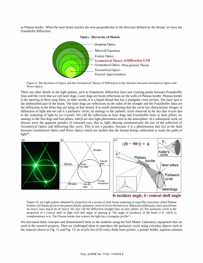
Figure 9. The divisions of Optics and the Geometrical Theory of Diffraction in the interface between Geometrical Optics and
Wave Optics.
There are other details in the light pattern, such as Fraunhofer diffraction lines and crossing points between Fraunhoffer
lines and the circle that we call laser dogs. Laser dogs are beam reflections on the walls of Plateau border. Plateau border
is the meeting of three soap films, in other words, it is a liquid thread that has a triangular cross section. The laser spot is
the undisturbed part of the beam. The laser dogs are reflections on the sides of the triangle and the Fraunhoffer lines are
the diffraction in the films that are lying on that thread. It is worth mentioning that the circle has characteristic fringes of
diffraction of light and we call it a parlaseric circle, by analogy to the parhelic circle observed in the sky that occurs due
to the scattering of light by ice crystals. We call the reflections as laser dogs and Fraunhoffer lines as laser pillars, by
analogy to the Sun dogs and Sun pillars, which are also light phenomena seen in the atmosphere. In a subsequent work we
discuss more the apparent paradox of refracted rays, that is, light obeying simultaneously the law of the reflection of
Geometrical Optics and diffracting like wave. This is not a paradox, because it is a phenomenon that lies in the limit
between Geometrical Optics and Wave Optics which are models that the human beings elaborated to study the paths of
light28.
Figure 10. (a) Light pattern obtained by projection on a screen of laser beam scattering in soap film structures called Plateau
borders. (b) Names given to the pattern details: parlaseric circle (Círculo Parlasérico), diffraction (Difração), laser spot (Ponto
do laser), laser dog (Cão de laser). We also call the diffraction straight lines as laser pillars. (c) The parlaseric circle is the
projection of a conical shell of light with half angle of opening . The angle of incidence of the beam is which is
complementary to he Plateau border that scatters the light has a triangular profile27.
We discussed these concepts and demonstrated them to the students using the Soft Matter Laboratory equipment that we
used in the research projects. Then we challenged them to reproduce the parlaseric circle using everyday objects such as
the material shown in Fig. 11 and Fig. 12: an acrylic box (CD case), diode laser pointer, a pointer holder, aqueous solution
Proc. of SPIE Vol. 11143 1114316-9

of detergent, as shown in our video29 “Faça um HALO com LASER” translated as “Make a HALO with LASER”. Thickness
and smooth surfaces of soap films make them great candidates for Wave Optics experiments, as students had already
learned in class about structural colors.
Figure 11. The CD case has soap films that diffracts the laser beam (No estojo de CD tem filme de sabão que difrata o feixe
laser). The laser beam must reach a Plateau Border. (O feixe laser deve incidir numa Borda de Plateau). The Plateau borders
are formed in the encounter of liquid films of soap solutions. In these images we can see two Plateau borders that can be used
in the experiment. To get these films, we plunged the opened acrylic box into the detergent solution, closed the box and took
it out slowly, letting the solution run, more details in the video “Make a HALO with LASER”29.
Figure 12. Objects found in the house that can be used for observation of the parlaseric circle. CD case (narrow acrylic box),
laser pointer, a tall and thin object used as a pointer holder and aqueous detergent solution.
We also present a demonstration of a parlaseric circle using a Ferrocell (Fig. 13), known as a magnetic lens30. In that case,
there is a superparamagnetic liquid called ferrofluid, which consists of ferromagnetic nanoscopic particles suspended in
an oil. When there is no external magnetic field, the magnetic moment of the particles distributes randomly, so the liquid
does not present macroscopic magnetization. When we apply a magnetic field, for example, by approximating a magnet,
the magnetic moments of the particles align with the field and the attraction between the particles makes needle-like
agglomerates as can be seen in the micrograph of Fig. 13. b. The needles are aligned with the magnetic field, so the needles
are parallel to each other. When there is an incident laser beam, without the magnet field, we see only two laser spots,
reflections on Ferrocell glass plates, Fig. 13. c. When the external magnetic field is applied, we see a parlaseric circle
which is the sum of many parlaseric circles, one for each needle the beam strikes, Fig. 13. d. Here there are no fringes of
diffraction because there is superposition of several circles. So, we have a fringe-free parlaseric circle when there is Keller
diffraction on many aligned nanoscopic needles.
Proc. of SPIE Vol. 11143 1114316-10

Now the analogy with the light patterns seen in the sky makes more sense, if we think of the ice crystals in suspension in
the atmosphere as needles aligned with each other. Then there is the possibility that for certain atmospheric conditions,
where ice crystals are microscopic needles or long prisms, that their alignment occurs by effects such as aerodynamics or
electric field, since the ice crystals may be electrically charged, or polarized, as they are made of water. We use Figure 14,
to discuss this model in which the atmosphere is seen as a complex fluid with properties similar to ferrofluid, liquid crystal,
and layers of micelles. Sunlight is a plane wave like the laser beam, but with all wavelengths visible. This model may be
one of the possibilities for explaining the occurrence of the parhelic circle in the atmosphere. The most common
explanation is also presented to students, in which sunlight is scattered by ice crystals in the form of horizontal hexagonal
plates in all directions, following the laws of Geometrical Optics31. Other atmospheric phenomena were presented with
our images or others available online, such as halos, glory effect, sun miracle, iridescent clouds. We also present results
from our work with jumping laser dogs in which we make analogy with the jumping Sun dogs, using the model of
suspended crystals in the atmosphere as a complex fluid.
Figure 13. (a) Ferrocell is composed of two flat glass plates, between them there is a thin layer of ferrofluid, as a sandwich.
Ferrofluid is a suspension of ferromagnetic particles. (b) When an external magnetic field is applied, there is the alignment of
the particles making needle-shaped agglomerates, which can be seen in the micrograph. (c) Without magnetic field, an incident
laser beam is only reflected by the glass plates and a little bit scattered by the ferrofluid without macroscopic magnetization.
(d) When we apply a magnetic field, the nanoscopic needles line up with the external field and we see a continuous parlaseric
circle which is the overlap of diffraction in the various needles reached by the beam30.
Figure 14. Diagram used to make the analogy between the parlaseric circle and the parhelic circle, modeling the suspended
ice crystals in the atmosphere as a complex fluid.
Proc. of SPIE Vol. 11143 1114316-11

2.2.4 Light Polarization and Birefringence
The 13th lesson is about light polarization and birefringence. We discuss theoretical concepts and applications by making
various demonstrations with polarizing filters, LCD displays, polarizing (linear) sunglasses, 3D cinema glasses (circular
polarizers), birefringent objects (calcite and plastics), examples in Figure 15, several are in our video about light
polarization and birefringence32. The videos are good for showing blue sky and rainbow polarization effects and online
images like F. Snik's "Reflecting Beetles"33 showing circular polarization effect of reflected light on beetles are examples
of application of concepts in natural phenomena that we could not reproduce in the didactic laboratory.
(a)
(b)
Figure 15. Examples of demonstrations of polarization and birefringence. (a) Overlap of polarizers on the LCD screen of a
notebook. (b) Plastic object superimposed on the LCD screen, observed without and with polarizer, showing a birefringence
colored effect.
The good conceptual discussion of this lesson was achieved with the seemingly simple demonstration using only three
polarizing filters, which can be explained by the vector transverse-wave model. First the students see the light from a
ceiling lamp of the room cross a polarizer, then add a second polarizer and rotate one of them observing the variation of
the luminous intensity that crosses the pair of filters. With the axes of the double crossed, in such a way that the luminous
Proc. of SPIE Vol. 11143 1114316-12
intensity is minimal, the third polarizer is added between them with axis at an angle of approximately 45° with respect to
the axes of the pair. The visual effect is wow type. The students discussed and experimented until they found the transversal
field vector explanation.
Another important activity was students wearing 3D movie glasses, looking at the mirrors and closing one eye. For
example, when we close the left eye and only looking through the right eye, we cannot see the right eye in the mirror. The
light could not pass through the same polarized lens twice, because one lens is a left circular polarizer, the other lens is
right circular polarizer, and the reflection in the mirror inverts the circular polarization. We heard some wow moments.
We discussed the differences between sunglasses that have two equally linearly polarizing lenses and the 3D cinema glasses
with different circular polarization orientations lens. We also discussed the stereoscopic effect of vision to explain how the
3D cinema works.
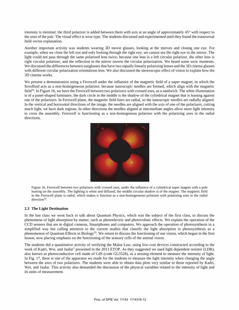
We present a demonstration using a Ferrocell under the influence of the magnetic field of a super magnet, in which the
ferrofluid acts as a non-homogeneous polarizer, because nanoscopic needles are formed, which align with the magnetic
field34. In Figure 16, we have the Ferrocell between two polarizers with crossed axes, as a sandwich. The white illumination
is of a panel-shaped luminaire, the dark circle in the middle is the shadow of the cylindrical magnet that is leaning against
one of the polarizers. In Ferrocell plane, the magnetic field lines are radial, so the nanoscopic needles are radially aligned.
In the vertical and horizontal directions of the image, the needles are aligned with the axis of one of the polarizers, cutting
much light, we have dark regions. In other directions the needles aligned at intermediate angles allow more light intensity
to cross the assembly. Ferrocell is functioning as a non-homogenous polarizer with the polarizing axes in the radial
directions.
Figure 16. Ferrocell between two polarizers with crossed axes, under the influence of a cylindrical super magnet with a pole
leaning on the assembly. The lighting is white and diffused, the middle circular shadow is of the magnet. The magnetic field
in the Ferrocell plane is radial, which makes it function as a non-homogeneous polarizer with polarizing axes in the radial
direction34.
2.3 The Light Destination
In the last class we went back to talk about Quantum Physics, which was the subject of the first class, to discuss the
phenomena of light absorption by matter, such as photoelectric and photovoltaic effects. We explain the operation of the
CCD sensors that are in digital cameras, Smartphones and computers. We approach the operation of photosynthesis in a
simplified way but calling attention to the current studies that classify the light absorption in photosynthesis as a
phenomenon of Quantum Effects in Biology35. We return to discuss the functioning of our vision, which began in the first
lesson, now placing emphasis on the functioning of the sensory cells of the animal vision.
The students did a quantitative activity of verifying the Malus Law, using low-cost devices constructed according to the
work of Kadri, Wei, and Jaafar5 presented in the 2013 ETOP. As they suggested we used light dependent resistor (LDR),
also known as photoconductive cell made of CdS (code GL5528), as a sensing element to measure the intensity of light.
In Fig. 17, there is one of the apparatus we made for the students to measure the light intensity when changing the angle
between the axes of two polarizers. The students were able to obtain data plots very similar to those reported by Kadri,
Wei, and Jaafar. This activity also demanded the discussion of the physical variables related to the intensity of light and
its units of measurement.
Proc. of SPIE Vol. 11143 1114316-13

Figure 17. Device constructed according to the work of Kadri, Wei, and Jaafar5 for study Malus Law. Close-up of the light
detector, a LDR, photoconductive cell made of CdS.
2.4 Evaluation
The students went through several types of evaluation: individual, group, written, oral, theoretical and practical. During
each class, the students worked in groups of three or doubles and at the end of the class each group delivered a written
report, containing introduction, drawings and diagrams, results, analyzes and conclusions. These reports were returned in
the following class with the relevant assessment grade and comments. The quality of these reports increases with passing
the classes, because initially some students are not experienced in reporting physics experiments but learn from mistakes.
Working in groups poses challenges to students, but they improve their social skills and learn various things from their
peers. We call the arithmetic mean of the notes (grades) of the reports of R. All grades are in the range of 0 to 10.
The first and third tests were written and done individually. The students answered the theoretical conceptual questions
and did quantitative practical activities. The second test was an oral presentation in groups of two or three students. The
presentation is to make a demonstration of an optical phenomenon and explain it to the class. Students can freely choose
the subject covered and the material used. In Fig. 18 and Fig. 19, we can see imagens of demonstrations that students did
in the second test. This test causes a lot of anxiety in most students, but they perform well in the demonstration and rarely
comment on conceptual errors in the explanation. They practice their oral communication skills and once again learn from
their colleagues. As several will be physics teachers, these activities are especially important for professional preparation.
So far, the subjects chosen by the students for this test are diverse, most can be classified as Geometrical Optics, but we
have already seen approaches using quantum physics, such as wave-particle duality, phosphorescence experiments,
microscope construction using web cam, and Wave Optics experiments. Some groups use ready-made materials, such as
the one in Fig. 18, but most build their demonstration with everyday material, sometimes elaborated assemblies, sometimes
simply as pictured in Fig. 19. We consider all student choices very important, mainly because shows the various
possibilities of practical activities to the class. We calculated, T, the weighted arithmetic mean of the test grades, with
weight 1 for the first and second test and weight 2 for the third test.
Some homework assignments were requested for the students, for preparation or supplementation of the classes, some of
these were done in a double or group of three students. We call the arithmetic mean of the grades of the homework as HW.
The final grade, FG, is calculated as FG = 0,3R + 0,1HW + 0,6T. Therefore, the tests grades have great weight, but the
reports grade mean also has great weight.
Proc. of SPIE Vol. 11143 1114316-14
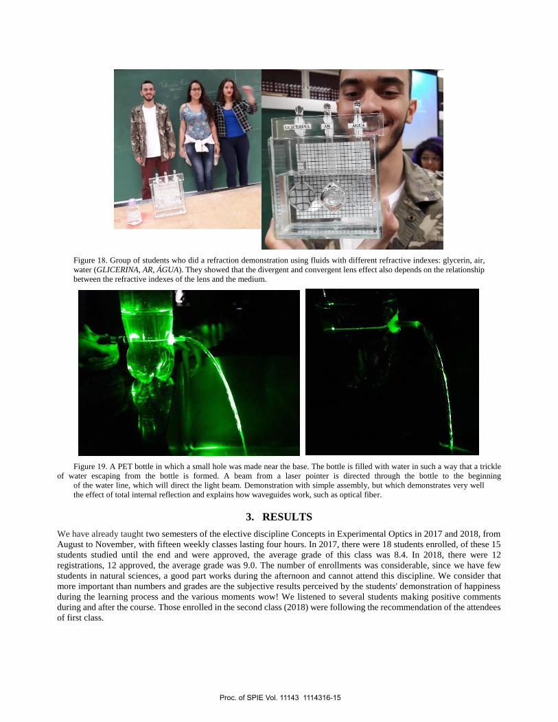
Figure 18. Group of students who did a refraction demonstration using fluids with different refractive indexes: glycerin, air,
water (GLICERINA, AR, ÁGUA). They showed that the divergent and convergent lens effect also depends on the relationship
between the refractive indexes of the lens and the medium.
Figure 19. A PET bottle in which a small hole was made near the base. The bottle is filled with water in such a way that a trickle
of water escaping from the bottle is formed. A beam from a laser pointer is directed through the bottle to the beginning
of the water line, which will direct the light beam. Demonstration with simple assembly, but which demonstrates very well
the effect of total internal reflection and explains how waveguides work, such as optical fiber.
3. RESULTS
We have already taught two semesters of the elective discipline Concepts in Experimental Optics in 2017 and 2018, from
August to November, with fifteen weekly classes lasting four hours. In 2017, there were 18 students enrolled, of these 15
students studied until the end and were approved, the average grade of this class was 8.4. In 2018, there were 12
registrations, 12 approved, the average grade was 9.0. The number of enrollments was considerable, since we have few
students in natural sciences, a good part works during the afternoon and cannot attend this discipline. We consider that
more important than numbers and grades are the subjective results perceived by the students' demonstration of happiness
during the learning process and the various moments wow! We listened to several students making positive comments
during and after the course. Those enrolled in the second class (2018) were following the recommendation of the attendees
of first class.
Proc. of SPIE Vol. 11143 1114316-15

Several of these students will begin their professional lives teaching physics in schools with little or no equipment to do
practical activities and will eventually get to work in schools with well-equipped physics laboratories. That is why we
teach them how to use didactic kits from manufacturers, but also to set up experiments with everyday objects.
We noticed that this discipline greatly broadens the knowledge of these students, in addition to broadening their interest in
mathematics. Some practical activities developed or used in this discipline were also used in other disciplines at EACH-
USP. In all classes, several students demonstrated greater interest and a better understanding of the subject matter. The
approach using the story of the light itself had a positive subjective result, as it presented subjects of modern physics early
on, for which the students showed considerable interest. An example: on her own initiative, a student used her Smartphone
to photograph effects that she found interesting during the class and broadcast on social networks, telling what she was
doing and learning at that moment. She has published at least one photo in each class, showing great enthusiasm.
In all classes, we present several applications of the concepts to understand optical phenomena and how the concepts are
applied in the technologies that surround us. This has raised many questions posed by students and facial or oral expressions
of understanding. We consider it important to present results of our research in Physics, because in addition to deepening
some issues and giving a different view, shows how we use scientific methods, and this can be a good example of coping
with issues. Several natural science students follow their academic career and will work with research in a branch of the
natural sciences, so these moments may be important to them as well.
The environment provided by practical activities and great proximity of professors provides more opportunities for
interaction and learning, as well as for professors to evaluate students' understanding informally.
4. CONCLUSIONS
The two classes that have already experienced this discipline took advantage of the approach focused on practical activities
and concepts. Unstructured teaching activities are extremely challenging for students, placing them as collaborators and
protagonists of learning.
The moments of application of scientific research, scientific dissemination and formal and non-formal education were very
well received. The success is attested by the good performance of the students and the animation they have shown.
During our experience of applying this discipline, we observed that students have a great interest in learning the optics of
natural phenomena such as rainbows, halos, jumping sundogs, glory effect, mirages, and structural color of animals. We
see a lot of interest in understanding how human vision, cameras, and 3D cinema work.
ACKNOWLEDGMENTS
This work was partially supported by Conselho Nacional de Desenvolvimento Científico e Tecnológico (CNPq),
Instituto Nacional de Ciência e Tecnologia de Fluidos Complexos (INCT-FCx), and by Fundação de Amparo à Pesquisa
do Estado de São Paulo (FAPESP) FAPES/CNPq#573560/2008-0.
REFERENCES
[1] Hewitt, P. G., [Conceptual Physics], Addison-Wesley, USA (2009).
[2] Tufaile, A. and Tufaile A. P. B., [Da Física do Faraó ao Fóton], Editora Livraria da Física, São Paulo, Brazil
(2013).
[3] Berry, M. V., “Reflections on a Christmas-tree bauble,” Physics Education 7, N.1, 1-6 (1972).
[4] Trikosko, W., “Physics in a Glitter Ball,” The Physics Teacher 49, 110-111 (2011).
[5] Kadri, S., Wei, D. C. B., Jaafar, R., “Student Activity: Verification on Malus's Law of Polarization at Low
Cost,” Proc. SPIE 9289, 12th Education and Training in Optics and Photonics Conference, 928992A, 1-9 (17
July 2014). doi:10.1117/12.2070727
[6] Tufaile, A. P. B., Tufaile, A., Mendes, C. M., Livério Jr, A. C., Santos, E. M., Imbernon, R. A. L., “Paleolithic
rock & roll: making music with granite and slate,” In The Trenches 4(4), 15-16 (2014).
[7] Santos, E. M., Molina, C., Tufaile, A. P. B., “Violão e guitarra como ferramentas para o ensino de Física,” Rev.
Bras. Ens. Fís. 35, N.2, 1-7 (2013).
Proc. of SPIE Vol. 11143 1114316-16
[8] Araújo, M. S. T., and Abib, M. L. V. S., “Atividades Experimentais no Ensino de Física: Diferentes Enfoques,
Diferentes Finalidades,” Rev. Bras. Ens. Fís. 25, 176-194 (2003).
[9] CIDEPE Centro Industrial de Equipamentos de Ensino e Pesquisa, “Conjunto para análise espectral e efeito
fotoelétrico II,” EQ256A.
[10] Tufaile, A. P. B. and Tufaile, A., “LEDs e a reinvenção da lâmpada,” Revista Ambiente Legal 12, 18-19 (2014).
[11] Tufaile, A. P. B. and Tufaile, A., “Espectros de lâmpadas do cotidiano (c/ CD desencapado)” YouTube,
https://youtu.be/wLXyNrb48II (30 April 2019).
[12] Meuris, J., [René Magritte 1898-1967], Taschen, Germany (1993).
[13] Ernst, B., [O espelho mágico de M. C. Escher], Taschen, Germany (2007).
[14] Tufaile, A. and Tufaile, A. P. B., “Hyperbolic Prism, Poincaré Disc, and Foams,” In: Skiadas, C. H., Skiadas, C.
(Org.) Handbook of Applications of Chaos Theory, Chapman and Hall/CRC, FL, EUA 627-635 (2016).
[15] Tufaile, A. and Tufaile, A. P. B., “Hyperbolic prisms and foams in Hele-Shaw cells,” Phys. Lett. A 375, 3693–
3698 (2011).
[16] Tufaile, A. P. B. and Tufaile, A., “Topologia: de Moebius ao Flexágono,” YouTube,
https://youtu.be/VxiBbTObXCo (30 April 2019).
[17] Young, A. T. and Frappa, E., “Mirages at Lake Geneva: the Fata Morgana,” Applied Optics 56, N. 19, G59-G58
(2017).
[18] Lewin, W., "Rainbows and Blue Sky" YouTube, https://www.youtube.com/watch?v=6QVbE_tU2sA (30 April
2019).
[19] Nussenzveig, H. M., “The theory of the rainbow,” American Scientist, 116-127 (1977).
[20] Tufaile, A. P. B. and Tufaile, A., “O arco-íris é polarizado” YouTube, https://youtu.be/d4Y3bA_-rUM (30
April 2019).
[21] Tufaile, A. P. B. and Tufaile, A., “Arco-íris uma cáustica colorida,” YouTube, https://youtu.be/8sPQQpTvSiM
(30 April 2019).
[22] Tufaile, A. P. B. and Tufaile, A., “Miragem na estrada (explicação ao final),” YouTube,
https://youtu.be/Ahb2QetjwyI (30 April 2019).
[23] Tufaile, A. P. B. and Tufaile, A., “Sol nascendo (refração diferencial),” YouTube,
https://youtu.be/x8ki-q7rPPs (30 April 2019).
[24] “DVD,” Wikipedia, https://en.wikipedia.org/wiki/DVD (30 April 2019).
[25] Keller, J. B., “Geometrical Theory of Diffraction,” Journal of the Optical Society of America 5, n. 2, 116-130
(1962).
[26] Tufaile, A., Ventura, M. F., Tufaile, A. P. B., “Some aspects of image processing using foams,” Physics Letters
A 378, 3111-3117 (2014).
[27] Tufaile, A. and Tufaile, A. P. B., “Parhelic-like circle from light scattering in Plateau borders,” Physics Letters
A 379, 529-534 (2015).
[28] Tufaile, A. and Tufaile, A. P. B., “The dynamics of diffracted rays in foams,” Physics Letters A 379, 3059-3068
(2015).
[29] Tufaile, A. and Tufaile, A. P. B., “Faça um HALO com LASER,” YouTube, https://youtu.be/IEsX4bDUu5U (30
April 2019).
[30] Tufaile, A., Vanderelli, T. A., Tufaile, A. P. B., “Observing the jumping laser dogs,” Journal of Applied
Mathematics and Physics 4, 1977-1988 (2016).
[31] Greenler, R., [Rainbows, halos, and glories], Cambridge University Press, Cambridge, UK (1980).
[32] Tufaile, A. P. B. and Tufaile, A., “Efeitos de polarização e birrefringência. Óculos cinema 3D,” YouTube,
https://youtu.be/bbFGZTU7LvU (30 April 2019).
[33] Snik, F., “Reflecting Beetles,” Honorable mention 2017 After Image photo contest, Optics & Photonics News,
https://www.osa-pn.org/home/gallery/photo_contests/2017/reflecting_beetles/ (30 April 2019).
[34] Tufaile, A., Vanderelli, T. A., Tufaile, A. P. B., “Light Polarization Using Ferrofluids and Magnetic Fields,”
Advances in Condensed Matter Physics 2017, 1-7 (2017).
[35] Wills, S., “Quantum Effects in Biology,” Optics & Photonics News, April, 42-49 (2019).
Proc. of SPIE Vol. 11143 1114316-17
![[C. Lemmi] Optica de Fourier](https://static.fdokumen.com/doc/165x107/6315892e511772fe4510654e/c-lemmi-optica-de-fourier.jpg)