applied sciences
23
applied sciences Article Design of a Two-DOFs Driving Mechanism for a Motion-Assisted Finger Exoskeleton Giuseppe Carbone 1,2, * , Eike Christian Gerding 3 , Burkard Corves 3 , Daniele Cafolla 4 , Matteo Russo 5 and Marco Ceccarelli 6 1 DIMEG, University of Calabria, 87036 Rende, Italy 2 CESTER, Technical University of Cluj-Napoca, 400114 Cluj-Napoca, Romania 3 IGMR, RWTH Aachen University, 52062 Aachen, Germany; [email protected] (E.C.G.); [email protected] (B.C.) 4 IRCCS Istituto Neurologico Mediterraneo Neuromed, 86077 Pozzilli, Italy; [email protected] 5 Faculty of Engineering, University of Nottingham, Nottingham NG7 2RD, UK; [email protected] 6 LARM2, Laboratory of Robot Mechanics, University of Rome “Tor Vergata”, 00133 Rome, Italy; [email protected] * Correspondence: [email protected] Received: 12 March 2020; Accepted: 8 April 2020; Published: 10 April 2020 Abstract: This paper presents a novel exoskeleton mechanism for finger motion assistance. The exoskeleton is designed as a serial 2-degrees-of-freedom wearable mechanism that is able to guide human finger motion. The design process starts by analyzing the motion of healthy human fingers by video motion tracking. The experimental data are used to obtain the kinematics of a human finger. Then, a graphic/geometric synthesis procedure is implemented for achieving the dimensional synthesis of the proposed novel 2 degrees of freedom linkage mechanism for the finger exoskeleton. The proposed linkage mechanism can drive the three finger phalanxes by using two independent actuators that are both installed on the back of the hand palm. A prototype is designed based on the proposed design by using additive manufacturing. Results of numerical simulations and experimental tests are reported and discussed to prove the feasibility and the operational effectiveness of the proposed design solution that can assist a wide range of finger motions with proper adaptability to a variety of human fingers. Keywords: bionic mechanism design; synthesis; exoskeleton; finger motion rehabilitation 1. Introduction Aging of population and stroke incidence are expected to significantly increase in the coming decades and become the second leading cause of disability in Europe as forecast, for example, in [1,2]. Usually, a stroke produces neuro-motory disabilities, including finger impairments. Since the movement of fingers is fundamental in activities of daily life, there is a strong motivation in focusing on finger rehabilitation as a high priority following an injury or a stroke. Several studies have shown that the rehabilitation after a stroke is faster and more cost effective when using a robotic system as compared to conventional rehabilitation methods, as reported, for example, in [3]. Accordingly, researchers have widely addressed the topic for developing finger exoskeletons and/or similar wearable devices for finger rehabilitation and exercising, as reported, for example, in [4–21]. The “index finger exoskeleton” reported by Agarwal et al. [4] consists of eight linkages that are actuated by two cable drives. The exoskeleton has three DOFs (degrees of freedom) in total, as each Appl. Sci. 2020, 10, 2619; doi:10.3390/app10072619 www.mdpi.com/journal/applsci
-
Upload
khangminh22 -
Category
Documents
-
view
1 -
download
0
Transcript of applied sciences

applied sciences
Article
Design of a Two-DOFs Driving Mechanism for aMotion-Assisted Finger Exoskeleton
Giuseppe Carbone 1,2,* , Eike Christian Gerding 3, Burkard Corves 3 , Daniele Cafolla 4,Matteo Russo 5 and Marco Ceccarelli 6
1 DIMEG, University of Calabria, 87036 Rende, Italy2 CESTER, Technical University of Cluj-Napoca, 400114 Cluj-Napoca, Romania3 IGMR, RWTH Aachen University, 52062 Aachen, Germany; [email protected] (E.C.G.);
[email protected] (B.C.)4 IRCCS Istituto Neurologico Mediterraneo Neuromed, 86077 Pozzilli, Italy; [email protected] Faculty of Engineering, University of Nottingham, Nottingham NG7 2RD, UK;
[email protected] LARM2, Laboratory of Robot Mechanics, University of Rome “Tor Vergata”, 00133 Rome, Italy;
[email protected]* Correspondence: [email protected]
Received: 12 March 2020; Accepted: 8 April 2020; Published: 10 April 2020�����������������
Abstract: This paper presents a novel exoskeleton mechanism for finger motion assistance.The exoskeleton is designed as a serial 2-degrees-of-freedom wearable mechanism that is ableto guide human finger motion. The design process starts by analyzing the motion of healthy humanfingers by video motion tracking. The experimental data are used to obtain the kinematics of ahuman finger. Then, a graphic/geometric synthesis procedure is implemented for achieving thedimensional synthesis of the proposed novel 2 degrees of freedom linkage mechanism for the fingerexoskeleton. The proposed linkage mechanism can drive the three finger phalanxes by using twoindependent actuators that are both installed on the back of the hand palm. A prototype is designedbased on the proposed design by using additive manufacturing. Results of numerical simulations andexperimental tests are reported and discussed to prove the feasibility and the operational effectivenessof the proposed design solution that can assist a wide range of finger motions with proper adaptabilityto a variety of human fingers.
Keywords: bionic mechanism design; synthesis; exoskeleton; finger motion rehabilitation
1. Introduction
Aging of population and stroke incidence are expected to significantly increase in the comingdecades and become the second leading cause of disability in Europe as forecast, for example,in [1,2]. Usually, a stroke produces neuro-motory disabilities, including finger impairments. Since themovement of fingers is fundamental in activities of daily life, there is a strong motivation in focusingon finger rehabilitation as a high priority following an injury or a stroke.
Several studies have shown that the rehabilitation after a stroke is faster and more cost effectivewhen using a robotic system as compared to conventional rehabilitation methods, as reported,for example, in [3]. Accordingly, researchers have widely addressed the topic for developing fingerexoskeletons and/or similar wearable devices for finger rehabilitation and exercising, as reported, forexample, in [4–21].
The “index finger exoskeleton” reported by Agarwal et al. [4] consists of eight linkages that areactuated by two cable drives. The exoskeleton has three DOFs (degrees of freedom) in total, as each
Appl. Sci. 2020, 10, 2619; doi:10.3390/app10072619 www.mdpi.com/journal/applsci

Appl. Sci. 2020, 10, 2619 2 of 23
linkage between the exoskeleton and finger has one DOF. Each linkage consists of four links and fourjoints with one DOF each. The exoskeleton allows flexion and extension of all phalanxes of the fingeras well as passive abduction and adduction of the first phalanx. This exoskeleton is quickly adjustableand has a low resistance against finger movement when the motors are not activated. The deviceapplies 80 g to the finger, and it has five angle-sensors to monitor link orientations. The index-fingerexoskeleton uses a closed-loop torque-control with maximum torque at the first phalanx equal to250 Nmm. The maximum torque at the second phalanx is 50 Nmm [4].
The exoskeleton reported by Bataller et al. [5] is optimized by an evolutionary synthesis algorithm.The synthesis determines the link length of the mechanism design to fulfill a given coupler curvewith high accuracy. The kinematic structure of the device is set before the synthesis. It consists ofseven links that are fixed on the back of the hand and on each phalanx, resulting in one DOF in total.A video analysis of the healthy finger motion acquires the coupler curve. The phalanx lengths of apatient’s finger are acquired by an X-ray. The proposed exoskeleton is manufactured for each patientindividually by 3D-printing and it has one servo motor.
Amadeo is a commercial hand and finger rehabilitation device that has been developed byTyromotion GmbH [6]. The fingertips can be connected to the caps of the exoskeleton while beingadjustable to different finger sizes. Each cap is attached to an automated linear slide. The fingertipscan be pushed with a predefined force, and the device can move the finger while they apply no force.In this way, a grasping activity is simulated. The arm and wrist are fixed on the device frame, and thefinger caps are connected to a slider. All fingers and the thumb can be treated. The device also allowsfor several measurements, such as force and range of motion (ROM). In [7], it is reported that 70% ofthe ROM of a healthy finger is sufficient for rehabilitation motions.
The Script SPO-F exoskeleton [8] is a passive device with no motor but a spring as the actuator.It consists of six links and seven joints with only one DOF. Earlier versions of this exoskeleton havebeen bulky, complex, and reached a weight of 1.5 kg. The Script SPO-F is actually an exoskeleton forboth the wrist and the hand. It is designed for home-usage during rehabilitation treatment. The fingeris flexed by a user, and a spring exerts a force on the finger due to the deflection. In contrast to otherexoskeletons, it has no predetermined trajectory. The finger can be moved due to a cable connectionbetween the fingertip and the exoskeleton. As the fingertip is fixed, only first and second phalanxescan move. A torque of about 125 Nmm is needed for a 90◦ flexion of the second phalanx.
The hand exoskeleton version HX [11] is suitable for both the index finger and the thumb.The exoskeleton has five DOFs and is driven by cables. The weight of the index finger module is 118 g,and the total weight lying on the hand is 438 g. The exoskeleton is made of a 3D-printed titanium alloy.
At LARM (Laboratory of Robotics and Mechatronics), a specific research line has been addressingthe development of exoskeletons for motion assistance, as reported, for example, in [22–24].Moreover, [25–27] focus on the fundamentals of the mechanics of grasping as well as the designand validation of anthropomorphic robotic hands. The LARM robotic hands are based on a drivingmechanism with linkages that remain within the finger body duringthe finger operation, as reportedin [28–30]. The design of such a driving mechanism is the conceptual reference for the exoskeletonsolution that is reported in [24] and in preliminary exoskeleton designs, as reported in [31–34].
The main problem with existing exoskeletons is that they are often not wearable by differentpatients, as in 4,5], are bulky, and the overall equipment is not easily transportable, such as in [6] or isheavy, such as in [11]. Commercial robots, as in [6], are considered too expensive for home rehabilitationuse. Further, the Amadeo device is not able to fulfill a complete grasping movement. The solutionin [8] has no defined trajectory to move all joints of the finger in a defined way. Accordingly, theauthors believe there is still a need for a design procedure that can lead to novel design solutions asbased on kinematic analysis and a proper mechanism synthesis referring to the specific task of fingermotion assistance.
This paper aims at a systematic design approach towards a novel two-DOFs driving linkagemechanism for a motion assistance finger exoskeleton by presenting a novel design solution for a
Appl. Sci. 2020, 10, 2619 3 of 23
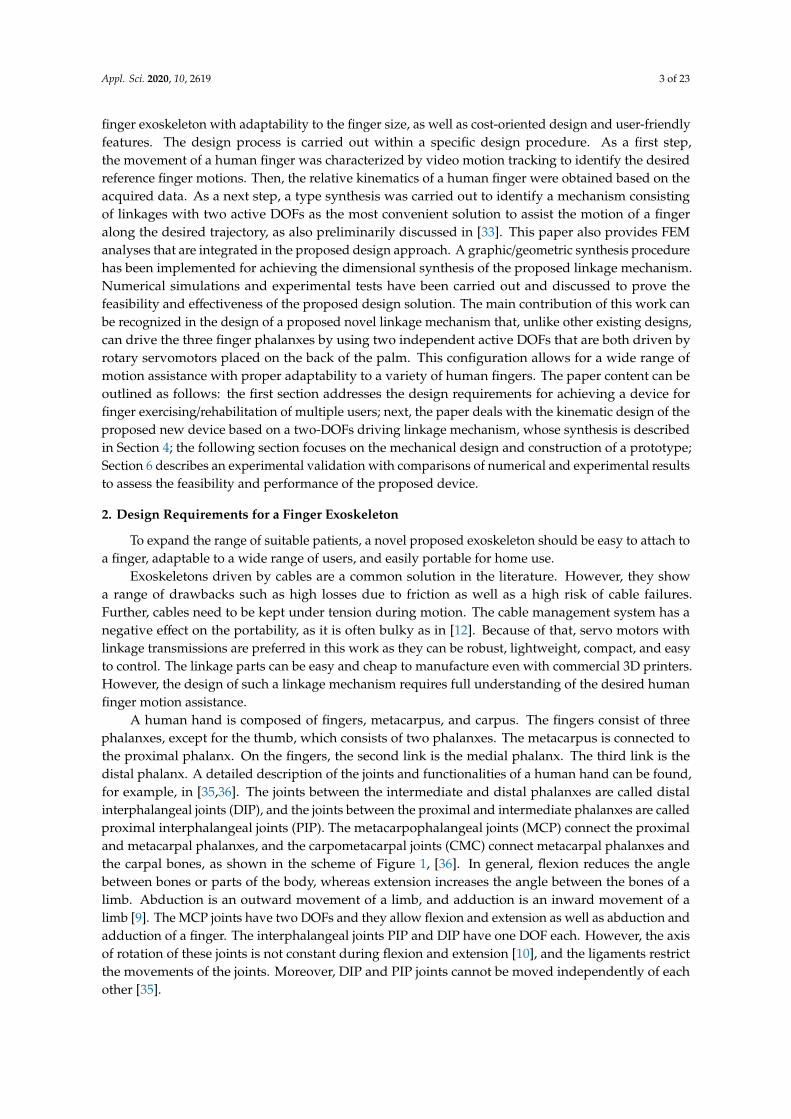
finger exoskeleton with adaptability to the finger size, as well as cost-oriented design and user-friendlyfeatures. The design process is carried out within a specific design procedure. As a first step,the movement of a human finger was characterized by video motion tracking to identify the desiredreference finger motions. Then, the relative kinematics of a human finger were obtained based on theacquired data. As a next step, a type synthesis was carried out to identify a mechanism consistingof linkages with two active DOFs as the most convenient solution to assist the motion of a fingeralong the desired trajectory, as also preliminarily discussed in [33]. This paper also provides FEManalyses that are integrated in the proposed design approach. A graphic/geometric synthesis procedurehas been implemented for achieving the dimensional synthesis of the proposed linkage mechanism.Numerical simulations and experimental tests have been carried out and discussed to prove thefeasibility and effectiveness of the proposed design solution. The main contribution of this work canbe recognized in the design of a proposed novel linkage mechanism that, unlike other existing designs,can drive the three finger phalanxes by using two independent active DOFs that are both driven byrotary servomotors placed on the back of the palm. This configuration allows for a wide range ofmotion assistance with proper adaptability to a variety of human fingers. The paper content can beoutlined as follows: the first section addresses the design requirements for achieving a device forfinger exercising/rehabilitation of multiple users; next, the paper deals with the kinematic design of theproposed new device based on a two-DOFs driving linkage mechanism, whose synthesis is describedin Section 4; the following section focuses on the mechanical design and construction of a prototype;Section 6 describes an experimental validation with comparisons of numerical and experimental resultsto assess the feasibility and performance of the proposed device.
2. Design Requirements for a Finger Exoskeleton
To expand the range of suitable patients, a novel proposed exoskeleton should be easy to attach toa finger, adaptable to a wide range of users, and easily portable for home use.
Exoskeletons driven by cables are a common solution in the literature. However, they showa range of drawbacks such as high losses due to friction as well as a high risk of cable failures.Further, cables need to be kept under tension during motion. The cable management system has anegative effect on the portability, as it is often bulky as in [12]. Because of that, servo motors withlinkage transmissions are preferred in this work as they can be robust, lightweight, compact, and easyto control. The linkage parts can be easy and cheap to manufacture even with commercial 3D printers.However, the design of such a linkage mechanism requires full understanding of the desired humanfinger motion assistance.
A human hand is composed of fingers, metacarpus, and carpus. The fingers consist of threephalanxes, except for the thumb, which consists of two phalanxes. The metacarpus is connected tothe proximal phalanx. On the fingers, the second link is the medial phalanx. The third link is thedistal phalanx. A detailed description of the joints and functionalities of a human hand can be found,for example, in [35,36]. The joints between the intermediate and distal phalanxes are called distalinterphalangeal joints (DIP), and the joints between the proximal and intermediate phalanxes are calledproximal interphalangeal joints (PIP). The metacarpophalangeal joints (MCP) connect the proximaland metacarpal phalanxes, and the carpometacarpal joints (CMC) connect metacarpal phalanxes andthe carpal bones, as shown in the scheme of Figure 1, [36]. In general, flexion reduces the anglebetween bones or parts of the body, whereas extension increases the angle between the bones of alimb. Abduction is an outward movement of a limb, and adduction is an inward movement of alimb [9]. The MCP joints have two DOFs and they allow flexion and extension as well as abduction andadduction of a finger. The interphalangeal joints PIP and DIP have one DOF each. However, the axisof rotation of these joints is not constant during flexion and extension [10], and the ligaments restrictthe movements of the joints. Moreover, DIP and PIP joints cannot be moved independently of eachother [35].

Appl. Sci. 2020, 10, 2619 4 of 23
Appl. Sci. 2020, 10, x FOR PEER REVIEW 4 of 23
exoskeleton, its installation space needs to be small enough to be attached onto the finger and not interfere with its motion. For the same reason, the total weight of the system should not exceed 500 g as reported, for example, in [7,13,17]. This value should be considered an upper bound, since a heavy exoskeleton can limit the effectiveness of motion exercising. Indeed, a high weight makes a patient easily tired and not willing to continue the treatment. Thus, it is advisable to limit the number of motors as they are the main source of weight. Motors need to provide a minimum torque of around 200 Nmm as reported previously [3,7].
One of the main peculiarities of the proposed novel linkage mechanism design solution is that it can move all three phalanxes of a human finger with two active DOFs. This is mainly achieved by coupling the motion of the last two phalanxes. Accordingly, only two DOFs are needed to replicate whole finger motions. The proposed mechanism is optimized to perform a specific desired motion but it is actually able to perform a wide range of other motion combinations, given its two active degrees of freedom. The proposed design is limited to flexion and extension movements of a finger. However, flexion and extension are identified in literature as the most important for activities of daily life and the first recovery priority in case of finger injury, as also mentioned in [35,36]. Therefore, a motion assistance mechanism at first instance does not need to focus on abduction and adduction movements, and these movements can be safely neglected to achieve a device with a light and simple design.
Figure 1. A scheme of bones and joints in a human hand.
(a) (b)
Figure 2. Desired motion assistance for a finger that moves from fully open (a) to fully closed (b).
3. Kinematic Design
Figure 1. A scheme of bones and joints in a human hand.
A finger exoskeleton can be conveniently designed for motion exercising of the muscles after aninjury or a stroke. For this application, the motion of a finger will be assisted by the exoskeleton witha motion trajectory similar to a healthy finger of the same size as proposed in Figure 2. The motiontrajectory does not require high accuracy. For example, in [11], a misalignment of a phalanx up to±8◦ is deemed acceptable. However, unnatural movements of the finger must be avoided by themechanism to prevent potential injuries. As an additional design requirement for a finger exoskeleton,its installation space needs to be small enough to be attached onto the finger and not interfere with itsmotion. For the same reason, the total weight of the system should not exceed 500 g as reported, forexample, in [7,13,17]. This value should be considered an upper bound, since a heavy exoskeleton canlimit the effectiveness of motion exercising. Indeed, a high weight makes a patient easily tired and notwilling to continue the treatment. Thus, it is advisable to limit the number of motors as they are themain source of weight. Motors need to provide a minimum torque of around 200 Nmm as reportedpreviously [3,7].
Appl. Sci. 2020, 10, x FOR PEER REVIEW 4 of 23
exoskeleton, its installation space needs to be small enough to be attached onto the finger and not interfere with its motion. For the same reason, the total weight of the system should not exceed 500 g as reported, for example, in [7,13,17]. This value should be considered an upper bound, since a heavy exoskeleton can limit the effectiveness of motion exercising. Indeed, a high weight makes a patient easily tired and not willing to continue the treatment. Thus, it is advisable to limit the number of motors as they are the main source of weight. Motors need to provide a minimum torque of around 200 Nmm as reported previously [3,7].
One of the main peculiarities of the proposed novel linkage mechanism design solution is that it can move all three phalanxes of a human finger with two active DOFs. This is mainly achieved by coupling the motion of the last two phalanxes. Accordingly, only two DOFs are needed to replicate whole finger motions. The proposed mechanism is optimized to perform a specific desired motion but it is actually able to perform a wide range of other motion combinations, given its two active degrees of freedom. The proposed design is limited to flexion and extension movements of a finger. However, flexion and extension are identified in literature as the most important for activities of daily life and the first recovery priority in case of finger injury, as also mentioned in [35,36]. Therefore, a motion assistance mechanism at first instance does not need to focus on abduction and adduction movements, and these movements can be safely neglected to achieve a device with a light and simple design.
Figure 1. A scheme of bones and joints in a human hand.
(a) (b)
Figure 2. Desired motion assistance for a finger that moves from fully open (a) to fully closed (b).
3. Kinematic Design
Figure 2. Desired motion assistance for a finger that moves from fully open (a) to fully closed (b).
One of the main peculiarities of the proposed novel linkage mechanism design solution is that it canmove all three phalanxes of a human finger with two active DOFs. This is mainly achieved by couplingthe motion of the last two phalanxes. Accordingly, only two DOFs are needed to replicate whole fingermotions. The proposed mechanism is optimized to perform a specific desired motion but it is actually

Appl. Sci. 2020, 10, 2619 5 of 23
able to perform a wide range of other motion combinations, given its two active degrees of freedom.The proposed design is limited to flexion and extension movements of a finger. However, flexion andextension are identified in literature as the most important for activities of daily life and the firstrecovery priority in case of finger injury, as also mentioned in [35,36]. Therefore, a motion assistancemechanism at first instance does not need to focus on abduction and adduction movements, and thesemovements can be safely neglected to achieve a device with a light and simple design.
3. Kinematic Design
The index finger of a healthy subject has been used as a reference to develop and validate theproposed novel exoskeleton. First, grasping motions have been analyzed by using the ComputerVision Toolbox of MATLAB (Mathworks, Natick, MA, USA). Markers have been attached to the jointsof the index finger and its fingertip (FT). Distances between the markers have been also measured witha digital caliper for calibration purposes. The camera has been aligned perpendicular to the side of thefinger under study, and a fixing frame has been used both for the hand and camera in order to achievea planar motion of the finger and a fully orthogonal video recording. The acquired videos have beenpost-processed to collect positions of the joints versus time. Figure 3 shows the experimental setup forthe finger motion tracking as well as the definition of the angles and reference frame with the x-axishorizontal oriented from left to right, and the y-axis vertical oriented from top to bottom. The z-axis isdefined according to the right-hand rule. The origin of the reference frame is attached to the center ofthe MCP joint. The angle of the MCP joint is called ϕ, the angle of the PIP joint is called ε, and theangle of the DIP joint is called τ. The angles have a clockwise positive direction.
Appl. Sci. 2020, 10, x FOR PEER REVIEW 5 of 23
The index finger of a healthy subject has been used as a reference to develop and validate the proposed novel exoskeleton. First, grasping motions have been analyzed by using the Computer Vision Toolbox of MATLAB (Mathworks, Natick, Massachusetts, USA). Markers have been attached to the joints of the index finger and its fingertip (FT). Distances between the markers have been also measured with a digital caliper for calibration purposes. The camera has been aligned perpendicular to the side of the finger under study, and a fixing frame has been used both for the hand and camera in order to achieve a planar motion of the finger and a fully orthogonal video recording. The acquired videos have been post-processed to collect positions of the joints versus time. Figure 3 shows the experimental setup for the finger motion tracking as well as the definition of the angles and reference frame with the x-axis horizontal oriented from left to right, and the y-axis vertical oriented from top to bottom. The z-axis is defined according to the right-hand rule. The origin of the reference frame is attached to the center of the MCP joint. The angle of the MCP joint is called φ, the angle of the PIP joint is called ε, and the angle of the DIP joint is called τ. The angles have a clockwise positive direction.
The lengths of the phalanxes of a test subject were identified from set-up measurements as 25 mm for the distal phalanx, 28 mm for the medial phalanx, and 43 mm for the proximal phalanx. Twenty-two frames have been evaluated from the motion tests for a suitable finger motion characterization. Figure 2 shows a detail of a video-captured motion for a healthy human finger movement referring to a typical human finger motion. In particular, the plot in Figure 4 shows trajectories of PIP, DIP, and FT markers during the motion of an index finger that moves from fully open to fully close. These trajectories will be used as the reference motion trajectories for the linkage mechanism of the proposed novel exoskeleton. However, the desired exercising motion usually does not require the full joint feasible rotation range of the motion range of a healthy human finger but only a subset of such a motion.
Moreover, it is advisable to avoid full finger closing as this would result in an undesired interference with the palm. A specific linkage mechanism has been identified as convenient for mimicking the desired reference finger motion. This proposed mechanism consists of eight links that are arranged as two interconnected four-bar mechanisms. This specific linkage arrangement has been proposed as an Italian patent [34]. The proposed mechanism requires two motors that each drive one of the two four-bar mechanisms. A detailed kinematic scheme is shown in Figure 5. The motors are located at joints D0 and B0. The angle of driving link D0-D is called δ. The angle of the driving link B0-B is called β. Both angles are positive in a clockwise direction. The first four-bar linkage (D0-D-E-MCP) has four links and four revolute joints with one active DOF. The second four-bar linkage (B0-B-A-A0-C) has one active DOF, four links, and four revolute joints.
(a) (b)
Figure 3. Experimental setup for finger motion video tracking (a) and definition of angles of the finger joints (b). Figure 3. Experimental setup for finger motion video tracking (a) and definition of angles of the fingerjoints (b).
The lengths of the phalanxes of a test subject were identified from set-up measurements as 25 mmfor the distal phalanx, 28 mm for the medial phalanx, and 43 mm for the proximal phalanx. Twenty-twoframes have been evaluated from the motion tests for a suitable finger motion characterization. Figure 2shows a detail of a video-captured motion for a healthy human finger movement referring to a typicalhuman finger motion. In particular, the plot in Figure 4 shows trajectories of PIP, DIP, and FT markersduring the motion of an index finger that moves from fully open to fully close. These trajectorieswill be used as the reference motion trajectories for the linkage mechanism of the proposed novelexoskeleton. However, the desired exercising motion usually does not require the full joint feasiblerotation range of the motion range of a healthy human finger but only a subset of such a motion.

Appl. Sci. 2020, 10, 2619 6 of 23
Appl. Sci. 2020, 10, x FOR PEER REVIEW 6 of 23
The second four-bar linkage drives the point C that is attached to the fingertip (FT). The exoskeleton is also attached to the palm at the fixed frame link D0-MCP and to the first phalanx with the link E-B0-A D, as shown in Figure 5.
For the first linkage, the link lengths need to be chosen by considering the dimensional constraints of the motor and the palm of a hand. Accordingly, the link length D0-MCP is close to the vertical dimension of the selected motor. The link length E-MCP is mostly determined by the geometrical constraints for the attachment of E-B0-A to the first phalanx. The link lengths D0-D and D-E need to be calculated to fulfil the desired motion trajectory of the PIP joint, according to the motion reference in Figure 4. Considering the finger in fully close configuration, one can identify that in this configuration, the longest distance is expected to be D0-E. This distance can be calculated as 63.3 mm from the reference motion data. For achieving this value, the link length MCP-D0 has to be equal to 27.8 mm, the link length D0-D has to be equal to 32.0 mm, and the link length D-E has to be equal to 58.1 mm. Joints E and A0 on body F have coaxial axes.
To size the link lengths of the second linkage mechanism, a graphic/geometric synthesis dimensional synthesis has been carried out to obtain the desired motion of point C. The procedure is reported as a general formulation, for example, in [35]. The dimensional synthesis starts by calculating the desired relative motion of point C relative to A0 based on the experimental data in Figs. 3, 4 and on the relative position of the joints in the proposed linkage mechanism shown in the scheme of Figure 6. In this scheme, γ is the angle between the horizontal axis and line through A0, α is the angle between the horizontal axis and line through C, and η is the difference between the angles. The relative coordinate system is located in A0 and has its p-axis along the line MCP-A0, as shown in Figure 6.
Figure 4. Acquired trajectories of PIP, DIP, and FT markers (as in the set-up of Figure 1 for the finger movement of a healthy human (dots indicate the measured data from the video capture tracking).
0102030405060708090
-30 -20 -10 0 10 20 30 40 50 60 70 80 90 100
y-po
sitio
n [m
m]
x-position [mm]
PIP
DIP
FT
Figure 4. Acquired trajectories of PIP, DIP, and FT markers (as in the set-up of Figure 1 for the fingermovement of a healthy human (dots indicate the measured data from the video capture tracking).
Moreover, it is advisable to avoid full finger closing as this would result in an undesired interferencewith the palm. A specific linkage mechanism has been identified as convenient for mimicking thedesired reference finger motion. This proposed mechanism consists of eight links that are arranged astwo interconnected four-bar mechanisms. This specific linkage arrangement has been proposed asan Italian patent [34]. The proposed mechanism requires two motors that each drive one of the twofour-bar mechanisms. A detailed kinematic scheme is shown in Figure 5. The motors are located atjoints D0 and B0. The angle of driving link D0-D is called δ. The angle of the driving link B0-B is calledβ. Both angles are positive in a clockwise direction. The first four-bar linkage (D0-D-E-MCP) has fourlinks and four revolute joints with one active DOF. The second four-bar linkage (B0-B-A-A0-C) has oneactive DOF, four links, and four revolute joints.
Appl. Sci. 2020, 10, x FOR PEER REVIEW 6 of 23
The second four-bar linkage drives the point C that is attached to the fingertip (FT). The exoskeleton is also attached to the palm at the fixed frame link D0-MCP and to the first phalanx with the link E-B0-A D, as shown in Figure 5.
For the first linkage, the link lengths need to be chosen by considering the dimensional constraints of the motor and the palm of a hand. Accordingly, the link length D0-MCP is close to the vertical dimension of the selected motor. The link length E-MCP is mostly determined by the geometrical constraints for the attachment of E-B0-A to the first phalanx. The link lengths D0-D and D-E need to be calculated to fulfil the desired motion trajectory of the PIP joint, according to the motion reference in Figure 4. Considering the finger in fully close configuration, one can identify that in this configuration, the longest distance is expected to be D0-E. This distance can be calculated as 63.3 mm from the reference motion data. For achieving this value, the link length MCP-D0 has to be equal to 27.8 mm, the link length D0-D has to be equal to 32.0 mm, and the link length D-E has to be equal to 58.1 mm. Joints E and A0 on body F have coaxial axes.
To size the link lengths of the second linkage mechanism, a graphic/geometric synthesis dimensional synthesis has been carried out to obtain the desired motion of point C. The procedure is reported as a general formulation, for example, in [35]. The dimensional synthesis starts by calculating the desired relative motion of point C relative to A0 based on the experimental data in Figs. 3, 4 and on the relative position of the joints in the proposed linkage mechanism shown in the scheme of Figure 6. In this scheme, γ is the angle between the horizontal axis and line through A0, α is the angle between the horizontal axis and line through C, and η is the difference between the angles. The relative coordinate system is located in A0 and has its p-axis along the line MCP-A0, as shown in Figure 6.
Figure 4. Acquired trajectories of PIP, DIP, and FT markers (as in the set-up of Figure 1 for the finger movement of a healthy human (dots indicate the measured data from the video capture tracking).
0102030405060708090
-30 -20 -10 0 10 20 30 40 50 60 70 80 90 100
y-po
sitio
n [m
m]
x-position [mm]
PIP
DIP
FT
Figure 5. A kinematic scheme of the proposed design with its linkage structure.
The second four-bar linkage drives the point C that is attached to the fingertip (FT). The exoskeletonis also attached to the palm at the fixed frame link D0-MCP and to the first phalanx with the linkE-B0-A D, as shown in Figure 5.
For the first linkage, the link lengths need to be chosen by considering the dimensional constraintsof the motor and the palm of a hand. Accordingly, the link length D0-MCP is close to the verticaldimension of the selected motor. The link length E-MCP is mostly determined by the geometricalconstraints for the attachment of E-B0-A to the first phalanx. The link lengths D0-D and D-E need to becalculated to fulfil the desired motion trajectory of the PIP joint, according to the motion reference inFigure 4. Considering the finger in fully close configuration, one can identify that in this configuration,the longest distance is expected to be D0-E. This distance can be calculated as 63.3 mm from thereference motion data. For achieving this value, the link length MCP−D0 has to be equal to 27.8 mm,
Appl. Sci. 2020, 10, 2619 7 of 23
the link length D0−D has to be equal to 32.0 mm, and the link length D-E has to be equal to 58.1 mm.Joints E and A0 on body F have coaxial axes.
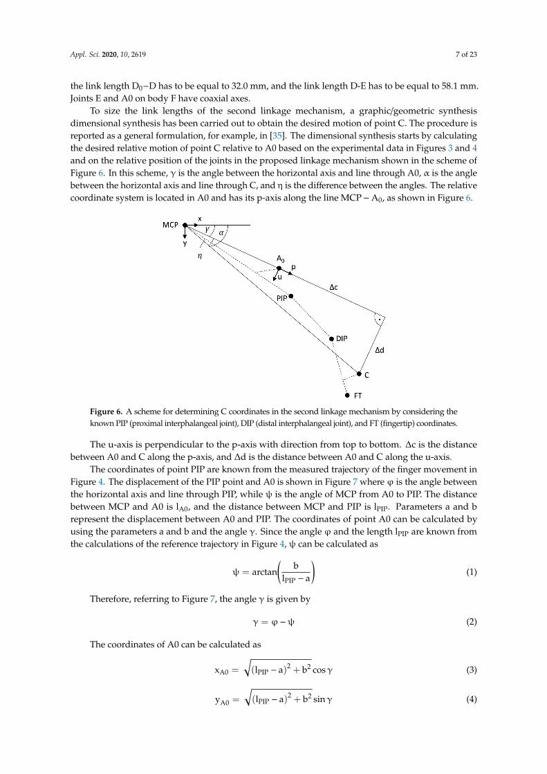
To size the link lengths of the second linkage mechanism, a graphic/geometric synthesisdimensional synthesis has been carried out to obtain the desired motion of point C. The procedure isreported as a general formulation, for example, in [35]. The dimensional synthesis starts by calculatingthe desired relative motion of point C relative to A0 based on the experimental data in Figures 3 and 4and on the relative position of the joints in the proposed linkage mechanism shown in the scheme ofFigure 6. In this scheme, γ is the angle between the horizontal axis and line through A0, α is the anglebetween the horizontal axis and line through C, and η is the difference between the angles. The relativecoordinate system is located in A0 and has its p-axis along the line MCP−A0, as shown in Figure 6.
Appl. Sci. 2020, 10, x FOR PEER REVIEW 7 of 23
Figure 5. A kinematic scheme of the proposed design with its linkage structure.
The u-axis is perpendicular to the p-axis with direction from top to bottom. Δc is the distance between A0 and C along the p-axis, and Δd is the distance between A0 and C along the u-axis.
The coordinates of point PIP are known from the measured trajectory of the finger movement in Figure 4. The displacement of the PIP point and A0 is shown in Figure 7 where φ is the angle between the horizontal axis and line through PIP, while ψ is the angle of MCP from A0 to PIP. The distance between MCP and A0 is l , and the distance between MCP and PIP is l . Parameters a and b represent the displacement between A0 and PIP. The coordinates of point A0 can be calculated by using the parameters a and b and the angle γ. Since the angle φ and the length l are known from the calculations of the reference trajectory in Figure 4, ψ can be calculated as ψ = arctan bl − a (1)
Therefore, referring to Figure 7, the angle γ is given by γ = φ − ψ (2)
The coordinates of A0 can be calculated as x = l − a + b cos γ (3) y = l − a + b sin γ (4)
Figure 6. A scheme for determining C coordinates in the second linkage mechanism by considering the known PIP (proximal interphalangeal joint), DIP (distal interphalangeal joint), and FT (fingertip) coordinates..
Figure 6. A scheme for determining C coordinates in the second linkage mechanism by considering theknown PIP (proximal interphalangeal joint), DIP (distal interphalangeal joint), and FT (fingertip) coordinates.
The u-axis is perpendicular to the p-axis with direction from top to bottom. ∆c is the distancebetween A0 and C along the p-axis, and ∆d is the distance between A0 and C along the u-axis.
The coordinates of point PIP are known from the measured trajectory of the finger movement inFigure 4. The displacement of the PIP point and A0 is shown in Figure 7 where ϕ is the angle betweenthe horizontal axis and line through PIP, while ψ is the angle of MCP from A0 to PIP. The distancebetween MCP and A0 is lA0, and the distance between MCP and PIP is lPIP. Parameters a and brepresent the displacement between A0 and PIP. The coordinates of point A0 can be calculated byusing the parameters a and b and the angle γ. Since the angle ϕ and the length lPIP are known fromthe calculations of the reference trajectory in Figure 4, ψ can be calculated as
ψ = arctan(
blPIP − a
)(1)
Therefore, referring to Figure 7, the angle γ is given by
γ = ϕ−ψ (2)
The coordinates of A0 can be calculated as
xA0 =
√(lPIP − a)2 + b2 cosγ (3)
yA0 =
√(lPIP − a)2 + b2 sinγ (4)

Appl. Sci. 2020, 10, 2619 8 of 23
By squaring and summing Equations (3) and (4), it is possible to obtain
lA0 =
√(lPIP − a
)2+ b2 (5)
Appl. Sci. 2020, 10, x FOR PEER REVIEW 8 of 23
Figure 7. A scheme showing the displacement between A0 and PIP (proximal interphalangeal joint).
By squaring and summing Equations (3) and (4), it is possible to obtain l = l − a + b (5)
A similar procedure is used to calculate the global coordinates of C. Figure 6 shows a sketch for the displacement between FT and C, where λ is the angle between the horizontal axis and the line from DIP to C; θ is the angle between the horizontal axis and the line from DIP to FT. The distance between DIP and FT is l , and the distance between DIP and C isl . Parameter e is the displacement between FT and C on the line from FT to DIP, and f is the displacement between C and FT perpendicular to that line.
The global x and y coordinates of DIP and FT are known from the captured trajectory in Figure 2. As given in Figure 8, the link orientation, given by angle θ, can be calculated as θ = arctan y − yx − x (6)
Therefore, the angle λ is calculated as λ = θ − arctan eDIP − FT − f (7)
The global coordinates of C can be calculated as x = DIP − FT − f + e cos λ + x (8) y = DIP − FT − f + e sin λ + y (9)
Consequently, η is calculated as η = α − γ = arctan xy − γ (10)
Finally, distances Δc and Δd can be computed as Δc = x + y cos η − l (11) Δd = x + y sin η (12)
The resulting parameters from the above-mentioned calculations for the offset of A0 and C are summarized in Table 1. The parameters are obtained from measurements on the finger of the subject and also referring to an early prototype. The diameter of a reference finger has been measured to calculate the distance from the finger joint to the top of the finger, giving parameters b and f. Parameters a and e were identified from a preliminary prototype, which showed that A0 could be placed directly above the PIP joint, whereas C requires some distance from FT to avoid slipping off the finger during motion. With the calculated positions of joint C, the dimensional synthesis of the second linkage mechanism can be conducted.
Figure 7. A scheme showing the displacement between A0 and PIP (proximal interphalangeal joint).
A similar procedure is used to calculate the global coordinates of C. Figure 6 shows a sketch forthe displacement between FT and C, where λ is the angle between the horizontal axis and the line fromDIP to C; θ is the angle between the horizontal axis and the line from DIP to FT. The distance betweenDIP and FT is lFT, and the distance between DIP and C is lC. Parameter e is the displacement betweenFT and C on the line from FT to DIP, and f is the displacement between C and FT perpendicular tothat line.
The global x and y coordinates of DIP and FT are known from the captured trajectory in Figure 2.As given in Figure 8, the link orientation, given by angle θ, can be calculated as
θ = arctan(
yFT − yDIP
xFT − xDIP
)(6)
Appl. Sci. 2020, 10, x FOR PEER REVIEW 9 of 23
No singular configuration is reachable within the used workspace of this mechanism. This has been verified at the design stage by setting up limits at the feasible transmission angles, and it has also been verified experimentally.
Figure 8. A scheme showing the displacement between FT (fingertip) and C.
Table 1. Design parameters from kinematic calculations in Figure 5 and Figure 6.
Parameter a b e f Length [mm] 4 17 15 19
4. Mechanism Synthesis of the Second Linkage
The dimensional synthesis of the second linkage can be outlined as the procedure of determining the remaining lengths of a 4-bar mechanism that guides a point on the coupler curve. One possibility for such a synthesis is the graphical method based on the Burmester theory as described in [37]. This synthesis approach has been selected since it can quickly address the desired features in terms of replicating a desired motion trajectory as given by the reference motion trajectory in Figure 4. The expected accuracy for joints (±4 degrees) does not justify the use of more complex and time-consuming synthesis methods such as numerical optimization.
The proposed procedure allows an approximation of the desired movement from the measured trajectory in Figure 4 by defining three points on the coupler curve that are reached precisely by the mechanism. The synthesis can be conducted when two lengths of a mechanism and two positions of joints are known. Figure 9a shows the initial problem with all given parameters. The position of joints A0 and B0, lengths A B0, B0B, BC, and three positions of joint C are given in the initial problem. From the input, the position of the missing joint can be determined. When the positions of all joints are established, the lengths can be determined. Curve k in Figure 9a shows the original movement of joint C, and curve kc in Figure 9b is the movement after the synthesis. With the synthesis in Figure 9b, joint A can be determined, giving the missing lengths A0A, AC, and AB.
A pose of a mechanism consists of the positions and the orientations of all links. For example, for pose 1 of the mechanism in Figure 4, joint A is in position A1, joint B is in position B1, and joint C is in Position C1.The graphical procedure for the dimensional synthesis is given in the flow-chart of Figure 10 according to the following steps:
1. The given parameters in Figure 9a are the positions of C1, C2, C3, and B0 as well as the lengths of B0B and BC;
2. With the information from step 1, joint B is known in pose 1, 2, and 3, as joint B moves on the curve kB. Therefore, the poses of B1C1, B2C2, and B3C3 are known. At this point, joint A is missing to complete the mechanism sizing:
3. Next, one link in one pose is chosen as a reference (in this example, link BC in pose 1); 4. Now, joint A0 is virtually moved around B1C1 to create A0 that corresponds to position 2 in
pose 1 (by moving A0 with respect to the coordinate system of pose 2 into pose 1). The
Figure 8. A scheme showing the displacement between FT (fingertip) and C.
Therefore, the angle λ is calculated as
λ = θ− arctan(
e
DIP− FT− f
)(7)
The global coordinates of C can be calculated as
xC =
√(DIP− FT− f
)2+ e2 cos λ+ xDIP (8)

Appl. Sci. 2020, 10, 2619 9 of 23
yC =
√(DIP− FT− f
)2+ e2 sin λ+ yDIP (9)
Consequently, η is calculated as
η = α− γ = arctan(
xC
yC
)− γ (10)
Finally, distances ∆c and ∆d can be computed as
∆c =√
x2c + y2
c cosη− lA0 (11)
∆d =√
x2c + y2
c sinη (12)
The resulting parameters from the above-mentioned calculations for the offset of A0 and C aresummarized in Table 1. The parameters are obtained from measurements on the finger of the subjectand also referring to an early prototype. The diameter of a reference finger has been measured tocalculate the distance from the finger joint to the top of the finger, giving parameters b and f. Parametersa and e were identified from a preliminary prototype, which showed that A0 could be placed directlyabove the PIP joint, whereas C requires some distance from FT to avoid slipping off the finger duringmotion. With the calculated positions of joint C, the dimensional synthesis of the second linkagemechanism can be conducted.
Table 1. Design parameters from kinematic calculations in Figures 5 and 6.
Parameter a b e f
Length [mm] 4 17 15 19
No singular configuration is reachable within the used workspace of this mechanism. This hasbeen verified at the design stage by setting up limits at the feasible transmission angles, and it has alsobeen verified experimentally.
4. Mechanism Synthesis of the Second Linkage
The dimensional synthesis of the second linkage can be outlined as the procedure of determining theremaining lengths of a 4-bar mechanism that guides a point on the coupler curve. One possibility for sucha synthesis is the graphical method based on the Burmester theory as described in [37]. This synthesisapproach has been selected since it can quickly address the desired features in terms of replicating adesired motion trajectory as given by the reference motion trajectory in Figure 4. The expected accuracyfor joints (±4 degrees) does not justify the use of more complex and time-consuming synthesis methodssuch as numerical optimization.
The proposed procedure allows an approximation of the desired movement from the measuredtrajectory in Figure 4 by defining three points on the coupler curve that are reached precisely by themechanism. The synthesis can be conducted when two lengths of a mechanism and two positionsof joints are known. Figure 9a shows the initial problem with all given parameters. The position ofjoints A0 and B0, lengths A0B0, B0B, BC, and three positions of joint C are given in the initial problem.From the input, the position of the missing joint can be determined. When the positions of all jointsare established, the lengths can be determined. Curve k in Figure 9a shows the original movement ofjoint C, and curve kc in Figure 9b is the movement after the synthesis. With the synthesis in Figure 9b,joint A can be determined, giving the missing lengths A0A, AC, and AB.
Appl. Sci. 2020, 10, 2619 10 of 23
Appl. Sci. 2020, 10, x FOR PEER REVIEW 10 of 23
transformation can be done by creating a triangle between C2, A0, and B2 and moving the triangle into the pose of C1 and B1. The resulting position is A0 from pose 2 in pose 1, written as (A0)2
1; 5. The same as step 4 is done with A0 from pose 3 in pose 1, resulting in (A0)3
1; 6. Finally, A1 is found by the intersection of the perpendicular bisectors between three positions
of A0. The resulting mechanism guides joint C along curve kC. Curve kC matches curve k in the points C1, C2, and C3 [33];
7. With all known positions of the joints, the link lengths can be determined. 8. Other link lengths/positions can be chosen to improve the matching of curves k and kc. 9. The dimensional synthesis is applied to the second linkage mechanism by using the relative
movement of C with respect to A0. The aim is to design a mechanism that matches the desired motion trajectory of point C.
(a) (b)
Figure 9. Schemes for a dimensional synthesis: (a) the problem to be solved; (b) graphical solution as based on the approach that is described in [33].
Figure 10. A flowchart for the mechanism synthesis according to the scheme in Figure 9.
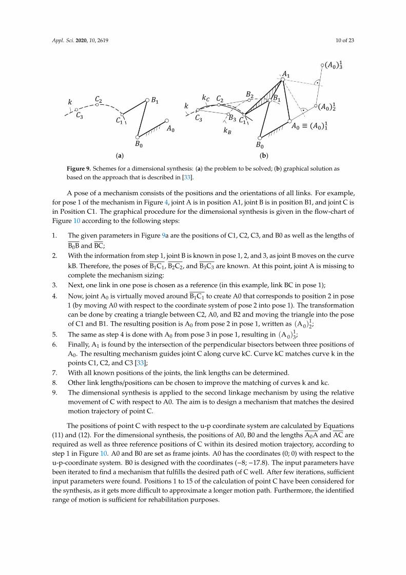
Figure 9. Schemes for a dimensional synthesis: (a) the problem to be solved; (b) graphical solution asbased on the approach that is described in [33].
A pose of a mechanism consists of the positions and the orientations of all links. For example,for pose 1 of the mechanism in Figure 4, joint A is in position A1, joint B is in position B1, and joint C isin Position C1. The graphical procedure for the dimensional synthesis is given in the flow-chart ofFigure 10 according to the following steps:
1. The given parameters in Figure 9a are the positions of C1, C2, C3, and B0 as well as the lengths ofB0B and BC;
2. With the information from step 1, joint B is known in pose 1, 2, and 3, as joint B moves on the curvekB. Therefore, the poses of B1C1, B2C2, and B3C3 are known. At this point, joint A is missing tocomplete the mechanism sizing:
3. Next, one link in one pose is chosen as a reference (in this example, link BC in pose 1);
4. Now, joint A0 is virtually moved around B1C1 to create A0 that corresponds to position 2 in pose1 (by moving A0 with respect to the coordinate system of pose 2 into pose 1). The transformationcan be done by creating a triangle between C2, A0, and B2 and moving the triangle into the poseof C1 and B1. The resulting position is A0 from pose 2 in pose 1, written as (A 0)
12;
5. The same as step 4 is done with A0 from pose 3 in pose 1, resulting in (A 0)13;
6. Finally, A1 is found by the intersection of the perpendicular bisectors between three positions ofA0. The resulting mechanism guides joint C along curve kC. Curve kC matches curve k in thepoints C1, C2, and C3 [33];
7. With all known positions of the joints, the link lengths can be determined.8. Other link lengths/positions can be chosen to improve the matching of curves k and kc.9. The dimensional synthesis is applied to the second linkage mechanism by using the relative
movement of C with respect to A0. The aim is to design a mechanism that matches the desiredmotion trajectory of point C.
The positions of point C with respect to the u-p coordinate system are calculated by Equations(11) and (12). For the dimensional synthesis, the positions of A0, B0 and the lengths A0A and AC arerequired as well as three reference positions of C within its desired motion trajectory, according tostep 1 in Figure 10. A0 and B0 are set as frame joints. A0 has the coordinates (0; 0) with respect to theu-p-coordinate system. B0 is designed with the coordinates (−8; −17.8). The input parameters havebeen iterated to find a mechanism that fulfills the desired path of C well. After few iterations, sufficientinput parameters were found. Positions 1 to 15 of the calculation of point C have been considered forthe synthesis, as it gets more difficult to approximate a longer motion path. Furthermore, the identifiedrange of motion is sufficient for rehabilitation purposes.

Appl. Sci. 2020, 10, 2619 11 of 23
Appl. Sci. 2020, 10, x FOR PEER REVIEW 10 of 23
transformation can be done by creating a triangle between C2, A0, and B2 and moving the triangle into the pose of C1 and B1. The resulting position is A0 from pose 2 in pose 1, written as (A0)2
1; 5. The same as step 4 is done with A0 from pose 3 in pose 1, resulting in (A0)3
1; 6. Finally, A1 is found by the intersection of the perpendicular bisectors between three positions
of A0. The resulting mechanism guides joint C along curve kC. Curve kC matches curve k in the points C1, C2, and C3 [33];
7. With all known positions of the joints, the link lengths can be determined. 8. Other link lengths/positions can be chosen to improve the matching of curves k and kc. 9. The dimensional synthesis is applied to the second linkage mechanism by using the relative
movement of C with respect to A0. The aim is to design a mechanism that matches the desired motion trajectory of point C.
(a) (b)
Figure 9. Schemes for a dimensional synthesis: (a) the problem to be solved; (b) graphical solution as based on the approach that is described in [33].
Figure 10. A flowchart for the mechanism synthesis according to the scheme in Figure 9. Figure 10. A flowchart for the mechanism synthesis according to the scheme in Figure 9.
The initially chosen link lengths and point coordinates are shown in Figure 11, similar to Figure 4.With this information, positions B2 and B3 can be determined as intersecting points with the knownsegments of B0B and BC, as mentioned in step 2. As a result of iterations of the synthesis, B0B has beenmeasured to have a length of 46 mm, and BC. has been measured to have a length of 53 mm. As inputfrom the positions of C, the first position is chosen as C1, position C2 is in the middle, and position C3refers to the last used configuration during the finger closing motion. According to step 3, pose 1 is thereference for the synthesis. A0 with respect to position B3C3 is transferred into position B1C1, resultingin (A 0)
13. (A 0)
13 is A0 in pose 3 transferred to pose 1. This means that the triangles C3-B3-A0 and
C1-B1- (A 0)13 are identical. In the same manner, the point (A 0)
12 can be identified. This corresponds to
step 4. The triangles to find the position (A 0)13 are given in Figure 12a. The synthesized mechanism
and the calculated positions of C are shown in Figure 12b. The previously calculated coordinates for Care marked as crosses, and the computed trajectory of the mechanism is marked as dots. The figurealso shows that the trajectory matches well with the desired motion for point C.
The position of A1 is the center point of a circle through the positions A0, (A 0)12 and (A 0)
13, as
mentioned in step 5. The resulting position is A1, as pose 1 has been used as a reference. The linklengths can be determined with the obtained position of A1. Since the given data in step 1 have alreadybeen identified by a prior iteration, step 7 can be skipped. The complete kinematic design is obtainedby combining both linkages. The resulting kinematic design of the whole exoskeleton mechanismis shown in Figure 13. The numerical values are summarized in Table 2, defined according to thescheme in Figure 5. The calculated positions of A0 and C are indicated with plus (+) and cross (x)marks, respectively.

Appl. Sci. 2020, 10, 2619 12 of 23
Appl. Sci. 2020, 10, x FOR PEER REVIEW 11 of 23
The positions of point C with respect to the u-p coordinate system are calculated by Equations (11) and (12). For the dimensional synthesis, the positions of A0, B0 and the lengths A0A and AC are required as well as three reference positions of C within its desired motion trajectory, according to step 1 in Figure 10. A0 and B0 are set as frame joints. A0 has the coordinates (0; 0) with respect to the u-p-coordinate system. B0 is designed with the coordinates (−8; −17.8). The input parameters have been iterated to find a mechanism that fulfills the desired path of C well. After few iterations, sufficient input parameters were found. Positions 1 to 15 of the calculation of point C have been considered for the synthesis, as it gets more difficult to approximate a longer motion path. Furthermore, the identified range of motion is sufficient for rehabilitation purposes.
The initially chosen link lengths and point coordinates are shown in Figure 11, similar to Figure 4. With this information, positions B2 and B3 can be determined as intersecting points with the known segments of B0B and BC, as mentioned in step 2. As a result of iterations of the synthesis, B0B has been measured to have a length of 46 mm, and BC has been measured to have a length of 53 mm. As input from the positions of C, the first position is chosen as C1, position C2 is in the middle, and position C3 refers to the last used configuration during the finger closing motion. According to step 3, pose 1 is the reference for the synthesis. A0 with respect to position B3C3 is transferred into position B1C1, resulting in (A0)3
1. (A0)31 is A0 in pose 3 transferred to pose 1. This means that the
triangles C3-B3-A0 and C1-B1-(A0)31 are identical. In the same manner, the point (A0)2
1 can be identified. This corresponds to step 4. The triangles to find the position (A0)3
1 are given in Figure 12a. The synthesized mechanism and the calculated positions of C are shown in Figure 12b. The previously calculated coordinates for C are marked as crosses, and the computed trajectory of the mechanism is marked as dots. The figure also shows that the trajectory matches well with the desired motion for point C
.
Figure 11. Initial problem of the synthesis for the second linkage with the selected three points C1, C2, C3 along the desired motion trajectory of point C.
Figure 11. Initial problem of the synthesis for the second linkage with the selected three points C1, C2,C3 along the desired motion trajectory of point C.Appl. Sci. 2020, 10, x FOR PEER REVIEW 12 of 23
(a) (b)
Figure 12. A scheme for determining the second linkage: (a) Triangles of the relative positions C0; (b) synthesized mechanism and resulting trajectory passing through the selected points C1, C2, C3.
The position of A1 is the center point of a circle through the positions A0, (A0)1 and (A0)31, as
mentioned in step 5. The resulting position is A1, as pose 1 has been used as a reference. The link lengths can be determined with the obtained position of A1. Since the given data in step 1 have already been identified by a prior iteration, step 7 can be skipped. The complete kinematic design is obtained by combining both linkages. The resulting kinematic design of the whole exoskeleton mechanism is shown in Figure 13. The numerical values are summarized in Table 2, defined according to the scheme in Figure 5. The calculated positions of A0 and C are indicated with plus (+) and cross (x) marks, respectively.
This paper reports the proposed graphical procedure for a specific case with nominal biometric measurements. However, the proposed graphical procedure is general in its approach. Accordingly, the same procedure can be performed again for different finger sizes when the phalanx lengths are expected to exceed the adaptability allowed by the proposed design. A chart can be generated with link dimensions for different patient biometrics to adapt the proposed finger exoskeleton to the wearer. Moreover, the proposed synthesis procedure can be also automated by implementing it in a numerical solving algorithm.
Table 2. Design parameters and link lengths of the finger exoskeleton for the scheme in Figure 5.
Parameter Length [mm] Parameter Length [mm] Parameter Length [mm] a 4.0 A0-B0 19.5 B-C 53.0 b 17.0 B0-B 46.0 D0-D 32.0 e 15.0 A-B 24.9 D-E 58.1 f 19.0 A-C 30.7 A0-A 48.2
MCP-PIP 43.0 PIP-DIP 28.0 DIP-FT 25.0
Figure 12. A scheme for determining the second linkage: (a) Triangles of the relative positions C0;(b) synthesized mechanism and resulting trajectory passing through the selected points C1, C2, C3.

Appl. Sci. 2020, 10, 2619 13 of 23Appl. Sci. 2020, 10, x FOR PEER REVIEW 13 of 23
Figure 13. The synthesized kinematic design of the finger exoskeleton in Figure 3 with the trajectories of A0 and C indicated with plus (+) and cross (x) marks.
5. Mechanical Design and Prototype
Based on the obtained kinematic design, a prototype of the proposed finger exoskeleton has been developed. Since the finger exoskeleton is manufactured by 3D printing, it has been necessary to define the secondary geometric parameters of each linkage, such as link thickness. For this purpose, given the slow speeds, accelerations, and inertias of the application, a specific static analysis has been carried out according to the schemes that are shown in Figure 14. The computation has been carried out by considering as load the maximum motor torque of 216 Nmm, and a maximum force at the connections between finger and exoskeleton equal to about 6 N on the fingertip. This value is calculated by using the principle of virtual powers from the given input torque and also matches previous experiences of similar prototypes.
FEM analyses have been carried out iteratively to find a proper linkage cross section and thickness. In particular, final FEM simulations have been carried out by considering the 3D CAD model that is shown in Figure 15. The main link thickness has been set as equal to 2 mm, also based on previous experiences. Similarly, the holes for the joints have been set at a diameter of 4 mm. Therefore, the links need to have a total width of 8 mm and a thickness of 2 mm. Link AC is crooked as per Figure 15 in order to avoid collisions with the finger, and link BC is crooked to allow for fixation of the joint A. Even though ABC behaves kinematically as a single body, it is realized with three different links that can be easily changed to fit the different finger sizes of different users. The link BC is manufactured with two beams to increase its stiffness. A CAD design has been elaborated with the above-mentioned design considerations. A functional solution of the mechanism with all its joints is shown in Figure 14. Screws and nuts of M3 size connect the links.
Figure 13. The synthesized kinematic design of the finger exoskeleton in Figure 3 with the trajectoriesof A0 and C indicated with plus (+) and cross (x) marks.
Table 2. Design parameters and link lengths of the finger exoskeleton for the scheme in Figure 5.
Parameter Length [mm] Parameter Length [mm] Parameter Length [mm]
a 4.0 A0-B0 19.5 B-C 53.0b 17.0 B0-B 46.0 D0-D 32.0e 15.0 A-B 24.9 D-E 58.1f 19.0 A-C 30.7 A0-A 48.2
MCP-PIP 43.0 PIP-DIP 28.0 DIP-FT 25.0
This paper reports the proposed graphical procedure for a specific case with nominal biometricmeasurements. However, the proposed graphical procedure is general in its approach. Accordingly,the same procedure can be performed again for different finger sizes when the phalanx lengths areexpected to exceed the adaptability allowed by the proposed design. A chart can be generated withlink dimensions for different patient biometrics to adapt the proposed finger exoskeleton to the wearer.Moreover, the proposed synthesis procedure can be also automated by implementing it in a numericalsolving algorithm.
5. Mechanical Design and Prototype
Based on the obtained kinematic design, a prototype of the proposed finger exoskeleton has beendeveloped. Since the finger exoskeleton is manufactured by 3D printing, it has been necessary to definethe secondary geometric parameters of each linkage, such as link thickness. For this purpose, given theslow speeds, accelerations, and inertias of the application, a specific static analysis has been carriedout according to the schemes that are shown in Figure 14. The computation has been carried out byconsidering as load the maximum motor torque of 216 Nmm, and a maximum force at the connectionsbetween finger and exoskeleton equal to about 6 N on the fingertip. This value is calculated by using

Appl. Sci. 2020, 10, 2619 14 of 23
the principle of virtual powers from the given input torque and also matches previous experiences ofsimilar prototypes.Appl. Sci. 2020, 10, x FOR PEER REVIEW 14 of 23
(a) (b)
(c)
Figure 14. Schemes for force distribution analysis: (a) a CAD front view of the second linkage (A0AB0B); (b) an overall free body diagram; (c) free body diagrams of single elements.
(a) (b)
Figure 15. A CAD model of the finger exoskeleton including motors with description of joints (a) and angular view (b).
Figure 14. Schemes for force distribution analysis: (a) a CAD front view of the second linkage (A0AB0B);(b) an overall free body diagram; (c) free body diagrams of single elements.
FEM analyses have been carried out iteratively to find a proper linkage cross section and thickness.In particular, final FEM simulations have been carried out by considering the 3D CAD model that isshown in Figure 15. The main link thickness has been set as equal to 2 mm, also based on previousexperiences. Similarly, the holes for the joints have been set at a diameter of 4 mm. Therefore, the linksneed to have a total width of 8 mm and a thickness of 2 mm. Link AC is crooked as per Figure 15 inorder to avoid collisions with the finger, and link BC is crooked to allow for fixation of the joint A.Even though ABC behaves kinematically as a single body, it is realized with three different links thatcan be easily changed to fit the different finger sizes of different users. The link BC is manufacturedwith two beams to increase its stiffness. A CAD design has been elaborated with the above-mentioneddesign considerations. A functional solution of the mechanism with all its joints is shown in Figure 14.Screws and nuts of M3 size connect the links.
The main merit of the proposed design can be identified in the adaptability to multiple users.This is achieved by slotted holes (Figure 15) in the exoskeleton that allow easy adjustability to users.The slotted holes are used to adapt the finger exoskeleton to the user’s biometrics (phalanx lengths) bymoving each link to the optimal configuration evaluated through the proposed dimensional synthesis.Cable straps and loop fasteners are used to fix the exoskeleton on the finger, giving some additionaladaptability. Accordingly, the proposed exoskeleton is expected to fit users having specific phalanx

Appl. Sci. 2020, 10, 2619 15 of 23
sizes exceeding ± 10% of the nominal sizes. A design limitation can be identified in the need toreplace the links of the device when users are expected to exceed ± 10% of the nominal finger size.This limitation can be partially overcome by preparing sets of replacement links whose sizes aredesigned to fit with different nominal finger sizes (e.g., for children, male/female adults).
Appl. Sci. 2020, 10, x FOR PEER REVIEW 14 of 23
(a) (b)
(c)
Figure 14. Schemes for force distribution analysis: (a) a CAD front view of the second linkage (A0AB0B); (b) an overall free body diagram; (c) free body diagrams of single elements.
(a) (b)
Figure 15. A CAD model of the finger exoskeleton including motors with description of joints (a) and angular view (b). Figure 15. A CAD model of the finger exoskeleton including motors with description of joints (a) andangular view (b).
Final FEM tests have been performed in SolidWorks 2019 to verify the correctness of the selectedcross-sections and minimum required thickness to avoid any failure or plastic deformation, as reportedin Figures 16 and 17. A minimum safety factor equal to 1 has been considered in static nodal stressanalysis for keeping the overall weight as low as possible. A minimum factor of safety equal 2.8 hasbeen found on shear stress. The chosen material is a commercial poly-lactic acid (PLA) filament thatis suitable for additive manufacturing with commercial 3D printers. Its main properties are tensilestrength equal to 3·107 N/m2, elastic modulus equal to 2·109 N/m2; Poisson’s ration equal to 0.394,mass density equal to 1020 Kg/m3, and shear modulus equal to 3.189·108 N/m2.
Appl. Sci. 2020, 10, x FOR PEER REVIEW 15 of 23
The main merit of the proposed design can be identified in the adaptability to multiple users. This is achieved by slotted holes (Figure 15) in the exoskeleton that allow easy adjustability to users. The slotted holes are used to adapt the finger exoskeleton to the user’s biometrics (phalanx lengths) by moving each link to the optimal configuration evaluated through the proposed dimensional synthesis. Cable straps and loop fasteners are used to fix the exoskeleton on the finger, giving some additional adaptability. Accordingly, the proposed exoskeleton is expected to fit users having specific phalanx sizes exceeding ± 10% of the nominal sizes. A design limitation can be identified in the need to replace the links of the device when users are expected to exceed ± 10% of the nominal finger size. This limitation can be partially overcome by preparing sets of replacement links whose sizes are designed to fit with different nominal finger sizes (e.g., for children, male/female adults).
Final FEM tests have been performed in SolidWorks 2019 to verify the correctness of the selected cross-sections and minimum required thickness to avoid any failure or plastic deformation, as reported in Figures 16 and 17. A minimum safety factor equal to 1 has been considered in static nodal stress analysis for keeping the overall weight as low as possible. A minimum factor of safety equal 2.8 has been found on shear stress. The chosen material is a commercial poly-lactic acid (PLA) filament that is suitable for additive manufacturing with commercial 3D printers. Its main properties are tensile strength equal to 3∙107 N/m2, elastic modulus equal to 2∙109 N/m2; Poisson’s ration equal to 0.394, mass density equal to 1020 Kg/m3, and shear modulus equal to 3.189∙108 N/m2.
The size of motors has been chosen to match the results of simulations for the designed mechanism as well as by comparison with similar devices in the literature. Both servo motors have been selected with a nominal torque of 216 Nmm while the desired torque was about 200 Nmm for the first joint and about 150 Nmm for the second joint. Servo motors with a torque of 216 Nmm are integrated into body F and lay on the back of the palm of the human hand. An Arduino microcontroller has been chosen to drive the motors.
The total cost of the system is around 50€, including the servomotors and the microcontroller. The motors are connected to an external power supply, which can be a LiPo battery for easy portability. The exoskeleton has a total weight of 64 g for the parts that are mounted on the finger. This includes the linkage, cable straps, hook and loop fasteners, and servo motors. The whole system has a weight of 175 g, including an Arduino board and all cablings. A full prototype has been built as shown in Figure 18.
Figure 16. Static nodal FEM analysis of the whole prototype. Figure 16. Static nodal FEM analysis of the whole prototype.

Appl. Sci. 2020, 10, 2619 16 of 23Appl. Sci. 2020, 10, x FOR PEER REVIEW 16 of 23
Figure 17. FEM factor of safety calculations based on maximum shear stress.
(a) (b)
Figure 18. The built prototype of the finger exoskeleton, front view (a), back view (b).
6. Test Results
The built finger exoskeleton prototype has been tested experimentally to prove its feasibility as a finger motion exercising device in terms of it kinematic and operation behaviors. Given the expected slow speed operation, dynamic simulations and tests are not required at this proof-of-concept stage. The finger exoskeleton can be easily worn with Velcro fasteners. The connection between the finger and exoskeleton can be as tight as the subject wishes. Even after long use, it is still comfortable to wear. Also, the calibration procedure is very straightforward. It consists of the following steps: Attaching the exoskeleton to the finger, manually placing the finger in its desired straight configuration; registering this position as the initial configuration; manually placing the finger in its desired fully closed configuration; registering this position as the fully closed configuration. After the above steps, the device is ready to operate within the desired operation range.
The exoskeleton movement has been compared with the reference motion of a healthy human finger, and the angular error has been calculated as also partially reported in [33]. The driving angle of joint D0 is called δ, and the driving angle of joint B0 is called β. The angles of the joints of the finger from the grasping test have been used as an input for a multibody motion simulation of the CAD
Figure 17. FEM factor of safety calculations based on maximum shear stress.
The size of motors has been chosen to match the results of simulations for the designed mechanismas well as by comparison with similar devices in the literature. Both servo motors have been selectedwith a nominal torque of 216 Nmm while the desired torque was about 200 Nmm for the first joint andabout 150 Nmm for the second joint. Servo motors with a torque of 216 Nmm are integrated into bodyF and lay on the back of the palm of the human hand. An Arduino microcontroller has been chosen todrive the motors.
The total cost of the system is around 50€, including the servomotors and the microcontroller.The motors are connected to an external power supply, which can be a LiPo battery for easy portability.The exoskeleton has a total weight of 64 g for the parts that are mounted on the finger. This includesthe linkage, cable straps, hook and loop fasteners, and servo motors. The whole system has a weightof 175 g, including an Arduino board and all cablings. A full prototype has been built as shown inFigure 18.
Appl. Sci. 2020, 10, x FOR PEER REVIEW 16 of 23
Figure 17. FEM factor of safety calculations based on maximum shear stress.
(a) (b)
Figure 18. The built prototype of the finger exoskeleton, front view (a), back view (b).
6. Test Results
The built finger exoskeleton prototype has been tested experimentally to prove its feasibility as a finger motion exercising device in terms of it kinematic and operation behaviors. Given the expected slow speed operation, dynamic simulations and tests are not required at this proof-of-concept stage. The finger exoskeleton can be easily worn with Velcro fasteners. The connection between the finger and exoskeleton can be as tight as the subject wishes. Even after long use, it is still comfortable to wear. Also, the calibration procedure is very straightforward. It consists of the following steps: Attaching the exoskeleton to the finger, manually placing the finger in its desired straight configuration; registering this position as the initial configuration; manually placing the finger in its desired fully closed configuration; registering this position as the fully closed configuration. After the above steps, the device is ready to operate within the desired operation range.
The exoskeleton movement has been compared with the reference motion of a healthy human finger, and the angular error has been calculated as also partially reported in [33]. The driving angle of joint D0 is called δ, and the driving angle of joint B0 is called β. The angles of the joints of the finger from the grasping test have been used as an input for a multibody motion simulation of the CAD
Figure 18. The built prototype of the finger exoskeleton, front view (a), back view (b).
6. Test Results
The built finger exoskeleton prototype has been tested experimentally to prove its feasibilityas a finger motion exercising device in terms of it kinematic and operation behaviors. Given the
Appl. Sci. 2020, 10, 2619 17 of 23
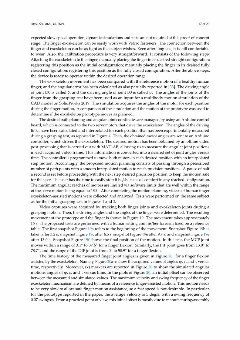
expected slow speed operation, dynamic simulations and tests are not required at this proof-of-conceptstage. The finger exoskeleton can be easily worn with Velcro fasteners. The connection between thefinger and exoskeleton can be as tight as the subject wishes. Even after long use, it is still comfortableto wear. Also, the calibration procedure is very straightforward. It consists of the following steps:Attaching the exoskeleton to the finger, manually placing the finger in its desired straight configuration;registering this position as the initial configuration; manually placing the finger in its desired fullyclosed configuration; registering this position as the fully closed configuration. After the above steps,the device is ready to operate within the desired operation range.
The exoskeleton movement has been compared with the reference motion of a healthy humanfinger, and the angular error has been calculated as also partially reported in [33]. The driving angleof joint D0 is called δ, and the driving angle of joint B0 is called β. The angles of the joints of thefinger from the grasping test have been used as an input for a multibody motion simulation of theCAD model on SolidWorks 2019. The simulation acquires the angles of the motor for each positionduring the finger motion. A comparison of the simulation and the motion of the prototype was used todetermine if the exoskeleton prototype moves as planned.
The desired path planning and angular joint coordinates are managed by using an Arduino controlboard, which is connected to the two servomotors that drive the exoskeleton. The angles of the drivinglinks have been calculated and interpolated for each position that has been experimentally measuredduring a grasping test, as reported in Figure 4. Then, the obtained motor angles are sent to an Arduinocontroller, which drives the exoskeleton. The desired motion has been obtained by an offline videopost-processing that is carried out with MATLAB, allowing us to measure the angular joint positionsin each acquired video frame. This information is converted into a desired set of joint angles versustime. The controller is programmed to move both motors in each desired position with an interpolatedstep motion. Accordingly, the proposed motion planning consists of passing through a prescribednumber of path points with a smooth interpolated motion to reach precision positions. A pause of halfa second is set before proceeding with the next step desired precision position to keep the motion safefor the user. The user has the time to easily stop if he/she feels discomfort in any reached configuration.The maximum angular reaches of motors are limited via software limits that are well within the rangeof the servo motors being equal to 180◦. After completing the motion planning, videos of human fingerexoskeleton-assisted motions were collected and analyzed. Tests were performed on the same subjectas for the initial grasping test in Figures 1 and 3.
Video captures were acquired by tracking both finger joints and exoskeleton joints during agrasping motion. Then, the driving angles and the angles of the finger were determined. The resultingmovement of the prototype and the finger is shown in Figure 19. The movement takes approximately16 s. The proposed tests are performed with a human sitting and his/her forearm fixed on a referencetable. The first snapshot Figure 19a refers to the beginning of the movement. Snapshot Figure 19b istaken after 3.2 s, snapshot Figure 19c after 6.5 s, snapshot Figure 19e after 9.7 s, and snapshot Figure 19eafter 13.0 s. Snapshot Figure 19f shows the final position of the motion. In this test, the MCP jointmoves within a range of 3.1◦ to 37.6◦ for a finger flexion. Similarly, the PIP joint goes from 13.0◦ to78.7◦, and the range of the DIP joint is from 0◦ to 58.9◦ for a finger flexion.
The time history of the measured finger joint angles is given in Figure 20. for a finger flexionassisted by the exoskeleton. Namely, Figure 20a–c show the acquired values of anglesϕ, ε, and τ versustime, respectively. Moreover, (x) markers are reported in Figure 20 to show the simulated angularmotions angles of ϕ, ε, and τ versus time. In the plots of Figure 20, an initial offset can be observedbetween the measured and simulated values. The maximum velocity and swing frequency of the fingerexoskeleton mechanism are defined by means of a reference finger-assisted motion. This motion needsto be very slow to allow safe finger motion assistance, so a fast speed is not desirable. In particular,for the prototype reported in the paper, the average velocity is 5 deg/s, with a swing frequency of0.07 swings/s. From a practical point of view, this initial offset is mostly due to manufacturing/assembly

Appl. Sci. 2020, 10, 2619 18 of 23
errors as well as joint clearances. These effects can be seen also as positive in terms of adaptability to amore natural finger trajectory.Appl. Sci. 2020, 10, x FOR PEER REVIEW 18 of 23
(a) (b) (c)
(d) (e) (f)
Figure 19. Snapshots of the exoskeleton motion during the test: (a) Starting position; (b) After 3.2 s; (c) After 6.5 s; (d) After 9.7 s; (e) After 13.0 s; (f) Final position.
(a) (b)
(c)
Figure 20. Comparison of finger joint angles in the prototype test (continuous line) and simulation (x marks): (a) angle φ versus time; (b) angleε versus time; (c) angle τ versus time
0
10
20
30
40
50
0 2 4 6 8 10 12 14 16
φ[deg]
Time [s]Video analysis Simulation
01020304050607080
0 2 4 6 8 10 12 14 16
ε[deg]
Time [s]Video analysis Simulation
010203040506070
0 2 4 6 8 10 12 14 16
τ[deg]
Time [s]Video analysis Simulation
Figure 19. Snapshots of the exoskeleton motion during the test: (a) Starting position; (b) After 3.2 s;(c) After 6.5 s; (d) After 9.7 s; (e) After 13.0 s; (f) Final position.
The absolute error of the angular positions of the finger joints can be calculated by comparing thetwo curves in Figure 20. To compensate for an initial misalignment, a systematic error can be calculated.Moreover, an angular deviation error can be calculated as the difference between the experimentallymeasured and simulated values at a given time. For example, the time history of the angle δ is givenin Figure 21 including both simulated and experimentally measured values. The experimentallymeasured angle δ versus time goes from −47.2◦ to −12.5◦ in this test. The comparison between theexperimentally measured and simulated angle δ versus time shows an initial systematic error of 17.5◦.If this systematic error is compensated, the angular deviation error of angle δ versus time is given inFigure 22. The systematic error is mainly due to the clearance between the exoskeleton and finger,which are connected through velcro straps, whose clearance cannot be eliminated.
The absolute error for the angle δ in Figure 20 is always below ± 4 deg. This absolute error can beconsidered suitable as it is exactly within the acceptable error given in the design requirements for theproposed motion assistance application. Similarly, the time history of the β angle is given in Figure 21including both simulated and experimentally measured values. The experimentally measured angle βversus time goes from −6.5◦ to 64.7◦ in this test. The comparison between the experimentally measuredand simulated angle β versus time shows an initial systematic error of 10.8◦. If one removes thissystematic error, the angular deviation error of angle β versus time is given in Figure 22. Similarly, acomparison of β from the experimental test and simulation is reported in Figure 23, and the computeddeviation error of β is reported in Figure 24. One can note that the absolute error for the angle δ inFigure 22 is below ± 4◦ until reaching a critical pose, corresponding to the pose reached after 13 s in thegiven experiment. Accordingly, operation of the prototype can be considered acceptable within thegiven design requirements until the closing configuration reaches the critical pose. Further motionneeds to be avoided, since it would lead to interference of the human finger with the palm. This limitphysically consists of allowing the finger flexion only until the DIP joint is vertically aligned with theMCP joint, referring to the scheme in Figure 5.

Appl. Sci. 2020, 10, 2619 19 of 23
Appl. Sci. 2020, 10, x FOR PEER REVIEW 18 of 23
(a) (b) (c)
(d) (e) (f)
Figure 19. Snapshots of the exoskeleton motion during the test: (a) Starting position; (b) After 3.2 s; (c) After 6.5 s; (d) After 9.7 s; (e) After 13.0 s; (f) Final position.
(a) (b)
(c)
Figure 20. Comparison of finger joint angles in the prototype test (continuous line) and simulation (x marks): (a) angle φ versus time; (b) angleε versus time; (c) angle τ versus time
0
10
20
30
40
50
0 2 4 6 8 10 12 14 16
φ[deg]
Time [s]Video analysis Simulation
01020304050607080
0 2 4 6 8 10 12 14 16
ε[deg]
Time [s]Video analysis Simulation
010203040506070
0 2 4 6 8 10 12 14 16
τ[deg]
Time [s]Video analysis Simulation
Figure 20. Comparison of finger joint angles in the prototype test (continuous line) and simulation (xmarks): (a) angle ϕ versus time; (b) angleε versus time; (c) angle τ versus time.Appl. Sci. 2020, 10, x FOR PEER REVIEW 20 of 23
Figure 21. Comparison of δ for the test and simulation versus time.
Table 3. Angular errors of the finger joints and driving links.
Angle [deg] φ ε τ δ β 1.8 3.6 5.2 1.8 3.2
Figure 22. Deviation error of δ versus time.
-70
-60
-50
-40
-30
-20
-10
0 1 2 3 4 5 6 7 8 9 10 11 12 13 14 15 16 17
δ[d
eg]
Time [s]Video analysis Simulation
-4
-3
-2
-1
0
1
2
3
4
0 1 2 3 4 5 6 7 8 9 10 11 12 13 14 15 16 17
Devi
atio
n er
ror[
deg]
Time [s]
Figure 21. Comparison of δ for the test and simulation versus time.
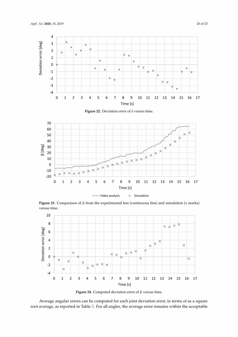
Appl. Sci. 2020, 10, 2619 20 of 23
Appl. Sci. 2020, 10, x FOR PEER REVIEW 20 of 23
Figure 21. Comparison of δ for the test and simulation versus time.
Table 3. Angular errors of the finger joints and driving links.
Angle [deg] φ ε τ δ β 1.8 3.6 5.2 1.8 3.2
Figure 22. Deviation error of δ versus time.
-70
-60
-50
-40
-30
-20
-10
0 1 2 3 4 5 6 7 8 9 10 11 12 13 14 15 16 17
δ[d
eg]
Time [s]Video analysis Simulation
-4
-3
-2
-1
0
1
2
3
4
0 1 2 3 4 5 6 7 8 9 10 11 12 13 14 15 16 17
Devi
atio
n er
ror[
deg]
Time [s]
Figure 22. Deviation error of δ versus time.Appl. Sci. 2020, 10, x FOR PEER REVIEW 21 of 23
Figure 23. Comparison of β from the experimental test (continuous line) and simulation (x marks) versus time.
Figure 24. Computed deviation error of β versus time.
7. Conclusions
This paper reports the design of a novel exoskeleton mechanism for finger motion guidance. A human finger motion is analyzed through video motion tracking as a design reference. Then, a novel 2-DOF linkage mechanism is synthesized to mimic the desired finger motion. This linkage mechanism is driven by two independent actuators that can be conveniently placed on the back of the palm. The obtained mechanism with two linkage mechanisms is implemented in a 3D CAD model, and it is rapidly prototyped and assembled into a prototype. The resulting design is achieved with compact and lightweight features, and it can be manufactured in an easy and low-cost manner. The finger exoskeleton has been experimentally validated showing an acceptable error of guiding the desired human finger motion while performing a proper range of motions for assistance and rehabilitation of a large variety of human fingers.
Author Contributions: Conceptualization, G.C. and M.C.; software, E.C.G.; validation, E.C.G., D.C., and M.R.; data curation, E.C.G.; writing—original draft preparation, E.C.G.; writing—review and editing, G.C. and M.R.; supervision, G.C., M.C., and B.C.
-20-10
010203040506070
0 1 2 3 4 5 6 7 8 9 10 11 12 13 14 15 16 17
β [d
eg]
Time [s]
Video analysis Simulation
-4
-2
0
2
4
6
8
10
0 1 2 3 4 5 6 7 8 9 10 11 12 13 14 15 16 17
Devi
atio
n er
ror [
deg]
Time [s]
Figure 23. Comparison of β from the experimental test (continuous line) and simulation (x marks)versus time.
Appl. Sci. 2020, 10, x FOR PEER REVIEW 21 of 23
Figure 23. Comparison of β from the experimental test (continuous line) and simulation (x marks) versus time.
Figure 24. Computed deviation error of β versus time.
7. Conclusions
This paper reports the design of a novel exoskeleton mechanism for finger motion guidance. A human finger motion is analyzed through video motion tracking as a design reference. Then, a novel 2-DOF linkage mechanism is synthesized to mimic the desired finger motion. This linkage mechanism is driven by two independent actuators that can be conveniently placed on the back of the palm. The obtained mechanism with two linkage mechanisms is implemented in a 3D CAD model, and it is rapidly prototyped and assembled into a prototype. The resulting design is achieved with compact and lightweight features, and it can be manufactured in an easy and low-cost manner. The finger exoskeleton has been experimentally validated showing an acceptable error of guiding the desired human finger motion while performing a proper range of motions for assistance and rehabilitation of a large variety of human fingers.
Author Contributions: Conceptualization, G.C. and M.C.; software, E.C.G.; validation, E.C.G., D.C., and M.R.; data curation, E.C.G.; writing—original draft preparation, E.C.G.; writing—review and editing, G.C. and M.R.; supervision, G.C., M.C., and B.C.
-20-10
010203040506070
0 1 2 3 4 5 6 7 8 9 10 11 12 13 14 15 16 17
β [d
eg]
Time [s]
Video analysis Simulation
-4
-2
0
2
4
6
8
10
0 1 2 3 4 5 6 7 8 9 10 11 12 13 14 15 16 17
Devi
atio
n er
ror [
deg]
Time [s]
Figure 24. Computed deviation error of β versus time.
Average angular errors can be computed for each joint deviation error, in terms of as a squareroot average, as reported in Table 3. For all angles, the average error remains within the acceptable

Appl. Sci. 2020, 10, 2619 21 of 23
range of ± 4 degrees as established in the design requirements. This confirms the proposed fingerexoskeleton can provide suitable motion assistance to replicate the desired human finger motiontrajectory. The error calculation can be affected by the accuracy of the used method for experimentallymeasured angles via video capture tracking. This can generate non-negligible errors, in particular, if thetracking camera is not properly aligned or calibrated. For this purpose, the camera has been attachedto a fixed frame, and the wrist is fixed, so that the exoskeleton movement is kept fixed in a properplane. Accordingly, main sources of angular error s can be identified in the used 2D video trackingmethod as well as in joint clearances and backlashes. However, the clearance and backlash aspects canalso provide positive features in terms of flexibility and adaptability of the finger exoskeleton motionto a natural finger motion.
Table 3. Angular errors of the finger joints and driving links.
Angle [deg] ϕ ε τ δ β
1.8 3.6 5.2 1.8 3.2
7. Conclusions
This paper reports the design of a novel exoskeleton mechanism for finger motion guidance.A human finger motion is analyzed through video motion tracking as a design reference. Then, a novel2-DOF linkage mechanism is synthesized to mimic the desired finger motion. This linkage mechanismis driven by two independent actuators that can be conveniently placed on the back of the palm.The obtained mechanism with two linkage mechanisms is implemented in a 3D CAD model, and it israpidly prototyped and assembled into a prototype. The resulting design is achieved with compactand lightweight features, and it can be manufactured in an easy and low-cost manner. The fingerexoskeleton has been experimentally validated showing an acceptable error of guiding the desiredhuman finger motion while performing a proper range of motions for assistance and rehabilitation of alarge variety of human fingers.
Author Contributions: Conceptualization, G.C. and M.C.; software, E.C.G.; validation, E.C.G., D.C., and M.R.;data curation, E.C.G.; writing—original draft preparation, E.C.G.; writing—review and editing, G.C. and M.R.;supervision, G.C., M.C., and B.C. All authors have read and agreed to the published version of the manuscript.
Funding: This paper presents results from the research activities of the project ID 37_215, MySMIS code 103415“Innovative approaches regarding the rehabilitation and assistive robotics for healthy ageing” co-financed by theEuropean Regional Development Fund through the Competitiveness Operational Programme 2014–2020, PriorityAxis 1, Action 1.1.4, through the financing contract 20/01.09.2016, between the Technical University of Cluj-Napocaand ANCSI as Intermediary Organism in the name and for the Ministry of European Funds.
Acknowledgments: The second author gratefully acknowledges the Erasmus+ program for a period of study hespent at LARM under the supervision of Prof. Marco Ceccarelli and Prof. Giuseppe Carbone.
Conflicts of Interest: The authors declare no conflict of interest.
References
1. United Nations Department of Economic and Social Affairs, Population Division: World Population Prospects:The 2019 Revision, Volume II: Demographic Profiles. 2019. Available online: https://population.un.org/wpp/
Publications/Files/WPP2019_PressRelease_EN.pdf (accessed on 9 April 2020).2. Kaplan, W.; Wirtz, V.; Mantel, A.; Béatrice, P.S.U. Priority medicines for Europe and the world update 2013
report. Methodology 2013, 2, 99–102.3. Sale, P.; Lombardi, V.; Franceschini, M. Hand robotics rehabilitation: Feasibility and preliminary results of a
robotic treatment in patients with hemiparesis. Stroke Res. Treat. 2012, 2012, 820931. [CrossRef] [PubMed]4. Agarwal, P.; Fox, J.; Yun, Y.; O’Malley, M.K.; Deshpande, A.D. An index finger exoskeleton with series
elastic actuation for rehabilitation: Design, control and performance characterization. Int. J. Robot. Res.2015, 34, 1747–1772. [CrossRef]
Appl. Sci. 2020, 10, 2619 22 of 23
5. Bataller, A.; Cabrera, J.A.; Clavijo, M.; Castillo, J.J. Evolutionary synthesis of mechanisms applied to thedesign of an exoskeleton for finger rehabilitation. Mech. Mach. Theory 2016, 105, 31–43. [CrossRef]
6. Stein, J.; Bishop, L.; Gillen, G.; Helbok, R. Robot-assisted exercise for hand weakness after stroke: A pilotstudy. Am. J. Phys. Med. Rehabil. 2011, 90, 887–894. [CrossRef] [PubMed]
7. Kun, L.I.U.; Hasegawa, Y.; Saotome, K.; Sainkai, Y. Design of a Wearable MRI-Compatible Hand ExoskeletonRobot. In International Conference on Intelligent Robotics and Applications; Springer: Cham, Switzerland, 2017;pp. 242–250.
8. Ates, S.; Haarman, C.J.; Stienen, A.H. SCRIPT passive orthosis: Design of interactive hand and wristexoskeleton for rehabilitation at home after stroke. Auton. Robot. 2017, 41, 711–723. [CrossRef]
9. Pons, J.L. (Ed.) Wearable Robots: Biomechatronic Exoskeletons; John Wiley & Sons: Chichester, UK, 2008.10. Heo, P.; Gu, G.M.; Lee, S.J.; Rhee, K.; Kim, J. Current hand exoskeleton technologies for rehabilitation and
assistive engineering. Int. J. Precis. Eng. Manuf. 2012, 13, 807–824. [CrossRef]11. Cempini, M.; Cortese, M.; Vitiello, N. A Powered Finger–Thumb Wearable Hand Exoskeleton with
Self-Aligning Joint Axes. IEEE/ASME Trans. Mechatron. 2015, 20, 705–716. [CrossRef]12. Li, J.; Zheng, R.; Zhan, Y.; Yao, J. iHandRehab: An Interactive Hand Exoskeleton for Active and Passive
Rehabilitation. In Proceedings of the IEEE International Conference on Rehabilitation Robotics, Zurich,Switzerland, 29 June–1 July 2011; pp. 597–602.
13. Aubin, P.M.; Sallum, H.; Walsh, C.; Stirling, L.; Correia, A. A Pediatric Robotic Thumb Exoskeleton forat-Home Rehabilitation: The Isolated Orthosis for Thumb Actuation (IOTA). In Proceedings of the IEEEInternational Conference on Rehabilitation Robotics, Seattle, WA, USA, 24–26 June 2013; pp. 665–671.
14. Mertz, L. The next generation of exoskeletons: Lighter, cheaper devices are in the works. IEEE Pulse J.2012, 3, 56–61. [CrossRef]
15. Jones, C.; Wang, F.; Morrison, R.; Sarkar, N.; Kamper, D. Design and development of the cable actuatedfinger exoskeleton for hand rehabilitation following stroke. IEEE/ASME Trans. Mechatron. 2014, 19, 131–140.[CrossRef]
16. Iqbal, J.; Tsagarakis, N.; Caldwell, D. Human hand compatible underactuated exoskeleton robotic system.Electron. Lett. 2014, 50, 494–496. [CrossRef]
17. Brokaw, E.; Black, I.; Holley, R.; Lum, P. Hand spring operated movement enhancer (handsome): A portable,passive hand exoskeleton for stroke rehabilitation. IEEE Trans. Neural Syst. Rehabil. Eng. 2011, 19, 391–399.[CrossRef]
18. Polygerinos, P.; Wang, Z.; Galloway, K.C.; Wood, R.J.; Walsh, C.J. Soft robotic glove for combined assistanceand at-home rehabilitation. Robot. Auton. Syst. 2015, 73, 135–143. [CrossRef]
19. Amirabdollahian, F.; Ates, S.; Basteris, A.; Cesario, A.; Buurke, J.; Hermens, H.; Hofs, D.; Johansson, E.;Mountain, G.; Nasr, N.; et al. Design, development and deployment of a hand/wrist exoskeleton forhome-based rehabilitation after stroke-script project. Robotica 2014, 32, 1331–1346. [CrossRef]
20. Nycz, C.J.; Meier, T.B.; Carvalho, P.; Meier, G.; Fischer, G.S. Design Criteria for Hand Exoskeletons:Measurement of Forces Needed to Assist Finger Extension in Traumatic Brain Injury Patients. IEEE Robot.Autom. Lett. 2018, 3, 3285–3292. [CrossRef]
21. Shen, Z.; Allison, G.; Cui, L. An Integrated Type and Dimensional Synthesis Method to Design One Degree-of-FreedomPlanar Linkages with Only Revolute Joints for Exoskeletons. J. Mech. Des. 2018, 140, 092302. [CrossRef]
22. Copilusi, C.; Ceccarelli, M.; Carbone, G. Design and numerical characterization of a new leg exoskeleton formotion assistance. Robotica 2015, 33, 1147–1162. [CrossRef]
23. Carbone, G.; Aróstegui Cavero, C.; Ceccarelli, M.; Altuzarra, O. A Study of Feasibility for a Limb ExercisingDevice. In Advances in Italian Mechanism Science; Springer: Cham, Switzerland, 2017; pp. 11–21.
24. Cafolla, D.; Carbone, G. A study of feasibility of a human finger exoskeleton. In Service Orientation in Holonicand Multi-Agent Manufacturing and Robotics; Springer: Cham, Switzerland, 2014; pp. 355–364.
25. Ceccarelli, M. Fundamentals of Mechanics of Robotic Manipulation; Kluwer/Springer: Dordrecht, The Netherlands, 2004.26. Carbone, G. (Ed.) Grasping in Robotics; Springer: London, UK, 2013.27. Russo, M.; Ceccarelli, M.; Corves, B.; Hüsing, M.; Lorenz, M.; Cafolla, D.; Carbone, G. Design and Test of a
Gripper Prototype for Horticulture Products. Robot. Comput. Integr. Manuf. 2017, 44, 266–275. [CrossRef]28. Carbone, G.; Ceccarelli, M. Experimental Tests on Feasible Operation of a Finger Mechanism in the LARM
Hand. Int. J. Mech. Based Des. Struct. Mach. 2008, 36, 1–13. [CrossRef]

Appl. Sci. 2020, 10, 2619 23 of 23
29. Carbone, G.; Iannone, S.; Ceccarelli, M. Regulation and Control of LARM Hand III. Robot. Comput. Integr.Manuf. 2010, 26, 202–211. [CrossRef]
30. Yao, S.; Ceccarelli, M.; Carbone, G.; Zhan, Q.; Lu, Z. Analysis and Optimal Design of an UnderactuatedFinger Mechanism for LARM Hand. Front. Mech. Eng. 2011, 6, 332–343. [CrossRef]
31. Carbone, G.; Ceccarelli, M. Design of LARM Hand: Problems and Solutions. In Proceedings of the IEEEInternational Conference on Automation, Quality and Testing, Robotics AQTR, Cluj-Napoca, Romania,22–25 May 2008.
32. Gerding, E.-C.; Carbone, G.; Cafolla, D.; Russo, M.; Ceccarelli, M.; Rink, S.; Corves, B. Design of a FingerExoskeleton for Motion Guidance. In 7th European Conference on Mechanism Science EuCoMeS 2018; Springer:Cham, Switzerland, 2018; Volume 59, pp. 11–18.
33. Gerding, E.-C.; Carbone, G.; Cafolla, D.; Russo, M.; Ceccarelli, M.; Rink, S.; Corves, B. Design and Testing ofa Finger Exoskeleton Prototype. In Advances in Italian Mechanism Science, Mechanisms and Machine Science;Springer: Cham, Switzerland, 2018; Volume 68, pp. 342–349.
34. Gerding, E.; Marco, C.; Carbone, G.; Daniele, C.; Matteo, R. Mechanism for Finger Exoskeleton. Italian PatentNo. IT. 102018000003847, 6 April 2020.
35. Levangie, P.K.; Norkin, C.C. Joint Structure and Function: A Comprehensive Analysis; FA Davis: Philadelphia,PA, USA, 2005.
36. ASSH Homepage. American Society for Surgery of the Hand. Available online: https://www.assh.org/
(accessed on 11 November 2019).37. Kerle, H.; Corves, B.; Hüsing, M. Mechanism Design: Fundamentals, Development and Application of
Non-Constantly Transmitting Gears; Springer: Wiesbaden, Germany, 2015. (In German)
© 2020 by the authors. Licensee MDPI, Basel, Switzerland. This article is an open accessarticle distributed under the terms and conditions of the Creative Commons Attribution(CC BY) license (http://creativecommons.org/licenses/by/4.0/).