Structuring the Semantic Definitions of Graphical Design Notations
11
Structuring the semantic definitions of graphical design notations by Stephen Paynter Although design notations are increasingly being given a formal semantics, often the notations are only informally related to their semantic models. This may be because graphical design notations cannot directly be given an abstract syntax using the well studied string grammars. The paper proposes the use of node-labelled controlled graph grammars to define the abstract syntax of graphical design notations. To illustrate this approach a simple twelve rule grammar is given for a subset of the MASCOT design notation. 1 Introduction Graphical design methods and notations, such as JSD (11, Yourdon dataflow diagrams 121, HOOD [3], MOON 141 and MASCOT 16, 71, have found widespread acceptance and use in the software industry. Their primary use is to provide a means of recording and visualising the gross structure or architecture of the software, and of encour- aging the designer to adopt an ab&act perspedive of its functionality. However, most software design notations are open to the criticism of only having an informally defined meaning, and some of only having an informally defined It is unfortunately the case that many graphical design notations are only defined through examples and accom- panying natural language descriptions. This has a number of undesirable side-effects; in particular, it means that - there is likely to be confusion as to whether certain designs are well formed and, if they are well Formed, what exactly they are supposed to mean. Examples of ambiguities found in informal design methods are described elsewhere 171. Similar problems with the ambiguity of the syntax of pro- gramming languages were overcome relatively quickly, because it was found that the parsing of programming Ian. guages benefited from a clearly defined syntax. Many design notations, in contrast, were developed independent- ly of tool support and, when tool support was developed, the level of consistency checking expected was lower, and -tax 171. hence design notations generally have not been subject to the same pressure to have a clearly defined vtax. Furthermore, programming languages, unlike design notations, have always had an implicit semantics assigned via their compilers and target processors. Nevertheless, it has still been found that better programming languages are developed as more general and abstract semantics have been defined for them. The main approaches to defining program language semantics are operational, where a computational model is given IS]; axiomatic, where the meaning of each language construct is cap- tured through a set of logical axioms [9]; and denotational, where an explicit mathematical model of a program is constructed [ 10, 1 11. More recently, the practice of defining formal semantics has spread to design methods as well; for example, data flow diagrams, [12, 131, JSD I141 and MASCOT 1151 have been given formal semantics. The reasons advocated for formalising design methods are similar to the arguments for formalising the semantics of programming and specification languages. The benefits of formalising the syntax of a design notation include e the facilition of automatic checking of the syntactic consistency of a design, including syntactic discrepancies between different parts of the design, and checking the 'well formedness' of the design hierarchy (e.g. the detec- tion of incomplete designs). e easier construction of software tool support 1161; for example, design drawing tools. 0 data flow within a design can be checked for continuity 1161. However, clearly, the extent to which this kind of con- sistency can be checked depends greatly on the properties that the design notation allows to be recorded. The benefits for formalising the semantics of design nota- tions include 0 the removal of ambiguity in the meaning of a design, facilitating communication between designer and specifier, and designer and programmer. a prerequisite of being able to prove that a design has certain properties. Software Engineering Journal May 1995 105
-
Upload
independent -
Category
Documents
-
view
6 -
download
0
Transcript of Structuring the Semantic Definitions of Graphical Design Notations
Structuring the semantic definitions of graphical design notations by Stephen Paynter
Although design notations are increasingly being given a formal semantics, often the notations are only informally related to their semantic models. This may be because graphical design notations cannot directly be given an abstract syntax using the well studied string grammars. The paper proposes the use of node-labelled controlled graph grammars to define the abstract syntax of graphical design notations. To illustrate this approach a simple twelve rule grammar is given for a subset of the MASCOT design notation.
1 Introduction
Graphical design methods and notations, such as JSD (11, Yourdon dataflow diagrams 121, HOOD [3], MOON 141 and MASCOT 16, 71, have found widespread acceptance and use in the software industry. Their primary use is to provide a means of recording and visualising the gross structure or architecture of the software, and of encour- aging the designer to adopt an ab&act perspedive of its functionality. However, most software design notations are open to the criticism of only having an informally defined meaning, and some of only having an informally defined
It is unfortunately the case that many graphical design notations are only defined through examples and accom- panying natural language descriptions. This has a number of undesirable side-effects; in particular, it means that
- there is likely to be confusion as to whether certain designs are well formed and, if they are well Formed, what exactly they are supposed to mean. Examples of ambiguities found in informal design methods are described elsewhere 171.
Similar problems with the ambiguity of the syntax of pro- gramming languages were overcome relatively quickly, because it was found that the parsing of programming Ian. guages benefited from a clearly defined syntax. Many design notations, in contrast, were developed independent- ly of tool support and, when tool support was developed, the level of consistency checking expected was lower, and
-tax 171.
hence design notations generally have not been subject to the same pressure to have a clearly defined vtax.
Furthermore, programming languages, unlike design notations, have always had an implicit semantics assigned via their compilers and target processors. Nevertheless, it has still been found that better programming languages are developed as more general and abstract semantics have been defined for them. The main approaches to defining program language semantics are operational, where a computational model is given IS]; axiomatic, where the meaning of each language construct is cap- tured through a set of logical axioms [9]; and denotational, where an explicit mathematical model of a program is constructed [ 10, 1 11. More recently, the practice of defining formal semantics has spread to design methods as well; for example, data flow diagrams, [12, 131, JSD I141 and MASCOT 1151 have been given formal semantics.
The reasons advocated for formalising design methods are similar to the arguments for formalising the semantics of programming and specification languages. The benefits of formalising the syntax of a design notation include
e the facilition of automatic checking of the syntactic consistency of a design, including syntactic discrepancies between different parts of the design, and checking the 'well formedness' of the design hierarchy (e.g. the detec- tion of incomplete designs). e easier construction of software tool support 1161; for example, design drawing tools. 0 data flow within a design can be checked for continuity 1161. However, clearly, the extent to which this kind of con- sistency can be checked depends greatly on the properties that the design notation allows to be recorded.
The benefits for formalising the semantics of design nota- tions include
0 the removal of ambiguity in the meaning of a design, facilitating communication between designer and specifier, and designer and programmer.
a prerequisite of being able to prove that a design has certain properties.
Software Engineering Journal May 1995 105
a prerequisite of being able to establish the equiva- lence of different designs. 0 the fadlition of the creation of sound prototyping tools. 0 a prerequisite of being able to prove an implementa- tion correct with respect to the design. 0 an aid in being able to integrate different design methods, and in being able to compare or transport designs between notations. 0 an aid in proliferating formal methods in industrial software development, by introducing them as extensions of familiar techniques [17]. 0 formal specification languages gain a graphical pres. entation notation, and perhaps, modularisation constructs [W.
It should be clear that some of these benelits only arise if the design notation is extended to capture more informa- tion. This is because most design notations only allow the structure of the system to be recorded, whereas for example, full functional behaviour is needed for the fifth benefit l ied above. Thus some of the literature, instead of talking of formalising design methods, discusses inte grating design methods and formal methods [19]. However, such integration usually involves formalising the preaisting semantics of the design notation.
Unfortunately, even when design notations are formal. ised, there is often a significant difference in the rigour with which programming languages and design notations are linked to their semantics. The semantics of programming languages are structured around the abstract syntax of the language, thus ensuring that each syntactically correct program has been assigned a meaning. In contrast, the formal semantics of design notations are often only infor- mally linked with the graphical symbols of the notation, for example where this lack of rigour is acknowledged [15].
The rgason for thii informality is probably that, although programming languages give rise to programs which are essentially a (onedimensional) list of characters, design notations are graphical, and hence designs can be con- sidered to be ‘two-dimensional’. The abstract syntax of ‘onedimensional’ textual languages can be described using the well studied string grammars [20]. This, however, is not true of the abstract syntax of ‘twodimensional’ graphical notations.
There are at least two solutions to this: one is to adopt textual representations of graphical notations, as in MASCOT 3 [5]; the abstract syntax of these textual lan- guages can then be defined using string grammars; another solution is to use a richer language to capture the syntax of graphical notations directly. A number of such languages have been proposed: for example, constraint logic formalisms [21], relational grammars [22], gener. alisations of attribute grammars [23], and graph grammars
The first solution, unless care is taken, may fail to for- malise the relationship between the graphical and textual representations of the design. However, there are algo- rithms for converting graphs (which most designs can be considered to be) into linear descriptions, thereby formal- ising the relationship. Unfortunately, such linearisations obscure much of the structure of a graph. This point is returned to in Section 4.
[24-271.
The second solution of using graph grammars is that pursued in this paper. We introduce a particular kind of graph grammar known as nodelabelled controlled (NLC) grammars. NLC graph grammars seem to be particularly suited to defining the abstract syntax of graphical design notations. The MASCOT design notation is brietly intro- duced, and an NLC graph grammar is used to define an abstract syntax for a subset of MASCOT designs. The grammar has been used previously [28] to structure the definition of a denotational semantic model for MASCOT.
2 Introduction to NLC graph grammars
In this Section, we provide a terse introduction to node- labelled controlled (NLC) graph grammars; fuller intro- ductions can be found elsewhere [29, 301. Basic graph terminology is introduced first and NLC grammars are defined and illustrated. A particular class of NLC gram- mars, edge-labelled directed neighborhood-controlled embedding (edNCE) grammars, is introduced, and it is these grammars which are used in Section 3 to define an abstract syntax of MASCOT diagrams.
NLC grammars are chosen rather than other graph grammars as they have many of the locality properties of context-free string grammars, which are often used in defining the syntax of programming languages. In particu- lar, in NLC grammars the applicability of a production rule only relies on the label of the node being rewritten. However, NLC grammars, unlike context-free string gram- mars, are not automatically confluent [29]. A string grammar is confluent if the order in which any two non- terminal symbols in a string may be rewritten can have no effect of the resulting string. Similarly, an NLC graph grammar is confluent if the order in which any two nodes labelled with non-terminal symbols may be rewritten can have no effect on the resulting graph.
2.1 Basic graph terminology
A directed graph is a pair (N, A), where N is a set of elements called nodes and A is a subset of the Cartesian product N x N ; the elements of A are called arcs. Two nodes n, and n, are said to be adjacent if (n,, nt) or (n, , n,) is an arc in A. For an arc, a = (n,, n,), n, is called the source node of the arc and may be denoted a,, and n, is the target node and may be denoted a,. The set of all nodes adjacent to a node are called the neighbours of that node. The in-neighbours of a node are those con- nected to it by arcs with that node as a target The out- neighbours of a node are those nodes connected to it by arcs with that node as a source. The predecessors to a node are the node’s in-neighbours and all of the prede cessors of the in-neighbours. Similarly, the successors of a node are all of its out-neighbours and all of their successors.
A subgraph H of graph G, where G = (N, A), is a pair, H = (Y, Ay), where Y G N, and A,. G A n (V x Y).
A node-labelled graph is a 4tuple (N, A, Z, L), where N and A are as for directed graphs, C is the set of node labels, and L is the node labelling function, L : N -P X. A nodeledged labelled graph is a 6-tuple (N, A, C,, CE,
Software Engineering Journal May 1995 106
L,, LE), where N, A, Z,, and L, are as for nodelabelled graphs, and ZE is a set of edge labels, and LE is the edge labelling function LE : A + Z, .
2.2 NLCgraph grammars
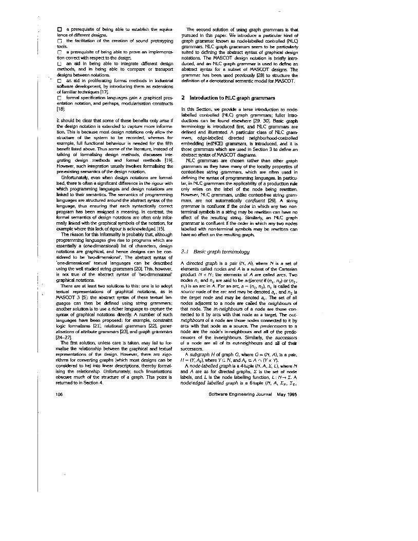
An NLC graph grammar is a five tuple (Z, A, 2, P, C), where Z is the set of all node labels, A is the set of all terminal node labels, and 2 is the initial nodelabelled graph (with its labels drawn from 3. Pis the set of pro- duction rules of the grammar: and C is the embedding relation. Z-A is the set of non-terminal node labels. A pro- duction p has the form p : x:= Y, where x is a non- terminal node label and Y is a node-labelled graph known as a daughter graph. The embedding relation is a binary relation over Z, C E C x Z.
An example NLC grammar is given in Fig. 1. The set of labels is {a, b, c, A}, the set of terminal labels is {a , b, c } , and there is one production rule p . The embedding rela- tion Cis {(b, b), (c, a)) . The derived graph is 2 with pro- duction p applied to the lower node labelled with A.
Generally, in graph grammars, the left-hand side of a production rule of a graph grammar can be an arbitrary subgraph, but NLC graph grammars limit this to the non- terminal label of a single node. A node labelled with a non- terminal symbol (the mother node) in a graph (the host graph) can be replaced with the daughter graph of any production rule whose left-hand-side matches its label. The mother node is removed from the host graph (ging the rest graph) and the daughter graph is inserted in its place. The nodes of the host graph in the neighbourhood of the mother node are linked to the nodes of the inserted daughter graph according to the rules given in the embed- ding relation. This means that if (c, a) E C, every node labelled with c in the daughter graph is linked with every node labelled with an a in the neighbourhood of the rewrit- ten node in the rest graph.
The complexity of embedding relations are needed in graph grammars, unlike in string grammars, because there are many ways in which a daughter graph could be integrated into a rest graph, whereas a string can only be inserted into a point in another string in one way.
The closure of an NLC grammar is the set of graphs that can be obtained by repeated applications of the pro. duction rules starting from the initial graph, and thii defines the language of the grammar. The terminal lan- guage of a grammar is the set of graphs in the grammar's closure whose nodes are only labelled with terminal symbols.
2.3 NCEgraph-grammars
An NCE (neighbourhood-controlled embedding) grammar [29] is a mcdified NLC grammar, where the embedding
relations are local to the production rules (each rule can specify a different embedding) and the actual nodes of the daughter graph, and not just their labels, can be specified in the embedding.
An NCE graph grammar is a Qtuple (Z, A , Z, R), where C, A, Z are the labels, terminal labels, and initial graph, respectively, as for NLC grammars. R is the set of rewriting rules, each rule taking the form (x:= Y, C), where x:= Y is a production and C is the embedding relation local to i t C s N, x Z, where Ny is the set of nodes of Y.
An example of an NCE grammar is given in Fig. 2. The derived graph again shows the application of rule p to the lower node labelled with A.
NCE grammars are more expressive than simple NLC grammars, and prove to be easier to use to define abstract syntax of design notations as it is often desirable to dis- tinguish how different nodes in the daughter graph are embedded in a rest graph, irrespective of whether they share the same labels.
2.4 edNE graph grammar
One last extension to the graph grammars used in this paper is described in this Section, edgelabelled directed NCE grammars.
The directed extension to NCE grammars is that two embedding relations are associated with each production rule, instead of one. The different relations distinguish between the nodes in the neighbourhood of the mother node according to the direction of the arc that connects them to the mother node.
The edgelabelled extension means that the graphs con- sidered are all noddedge-labelled graphs, and the embed- ding rules now distinguish between the labels on the arcs as well as the labels on the nodes of the neighbouring nodes. Strictly, the directed extension can be encoded within the edgelabelled extension: however, it is not normal to do this [29].
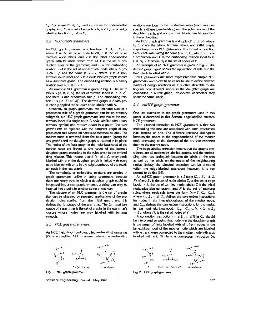
An edNCE graph grammar is a 5-tuple ( E N , C,, A, Z, R), where Z, is the set of node labels; Z, is the set of edge labels; A is the set of terminal node labels; Z is the initial nodeledge-labelled graph; and R is the set of rewriting rules, where each rule takes the form (x:= Y, Ci,. CouJ, where x E Z, - A, Ci, defines the connection instructions for nodes in the in-neighbourhood of the mother node, and CO,, defines the connection instructions for the nodes in the out-neighbourhood. Ci,, C,,, C _ N, x Z6 x Z, x C, , where N, is the set of nodes of Y.
A connection instruction (n, el l , nl, el2) in Ci, should be interpreted as saying that node n in the daughter graph is the target of links labelled with el l , from nodes in the in-neighbourhood of the mother node which are labelled with n 1 and were connected to the mother node with arcs labelled with e12. Similarly, a connection instruction (n,
1 / A l h a K A
z C = i (b.b). I C a) I derived graph 2 C = ( (1 ,b), (2.a) (3.a) 1 derived graph
Fig. 1 NLC graph grammar Fig. 2 NCE graph grammar
Software Engineering Journal May 1995 107
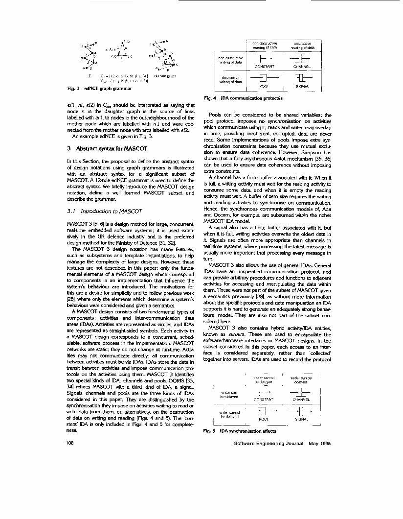
Fig. 3 edNCE graph grammar
el l , nl, e12) in CO,, should be interpreted as saying that node n in the daughter graph is the source of links labelled with el 1. to nodes in the out-neighbourhood of the mother node which are labelled with n l and were con- nected from the mother node with arcs labelled with e12.
An example edNCE is given in Fig. 3.
3 Abstract syntax for W C O T
In this Section, the proposal to define the abstract syntax of design notations using graph grammars is illustrated with an abstract syntax for a significant subset of MASCOT. A 12-rule edNCE grammar is used to define the abstract syntax. We briefly introduce the MASCOT design notation, define a well formed MASCOT subset and describe the grammar.
3.1 Introduction to MASCOT
MASCOT 3 [5, 61 is a design method for large, concurrenf real-time embedded software systems: it is used exten- sively in the UK defence industry and is the preferred design method for the Minisby of Defence [31,32].
The MASCOT 3 design notation has many features, such as subsystems and template instantiations, to help manage the complexity of large designs. However, these features are not described in this paper: only the funda- mental elements of a MASCOT design which correspond to components in an implementation that influence the system's behaviour are introduced. The motivations for this are a desire for simplicity and to follow previous work [28], where only the elements which determine a system's behaviour were considered and given a semantics.
A MASCOT design consists of two fundamental types of components: activities and inter-communication data areas (IDAs). Activities are represented as circles, and IDAs are represented as straight-sided symbols. Each activity in a MASCOT design corresponds to a concurrent, sched- ulable, software process in the implementation. MASCOT networks are static: they do not change at run-time. Activ- ities may not communicate directly: all communication between activities must be via IDAs. IDAs store the data in transit between activities and impose communication pro tocols on the activities using them. MASCOT 3 identifies two special kinds of IDA: channels and pools. DORIS [33, 341 refines MASCOT with a third kind of IDA, a signal. Signals. channels and pools are the three kinds of IDAs considered in this paper. They are distinguished by the synchronisation they impose on activities waiting to read or Write data from them, or, alternatively, on the destruction of data on writing and reading Figs. 4 and 5). The 'con. stant' IDA is only included in Figs. 4 and 5 for complete- ness.
non-deslructive destructive
non destructive writing of data
destructive writing of data
Fig. 4 IDA communication protocols
Pools can be considered to be shared variables; the pool protocol imposes no synchronisation on activities which communicate using it; reads and Writes may overlap in time, providing incoherenf corrupted, data are never read. Some implementations of pools impose extra syn- chronisation constraints because they use mutual exclu- sion to ensure data coherence. However, Simpson has shown that a fully asychronous 4-slot mechanism [35, 361 can be used to ensure data coherence without imposing extra constraints.
A channel has a finite buffer associated with it When it is full, a writing activity must wait for the reading activity to consume some data, and when it is empty the reading activity must wait A buffer of zero size requires the writing and reading activities to synchronise on communication. Hence, the synchronous communication models of, Ada and Occam, for example, are subsumed within the richer MASCOT IDA model.
A signal also has a finite buffer associated with if but when it is full, writjng activities overwrite the oldest data in i t Signals are often more appropriate than channels in real-time systems, where processing the latest message is usually more important that processing every message in turn.
MASCOT 3 also allows the use of general IDAs. General IDAs have an unspecified communication protocol, and can provide arbitrary procedures and functions to adjacent activities for accessing and manipulating the data within them. These were not part of the subset of MASCOT given a semantics previously [28], as without more information about the speafic protocols and data manipulation an IDA supports it is hard to generate an adequately strong behav- ioural model. They are also not part of the subset con- sidered here.
MASCOT 3 also contains hybrid activity/lDA entities, known as sewers. These are used to encapsulate the softwarelhardware interfaces in MASCOT designs. In the subset considered in this paper, each access to an inter- face is considered separately, rather than 'collected' together into servers. IDAs are used to record the protocol
, reader cannot reader can be
be delayed de I ay e d
writer can k- - T E I CONSTANT CHANNEL 1 be delayed
writer cannot -> + -Y --
POOL ~ SIGNAL be delayed
1 1 1 1
Fig. 5 IDA synchronisation effects
Software Engineering Journal May 1995 1 08
imposed on the software by each hardware interface; memory mapped hardware registers, for example, are usually represented as pool IDA.
3.2 Well formed MASCOTsubset
In the subset of MASCOT considered here, a MASCOT design can be considered to be a nodelabelled directed graph, where the nodes are either activities or IDAs, and the arcs represent the direction of data flowing between the nodes. Advitjes do not label adjacent nodes, and each path through the network is bounded by IDA nodes. These constraints are formalised below.
A MASCOT design M is a node-labelled directed graph (N, A, X, L), where N is the set of nodes, A is the set of arcs, the set of node labels C is {IDA, ACTMN}, and L is the node labelling function, L : N+ X. A partial function, IDA-Type : N + {Channel, Signal, Pool}, is assumed to exist, which retums the protocol that each IDA enforces; obviously, the function is only defined for nodes labelled with ‘IDA’.
(i) { n : NI 3a E A a, = n V a, = n } = N
This requires that there are no isolated nodes in well formed designs.
(ii) Va E A 0 L(a$ # L(4)
This requires that activities and IDAs must alternate on each path through a well formed design.
(iii) Vn E N ( i 3 a E A a, = n)-L(n) = IDA
This requires all design components with no predecessors to be labelled with ‘IDA‘, this reflects the intention to use IDAs to model the protocols of the hardware/software interface. Such IDAs are called input IDAS.
(iu) Vn E N o (1% E A a, = n)-L(n) = IDA
Similarly, this requires all design components with no suc- cessors to be labelled with IDAs. Such IDAs are called output IDAs.
(U) Vn E N 0 Predecessors(n) = 0 V
3n’ E N 0 n’ E Predecessors(n)
A Predecessors(n’) = 0 This requires every component in a design to be linked by some route to at least one input IDA No part of a well formed MASCOT design should be independent of all inputs.
(ui) Vn E N. Successors(n) = 0 V
3n’ E N 0 n’ E Successors(n) A Successors(n’) = 0 This requires every component in a design to be linked to at least one ouput IDA; no part of a well formed MASCOT design may be excluded by the design structure from being able to contribute to a system output; otherwise the computations that it performs are wasted.
(uii) Va, a’ E A 0 (a, = a; A /-(a,) = IDA
A lDA-Type(a,) = Pool) a’ = a
This requires that only one activity should be able write to a pool. This is not required in MASCOT 3, but its adoption
means that pools do not need a mutual exclusion mecha- nism; it is advocated in DOHS [34].
(uiii) Va, a‘ E A 0 (a, = 4 A L(a$ = IDA
A IDA-TMq) # Pool) + a’ = a
This requires that only one activity may read from each channel or signal; this simplification is also advocated in DORIS 1341.
Having defined the class of designs that are considered well formed, it is tempting to define denotational models directly for activities and the three kinds of IDA, and to assume that in doing so this subset of MASCOT has been adequately formalised. However, this leaves informal the link between the notation and the semantics. This is prob lematic, for there is no guarantee that the denotational models given to activities and IDAs would be suitable for every design that satisfies the ‘well formedness’ criteria. This uncertainty arises because it is difficult to visualise all the designs that would satisfy the ‘well formedness’ rules. In contrast, relating the notation and its denotational model through the notation’s abstract syntax enables the adequacy of the denotational model to be considered in a small number of cases, and it enables the adequacy of the model to be considered when these cases are combined. This approach can therefore bring confidence that all the well formed designs will have an adequate model.
3.3 MASCOT abstract syntax
A 1Zrule edNCE graph grammar is presented in this Section as an abstract syntax for a subset of the well formed designs defined above. The grammar acts as an abstract syntax for the designs in the terminal language of the grammar. The terminal language of the 12-rule grammar defined in this Section includes MASCOT designs which may arbitrarily branch and merge at activity nodes, and which may contain loops. Therefore, the grammar is called the branchinglooping MASCOT (BLM) grammar.
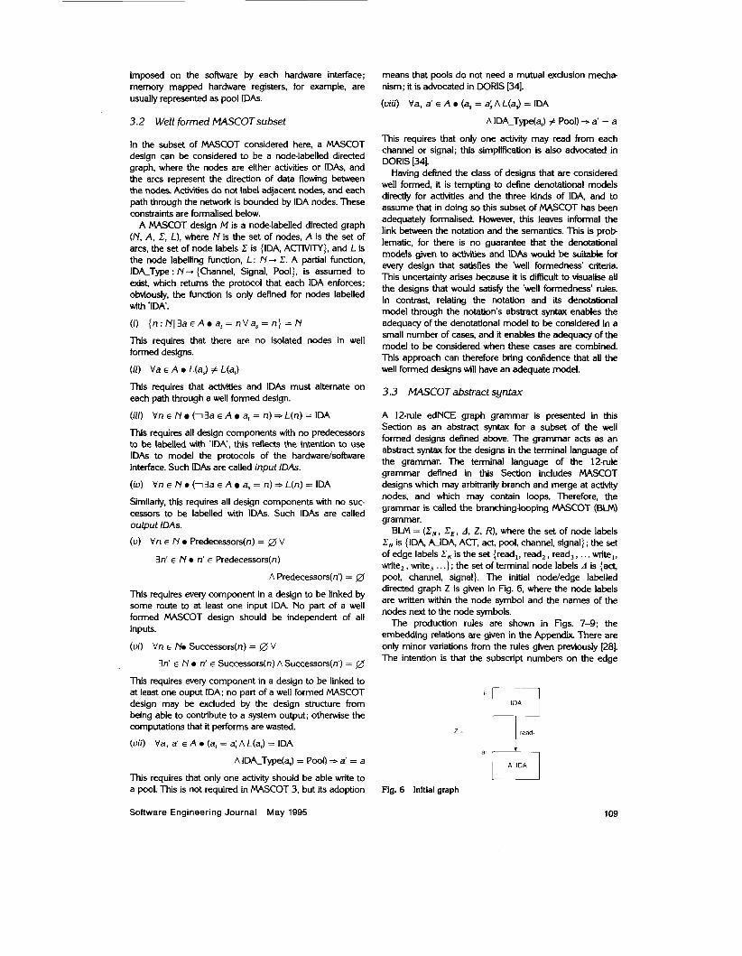
BUU\ = (EN, X E , A, Z, R), where the set of node labels C, is {IDA, A-IDA, ACT, act, pool, channel, signal} ; the set of edge labels X E is the set {read,, read,, read,, ... write,, wite, , write, . . .}; the set of terminal node labels A is {act, pool, channel, signal}. The initial nodeledge labelled directed graph Z is given in Fig. 6, where the node labels are written within the node symbol and the names of the nodes next to the node symbols.
The production rules are shown in Figs. 7-9; the embedding relations are given in the Appendix There are only minor variations from the rules given previously [ZS]. The intention is that the subscript numbers on the edge
’ I IDA i Z = read.
a1 [*I Fig. 6 Initial graph
Software Engineering Journal May 1995 109
write'
A-IDA read' read, read, read,
rule 1 I I
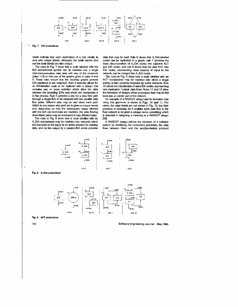
Fig. 7 IDAproductions
labels indicate that each application of a rule results in arcs with unique labels; obviously, the node names (but not the node labels) are also unique.
The rules in Fig. 7 show that a node labelled with the IDA non-terminal symbol can be rewritten into a single intercommunication data area with any of the protocols (rules 1-3) or into one of the graphs given in rules 4 and 5. These rules ensure that the resulting graphs present IDA-interfaces to the restgraph Rule 4 basically allows for an IDA-labelled node to be replaced with a design that contains one or more activities which ddve the data betwFeen the bounding IDAs and which can manipulate it in the process. Rule 5 provides a way for a data flow path through a single IDA to be replaced with two parallel data flow paths. Different data may be sent down each path (which is one reason why each arc is given a unique name) and, depending on how the subsequent nodes labelled with the IDA non-terminals are rewritten, the data flowing down these paths may be processed in very different ways.
The rules in Fig. 8 show how a node labelled with an &IDA non-terminal may be rewritten into networks which are bounded on the input by an active element for reading data, and on the output by a passive IDA which provides
rule 6 , I I
Ag. 8 AlDA productions
I I
lread, 1 read,
wrile' write,
P r i t e ? , IDA
write, I
rule 9 I rule 10
Rg. 9 ACT productions
110
write. writen
&p read\\\j/;.adi
rule 5
data that may be read. Rule 6 shows that A-IDA-labelled nodes can be replicated in a graph; rule 7 provides the basic decomposition of &IDA nodes into adjacent ACT and IDA nodes; and rule 8 shows that the data from new IDA nodes, representing newS sources of input to the network, can be merged into &IDA nodes.
The rules in Fig. 9 show how a node labelled with an ACT non-terminal may be rewritten into either a single activity or into networks bounded by active elements. Rule 10 allows the introduction of extra IDA nodes, representing new destination 'output' data flows. Rules 11 and 12 allow the formation of designs where processed data may be fed back into an earlier part of the network
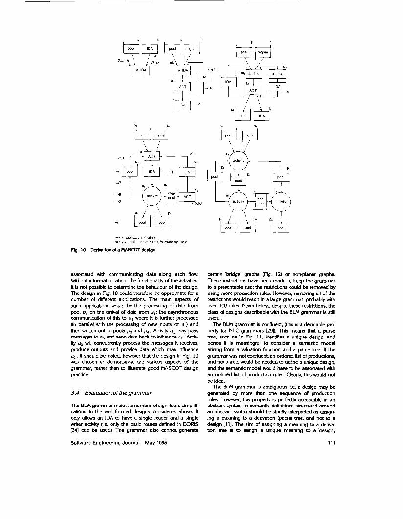
An example of a MASCOT design and its derivation tree using this grammar is shown in Figs. 10 and 1 1. For clarity, the edge labels are not shown in Fig. 10; but their presence is essential, for it enables each data flow in the final network to be given a unique name, something which is essential in assigning a meaning to a MASCOT design Wl.
A MASCOT design defines the structure of a sohare system by identifying the concurrent processes, the data flows between them and the synchronisation protocol
write,
readz
read.
1 read,
rule 7 I rule8
1 I read? I read, read2
writez 1 write,
read,
writeg write,
rule 11 ~ rule 12
Software Engineering Journal May 1995
10
=.x = application of rule x -x.y = application of rule x, followed by rule y
Derivation of a MASCOT design
associated with communicating data along each flow. Without information about the functionality of the activities, it is not possible to determine the behaviour of the design. The design in Fig. 10 could therefore be appropriate for a number of different applications. The main aspects of such applications would be the processing of data from pool pI on the anival of data from sl; the asynchronous communication of this to a, where it is further processed (in parallel with the processing of new inputs on sl) and then written out to pools p2 and p4. Activity a, may pass messages to a3 and send data back to influence a2. Activ- ity a3 will concurrently process the messages it receives, produce outputs and provide data which may influence a2. It should be noted, however that the design in Fig. 10 was chosen to demonstrate the various aspects of the grammar, rather than to illustrate good MASCOT design practice.
3.4 Evaluation of the grammar
The BLM grammar makes a number of significant simplifi- cations to the well formed designs considered above. It only allows an IDA to have a single reader and a single writer activity (i.e. only the basic routes defined in DORIS (341 can be used). The grammar also cannot generate
P' SI
pool signal
.4
pool IDA
activity . ..
certain 'bridge' graphs (Fig. 12) or non-planar graphs. These restrictions have been made to keep the grammar to a presentable size; the restrictions could be removed by using more production rules. However, removing all of the restrictions would result in a large grammar, probably with over 100 rules. Nevertheless, despite these restrictions, the class of designs describable with the BLM grammar is still useful.
The BLM grammar is confluent, (this is a decidable pro perty for NLC grammars [29D. This means that a parse tree, such as in Fig. 11, identifies a unique design, and hence it is meaningful to consider a semantic model arising from a valuation function and a parse tree. If the grammar was not confluent, an ordered list of productions, and not a tree, would be needed to define a unique design, and the semantic model would have to be associated with an ordered list of production rules. Clearly, this would not be ideal.
The BLM grammar is ambiguous, i.e. a design may be generated by more than one sequence of production rules. However, this property is perfectly acceptable in an abstract synta~~, as semantic definitions structured around an abstract syntax should be strictly interpreted as assign- ing a meaning to a delivation (parse) tree, and not to a design [I 11. The aim of assigning a meaning to a deriva- tion tree is to assign a unique meaning to a design;
111 Software Engineering Journal May 1995

n p, pool
IDA
A-IDA
ACT
IDA
A
ACT
r l r9
pa pool a, activity
IDA
IDA ACT
7 InA
pr pool
IDA
P, Pool
Ps rtA pool a3 activity r9 "' IDA
I r9 a2 activity p pool
IDA
\ ACT
Fig. 11 Parse tree of the design
however, clearly, there is a danger thaf if a design can have two or more derivation trees, it may be given conflict- ing semantic models. There are two ways around this: one is to provide a separate grammar which defines the con-
Crete syntax of notation; the other is to show for a particu- lar semantic model that all the possible models that may be given to the same design are the same (or at least, identical up to some notion of obselvational equivalence defined over the semantic model). It is the first approach which is usually used when defining the semantics of pro- gramming languages. A concrete syntax is used to associ- ate a single tree with a design, and so the concrete grammar needs to be unambiguous. This often means that the concrete grammar for a language is more complex than the grammar which defines the language's abstract syntax. The desirability of structuring semantic models around the simplest suitable grammar is one reason why concrete and abstract grammars are com- monly distinguished.
It is to be supposed, however, that there are inherently ambiguous graphical edNCE languages, as there are inherently ambiguous textual languages for context-free grammars [20], and so it may be the case that some design notations will need to be modified before they can be given an unambiguous concete syntax. Furthermore, concerete grammars have to be evaluated for the compu- tational complmity of using them to parse designs expressed in the language. These issues are beyond the scope of this paper, which is concentrating on the use of graph grammars to define the abstract syntax of a design notation.
112 Software Engineering Journal May 1995
4 Structuring semantic definitions around graph grammars
Our central argument is that, if M is the meaning or valu. ation function which defines the model denoted by the design notation, M should be defined around the structure of the grammar that defines the abstract syntax of the notation. In the MASCOT example in this paper, this means that M should be defined for the initial graph and each of the 12 daughter graphs. This has been done pre- viously 1281. This approach ensures that there is an incre- mental way of building a semantic model for any legal design in the language.
It is beyond the scope of this paper to provide a com- plete denotational semantics for MASCOT, for this would require a detailed discussion about the meaning of MASCOT. Nevertheless, an example is given of the meaning of the initial graph to illustrate this approach. The meaning of the initial graph (Fig. 6) is the parallel com- position of the meaning of its two nodes, with all the mes- sages passing between the two nodes hidden from the outside world. The semantic model is defined using CSP. This example shows that the arc labels in the grammar are used to name the CSP channel which links the two parallel processes. This is important in the semantic model because it provides a mechanism for hiding all the internal data flows in design fragments from the rest of the design.
lnitial graph Z
il ai,
y VI- A-IDA 1 J
It should be noted that potentially the relationships between daughter graphs and their semantic models are open to the same problems of informality as informally linked design notations and models. However, the differ- ence is that the model is defined for a single daughter graph, and hence the opportunities for ambiguity are limited.
A significant advantage of structuring the semantic defi. nitions of design notations around an abstract syntax c a p tured using graph grammar, as opposed to around an abstract syntax of a textual version captured by a string grammar, is that the structure of the design is faithfully reflected in the structure of the semantic model. For example, the grammatical structure of a textual version of a MASCOT design is a collection of modules; the relation- ship between those modules is only revealed in the details of the modules, (i.e. by which other modules are explicitly imported) and not in some linking syntax. In contrasf the grammatical structure of the graphical representation of a MASCOT design captures the structure and intercon- nections directly. This means that a semantic model defined around the graphical grammar should reflect the structure of the design more naturally. Although both styles work, the advantage of the graphical structure is important because semantic models are simply asserted; they are not subject to verification. A model's best vali.
dation is that it appears to be 'obviously' correct; it is sug- gested that such validation is faaliited by the semantic definition closely following the structure of the design.
5 Conclusions
There is a growing body of work concerned with defining the semantics of graphical design notations. However, the relationship between the design notations and the formal text is often left informal. In contrast, the semantics of pro gramming languages are defined around their abstract syntax. It has been argued that a similar approach should be used for formalising design notations and that NLC graph grammars are suitable for defining the abstract syntax of (at least some) design notations.
The suitability of graph grammars to define the abstract syntax of design notations has been illustrated using edNCE grammars and MASCOT. It is believed that there is nothing unique about MASCOT which would indicate that similar results could not be achieved with other design notations. Some design notations use a number of differ- ent notations for capturing different aspeas of a design, rather than one integrated notation like MASCOT. However, each individual notation still needs to have a formally defined abstract syntax
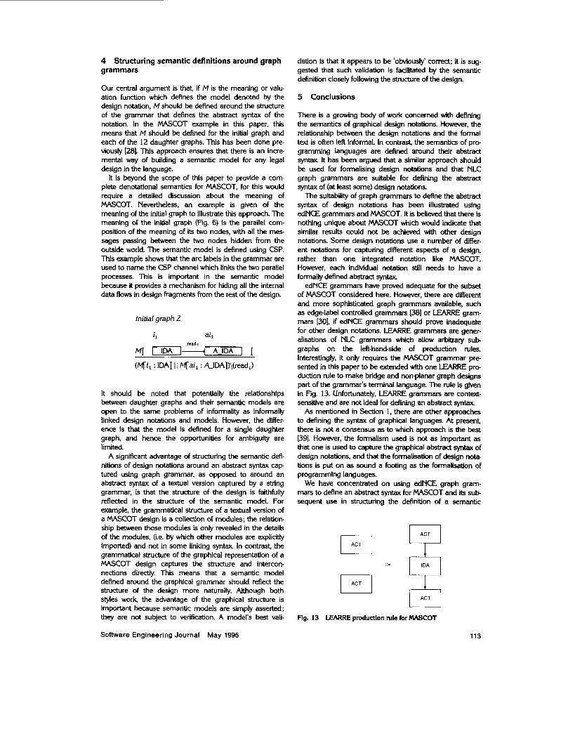
edNCE grammars have proved adequate for the subset of MASCOT considered here. However, there are different and more sophisticated graph grammars available, such as edgelabel controlled grammars [38] or LEARRE gram- mars [30], if edNCE grammars should prove inadequate for other design notations. LEARRE grammars are gener- alisations of NLC grammars which allow arbitrary sub graphs on the left-hand-side of production rules. Interestingly, it only requires the MASCOT grammar pre- sented in this paper to be extended with one LEARRE pro dudion rule to make bridge and non-planar graph designs part of the grammar's terminal language. The rule is given in Fig. 13. Unfortunately, LEARRE grammars are context- sensitive and are not ideal for defining an abstract syntax As mentioned in Section 1, there are other approaches
to defining the syntax of graphical languages. At present, there is not a consensus as to which approach is the best 1391. However, the formalism used is not as important as that one is used to capture the graphical abstract syntax of design notations, and that the formalisation of design nota- tions is put on as sound a footing as the formalisation of programming languages.
We have concentrated on using edNCE graph gram- mars to define an abstract syntax for MASCOT and its sub sequent use in structuring the definition of a semantic
- Fig. 13 LEARRE produdion rule for MASCOT
Software Engineering Journal May 1995 113
model; no.attempt has been made to explore the use of edNCE grammars in defining a concrete syntax of the MASCOT design notation. This has meant that the problem of parsing MASCOT designs was not.considered.
The BLM graph grammar defined in this paper has been used previously [28] to structure the definition of a denotational model for MASCOT. It is intended for that denotational model to be the subject of a subsequent paper.
6 Acknowledgments
British Aerospace Defence Ltd., Dynamics Division, employed the author during this research.
The author would like to thank Professor Ekmard Carre (University of Southampton and Program Validation Ltd.) for his scepticism about informally linked notations and semantics; Mr. William Marsh for suggesting the use of graph grammars; and the referees for their comments which helped to improve the paper.
7 References
[I] CAMERON, J.R.: 'An overview of JSD, /E€€ Tram., 1986,
[2] WOODMAN, M: Yourdon dataflow diagrams: a tool for dis- ciplined requirements analysis', Inform. Softw. Techno/.,
131 ROBINSON, PJ.: 'HOOD manual'. Issue 2.2, European Space Agency, ESTEC, April I988
[4] HULL, ME.C., ODONOGHUE, P.G., and HAGAN, BJ.: 'MOON: modular object-oriented notation', Sob. Eng. J.,
151 Joint IECCA and MUF Committee on MASCOT (JIMCOM): 'The official handbook of MASCOT Version 3.1, Issue 1, Crown Copyrighf June 1987
161 SIMPSON, H.R: 'The Mascot Method, Softw. Eng. J., 1986,
[7] ter HOFSTEDE, AHA, and van der WEIDE, T.P.: 'Formal- isation of techniques: chopping down the methodology jungle', Inform. S o b . Technol., 1992, 34, (1)
[8] PLOTKIN, G.D.: 'A structural approach to operational semantics'. Technical Report, DAlMl FN.19, Computer Science Department, Aarhus University, Denmark, 1981
191 HOARE, CAR.: 'An axiomatic basis for computer pro- gramming., Cornrnun. ACM, 1978,21, (8)
[IO] SCOT, D., and STRACHEY, C.: 'Toward a mathematical semantics for computer languages' Proc. Symp. on Com- puters and Automata, Polytechnic Institute of Brooklyn, New York, April 1971
[Ill SCHMIDT, D A : 'Denotational semantics: a methodology for language development' (Wm. C. Brown Publishers, 1986)
1121 TSE, T.H., and PONG, L: 'Towards a formal foundation for DeMarco data flow diagrams', Cornput. J. , 1989,32, (I)
(131 RANDEU, G.: 'Data flow diagrams and Z in NICHOLLS, J.E. (Ed.): 'Z User Workshop: Oxford 1990, Workshops in Computing (Springer-Verlag, 1991)
1141 SRIDHAR, R.T., and HOARE, CAR.: 'JSD expressed in CSP. Technical Monograph PRG-51, Word University Com- puting Laboratory Programming Research Group, UK, July 1985
(151 BROY, M. JACKSON, K., and PENNINGTON, R: 'A stream function definition of MASCOT'. Final Technical Report, Issue I.]., System Designers, Software Technology Centre, OK, March 1987
1161 TSE, T.H.: 'A unifying framework for structured analysis and
114
SE-12, (12). pp. 222-240
1988,30, (9), pp. 515-533
1991,6, (I), pp. 25-32
1, (3), pp. 103-120
design methods' Cambridge Tracts in Theoretical Computer Science, No. 1 1 (Cambridge Uniwrsity Press, 1991)
1171 SEMMENS, L, and ALLEN, P.: 'Using Yourdon and Z: an approach to formal specification' in NICHOUS, J.E. (Ed.): 'Z User Workshop: Oxford 1990. Workshops in Computing (Springer-Verlag, 1991) TOETENEL H.. van KATWlJK, J., and PLAT. N.: 'Struc- tured analysis - formal design, using stream and object. oriented formal spedfication'. Proc. ACM SIGSOFT Int Workshop on Formal Methods in Software Development, SopW. fng . Notices, 1990.15, (4) SEMMENS, LT.. FRANCE, RB., and DoCKER, T.W.G.: 'Integrated structured analysis and formal specilication tech- niques', Cornput. J., 1992.35, (6) HOPCROFT. J.E., and UUMAN, J.D.: 'Intrcduction to Automata theory, languages, and computation' (Addison- Wesley Publishing Company, 1979) HEM, R, and MARRIOlT, K.: 'A declarative specification and semantics for visual languages', J. Visual Lang. Cornput., 1990,2 CRIMI, C., GUERICO, A., NOTA G., PACINI, G. TORTOFA, G., and TUCCI, M : 'Relational grammars and the application to multdimensional languages', J. Visual Lang. Cornput., 1991.2 GOLIN, EJ., and REISS, S.P.: 'The specification of visual language syntax', J. Visual Lang. Cornput., 1990,2 CIAUS, V., EHRIG. G., and ROZENBERG, G. (Eds.): 'Graph grammars and their application to computer saence and biology'. Proc. 1st Int Workshop, Lect. Notes Cornput. Sci., 73 (Springer-Verlag. 1979) EHRIG, H., NAGL M, and ROZENBERG, G. (Eds.): 'Graph grammars and their application to computer science'. Proc. 2nd Int. Workshop, Lect. Notes Cornput. Sci., 153 (Springer-Verlag. 1983) EHRIG, H., NAGL M, and ROZENBERG, G. (Eds.): 'Graph grammars and their application to computer science'. Proc. 3rd Int. Workshop, Lect. Notes Cornput. Sci., 291 (Springer-Verlag, 1986) EHRIG. H., KREOWSKI, H.J.. and ROZENBERG, G. (Eds.): 'Graph grammars and their application to computer science'. Proc. 4th Int Workshop, Lect. Notes Cornput. Sci., 532 (Springer-Verlag. 1990) PAYNTER, S.E.: The formalisation of software development using MASCOT. PhD Thesis, Mathematics Department, University of Southampton, UK, December 1993 ENGELFRIET. J., and ROZENBERG, G.: 'Graph grammars based on node rewriting: an introduction to NLC graph grammars'. Proc. 4th Int Workshop, Lect. Notes Cornput. Sci., 532 (Springer-Verlag, 1990) ROZENBERG, G.: 'An introduction to the NLC way of rewriting graphs'. ibid. CIK Ministry of Defence: 'Modular approach to software con- struction, operation and test4WSCOT'. Defence Standard 00-17, Issue 1, October 1985 UK Ministry of Defence, Sea Systems Controllerate: 'Require- ments for software use with digkal processors'. Naval Engin- eering Standard, NES 620, Issue 4, June 1991 THOMAS, C. : 'The data oriented requirements implementa- tion scheme'. AGARD Proc. 503, NATO, 1991
1341 SIMPSON, H.R: %\ethodological and notational conventions in DORIS real time networks'. SPIRITS and BAe Dynamics Technical Report, February 1994
1351 SIMPSON, H.R: 'Four-slot hlly asynchronous communica- tion mechanism', IEEfroc. E, 1990, 137, (I), pp. 17-30
(361 SIMPSON, H.R: 'Correctness a n a w i for class of asynchro- nous communication mechanisms', /E€ hoc. E, 1992,
(371 ASHW0KlI-l. C.M : 'Structured systems analysis and design 139, (I), pp. 35-49
method (SADMY, Inform. Softw. Technol., 30; (3),
Software Engineering Journal May 1995
1381 MAIN, MG., and ROZENBERG, G. : 'Fundamentals of edge- label controlled graph grammars'. J. Visual Lang. Cornput.. 1986
1391 'Visual language syntax and semantics: questions and answers'. Discussion Group, &ual Software Programming Language Workshop, Scottsdale, Arizona, 5-7 October 1993
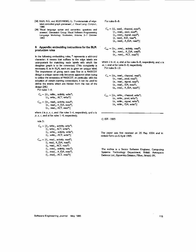
8 Appendix: embedding instructions for the BLM production rules
In the following embedding rules, represents a wild-card character: it means that suffixes to the edge labels are unimportant for matching node labels with which the daughter graph is to be connected. (llus complexity is necessary if, as in BLM, each arc is given an unique label. The importance of giving each data flow in a MASCOT design a unique name only becomes apparent when trying to define the semantics of MASCOT; in particular, with the adoption of certain naming conventions, it can be used to define the events which are hidden from the rest of the design [28].)
For rules 1-4:
Cia = {(A, , vnite,, activity, write'), (A,, write,, ACT, write*)}
CO,, = {(x,, read,, activity, read*), (x,, read,, A-IDA, read*), (x , , read , , ACT. read*)}
where 1 is p , s, c, and i for rules 1,-4, respectively, and n is p , s, c, and ai for rules 1-4, respectively.
rule 5 :
Ci, = {(i,, write,, activity, write'), (i,, write,, ACT, write*), (i, , write,, aaivity, write.), (i, , write, , ACT, write.)}
CO,, = {(il, read,, activity, read*), (i, read, A-IDA, read*), (i,, read,, ACT, read*) (i, , read,, activity, read'), (i, , read,, &IDA, read*), (i2, read,, ACT, read*)}
For rules 6-8:
Ci, = { ( A , read,, channel, read.), (A,, read,, pool, read.), (A,, read,, signal, read.), (1, read,, IDA, read*), (A,, read,, &IDA, read.)}
qu, = {(n, , read,, activity, read*), (n, , read,, A-IDA, read*), (IT,, read,, ACT, read*))
where 1 is ai, a, and ai for rules 6-8, respectively, and n is ai, i, and ai for rules 6-8, respectively.
For rules 9-12:
Ci, = {(a,, read,, channel, read*), (a,, read,, pool. read.), (a,, read,, signal, read*), (a,, read,, IDA, read.), (a,, read,, A-IDA, read*)}
CO,, = {(a,, write,, channel, write'), (a,, write,, pool, write.), (a,, vnite,, signal, d e . ) , (ai! *I, IDA, **I}
0 IEE: 1995
The paper was first received on 20 May 1994 and in revised form on 6 April 1995.
The author is a Senior Software Engineer, Computing Systems Technology Department, British Aerospace Defence Ltd., Dynamics Division, Elton, Bristol, UK.
Software Engineering Journal May 1995 115