Structural Colors in Nature and Butterfly-Wing Modeling
7
Structural Colors in Nature and Butterfly-Wing Modeling Gérard Tayeb, Boris Gralak and Stefan Enoch
-
Upload
independent -
Category
Documents
-
view
1 -
download
0
Transcript of Structural Colors in Nature and Butterfly-Wing Modeling

Structural Colors in Nature and Butterfly-Wing
Modeling
Gérard Tayeb, Boris Gralak
and Stefan Enoch

Periodic structures, such as gratings and photonic crystals,
offer the ability to control light propagation. Since reflection
from these objects is strongly wavelength sensitive, it can
generate iridescent colors of structural origin. Periodic structures
are present in opals and in some animals, a characteristic that
allows them to display gleaming colors, even in the absence of
pigments. Electromagnetic theories allow this phenomenon
to be better understood through modeling.
Iridescent threads and spines of a sea mouse. [From http://www.physics.usyd.edu.au/~nicolae/seamouse.html]

Over the course of recent years,numerous research groups havedevoted increasing attention to
photonic band structures. These struc-tures, which are composed of a periodicarrangement of dielectric materials, areunique in that, although they are made oftransparent materials, they can inhibit thepropagation of light over some wave-length ranges. The range of wavelengthsover which the passage of light is inhib-ited is known as a bandgap. Photonicband structures soon may find commer-cial application in devices that entail theinhibition of spontaneous emission, suchas laser diodes and high-efficiency light-emitting diodes, as well as in integratedoptics components, such as waveguidesand wavelength multiplexers for opticaltelecommunications.
The structural control of light is mani-fest in the animal and mineral worlds, aswell as in the realm of high technology.The oldest and best-known example isthe opal, a sedimentary gem used as farback as the early Aztecs. Unlike othermineral gems, the opal does not have acrystalline structure. It is made of tinyspheres of silica packed together. The
have shown that these 2D photonic crys-tals possess a partial bandgap (i.e., forsome directions of propagation of light),which is the physical explanation of theiriridescence.
It is worth noting that, in the case ofthe opal and the sea mouse, the colors aregenerated by the structural properties ofthe objects themselves. They are caused,in other words, by interference, or morespecifically by the light-diffracting char-acteristics of the microstructure, not byselective absorption or reflection of lightby pigments, the most common origin ofcolors.
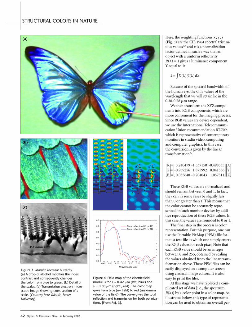
Let us now consider the butterfly, aspecies in which color is generally pro-duced in both of the ways describedabove. In butterflies, color plays animportant role in thermal regulation,communication and camouflage. Forsome butterflies, such as the Morphorhetenor, one way of producing color pre-dominates. The iridescent blue color ofthe Morpho rhetenor, an extremely metal-lic and iridescent butterfly that lives inSouth America, comes from diffractionby the microstructure of its wings. Bluepigments are, in fact, very uncommon innature. The wingspan of Morpho rhetenoris about 12 cm. Its wings consist of amembrane covered with layers of scales.The bottom layer is composed of struc-tural scales that produce color, while theupper layer does not contribute to theproduction of color.2 The scales, each ofwhich is about 200 �m long and 80 �mwide, are made of chitin and coveredwith about 1300 thin, parallel ridges permillimeter. This periodic structure con-stitutes a diffraction grating, the cross-section of which exhibits a tree-likegeometry.
In keeping with grating theory, thestudy of the microstructure, because ofits very fine scale, requires that the vecto-rial nature of light (polarization) betaken into account. The numerical meth-ods developed to solve Maxwell’s equa-tions can be used to study this complexproblem.3 Here we model the scale as amultilayered grating of ribs, as shown inFig. 4. The figure shows field maps fortwo wavelengths corresponding to thecolors blue and red. The scale is illumi-nated from the top in normal incidenceand in E// polarization (the electric field
40 Optics & Photonics News ■ February 2003
STRUCTURAL COLORS IN NATURE
Figure 1. The opal is perhaps the best-known example of photonic band structures in nature.[From http://www.roughcutgems.com/]
1047-6938/03/02/0038/6-$0015.00 © Optical Society of America
diffraction of light through this arrange-ment produces a characteristic play ofcolors, the nature of which is determinedby the size of the spheres and the regular-ity of the periodic structure. Researchershave drawn inspiration from these gemsto build artificial opals by sedimentationof spheres. This is one of the two princi-pal techniques used for building three-dimensional (3D) photonic crystals.
At the University of Sydney, Australia,a research group headed by ProfessorRoss C. McPhedran has discovered thatphotonic crystals are also present in theanimal world,1 specifically in the seamouse, a marine worm found in moder-ately deep water. The sea mouse is partlycovered with long, feltlike threads thatproduce a brilliant iridescence, a range ofcolors that changes with the direction ofthe incident light and the direction ofobservation. It is also characterized by iri-descent spines. Both threads and spinesare clearly visible in the photograph onthe preceding pages. A scanning electronmicroscope (SEM) image of a cross-sec-tion of a thread or of a spine reveals aperiodic microstructured pattern withhexagonal symmetry. Numerical studies

February 2003 ■ Optics & Photonics News 41
is perpendicular to the figure). It is evi-dent that blue is strongly reflected (thefield on the field map below the structureis weak) while red is not. For � = 0.6 �m,we observe that the field propagatesinside the structure along the dielectricregions. The scale structure in the regionbetween the ridges and the bottom mem-brane is actually rather complex and dis-ordered, with probable inclusion ofpigments. This means that the longerwavelengths that pass through the tree-like grating are much more sensitive tothe bottom region of the scale. If theabsorption phenomenon in the actualscale were mainly caused by localizedeffects inside the pigments (or otherabsorbing defaults), it would explain theabsorption of red light observed in theexperiments.4
Strong chromatic selection is also evi-dent in the reflection curves for both E//and H// polarizations (electric and mag-netic field perpendicular to the figure,respectively). Indeed, the structure of thebutterfly wing works as a short-wave-pass filter for the reflected waves. For thisreason, one can infer that the color pro-duced will be blue.
Yet colors are, by nature, complex.Although each of us may perceive colors
slightly differently, both the eye and thebrain always play important roles in colorperception. Standard conditions for per-forming color measurement experimentshave been formulated by theCommission Internationale de l'Éclairage(CIE). By use of reference stimuli, theCIE has defined a standard set of tristim-ulus values to match each wavelength ofthe spectrum.
Let us now summarize the basic ideasfor converting reflection coefficients intocolor maps. We assume that the bodyunder study is illuminated by an illumi-nant characterized by its energy distribu-tion D(�). In this article, we use the CIEnormalized illuminant D65, whichclosely matches that of the sky in condi-tions of daylight.5,6
Assuming that the body has a reflec-tivity R(�), we can compute the CIE XYZtristimulus values,7 which are one possi-ble way to characterize the reflected color,according to:
1X = – �D(�) R(�) x–(�)d�k
1Y = – �D(�) R(�) y–(�)d�k
1Z = – �D(�) R(�) z–(�)d�k
STRUCTURAL COLORS IN NATURE
Figure 2. (a) Sea mouse, (b) its iridescentthreads, (c) SEM cross-section of a spine.[From http://www.physics.usyd.edu.au/~nicolae/seamouse.html].
(a)
(b)
(c)
Here, the weighting functions x–, y–, z–
(Fig. 5) are the CIE 1964 spectral tristim-ulus values6,8 and k is a normalizationfactor defined in such a way that anobject with a uniform reflectivity R(�) = 1 gives a luminance component Y equal to 1:
k = �D(�) y–(�)d�
Because of the spectral bandwidth ofthe human eye, the only values of thewavelength that we will retain lie in the0.38-0.78 �m range.
We then transform the XYZ compo-nents into RGB components, which aremore convenient for the imaging process.Since RGB values are device dependent,we use the International Telecommuni-cation Union recommendation BT.709,which is representative of contemporarymonitors in studio video, computing and computer graphics. In this case,the conversion is given by the lineartransformation7:
R = 3.240479 -1.537150 -0.498535 XG = -0.969256 1.875992 0.041556 Y[B
]=
[0.055648 -0.204043 1.057311
][Z
]These RGB values are normalized and
should remain between 0 and 1. In fact,they can in some cases be slightly lessthan 0 or greater than 1. This means thatthe color cannot be accurately repre-sented on such monitor devices by addi-tive reproduction of these RGB values. Inthis case, the values are rounded to 0 or 1.
The final step in the process is colorrepresentation. For this purpose, one canuse the Portable PixMap (PPM) file for-mat, a text file in which one simply entersthe RGB values for each pixel. Note thateach RGB value should be an integerbetween 0 and 255, obtained by scalingthe values obtained from the linear trans-formation above. These PPM files can beeasily displayed on a computer screenusing classical image editors. It is alsoeasy to print the files.
At this stage, we have replaced a com-plicated set of data [i.e., the spectrumR(�)] by a color point in a color map. Asillustrated below, this type of representa-tion can be used to obtain an overall per-
42 Optics & Photonics News ■ February 2003
STRUCTURAL COLORS IN NATURE
Figure 4. Field map of the electric field modulus for � = 0.42 �m (left, blue) and � = 0.60 �m (right , red). The color mapgoes from blue (no field) to red (maximumvalue of the field). The curve gives the totalreflection and transmission for both polariza-tions. [From Ref. 3].
0.40 0.45 0.50 0.55 0.60 0.65 0.70 0.750.0
0.1
0.2
0.3
0.4
0.5
0.6
0.7
Total reflection H// or TE Total reflection E// or TM
Wavelength (µm)Figure 3. Morpho rhetenor butterfly. (a) A drop of alcohol modifies the index contrast and consequently changes the color from blue to green. (b) Detail ofthe scales. (c) Transmission electron micro-scope image showing cross-section of ascale. [Courtesy Pete Vukusic, ExeterUniversity].
(a)
(b)
(c)

February 2003 ■ Optics & Photonics News 43
spective of the reflection properties ofa body. A 2D color map based on thisrepresentation provides two free parame-ters (for example, the two angles ofdiffraction).
Let us now suppose that the butterflywing is illuminated by skylight, and thatwe want to determine the color reflectedby the wing in a direction characterizedby the polar angle � (the angle betweenthe normal to the wing and the directionof observation) and the azimutal angle �.To simulate the uniform luminance ofthe skylight, the incident field is modeledby the superposition of a great number ofplane waves illuminating the wing withvarious incidences coming from theupper half space. To sample the visiblespectrum, the calculations are made forseveral values of the wavelength �. Toobtain the reflectivity R(�,�,�) thatdescribes the color spectrum reflected inthe (�,�) direction, we incoherently addthe intensities reflected by the grating. Byuse of the procedure described above, wetransform this function into aRGB(�,�)color map.
Figure 6 shows such maps for thestructure of Fig. 4. On these maps, thehorizontal axis gives the � value, from 0°to 80°, and the vertical axis gives the �value, from 0° to 180°. This means thatthe left side of the maps shows thereflected color in the direction normal tothe scale (� = 0) and the right side givesthe reflected color for near grazingangles. The left-hand figure correspondsto the scale while the wing is suspendedin the air, while the right-hand one corre-sponds to the scale while the wing is lyingin isopropyl alcohol (IPA), with an opti-cal index of 1.38. Because of the changeof index contrast between the scale (theoptical index of chitin is close to 1.56)and the embedding media (air or IPA),the diffraction phenomenon is stronglymodified by immersion in IPA (the opti-cal paths are roughly changed), and thereflected colors are completely modified.This modeling agrees with the experi-ment shown in Fig. 3. After evaporationof the IPA, the wing recovers its originalblue color, thus confirming the fact thatthe colors are structural.
ConclusionNatural opal gems can serveas a source of inspiration tophysicists in the creation of3D photonic crystals. In but-terflies, both structural andchemical processes (pig-ments) serve to produce col-ors. In the future, thecombination of these twoprocesses of color creationcould be used in the realiza-tion of textiles for clothing.Indeed, researchers are nowstudying the incorporationof structural colors inthread. The field of potentialapplications of the under-standing of these processesincludes all the domains inwhich color plays an impor-tant role. Automobile manufacturers, forexample, sometimes combine pigmentsand structural properties to produce spe-cific shades of color. In the future, experi-ments in a number of technological andproductive realms will be furthered bythe opportunities to create color that areinspired by the opal, the sea mouse, thebutterfly wing and other manifestationsof color in nature.
ReferencesPlease see OPN Feature Article References,page 49.
Gérard Tayeb, a professor at the Université Aix-Marseille, and Stefan Enoch ([email protected]), a researcher with the Centre National dela Recherche Scientifique, are both affiliated withthe Fresnel Institute, Marseille, France. Boris Gralakoccupies a post-doctoral position at FOM-Institutefor Atomic and Molecular Physics, Amsterdam, TheNetherlands.
STRUCTURAL COLORS IN NATURE
Figure 5. Left: Relative energy distribution of D65 illuminant (blue) and its 5th order polyno-mial approximation used in computations (red) versus wavelength �. Right: Spectral x–, y–, z–
tristimulus values. [From Ref. 3].
Figure 6. Colors reflected by a butterfly wingscale modeled as in Fig. 4. The horizontalaxis gives the � value, from 0° to 80°, andthe vertical axis gives the � value, from 0° to180°. The angular shift between two neigh-boring squares is equal to 10°. The left-handmap corresponds to a scale of the wing sus-pended in air, while the right-hand one cor-responds to a scale of the wing lying in IPA.[From Ref. 3.]
0.3 0.4 0.5 0.6 0.7 0.80
20
40
60
80
100
120
Rel
ativ
e en
ergy (a)
λ (µm)
D65 illuminant (CIE data) 5th order polynomial approximant
0.4 0.5 0.6 0.7 0.80.0
0.5
1.0
1.5
2.0 (b)
λ (µm)
x y z

February 2003 ■ Optics & Photonics News 49
Optoelectronic MicrosystemsIntegration for System-on-a-Packageand System-on-a-Chip Applications 26Nan Marie Jokerst, Martin A. Brooke, Sang-Yeon Cho, Dae-Ik Kim, Mikkel Thomas andSuzanne Fike
1. S. K. Tewksbury and L. A. Hornak, “Opticalclock distribution in electronic systems,” Journ.VLSI Sig. Pro., vol. 16, 1997, pp. 225-246.
2. Rassaian, M.; Beranek, M.W., “Quantitativecharacterization of 96.5Sn3.5Ag and80Au20Sn optical fiber solder bond joints onsilicon micro-optical bench substrates,” IEEETrans. on Adv. Pack., vol. 22, 1999, pp. 86-93.
3. S. J. Walker and J. Jahns, “Optical clock distri-bution using integrated free-space optics,”Opt. Comm., vol. 90, 1992, pp. 359-371.
4. P. J. Delfyett, D. H. Hartman, and S. Z. Ahmad,“Optical clock distribution using a mode-locked semiconductor laser-diode system,”Journ. of Light. Tech., vol. 9, 1991, pp. 1646-1649.
5. B. Bihari, J. Gan, L, Wu, Y. Liu, S. Tang, and R.T. Chen, “Optical clock distribution in super-computers using polyimide-based waveg-uides,” Proc., Opto. Intercon. VI., San Jose, CA,Jan. 1999, pp. 123-133.
6. David A. B. Miller, “Rationale and Challengesfor Optical Interconnects to Electronic Chips,”Proc. of the IEEE, vol. 88, 2000, pp. 728-749.
7. Y. Liu, E. Strezelecka, J. Nohava, M. Hibbs-Brenner, E. Towe, “Smart-Pixel ArrayTechnology for Free-Space OpticalInterconnects,” Proceedings of the IEEE, vol.88, No. 6, p. 764-768June, 2000.
8. Jokerst, N.M.; Brooke, M.A.; Laskar, J.; Wills,D.S.; Brown, A.S.; Vrazel, M.; Jung, S.; Joo, Y.;Chang, J.J., “Microsystem optoelectronic inte-gration for mixed multisignal systems,” IEEEJournal on Special Topics in QuantumElectronics Millenium Issue, Vol. 6, No. 6, pp.1231-1239, November/December, 2000.
9. Chang, J.J.; Jung, S.; Vrazel, M.; Jung, K.; Lee,M.; Brooke, M.A.; Jokerst, N., “Hybrid opticallyinterconnected microprocessor: an InP I-MSMintegrated onto a mixed-signal CMOS ana-log/microprocessor IC,” Proceedings of theInternational Society for Optical Engineering,Vol. 4089, pp.708-714, 2000.
10. S. Cho, N. Jokerst, “Polymer waveguide opticalinterconnections for electrical interconnectionsubstrates,” Proceedings of the IEEEConference on Lasers and Electro-Optics, pp.161-162, Long Beach, CA, May, 2002.
11. S. Fike, B. Buchanan, N. M. Jokerst, M. Brooke,T. Morris, S. DeWeerth, “8 X 8 Array of ThinFilm Photodetectors Vertically ElectricallyInterconnected to Silicon Circuitry,” IEEEPhotonics Technology Letters, Vol. 7, No. 10,pp. 1168-1170, October, 1995.
12. S. Wilkinson, J. Tabler, N. Jokerst, M. Brooke, R.Leavitt, “An 8*8 array of resonant cavityenhanced light emitting diodes integratedonto silicon grayscale (32 level) driver cir-cuitry,” Proceedings of the IEEE LEOS 9thAnnual Meeting, Boston, MA, Vol. 2, p.277-8,Nov. 18-19, 1996.
Femtosecond-Laser-AssistedMicrostructuring of Silicon Surfaces forNew Optoelectronics Applications 32James E. Carey, Catherine H. Crouch and Eric Mazur
1. T.-H. Her, R. J. Finlay, C. Wu, and E. Mazur,Appl. Phys. A 70, 383 (2000).
2. C. Wu, C. H. Crouch, L. Zhao, J. E. Carey, R.Younkin, J. A. Levinson, E. Mazur, R.M. Farrell,P. Gothoskar, and A. Karger, Appl. Phys. Lett.78, 1850 (2001).
3. J.-M. Bonard, H. Kand, T. Stockli, and L.-O.Nilsson Solid State Electronics, vol. 45, p. 893,(2001).
4. A. Pokhmurska, O. Bonchik, S. Kiyak, G.Savitski, A. Gloskovsky, Appl. Surf. Sci. 154-155, 712-715 (2000).
5. Y. Hatanaka, M. Niraula, A. Nakamura, T. Aoki,Appl. Surf. Sci. 175-176, 462-467 (2001).
6. E. Janzen, R. Stedman, G. Grossman, and H.G.Grimmeiss, Phys. Rev. B 29, 1907-1918(1984).
7. C. Wu, C.H. Crouch, L. Zhao, and E. Mazur,Appl. Phys. Lett. 81, 1999-2001 (2002).
8. M. Shen, C. H. Crouch, J. E. Carey. R. Younkin,M. Sheehy. C. M. Friend, E. Mazur, submittedto Appl. Phys. Lett.
Structural Colors in Nature and Butterfly-Wing Modeling 38Gérard Tayeb, Boris Gralak and Stefan Enoch
1. A. R. Parker, R. C. McPhedran, D. R. McKenzie,L. C. Botten and N. A. Nicorovici, "Photonicengineering: Aphrodite's iridescence," Nature409, 36-37 (2001).
2. H. Ghiradella, "Light and color on the wing:structural colors in butterflies and moths,"Applied Optics 30, 3492-3500 (1991).
3. B. Gralak, G. Tayeb and S. Enoch. "Morphobutterflies wings color modeled with lamellargrating theory," Optics Express Vol. 9, No. 11,567-578 (2001).
4. P. Vukusic, J.R. Sambles, C.R. Lawrence and R.J.Wootton, "Quantified interference and diffrac-tion in single Morpho butterfly scales,"Proceedings: Biological Sciences, The RoyalSociety of London 266, 1403 -1411 (1999).
5. Colourware, Colour FAQ, http://www.colourware.co.uk/cpfaq.htm
6. CVRL Color & Vision database,http://www.cvrl.org/
7. Charles A. Poynton, Color technology, http://www.poynton.com/ColorFAQ.html
8. Color Science,http://www.physics.sfasu.edu/astro/color.htm
REFERENCES
Feature Article ReferencesNote: References in OPN feature articles are published exactly as submitted by the authors.
www.osa-opn.org
OPN onlineSearch feature articles from January 2002
Information for advertisers
Author guidelines