Structural Analysis Chapter 07
35
Structural Analysis Russell C. Hibbeler Approximate Analysis of Frames
-
Upload
khangminh22 -
Category
Documents
-
view
3 -
download
0
Transcript of Structural Analysis Chapter 07

Structural AnalysisRussell C. Hibbeler
Approximate Analysis of Frames

Idealized Structure

One-Way System

Two-Way System

Two-Way System

Load Path

Braced frames

Stiffness of Braced Bays
approximation
Each bay contribute with the ratio
of its Stiffness
d
F
K=F/D =>
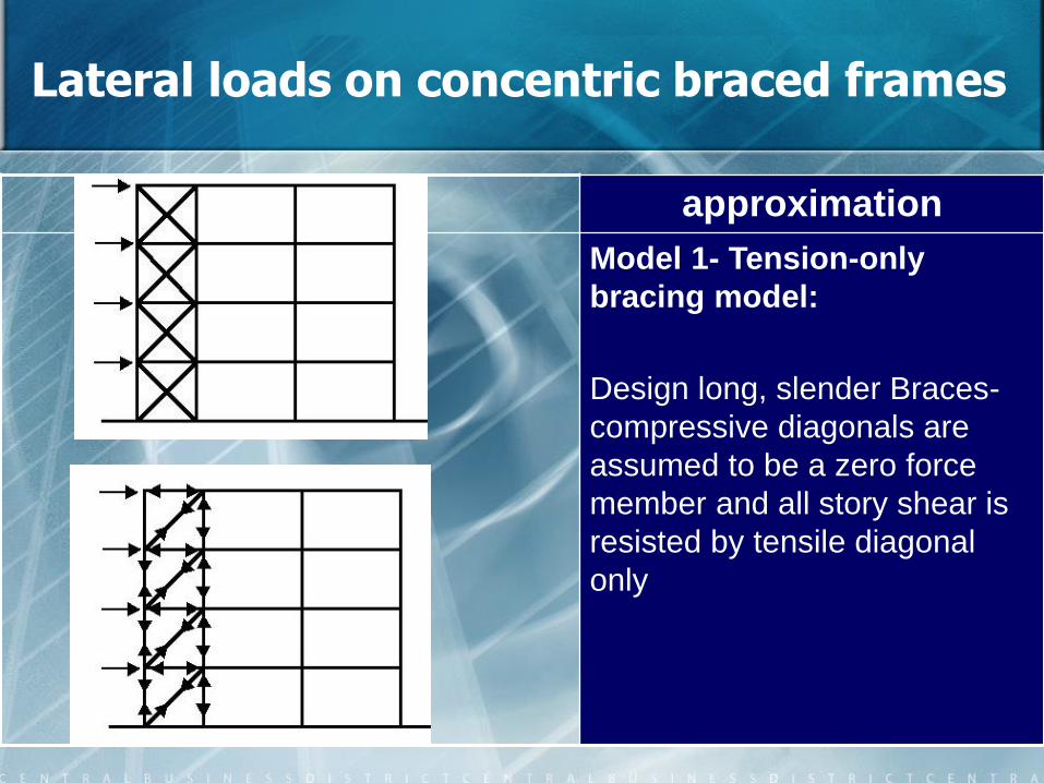
Lateral loads on concentric braced frames
approximation
Model 1- Tension-only
bracing model:
Design long, slender Braces-
compressive diagonals are
assumed to be a zero force
member and all story shear is
resisted by tensile diagonal
only

Lateral loads on concentric braced frames
approximation
Model 1- Tension-only bracing model
The Open Civil Engineering Journal, 2017, 11, (Suppl-1, M11) 453-463

Lateral loads on concentric braced frames
approximation
Model 2- tension-compression
bracings model:
Design braces to support both
tensile and compressive forces -
each brace is assumed to carry half
the bay shear.

Lateral loads on concentric braced frames
approximation
Model 2- tension-compression bracings model:
The Open Civil Engineering Journal, 2017, 11, (Suppl-1, M11) 453-463

Lateral loads on concentric braced frames
approximation
Model 2- tension-compression bracings model for Chevron
Braces
The Open Civil Engineering Journal, 2017, 11, (Suppl-1, M11) 453-463

Lateral loads on concentric braced frames
One braced bay contribution (based on lateral Stiffness)
Story Forces Story Shears Story Moments
For all
storiesh=3. 2 m
Method 2: for obtaining columns Forces

Lateral loads on concentric braced frames
Method 2: for obtaining columns Forces
Story Forces Story Moments
M6=37.85/2
M4=(105.81+197.64)/2
M2=(307.15+428.20)/2
For all
storiesh=3.20 m
b=5.92 m
P6 P6
Pi=Mi/b
P4 P4
M6
M4

Building frames

Vertical loads on building frames
• Building frames often consist of girders that are rigidly connected to columns
• This is to allow the structure to better able to resist the effects of lateral forces
© 2009 Pearson Education South Asia Pte Ltd
Structural Analysis 7th Edition
Chapter 7: Approximate Analysis of Statically Indeterminate Structures

Vertical loads on building frames
• One technique would be to consider only the members within a localised region of the structure
• This is possible if the deflections of the members within the region caused little disturbance to the members outside the structure
• The approximate location of the points of inflection can be specified
• These points are zero moments
© 2009 Pearson Education South Asia Pte Ltd
Structural Analysis 7th Edition
Chapter 7: Approximate Analysis of Statically Indeterminate Structures

Vertical loads on building frames
• Assumptions for approximate analysis• The column supports at A & B will each exert 3 reactions on
the girder
• The girder will be statically indeterminate to the third degree
• 3 assumptions would be needed to perform an approximate analysis
© 2009 Pearson Education South Asia Pte Ltd
Structural Analysis 7th Edition
Chapter 7: Approximate Analysis of Statically Indeterminate Structures

Vertical loads on building frames
• Assumptions for approximate analysis• If the columns are stiff, no rotation at A & B will occur
• However, if the column connections at A & B are very flexible, then zero moments will occur at the supports
• In reality, the columns will provide some flexibility at the supports
© 2009 Pearson Education South Asia Pte Ltd
Structural Analysis 7th Edition
Chapter 7: Approximate Analysis of Statically Indeterminate Structures

Vertical loads on building frames
• Assumptions for approximate analysis• Therefore, point of zero moment occurs at the average point
between the two extremes (0.21L+0) / 2 ~ 0.1L from each support.
• [Assuming 0.15 L for the location of zero moment leads to the better results.]
© 2009 Pearson Education South Asia Pte Ltd
Structural Analysis 7th Edition
Chapter 7: Approximate Analysis of Statically Indeterminate Structures

Vertical loads on building frames
• Assumptions for approximate analysis
• The 3 assumptions are:
• There is zero moment in the girder, 0.1L from the left support
• There is zero moment in the girder, 0.1L from the right support
• The girder does not support an axial force
© 2009 Pearson Education South Asia Pte Ltd
Structural Analysis 7th Edition
Chapter 7: Approximate Analysis of Statically Indeterminate Structures
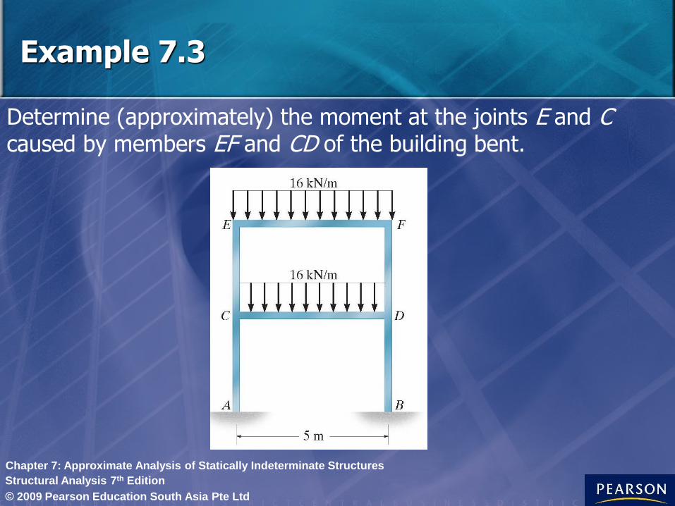
Determine (approximately) the moment at the joints E and C caused by members EF and CD of the building bent.
Example 7.3
© 2009 Pearson Education South Asia Pte Ltd
Structural Analysis 7th Edition
Chapter 7: Approximate Analysis of Statically Indeterminate Structures
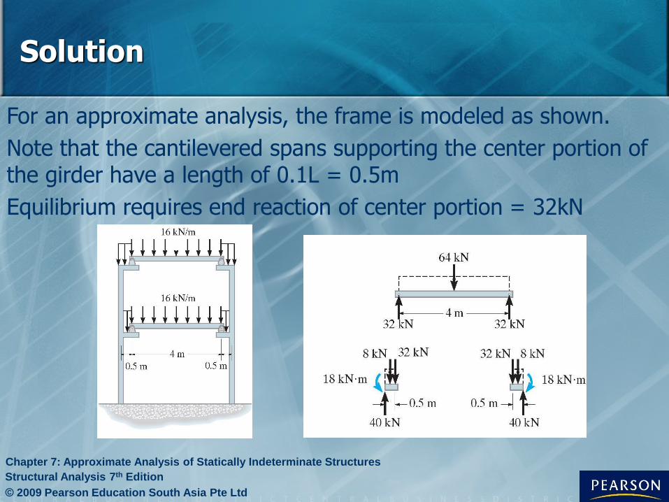
For an approximate analysis, the frame is modeled as shown.
Note that the cantilevered spans supporting the center portion of the girder have a length of 0.1L = 0.5m
Equilibrium requires end reaction of center portion = 32kN
Solution
© 2009 Pearson Education South Asia Pte Ltd
Structural Analysis 7th Edition
Chapter 7: Approximate Analysis of Statically Indeterminate Structures

Cantilevered spans are subjected to moment of:
This approximate moment with opposite direction acts on the joints at E & C.
Approximate Analysis of Columns is Complex and is not Simple, because of the presence of Shear in the Columns and Axial Forces in Beams. But, Axial Force of Columns is Simply calculated by their vertical equilibrium.
Solution
© 2009 Pearson Education South Asia Pte Ltd
Structural Analysis 7th Edition
Chapter 7: Approximate Analysis of Statically Indeterminate Structures
kNmM 18)5.0(32)25.0(8

Portal Frames & Trusses
• Portal frames are used to transfer horizontal forces applied at the top of frame to the foundation
• Portals can be pin supported, fixed supported or supported by partial fixity
© 2009 Pearson Education South Asia Pte Ltd
Structural Analysis 7th Edition
Chapter 7: Approximate Analysis of Statically Indeterminate Structures

Portal frames – lateral loads
real structure approximation
Pin-supported
fixed -supported
Partial fixity
assumed
hinge
assumed
hinge
assumed
hinge
A point of inflection
is located
approximately at
the girder’s
midpoint
Points of inflection
are located
approximately at
the midpoints of all
three members
Points of inflection for
columns are located
approximately at h/3
and the centre of the
girder
One assumption
must be made
Three assumption
must be made

Portal Frames
• We analyze the trussed portals using the same assumptions as those for simple portal frames
• For pin-supported column, assume horizontal shear are equal
• For fixed-supported column, assume horizontal reactions are equal and an point of inflection occurs on each column, midway between base of column & the lowest point of truss member connection to column
© 2009 Pearson Education South Asia Pte Ltd
Structural Analysis 7th Edition
Chapter 7: Approximate Analysis of Statically Indeterminate Structures

Lateral loads on building frames: Portal method
• The portal method for analyzing fixed supported building frames requires the following assumptions:
• A hinge is placed at the center of each girder
• A hinge is placed at the center of each column
• At a given floor level, the shear at the int column hinges is 2x that at the ext column hinges
• [For frames with non-equal spans, the story shear can be distributed among the columns, based on their load bearing spans]
© 2009 Pearson Education South Asia Pte Ltd
Structural Analysis 7th Edition
Chapter 7: Approximate Analysis of Statically Indeterminate Structures

Lateral loads on building frames: Portal method
• These assumptions provide an adequate reduction of the frame to one that is statically determinate and yet stable under loading
• This method is more suitable for buildings having low elevation and uniform framing
© 2009 Pearson Education South Asia Pte Ltd
Structural Analysis 7th Edition
Chapter 7: Approximate Analysis of Statically Indeterminate Structures

Determine (approximately) the reactions at the base of the columns of the frame. Use the portal method of analysis.
Example
© 2009 Pearson Education South Asia Pte Ltd
Structural Analysis 7th Edition
Chapter 7: Approximate Analysis of Statically Indeterminate Structures

Applying the first 2 assumptions of the portal method, we place hinges at the centers of the girders & columns of the frame.
A section through the column hinges at I, J, K & L yields the free body diagram.
The third assumption regarding the column shear applies.
Solution
© 2009 Pearson Education South Asia Pte Ltd
Structural Analysis 7th Edition
Chapter 7: Approximate Analysis of Statically Indeterminate Structures
lbVVFx 200062001 ;0

Using this result, we proceed to dismember the frame at the hinges & determine their reactions.
As a general rule, always start analysis at the corner or joint where the horizontal load is applied.
The free-body diagram of segment IBM is shown.
The 3 reactions components at the hinges are determined by applying
Solution
© 2009 Pearson Education South Asia Pte Ltd
Structural Analysis 7th Edition
Chapter 7: Approximate Analysis of Statically Indeterminate Structures
0 ;0 ;0 yxM FFM

The adjacent segment MJN is analyzed next.
This is followed by segment NKO and OGL.
Using these results, the free body diagram of the columns with their support reactions are shown.
Solution
© 2009 Pearson Education South Asia Pte Ltd
Structural Analysis 7th Edition
Chapter 7: Approximate Analysis of Statically Indeterminate Structures

Example
Determine (approximately) the reactions at
the base of the columns of the frame.