Strengthening techniques: code-deficient steel buildings
31
This is a repository copy of Strengthening techniques: code-deficient steel buildings . White Rose Research Online URL for this paper: http://eprints.whiterose.ac.uk/86572/ Version: Accepted Version Book Section: Tsavdaridis, KD orcid.org/0000-0001-8349-3979 (2014) Strengthening techniques: code-deficient steel buildings. In: Beer, M, Kougioumtzoglou, IA and Au, IS-K, (eds.) Encyclopedia of Earthquake Engineering. Springer Berlin Heidelberg . ISBN 978-3-642-36197-5 https://doi.org/10.1007/978-3-642-36197-5_207-1 [email protected] https://eprints.whiterose.ac.uk/ Reuse See Attached Takedown If you consider content in White Rose Research Online to be in breach of UK law, please notify us by emailing [email protected] including the URL of the record and the reason for the withdrawal request.
-
Upload
khangminh22 -
Category
Documents
-
view
3 -
download
0
Transcript of Strengthening techniques: code-deficient steel buildings
This is a repository copy of Strengthening techniques: code-deficient steel buildings.
White Rose Research Online URL for this paper:http://eprints.whiterose.ac.uk/86572/
Version: Accepted Version
Book Section:
Tsavdaridis, KD orcid.org/0000-0001-8349-3979 (2014) Strengthening techniques: code-deficient steel buildings. In: Beer, M, Kougioumtzoglou, IA and Au, IS-K, (eds.) Encyclopedia of Earthquake Engineering. Springer Berlin Heidelberg . ISBN 978-3-642-36197-5
https://doi.org/10.1007/978-3-642-36197-5_207-1
[email protected]://eprints.whiterose.ac.uk/
Reuse
See Attached
Takedown
If you consider content in White Rose Research Online to be in breach of UK law, please notify us by emailing [email protected] including the URL of the record and the reason for the withdrawal request.
1
Strengthening techniques: code-deficient steel buildings
Konstantinos Daniel Tsavdaridis, MEng, MSc, DIC, PhD, CEng, M.ASCE
Lecturer in Structural Engineering, School of Civil Engineering, University of Leeds, LS2 9JT, Leeds, UKEmail: [email protected]
Published to: Structural Engineering - Retrofitting and Strengthening, Encyclopedia of Earthquake
Engineering, edited by M. Beer, E. Pateli, I. Kougioumtzoglou and I. Siu-Kui Au, Springer Verlag, 2013
Contents
Synonyms .................................................................................................................................. 2
1. Introduction ....................................................................................................................... 2
2. Code-deficient buildings ................................................................................................... 3
3. Code-efficient buildings resistant to earthquake ............................................................... 4
4. Design concept for EC8..................................................................................................... 5
5. Introduction to strengthening techniques .......................................................................... 5
5.1 Preliminary investigation................................................................................................. 5
5.2 Assessing existing conditions and strengthening methods.............................................. 6
5.2.1 Introduction ............................................................................................................. 6
5.2.2 Determining load capacity of existing buildings .................................................... 7
5.2.3 Increasing capacity of connections......................................................................... 8
5.2.4 Increasing flexural strength floor framing members............................................. 8
5.2.5 Increasing axial load capacity of columns ............................................................. 8
5.2.6 Dealing with weldability issues ............................................................................... 8
5.2.7 Connecting new frame to existing frame ................................................................ 9
6. Detailed description of retrofitting and strengthening techniques..................................... 9
6.1 Introduction ..................................................................................................................... 9
6.2 Steel connections - fuses ................................................................................................. 9
6.2.1 Beam-to-column connections - Developing ductile behavior (fuse-concept) ........ 9
6.2.2 Ductile behavior – Fuses in bracing members ..................................................... 13
6.2.3 Pin-Fuse joints....................................................................................................... 15
6.2.4 Replaceable links ................................................................................................... 15
6.3 Steel connections - stiffeners......................................................................................... 17
6.3.1 Introduction ........................................................................................................... 17
6.3.2 SidePlateTM
connections ........................................................................................ 17
6.3.3 Stiffeners at connections ....................................................................................... 18
6.4 Steel frames – modifications ......................................................................................... 19
6.4.1 Frame modification at beam’s mid-span (fuse-concept)...................................... 19
6.4.2 Cabling – Self-centering systems .......................................................................... 20
6.5 Structural system – adding structural elements (bracings – walls – blocks) ................. 21
6.5.1 Introduction ........................................................................................................... 21
6.5.2 Bearing walls ......................................................................................................... 22
6.5.3 Steel plate shear walls............................................................................................ 22
6.5.4 Braced frames ........................................................................................................ 23
6.5.5 Non-buckling braces.............................................................................................. 24
6.6 Strengthening members ................................................................................................. 24
6.7 Materials........................................................................................................................ 25
6.8 Energy dissipation and active/passive structural control systems ................................. 26

2
7. Summary ......................................................................................................................... 27
8. Cross References ............................................................................................................. 27
9. References ....................................................................................................................... 28
Synonyms
seismic retrofitting, repair, steel buildings, connections, fuses, braced frames, composite
materials, strengthening techniques, cyclic behavior, energy dissipation, deformation
capacity.
1. Introduction
The design of steel buildings is often governed by lateral wind loads and not seismic
loads. Also, statistics indicate that the number of fatalities during earthquakes due to
failure of all types of steel buildings is significantly less compared to other types of
buildings. Consequently, much effort has been invested to seismically retrofit buildings
having unreinforced masonry walls and reinforced concrete frames. However, recently
steel buildings have received significant attention, while this interest is mainly stems
from the realization following the 1994 Northridge earthquake, that the welded beam-
to-column connections in moment resisting frames were likely to fail in a brittle manner,
prior the development of significant inelastic response; therefore negating the design
intent and possibility causing safety hazards.
Recent research has expanded the variety and versatility of the tools available in the
structural engineer�s toolbox to meet the seismic performance objectives. This chapter
provides an overview of how this research is expanding the available options for the
seismic strengthening of steel buildings, by reporting on some selected research
projects.

3
Structural strengthening and proving seismic resistance for steel building, but also
masonry and reinforced concrete, may be done by first considering the direction of the
weak links in the structures. For instance for a heavy building with large dead load, this
would be the major factor that contributes to the increase of lateral seismic load.
Therefore, it is reasonable to first consider reducing the overall existing dead load and
then provide the necessary strengthening technique for the lateral load resisting system
of the structure.
The use of structural steel in buildings� retrofitting can be often considered economical
and efficient because:
Steel buildings are particularly effective under performance based design;
Steel members exhibit ductile behavior beyond elastic limit, hence dissipate
considerable amount of energy before damages occur;
Steel members have higher strength-to-weight and stiffness-to-weight ratios,
hence the buildings attract less base shear under an earthquake;
A better quality control practiced in the production of the material as well as the
fabrication and erection of them, while ensuring results close to the theoretical
predictions; and
Steel can be generally used to retrofit all types of structures without increasing
the dead weight dramatically, making the works less intrusive and time
consuming.
2. Code-deficient buildings
All buildings can carry their own weight. They can usually carry a bit of snow and a few
other floor loads vertically; so even badly built buildings and structures can resist some
up-and-down loads. However, buildings and structures are not necessarily resistant to
lateral loads, unless this has been taken into account carefully during the structural
engineering design and construction phase with some earthquake proof measures taken
into consideration. It is the side-to-side load which causes the worst damage. Poorly
designed buildings often collapse on the first shake. The side-to-side load can be even
worse if the shocks come in waves, as taller buildings can vibrate like a huge tuning fork,
while each new sway is bigger that the last one, until failure. Usually, significant weight
is added in time to such code-deficient steel buildings (i.e. walls, partitions to make
more and smaller rooms, etc.), or even due to extreme reinforcing techniques. The more
weight there is, and the higher this weight is located in the building, the stronger the
building and its foundations must be to withstand the earthquake actions. Many
buildings have not been strengthened when such extra weight was added. These
buildings are then more vulnerable to even a weak aftershock, perhaps from a different
direction, or at a different frequency, which can cause collapse. Moreover, in a lot multi-
storey steel buildings the ground floor has increased headroom with taller slender
columns as well as with more large openings and fewer walls. So, these columns, which
carry the largest loads from both the self-weight and the cumulative sideways actions
from the seismic event, are vulnerable and they are often the first to fail. It only takes

4
one to fail for the worst disaster; therefore it is deemed necessary to cautiously
strengthen steel buildings with the most appropriate method.
The potential deficiencies are different for different types of steel buildings (i.e. Steel
Moment Frames; Steel Braced Frames; Steel Frames with Concrete Shear Walls; Steel
Frames with Infill Masonry Shear Walls). The indicators such as the global strength and
stiffness, the configuration, the load path, the component detailing, the diaphragm and
the foundation design demonstrate the performance under seismic actions and the
margins for improvement in specific ways, hence they should be studied carefully before
any decision is taken.
Retrofitting of existing code-deficient steel buildings, accounts for a major portion of the
total cost of hazard mitigation. Therefore, it is important to identify correctly the
structures that need and can accept strengthening, while the overall cost should be also
monitored. If appropriate, seismic retrofitting should be performed through several
methods such as increasing the load, deformation and energy dissipation capacity of the
structure [FEMA 356, 2000].
3. Code-efficient buildings resistant to earthquake
To be earthquake proof, the buildings and their foundations need to be built to be
resistant to sideways loads. The lighter the building is, the less the loads are. In steel,
especially in high-rise buildings, the sideways resistance is mainly comes from diagonal
bracing which must be placed equally in both directions. Where possible, the diagonal
bracing should be strong enough to accept tension as well as compression loads; the
bolted or welded connections should resist more tension that the ultimate tension value
of the brace, or much more than the design load. If the sideways load is to be resisted
with moment resisting framing then great care has to be taken to ensure that the joints
are stronger than the beams, and that the beams will fail before the columns. Also in
such a case, special care should provided to the foundation-to-first floor level, avoiding
soft-storey effects while the columns should be much stronger than at higher levels. The
foundations could be enhanced by having a grillage of steel beams at the foundation
level able to resist the high column moments and keep the foundations in place. The
main beams should be fixed to the outer columns with full capacity joints; which almost
means hunched connections, and care should be taken to consider the shear within the
column at these connections.
When the steel beams are able to yield and bend at their highest stressed points,
without losing resistance, while the connections and the columns remain full strength,
then the resonant frequency of the whole frame changes, while the energy is absorbed
and evenly dissipated across the framing. The vibration occurred from the shock waves
is tend to be damped out. This phenomenon is called �plastic hinging� and is easily
demonstrated in steel beams. In extreme earthquake sway, the beams should always be
able to form hinges somewhere, while the columns should behave elastically. In this way
the frame can deflect and the plastic hinges can absorb energy while the resonant
frequency of the structure is altered without major loss of strength and inevitable

5
collapse. All floors should be connected to the framing in a robust and resilient way and
should be as light as possible. They should possibly span around each column and be
fixed to every supporting beam using enough shear connectors (i.e. studs). An effective
way of reducing the vulnerability of large buildings is to isolate them from the floors
using bearings or dampers; however this is an expensive process and it is not applied to
low to medium rise buildings which have not been classified as important, due to the
content they carry and the occupancy usage.
Nothing can be though guaranteed to behave as such, even in code-based designs; hence
most of the steel buildings and especially those under-designed with older seismic
codes, can be considered as code-deficient buildings in certain circumstances.
4. Design concept for EC8
Eurocode 8 (EC8) follows three general design concepts based on the ductility
requirements and capacity design considerations of steel buildings. The concept of the
low-dissipative structural behavior of DCL structures, the concept of dissipative
structural behavior of DCM and DCH structures satisfying the ductility and capacity
design requirement, and the dissipative structural behavior with steel dissipative
controlled zones. In the latter case, when composite action may be considered from
Eurocode 4 (EC4) in presence of the steel and concrete (slab) interaction, specific
measures have been stipulated to prevent the contribution of concrete under seismic
conditions, hence apply general rules for steel frames.
5. Introduction to strengthening techniques
5.1 Preliminary investigation
It is becoming preferable, both environmentally and economically, to upgrade building
structures rather than to demolish them and rebuild them. Engineers assessing
structures for increased or special loadings are finding that new methods of analysis
using, for instance, computer models are revealing shortcomings under service and
ultimate conditions. Under such circumstances, a method has to be found to bring the
structure up to the required standard. There is a range of techniques which can be used
on structures, but, one must take into consideration that disruption to normal stage
must be minimal whilst work is in progress.
Evaluation and subsequent strengthening of existing structures require a realistic and
pragmatic design approach. However, some of the solutions proposed by researchers do
not lie within this category and there will be eliminated in the current study. Also,
effective communication between the owner, structural engineer, architect, risk analyst,
insurance provider and other stakeholders is paramount to a successful finished
solution. In general, in the case where additional load carrying capacity is required of an
existing building, engineers have the option to either reinforcing the existing framing or
adding new framing to replace or supplement the existing.

6
Where a decision is made to strengthen some parts of an existing facility or a specific
structural system or element, the design approach is influenced by a series of factors:
Information about relevant existing conditions which is often limited;
When the structure to be strengthened is commonly hidden or obstructed by
existing architectural or building services systems that are difficult or costly to
remove;
When structural renovation work is typically constrained by the need for
continuity of building operations;
That the level of ductility of the existing construction may limit its strength; and
The susceptibility to local buckling of outstanding flanges as well as the lack of
connection ductility.
Often, the non-structural costs will likely exceed the structural costs, therefore the true
costs of a retrofit project is primarily dependent on the number of locations of work
than the amount of work done in each location, and thus this influences the structural
design and analysis decisions.
The general approach to strengthen existing structures includes the following aspects:
Risk assessment and structural vulnerability assessment;
Preliminary analysis;
Consideration of alternatives (structural and non-structural); and
Detailed design and the impact of connections.
The common goal is to:
Protect specific structural elements;
Provide redundancy to structural systems; and
Strengthen a specific part of the structure.
5.2 Assessing existing conditions and strengthening methods
5.2.1 Introduction
A site visit should also be performed to inspect the building; especially for structures
more than 30 years old. Some key things to look for when assessing the existing
condition of a steel building are: damage to framing; noticeable corrosion; signs that
modifications to the structure that may have been performed without engineering
review; unusual deflections in floor framing; cracks in supported slabs; signs of
foundation settlement; signs for new rooftop equipment; heavy hung piping loads;
folding partitions; rigging or other suspended loads that may have been added without
proper structural engineering review [Schwinger, online]. A valuable resource available
to structural engineers working with existing building structures is the AISC Steel Design
Guide 15 � AISC Rehabilitation and Retrofit Guide [Brockenbrough, 2002]. Other
publications for further reference are [ASCE 41-06, 2006; FEMA 274, 1997; FEMA 547,
2006].
The strengthening methods can be categorized as follows:
1. Passive against Active methods; and
2. Strengthening techniques:

7
a. Reinforcing beams by welding (enlarge section with plates);
b. Reinforcing connections;
o Framing
o Seated angles
o Partial-depth end-plate
o Replace with high strength fasteners
o Add welds at the perimeter of the connection and/or to properly
cleaning existing welds
o Converting single to double-shear connections adding angles or
plates
o Add web stiffener plate
o Add steel cover plates
o Enhance column splices
o Enhance braced frame connection
c. Shortening span (provided that there are no fitting issues);
o Add beams
o Add columns, girders
o Add diagonal braces
o Add walls with openings
o Add steel braced frame
o Add concrete, masonry or steel plate walls
o Enhance strength and ductility of braced frames
d. Introducing composite action;
o Steel (partially or fully) encased with concrete
o Shear connectors
e. Post-tensioning (or external pre-stressing) of beams and connections
(considering eccentricities of brackets on member capacity - some need
protection from corrosion, fire, and vandalism);
f. Openings in existing beams (using thermal cutting - plasma ark cutting is
faster than oxy-fuel, while avoiding cuts at areas subjected to high shear);
o Place reinforcement (eg. stiffeners) before cutting holes
g. Replacement of members (may be economical);
h. Strengthening columns; and
i. Convert gravity frame to moment resisting frame.
5.2.2 Determining load capacity of existing buildings
Knowing the yielding strength of the steel used in the framing is essential for computing
the load capacity, therefore testing should be performed to ascertain and verify the
actual yield strength. One technique is to test the steel to determine its actual yield
strength, in hope of finding it to be a higher value than the one was used in the original
design. Another technique applied in existing structures in to analyze the framing using
the Load and Resistance Factor Design (LRFD) method [AISC, 1999]; LRFD useable
strength is approximately 1.5 times greater than the older Allowable Stress Design
(ASD) service level strength.

8
5.2.3 Increasing capacity of connections
The technique by which existing shear and moment connections can be strengthened is
limited only by the imagination of the engineer. Various techniques are going to be
presented thereafter, based on well established but also recent research outcomes
obtained from numerous computational analyses and experimental campaigns. It is
worth to be aforementioned that the capacities of existing connections must be
determined when existing framing is modified or additional capacity is sought.
5.2.4 Increasing flexural strength floor framingmembers
There are two options for reinforcing existing flooring systems to support additional
loads: (a) add new framing to supplement the existing framing and (b) reinforce the
existing beams, girders and connections. The easiest solution is usually that of
reinforcing the existing structural elements, provided that the floor slab has sufficient
capacity to carry the loads. The most efficient way is to weld rectangular High Strength
Steels (HSS) to the flanges as shown in Figure 1.
Figure 1: Examples of strengthened beams
5.2.5 Increasing axial load capacity of columns
The buckling limit state and its variable slenderness should be determined in order to
evaluate the axial load capacity of columns. Column strengthening serves both to reduce
slenderness by increasing the radius of gyration of the section as well as to reduce
stress. Column buckling is a mid-height phenomenon, therefore increasing column
stiffness between the supports, not at the supports, is required to increase column
capacity. Both methods shown in Figure 2 are effective, however the one on the left
better increases the weak axis stiffness of an H-shaped section.
Figure 2: Examples of strengthened columns
5.2.6 Dealing with weldability issues
Weldability is verified by mechanical and chemical testing. The former measures
ductility and the latter determines the �carbon equivalent� value.
9
5.2.7 Connecting new frame to existing frame
Similarly to the connections, there are numerous ways that new framing can be
connected to existing framing. Welding the new steel members to the existing members
is a straight forward approach which requires less precision as compared to the bolting
process, while drilling new holes through existing steel and bolting in the field. Various
details for connecting new framing to an existing one can be found by Schwinger,
(online).
6. Detailed description of retrofitting and strengthening techniques
6.1 Introduction
The performance of steel frames can be synopsized in three very different behaviors:
1. Formation of plastic hinges;
2. Local and global instabilities; and
3. Fracture and structural discontinuity.
These three behaviors and/or combinations of them are likely to occur and govern the
capacity of a connection or member with result on the structural continuity and
integrity of the system. Overall, it is known from seismic studies that frame capacity is
related to two different aspects of frame behavior:
1. The member response; as controlled by plastic rotational strength and
deformation characteristics (including local and global buckling), and
2. The connection response; as controlled by bolt fracture, premature brittle weld
failure and panel zone failure.
Determining the capacity of columns is difficult as in many situations code-deficient
buildings are not designed for large lateral loading.
6.2 Steel connections - fuses
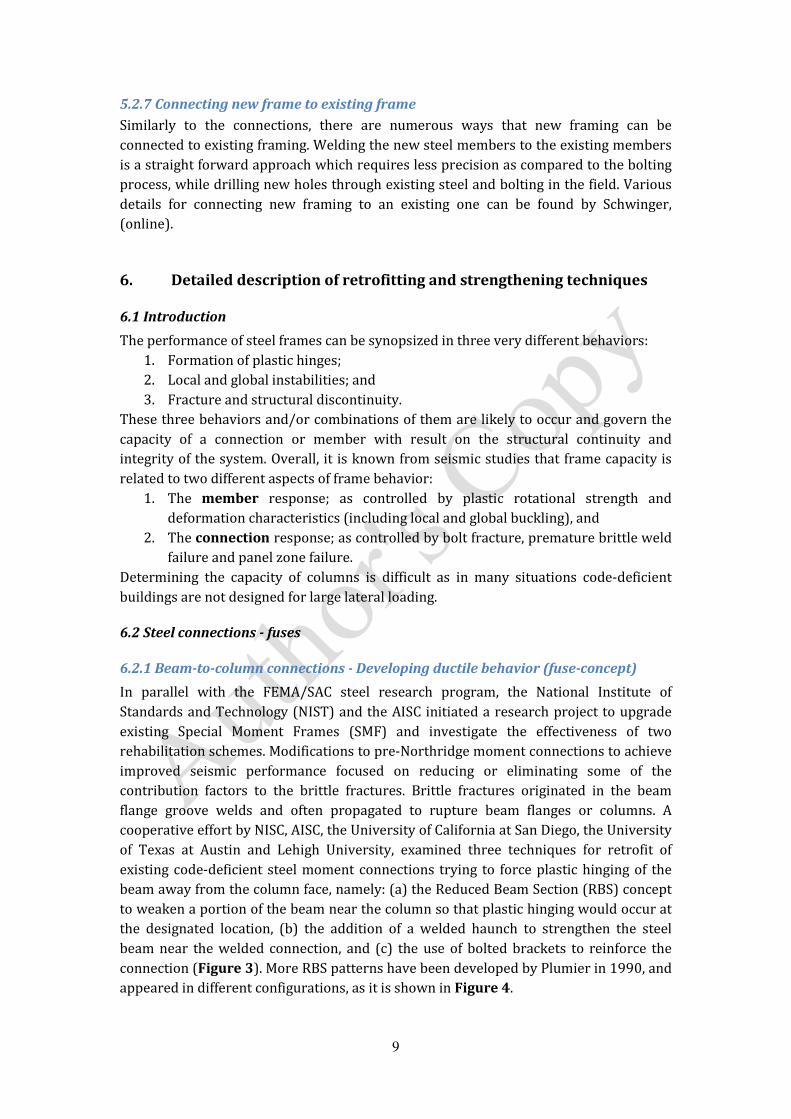
6.2.1 Beam-to-column connections - Developing ductile behavior (fuse-concept)
In parallel with the FEMA/SAC steel research program, the National Institute of
Standards and Technology (NIST) and the AISC initiated a research project to upgrade
existing Special Moment Frames (SMF) and investigate the effectiveness of two
rehabilitation schemes. Modifications to pre-Northridge moment connections to achieve
improved seismic performance focused on reducing or eliminating some of the
contribution factors to the brittle fractures. Brittle fractures originated in the beam
flange groove welds and often propagated to rupture beam flanges or columns. A
cooperative effort by NISC, AISC, the University of California at San Diego, the University
of Texas at Austin and Lehigh University, examined three techniques for retrofit of
existing code-deficient steel moment connections trying to force plastic hinging of the
beam away from the column face, namely: (a) the Reduced Beam Section (RBS) concept
to weaken a portion of the beam near the column so that plastic hinging would occur at
the designated location, (b) the addition of a welded haunch to strengthen the steel
beam near the welded connection, and (c) the use of bolted brackets to reinforce the
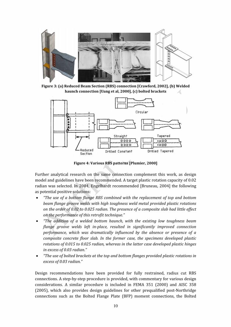
connection (Figure 3). More RBS patterns have been developed by Plumier in 1990, and
appeared in different configurations, as it is shown in Figure 4.
10
Figure 3: (a) Reduced Beam Section (RBS) connection [Crawford, 2002], (b) Welded
haunch connection [Uang et al, 2000], (c) bolted brackets
Figure 4: Various RBS patterns [Plumier, 2000]
Further analytical research on the same connection complement this work, as design
model and guidelines have been recommended. A target plastic rotation capacity of 0.02
radian was selected. In 2004, Engelhardt recommended [Bruneau, 2004] the following
as potential positive solutions:
�The use of a bottom flange RBS combined with the replacement of top and bottom
beam flange groove welds with high toughness weld metal provided plastic rotations
on the order of 0.02 to 0.025 radian. The presence of a composite slab had little effect
on the performance of this retrofit technique.�
�The addition of a welded bottom haunch, with the existing low toughness beam
flange groove welds left in-place, resulted in significantly improved connection
performance, which was dramatically influenced by the absence or presence of a
composite concrete floor slab. In the former case, the specimens developed plastic
rotations of 0.015 to 0.025 radian, whereas in the latter case developed plastic hinges
in excess of 0.03 radian.�
�The use of bolted brackets at the top and bottom flanges provided plastic rotations in
excess of 0.03 radian.�
Design recommendations have been provided for fully restrained, radius cut RBS
connections. A step-by-step procedure is provided, with commentary for various design
considerations. A similar procedure is included in FEMA 351 (2000) and AISC 358
(2005), which also provides design guidelines for other prequalified post-Northridge
connections such as the Bolted Flange Plate (BFP) moment connections, the Bolted

11
Unstiffened (BUEEP) and Stiffened Extended End-plate (BSEEP) moment connections,
and the so called CONXTECH CONX and KAISER Bolted Bracket (KBB) moment
connections.
It is worth to note that conventional beam theory cannot provide a reliable prediction
for neither of the above structural systems. Uang et al. (2000) and Yu et al. (2000)
proposed a simplified model that considers the interaction of forces and deformation
compatibility between the beam and the haunches.
Exhaustive research works have been conducted on RBS connections varying the
geometric characteristics of both the beam as well as the connection assembly itself.
More recently, RBS moment resisting connections have been also investigated by
researchers in Europe using European HEA-profile sections [Pachoumis et al. 2008],
since so far they have been only investigated by the US design construction practices.
Result is the readjustment of the geometrical characteristics of the RBS in order to apply
to the European profiles. Limitation in using RBS is the shear connection between the
top steel flange and the metal decking of the Steel-Concrete Composite (SCC) slab due to
the significant width reduction.
More recently, the same concept has been applied to steel frames as a strengthening-
weakening technique, while introducing a circular opening (Figure 5) in the beam�s web
instead, at a certain distance from the beam-to-column connection, as an effective
method to improve the aseismic behavior of MRFs [Qingshan et al., 2009]. The accurate
position and size of the circular opening has been investigated through numerical
modeling as well as experimental works, while the plastic hinge positions is effectively
controlled. Similar studies have demonstrated the effect of various nonstandard web
opening shapes (Figure 6), in enhancing the ductility but also the strength of the
connections [Tsavdaridis et al., 2014]. Step-by-step procedures have been proposed to
determine the most suitable geometries to achieve adequate connection strength,
ductility, stiffness and rotational capacities. Such techniques prove suitable in cases
where large plastic rotations are required (i.e. larger than 0.03 radian). Tsavdaridis et al.
(2014) have further proposed novel elliptically-based web opening shapes, which can
also be used for perforated beams (eg. cellular and castellated beams) adding numerous
advantages from the manufacturing process to their life-span while they can develop
rotational capacities up to 0.05 radian with insignificant strength degradation (Figure
7).

12
Figure 5: Failure mode of connection with circular web opening [Qingshan et al., 2008]
Figure 6: Types of perforated beam webs [Hedayat and Celikag, 2009]

13
Figure 7: Geometric parameters of novel perforated beam-to-columnmoment connections
and VonMises plastic stresses [Tsavdaridis et al., 2014]
The so called Reduced Web Section (RWS) connections have been studied on multi-
storey MRF steel buildings experimentally as well as computationally with cyclic (quasi-
static), pseudo-dynamic (PSD) and dynamic analyses, and evaluated in detail after the
1994 Northridge and 1995 Kobe earthquake cases. The results show that the ultimate
displacement of the modified buildings increases a lot due to the web openings and thus
the building ductility is improved greatly. Moreover, brittle weld fractures can be
avoided and the maximum plastic zone moved to the weakened areas. RWS connections
can easily be applied to the beams of new as well as existing code-deficient buildings. It
is worth to mention that different geometric characteristics and limitations of beams
and columns should be used for different RWS connection types. There is a need to bring
the attention and propose more experiment physical testing to validate and establish
RWS connections in the current European and American practices.
Welded haunches and bolted brackets are used to move the plastic hinges away from the
column, but also strengthen the existing connection and seek to maintain the original
flexural capacity of the beam.
6.2.2 Ductile behavior � Fuses in bracing members
The concept of adding ductile fuses in bracing members of steel concentrically braced
frames (CBF) resisting seismic loads is well linked to the RBS technique. Current code
provisions require that steel CBFs are designed to exhibit ductile energy dissipation.
Limits on brace overall slenderness ratio must be satisfied to achieve ductile inelastic

14
behavior. It is apparent that implementation of this design approach may result in
significant increases in design loads for brace connections, beams and columns [Egloff et
al., 2012].
In order to reduce seismic design loads ductile fuses in bracing members have been
recently proposed, as they control their axial resistances. Such behavior can be achieved
by locally reducing the brace cross-section area or by introducing ductile components
that yield in both tension and compression. In the former case, the reduced section
might need to be confined to prevent local buckling, or it can be resized to yield in
tension while remaining elastic in compression, which means that the effect of fatigue
loading will be minimized. In the latter case, the overall buckling is eliminated and hence
the strength degradation is limited due to symmetrical hysteretic behavior. This type of
fuse technique can be applied in open and closed profile sections of the bracing
members, while it has been noticed that the former ones perform better exhibiting
higher ductility. A special fuse (Figure 8) for controlling the tension resistance of open
bracing members has been proposed by Vincent in 2008. A part of the flange to web
intersection is removed to limit the impact on the brace flexural stiffness and buckling
resistance. In 2012, Egloff et al. introduced a new local buckling restraining system
(LBRS) which includes two cold-formed channels that support the web and the flanges.
Moreover, external cover plates can be bolted to the channels in order to prevent local
buckling of the brace flanges. Splice plates can also be used to provide lateral support to
the flanges in the fuse (Figure 9). This LBRS can slip longitudinally with respect to the
brace so that it does not attract any axial forces. Further improvements and the design
procedure for the fuse and the fuse LBRS are available in the literature.
Figure 8: Ductile fuse for H-shape bracing members (Vincent, 2008)
Figure 9: Proposed fuse local buckling restraining mechanism [Egloff et al., 2012]
Cast Connex, a high strength steel connector for round hollow structural section brace
members in CBF, has also developed a yielding fuse connector for CBF, called the

15
Scorpion Yielding Brace System (SCBF), that relies on flexural yielding of finger-like
plates what are specially designed to dissipate energy locally and can be used in both
architecturally exposed and non-exposed braced bays.
6.2.3 Pin-Fuse joints
A new type of connection, which just begun its prequalification process in 2011, is the
Pin-Fuse connection (Figure 10) which incorporates a curved plated end connection
using slip-critical bolts and a steel pin adjacent to the beam-to-column joint. The bolts
are designed to slip within slotted holes allowing the pin joint to rotate dissipating the
energy through frictional resistance. This joint acts as the fuse for the system, while the
rest of the steel frame can be designed to remain elastic. Following an earthquake, and
avoiding damages, the frame can be adjusted to its initial position, reducing the potential
for permanent residual displacements while both the connection and the frame
maintain their structural integrity and reduce the need for costly structural repairs. The
simplicity of the pin-fuse connection offers the ability to accommodate braces and
dampers.
Figure 10: Structural details of Pin-Fuse connection [Cordova and Hamburger, 2011]
6.2.4 Replaceable links
Using RBS and RWS type connections have been proved very efficient for certain
applications, however there are some drawbacks. As the yielding fuse is a part of the
beam, strength design and drift design of the structure are interlinked. For instance, due
to increased drift requirements, the capacity of the yielding fuse may be also increased,
which then leads to higher demands on the other parts of the structure including
columns, floor slabs, connections, and foundations and often resulting in overdesigned
buildings with increased overall cost. Further, significant damage can result in the beam
from repeated inelastic deformation and localized buckling during a design level
earthquake. As this cumulative inelastic action of the building cannot be precisely
anticipated, it is not trivial to assess the extent of damage on site and the residual
capability of the structure to adequately provide the required level of safety for any
subsequent loading. In such a case, repair of the beam is not a straight forward
procedure and it can be disruptive and costly.
The replaceable link concept (Figure 11) effectively eliminates the aforementioned
concerns while instead of reducing the beam section size; dismountable dissipative

16
elements (Figure 12) which can be removed and replaced with smaller flexural
capacities are used at the locations of the expected inelastic actions. Consequently, the
other structural elements in the frame will remain elastic during an earthquake. This
efficient method of repair for MRFs, allows for quick inspection and replacement of
damaged links while it minimizes the disruption time. Further, the welding of critical
elements of beam-to-column can be done in the shop while improving construction
quality and significantly reducing the initial erection time [Shen, 2009].
Figure 11: Proposed connections with replaceable link [Shen, 2009]
Figure 12: End plate model boundary conditions [Shen, 2009]
In particular, two types of replaceable links have been proposed by Shen (2009): (i) H-
section with end plates, and (ii) back-to-back channels eccentrically bolted to the beam
web. The former one is prepared in the shop using complete joint penetration welds.
The end plate (flush or extended) is then bolted to the column flange using pre-stressed

17
high strength bolts. The latter type of these double channel built sections intended to act
as truss girders in special truss moment frames, and they have been connected using
welded reinforcing gusset plates. In certain circumstances lateral bracing is deemed
necessary in the region adjacent to the plastic hinge to achieve large (i.e. 0.06 radian)
plastic rotation of the hinge. However, sometimes large over-strength has been
observed in these build-up channel sections.
The end plate links can exhibit 0.04 radian contributing to 90% of the total storey drift
and demonstrate higher energy dissipating capacity than the double channel links, while
some strength degradation occurs due to ductile local flange and web buckling. On the
other hand, higher storey drift can be reached by the double channel links before
experiencing strength degradation at 0.06 radian. The degradation has been also caused
due to ductile tearing of the flanges and the webs. Overall, double channel links type has
been considered to be preferable as it provides a more gradual transmission of forces at
the connections via friction. For more stability, further modifications can take place
enhancing the connection of the channel webs and the connection of the beam segments.
6.3 Steel connections - stiffeners
6.3.1 Introduction
Forcing the plastic deformation to the beam end away from the connection is a common
practice in seismic moment resisting frames, but in contrast to the fuse concept, this can
be also achieved by increasing the relative stiffness of the column and the connection
with respect to the beam. Eventually, this is an alternative in effective controlling the
position and intensity of the plastic hinge in the connection zone when such
modifications are allowed.
6.3.2 SidePlateTM connections
A well promising retrofitting method for upgrading an existing traditional moment
resisting connection is shown in Figure 13. This concept uses the so called SidePlateTM
retrofit system where the physical separation between the face of the column flange and
the end of the beam, for mitigating the stress concentration, is achieved using parallel
full-depth side plates which act as discrete continuity elements to sandwich connecting
the beam(s) and the column [Crawford, 2002]. Similar design concept can be used for
steel and concrete-filled hollow section columns (Figure 14).
Figure 13: SidePlateTM retrofit connection [Crawford, 2002]

18
Figure 14: Strengthening retrofit concept: concrete filled hollow section of column
[Crawford, 2002]
Whole steel frame is eventually stiffened and the zone panel deformation is eliminated
using this type of connections due to the increased stiffness of the side plates that
ultimately providing the three panel zones. This connection system uses all fillet-welded
fabrication which predominately carries all shear actions as well as moments through
the combination of vertical shear plates and fillet welds. The side plates should be
designed with sufficient strength and stiffness to force all significant plastic behavior of
the connection system into the beam.
The same system can be used for upgrade construction of deficient buildings. The
difference is that an initial hole is required in each side of the plates to permit welding
access, while the holes are closed with the same cut off plate following the completion of
the welding process. All new welds are again fillet welds loaded in shear along their
length, whereas if any existing Complete Joint Penetration (CJP) welds are removed by
air arcing to eliminate the reliance on through thickness properties and tri-axial stress
concentrations. More information can be found from FEMA 351 (2000).
6.3.3 Stiffeners at connections
In addition to the prequalified connections for SMFs and intermediate moment frames
(IMF) presented in AISC (1999) and the SidePlateTM system, research has been focused
on the effect of stiffeners on the strain patterns of welded connection zone.
For example, the effect of both internal and external stiffeners on the behavior of I-beam
to hollow-column section connections (Figure 15) has been initially thoroughly
investigated by Chen and Lin (1990). It has been observed that the connections with
triangular stiffeners have the lowest rigidity, in contrast to those with side-stiffeners
which present significantly higher moment rotation capacities, stiffness and ductility.
Moreover, the performance of the retrofitted connections with side-stiffeners has been
investigated [Ghobadi et al., 2008] and design guidelines proposed. The benefits of using
side-stiffeners have been also introduced on concrete filled tabular (CFT) columns

19
connected to I-beams, while stable hysteresis and adequate ductility is provided.
Overall, it bas been concluded that connections with both column stiffeners and top-
flange stiffeners have the highest value of energy dissipation, while the beam top flange
stiffener is the most effective one, especially when it is incorporated with the column
stiffeners of hollow section.
Figure 15: Typical I-beam to box-column connection [Kiamanesh et al., 2010]
6.4 Steel frames � modifications
6.4.1 Framemodification at beam�s mid-span (fuse-concept)
A retrofitting method which can be used for new construction as well as a strengthening
technique for existing moment resisting frames has been developed by Leelataviwat et
al. (1998). This technique replaces certain beams and introducing a ductile fuse element
in shear at their mid-span instead of modifying the beam-to-column connections
(Figure 16). A braced rectangular opening is created in the web of each girder at the
mid-span, to move the plastic deformation away from the critical connection regions,
while ensuring the development of a ductile mechanism.
Figure 16: Frame modified with mid-span truss opening [Leelataviwat et al., 1998]

20
6.4.2 Cabling � Self-centering systems
The use of the cables is another promising technique, which can be applied to both slabs
and connections. Placement of cables with connections to girders or cables with
connections to beams is very important especially for high-rise buildings. Self-centering
braces have been designed and built using prestressed aramid fiber strands in
conjunction with friction pads or memory alloys. Energy dissipation is implemented
using yielding seat angles, friction dampers, or energy dissipating bars confined in tubes.
Researchers have investigated self-centering column bases that use post-tensioned (PT)
bars or spring loaded wedges. Tendons can span over multiple floors, while elastomeric
spring dampers and fuse bars can be used to provide energy dissipation.
Self-centering structural systems (Figure 17) have been proposed, for the seismic
retrofit of special moment resisting frames, by Christopoulos et al. (2002). This is a Post-
Tensioned Energy Dissipating (PTED) steel frame design, where high strength bars or
tendons provide the post-tension at each floor. Confining steel sleeves have been often
used to prevent the energy-dissipating bars from buckling during cyclic inelastic
loading. It has been concluded that these economical innovative systems:
�Incorporate the nonlinear characteristics of yielding structures and, thereby, limit
the induced seismic forces and provide additional damping characteristics.�
�Encompass self-centering properties allowing the structural system to return to
its original position after an earthquake.�
�Reduce or eliminate cumulative damage to the main structural elements.�
Figure 17: PTED System [Christopoulos et al., 2002]
Later, Garlock et al. (2004) has proposed a similar structural system with high strength
steel strands PT, after bolted replaceable top-and-seat angles have been installed
(Figure 18). Here, the vertical shear is supported by both the angles as well as the
friction between the beam and the column, and it is expected to continue to perform if
failure of one or more strands occurs. It is proved that this system can achieve greater
strength and ductility.

21
Figure 18: Post-Tension moment connection with top and bottom seat angles [Garlock et
al., 2004]
Recently, researchers have designed and experimentally evaluated a new self-centering
PT connection using yielding web hourglass shape pins (WHPs) as seismic energy
dissipaters. WHPs do not interfere with the composite slab and can be very easily
replaced without the need for welding and bolting, and therefore, can significantly
decrease downtime in the aftermath of a strong earthquake. Repeated experiments
described in detail and proved the reparability of the PT connection withWHPs.
6.5 Structural system � adding structural elements (bracings � walls � blocks)
6.5.1 Introduction
Conventional retrofitting methods include addition of new structural elements to the
system and enlarging the existing members. Bracings as well as reinforced concrete
(pre- and post-cast infill) shear walls (Figure 19) are the most popular and efficient
strengthening techniques as they provide lower overall cost and they are easy to use.
Braces are more effective due to their much higher ductility, but the shear walls is
indeed the most commonly applied method, as they also reduce the demand on the
other structural members resisting large lateral loads, hence increasing their safety. The
actual capacity of bearing walls has been often underestimated, or even ignored.
However, it can be a major contributor and it can provide the required capacity, without
the need of more complex strengthening techniques.

22
Figure 19: Additional RC shear wall [adopted by MIT.edu website]
6.5.2 Bearing walls
Walls must go equally in both directions, and they must be strong enough to add
stiffness to the steel framing system while they are tied in to any framing in order to
take load in their weakest direction. Also, they must not fall apart and must remain in
place after the worst shock waves, so as to retain strength for the aftershocks.
In particular, three approaches have been identified [Crawford, 2002] for enhancing the
resilience of a building�s bearing walls under the progressive collapse and seismic
scenarios. These are the following: (i) back-up wall � build second wall or gravity
carrying frame to support existing wall, (ii) strong wall � employ fabric retrofit to
control the breach area, and (iii) ductile wall � polyurethane spray to prevent punching
shear failure. Moreover, openings can be accommodated in such walls, especially when
multi-story buildings, while further enhancements are needed.
6.5.3 Steel plate shear walls
In addition to concrete and reinforced concrete (RC) walls with SCC beams, research has
been initially conducted by Thorburn et al. (1983) and others later, on Steel Plate Shear
Wall (SPSW) design (Figure 20a) and retrofitting methods. SPSWs can be used as the
primary lateral force resisting system in steel buildings allowing the occurrence of shear
buckling. Following buckling, diagonal tension field is developed to transfer the lateral
load in the panel, while the forces in beams and columns are reduced. Furthermore, the
use of low yield strength steel panels and RBS connections as well as light-gauge cold-
formed steel plates has been examined as potential applications by Berman and
Bruneau (2004). The former one demonstrates an earlier onset of energy dissipation by
the panel, while perforated panel specimens (Figure 20b) can be used to control the
stiffness and over-strength issues using hot-rolled plates. This option is also useful in a
retrofit situation, providing access for utilities to penetrate the pre-designed system.

23
Figure 20a: SPSW specimen with cut-out corners (right)
Figure 20b: Buckled panel and RBS yielding of SRW specimen
[Vian and Bruneau, 2004]
6.5.4 Braced frames
Braced frames can be constructed of single diagonal, x- and k-braces, chevron and split
braces, lattice or knee braces, and they can be used in interior cores - so connections
could be easily made with wall panels, as well as in the exterior. Composite braced
frames are also becoming popular where concrete bracings are supporting steel frames.
A simplified design procedure for suspended zipper frames, initially proposed by Khatib
et al., 1988, has been introduced by Leon and Yang (2003), and consisted from inverted
V-braces adding zipper columns which connect the intersection point of the braces
above the first floor. The zipper columns tie all brace-to-beam intersection points
together and force compression braces in a braced bay to buckle simultaneously, hence
better distribute the dissipated energy over the height of the building [Bruneau, 2004].
A suspension system has been proposed later, ensuring that the top story braces are
designed to remain elastic, whereas all other compression braces are designed to
buckle, while the suspended zipper struts are designed to yield in tension. Therefore,
adequate ductility is provided, with superior seismic performance.

24
Engaging the fuse, the replaceable links and the braced frame retrofitting concept,
Eatherton et al. (2008) proposed a control rocking system which virtually eliminates
residual drifts and concentrates the majority of structural damage in replaceable fuse
elements. The system is consisted of three components: (a) a stiff steel braced frame
which remains elastic, but it is not tied to the foundation and hence allowed to rock, (b)
vertical post-tensioning strands the top of the frame down to the foundation and brings
the frame back to the center, and (c) the replaceable fuses that absorb the energy as the
frame rocks.
6.5.5 Non-buckling braces
Conventional braces tend to buckle under the compression cycle of the seismic load,
hence dissipating little energy under compression. This causes pinching of the
hysteresis look and failure of the braces within a few cycles, due to the formation of
plastic hinge close to mid-length of the member. The use of non-buckling braces (also
known as buckling restrained braces or un-bonded braces) bypasses this problem
[Chakrabarti, 2007]. In this type of bracing system, the requirements of adequate
strength to resist compression as well as rigidity to avoid buckling, have been addressed
separately to a core and a sleeve (Figure 21).
The last decade, Buckling Restrained Braced (BRB) frames have received much attention
in the United States, as they demonstrate stable hysteretic behavior and excellent low-
cycle fatigue life characteristics. However, buckling and cracking of gusset plates is
expected in certain cases, similarly to all types of braced frames.
Figure 21: A non-buckling brace [Chakrabarti, 2007]
6.6 Strengthening members
Strengthening members by adding plates or encasing/filling them with concrete
provides an effective technique to add strength, and it can be applied for a particular
group of members, such as on the ground floor. Thus, concrete encasement of columns
(Figure 14 and 19), and floor beams (Figure 22) have been proposed [Tsavdaridis et
al., 2013], and they constitute a form of strengthening technique for new and existing
steel buildings.

25
Figure 22: Schematic representation of the USFB system and the internal actions
[Tsavdaridis et al., 2013]
6.7 Materials
Innovative ways have been explored for the strengthening and rehabilitation of deficient
steel buildings, due to the demand to increase the specified load and the deterioration as
a result of corrosion. In particular, externally bonded Fiber Reinforced Polymer (FRP)
composites can be applied to various structural members such as columns, beams, slabs
and walls in order to improve their structural performance in terms of stiffness, load
carrying and deformation capacity and ductility, while simultaneously providing
environmental durability. Generally, FRPs have been widely used mostly in applications
that allow complete wrapping of the member, while attention deemed necessary to
avoid brittle shear and de-bonding failures, especially prone when used on steel. In such
cases the actual member can entirely waste the strengthening application, or the
composite material might harm the member itself by decreasing its ductility
[Buyukozturk et al., 1999]. It has been proposed that for buildings with large seismic
deficiencies, a combination of conventional and FRP strengthening techniques may
prove to be an effective retrofitting solution.
The pre-formed high strength carbon fiber plates currently being used for concrete
structures are typically 4mm thick. To strengthen steel beams, they would need to be at
least 20mm thick, in order to achieve a significant increase in bending moment for the
steel or SCC beam. Consequently, new high modulus Carbon Fiber Reinforced Polymer
(CFRP) materials are likely to provide solutions for steel structures� deterioration issue
[Schnerch et al., 2006]. Time should be allowed for the surface preparation, application
of the adhesive and curing time (usually between 4 to 8 hrs). Specific surface
preparation and detailing is critical to ensure adequate bond interaction between steel
and FRP materials, both in the short and long term, and capable of sustaining the high
interfacial stresses necessary to appreciate the full strength of these materials [Lenwari
et al., 2006].

26
6.8 Energy dissipation and active/passive structural control systems
A quite different retrofitting method, which can be quite cost efficient, is the installation
of complementary energy dissipation devices in structures as a means of passive, semi-
active or active structural control systems. These are not described thoroughly here, as
it is beyond the scope of the present work. The main objective of structural control is to
minimize structural vibrations improving safety and serviceability limits under wind
and earthquake actions. Up to date, the majority of passive energy dissipation devices
have been found very effective in cotrolling the seismic response of steel frame. Further
advanced techniques seem very promising such as the introduction of an �inerter�
[Smith, 2002; Marian and Giaralis, 2014] and its combined use with the already well
operated tuned-mass-dampers, with scope to reduce the size of the mass required to
control and dissipate the energy of high-rise buildings. Figure 23 shows the basic
principles of various control systems commonly used on building structures.
There is vast research conducted on energy dissipation devices during the past 20 years,
while their use becomes more direct and apparent with the upsurge of technology.
However, a diverse background of researchers is required, integrating a number of
disciplines, some of which are not within the domain of traditional Civil Engineering. In
particular, the control theory is elaborated with computer science, data processing,
sensing technology and materials science using the knowledge and principles of
earthquake (and wind) engineering, structural dynamics as well as stochastic processes.
It is essential to mention though, that the effectiveness of such dissipation devices is
predominantly dependent of the deformation capacity of the structure. Consequently,
the application of such devices to code-deficient buildings with inadequate seismic
detailing or post-earthquake damages, should be carefully considered, and perhaps it
should be combined with an appropriate strengthening technique with deformation
enhancement measures as proposed above.
Ongoing research on special strengthening techniques involving the use of simple and
robust active control systems, while emphasizing on the performance of various
controllers [Demetriou et al., 2014] as well as new conceptual methods introducing the
ability of structures to adapt under dynamic loads [Slotboom et al., 2014], are posing
great expectations.

27
Figure 23: Supplemental energy dissipation devices [adopted fromMIT.edu website]
7. Summary
It is worth to mention that there are factors which inhibiting retrofit design when it
comes to strengthening existing buildings. Many times important issues are
misaddressed due to the complexity of strengthening design concepts, lack of
technology understanding or even ignoring it, and uncertainties about the design of the
building involved. Therefore, existing buildings should be best approached with a risk-
based retrofit scheme in order to concentrate the works where they are actually needed
most. In this way, more safe, effective and cost-efficient steel buildings will stay
operated in the future. This inherently requires more skilled designers and engineers,
better design tools, and more truly innovative �smart� strengthening techniques to be
developed for the seismic strengthening of code-deficient steel buildings.
8. Cross References
1. Assessment of existing structures using inelastic static analysis
2. Buckling restraint braces and their implementation into structural design of
steel buildings
3. Code based design � Self centering systems
4. Design of passive control systems to control inelastic structures aiming seismic
resilience
5. Performance-based earthquake engineering
6. Retrofitting & strengthening: An overview
7. Retrofitting & strengthening of contemporary structures: materials used
8. Seismic vulnerability assessment: steel structures

28
9. Steel structures
10. Strengthened structural members and structures: analytical assessment
11. Tuned mass dampers for passive control of structures under earthquake
excitations
12. Uncertainty in structural properties: effects on seismic performance
9. References
AISC 1999 LRFD. (1999). Specification for structural steel buildings, American Institute of Steel
Construction.
AISC 358. (2005). Specification for structural steel buildings, Chicago (IL): American Institute of
Steel Construction.
ASCE 41-06. (2006). Seismic rehabilitation of existing buildings, American Society of Civil
Engineers � ASCE.
Bernam, J. and Bruneau, M. (2004). Steel plate shear walls are not plate girders, AISC Engineering
Journal, 95(3).
Brockenbrough, R.L. (2002). AISC Rehabilitati Bernam on and retrofit guide � A reference for
Historic Shapes and Specifications, Steel Design Guide Series 15, American Institute for Steel
Construction.
Bruneau, M. (2004). Seismic retrofit of steel structures, Sociedad Mexicana de Ingeniera Sismica,
VIII SNIS, Tlaxcala.
Buyukozturk, O., Gunes, O. and Karaca, E. (2004). Progress on understanding de-bonding
problems in reinforced concrete and steel members strengthened using FRP composites,
Construction and Building Materials, 18(1): 9-19.
Chen, S.J. and Lin, H.Y. (1990). Experimental study of steel I-beam to Box-Column moment
connection, 4th International Conference on steel structures and space frames, 41-7.
Christopoulos, C., Filiatrault, A. and Uang, C.M. (2002). Self-centering post-tensioned energy
dissipating (PTED) steel frames for seismic regions, Structural Systems Research Project Report
No. SSRP-2002/06, Department of Structural Engineering, University of California, San Diego, La
Jolla, CA, 292.
Coedova, P.P. and Hamburger, R.O. (2011). Steel connections: proprietary or public domain,
Modern Steel Construction, October.
Crawford, J.E. Retrofit methods to mitigate progressive collapse, 2002, online: (available in May
2014).
Demetriou, D., Nikitas, N. and Tsavdaridis, K.D. (2014). Performance of proportional-integral-
derivative controllers on structures with variable damping tuned mass dampers, 6th World
Conference on Structural Control and Monitoring, Barcelona, Spain.
Eatherton, M.R., Hajjar, J.F., Deierlein, G.G., Krawinkler, H, Billington, S. and Ma, X. (2008).
Controlled rocking of steel-framed buildings with replaceable energy-dissipating fuses, The 14th
World Conference on Earthquake Engineering, October 12-17, Beijing, China.
Egloff, O., Tremblay, R., Vincent, R. And Dussault, S. ( 2012). Finite element analysis of ductile
fuses for W-shape steel bracing members, 15th World Conference of Earthquake Engineering,
Lisboa.

29
FEMA 274. (1997). NEHRP commentary on the guidelines for the seismic rehabilitation of
buildings, Report No. FEMA 274, Federal Emergency Management Agency, Washington, D.C..
FEMA 351. (2000). Recommended seismic evaluation and upgrade criteria for existing welded
steel moment frame buildings, Report No. FEMA 351, Federal Emergency Management Agency,
Washington, D.C..
FEMA 356. (2000). Prestandard and commentary for the seismic rehabilitation of buildings,
Report No. FEMA 356, Federal Emergency Management Agency, Washington, D.C..
FEMA 547. (2006). Techniques for the seismic rehabilitation of existing buildings, Report No.
FEMA 547, Federal Emergency Management Agency, Washington, D.C..
Garlock, M., Ricles, J.M. and Sauce, R., (2004). Experimental studies on full-scale post-tensioned
steel moment connections, 13th World Conference of Earthquake Engineering, Vanvouver, B.C.,
Canada.
Ghobadi, M.S., Ghassemieh, M., Mazroi, A. and Abolmaali, A. (2009b). Seismic performance of
ductile welded connections using T-stiffener, Journal of Constructioal Steel Research, 65: 766-
775.
Khabit, I.F., Mahin, S.A. and Pister, K.S. (1998). Seismic behavior of concentrically braced steel
frames, Report No. UCB/EERC-88/01, Berkeley: Earthquake Engineering Research Center,
University of California.
Kiamanesh, R., Abolmaali, A. and Ghassemieh, M. (2010). The effect of stiffeners on the strain
patterns of the welded connection zone, Journal of Constructional Steel Research, 66(1): 19-27.
Leelataviwat, S., Goel, S.C. and Stojadinovic, B. (1998). Drift and yield mechanism based seismic
design and upgrading of steel moment frames, Research Report No. UMCEE 98-29, Department of
Civil & Environmental Engineering, The University of Michingan, Ann Arbor, MI.
Leon, R.T. and Yang, C.S. (2003). Special inverted-V-braced frames with suspended zipper struts,
Georgia Institute of Technology.
Lenwari, A., Thepchatri, T. and Albrecht, P. (2006). Debonding strength of steel beams
strengthened with CFRP plates, Journal of Composites for Construction, 10(1): 69-67.
Marian, L. and Giaralis, A. (2014). Optimal design of a novel tuned mass-damper-inerter (TMDI)
passive vibration control configuration for stochastically support-excited structural systems,
Probabilistic Engineering Mechanics.
Pachoumis, D.T., Galousis, E.G., Kalfas, C.N. and Christitsa, A.D. (2008). Reduced beam section
moment connections subjected to cyclic loading: Experimental analysis and FEM simulation,
Engineering Structures, 31:216-223.
Plumier, A. (1997). The dog-bone: back to the future, Engineering Journal, New York.
Qingshan, Y., Bo, L. And Na, Y. (2009). Aseismic behaviors of steel moment resisting frames with
opening in beam web, Journal of Constructional Steel Research, 65:1323-1336.
Shen, Y. (2009). Seismic performance of steel moment-resisting frames with nonlinear
replaceable links, Master Thesis, Department of Civil Engineering, University of Toronto.
Schnerch, D.A. (2005). Strengthening of steel structures with high module carbon fiber reinforced
polymer (CFRP) materials, PhD Dissertation, North Carolina State University, 265.
30
Schwinger, C. Quality assurance for structural engineering firms, online:http://www.modernsteel.com/uploads/fullfiles/schwinger.pdf (available in May 2014).
Slotboom, M., Robbemont, A., Habraken, A. and Teuffel, P. (2014). Safety and redundancy of
adaptive buildings structures, Civil Engineering for Sustainability and Resilience International
Conference, CESARE �14, Amman, Jordan.
Smith, MC. (2002). Synthesis of mechanical networks: The inerter. IEEE Trans Autom. Contr.
2002l 47-10:1648-1662.
Thorburn, L.J., Kulak, G.L. and Montgomery, C.J. (1983). Analysis of steel plate shear walls,
Structural Engineering Rep. No. 107, Dept. of Civil Engineering, University of Alberta, Edmonton,
Alberta, Canada.
Tsavdaridis, K.D., D�Mello, C. and Huo, B.Y. (2013). Experimental and Computational Study of
Vertical Shear Behaviour of Partially Encased Perforated Steel Beams, The Journal of Engineering
Structures, 56: 805-822.
Tsavdaridis, K.D., Faghih, F. and Nikitas, N. (2014). Assessment of Perforated Steel Beam-to-
Column Connections Subjected to Cyclic Loading. Journal of Earthquake Engineering.
Uang, C.M., Yu, Q.S., Noel, S. And Gross, J.L. (2000). Cyclic testing of steel moment connections
rehabilitated with RBS or welded haunch, Journal of Structural Engineering, ASCE, 126(1):57-68.
Vian, D., Bruneau, M. (2004). Testing of special LYS steel plate shear walls, 13th World
Conference on Earthquake Engineering, Vancouver, Canada, Paper No. 978.
Vincent, R.B. (2008). Minimizing the strength of bracing connections, 6th International Workshop
Connections in Steel Structures VI, Chicago, IL: 127-141.
Faschan, W.J., Garlock, R.B. and Sesil, D.A. Considerations for Retrofit of Existing Steel Buildings
for Resisting Blast and Progressive Collapse, American Institute of Steel Construction � AISC,
Conference Proceedings (AISC - online bookstore).
Yu, Q.S., Uang, C.M. and Gross, J.L. (2000). Seismic rehabilitation design of steel moment
connection with welded haunch, Journal of Structural Engineering, ASCE, 126(1):57-68.