
Strawcode two
442
Transcript of Strawcode two
Road Safety Audit Guidelines
developed by
University of New BrunswickTransportation Group
Department of Civil Engineering Fredericton, New Brunswick
sponsored by
Maritime Road Development CorporationNational Research Council’s Industrial Research Assistance Program
Editors:Dr. Eric Hildebrand, P. Eng
Dr. Frank Wilson, P. Eng
© UNB Transportation Group 1999
i
FOREWORD
Although practiced elsewhere for nearly two decades, the concept of Road Safety Auditshas only recently gained acceptance in North America. Originally developed in the UnitedKingdom in the 1980s as part of Accident Investigation and Prevention techniques, theyhave evolved to the point where they are now an integral component of the road safetyprocess.
The road safety audit process is best characterized as a proactive approach to road safetyby addressing issues before accidents occur. This is a radically different approach totraditional blackspot analyses used to identify problem areas based on frequency of accidentoccurrence. A fundamental trait of road safety audits is that they are most effective whenundertaken during the early stages of project development and design. Despite this, muchof the promotion of road safety audits within North America seems to focus on existing orin-service facilities where the potential influence is usually less than if applied during adesign stage.
This document was developed to provide a reference containing a local perspective of theroad safety audit process. It provides a synthesis of existing documentation and is temperedto suit Canadian conditions, standards, and practices. The guide provides an overview ofpractices and suggests issues to be considered for audits undertaken at different stages.Experience, discretion and good judgement must complement the use of a manual.Although road safety audit procedures will continue to evolve, the main spirit of theapproach is captured by this document.
Diverse opinions and views currently exist regarding the scope, role, and application ofsafety audits. It is hoped that a common document will help focus the development andharmonize the application of road safety audits among Canadian authorities. Expectedusers of the manual include federal, provincial, and municipal authorities involved in roaddesign/operation. Consultants and road safety experts should find the manual a usefulreference when contracted to undertake an audit.

ii
ACKNOWLEDGMENTS
Special thanks must be extended to a number of people who contributed to the developmentof these guidelines. The University of New Brunswick Transportation Group would liketo first thank graduate students Tammy Dow, Stephen Ellsworth, Jennifer Mehan andJeannette Montufar for their research, written material and editing work. Without theirhelp, this project would not have materialized. The initiative taken by Mr. Robert Nairn,P. Eng, formerly with the Maritime Road Development Corporation (MRDC), to encouragethe project and the manual is acknowledged.
Many members of the transportation community generously contributed their time andadvice during the final stages of development. In particular, the comments and opinionsprovided by the New Brunswick Department of Transportation and the City of Frederictonenhanced the quality of materials provided in this report.
Finally, the authors wish to thank MRDC and the National Research Council’s IndustrialResearch Assistance Program (IRAP) for their financial assistance throughout this project.Their support has enabled this project to develop from concept to reality.
iii
TABLE OF CONTENTS
PAGEForeword . . . . . . . . . . . . . . . . . . . . . . . . . . . . . . . . . . . . . . . . . . . . . . . . . . . . . . . . . . . . . iAcknowledgments . . . . . . . . . . . . . . . . . . . . . . . . . . . . . . . . . . . . . . . . . . . . . . . . . . . . . iiTable of Contents . . . . . . . . . . . . . . . . . . . . . . . . . . . . . . . . . . . . . . . . . . . . . . . . . . . . . . iiiList of Tables/Figures . . . . . . . . . . . . . . . . . . . . . . . . . . . . . . . . . . . . . . . . . . . . . . . . . . vi
1.0 INTRODUCTION . . . . . . . . . . . . . . . . . . . . . . . . . . . . . . . . . . . . . . . . . . . . . . . . . . 1- 11.1 Purpose . . . . . . . . . . . . . . . . . . . . . . . . . . . . . . . . . . . . . . . . . . . . . . . . 1- 11.2 Background . . . . . . . . . . . . . . . . . . . . . . . . . . . . . . . . . . . . . . . . . . . . 1- 1
1.2.1 Road Safety Audit Concept . . . . . . . . . . . . . . . . . . . . . . . . . . 1- 11.2.2 What is a Road Safety Audit? . . . . . . . . . . . . . . . . . . . . . . . . 1- 11.2.3 Why Road Safety Audits? . . . . . . . . . . . . . . . . . . . . . . . . . . . 1- 21.2.4 Why Canadian Guidelines? . . . . . . . . . . . . . . . . . . . . . . . . . . 1- 3
1.3 Structure of Manual . . . . . . . . . . . . . . . . . . . . . . . . . . . . . . . . . . . . . . 1- 4
2.0 REVIEW OF EXISTING PRACTICES REGARDING ROAD SAFETY AUDITS . . . . . . 2-12.1 United Kingdom . . . . . . . . . . . . . . . . . . . . . . . . . . . . . . . . . . . . . . . . . 2-12.2 Australia . . . . . . . . . . . . . . . . . . . . . . . . . . . . . . . . . . . . . . . . . . . . . . . . 2-12.3 New Zealand . . . . . . . . . . . . . . . . . . . . . . . . . . . . . . . . . . . . . . . . . . . . 2-22.4 United States . . . . . . . . . . . . . . . . . . . . . . . . . . . . . . . . . . . . . . . . . . . . 2-22.5 Canada . . . . . . . . . . . . . . . . . . . . . . . . . . . . . . . . . . . . . . . . . . . . . . . . . 2-3
2.5.1 British Columbia . . . . . . . . . . . . . . . . . . . . . . . . . . . . . . . . . . . 2-32.5.2 Alberta . . . . . . . . . . . . . . . . . . . . . . . . . . . . . . . . . . . . . . . . . . . 2-32.5.3 Ontario . . . . . . . . . . . . . . . . . . . . . . . . . . . . . . . . . . . . . . . . . . . 2-32.5.4 Quebec . . . . . . . . . . . . . . . . . . . . . . . . . . . . . . . . . . . . . . . . . . . 2-52.5.5 New Brunswick . . . . . . . . . . . . . . . . . . . . . . . . . . . . . . . . . . . . 2-52.5.6 Nova Scotia . . . . . . . . . . . . . . . . . . . . . . . . . . . . . . . . . . . . . . . 2-52.5.7 Prince Edward Island . . . . . . . . . . . . . . . . . . . . . . . . . . . . . . . . 2-5
3.0 PRINCIPLES OF ROAD SAFETY AUDITS . . . . . . . . . . . . . . . . . . . . . . . . . . . . . . . . 3-13.1 Defining Road Safety Audit . . . . . . . . . . . . . . . . . . . . . . . . . . . . . . . . . 3-13.2 Audit Stages . . . . . . . . . . . . . . . . . . . . . . . . . . . . . . . . . . . . . . . . . . . . . 3-3
3.2.1 Feasibility (Planning) Stage . . . . . . . . . . . . . . . . . . . . . . . . . . 3-33.2.2 Draft (Preliminary/Layout) Design Stage . . . . . . . . . . . . . . . . 3-43.2.3 Detailed Design Stage . . . . . . . . . . . . . . . . . . . . . . . . . . . . . . . 3-43.2.4 Pre-Opening Stage . . . . . . . . . . . . . . . . . . . . . . . . . . . . . . . . . . 3-43.2.5 Post-Opening (and Existing) Stage . . . . . . . . . . . . . . . . . . . . . 3-4
3.3 Types of Projects to Audit . . . . . . . . . . . . . . . . . . . . . . . . . . . . . . . . . . 3-53.4 The Audit Team . . . . . . . . . . . . . . . . . . . . . . . . . . . . . . . . . . . . . . . . . . 3-6
3.4.1 Independence . . . . . . . . . . . . . . . . . . . . . . . . . . . . . . . . . . . . . . 3-63.4.2 Qualifications . . . . . . . . . . . . . . . . . . . . . . . . . . . . . . . . . . . . . . 3-63.4.3 Experience . . . . . . . . . . . . . . . . . . . . . . . . . . . . . . . . . . . . . . . . 3-6

iv
3.4.4 Audit Team Size . . . . . . . . . . . . . . . . . . . . . . . . . . . . . . . . . . . 3-73.4.5 Composition by Audit Stage . . . . . . . . . . . . . . . . . . . . . . . . . . 3-7
3.4.5.1 Feasibility and Preliminary Design (Stages 1 and 2) . . 3-73.4.5.2 Detailed Design (Stage 3) . . . . . . . . . . . . . . . . . . . . . . 3-83.4.5.3 Pre-Opening (Stage 4) . . . . . . . . . . . . . . . . . . . . . . . . . 3-83.4.5.4 Post Opening and In Service (Stage 5) . . . . . . . . . . . . 3-83.4.5.5 Existing Road Audits . . . . . . . . . . . . . . . . . . . . . . . . . . 3-83.4.5.6 Municipal Audits . . . . . . . . . . . . . . . . . . . . . . . . . . . . . 3-9
3.5 Roles and Responsibilities of Participants . . . . . . . . . . . . . . . . . . . . . . 3-93.5.1 Client (Highway Authority) . . . . . . . . . . . . . . . . . . . . . . . . . . . 3-93.5.2 Design Team/Project Manager . . . . . . . . . . . . . . . . . . . . . . . . 3-103.5.3 Audit Team . . . . . . . . . . . . . . . . . . . . . . . . . . . . . . . . . . . . . . 3-10
3.6 Organization of Road Safety Audits . . . . . . . . . . . . . . . . . . . . . . . . . 3-113.6.1 Audits Conducted by a Specialist Auditor or Team . . . . . . . 3-11
3.6.1.1 Specialist Audit Team, reporting to an Independent Third Party . . . . . . . . . . . . . . . . . . . . . . . . . . . . . . . . . 3-11
3.6.1.2 Specialist Audit Team, reporting to the Designer/Project Manager . . . . . . . . . . . . . . . . . . . . . . . . . . . . . . . . . . . 3-12
3.6.2 Audits Conducted by Other Road Designers . . . . . . . . . . . . . 3-123.6.2.1 Second Design Team, reporting to an Independent
Third Party . . . . . . . . . . . . . . . . . . . . . . . . . . . . . . . . . 3-123.6.2.2 Second Design Team Audit, reporting to Designer/Project
Manager . . . . . . . . . . . . . . . . . . . . . . . . . . . . . . . . . . . 3-123.6.3 Design Team Self-Audit . . . . . . . . . . . . . . . . . . . . . . . . . . . . 3-13
3.7 Training of Auditors . . . . . . . . . . . . . . . . . . . . . . . . . . . . . . . . . . . . . 3-133.8 Monitoring and Evaluation . . . . . . . . . . . . . . . . . . . . . . . . . . . . . . . . 3-14
4.0 ROAD SAFETY AUDIT PROCESS . . . . . . . . . . . . . . . . . . . . . . . . . . . . . . . . . . . . . . 4-14.1 Selecting the Audit Team . . . . . . . . . . . . . . . . . . . . . . . . . . . . . . . . . . . 4-24.2 Collection of Background Information . . . . . . . . . . . . . . . . . . . . . . . . 4-24.3 Commencement Meeting . . . . . . . . . . . . . . . . . . . . . . . . . . . . . . . . . . . 4-24.4 Methodology . . . . . . . . . . . . . . . . . . . . . . . . . . . . . . . . . . . . . . . . . . . . 4-2
4.4.1 Highway Audits . . . . . . . . . . . . . . . . . . . . . . . . . . . . . . . . . . . . 4-34.4.1.1 Background Information . . . . . . . . . . . . . . . . . . . . . . . 4-34.4.1.2 Assessment/Analysis of Background Information . . . . . . . . . . . . . . . . . . . . . . . . . . . . 4-44.4.1.3 Site Inspections . . . . . . . . . . . . . . . . . . . . . . . . . . . . . . 4-44.4.1.4 Audit Findings . . . . . . . . . . . . . . . . . . . . . . . . . . . . . . . 4-5
4.4.2 Audits of Isolated Facilities . . . . . . . . . . . . . . . . . . . . . . . . . . . 4-54.4.3 Municipal Audits . . . . . . . . . . . . . . . . . . . . . . . . . . . . . . . . . . . 4-6
4.5 Documentation and Audit Report . . . . . . . . . . . . . . . . . . . . . . . . . . . . 4-74.6 Completion Meeting . . . . . . . . . . . . . . . . . . . . . . . . . . . . . . . . . . . . . . 4-94.7 Follow-Up . . . . . . . . . . . . . . . . . . . . . . . . . . . . . . . . . . . . . . . . . . . . . . 4-9
v
5.0 OVERVIEW OF CHECKLISTS FOR ROAD SAFETY AUDITS . . . . . . . . . . . . . . . . . . . . 5-15.1 Structure of Checklists . . . . . . . . . . . . . . . . . . . . . . . . . . . . . . . . . . . . . . 5-15.2 Use of Checklists . . . . . . . . . . . . . . . . . . . . . . . . . . . . . . . . . . . . . . . . . . 5-1
6.0 ECONOMIC IMPLICATIONS OF ROAD SAFETY AUDITS . . . . . . . . . . . . . . . . . . . . . . 6-16.1 Costs of Conducting Road Safety Audits . . . . . . . . . . . . . . . . . . . . . . . . 6-16.2 Benefits of Conducting Road Safety Audits . . . . . . . . . . . . . . . . . . . . . . . 6-16.3 Benefit-to-Cost Ratios of Conducting Road Safety Audits . . . . . . . . . . . . 6-2
7.0 LEGAL ISSUES ASSOCIATED WITH ROAD SAFETY AUDITS . . . . . . . . . . . . . . . . . . 7-1
8.0 REFERENCES . . . . . . . . . . . . . . . . . . . . . . . . . . . . . . . . . . . . . . . . . . . . . . . . . . . . . 8-1
Appendix A: Checklists: New Facilities/Upgrades . . . . . . . . . . . . . . . . . . . . . . . . . . . . A-1Master Checklist . . . . . . . . . . . . . . . . . . . . . . . . . . . . . . . . . . . . . . . . . A-1Master Template . . . . . . . . . . . . . . . . . . . . . . . . . . . . . . . . . . . . . . . . . A-8Detailed Checklist . . . . . . . . . . . . . . . . . . . . . . . . . . . . . . . . . . . . . . . . A-9
Appendix B: Checklists: Municipal . . . . . . . . . . . . . . . . . . . . . . . . . . . . . . . . . . . . . . . . B-1Master Checklist . . . . . . . . . . . . . . . . . . . . . . . . . . . . . . . . . . . . . . . . . B-1Detailed Checklist . . . . . . . . . . . . . . . . . . . . . . . . . . . . . . . . . . . . . . . . B-4
Appendix C: Case Studies . . . . . . . . . . . . . . . . . . . . . . . . . . . . . . . . . . . . . . . . . . . . . C-1Route 1000 Audit . . . . . . . . . . . . . . . . . . . . . . . . . . . . . . . . . . . . . . . . C-1Fredericton-South Audit . . . . . . . . . . . . . . . . . . . . . . . . . . . . . . . . . . . C-13Detailed Design Example . . . . . . . . . . . . . . . . . . . . . . . . . . . . . . . . . . C-39Pre-Opening Audit . . . . . . . . . . . . . . . . . . . . . . . . . . . . . . . . . . . . . . . C-51
Appendix D: Glossary . . . . . . . . . . . . . . . . . . . . . . . . . . . . . . . . . . . . . . . . . . . . . . . . . D-1
vi
LIST OF TABLES/FIGURES
List of Tables
Table Title Page
3-1 Recommended Stages for Various Projects 3-54-1 Isolated Facility Projects and Recommended Design Stage
Audits 4-6
List of Figures
Figure Title Page4-1 Process for Conducting Road Safety Audits 4-1
Road Safety Audit Guidelines1-1
1.0 INTRODUCTION
1.1 PURPOSE
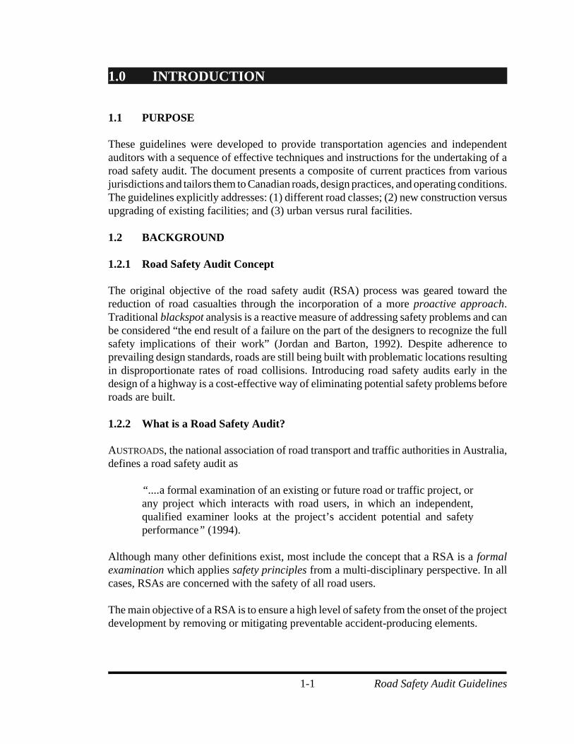
These guidelines were developed to provide transportation agencies and independentauditors with a sequence of effective techniques and instructions for the undertaking of aroad safety audit. The document presents a composite of current practices from variousjurisdictions and tailors them to Canadian roads, design practices, and operating conditions.The guidelines explicitly addresses: (1) different road classes; (2) new construction versusupgrading of existing facilities; and (3) urban versus rural facilities.
1.2 BACKGROUND
1.2.1 Road Safety Audit Concept
The original objective of the road safety audit (RSA) process was geared toward thereduction of road casualties through the incorporation of a more proactive approach.Traditional blackspot analysis is a reactive measure of addressing safety problems and canbe considered “the end result of a failure on the part of the designers to recognize the fullsafety implications of their work” (Jordan and Barton, 1992). Despite adherence toprevailing design standards, roads are still being built with problematic locations resultingin disproportionate rates of road collisions. Introducing road safety audits early in thedesign of a highway is a cost-effective way of eliminating potential safety problems beforeroads are built.
1.2.2 What is a Road Safety Audit?
AUSTROADS, the national association of road transport and traffic authorities in Australia,defines a road safety audit as
“....a formal examination of an existing or future road or traffic project, orany project which interacts with road users, in which an independent,qualified examiner looks at the project’s accident potential and safetyperformance” (1994).
Although many other definitions exist, most include the concept that a RSA is a formalexamination which applies safety principles from a multi-disciplinary perspective. In allcases, RSAs are concerned with the safety of all road users.
The main objective of a RSA is to ensure a high level of safety from the onset of the projectdevelopment by removing or mitigating preventable accident-producing elements.
Road Safety Audit Guidelines1-2
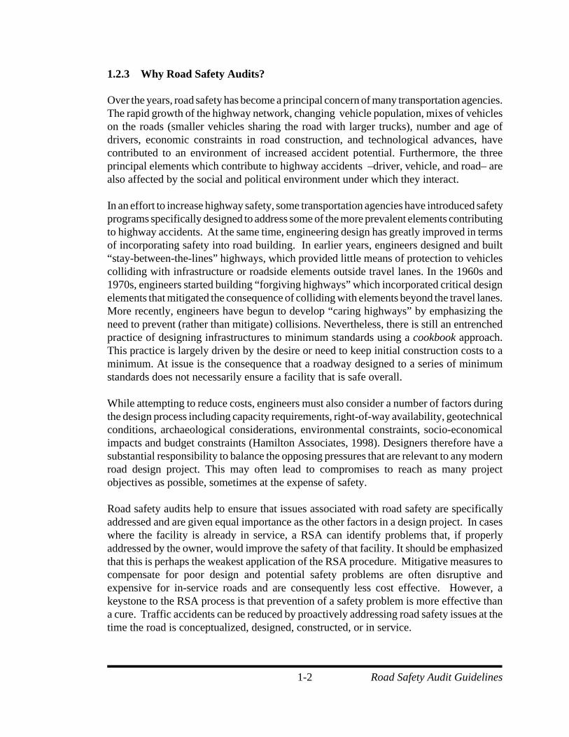
1.2.3 Why Road Safety Audits?
Over the years, road safety has become a principal concern of many transportation agencies.The rapid growth of the highway network, changing vehicle population, mixes of vehicleson the roads (smaller vehicles sharing the road with larger trucks), number and age ofdrivers, economic constraints in road construction, and technological advances, havecontributed to an environment of increased accident potential. Furthermore, the threeprincipal elements which contribute to highway accidents –driver, vehicle, and road– arealso affected by the social and political environment under which they interact.
In an effort to increase highway safety, some transportation agencies have introduced safetyprograms specifically designed to address some of the more prevalent elements contributingto highway accidents. At the same time, engineering design has greatly improved in termsof incorporating safety into road building. In earlier years, engineers designed and built“stay-between-the-lines” highways, which provided little means of protection to vehiclescolliding with infrastructure or roadside elements outside travel lanes. In the 1960s and1970s, engineers started building “forgiving highways” which incorporated critical designelements that mitigated the consequence of colliding with elements beyond the travel lanes.More recently, engineers have begun to develop “caring highways” by emphasizing theneed to prevent (rather than mitigate) collisions. Nevertheless, there is still an entrenchedpractice of designing infrastructures to minimum standards using a cookbook approach.This practice is largely driven by the desire or need to keep initial construction costs to aminimum. At issue is the consequence that a roadway designed to a series of minimumstandards does not necessarily ensure a facility that is safe overall.
While attempting to reduce costs, engineers must also consider a number of factors duringthe design process including capacity requirements, right-of-way availability, geotechnicalconditions, archaeological considerations, environmental constraints, socio-economicalimpacts and budget constraints (Hamilton Associates, 1998). Designers therefore have asubstantial responsibility to balance the opposing pressures that are relevant to any modernroad design project. This may often lead to compromises to reach as many projectobjectives as possible, sometimes at the expense of safety. Road safety audits help to ensure that issues associated with road safety are specificallyaddressed and are given equal importance as the other factors in a design project. In caseswhere the facility is already in service, a RSA can identify problems that, if properlyaddressed by the owner, would improve the safety of that facility. It should be emphasizedthat this is perhaps the weakest application of the RSA procedure. Mitigative measures tocompensate for poor design and potential safety problems are often disruptive andexpensive for in-service roads and are consequently less cost effective. However, akeystone to the RSA process is that prevention of a safety problem is more effective thana cure. Traffic accidents can be reduced by proactively addressing road safety issues at thetime the road is conceptualized, designed, constructed, or in service.
Road Safety Audit Guidelines1-3
1.2.4 Why Canadian Guidelines ?
Road safety audit manuals have been prepared by transportation agencies in Australia, NewZealand and the United Kingdom. However, these manuals often reflect local road systems,characteristics, design standards, and practices of the country in which the audit process isimplemented.
Road safety audits are relatively new to the Canadian transportation sector. As discussed inChapter 2, several provinces have introduced the concept of road safety audits; though varyingin design and scope. No generic document exists that formally presents a recommended sequenceof the most effective techniques and practices which accommodate Canadian roads, designpractices, and operating conditions. The need for a Canadian manual results from the fact thatCanadian roads are unique in many ways such as:
C Local climatic conditions: Road users in Canada experience arduous driving conditionsresulting from snow, freezing rain and sleet during the winter months. Roadmaintenance issues such as snow plowing and storage are also important factorsto include within a Canadian manual.
C Size of the country: Due to its size, most of Canada has large areas of sparselypopulated land and long highway segments connecting population centers. Roadusers traveling from one population center to the next drive for long periods oftime without encountering high levels of activity on the highway.
C Fleet mixes: There are a wide variety of special vehicles that use the roads, and their mixis constantly changing. There are now more, longer, and heavier trucks sharingthe road with smaller vehicles. There is also an increased use of snow mobiles,sport utility vehicles, and all-terrain vehicles that interact within the roadenvironment.
C Traffic volumes: Most Canadian highways experience low traffic volumes. In someprovinces, a small percentage of the highway mileage accounts for approximately90 percent of all traffic volume. This requires careful consideration whenincorporating safety principles in the design of highways.
C Types and characteristics of animals: In most of Canada, the migration of animals suchas deer and moose across highways poses a significant threat to motorists.
The development of a Canadian manual is of benefit to transportation agencies, road safetyprofessionals, and other parties interested in conducting road safety audits to improve highwaysafety in Canada.
Road Safety Audit Guidelines1-4
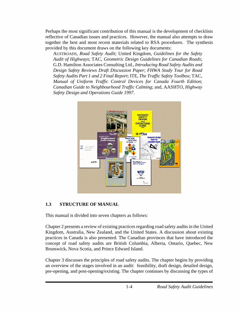
Perhaps the most significant contribution of this manual is the development of checklistsreflective of Canadian issues and practices. However, the manual also attempts to drawtogether the best and most recent materials related to RSA procedures. The synthesisprovided by this document draws on the following key documents:
AUSTROADS, Road Safety Audit; United Kingdom, Guidelines for the SafetyAudit of Highways; TAC, Geometric Design Guidelines for Canadian Roads;G.D. Hamilton Associates Consulting Ltd., Introducing Road Safety Audits andDesign Safety Reviews Draft Discussion Paper; FHWA Study Tour for RoadSafety Audits Part 1 and 2 Final Report; ITE, The Traffic Safety Toolbox; TAC,Manual of Uniform Traffic Control Devices for Canada Fourth Edition;Canadian Guide to Neighbourhood Traffic Calming; and, AASHTO, HighwaySafety Design and Operations Guide 1997.
1.3 STRUCTURE OF MANUAL
This manual is divided into seven chapters as follows:
Chapter 2 presents a review of existing practices regarding road safety audits in the UnitedKingdom, Australia, New Zealand, and the United States. A discussion about existingpractices in Canada is also presented. The Canadian provinces that have introduced theconcept of road safety audits are British Columbia, Alberta, Ontario, Quebec, NewBrunswick, Nova Scotia, and Prince Edward Island.
Chapter 3 discusses the principles of road safety audits. The chapter begins by providingan overview of the stages involved in an audit: feasibility, draft design, detailed design,pre-opening, and post-opening/existing. The chapter continues by discussing the types of
Road Safety Audit Guidelines1-5
projects which can be audited, the composition and characteristics of the audit team, theroles and responsibilities of those involved in the audit process, the organization of roadsafety audits, and the training of auditors. The chapter concludes with a descriptionregarding the monitoring and evaluation of the audit process.
Chapter 4 presents a discussion of the safety audit process. This discussion describes thecomplete process followed from the selection of the audit team to the completion meetingand follow-up. The chapter also discusses the methodology used when conducting auditsat different project stages. Finally, there is a detailed discussion addressing municipalaudits.
Chapter 5 presents an overview of checklists for road safety audits. The chapter discussesthe structure of the checklists, as well as their use. The master checklist and detailedchecklists are also presented in this chapter.
Chapter 6 is a cursory evaluation of the economic implications of road safety audits. Thechapter, which is divided into three sections, discusses: (1) costs of conducting road safetyaudits; (2) benefits; and (3) benefit-to-cost ratios associated with road safety audits.
Chapter 7 provides a discussion of legal issues associated with road safety audits.
Appendix A contains the checklists used for the conduct of safety audits of new facilitiesand/or upgrades. Appendix B contains the checklists used for the conduct of safety auditsof municipal networks. Appendix C presents illustrative examples of road safety auditsconducted in New Brunswick including highway audits and a municipal audit of a portionof Fredericton. Appendix D contains a glossary of key terms.
Road Safety Audit Guidelines2-1
2.0 REVIEW OF EXISTING ROAD SAFETY AUDITPRACTICES
This chapter presents a review of existing practices regarding road safety audits in theUnited Kingdom, Australia, New Zealand, and the United States. A discussion of existingpractices in Canada is also presented. The Canadian provinces that have initiated roadsafety audit studies include British Columbia, Alberta, Ontario, Quebec, New Brunswick,Nova Scotia, and Prince Edward Island.
2.1 UNITED KINGDOM
The concept of road safety audits originated in the United Kingdom during the 1980s. In1987, the United Kingdom (UK) Department of Transport formulated strategies directedtoward achieving a one-third reduction in the number of annual highway casualties by theyear 2000. In 1988, the UK passed legislation requiring all road authorities in mainlandBritain to take necessary steps to reduce crashes on new roads. This requirement led tothe development of two key publications: A Road Safety Code of Good Practice (LocalAuthorities Association, 1989) and Guidelines for the Safety Audit of Highways (Institutionof Highways and Transportation, 1990, revised 1996).
In 1991, the UK Department of Transport made road safety audits mandatory for allnational trunk roads and freeways. It currently remains the responsibility of the individualhighway organizations to determine what to audit and when as a function of their highwayprograms, design procedures, and type of project.
2.2 AUSTRALIA
In Australia, the national association of road transport and traffic authorities is known asAUSTROADS. In 1994, AUSTROADS released a publication entitled, Road Safety Audit. Thispublication establishes a broad set of guidelines for a national road safety audit program.It includes widely adopted checklists, developed through close interaction with Transit NewZealand, which are used to ensure all areas of safety are considered when conducting a roadsafety audit.
Individual states are incorporating road safety audits at different rates throughout Australia.The state of Victoria’s road agency, Victoria Roads Corporation (VicRoads), considers theroad safety audit to be an integral component of the quality management process. Roadsafety audits are carried out from project conception to construction completion on allprojects costing in excess of A$5 million (CDN $4.8 million). Furthermore, VicRoadsrandomly audits 20 percent of other construction projects at one or more stages and 10percent of maintenance work.
Road Safety Audit Guidelines2-2
The Roads and Traffic Authority (RTA) is responsible for road safety in New South Wales.RTA published a road safety audit manual as part of the New South Wales qualitymanagement approach in 1991. Twenty percent of existing roadways within all regions areto be audited to “identify deficiencies in existing roads and identify priorities for action”(Roads and Traffic Authority, 1991). Furthermore, twenty construction projects, varyingin project size and stages, are to be audited every year within each region.
2.3 NEW ZEALAND
Transit New Zealand (TNZ) is the national road agency responsible for the maintenanceand improvements to the New Zealand highway network. In 1989, TNZ created anAuthority whose main objective is the provision of an integrated and safe highway network.After reviewing the practices and procedures of road safety audits developed by the UK andAustralia, TNZ published a document entitled, Safety Audit Policy and Procedures (TransitNew Zealand, 1993). This publication states that all projects costing more than NZ$5million (CDN$4.2 million) would be audited from project conception to constructioncompletion. TNZ mandated that road safety audits would be conducted on a 20 percentsample of state highway projects, however, there are no guidelines for the identification ofprojects to be included in the sample.
2.4 UNITED STATES
In 1996, the Federal Highway Administration (FHWA) dispatched a scanning team toevaluate the road safety audit process in Australia and New Zealand. The group consistedof a multi-disciplinary delegation of highway engineers, safety specialists, and educators.In a 1997 report entitled, FHWA Study Tour for Road Safety Audits - Parts 1 and 2(Trentacoste et al.,1997), the scanning team concluded that road safety audits couldmaximize safety of roadways design and operation. The program participantsrecommended that a United States pilot study be conducted. The team provided the FHWAwith a nine-goal implementation strategy. These goals include (Trentacoste et al.,1997):
• Goal 1: “Get the word out”• Goal 2: Gain support and enlist pilot agencies• Goal 3: Pilot the RSA Process• Goal 4: Revise the RSA Process• Goal 5: Develop “best practices” guide• Goal 6: Train support group• Goal 7: Develop training course• Goal 8: Monitor implementation• Goal 9: Adopt guidelines
Subsequently, the FHWA started a Road Safety Audit Pilot Project in 1998 to determinethe feasibility of national implementation of road safety audits into the process of roadway
Road Safety Audit Guidelines2-3
project development, construction and operation. Fourteen states are currently involved inthe pilot project. Pennsylvania and Kansas had already been conducting road safety auditsprior to the FHWA pilot project. Kansas is not participating in the FHWA pilot project.
The FHWA has sponsored road safety audit workshops for all parties engaged in the pilotproject. The Pennsylvania Department of Transportation, which initiated road safety auditsin 1997, presented their most recent work at the May 1998 workshop. A contractor wasemployed to evaluate the pilot process and a written report is expected in 1999.
2.5 CANADA
There is a growing recognition among Canadian provincial jurisdictions that a more pro-active approach to road safety is needed. Although Ontario is currently establishing astructured framework to enhance safety, other efforts have focussed on isolated reviewsof specific projects. An overview of recent road safety initiatives undertaken by differentCanadian Provinces is provided below.
2.5.1 British Columbia
The Insurance Corporation of British Columbia (ICBC), in association with the BritishColumbia Ministry of Transportation, and various municipalities, has actively identifiedand funded improvements to high accident locations throughout the province. ICBC hasrecently acted to promote more pro-active strategies, including the implementation of roadsafety audits. A key document entitled, “Introducing Road Safety Audit and design reviews-Draft Discussion Paper”, was recently funded by ICBC and produced by HamiltonAssociates in 1998. Efforts continue toward the development of a more formal frameworkfor the implementation of audits.
2.5.2 Alberta
Within the Province of Alberta, a few applications of the safety audit process have beenrecently undertaken. The City of Calgary used a road safety audit approach as part of amore comprehensive safety/needs review for on Highway 22X (Bowron and Morrall,1998). There has been some local activity through the University of Calgary toward thepromotion of the road safety audit process. Smaller audits have recently been conductedat different locations within the province including the City of Red Deer.
2.5.3 Ontario
Based on the needs identified by internal staff of the Ministry of Transportation of Ontario(MTO) and in the wake of the Highway 407 Safety review, it was decided that acomprehensive, cohesive approach is required to amalgamate data, procedures, techniquesand expertise to address road safety (Porietti and Anders, 1998). This has lead to thedevelopment of a wholistic, system-wide approach to safety through the “Road Operational
Road Safety Audit Guidelines2-4
Performance Framework”. The framework was delivered in the spring of 1999 and theMTO is currently implementing the program.
This framework combines operational performance with the decision-making processesassociated with the development and management of road infrastructure. Furthermore,Ontario’s approach systematically incorporates road safety improvement opportunities.The framework consists of three broad processes which encompass seven main activities.These include (Proietti and Anders, 1998):
Network Evaluation: An annual screening of road networks is conducted on the basis ofactual verses expected safety performance. Where unforeseen operationalperformance characteristics are identified, diagnosis and analysis can be conductedto understand further the nature of the operation. Cost-beneficial countermeasuresare identified for locations where collision severity and numbers may be reduced.Ultimately, the evaluation yields a prioritized list of projects organized accordingto their operational performance and potential for improvement. To facilitate thenetwork evaluation process, a computer model has been developed to automate thescreening and diagnosis activities.
Design and Construction Procedures: Operational performance awareness andknowledge will be incorporated into the engineering development process. Thisinclusion involves training and the provision of appropriate tools necessary forestimating the decision performance implications throughout the feasibilityplanning, preliminary design, detailed design, construction, and post-opening stagesof the project. These procedures will be applied to all project types, includingexpansion and rehabilitation projects. Performance issues should be consideredearly in the project and properly documented.
An independent assessment may be conducted on certain projects by a multi-disciplinary team. The assessment is formal in nature and identifies key safety-related problems associated with the project. Essentially the equivalent of a roadsafety audit; it is conducted early in the project life cycle and is well documented.
Improvements to Standards, Policies, and Procedures: This process involves thedevelopment of a ‘knowledge engine’ through performance analyses, the latestresearch findings and the experience of other jurisdictions. This tool can be usedfor the ongoing refinement of the framework components.
A development/ review activity will provide an understanding of the performanceeffect of the several components of a road network and how they relate to standards,engineering processes and operational procedures. Modifications to standards,policies, and procedures should be implemented where advisable. This stageessentially provides a feedback loop which allows any necessary changes to bemade.
Road Safety Audit Guidelines2-5
An overall performance evaluation activity is conducted on the techniques andprocedures used. It will assist in incorporating changes toward an improvedknowledge-based management of road operational performance.
2.5.4 Quebec
In 1995, the Quebec Ministry of Transportation developed an Action Plan thatrecommended Road Safety Audits be incorporated as part of their safety regime(Vaillancourt, 1999). Since then, an RSA framework has not been adopted in favour ofhigher priority issues. Nevertheless, only a few audits have been undertaken within theprovince on selected road projects. The staff within the Ministry is currently workingtoward promoting the integration of RSAs for inclusion in the 2000-2004 Action Plan.
During January 1998, winter maintenance audits were undertaken for two major arterialroads near Quebec City. These “audits” scrutinized winter road maintenance practices andcorresponding safety issues attributed to accumulated snow and poor snowremoval/plowing.
2.5.5 New Brunswick
In early 1998, the Maritime Road Development Corporation (MRDC) was awarded acontract by the Province of New Brunswick to design/build/operate the 195-kilometre tollhighway from Fredericton to Moncton. MRDC is the first organization in North Americato incorporate fully a road safety audit procedure in the development of a highway from thepreliminary design stage through to the post-opening of the facility. This project (valueof approximately $600 million) represents a textbook application of a classical road safetyaudit. MRDC retained a three-member team to conduct the audit process.
2.5.6 Nova Scotia
The Nova Scotia Department of Transportation and Public Works has recently contractedfor an RSA of a proposed realignment/upgrading of Highway 104 in Antigonish. The auditprocess supplemented a safety review of three proposed alignments with the objective ofidentifying the scheme with the “greatest safety”.
2.5.7 Prince Edward Island
The Prince Edward Island Department of Transportation and Public Works recently had anRSA conducted for a 67 km section of the Trans-Canada Highway. The audit wasundertaken as part of the assessment and strategic planning for longer term improvementsto the corridor.
Road Safety Audit Guidelines3-1
3.0 PRINCIPLES OF ROAD SAFETY AUDITS
This chapter discusses the broader principles of road safety audits. An overview ispresented of the development stages at which audits can be conducted: feasibility, draftdesign, detailed design, pre-opening, and post-opening/existing. The chapter then continuesby discussing the types of projects that can be audited, the composition and characteristicsof the audit team, the roles and responsibilities of those involved in the audit process, theorganization of road safety audits, and the training of auditors. Finally, a description of themonitoring and evaluation process of audits is presented.
3.1 DEFINING ROAD SAFETY AUDIT
A road safety audit has been defined as. . .
“. . . a formal examination of an existing or future road or traffic project,or any project that interacts with road users, in which an independent,qualified examiner reports on the project’s accident potential and safetyperformance” (AUSTROADS, 1994).
The Road and Traffic Authority in New South Wales, describes a road safety audit as
“. . . a means of checking the design, implementation and operation of roadprojects against a set of safety principles as a means of accident preventionand treatment.” ( RTA, 1991).
A key concept associated with road safety audits is that they are conducted independentlyby an individual or team, with pertinent training and experience in road safety engineering,who have no prior affiliation with the project. The primary objective is to identify potentialsafety deficiencies for all road users and to consider the measures required to eliminate orreduce their impacts. Explicit consideration is given to all road users rather than motoristsonly. Users include pedestrians (young and old), cyclists, motorcyclists, automobiles,trucks, buses, and public transit riders.
A road safety audit is normally a formalized process whereby a written report is submittedto the design team and/or client listing safety deficiencies. The audit report should notcontain recommended remedial measures although exemplary solutions may be identified.The design team, who remains responsible for all design decisions, must give the auditteam a documented response addressing all safety recommendations.
Road Safety Audit Guidelines3-2
To avoid misconceptions, it is necessary to identify tasks that are beyond the scope of atraditional road safety audit. The following items have often been a source of confusion.
C Road safety audits are not a project redesign. Deficiencies should only be identified by the audit team. It is not within an audit’smandate for a redesign or recommendation to be made to mitigate a deficiency.This responsibility will rest with the project owners or their design staff. Auditorsmay suggest exemplary measures, but it is not their responsibility to make specificrecommendations nor to promote a particular solution. The primary task should befor auditors to ‘describe the problem’.
C Road safety audits are not intended for high cost projects only. In fact, experience has shown that RSAs can be particularly effective for smallerprojects where design teams have limited labor and resources. Larger projects oftenhave enough individuals involved with the required expertise so that internal checksbecome either inherent or a structured part of the design process.
C Road safety audits are not informal checks or inspections. Informal reviews should be a part of the normal design process separate from theservice an RSA provides.
C Road safety audits are not a means to select among alternative projects. It is inappropriate to rely on the products of an audit to choose among alternativeprojects/alignments or to solve public opinion conflicts concerning route location.
C Road safety audits should not be viewed as a check of standards compliance. Highway safety goes well beyond adherence to a set of minimum design standards.An audit is meant to be a wholistic and multi-disciplinary review of the safety levelprovided by a facility.
AUSTROADS and the United Kingdom identified the following benefits of conducting a roadsafety audit. (AUSTROADS, 1994 and IT, 1996). An RSA can:
(1) reduce the risk (including probability and severity)of accidents on newprojects and at interfaces with existing roads;
(2) increase the prominence of road safety in the minds of all involved in theplanning, design, construction, and maintenance of the project;
(3) reduce the whole life cost of the project by reducing the number of post-opening modifications; and
(4) ensure inclusion of all road users rather than the traditional focus on theautomobile.
Road Safety Audit Guidelines3-3
Belcher and Proctor (1990) suggest that road safety audits can provide increased safety intwo ways:
(1) by removing preventable accident-producing elements, such asinappropriate intersection layouts, at the planning and design stages; or
(2) by mitigating the effects of remaining or existing problems by the inclusionof suitable crash-reducing features, such as anti-skid surfacing, guardfencing, traffic control devices, and delineation.
It should be stressed that audits are most effective when conducted during the earlier stagesof planning and design. Economics are greatly diminished at the final design, construction,and post-opening stages of project development since mitigation is typically much moreexpensive.
3.2 AUDIT STAGES
Road safety audits can be effective for most projects, regardless of size, and at any or allkey milestones in the development of a highway project. Traditionally, audits have beenundertaken at the following key stages:
(1) feasibility (planning); (2) draft (preliminary/layout) design; (3) detailed design; (4) pre-opening; and (5) post-opening (including existing or in-service facilities).
The complexity and level of effort of the audit process changes with each stage. Anoverview of what each of the audit stages entails is provided below.
3.2.1 Feasibility (Planning) Stage
An audit at the feasibility stage assesses the potential safety performance of the conceptualdesign proposal with respect to the route location, road design standards, and the scope ofthe project. Auditors should focus on how the facility will affect the continuity of theadjacent road network and identify the safety needs of all road users (i.e., pedestrians,cyclists, motorists, and others). Audits can be very effective at this stage; changes orimprovements to the project are often highly cost effective due to inexpensiveimplementation costs.
Road Safety Audit Guidelines3-4
3.2.2 Draft (Preliminary/Layout) Design Stage
An audit may be conducted upon completion of the draft design plans. Primary objectivesare to evaluate the relative safety of intersection or interchange layout, horizontal andvertical alignment, cross section, sight distance, and other design standards. Auditsconducted at this stage should be completed before the finalization of land acquisition toavoid complications if significant alignment changes are required.
3.2.3 Detailed Design Stage
An audit should be undertaken upon completion of the detailed design plans and typicallyprior to the preparation of the contract documents. The geometric design, lighting, trafficsigning, and landscaping plans are made available to the audit team and evaluated inrelation to the operation of the facility.
3.2.4 Pre-Opening Stage
Immediately before opening a facility, the audit team should conduct a site inspection toensure the safety needs of all road users (i.e., pedestrians, cyclists, motorists, and others)are adequate. The audit team should conduct day and night drive through inspections and,if possible, perform the inspection in adverse weather conditions. This type of auditattempts to determine if hazardous conditions exist which were not evident in the previousaudits.
3.2.5 Post-Opening (and Existing) Stage
Road safety audits can be undertaken soon after opening a new facility to the public.Insight into operational behaviour and subsequent problem areas can be gained throughobservation which may not have been readily apparent before opening the facility.Corrective measures, although much more expensive to carry out at this stage, may still becost effective.
RSAs can also be conducted on any section of an existing road network to identify safety-related deficiencies. The information collected from accident reports is an importantcomponent for these audits; however, as an extension of traditional blackspot analyses theyshould be supplemented by informed judgements surrounding the potential for otheraccidents.
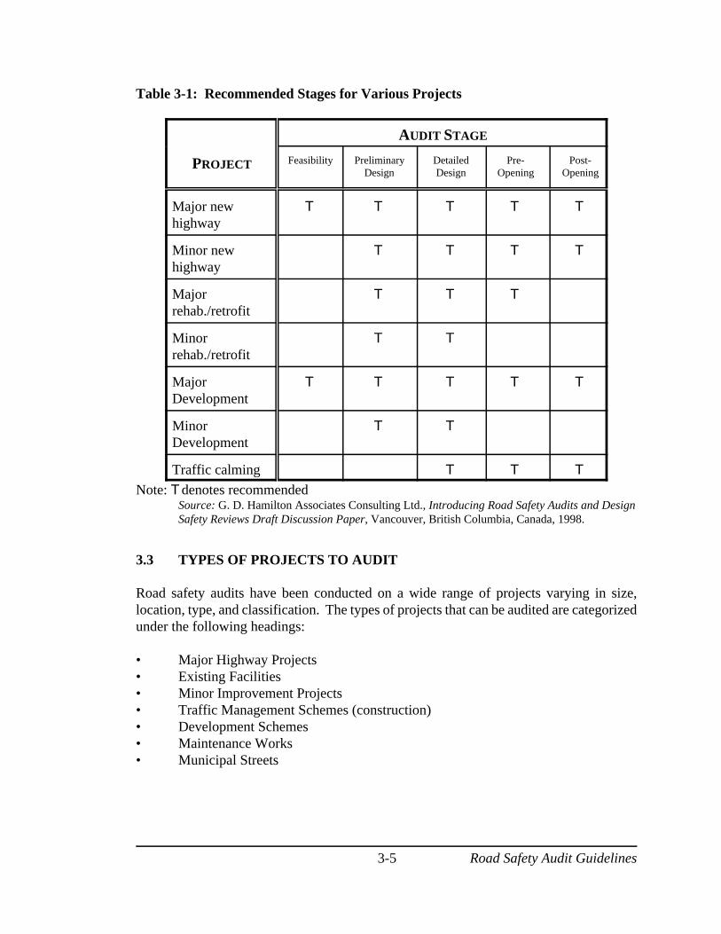
Hamilton Associates have developed a table which summarizes a range of project types andthe corresponding recommended stages for audits. This table is intended to help roadagencies decide which projects to audit and at what stage. As they indicate, Table 3-1represents a recommended practice, and should only be used as a guide.
Road Safety Audit Guidelines3-5
Table 3-1: Recommended Stages for Various Projects
AUDIT STAGE
PROJECT Feasibility PreliminaryDesign
DetailedDesign
Pre-Opening
Post-Opening
Major newhighway
T T T T T
Minor newhighway
T T T T
Majorrehab./retrofit
T T T
Minorrehab./retrofit
T T
MajorDevelopment
T T T T T
MinorDevelopment
T T
Traffic calming T T T
Note: Tdenotes recommended Source: G. D. Hamilton Associates Consulting Ltd., Introducing Road Safety Audits and DesignSafety Reviews Draft Discussion Paper, Vancouver, British Columbia, Canada, 1998.
3.3 TYPES OF PROJECTS TO AUDIT
Road safety audits have been conducted on a wide range of projects varying in size,location, type, and classification. The types of projects that can be audited are categorizedunder the following headings:
• Major Highway Projects• Existing Facilities• Minor Improvement Projects• Traffic Management Schemes (construction)• Development Schemes• Maintenance Works• Municipal Streets
Road Safety Audit Guidelines3-6
Conducting road safety audits on all projects would be ideal, however, resource allocationis a major factor in determining which projects to audit. It is often necessary for roadauthorities to develop methods for ranking projects which should be audited and at whichstage. In Australia and the United Kingdom, the road authorities are currently evaluatingwhich projects should be audited and at what stage audits are most effective. It is importantto note that certain road authorities require all major road projects to be audited whileothers are only able to audit a sample of projects due to financial constraints.
Road authorities must be aware that audits of large projects do not always produce thegreatest benefits. Often larger projects have sufficient labor to provide internal checks ondesign. Smaller projects may lack team members with the expertise to identify safety-related design flaws. Conducting an audit on such projects may make them a more effectiveuse of the audit process as it encourages a more careful review of safety issues.
3.4 THE AUDIT TEAM
3.4.1 Independence
Most practitioners agree that road safety auditors should be independent of the projectdesign team to ensure that those who are unbiassed and those who may have a differentperspective are reviewing the project. Audit teams can be established within largeorganizations or by using consultant firms or consortia. It is essential that an environmentexists which fosters good communication between the audit team and the client/designteam to ensure the audit is effective.
3.4.2 Qualifications
Road safety audits should be conducted by an individual or team with adequate experiencein road safety engineering principles and practices, accident investigation and prevention,traffic engineering and road design. Additionally, members with experience inenforcement, maintenance, and human factors can be added to the team on a project byproject basis and at different audit stages. Human factor expertise may, in selected areas,contribute to a road safety audit by providing an understanding of the interactive nature ofuser behaviour with the road environment.
3.4.3 Experience
It is imperative that the audit team has substantial collective experience in the key areasnoted in the pervious section. While audit checklists serve to identify critical items/areasto be considered, they should only be considered memory aides for individuals with awealth of experience and not an exhaustive listing of issues.
Road Safety Audit Guidelines3-7
Australia has implemented a national accreditation for those conducting audits. Accreditedauditors must have undertaken a two-day course in road safety audits and have participatedin at least five audits with an experienced auditor, including at least three at the designstages. This process should be carefully reviewed and considered with caution beforeCanadian adoption is contemplated. Placing the audit process in the hands of a few selectedpersons could deprive the process of a wide range of specialists and experience.
3.4.4 Audit Team Size
The associated benefits of conducting an audit with a multi-disciplinary team are the diverseknowledge and approaches of each individual, cross fertilization of ideas that can be theresult of discussions, and more than one pair of eyes reviewing the project (AUSTROADs,1994). Using a multi-disciplinary team also provides the opportunity to expand the numberof persons in an organization that are experienced in the audit process
The size of the audit team will vary depending upon the size and type of project. It isrecommended that the team consist of two to five multi-disciplinary individuals. The useof at least two individuals provides cross fertilisation. When the team becomes too large,it becomes difficult to reach a consensus and develop a focussed/concise audit. Additionalexpertise may be added to the project team as required at different stages of the auditprocess (i.e., police officers, maintenance personnel, human factors, and others).
There may be projects that –due to their size– only require the review of a single plan, afield visit, and a one page report. In this situation, an audit by two or more individuals maynot be justified. A carefully-selected individual may be sufficient to conduct the audit andraise issues that could result in significant safety-related savings.
3.4.5 Composition by Audit Stage
The selection of an audit team depends on the size and type of project, the stage of the auditand available resources. An assortment of young and older individuals may constitute theaudit team. This ensures that safety issues are analyzed from a variety of perspectives. Thisinformation is a composite of current practices in other jurisdictions, including Australia,New Zealand, the United Kingdom, the United States, and Canadian provinces. Thefollowing are some suggestions for selecting an audit team (Hamilton Associates, 1998;Institution of Highways and Transportation, revised 1996).
3.4.5.1 Feasibility and Preliminary Design (Stages 1 and 2)
Audits undertaken at both the feasibility and preliminary design stages should only beconducted by an experienced audit team which includes:
C A road safety specialist experienced in:
Road Safety Audit Guidelines3-8
(1) accident reconstruction and collision investigation; (2) safety management; (3) safety engineering; (4) road safety audits; and (5) knowledge of the latest safety research and standards.
C A highway design engineer who has knowledge of the current road designstandards and practices. Furthermore, the engineer must be able to visualise thethree-dimensional layout of the project from two-dimensional plans.
C An individual experienced in conducting road safety audits who can promptdiscussions, assist in the audit procedure, and preferably has expertise with at leastone prospective aspect of the audit.
Individuals involved in this type of audit can cover more than one of the above areas. Aroad safety specialist may also be a highway design engineer, or traffic engineer, who isfamiliar with the current road design standards and practices, and traffic operatingconditions.
3.4.5.2 Detailed Design (Stage 3)
An audit at the detailed design stage requires the expertise identified in the previous sectionand may include additional individuals with expertise and skills, depending on the natureof the project, in such areas as traffic signal control, intelligent transportation systems,cyclists and pedestrians, transit systems and facilities, street lighting and traffic calming.
3.4.5.3 Pre-Opening (Stage 4)
Pre-opening audits require the expertise identified for Stage 1 and 2 audits. However,additional expertise may be added to the team where required. This may include one ormore of the following: (1) a police officer with traffic and safety experience; (2) an engineeror supervisor who is familiar with all aspects of facility maintenance including signage,lighting, traffic controls, vegetation, snow removal, and others; and (3) an individual withknowledge of human behavioural aspects of road safety.
3.4.5.4 Post-Opening (Stage 5)
Post-opening audits require the same team composition and expertise as identified in thepre-opening audit stage.
Road Safety Audit Guidelines3-9
3.4.5.5 Existing (In-Service) Roads
To evaluate the safety issues associated with existing roads, an audit team requires members withsimilar qualifications and experience to those individuals outlined in the pre-opening stage.
3.4.5.6 Municipal Audits
A municipal audit can be conducted by a single person or a team of experts. The selection of anauditor or audit team depends on the nature of the project and the city in which the audit is to beperformed. Ideally, a municipal audit should be conducted by two or three auditorsknowledgeable in traffic management and safety, road design, driver behaviour, and crashinvestigation and prevention, (Haiar and Wilson, 1999). Members of a municipal audit teamshould also have experience at street safety audits and must be able to assess and identify safetyconcerns of urban streets in an independent and objective manner.
In municipalities where funding is limited, hiring qualified consultants may not be feasible.Depending on the size of the audit, a reasonable alternative may involve utilizing local personnelfrom a nearby town or city. It is important that the auditor(s) possess adequate knowledge andskill in traffic safety engineering and that the auditor is not associated with the municipalityrequesting the audit.
3.5 ROLES AND RESPONSIBILITIES OF PARTICIPANTS
Terms of reference should be developed at the beginning of a project. This document shouldcontain the scope of the audit and the roles and responsibilities of all parties (i.e., client, designand audit team) involved in the audit. The terms of reference may be a standard agencydocument or one developed for a specific project. It should incorporate any special requirementsof the audit (i.e., a night site inspection during winter conditions) and describe the process for thepresentation of the audit results.
From one agency to another, the roles and responsibilities of the parties involved in an audit willvary depending upon the resources available and the operating procedures for highway designand implementation. It is the responsibility of all parties to maintain good communicationthroughout the audit. This is to ensure the audit is conducted efficiently and to provide a meansfor resolving conflicts. The typical roles and responsibilities of all parties involved in the safetyaudit process are outlined in the following sections (Hamilton Associates, 1998; Institution ofHighways and Transportation, revised 1996).
Road Safety Audit Guidelines3-10
3.5.1 Client (Highway Authority)
Road safety audits should be considered an integral component of highway conception,feasibility and design processes. It is therefore essential that highway authorities allocatesufficient funding and resources to support the road safety audit process.
Highway authorities should: (1) consent to road safety audits as a quality managementrequirement; (2) commission audits at the proper project stages; and (3) review the formalaudit report and act upon recommendations whenever appropriate and feasible. Without theclient’s full commitment to the process, particularly by giving genuine consideration torecommendations, the audit process becomes ineffective.
The highway authority should provide training at all levels within the organization to ensurethat safety is an integral component of all phases of a highway project (i.e., planning,design, construction, and maintenance). Correct training of personnel increases the potentialof safety issues being identified by the audit team.
It is the responsibility of the highway authority to: (1) select an audit team with theappropriate training and experience; (2) provide project documentation; (3) ensure theauditors have satisfied the requirements described in the terms of reference; (4) attend theinitial and completion meetings; and (5) refer all design changes to the audit team.
3.5.2 Design Team/Project Manager
It is the responsibility of the design team/project manager to provide the audit group withproject background information (including previous audit reports), design drawings, trafficcomposition and characteristics, accident reports where available, and any otherdocumentation affecting the design. The design team/project manager initiates audits whenrequired; attends the initial and completion meetings; and reviews the issues raised by theaudit report.
The audit report, in turn, provides the design team/project manager with a list of safety-related deficiencies; however, it should not provide specific design solutions orrecommendations. As noted previously, the audit may list “possible” mitigative measures,but specific recommendations are not given. The responsibility of developing and adoptingcorrective solutions lies with the design team/project manager.
The design team/project manager in turn provides the audit team with a written responseaddressing all safety issues. This includes either: (1) accepting the possible mitigativemeasures and providing a design solution for the hazard; or (2) rejecting the measures andstating the reasons for this action.
Road Safety Audit Guidelines3-11
It is the responsibility of the design team/project manager to assess financial and budgetconstraints to determine whether, how, or when to adopt an audit’s suggested solutions. Thedesign team/project manager is responsible for all design decisions; however, decisionsmay sometimes require the involvement of the highway authority (if design is beingundertaken externally). Any design changes must be submitted to the audit team whodecides whether to audit the revised design further or to incorporate it into the next auditstage.
3.5.3 Audit Team
The primary role of the audit team is to identify potential safety problems of a highwayproject by reviewing project documentation and drawings, and conducting site inspections.They typically do not redesign the project or implement changes. The audit team may usea developed set of checklists to assist them while conducting the audit. Checklists identifyissues and problems that can arise at the relevant stages of an audit. These checklists aremerely guides and should not be used as a substitute for experience. They also provide ameasure of continuity from audit to audit.
The audit team is required to submit a report to the design team/project manager,identifying critical issues based on safety engineering experience. A completion meetingis held between the audit team, the design team/project manager, and the client to discussthe audit findings. The audit team is required to review the design team/project manager’sresponse to the audit report. It is not the role of the audit team to approve of or agree withthe obtained response.
3.6 ORGANIZATION OF ROAD SAFETY AUDITS
There are several methods of organizing a road safety audit while ensuring the audit teamhas the appropriate training, expertise and independence of the design team. AUSTROADS
(1994) has developed a list of recommendations outlining how a road safety audit shouldbe organized (similar information is not discussed in any of the other available publishedmaterial). As indicated by AUSTROADS, there are three preferred ways of organizing a roadsafety audit: (1) audit by a specialist auditor or team; (2) audit by other road designers; and(3) audit within the original design team. Beyond the AUSTROADS model, there is agrowing trend toward using a team which consists of numerous specialists. The teamconcept has the advantage of allowing the cross-fertilization of ideas and issues due todifferent perspectives.
3.6.1 Audits Conducted by a Specialist Auditor or Team
Specialist audit teams can be established within a highway organization or by consultingfirms or consortia. Road safety audits should be conducted by an individual or team with
Road Safety Audit Guidelines3-12
adequate experience and training, and independent of the design team. This maximizes theeffectiveness of the processes and ensures that unforseen safety problems are identified.
In cases where an audit is conducted by a specialist team, the audit findings can be reportedin one of the following ways: (1) the specialist can report the findings to the client or anindependent third party on behalf of the client; or (2) the specialist can report the findingsdirectly to the original designer.
3.6.1.1 Specialist Audit Team, reporting to an Independent Third Party
The road safety audit team may submit a formal report to a third party who is responsiblefor deciding what actions are to be taken regarding the safety issues raised by the auditteam. This method can be adopted by highway authorities when major highway projectsare designed by a consulting firm. The design is submitted by the consulting firm to theaudit team who submits a report to the independent third party. The independent third partyprovides the audit team and the Highway Authority with a documented response addressingall safety issues.
The third party may be a senior manager within a highway organization with no direct lineof management to the project being audited. The possibility of conflicts between the auditteam and the design team can be reduced when an independent third party is involved.
3.6.1.2 Specialist Audit Team, reporting to the Designer/Project Manager
This is similar to the previous method but the audit team report is submitted to the originaldesigner or design team who provides the audit team and client with a documentedresponse addressing all safety mitigative measures.
3.6.2 Audits Conducted by Other Road Designers
Audits conducted by another design team are an alternative means of conducting a roadsafety audit. This approach may be used by large highway organizations that have morethan one design team. However, in cases where the highway organization only has onedesign team, it may be feasible to approach another road agency for assistance.
A weakness of this approach (i.e., having road designers conduct audits) is the lack ofmulti-disciplinary knowledge that designers bring to the process. For example, they mayhave little or no experience in safety engineering, maintenance, operations, and accidentinvestigation and prevention. The design team can assess the project for compliance to roaddesign standards; however, these aspects are a minimal component of a road safety audit.
In cases where a safety audit is conducted by other road designers, the findings from theaudit can be either submitted to the client, or an independent third party on behalf of theclient; or to the designer/project manager for their comments.
Road Safety Audit Guidelines3-13
3.6.2.1 Second Design Team, reporting to an Independent Third Party
The project is audited by another design team, within or outside an organization, and a writtenreport is submitted to an independent third party on behalf of the client for review. The individualwho provides the response to the audit report should have no direct line of management to theoriginal or auditing designers. This is to make certain that independent appraisals can be madewhere disagreements arise. Note that a second design team can also lack the broader multi-disciplinary approach.
3.6.2.2 Second Design Team Audit, reporting to Designer/Project Manager
This approach is similar to the previous method (3.6.2.1); however, the audit report is submittedto the original design team or project manager. The disadvantages of this method are that theoriginal designer may reject criticism of the design either for genuine reasons or time constraints.The original design team provides the auditing designers with a documented response addressingall safety issues raised.
3.6.3 Design Team Self-Audit
This type of road safety audit, which is the least desirable due to the lack of independence, isconducted by a member of the original design team. While all designers and design teams aretypically concerned with safety, they are too familiar with the design process; therefore, they areprone to offer biassed opinions about the design. It is preferable that individuals who are notinvolved in the project conduct the audit.
3.7 TRAINING OF AUDITORS
There are currently no national guidelines for the training of road safety auditors. In Canada andabroad, short courses have been offered as an introduction to the road safety audit process whichincluded some comments on training. Audit teams should be composed of individuals with avariety of backgrounds related to the design, maintenance, operations and safety evaluation ofhighway infrastructure. The benefits from safety audits will to a degree depend on the expertise,experience and common sense of the members of the team. It will be incumbent for the client toensure that the personnel assembled for undertaking an audit provide a blend of appropriateexpertise and experience.
There are varying philosophies concerning the designation of auditors. One such philosophy setsout very specific guidelines governing education and experience. Typically, a specific number ofaudits are required to be completed each year in order to maintain auditor status. For example,a lead auditor should have a particular number of years experience, have completed a trainingcourse and participated in a prescribed number of audits. Of these completed audits, apredetermined number must address specific design stages.

Road Safety Audit Guidelines3-14
An alternate school of thought believes that highway safety is not “rocket science”, but requirespractical experience and training in the field. Audit participants should have completed a soundtraining program and have practical experience in one or more of the following areas: road design,human behaviour, traffic safety, reconstruction techniques, etc. A lead auditor should haveprevious audit experience, but need not have completed any specific number of audits and neednot be active at a specified level each year. In many Canadian jurisdictions, it would not bepossible to obtain exposure to say five audits each and every year.
UNB follows the second of the above mentioned philosophies. A less rigid scheme producesmore benefits and allows a greater number of people to be involved in the audit process. Toincrease the awareness level of highway safety and expand the safety audit process, a provincialdepartment of transportation/highways for example should develop a process that involves anumber of their professionals in the audit process. A structured and restrictive system for theselection of auditors would be exclusionary and discourage that objective. A mandatorycompletion of a certain number of audits in a year is not crucial. The goal of training as manypeople in an organization as possible to understand the audit process, and therefore be able toparticipate in audit activity, is a better use of resources. It is not in the best interest of the roadusers, or of expanding the RSA concept, to establish a select number of auditors with stringentcriteria.
The training course need not be extensive. A two day course would be sufficient to provideexperienced personnel with enough knowledge for meaningful participation in an audit. Day 1would provide an overview of audits. Topics to be covered include a history of audits, how andwhen to audit, and an explanation of the checklists and audit report preparation. Day 2 wouldconsist of practical work, either laboratory or field exercises concerning both municipal and ruralsituations.
3.8 MONITORING AND EVALUATION
All highway organizations involved with safety audits should monitor and evaluate their road safetyaudit procedures. This may be accomplished by maintaining a complete record of the safety auditprojects conducted by the organization. The record would contain a list of common deficienciesidentified during all stages of road safety audits. This, in turn, provides feedback for designers andauditors performing future projects. The intent is to prevent recurring deficiencies from beingdesigned into road projects. Otherwise, designers will continue to “build blackspots” into theroad system.
Road Safety Audit Guidelines4-1
Figure 4-1: Process for Conducting Road Safety Audits
4.0 ROAD SAFETY AUDIT PROCESS
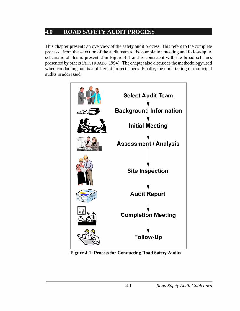
This chapter presents an overview of the safety audit process. This refers to the completeprocess, from the selection of the audit team to the completion meeting and follow-up. Aschematic of this is presented in Figure 4-1 and is consistent with the broad schemespresented by others (AUSTROADS, 1994). The chapter also discusses the methodology usedwhen conducting audits at different project stages. Finally, the undertaking of municipalaudits is addressed.
Road Safety Audit Guidelines4-2
4.1 SELECTING THE AUDIT TEAM
It is the responsibility of the client to select the audit team. As previously noted, the auditteam should be independent of the design team and have appropriate experience andtraining in road safety engineering. A list of potential auditors, including qualifications,would be beneficial to the client when selecting the audit team. An audit team leadershould be selected who has experience in road safety engineering and has participated inprevious audits. The client should exercise caution when selecting the audit team. The teamwith the lowest bid is not always the most experienced. In road safety audits, experienceis paramount, and cost is secondary.
4.2 COLLECTION OF BACKGROUND INFORMATION
The client is responsible for providing all relevant project documentation; including reports,data, drawings, contract documents and where required traffic volumes. This informationwill be used by the audit team to assess the project from a safety perspective. Furtherdetails about this are discussed in Section 4.4.1.1.
4.3 INITIAL MEETING
An initial meeting is normally held between the audit team, client and designer. Theobjective of this meeting is to familiarize the audit team with the project scope and safety-related information, exchange data, delegate responsibilities, and to set up communicationlines (Hamilton Associates, 1998).
The audit team can familiarize the designer and client with the audit process and familiarizethe design team with the checklists to be used. The client/designer should inform the auditteam of any problems encountered during the planning, design, and construction stages.The terms of reference identifying the project scope, and roles/responsibilities during theaudit should be completed. Project schedules and special requirements should beidentified and discussed at this stage.
4.4 THE PROCESS
After the initial meeting, it is the responsibility of the audit team to assess the projectdocumentation and to conduct site inspections (if appropriate) to determine the safety-related issues of the project. The following sections present the process used whenconducting road safety audits for highways, isolated facilities, and in municipalities. Thisinformation is a composite of current practices in other jurisdictions, including Australia,New Zealand, the United Kingdom, the United States, and Canadian provinces.
Road Safety Audit Guidelines4-3
4.4.1 Highway Audits
Figure 4-1 shows the general steps to follow when conducting road safety audits (this alsoapplies to audits of isolated facilities, and municipalities). While all the steps apply to allaudit stages, there are specific items to consider in each of the different steps, dependingon the audit stage.
4.4.1.1 Background Information
The client must provide the audit team with all necessary background information prior tothe start of the audit. This information will assist the team in developing an adequateassessment of the facility prior to the audit.
For audits at the feasibility stage, the required background information may include:
(1) project scope, goals, and objectives; (2) general project constraints; (3) route choice and layout options; (4) continuity with adjacent road networks and land uses; and (5) environmental and geotechnical constraints.
For audits at the preliminary and detailed design stage, the required backgroundinformation may include:
(1) standards and design criteria used; (2) land acquisition; (3) information about previous consultation with the community; (4) design drawings; (5) details of plans; (6) plans showing adjacent roads which may be affected by the project; (7) traffic forecasts; (8) right-of-way; and (9) potential/expected road users.
For audits at the pre-opening stage, it is necessary to provide the audit team with previousaudit reports (if available) and other relevant information, such as road users expected totravel on that road. Audits that are conducted at the post-opening stage or on existingfacilities require background information regarding:
(1) traffic volumes for all road users; (2) collision information; (3) previous audit reports–if available; and (4) as-built drawings.
Road Safety Audit Guidelines4-4
4.4.1.2 Assessment/Analysis of Background Information
Once all the background information is collected, the audit team needs to assess/evaluateand analyze all the available information. For audits at the feasibility, preliminary design,or detailed design stage, the audit team should examine the details about the proposedproject, details of plans and background information on a section by section basis. Thisprovides an opportunity to consider the impact of the design on all road users.
If the audit is being conducted at the pre-opening or post-opening stage, or if this is an auditof an existing facility, the team should analyze all pertinent information such as accidentreports (this does not apply to pre-opening stage), and all other relevant information. Theanalysis of accident reports is not intended to be used as a blackspot analysis, but as an aidfor the auditors in determining potential areas with safety problems. This would make theaudit pro-active rather than reactive.
The use of a multi-disciplinary team provides the opportunity for ‘brainstorming’ sessions.This results in a more constructive and comprehensive assessment of safety issues.
4.4.1.3 Site Inspections
Field inspections are required at all stages because they provide the team with a feel for theexisting conditions.
Prior to going to the field, the team should become familiar with checklists to ensure theinspection is productive and relevant concerns are raised. The use of checklists, in additionto background information, will assist the auditors to ensure that relevant safety aspects areaddressed. Checklists should not be used as a substitute for experience, nor consideredexhaustive.
For audits at the feasibility, preliminary design, and detailed design stages, the teamconducts a site inspection, including ‘green field’ sites, upon completion of the preliminaryassessment. The audit team should examine the transition between any new and existingroads to ensure consistency from a multi-modal perspective. This includes cyclists, elderlydrivers, elderly pedestrians, truck and bus drivers, pedestrians, children, disabled, all terrainvehicles, and snowmobiles. Additionally, the team should focus on prevailing climate andgeographic conditions.
Audits at the pre-opening and post-opening stage, as well as audits of existing facilities,review the physical characteristics of the project by conducting a site inspection. Theseinspections involve assessing the furniture, signs, lighting, markings, delineation, andgeometric features from a multi-modal perspective. The team should identify issues thatmay affect the road users’ perception of the road or restrict sight lines. In the case of pre-opening audits, the inspection should be conducted as close as possible to the opening date
Road Safety Audit Guidelines4-5
but still allow time for the design team to implement any changes. For larger projects, pre-opening audits may be conducted in phases as the sections of the project become complete.
The audit team should conduct the inspection by driving and walking (if feasible) throughthe project in opposite directions. In addition, site inspections should be conducted at nightand in adverse weather conditions if possible. The team should consider going beyondproject limits to assess the adjacent road network, paying particular attention to theinterface if it is a new project. Photographs and videotapes can be used to capture roadwayfeatures for later discussions.
After conducting the site inspection, document assessments and site inspection material areanalyzed, with the use of checklists, to determine if all relevant safety issues wereaddressed. The team should not address non-safety related issues such as aesthetics,amenities, etc. An audit should not be used to simply evaluate highway capacity issues.
4.4.1.4 Audit Findings
Once the site inspections are completed, the audit report is prepared. The report shouldclearly and concisely describe the project, the audit stage, the audit team members, theprocess of the audit, any safety issues identified, and mitigative countermeasures. Thesecountermeasures are conceptual in nature and should not provide the design team withdesign solutions. If time constraints are identified in pre-opening audits, a preliminaryreport may be developed immediately and submitted to the project manager before the finalreport is prepared.
4.4.2 Audits of Isolated Facilities
Road safety audits can also be used to evaluate isolated safety concerns of a highwayfacility. An audit of a localized facility can be conducted where a change in design of asection or all of an existing facility has been proposed. For example, the audit team maybe required to conduct a safety audit on a short section of highway that requiresrealignment. Similarly, the proposed widening of an auxiliary lane at an existingintersection may be audited. In either case, the audit of an isolated facility investigates thesafety issues at various stages of design and construction. Since the safety issues will varydepending on the facility, no single checklist can be recommended for this style of audit.Furthermore, depending on the project, it may not be necessary to conduct a full-scale auditof each stage of the design process. Audits of isolated facilities can also be conductedfollowing the steps illustrated in Figure 4-1. The type of project to be audited determinesthe initial stage at which the audit will be conducted. Table 4-1 illustrates the variousisolated projects that an audit team may encounter, as well as recommended design stagesthat may apply to the audit process.
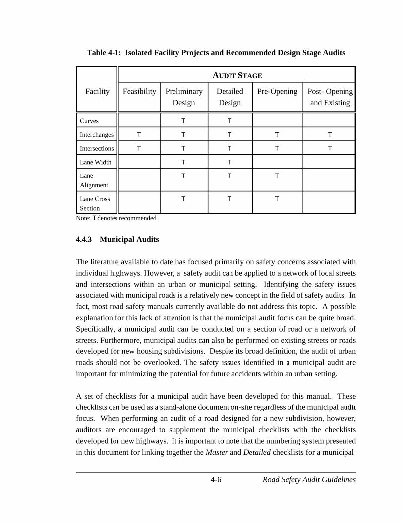
Road Safety Audit Guidelines4-6
Table 4-1: Isolated Facility Projects and Recommended Design Stage Audits
AUDIT STAGE
Facility Feasibility Preliminary
Design
Detailed
Design
Pre-Opening Post- Opening
and Existing
Curves T T
Interchanges T T T T T
Intersections T T T T T
Lane Width T T
Lane
Alignment
T T T
Lane CrossSection
T T T
Note: Tdenotes recommended
4.4.3 Municipal Audits
The literature available to date has focused primarily on safety concerns associated with
individual highways. However, a safety audit can be applied to a network of local streetsand intersections within an urban or municipal setting. Identifying the safety issues
associated with municipal roads is a relatively new concept in the field of safety audits. Infact, most road safety manuals currently available do not address this topic. A possible
explanation for this lack of attention is that the municipal audit focus can be quite broad.Specifically, a municipal audit can be conducted on a section of road or a network of
streets. Furthermore, municipal audits can also be performed on existing streets or roadsdeveloped for new housing subdivisions. Despite its broad definition, the audit of urban
roads should not be overlooked. The safety issues identified in a municipal audit areimportant for minimizing the potential for future accidents within an urban setting.
A set of checklists for a municipal audit have been developed for this manual. These
checklists can be used as a stand-alone document on-site regardless of the municipal auditfocus. When performing an audit of a road designed for a new subdivision, however,
auditors are encouraged to supplement the municipal checklists with the checklistsdeveloped for new highways. It is important to note that the numbering system presented
in this document for linking together the Master and Detailed checklists for a municipal
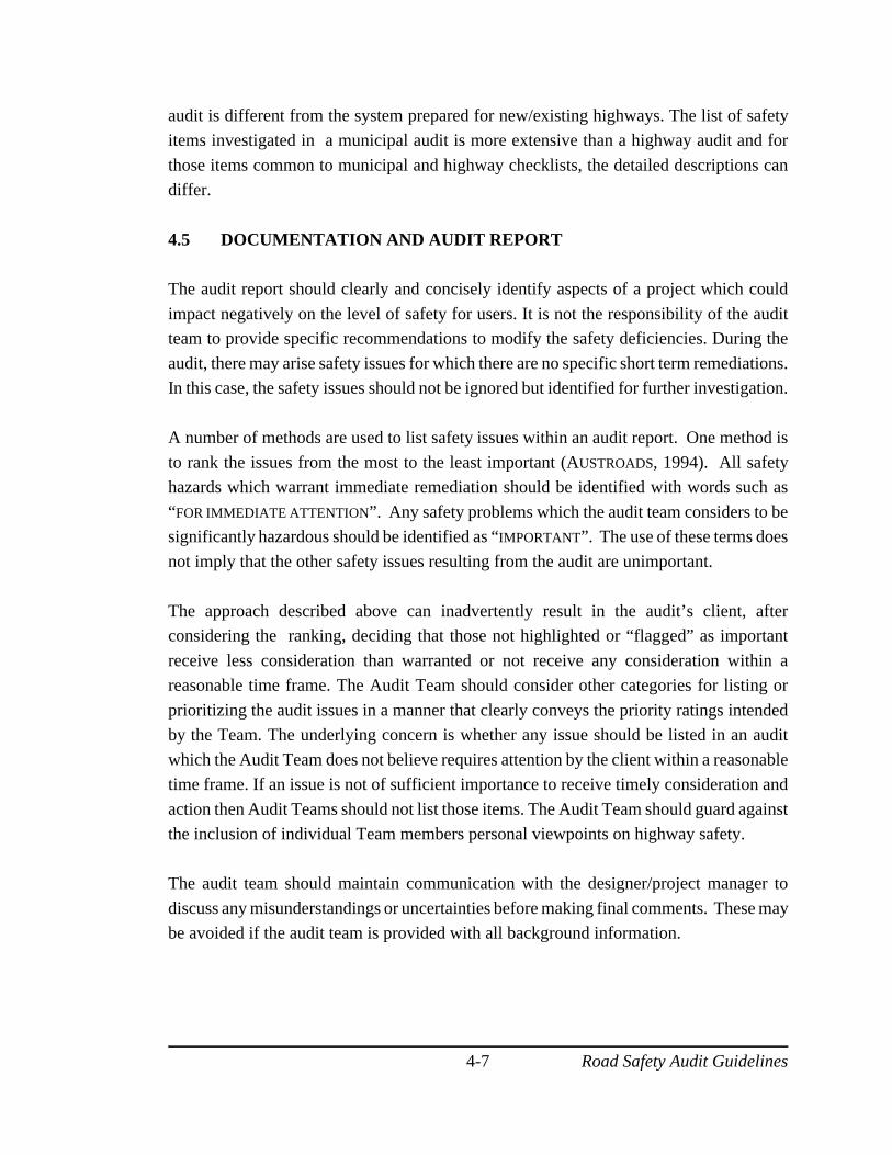
Road Safety Audit Guidelines4-7
audit is different from the system prepared for new/existing highways. The list of safetyitems investigated in a municipal audit is more extensive than a highway audit and for
those items common to municipal and highway checklists, the detailed descriptions candiffer.
4.5 DOCUMENTATION AND AUDIT REPORT
The audit report should clearly and concisely identify aspects of a project which could
impact negatively on the level of safety for users. It is not the responsibility of the auditteam to provide specific recommendations to modify the safety deficiencies. During the
audit, there may arise safety issues for which there are no specific short term remediations.In this case, the safety issues should not be ignored but identified for further investigation.
A number of methods are used to list safety issues within an audit report. One method is
to rank the issues from the most to the least important (AUSTROADS, 1994). All safetyhazards which warrant immediate remediation should be identified with words such as
“FOR IMMEDIATE ATTENTION”. Any safety problems which the audit team considers to besignificantly hazardous should be identified as “IMPORTANT”. The use of these terms does
not imply that the other safety issues resulting from the audit are unimportant.
The approach described above can inadvertently result in the audit’s client, afterconsidering the ranking, deciding that those not highlighted or “flagged” as important
receive less consideration than warranted or not receive any consideration within areasonable time frame. The Audit Team should consider other categories for listing or
prioritizing the audit issues in a manner that clearly conveys the priority ratings intendedby the Team. The underlying concern is whether any issue should be listed in an audit
which the Audit Team does not believe requires attention by the client within a reasonabletime frame. If an issue is not of sufficient importance to receive timely consideration and
action then Audit Teams should not list those items. The Audit Team should guard againstthe inclusion of individual Team members personal viewpoints on highway safety.
The audit team should maintain communication with the designer/project manager to
discuss any misunderstandings or uncertainties before making final comments. These maybe avoided if the audit team is provided with all background information.
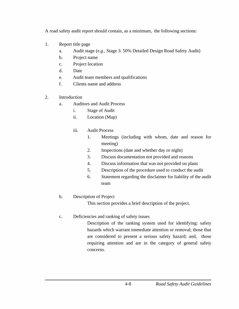
Road Safety Audit Guidelines4-8
A road safety audit report should contain, as a minimum, the following sections:
1. Report title pagea. Audit stage (e.g., Stage 3: 50% Detailed Design Road Safety Audit)
b. Project namec. Project location
d. Datee. Audit team members and qualifications
f. Clients name and address
2. Introductiona. Auditors and Audit Process
i. Stage of Audit ii. Location (Map)
iii. Audit Process
1. Meetings (including with whom, date and reason formeeting)
2. Inspections (date and whether day or night)3. Discuss documentation not provided and reasons
4. Discuss information that was not provided on plans5. Description of the procedure used to conduct the audit
6. Statement regarding the disclaimer for liability of the auditteam
b. Description of Project
This section provides a brief description of the project.
c. Deficiencies and ranking of safety issuesDescription of the ranking system used for identifying: safety
hazards which warrant immediate attention or removal; those thatare considered to present a serious safety hazard; and, those
requiring attention and are in the category of general safetyconcerns.
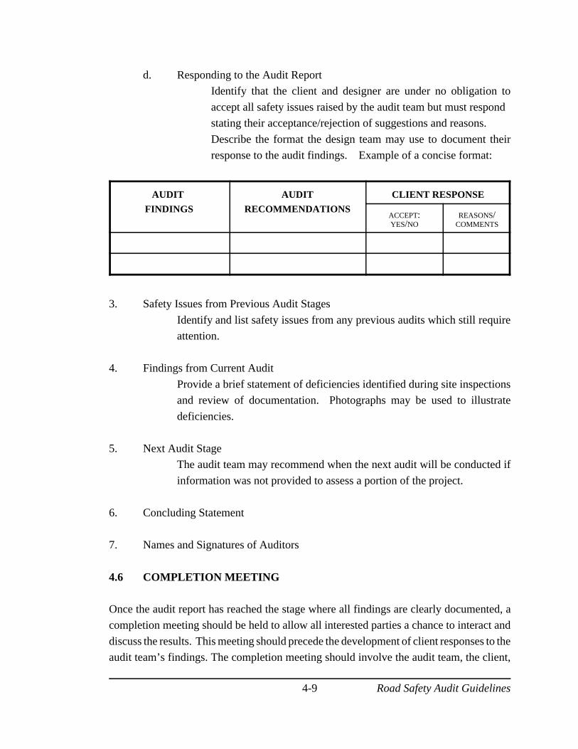
Road Safety Audit Guidelines4-9
d. Responding to the Audit ReportIdentify that the client and designer are under no obligation to
accept all safety issues raised by the audit team but must respond stating their acceptance/rejection of suggestions and reasons.
Describe the format the design team may use to document theirresponse to the audit findings. Example of a concise format:
AUDIT
FINDINGS
AUDIT
RECOMMENDATIONS
CLIENT RESPONSE
ACCEPT:YES/NO
REASONS/COMMENTS
3. Safety Issues from Previous Audit Stages
Identify and list safety issues from any previous audits which still requireattention.
4. Findings from Current Audit
Provide a brief statement of deficiencies identified during site inspectionsand review of documentation. Photographs may be used to illustrate
deficiencies.
5. Next Audit StageThe audit team may recommend when the next audit will be conducted if
information was not provided to assess a portion of the project.
6. Concluding Statement
7. Names and Signatures of Auditors
4.6 COMPLETION MEETING
Once the audit report has reached the stage where all findings are clearly documented, acompletion meeting should be held to allow all interested parties a chance to interact and
discuss the results. This meeting should precede the development of client responses to theaudit team’s findings. The completion meeting should involve the audit team, the client,
Road Safety Audit Guidelines4-10
the design team, and any other employees who might be involved in formulating responsesto the audit findings.
The objective of the completion meeting is to foster a constructive dialogue centred on the
audit report findings. The meeting provides an opportunity to:
1. formally present the audit findings and clarify or elaborate their meaning,2. suggest improvements to the report structure,
3. discuss possible remedial measures for problems identified, and4. set a timetable for completion of client responses.
It is crucial that a positive, constructive, and cooperative tone pervade the meeting. The
meeting should be prefaced with a reminder that the intent of an audit is simply to enhancesafety of the final project and that it is not a critique of individual or design team
performances. It is essential for those involved to believe that the audit is a beneficial partof project development. Special effort therefore should be made to ensure that those
involved have been educated in the audit process and the positive experiences associatedwith it. Meeting facilitators should be careful to maintain an atmosphere for positive
exchange and not to permit animosity or unfounded disagreement. Discretion and insightare required attributes that all parties should bring to the meeting.
4.7 FOLLOW-UP
The follow up process is lead by the designer/project manager. The designer/project
manager reviews the audit report and prepares a written response to each concern cited.Each remedial measure suggested in the audit report can be accepted or rejected. For each
accepted suggestion, logical remedial measures should be identified and adopted by thedesigner/project manager. The redesign should then advance to diminish the safety hazard.
All project redesigns should be submitted to the audit team for consideration or re-auditing.The designer/project manager must make sure that modifications are made to the project
which result from agreed improvements described in the audit report.
For each audit suggestion rejected, justification (physical, economic, or social) should bedocumented in the report by the client. The designer/project manager should confirm the
decided action for every suggestion in the audit report. Both the audit report and thedesigner/project manager’s response become part of the final audit record. A formal signed
acceptance of the final report may be a requirement within the organization.
Road Safety Audit Guidelines5-1
5.0 OVERVIEW OF CHECKLISTS FOR ROAD SAFETYAUDITS
This chapter presents an overview of checklists for road safety audits. The chapter discussesthe structure of the checklists, as well as their use. The master checklist and detailedchecklists are also discussed in this chapter. The checklists developed for this manual arebased on Australian, New Zealand, United Kingdom, United States, and Canadianexperiences.
5.1 STRUCTURE OF CHECKLISTS
The four series of checklists developed for this manual are contained in Appendices A andB. Two of the checklists apply to highway audits (Appendix A), and two apply to municipalaudits (Appendix B). For each case, there is a master checklist and a detailed checklist. Themaster checklist provides the auditor with a general listing of the topics to be considereddepending on the stage of design at the time of audit. The detailed checklists elaborate onthe topics contained in the master checklist. These lists provide exemplary issues/items tobe considered - grouped by area of concern (e.g., alignment, intersections, road surface,visual aids, physical object, and others). The detailed checklists contain two columns: onethat displays the audit item, and another that provides key points to consider for each itemwhen conducting the audit. Appendix C contains case studies of a highway and amunicipal audit where these checklists were applied.
It is important to note that the checklists should serve only as a guide or memory-aid for theindividual or team conducting the safety audit. They are not all inclusive, nor are theyintended to be used as a substitute for knowledge or experience.
5.2 USE OF CHECKLISTS
The first step involved in using the system of checklists presented in this manual is to refer to the appropriate column in the master checklist depending on the design stage beingaudited. The master checklist can then be used to scan the key topics to be considered forthat audit. The master checklist should encourage the auditor to begin thinking about thesafety audit and help identify any additional topics that are not included in the manual. Thedetailed checklist should be consulted if a master checklist item is vague or misunderstood.The detailed list should be consulted before, during, and after the field portion of the safetyaudit.
During the field visit, team members may wish to carry a copy of both the master anddetailed checklists. It must be reemphasized that the checklists provided in this manualshould only be used as a guide or memory aid. The topics listed are intended to remind theauditor or audit team of common elements involved in a safety audit. A comprehensive

Road Safety Audit Guidelines5-2
safety audit can only be achieved through the collaboration and participation of each auditorduring the audit process based on individual experience and knowledge.
Road Safety Audit Guidelines6-1
6.0 ECONOMIC IMPLICATIONS OF ROAD SAFETYAUDITS
This chapter provides an overview of the economic implications of road safety audits. Thechapter is divided into three sections that include: (1) costs of conducting road safetyaudits; (2) benefits; and (3) benefit-to-cost ratios associated with road safety audits.
6.1 COSTS OF CONDUCTING ROAD SAFETY AUDITS
In the safety audit manual published by TNZ (1993), the cost of audits was divided intothree categories: consultant fees, the client’s time to manage the audit, and costs associatedwith implementing recommendations that are adopted. The client’s time on a projectaveraged about 1 day per audit. It is important to note that additional costs may result fromchanges to a project’s scope and schedule. RTA indicated that a safety audit of a newfacility cost approximately the same as a geotechnical survey (FHWA Study Tour, 1997).
Recent experience places the average cost of a conventional audit for small to mid-sizedprojects between $1,000 and $5,000 (Sabey, 1993, Jordan, 1994, Pieples, 1999). TNZfound that fees range from NZ$1000 to $8000 (US$700 to $6000) with most falling in theNZ$3000 to $5000 (US$2000 to $3600) range (1993). The actual cost depends greatly onthe size and complexity of the project and composition of the required audit team.Hamilton Associates estimate that audits add approximately 5 to 10 percent to designcosts, or less than one-half of 1 percent to construction expenses (1998). These estimatesare slightly higher than costs experienced to date for the MRDC project. AUSTROADS
approximates that audits will add 4 to 10 percent to the road design costs (1994). As designcosts are roughly 5 to 6 percent of the project sum, the increase in total cost is usually quitesmall. On smaller projects (traffic calming or retrofits), the costs may be a higherpercentage of the overall capital cost. Costs of redesign/rectification should be consideredwhich will vary on a project-to-project basis. The cost of rectifying deficiencies dependson how early in the design process the problem is identified as well as the amount of timerequired to redesign the area.
6.2 BENEFITS OF CONDUCTING ROAD SAFETY AUDITS
Benefits of road safety audits extend from economics of reduced accidents to improvementsin policy and design. Some of these benefits include:
• Safer highways through accident prevention and accident severity reduction.Research in the United Kingdom indicated that up to 1/3 of collisions maybe prevented on a road that has been audited. Other research indicated a 1to 3 percent reduction in injury collisions.
• Safer road networks.
Road Safety Audit Guidelines6-2
• Enhancement of road safety engineering.• Reduced whole life costs of road schemes.• Reduced need to modify new schemes after construction.• A better understanding and documentation of road safety engineering.• Safety improvements to standards and procedures in the future.• More explicit consideration of the safety needs of vulnerable road users.• Encouragement of other personnel in road safety.• Foster a principle of safety conscious design among owners and designers.• By providing a high quality product, the potential for future remedial work
may be reduced, thus reducing the overall risk taken by the agency.• Claims cost savings, lower health care and societal costs due to reduced
collisions.• Design improvement.• Enhancement of the corporate safety culture .• Cross-fertilization between specialists within a highway department
(eg. Design, Maintenance, Traffic, etc.).(AUSTROADS, 1994; Hamilton Associates, 1998).
6.3 BENEFIT-TO-COST RATIOS ASSOCIATED WITH ROAD SAFETYAUDITS
Although cost effectiveness of road safety audits is difficult to estimate, Scotland hasestimated a benefit:cost ratio of 15:1 based on experience, while New Zealand hasestimated the ratio to be closer to 20:1 (TNZ, 1993). A 1994 study of minor works projectsin Surrey compared 2 groups matched by project type; one group having been audited, theother not. It was determined that the economic benefits would be well in excess of theaudit cost for these small projects. For larger projects, the potential saving in casualties islikely to be greater, justifying the greater resources incorporated within their audits.
Road Safety Audit Guidelines7-1
7.0 SAFETY AUDIT LEGAL ISSUES - AN OVERVIEW
Safety audits are a vehicle to identify deficiencies or problems which have the capacity toimpact on the safety of highway infrastructure. They also identify remedial actions thatcould reduce or eliminate the potential safety problems. These audits raise legal issueswhich the auditor should consider. The time frame during which safety audits have beenused is short relative to that required for building case histories on which legal precedencecan be based and/or influenced.
The experience to date in the United Kingdom and Australia indicate that claims related tothe use of safety audits have not been a problem. The experience in Canada is the same.In the United States, where the level of road accident litigation is considered to be high, theuse of road safety audits is not yet extensive and the litigation climate has not commenced.
Notwithstanding this positive record, road safety audits will play an increasing role in roadaccident litigation. This situation should not influence the adoption of the safety auditprocess. The associated legal issues should be recognized and legal counsel obtained byparticular parties to the process on an as required basis.
A statement in the AUSTROADS (1994) report on Road Safety Audits is worth noting bythose individuals/agencies concerned with the legal issues related road safety audits. Thatstatement is: “Will the undertaking of road safety audits expose those authorities that adoptthem to greater liability than at present? The answer is no.”
The authors of the UNB manual are of the opinion that consideration should be given tothe possibility that the non-use of road safety audits in an environment where they are beingextensively applied elsewhere could raise in the legal environment the question: “Will theabsence of the use of a road safety audit which could have identified the safety problemunder consideration be considered in a negative context by the courts?” We believe that theanswer to this question will eventually be “yes”.
The history of legal discussions relative to highway safety in England, Australia, NewZealand, etc. is different than Canada. This fact further complicates the comparison of theclimate around the safety audit legal issues between those jurisdictions and Canada. Thebottom line is that any highway authority owes a duty of care to the users of the facilitiesto provide a safe roadway operating environment and not to omit strategies that are knownto improve highway safety. Road safety audits provide a means to check that all reasonablesafety initiatives have been taken in the planning, design, construction and operation ofroadways.
A useful reference on the issue of legal aspects of road safety audits is an introductoryassessment of the potential legal impact upon the participants in the audits and reviewprocess. That paper was prepared in British Columbia and is included as Appendix A in the
Road Safety Audit Guidelines7-2
discussion paper prepared by Hamilton Associates (1998). Since there does not exist any bodyof legal references on the topic, examples used in the document relate to hypothetical cases orsituations.
In Canada, there is a Supreme Court decision that “true policy decisions should be exempt fromtort claims so that governments are not restricted in making decisions based upon social, politicalor economic factors. However, the implementation of those decisions may well be subject toclaims in tort” (Justice vs. British Columbia (1994)). This position should be considered whenowners/clients are responding to a safety audit. To use this position to reject safety audit findingsof specific safety issues based simply on social, political or economic factors would no doubtrequire solid justification beyond just a general policy statement.
The owner/client’s response to the audit report should provide reasons for not accepting anyfinding/recommendation. The reason for the detailed response is that in most jurisdictions inCanada the safety audit report can, through the right to information Acts, find its way to the publicforum and hence to any lawyers who may commence action on any real or perceived safety issue.This fact should not deter the use of audits but instead ensure that responses are detailed anddefendable.
Chapter 3 contains a discussion of the stages at which road safety audits can be effective and thetypes of projects where audits can be applied. There is concern in some circles that safety auditsapplied to existing facilities could increase an agency/owner’s exposure to liability if safety issuesidentified on existing facilities are not addressed or not addressed within a reasonable time frame.The authors believe that it is a short sighted position to avoid auditing existing facilities in fear oflitigation. In fact, as safety audits become more widely accepted and applied such a position mayeven attract litigation. One of the benefits of safety audits is to increase for the user the level ofsafety of the facility. Should not the users of existing facilities receive the same benefits as usersof new facilities?
Safety audits of existing facilities can identify safety deficiencies and provide suggested remedies.In turn this data can be used to establish priorities and a time frame to implement improvements.(This is not far removed from some black spot programs that have been in place in jurisdictionsfor decades).
It is unlikely that some employees of an agency/owner would not have been aware of some ofthe safety issues identified in a safety audit report of an existing facility. To argue that avoiding asafety audit will enable the agency/owner to plead “ignorance” of safety deficiencies on an existingfacility appears to be ill founded. Safety audits of existing facilities will only strengthen anagency/owner’s ability to defend against litigation arising from safety issues on existing facilities.
Members of a safety audit team can incur exposure to liability unless they are very specific as totheir role in conducting audits. Auditors must be clear that they are not performing any design

Road Safety Audit Guidelines7-3
role. Further, it must be explicitly stated that they are not approving any designs or operationalprocedures. The auditors are simply identifying safety issues or concerns that have the potentialto lower the safety level of the facility under review. They must be specific that no guarantee isbeing made that every safety issue will be identified in an audit - rather that a reasonable effortwill be made to identify issues and/or deficiencies.
The authors believe that upon completing an audit the sole auditor (or team) should clearly identifytheir position with a statement in the report similar to the one stated below.
“This audit (identify it as a design, pre-opening, night time audit, etc.)covers physical features which may affect road user safety and it hassought to identify potential safety hazards. However, the auditors point outthat no guarantee is made that every deficiency has been identified.Further, if all recommendations in this report were to be followed, thiswould not confirm that the highway is “safe” rather, adoption of therecommendations should improve the level of safety of the facility” (Wilson,1999).
Some highway safety audits could become a factor at some time in litigation. The benefits ofsafety audits far outweigh legal issue disbenefits and the legal environment should not deteragencies/owners from adopting audits.
Road Safety Audit Guidelines8-1
8.0 REFERENCES
AASHTO, Highway Safety Design and Operations Guide 1997, Washington,D.C.
AUSTROADS, Road Safety Audit, Austroads, Sydney, Australia,1994.
Barton, E.V and Jordan, P.W., Road Safety Audit - What is it and Why Do We Need It,in Proceedings 16th ARRB Conference, Part IV, 1992, Australia, pp. 67-80.
Beasy Nicoll Engineering Limited, Highway 104 Antigonish Safety Review, January1999.
Belcher, M. and Proctor, S., Auditing Safety by Design, Highways Journal, March 1990.
Bowron, D. and Morrall, J., Road Safety Audit for Highway 22X (Marquis of LorneTrail). Transportation Department, Traffic Operations Division, City of Calgary,Canada,1998.
Bray, J.S., Safety Appurtenance Program, Presented at the ITE InternationalConference, March 1999, Kissimmee, Florida.
G.D. Hamilton Associates Consulting Ltd., Introducing Road Safety Audits and DesignSafety Reviews Draft Discussion Paper, Vancouver, British Columbia,Canada,1998.
Haiar, K.A and Wilson, E.M., Adapting Safety Audits for Smaller Cities, Presented atthe Transportation Research Board 78th Annual Meeting, January 1999,Washington, D.C.
Hildebrand, E.D. and Wilson, F.R., The Role of Safety Audits in the Planning, Design,Construction, and Maintenance of Canadian Roads, Prepared for presentation atthe 1999 Annual Conference of the Transportation Association of Canada,September 1999, Saint John, New Brunswick.
Institution of Highways and Transportation, Guidelines for the Safety Audit ofHighways, London, United Kingdom, revised 1996.
Institute of Transportation Engineers, The Traffic Safety Toolbox A Primer on TrafficSafety, Washington, D.C., 1993.
Institute of Transportation Engineers Technical Council Committee 4S-7, Road SafetyAudits: A New Tool for Accident Prevention. ITE Journal, February 1995, pp.15-22.
Road Safety Audit Guidelines8-2
Institute of Transportation Engineers Technical Council Committee 4S-7, Road SafetyAudits. Institute of Transportation Engineers, Washington, D.C., 1995.
Jordan, P.W., Road Safety Audit - A Process for Ensuring Safer Roads, Proceedings ofthe National Road Safety Conference, Canberra, 1994.
Jordan, P. ITE and Road Safety Audit - A Partnership for Traffic Safety. Institute ofTransportation Engineers Journal, March 1999, pp. 24-27
Local Authorities Associations, Road Safety Code of Good Practice, Association of CountyCouncils, London, United Kingdom, 1989.
Morgan, R., In Service (Existing Road) Road Safety Audits, in Road Safety Audit SeminarNotebook, Institute of Transportation Engineers, Orlando, March 1999.
Navin, F., presentation at the ITE International Conference, March 1999, Kissimmee,Florida.
Ogden, K.W. Safer Roads: A Guide to Road Safety Engineering, Institute of TransportStudies, Department of Civil Engineering, Monash University, Melbourne, Australia,1996.
Pieples, T.R., PennDOT’s Road Test of the Road Safety Audit Process, Institute ofTransportation Engineers Journal, January 1999 pp.20-24.
Ontario Ministry of Transportation, The Science of Highway Safety, Traffic Office,1999.
Professional Engineers of Ontario, Highway 407 Safety Review, Ontario, Canada,1996
Proietti. J. and Anders, H., Roadway Operational Performance Refinement to Tools andMethods, to Effect Improvements in Roadway Safety, Ministry of Transportationof Ontario, Canada, 1998.
Roads and Traffic Authority of New South Wales, Road Safety Audits, RTA, Sydney,Australia. 1991.
Robinson, J., Smith, G., and Morrall, J., Road Safety Audit Workshop: A workshopintroducing the principles and practices underlying road safety audits, Winnipeg,Manitoba, June 15th - 16th, 1999.
Russell, G., Brewer, J., Pieples, T., Jordan, P., Proietti, J., and Zein, S., Road Safety AuditWorkshop, Department of Civil Engineering, Kansas State University, Topeka,Kansas, July 29-30, 1999.
Road Safety Audit Guidelines8-3
Sabey, B.E., Safety Audits Procedures and Practices, Education and Research Services,London, 1993.
TMS Consulting, What Goes Wrong in Highway Design, AA Group Public Policy, NorfolkHouse, Basingstoke, 1999.
Transit New Zealand, Safety Audit Policy and Procedures, Transit New Zealand,Wellington, New Zealand, 1993.
Transportation Association of Canada. Canadian Guide to Neighbourhood Traffic Calming. Ottawa, Ontario. 1998.
Transportation Association of Canada. Geometric Design Guide for Canadian Roads 1999Edition Parts 1 and 2. Ottawa, Ontario.1999.
Transportation Association of Canada. Manual of Uniform Traffic Control Devices forCanada Fourth Edition. Ottawa, Ontario.1999
Transport Systems Centre, University of South Australia. (1998). Road Safety AuditorsTraining Course. [on-line]. Available: http://www.unisa.edu.au/tsc/training/rsa98.html
Trentscoste, M. et al., FHWA Study Tour for Road Safety Audits - Parts 1 and 2, FederalHighway Administration, US Department of Transportation, Washington, D.C, 1997.
Vaillancourt, G., Quebec Ministry of Transportation, in conversation, June, 1999.
Wallen, M.A,. What Makes a Good Safety Management System?, Institute ofTransportation Engineers Journal, January 1993, pp.26-30.
Wilson, F.R. and Hildebrand, E.D., Road Safety Audits for New Brunswick, Presentation to New Brunswick Department of Transportation, Fredericton, New Brunswick,April 9, 1999.
Zein, S. Other Audits & Issues: Evaluation and Closure, presented at the Road SafetyAudit Seminar, ITE International Conference, Kissimmee, Florida, March 28,1999.

Appendix A
Master Checklist
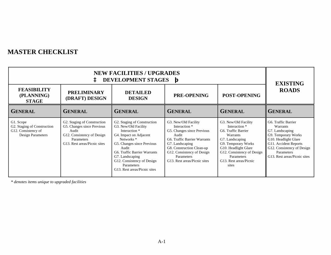
A-1
MASTER CHECKLIST
NEW FACILITIES / UPGRADES³³ DEVELOPMENT STAGES þþ
EXISTINGROADSFEASIBILITY
(PLANNING)STAGE
PRELIMINARY(DRAFT) DESIGN
DETAILEDDESIGN
PRE-OPENING POST-OPENING
GENERAL GENERAL GENERAL GENERAL GENERAL GENERAL
G1. ScopeG2. Staging of ConstructionG12. Consistency of Design Parameters
G2. Staging of ConstructionG5. Changes since Previous AuditG12. Consistency of Design ParametersG13. Rest areas/Picnic sites
G2. Staging of ConstructionG3. New/Old Facility Interaction *G4. Impact on Adjacent Networks * G5. Changes since Previous AuditG6. Traffic Barrier WarrantsG7. LandscapingG12. Consistency of Design ParametersG13. Rest areas/Picnic sites
G3. New/Old Facility Interaction *G5. Changes since Previous AuditG6. Traffic Barrier WarrantsG7. LandscapingG8. Construction Clean-upG12. Consistency of Design ParametersG13. Rest areas/Picnic sites
G3. New/Old Facility Interaction *G6. Traffic Barrier WarrantsG7. LandscapingG9. Temporary WorksG10. Headlight GlareG12. Consistency of Design ParametersG13. Rest areas/Picnic sites
G6. Traffic Barrier WarrantsG7. LandscapingG9. Temporary WorksG10. Headlight GlareG11. Accident ReportsG12. Consistency of Design ParametersG13. Rest areas/Picnic sites
* denotes items unique to upgraded facilities
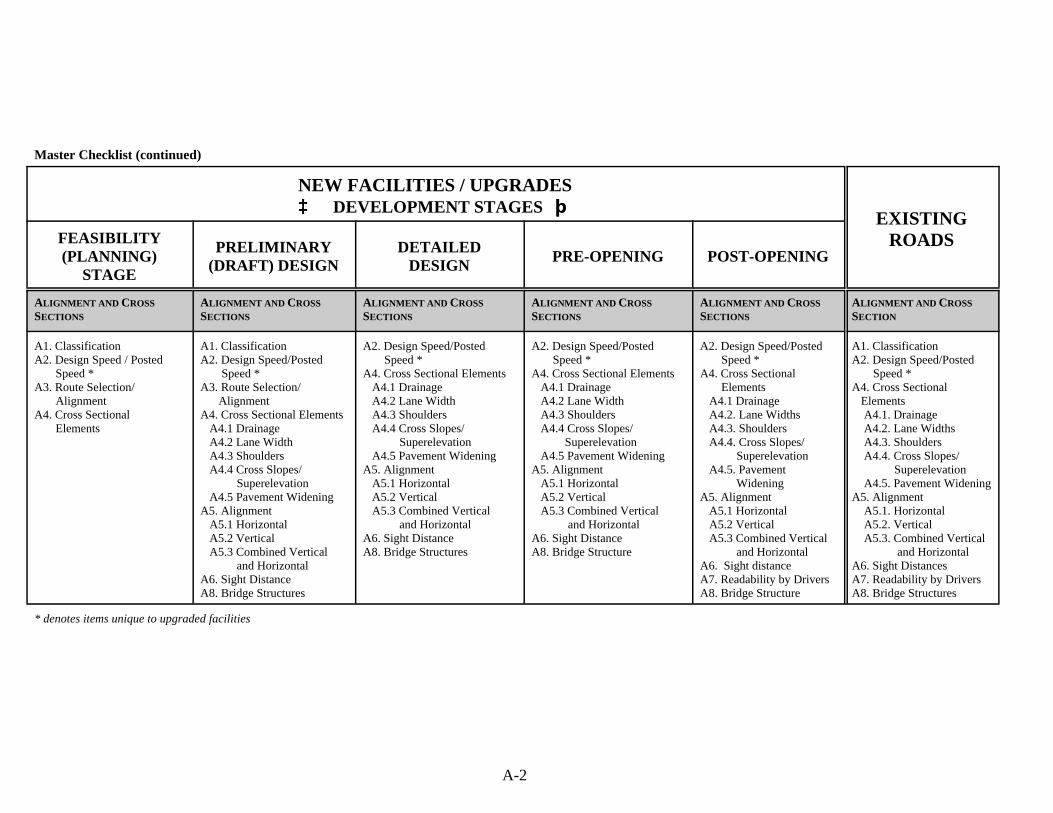
A-2
Master Checklist (continued)
NEW FACILITIES / UPGRADES³³ DEVELOPMENT STAGES þþ
EXISTINGROADSFEASIBILITY
(PLANNING)STAGE
PRELIMINARY(DRAFT) DESIGN
DETAILEDDESIGN
PRE-OPENING POST-OPENING
ALIGNMENT AND CROSS
SECTIONS
ALIGNMENT AND CROSS
SECTIONS
ALIGNMENT AND CROSS
SECTIONS
ALIGNMENT AND CROSS
SECTIONS
ALIGNMENT AND CROSS
SECTIONS
ALIGNMENT AND CROSS
SECTION
A1. ClassificationA2. Design Speed / Posted Speed *A3. Route Selection/ AlignmentA4. Cross Sectional Elements
A1. Classification A2. Design Speed/Posted Speed *A3. Route Selection/ AlignmentA4. Cross Sectional Elements A4.1 Drainage A4.2 Lane Width A4.3 Shoulders A4.4 Cross Slopes/ Superelevation A4.5 Pavement WideningA5. Alignment A5.1 Horizontal A5.2 Vertical A5.3 Combined Vertical and HorizontalA6. Sight Distance A8. Bridge Structures
A2. Design Speed/Posted Speed *A4. Cross Sectional Elements A4.1 Drainage A4.2 Lane Width A4.3 Shoulders A4.4 Cross Slopes/ Superelevation A4.5 Pavement WideningA5. Alignment A5.1 Horizontal A5.2 Vertical A5.3 Combined Vertical and HorizontalA6. Sight DistanceA8. Bridge Structures
A2. Design Speed/Posted Speed *A4. Cross Sectional Elements A4.1 Drainage A4.2 Lane Width A4.3 Shoulders A4.4 Cross Slopes/ Superelevation A4.5 Pavement WideningA5. Alignment A5.1 Horizontal A5.2 Vertical A5.3 Combined Vertical and HorizontalA6. Sight Distance A8. Bridge Structure
A2. Design Speed/Posted Speed *A4. Cross Sectional Elements A4.1 Drainage A4.2. Lane Widths A4.3. Shoulders A4.4. Cross Slopes/ Superelevation A4.5. Pavement WideningA5. Alignment A5.1 Horizontal A5.2 Vertical A5.3 Combined Vertical and HorizontalA6. Sight distanceA7. Readability by DriversA8. Bridge Structure
A1. ClassificationA2. Design Speed/Posted Speed *A4. Cross Sectional Elements A4.1. Drainage A4.2. Lane Widths A4.3. Shoulders A4.4. Cross Slopes/ Superelevation A4.5. Pavement WideningA5. Alignment A5.1. Horizontal A5.2. Vertical A5.3. Combined Vertical and HorizontalA6. Sight DistancesA7. Readability by DriversA8. Bridge Structures
* denotes items unique to upgraded facilities
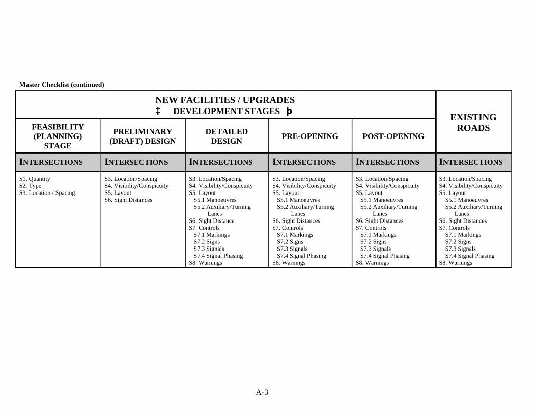
A-3
Master Checklist (continued)
NEW FACILITIES / UPGRADES³³ DEVELOPMENT STAGES þþ
EXISTINGROADSFEASIBILITY
(PLANNING)STAGE
PRELIMINARY(DRAFT) DESIGN
DETAILEDDESIGN
PRE-OPENING POST-OPENING
INTERSECTIONS INTERSECTIONS INTERSECTIONS INTERSECTIONS INTERSECTIONS INTERSECTIONS
S1. QuantityS2. TypeS3. Location / Spacing
S3. Location/SpacingS4. Visibility/ConspicuityS5. LayoutS6. Sight Distances
S3. Location/SpacingS4. Visibility/ConspicuityS5. Layout S5.1 Manoeuvres S5.2 Auxiliary/Turning LanesS6. Sight DistanceS7. Controls S7.1 Markings S7.2 Signs S7.3 Signals S7.4 Signal PhasingS8. Warnings
S3. Location/SpacingS4. Visibility/ConspicuityS5. Layout S5.1 Manoeuvres S5.2 Auxiliary/Turning LanesS6. Sight DistancesS7. Controls S7.1 Markings S7.2 Signs S7.3 Signals S7.4 Signal PhasingS8. Warnings
S3. Location/SpacingS4. Visibility/ConspicuityS5. Layout S5.1 Manoeuvres S5.2 Auxiliary/Turning LanesS6. Sight DistancesS7. Controls S7.1 Markings S7.2 Signs S7.3 Signals S7.4 Signal PhasingS8. Warnings
S3. Location/SpacingS4. Visibility/Conspicuity S5. Layout S5.1 Manoeuvres S5.2 Auxiliary/Turning LanesS6. Sight DistancesS7. Controls S7.1 Markings S7.2 Signs S7.3 Signals S7.4 Signal PhasingS8. Warnings
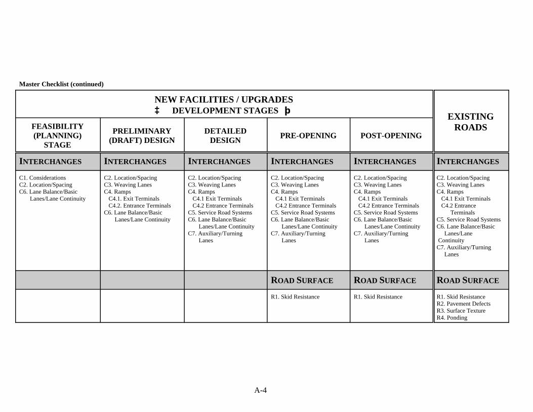
A-4
Master Checklist (continued)
NEW FACILITIES / UPGRADES³³ DEVELOPMENT STAGES þþ
EXISTINGROADSFEASIBILITY
(PLANNING)STAGE
PRELIMINARY(DRAFT) DESIGN
DETAILEDDESIGN
PRE-OPENING POST-OPENING
INTERCHANGES INTERCHANGES INTERCHANGES INTERCHANGES INTERCHANGES INTERCHANGES
C1. ConsiderationsC2. Location/SpacingC6. Lane Balance/Basic Lanes/Lane Continuity
C2. Location/SpacingC3. Weaving LanesC4. Ramps C4.1. Exit Terminals C4.2. Entrance TerminalsC6. Lane Balance/Basic Lanes/Lane Continuity
C2. Location/SpacingC3. Weaving LanesC4. Ramps C4.1 Exit Terminals C4.2 Entrance TerminalsC5. Service Road SystemsC6. Lane Balance/Basic Lanes/Lane ContinuityC7. Auxiliary/Turning Lanes
C2. Location/SpacingC3. Weaving LanesC4. Ramps C4.1 Exit Terminals C4.2 Entrance TerminalsC5. Service Road SystemsC6. Lane Balance/Basic Lanes/Lane ContinuityC7. Auxiliary/Turning Lanes
C2. Location/SpacingC3. Weaving LanesC4. Ramps C4.1 Exit Terminals C4.2 Entrance TerminalsC5. Service Road Systems C6. Lane Balance/Basic Lanes/Lane ContinuityC7. Auxiliary/Turning Lanes
C2. Location/SpacingC3. Weaving LanesC4. Ramps C4.1 Exit Terminals C4.2 Entrance TerminalsC5. Service Road SystemsC6. Lane Balance/Basic Lanes/Lane ContinuityC7. Auxiliary/Turning Lanes
ROAD SURFACE ROAD SURFACE ROAD SURFACE
R1. Skid Resistance R1. Skid Resistance R1. Skid ResistanceR2. Pavement DefectsR3. Surface TextureR4. Ponding
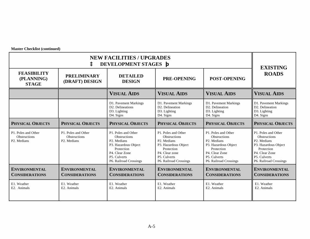
A-5
Master Checklist (continued)
NEW FACILITIES / UPGRADES³³ DEVELOPMENT STAGES þþ
EXISTINGROADSFEASIBILITY
(PLANNING)STAGE
PRELIMINARY(DRAFT) DESIGN
DETAILEDDESIGN
PRE-OPENING POST-OPENING
VISUAL AIDS VISUAL AIDS VISUAL AIDS VISUAL AIDS
D1. Pavement MarkingsD2. DelineationsD3. LightingD4. Signs
D1. Pavement MarkingsD2. DelineationD3. LightingD4. Signs
D1. Pavement MarkingsD2. DelineationD3. LightingD4. Signs
D1. Pavement MarkingsD2. DelineationD3. LightingD4. Signs
PHYSICAL OBJECTS PHYSICAL OBJECTS PHYSICAL OBJECTS PHYSICAL OBJECTS PHYSICAL OBJECTS PHYSICAL OBJECTS
P1. Poles and Other ObstructionsP2. Medians
P1. Poles and Other ObstructionsP2. Medians
P1. Poles and Other ObstructionsP2. MediansP3. Hazardous Object ProtectionP4. Clear ZoneP5. CulvertsP6. Railroad Crossings
P1. Poles and Other ObstructionsP2. MediansP3. Hazardous Object ProtectionP4. Clear zoneP5. CulvertsP6. Railroad Crossings
P1. Poles and Other ObstructionsP2. Medians P3. Hazardous Object ProtectionP4. Clear ZoneP5. CulvertsP6. Railroad Crossings
P1. Poles and Other ObstructionsP2. MediansP3. Hazardous Object ProtectionP4. Clear ZoneP5. CulvertsP6. Railroad Crossings
ENVIRONMENTAL
CONSIDERATIONS
ENVIRONMENTAL
CONSIDERATIONS
ENVIRONMENTAL
CONSIDERATIONS
ENVIRONMENTAL
CONSIDERATIONS
ENVIRONMENTAL
CONSIDERATIONS
ENVIRONMENTAL
CONSIDERATIONS
E1. WeatherE2. Animals
E1. WeatherE2. Animals
E1. WeatherE2. Animals
E1. WeatherE2. Animals
E1. WeatherE2. Animals
E1. Weather E2. Animals
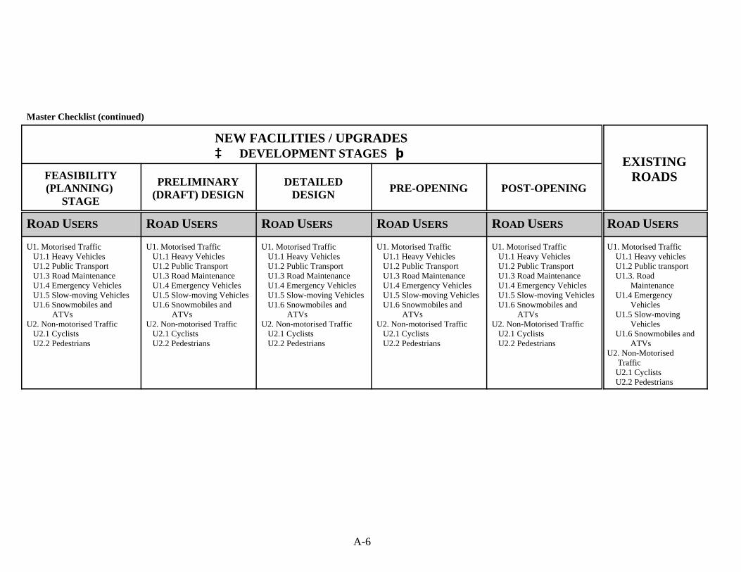
A-6
Master Checklist (continued)
NEW FACILITIES / UPGRADES³³ DEVELOPMENT STAGES þþ
EXISTINGROADSFEASIBILITY
(PLANNING) STAGE
PRELIMINARY(DRAFT) DESIGN
DETAILEDDESIGN
PRE-OPENING POST-OPENING
ROAD USERS ROAD USERS ROAD USERS ROAD USERS ROAD USERS ROAD USERS
U1. Motorised Traffic U1.1 Heavy Vehicles U1.2 Public Transport U1.3 Road Maintenance U1.4 Emergency Vehicles U1.5 Slow-moving Vehicles U1.6 Snowmobiles and ATVsU2. Non-motorised Traffic U2.1 Cyclists U2.2 Pedestrians
U1. Motorised Traffic U1.1 Heavy Vehicles U1.2 Public Transport U1.3 Road Maintenance U1.4 Emergency Vehicles U1.5 Slow-moving Vehicles U1.6 Snowmobiles and ATVsU2. Non-motorised Traffic U2.1 Cyclists U2.2 Pedestrians
U1. Motorised Traffic U1.1 Heavy Vehicles U1.2 Public Transport U1.3 Road Maintenance U1.4 Emergency Vehicles U1.5 Slow-moving Vehicles U1.6 Snowmobiles and ATVsU2. Non-motorised Traffic U2.1 Cyclists U2.2 Pedestrians
U1. Motorised Traffic U1.1 Heavy Vehicles U1.2 Public Transport U1.3 Road Maintenance U1.4 Emergency Vehicles U1.5 Slow-moving Vehicles U1.6 Snowmobiles and ATVsU2. Non-motorised Traffic U2.1 Cyclists U2.2 Pedestrians
U1. Motorised Traffic U1.1 Heavy Vehicles U1.2 Public Transport U1.3 Road Maintenance U1.4 Emergency Vehicles U1.5 Slow-moving Vehicles U1.6 Snowmobiles and ATVsU2. Non-Motorised Traffic U2.1 Cyclists U2.2 Pedestrians
U1. Motorised Traffic U1.1 Heavy vehicles U1.2 Public transport U1.3. Road Maintenance U1.4 Emergency Vehicles U1.5 Slow-moving Vehicles U1.6 Snowmobiles and ATVsU2. Non-Motorised Traffic U2.1 Cyclists U2.2 Pedestrians
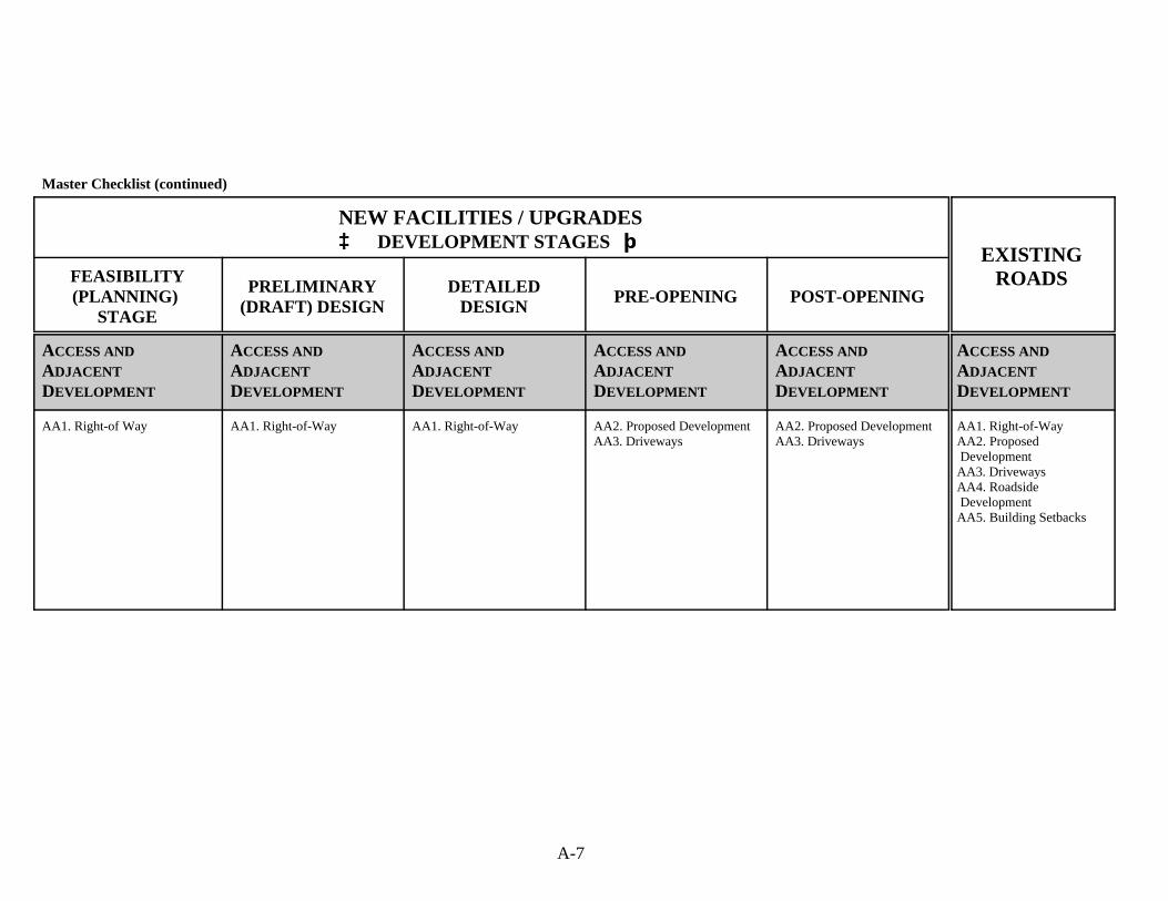
A-7
Master Checklist (continued)
NEW FACILITIES / UPGRADES³³ DEVELOPMENT STAGES þþ
EXISTINGROADSFEASIBILITY
(PLANNING) STAGE
PRELIMINARY(DRAFT) DESIGN
DETAILEDDESIGN
PRE-OPENING POST-OPENING
ACCESS AND
ADJACENT
DEVELOPMENT
ACCESS AND
ADJACENT
DEVELOPMENT
ACCESS AND
ADJACENT
DEVELOPMENT
ACCESS AND
ADJACENT
DEVELOPMENT
ACCESS AND
ADJACENT
DEVELOPMENT
ACCESS AND
ADJACENT
DEVELOPMENT
AA1. Right-of Way AA1. Right-of-Way
AA1. Right-of-Way
AA2. Proposed DevelopmentAA3. Driveways
AA2. Proposed DevelopmentAA3. Driveways
AA1. Right-of-WayAA2. Proposed DevelopmentAA3. DrivewaysAA4. Roadside DevelopmentAA5. Building Setbacks
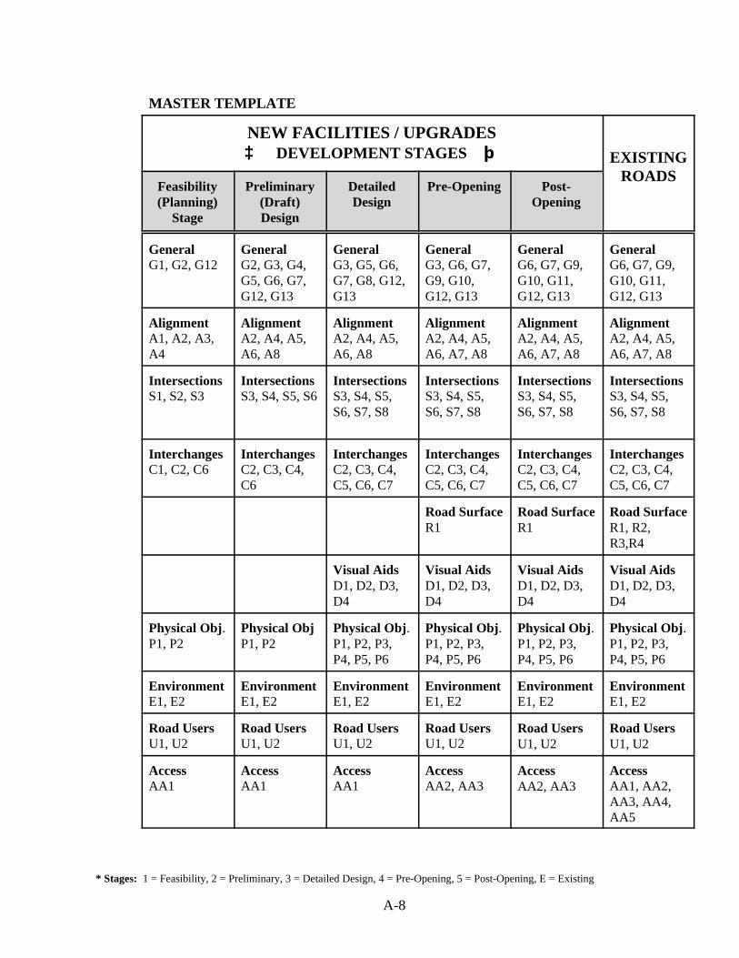
* Stages: 1 = Feasibility, 2 = Preliminary, 3 = Detailed Design, 4 = Pre-Opening, 5 = Post-Opening, E = Existing
A-8
MASTER TEMPLATE
NEW FACILITIES / UPGRADES³³ DEVELOPMENT STAGES þþ EXISTING
ROADSFeasibility(Planning)
Stage
Preliminary(Draft)Design
DetailedDesign
Pre-Opening Post-Opening
GeneralG1, G2, G12
GeneralG2, G3, G4,G5, G6, G7,G12, G13
GeneralG3, G5, G6,G7, G8, G12,G13
GeneralG3, G6, G7,G9, G10,G12, G13
GeneralG6, G7, G9,G10, G11,G12, G13
GeneralG6, G7, G9,G10, G11,G12, G13
AlignmentA1, A2, A3,A4
AlignmentA2, A4, A5,A6, A8
AlignmentA2, A4, A5,A6, A8
AlignmentA2, A4, A5,A6, A7, A8
AlignmentA2, A4, A5,A6, A7, A8
AlignmentA2, A4, A5,A6, A7, A8
IntersectionsS1, S2, S3
IntersectionsS3, S4, S5, S6
IntersectionsS3, S4, S5,S6, S7, S8
IntersectionsS3, S4, S5,S6, S7, S8
IntersectionsS3, S4, S5,S6, S7, S8
IntersectionsS3, S4, S5,S6, S7, S8
InterchangesC1, C2, C6
InterchangesC2, C3, C4,C6
InterchangesC2, C3, C4,C5, C6, C7
InterchangesC2, C3, C4,C5, C6, C7
InterchangesC2, C3, C4,C5, C6, C7
InterchangesC2, C3, C4,C5, C6, C7
Road SurfaceR1
Road SurfaceR1
Road SurfaceR1, R2,R3,R4
Visual AidsD1, D2, D3,D4
Visual AidsD1, D2, D3,D4
Visual AidsD1, D2, D3,D4
Visual AidsD1, D2, D3,D4
Physical Obj.P1, P2
Physical ObjP1, P2
Physical Obj.P1, P2, P3,P4, P5, P6
Physical Obj.P1, P2, P3,P4, P5, P6
Physical Obj.P1, P2, P3,P4, P5, P6
Physical Obj.P1, P2, P3,P4, P5, P6
EnvironmentE1, E2
EnvironmentE1, E2
EnvironmentE1, E2
EnvironmentE1, E2
EnvironmentE1, E2
EnvironmentE1, E2
Road UsersU1, U2
Road UsersU1, U2
Road UsersU1, U2
Road UsersU1, U2
Road UsersU1, U2
Road UsersU1, U2
AccessAA1
AccessAA1
AccessAA1
AccessAA2, AA3
Access AA2, AA3
AccessAA1, AA2,AA3, AA4,AA5
Appendix A
Detailed Checklist

* Stages: 1 = Feasibility, 2 = Preliminary, 3 = Detailed Design, 4 = Pre-Opening, 5 = Post-Opening, E = Existing
A-9
DETAILED CHECKLIST
NEW FACILITIES/UPGRADES/EXISTING
Item Stages* Potential Safety Issues(Note: Not all Issues Pertain to Each Audit Stage)
GENERAL
G1. Scope 1 Review all pertinent documentation to gain an understanding of thescope of the project; including project objectives, usercharacteristics, design vehicles, access, adjacent development,existing network information, and future network expansion.
G2. Staging ofConstruction
1,2,3 What are the effects of staging the construction of the project ordividing it into several contracts?
G3. New / OldFacilityInteraction
3,4,5 Check that the horizontal and vertical alignments of the proposedfacility co-ordinate effectively with those of existing facilities.
Are road transition environments safe? Is advance warning required?
Is there a sudden change in speed regime, access or side frictioncharacteristics?
Does the interface occur near hazards (i.e.,. crest, bend, etc.)?
G4. Impact onAdjacent Networks
3 Will traffic volume on nearby roads change as a result of thisproject?
If traffic volume and flow have altered along adjacent roads, has achange in ROW been considered?
G5. Changes SincePrevious Audit
2,3,4 Check for changes in the scope of the project.
Check for changes in the conditions for which the project wasdesigned.
G6. Traffic BarrierWarrants
3,4,5,E Presence of non-traversable or fixed object hazards within clear zone.
Does a potential risk exist for vehicles crossing over the median intothe path of an opposing vehicle?
Accident history of area.

* Stages: 1 = Feasibility, 2 = Preliminary, 3 = Detailed Design, 4 = Pre-Opening, 5 = Post-Opening, E = Existing
A-10
Detailed Checklist (continued)
Item Stages* Potential Safety Issues(Note: Not all Issues Pertain to Each Audit Stage)
GENERAL (continued)
G7. Landscaping 3,4,5,E Landscaping along road in accordance with guidelines?
Required clearances and sight distances restricted due to future plantgrowth?
G8. Construction Clean-up
4 Interaction between construction clean-up area and traffic flow.
Signage of clean-up area.
Visibility of clean-up area from approaching traffic.
G9. Temporary Work 5,E Interaction between temporary work and traffic flow.
Is temporary work adequately signed?
Does temporary work signage remain even though construction iscomplete?
Visibility of temporary work area from approaching traffic.
G10. Headlight Glare 5,E Severity of head light glare during night time operations.
G11. Accident Reports E Accident reports available for specific facility?
Frequency of accidents at facility.
Common accident characteristics discussed in reports.
G12. Consistency ofDesignParameters
1,2,3,4,5,E
Ensure design parameters are consistent in alignment, cross section,interchanges, and intersections.
G13. Rest areas/Picnic sites
2,3,4,5,E Are rest areas/picnic sites desirable?
Is the number of rest areas/picnic sites within the project adequate?
Do rest areas/picnic sites have safe access?
Are rest areas/picnic sites placed at appropriate locations?
Have appropriate signs been chosen and placed correctly to notifydrivers of an upcoming rest area/picnic site?
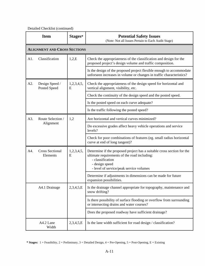
* Stages: 1 = Feasibility, 2 = Preliminary, 3 = Detailed Design, 4 = Pre-Opening, 5 = Post-Opening, E = Existing
A-11
Detailed Checklist (continued)
Item Stages* Potential Safety Issues(Note: Not all Issues Pertain to Each Audit Stage)
ALIGNMENT AND CROSS SECTIONS
A1. Classification 1,2,E Check the appropriateness of the classification and design for theproposed project’s design volume and traffic composition.
Is the design of the proposed project flexible enough to accommodateunforseen increases in volume or changes in traffic characteristics?
A2. Design Speed /Posted Speed
1,2,3,4,5,E
Check the appropriateness of the design speed for horizontal andvertical alignment, visibility, etc.
Check the continuity of the design speed and the posted speed.
Is the posted speed on each curve adequate?
Is the traffic following the posted speed?
A3. Route Selection / Alignment
1,2 Are horizontal and vertical curves minimized?
Do excessive grades affect heavy vehicle operations and service levels?
Check for poor combinations of features (eg. small radius horizontalcurve at end of long tangent)?
A4. Cross Sectional Elements
1,2,3,4,5,E
Determine if the proposed project has a suitable cross section for theultimate requirements of the road including: - classification - design speed - level of service/peak service volumes
Determine if adjustments in dimensions can be made for futureexpansion possibilities.
A4.1 Drainage 2,3,4,5,E Is the drainage channel appropriate for topography, maintenance andsnow drifting?
Is there possibility of surface flooding or overflow from surroundingor intersecting drains and water courses?
Does the proposed roadway have sufficient drainage?
A4.2 Lane Width
2,3,4,5,E Is the lane width sufficient for road design / classification?
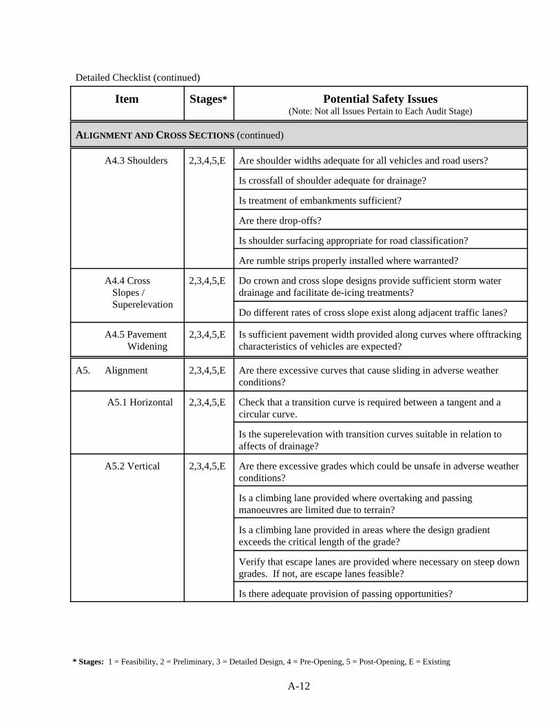
* Stages: 1 = Feasibility, 2 = Preliminary, 3 = Detailed Design, 4 = Pre-Opening, 5 = Post-Opening, E = Existing
A-12
Detailed Checklist (continued)
Item Stages* Potential Safety Issues(Note: Not all Issues Pertain to Each Audit Stage)
ALIGNMENT AND CROSS SECTIONS (continued)
A4.3 Shoulders 2,3,4,5,E Are shoulder widths adequate for all vehicles and road users?
Is crossfall of shoulder adequate for drainage?
Is treatment of embankments sufficient?
Are there drop-offs?
Is shoulder surfacing appropriate for road classification?
Are rumble strips properly installed where warranted?
A4.4 Cross Slopes /
Superelevation
2,3,4,5,E Do crown and cross slope designs provide sufficient storm waterdrainage and facilitate de-icing treatments?
Do different rates of cross slope exist along adjacent traffic lanes?
A4.5 Pavement Widening
2,3,4,5,E Is sufficient pavement width provided along curves where offtrackingcharacteristics of vehicles are expected?
A5. Alignment 2,3,4,5,E Are there excessive curves that cause sliding in adverse weatherconditions?
A5.1 Horizontal 2,3,4,5,E Check that a transition curve is required between a tangent and acircular curve.
Is the superelevation with transition curves suitable in relation toaffects of drainage?
A5.2 Vertical 2,3,4,5,E Are there excessive grades which could be unsafe in adverse weatherconditions?
Is a climbing lane provided where overtaking and passingmanoeuvres are limited due to terrain?
Is a climbing lane provided in areas where the design gradientexceeds the critical length of the grade?
Verify that escape lanes are provided where necessary on steep downgrades. If not, are escape lanes feasible?
Is there adequate provision of passing opportunities?
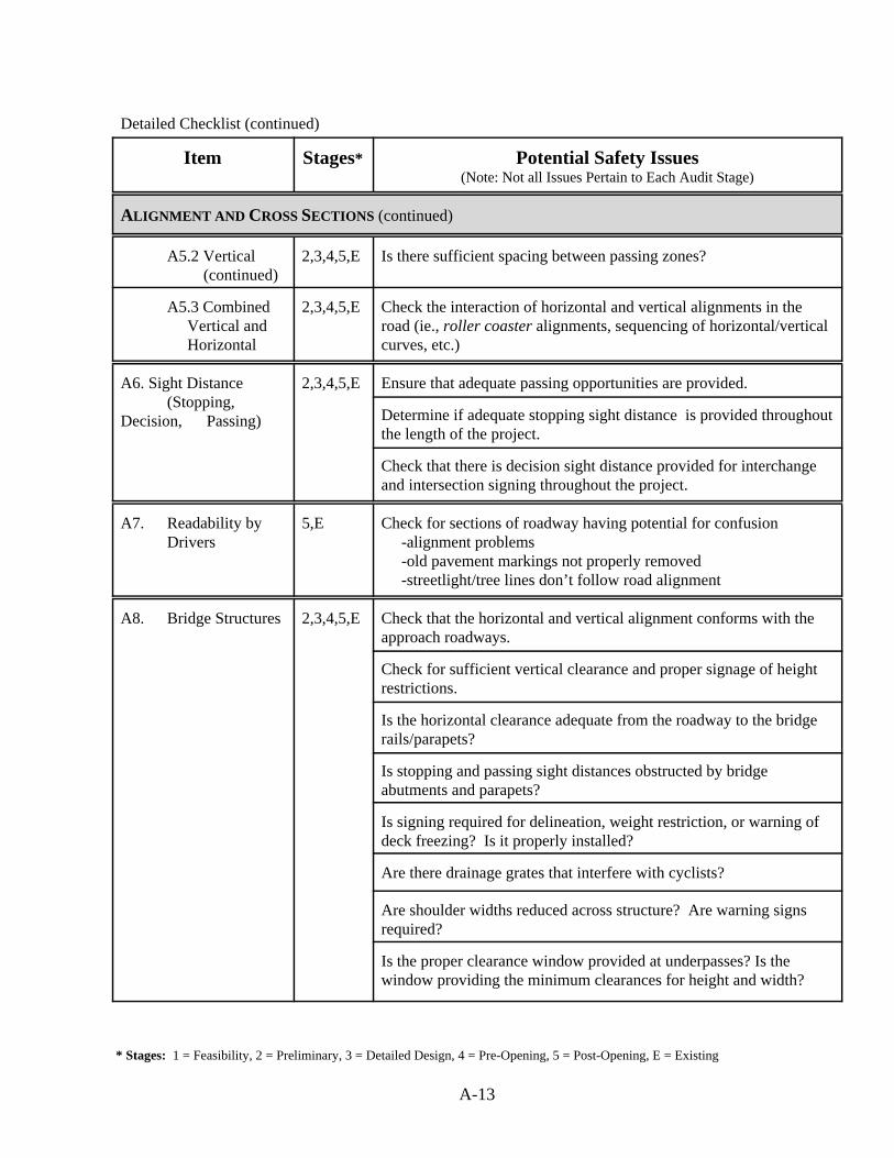
* Stages: 1 = Feasibility, 2 = Preliminary, 3 = Detailed Design, 4 = Pre-Opening, 5 = Post-Opening, E = Existing
A-13
Detailed Checklist (continued)
Item Stages* Potential Safety Issues(Note: Not all Issues Pertain to Each Audit Stage)
ALIGNMENT AND CROSS SECTIONS (continued)
A5.2 Vertical (continued)
2,3,4,5,E Is there sufficient spacing between passing zones?
A5.3 Combined Vertical and
Horizontal
2,3,4,5,E Check the interaction of horizontal and vertical alignments in theroad (ie., roller coaster alignments, sequencing of horizontal/verticalcurves, etc.)
A6. Sight Distance (Stopping,
Decision, Passing)
2,3,4,5,E Ensure that adequate passing opportunities are provided.
Determine if adequate stopping sight distance is provided throughoutthe length of the project.
Check that there is decision sight distance provided for interchangeand intersection signing throughout the project.
A7. Readability byDrivers
5,E Check for sections of roadway having potential for confusion -alignment problems -old pavement markings not properly removed -streetlight/tree lines don’t follow road alignment
A8. Bridge Structures 2,3,4,5,E Check that the horizontal and vertical alignment conforms with theapproach roadways.
Check for sufficient vertical clearance and proper signage of heightrestrictions.
Is the horizontal clearance adequate from the roadway to the bridgerails/parapets?
Is stopping and passing sight distances obstructed by bridgeabutments and parapets?
Is signing required for delineation, weight restriction, or warning ofdeck freezing? Is it properly installed?
Are there drainage grates that interfere with cyclists?
Are shoulder widths reduced across structure? Are warning signsrequired?
Is the proper clearance window provided at underpasses? Is thewindow providing the minimum clearances for height and width?
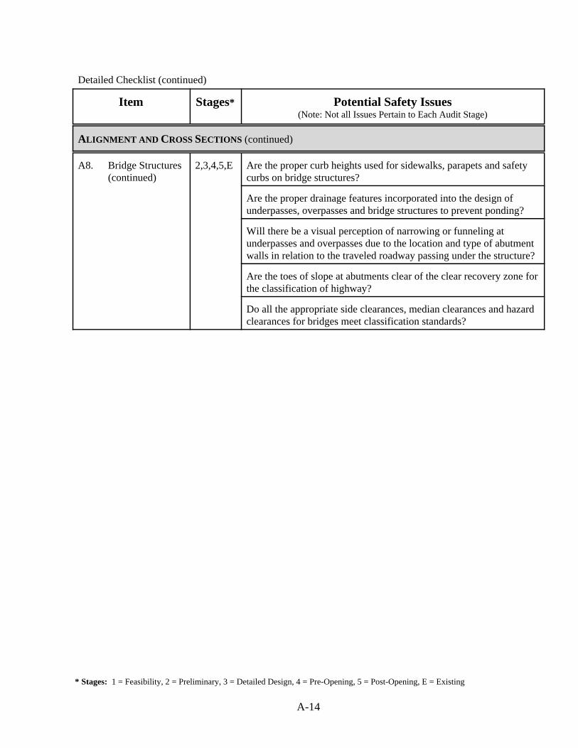
* Stages: 1 = Feasibility, 2 = Preliminary, 3 = Detailed Design, 4 = Pre-Opening, 5 = Post-Opening, E = Existing
A-14
Detailed Checklist (continued)
Item Stages* Potential Safety Issues(Note: Not all Issues Pertain to Each Audit Stage)
ALIGNMENT AND CROSS SECTIONS (continued)
A8. Bridge Structures (continued)
2,3,4,5,E Are the proper curb heights used for sidewalks, parapets and safetycurbs on bridge structures?
Are the proper drainage features incorporated into the design ofunderpasses, overpasses and bridge structures to prevent ponding?
Will there be a visual perception of narrowing or funneling atunderpasses and overpasses due to the location and type of abutmentwalls in relation to the traveled roadway passing under the structure?
Are the toes of slope at abutments clear of the clear recovery zone forthe classification of highway?
Do all the appropriate side clearances, median clearances and hazardclearances for bridges meet classification standards?

* Stages: 1 = Feasibility, 2 = Preliminary, 3 = Detailed Design, 4 = Pre-Opening, 5 = Post-Opening, E = Existing
A-15
Detailed Checklist (continued)
Item Stages* Potential Safety Issues(Note: Not all Issues Pertain to Each Audit Stage)
INTERSECTIONS
S1. Quantity 1 Is the number of intersections appropriate given the surroundingnetwork?
S2. Type 1 Are types of intersections selected appropriate for traffic and safetyaspects of the project?
Can intersection designs accommodate all design vehicleclassifications?
S3. Location /Spacing
1,2,3,4,5,E
Is there sufficient spacing between intersections?
Does horizontal/vertical alignment affect the location/spacing of theintersections?
Junctions and access adequate for all permitted vehicle movements?
S4. Visibility /Conspicuity
2,3,4,5,E Does the horizontal and vertical alignment provide adequate visibilityof the intersection?
Are sight lines to the intersection obstructed?
S5. Layout 2,3,4,5,E Are the lane widths adequate for all vehicle classes?
Are there any upstream and downstream features which may affectsafety? (i.e., “visual clutter”, angle parking, high volume driveways)
Are separate through lanes needed but not provided?
S5.1 Maneuvers 3,4,5,E Are vehicle maneuvers obvious to all users?
Identify any potential conflicts in movements.
S5.2 Auxiliary / Turning Lanes
3,4,5,E Are they of appropriate length?
Is there advance warning of approaching auxiliary lanes?
Is sight distance for entering/leaving vehicles adequate?
Are tapers installed where needed? Are they correctly aligned?
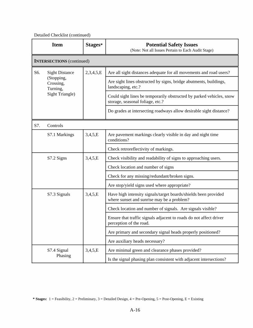
* Stages: 1 = Feasibility, 2 = Preliminary, 3 = Detailed Design, 4 = Pre-Opening, 5 = Post-Opening, E = Existing
A-16
Detailed Checklist (continued)
Item Stages* Potential Safety Issues(Note: Not all Issues Pertain to Each Audit Stage)
INTERSECTIONS (continued)
S6. Sight Distance(Stopping,Crossing,Turning, Sight Triangle)
2,3,4,5,E Are all sight distances adequate for all movements and road users?
Are sight lines obstructed by signs, bridge abutments, buildings,landscaping, etc.?
Could sight lines be temporarily obstructed by parked vehicles, snowstorage, seasonal foliage, etc.?
Do grades at intersecting roadways allow desirable sight distance?
S7. Controls
S7.1 Markings 3,4,5,E Are pavement markings clearly visible in day and night timeconditions?
Check retroreflectivity of markings.
S7.2 Signs 3,4,5,E Check visibility and readability of signs to approaching users.
Check location and number of signs
Check for any missing/redundant/broken signs.
Are stop/yield signs used where appropriate?
S7.3 Signals 3,4,5,E Have high intensity signals/target boards/shields been providedwhere sunset and sunrise may be a problem?
Check location and number of signals. Are signals visible?
Ensure that traffic signals adjacent to roads do not affect driverperception of the road.
Are primary and secondary signal heads properly positioned?
Are auxiliary heads necessary?
S7.4 Signal Phasing
3,4,5,E Are minimal green and clearance phases provided?
Is the signal phasing plan consistent with adjacent intersections?
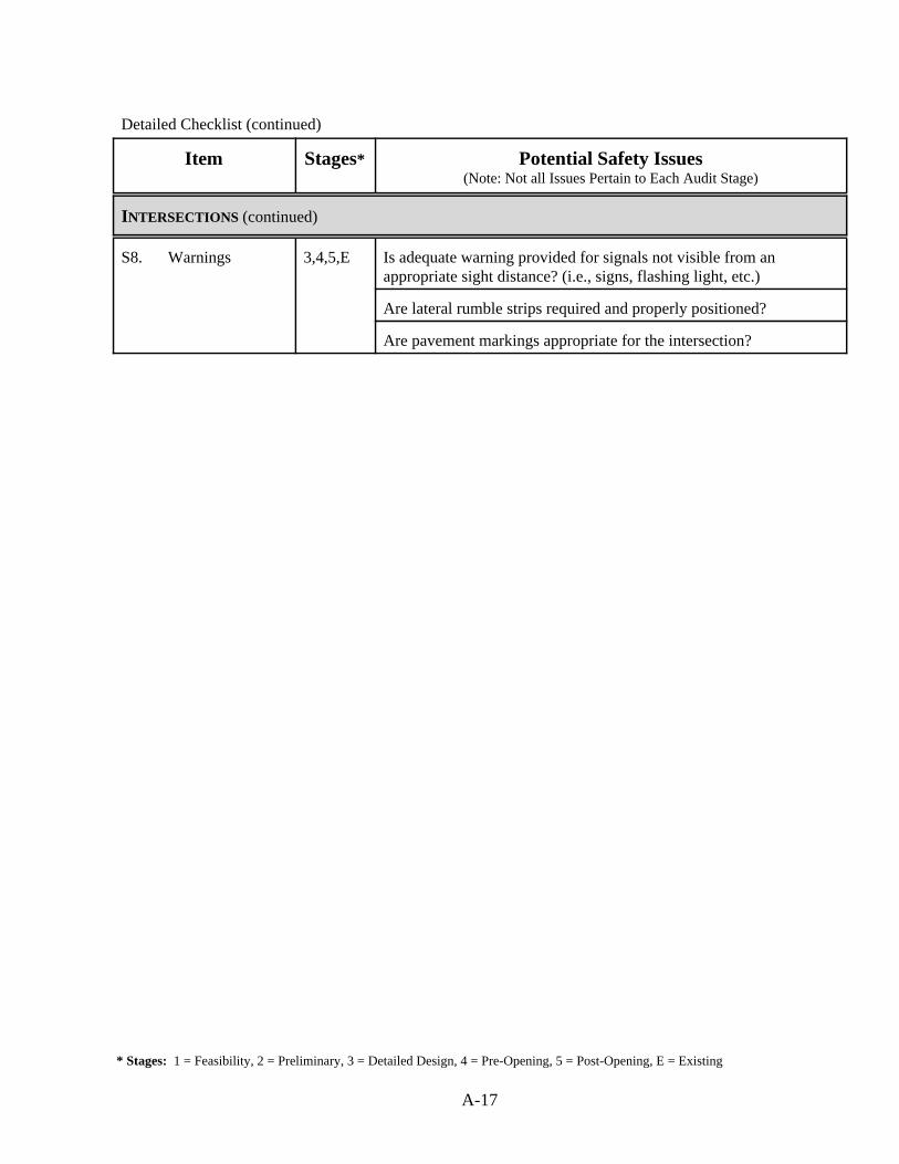
* Stages: 1 = Feasibility, 2 = Preliminary, 3 = Detailed Design, 4 = Pre-Opening, 5 = Post-Opening, E = Existing
A-17
Detailed Checklist (continued)
Item Stages* Potential Safety Issues(Note: Not all Issues Pertain to Each Audit Stage)
INTERSECTIONS (continued)
S8. Warnings 3,4,5,E Is adequate warning provided for signals not visible from anappropriate sight distance? (i.e., signs, flashing light, etc.)
Are lateral rumble strips required and properly positioned?
Are pavement markings appropriate for the intersection?
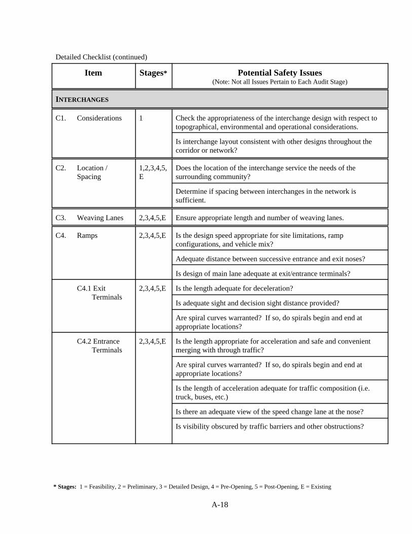
* Stages: 1 = Feasibility, 2 = Preliminary, 3 = Detailed Design, 4 = Pre-Opening, 5 = Post-Opening, E = Existing
A-18
Detailed Checklist (continued)
Item Stages* Potential Safety Issues(Note: Not all Issues Pertain to Each Audit Stage)
INTERCHANGES
C1. Considerations 1 Check the appropriateness of the interchange design with respect totopographical, environmental and operational considerations.
Is interchange layout consistent with other designs throughout thecorridor or network?
C2. Location /Spacing
1,2,3,4,5,E
Does the location of the interchange service the needs of thesurrounding community?
Determine if spacing between interchanges in the network issufficient.
C3. Weaving Lanes 2,3,4,5,E Ensure appropriate length and number of weaving lanes.
C4. Ramps 2,3,4,5,E Is the design speed appropriate for site limitations, rampconfigurations, and vehicle mix?
Adequate distance between successive entrance and exit noses?
Is design of main lane adequate at exit/entrance terminals?
C4.1 Exit Terminals
2,3,4,5,E Is the length adequate for deceleration?
Is adequate sight and decision sight distance provided?
Are spiral curves warranted? If so, do spirals begin and end atappropriate locations?
C4.2 Entrance Terminals
2,3,4,5,E Is the length appropriate for acceleration and safe and convenientmerging with through traffic?
Are spiral curves warranted? If so, do spirals begin and end atappropriate locations?
Is the length of acceleration adequate for traffic composition (i.e.truck, buses, etc.)
Is there an adequate view of the speed change lane at the nose?
Is visibility obscured by traffic barriers and other obstructions?
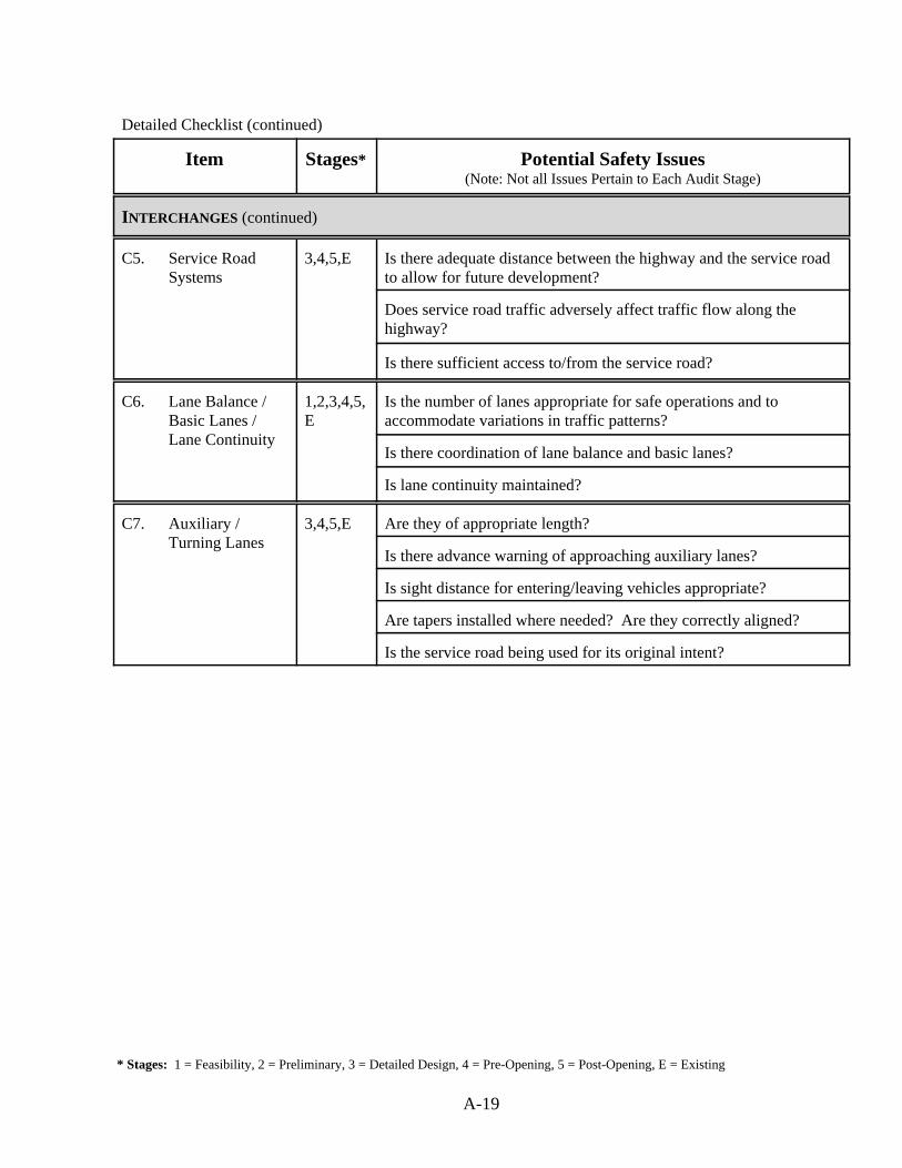
* Stages: 1 = Feasibility, 2 = Preliminary, 3 = Detailed Design, 4 = Pre-Opening, 5 = Post-Opening, E = Existing
A-19
Detailed Checklist (continued)
Item Stages* Potential Safety Issues(Note: Not all Issues Pertain to Each Audit Stage)
INTERCHANGES (continued)
C5. Service RoadSystems
3,4,5,E Is there adequate distance between the highway and the service roadto allow for future development?
Does service road traffic adversely affect traffic flow along thehighway?
Is there sufficient access to/from the service road?
C6. Lane Balance /Basic Lanes /Lane Continuity
1,2,3,4,5,E
Is the number of lanes appropriate for safe operations and toaccommodate variations in traffic patterns?
Is there coordination of lane balance and basic lanes?
Is lane continuity maintained?
C7. Auxiliary /Turning Lanes
3,4,5,E Are they of appropriate length?
Is there advance warning of approaching auxiliary lanes?
Is sight distance for entering/leaving vehicles appropriate?
Are tapers installed where needed? Are they correctly aligned?
Is the service road being used for its original intent?
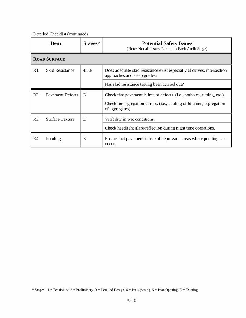
* Stages: 1 = Feasibility, 2 = Preliminary, 3 = Detailed Design, 4 = Pre-Opening, 5 = Post-Opening, E = Existing
A-20
Detailed Checklist (continued)
Item Stages* Potential Safety Issues(Note: Not all Issues Pertain to Each Audit Stage)
ROAD SURFACE
R1. Skid Resistance 4,5,E Does adequate skid resistance exist especially at curves, intersectionapproaches and steep grades?
Has skid resistance testing been carried out?
R2. Pavement Defects E Check that pavement is free of defects. (i.e., potholes, rutting, etc.)
Check for segregation of mix. (i.e., pooling of bitumen, segregationof aggregates)
R3. Surface Texture E Visibility in wet conditions.
Check headlight glare/reflection during night time operations.
R4. Ponding E Ensure that pavement is free of depression areas where ponding canoccur.
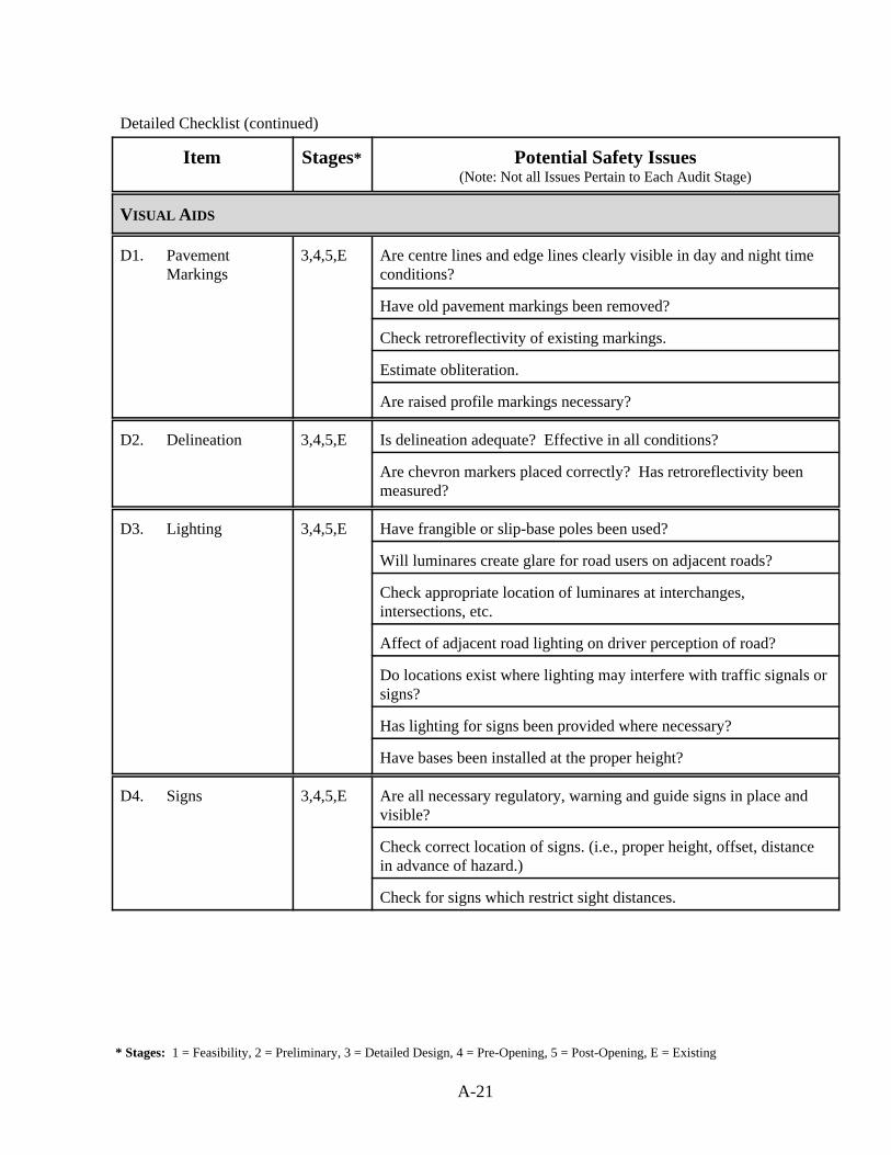
* Stages: 1 = Feasibility, 2 = Preliminary, 3 = Detailed Design, 4 = Pre-Opening, 5 = Post-Opening, E = Existing
A-21
Detailed Checklist (continued)
Item Stages* Potential Safety Issues(Note: Not all Issues Pertain to Each Audit Stage)
VISUAL AIDS
D1. PavementMarkings
3,4,5,E Are centre lines and edge lines clearly visible in day and night timeconditions?
Have old pavement markings been removed?
Check retroreflectivity of existing markings.
Estimate obliteration.
Are raised profile markings necessary?
D2. Delineation 3,4,5,E Is delineation adequate? Effective in all conditions?
Are chevron markers placed correctly? Has retroreflectivity beenmeasured?
D3. Lighting 3,4,5,E Have frangible or slip-base poles been used?
Will luminares create glare for road users on adjacent roads?
Check appropriate location of luminares at interchanges,intersections, etc.
Affect of adjacent road lighting on driver perception of road?
Do locations exist where lighting may interfere with traffic signals orsigns?
Has lighting for signs been provided where necessary?
Have bases been installed at the proper height?
D4. Signs 3,4,5,E Are all necessary regulatory, warning and guide signs in place andvisible?
Check correct location of signs. (i.e., proper height, offset, distancein advance of hazard.)
Check for signs which restrict sight distances.
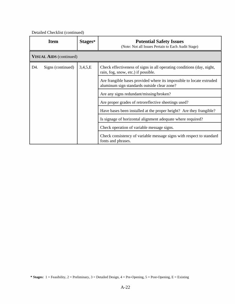
* Stages: 1 = Feasibility, 2 = Preliminary, 3 = Detailed Design, 4 = Pre-Opening, 5 = Post-Opening, E = Existing
A-22
Detailed Checklist (continued)
Item Stages* Potential Safety Issues(Note: Not all Issues Pertain to Each Audit Stage)
VISUAL AIDS (continued)
D4. Signs (continued) 3,4,5,E Check effectiveness of signs in all operating conditions (day, night,rain, fog, snow, etc.) if possible.
Are frangible bases provided where its impossible to locate extrudedaluminum sign standards outside clear zone?
Are any signs redundant/missing/broken?
Are proper grades of retroreflective sheetings used?
Have bases been installed at the proper height? Are they frangible?
Is signage of horizontal alignment adequate where required?
Check operation of variable message signs.
Check consistency of variable message signs with respect to standardfonts and phrases.

* Stages: 1 = Feasibility, 2 = Preliminary, 3 = Detailed Design, 4 = Pre-Opening, 5 = Post-Opening, E = Existing
A-23
Detailed Checklist (continued)
Item Stages* Potential Safety Issues(Note: Not all Issues Pertain to Each Audit Stage)
PHYSICAL OBJECTS
P1. Poles and Other Obstructions
1,2,3,4,5,E
Unprotected median widths appropriate for lighting poles?
Appropriate positioning of traffic signal and other service poles?
Consider the location of services and utilities with respect to theproject (i.e. buried and overhead) Clearance for overhead wires?
P2. Medians 1,2,3,4,5,E
Is type of median chosen appropriate for width available?
Do barriers possess the proper geometrical configuration?
Are slopes of grass median adequate?
Are median barriers sufficiently offset from roadway?
Are median barrier offsets in the correct range of values?
Do roadside barriers and bridge barriers meet the appropriate crashtest performance level that is consistent with the roadwayclassification?
Is there sufficient width for overpass/underpass piers and lightstandards?
Check appropriate spacing between median crossovers.
P3. Hazardous Object Protection
3,4,5,E Is adequate protection provided where required? (i.e., barriers, energyattenuators)
Is protection visible in all operating conditions?
Are end treatments of guiderail properly treated?
Are dimensions (i.e. length) of protection appropriate?
Are barrier treatments consistent throughout?
Is there appropriate transition from one barrier to another?
Are reflectorized tabs used to delineate guiderail?
P4. Clear Zone 3,4,5,E Ensure no unprotected objects (temporary or permanent) are withinthe required clear zone.
Check that clear zone is of adequate dimensions.
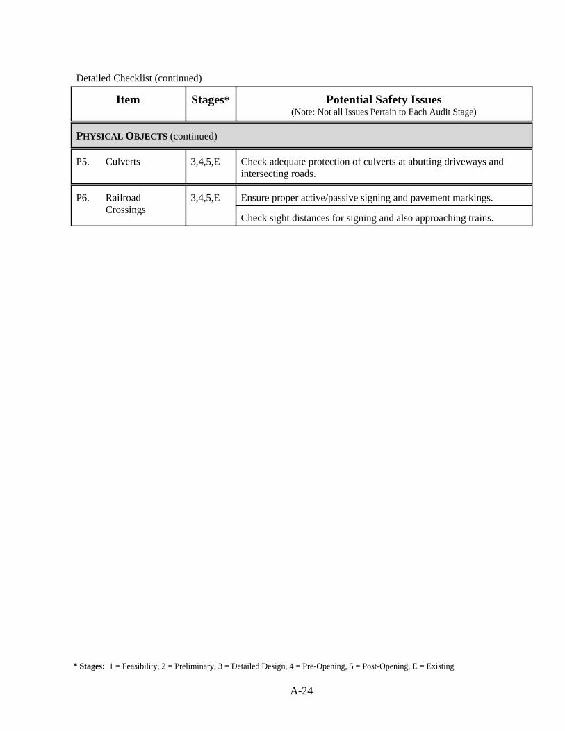
* Stages: 1 = Feasibility, 2 = Preliminary, 3 = Detailed Design, 4 = Pre-Opening, 5 = Post-Opening, E = Existing
A-24
Detailed Checklist (continued)
Item Stages* Potential Safety Issues(Note: Not all Issues Pertain to Each Audit Stage)
PHYSICAL OBJECTS (continued)
P5. Culverts 3,4,5,E Check adequate protection of culverts at abutting driveways andintersecting roads.
P6. RailroadCrossings
3,4,5,E Ensure proper active/passive signing and pavement markings.
Check sight distances for signing and also approaching trains.
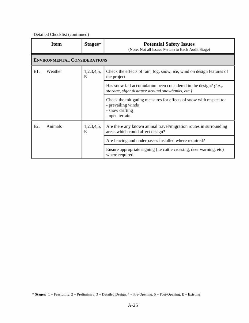
* Stages: 1 = Feasibility, 2 = Preliminary, 3 = Detailed Design, 4 = Pre-Opening, 5 = Post-Opening, E = Existing
A-25
Detailed Checklist (continued)
Item Stages* Potential Safety Issues(Note: Not all Issues Pertain to Each Audit Stage)
ENVIRONMENTAL CONSIDERATIONS
E1. Weather 1,2,3,4,5,E
Check the effects of rain, fog, snow, ice, wind on design features ofthe project.
Has snow fall accumulation been considered in the design? (i.e.,.storage, sight distance around snowbanks, etc.)
Check the mitigating measures for effects of snow with respect to: - prevailing winds- snow drifting- open terrain
E2. Animals 1,2,3,4,5,E
Are there any known animal travel/migration routes in surroundingareas which could affect design?
Are fencing and underpasses installed where required?
Ensure appropriate signing (i.e cattle crossing, deer warning, etc)where required.
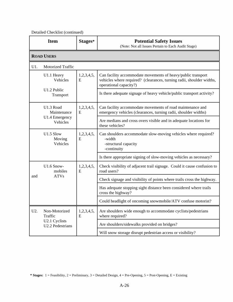
* Stages: 1 = Feasibility, 2 = Preliminary, 3 = Detailed Design, 4 = Pre-Opening, 5 = Post-Opening, E = Existing
A-26
Detailed Checklist (continued)
Item Stages* Potential Safety Issues(Note: Not all Issues Pertain to Each Audit Stage)
ROAD USERS
U1. Motorized Traffic
U1.1 Heavy Vehicles
U1.2 Public Transport
1,2,3,4,5,E
Can facility accommodate movements of heavy/public transportvehicles where required? (clearances, turning radii, shoulder widths,operational capacity?)
Is there adequate signage of heavy vehicle/public transport activity?
U1.3 Road MaintenanceU1.4 Emergency Vehicles
1,2,3,4,5,E
Can facility accommodate movements of road maintenance andemergency vehicles (clearances, turning radii, shoulder widths)
Are medians and cross overs visible and in adequate locations forthese vehicles?
U1.5 SlowMoving Vehicles
1,2,3,4,5,E
Can shoulders accommodate slow-moving vehicles where required? -width -structural capacity -continuity
Is there appropriate signing of slow-moving vehicles as necessary?
U1.6 Snow-mobiles
and ATVs
1,2,3,4,5,E
Check visibility of adjacent trail signage. Could it cause confusion toroad users?
Check signage and visibility of points where trails cross the highway.
Has adequate stopping sight distance been considered where trailscross the highway?
Could headlight of oncoming snowmobile/ATV confuse motorist?
U2. Non-MotorizedTraffic
U2.1 Cyclists U2.2 Pedestrians
1,2,3,4,5,E
Are shoulders wide enough to accommodate cyclists/pedestrianswhere required?
Are shoulders/sidewalks provided on bridges?
Will snow storage disrupt pedestrian access or visibility?
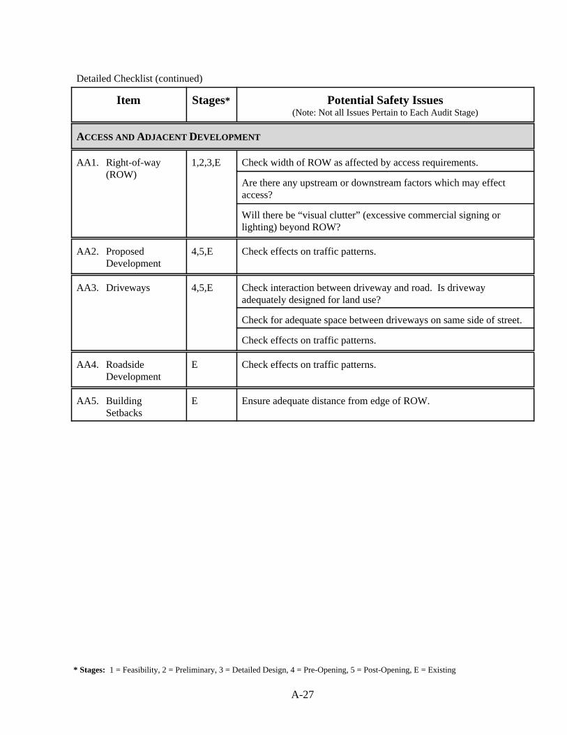
* Stages: 1 = Feasibility, 2 = Preliminary, 3 = Detailed Design, 4 = Pre-Opening, 5 = Post-Opening, E = Existing
A-27
Detailed Checklist (continued)
Item Stages* Potential Safety Issues(Note: Not all Issues Pertain to Each Audit Stage)
ACCESS AND ADJACENT DEVELOPMENT
AA1. Right-of-way(ROW)
1,2,3,E Check width of ROW as affected by access requirements.
Are there any upstream or downstream factors which may effectaccess?
Will there be “visual clutter” (excessive commercial signing orlighting) beyond ROW?
AA2. Proposed Development
4,5,E Check effects on traffic patterns.
AA3. Driveways 4,5,E Check interaction between driveway and road. Is drivewayadequately designed for land use?
Check for adequate space between driveways on same side of street.
Check effects on traffic patterns.
AA4. Roadside Development
E Check effects on traffic patterns.
AA5. BuildingSetbacks
E Ensure adequate distance from edge of ROW.

Appendix B
Municipal Checklists
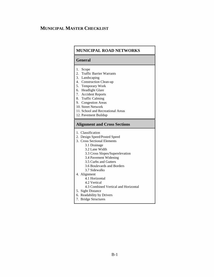
B-1
MUNICIPAL MASTER CHECKLIST
MUNICIPAL ROAD NETWORKS
General
1. Scope2. Traffic Barrier Warrants3. Landscaping4. Construction Clean-up5. Temporary Work6. Headlight Glare7. Accident Reports8. Traffic Calming9. Congestion Areas10. Street Network11. School and Recreational Areas12. Pavement Buildup
Alignment and Cross Sections
1. Classification2. Design Speed/Posted Speed3. Cross Sectional Elements 3.1 Drainage 3.2 Lane Width 3.3 Cross Slopes/Superelevation 3.4 Pavement Widening 3.5 Curbs and Gutters 3.6 Boulevards and Borders 3.7 Sidewalks4. Alignment 4.1 Horizontal 4.2 Vertical 4.3 Combined Vertical and Horizontal5. Sight Distance6. Readability by Drivers7. Bridge Structures
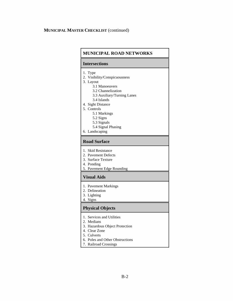
MUNICIPAL MASTER CHECKLIST (continued)
B-2
MUNICIPAL ROAD NETWORKS
Intersections
1. Type2. Visibility/Conspicuousness3. Layout 3.1 Manoeuvers 3.2 Channelization 3.3 Auxiliary/Turning Lanes 3.4 Islands4. Sight Distance5. Controls 5.1 Markings 5.2 Signs 5.3 Signals 5.4 Signal Phasing6. Landscaping
Road Surface
1. Skid Resistance2. Pavement Defects3. Surface Texture4. Ponding5. Pavement Edge Rounding
Visual Aids
1. Pavement Markings2. Delineation3. Lighting4. Signs
Physical Objects
1. Services and Utilities2. Medians3. Hazardous Object Protection4. Clear Zone5. Culverts6. Poles and Other Obstructions7. Railroad Crossings
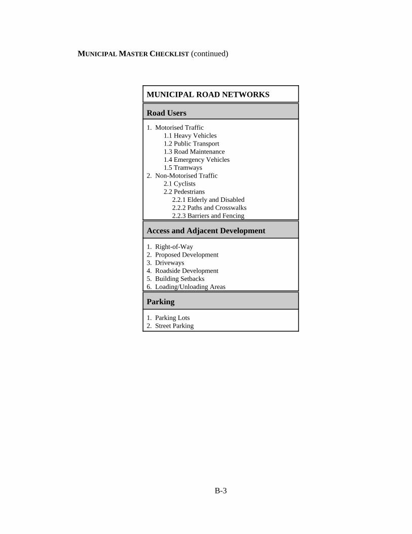
MUNICIPAL MASTER CHECKLIST (continued)
B-3
MUNICIPAL ROAD NETWORKS
Road Users
1. Motorised Traffic 1.1 Heavy Vehicles 1.2 Public Transport 1.3 Road Maintenance 1.4 Emergency Vehicles 1.5 Tramways 2. Non-Motorised Traffic 2.1 Cyclists 2.2 Pedestrians 2.2.1 Elderly and Disabled 2.2.2 Paths and Crosswalks 2.2.3 Barriers and Fencing
Access and Adjacent Development
1. Right-of-Way2. Proposed Development3. Driveways4. Roadside Development5. Building Setbacks6. Loading/Unloading Areas
Parking
1. Parking Lots2. Street Parking

B-4
MUNICIPAL DETAILED CHECKLIST
Item Description
General
1. Scope Review all pertinent documentation to gain anunderstanding of the scope of the project; including projectobjectives, user characteristics, design vehicles, access,adjacent development, existing network information, andfuture network expansion.
2. Traffic Barrier Warrants Presence of non-traversable or fixed object hazards withinclear zone.
Does a potential risk exist for vehicles crossing over themedian into the path of an opposing vehicle?
Accident history of area.
3. Landscaping Landscaping along road in accordance with guidelines?
Required clearances and sight distances restricted due tofuture plant growth?
4. Temporary Work Area (Maintenance/Construction)
Interaction between work area and traffic flow.
Is temporary work site adequately signed for approachingtraffic?
Does temporary work signage remain even thoughconstruction is complete?
Visibility of temporary work area from approachingtraffic.
6. Glare Severity of head light glare during night time operations.
Do areas exist along a road or at an intersection wheresunlight reduces visibility?
7. Traffic Calming Are traffic calming measures effective at reducing vehiclespeeds?
Is traffic calming required?
8. Congestion Areas Have areas of congestion been identified?
Are areas of regular congestion visible by approachingroad users?
9. Street Network Have changes in traffic flow altered hierarchy of streets.

MUNICIPAL DETAILED CHECKLIST (continued)
B-5
Item Description
General (continued)
10. School and Recreation Areas
Is posted speed limit appropriate for neighbourhoodactivities?
Is speed limit effective at controlling traffic speed?
Is existing signage sufficient at notifying motorists ofupcoming activities, or is some other traffic control devicenecessary?
Visibility of signage from approaching traffic adequate?
Visibility of school and recreational areas by approachingtraffic.
Does on-street parking exist near school? If so, willvisibility of children be obstructed by parked vehicles?
Do crosswalks exist in area? If so, what is their condition?
Does approaching traffic adhere to pedestrian rules atcrosswalks or are further traffic control measuresnecessary? (Crossing guard, pedestrian corridors, etc.)
11. EnvironmentalConsiderations
Check the effects of adverse weather conditions on thefacility.
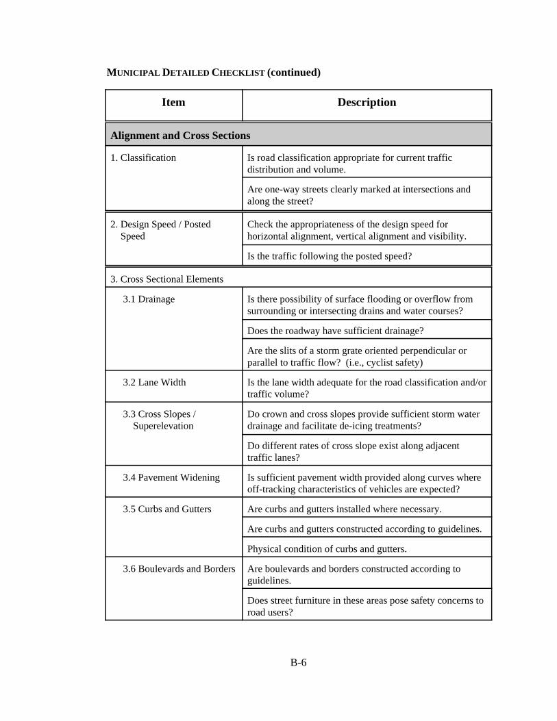
MUNICIPAL DETAILED CHECKLIST (continued)
B-6
Item Description
Alignment and Cross Sections
1. Classification Is road classification appropriate for current trafficdistribution and volume.
Are one-way streets clearly marked at intersections andalong the street?
2. Design Speed / Posted Speed
Check the appropriateness of the design speed forhorizontal alignment, vertical alignment and visibility.
Is the traffic following the posted speed?
3. Cross Sectional Elements
3.1 Drainage Is there possibility of surface flooding or overflow fromsurrounding or intersecting drains and water courses?
Does the roadway have sufficient drainage?
Are the slits of a storm grate oriented perpendicular orparallel to traffic flow? (i.e., cyclist safety)
3.2 Lane Width Is the lane width adequate for the road classification and/ortraffic volume?
3.3 Cross Slopes / Superelevation
Do crown and cross slopes provide sufficient storm waterdrainage and facilitate de-icing treatments?
Do different rates of cross slope exist along adjacenttraffic lanes?
3.4 Pavement Widening Is sufficient pavement width provided along curves whereoff-tracking characteristics of vehicles are expected?
3.5 Curbs and Gutters Are curbs and gutters installed where necessary.
Are curbs and gutters constructed according to guidelines.
Physical condition of curbs and gutters.
3.6 Boulevards and Borders Are boulevards and borders constructed according toguidelines.
Does street furniture in these areas pose safety concerns toroad users?

MUNICIPAL DETAILED CHECKLIST (continued)
B-7
Item Description
Alignment and Cross Sections (continued)
3.7 Sidewalks Physical condition of sidewalk.
Is sidewalk width adequate for pedestrian volumes?
Do objects exist on or near sidewalk that cause pedestriansto use street (i.e. canopies, patios, advertisement signs,etc.)
4. Alignment
4.1 Horizontal Are there excessive horizontal curves that cause sliding inadverse weather conditions?
Signage of excessive horizontal alignment adequate?
4.2 Vertical Are there excessive grades which could be unsafe inadverse weather conditions?
4.3 Combined Vertical and Horizontal
Check the interaction of horizontal and vertical alignmentsin the road.
5. Sight Distance Any obstructions that could interfere with sight distancealong route.
Determine if adequate stopping sight distance is provided.
6. Readability by Drivers Check for sections of roadway having potential forconfusion -alignment problems -old pavement markings not properly removed -streetlight/tree lines don’t follow road alignment
7. Bridge Structures Check that the horizontal and vertical alignment conformswith the approach roadways.
Check for sufficient vertical clearance and proper signageof height restrictions.
Is the horizontal clearance adequate from the roadway tothe bridge rails/parapets?
Is horizontal sight distance obstructed by bridge abutmentsand parapets?
Is signing required for delineation, weight restriction, orwarning of freezing deck? Is it properly installed?
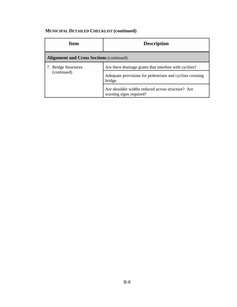
MUNICIPAL DETAILED CHECKLIST (continued)
B-8
Item Description
Alignment and Cross Sections (continued)
7. Bridge Structures (continued)
Are there drainage grates that interfere with cyclists?
Adequate provisions for pedestrians and cyclists crossingbridge.
Are shoulder widths reduced across structure? Arewarning signs required?
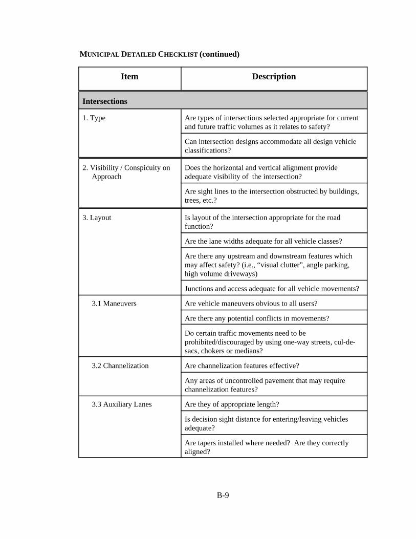
MUNICIPAL DETAILED CHECKLIST (continued)
B-9
Item Description
Intersections
1. Type Are types of intersections selected appropriate for currentand future traffic volumes as it relates to safety?
Can intersection designs accommodate all design vehicleclassifications?
2. Visibility / Conspicuity on Approach
Does the horizontal and vertical alignment provideadequate visibility of the intersection?
Are sight lines to the intersection obstructed by buildings,trees, etc.?
3. Layout Is layout of the intersection appropriate for the roadfunction?
Are the lane widths adequate for all vehicle classes?
Are there any upstream and downstream features whichmay affect safety? (i.e., “visual clutter”, angle parking,high volume driveways)
Junctions and access adequate for all vehicle movements?
3.1 Maneuvers Are vehicle maneuvers obvious to all users?
Are there any potential conflicts in movements?
Do certain traffic movements need to beprohibited/discouraged by using one-way streets, cul-de-sacs, chokers or medians?
3.2 Channelization Are channelization features effective?
Any areas of uncontrolled pavement that may requirechannelization features?
3.3 Auxiliary Lanes Are they of appropriate length?
Is decision sight distance for entering/leaving vehiclesadequate?
Are tapers installed where needed? Are they correctlyaligned?
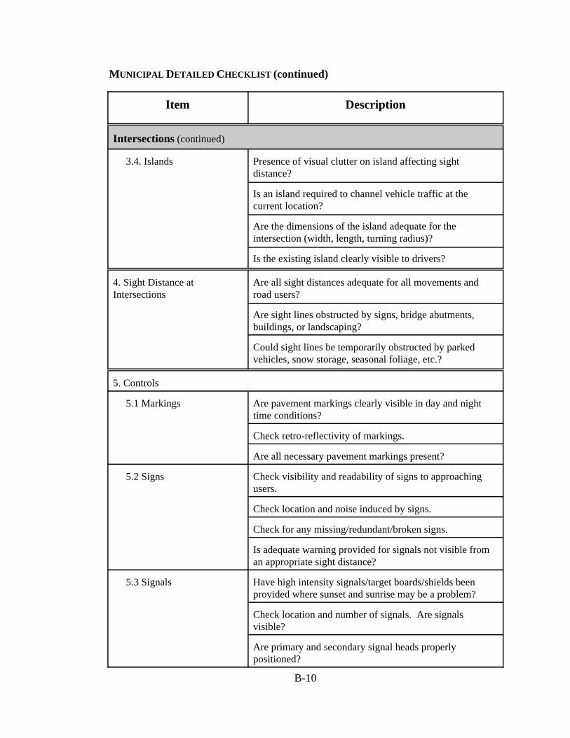
MUNICIPAL DETAILED CHECKLIST (continued)
B-10
Item Description
Intersections (continued)
3.4. Islands Presence of visual clutter on island affecting sightdistance?
Is an island required to channel vehicle traffic at thecurrent location?
Are the dimensions of the island adequate for theintersection (width, length, turning radius)?
Is the existing island clearly visible to drivers?
4. Sight Distance at Intersections
Are all sight distances adequate for all movements androad users?
Are sight lines obstructed by signs, bridge abutments,buildings, or landscaping?
Could sight lines be temporarily obstructed by parkedvehicles, snow storage, seasonal foliage, etc.?
5. Controls
5.1 Markings Are pavement markings clearly visible in day and nighttime conditions?
Check retro-reflectivity of markings.
Are all necessary pavement markings present?
5.2 Signs Check visibility and readability of signs to approachingusers.
Check location and noise induced by signs.
Check for any missing/redundant/broken signs.
Is adequate warning provided for signals not visible froman appropriate sight distance?
5.3 Signals Have high intensity signals/target boards/shields beenprovided where sunset and sunrise may be a problem?
Check location and number of signals. Are signalsvisible?
Are primary and secondary signal heads properlypositioned?
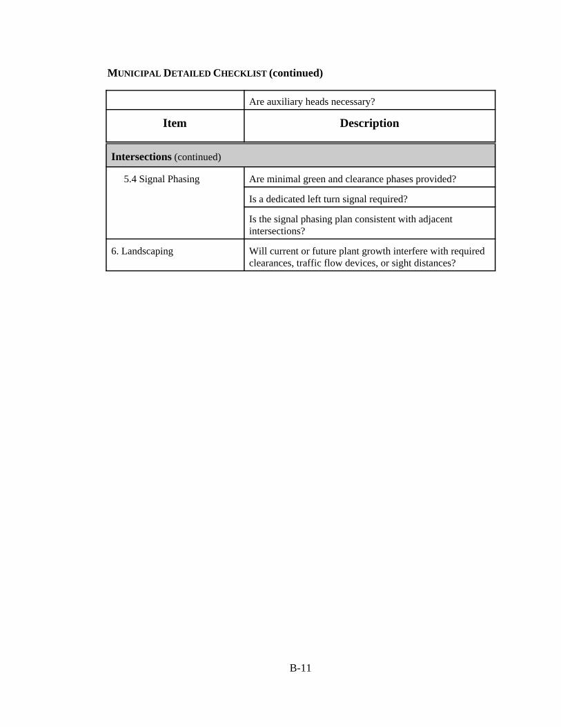
MUNICIPAL DETAILED CHECKLIST (continued)
B-11
Are auxiliary heads necessary?
Item Description
Intersections (continued)
5.4 Signal Phasing Are minimal green and clearance phases provided?
Is a dedicated left turn signal required?
Is the signal phasing plan consistent with adjacentintersections?
6. Landscaping Will current or future plant growth interfere with requiredclearances, traffic flow devices, or sight distances?
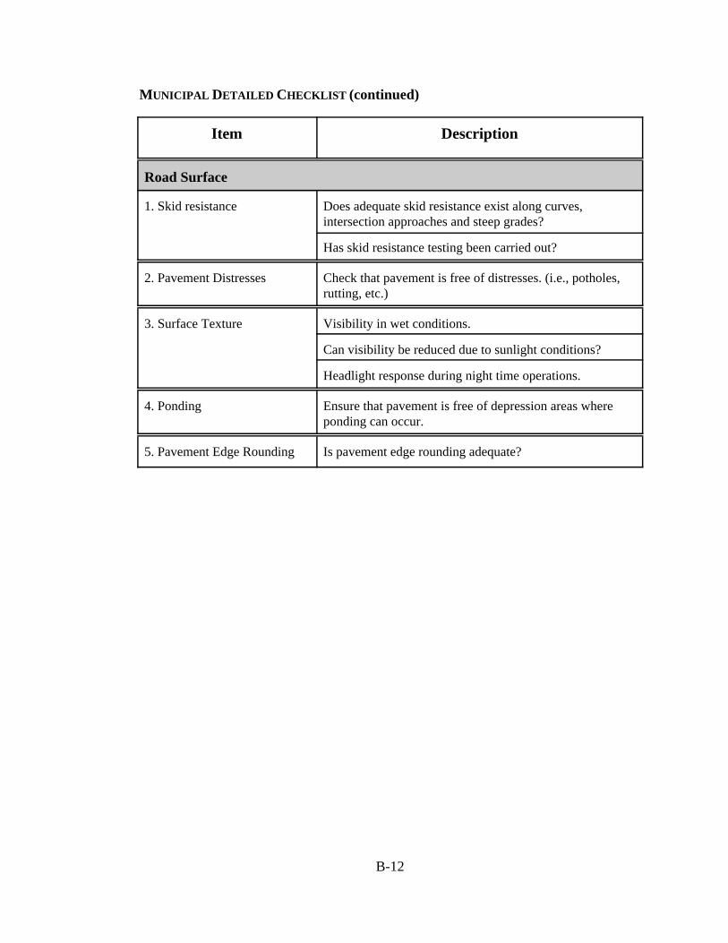
MUNICIPAL DETAILED CHECKLIST (continued)
B-12
Item Description
Road Surface
1. Skid resistance Does adequate skid resistance exist along curves,intersection approaches and steep grades?
Has skid resistance testing been carried out?
2. Pavement Distresses Check that pavement is free of distresses. (i.e., potholes,rutting, etc.)
3. Surface Texture Visibility in wet conditions.
Can visibility be reduced due to sunlight conditions?
Headlight response during night time operations.
4. Ponding Ensure that pavement is free of depression areas whereponding can occur.
5. Pavement Edge Rounding Is pavement edge rounding adequate?
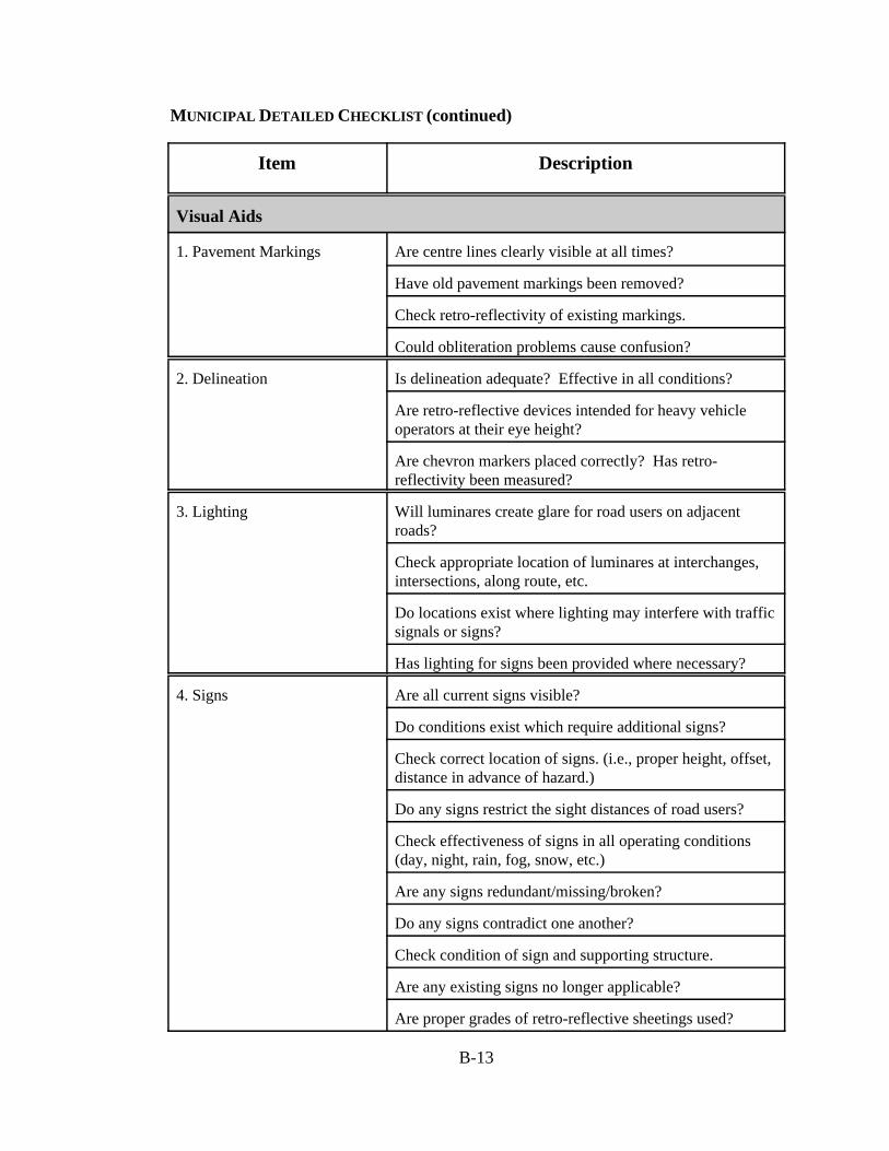
MUNICIPAL DETAILED CHECKLIST (continued)
B-13
Item Description
Visual Aids
1. Pavement Markings Are centre lines clearly visible at all times?
Have old pavement markings been removed?
Check retro-reflectivity of existing markings.
Could obliteration problems cause confusion?
2. Delineation Is delineation adequate? Effective in all conditions?
Are retro-reflective devices intended for heavy vehicleoperators at their eye height?
Are chevron markers placed correctly? Has retro-reflectivity been measured?
3. Lighting Will luminares create glare for road users on adjacentroads?
Check appropriate location of luminares at interchanges,intersections, along route, etc.
Do locations exist where lighting may interfere with trafficsignals or signs?
Has lighting for signs been provided where necessary?
4. Signs Are all current signs visible?
Do conditions exist which require additional signs?
Check correct location of signs. (i.e., proper height, offset,distance in advance of hazard.)
Do any signs restrict the sight distances of road users?
Check effectiveness of signs in all operating conditions(day, night, rain, fog, snow, etc.)
Are any signs redundant/missing/broken?
Do any signs contradict one another?
Check condition of sign and supporting structure.
Are any existing signs no longer applicable?
Are proper grades of retro-reflective sheetings used?
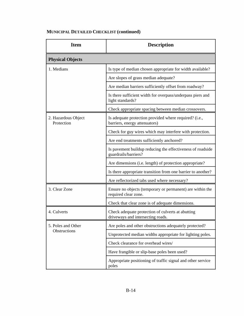
MUNICIPAL DETAILED CHECKLIST (continued)
B-14
Item Description
Physical Objects
1. Medians Is type of median chosen appropriate for width available?
Are slopes of grass median adequate?
Are median barriers sufficiently offset from roadway?
Is there sufficient width for overpass/underpass piers andlight standards?
Check appropriate spacing between median crossovers.
2. Hazardous Object Protection
Is adequate protection provided where required? (i.e.,barriers, energy attenuators)
Check for guy wires which may interfere with protection.
Are end treatments sufficiently anchored?
Is pavement buildup reducing the effectiveness of roadsideguardrails/barriers?
Are dimensions (i.e. length) of protection appropriate?
Is there appropriate transition from one barrier to another?
Are reflectorized tabs used where necessary?
3. Clear Zone Ensure no objects (temporary or permanent) are within therequired clear zone.
Check that clear zone is of adequate dimensions.
4. Culverts Check adequate protection of culverts at abuttingdriveways and intersecting roads.
5. Poles and Other Obstructions
Are poles and other obstructions adequately protected?
Unprotected median widths appropriate for lighting poles.
Check clearance for overhead wires/
Have frangible or slip-base poles been used?
Appropriate positioning of traffic signal and other servicepoles
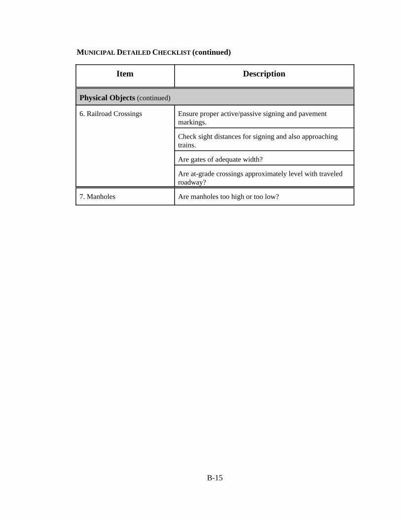
MUNICIPAL DETAILED CHECKLIST (continued)
B-15
Item Description
Physical Objects (continued)
6. Railroad Crossings Ensure proper active/passive signing and pavementmarkings.
Check sight distances for signing and also approachingtrains.
Are gates of adequate width?
Are at-grade crossings approximately level with traveledroadway?
7. Manholes Are manholes too high or too low?
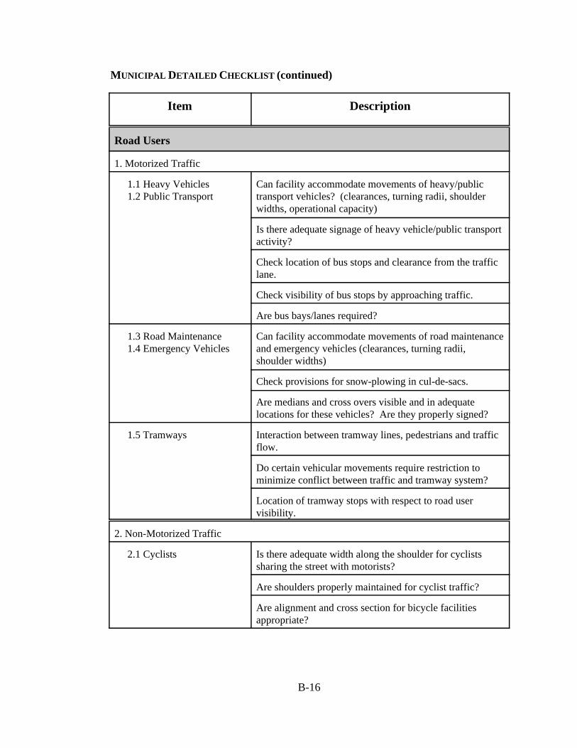
MUNICIPAL DETAILED CHECKLIST (continued)
B-16
Item Description
Road Users
1. Motorized Traffic
1.1 Heavy Vehicles 1.2 Public Transport
Can facility accommodate movements of heavy/publictransport vehicles? (clearances, turning radii, shoulderwidths, operational capacity)
Is there adequate signage of heavy vehicle/public transportactivity?
Check location of bus stops and clearance from the trafficlane.
Check visibility of bus stops by approaching traffic.
Are bus bays/lanes required?
1.3 Road Maintenance 1.4 Emergency Vehicles
Can facility accommodate movements of road maintenanceand emergency vehicles (clearances, turning radii,shoulder widths)
Check provisions for snow-plowing in cul-de-sacs.
Are medians and cross overs visible and in adequatelocations for these vehicles? Are they properly signed?
1.5 Tramways Interaction between tramway lines, pedestrians and trafficflow.
Do certain vehicular movements require restriction tominimize conflict between traffic and tramway system?
Location of tramway stops with respect to road uservisibility.
2. Non-Motorized Traffic
2.1 Cyclists Is there adequate width along the shoulder for cyclistssharing the street with motorists?
Are shoulders properly maintained for cyclist traffic?
Are alignment and cross section for bicycle facilitiesappropriate?
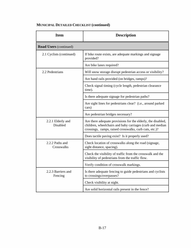
MUNICIPAL DETAILED CHECKLIST (continued)
B-17
Item Description
Road Users (continued)
2.1 Cyclists (continued) If bike route exists, are adequate markings and signageprovided?
Are bike lanes required?
2.2 Pedestrians Will snow storage disrupt pedestrian access or visibility?
Are hand rails provided (on bridges, ramps)?
Check signal timing (cycle length, pedestrian clearancetime).
Is there adequate signage for pedestrian paths?
Are sight lines for pedestrians clear? (i.e., around parkedcars)
Are pedestrian bridges necessary?
2.2.1 Elderly and Disabled
Are there adequate provisions for the elderly, the disabled,children, wheelchairs and baby carriages (curb and mediancrossings, ramps, raised crosswalks, curb cuts, etc.)?
Does tactile paving exist? Is it properly used?
2.2.2 Paths and Crosswalks
Check location of crosswalks along the road (signage,sight distance, spacing).
Check the visibility of traffic from the crosswalk and thevisibility of pedestrians from the traffic flow.
Verify condition of crosswalk markings.
2.2.3 Barriers and Fencing
Is there adequate fencing to guide pedestrians and cycliststo crossings/overpasses?
Check visibility at night.
Are solid horizontal rails present in the fence?
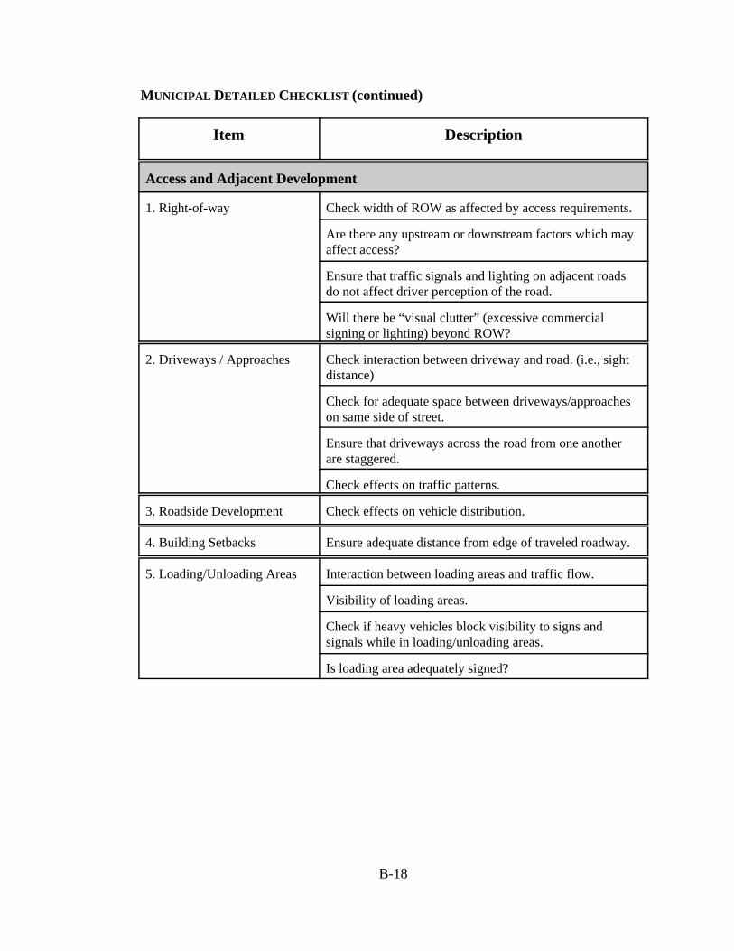
MUNICIPAL DETAILED CHECKLIST (continued)
B-18
Item Description
Access and Adjacent Development
1. Right-of-way Check width of ROW as affected by access requirements.
Are there any upstream or downstream factors which mayaffect access?
Ensure that traffic signals and lighting on adjacent roadsdo not affect driver perception of the road.
Will there be “visual clutter” (excessive commercialsigning or lighting) beyond ROW?
2. Driveways / Approaches Check interaction between driveway and road. (i.e., sightdistance)
Check for adequate space between driveways/approacheson same side of street.
Ensure that driveways across the road from one anotherare staggered.
Check effects on traffic patterns.
3. Roadside Development Check effects on vehicle distribution.
4. Building Setbacks Ensure adequate distance from edge of traveled roadway.
5. Loading/Unloading Areas Interaction between loading areas and traffic flow.
Visibility of loading areas.
Check if heavy vehicles block visibility to signs andsignals while in loading/unloading areas.
Is loading area adequately signed?
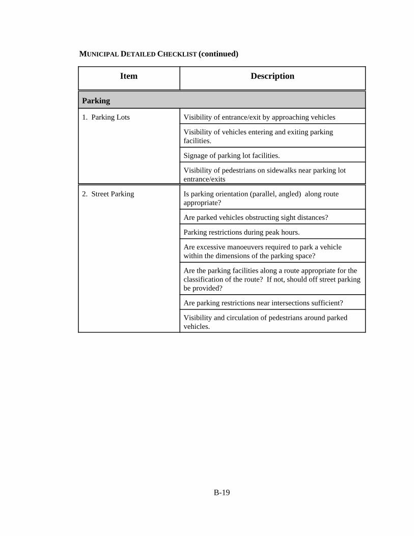
MUNICIPAL DETAILED CHECKLIST (continued)
B-19
Item Description
Parking
1. Parking Lots Visibility of entrance/exit by approaching vehicles
Visibility of vehicles entering and exiting parkingfacilities.
Signage of parking lot facilities.
Visibility of pedestrians on sidewalks near parking lotentrance/exits
2. Street Parking Is parking orientation (parallel, angled) along routeappropriate?
Are parked vehicles obstructing sight distances?
Parking restrictions during peak hours.
Are excessive manoeuvers required to park a vehiclewithin the dimensions of the parking space?
Are the parking facilities along a route appropriate for theclassification of the route? If not, should off street parkingbe provided?
Are parking restrictions near intersections sufficient?
Visibility and circulation of pedestrians around parkedvehicles.
Appendix C
Exemplary Audits
C-1
Stage 5: Existing Road Safety Audit
ROUTE 1000
BETWEEN ROUTE 666 AND ROUTE 999
Audit Dates: June 25 and 29, 1999
Audit Team Leaders: Dr. E.D. Hildebrand, P.Eng.Dr. F.R. Wilson, P.Eng.
Audit Team Members: Tammy Dow, BScE, EITJennifer Mehan, BScE, EITJeanette Montufar, MScE, PhD (Candidate), P.Eng.Stephen Ellsworth, BEng, P.Eng.
University of New BrunswickP.O. Box 4400Fredericton NB E3B 5A3Tel: (506) 453-5113 Fax: (506) 453-3568

C-2
EXISTING HIGHWAY SAFETY AUDITROUTE 1000 (FROM ROUTE 666 TO ROUTE 999)
Introduction
Although the concept of Road Safety Audits is relatively new in Canada, there is a strong interestin their application to develop safer road facilities. Numerous audits have already been undertakenon both existing road facilities and those in the design stage.
A basic objective of road safety audits is the reduction of road casualties through the adoption ofa more proactive approach, contrary to traditional blackspot analysis which is a reactive methodof identifying high accident locations. The intent is to identify and mitigate problem areas beforeaccidents have a chance to occur.
A road safety audit was conducted on a section of Route 1000 on June 25 and 28, 1999. The 41.3kilometre section extends from Route 1000's intersection with Route 666 (Ashton) to Route 999(Medford). The collector provides a secondary east-west connection between the communities ofAshton and Medford.
The audit covers physical features of the study area which may affect road user safety and it hassought to identify potential safety hazards. However, the auditors point out that no guarantee ismade that every deficiency has been identified. Further, if all the recommendations in this reportwere to be followed, this would not confirm that the highway is ‘safe’; rather, adoption of therecommendations should improve the level of safety of the highway.
Study Area
Site surveys were conducted on June 25 (all day) and the late evening of June 28 (it was foggy andraining during the night time audit). The audit consisted of a careful and detailed examination ofeach of the control sections within the study area. The following areas were considered during thisreview: (1) background information (2) alignment and cross section; (3) intersections and access;(4) road surface; (5) visual aids; (6) the roadside; and (7) road users. The following sectionssummarize the relevant information and observations recorded during the site visits.
The audited area is illustrated in Figure 1. Three control sections make up this road segment:
Control section 005 – from Route 666 to bridge S11 - 17.53 km.Control section 006 – from bridge S11 to Route 555 - 19.00 km.Control section 007 – from Route 555 to Route 999 - 4.77 km.
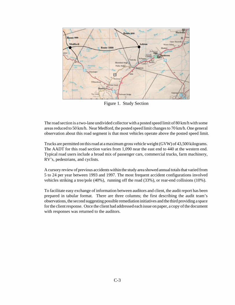
C-3
Figure 1. Study Section
The road section is a two-lane undivided collector with a posted speed limit of 80 km/h with someareas reduced to 50 km/h. Near Medford, the posted speed limit changes to 70 km/h. One generalobservation about this road segment is that most vehicles operate above the posted speed limit.
Trucks are permitted on this road at a maximum gross vehicle weight (GVW) of 43,500 kilograms.The AADT for this road section varies from 1,090 near the east end to 440 at the western end.Typical road users include a broad mix of passenger cars, commercial trucks, farm machinery,RV’s, pedestrians, and cyclists.
A cursory review of previous accidents within the study area showed annual totals that varied from5 to 24 per year between 1993 and 1997. The most frequent accident configurations involvedvehicles striking a tree/pole (40%), running off the road (33%), or rear-end collisions (10%).
To facilitate easy exchange of information between auditors and client, the audit report has beenprepared in tabular format. There are three columns; the first describing the audit team’sobservations, the second suggesting possible remediation initiatives and the third providing a spacefor the client response. Once the client had addressed each issue on paper, a copy of the documentwith responses was returned to the auditors.
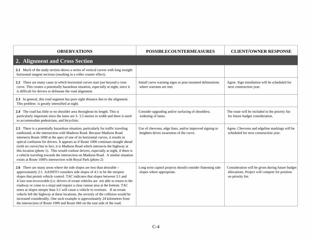
C-4
OBSERVATIONS POSSIBLECOUNTERMEASURES CLIENT/OWNER RESPONSE
2. Alignment and Cross Section
2.1 Much of the study section shows a series of vertical curves with long straight horizontal tangent sections (resulting in a roller coaster effect).
2.2 There are many cases in which horizontal curves start just beyond a crest curve. This creates a potentially hazardous situation, especially at night, since it is difficult for drivers to delineate the road alignment.
Install curve warning signs or post mounted delineations where warrants are met.
Agree. Sign installation will be scheduled for next construction year.
2.3 In general, this road segment has poor sight distance due to the alignment. This problem is greatly intensified at night.
2.4 The road has little or no shoulder area throughout its length. This is particularly important since the lanes are 3- 3.5 metres in width and there is need to accommodate pedestrians, and bicyclists.
Consider upgrading and/or surfacing of shoulders; widening of lanes.
The route will be included in the priority list for future budget consideration.
2.5 There is a potentially hazardous situation, particularly for traffic traveling eastbound, at the intersection with Madison Road. Because Madison Road intersects Route 1000 at the apex of one of its horizontal curves, it results in optical confusion for drivers. It appears as if Route 1000 continues straight ahead (with no curve) but in fact, it is Madison Road which intersects the highway at this location (photo 1). This would confuse drivers, especially at night, if there is a vehicle traveling towards the intersection on Madison Road. A similar situation exists at Route 1000's intersection with Royal Park (photo 2)
Use of chevrons, edge lines, and/or improved signing to heighten driver awareness of the curve.
Agree. Chevrons and edgeline markings will be scheduled for next construction year.
2.6 There are many areas where the side slopes are less than desirable – approximately 2:1. AASHTO considers side slopes of 4:1 to be the steepest slopes that permit vehicle control. TAC indicates that slopes between 3:1 and 4:1are non-recoverable (i.e. drivers of errant vehicles are not able to return to the roadway or come to a stop) and require a clear runout area at the bottom. TAC notes at slopes steeper than 3:1 will cause a vehicle to overturn. If an errant vehicle left the highway at these locations, the severity of the collision would be increased considerably. One such example is approximately 24 kilometres from the intersection of Route 1000 and Route 666 on the east side of the road.
Long term capitol projects should consider flattening side slopes where appropriate.
Consideration will be given during future budget allocations. Project will compete for position on priority list.
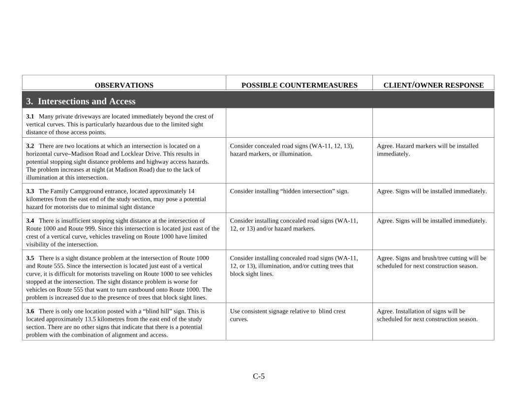
C-5
OBSERVATIONS POSSIBLE COUNTERMEASURES CLIENT/OWNER RESPONSE
3. Intersections and Access
3.1 Many private driveways are located immediately beyond the crest of vertical curves. This is particularly hazardous due to the limited sightdistance of those access points.
3.2 There are two locations at which an intersection is located on ahorizontal curve–Madison Road and Locklear Drive. This results inpotential stopping sight distance problems and highway access hazards. The problem increases at night (at Madison Road) due to the lack ofillumination at this intersection.
Consider concealed road signs (WA-11, 12, 13),hazard markers, or illumination.
Agree. Hazard markers will be installedimmediately.
3.3 The Family Campground entrance, located approximately 14kilometres from the east end of the study section, may pose a potentialhazard for motorists due to minimal sight distance
Consider installing “hidden intersection” sign. Agree. Signs will be installed immediately.
3.4 There is insufficient stopping sight distance at the intersection ofRoute 1000 and Route 999. Since this intersection is located just east of thecrest of a vertical curve, vehicles traveling on Route 1000 have limitedvisibility of the intersection.
Consider installing concealed road signs (WA-11,12, or 13) and/or hazard markers.
Agree. Signs will be installed immediately.
3.5 There is a sight distance problem at the intersection of Route 1000and Route 555. Since the intersection is located just east of a verticalcurve, it is difficult for motorists traveling on Route 1000 to see vehiclesstopped at the intersection. The sight distance problem is worse forvehicles on Route 555 that want to turn eastbound onto Route 1000. Theproblem is increased due to the presence of trees that block sight lines.
Consider installing concealed road signs (WA-11,12, or 13), illumination, and/or cutting trees thatblock sight lines.
Agree. Signs and brush/tree cutting will bescheduled for next construction season.
3.6 There is only one location posted with a “blind hill” sign. This islocated approximately 13.5 kilometres from the east end of the studysection. There are no other signs that indicate that there is a potentialproblem with the combination of alignment and access.
Use consistent signage relative to blind crestcurves.
Agree. Installation of signs will bescheduled for next construction season.
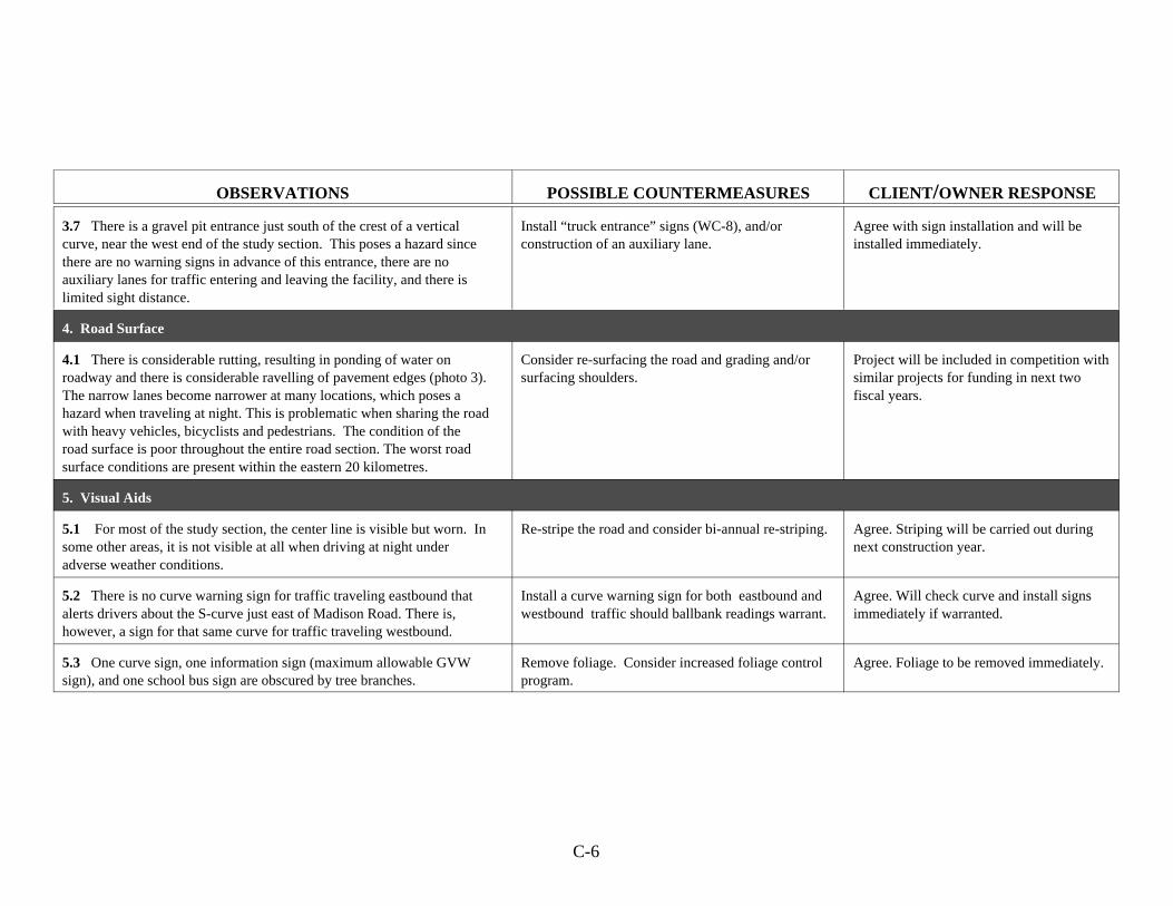
C-6
OBSERVATIONS POSSIBLE COUNTERMEASURES CLIENT/OWNER RESPONSE
3.7 There is a gravel pit entrance just south of the crest of a verticalcurve, near the west end of the study section. This poses a hazard sincethere are no warning signs in advance of this entrance, there are noauxiliary lanes for traffic entering and leaving the facility, and there islimited sight distance.
Install “truck entrance” signs (WC-8), and/orconstruction of an auxiliary lane.
Agree with sign installation and will beinstalled immediately.
4. Road Surface
4.1 There is considerable rutting, resulting in ponding of water onroadway and there is considerable ravelling of pavement edges (photo 3). The narrow lanes become narrower at many locations, which poses ahazard when traveling at night. This is problematic when sharing the roadwith heavy vehicles, bicyclists and pedestrians. The condition of theroad surface is poor throughout the entire road section. The worst roadsurface conditions are present within the eastern 20 kilometres.
Consider re-surfacing the road and grading and/orsurfacing shoulders.
Project will be included in competition withsimilar projects for funding in next twofiscal years.
5. Visual Aids
5.1 For most of the study section, the center line is visible but worn. Insome other areas, it is not visible at all when driving at night underadverse weather conditions.
Re-stripe the road and consider bi-annual re-striping. Agree. Striping will be carried out duringnext construction year.
5.2 There is no curve warning sign for traffic traveling eastbound thatalerts drivers about the S-curve just east of Madison Road. There is,however, a sign for that same curve for traffic traveling westbound.
Install a curve warning sign for both eastbound andwestbound traffic should ballbank readings warrant.
Agree. Will check curve and install signsimmediately if warranted.
5.3 One curve sign, one information sign (maximum allowable GVWsign), and one school bus sign are obscured by tree branches.
Remove foliage. Consider increased foliage controlprogram.
Agree. Foliage to be removed immediately.
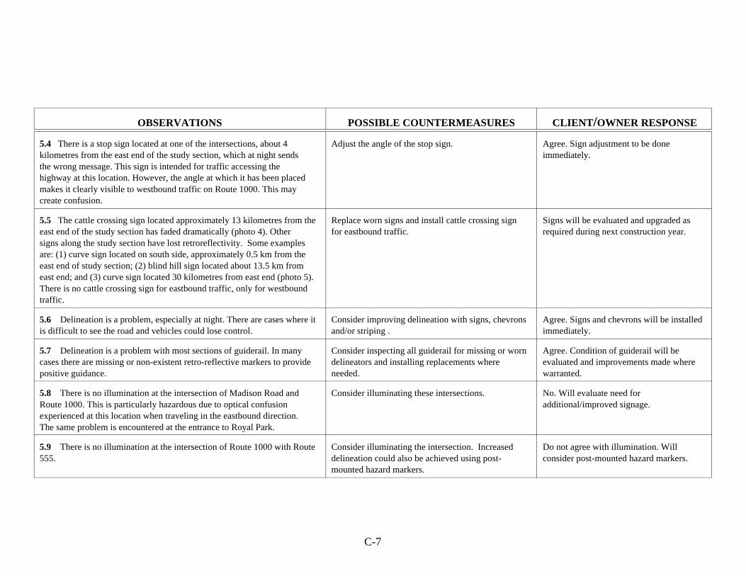
C-7
OBSERVATIONS POSSIBLE COUNTERMEASURES CLIENT/OWNER RESPONSE
5.4 There is a stop sign located at one of the intersections, about 4kilometres from the east end of the study section, which at night sendsthe wrong message. This sign is intended for traffic accessing thehighway at this location. However, the angle at which it has been placedmakes it clearly visible to westbound traffic on Route 1000. This maycreate confusion.
Adjust the angle of the stop sign. Agree. Sign adjustment to be doneimmediately.
5.5 The cattle crossing sign located approximately 13 kilometres from theeast end of the study section has faded dramatically (photo 4). Othersigns along the study section have lost retroreflectivity. Some examplesare: (1) curve sign located on south side, approximately 0.5 km from theeast end of study section; (2) blind hill sign located about 13.5 km fromeast end; and (3) curve sign located 30 kilometres from east end (photo 5). There is no cattle crossing sign for eastbound traffic, only for westboundtraffic.
Replace worn signs and install cattle crossing signfor eastbound traffic.
Signs will be evaluated and upgraded asrequired during next construction year.
5.6 Delineation is a problem, especially at night. There are cases where itis difficult to see the road and vehicles could lose control.
Consider improving delineation with signs, chevronsand/or striping .
Agree. Signs and chevrons will be installedimmediately.
5.7 Delineation is a problem with most sections of guiderail. In manycases there are missing or non-existent retro-reflective markers to providepositive guidance.
Consider inspecting all guiderail for missing or worndelineators and installing replacements whereneeded.
Agree. Condition of guiderail will beevaluated and improvements made wherewarranted.
5.8 There is no illumination at the intersection of Madison Road andRoute 1000. This is particularly hazardous due to optical confusionexperienced at this location when traveling in the eastbound direction.The same problem is encountered at the entrance to Royal Park.
Consider illuminating these intersections. No. Will evaluate need foradditional/improved signage.
5.9 There is no illumination at the intersection of Route 1000 with Route555.
Consider illuminating the intersection. Increaseddelineation could also be achieved using post-mounted hazard markers.
Do not agree with illumination. Willconsider post-mounted hazard markers.

C-8
OBSERVATIONS POSSIBLE COUNTERMEASURES CLIENT/OWNER RESPONSE
6. The Roadside
6.1 Considering the posted speeds of this road, it is evident that theclear zone provided is often inadequate. For sections of the road with aposted speed limit of 70 km/h or 80 km/h, a minimum clear zone of 2.5metres is recommended by TAC, subject to type (fill vs. cut) and grade ofslope as well as traffic volume. As the side slope steepens, the minimumclear zone increases.
Review the study area to identify long termopportunities to remove/relocate specific objectswithin the clear zone, to flatten slopes, or installguiderail.
Review will be undertaken. Improvementwould require major expenditure and thisproject would have to compete Provincewide for funding.
6.2 Many large trees are located very close to the edge of the pavement(well within any prescribed clear zones), for example the two trees locatedjust west of Bridge S11 (where Control Section 006 begins–17.6 kilometresfrom the east end of the study section). Guy wires are located within theclear zone, and in some cases, in the vicinity of guiderail.
Consider removing problematic trees or installingguiderail.
Agree. Will review tree location andpossible removal.
6.3 Most driveway culverts are exposed. Furthermore, the side slopes ofdriveways pose a potential hazard for motorists.
Install protection in vicinity of culverts andsoftening slopes for increased safety. Higherpriority should be given to those located onhorizontal curves.
Will review culverts located on horizontalcurves.
6.4 The guiderail on the southwest corner of bridge J23 is not mountedflush with the inside of the concrete bridge endpost (photo 12). An errantvehicle striking this guiderail is in danger of not being directed away fromthe endpost.
Consider adjusting guiderial so that it is flush withthe endpost.
Agree. Guiderails will be adjustedimmediately.
6.5 There is an unprotected steep side slope on the south side of theroad, approximately 20 kilometres from the east end of the study section.There is a barrier which ends just west of that location. However, thatbarrier does not extend far enough to prevent an errant vehicle (especiallytraveling in the southbound direction) from leaving the road. There aresimilar problems at other locations along this road segment.
Extend the barrier. Agree. Will be adjusted during nextconstruction year.

C-9
OBSERVATIONS POSSIBLE COUNTERMEASURES CLIENT/OWNER RESPONSE
6.6 Many sections of guiderail require maintenance. Some of thosebarriers are not in good condition to withstand the impact of a vehicle. Examples include:
(1) the south guiderail located 2.6 kilometres from the eastend of the study section has two of the woodensupports broken;
(2) the north guiderail located 4.3 kilometres from the eastend of the study section is not visible due to trees andbushes;
(3) the south guiderail located 5.0 kilometres from the eastend of the study section is too low–an errant vehiclewould roll over the barrier (photo 7);
(4) the cable guiderail located 16 kilometres from the eastend of the study section has some broken supports andloose cables (photos 8 and 9);
(5) some steel flex beam rails are missing spacer blocks; (6) some of the guiderails are too short and need to be
extended (photo 10);(7) the embankments of several sections of guiderail along the river’s edge have partially washed away resulting in inadequate support for the wooden posts (photo 11).
Maintain guiderail. Agree. Maintenance will be completed onguiderail.
6.7 Most mailboxes are located within 2.5 metres from the edge of thepavement. There is one particular case (approximately 28 kilometres westof the intersection of Route 1000 and Route 666) in which the mailbox ismounted on a large wooden log positioned within the clear zone (photo6).
Have larger mailbox structures either moved outsidethe clear zone or replaced with “friendlier” frames.
Agree. Will discuss problem with owner.
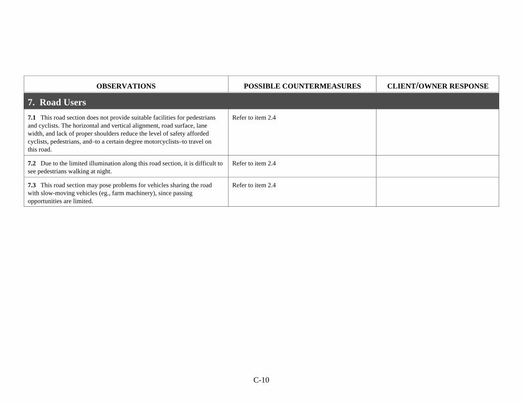
C-10
OBSERVATIONS POSSIBLE COUNTERMEASURES CLIENT/OWNER RESPONSE
7. Road Users
7.1 This road section does not provide suitable facilities for pedestriansand cyclists. The horizontal and vertical alignment, road surface, lanewidth, and lack of proper shoulders reduce the level of safety affordedcyclists, pedestrians, and–to a certain degree motorcyclists–to travel onthis road.
Refer to item 2.4
7.2 Due to the limited illumination along this road section, it is difficult tosee pedestrians walking at night.
Refer to item 2.4
7.3 This road section may pose problems for vehicles sharing the roadwith slow-moving vehicles (eg., farm machinery), since passingopportunities are limited.
Refer to item 2.4
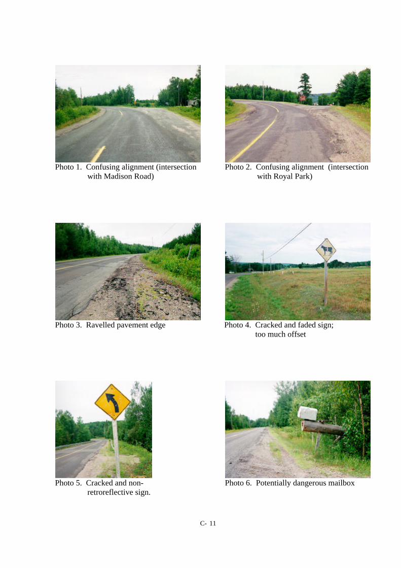
C- 11
Photo 1. Confusing alignment (intersection Photo 2. Confusing alignment (intersection with Madison Road) with Royal Park)
Photo 3. Ravelled pavement edge Photo 4. Cracked and faded sign; too much offset
Photo 5. Cracked and non- Photo 6. Potentially dangerous mailbox retroreflective sign.
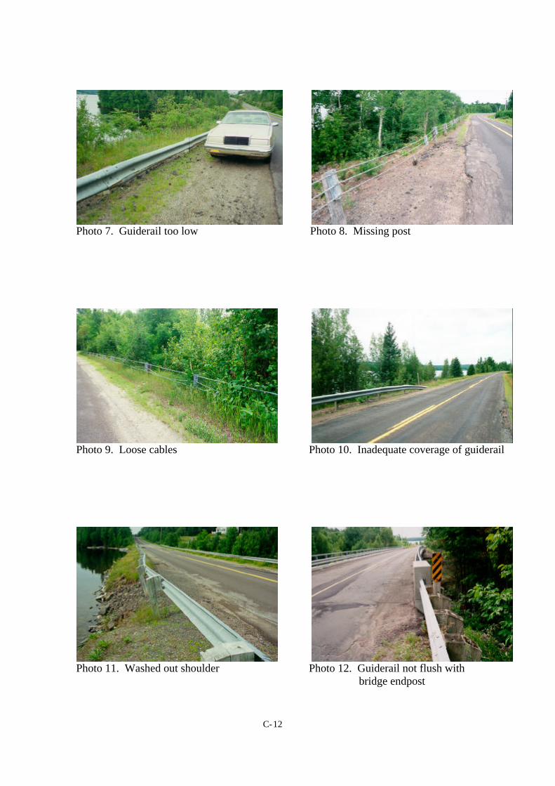
C-12
Photo 7. Guiderail too low Photo 8. Missing post
Photo 9. Loose cables Photo 10. Inadequate coverage of guiderail
Photo 11. Washed out shoulder Photo 12. Guiderail not flush with bridge endpost
C-13
Municipal Audit
CITY OF FREDERICTON - SOUTH
NEW BRUNSWICK, CANADA
Audit Dates: June 29, July 6, and July 11, 1999
Audit Team Leaders: Dr. Eric D. Hildebrand, P.Eng.Dr. Frank R. Wilson, P.Eng.
Audit Team Members: Tammy Dow, BScE, EITJennifer Mehan, BScE, EITJeanette Montufar, MScE, PhD (Candidate U.Man.), P.Eng.Stephen Ellsworth, BEng, P.Eng.
Department of Civil EngineeringUniversity of New BrunswickP.O. Box 4400Fredericton NB E3B 5A3Tel: (506) 453-5113 Fax: (506) 453-3568
C-14
MUNICIPAL AUDITCITY OF FREDERICTON - SOUTH, NB
Introduction
Although the concept of Road Safety Audits is relatively new in Canada, there is a strong interest in theirapplication to develop safer road facilities. Numerous audits have already been undertaken on both existingroad facilities and those in the design stage. While most audits of existing facilities have focused on ruralhighways the approach can easily be applied to more urban contexts. This audit is believed to be the firstapplication of a safety audit to a municipality in Canada.
A basic objective of road safety audits is the reduction of road casualties through the adoption of a moreproactive approach, contrary to traditional blackspot analysis which is a reactive method of identifying highaccident locations. The intent is to identify and mitigate problem areas before accidents have a chance tooccur.
A municipal road safety audit was conducted in the City of Fredericton, New Brunswick over a two-dayperiod on June 29 and July 6, 1999. Safety issues associated with the study area were also investigatedduring night time conditions on July 11, 1999.
The audit covers physical features of the study area which may affect road user safety and it has soughtto identify potential safety hazards. However, the auditors point out that no guarantee is made that everydeficiency has been identified. Further, if all the recommendations in this report were to be followed, thiswould not confirm that the street network is ‘safe’; rather, adoption of the recommendations should improvethe level of safety of the street system.
The results of this audit should not be used for a comparative analysis of other municipalities. In general,the infrastructure within the study area is safe and provides an efficient transportation network. The purposeof this audit was twofold: 1. to field test a newly developing approach to safety and, 2. to provide the Citywith a list of safety-related issues or problem areas that should be considered and mitigated where resourcesallow. It must be recognized that no jurisdiction can afford to correct all infrastructure deficiencies.However, information such as that provided herewith can be used to develop prioritized work programs tomore effectively manage and distribute limited resources.
Study Area
All local, collector and arterial roads were audited within a study area that extended east to west fromRegent Street to Smythe Street and north to south from St. Anne Point Drive to Prospect Street (see Figure1). Two additional blocks were included in the study: (1) Windsor Street to Regent Street and MontgomeryStreet to Beaverbrook Street; and (2) Waterloo Row to Regent Street and Beaverbrook Street to QueenStreet.
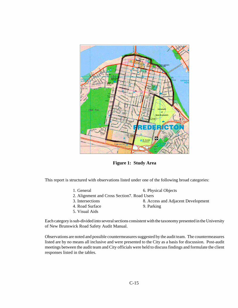
C-15
Figure 1: Study Area
This report is structured with observations listed under one of the following broad categories:
1. General 6. Physical Objects2. Alignment and Cross Section7. Road Users3. Intersections 8. Access and Adjacent Development4. Road Surface 9. Parking5. Visual Aids
Each category is sub-divided into several sections consistent with the taxonomy presented in the Universityof New Brunswick Road Safety Audit Manual.
Observations are noted and possible countermeasures suggested by the audit team. The countermeasureslisted are by no means all inclusive and were presented to the City as a basis for discussion. Post-auditmeetings between the audit team and City officials were held to discuss findings and formulate the clientresponses listed in the tables.
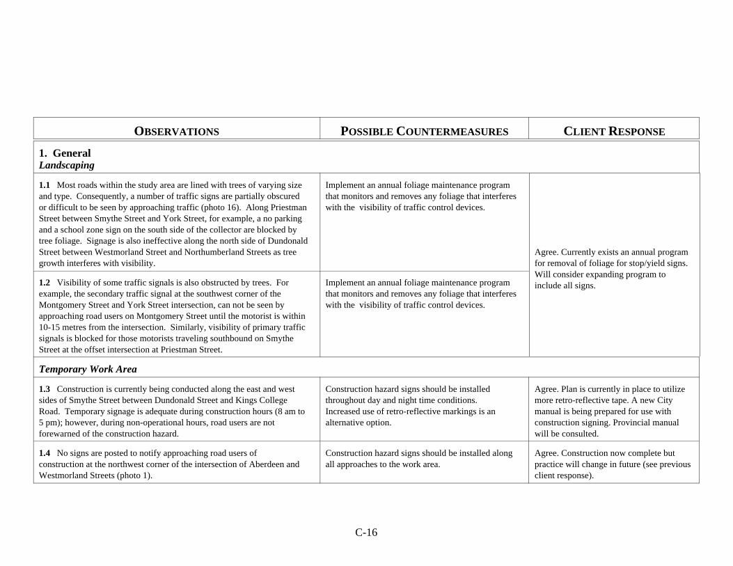
C-16
OBSERVATIONS POSSIBLE COUNTERMEASURES CLIENT RESPONSE
1. GeneralLandscaping
1.1 Most roads within the study area are lined with trees of varying sizeand type. Consequently, a number of traffic signs are partially obscuredor difficult to be seen by approaching traffic (photo 16). Along PriestmanStreet between Smythe Street and York Street, for example, a no parkingand a school zone sign on the south side of the collector are blocked bytree foliage. Signage is also ineffective along the north side of DundonaldStreet between Westmorland Street and Northumberland Streets as treegrowth interferes with visibility.
Implement an annual foliage maintenance programthat monitors and removes any foliage that interfereswith the visibility of traffic control devices.
Agree. Currently exists an annual programfor removal of foliage for stop/yield signs.Will consider expanding program toinclude all signs. 1.2 Visibility of some traffic signals is also obstructed by trees. For
example, the secondary traffic signal at the southwest corner of theMontgomery Street and York Street intersection, can not be seen byapproaching road users on Montgomery Street until the motorist is within 10-15 metres from the intersection. Similarly, visibility of primary trafficsignals is blocked for those motorists traveling southbound on SmytheStreet at the offset intersection at Priestman Street.
Implement an annual foliage maintenance programthat monitors and removes any foliage that interfereswith the visibility of traffic control devices.
Temporary Work Area
1.3 Construction is currently being conducted along the east and westsides of Smythe Street between Dundonald Street and Kings CollegeRoad. Temporary signage is adequate during construction hours (8 am to5 pm); however, during non-operational hours, road users are notforewarned of the construction hazard.
Construction hazard signs should be installedthroughout day and night time conditions. Increased use of retro-reflective markings is analternative option.
Agree. Plan is currently in place to utilizemore retro-reflective tape. A new Citymanual is being prepared for use withconstruction signing. Provincial manualwill be consulted.
1.4 No signs are posted to notify approaching road users ofconstruction at the northwest corner of the intersection of Aberdeen andWestmorland Streets (photo 1).
Construction hazard signs should be installed alongall approaches to the work area.
Agree. Construction now complete butpractice will change in future (see previousclient response).
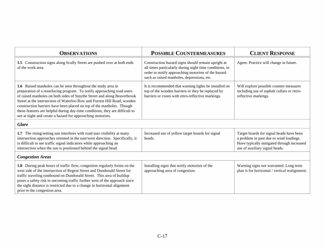
C-17
OBSERVATIONS POSSIBLE COUNTERMEASURES CLIENT RESPONSE
1.5 Construction signs along Scully Street are pushed over at both endsof the work area.
Construction hazard signs should remain upright atall times particularly during night time conditions, inorder to notify approaching motorists of the hazardsuch as raised manholes, depressions, etc.
Agree. Practice will change in future.
1.6 Raised manholes can be seen throughout the study area inpreparation of a resurfacing program. To notify approaching road usersof raised manholes on both sides of Smythe Street and along BeaverbrookStreet at the intersection of Waterloo Row and Forrest Hill Road, woodenconstruction barriers have been placed on top of the manholes. Thoughthese features are helpful during day-time conditions, they are difficult tosee at night and create a hazard for approaching motorists.
It is recommended that warning lights be installed ontop of the wooden barriers or they be replaced bybarriers or cones with retro-reflective markings.
Will explore possible counter-measuresincluding use of asphalt collars or retro-reflective markings.
Glare
1.7 The rising/setting sun interferes with road user visibility at manyintersection approaches oriented in the east/west direction. Specifically, itis difficult to see traffic signal indicators while approaching anintersection when the sun is positioned behind the signal head.
Increased use of yellow target boards for signalheads.
Target boards for signal heads have beena problem in past due to wind loadings. Have typically mitigated through increaseduse of auxiliary signal heads.
Congestion Areas
1.8 During peak hours of traffic flow, congestion regularly forms on thewest side of the intersection of Regent Street and Dundonald Street fortraffic traveling eastbound on Dundonald Street. This area of buildupposes a safety risk to oncoming traffic further west of the approach sincethe sight distance is restricted due to a change in horizontal alignmentprior to the congestion area.
Installing signs that notify motorists of theapproaching area of congestion.
Warning signs not warranted. Long termplan is for horizontal / vertical realignment.
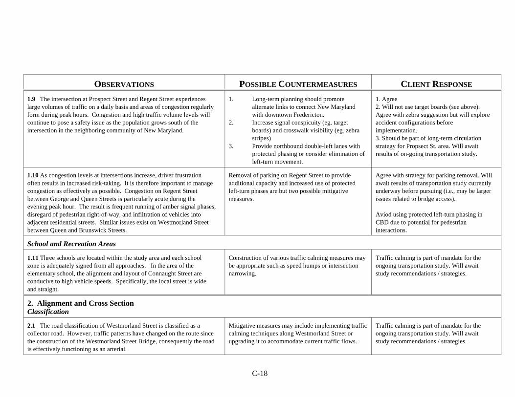
C-18
OBSERVATIONS POSSIBLE COUNTERMEASURES CLIENT RESPONSE
1.9 The intersection at Prospect Street and Regent Street experienceslarge volumes of traffic on a daily basis and areas of congestion regularlyform during peak hours. Congestion and high traffic volume levels willcontinue to pose a safety issue as the population grows south of theintersection in the neighboring community of New Maryland.
1. Long-term planning should promotealternate links to connect New Marylandwith downtown Fredericton.
2. Increase signal conspicuity (eg. targetboards) and crosswalk visibility (eg. zebrastripes)
3. Provide northbound double-left lanes withprotected phasing or consider elimination ofleft-turn movement.
1. Agree2. Will not use target boards (see above).Agree with zebra suggestion but will exploreaccident configurations beforeimplementation.3. Should be part of long-term circulationstrategy for Propsect St. area. Will awaitresults of on-going transportation study.
1.10 As congestion levels at intersections increase, driver frustrationoften results in increased risk-taking. It is therefore important to managecongestion as effectively as possible. Congestion on Regent Streetbetween George and Queen Streets is particularly acute during theevening peak hour. The result is frequent running of amber signal phases,disregard of pedestrian right-of-way, and infiltration of vehicles intoadjacent residential streets. Similar issues exist on Westmorland Streetbetween Queen and Brunswick Streets.
Removal of parking on Regent Street to provideadditional capacity and increased use of protectedleft-turn phases are but two possible mitigativemeasures.
Agree with strategy for parking removal. Willawait results of transportation study currentlyunderway before pursuing (i.e., may be largerissues related to bridge access).
Aviod using protected left-turn phasing inCBD due to potential for pedestrianinteractions.
School and Recreation Areas
1.11 Three schools are located within the study area and each schoolzone is adequately signed from all approaches. In the area of theelementary school, the alignment and layout of Connaught Street areconducive to high vehicle speeds. Specifically, the local street is wideand straight.
Construction of various traffic calming measures maybe appropriate such as speed humps or intersectionnarrowing.
Traffic calming is part of mandate for theongoing transportation study. Will awaitstudy recommendations / strategies.
2. Alignment and Cross SectionClassification
2.1 The road classification of Westmorland Street is classified as acollector road. However, traffic patterns have changed on the route sincethe construction of the Westmorland Street Bridge, consequently the roadis effectively functioning as an arterial.
Mitigative measures may include implementing trafficcalming techniques along Westmorland Street orupgrading it to accommodate current traffic flows.
Traffic calming is part of mandate for theongoing transportation study. Will awaitstudy recommendations / strategies.
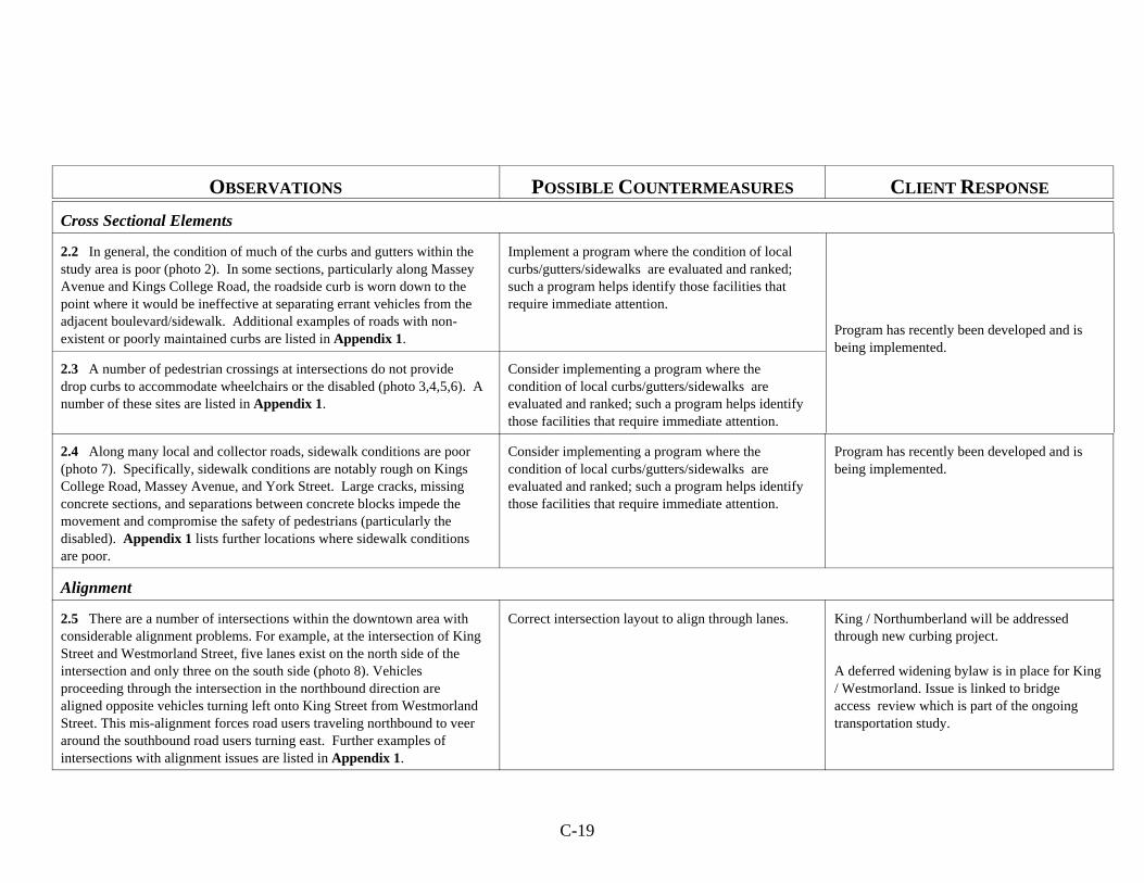
C-19
OBSERVATIONS POSSIBLE COUNTERMEASURES CLIENT RESPONSE
Cross Sectional Elements
2.2 In general, the condition of much of the curbs and gutters within thestudy area is poor (photo 2). In some sections, particularly along MasseyAvenue and Kings College Road, the roadside curb is worn down to thepoint where it would be ineffective at separating errant vehicles from theadjacent boulevard/sidewalk. Additional examples of roads with non-existent or poorly maintained curbs are listed in Appendix 1.
Implement a program where the condition of localcurbs/gutters/sidewalks are evaluated and ranked;such a program helps identify those facilities thatrequire immediate attention.
Program has recently been developed and isbeing implemented.
2.3 A number of pedestrian crossings at intersections do not providedrop curbs to accommodate wheelchairs or the disabled (photo 3,4,5,6). Anumber of these sites are listed in Appendix 1.
Consider implementing a program where thecondition of local curbs/gutters/sidewalks areevaluated and ranked; such a program helps identifythose facilities that require immediate attention.
2.4 Along many local and collector roads, sidewalk conditions are poor(photo 7). Specifically, sidewalk conditions are notably rough on KingsCollege Road, Massey Avenue, and York Street. Large cracks, missingconcrete sections, and separations between concrete blocks impede themovement and compromise the safety of pedestrians (particularly thedisabled). Appendix 1 lists further locations where sidewalk conditionsare poor.
Consider implementing a program where thecondition of local curbs/gutters/sidewalks areevaluated and ranked; such a program helps identifythose facilities that require immediate attention.
Program has recently been developed and isbeing implemented.
Alignment
2.5 There are a number of intersections within the downtown area withconsiderable alignment problems. For example, at the intersection of KingStreet and Westmorland Street, five lanes exist on the north side of theintersection and only three on the south side (photo 8). Vehiclesproceeding through the intersection in the northbound direction arealigned opposite vehicles turning left onto King Street from WestmorlandStreet. This mis-alignment forces road users traveling northbound to veeraround the southbound road users turning east. Further examples ofintersections with alignment issues are listed in Appendix 1.
Correct intersection layout to align through lanes. King / Northumberland will be addressedthrough new curbing project.
A deferred widening bylaw is in place for King/ Westmorland. Issue is linked to bridgeaccess review which is part of the ongoingtransportation study.
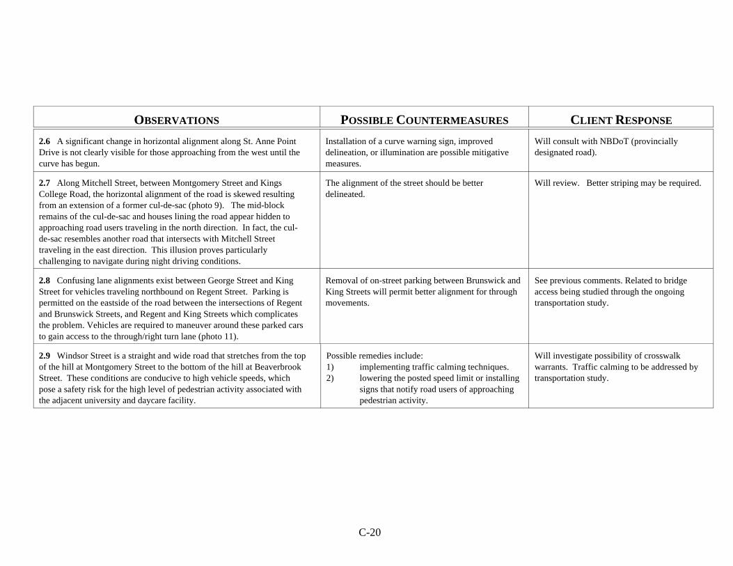
C-20
OBSERVATIONS POSSIBLE COUNTERMEASURES CLIENT RESPONSE
2.6 A significant change in horizontal alignment along St. Anne PointDrive is not clearly visible for those approaching from the west until thecurve has begun.
Installation of a curve warning sign, improveddelineation, or illumination are possible mitigativemeasures.
Will consult with NBDoT (provinciallydesignated road).
2.7 Along Mitchell Street, between Montgomery Street and KingsCollege Road, the horizontal alignment of the road is skewed resultingfrom an extension of a former cul-de-sac (photo 9). The mid-blockremains of the cul-de-sac and houses lining the road appear hidden toapproaching road users traveling in the north direction. In fact, the cul-de-sac resembles another road that intersects with Mitchell Streettraveling in the east direction. This illusion proves particularlychallenging to navigate during night driving conditions.
The alignment of the street should be betterdelineated.
Will review. Better striping may be required.
2.8 Confusing lane alignments exist between George Street and KingStreet for vehicles traveling northbound on Regent Street. Parking ispermitted on the eastside of the road between the intersections of Regentand Brunswick Streets, and Regent and King Streets which complicatesthe problem. Vehicles are required to maneuver around these parked carsto gain access to the through/right turn lane (photo 11).
Removal of on-street parking between Brunswick andKing Streets will permit better alignment for throughmovements.
See previous comments. Related to bridgeaccess being studied through the ongoingtransportation study.
2.9 Windsor Street is a straight and wide road that stretches from the topof the hill at Montgomery Street to the bottom of the hill at BeaverbrookStreet. These conditions are conducive to high vehicle speeds, whichpose a safety risk for the high level of pedestrian activity associated withthe adjacent university and daycare facility.
Possible remedies include:1) implementing traffic calming techniques.2) lowering the posted speed limit or installing
signs that notify road users of approachingpedestrian activity.
Will investigate possibility of crosswalkwarrants. Traffic calming to be addressed bytransportation study.
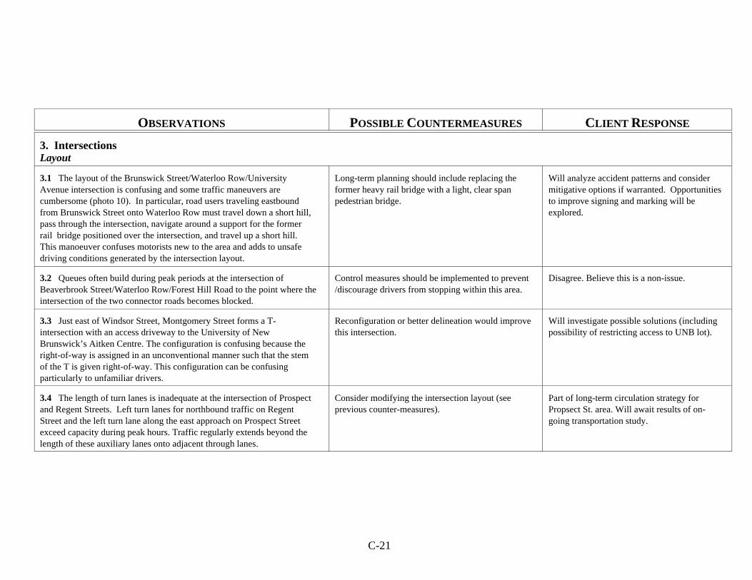
C-21
OBSERVATIONS POSSIBLE COUNTERMEASURES CLIENT RESPONSE
3. IntersectionsLayout
3.1 The layout of the Brunswick Street/Waterloo Row/UniversityAvenue intersection is confusing and some traffic maneuvers arecumbersome (photo 10). In particular, road users traveling eastboundfrom Brunswick Street onto Waterloo Row must travel down a short hill,pass through the intersection, navigate around a support for the formerrail bridge positioned over the intersection, and travel up a short hill. This manoeuver confuses motorists new to the area and adds to unsafedriving conditions generated by the intersection layout.
Long-term planning should include replacing theformer heavy rail bridge with a light, clear spanpedestrian bridge.
Will analyze accident patterns and considermitigative options if warranted. Opportunitiesto improve signing and marking will beexplored.
3.2 Queues often build during peak periods at the intersection ofBeaverbrook Street/Waterloo Row/Forest Hill Road to the point where theintersection of the two connector roads becomes blocked.
Control measures should be implemented to prevent/discourage drivers from stopping within this area.
Disagree. Believe this is a non-issue.
3.3 Just east of Windsor Street, Montgomery Street forms a T-intersection with an access driveway to the University of NewBrunswick’s Aitken Centre. The configuration is confusing because theright-of-way is assigned in an unconventional manner such that the stemof the T is given right-of-way. This configuration can be confusingparticularly to unfamiliar drivers.
Reconfiguration or better delineation would improvethis intersection.
Will investigate possible solutions (includingpossibility of restricting access to UNB lot).
3.4 The length of turn lanes is inadequate at the intersection of Prospectand Regent Streets. Left turn lanes for northbound traffic on RegentStreet and the left turn lane along the east approach on Prospect Streetexceed capacity during peak hours. Traffic regularly extends beyond thelength of these auxiliary lanes onto adjacent through lanes.
Consider modifying the intersection layout (seeprevious counter-measures).
Part of long-term circulation strategy forPropsect St. area. Will await results of on-going transportation study.
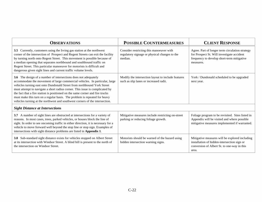
C-22
OBSERVATIONS POSSIBLE COUNTERMEASURES CLIENT RESPONSE
3.5 Currently, customers using the Irving gas station at the northwestcorner of the intersection of Prospect and Regent Streets can exit the facilityby turning north onto Regent Street. This movement is possible because ofa median opening that separates northbound and southbound traffic onRegent Street. This particular manoeuver for motorists is difficult anddangerous given sight lines and current traffic volume levels.
Consider restricting this manoeuver withregulatory signage or physical changes to themedian.
Agree. Part of longer term circulation strategyfor Prospect St. Will investigate accidentfrequency to develop short-term mitigativemeasures.
3.6 The design of a number of intersections does not adequatelyaccommodate the movement of large commercial vehicles. In particular, largevehicles turning east onto Dundonald Street from northbound York Streetmust attempt to navigate a short radius corner. This issue is complicated bythe fact that a fire station is positioned on the same corner and fire trucksmust make this turn on a regular basis. The problem is repeated for heavyvehicles turning at the northwest and southwest corners of the intersection.
Modify the intersection layout to include featuressuch as slip lanes or increased radii.
York / Dundonald scheduled to be upgradednext year.
Sight Distance at Intersections
3.7 A number of sight lines are obstructed at intersections for a variety ofreasons. In most cases, trees, parked vehicles, or houses block the line ofsight. In order to see oncoming traffic in either direction, it is necessary for avehicle to move forward well beyond the stop line or stop sign. Examples ofintersections with sight distance problems are listed in Appendix 1.
Mitigative measures include restricting on-streetparking or reducing foliage growth.
Foliage program to be revisited. Sites listed inAppendix will be visited and where possiblemitigative measures implemented if warranted.
3.8 Sub-standard sight distance exists for vehicles stopped on Albert Streetat its intersection with Windsor Street. A blind hill is present to the north ofthe intersection on Windsor Street.
Motorists should be warned of the hazard usinghidden intersection warning signs.
Mitigative measures will be explored includinginstallation of hidden-intersection sign orconversion of Albert St. to one-way in thisarea.
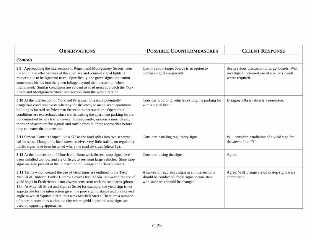
C-23
OBSERVATIONS POSSIBLE COUNTERMEASURES CLIENT RESPONSE
Controls
3.9 Approaching the intersection of Regent and Montgomery Streets fromthe south, the effectiveness of the auxiliary and primary signal lights isreduced due to background trees. Specifically, the green signal indicationsometimes blends into the green foliage beyond the intersection whenilluminated. Similar conditions are evident as road users approach the YorkStreet and Montgomery Street intersection from the west direction.
Use of yellow target boards is an option toincrease signal conspicuity.
See previous discussion of target boards. Willinvestigate increased use of auxiliary headswhere required.
3.10 At the intersection of York and Priestman Streets, a potentiallydangerous condition exists whereby the driveway to an adjacent apartmentbuilding is located on Priestman Street at the intersection. Operationalconditions are exacerbated since traffic exiting the apartment parking lot arenot controlled by any traffic device. Subsequently, motorists must closelymonitor adjacent traffic signals and traffic from all three approaches beforethey can enter the intersection.
Consider providing vehicles exiting the parking lotwith a signal head.
Disagree. Observation is a non-issue.
3.11 Simcoe Court is shaped like a ‘Y’ as the road splits into two separatecul-de-sacs. Though this local street receives very little traffic, no regulatorytraffic signs have been installed where the road diverges (photo 12).
Consider installing regulatory signs. Will consider installation of a yield sign forthe stem of the “Y”.
3.12 At the intersection of Church and Brunswick Streets, stop signs havebeen installed too low and are difficult to see from large vehicles. Short stopsigns are also present at the intersection of George and Church Streets.
Consider raising the signs. Agree.
3.13 Terms which control the use of yield signs are outlined in the TACManual of Uniform Traffic Control Devices for Canada. However, the use ofyield signs in Fredericton is not always consistent with the standards (photo13). At Mitchell Street and Squires Street for example, the yield sign is notappropriate for the intersection given the poor sight distance and the skewedangle in which Squires Street intersects Mitchell Street. There are a numberof other intersections within the city where yield signs and stop signs areused on opposing approaches.
A survey of regulatory signs at all intersectionsshould be conducted; those signs inconsistentwith standards should be changed.
Agree. Will change yields to stop signs wereappropriate.

C-24
OBSERVATIONS POSSIBLE COUNTERMEASURES CLIENT RESPONSE
4. Road Surface
4.1 Within the study area, the condition of pavement varies according tothe road classification. Generally, local roads appear to be roughest, withsections of road filled with cracks, bumps and potholes. The pavementcondition is particularly poor where the edge of the pavement meets thecurb. This is especially problematic for cyclists. A list of roads andintersections showing pavement distress are found in Appendix 1.
Consider resurfacing the pavement in areas whereroad conditions are particularly poor.
Currently developing a program to manageand prioritize pavement resurfacing.
4.2 The arterial roads are generally free of pavement defects. However, thepavement on the south approach of the Regent-Dundonald Streetintersection has rippled as a result of vehicles, particularly heavy trucks,stopping at the base of the hill.
Consider resurfacing the pavement.
4.3 Pavement conditions at the entrance to several parking lots alongProspect Street are deteriorating. Specifically, pavement is crumbling andcracking in areas where the edge of the arterial street connects with theentrance/exit of the access route.
5. Visual AidsPavement Markings
5.1 Most pavement centrelines are well defined. However, supplementalpavement markings are often faded or absent. At the intersection ofBeaverbrook and Regent Streets, and also the intersection of Montgomeryand Regent Streets, crosswalk markings are missing.
Consider increasing frequency of re-stripingprogram.
Annual program is in place. May considerchanging paint types (to something moredurable) and/or increased use of manufacturedpavement markings (eg., thermoplastics).
5.2 An issue associated with channelization measures at intersections is thecondition of pavement markings within the study area. At Montgomery andRegent Streets for example, the left turn arrows are faded and their visibilityfrom the approach is limited. Along Regent Street, the effectiveness ofchannelization markings are also reduced due to fading. Appendix 1 listsadditional areas where the effectiveness of channelization is reduced due topoor pavement markings.
C-25
OBSERVATIONS POSSIBLE COUNTERMEASURES CLIENT RESPONSE
5.3 The southwest corner of the intersection of Regent and DundonaldStreets has a pedestrian crossing marked despite the lack of a sidewalkadjacent to either street in this area.
Consider removing the markings. Agree.
Lighting
5.4 Overhead luminaires are not functionary along Regent Street betweenKings College Road and Montgomery Street. Street lamps are also missingat the intersection of King and Northumberland Streets.
Maintain/repair as required. Annual program in place.
5.5 Proper illumination is not provided at two confusing and complicatedintersections; (1) at Waterloo Row/Beaverbrook Street/Forrest Hill Road,vehicles must exercise caution when using the poorly lit west corner of theintersection and (2) at Waterloo Row/Brunswick Street/University Avenue, anumber of dangerous obstacles exist in and around the intersection thatcould be better illuminated.
Consider installing additional illumination devices. Agree. Will investigate.
5.6 Along Dundonald Street, from Regent to Northumberland Streets, darksegments of the road exist due to a general lack of overhead lighting. Furthermore, overhanging trees reduce the effectiveness of luminaires thatare present.
Installing additional luminaires or reducing foliageare possible mitigative measures.
Long term plan is to replace trees withdifferent species (with less intrusivecanopies). Will re-evaluate planting policy onarterial streets.
Signs
5.7 An assortment of signs are improperly positioned. For example, the“traffic signal ahead” sign on the east side of Montgomery Street, prior toYork Street, is too close to the intersection. On Connaught Street, a noparking sign is turned away from traffic flow rendering it ineffective.
All traffic signs should be positioned according toTAC standards.
Agree. The traffic signal ahead sign was onlymeant to be temporary and will be removed.
5.8 The “no parking” sign located on Priestman Street near Regent Streetis faded. Similarly, the “do not enter” signs on the west side of RegentStreet prior to Priestman Street are difficult to see and offer poor retro-reflectivity. Appendix 1 lists other examples of signs that have faded and areno longer retro-reflective (photos 17 and 18).
Consider replacing the signs. Agree.
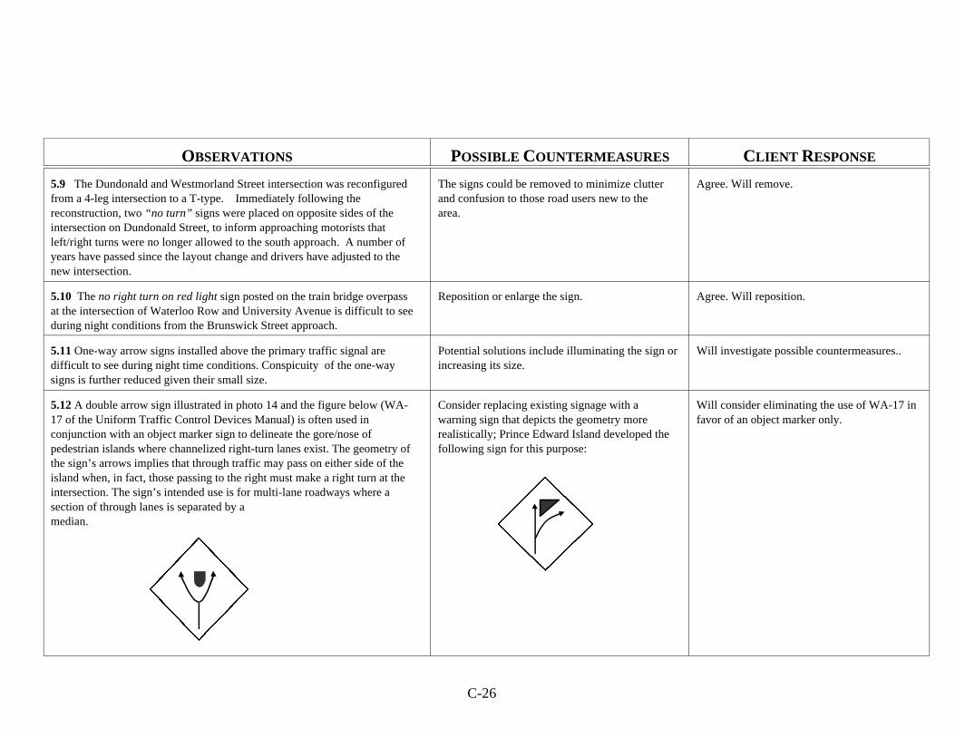
C-26
OBSERVATIONS POSSIBLE COUNTERMEASURES CLIENT RESPONSE
5.9 The Dundonald and Westmorland Street intersection was reconfiguredfrom a 4-leg intersection to a T-type. Immediately following thereconstruction, two “no turn” signs were placed on opposite sides of theintersection on Dundonald Street, to inform approaching motorists thatleft/right turns were no longer allowed to the south approach. A number ofyears have passed since the layout change and drivers have adjusted to thenew intersection.
The signs could be removed to minimize clutterand confusion to those road users new to thearea.
Agree. Will remove.
5.10 The no right turn on red light sign posted on the train bridge overpassat the intersection of Waterloo Row and University Avenue is difficult to seeduring night conditions from the Brunswick Street approach.
Reposition or enlarge the sign. Agree. Will reposition.
5.11 One-way arrow signs installed above the primary traffic signal aredifficult to see during night time conditions. Conspicuity of the one-waysigns is further reduced given their small size.
Potential solutions include illuminating the sign orincreasing its size.
Will investigate possible countermeasures..
5.12 A double arrow sign illustrated in photo 14 and the figure below (WA-17 of the Uniform Traffic Control Devices Manual) is often used inconjunction with an object marker sign to delineate the gore/nose ofpedestrian islands where channelized right-turn lanes exist. The geometry ofthe sign’s arrows implies that through traffic may pass on either side of theisland when, in fact, those passing to the right must make a right turn at theintersection. The sign’s intended use is for multi-lane roadways where asection of through lanes is separated by amedian.
Consider replacing existing signage with awarning sign that depicts the geometry morerealistically; Prince Edward Island developed thefollowing sign for this purpose:
Will consider eliminating the use of WA-17 infavor of an object marker only.
C-27
OBSERVATIONS POSSIBLE COUNTERMEASURES CLIENT RESPONSE
5.13 Crosswalk signs installed at the intersections of St. John Street-Aberdeen Street and Church Street-Aberdeen Street are non-conformingaccording to the Manual of Uniform Traffic Control Devices for Canada. Thesymbol for the ‘Playground Area Sign’ was used which is traditionallydisplayed on a yellow board and is used to indicate upcoming sections ofroads adjoining public playgrounds (photo 15).
Consider replacing non-conforming signs. Agree. Will replace with TAC standard signs.
5.14 Visual clutter exists due to the quantity of signs installed in the vicinityof the Beaverbrook Street/Waterloo Row/Forrest Hill Road intersection. Road users traveling east and west through the intersection alongBeaverbrook Street can be confused/ distracted by stop signs used tocontrol traffic along the adjacent walking/bicycle trail. Conditions areexacerbated during night time driving.
Eliminate or modify trail signs. Will investigate use of non-reflectivesheetings or alternate colours / messages. Willalso consider lowering signs and anglingaway from adjacent motorists.
6. Physical ObjectsMedians
6.1 The median located at the south end of Regent Street has becomecluttered with signs. The “visual noise” created by these signs can confuseapproaching road users as it is difficult to process each sign individually.
Rationalize signing as much as possible in thisarea.
Disagree. All signing is required. Noopportunities to rationalize.
Clear Zone
6.2 There is no curb on King Street between Westmorland andNorthumberland Streets. The absence of this feature creates a serious safetyhazard since there are utility poles located on the south side of King Street,with no separation from eastbound traffic.
Install curbing. Upgrading of the street is programmed.
Poles and Other Obstructions
6.3 At the northeast corner of Regent-Montgomery Streets and thesoutheast corner of Aberdeen-Regent Streets, large steel utility poles standunprotected on each island (photo 19).
Poles should be protected to help reduce theseverity of accidents.
Will investigate possible countermeasures(eg., guardrail).
C-28
OBSERVATIONS POSSIBLE COUNTERMEASURES CLIENT RESPONSE
6.4 The breakaway base of a number of traffic light poles have been placedon top of fixed pedestals which extend well above grade levels. On thenorthwest corner of York Street and Dundonald Street for example, the baseof a traffic light pole is placed on a concrete foundation approximately 2-3 fthigh (photo 20). Also, at the intersection of York and Queen Streets, trafficlight poles were placed on stone blocks about 2 feet high (photo 21). Similarexamples of elevated traffic lights and poles not protected by curbs are listedin Appendix 1 (see also photos 22 and 23).
Fixed pedestals should be lowered so that thefrangible bases may function properly if struck byan errant vehicle.
Poles with ornamental bases are in low speedareas and are not considered a hazard. Somepoles are preferred to remain standing ratherthan endanger pedestrian bystanders. Somebases will be converted where appropriate.
7. Road UsersMotorized Traffic
7.1 The bus stop on the north side of Montgomery Street east of RegentStreet, is located very close to the intersection. A potential safety hazardexists for motorists using the intersection if the bus stops for passengersand a resultant queue forms.
Consider relocating the bus stop. Disagree. Non-issue.
7.2 A bus stop is located on the east side of Regent Street betweenBrunswick Street and King Street. A potential safety hazard exists for bothmotorists and bus passengers at this location as vehicle parking is permitteddirectly in front of the bus stop sign.
Restricting parking or relocating the bus stop aretwo possible mitigative measures.
Will be considered in conjunction withpossible changes to parking. Will discussissue with Fredericton Transit.
Non-Motorized Traffic
7.3 The slats on many storm grates are oriented parallel to the flow oftraffic. Such conditions could prove dangerous as a set of bicycle tirescould get caught in the slats thereby causing the user to lose control. Listedin Appendix 1 are roads where the orientation of storm grates are hazardousto cyclists.
Slats should be oriented perpendicular to trafficflow.
Agree. Will correct where misaligned.
7.4 Poor pavement conditions along many street edges force bicycle usersto travel further away from curbs closer to the flow of traffic. Theseconditions are dangerous to both vehicle owners and cyclists.
Resurface where necessary. See previous comment. Pavement managementprogram under development.
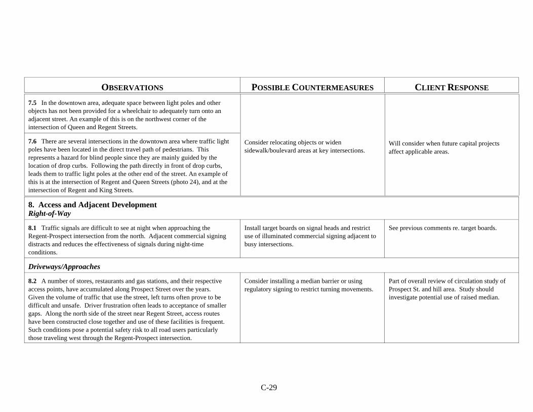
C-29
OBSERVATIONS POSSIBLE COUNTERMEASURES CLIENT RESPONSE
7.5 In the downtown area, adequate space between light poles and otherobjects has not been provided for a wheelchair to adequately turn onto anadjacent street. An example of this is on the northwest corner of theintersection of Queen and Regent Streets.
Consider relocating objects or widensidewalk/boulevard areas at key intersections.
Will consider when future capital projectsaffect applicable areas.
7.6 There are several intersections in the downtown area where traffic lightpoles have been located in the direct travel path of pedestrians. Thisrepresents a hazard for blind people since they are mainly guided by thelocation of drop curbs. Following the path directly in front of drop curbs,leads them to traffic light poles at the other end of the street. An example ofthis is at the intersection of Regent and Queen Streets (photo 24), and at theintersection of Regent and King Streets.
8. Access and Adjacent DevelopmentRight-of-Way
8.1 Traffic signals are difficult to see at night when approaching theRegent-Prospect intersection from the north. Adjacent commercial signingdistracts and reduces the effectiveness of signals during night-timeconditions.
Install target boards on signal heads and restrictuse of illuminated commercial signing adjacent tobusy intersections.
See previous comments re. target boards.
Driveways/Approaches
8.2 A number of stores, restaurants and gas stations, and their respectiveaccess points, have accumulated along Prospect Street over the years. Given the volume of traffic that use the street, left turns often prove to bedifficult and unsafe. Driver frustration often leads to acceptance of smallergaps. Along the north side of the street near Regent Street, access routeshave been constructed close together and use of these facilities is frequent. Such conditions pose a potential safety risk to all road users particularlythose traveling west through the Regent-Prospect intersection.
Consider installing a median barrier or usingregulatory signing to restrict turning movements.
Part of overall review of circulation study ofProspect St. and hill area. Study shouldinvestigate potential use of raised median.
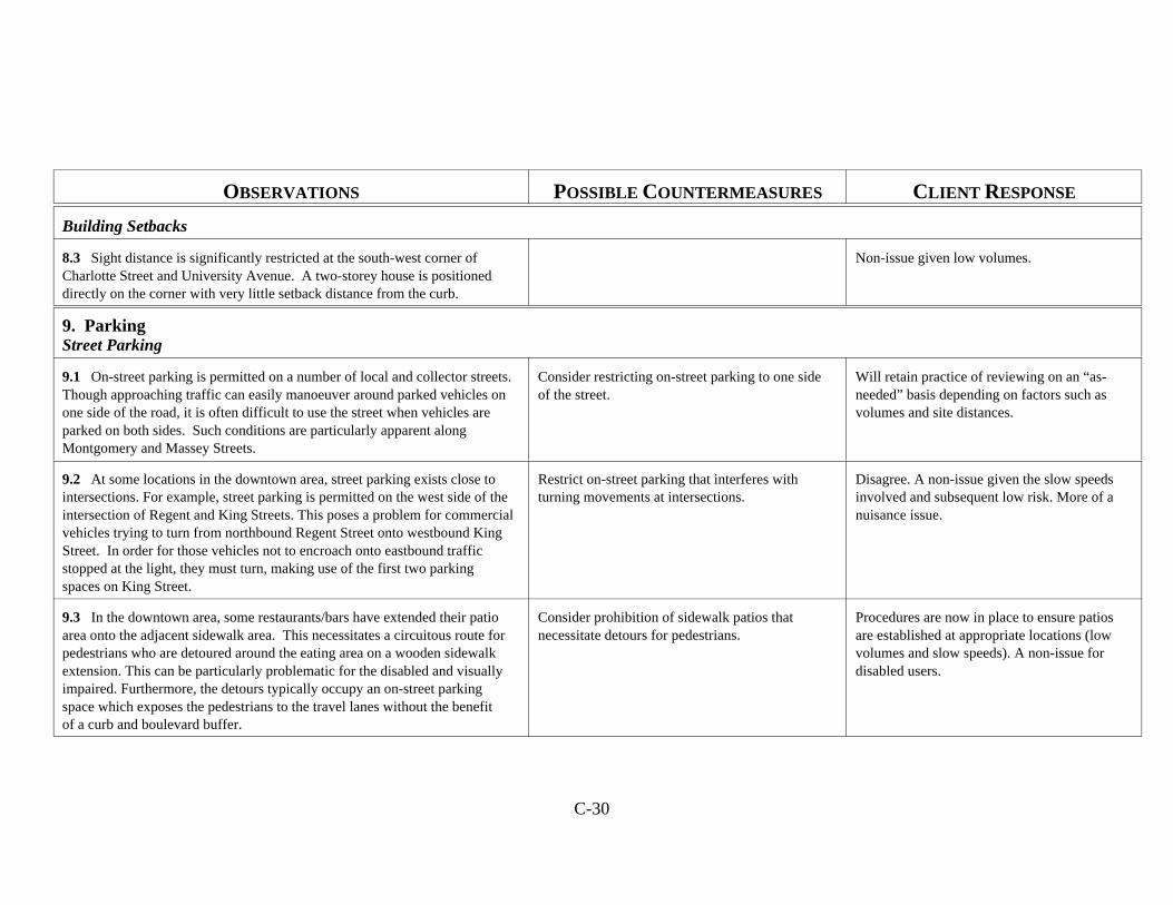
C-30
OBSERVATIONS POSSIBLE COUNTERMEASURES CLIENT RESPONSE
Building Setbacks
8.3 Sight distance is significantly restricted at the south-west corner ofCharlotte Street and University Avenue. A two-storey house is positioneddirectly on the corner with very little setback distance from the curb.
Non-issue given low volumes.
9. ParkingStreet Parking
9.1 On-street parking is permitted on a number of local and collector streets. Though approaching traffic can easily manoeuver around parked vehicles onone side of the road, it is often difficult to use the street when vehicles areparked on both sides. Such conditions are particularly apparent alongMontgomery and Massey Streets.
Consider restricting on-street parking to one sideof the street.
Will retain practice of reviewing on an “as-needed” basis depending on factors such asvolumes and site distances.
9.2 At some locations in the downtown area, street parking exists close tointersections. For example, street parking is permitted on the west side of theintersection of Regent and King Streets. This poses a problem for commercialvehicles trying to turn from northbound Regent Street onto westbound KingStreet. In order for those vehicles not to encroach onto eastbound trafficstopped at the light, they must turn, making use of the first two parkingspaces on King Street.
Restrict on-street parking that interferes withturning movements at intersections.
Disagree. A non-issue given the slow speedsinvolved and subsequent low risk. More of anuisance issue.
9.3 In the downtown area, some restaurants/bars have extended their patioarea onto the adjacent sidewalk area. This necessitates a circuitous route forpedestrians who are detoured around the eating area on a wooden sidewalkextension. This can be particularly problematic for the disabled and visuallyimpaired. Furthermore, the detours typically occupy an on-street parkingspace which exposes the pedestrians to the travel lanes without the benefitof a curb and boulevard buffer.
Consider prohibition of sidewalk patios thatnecessitate detours for pedestrians.
Procedures are now in place to ensure patiosare established at appropriate locations (lowvolumes and slow speeds). A non-issue fordisabled users.

C-31
APPENDIX 1
A. Curb Condition Problems
1. Beaverbrook Street (no curbs on north side from Regent Street to Tweedsmuir Street)2. Grandame Street/Fenety Street (rough curbs)3. Windsor Street (bad curbs)4. University Avenue (no curbs at south end)5. Alexandra Street (low curbs)6. Grey Street (poor curbs)7. Charlotte Street (no curbs between St. John Street and Church Street)8. Albert Street (poor curbs east of York Street)9. Reid Street (no curbs at north end)10. Dundonald Street (poor curbs)11. Prospect Street (poor curbs)12. Priestman Street 13. Regent Street (no curb in sections)14. Smythe Street (poor curbs) 15. Queen Street/Westmorland Street (poor curbs on westside of intersection)16. Westmorland Street/King Street (poor curbs on southwest side of intersection)17. Northumberland Street/King Street (poor curbs on northeast corner)
B. Wheelchair Accessibility Problems
1. Mitchell Street and Kings College Road (at NE and NW corners)2. Massey Street 3. Westmorland Street4. Regent Street (west side, from Kings College Road to Montgomery Street)5. Burden Street and Fenety Street6. Windsor Street7. Winslow Street8. Charlotte Street9. Albert Street (near York Street and near UNB)10. Churchill Row and St. John Street 11. Kings College Road and York Street12. Regent Street/Queen Street (northside of intersection)13. Entrance/exit to pedestrian bridge on northside of St. Anne Drive made of gravel14. Queen Street/York Street15. Smythe Street16. King Street/York Street17. Carleton Street/King Street18. Victoria Street19. Argyle Street
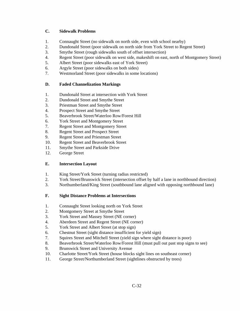
C-32
C. Sidewalk Problems
1. Connaught Street (no sidewalk on north side, even with school nearby)2. Dundonald Street (poor sidewalk on north side from York Street to Regent Street)3. Smythe Street (rough sidewalks south of offset intersection)4. Regent Street (poor sidewalk on west side, makeshift on east, north of Montgomery Street)5. Albert Street (poor sidewalks east of York Street)6. Argyle Street (poor sidewalks on both sides)7. Westmorland Street (poor sidewalks in some locations)
D. Faded Channelization Markings
1. Dundonald Street at intersection with York Street 2. Dundonald Street and Smythe Street 3. Priestman Street and Smythe Street4. Prospect Street and Smythe Street5. Beaverbrook Street/Waterloo Row/Forest Hill6. York Street and Montgomery Street 7. Regent Street and Montgomery Street 8. Regent Street and Prospect Street9. Regent Street and Priestman Street 10. Regent Street and Beaverbrook Street11. Smythe Street and Parkside Drive12. George Street
E. Intersection Layout
1. King Street/York Street (turning radius restricted)2. York Street/Brunswick Street (intersection offset by half a lane in northbound direction)3. Northumberland/King Street (southbound lane aligned with opposing northbound lane)
F. Sight Distance Problems at Intersections
1. Connaught Street looking north on York Street2. Montgomery Street at Smythe Street3. York Street and Massey Street (NE corner)4. Aberdeen Street and Regent Street (NE corner)5. York Street and Albert Street (at stop sign)6. Chestnut Street (sight distance insufficient for yield sign)7. Squires Street and Mitchell Street (yield sign where sight distance is poor)8. Beaverbrook Street/Waterloo Row/Forest Hill (must pull out past stop signs to see)9. Brunswick Street and University Avenue10. Charlotte Street/York Street (house blocks sight lines on southeast corner)11. George Street/Northumberland Street (sightlines obstructed by trees)
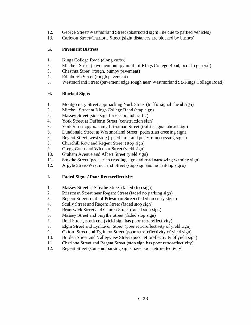
C-33
12. George Street/Westmorland Street (obstructed sight line due to parked vehicles)13. Carleton Street/Charlotte Street (sight distances are blocked by bushes)
G. Pavement Distress
1. Kings College Road (along curbs)2. Mitchell Street (pavement bumpy north of Kings College Road, poor in general)3. Chestnut Street (rough, bumpy pavement)4. Edinburgh Street (rough pavement)5. Westmorland Street (pavement edge rough near Westmorland St./Kings College Road)
H. Blocked Signs
1. Montgomery Street approaching York Street (traffic signal ahead sign)2. Mitchell Street at Kings College Road (stop sign)3. Massey Street (stop sign for eastbound traffic)4. York Street at Dufferin Street (construction sign)5. York Street approaching Priestman Street (traffic signal ahead sign)6. Dundonald Street at Westmorland Street (pedestrian crossing sign)7. Regent Street, west side (speed limit and pedestrian crossing signs)8. Churchill Row and Regent Street (stop sign)9. Gregg Court and Windsor Street (yield sign)10. Graham Avenue and Albert Street (yield sign)11. Smythe Street (pedestrian crossing sign and road narrowing warning sign)12. Argyle Street/Westmorland Street (stop sign and no parking signs)
I. Faded Signs / Poor Retroreflectivity
1. Massey Street at Smythe Street (faded stop sign)2. Priestman Street near Regent Street (faded no parking sign)3. Regent Street south of Priestman Street (faded no entry signs)4. Scully Street and Regent Street (faded stop sign)5. Brunswick Street and Church Street (faded stop sign)6. Massey Street and Smythe Street (faded stop sign)7. Reid Street, north end (yield sign has poor retroreflectivity)8. Elgin Street and Lynhaven Street (poor retroreflectivity of yield sign)9. Oxford Street and Eglinton Street (poor retroreflectivity of yield sign)10. Burden Street and Valleyview Street (poor retroreflectivity of yield sign)11. Charlotte Street and Regent Street (stop sign has poor retroreflectivity)12. Regent Street (some no parking signs have poor retroreflectivity)
C-34
J. Raised Traffic Poles and Unprotected Obstructions
1. Montgomery Street and Regent Street (raised traffic poles)2. Regent Street and Prospect Street (raised traffic poles)3. Priestman Street and Smythe Street (raised traffic poles)4. Queen Street and York Street (raised traffic poles)5. King Street and York Street (raised traffic poles)6. Carlton Street and King Street (telephone pole on the southwest side unprotected)7. Regent Street and King Street (poles located in path of pedestrians at the crosswalk)8. Northumberland Street and King Street (exposed telephone pole)
K. Storm Grates Oriented Parallel to Traffic Flow
1. Windsor Street 2. Reid Street3. Chestnut Street4. Edinburgh Street
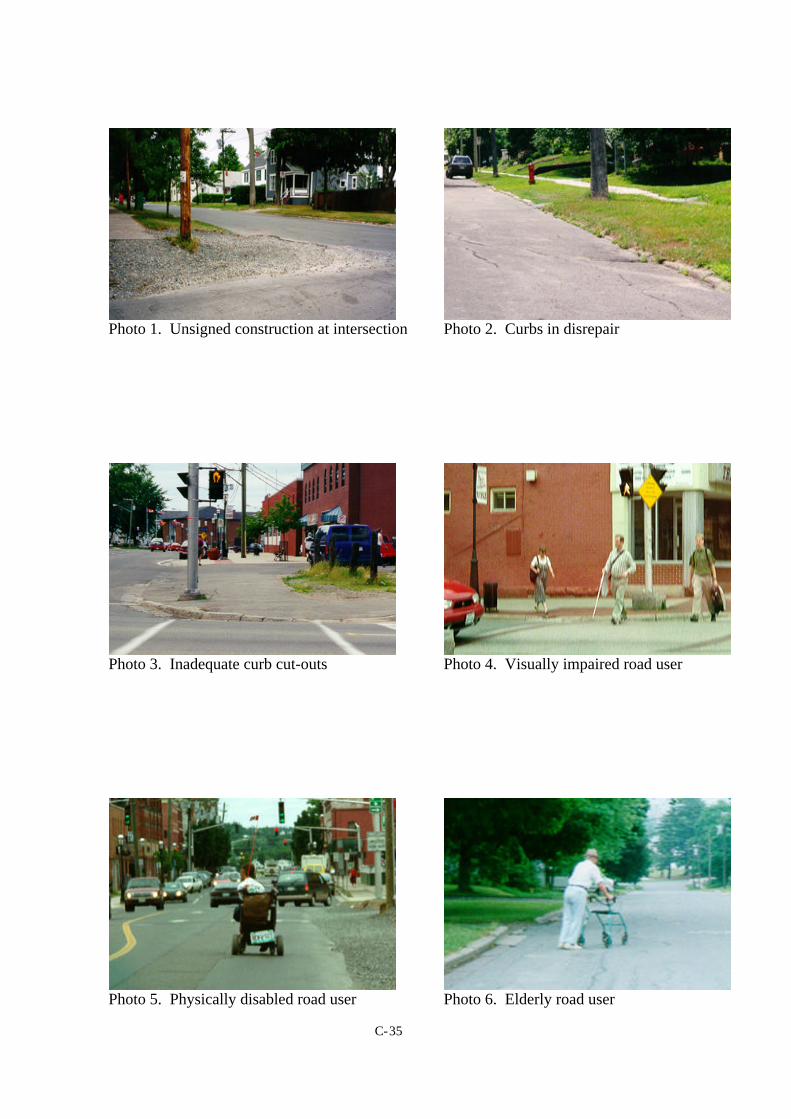
C-35
Photo 1. Unsigned construction at intersection Photo 2. Curbs in disrepair
Photo 3. Inadequate curb cut-outs Photo 4. Visually impaired road user
Photo 5. Physically disabled road user Photo 6. Elderly road user
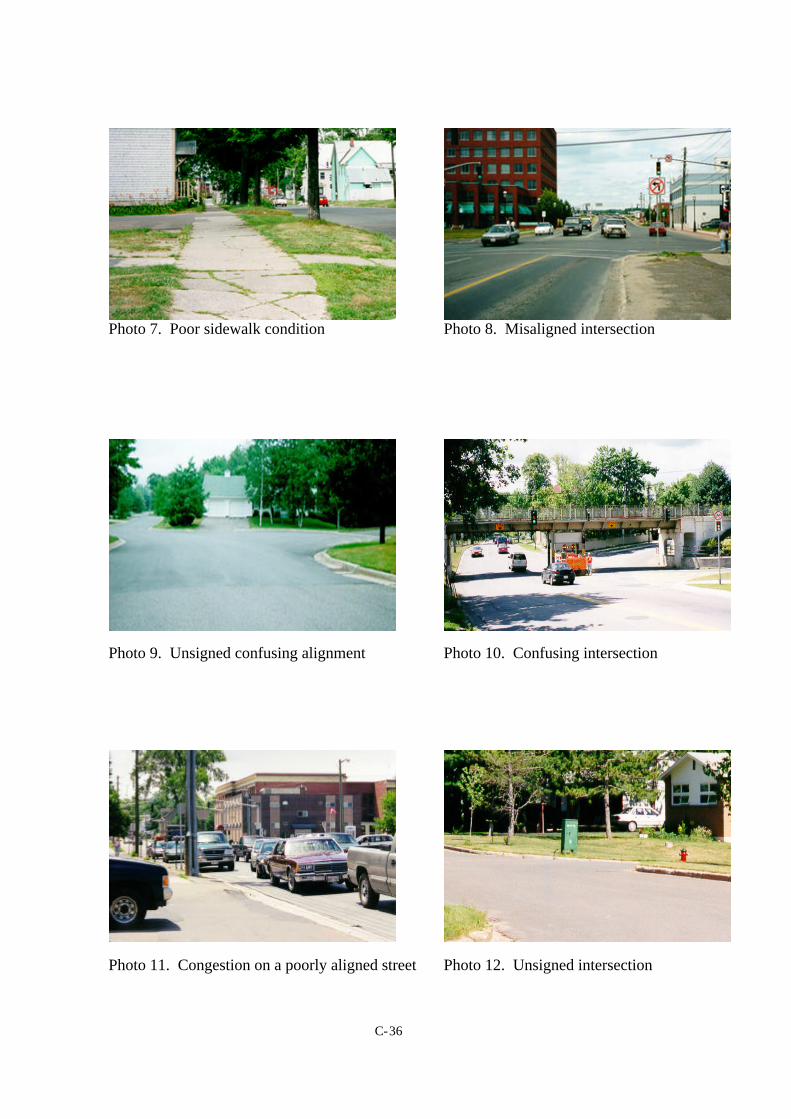
C-36
Photo 7. Poor sidewalk condition Photo 8. Misaligned intersection
Photo 9. Unsigned confusing alignment Photo 10. Confusing intersection
Photo 11. Congestion on a poorly aligned street Photo 12. Unsigned intersection
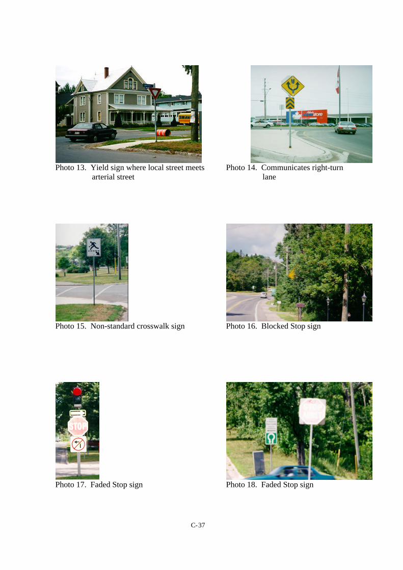
C-37
Photo 13. Yield sign where local street meets Photo 14. Communicates right-turn arterial street lane
Photo 15. Non-standard crosswalk sign Photo 16. Blocked Stop sign
Photo 17. Faded Stop sign Photo 18. Faded Stop sign
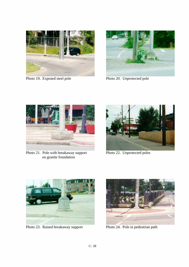
C- 38
Photo 19. Exposed steel pole Photo 20. Unprotected pole
Photo 21. Pole with breakaway support Photo 22. Unprotected poles on granite foundation
Photo 23. Raised breakaway support Photo 24. Pole in pedestrian path
C-39
Road Safety Audit Report
75% DESIGN STAGE -NEW FACILITYROUTE 20 HIGH SPEED CONNECTOR TO ROUTE 21 INTERCHANGE
August, 1999
Audit Team
Dr. F.R. Wilson, P.Eng.Dr. E.D. Hildebrand, P.Eng.
Tammy Dow, B.Sc.E.
Client
Road Builders Inc.Saint John, N.B.
C-40
75% DESIGN STAGE AUDIT: ROUTE 20 HIGH SPEED CONNECTOR TO ROUTE 21INTERCHANGE
Section 1.0: INTRODUCTION
This 75% Design Stage audit is supplementary to the Preliminary Design, 50% Design, and Pre-OpeningAudits completed on June 7, July 16, and August 5, 1999, respectively. The reports of those audits werepreviously submitted to the client. This supplementary audit was conducted by Frank R. Wilson, EricHildebrand, and Tammy Dow during the week of August 20-27, 1999. The audit followed the proceduresused in previous audits.
The 75% Design Stage audit refers to the construction staging of the project. At the time of this audit,approximately 75% of the length of project had the detailed design work completed. The scheduled phasingof construction necessitated that audits be preformed at preset intervals to allow the project to progressefficiently toward full completion.
Material used in this initial pre-opening audit is listed in Appendix 1. In addition to these reference materials,F.R. Wilson and E.D. Hildebrand met with Messers. D. LePage, J. Miller, J. Mosser, and G. Auden priorto undertaking the audit.
Section 2.0 FORMAT OF REPORT
At the time of the audit a number of issues identified in previous audits were outstanding, or their status havechanged. Table 1 presents the outstanding issues that still need to be resolved at this time, while Table 2summaries the findings of the current audit.
Note:The 75% design stage audit covers physical features which may affect road user safety and it hassought to identify potential safety hazards. However, the auditors point out that no guarantee ismade that every deficiency has been identified. Further, if all the recommendations in this reportwere to be followed, this would not confirm that the highway is ‘safe’; rather, adoption of therecommendations should improve the level of safety of the facility.
C-41
Section 3.0: FINDINGS AND RECOMMENDATIONS
Findings and Recommendations from this 75% Design Stage Audit completed on August 27, 1999 arepresented in Table 2. This table complements those findings identified in Table 1 and from those in theprevious audit reports
____________________ ______________________ ________________Dr. F. R. Wilson, P. Eng. Dr. E.D. Hildebrand, P.Eng. T.C. Dow, B.Sc.E.
August 31, 1999
Appendix 1: Documents Used During Audit
1. Revised signage design package prepared by builder and transmitted to F. R. Wilson onAug. 8, 1999.
2. Detailed set of design plans for entire section under review including, cross-sections,horizontal and vertical alignments, drainage, structures, lighting, signing, and pavementmarkings.
3. Owner’s signing plan for Route 21 interchange, dated July 19, 1999.
4. Plan of Pavement Markings, Route #20 Extension and Interchange 21 by Homer &Associates dated June 1, 1999.
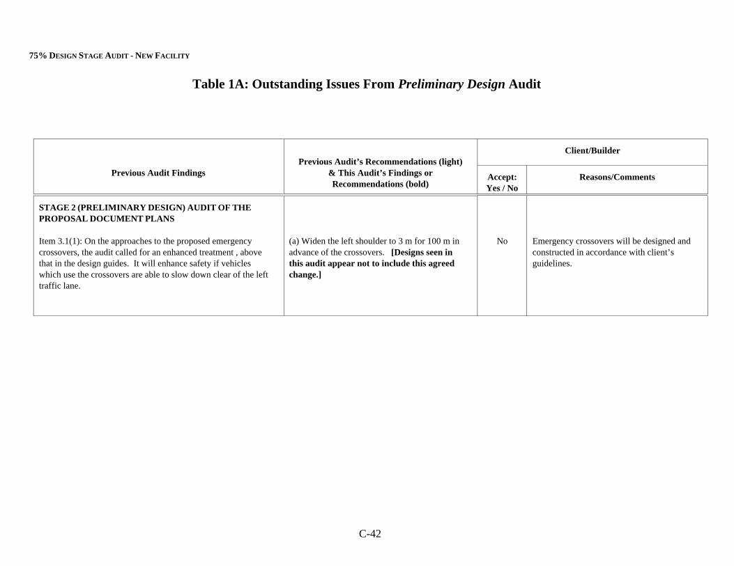
75% DESIGN STAGE AUDIT - NEW FACILITY
Table 1A: Outstanding Issues From Preliminary Design Audit
C-42
Previous Audit FindingsPrevious Audit’s Recommendations (light)
& This Audit’s Findings orRecommendations (bold)
Client/Builder
Accept:Yes / No
Reasons/Comments
STAGE 2 (PRELIMINARY DESIGN) AUDIT OF THEPROPOSAL DOCUMENT PLANS
Item 3.1(1): On the approaches to the proposed emergencycrossovers, the audit called for an enhanced treatment , abovethat in the design guides. It will enhance safety if vehicleswhich use the crossovers are able to slow down clear of the lefttraffic lane.
(a) Widen the left shoulder to 3 m for 100 m inadvance of the crossovers. [Designs seen inthis audit appear not to include this agreedchange.]
No Emergency crossovers will be designed andconstructed in accordance with client’sguidelines.
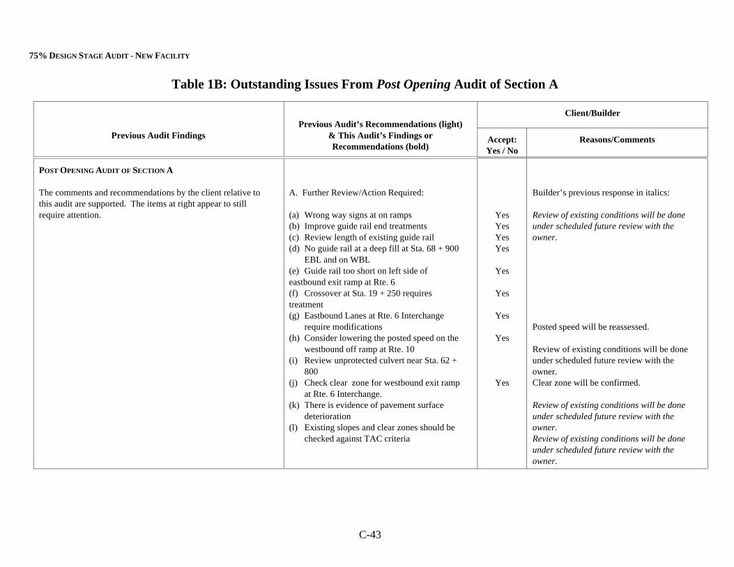
75% DESIGN STAGE AUDIT - NEW FACILITY
Table 1B: Outstanding Issues From Post Opening Audit of Section A
Previous Audit FindingsPrevious Audit’s Recommendations (light)
& This Audit’s Findings orRecommendations (bold)
Client/Builder
Accept:Yes / No
Reasons/Comments
C-43
POST OPENING AUDIT OF SECTION A
The comments and recommendations by the client relative tothis audit are supported. The items at right appear to stillrequire attention.
A. Further Review/Action Required:
(a) Wrong way signs at on ramps(b) Improve guide rail end treatments(c) Review length of existing guide rail(d) No guide rail at a deep fill at Sta. 68 + 900
EBL and on WBL(e) Guide rail too short on left side of eastbound exit ramp at Rte. 6(f) Crossover at Sta. 19 + 250 requires treatment(g) Eastbound Lanes at Rte. 6 Interchange
require modifications(h) Consider lowering the posted speed on the
westbound off ramp at Rte. 10(i) Review unprotected culvert near Sta. 62 +
800(j) Check clear zone for westbound exit ramp
at Rte. 6 Interchange.(k) There is evidence of pavement surface
deterioration(l) Existing slopes and clear zones should be
checked against TAC criteria
YesYesYesYes
Yes
Yes
Yes
Yes
Yes
Builder’s previous response in italics:
Review of existing conditions will be doneunder scheduled future review with theowner.
Posted speed will be reassessed.
Review of existing conditions will be doneunder scheduled future review with theowner.Clear zone will be confirmed.
Review of existing conditions will be doneunder scheduled future review with theowner. Review of existing conditions will be doneunder scheduled future review with theowner.
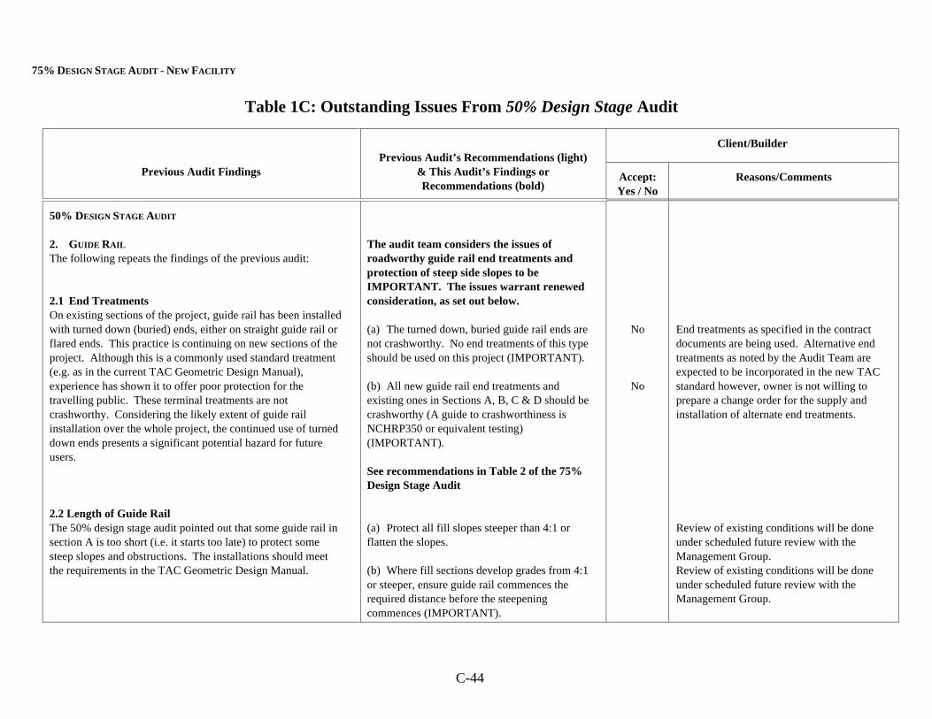
75% DESIGN STAGE AUDIT - NEW FACILITY
Table 1C: Outstanding Issues From 50% Design Stage Audit
Previous Audit FindingsPrevious Audit’s Recommendations (light)
& This Audit’s Findings orRecommendations (bold)
Client/Builder
Accept:Yes / No
Reasons/Comments
C-44
50% DESIGN STAGE AUDIT
2. GUIDE RAIL
The following repeats the findings of the previous audit:
2.1 End TreatmentsOn existing sections of the project, guide rail has been installedwith turned down (buried) ends, either on straight guide rail orflared ends. This practice is continuing on new sections of theproject. Although this is a commonly used standard treatment(e.g. as in the current TAC Geometric Design Manual),experience has shown it to offer poor protection for thetravelling public. These terminal treatments are notcrashworthy. Considering the likely extent of guide railinstallation over the whole project, the continued use of turneddown ends presents a significant potential hazard for futureusers.
2.2 Length of Guide RailThe 50% design stage audit pointed out that some guide rail insection A is too short (i.e. it starts too late) to protect somesteep slopes and obstructions. The installations should meetthe requirements in the TAC Geometric Design Manual.
The audit team considers the issues ofroadworthy guide rail end treatments andprotection of steep side slopes to beIMPORTANT. The issues warrant renewedconsideration, as set out below.
(a) The turned down, buried guide rail ends arenot crashworthy. No end treatments of this typeshould be used on this project (IMPORTANT).
(b) All new guide rail end treatments andexisting ones in Sections A, B, C & D should becrashworthy (A guide to crashworthiness isNCHRP350 or equivalent testing)(IMPORTANT).
See recommendations in Table 2 of the 75%Design Stage Audit
(a) Protect all fill slopes steeper than 4:1 orflatten the slopes.
(b) Where fill sections develop grades from 4:1or steeper, ensure guide rail commences therequired distance before the steepeningcommences (IMPORTANT).
No
No
End treatments as specified in the contractdocuments are being used. Alternative endtreatments as noted by the Audit Team areexpected to be incorporated in the new TACstandard however, owner is not willing toprepare a change order for the supply andinstallation of alternate end treatments.
Review of existing conditions will be doneunder scheduled future review with theManagement Group.Review of existing conditions will be doneunder scheduled future review with theManagement Group.
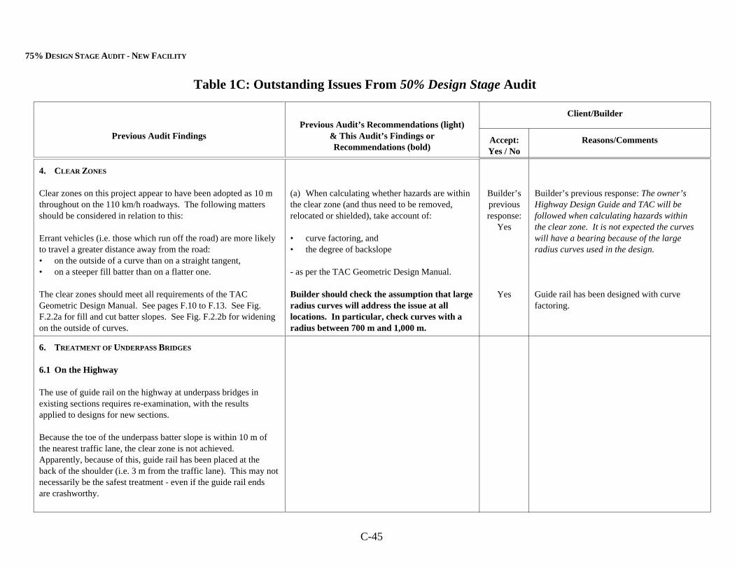
75% DESIGN STAGE AUDIT - NEW FACILITY
Table 1C: Outstanding Issues From 50% Design Stage Audit
Previous Audit FindingsPrevious Audit’s Recommendations (light)
& This Audit’s Findings orRecommendations (bold)
Client/Builder
Accept:Yes / No
Reasons/Comments
C-45
4. CLEAR ZONES
Clear zones on this project appear to have been adopted as 10 mthroughout on the 110 km/h roadways. The following mattersshould be considered in relation to this:
Errant vehicles (i.e. those which run off the road) are more likelyto travel a greater distance away from the road:• on the outside of a curve than on a straight tangent,• on a steeper fill batter than on a flatter one.
The clear zones should meet all requirements of the TACGeometric Design Manual. See pages F.10 to F.13. See Fig.F.2.2a for fill and cut batter slopes. See Fig. F.2.2b for wideningon the outside of curves.
(a) When calculating whether hazards are withinthe clear zone (and thus need to be removed,relocated or shielded), take account of:
• curve factoring, and• the degree of backslope
- as per the TAC Geometric Design Manual.
Builder should check the assumption that largeradius curves will address the issue at alllocations. In particular, check curves with aradius between 700 m and 1,000 m.
Builder’spreviousresponse:
Yes
Yes
Builder’s previous response: The owner’sHighway Design Guide and TAC will befollowed when calculating hazards withinthe clear zone. It is not expected the curveswill have a bearing because of the largeradius curves used in the design.
Guide rail has been designed with curvefactoring.
6. TREATMENT OF UNDERPASS BRIDGES
6.1 On the Highway
The use of guide rail on the highway at underpass bridges inexisting sections requires re-examination, with the resultsapplied to designs for new sections.
Because the toe of the underpass batter slope is within 10 m ofthe nearest traffic lane, the clear zone is not achieved. Apparently, because of this, guide rail has been placed at theback of the shoulder (i.e. 3 m from the traffic lane). This may notnecessarily be the safest treatment - even if the guide rail endsare crashworthy.
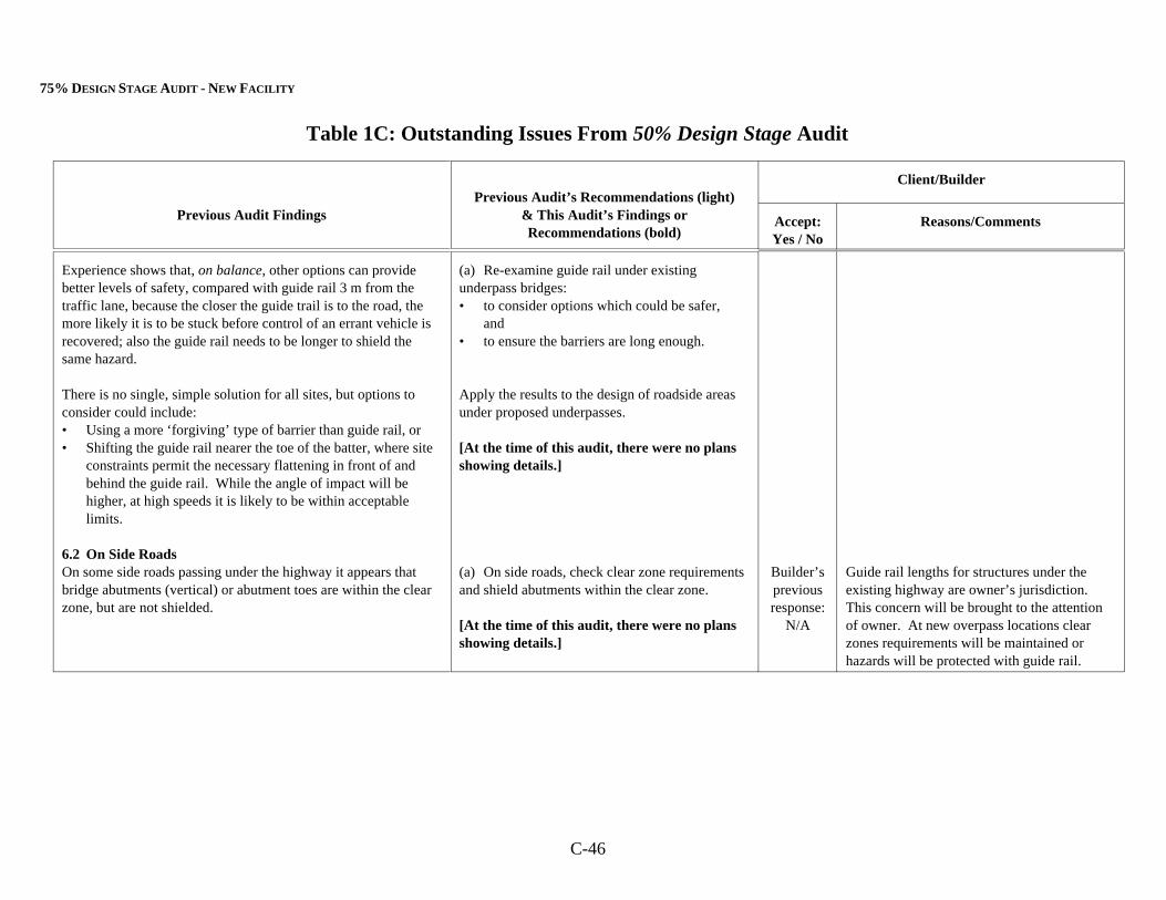
75% DESIGN STAGE AUDIT - NEW FACILITY
Table 1C: Outstanding Issues From 50% Design Stage Audit
Previous Audit FindingsPrevious Audit’s Recommendations (light)
& This Audit’s Findings orRecommendations (bold)
Client/Builder
Accept:Yes / No
Reasons/Comments
C-46
Experience shows that, on balance, other options can providebetter levels of safety, compared with guide rail 3 m from thetraffic lane, because the closer the guide trail is to the road, themore likely it is to be stuck before control of an errant vehicle isrecovered; also the guide rail needs to be longer to shield thesame hazard.
There is no single, simple solution for all sites, but options toconsider could include:• Using a more ‘forgiving’ type of barrier than guide rail, or• Shifting the guide rail nearer the toe of the batter, where site
constraints permit the necessary flattening in front of andbehind the guide rail. While the angle of impact will behigher, at high speeds it is likely to be within acceptablelimits.
6.2 On Side RoadsOn some side roads passing under the highway it appears thatbridge abutments (vertical) or abutment toes are within the clearzone, but are not shielded.
(a) Re-examine guide rail under existingunderpass bridges:• to consider options which could be safer,
and• to ensure the barriers are long enough.
Apply the results to the design of roadside areasunder proposed underpasses.
[At the time of this audit, there were no plansshowing details.]
(a) On side roads, check clear zone requirementsand shield abutments within the clear zone.
[At the time of this audit, there were no plansshowing details.]
Builder’spreviousresponse:
N/A
Guide rail lengths for structures under theexisting highway are owner’s jurisdiction. This concern will be brought to the attentionof owner. At new overpass locations clearzones requirements will be maintained orhazards will be protected with guide rail.
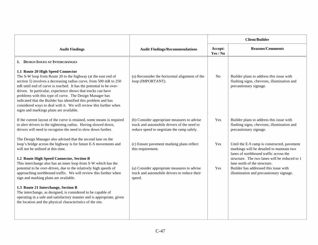
C-47
Audit Findings Audit Findings/Recommendations
Client/Builder
Accept:Yes / No
Reasons/Comments
1. DESIGN ISSUES AT INTERCHANGES
1.1 Route 20 High Speed ConnectorThe S-W loop from Route 20 to the highway (at the east end ofsection 5) involves a decreasing radius curve, from 500 mR to 250mR until end of curve is reached. It has the potential to be over-driven. In particular, experience shows that trucks can haveproblems with this type of curve. The Design Manager hasindicated that the Builder has identified this problem and hasconsidered ways to deal with it. We will review this further whensigns and markings plans are available.
If the current layout of the curve is retained, some means is requiredto alert drivers to the tightening radius. Having slowed down,drivers will need to recognise the need to slow down further.
The Design Manager also advised that the second lane on theloop’s bridge across the highway is for future E-S movements andwill not be utilised at this time.
1.2 Route High Speed Connector, Section BThis interchange also has an inner loop from S-W which has thepotential to be over-driven, due to the relatively high speeds ofapproaching northbound traffic. We will review this further whensign and marking plans are available.
1.3 Route 21 Interchange, Section BThe interchange, as designed, is considered to be capable ofoperating in a safe and satisfactory manner and is appropriate, giventhe location and the physical characteristics of the site.
(a) Reconsider the horizontal alignment of theloop (IMPORTANT).
(b) Consider appropriate measures to advisetruck and automobile drivers of the need toreduce speed to negotiate the ramp safely.
(c) Ensure pavement marking plans reflectthis requirement.
(a) Consider appropriate measures to advisetruck and automobile drivers to reduce theirspeed.
No
Yes
Yes
Yes
Builder plans to address this issue withflashing signs, chevrons, illumination andprecautionary signage.
Builder plans to address this issue withflashing signs, chevrons, illumination andprecautionary signage.
Until the E-S ramp is constructed, pavementmarkings will be detailed to maintain twolanes of northbound traffic across thestructure. The two lanes will be reduced to 1lane north of the structure.Builder has addressed this issue withillumination and precautionary signage.
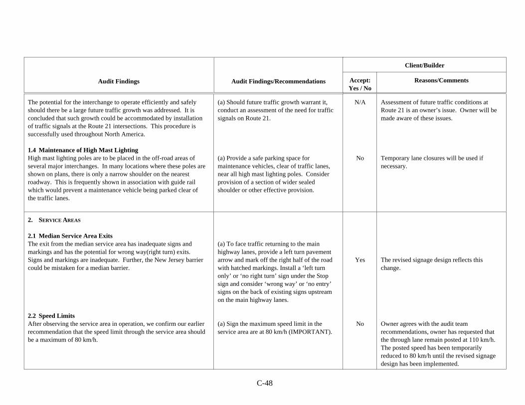
Audit Findings Audit Findings/Recommendations
Client/Builder
Accept:Yes / No
Reasons/Comments
C-48
The potential for the interchange to operate efficiently and safelyshould there be a large future traffic growth was addressed. It isconcluded that such growth could be accommodated by installationof traffic signals at the Route 21 intersections. This procedure issuccessfully used throughout North America.
1.4 Maintenance of High Mast LightingHigh mast lighting poles are to be placed in the off-road areas ofseveral major interchanges. In many locations where these poles areshown on plans, there is only a narrow shoulder on the nearestroadway. This is frequently shown in association with guide railwhich would prevent a maintenance vehicle being parked clear ofthe traffic lanes.
(a) Should future traffic growth warrant it,conduct an assessment of the need for trafficsignals on Route 21.
(a) Provide a safe parking space formaintenance vehicles, clear of traffic lanes,near all high mast lighting poles. Considerprovision of a section of wider sealedshoulder or other effective provision.
N/A
No
Assessment of future traffic conditions atRoute 21 is an owner’s issue. Owner will bemade aware of these issues.
Temporary lane closures will be used ifnecessary.
2. SERVICE AREAS
2.1 Median Service Area ExitsThe exit from the median service area has inadequate signs andmarkings and has the potential for wrong way(right turn) exits. Signs and markings are inadequate. Further, the New Jersey barriercould be mistaken for a median barrier.
2.2 Speed LimitsAfter observing the service area in operation, we confirm our earlierrecommendation that the speed limit through the service area shouldbe a maximum of 80 km/h.
(a) To face traffic returning to the mainhighway lanes, provide a left turn pavementarrow and mark off the right half of the roadwith hatched markings. Install a ‘left turnonly’ or ‘no right turn’ sign under the Stopsign and consider ‘wrong way’ or ‘no entry’signs on the back of existing signs upstreamon the main highway lanes.
(a) Sign the maximum speed limit in theservice area are at 80 km/h (IMPORTANT).
Yes
No
The revised signage design reflects thischange.
Owner agrees with the audit teamrecommendations, owner has requested thatthe through lane remain posted at 110 km/h. The posted speed has been temporarilyreduced to 80 km/h until the revised signagedesign has been implemented.
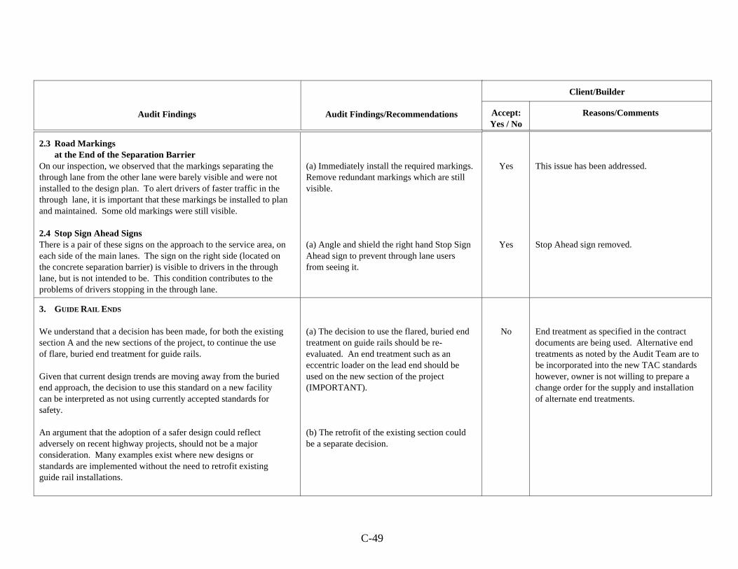
Audit Findings Audit Findings/Recommendations
Client/Builder
Accept:Yes / No
Reasons/Comments
C-49
2.3 Road Markingsat the End of the Separation Barrier
On our inspection, we observed that the markings separating thethrough lane from the other lane were barely visible and were notinstalled to the design plan. To alert drivers of faster traffic in thethrough lane, it is important that these markings be installed to planand maintained. Some old markings were still visible.
2.4 Stop Sign Ahead SignsThere is a pair of these signs on the approach to the service area, oneach side of the main lanes. The sign on the right side (located onthe concrete separation barrier) is visible to drivers in the throughlane, but is not intended to be. This condition contributes to theproblems of drivers stopping in the through lane.
(a) Immediately install the required markings. Remove redundant markings which are stillvisible.
(a) Angle and shield the right hand Stop SignAhead sign to prevent through lane usersfrom seeing it.
Yes
Yes
This issue has been addressed.
Stop Ahead sign removed.
3. GUIDE RAIL ENDS
We understand that a decision has been made, for both the existingsection A and the new sections of the project, to continue the useof flare, buried end treatment for guide rails.
Given that current design trends are moving away from the buriedend approach, the decision to use this standard on a new facilitycan be interpreted as not using currently accepted standards forsafety.
An argument that the adoption of a safer design could reflectadversely on recent highway projects, should not be a majorconsideration. Many examples exist where new designs orstandards are implemented without the need to retrofit existingguide rail installations.
(a) The decision to use the flared, buried endtreatment on guide rails should be re-evaluated. An end treatment such as aneccentric loader on the lead end should beused on the new section of the project(IMPORTANT).
(b) The retrofit of the existing section couldbe a separate decision.
No End treatment as specified in the contractdocuments are being used. Alternative endtreatments as noted by the Audit Team are tobe incorporated into the new TAC standardshowever, owner is not willing to prepare achange order for the supply and installationof alternate end treatments.
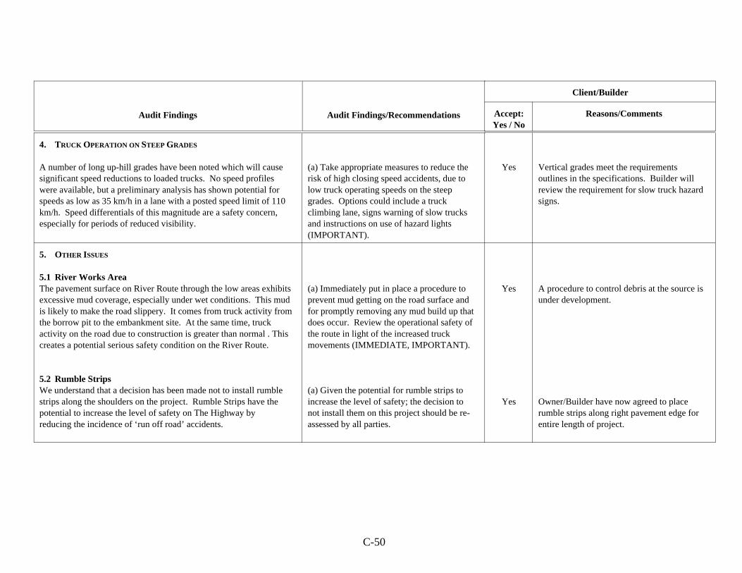
Audit Findings Audit Findings/Recommendations
Client/Builder
Accept:Yes / No
Reasons/Comments
C-50
4. TRUCK OPERATION ON STEEP GRADES
A number of long up-hill grades have been noted which will causesignificant speed reductions to loaded trucks. No speed profileswere available, but a preliminary analysis has shown potential forspeeds as low as 35 km/h in a lane with a posted speed limit of 110km/h. Speed differentials of this magnitude are a safety concern,especially for periods of reduced visibility.
(a) Take appropriate measures to reduce therisk of high closing speed accidents, due tolow truck operating speeds on the steepgrades. Options could include a truckclimbing lane, signs warning of slow trucksand instructions on use of hazard lights(IMPORTANT).
Yes Vertical grades meet the requirementsoutlines in the specifications. Builder willreview the requirement for slow truck hazardsigns.
5. OTHER ISSUES
5.1 River Works AreaThe pavement surface on River Route through the low areas exhibitsexcessive mud coverage, especially under wet conditions. This mudis likely to make the road slippery. It comes from truck activity fromthe borrow pit to the embankment site. At the same time, truckactivity on the road due to construction is greater than normal . Thiscreates a potential serious safety condition on the River Route.
5.2 Rumble StripsWe understand that a decision has been made not to install rumblestrips along the shoulders on the project. Rumble Strips have thepotential to increase the level of safety on The Highway byreducing the incidence of ‘run off road’ accidents.
(a) Immediately put in place a procedure toprevent mud getting on the road surface andfor promptly removing any mud build up thatdoes occur. Review the operational safety ofthe route in light of the increased truckmovements (IMMEDIATE, IMPORTANT).
(a) Given the potential for rumble strips toincrease the level of safety; the decision tonot install them on this project should be re-assessed by all parties.
Yes
Yes
A procedure to control debris at the source isunder development.
Owner/Builder have now agreed to placerumble strips along right pavement edge forentire length of project.
C-51
AUDIT TEAM:
Dr. F. R. Wilson, P. Eng.Dr. E. D. Hildebrand, P. Eng.
CLIENT:
Road Builders Inc.Saint John, N.B.
ROAD SAFETY AUDIT REPORT
PRE-OPENING AUDIT(Section P from western terminus to and including
Beaver Road Interchange)
NEW BRUNSWICK
November 27 , 1999
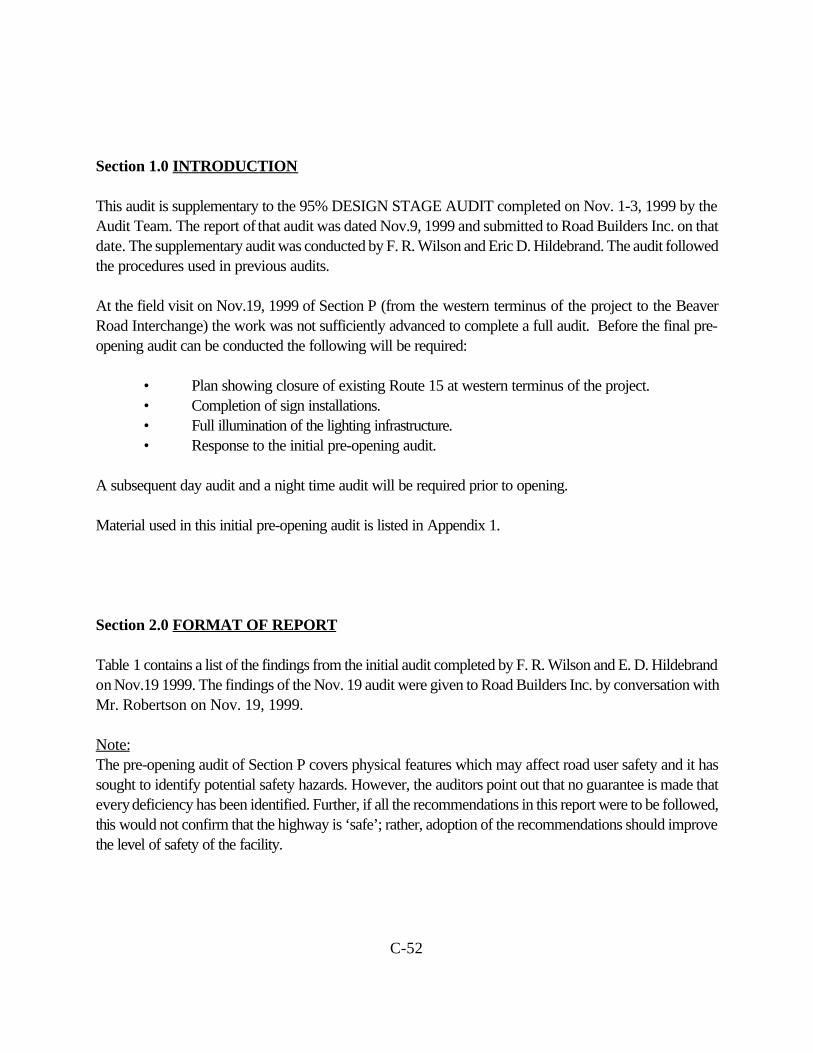
C-52
Section 1.0 INTRODUCTION
This audit is supplementary to the 95% DESIGN STAGE AUDIT completed on Nov. 1-3, 1999 by theAudit Team. The report of that audit was dated Nov.9, 1999 and submitted to Road Builders Inc. on thatdate. The supplementary audit was conducted by F. R. Wilson and Eric D. Hildebrand. The audit followedthe procedures used in previous audits.
At the field visit on Nov.19, 1999 of Section P (from the western terminus of the project to the BeaverRoad Interchange) the work was not sufficiently advanced to complete a full audit. Before the final pre-opening audit can be conducted the following will be required:
• Plan showing closure of existing Route 15 at western terminus of the project.• Completion of sign installations.• Full illumination of the lighting infrastructure.• Response to the initial pre-opening audit.
A subsequent day audit and a night time audit will be required prior to opening.
Material used in this initial pre-opening audit is listed in Appendix 1.
Section 2.0 FORMAT OF REPORT
Table 1 contains a list of the findings from the initial audit completed by F. R. Wilson and E. D. Hildebrandon Nov.19 1999. The findings of the Nov. 19 audit were given to Road Builders Inc. by conversation withMr. Robertson on Nov. 19, 1999.
Note:The pre-opening audit of Section P covers physical features which may affect road user safety and it hassought to identify potential safety hazards. However, the auditors point out that no guarantee is made thatevery deficiency has been identified. Further, if all the recommendations in this report were to be followed,this would not confirm that the highway is ‘safe’; rather, adoption of the recommendations should improvethe level of safety of the facility.
C-53
Section 3.0 FINDINGS AND RECOMMENDATIONS
Findings and Recommendations from the Pre-Opening Audit of a portion of Section P are presented inTable 1, which is attached.
____________________Dr. F. R. Wilson, P. Eng.
________________________Dr. E. D. Hildebrand, P. Eng.
Nov. 27, 1999
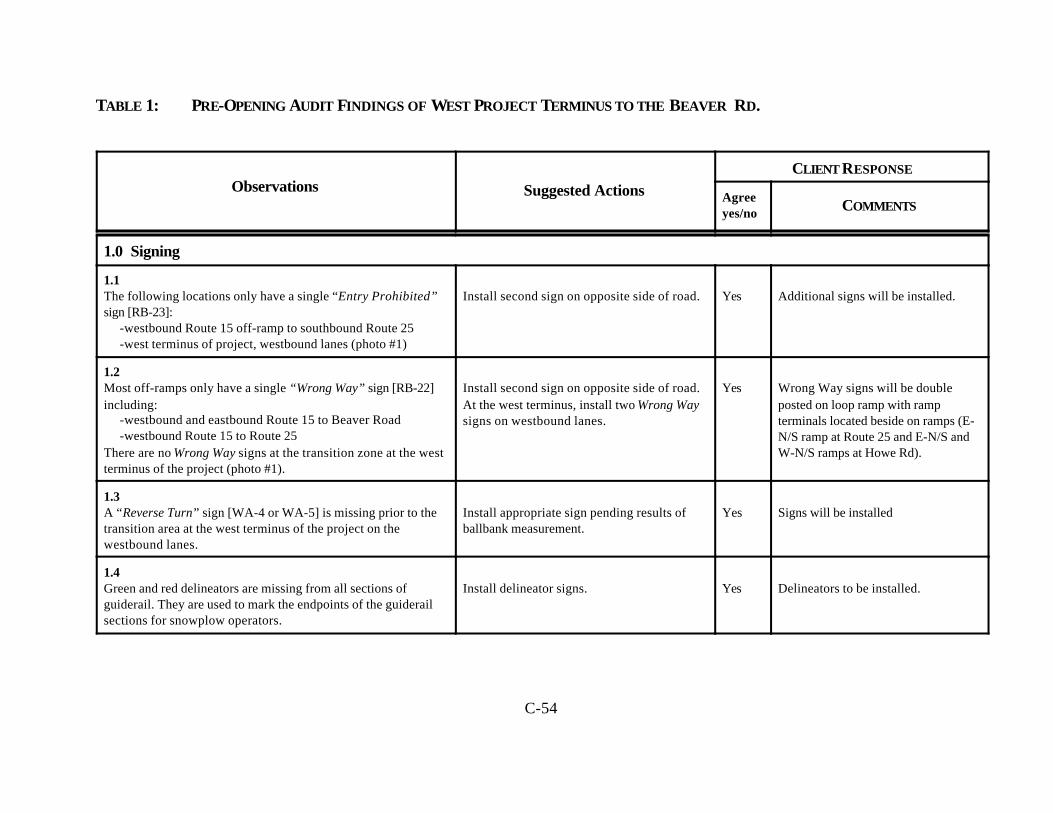
C-54
TABLE 1: PRE-OPENING AUDIT FINDINGS OF WEST PROJECT TERMINUS TO THE BEAVER RD.
Observations Suggested ActionsCLIENT RESPONSE
Agreeyes/no COMMENTS
1.0 Signing
1.1The following locations only have a single “Entry Prohibited”sign [RB-23]:
-westbound Route 15 off-ramp to southbound Route 25-west terminus of project, westbound lanes (photo #1)
Install second sign on opposite side of road. Yes Additional signs will be installed.
1.2Most off-ramps only have a single “Wrong Way” sign [RB-22]including:
-westbound and eastbound Route 15 to Beaver Road-westbound Route 15 to Route 25
There are no Wrong Way signs at the transition zone at the westterminus of the project (photo #1).
Install second sign on opposite side of road.At the west terminus, install two Wrong Waysigns on westbound lanes.
Yes Wrong Way signs will be doubleposted on loop ramp with rampterminals located beside on ramps (E-N/S ramp at Route 25 and E-N/S andW-N/S ramps at Howe Rd).
1.3A “Reverse Turn” sign [WA-4 or WA-5] is missing prior to thetransition area at the west terminus of the project on thewestbound lanes.
Install appropriate sign pending results ofballbank measurement.
Yes Signs will be installed
1.4Green and red delineators are missing from all sections ofguiderail. They are used to mark the endpoints of the guiderailsections for snowplow operators.
Install delineator signs. Yes Delineators to be installed.
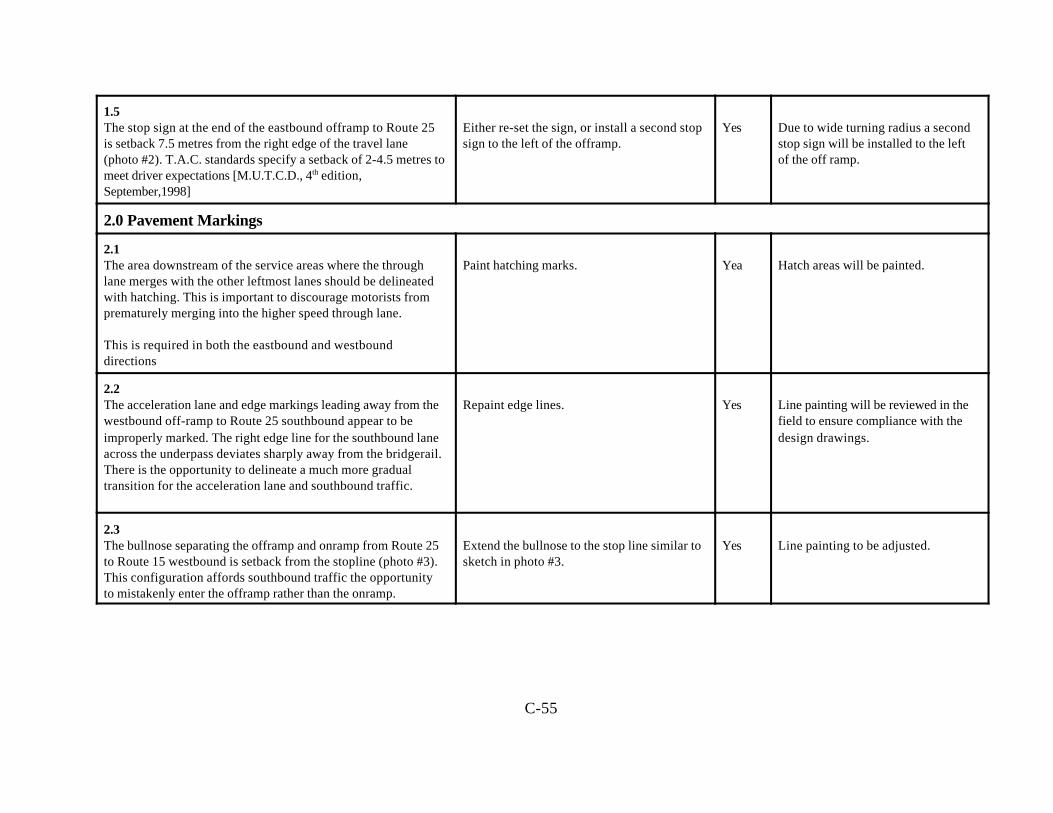
C-55
1.5The stop sign at the end of the eastbound offramp to Route 25is setback 7.5 metres from the right edge of the travel lane(photo #2). T.A.C. standards specify a setback of 2-4.5 metres tomeet driver expectations [M.U.T.C.D., 4th edition,September,1998]
Either re-set the sign, or install a second stopsign to the left of the offramp.
Yes Due to wide turning radius a secondstop sign will be installed to the leftof the off ramp.
2.0 Pavement Markings
2.1The area downstream of the service areas where the throughlane merges with the other leftmost lanes should be delineatedwith hatching. This is important to discourage motorists fromprematurely merging into the higher speed through lane.
This is required in both the eastbound and westbounddirections
Paint hatching marks. Yea Hatch areas will be painted.
2.2The acceleration lane and edge markings leading away from thewestbound off-ramp to Route 25 southbound appear to beimproperly marked. The right edge line for the southbound laneacross the underpass deviates sharply away from the bridgerail.There is the opportunity to delineate a much more gradualtransition for the acceleration lane and southbound traffic.
Repaint edge lines. Yes Line painting will be reviewed in thefield to ensure compliance with thedesign drawings.
2.3The bullnose separating the offramp and onramp from Route 25to Route 15 westbound is setback from the stopline (photo #3).This configuration affords southbound traffic the opportunityto mistakenly enter the offramp rather than the onramp.
Extend the bullnose to the stop line similar tosketch in photo #3.
Yes Line painting to be adjusted.
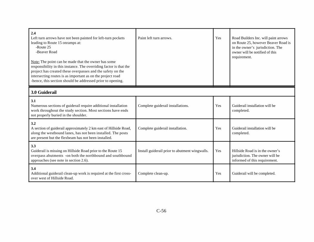
C-56
2.4Left turn arrows have not been painted for left-turn pocketsleading to Route 15 onramps at:
-Route 25 -Beaver Road
Note: The point can be made that the owner has someresponsibility in this instance. The overriding factor is that theproject has created these overpasses and the safety on theintersecting routes is as important as on the project road -hence, this section should be addressed prior to opening.
Paint left turn arrows. Yes Road Builders Inc. will paint arrowson Route 25, however Beaver Road isin the owner’s jurisdiction. Theowner will be notified of thisrequirement.
3.0 Guiderail
3.1Numerous sections of guiderail require additional installationwork throughout the study section. Most sections have endsnot properly buried in the shoulder.
Complete guiderail installations. Yes Guiderail installation will becompleted.
3.2A section of guiderail approximately 2 km east of Hillside Road,along the westbound lanes, has not been installed. The postsare present but the flexbeam has not been installed.
Complete guiderail installation. Yes Guiderail installation will becompleted.
3.3Guiderail is missing on Hillside Road prior to the Route 15overpass abutments -on both the northbound and southboundapproaches (see note in section 2.6).
Install guiderail prior to abutment wingwalls. Yes Hillside Road is in the owner’sjurisdiction. The owner will beinformed of this requirement.
3.4Additional guiderail clean-up work is required at the first cross-over west of Hillside Road.
Complete clean-up. Yes Guiderail will be completed.
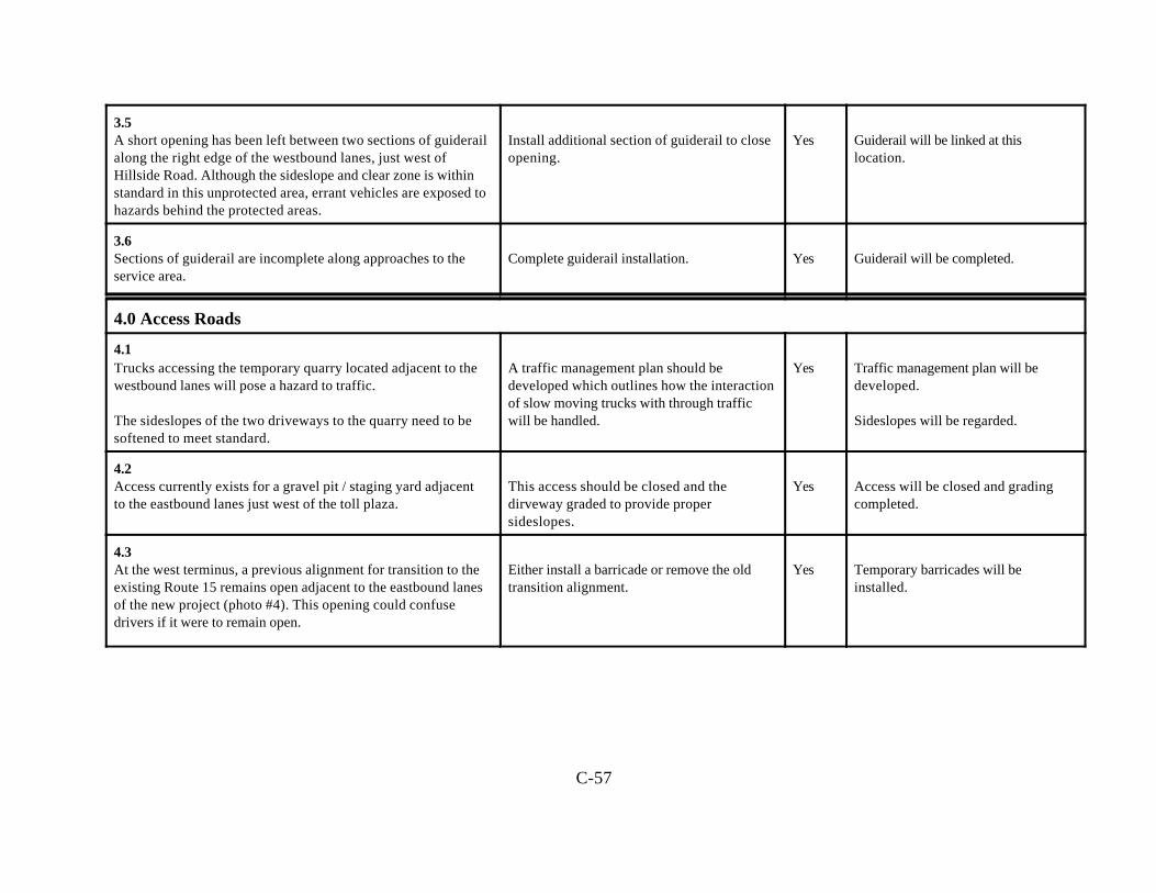
C-57
3.5A short opening has been left between two sections of guiderailalong the right edge of the westbound lanes, just west ofHillside Road. Although the sideslope and clear zone is withinstandard in this unprotected area, errant vehicles are exposed tohazards behind the protected areas.
Install additional section of guiderail to closeopening.
Yes Guiderail will be linked at thislocation.
3.6Sections of guiderail are incomplete along approaches to theservice area.
Complete guiderail installation. Yes Guiderail will be completed.
4.0 Access Roads
4.1Trucks accessing the temporary quarry located adjacent to thewestbound lanes will pose a hazard to traffic.
The sideslopes of the two driveways to the quarry need to besoftened to meet standard.
A traffic management plan should bedeveloped which outlines how the interactionof slow moving trucks with through trafficwill be handled.
Yes Traffic management plan will bedeveloped.
Sideslopes will be regarded.
4.2Access currently exists for a gravel pit / staging yard adjacentto the eastbound lanes just west of the toll plaza.
This access should be closed and thedirveway graded to provide propersideslopes.
Yes Access will be closed and gradingcompleted.
4.3At the west terminus, a previous alignment for transition to theexisting Route 15 remains open adjacent to the eastbound lanesof the new project (photo #4). This opening could confusedrivers if it were to remain open.
Either install a barricade or remove the oldtransition alignment.
Yes Temporary barricades will beinstalled.
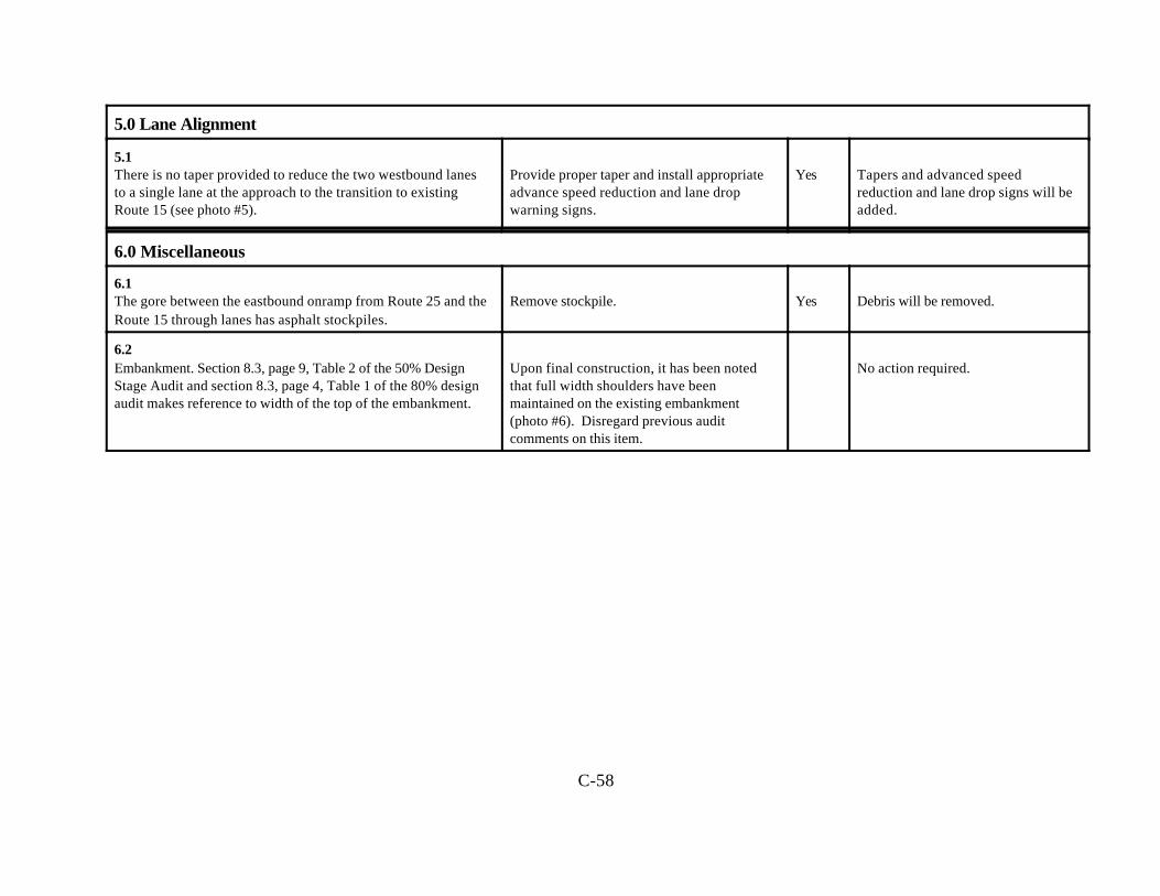
C-58
5.0 Lane Alignment
5.1There is no taper provided to reduce the two westbound lanesto a single lane at the approach to the transition to existing Route 15 (see photo #5).
Provide proper taper and install appropriateadvance speed reduction and lane dropwarning signs.
Yes Tapers and advanced speedreduction and lane drop signs will beadded.
6.0 Miscellaneous
6.1The gore between the eastbound onramp from Route 25 and theRoute 15 through lanes has asphalt stockpiles.
Remove stockpile. Yes Debris will be removed.
6.2Embankment. Section 8.3, page 9, Table 2 of the 50% DesignStage Audit and section 8.3, page 4, Table 1 of the 80% designaudit makes reference to width of the top of the embankment.
Upon final construction, it has been notedthat full width shoulders have beenmaintained on the existing embankment(photo #6). Disregard previous auditcomments on this item.
No action required.
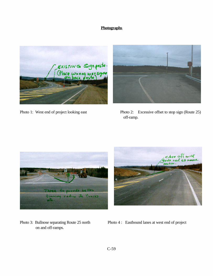
C-59
Photographs
Photo 1: West end of project looking east Photo 2: Excessive offset to stop sign (Route 25) off-ramp.
Photo 3: Bullnose separating Route 25 north Photo 4 : Eastbound lanes at west end of project on and off-ramps.
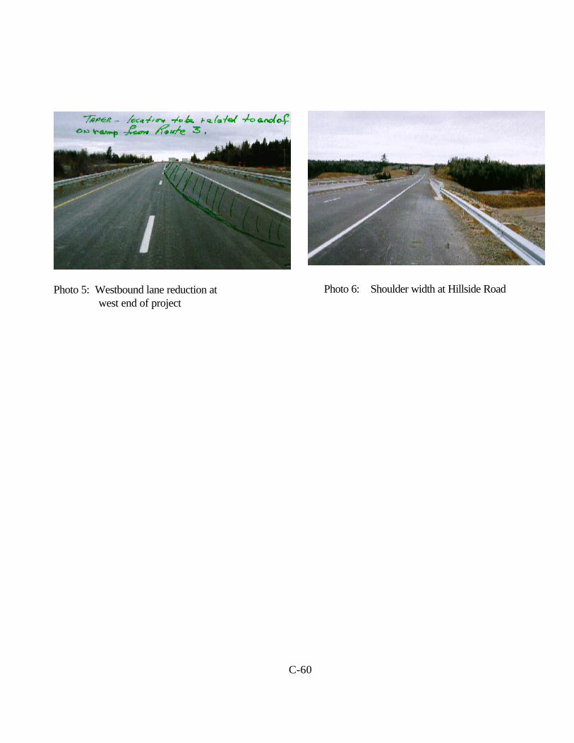
C-60
Photo 5: Westbound lane reduction at Photo 6: Shoulder width at Hillside Road west end of project

Appendix D
Glossary
D-1
GLOSSARY
The following definitions have been collected from various sources, including the TAC GeometricDesign Guide for Canadian Roads (1986) and the Highway 407 Safety Review (1996).
Acceleration laneA lane in addition and adjacent to a through lane to enable a vehicle entering a roadway toincrease speed to merge with through traffic. Used at intersections where traffic is channeled bymeans of islands or markings, or as a speed-change lane at interchanges.
Auxiliary laneA lane in addition and adjacent to a through lane intended for a specific manoeuvre, such asturning, merging, diverging, weaving, and for slow vehicles, but not for parking.
Back slopeThe slope between the drainage channel and the natural ground, used when a roadway is belownatural elevation.
BarrierA device providing a physical limitation through which a vehicle would not normally pass. It isintended to contain or redirect errant vehicles of a particular size range, at a given speed andangle of impact.
BreakawayA design feature enabling such devices as signs, luminaires or traffic signal supports to yield orseparate upon impact. The release mechanism may be a slip plan, plastic hinges, fractureelements, or a combination of these.
Clear ZoneThe total roadside border area clear of obstacles, starting at the edge of the traveled way,available for safe use by errant vehicles. This area may consist of a shoulder, a recoverable slopeand/or a clear run-out area. The desired width depends on traffic volumes and speed, and onroadside geometry.
Cross-sectionThe transverse profile of a road.
Deceleration laneA lane in addition and adjacent to the through lane to enable a vehicle exiting a roadway toreduce speed after it has left the through traffic lanes. Used at intersections where traffic ischanneled by islands or markings, or as a speed-lane change at interchanges.
D-2
Decision sight distanceThe distance required for a driver to detect an information source or hazard in a visually clutteredroadway environment, recognize the hazard or its potential threat, select appropriate action, andcomplete the manoeuvre safely and efficiently.
Design criteriaA set of parameters established at the outset of the design phase for the major elements of afacility, to provide direction for the designers.
Design speedA speed selected for designing and correlating the geometric features of a road, and used as ameasure of the quality of the road’s design.
End treatmentThe design modification of a roadside or median barrier at the end of the installation.
EntranceThe general area where traffic turns to enter the main roadway.
Entrance terminal The acceleration or speed-change lanes that are part of a roadway entrance, including the rampproper up to the ramp controlling curve.
ExitThe general area where traffic departs from the main roadway.
Exit terminalThe deceleration or speed-change lanes that are part of a roadway exit, including the rampproper up to the ramp controlling curve.
Geometric designSelection of visible dimensions of a roadway’s elements.
GradeHow fast elevation changes relative to a horizontal distance (steepness), usually expressed as apercentage.
Guiderail (guardrail)A barrier adjacent to and in line with the roadway, which can be made of concrete, steel beam,or post and rail.
D-3
HazardAny obstacle or other feature, such as an embankment or a body of water deeper than 1m,which, without protection, is likely to cause significant injury to the occupants of a vehicleencountering it.
Horizontal alignmentThe configuration of a road, as seen in a plan, consisting of straight lines, lengths of circular curve,and lengths of spiral or transition curves.
Horizontal curveA circular curve, as seen in a plan, that enables a driver to change direction.
InterchangeThe general area where two or more roads join or cross, within which are included the roadwayand roadside facilities for traffic movements.
Intersection (at-grade)The general area where two or more roads join or cross, within which are included the roadwayand roadside facilities or traffic movements.
LaneA part of the traveled roadway intended for the movement of a single line of vehicles.
MedianThe area that separates traffic lanes carrying traffic in opposite directions. A median is describedas flush, raised or depressed, referring to its general elevation relative to the adjacent edges oftraffic lanes. The terms wide and narrow are often used to distinguish different types of median.A wide median generally refers to depressed medians sufficiently wide to form a channel thatdrains a roadway’s base or sub-base. Flush and raised median are usually narrow medians.
Median barrierA barrier in line with the roadway placed in the median to prevent a vehicle from crossing themedian and encountering oncoming traffic, or to protect a vehicle from hitting a fixed object in themedian.
Minimum stopping sight distanceThe minimum distance a driver who sees an object ahead requires to come to a stop underprevailing vehicle, pavement and climatic conditions.
OffsetThe distance between the traveled roadway and a roadside barrier or other obstacle.
D-4
Operating speedThe speed on a section of highway below which 85% of drivers are operating vehicles when thereis little traffic and good weather. This speed may be higher or lower than posted or legislatedspeed limits, or nominal design speeds, where alignment, surface, roadside development or otherfeatures affect vehicle operations.
RampA turning roadway that enables traffic to move from one highway to another.
Right-of-wayThe land acquired to build a road.
RoadAll the land acquired to provide a common or public thoroughfare, including a highway, street,bridge and any other structure incidental thereto.
RoadsideThe area between the outside shoulder edge and the right-of-way limits.
Roadside barrierA barrier in line with the roadway placed adjacent to the right or left edge, to prevent a vehicleleaving the roadway from encountering a hazard.
RoundingThe introduction of a smooth transition between two transverse slopes to minimize the abruptslope change and to enable a vehicle to transverse such slopes without bottoming out or vaulting.
ShoulderAn area of pavement, gravel or hard surface placed adjacent to through or auxiliary lanes.Intended for emergency stopping and travel by emergency vehicles only, it also providesstructural support for the pavement.
SlopeThe relative steepness of the terrain expressed as a ratio or percentage change. Slopes may becategorized as positive (back slopes) or negative (fore slopes), and as parallel or cross slopesrelative to the traffic direction.
Speed-change laneA deceleration or acceleration lane.
D-5
Stopping distanceThe distance a vehicle travels from when a driver decides to take remedial action to when thevehicles stops (total or reaction and braking distances).
Stopping sight distanceThe distance between a vehicle and an object for which a driver decides stop, measured fromwhere the object first comes into view (total of perception, reaction and braking distances).
SuperelevationThe change in elevation across a roadway from the inside to the outside edge of a curvemeasured at right angles to the centre line.
Through laneA lane intended for through traffic movement.
Traffic barrierTraffic barriers are placed adjacent to and in line with a roadway to protect traffic on theroadway from hazardous objects either fixed or moving (other traffic). Barriers placed in amedian are referred to as median barriers and may be placed in flush, raised or depressedmedians.
Transition (spiral curve)A curve whose radius continually changes.
Vertical alignmentThe configuration of a road or roadway as seen in longitudinal section, consisting of tangents andparabolic curves.
Vertical curvatureThe horizontal distance along a hill required to effect a 1% change in elevation.
Vertical curveA parabolic curve on the longitudinal profile or in a vertical plane of a road to provide for achange of gradient.
WarrantThe criteria by which the need for a safety treatment or improvement can be determined.
Weaving sectionA section of roadway between an entrance and an exit where the frequency of lane changingexceeds the frequency on the open highway.
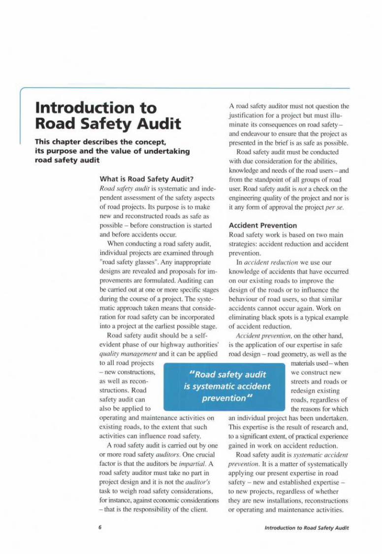
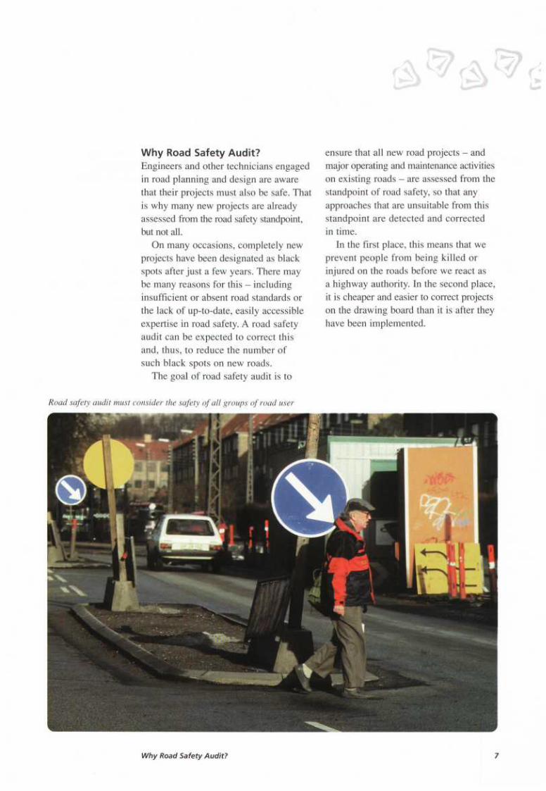
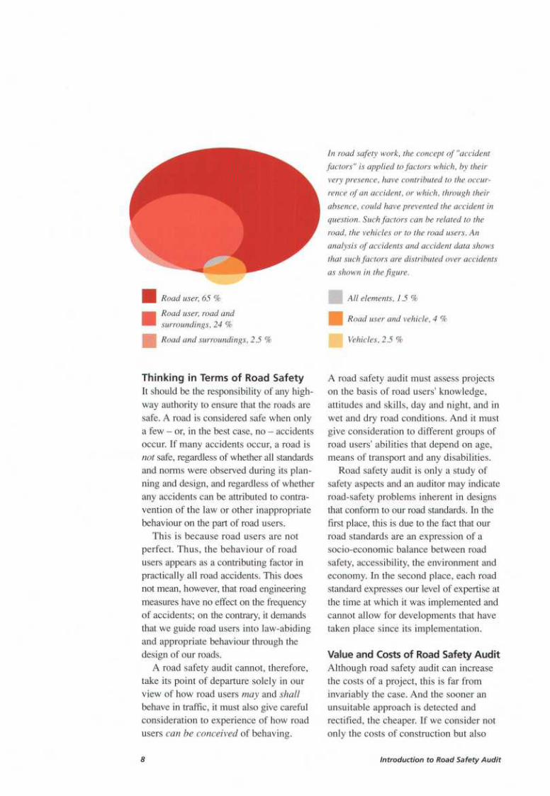
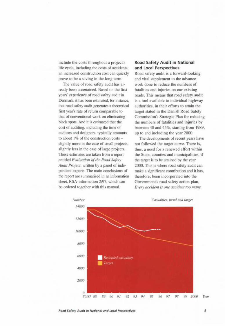
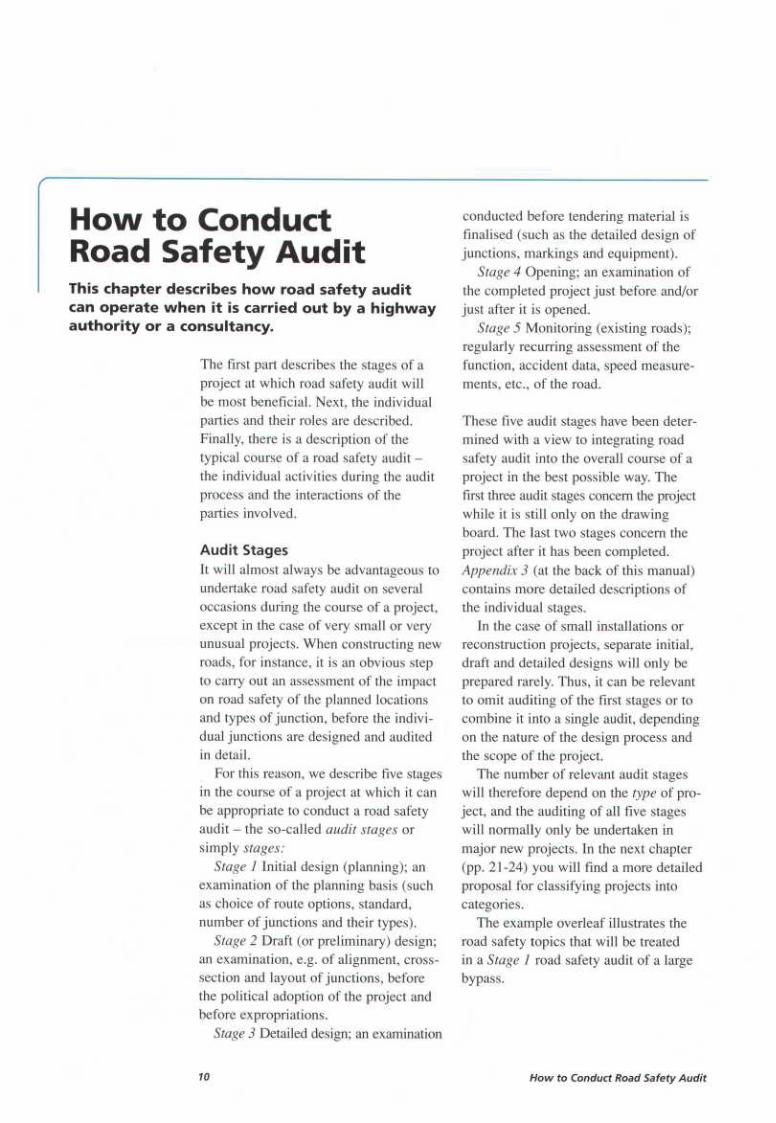
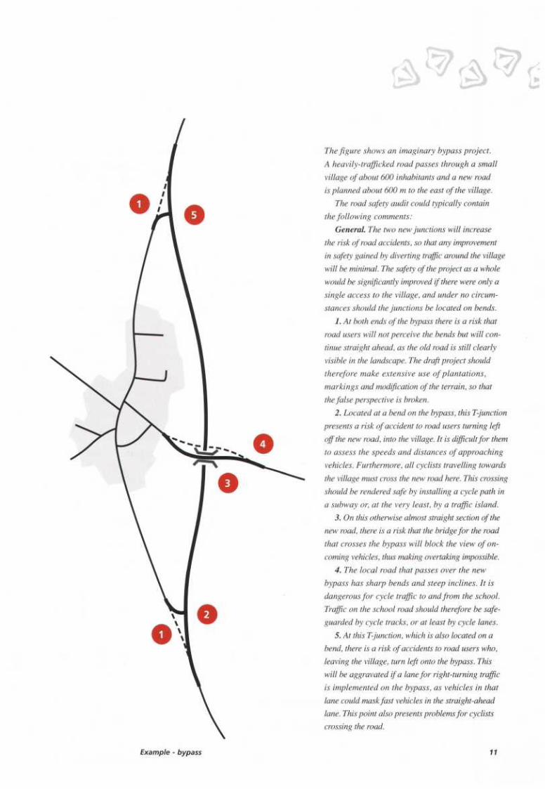

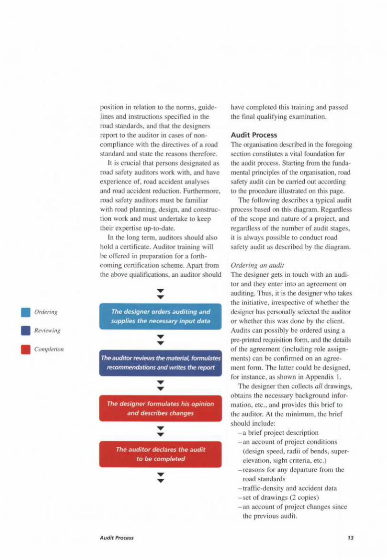
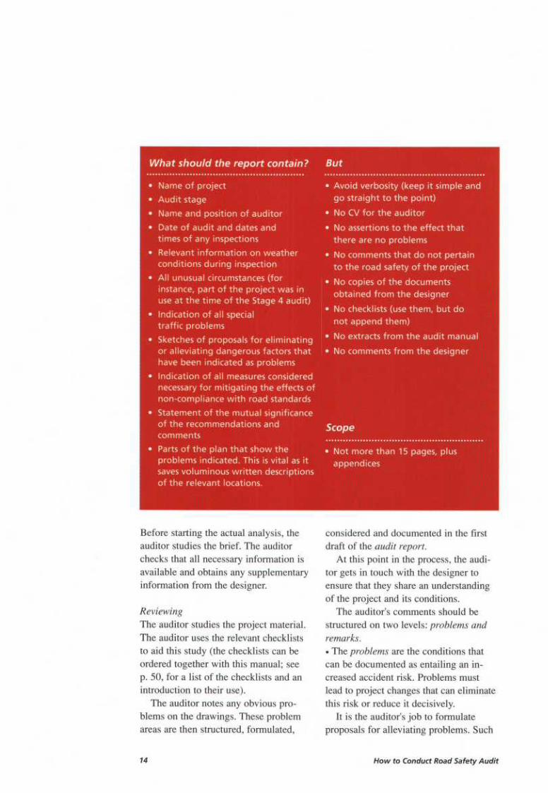
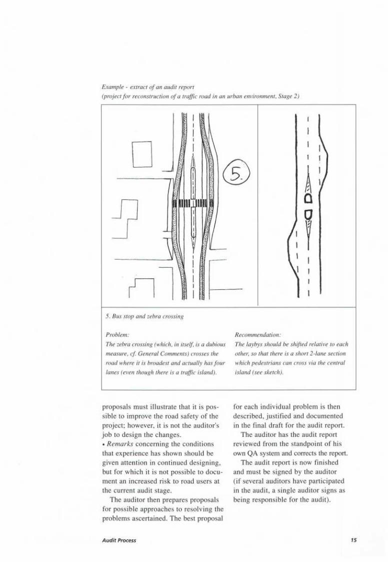

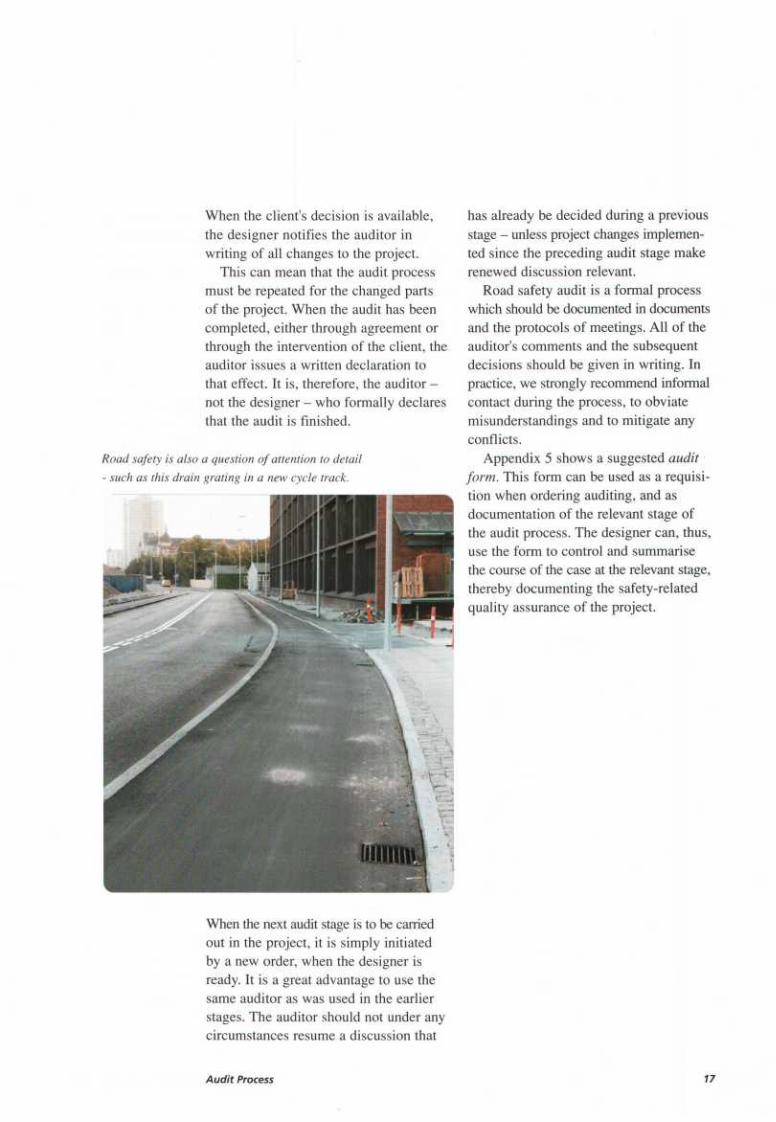
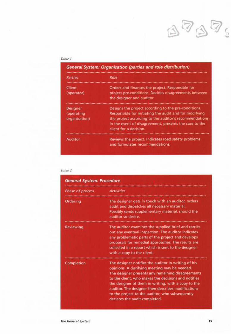
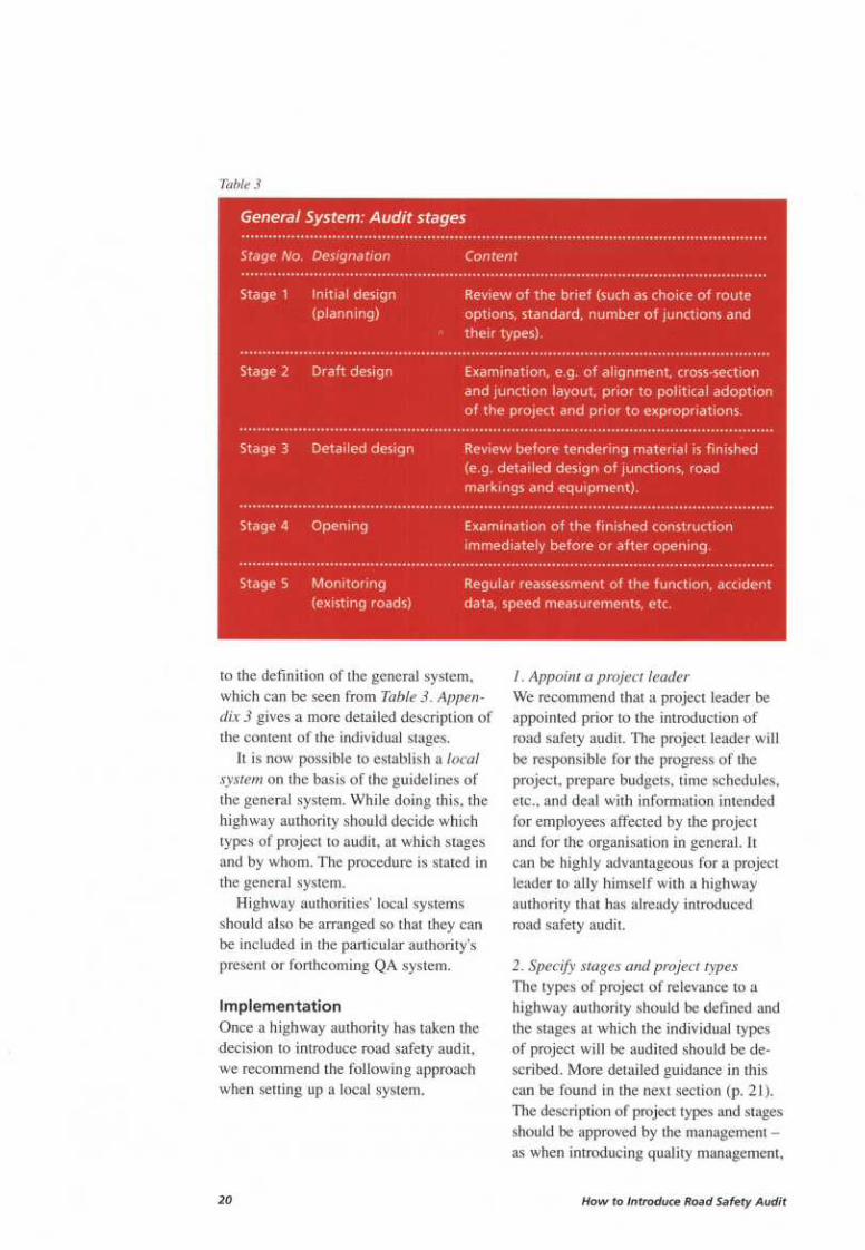
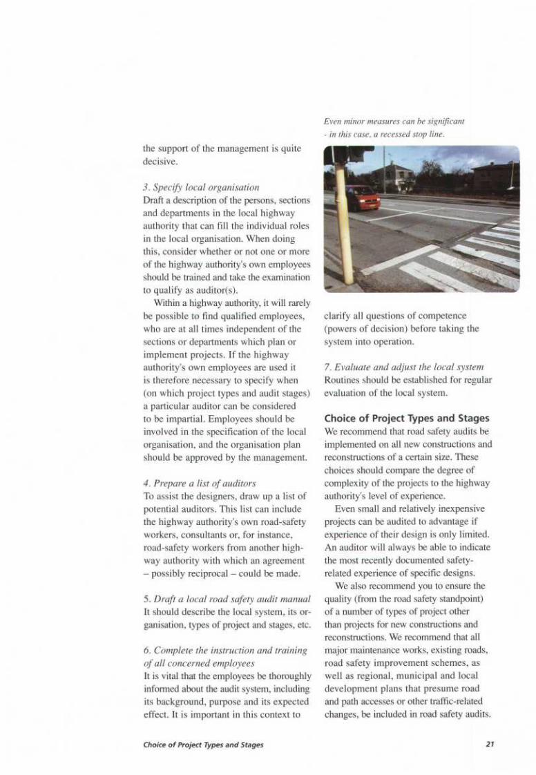
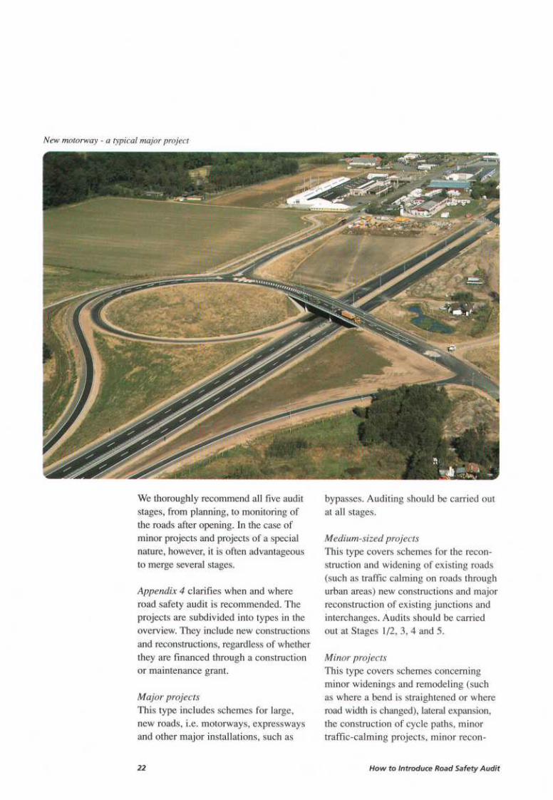
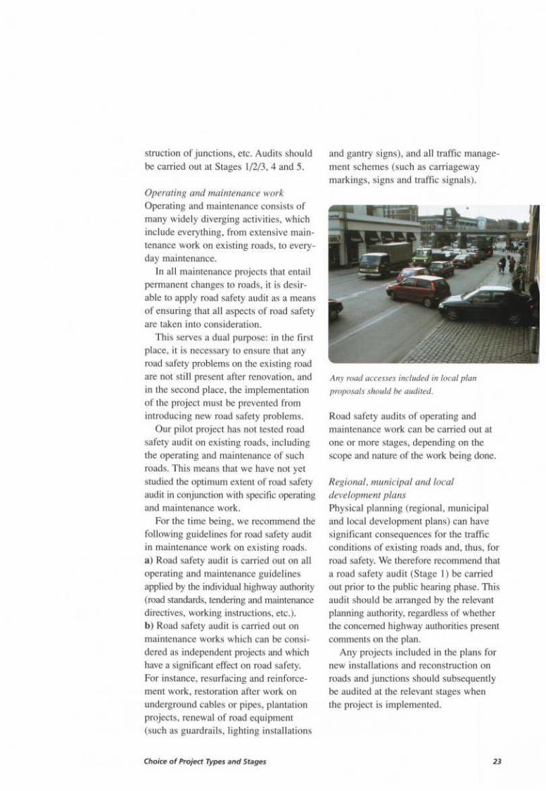
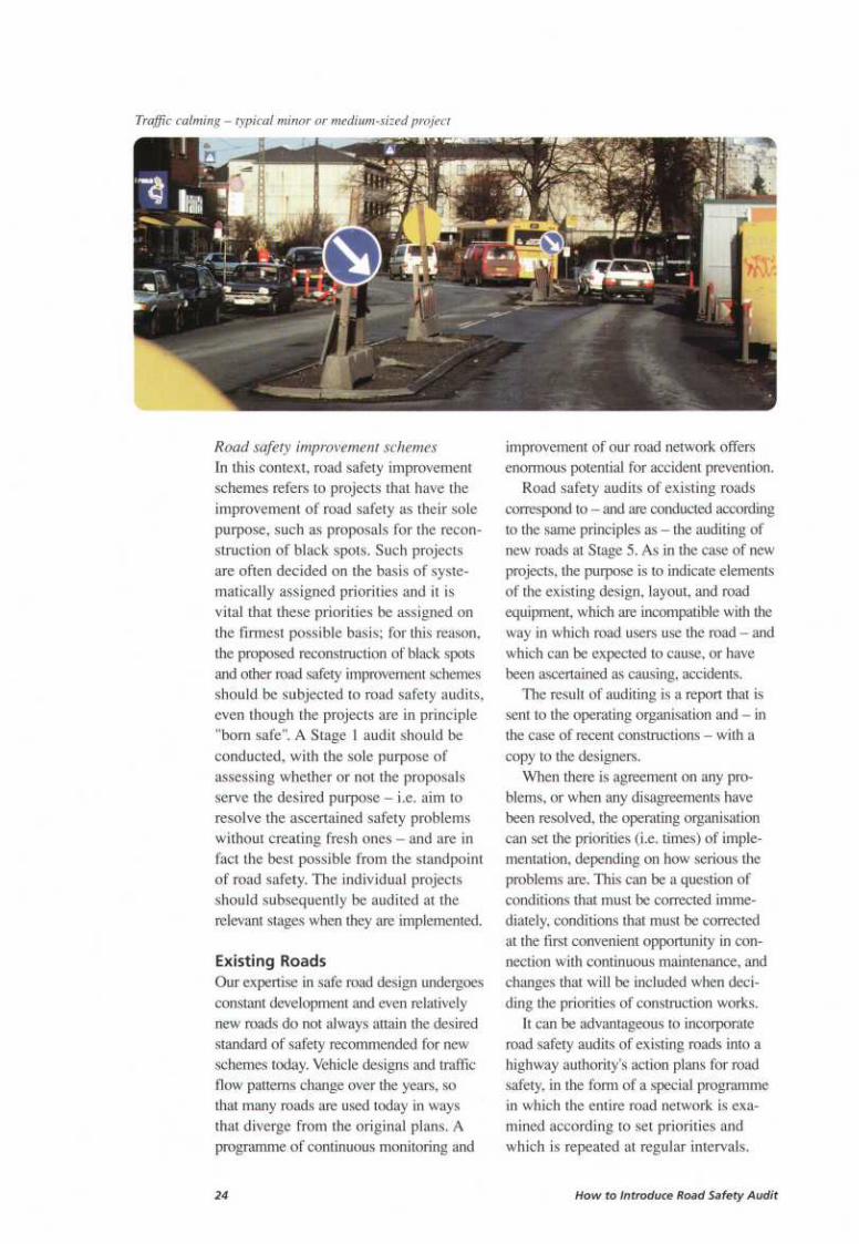
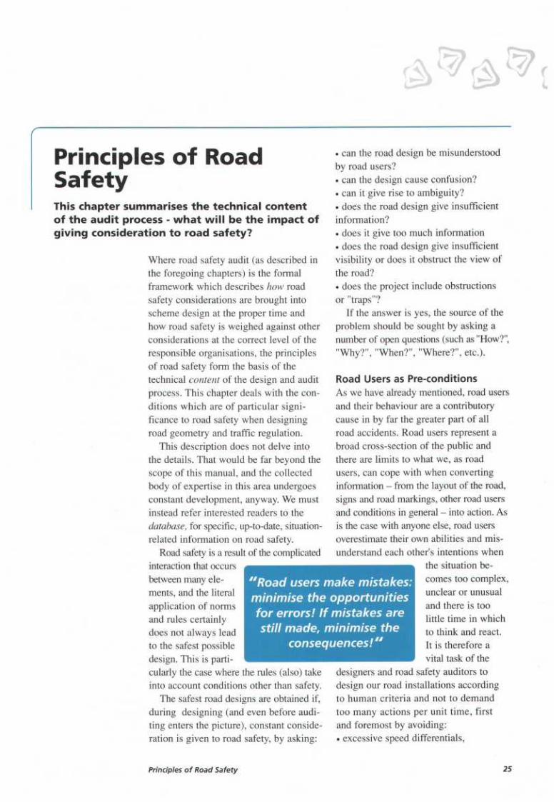

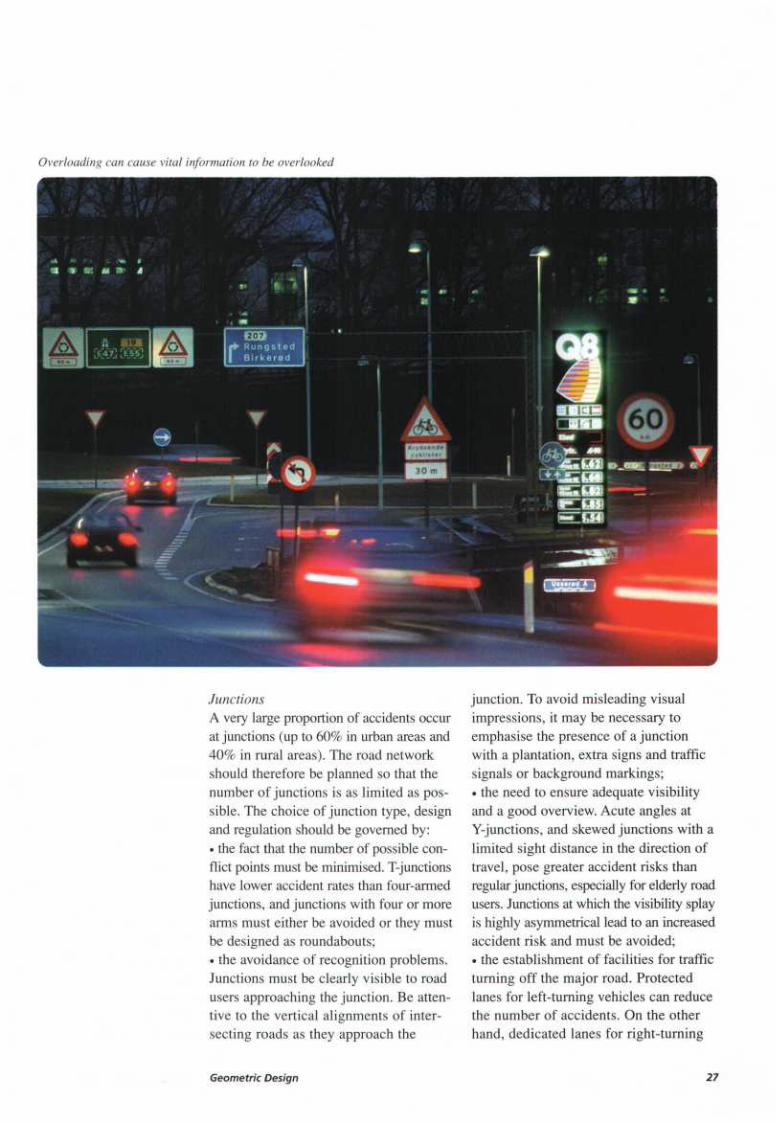
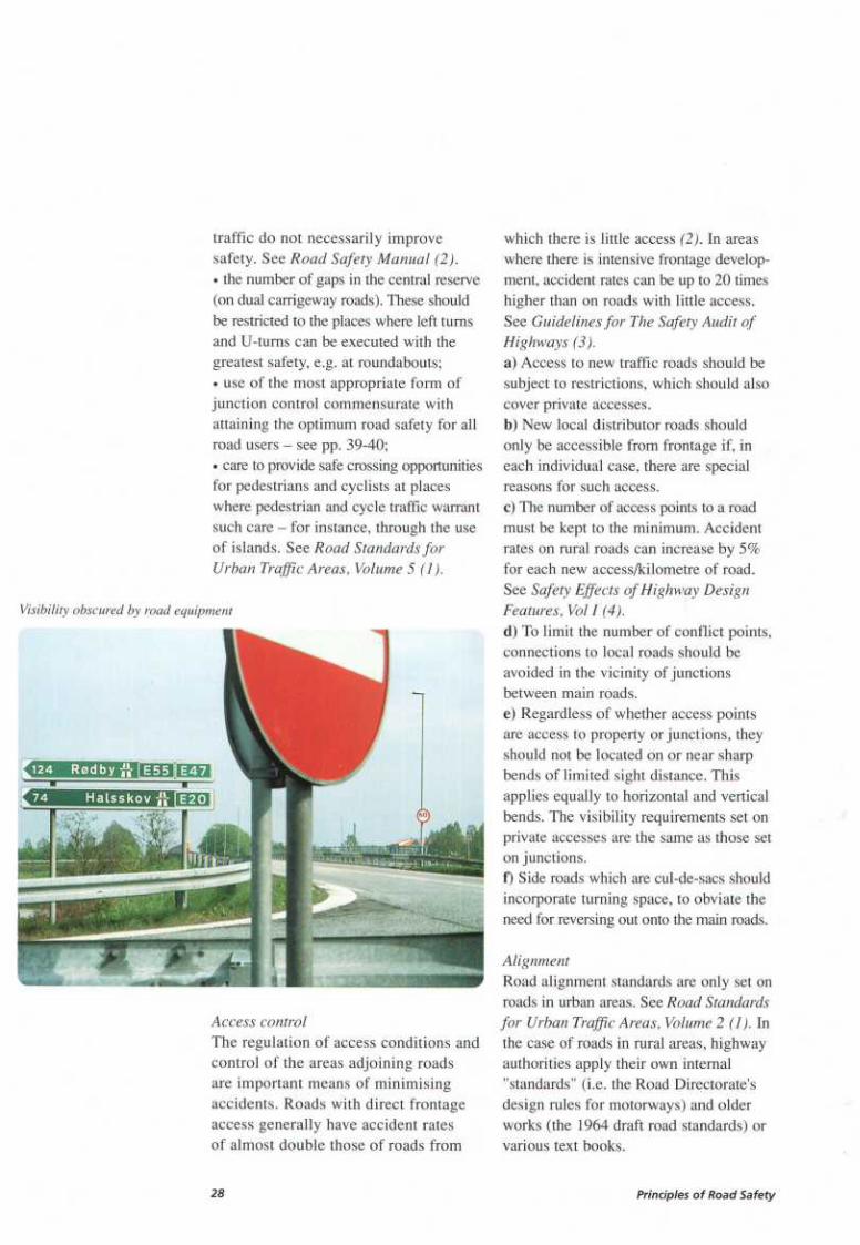
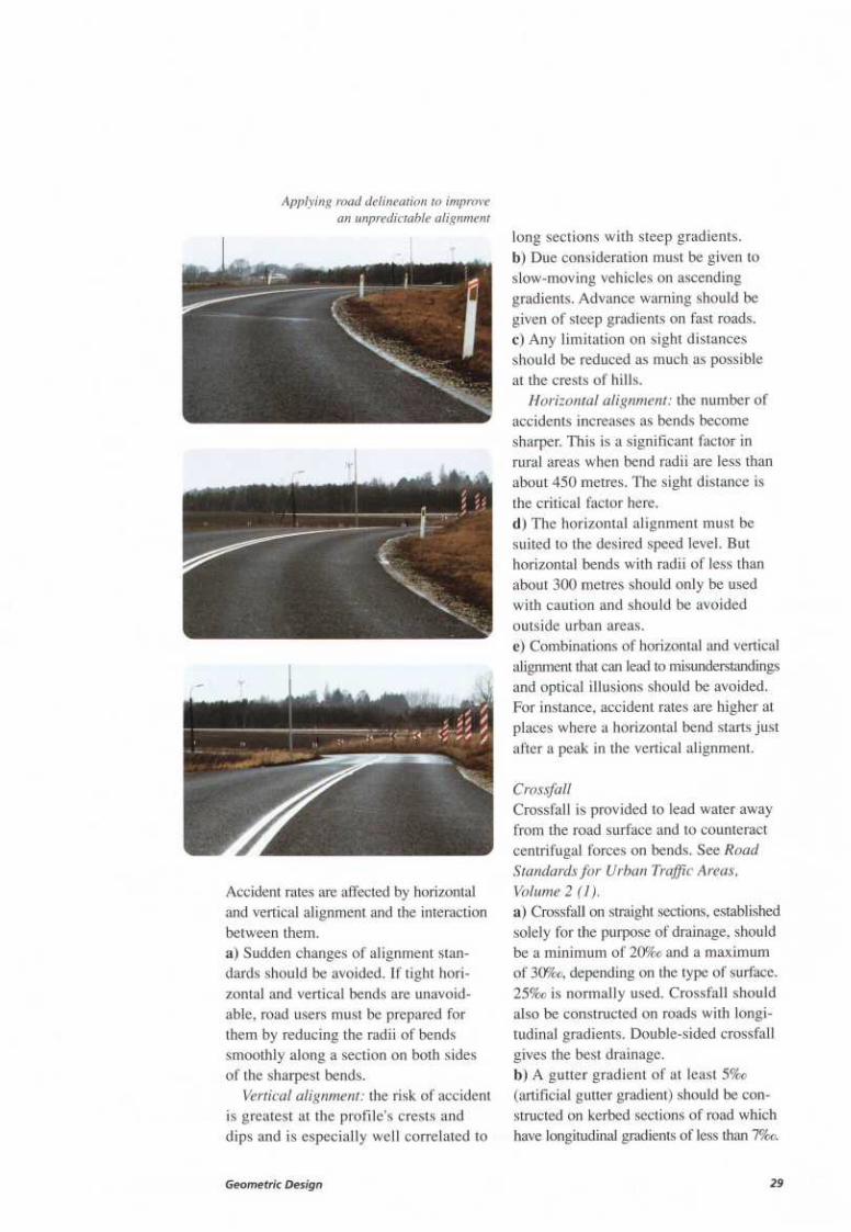
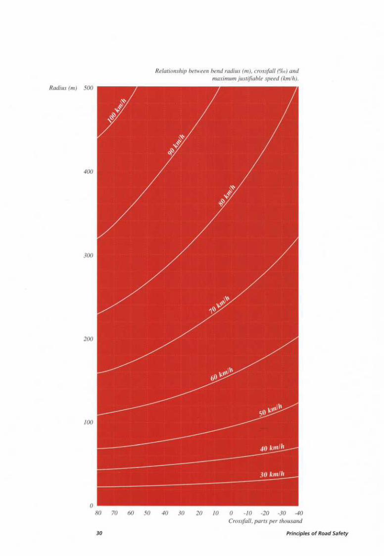
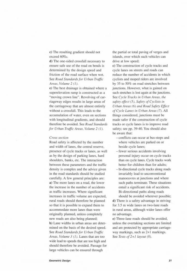
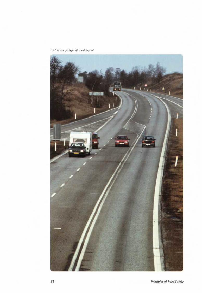
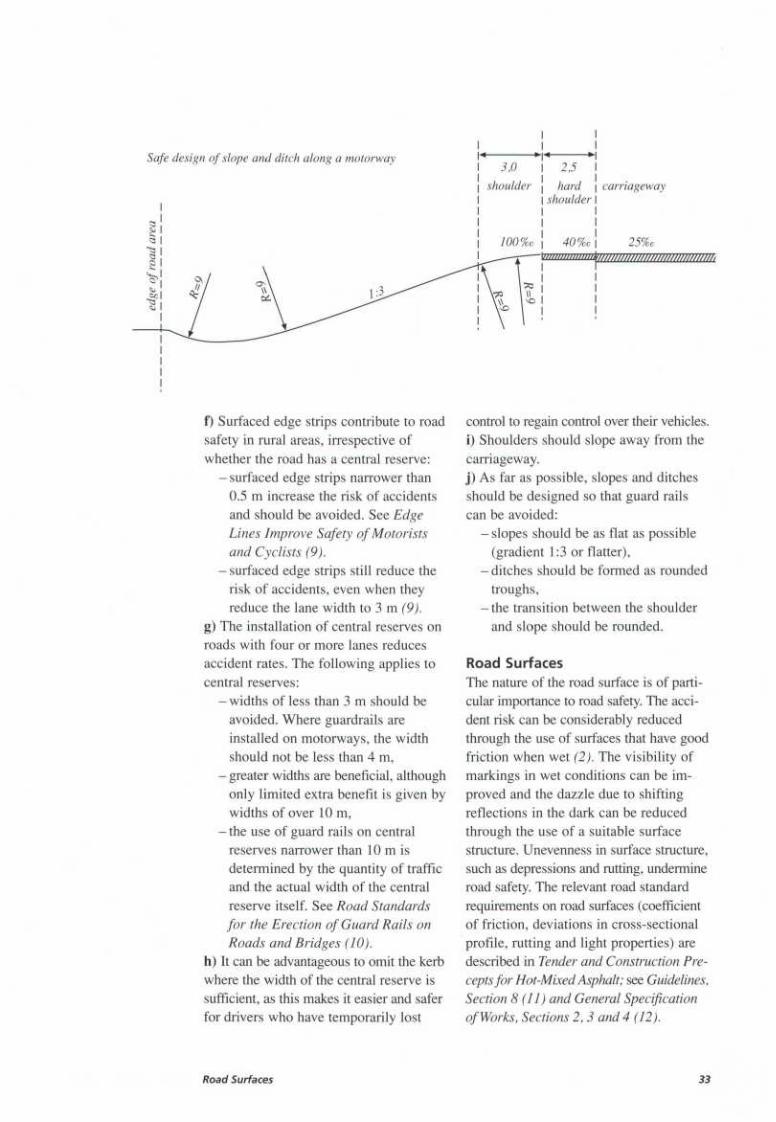
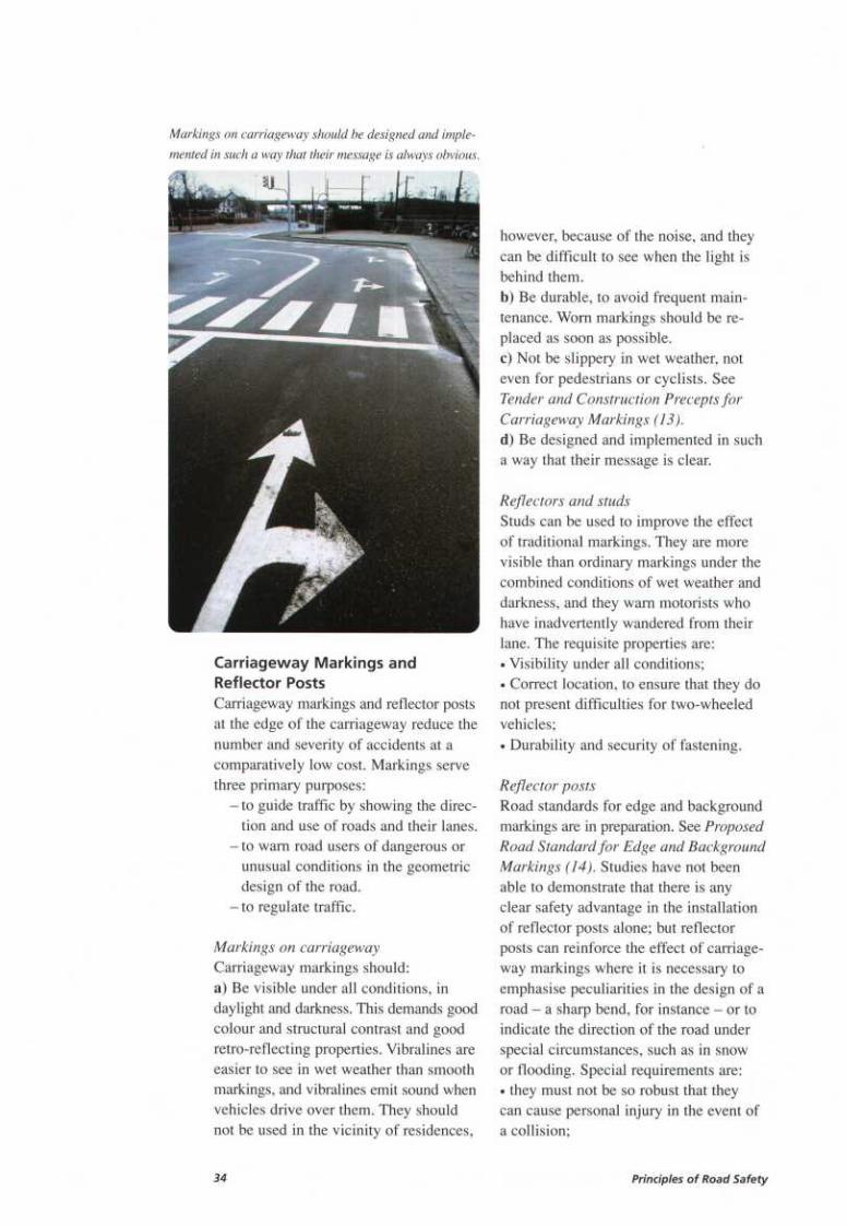
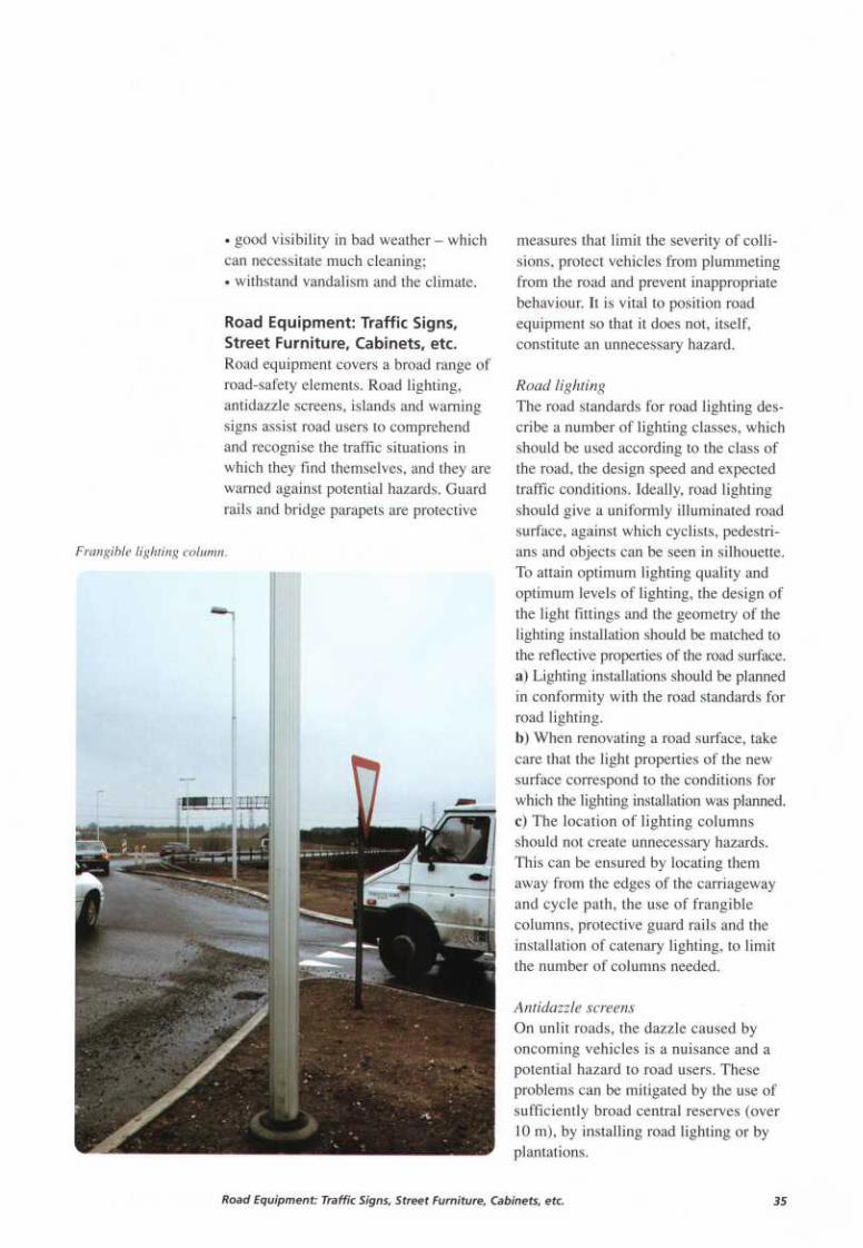
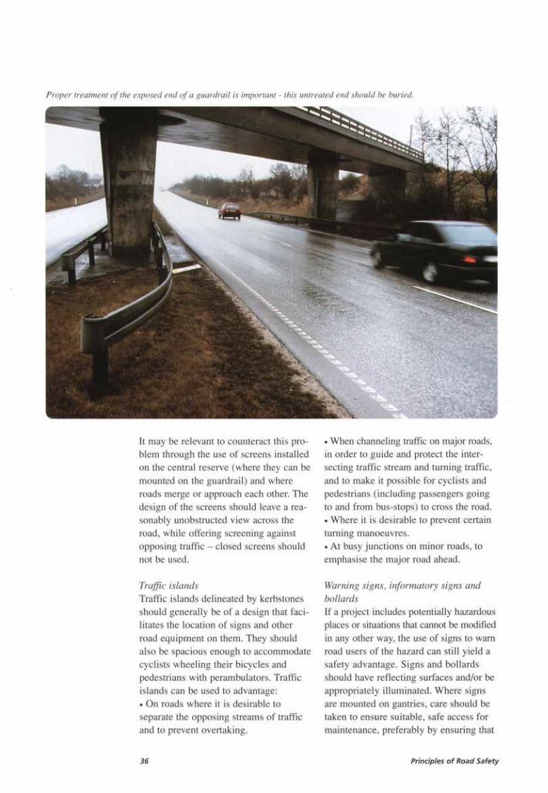
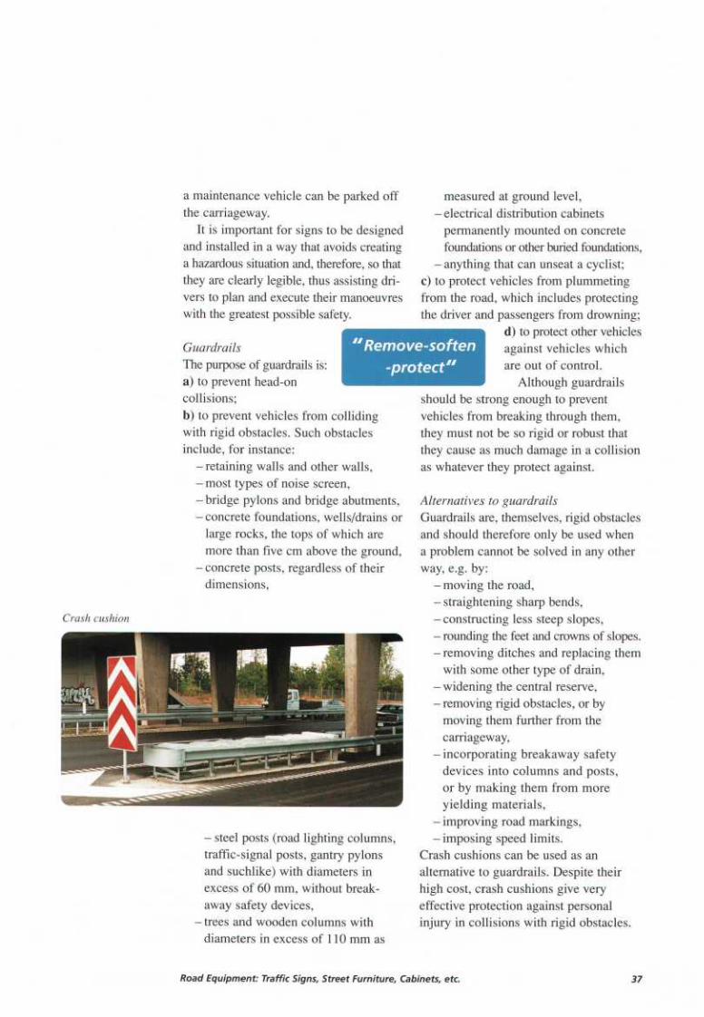
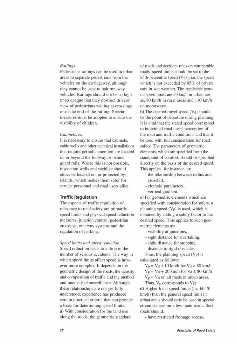
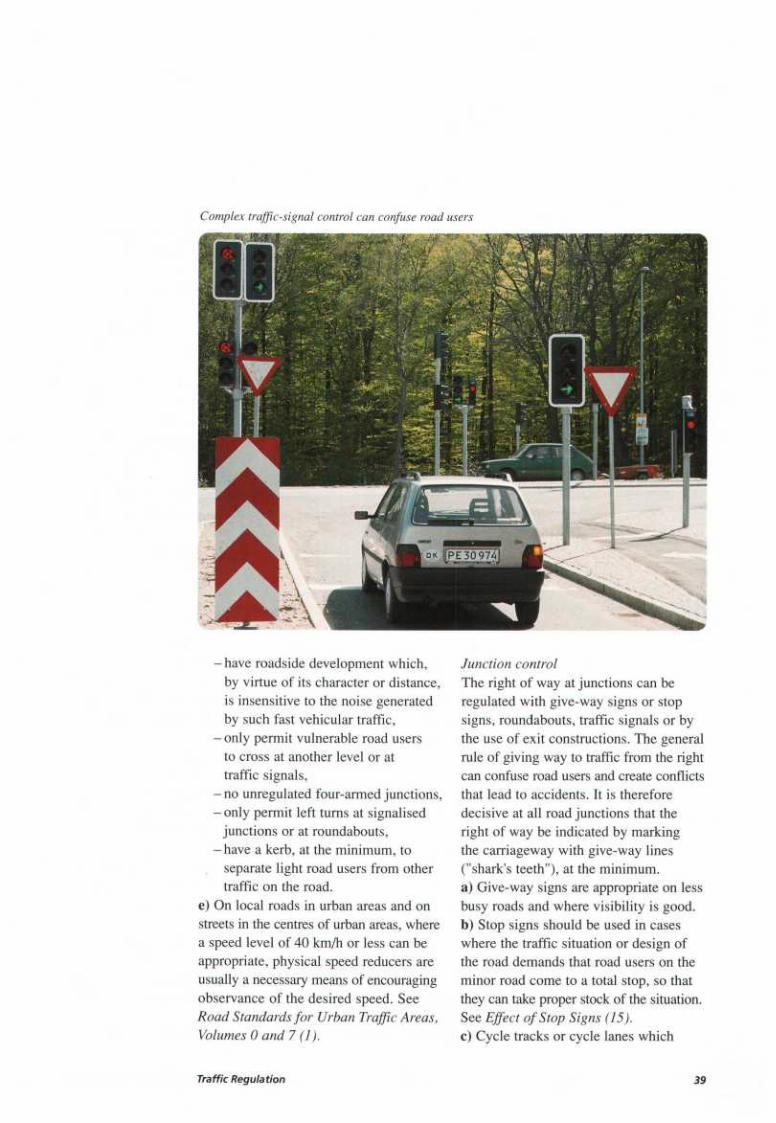
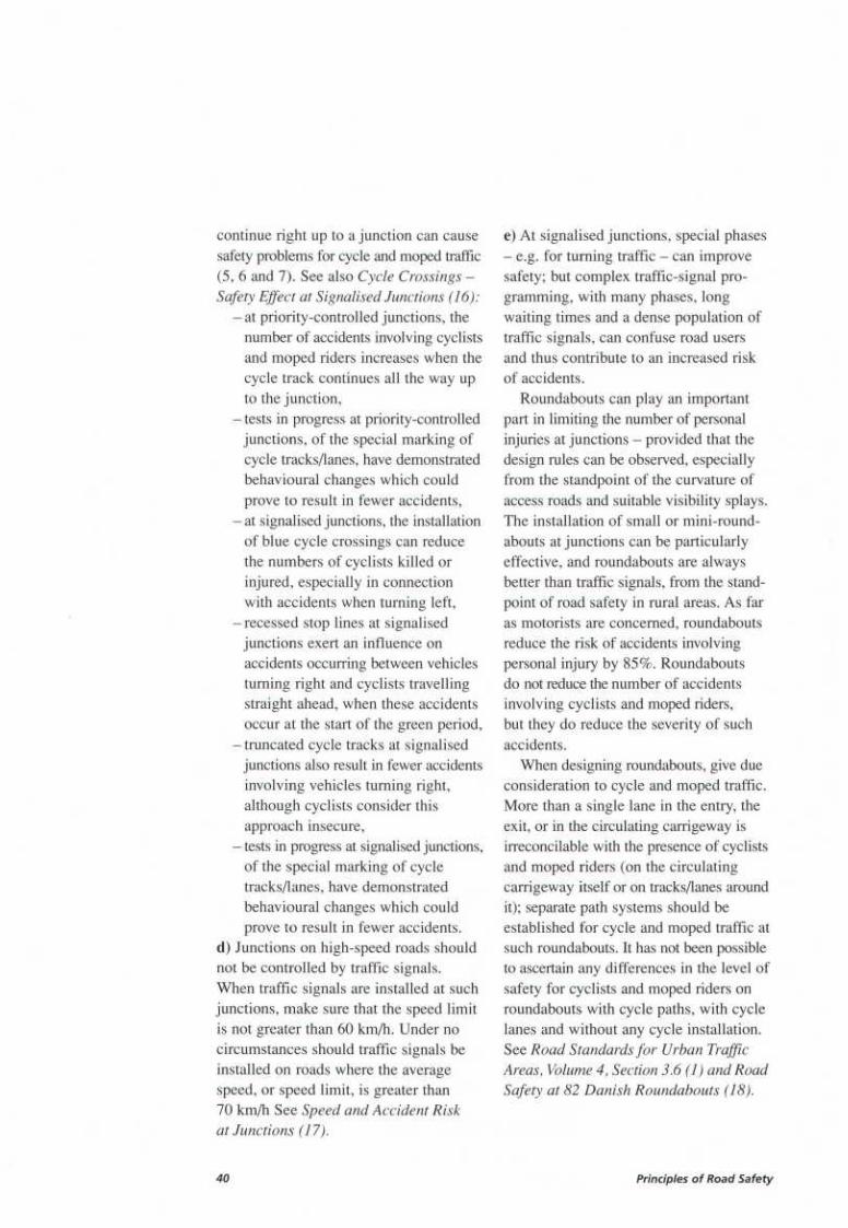
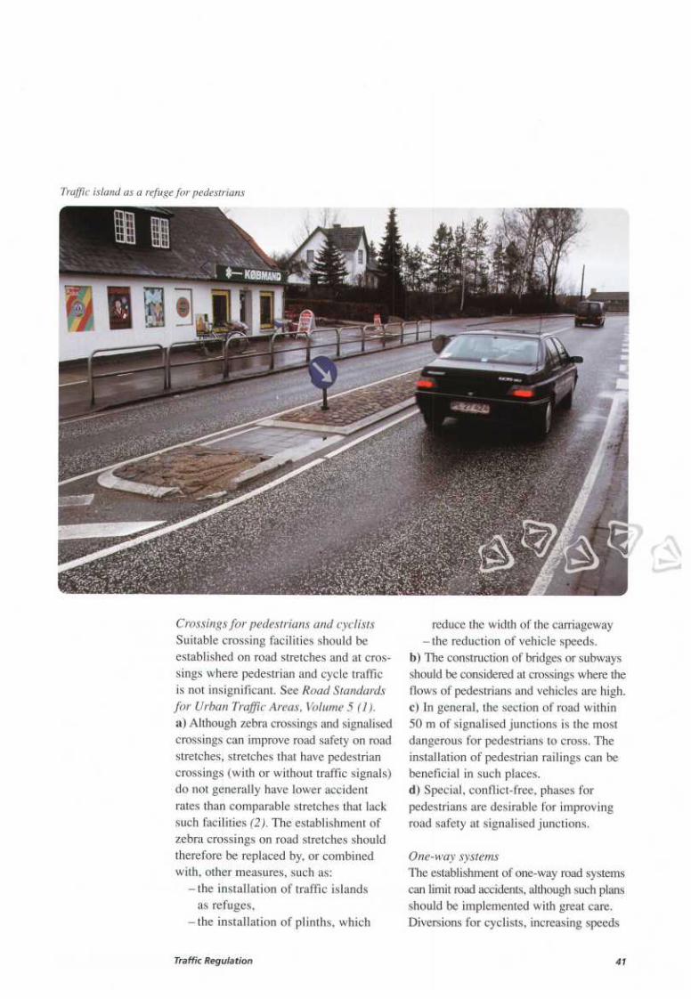

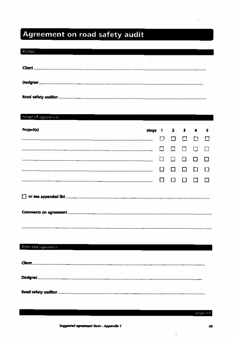
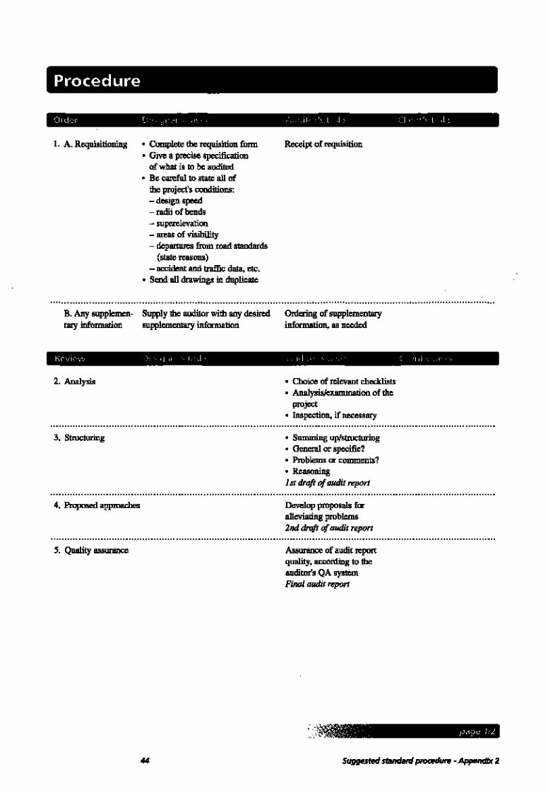
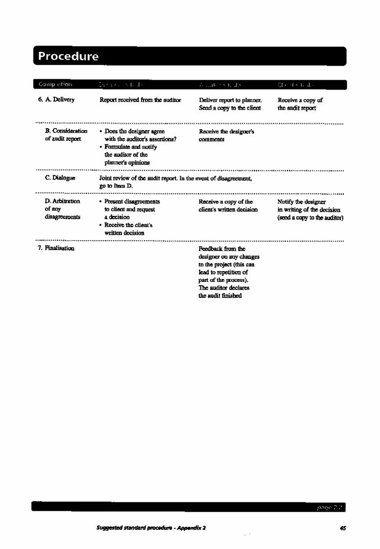
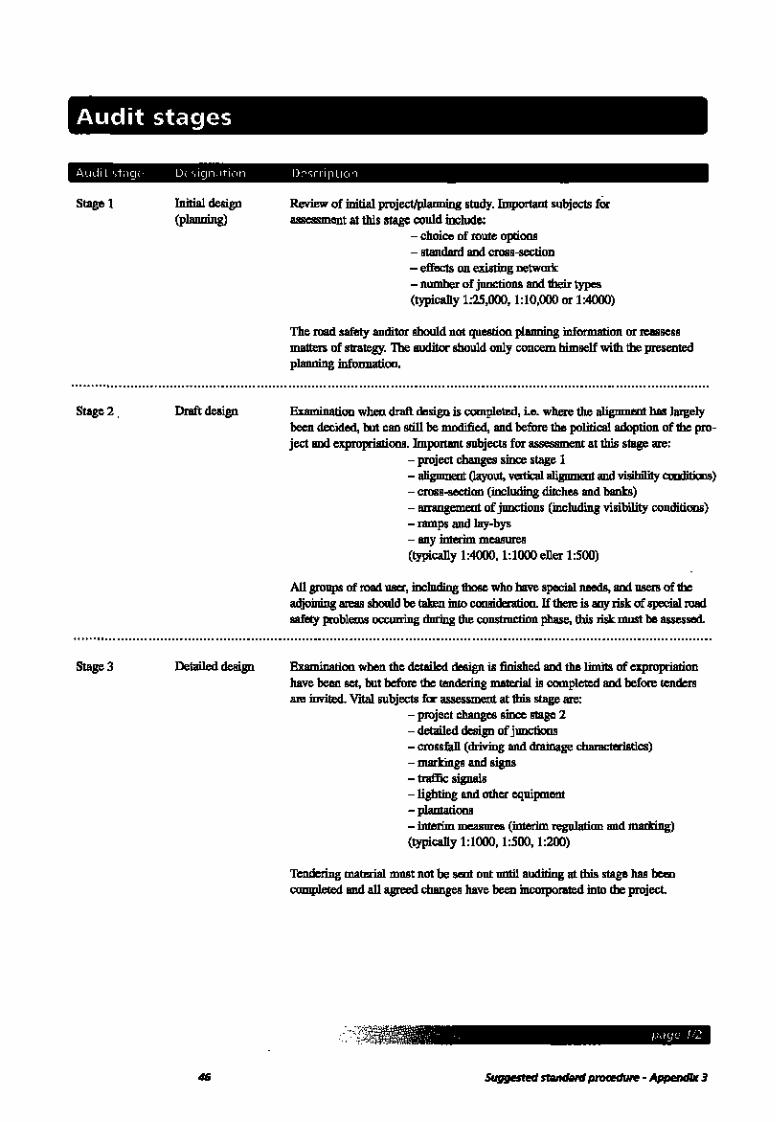

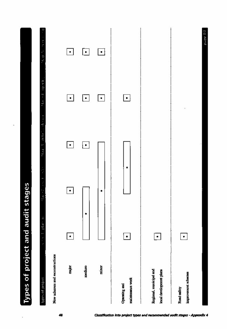
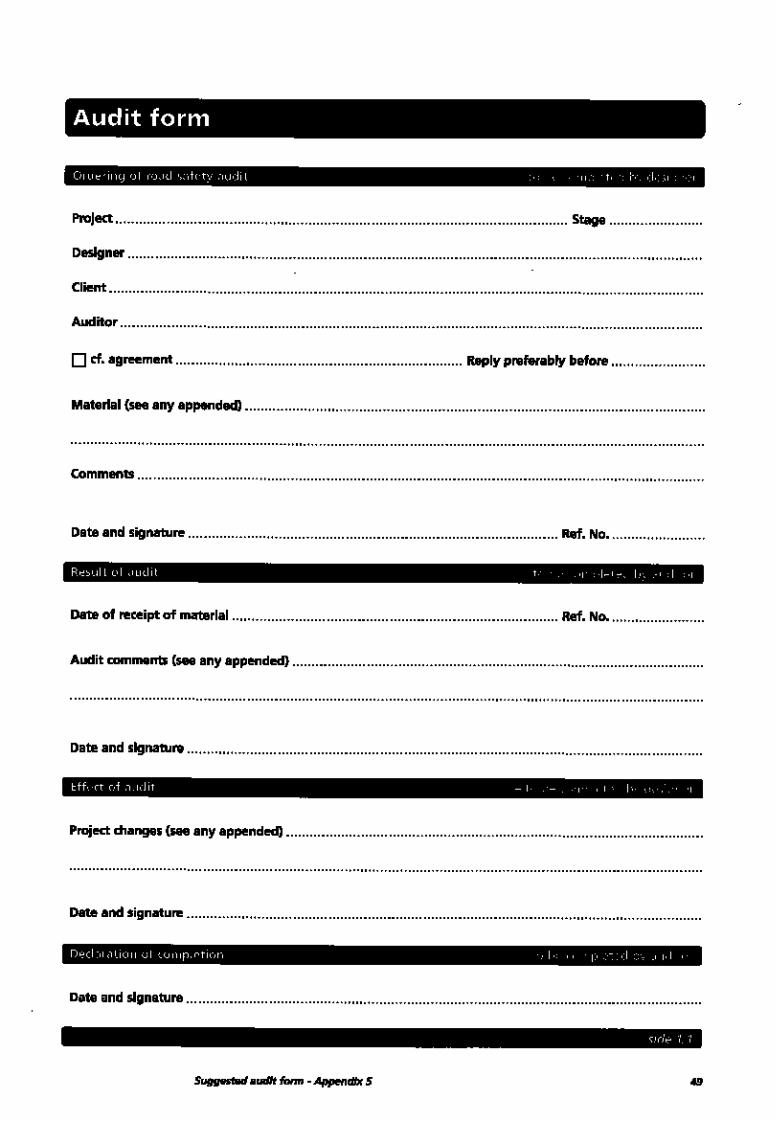
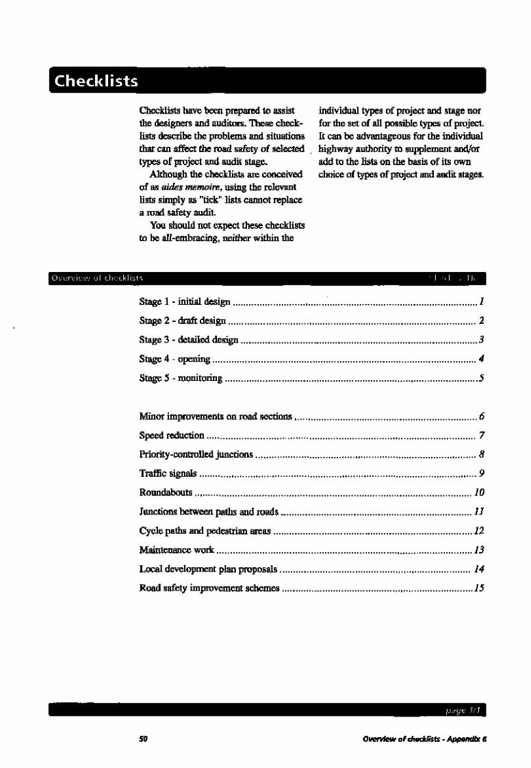
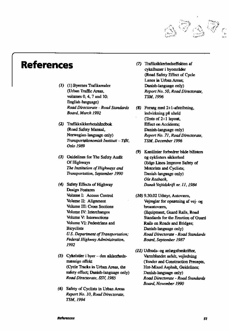

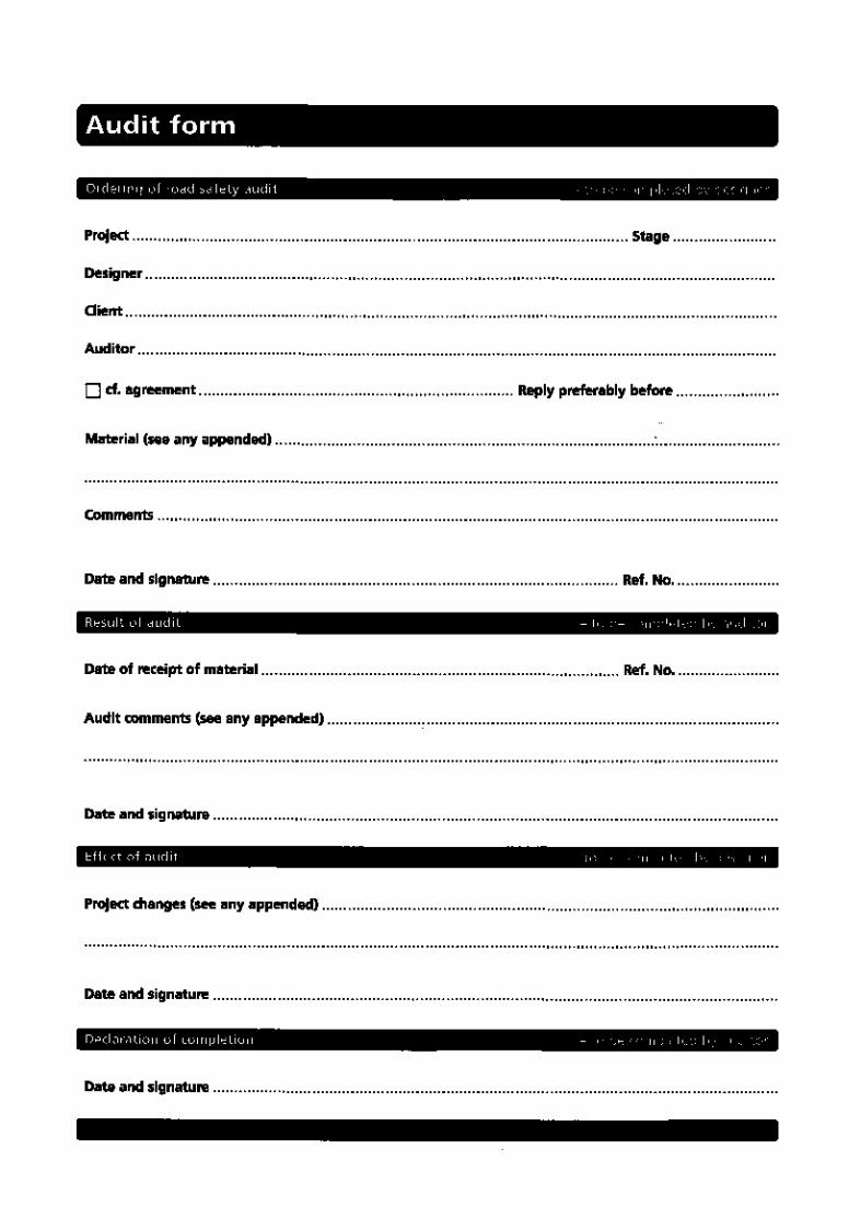


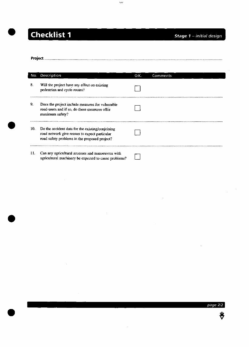
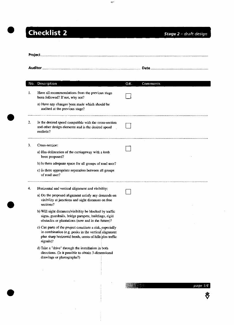
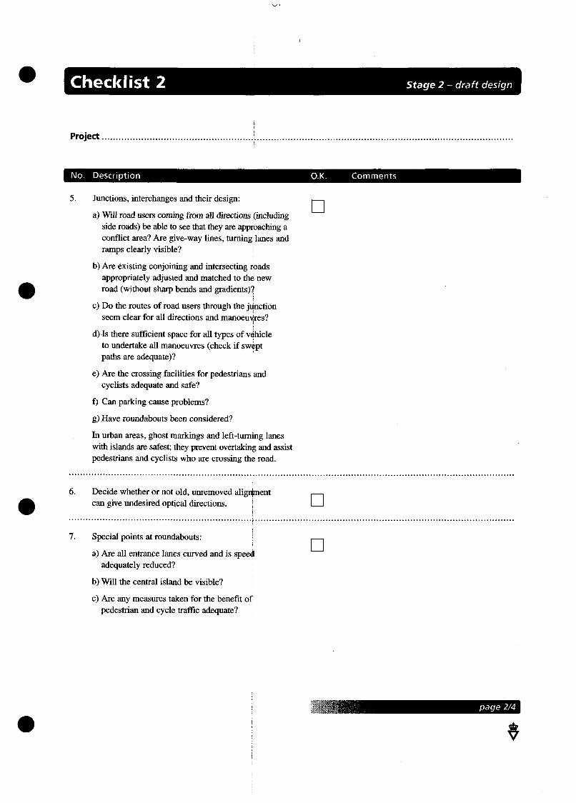
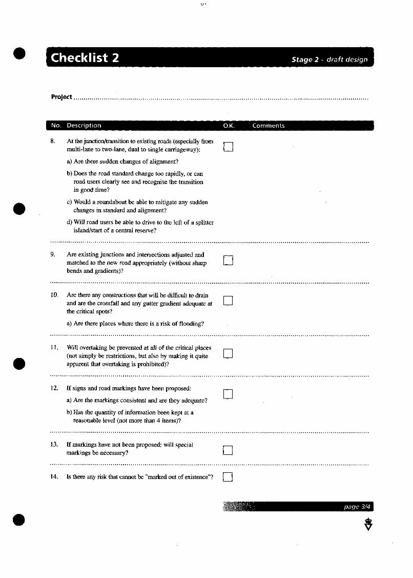
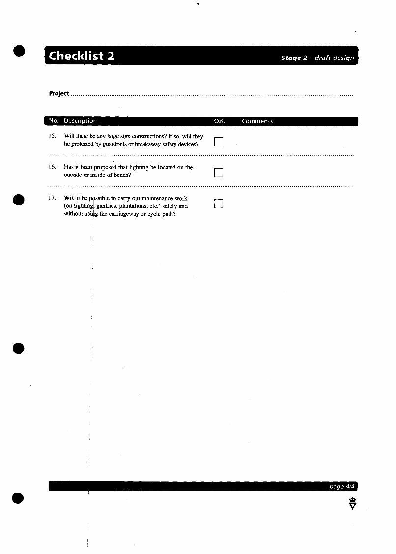

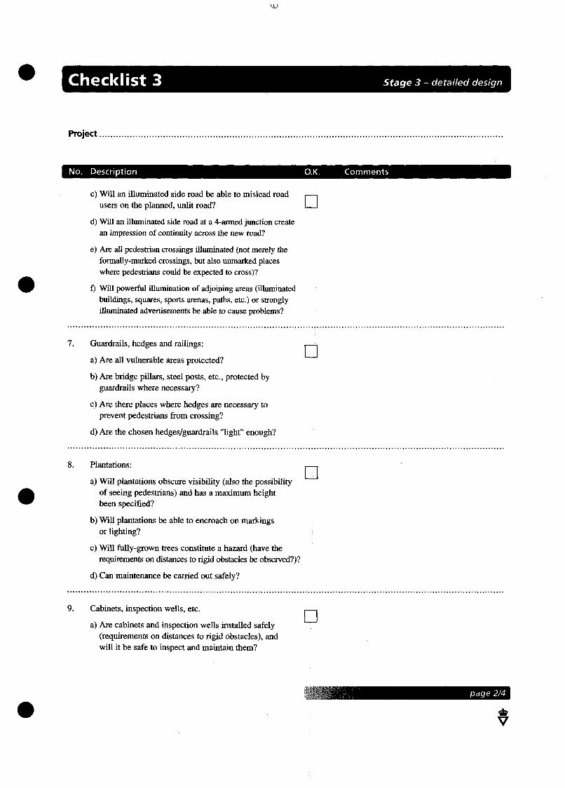
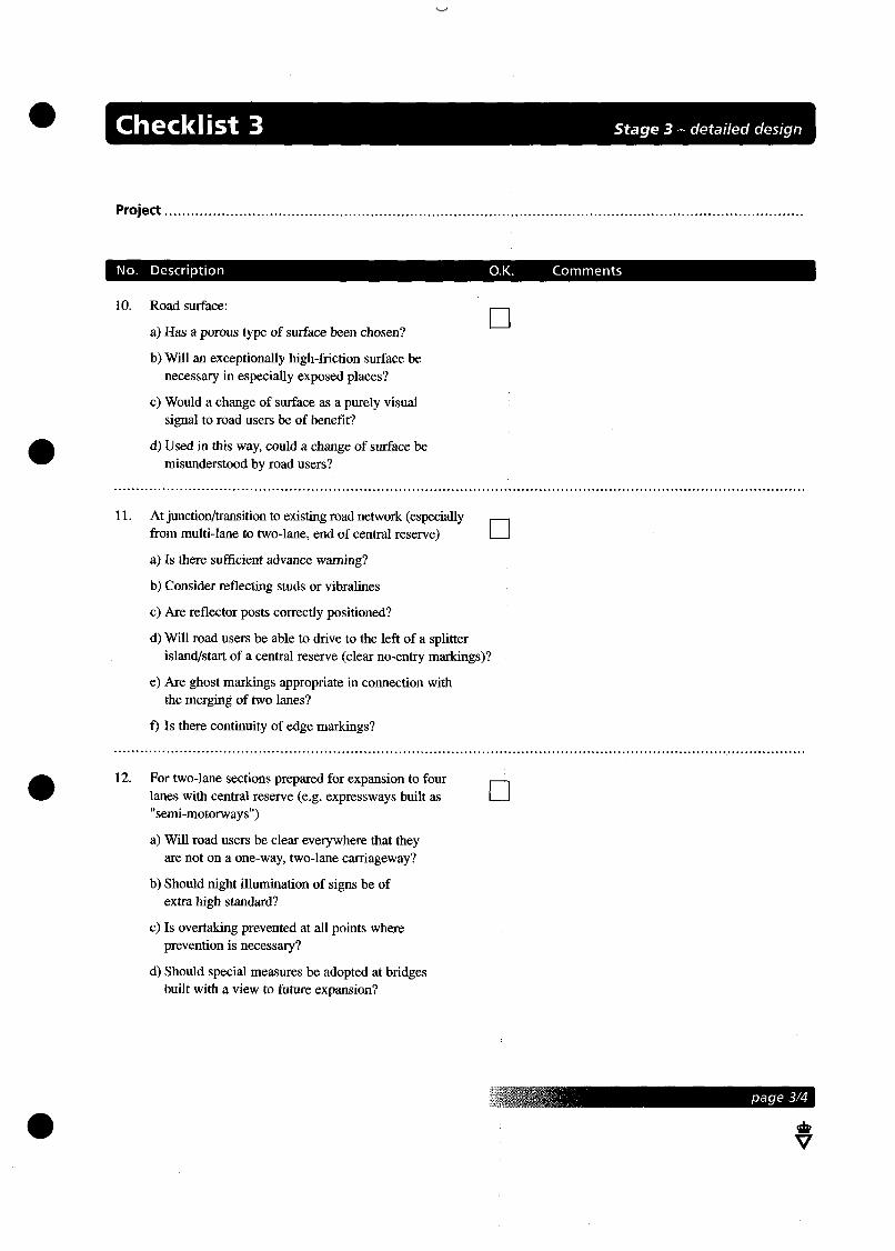
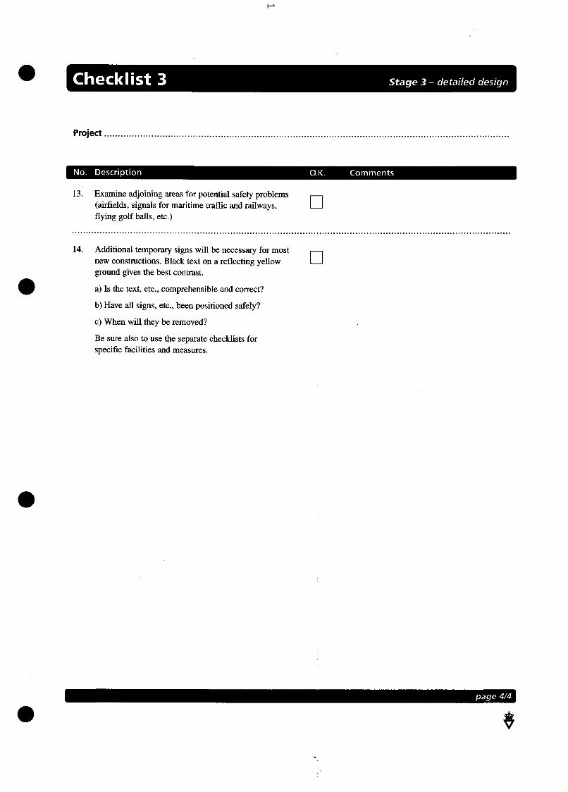
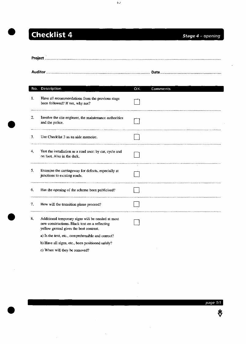
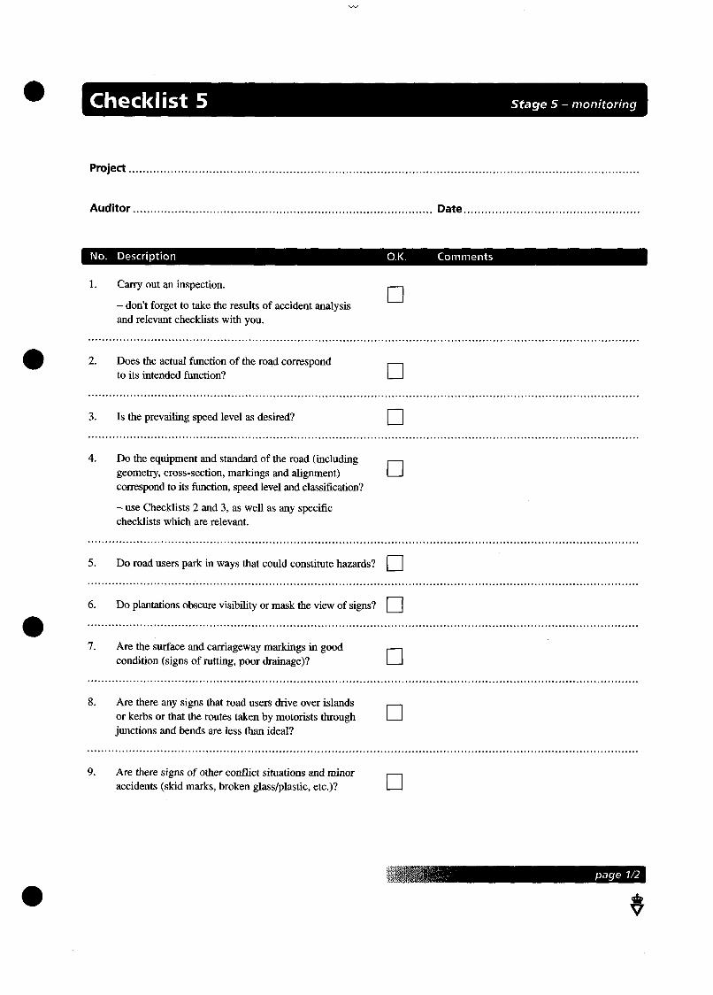

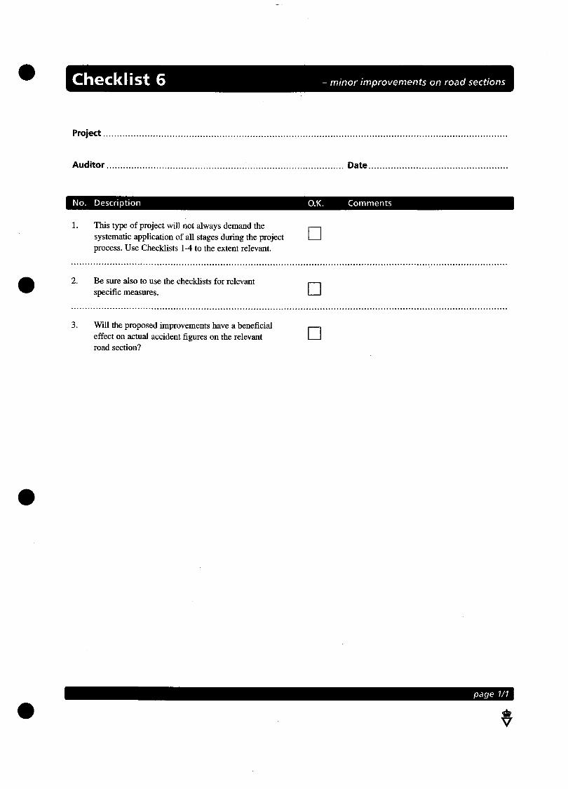
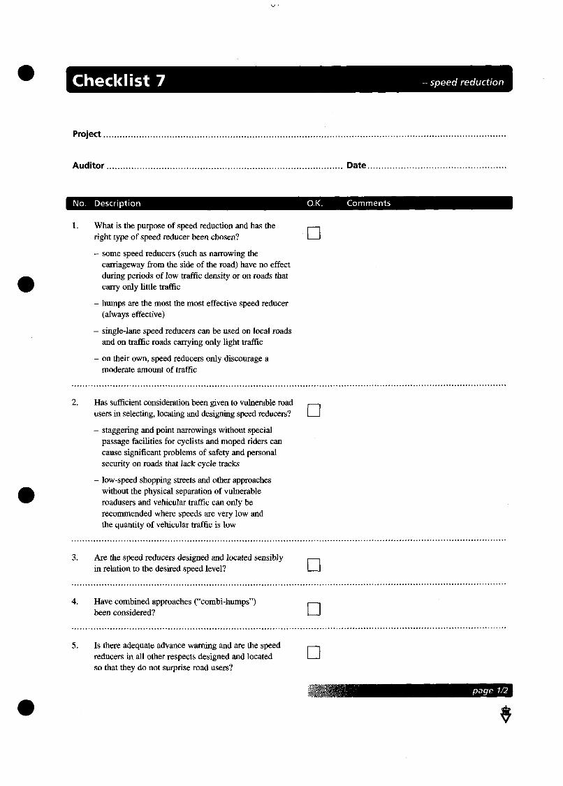
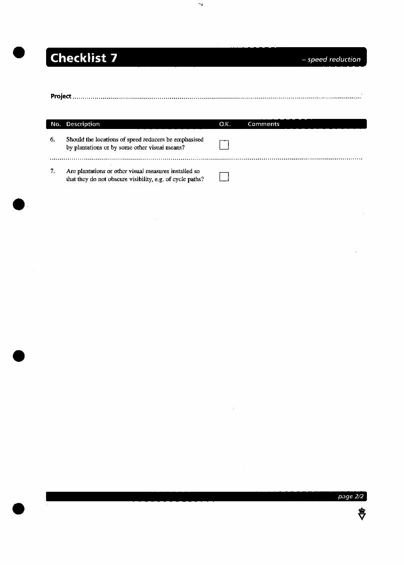
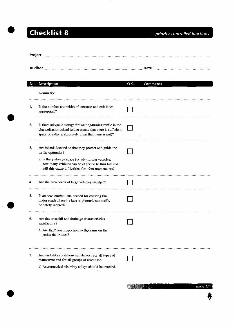
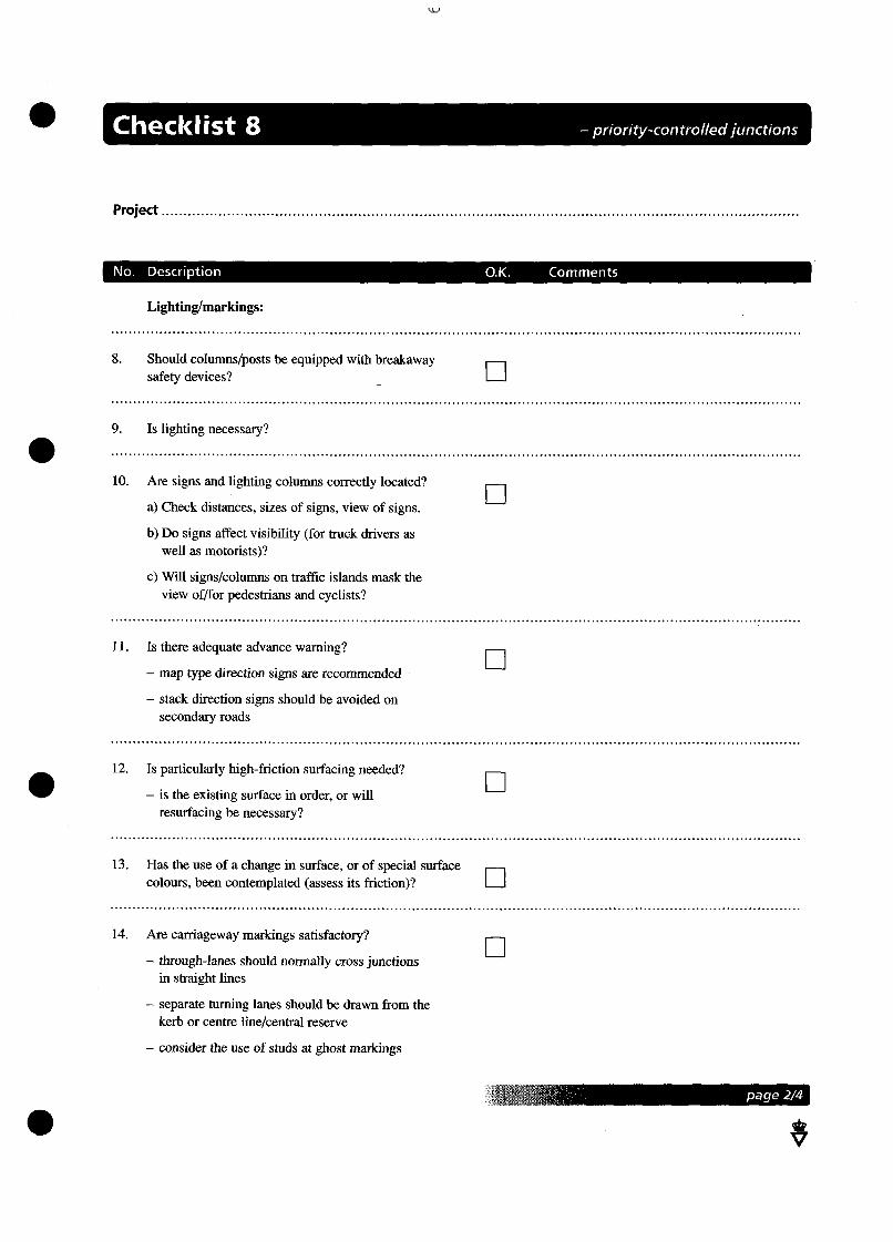
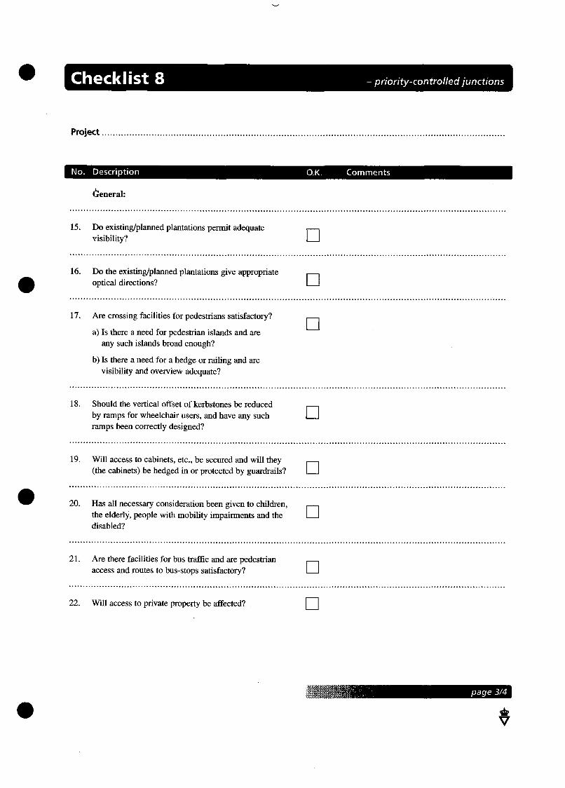
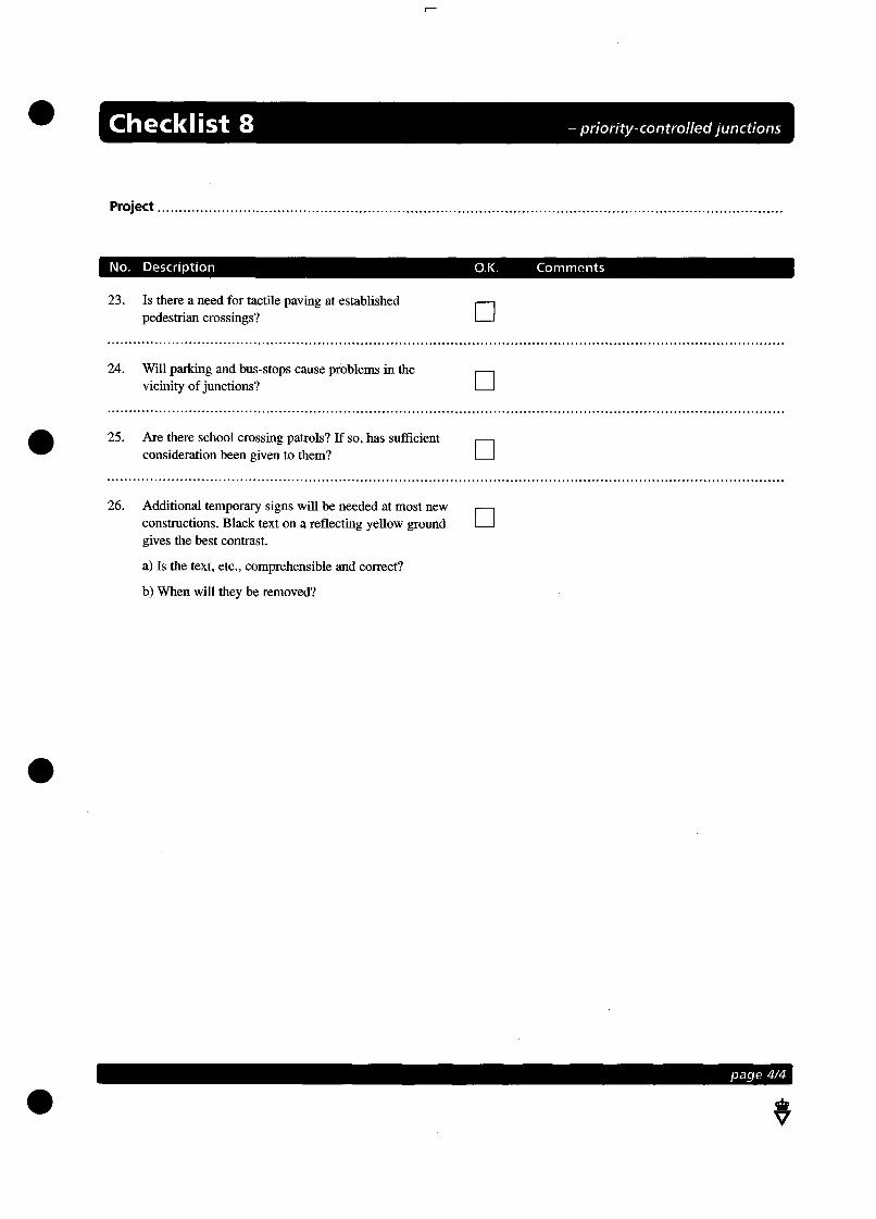
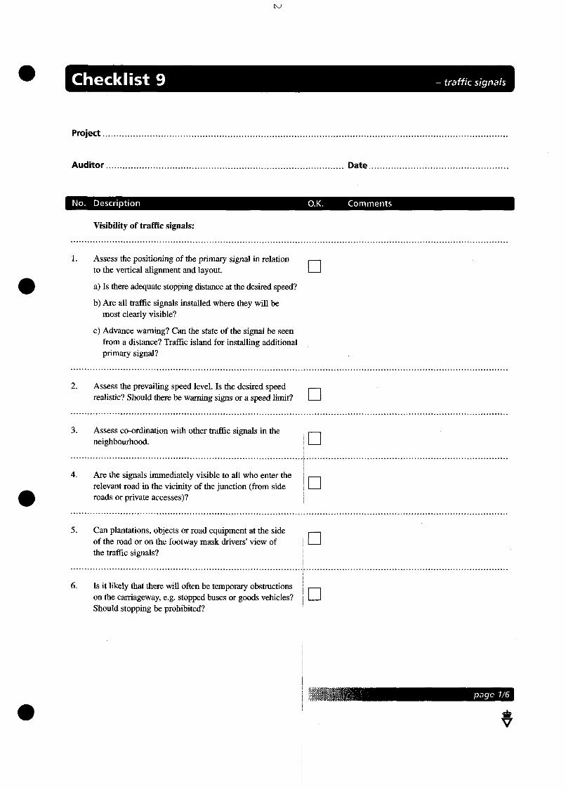
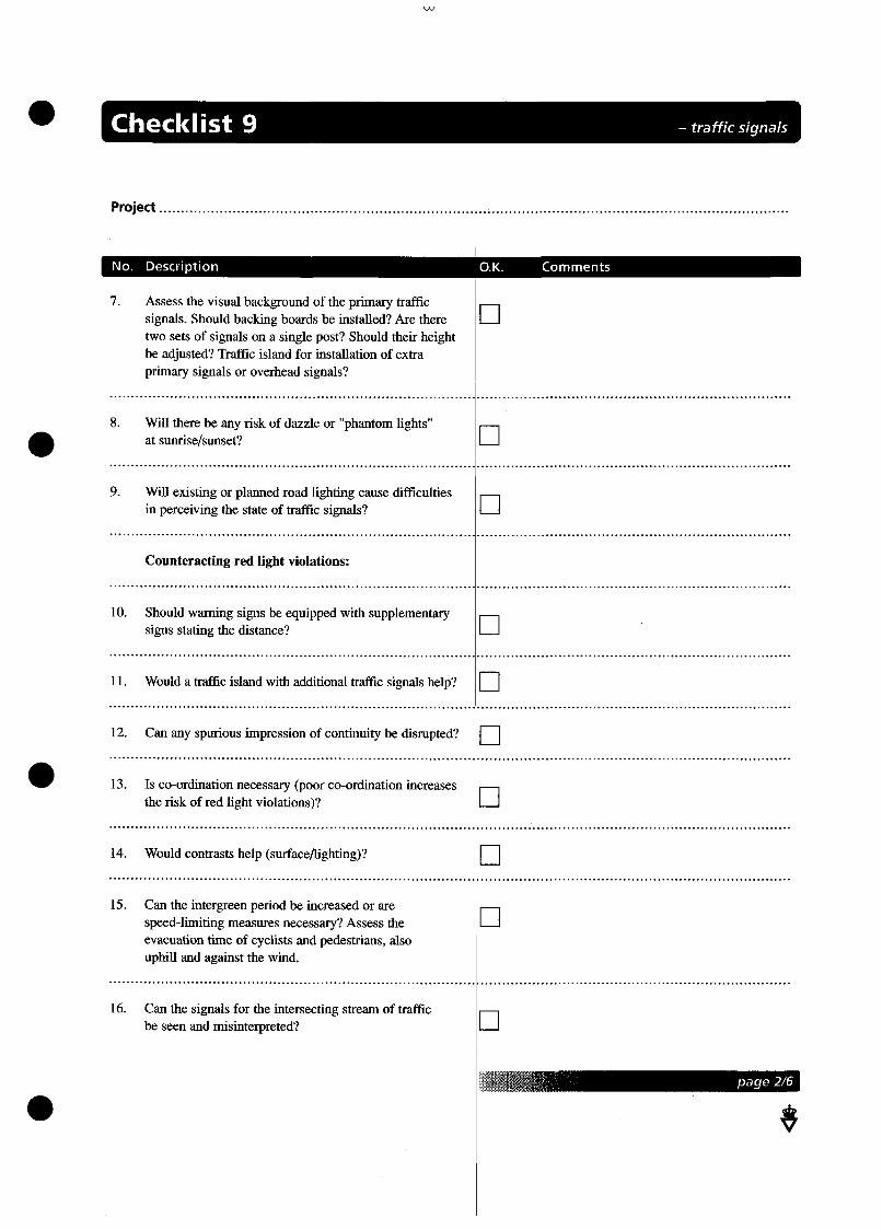
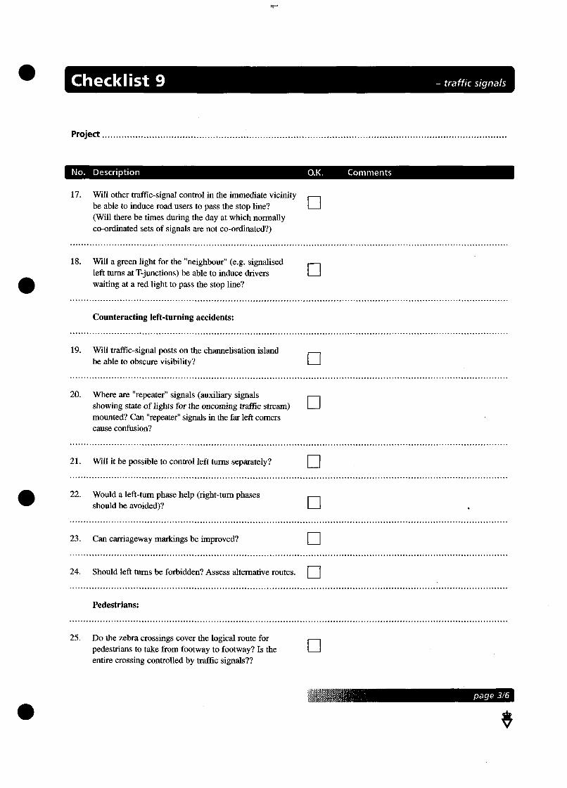
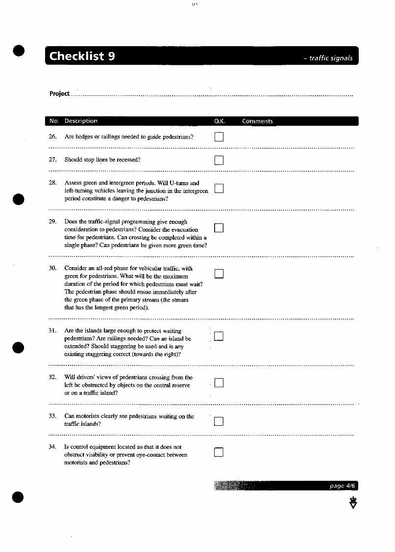
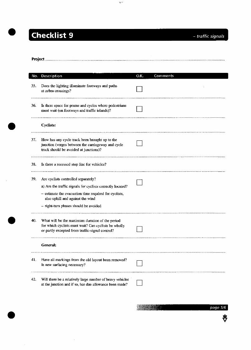
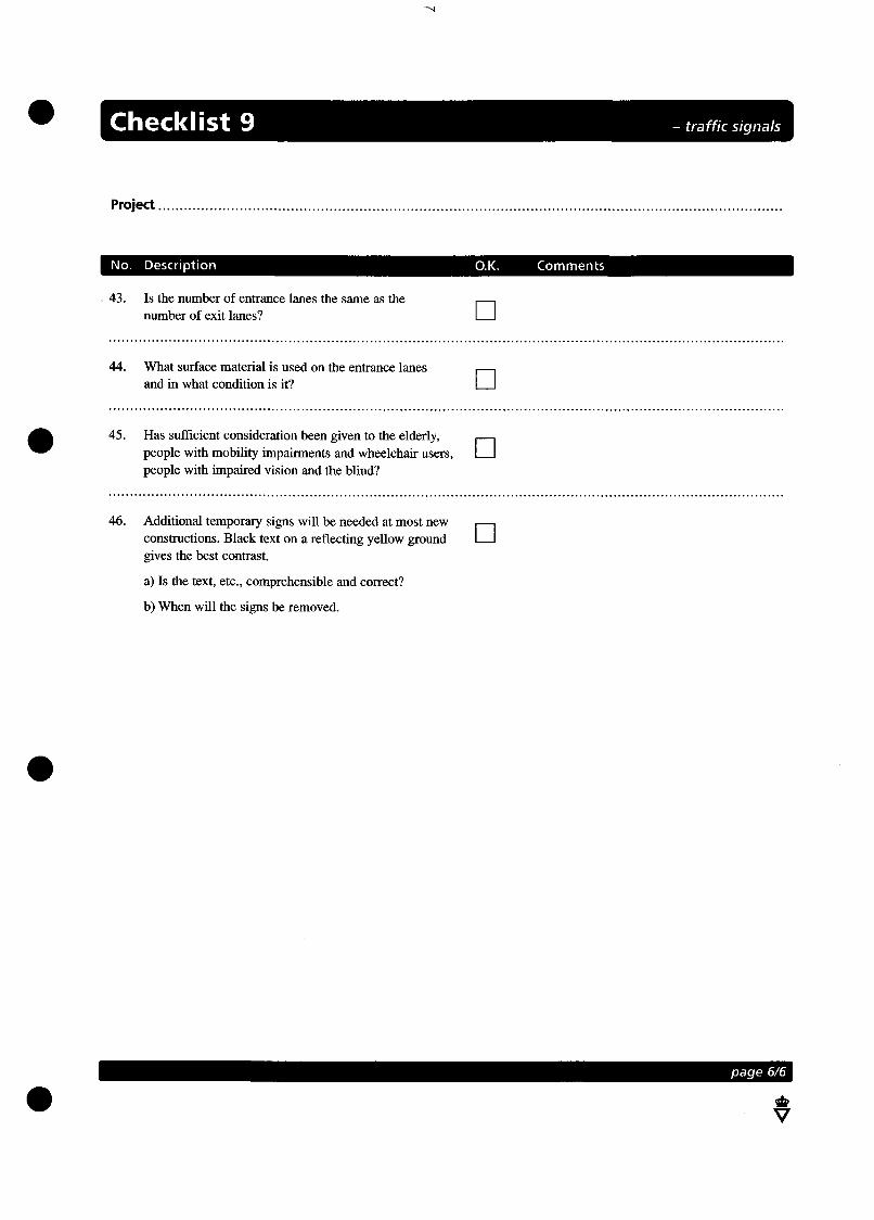
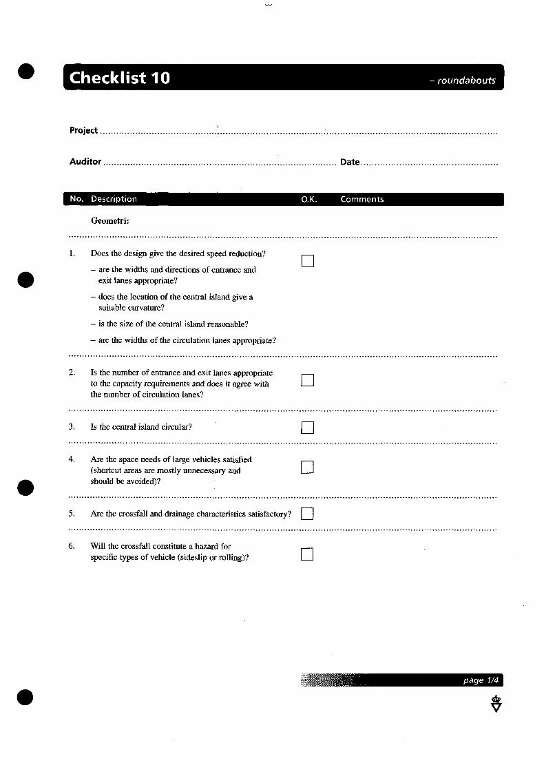
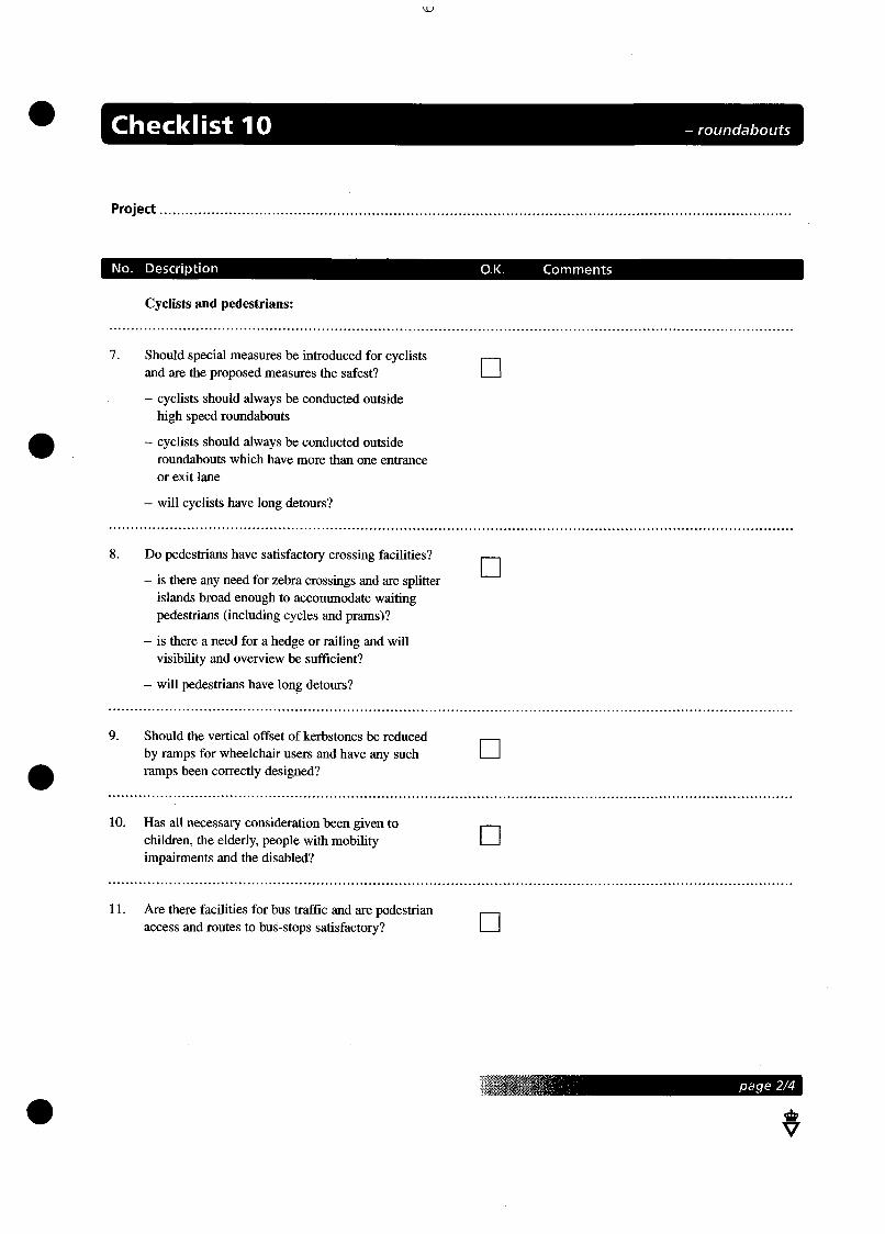
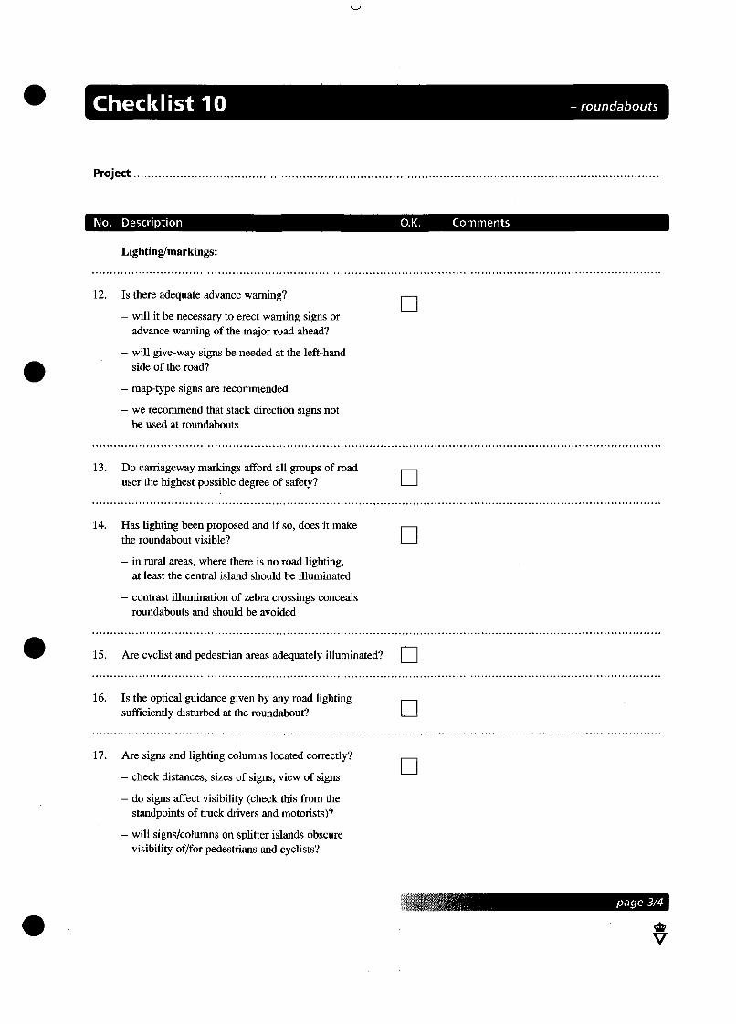

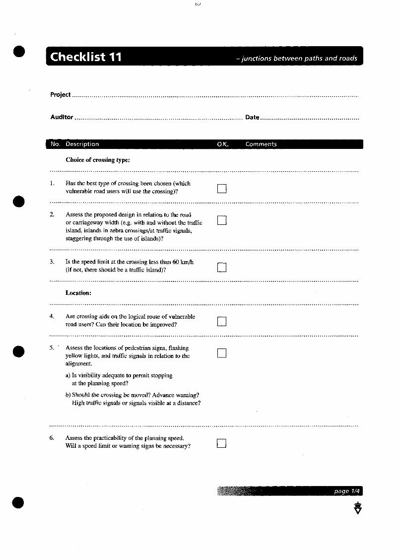

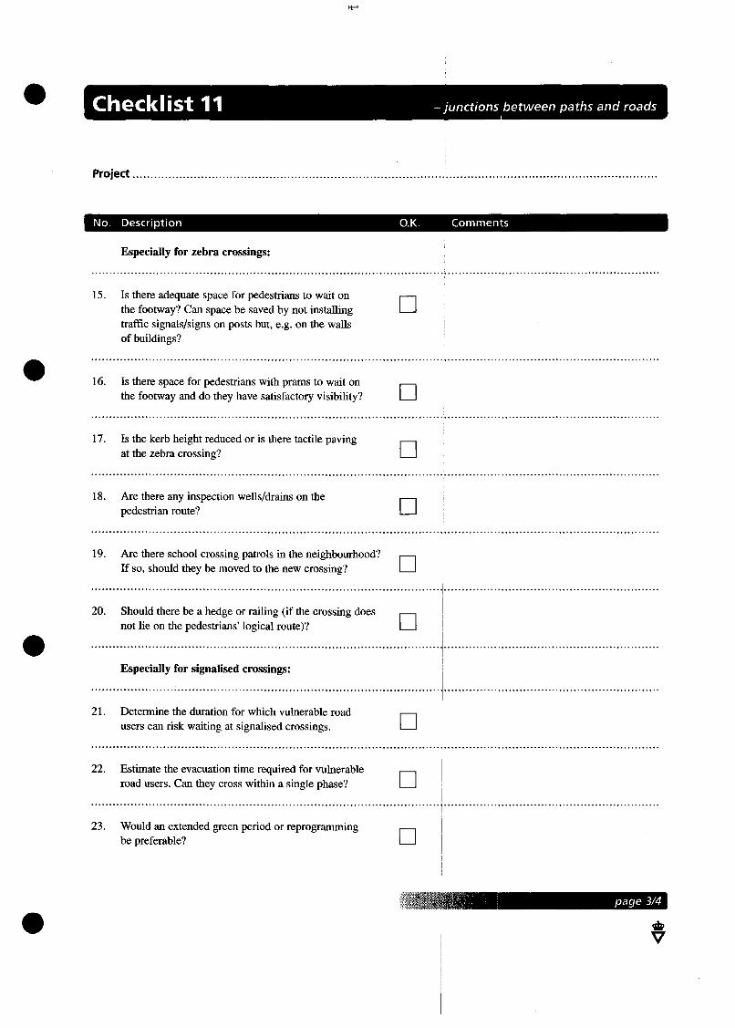
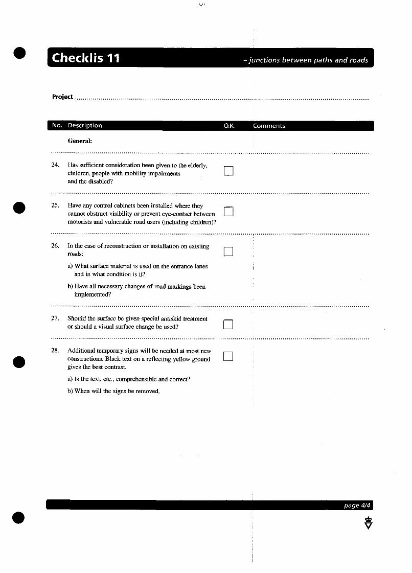
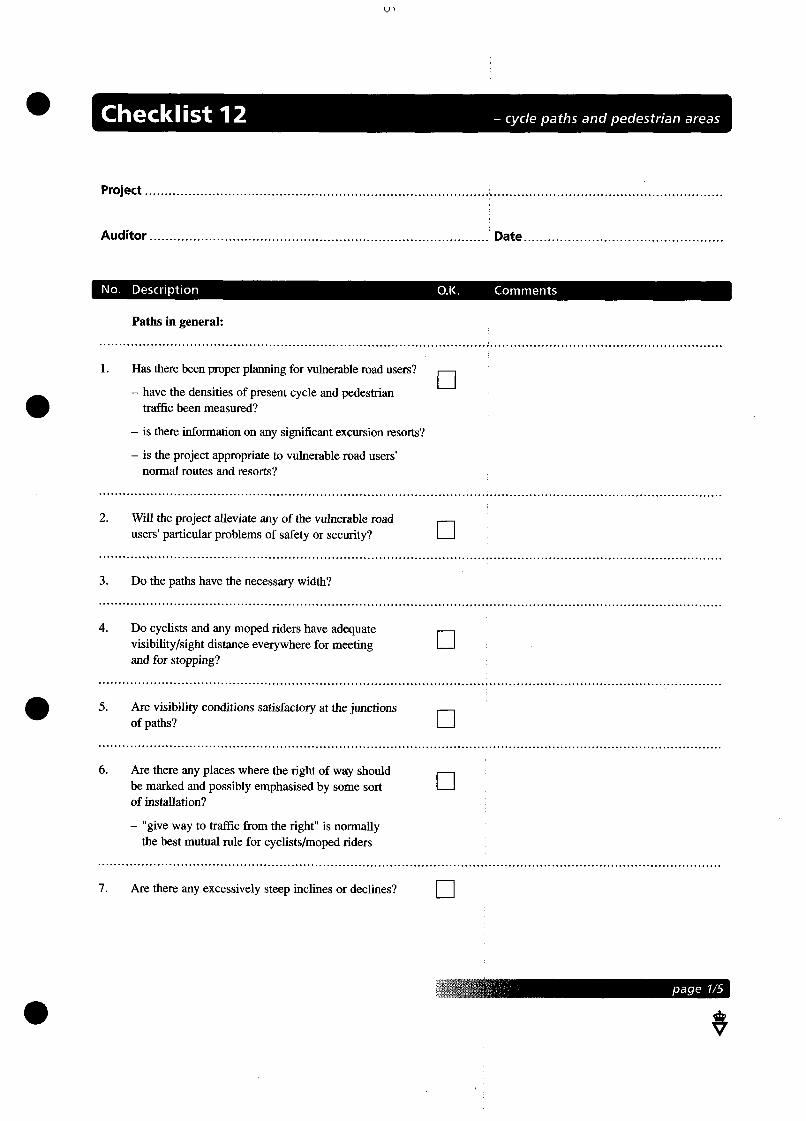
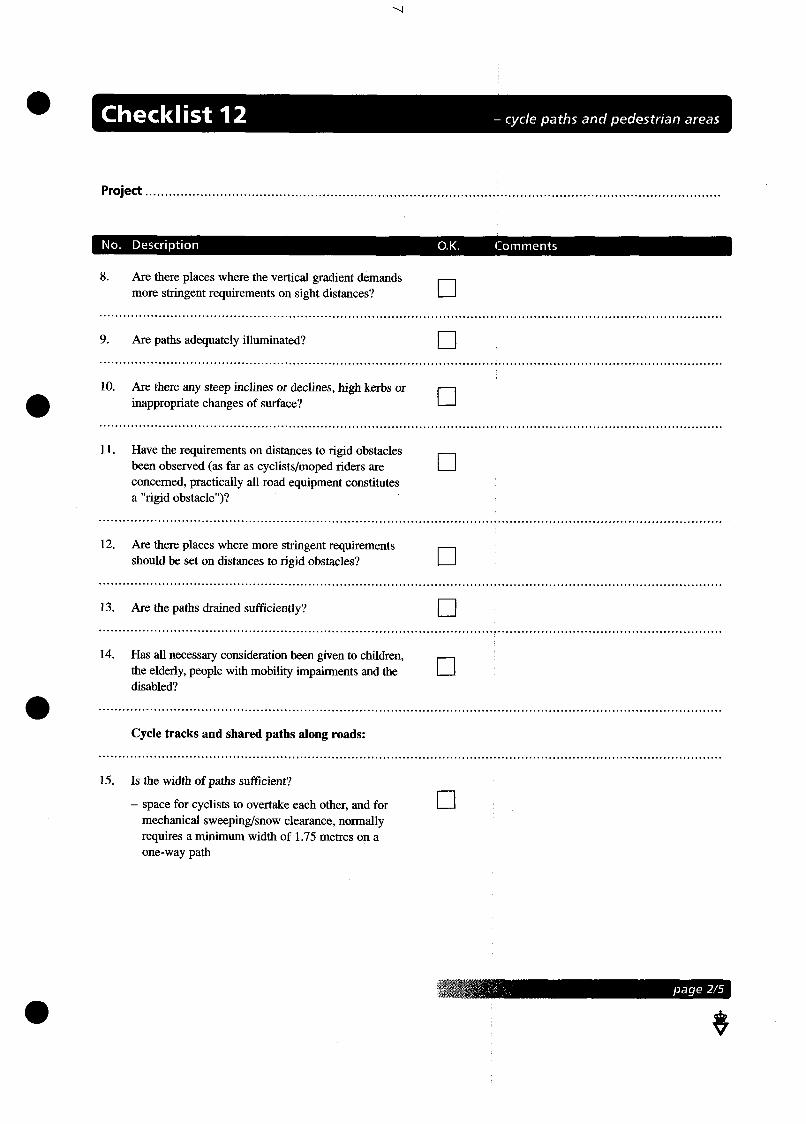
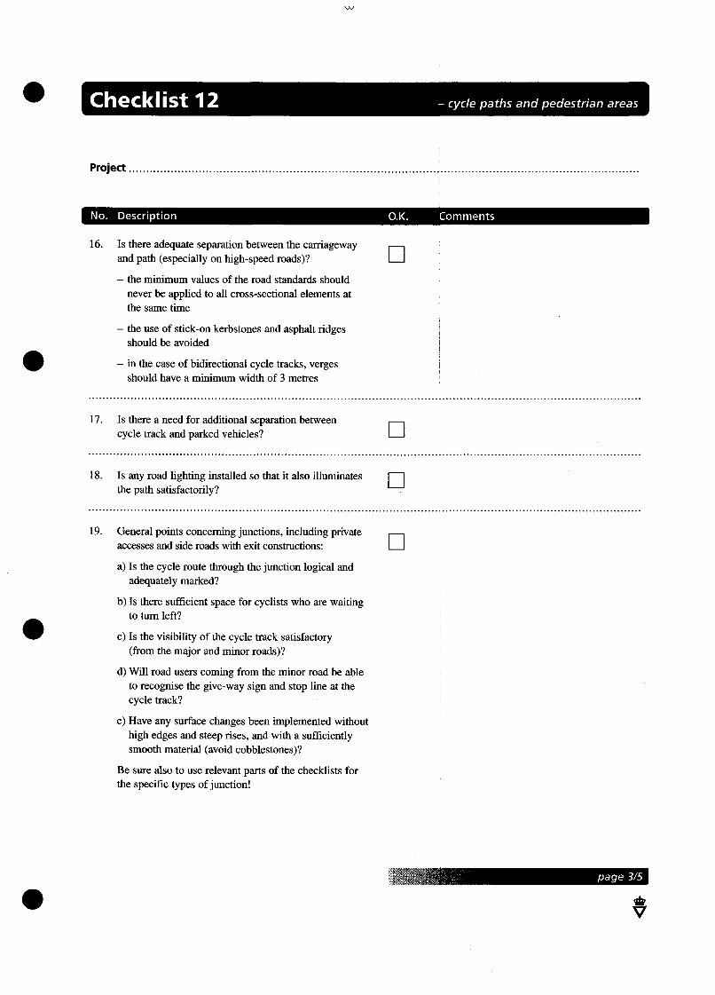
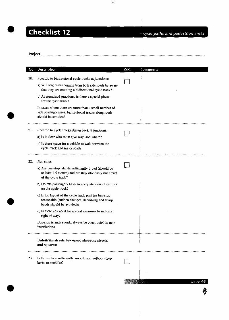
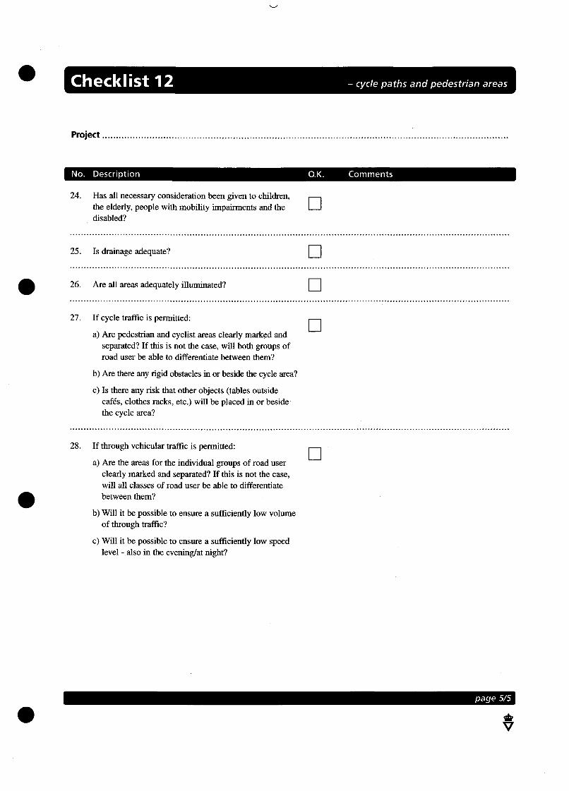
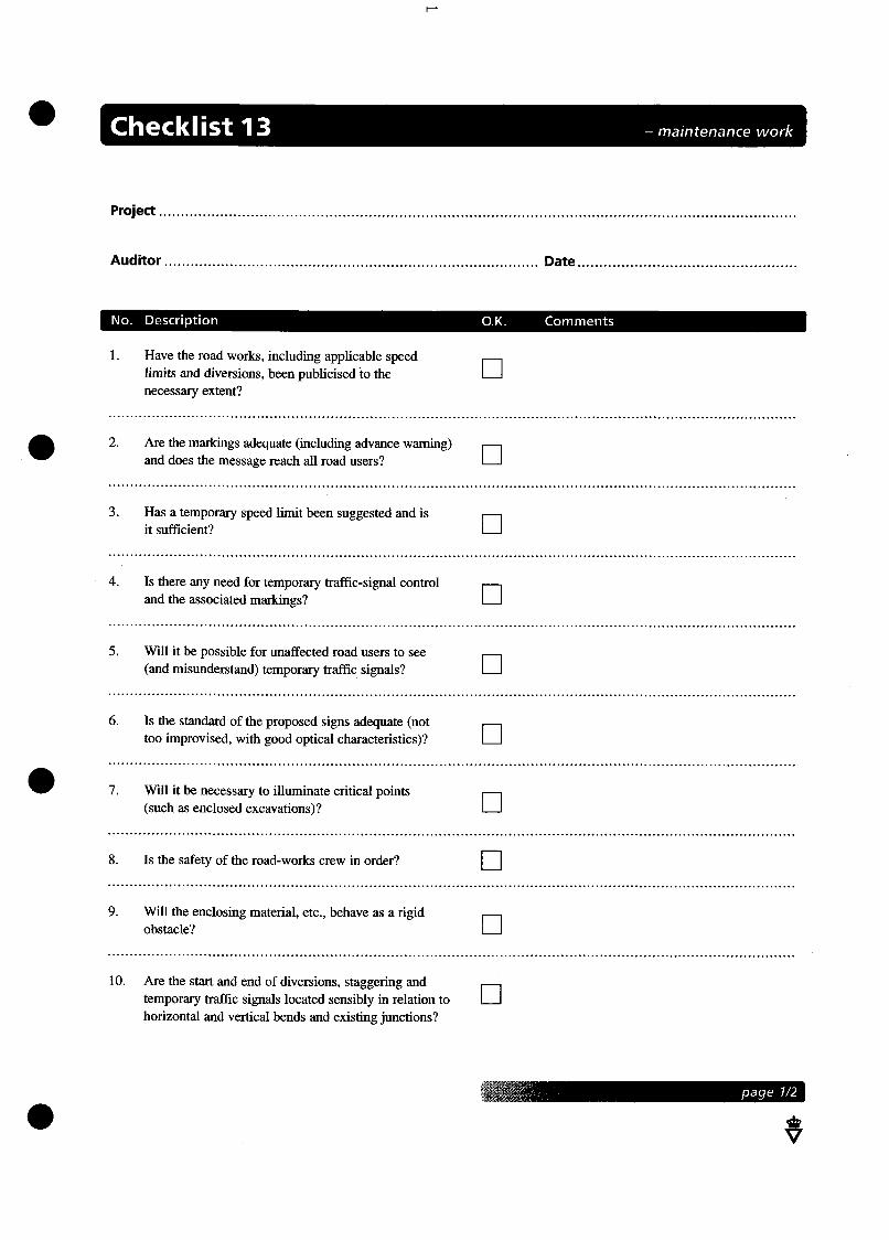

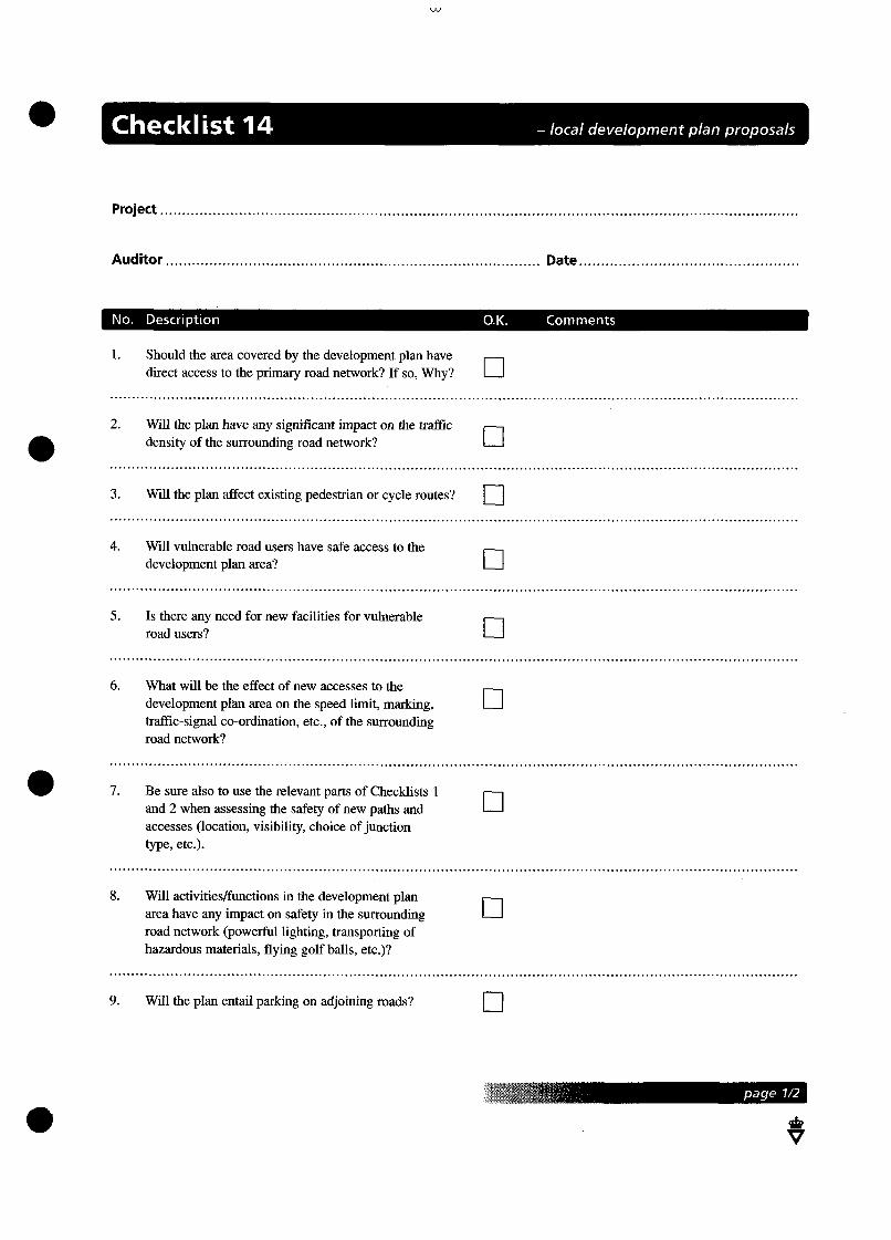
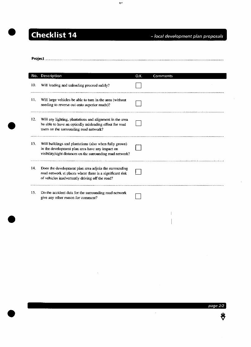
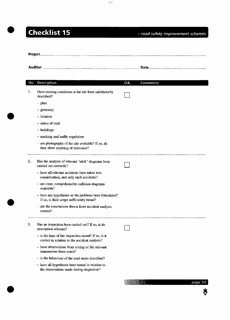

ROAD SAFETY AUDIT AND SAFETY IMPACT ASSESSMENT
August 1997
European Transport Safety Council Rue du Cornet 34 B-1040 Brussels
Tel.: + 32 2 230 41 06 / 40 04
Fax : + 32 2 230 42 15

2
© 1997 European Transport Safety Council Extracts from this publication may be reproduced with the permission of ETSC. ISBN: 90-76024-02-2
3
Acknowledgements ETSC gratefully acknowledges the contributions of members of ETSC's Road Infrastructure Working Party to this review and, in particular, the work of Professor Richard Allsop, Chairman of the Working Party and editor of the review: Prof. Richard Allsop (WP Chairman) Mr Geoff Maycock Prof. Werner Brilon Prof. Jef Mortelmans Mr Finbarr Crowley Dr Aristoteles Naniopoulos Mr Dominique Fleury Mr Fred Wegman Prof. Siegfried Giesa Prof. Aniceto Zaragoza Dr Lene Herrstedt Mrs Ingrid van Schagen (WP Secretary) Prof. António Lemonde de Macedo ETSC is grateful for the financial support provided by DGVII of the European Commission and for the contribution towards the printing and dissemination costs of this review provided by 3M Europe, Ford Europe, BP, KeyMed and KLM Royal Dutch Airlines. The contents of this review are the sole responsibility of ETSC and do not necessarily reflect the view of sponsors nor organisations to which research staff participating in the Working Party belong.
The European Transport Safety Council The European Transport Safety Council (ETSC) is an international non-governmental organisation which was formed in 1993 in response to the persistent and unacceptably high European road casualty toll and public concern about individual transport tragedies. Cutting across national and sectoral interests, ETSC provides an impartial source of advice on transport safety matters to the European Commission, the European Parliament and, where appropriate, to national governments and organisations concerned with safety throughout Europe. The Council brings together experts of international reputation on its Working Parties, and representatives of a wide range of national and international organisations with transport safety interests and Parliamentarians of all parties on its Main Council to exchange experience and knowledge and to identify and promote research-based contributions to transport safety. Board of Directors: Main Council Chairmen: Professor Herman De Croo (Chairman) Miss Anne McIntosh MEP Mr PAM Cornelissen MEP Mr Günter Lüttge MEP Professor G. Murray Mackay Dr Gerhard Schork Executive Director: Mr Pieter van Vollenhoven Mrs Jeanne Breen

Contents Executive Summary ............................................................................................................................5 1. Introduction....................................................................................................................................10 2. Road Safety Audits ............................................................................................... ........................11
2.1 The aim and nature of a safety audit..................... ............................................................11 2.2 Organising and carrying out an audit ..............................................................................12 2.3 Safety audit and existing roads ........................................... ..............................................14
3. Road Safety Impact Assessment..................................................................................................14
3.1 The aim and nature of safety impact assessment......................... ...................................14 3.2 Carrying out a safety impact assessment..........................................................................15
4. Cost-effectiveness ..................................................................................... ....................................16 5. The roles of the EU and Member States................................................... ..................................18
5.1 Implementation in Member States ....................................................................................18 5.1.1 Safety Audit............................................................................................. ...................18 5.1.2 Safety impact assessment..........................................................................................19
5.2 EU responsibilities and opportunities ..............................................................................19 5.2.1 Implementation in the TERN................................................................... ................19 5.2.2 Promotion of safety audit ......................................................................... ...............20 5.2.3 Promotion of safety impact assessment .................................................. ...............21
6. Conclusions ......................................................................................................... ..........................21 Reference.............................................................................................................................................24 Annex 1: Safety Audit: a British example..................... .................................................................26 Annex 2: Safety impact assessment: a Dutch example.................................................................29
4
5
Executive Summary Road safety audit is a formal procedure for independent assessment of the accident potential and likely safety performance of a specific design for a road or traffic scheme - whether new construction or an alteration to an existing road. Road safety impact assessment is a formal procedure for independent assessment of the likely effects of proposed road or traffic schemes, or indeed other schemes that have substantial effects on road traffic, upon accident occurrence throughout the road network upon which traffic conditions may be affected by the schemes. These two procedures enable the skills of road safety engineering and accident analysis to be used for the prevention of accidents on new or modified roads. They thus complement the use of these same skills to reduce the occurrence of accidents on existing roads by means of local safety schemes, in many cases in the form of low-cost measures (ETSC, 1996). This review aims to describe and illustrate the use of safety audits and safety impact assessment in helping to design and build safe road and traffic schemes, and at the planning stage in choosing which schemes to progress from among a range of possibilities. Both procedures have strong contributions to make to rational and effective decision-making when considering alternative options, and safety audit is important to the achievement of a safe design for a chosen alternative. The two procedures are complementary - the aim is similar and the difference is in scope and timing. The scope of safety audit is usually confined to an individual road scheme, which may be a new road or modification to an existing road. The basis for safety audit is the application of safety principles to the design of a new or a modified road section to prevent future accidents occurring or to reduce their severity. The procedure is usually carried out at some or all of five stages in carrying out a scheme: feasibility study, draft design, detailed design, pre-opening and a few months after opening. An essential element of the process is that it is carried out independently of the design team. It should be undertaken by a team of people who have experience and up-to-date expertise in road safety engineering and accident investigation. The scope of safety impact assessment is dependent on the scale of the schemes being considered. For small-scale schemes, the impact of change can usually be expected to be confined largely within the scheme itself. In this situation safety impact assessment and safety audit share many procedural characteristics. For larger schemes, the impact on accident occurrence can be expected to be felt over a larger part of the road network. In that case, the impact may be estimated using a
6
scenario technique. By considering different road types, the corresponding values of relevant safety indicators and the forecast traffic volumes, the impact on accident occurrence can be estimated for different alternatives. The development of safety audit for road and traffic schemes, and especially the fifth stage of monitoring the operation of such schemes after they have been open to traffic for some months, raises the question of the role of safety audit or analogous safety checking in respect of existing roads. There is a prima facie case that an independent assessment of conditions on an existing road would be likely to reveal deficiencies indicating scope for cost-effective measures for accident prevention additional to the accident remedial measures that are routinely identified by investigation of accident occurrence. The benefits of safety audits and safety impact assessment are in: � minimising the risk of accidents occurring in the future as a result of
planning decisions on new transport infrastructure schemes; � reducing the risk of accidents occurring in the future as a result of
unintended effects of the design of road schemes; � reducing the long-term costs associated with a planning decision or a road
scheme; � enhancing the awareness of road safety needs among policy-makers and
scheme designers. Well-documented experience in Europe and elsewhere shows that formal systematic safety audit procedures are a demonstrably effective and cost-beneficial tool to improve road safety. But they are used so far by only a minority of Member States. ETSC believes that sufficient information is available to warrant the EU and Member States taking a series of measures leading to routine application of safety audit procedures to schemes for new road construction and modification of existing roads in order to realise the full contribution that road infrastructure schemes can make to casualty reduction. Consideration should also be given to systematic safety checking of existing roads to complement accident investigation work. Safety impact assessment procedures are not yet carried out anywhere on a national basis, although there has been some initial experience in The Netherlands and some aspects of safety impact assessment are included in appraisal procedures in some other Member States. Some Member States, however, have valuable experience in safety auditing techniques for road infrastructure projects and for these, the next step is to take a more strategic approach by looking at safety effects on the wider road network by means of safety impact assessment. There is also an important role for the EU in encouraging work in this area.
7
In urging action by Member States, ETSC wishes to emphasise that although the procedures of safety audit and safety impact assessment are complementary, neither is dependent upon the other. Early action to implement safety audit can therefore go ahead and be yielding benefits whilst work proceeds on the lengthier task of establishing procedures for safety impact assessment. In relation to safety audit ETSC recommends that Member States should: (a) examine their own procedures for the assessment of safety in road
infrastructure projects to see how they can be made more effective in the light of practice in other Member States;
(b) where no formal procedure for safety audit exists, introduce a mandatory
requirement that all major new road schemes be subjected to an independent safety audit;
(c) in time, extend formal procedures to smaller schemes and the safety
checking of existing roads; (d) prepare guidelines for use at national and local level laying down the terms
of reference for safety audit including the roles and responsibilities of all concerned, with the help of experience in countries where safety audit is already practised;
(e) prepare a detailed manual of good practice which may be used in
conjunction with the guidelines; (f) send technically trained road safety professionals and their managers to
learn at first hand from their counterparts in other Member States about their application of safety audit, and be ready to receive such visiting professionals from other Member States; and
(g) reconsider their allocation of trained staff and finance within their highway
budgets to application of safety audit in the light of the benefit to cost ratios that it offers.
Regional and local authorities should:
be ready to share their experience of applying safety audit procedures with their counterparts in other Member States and to learn from them in return, especially by contributing to and drawing upon the EU's documentation of best practice and by exchange of visits by road safety engineers and managers.
8
In relation to safety impact assessment, ETSC recommends that Member States should:
(a) consider to what extent their existing arrangements for the appraisal of transport infrastructure projects take account of the likely impact of each project on accident occurrence throughout the affected road network;
(b) enhance their procedures for such appraisal so that they include all aspects
of safety impact assessment. Any new scheme on the TERN will, at the stage of feasibility study, be subject to mandatory Environmental Impact Assessment (EEC, 1985). ETSC believes that they should in a comparable way be subject to safety impact assessment covering the likely effects on accident occurrence, injury and damage not only on the relevant section of the TERN itself but also on all local roads on which traffic will be affected by the scheme. ETSC therefore welcomes the Commission's stated intention in its new action programme (CEC, 1997) to prepare new guidelines on safety impact assessment which would be applied in a first stage to the TERN and other EU financed projects. The chosen scheme that emerges from the feasibility study should then be subject to safety audit at the stages of preliminary design and detailed design, and on site just before opening to traffic and after several months of operation. In the context of its responsibility for transport safety, the EU can add value to the efforts of the Member States by acting to accelerate the rate at which citizens of the EU can benefit from more widespread and effective use of safety audits within each Member State. Further steps by the EU which ETSC believes would be useful are as follows: (a) as a first step promote international best practice by producing technical
guidelines on safety audit; (b) as a second step introduce an EU Directive requiring that all major new
road schemes be subject to an independent safety audit; (c) establish a European network of training in safety audit for road safety
professionals and managers; (d) encourage the transnational mobility of technically trained road safety
professionals and their managers to accelerate the transfer among Member States of successful techniques and procedures for applying safety audits; and
(e) look for mechanisms by which its own allocation of funds to Member States
for investment in roads can be used to encourage the recipient states to
9
allocate funding within their highway budgets to programmes of safety audit.
ETSC believes that the promotion of safety impact assessment through the establishment of guidelines for the TERN and all EU funded projects would be a helpful first stage in integrating safety considerations into the relevant decision-making processes. As a second stage, ETSC recommends that a mandatory requirement for safety impact assessment covering all new transport infrastructure projects should exist alongside EU procedures for environmental impact assessment with immediate application to the TERN and subsequent application to all transport infrastructure projects in all Member States. Eventually, safety impact assessment should extend to all land use planning decisions as is envisaged for the developing environmental impact assessment.
10
1. Introduction Road safety audit is a formal procedure for independent assessment of the accident potential and likely safety performance of a specific design for a road or traffic scheme - whether new construction or an alteration to an existing road. Road safety impact assessment is a formal procedure for independent assessment of the likely effects of proposed road or traffic schemes, or indeed other schemes that have substantial effects on road traffic, upon accident occurrence throughout the road network upon which traffic conditions may be affected by the schemes. These two procedures enable the skills of road safety engineering and accident analysis to be used for the prevention of accidents on new or modified roads. They thus complement the use of these same skills to reduce the occurrence of accidents on existing roads by means of local safety schemes, in many cases in the form of low-cost measures (ETSC, 1996). This review aims to describe and illustrate the use of safety audits and safety impact assessment in helping to design and build safe road and traffic schemes, and at the planning stage in choosing which schemes to progress from among a range of possibilities. Generally, roads are designed with a large number of criteria in mind, such as travel time, user comfort and convenience, fuel consumption, construction costs, environmental impact and objectives of urban or regional planning. Safety is one of the criteria, but is often implicitly assumed to be achieved by adhering to prescribed standards of alignment and layout for each element of the design. These standards are indeed laid down with safety in mind, and some of these include explicit safety checklists (e.g. FGSV, 1988), but experience shows that adherence to them is not sufficient to ensure that a resulting design is free from avoidable hazardous features. Formal safety audit and safety impact assessment procedures ensure that independent expertise is used to make explicit the safety implications of an entire design and, in doing so, lead to safer designs of both new and modified roads. Both procedures have strong contributions to make to rational and effective decision-making when considering alternative options, and safety audit is important to the achievement of a safe design for a chosen alternative. The two procedures are complementary - the aim is similar and the difference is in scope and timing. The scope of safety audit is usually confined to an individual road scheme, which may be a new road or modification to an existing road. The basis for safety audit is the application of safety principles to the design of a new or a modified road section to prevent future accidents occurring or to reduce their severity. The procedure is usually carried out at one or all of five stages in carrying out a scheme: feasibility study, draft design, detailed design, pre-opening and a few
11
months after opening. An essential element of the process is that it is carried out independently of the design team. It should be undertaken by a team of people who have experience and up-to-date expertise in road safety engineering and accident investigation. The scope of safety impact assessment is dependent on the scale of the schemes being considered. For small-scale schemes, the impact of change can usually be expected to be confined largely within the scheme itself. In this situation safety impact assessment and safety audit share many procedural characteristics. For larger schemes, the impact on accident occurrence can be expected to be felt over a larger part of the road network. In that case, the impact may be estimated using a scenario technique. By considering different road types, the corresponding values of relevant safety indicators and the forecast traffic volumes, the impact on accident occurrence can be estimated for different alternatives. The following two Sections deal in more detail with safety audit and safety impact assessment respectively, presenting information on procedural, methodological and organisational aspects, illustrated by means of specific case studies. Section 4 provides some information about the cost-effectiveness of safety audit as estimated in different countries where this approach has already been in use for some time. Section 5 considers the role of Member States and the European Union in promoting safety audit and safety impact assessment. Direct implementation could play an important role in the further development of the Trans-European Road Network, and implementation in Member States could be promoted in similar ways to that of the now mandatory environmental impact assessment procedures. In the last Section, the main conclusions are set out.
2. Road safety audits 2.1 The aim and nature of a safety audit In safety audits "The main objective is to ensure that all new highway schemes operate as safely as is practicable. This means that safety should be considered throughout the whole preparation and construction of any project" (IHT, 1996). More specific aims are: � to minimise the number and severity of accidents that will occur on the new
or modified road; � to avoid the possibility of the scheme giving rise to accidents elsewhere in
the road network; and
12
� to enable all kinds of users of the new or modified road to perceive clearly how to use it safely.
Whatever the reason for the scheme, a safety audit always begins with a road design. An audit is intended to identify potential road safety problems by looking at the scheme as if through the eyes of the potential users of all kinds, and to make suggestions for solving these problems by applying the principles of road safety engineering (AUSTROADS, 1994; Danish Road Directorate, 1993; IHT, 1996). This means that an audit goes much farther than just assessing whether or not the relevant design standards are properly applied. An example of the application of safety audit in the work of a British local authority is given in Annex 1. By minimising at the design stage the risk of accidents during the lifetime of a road scheme, there is less likelihood of having to take accident remedial measures later, and the whole-life cost of the scheme can be reduced. Road safety audit is an important means for paying explicit attention to road safety during the design of road schemes. This explicit attention should help everyone involved in making decisions regarding changes to road infrastructure to assess the safety implications of the many choices that arise during the design process, and thus increase the road safety awareness of infrastructure planners, designers and authorities. 2.2 Organising and carrying out an audit The process of safety audit as applied to an individual road scheme can be seen as taking place at up to five stages (Wrisberg and Nilsson, 1996), some of which can be combined for smaller schemes: � The feasibility stage. During this stage, the nature and extent of the scheme
are assessed, and the starting points for the actual design are determined, such as route options, the relevant design standards, the relationship of the scheme to the existing road network, the number and type of intersections, and whether or not any new road is to be open to all kinds of traffic.
� The draft design stage. Horizontal and vertical alignments and junction
layout are broadly determined. At the completion of this stage, the design should be well enough established so that, if necessary, decisions can be made about land acquisition.
� The detailed design stage. Layout, signing, marking, lighting, other roadside
equipment and landscaping are determined. � The pre-opening stage. Immediately before the opening, a new or modified
road should be driven, cycled and walked. It is advisable to do this under different conditions such as darkness and bad weather.
13
� Monitoring of the road in use. When a new or improved road has been in
operation for a few months, it is possible to assess whether it is being used as intended and whether any adjustments to the design are required in the light of the actual behaviour of the users.
Checklists have been designed for use during each stage of auditing (AUSTROADS, 1994; IHT, 1996). In practice, these checklists have proved very useful as reminders for the auditors, but there is also a risk that they are used too blindly as recipes without sufficient consideration for individual situations. What is required is a combination of judgement, skill and systematic working. The essence of road safety audit is that it is carried out by auditors who are independent of the design team, have expertise in both highway design and road safety, and are properly trained and experienced in carrying out audits. This means that not only must they possess sufficient specialised professional knowledge and have the required experience, but they must also possess the communication skills necessary to present audit results constructively and encourage a positive response to them from the design team. Experience has shown that it is preferable to hire a small auditing team rather than a single auditor. The members of an auditing team can jointly offer more skills than an individual, and a team can operate its own system of checks and balances and thus be less susceptible to its assessments being swayed by personal preferences. The results of audit should be documented and reported at each stage to the design team and in turn to the client for the scheme. They will usually include recommendations for improvements to the design. There is much to be said for linking a form of certification to the entire auditing process, and having the audit results made public so that citizens, prospective users of the new or modified road, and other interested parties can make informed contributions to further decision-making. Whether this can be done or not depends greatly on the way in which the decision-making process relating to the scheme is organised. It is therefore impossible to give a generally applicable rule in this regard. The conduct of safety audits can sometimes lead to tensions between the audit team, the design team and the client for the scheme. What is necessary from the start, therefore, is to create a sufficiently solid, formal basis (whether or not anchored in law) that enables safety audits to be carried out successfully and the recommendations based on the audits to be implemented. There also needs to be commitment to the procedures on the part of the organisations involved. The procedures should include arrangements for dealing with situations in which the design team and the audit team are nevertheless at odds about carrying out the audit recommendations. What is required in these cases is a decision by the client for the scheme, and this may be assisted by some form of arbitration. 2.3 Safety audit and existing roads
14
The development of safety audit for road and traffic schemes, and especially the fifth stage of monitoring the operation of such schemes after they have been open to traffic for some months, raises the question of the role of safety audit or analogous safety checking in respect of existing roads. There is a prima facie case that an independent assessment of conditions on an existing road would be likely to reveal deficiencies indicating scope for cost-effective measures for accident prevention additional to the accident remedial measures that are routinely identified by investigation of accident occurrence. Yet the task of checking all existing roads is demanding in terms of scarce resources of expertise. This issue has been investigated in France (Machu, 1996) by means of a pilot study covering nearly 2,000 km of roads ranging from motorways to local roads. The results provide useful indications concerning complementarity between safety checking and accident analysis, the range of deficiencies which it is practicable for the checking to cover, and ways of putting road sections of different kinds into an order of priority for checking during the many years it is likely to take to cover the whole network.
3. Road safety impact assessment 3.1 The aim and nature of safety impact assessment Being able to estimate explicitly the impact on road safety that results from building new roads or making substantial modifications to the existing road infrastructure that alter the capacity of the road network in a certain geographic area is of crucial importance if road safety is not to suffer unintentionally from such changes. The same applies to other schemes and developments that have substantial effects on the pattern of road traffic. The procedure that has been designed for this purpose is known as road safety impact assessment (Wegman et al, 1994). This procedure is intended to be applied at the planning stage, often proceeding to a definite design for the scheme. Safety impact assessment thus precedes and complements the eventual safety audit of any specific design for the scheme. A parallel to these two procedures can be seen in the Strategic Environmental Impact Assessment and the ordinary Environmental Impact Assessment (OECD, 1994). The two procedures together first provide an estimate of the impact of possible schemes on safety for an entire geographic area at the strategic level and then follow this with an audit of the safety of the specific design of the chosen scheme. For smaller schemes, the two procedures can be combined by extending the feasibility stage of the safety audit to include the likely effects of the scheme on accident occurrence in the surrounding network.
15
The results of safety impact assessment should be considered in the planning process alongside other information relevant to decision-making about which schemes should be implemented, and thus improve the quality of such decision-making. 3.2 Carrying out a safety impact assessment A scenario method is used to carry out a safety impact assessment. The starting point is the existing road network, the current pattern of traffic on that network, and the level of reported road accidents there. It is helpful, though not essential, to have the information in a digital form within a geographic information system (GIS), as in the German system Euska (GDV, 1997). This information relates to a road network which is made up of roads of a number of types that have different road safety characteristics. Each road consists of junctions and stretches of road between the junctions, with associated traffic volumes, and numbers of accidents and casualties. Alternative scenarios to this current situation are the possible changes being studied in respect of the physical infrastructure and the associated traffic volumes in the road network in the future. If, for example, a new road is to be added to the existing network, the traffic and transport models can be used to estimate what this will mean for the traffic volumes throughout the network in the future. The central step is to interpret these changes in terms of the impacts they will have on the numbers of accidents and casualties. To accomplish this, what are needed are quantitative indicators of risk (such as casualty rates per million vehicle-km) for each type of road, supplemented if possible by corresponding indicators for each main type of junction. One way of obtaining such indicators is to estimate them at a national level and adjust them if necessary using data for the area in question. In addition, thought should be given to any expected changes over time in the level of risk for each type of road or junction. These kinds of information enable safety impacts to be estimated. An example from The Netherlands is given in Annex 2. If the various data are accessible from a computer, calculations of safety impacts for a range of scenarios and comparisons between impacts of different scenarios can be made quite readily. The procedure can be adapted in order to help to identify what changes are needed in a given scenario in order to bring its safety impact within some target range. When implementing this scenario technique it is important to bear in mind the quality of the information being used. It is also important for the information to be accessible in such a way that calculations for a range of scenarios can be elaborated at relatively modest costs within a short period of time. For this purpose, the traffic and transport models should be set up in such a way that a road safety impact assessment module to apply the relevant indicators of risk for future years can be linked up with them readily.
16
4. Cost-effectiveness The cost-effectiveness of road safety audits and safety impact assessments are at present difficult to quantify rigorously. Both techniques are relatively recent, and it is difficult to find well documented cases in which both the benefits and the costs of the procedures have been established, but there is nevertheless useful evidence of the cost-effectiveness of safety audit. Whereas it is not too difficult to assess the costs of carrying out either procedure, estimating the benefits requires an estimate to be made of difference in the accident costs occurring on schemes which have been subject to impact assessment and/or audit, compared with the costs on similar schemes which have not. The main immediate benefits of the procedures will be accident savings. In principle however, there are other longer term and more broadly based potential benefits; these include not just the immediate accident savings on the schemes subjected to the procedures, but more generally, improvements to the management of design and construction, reduced whole-life cost of road schemes, the development of good safety engineering practice, the explicit recognition of the safety needs of road users, and the improvement of design standards for safety (Ogden and Jordan, 1993). As regards the quantification of the immediate road safety benefits, there has been some experience in the UK, Denmark, Australia and New Zealand, which can give a broad indication of the value of road safety audit (AUSTROADS, 1994; IHT, 1996; Schelling, 1995; Transit New Zealand, 1993). In 1994 a study was undertaken in an English county in which two groups of matched schemes, one group having been audited and the other not, were compared (Surrey County Council, 1994). This study estimated that the audited schemes showed a saving of about 1 accident per site per year compared with the schemes which were not audited - a saving which represents an accident cost saving per scheme well in excess of the cost of auditing the schemes. Estimates have also been made of the benefits to a local highway authority of applying road safety audits to all of its road schemes. The Lothian Regional Council (a former local highway authority in Scotland) which had about 3,000 injury accident per year, estimated that the consistent application of road safety audits would give a 1 per cent accident saving, and that such a saving would represent a benefit to cost ratio of about 14:1. In New Zealand a potential benefit to cost ratio of 20 has been estimated for the application of road safety audit procedures (Transit New Zealand, 1993). One way of forming a judgement about the likely cost-effectiveness of road safety audits in the absence of objective accident savings data, is to compare the costs of carrying out an audit with the economic cost of a single injury accident. It then
17
becomes apparent how large an accident saving would be needed to cover the audit costs. In 1995, a review of road safety audit practice was undertaken by the Institution of Highways and Transportation (IHT) and the University of Southampton (Crafer, 1995). This review estimated that an average of 25 hours of the time of professional road safety engineers was required to complete an audit; 21 per cent of schemes took less that 10 hours and 7 per cent took more than 40 hours. Audit costs were estimated to be in the range of from £ 100 to £ 6,000 (at 1993 prices). In the UK, the 1994 value of preventing an injury accident was £55,650 , so the actual cost of carrying out a relatively extensive audit is a fraction of the value of preventing a single injury accident. In Australia, each stage of an audit of a scheme typically costs between AUS $ 1,000 to AUS $ 4,000 depending on the size of the scheme (Jordan, 1994). It has to be borne in mind however, that the actual costs of safety audit are not only the costs involved in completing the audit itself. Having audited the scheme, it is necessary in those cases where a design change is recommended, to make the appropriate design changes. The extent of such changes depends upon the quality of the original design. In the IHT review mentioned above, some redesign was required in about half of the schemes audited. Although the actual cost of redesign varied considerably from scheme to scheme, it was estimated that redesign costs ranged from about 0.5 per cent of the cost for the larger schemes to about 3 per cent of the cost for the smaller schemes. Australian and New Zealand experience suggests that safety audit adds about 4 per cent to road design costs (ITE, 1994). Even including the costs of both the audit and any subsequent redesign, it is clear from these figures that the saving of only one injury accident will more than repay the cost of the audit and its redesign consequences. Both the actual costs of the audit process and the redesign costs were included in a study conducted in Denmark in which the usefulness of safety audits was assessed in cost-benefit terms by a panel of experts (Schelling, 1995). The panel considered 13 schemes with construction costs ranging from 2M DKK to 400M DKK. To assess the safety benefits of the audit process, the auditors estimated to the satisfaction of the panel the number of accidents which would be expected on the schemes with and without the changes in design recommended by the audit. The total reduction on the 13 schemes was estimated to be 34.5 accidents per year involving 21.3 casualties. The time costs involved for those carrying out the audits and for the resulting redesign amounted to about 0.5 per cent of the scheme costs - the proportion being rather larger for the small schemes and considerably smaller for the larger schemes. Construction costs were estimated to increase by about 1 per cent as a result of the audit. As is to be expected, the rate of return varied considerably from scheme to scheme, but overall the cost involved in auditing the 13 schemes amounted to 13.5M DKK and the resulting design changes were expected to lead to a reduction in casualty costs of 20M DKK per year, giving a first year rate of return of well over 100 per cent. The study therefore concluded that safety audit is very effective in cost-benefit terms.
18
5. The roles of the EU and Member States Well-documented experience in Europe and elsewhere shows that formal systematic safety audit procedures are a demonstrably effective and cost-beneficial tool to improve road safety. But they are used so far by only a minority of Member States. ETSC believes that sufficient information is available to warrant the EU and Member States taking a series of measures leading to routine application of safety audit procedures to schemes for new road construction and modification of existing roads in order to realise the full contribution that road infrastructure schemes can make to casualty reduction. Consideration should also be given to systematic safety checking of existing roads to complement accident investigation work. Safety impact assessment procedures are not yet carried out anywhere on a national basis, although there has been some initial experience in The Netherlands and some aspects of safety impact assessment are included in appraisal procedures in some other Member States. Some Member States, however, have valuable experience in safety auditing techniques for road infrastructure projects and for these, the next step is to take a more strategic approach by looking at safety effects on the wider road network by means of safety impact assessment. There is also an important role for the EU in encouraging work in this area. 5.1 Implementation in Member States In urging action by Member States, ETSC wishes to emphasise that although the procedures of safety audit and safety impact assessment are complementary, neither is dependent upon the other. Early action to implement safety audit can therefore go ahead and be yielding benefits whilst work proceeds on the lengthier task of establishing procedures for safety impact assessment. 5.1.1 Safety audit In relation to safety audit ETSC recommends that Member States should: (a) examine their own procedures for the assessment of safety in road
infrastructure projects to see how they can be made more effective in the light of practice in other Member States;
(b) where no formal procedure for safety audit exists, introduce a
mandatory requirement that all major new road schemes be subjected to an independent safety audit;
(c) in time, extend formal procedures to smaller schemes and the safety
checking of existing roads;
19
(d) prepare guidelines for use at national and local level laying down
the terms of reference for safety audit including the roles and responsibilities of all concerned, with the help of experience in countries where safety audit is already practised.
(e) prepare a detailed manual of good practice which may be used in
conjunction with guidelines; (f) send technically trained road safety professionals and their
managers to learn at first hand from their counterparts in other Member States about their application of safety audit, and be ready to receive such visiting professionals from other Member States; and
(g) reconsider their allocation of trained staff and finance within their
highway budgets to application of safety audit in the light of the benefit to cost ratios that it offers.
Regional and local authorities should: be ready to share their experience of applying safety audit
procedures with their counterparts in other Member States and to learn from them in return, especially by contributing to and drawing upon the EU's documentation of best practice and by exchange of visits by road safety engineers and managers.
5.1.2 Safety impact assessment In relation to safety impact assessment, ETSC recommends that Member States should: (a) consider to what extent their existing arrangements for the appraisal
of transport infrastructure projects take account of the likely impact of each project on accident occurrence throughout the affected road network.
(b) enhance their procedures for such appraisal so that they include all
aspects of safety impact assessment. 5.2 EU responsibilities and opportunities 5.2.1 Implementation in the TERN The Trans-European Road Network (TERN), established by the Maastricht Treaty in 1993, provides an opportunity for the EU to promote best practice in road safety engineering work.
20
By its very nature, each section of the TERN will be used not only by residents of the Member State in which that section lies, but also by an appreciable proportion, on some sections a substantial proportion, of cross-border traffic from other Member States. The vision of the TERN as a unified European road network implies that cross-border users can expect to find levels of risk at least as low as on comparable roads in their home country, and concern for safety in the provision and operation of the network at least as great. In July 1996, a decision by the Council of Ministers and the European Parliament authorised the European Commission to propose guidelines such that the TERN should "guarantee users a high, uniform and continuous level of services, comfort and safety" on this network (European Parliament and Council of the European Union, 1996). Any new scheme on the TERN will, at the stage of feasibility study, be subject to mandatory Environmental Impact Assessment (EEC, 1985). ETSC believes that they should in a comparable way be subject to safety impact assessment covering the likely effects on accident occurrence, injury and damage not only on the relevant section of the TERN itself but also on all local roads on which traffic will be affected by the scheme. ETSC therefore welcomes the Commission's stated intention in its new action programme (CEC, 1997) to prepare new guidelines on safety impact assessment which would be applied in a first stage to the TERN and other EU financed projects. The chosen scheme that emerges from the feasibility study should then be subject to safety audit at the stages of preliminary design and detailed design, and on site just before opening to traffic and after several months of operation. 5.2.2 Promotion of safety audit In the context of its responsibility for transport safety, the EU can add value to the efforts of the Member States by acting to accelerate the rate at which citizens of the EU can benefit from more widespread and effective use of safety audits within each Member State. This has been acknowledged to some extent already by the Commission in the support given to the SAFE STAR Fourth Framework project which aims to document best practice in safety audit from all the Member States and in its support for this ETSC review. Further steps by the EU which ETSC believes would be useful are as follows: (a) as a first step promote international best practice by producing
technical guidelines on safety audit;
21
(b) as a second step introduce an EU Directive requiring that all major new road schemes be subject to an independent safety audit;
(c) establish a European network of training in safety audit for road
safety professionals and managers; (d) encourage the transnational mobility of technically trained road
safety professionals and their managers to accelerate the transfer among Member States of successful techniques and procedures for applying safety audits; and
(e) look for mechanisms by which its own allocation of funds to
Member States for investment in roads can be used to encourage the recipient states to allocate funding within their highway budgets to programmes of safety audit.
5.2.3 Promotion of safety impact assessment ETSC believes that the promotion of safety impact assessment through the establishment of guidelines for the TERN and all EU funded projects, as indicated in Section 5.2.1 would be a helpful first stage in integrating safety considerations into the relevant decision-making processes. As a second stage, ETSC recommends that a mandatory requirement for safety impact assessment covering all new transport infrastructure projects should exist alongside EU procedures for environmental impact assessment with immediate application to the TERN and subsequent application to all transport infrastructure projects in all Member States. Eventually, safety impact assessment should extend to all land use planning decisions as is envisaged for the developing environmental impact assessment.
6. Conclusions The road safety implications of planning decisions and infrastructure projects need to be taken explicitly into account in general policy-making at Community, national and local levels. The purpose is to avoid the cost of any unnecessary future accident and casualty problems. At the strategic level, this entails assessment of the road safety implications of planning decisions that relate to modal choice, land use, the characteristics of city centres, transport infrastructure and services, and the interaction between public provision and private choice. Formal safety impact assessment procedures provide
22
an appropriate mechanism to this end but, as yet, they have not been adopted in their entirety in any Member State. Road safety impact assessment procedures are designed to assess the likely effects of the scheme or transport planning decision on accident occurrence, injury and damage over the whole of the road network which will be affected. Following this procedure, any highway scheme that emerges from the feasibility study should then be subject to safety audit at the stages of preliminary design and detailed design, and on site just before opening to traffic and after several months of operation. Safety audit of a specific design for a new or modified road assesses the accident potential and likely safety performance of the design with a view to enabling the scheme to operate as safely as is practicable by identifying and recommending any necessary changes to the design. For both safety impact assessment and safety audit, the application of safety principles is achieved through formal audit procedures carried out by expertise independent of the planning or road infrastructure project design team. Experience shows that audit work is best carried out as a team task with the team having specialist expertise in the road safety engineering and accident investigation and prevention fields. Mandatory and cost-beneficial safety audit procedures programmed at well-defined stages during the planning, design and construction of road schemes have been used in the UK, Denmark, Australia and New Zealand for several years and have contributed to identifiable improvements in road safety. Experience has shown that on most schemes it is necessary to prevent only one injury accident to more than repay the cost of the audit itself and any consequential design changes. The benefits of safety audits and safety impact assessment are in: � minimising the risk of accidents occurring in the future as a result of
planning decisions on new transport infrastructure schemes; � reducing the risk of accidents occurring in the future as a result of
unintended effects of the design of road schemes; � reducing the long-term costs associated with a planning decision or a road
scheme; � enhancing the awareness of road safety needs among policy-makers and
scheme designers. Recommendations to the EU and Members States to realise these benefits throughout the EU have been set out in Chapter 5.

23
24
References
AUSTROADS (1994) Road safety audit. Sydney: AUSTROADS National Office. CEC (1997) Promoting road safety in the EU: The programme for 1997-2001, COM(97)131 final, Brussels: Commission of the European Communities. CRAFER, A. (1995) Review of road safety audit procedures. Occasional Paper. London: Institution of Highways and Transportation. DANISH ROAD DIRECTORATE (1993) Safety audit handbook. Copenhagen: Danish Road Directorate. EEC (1985) Council Directive on assessment of the effects of certain public and private projects on the environment, (85/337/EEC), Official Journal of the European Communities , L 175,40. ETSC (1996) Low-cost road and traffic engineering measures for casualty reduction, Brussels: European Transport Safety Council. EUROPEAN PARLIAMENT AND COUNCIL OF THE EUROPEAN UNION (1996) Community guidelines for the development of the Trans-European transport network. Decision No. 1692/96/EC, Official Journal of the European Communities, L 228, 39. FGSV (1988) Richtlinien für die Anlage von Strassen, Teil Knotenpunkte, Abschnitt 1 (RAS-K-1), Köln: Forschungsgesellschaft für Strassen unde Verkehrswesen. GDV (1997) Euska, Zeitgemässe Verkehrssicherheitsarbeit. Bonn: Institut für Strassenverkehr - Gesamtverband der Deutscher Versicherungswirtschafte. IHT (1996) Guidelines for road safety audit. London: Institution of Highways and Transportation. ITE (1994) Informational report: road safety audit. Committee 4S-7, July 1994. Washington DC: Institute of Transportation Engineers. JORDAN, P.W. (1994) Road safety audit: the AUSTROADS approach. Road and Transport Research 3(1), 4-11. MACHU, C. (1996) A new approach to improved road safety: safety checking of road infrastructure in Proceedings of the FERSI International Conference "Road Safety in Europe", Birmingham, September 1996. VTI Konferens 7A(4), 19-28. OECD (1994) Environmental impact assessment of roads. Paris: Organisation for Economic Co-operation and Development.
25
OGDEN, K.W., JORDAN, P.W. (1993) Road safety audit: an overview. In the proceedings of the Pacific Rim Transport Technology Conference, Seattle, July 1993. SCHELLING, A. (1995) Road safety audit, the Danish experience. In the proceedings of the FERSI International Conference Road Safety in Europe and Strategic Highway Research Program, Prague, September 1995. VTI Konferens 4A(4), 1-8. SURREY COUNTY COUNCIL (1994) Road safety audit: an investigation into casualty savings. Kingston upon Thames: Surrey County Council. TRANSIT NEW ZEALAND (1992) Accident countermeasures: literature review. TNZ Research Report Number 10. Wellington: Transit New Zealand. WEGMAN, F.C.M., ROSZBACH, R., MULDER, J.A.G., SCHOON, C.C., POPPE, F. (1994) Road safety impact assessment: RIA. Report R-94-20. Leidschendam: SWOV Institute for Road Safety Research. WRISBERG, J., NILSSON, P.K. (1996) Safety audit in Denmark - a cost-effective activity. Copenhagen: Danish Road Directorate.

26
Annex 1: Safety Audit: a British example This example describes the road safety audit arrangements for roads in the English County of Staffordshire, where the County Council contracted a small independent road safety consultancy firm, TMS Consultancy, to carry out audits throughout the county. The firm initially carried out audits on schemes on roads of national importance in Staffordshire, and currently produces reports on all local road schemes in the county. 1. The safety audit process in Staffordshire
Requests for safety audit are sent to the consultant through the County Council. The design teams for the schemes come from a variety of backgrounds within the County and its District Councils.
One of the main advantages of this method of operation is that the audit team is completely independent, not only of the design team but also of the organisation responsible for the scheme. The consultants use a minimum of two experienced safety auditors for each scheme. For stages of audit prior to construction the process is as follows:
− audit brief and scheme plans sent to consultant, together with accident and traffic records as appropriate;
− site visit by at least one member of audit team; − detailed examination of scheme plans by audit team members using in-house
checking procedures; − audit team discussion to determine which items should go forward into audit
report; − production of audit report in 'problem and recommendation' format dealing
only with easily identified road safety problems; and − submission of report to the County Council.
The audit report to the client is accompanied by feedback forms on which the client can record action taken in response to each recommendation.
For post-construction stages of audit, the consultants arrange a site visit with members of the police and the authority responsible for maintaining the road. At least two audit team members visit the site and record all comments made during the visit. A report in 'problem and recommendation' format is provided to the client together with feedback forms. 2. Audits carried out
Between 1994 and 1997 the consultant has carried out a total of 166 stages of road safety audit in Staffordshire, on a wide range of schemes. Scheme types include new bypasses, cycle routes, junction improvements, installation of traffic signals, installation of
27
roundabouts, traffic calming, bend realignment, safety fence schemes and pedestrian crossing facilities. Schemes have been undertaken in both urban and rural situations.
The number of schemes for each stage of audit is as follows: − Stage 0 - Feasibility: 5 − Stage 1 - Draft design: 18 − Stage 1/2 - Draft/detailed design: 28 − Stage 2 - Detailed design: 46 − Stage 3 - Pre-opening: 69
A total of 32 schemes have been audited at more than one stage. Fifteen of schemes audited at Stage 3 have also been audited by the consultants at previous stages. Continuity has been provided by the same audit team working on subsequent stages of the same scheme. 3. Case study of stages of audit
An example of a scheme audited at Stages 1, 2 and 3 is the implementation of a complex set of traffic signals at a staggered four-arm junction between a dual carriageway main road and two minor roads. The scheme was audited at these stages during a design and implementation process that took fifteen months.
A total of fourteen safety comments were made at Stage 1, fourteen at Stage 2, and just four at Stage 3.
The Stage 1 (draft design) audit commented on some of the fundamental aspects of the scheme, such as the need for the speed discrimination equipment at the signals, for traffic orders to prohibit potentially dangerous turning movements, and for changes to kerb lines to accommodate safer positions for bus lay-bys and pedestrian movements.
The Stage 2 (detailed design) audit looked at the detail of the scheme, commenting particularly on road markings, signs and pedestrian signal positions.
The Stage 3 (pre-opening) audit made comments on surfacing, signing and markings.
Many of the comments made at Stages 1 and 2 were acted upon by the design team. For example, at Stage 1, it was suggested that a bus lay-by should be moved, and this was carried out by the time the detailed design had been prepared. A pre-Stage 3 visit showed that nine of the fourteen points raised by the audit team at Stage 2 had either been implemented or were about to be implemented on site. Where action was not taken, the audit team consistently repeated their concern throughout the process. For example at all three stages the team repeated their concern that U-turning should be prohibited at the signals. 4. Wider implications
28
Two more general aspects of the safety audit process arise in relation to this example. Litigation following accidents on road schemes has concentrated the minds of both auditors and designers. The consultancy has taken legal advice and improved its in-house procedures as a result.
Secondly, and more importantly, safety audit should be seen as part of a road safety culture within design organisations. It is hoped that designers learn to build in safety features through having schemes audited. At the start of the firm's work with Staffordshire, the consultants put on a series of safety audit seminars for County highways staff. Over 100 members of staff attended the seminars which were aimed at raising awareness of safety issues and explaining safety audit procedures.
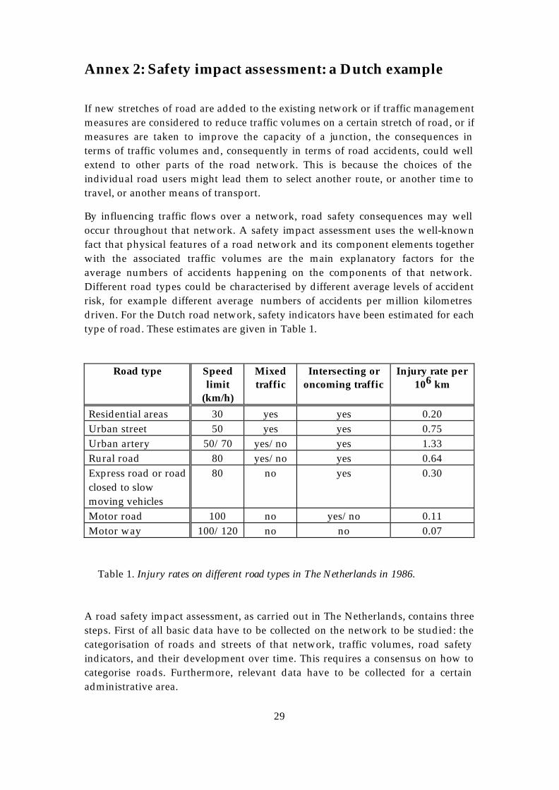
29
Annex 2: Safety impact assessment: a Dutch example
If new stretches of road are added to the existing network or if traffic management measures are considered to reduce traffic volumes on a certain stretch of road, or if measures are taken to improve the capacity of a junction, the consequences in terms of traffic volumes and, consequently in terms of road accidents, could well extend to other parts of the road network. This is because the choices of the individual road users might lead them to select another route, or another time to travel, or another means of transport.
By influencing traffic flows over a network, road safety consequences may well occur throughout that network. A safety impact assessment uses the well-known fact that physical features of a road network and its component elements together with the associated traffic volumes are the main explanatory factors for the average numbers of accidents happening on the components of that network. Different road types could be characterised by different average levels of accident risk, for example different average numbers of accidents per million kilometres driven. For the Dutch road network, safety indicators have been estimated for each type of road. These estimates are given in Table 1.
Road type Speed limit
(km/h)
Mixed traffic
Intersecting or oncoming traffic
Injury rate per 106 km
Residential areas 30 yes yes 0.20 Urban street 50 yes yes 0.75 Urban artery 50/70 yes/no yes 1.33 Rural road 80 yes/no yes 0.64 Express road or road closed to slow moving vehicles
80 no yes 0.30
Motor road 100 no yes/no 0.11 Motor way 100/120 no no 0.07
Table 1. Injury rates on different road types in The Netherlands in 1986. A road safety impact assessment, as carried out in The Netherlands, contains three steps. First of all basic data have to be collected on the network to be studied: the categorisation of roads and streets of that network, traffic volumes, road safety indicators, and their development over time. This requires a consensus on how to categorise roads. Furthermore, relevant data have to be collected for a certain administrative area.
30
In the second step the possible changes to the existing network are defined. This, again, will be done in terms of network composition, traffic volumes for the different network components and the road safety indicators. An important step is to compare regional road safety indicators with the national indicators and to draw conclusions on the differences which are found. Sometimes the national indicators are used because their quality is higher than is currently practicable for the regional indicators. Sometimes regional indicators are used because the national indicators do not offer a correct picture for a region.
In the third phase the possible future network, traffic volumes and road safety indicators are described or estimated in order to compare the existing situation with different scenarios in the future. The results of this comparison (the existing situation with at least one situation in the future) can be brought to the consideration of those who have to decide on the basis of all kinds of impacts of each scenario. In other words: safety impact assessments allow for a better consideration to be given to safety implications of possible measures in the context of their other effects.
The results of safety impact assessments can be translated into monetary terms by using values attached to preventing accidents and casualties, and thus provide an input to monetary cost-benefit analysis.

NCHRP SYNTHESIS 336
Road Safety Audits
A Synthesis of Highway Practice
TRANSPORTATION RESEARCH BOARD
OF THE NATIONAL ACADEMIES
NATIONAL COOPERATIVE HIGHWAY RESEARCH PROGRAM

TRANSPORTATION RESEARCH BOARD EXECUTIVE COMMITTEE 2004 (Membership as of July 2004)
Officers
Chair: Michael S. Townes, President and CEO, Hampton Roads Transit, Hampton, VA Vice Chairman: Joseph H. Boardman, Commissioner, New York State DOT Executive Director: Robert E. Skinner, Jr., Transportation Research Board
Members
MICHAEL W. BEHRENS, Executive Director, Texas DOT SARAH C. CAMPBELL, President, TransManagement, Inc., Washington, DC E. DEAN CARLSON, Director, Carlson Associates, Topeka, KS JOHN L. CRAIG, Director, Nebraska Department of Roads DOUGLAS G. DUNCAN, President and CEO, FedEx Freight, Memphis, TN GENEVIEVE GIULIANO, Director, Metrans Transportation Center and Professor, School of Policy, Planning, and Development, USC, Los Angeles BERNARD S. GROSECLOSE, JR., President and CEO, South Carolina State Ports Authority SUSAN HANSON, Landry University Professor of Geography, Graduate School of Geography, Clark University JAMES R. HERTWIG, President, CSX Intermodal, Jacksonville, FL GLORIA J. JEFF, Director, Michigan DOT ADIB K. KANAFANI, Cahill Professor of Civil Engineering, University of California, Berkeley RONALD F. KIRBY, Director of Transportation Planning, Metropolitan Washington Council of Governments HERBERT S. LEVINSON, Principal, Herbert S. Levinson Transportation Consultant, New Haven, CT SUE MCNEIL, Director, Urban Transportation Center and Professor, College of Urban Planning and Public Affairs and Department of Civil and Material Engineering, University of Illinois, Chicago MICHAEL D. MEYER, Professor, School of Civil and Environmental Engineering, Georgia Institute of Technology CAROL A. MURRAY, Commissioner, New Hampshire DOT JOHN E. NJORD, Executive Director, Utah DOT DAVID PLAVIN, President, Airports Council International, Washington, DC JOHN H. REBENSDORF, Vice President, Network Planning and Operations, Union Pacific Railroad Company, Omaha, NE PHILIP A. SHUCET, Commissioner, Virginia DOT C. MICHAEL WALTON, Ernest H. Cockrell Centennial Chair in Engineering, University of Texas, Austin LINDA S. WATSON, Executive Director, LYNX, Central Florida Regional Transportation Authority, Orlando, FL
MARION C. BLAKEY, Federal Aviation Administration, U.S. DOT (ex officio) SAMUEL G. BONASSO, Acting Administrator, Research and Special Programs Administration, U.S. DOT (ex officio) REBECCA M. BREWSTER, President and COO, American Transportation Research Institute, Smyrna, GA (ex officio) GEORGE BUGLIARELLO, Chancellor, Polytechnic University and Foreign Secretary, National Academy of Engineering (ex officio) THOMAS H. COLLINS (Adm., U.S. Coast Guard), Commandant, U.S. Coast Guard (ex officio) JENNIFER L. DORN, Federal Transit Administrator, U.S. DOT (ex officio) EDWARD R. HAMBERGER, President and CEO, Association of American Railroads (ex officio) JOHN C. HORSLEY, Executive Director, American Association of State Highway and Transportation Officials (ex officio) RICK KOWALEWSKI, Deputy Director, Bureau of Transportation Statistics, U.S. DOT (ex officio) WILLIAM W. MILLAR, President, American Public Transportation Association (ex officio) BETTY MONRO, Acting Administrator, Federal Railroad Administration, U.S. DOT (ex officio) MARY E. PETERS, Federal Highway Administrator, U.S. DOT (ex officio) SUZANNE RUDZINSKI, Director, Transportation and Regional Programs, U.S. Environmental Protection Agency (ex officio) JEFFREY W. RUNGE, National Highway Traffic Safety Administrator, U.S. DOT (ex officio) ANNETTE M. SANDBERG, Federal Motor Carrier Safety Administrator, U.S. DOT (ex officio) WILLIAM G. SCHUBERT, Maritime Administrator, U.S. DOT (ex officio) JEFFREY N. SHANE, Under Secretary for Policy, U.S. DOT (ex officio) CARL A. STROCK (Maj. Gen., U.S. Army), Chief of Engineers and Commanding General, U.S. Army Corps of Engineers (ex officio) ROBERT A. VENEZIA, Program Manager of Public Health Applications, National Aeronautics and Space Administration (ex officio)
NATIONAL COOPERATIVE HIGHWAY RESEARCH PROGRAM Transportation Research Board Executive Committee Subcommittee for NCHRP
MICHAEL S. TOWNES, Hampton Roads Transit, Hampton, VA (Chair)
JOSEPH H. BOARDMAN, New York State DOT GENEVIEVE GIULIANO, University of Southern California,
Los Angeles
JOHN C. HORSLEY, American Association of State Highway and Transportation Officials
MARY E. PETERS, Federal Highway Administration ROBERT E. SKINNER, JR., Transportation Research Board C. MICHAEL WALTON, University of Texas, Austin
N A T I O N A L C O O P E R A T I V E H I G H W A Y R E S E A R C H P R O G R A M
NCHRP SYNTHESIS 336
Road Safety Audits
A Synthesis of Highway Practice
CONSULTANTS
EUGENE M. WILSON
Laramie, Wyoming
and
MARTIN E. LIPINSKI
University of Memphis
TOPIC PANEL
RAY KRAMMES, Turner–Fairbank Highway Research Center
ALLAN KWAN, Alberta Transportation
JOHN LOGAN, JL and Associates, Seattle
RICHARD PAIN, Transportation Research Board
CLIFFORD REUER, South Dakota Department of Transportation EUGENE RUSSELL, Kansas State University
LOIS THIBAULT, U.S. Access Board
TOM WELCH, Iowa Department of Transportation TERECIA WILSON, South Carolina Department of Transportation
HARI KALLA, Federal Highway Administration (Liaison)
SUBJECT AREAS
Safety and Human Performance
Research Sponsored by the American Association of State Highway and Transportation Officials in Cooperation with the Federal Highway Administration
TRANSPORTATION RESEARCH BOARD
WASHINGTON, D.C. 2004
www.TRB.org
NATIONAL COOPERATIVE HIGHWAY RESEARCH PROGRAM Systematic, well-designed research provides the most effective approach to the solution of many problems facing highway ad-ministrators and engineers. Often, highway problems are of local interest and can best be studied by highway departments individu-ally or in cooperation with their state universities and others. How-ever, the accelerating growth of highway transportation develops increasingly complex problems of wide interest to highway au-thorities. These problems are best studied through a coordinated program of cooperative research. In recognition of these needs, the highway administrators of the American Association of State Highway and Transportation Officials initiated in 1962 an objective national highway research program employing modern scientific techniques. This program is supported on a continuing basis by funds from participating member states of the Association and it receives the full coopera-tion and support of the Federal Highway Administration, United States Department of Transportation. The Transportation Research Board of the National Research Council was requested by the Association to administer the re-search program because of the Board’s recognized objectivity and understanding of modern research practices. The Board is uniquely suited for this purpose as it maintains an extensive committee struc-ture from which authorities on any highway transportation subject may be drawn; it possesses avenues of communication and coop-eration with federal, state, and local governmental agencies, uni-versities, and industry; its relationship to the National Research Council is an insurance of objectivity; it maintains a full-time re-search correlation staff of specialists in highway transportation matters to bring the findings of research directly to those who are in a position to use them. The program is developed on the basis of research needs iden-tified by chief administrators of the highway and transportation departments and by committees of AASHTO. Each year, specific areas of research needs to be included in the program are proposed to the National Research Council and the Board by the American Association of State Highway and Transportation Officials. Re-search projects to fulfill these needs are defined by the Board, and qualified research agencies are selected from those that have submitted proposals. Administration and surveillance of research contracts are the responsibilities of the National Research Council and the Transportation Research Board. The needs for highway research are many, and the National Cooperative Highway Research Program can make significant contributions to the solution of highway transportation problems of mutual concern to many responsible groups. The program, however, is intended to complement rather than to substitute for or duplicate other highway research programs.
NOTE: The Transportation Research Board of the National Acad-emies, the National Research Council, the Federal Highway Admini-stration, the American Association of State Highway and Transporta-tion Officials, and the individual states participating in the National Cooperative Highway Research Program do not endorse products or manufacturers. Trade or manufacturers’ names appear herein solely because they are considered essential to the object of this report.
NCHRP SYNTHESIS 336 Project 20-5 FY 2002 (Topic 34-02) ISSN 0547-5570 ISBN 0-309-07015-5 Library of Congress Control No. 2004096315 © 2004 Transportation Research Board Price $20.00
NOTICE The project that is the subject of this report was a part of the National Co-operative Highway Research Program conducted by the Transporta-tion Research Board with the approval of the Governing Board of the Na-tional Research Council. Such approval reflects the Governing Board’s judg-ment that the program concerned is of national importance and appropriate with respect to both the purposes and resources of the National Research Council. The members of the technical committee selected to monitor this pro-ject and to review this report were chosen for recognized scholarly com-petence and with due consideration for the balance of disciplines appro-priate to the project. The opinions and conclusions expressed or implied are those of the research agency that performed the research, and, while they have been accepted as appropriate by the technical committee, they are not necessarily those of the Transportation Research Board, the Na-tional Research Council, the American Association of State Highway and Transportation Officials, or the Federal Highway Administration of the U.S. Department of Transportation. Each report is reviewed and accepted for publication by the technical committee according to procedures established and monitored by the Transportation Research Board Executive Committee and the Governing Board of the National Research Council.
Published reports of the NATIONAL COOPERATIVE HIGHWAY RESEARCH PROGRAM are available from: Transportation Research Board Business Office 500 Fifth Street Washington, D.C. 20001 and can be ordered through the Internet at: http://www.national-academies.org/trb/bookstore Printed in the United States of America
THE NATIONAL ACADEMIES Advisers to the Nation on Science, Engineering, and Medicine The National Academy of Sciences is a private, nonprofit, self-perpetuating society of distinguished scholars engaged in scientific and engineering research, dedicated to the furtherance of science and technology and to their use for the general welfare. On the authority of the charter granted to it by the Congress in 1863, the Academy has a mandate that requires it to advise the federal government on scientific and technical matters.
r. Bruce M. Alberts is president of the National Academy of Sciences. D The National Academy of Engineering was established in 1964, under the charter of the National Academy of Sciences, as a parallel organization of outstanding engineers. It is autonomous in its administration and in the selection of its members, sharing with the National Academy of Sciences the responsibility for advising the federal government. The National Academy of Engineering also sponsors engineering programs aimed at meeting national needs, encourages education and research, and recognizes the superior achievements of engineers. Dr. William A. Wulf is president of the National Academy of
ngineering. E The Institute of Medicine was established in 1970 by the National Academy of Sciences to secure the services of eminent members of appropriate professions in the examination of policy matters pertaining to the health of the public. The Institute acts under the responsibility given to the National Academy of Sciences by its congressional charter to be an adviser to the federal government and, on its own initiative, to identify issues of medical care, research, and education. Dr. Harvey V. Fineberg is president
f the Institute of Medicine. o The National Research Council was organized by the National Academy of Sciences in 1916 to associate the broad community of science and technology with the Academy’s purposes of furthering knowledge and advising the federal government. Functioning in accordance with general policies determined by the Acad-emy, the Council has become the principal operating agency of both the National Academy of Sciences and the National Academy of Engineering in providing services to the government, the public, and the scientific and engineering communities. The Council is administered jointly by both Academies and the Institute of Medicine. Dr. Bruce M. Alberts and Dr. William A. Wulf are chair and vice chair, respectively, of the
ational Research Council. N The Transportation Research Board is a division of the National Research Council, which serves the National Academy of Sciences and the National Academy of Engineering. The Board’s mission is to promote innovation and progress in transportation through research. In an objective and interdisciplinary setting, the Board facilitates the sharing of information on transportation practice and policy by researchers and practitioners; stimulates research and offers research management services that promote technical excellence; provides expert advice on transportation policy and programs; and disseminates research results broadly and encourages their implementation. The Board’s varied activities annually engage more than 5,000 engineers, scientists, and other transportation researchers and practitioners from the public and private sectors and academia, all of whom contribute their expertise in the public interest. The program is supported by state transportation departments, federal agencies including the component administrations of the U.S. Department of Transportation, and other organizations and individuals interested in the development of transportation. www.TRB.org
www.national-academies.org
FOREWORD By Staff
Highway administrators, engineers, and researchers often face problems for which in-formation already exists, either in documented form or as undocumented experience and practice. This information may be fragmented, scattered, and unevaluated. As a conse-quence, full knowledge of what has been learned about a problem may not be brought to bear on its solution. Costly research findings may go unused, valuable experience may be overlooked, and due consideration may not be given to recommended practices for solv-ing or alleviating the problem.
Transportation Research Board
PREFACE
There is information on nearly every subject of concern to highway administrators and engineers. Much of it derives from research or from the work of practitioners faced with problems in their day-to-day work. To provide a systematic means for assembling and evaluating such useful information and to make it available to the entire highway community, the American Association of State Highway and Transportation Officials—through the mechanism of the National Cooperative Highway Research Program—authorized the Transportation Research Board to undertake a continuing study. This study, NCHRP Project 20-5, “Synthesis of Information Related to Highway Problems,” searches out and synthesizes useful knowledge from all available sources and prepares concise, documented reports on specific topics. Reports from this endeavor constitute an NCHRP report series, Synthesis of Highway Practice. The synthesis series reports on current knowledge and practice, in a compact format, without the detailed directions usually found in handbooks or design manuals. Each re-port in the series provides a compendium of the best knowledge available on those meas-ures found to be the most successful in resolving specific problems. This synthesis report provides a review of the state of the practice of road safety audit (RSA) and road safety audit review (RSAR) applications for U.S. states and Canadian provinces. Transportation safety professionals with these agencies and with local and re-gional entities, as well as others in both the public and private sectors, may be interested in this documentation of international, state, and some local agency approaches to the use of these tools in comprehensive safety programs. This synthesis of the Transportation Research Board places emphasis on North American applications. However, this document also dis-cusses international practice as RSAs were first introduced in the United Kingdom more than 20 years ago, and RSAs have been extensively applied in New Zealand and Austra-lia since the 1990s. This document promotes the use of RSAs and RSARs. The increased use of these applications may help reduce roadway crashes and fatalities. For this synthesis report of the Transportation Research Board survey responses were received from 38 state departments of transportation (DOTs) and 6 Canadian provinces. The state of the practice was developed based on this 2003 survey, state, and local agency practices, Federal Highway Administration- and National Highway Institute-sponsored training for state DOTs, local agency training experiences, international prac-tices, literature, and personal contacts. A panel of experts in the subject area guided the work of organizing and evaluating the collected data and reviewed the final synthesis report. A consultant was engaged to collect and synthesize the information and to write this report. Both the consultant and the members of the oversight panel are acknowledged on the title page. This synthesis is an immediately useful document that records the practices that were acceptable within the limitations of the knowledge available at the time of its preparation. As progress in research and practice continues, new knowledge will be added to that now at hand.
CONTENTS 1 SUMMARY 3 CHAPTER ONE INTRODUCTION Purpose and Methodology, 3 International Definition of Road Safety Audits and U.S. Definition of Road Safety Audit Reviews, 3 Clarifying Existing U.S. Safety Practice, 4 U.S. Road Safety Audit and Road Safety Audit Review Concerns, 4 U.S. Road Safety Audit and Road Safety Audit Review Status in 2003, 4 Future Issues of Road Safety Audit and Road Safety Audit Reviews, 4 6 CHAPTER TWO ROAD SAFETY AUDIT PROCESS What Is a Road Safety Audit?, 6 What Are the Benefits of Road Safety Audits?, 6 What Are the Stages of a Road Safety Audit?, 6 How Is a Road Safety Audit Conducted?, 7 Key Issues to Consider in Audit Reports, 9 Using Checklists and Prompt Lists, 9 What Is a Road Safety Audit Review?, 9 11 CHAPTER THREE U.S. PRACTICE OF ROAD SAFETY AUDITS AND ROAD SAFETY AUDIT REVIEWS Early Development in the United States, 11 Summary of Survey Responses, 11 Road Safety Audit and Road Safety Audit Review Practices of Model States, 16 21 CHAPTER FOUR INTERNATIONAL PRACTICE OF ROAD SAFETY AUDITS AND ROAD SAFETY AUDIT REVIEWS Introduction, 21 United Kingdom, 21 Australia and New Zealand, 23 Canada, 23 Ireland, 24 Italy, 24 Other Countries with Road Safety Audits, 24 Road Safety Audit Benefits, 25 International Training, 25 26 CHAPTER FIVE CONCLUSIONS 28 REFERENCES
29 BIBLIOGRAPHY 32 APPENDIX A SURVEY QUESTIONNAIRE 40 APPENDIX B SURVEY RESPONDENTS 41 APPENDIX C SAMPLE AUDIT REPORTS 83 APPENDIX D AUDIT CHECKLISTS 121 APPENDIX E SOUTH CAROLINA DOT ROAD SAFETY AUDIT PROGRAM
NCHRP COMMITTEE FOR PROJECT 20-5 CHAIR GARY D. TAYLOR, CTE Engineers MEMBERS SUSAN BINDER, Federal Highway Administration THOMAS R. BOHUSLAV, Texas DOT DONN E. HANCHER, University of Kentucky DWIGHT HORNE, Federal Highway Administration YSELA LLORT, Florida DOT WESLEY S.C. LUM, California DOT JOHN M. MASON, JR., Pennsylvania State University LARRY VELASQUEZ, New Mexico, DOT PAUL T. WELLS, New York State DOT FHWA LIAISON WILLIAM ZACCAGNINO TRB LIAISON MARK R. NORMAN
COOPERATIVE RESEARCH PROGRAMS STAFF ROBERT J. REILLY, Director, Cooperative Research Programs CRAWFORD F. JENCKS, Manager, NCHRP EILEEN DELANEY, Director of Publications NCHRP SYNTHESIS STAFF STEPHEN R. GODWIN, Director for Studies and Information Services JON WILLIAMS, Manager, Synthesis Studies DONNA L. VLASAK, Senior Program Officer DON TIPPMAN, Editor CHERYL KEITH, Senior Secretary
ROAD SAFETY AUDITS SUMMARY Road safety audits (RSAs) and road safety audit reviews (RSARs) are two safety tools that
offer promise to help reduce roadway crashes and fatalities. Globally, these tools have been used by transportation safety professionals since the 1980s and are beginning to emerge as proactive safety tools in U.S. practice. The purpose of this synthesis is to describe RSA and RSAR processes and to summarize their current usage. It is anticipated that this document will promote increased use of RSAs and RSARs and, as a result of the increased use, a reduction in roadway crashes and fatali-ties. The internationally accepted definition of an RSA as used in this synthesis comes from The Canadian Road Safety Audit Guide and is as follows: “An RSA is a formal and inde-pendent safety performance review of a road transportation project by an experienced team of safety specialists, addressing the safety of all road users.” An RSAR is defined for use in this synthesis as “an evaluation of an existing roadway section by an independent team, again focusing solely upon safety issues” and comes from NHI Course 380069 (“Road Safety Audits and Road Safety Audit Reviews”). Internationally, the distinction between the evaluation of a plan or a design (RSA) and the evaluation of a roadway section or intersection (RSAR) either just before opening or already open to traffic is becoming more pronounced. Terms such as RSAR, road infrastructure as-sessment, road review, roadway assessment, and roadway inspection have been used to dif-ferentiate an RSAR of an existing roadway from an RSA of a plan. RSAs were introduced in the United States in 1996 as a result of an FHWA-sponsored scanning tour of Australia and New Zealand. The FHWA contacted all state departments of transportation (DOTs) to solicit interest in applying the concepts as a pilot study. In 1997, it sponsored a workshop in St. Louis to discuss the practice and pilot activities. Thirteen states and two local governments participated in this pilot project, marking the beginning of U.S. practice. This synthesis was developed using a comprehensive literature review, a survey of state and provincial DOTs by means of a structured questionnaire, and the authors’ personal con-tacts and experiences in providing RSA team leadership and training worldwide. The questionnaire was designed to elicit responses related to key RSA issues defining DOT practices and to clarify and identify possible DOT concerns when agencies consider implementing these proactive safety tools. The survey responses indicated that by mid-year 2003, only seven state DOTs were using both RSAs and RSARs in their safety programs. An additional 10 states indicated that they were using one but not both of these tools. Most of these states indicated that their use was best described as a beginning program to determine the benefits of incorporating the tools into their safety programs. That is not surprising, for the initial exposure of most state DOTs to RSAs was relatively recent, in 1997, compared with international practices, which date from the 1980s.
2
The survey identified several issues that affect the use of RSA processes and the way in which they are applied, including
•
•
•
Institutional issues—agency culture, staff interests, manpower, expertise availability, financial resources, liability, and management acceptance. Audit team composition—size of team (three to five members were recommended) and team skills—most states identified a core related to traffic operations, design, and safety, with additional skills related to construction, maintenance, law enforcement, planning emergency medical services, and human factors depending on the audit stage and scope of the project. In general, the benefits of conducting RSAs during an early project stage were identi-fied as a key to maximizing their impact or effectiveness. The advantage of identifying the safety issues before the project’s footprint has been developed was seen as an im-portant benefit of the RSA approach.
Several states have advanced beyond the initial assessment stage. Specifically, Iowa, Pennsylvania, New York, South Carolina, and South Dakota were identified as having devel-oped programmed approaches for including proactive safety assessments. Training was a major component of the South Carolina program, and two workshops were held to provide a core group of trained auditors. The number of countries worldwide using the tools of RSAs and RSARs is growing rap-idly. Historically, the most advanced countries have been involved in applying these tech-niques since the mid-1980s. The United Kingdom, Australia, and New Zealand are leaders in refining and advancing the state of the practice. It is noteworthy that these three countries have active and extensive programs, are requiring audits to be undertaken, and are conduct-ing RSAs during different project stages. In some cases, multiple audits are required, and the monitoring of RSA audited projects is becoming a mandatory activity in the United King-dom program. Auditor certification is beginning to emerge as an international issue. In the United States, more and more states are learning of RSAs through a National Highway Institute training course. Local agencies are also beginning to explore and develop programs based on applying RSARs. The value added in using RSAs and RSARs will con-tinue to grow in the United States as more state DOTs and local agencies try these safety tools on their roadways.
3
CHAPTER ONE
INTRODUCTION Roadway crashes and fatalities in the United States con-tinue to be a major health and safety issue. In 2002, almost 3 million injuries and 42,815 fatalities occurred on U.S. roads. In all, the 6 million crashes in the United States in that year resulted in an estimated $230 billion financial loss (1). Worldwide the estimates of annual road fatalities are in excess of 1 million. Road safety audits (RSAs) and road safety audit reviews (RSARs) are two safety tools that offer promise in reducing roadway crashes and fatalities. Globally, these tools have been in safety practice since the 1980s and are beginning to emerge as proactive safety tools in the United States. PURPOSE AND METHODOLOGY This synthesis provides a review of the state of the practice of RSA applications for state departments of transportation (DOTs) in the United States and provincial transportation agencies in Canada. Also included are summaries of some local agency approaches to the use of these tools in com-prehensive safety programs. The purpose of this synthesis is to describe RSA and RSAR processes and to summarize their current usage. Emphasis is placed on applications in North America. However, this document also discusses in-ternational practice, because RSAs were first introduced in Great Britain more than 20 years ago, and have been exten-sively applied in New Zealand and Australia since the early 1990s. In those countries, the extent of application and the level of maturity of usage exceed that of the United States. Practices are evolving in the United States as more states receive training and are beginning to implement audit pro-grams. It is anticipated that this document will promote in-creased use of RSAs and RSARs and, as a result of the in-creased use, a reduction in roadway crashes and fatalities. The state of practice was developed based on the fol-lowing:
• • •
• • •
A 2003 survey of state DOTs and Canadian provinces, State and local agency practices, Training for state DOTs sponsored by the FHWA and the National Highway Institute (NHI), Local agency training experiences, International practices, and Literature and personal contacts.
The survey questionnaire is contained in Appendix A. A list of the 38 states and 6 governmental agencies in Canada that responded to the survey is included in Appendix B.
International practices are described to illustrate the global acceptance of RSA practices and advancements that have been made worldwide. Recent progress in countries that have a long history of applying RSAs is highlighted. Examples of other countries where RSA and RSAR prac-tices are in the initial stages are provided. The most current information on these international practices was obtained from presentations delivered at an international forum on RSAs sponsored by the Institute of Highways and Trans-portation (IHT) held in London, England, in October 2003. Chapter four provides an update on international appli-cations. Included in that chapter are survey inputs from Canadian cities and provinces that also responded to the DOT survey. The final chapter contains a summary of key issues associated with these safety tools. References, a bib-liography, and appendixes conclude the report. The appen-dices include the synthesis DOT survey, sample RSA and RSAR reports, sample RSA and RSAR checklists, and an example of a DOT RSA program. INTERNATIONAL DEFINITION OF ROAD SAFETY AUDITS AND U.S. DEFINITION OF ROAD SAFETY AUDIT REVIEWS The internationally accepted definition of an RSA as used in this synthesis is as follows: “An RSA is a formal and in-dependent safety performance review of a road transporta-tion project by an experienced team of safety specialists, addressing the safety of all road users” (2). An RSAR is de-fined as “an evaluation of an existing roadway section by an independent team, again focusing solely upon safety issues” (3). Internationally, this distinction between the evaluation of a plan and the evaluation of a roadway already open to traf-fic is becoming more pronounced. Terms such as RSAR, road infrastructure assessment, road review, roadway as-sessment, and roadway inspection have been used to differ-entiate an RSAR of an existing roadway from an RSA of a plan. In 1996, an FHWA-sponsored U.S. scanning tour visited Australia and New Zealand to investigate their applications of RSAs and to determine if that tool would have added value in advancing U.S. safety practices. The proactive RSA practice and its wide acceptance were recognized by the team as adding value to road safety practices. It is hoped that this synthesis will continue to advance U.S. ac-ceptance and implementation of both safety tools.
4
CLARIFYING EXISTING U.S. SAFETY PRACTICE There is a great deal of confusion and misunderstanding regarding these proactive tools and existing safety prac-tices. Although most state DOTs currently include some elements of these tools, implementation of the RSA and RSAR processes to achieve full benefit is not occurring. The following are typical first reactions to the application of the process to an audit of a plan and an audit of an exist-ing roadway.
•
•
•
•
•
“We already do RSAs and RSARs.”
The perception of many individuals involved with roadway safety in the United States is that they are already applying RSA processes in their work. How-ever, most are not. Although most DOTs are conduct-ing comprehensive project scoping reviews that in-clude many of the aspects of the RSA or RSAR process, those scoping reviews do not involve re-view examinations by an independent team focus-ing solely on safety. A common response from in-dividuals who have received RSA and RSAR training has been that those two tools are best used in the early stages of a project. Another primary re-sponse to the training is that the RSA would provide excellent input into project scoping and preliminary project design.
“We already do RSARs.”
Most state DOTs have a reactive component in their safety programs that focuses on high-crash locations. Although these analyses may include evaluations and input from several people, they do not constitute an RSAR. An RSAR is not a reactive tool drawing con-clusions from crash histories. Instead, it focuses on safety issues associated with the roadway, all road users (e.g., drivers, pedestrians young and old, and bicyclists), operating under all environmental condi-tions (e.g., day versus night and wet versus dry), to identify the safety issues associated with the existing facility. It includes evaluations from an independent team and results in a formal report. Iowa, New York, and South Dakota are three DOTs leading RSAR ac-tivities. Iowa and New York have incorporated RSARs into their resurfacing, restoration, and reha-bilitation/resurfacing, restoration, rehabilitation, and reconstruction (3R/4R) programs.
U.S. ROAD SAFETY AUDIT AND ROAD SAFETY AUDIT REVIEW CONCERNS There are many implementation issues identified by state DOTs and local agencies in the United States. First and
foremost is a general concern about the rigidity of the process as practiced internationally. Second is a concern about how best to integrate the audit approach into existing safety practices and programs. Related are concerns about liability, audit process and procedures, identifying projects to audit, and auditor skills and training. These issues and the details associated with conducting both RSAs and RSARs are addressed in chapters two and three. Chapter two provides a detailed discussion of the RSA and RSAR process. An overview of the survey results from state DOTs in the United States is presented in chapter three. A section focusing on local agency issues concludes that chapter. A more complete focus on local safety tools is pro-vided in NCHRP Synthesis of Highway Practice 321, published in 2003 (4). U.S. ROAD SAFETY AUDIT AND ROAD SAFETY AUDIT REVIEW STATUS IN 2003 The application of RSAs and RSARs is in its infancy in the United States, with only a few states having safety pro-grams that include either an RSA or RSAR component. However, as a result of training, more states appear to be willing to try these approaches to enhance safety. In Can-ada, RSAs are being evaluated for use in value engineering processes and in design-build projects. The philosophy behind RSAs and RSARs is to be pro-active in independently evaluating safety issues and rec-ommending alternative applications or technologies where appropriate. At the completion of the audit process comes the implementation of selected alternatives to improve the safety of the roadway and then to evaluate the benefits as-sociated with those safety improvements. FUTURE ISSUES OF ROAD SAFETY AUDIT AND ROAD SAFETY AUDIT REVIEWS The application of RSAs is in its earliest stages in the United States. To advance and expand the application of the concept and to enhance safety benefits the following activities are needed:
Training programs should be continued to introduce more state DOT personnel to RSA practices and how these safety tools can be applied. A compendium of best practices could be developed and disseminated to state DOTs, cities, and local road agencies. Local transportation assistance program (LTAP) centers or technology transfer (T2) centers could assist in the distribution of this information. RSA training courses might be developed to focus on urban applications such as at intersections or on RSA and RSAR aspects of access management.

5
• A study is needed to establish the benefits of audits based on U.S. practice. This could include a quantitative evaluation to establish the economic benefits of audits.
• A forum on RSA and RSAR to advance U.S. practice could be held.
Time, training, and a record of successful applications will be the keys to making RSAs and RSARs a common safety practice in the United States. Agencies can stay up to date on RSA and RSAR activities by visiting the website www.roadwaysafetyaudits.org.
6
CHAPTER TWO
ROAD SAFETY AUDIT PROCESS WHAT IS A ROAD SAFETY AUDIT? An RSA as applied in the United States is a formal exami-nation of a future roadway plan (or project plan) by an in-dependent, qualified audit team, which then reports on safety issues. The key elements of this definition are that the RSA
•
•
•
•
• •
• •
• • •
•
•
•
• • • •
•
Is a formal examination with a structured process and not a cursory review; Is conducted independently, by professionals who are not currently involved in the project; Is completed by a team of qualified professionals representing appropriate disciplines; and Focuses solely on safety issues.
The RSA is proactive, done before a crash history indi-cates a problem exists. It considers all road users—for ex-ample, drivers, pedestrians, and bicyclists—and it consid-ers all environmental conditions, including daylight, nighttime, and inclement weather.
The RSA is not a means to rank or rate a project, nor is it a check of compliance with standards. In addition, the RSA does not attempt to redesign a project; it results in recommendations or findings that should be considered when a project is reviewed. Audits conducted early in the life of a project—in the planning or initial design stages—have been shown to be the most beneficial and the easiest to integrate with an agency’s existing safety program.
WHAT ARE THE BENEFITS OF ROAD SAFETY AUDITS? The safety benefits of RSAs have been documented pri-marily in international applications, which are summarized in chapter four. International assessments focus on the value added by proactively implementing the RSA find-ings. Several studies compared benefits of similar projects where RSAs were conducted with projects in which RSAs were not conducted. In the United States, where RSA tools have only recently been introduced, the quantitative bene-fits of RSAs have been difficult to document because the RSA is a proactive rather than a reactive safety tool. An analogy can be made to the medical field. It may be diffi-cult to prove the benefits of preventive medicine, yet it is generally accepted that exercise, proper diet, and other measures can help reduce long-term medical costs.
Nevertheless, in an unpublished study of RSA pilot studies assessed in 1997 by the FHWA, a number of impor-tant benefits were identified. Audits were found to
Provide safety beyond established standards; Identify additional improvements that can be incor-porated into the projects; Create consistency among all projects; Encourage personnel to think about safety in the course of their normal activities, throughout all stages of a project; Invite interdisciplinary input; Enhance the quality of field reviews; Provide learning experiences for the audit team and design team members; Provide feedback to highway designers that they can apply to other projects as appropriate; Provide feedback that helps to affirm actions taken and to work through outstanding issues; and Ensure that high quality is maintained throughout a project’s life cycle.
WHAT ARE THE STAGES OF A ROAD SAFETY AUDIT? RSAs can be performed at one or more stages of a new roadway project (3):
Planning, Draft design, Detail design, Traffic control device (TCD) construction planning, and Construction.
The different emphasis at each stage principally relates the level of detail addressed. Each stage is described in the following sections.
Planning RSAs conducted during the planning stage occur early in a project and generally evaluate the basic project scope, route location and layouts, intersection types, access con-trol, interchange locations and types, and impacts on the existing infrastructure. Some of those items also receive at-tention during audits conducted during other stages. As
7
more details of the project become available, safety con-siderations become more focused. Draft Design During the draft—or preliminary—design stage, the audit team evaluates general design standards. Some factors that the team might consider include horizontal and vertical alignment; intersection and interchange type and layout; sight distances; lane and shoulder widths; superelevation; and provisions for pedestrians, including children, the eld-erly, the disabled, and bicyclists. Detail Design All elements of the final design should be in place during the detail design stage. During this stage, the audit team reviews the final geometric design features; traffic signing and pavement marking plans; lighting plans; landscaping; and intersection and interchange details such as tapers, lengths of acceleration and deceleration lanes, and turning radii. The team also reviews provisions for special users such as elderly pedestrians, children, the disabled, and bi-cyclists; drainage, guardrails, and other roadside objects; and constructability. TCD Construction Planning An RSA conducted during this stage focuses on the devel-opment and implementation of the traffic control plan. It evaluates the implications of alternative TCDs, use of vari-ous types of devices, impact of temporary geometric changes, and implementation of changes that might occur as the project progresses. Construction During this stage, the audit team focuses on safety issues during construction and looks at how a new construction project interacts with utilities, railroads, businesses, main-tenance, and other parts of the existing infrastructure. The team also considers the safety impacts of alternative stag-ing plans. HOW IS A ROAD SAFETY AUDIT CONDUCTED? Conducting an RSA requires that a formalized, systematic process be followed. However, each agency may tailor the process to satisfy specific organizational and safety goals. Generally, the following steps are followed in conducting an audit.
Select the RSA Team The RSA team consists of trained and experienced trans-portation professionals and others with special skills. The team members also should be chosen independent of the project being audited and therefore able to look at the project without bias. A team leader who has experience in conducting audits is identified. A core team compris-ing a highway and traffic safety specialist, highway de-signer, and traffic engineer is usually used effectively on most projects. To that core team others may be added as needed to provide expertise pertinent to the project being audited. Specific disciplines that can be added include ex-perts in planning, enforcement, pedestrians and bicyclists, and human factors, as well as local residents. Diverse per-spectives of the team members foster the exchange of ideas that can enrich the audit. Of utmost importance, the audit team members should have the time and desire to conduct the audit. Provide Relevant Data and Documentation The project designer or an appropriate internal client who is requesting the audit provides all available relevant data and documents to the audit team, as well as a statement of the scope of the audit. The individual supplying the infor-mation reflects the type of project being audited, the stage of the audit, and the organization of the audit process within each agency. Relevant data and documentation include, but are not limited to the following:
• • • •
• • •
Plans and drawings; Design standards used; Traffic volume data; Crash records, if applicable (only on a redesign or an RSAR); Public input; Videotapes; and Data concerning utilities, railroads, schools, and businesses, among others.
Hold Kick-Off Meeting The project designer or internal client calls the kick-off meeting to launch the audit. The audit team members, de-signer or internal client, and any others who have knowl-edge of the project that the audit team needs should attend. During this meeting, the designer or client turns over the relevant data and documents. The participants discuss the purpose and conduct of the audit, scope, roles, and respon-sibilities, as well as the desired presentation format for the audit report.
8
Assess Data and Documents After the kick-off meeting, the audit team reviews the data and documentation, records its initial impressions, and plans the site inspection(s). Team members consider ap-propriate checklists and prompt lists to refer to during the site visit. From these data and documents, the team begins to identify safety-related issues and concerns. Inspect Site After reviewing the relevant data and documentation, the RSA team inspects the site. Team members bring the data and documentation with them and review the site from all possible perspectives (e.g., planning, design, construction, and maintenance), considering all possible road conditions (e.g., sunshine, darkness, rain, snow, sleet, and hail), and users (e.g., motorists, both elderly and inexperienced driv-ers, motorcyclists, bicyclists, children, and elderly pedes-trians). Any checklists or prompt lists selected are used during the site visit to assist in evaluating safety issues. The team also considers factors such as glare from headlights and the sun, external lighting, and existing infrastructure (e.g., railroad crossings, industry, schools, businesses, parks, and recreation). The team looks at adjacent road-ways that transition into the site as well. More than one visit might be necessary, with both nighttime and daytime visits beneficial. Discuss Audit Safety Issues with the Designer or Internal Client There are two alternative formats to presenting the audit report. First, before writing the report, the audit team and designer or internal client meet to discuss the issues and concerns raised during the audit. Doing so establishes an atmosphere of cooperation and encourages the sharing of knowledge and perspectives on the project being audited. This gives everyone an opportunity to brainstorm conclusions, solutions, and recommendations and have input into the audit report. The second approach is to write the report and then to present the audit report findings. Whatever format is used should be defined in the initial meeting with the client. Write RSA Report The audit report documents the results of the RSA. Several examples of RSA and RSAR reports are included in Ap-pendix C. These are actual reports that have been edited to eliminate references to specific agencies or locations. In general, the RSA report
•
•
•
•
•
•
•
•
•
Identifies all safety issues and deficiencies, noting those that require immediate attention; and
Draws conclusions in the form of recommendations or suggestions for possible corrective actions if requested.
An audit report has no set format, but at a minimum it should include the following sections:
Project description—Describe the project being au-dited, summarize its background, and state why the audit is being performed. Audit team members—Identify each team member by name and title. If consultants are used, describe their credentials. Data and documentation—Identify all data and list all documentation reviewed. If appropriate, indicate the usefulness of each. Assumptions—List any assumptions relied on, if ap-plicable. Site visits—Identify the dates and times when visits have been conducted. Also, identify any conditions present at the time of the visit (e.g., bright sunshine versus clouds and heavy versus light traffic flow). Describe the site’s layout and physical characteristics. Identify anything that the site inspection reveals that the data and documentation do not. Identify any checklists or prompt lists that were used. Findings—Clearly state safety-related observations, identifying in detail all safety issues and concerns. Conclusions—State the recommendations, sugges-tions, alternatives, implementation strategies, etc., that relate to the scope of the audit. Present the con-tent in a format established by the agency. Some agencies prefer to include recommendations, whereas others prefer findings.
Hold Completion Meeting During the completion meeting, the audit team presents its findings orally and answers any questions that the stake-holders might have. To get the most from the meeting, the report should be distributed in advance so that it can be re-viewed by the attendees who can then formulate their ques-tions and comments. The meeting should be an open, posi-tive, and constructive discourse that is free of criticism. All parties should work together to be proactive, not adversar-ial, in their approach to safety. Respond to Report The project designer, internal client, or other stakeholder responds to the audit report. Audit reports generally in-clude corrective actions; for example, recommendations or suggested safety improvements. A written documented re-sponse indicates which corrective actions are accepted and which are rejected, as well as reasons associated with the
9
decisions made. Including an implementation plan may also be of value. An official with authority to make deci-sions should sign the report. Implement Agreed-on Changes Because the whole point of conducting an RSA is to im-prove safety, an important step is to actually implement the changes that the audit team and stakeholders agree to im-plement. That implementation also should be documented and made part of the total audit file. Share Lessons Learned The final step of an RSA is to share the lessons learned with all the stakeholders and with the planning, design, construction, operations, and maintenance teams. Those lessons then can be applied to all future projects as appro-priate. A project that has been audited also should be moni-tored to determine if the audit and implementation of find-ings have been successful. The agency that requested the audit maintains the audit records KEY ISSUES TO CONSIDER IN AUDIT REPORTS Because the audit report is important, it deserves special attention. The audit report should be concise and to the point. It should contain at least the elements that were listed earlier. However, the audit report need not be too long; 2 to 10 pages would be ideal for most projects. Agen-cies appear to be divided on whether the reports should contain findings or recommendations. Recommendations suggest further specific actions or improvements, whereas findings address the results of the audit. It is important that the report’s contents be discussed during the kick-off meet-ing to determine the objectives of the client. Sample audit reports are included in Appendix C. Another consideration is the disposition of the report af-ter the audit has been completed. Each agency should es-tablish procedures for maintaining RSA reports. If the agency has a central RSA coordinator, that person should maintain the records. Another option is to house the reports at a district office. In all cases, a copy of the audit report should be included with the documentation of the specific project that is audited. USING CHECKLISTS AND PROMPT LISTS One tool that has been a key component in conducting RSAs is a checklist. Checklists have been developed to aid auditors in reviewing projects to ensure that all issues that
can affect safety are addressed. Both Road Safety Audit from Austroads (5) and Guidelines for the Safety Audit of Highways from IHT (6) contain extensive checklists that can be used for each audit stage. In the United States, Pennsylvania has developed checklists for use in its audit process. These checklists can be viewed at the previously mentioned website, www.roadwaysafetyaudits.org. Checklists should not be used so rigidly that the audit team allows the checklist to dictate the audit. Instead, the checklists should be flexible guidelines and reminders of things to look for in steering the team to a comprehensive evaluation of the project. Checklists should be viewed as only one tool available to the audit team, just as the project data and documentation are tools. Many international agencies are now using prompt lists. Those tools are less prescriptive than checklists and iden-tify broader areas for the audit team to examine during the field review. The Canadian Road Safety Audit Guide (2) contains an example of a prompt list. It is recommended that an audit team develop a check-list or prompt list tailored to the specific project and stage of the audit being conducted. This should be accomplished during the kick-off meeting and the list then taken to the site inspection. The team can use an existing list and mod-ify it to fit the project. Appendix D contains samples of audit checklists. Checklists have been developed for spe-cific audit stages and for specific types of projects. The ap-pendix provides several different RSA checklist styles. Essen-tial to using a checklist or prompt list is to include relevant local safety concerns and issues. Tailoring a checklist to spe-cific facility types or project types may have benefits in advancing the application of RSAs and RSARs. WHAT IS A ROAD SAFETY AUDIT REVIEW? An RSAR is a safety assessment of an existing street or roadway section or a newly completed section before open-ing. An independent, qualified audit team reports, in an RSAR, on the safety issues of these road or street sections. The RSAR is a practical safety tool for local rural road agencies with typically limited resources, whose primary responsibilities are the maintenance and operation of exist-ing roadway networks. The RSAR can also be used as part of an agency’s overall safety program or in conjunction with other ongoing activities such as a 3R/4R program. The RSAR differs from the conventional safety analysis and scoping study because it is proactive and not dependent solely on crash statistics. The RSAR concentrates on a spe-cific roadway section to address safety issues and therefore is different from traditional U.S. and Canadian scoping studies. RSARs may be used as planning tools to identify safety issues to be considered in improvement projects.
10
•
• •
State DOTs and local agencies are continuously faced with the need to consider how the safety of an existing road or street may be enhanced. Because the uses of a roadway change over time, roads that fully complied with all safety standards at the time they were built may no longer provide a high degree of safety for the traveling public. Typical ap-proaches used by most DOTs include an analysis of crash data, generally focusing on high-crash locations. Applying proactive evaluations through the use of the RSAR is an-other method. The RSAR may be performed
During the preopening stage of a new project to en-sure that the safety concerns of all road users have been addressed, On a road section just opened to traffic, and On an existing road to identify safety deficiencies.
The concept of the RSAR is based on an analysis tech-nique that formalizes documentation of safety issues. Pro-actively considering safety is the value of the RSAR tool. Iowa, New York, and South Dakota have integrated RSARs into their safety programs. In Michigan, an RSAR ap-proach is being used to evaluate safety issues in regard to urban intersections. The use of the RSAR by rural local agencies was identi-fied in Arizona, South Dakota, and Wyoming in surveys used to develop an NCHRP synthesis on safety tools for local agencies (4). The RSAR concept is being used by more local agencies each year. Depending on resources, there are a number of different ways to use the RSAR con-cept to develop a local safety program. An important subject in the low-volume rural road envi-ronment is that improving so many miles of roadway to current standards would be neither economical nor practi-cal. For rural local governments, a proactive program in-volving a functional classification of their rural roadway system and the use of an independent peer group of audi-tors is both practical and affordable.
The classification system helps to guide the improve-ments of the identified safety issues into alternatives by considering the use of the roadway section being evaluated and the ability to apply the improvements incrementally. Such decisions are made in light of the classification and the safety issue involved, as well as by applying a value judgment to the urgency of the improvement and the re-sources available. Because there are several key elements to the RSAR that provide value beyond an unstructured safety review, locally needed modifications to the concept are encour-aged. The RSAR results in a formal written report that is short, simple, and proactive. Orally communicating the re-port is also important, as is the local agency’s formal writ-ten response to the report. Independence is another key to the RSAR. The local agency becomes the client for the RSAR report and provides the review team with the roads and streets to be audited, plus information on their func-tional classification. The review team reflects a blend of background and ex-pertise. Core knowledge is generally considered to be knowledge of local road safety and maintenance skills. Other skills of team members may vary depending on the issues associated with the road users and/or the complexity of the facility. Review team member’s skills could include traffic engineering, human factors, construction, design, and operations. Team members may also have knowledge about pedestrians, bicyclists, and trucks. There are a number of different ways to undertake an RSAR and to develop a team. One suggested methodology is that one county audit another county’s network. A system to classify existing roads, examine their current usage, identify deficiencies, and prioritize needed safety im-provements is the goal of an RSAR program. The premise is that local agencies can best achieve needed safety im-provements by prioritizing activities and chipping away at problems as resources allow.
11
CHAPTER THREE
U.S. PRACTICE OF ROAD SAFETY AUDITS AND ROAD SAFETY AUDIT REVIEWS EARLY DEVELOPMENT IN THE UNITED STATES The initial exposure to RSAs and RSARs in the United States was the result of the 1994 FHWA safety manage-ment scanning tour and the 1996 RSA FHWA scanning tour that assessed the practice in Australia and New Zea-land. The FHWA then contacted all state DOTs to deter-mine interest in applying the concepts as a pilot study. In 1997, a workshop was held in St. Louis to discuss the prac-tice and pilot activities. The pilot DOTs were from 13 states, with local governments in 2 states also participating in the pilot program. That marked the beginning of U.S. practice. The pilot studies identified issues, concerns, successes, and limitations pertaining to the application of RSA concepts in the United States. In an unpublished as-sessment of the pilots performed for the FHWA Office of Highway Safety, issues and challenges identified included how to obtain a funding commitment, costs associated with performing the audits, costs of implementing sug-gested changes, costs associated with liability, and ways to best balance costs of safety with costs of other project fac-tors? Concerns were also expressed about the environment in which the audit would be conducted. Questions included
• • •
Is an audit a criticism of the design? Will the designer feel threatened by audit findings? What is expected in an audit?
Other concerns were associated with administrative and personnel matters. Administratively, issues such as the un-known value and benefits of an audit, selling management on audits, overcoming such reactions as “the way we al-ways have done it” or “we are already doing it,” and the control of the design process were identified. Personnel is-sues reflected the availability of staff time, peer-to-peer problems, and training and education in the process. One principal issue raised was the training of auditors. Collectively, these responses indicated that agencies needed additional information and guidance concerning the application of an RSA. In response, the FHWA developed a training course to raise awareness of the concepts, identify RSA issues, and provide ways to make the RSA and RSAR practice work for state DOTs. The FHWA course was ini-
tially presented in Kentucky in August 2000. It was also later presented in Georgia, Mississippi, Missouri, New York, South Dakota, Utah, and Vermont. In 2001, that course was then developed into an NHI course (3). The pi-lot of the NHI RSA course was held in Maine in June 2002. By the end of 2003, the course had been presented in Delaware, Indiana, Maine, Massachusetts, South Carolina (twice), and Wyoming, as well as in Puerto Rico. By the end of 2003, this training course had been given to 13 dif-ferent state DOTs. Additional training has taken place in the United States, including a rural course for local county governments in three states and other training provided by international RSA experts in several other states. Courses have also been presented in Kansas and Maryland by internationally based instruction and locally by the Pennsylvania DOT (Penn-DOT). Local rural RSAR training courses have been pre-sented in Arizona, South Dakota, and Wyoming. Awareness presentations have also been made at both the local rural RSAR workshop and the DOT workshop in a number of different forums, both internationally and within the United States. It is generally recognized that the proactive RSAs and RSARs, internationally, have the po-tential to advance safety in the United States. To assess the current state of the practice, a survey was developed and distributed to all state DOTs. Surveys were also sent to Canadian provinces and selected local govern-ments. Canadian responses are discussed in chapter four. The survey was designed to determine the extent to which safety audits were being used, identify advance-ments since 1997, determine if states that received training have implemented RSA or RSAR processes, and gather in-formation on issues that were raised in the summary of the pilot programs. The survey questionnaire is contained in Appendix A. SUMMARY OF SURVEY RESPONSES Thirty-eight states and six Canadian agencies responded to the survey. Seven states indicated that both RSAs and RSARs were being conducted by their DOTs. Ten states indicated that either RSAs or RSARs, but not both, were being used by their DOTs. A total of 22 states responded
12
that neither safety tool was being used. Responses to the survey are discussed in the following sections and summa-rized according to by the key issues. A list of states and Canadian provinces that responded to the survey is con-tained in Appendix B. Also included in the following sections is information provided from various states that hosted RSA training courses. These state responses are not specifically refer-enced, but all information provided has an origin of a train-ing course, either during the course or follow-up activities or as given in survey responses. Institutional Issues All respondents were asked to complete the section on in-stitutional issues. Seventeen states indicated that safety management planning was part of their safety program. Of these, only five states indicated that RSAs or RSARs were part of their safety management plan. Sovereign Immunity In regard to this issue, there appeared to be no specific trend in applying RSAs and RSARs and whether or not the state had sovereign immunity. Two states that were apply-ing both tools indicated full immunity and three indicated partial immunity. For states that apply one of the tools but not both, two indicated full immunity, four had partial im-munity, and four had no immunity. The issue of using the RSA tools and not implementing the changes was also raised. It is related to organizational issues addressed later in this chapter. This issue has been a major focus during the training courses. Local legal staffs have presented a variety of positive statements supporting the use of RSAs and minimizing the fear of liability. Com-mon responses by the DOT legal staffs are that RSAs will help in the defense of tort liability, engineers should do the engineering and leave the liability issues to the legal staff, and RSAs can only help the DOT. Measurable Safety Goals Most states indicated that measurable safety goals were as-sociated with rate-based crash statistics, although several states noted that crash numbers or both were included in their measures of accountability. The following list gives several examples of specific state responses:
•
•
•
•
•
•
• • • • • • • • • • • South Dakota indicated a desire to keep the crash rate
below 200 per 100 million vehicle miles traveled and
2 crashes per 1 million vehicles entering or leaving a spot location. Michigan stated that their goal was to “ensure that highway safety is considered in the development and implementation of all department projects for the purpose of reducing deaths, injuries, and total acci-dents occurring on the state’s highways. All actions should result in an average annual reduction of 1,500 crashes occurring at identified high crash locations.” The Alabama DOT adopted the FHWA goal of a 20% reduction in crashes and fatalities in 10 years. The Washington State DOT tied its safety goals to a benefit–cost ratio method that considers projected versus actual benefit–cost aimed at reducing societal costs of collisions at both specific locations and statewide. Louisiana stated that their goal was to reduce the crash rate for fatal and injury crashes by 4% each year. Iowa’s goal was to have a 10% reduction in run-off-the-road crashes on roadways on which 4-ft paved shoulder and shoulder rumble stripes are installed.
Institutional Barriers Overcoming institutional barriers associated with the prac-tice of implementing RSAs or RSARs was an important consideration for many states. States implementing both RSAs and RSARs highlighted issues such as agency cul-ture, staff interests, manpower, expertise, and financial fac-tors. One response was that “Questions were raised if we were duplicating the efforts of our Roadway Safety Im-provement (RSI) program. Once the difference was de-fined, the barriers seemed to disappear.” Another response was that “Some local governments had reservations about identifying safety concerns and not doing anything about them for an extended period of time.” Other issues were raised by states that applied one but not both of the tools. Comments included questions and statements such as:
When is an audit most beneficial? Is this a necessary addition to the core project team? Is a formal implementation policy needed? Where are the staff resources? There is a need for more timely crash data. There is a competition issue with present practice. RSAs need to have champions with the facts. We don’t have sovereign immunity. Turf issues are a problem. Design and operation conflicts will expand. How does the prior investment in current safety needs process fit into the practice?
13
• There is a lack of a clear link from RSA to tort liabil-ity issues.
States that do not apply either tool provided these com-ments:
• •
• •
•
• • • • • •
• • • •
What are these tools? NHTSA (National Highway Traffic Safety Admini-stration) program assessment and annual plan already requires this. There is no requirement to do them. There is a perception that we already have a relative safe roadway system. Behavioral factors account for 85% of the crashes; these tools will not provide a good return given this fact. Training is inadequate. Labor is lacking. We don’t need another layer of bureaucracy. We do safe design. Limited funds exist to respond to audits. What is the appropriate lead agency?
All of these issues, whether raised by states applying the tools or not, point to the continuing need to raise aware-ness, to provide benefit assessments when the tools are used, to provide models of how various states have devel-oped a framework for applying the tools, and to provide training and share experiences. Only three state DOTs that had some RSA training indicated that neither safety tool was being applied in their DOT safety practice. One of those states indicated a local application focus and another indicated the training was not based on U.S. practice. The training developed in the NHI course addressed these is-sues as well as the concept that both tools need to be exam-ined in light of how they can be made to work for a given agency. Several examples of the latter are provided here to show how these issues have been addressed and how the RSAs and RSARs have been tailored to fit and improve current safety practices. The following two sections ad-dress specific issues for states that indicated that RSAs or RSARs are part of their safety tools. Road Safety Audit Issues Only 11 states indicated that RSAs were being used. Most of these states were in the initial stages of assessing the benefits and had conducted only a handful of audits. Most indicated that fewer than six audits had been conducted by the time the survey was taken in the summer of 2003. The primary stages audited were planning and preliminary de-sign. One state indicated that after evaluating different stages of audits, future audits would focus on preliminary design stage audits. Three states had conducted one final design stage audit. Pennsylvania has conducted the most audits. That state started a program to evaluate the benefits
and issues in 1997, had management support, and selected two districts in the state to evaluate the issues. Although only one of the districts became a proponent of the tool, today the RSA is being used as a statewide safety tool and this state (Pennsylvania) has an RSA coordinator. Audit Team Size and Skills Audit team size and skills were of interest. Many states in-dicated that large teams were used, perhaps associated with the desire to have a broad base of evaluation for future ap-plications. Teams ranged from 4 to 10 members. Team member skills included traffic engineering, final design, construction, maintenance, local law enforcement, human factors, and Americans with Disabilities Act and emer-gency medical service specialists. The audit team members were from the FHWA, state DOT headquarters and dis-tricts, local governments, and transportation consultants. Six states indicated that audits were conducted by in-house personnel, and five states indicated the use of both in-house personnel and consultants in conducting audits. Types of RSA Projects Projects audited included interchange modifications, ex-pressway widening projects, reconstruction and expansion projects, intersections, bridge projects, and railroad grade crossing projects. Most audits involved projects to improve existing facilities. There were also RSAs for projects in-volving urban arterial cross sections and alternative rural highway cross sections. Implementation of Audit Findings Most states responded that the audit recommendations were used in scoping the project for some of the planning stage audits, were carried over to the final design stage for some preliminary stage audits, or were implemented. An important finding was that the audit did raise issues and present recommendations that would most likely have not been considered without an audit. RSA Checklists and Prompt Lists RSA checklists and prompt lists were used by most of the audit teams. Additional information used in various audits included:
Crash data; Past plans; Scoping reports; Field visits;

14
• Alternative layouts; • •
• • • •
•
•
• • • •
• • • • • •
Area maps; Traffic volume data, including, when appropriate, current and projected average daily traffic; Turning movement counts; Zoning information; Program funding; Accident analysis and plans from previous projects; and Modal data.
Furthermore, all states indicated that the needs of pedes-trians and bicyclists were specifically considered in the au-dits. Also, all states noted that other modes of transporta-tion were considered by addressing access and public input and by using a multidisciplinary audit team. Organizational Issues Internal organizational issues were also investigated, such as those posed here by the following questions:
How supportive is top management to the audit proc-ess? Does your state have an audit coordinator? How are RSA reports maintained? How are projects selected for audits? How is the audit program administered in your agency? How is the audit program funded? How are institutional issues addressed? What are the benefits of RSAs? What is your program’s biggest success? What are the shortcomings of RSAs? What are the liabilities of RSAs?
How Supportive Is Top Management to the Audit Proc-ess? Top management support was indicated by all states that are conducting RSAs. “Yes, the director of program development said that we should do RSAs for all roadway projects”; “Believe so, they have agreed to RSA training of more than 15 individuals”; “Approval of the program im-plementation and approved funding for the effort was given after a presentation was made to the state highway engi-neer, deputy director for strategic planning, finance and administration, and the FHWA division engineer.” Does Your State Have an Audit Coordinator? Only two states, Pennsylvania, which has the longest history of RSA involvement in its safety program, and South Carolina, which developed an organizational framework for their RSA program, have RSA coordinators. How Are RSA Reports Maintained? RSA reports are maintained at a wide variety of locations. They may be
with the safety management coordinator, division traffic safety engineer, project manager, headquarters traffic engi-neering department, roadway design, or RSA coordinator. How Are Projects Selected for Audits? Criteria used to select projects to be audited varied by state, with project size as one criterion. Among others were large projects with complex traffic control; regionally requested projects; controversial projects; projects with a high rate of accident and/or congestion problems; and projects with internal DOT differences of opinion as to the safest alternative. How Is the Audit Program Administered in Your Agency? Program administration varied widely. In one state, the traffic safety engineer was the coordinator and responsible for assembling an audit team. In other states, the audit ac-tivities were driven by the regional traffic or district safety engineers or by the state’s assistant chief engineer for pre-construction. Most states did not have an audit coordinator. How Is the Audit Program Funded? Funding for au-dits came from a variety of sources, including maintenance program funds, FHWA support of audits on any federally participated projects, federal safety set-aside funds, and funding of the consultant/team leader using contractual services funds. On occasion, no separate special funding was provided because the project is charged as a prelimi-nary engineering expense or as an overhead expense. How Are Institutional Issues Addressed? Responses pertaining to institutional barriers to implementation of au-dit recommendations included the expected issues of fund-ing as well as environmental and political considerations. One response was “The town did not want the improve-ment.” Another response, however, was very positive and also demonstrated the benefit of an audit: “We have not encountered any institutional barriers. The DOT has been receptive to the audit findings and has made changes to de-signs of projects accordingly. The biggest barriers are budget constraints.” Two states indicated that RSAs were formally included in their programs. Pennsylvania responded that audits were included in its design manual, and South Carolina reported that audits were included in the safety office’s business plan. The newness of audit activities in most states brought in responses that indicated the audits were not being used to check against safety performance goals. What Are the Benefits of RSAs? The newness of the audit process was also a factor in assessing the benefits. Factors under consideration were to assess benefits using a benefit–cost approach, evaluating accident reductions, be-fore-and-after analysis, and evaluating potential cost sav-ings of implementing audit findings. One state commented that it did not have any formal assessment of success to
15
date, except the positive responses associated with the re-vised plans. Another stated, “None yet, except doing what is right within ultimate budgetary and other constraints.” What Is Your Program’s Biggest Success? The follow-ing were responses that addressed the program’s biggest suc-cess:
•
•
•
• •
•
• •
•
•
•
•
•
•
•
• •
•
ment.
“Explicit consideration of safety for the projects and being able to portray the safety considerations to other engineers, the public, and public officials.” “Having issues identified that were not thought of be-fore because we had outside eyes looking at the project.” “Cooperation among the division and districts to de-termine the best options for roadway improvements.” “Reduced fatalities and crashes.” “Since we are in the first year of our program I think the biggest success is gaining agencywide support for the effort, including the commitment of time for RSA team members to travel the state to conduct audits.” “Only one done and the recommendations were ac-cepted.”
What Are the Shortcomings of RSAs? The following responses addressed some of the more common shortcom-ings of RSAs:
“Finding time to do more audits may be a problem. “Not enough RSAs being conducted due to funding issue.” “Need to have formal RSA training and knowledge-able people to do this specialized analysis.” “Following through to determine the benefits and successes; not done on a mass basis.” “Would like to see the program formalized as a valid project activity.”
What Are the Liabilities of RSAs? Liability assess-ment resulted in the following typical responses:
“Liability is one of the major driving factors in per-forming a good audit.” “It demonstrates a proactive approach to identifying and mitigating safety concerns.” “When findings cannot be implemented an exception report is developed to address liability and mitigating measures.” “Our attorneys say that once safety issues are identi-fied, and if we have financial limitations on how much and how fast we can correct the issues, then the audit will help us in defense of liability.” “Liability is not considered as an issue.” “The RSA process is not discoverable in court as ex-cluded from evidence by 23 USA Code 409.” “Chief Counsel has reviewed the process and check-lists.”
Although the number of states conducting RSA activi-ties is small, the responses as summarized illustrate a very positive acceptance of the concept. The agencies’ com-ments also indicated the need to expand the training to more states and to promote the benefits of RSAs in the United States to help heighten the awareness and ability of state DOTs to assess their own acceptance of RSAs in their safety programs. Road Safety Audit Review Issues Thirteen states indicated that RSARs were part of their state’s safety program. This section highlights the ques-tionnaire responses of these state DOTs. The modifications of RSAR practice in Iowa, New York, and South Dakota are detailed in the next section. Those states have tailored their programs for 3R/4R projects. Types of RSAR Projects RSARs have been conducted on transportation corridors, intersections, interchanges, and special areas such as school zones. Facility types ranged from two-lane county roads to multi-lane divided urban freeways. Among the bases for selection of roadway sections for RSARs were general safety concerns, sections with high crash levels, high traffic volumes, geometric roadway and associated design issues, sections scheduled for overlay projects, and including an RSAR as part of the project scoping process. Four states indicated that they had safety performance planning and that their RSAR activities were part of that process. One state was evaluating RSARs to determine if they should be part of its program. RSAR Team Expertise The various skills reported for the team members included traffic engineering, design, maintenance, and safety engineering, as well as expertise in pedestrians and bicyclists, young and older pedestrians, older drivers, local knowledge, human factors, law enforcement, and project scoping. There were also representatives from local and federal govern Typically, teams were tailored to the type of facility be-ing reviewed. In South Dakota, a review team for county road sections consisted of FHWA and state DOT traffic safety engineers, an independent county highway superin-tendent, and a representative from the LTAP. The review team for state roads consisted of a visiting regional traffic engineer, visiting area engineer, road design engineer, South Dakota Highway Patrol officer, and traffic safety engineers from the DOT and FHWA. In another state, a
16
three-person team consisted of a specialist in highway de-sign, one in traffic operations with expertise in pedestrians and bicyclists, and one in project scoping. Administration of RSAR Activities RSAR activities were administered by the state traffic en-gineer, regional and local traffic engineers, and a statewide RSA coordinator. There was no consensus about any spe-cific location within the DOT. The RSAR reports were maintained at both headquarters and district levels of the DOT. Generally, the branch involved traffic engineering or safety engineering, although in some states the roadway design division maintained the RSAR reports. Number of RSAR Projects, Team Size, and Data Issues Various numbers of audits were conducted in the last 5 years, with Pennsylvania conducting the largest number. Most respondents indicated that fewer than a dozen RSARs were undertaken. Most states indicated that only a few audits had been conducted because they were just beginning to as-sess the use of RSAs and RSARs. Typical responses indicated on the order of four to six audits during the initial year. Audit teams consisted of both in-house teams and con-sultants. Seven states reported using only in-house teams. In some cases, a consultant was added to the team to pro-vide specialized input. Consultant activities included lead-ing the team, writing the report, and providing expert input on issues related to older drivers. Team sizes vary from state to state and for different pro-jects. RSAR teams had as few as 2 and as many as 6 mem-bers. Typically, an RSAR team has 4 to 5 members, al-though several states indicated that teams can be made up of as many as 12 to 15 individuals. These were teams most likely formed to assess the issues of an RSA practice or in-volved in a learning exercise. Ten states indicated that they used prompt lists and/or checklists during their reviews. Other information used by various states included detailed geographic information system crash data, collision diagrams, detailed traffic vol-ume data, past plans, and site evaluations. RSAR Implementation Issues Various states indicated that their RSARs identified a number of ways to make safety issue improvements, which were then implemented. Spot improvements, such as sign-ing, markings, and the addition of turning lanes were made. Other states indicated that low-cost safety improvements
were added to maintenance activities and resurfacing pro-jects. Still others mentioned that the RSAR resulted in de-sign alternatives that addressed the findings. The major limitations to implementing an RSAR program were a lack of funding, manpower issues, and project schedules. One state identified the idea of another district telling them what to do as a point of controversy. In another state, the effects of budget cutting had limited its ability to continue the RSAR activity to the desired level. Top management was identified as supporting the RSAR activities in all but two of the states using the RSAR process. RSAR Liability Issues Liability was addressed in a number of different ways. Among the statements received were that there is no liabil-ity concern, the reports include a disclaimer statement, re-ports are not discoverable, the legal department handles this issue, and the agency has discretionary immunity. Benefits and Successes of RSARs The evaluation of the successes and benefits of RSARs brought responses that pertained to the willingness of agencies to incorporate the safety improvements suggested in the audit and that there are repeat requests for more RSARs. In one case, a benefit–cost analysis was under-taken before recommendations were finalized through his-torical data associated with the recommended improve-ments. Another response reported that safety has acquired greater emphasis; there is now a better understanding of law enforcement and human resource issues. As for the success of RSAR activities, district and cen-tral office design staffs are now looking for opportunities to incorporate low-cost safety improvements following RSA and RSAR training. Personnel now have a better understanding of why specific safety enhancements are being suggested. The diversity of the team was viewed as both a benefit and success of the program. One state reported, specifically as a result of the RSAR, “being able to identify a location with an accident problem or potential safety issue and recommend-ing changes to actually reduce the number of accidents.” ROAD SAFETY AUDIT AND ROAD SAFETY AUDIT REVIEW PRACTICES OF MODEL STATES Five states that have adapted either an RSA or RSAR pro-gram or have developed a tailored approach for their DOTs to assess those safety tools are highlighted in this section. These states provided specific details that should help oth-ers considering developing RSA and RSAR programs.
17
Iowa Iowa has developed a modified approach to employing RSA concepts. The program is administered by the Office of Traffic and Safety. The state safety engineer has pro-gram responsibility. Audits are conducted in conjunction with corridors scheduled for resurfacing. The audits focus on 3R projects. Project concept statements are reviewed and a detailed summary of the corridor’s crash history is prepared. The crash history in each corridor includes geo-graphic information system analyses of fatal and injury crashes, fixed-object crashes, crashes grouped by roadway characteristics, crashes linked to geometric features, and crashes by type—single vehicle, rollover, right angle, etc. Collision diagrams are also prepared. The audit consists of a field review by central office safety staff and district personnel. A typical team may con-sist of safety personnel from the DOT and FHWA, as well as district design, maintenance, and construction staffs. Local law enforcement is asked to identify any perceived safety deficiencies, but those officials are not part of the audit team. In addition, an older driver (an outside paid consultant who is a retired safety engineer) is added to the team to provide a unique perspective. A trip summary is prepared for the FHWA district administrator and the DOT district engineer. The FHWA safety engineer has the lead program responsibility. Before initiating the RSAR program, district staff par-ticipated in a 3R safety workshop. This workshop was de-veloped and is presented in-house by Iowa DOT and Iowa State University Center for Transportation Research and Education staff. Both the proposed and recently completed 3R projects are reviewed in each district. These district RSARs are proposed as being completed once every 3 years in each district. Among the safety deficiencies and recommended treat-ments identified in the audits are
•
•
•
•
•
•
•
• •
• Substandard curves—add or correct superelevation, add pavement, remove fixed objects, delineate curves, pave shoulders, install shoulder rumble strips, and use larger or brighter chevrons. Safety dikes (escape ramps)—install opposite “T” in-tersections and remove fixed objects. Daylighting of intersections and driveways—cut vegetation, remove fixed objects, and flatten drive-way cross slopes. Other intersection needs—add turn lanes and signal enhancements. Roadside features—add or undertake guardrails, cul-vert and inlet modifications, cattle crossings, tree re-
moval, and improvements of cross slopes, and riprap; relocate and delineate utility poles. Other—install larger stop signs and center and shoul-der rumble strips.
The audit team uses a checklist to identify key safety is-sues to be evaluated during the field inspection. The audits have identified low-cost safety improve-ments. As a result, district and central office personnel have a greater awareness about safety. The 3R safety workshop will be offered to county staff. Iowa has also proposed to conduct an RSA of a major cor-ridor project at the planning stage. New York The state of New York has developed and implemented a comprehensive, modified RSAR process to incorporate safety considerations in its existing pavement preventive mainte-nance program. The program, SAFETAP (Safety Appurte-nance Program), involves maintaining existing safety features and adding appropriate, implemental, low-cost safety features at preventive maintenance project locations before, during, or after resurfacing as part of a joint effort (7). The impetus for the project was the observation in the 1980s that simple resurfacing without roadside improve-ments contributed to increases in the number of crashes in the 3 years following resurfacing. The program existing at the time did include a safety screening process, but safety im-provements were not implemented so that funds would be conserved for maximizing the number of miles resurfaced. The SAFETAP initiative included the following elements:
Team of auditors with the expertise to assess existing and potential crash problems, Review of existing crash data and a site inspection, Recommendations of cost-effective solutions by the audit team to agency leaders with the responsibility for implementing crash countermeasures, and Reports to the Traffic Engineering and Highway Safety Division describing the disposition of recom-mendations and implemented actions.
Program Implementation Issues Given the limited resources and the competing concerns of different elements within the New York State DOT, an im-plementation strategy was developed to obtain manage-ment buy-in for the program. The chief engineer’s support was an essential factor in the program’s success. The pro-gram was first presented to main office managers, then to
18
regional managers, and then to executive management. In this manner, the supporters of the program were able to ad-dress the concerns of affected parties. Audit Process Projects are selected in accordance with the criteria estab-lished for pavement resurfacing priorities. When a site is selected, the regional director assigns an RSA team con-sisting of experts from the regional traffic, design, and maintenance groups and others as appropriate. The team analyzes crash data, makes a site visit, and develops rec-ommendations for safety work. The team uses a checklist for guidance in identifying potential safety issues. Safety treatments identified include those necessary to avoid de-grading safety and those that are practical and necessary to address existing and potential safety problems. Procedures are established for conducting the audit and reporting the audit results. The audit forms become part of the paving project file and are also maintained at regional offices. The timing of safety work is coordinated with the pav-ing process on the basis of need, complexity, and resource availability. In general, recommendations pertaining to sign replacement are done before paving. Superelevation, shoulder treatments, and edge of pavement drop-off prob-lems are addressed during the paving contract; pavement markings, rumble strips, guiderails, delineation, fixed ob-jects, and new signing are done during or as soon as possi-ble after completion of paving. Other items such as guide signing, major treatment of fixed objects, and other fea-tures of concern not specifically covered are done in a timely manner following the completion of paving. SAFETAP Results During the first year of the program, 216 safety treatment sites were identified, and 107 safety improvements were implemented. Predictions based on past safety activities were that the program would cost from $15 to $25 million each year, would result in 1,000 fewer crashes per year, and would result in a savings of $25 to $50 million in crash costs. The actual results after the first few years indicated that the estimated savings were conservative. Crash reduc-tions occurred at more than 300 high-crash locations treated with low-cost improvements; crash reductions ranged from 20% to 40% depending on the type of im-provement implemented (8). South Dakota Since South Dakota received RSA and RSAR training in July 2001, its DOT has conducted three RSAs on projects
during the preliminary design stage and two RSARs on projects in the planning stage on the state trunk and Inter-state systems. The South Dakota DOT has also assisted in five RSARs on county road systems since the initial train-ing. The region traffic engineer initiated and organized the RSAs on the state trunk and Interstate systems, and has been the keeper of the master report and file. The county highway superintendents initiated RSARs through the South Dakota LTAP (SDLTAP). The SDLTAP in turn asked for assistance from the DOT traffic and safety engineer in the DOT Office of Local Government Assistance. A check-list as an inspection guide was used to ensure that safety is-sues were not overlooked when observing any of the road-way features. The South Dakota DOT has conducted three RSAs on projects during the design stages. One was on a U.S. high-way in an urban setting; one on an Interstate interchange and a state highway, where the state highway portion of the project intersects the interchange in an urban setting; and one on a state highway in a rural setting. The teams con-sisted of the DOT region traffic engineer, DOT road design engineer, FHWA traffic and safety engineer, city engineer-ing staff member, city commissioner, business owner, city traffic engineer, guest region traffic engineer, assistant public works director, FHWA pavement and materials engineer, law enforcement, and DOT traffic and safety engineer. Not all of those individuals participated in each RSA, but a team of five to six people with the such backgrounds were se-lected for each RSA. The information gathered from RSAs was given to the DOT road designer or the consultant engi-neer designing the project. In all cases, there were changes made in the design as a result of the RSA inspection. The South Dakota DOT has conducted two RSARs for planning purposes. One was on an Interstate interchange, which is in the long-range State Transportation Improve-ment Program (STIP). The Interstate interchange RSAR was organized by the region traffic engineer with the team consisting of the region traffic engineer, DOT operations engineer, DOT traffic and safety engineer, FHWA traffic and safety engineer, county highway superintendent, city engineer, and city council member. The crossroad over the interchange is a city street feeding an industrial area on one side of the interchange, and a county road through a hous-ing area along a lake on the other side of the interchange. The information from the RSAR will be used as input into the planning process. The second planning RSAR was on a tourist-oriented/scenic road in the Black Hills. The RSAR was or-ganized by a region traffic engineer from a different region than the one mentioned earlier. The team consisted of a guest region traffic engineer, guest area engineer, FHWA traffic and safety engineer, DOT road design engineer, DOT traffic and safety engineer, and South Dakota High-
19
way Patrol officer. As a result of this RSAR, there was a project incorporated into the STIP. The information from the RSAR is to be used as a design guide for the improve-ments to be done on the project. There were five RSARs conducted on the local county road systems. They were organized by the SDLTAP after being contacted by the county highway superintendent. The SDLTAP requested assistance from the DOT traffic and safety engineer in the DOT Office of Local Government Assistance. That engineer served as the team leader with the remainder of the team consisting of an SDLTAP repre-sentative, FHWA traffic and safety engineer, and a guest county highway superintendent. The county highway su-perintendent responsible for the roadway classifies the roadways to be inspected using the local classification as given in the RSAR section of NCHRP Synthesis of High-way Practice 321(4). For the final report, the team classi-fied the items for improvement:
•
•
•
• •
•
• •
• • • •
• • •
• • • •
Items where immediate safety improvements should be made, Items where low-cost improvements could have a positive impact on safety and should be considered in a reasonable period of time, and Items identified as high-cost improvements that should be considered as funds become available for a major rehabilitation or reconstruction of the roadway.
Ultimately, the items listed in the report are reviewed in a closeout meeting with the highway superintendent re-sponsible for the roadway. The traffic and safety engineer then writes the final report and forwards it to the highway superintendent. The traffic and safety engineer keeps the master copy in the files at the Office of Local Government Assistance. Pennsylvania PennDOT began a pilot program of RSAs in 1997. The goals of this program were to answer these questions:
Does the RSA process add value? Can the RSA process be implemented by using exist-ing resources? Will the RSA process delay project delivery?
The pilot project was initiated in one district with pro-cedures developed based on the Australian audit model. Particular attention was paid to developing a process that differentiated the audit process from safety reviews. For the pilot projects, a safety audit team of five people was selected from the following six discipline areas: traffic engineer (coordinator), construction services, project de-
sign, highway safety maintenance, risk management, and comprehensive safety (human factors). All were in-house, except for the human factors person. Projects to be audited were selected by the RSA coordinator and the assistant dis-trict engineer for design. Eleven projects were selected in all phases of project development. To date, 60 projects have been audited. Typical safety issues identified in the audits included the need for left-turn lanes, daylighting of intersections, presence of fixed objects, roadway realignment, lengths of acceleration and deceleration lanes, pedestrian needs, and sight distance. The estimated costs of the audits, exclusive of the cost of the improvements, ranged from $2,000 to $5,000. The recommendations developed by the audit team were submitted to the audit coordinator, who reviewed the re-port, forwarded the report to the assistant district engineer for design, and met with the project manager to discuss concerns and possible improvements. Numerous benefits were identified as a result of the au-dit process, including
Maintaining a safety focus, Identifying safety concerns early in the design proc-ess, Achieving interdisciplinary cooperation, Developing consistency in design, Enhancing communication, and Recognizing safety improvements that were beyond the scope of the original project.
The pilot projects generated a number of challenges and opportunities related to implementation of the audit proc-ess. Some of the major challenges were time demands on the coordinator, team members’ changing positions, the need for audits to be conducted early in the design process, dealing with changes that affect the project’s environmental footprint, dealing with stakeholders and controversial rec-ommendations, identification and selection of projects to be audited, liability concerns, and gaining buy-in from top administrators and others involved in the process. A set of recommendations was developed that included the following:
Get buy-in at all levels early in the process, Establish a coordinator’s position, Select an audit team that is interdisciplinary and has the required expertise, Provide training to team members, Separate the audit process from safety reviews, Conduct the audits early in the design process, Cite audit safety concerns and not provide recommenda-tions, and
20
•
•
•
•
Ensure that the process involves multiple opportuni-ties for communication.
The pilot audit project concluded that:
The RSA process definitely added value by identify-ing safety issues, RSAs could be completed without draining existing resources—not accounting for the additional cost of the safety improvements that were identified, and RSAs will not affect project delivery time if con-ducted early in the process.
Since the pilot program, PennDOT has continued its au-dit program. The agency has conducted audits in its 11 dis-tricts. The central office has an RSA coordinator who pro-vides training to the districts. There is also an open-ended consulting contract to provide assistance to the districts. Funding difficulties have constrained the conducting of more RSAs but, with FHWA’s commitment to the program, PennDOT anticipates expanding the program. South Carolina The RSA program in South Carolina is administered by the South Carolina DOT safety office. The program has buy-in from top administrators, because they approved implemen-tation and funding for the effort. The director of safety is responsible for the overall program administration. The program is housed in the safety program unit of the safety office and the director of safety is responsible for the over- all administration of the program. The RSA coordinator handles the day-to-day operations of the program. The RSA program is supported by an RSA advisory committee that includes the deputy state highway engineer, the engi-neering directors (e.g., traffic, construction, maintenance, pre-Construction, etc.), and the director of safety. The
committee approves operating procedures for the program and selects projects for audit. The South Carolina DOT has established a procedures manual for the audit process. That manual includes infor-mation on the management of the process, procedures for selecting projects to be audited, and instructions for dis-tributing audit results. The program is funded with federal set-aside monies. Projects are solicited annually by the RSA coordinator from the deputy state highway engineers, the engineering directors, the district engineering administrators, and the director of safety. The RSA coordinator compiles a list of the project’s along with additional information on the pro-ject cost and crash history, if available. The coordinator prepares a prioritized list of recommended projects for ap-proval by the RSA advisory committee. Project selection includes new infrastructure projects, projects under con-struction, and existing infrastructure projects. Projects in-clude Interstate projects, rural and urban system upgrades, and innovative projects listed in the STIP pertaining to ex-isting roads. The RSA plan calls for 10 audits to be conducted each year; 11 audits were conducted in 2003. These were in the process of being finalized. Five audits were conducted on projects under construction, two on new infrastructure pro-jects in the final design stage, and four on existing road-ways (RSARs). Each audit involved a team of four to five people representing construction, road design, traffic engi-neering, maintenance, and safety. The teams used check-lists to aid in conducting the audits. Because the projects have not yet been finalized, benefits have not been docu-mented. However, it is anticipated that the response to the audit reports will address benefits. A more complete dis-cussion of the South Carolina RSA program is provided in Appendix E.
21
CHAPTER FOUR
INTERNATIONAL PRACTICE OF ROAD SAFETY AUDITS AND ROAD SAFETY AUDIT REVIEWS INTRODUCTION The first documented use of RSA practices was in the United Kingdom in the 1980s. It involved the modification of a tool used by railway engineers at the turn of the cen-tury to examine safety issues on railways. The United Kingdom published the first set of road safety guidelines in the early 1990s. The use of RSAs followed shortly after in Australia and New Zealand. It was the applications in these countries that attracted the attention of the United States and other countries. They perceived the RSA as a tool that could enhance safety and reduce the number and severity of roadway crashes. During the past decade, the global application of RSAs has expanded. The United Kingdom, Australia, and New Zealand have continued to refine, modify, and enhance their RSA practices. Much of the information provided in this chapter is based on an international conference spon-sored by the United Kingdom’s IHT held in London, Eng-land, in October 2003. Although information on interna-tional practices has come from a variety of sources, that conference provided an excellent assessment of the state of practice in many countries around the world. UNITED KINGDOM It is important to remember that RSAs have been used for more than 20 years, beginning with the United Kingdom. There are consulting firms in the United Kingdom that have conducted literally thousands of RSAs. The United Kingdom has advanced the applications of RSAs to the point where it is mandatory for all trunk road highway im-provement projects and also mandatory to conduct an RSA monitoring process of all projects that have involved an RSA. Monitoring the effects of RSAs on those facilities began in 1990. The requirement to monitor the effects of RSAs was added to the 2003 edition of the Design Manual for Roads and Bridges in the “Road Safety Audit” section, HD 19/03, which became effective in November 2003 (9). Projects are now required to be monitored after 12 and 36 months. Several practice issues of the HD 19/03 section on RSAs are briefly highlighted here. There are three stages of audits required separately or in combination for improve-
ment projects, unless excluded for small projects within the same alignment. The required U.K. audit stages are
• • •
•
•
•
•
Completion of the preliminary design, Completion of the detailed design, and Completion of construction (in the United States, re-ferred to as an RSAR).
In addition to those three types of audits, an interim stage audit has been being introduced as a new concept for RSA application anytime during the first two audit stages. The interim audit is not a requirement. The concept is to provide input into the design process while the plans are being developed. The independence of the formal audit process is still stressed. The trial applications of an interim audit have been found to aid in reducing road safety prob-lems earlier and thereby reducing program and design costs. The requirements for an accident monitoring report us-ing both 12- and 36-month crash data have also been intro-duced as part of HD 19/03 (9). Such a monitoring process focuses on linking crash characteristics and audits to help future RSA activities to reduce crashes. Through HD 19/03, many issues of practice can be recognized that should aid in RSA applications worldwide. HD 19/03 also offers samples of all audit stage reports, stage checklists, issues and monitoring reports. The check-lists for each audit stage are contained in Appendix D. In the United Kingdom, audit teams are identified as re-quiring minimum of two members. Suggested guidelines specify that the team leader have these qualifications:
A minimum of 4 years of accident investigation or road safety engineering experience; Completion of at least five audits in the past 12 months; A minimum of 2 days of continuing professional de-velopment in the field of RSA, accident investiga-tion, or road safety engineering in the past 12 months; and Meets the requirements of a team member.
Suggested guidelines concerning qualifications for team members are:
22
• A minimum of 2 years of the previously cited associ-ated skills;
•
•
Completion of at least five audits in 24 months as a member, leader, or observer in the past 24 months. The audit team member should have undertaken at least 10 days of the previously cited skills; and A minimum of 2 days of professional development.
Two additional categories of expertise are identified to assist in auditing, although they are not specifically identi-fied as being possessed by team members. They are an ob-server and a specialist. It is suggested that the observer have a minimum of 1 year experience and a minimum of 10 days of formal training. The observer assists in the audit process; the intent is to develop the pool of new audit team members. In addition, there is provision for specialist advi-sors. The use of a specialist requires approval of the project sponsor. The specialist is not a member of the team but ad-vises the team on matters relating to their expertise. Such requirements indicate that the audit process is very formal, which certainly is the case (9). The design team provides a brief to the project sponsor, who may instruct the design team to delete unnecessary items or to add information. Any changes must be docu-mented. In the United Kingdom the RSA information pro-ceeds from the team that designs the project to a supervisor or project sponsor. The brief consists of the following 10 items:
1. The alternative design showing full geographical extent and including areas beyond the project;
2. Details of the approved departures and relations from standards; that is, design exceptions;
3. General details, purpose, speed limits, forecasts of traffic flow, nonmotorized flows, and desired lines and environmental constraints;
4. Other relevant factors such as adjacent land uses, proximity to schools, and emergency vehicle ac-cesses;
5. Accident data for design alternative and adjacent sections;
6. Details of changes introduced at previous audits; 7. Plan sheets; 8. Previous RSA reports and a copy of the interim
file if an interim audit has taken place; 9. Contact details for transmitting maintenance de-
fects (telephone call or separate written message from audit report); and
10. Details of appropriate police contact (9). The audit team submits the RSA report to the project supervisor, not directly to the design team. The initial sub-mittal is in draft form so that any issues agreed to be out-side the scope of the project can be identified and removed. The audit team includes only issues relevant to safety. Any
items such as observed maintenance defects are addressed separately. The detailed requirements of the audit report are also specified in 10 separate items:
1. Brief project description; 2. Audit stage team members and other members; 3. Site details, who was present, and conditions of
weather and traffic on day of site visit; 4. Specific road safety problems identified, with sup-
porting documentation; 5. Recommended actions for removal and mitigation; 6. Location maps marked and referenced to problems; 7. Statement signed by the audit team leader, in a re-
quired format; 8. List of documents and diagrams considered for the
audit; 9. Separate statement for each identified problem de-
scribing the location, nature, and types of accidents likely to be considered as a result of the problem; and
10. Associated recommendations (checklists are not to be included) (9).
An example of the audit report from HD 19/03 is in-cluded in Appendix C. Integral to the audit process are the implementation of the audit recommendations and identifi-cation of the exceptions, to ensure that the problems raised by the audit team were given consideration.
The project team may wish to consult the design team at this stage of the audit. If the Project Sponsor considers any prob-lem to be outside the scope of the project or not suitable given the relevant environmental or economic constraints, the pro-ject sponsor shall prepare an Exception Report giving the rea-sons and proposed alternatives for submission to the Director, with whom the final decision rests. The project sponsor shall provide copies of each approved Exception Report to the De-sign Team and to the Audit Team Leader for action and in-formation respectively (9).
Finally, the project sponsor instructs the design team with respect to any changes required resulting from the au-dit. Prompt action and continued communication are re-quired. Closing the loop is feedback to the auditors regard-ing the actions taken as a result of the audit. This brief overview of U.K. practice indicates the strong history, continuing belief in the benefits of the RSA safety tool, and continued commitment to advancing the state of the practice. For additional information, a 2001 U.K. publi-cation entitled Practical Road Safety Auditing (10) as well as other works previously mentioned (6,9). In the United Kingdom, RSA practice has continually led to safety im-provements implemented in projects as an initial safety benefit and not as a needed safety retrofit after a project has been completed.
23
The following snapshots of various countries’ experi-ences raise key issues for advancing the U.S. practice of RSAs and RSARs. AUSTRALIA AND NEW ZEALAND The experiences of Australia and New Zealand formed the basis for audit practices in the United States. It is interest-ing to follow the development in those countries and con-trast their progress with that of the United States. In 1990, Transit New Zealand (Transit), which is responsible for man-aging the national road network (state highways), began ex-amining the RSA. The initial efforts emphasized awareness programs, which were followed by pilot RSA exercises. Ex-perienced auditors from the United Kingdom and Australia assisted the pilot audits, which were used as training exer-cises. Australia underwent a similar but earlier develop-ment in the states of Victoria and New South Wales. U.S. states were encouraged to pilot the RSA. Approxi-mately 20% of the states did so in the first years after the FHWA’s 1996 scanning tour in Australia and New Zealand. The scanning tour focused on the development activities of the states of New South Wales and Victoria in Australia and of Transit in New Zealand (11). New South Wales, VicRoads, and Transit all had RSA Manuals, and by 1993 had all adopted RSA practice. Australia and New Zealand worked together in 1994 developing the Austroads Road Safety Audit Manual, which was the focus of the U.S. scan-ning tour. The second edition of the Austroads guide, Road Safety Audit, was completed in 2002 (5). Transit’s policy in 1993 was to apply RSAs to a 20% sample of its state projects. By 1993, the United Kingdom, New South Wales and Victoria in Australia, and Transit were the world leaders in RSA practice. That statement ap-plies today, although other countries including the United States are actively following similar paths to RSA devel-opment. Other international activities are highlighted later in this chapter. As RSA development continued in New Zealand, there was no initial requirement for local agencies to undertake audits. However, Transit demonstrated RSAs using several local authority projects in the early learning stages (pre-1993) and encouraged local agencies to adopt RSAs. Tran-sit has incorporated a revision to its early RSA practice by now referring to RSAs as audits of projects being devel-oped to project construction; audits of existing roads are now excluded in the revised manual. This is similar to the current U.S. philosophy and the use of the term “RSAR” for the audits of existing roadways. Today in New Zealand, the current policy of Transit is to apply RSAs to all projects and to allow for exceptions if
the project manager believes that an RSA is not necessary. Documentation is required if the decision not to conduct an RSA is made. In the United Kingdom, the RSA Standard HD 19/03 has a similar provision. The similarities of development patterns for those coun-tries that are the world leaders in RSA practice is continu-ing. Today, auditor certification, continuing requirements for auditor training, and liability are common issues. A major reason for the international acceptance of RSA activities is that accident investigators initially found de-sign faults that should have been identified before new fa-cilities were built. The added value of proactively prevent-ing crashes is the primary reason that the two Australian states and the United Kingdom continue to apply RSAs as an operational practice. In New Zealand, the RSA is recog-nized as an essential safety management tool. CANADA Canada has been a leader in North America in the imple-mentation of RSA concepts. The first formal audit was completed in Vancouver, British Columbia, in 1997. Since that initial audit, several provinces and local governments have conducted audits. One impetus for their use was the support of the Insurance Corporation of British Columbia in the development and application of audit techniques as a tool to reduce the number and severity of traffic crashes. The Transportation Association of Canada (TAC) has de-veloped The Road Safety Audit Guide to aid safety profes-sionals in the application of the audit process (2). For this synthesis, four Canadian provinces and two Ca-nadian cities completed and returned survey question-naires. One city and two provinces have conducted RSAs, and two cities and two provinces have conducted RSARs. One province indicated that it had conducted many safety reviews, although not by an independent team. Those agen-cies that conducted audits reported that the number they did varied from a single preliminary design stage audit to 10. The audits were done about equally during the plan-ning, preliminary design, and design stages. Two current issues of concern in Canada are using RSAs in design-build projects and in value engineering. Institutional Issues Only one agency had a safety management plan and only one other agency had measurable safety goals. None of the provinces or cities reporting had sovereign immunity. Ma-jor barriers to implementation that were identified included inadequate funding, lack of staff, and difficulty in achiev-ing buy-in, although two agencies did indicate support

24
from senior management. Four of the agencies had used modified concepts of RSAs or RSARs, and three used the RSA guide developed by the TAC as the basis for their work (2). Four agencies had participated in some training provided in-house, by consultants, or by the TAC. Additional Findings Audit Team Size and Skills The typical size of an audit team was five to six people. Disciplines represented included planning, design, con-struction, and traffic engineering. Consultants were used by one agency as part of the audit team. Types of RSA Projects Projects audited included interchange design, freeway de-sign, and upgrading a two-lane arterial to a four-lane arte-rial. Implementation of Audit Findings Agencies indicated that some of the recommendations were implemented and that concepts identified in the au-dits were incorporated into the design. Use of Checklists One province used checklists and two used prompt lists. Organizational Issues The resources made available to the team included staff time and funding for external consultants. Two agencies used consultants. Two agencies maintained audit reports locally, and one city had an RSA coordinator. Projects were selected both on an ad hoc basis and according to a defined selection process. Institutional barriers mentioned included the lack of staff resources and difficulty in implementation if the recommendations were considered too costly or im-practical. The audits did address the needs of pedestrians and bicyclists, except on freeway projects. Road user input was part of the audit process for three agencies. No agency used cost-effectiveness procedures to evaluate the benefits of the RSA process. Success was measured by increased awareness of safety and the establishment of a process for identifying tangible safety benefits. Shortcomings men-tioned were inadequate funding and a lack of integration with other safety programs. Programs were funded through a municipal tax base and capital budgeting.
Administration of RSAR Activities Most of the RSARs were conducted in urban areas, with two agencies focusing their reviews on intersections. The size of the audit teams varied from two to eight individuals. Disciplines included traffic operations, planning, police, and consultants with RSA expertise. Two agencies used prompt lists rather than checklists in their RSARs. The RSARs were carried out with both local staff and consultants and resulted in spot improvements. Projects were selected on the basis of crash data and operational concerns. Institutional barriers encountered included in-adequate resources, some confusion among the various ex-isting safety programs, resistance to accept a new proce-dure, and concerns over legal implications. Only one agency had RSARs as part of its overall safety program. In one city, the audit included input from motorists, bicyclists, pedestrians, and the handicapped as observers. Benefit–cost evaluations of RSARs are just beginning to be developed, but one agency uses published data on projected safety benefits resulting from various safety enhancements. All established RSAR programs have top management sup-port. The biggest successes identified to date included buy-in from engineers and management, identification of tangible safety benefits, and increased visibility and acceptance by the public and at the political level. IRELAND In Ireland nationally and 33 major cities in the country, the design manual procedures have incorporated RSAs. The RSA process is required for all projects involving a change, and approximately 75 projects are audited each year. Training of auditors is stressed in the program. The subject of international auditor training is presented in a separate section in this chapter. ITALY In 2000, a pilot program to assess RSAs in Italy was under-taken. From 2001 to 2003, the emphasis has been on exist-ing routes. Currently, a process is being developed to com-bine crash data and safety inspections. Design stage audit RSAs are required for urban areas with populations of greater than 30,000 and in high-risk areas. Education is another major area of focus. OTHER COUNTRIES WITH ROAD SAFETY AUDITS A number of other countries are involved in conducting RSAs. The World Bank has championed the use of RSAs,
25
• • • •
•
•
•
•
.
providing funding for consultants, performance of audits, and training. The following list is not intended to be all in-clusive, but is provided to indicate global acceptance of the practice. Other RSA participants include
India, Thailand, and others in Southeast Asia; South Africa; Eritrea in Northeast Africa; and Denmark, Finland, Germany, Italy, Norway, The Nether-lands, and Switzerland in Europe.
ROAD SAFETY AUDIT BENEFITS RSAs are internationally viewed as inexpensive to con-duct (5). Furthermore, studies of the benefits of RSAs have indicated high positive benefits. At the 2003 IHT Conference on Road Safety Audits, Phillip Jordan of VicRoads in Australia summarized the studies of RSA benefits as part of his presentation. Highlights of his presentation follow.
Typical costs of audits were estimated to range from $1,000 to $8,000 U.S. dollars, depending on the size of the project. Several examples of benefits were based on the analysis of similar projects with before-and-after crash data. One report examined crash data over a 2-year period for 19 audited and 19 nonaudited project sites in the United Kingdom. The audited sites had a casualty savings of 1.25 per annum, whereas the nonaudited sites exhibited a savings of only 0.26 per annum. In another U.K. study that examined 22 audited trunk road sites, the cost of implementing the recommendations was compared with the cost of rec-tifying the sites after the project was constructed. The average savings per site was 11,373 British pounds sterling or about $19,600 per site. Austroads described an analysis of nine audit sites reporting 250 different design stage audit findings that resulted in benefit–cost ratios ranging from 3:1 to 242:1. As for audits of existing roads, benefit–cost ratios ranged from 2:1 to 84:1. In other studies that presented the audit results in the form of a rate of return, figures such as a 120% rate of return in the first year were reported. In Denmark, analyses of 13 projects provided a first-year rate of return of 146%. Recognizing that these types of analysis are often questioned, a sensitivity analysis of input data was conducted. That analysis involved multiplying the input data by magnitudes of 2 and 4. The following conclusions were given: With a sensi-
tivity of input estimate of 4, a 7% positive benefit still occurred. When a factor of 2 was applied as a multiplier to the input estimates, the analysis resulted in a positive benefit of 37%. If one life is saved as a result of an audit, the benefits will far exceed the audit costs. It is, however, difficult to attribute saving lives to any one audit or audit rec-ommendation or action. Over time, monitoring au-dited projects and the actions taken should help to re-inforce the value of an audit.
When the benefits and costs of audits were discussed during the IHT 2003 conference, several factors were gen-erally accepted. Analysis of audit costs generally included the audit fee or personnel costs, costs of changes required as a result of the audit, and any costs associated with addi-tional project delays and audit time. To date, studies that have used benefit–cost analyses have compared the acci-dent characteristics of designs that have audit recommen-dations with those of designs that do not have such rec-ommendations. The approach of monitoring, which is beginning to occur in the United Kingdom, should advance the state of RSA benefit–cost project analysis. The crash data from the U.K. requirement to monitor RSA projects after 12 and 36 months should become key input to future analyses and to providing the benefits of the RSA, at least internationally. It is important to note that no negative benefit–cost analysis results of RSAs were presented during the IHT conference. Internationally, there is increasingly strong acceptance of the benefits of audits INTERNATIONAL TRAINING The following points primarily highlight the RSA training as reported at the 2003 U.K. conference. It is included to show the importance that various countries have placed on audit activities as well as the level of effort. Several courses have been offered in Australia, and New Zealand has a 5-day course. In the United Kingdom there are courses for basic and advanced audits consisting of 3-day workshops for each; in Germany a 10-day training program over a 6-month period; and in Ireland 3-day courses on auditor training. Two related topics being discussed are auditor skills re-quirements and certification of auditors. Several countries have skill guidelines for auditors, which are similar to those discussed previously in the U.K. section.

26
CHAPTER FIVE
CONCLUSIONS This synthesis provides a snapshot of the state of the prac-tice for road safety audits (RSAs). It was developed through a comprehensive literature review, a survey of state and provincial departments of transportation (DOTs) by us-ing a structured questionnaire, and the authors’ personal contacts and experiences in providing RSA team leadership and training worldwide. The questionnaire was designed to elicit responses re-lated to key RSA issues defining DOT practices. It was also designed to clarify and identify possible DOT con-cerns considered in implementing this proactive safety tool, as well as the road safety audit review (RSAR). The survey responses indicated that by mid-year 2003, only seven state DOTs were using both RSAs and RSARs in their safety programs. An additional 10 indicated that their state was using one but not both of the tools. Most of these states indicated that their use was best described as a be-ginning program to determine the benefits of incorporating these tools into their safety programs. Exposure of most state DOTs to RSAs was relatively recent and came about as the result of a 1996 international scanning tour by the FHWA to Australia and New Zealand. The scanning report was published in 1997, and the first U.S. conference on this topic was held that year. Several states have advanced beyond the initial assess-ment stage. Specifically, Iowa, New York, Pennsylvania, South Carolina, and South Dakota have developed pro-grammed approaches for including proactive safety as-sessments. Kentucky, Maine, and Mississippi are others that have participated in audit training and then conducting RSAs. A major concern of RSAs and RSARs is the issue of liability. The National Highway Institute training course clarifies the liability issues associated with conducting RSAs and RSARs. In all states where training was pro-vided, local DOT legal counsels sounded a common mes-sage—that audits are a positive approach and do not in-crease the agency’s liability. Ideal or required auditor skills were identified when a team approach was taken to conducting RSAs and RSARs. Core disciplines specifically included on the team were identified by most DOTs as traffic operations, design, and safety. Additional team members included individuals with expertise in construction, maintenance, law enforcement, planning, Americans with Disabilities Act, emergency
medical services, pedestrians, and bicyclists. Individuals with local knowledge and other expertise were included on teams depending on the type of project and audit stage. The recommended size of an audit team was three to five per-sons. In general, there were advantages to conducting RSAs at an early project stage and identifying the safety issues before the project’s footprint has been developed. Using the RSA tool at multiple stages of the same project was not identified as a U.S. practice—perhaps owing to the rela-tively recent introduction of the concept in this country. Management buy-in and support of the tools and practice were viewed as necessary ingredients for successful pro-grams. The number of countries worldwide using the tools of RSAs and RSARs is growing rapidly. Historically, the most advanced countries have been involved in applying these techniques since the mid-1980s. The United Kingdom, Australia, and New Zealand are leaders in refining and ad-vancing the state of practice. Other countries are actively advancing their safety prac-tices by using RSAs and RSARs. No country was identi-fied as abandoning the use of these proactive safety tools nor were any negative benefits identified during this state-of-practice assessment. However, liability issues are a con-cern both within the United States and worldwide. At the international level, the most important statement concern-ing liability repeated by many RSA users is that these safety tools add value to the decisions being made in pro-jects and the consideration of safety when projects are im-plemented. Documentation of the audit findings and requiring a re-sponse from the client to the issues identified were com-monly used and recommended practices internationally. Detailed record keeping was common practice in interna-tional RSA activities; however, the reporting documenta-tion is kept simple. Building a knowledge base by continu-ing to learn from the application of audit findings was also identified as adding value to improving project design and safety considerations. It is widely accepted that RSAs re-duced the need for adding safety improvements at a later date. The independence of the RSA is a common feature of international audits. Recent analytical studies have identi-fied the benefit–cost ratio of RSA applications to be as low as 3:1 for some RSAs and RSARs to as high 240:1 for others.

27
Local U.S. agency applications have generally concen-trated on using the RSAR. Most rural local agencies have many miles of roadway in need of a large number of safety improvements. Rural U.S. governments are becoming in-creasingly aware of the value of the proactive tools. Appli-cations by rural agencies are being advanced by training. The application of RSAs is in the earliest stages in the United States. To encourage and expand the application of the concept and to enhance safety benefits the following actions are needed:
•
•
•
•
•
Training programs should be continued to introduce more state DOT personnel to RSA practices and how the safety tools can be applied. A compendium of best practices could be developed and disseminated to state DOTs, cities, and local road
agencies. Local transportation assistance program cen-ters [also known as technology transfer (T2) centers] could assist in the distribution of this information. RSA training could be developed to focus on urban applications such as at intersections or on RSA and RSAR aspects of access management issues. A study is needed to establish the benefits of audits based on U.S. practice. It could include a quantitative evaluation to establish the economic benefits of audits. A forum on RSA and RSAR could be held to ad-vance U.S. practice.
Time, training, and a record of successful applications will be the keys to making RSAs and RSARs a common safety practice in the United States. Agencies can stay up to date on RSA and RSAR activities by visiting the website www.roadwaysafetyaudits.org.
28
REFERENCES
1. Petzold, R., S. Herbel, and T. Franceschi, “Conscious Objector: Reducing Highway Fatalities,” Traffic Technology International, Aug./Sep. 2003, pp. 19–22.
2. Ho, G., S. Zein, and P. de Leur, The Canadian Road Safety Audit Guide, Transportation Association of Canada, Ottawa, ON, Canada, 2001.
3. “Road Safety Audits and Road Safety Audit Re-views,” NHI Course 380069, National Highway Insti-tute, Arlington, Va., Dec. 2002.
4. Wilson, E.M., NCHRP Synthesis of Highway Prac-tice 321: Roadway Safety Tools for Local Agencies, Transportation Research Board, National Research Council, Washington, D.C., 2003, 168 pp.
5. Morgan, R., J. Epstein, and A. Drummond, Road Safety Audit, 2nd ed., Austroads, Sydney, New South Wales, Australia, 2002.
6. Guidelines for the Safety Audit of Highways, Institu-tion of Highways and Transportation, London, U.K., 1996.
7. Bray, J.S., “Safety Appurtenance Program (SAFETAP)—
NYSDOT’s Road Safety Audit Pilot,” ITE Journal, Vol. 69, No. 1, Jan. 1999, p. 14.
8. Bray, J.S., “New York State Department of Transpor-tation Safety Appurtenance Program: Alternative Ap-plication of Road Safety Audits,” Proceedings of the 9th Maintenance Management Conference, Juneau, Alaska, July 16–20, 2000, 2001, pp. 31–42.
9. Design Manual for Roads and Bridges, Road Safety Audits, Part 2, HD 19/03, Vol. 5, Section 2, Depart-ment of Transport, South Ruislip, Middlesex, U.K., 1993.
10. Proctor, S., M. Belcher, and P. Cook, Practical Road Safety Auditing, Thomas Telford Publishing, London, United Kingdom, 2001.
11. Trentacoste, M., P. Boekamp, L. Depue, M.E. Lipin-ski, D. Manning, G. Schertz, J. Shanafelt, T. Werner, and E.M. Wilson, FHWA Study Tour for Road Safety Audits, Part 1—Final Report, Report FHWA-PL-98-008, Federal Highway Administration, Washington, D.C., Oct. 1997.
29
BIBLIOGRAPHY Achwan, N. and Lanalyawati, “Application and Develop-
ment of Road Safety Audit in Indonesia,” Proceedings of the Conference on Road Safety on Three Continents, Pretoria, South Africa, Sep. 20–22, 2000, pp. 107–115.
Adapting the Road Safety Audit Review for Local Rural Roads, Report No. 00-114, Final Report, Mountain–Plains Consortium, North Dakota State University, Fargo, July 2000.
Bowler, C.P. and E.M. Wilson, Road Construction Safety Audit for Interstate Reconstruction, Report No. 98-98, Vols. 1 and 2, Mountain–Plains Consortium, North Da-kota State University, Fargo, 1998.
Bray, J.S., “Safety Appurtenance Program: NYDOT’s Road Safety Audit Pilot,” Presented at the ITE International Conference on Enhancing Transportation Safety in the 21st Century, Kissimmee, Fla., Mar. 28–31, 1999.
Bray, J., “NYDOT’s Safety Appurtenance Program,” Pre-sented at the ITE 2000 Annual Meeting and Exhibit, Nashville, Tenn., Aug. 6–9, 2000.
Calvert, E.C. and D.F. Ellinger, “Implementing a Road Safety Audit for a Local Improvement Project,” Pre-sented at the ITE International Conference on Enhanc-ing Transportation Safety in the 21st Century, Kissim-mee, Fla., Mar. 28–31, 1999.
Calvert, E.C. and D.F. Ellinger, “Applying Road Safety Audits to County Roads,” ITE 2000 Annual Meeting and Exhibit, Nashville, Tenn., Aug. 6–9, 2000.
Calvert, E.C. and E.M. Wilson, Incremental Safety Im-provements for Unpaved Rural Roads, Report No. 97-87, Final Report, Mountains–Plains Consortium, North Dakota State University, Fargo, Nov. 1997.
Forbes, G. and P. Jordan, “Integrating Road Safety Audits into the Design Process,” Presented at the Institute of Transportation Engineers Conference on Transportation Operations: Moving into the 21st Century, Irvine, Calif., Apr. 2–5, 2000.
Ford, S.H. and E.C. Calvert, “Evaluation of Low-Cost Pro-gram of Road System Traffic: Safety Reviews for County Highways,” Transportation Research Record 1819, Transportation Research Board, National Re-search Council, Washington, D.C., 2003, pp. 231–236.
Haiar, K.A. and E.M. Wilson, Adapting Safety Audits for Small Cities, Report No. 98-96A, Final Report, Moun-tain–Plains Consortium, North Dakota State University, Fargo, 1998.
Horne, D.A., “Road Safety Audits: The Federal Highway Administration Perspective,” Presented at the Transpor-tation Frontiers for the Next Millennium: 69th Annual Meeting of the Institute of Transportation Engineers, Las Vegas, Nev., Aug. 1–4, 1999.
Implementing Road Safety Audits in North America: An In-formational Report, Report No. IR-111, Institute of Transportation Engineers, Washington, D.C., 2001.
“Improving Transition Systems Safety and Performance,” Presented at the Improving Transportation Systems Safety and Performance 2001 Spring Conference and Exhibit, Monterey, Calif., Mar. 25–28, 2001.
Isaacs, B. and R.K. Wassall, “Transportation Safety Needs of Small Towns,” Presented at the ITE International Conference Enhancing Transportation Safety in the 21st Century, Kissimmee, Fla., Mar. 28–31, 1999.
Jordan, P., Road Safety Audit, Austroads, Haymarket, New South Wales, Australia, 1994.
Jordan, P., ITE and Road Safety Audit—A Partnership for Traffic Safety, ITE Journal, Vol. 69, No. 3, Mar. 1999, pp. 24–27.
Jordan, P., “Vital Steps in the Implementation of Road Safety Audit—Getting It Started in Your Area,” Pre-sented at the Transportation Frontiers for the Next Mil-lennium: 69th Annual Meeting of the Institute of Trans-portation Engineers, Las Vegas, Nev., Aug. 1–4, 1999.
Jordan, P. and I. Appleton, “Road Safety Audit: Its Progress in Australia and New Zealand,” Compendium of Techni-cal Papers, 64th ITE Annual Meeting, Dallas, Tex., Oct. 16–19, 1994, 1996, pp. 571–575.
Kanellaidis, G., “Aspects of Road Safety Audits,” Journal of Transportation Engineering, Vol. 125, No. 6, Nov. 1999, pp. 481–486.
Kaub, A.R., “Demonstration Corridor Road Safety Audit with Software,” Presented at the ITE International Conference on Enhancing Transportation Safety in the 21st Century, Kissimmee, Fla., Mar. 28–31, 1999.
Krammes, R.A., “Interactive Highway Safety Design Model: A Brief Overview,” Presented at the ITE Inter-national Conference on Enhancing Transportation Safety in the 21st Century, Kissimmee, Fla., Mar. 28–31, 1999.
Langer, K.A., “Road Safety Audit of Existing Roads,” Pre-sented at the International Conference: Traffic Safety on Three Continents, Moscow, Russia, Sep. 19–21, 2001.
Lewis, D., “Road Safety Audits: Will They Work in the U.S.?” Traffic Safety, No. 4, July 2000, pp. 14–16.
Lipinski, M.E. and E.M. Wilson, “Road Safety Audits—A Summary of Current Practice,” Proceedings of Traffic Congestion and Traffic Safety in the 21st Century: Chal-lenges, Innovations, and Opportunities, Chicago, Ill., June 8–11, 1997, pp. 111–117.
Lipinski, M.E. and E.M. Wilson, “A New Champion for Safety—The Road Safety Audit: Improving Transporta-tion Systems Safety and Performance,” Presented at the 2001 Spring Conference and Exhibit, Monterey, Calif., Mar. 25–28, 2001.
Morgan, R., “Safety Beyond Standards: America's Biggest Road Safety Audit Challenge,” Presented at the ITE Inter-national Conference on Enhancing Transportation Safety in the 21st Century, Kissimmee, Fla., Mar. 28–31, 1999.
30
Morgan, R. and P. Jordan, “The New Austroads Safety Au-dit Guidelines,” Presented at the ITE 2000 Annual Meeting and Exhibit, Nashville, Tenn., Aug. 6–9, 2000.
Navin, F., S. Zein, J. Nepomuceuo, and G. Ho, “Road Safety Audits and Reviews: The State-of-the-Art and Beyond,” Presented at the Transportation Frontiers for the Next Millennium: 69th Annual Meeting of the Insti-tute of Transportation Engineers, Las Vegas, Nev., Aug. 1–4, 1999.
O’Brien, A. and R. Fairlie, Road Safety Audit—Some Ex-periences, Institute of Transportation Engineers, Washington, D.C., 1996, pp. 138–142.
99.
O’Brien, A.P. and D. Donald, “Road Safety Audit ‘Nitty Gritty’—Design Stage Audits,” Presented at the ITE 2000 Annual Meeting and Exhibit, Nashville, Tenn., Aug. 6–9, 2000.
Ogden, K.W. and P.W. Jordan, Pacific Rim Transtech Con-ference Proceedings. Volume II: Road Safety Audit: Pre-vention Is Better Than Cure, Pacific Rim TransTech Conference, ASCE Third International Conference on Applications of Advanced Technologies in Transporta-tion Engineering, Seattle, Wash., July 25–28, 1993, pp. 171–177.
Owers, R.S. and E.M. Wilson, Defining a Road Safety Au-dits Program for Enhancing Safety and Reducing Tort Liability, Report No. 00-113, Mountain–Plains Consor-tium, North Dakota State University, Fargo, July 2000.
Owers, R.S. and E.M. Wilson, Safety Analysis Without the Legal Paralysis: The Road Safety Audit Program, Report No. 02-129, Mountain–Plains Consortium, North Da-kota State University, Fargo, Dec. 2001.
Pieples, T.R., “PennDOT’s Road Test of the Road Safety Audit Process,” ITE Journal, Vol. 69, No. 1, Jan. 1999, pp. 20–24.
Pieples, T.R., “PennDOT’s Road Test of the Road Safety Audit Process,” Presented at the ITE International Conference on Enhancing Transportation Safety in the 21st Century, Kissimmee, Fla., Mar. 28–31, 19
Pietrucha, M.T., T.R. Pieples, and P.M. Garvey, “Evaluation of Pennsylvania Road Safety Audit Pilot Program,” Transportation Research Record 1734, Transportation Research Board, National Research Council, Washing-ton, D.C., 2000, pp. 12–20.
Pringle, W.S., Jr., “Safety Issues Related to Traffic Impact Analysis,” Presented at the ITE 2002 Annual Meeting and Exhibit, Philadelphia, Pa., Aug. 4–7, 2002.
Proceedings of the Conference on Traffic Safety on Two Continents, Malmo, Sweden, Sep. 20–22, 1999, Swed-ish National Road and Transport Research Institute, Linkoping, Sweden, 2000.
Proceedings of the Conference on Traffic Safety on Three Con-tinents, Moscow, Russia, Sep. 19–21, 2001, Swedish Na-tional Road and Transport Research Institute, Report No. VTI Konferens 18A, Swedish National Road and Transport Research Institute, Linkoping, Sweden, 2001.
Road Safety, Report of the Committee, Permanent Interna-tional Association of Road Congresses, XXth World Road Congress, Montreal, QC, Canada, Sep. 3–9, 1995.
“Road Safety Audit: A New Tool for Accident Prevention,” ITE Journal, Vol. 65, No. 2, Feb. 1995, p. 15.
Road Safety Audits, Report No. HA 42/90, Department of Transport, South Ruislip, Middlesex, U.K., 1990.
Road Safety Audits, World Road Association—PIARC, Cedex, France, 2002.
“Road Safety Audits/Reviews: This Week’s Survey Results (I),” Urban Transportation Monitor, Vol. 12, No. 15, July 21, 1998, pp. 10–11.
“Road Safety Audits/Reviews: This Week’s Survey Results (II),” Urban Transportation Monitor, Vol. 12, No. 16, Aug. 28, 1998, pp. 9–11.
Smart Innovations in Traffic Engineering: Regional Con-ference Proceedings, Amsterdam RAI, Holland, The Netherlands, Apr. 10–11, 2000.
Tate, J., III, and E.M. Wilson, Adapting Road Safety Audits to Local Rural Roads, Report No. 98-96B, Mountain–Plains Consortium, North Dakota State University, Fargo, Oct. 1998.
Tate, J.G., “Adapting Road Safety Audits to Local Rural Roads,” Compendium of Papers, ITE 2000, District 6 Annual Meeting, San Diego, Calif., June 24–28, 2000.
The Traffic Safety Toolbox: A Primer on Traffic Safety, ITE Report No. LP-279A, Institute of Transportation Engi-neers, Washington, D.C., 1999.
Trentacoste, M.F., “Road Safety Audits: Scanning for ‘Gold’ Down Under,” Public Roads, Vol. 61, No. 2, Sep. 1997, pp. 42–46.
Wallen, M., “The Road Safety Audit: Boon or Boondoggle. Technology Tools for Transportation Professionals—Moving into the 21st Century,” Resource Papers for the 1995 International Conference, Fort Lauderdale, Fla., Apr. 9–12, 1995, pp. 194–198.
Wells, P., “Benefits of Road Safety Audit,” Traffic Safety on Two Continents, Malmo, Sweden, Sep. 20–22, 1999, Swedish National Road and Transport Research Insti-tute, Linkoping, Sweden, 2000, pp. 147–160.
Wilson, E.M., Defining a Road Safety Audits Program for Enhancing Safety and Reducing Tort Liability, Report No. 183, Mountain–Plains Consortium, North Dakota State University, Fargo, July 1999.
Wilson, E.M., “Status Report on Applications of Road Safety Audits in the United States,” Presented at the Smart Innovations in Traffic Engineering: Regional Conference, Amsterdam RAI, Holland, The Nether-lands, Apr. 10–11, 2000.
Wilson E.M., Adapting the Road Safety Audit Review for Local Rural Roads, Report No. 00-114, Mountain–Plains Consortium, North Dakota State University, Fargo, July 2000.
Wilson, E.M. and M.E. Lipinski, “The Use of Road Safety Audits by Local Agencies,” Presented at the ITE 2000
31
Annual Meeting and Exhibit, Nashville, Tenn., Aug. 6–9, 2000.
Wilson, E.M. and M.E. Lipinski, “Tailoring Road Safety Audits for Local US Applications,” Traffic Safety on Two Conti-nents, Malmo, Sweden, Sep. 20–22, 1999, pp. 177–188.
Wilson, E.M. and M.E. Lipinski, “Application of Road Safety Audits to Urban Streets,” Circular No. E-C019, Paper H-1, Urban Street Symposium, Dallas, Tex., June 28–30, 1999.
Wilson, E.M., M. Lipinski, and F. Small, “Advancing De-sign Stage Road Safety Audits in the United States,” Proceedings of the Conference Road Safety on Three Continents, Pretoria, South Africa, Sep. 20–22, 2000, Statens Vaeg-Och Transportforskningsinstitut, Linkoping, Sweden, 2001, pp. 405–417.
Wilson, E.M. and M. Lipinski, “Practical Safety Tool for Local Low-Volume Roads: The Road Safety Audit Re-view,” Transportation Research Record 1819, Transpor-tation Research Board, National Research Council, Washington, D.C., 2003, pp. 225–230.
Zein, S.R. and F. Navin, “Road Safety Engineering: Role for Insurance Companies?” Transportation Re-search Record 1734, Transportation Research Board, National Research Council, Washington, D.C., 2000, pp. 7–11.
Zogby, J.J., R.R. Knipling, and T.C. Werner, Transportation Safety Issues: Transportation in the New Millennium, Transportation Research Board, National Research Council, Washington, D.C., 2000, 8 pp.
32
APPENDIX A Survey Questionnaire
TRANSPORTATION RESEARCH BOARD
NATIONAL COOPERATIVE HIGHWAY RESEARCH PROGRAM Project 20-5, Topic 34-02
Road Safety Audits: State of the Practice Questionnaire
Name of respondent:
Agency:
Title:
Telephone: Fax: E-mail:
INSTRUCTIONS The information collected will be used to develop a National Cooperative Highway Research Program (NCHRP) synthesis report on “Road Safety Audits: State of the Practice.” If you or your agency has conducted any Road Safety Audits or Road Safety Audit Reviews, or conducted related safety assessments, please review and respond to this survey. The purpose of this survey is to document information on existing experiences and planned activities in the application of road safety audits and related proactive safety programs. For the purpose of this survey, the following definitions are used: Road Safety Audit—An RSA is a formal examination of a future roadway project by an independent, qualified audit team that then reports on potential safety issues. Road Safety Audit Review—An RSAR is a road safety audit of an existing roadway made by a qualified independent audit team that reports on the potential safety issues on the existing roadway section. There are three parts to this survey. All DOTs are asked to please respond to Part I (10 questions). Please respond to Parts II and III if your state is using RSAs or RSARs. The survey should be completed by the person(s) with knowledge of the agency’s activities related to safety evaluations. You may skip any questions that are not applicable. Attach additional sheets, if necessary. Please send the completed survey and additional documentation to: Eugene M. Wilson 3212 Reynolds Street Laramie, WY 82072 If you have any questions, please contact Dr. Wilson by telephone: (307) 766-3202 or by e-mail at: [email protected], or Dr. Martin Lipinski by telephone: (901) 678-3279 or by e-mail at: [email protected].
WE APPRECIATE YOUR RESPONSE—THANK YOU

33
PART I—INSTITUTIONAL ISSUES 1. Does your agency have a safety management plan? ___ Yes ____ No (Please provide a copy if possible.) 2. Is a road safety audit/road safety audit review program part of the safety management plan? ____Yes ___ No 3. Does your state have sovereign immunity? _____ Full ____ Partial _______ None 4. Does your agency have measurable safety goals? Are these goals specific to reduction in numbers of fatalities_____ or are these goals rate-based _____? (Please provide a copy if possible.) 5. What are the measures of accountability used for the achievement of these goals? 6. What are the institutional barriers to implementing a road safety audit/road safety audit review program? 7. If your agency has developed and used modified concepts of road safety audit and road safety audit reviews, please provide examples of these changes. 8. Has your agency participated in any road safety audit training? Please describe. 9. Please provide any additional information that you feel would be helpful to improve the understanding of the state of the practice of road safety audits and road safety audit reviews. 10. Does your agency have case studies of actual audits/reviews that you would provide for use in the synthesis? If Yes, please check if you want them returned________. Please return all information provided to:
34
PART II—ROAD SAFETY AUDITS Road Safety Audit—An RSA is a formal examination of a future roadway project by an independent, qualified audit team who then reports on potential safety issues. 11. Has your agency conducted any road safety audits? Yes No If No, go to question 35. 12. How many audits have you conducted in the past five years? 13. How many were conducted in the following stages of the design process? ___________ Planning ___________ Preliminary Design ___________ Final Design ___________ Traffic Control Planning During Construction ___________ Construction 14. How many people were on the audit teams and what disciplines did they represent? ___Planning Stage Audit ___Preliminary Design Stage Audit ___Final Design Stage Audit ___Traffic Control Planning Audit ___Construction Stage Audit 15. What types of projects were audited? 16. Did the team use the following? Checklists Prompt Lists Neither 17. Were the results of the audit implemented? Please explain and if possible please provide sample audits. (If provided, these will be used only in a generic fashion.) 18. What resources were made available to the audit program?
35
19. Where are the audit reports maintained? (Is there a central road safety audit coordinator?) 20. Were the audits done in-house or with outside consultants, or both? 21. How are audit projects selected? (Please provide any selection criteria used and/or any overview characteristics of audit projects.) 22. What are the institutional barriers encountered that hindered implementation of audit findings? 23. Is there a road safety audit component specified in your agency’s safety performance plan? (Please provide a copy if possible.) 24. Are the results of the audits checked against safety performance goals? ____Yes_____ No. Please explain. 25. Do the audits address the needs of pedestrians, bicyclists, or other road users? ____Yes_____ No. Please explain. 26. How do you gain knowledge of road users’ needs on projects being audited? 27. How is the audit program administered in your agency?
36
28. How do you evaluate the success/benefits of the road safety audit program? Do you use any cost-effectiveness or cost–benefit methods of analysis? Please explain. 29. Does your agency have buy-in from the top administration for the road safety audit program? 30. How are liability issues addressed in your road safety audit program? 31. What is your biggest success with the road safety audit program? 32. What is the major failure or shortcoming of your road safety audit program? 33. How is the road safety audit program organized in your state? 34. How is your road safety audit program funded?
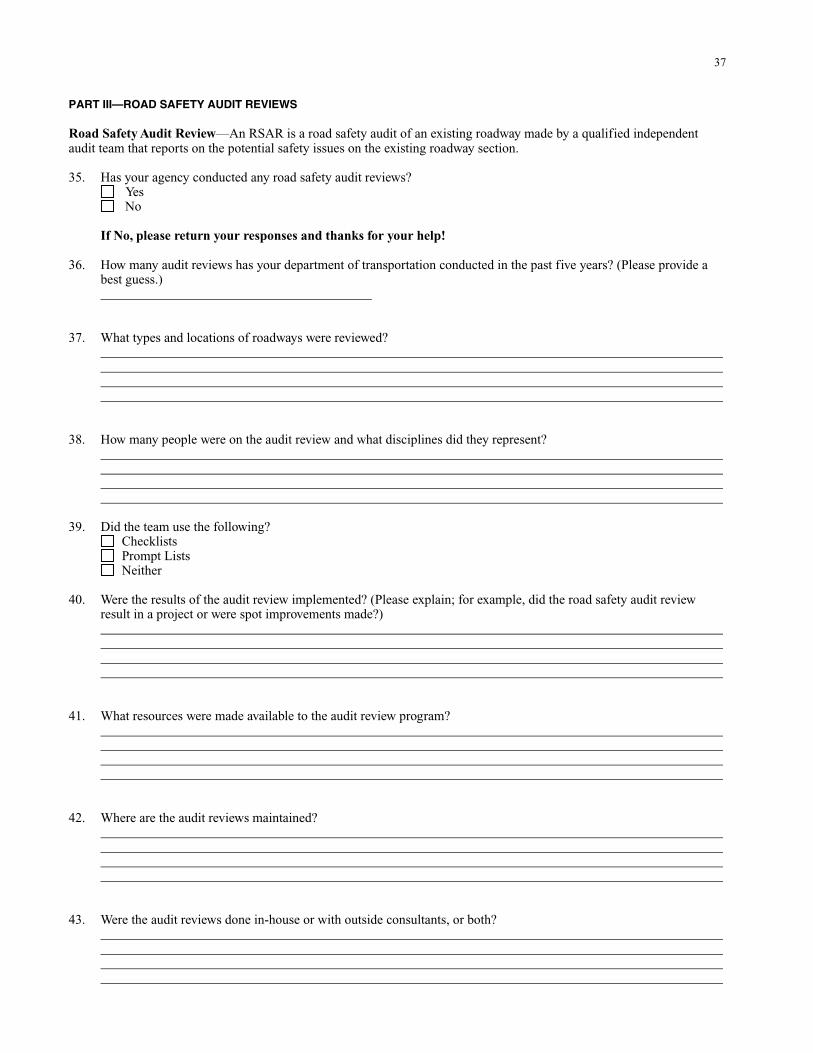
37
PART III—ROAD SAFETY AUDIT REVIEWS Road Safety Audit Review—An RSAR is a road safety audit of an existing roadway made by a qualified independent audit team that reports on the potential safety issues on the existing roadway section. 35. Has your agency conducted any road safety audit reviews? Yes No If No, please return your responses and thanks for your help! 36. How many audit reviews has your department of transportation conducted in the past five years? (Please provide a best guess.) 37. What types and locations of roadways were reviewed? 38. How many people were on the audit review and what disciplines did they represent? 39. Did the team use the following? Checklists Prompt Lists Neither 40. Were the results of the audit review implemented? (Please explain; for example, did the road safety audit review result in a project or were spot improvements made?) 41. What resources were made available to the audit review program? 42. Where are the audit reviews maintained? 43. Were the audit reviews done in-house or with outside consultants, or both?
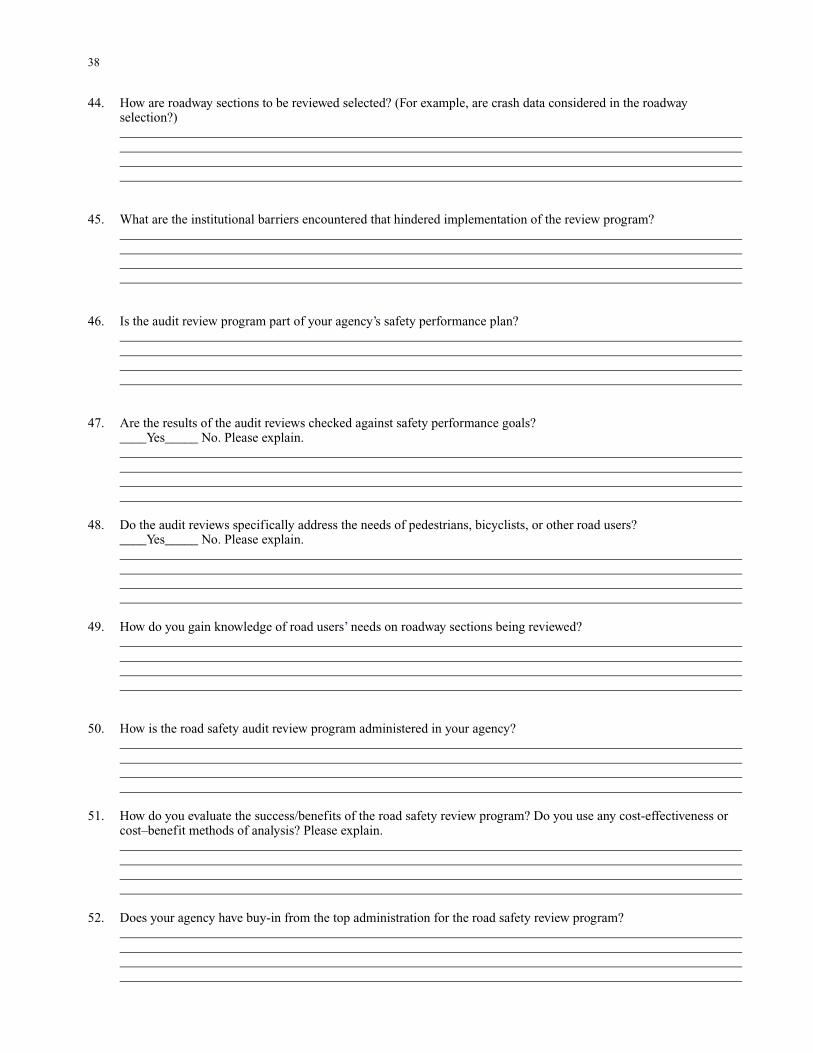
38
44. How are roadway sections to be reviewed selected? (For example, are crash data considered in the roadway selection?) 45. What are the institutional barriers encountered that hindered implementation of the review program? 46. Is the audit review program part of your agency’s safety performance plan? 47. Are the results of the audit reviews checked against safety performance goals? ____Yes_____ No. Please explain. 48. Do the audit reviews specifically address the needs of pedestrians, bicyclists, or other road users? ____Yes_____ No. Please explain. 49. How do you gain knowledge of road users’ needs on roadway sections being reviewed? 50. How is the road safety audit review program administered in your agency? 51. How do you evaluate the success/benefits of the road safety review program? Do you use any cost-effectiveness or cost–benefit methods of analysis? Please explain. 52. Does your agency have buy-in from the top administration for the road safety review program?
39
53. How are liability issues addressed in your road safety review program? 54. What is your biggest success with the road safety review program? 55. How is the road safety review program organized in your state?
Thanks for your cooperation and assistance. If you know of any other agency within your state or international contacts that you feel would provide information that would improve the synthesis, please provide contact
information.
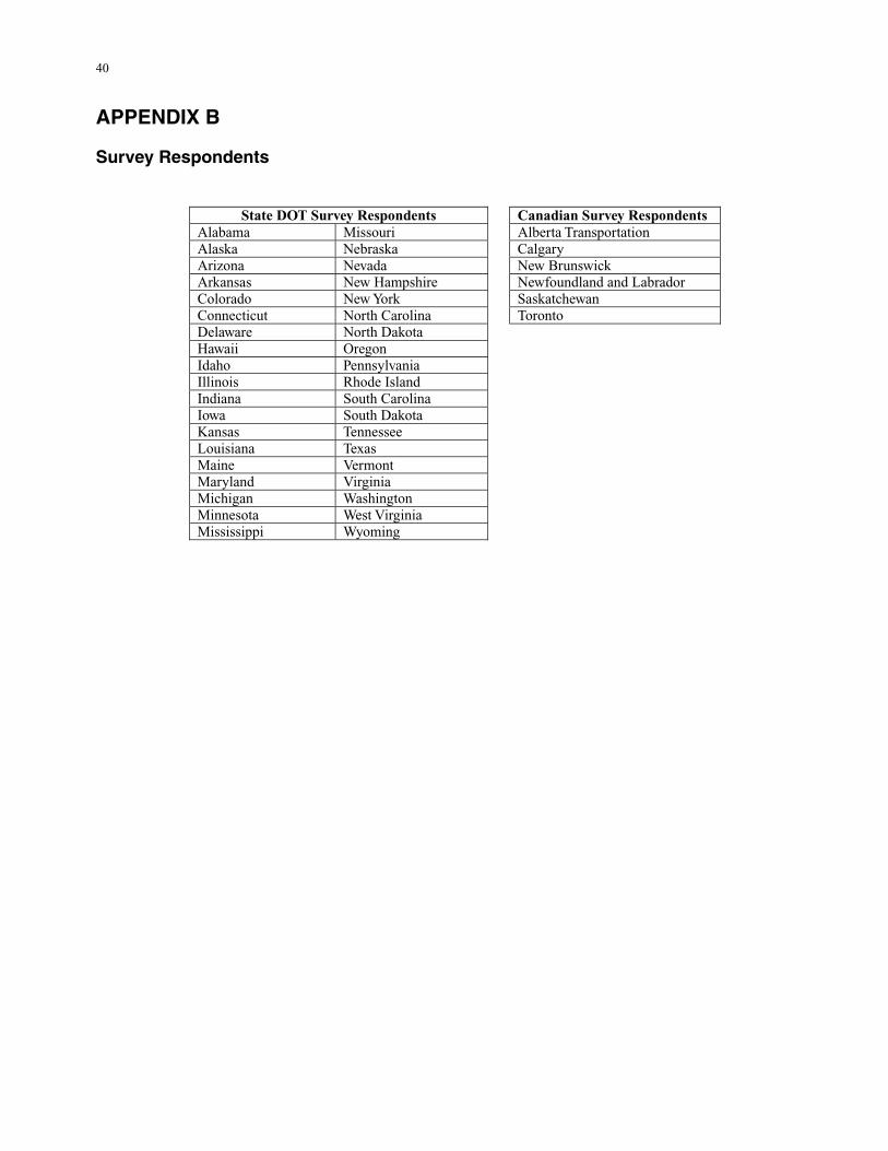
40
APPENDIX B Survey Respondents
State DOT Survey Respondents Canadian Survey Respondents Alabama Missouri Alberta Transportation Alaska Nebraska Calgary Arizona Nevada New Brunswick Arkansas New Hampshire Newfoundland and Labrador Colorado New York Saskatchewan Connecticut North Carolina Toronto Delaware North Dakota Hawaii Oregon Idaho Pennsylvania Illinois Rhode Island Indiana South Carolina Iowa South Dakota Kansas Tennessee Louisiana Texas Maine Vermont Maryland Virginia Michigan Washington Minnesota West Virginia Mississippi Wyoming
41
APPENDIX C Sample Audit Reports The following four audit reports are included in this appendix: 1. Sample road safety audit report, National Highway Institute 2. HD 19/03 reports 3. Sample road safety audit tool kit 4. Sample state road safety audit reports
42
Sample RSA Report
The following is a sample RSA report. This sample has been created using reports submitted by students of the
RSA course.

43
Road Safety Audit Report on the
Preliminary Design of the Proposed Widening of Route 60 between
Milepost 8.7 and 10.4
PROJECT DESCRIPTION Route 60 is currently a two-lane rural/suburban highway that traverses a two-mile portion of Henderson. The existing speed limit on Route 60 is 45 miles per hour. Adjacent land uses include industrial, commercial, and farming. Major intersections along the corridor include: • • • •
• • • •
US 60/Borax Drive/US 41A Ohio Drive/Collier Spur Road Old Corydon Road/Community Drive/Route 60 Dana Drive/Route 60.
There are numerous driveway accesses and “wide open” driveways on this section of Route 60. Concerns have been raised in terms of the number of crashes throughout the corridor. Crashes in parts of this section are substantially greater than the statewide average. We have reviewed the three alternative designs to upgrade Route 60 from east of Dana Drive to west of US 41A. All alternatives assume an upgrade of Route 60 from a two-lane section to a five-lane, curb and gutter section (four through lanes plus one two-way center left-turn lane). The proposed typical section also includes a five-foot sidewalk on both the north and south sides of the highway. AUDIT TEAM MEMBERS The following members comprise the audit team.
John Smith, Highway Designer Mary Jones, Transportation Engineer Juan Lopez, Highway/Traffic Safety Specialist Sue Ling, Project Manager
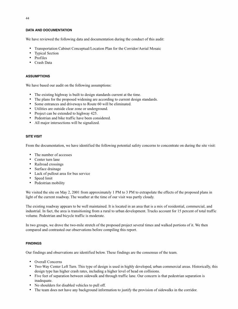
44
DATA AND DOCUMENTATION We have reviewed the following data and documentation during the conduct of this audit:
• • • •
• • • • • • •
• • • • • • •
• •
•
• •
Transportation Cabinet Conceptual/Location Plan for the Corridor/Aerial Mosaic Typical Section Profiles Crash Data
ASSUMPTIONS We have based our audit on the following assumptions:
The existing highway is built to design standards current at the time. The plans for the proposed widening are according to current design standards. Some entrances and driveways to Route 60 will be eliminated. Utilities are outside clear zone or underground. Project can be extended to highway 425. Pedestrian and bike traffic have been considered. All major intersections will be signalized.
SITE VISIT From the documentation, we have identified the following potential safety concerns to concentrate on during the site visit:
The number of accesses Center turn lane Railroad crossings Surface drainage Lack of pullout area for bus service Speed limit Pedestrian mobility
We visited the site on May 2, 2001 from approximately 1 PM to 3 PM to extrapolate the effects of the proposed plans in light of the current roadway. The weather at the time of our visit was partly cloudy. The existing roadway appears to be well maintained. It is located in an area that is a mix of residential, commercial, and industrial. In fact, the area is transitioning from a rural to urban development. Trucks account for 15 percent of total traffic volume. Pedestrian and bicycle traffic is moderate. In two groups, we drove the two-mile stretch of the proposed project several times and walked portions of it. We then compared and contrasted our observations before compiling this report. FINDINGS Our findings and observations are identified below. These findings are the consensus of the team.
Overall Concerns Two-Way Center Left Turn. This type of design is used in highly developed, urban commercial areas. Historically, this design type has higher crash rates, including a higher level of head on collisions. Five feet of separation between sidewalk and through traffic lane. Our concern is that pedestrian separation is inadequate. No shoulders for disabled vehicles to pull off. The team does not have any background information to justify the provision of sidewalks in the corridor.
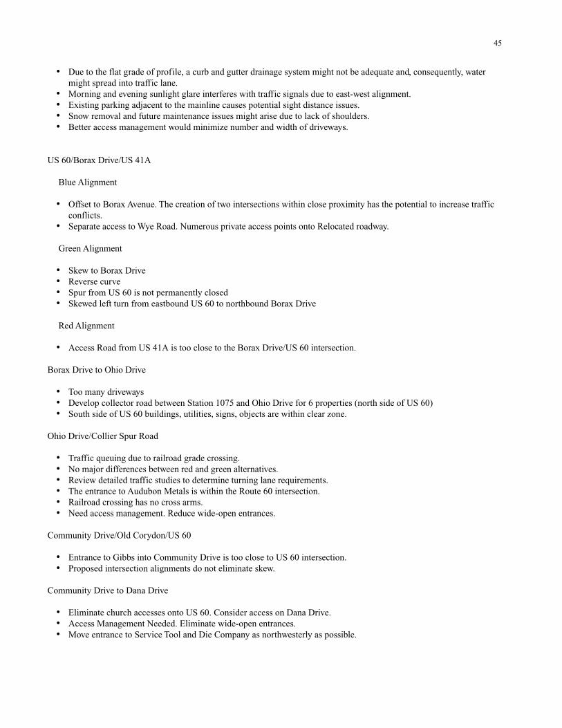
45
• Due to the flat grade of profile, a curb and gutter drainage system might not be adequate and, consequently, water might spread into traffic lane.
• • • •
•
•
• • • •
•
• • •
• • • • • •
• •
• • •
Morning and evening sunlight glare interferes with traffic signals due to east-west alignment. Existing parking adjacent to the mainline causes potential sight distance issues. Snow removal and future maintenance issues might arise due to lack of shoulders. Better access management would minimize number and width of driveways.
US 60/Borax Drive/US 41A Blue Alignment
Offset to Borax Avenue. The creation of two intersections within close proximity has the potential to increase traffic conflicts. Separate access to Wye Road. Numerous private access points onto Relocated roadway.
Green Alignment
Skew to Borax Drive Reverse curve Spur from US 60 is not permanently closed Skewed left turn from eastbound US 60 to northbound Borax Drive
Red Alignment
Access Road from US 41A is too close to the Borax Drive/US 60 intersection. Borax Drive to Ohio Drive
Too many driveways Develop collector road between Station 1075 and Ohio Drive for 6 properties (north side of US 60) South side of US 60 buildings, utilities, signs, objects are within clear zone.
Ohio Drive/Collier Spur Road
Traffic queuing due to railroad grade crossing. No major differences between red and green alternatives. Review detailed traffic studies to determine turning lane requirements. The entrance to Audubon Metals is within the Route 60 intersection. Railroad crossing has no cross arms. Need access management. Reduce wide-open entrances.
Community Drive/Old Corydon/US 60
Entrance to Gibbs into Community Drive is too close to US 60 intersection. Proposed intersection alignments do not eliminate skew.
Community Drive to Dana Drive
Eliminate church accesses onto US 60. Consider access on Dana Drive. Access Management Needed. Eliminate wide-open entrances. Move entrance to Service Tool and Die Company as northwesterly as possible.

46
CONCLUSIONS In our judgment, consideration of the findings should improve the overall safety of the US 60 corridor in Henderson. We also suggest that a subsequent road safety audit take place after the preliminary plans have been completed.
47
Volume 5 Section 2 Annex E Part 2 HD 19/03 Illustrative Report—A795 Ambridge Bypass—Road Safety Audit Stage 2
ANNEX E: ILLUSTRATIVE REPORT A795 AMBRIDGE BYPASS ROAD SAFETY AUDIT STAGE 2 E WING AND BARNES PARTNERSHIP November 2004 November 2003 E/1
48
1 INTRODUCTION 1.1 This report results from a Stage 2 Road Safety Audit carried out on the A795 Ambridge Bypass at the request of the Design Organisation: Ambridge Bypass Design Team, DLS Partnership (Highways Division), 12-14 Cathedral Close, Borchester. The Audit was carried out during November 2004. 1.2 The Audit Team membership was as follows: I K Brunel (Ms) BSc, MSc, CEng, MICE, MIHT Ewing and Barnes Partnership (Traffic and Accident Investigation Division) T MacAdam IEng, FIHIE Ewing and Barnes Partnership (Traffic and Accident Investigation Division) Eur Ing. C Chan MEng, CEng, MICE Road Safety Engineering Consultant 1.3 The audit took place at the Erinsborough Office of The Ewing and Barnes Partnership on 17 and 18 November 2004. The audit was undertaken in accordance with the audit brief contained in Highways Agency letter reference HA/11.10.04/001. The audit comprised an examination of the documents provided by the Highways Agency’s Project Sponsor, South Midlands Regional Office, and listed in the Annex. These documents consisted of a complete set of the draft tender drawings, a summary of the general details of the scheme including traffic flows, predicted queue lengths, non-motorised user counts and desire lines, an A3 plan for the Audit Team’s use, a copy of the Stage 1 Road Safety Audit Report dated June 2003, details of the response to the issues raised in the Stage 1 Audit, details of other changes to the design since June 2003 and a schedule of Departures from Standards and the relevant approvals contained in the design. A visit to the site of the proposed bypass was made on the morning of Wednesday 17 November 2004. During the site visit the weather was fine and sunny and the existing road surface was dry. 1.4 The terms of reference of the audit are as described in HD 19/03. The team has examined and reported only on the road safety implications of the scheme as presented and has not examined or verified the compliance of the designs to any other criteria. 1.5 All comments and recommendations are referenced to the detailed design drawings and the locations have been indicated on the A3 plan supplied with the audit brief. 1.6 The proposed A795 Ambridge Bypass incorporates the provision of 2.3km of 7.3m wide single carriageway between Station Road to the south of the A827 and Ambridge Road to the north east of Ambridge village. The scheme includes the provision of 5 priority junctions and a roundabout at the A827 dual carriageway junction. The improvement also encompasses the provision of two lay-bys, the diversion of a footpath and the stopping up of Old Church Lane.
2 ITEMS RAISED AT THE STAGE 1 AUDIT 2.1 The safety aspects of the Ambridge Road Junction were the subject of comment in the June 2003 Stage 1 Road Safety Audit Report. (Items A3.1 and A3.2) These items remain a problem and are referred to again in this report (paragraph 3.13 below). 2.2 All other issues raised in the Stage 1 Audit have been resolved.
3 ITEMS RAISED AT THIS STAGE 2 AUDIT 3.1 GENERAL 3.2 PROBLEM Locations: A and N (drawing RSA/S2/001) —Adjacent to the Ambridge railway station. Summary: Risk of an accident between a pedestrian and a vehicle due to potential shortcut to bus stop. A cross-section departure (in that there is no room for provision of a footway) on the existing railway bridge at location A has been reported. The departure has been introduced since the Stage 1 Audit. Although
49
pedestrians have been rerouted to cross the railway using the renovated station footbridge they may still be tempted to use the road bridge as this will provide a much shorter route to the adjacent bus stop (location N). Pedestrians using the road bridge would have to walk on the carriageway and therefore there would be an increased risk of an accident between a vehicle and a pedestrian. RECOMMENDATION Relocate the bus stop currently on the bypass to Station Road. In addition provide pedestrian deterrent paving on the verges on the immediate approaches to the bridge (both sides). 3.3 PROBLEM Locations: B and C (drawing RSA/S2/001)—Northern verge of Home Farm Road. Summary: Open ditch is a potential hazard to an errant road user. An open ditch is proposed to run along the side of Home Farm Road on the outside of the bend. This ditch is the main outfall for the storm water drainage from much of the bypass and in places is more than 1.5m deep. It is likely to carry substantial quantities of water following heavy rainfall and represents a danger to errant motorists and cyclists. This problem could increase the severity of an accident involving a vehicle or cyclist leaving the carriageway in this location. RECOMMENDATION Provide a safety fence at the back of the grass verge between location B and location C. 3.4 PROBLEM Locations: D and E (drawing RSA/S2/001)—Lay-bys north of Old Church Lane. Summary: Lay-by positions provide an increased risk of shunt and right turn accidents. Drivers travelling north will reach the lay-by at location D on their right before the lay-by at location E on their left. Similarly vehicles travelling south will reach the lay-by at E on their right first. Since the lay-bys are not inter-visible and there are no advance signs, drivers could be tempted to cross the carriageway to use the first lay-by that they reach. This problem would increase the number of right turning manoeuvres and therefore increase the potential for accidents between right turning vehicles and vehicles travelling ahead in the opposite direction. It could also increase the likelihood of shunt accidents involving vehicles running into the back of other vehicles waiting to turn right into the lay-by. RECOMMENDATION Reposition the lay-bys so that drivers encounter a lay-by on their nearside first. When relocating the lay-bys ensure that adequate visibility is provided for a driver both entering and leaving the facility. In addition, provide advance signing of both facilities. 3.5 PROBLEM Location: F (drawing RSA/S2/001)—Junction between Old Church Lane and the bypass. Summary: Downhill gradient and limited visibility on sideroad approach increases the risk of overshoot type accidents. The realigned section of Old Church Lane where it meets the bypass has a downhill longitudinal gradient of 7% and limited forward visibility. There is danger of traffic failing to stop at the give way line and skidding into the bypass in bad weather conditions. This feature could result in vehicles on Old Church Lane overrunning the give way line and colliding with through traffic on the bypass. RECOMMENDATION Provide the realigned section of Old Church Lane with a high grip surfacing and additional signs to warn traffic of the give way junction ahead.
50
3.6 PROBLEM Location: G (drawing RSA/S2/001)—On the bypass midway between Old Church Lane and Home Farm Road adjacent to the northbound lane. Summary: Unprotected embankment could increase the severity of an accident in this location. The safety fence on the west side of the bypass between chainage 1+550 and 1+650 leaves some embankment unprotected. This could increase the severity of an accident involving a vehicle or cyclist leaving the carriageway. RECOMMENDATION Extend the safety fence back to chainage 1+500. 3.7 PROBLEM Locations: H to I (drawing RSA/S2/001)—On the bypass adjacent to the Westlee dairy. Summary: Headlights of vehicles on the parallel dairy access road could distract and disorientate drivers on the bypass. The access road to the Westlee Diary Depot runs parallel to the bypass for about 250m. We understand that there is considerable vehicular activity on this road at night. The headlights of traffic using this road could be very confusing when viewed from the bypass. This could distract and disorientate drivers on the bypass to the extent they lose control of their vehicles. RECOMMENDATION Provide earth bund, solid fence or similar screen adjacent to Westlee Diary boundary. 3.8 PROBLEM Location: Q (drawing RSA/S2/001)—Entrance to the electricity sub-station north of Home Farm Road. Summary: No provision for service vehicles to stop off the bypass when accessing the sub-station. The entrance gates to the electricity sub-station at chainage 1+900 (location Q) are located such that drivers wishing to enter the compound would have to park on the bypass whilst they unlock the gate. This could result in a vehicle travelling on the bypass colliding with the parked vehicle. It could also encourage vehicles to overtake parked vehicles increasing the risk of head-on collisions. RECOMMENDATION Relocate the gates further back from the edge of the carriageway. If, however, the location of equipment in the compound precludes the relocation of the gates, provide a lay-by or hardstanding area to allow vehicles to wait off the road while the gates are being opened or secured. 3.9 THE ALIGNMENT 3.10 PROBLEM Location: J to L (drawing RSA/S2/001)—Crest to the north of Old Church Lane. Summary: Proposed hazard road marking is not sufficient to discourage drivers from overtaking in this area. The entire length of the bypass between the Ambridge Road Junction (location J) and the Bull Roundabout (location L) is marked with hazard lines (to Traffic Signs Regulations and General Directions diagram 1004.1) indicating the lack of full overtaking sight distance. The meaning of this lining is not understood by
51
the general public and there is no indication that the visibility reduces appreciably over the crest at chainage 1+250. This problem could increase the potential for accidents involving inappropriate overtaking. RECOMMENDATION Provide 1m carriageway hatch markings (to Traffic Signs Regulations and General Directions diagram 1013.1B) over the crest. The use of this marking must be coordinated with recommendation 3.13 below. 3.11 THE JUNCTIONS 3.12 PROBLEM Location: L (drawings RSA/S2/001 and RSA/S2/002)—North from the Bull Roundabout. Summary: Confusion over the layout of road north of the roundabout may result in inappropriate overtaking. Traffic originating from the existing dual carriageway A827 Borchester Road (which has a mature quickthorn hedge in the central reserve) and turning onto the new bypass (northbound) may be confused into thinking that the new bypass is a dual carriageway, particularly as the old field hedge to the west could be assumed to be in a central reserve and concealing a northbound carriageway. Traffic on the access road to the Westlee Diary could further confuse traffic in this location unless the recommendation at paragraph 3.7 above is implemented. This problem could increase the potential for accidents involving vehicles overtaking in an inappropriate location. RECOMMENDATION Redesign the splitter island and associated hatch markings shown on drawing RSA/S2/002 to accentuate that the bypass is a single carriageway. In addition provide two-way traffic signs (to diagram number 521 of The Traffic Signs Regulations and General Directions) on the northbound bypass immediately after the roundabout. 3.13 PROBLEM Location: J (drawings RSA/S2/001 and RSA/S2/003)—Northbound approach to Ambridge Road Junction. Summary: The road layout on the approach to the junction does not discourage overtaking on this straight downhill section of the bypass. The approach to this junction along the proposed bypass from the south is via a straight downhill section of about 1km length and traffic speeds are likely to be high. The necessity of making sure that overtaking manoeuvres are complete in good time before the central reserve at the junction commences was flagged at the Stage 1 Audit. The current design does not adequately address this issue. As a result there is a potential for overtaking accidents and side impact accidents as overtaking vehicles abruptly move back into the northbound lane before the junction. RECOMMENDATION (a) Provide a continuous prohibitory double white line to diagram 1013.1 from the southern end of the central reserve (location M drawing RSA/S2/003) for a distance of about 340m uphill (FOSD/4 before the nosing), to replace the proposed hazard marking. This will force drivers into a single line well before the junction. Coordination with the recommendation in paragraph 3.10 above is necessary. (b) Reposition the advanced direction sign ADS6 approximately 150m from the junction to warn traffic travelling at higher speeds. (c) Provide “SLOW” carriageway markings on the approaches to the junction from both the north and south direction to moderate speeds through the junction. (d) Provide hatching within the hard strip to further discourage drivers from attempting to overtake in the short single lane dual carriageway section through the junction.
52
3.14 NON-MOTORISED USERS 3.15 PROBLEM Locations: O and P (See drawing RSA/S2/001)—Former line of the footpath at the crest to the north of Old Church Lane. Summary: The former footpath alignment may still attract pedestrians to cross at a location with limited visibility. The scheme allows for the diversion of Footpath No 12 so that it crosses the bypass away from the crest curve at location K. The old route may, however, be more attractive to pedestrians. This could result in an accident between a vehicle and pedestrian due to the reduced visibility at the crest curve. RECOMMENDATION Modify landscaping with heavy planting to block old route at the edge of the bypass (location O) and remove the old stile at the field boundary (location P) and replace with solid wall to match existing. 3.16 PROBLEM Location: Throughout the length of the bypass. Summary: The proposed raised ribbed edge line may be hazardous to cyclists at junctions. It is not uncommon for cyclists to use the marginal strip provided along busy bypasses to avoid being intimidated by other vehicles. The drawings indicate that road markings to Diagram 1012.3, raised ribbed markings, will be used as edge line markings. These markings may cause difficulties for cyclists entering or leaving the marginal strip near junctions and result in cyclists losing control of their bicycle. RECOMMENDATION Replace markings to Diagram 1012.3 by those to Diagram 1012.1 for a length of 20m on the approach and exit sides of any junction. 3.17 SIGNING AND LIGHTING 3.18 PROBLEM Location: L (drawings RSA/S2/001 and RSA/S2/002)—westbound approach to the Bull Roundabout. Summary: The risk of errant vehicle colliding with a lighting column located in front of the safety fence. On the A827 Borchester Road dual carriageway approach to the Bull Roundabout a length of safety fence is proposed to protect a large advance direction sign in the nearside verge. The drawings provided show a lighting column approximately 60 metres from the roundabout located in front of the proposed safety fence. A vehicle leaving the carriageway in this location could run along the length of safety fence into the lighting column, this could significantly increase the severity of an accident occurring in this location. RECOMMENDATION Relocate the proposed lighting column behind the length of safety fence.
53
4 AUDIT TEAM STATEMENT I certify that this audit has been carried out in accordance with HD 19/03. AUDIT TEAM LEADER Ms I K Brunel BSc, MSc, CEng, MICE, MIHT Signed I K Brunel Principal Highway Engineer Traffic and Accident Investigation Division Date 22/11/04 Ewing and Barnes Partnership Albert Square Erinsborough Rutland AUDIT TEAM MEMBERS T MacAdam IEng, FIHIE Eur Ing. C Chan CEng, MICE Senior Engineer Road Safety Engineering Consultant Traffic and Accident Investigation Division 5 Brookside Ewing and Barnes Partnership Post Green Albert Square Wessex Erinsborough Rutland
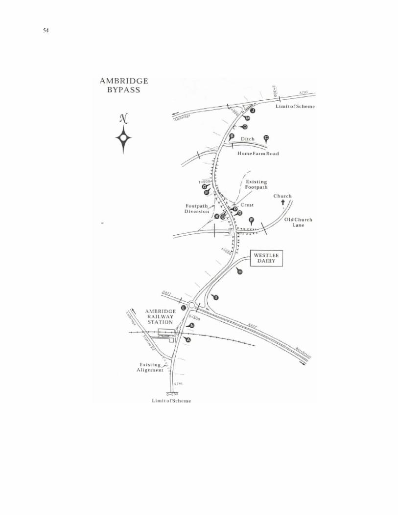
54
55
Volume 5 Section 2 Annex F Part 2 HD 19/03 Illustrative Report—A795 Ambridge Bypass—Road Safety Audit Stage 4
ANNEX F:
ILLUSTRATIVE REPORT A795 AMBRIDGE BYPASS ROAD SAFETY AUDIT STAGE 4 12 MONTH MONITORING REPORT D LS PARTNERSHIP May 2007 November 2003 F/1
56
1 INTRODUCTION 1.1 This report results from the Road Safety Audit Stage 4 - 12 month monitoring carried out on the A795 Ambridge Bypass Scheme as part of DLS Partnership (Maintenance Division) maintenance agreement with the Highway Agency. The report has been produced as part of a routine accident monitoring/Road Safety Audit procedure and the terms of reference for this monitoring report are described in HD 19/03. 1.2 A site visit was conducted on Monday 7th May 2007, during which the road surface was wet as it was raining heavily. 2 SCHEME DETAILS 2.1 The A795 Ambridge Bypass was completed in March 2006 and involved the provision of 2.3km of 7.3m wide single carriageway between Station Road to the south of the A827 and Ambridge Road to the north east of Ambridge village. 2.2 The scheme included the provision of 5 priority junctions and a roundabout at the A827 dual carriageway. The improvement also encompassed the provision of two lay-bys, the diversion of a footpath and the stopping up of Old Church Lane. 2.3 The scheme was subjected to a Stage 1 Road Safety Audit in June 2003, a Stage 2 Audit in November 2004 and a Stage 3 audit prior to opening in March 2006. 3 ANALYSIS OF ACCIDENTS 3.1 During the period 1st April 2006 to 31st March 2007 a total of 3 personal injury accidents were recorded throughout the 2.3km length of the scheme. The severity of all three accidents was slight. 3.2 The accident frequency on Ambridge bypass has been briefly compared with values predicted in the Design Manual for Roads and Bridges COBA manual. The COBA manual predicts an accident frequency of 3.48 accidents a year based on the Annual Average Daily Traffic (AADT) flow of 18500 vehicles in 2006. 3.3 All three accidents have occurred at different locations throughout the scheme. The location and a brief description of each accident has been included below:
• • • • •
Accident Ref. 1—A827/A795 roundabout. Vehicle 1 from A827 fails to give way at roundabout and runs into vehicle 2. Accident Ref. 2—N/bound approach to Old Church Lane. M/cycle loses control on a patch of oil. Accident Ref. 3—S/bound lay-by north of Old Church Lane. Vehicle 2 travelling north waiting to turn right into lay-by struck in rear by vehicle 1.
3.4 Two of the accidents (references 2 and 3) occurred during the daytime in fine weather on a dry road surface. The remaining accident (reference 1) occurred during the daytime in a period of rain on a wet road surface. 4 TRAFFIC CONDITIONS 4.1 Traffic count data has been obtained from an Automatic Traffic Counter (ATC) located on the A795 north of Home Farm Lane. The ATC indicates that the traffic flows along the A795 are 18500 vehicles AADT in 2006. 4.2 No significant congestion has been recorded throughout the scheme in its first year of opening. However, some queuing has been observed on the A827 westbound approach to the A827/A795 roundabout during the am peak period.
57
5 CONCLUSIONS 5.1 A brief assessment of the 12-month accident history of the Ambridge Bypass has indicated that the accident frequency is lower than the predicted national average and no common factors or trends have been identified in the data. However, it has been noted that one of the three accidents that have occurred has resulted from a vehicle travelling northbound waiting to turn right into the southbound lay-by being struck from behind. This problem was raised in the Stage 2 Audit report, however there were difficulties in acquiring the land necessary to relocate the lay-by so an Exception Report was approved. 5.2 As this report considers only 12 months of accident data and no common factors or trends have been identified at this early stage no firm conclusions can be drawn from the accident information.
58
Volume 5 Section 2 Annex G Part 2 HD 19/03 Illustrative Report—A795 Ambridge Bypass—Road Safety Audit Stage 4
ANNEX G: ILLUSTRATIVE REPORT A795 AMBRIDGE BYPASS ROAD SAFETY AUDIT STAGE 4 36 MONTH MONITORING REPORT D LS PARTNERSHIP May 2009 November 2003 G/1
59
CONTENTS 1 INTRODUCTION 1.1 Background to the Study 1.2 Study Purpose 2 SCHEME DETAILS 2.1 Description of the Scheme 3 ANALYSIS OF ACCIDENTS 4 TRAFFIC CONDITIONS 4.1 Traffic Flows 4.2 Traffic Speeds 5 STATEMENT OF SAFETY PROBLEMS ON THE AMBRIDGE BYPASS 5.1 Problems Identified 5.2 Review of Previous Road Safety Audit Reports and Exception Reports 6 OPTIONS FOR TREATMENT 6.1 Accidents Occurring on the A827 dual carriageway approach to the A827/A795 roundabout 6.2 Accidents Involving Cyclists at the A827/A795 roundabout 6.3 Accidents Occurring at the Lay-by 7 CONCLUSIONS APPENDICES I Summary of Accident Record between 1st April 2006 to 31st March 2009 II Summary Accident Plot III Graphs showing Accident Frequency by Year, Month & Day of the Week IV Graphs showing Accident Frequency by Hour of the Day, Weather Conditions & Road Surface Conditions V Graph showing Accidents by Light Conditions
60
1 INTRODUCTION 1.1 Background to the study 1.1.1 This report results from the Road Safety Audit Stage 4 - 36 month monitoring carried out on the A795 Ambridge Bypass Scheme as part of DLS Partnership (Maintenance Division) maintenance agreement with the Highways Agency. The report has been produced as part of a routine accident monitoring / Road Safety Audit procedure and the terms of reference for this monitoring report are described in HD 19/03. 1.1.2 A site visit was conducted on Friday 8th May 2009, during which the weather was overcast and the road surface was dry. 1.2 Study purpose 1.2.1 The purpose of this study is as follows:
• • • •
to undertake an in-depth study of the accidents that have occurred on the scheme during the three years since opening; to identify any road accident problems; to suggest possible measures that would contribute to accident reduction on the scheme; to review the recommendations from the Road Safety Audit Reports at Stages 1 to 3 and the Exception Reports to identify if they had any effect on the scheme.
2 SCHEME DETAILS 2.1 Description of the scheme 2.1.1 The A795 Ambridge Bypass was completed in March 2006 and involved the provision of 2.3km of 7.3m wide single carriageway between Station Road to the south of the A827 and Ambridge Road to the north east of Ambridge village. 2.1.2 The scheme included the provision of 5 priority junctions and a roundabout at the A827 dual carriageway. The improvement also encompassed the provision of two lay-bys, the diversion of a footpath and the stopping up of Old Church Lane. 2.1.3 The road is subject to the national speed limit and with the exception of the A827 / A795 Bull Roundabout the scheme is unlit. 2.1.4 The scheme was subjected to a Stage 1 Road Safety Audit in June 2003, a Stage 2 Audit in November 2004, a Stage 3 Audit prior to opening in March 2006 and a Stage 4 12 month monitoring report in May 2007. 3 ANALYSIS OF ACCIDENTS 3.1.1 During the 36 month period between 1st April 2006 to 31st March 2009 a total of 11 personal injury accidents were recorded throughout the 2.3km length of the scheme. There have been 2 (18%) serious accidents and 9 (82%) accidents that were slight in severity. No accidents involving fatalities have been recorded during the 36 month period. These figures are generally consistent with national average values taken from the DfT publication “Road Accidents in Great Britain” (RAGB) which indicates that on major roads with a 60mph speed limit 4% of accidents were fatal, 21% were serious and 75% were slight in severity. 3.1.2 Stick diagrams for these accidents together with a breakdown of accident types are included in Appendix I. 3.1.3 Appendix II shows a plot of the location of each of the accidents. Generally this diagram shows that the accidents are evenly distributed throughout the scheme, however there is a cluster of 4 accidents at the A827/A795 roundabout and two accidents at the lay-by north of Old Church Lane. 3.1.4 The information contained in the accident data has been compared to national averages from the DfT publication “Road Accidents in Great Britain” (RAGB) and the “Design Manual for Roads and Bridges COBA manual” below and in Appendices III to V:
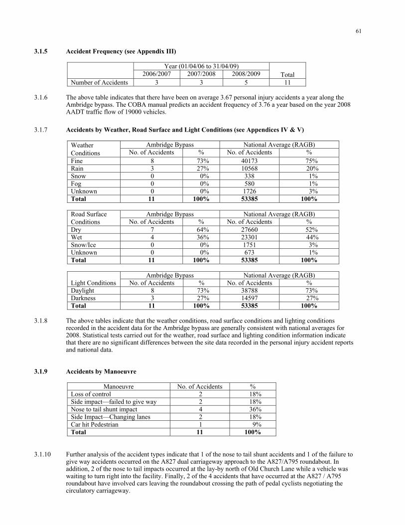
61
3.1.5 Accident Frequency (see Appendix III)
Year (01/04/06 to 31/04/09) 2006/2007 2007/2008 2008/2009
Total
Number of Accidents 3 3 5 11 3.1.6 The above table indicates that there have been on average 3.67 personal injury accidents a year along the Ambridge bypass. The COBA manual predicts an accident frequency of 3.76 a year based on the year 2008 AADT traffic flow of 19000 vehicles.
3.1.7 Accidents by Weather, Road Surface and Light Conditions (see Appendices IV & V)
Ambridge Bypass National Average (RAGB) Weather Conditions No. of Accidents % No. of Accidents % Fine 8 73% 40173 75% Rain 3 27% 10568 20% Snow 0 0% 338 1% Fog 0 0% 580 1% Unknown 0 0% 1726 3% Total 11 100% 53385 100%
Ambridge Bypass National Average (RAGB) Road Surface
Conditions No. of Accidents % No. of Accidents % Dry 7 64% 27660 52% Wet 4 36% 23301 44% Snow/Ice 0 0% 1751 3% Unknown 0 0% 673 1% Total 11 100% 53385 100%
Ambridge Bypass National Average (RAGB) Light Conditions No. of Accidents % No. of Accidents % Daylight 8 73% 38788 73% Darkness 3 27% 14597 27% Total 11 100% 53385 100%
3.1.8 The above tables indicate that the weather conditions, road surface conditions and lighting conditions recorded in the accident data for the Ambridge bypass are generally consistent with national averages for 2008. Statistical tests carried out for the weather, road surface and lighting condition information indicate that there are no significant differences between the site data recorded in the personal injury accident reports and national data. 3.1.9 Accidents by Manoeuvre
Manoeuvre No. of Accidents % Loss of control 2 18% Side impact—failed to give way 2 18% Nose to tail shunt impact 4 36% Side Impact—Changing lanes 2 18% Car hit Pedestrian 1 9% Total 11 100%
3.1.10 Further analysis of the accident types indicate that 1 of the nose to tail shunt accidents and 1 of the failure to give way accidents occurred on the A827 dual carriageway approach to the A827/A795 roundabout. In addition, 2 of the nose to tail impacts occurred at the lay-by north of Old Church Lane while a vehicle was waiting to turn right into the facility. Finally, 2 of the 4 accidents that have occurred at the A827 / A795 roundabout have involved cars leaving the roundabout crossing the path of pedal cyclists negotiating the circulatory carriageway.
62
4 TRAFFIC CONDITIONS 4.1 Traffic Flows 4.1.1 Traffic count data has been obtained from an Automatic Traffic Counter (ATC) located on the A795 north of Home Farm Lane. The ATC indicates that the traffic flows along the A795 in 2008 were 19,000 vehicles AADT. This compares to the AADT flow recorded in 2006 of 18,500 vehicles. 4.1.2 The daily flow profile suggests that the Ambridge bypass has pronounced peaks in both the AM and PM periods and the traffic volumes are tidal, the high volumes occur in the southbound direction in the AM period and in the northbound direction in the PM period. 4.2 Traffic Speeds 4.2.1 Traffic speeds were measured during January 2009 and the results are shown below:
Southbound Northbound Location of Survey
85% ile speed (mph)
Speed range (mph)
85% ile speed (mph)
Speed range (mph)
100 m South of Old Church Ln 52 41–65 51 41–62 100 m North of Old Church Ln 54 44–66 55 40–66
4.2.2 The results show that speeds along the Ambridge Bypass are typical of those with a 60mph speed limit. A small proportion of drivers exceed the speed limit by more than 5mph. 4.2.3 No significant congestion has been recorded throughout the scheme. However, some queuing has been observed on the A827 westbound approach to the A827 / A795 roundabout during the am peak period. This congestion generally occurs between 08:30 and 09:00 in the morning on weekdays and extends for a length of approximately 15 vehicles in each lane. 5 STATEMENT OF SAFETY PROBLEMS ON THE AMBRIDGE BYPASS 5.1 Problems Identified 5.1.1 Although the accident rate along the Ambridge bypass is consistent with the national average for the type of road, this study has shown that there are a number of specific safety problems along the route:
• • • • •
Two accidents on the A827 dual carriageway approach have involved drivers failing to appreciate the A827/A795 roundabout. Two accidents at the A827/A795 roundabout have involved car drivers exiting the junction across the path of cyclists. A cluster of two accidents have occurred at the lay-by north of Old Church Lane.
5.2 Review of Previous Road Safety Audit Reports and Exception Reports 5.2.1 None of the previous Road Safety Audits raised a specific problem in respect of either the potential for accidents involving drivers approaching from the A827 not appreciating the A827/A795 roundabout or for accidents involving car drivers exiting the junction across the path of cyclists. However, the potential for accidents involving vehicles turning right into the lay-by to the north of Old Church Lane was identified in the Stage 2 Road Safety Audit undertaken in November 2004.
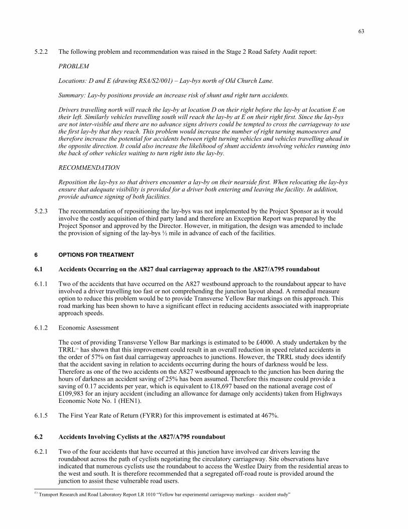
63
5.2.2 The following problem and recommendation was raised in the Stage 2 Road Safety Audit report: PROBLEM Locations: D and E (drawing RSA/S2/001) – Lay-bys north of Old Church Lane. Summary: Lay-by positions provide an increase risk of shunt and right turn accidents. Drivers travelling north will reach the lay-by at location D on their right before the lay-by at location E on their left. Similarly vehicles travelling south will reach the lay-by at E on their right first. Since the lay-bys are not inter-visible and there are no advance signs drivers could be tempted to cross the carriageway to use the first lay-by that they reach. This problem would increase the number of right turning manoeuvres and therefore increase the potential for accidents between right turning vehicles and vehicles travelling ahead in the opposite direction. It could also increase the likelihood of shunt accidents involving vehicles running into the back of other vehicles waiting to turn right into the lay-by. RECOMMENDATION Reposition the lay-bys so that drivers encounter a lay-by on their nearside first. When relocating the lay-bys ensure that adequate visibility is provided for a driver both entering and leaving the facility. In addition, provide advance signing of both facilities. 5.2.3 The recommendation of repositioning the lay-bys was not implemented by the Project Sponsor as it would involve the costly acquisition of third party land and therefore an Exception Report was prepared by the Project Sponsor and approved by the Director. However, in mitigation, the design was amended to include the provision of signing of the lay-bys ½ mile in advance of each of the facilities. 6 OPTIONS FOR TREATMENT 6.1 Accidents Occurring on the A827 dual carriageway approach to the A827/A795 roundabout 6.1.1 Two of the accidents that have occurred on the A827 westbound approach to the roundabout appear to have involved a driver travelling too fast or not comprehending the junction layout ahead. A remedial measure option to reduce this problem would be to provide Transverse Yellow Bar markings on this approach. This road marking has been shown to have a significant effect in reducing accidents associated with inappropriate approach speeds. 6.1.2 Economic Assessment The cost of providing Transverse Yellow Bar markings is estimated to be £4000. A study undertaken by the TRRL(1) has shown that this improvement could result in an overall reduction in speed related accidents in the order of 57% on fast dual carriageway approaches to junctions. However, the TRRL study does identify that the accident saving in relation to accidents occurring during the hours of darkness would be less. Therefore as one of the two accidents on the A827 westbound approach to the junction has been during the hours of darkness an accident saving of 25% has been assumed. Therefore this measure could provide a saving of 0.17 accidents per year, which is equivalent to £18,697 based on the national average cost of £109,983 for an injury accident (including an allowance for damage only accidents) taken from Highways Economic Note No. 1 (HEN1). 6.1.5 The First Year Rate of Return (FYRR) for this improvement is estimated at 467%. 6.2 Accidents Involving Cyclists at the A827/A795 roundabout 6.2.1 Two of the four accidents that have occurred at this junction have involved car drivers leaving the roundabout across the path of cyclists negotiating the circulatory carriageway. Site observations have indicated that numerous cyclists use the roundabout to access the Westlee Dairy from the residential areas to the west and south. It is therefore recommended that a segregated off-road route is provided around the junction to assist these vulnerable road users. (1) Transport Research and Road Laboratory Report LR 1010 “Yellow bar experimental carriageway markings – accident study”
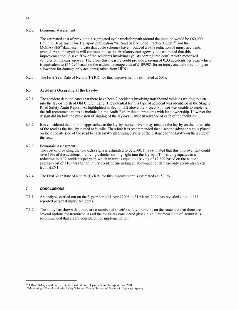
64
6.2.2 Economic Assessment The estimated cost of providing a segregated cycle track/footpath around the junction would be £60,000. Both the Department for Transport publication “A Road Safety Good Practice Guide”(2) and the MOLASSES(3) database indicate that cycle schemes have produced a 58% reduction of injury accidents overall. As some cyclists will continue to use the circulatory carriageway it is estimated that this improvement could save 50% of the accidents involving cyclists coming into conflict with motorised vehicles on the carriageway. Therefore this measure could provide a saving of 0.33 accidents per year, which is equivalent to £36,294 based on the national average cost of £109,983 for an injury accident (including an allowance for damage only accidents) taken from HEN1. 6.2.3 The First Year Rate of Return (FYRR) for this improvement is estimated at 60%. 6.3 Accidents Occurring at the Lay-by 6.3.1 The accident data indicates that there have been 2 accidents involving northbound vehicles waiting to turn into the lay-by north of Old Church Lane. The potential for this type of accident was identified in the Stage 2 Road Safety Audit Report. As highlighted in Section 5.2 above the Project Sponsor was unable to implement the full recommendations as included in the Audit Report due to problems with land ownership. However the design did include the provision of signing of the lay-bys ½ mile in advance of each of the facilities. 6.3.2 It is considered that on both approaches to the lay-bys some drivers may mistake the lay-by on the other side of the road as the facility signed at ½ mile. Therefore it is recommended that a second advance sign is placed on the opposite side of the road to each lay-by informing drivers of the distance to the lay-by on their side of the road. 6.3.3 Economic Assessment: The cost of providing the two extra signs is estimated to be £500. It is estimated that this improvement could save 10% of the accidents involving vehicles turning right into the lay-bys. This saving equates to a reduction in 0.07 accidents per year, which in turn is equal to a saving of £7,699 based on the national average cost of £109,983 for an injury accident (including an allowance for damage only accidents) taken from HEN1. 6.2.4 The First Year Rate of Return (FYRR) for this improvement is estimated at 1539%. 7 CONCLUSIONS 7.1.1 An analysis carried out on the 3-year period 1 April 2006 to 31 March 2009 has revealed a total of 11 reported personal injury accidents. 7.1.2 The study has shown that there are a number of specific safety problems on the route and that there are several options for treatment. As all the measures considered give a high First Year Rate of Return it is recommended that all are considered for implementation. (2) A Road Safety Good Practice Guide, First Edition: Department for Transport, June 2001 (3) Monitoring Of Local Authority Safety Schemes, County Surveyors’ Society & Highways Agency
65
APPENDICES Appendix I—Accident Record 1st April 2006 to 31st March 2009
66
Appendix II—Accident Plot 1st April 2006 to 31st March 2009

67
Appendix III—Accident Frequency by Year, Month & Day of Week
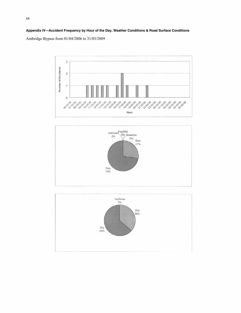
68
Appendix IV—Accident Frequency by Hour of the Day, Weather Conditions & Road Surface Conditions Ambridge Bypass from 01/04/2006 to 31/03/2009
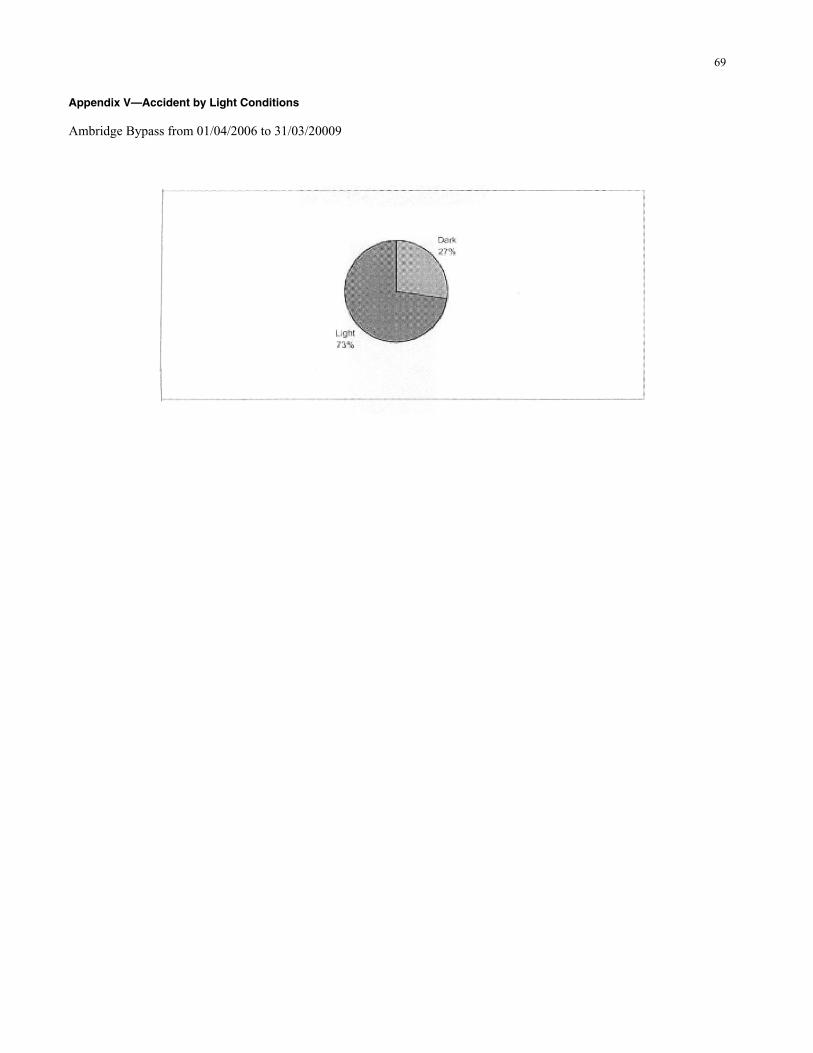
69
Appendix V—Accident by Light Conditions Ambridge Bypass from 01/04/2006 to 31/03/20009
70
RSA TOOL KIT
Developed by Eugene M. Wilson, Ph.D., PE, PTOE
LOCAL RURAL GOVERNMENT RSAR PROCESS
Functional Local Rural Road Classifications RSAR Form Instructions for Local Rural Road Safety Audit Review Program Safety Issues to LOOK FOR Sample Report of RSAR Findings
“The key to safety is implementing
improvements for safety issues identified as urgent.”

71
SAMPLE REPORT County Road Safety Audit Reviews Roadways reviewed and the recommendations resulting from the reviews are as follows (specifics on exact locations and more details are provided in the review notes): Local/Rural Major High Speed Road Several items were noted that could be improved if the road was ever reconstructed. However, considering the classifications of the road and the cost of improvements, many items were recommended to leave as they are. Included are parallel drainage pipe blunt ends, trees, power poles, mailbox supports, and some relatively steep side slopes. The following items were thought to be of a relatively low cost improvement that could have positive safety benefits and should be considered for improvement within a reasonably short time frame: Westbound:
• • •
• • • • • •
•
• • •
•
Relocate curve sign further upstream Delineate roadside where roadway narrows at horizontal curve and a relatively steep slope exists (2 locations) Replace non-standard speed limit signs
Eastbound:
Replace curve sign with a curve/intersection warning sign Relocate mailboxes Relocate curve sign further upstream Replace curve warning advisory speed plate to be consistent with opposite direction Add delineation to clearly define edge of roadway cross-section Install a STOP sign
The following item was thought to be of such a nature that we recommend the improvement be initiated as soon as possible:
Install delineation where roadway alignment is not consistent with the power pole alignment The following items were considered to be of such a nature that they would have relatively high safety benefit if corrected, but are of relatively high cost for this classification of roadway. Therefore, it is recommended that they be considered for improvement if major reconstruction occurs on the roadway at or near these locations.
Driveway approach in poor location Westbound view blocked by fence, restricted sight distance Driveway approach grades cause restricted sight distance
Local/Rural Local Road
Numerous potential safety concerns exist on this roadway. However, due to the classification of the roadway, it is recommended that no improvements be made except to install a STOP sign.
Local/Rural Low Volume Local Road Several items were noted that could be improved if the road was ever reconstructed at those specific locations. However, considering the classification of the road and the cost of improvements, many items were recommended to leave as they are. Included are relatively steep slopes and ditches, vertical and horizontal alignment creating sight restrictions, no notification of road ending, and power poles.

72
The following item was thought to be a relatively low cost improvement that could have positive safety benefits and should be considered for improvement within a reasonably short time frame:
• Pull ditches and remove large rocks
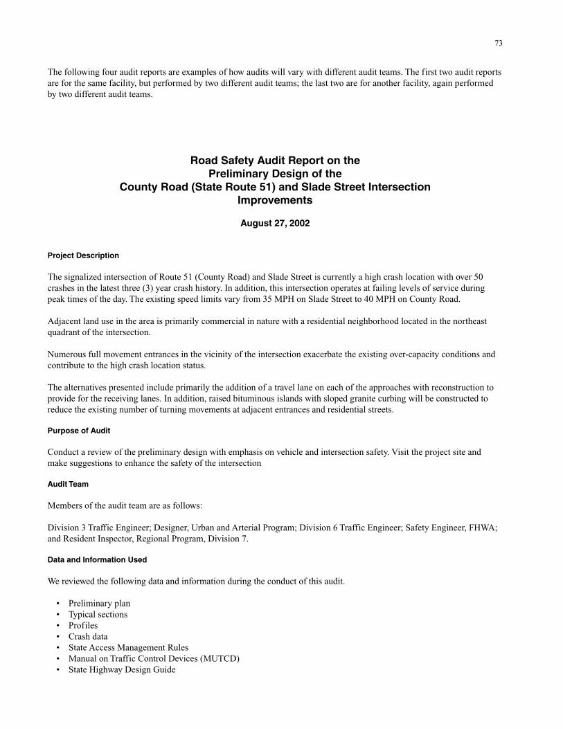
73
The following four audit reports are examples of how audits will vary with different audit teams. The first two audit reports are for the same facility, but performed by two different audit teams; the last two are for another facility, again performed by two different audit teams.
Road Safety Audit Report on the Preliminary Design of the
County Road (State Route 51) and Slade Street Intersection Improvements
August 27, 2002
Project Description The signalized intersection of Route 51 (County Road) and Slade Street is currently a high crash location with over 50 crashes in the latest three (3) year crash history. In addition, this intersection operates at failing levels of service during peak times of the day. The existing speed limits vary from 35 MPH on Slade Street to 40 MPH on County Road. Adjacent land use in the area is primarily commercial in nature with a residential neighborhood located in the northeast quadrant of the intersection. Numerous full movement entrances in the vicinity of the intersection exacerbate the existing over-capacity conditions and contribute to the high crash location status. The alternatives presented include primarily the addition of a travel lane on each of the approaches with reconstruction to provide for the receiving lanes. In addition, raised bituminous islands with sloped granite curbing will be constructed to reduce the existing number of turning movements at adjacent entrances and residential streets. Purpose of Audit Conduct a review of the preliminary design with emphasis on vehicle and intersection safety. Visit the project site and make suggestions to enhance the safety of the intersection Audit Team Members of the audit team are as follows: Division 3 Traffic Engineer; Designer, Urban and Arterial Program; Division 6 Traffic Engineer; Safety Engineer, FHWA; and Resident Inspector, Regional Program, Division 7. Data and Information Used We reviewed the following data and information during the conduct of this audit.
• • • • • • •
Preliminary plan Typical sections Profiles Crash data State Access Management Rules Manual on Traffic Control Devices (MUTCD) State Highway Design Guide
74
General Findings
•
• •
•
•
•
•
•
•
The existing intersections operate at low levels of service with turning movements into/out of the driveways/entrances/streets in the immediate vicinity. Vehicles use shoulders inappropriately. Existing insufficient truck turning radii.
SPECIFIC FINDINGS County Road Westbound Approach
Receiving lanes on the east leg of the intersection appear to be short prior to the lane drop. The concern is that the contributing westbound through or southbound dual left turn lanes will not be fully utilized. Extend the two eastbound receiving lanes to station 1+420 before starting lane drop. Ideally, the two-lane section should be extended to the intersection of County Road and the Exit 7A connector road.
The westbound approach right and through lanes need to be extended to Station 1+420. The lane transition length appears to be the same as the lane drop transition; this should be one half the lane drop distance.
Consider a frontage road to connect Cottonwood Street with Elm Street. This configuration will reduce the number accesses onto County Road.
County Road Eastbound Approach
The proposed median opening on Route 51 at Station 1+100 to 1+120 should be closed and the access to the CMP substation be restricted to right in and right out only.
Slade Street Northbound Approach
Narrow the proposed median opening on Slade Street at approximately Station 5+320 Lt to 5+340 Lt to allow passenger cars only. The shared entrance narrowed to 30-foot wide and signed to prohibit truck traffic and direct them to Lance Drive.
Intersection Signal
The phasing of the intersection indicates the southbound (SB) dual left turns will operate concurrently with the northbound (NB) left-turn lane. There does not appear to be sufficient room within the intersection for this to occur.
Speed Limit The speed zones on County Road and Slade Street should be reviewed. A speed reduction may reduce the number of crashes Conclusions In our judgment, consideration of the findings should improve the overall safety of the signalized intersection of Route 51 (County Road) and Slade Street in Layton. We also suggest that a subsequent road safety audit take place after final design plans have been completed. Although we still have concerns with the Elm Street and County Road intersection, there does not seem to be a feasible solution that would not significantly alter the scope of the project while allowing for safe and efficient traffic flow at this location. Respectfully submitted, Team Leader
75
Road Safety Audit Report on the Preliminary Design of the Intersection Improvement at Route 51 and Slade Street in the
Town of Layton Project Description The Route 51 and Slade Street intersection is a suburban intersection surrounded by commercial and residential land use. The intersection is in a major commuter route from the surrounding communities to the Turnpike/Interstate as well as the mall area. It is believed that capacity issues are the driving forces behind this improvement. The existing intersection is classified a high crash location by the state Department of Transportation, with 50 accidents in the years 1999–2001. We have reviewed the preliminary plan, which includes widening of the intersection to separate turning movements and provide dedicated left-turn lanes as well as additional thru lanes at the intersection. Audit Team Members The following members comprise the audit team:
• • • • • •
•
•
• • • • • •
Division 2 Traffic Engineer Division Engineer, Division 4 Division 7 Traffic Engineer DOT Traffic Division 7 Regional Program Assistant Engineer, Division 6
Data and Documentation We have reviewed the following data and documentation during the conduct of this audit:
Preliminary Plan titled Layton, Project No. 1452, Produced by Smith Consulting Engineers, Dated PDR August 9, 2002. Crash data produced by state DOT.
Assumptions We have based our audit on the following assumptions:
The existing highway is built to design standards at the time of construction. The plans for the proposed intersection improvements are according to current design standards. Utilities will be moved outside of the clear zone. Pedestrian and bicycle traffic has been considered. Turning movements and capacity issues have been considered. All traffic signals and signage will be according to the MUTCD.
Site Visit We visited the site on August 29, 2002, from approximately 8 AM to 10 AM to review field conditions and traffic flows. The weather at the time of the visit was partly cloudy. The intersection was viewed from all quadrants during the site visit. The existing intersection is located in a mix of residential and commercial land uses. There are a few entrances located within the project limits, which should be considered for access management. Pedestrian and bicycle use was non-existent during our visit. Drainage did not appear to be an issue at this time, but storage for winter snow appeared to be limited due to the narrow shoulders in the intersection.
76
Findings The group identified the following issues as potential safety problems:
•
•
•
•
•
•
• • •
•
•
The left turns on both legs of Slade Street are allowed to run at the same time, under the proposed signal phasing. There does not appear to be enough room in the intersection for these movements to be made at the same time without conflict. Increasing the space in the intersection for these opposing left-turning movements is one possible solution. The other solution would be to not allow the left turns to run concurrently. Left-turning trucks from County Road onto Slade Street need additional room to make the turn due to the acute angle involved. This occurs on both legs of the County Road. Additional room should be given for these truck movements. Access management should be strongly considered around Wren’s Auto Repair and the local side streets (Cottonwood and Elm Streets). We feel that consideration should be given to combining Cottonwood and Elm Streets at Elm Street and eliminating the present Cottonwood Street entrance onto Route 51. The connection should be located as far from Route 51 as possible to provide the maximum comer clearance. The Wren’s Auto Repair lot should only have access off from Cottonwood Street. We also feel that the little house behind Wren’s Auto Repair on Slade Street should be purchased so that the present entrance can be eliminated. Is the proposed left-turn pocket long enough for expected traffic? We feel that a refuge may be appropriate for left-turning vehicles into and out of Elm Street. Left-turning traffic would only have to cross half of the roadway at a time if a refuge was provided. No lighting was shown on the plans. We recommend that additional overhead lighting should be installed at the intersection. There are numerous trees around the intersection that inhibit sight distance. These trees should be removed and any new plantings should be small enough or located such that sight distance is not impaired. The No Parking ordinance should be maintained in the area around the intersection after construction. All utilities should be moved outside of the clear zone. The island on Slade Street at Station 5+200 does not appear to be wide enough on the plans. This island needs to be wide enough to accommodate keep right signs. The tapers entering into the intersections do not appear to be long enough for the proposed transition zones. These transition zones should be lengthened to meet existing standards. The group feels that the entrance at 5+330 right on Slade Street should be moved across from the drive at 5+370 left. This would eliminate some turning conflicts at the two locations. It would also eliminate the median cut at this location.
Conclusions In our judgment, considerations of the findings should improve the overall safety of the intersection improvement at the intersection of Route 51 and Slade Street in Layton. We also feel that a subsequent Road Safety Audit should be conducted later on in the design phase to provide additional feedback on any design changes that are made.
77
ROAD SAFETY AUDIT REPORT for the design of the
Route 197 Project in Stanford
August 29, 2002 Project Description The proposed project is on State Route 197 from the intersection of Castle Road to the state DOT compact urban line, approximately 1.2 miles from the intersection heading toward Douglas. The project also involves several intersections beyond Castle Road. This includes Maple Drive, Hill Road, and Stanford Road/Clay Drive (a 4-way signalized intersection). This particular area has experienced residential/commercial growth and will continue to experience more growth in the future. From the increase in traffic volume, geometries have become a concern for safety. This road has a variety of vertical curve elements that need addressing. In combination with the geometries, driver inattention has contributed to the largest population of crashes for the current speeds in this corridor. To address some of the crashes and pedestrian uses, 12-foot lanes are being proposed with 6-foot shoulders. In conjunction with these modifications, sidewalks with an esplanade are being implemented to accommodate the expanding bedroom community here. Purpose of Audit The purpose of the audit is to review preliminary plans for safety issues. A field review was also conducted. The field review and plan review will be combined for recommendations and proposed changes to plans and/or specifications for the purpose of improving safety on this project. Audit Team Members of the Audit Team are as follows: Safety and Traffic Engineer, FHWA; Designer, Urban and Arterial Program; Major Project Studies, Bureau of Planning; Traffic Engineer, Bureau of Planning; Assistant Engineer, Bureau of Planning; Resident Inspector, Regional Program, Division 7; and Project Administrator, Urban and Arterial Program. Data and Information Used We reviewed, or used information from, the following sources while conducting this audit:
Preliminary plan Crash data Cover letter from Designer that included additional project information State Access Management Rules Manual on Uniform Traffic Control Devices (MUTCD) State Highway Design Guide
General Findings There are currently inadequate shoulders throughout the length of this project. The lack of shoulders appears to contribute to many of the crashes along this section. Sight distance is a problem throughout this project. Unimproved horizontal and vertical alignment in conjunction with the numerous residential and light commercial properties creates safety concerns throughout the length of the project. The intersection just before the southern project terminus (Castle Road Intersection) is a relatively high-volume intersection that is likely to see significant increases in volume due to development of adjacent property for high-use
78
commercial purposes. This intersection also has a fairly high accident cluster over the past 3 years. As such, this intersection was included in our review. The project also includes another signalized four-way intersection at Stanford Road. This intersection involves many traffic movements and will require realignment, increased turning radii, and construction of exclusive left-turn lanes in all directions. Specific Findings Review stopping and intersection sight distances throughout the project. For example, the Credit Union area between 0+420 to 0+580 and all other intersections. School bus was observed making a wide turn onto Maple Street. Please review all turning radii at intersections. Crash data indicate a problem in the Credit Union area. Consider adding turning lanes if warranted. Consider adding a protected left-turn phase at both intersections if warranted. Consider exclusive left-turn lanes at Castle Road if warranted, while R/W is more readily available. Consider pedestrian signals at all signalized intersections. Improve “landing area” at Hill Street as much as possible. Verify guardrail length of need and all end treatments throughout project. Use guardrail along sidewalk even if outside designated clear zone (as opposed to chain-link fence), because of the severe slopes. Coordinate design effort with Bridge Design to ensure adequate treatment of structure at north terminus of project. Eradicate poison ivy before construction. The proposed design will severely impact homes in the northeast and southwest corners of the intersection at Stanford Road/Clay Drive; consider realigning the intersection (Clay Drive) southerly (20 m) to improve traffic operations. By taking one property this will eliminate sever impacts to both residences. Conclusions The Review Team strongly recommends consideration of all recommendations in this report. This is an unimproved roadway that has high traffic volumes and currently connects two improved sections of roadway that appear to meet all current standards. The proposed design will significantly improve safety in the vicinity with the construction of the 12-foot travel lanes along with 6-ft shoulders. The inclusion of a 5 ft sidewalk from Castle Road to Stanford Road on the west side of the roadway (including a 4 ft esplanade) and a 5 ft sidewalk on the east side between Hill Road and Stanford Road will also significantly increase safety along this stretch of roadway. To further improve safety in this area, we have made several recommendations that relate to further improving the sight distance along the project. In addition, we recommend that a complete guardrail review be completed to ensure that adequate protection is provided in areas where the slopes are not traversable and hazards are present. Other recommendations relate specifically to the intersections at Castle Road and Stanford Road.
79
State Department of Transportation
Road Safety Audit Route 197 Stanford
Preliminary Plan Review
Tuesday, August 27, 2002 Project Description Route 197 is currently a two-lane rural/suburban minor arterial highway extending one mile north of the intersection with the Castle Road. The existing speed limit on Route 197 is 35 miles per hour. Adjacent land uses include residential and commercial. Intersections along the corridor include:
• • • •
• • • • • •
• • •
• • • • • •
Castle Road/Route 197 Maple Street/Route 197 Hill Street/Route 197 Stanford and Clay Road/Route 197
There are numerous driveway accesses and wide driveways on this section. We have reviewed a preliminary proposal to use a two-lane curb and gutter section with additional left- and right-turn lanes at intersections. The proposed typical section is assumed to include 5-foot sidewalks on the east and west side of the road north of the Clay and Stanford Roads, with a 4-foot grass esplanade separating the shoulder and sidewalk on the west side. Audit Team Members The following members comprise the audit team:
Division 1 Traffic Engineer Division 2 Traffic Engineer Assistant Project Manager Transportation Analysis FHWA Urban and Arterial Designer
Data and Documentation We have reviewed the following data and documentation while conducting this audit:
Preliminary alignment plans and profile entitled Improvements to Route 197 Stanford by Smith Engineering. Crash data for 1999–2001 produced by state DOT for this section of road. Letter re: Route 197 Stanford, Plans for Safety Training Course.
Needs The following data will be needed to adequately address safety:
Design AADTs, including truck counts; Present timing and phase layout of existing signals; Turning movements at intersections; Design speed; Typical cross sections; Maintenance concerns could possibly be addressed by including a maintenance person on the Road Safety Audit teams; and

80
• Law enforcement input should be encouraged. Assumptions We have based our audit on the following assumptions:
• • • • • • • •
•
•
•
• • •
• • •
• •
The plans for the proposed section are according to current design standards. Some entrances and driveways on Route 197 will be eliminated. Intersections presently signalized will remain signalized. Curbing will be used at the sidewalks and esplanade. Utilities will be moved outside the clear zone or underground. Pedestrian and bike traffic have been considered. Parking will be regulated. Center lanes are typically left-turn lanes and far right lanes are right-turn lanes when shown on the plan.
Site Visit We visited the site on August 27, 2002, from approximately 1:30 PM to 4 PM to evaluate the proposed plans in relation to present use of the current roadway. The weather was mostly sunny. The existing roadway appears to have drainage deficiencies with excessive rutting along sections with the greater grades. This area is a mix of commercial and residential uses. This area transitions from rural to recently completed urban development. Trucks were observed to account for a significant portion of the traffic volume. Pedestrians and bicyclists are assumed to be significant here as well, although very little was observed during our review. The 85th percentile speeds appeared to be between 40 and 45 miles per hour. We walked the entire proposed project while reviewing the proposed plans. We then compared and contrasted our observations with those we anticipated before compiling this report. We were not able to visit the site after dark or under differing weather conditions, which may reveal additional safety needs beyond those outlined below. Safety needs determined because of these different conditions should be considered in the design of this project and may normally require additional visits to the sites during road safety audits. Findings Our findings and observations are identified below. These findings are the consensus of the team. Overall Concerns
Queue lengths of proposed left-turn and right-turn lanes should be designed to be adequate for design AADTs and turning movements. Sidewalk south of this project near Red Creek is on the east side of Route 197. Sidewalk should be extended from this project to that area. Presently, no sidewalk is shown on the east side of the proposed plan from Hill Street south. Schools are on the east side of this route. These factors should be considered in determining whether the sidewalk should be on the east, west, or both sides throughout and along the project. All utilities should be moved outside the proposed clear zone. Numerous utility poles and fire hydrants were observed inside the proposed clear zone. Sight distance concerns were observed at numerous accesses and intersections near the vertical curve crests. The speed limit sign at 0+240± right is a 35 mile per hour sign, not 25 miles per hour as shown on the plan. Slope stability needs to be considered at a number of locations including:
0+240± right 1+540± right 0+740± left.
Guardrail end treatments should reflect current standards. Proposed locations of guardrails should be considered when evaluating sight distances. Remember to consider the location of the guardrail in relation to the proposed edge of shoulder as it will be built.
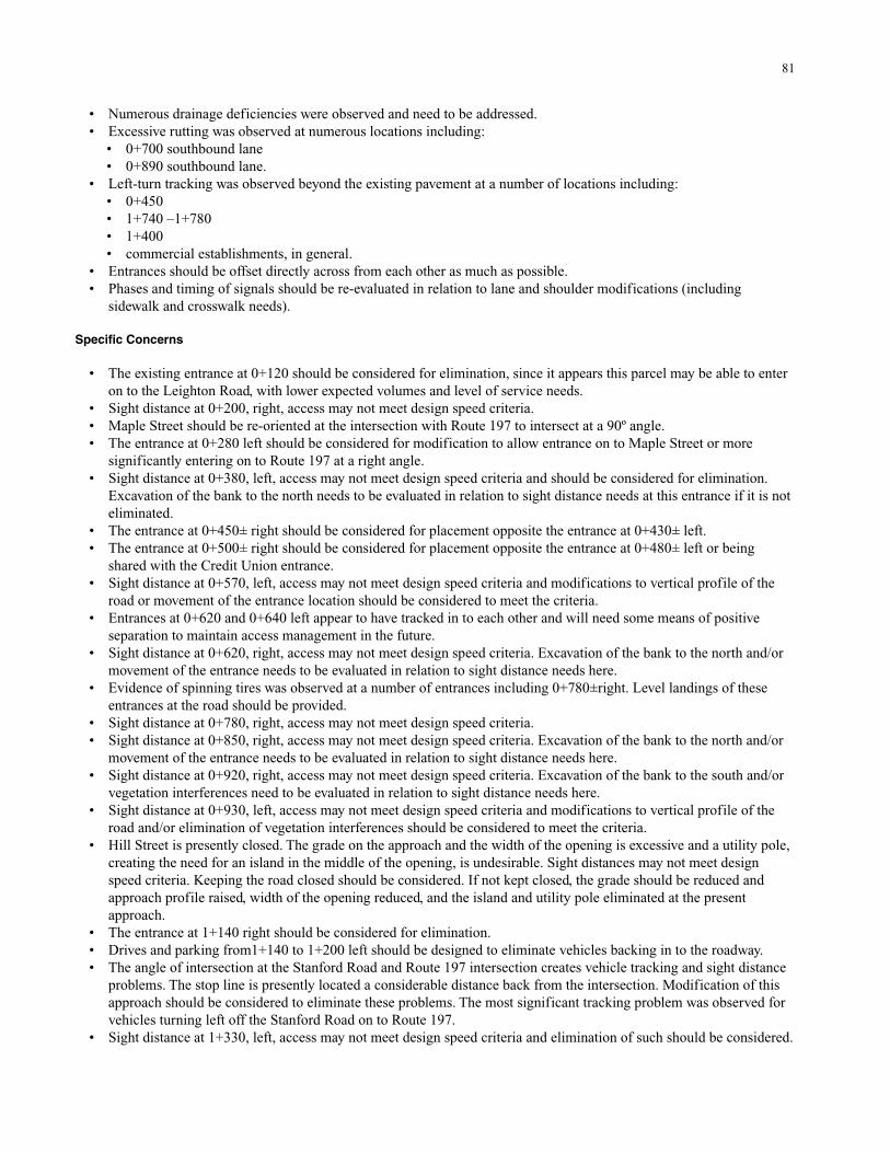
81
• Numerous drainage deficiencies were observed and need to be addressed. •
• •
• • • • •
• •
•
• • •
•
• •
•
•
•
•
• •
•
•
•
• • •
•
Excessive rutting was observed at numerous locations including: 0+700 southbound lane 0+890 southbound lane.
Left-turn tracking was observed beyond the existing pavement at a number of locations including: 0+450 1+740 –1+780 1+400 commercial establishments, in general.
Entrances should be offset directly across from each other as much as possible. Phases and timing of signals should be re-evaluated in relation to lane and shoulder modifications (including sidewalk and crosswalk needs).
Specific Concerns
The existing entrance at 0+120 should be considered for elimination, since it appears this parcel may be able to enter on to the Leighton Road, with lower expected volumes and level of service needs. Sight distance at 0+200, right, access may not meet design speed criteria. Maple Street should be re-oriented at the intersection with Route 197 to intersect at a 90º angle. The entrance at 0+280 left should be considered for modification to allow entrance on to Maple Street or more significantly entering on to Route 197 at a right angle. Sight distance at 0+380, left, access may not meet design speed criteria and should be considered for elimination. Excavation of the bank to the north needs to be evaluated in relation to sight distance needs at this entrance if it is not eliminated. The entrance at 0+450± right should be considered for placement opposite the entrance at 0+430± left. The entrance at 0+500± right should be considered for placement opposite the entrance at 0+480± left or being shared with the Credit Union entrance. Sight distance at 0+570, left, access may not meet design speed criteria and modifications to vertical profile of the road or movement of the entrance location should be considered to meet the criteria. Entrances at 0+620 and 0+640 left appear to have tracked in to each other and will need some means of positive separation to maintain access management in the future. Sight distance at 0+620, right, access may not meet design speed criteria. Excavation of the bank to the north and/or movement of the entrance needs to be evaluated in relation to sight distance needs here. Evidence of spinning tires was observed at a number of entrances including 0+780±right. Level landings of these entrances at the road should be provided. Sight distance at 0+780, right, access may not meet design speed criteria. Sight distance at 0+850, right, access may not meet design speed criteria. Excavation of the bank to the north and/or movement of the entrance needs to be evaluated in relation to sight distance needs here. Sight distance at 0+920, right, access may not meet design speed criteria. Excavation of the bank to the south and/or vegetation interferences need to be evaluated in relation to sight distance needs here. Sight distance at 0+930, left, access may not meet design speed criteria and modifications to vertical profile of the road and/or elimination of vegetation interferences should be considered to meet the criteria. Hill Street is presently closed. The grade on the approach and the width of the opening is excessive and a utility pole, creating the need for an island in the middle of the opening, is undesirable. Sight distances may not meet design speed criteria. Keeping the road closed should be considered. If not kept closed, the grade should be reduced and approach profile raised, width of the opening reduced, and the island and utility pole eliminated at the present approach. The entrance at 1+140 right should be considered for elimination. Drives and parking from1+140 to 1+200 left should be designed to eliminate vehicles backing in to the roadway. The angle of intersection at the Stanford Road and Route 197 intersection creates vehicle tracking and sight distance problems. The stop line is presently located a considerable distance back from the intersection. Modification of this approach should be considered to eliminate these problems. The most significant tracking problem was observed for vehicles turning left off the Stanford Road on to Route 197. Sight distance at 1+330, left, access may not meet design speed criteria and elimination of such should be considered.
82
•
•
•
Sight distance at 1+360, left, access may not meet design speed criteria. Excavation of the bank to the north and/or movement of the entrance needs to be evaluated in relation to sight distance needs here. A level landing of the entrance should be provided at the road. Parking needs at 1+410 right exceeded parking available off the road. Three cars were parked along the shoulder of the road when we passed by. This will create traffic flow problems along the project if parking is allowed along the shoulders. Entrance at 1+610 right allows for vehicles to enter road at excessive speeds. This should be configured to constrict their entrance to be more perpendicular to the road.
Conclusions In our judgment, consideration of the findings should improve the overall safety of the Route 197 corridor in Stanford. We also suggest that a subsequent road safety audit take place after the preliminary plans have been completed. Signed by: Division 1 Traffic Engineer Division 2 Traffic Engineer Assistant Project Manager Transportation Analysis FHWA Urban and Arterial Designer
83
APPENDIX D Audit Checklists
FHWA Study Tour for ROAD SAFETY AUDITS
Part 2
October 1997
Prepared by the Scanning Team:
Michael Trentacoste FHWA Team Leader
Patti Boekamp . . . . . . . . . . . . . . Leanna Depue City of San Diego . . . . . . . . . . . . . . Central Missouri State University
Martin E. Lipinski . . . . . . . . . . . . . . David Manning University of Memphis . . . . . . . . . . . . . .Wisconsin DOT Greg Schertz . . . . . . . . . . . . . . . . . . . . .James Shanafelt
FHWA, Region 8 . . . . . . . . . . . . . . Washington State DOT Thomas Werner . . . . . . . . . . . . . . Eugene M. Wilson
New York State DOT . . . . . . . . . . . . . . University of Wyoming
and by American Trade Initiatives, Inc.
Prepared for: Federal Highway Administration
U.S. Department of Transportation October 1997
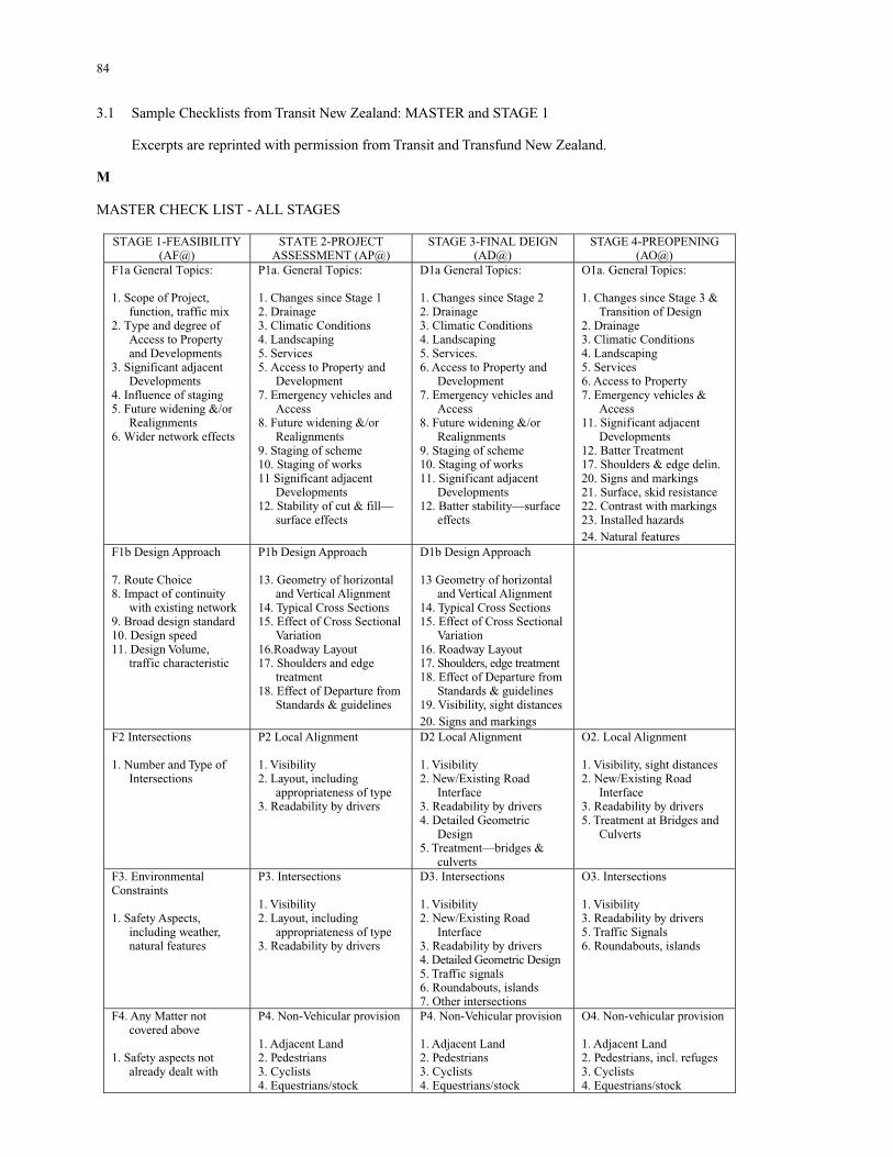
84
3.1 Sample Checklists from Transit New Zealand: MASTER and STAGE 1 Excerpts are reprinted with permission from Transit and Transfund New Zealand. M MASTER CHECK LIST - ALL STAGES
STAGE 1-FEASIBILITY (AF@)
STATE 2-PROJECT ASSESSMENT (AP@)
STAGE 3-FINAL DEIGN (AD@)
STAGE 4-PREOPENING (AO@)
F1a General Topics: 1. Scope of Project,
function, traffic mix 2. Type and degree of
Access to Property and Developments
3. Significant adjacent Developments
4. Influence of staging 5. Future widening &/or
Realignments 6. Wider network effects
P1a. General Topics: 1. Changes since Stage 1 2. Drainage 3. Climatic Conditions 4. Landscaping 5. Services 5. Access to Property and
Development 7. Emergency vehicles and
Access 8. Future widening &/or
Realignments 9. Staging of scheme 10. Staging of works 11 Significant adjacent
Developments 12. Stability of cut & fill—
surface effects
D1a General Topics: 1. Changes since Stage 2 2. Drainage 3. Climatic Conditions 4. Landscaping 5. Services. 6. Access to Property and
Development 7. Emergency vehicles and
Access 8. Future widening &/or
Realignments 9. Staging of scheme 10. Staging of works 11. Significant adjacent
Developments 12. Batter stability—surface
effects
O1a. General Topics: 1. Changes since Stage 3 &
Transition of Design 2. Drainage 3. Climatic Conditions 4. Landscaping 5. Services 6. Access to Property 7. Emergency vehicles &
Access 11. Significant adjacent
Developments 12. Batter Treatment 17. Shoulders & edge delin. 20. Signs and markings 21. Surface, skid resistance 22. Contrast with markings 23. Installed hazards 24. Natural features
F1b Design Approach 7. Route Choice 8. Impact of continuity
with existing network 9. Broad design standard 10. Design speed 11. Design Volume,
traffic characteristic
P1b Design Approach 13. Geometry of horizontal
and Vertical Alignment 14. Typical Cross Sections 15. Effect of Cross Sectional
Variation 16.Roadway Layout 17. Shoulders and edge
treatment 18. Effect of Departure from
Standards & guidelines
D1b Design Approach 13 Geometry of horizontal
and Vertical Alignment 14. Typical Cross Sections 15. Effect of Cross Sectional
Variation 16. Roadway Layout 17. Shoulders, edge treatment 18. Effect of Departure from
Standards & guidelines 19. Visibility, sight distances 20. Signs and markings
F2 Intersections 1. Number and Type of
Intersections
P2 Local Alignment 1. Visibility 2. Layout, including
appropriateness of type 3. Readability by drivers
D2 Local Alignment 1. Visibility 2. New/Existing Road
Interface 3. Readability by drivers 4. Detailed Geometric
Design 5. Treatment—bridges &
culverts
O2. Local Alignment 1. Visibility, sight distances 2. New/Existing Road
Interface 3. Readability by drivers 5. Treatment at Bridges and
Culverts
F3. Environmental Constraints 1. Safety Aspects,
including weather, natural features
P3. Intersections 1. Visibility 2. Layout, including
appropriateness of type 3. Readability by drivers
D3. Intersections 1. Visibility 2. New/Existing Road
Interface 3. Readability by drivers 4. Detailed Geometric Design 5. Traffic signals 6. Roundabouts, islands 7. Other intersections
O3. Intersections 1. Visibility 3. Readability by drivers 5. Traffic Signals 6. Roundabouts, islands
F4. Any Matter not covered above
1. Safety aspects not
already dealt with
P4. Non-Vehicular provision 1. Adjacent Land 2. Pedestrians 3. Cyclists 4. Equestrians/stock
P4. Non-Vehicular provision 1. Adjacent Land 2. Pedestrians 3. Cyclists 4. Equestrians/stock
O4. Non-vehicular provision 1. Adjacent Land 2. Pedestrians, incl. refuges 3. Cyclists 4. Equestrians/stock
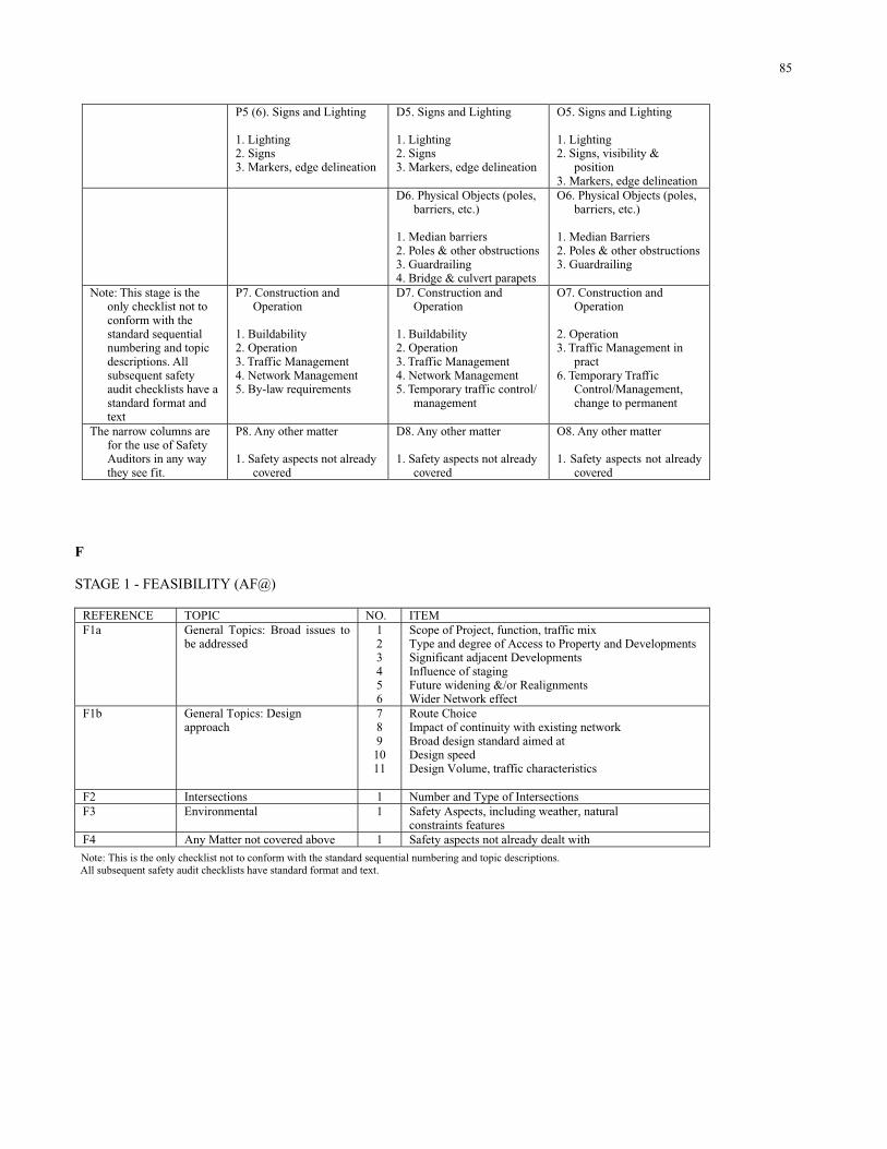
85
P5 (6). Signs and Lighting 1. Lighting 2. Signs 3. Markers, edge delineation
D5. Signs and Lighting 1. Lighting 2. Signs 3. Markers, edge delineation
O5. Signs and Lighting 1. Lighting 2. Signs, visibility &
position 3. Markers, edge delineation
D6. Physical Objects (poles, barriers, etc.)
1. Median barriers 2. Poles & other obstructions 3. Guardrailing 4. Bridge & culvert parapets
O6. Physical Objects (poles, barriers, etc.)
1. Median Barriers 2. Poles & other obstructions 3. Guardrailing
Note: This stage is the only checklist not to conform with the standard sequential numbering and topic descriptions. All subsequent safety audit checklists have a standard format and text
P7. Construction and Operation
1. Buildability 2. Operation 3. Traffic Management 4. Network Management 5. By-law requirements
D7. Construction and Operation
1. Buildability 2. Operation 3. Traffic Management 4. Network Management 5. Temporary traffic control/
management
O7. Construction and Operation
2. Operation 3. Traffic Management in
pract 6. Temporary Traffic
Control/Management, change to permanent
The narrow columns are for the use of Safety Auditors in any way they see fit.
P8. Any other matter 1. Safety aspects not already
covered
D8. Any other matter 1. Safety aspects not already
covered
O8. Any other matter 1. Safety aspects not already
covered F STAGE 1 - FEASIBILITY (AF@)
REFERENCE TOPIC NO. ITEM F1a General Topics: Broad issues to
be addressed
1 2 3 4 5 6
Scope of Project, function, traffic mix Type and degree of Access to Property and Developments Significant adjacent Developments Influence of staging Future widening &/or Realignments Wider Network effect
F1b General Topics: Design approach
7 8 9 10 11
Route Choice Impact of continuity with existing network Broad design standard aimed at Design speed Design Volume, traffic characteristics
F2 Intersections 1 Number and Type of Intersections F3 Environmental 1 Safety Aspects, including weather, natural
constraints features F4 Any Matter not covered above 1 Safety aspects not already dealt with
Note: This is the only checklist not to conform with the standard sequential numbering and topic descriptions. All subsequent safety audit checklists have standard format and text.
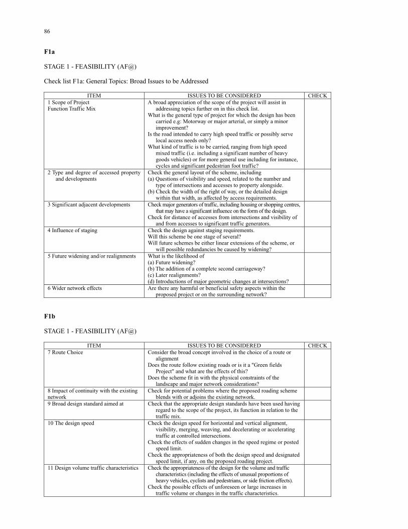
86
F1a STAGE 1 - FEASIBILITY (AF@) Check list F1a: General Topics: Broad Issues to be Addressed
ITEM ISSUES TO BE CONSIDERED CHECK 1 Scope of Project Function Traffic Mix
A broad appreciation of the scope of the project will assist in addressing topics further on in this check list.
What is the general type of project for which the design has been carried e.g: Motorway or major arterial, or simply a minor improvement?
Is the road intended to carry high speed traffic or possibly serve local access needs only?
What kind of traffic is to be carried, ranging from high speed mixed traffic (i.e. including a significant number of heavy goods vehicles) or for more general use including for instance, cycles and significant pedestrian foot traffic?
2 Type and degree of accessed property and developments
Check the general layout of the scheme, including (a) Questions of visibility and speed, related to the number and
type of intersections and accesses to property alongside. (b) Check the width of the right of way, or the detailed design
within that width, as affected by access requirements.
3 Significant adjacent developments
Check major generators of traffic, including housing or shopping centres, that may have a significant influence on the form of the design.
Check for distance of accesses from intersections and visibility of and from accesses to significant traffic generators.
4 Influence of staging Check the design against staging requirements. Will this scheme be one stage of several? Will future schemes be either linear extensions of the scheme, or
will possible redundancies be caused by widening?
5 Future widening and/or realignments What is the likelihood of (a) Future widening? (b) The addition of a complete second carriageway? (c) Later realignments? (d) Introductions of major geometric changes at intersections?
6 Wider network effects Are there any harmful or beneficial safety aspects within the proposed project or on the surrounding network?
F1b STAGE 1 - FEASIBILITY (AF@)
ITEM ISSUES TO BE CONSIDERED CHECK 7 Route Choice Consider the broad concept involved in the choice of a route or
alignment Does the route follow existing roads or is it a "Green fields
Project" and what are the effects of this? Does the scheme fit in with the physical constraints of the
landscape and major network considerations?
8 Impact of continuity with the existing network
Check for potential problems where the proposed roading scheme blends with or adjoins the existing network.
9 Broad design standard aimed at Check that the appropriate design standards have been used having regard to the scope of the project, its function in relation to the traffic mix.
10 The design speed Check the design speed for horizontal and vertical alignment, visibility, merging, weaving, and decelerating or accelerating traffic at controlled intersections.
Check the effects of sudden changes in the speed regime or posted speed limit.
Check the appropriateness of both the design speed and designated speed limit, if any, on the proposed roading project.
11 Design volume traffic characteristics Check the appropriateness of the design for the volume and traffic characteristics (including the effects of unusual proportions of heavy vehicles, cyclists and pedestrians, or side friction effects).
Check the possible effects of unforeseen or large increases in traffic volume or changes in the traffic characteristics.
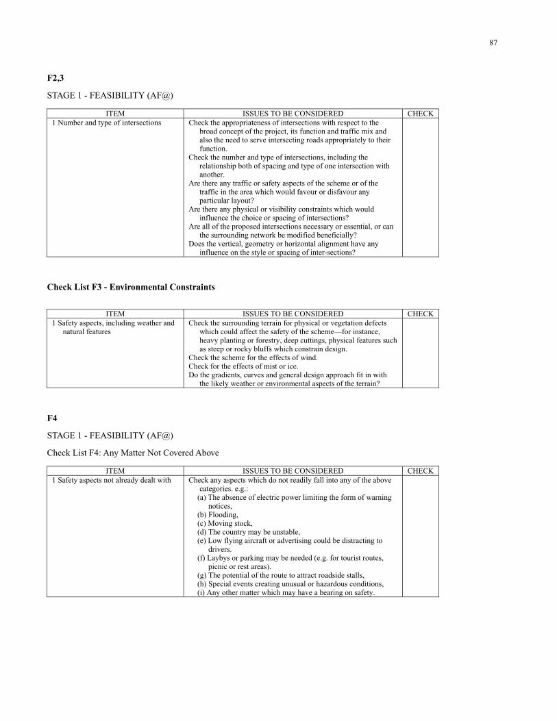
87
F2,3 STAGE 1 - FEASIBILITY (AF@)
ITEM ISSUES TO BE CONSIDERED CHECK 1 Number and type of intersections Check the appropriateness of intersections with respect to the
broad concept of the project, its function and traffic mix and also the need to serve intersecting roads appropriately to their function.
Check the number and type of intersections, including the relationship both of spacing and type of one intersection with another.
Are there any traffic or safety aspects of the scheme or of the traffic in the area which would favour or disfavour any particular layout?
Are there any physical or visibility constraints which would influence the choice or spacing of intersections?
Are all of the proposed intersections necessary or essential, or can the surrounding network be modified beneficially?
Does the vertical, geometry or horizontal alignment have any influence on the style or spacing of inter-sections?
Check List F3 - Environmental Constraints
ITEM ISSUES TO BE CONSIDERED CHECK 1 Safety aspects, including weather and
natural features
Check the surrounding terrain for physical or vegetation defects which could affect the safety of the scheme—for instance, heavy planting or forestry, deep cuttings, physical features such as steep or rocky bluffs which constrain design.
Check the scheme for the effects of wind. Check for the effects of mist or ice. Do the gradients, curves and general design approach fit in with
the likely weather or environmental aspects of the terrain?
F4 STAGE 1 - FEASIBILITY (AF@) Check List F4: Any Matter Not Covered Above
ITEM ISSUES TO BE CONSIDERED CHECK 1 Safety aspects not already dealt with
Check any aspects which do not readily fall into any of the above categories. e.g.:
(a) The absence of electric power limiting the form of warning notices,
(b) Flooding, (c) Moving stock, (d) The country may be unstable, (e) Low flying aircraft or advertising could be distracting to
drivers. (f) Laybys or parking may be needed (e.g. for tourist routes,
picnic or rest areas). (g) The potential of the route to attract roadside stalls, (h) Special events creating unusual or hazardous conditions, (i) Any other matter which may have a bearing on safety.
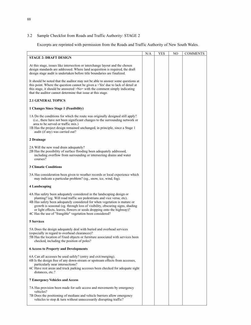
88
3.2 Sample Checklist from Roads and Traffic Authority: STAGE 2 Excerpts are reprinted with permission from the Roads and Traffic Authority of New South Wales.
N/A YES NO COMMENTS STAGE 2: DRAFT DESIGN At this stage, issues like intersection or interchange layout and the chosen design standards are addressed. Where land acquisition is required, the draft design stage audit is undertaken before title boundaries are finalized. It should be noted that the auditor may not be able to answer some questions at this point. Where the question cannot be given a >Yes' due to lack of detail at this stage, it should be answered >No= with the comment simply indicating that the auditor cannot determine that issue at this stage. 2.1 GENERAL TOPICS 1 Changes Since Stage 1 (Feasibility) 1A Do the conditions for which the route was originally designed still apply?
(i.e., there have not been significant changes to the surrounding network or area to be served or traffic mix.)
1B Has the project design remained unchanged, in principle, since a Stage 1 audit (if any) was carried out?
2 Drainage 2A Will the new road drain adequately? 2B Has the possibility of surface flooding been adequately addressed,
including overflow from surrounding or intersecting drains and water courses?
3 Climatic Conditions 3A Has consideration been given to weather records or local experience which
may indicate a particular problem? (eg., snow, ice, wind, fog). 4 Landscaping 4A Has safety been adequately considered in the landscaping design or
planting? (eg. Will road traffic see pedestrians and vice versa; etc). 4B Has safety been adequately considered for when vegetation is mature or
growth is seasonal (eg. through loss of visibility, obscuring signs, shading or light effects, leaves, flowers or seeds dropping onto the highway)?
4C Has the use of "frangible" vegetation been considered? 5 Services 5A Does the design adequately deal with buried and overhead services (especially in regard to overhead clearances)? 5B Has the location of fixed objects or furniture associated with services been
checked, including the position of poles? 6 Access to Property and Developments 6A Can all accesses be used safely? (entry and exit/merging). 6B Is the design free of any down-stream or upstream effects from accesses,
particularly near intersections? 6C Have rest areas and truck parking accesses been checked for adequate sight
distances, etc.? 7 Emergency Vehicles and Access 7A Has provision been made for safe access and movements by emergency
vehicles? 7B Does the positioning of medians and vehicle barriers allow emergency
vehicles to stop & turn without unnecessarily disrupting traffic?
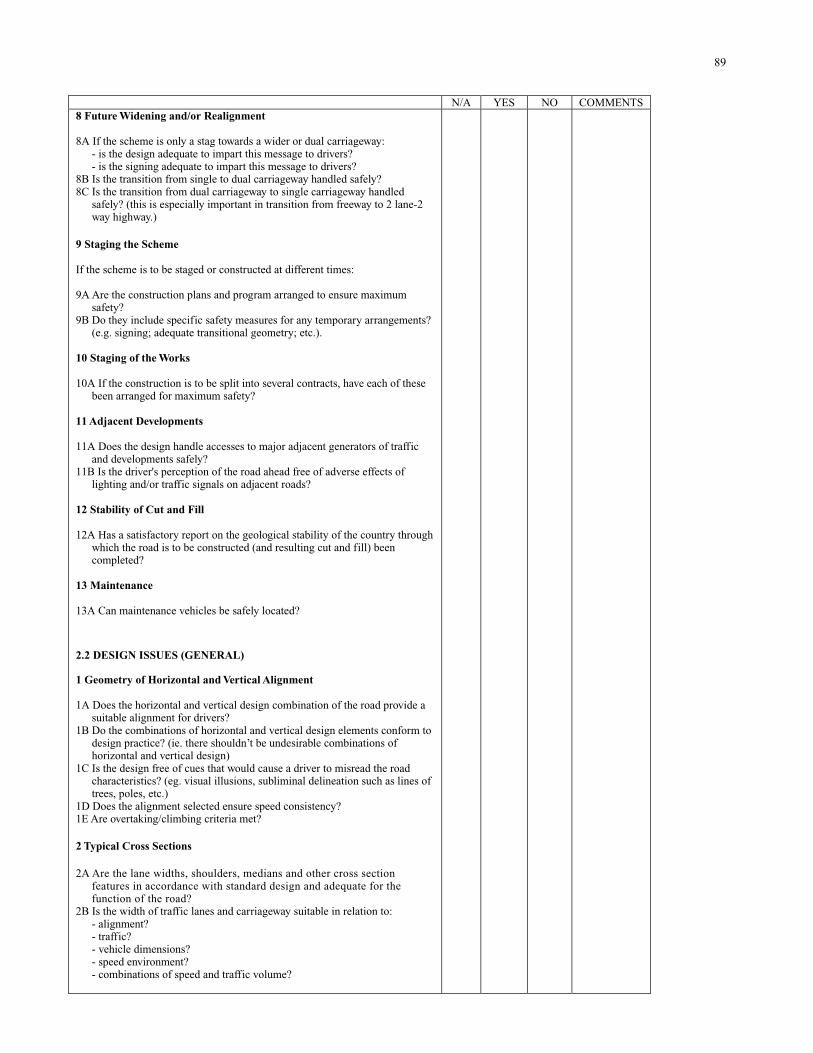
89
N/A YES NO COMMENTS 8 Future Widening and/or Realignment 8A If the scheme is only a stag towards a wider or dual carriageway:
- is the design adequate to impart this message to drivers? - is the signing adequate to impart this message to drivers?
8B Is the transition from single to dual carriageway handled safely? 8C Is the transition from dual carriageway to single carriageway handled
safely? (this is especially important in transition from freeway to 2 lane-2 way highway.)
9 Staging the Scheme If the scheme is to be staged or constructed at different times: 9A Are the construction plans and program arranged to ensure maximum
safety? 9B Do they include specific safety measures for any temporary arrangements?
(e.g. signing; adequate transitional geometry; etc.). 10 Staging of the Works 10A If the construction is to be split into several contracts, have each of these
been arranged for maximum safety? 11 Adjacent Developments 11A Does the design handle accesses to major adjacent generators of traffic
and developments safely? 11B Is the driver's perception of the road ahead free of adverse effects of
lighting and/or traffic signals on adjacent roads? 12 Stability of Cut and Fill 12A Has a satisfactory report on the geological stability of the country through
which the road is to be constructed (and resulting cut and fill) been completed?
13 Maintenance 13A Can maintenance vehicles be safely located?
2.2 DESIGN ISSUES (GENERAL) 1 Geometry of Horizontal and Vertical Alignment 1A Does the horizontal and vertical design combination of the road provide a
suitable alignment for drivers? 1B Do the combinations of horizontal and vertical design elements conform to
design practice? (ie. there shouldn’t be undesirable combinations of horizontal and vertical design)
1C Is the design free of cues that would cause a driver to misread the road characteristics? (eg. visual illusions, subliminal delineation such as lines of trees, poles, etc.)
1D Does the alignment selected ensure speed consistency? 1E Are overtaking/climbing criteria met? 2 Typical Cross Sections 2A Are the lane widths, shoulders, medians and other cross section
features in accordance with standard design and adequate for the function of the road?
2B Is the width of traffic lanes and carriageway suitable in relation to: - alignment? - traffic? - vehicle dimensions? - speed environment? - combinations of speed and traffic volume?
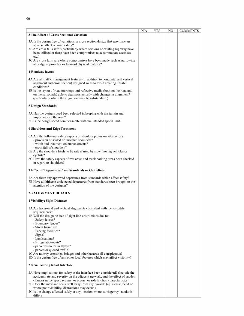
90
N/A YES NO COMMENTS 3 The Effect of Cross Sectional Variation 3A Is the design free of variations in cross section design that may have an
adverse affect on road safety? 3B Are cross falls safe? (particularly where sections of existing highway have
been utilised or there have been compromises to accommodate accesses, etc.)
3C Are cross falls safe where compromises have been made such as narrowing at bridge approaches or to avoid physical features?
4 Roadway layout 4A Are all traffic management features (in addition to horizontal and vertical
alignment and cross section) designed so as to avoid creating unsafe conditions?
4B Is the layout of road markings and reflective media (both on the road and on the surrounds) able to deal satisfactorily with changes in alignment? (particularly where the alignment may be substandard.)
5 Design Standards 5A Has the design speed been selected in keeping with the terrain and
importance of the road? 5B Is the design speed commensurate with the intended speed limit? 6 Shoulders and Edge Treatment 6A Are the following safety aspects of shoulder provision satisfactory:
- provision of sealed or unsealed shoulders? - width and treatment on embankments? - cross fall of shoulders?
6B Are the shoulders likely to be safe if used by slow moving vehicles or cyclists?
6C Have the safety aspects of rest areas and truck parking areas been checked in regard to shoulders?
7 Effect of Departures from Standards or Guidelines 7A Are there any approved departures from standards which affect safety? 7B Have all hitherto undetected departures from standards been brought to the
attention of the designer? 2.3 ALIGNMENT DETAILS 1 Visibility; Sight Distance 1A Are horizontal and vertical alignments consistent with the visibility
requirements? 1B Will the design be free of sight line obstructions due to:
- Safety fences? - Boundary fences? - Street furniture? - Parking facilities? - Signs? - Landscaping? - Bridge abutments? - parked vehicles in laybys? - parked or queued traffic?
1C Are railway crossings, bridges and other hazards all conspicuous? 1D Is the design free of any other local features which may affect visibility? 2 New/Existing Road Interface 2A Have implications for safety at the interface been considered? (Include the
accident rate and severity on the adjacent network, and the effect of sudden changes in the speed regime, or access, or side friction characteristics.)
2B Does the interface occur well away from any hazard? (eg. a crest, bend or where poor visibility/ distractions may occur.)
2C Is the change affected safely at any location where carriageway standards differ?
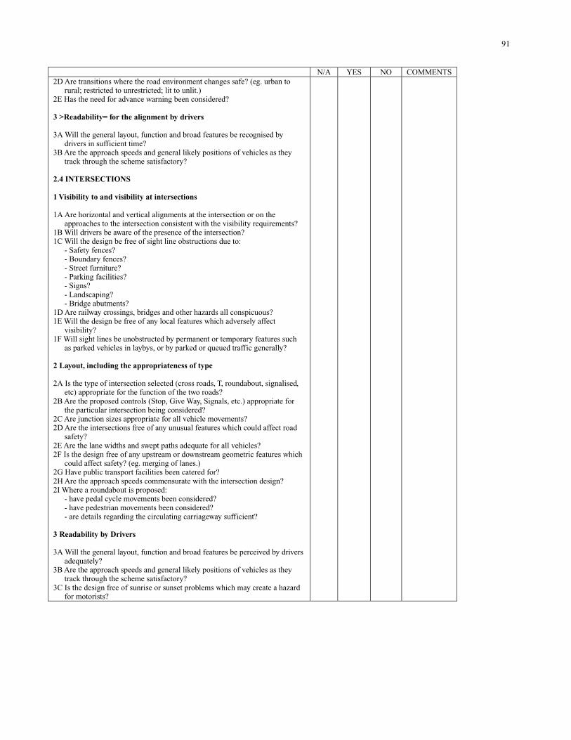
91
N/A YES NO COMMENTS 2D Are transitions where the road environment changes safe? (eg. urban to
rural; restricted to unrestricted; lit to unlit.) 2E Has the need for advance warning been considered? 3 >Readability= for the alignment by drivers 3A Will the general layout, function and broad features be recognised by
drivers in sufficient time? 3B Are the approach speeds and general likely positions of vehicles as they
track through the scheme satisfactory? 2.4 INTERSECTIONS 1 Visibility to and visibility at intersections 1A Are horizontal and vertical alignments at the intersection or on the
approaches to the intersection consistent with the visibility requirements? 1B Will drivers be aware of the presence of the intersection? 1C Will the design be free of sight line obstructions due to:
- Safety fences? - Boundary fences? - Street furniture? - Parking facilities? - Signs? - Landscaping? - Bridge abutments?
1D Are railway crossings, bridges and other hazards all conspicuous? 1E Will the design be free of any local features which adversely affect
visibility? 1F Will sight lines be unobstructed by permanent or temporary features such
as parked vehicles in laybys, or by parked or queued traffic generally? 2 Layout, including the appropriateness of type 2A Is the type of intersection selected (cross roads, T, roundabout, signalised,
etc) appropriate for the function of the two roads? 2B Are the proposed controls (Stop, Give Way, Signals, etc.) appropriate for
the particular intersection being considered? 2C Are junction sizes appropriate for all vehicle movements? 2D Are the intersections free of any unusual features which could affect road
safety? 2E Are the lane widths and swept paths adequate for all vehicles? 2F Is the design free of any upstream or downstream geometric features which
could affect safety? (eg. merging of lanes.) 2G Have public transport facilities been catered for? 2H Are the approach speeds commensurate with the intersection design? 2I Where a roundabout is proposed:
- have pedal cycle movements been considered? - have pedestrian movements been considered? - are details regarding the circulating carriageway sufficient?
3 Readability by Drivers 3A Will the general layout, function and broad features be perceived by drivers
adequately? 3B Are the approach speeds and general likely positions of vehicles as they
track through the scheme satisfactory? 3C Is the design free of sunrise or sunset problems which may create a hazard
for motorists?
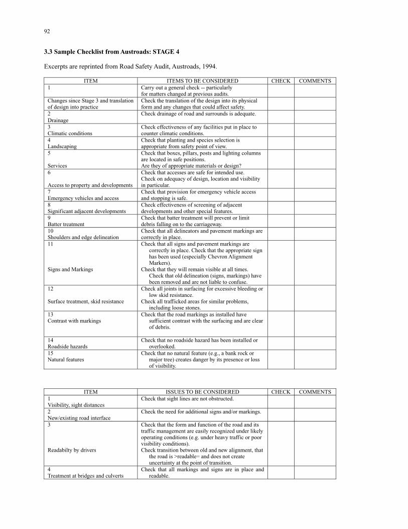
92
3.3 Sample Checklist from Austroads: STAGE 4 Excerpts are reprinted from Road Safety Audit, Austroads, 1994.
ITEM ITEMS TO BE CONSIDERED CHECK COMMENTS 1 Carry out a general check -- particularly
for matters changed at previous audits.
Changes since Stage 3 and translation of design into practice
Check the translation of the design into its physical form and any changes that could affect safety.
2 Drainage
Check drainage of road and surrounds is adequate.
3 Climatic conditions
Check effectiveness of any facilities put in place to counter climatic conditions.
4 Landscaping
Check that planting and species selection is appropriate from safety point of view.
5 Services
Check that boxes, pillars, posts and lighting columns are located in safe positions. Are they of appropriate materials or design?
6 Access to property and developments
Check that accesses are safe for intended use. Check on adequacy of design, location and visibility in particular.
7 Emergency vehicles and access
Check that provision for emergency vehicle access and stopping is safe.
8 Significant adjacent developments
Check effectiveness of screening of adjacent developments and other special features.
9 Batter treatment
Check that batter treatment will prevent or limit debris falling on to the carriageway.
10 Shoulders and edge delineation
Check that all delineators and pavement markings are correctly in place.
11 Signs and Markings
Check that all signs and pavement markings are correctly in place. Check that the appropriate sign has been used (especially Chevron Alignment Markers).
Check that they will remain visible at all times. Check that old delineation (signs, markings) have been removed and are not liable to confuse.
12 Surface treatment, skid resistance
Check all joints in surfacing for excessive bleeding or low skid resistance.
Check all trafficked areas for similar problems, including loose stones.
13 Contrast with markings
Check that the road markings as installed have sufficient contrast with the surfacing and are clear of debris.
14 Roadside hazards
Check that no roadside hazard has been installed or overlooked.
15 Natural features
Check that no natural feature (e.g., a bank rock or major tree) creates danger by its presence or loss of visibility.
ITEM ISSUES TO BE CONSIDERED CHECK COMMENTS 1 Visibility, sight distances
Check that sight lines are not obstructed.
2 New/existing road interface
Check the need for additional signs and/or markings.
3 Readabilty by drivers
Check that the form and function of the road and its traffic management are easily recognized under likely operating conditions (e.g. under heavy traffic or poor visibility conditions). Check transition between old and new alignment, that
the road is >readable= and does not create uncertainty at the point of transition.
4 Treatment at bridges and culverts
Check that all markings and signs are in place and readable.
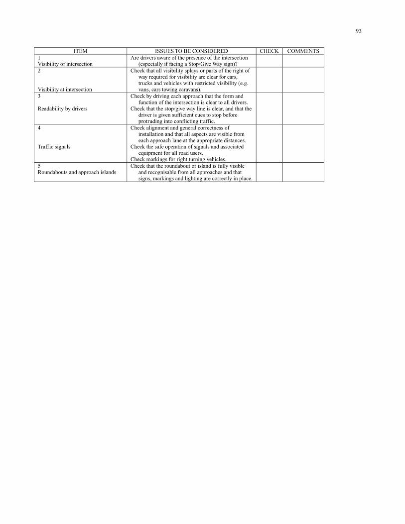
93
ITEM ISSUES TO BE CONSIDERED CHECK COMMENTS 1 Visibility of intersection
Are drivers aware of the presence of the intersection (especially if facing a Stop/Give Way sign)?
2 Visibility at intersection
Check that all visibility splays or parts of the right of way required for visibility are clear for cars, trucks and vehicles with restricted visibility (e.g. vans, cars towing caravans).
3 Readability by drivers
Check by driving each approach that the form and function of the intersection is clear to all drivers.
Check that the stop/give way line is clear, and that the driver is given sufficient cues to stop before protruding into conflicting traffic.
4 Traffic signals
Check alignment and general correctness of installation and that all aspects are visible from each approach lane at the appropriate distances.
Check the safe operation of signals and associated equipment for all road users.
Check markings for right turning vehicles.
5 Roundabouts and approach islands
Check that the roundabout or island is fully visible and recognisable from all approaches and that signs, markings and lighting are correctly in place.
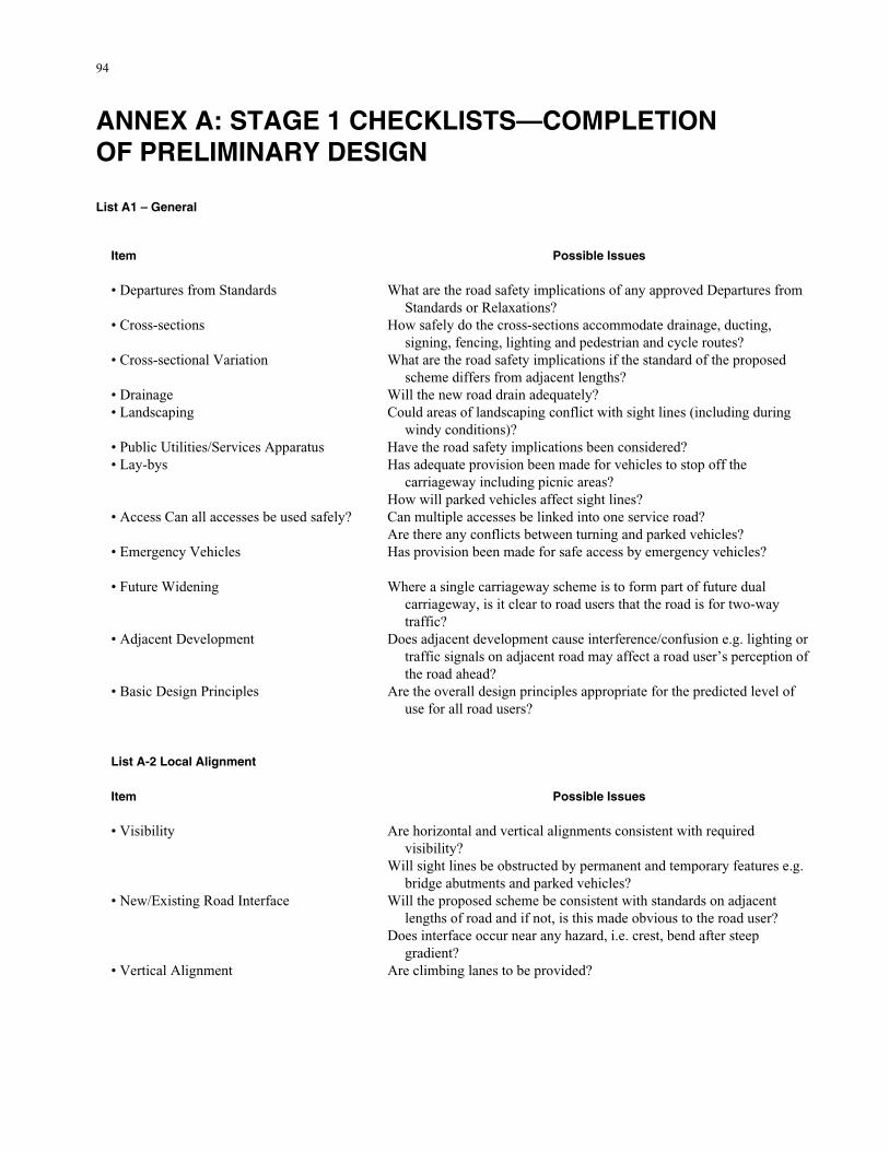
94
ANNEX A: STAGE 1 CHECKLISTS—COMPLETION OF PRELIMINARY DESIGN List A1 – General
Item Possible Issues • Departures from Standards
What are the road safety implications of any approved Departures from Standards or Relaxations?
• Cross-sections
How safely do the cross-sections accommodate drainage, ducting, signing, fencing, lighting and pedestrian and cycle routes?
• Cross-sectional Variation
What are the road safety implications if the standard of the proposed scheme differs from adjacent lengths?
• Drainage Will the new road drain adequately? • Landscaping
Could areas of landscaping conflict with sight lines (including during windy conditions)?
• Public Utilities/Services Apparatus Have the road safety implications been considered? • Lay-bys
Has adequate provision been made for vehicles to stop off the carriageway including picnic areas?
How will parked vehicles affect sight lines? • Access Can all accesses be used safely? Can multiple accesses be linked into one service road?
Are there any conflicts between turning and parked vehicles? • Emergency Vehicles Has provision been made for safe access by emergency vehicles?
• Future Widening Where a single carriageway scheme is to form part of future dual
carriageway, is it clear to road users that the road is for two-way traffic?
• Adjacent Development Does adjacent development cause interference/confusion e.g. lighting or traffic signals on adjacent road may affect a road user’s perception of the road ahead?
• Basic Design Principles Are the overall design principles appropriate for the predicted level of use for all road users?
List A-2 Local Alignment Item Possible Issues • Visibility Are horizontal and vertical alignments consistent with required
visibility? Will sight lines be obstructed by permanent and temporary features e.g.
bridge abutments and parked vehicles? • New/Existing Road Interface Will the proposed scheme be consistent with standards on adjacent
lengths of road and if not, is this made obvious to the road user? Does interface occur near any hazard, i.e. crest, bend after steep
gradient? • Vertical Alignment Are climbing lanes to be provided?
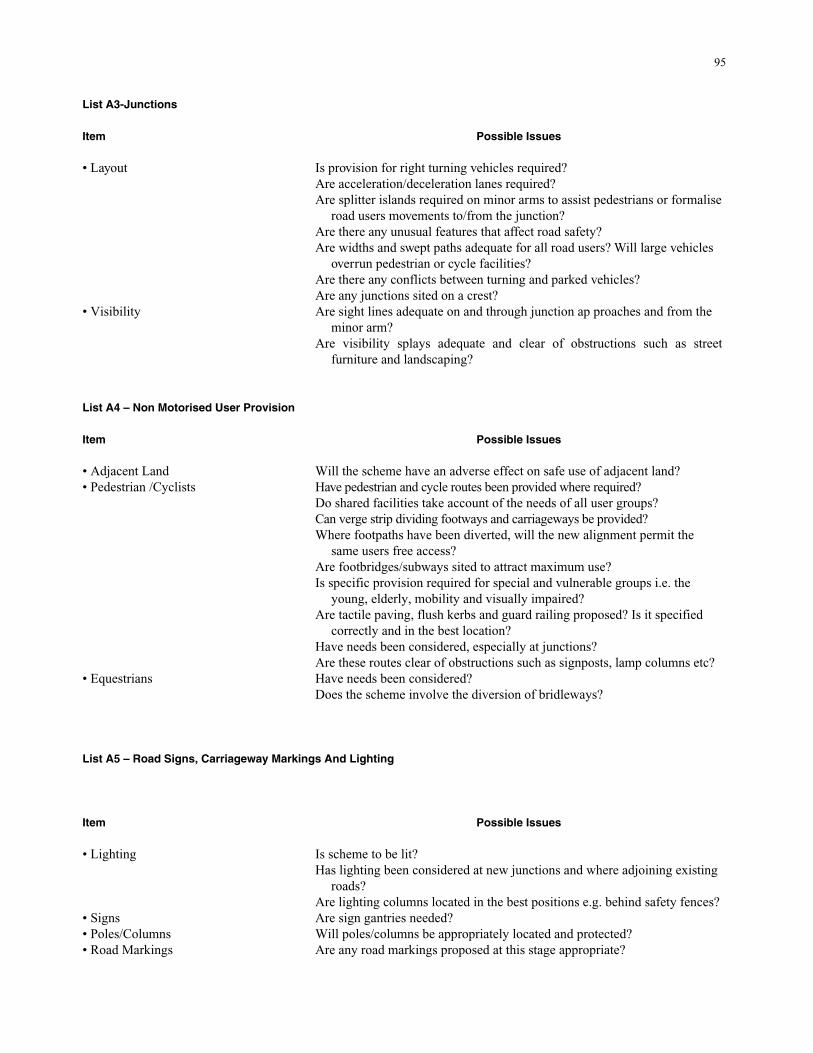
95
List A3-Junctions
Item Possible Issues • Layout Is provision for right turning vehicles required?
Are acceleration/deceleration lanes required? Are splitter islands required on minor arms to assist pedestrians or formalise
road users movements to/from the junction? Are there any unusual features that affect road safety? Are widths and swept paths adequate for all road users? Will large vehicles
overrun pedestrian or cycle facilities? Are there any conflicts between turning and parked vehicles? Are any junctions sited on a crest?
• Visibility Are sight lines adequate on and through junction ap proaches and from the minor arm?
Are visibility splays adequate and clear of obstructions such as street furniture and landscaping?
List A4 – Non Motorised User Provision
Item Possible Issues • Adjacent Land Will the scheme have an adverse effect on safe use of adjacent land?
• Pedestrian /Cyclists Have pedestrian and cycle routes been provided where required? Do shared facilities take account of the needs of all user groups? Can verge strip dividing footways and carriageways be provided? Where footpaths have been diverted, will the new alignment permit the
same users free access? Are footbridges/subways sited to attract maximum use? Is specific provision required for special and vulnerable groups i.e. the
young, elderly, mobility and visually impaired? Are tactile paving, flush kerbs and guard railing proposed? Is it specified
correctly and in the best location? Have needs been considered, especially at junctions? Are these routes clear of obstructions such as signposts, lamp columns etc?
• Equestrians Have needs been considered? Does the scheme involve the diversion of bridleways?
List A5 – Road Signs, Carriageway Markings And Lighting
Item Possible Issues • Lighting Is scheme to be lit?
Has lighting been considered at new junctions and where adjoining existing roads?
Are lighting columns located in the best positions e.g. behind safety fences?
• Signs Are sign gantries needed?
• Poles/Columns Will poles/columns be appropriately located and protected?
• Road Markings Are any road markings proposed at this stage appropriate?
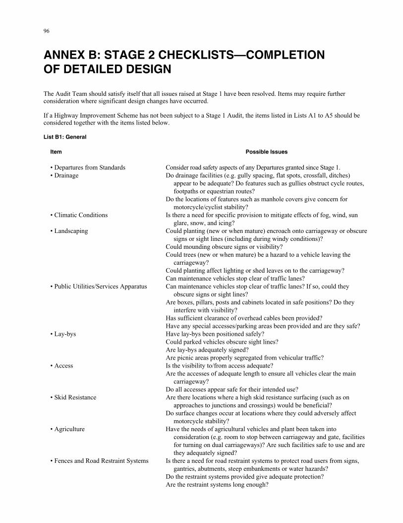
96
ANNEX B: STAGE 2 CHECKLISTS—COMPLETION OF DETAILED DESIGN
The Audit Team should satisfy itself that all issues raised at Stage 1 have been resolved. Items may require further consideration where significant design changes have occurred. If a Highway Improvement Scheme has not been subject to a Stage 1 Audit, the items listed in Lists A1 to A5 should be considered together with the items listed below. List B1: General
Item Possible Issues • Departures from Standards Consider road safety aspects of any Departures granted since Stage 1. • Drainage Do drainage facilities (e.g. gully spacing, flat spots, crossfall, ditches)
appear to be adequate? Do features such as gullies obstruct cycle routes, footpaths or equestrian routes?
Do the locations of features such as manhole covers give concern for motorcycle/cyclist stability?
• Climatic Conditions Is there a need for specific provision to mitigate effects of fog, wind, sun glare, snow, and icing?
• Landscaping Could planting (new or when mature) encroach onto carriageway or obscure signs or sight lines (including during windy conditions)?
Could mounding obscure signs or visibility? Could trees (new or when mature) be a hazard to a vehicle leaving the
carriageway? Could planting affect lighting or shed leaves on to the carriageway? Can maintenance vehicles stop clear of traffic lanes?
• Public Utilities/Services Apparatus Can maintenance vehicles stop clear of traffic lanes? If so, could they obscure signs or sight lines?
Are boxes, pillars, posts and cabinets located in safe positions? Do they interfere with visibility?
Has sufficient clearance of overhead cables been provided? Have any special accesses/parking areas been provided and are they safe?
• Lay-bys Have lay-bys been positioned safely? Could parked vehicles obscure sight lines? Are lay-bys adequately signed? Are picnic areas properly segregated from vehicular traffic?
• Access Is the visibility to/from access adequate? Are the accesses of adequate length to ensure all vehicles clear the main
carriageway? Do all accesses appear safe for their intended use?
• Skid Resistance Are there locations where a high skid resistance surfacing (such as on approaches to junctions and crossings) would be beneficial?
Do surface changes occur at locations where they could adversely affect motorcycle stability?
• Agriculture Have the needs of agricultural vehicles and plant been taken into consideration (e.g. room to stop between carriageway and gate, facilities for turning on dual carriageways)? Are such facilities safe to use and are they adequately signed?
• Fences and Road Restraint Systems Is there a need for road restraint systems to protect road users from signs, gantries, abutments, steep embankments or water hazards?
Do the restraint systems provided give adequate protection? Are the restraint systems long enough?
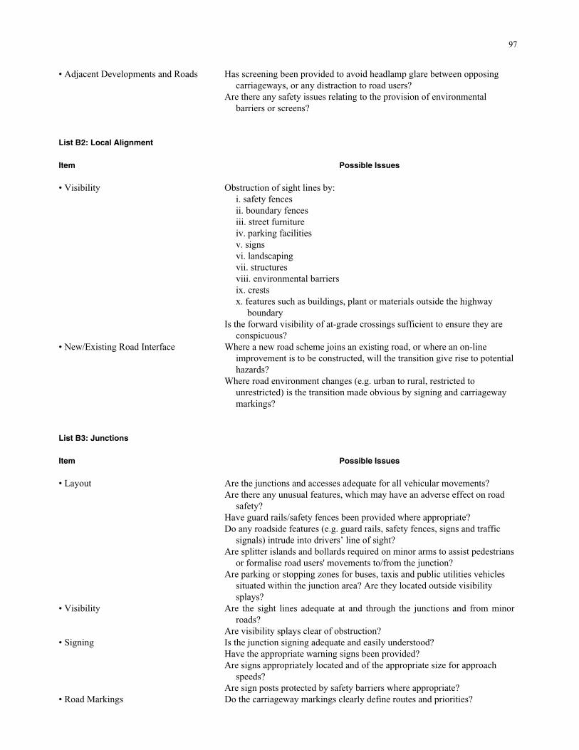
97
• Adjacent Developments and Roads Has screening been provided to avoid headlamp glare between opposing carriageways, or any distraction to road users?
Are there any safety issues relating to the provision of environmental barriers or screens?
List B2: Local Alignment
Item Possible Issues • Visibility Obstruction of sight lines by:
i. safety fences ii. boundary fences iii. street furniture iv. parking facilities v. signs vi. landscaping vii. structures viii. environmental barriers ix. crests x. features such as buildings, plant or materials outside the highway
boundary Is the forward visibility of at-grade crossings sufficient to ensure they are
conspicuous? • New/Existing Road Interface Where a new road scheme joins an existing road, or where an on-line
improvement is to be constructed, will the transition give rise to potential hazards?
Where road environment changes (e.g. urban to rural, restricted to unrestricted) is the transition made obvious by signing and carriageway markings?
List B3: Junctions
Item Possible Issues • Layout Are the junctions and accesses adequate for all vehicular movements?
Are there any unusual features, which may have an adverse effect on road safety?
Have guard rails/safety fences been provided where appropriate? Do any roadside features (e.g. guard rails, safety fences, signs and traffic
signals) intrude into drivers’ line of sight? Are splitter islands and bollards required on minor arms to assist pedestrians
or formalise road users' movements to/from the junction? Are parking or stopping zones for buses, taxis and public utilities vehicles
situated within the junction area? Are they located outside visibility splays?
• Visibility Are the sight lines adequate at and through the junctions and from minor roads?
Are visibility splays clear of obstruction? • Signing Is the junction signing adequate and easily understood?
Have the appropriate warning signs been provided? Are signs appropriately located and of the appropriate size for approach
speeds? Are sign posts protected by safety barriers where appropriate?
• Road Markings Do the carriageway markings clearly define routes and priorities?
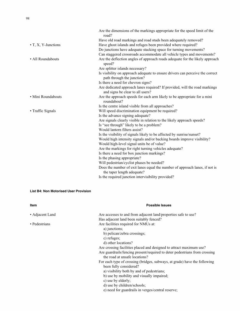
98
Are the dimensions of the markings appropriate for the speed limit of the road?
Have old road markings and road studs been adequately removed? • T, X, Y-Junctions Have ghost islands and refuges been provided where required?
Do junctions have adequate stacking space for turning movements? Can staggered crossroads accommodate all vehicle types and movements?
• All Roundabouts Are the deflection angles of approach roads adequate for the likely approach speed?
Are splitter islands necessary? Is visibility on approach adequate to ensure drivers can perceive the correct
path through the junction? Is there a need for chevron signs? Are dedicated approach lanes required? If provided, will the road markings
and signs be clear to all users? • Mini Roundabouts Are the approach speeds for each arm likely to be appropriate for a mini
roundabout? Is the centre island visible from all approaches?
• Traffic Signals Will speed discrimination equipment be required? Is the advance signing adequate? Are signals clearly visible in relation to the likely approach speeds? Is “see through” likely to be a problem? Would lantern filters assist? Is the visibility of signals likely to be affected by sunrise/sunset? Would high intensity signals and/or backing boards improve visibility? Would high-level signal units be of value? Are the markings for right turning vehicles adequate? Is there a need for box junction markings? Is the phasing appropriate? Will pedestrian/cyclist phases be needed? Does the number of exit lanes equal the number of approach lanes, if not is
the taper length adequate? Is the required junction intervisibility provided?
List B4: Non Motorised User Provision
Item Possible Issues • Adjacent Land Are accesses to and from adjacent land/properties safe to use?
Has adjacent land been suitably fenced? • Pedestrians Are facilities required for NMUs at:
a) junctions; b) pelican/zebra crossings; c) refuges; d) other locations?
Are crossing facilities placed and designed to attract maximum use? Are guardrails/fencing present/required to deter pedestrians from crossing
the road at unsafe locations? For each type of crossing (bridges, subways, at grade) have the following
been fully considered? a) visibility both by and of pedestrians; b) use by mobility and visually impaired; c) use by elderly; d) use by children/schools; e) need for guardrails in verges/central reserve;
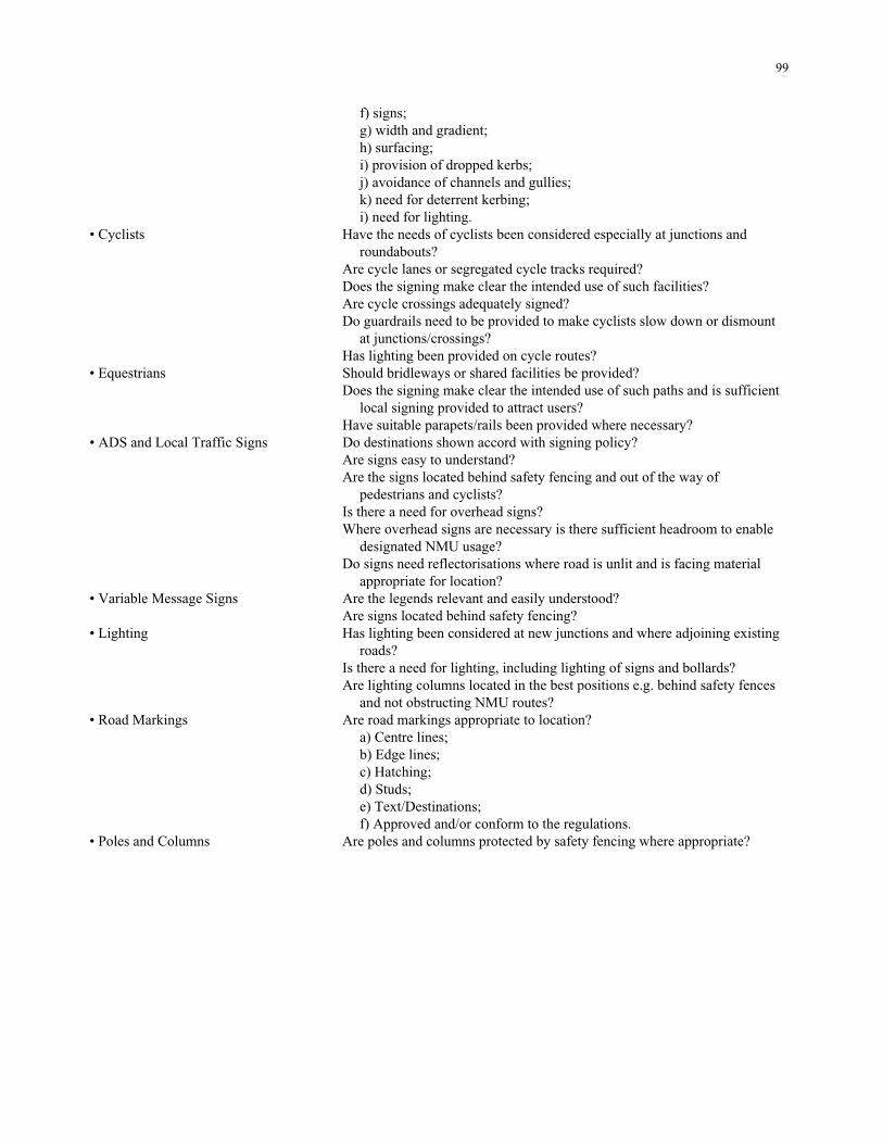
99
f) signs; g) width and gradient; h) surfacing; i) provision of dropped kerbs; j) avoidance of channels and gullies; k) need for deterrent kerbing; i) need for lighting.
• Cyclists Have the needs of cyclists been considered especially at junctions and roundabouts?
Are cycle lanes or segregated cycle tracks required? Does the signing make clear the intended use of such facilities? Are cycle crossings adequately signed? Do guardrails need to be provided to make cyclists slow down or dismount
at junctions/crossings? Has lighting been provided on cycle routes?
• Equestrians Should bridleways or shared facilities be provided? Does the signing make clear the intended use of such paths and is sufficient
local signing provided to attract users? Have suitable parapets/rails been provided where necessary?
• ADS and Local Traffic Signs Do destinations shown accord with signing policy? Are signs easy to understand? Are the signs located behind safety fencing and out of the way of
pedestrians and cyclists? Is there a need for overhead signs? Where overhead signs are necessary is there sufficient headroom to enable
designated NMU usage? Do signs need reflectorisations where road is unlit and is facing material
appropriate for location? • Variable Message Signs Are the legends relevant and easily understood?
Are signs located behind safety fencing? • Lighting Has lighting been considered at new junctions and where adjoining existing
roads? Is there a need for lighting, including lighting of signs and bollards? Are lighting columns located in the best positions e.g. behind safety fences
and not obstructing NMU routes? • Road Markings Are road markings appropriate to location?
a) Centre lines; b) Edge lines; c) Hatching; d) Studs; e) Text/Destinations; f) Approved and/or conform to the regulations.
• Poles and Columns Are poles and columns protected by safety fencing where appropriate?
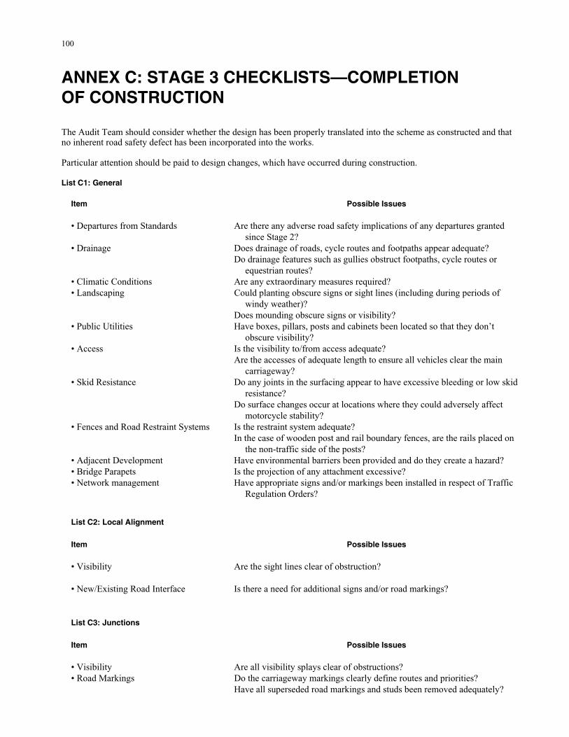
100
ANNEX C: STAGE 3 CHECKLISTS—COMPLETION OF CONSTRUCTION The Audit Team should consider whether the design has been properly translated into the scheme as constructed and that no inherent road safety defect has been incorporated into the works. Particular attention should be paid to design changes, which have occurred during construction. List C1: General
Item Possible Issues • Departures from Standards Are there any adverse road safety implications of any departures granted
since Stage 2? • Drainage Does drainage of roads, cycle routes and footpaths appear adequate?
Do drainage features such as gullies obstruct footpaths, cycle routes or equestrian routes?
• Climatic Conditions Are any extraordinary measures required? • Landscaping Could planting obscure signs or sight lines (including during periods of
windy weather)? Does mounding obscure signs or visibility?
• Public Utilities Have boxes, pillars, posts and cabinets been located so that they don’t obscure visibility?
• Access Is the visibility to/from access adequate? Are the accesses of adequate length to ensure all vehicles clear the main
carriageway? • Skid Resistance Do any joints in the surfacing appear to have excessive bleeding or low skid
resistance? Do surface changes occur at locations where they could adversely affect
motorcycle stability? • Fences and Road Restraint Systems Is the restraint system adequate?
In the case of wooden post and rail boundary fences, are the rails placed on the non-traffic side of the posts?
• Adjacent Development Have environmental barriers been provided and do they create a hazard? • Bridge Parapets Is the projection of any attachment excessive? • Network management Have appropriate signs and/or markings been installed in respect of Traffic
Regulation Orders? List C2: Local Alignment
Item Possible Issues • Visibility Are the sight lines clear of obstruction?
• New/Existing Road Interface Is there a need for additional signs and/or road markings? List C3: Junctions
Item Possible Issues • Visibility Are all visibility splays clear of obstructions? • Road Markings Do the carriageway markings clearly define routes and priorities?
Have all superseded road markings and studs been removed adequately?
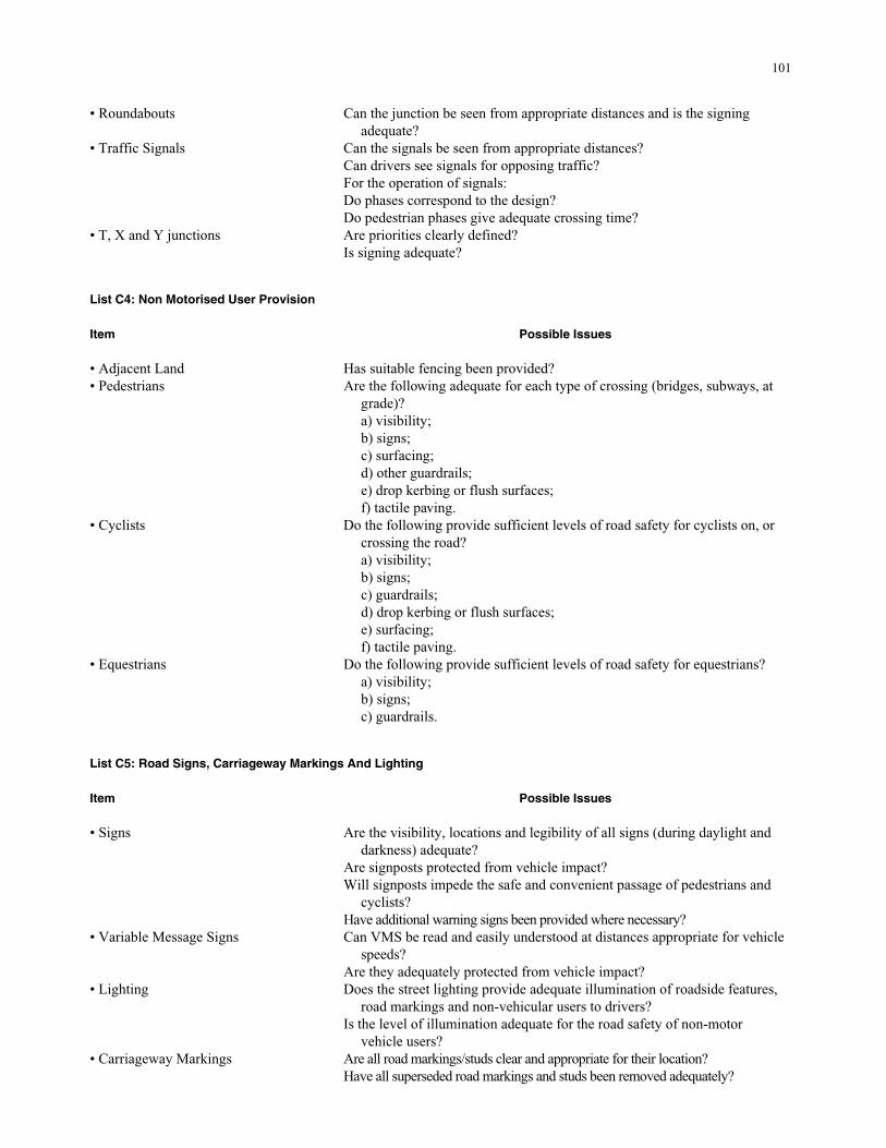
101
• Roundabouts Can the junction be seen from appropriate distances and is the signing adequate?
• Traffic Signals Can the signals be seen from appropriate distances? Can drivers see signals for opposing traffic? For the operation of signals: Do phases correspond to the design? Do pedestrian phases give adequate crossing time?
• T, X and Y junctions Are priorities clearly defined? Is signing adequate?
List C4: Non Motorised User Provision
Item Possible Issues • Adjacent Land Has suitable fencing been provided? • Pedestrians Are the following adequate for each type of crossing (bridges, subways, at
grade)? a) visibility; b) signs; c) surfacing; d) other guardrails; e) drop kerbing or flush surfaces; f) tactile paving.
• Cyclists Do the following provide sufficient levels of road safety for cyclists on, or crossing the road? a) visibility; b) signs; c) guardrails; d) drop kerbing or flush surfaces; e) surfacing; f) tactile paving.
• Equestrians Do the following provide sufficient levels of road safety for equestrians? a) visibility; b) signs; c) guardrails.
List C5: Road Signs, Carriageway Markings And Lighting Item Possible Issues • Signs Are the visibility, locations and legibility of all signs (during daylight and
darkness) adequate? Are signposts protected from vehicle impact? Will signposts impede the safe and convenient passage of pedestrians and
cyclists? Have additional warning signs been provided where necessary?
• Variable Message Signs Can VMS be read and easily understood at distances appropriate for vehicle speeds?
Are they adequately protected from vehicle impact? • Lighting Does the street lighting provide adequate illumination of roadside features,
road markings and non-vehicular users to drivers? Is the level of illumination adequate for the road safety of non-motor
vehicle users? • Carriageway Markings Are all road markings/studs clear and appropriate for their location?
Have all superseded road markings and studs been removed adequately?
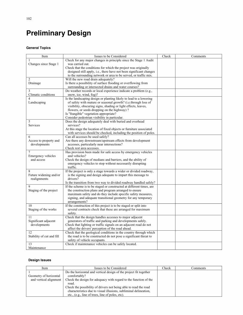
102
Preliminary Design General Topics
Item Issues to be Considered Check Comments 1 Changes since Stage 1
Check for any major changes in principle since the Stage 1 Audit was carried out.
Check that the conditions for which the project was originally designed still apply, i.e., there have not been significant changes to the surrounding network or area to be served, or traffic mix.
2 Drainage
Will the new road drain adequately? Is there a possibility of surface flooding or overflowing from
surrounding or intersected drains and water courses?
3 Climatic conditions
Do weather records or local experience indicate a problem (e.g., snow, ice, wind, fog)?
4 Landscaping
Is the landscaping design or planting likely to lead to a lowering of safety with mature or seasonal growth? (i.e.through loss of visibility, obscuring signs, shading or light effects, leaves, flowers, or seeds dropping on the highway) ?
Is ''frangible" vegetation appropriate? Consider pedestrian visibility in particular.
5 Services
Does the design adequately deal with buried and overhead services?
At this stage the location of fixed objects or furniture associated with services should be checked, including the position of poles.
6 Access to property and
developments
Can all accesses be used safely? Are there any downstream/upstream effects from development
accesses, particularly near intersections? Check rest area accesses.
7 Emergency vehicles
and access
Has provision been made for safe access by emergency vehicles and vehicles?
Check the design of medians and barriers, and the ability of emergency vehicles to stop without necessarily disrupting traffic.
8 Future widening and/or
realignments
If the project is only a stage towards a wider or divided roadway, is the signing and design adequate to impart this message to drivers?
Is the transition from two way to divided roadway handled safely?
9 Staging of the project
If the scheme is to be staged or constructed at different times, are the construction plans and program arranged to ensure maximum safety and do they include specific safety measures, signing, and adequate transitional geometry for any temporary arrangements?
10 Staging of the works
If the construction of this project is to be staged or split into several contracts check that these are arranged for maximum safety.
11 Significant adjacent
developments
Check that the design handles accesses to major adjacent generators of traffic and parking and developments safely.
Check that lighting or traffic signals on an adjacent road do not affect the drivers' perception of the road ahead.
12 Stability of cut and fill
Check that the geological conditions in the country through which the road is to be constructed do not pose a significant threat to safety of vehicle occupants.
13 Maintenance
Check if maintenance vehicles can be safely located.
Design Issues
Item Issues to be Considered Check Comments 1 Geometry of horizontal
and vertical alignment
Do the horizontal and vertical design of the project fit together comfortably?
Check the design for adequacy with regard to the function of the road.
Check the possibility of drivers not being able to read the road characteristics due to visual illusions, subliminal delineation, etc., (e.g., line of trees, line of poles, etc).
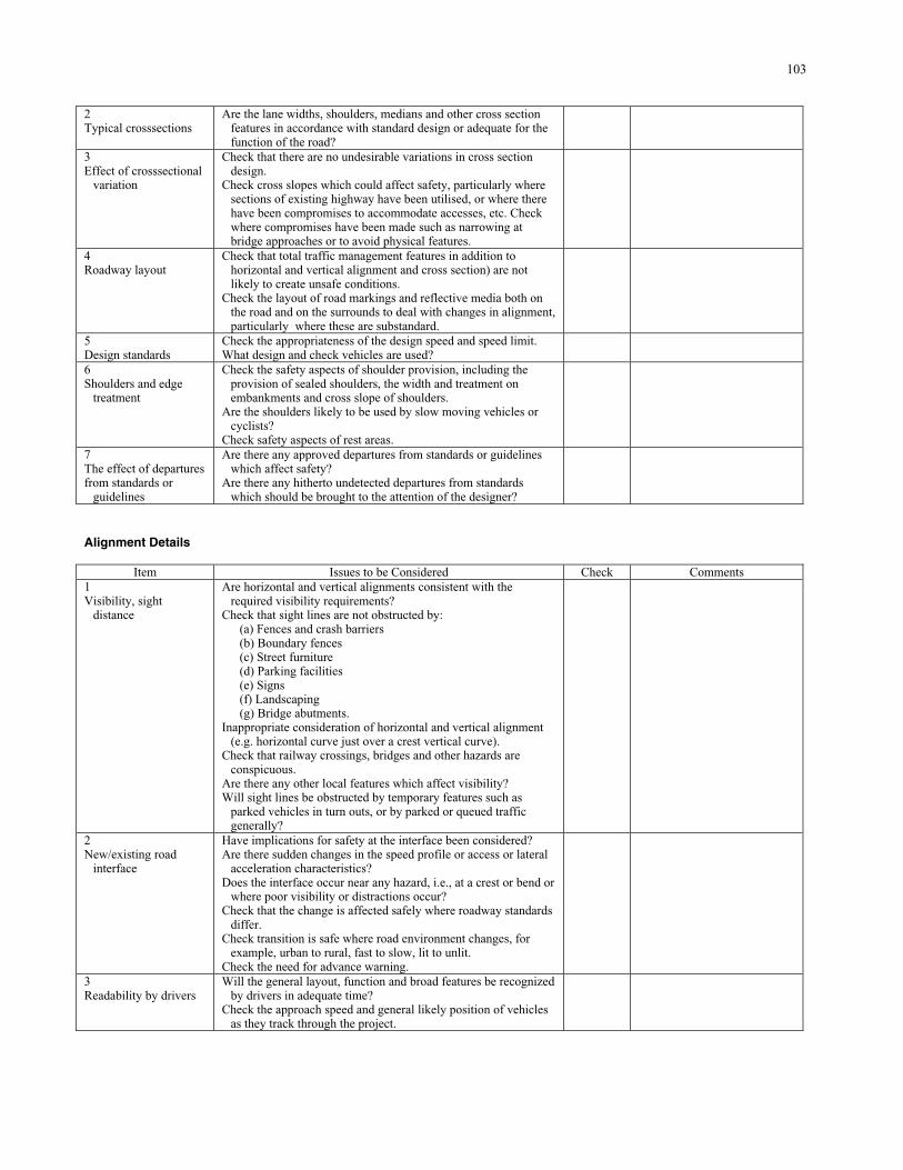
103
2 Typical crosssections
Are the lane widths, shoulders, medians and other cross section features in accordance with standard design or adequate for the function of the road?
3 Effect of crosssectional
variation
Check that there are no undesirable variations in cross section design.
Check cross slopes which could affect safety, particularly where sections of existing highway have been utilised, or where there have been compromises to accommodate accesses, etc. Check where compromises have been made such as narrowing at bridge approaches or to avoid physical features.
4 Roadway layout
Check that total traffic management features in addition to horizontal and vertical alignment and cross section) are not likely to create unsafe conditions.
Check the layout of road markings and reflective media both on the road and on the surrounds to deal with changes in alignment, particularly where these are substandard.
5 Design standards
Check the appropriateness of the design speed and speed limit. What design and check vehicles are used?
6 Shoulders and edge
treatment
Check the safety aspects of shoulder provision, including the provision of sealed shoulders, the width and treatment on embankments and cross slope of shoulders.
Are the shoulders likely to be used by slow moving vehicles or cyclists?
Check safety aspects of rest areas.
7 The effect of departures from standards or
guidelines
Are there any approved departures from standards or guidelines which affect safety?
Are there any hitherto undetected departures from standards which should be brought to the attention of the designer?
Alignment Details
Item Issues to be Considered Check Comments 1 Visibility, sight
distance
Are horizontal and vertical alignments consistent with the required visibility requirements?
Check that sight lines are not obstructed by: (a) Fences and crash barriers (b) Boundary fences (c) Street furniture (d) Parking facilities (e) Signs (f) Landscaping (g) Bridge abutments.
Inappropriate consideration of horizontal and vertical alignment (e.g. horizontal curve just over a crest vertical curve).
Check that railway crossings, bridges and other hazards are conspicuous.
Are there any other local features which affect visibility? Will sight lines be obstructed by temporary features such as
parked vehicles in turn outs, or by parked or queued traffic generally?
2 New/existing road
interface
Have implications for safety at the interface been considered? Are there sudden changes in the speed profile or access or lateral
acceleration characteristics? Does the interface occur near any hazard, i.e., at a crest or bend or
where poor visibility or distractions occur? Check that the change is affected safely where roadway standards
differ. Check transition is safe where road environment changes, for
example, urban to rural, fast to slow, lit to unlit. Check the need for advance warning.
3 Readability by drivers
Will the general layout, function and broad features be recognized by drivers in adequate time?
Check the approach speed and general likely position of vehicles as they track through the project.
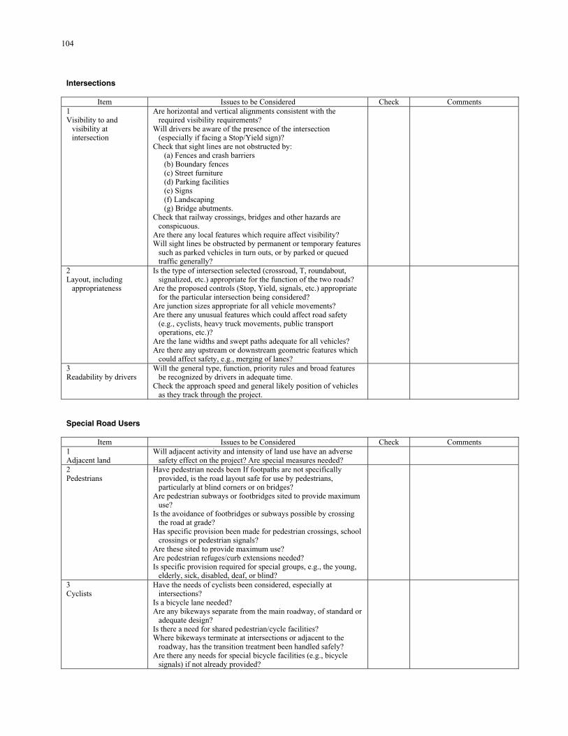
104
Intersections
Item Issues to be Considered Check Comments 1 Visibility to and
visibility at intersection
Are horizontal and vertical alignments consistent with the required visibility requirements?
Will drivers be aware of the presence of the intersection (especially if facing a Stop/Yield sign)?
Check that sight lines are not obstructed by: (a) Fences and crash barriers (b) Boundary fences (c) Street furniture (d) Parking facilities (e) Signs (f) Landscaping (g) Bridge abutments.
Check that railway crossings, bridges and other hazards are conspicuous.
Are there any local features which require affect visibility? Will sight lines be obstructed by permanent or temporary features
such as parked vehicles in turn outs, or by parked or queued traffic generally?
2 Layout, including
appropriateness
Is the type of intersection selected (crossroad, T, roundabout, signalized, etc.) appropriate for the function of the two roads?
Are the proposed controls (Stop, Yield, signals, etc.) appropriate for the particular intersection being considered?
Are junction sizes appropriate for all vehicle movements? Are there any unusual features which could affect road safety
(e.g., cyclists, heavy truck movements, public transport operations, etc.)?
Are the lane widths and swept paths adequate for all vehicles? Are there any upstream or downstream geometric features which
could affect safety, e.g., merging of lanes?
3 Readability by drivers
Will the general type, function, priority rules and broad features be recognized by drivers in adequate time.
Check the approach speed and general likely position of vehicles as they track through the project.
Special Road Users
Item Issues to be Considered Check Comments 1 Adjacent land
Will adjacent activity and intensity of land use have an adverse safety effect on the project? Are special measures needed?
2 Pedestrians
Have pedestrian needs been If footpaths are not specifically provided, is the road layout safe for use by pedestrians, particularly at blind corners or on bridges?
Are pedestrian subways or footbridges sited to provide maximum use?
Is the avoidance of footbridges or subways possible by crossing the road at grade?
Has specific provision been made for pedestrian crossings, school crossings or pedestrian signals?
Are these sited to provide maximum use? Are pedestrian refuges/curb extensions needed? Is specific provision required for special groups, e.g., the young,
elderly, sick, disabled, deaf, or blind?
3 Cyclists
Have the needs of cyclists been considered, especially at intersections?
Is a bicycle lane needed? Are any bikeways separate from the main roadway, of standard or
adequate design? Is there a need for shared pedestrian/cycle facilities? Where bikeways terminate at intersections or adjacent to the
roadway, has the transition treatment been handled safely? Are there any needs for special bicycle facilities (e.g., bicycle
signals) if not already provided?
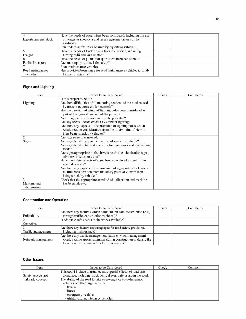
105
4 Equestrians and stock
Have the needs of equestrians been considered, including the use of verges or shoulders and rules regarding the use of the roadway?
Can underpass facilities be used by equestrians/stock?
5 Freight
Have the needs of truck drivers been considered, including turning radii and lane widths?
6 Public Transport
Have the needs of public transport users been considered? Are bus stops positioned for safety?
7 Road maintenance
vehicles
Road maintenance vehicles Has provision been made for road maintenance vehicles to safely
be used at this site?
Signs and Lighting
Item Issues to be Considered Check Comments 1 Lighting
Is this project to be lit? Are there difficulties of illuminating sections of the road caused
by trees or overpasses, for example? Has the question of siting of lighting poles been considered as
part of the general concept of the project? Are frangible or slip-base poles to be provided? Are any special needs created by ambient lighting? Are there any aspects of the provision of lighting poles which
would require consideration from the safety point of view in their being struck by vehicles?
2 Signs
Are sign structures needed? Are signs located at points to allow adequate readability? Are signs located to limit visibility from accesses and intersecting
roads? Are signs appropriate to the drivers needs (i.e., destination signs,
advisory speed signs, etc)? Have the safety aspects of signs been considered as part of the
general concept? Are there any aspects of the provision of sign posts which would
require consideration from the safety point of view in their being struck by vehicles?
3 Marking and
delineation
Check that the appropriate standard of delineation and marking has been adopted.
Construction and Operation
Item Issues to be Considered Check Comments 1 Buildability
Are there any features which could inhibit safe construction (e.g., through traffic, construction vehicles.)?
2 Operation
Is adequate safe access to the works available?
3 Traffic management
Are there any factors requiring specific road safety provision, including maintenance?
4 Network management
Are there any traffic management features which management would require special attention during construction or during the transition from construction to full operation?
Other Issues
Item Issues to be Considered Check Comments 1 Safety aspects not
already covered
This could include unusual events, special effects of land uses alongside, including stock being driven onto or along the road.
The ability of the road to take overweight or over-dimension vehicles or other large vehicles
- trucks - buses - emergency vehicles - utility/road maintenance vehicles.
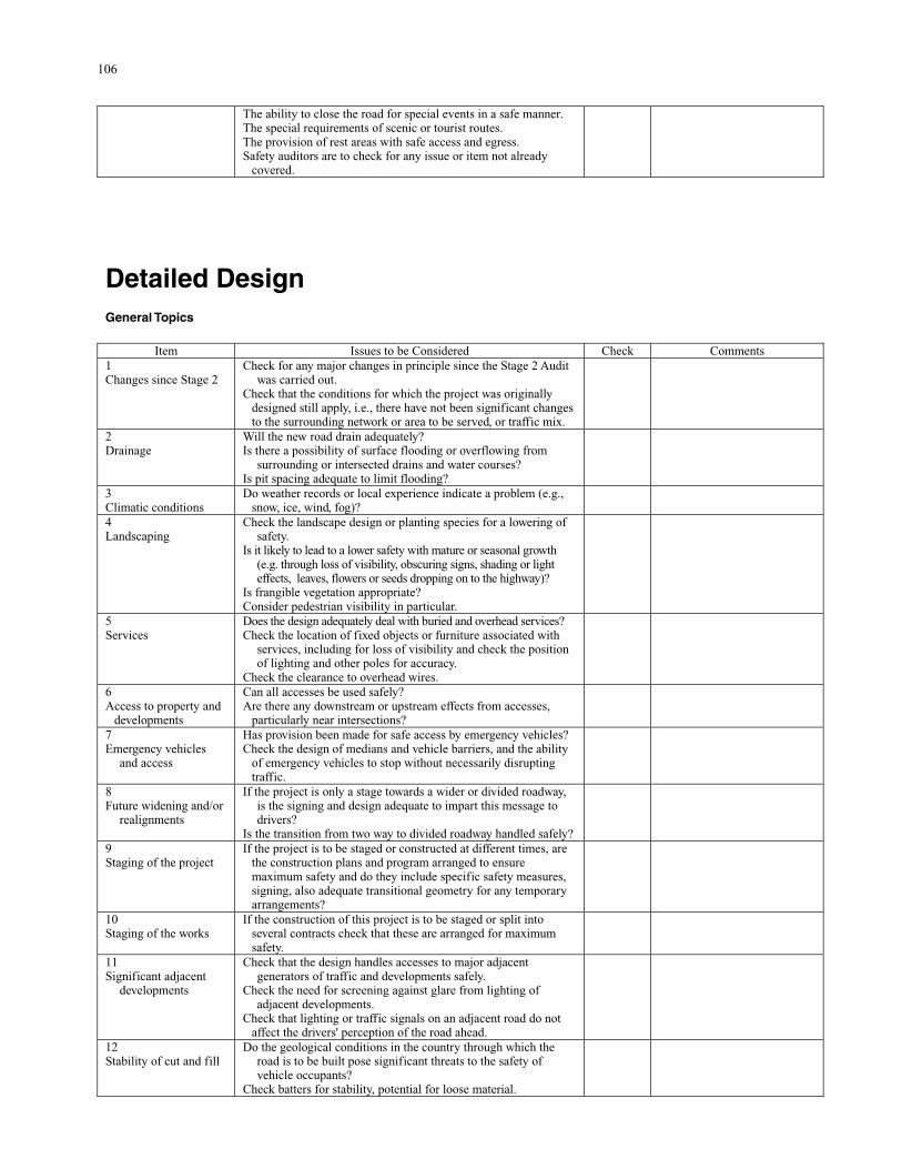
106
The ability to close the road for special events in a safe manner. The special requirements of scenic or tourist routes. The provision of rest areas with safe access and egress. Safety auditors are to check for any issue or item not already
covered.
Detailed Design General Topics
Item Issues to be Considered Check Comments 1 Changes since Stage 2
Check for any major changes in principle since the Stage 2 Audit was carried out.
Check that the conditions for which the project was originally designed still apply, i.e., there have not been significant changes to the surrounding network or area to be served, or traffic mix.
2 Drainage
Will the new road drain adequately? Is there a possibility of surface flooding or overflowing from
surrounding or intersected drains and water courses? Is pit spacing adequate to limit flooding?
3 Climatic conditions
Do weather records or local experience indicate a problem (e.g., snow, ice, wind, fog)?
4 Landscaping
Check the landscape design or planting species for a lowering of safety.
Is it likely to lead to a lower safety with mature or seasonal growth (e.g. through loss of visibility, obscuring signs, shading or light effects, leaves, flowers or seeds dropping on to the highway)?
Is frangible vegetation appropriate? Consider pedestrian visibility in particular.
5 Services
Does the design adequately deal with buried and overhead services? Check the location of fixed objects or furniture associated with
services, including for loss of visibility and check the position of lighting and other poles for accuracy.
Check the clearance to overhead wires.
6 Access to property and
developments
Can all accesses be used safely? Are there any downstream or upstream effects from accesses,
particularly near intersections?
7 Emergency vehicles
and access
Has provision been made for safe access by emergency vehicles? Check the design of medians and vehicle barriers, and the ability
of emergency vehicles to stop without necessarily disrupting traffic.
8 Future widening and/or
realignments
If the project is only a stage towards a wider or divided roadway, is the signing and design adequate to impart this message to drivers?
Is the transition from two way to divided roadway handled safely?
9 Staging of the project
If the project is to be staged or constructed at different times, are the construction plans and program arranged to ensure maximum safety and do they include specific safety measures, signing, also adequate transitional geometry for any temporary arrangements?
10 Staging of the works
If the construction of this project is to be staged or split into several contracts check that these are arranged for maximum safety.
11 Significant adjacent
developments
Check that the design handles accesses to major adjacent generators of traffic and developments safely.
Check the need for screening against glare from lighting of adjacent developments.
Check that lighting or traffic signals on an adjacent road do not affect the drivers' perception of the road ahead.
12 Stability of cut and fill
Do the geological conditions in the country through which the road is to be built pose significant threats to the safety of vehicle occupants?
Check batters for stability, potential for loose material.
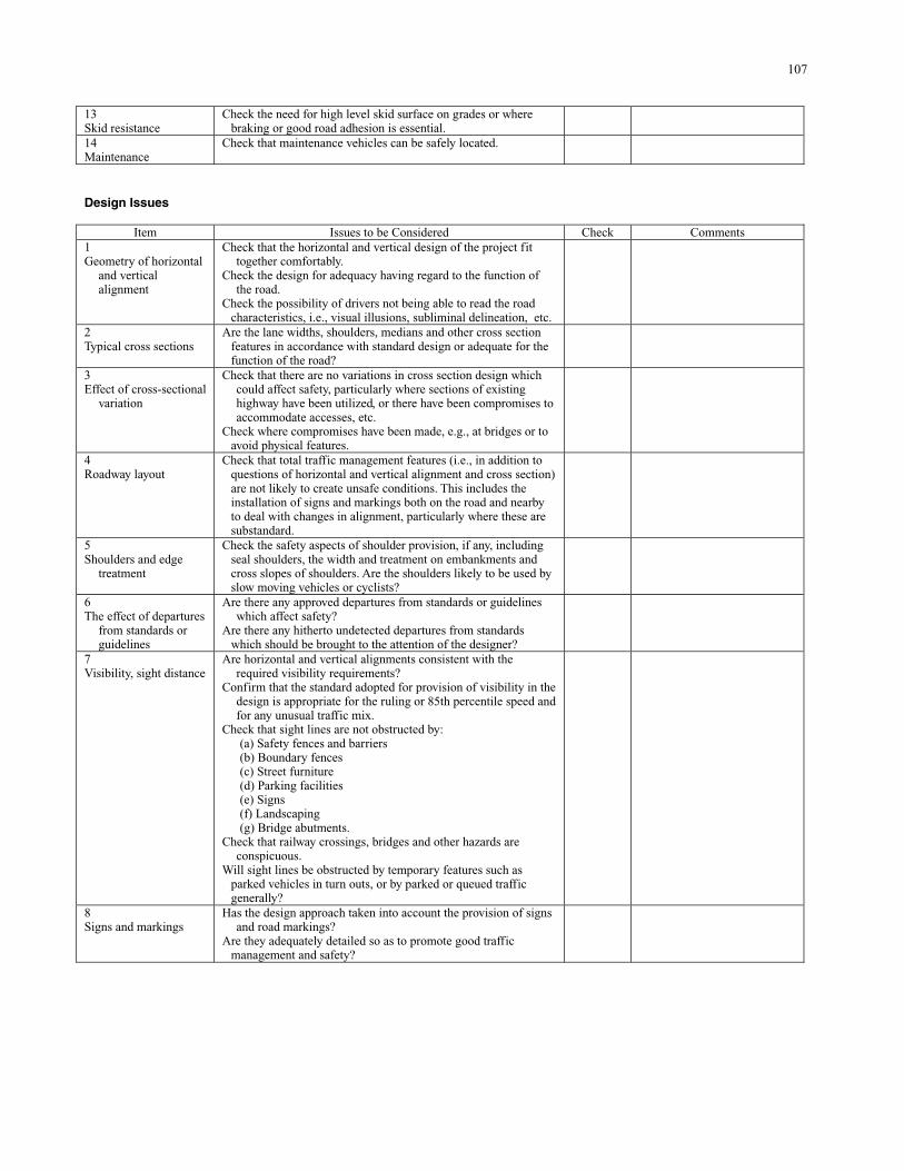
107
13 Skid resistance
Check the need for high level skid surface on grades or where braking or good road adhesion is essential.
14 Maintenance
Check that maintenance vehicles can be safely located.
Design Issues
Item Issues to be Considered Check Comments 1 Geometry of horizontal
and vertical alignment
Check that the horizontal and vertical design of the project fit together comfortably.
Check the design for adequacy having regard to the function of the road.
Check the possibility of drivers not being able to read the road characteristics, i.e., visual illusions, subliminal delineation, etc.
2 Typical cross sections
Are the lane widths, shoulders, medians and other cross section features in accordance with standard design or adequate for the function of the road?
3 Effect of cross-sectional
variation
Check that there are no variations in cross section design which could affect safety, particularly where sections of existing highway have been utilized, or there have been compromises to accommodate accesses, etc.
Check where compromises have been made, e.g., at bridges or to avoid physical features.
4 Roadway layout
Check that total traffic management features (i.e., in addition to questions of horizontal and vertical alignment and cross section) are not likely to create unsafe conditions. This includes the installation of signs and markings both on the road and nearby to deal with changes in alignment, particularly where these are substandard.
5 Shoulders and edge
treatment
Check the safety aspects of shoulder provision, if any, including seal shoulders, the width and treatment on embankments and cross slopes of shoulders. Are the shoulders likely to be used by slow moving vehicles or cyclists?
6 The effect of departures
from standards or guidelines
Are there any approved departures from standards or guidelines which affect safety?
Are there any hitherto undetected departures from standards which should be brought to the attention of the designer?
7 Visibility, sight distance
Are horizontal and vertical alignments consistent with the required visibility requirements?
Confirm that the standard adopted for provision of visibility in the design is appropriate for the ruling or 85th percentile speed and for any unusual traffic mix.
Check that sight lines are not obstructed by: (a) Safety fences and barriers (b) Boundary fences (c) Street furniture (d) Parking facilities (e) Signs (f) Landscaping (g) Bridge abutments.
Check that railway crossings, bridges and other hazards are conspicuous.
Will sight lines be obstructed by temporary features such as parked vehicles in turn outs, or by parked or queued traffic generally?
8 Signs and markings
Has the design approach taken into account the provision of signs and road markings?
Are they adequately detailed so as to promote good traffic management and safety?
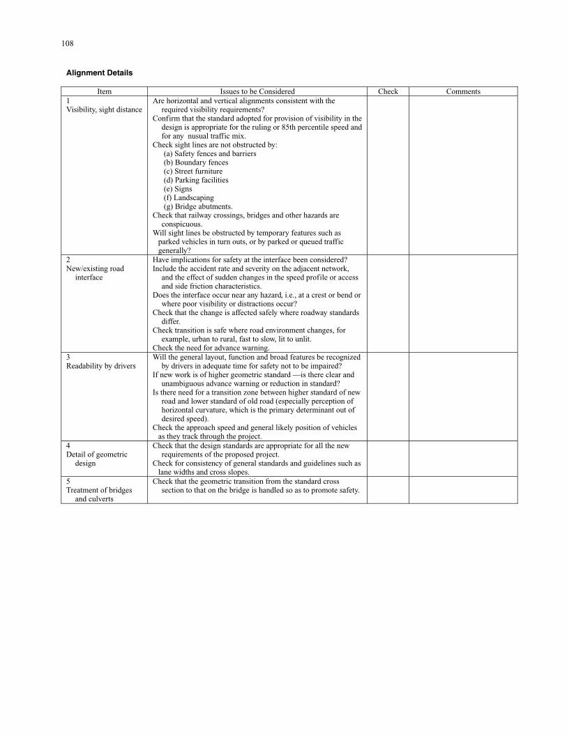
108
Alignment Details
Item Issues to be Considered Check Comments 1 Visibility, sight distance
Are horizontal and vertical alignments consistent with the required visibility requirements?
Confirm that the standard adopted for provision of visibility in the design is appropriate for the ruling or 85th percentile speed and for any nusual traffic mix.
Check sight lines are not obstructed by: (a) Safety fences and barriers (b) Boundary fences (c) Street furniture (d) Parking facilities (e) Signs (f) Landscaping (g) Bridge abutments.
Check that railway crossings, bridges and other hazards are conspicuous.
Will sight lines be obstructed by temporary features such as parked vehicles in turn outs, or by parked or queued traffic generally?
2 New/existing road
interface
Have implications for safety at the interface been considered? Include the accident rate and severity on the adjacent network,
and the effect of sudden changes in the speed profile or access and side friction characteristics.
Does the interface occur near any hazard, i.e., at a crest or bend or where poor visibility or distractions occur?
Check that the change is affected safely where roadway standards differ.
Check transition is safe where road environment changes, for example, urban to rural, fast to slow, lit to unlit.
Check the need for advance warning.
3 Readability by drivers
Will the general layout, function and broad features be recognized by drivers in adequate time for safety not to be impaired?
If new work is of higher geometric standard —is there clear and unambiguous advance warning or reduction in standard?
Is there need for a transition zone between higher standard of new road and lower standard of old road (especially perception of horizontal curvature, which is the primary determinant out of desired speed).
Check the approach speed and general likely position of vehicles as they track through the project.
4 Detail of geometric
design
Check that the design standards are appropriate for all the new requirements of the proposed project.
Check for consistency of general standards and guidelines such as lane widths and cross slopes.
5 Treatment of bridges
and culverts
Check that the geometric transition from the standard cross section to that on the bridge is handled so as to promote safety.
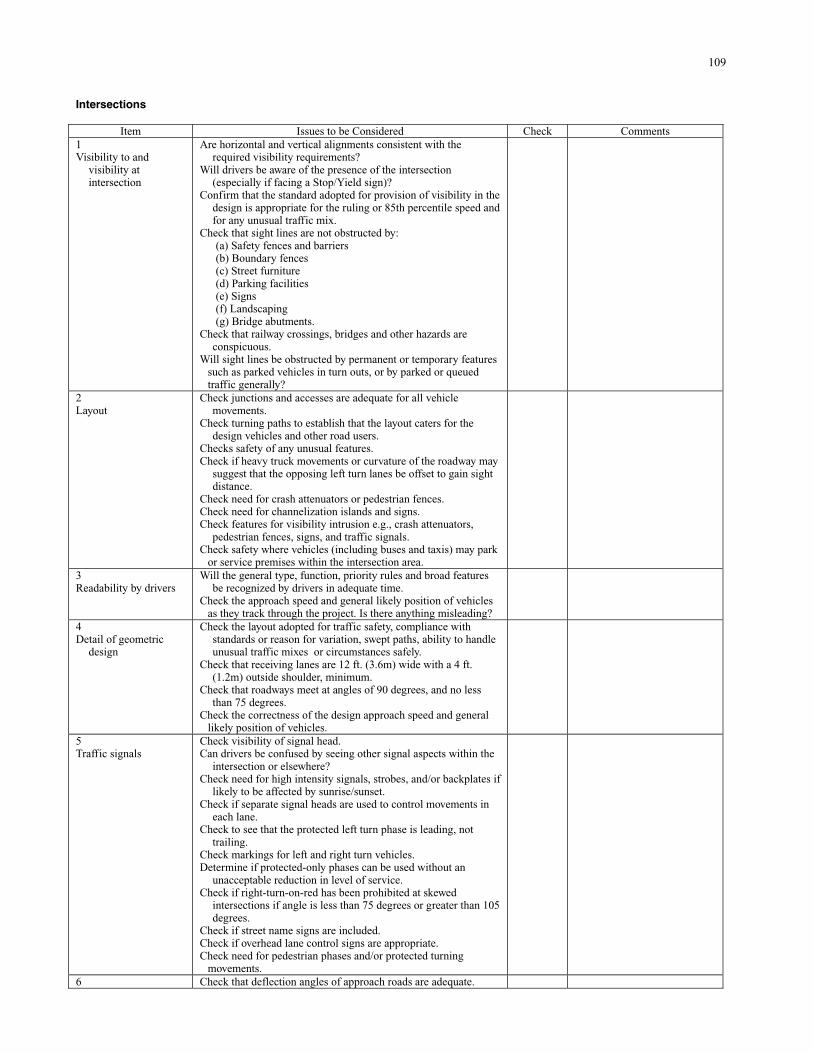
109
Intersections
Item Issues to be Considered Check Comments 1 Visibility to and
visibility at intersection
Are horizontal and vertical alignments consistent with the required visibility requirements?
Will drivers be aware of the presence of the intersection (especially if facing a Stop/Yield sign)?
Confirm that the standard adopted for provision of visibility in the design is appropriate for the ruling or 85th percentile speed and for any unusual traffic mix.
Check that sight lines are not obstructed by: (a) Safety fences and barriers (b) Boundary fences (c) Street furniture (d) Parking facilities (e) Signs (f) Landscaping (g) Bridge abutments.
Check that railway crossings, bridges and other hazards are conspicuous.
Will sight lines be obstructed by permanent or temporary features such as parked vehicles in turn outs, or by parked or queued traffic generally?
2 Layout
Check junctions and accesses are adequate for all vehicle movements.
Check turning paths to establish that the layout caters for the design vehicles and other road users.
Checks safety of any unusual features. Check if heavy truck movements or curvature of the roadway may
suggest that the opposing left turn lanes be offset to gain sight distance.
Check need for crash attenuators or pedestrian fences. Check need for channelization islands and signs. Check features for visibility intrusion e.g., crash attenuators,
pedestrian fences, signs, and traffic signals. Check safety where vehicles (including buses and taxis) may park
or service premises within the intersection area.
3 Readability by drivers
Will the general type, function, priority rules and broad features be recognized by drivers in adequate time.
Check the approach speed and general likely position of vehicles as they track through the project. Is there anything misleading?
4 Detail of geometric
design
Check the layout adopted for traffic safety, compliance with standards or reason for variation, swept paths, ability to handle unusual traffic mixes or circumstances safely.
Check that receiving lanes are 12 ft. (3.6m) wide with a 4 ft. (1.2m) outside shoulder, minimum.
Check that roadways meet at angles of 90 degrees, and no less than 75 degrees.
Check the correctness of the design approach speed and general likely position of vehicles.
5 Traffic signals
Check visibility of signal head. Can drivers be confused by seeing other signal aspects within the
intersection or elsewhere? Check need for high intensity signals, strobes, and/or backplates if
likely to be affected by sunrise/sunset. Check if separate signal heads are used to control movements in
each lane. Check to see that the protected left turn phase is leading, not
trailing. Check markings for left and right turn vehicles. Determine if protected-only phases can be used without an
unacceptable reduction in level of service. Check if right-turn-on-red has been prohibited at skewed
intersections if angle is less than 75 degrees or greater than 105 degrees.
Check if street name signs are included. Check if overhead lane control signs are appropriate. Check need for pedestrian phases and/or protected turning
movements.
6 Check that deflection angles of approach roads are adequate.
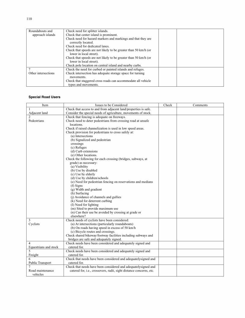
110
Roundabouts and approach islands
Check need for splitter islands. Check that center island is prominent. Check need for hazard markers and markings and that they are
correctly located. Check need for dedicated lanes. Check that speeds are not likely to be greater than 50 km/h (or
lower in local street). Check that speeds are not likely to be greater than 50 km/h (or
lower in local street). Check pole location on central island and nearby curbs.
7 Other intersections
Check the need for curbed or painted islands and refuges. Check intersection has adequate storage space for turning
movements. Check that staggered cross roads can accommodate all vehicle
types and movements.
Special Road Users
Item Issues to be Considered Check Comments 1 Adjacent land
Check that access to and from adjacent land/properties is safe. Consider the special needs of agriculture, movements of stock.
2 Pedestrians
Check that fencing is adequate on freeways. Check need to deter pedestrians from crossing road at unsafe
locations. Check if raised channelization is used in low speed areas. Check provision for pedestrians to cross safely at:
(a) Intersections (b) Signalized and pedestrian crossings (c) Refuges (d) Curb extensions (e) Other locations.
Check the following for each crossing (bridges, subways, at grade) as necessary: (a) Visibility (b) Use by disabled (c) Use by elderly (d) Use by children/schools (e) Need for pedestrian fencing on reservations and medians (f) Signs (g) Width and gradient (h) Surfacing (j) Avoidance of channels and gullies (k) Need for deterrent curbing (I) Need for lighting (m) Sited to provide maximum use (n) Can their use be avoided by crossing at grade or elsewhere?
3 Cyclists
Check needs of cyclists have been considered: (a) At intersections (particularly roundabouts) (b) On roads having speed in excess of 50 km/h (c) Bicycle routes and crossings.
Check shared bikeway/footway facilities including subways and bridges are safe and adequately signed.
4 Equestrians and stock
Check needs have been considered and adequately signed and catered for.
5 Freight
Check needs have been considered and adequately signed and catered for.
6 Public Transport
Check that needs have been considered and adequatelysigned and catered for.
7 Road maintenance
vehicles
Check that needs have been considered and adequatelysigned and catered for, i.e., crossovers, radii, sight distance concerns, etc.
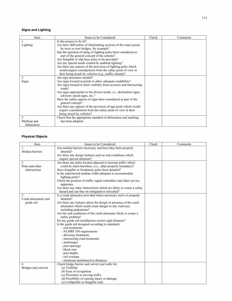
111
Signs and Lighting
Item Issues to be Considered Check Comments 1 Lighting
Is this project to be lit? Are there difficulties of illuminating sections of the road caused
by trees or over bridges, for example? Has the question of siting of lighting poles been considered as
part of the general concept of the scheme? Are frangible or slip-base poles to be provided? Are any special needs created by ambient lighting? Are there any aspects of the provision of lighting poles which
would require consideration from the safety point of view in their being struck by vehicles (e.g., traffic islands)?
2 Signs
Are sign structures needed? Are signs located at points to allow adequate readability? Are signs located to limit visibility from accesses and intersecting
roads? Are signs appropriate to the drivers needs, i.e., destination signs,
advisory speed signs, etc.? Have the safety aspects of signs been considered as part of the
general concept? Are there any aspects of the provision of sign posts which would
require consideration from the safety point of view in their being struck by vehicles?
3 Marking and
delineation
Check that the appropriate standard of delineation and marking has been adopted.
Physical Objects
Item Issues to be Considered Check Comments 1 Median barriers
Are median barriers necessary and have they been properly detailed?
Are there any design features such as end conditions which require special attention?
2 Poles and other
obstructions
Are there any poles located adjacent to moving traffic which could be sited elsewhere, (i.e., atthe property boundary)?
Have frangible or breakaway poles been detailed? Is the unprotected median width adequate to accommodate
lighting poles? Check the position of traffic signal controllers and other service
apparatus. Are there any other obstructions which are likely to create a safety
hazard and can they be mitigated or relocated?
3 Crash attenuators and
guide rail
Is a crash attenuator provided where necessary and is it properly detailed?
Are there any features about the design or presence of the crash attenuator which could create danger to any road user, including pedestrians?
Are the end conditions of the crash attenuator likely to create a safety problem?
Do any guide rail installations restrict sight distance? Is the guide rail designed according to standards:
- end treatments - NCHRP 350 requirements - driveway treatments - intersecting road treatments - anchorages - post spacings - block outs - post depths - rail overlaps - minimum unobstructive distances
4 Bridges and culverts
Check bridge barrier and culvert end walls for: (a) Visibility (b) Ease of recognition (c) Proximity to moving traffic (d) Possibility of causing injury or damage (e) Collapsible or frangible ends
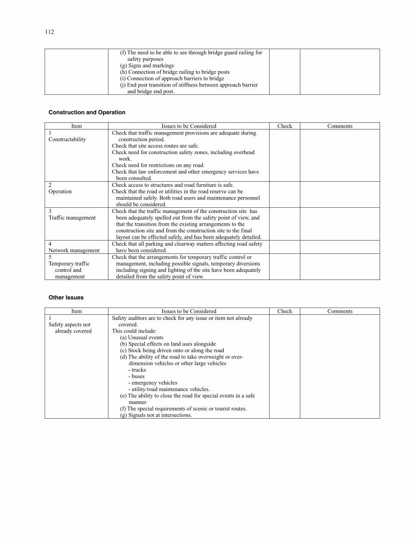
112
(f) The need to be able to see through bridge guard railing for safety purposes (g) Signs and markings (h) Connection of bridge railing to bridge posts (i) Connection of approach barriers to bridge (j) End post transition of stiffness between approach barrier and bridge end post.
Construction and Operation
Item Issues to be Considered Check Comments 1 Constructability
Check that traffic management provisions are adequate during construction period.
Check that site access routes are safe. Check need for construction safety zones, including overhead
work. Check need for restrictions on any road. Check that law enforcement and other emergency services have
been consulted.
2 Operation
Check access to structures and road furniture is safe. Check that the road or utilities in the road reserve can be
maintained safely. Both road users and maintenance personnel should be considered.
3 Traffic management
Check that the traffic management of the construction site has been adequately spelled out from the safety point of view, and that the transition from the existing arrangements to the construction site and from the construction site to the final layout can be effected safely, and has been adequately detailed.
4 Network management
Check that all parking and clearway matters affecting road safety have been considered.
5 Temporary traffic
control and management
Check that the arrangements for temporary traffic control or management, including possible signals, temporary diversions including signing and lighting of the site have been adequately detailed from the safety point of view.
Other Issues
Item Issues to be Considered Check Comments 1 Safety aspects not
already covered
Safety auditors are to check for any issue or item not already covered.
This could include: (a) Unusual events (b) Special effects on land uses alongside (c) Stock being driven onto or along the road (d) The ability of the road to take overweight or over- dimension vehicles or other large vehicles
- trucks - buses - emergency vehicles - utility/road maintenance vehicles.
(e) The ability to close the road for special events in a safe manner. (f) The special requirements of scenic or tourist routes. (g) Signals not at intersections.
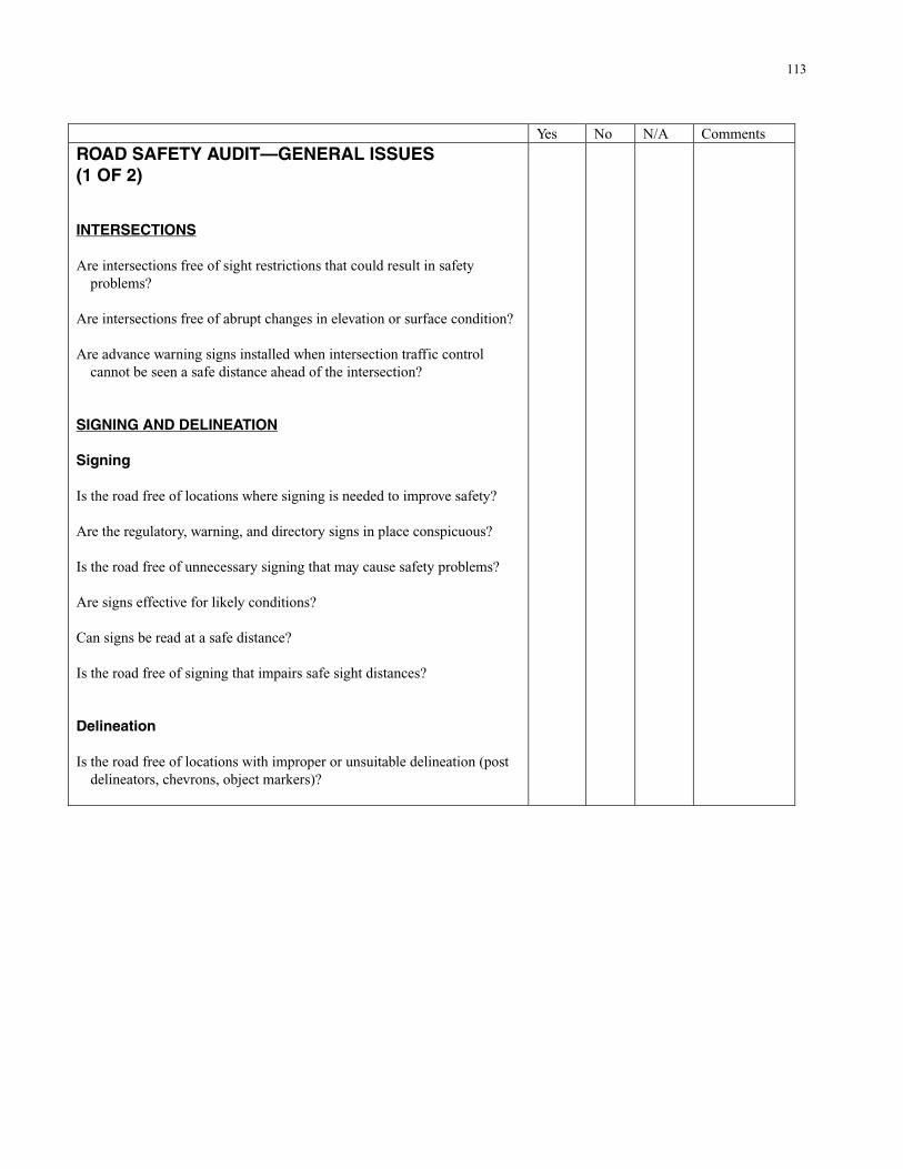
113
Yes No N/A Comments
ROAD SAFETY AUDIT—GENERAL ISSUES (1 OF 2) INTERSECTIONS Are intersections free of sight restrictions that could result in safety
problems? Are intersections free of abrupt changes in elevation or surface condition? Are advance warning signs installed when intersection traffic control
cannot be seen a safe distance ahead of the intersection? SIGNING AND DELINEATION Signing Is the road free of locations where signing is needed to improve safety? Are the regulatory, warning, and directory signs in place conspicuous? Is the road free of unnecessary signing that may cause safety problems? Are signs effective for likely conditions? Can signs be read at a safe distance? Is the road free of signing that impairs safe sight distances? Delineation Is the road free of locations with improper or unsuitable delineation (post
delineators, chevrons, object markers)?
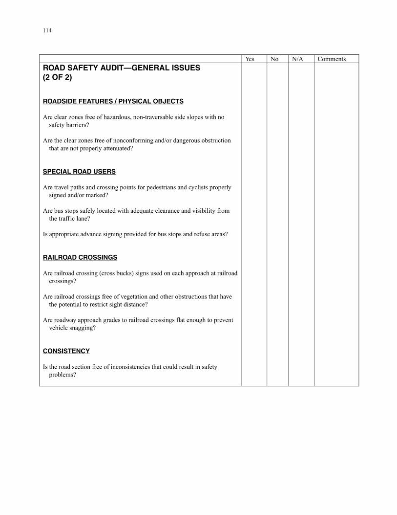
114
Yes No N/A Comments
ROAD SAFETY AUDIT—GENERAL ISSUES (2 OF 2) ROADSIDE FEATURES / PHYSICAL OBJECTS Are clear zones free of hazardous, non-traversable side slopes with no
safety barriers? Are the clear zones free of nonconforming and/or dangerous obstruction
that are not properly attenuated? SPECIAL ROAD USERS Are travel paths and crossing points for pedestrians and cyclists properly
signed and/or marked? Are bus stops safely located with adequate clearance and visibility from
the traffic lane? Is appropriate advance signing provided for bus stops and refuse areas? RAILROAD CROSSINGS Are railroad crossing (cross bucks) signs used on each approach at railroad
crossings? Are railroad crossings free of vegetation and other obstructions that have
the potential to restrict sight distance? Are roadway approach grades to railroad crossings flat enough to prevent
vehicle snagging? CONSISTENCY Is the road section free of inconsistencies that could result in safety
problems?

115
Yes No N/A Comments
ROAD SAFETY AUDIT—PAVED ROAD ISSUES (1 OF 1) PAVEMENT MARKINGS Is the road free of locations with pavement marking safety deficiencies? Is the road free of pavement markings that are not effective for likely
conditions? Is the road free of old pavement markings that affect the safety of the
roadway? PAVEMENT CONDITION Is the pavement free of defects that could result in safety problems (e.g.,
loss of steering control)? Are changes in surface type (e.g., pavement ends) free of drop-offs/poor
transitions? Is the pavement free of locations that appear to have inadequate skid
resistance that could result in safety problems, particularly on curves, steep grades, and approaches to intersections?
Is the pavement free of areas where ponding or sheet flow of water occurs
resulting in safety problems? Is the pavement free of loose aggregate/gravel that may cause safety
problems?
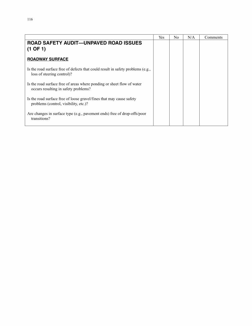
116
Yes No N/A Comments
ROAD SAFETY AUDIT—UNPAVED ROAD ISSUES (1 OF 1) ROADWAY SURFACE Is the road surface free of defects that could result in safety problems (e.g.,
loss of steering control)? Is the road surface free of areas where ponding or sheet flow of water
occurs resulting in safety problems? Is the road surface free of loose gravel/fines that may cause safety
problems (control, visibility, etc.)? Are changes in surface type (e.g., pavement ends) free of drop-offs/poor
transitions?

117
Road Safety Audits and Road Safety Audit Reviews Road safety audits (RSAs), adaptable to local needs and conditions, are a powerful tool for state and local agencies to enhance the state of safety practices in their jurisdictions. With fewer new projects being constructed, the focus of RSAs is shifting to use by local agencies on existing roadways. For an existing road, the RSA is called a road safety audit review (RSAR). What is an RSA? Simply put, an RSA is an examination of a future or existing roadway in which an independent, qualified audit team reports on safety issues. The step-by-step procedure of an RSA can be performed during any or all stages of a project, including planning, preliminary design, detailed design, construction, pre-opening, and on existing roads. RSAs are a proactive approach to improving transportation safety. Agencies in the United States are just beginning to focus on RSAs. Considering the unacceptable number of motor vehicle crashes that occur each year, the potential savings—in lives, serious injuries, and property damage—is incalculable. Although concerns have been raised that the use of RSAs would increase an agency’s liability, in fact, just the opposite should be true. Implementing a plan to reduce the crash potential and improve the safety performance of a roadway using a proactive approach to safety can be used in defense of tort liability. Identifying and documenting safety issues on an existing roadway is not an admission of guilt. Rather, it is the first step in a process designed to improve safety. Proper documentation, communication, and logical prioritization of an agency’s plan to address safety issues would be difficult to fault. An RSAR program need not be disruptive to an agency’s ongoing operations; it can be implemented in small stages as time and resources allow. Classifying the roads in your jurisdiction and tailoring the RSAR to fit your needs is a practical approach to improving road safety that can be implemented in spite of limited resources and the ongoing need to focus on maintenance and operations. Consider using the expertise of personnel from neighboring counties to lend more eyes and fresh viewpoints in assessing the safety of your roadways. Seek additional and special funding from 402 safety funds using the results of the audit. Determine the value of an RSAR by (1) having a roadway section audited using a team of three or four road supervisors and engineers from adjacent counties, and/or (2) auditing a major project being designed to improve one of your roads. The value of the RSA/RSAR process as an important component of any agency’s safety strategy will become evident.
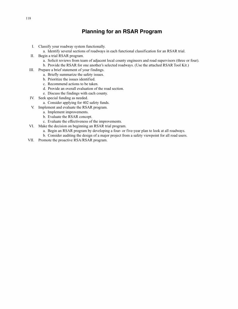
118
Planning for an RSAR Program
I. Classify your roadway system functionally. a. Identify several sections of roadways in each functional classification for an RSAR trial.
II. Begin a trial RSAR program. a. Solicit reviews from team of adjacent local county engineers and road supervisors (three or four). b. Provide the RSAR for one another’s selected roadways. (Use the attached RSAR Tool Kit.)
III. Prepare a brief statement of your findings. a. Briefly summarize the safety issues. b. Prioritize the issues identified. c. Recommend actions to be taken. d. Provide an overall evaluation of the road section. e. Discuss the findings with each county.
IV. Seek special funding as needed. a. Consider applying for 402 safety funds.
V. Implement and evaluate the RSAR program. a. Implement improvements. b. Evaluate the RSAR concept. c. Evaluate the effectiveness of the improvements.
VI. Make the decision on beginning an RSAR trial program. a. Begin an RSAR program by developing a four- or five-year plan to look at all roadways. b. Consider auditing the design of a major project from a safety viewpoint for all road users.
VII. Promote the proactive RSA/RSAR program.
119
RSA TOOL KIT
Developed by Eugene M. Wilson, Ph.D., PE, PTOE

120
Safety Issues to LOOK FOR: Roadside Features 1. Are clear zones free of hazards and non-traversable side slopes without safety barriers? 2. Are the clear zones free of nonconforming and/or dangerous obstructions that are not properly shielded? Road Surface—Pavement Condition 3. Is the pavement free of defects that could result in safety problems (e.g., loss of steering control)? 4. Are changes in surface type (e.g., pavement ends or begins) free of poor transitions? 5. Is the pavement free of locations that appear to have inadequate skid resistance that could result in safety problems, particularly on curves, steep grades, and approaches to intersections? 6. Is the pavement free of areas where ponding or sheet flow of water may occur resulting in safety problems? 7. Is the pavement free of loose aggregate/gravel that may cause safety problems? Road Surface—Pavement Markings 8. Is the road free of locations with pavement marking safety deficiencies? 9. Is the road free of pavement markings that are not effective for the conditions present? 10. Is the road free of old pavement markings that affect the safety of the roadway? Road Surface—Unpaved Roads 11. Is the road surface free of defects that could result in safety problems (e.g., loss of steering control)? 12. Is the road surface free of areas where ponding or sheet flow of water may occur resulting in safety problems? 13. Is the road surface free of loose gravel or fines that may cause safety problems (control, visibility, etc.)? 14. Are changes in surface type (e.g., pavement ends or begins) free of drop-offs or poor transitions? Signing and Delineation 15. Is the road free of locations where signing is needed to improve safety? 16. Are existing regulatory, warning, and directory signs conspicuous? 17. Is the road free of locations with improper signing that may cause safety problems? 18. Is the road free of unnecessary signing that may cause safety problems? 19. Are signs effective for existing conditions? 20. Can signs be read at a safe distance? 21. Is the road free of signing that impairs safe sight distances? 22. Is the road free of locations with improper or unsuitable delineation (post delineators, chevrons, and object markers)? Intersections and Approaches 23. Are intersections free of sight restrictions that could result in safety problems? 24. Are intersections free of abrupt changes in elevation or surface condition? 25. Are advance warning signs installed when intersection traffic control cannot be seen a safe distance ahead of the intersection? Special Road Users, Railroad Crossings, Consistency 26. Are travel paths and crossing points for pedestrians and cyclists properly signed and/or marked? 27. Are bus stops and mail boxes safely located with adequate clearance and visibility from the traffic lane? 28. Is appropriate advance signing provided for bus stops and refuge areas? 29. Are railroad crossing (cross bucks) signs used on each approach at railroad crossings? 30. Are railroad advance warning signs used at railroad crossing approaches? 31. Are railroad crossings free of vegetation and other obstructions that have the potential to restrict sight distance? 32. Are roadway approach grades to railroad crossings flat enough to prevent vehicle snagging? 33. Is the road section free of inconsistencies that could result in safety problems?
121
APPENDIX E South Carolina DOT Road Safety Audit Program
SCDOT SAFETY AUDIT
Administrative Procedures
August 2002 Road Safety Audit Roles/Responsibilities
Road Safety Audit Team Selection Process
Road Safety Audit Project Selection Process
Road Safety Audit Project Procedures
Road Safety Audit Reporting Procedures
Follow-up on Results of Audit
122
SCDOT ROAD SAFETY AUDIT PROGRAM
Administrative Procedures August, 2002
ROAD SAFETY AUDIT (RSA) ROLES/RESPONSIBILITIES Program Coordination The SCDOT RSA Program will be coordinated by the SCDOT Safety Office. The Director of Safety is responsible for oversight and management of the program. Road Safety Audit Program Advisory Committee An RSA Program Advisory Committee has been established to provide guidance and advice in the implementation of the RSA Program. The RSA Program Advisory Committee’s role in the program is as follows:
• • • •
• • • • • • •
• • • • • • •
• • • •
Participate in quarterly or semi-annual (as appropriate) meetings. Review program procedures and make recommendations to enhance operations. Review and approve annual projects selected for audit. Review and approve an annual report to be submitted to Executive Management, detailing progress, cost, cost savings, and benefits realized by the program.
The RSA Program Advisory Committee is chaired by the Director of Safety. Committee members include:
Deputy State Highway Engineer Director of Construction Director of Maintenance Director of Pre-Construction Director of Traffic Engineering Director of Planning District Engineering Administrators (2–3 selected annually).
RSA Program Coordinator The Director of Safety will assign a staff member to serve as the RSA Program Coordinator (PC). The RSA PC is responsible for day-to-day operations and the full implementation of the program. Responsibilities include but are not limited to the following areas:
Develops, monitors, and updates policies and procedures for the RSA Program. Solicits and assembles an annual list of proposed projects for consideration for audit. Assembles RSA personnel on a bi-annual basis. Develops and prepares a final annual list of projects selected for audit. Schedules and coordinates RSA Program Advisory Committee meetings. Coordinates bi-annual RSA personnel training through seminars/workshops. Obtains project information from Pre-Construction Program Manager (PM) and/or District Engineering Administrator (DEA). Makes RSA team assignments based on project specifics in coordination with Engineering Directors and DEAs. Coordinates team meetings for each stage of the project. Oversees and monitors the implementation of RSA stages for all audits conducted. Monitors communication between RSA teams and the PM and/or DEA.
123
• Serves as a mediator for conflict resolution. • • • • • •
• • • • •
• • • • • • • • •
• • •
Provides the RSA team with the DEA’s response to audit. Briefs the RSA Program Advisory Committee on the annual progress of audits. Maintains all original correspondence, audit reports, budget, and logistics associated with all audits. Monitors funding allocated to RSA projects. Develops RSA Program annual budget. Compiles evaluation data as appropriate for roads/projects for which audits were conducted.
RSA Team An RSA Team will be established for each project selected for audit. A different team may be established for the various phases of the audit, depending upon the amount of time between phases and the availability of team members. The RSA PC will select team members based upon their expertise as related to the project selected for audit. The RSA PC will contact the appropriate Engineering Director/DEA to verify the availability of the selected individual for service on a team. Once the Engineering Director/DEA has given approval for the individual to serve on the team, the person selected will be notified accordingly. RSA Team members will be nominated for service bi-annually by the Engineering Directors and DEAs. Team members will serve a two-year term and will receive training in the RSA concept and procedures prior to service. Each RSA Team is responsible for the following:
Completing RSA training prior to participating in an audit. Electing a Team Leader at the beginning of each audit. Using their expertise to identify concerns relative to proposed project. Preparing audit reports for each audit stage completed. Providing documentation to the RSA PC regarding expenditures and time allocated to a specific audit.
District Engineering Administrator The DEAs will serve as the central point of contact for projects selected for audit within their districts. The DEA’s role in the RSA Program is as follows:
Provide necessary information on the project as requested by the RSA PC. Present the project to the audit team. Be available for questions during an audit. Review RSA report recommendations. Determine action(s) to be taken. Investigate alternate solutions to address the identified concerns. Respond to concerns outlined in the RSA report. Respond to the RSA report and forward a written response to the RSA PC. Seek funding and implement solutions.
In fulfilling these responsibilities, the DEA may appoint/assign staff as appropriate to assemble the information needed. Pre-Construction Program Manager The PM’s role in the RSA Program is as follows:
Provide necessary information on projects as requested by the RSA PC. Present project (Stages 1 and 2) to audit team. Be available for questions during audit.
124
ROAD SAFETY AUDIT TEAM SELECTION PROCESS
•
•
•
•
•
•
•
The RSA PC will assemble RSA teams based on assigned projects. Teams will include a minimum of four members and often additional members from the following areas:
– Preconstruction – Construction (includes CRM representative) – Planning – Traffic engineering – Maintenance – District offices – Non-SCDOT personnel (police/fire/EMS/community organizations—pedestrian, bicyclist, transit, etc./local traffic
engineers) – Safety – Risk management
The RSA PC will submit a memorandum to the DEA or Engineering Director advising which project team members in their division are being requested to serve on a team. Once approval is granted, the RSA PC will contact the individual selected.
The RSA PC will schedule a meeting with each team independently. At the meeting, the teams will select a Team Leader for each project.
The RSA PC will open the meeting, introducing the team members and then the Pre-Construction PM and/or the DEA (or his assigned staff person) who will present the audit projects. Following the introductions and project presentation, the team will be required to accomplish the following:
– Select a Team Leader. – Establish a Project Completion Schedule.
> Schedule a meeting with project PM, > Conduct the audit and draft a report, and > Establish final submittal date of report.
– Assign Project Responsibilities (if applicable).
RSA Team members will serve a two-year term. Department Directors and DEAs will have the opportunity to assign individuals to assist in the RSA Program on a bi-annual cycle.
RSA Training Workshops will be conducted every two years for new team members. The RSA PC will conduct the workshops.
ROAD SAFETY AUDIT PROJECT SELECTION PROCESS
During the first week of May of each year, the RSA PC will request from various SCDOT Directors/DEAs/Deputy State Highway Engineer a list of five potential projects to be evaluated through the RSA program for the upcoming fiscal year (July 1–June 30). Proposed projects will be submitted to the RSA PC within two weeks of the request. The following individuals will be asked to submit potential projects:
– Director of Preconstruction – Director of Construction – Director of Planning – Director of Traffic Engineering – Director of Maintenance
125
– District Engineering Administrators – Director of Safety – Deputy State Highway Engineer.
•
•
•
•
•
•
•
•
•
•
•
The RSA PC will compile a summary of the potential projects by category: (1) new infrastructure projects, (2) projects under construction, and (3) existing infrastructure with high crash frequencies. The listing will denote if a road/project has been proposed by more than one office.
The RSA PC will review the project summary and compile a proposed list of projects selected for audit for the upcoming fiscal year. The number of projects included for audit may vary annually and will be based on the availability of budget funds and the estimated amount of time needed to conduct audits on the projects selected.
Upon completion of the “Proposed Projects Selected for Audit” list, the RSA PC will schedule a meeting of the RSA Program Advisory Committee for mid-June. The RSA PC will forward the “Proposed Projects Selected for Audit” list to members of the RSA Program Advisory Committee for their review in advance of the meeting.
The RSA PC shall serve as staff/resource personnel for the Advisory Committee.
The RSA PC will make all necessary arrangements for the annual RSA Advisory Committee meeting, as well as prepare all necessary materials.
The RSA Advisory Committee will meet on the scheduled day to discuss and select the RSA projects for the upcoming fiscal year. Projects will be chosen as follows:
– 2-New Infrastructure Projects – 5-Projects Under Construction – 3-Existing Infrastructure.
The RSA Advisory Committee will review RSA operational procedures and discuss any recommended changes.
The RSA PC will provide the Committee with an annual report summarizing the results of audits conducted during the previous fiscal year.
The RSA PC will prepare meeting minutes from the annual meeting and distribute them to all Committee and RSA Team members.
ROAD SAFETY AUDIT PROJECT PROCEDURES Projects will be evaluated using the established RSA stages. Future Roads
RSA Stage 1—Planning The RSA team will complete at a minimum the following:
– Review basic project scope, – Review proposed layouts for alternative routes, – Evaluate intersection access and surrounding topography, – Examine project impact to surrounding roadway system, and – Evaluate type of access/access management.
RSA Stage 2—Preliminary Design
The RSA team will evaluate at a minimum the following categories:
126
– Alignment alternatives, – Interchange type and layout, – Intersection design, – Sight distances, – Lane and shoulder widths, – Provisions for non-motorized vehicles, and – Superelevation.
•
•
•
•
•
•
•
•
•
Once a project is under construction, the Team will follow guidelines for RSA stages listed under “Roads Under Construction.”
Roads Under Construction
RSA Stage 3—Final Design The RSA team will evaluate at a minimum the following:
– Final geometric design, – Signing and pavement marking plan, – Lighting, – Landscaping, – Provisions for special users, and – Drainage, guardrail, and other roadside obstacles.
RSA Stage 4—Pre-Opening
The RSA team will review the road after most construction is complete. The main focus is to find overlooked physical obstructions and weather-related concerns missed in prior audit stages.
Once the project is complete, the Team will follow guidelines for the RSA stage listed under “Existing Roadways.” Existing Roadways
RSA Stage 5—Operations Review This stage allows the audit team a final look at how well the road operates and to identify safety concerns while observing actual traffic and traveling the route. ROAD SAFETY AUDIT REPORTING PROCEDURES The following steps will be completed for each RSA stage:
The RSA team meets with the Pre-Construction PM or DEA (or the staff person to whom he has assigned the project) to discuss the project and receive background materials.
The RSA team conducts a RSA audit based on established RSA procedures.
Upon completion of each RSA stage, the Team will discuss their observations, develop recommendations, prioritize recommendations, and establish a consensus on which concerns and recommendations should be included in the RSA report. The Team Leader will prepare a report outlining the stage’s findings and recommendations. The report will be submitted to the DEA in charge of the project, RSA Team members, and the RSA (PC).
The DEA has up to 45 days to reply to the RSA report. The RSA Team will determine the amount of time for reply, based on the complexity of the recommendations made. The time for response may vary from 15 to 45 days. Extensions may be requested as needed. The reply should address each of the issues listed. The DEA has the option
127
•
•
•
•
•
•
of incorporating the recommendations; however, the recommendations are not mandatory. If the DEA does not use a recommendation, he must state a reason.
In assembling information for response to the audit recommendations, the DEA (or the staff person assigned) should contact at a minimum the Pre-Construction Program Manager; Traffic Engineering; Environmental; Right-of-Way; and other units that may have pertinent information or be impacted by the recommendation. Information these groups provide will assist the DEA in making a determination as to whether the recommendation can be implemented.
The DEA forwards his response to the RSA PC.
The RSA PC will forward to the RSA Team the DEA’s response.
The RSA PC is responsible for maintaining all original correspondence, reports, etc.
Team members will provide copies of their time sheets and expense reports to the RSA PC to be used as documentation of total expenditures. This documentation will be filed by audit.
The RSA PC will be required to review the expenditure/time documents and verify validity. If there are any discrepancies, the RSA PC will request an explanation (via email or written memorandum) from the team member.
Abbreviations used without definition in TRB Publications: AASHO American Association of State Highway Officials AASHTO American Association of State Highway and Transportation Officials APTA American Public Transportation Association ASCE American Society of Civil Engineers ASME American Society of Mechanical Engineers ASTM American Society for Testing and Materials CTAA Community Transportation Association of America CTBSSP Commercial Truck and Bus Safety Synthesis Program FAA Federal Aviation Administration FHWA Federal Highway Administration FMCSA Federal Motor Carrier Safety Administration FRA Federal Railroad Administration FTA Federal Transit Administration IEEE Institute of Electrical and Electronics Engineers ITE Institute of Transportation Engineers NCHRP National Cooperative Highway Research Program NCTRP National Cooperative Transit Research and Development Program NHTSA National Highway Traffic Safety Administration NTSB National Transportation Safety Board SAE Society of Automotive Engineers TCRP Transit Cooperative Research Program TRB Transportation Research Board U.S.DOT United States Department of Transportation