
Metaheuristics for computing the forwarding index of a graph
Upload
independentCategory
view
3download
0
1. “Broadcast Domain” ve “Collasion Domain”;
2. DTE ve DCE nedir?
DTE ve DCE kavramları network’teki cihazları işlevsel olarak sınıflandırmamızı sağlar. DTE cihazları
genellikle end-user cihazlardır. Örneğin PC’ler, yazıcılar ve router’lar, DTE cihazlardır. DCE cihazları ise
DTE’lerin servis sağlayıcıların ağlarına ulaşabilmek için kullandıkları modem, multiplexer gibi
cihazlardır. DCE’ler DTE’lere clock işaretini sağlarlar.
3. CSU/DSU nedir?
CSU ve DSU modemler ise yerel alan ağlarında kullanılan veri çerçeveleri (data frame) geniş alan ağı
çerçevelerine veya geniş alan ağı çerçevelerinini yerel alan ağı çerçevelerine dönüştürmek için
kullanılır.
CSU/DSU converts digital signals from router to a leased line, modem converts digital signals
from router to a phone line.
NOT: Farklı VLAN’lar farklı Broadcast domain’ler oluşturur.
NOT: Physical Layer’da bir problem cable ya da power’dan kaynaklanmaktadır.

IPV4 Adresi
IP Adres sınıflandırılması;
Class A: 0.0.0.0 - 127.255.255.255
Class B: 128.0.0.0 - 191.255.255.255
Class C: 192.0.0.0 - 223.255.255.255
Class D: 224.0.0.0 - 239.255.255.255
Class E: 240.0.0.0 - 255.255.255.255

MAC Adresi
6 oktet’den oluşur. İlk 3 oktet üreticiye özeldir. Buna Organizationally Unique Identifier (OUI) denir.
Sonraki 3 oktet ise üretici tarafından üretilen cihazlara verilir. Buna Network Interface Controller
(NIC) denir.
Layers
OSI Layer TCP/IP Layer PDU
7. Application Application Data
6. Presentation Data
5. Session Data
4. Transport Transport Segment
3. Network Internet Packet
2. Data Link Network Access Frame
1. Physical Bits
NOT: Katmanlara göre paketlere eklenen kısımlar şu şekildedir.
Layer 7 – Application – Application Data
Layer 6 – Presentation – Formatting Data
Layer 5 – Session – Control Data
Layer 4 – Transport – Source and Destination Service - Port Numbers
Layer 3 – Network – Source and Destination Logical Addresses – IP addresses
Layer 2 – Data Link – Source and Destination Physical Addresses – MAC addresses
Layer 1 – Physical – Encoding, Timing and Bit Sequence

Appliccation Layer
Most common application Layer protocols are HTTP, SMTP, FTP, SSH, TELNET, DNS, DHCP, POP
Transport Layer
Two main functions are UDP and TCP
Differences between UDP and TCP;
UDP fast
TCP have much overhead
UDP no establish connection
TCP have flow control
İmportant Port Number in Layer 4;
HTTP 80
Telnet 23
FTP 20,21
SSH 22
SMTP 25
DNS 53
POP 110
Well Known Ports 0-1023
Registered Ports 1024-49151
Dynamic Ports 49152-65535
Network Layer
Most common Network Layer Protocol IPV4, IPV6, ICMP, IPSec
Sınıfsız Alanlar Arası Yönlendirme (Classless Inter Domain Routing) = CIDR
IP adresi ataması işlemi sırasında VLSM (Variable Length Subnet Masking) kullanılıyorsa, bu
yapıya CIDR denir.
VLSM bize her alt ağ için farklı subnet mask kullanmamızı sağlar.
Data Link Layer
Ethernet, Token Ring, FDDI and 802.11 (wireless) called “data link layer Technologies.

Data link layer composed of 2 sublayers. There are LLC (Logical Link Control) and MAC (Media Access
Control).
LLC: Logical link control refers to the functions required for the establishment and control of logical
links between local devices on a network
MAC: Since many networks use a shared medium, it is necessary to have rules for managing the
medium to avoid conflicts. for instance, Ethernet uses the CSMA/CD method of media access control,
while Token Ring uses token passing.
Data link layer also responsible for;
Data Framing
Addressing (Mac adressing)
Error Detection and Handling (CRC)
NOT: Some of the most popular technologies and protocols generally associated with layer 2 are
Ethernet, Token Ring, FDDI (plus CDDI), HomePNA, IEEE 802.11(WİFİ), ATM, Serial Link Interface
Protocol (SLIP) and Point-To-Point Protocol (PPP).
NOT: Topologies (Star, RinG,mesh,bus, Point2Point…) are involved in Link Layer.
Physical Layer
Cooper Media, Fiber Media, Wireless Media.
NOT: DTEs are host devices. DCEs are network devices, that is, any device that stands between two
host devices
NOT: Coaxial cables like 10Base2 (Thinnet) and the predominant Fast Ethernet and Gigabit Ethernet
using Cat5E

Router
Router’da 4 farklı memory bulunur. Bunlar;
ROM (post, bootstrap, ROMMON)
Flash (IOS)
NVRAM (Configuration File)
SDRAM (Running-config, Routing Table, IOS)
While router is starting these processes carry out.
- POST
- Bootstrap
- Load of IOS
o Router check Flash, TFTP and ROM for IOS successively.
- Load the startup-config
o Router check NVRAM, TFTP, Setup-mode successively.
NOT:
Rommon = Düşük level işletim sistemi. Disaster recovery and password recovery.
Bootstrap = Routerı up konuma getirir. NVRAM üzerindeki configuration register'ı okuyarak Router'ın
nasıl boot edileceğine yardımcı olur.
POST = (Power on self testtir.) Router üzerindeki basic fonksiyonları ve donanımda ne tür bileşenlerin
tanımlandığını test eder.
Routing
NOT: Typically distance vector routing protocols like RIPv1, RIPv2 and IGRP, do not converge
networks as quickly as link state routing protocols like OSPF and ISIS.
CCNA Routing Protocols

Static Routing
İki yöntem mevcut. Birinde Next Hop Router’s IP adresi, diğerinde local router exit interface belirtilir.
R1(config)#ip route <destination network> <subnet mask> <next hop router address>
R1(config)#ip route <destination network> <subnet mask> <local router exit interface>
NOT: Yalnızca belli router’lar arasında değilde, tüm router’lardan gelen istekleri yönlendirmek
istersek
R1(config)#ip route 0.0.0.0 0.0.0.0 <next hop router IP address>
R1(config)#ip route 0.0.0.0 0.0.0.0 <exit interface>
CDP (Cisco Discovery Protocol)
used to share information about other directly connected Cisco equipment, such as the operating
system version and IP address
bağlı olduğu cihazlara ilişkin bilgileri görüntülemek için;
R1(Enable)#show cdp entry
R1(Enable)#show cdp interface
R1(Enable)#show cdp neighbor
NOT: CDP protokolünü aktif yada de aktif etmek için configure moda geçilir ve
#“cdp run” yada “no cdp run” komutları kullanılır.
RIP
RIP V1
RIP V1 routing characteristics are;
- Classful routing
- Periodic and Triggered updates
- Hop count (16 hop is limit, Rip can not deliver to the packets more than 16 hops)
- RIP can avoid from loops using with Hold down timer, split horizon rule, TTL.

- RIP use UDP port 520
- RIP can load balance between 4 equal routes.
RIP V1 config;
router(config)#router rip //to activate RIP
router(config-router)#network <network ip address> //to add a participating network
NOT: İnitial RIP commands;
router(config-router)#passive-interface <interface type> <interface number> //to stop RIP from
sending updates out of an interface
router#show running-config //to verify your configuration
router#show ip route //to verify your routing table
router#show ip protocols //to verify your RIP configuration
router#copy running-config startup-config //to save your configuration
router#debug ip rip
RIP V2
RIP V2 routing characteristics are;
- it can sends the subnet mask and the next hop address as well
- İt is non-classful
Similarities between RIP V1 and RIP V2
- Auto Summarizes
- Distance vector protocol
- Hop count
Differences between RIP V1 and RIP V2
- RIP V1 classful (do not support VLSM and CIDR)
- RIP V1 multicast is 255.255.255.255, RIP V2 multicast 224.0.0.9
- An important point to remember is the difference in sending and receiving version updates.
RIPv1 sends version 1 updates, receives both version 1 and 2 updates, but will ignore the
version 2 updates. RIPv2 sends and receives only version 2 updates.
- RIP 2 has autorization. (RIP 2 kimlik denetimini destekler.)
- Adresleme türü RIP-1'de broadcast, RIP-2'de multicast'dir.
RIP V2 Configuration
- router(config)#router rip
- router(config-router)#version 2
- router(config-router)#no auto-summary
- router(config-router)#network <network address>
NOT: Örneğin router 1, 172.16.5.0'ı içeren bir update'i Router 2 ye gönderdiğinde router
172.16.5.0/24'u 172.16.0.0/16 olarak çevirir. Bu işlem auto-summarization olarak adlandırılır.
Ayrık networkleri desteklemek için automatic summarization disable edilmelidir.

EIGRP
Enhanced Interior Gateway Routing Protocol or EIGRP is Cisco's proprietary Distance Vector routing
protocol that replaced the earlier IGRP routing protocol.
Administrative Distance Values for Different Routing Protocols
Improvments of EIGRP
- EIGRP supports VLSM & CIDR
- EIGRP guranteed “loop free” using to the DUAL
- No periodic updates like RIP. EIGRP only sends information when there is a change in the
network. That is provide faster convergence
- Unequal Cost Load Balancing (farklı uzunluktaki yollar arasında load balance yapabilir)
EIGRP have 3 different types of routing table. These are;
Routing Table
Neighbor Table
Topology Table
EIGRP configuration
router(config)# router(e)igrp <AS/ID-number>[istenilen numara verilebilir.
Haberleşmesi istenen tüm routerlarda aynı olmalı.]
router(config-router)# network <network-number> <wildcard-mask>
router(config-router)# no auto-summary
router(config-router)# redistribute static
router(config-router)#passive-interface <interface>
NOT:
auto-summarize features sustain to send of wild card. (Bu komut yazılırsa network’e ait wild
cardın yazılmasına gerek kalmaz)
redistribute static command will propagate all static routes including the default route to all
other EIGRP routers

The passive-interface command can be used to stop EIGRP packets from being sent out of a
network interface where there are no other EIGRP routers present.
Initial EIGRP commands
show ip eigrp interfaces IP-EIGRP interfaces
neighbors IP-EIGRP neighbors
topology IP-EIGRP Topology Table
traffic IP-EIGRP Traffic Statistics
Link State Protocols
Link State Charactaristics
Link-State routing protocols use SPF
Cost Metric SPF algorithm finds the shortest path based on a cost metric
Link-State routing protocols establish connect with neighboring routers using hello packets.
Link-State routing protocols build and maintain a complete map or topology of the network
area (Topology or SPF tree)
Disadvantages of Link State
Greater Processing Requirements (power and memory)
Greater Administrator Knowledge
OSPF
Classless routing protocol that use Shortest Path First (SPF) algorithm to calculate the best path.
NOT: OSPF has some similarities to EIGRP, especially in regards to configuration, like requiring a
process-id number, using wildcard bits for the subnet mask, hello packets, neighbor relationships or
adjacencies, triggered updates, and the use of multiple tables like the neighbor and topology tables.
Features of OSPF
- Using SPF Algorithm
- Using Metric which is based bandwidth of link
- Process ID number (special to the router)
- Use Wildcard
- Area Number (Which must be same to the other connecting routers)
- Hello packets in every 10 seconds
- Dead interval 40 seconds
- Multiple tables like EIGRP
Configuration of OSPF
router(config)# router ospf <process-id>
router(config-router)# network <network-number> <wildcard-mask> area
<area-number>

router(config-router)# router-id <ip-address>
router(config-router)# passive-interface <interface-number>
Initial OSPF commands
- "Show ip ospf" komutu routerda çalışan bir ya da tüm OSPF proseslerini görüntülemede
kullanılır.
- "show ip ospf interface brief" komutu network statementlarımızın doğru olup olmadığını
kontrol eder.
- "show ip route ospf" Son olarakta OSPF routing tablosunun içerini görüntülemek için
- "sh ip ospf interface (ilgili interface) komutu ile interface üzerinde çalışan OSPF hakkında
detaylı bir çıktısını görülebilir
- "debug ip ospf events"
- debug ip ospf packet"
Port Security
1. interface (arayüz) [Güvenlik uygulanmak istenen interface'e girilir]
2. switchport mode (access /trunk)
3. switchport port-security
4. switchport port-security max (numara) [bu interface üzerinde kaç farklı MAC olabileceğini
belirler]
5. switchport port-security violation (shutdown / restrict / protect)
STATİK olarak yalnızca belirli bir MAC'i atamak için
6. switchport port-security mac (mac adresi)
DİNAMİK olarak
7. Switchport port-security mac-address sticky [sticky ile MAC girmek gerekmez ancak bu
noktada yukarıdaki maximum sayısı önemlidir]
Protect which discards the traffic but keeps the port up and does not send a SNMP
message.
Restrict which discards the traffic and sends a SNMP message but keeps the port up
Shutdown which discards the traffic sends a SNMP message and disables the port. (This
is the default behavior is no setting is specified.)
TELNET ve SSH Bağlantısı
Telnet
1. hostname (name)

2. username (name) password (pass) [uzaktan erişim için]
3. enable secret (secret password) [bu olmadan telnet ile erişilir ancak enable moda geçilemez]
4. login local (şifreyi sormak için)
5. line vty 0 4
SSH
1. hostname (name)
2. ip domain-name (domain name)
3. crypto key generate rsa
4. 360-2048
5. username (name) password (pass)
6. line vty 0 4
7. login local(şifreyi sormak için)
8. transport input ssh / telnet (hangi tür bağlantıya izin verilebileceği)
9. ip ssh time-out (sn) [şifre time-out süresi)
10. ip ssh authentcation-retries (count) [şifre tekrar süresi]
NOT: Konfigürasyonlar yapıldıktan sonra bir router'dan başka bir router'a ssh bağlantısı
telnet (ip adresi)
ssh -l (username) (ip adresi)
DTP
Uses trunk advertisements between switchs. Auto-negotiate a switchport to either an access or trunk
link.
There are four switchport modes;
Access
Trunk
Dynamic Auto
Dynamic Desirable NOT: When DTP is enabled by default on a switch, the default switchport mode is Dynamic Auto. Following chart shows how the link will auto negotiate when DTP is enabled on both switches and different DTP modes are configured.

VTP
VLAN Trunking Protocol allows switches to share VLAN information dynamically. This way an administrator only needs to change VLAN information on one switch and it will automatically propagate to other switches in the VTP domain. NOT:
For VTP to begin functioning the participating switches must be configured with the same VTP domain name.
VTP advertisements are sent every 5 minutes by default, or when there is a change VTP Modes
Server Mode
Client Mode
Transparent Mode
STP (Spanning Tree Protocol)
STP used to prevent Layer 2 Switching Loops and Layer 2 Broadcast Storms. STP is necessary in big
networks. In layer 3 there is TTL. Since there is not TTL in Layer 2 STP used. Spanning Tree Algorithm
(STA) calculates the costs of all the paths in the network starting from the root bridge. The root
bridge is determined by an election process in which the switch with the lowest bridge ID (BID) is
elected root bridge.
NOT: STP recalculated when there is a change in the network
NOT: IEEE 802.1D STP protokolünün diğer ismidir.
STP solves this problem by automatically blocking redundant or duplicate paths (ports) from switch
to switch, thus closing the loops. There is root bridge at the top of the Spanning Tree.
Hız arttıkça STP Maliyeti düşer.

PVSTP (Per VLAN Spanning Tree Protocol)
Allowing a separate spanning tree for each VLAN. By creating a separate spanning tree for each
VLAN, data traffic from the different VLANs can take different paths across the network.
RSTP (Rapid Spanning Tree Protocol)
RSTP is enhancement of the original STP. RSTP is an IEEE open implementation. Rapid-PVST+ is
special RSTP which only used in CISCO devices. Network convergence of RTSP is much better than
STP after link failure. Öncelikle ROOT CİHAZ belirlenir. Bu cihaz beyin olarak hareket eder. Root cihaz
seçilirken önce “Priority değerine” sonra “MAC” adreslerine bakılır.
NOT: Hem STP hem de RSTP de alernatif yollar BPDU paketleri yardımı ile belirlenir.
Differences Between STP and RSTP
reconverging time ( RSTP > STP)
RSTP expends the STP port roles by adding the alternate and backup roles BPDU packets are more active in RSTP
NOT: STP yol hesaplamarında Fast-Ethernet 19, Gb-Ethernet 4 değerinde maliyet getirir.
STP’de Port States RSTP’de Port States
Disabled Discarding
Blocking Discarding
Listening Discarding
Learning Learning
Forwarding Forwarding
Detail Port roles
Root Port: Cihazların root bridge e bakan portları
Designated Port: root bridge yönünde veri gönderen loglardır. (Designated portun belirlenmesinde
path cost önemlidir)
Alternate Port: Başka cihazda daha uygun (kullanışlı) port olduğu için bloklanan porttur.
Backup Port: Aynı cihazda daha uygun port olduğu için bloklanan porttur.
NOT: RSTP provides a faster transition to the forwarding state on p2p links than STP does.

Benefits of VLAN
Higher level of network security which seperated for sensitive data trafic
Efficient use of bandwidth for different networks wihch using same infrastructure
Decreasing Broadcast storm bu increasing Broadcast domain number.

VLAN Configuration
VLAN
1. Switch configure moda geçilir
2. #VLAN (vlan numarası)
3. #Name (vlan ismi)
4. #İnterface (arayüz türü) (arayüz no) [oluşturuluna VLAN'ı seçilen cihaza atamak için arayüz
seçilir]
5. #Switchport mode (tür; access / trunk)
6. #Switchport access vlan (vlan numarası) [bu adım trunk da bulunmaz]
7. Vlanlara IP vermek için router bacağı alt interfacelere bölünür.
8. #Interface fastethernet (router bacak no.1-2-3...) [Örn: 0/0.1]
9. #encapsulation dot1Q (vlan no)
10. #ip ad (IP Numarası) (Subnet Mask)
VLAN DHCP Konfigürasyonu
belirli bir vlan daki cihazlara DHCP ile IP atamak için;
1. #Ip dhcp pool vlan(vlan numrası)
2. #Network (IP alacak cihazın bulunduğu network IP) (Subnet mask)
3. #Default-router (gateway adresi)
4. #Dns-server (server IP'si)
VLAN
VLAN Works in Layer 2. VLAN sustain effective bandwidth utilization, increasing bandwidth and
security.
VLAN içerisinde anahtarlayıcı veya yönlendiricinin VLAN’ları tanıyabilmesi için VLAN etiketleme (VLAN
Tagging) adı verilen bir yöntem kullanılır. Paketin geldiği anahtarlayıcı paketin VLAN kimliğine bakarak
pakete ne yapılması gerektiğine karar verir. Hangi paketin hangi VLAN’a ait olduğunu tanımlamak için
değişik izleme yöntemleri kullanılır. There are ISL and 802.1Q. Bot hare used for multi VLAN over
single Link.
NOT: Normal switches can operate without plan
NOT: “Show VLAN” command only Show Access ports for trunk ports, “Show interface trunk”
or “Show interface switchport” must be used.
Native VLAN use for untagged traffic.
ISL ( Inter Switch Link)
İt is an encapsulation standard. This protocol works only in Cisco devices. Works in Layer 2. 26 byte
header vardır. Bunun 15’i VLAN ayırı olarak kullanılır. Can support 100 VLAN.

802.1Q
Ethernet paketlerinin içerisine yerleştirdiği bitler sayesinde vlan kimliğinin ne olduğunu belirler.
802.1Q standartı VLAN kullanımında ortaya çıkan büyük ağları daha küçük ve yönetilebilir parçalara
bölme ihtiyacını karşılamak için geliştirilmiştir. 802.1Q use to prevent loops in a layer 2 network.
ISL’nin alternatifidir. 802.1Q açık standarttır. Özellikleri;
4096 VLAN can be supported
802.1Q trunks support tagged and untagged Ethernet frames. In 802.1Q trunking, all VLAN
packets are tagged on the trunk link, native VLAN is untagged.
Enkapsülasyonsuz 4 byte’lik bir VLAN tanıtıcı kısmı vardır.
Hedef çerçeveye ayrılan alan daha küçüktür.
In 802.1Q, FCS is recomputed after the 4-byte tag is inserted. (It modifies the 802.3 frame
header and thus requires that the FCS be recomputed.)
802.1Q native VLAN frames are untagged by default.
802.1Q trunks can use 10 Mb/s Ethernet interfaces.
802.1Q trunks should have native VLANs that are the same at both ends.
NOT: 802.1Q ve ISL trunking protokolünün alt türleridir. İkisi ile de tel link üzerinden birden fazla
VLAN taşınabilir.
VLAN identifier of 802.1Q(4byte) are smaller than ISL(26byte).
WAN
Circuit Switched Network PSTN (analog), ISDN (Digital)
Packet Switched NetworkX.25, Frame Relay, MPLS
Cell Switched: ATM
Dedicated Line NetworksPPP (T1/E1)
Public Internet Networks DSL, Cable, Wireless
WAN protocols operate at Layer 1 and Layer 2. When we talk about WAN protocols we are
talking about Layer 2 encapsulation and framing.

WAN links are typically point-to-point connections, the frames do not have source and
destination addresses in the header like Ethernet frames.
A WAN device is typically a modem or a CSU/DSU. DCE also WAN device.
6. WAN Technologies
PPP de bir WAN teknolojisi.
6.1. Metro Ethernet
Provide p2p and multipoint connection. Most scalable transport tech. Starting 10 Mbps to 40 Gbps.
Methods which transport Ethernet over metro network are;
Ethernet over dark fiber
Ethernet over SONET
SDH networks
Ethernet using with Resilient Packet Ring (RPR) technology
6.2. VAST
Provides two way broadband satellite connectivity. Generally use for backup connections. VAST
composed of 2 main unit. These are Indoor and Outdoor units. ODU is dish antenna. IDU is
transmitter and receiver.
6.3. MPLS
MPLS is switching that imposes labels(numbers) to packets, than use it for forwarding. Labels usually
correspond to a path to layer 3 destination adresses. Now a days frema relay networks are replacing
with MPLS
6.4. ISDN
Integrated Services Digital Network (ISDN) is a set of digital services that transmit voice amd data
over existing phone lines. It is cost effective solution for high speed remote user. ISDN also good back
up for other types of link such as Frame Relay or T1.
6.5. DSL
It works over twisted pair copper telephone wires. Speed can be ranged limited by line lengths and
quality. DSL is not e2e solution. It is phsical layer transmission technology like dial up, cable or
wireless. Connection set up between CPE(modem) and DSLAM.
6.6. Frame Relay
Frame Relay is packet switching technology. It is high performance data link and physical layer
spesification. İt is successor of X.25 Frame relay is more cost effective than p2p connection. Speed of
frame relay is changes between 64Kbps to 45 Mbps. Frame Relay sustain Dynamic bandwidth
allocation and congestion control.
6.7. Cable
Provides Access to a data signal sent over cable television infrastructure. Advantage is using
bandwidth on a cable television network which is unused. Speed is changed between 3 Mbps – 30
Mbps.
6.8. VPN
Internet based solution. Secure is most important thing. VPN sustain us cost effective and high
bandwidth.
7. WAN Configurations
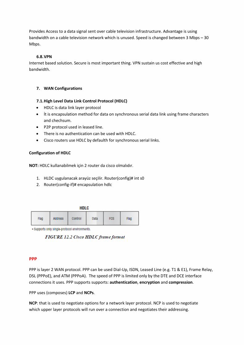
7.1. High Level Data Link Control Protocol (HDLC)
HDLC is data link layer protocol
İt is encapsulation method for data on synchronous serial data link using frame characters
and chechsum.
P2P protocol used in leased line.
There is no authentication can be used with HDLC.
Cisco routers use HDLC by defaulth for synchronous serial links.
Configuration of HDLC
NOT: HDLC kullanabilmek için 2 router da cisco olmalıdır.
1. HLDC uygulanacak arayüz seçilir. Router(config)# int s0
2. Router(config-if)# encapsulation hdlc
PPP
PPP is layer 2 WAN protocol. PPP can be used Dial-Up, ISDN, Leased Line (e.g. T1 & E1), Frame Relay,
DSL (PPPoE), and ATM (PPPoA). The speed of PPP is limited only by the DTE and DCE interface
connections it uses. PPP supports supports: authentication, encryption and compression.
PPP uses (composes) LCP and NCPs.
NCP: that is used to negotiate options for a network layer protocol. NCP is used to negotiate
which upper layer protocols will run over a connection and negotiates their addressing.

LCP: Link Control Protocol handles link setup and termination as well as most of the configuration
options including: authentication, compression error detection, and multilink (load balancing)
LCP responsible to the;
Authentication: CHAP and PAP. CHAP is more secure than PAP
PAP uses clear text, CHAP uses encripted text.
Comprension: PPP supports stacker and predictor compression mode
Error Detection: report the quality of the serial link
Multilink: PPP can be configured to load balance across multiple serial interfaces for greater
bandwidth.
NOT:
DSL (PPPoE), and ATM (PPPoA)
For serial connections, Cisco routers by default use Cisco's version of the HDLC protocol
(Cisco-HDLC) but if you are going to connect to another non-Cisco router it is recommended
to use the PPP protocol and frame encapsulation.
PPP provide Error detection & Error correction.
CHAP uses three way handshake
CHAP authantication periodically occur
Configuration of PPP
PAP Configuration
1. Kurulan network mimarisine ilişkin ip adresleri verilir.
2. Dinamik yada statik olarak gerekli yönlendirmeler yapılır.
3. noktadan noktaya bağlantı yapılacak router'lardan biri seçilir.(Örn: R1)
#username (Diğer noktanın username'i) password (Şifre)
4. Diğer nokta ile bağlantıyı sağlayan arayüz seçilir.
#int s1/1
5. PPP için gerekli encap. komutları girilir.
#encapsulation ppp
#ppp authentication pap
#ppp pap sent-username (kendi username'i) password (atanan şifre)
6. Aynı işlem diğer router için yapılır.

CHAP Configuration
1. Kurulan network mimarisine ilişkin ip adresleri verilir.
2. Dinamik yada statik olarak gerekli yönlendirmeler yapılır.
3. noktadan noktaya bağlantı yapılacak router'lardan biri seçilir.(Örn: R1)
#username (Diğer noktanın username'i) password (Şifre)
4. Diğer nokta ile bağlantıyı sağlayan arayüz seçilir.
#int s1/1
5. PPP için gerekli encap. komutları girilir.
#encapsulation ppp
#ppp authentication chap
6. Aynı işlem diğer router için yapılır.
Frame Relay
Frame Relay uses virtual circuits;
o (SVCs) Switched Virtual Circuits: temporary connections, SVC connections require
call setup and termination for each connection.
o (PVC) to interconnect routers across the WAN.
Unlike with LANs, you cannot send a data link layer broadcast over Frame Relay. Therefore,
Frame Relay networks are called nonbroadcast multiaccess (NBMA) networks Root of Frame
Relay is X.25
Frame Relay provides no error recovery mechanism. It only provides CRC error detection.
CIR (Committed indormation rate) however is a speed that is guaranteed in Frame Relay.
Exceeding trafic marked as Discard eligable.
“Frame Relay Switch” is DCE devices.
In Frame Relay, separete sub-interface for each PVC has unique DLCI.
Frame-relay uses something called LMI (Local Management Interface). LMI has two functions;
It’s a keepalive mechanism.
It tells us if the PVC is active or inactive.
It also gives us a DLCI (Data Link Connection Identifier)
LMI Types;
Cisco
Ansi
Q933A
Frame-relay uses data-link connection identifiers (DLCIs) to build up logical circuits. The
identifiers have local meaning only, that means that their values are unique per router.
Frame Relay use DLCI (Data Link Connection Identifier) in data link layer.

Split-horizon will prevent routing updates from being sent back on the same interface it
received.
Routers(DLCI) which communicate with Frame Relay should be same network .
Inverse ARP protocol enable dynamic “Frame Relay Mapping”
“Show Frame Relay Map” command provide DLCI No and PVC Status.
Cisco support 2 “Frame Relay” encapsulation type;
IETF
Cisco
Status of the Frame Relay;
ACTIVE: the PVC is operational and can transmit data
INACTIVE: the connection from the local router to the switch is working, but the connection
to the remote router is not available
DELETED: the PVC is not present and no LMI information is being received from the Frame
Relay switch
STATIC: the Local Management Interface (LMI) mechanism on the interface is disabled
“show frame-relay map” komutu ile Statüler görüntülebilir.
BECN is used to warn source devices that congestion has occurred on that path while FECN is used
to alert receiving devices.
Configuration of Frame Relay
1. Tüm router, switch, pc ve cloud konularak bağlantıları yapılır.
Bağlantılar sırasında DCE bulut tarafında, DTE router tarafında olmalıdır.
2. Router bacakları ve pc'lere IP adresleri verilir.
3. Router'lar arası statik yada dinamik konfigürasyonları yapılır.
4. Cloud'a girilir. Uygun serial intarface seçilerek DLCI numaraları belirlenir.
DLCI kısmına seçilen serial'ın bağlı olduğu DLCI no'ları, Name'de router isimleri yazılır.
[DCLI = (Başlangıç Router No) ----> (Bitiş Router No)] [NAME = Başlangıç Router ------> Bitiş
Router]
5. Cloud altındaki "Frame-Relay" Sekmesinden serial'lar birbiri ile eşlenerek configürasyona
eklenir.
Port=Serial, Sublink=gideceği router; Port=bulutun gideceği router serial'ı,
sublink=yola çıktığı router.
6. Router'ın cloud'a bağlanan serial interface'i açılarak
a #encapsulation frame-relay
b #frame-relay interface-dlci "(gidilecek router dcli)"

c #frame-relay lmi-type (frame-relay tipi)
Frame-Relay MAP tekniği ile 3. ve 6. adımın b ve c'leri yapılmadan şu komutlarla frame-relay
gerçekleştirilebilir.
6.a'dan sonra
#bandwidth (bant genişliği)
#frame-relay map ip [(gideceği router'ın cloud'a bağlı olduğu IP)] [ilgili DLCI NO (Örneğin R1--
>R2 ise 102)] broadcast
öRN: frame-relay map ip 10.0.0.2 102 broadcast
Not: Bu işlem tüm router'lara yapılır.
Access Lists
Used for firewall security on a router.
Types of Access List;
Standard (1-99, 2000-2699)
Extended (100-199)
Named
Differences Between Standard and Extended Access List
ACL Configuration
1. Router'a girilerek access-list oluşturulur.
ip access-list standard (List No) [List No 1-99 Standart, 100-199 Extended]
deny host (Engellenmek istenen IP)
permit host (izin verilmek istenen IP)
2. access-list uygulanmak istenen arayüz seçilir.

ip access-group (access grup no) in
Named Acceess List
Hem standard hem de extended için uygulanabilir. Tek fark numara yerine isim verilmesi
router(config)#ip access-list <standard | extended> <name>
router(config-std-nacl)#<permit | deny> <source host or network>
<wildcard> <destination host or network> <wildcard>
DHCP Configuration
1. Topolojiye ilişkin konfigürasyonlar yapılır.
2. Router üzerinde DHCP konfigürasyonları yapılır.
#İp dhcp pool “pool adı”
#Network <DHCP dağıtacağı network adresi> <subnet mask>
#Defaulth-router 10.1.8.1
#exit
NOT: belirtilen network içinde verilmesi istenmeyen bir IP adresi varsa;
#ip dhcp excluded-address 10.1.8.1
NOT: defaulth router adresi DHCP ile IP dağıtılacak network’e bağlı olan router bacağına atanır.
IP Proccess in DHCP
The DHCP client broadcasts a DHCPDISCOVER packet.
A DHCP server returns a DHCPOFFER packet.
The client may receive multiple DHCPOFFER packets.
The client chooses a DHCP server based on the DHCPOFFER packet.
The client sends a DHCPREQUEST packet to the server.
The server responds with a DHCPACK message and the lease is finalized.
DNS Configuration
#İp domain-lookup
#İp name-server <IP adresi>
#İp domain-name < ___.com>
NOT: Packets are created when network layer encapsulate segments with destination address and
control information.

Physical Layer
Physical layer translates bits into voltages for transmission across the physical link.
SNMP Protocol
SNMP operate in “Application Layer”
Uses monitoring and management over various devices.
Nice to know informations.
SNMP Manager: The SNMP manager is a central system that is used to monitor traffic as well as provide a
mechanism for the control of these agents
SNMP Agent: SNMP agent is a software component that exists within a network element
Management Information Base (MIB): MIB is a virtual information storage location where network management
information is held.
There is not big differences between SNMP V1 and SNMP V2, SNMP V3 HAS much higher level of security such
as;
Message Integrity
Authentication
Encryption
The two additional messages are added in SNMP2;
GetBulk: Sustain more information
Inform: used to send an acknowledged message from the agent to the manager
Trap: used to send an acknowledged message from the agent to the manager
NOT:

Yukarıdaki topolojide PC-1’den FTP server’a paket aktarılırken MAC adresleri cihazların birbirine
bakan farklı router’kardaki bacaklara ait interface’ler e ait MAC adresleri, IP adresleri ise cihazlara ait
IP adreslerini alır.
NETFLOW
Netflow provides detailed information on packets flowing. Flow is described by these 7 values;
Source IP
Destination IP
Source Port No
Destination Port No
Layer 3 Protocol Type
Input Logical Interface
Type of Service
Netflow’un aktif olduğu cihazlarda netflow raporları oluşturulur. Raporlar UDP veya SCTP (Stream
Control Transmission Protocol) ile netlow data toplama sunucusuna iletilir.
Netflow datasına CLI üzerinden ve “NetFlow Collector” adı verilen sunucular üzerinde ulaşılır. Show
komutları ile anlık olarak CLI üzerinden trafik bilgisi alınabilir. Troubleshooting için büyük öneme
sahiptir.
Purposes and Adventages of Netlow
Network monitoring
Network security
Network Design
Network Billing

DDOS and DOS preventing
Display details of WHO USES network resources
Information can be used by billing and charging for resource utilization
Detailed information for network planing
Detail data for network application and services
Netflow tools are Netflow Collectors and Netflow Analyzers.
NOT:
“show ip cache flow” komutu ile genel netflow istatistikleri görüntülenebilir.
Netflow Network Components;
Network devices that are configured for NetFlow
NetFlow Collector, which receives NetFlow information from network devices
IPV6
IPv6 is equipped with 128 bits for addressing. IPV6 8 adet 4’lü den oluşur. Bu 4’lüde
bulunan ifadeler yalnızca Hexadecimal olabilir(0-9 ve A-F).
0012 yerine 12 yazılabilir. Solda bulunan sıfırların yazılması şart değiş.
Yalnızca 0’lardan oluşan 4’lüler yazılmayabilir. Örneğin;
o ABC:567:0:0:8888:9999:1111:0 ABC:567::8888:9999:1111:0
o 0:0:0:0:0:0:0:5 ::5
Not: Bir adreste yalnızca 1 tane :: olabilir.
Improvments of IPv6
Superior IP Addressing
Larger address space which sustain global connectivity and flexibility. Offers more plug-and-play
options for more devices
Simplified Header
- Better routing efficiency for performance
- Elimination of broadcasts (no Broadcast storm)
- No requirement for processing checksums
- Simplified and more efficient extension header mechaism
Improved Mobility and Security
Mobility enables people with mobile network. IPV6 have auto-configuration feature.
Standardized IPV6 Adresses

Known IPV6 Multicast Groups
Type of IPv6 Adressing
Unicast addressed and delivered to only a single interface Global Unicast is used just like a regular public routable address in IPv4 Multicast is meant to be delivered to multiple interfaces Anycast address identifies multiple interfaces, but packets are delivered only
to the first address it finds Link-local address is private addresses in IPv4 in that they are not meant to
be routed over the Internet. Every IPV6 interface contains at least one loopback address The encapsulation of IPv6 packets inside IPv4 packets is called tunneling
IPV6 Transition (Tunel) Mechanisms
6to4 Tunnels
ISATAP Tunnels (Intra-Site automatic tunnel addresing protocol)
GRE Tunnels (Generic Routing Encapsulation) NOT: Router interface’ine IPV6 adresi atmak için; ipv6 address 2001:db8….. komutu uygulanır.

Router Passwords
Enable Password In order to Access “ENABLE” mode
When we are in global config mode;
# enable password (şifre)
If we do not want to see our password on the screen;
# enable secret (şifre)
Console and VTY (Telnet password) In order to reach router using Telnet or Consol
#line console 0
#password (şifre)
#login
After these commands, we can Access router using “TERMINAL” in PC.
#line vty 0 4
#password (şifre)
#login
After these commands, we can Access router using “Command Probe” in PC.
Not: Bu şifrelerin tümü router da “running – config” komutu ile görülebilir. Bu komut ile şifrelere
ulaşılamaması için;
# service password-encryption komutu kullanılır.
HSRP (Hot Standby Router Protocol)
2(or more) routers act as a single virtual router with the help of “Virtual IP” and “Virtual default
gateway”.
HSRP V1: 0000.0C07.ACxx (multicast address 224.0.0.2)
HSRP V2: 0000.0C9F.Fxxx (multicast address 224.0.0.102)
Currently HSRPv1 is the default version when running HSRP on Cisco devices.
hello packet is sent between the HSRP standby group devices every 3 seconds. If does not receive
any hello packet in 10 seconds. Standby device became active device.
HSRP States
Initial: while turn on
Listen: if there are both active and standby, new router became listen.
Speak: While chosing process routers became.
Standby:
Active:

HSRP version 1 supports up to 256 group numbers. HSRP version 2 supports 4096 group numbers.
VRRP (Virtual Router Redundancy Protocol)
HSRP and VRRP are nearly same but while HSRP cisco spesific, VRRP open standart. Like HSRP only if
active router fail standby start to work.
There can be more than one redundant router.
VRRP also provide load balancing between routers.
VRRP provide 255 VRRP group.
Router which has highest priority number became master.
VRRP allow us to assign more than 1 virtual IP for single port. In this way, single physical port can be
used for different subnets.
Preemption: In case of failure standby became master, master stand up again, standby router return
back to the standby.
We can partially configure load balancing via HSRP or VRRP using “Multiple groups”.
GLBP (Gateway Load Balancing Protocol)
GLBP is a Cisco proprietary protocol and performs the similar function to HSRP and VRRP but it
supports load balancing among members in a GLBP group. [more than 1 active routers at the same
time]
Aynı GLBP grubunda bulunan router’lar birbirlerine her 3 sn’ de bir “hello” mesajı gönderir.
GLBP router’lar AVG ve AVF olmak üzere iki ayrı grupta toplanırlar.
AVG: AVG GLBP nin beynini oluşturur. AVG grupta bulunan diğer router’lara sanal MAC
adresleri atar. AVG nin hizmet verememesi durumunda bu görevi diğer elemanlardan biri
üstlenir. Bir grupta aynı anda sadece 1 adet AVG bulunabilir.
AVF: GLBP grubunda yer alan AVG haricindeki diğer routerlardır.
Bir GLBP grubunda maksimum 4 adet router bulunabilmektedir. GLBP üyesi router’lar kendi
aralarında 224.0.0.102 multicast IP adresini UDP 3222 portunu kullanaraktan haberleşirler.
AVG seçimi router’ların “priority” değerine bakılaraktan gerçekleşir. Priority değeri her bir router için
varsayılan olaraktan 100 değerindedir. Priority değeri 1 ile 255 arasında değişir ve yüksek priority
değeri tercih sebebidir. Priority değerlerinin eşit olması durumunda en yüksek IP adresine sahip
router AVG seçilir.
Preempt modu AVF’ler için varsayılan olarak açık konumdadır.

GLBP Load Balancıng
1. Round Robin (Default)
2. Host Dependent: Kullanıcıların sadece belirtilen router üzerinden çıkış yapmasının sağlandığı
load-balancing türüdür.
3. Weighted: GLBP işlemi dahilinde her bir router’a atanmış “weight” değeri oranınca
kullanıcıların routerlar arasında paylaştırılması esasına dayanır.
GLBP supports clear text and MD5 password authentication between GLBP group members.
First Hop Redundancy Protocol (FHRP)
Tek bir “default gateway” adresinin birden fazla router tarafından kullanılmasına sağlar. Fail-over anında
yedeklilik sağlar. Bu protokol yalnızca router değil diğer cihazlarda da kullanılmaktadır.
Examples of FHRP are;
VRRP
HSRP
GLBP
VRRP (Virtual Router Redundancy Protocol) :
Birden çok yönlendirici (router)'nin tek bir sanal yönlendirici (virtual router) gibi davranmasına imkan sağlar.
VRRP’nin başlıca özellikleri;
Redundancy
Load Sharing (VRRP LAN cihazlarının trafiğinin birden fazla yönlendirici üzerinden iletilmesine imkan
sağlar)
Multiple virtual routers support (VRRP, yönlendiricinin fiziksel portunda 255 adete kadar sanal
yönlendirici (VRRP grubu)'yi destekler. Birden çok yönlendirici desteği alan bir LAN topolijisinde yedeklilik
ve yük paylaşımı sağlanmış olur.) Kısacası 1 router 1’den fazla router’ın yedeği olabilir.)
Multiple IP adresses: Ethernet bağlantı noktasında birden fazla alt ağ (subnet) yapılandırılırsa her alt
ağ için ayrı bir VRRP yapılandırması yapılabilir.
Preemption: Ana makinede sıkıntı olursa yedek ana olur. Ana makine düzelince tekrar yedeğe geçer.
HSRP (Hot Standby Router Protocol)
Sustain redundancy. While one of the router is Active, other would be standby. Connection realized
by the means of hello packets in every 3 seconds. This time period can be adjustable.
HSRP ve VRRP Arasındaki Farklar.
o HSRP Cisco’ya özel bir protokolken VRRP IEEE standartında açık bir protokoldür.
o HSRP’deki aktif yönlendirici (active router) VRRP’de ana yönlendirici olarak adlandırılır.
o VRRP’de yönlendiricilere sanal yönlendirici grubunun IP adresi verilebilir. Sanal yönlendirici grubunun IP adresi verilen yönlendirici ana yönlendirici olur.

o HSRP’de sadece bir adet yedek yönlendirici bulunurken VRRP’de birden fazla yedek yönlendirici bulunabilir.
GLBP (Gateway Load Balancing Protocol)
Cisco’ya özgüdür. GLBP’yi diğer dinamik gateway yedekliliği sağlayan protokollerden ayıran en büyük
özelliği aktif olarak paket aktarımının yapıldığı birden fazla router’ın aynı anda çalışmasına
imkan sağlamasıdır. GLBP bununla da kalmayıp aktif çalışan routerlar üzerinde istenilen
düzeyde load-balancing yapılmasına da imkân sağlar.
GLBP router'lar AVG ve AVF olmak üzere iki ayrı grupta toplanırlar;
AVG(Active Virtual Gateway) Router’lara sanal MAC’ler atayan, grubun beyni
AVF(Active Virtual Forwarder) Beyin olmayan routerlar
GLBP ile Round Robin, Host Dependent ve Weighted yük dengeleme yapılabilir.
SNMP
Using for monitoring. SNMP consist of 3 component;
SNMP Manager(NMS): Software run on the pc of the network administer.
SNMP Agent: software that run on the network devices.
Management Inf. Base (MIB): MIB contains a set of questions that the SNMP Manager can ask the
Agent
SNMP Versions:
SNMP V1,
SNMP V2c = (SNMP1+INFORM and GETBULK messages)
SNMP V3 = (SNMPV2c+Security)
SNMPV1 and SNMPV2 have community string security;
Read-Only (RO): Gives read-only access to the MIB
Read-Write(RW): This method allows SNMP Manager to change the configuration of the
managed router/switch
SNMP V3 Security has; Authentication, Message integrity and Privacy (Encryption)
SNMP Messages;
SNMP GET (NEXT, RESPONSE) : Retrieve information.

SNMP SET: Used by the SNMP Manager to modify or assign the value to the SNMP Agents.
SNMP TRAP: TRAP messages are initiated from the SNMP Agents to inform the SNMP Manager on
the occurrence of an event. (olay olursa bilgilendiriyor.)
SNMP INFORM: More reliable than TRAP. Trap use UDP, Inform TCP.
SNMP GETBULK: operation efficiently retrieve large blocks of data
Syslog
Syslog is an excellent tool for system monitoring.
Syslog messeges can be stored in;
Internal buffer, Syslog Server, Flash Memory, Nonconsole Terminal, Console Line.
Syslog messages include; sequence no, time stamp, facility (protocol, modüle, process..) and
severity (from 0 to 7)
0 is most emergence. [0 -> Emergence, 1->Alert, 2->critic, 3->error, 4->warning, 5->notification,
6->informal, 7->debug]
Eventually All Critical Errors Will Not Involve Damage
Default Syslog facility level is 7.
NOTLAR:

MTU = Maximum Unit (Packet) size
line vty 0 4 (bu komutu yazdıktan sonra telnet bağlantısı yapabilmek için vty password ü
vermeliyiz.)
show versiyon ile router belleklerinin ve ne kadarının kullanıldığını görebiliriz.
segment LAYER 4
STP prevents loop in local area network so "Layer 2"
Router(config)# service password-encryption
configuration dasyasındaki daha önce girilmiş yada girilecek tüm text olan paroları şifreler.
Virtual interface güvenliği için;
1. Virtual Terminal için password atanabilir.
2. Access-list oluşturulur. Fiziksel arayüzler için Access-Group, Sanal arayüzler için Access-
class komutları kullanılır.
Global command = Global configuration mode
Cisco da "traceroute" var. diğeri yok
Cisco da "ipconfig" kullanılmıyor.
"show sessions" kurulu session'ları gösterir
line vty "Sayı" belirtilen sayı kadar telnet, ssh session'ına izin verilir.

PPP supports both synchronous (like analog phone lines) and asynchronous circuits (such as
ISDN or digital links). With synchronous circuits we need to use clock rate.
PPP de authantication türleri arasında tek komut ile önceliklendirme yapılabilir. Örneğin;
(config-if)# ppp authentication chap pap “chap uygula olmazsa pap demek”
A CSU/DSU terminates a digital local loop, A modem terminates an analog local loop
FCS (Frame Check Sequence) is 4 octed field used to verify frame was received without loss
and error.
NAT – PAT
Static NAt: 1to1 mapping.
Dynamic NAT: It must be enough real IP addresses for everyone who wants to send packets
through the Internet. If all the public IP addresses are already allocated, the router discards the
packet that requires a public IP address.
Pat (NAT Overload ): permits multiple devices on LAN to be mapped to a single public IP address
with different port numbers.
PAT can support 216 IP adress.
Copyright © 2022 FDOKUMEN