Steam Reformer Surveys - Techniques for Optimization of Primary Reformer Operation
71
Steam Reformer Surveys Gerard B. Hawkins Managing Director Techniques for Optimization of Primary Reformer Operation
-
Upload
independent -
Category
Documents
-
view
2 -
download
0
Transcript of Steam Reformer Surveys - Techniques for Optimization of Primary Reformer Operation

Steam Reformer Surveys
Gerard B. Hawkins Managing Director
Techniques for Optimization of Primary Reformer Operation

Introduction Background Radiation and Temperature
Measurement Reformer Survey Inputs Case Study 1 Case Study 2 Case Study 3 Conclusions

Reformer is at the heart of the plant ◦ Converts feed gas to Syngas ◦ Complex operation ◦ Integrated design ◦ Main energy consumer ◦ Most expensive single plant item
Reformer is often a throughput constraint

Combination of techniques used Tube Wall Temperature measurement Plant heat & mass reconciliation Reformer simulations
Output provides assessment of Catalyst performance Reformer operation Operating limits Tube life estimation

Introduction Background Radiation and Temperature
Measurement Reformer Survey Inputs Case Study 1 Case Study 2 Case Study 3 Conclusions

Tube Wall

Background radiation affects readings Minimize errors when using IR pyrometer ◦ Use emissivity setting of 1.00 ◦ Use correction formula Post processing calculation Use Gold Cup pyrometer

Reformer Surveys TWT Survey (Optical Pyrometer)
Gold Cup: •Most accurate temperature measurement •Eliminates the effects of background radiation •Limited number of tubes can be measured •Large cumbersome equipment •Significantly more readings on side fired furnaces

Reformer Surveys TWT Survey (Optical Pyrometer)
Optical Pyrometer: •Good for taking 'lots' of readings
•Most tubes are visible •Easy to use •Portable •Absolute figures not accurate •Relative figures are more accurate

Reformer Surveys TWT Survey (Optical Pyrometer)
•Measures total radiation from target •Picks up radiation from
•refractory •flue gas •other tubes
•Can not distinguish between •radiation emitted and radiation reflected
•Measured temperature is high •Typically 68-104°F (20-40°C)

Reformer Surveys TWT Survey (Optical Pyrometer)
•Cyclops 52/153 has narrow bandwidth •0.8-1.1 micron •Reduces radiation from flue gas effect
•Ensure that reading taken at 90° to tubes •Both vertically and horizontally
•It is possible to correct for these radiation effects •Temperature to Fourth Power
•Lots of data should eliminate random errors

Reformer Surveys TWT Survey (Optical Pyrometer)
•Correct to minimize background radiation effects •Use a Stefan-Bolzman Equation Tt = {(Tm
4 - [1 -e] Tw4)/e}0.25
• Tt : True temperature • Tm : Measured temperature • Tw : Background temperature • e : emissivity

Reformer Surveys TWT Survey (Optical Pyrometer)
•Must correct measured temperatures •For background readings use temperatures from: •Refractory (walls, floor and roof)
•Use following expression Tw = {1/N *( TW1
4 + TW24+ TW3
4 .…+ TWN4)}0.25
•N is number of readings

Reformer Surveys TWT Survey (Optical Pyrometer)
•Pyrometer used with an emissivity of 1 •Emissivity of 0.85 used in correction •Plant data reconciled and furnace modelled in ASPEN HYSYS V8 •Corrected temperature compared to simulated values

830
790
750
710
Temperature ºC
40
35
30
25
20
15
10
5A B C D E F G H
RowTube N
umber
Hot Zone
Cold Zones

Introduction Background Radiation and Temperature
Measurement Reformer Survey Inputs Case Study 1 Case Study 2 Case Study 3 Conclusions

Tube wall temperature survey ◦ Tube temperatures ◦ Background temperatures
Process operating data collection ◦ Pressure, Temperature, Flows
Chemical analysis of all streams Radiant and convection section data ◦ Geometry, Layouts …

VULCAN CERES - data fitting package used to reconcile data
The use VULCAN REFSIM to model furnace Close H&M balance on process and flue
gas using Aspen HYSYS V8 Allow certain values to float Wider data envelope = better fit

VULCAN REFSIM - fully coupled computer model ◦ Radiant heat transfer in flue gas ◦ Heat transfer inside tubes ◦ Reaction kinetics inside tubes
Radiation based on proven theory Tubeside based on operating plant data

Heat Flows
Radiation
Convection
Tube Fluegas Flame Wall

680700720740760780800820840860
0 0.2 0.4 0.6 0.8 1 1.2Fractional Distance Down Tube
Tem
pera
ture
(°C
)
SimulationMeasured

Fire Extinguisher ◦ Inject via side peepholes or burner ignition port ◦ Check for flue gas maldistribution ◦ See case study 1 ◦ Can use K2CO3
Fuel gas pressures ◦ Check for fuel mal-distribution ◦ Use standard pressure gauge

Combustion air pressure ◦ Use standard manometer ◦ Check by row and then by burner
Visual Inspection ◦ Look at tubes, refractory and burners ◦ Check for deviations from expectation
Design Philosophy ◦ Check for deviations from expectation

Check wind box pressure ◦ Ensure even firing through out furnace
Check oxygen levels ◦ Ensure even combustion air flow
Thermal Imaging ◦ Check for refractory damage

Reformer Surveys Summary
A Reformer Survey involves: •Collection and analysis of data from both the process and flue gas sides •Assess the performance of the reformer •Assess the performance of the catalyst Collecting data from the whole reformer minimizes errors.

Reformer Surveys Summary
Typical outputs from a Reformer Survey includes:
• Catalyst performance • Real tube skin temperature • Reformer balance • Efficiency gains • Benchmarking

Reformer Surveys Content
• Introduction • Safety • Preparation • Onsite Data Collection • TWT Survey • Observation/Troubleshooting • Modelling and Analysis • Results/Outputs • Case Studies • Conclusions
Reformer Surveys Introduction
• Primary is the most complicated and expensive piece of equipment on the plant •Heat transfer - Provides sensible heat and heat of reaction •High pressure and very high temperature •Data collection can highlight trends •Reformer survey required to allow full diagnosis

Main additional risks are burns and overheating, ◦ Burns from exposed hot surfaces ◦ Radiation burns via open peepholes ◦ Burns due to hot gas or flames ◦ Heat stroke/Dehydration

In addition to standard PPE the following should be considered,
◦ Heat resistant gloves ◦ Flame retardant overalls ◦ Furnace eye protection

Reformer Surveys Typical Work Remit
Typically a reformer survey consists of a number of actions:
•Preparation •On-site data collection •Tube wall temperature measurement •Observations and trouble shooting •Modelling and analysis •Report writing

Reformer Surveys Preparation
Usually carried out prior to site visit and would normally include:
• A wish list of requirements from the plant • Mechanical design of the reformer • Piping and instrument drawings • Process flow diagrams • Any known process problems

Reformer Surveys On-site Data Collected
•Feed, Steam, Fuel, Combustion air data including, •Flows •Pressures •Temperatures
•Gas analysis from on line analyzers & laboratories •Reformer dimensions •Tube temperatures using an optical pyrometer (or gold cup)

Reformer Surveys Tube Wall Temperature Survey
•Tube skin temperature used to fit temperature profile •Generates an activity figure
•No one ideal method of measurement •Two methods currently used
•Optical Pyrometer •Gold Cup
•Both have advantages and disadvantages

Introduction Background Radiation and Temperature
Measurement Reformer Survey Inputs Case Study 1 Case Study 2 Case Study 3 Conclusions

• Large scale ammonia plant • Tube temperatures split in box • No apparent process reason
Hot Zones
Cold Zones

• Eliminated other possibilities • Maldistribution due to
•Process gas • Fuel gas • Firing
• Only left with combustion air • Subsequent shut down
• Found one of the two air dampers stuck • Repaired

• After shut down temperatures were

Survey highlighted an problem on the furnace
By working closely with plant personnel, determined root cause
Subsequent work proved root cause
Problem worth US$750,000 per year

Customer complained of high ATE Survey found ◦ High box pressure (-2 or -3 mm H2O) ◦ Afterburning in centre of furnace but O2 levels exit
box in excess of 2.5 % ◦ Cool outer rows ◦ Hot centre rows

Design of combustion air duct was symmetrical
Combustion air and flue gas fans at limit
Insufficient driving force to get air to centre of furnace
Cause after burning

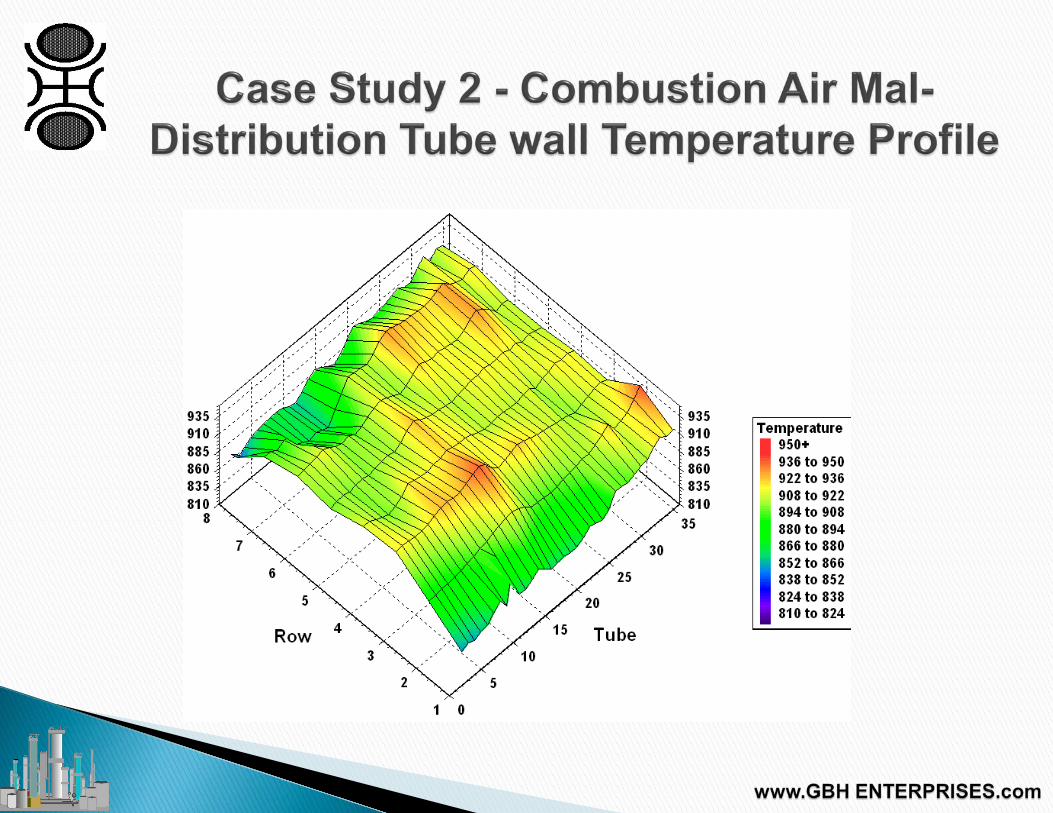
• Survey on plant found odd temperature distribution • Not explained by burner pressure • Not explained by combustion air mal-
distribution
10 18
26 34
42 50
58 66
2 3
4 5
860
880
900
920
940
860
880
900
920
940
Temperature
940+ 932 to 940 924 to 932 916 to 924 908 to 916 900 to 908 892 to 900 884 to 892 876 to 884 868 to 876 860 to 868
Row Number
Tube Number

Checks on furnace geometry highlighted an issue ◦ Outer lanes were the same size as the inner
lanes ◦ Outer row of burners were rated at 70% of
the inner burners Injected dry powder from fire
extinguisher into furnace ◦ Unusual flow patterns


Computational Fluid Dynamics was used to model reformer in detail
Burners
Tunnel Ports
Velocity Vectors

A B C D E F Tube Number

CFD simulations matched the observations from the plant ◦ Dry powder tests and TWT measurements
Three proposed solutions to eliminate the effect ◦ Increase burner size to match tunnel size ◦ Decrease furnace width to match burner size ◦ Increase velocity through the burners

70% 100% burner burner
100% 100% burner burner
70% 100% burner burner
Recirculating Case
Solution 1 Solution 2
100% 2.1 m
100% 2.1 m
100% 2.1 m
100% 2.1 m
70% 1.5 m
100% 2.1 m

Solution 1 - Requires 100% burner in outside rows ◦ Difficult to achieve ◦ Requires either Modification of burners Replace with 100% burners ◦ But too much heat flux ◦ Must increase process gas flow ◦ Install orifice plates inlet all tubes ◦ Outer rows are larger than inner

Solution 2 is to reduce furnace width so outer lane width matches the 70% burners ◦ Requires modification to refractory ◦ Increase in number of ports on the outer
rows of tunnels Solution 3 - Increase velocity through
outer row of burners ◦ 154% of existing velocity

Highlighted a mal-distribution Costing plant approximately US$350,000 in
lost production Reduce peak tube temperatures Methodology proved initial theory Allowed for a set of solutions to be
proposed

Visual Inspection ◦ Look at tubes, refractory and burners ◦ Inspect external casing ◦ Check for deviations from expectation
Design Philosophy ◦ Check for deviations from expectation
Fuel gas pressures ◦ Check for fuel mal-distribution ◦ Use standard pressure gauge

Combustion air pressure ◦ Use standard manometer ◦ Check by row and then by burner
Fire Extinguisher ◦ Inject via side peepholes or burner
ignition port ◦ Check for flue gas maldistribution ◦ See case study 3 ◦ Can use K2CO3

Check wind box pressure ◦ Ensure even firing through out furnace
Check oxygen levels ◦ Ensure complete combustion ◦ Ensure even combustion air flow
Thermal Imaging ◦ Check for refractory damage

Reformer Surveys Modelling and Analysis
Computer packages used: • VULCAN REFSIM
• Heat and Mass Transfer in radiant box
•Aspen HYSYS • Flowsheeting package
• VULCAN TP3 or VULCAN CERES •Match data between models

Reformer Surveys Modelling and Analysis - VULCAN
REFSIM •Developed using research and plant data •Accurate analysis of Radiant box •Results are:
•Kinetic model •Equilibrium model •Tube wall temperatures & margins •Pressure drops •Carbon laydown prediction

Reformer Surveys Modelling and Analysis – Aspen HYSYS V8
•Flowsheeting package •Contains VULCAN REFSIM Reformer and Reactor models •Used for detail modelling of the plant
•Both front end and loop •Steam system •Heat recovery
•Results include: •Flow sheet of the plant •Heat loads of coils and exchangers

Reformer Survey Results - Statistical Temp. Analysis
•Look at various splits of box •Depending on design and size
•Look at •Average •Maximum •Minimum •Standard deviation •Spreads
•Three dimensional plots •Frequency plots •Compare to others

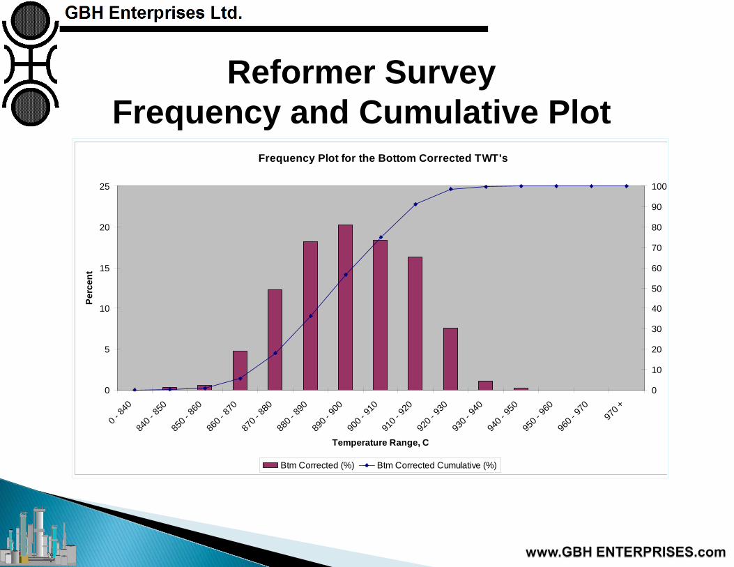
Reformer Survey Frequency and Cumulative Plot
Frequency Plot for the Bottom Corrected TWT's
0
5
10
15
20
25
0 - 84
0
840 -
850
850 -
860
860 -
870
870 -
880
880 -
890
890 -
900
900 -
910
910 -
920
920 -
930
930 -
940
940 -
950
950 -
960
960 -
970
970 +
Temperature Range, C
Perc
ent
0
10
20
30
40
50
60
70
80
90
100
Btm Corrected (%) Btm Corrected Cumulative (%)

• Detailed heat and mass balance of Primary reformer •Using kinetics and equilibrium •Pressure drop prediction •Process and tube temperature profiles
• Flowsheet of plant • Ideas for plant improvements •Efficiency or Rate increases

Reformer Survey Tube Wall Temperature Results
•Max tube wall temperature •Predicted by VULCAN REFSIM
•Tube wall temperature margin is •Predicted by VULCAN REFSIM •Worst case analysis •Based on GBHE Codes •Based on 100,000 hours operation

Introduction Background Radiation and Temperature
Measurement Reformer Survey Inputs Case Study 1 Case Study 2 Case Study 3 Conclusions

Reformer Surveys GBHE Tube wall Temperature Margins •Based on
•inlet pressure •hoop stress calculation
•GBHE Tube wall temperature margins do not include •transient stresses (Start Ups/Shut Downs) •longitudinal stresses •bending stresses •weld region stresses

Reformer Surveys General Conclusions
Indications of: •Tube appearance
•Hot spots or bands •The operation of reformer •Optimization •Current catalyst performance •Benchmarking •Instrument Calibration •Oxygen levels

• Air damper stuck • Air preheater leaks • Correct exit temperatures • Flue gas recirculation • Flue gas maldistribution • Explanation of early tube failures

Accurate assessment of reformer requires ◦ Tube wall temperature survey ◦ Extensive data collection ◦ Data reconciliation by H&M balance ◦ Fully predictive reformer model
All of the above used together

Proven and robust methodology ◦ Used on over 30 plants
Allows identification of problems ◦ Identified NEW issues with designs
Has saved customers money ◦ Short Term - Efficiency/Production
improvements ◦ Long Term - Extended tube life