Status of cryogenic layering for NIF ignition targets
7
UCRL-CONF-214826 Status Of Cryogenic Layering For NIF Ignition Targets J. D. Moody, B. J. Kozioziemski, R. L. London, D. S. Montgomery, J. J. Sanchez, J. D. Sater, D. N. Bittner, J. A. Burmann, R. L. Jones, J. Pipes, D. Stefanescu August 25, 2005 Fourth International Conference on Inertial Fusion Sciences and Applications Biarritz, France September 4, 2005 through September 9, 2005
-
Upload
independent -
Category
Documents
-
view
5 -
download
0
Transcript of Status of cryogenic layering for NIF ignition targets

UCRL-CONF-214826
Status Of Cryogenic Layering ForNIF Ignition Targets
J. D. Moody, B. J. Kozioziemski, R. L. London, D. S.Montgomery, J. J. Sanchez, J. D. Sater, D. N. Bittner, J.A. Burmann, R. L. Jones, J. Pipes, D. Stefanescu
August 25, 2005
Fourth International Conference on Inertial Fusion Sciencesand ApplicationsBiarritz, FranceSeptember 4, 2005 through September 9, 2005

Disclaimer
This document was prepared as an account of work sponsored by an agency of the United States Government. Neither the United States Government nor the University of California nor any of their employees, makes any warranty, express or implied, or assumes any legal liability or responsibility for the accuracy, completeness, or usefulness of any information, apparatus, product, or process disclosed, or represents that its use would not infringe privately owned rights. Reference herein to any specific commercial product, process, or service by trade name, trademark, manufacturer, or otherwise, does not necessarily constitute or imply its endorsement, recommendation, or favoring by the United States Government or the University of California. The views and opinions of authors expressed herein do not necessarily state or reflect those of the United States Government or the University of California, and shall not be used for advertising or product endorsement purposes.

Status of cryogenic layering for NIF ignition targets
J. D. Moody, B. J. Kozioziemski, R. L. London, D. S. Montgomery[1], J. J. Sanchez, J. D. Sater, D. N. Bittner[2] J. A. Burmann[2], R. L. Jones, J. Pipes, and D. Stefanescu[3]
Lawrence Livermore National Laboratory, P.O. Box 808, Livermore, CA 94551, USA [1] Los Alamos National Laboratory, Los Alamos, NM, 87845, USA [2]Schafer Corporation, Livermore, CA 94551, USA [3] IAP World Services, Livermore, CA 94550, USA
Abstract
Recent advances in cryogenic layering include the development of a self-contained and self-filling cro hohlraum, application of phase contrast x-ray measurements for ice layer characterization, an ice layer achieved with beta-layering which meets the NIF specification for surface roughness at 1.5 K below the triple point. In addition, recent results on target integration in a hohlraum show effective layer control using heaters on the hohlraum.
Introduction
The current design for the NIF indirect drive ignition target consists of a cryogenically cooled fuel capsule suspended in the center of a hohlraum[1]. The fuel capsule consists of an ablator shell (either Be or CH) with a layer of DT (deuterium-tritium) ice on the inside. The hohlraum is filled with a SiO2 foam (silica aerogel) at 1 mg/cc and He gas at a pressure of ~ 2-3 Torr. High intensity laser beams pass through the laser entrance holes (LEHs) and through the foam/gas medium to strike the hohlraum inner wall where they are converted to x-rays which illuminate the fuel capsule. The capsule implodes compressing and heating the DT to conditions sufficient for thermonuclear fusion. One requirement for significant fusion energy yield is that the initial DT ice layer be sufficiently smooth so as not to seed Rayleigh-Taylor instabilities that disrupt the implosion.
The ice surface smoothness requirement is defined in terms of a 2D power spectrum. Achieving an ice layer meeting this requirement involves a number of important steps. For example, the DT fuel must be loaded into the ablator capsule. This is done by condensing the fuel from a 1 cc reservoir which is warm-loaded with about 2-3 atm of DT gas. Once the fuel is placed into the capsule the DT ice layer is slowly formed. A process called beta-layering which is a consequence of the self-heating of DT from radioactive decay causes the inner ice surface to slowly conform to the local temperature isotherms. The cooling rate is known to play an important role is determining the resulting roughness of the ice layer. The final ice temperature should be at least 1.5 K below the DT triple point (19.79 K). A low ice temperature results in a low vapor pressure of DT inside the ice layer which is favorable to ignition. However, as the ice becomes colder the ice surface becomes rougher. During the cool-down process the ice layer roughness is monitored with phase contrast x-ray imaging. This gives a measure of the 1D power spectrum which can be compared to the required 1D power spectrum. Conduction of heat generated by the DT to the surrounding hohlraum wall results in

isotherms at the ice surface which are slightly elliptical. Heaters placed on the body of the hohlraum are used to adjust the isotherms to make them nearly spherical. This adjustment is called thermal shimming of the hohlraum thermal field. All of these steps must be coordinated to provide an ice layer which meets the smoothness and temperature requirement for an ignition experiment.
There has been significant progress and successful demonstration of all these steps. The remainder of this paper will describe in greater detail each step and recent results associated with them.
Fuel loading of the capsule
We have developed a self-filling target which allows a DT cryo ignition hohlraum to be filled with DT and transported to NIF at room temperature (RT). The fuel is loaded into a 1 cc volume at about 3 atm of pressure at RT. The reservoir is connected to the capsule through a fill tube which narrows to 5 µm ID where it attaches to the capsule. The filling procedure begins by cooling the reservoir and hohlraum down to about 30 K. The reservoir temperature is kept lower than the hohlraum during this cooldown in order to condense any impurities in the reservoir. The hohlraum is then cooled to about 20 K and the reservoir is heated to between 30 to 50 K. Once the reservoir pressure exceeds the sum of the DT vapor pressure in the capsule, the He3 pressure, and the capillary pressure associated with liquid DT flow through the fill tube DT liquid begins to condense in the fill tube at the hohlraum wall and then flows into the capsule. Approximately 30 minutes or less is required to transfer the needed quantity of DT into the capsule.
Figure 1. A 2mm diameter polyimide shell with a fill tube at 2 o’clock is partially filled with DT from the self-filling reservoir. The hohlraum axis is horizontal and the capsule is viewed through the laser entrance holes; the capsule is backlit using red light.
Figure 1 shows a transparent capsule with liquid DT inside that was filled from the reservoir. The shell is backlit and the camera views the shell through the LEHs. He3 buildup in the reservoir makes it gradually more difficult to fill the capsule. We have found that this type of target can be used for about 3 to 4 weeks of experiments before the He3 buildup makes it impossible to fill the capsule with DT. Ignition hohlraums must be shot within 36 hours of the initial DT fill in order to limit the He3 partial pressure in the hotspot.

Ice layer formation
Beta decay of the tritium in the DT ice produces 50 µW/cm3 of heat which is conducted through the ice, the shell, the foam/He gas filling the hohlraum to the hohlraum walls. Variations in the thickness of the ice layer lead to temperature variations at the inner ice surface. The local temperature and local DT vapor density set the relative rate at which DT molecules sublime and condense on this inner ice surface. The consequence of this is that the ice slowly redistributes itself in a process called beta-layering. Once the inner ice surface matches an isotherm there is no more DT redistribution.as the rate of sublimation and condensation is in equilibrium everywhere on the ice surface. Since the rate of ice redistribution is proportional to the surface temperature variation the ice layer approaches equilibrium asymtotically. The timescale for one e-fold change in the ice redistribution is about 30 minutes.
The ice layer is formed near the triple point. After this the ice temperature is slowly decreased until it reaches the aim value of 1.5 K below the triple point. Experiments at LLNL, LANL, LLE, and CEA show that the ice surface becomes rougher as the temperature decreases. The surface develops small scalesize crystal facets which become more prominent at lower temperature. It is not known for sure if these facets are part of the original layer or if they develop spontaneously. Empirical studies show that cooling the layer at a slow rate can minimize the surface roughness. One area of active research involves developing a better understanding of the roughening process and how to control it.
Ice layer diagnosis using x-ray phase contrast imaging
Quantitative determination of the ice surface roughness is done using the technique of phase contrast x-ray imaging. A copper anode x-ray source with a measured spot size of about 5 µm illuminates the target from a distance of about 80 cm. The majority of x-rays are at 8 keV with some spread around this. The capsule and DT ice refract the x-rays according to their index of refraction at the x-ray wavelength. A detector is placed about 800 cm from the target to collect the x-rays. As the x-rays propagate to the detector and form an image the refraction causes the boundaries between materials with different dielectric values to appear with a strong x-ray intensity contrast.
We have used both a directly illuminated CCD detector as well as a scintillator detector coupled through an optical package to an optical CCD. A directly illuminated CCD pixel reaches nearly full well capacity after ~250 x-ray photons. This takes about 6 seconds for the commercially available Cu anode source used in the experiment. In order to achieve sufficient signal-to-noise for accurately diagnosing the ice layer roughness 20 images are averaged together. Thus, a total of 120 seconds of x-ray exposure is required to achieve one image with sufficient signal-to-noise. The scintillator based detector has a coupling resulting in ~1 digital count (about 2 electrons) for every x-ray photon. A two minute exposure time also gives sufficient signal-to-noise for accurate analysis of the ice layer roughness.

Figure 2 (a) shows a DT ice layer at 0.4 K below the DT triple point in a Be shell obtained using x-ray phase contrast imaging and a direct detection CCD. Figure 2 (b) shows the spectral analysis of the ice surface (at 0.4 and 1.5 K below the triple point) in comparison with the NIF ice specification for ice roughness. Both ice surfaces meet or exceed the NIF specification for ice roughness.
10-5
0.0001
0.001
0.01
0.1
1
10
0 20 40 60 80 100
NIF D1.1Tmelt-0.4KTmelt-1.5K
Mod
al p
ower
[µm
2 ]
Mode
DT ice surface
(a) (b)
Modes dominated by fill-tube attachment
Figure 2 (a) The DT ice surface is visible with x-ray phase contrast imaging through a Be shell. The fill tube is visible at the top. (b) The ice layer meets or exceeds the NIF ice roughness specification for modes above mode 9. A cold region caused by glue around the fill tube leads to increased roughness in the low modes.
Capsule vibration must be controlled due to the long time exposure required for x-ray characterization. Simulations show that target vibration effectively adds white noise to the power spectrum. Simulations show that accurate ice characterization out to mode 120 requires limiting the target vibration amplitude to 1 µm during characterization.
Target integration
Heat generated by the DT is conducted to the hohlraum wall creating isotherms which are naturally eliptical due to the cylindrical shape of the hohlraum. Two azimuthally symmetric heaters on the body of the hohlraum are used to “shim” the boundary temperature on the hohlraum and create temperature isotherms near the ice surface which are very nearly spherical. These heaters are independently controlled so they can introduce symmetric and asymmetric thermal corrections to the ice layer as needed.
Figure 3 (a) shows a DT ice layer in a transparent shell in a hohlraum which is offset axially. This is a consequence of initially growing the ice layer in a thermal gradient as this has proven experimentally to be the best procedure. As labeled in the figure, the top region is colder than the bottom region and this results in a thicker ice layer on the cold side and a thinner layer on the warm side. Figure 3 (b) shows the layer centered after adjusting the hohlraum shimming heaters and waiting several layering times for the ice to redistribute. The layer in Fig. 3 (b) has an RMS roughness of ≤ 2 µm at a temperature of
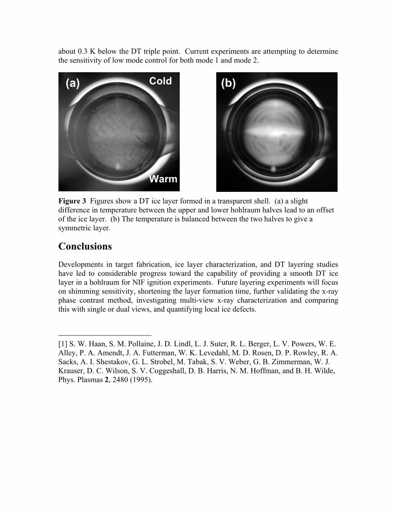
about 0.3 K below the DT triple point. Current experiments are attempting to determine the sensitivity of low mode control for both mode 1 and mode 2.
Cold
Warm
(a) (b)
Figure 3 Figures show a DT ice layer formed in a transparent shell. (a) a slight difference in temperature between the upper and lower hohlraum halves lead to an offset of the ice layer. (b) The temperature is balanced between the two halves to give a symmetric layer.
Conclusions
Developments in target fabrication, ice layer characterization, and DT layering studies have led to considerable progress toward the capability of providing a smooth DT ice layer in a hohlraum for NIF ignition experiments. Future layering experiments will focus on shimming sensitivity, shortening the layer formation time, further validating the x-ray phase contrast method, investigating multi-view x-ray characterization and comparing this with single or dual views, and quantifying local ice defects.
[1] S. W. Haan, S. M. Pollaine, J. D. Lindl, L. J. Suter, R. L. Berger, L. V. Powers, W. E. Alley, P. A. Amendt, J. A. Futterman, W. K. Levedahl, M. D. Rosen, D. P. Rowley, R. A. Sacks, A. I. Shestakov, G. L. Strobel, M. Tabak, S. V. Weber, G. B. Zimmerman, W. J. Krauser, D. C. Wilson, S. V. Coggeshall, D. B. Harris, N. M. Hoffman, and B. H. Wilde, Phys. Plasmas 2, 2480 (1995).
nijhuis2
Text Box
This work was performed under the auspices of the U.S. Department of Energy by University of California, Lawrence Livermore National Laboratory under contract W-7405-Eng-48.