urban space and the proliferation of industrial labor practices ...
Upload
khangminh22Category
view
3download
0
State of Hawai‘i DEPARTMENT OF LABOR AND INDUSTRIAL RELATIONS
Princess Ruth Ke‘elikolani Building 830 Punchbowl Street
Honolulu, Hawai‘i 96813
September 17, 2018 WAGE RATE SCHEDULE BULLETIN NO. 493
This schedule of wage rates contained herein is recognized by the Director of Labor and Industrial Relations to be prevailing on public construction work for the purposes of Chapter 104, Hawai‘i Revised Statutes. The schedule of wage rates determines the applicable wage determination for each classification and does not impose any staffing requirements for any classification. The schedule of wage rates is applicable only to those laborers and mechanics employed at the site of work. As required by law, future wage rates for laborers and mechanics are incorporated into this bulletin based on available information and are subject to change. Whenever the Director determines that the prevailing wage has increased as shown in the wage rate schedule, the contractor must increase the wages accordingly during the performance of the contract. For addenda or additional wage rate schedules, please consult the Internet at http://labor.hawaii.gov/rs. The Apprentice Schedule is available on the Internet or upon request from the Research and Statistics Office. Pursuant to Section 12-22-6 (1), Hawai‘i Administrative Rules, the Apprentice Schedule is applicable only to apprentices who are parties to apprenticeship agreements registered with or recognized by the Department of Labor and Industrial Relations. Questions on the schedule should be referred to the Research and Statistics Office at (808) 586-9005. The next regular schedule will be issued on or about February 15, 2019. LEONARD HOSHIJO
Director
STATE OF HAWAI‘I DAVID Y. IGE, Governor
DEPARTMENT OF LABOR AND INDUSTRIAL RELATIONS LEONARD HOSHIJO, Director
LOIS IYOMASA, Deputy Director
RESEARCH AND STATISTICS OFFICE PHYLLIS DAYAO, Research & Statistics Officer
OPERATIONS MANAGEMENT INFORMATION STAFF Janet Kaya, Supervisor
Geraldyne Lacno, Research Statistician Elienne Yoshida, Research Statistician
In cooperation with: WAGE STANDARDS DIVISION PAMELA MARTIN, Administrator
Prevailing Basic Fringe Prevailing Basic Fringe Prevailing Basic Fringe Prevailing Basic Fringe Remarks Classification Wage Hourly Hourly Wage Hourly Hourly Wage Hourly Hourly Wage Hourly Hourly See
Total Rate Rate Total Rate Rate Total Rate Rate Total Rate Rate Pg 6-8
* ASPHALT PAVING GROUP: 9/17/18 Asphalt Concrete Material Transfer $76.24 $42.92 $33.32 - - - - - - - - - 13 Asphalt Raker $75.28 $41.96 $33.32 - - - - - - - - - 13 Asphalt Spreader Operator $76.76 $43.44 $33.32 - - - - - - - - - 13 Laborer, Hand Roller $72.51 $39.19 $33.32 - - - - - - - - - 13 Roller Operator (5 tons and under) $75.01 $41.69 $33.32 - - - - - - - - - 13 Roller Operator (over 5 tons) $76.44 $43.12 $33.32 - - - - - - - - - 13 Screed Person $76.24 $42.92 $33.32 - - - - - - - - - 13 EQUIPMENT OPERATOR: Combination Loader/Backhoe (over 3/4 cu. yd.) $75.28 $41.96 $33.32 - - - - - - - - - 13 Combination Loader/Backhoe (up to 3/4 cu. yd.) $74.30 $40.98 $33.32 - - - - - - - - - 13 Concrete saws and/or Grinder (self-propelled unit on streets, highways, airports and canals) $76.24 $42.92 $33.32 - - - - - - - - - 13 Grader, Soil Stabilizer, Cold Planer $77.07 $43.75 $33.32 - - - - - - - - - 13 Loader (2-1/2 cu. yds. and under) $76.24 $42.92 $33.32 - - - - - - - - - 13 Loader (over 2-1/2 cu. yds. to and including 5 cu. yds.) $76.56 $43.24 $33.32 - - - - - - - - - 13 TRUCK DRIVER: Assistant to Engineer $75.01 $41.69 $33.32 - - - - - - - - - 13 Oil Tanker (double), Hot Liquid Asphalt Tanker $76.56 $43.24 $33.32 - - - - - - - - - 13 Semi-Trailer, Semi-Dump, Asphalt Distributor $76.24 $42.92 $33.32 - - - - - - - - - 13 Slip-in or Pup $76.56 $43.24 $33.32 - - - - - - - - - 13 Single or Rock Cans Tandem Dump Truck (8 cu. yds. & under, water level) $75.28 $41.96 $33.32 - - - - - - - - - 13 Single or Rock Cans Tandem Dump Truck (over 8 cu. yds., water level) $75.59 $42.27 $33.32 - - - - - - - - - 13 Tractor Trailer (hauling equipment) $76.67 $43.35 $33.32 - - - - - - - - - 13 Utility, Flatbed $75.01 $41.69 $33.32 - - - - - - - - - 13
* BOILERMAKER (Note: 2 increases in 2018) 9/17/18 10/1/18$66.08 $36.36 $29.72 $67.08 $36.36 $30.72 - - - - - - 13
* CARPENTER: 9/17/18 Carpenter; Patent Scaffold Erector (14 feet and over); Piledriver; Pneumatic Nailer $71.20 $49.45 $21.75 - - - - - - - - - 1,13 Millwright $71.45 $49.70 $21.75 - - - - - - - - - 1,13 Power Saw Operator (2 h.p. & above) $71.35 $49.60 $21.75 - - - - - - - - - 1,13
* CEMENT FINISHER: 9/17/18 Cement Finisher; Curb Setter; Precast Panel Setter; Manhole Builder $69.43 $39.80 $29.63 - - - - - - - - - 2,13 Trowel Machine Operator $69.58 $39.95 $29.63 - - - - - - - - - 2,13
CHAIN-LINK FENCE ERECTOR 10/2/17 10/1/18$36.55 $22.60 $13.95 $38.75 $24.00 $14.75 - - - - - - 10,13
* CHLORINATOR 9/17/18$32.79 $29.63 $3.16 - - - - - - - - -
WAGE RATE SCHEDULE BULLETIN NO. 493
Current 2018 2019 2020
9/17/18 Page 1
Prevailing Basic Fringe Prevailing Basic Fringe Prevailing Basic Fringe Prevailing Basic Fringe Remarks Classification Wage Hourly Hourly Wage Hourly Hourly Wage Hourly Hourly Wage Hourly Hourly See
Total Rate Rate Total Rate Rate Total Rate Rate Total Rate Rate Pg 6-8
WAGE RATE SCHEDULE BULLETIN NO. 493
Current 2018 2019 2020
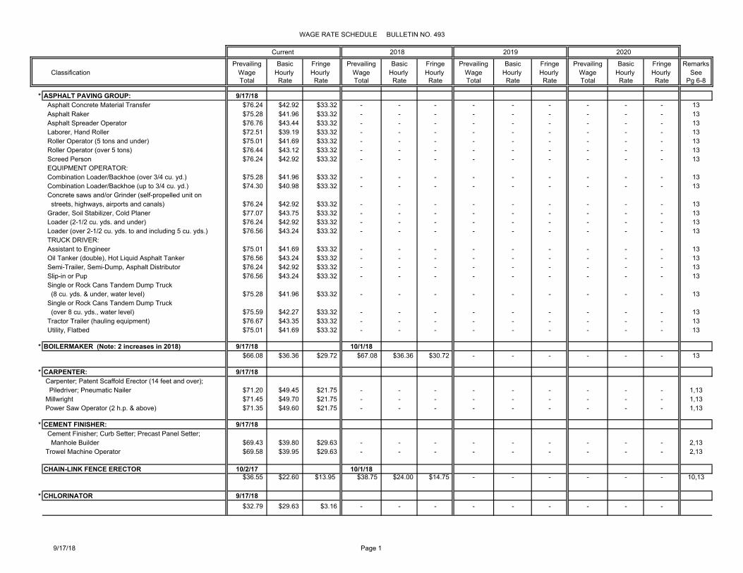
* DIVER: 9/17/18 Diver (Aqua Lung) (Scuba) - Up to a depth of 30 feet $89.39 $56.63 $32.76 - - - - - - - - - 13 Diver (Aqua Lung) (Scuba) - Over a depth of 30 feet $98.76 $66.00 $32.76 - - - - - - - - - 13 Stand-By Diver (Aqua Lung) (Scuba) $80.01 $47.25 $32.76 - - - - - - - - - 13 Diver (Other than Aqua Lung) $98.76 $66.00 $32.76 - - - - - - - - - 3,13 Stand-By Diver (Other than Aqua Lung) $80.01 $47.25 $32.76 - - - - - - - - - 3,13 Tender (Other than Aqua Lung) $76.98 $44.22 $32.76 - - - - - - - - - 13
* DRAPERY INSTALLER 9/17/18$19.02 $16.50 $2.52 - - - - - - - - -
* DRYWALL INSTALLER 9/17/18$71.45 $49.70 $21.75 - - - - - - - - - 13
DRYWALL TAPERS/FINISHERS 2/19/18 1/1/1900$68.25 $42.10 $26.15 - - - - - - - - -
ELECTRICIAN (Note: 2 increases for 2019) 8/26/18 2/17/19 2/23/20 Cable Splicer (inside/outside) $83.98 $54.78 $29.20 - - - $84.67 $55.33 $29.34 $86.17 $56.43 $29.74 4,13 Ground Worker (outside) $61.83 $37.35 $24.48 - - - $62.30 $37.73 $24.57 $63.36 $38.48 $24.88 4,13 Heavy Equipment Operator (outside) $71.31 $44.82 $26.49 - - - $71.90 $45.27 $26.63 $73.13 $46.17 $26.96 4,13 Line Installer (outside); Wire Installer (inside) $77.65 $49.80 $27.85 - - - $78.28 $50.30 $27.98 $79.66 $51.30 $28.36 4,13
8/25/19 Cable Splicer (inside/outside) - - - - - - $85.48 $55.88 $29.60 - - - 4,13 Ground Worker (outside) - - - - - - $62.87 $38.10 $24.77 - - - 4,13 Heavy Equipment Operator (outside) - - - - - - $72.56 $45.72 $26.84 - - - 4,13 Line Installer (outside); Wire Installer (inside) - - - - - - $79.01 $50.80 $28.21 - - - 4,13
* Telecommunication Worker 9/17/18 Licensed Technician $43.30 $30.94 $12.36 - - - - - - - - - 13 Technician I / Splicer $41.50 $29.39 $12.11 - - - - - - - - - 13
ELEVATOR CONSTRUCTOR MECHANIC 2/19/18 $90.005 $57.36 $32.645 - - - - - - - - - 13
* EQUIPMENT OPERATOR: 9/17/18 Group 1 $74.70 $41.94 $32.76 - - - - - - - - - 5,13 Group 2 $74.81 $42.05 $32.76 - - - - - - - - - 5,13 Group 3 $74.98 $42.22 $32.76 - - - - - - - - - 5,13 Group 4 $75.25 $42.49 $32.76 - - - - - - - - - 5,13 Group 5 $75.56 $42.80 $32.76 - - - - - - - - - 5,13 Group 6 $76.21 $43.45 $32.76 - - - - - - - - - 5,13 Group 7 $76.53 $43.77 $32.76 - - - - - - - - - 5,13 Group 8 $76.64 $43.88 $32.76 - - - - - - - - - 5,13 Group 9 $76.75 $43.99 $32.76 - - - - - - - - - 5,13 Group 9A $76.98 $44.22 $32.76 - - - - - - - - - 5,13 Group 10 $77.04 $44.28 $32.76 - - - - - - - - - 5,13 Group 10A $77.19 $44.43 $32.76 - - - - - - - - - 5,13 Group 11 $77.34 $44.58 $32.76 - - - - - - - - - 5,13 Group 12 $77.70 $44.94 $32.76 - - - - - - - - - 5,13 Group 12A $78.06 $45.30 $32.76 - - - - - - - - - 5,13
9/17/18 Page 2
Prevailing Basic Fringe Prevailing Basic Fringe Prevailing Basic Fringe Prevailing Basic Fringe Remarks Classification Wage Hourly Hourly Wage Hourly Hourly Wage Hourly Hourly Wage Hourly Hourly See
Total Rate Rate Total Rate Rate Total Rate Rate Total Rate Rate Pg 6-8
WAGE RATE SCHEDULE BULLETIN NO. 493
Current 2018 2019 2020
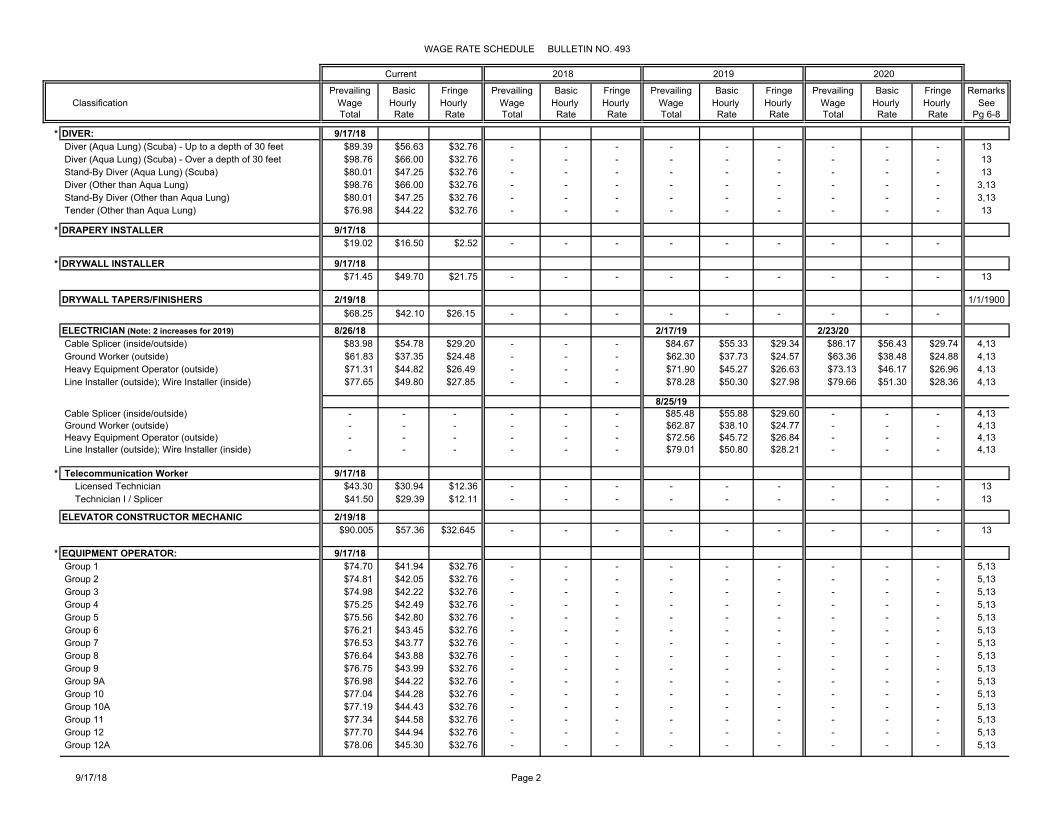
FENCE ERECTOR (CHAIN-LINK TYPE) See Chain-Link Fence Erector - - - - - - - - - - - -
FLOOR LAYER (CARPET, LINOLEUM & SOFT TILE) 3/4/18$63.47 $34.15 $29.32 - - - - - - - - - 13
* GLAZIER 9/17/18$69.78 $38.00 $31.78 - - - - - - - - - 6,13
* HELICOPTER WORK: 9/17/18 Airborne Hoist Operator $78.56 $45.80 $32.76 - - - - - - - - - 13 Co-Pilot $78.70 $45.94 $32.76 - - - - - - - - - 13 Pilot $78.87 $46.11 $32.76 - - - - - - - - - 13
INSULATOR 9/2/18 9/1/19 8/30/20$65.10 $40.40 $24.70 - - - $65.90 $40.90 $25.00 $67.30 $41.90 $25.40 7,12,13
* IRONWORKER: 9/17/18 9/1/19 9/1/20 Reinforcing, Structural $73.80 $40.25 $33.55 - - - $76.02 $41.50 $34.52 $76.02 $41.50 $34.52 8,12,13
LABORER: 9/3/18 Driller $58.66 $38.40 $20.26 - - - - - - - - - 1,13 Gunite Operator or Shotcrete Operator $58.16 $37.90 $20.26 - - - - - - - - - 1,13 High Scaler (Working Suspended) $58.16 $37.90 $20.26 - - - - - - - - - 13 Laborer I $57.66 $37.40 $20.26 - - - - - - - - - 1,13 Laborer II $55.06 $34.80 $20.26 - - - - - - - - - 1,13 Light/Final Clean-up (Janitorial) Laborer $44.92 $28.80 $16.12 - - - - - - - - - 1,13 Mason Tender/Hod Carrier $58.16 $37.90 $20.26 - - - - - - - - - 1,13 Powder Blaster $58.66 $38.40 $20.26 - - - - - - - - - 1,13 Window Washer (Outside) (On bosun's chair, cable-suspended scaffold or work platform) $57.16 $36.90 $20.26 - - - - - - - - - 13
LANDSCAPER: 9/3/18 9/2/19 Landscape & Irrigation Laborer A $38.18 $25.50 $12.68 - - - $39.60 $26.15 $13.45 - - - Landscape & Irrigation Laborer B $39.08 $26.40 $12.68 - - - $40.60 $27.15 $13.45 - - - Landscape & Irrigation Maintenance Laborer $33.78 $21.10 $12.68 - - - $35.00 $21.55 $13.45 - - -
* LATHER 9/17/18 $71.45 $49.70 $21.75 - - - - - - - - - 13
MASON; Bricklayer; 9/18/17 Cement Blocklayer; Stone Mason; Precast Sill Setter $68.23 $39.76 $28.47 - - - - - - - - - 2,13 Pointer-Caulker-Weatherproofer $68.48 $40.01 $28.47 - - - - - - - - - 2,13
* PAINTER: (Note: 2 increases for 2019 & 2010) 1/1/18 1/1/19 1/1/20 Painter; Spray Painter; Sandblaster or Waterblaster; $66.21 $37.35 $28.86 - - - $67.74 $38.35 $29.39 $68.44 $38.80 $29.64 Thermoplastic Striper; Paper Hanger
7/1/19 7/1/20 Painter; Spray Painter; Sandblaster or Waterblaster - - - - - - $68.44 $38.80 $29.64 $68.44 $38.80 $29.64 Thermoplastic Striper; Paper Hanger
9/17/18 Page 3
Prevailing Basic Fringe Prevailing Basic Fringe Prevailing Basic Fringe Prevailing Basic Fringe Remarks Classification Wage Hourly Hourly Wage Hourly Hourly Wage Hourly Hourly Wage Hourly Hourly See
Total Rate Rate Total Rate Rate Total Rate Rate Total Rate Rate Pg 6-8
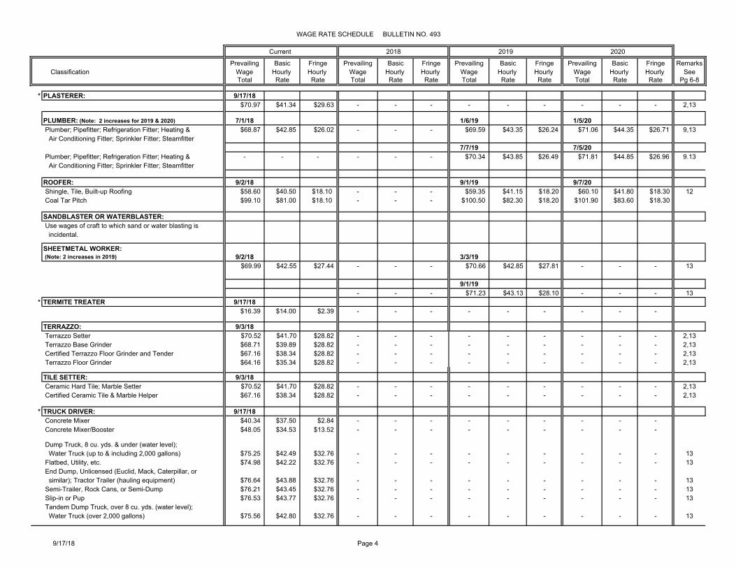
WAGE RATE SCHEDULE BULLETIN NO. 493
Current 2018 2019 2020
* PLASTERER: 9/17/18$70.97 $41.34 $29.63 - - - - - - - - - 2,13
PLUMBER: (Note: 2 increases for 2019 & 2020) 7/1/18 1/6/19 1/5/20 Plumber; Pipefitter; Refrigeration Fitter; Heating & $68.87 $42.85 $26.02 - - - $69.59 $43.35 $26.24 $71.06 $44.35 $26.71 9,13 Air Conditioning Fitter; Sprinkler Fitter; Steamfitter
7/7/19 7/5/20 Plumber; Pipefitter; Refrigeration Fitter; Heating & - - - - - - $70.34 $43.85 $26.49 $71.81 $44.85 $26.96 9.13 Air Conditioning Fitter; Sprinkler Fitter; Steamfitter
ROOFER: 9/2/18 9/1/19 9/7/20 Shingle, Tile, Built-up Roofing $58.60 $40.50 $18.10 - - - $59.35 $41.15 $18.20 $60.10 $41.80 $18.30 12 Coal Tar Pitch $99.10 $81.00 $18.10 - - - $100.50 $82.30 $18.20 $101.90 $83.60 $18.30
SANDBLASTER OR WATERBLASTER: Use wages of craft to which sand or water blasting is incidental.
SHEETMETAL WORKER: (Note: 2 increases in 2019) 9/2/18 3/3/19 $69.99 $42.55 $27.44 - - - $70.66 $42.85 $27.81 - - - 13
9/1/19- - - $71.23 $43.13 $28.10 - - - 13
* TERMITE TREATER 9/17/18$16.39 $14.00 $2.39 - - - - - - - - -
TERRAZZO: 9/3/18 Terrazzo Setter $70.52 $41.70 $28.82 - - - - - - - - - 2,13 Terrazzo Base Grinder $68.71 $39.89 $28.82 - - - - - - - - - 2,13 Certified Terrazzo Floor Grinder and Tender $67.16 $38.34 $28.82 - - - - - - - - - 2,13 Terrazzo Floor Grinder $64.16 $35.34 $28.82 - - - - - - - - - 2,13
TILE SETTER: 9/3/18 Ceramic Hard Tile; Marble Setter $70.52 $41.70 $28.82 - - - - - - - - - 2,13 Certified Ceramic Tile & Marble Helper $67.16 $38.34 $28.82 - - - - - - - - - 2,13
* TRUCK DRIVER: 9/17/18 Concrete Mixer $40.34 $37.50 $2.84 - - - - - - - - - Concrete Mixer/Booster $48.05 $34.53 $13.52 - - - - - - - - -
Dump Truck, 8 cu. yds. & under (water level); Water Truck (up to & including 2,000 gallons) $75.25 $42.49 $32.76 - - - - - - - - - 13 Flatbed, Utility, etc. $74.98 $42.22 $32.76 - - - - - - - - - 13 End Dump, Unlicensed (Euclid, Mack, Caterpillar, or similar); Tractor Trailer (hauling equipment) $76.64 $43.88 $32.76 - - - - - - - - - 13 Semi-Trailer, Rock Cans, or Semi-Dump $76.21 $43.45 $32.76 - - - - - - - - - 13 Slip-in or Pup $76.53 $43.77 $32.76 - - - - - - - - - 13 Tandem Dump Truck, over 8 cu. yds. (water level); Water Truck (over 2,000 gallons) $75.56 $42.80 $32.76 - - - - - - - - - 13
9/17/18 Page 4

Prevailing Basic Fringe Prevailing Basic Fringe Prevailing Basic Fringe Prevailing Basic Fringe Remarks Classification Wage Hourly Hourly Wage Hourly Hourly Wage Hourly Hourly Wage Hourly Hourly See
Total Rate Rate Total Rate Rate Total Rate Rate Total Rate Rate Pg 6-8
WAGE RATE SCHEDULE BULLETIN NO. 493
Current 2018 2019 2020
UNDERGROUND LABORER: 9/3/18 Worker in a raise, shaft, or tunnel. Group 1 $58.26 $38.00 $20.26 - - - - - - - - - 13 Group 2 $59.76 $39.50 $20.26 - - - - - - - - - 13 Group 3 $60.26 $40.00 $20.26 - - - - - - - - - 13 Group 4 $61.26 $41.00 $20.26 - - - - - - - - - 13 Group 5 $61.51 $41.25 $20.26 - - - - - - - - - 13 Group 6 $61.61 $41.35 $20.26 - - - - - - - - - 13 Group 7 $61.86 $41.60 $20.26 - - - - - - - - - 13 Group 8 $62.31 $42.05 $20.26 - - - - - - - - - 13
* WATER FRONT CONSTRUCTION (DREDGING): 9/17/18 CLAMSHELL OR DIPPER DREDGES: Clamshell or Dipper Operator $77.70 $44.94 $32.76 - - - - - - - - - 11,13 Mechanic; Welder; Watch Engineer $77.04 $44.28 $32.76 - - - - - - - - - 13 Deckmate; Bargemate $76.64 $43.88 $32.76 - - - - - - - - - 13 Fire Person; Oiler; Deckhand; Barge Worker $74.98 $42.22 $32.76 - - - - - - - - - 13 HYDRAULIC SUCTION DREDGES: Lever Operator $77.34 $44.58 $32.76 - - - - - - - - - 13 Mechanic; Welder $77.04 $44.28 $32.76 - - - - - - - - - 13 Watch Engineer (steam or electric) $77.19 $44.43 $32.76 - - - - - - - - - 13 Dozer Operator $76.98 $44.22 $32.76 - - - - - - - - - 13 Deckmate $76.64 $43.88 $32.76 - - - - - - - - - 13 Winch Operator (stern winch on dredge) $76.53 $43.77 $32.76 - - - - - - - - - 13 Fire Person; Oiler; Deckhand (can operate anchor scow under direction of deckmate); Levee Operator $74.98 $42.22 $32.76 - - - - - - - - - 13 DERRICKS: Operator: Derrick, Piledriver, Crane $77.70 $44.94 $32.76 - - - - - - - - - 13 Deckmate; Saurman Type Dragline (up to & including 5 yds.) $76.64 $43.88 $32.76 - - - - - - - - - 13 Saurman Type Dragline (over 5 cu. yds.) $77.04 $44.28 $32.76 - - - - - - - - - 13 Fire Person; Oiler; Deckhand $74.98 $42.22 $32.76 - - - - - - - - - 13 BOAT OPERATORS: Master Boat Operator $77.34 $44.58 $32.76 - - - - - - - - - 13 Boat Operator $77.19 $44.43 $32.76 - - - - - - - - - 13 Boat Deckhand $74.98 $42.22 $32.76 - - - - - - - - - 13
* WATER WELL DRILLER: 9/17/18 Water Well Driller $46.21 $31.00 $15.21 - - - - - - - - - Water Well Driller Helper $31.69 $18.00 $13.69 - - - - - - - - -
WELDER: Use wages of craft to which welding is incidental, except for Chain-Link Fence Erector. See remark. 10
* Indicates a wage, fringe benefit, remark, or title change from the previous bulletin.Comments: Overtime must be paid at one and one-half times the basic hourly rate plus the hourly cost of required fringe benefits.
9/17/18 Page 5


A. Two times the basic hourly rate, plus the hourly cost of required fringe.
Three times the basic hourly wage, plus the hourly cost of required fringe on Labor Day.
FRINGEBENEFIT
HOURLY RATE
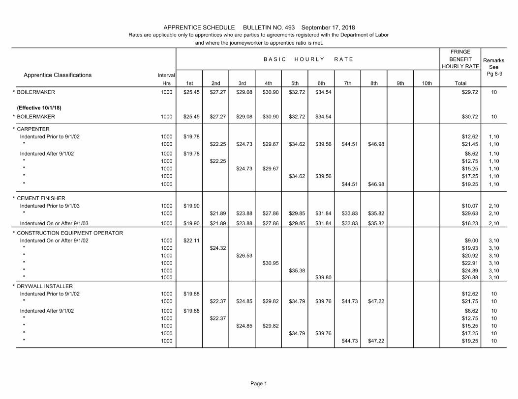
Hrs 1st 2nd 3rd 4th 5th 6th 7th 8th 9th 10th Total* BOILERMAKER 1000 $25.45 $27.27 $29.08 $30.90 $32.72 $34.54 $29.72 10
(Effective 10/1/18)* BOILERMAKER 1000 $25.45 $27.27 $29.08 $30.90 $32.72 $34.54 $30.72 10
* CARPENTER Indentured Prior to 9/1/02 1000 $19.78 $12.62 1,10 " 1000 $22.25 $24.73 $29.67 $34.62 $39.56 $44.51 $46.98 $21.45 1,10
Indentured After 9/1/02 1000 $19.78 $8.62 1,10 " 1000 $22.25 $12.75 1,10 " 1000 $24.73 $29.67 $15.25 1,10 " 1000 $34.62 $39.56 $17.25 1,10 " 1000 $44.51 $46.98 $19.25 1,10
* CEMENT FINISHER Indentured Prior to 9/1/03 1000 $19.90 $10.07 2,10 " 1000 $21.89 $23.88 $27.86 $29.85 $31.84 $33.83 $35.82 $29.63 2,10
Indentured On or After 9/1/03 1000 $19.90 $21.89 $23.88 $27.86 $29.85 $31.84 $33.83 $35.82 $16.23 2,10
* CONSTRUCTION EQUIPMENT OPERATOR Indentured On or After 9/1/02 1000 $22.11 $9.00 3,10 " 1000 $24.32 $19.93 3,10 " 1000 $26.53 $20.92 3,10 " 1000 $30.95 $22.91 3,10 " 1000 $35.38 $24.89 3,10 " 1000 $39.80 $26.88 3,10
* DRYWALL INSTALLER Indentured Prior to 9/1/02 1000 $19.88 $12.62 10 " 1000 $22.37 $24.85 $29.82 $34.79 $39.76 $44.73 $47.22 $21.75 10
Indentured After 9/1/02 1000 $19.88 $8.62 10 " 1000 $22.37 $12.75 10 " 1000 $24.85 $29.82 $15.25 10 " 1000 $34.79 $39.76 $17.25 10 " 1000 $44.73 $47.22 $19.25 10
APPRENTICE SCHEDULE BULLETIN NO. 493 September 17, 2018Rates are applicable only to apprentices who are parties to agreements registered with the Department of Labor
and where the journeyworker to apprentice ratio is met.
B A S I C H O U R L Y R A T E
Apprentice Classifications Interval
RemarksSee
Pg 8-9
Page 1
FRINGEBENEFIT
HOURLY RATE
Hrs 1st 2nd 3rd 4th 5th 6th 7th 8th 9th 10th Total
APPRENTICE SCHEDULE BULLETIN NO. 493 September 17, 2018Rates are applicable only to apprentices who are parties to agreements registered with the Department of Labor
and where the journeyworker to apprentice ratio is met.
B A S I C H O U R L Y R A T E
Apprentice Classifications Interval
RemarksSee
Pg 8-9
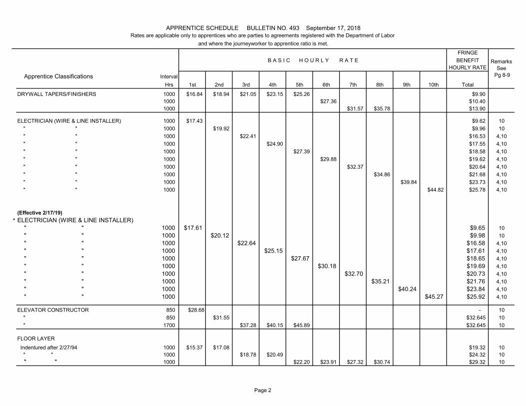
DRYWALL TAPERS/FINISHERS 1000 $16.84 $18.94 $21.05 $23.15 $25.26 $9.901000 $27.36 $10.401000 $31.57 $35.78 $13.90
ELECTRICIAN (WIRE & LINE INSTALLER) 1000 $17.43 $9.62 10 " " 1000 $19.92 $9.96 10 " " 1000 $22.41 $16.53 4,10 " " 1000 $24.90 $17.55 4,10 " " 1000 $27.39 $18.58 4,10 " " 1000 $29.88 $19.62 4,10 " " 1000 $32.37 $20.64 4,10 " " 1000 $34.86 $21.68 4,10 " " 1000 $39.84 $23.73 4,10 " " 1000 $44.82 $25.78 4,10
(Effective 2/17/19)* ELECTRICIAN (WIRE & LINE INSTALLER)
" " 1000 $17.61 $9.65 10 " " 1000 $20.12 $9.98 10 " " 1000 $22.64 $16.58 4,10 " " 1000 $25.15 $17.61 4,10 " " 1000 $27.67 $18.65 4,10 " " 1000 $30.18 $19.69 4,10 " " 1000 $32.70 $20.73 4,10 " " 1000 $35.21 $21.76 4,10 " " 1000 $40.24 $23.84 4,10 " " 1000 $45.27 $25.92 4,10
ELEVATOR CONSTRUCTOR 850 $28.68 - 10 " 850 $31.55 $32.645 10 " 1700 $37.28 $40.15 $45.89 $32.645 10
FLOOR LAYER Indentured after 2/27/94 1000 $15.37 $17.08 $19.32 10 " " 1000 $18.78 $20.49 $24.32 10 " " 1000 $22.20 $23.91 $27.32 $30.74 $29.32 10
Page 2
FRINGEBENEFIT
HOURLY RATE
Hrs 1st 2nd 3rd 4th 5th 6th 7th 8th 9th 10th Total
APPRENTICE SCHEDULE BULLETIN NO. 493 September 17, 2018Rates are applicable only to apprentices who are parties to agreements registered with the Department of Labor
and where the journeyworker to apprentice ratio is met.
B A S I C H O U R L Y R A T E
Apprentice Classifications Interval
RemarksSee
Pg 8-9
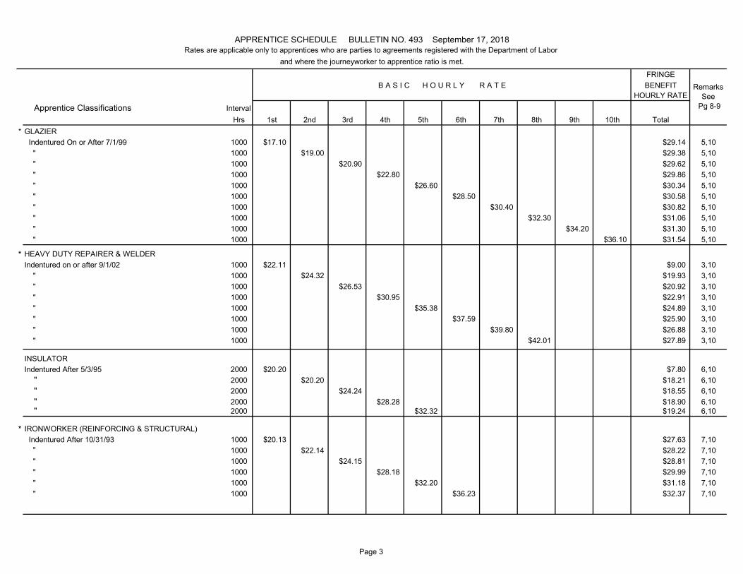
* GLAZIER Indentured On or After 7/1/99 1000 $17.10 $29.14 5,10 " 1000 $19.00 $29.38 5,10 " 1000 $20.90 $29.62 5,10 " 1000 $22.80 $29.86 5,10 " 1000 $26.60 $30.34 5,10 " 1000 $28.50 $30.58 5,10 " 1000 $30.40 $30.82 5,10 " 1000 $32.30 $31.06 5,10 " 1000 $34.20 $31.30 5,10 " 1000 $36.10 $31.54 5,10
* HEAVY DUTY REPAIRER & WELDERIndentured on or after 9/1/02 1000 $22.11 $9.00 3,10 " 1000 $24.32 $19.93 3,10 " 1000 $26.53 $20.92 3,10 " 1000 $30.95 $22.91 3,10 " 1000 $35.38 $24.89 3,10 " 1000 $37.59 $25.90 3,10 " 1000 $39.80 $26.88 3,10 " 1000 $42.01 $27.89 3,10
INSULATORIndentured After 5/3/95 2000 $20.20 $7.80 6,10 " 2000 $20.20 $18.21 6,10 " 2000 $24.24 $18.55 6,10 " 2000 $28.28 $18.90 6,10 " 2000 $32.32 $19.24 6,10
* IRONWORKER (REINFORCING & STRUCTURAL) Indentured After 10/31/93 1000 $20.13 $27.63 7,10 " 1000 $22.14 $28.22 7,10 " 1000 $24.15 $28.81 7,10 " 1000 $28.18 $29.99 7,10 " 1000 $32.20 $31.18 7,10 " 1000 $36.23 $32.37 7,10
Page 3
FRINGEBENEFIT
HOURLY RATE
Hrs 1st 2nd 3rd 4th 5th 6th 7th 8th 9th 10th Total
APPRENTICE SCHEDULE BULLETIN NO. 493 September 17, 2018Rates are applicable only to apprentices who are parties to agreements registered with the Department of Labor
and where the journeyworker to apprentice ratio is met.
B A S I C H O U R L Y R A T E
Apprentice Classifications Interval
RemarksSee
Pg 8-9
LABORER I
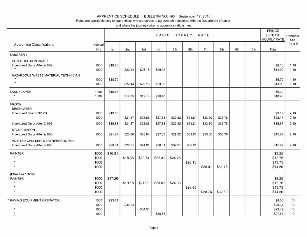
CONSTRUCTION CRAFT Indentured On or After 9/3/02 1000 $18.70 $8.10 1,10 " 1000 $22.44 $26.18 $29.92 $14.90 1,10
HAZARDOUS WASTE MATERIAL TECHNICIAN " 1000 $18.70 $6.70 1,10 " 1000 $22.44 $26.18 $29.92 $13.00 1,10
LANDSCAPER 1000 $16.58 $6.70 " 1000 $17.85 $19.13 $20.40 $10.43
MASON BRICKLAYER Indentured prior to 9/1/03 1000 $19.88 $9.12 2,10
1000 $21.87 $23.86 $27.83 $29.82 $31.81 $33.80 $35.78 $28.47 2,10
Indentured On or After 9/1/03 1000 $19.88 $21.87 $23.86 $27.83 $29.82 $31.81 $33.80 $35.78 $15.87 2,10
STONE MASON Indentured On or After 9/1/03 1000 $21.87 $23.86 $25.84 $27.83 $29.82 $31.81 $33.80 $35.78 $15.87 2,10
POINTER-CAULKER-WEATHERPROOFER Indentured On or After 9/1/03 1000 $20.01 $22.01 $24.01 $28.01 $32.01 $36.01 $15.87 2,10
PAINTER 1000 $16.81 $9.25 " 1000 $18.68 $20.54 $22.41 $24.28 $12.75 " 1000 $26.15 $13.75 " 1000 $28.01 $31.75 $14.50
(Effective 1/1/19)* PAINTER 1000 $17.26 $9.25
" 1000 $19.18 $21.09 $23.01 $24.93 $12.75 " 1000 $26.85 $13.75 " 1000 $28.76 $32.60 $14.50
* PAVING EQUIPMENT OPERATOR 1000 $23.61 $9.00 10 " 1000 $30.04 $20.37 10 " 1000 $34.34 $23.49 10 " 1000 $38.63 $27.63 10
Page 4
FRINGEBENEFIT
HOURLY RATE
Hrs 1st 2nd 3rd 4th 5th 6th 7th 8th 9th 10th Total
APPRENTICE SCHEDULE BULLETIN NO. 493 September 17, 2018Rates are applicable only to apprentices who are parties to agreements registered with the Department of Labor
and where the journeyworker to apprentice ratio is met.
B A S I C H O U R L Y R A T E
Apprentice Classifications Interval
RemarksSee
Pg 8-9
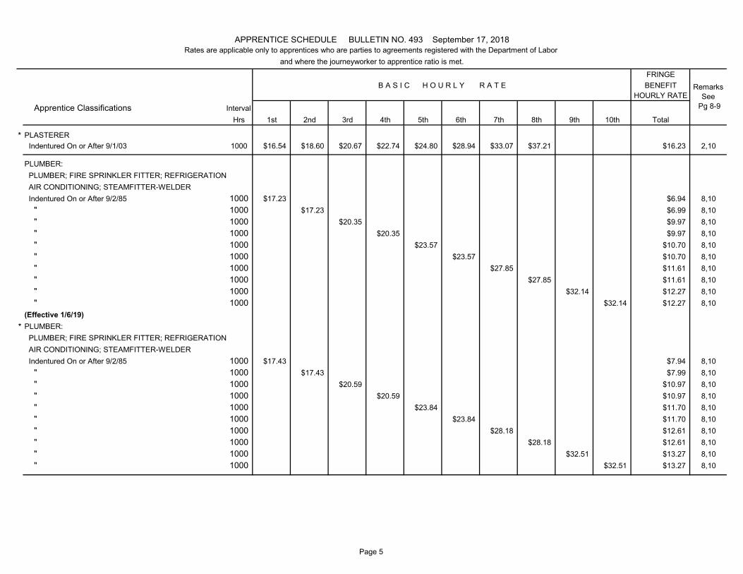
* PLASTERER Indentured On or After 9/1/03 1000 $16.54 $18.60 $20.67 $22.74 $24.80 $28.94 $33.07 $37.21 $16.23 2,10
PLUMBER: PLUMBER; FIRE SPRINKLER FITTER; REFRIGERATION AIR CONDITIONING; STEAMFITTER-WELDER Indentured On or After 9/2/85 1000 $17.23 $6.94 8,10 " 1000 $17.23 $6.99 8,10 " 1000 $20.35 $9.97 8,10 " 1000 $20.35 $9.97 8,10 " 1000 $23.57 $10.70 8,10 " 1000 $23.57 $10.70 8,10 " 1000 $27.85 $11.61 8,10 " 1000 $27.85 $11.61 8,10 " 1000 $32.14 $12.27 8,10 " 1000 $32.14 $12.27 8,10(Effective 1/6/19)
* PLUMBER: PLUMBER; FIRE SPRINKLER FITTER; REFRIGERATION AIR CONDITIONING; STEAMFITTER-WELDER Indentured On or After 9/2/85 1000 $17.43 $7.94 8,10 " 1000 $17.43 $7.99 8,10 " 1000 $20.59 $10.97 8,10 " 1000 $20.59 $10.97 8,10 " 1000 $23.84 $11.70 8,10 " 1000 $23.84 $11.70 8,10 " 1000 $28.18 $12.61 8,10 " 1000 $28.18 $12.61 8,10 " 1000 $32.51 $13.27 8,10 " 1000 $32.51 $13.27 8,10
Page 5
FRINGEBENEFIT
HOURLY RATE
Hrs 1st 2nd 3rd 4th 5th 6th 7th 8th 9th 10th Total
APPRENTICE SCHEDULE BULLETIN NO. 493 September 17, 2018Rates are applicable only to apprentices who are parties to agreements registered with the Department of Labor
and where the journeyworker to apprentice ratio is met.
B A S I C H O U R L Y R A T E
Apprentice Classifications Interval
RemarksSee
Pg 8-9
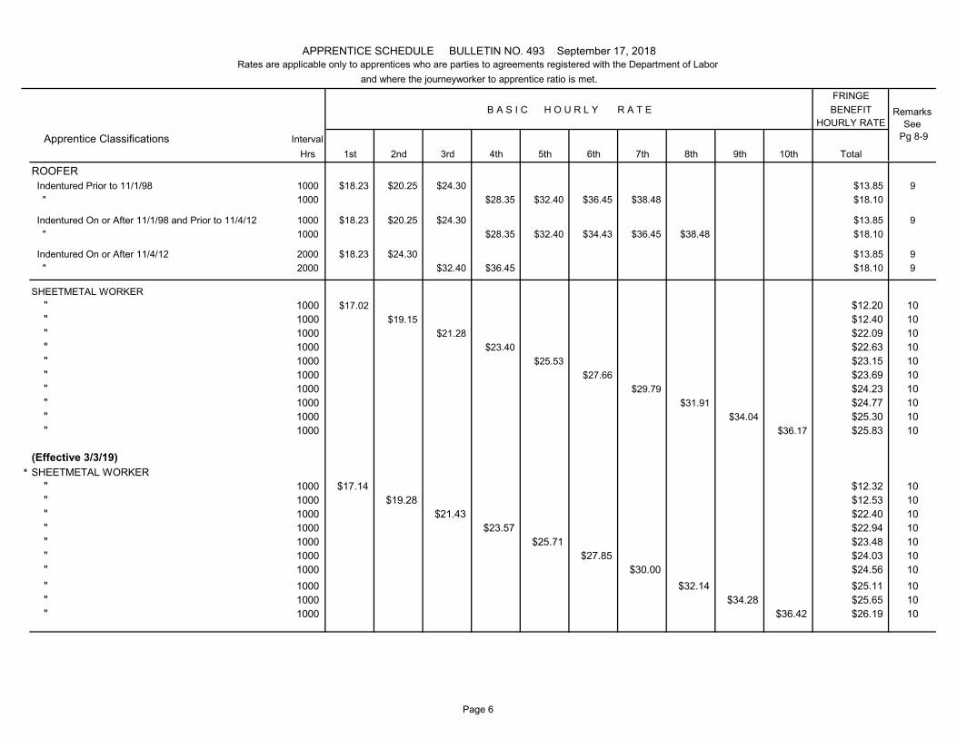
ROOFER Indentured Prior to 11/1/98 1000 $18.23 $20.25 $24.30 $13.85 9 " 1000 $28.35 $32.40 $36.45 $38.48 $18.10
Indentured On or After 11/1/98 and Prior to 11/4/12 1000 $18.23 $20.25 $24.30 $13.85 9 " 1000 $28.35 $32.40 $34.43 $36.45 $38.48 $18.10
Indentured On or After 11/4/12 2000 $18.23 $24.30 $13.85 9 " 2000 $32.40 $36.45 $18.10 9
SHEETMETAL WORKER " 1000 $17.02 $12.20 10 " 1000 $19.15 $12.40 10 " 1000 $21.28 $22.09 10 " 1000 $23.40 $22.63 10 " 1000 $25.53 $23.15 10 " 1000 $27.66 $23.69 10 " 1000 $29.79 $24.23 10 " 1000 $31.91 $24.77 10 " 1000 $34.04 $25.30 10 " 1000 $36.17 $25.83 10
(Effective 3/3/19)* SHEETMETAL WORKER
" 1000 $17.14 $12.32 10 " 1000 $19.28 $12.53 10 " 1000 $21.43 $22.40 10 " 1000 $23.57 $22.94 10 " 1000 $25.71 $23.48 10 " 1000 $27.85 $24.03 10 " 1000 $30.00 $24.56 10 " 1000 $32.14 $25.11 10 " 1000 $34.28 $25.65 10 " 1000 $36.42 $26.19 10
Page 6
FRINGEBENEFIT
HOURLY RATE
Hrs 1st 2nd 3rd 4th 5th 6th 7th 8th 9th 10th Total
APPRENTICE SCHEDULE BULLETIN NO. 493 September 17, 2018Rates are applicable only to apprentices who are parties to agreements registered with the Department of Labor
and where the journeyworker to apprentice ratio is met.
B A S I C H O U R L Y R A T E
Apprentice Classifications Interval
RemarksSee
Pg 8-9
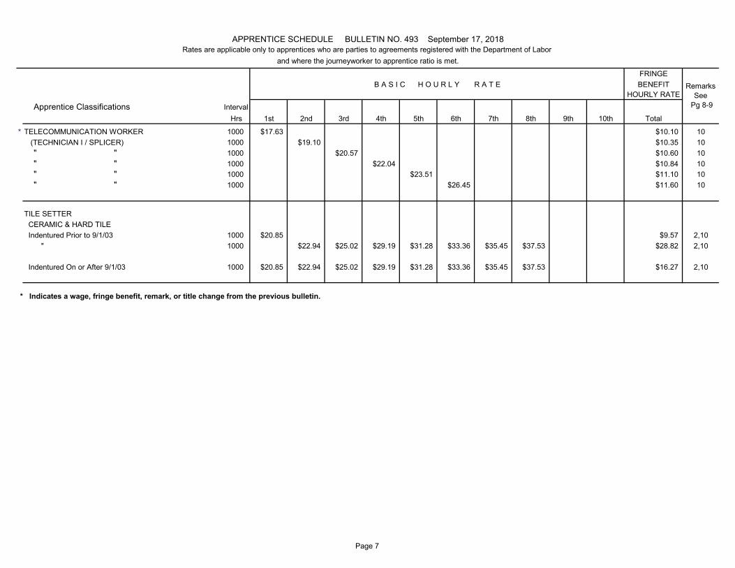
* TELECOMMUNICATION WORKER 1000 $17.63 $10.10 10 (TECHNICIAN I / SPLICER) 1000 $19.10 $10.35 10 " " 1000 $20.57 $10.60 10 " " 1000 $22.04 $10.84 10 " " 1000 $23.51 $11.10 10 " " 1000 $26.45 $11.60 10
TILE SETTER CERAMIC & HARD TILE Indentured Prior to 9/1/03 1000 $20.85 $9.57 2,10 " 1000 $22.94 $25.02 $29.19 $31.28 $33.36 $35.45 $37.53 $28.82 2,10
Indentured On or After 9/1/03 1000 $20.85 $22.94 $25.02 $29.19 $31.28 $33.36 $35.45 $37.53 $16.27 2,10
* Indicates a wage, fringe benefit, remark, or title change from the previous bulletin.
Page 7
APPRENTICE SCHEDULE BULLETIN NO. 493 SEPTEMBER 17, 2018
REMARKS:
Page 8
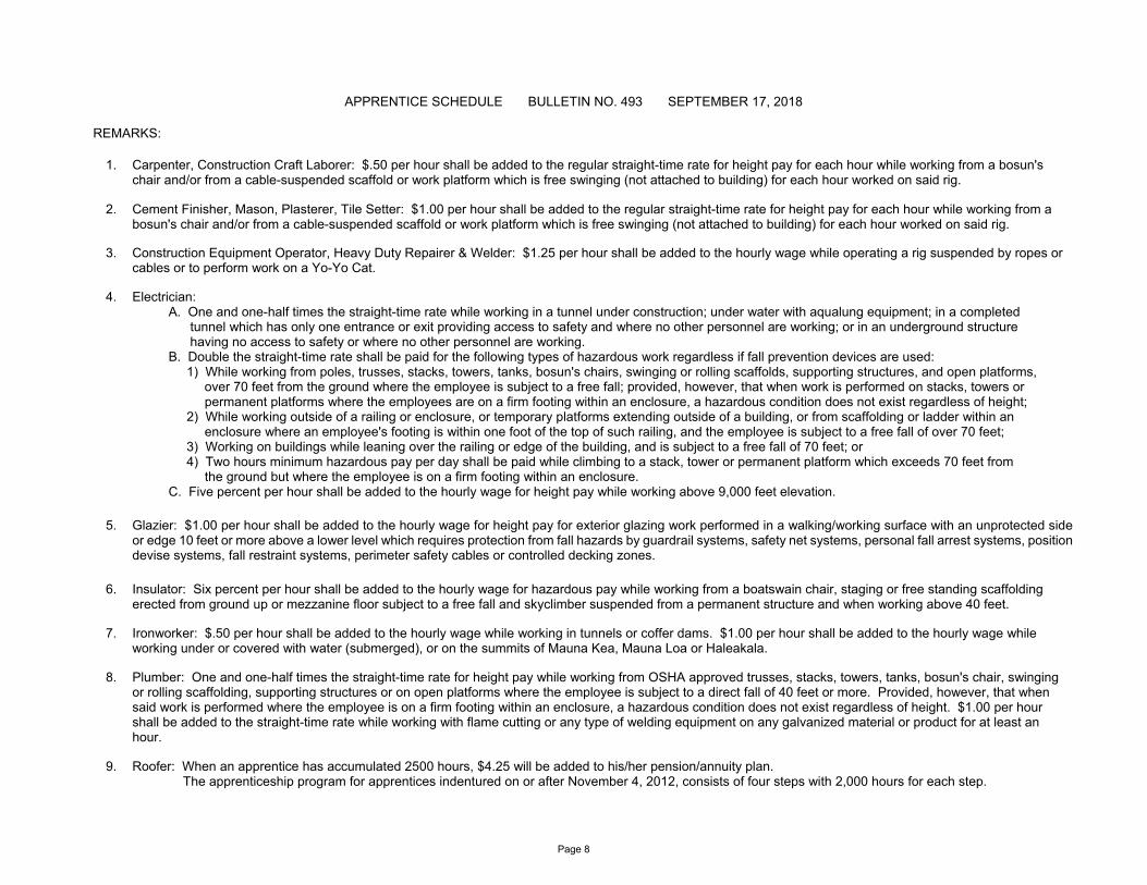
1. Carpenter, Construction Craft Laborer: $.50 per hour shall be added to the regular straight-time rate for height pay for each hour while working from a bosun's chair and/or from a cable-suspended scaffold or work platform which is free swinging (not attached to building) for each hour worked on said rig.
2. Cement Finisher, Mason, Plasterer, Tile Setter: $1.00 per hour shall be added to the regular straight-time rate for height pay for each hour while working from a bosun's chair and/or from a cable-suspended scaffold or work platform which is free swinging (not attached to building) for each hour worked on said rig.
3. Construction Equipment Operator, Heavy Duty Repairer & Welder: $1.25 per hour shall be added to the hourly wage while operating a rig suspended by ropes or cables or to perform work on a Yo-Yo Cat.
4. Electrician: A. One and one-half times the straight-time rate while working in a tunnel under construction; under water with aqualung equipment; in a completed tunnel which has only one entrance or exit providing access to safety and where no other personnel are working; or in an underground structure having no access to safety or where no other personnel are working. B. Double the straight-time rate shall be paid for the following types of hazardous work regardless if fall prevention devices are used: 1) While working from poles, trusses, stacks, towers, tanks, bosun's chairs, swinging or rolling scaffolds, supporting structures, and open platforms, over 70 feet from the ground where the employee is subject to a free fall; provided, however, that when work is performed on stacks, towers or permanent platforms where the employees are on a firm footing within an enclosure, a hazardous condition does not exist regardless of height; 2) While working outside of a railing or enclosure, or temporary platforms extending outside of a building, or from scaffolding or ladder within an enclosure where an employee's footing is within one foot of the top of such railing, and the employee is subject to a free fall of over 70 feet; 3) Working on buildings while leaning over the railing or edge of the building, and is subject to a free fall of 70 feet; or 4) Two hours minimum hazardous pay per day shall be paid while climbing to a stack, tower or permanent platform which exceeds 70 feet from the ground but where the employee is on a firm footing within an enclosure. C. Five percent per hour shall be added to the hourly wage for height pay while working above 9,000 feet elevation.
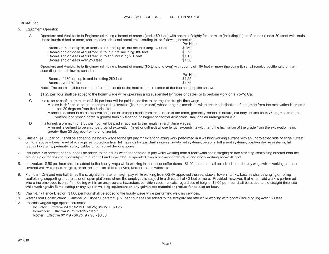
5. Glazier: $1.00 per hour shall be added to the hourly wage for height pay for exterior glazing work performed in a walking/working surface with an unprotected side or edge 10 feet or more above a lower level which requires protection from fall hazards by guardrail systems, safety net systems, personal fall arrest systems, position devise systems, fall restraint systems, perimeter safety cables or controlled decking zones.
6. Insulator: Six percent per hour shall be added to the hourly wage for hazardous pay while working from a boatswain chair, staging or free standing scaffolding erected from ground up or mezzanine floor subject to a free fall and skyclimber suspended from a permanent structure and when working above 40 feet.
7. Ironworker: $.50 per hour shall be added to the hourly wage while working in tunnels or coffer dams. $1.00 per hour shall be added to the hourly wage while working under or covered with water (submerged), or on the summits of Mauna Kea, Mauna Loa or Haleakala.
8. Plumber: One and one-half times the straight-time rate for height pay while working from OSHA approved trusses, stacks, towers, tanks, bosun's chair, swinging or rolling scaffolding, supporting structures or on open platforms where the employee is subject to a direct fall of 40 feet or more. Provided, however, that when said work is performed where the employee is on a firm footing within an enclosure, a hazardous condition does not exist regardless of height. $1.00 per hour shall be added to the straight-time rate while working with flame cutting or any type of welding equipment on any galvanized material or product for at least an hour.
9. Roofer: When an apprentice has accumulated 2500 hours, $4.25 will be added to his/her pension/annuity plan. The apprenticeship program for apprentices indentured on or after November 4, 2012, consists of four steps with 2,000 hours for each step.
APPRENTICE SCHEDULE BULLETIN NO. 493 SEPTEMBER 17, 2018
REMARKS:
Page 9
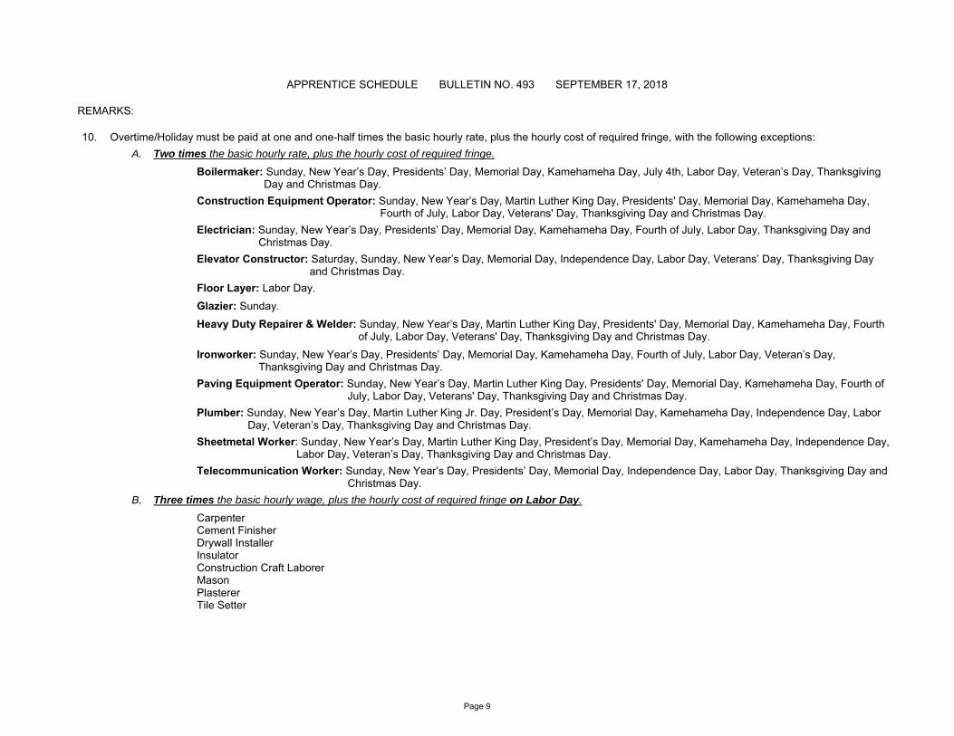
10. Overtime/Holiday must be paid at one and one-half times the basic hourly rate, plus the hourly cost of required fringe, with the following exceptions:
A. Two times the basic hourly rate, plus the hourly cost of required fringe.
Boilermaker: Sunday, New Year’s Day, Presidents’ Day, Memorial Day, Kamehameha Day, July 4th, Labor Day, Veteran’s Day, Thanksgiving Day and Christmas Day.
Construction Equipment Operator: Sunday, New Year’s Day, Martin Luther King Day, Presidents' Day, Memorial Day, Kamehameha Day, Fourth of July, Labor Day, Veterans' Day, Thanksgiving Day and Christmas Day.
Electrician: Sunday, New Year’s Day, Presidents’ Day, Memorial Day, Kamehameha Day, Fourth of July, Labor Day, Thanksgiving Day and Christmas Day.
Elevator Constructor: Saturday, Sunday, New Year’s Day, Memorial Day, Independence Day, Labor Day, Veterans’ Day, Thanksgiving Day and Christmas Day.
Floor Layer: Labor Day.
Glazier: Sunday.
Heavy Duty Repairer & Welder: Sunday, New Year’s Day, Martin Luther King Day, Presidents' Day, Memorial Day, Kamehameha Day, Fourth of July, Labor Day, Veterans' Day, Thanksgiving Day and Christmas Day.
Ironworker: Sunday, New Year’s Day, Presidents’ Day, Memorial Day, Kamehameha Day, Fourth of July, Labor Day, Veteran’s Day, Thanksgiving Day and Christmas Day.
Paving Equipment Operator: Sunday, New Year’s Day, Martin Luther King Day, Presidents' Day, Memorial Day, Kamehameha Day, Fourth of July, Labor Day, Veterans' Day, Thanksgiving Day and Christmas Day.
Plumber: Sunday, New Year’s Day, Martin Luther King Jr. Day, President’s Day, Memorial Day, Kamehameha Day, Independence Day, Labor Day, Veteran’s Day, Thanksgiving Day and Christmas Day.
Sheetmetal Worker: Sunday, New Year’s Day, Martin Luther King Day, President’s Day, Memorial Day, Kamehameha Day, Independence Day, Labor Day, Veteran’s Day, Thanksgiving Day and Christmas Day.
Telecommunication Worker: Sunday, New Year’s Day, Presidents’ Day, Memorial Day, Independence Day, Labor Day, Thanksgiving Day and Christmas Day.
B. Three times the basic hourly wage, plus the hourly cost of required fringe on Labor Day.
Carpenter Cement Finisher Drywall Installer Insulator Construction Craft Laborer Mason Plasterer Tile Setter
455 9
Rev. 11.9.17
Page 1
STATE OF HAWAII
DEPARTMENT OF LABOR AND INDUSTRIAL RELATIONS
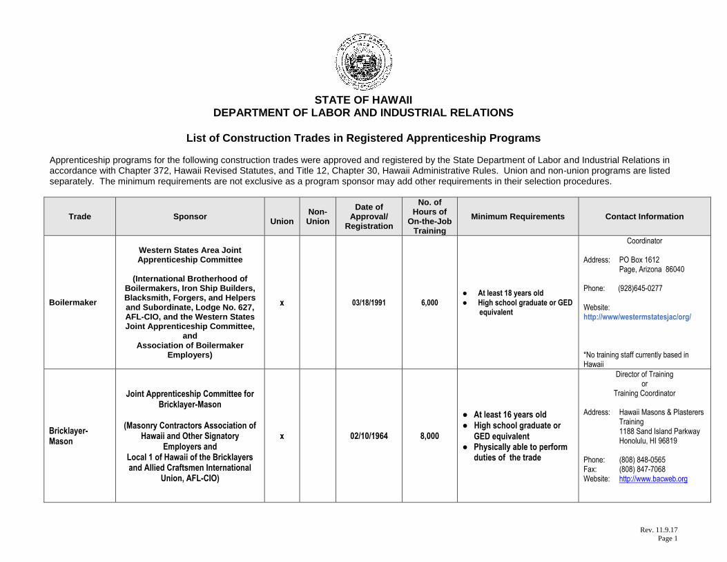
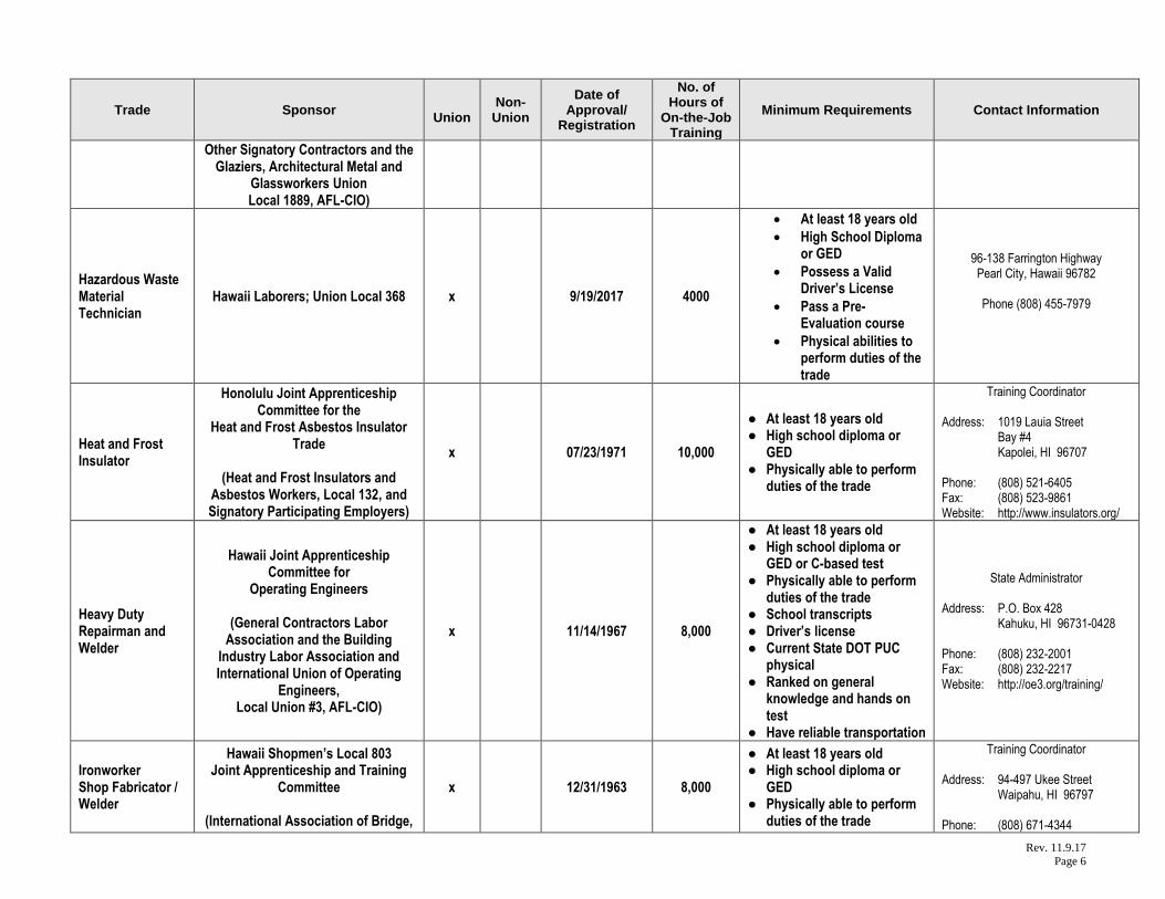
List of Construction Trades in Registered Apprenticeship Programs Apprenticeship programs for the following construction trades were approved and registered by the State Department of Labor and Industrial Relations in accordance with Chapter 372, Hawaii Revised Statutes, and Title 12, Chapter 30, Hawaii Administrative Rules. Union and non-union programs are listed separately. The minimum requirements are not exclusive as a program sponsor may add other requirements in their selection procedures.
Trade Sponsor
Union Non-Union
Date of Approval/
Registration
No. of Hours of
On-the-Job Training
Minimum Requirements Contact Information
Boilermaker
Western States Area Joint Apprenticeship Committee
(International Brotherhood of
Boilermakers, Iron Ship Builders, Blacksmith, Forgers, and Helpers and Subordinate, Lodge No. 627, AFL-CIO, and the Western States Joint Apprenticeship Committee,
and Association of Boilermaker
Employers)
x 03/18/1991 6,000 ● At least 18 years old ● High school graduate or GED
equivalent
Coordinator Address: PO Box 1612 Page, Arizona 86040 Phone: (928)645-0277 Website: http://www/westermstatesjac/org/ *No training staff currently based in Hawaii
Bricklayer-Mason
Joint Apprenticeship Committee for Bricklayer-Mason
(Masonry Contractors Association of
Hawaii and Other Signatory Employers and
Local 1 of Hawaii of the Bricklayers and Allied Craftsmen International
Union, AFL-CIO)
x 02/10/1964 8,000
● At least 16 years old
● High school graduate or
GED equivalent ● Physically able to perform
duties of the trade
Director of Training or
Training Coordinator Address: Hawaii Masons & Plasterers Training 1188 Sand Island Parkway Honolulu, HI 96819 Phone: (808) 848-0565 Fax: (808) 847-7068 Website: http://www.bacweb.org

Rev. 11.9.17
Page 2
Trade Sponsor
Union Non-
Union
Date of Approval/
Registration
No. of Hours of
On-the-Job Training
Minimum Requirements Contact Information
Carpenter
Carpenters Joint Apprenticeship Committee
aka Hawaii Carpenters Apprenticeship and Training
Program
(General Contractors Association of Hawaii and Building Industry Labor
Association and Other Signatory Contractors and the
United Brotherhood of Carpenters and Joiners of America, Local 745
AFL-CIO)
x 04/01/1964 8,000
● At least 17 years old ● High school diploma or
equivalent education, or equivalent work experience
● Pass basic math test ● Complete questionnaire ● Able to lift 75 lbs.
Director of Training Address: 1311 Houghtailing Street Room 201 Honolulu, HI 96817 Phone: (808) 848-0794 Ext. 5 Fax: (808) 841-5961 (808) 841-0300 Website: http://www.carpenters.org/
Carpenter Associated Builders and Contractors
Apprenticeship Committee x 02/08/1990 8,000
● At least 18 years old ● High school diploma or
GED ● Full-time employee of a
member company for a period of not less than six continuous weeks
● Legally able to work ● Physically able to perform
duties of the trade
Director of Training Address: 1375 Dillingham Blvd. Suite 200 Honolulu, HI 96817 Phone: (808) 845-4887 Fax: (808) 847-7876 Website: http://www.abchawaii.org/
Cement Finisher
Joint Apprenticeship Committee for Cement Finishers
(Operative Plasterers and Cement
Finishers International Association, Local 630, AFL-CIO, and
Local 1 of the International Union of Bricklayers and Allied Craftsmen,
AFL-CIO)
x 04/01/1961 8,000 ● At least 16 years old ● Physically able to perform
duties of the trade
Director of Training
or Training Coordinator
Address: Hawaii Masons & Plasterers Training 1188 Sand Island Parkway Honolulu, HI 96819 Phone: (808) 848-0565 Fax: (808) 847-7068 Website: http://www.opcmia.org/ http://www.bacweb.org

Rev. 11.9.17
Page 3
Trade Sponsor
Union Non-
Union
Date of Approval/
Registration
No. of Hours of
On-the-Job Training
Minimum Requirements Contact Information
Construction Craft Laborer
Hawaii Laborers’ Joint Apprenticeship Committee
(International Union of North
America, Local 368, and Signatory Contractors Association)
x 02/11/2000 4,000
● At least 18 years old ● High school diploma or
GED ● Driver’s license ● Successfully complete Pre-
Construction Apprentice Evaluation Course
Director of Training Address: 96-138 Farrington Hwy. Pearl City, HI 96782 Phone: (808) 455-7979 Fax: (808) 456-8689 Website: http://www.liuna.org/
Construction Equipment Operator
Hawaii Joint Apprenticeship Committee for
Operating Engineers
(General Contractors Labor Association and the Building
Industry Labor Association and International Union of Operating
Engineers, Local Union #3, AFL-CIO)
x 11/14/1967 6,000
● At least 18 years old ● High school diploma or
GED or C-based test ● Physically able to perform
duties of the trade ● School transcripts ● Driver’s license ● Current State DOT PUC
physical ● Pass industry or general
knowledge test ● Have reliable transportation
State Administrator Address: P.O. Box 428 Kahuku, HI 96731-0428 Phone: (808) 232-2001 Fax: (808) 232-2217 Website: http://oe3.org/training/
Drywall, Acoustic and Lather Installer
Carpenters Joint Apprenticeship Committee
aka Hawaii Carpenters Apprenticeship and Training
Program
(General Contractors Association of Hawaii and Building Industry Labor
Association and Other Signatory Contractors and the
United Brotherhood of Carpenters and Joiners of America, Local 745,
AFL-CIO)
x 04/06/1988 8,000
● At least 17 years old ● High school diploma or
GED ● Complete questionnaire ● Pass basic math test ● Able to lift 100 lbs.
Director of Training
Address: 1311 Houghtailing Street Room 201 Honolulu, HI 96817 Phone: (808) 848-0794 Ext. 5 Fax: (808) 848-5961 (808) 841-0300 Website: http://www.carpenters.org/

Rev. 11.9.17
Page 4
Trade Sponsor
Union Non-
Union
Date of Approval/
Registration
No. of Hours of
On-the-Job Training
Minimum Requirements Contact Information
Electrical Wireperson
PECA-HEW Joint Apprenticeship Committee
(Pacific Electrical Contractors
Association and the Hawaii Electrical Workers
Division of Laborers International, Local 368)
x 11/20/1991 10,000
● At least 18 years old ● High school diploma or
GED ● Pass color code test ● Pass aptitude test ● Transcript of high school
or post high school courses
● Pass one-year high school Algebra 1 (not pre-Algebra) or higher
● Valid driver’s license
Training Coordinator Address: 1617 Palama Street Honolulu, HI 96817 Phone: (808) 841-5877 Ext 234 Fax: (808) 847-7829 Website: N/A
Electrician Associated Builders and Contractors
Apprenticeship Committee x 02/08/1990 10,000
● At least 18 years old ● High school diploma or
GED ● Full-time employee of a
member company for a period of not less than six continuous weeks
● Legally able to work ● Physically able to perform
duties of the trade ● Pass eye examination for
color blindness ● Completed one-year high
school algebra (not pre-algebra)
Director of Training Address: 1375 Dillingham Blvd. Suite 200 Honolulu, HI 96817 Phone: (808) 845-4887 Fax: (808) 847-7876 Website: http://www.abchawaii.org/
(Electrician) Wireperson
Hawaii Electricians Joint Apprenticeship Committee
(International Brotherhood of
Electrical Workers (IBEW) Local 1186, AFL-CIO, and
Signatory Employers)
x 04/08/1947 10,000
● At least 18 years old ● High school diploma or
GED ● Complete the National Joint
Apprenticeship and Training Committee Math Course or one-year high school Algebra 1
● Transcript of high school or post high school
Apprenticeship or Training Coordinator Address: 1935 Hau Street Room 301 Honolulu, HI 96819 Phone: (808) 847-0629 Fax: (808) 843-8818 Website: http://www.njatc.org/

Rev. 11.9.17
Page 5
Trade Sponsor
Union Non-
Union
Date of Approval/
Registration
No. of Hours of
On-the-Job Training
Minimum Requirements Contact Information
courses ● Pass industry aptitude test
to qualify for oral interview ● Application fee (non-
refundable)
Elevator Constructor
International Union of Elevator Constructors Local 126 Joint Apprenticeship Committee
(International Union of Elevator
Constructors, Local 126 and Signatory Employers)
x 03/27/2003 6,800
● At least 18 years old ● High school diploma or
GED ● School transcripts ● Pass aptitude test (math,
reading) ● Pass medical exam ● Physically able to perform
duties of the trade
Business Representative Address: 707 Alakea Street Room 314 Honolulu, HI 96813 Phone: (808) 536-8653 Fax: (808) 537-3779 Website: http://iuec.org/
Fire Sprinkler Fitter
Honolulu Joint Apprenticeship and Training Committee for the Plumbing
and Pipefitting Industry aka JATC of UA Plumbers and
Fitters, Local 675, AFL-CIO, and PAMCAH
(Plumbing and Mechanical
Contractors Association of Hawaii and
United Association of Plumbers and Pipefitters Local 675, AFL-CIO)
x 10/19/1992 10,000
● At least 17 years old ● High school diploma or
GED ● School transcripts ● Pass placement evaluation
with minimum score of 70% ● Driver’s license
Training Coordinator
Address: 720 Iwilei Road, Suite 222
Honolulu, HI 96817 Phone: (808) 456-0585 Fax: (808) 456-7131 Website: http://www.ua.org/
Floor Layer
Joint Apprenticeship and Training Committee for Floor Layers
(Hawaii Floor Covering Association
and Carpet, Linoleum, and Soft Tile Union Local 1926, AFL-CIO)
x 02/17/1966 8,000
● At least 18 years old ● Driver’s license ● Distinguish colors ● High school diploma or
equivalent ● Physically able to perform
duties
Training Coordinator Address: 2240 Young Street Honolulu, HI 96826 Phone: (808) 942-3988 Fax: (808) 946-6667 Website: http://www.iupat.org/
Glazier
Joint Apprenticeship Committee for Glaziers, Architectural Metal and
Glassworkers Industry aka Glaziers, Architectural Metal and
Glassworkers JATC
(Glass/Metal Contractors Association of Hawaii and
x 04/01/2001 10,000
● At least 18 years old ● High school diploma or
GED ● Driver’s license ● Physically able to perform
duties of the trade
Training Coordinator
Address: 2240 Young Street Honolulu, HI 96826 Phone: (808) 942-3988 Fax: (808) 946-6667 Website: http://www.iupat.org/
Rev. 11.9.17
Page 6
Trade Sponsor
Union Non-
Union
Date of Approval/
Registration
No. of Hours of
On-the-Job Training
Minimum Requirements Contact Information
Other Signatory Contractors and the Glaziers, Architectural Metal and
Glassworkers Union Local 1889, AFL-CIO)
Hazardous Waste Material Technician
Hawaii Laborers; Union Local 368 x 9/19/2017 4000
• At least 18 years old
• High School Diploma or GED
• Possess a Valid Driver’s License
• Pass a Pre-Evaluation course
• Physical abilities to perform duties of the trade
96-138 Farrington Highway Pearl City, Hawaii 96782
Phone (808) 455-7979
Heat and Frost Insulator
Honolulu Joint Apprenticeship Committee for the
Heat and Frost Asbestos Insulator Trade
(Heat and Frost Insulators and
Asbestos Workers, Local 132, and Signatory Participating Employers)
x 07/23/1971 10,000
● At least 18 years old ● High school diploma or
GED ● Physically able to perform
duties of the trade
Training Coordinator Address: 1019 Lauia Street Bay #4 Kapolei, HI 96707 Phone: (808) 521-6405 Fax: (808) 523-9861 Website: http://www.insulators.org/
Heavy Duty Repairman and Welder
Hawaii Joint Apprenticeship Committee for
Operating Engineers
(General Contractors Labor Association and the Building
Industry Labor Association and International Union of Operating
Engineers, Local Union #3, AFL-CIO)
x 11/14/1967 8,000
● At least 18 years old ● High school diploma or
GED or C-based test ● Physically able to perform
duties of the trade ● School transcripts ● Driver’s license ● Current State DOT PUC
physical ● Ranked on general
knowledge and hands on test
● Have reliable transportation
State Administrator Address: P.O. Box 428 Kahuku, HI 96731-0428 Phone: (808) 232-2001 Fax: (808) 232-2217 Website: http://oe3.org/training/
Ironworker Shop Fabricator / Welder
Hawaii Shopmen’s Local 803 Joint Apprenticeship and Training
Committee
(International Association of Bridge,
x 12/31/1963 8,000
● At least 18 years old ● High school diploma or
GED ● Physically able to perform
duties of the trade
Training Coordinator Address: 94-497 Ukee Street Waipahu, HI 96797 Phone: (808) 671-4344
Rev. 11.9.17
Page 7
Trade Sponsor
Union Non-
Union
Date of Approval/
Registration
No. of Hours of
On-the-Job Training
Minimum Requirements Contact Information
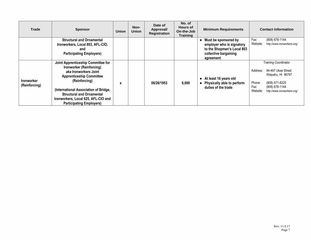
Structural and Ornamental Ironworkers, Local 803, AFL-CIO,
and Participating Employers)
● Must be sponsored by employer who is signatory to the Shopmen’s Local 803 collective bargaining agreement
Fax: (808) 676-1144 Website: http://www.ironworkers.org/
Ironworker (Reinforcing)
Joint Apprenticeship Committee for Ironworker (Reinforcing) aka Ironworkers Joint
Apprenticeship Committee (Reinforcing)
(International Association of Bridge,
Structural and Ornamental Ironworkers, Local 625, AFL-CIO and
Participating Employers)
x 06/26/1953 6,000 ● At least 16 years old ● Physically able to perform
duties of the trade
Training Coordinator Address: 94-497 Ukee Street Waipahu, HI 96797 Phone: (808) 671-8225 Fax: (808) 676-1144 Website: http://www.ironworkers.org/
Rev. 11.9.17
Page 8
Trade Sponsor
Union Non-
Union
Date of Approval/
Registration
No. of Hours of
On-the-Job Training
Minimum Requirements Contact Information
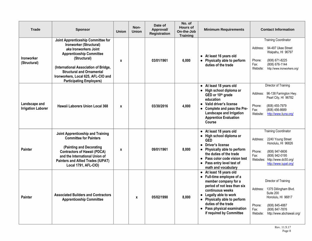
Ironworker (Structural)
Joint Apprenticeship Committee for Ironworker (Structural) aka Ironworkers Joint
Apprenticeship Committee (Structural)
(International Association of Bridge,
Structural and Ornamental Ironworkers, Local 625, AFL-CIO and
Participating Employers)
x 03/01/1961 6,000 ● At least 16 years old ● Physically able to perform
duties of the trade
Training Coordinator Address: 94-497 Ukee Street Waipahu, HI 96797 Phone: (808) 671-8225 Fax: (808) 676-1144 Website: http://www.ironworkers.org/
Landscape and Irrigation Laborer
Hawaii Laborers Union Local 368 x 03/30/2016 4,000
● At least 18 years old
● High school diploma or GED or 10th grade education
● Valid driver’s license ● Complete and pass the Pre-
Landscape and Irrigation Apprentice Evaluation Course
Director of Training Address: 96-138 Farrington Hwy. Pearl City, HI 96782 Phone: (808) 455-7979 Fax: (808) 456-8689 Website: http://www.liuna.org/
Painter
Joint Apprenticeship and Training Committee for Painters
(Painting and Decorating
Contractors of Hawaii (PDCA) and the International Union of
Painters and Allied Trades (IUPAT) Local 1791, AFL-CIO)
x 09/01/1961 8,000
● At least 18 years old ● High school diploma or
GED ● Driver’s license ● Physically able to perform
the duties of the trade ● Pass color code vision test ● Pass entry level test of
math and vocabulary
Training Coordinator Address: 2240 Young Street Honolulu, HI 96826 Phone: (808) 947-6606 Fax: (808) 942-0195 Websites: http://www.dc50.org/ http://www.iupat.org/
Painter Associated Builders and Contractors
Apprenticeship Committee x 05/02/1990 8,000
● At least 18 years old ● Full-time employee of a
member company for a period of not less than six continuous weeks
● Legally able to work ● Physically able to perform
duties of the trade ● Pass physical examination
if required by Committee
Director of Training Address: 1375 Dillingham Blvd. Suite 200 Honolulu, HI 96817 Phone: (808) 845-4887 Fax: (808) 847-7876 Website: http://www.abchawaii.org/
Rev. 11.9.17
Page 9
Trade Sponsor
Union Non-
Union
Date of Approval/
Registration
No. of Hours of
On-the-Job Training
Minimum Requirements Contact Information
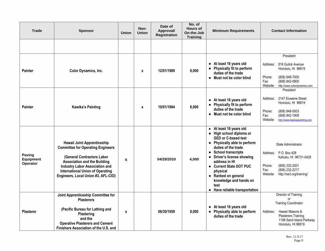
Painter Color Dynamics, Inc. x 12/01/1989 8,000
● At least 16 years old ● Physically fit to perform
duties of the trade ● Must not be color blind
President Address: 816 Gulick Avenue Honolulu, HI 96819 Phone: (808) 848-7000 Fax: (808) 842-0800 Website: http://www.colordynamics.com
Painter Kawika’s Painting x 10/01/1984 8,000
● At least 16 years old ● Physically fit to perform
duties of the trade ● Must not be color blind
President Address: 2147 Eluwene Street Honolulu, HI 96819 Phone: (808) 848-0003 Fax: (808) 842-1908 Website: http://www.kawikaspainting.com
Paving Equipment Operator
Hawaii Joint Apprenticeship Committee for Operating Engineers
(General Contractors Labor
Association and the Building Industry Labor Association and International Union of Operating
Engineers, Local Union #3, AFL-CIO)
x
04/29/2010 4,000
● At least 18 years old ● High school diploma or
GED or C-based test ● Physically able to perform
duties of the trade ● School transcripts ● Driver’s license showing
address in HI ● Current State DOT PUC
physical ● Ranked on general
knowledge and hands on test
● Have reliable transportation
State Administrator Address: P.O. Box 428 Kahuku, HI 96731-0428 Phone: (808) 232-2001 Fax: (808) 232-2217 Website: http://oe3.org/training/
Plasterer
Joint Apprenticeship Committee for Plasterers
(Pacific Bureau for Lathing and
Plastering and the
Operative Plasterers and Cement Finishers Association of the U.S. and
x 06/30/1959 8,000 ● At least 16 years old ● Physically able to perform
duties of the trade
Director of Training or
Training Coordinator Address: Hawaii Masons & Plasterers Training 1188 Sand Island Parkway Honolulu, HI 96819
Rev. 11.9.17
Page 10
Trade Sponsor
Union Non-
Union
Date of Approval/
Registration
No. of Hours of
On-the-Job Training
Minimum Requirements Contact Information
Canada, Local 630, AFL-CIO) Phone: (808) 848-0565 Fax: (808) 847-7068 Website: http://www.opcmia.org/ http://www.bacweb.org
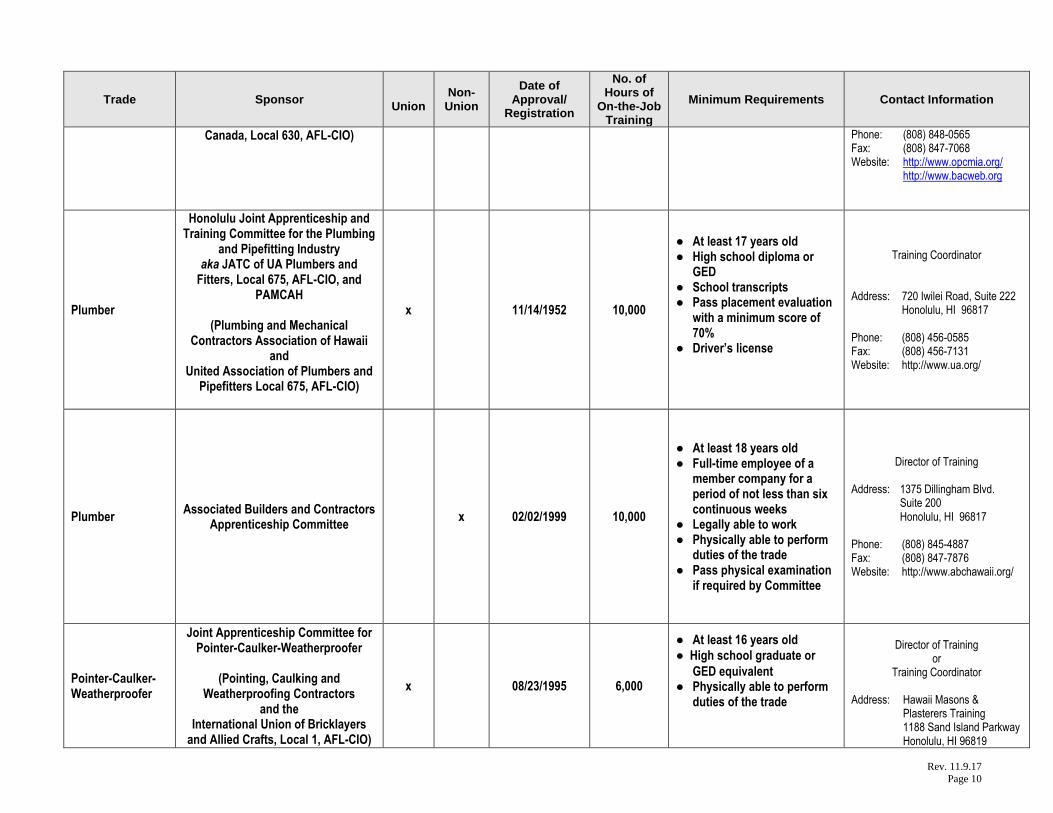
Plumber
Honolulu Joint Apprenticeship and Training Committee for the Plumbing
and Pipefitting Industry aka JATC of UA Plumbers and
Fitters, Local 675, AFL-CIO, and PAMCAH
(Plumbing and Mechanical
Contractors Association of Hawaii and
United Association of Plumbers and Pipefitters Local 675, AFL-CIO)
x 11/14/1952 10,000
● At least 17 years old ● High school diploma or
GED ● School transcripts ● Pass placement evaluation
with a minimum score of 70%
● Driver’s license
Training Coordinator
Address: 720 Iwilei Road, Suite 222
Honolulu, HI 96817 Phone: (808) 456-0585 Fax: (808) 456-7131 Website: http://www.ua.org/
Plumber Associated Builders and Contractors
Apprenticeship Committee x 02/02/1999 10,000
● At least 18 years old ● Full-time employee of a
member company for a period of not less than six continuous weeks
● Legally able to work ● Physically able to perform
duties of the trade ● Pass physical examination
if required by Committee
Director of Training Address: 1375 Dillingham Blvd. Suite 200 Honolulu, HI 96817 Phone: (808) 845-4887 Fax: (808) 847-7876 Website: http://www.abchawaii.org/
Pointer-Caulker-Weatherproofer
Joint Apprenticeship Committee for Pointer-Caulker-Weatherproofer
(Pointing, Caulking and
Weatherproofing Contractors and the
International Union of Bricklayers and Allied Crafts, Local 1, AFL-CIO)
x 08/23/1995 6,000
● At least 16 years old
● High school graduate or
GED equivalent ● Physically able to perform
duties of the trade
Director of Training
or Training Coordinator
Address: Hawaii Masons & Plasterers Training 1188 Sand Island Parkway Honolulu, HI 96819
Rev. 11.9.17
Page 11
Trade Sponsor
Union Non-
Union
Date of Approval/
Registration
No. of Hours of
On-the-Job Training
Minimum Requirements Contact Information
Phone: (808) 848-0565 Fax: (808) 847-7068 Website: http://www.bacweb.org
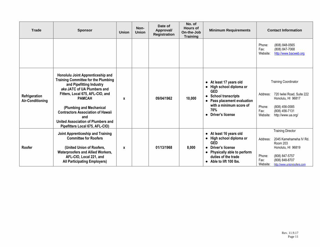
Refrigeration Air-Conditioning
Honolulu Joint Apprenticeship and
Training Committee for the Plumbing and Pipefitting Industry
aka JATC of UA Plumbers and Fitters, Local 675, AFL-CIO, and
PAMCAH
(Plumbing and Mechanical Contractors Association of Hawaii
and United Association of Plumbers and
Pipefitters Local 675, AFL-CIO)
x 09/04/1962 10,000
● At least 17 years old ● High school diploma or
GED ● School transcripts ● Pass placement evaluation
with a minimum score of 70%
● Driver’s license
Training Coordinator
Address: 720 Iwilei Road, Suite 222
Honolulu, HI 96817 Phone: (808) 456-0585 Fax: (808) 456-7131 Website: http://www.ua.org/
Roofer
Joint Apprenticeship and Training Committee for Roofers
(United Union of Roofers,
Waterproofers and Allied Workers, AFL-CIO, Local 221, and
All Participating Employers)
x 01/13/1968 8,000
● At least 16 years old ● High school diploma or
GED ● Driver’s license ● Physically able to perform
duties of the trade ● Able to lift 100 lbs.
Training Director Address: 2045 Kamehameha IV Rd. Room 203 Honolulu, HI 96819 Phone: (808) 847-5757 Fax: (808) 848-8707 Website: http://www.unionroofers.com

Rev. 11.9.17
Page 12
Trade Sponsor
Union Non-
Union
Date of Approval/
Registration
No. of Hours of
On-the-Job Training
Minimum Requirements Contact Information
Roofer Associated Builders and Contractors
Apprenticeship Committee x 01/09/1996 7,000
● At least 18 years old ● Full-time employee of a
member company for a period of not less than six continuous weeks
● Legally able to work ● Physically able to perform
duties of the trade ● Pass physical examination
if required by Committee
Director of Training Address: 1375 Dillingham Blvd. Suite 200 Honolulu, HI 96817 Phone: (808) 845-4887 Fax: (808) 847-7876 Website: http://www.abchawaii.org/
Sheet Metal Worker
Hawaii Joint Apprenticeship Committee for the
Sheet Metal Industry
(Sheet Metal Contractor’s Association and
Sheet Metal Workers’ International Association, Local 293)
x 01/02/1958 10,000
● At least 18 years old ● High school diploma or
GED ● Complete industry test ● Driver’s license ● Physically able to perform
work
Apprenticeship Coordinator Address: 1405 North King Street Room 403 Honolulu, HI 96817 Phone: (808) 841-6106 Fax: (808) 841-1842 Website: http://www.smwia.org/
Steamfitter/ Welder
Honolulu Joint Apprenticeship and Training Committee for the Plumbing
and Pipefitting Industry aka JATC of UA Plumbers and
Fitters, Local 675, AFL-CIO, and PAMCAH
(Plumbing and Mechanical
Contractors Association of Hawaii and
United Association of Plumbers and Pipefitters Local 675, AFL-CIO)
x 02/05/2002 10,000
● At least 17 years old ● High school diploma or
GED ● School transcripts ● Pass placement evaluation
with a minimum score of 70%
● Driver’s license
Training Coordinator
Address: 720 Iwilei Road, Suite 222
Honolulu, HI 96817 Phone: (808) 456-0585 Fax: (808) 456-7131 Website: http://www.ua.org/
Stone Mason
Joint Apprenticeship Committee for Stone Mason Industry
(Masonry Contractors Association of
Hawaii and Local 1 of Hawaii of the Bricklayers and Allied Craftsmen International
Union, AFL-CIO, and Other Signatory Employers)
x 02/10/1964 8,000
● At least 16 years old
● High school graduate or
GED equivalent ● Physically able to perform
duties of the trade
Director of Training or
Training Coordinator Address: Hawaii Masons & Plasterers Training 1188 Sand Island Parkway Honolulu, HI 96819

Rev. 11.9.17
Page 13
Trade Sponsor
Union Non-
Union
Date of Approval/
Registration
No. of Hours of
On-the-Job Training
Minimum Requirements Contact Information
Phone: (808) 848-0565 Fax: (808) 847-7068 Website: http://www.bacweb.org
Taper
Joint Apprenticeship Committee for Tapers
(Gypsum Drywall Contractors Association of Hawaii and the International Brotherhood of
Painters and Allied Trades Tapers Local
Union 1944, AFL-CIO)
x 09/01/1967 8,000
● At least 18 years old ● Physically able to perform
duties of the trade ● Driver’s license ● High school diploma or
equivalent
Training Coordinator Address: 2240 Young Street Honolulu, HI 96826 Phone: (808) 941-0991 Fax: (808) 946-6623 Website: http://www.dc50.org/
Telecommunication /
CATV Installer Technician
Hawaii Electricians Joint Apprenticeship Committee
aka
Joint Apprenticeship Committee for Telecommunications
(International Brotherhood of
Electrical Workers Local Union 1186, AFL-CIO, and
Signatory Employers)
x 09/16/1998 6,000
● At least 18 years old ● High school diploma or
GED ● Complete the National Joint
Apprenticeship and Training Committee Math Course or one-year high school Algebra 1
● Transcript of high school or post high school courses
● Pass industry aptitude test to qualify for oral interview
● Application fee (non-refundable)
Apprenticeship or Training Coordinator Address: 1935 Hau Street Room 301 Honolulu, HI 96819 Phone: (808) 847-0629 Fax: (808) 843-8818 Website: http://www.njatc.org/
Tile Setter
Joint Apprenticeship Committee for Tile Setters
(Tile, Marble and Terrazo
Contractors Association of Hawaii and
Local 1 of Hawaii of the Bricklayers, and
Allied Craftsmen International Union of America, AFL-CIO)
x 06/24/1958 8,000
● At least 16 years old
● High school graduate or
GED equivalent ● Physically able to perform
duties of the trade
Director of Training or
Training Coordinator Address: Hawaii Masons & Plasterers Training 1188 Sand Island Parkway Honolulu, HI 96819 Phone: (808) 848-0565 Fax: (808) 847-7068 Website: http://www.bacweb.org
Rev. 11.9.17
Page 14
Trade Sponsor
Union Non-
Union
Date of Approval/
Registration
No. of Hours of
On-the-Job Training
Minimum Requirements Contact Information
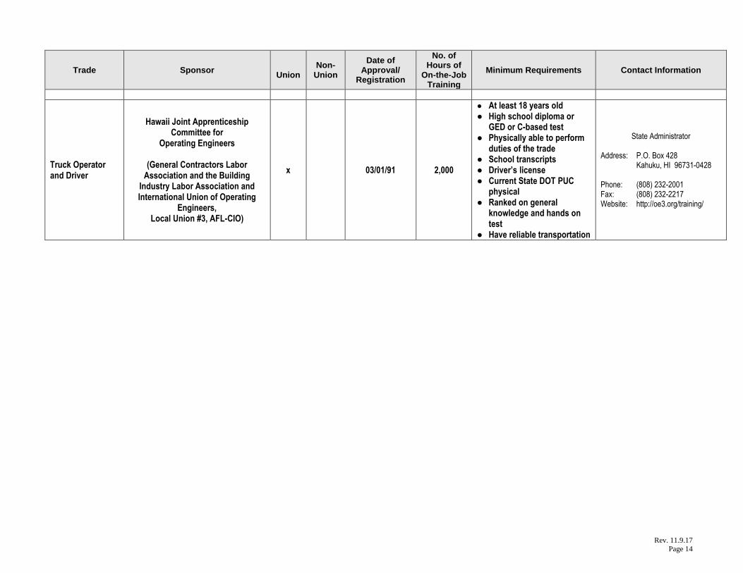
Truck Operator and Driver
Hawaii Joint Apprenticeship Committee for
Operating Engineers
(General Contractors Labor Association and the Building
Industry Labor Association and International Union of Operating
Engineers, Local Union #3, AFL-CIO)
x 03/01/91 2,000
● At least 18 years old ● High school diploma or
GED or C-based test ● Physically able to perform
duties of the trade ● School transcripts ● Driver’s license ● Current State DOT PUC
physical ● Ranked on general
knowledge and hands on test
● Have reliable transportation
State Administrator Address: P.O. Box 428 Kahuku, HI 96731-0428 Phone: (808) 232-2001 Fax: (808) 232-2217 Website: http://oe3.org/training/

Years 2018 and 2019 www.dhrd.hawaii.gov Holidays to be observed by the Website where State Holiday Schedule posted
HAWAII STATE GOVERNMENT
Year 2018 HAWAII STATE HOLIDAYS (Hawaii Rev. Statutes, Sec. 8-1) Day Observed in 2018 Official Date Designated in Statute/Constitution New Year’s Day…………………………….. Jan. 1 Monday…………….. The first day in January
Dr. Martin Luther King, Jr. Day……………. Jan. 15 Monday……………. The third Monday in January
Presidents’ Day……………………………... Feb. 19 Monday……………. The third Monday in February
Prince Jonah Kuhio Kalanianaole Day…… Mar. 26 Monday…………… The twenty-sixth day in March
Good Friday…………………………………. Mar. 30 Friday……………… The Friday preceding Easter Sunday
Memorial Day……………………………….. May 28 Monday……………. The last Monday in May
King Kamehameha I Day………………….. June 11 Monday…………... The eleventh day in June
Independence Day…………………………. July 4 Wednesday……….... The fourth day in July
Statehood Day…………………………….…Aug. 17 Friday……………… The third Friday in August
Labor Day…………………………………….Sept. 3 Monday…………….. The first Monday in September
General Election Day………………………. Nov. 6 Tuesday…………….. The first Tuesday in Nov. following the first Monday of even-numbered years. (Hawaii State Constitution, Article 2 – Section 8)
Veterans’ Day……………………………….. Nov. 12 Monday…………… The eleventh day in November
Thanksgiving………………………………… Nov. 22 Thursday………….. The fourth Thursday in November
Christmas……………………………………. Dec. 25 Tuesday……………The twenty-fifth day in December
Year 2019 HAWAII STATE HOLIDAYS (Hawaii Rev. Statutes, Sec. 8-1) Day Observed in 2019 Official Date Designated in Statute/Constitution New Year’s Day…………………………….. Jan. 1 Tuesday ……………. The first day in January
Dr. Martin Luther King, Jr. Day……………. Jan. 21 Monday……………. The third Monday in January
Presidents’ Day……………………………... Feb. 18 Monday……………. The third Monday in February
Prince Jonah Kuhio Kalanianaole Day…… Mar. 26 Tuesday ………….. The twenty-sixth day in March
Good Friday…………………………………. April 19 Friday…………….. The Friday preceding Easter Sunday
Memorial Day……………………………….. May 27 Monday……………. The last Monday in May
King Kamehameha I Day………………….. June 11 Tuesday…..………. The eleventh day in June
Independence Day…………………………. July 4 Thursday……………. The fourth day in July
Statehood Day…………………………….…Aug. 16 Friday……………… The third Friday in August
Labor Day…………………………………….Sept. 2 Monday…………….. The first Monday in September
Veterans’ Day……………………………….. Nov. 11 Monday…….……… The eleventh day in November
Thanksgiving………………………………… Nov. 28 Thursday………….. The fourth Thursday in November
Christmas…………………………………….Dec. 25 Wednesday.…….… The twenty-fifth day in December
FOOTNOTES: For use solely by State government agencies. Federal government and local banking holidays may differ. For State agencies that operate on other than Monday-Friday 7:45 AM to 4:30 PM schedules, also refer to appropriate collective bargaining agreements. Created by the Department of Human Resources Development 8/31/2017; subject to change.

W.O. 7053-00 GEOLABS, INC. Page i Hawaii • California
GEOTECHNICAL ENGINEERING EXPLORATION
HONOKAIA NON-POTABLE WATER SYSTEM
DEPARTMENT OF HAWAIIAN HOME LANDS
HAMAKUA DISTRICT, ISLAND OF HAWAII
W.O. 7053-00 FEBRUARY 25, 2015
TABLE OF CONTENTS
Page
SUMMARY OF FINDINGS AND RECOMMENDATIONS.............................................. iii
1. GENERAL............................................................................................................ 1 1.1 Project Considerations............................................................................... 1 1.2 Purpose and Scope ................................................................................... 2
2. SITE CHARACTERIZATION................................................................................ 3 2.1 Regional Geology ...................................................................................... 3 2.2 Site Description.......................................................................................... 4 2.3 Subsurface Conditions............................................................................... 4 2.4 Seismic Design Considerations ................................................................. 5
2.4.1 Earthquakes and Seismicity ........................................................... 6 2.4.2 Soil Profile Type for Seismic Design .............................................. 7
3. DISCUSSION AND RECOMMENDATIONS ........................................................ 8 3.1 Water Tank Foundations.......................................................................... 10 3.2 Site Grading............................................................................................. 12
3.2.1 Site Preparation............................................................................ 12 3.2.2 Volcanic Ash Soils........................................................................ 13 3.2.3 Fill Materials ................................................................................. 14 3.2.4 Fill Placement and Compaction Requirements ............................ 15 3.2.5 Excavation.................................................................................... 15
3.3 Pavement Design .................................................................................... 16 3.4 Underground Utility Lines......................................................................... 17 3.5 Drainage .................................................................................................. 18 3.6 Design Review......................................................................................... 19 3.7 Post-Design Services/Services During Construction ............................... 19
4. LIMITATIONS..................................................................................................... 21
CLOSURE..................................................................................................................... 23 PLATES
Project Location Map................................................................................... Plate 1 Site Plan ...................................................................................................... Plate 2
TABLE OF CONTENTS
Page
W.O. 7053-00 GEOLABS, INC. Page ii Hawaii • California
APPENDIX A Field Exploration...................................................................................... Page A-1 Logs of Test Pits....................................................................... Plates A-1 and A-2
APPENDIX B Laboratory Tests...................................................................................... Page B-1 Laboratory Test Data................................................................ Plates B-1 thru B-5
W.O. 7053-00 GEOLABS, INC. Page iii Hawaii • California
GEOTECHNICAL ENGINEERING EXPLORATION
HONOKAIA NON-POTABLE WATER SYSTEM
DEPARTMENT OF HAWAIIAN HOME LANDS
HAMAKUA DISTRICT, ISLAND OF HAWAII
W.O. 7053-00 FEBRUARY 25, 2015
SUMMARY OF FINDINGS AND RECOMMENDATIONS
Our field exploration at the Lower Tank Site generally encountered a surface
layer of volcanic ash that graded with depth to weathered basalt rock formation while our field exploration at the Upper Tank Site generally encountered medium dense granular fill materials ranging in thickness from about 2.5 to 8 feet overlying ash soil and weathered basalt rock formation. We did not encounter groundwater in the excavated test pits at the time of our field exploration.
In general, volcanic ash soils typically are relatively soft and will compress when subjected to structural and vehicular loads. Consequently, volcanic ash soils generally have poor structural characteristics with respect to foundation and pavement support. In addition, ash soils have thixotropic properties (i.e., they temporarily lose strength when remolded or are subjected to vibrations, such as seismic events). Therefore, to the extent practicable, the surface ash soils should be over-excavated and removed from structural areas to basalt rock formation and replaced with compacted structural fill materials.
Based on the anticipated structural loads and the subsurface conditions encountered, we believe shallow foundations consisting of spread and/or continuous footings may be used to support the proposed new water tank structures. We recommend over-excavating the volcanic ash soils at the Lower Tank Site to the underlying basalt formation and replacing with well-compacted structural fill. Similarly, we recommend over-excavating the existing fill materials encountered at the Upper Tank Site a minimum depth of 3 feet below water tank foundations and replacing with well-compacted structural fill materials. In addition, this over-excavation and replacement with well-compacted structural fill materials should extend a lateral distance of at least 3 feet beyond the perimeter of the water tank foundations.
Structural fill materials should consist of well-graded granular materials generally less than 6 inches in maximum dimension with sufficient fines to prevent the occurrence of voids in the compacted mass. The existing granular fill materials encountered at the Upper Tank Site may be re-used as a source of structural fill materials, provided that they are free of vegetation, deleterious materials, and rock fragments greater than 6 inches in maximum dimension. Excavated ash soils should not be re-used as structural fill materials. The structural fill materials should be compacted to a minimum of 95 percent relative compaction.
SUMMARY OF FINDINGS AND RECOMMENDATIONS
W.O. 7053-00 GEOLABS, INC. Page iv Hawaii • California
Based on our experience in the vicinity of the project site, cavities and/or voids may be present in the hard basaltic lava flows. To reduce the potential for loss of foundation support resulting from the collapse of cavities below foundations, a cavity probing and grouting program is generally implemented for new foundations during construction. However, the weathered basalt encountered below the Lower Tank site consisted primarily of clinker, which does not contain cavities or lava tubes. Therefore, it is our opinion that probing and grouting may be omitted.
Conventional earthwork and construction methods may be used for the proposed project grading. Based on the anticipated grading and our field exploration, excavation for this project will generally consist of excavations for foundation construction and infrastructure installation. Some of the excavations may encounter boulders and involve cuts into the underlying basalt formation. It is anticipated that most of the material may be excavated with normal heavy excavation equipment. However, deep excavations and excavations into basalt formations may require the use of hoerams or trenching machines. We recommend encouraging contractors bidding on this project to examine the site conditions and soil data to make their own interpretation.
The text of this report should be referred to for detailed discussions and specific geotechnical recommendations.
END OF SUMMARY OF FINDINGS AND RECOMMENDATIONS
W.O. 7053-00 GEOLABS, INC. Page 1 Hawaii • California
SECTION 1. GENERAL
This report presents the results of our geotechnical engineering exploration
performed for the Honokaia Non-Potable Water System project in the Hamakua District
of the Island of Hawaii. The project location and general vicinity are shown on the
Project Location Map, Plate 1.
This report summarizes the findings and geotechnical recommendations resulting
from our field exploration, laboratory testing, and engineering analyses. These findings
and geotechnical recommendations are intended for the design of water tank
foundations, site grading, pavements, and utilities only. The findings and
recommendations presented herein are subject to the limitations noted at the end of this
report.
1.1 Project Considerations
The proposed Honokaia Non-Potable Water System project is to the south of the
Old Mamalahoa Highway, between Honokaa and Waimea, in the Hamakua District of the
Island of Hawaii. We understand the project involves constructing a non-potable water
system consisting of underground water lines and two non-potable steel water tanks with
capacities of about 40,500 and 45,000-gallons for the Department of Hawaiian Home
Lands (DHHL) Honokaia Pastoral Lots.
Based on the information provided, the proposed 40,500 and 45,000-gallon water
tanks will be located off the eastern side of Alanui Honokaia Road on Lots 4 and 5,
respectively. We understand the 40,500-gallon water tank proposed for Lot 4 is being
referred to as the Lower Tank Site, while the 45,000-gallon water tank proposed for Lot
5 is referred to as the Upper Tank Site. Details of the water tank foundations were not
available at the time this report was prepared; however, it is anticipated that the water
tanks will be supported by spread or continuous concrete foundations.
A grading plan was not provided at the time this report was prepared; however, it is
anticipated that minimal grading will be required to achieve the design project site
elevations and will generally consist of excavations for foundation construction.

SECTION 1. GENERAL
W.O. 7053-00 GEOLABS, INC. Page 2 Hawaii • California
1.2 Purpose and Scope
The purpose of our exploration was to obtain an overview of the surface and
subsurface conditions to develop an idealized soil/rock data set to formulate
geotechnical engineering recommendations for design of the project. The work was
performed in general accordance with our fee proposal dated March 21, 2014. The
scope of work for this exploration included the following tasks and work efforts:
1. Research and review of available in-house soils and geologic information for the project site and its vicinity.
2. Mobilization and demobilization of a Case 590L Super backhoe and operator to the project site and back.
3. Excavation and sampling of four test pits extending to depths of about 8 to 11 feet below the existing ground surface. Two bulk samples were collected for laboratory testing.
4. Coordination of the field exploration and logging of the test pits by our field engineer.
5. Laboratory testing of selected soil samples obtained during the field exploration as an aid in classifying the materials and evaluating their engineering properties.
6. Analyses of the field and laboratory data to formulate geotechnical recommendations for the design of the project.
7. Preparation of this report summarizing our work and presenting our findings and geotechnical recommendations.
8. Coordination of our overall work on the project by our project engineer.
9. Quality assurance of our work and client/design team consultation by our principal engineer.
10. Miscellaneous work efforts such as drafting, word processing, and clerical support.
Detailed descriptions of our field exploration methodology and the Logs of Test
Pits are presented in Appendix A. Results of the laboratory tests performed on selected
soil samples are presented in Appendix B.
END OF GENERAL
W.O. 7053-00 GEOLABS, INC. Page 3 Hawaii • California
SECTION 2. SITE CHARACTERIZATION
2.1 Regional Geology
The Island of Hawaii is the largest island in the Hawaiian Archipelago and covers
an area of approximately 4,000 square miles. The island was formed by the activity of
five shield volcanoes, which include the following: Kohala (long extinct), Mauna Kea
(activity during recent geologic time), Hualalai (last erupted in 1801 – 1803), and
Mauna Loa and Kilauea (both still active).
The project site is situated on the northern flank of Mauna Kea near its contact
with the southeastern flank of Kohala. The project site appears to be underlain by
basaltic lava flows of the Laupahoehoe Volcanic Series of Mauna Kea, which were
deposited during the Pleistocene Epoch (Stearns and Macdonald, 1946).
The project region consists of Laupahoehoe Volcanic Series that is typically
composed of basaltic lava flows mantled by a relatively thin layer of palagonitized ash
(locally referred to as Pahala Ash). This ash soil is typified by very high in-situ moisture
contents and is generally thixotropic in nature (i.e., the soil loses shear strength when
remolded) due to transient increases in soil pore pressure.
The lava formation at the site and in the vicinity appears to be of both a`a and
pahoehoe basalt type flows, which are typical of the flank flows that originate from vents
along the rift zones of Mauna Kea. The a`a form seems to be predominant at the site.
A`a lava is typically characterized by a porous, rough, and irregular flow surface
resembling a jagged accumulation of rock fragments, cobbles, and boulders. Typically,
a more dense and layered lava rock material is contained within the lava flow core.
Pahoehoe lava is characterized by a smooth, rope-like or billowy surface and an internal
structure of vesicular (porous) rock. Cavities are commonly encountered in pahoehoe
lavas. Cavities are formed when the lavas are still in a molten state and represent both
lava tubes (intra-flow cavities) and blisters and pockets (inter-flow cavities). Lava tubes
are formed when molten lava drains from the cooling flow, leaving a hollow tube-like
structure that may extend for a large longitudinal distance along the flow. Blisters and
pockets (inter-flow cavities) are generally smaller in horizontal extent.

SECTION 2. SITE CHARACTERIZATION
W.O. 7053-00 GEOLABS, INC. Page 4 Hawaii • California
2.2 Site Description
The project site is located to the south of the Old Mamalahoa Highway, between
Honokaa and Waimea, in the Hamakua District of the Island of Hawaii. The site is
generally open pastureland that is traversed by a series of fence lines.
The Lower and Upper Tank Sites are located on Lots 4 and 5, respectively, and
are bounded by Alanui Honokaia Road to the west and pasture on all other sides. At the
time of our field exploration, an existing water tank was located at the Upper Tank Site
in generally the same location as the new proposed water tank. The existing water tank
was roughly 15 feet in diameter and about 3.5 feet high.
The ground surfaces at both tank site locations were covered by lush grasses up
to about 12 inches high. The surface soils generally consist of brown to orangish brown
clayey silts, which appear to be volcanic ash. The terrain around both tank sites is
generally rolling, reflects the original surfaces of the basalt lava flows, and generally
slopes down towards the north. The existing ground surface at both tank sites are
generally flat; however, the upper tank site is at the top of an approximately 10-foot high
embankment with a slope inclination of about two horizontal to one vertical (2H:1V).
This embankment appears to be fill that may have been placed during construction of
the adjacent roadway.
Based on the topographic survey map provided, the site elevations at the Upper
and Lower Tank Sites range from approximately +3,335 feet to +3,253 feet Mean Sea
Level (MSL), respectively.
2.3 Subsurface Conditions
Our field exploration consisted of excavating and sampling four test pits,
designated as Test Pit Nos. 1 through 4, extending to depths ranging from about 8 to
11 feet below the existing ground surface. In addition, two bulk samples of the
near-surface soils, designated as Bulk-1 and Bulk-2, were obtained to evaluate the
pavement support characteristics of the near-surface soils. The approximate test pit and
bulk sample locations are shown on the Site Plan, Plate 2.
SECTION 2. SITE CHARACTERIZATION
W.O. 7053-00 GEOLABS, INC. Page 5 Hawaii • California
The test pits at the Lower Tank Site generally encountered a surface layer of
volcanic ash that graded with depth to weathered basalt rock formation. The ash soil
encountered ranged from about 3.5 to 4 feet thick and generally consisted of medium
stiff clayey silt. The ash soil was overlying highly weathered basalt rock formation that
was generally medium hard and could be excavated by the backhoe. Hard basalt rock
was encountered at a depth of about 7 feet in Test Pit No. 4.
The test pits at the Upper Tank Site encountered medium dense granular fill
materials overlying ash soil and weathered basalt rock formation. The fill materials
encountered ranged in thickness from about 2.5 to 8 feet and generally consisted of
silty/sandy basalt gravel with cobbles and boulders up to about 2 feet in maximum
dimension. The fill materials encountered were overlying a layer of ash soil, roughly
3.5 feet thick, and highly weathered basalt rock formation. The exception was Test Pit
No. 1 in which medium stiff ash soil was still encountered at the termination depth of
11 feet below the existing ground surface.
Voids were not encountered in our field exploration, although lava tubes and
cavities are commonly encountered in basalt formations. Therefore, the presence of
lava tubes and/or cavities should be anticipated and should be expected at the project
site.
We did not encounter groundwater in the test pits at the time of our field
exploration. However, groundwater levels may change due to seasonal precipitation,
surface water runoff, and other factors.
Detailed descriptions of our field exploration methodology and the Logs of Test
Pits are presented in Appendix A. Results of the laboratory tests performed on selected
soil samples are presented in Appendix B.
2.4 Seismic Design Considerations
Based on the International Building Code (2006 Edition), the project site may be
subject to seismic activity, and seismic design considerations will need to be addressed.
The following sections provide discussions on the seismicity and soil profile type for
seismic design at the project site.
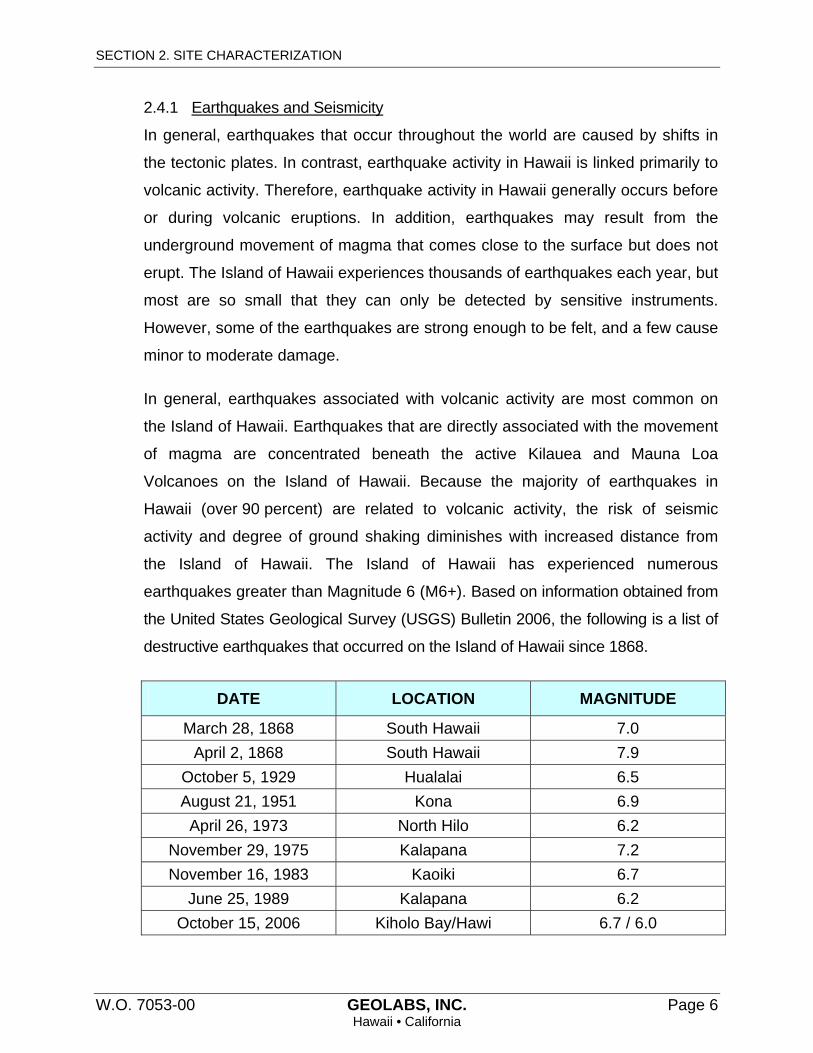
SECTION 2. SITE CHARACTERIZATION
W.O. 7053-00 GEOLABS, INC. Page 6 Hawaii • California
2.4.1 Earthquakes and Seismicity
In general, earthquakes that occur throughout the world are caused by shifts in
the tectonic plates. In contrast, earthquake activity in Hawaii is linked primarily to
volcanic activity. Therefore, earthquake activity in Hawaii generally occurs before
or during volcanic eruptions. In addition, earthquakes may result from the
underground movement of magma that comes close to the surface but does not
erupt. The Island of Hawaii experiences thousands of earthquakes each year, but
most are so small that they can only be detected by sensitive instruments.
However, some of the earthquakes are strong enough to be felt, and a few cause
minor to moderate damage.
In general, earthquakes associated with volcanic activity are most common on
the Island of Hawaii. Earthquakes that are directly associated with the movement
of magma are concentrated beneath the active Kilauea and Mauna Loa
Volcanoes on the Island of Hawaii. Because the majority of earthquakes in
Hawaii (over 90 percent) are related to volcanic activity, the risk of seismic
activity and degree of ground shaking diminishes with increased distance from
the Island of Hawaii. The Island of Hawaii has experienced numerous
earthquakes greater than Magnitude 6 (M6+). Based on information obtained from
the United States Geological Survey (USGS) Bulletin 2006, the following is a list of
destructive earthquakes that occurred on the Island of Hawaii since 1868.
DATE LOCATION MAGNITUDE
March 28, 1868 South Hawaii 7.0
April 2, 1868 South Hawaii 7.9
October 5, 1929 Hualalai 6.5
August 21, 1951 Kona 6.9
April 26, 1973 North Hilo 6.2
November 29, 1975 Kalapana 7.2
November 16, 1983 Kaoiki 6.7
June 25, 1989 Kalapana 6.2
October 15, 2006 Kiholo Bay/Hawi 6.7 / 6.0

SECTION 2. SITE CHARACTERIZATION
W.O. 7053-00 GEOLABS, INC. Page 7 Hawaii • California
Several of the significant earthquakes on the Island of Hawaii have occurred in
the past 160 years, including three earthquakes greater than Magnitude 7.0.
Therefore, it may be concluded that the project area could experience moderate
to severe earthquakes and associated ground shaking, depending on the
earthquake origin.
2.4.2 Soil Profile Type for Seismic Design
Based on the subsurface materials anticipated at the project site and the
geologic setting of the area, we anticipate the project site may be classified from
a seismic analysis standpoint as being a “Very Dense Soil and Soft Rock Profile”.
Therefore, we believe the seismic design of the project may be designed based
on a Site Class C soil profile based on the International Building Code
(Table No. 1613.5.2), 2006 Edition.
When seismic waves propagate through a soil profile, most of the times the
seismic shear waves get intensified and amplified (or attenuated) depending on
the thickness and properties of the soils. Based on a Site Class C soil profile, the
following seismic design parameters were estimated and may be used for the
seismic analysis of the project site.
SEISMIC DESIGN PARAMETERS
Parameter Value
Mapped MCE Spectral Response Acceleration, SS = 1.278g
Mapped MCE Spectral Response Acceleration, S1 = 0.477g
Site Class = “C”
Site Coefficient, Fa = 1.000
Site Coefficient, Fv = 1.323
Adjusted MCE Spectral Response Acceleration, SMS = 1.278g
Adjusted MCE Spectral Response Acceleration, SM1 = 0.631g
Design Spectral Response Acceleration, SDS = 0.852g
Design Spectral Response Acceleration, SD1 = 0.420g
Peak Bedrock Acceleration, PBA (Site Class B) = 0.341g
Peak Ground Acceleration, PGA (Site Class C) = 0.341g
END OF SITE CHARACTERIZATION
W.O. 7053-00 GEOLABS, INC. Page 8 Hawaii • California
SECTION 3. DISCUSSION AND RECOMMENDATIONS
Our field exploration at the Lower Tank Site generally encountered a surface
layer of volcanic ash that graded with depth to weathered basalt rock formation while
our field exploration at the Upper Tank Site encountered medium dense granular fill
materials ranging in thickness from about 2.5 to 8 feet overlying ash soil and weathered
basalt rock formation. We did not encounter groundwater in the excavated test pits at
the time of our field exploration.
In general, we believe that the primary geotechnical considerations for the project
design include the following:
Volcanic ash soils beneath foundations
Existing, uncontrolled fill of varying thickness beneath foundations
Volcanic ash soils, which are relatively soft and will compress when subjected to
structural and vehicular loads, generally have poor structural characteristics with
respect to foundation and pavement support. In addition, ash soils have thixotropic
properties (i.e., they temporarily lose strength when remolded or are subjected to
vibrations, such as seismic events). Therefore, to the extent practicable, the surface ash
soils should be over-excavated and removed from structural areas to basalt rock
formation and replaced with compacted structural fill materials.
Surface ash soil ranging from about 3.5 to 4 feet thick was generally encountered
during our field exploration at the Lower Tank Site. These volcanic ash soils should be
over-excavated to the underlying basalt formation and replaced with well-compacted
structural fill. In addition, this over-excavation and replacement with well-compacted
structural fill materials should extend a lateral distance of at least 3 feet beyond the
perimeter of the water tank foundations. Structural fill materials should consist of
well-graded granular materials generally less than 6 inches in maximum size compacted
to a minimum of 95 percent relative compaction.
Our field exploration at the Upper Tank Site generally encountered existing fill
materials ranging from about 2.5 to 8 feet thick overlying ash soil and weathered basalt
rock formation. The fill materials encountered generally consisted of silty/sandy basalt

SECTION 3. DISCUSSION AND RECOMMENDATIONS
W.O. 7053-00 GEOLABS, INC. Page 9 Hawaii • California
gravel with cobbles and boulders up to about 2 feet in maximum dimension. Based on
the observed consistency and varying thickness of the fill materials encountered, we
recommend over-excavating the existing fill materials a minimum depth of 3 feet below
water tank foundations and replacing with structural fill materials compacted to a
minimum of 95 percent relative compaction. In addition, this over-excavation and
replacement with compacted structural fill materials should extend a lateral distance of
at least 3 feet beyond the perimeter of the water tank foundations. The removed existing
fill materials may be re-used as a source of structural fill materials, provided that they
are free of vegetation, deleterious materials, and rock fragments greater than 6 inches
in maximum dimension.
Based on our experience in the vicinity of the project site, cavities and/or voids
may be present in the hard basaltic lava flows. To reduce the potential for loss of
foundation support resulting from the collapse of cavities below foundations, a cavity
probing and grouting program is generally implemented for new foundations during
construction. However, the weathered basalt encountered below the Lower Tank site
consisted primarily of clinker, which does not contain cavities or lava tubes. Therefore, it
is our opinion that probing and grouting may be omitted. Due to the thickness of existing
fill materials and the observed depth to basalt formation, the cavity probing and grouting
program may also be omitted for the Upper Tank Site.
We anticipate that asphaltic concrete pavements will be used for the water tank
access roads at the project site. Due to the poor pavement support characteristics of the
volcanic ash soils at the project site, we recommend removing the ash soil a minimum
depth of 2 feet below pavement subgrades or to basalt rock formation and replacing
with structural fill materials compacted to a minimum of 95 percent relative compaction.
Conventional earthwork and construction methods may be used for the proposed
project grading. Based on the anticipated grading and our field exploration, excavation for
this project will generally consist of excavations for foundation construction and
infrastructure installation. Some of the excavations may encounter boulders and involve
cuts into the underlying basalt formation. It is anticipated that most of the material may be
excavated with normal heavy excavation equipment. However, deep excavations and

SECTION 3. DISCUSSION AND RECOMMENDATIONS
W.O. 7053-00 GEOLABS, INC. Page 10 Hawaii • California
excavations into basalt formations may require the use of hoerams or trenching machines.
We recommend encouraging contractors bidding on this project to examine the site
conditions and soil data to make their own interpretation.
Detailed discussion of these items and our geotechnical engineering design
recommendations are presented in the following sections.
3.1 Water Tank Foundations
Based on the anticipated structural loads and the subsurface conditions
encountered, we believe shallow foundations consisting of spread and/or continuous
footings may be used to support the proposed new water tank structures. As previously
mentioned above, we recommend over-excavating the volcanic ash soils at the Lower
Tank Site to the underlying basalt formation and replacing with well-compacted
structural fill. In addition, this over-excavation and replacement with well-compacted
structural fill materials should extend a lateral distance of at least 3 feet beyond the
perimeter of the water tank foundations. The structural fill materials should consist of
well-graded granular materials generally less than 6 inches in maximum size compacted
to a minimum of 95 percent relative compaction.
Similarly, we recommend over-excavating the existing fill materials encountered
at the Upper Tank Site a minimum depth of 3 feet below water tank foundations and
replacing with well-compacted structural fill materials. This over-excavation and
replacement with well-compacted fill materials should also extend a lateral distance of
at least 3 feet beyond the perimeter of the water tank foundations.
We recommend using an allowable bearing pressure of up to 4,000 pounds per
square foot (psf) for design of footings bearing on structural fill. This bearing value is for
supporting dead-plus-live loads and may be increased by one-third (1/3) for transient
loads, such as those caused by wind or seismic forces.
In general, footings should be embedded a minimum of 18 inches below the
lowest adjacent grade. Footings constructed near the tops of slopes or on slopes should
be embedded deep enough such that the horizontal distance measured from the
outside edge (at the base of the footing) to the face of the slope is no less than 8 feet.

SECTION 3. DISCUSSION AND RECOMMENDATIONS
W.O. 7053-00 GEOLABS, INC. Page 11 Hawaii • California
In addition, foundations next to other foundations, utility trenches, easements or
other retaining walls should be embedded below a 45-degree imaginary plane
extending upward from the bottom edge of the structure or utility trench, or the footings
should be extended to a depth as deep as the inverts of the utility lines. This
requirement is necessary to avoid surcharging adjacent below-grade structures with
additional structural loads and to reduce the potential for appreciable foundation
settlement.
Soft and/or loose materials encountered at the bottom of footing excavations
should be over-excavated until dense materials are exposed in the footing excavation.
The over-excavation should be backfilled with structural fill materials
moisture-conditioned to above the optimum moisture content and compacted to a
minimum of 95 percent relative compaction. Alternatively, the bottom of the footing may
be extended down to bear directly on the underlying competent material.
If the foundations are designed and constructed in strict accordance with our
recommendations, we estimate the total settlements of the foundations to be less than
1 inch. Differential settlements between adjacent footings supported on similar materials
may be on the order of about 0.5 inches or less.
Lateral loads acting on the structure may be resisted by friction developed
between the bottom of the foundation and the bearing soil and by passive earth
pressure acting against the near-vertical faces of the foundation system. A coefficient of
friction of 0.45 may be used for footings bearing on structural fill materials or on-site
materials. Resistance due to passive earth pressure may be estimated using an
equivalent fluid pressure of 450 pounds per square foot per foot of depth (pcf) assuming
the soils around the footings are well compacted. The passive pressure resistance in
the upper 12 inches of the soil should be neglected unless covered by pavements or
slabs.
A Geolabs representative should observe the footing excavations prior to the
placement of reinforcing steel and concrete to confirm the foundation bearing conditions
and the required embedment depths.
SECTION 3. DISCUSSION AND RECOMMENDATIONS
W.O. 7053-00 GEOLABS, INC. Page 12 Hawaii • California
3.2 Site Grading
Based on the existing topography and the proposed finished grades for the water
tanks, we anticipate that site grading work for the proposed construction will consist of
cuts and fills on the order of about 3 to 4 feet deep for foundation construction. The
following grading items are addressed in the succeeding subsections:
Site Preparation
Volcanic Ash Soils
Fill Materials
Fill Placement and Compaction Requirements
Excavation
A Geolabs representative should monitor the site grading operations to observe
whether undesirable materials are encountered during the excavation and scarification
process and to confirm whether the exposed soil conditions are similar to those
encountered in our field exploration.
3.2.1 Site Preparation
As previously mentioned, the project site is generally underlain by basalt lava
flows covered with volcanic ash soils at the ground surface. The volcanic ash
soils, which are relatively soft and will compress when subjected to structural and
vehicular loads, generally have poor structural characteristics with respect to
foundation and pavement support. In addition, ash soils have thixotropic
properties (i.e., they temporarily lose strength when remolded or are subjected to
vibrations, such as seismic events). Therefore, to the extent practicable, site
grading should be designed to remove the surface ash soils from structural
areas.
At the on-set of earthwork, areas within the contract grading limits should be
cleared and grubbed thoroughly. As previously mentioned, we recommend
removing the surface volcanic ash soils encountered at the Lower Tank Site to
expose the underlying basalt rock formation. Similarly, the existing fill materials
encountered at the Upper Tank Site should be removed below the bottom of the
tank foundations a minimum of 3 feet and replaced with well-compacted structural
SECTION 3. DISCUSSION AND RECOMMENDATIONS
W.O. 7053-00 GEOLABS, INC. Page 13 Hawaii • California
fill materials. Over-excavations at both tank sites should extend a minimum lateral
distance of at least 3 feet beyond the perimeter of the water tank foundations.
Vegetation, debris, deleterious materials, and other unsuitable materials should be
removed and disposed properly off-site to reduce the potential for contaminating
the excavated materials to be used as fill materials. Volcanic ash soils may be
stockpiled and reused as a source of general fill materials in landscape areas.
Prior to filling, we recommend proof-rolling the cut subgrades with a minimum
10-ton (static weight) vibratory drum roller for a minimum of eight passes to help
detect near-surface soft spots. The vibratory drum roller should also be operated at
a speed of about 300 feet per minute. The proof-rolling operations should be
performed in the presence of a Geolabs representative.
Yielding or loose areas disclosed during the proof-rolling operations should be
over-excavated and backfilled with compacted fill materials. The depth of
over-excavation should be extended until dense underlying materials are exposed
and should be evaluated in the field by a Geolabs representative. Contract
documents should include additive and deductive unit prices for over-excavation of
the soft areas and backfilling with compacted fill to account for variations in the
over-excavation and backfill quantities.
3.2.2 Volcanic Ash Soils
As previously mentioned, the surface volcanic ash soils at the site, locally referred
to as Pahala Ash, consist of soft friable clayey silts generally extending to depths of
about 3.5 to 4 feet below the existing ground surface at the Lower Tank Site. Ash
soils were also encountered in our test pits at the Upper Tank Site but were
overlain by existing fill materials ranging from about 2.5 to 8 feet thick.
The volcanic ash is characterized as having very high in-situ moisture contents and
is highly compressible. Due to the soft consistency and high moisture contents, our
experience in the past with similar material suggests that the contractor will have a
difficult time when working with these volcanic ash soils during the earthwork
operation.
SECTION 3. DISCUSSION AND RECOMMENDATIONS
W.O. 7053-00 GEOLABS, INC. Page 14 Hawaii • California
Volcanic ash soils in the existing ground may be left in place provided that there are
no structures, pavements, slabs, and other improvements on top. Volcanic ash soils
under water tank foundations and pavement areas should be removed and
replaced in accordance with the recommendations presented in the “Water Tank
Foundations” and “Pavement Design” sections herein.
Since the volcanic ash soils also exhibit thixotropic properties (i.e., they temporarily
lose strength when remolded or are subjected to vibrations, such as seismic events
or vehicle loading), we recommend completely removing volcanic ash soils at the
Lower Tank Site and removing a minimum depth of 2 feet below pavement
subgrades or to basalt rock formation. The volcanic ash soils removed should be
replaced with structural fill materials compacted to a minimum of 95 percent relative
compaction.
3.2.3 Fill Materials
In general, fill materials required should consist of structural fill materials. Structural
fill materials should consist of well-graded granular materials generally less than
6 inches in maximum dimension with sufficient fines to prevent the occurrence of
voids in the compacted mass. The existing granular fill materials encountered at
the Upper Tank Site may be re-used as a source of structural fill materials,
provided that they are free of vegetation, deleterious materials, and rock fragments
greater than 6 inches in maximum dimension. Excavated ash soils should not be
re-used as structural fill materials.
The maximum particle size of the fills and backfills should be limited to a maximum
of 3 inches for fills and backfills to be placed in confined locations. Confined
locations are defined as areas where the compaction equipment is limited in size to
less than 2 tons in static weight. In addition, if the contractor elects to use
smaller-sized compaction equipment (less than 2 tons in static weight), the
maximum particle size of the fill and backfill materials should be limited to 3 inches
in dimension.
SECTION 3. DISCUSSION AND RECOMMENDATIONS
W.O. 7053-00 GEOLABS, INC. Page 15 Hawaii • California
Aggregate base course materials required for pavement sections should consist of
crushed basaltic aggregates and should conform to Subsection 703.06 of the
Hawaii Standard Specifications for Road and Bridge Construction (2005).
Imported fill materials (where required) should be free of organics and deleterious
materials and should be suitable for the intended use. In addition, imported fill
materials should be observed and/or tested by Geolabs prior to being transported
to the site for the intended use.
3.2.4 Fill Placement and Compaction Requirements
Structural fill materials should be placed in level lifts not exceeding 12 inches in
loose thickness, moisture-conditioned to above the optimum moisture, and
compacted to at least 95 percent relative compaction. Relative compaction refers to
the in-place dry density of soil expressed as a percentage of the maximum dry
density of the same soil established in accordance with ASTM D1557. Optimum
moisture is the water content (percentage by weight) corresponding to the
maximum dry density. Compaction should be accomplished by sheepsfoot rollers,
vibratory rollers, or other types of acceptable compaction equipment.
Conventional compaction testing is generally not practical in fills composed of
rocks, boulders, and/or cobbles. Instead, a testing program to evaluate the number
of passes by a compactor needed to achieve the desired level of compaction
should be conducted at the start of the grading phase of the project under the
observation of a Geolabs representative. Based on this testing program, the
number of passes then may be used as the field criterion for adequate compaction.
For preliminary estimating purposes, compaction may be accomplished by using a
large vibratory drum roller having a static weight of at least 10 tons traveling at a
speed of about 300 feet per minute (3½ miles per hour). The roller should pass
over the fill surface at least eight times for structural fill.
3.2.5 Excavation
Based on the anticipated grading and our field exploration, excavation for this
project will generally consist of excavations for foundation construction and
SECTION 3. DISCUSSION AND RECOMMENDATIONS
W.O. 7053-00 GEOLABS, INC. Page 16 Hawaii • California
infrastructure installation. Some of the excavations may encounter boulders and
involve cuts into the underlying basalt formation. It is anticipated that most of the
material may be excavated with normal heavy excavation equipment. However,
deep excavations and excavations into basalt formations may require the use of
hoerams or trenching machines.
The above discussions regarding the rippability of the surface materials are based
on our visual observation of the existing basalt formation and field and laboratory
data from the test pits. Contractors should be encouraged to examine the site
conditions and the subsurface data to make their own reasonable and prudent
interpretation.
3.3 Pavement Design
We anticipate that asphaltic concrete pavements will be used for the water tank
access roads at the project site. In general, we anticipate that the vehicle loading for the
proposed roadways would primarily consist of passenger vehicles and light trucks.
Therefore, we have assumed generally light to medium traffic loading conditions for
pavement design purposes. We have further assumed that there will be a minimum of
2 feet of compacted structural fill material or basalt rock formation below the road
subgrade level. On this basis, we recommend using the following preliminary pavement
design for the project.
Flexible Pavement Section
2.0-Inch Asphaltic Concrete 6.0-Inch Aggregate Base Course (95 Percent Relative Compaction) 8.0-Inch Total Pavement Thickness on Moist Compacted Subgrade
To confirm that the above design section is adequate, CBR tests and/or field
observations should be performed on the actual subgrade soils during construction. The
aggregate base course should consist of crushed basaltic aggregate compacted to a
minimum of 95 percent relative compaction. The subgrade soils should be thoroughly
moistened and kept moist until covered by the pavement structural section. We
recommend performing CBR and density tests on the actual subgrade soils
encountered during pavement construction to confirm the adequacy of the above

SECTION 3. DISCUSSION AND RECOMMENDATIONS
W.O. 7053-00 GEOLABS, INC. Page 17 Hawaii • California
section. The recommended section also assumes that adequate drainage will be
provided for the paved areas.
Aggregate base course materials required for pavement sections should consist of
crushed basaltic aggregates and should conform to Subsection 703.06 of the Hawaii
Standard Specifications for Road and Bridge Construction (2005).
In general, paved areas should be sloped, and drainage gradients should be
maintained to carry surface water off the pavements. Surface water ponding should not
be allowed on the site during or after construction. To reduce the potential for migration
of excessive landscape water into the pavement section in areas where concrete curbs
are used to isolate landscaping in or adjacent to the pavement areas, we recommend
that the curbs extend a minimum of 2 inches into the subgrade soil.
3.4 Underground Utility Lines
We envision that new underground utility lines will be required for the project
development. It is anticipated that most of the trenches for the utility lines will be
excavated in the volcanic ash, clinker, compacted fill, or the hard basalt rock. In general,
good construction practices should be utilized for the installation and backfilling of the
trenches for the new utilities. The contractor should determine the method and
equipment to be used for trench excavation, subject to practical limits and safety
considerations. In addition, the excavations should comply with the applicable federal,
state, and local safety requirements. The contractor should be responsible for trench
shoring design and installation.
In general, we recommend providing a granular bedding layer consisting of
6 inches of open-graded gravel (ASTM C33, No. 67 gradation) for uniform support
below the pipes. Free-draining granular materials, such as open-graded gravel
(ASTM C33, No. 67 gradation), should be used for the initial trench backfill up to about
12 inches above the pipes. It is critical to use this free-draining material to reduce the
potential for formation of voids below the haunches of pipes and to provide adequate
support for the sides of the pipes. Improper backfill material around the pipes and
SECTION 3. DISCUSSION AND RECOMMENDATIONS
W.O. 7053-00 GEOLABS, INC. Page 18 Hawaii • California
improper placement of the backfill could result in backfill settlement and damage to the
pipes.
As an alternative, the granular bedding and the initial trench backfill (up to about
12 inches above the tops of the pipes) may consist of 1-inch minus, well-graded
granular materials (aggregate base course). Where these materials are used, the
granular bedding and the initial trench backfill should be moisture-conditioned and
compacted to not less than 90 percent relative compaction.
The upper portion of the trench backfill, from a level of 12 inches above the pipes
to the top of the subgrade or finished grade, should consist of well-graded granular
materials less than 6 inches in maximum size. The trench backfill should be
moisture-conditioned to above the optimum moisture, placed in about 8-inch loose lifts,
and mechanically compacted to at least 90 percent relative compaction. Where
trenches are located in paved areas, the upper 3 feet of the trench backfill below the
pavement grade should be compacted to not less than 95 percent relative compaction.
Because basalt formation was encountered in the test pits, trench excavation for
the utility line installation will likely involve excavation in the basalt formation and will
require hard ripping or the use of hoerams. The contractor must exercise care to avoid
over-ripping of the basalt formation, which would disrupt the structure of the rock
formation and would result in a potential loss of bearing strength for foundations of the
vicinity.
3.5 Drainage
Finished grades outside the new structures should be sloped to shed water away
from the slabs and foundations and to reduce the potential for ponding around the
structure. Excessive landscape watering near the slabs and foundations also should be
avoided. Planters next to foundations should be avoided or have concrete bottoms and
drains to reduce the potential for excessive water infiltration into the subsurface.
These drainage requirements are essential for the proper performance of the
above foundation recommendations because ponded water could cause subsurface soil
saturation and subsequent heaving or loss of strength. The foundation excavations
SECTION 3. DISCUSSION AND RECOMMENDATIONS
W.O. 7053-00 GEOLABS, INC. Page 19 Hawaii • California
should be properly backfilled against the walls or slab edges immediately after setting of
the concrete to reduce the potential for excessive water infiltration into the subsurface.
Drainage swales should be provided as soon as possible and should be maintained to
drain surface water runoff away from the slabs and foundations.
3.6 Design Review
Preliminary and final drawings and specifications for the project should be
forwarded to Geolabs for review and written comments prior to bid solicitation for
construction. This review is necessary to evaluate conformance of the plans and
specifications with the intent of the foundation and earthwork recommendations
provided herein. If this review is not made, Geolabs cannot be responsible for
misinterpretation of our recommendations.
3.7 Post-Design Services/Services During Construction
Geolabs should be retained to provide geotechnical engineering services during
construction. The critical items of construction monitoring that require "Special
Inspection" include the following:
Observation of subgrade preparation
Observation of fill and backfill placement
Observation of the shallow foundation excavations
A Geolabs representative also should monitor other aspects of earthwork
construction to observe compliance with the design concepts, specifications, or
recommendations and to expedite suggestions for design changes that may be required
in the event that subsurface conditions differ from those anticipated at the time this
report was prepared. Geolabs should be accorded the opportunity to provide
geotechnical engineering services during construction to confirm our assumptions in
providing the recommendations presented herein.

SECTION 3. DISCUSSION AND RECOMMENDATIONS
W.O. 7053-00 GEOLABS, INC. Page 20 Hawaii • California
If the actual exposed subsurface conditions encountered during construction
differ from those assumed or considered herein, Geolabs should be contacted to review
and/or revise the geotechnical recommendations presented herein.
END OF DISCUSSION AND RECOMMENDATIONS
W.O. 7053-00 GEOLABS, INC. Page 21 Hawaii • California
SECTION 4. LIMITATIONS
The analyses and recommendations submitted herein are based in part upon
information obtained from the test pits and bulk samples. Variations of the subsurface
conditions between and beyond the test pits and bulk samples may occur, and the
nature and extent of these variations may not become evident until construction is
underway. If variations then appear evident, it will be necessary to re-evaluate the
recommendations presented herein.
The test pit and bulk sample locations indicated herein are approximate, having
been estimated by taping from visible features shown on the Topographic Survey Map
transmitted by Akinaka & Associats, Ltd. on January 13, 2015. Elevations of the test pits
were estimated from contours and spot elevations on the same plan. The test pit
locations and elevations should be considered accurate only to the degree implied by
the methods used.
The stratification breaks shown on the graphic representations of the test pits
depict the approximate boundaries between soil types and, as such, may denote a
gradual transition. We did not encounter groundwater in the test pits at the time of our
field exploration. However, it must be noted that fluctuation may occur due to variation
in seasonal rainfall, and other factors. These data have been reviewed and
interpretations made in the formulation of this report.
This report has been prepared for the exclusive use of Akinaka & Associates,
Ltd. and their project consultants for specific application to the design of the
Honokaia Non-Potable Water System project in accordance with generally accepted
geotechnical engineering principles and practices. No warranty is expressed or implied.
This report has been prepared solely for the purpose of assisting the design
engineers in the design of the proposed project. Therefore, this report may not contain
sufficient data, or the proper information, to serve as a basis for detailed construction
cost estimates.
SECTION 4. LIMITATIONS
W.O. 7053-00 GEOLABS, INC. Page 22 Hawaii • California
The owner/client should be aware that unanticipated soil and/or rock conditions
are commonly encountered. Unforeseen subsurface conditions, such as soft deposits,
hard layers, cavities, or perched groundwater, may occur in localized areas and may
require additional probing or corrections in the field (which may result in construction
delays) to attain a properly constructed project. Therefore, a sufficient contingency fund
is recommended to accommodate these possible extra costs.
This geotechnical engineering exploration conducted at the project site was not
intended to investigate the potential for presence of hazardous materials existing at the
site. It should be noted that the equipment, techniques, and personnel used to conduct
a geo-environmental exploration differ substantially from those applied in geotechnical
engineering.
END OF LIMITATIONS

PLATES


APPENDIX A
W.O. 7053-00 GEOLABS, INC. FEBRUARY 2015 Page A-1 Hawaii • California
A P P E N D I X A
Field Exploration
We explored the subsurface conditions at the project site by excavating and sampling four test pits, designated as Test Pit Nos. 1 through 4, extending to depths ranging from about 8 to 11 feet below the existing ground surface. In addition, two bulk samples of the near-surface soils, designated as Bulk-1 and Bulk-2, were obtained to evaluate the pavement support characteristics of the near-surface soils. The approximate test pit and bulk sample locations are shown on the Site Plan, Plate 2. The test pits were excavated using a Case 590L Super backhoe equipped with 24-inch wide digging bucket.
Our engineer classified the materials encountered in the test pits by visual and textural examination in the field in general accordance with ASTM D2488, Standard Practice for Description and Identification of Soils, and monitored the excavation operations on a near-continuous (full-time) basis. These classifications were further reviewed visually and by testing in the laboratory. Soils were classified in general accordance with ASTM D2487, Standard Practice for Classification of Soils for Engineering Purposes (Unified Soil Classification System). The Logs of Test Pits are presented on Plates A-1 through A-4.
Pocket penetrometer tests were performed on selected cohesive soil samples in the field. The pocket penetrometer test provides an indication of the unconfined compressive strength of the sample. Pocket penetrometer test results are summarized on the Logs of Test Pits at the appropriate sample depths.
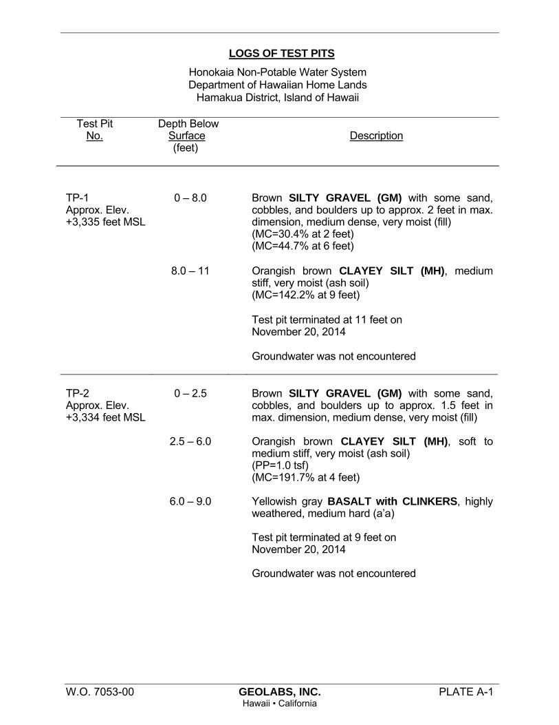
LOGS OF TEST PITS
Honokaia Non-Potable Water System Department of Hawaiian Home Lands
Hamakua District, Island of Hawaii
Test Pit Depth Below No. Surface Description (feet)
W.O. 7053-00 GEOLABS, INC. PLATE A-1 Hawaii • California
0 – 8.0
Brown SILTY GRAVEL (GM) with some sand, cobbles, and boulders up to approx. 2 feet in max. dimension, medium dense, very moist (fill) (MC=30.4% at 2 feet) (MC=44.7% at 6 feet)
8.0 – 11 Orangish brown CLAYEY SILT (MH), medium
stiff, very moist (ash soil) (MC=142.2% at 9 feet)
Test pit terminated at 11 feet on
November 20, 2014
TP-1 Approx. Elev. +3,335 feet MSL
Groundwater was not encountered
0 – 2.5
Brown SILTY GRAVEL (GM) with some sand, cobbles, and boulders up to approx. 1.5 feet in max. dimension, medium dense, very moist (fill)
2.5 – 6.0
Orangish brown CLAYEY SILT (MH), soft to
medium stiff, very moist (ash soil) (PP=1.0 tsf) (MC=191.7% at 4 feet)
6.0 – 9.0 Yellowish gray BASALT with CLINKERS, highly
weathered, medium hard (a’a)
Test pit terminated at 9 feet on November 20, 2014 Groundwater was not encountered
TP-2 Approx. Elev. +3,334 feet MSL

LOGS OF TEST PITS
Honokaia Non-Potable Water System Department of Hawaiian Home Lands
Hamakua District, Island of Hawaii
W.O. 7053-00 GEOLABS, INC. PLATE A-2 Hawaii • California
0 – 3.5
Brown CLAYEY SILT (MH), soft to medium stiff, very moist (ash soil) (PP=1.0 tsf) (MC=201.4% at 2 feet) Grades to orangish brown at 2.5 feet (PP=1.25 tsf)
3.5 – 8.0 Yellowish gray BASALT with CLINKERS,
moderately to highly weathered, medium hard (a’a)(MC=41.1% at 6 feet)
Test pit terminated at 8 feet on
November 20, 2014
TP-3 Approx. Elev. +3,253 feet MSL
Groundwater was not encountered
0 – 4.0
Orangish brown CLAYEY SILT (MH), very moist, soft to medium stiff (ash soil) (PP=0.75 tsf) (MC=184.2% at 2 feet)
4.0 – 8.0 Yellowish gray BASALT with CLINKERS, highly
weathered, medium hard (a’a) (MC=52.4% at 5.5 feet)
Grades to hard at approx. 7 feet
Test pit terminated at 8 feet on
November 20, 2014
TP-4 Approx. Elev. +3,253 feet MSL
Groundwater was not encountered

APPENDIX B

W.O. 6623-00 GEOLABS, INC. MARCH 2012 Page B-1 Hawaii ● California
A P P E N D I X B
Laboratory Tests

APPENDIX B

W.O. 7053-00 GEOLABS, INC. FEBRUARY 2015 Page B-1 Hawaii • California
A P P E N D I X B
Laboratory Tests
Moisture Content (ASTM D2216) were performed on selected samples as an aid in the classification and evaluation of soil properties.
One Atterberg Limits test (ASTM D4318) was performed on a selected soil sample to evaluate the liquid and plastic limits. Graphic presentation of the test results is provided on Plate B-1.
One Sieve Analysis test (ASTM C117 & C136) was performed on a selected soil sample to evaluate the gradation characteristics of the soil and to aid in soil classification. Graphic presentation of the grain size distribution is provided on Plate B-2.
One Modified Proctor compaction test (ASTM D1557 C) was performed on a bulk sample of the near-surface soils to evaluate the dry density and moisture content relationships. The test results are presented on Plate B-3.
Two laboratory California Bearing Ratio tests (ASTM D1883) were performed on bulk samples of the near-surface soils to evaluate the pavement support characteristics of the soils. The test results are presented on Plates B-4 and B-5.
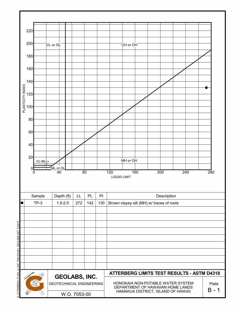
0
20
40
60
80
100
120
140
160
180
200
220
0 40 80 120 160 200 240 280
Description
142
LL
B - 1
Brown clayey silt (MH) w/ traces of roots
LIQUID LIMIT
PL PIDepth (ft)Sample
272
PLA
ST
ICIT
Y I
ND
EX
1301.5-2.5TP-3
ATTERBERG LIMITS TEST RESULTS - ASTM D4318
HONOKAIA NON-POTABLE WATER SYSTEMDEPARTMENT OF HAWAIIAN HOME LANDS
HAMAKUA DISTRICT, ISLAND OF HAWAII
Plate
W.O. 7053-00
GEOTECHNICAL ENGINEERING
GEOLABS, INC.
G_A
TT
ER
BE
RG
_PI-
200_
LL-
240
705
3-00
.GP
J G
EO
LAB
S.G
DT
2/2
4/1
5
CL-ML
CH or OHCL or OL
MH or OH
ML or OL
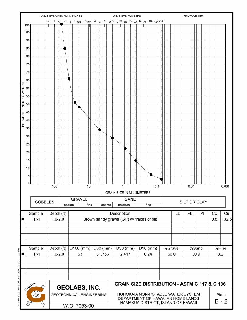
0
5
10
15
20
25
30
35
40
45
50
55
60
65
70
75
80
85
90
95
100
0.0010.010.1110100
3/8
0.8 132.5
HYDROMETER
3
GRAIN SIZE IN MILLIMETERS
PE
RC
EN
T F
INE
R B
Y W
EIG
HT
100
coarse
1/2
Sample
2.41731.766
B - 2
PILL PL
coarse
11.53 2
0.24
40
Depth (ft)
%Gravel
66.0 30.9
%Sand
COBBLES
Sample D30 (mm)
14020
Description Cu
GRAVEL
U.S. SIEVE NUMBERS
D10 (mm)
Brown sandy gravel (GP) w/ traces of silt
16
fine
63
Cc
3/4
fineSILT OR CLAY
medium
GRAIN SIZE DISTRIBUTION - ASTM C 117 & C 136
SAND
%Fine
604 30 20046
3.2
Depth (ft)
810 14 50
U.S. SIEVE OPENING IN INCHES
6
D60 (mm)D100 (mm)
TP-1
1.0-2.0
1.0-2.0
TP-1
HONOKAIA NON-POTABLE WATER SYSTEMDEPARTMENT OF HAWAIIAN HOME LANDS
HAMAKUA DISTRICT, ISLAND OF HAWAII
Plate
W.O. 7053-00
GEOTECHNICAL ENGINEERING
GEOLABS, INC.
G_G
RA
IN_S
IZE
705
3-0
0.G
PJ
GE
OLA
BS
.GD
T 2
/24/
15

75
80
85
90
95
100
105
110
115
120
125
130
135
0 10 20 30 40
% Retained on 3/8" Sieve:
Oversize Fraction (%):
Brown sandy gravel w/ traces of silt
Test Fraction (%):
Specific Gravity:
%
0.0 - 2.0 feet
pcf
pcf
%
98.0
89.0
23.5
31.5
TEST RESULTS
Uncorrected
Corrected for Oversize Fraction
9.7
5.0
28.8
71.2
-
-
DR
Y D
EN
SIT
Y,
pcf
Sample:
Depth:
MOISTURE CONTENT, %
B - 3
2.08
28.8
December 26, 2014
As-Received Moisture Content (%):
3.20
3.10
3.00
2.90
2.80
2.70
2.60
BULK-1
MOISTURE-DENSITY RELATIONSHIP - ASTM D1557 C
Curves of 100%Saturation forSpecific GraviltyEqual to:
Test Date:
Description:
Corrected Maximum Dry Density:
Corrected Optimum Moisture Content:
Uncorrected Maximum Dry Density:
Uncorrected Optimum Moisture Content:
% Retained on 3/4" Sieve:
% Retained on #4 Sieve:
N/A
HONOKAIA NON-POTABLE WATER SYSTEMDEPARTMENT OF HAWAIIAN HOME LANDS
HAMAKUA DISTRICT, ISLAND OF HAWAII
Plate
W.O. 7053-00
GEOTECHNICAL ENGINEERING
GEOLABS, INC.
G_C
OM
PA
CT
ION
_CO
RR
&U
NC
OR
R 7
053-
00.G
PJ
GE
OLA
BS
.GD
T 2
/24/
15

0
200
400
600
800
1,000
1,200
1,400
1,600
1,800
2,000
2,200
0 0.10 0.20 0.30 0.40 0.50 0.60
Brown sandy gravel w/ traces of siltDescription:
Days Soaked 4
BULK-1Swell (%) 0.04
83.1
67.0
Molding Dry Density (pcf)
PENETRATION, inches
ST
RE
SS
, ps
i
0.0 - 2.0 feet
No. of Blows
27.6
96.3
Molding Moisture (%)
Hammer Wt. (lbs)
Hammer Drop (inches)
Sample:
Corr. CBR @ 0.1"
Depth:
Corr. CBR @ 0.2"
No. of Layers
CALIFORNIA BEARING RATIO - ASTM D1883
18
56
10
5Aggregate
B - 4
3/4 inch minus
HONOKAIA NON-POTABLE WATER SYSTEMDEPARTMENT OF HAWAIIAN HOME LANDS
HAMAKUA DISTRICT, ISLAND OF HAWAII
Plate
W.O. 7053-00
GEOTECHNICAL ENGINEERING
GEOLABS, INC.
G_C
BR
705
3-00
.GP
J G
EO
LAB
S.G
DT
2/2
4/1
5

0
20
40
60
80
100
120
140
0 0.10 0.20 0.30 0.40 0.50 0.60
Brown clayey silt (MH) w/ traces of rootsDescription:
Days Soaked 4
BULK-2Swell (%) 0.17
6.1
5.7
Molding Dry Density (pcf)
PENETRATION, inches
ST
RE
SS
, ps
i
1.0 - 2.0 feet
No. of Blows
169.8
29.8
Molding Moisture (%)
Hammer Wt. (lbs)
Hammer Drop (inches)
Sample:
Corr. CBR @ 0.1"
Depth:
Corr. CBR @ 0.2"
No. of Layers
CALIFORNIA BEARING RATIO - ASTM D1883
18
56
10
5Aggregate
B - 5
3/4 inch minus
HONOKAIA NON-POTABLE WATER SYSTEMDEPARTMENT OF HAWAIIAN HOME LANDS
HAMAKUA DISTRICT, ISLAND OF HAWAII
Plate
W.O. 7053-00
GEOTECHNICAL ENGINEERING
GEOLABS, INC.
G_C
BR
705
3-00
.GP
J G
EO
LAB
S.G
DT
2/2
4/1
5

SCAFCO Grain Systems Company
5400 E. Broadway Avenue PO Box 11215
Spokane, WA 99211-1215, USA
Tel: 509-535-1571 • Toll Free: 1-800-224-0676 • Fax: 509-535-9130 • [email protected] • www.scafco.com
290350 R170309
SCAFCO
WATER STORAGE SYSTEMS
INSTALLATION INSTRUCTIONS

PAGE 1 SPECIFICATIONS SUBJECT TO CHANGE WITHOUT NOTICE
Congratulations on purchasing a quality SCAFCO Water Storage Tank! The SCAFCO Water Storage Tank is a unique and practical combination of corrugated galvanized steel wall sheets, a conical galvanized steel roof, a vinyl liner capable of retaining water, and a concrete foundation. Proper design of a complete water storage system can only be insured by a local engineer skilled in the water supply field. Every tank purchaser should retain a local professional engineer and charge him with the responsibility for adequate design of the foundation, inlets, outlets, overflow pipes and controls. The success of a SCAFCO Water Storage Tank depends upon proper erection and installation of the tank. The following instructions will be helpful to those individuals involved in tank installation.

SPECIFICATIONS SUBJECT TO CHANGE WITHOUT NOTICE PAGE 2
SNOW, WIND AND SEISMIC LOADS
The roof and sidewalls of SCAFCO Water Storage Tanks shall be designed to resist snow, wind and seismic loads as required by the 2006 International Building Code, and the local Regulatory Agency issuing building permits for new construction. Minimum roof design live (snow) load is 20 psf, applied to the horizontal projection. Where required by climatic conditions or the local Regulatory Agency, roof design loads shall be increased to satisfy local requirements. SCAFCO Water Storage Tanks are designed to resist wind pressures described in the 2006, International Building Code, Wind Exposure C. Standard SCAFCO Water Storage Tanks are designed for Seismic Design Category C, site class D per the 2006 International Building Code, AWWA D100-05, Section 13, and AWWA D103-97, Section 12. Upon engineer’s design requirements, tank will be designed to resist additional seismic loads or those required by the local Regulatory Agency.

PAGE 3 SPECIFICATIONS SUBJECT TO CHANGE WITHOUT NOTICE
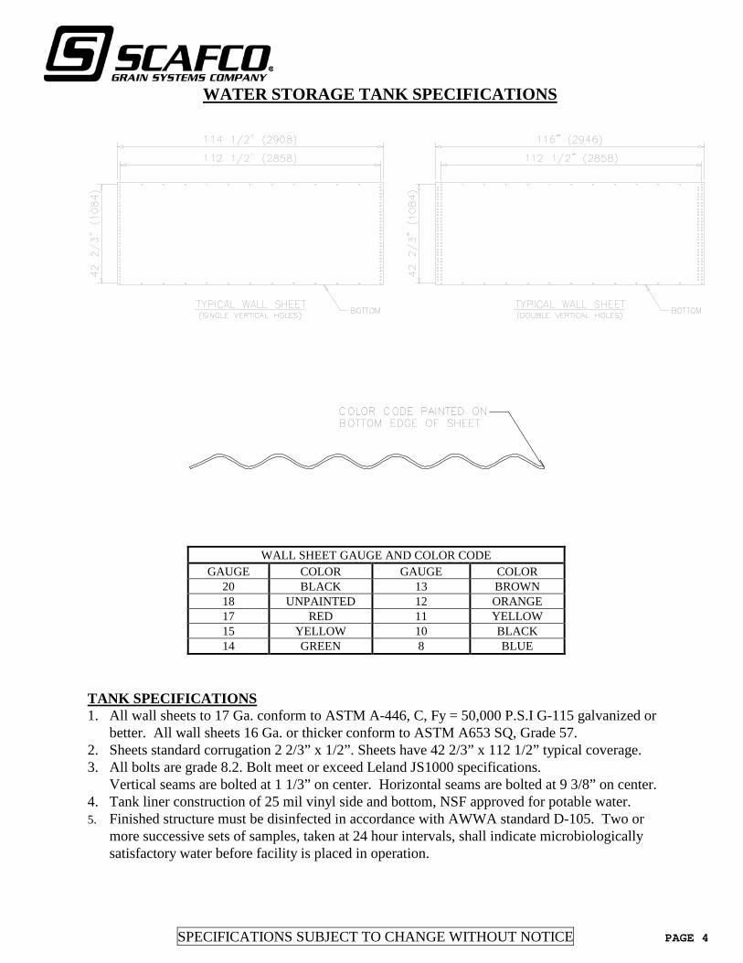
SPECIFICATIONS SUBJECT TO CHANGE WITHOUT NOTICE PAGE 4
WATER STORAGE TANK SPECIFICATIONS
WALL SHEET GAUGE AND COLOR CODE GAUGE COLOR GAUGE COLOR
20 BLACK 13 BROWN 18 UNPAINTED 12 ORANGE 17 RED 11 YELLOW 15 YELLOW 10 BLACK 14 GREEN 8 BLUE
TANK SPECIFICATIONS 1. All wall sheets to 17 Ga. conform to ASTM A-446, C, Fy = 50,000 P.S.I G-115 galvanized or better. All wall sheets 16 Ga. or thicker conform to ASTM A653 SQ, Grade 57. 2. Sheets standard corrugation 2 2/3” x 1/2”. Sheets have 42 2/3” x 112 1/2” typical coverage. 3. All bolts are grade 8.2. Bolt meet or exceed Leland JS1000 specifications. Vertical seams are bolted at 1 1/3” on center. Horizontal seams are bolted at 9 3/8” on center. 4. Tank liner construction of 25 mil vinyl side and bottom, NSF approved for potable water. 5. Finished structure must be disinfected in accordance with AWWA standard D-105. Two or
more successive sets of samples, taken at 24 hour intervals, shall indicate microbiologically satisfactory water before facility is placed in operation.
COLOR CODE PAINTED ONBOTTOM EDGE OF SHEET
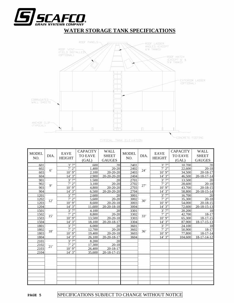
PAGE 5 SPECIFICATIONS SUBJECT TO CHANGE WITHOUT NOTICE
WATER STORAGE TANK SPECIFICATIONS
MODEL NO. DIA. EAVE
HEIGHT
CAPACITY TO EAVE
(GAL)
WALL SHEET
GAUGES
MODEL NO. DIA. EAVE
HEIGHT
CAPACITY TO EAVE
(GAL)
WALL SHEET
GAUGES 601
6’ 3’ 7” 600 20 2401
24’ 3’ 7” 10,700 20
602 7’ 2” 1,400 20-20 2402 7’ 2” 22,600 20-18 603 10’ 9” 2,100 20-20-20 2403 10’ 9” 34,500 20-18-17 604 14’ 3” 2,900 20-20-20-20 2404 14’ 3” 46,500 20-18-17-14 901
9’ 3’ 7” 1,500 20 2701
27’ 3’ 7” 13,500 20
902 7’ 2” 3,100 20-20 2702 7’ 2” 28,600 20-18 903 10’ 9” 4,800 20-20-20 2703 10’ 9” 43,700 20-18-15 904 14’ 3” 6,500 20-20-20-20 2704 14’ 3” 58,800 20-18-15-14
1201 12’
3’ 7” 2,600 20 3001 30’
3’ 7” 16,700 20 1202 7’ 2” 5,600 20-20 3002 7’ 2” 35,300 20-18 1203 10’ 9” 8,600 20-20-18 3003 10’ 9” 54,000 20-18-15 1204 14’ 3” 11,600 20-20-18-18 3004 14’ 3” 72,600 20-18-15-13 1501
15’ 3’ 7” 4,100 20 3301
33’ 3’ 7” 20,200 18
1502 7’ 2” 8,800 20-20 3302 7’ 2” 42,700 18-17 1503 10’ 9” 13,500 20-20-18 3303 10’ 9” 65,300 18-17-15 1504 14’ 3” 18,100 20-20-18-17 3304 14’ 3” 87,900 18-17-15-13 1801
18’ 3’ 7” 6,000 20 3601
36’ 3’ 7” 24,100 18
1802 7’ 2” 12,700 20-20 3602 7’ 2” 50,900 18-17 1803 10’ 9” 19,400 20-20-18 3603 10’ 9” 77,800 18-17-14 1804 14’ 3” 26,100 20-20-18-17 3604 14’ 3” 104,600 18-17-14-12 2101
21’ 3’ 7” 8,200 20
2102 7’ 2” 17,300 20-18 2103 10’ 9” 26,400 20-18-17 2104 14’ 3” 35,600 20-18-17-15
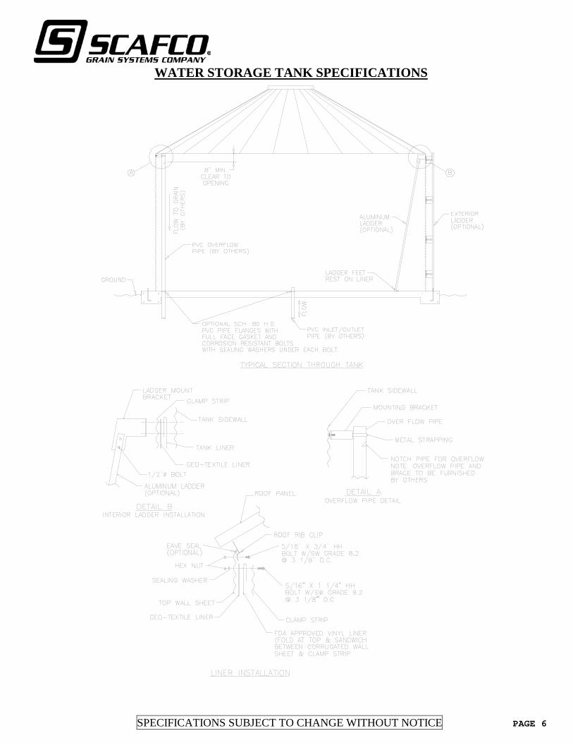
SPECIFICATIONS SUBJECT TO CHANGE WITHOUT NOTICE PAGE 6
WATER STORAGE TANK SPECIFICATIONS

PAGE 7 SPECIFICATIONS SUBJECT TO CHANGE WITHOUT NOTICE
ROOF ASSEMBLY 6’ & 9’ WATER STORAGE TANKS
NOTES: 1. Roof segment sheets fit outside wall sheet ring. 2. Top sheets must overlap lower sheets. 3. Use bead sealant on all seams of roof assembly for weatherproofing. 4. For proper fitting roof, leave roof bolted loosely until roof collar ring has been installed, then
tighten all roof and collar ring bolts.

SPECIFICATIONS SUBJECT TO CHANGE WITHOUT NOTICE PAGE 8
ERECTION PROCEDURES

PAGE 9 SPECIFICATIONS SUBJECT TO CHANGE WITHOUT NOTICE
ROOF INSTALLATION DETAILS

SPECIFICATIONS SUBJECT TO CHANGE WITHOUT NOTICE PAGE 10
RIB CLIP & EAVE SEAL INSTALLATION (OPTIONAL PURCHASE)
NOTES: 1. Install eave seal around top edge of wall sheets. 2. Glue rib clip sealing block to rib clip (1 per clip). 3. Bolt center clips and rib clips to wall sheets and roof panels as shown. 4. Fill all unused holes w/ 5/16” x ¾” bolts. When installed properly, silo will have a weather tight seal.

PAGE 11 SPECIFICATIONS SUBJECT TO CHANGE WITHOUT NOTICE
STANDARD RIB & CENTER CLIP CONNECTIONS
12’ DIAMETER TANKS
15’ DIAMETER TANKS
18’ DIAMETER TANKS
21’ DIAMETER TANKS

SPECIFICATIONS SUBJECT TO CHANGE WITHOUT NOTICE PAGE 12
STANDARD RIB & CENTER CLIP CONNECTIONS
24’ DIAMETER TANKS
27’ DIAMETER TANKS
30’ DIAMETER TANKS
33’ DIAMETER TANKS
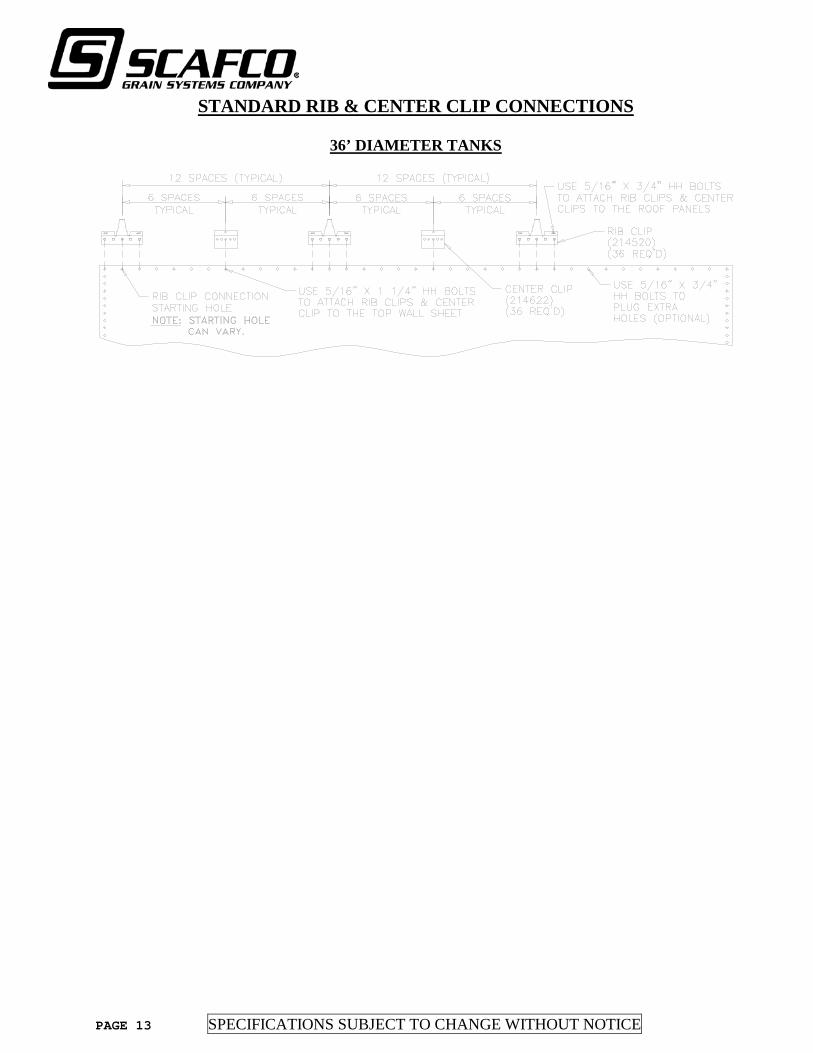
PAGE 13 SPECIFICATIONS SUBJECT TO CHANGE WITHOUT NOTICE
STANDARD RIB & CENTER CLIP CONNECTIONS
36’ DIAMETER TANKS

SPECIFICATIONS SUBJECT TO CHANGE WITHOUT NOTICE PAGE 14
WEATHERSKIRT & CAP INSTALLATION 12’ – 24’ DIAMETER TANKS

PAGE 15 SPECIFICATIONS SUBJECT TO CHANGE WITHOUT NOTICE
ROOF CAP HINGE INSTALLATION 12’ – 24’ DIAMETER TANKS
NOTES: 1. Connect hinge (part B) (214002) to roof cap (214001) using (2) 5/16” x 3/4” HH bolt (290001) & 5/16” Hex Nut (290010). 1. Connect hinge (part A) (214003) to weatherskirt (210196) using (4) 5/16” x 3/4” HH bolt
(290001) & 5/16” Hex Nut (290010). 2. Assemble together using hinge spacer (214004) & 3/8” x 3 1/2” HH bolt (290012) & 3/8” Hex
Nut (290014) as shown.

SPECIFICATIONS SUBJECT TO CHANGE WITHOUT NOTICE PAGE 16
ROOF CAP ASSEMBLY 27’ – 36’ DIAMETER TANKS
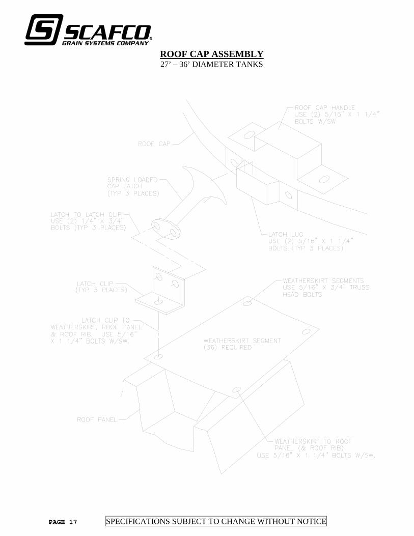
PAGE 17 SPECIFICATIONS SUBJECT TO CHANGE WITHOUT NOTICE
ROOF CAP ASSEMBLY 27’ – 36’ DIAMETER TANKS

SPECIFICATIONS SUBJECT TO CHANGE WITHOUT NOTICE PAGE 18
COMPLETE ROOF CAP ASSEMBLY 27’ – 36’ DIAMETER TANKS
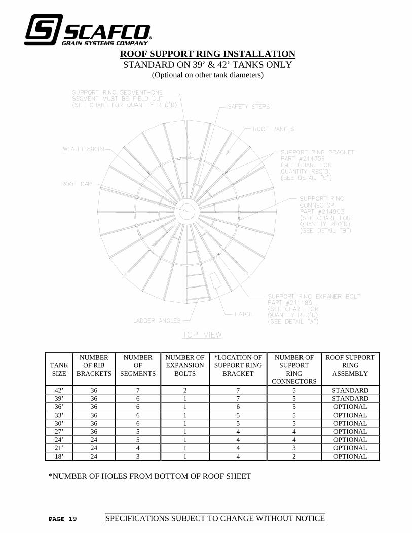
PAGE 19 SPECIFICATIONS SUBJECT TO CHANGE WITHOUT NOTICE
ROOF SUPPORT RING INSTALLATION STANDARD ON 39’ & 42’ TANKS ONLY
(Optional on other tank diameters)
TANK SIZE
NUMBER OF RIB
BRACKETS
NUMBER OF
SEGMENTS
NUMBER OF EXPANSION
BOLTS
*LOCATION OF SUPPORT RING
BRACKET
NUMBER OF SUPPORT
RING CONNECTORS
ROOF SUPPORT RING
ASSEMBLY
42’ 36 7 2 7 5 STANDARD 39’ 36 6 1 7 5 STANDARD 36’ 36 6 1 6 5 OPTIONAL 33’ 36 6 1 5 5 OPTIONAL 30’ 36 6 1 5 5 OPTIONAL 27’ 36 5 1 4 4 OPTIONAL 24’ 24 5 1 4 4 OPTIONAL 21’ 24 4 1 4 3 OPTIONAL 18’ 24 3 1 4 2 OPTIONAL
*NUMBER OF HOLES FROM BOTTOM OF ROOF SHEET
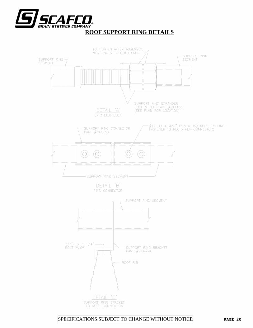
SPECIFICATIONS SUBJECT TO CHANGE WITHOUT NOTICE PAGE 20
ROOF SUPPORT RING DETAILS

PAGE 21 SPECIFICATIONS SUBJECT TO CHANGE WITHOUT NOTICE
BOLT SCHEDULE INSTRUCTIONS FOR BOLT PLACEMENT
ON WATER TANKS WITH ROOFS Anchor Clips: (Refer To Page 22)
- Insert 3/8” diameter x 1” Button Head Bolt from inside the tank. - Use 3/8” Metal-Backed Sealing Washer between the tank wall and bolt head. - Fasten with 3/8” Hex Nut.
Clamp Strip to Top Wall Sheet: (Refer To Page 32) - Insert 5/16” diameter x 1 1/4” Hex Head Bolt from inside the tank. - Use 5/16 Metal-Backed Sealing Washer between wall sheet and Hex Nut. - Fasten with 5/16” Hex Nut.
All Vertical Seams and All Other Horizontal Seams: - Insert 5/16” diameter x 3/4” Truss Head Bolt from inside the tank. - Fasten with 5/16” Hex Nut.
For Tanks with Wall Sheets 15 Gauge and Thicker (All Wall Sheet Bolts are 3/8”): - Insert 3/8” diameter x 1” Button Head Bolt from inside the tank. - Use 3/8” Metal-Backed Sealing Washer between the tank wall and bolt head. - Fasten with 3/8” Hex Nut.
NOTE: Upper wall sheet ring always overlaps the wall sheet ring below it. IT IS NOT NECESSARY TO FIELD DRILL the bottom seam of the upper wall sheet to match the extra holes on the top seam of the wall sheets below.
Roof Panel Bolts: (Refer To Pages 7 & 9) - Insert 5/16” diameter x 1 1/4” Hex Head Bolt from the top of the Roof Panel. - Fasten with 5/16” Hex Nut. - For 6’ & 9’ Dia. Tanks use 5/16” x 3/4" Hex Head Bolt. - Fasten with 5/16” Hex Nut.
Roof Center Clips and Rib Clips To Roof Panels: (Refer To Pages 9 - 13) - Insert 5/16” diameter x 3/4” Hex Head Bolt from the top of the Roof Panel. - Fasten with 5/16” Hex Nut.
Roof Center Clips and Rib Clips To Wall Sheets: (Refer To Pages 9 - 13) - Insert 5/16” diameter x 1 1/4” Hex Head Bolt from outside the tank. - Fasten with 5/16” Hex Nut.
Access Panel: (Refer To Page 24) - Insert 3/8” diameter x 1 1/4” Button Head Bolt from inside tank. - Place 3/8” Jam Nut between Wall Sheet and Access Panel. - Places 3/8” Metal- Backed Sealing Washer on outside of Access Panel. - Fasten with 3/8” Hex Nut.
DESCRIPTION PART NUMBER
3/8" X 1" BUTTON HEAD BOLT GR. 8.2 290158
3/8" X 1 1/4" BUTTON HEAD BOLT GR. 8.2 290369
5/16" X 3/4" HEX HEAD BOLTS W/ SEALING WASHER GR. 8.2 290001
5/16" X 3/4" TRUSS HEAD BOLT W/ SEALING WASHER GR. 8.2 290410
5/16" X 1 1/4" HEX HEAD BOLT W/ SEALING WASHER GR. 8.2 290002
5/16" METAL-BACKED SEALING WASHER 290007
3/8" METAL-BACKED SEALING WASHER 290042
3/8" JAM NUT 290049
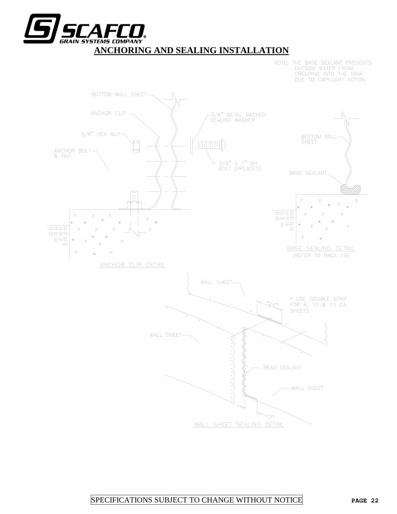
SPECIFICATIONS SUBJECT TO CHANGE WITHOUT NOTICE PAGE 22
ANCHORING AND SEALING INSTALLATION
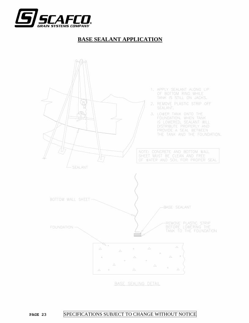
PAGE 23 SPECIFICATIONS SUBJECT TO CHANGE WITHOUT NOTICE
BASE SEALANT APPLICATION

SPECIFICATIONS SUBJECT TO CHANGE WITHOUT NOTICE PAGE 24
ACCESS PANEL INSTALLATION
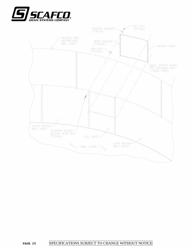
PAGE 25 SPECIFICATIONS SUBJECT TO CHANGE WITHOUT NOTICE
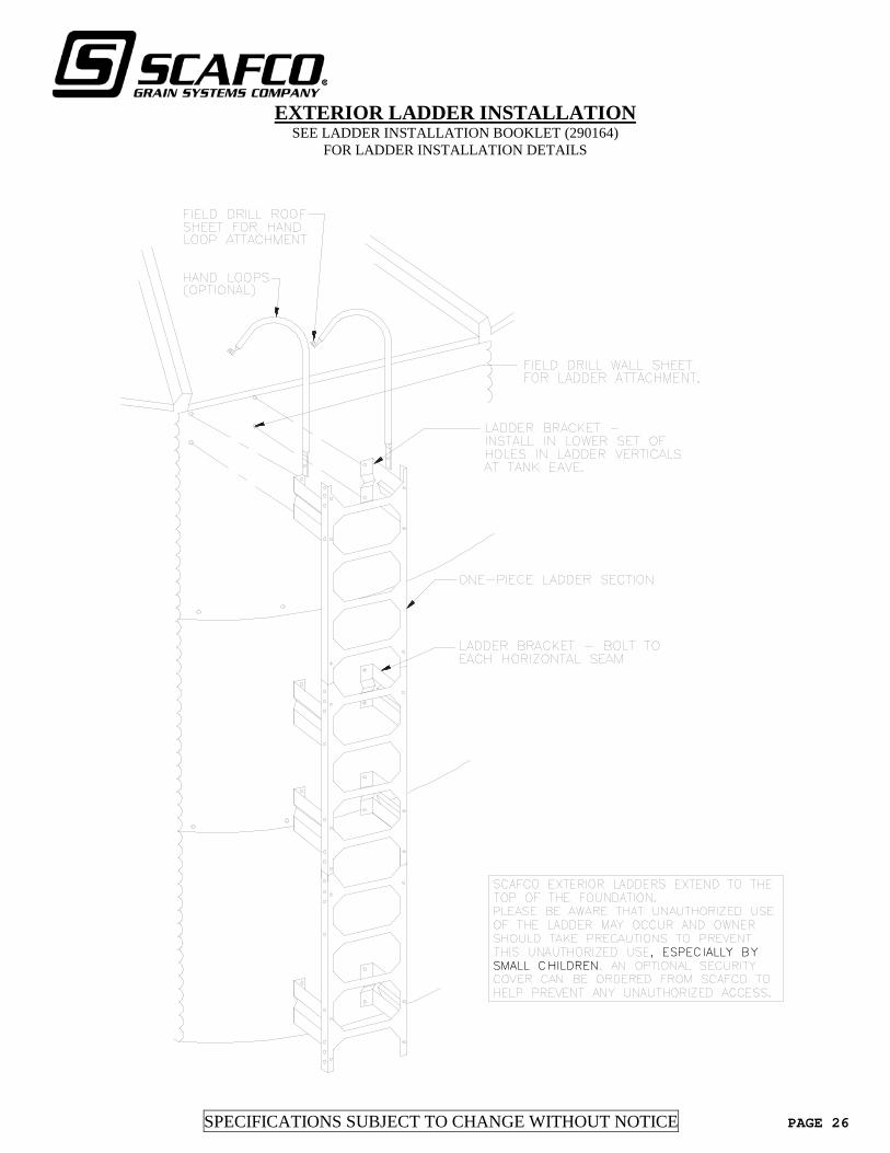
SPECIFICATIONS SUBJECT TO CHANGE WITHOUT NOTICE PAGE 26
EXTERIOR LADDER INSTALLATION SEE LADDER INSTALLATION BOOKLET (290164)
FOR LADDER INSTALLATION DETAILS
, ESPECIALLY BY SMALL CHILDREN

PAGE 27 SPECIFICATIONS SUBJECT TO CHANGE WITHOUT NOTICE
FOUNDATION, INLETS, OUTLETS & OVERFLOWS
CONCRETE FOUNDATIONS The concrete foundation provides structural support for the Water Storage Tank and its contents, transferring the imposed loads to the surrounding soil and underlying strata. In addition, the foundation can accommodate provisions for adequate drainage and sludge removal. See Figures 1 through 5 for recommendations. Foundation design must be done by a local engineer familiar with site conditions.
Figure 1: Concrete Floor and Foundation Profile. For removal of sludge and silt, a drain trough should terminate at the selected discharge pipe.
A CONCRETE FOUNDATION IS REQUIRED FOR AN APPROVED SCAFCO WATER STORAGE TANK. FOUNDATION DESIGN IS THE RESPONSIBILITY OF A LOCAL ENGINEER RETAINED BY TANK PURCHASER.

SPECIFICATIONS SUBJECT TO CHANGE WITHOUT NOTICE PAGE 28
INSTALLING INLETS, OUTLETS & OVERFLOW PIPES WATER INLET-OUTLET REQUIREMENTS Every SCAFCO Water Storage Tank has mandatory inlet-outlet and overflow requirements. Each tank must be equipped with a water inlet-outlet pipe and an overflow pipe. Pipe sizes, connections and any controls should be designed by a local engineer retained by the tank purchaser. Several drawings of recommended piping connections to the SCAFCO tank liner are shown in succeeding pages.
Figure 2: Discharge Outlet Details. Silt and sludge may be removed through the discharge pipe by using a removable silt stop in the outlet flange.
A DISCHARGE OUTLET AND SILT STOP ARE REQUIRED. DESIGN OF INLET-OUTLET IS RESPONSIBILITY OF PURCHASER’S ENGINEER. WARNING: DO NOT LEAVE ANY PORTION OF FLEXIBLE LINER UNSUPPORTED AT FLANGE CONNECTION.
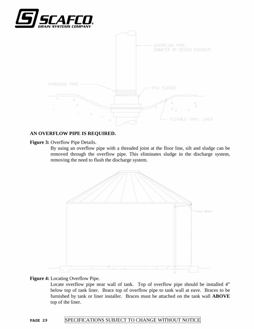
PAGE 29 SPECIFICATIONS SUBJECT TO CHANGE WITHOUT NOTICE
AN OVERFLOW PIPE IS REQUIRED.
Figure 3: Overflow Pipe Details. By using an overflow pipe with a threaded joint at the floor line, silt and sludge can be removed through the overflow pipe. This eliminates sludge in the discharge system, removing the need to flush the discharge system.
Figure 4: Locating Overflow Pipe.
Locate overflow pipe near wall of tank. Top of overflow pipe should be installed 4” below top of tank liner. Brace top of overflow pipe to tank wall at eave. Braces to be furnished by tank or liner installer. Braces must be attached on the tank wall ABOVE top of the liner.

SPECIFICATIONS SUBJECT TO CHANGE WITHOUT NOTICE PAGE 30
Figure 5: A drain sump discharging outside the tank. Rather than using the discharge or overflow systems to eliminate silt and sludge, install a separate silt removal flange, pipe and valve. A drain sump discharging outside the tank is required. This design is optional if the overflow pipe cannot be used for discharge. INSTALLING INLETS AND OUTLETS Inlets and outlets through the liner should be made through the tank bottom. Clamp the liner between two cast iron flanges or Schedule 80 plastic flanges or PVC tank adapters or use a prefabricated boot assembly included and located by the liner manufacturer (optional – call SCAFCO for pricing). Use a neoprene rubber gasket between top flange and liner. Seal both sides of liner to flange (and screw threads when applicable) with a waterproof elastometic sealant. Bolt flanges firmly together with stainless steel bolts, or screw PVC tank adapters together, being careful not to over tighten and damage flanges (tighten bolts alternately). Cut opening through liner last on bolt-together flanges. Cut opening through liner first on screw type PVC tank adapters (opening should be slightly undersized). WARNING: DO NOT LEAVE FLEXIBLE LINER UNSUPPORTED AT FLANGE CONNECTION.

PAGE 31 SPECIFICATIONS SUBJECT TO CHANGE WITHOUT NOTICE
TANK PREPARATION
1. Check interior wall for any sharp edges or protrusions that may damage tank. Sand or grind
these areas. SPECIAL REQUIREMENT: Geotextile fabric, if supplied, must be installed on the wall and floor prior to liner installation.
2. Sweep concrete floor clean of all debris. Check for sharp objects or protrusions. Remove these
by grinding. FLOOR SURFACE The vinyl liner is in direct contact with the floor finish. The concrete surface must be fine troweled without imperfections, sharp edges, debris or projections that could damage the liner. A cove fill of non-shrink grout shall be placed at the intersection of the wall and floor to provide a smooth backing for the liner. See Figure 6. Install geotextile fabric on the concrete floor with adhesive prior to liner installation. This is especially helpful when the concrete finish is not smooth. Design of the silt stop, sludge discharge, reinforced concrete foundation and liner protection must be determined by the purchaser’s Design Engineer or other design professional.
Figure 6: Tank Perimeter Preparation. Provide an expanding grout cove around tank perimeter to reduce corner stress on flexible vinyl liner.
A COVE AT THE WALL TO FLOOR INTERSECTION IS REQUIRED.
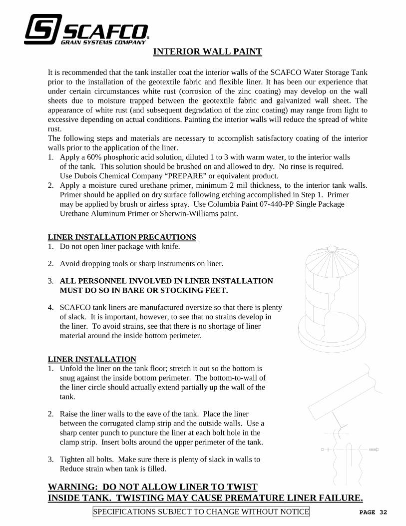
SPECIFICATIONS SUBJECT TO CHANGE WITHOUT NOTICE PAGE 32
INTERIOR WALL PAINT It is recommended that the tank installer coat the interior walls of the SCAFCO Water Storage Tank prior to the installation of the geotextile fabric and flexible liner. It has been our experience that under certain circumstances white rust (corrosion of the zinc coating) may develop on the wall sheets due to moisture trapped between the geotextile fabric and galvanized wall sheet. The appearance of white rust (and subsequent degradation of the zinc coating) may range from light to excessive depending on actual conditions. Painting the interior walls will reduce the spread of white rust. The following steps and materials are necessary to accomplish satisfactory coating of the interior walls prior to the application of the liner. 1. Apply a 60% phosphoric acid solution, diluted 1 to 3 with warm water, to the interior walls of the tank. This solution should be brushed on and allowed to dry. No rinse is required. Use Dubois Chemical Company “PREPARE” or equivalent product. 2. Apply a moisture cured urethane primer, minimum 2 mil thickness, to the interior tank walls.
Primer should be applied on dry surface following etching accomplished in Step 1. Primer may be applied by brush or airless spray. Use Columbia Paint 07-440-PP Single Package Urethane Aluminum Primer or Sherwin-Williams paint.
LINER INSTALLATION PRECAUTIONS 1. Do not open liner package with knife. 2. Avoid dropping tools or sharp instruments on liner. 3. ALL PERSONNEL INVOLVED IN LINER INSTALLATION
MUST DO SO IN BARE OR STOCKING FEET. 4. SCAFCO tank liners are manufactured oversize so that there is plenty of slack. It is important, however, to see that no strains develop in
the liner. To avoid strains, see that there is no shortage of liner material around the inside bottom perimeter.
LINER INSTALLATION 1. Unfold the liner on the tank floor; stretch it out so the bottom is
snug against the inside bottom perimeter. The bottom-to-wall of the liner circle should actually extend partially up the wall of the tank.
2. Raise the liner walls to the eave of the tank. Place the liner
between the corrugated clamp strip and the outside walls. Use a sharp center punch to puncture the liner at each bolt hole in the clamp strip. Insert bolts around the upper perimeter of the tank.
3. Tighten all bolts. Make sure there is plenty of slack in walls to
Reduce strain when tank is filled. WARNING: DO NOT ALLOW LINER TO TWIST INSIDE TANK. TWISTING MAY CAUSE PREMATURE LINER FAILURE.

PAGE 33 SPECIFICATIONS SUBJECT TO CHANGE WITHOUT NOTICE
GEO-TEXTILE LINER INSTALLATION
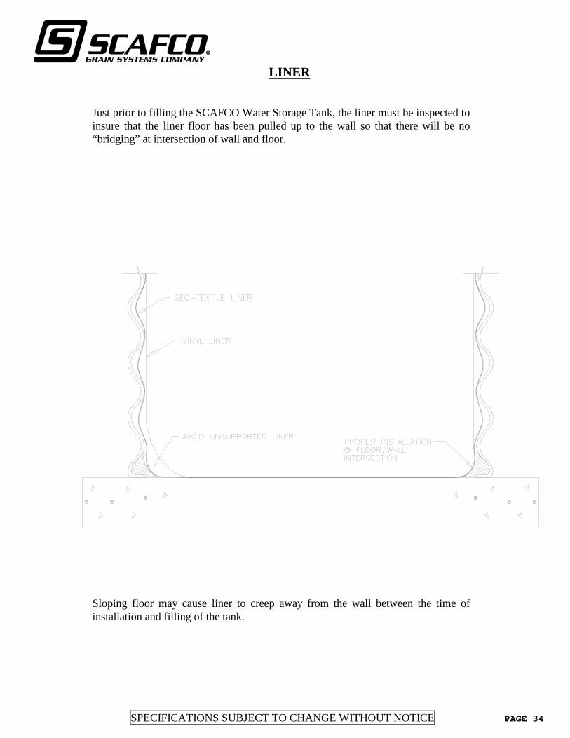
SPECIFICATIONS SUBJECT TO CHANGE WITHOUT NOTICE PAGE 34
LINER Just prior to filling the SCAFCO Water Storage Tank, the liner must be inspected to insure that the liner floor has been pulled up to the wall so that there will be no “bridging” at intersection of wall and floor.
Sloping floor may cause liner to creep away from the wall between the time of installation and filling of the tank.

PAGE 35 SPECIFICATIONS SUBJECT TO CHANGE WITHOUT NOTICE
VINYL LINER PROTECTION
The vinyl liner is durable and will provide many years of service if installed and maintained properly. The liner will NOT withstand normal foot traffic during installation and routine cleaning. The following precautions are recommended when working inside a tank or walking on the liner. 1. Do not remove the liner from its carton until it is to be installed. Do not cut carton with a
knife. Avoid dropping tools or sharp objects on the liner. Do not drag vinyl liner excessive distances over floor as the scrim will be exposed and lead to “weeping” type liner leaks.
2. All personnel installing and maintaining liner should do so in bare feet or thin stockings. In
no case should personnel enter tank, beneath liner, or inside liner with shoes or boots on. Wearing shoes may introduce foreign matter which could perforate the flexible liner. In addition, personnel working in bare feet can feel foreign matter that may be remaining on the foundation before it can damage the liner.
3. Access to the tank interior through center hatch or additional access manhole may be made
with an extension ladder with padded feet. Use of a rope ladder suspended from the hatch opening (See Figure 7) is highly recommended. Permanent interior ladders are not practical.
4. Periodic entry between the steel tank and liner, for the purpose of inspection, repair, or
readjusting sand overlay, may be made through sidewall wall sheets. 5. A SCAFCO exterior ladder can be supplied (optional). Ladder extends to the top of the foundation.
SPECIFICATIONS SUBJECT TO CHANGE WITHOUT NOTICE PAGE 36
TANK DISINFECTION
TANK DISINFECTION The finished SCAFCO Water Storage Tank must be disinfected by the purchaser or installer prior to use. Finished structure must be disinfected in accordance with AWWA D105, Method No. 3.
CHLORINATION METHOD 3 Water and chlorine shall be added to the storage facility in amount such that initially the solution will contain 50 mg/L available chlorine and will fill approximately 5% of the total storage volume, and this solution shall be held in the storage facility for a period of not less than 6 hours. The storage facility shall then be filled to the overflow level by flowing potable water into the highly chlorinated water, and shall be half-full for a period of not less than 24 hours. All highly chlorinated water shall then be purged from the drain piping. Then, subject to satisfactory bacteriological testing and acceptable aesthetic quality, the remaining water may be delivered to the distribution system. 4.3.1. Adding Chlorine. Chlorine shall be added to the storage facility by the method described in Section 4.1.1, Section 4.1.2, or Section 4.1.3. The actual volume of the 50 mg/L chlorine solution shall be such that after the solution is mixed with filling water and the storage facility is held full for 24 hours, there will be free chlorine residual of not less than 2 mg/L.

PAGE 37 SPECIFICATIONS SUBJECT TO CHANGE WITHOUT NOTICE
CARE OF VINYL LINER
CLEANING THE VINYL LINER The surface of the liner is relatively smooth and can be cleaned with a light brushing and pressure spray (water) washdown. The liner can easily accept sweeping, foot traffic and agitation necessary to remove any silt and sludge collected in the tank. Remember, all personnel entering tank must be in bare feet or thin stockings…no shoes or boots. Sanitizing the liner with chlorine wash applied with spray equipment has no negative effects on the vinyl liner. VINYL LINER REPAIR In the event of a cut or damage to the liner, repair can be accomplished by chemically welding a new piece of vinyl over the affected area, using a large second ply over the first patch. This repair may be done to the inside or outside of the liner sheet. Proper repair instructions are provided in the patching kit. All repairs shall be accomplished by personnel in bare feet or stocking feet.
CONTROLS Water level controls may be installed inside the tank. Control wires for these devices should exit the tank at the eave. Penetrations through the roof panels for control wires are not recommended unless proper sealing methods are used.
SPECIFICATIONS SUBJECT TO CHANGE WITHOUT NOTICE PAGE 38
ICE FORMATION
Ice may form inside the tank in certain climatic conditions. Large quantities of ice forming around the top water level in a tank provides some potential for damage to the flexible liner. If ice formation potential is substantial, the tank should be protected by some means of maintaining water movement – air spargers, small recycle pumps, or liquid level fluctuations – during the potential problem period. When approved by a local engineer, insulation of the tank is a common method to avoid freezing damage. Tank heating may present viable protection against ice formation. In the event that tank heating is chosen as the method to be used to prevent ice formation, follow the recommendations of the National Fire Protection Association Standard 22, Standard For Water Tanks For Private Fire Protection, Chapter 10. WARNING: FAILURE TO ADEQUATELY PROTECT AGAINST ICE
FORMATION INSIDE THE TANK SHALL VOID THE WARRANTY ON THE FLEXIBLE MEMBRANE LINER.
VENTING
A suitable roof vent shall be furnished. The vent or vents should be installed in the roof and shall have the capacity to pass air, so that at the maximum possible rate of the water, either entering or leaving the tank, excessive pressure will not be developed. THE OVERFLOW PIPE SHALL NOT BE CONSIDERED A TANK VENT.


SCAFCO Grain Systems Company
5400 E. Broadway Avenue PO Box 11215
Spokane, WA 99211-1215, USA
Tel: 509-535-1571 • Toll Free: 1-800-224-0676 • Fax: 509-535-9130 • [email protected] • www.scafco.com
Copyright © 2022 FDOKUMEN