Spring 1991 Restructuring of MAN B&W Diesel A/S, Holeby
89
1991-05 Spring 1991 Restructuring of MAN B&W Diesel A/S, Holeby Michael Petersen AX33 a W I H RE'STR'UCTURING * ** *** * * * * * * ** * *** * ** ** of ** MAN B&W DIESEL A/S, HOLEBY / I ,
-
Upload
khangminh22 -
Category
Documents
-
view
3 -
download
0
Transcript of Spring 1991 Restructuring of MAN B&W Diesel A/S, Holeby

1991-05 Spring 1991
Restructuring of MAN B&W Diesel A/S, Holeby
Michael Petersen
AX33 a W I
H
RE'STR'UCTURING * ** *** * * * * * * ** * *** * ** **
of **
MAN B&W DIESEL A/S, HOLEBY
/ I
,

1 rE3 JV%6'W^ MAN B&W Diesel A/S
RESTRUCTURING
of **
MAN B&W DIESEL A/S, HOLEBY * **** * ** **** * * ** * * * * * * ** **
0

V -
• -L 1- r I II •• I.
t oil
IJ g
- I
YA I
'I
I_., - -- -
-•
-
-
f . - I- '- •- -
•'
• - - -

QwcJ 6cc
. 1 I L--- o-O H C
S 2
5 -vcro_ -to
3 I _ -
I S 4 ?CfN1
0 51

S
S . S S
fl U
I S
fl
0

August 10, 1991
Dr. R. Barr CSE Department Southern Methodist University Dallas, TX 75275
Dear Dr. Barr:
Here is my proposal for the restructuring of the B&W Holeby Genset plant. The original document was written and presented in Danish to the Production Technique Department. Since I know that your Danish is not up to par, (if so, with a heavy Texas accent!), I have translated everything for you.
In addition to the final report, I have included a few brochures about the company, as well as a brief rundown of the operation and history.
I thoroughly enjoyed working on this project and through it I have gained much experience and contacts. Although my project started off very slow, a visit to the plant during spring-break, I am confident that the continuous effort to get acquainted with the operation paid of f. One of the comments made during my summer work highlighted exactly this point.
I worked with the Production Technique Dept., responsible for all the materials flow and operations. The department employs 28 people who's daily job is to make sure that orders are placed to the right machining stations and follows a correct work specification. The last two months were very hectic and small problems with the die-casting of several components
•did not'flelp the situation. Although very busy, most of the people I came in contact with were very helpful and realized the importance of a better flow within the plant.
As a final note, I would like to acknowledge and thank Stefan Asgeirson and Ole Andersen for their close guidance and helpful information. Without their help the financial estimation for the project would have been virtually impossible on my own.
I wish you happy reading. I'm looking forward to coming back to Dallas, the weather here is not too great.
Sincerely Yours,
Michael Petersen

S
S S
S I
S I . fl 0
CONTENTS
LETTER OF TRANSMITTAL . iii
INTRODUCTION TO MAN B&W DIESEL .................................... iv-v
RESTRUCTURING OF MAN B&W A/S, HOLEBY
Assumptions for the restructuring............................. p.1
Logistics concept .................................................................p.2-3
Heavy unit section.............................................................p.4
Small unit section ............................................................... p.5 Genset assembly section ..................................................p.5-6
Financial estimations.........................................................1-5
Enclosures-plant drawings .............................................. Encl. 1-13
BROCHURES
S
n

M.A.N. B&W DIESEL A/S, HOLEM
A COMPANY IN THE MAN GROUP
Introduction
MAN B&W Diesel A/S, Holeby is a wholly owned subsidiary of • MAN Aktiengesellschaft, Munich forming one of Europe's largest
engineering groups. Around DM 45 million is set aside each year by MAN B&W Diesel for research and development in two-stroke, four-stroke, and gas turbochargers.
The companies in the MAN Group are engaged In engine and plant construction, commercial vehicle construction and commercial activities. They offer high-guality technology for the energy supply, chemical, and petrochemical sectors, for buses and trucks, primary industry, for the typographical and communications industries. (For a complete list of MAN subsidiaries see ref. 1).
MAN &Ws organizational structure is based in five locations within Denmark and Germany:
Augsburg, Germany: location of company's administrative head-quarters and manufacturers of medium speed 4-stroke diesel engines. Power range from 619-19000 HP.
Hamburg, Germany: location of largest service center. Responsible for service activities that include repairs, maintenance, and modernization work.

Copenhagen, Denmark: location of MAN B&W Diesel Service and manufacturer of slow speed 2 -stroke diesel engines. The development of the revolutionary MC-series are concentrated here.
Frederikshavn, Denmark: location for the manufacturing of complete propulsion systems.
Holeby, Denmark: location for the manufacturing of 4-stroke diesel gensets for seagoing, coastal and fishing vessels.
•Power range from 715-5400 HP.
This concludes a brief introduction to the MAN Group. The focus from here on will be on the plant in Holeby, Denmark.
MAN B&W Diesel A/S. Holeby
Holeby Diesel was founded in 1883 as a blacksmith shop producing machines for the farmers in Denmark. In 1901, having gained experience in machine manufacturing, Holeby Diesel took a license from Mr. Rudolph Diesel for diesel engines and delivered the first engine of 4 HR in 1903.
Although very successful in developing and producing these diesel
•engines, they were taken over by Burmeister & Wain (B&W) in 1933. This marriage lasted just about 50 years until growing world competition forced B&W to merge with MAN. MAN B&W Diesel is today the biggest 2-and 4-stroke diesel engine designer and producer in the world with more than 60 of the market share of vessels above 5000 dwt.
Situated in the South of Denmark, Holeby Diesel Is now the GenSet division at MAN B & W and has 800 employees. A marine Gen Set consists of the prime mover four stroke medium speed (720 and 750 RPM) diesel engines between 500 kW - 2000 kW in output and a generator (or alternator) built on a common frame. (see picture)
The factory has many traditions in manufacturing, but world demand and search for competitiveness, Is forcing the production technique people to upgrade production methods.

S
S
S
fl U
U
S
^11!
S
fl 0

MAN B&W Diesel A/S r M M^M
JEL'^
1.
In order to increase the productivity and the profitability of the MED-H manufacturing plant inside the existing areas, the following changes have to be made. The changes will make it possible for MBD-H to meet the increasing demand from the Wes-tern European shipyards for MED GenSets,
ASSUMPTIONS FOR THE RESTRUCTURING
. The today's manufacturing philosophy at MED-H is that we are manufacturing parts for stocks in different areas.
After having seen the production in Augsburg, and at Pielstick, the management at MED-H recommends to divide the manufacturing at MED-H into 3 main sectors, after the component/unit theory which means the following sectors:
1) HEAVY UNIT SECTION
2) SMALL UNIT SECTION
3) ASSEMBLY SECTION
The above requires a complete new logistic concept which is de-scribed later on.
Further, the increased output of MED-H will also require more . office space.
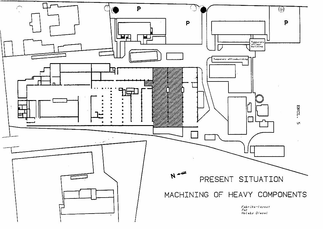
The existing lay-out of the plant is shown in End. 1 and the proposed one in End. 13. -
The increased output of GenSets will require 6 test beds, all equipped with electrical systems, and 2 of them must also have the possibility of testing on water brakes. Today 4 test beds are available.
In order to be able to keep the 2-stroke 35MC engine and to continue the research and development of the 4-stroke GenSets it will be necessary to increase the number of test beds for research from the existing 2 to a number of 3.
Totally, the number of test beds shall be increased from 6 to 9.
FT

M AM t4 MAN B&W Diesel A/S rIDE343 im. 04)
2.
LOGISTIC CONCEPT
In order to facilitate the restructuring of the workshops, a complete new logistic concept is needed to make the space available in the existing area, and also in order to reduce the transportation of parts and components as much as possible.
Therefore, we propose to put the major stock areas together, as shown in End. 2.
BAR - PIPE AND ROLLER STOCK
In the new concept it is the idea to have the delivery to the small unit section, as follows:
* Bars cut in the required lengths.
* All parts cleaned and, if necessary, in centred condition too.
We have discussed whether it would be feasible to place the stock where the existing tool shop is placed, but we will not recommend this solution.
The required area covered by crane that we will have to establish 400 ing. Therefore, we assume that the
. shop will be less than the cost of
For this reason we recommend to es bars, pipes and rollers of approx.
is 700 m2, and this means m2 in the new stock build-savings by using the tool removing the tool shop.
tablish a new built stock for 600 m2.
The existing warehouse facilities are spread all over our plant as shown in End. 3.
Warehouse for patterns
Today we are leasing a warehouse of 600 m2, approx. 30 km away from our plant.
We intend to move the patterns into the existing, separate warehouse, close to the administration building.
HOLEflY
MAN B&W Diesel A/S
rl@E3A3 ink W"
3.
Warehouse for semi-heavy parts
Today the semi-heavy parts are stocked in the Southern hail and in the shop behind the FMS system and covering approx. 500 m2.
The max. weight of the parts are approx. 10 ts, and therefore we need a stock with crane facilities of mm. 10 ts for these parts.
Carpenter shop
The carpenter shop is today placed in the Southern hail and is to be placed in close connection with the packing and forward-
Sing department.
Receiving - forwarding and packing
The increased level of activity, both at Holeby and at Tegi-hoimen, causes a need for an extra area in order to store packed consignments, ready for shipment, and extra space to handle the packing and the receiving of goods.
Some of the existing stock area may be utilized for this pur-pose but it will be necessary to increase the area with 250 m2.
Stocking of complete GenSets
We need approx. 300 m2 of the Southern area, covered by 32 ts crane capacity, for stocking of GenSets which are ready for shipment. -
Warehouse for components and spares
Besides the existing warehouse, the stocking of the parts and components is situated in different places, such as the ware-house nearby the administration building, the platform at the rail track, etc.
Needed capacity of pallets due to the higher activity level and rearranging of stock: 3800 pcs.
Warehouse, forwarding and receiving administration
The existing facilities - 110 m2 - are too small today. The increasing level of activity with regard to GenSets, licence components and spare parts, which is to be foreseen in the years to come will mean that the administration area needs to be increased to approx. 200 m2.
In the administration area washing room facilities are to be established for both sexes.
1-IOLEBY

MAN B&W Diesel A/S (1013 aw i
4.
Total new warehouse area needed
• Roller-pipe-bar stock with 5 ts crane .........600 m2 y
• Warehouse for semi-heavy units with a 10 ts crane .. . .......................... 510 m24
• Carpenter shop ................................200 m2
• Packing, forwarding and receiving .............250 m2
. • Spare parts and component stock, height 12 mtr for pallet stacking, pallet size 800 x 1200 mm .....................800 m2 V
• Warehouse administration ......................100 m2 i
• Washing room facilities for both sexes ........20 m2*
TOTAL NEW AREA NEEDED (End. 4) .......approx. 2500 m2
HEAVY SECTION UNIT (End. 5 and 6)
Today the production and assembly of larger components takes place in differet departments, so that the responsibility for the final unit is divided.
The purpose of the new lay-out is to have the responsibility . for the unit at one place/section.
Under the heavy section the manufacturing of three major units shall take place:
• Bed plates are to be welded, machined, cleaned, and painted, and delivered to the assembly area as a finished unit. Transportation of the com-ponent will only take place inside the section.
• Crankshafts are machined and assembled with fly-
wheel, counterweights, gear wheel and damper.
* The engine frames are machined, cleaned, pressure tested, painted, and assembled with crankshaft be-fore supply to the assembly line.
HOLEDY

MAN B&W Diesel A/S aw I
5.
CHANGES IN EXISTING BUILDINGS
No major changes in the existing buildings are to take place;.
4 cabins will be needed for welding of bed plates. Needed area : 240 m2.
Facilities for sub-assembly of frames before pressure test are to be established. This can be done in the existing FMS area, where the 500 m2 is equal to the need.
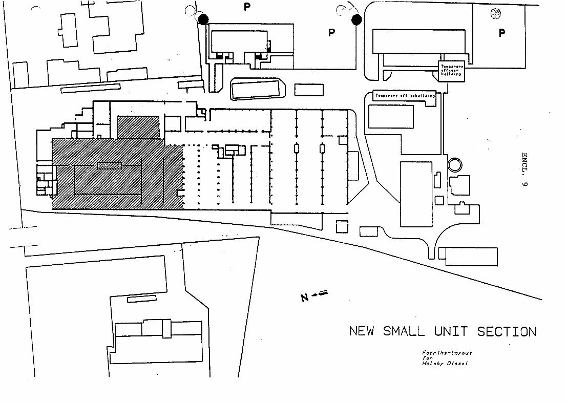
SMALL UNIT SECTION (End. 7 and 9)
This section is to be responsible for the manufacturing of small units, where the dividing line to the assembly section could be decided on the basis of the unit being engine speci-fic or whether it can be used as a spare part or licence com-ponent.
This concept will result in a manufacturing procedure with fewer responsibility changes, and it will minimize the trans-portation within the plant.
The following activities have to be carried out:
* Move the FMS to the present iron stock.
* Move the machining centre to the present painting section.
* Move the con.rod shop to the present pipe shop, where a new roof has to be established (End. 8).
* Establish assembly of small units in part of the present stock area.
* Establish facilities for cleaning and painting of small components on the platform.
GENSET ASSEMBLY SECTION (End. 10 and 12)
The major job for the assembly section is to assemble the Gen-Sets and the general idea is to make this section responsible for the main assembly of all units, built to customers' re-quirements.
.
1401FDY

( MALM IOM3471 ai ZW***:*) MAN B&W Diesel A/S
6.
The manufacturing of pipes, welding of smaller components, and assembling of exhaust pipes will take place within the assembly section.
Further, the assembly section will be responsible for the testing of units together with the project department.
The assembly section is also responsible for managing the service fitters together with the service department.
During the last years, each unit of GenSet has become heavier and the length has also increased.
The available facilities of today for the assembly of GenSets are a major shop with a span between pillars of 10 mtr. and equipped with a crane with a max. lifting capacity of 35 ts.
In order to cover the future demand it will be necessary to establish an assembly shop with a 50 ts crane and with a span between the pillars of 15 mtr.
As shown in End. 11, the recommendation is to establish this facility in the Southern part of the existing assembly area.
The project for the assembly section will be as follows:
* New roof over the existing Southern assembly area. The height of the new shop shall be just as high as for the Northern assembly shop.
* Installation of a 50 ts crane, covering an area of approx. 600 m2.
* Replace the existing offices and toilets.
* The pipe shop is recommended to be established in the existing con. rod shop.
'-IoI-BY

MAN B&W Diesel A/S I
7.
Needed capacity of pallets due to the higher activity level and rearranging of stock: 4500 pcs.
Warehouse, forwardin q and receivina administration
The existing facilities - 110 m2 - are too small today. The increasing level of activity with regard to GenSets, licence components and spare parts, which is to be foreseen in the years to come will mean that the administration area needs to be increased to approx. 200 m2.
- In the administration area washing room facilities are to be established for both sexes.
Total new warehouse area needed
* Roller-pipe-bar stock with 5 ts crane .........600 m2
* Warehouse for semi-heavy units with a10 ts crane .................................510 m2
• Carpenter shop ................................200 m2
• Packing, forwarding and receiving .............250 m2
* Spare parts and component stock, height 12 mtr for pallet stacking, pallet size 800 x 1200 mm .....................800 m2
* Warehouse administration ......................100 m2
* Washing room facilities for both sexes ........20 m2
TOTAL NEW AREA NEEDED .................approx. 2500 rn2
MAN B&W Diesel A/S
rIEW3 2 W")
1.
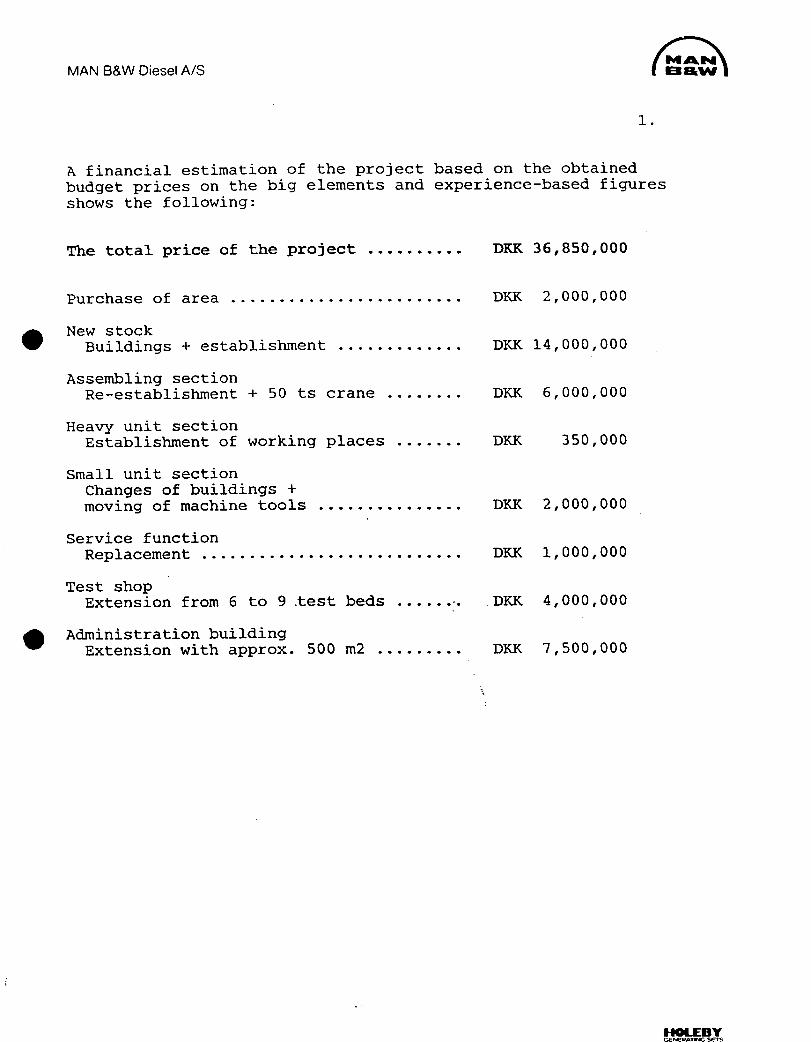
A financial estimation of the project based on the obtained budget prices on the big elements and experience-based figures shows the following:
The total price of the project ..........DKK 36,850,000
Purchase of area ........................ DKK 2,000,000
. New stock Buildings + establishment .............
Assembling section Re-establishment + 50 ts crane ........
Heavy unit section Establishment of working places .......
Small unit section Changes of buildings + moving of machine tools ...............
Service function Replacement...........................
Test shop Extension from 6 to 9 test beds ......
• Administration building Extension with approx. 500 m2 .........
DKK 14,000,000
DKK 6,000,000
DKK 350,000
DKK 2,000,000
DKK 1,000,000
DKK 4,000,000
DKK 7,500,000
HOLEBY

• MAN B&W Diesel A/S rIPE343
2.
The prices for restructurali.Zatiofl to the following:
Thirhae of area ........................DKK 2,000,000
Stock area
Total price ............................. DKX 14,000,000
m2 stock of bars + pipes ........... DKK 1,500,000 5 ts crane cover ....... DKK 300,000
800 m2 stock 12 in high ... DKK 3,000,000
Establishment of narrow-way truck and mini-load .............. DKK 4,500,000
1080 m2 stock ............ DKK 2,750,000
510 m2 with 10 ts crane cover ............ DKK 375,000
200 m2 office area ....... DKK 200,000
10 toilets Bath + changing facili-ties for 40 women ...... DKK 200,000
Moving of stock .......... DKX 175,000
Other .................... DKK 1,000,000 -
Assembling section
Total price ............................. DKK 6,000,000
50 ts crane .............. DKK 1,000,000 10 ts crane .............. DKK 200,000
Floor + pillar foundation ............. DKK 1,100,000
New roof construction over part assembling section + assembling section f/small parts .. DKK 2,600,000
(
HOLEBY

MAN B&W Diesel A/SmAkM
I 1100'^W (PE43 Enk::
Demolition + other building work .......... DKK 600,000
Moving of pipe forge, part assembling section, and part of the welding section to the con.rod department ............. DKK 150,000
Establishment of new toilets for men and women .......... DKK 100,000
Establishment of foreman's office ....... DKK 100,000
Other .................... DKK 150,000
Heavy unit section
Total price .............................
Establishment of 4 welding cabins for bed plates ......... DKK 100,000
Establishment of area for mounting and pressure test of frame . DKK 100,000:
•Establishment of
working place for crankshaft mounting .... DKK 100,000
Other .................... DKK 50,000
DKK 350,000
Small unit section Total price .............................
Moving FMS to stock of bars and pipes ......DKK 250,000
Moving con.rod dept. to pipe forge DKK 100,000
DKK 2,000,000
HOLEBY

MAN B&W Diesel A/S ( mAk" 0**^
4.
New roof and floor ....... DKK 850,000
Moving machining centre to the painter's workshop ................ DKK 100,000
Estahlishment of part assembling section in pallet stock ........... DKK 100,000
. Establishment of goods cleaning f/ small parts on the platform ........ DKK 300,000
Establishment of pre-setting shop ....... DKK 75,000
Other .................... DK.K 225,000
Service functions
Total price . . . . . . . . . . . ..................
Moving the repair area to the Northern end of the welding section ................ DKK 75,000
Moving the crankshaft control dept. to the present MC area ........ DKK 75,000
Q.C. area ................ DKK 850,000
Test shop
Total price .............................
Extension with 3 test beds ............ DKK 3,000,000
Electricity and water installations .......... DKK 500,000
Foundations for engines ................ DKK 300,000
Other .................... DKK 200,000
DKK 1,000,000
DKK 4,000,000
1-IOLEBY

MAN B&W Diesel A/S
(PE43 IMM ^W"
5.
Administration Building
Total price .............................
Extension of the existing administration building with 536 m2 per floor - 2 floors totalling 1072 m2 ............
Intermediate building 190 m2 with staircase .................
S Basement 536 m2 basement to be built in order to increase the space in the canteen by eliminating the existing meeting room, further, we will get the neces-sary space for our archives and other meeting rooms ..........................
The basement is to be built acc. to the Danish Civil Defense Requirements and to act as a security and safety basement for the city. About 80% of the cost for the basement will be paid by the authorities ...............
DKK 7,500,000
DKK 5,500,000
DKK 1,000,000
DKK 1,600,000
(DKK 1,300,000)
Net investment for MBD-H ................DKK 6,800,000 plus 10% security margin ................DKK 700,000
Totally needed for the extension of • the Administration Building ............. DKK 7,500,000
IIOLEBY

S
S
S
S
S
S
S
S E

P
T.toror, .tr .- b.. (14 (no
FA
txj z
tl
f—a
0
-=--0
-'
PRESENT SITUATION
ASSEMBLY AREA
Fobr iksl apout for' Holob, O(esel

F-z
-J 0
I
O 0 co
z
F-(I) FH
w
ENCL. 1
C)
D 0
S • I 4J i a a a a a
. a .-c a a S i a
- r 1•'• '•• % 1•
II I -. • • • I I
Ur1' •••• S
..E .......... U
1...
tC

NEW STOCK AREA Fob,' tkstoyout
for Hobby O(oseb
no P
5^
P
p
lm mar ,
C
1I liriL-LL
I
_J4__- I$IIlt4-1I, 4 :. . . . . — . rn__i•
S - a S I • •
a I t Iørn a 0
• S
tn z
0

z
t-1 I' I
PRESENT SITUATION
STOCK AREA
Pobrikslayo&t for Ho1by Diesel
O,j
P
P
oft 1oo bu(td(n
- -'1IPI1i ottiø.bwUd

I El
tTj z C)
NEW BUILDING FOR STOCK
Fob,' 11-cs -( o,rout
/'O , -
Hobby Dims A(
rJIIàIIL\ • _________ _____ VA-lip i
E
I- I I I-
-I u,aI - II
uI
- t -
P
temporar, ou e. buUdrg L-4ll) r I1 T.moory
PRESENT SITUATION MACHINING OF HEAVY COMPONENTS
Fab,' iks -1 ay ou f far Haleby Diesel

n P
P
P
Taporar? of LJ bu((dtn
Temporary
!iI
E1rir4I0
iiLII z
t-1
--I
NEW HEAVY UNIT SECTION
Fc,b,' (ks- layout for Holel,y Diesel

tTi z
t-1
P
P
I!'Tpror, off(oebutld
Tosp,'ai o4f(oi- butLdtnø
IA PRESENT SITUATION
MACHINING OF SMALL COMPONENTS Fob,' IAs-oyou t "or Hoôby Dtôse(

0, j Pcr
flI P
P
RECONSTRUCTED SMALL UNIT SECTION
Pabr (ksl opout for Hobby Diesel
of butLd(ro
• I T..poiovy off (o.buUd
0
a 1 I I
I II
co
^l uj L JI H
issss
E.
tTi z
I]NEW SMALL UNIT SECTION
Fob,' iks-1ayout (or Hotob, Oteset
p(:.
p
p
ofl (o. bu(Ld the

io P
P
off(ø.-
buiLd C
0 pol.
tTi z t.1
0
I - ^--
PRESENT SITUATION
ASSEMBLY AREA
Fabr(ks(o,ouf
for Ho(eby Dlesel

til z C) 1:1 III
E ol
:-=j
AA -
N
U
0
. . . . .
RECONSTRUCTED ASSEMBLY
Fob,- iksloyo&it fo Hobby Dies(
0,0 p I P
T.spor, •rr .— buUd (nø

NEW ASSEMBLY AREA
Fob,'tks1apout
to,' Hobby 016s41
(Th
P
T.aora, . (0• but (dine
^= I I
I
fd I 1 1;.
U
tli z
H t'J
U

,is
P Ii P
0
z
P
L= I • - i—i-- t I t I I I
.. •••a •• 1 • • S a
• • I I
• I I • a P 4
• I I • a I 4
• I I • a I 4
• I I
a• a
• I I • I 4
• 1 I • • I £I
1^'
Fab,' iks opout (0 Ho1b, Diesel
NEW MBD-H PLANT

'!

0*1F14111.111ift S'
Group data: (Status. 30.06.86) Capital stock DM 675 million
MAN Aktiengesellschaft, Munich (thu11aOá1P41' Employees 55,000 Turnover DM 14,600 million
rFEROROSTAM I
M:
i-u-i 1 rMAN
AND rneKw) MAN Nutzfahrzeuge GmbH, Munich
Diesel trucks from 6 to 48 t g.v.w. and rat-ings of 66 to 324 kW (90 to 440 HP DIN). Bonneted and for-ward-control trucks, underfloor-engined models, with two, three or four axles, optionally with all wheel drive. Leaf springs, leaf/air suspension or full air suspension. Platform trucks, tippers, semi-trailer tractors, chassis for special-purpose bodies. Chassis for local authority and fire-service bodies. Coaches for excur-sions, touring and long distance tours. High-liners for luxury long-distance tours. Standard city buses, standard intercity buses, standard ar-ticulated buses with rear-mounted engine, double-articulated buses, standard dou-ble-decker buses, bus floor assemblies, bus chassis. Automo-tive Diesel engines from 66 to 386 kW (90 to 525 HP DIN). Diesel engines with ratings of 26 to 404 kW (35 to 550 HP DIN) for use in sta-tionary apparatuses. Multifuel engines, en-gines for operation with liquefied gas.
Ferrostaal Aktiengesellschaft, Essen
Export of and interna-tional trade in iron and steel. Planning, turnkey erection and financing of industrial plants, especially in steel production and steel processing, non-metallic minerals, wood and metalwork-ing, chemical and plastics industries, textile, provisions and fine-foods industries, printing, packing and paperworking indus-tries. Supply and financing of equipment for on-shore and offshore exploration and exploitation for the mineral-oil industry. Machine tools, plas-tics-processing ma-chines, woodworking machines; planning, supply and financing of forges, foundries and service centres or their components, as well as of chip-board factories. Plan-ning, supply and financing of equip-ment for infrastructure projects: Rolling stock and permanent way material, ships of all kinds, dredgers, float-ing cranes, docks, harbour and yard equipment, power stations, installations for hydraulic engin-eering.
MAN Gutehoffnungshutte GmbH, Oberhausen
Plant and equipment for iron and steel pro-duction, nonferrous-metal production, heat recovery, press-urized oil and coal gasification, hazard-ous-waste inciner-ation; minerals and coal preparation plants. Plant and equipment for wind-ing and haulage in underground and opencast mining. Trackless mining and industrial vehicles. Bulk handling plant and equipment. Mechanical handling plant and cranes. Gas compresssor stations. Turbo compressors, screw-type compres-sors, industrial steam turbines, process gas expanders. Thermal power plants, total project engineering. Project engineering for environmental pro-tection. Steam turbo gener-ators, 100 to 900 MW capacity. Components for nu-clear power stations. Nuclear inspection service. Rail vehicles, wheel sets. Floating drydocks. Hydraulic steel struc-tures. Portable bridge equipment. Mechanical equip-ment for parabolic antennas. Optical and radio telescopes. Theatre stage ma-chinery. Pumps. Contracting of plants, buildings, steel struc-tures. Maintenance and general services. Transport and pipe-line systems. Assemblies. Pressings for the motor-car industry, metal-forming tools and dies.
MAN ROLAND Druckmaschinen Aktiengesellschaft, Offenbach
Single- and multicol-our sheetfed offset printing machines; convertible printing and perfecting ma-chines. Web offset presses as well as rotary pres-ses for for rotogravure and letterpress; stereotype facilities.
MAN B&W Diesel GmbH, Augsburg Copenhagen
Four-stroke Diesel en-gines in the power Output range from 450 kW (610 HP) to 14,000 kW (19,000 HP) for propelling ocean-going, coastal and inland ships as well as fishing ves-sels, for marine auxili-ary propulsion units and for stationary op-eration and emerg-ency generator sets. Gas engines and dual-fuel engines in the power output range from 250 kW (340 HP) to 5,895 kW (8,010 HP). Ex-haust gas turbo-chargers for four-stroke and two-stroke Diesel engines in the output range from approx. 300 kW (400 HP) to 22,000 kW (30,000 HP) charged output per exhaust gas turbocharger Two-stroke Diesel en-gines for ocean-going vessels and station-ary operation in the power output range from 700 kW (950 HP) to 47,280 kW (64,320 HP). Com-plete propulsion sys-tems, consisting of engine, gear unit, variable pitch propel-ler, remote control for ocean-going, coastal and inland ships and fishing vessels in the power output range from 280 kW (380 HP) to 3,960 kW (5,400 HP). Maintenance, repair and modernisation work carried out on MAN B&W and other Diesel engines. Repair of marine tur-bines and steam boi-ler units of all sizes. Foundry products. Oil and gas burners.
TEIIPIQLQGIE
MAN Technologie GmbH, Munich
Energy technology - Gas centrifuges for nuclear fuel enrich-ment, energy-saving technologies, notably motor-driven heat pumps for producing heat and utilizing waste heat, solar en-ergy, wind energy, biomass.
The Europea space progra e ARIANE - Turbo pumps/gas generators for the en-gines, thrust frame and torus tank for the VIKING, apogee en-gine and booster separation mechan-ism for the MAGE.
Transport engineer-ing - High-speed wheel/rail system, flywheel brake energy storage, vehicle aerodynam-ics.
Materials engineer-ing - Light constructions of composite materials, quality enhancement through LASER and CVD systems Ic-graphic exar ions.
Electronics and metrology - Instrumentation and control systems for heat pumps, printing machines, wind-energy converters and solar-energy plants.
System dynamics and automatic control engineering - Safety and monitoring equipment, informa-tion and diagnostic systems.
Production engineer-ing - Five-axis milling, flow turning, electron-beam welding.
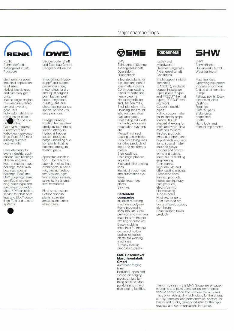
Major shareholdings
rim 0 M W
RENK Zahnrudertabrik Aktiengesellschaft, Augsburg
Gear units for every industrial application in all sizes: Helical, bevel, turbo and planetary gear units. Marine single-engine, multi-engine, planet-ary and reversing gear units. Fully ii P matic trans - rniiiiui iu for buses (D it")andspe-cia iicles. Gear-type couplings (Globoflex") and turbo gear-type coup-lings, Renk-SSS over-running clutches, gear wheels.
Drive elements for every industrial appli-cation: Plain bearings of radial and axial type, complete thrust bearings, radial-axial bearings, special bearings. Elco and Elbi" couplings, aero, centrifugal, overrun-ning, diaphragm and special-purpose clut-ches. EDP calculation service for plain bear-ings and Elco" coup-lings Test and control ysti 'rus
Deggendorfer Werft und Eisenbau GmbH, Deggendorf/Danube
Shipbuilding: Hydra-klapp split barges, passenger ships, motor ships for dry and liquid cargoes, push barges, push boats, ferry boats, coast-guard laun-ches, floating cranes, special-service ves-sels, pontoons.
Dredger building: Floating bucket-chain dredgers, cutterhead suction dredgers, Hydrot rail hopper suction dredgers, barge-unloading suc-tion plants, floating backhoe dredgers, floating grabs
Apparatus construc-tion: Tube reactors, quench coolers, heat exchangers, autocla-yes, electric prehea-ters, vessels, agita-tors, agitator vessels, tanks, tank systems, heat treatments.
Plant construction: Refuse disposal plants, seawater desalination plants, :lSSarTl blies.
SMS Schloemann Siemag Aktiengesellschaft, Düsseldorf, Hilchenbach Integrated plants for the steel and nonfer-rous-metal industry. Continuous casting plants for slabs and heavy blooms. Hot rolling mills for flats; section mills; 3-roll planetary mills. Finishing lines for bil-lets, sections, steel bars and tubes. Cold rolling mills with hydraulic, lubrication, preparation systems etc. Morgoil roll neck bearing assemblies. Strip processing lines for rolled products of steel and nonferrous metals. Steel castings. Plate edge process-ing lines. Slab and billet cooling lines. Electrical equipment and automation sys-tems. Water treatment plants. Services.
Battenfeld companies Injection moulding machines, polyure-thane processing lines, moulds. Com-pression and injection machines for the pro-cessing of duroplast. Blow-moulding machines for the pro-duction of hollow bodies, extrusion plants, foil welding machines. Turnkey plastics-processing plants.
SMS Hasenclever Maschinenfabrik GmbH Automatic forging lines. Extruders, open and closed-die forging presses, plate for-ming presses. Mani-pulators and strand discharging facilities.
kabelmetal,
Kabel- und Metallwerke GutehoftnungshOtte Aktiengesellschaft, Osnabrück Bright copper installa-tion pipes (SANCO), insulated copper installation pipes (WlCU pipes and PRECU thermal pipes), PRECU heat-ing floors. Copper industrial pipes. Rolled copper mate-rial in sheets, strips, rounds, TECU shaped sheeting for roofs and walls. Raw materials for semi-finished products, shaped copper parts, copper rods and sec-tions. Special mate-rials and alloys. Copper and bronze wires and cables. Materials for welding engineering. Coin blanks. Ingot moulds and other casting moulds. Processed semi-finished products, hollow continuously-cast products, electrotorming, electroplating. Tube bundles. Heat exchangers. Cold extruded pro-ducts of steel, copper, aluminium. Semi-finished brass products.
SHW Schwdbische Hüttenwerke GmbH, Wasseralfingen
Machine tools. Operating equipment. Process equipment. Chilled cast iron rolls. Pumps. Railway points. Deck expansion loots. Castings. Forgings. Sintered parts. Brake discs. Bright steel. Shafts. Hand tools and manual implements.
The companies in the MAN Group are engaged in engine and plant construction, commercial vehicle construction and commercial activities. They offer high-quality technology for the energy supply, chemical and petrochemical sectors, for buses and trucks, primary industry, for the typo-grapical and communications industries.

Worldwide Service
rn
... • . ••• ,• •• S
S. • ..•.. •...•.• S...... ....•••• .. • ...• S
S. • S. S
Two-stroke engine programme
250 S 26 MC/MCE
200 L 35 MC/MCE
180 L42MC/MCE
141 L5OMC/MCE
123 S5OMC/MCE
I 117 L6OMC/MCE
102 S6OMCIMCE
100 L 70 MC/MCE
88 S7OMC/MCE
88
100
III liii. 78 I L 90 MC/MCE • • I I 90K90MC/MCEI I II I
0 6000 12000 18000 24000 30000 36000 42000 48000 engine 0111501 (kWI
NR- and NA-turbocharger series Four-stroke engine programme
1/111111
NA 15/9 1000
t N520 750
NA 24/A1000
NA 26/9
I 750
NA 34/1
750
NA 40/1
514
NA 48/3
NA 57/T
__ 480 NA 70/3
NA 11 I I 428
-II-0 4000 8000 12000 16000 20000 24000
engine output per turbocharger [kW]
L 80 MC/MCE
K 80 MC/MCE
S80 MC/5
• • L23/30
L+V 25/30
• L+V 28/32
•L+V 32/36
LL0/54
L5 8
V52/55B
H —--^ L 58i64 II
—-—-0 2000 4000 6000 8000 100(8) 12(03) 141111
errglrre output 1kW I

r MAMM :,mm Heavy Fuel GenSets
- - - - - --- - -- - - MM
-- - - GENERATING SETS
0

The 23 & 28 Series
GenSets of the 23 & 28 Series are diesel power modules for generation of electrical or mechanical power in marine and stationary applications.
The engines of the 23 & 28 Series are four-stroke, turbo-charged medium-speed engines. The two engine types are of identical design concept but of different cylinder dimensions and power range.
The 23 & 28 Series are well-proven engine designs, continuously developed to meet changing markets demands, to extent the versatility, and in order to always representing the latest state-of-art for any application.
The 23 & 28 Series are designed for operation on HFO of nominal viscosity of up to 700 cSt/50°C, and thus comply with the unifuel ship concept, i.e. propulsion engine and diesel-generators to be operated on the same grade of HFO.
The 28 Series also is available as gas diesel engine for operation on natural gas with performance and power output identical with the HFO-version.
The diesel power modules are delivered as complete packages with the diesel engine and the driven machinery mounted on a common base frame.
Any type and make of driven machinery can be specified, the base frame will be specially adapted in each case.
Due to a wide range of optional equipment for the media systems on the diesel power module, it is possible to deliver tailormade solutions, meeting the requirements from owners, shipyards, classification- and national authorities.
The diesel power modules can according to project oriented interface concepts be supplemented with extra equipment and modules for the external media and support systems, thus forming complete solutions for production of electrical or mechanical power.
Engine Types 23 & 28
• High Availability Reliability Durability
• Low Operation Costs
• Low Maintenance Demand
Modular Engineering Concept
Diesel Power Modules
System Solutions
Four-stroke, medium-speed diesels.
Turbocharged and charge air cooled.
Trunk piston engines, non-reversible type.
L23/30 530-1280 kW 5-6-7-8 cyl.
L28/32H 880-1980 kW 5-6-7-8-9 cyl.
V28/32H 2100-3960 kW 12-16-18 cyl.
Easy Operation and Maintenance
• Low Fuel and Lub.oil Consumption
• Long Intervals between Overhauls
o Long Lifetimes of Components
• Tailormade Solutions • Factory-tested Modules • Ready-to-start State • Easy Installation • Easy Connection to
external Systems • Optimized for
Compactness and Accessability
o GenSets o PumpSets o CombiSets
• Extra Equipment • Support Modules • Interface Concepts

.
.
Contents Output Range, Dimensions and Weights Page 4 Main Particulars, Technical Data Page 5
L23/32ft1I Output Range, Dimensions and Weights Page 6 Main Particulars, Technical Data Page 7
V28/32H Output Range, Dimensions and Weights Page 8 Main Particulars, Technical Data Page 9
Fuel Oil Requirements, Overhaul Intervals Page 10
23 128 Pressurized Uni Fuel System Page 11 Product Support Page 13
3

GenSet Output Engine Flywheel Type 720 rpmI60 Hz 750 rpm/50 Hz 900 rpm/60 Hz
51-23/30 E 530 kW 720 BHP 550 kW 750 BHP 51-23/30 650 kW 890 BHP 680 kW 920 BHP 800 kW 1090 BHP 61-23130 780 kW 1060 BHP 810 kW 1100 BHP 960 kW 1300 BHP 71-23/30 910 kW 1240 BHP 950 kW 1290 BHP 1120kW 1520BHP 81-23/30 1040 kW 1420 BHP 1080 kW 1470 BHP 1280 kW 1740 BHP
50
0
Mm. 1950 L3 L4
H
250
.
L23130 Output Range Dimensions and Weights
Dry Weight in tons GenSet Li L2 L3 L4 L5 Bi Hi Engine and GenSet Type mm mm mm mm mm mm mm Base Frame complete
51-23130 E 3920 980 3320 2115 2340 1500 1520 12,2 16,8 51-23130 3920 980 3320 2115 2340 1500 1520 12,2 16,8 61-23130 4500 980 3690 2325 2710 1500 1565 12,9 18,7 71-23130 4735 980 4060 2210 3080 1600 2015 14,3 19,2 81-23130 5215 980 4430 2320 3450 1600 2015 15,8 23,7
Dimensions 1-1-1-4-B1 and Weight GenSet complete are valid for GenSets with standard generator, make A.v.K. The dismantling height is stated for monorail crane arrangement; reduced height is obtainable by special crane arrangement.
.
4

L23130 Main Particulars Technical Data
___ It
tL4L
U
.
Main Particulars Four-stroke diesel with direct injection. Turbocharged medium-speed engine. Non-reversible trunk piston engine. Number of Cylinders .................5-6-7-8 In-line Power range ........................530-1280 kW
720-1740 BHP
Technical Data Bore ...................... 225 mm Stroke ..................... 300 mm Stroke/Bore ratio ............ 1,33:1 Piston area per cyl . .......... 398 cm2 Swept volume per cyl......... 11,9 ltr. Compression ratio ........... 13,3:1 Max. combustion pressure .... 130 bar Mean effective pressure....... 18 bar/15 bar E Speed ..................... 720-750-900 rpm Mean piston speed .......... 7,2-7,5-9,0 m/s Turbocharging principle ....... Constant pressure
with charge air cooling
Cylinder jackets coolant ....... Fresh water Charge air coolant ........... Fresh water or
raw/sea water
Starting method .............Air starter motor
Performance Data MCR Maximum Continuous Rating ECR Economy Continuous Rating
Output per cylinder MCR ECR 720 rpm ................... 130kW 105 kW
177 BHP 143 BHP 750 rpm ................... 135kW 110 kW
184 BHP 150 BHP 900 rpm ................... 160kW
217 BHP
Fuel quality acceptance ....... HFO up to 700 cStJ500C, Grade H55 in ISO 8217/13S 6843
5

GenSet Output Engine Flywheel Type 720 rpm/60 Hz 750 rpm/50 Hz
51-281321-1 E 880 kW 1190 BHP 930 kW 1260 BHP 51-28/321-1 1050 kW 1430 BHP 1100 kW 1500 BHP 61-281321-1 1260 kW 1710 BHP 1320 kW 1800 BHP 71-28/321-1 1470 kW 2000 BHP 1540 kW 2100 BHP 81-281321-1 1680 kW 2280 BHP 1760 kW 2400 BHP 91-281321-1 1890 kW 2570 BHP 1980 kW 2690 BHP
L3 L4 Mm. 2100
c1L.1
Hi
L28/32H Output Range Dimensions and Weights
Dry Weight in tons GenSet Li L2 L3 L4 L5 Bi Hi Engine and GenSet Type mm mm mm mm mm mm mm Base Frame complete
5L28/32H E 4745 1240 4220 2320 2980 1500 2185 18,2 25,5 51-28/321-1 4745 1240 4220 2320 2980 1500 2185 18,2 25,5 61-28/321-1 5335 1240 4700 2430 3460 1500 2185 20,8 28,7 71-28/321-1 5910 1240 5180 2435 4160 1800 2375 22,6 32,8 81-28/321-1 6460 1240 5885 2505 4640 1800 2375 24,9 36,3 91-28/321-1 6875 1240 6140 2610 4900 1800 2534 27,8 39,2
Dimensions L1-1-4-131 and Weight GenSet complete are valid for GenSets with standard generator, make A.v.K. The dismantling height is stated for monorail crane arrangement; reduced height is obtainable by special crane arrangement.
.
6

L28/32H Main Particulars Technical Data
.
[1
Main Particulars Four-stroke diesel with direct injection. Turbocharged medium-speed engine. Non-reversible trunk piston engine. Number of Cylinders ................5-6-7-8-9 In-line Power range .......................880-1980 kW
1190-2690 BHP
Technical Data Bore ...................... 280 mm Stroke ..................... 320 mm Stroke/Bore ratio ............ 1,14:1 Piston area per cyl........... 616 cm2 Swept volume per cyl......... 19,7 ltr. Compression ratio ........... 13,3:1 Max. combustion pressure
130 bar
Mean effective pressure....... 18 bar/15 bar E Speed..................... 720-750 rpm Mean piston speed .......... 7,7-8,0 m/s Turbocharging principle ....... Constant pressure
with charge air cooling
Cylinder jackets coolant ....... Fresh water Charge air coolant ........... Fresh water or
raw/sea water
Starting method .............Air starter motor
Performance Data MCR Maximum Continuous Rating ECR Economy Continuous Rating
Output per cylinder MCR ECR 720 rpm ................... 210kW 175 kW
285 BHP 238 BHP 750 rpm ................... 220kW 185 kW
300 BHP 252 BHP
Fuel quality acceptance ....... HFO up to 700 cSt/50°C, Grade H55 in ISO 8217/13S 6843
LN 28/32 GI Engine Series "28" also available as gas diesel engine for operation on natural gas. Performance and power output for the gas-fuelled version identical to that of the HFO-version.
7

.
Mm. 2870
1100 1100
)I T _ H1[
315
L3 L4
V28/32H Output Range Dimensions and Weights
GenSet Output Engine Flywheel Type 720 rpm/60 Hz 750 rpm/50 Hz
12V28/32H E 2100 kW 2860 BHP 2220 kW 3020 BHP 12V28/32H 2520 kW 3420 BHP 2640 kW 3600 BHP 16V28/32H 3360 kW 4560 BHP 3520 kW 4800 BHP 18V28/32H 3780 kW 5130 BHP 3960 kW 5400 BHP
Dry Weight in tons GenSet Li L2 L3 L4 L5 Bt Hi Engine and GenSet Type mm mm mm mm mm mm mm Base Frame complete
12V28/32H E 6720 1020 4905 3495 3885 1900 2385 33,1 47,3 12V28/32H 6720 1020 4905 3495 3885 1900 2385 33,1 47,3 16V28132H 7730 1020 5925 3855 4905 2400 2555 45,7 66,8 18V28/32H 8240 1020 6435 4000 5415 2400 2705 47,1 70,0
Dimensions 1-1-1-4-B1 and Weight GenSet complete are valid for GenSets with standard generator, make A.v.K. The dismantling height is stated for monorail crane arrangement; reduced height is obtainable by special crane arrangement.
.
8

V28/32H Main Particulars Technical Data
FAL
Main Particulars Four-stroke diesel with direct injection. Turbocharged medium-speed engine. Non-reversible trunk piston engine. Number of Cylinders ................12-16-18 Vee Power range .......................21 00-3960 kW
2860-5400 BHP
Technical Data Bore ...................... 280 mm Stroke ..................... 320 mm Stroke/Bore ratio ............ 1,14:1 Piston area per cyl. .......... 616 cm2 Swept volume per cyl......... 19,7 ltr. Compression ratio ........... 13,3:1 Max. combustion pressure .... 130 bar Mean effective pressure....... 18 bar/1 5 bar E Speed ..................... 720-750 rpm Mean piston speed .......... 7,7-8,0 m/s Turbocharging principle ....... Constant pressure
with charge air cooling
Cylinder jackets coolant ....... Fresh water Charge air coolant ........... Fresh water or
raw/sea water
Starting method .............Air starter motor
Performance Data MCR Maximum Continuous Rating ECR Economy Continuous Rating
Output per cylinder MCR ECR 720 rpm ................... 210kW 175 kW
285 BHP 238 BHP 750 rpm ................... 220kW 185 kW
300 BHP 252 BHP
Fuel quality acceptance ....... HFO up to 700 cSt/50°C, Grade H55 in ISO 8217/13S 6843
LN 28/32 GI Engine Series "28" also available as gas diesel engine for operation on natural gas. Performance and power output for the gas-fuelled version identical to that of the HFO-version.
9
Guiding Specification, Fuel Oil as Bunkered
Installation Related Properties max. value
Viscosity ................. cSt/50°C 700 cStIlOO°C 55 sRlIlOO°F 7000
Density .................. kg/m3 atl5°C 991/1010* Flash Point ................ °C >60 Pour Point ................ °C 30
Engine Related Properties max. value
Conradson Carbon (CCR) % by weight 22 Sulphur .................. % by weight 5 Water .................... %byvolume 1,0 Ash ..................... %byweight 0,2 Aluminium ................ ppm (mg/kg) 30 Vanadium (V) ppm (mg/kg) 600
Sodium .................. ppm (mg/kg) 30 % of V Asphalt ppm (mg/kg) 60 % of CCR
* Density up to 1010 kg/rn at 15°C is acceptable if centrifugal separators of the type without gravity disc are installed.
[1
Preferable Fuel Oil Cleanness at Inlet Engine
Water ....................% by volume max. 0,2 Solid particles .............ppm (mg/kg) max. 20 Particles size ..............micron max. 5
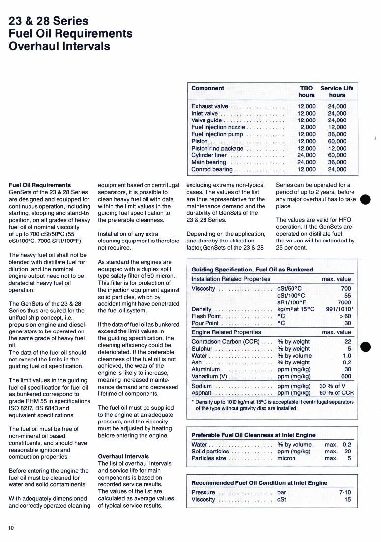
23 & 28 Series Fuel Oil Requirements Overhaul Intervals
Component
Exhaust valve ................. Inlet valve .................... Valve guide ................... Fuel injection nozzle ............ Fuel injection pump ............ Piston ....................... Piston ring package ............ Cylinder liner ................. Main bearing.................. Conrod bearing ................
TBO Service Life hours hours
12,000 24,000 12,000 24,000 12,000 24,000 2,000 12,000
12,000 36,000 12,000 60,000 12,000 12,000 24,000 60,000 24,000 36,000 12,000 24,000
Fuel Oil Requirements GenSets of the 23 & 28 Series are designed and equipped for continuous operation, including starting, stopping and stand-by position, on all grades of heavy fuel oil of nominal viscosity of up to 700 cSt/50°C (55 cSt/100°C, 7000 SR1/1000F).
equipment based on centrifugal separators, it is possible to clean heavy fuel oil with data within the limit values in the guiding fuel specification to the preferable cleanness.
excluding extreme non-typical cases. The values of the list are thus representative for the maintenance demand and the durability of GenSets of the 23 & 28 Series.
Series can be operated for a period of up to 2 years, before any major overhaul has to take place.
The values are valid for HFO operation. If the GenSets are operated on distillate fuel, the values will be extended by 25 per cent.
Installation of any extra Depending on the application, cleaning equipment is therefore and thereby the utilisation not required. factor, GenSets of the 23 & 28
The heavy fuel oil shall not be blended with distillate fuel for dilution, and the nominal engine output need not to be derated at heavy fuel oil operation.
The GenSets of the 23 & 28 Series thus are suited for the unifuel ship concept, i.e. propulsion engine and diesel-generators to be operated on the same grade of heavy fuel oil. The data of the fuel oil should not exceed the limits in the guiding fuel oil specification.
The limit values in the guiding fuel oil specification for fuel oil as bunkered correspond to grade RHM 55 in specifications ISO 8217, BS 6843 and equivalent specifications.
The fuel oil must be free of non-mineral oil based constituents, and should have reasonable ignition and combustion properties.
Before entering the engine the fuel oil must be cleaned for water and solid contaminents.
With adequately dimensioned and correctly operated cleaning
As standard the engines are equipped with a duplex split type safety filter of 50 micron. This filter is for protection of the injection equipment against solid particles, which by accident might have penetrated the fuel oil system.
If the data of fuel oil as bunkered exceed the limit values in the guiding specification, the cleaning efficiency could be deteriorated. If the preferable cleanness of the fuel oil is not achieved, the wear of the engine is likely to increase, meaning increased mainte-nance demand and decreased lifetime of components.
The fuel oil must be supplied to the engine at an adequate pressure, and the viscosity must be adjusted by heating before entering the engine.
Overhaul Intervals The list of overhaul intervals and service life for main components is based on recorded service results. The values of the list are calculated as average values of typical service results,
Recommended Fuel Oil Condition at Inlet Engine
Pressure .................bar 7-10 Viscosity .................cSt 15
10

- _
_ I
) _i 4.
L.
LI
I
Same Heavy Fuel up to 7.000 Sec. R.I. for
Main Engine and GenSets Simplified Fuel Oil System
Simplified and Cheap Bunkering
Ar
I
,-
Venting Tank with Aut. De-aerating Valve \
MOO Circulation Pump Pressure Control Valve
HFO Circulation Pumps
Changing Valves for Remote Control (optional for local control)
Pressurized Uni-Fuel System
• Modules for easy Installation • Control Panel for Automatic Operation • Automatic Viscosity Control • Electrical and/or Steam HFO Heaters • Classified for Unmanned Machinery Space
L Thermostatic Valve Nozzle Cooling Pumps
Back Pressure Valve MDO Circulation Line
HFO Heaters Back Pressure Valve MDO Return Line
I I FG
H L / I11 14
- .\ c -W- Control Cabinet
MOO
7
Flowmeter
HFO Supply Pumps
Pressure Control Valve
Feeder Modul (optional for press. System)
11

• Pre-Sales Service • Project Service • After-Sales Service
Product SupportHoleby Diesel Ostervej 2, DK-4960 Holeby Telephone: + 45 53 90 60 26 Telefax: + 45 53 9066 76 Cables: oildiesel maribo Telex: 40646 hodiel dk
MAN B&W Diesel A/S
88 000
00 00 00
Advice & Consulting System Solutions Documentation Commissioning Customer Training
Maintenance Service - Repair Service
Trouble Shooting Service Agreements Spare Parts Service
c Licensees c Service Centres
The 23 & 28 Series are produced on licence: • Brazil
Equipmentos Villares S.A. • Spain
Empresa Nacional Bazan • Yugoslavia
Titovi Zavodi Litostroj Brodogradjevna Industrija S
• Rep. of Korea Ssangyong Heavy lndustrie
• People's Rep. of China Zhanjiang Marine Diesel Engine Works
:L
L 888: 8888
08880 -8, 000 000000
AMR.
0. •• 00
00
Service Centres and Authorized Repair Shops
.
13

Marine GenSet TechnologyAft M
rmn :,a
- --- - -- - - - w - -- - GENERATING SETS
0
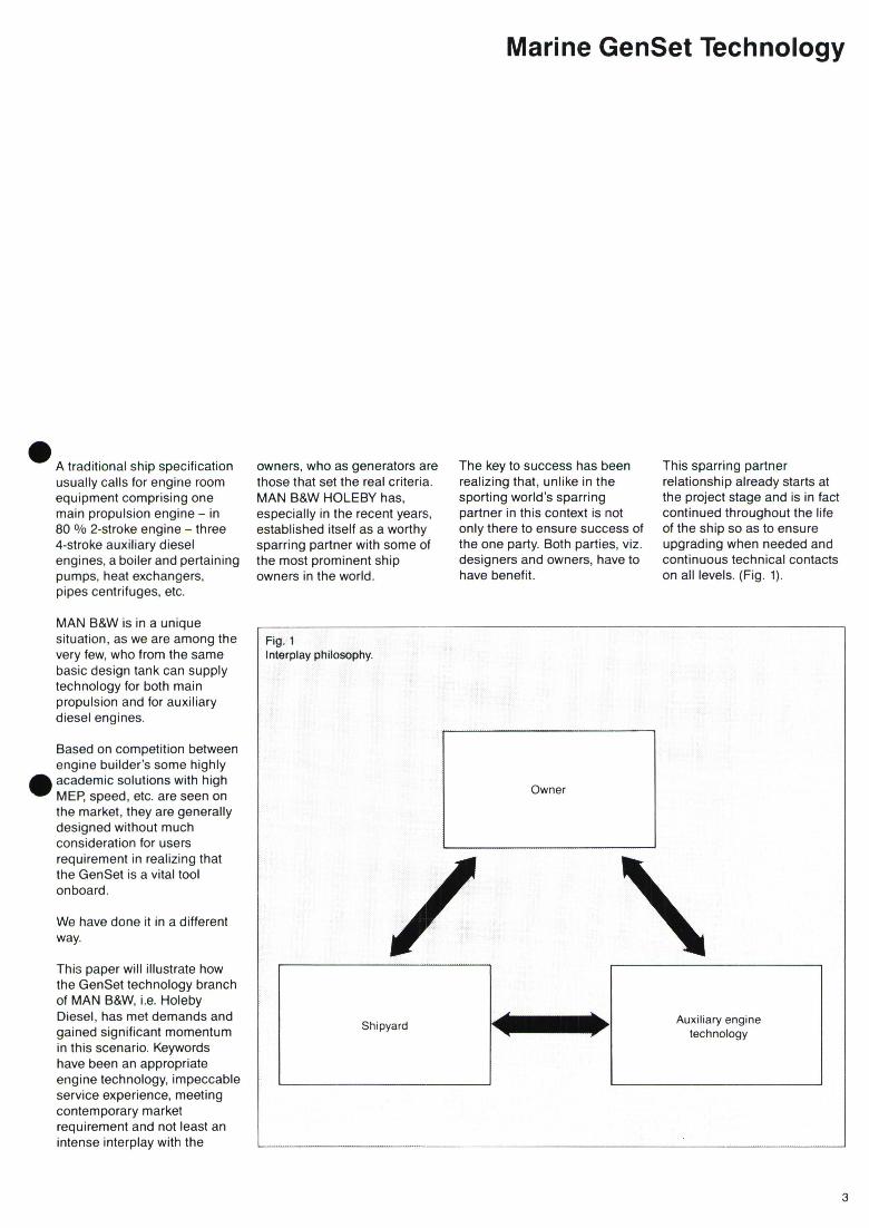
Marine GenSet Technology
A traditional ship specification usually calls for engine room equipment comprising one main propulsion engine - in 80 % 2-stroke engine - three 4-stroke auxiliary diesel engines, a boiler and pertaining pumps, heat exchangers, pipes centrifuges, etc.
owners, who as generators are those that set the real criteria. MAN B&W HOLEBY has, especially in the recent years, established itself as a worthy sparring partner with some of the most prominent ship owners in the world.
The key to success has been realizing that, unlike in the sporting world's sparring partner in this context is not only there to ensure success of the one party. Both parties, viz. designers and owners, have to have benefit.
This sparring partner relationship already starts at the project stage and is in fact continued throughout the life of the ship so as to ensure upgrading when needed and continuous technical contacts on all levels. (Fig. 1).
MAN B&W is in a unique situation, as we are among the very few, who from the same basic design tank can supply technology for both main propulsion and for auxiliary diesel engines.
Based on competition between engine builder's some highly
. academic solutions with high MEP, speed, etc. are seen on the market, they are generally designed without much consideration for users requirement in realizing that the GenSet is a vital tool onboard.
We have done it in a different way.
This paper will illustrate how the GenSet technology branch of MAN B&W, i.e. Holeby Diesel, has met demands and gained significant momentum in this scenario. Keywords have been an appropriate engine technology, impeccable service experience, meeting contemporary market requirement and not least an intense interplay with the
Fig. 1 Interplay philosophy.
Owner
Shipyard Auxiliary engine technology

Engine Technology
Engine Technology! Market Situation Although both smaller and larger engines in our 4-stroke engine programme, can be and have been delivered as auxiliary diesel engines for ships, the frontline technology in GenSet application is concentrated around our 23 and 28 type of engines. The power range is from 500 to 2000 kW for inline engines and up to 4000 kW for V-type 28.
The speed is selected in the 720/750 RPM range realizing that this is what the market wants.
It is beyond the scope of this paper to go into a technical description of these engines, and in fact it would not really be needed, as they have been around for quite a long time.
However, an outstanding difference from the regular engines on the market is the use of constant pressure turbocharging giving significant advantages on fuel consumption and reliability.
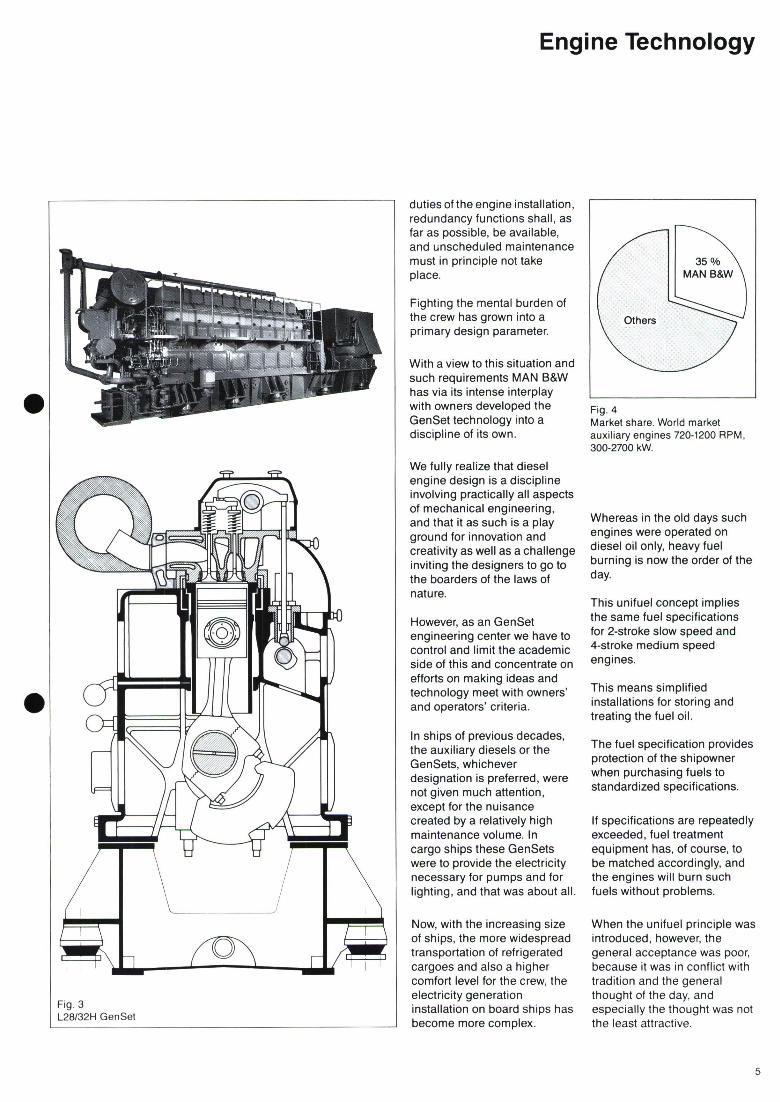
In fig. 2 and 3 are shown cross sectional drawings of the engines together with recent photographs of GenSet executions.
Traditionally MAN B&W has maintained a policy of allowing license production of our engines, and although more pronounced on the 2-stroke side than on the 4-stroke side, it is naturally that such license agreements today exist in major ship building centres for the active production of our auxiliary engines in Spain, Yugoslavia, Brazil, China and in Korea. In Japan a special agreement with our 2-stroke licensees enables an outlet for our engines to the Japanese market.
Bearing in mind that when going down the list of potential suppliers of equipment to a ship, such a network of licensees will in the same way as has been the case for 2-stroke main engines allow the shipyards in the major shipbuilding centres of the world to comply with owners' wish for MAN B&W auxiliary engines and still be able to install a locally manufactured product.
Bearing this situation in mind our market share shown in fig. 4 is hardly surprising. MAN B&W HOLEBY is in fact today the world's largest designer/ Supplier of auxiliary diesel engines.
GenSet Technology Referring to the traditional ship specification - one main propulsion engine and three GenSets - GenSet technology is hardly an issue. Many suppliers can easily comply with the GenSet part.
However this is simply not enough to meet the owners need and requirements and should belong to history only.
From the shipowner's point of view safe and uninterrupted service of the ship and its cargo installations will always be a primary requirement.
Reduced and alternating crews, shorter stays in port, and considerably extended docking intervals are service conditions, which have to be considered by the designers of the engine installations.
Accordingly, proposals to optimize plant economy shall be based upon proven components with a high reliability. As no risk can be accepted for the primary
.
Engine Technology
duties of the engine installation, redundancy functions shall, as far as possible, be available, and unscheduled maintenance must in principle not take place.
Fighting the mental burden of the crew has grown into a primary design parameter.
With a view to this situation and such requirements MAN B&W has via its intense interplay with owners developed the GenSet technology into a discipline of its own.
We fully realize that diesel engine design is a discipline involving practically all aspects of mechanical engineering, and that it as such is a play ground for innovation and creativity as well as a challenge inviting the designers to go to the boarders of the laws of nature.
However, as an GenSet engineering center we have to control and limit the academic side of this and concentrate on efforts on making ideas and technology meet with owners' and operators' criteria.
In ships of previous decades, the auxiliary diesels or the GenSets, whichever designation is preferred, were not given much attention, except for the nuisance created by a relatively high maintenance volume. In cargo ships these GenSets were to provide the electricity necessary for pumps and for lighting, and that was about all
Now, with the increasing size of ships, the more widespread transportation of refrigerated cargoes and also a higher comfort level for the crew, the electricity generation installation on board ships has become more complex.
MAN B&W
Fig. 4 Market share. World market auxiliary engines 720-1200 RPM, 300-2700 kW.
Whereas in the old days such engines were operated on diesel oil only, heavy fuel burning is now the order of the day.
This unifuel concept implies the same fuel specifications for 2-stroke slow speed and 4-stroke medium speed engines.
This means simplified installations for storing and treating the fuel oil.
The fuel specification provides protection of the shipowner when purchasing fuels to standardized specifications.
If specifications are repeatedly exceeded, fuel treatment equipment has, of course, to be matched accordingly, and the engines will burn such fuels without problems.
When the unifuel principle was introduced, however, the general acceptance was poor, because it was in conflict with tradition and the general thought of the day, and especially the thought was not the least attractive.

Implementation of GenSet Technology
Another criterion which must be fulfilled for a diesel GenSet to qualify in the same way as the main engine in an integrated energy concept with appropriate engine management is a wide load range for continuous operation
Basically, a GenSet should be able to operate continously down to 20-30 % load on heavy fuel with no special precautions and, indeed, the MAN B&W HOLEBY GenSet can do this, but this is not enough.
It is clear that when a main engine dependent electricity producer is operated near to its capacity, a safe and fast back up is necessary in order to cater for unavoidable power fluctuations.
Hence, the requirement for idling capability emerged as, otherwise, the traditional lower load of 30 % would require a certain load sharing with subsequent loss of energy in cases where the parallel running unit would be a turbogenerator.
The answer was the ICS GenSet, i.e. a GenSet with its charge air system integrated with that of main engine.
A third requirement of qualification is, of course, reliability. Both from a general point of view, and also with regard to the implementation of the above-mentioned idling ability which, in turn, calls for a continuously operating GenSet, the reliability must be exceptional.
Hence, with unrestricted heavy fuel capability, ability to operate continuously at all loads down to idling and still having an extremely high reliability, it has been the judgement of the shipowners
and the designer that these GenSets, similar to the main engines, qualify to be incorporated in a Total Energy Concept with energy management.
Therefore it is in fact an irrelevant question whether a particular auxiliary engine is a modern engine or not.
You may even ask the question, what is a modern engine and as owner, most likely get an answer which is of no use to your question.
The main task is to fulfil the requirements set and to be able to enter into an integrated marine propulsion system.
With view to this our auxiliary engines are not multifunction engines. We realize that the operating conditions and environment of propulsion engines and auxiliary engines are completely different and cannot be catered for by a few alterations.
An engine can be allegedly so good at everything that it is not really optional for anything. Therefore, together with their pertaining application technology our engines are tailormade as auxiliary engines and are, therefore, as such second to none.
Implementation of GenSet Technology A prerequisite for modern GenSet technology is heavy fuel burning.
On previous occasions MAN B&W has presented papers on heavy fuel burning auxiliary engines, and we were - admittedly by actions taken by owners - unaware of our pioneering efforts in this respect.
However, the idea was pursued, and in 1981 we in fact invented the word unifuel, which is today common term used for installations where main and auxiliary engines are burning the same fuel oil.
MAN B&W 4-stroke auxiliary engines have been designed not only for burning of today's fuels, but with potential for even lower quality fuels in future.
Our fuel specification which is the same as generally used for main propulsion engines is shown in fig. 5.
With regard to ignition quality we have expressed our current requirements in fig. 6, but in all fairness we have not seen situations where we really have been faced with problems of that nature.
All the more complicated fuel installations with starting and stopping on marine diesel, blending of fuels, load restrictions, etc. involving a multitude of extra components and extra operations with subsequent risk of failure and extra work load on the crew, have been disposed with and can be considered superfluous.
This all belongs to history.
Today's fuel system and fuel treatment plant is common for main propulsion engine and auxiliary engines.
Unrestricted heavy fuel operation from idle to full load is available to cover all situations (sea condition, manoeuvre, port) and on top of that new energy savings in main engine derived waste heat recovery have been made available by introduction of the unrestricted low load capability.
The classic load response problems during sudden load changes have been eliminated by our jet system (fig. 7) and the actual load response is now far beyond what is required from various classification societies (fig. 8).
Smoke emission during sudden load changes has practically been eliminated by our smoke limiting system. Fuel limitation is controlled by the scavenge air pressure as shown in fig. 9.
Whereas the introduction of the unifuel concept came as a - in reality unplanned - consequence of a fuel oil price increase, the 1980'ies saw a much more planned introduction of GenSet technology.
Service Experience In this context the foresight and cooperation of a large Danish ship owner cannot be overlooked.
. We were in fact given the task of meeting a number of specific requirements to be implemented in the expanding fleet. The requirements were for a number of reasons mainly specified as extended service life and extended load range.
The first step in the development plan was taken in 1983, when a new prototype aux. engine was installed as a replacement engine in a first generation container vessel, built in the late sixties.
This prototype engine of the MAN B&W HOLEBY 23-type was designed and equipped to burn the low quality fuels of the future.

(The data given refer to the fuel as supplied, i.e. before the on-board cleaning).
Guiding Fuel Oil Specification (max. values)
Viscosity cSt/50 0C 700 Density g/ml at 15 °C *) 0.991 Flashpoint °C >60 Conradson Carbon % weight 22 Asphalt % weight 14
Sulphur % weight 5 Water % weight 1.0 Ash O/ weight 0.2 Aluminium ppm 30 Vanadium ppm 600 Sodium ppm 300/6ofV
May be exceeded provided adequate cleaning is installed i.e. new types of centrifuges.
Fig. 5 Fuel specification.
CCAI 800
Real Criterion is Engine Speed 810
23 and 20 Engines 820
Normal operating 830 conditions
840N'
., H 850
NPresent design
860
870
880
890Difficuulties
may be encountered
900
Increasingly 920 difficult
930 1 I I
1000 750 500I
250
Fig. 6 Heavy fuel requirements.
Service Experience
The intention was to operate this engine continuously on heavy fuel to obtain as many running hours as possible during a relatively short period
During four and a half years this engine operated 36.199 hours corresponding to 8.300 hrs./year or 93 % of all the time available.
Engineers from Holeby made inspections 5 times during this period to observe the engine performance stability and wear of components.
The result was excellent, the wear rates were extremely low and the only alteration introduced was a slightly modified exhaust valve guide.
After this modification the engine operated continuously without unscheduled maintenance during the whole period.
The consumption of spare parts during the 36,199 hrs. was 200 USD/1000 hrs. or 0,0003 USD/kWh. and the resulting maintenance and lifetime of components are shown in fig. 10.
Traditionally the service hours for power generation on auxiliary engines have always been distributed evenly between the number of units installed.
This philosophy belongs to the past, where maintenance work was part of the crew's daily workingtime.
For several years, we have had the ' unmanned engine room which has lead to drastic reductions of the crew members leaving little margin for maintenance by the crew.
In the ships of today the whole engine installation must,
therefore, be able to cope with this situation without compromising the reliability and increasing the maintenance cost.
The long maintenance intervals without unscheduled events combined with optimal economy by operating on low quality fuels are a general requirement.
The prototype of our 8T23LH-4E engine installed in 1983 proved that these expectations from the ship owners could be fulfilled, and this engine design served as a model for the subsequent types.
Based on experience the owner successively repowered 3 sister ships with the similar engines.
On this background the owner found it natural to look after further improvements of the operational economy to be combined with the continuous operation or baseload engine philosophy, which was already introduced.
So the next question to us as engine builders was, if we could develop an auxiliary engine, which was able to operate at least 7.000 hrs. per year on the same heavy fuel as the main engine without any low load restrictions.

Service Experience
Momentary Sudden Stepload Speed with JET SYSTEM Variation
Predicted
10%
Sudden II with JET I SYSTEM
Ex. Emergency Start
Conventional
Load I I I I
25% 50% 75% 100% Fig. 8 Load response.
Extended Load Range This requirement was based on the idea of optimal utilization of waste heat recovery by turbogenerator with which the auxiliary diesel should operate in parallel.
The control system of the auxiliary engine, was supplemented with a blow back monitor to ensure that optimum performance conditions are maintained at all loads from idling to full. (Fig. 11).
The ICS-system was introduced in service in 1986, when the owner decided to convert one of the existing 7S28LH-2 auxiliary engines in each vessel.
The owner's intention was to get a confirmed service result of the new concept before introduction in a newbuilding.
The job was undertaken without affecting the sailing schedules of the vessels, and completed in October, 1986 on the first vessel and in March, 1987 on the second vessel.
The actual ships were second generation large container vessels built in the early eighties. These vessels were equipped with a 12-cylinder L90 GFCA MAN B&W main propulsion engine and four auxiliary engines of the first generation 28 engines, two 7-cylinder S28LH-2 and two 8-cylinder S28LH-2.
Under sea condition the electric power consumption was covered by the turbogenerator and one diesel generator.
Of course, the intention was to generate as much free of charge electric power by the turbo generator unit as possible.
Pressure Charge Charge ' Air to receiver e] turbocharger
Analog out if z>set-point Open' x-y=Z IN then
Solenoid Analog valve calculator Fuel pump
index (load)
Distance X
transducer Pressure air
Fig. 9 Jet control system.
8

• Cylinder liners ............... 200,000 hrs • Pistons (ring grooves) ......... 100,000 hrs • Piston rings .................. 16,000 hrs • Valve seats .................. 48,000 hrs • Valve spindles ................ 48,000 hrs • Valve guides ................. 50,000 hrs • Connecting rod bearings ....... 30,000 hrs • Main bearings, more than ...... 36,000 hrs • Fuel pumps, more than ........ 36,000 hrs • Nozzle ring, more than ......... 16,000 hrs • TC bearings .................. 36,000 hrs • Fuel nozzle .................. 12,000 hrs
Fig. 10 Expected lifetime of continuously running GenSet.
Regulating Engine Control Box]
[T Shaft
Power Supply
Blow-back Monitor
ICS Control Unit ® ® 00
111
H Cooling Water
Supplementary Air
E External L Cooling Water
Fig. 11
ICS control system.
Service Experience
These newbuildings fig. 15 represent the most advanced in engine technology and fuel economy, but the concept is
The fuel consuming diesel generator had to be operated as a back-up unit to ensure safety in the electric power supply under all conditions, and to cater for fluctuations in power requirements.
Hence optimal utilization of the turbo generator set called for an unlimited load range of the auxiliary engine even down to idling.
There we met one of the traditional diesel engine problems, as the limitation of a conventionel engine for low load operation is the blow back problem.
Inverse cooling as traditionally introduced will to some extent enable lower load running, but will not solve the problems connected with continuous idling.
The only right way to solve the problem is the combination of a high compression ratio, scavenging air temperature control and increased charge air pressure in the low load range. (Fig. 12).
This is exactly the way the ICS-system solves the problem.
ICS (Integrated Charge Air System) was developed and documented by Holeby in 1985 on the test-bed and first published at the 1987 CIMAC in Warsaw and at last year's Motorship conference. It takes advantage of the running main engine, from whose air receiver a small amont of supplementary air is branched off to the turbocharger system of the auxiliary engine. (Fig. 13).
The tests confirmed the calculations that the amount required of air had no measurable effect on main engine performance.
In addition to fitting the ICS equipment, the engines were upgraded for continuous heavy fuel operation with increased compression ratio and constant pressure turbocharging, with new camshafts and new high efficiency turbochargers.
We inspected the combustion space and air and gas ways of the first 105 engine of the 6.000 running hours, which showed that they were clean and in excellent condition without any sign of blow back, so we could recommend the owner to postpone the overhaul until 18.000 service hours.
In September 1989 the first ICS-Engine passed 20000 servicehours without any problems and without mainoverhaul.
In these ships the savings amount to at least 200 kW "cost free ' electric power obtained at sea, by full utilization of the energy derivable from the turbogenerator. (Fig. 14).
The succesful service of these installations resulted in upgrading of one of the diesel GenSets in each of another 12 vessels, in which the concept of the continuously running diesel GenSet is now operating or being introduced.
As earlier mentioned the advantages of the continuously running GenSet with unrestricted idling ability have been finally confirmed by the owners decision to specify this concept for two series of newbuildings for his container lines and feeder services.
equally applicable in designing the engine installations of the more conventional tonnage.
is Utilizing of waste heat recovery to the limit will require a safety and fast back-up producer to cater for load variations in excess of the actual capacity.

Service Experience
charge air temp. 100
60 t = 600 °C Compression temperature
40 10 12 14
Fig. 12Compression ratio £
Relations between compression temperature, compression ratio and charge air temperature. S
10

Fig. 17 The CODAG GenSet
Alternative Operation Modes
The example shows that to get an optimal solution the shipowners need an evaluation of the various solutions available at a very early stage in the project planning.
Alternative Operation Modes The experience which we have now harvested proves the idea of operating a single main auxiliary engine continuously on heavy fuel at sea, during manoeuvres and in port as an attractive alternative to the traditional idea.
To cope with the minimum load condition, which for example occurs under port conditions for ships relying entirely on shore facilities the blow back free ICS engine is equipped with a small electrically driven compressor to cater for low load operation during main engine stop. (Fig. 16).
With the definition of the -ICS engine the road is open for the CODAG system shown in fig. 17. This system ' Combination of Diesel Engine
.and Gas Turbine makes it possible to utilize free of charge compound energy from the main engine in the ship's electrical system.
On top of that it leaves the main engine untouched and as such maintains one of the virtues of in particular the 2-stroke engine, viz, its simplicity.
Potentials are at hand, and we are there to enable in their utilization.
In pursuing potentials we are presently testing our 28 type engine as a high pressure dual fuel gas injection engine so as to enable our GenSet technology to be utilized also in future LNG carriers.
II

Conclusion
-4
Fig. 15 3rd generation container vessel with continuosly running GenSet.
- -.
Conclusion Traditionally the decision for electric power generation equipment has been left to a rather late stage in the planning process. We challenge this tradition and
our message is that GenSets might not be considered on their own. They are an integral part of the ships' system.
MAN B&W HOLEBY as the only independent company solely
devoted to the development of auxiliary engine technology, but with the advantage of being an integral part of the largest marine diesel engine design group in the world. This gives a unique interplay
enabling a consulting service that can assist in specifying needs and in evaluations in order to arrive at an optimized solution in each individual project.
IN

.
.
MANSE = = GENERATING SETS
Ostervej 2, DK-4960 Holeby Telephone: + 45 53 90 60 26 Telefax: + 45 53 90 66 76 Cables: oildiesel maribo Telex: 40646 hodiel dk
MAN B&W Diesel A/S Holeby Diesel
m :m wm)
1991-04 Spring 1991
Design Project
Dustin Summers
DESIGN PROJECT
CSE 4395
SENIOR DESIGN
Dustin Summers

I I MANAGEMENT SUMMARY
Joe Kalka, Vice President of sales at Horticultural Printers,
1 Inc. was in need of a way to quickly determine which of the eleven
different types of printing presses and five different size press
I sheets would be the fastest and most cost effective combination to
I run a given printing job on. Joe was using spread sheets that he had
developed on Lotus 1-2-3 to determine bid prices of different jobs.
IThis involved some trial and error and many steps, including the
merging in of several different files in order to find the cost of
I running the job for each press and press sheet combination. Joe was
interested in saving time by optimizing this bidding process.
I After different analyzing Joe's spread sheets and the given
Iinformation on the presses I decided that a single file containing all
the relevant information could be put together. This file would be
Iable to display the different times and costs for each press. These
results could then be analyzed by the decision maker in order to
I choose the optimum machine to run a given job. By running just one
file for each job the time involved would be reduced significantly. I In order to create this file I made several standardizing
Iassumptions. Only jobs that have a finished output on 8.5 by 11 inch
paper (including magazine type publications) would be considered.
I The file would also assume the same fixed paper costs for each
press. Despite these assumptions, 36 different combinations of
I presses Given and press sheets are produced with each run. the
results produced with my file, Joe will be able to run his spread
I I

IPROBLEM SITUATION
IFor in door Horticultural any given job that comes the at
IPrinters, there are eleven different types of presses available, each
with two or three paper sizes that can be run through in three
Idifferent ways. This can create up to one hundred different
combinations for a single job, each one with a different cost and run
Itime. The problem of trying to accurately estimate what a given job
should be bid is given to Joe Kalka, Vice President in charge of
Sales. Joe has developed an accurate method of determining the cost
Iof each combination using a Lotus spread ,sheet, but must repeat the
calculations for each combination, a time consuming task. A sample
of Joe's Lotus model is shown in Appendix 2. The Solution would be
to create a program or spread sheet that would find the best
Icombination, and then apply that combination to the existing spread
sheet. In order to do this I had to learn a lot about the printing
business.
My first task was to become familiar with the different
equipment involved in the printing process. The eleven different
types of presses are outlined in Appendix 3. I discovered that the
final cost of a job could be divided up into three categories:
prepress operations, press running, and finishing operations. The
prepress operations consist of the plate costs and the make ready
costs. The press running costs are the actual cost of running the
press for the length of time necessary to complete the job. The
finishing cost are those costs associated with the folding and
binding of the jobs. For this analysis I assumed that the finishing
costs would be the same for each press and did not include them in
my model. I

I'sheet only once for a more accurate estimation of cost already I knowing which combination will produce the best results.
I I BACKGROUND INFORMATION
U Horticultural Printers, located in Mesquite Texas, was started
I
in 1957 by Harold and Becky Vanberg to manufacturing stock tags
and labels for nursery and horticultural businesses (hence the name).
I'
They have since expanded by developing expertise in catalog
production, magazine publishing, and commercial printing. Currently
I they have over 5,000 customers nationally including the American
,
Heart Association, J.C. Penney Co., NCNB Texas, and Phillips
Petroleum Company. They were the first Printing company in the
IUnited States to be inducted into the National Association of
Printers and Lithographers Hall of Fame as recognition of their
Iexcellence in management.
Horticultural Printers employs over 160 people to run their
thirteen different printing presses. These presses range from a one
I, color sheet fed press that will run only 11 by 17 inch paper to a six
color web fed press that prints out onto 22 by 38 inch paper. There
is also a variety of auxiliary equipment that does everything from
folding and binding to laminating. 1 In order to understand the problem situation it was necessary
for me to become familiar with many of the terms used in the I Printing industry. Appendix 1 has a list of helpful definitions that
Iwere used in the analysis.
I, I

HSince a large portion of the printing jobs that Horticultural I Printers does are magazine or catalog publications, it was decided
Ithat I would concentrate only on jobs of this type. This simplified
the analysis by ignoring the odd sized jobs that would greatly
Imagnify the number of variables involved.
The next step involved breaking down the costs into fixed and
1 variable1 In doing this I found that most of the cost was dependfit
I on the number of plates required to run the job. The number of
plates used depends on the size of press sheets that can be used
with each press, which regulates how many pages can fit on a plate.
The more pages you can fit on a plate, the fewer number of plates
I are required. The number of plates and type of imposition also
determines the number of impressions each press makes. Using I these assumptions I was able to model the model with only three
variables: number of plates, number of colors and number of
impressions
*
ANALYSIS OF THE MODEL
I decided that it would be best to model this problem on the
Lotus spreadjheet. The management at Horticultural Printers is
familiar with Lotus and would be able to adapt the model as the need
arose. A copy of the spread sheet I devised can be seen in appendix
4.
In developing the spread sheet, I first set up a table of all the
apossible combinations of press sheet sizes, presses and impositions.
I then made a table for the input data. Data that is asked to is the I I

Inumber of pages, number of colors, and finished number of copies. I From this data I then calculated the number of plates that would be
Irequired. This presented a problem as there could not be a fractional
number of plates pages. Utilizing the integer and rounding functions
of Lotus I was able to maintain integer values for the number of
plates.
5 Next, the number of impressions that each press must make
I
was calculated using the previous data. Finally, the make ready PPI
costs were calculated using the imputed value for the number of
1 colors involved in the job. From this information a relative cost is
calculated. While the total cost calculated is far from the real cost
of the printing job it can be used on a comparative basis to
determine which press and press sheet combination is the most cost
I effective.
I
The rates from which I calculated each of the costs were
supplied to me by Horticultural Printers and can be seen in appendix
I 5.
CONCLUSION
IMy project provides a very rough estimate for the comparative
costs of running a job on different combinations of presses and
jpress sheets. It is by no means meant to be used as an actual
approximation of the job cost. Due to the simplifying assumptions
I made there may be other considerations that will have to be added to
Ithe model at a later time. Given a more in depth analysis, factors
such as paper costs, and ink charges could be added to the model to I I

further facilitate the optimization process. Some other standard
paper sizes may also be included into the model at a later date.
I Ii
I I

IImpression - Each time the press makes an imprint onto a page.
I Page - One side of an 8.5 X1 sheet of paper. An 11 X 17 form will have 4 pages.
I Plate - The master from which the press will make an impression.
5 Form - The finished size of the paper. An ii X 17 form will fold down to 8.5 Xli.
1 Make Ready Paper Plate Ink (MR PPI) - The set up procedure to prepare a press to print in a certain ink color.
5 Make Ready Plate Change (MR PC) - The procedure involved wheQ,ver a new plate is added to the press.
I Wash Up (WU) - The process of cleaning excess ink from the press
I
between plate changes.
Work and Turn Imposition - The process where the front side of the press sheet is impressed first and then turned over and the I back side is impressed. Involves changing the plates between front and back impressions.
*Work and Back Imposition - The process where the plate has both the
front and back etched on it. The press sheet is run through, J turned over and run through again. Does not involve a plate change.
I Perfect Imposition - The process where both the front and back sides are impressed during the same pass through the press. Involves two plates. Not all presses have perfecting I capabilities.
I Press Sheet - The sheet of paper that runs through the press. A press sheet may include multiple copies of the final form.
I Binding - The process where finished forms are bound together; usually with staples down the middle of the folded forms.
I (Appendix 6)
Appendix 1 - Definitions
I I

I Li
2-up (4,6,8 - up) - The number of pages that will be printed out onto the press sheet.
Web Fed Press - The paper is fed into the press from large rolls of paper. The paper is cut and folded inline. (Appendix 7)
Sheet Fed Press - The paper is fed into the press in sheets. Different presses have different capacities regarding the size of the sheet that can be fed into them. (Appendix 8)

T7:36:05 AM al-Feb-91
File 'äie C:\\2.t40 tlieit thilie Clth OF ATEr-ica Title B.jllin ( 32 ) -3iCfl 1 War 1•
Q.t1ty 2,500 Et of 1 Fans 2 Bleeds 4 Sides Irnçiticn 2 (W34< & Back iffxEitia,)
t'b taiw preas U( 16 Pages a-
Siz QJaitit)/ Width x Leith (Cain)
Finin Lhits (flat) 5,0(X) 22.00(X) 34.0000 1.77085 C.ithit 0.25 Bleed Final (fold/trir,iJ) 2,50) 11.0000 8.50(X) Pre.o. s-nets 5,00) 23.0000 35.00(X) 1 Flat Siza'1 ht Rrd Size SSets 6,325 23.0000 35.0000 1 ts4ixtfase Size 9ts
0.25 (t)la' Ears 0.215" Gripper
ie- White Fktzf.ctolith Gls Spl1B- Claupitt b ("t. Basic Size M Wait Cli' .,4.'bi. ('tos U's $,A"l
70 25*38 119 0.0035 800 8 750 $108.68 $91.65
INK Sitfa1 Ink fl's fl's B'iae1 side'I (b,e'aja SIda 2 (b.eriap Mlleae Fi>I Variable
4p Special Fjla vS
1 20.W 1 20. OR 350,0(0) 1.00 2.14 $4.00
iSe $e Wt
- - - --- - - an - -
2.50) cxp1 @ $1,1.93 ,'1'1 Adtltjaisl $530.03 fri
375 Sat L (press 95U Spailaga (press -
1,325 C (press 26.5c Waste
$2,39.S3
CD
0.
Is')
Cl) 0)
3 CD
-I
0
3 U)
-I CD 0) 0. U)
CD CD
Cljtpjt krggArne (t O-itr Q.nty Craticn Size $/itei TinWftan flfr*'. Tine Fete Itrls Fd Ntrls *bl
Lbat (.ta' (rt (E-' Lnèxr Fd Labor *1le Total $ Total Tine
Plates4 a; $11.23 0.250) 4.00 1.00 $3'7.0() $44.92 $31.00 8 B(tre B.rre 0.06 180.00 0.04 $24.00 $1.07 4 Plate U< 0.1000 10.00 0.40 $31.00 $14.80 Line Nageitives
32 LN 10<12 $0.45 0.1250 8.00 4.00 $37.00 $14.40 $148.00 32 Strip LN 10<12 0.2000 5.00 6.40 $43.00 $275.20 Gluelire2 EL 2538 $2.30 0.5222 5.00 1.04 $37.00 $4.60 $38.64 4 Extra B.ns 0.0250 40.00 0.10 $24.00 $2.40 2 EL Athly 0.5222 10.00 1.04 $37.00 VAB M
RAW4 k.bj 3Q0 $3.90 $15.60
Q'açp Virngl2 O 32>30 W.57 $1.34
te' Flat2 F 3U>0 0.5000 1.00 $43.00 $43.00

=mom - - - a; -1
Set UP (RIMS Sheets)- 4.'4.LIJ $47.09
a; -=. iR R)150 0.2778 225 0.2213
3. 4.40
0.28 0.68
$94.00 $26.11 k.n Spoilage (F s) $94.00 $64.09 1O,rJ(xj Inp-1c 700 0.0001 7,000.00 1.43 $94.00
BTh1' $134.29 Fold1r " Trl 1
$271.49 2.89 Er g Stahl 1 1st IYR
lO1,7.14 ,l-b.s' " Lr'g Stahl 3 kItl M 0.3333
0.33333.00 O. $42.00
$14.00 Erg Stahl 1 I'fa'at IVR 0.3333.09 3.00
1.00 $42.0 0$42.00
Large StahlFol ' Spoilage(F Sheets)
0.33 $42.00 $14.09
Stitching5.000 Fold 100 09 2,913. 1.72 $42.00
1 istIvR $72.09 1 kki'l Paiets 0.2000
1.67 5.00
0.60 $72.00 $43.20 Macey 2,500 R.n
St1- (Press0.20 $72.00 $14.40
150 0.0004 2,250.00 Lii $72.09 H) 8ThLER' $80.00
M<1r Labels 1 'R $279.69 5.29 13 Labels 0.286 7
0.00103.50
1,009.000.29 0.01
$17. 00 $4.86 1 M
Off StltStitcher 0.2867 3.50 0.29$17.09 $17.00 $4.86
$0.22 I 4 9i Tr.thç 2400 $25.001.11 $17.09
$18.89 MTERLALs& $25.00 4
^ \13
6,325 9 $0.75 4±3.82 1.70
Ink 3.14W$119.54M
$4.00,'1$9.75
$44.83 $711.28$4.00 $8.515
$778.41 H.4
4
•1
•1
I -I

IWeb Pressroom
1 Hantcho five unit heat set web offset press with: • a) 22 3/4" cutoff I b) 38"maximum roll width
c) Combination folder Double roll stand
Id) e) Sheeter f) Color Control Console
1 Komori five unit heat set web offset press with: a) 23" cutoff b) 18 1/2" maximum roll width I c) Combination folder d) Perforating unit
I e) Single roll stand • f) Sheeter
I g) Color Control Console
Format Sheetfed Pressroom
I
Small
2 ATF Davidson one color 11" x 17"
1 1 AB Dick 111/2" x 17 1/2" with T-Head for two color printing & envelope feeder attachment
1 1 AB Dick 360 one color 11" x 17"
1 Omsca one color, 25" x 36"
1 Heidelberg GTO two color, 14 3/16" x 20 1/2"*
1 1 Heidelberg GTO four color, 14 3/16" x 20 1/2"*
1 * Perfecting capabilities
ILarge Format Sheetfed Pressroom
Heidelberg two color, 28 3/8" x 40" with Color Control Console*
I
I
I Heidelberg four color, 28 3/8" x 4011*
1 2 Komori six color, 28 3/8" x 40 1/2" with Color Control Console
* Perfecting capabilities
Appendix 3 - List of Presses
I

JOB : TRIAL OPTIMUM PRESS HEIDELBERG 2C USING 23 x 35 PAPER
I * PAGES 56 10000 COPIES OF
14 FORMS
t-------------------------------------------------------------------------
ENTER JOB TITLE IN )E7) TRIAL
IENTER NUMBER OF PAGES FOR JOB (E9) 56
ENTER TOTAL COPPIES TO RUN (ElO) 10000
COLORS OF JOB 1/11, 2/2:2 ... (Eli) 2
IPAPER SUE
PRESS NO BLEED FORM I PLATES IMPOSITION * IMPRESSIONS PLATE COST MR PPI
IMPRESSIONS COST TOTAL COST
IfIEE PS ES JENTER NUMBER OF PAGES FOR JOB (E9) 56
ENTER TOTAL COPPIES TO RUN (ElO) 10000
OF JOB 111 : 1, 212:2 ... (ElI) 2
1
111.01S
IPAPER SUE
PRESS NO BLEED FORM * PLATES IMPOSITION * IMPRESSIONS PLATE COST MR RN
IMPRESSIONS COST TOTAL COST
LARGE PRESSES
IAppendix 4 - Lotus Spread sheet
IHARRIS 1C 23 135 8 UP 4 WORK & BACK 80000 $212.77 $39.26
• $785.19 $1037.21 -
1 17.5 123 4 UP 7 WORK & BACK 140000 $372.35 $39.26
$1,374.07 $1,785.68 J 11.5 X 11.5 2 UP 14 WORK & BACK 280000 *744.70 $39.26
$2748.15 $3532.10
23135 8 UP 4 WORK & TURN 80000 $212.77 $39.26
$785.19 $1,037.21 I
17.5 123 4 UP 7 WORK & TURN 140000 $372.35 $39.26

our -,
$785.19 $1,037.217 WORK & TURN 140000 $372.35 $39.26
17.5 123 4 UP
$1,374.07 $1,785.6814 WORK & TURN 280000 $744.70 $39.26
11.5 117.5 2 UP
$2,748.15 $3,532.10
4EIDELBER6 2C 23 135 8 UP 4 WORK & BACK 40000 $261.37 $52.22
$537.14
I2
$850.74
17.5 123 4 UP 7 WORK & BACK 70000 $457.41 $52.22
$940.00 $1,449.634 WORK & TURN 40000 $261.31 $52.2 2
23 I 35 8 UP
• $537.14 $850.741 WORK & TURN 10000 $451.41 $52.22
•17.5 123 4 UP
$940.00 $1,449.634 PERFECT 40000 $261.37 $52.22
23 135 8 UP
$537.14 I
$850.744 UP 7 PERFECT 70000 $457.41 $52.22
17.5 123
$940.00 $1,449.63
HEIDELBERG 4C 23 I 35 SUP 4 WORK & BACK 40000 $379.71 $109.63
• $833.80 $1,323.157 WORK & BACK 70000 $664.50 $109.63
14
17.5 123 4 UP
• $1,459.15 $2,233.284 WORK & TURN 40000 $379.71 $109.63
23 I 35 8 UP
$833.80 $1,323.157 WORK & TURN 70000 $oo4.50 $109.63
17.5 123 4 UP
$1,459.15 $2,233.284 PERFECT 20000 $379.71 $109.63
.23135 SUP
$416.90 I $906.247 PERFECT 35000 $664.50 $109.63
17.5 123 4 UP
$729.58 $1,503.71 IKOMORI 6C 23 1 35 8 UP 4 WORK & BACK 40000 $357.61 $93.33
$1,200.00 $1,650.947 WORK & BACK 70000 $625.81 $93.33
6 17.5 123 4 UP
$2,100.00 $2,819.154 WORK & TURN 40000 $357.61 $93.33
231 35 8 UP
$1,200.00 $1,650.941 WORK & TURN 10000 $625.81 $93.33 I 17.5 123 4 UP
$2,100.00 $2,819.15
ISMALL PRESSES
2 UP 14 WORK & BACK 280000 $345.91 $14.22 DAVIDSON IC 11117
$2,357.89 $2,718.03UP 2 14 WORK & TURN 280000 $345.91 $14.22
1 11117
$2 1 357.89 $2,718.03
Al 111K-TH 11.5 117.5 2 UP 14 WORK .& BACK 140000 $426.44 $19.56
$1,232.00 $1,678.002 UP 14 WORK & TURN 140000 $426.44 $19.56
2 11.5 117.5
$1,232.00 $1,678.00
I 2 UP 14 WORK & BACK 280000 $325.47 $13.33 AB DICK 1C 11117
$2,800.00 $3,138.802 UP 14 WORK & TURN 280000 $325.47 $13.33
1 11117
$2,800.00 $3,138.80 -
2 UP 14 WORK & BACK 140000 $632.41 $40.37 610 4C 11117
$2,865.73 $3,538.502 UP 14 WORK & TURN 140000 $632.41 $40.37
4 11117
$2,865.73 $3,538.5014 PERFECT 70000 $632.41 $40.37
11117 2 UP
I $1,432.86 $2,105.64
•A

I • A £0 I LW I tJir, u vim .•.
$1,459.15 $2,233.28
• 23 135 2 UP 4 PERFECT 20000 $379.71 $109.63
$416.90 $906.24
17.5 I 23 4 UP 7 PERFECT 35000 $6o4.50 $109.63
$729.58 $1,503.71
tUMOR! $93.33 6C 23135 8 UP 4 WORK & BACK 40000 $357.61
$1,200.00 $1,650.94
• 6 17.5 123 4 UP 7 WORK & BACK 70000 $625.81 $93.33
• $2,100.00 $2,819.15
23 135 B UP 4 WORK & TURN 40000 $357.61 $93.33
• $1 1 200.00 $1,650.94
117.5123 4 UP 7 WORK & TURN 70000 $625.81 $93.33
$2,100.00 $2,819.15
SHALL PRESSES
DAVIDSON 1C 11 117 2 UP 14 WORK & BACK 280000 $345.91 $14.22
$2,357.89 $2,718.03
• 1 11117 2 UP 14 WORK & TURN 280000 $345.91 $14.22
•$2,357.89 $2,718.0
DICK-TH
$1,232.00
; 11 11.5 1 17.5
*1,678.00
2 UP 14 wORK& BACK 140000 $426.44 $19.56
2 11.5 117.5 2 UP 14 WORK & TURN 140000 $426.44 $19.56
$1,232.00 $1,678.00
lAb DICK 1C 11117 2 UP 14 WORK & BACK 280000 *325.47 $13.33
$2,800.00 $31138.80
• 1 11117 2 UP 14 WORK & TURN 290000 $325.47 $13.33
$2,800.00 $3,138.80
41 11117 2 UP 14 WORK & BACK 140000 $632.41 $40.37 1111
$2,865.73 $3,536.50
4 11117 2 UP 14 WORK & TURN 140000 $632.41 $40.37
$2,865.73 $3,538.50
• 11117 2 UP 14 PERFECT 70000 $632.41 $40.37
• $1,432.86 $2,105.64
•ETD 2C 11117 2 UP 14 WORK & BACK 140000 $704.31 $53.33
$2,016.00 $2,773.65
2 11117 2 UP 14 WORK & TURN 140000 $704.31 $53.33
$2,016.00 $2773.65
I
ii I 17 2 UP 14 PERFECT 10000 $704.31 $53.33
$1,008.00 $1,765.65
PRESSES
I
WEB
KOMURI 17.5 12$ 4 UP 7 PERFECT 35000 $418.09 $60.32
$350.00 $828.40
I 6 $77.78 HANTASCHO 35123 9 UP 4 PERFECT 20000 $400.51
0.0
I I I

- . - - - - -.- - - - -- - -Mtr1s iea C-1 Center Quantity Operation Size S/lte.n Tin': #1t-ir. Lame Rate xd
PREPRESS -: Plates
I Chief $1.55 i... .6 21.00 0.05 $37.00 $1.55 •....I I Davidson $1.64 1..:.: 4.00 0.:"5 $37.00 $1.64
1 AB Dick S2.8", 0.L..J 7.50 0.13 $37.00 $2.86
2 1 AB DickTH $2.' .. 0.1. 3 7.50 0.13 '37.O0 $286 1 ciTo 2C 3) 0.2J 5.00 0.20 $37.00 I (iTO4C . 000 5(K) 0.20 $37.00 $3.(J)
1 Harris 36" f). 36 0.2500 4.00 0.25 $37.00 $10.36 1 2C $1123 0.2500 4.00 0.25 $37.00 $11.23 1 4C $l1.3 0.2500 4.00 0.25 $37.00 $11.23
6C 1 l.Yi 0.2500 4.00 0,25 $37.00 $11.97 I ISCLR $t5.79 0.2500 4.00 0.25 $37.00 $15.79
CL
X I KW . $4.94 fl.2500 4.00 0.25 $37i) 'i4.94 Cl! 1 KW [9 $.70 0.2500 4.00 0.25 $37.00
1 UW $9.06 0.2500 4.00 0.2.5 $37.0 C I FIWLR $15.66 0.2500 4.00 0.6 $37.00 $15.66 0)
0) 2 xu,.. Reims' 0.0056 180.00 $24.00 O 0.1000 10.00 0. iO $37.$)
LARGE SHEET FED PRESS IC I WU 0..33 3.00 0.33 $53.00
2C I WIJ 0.2500 4.00 0.25 $94.00 0 C I WU 0.2000 5.00 0.20 $14800 U)
6C I WIJ f.1429 7.00 0.14 $210.00 Set U. 'ss Sj'aee's)
IC 1 MR PPI 0.3704 2.70 0.37 $53.03
2C I MR PP[ *7 0.2778 3.60 0.8 $94.00 4C I. MR. f ? J . 0.3704 2.70 0.37 $148.00
2 6C I. MR P11 130 0.2222 4.50 0.22 $210.00
IC I MR PC 50 0.3030 3.30 0.30 $53.0
2C 1 Mt PC 0.2273 4.40 0.23 4C 1 'R!T . 0.3030 3.30 0.30 $1r.....
6C 1 M._f
0.1818 5.50 0.18 $210.00

- - - - - - - - - - an - - - an . - MAN 1C 1 P0K 0.5000 2.00 0.50 $53.00 2C 1 P0K 0.5000 2.00 0.50 $94.00 4C 1 P0K (Y5013 1.33 0.75 $148.00
• 6C 0
1 P0K 1.0000 1.00 1.00 $210.00 Run Spoilage (Press Sheets)
IC 1,000 impressions 60 0.0002 5,400.00 0.19 $53.00 INC 1,000 Impressions 70 0.0001 7,000.00 0.14 $94.00 4C 1,000 Impressions 60 0.0001 7,100.00 0.14 $148.00 6C 1,000 Impressions 60 0.0001 7,0(X).00 0.14 $210.00
1C 1 DRY 1.0000 1.00 1.00 $53.00 2C I DRY 1.0000 1.00 1.00 $94.00 4C 1 DRY 1.0000 1.00 .00 $148.00 6C I DRY 1.0000 1.00 1.00 $210.00
SMALL SHEET FED PRESS Chief I WU 0.2500 4.00 0.25 $32.00 Davidson 1 WU 0.2500 4.00 0.25 $32.00 AB Dick 1 WU 0.3333 3.00 0.33 $30.00 AB Dick TH 1 WU 0.3333 3.00 0.33 $44.00 GTO 2C 1 WU 0.2500 4.00 0.25 $72.00 GTO 4C 1 WU 0.1667 6.00 0.17 $109.00
Set Up (Press Sheets) Chief 1 MR PPI 150 0.2222 4.50 0.22 $32.00 Davidson I MR PPI 150 0.2222 4.50 0.22 $32.00 AB Dick 1 MR PPI 150 0.2222 4.50 0.22 $30.0() AB Dick TH 1 MR PPI 150 0.2222 4.50 0.22 $44.00 GTO 2C 1 MR PPI 100 0.3704 2.70 0.37 $72.00 GTO 4C 1 MR PPI 75 0.1852 5.40 0.19 $109.00
Ul
Chief 1 MR PC 75 0.1818 5.50 0.18 $32.00 Davidson 1 MR PC 75 0.1818 5.50 0.18 $32.00
LL AB Dick 1 MR PC 75 0.1818 5.50 0.18 $30.00 AB Dick Th GTO 2C
1 MR PC -0Jfl8__ 45LL_ 0.18 1 MR PC 50 0.3030 3.30 0.30 $72.00
Gi'04C 1 MR PC 37.5 0.1515 6.60 0.15 $109.00
Chief 1 P0K 0.3333 3.00 0.33 $32.00 Davidson 1 P0K 0.3333 3.00 0.33 $32.00 AB Dick 1 P0K 03333 3.00 0.33 $30.00

- ORB MPTH - P( 0.3333 3.00 033 $44.00 (iTO 2C 1 P0K 0.5000 2.00 0.50 $72.00
Cl GTO4C 1 P0K 0.7500 1.33 0.75 $109.00 Run Spoilage (Press Sheets)
Chief 1,000 Impressions 30 :0.0003 3,800.00 0.26 $32.00 Davidson 1,000 Impressions 60 0.0003 3,800.00 0.26 $32.00 AB Dick 1,000 impressions 70 0.0003 3,000.00 0.33 $30.0) AB Dick TH 1,000 impressions 0 0.(X)02 5,000.0() 0.20 $44.00 GTO 2C 1,000 impressions 60 0.0002 5,000.00 0.2.0 $72.00 GTO 4C 1,000 Impressions 60 00002 5,325.00 0.19 $109.00
Chief 1 DRY 1.0000 1.00 1.00 $32.00 Davidson 1 DRY 1.0000 1.00 1.00 $32.00 AB Dick 1 DRY 1.0000 1.00 1.00 $30.00 AB Dick TEl 1 DRY 1.0000 1.00 1.00 $44.00 (iTO 2C 1 DRY 1.0000 1.00 1.00 $72.00 GTO4C 1 DRY 1.0000 1.00 1.00 $109.0)
WEB PRESS Hantcho 1 WU 0.1429 7.00 0.14 $350.00 Komori 1 WU 0.1111 9.00 0.11 $190.00
Hantcho 1 Sheeter Changeover 1.0000 1.00 1.00 $350.00 Komori 1 Sheeter Changeover 1.2500 0.80 1.25 $190.00
Hantcho 1 Fold Changeover 1.0000 1.00 1.00 $350.00 Komori I Fold Changeover 1.2500 0.80 1.25 $190.00
Set Up (Cut offs) Hantcho 1 MR PH 413 0.1111 9.00 0.11 $350.00
CeKomori 1 MR PPI 413 0.1587 6.30 0.16 $190.00
ILI
Hantcho I MR PC 337.5 0.0909 11.00 0.09 $350.00 Komori 1 MR PC 337.5 0.1299 7.70 0.13 $190.00
Hantcho I Perf MR 338 0.5000 2.00 0.50 $350.00 Komori 1 Perf MR 338 0.5000 2.00 0.50 $190.00
Hantcho 1 P0K 1.0000 1.00 1.00 $350.00 Komori 1 P0K 11000 1.00 1.00 $190.00
Run Spoilage (Press Sheets)

j.Jng. 1 "Travel I Sm! Stahl 1 1st MR Medium Stahl 1 1st MR Lrg Stahl 1 lstMR
Still Stahl I Adil MR Medium Stahl 1 Add MR Lrg Stahl 1 Add MR
Smi Stahl 1 Slit MR Medium Stah1\,JSffi1R Lrg Stahl 1 Slit MR
Srnl,,Stahl/-'\ 2 'erforntor MR Mc4iurnStah1 \7 1 PerforatorMR Lrg Stahl I Perforator MR
Folder Spoilage (Press Sheets) Small Stahl 1,000 Fold 20 Medium Stahl 1,000 Fold 20 Large Stahl 1,000 Fold 20
Stitching Macey 1 1st MR McCn 2M 1 1st MR McCn 3M 1 1st MR
\May I MCn 24-
L/ IT McCn3M 1
Macey 1,000 McCn2M 1,000 McCn 3M 1,000
AdcI'l Pockets '.4dd'iPoâkts Add'I Pockets
Stitcher Spoilage (Press Sheets) Run 30 Run 30 Run 30
- tantc rio 1 - Impressions - 130 0.0001 Komori 1,000 Impressions 130 0.0001
0.3333 0.5000 0.3333
- - - - - - 19,750,00 0.05 $350.00 19,000.00 0.05 $190.00.
222,707.4 "/Hour /ko.') 3.00 0.33 $37.00 2.00 0.50 S42.00 3.00 033 $42.00
0.3333 3.00 0.33 $37.00 0.5000 2.00 0.50 $42.0() 0.3333 3.00 0.33 $42.00
0.3333 100 0.33 $37.00 0.5000 2.00 0.50 $42.00 0.3333 3.00 0.33 $42.00
0.3333 3.00 0.33 $37.00 0.5000 2.00 0.50 $42.00 0.3333 3.00 0.33 $42.00
ERR ERR $37.00 ERR ERR $42.00 ERR ERR $42.00
0.6000 1.67 0.60 $72.00 0.6000 1.67 0.60 $115.00 0.6000 1.67 0.60 $146.00
0.2000 5.00 0.20 $72.00 0.2000 5.00 0.20 $115.00 0.2000 5.00 0.20 $146.00
0.0004 2,250.00 0.44 $72.00 0.0002 4,500.00 0.22 $115.00 0.0002 4,500.00 0.22 $146.00

I I 1 I I I I 1 I 1 I I I I I I I I I
HORTICULTURAL PRINTIPS NAUSITON PUBLISHING CO.
7^-

p
1
I _ I
---
1T Lb' ____
ø-t
4 &
Amp
-. --a.

L
I I I I I I U rl I I 11 I I I [1
I I I Appendix 7 - Web Fed Press
I

)
WE
I I I I I 1 I 1 1 I I I I I I I I I I
Appendix 8 - Sheet Fed Press