Spillways, Energy Dissipators, and Spillway Gates - Civil ...
56
-- Spillways, Energy Dissipators, and Spillway Gates 21.1. Introduction ----------- -21 A spillway is a structure constructed at a dam site, for effectively disposing of the surplus water from upstream to downstream. Just after the reservoir gets filled up, up to the normal pool level, water starts flowing over the top of the spillway crest (which is generally kept at normal pool level). Depending upon the inflow rate, water will start rising above the normal pool level, and at the same time, it will be let off over the spillway. The water can rise over the s-pillway crest, upto the maximu:n;i reservoir level, which cari be estimated from the inflow flood hydrograph and the spillway charac- teristics, by the process of flood routing, explained earlier. Therefore, it is only the spillway, which will dispose of the surplus water and will not let the water rise above the maximum reservoir level. Had there been no such structure, over which the water would have overflown, the water level must have exceeded maximum reservoir level, - and ultimately would have crossed the freeboard and thus overtopped the dam, causing the failure of the dam. Hence, a spillway is essentially a_ safety valve for a dam. It must be properly designed and must have adequate capacity to dispose of the entire surplus water at the time of the arrival of the worst design -flood. Many dams bav_e_faikd the __ because of the improperly designed or inadequate spillways. - - - ------- ---- co_-----c--- --- -- -- -- - 21.2. Location of a Spillway A spillway can be located either within the body of the dam, or at one end of it or en- tirely away from it, inde- pendently in a saddle. If a deep narrow gorge with steep banks, separated from a flank by a hillock with its level above the top of the dam (such ---- as-showncin Fig. 21.1), isavail- able, the spillway can be best built independently of the dam. Top: of dam - Fig. 21.l Flank called saddle Under such circumstances, a concrete or an earthen dam can be constructed across the main valley and a spillway'can be constructed independently into the saddle. Some- times, a concrete or a masonry dam along with its spillway can be constructed in the main valley, while the flank or flanks are closed by earthen dikes or embankments. The 1099
-
Upload
khangminh22 -
Category
Documents
-
view
0 -
download
0
Transcript of Spillways, Energy Dissipators, and Spillway Gates - Civil ...

--
Spillways, Energy Dissipators, and Spillway Gates
21.1. Introduction
-----------
-21
A spillway is a structure constructed at a dam site, for effectively disposing of the surplus water from upstream to downstream. Just after the reservoir gets filled up, up to the normal pool level, water starts flowing over the top of the spillway crest (which is generally kept at normal pool level). Depending upon the inflow rate, water will start rising above the normal pool level, and at the same time, it will be let off over the spillway. The water can rise over the s-pillway crest, upto the maximu:n;i reservoir level, which cari be estimated from the inflow flood hydrograph and the spillway characteristics, by the process of flood routing, explained earlier. Therefore, it is only the spillway, which will dispose of the surplus water and will not let the water rise above the maximum reservoir level. Had there been no such structure, over which the water would have overflown, the water level must have exceeded maximum reservoir level, -and ultimately would have crossed the freeboard and thus overtopped the dam, causing the failure of the dam. Hence, a spillway is essentially a_ safety valve for a dam. It must be properly designed and must have adequate capacity to dispose of the entire surplus water at the time of the arrival of the worst design -flood.
Many dams bav_e_faikd (~ReQ_ill.llY the __ e_~rtJ:i~f!_dams) because of the improperly designed or inadequate spillways. - - - ------- ---- co_-----c--- --- -c~- -- -- -- -
21.2. Location of a Spillway
A spillway can be located either within the body of the dam, or at one end of it or entirely away from it, independently in a saddle. If a deep narrow gorge with steep banks, separated from a flank by a hillock with its level above the top of the dam (such
---- as-showncin Fig. 21.1), isavailable, the spillway can be best built independently of the dam.
Top: of dam -
Fig. 21.l
Flank called saddle
Under such circumstances, a concrete or an earthen dam can be constructed across the main valley and a spillway'can be constructed independently into the saddle. Sometimes, a concrete or a masonry dam along with its spillway can be constructed in the main valley, while the flank or flanks are closed by earthen dikes or embankments. The
1099
1100 IRRIGATION ENGINEERING AND HYDRAULIC STRUCTURES
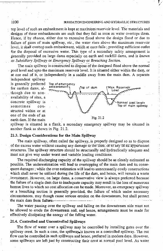
top level of such an embankment is kept at maxiniurn: reservoir level. The mateiials and designs of these embankments are suclJ. ·that they fail as soon as water overtops them. Hence, if by chance, either due to excessive flood above the design flood or due to failure of gates of main spillway, etc., the water rises above the maximum reservoir level, it shall overtop such embankment, which at onc.e fails ; providing sufficient outlet for the disposal of excessive water. This type of a secondary safety arrangement is generally provided on large dams especially on earth and rockfill dams, and is known as Subsidiary Spillway or Emergency Spillway or Breaching Section.
The main spillway is constructed to dispose of the designed flood above the normal . pool level and upto the maximum reservoir level. It is situated either within the dam, or
at one end of it, or independently in a saddle away from the main dam. A separate independent spillway is generally preferred for earthen dams, although due to nonavailability of sites, a concrete spillway is sometimes constructed within or at one of the ends of an earth dam. If the main Fig.21.2
spillway is situated in a flank, a secondary .emergency spillway may be situated in another flank as shown in Fig. 21.2.
21.3. Design Considerations for the Main Spillway
The main spillway, often called the spillway, is properly designed so as to dispose: ·· .. of the·excess water with·outcausing a:n:y-dal:Ilage t<Hhe·aa:m; oncfany of its··app~fteriant
structures. The spillway structure should be structurally an<:l hydraulically adequate and must not give way under worst a.nd variable loading conditions.
The required discharging capacity.of the spillway should be as closely estimated as possible. The underestimation will lead to overtopping of the main dam and its consequent damages ; while the over estimation will lead to unnecessarily costly constructions which shall never he utilised during the life of the dam, and hence, will remain a waste
. investment. However, on large dams, a conservative view is always preferred because · the failure of a single dam due to inadequate capacity may result in the loss of numerous human lives to which no cost allocation can be made. Moreover, an emergency spillway or a breaching section is generally provided,· the failure of which under necessary circumstances, may though cause serious erosibn on the downstream, but shall protect
~--lhe-mai-n-dam-from-failure-.-------------- ~ -~~,- -- ----- -- --________________ ____::.....:
The water passing over the spillway and falling on the downstream side must not be allowed to erode the downstream soil, and hence, arrangements must be made for effectively dissipating the energy of the falli~g water.
21.4. Controlled and Uncontrolled Spillways
The flow of water over a spillway may be controlled by installing gates over the spillway crest. In such a case, the spillway.is known as a controlled spillway. The out flow can be controlled in such spillways and hence, preferred in modern days. However, some spillways are left just by constructing their crest at normal pool level. As water

SPILLWAYS, ENERGY DISSIPATORS, AND SPILLWAY GA TES 1101
will flow over such a spillway, depending upon the reservoir level and the correspondirig head over the spillway, such uncontrolled spillways are guided only by the available water head, and hence, are called uncontrolled spillways. The comparative advantages and disadvantages of controlled and uncontrolled reservoirs have been discussed in chapter 18.
VARIO US TYPES OF SPILLWAYS
Depending upon the type of the structure constructed for disposing of the surplus water, the spillways can be of the following major types :
(1) Straight Drop Spillway. (2) Overflow Spillway generally called Ogee Spillway.
(3) Chute Spillway often called Trough Spillway or Open channel Spillway.
(4) Side Channel Spillway. (5) Shaft Spillway. (6) Syphon Spillway.
The various types of spillways enumerated above are described below along with the design details of 'Ogee Spillway' and 'Chute Spillway'.
21.5. Straight Drop Spillway or ·overfall Spillway
This is the simplest type of spillway and may/ be constructed on smal1 bunds or on thin arch dams, etc. It is a low weir and simple vertical fall type structure, as show11 in_ fig. 21.3. The downstream face of the structure may be kept vertical or slightly inclined. The crest is sometimes extended in the form of an overhanging lip, which keeps small discharges away from the face of the overfall section. The water falls freely from the crest under the action of
Free overfall
Serious erosion is caused here if no apron etc. is provided
Fig. 21.3. (a) Straight drop spillway without dis protection.
gravity. Since vacuum gets created"'in-i-he---un-derside-~-"---:-- - - - 0 - - -
. . . Werr wall or port10n of the fallmg Jet, sp"illway wall sufficient ventilation of the nappe is required in order to avoid pulsating and fluctuating effects of the jet. · The design of such a spillway is done as that of a weir which was explained in the chapter on
Fig. 21.3. (b) Straight drop spillway with dis protection works.

1102 IRRIGATION ENGINEERING ANO.HYQRAULIC'STRUCTU~S
weirs. Sometimes, a secondary dam of low height is constructed on the downstream side to create an artificial pool of water so as to dissipate the energy of the fal}ing water.
21.6. Ogee Spillway or Overflow Spillway
Ogee spillway is an improvement upon the 'free overfall spillway, and is widely used with concrete, masonry, arch and buttress dams. Such a spillway can be easily used on valleys where the width of the river is sufficient to provide the required crest length
Upper nappe
Fig. 21.4. (a) Section of an ogee spillway with vertical u/s face.
and the river bed below can be protected from scour at moderate costs. The profile of this spillway is made in accordance with the shape of the lower nappe of a free falling jet, over a duety ventilated sharp crested weir, as shown in Fig. 21.4 (a).
fig. :.d.4. (bJ Photoview of an Ogee1Spfil~ay of Amaravathi dam (earthem cum masonry dam) -- located on river Amaravathi (a tributary of river Cauvery)
in Coimbatore District in Tamil Nadu state.

---. --· -· ------ ~~"'=,....,,.,··= ..... ----
SPILLWAYS, ENERGY DISSIPATORS, AND SPILLWAY GA TES I 103
The shape of the lower nappe of freely falling jet over a sharp crested weir can be determined by the principle of projectile. It generally rises slightly (to point C) as it originates from the crest ( 0) of a sharp crested weir and then falls to make a parabolic form. Now, if the space between the sharp crested weir and the lower nappe is filled with concrete or masonry, the weir so formed will have a profile similar to an 'ogee' (S-shaped .curve in s~ction), and hence called an 'ogee weir' or an 'ogee spillway'. This lower nappe, will then become the crest of the spillway. Since the lower nappe of the free falling jet will be different for different heads over the crest of the sharp crested .weir, the profile of the ogee weir is generally confined to the lower nappe that would be obtained for maximum head over the spillway (i.e. upto the maximum reservoir level).
In a free overfall spillway, the water jet falls clearly away from the face of the spillway .. and the gap between the jet and the face is kept ventilated. While in an ogee spillway, the falling water glides over the curved profile of the spillway, and there is no M.W.L. space between water and crest · - - - -- - - - - - -
- - Designed head - --~"'-' of the spillway, under normal __ _._ ___ ---"--,.,...,.,~ ~
d". - - - - - - -0 .. ·, '(> --~~ . design con 1t10ns. "' . . . . . ·. ~
Normally, the upstream U/S Face of . · -. z. •. 4.' ~ .'· ·-~~\ face of the spillway is kept ver- spillway ; ;i • ••·. · ·;, ·; ·._ ~ · :. ~~' tic al and the crest shape con- · " ' - ' · · ... · firms to the lower nappe of a :: ·>·_:: _:.:_·:~._-·.;:: __ i'; t>'. ~/·;; vertical sharp crested weir . - _,. under maximum head. But if the
Crest of the spHlway
upstream_face of the spillway is _ kept sloping, the crest shap_e_ Fig. 21S Ogeespiilwaycwithcinclinedu/s-face:- -
should also confirm to the lower nappe that would be obtained for an inclined sharp crested weir (Fig. 21.5).
21.6.1. Cavitation. The crest of the ogee spillway can be made to confirm only to one particular nappe that would be obtained at one particular head. This head is called the designed head and represented by, say, Hd· But in practice, the actual head of water on the spillway crest, called the operating head, may be less or more than the designed head. If this operating head on the spillway is more than the designed head, the lower nappe of the falling jet may leave the ogee profile, thereby generating negative pressure at the point of separation. The generation of vacuum or negative pressure (i.e. pressure below the atmospheric pressure) may lead to formation of bubbles or cavities in the water.These cavities or bubbles_filled with air,_ vapour ll,nd ot)l.er ga,~es are formed in a __ _ liquid, whenever the absolute pressure (i.e. atmospheric pressure-vacuum pressure) of the liquid is close to its vapour pressure, so as to commence evaporation. Such a condition may arise when the head of water is more than the designed head and the consequent high velocity jet causes reduced pressures or negative pressures in the lower region of the water jet.
Such cavities, on moving downstream, may enter a region where the absolute pressure is much higher (i.e. more vacuum). This causes the vapour in the cavity to condense and return to liquid with a res~lting implosion or collapse of the cavity. When

1104 IRRIGATION ENGINEERING AND HYDRAULIC STRUCTURES
the cavity collapses, extremely high pressures are generated. The continuous bombardment of these implosions will thus take place near the surface of the spillway, causing fatigue failure of its material. The small particles of concrete or masonry are thus broken away, causing formation of pits on its surface and giving the surface. a spongy appearance. This damaging action of cavitation is called 'pitting': The cavitation plus the vibrations from the alternate making and breaking of contact between the water and face of the spillway, may thus result in serious structural damages to the spillway crest. Hence, it can be cpncllµ]ed that if the head of water over the spillway is more than the designed head, cavitation may occur. On the other hand, if the head of water over the spillway is less than the designed head, the falling jet would adhere to the crest of the ogee spillway, creating positive hydrostatic pressures and thereby reducing the discharge coefficient of the weir.
. e---, ~ .
~~
21.6.2. Designing the Crestof the Ogee Spillway. The ogee spill ways were I being designed in the earlier periods, in accordance with the theoretical profile obtained . i fTohr the !ow
11er nhappde of, a frefe falhling jet. The pr
1ofile was known, as Bazin's profilhe. ~·
eoretica y, t e a option o sue a profile, "shou d cause no negative pressures on t e crest under designed head. "But in practice, th.ere exists a lot of friction due to roughness t
.. on the surface of the spillway. Hence, negative pressure on such a profile seems inevitable. The presence of negative pressure causes the danger of cavitation and sometimes fluctuations and pulsations of the nappe. Hence, while adopting a profile for the spillway crest, the avoidance of negative pressures must be an objective along with consideration of other factors such as practicability, hydraulic efficiency, stability and economy. Depending upon research work based on these objectives, various modified
·profiles have been proposed these days.
Several standard ogee shapes have been developed by U.S. Army Corp$ .Qt BJl_:
gineers at their' Waterways Experimeniaf.Station (WES). Such shapes are known as 'WES .Standard Spillway Shapes': The dis profile can be represented by the equation
x"=K·H/- 1 ·y ... (21.1)
Slope of the u/sface of the spillway
Vertical
1 : 3 (IH: 3V)
1 : I-} (IH: 1-}V)
where (x, y) are the co-ordinates of the points on the • crest profile with the origin at the highest point C of the crest, called the apd.
Hd is the design head including the velocity head.
Kand n are constants depending upon the slope of the upstream face. The values of Kand n are tabulated in Table 21.1.
---·------~-.::.......-------------.-· -~--· -- -
Table 21.1
K n
2.0 1.85
1.936 1.836
1.939 1.810

SPILLWAYS, ENERGY DISSIPATORS,_AN'D SPILLWAY GA TES ll05
Vertical
b-i
Dis curve in accordance with eq·21-·2
I I
~Crest axis
I r,=0·5Hd r1 =0·2 Hd
, a=0-175 Hd b = 0·282Hd
I ' l-b--J r,=0·68 Hct ( r1 =0·21 Hd , a ·0·139Hd
b "0·237Hct
In accordance with eq. 21-1
( ~)
(ii)
Thus, for a spillway having a vertical u/s face, the dis crest is given by the equation
xl.85 = 2. ~.85. y ... (21.2)
Different upstream curves were given by WES for different slopes, as shown in Fig. 21.6.
According to the latest studies of U.S. Army Corps, the u/s curve of the ogee spillway having a vertical u/s face, should have the following equation:
0.724 (x + 0.27 Hd)!. 85
y= ~-85 +0.l26Hd
- 0.4315 ~-375 x (x + 0.27 Hd)0·625
... (21.3)
The u/s profile extends up to
x=-0.27 Hd
Co-ordinates for the upper nappe for various WES shapes of ogee spillway are also available and can be utilised in the design of training walls
-=-c.-=•-=-=-- --- -_ • an:a-·spillway bridge{etc:-:··--:. c -
(ii.'tl
Fig. 21.6. WES profiles for Ogee Spillways for different u/s slopes.
The profile for an ogee spillway, having a vertical upstream face, can be
·determined on the· basis of its WES profile, or Table 21.2 may be used for making the ogee profile.
Table 21.2. Table for marking Ogee profile
x' .. y
Hd Hd
LowerNappe UpperNappe
.;.0 ...... _ - ------ --- ·c_·_-_- QJ..22_ 0.831 0.10 -0.033 0.807 0.25 -0.000 0.763 0.50. -0.034 0.668 0.75 - 0.129 0.539 1.0 -0.283 C.373 1.5 -0.738 -0.088 2.0 -1.393 -0.743
3.0 - 3.303 -2.653
4.0 - 6.013 -5.363
5.0 -9.523 -8.873
1106
( , . . IRRIGATION ENGINEERING AND HYDRAULIC STRUC'fURES
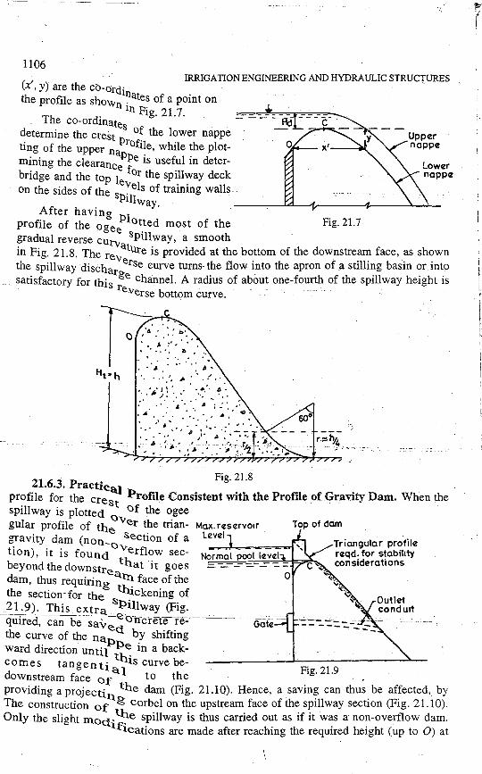
x, y) are the cb-ordi the profile as shown ~ates of a point on
in Pig 21 7 The co-ordinates · · · - - - - Ad"" - - - c:- ·
determine the crest .of the lower nappe ting of the upper nttofiJe, while the plotmining the clearanc Ppe is useful in deterbridge and the top le for the spillway deck on the sides of the s e:'els of training walls .
Pill way After having · ·
profile of the oge Plotted most of the Fig. 21.7 e Sp'lJ gradual reverse curv i way, a smooth ·
in Fig. 21. 8. The rev ature is provided at the bottom of the downstream face, as shown the spillway discha erse curve turns- the flow into the apron of a stilling basin or into satisfactory for this rge channel. A radius of about one-fourth of the spillway height is
reverse bottom curve. · · · -
Tr.·.~ . . ... . · . . j •• :· • .,; ,' .•
11 ::·;_:·.-..··:~·-t"' " . . . . . ', ,. ... ( ..
• ' 1r.,' Ii' • • • ~:- I>" <· _<·: > "·. ·.:·~ :·; -~: .·· ... · ... ...
21 6 3 P Fig. 21.8
• . . ractical . profile for the crest :Profile Consistent with the Profile of Gravity Dam. When the spillway is plotted Of the ogee gular profile of th Over the trian- Max. reservoir
gravity dam (non-e Section of a Level
tion), it is found Overflow sec- No_r_m_a,!-1 =p~oo~l=l,...ev~e=l-1 beyond the downstre that it goes dam, thus requiring a.~ face of the the section·for the thickening of
Gate
Triangular profile reqd. for stability considerations
-~!_-.9). This extra s~i~lw~~ (Fig. quired, can be sav Oncrete rethe curve of the na~cl b.y shifting ward direction until i~ in a backcomes tan gen ti h.1s curve be-downstream face Of a.1 to the Fig. 21.9 . . providing a projectill. the dam (Fig. 21.10). Hence, a _savin~ can thus. be af~ected, by The construction of g corbel on the upstream face of the spillway sect10n (Fig. 21.10). Only the slight mocJ.. 11:1e spillway is thus carried out as if it was a non-overflow dam.
lf1cations are made after reaching the required height (up to 0) at

~f ~~:
. . -
SPILLWAYS, ENERGY DISSIPATORS, AND SPILLWAY GATES 1107
which corbel is provided, and a smooth required curve OCA is given, as shown in Fig. 21.10.
If the spillway is provided with gates on the upstream face to control the flow in outlet conduits (Fig. 21.9), then the corbel will i11terfere with· gate -operation -and hence the above concrete saving cannot be affected.
The structural design and
Max. R.l.
Normal pool level
Projecting corbel
Triangular profile A reqd._ior s~abil"ity
... ,,. _ cons.1derat1ons I 0 '. " ·-I >- "· · .. : ~ I : ;.· : . ·>' I . ·',:.: . • .J:' "
. I . . . • : !
No concreting 1 • ".• : : , : , " •• done here ::.--1'" '. '. · 'I> , ; ,, --~ '.
I '" •. . . .. I , . . /$ • ', •• ~ .... • I>•' •
l <~·~--:--~:_.-~ .... ·.::~_: ..... stability requirements of ogee Fig. 21.10. Provision of Corbel. spillway are exactly the same as that of a gravity dam. The forces acting on a gravity dam also act _on the ogee spillway and remain predominant. The pressure exerted on the crest of the spillway by the flowing water and the drag force caused by the fluid-friction are usually negligible as compared to other forces which are acting on a gravity dam and also act on an ogee spillway'. Hence, the design and construction of the ogee spillway is consistent with that of the gravity dam. Due to this reason, the spillway is sometimes called overflow portion of the dam, and the real dam section is termed as non-overflow section of the dam.
However, the change in momentum of the flow in the vicinity of the reverse curve may create a dynamic force on the spillway, in addition to the forces acting on the gi;avity dam. This force must be considered in designing bottom of the d/s face of spillway or the bucket type energy dissipator. This is dealt separately while discussing the design of energy dissipators for the spillways.
21.6.4. Discliarge Formula for the Ogee Spillway. The discharge passing over the ogee spillway is given by the equation :
Fig. 21.11
Q= C ·L H312 e e ... (21.4)
where Q = Discharge Le= Effective length of the spillway crest
1108 IRRIGATION ENGINEERING AND HYDRAULIC STRUCTURES
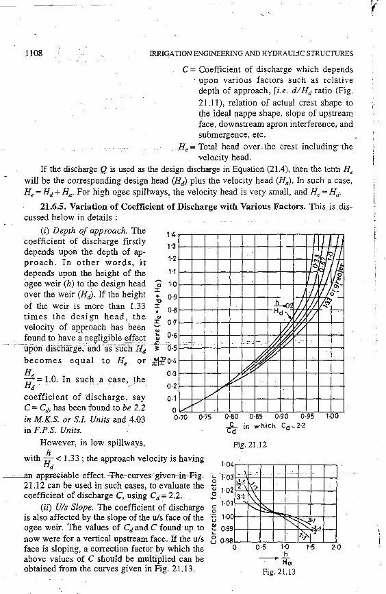
C = Coefficient of discharge which depends · upon various factors such as relative
depth ofapproach, [i.e. d/Hd ratio (Fig. 21.11), relation of actual crest shape to the ideal nappe shape, slope of upstream face, downstream apron interference, and submergence, etc.
H;, = Total head over the crest including the velocity head.
If the discharge Q is used as the design discharge in Equation (21.4), then the term He will be the corresponding design head (Hd) plus the velocity head (Ha). In such a case, He= Hd +Ha. For high ogee spillways, the velocity head is very small, and He""' Hd.
21.6.5. Variation of Coefficient of Discharge with Various Factors, This is discussed below in details :
(i) Depth of approach. The coefficient of discharge firstly depends upo~ the depth of approach. In other words, it depends upon the height of the
1·3
1·2
1 ·1
ogee weir (h) to the design head c 1·0 :c:
over the weir (Hd). If the height + 0-9
of the weir is more than 1.33 ? 0.8 times the design head, the ..,
:c: 0·7 velocity of approach has been .., found to have a neglig~ble effect i ~-6
- -~- -'upon discliarge;· a:nd-as-s-ucli H'd·- ~--(5-5
becomes equal to He or ~:i'0·4
He 0·3
Hd = 1.0. In such a case, )he
0·2
0.1
0 / /
.. ·-·--
~ ~,
v'
I I I
111j "> .... Jo . :; I I I J g
o,-
I !1//~" .h..=-0-, I) VJJ j:j_l -Hd.~ '//, 'l -~ V/
-I~ w ~ ~ ~
coefficient of 'discharge, say C =Cd, has been found to be 2.2 in M.K.S. or S.J. Units and 4.03 in F.P.S. Units.
0·70 0·75 0·80 0·85 Q.90 0·95 1-00 fer in which Cd; 2·2
However, in low spillways, Fig. 21.12
with Hh < 1.33 ; the approach velocity is having d 1·04 r--,---r--.-.-...--.---,,---,
-~· -· an-appreciable-effeet,-'Fhe-eurves"·given-'in-'-Fig.--'c·'1. 03r.-.-..-+---+--+---+-+---+---i
21.12 can be used in such cases, to evaluate the ~ 1_021-
12_:1-'t-'l-+---+-+---+--+---t--i
coefficient of discharge C, using Cd= 2.2. 2 3:1
(ii) Uls Slope. The coefficient of discharge § 1 ·0l!--'"k:-'~-+-.....,--1--+--+--1
is also affected by the slope of the u/s face of the ~ 1·00f--t--+--+~~b-~-+-I ogee weir. The values of Cd and C found up to ~ 0·99i---+--+---+---+--..,
now were for a vertical upstream face. If the u/s S 0·98~......__.__..__,_.._-+-_.__.. face is sloping, a correction factor by which the O 0·5 1~ above values of C should be multiplied can be - Ho
obtained from the curves given in Fig. 2L13. Fig. 21.13
2·0

SPILLWAYS, ENERGY DISSIPATORS, AND SPILLWAY GATES 1109
. (iii) Dis apron inter- __ --~-------------:---T-------ference and submergence ef- =-~ _ =- ~ _-= _ . fects. The third important - He - H - - - · hd
factor affecting the discharge _:__ 1. _ t _ . · . : coefficientofanogeeweiris l K _ -_ -:._-_-_'-_-_ the effect of downstream . . h d Tail water
. I depth apron rn te r fer enc e and t ...,..."7"7"~~,..t77""~..,-;,,,.,,., downstream submergence. 77//77 i /; 77/~ > 7,,,; // , / ;;;;77., >,, ;o;
When the tail water Fig. 21.14. Maximum tail water depth 1
..
for a non~submerged weir. level is such that the top of the weir is covered by it, such that the weir cannot discharge freely ; the weir is then said to be a submerged weir.
Where the hydraulic jump occurs, the coefficient of discharge may decrease due to back pressure effect of the downstream apron and is independent of the submergence
. hd+d effect. When the value of~ (Fig. 21.15) exceeds 1.7, the downstream apron is found
e
to have negligible effect on the coefficient of discharge. But there may be a decrease in the coefficient due to tail water submergence. The correction factor, by which the value of C should be multiplied in order to get the modified or correct value of coefficient of discharge, can.be obtained from the curve of Fig. 21.15.
1·0 -----/
,,,... I /
~· / -
I ..
.. J_ ---- -- -"-
' rh r Tail water
I . dePth,d , .
,
0·8
0·6
0·4
I -~~
I 0·2
0 0·1 0·2 0·3 0·4 0·5 0·6 O'l 0·8 0·9
Degree of submQ.rgence, hct_ d
Fig. 21.15. Effect of submergence on C.
21.6.6. EffectS of A.dual PrevailingKeaa on tlieJ)jsenargeCapacity-of_a_· -Spillway. It was pointed out earlier that when once a spillway has been designed and constructed for a design head (Hd), and for a corresponding coefficient of discharge (say C), it will not always find the same head over its crest in its actual operations. The actual operating head (H) ii c velocity head, may be less or more than the designed head. Since the design is done for maximum head, the possibility of a head more than the designed head is very meagre. When the actual" operating head passing over the spillway is 'less than the designed head, the prevailing coefficient of discharge (Cd) tends to reduce, and is given by the equation 1-
1

1110 IRRIGATION ENGINEERING AND HYDRAULIC STRUCTURES
.c,~c (J:.)°12
... (21.5)
where He is the designed head including velocity head.
Since an overflow spillway is sufficient in height (i.e h.> 1.33 Hd) ; the coefficient of discharge C at designed head can· be taken as. 2.2. The prevailing coefficient of discharge at 50%
1 head (ii c velocity head) will then be . ~ ·
0.5 He . . . ( J
0.12 .
. Cd=2.2x ~· . =2.2x0.92=2.02. .
Similarly, for still lower heads, the coefficient of discharge goes on reducing and tend~ to become constant at about 1.7. (Because at very low heads, the velocity head becomes the governing factor, which tries to make H a constant).
Theeffective length (Le) of ogee spillway.
The effective length of the spillway crest (Le) to be used in equation (21.4), is-given by the equation.
O·+Ho t Blunt nose square pier, Cp=O·~
0·267Hd
Square pier with corners rounded Cp=0·02
90° Cut water Nose pier, Cp:: 0·01
~0...-..\.. o'?/'" ------..--~-1 "(' .
......_ ___ __.._--l ers.
Le=L-2[K ·N+K]H P a e ... (21.6)
where L = the net clear length of the spillway crest KP = Pier constraction coefficient
Ka= Abutmen( c.ontraction coefficient
N = Number of piers He= Total design head on the crest including
velocity head. _ ..
The values of KP and Ka depend mainl)'. upon the shape of the piers and tha.t of the abutments. The greater is the divergence from streamlined flow, the greater is the constraction coefficient and lesser is the effective length of the crest. A 90° cut water nose pier is most efficient and has quite a low value of Ifp• and is generally preferred. Values of KP and Ka are given in Tables 21.3 and 21.4. Various shapes of piers are shown in Fig. 21.16 .
Pointed nose pier Cp=0-08 -· -Hg:-'2tt6-:-Yarioussnapesorpfers-: -~ -~ -'I'able 21.3
S.No.
1.
2.
3.
4.
Pier Shape
Square nosed piers without any rounding
Square nosed piers with comers rounded on radius equal to 0.1 of pier thickness
Rounded nose piers and 90° cut water nosed piers
Pointed nose piers
Contraction coefficient Kp
0.1
0.02
0.01
0.0

SPILLWAYS, ENERGY DISSIPATORS, AND SPILLWAY GATES
Table 21.4
S.No.
I.
2.
Shape of abutment
Square abutment with head wall at 90° to the direction of flow
Rounded abutment with head wall at 90° to the direction of flow
Contraction coefficient Ka
0.2
0.1
--···"~
llll
21.6.7. Aeration Arrangements in Gated Ogee Spillways. The entire design of an overflow spillway has been done with the assumption that upper and lower nappe are subjected to full atmospheric pressure. But in practice; due to insufficient aeration, development of negative pressures takes place beneath-the nappe due to removal of air by the falling jet. The development of negative pressures causes the danger of cavitation and induces fluctuation and pulsation effects on the jet, which may be very objectionable if the spillway is to be used as a discharge measuring device.
To control the development of negative pressures, aeration pipes 25 mm dia at say 3 m centre to centre may be provided along spillway face below the gate lip. These pipes can be connected to a bigger sized header. Formulas have been developed on the basis of model studies, for evaluating the amount of air required for aeration, and may have. to be used in large dam designs, but are beyond the scope of this book.
Example 21.1. Design a suitable section for the overflow portion of a concrete gravity dam having the downstream face sloping at a slope of 0.7 H: 1 V. The design discharge for the spillway is 8,000 cumecs. The height of the spillway crest is kept at RL 204.0 m. The average river bed level at the site is 100.0 m. The spillway length consists of 6 spans having a clear width of 10 m each. Thickness of each pier may be -taken to be 2.5 m.
Solution. Since the given spillway looks like a high weir, the coefficient of discharge may be assumed to be 2.2.
or
or
Now Q -= C. L H312 e e
where Le = L - 2 [N KP + Ka] He
Let us first work out the approximate value of He for a value of
Le= L =clear waterway= 6 x 10 =.60 m.
8,000 = 2.2 x 60 H~12
H312 = . 8,000 60:6 e 2.2 X 60
. 2/3 He= (60.6) = 15.5 m.
The height of the spillway above the river bed (see Fig. 21.15)
= h = 204 '- 100 = 104.0 m
S. h . 104 1 33 mce H/ z.e. lS.5 > . ,

1112 IRRIGATION ENGINEERING AND HYDRAULIC STRUCT:URES
it is a high spillway, the effect of velocity head can, therefore, be. neglected. hd+d He+h 15.5+ 104
Since ~=~ 15.5 > 1.7;
the discharge coefficient is not affected by fail water. conditions, and the spillway remains a high spillway.
Vis Slope. The upstream face of the dam and spillway is proposed to be kept · vertical. However, a batter of 1 : 10 will be provided from stability considerations in the lower part. This batter is small and will not have any effect on the coefficient of discharge.
Effective length of spillway (Le) can now be worked out as
Le=L-2 [N.Kp +Ka] He
Assuming that 90° cut water nose piers and rounded abutments shall be provided, we have
and Kp=0.01
Ka=O.l No. of piers= N = 5.
Also assuming that the actual value of He is slightly more than the approximate value worked out (i.e. 15.5 m), say, let it be 16.3 m, we have
or
or
or
. . Le= 60- 2 [5 X 0.01+0.1] X 16.3 = 55.1 m.
Hence Q = 2.2 x 55.1 x H;12
8,000 = 2.2 x 55.1 x Ii;12
H312 = · 8,000 _ 66 O e 2.2X 55.1 ·
He= (66.0)213 = 16.4 m = 16.3 (assumed)
H~nce,. the assumed He for calculating. Le is all right. The crest profile will be designed for Hd = ~6.4 m (neglecting velocity head).
Note. The velocity head (HJ can also be calculated as follows :
'' 1 .t f h V 8,000 ye oc1 yo approac = a= (60 + 5 x 2.5)(104 + 16.4)
= n.;~~0.4 =0.917m/sec.
---------~. --- ---~-~ ¥~-'- (0;917)2
Ha= Velocity Head"'.:. 2g = 2 x
9.81
= 0.043 m.
This is very small and was, therefore, neglected.
Downstream profile. The W.E.S. dis profile for a vertical u/s face is _g_iven by equation (21.2) as : ·
xl.85 = 2 . lf,;35 . y xl.85 xl.85
or y= 2 (HJiJ.85 2 x (l.64)0.85

SPILLWAYS, ENERGY DISSIPATORS, AND SPILLWAY GATES 1113
xl.85
or y = 2 x 10.8
or ... (21. 7)
Before we determine the various co-ordinates of the dis profile, we shall first determine the tangent point.
or
or
The dis slope of the dam is given to be 0. 7 H : 1 V.
::!1_ _ _ 1 dx - 0.7 Hence,
Differentiating the equation of the dis profile w.r. to x, we get
::!l_ l.85xl.85 - I 1 dx=~-=o.7
X0.85 = 21.6 - = 16.7 1.85 x 0.7
x=22.4m. (22.4)1.85
y = 2
1.6
= 14.6 m.
The co-ordinates from x = 'O to x = 22.4 mare worked out in Table 21.5.
x metres
Table 21.5
XJ.85
y = 21
.6
metres
0.046
2 0.166
3 0.354
4 ~~
5 - 0.905
6 1.274-
7 1.710
8 2.162
9 2.684
10 3.240
12 4.575
14 6.020 ------------ -- -------- --- --'-16- ________ , ___ _:__:__; ___ - --9-;-s-s----C----'---'---"-_:__:___=--------
18 9.74
20 11.85
n 14.35
22.4 14.60
The u/s profile. The u/s profile may be designed as per equation (21.3), as :

1114 IRRIGATION ENGINEERING AND HYDRAULIC STRUCTURES
0 724 (x + 0 27 H )1.85 .·. Y = . IIJ·~5 d + 0.126 Hd - 0.4315 IIJ.375 (x + 0.27 Hd)°· 625
Using Hd = 16.4 m, we get
= 0.724 [x+ 0.27 x 16.4]1·85+ 0. 126 (1 6.4)
y (16.4)°·85 .
- 0.4315 (16.4)0.375 (x + 0.27 x 16.4)°·625
or y = 0.07 (x + 4.44)1-85 + 2.07 - 1.234 (x + 4.432)0·625 ... (21.8)
This curve should go upto x = - 0.27 Hd
or x = - 0.27 x 16.4 = - 4.443 m. Various values of x such as, x=-0..5,x=-l.O,x=-2.0, x=-3.0,x=-4.0,
x = - 4.443 are substituted in equation (21.8) arid corresponding values of y are worked out, as given below in Table 21.6.
··Table 21.6
x in metres yin metres
-0.5 0.020
-1.0 0:063
-2.0 0.27
-3.0 0.65
-4.0 1.34
-4.443 2.07.
Z·07;;~t-- · 1-x Y .--Tangent pt.
(22-4.14·8)
4·443
1:10
~ ' ~Axis of i ,prnway
Fig. 21.17 -
The profile of the spillway has been determined and plotted in Fig. 21.17. A reverse
curve at the toe with a radius equal to 1 = ~~4 = 26 m can be drawn at angle 60°, as
shown in Fig. 21.17. Aeration pipes (say 25 mm pipes at 3 m c/c) can be installed along I the spillway face below the gate lip, so as to prevent the development of negative
Ill pressures. The energy dissipation arrangements have not been shown. They should be 11 designed depending upon the position of the jump height curve and tail water curve, as
explained afterwards. A sky jump bucket or an apron may be provided as per the · prevailing conditions.
21.7. Chute Spillway or the Trough Spillway -·----~Kn~o_:ge-e_:__sl)-fltway-is-moStly-suitabI-e-iot-c-on-ctete--gravity-da:m.g-espeei-ally--whe-n- -the
spillway is located within the dam body in the same valley. But for earthen and rockfill dams, a separate spillway is generally constructed in a flank or a saddle, away from the main valley, as explained earlier. Sometimes, even for gravity dams, a separate spillway is required because of the narrowness of the main valley. In all such circumstances, a separate spillway may have to be provided. The Trough Spillway or Chute Spillway is
. the sim~lest type of a spillway which can be easily provided independently and at low costs. It is lighter and adaptable to any type of foundations ; and hence provided easily on earth and rockfill dams. A chute spillway is sometimes known as a waste weir. If it

SPILLWAYS, ENERGY DISSIPATORS, AND SPILLWAY GATES 1115
is constructed in continuation to the dam at one end, it may be called a flank weir. If it is constructed in a natural saddle in a bank of the river separated from the main dam by a high ridge, it is called a saddle weir.
A chute spillway (Fig. 21.18) essentially consists of a steeply sloping open channel, placed along a dam abutment or through a flank or a saddle. It leads the water from the reservoir to the downstream channel below. The base for the channel is usually made of reinforced concrete slabs, 25 to 50 cm thick. Light reinfor
= =-=o/s River channel= =: .:::- .:::
Fig. 21.18 (a). Simplified Line sketch of a Chute Spillway.
cement of about 0.25% of the concrete area is provided in the top of the slabs in both directions. The chute is sometimes of constant width, but is usually narrowed for economy and then widened near the end to reduce the discharging velocity. Expansion joints are usually provided in the chute at intervals of about 10 metres in either direction. The expansion joints should be made watertight so as to avoid any under-seepage and its troublesome effects. Under-drains are also provided, so as to drain the water which may seep through the trough bottom and side walls. These under-drains may be in the form of perforated steel pipes, clay tiles or rock-filled trenches.
If the slope of the chute can confinl1 to available topography' the excavatiohnliall be minimum. But the slope of the chute must be high enough, and should atleast be able to maintain super critical flow, to avoid unstable flow conditions.
F~g. 2L8. (b) Photoview of the Chute Spillway of Anderson Ranch Dam, Idaho (USA).

1116 IRRIGATION ENGINEERING AND HYDRAULIC ST.RUCTURES
Fig. 21.!8: (c) Photoview of two chutes provided at Bhakra Dam (India).
Normal pool level (full reservoir level)
Tile dra·ins surrounded by gravel
Fig. 21.18. (d) Section through a Chute Spillway.
When a vertical curve is provided at a point where the chute slope changes, it must be gradual and designed so as to avoid any separation of flow.
21.7.1. Control Structure or a Low Ogee Weir. Since the trough spillway is provided in a flank or a saddle, the height of spillway or ogee weir reqmred to be constructed in that flank, will be small ; sometimes almost flat low weir shall be required. depending on the natural levels of the bottom of the flank. If the flank bottom is at a level lower than the natural pool level, an ogee weir shall have to be constructed upto that level. If the flank bottom is at higher level than the normal pool level, excavations
- ----Wi-11-ha:v:e to be done upto that level. In such a case, the weir crest is normally_l~ft flat as it shall seldom be economical to excavate the rock just for the sake of constructing 9n 'ogee shape' for obtaining high coefficient of discharge.
21.7.2. Chute Slope. The water spilling over the control structure (i.e. ogee weir), then flows through the chute channel. The minimum slope of the chute is governed by
·the condition that supercritical flow must be maintained. The slope of the chute is. kept just sufficient to meet this flow requirement ·from the crest for as long a distance as possible without any filling. After that, the slope is made as steep as possible without endangering the stability or without getting into heavy excavations.
<;PILL WAYS, ENERGY DISS IP A TORS, AND SPILLWAY GA TES 1117
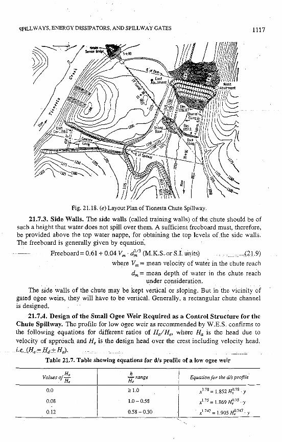
Fig. 21.18. (e) Layout Plan of Tionesta Chute Spillway.
21.7.3. Side Walls. The side walls (called training walls) of the chute should be of such a height that water does not spill over them. A sufficient freeboard must, therefore, be provided above the top water nappe, for obtaining the top levels of .the side walls. The freeboard is generally given by equation,
Freeboard= 0.61+0.04Vm · d~3-(M.K.S. or S.I~ units) _ cc·-(21.9)
where Vm = mean velocity of wate~ in the chute reach
dm = mean depth of water in the chute reach under consideration.
The side walls of the chute may be kept vertical or sloping. But in the vicinity of gated ogee weirs, they will have to be vertical. Generally, a rectangular chute channel is designed.
21.7.4. Design of the Small Ogee Weir Required as a Control Structure for the Chute Spillway. The profile for low ogee weir as recommended by W.E.S. confirms to the following equations for different ratios of Haf He, where Ha is the head due to velocity of approach and He is the design head over the crest including velocity head,
. _ ___Le~_(H_e = Hd.+. Ha)·
Table 21.7. Table showing equations for dis profile of a low ogee weir
0.0
0.08
0.12
h ·H, range
~ 1.0
1.0- 0.58
0.58 - 0.30
Equation for the dis profile
xl.78 = 1.852 H,l.78. y
xl.75 = 1.869 H,J.75. y
xl.747 = 1.905 H,J.747. y
'' '
i ~ i
i·'i' 11,,! \'I'
l11'
1
,
1118 JRRIGA TION ENGINEERING AND HYDRAULIC STRUCTURES
vel head Ha-~-~-
h
D/S Profile ;1 I I
I I I Ir =-2He
/ I I
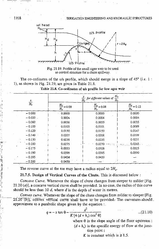
Fig. 21.19. Profile ofihe small ogee weir to be used as control structure for a chute spillway.
The co-ordinates of the u/s profile, which should merge in a slope of 45° (i.e. 1 : 1), as shown in Fig. 21.19, are given in Table 21.8.
Table 21.8. Co-ordinates of u/s profile for low ogee weir
_l_ Ha for different values of H
x He e He
~: =0.00 Ha =008 Ha =012 He . He .
-0.000 0.0000 0.0000 0.0000
-0.020 0.0004 0.0004 0.0004
-0.060 0.0036 0.0035 0.0035 -0.100 0.0103 0.0101 0.0099 -0.120 0.0150 0.·0150 0.0147
- 0.140 0.0207 0.0208 0.0199 - 0.150 0.0239 0.0235 0.0231 - 0.160 0.0275 - 0;0270 -· 0,0265 -0.175 0.0"333 0.0328 0.0325
-0.190 0.0~99 0.0395 0.0390
-0.195 0.0424 0.0420 --0.200 0.0450 - -
The reverse curve at the toe may have a radius equal to 2H •.
21.7.5. Design of Vertical Curves of the Chute. This is discussed below :
Concave Curve. Whenever the slope of chute changes from steeper to milder [Fig. 21.20 (a)], a concave vertical curve shall be provided. In no case, the radius of this curve should be less than 10 d, where d is the depth of water in metres.
',J{ . Convex curve. Whenever the slope of the chute changes from milder to sleeper [Fig. ·~r~~.2T:-10""-:-(b-·)l, convex vertica:i-cutve-shan··have-1oc he~provitled.-+he-Gur-vature~-should._ : ,', approximate to a parabolic shape given by the equation : . 111:'11 i2 · q=-xtane--------- ... (21.10)
I I
I I
K [4 (d + hv) cos2 9] where e is the slope angle of the floor upstream ; (d + hv) is the specific energy of flow at the junc
tion point ,; K is constant which is ;;:: 1.5.

SPILLWAYS, ENERGY DISSIPA TORS, AND SPILLWAY GA TES 1119
I Min.radius=100
Fig. 21.20 (a). Concave Vertical Curve. ' : Junc1ion poin1 _ -(1 :SI
'77'"77-7'7"~777777..,,.,.'l'".>-:;:- - - - - - - - - - - - --X
Y-axis
Fig. 21.20 (b). Convex Vertical Curve.
21.7.6. Approach Channel of Chute Spillway. An entrance channel called an approach channel, trapezoidal" in shape with side slopes 1 : 1, may be constructed so as to lead the reservoir water up to the control structure (low ogee weir). If any curvature (in plan) is required, it is generally confined to the entrance channel, because the velocity
-oCflow-is low 1n= Uiis clfanneL The chute=channel,caHed"the:cdischarge=charrnel ordischarge carrier is generally kept straight in plan. If, however, any curvature is required to be provided, its floor should be super elevated to guide the high velocity flow around the bend, thus avoiding piling up of flow towards the outside of the chute. The friction
~
head lost in the entrance channel upto the spillway crest can be calculateci by Manning's formula, given as :
n2 · V2
· L h1= s1 x L = 413 ... (21.11)
R where n =Manning's coefficient of roughness
V= Velocity in channel R = Hydraulic mean depth
__ ---------~ __ _ L = Length of channel ----5;;--:Meari- energy slopeb~tween two pomts.
The entire chute spillway can hence be divided into the following parts :
(i) Entrance channel
(ii) Control structure (Low Ogee weir)
(iii) Chute channel or Discharge carrier
· (iv) Energy dissipation arrangements at the bottom in the form of a stilling basin.

1120 IRRIGATION ENGINEERING AND HYDRAULIC STRUCTURES
The design prinCiples for the various components have already been explained except those for energy dissipation. The energy dissipation arrangements required at the bottom of the spillway shall be explained a little later.
Example 21.2. Design a suitable profile for a chute spillway with the following data : Spillway crest level = 200.0 m Level of bottom of flank at which the low
·agee weir is to be constructed = 192.0 m Design discharge = 5,000 cumecs. Downstream tail water level corresponding to 5,000 ·cumecs = J-03.0 m.
The spillway length consists of 5 spans of 10.0 m clear width each. The thickness of each spillway pier may be assumed to be 3 m. Assume any other data required.
/ Solution. Design of approach channel :
Q = C · Le H;12.
Assume the coefficient of discharge as-2.18, and taking Le as the clear width (approximately)= 10 x 5 = 50 m: and assuming He = H
we get 5,000= 2.18 (50) H312
or H312
= u.~~ )= 45.S m.
or H = (4S.8)0·667 = 12.8 m.
Upstream water level =Crest level+ H = 200 + 12.8 = 212.8 m.
Bed level of river in flank= 192.0 :. Water depth= 212.8- 19:2~0-=-20.Sm. _ _ _____ _ Assuming the trapezoidal approach channel with 1 : 1 side slopes,
The width of the channel = B =Total length of spillway= 50 + 4 x 3 = 62 m.
Area of channel =A= (B + y) y = (62 + 20.8) 20.8 = 1,720 sq. m.
Velocity of approach= Va= i:~~~ = 2.9 m/sec
v~ (2.9)2
Velocity Head =Ha= 2g =
2 x
9.81
= 0.43 m.
The wetted perimeter P of the channel = [B + 2 ..fl" (water depth)]
·· '=f62+2-n-:x-20.8]=~62 +58.8) = l~Q,81Il. ____ _ A 1,720
R =-p = 120.8 =14.2m.
Assuming the length of the channel to be 160 m ; the head loss due to friction upto the spillway crest, is given by Manning's formula, as :
n2V2L h1= R413 (assume n =Manning's rugosity Coefficient= 0.019)
h = co.019)2
x c2.9)2
x 160 = 0.016 n1. f (14.2)1.33
SPILLWAYS, ENERGY DISSIPATORS, AND SPILLWAY GATES 1121
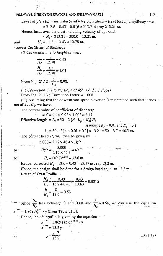
Level of u/s TEL = u/s water level+ Velocity Head - Head lost up to spillway crest
= 212.8 + 0.43 -0.016 = 213.214; say 213.21 m. Hence, head over the crest including velocity of approach
=He =213.21-200.0= 13.21 m.
and Hd= 13.21- 0.43=12.78 m. Correct Coefficient of Discharge
(i) Cqrrection .due to height of weir, h 8
Hd = 12.78 = 0·63
He= 13.21 = l 03 Hd 12.78 .
From Fig. 21.12 ; ~ = 0.98.
(ii) Correction due to u!s slope of 45° (i.e. 1 ." 1 slope) From Fig. 21.13; Correction factor= 1.008. (iii) Assuming that the downstream apron elevation is maintained such that it does
not affect Cd, we have, ·
The correct value of coefficient of discharge = C = 2.2 X 0.98 X 1.008 =rl.17
Effective length =Le= 50 - 2 [N · KP+ Kal He assuming KP= 0.01andKa=0.1
Le= 50-2 [4 X 0.01+0.1] X 13.21=50-3.7 =46.3 m.
The correct head He will then be given by
5,000= 2.l 7x 46.4 x H~12
! or H312 = 5,ooo- -= 49 7 I e 2.11x46.3 ·
f or He= (49.7)0·667 =13.6 m.
f
Hence, correctedHd= 13.6-0.43= 13.17m; say q.2m.
· Hence, the design shall be done for a design head equal to 13.2 m. ·. Design of Crest Profile f I ~ Q~ O~ . I 1:: 1~.2+0.43 = 13.63 =
0·031
'
He = 13.6 = 0.58
! H · h r----since-H: lies-between-0-·and _0.08 and He= 0.58, we c_an use the equation
t x1.75 = 1.869 ~-75 · y (from Table 21.7}.
or
01
Hence, the d/s p:rofile is given by the equation xl.75 = 1.869 (13.(13)0·75 · y XJ.75 = 13.2 y .
xl.75
y = 13.2 ... (21.12)
1122 IRRIGATION ENGINEERING AND HYDRAULIC STRUCTURES
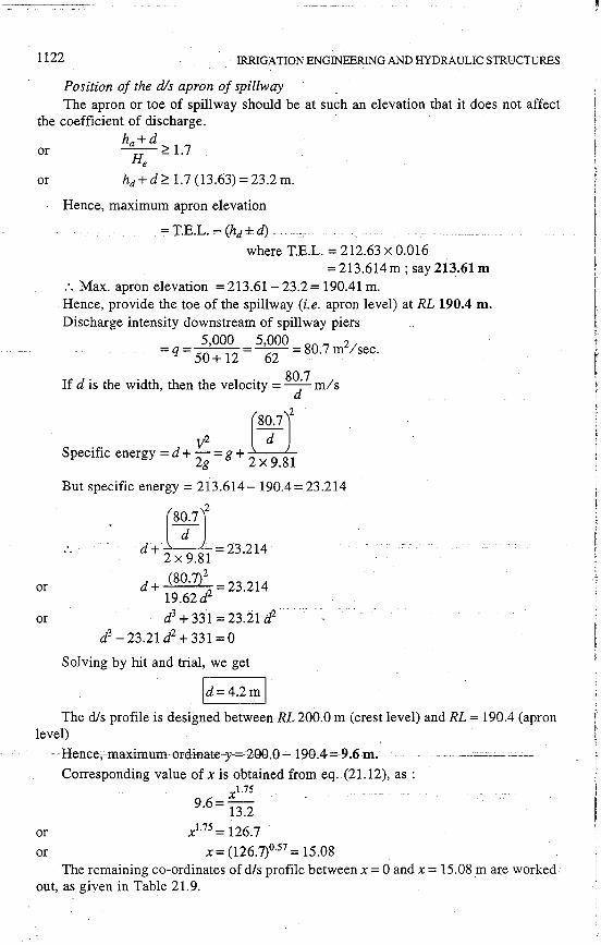
Position of the dis apron of spillway The apron or toe of spillway should be at such an elevation that it does not affect
the coefficient of discharge. · ha+d
or ~;:::1.7 e
or hd + d;::: 1.7 (13.63) = 23.2 m.
or
or
Hence, maximum apron elevation
= T.E.L. ,... (hd + d)
where T.E.L. = 212.63 x 0.016 =213.614m; say 213.61m
:. Max. apron elevation = 213.61- 23.2 = 190.41 m. Hence, provide the toe of the spillway (i.e. apron level) at RL 190.4 m. Discharge intensity downstream of spillway piers
5,000 5,000 2 =q= 50 + 12 =~=80.7m /sec.
If dis the width, then the velocity= 8~ 7
m/s
7 EI v2 Specific energy= d +
2g = g +
2 x
9_81
But specific energy= 213.614- 190.4 = 23.214
(8~7J _ d+
2x
9_81
-23.214
d + (30.7)2
23.214 19.62d2
d3 + 331=23.21 d2
d3 - 23.21d2 +331=0
Solving by hit and trial, we get
id=4.2m I The dis profile is designed between RL 200.0 m (crest level) and RL = 190.4 (apron
level) ----Henee,maximum~ordinate-y-=200,0-1-90.4-=9.6-m.------· --
Corresponding value of xis obtained from eq. (21.12), as : xl.75
9·6 = 13.2
or or
xl.75 = 126.7
x= (126.7)057 =15.08 The remaining co-ordinates of d/s profile between x = 0 and x = 15.08 m are worked·
out, as given in Table 21.9.

SPILLWAYS, .ENERGY DISSIPATORS, AND SPILLWAY GATES
Table 21.9. Coordinates of dis Profile
x in metres xl.75 .
y = 13.2 in metres
0 0
0.5 0.023
1.0 0.077
2.0 0.25
4.0 0.86
6.0 .. . ·l:74---·- ...
8.0 2.88
10.0 4.03
12.0 5.84
14.0 7.9
15.08 9.6
T.he co-ordinates of the u/s profile are calculated in Table 21.10~ Table 21.10. Co-ordinates of u/s Profile
He=13.61m
x y H, H,
x
-0.000 0.0000 0
-0.020 0.0004 -0.272
-0.060 0.0035 - 0.817
- 0.100 0.0101 -1.361
-0.120 0.0150 - 1.633 --------- ··;..;0:140· ------ . ··· ---0:0108 · -L905
- 0.150 0.0235 -2.042
-0.160 0.0270 - 2.178
- 0.175 0.0328 -2.382 - .
- 0.190 0.0395 -2.586
-0.200 0.0420 -2.722
1123
y
0
0.0054
0.0476
0.1375
0.2042
0..2831 . .. -- --
0.3198
0.3675
0.4464
0.5375
0.5716
The u/s crest is joined at an angle of 45° to the bottom, as shown in Fig. 21.21.
Design of the Chute or Discharge Carrier
The critical depth Ye=~ =-4\/..-(-~0-.S-~~2-= 8.77 m.
·---'fh.ecdepth-aHhe.ctop.cof'cspiU-way-=(d}-was-calculated to_beA-.2m,c.whkh is. less than Ye· Hence, the fl.ow at the top of the spillway. is supercritical.
The chute cha~nel or the discbarge carrier should now be given a milder slope for a little dis.tance from toe, but in no case less than the critical slope, so that the flow remains super-critical.
Critical velocity = Ve = ~ = :~~ = 9 .18 m/ sec.

1124 IRRIGATION ENGINEERING AND HYDRAULIC STRUCTURES
But
A rectangular channel with bottom width 62 m should be provided as the chute channel (discharge carrier) for the chute spillway.
or
or
At critical flow, A = 62 x 8]7 P=62+8.77x2
R = :1_p = (6
62 x 8.77 . 6_82 2+8.77x2)
Critical slope Sc !s-, therefore, given as :
1 ~ 1/2 9 .18 = O.Ol 9 (6.82)3 ·Sc
s 1/2 = 9.18 x 0.019 = 9.18 x 0.019 =_l_ c (6.82)213 3.61 20.7
-- 1 -Sc= 428
--A slope of say 11250 is provided in 25 m distance from the top of the spillway.
1 - 25 Bed level at the end of
250 slope = 190.4 -
250 = 190.3 m.
The reverse curve at toe may have a radius equal to 2He = 2 x 13.63 = 27.22 m; say 27.5 m.
From this point onwards, .i.e. RL = 190.3 m and upto RL 103.0 m, the slope of the discharge carrier may be steepened depending upon the site contours. A slope such a,s 8 : 1 to 4 : 1 may be given in the initial stage and then a steeper slope of say 2 : 1 or 3 : 1 may be given. The entire design is now like that of a rectangular channel. Wherever,
·the slope is changed, transition curve (convex or concave) may be designed as explained earlier. _,_ - ----- - . "--~- - . -- -
In the given question, since the site contours are not known, we shall assume that a slope of 6 : 1 is given for the first 21 m fall (i.e. up a RL 169.3) and then a slope of say 2 : 1 is given for the rest of the reach. The depth; velocity, etc. at the end point of l in 250 slope may be taken to be the same, as they were at the toe of the spillway, because the small length of 25 m shall not produce much difference. With this assumption, the TEL at the starting point of new slope 6 : 1 (RL =: 190.3) is equal to 213.21- 0.1=213.11 m.
The calculations -of water depth, velocity, etc. can now be carried out for the entire reach (RL.= l90.3toRL= 103.0m) of the discharge carrier by dividing the channel length into ~mall reaches ; say of lerigth 42 m each, as shown in Table 21.11. The depth
----fdj-aHhe'-point-is"asst1med-in~eolt1mn-('6]:-SpecifiC-energyis-cakulate-d--in-'eot-e9]:'TheTEL at the end is calculated in Col. (10). The drop in energy line (h1) in the interval is calculated in Col. (17). The drop (h1) at the end of the interval is subtracted from the final calculated TEL at the beginning of interval in Col. ( 18). The Col. (18), is then compared with Col. (10). They should be .almost equal. If difference is large, the assumed depth is changed till equivalence is obtained. The table is otherwise self explanatory. -

:<; Clj
(1)
2
3
4
~ t: .a ., "' i:: §-o -.... .,
<.;:::......,
"'" ~(() ,(j .
),-- .... ~
(2)
0
42
84
126
.....:i
~ ~I
I I !
(3)
0 !
42
I
42 i
I
42 I Start of Slope 2 : 1 I·
5 168 45
6 210 42
7 258.6 48.6
~ ..0
.~ §-.... ~
(4)
7
7
7
21
21
24.3
Table 21.11. Calculations of :fater depth on chute channel (i.e. Discharge Carrier) "' "" F
~ ~
~ ·i:Q
~~ 'C "' ...:: i:: .... ::! &~ ~ tl
(5) I (6)
190.3 I 4.2
183.3 I 3.7 3.7 3.62
176.3 I 3.30 3.28
169.3 I 3.05
148.3 I 2.5
"tl ...... ir"tl ...... :::. t-...
-~g g II
~
(7)
19.2
21.4 22.4 22.3
24.45 24.60
26.4
32.3
~ ...... <'<:::.
II
] ~-
I
~ ....... C<
:::. + "tl II
£ .... ~ "' ~
(8) I (9)
18.9 I 23.1
24.2 · 127.9 25.7 i 29.3 25.3 28.92
I
30.4 :I 33.7 30.8 34.08.
35.7 !I 38.75 't
,r ,,
53.2 :1 55.7
127.3 I 2.21 36.5 I 67.9 I 70.11
103.0 I 1.98 I 40.7 2.015 40.0
84.7 I 86.68 81.85. 83.865
II 11 £~ .... ...:: "' .... ~ t;
~] +~
..... ::! "'<.> ~ t! ..... <.>
~~ i:q E-<
(10)
213.4
211.2 212.6 212.22
210.0 210.38
208.05
204.0
197.41
"tl ~ ~g i:q ::'.S II
'<I'.!
(11)
260
229 223 224
205 205
188
155
136
"tl e-:i .... +~
~~ II·;:::
"tl ~ e-:i "tl +~
i:q 't II ::J ~
(12)
70.4
69.4 69.2 69.24
68.6 68.56
68.08
67
66.4
189.98 I 122.6 I 66 186.865 125.0 66.04
~ ...... ...: II
i:G
(13)
3.7
3.31 3.23 3.24
2.98 2.98
2.77
2.32
t
(14)
5.72
4.94 4.78 4.8
4.28 4.28
3.88
3.07
"' ~O) ............ ~~ :::.o
°" II ~" II
ils'
ils' "' ~ .... "' :::. ...:
(15) I 06)
0.0232
0.03781 0.029 0.0378 0.0305 0.0374 0.0303
0.050410.0439 0.0505 0.0439
0.0652.I o.0578
0.1224 I 0:0938
~ II
ils' .....:i
.....:i
~ Cj ~ <.> ~
~ =< Y'
-~ ~ ..0 "1:j tI1 E: bJ) :;<:! ::!<- a ".._ >< .,, :::. t-1
"1:j II ;:::::
51::<. ~ .... -
r.:. ~ ~ Vl
07) I (18) I (19) ~ t)
213.53 I 2.97
1.22 1212.18 1.28 212.12 1.27 212.13 I 3.74
l.84 1210.38 l.84 210.38 I 4.33
2.43 1207.951 4.95
3:94 I 204.11 I 6.46
Vl
~ >< a :i> tri Vl
2.05 I 2.56 I0.189510.15591 6.54 1197.461 7.84
1.86 I 2.29 1.895 2.35
o.259 I 0.2242 0.245 0.2172
10.9 1186.51 10.54 186.87 I 9.00 -N
Ul
/

1126 IRRIGATION ENGINEERING AND HYDRAULIC STRUCTURES
Design of Curve No. 1. (At the junction of 250 : 1 and 6: 1 slopes, a convex curve shall be provided).
The convex curve No. 1 can be designed as per Equation (21.10), as : xz
y = -x tan e - --------1.5 [ 4 (d + hv) cos2 9)
(d + hv) is the sp. energy at the junction point
ffi1 -~'4.2 +2
x 9
.Sl '= 23.21.m.
tan e = slope of the angle of the floor u/s of the . . . 1 JUnct10n pomt =
250
Since tan e is small, cos2 e will be approximately u.nity.
x x -x x2
y=- 250 - 6x 23.21=250- 139.3
Differentiating w.r. to x, we get
!!l_ - _l_ - ___£_ dx - 250 69.7
The curve meets the downstream slope where
!!l_ __ l (-ve sign shows that as x increases, y decreases) . . dx- 6
E . 1 x 1 quatmg, we get 250 +
69.7
= 6
or x=69.7(~·~2;~)=69.7[ 1~;~0] or x= 11.3 m.
Other co~ordinates of this curve for values of x between x = 0 and x = I.l .3 m, . . 2 . .
determined from the equation y = 2~0 + 1 ;9
,3
(y is negative of course) are given in table
21.12.
x in metres
0
~~..::-..~~~~·-··----·-~11-··~~~-
3
5
7
9
10.0
11.3
Table 21.12
x x2 . y =
250 +
1393 m metres
0
··--------------o~on-··
0.077
0.20
0.371
0.619
0.78
0.97

SPILLWAYS, ENERGY DISSIPATORS, AND SPILLWAY GA TES
or
Design of curve No. II (convex). At the junction of 6: 1 slope and 2 : 1 slope.
From Table 21.11, ·the specific energy at this point is found to be
=d+ hv= 3.05 + 35.7 = 38.75 m
y = -{x tan e +----2----}
1.5[ 4(d + hv) cos2 8]
tan e = 1- . cos e "" 1 6'
-y=-[ ~+ 6x 3:.75x 1]
y =-[ ~+ 2:~.5] ~ = -[ i + -11-:-.2-5]
1127
It meets the downstream slope of 2 : 1 . . ~ = - ~ (-ve sign shows that as x
increases, y decreases.)
1 x 1 .. 6+ 116.25 =1
or
or
are
x 1 1 1 116.25 =1-6=3
x= 11 ~·25 =38.75m
x=38.75m. ---__ -Ifmearis-that this-convex curve sl.fa:Ubecom:e--:rn:ngentialtcfthe slope of2: 1 after traversing a distance of 38.75 m. The co~ ordinates of this curve can be found (between
x = 0 andx = 38.75 m), using the equation y =-[ ~ + 2;~.5] as shown in table 21.13.
x in metres
0
5
_10 15
20
25
30
. 35
38.75
Table 21.13
2
y = ~ + 2;
2.5
in metres (y is downward)
0
0.17
0.95
2.10
3.47
5.05
6.85
8.87
11.10
' 12.93

Llwo·u
- -.~R. 11 - - 1-14 t2·s14·0J 6~"' f 5·84 I 8
I 1 , tf-12 ' ' I 190-)r---
R:2l·5m · I
@ I Convex 190·3_ _ _ _curve 1
25·0m 1 6:7 -~- 6:1
L,.m 6:7
(10,2·10)
Fig:21.21. Section of Chute Spillway.
6 :1
Convex curve JI
X-axis
--N 00
;;:; :;ti
0 ~ 0 z tI1 z 0
i z 0
:z tJ ::r: -< tJ :;ti ;i;.. p n en "'I :;ti c 0 "'I c Gl en

SPILLWAYS, ENERGY DISSIPATORS, AND SPILLWAY GA TES 1129
Position of Stilling Basin for Energy Dissipation by Hyd~aul~c Jump (Explained later)•
From Table 21.11, the depth at tail water level
Hence
d=2.015m F=9.00 V=40m/sec.
y1 =2.015m
V1 = 40 m/sec.
F1 =9.0.
Y2 = ~ [ '\/1+8Ft - 1] = 2·~15 [ ../1+648 - 1]
= 1.0075 [../649 - 1) = 24.7 m.
Provide the basin tail water depth, 50% more than the conjugate depth, as the Froude number is large, or at a depth
= 1.05 x Y2 = 1.05 x 24.7 = 25.9m say; 26 m.
Hence, floor level of jump basin
= 103-26=77.0m.
U.S.B.R. stilling basin II c:an be provided. This is described in this chapter in article 21.15.
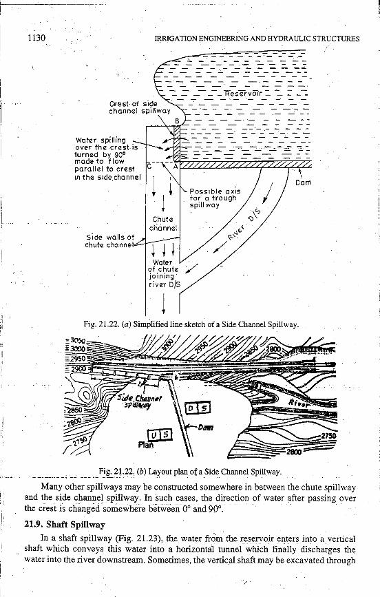
21.8. Side ChannelSpillway
The side channel spillway (Fig. 21.22) differs from the chute spillway in the sense that while in a chute spillway, the water flows at right angles to the weir crest after sgi11!11_g over jt,_ whe_!"e_as in a side channel spillway the flow of water after spilling over the crest, is-turriea-bi90°. such-that H flows parilfefto the· weir ·cresf'TAB)~=as=-shown in Fig. 21.22 (a).
This type of spillway is provided in narrow valleys where no side flanks of sufficient width to accommodate a chute spillway are ·available. If a crest length equal to AB is provided along AC (i.e., along axis of a chute spillway), heavy cutting shall be required. In such topographies, a chµte spillway may be replaced by a side channel spillway.
The design of side channel, required for diverting the flow, is beyond the scope of this book. However, it may be mentioned that the analysis of flow in the side channel, is made by the application of the momentum principle in the direction of flow. The water entering the side channel has no momentum in the direction in which it has to move. The slope of the side channel should, therefore, be sufficient to overcome friction losses
· as-wellastcqJtbvide acceleration-in the·direction-0ffl0w-against-'tlle-mass-ofJ.nc_oming __ . water.
After the end of the crest A, the water is taken away as. in an ordinary chute channel, till it joins the river downstream.
* Readers are advised to go through this article, only after going through its theory as given i"n article 21.11.
d::
1130
Water spilling over the crest is turned by 90° made to flow parallel ·to crest 1n the side channel
Side walls of chute channel
IRRIGATION ENGINEERING AND HYDRAULIC STRUCTURES
c
Water of chute jo·1ning river D/S
Possible axis for a trough spillway·
Fig. 21.22. (a) Simplified line sketch of a Side Channel Spillway.
Fig. ;n.~2. (b)_~aro~t plan_~{ a_ Side_ Channe! Sp~lway.
Many other spillways may be constructed somewhere in between the chute spillway and the side channel spillway. In such cases, the direction of water after passing over the crest is changed 'somewhere between 06 and 90°. . .
21.9. Shaft Spillway
In a shaft spillway (Fig. 21.23), the water from the reservoir enters into a vertical shaft which conveys this water into a horizontal tunnel which finally discharges the water into the river downstream. Sometimes, the vertic~I shaft may be excavated through

SPILLWAYS, ENERGY DISSIPATORS, AND SPILLWAY GATES
some natural rocky island _-_: ..= =- -=. - -= :.._ = or rocky spur existing on · - - - - - - - - -
the u/s of the river near ::-..::::-:_ -- = ...:::::: ..:::: ....::::: R.L.~ormal poof- - - - - .,.... - - - level-~..:
the dam. Sometimes, ar- · ... -;,.._,~-.-.-:--:-,;. .. - - - - - - - - -- ;-: .. -:.-tificial shafts may be ·· ~~
1 constructed. For small heights, the shafts may be constructed entirely of metal or concrete, or clay tiles. But for larger heights, reinforced ce-ment concrete may be
0,
c;, •.'
Gradual transition "
· ..
t
J I
I
·~·
~.
i: " "t
-~
Vertical pipe called shaft
Horizontal tunnel ;,._.__,..,..-:-T"="-o-r-~.....,..,.~ \ ......... ··.···= ·-.. -.;- .. :..-.·.- .. :-- .::-,.
1131
used. For smaller heights, no special inlet design is necessary, but on large projects, a flared inlet called morning glory is often used. ~ .., Water joining -.,._ ___ - the river ·
The horizontal tunnel or the conduit may be taken either through the body of the dam (as may
Fig. 21.23. Shaft Spillway.
down strea·m
be done in concrete gravity dams) or below the foundations (as may be done in earthen dams). The diversion tunnels constructed for diversion of the river, may sometimes be planned and used for shaft spillways, as shown in Fig. 21.24.
Sealed or plugged
Fig. 21.24. Diversion Tunnel being used as a conduit for the shaft spill way.
A shaft spillway may be adopted when the possibility of an over-flow spillway and a trough spill way has been ruled'ceut -becauseof-non-a¥ailability of space due_to_to.p_og_-__ raphy. The choice may then lie between a side channel spillway and a shaft spillway. If some suitable rock spur, etc. is available near the reservoir on the upstream, naturally,' shaft spillway may become· economical and consequently the first choice.
The discharge through the shaft spillway does not increase at such a high rate as it increases in weir type spills. Hence, if the unestimated high floods occur, the shaft . spillway may not prove as useful as a weir type spillway (such as overflow, chute or side channel) would have been. Hence, a shaft spillway design should be much more conservative than that of othe.r weir type spillways.

1132 .··IRRIGATION ENGINEERING AND HYDRAULIC STRUCTURES
A gradual transition must be provided between the vertical shaft and the horizontal conduit, in order to avoid danger of cavitation. Hydraulic analysis of shaft spillways is difficult and their functioning is generally tested in models. The entry of debris and other materials floating in the reservoir must be prevented from entering the shaft, otherwise, they will clog the shaft or the conduit, especially at the junction point. Properly designed or tested trash racks or floating booms may be provided for this purpose. Since, a shaft spillway is surrounded by water on all sides, it must be connected to the dam or the hill side by a bridge.
21.10. Syphon Spillw::iy -
A siphon spillway essentially consists.of a siphon pipe, one end of which is kept on the upstream side and is in contact with the reservoir, while the other end discharges water on thedownstream side. Two typical installations of siphon pipes are shown in Figs. 21.25 and 21.26.
21.10;1. Tilted Outlet Type of a Syphon Spillway. The siphon pipe in Fig. 21.25 has been installed within the body of the dam. Whe.n the valley is very narrow and no space
'.is availabk for constructing a separate spillway, the siphon pipes can be installed within the dam body, as shown in Fig. 21.25. An air vent may be connected with the siphon pipe. The
Fig. 21.25. Siphon pipe installed within the gravity dam.
level of the air vent may be k~pt at normal pool level, while the entry point of the siphon pipe may be kept still lower so as to prevent the entry of debris, etc. in the siphon. The outlet of the siphon may be submerged so as to prevent the entry of the air in the siphon from its dis end.
When the water in the reservoir is 1upto or below the normal pool level, air enters the siphon through the yent and s_ii:>ho_!!i_t_a.f.!!Qll_.f~nn,o_Lti!~~RJ~ce._Wh~n_9J1Q.~the wate_I____c_ __
-revel in the reservoir goes above the normal pool level, and if once the siphon is filled I -with water (i.e., it is primed) ; the water will start flowing through the siphon by siphonic action. The outflow will continue till the water level in the reservoir falls back to normal
1
1,.
pool level. As soon as it happens, the air will enter the siphon through the new exposed ~ air vent and the flow will stop.
Discharge formula. The velocity of flow at the outlet of the siphon can be obtained by equating the effective head H1 (i.e., the difference of water level in the reservoir and the tail water level, for submerged outlet) to the ".elocity head.
:.'\ I

SPILLWAYS, ENERGY DISSIPATORS, AND SPILLWAY GATES
vz -=H·
or
2g !
V=..J2gH1
Q =Discharge= Cd · A .Y2gH1 •
Hence, the discharge through the siphon is given by the equation,
Q = Cd A · ..J2gH1
1133
... (21.13)
where Cd is the co-efficient of discharge, which is . usually about o:9.
The above equation clearly shows that the discharge, through a siphon spillway is sufficiently independent of the water surface elevation of the reservoir. If the water surface in the reservoir rises, the discharge through the spillway is affected to a less extent because change in H1 is small as compared to the corresponding change in head over an ogee type spillway. Hence, the discharge through the siphon is nearly always at capacity, when once the water level has risen above the normal pool level. This makes the siphon spillway particularly advantageous in disposing of sudden surges of water, such as may occur in canals and forebays when the outlet gates are closed rapidly. As the rise of water above the crest level is smaller (because of higher di;;charging capacity even at the start of inflow flood above normal pool level), the height of the non-overflow section of the dam can be kept smaller for the same height of overflow section.
Sometimes, it may not be possible to keep the outlet submerged in tail water because of limitations of negative pressure at the crown. In such a case, the outlet can be left open above the water level, but air entry through the outlet will have to be controlled by priming devices. The effective head H1, in such a case, will be the difference of reservoir water level and outlet level of siphon.
21.10.2. Hooded Type of a Syj>hon S_pillway. The construction of a Hooded type ofSiphon spillway[Fig. 21.26 (a)) is more commonly adopted. In this case, a reinforced concrete hood is constructed over an ordinary overflow section of a gravity dam. The inlet of this hood is kept submerged so as to prevent the entry of debris, ice, etc. A small depriming hood is kept above the main hood and both these hoods are connected by an
DEPRIMER HOOD
RE~E13YOI~ Ll~!'_E!:_ _ J
CROWN
- - - - -t- -SIPHON I HOOD I
H1
-- -_f_!ijii(_~~~~----- -~ --~ t
, . . · -,OUT LET'
\ 'J> :: ~ •• l ;.'<:lOVE'f! FLOW •• · _ · T.W.L_ , • SPJ1:-[.WAY . • , ~ ... ~ • ....q' '. :_ :'7"" . - -_ ~ __ -== ' • ~. • ~ . ... . . ·,,. ~ -:= --
- - .... - .. -· - ........ ~ - -,::
Fig. 21.26. (a) Siphon installed over tl;le overflow spillway to increase its effectiveness and discharging capacity.

ii: ',.
1134 IRRIGATION ENGINEERING AND HYDRAULIC-STRUCTURES
/~it .vent. The inlet of the deprimer hood is kept at norm;;tl pool level. The principle of 1 functioning of both types of installations is essentially the same, except for the initial filling up of the siphon or 'priming'. At normal pool level (i.e. full reservoir level), the water stands up to the crest of the spillway. If now a flood enters the reservoir, the water level would start rising and a sheet of water would start flowing over the spillway crest. Since the water level is above the deprimer hood, the air entry at the inlet is sealed. The air entry at the outlet is also sealed by tail water, etc. Hence, the water spilling over the crest, sucks all the remaining air from the hood within minutes. Siphonic action gets established after the air in the bend over the crest have been completely exhausted. A photoview of this type of siphon spillway, called Sarala Sagar spillway, flanked by earth dam constructed on China Vagu stream (a tributary of Krishna river) is shown in Fig. 21.26 (b).
Fig. 21.26 (b ). Photoview of a Siphon Spillway (Hooded Type).
21.10.3. Priming Devices. When the outlet cannot be sealed by tail water, some other devices, called priming devices, are used which lead to an automatic priming of the siphon at a certain rise of water level above the crest. The maximum rise of water level is called priming depth. In Fig. 21.26 (a), the priming is accomplished by means of a step called Joggle which deflects the sheet of water to strike against the lower end of the cover or_ hood, thus sealing the lower end from the atmosphere. Sometimes, an additional baby siphon may be installed as a priming device, as shown in Fig. 21.27.
When the water level Water shooting ':~·~--reaches-slightly above the crest,
the baby siphon, which is an ad Baby siphon
. __ from babysipl'lon \ closing the outlet
·: ·. ~-. ;:·- .. ~.::\- '. :·. Outlet Ill I
ditional siphon, starts running full. The sheet _of water issuing from it, is arranged to shoot across the lower end of the main siphon, so as to seal it from the atmosphere.
... : ~: : "'. ·,' '. ~ ...
,' : '/).};) -· . ., .. ~ ~ . .. . . ... . :
Fig. 21.27. Baby Siphon installed as a priming device.

-SPILLWAYS, ENERGY DISSIPATORS, AND SPILLWAY GA TES ] 135
·. 21.10.4. Negative Pressures: As soon as the siphon is primed, a vacuum is formed at the throat. The negative pressure developed should be limited to such a magnitude that the absolute pressure of water does not exceed the vapour pressure of wate1 at the temperature. This is necessary to avoid cavitation (explained earlier) and its ill effects. Hence, on an average, a maximum negative head equal to 7.5 m or so can be allowed. In other words, the vertical distance from the crown of the siphon (Top point) down to the discharging point (more precisely it is down to the hydraulic gradient line) should
not exceed a value of about 7.5 m or so, under average conditions [·: atmospheric pressure_- vapour pressure =limiting vacuum pressure ; or 10 - 2.5 = 7.5 m of water': At high altitudes or in hotter regions, this limit may still go down. This fixes a limit on H1 and on the discharging capacity of a siphon spillway.
Both types of syphon spillways described above are known as Saddle siphon spillways. A special type of siphon spillway called Volute Siphon Spillway has been designed in India by Ganesh Iyer and is shown in Fig. 21.28 .
DEPRIMER .;····
R.C.C. PLATFORM
DOME
SIDE WALL OF ____ ,
DOME
Fig. 21.28. Volute Siphon Spillway.
ENERGY DISSIPATORS
21.11. Energy Dissipation below Overflow Spillways
The water flowing over the spillway acquires a lot of kinetic energy by the time it reaches near the toe of the spillway (because of conversion of potential energy into kinetic energy). If arrangements are not made to dissipate this huge kinetic energy of water, and if the velocity of water is not reduced, large_scale scol1r _c:gn t~Ke_gh1ceo _n __ the downstream side near the toe of the dam and away from it. These arrangements are known as energy dissipation arrangements or energy dissipators.
In general, the kinetic energy of this super-critical flow can be dissipated in two ways : (i) By converting the super -critical flow into· sub-critical flow by hydraulic jump .
. (ii) By directing the-flow of water into air and then making it fall away from the toe of the structure. The energy is 'dissipated by the aeration of jet and impa.r:.t of water on the river bed. Though some scour will take place, but it is too

1136 IRRIGATION ENGINEERING AND HYDRAULIC STRUCTURES
small or too far away from the dam to endanger it. Bucket type energy dissipaters work on this principle.
21.11.1. Hydraulic Jump Formation. The phenomenon of hydraulic jump has al~ ready been explained in details in Chapter 10. It was mentioned therein, that a hydraulic jump can form in a horizontal rectangular channel, when the following relation 1s
satisfied between the pre-jump depth 6'1) and post-jump depth 6'2) . •
YI ... I yf ·'ld._ Y2 =-2+ \J 4+ gy
1 i.e. Eq. (10.4)
- where q is the oischarge intensity. For a given discharge intensity over a spillway, the depth y1 is equal to
q/V1 ; and V1 is determined by the drop H1, being equal to °'12gH1 •
UIS_ T!.-h· _______ ·- ---T--T-1 HL
I D/S T.E.L:
-·*-- -· - ----
Fig. 21.29
Hence, for a given discharge intensity and given height of spillway, y1 is fixed and thus Y2 (i.e. the dep!}l required.for the.formation ofhydraulic jump) is also fixed. But the availability of a depth equal to y2 in the channel on the dis cannot be guaranteed as it depends upo.n the tail water level, which depends upon the hydraulic dimensions and' slope of the river channel below. The problem should, therefore, be analysed before any solution can be found. Hence, for different discharges, the tail water depth is found by actual gauge discharge observations and by hydraulic computations. The post jump depths (y2) for all those discharges, are also computed from equation (10.4). If a graph is now plotted between q and tail water depth, the curve obtained is known as the Tail . Water Curve (T. W.C.). Similarly, if a curve is plotted on the same graph, between q and y2, the curve obt?ined is known as the Jump Height Curve (J.H. C.) or y2 curve.
Now there are five possibilities
(a) T.W.C._ coinciding with y2 curve at all discharges [Fig. 21.30 (a)]. -~-~--------· ___ _o __ -_ _-_ ----~--- ·-----C- ------ -- -------------------- -------
r.w.c. COIN ClDI NG Y2 CURVE
q
(a)
DEPTH 1
-----< ... q
(b)

SPILLWAYS, ENERGY DISSIPATORS, AND SPILLWAY GATES
(b) T.W.C. lying above the _y2 cur~e at all discharges [Fig. 21.30 (b)].
(c) T.W.C. lying below the y2 curve at all discharges [Fig. 21.30 (c)].
DEPTH I Yz -
CURVE:---/
/
____ q
(c)
(d) T.W.C. lying above the y2 curve at _smaller discharges and lying below the y2 curve at larger discharges [Fig. 21.30 (d)].
(e) T.W.C. lying below the y2 curve at smaller discharges and lying above the y2 curve at larger discharges [Fig. 21.30 (e)].
O<PTH t I
DEPTH 1
---q (d)
---q (e)
Fig. 21.30
1137
Depending upon the relative positions of T.W.C. and Y2 curve, the energy dissipation arrangements can be provided below the spillway, as explained below for all these
__ fi}le_cases. ---_:.--::---:::-:-·::-_ - - ::--- - -- -----------~-
-21.ll.l.1. Energy dissipators for case (a) : When T. W.C. coincides with Y2 curve at all discharges. This is the most idea_I condition for jump formation. The hydraulic jump will form at the t9e of the spillway at all discharges. In such a case, a simple concrete apron of length 5 (y2 - y1) is generally sufficient to provide protection in the region of hydraulic jump, as shown in Fig. 21.31 (a).
- T.W.L - -- ----·--- - -- - -
Fig. 21.31. (a) Simple horizontal apron.
STILLING BASIN
- i
I

. .
1138 IRRIGATION ENGINEERING AND HYDRAULIC STRUCTURES . .
.21.11.1.2. Energy dissipators for case (b) : When T. W.C. is lying above 1the y2 c·urve at all discharges. In this case, when y2 is always below the tail water, th~__jump forming at toe will be drowned out by the· tail water, and little energy will be dissipated. Water may continue to flow at high velocity along the channel bottom for a considerable distance.
,_\ The problem can be solved: ·:7.~ (i) by constructing a sloping apron above. the river bed level as show~ in Fig. 21.3 I
{b1). The jump will form on the sloping apron where depth equal to y2 (lesser than the --. ,c -~_,__·:~·k-- ~·-
SLOPING APRON ABOVE THE .BED
t TWL
Fig. 21.31. (b1) Sloping apron above the bed.
tail water depth at toe) is available. The sfope of the apron is made in such a way that proper conditions for a jump will occur somewhere on the apron at all discharges; A lot of extra concreting is required to be done, as shown. ·
(ii) A secon_d solution of this problem caq be in the form of providing a roller bucket type of energy dissipator. It consists of an apron, which is upturned sharply at ends, as shown as in Fig. 21.31 (b2). · ····- - · --·
Fig. 21.31. (b2) Roll~r Bucket.
Two main rollers are formed which dissipate the energy due to internal turbulence. .
The roller which is formed downstream of the bucket, tends to move the scoured bed material towards the dam, thus, preventii:J.g serious scour at toe of the dam. Sometimes, the scoured material may enter the bucket under the action of u/s roller, and may 1
c1ause severe abrasion. A dentated bucket lip may, therefore, have to be provided; so as
to permit removal of material caught in the bucket.

SPILLWAYS, ENERGY DISSIPATORS, AND SPILLWAY GATES 1139
21.11.1.3. Energy dissipators for case (c) : When T. W.C. lies below the Y2 curve at all dischages. (i) If the tail water is very low, the water may shoot up out of the above bucket, and fall harmlessly into the river at some, distance downstream of the bucket. This bucket is then known as ski jump ·bucket and can be used for energy dissipation in case (c) : i.e. when the tail water depth is insufficient ol: low at all discharges. The ski jump bucket type of an energy dissipator requires sound and rocky river bed, because a part of the energy dissipation takes place by impact, although some of the energy is dissipated in air by diffusion and aeration. ·
Fig. 21.31. (c1) Ski jump bucket.
(ii) The second solution to the problem can be the provision of a sloping.apron as in case (b) but below the river bed, as shown in Fig. 21.3_1 (c2). The required-depth y2
Fig. 21.31. (c2) Sloping apron below the bed .. - ----- --------- ---- -------- ------- ---- ~--- ------- -~-:.__· _ _:_ __ _:__--..::....__: _________ ._ ~ --- -
which is greater than T.W. depth, can thus be made available by letting the jump form on this sloping apron as shown. This sloping apron and the horizontal cistern of length 5 (y2 - y1) shall be entirely in cutting and may be expensive, though otherwise quite
satiacto~.
(iii) The third solution to this problem may be the construction of a subsidiary .dam below the main dam, so as to increase the tail water depth and cause a jump to form at the toe of the main dam, as s~own in Fig. 21.31 (c3).

1140 IRRIGATION ENGINEERING AND HYDRAULIC STRUCTURES
{BAFFLE WALL
DAM
Fig. 21.31. (c3) Sub~idiary dam construction.
If the tail water defficiency is small, a baffle wall or a row of friction blocks may 1 ;; be provided so as to dissipate the residual energy. The baffles, generally give way, under
high velocity jets due to their cavitation effects, and hence; are suitable only for low spillways or weirs. They should be sufficiently strong to withstand impact from ice and
··floating debris. The location, shape, size and spacing of these baffles can be best determined by model studies. Their use for weirs and canal falls have already been explained in rhe earlier chapters.
21.11.1.4. Energy dissipators for case (d). When T. W.C. lies above the y2 curve at low discharges and lies below the y2 curve at high discharges. In this case, at low discharges, the jump will be drowned and at high discharges, tail water depth is insuf
, :ficient. The solution to the problem lies in providing a sloping a:pron partly above and · partly below the river bed as shown in Fig. 21.31 (d). The.horizontal apron and end sill
should also be provided .
......._ LOW - '-.. DI SC HARGES
"...,rHIGH DISCHARGES
At low discharges, the jump will form on the apron above the river bed, where the available depth is equal to the required depth and Jess than the T.W. depth. Similarly, at high discharges, the jump will form on the apron below the river bed, where the available depth is more than the T.W. depth and equal to the depth required for jump formation.
21.11.1.5. Energy dissipators for case le). When tail water depth is insufficient at low discharges and is greater at high discharges. This case is just the reverse of case (d)
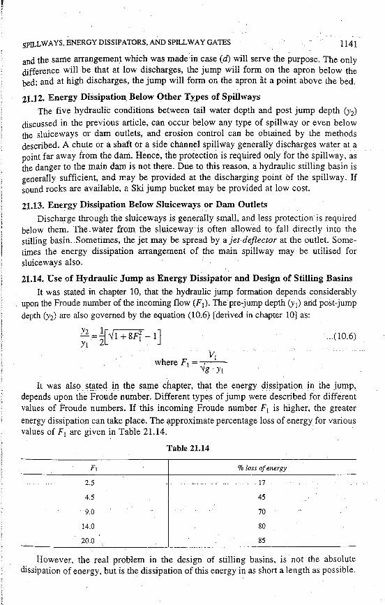
SPILLWAYS, ENERGY DISS IP A TORS, AND SPILLWAY GA TES 1141
and the same arrangement which was made in case (d) will serve the purpose. The only difference will be that at low discharges, the jump will form on the apron below the bed; and at high discharges, the jump will form on the apron at a point above the bed.
21.12. Energy Dissipation Below Other Ty:pes of Spillways
The five hydraulic conditions between tail water depth and post jump depth (Y2) discussed in the previous article, can occur below any type of spillway or even below the sluiceways or dam outlets, and erosion control can be obtained by the methods described. A chute or a shaft or a side channel spillway generally discharges water at a point far away from the dam. Hence, the protection is required only for the spillway, as the danger to the main dam is not there. Due to this reason, a hydraulic stilling basin is uenerally sufficient, and may be provided at the discharging point bf the spillway. If ~ound rocks are available, a Ski jump bucket may be provided at low cost.
21.13. Energy Dissipation Below Sluiceways or Dam Outlets
Discharge through the sluiceways is generally small, and less protection is required below them. The. water from the sluiceway is often allowed to fall directly into the stilling basin. Sometimes, the jet may be spread by a jet deflector at the outlet. Sometimes the energy dissipation arrangement of the main spillway may be utilised for sluiceways also.
21.14. Use of Hydraulic Jump as Energy Dissipator and Design of Stilling Basins
It was stated in chapter 10, that the hydraulic jump formation depends considerably upon the Froude number of the incoming flow (F1). The pre-jump depth (y1) and post-jump depth (y2) are also governed by the equation (10.6) [derived in chapter 10] as:
y2 =_!_r .Y1+8Fi -1] Y1 2L
. V1 where F1 = _ ,----·
'lg· Y1
.... (10.6)
It was also stated in the same chapter, that the energy dissipation in -the jump, depends upon the Froude number. Different types of jump were described for different values of Froude numbers. If this incoming Froude number F1 is higher, the greater energy dissipation can take place. The approximate percentage loss of energy for various values of F1 are given in Table 21.14.
2.5 ..
4.5
9.0
14.0
20.0
Table 21.14
% loss of energy
-- ---11 ..
45
70
80
85
However, the real problem in the design of stilling basins, is not the absolute dissipation of energy, but is the dissipation of this energy in as short a length as possible.

1142 IRRIGATION ENGINEERING AND HYDRAULIC STRUCTURES
Hence, the effectiveness of a hydraulic jump has to be viewed in this light. The types of jumps for different ranges of Froude numbers, given in chapter 10, are again sum-marised below : - ~
(i) When F1 < 2.5, the jump is weak and energy loss is low. No blocks or other devices are provided in this range.
(ii) When F1 lies between 2.5 to 4.5, as in case of weirs and barrages, the jump is --trouble-some and oscillating, which gives rise to heavy waves on the surface. Wave
Suppressors may be needed in this range. The length of jump may be taken as 5 (J2-'- Yi),
(iii) When F1 lies between 4.5 and 9.0; as is generally the case for dam spillways, the jump performance is at its best. The jump is then called a steady jump. The length of the jump is almost constant and equal to 6y2 in this range. Hence for large spillways, where y2 may be quite high, very long and expensive stilling basins may be required. Some auxiliary devices may also be introduced for further stabi1ising the flow and to reduce the length of the basin.
_(iv) When F1 = 9.0 and larger; it is a strong jump. But the jump is likely to be rough and choppy. Hence, a bucket type of energy dissipator is preferred to a stilling basin of hydr~ulic jump type.
21.15. _Standard Stilling Basins
Various types of stilling basins have been generalised for use on different types of works, by various agencies. The designs of these basins have been developed on the basis of l~mg experience and on model studies, keeping in view the protection obtained consistent.with economy. These basins are not simple concrete aprons but are generally provided with auxiliary devices such as chute blocks, sills, baffle walls, etc. These dev,ices can-_help in dissipating the energy of flow by offering resistance to flow and -may stabilise the flow in a shorter length of the basin, thus affecting economy.
In general, a stilling basin may be defined, as a structure in which the energy dissipating action is confined. If the phenomenon of hydraulic jump is basically used for dissipating this energy; it may be called a hydraulic jump type of stilling basin. The !;!uxiliary devices may be used as additional measures for contro_lling the jump, etc.
Before we reproduce a few standard stilling basins, let us first describe, in brief, the effects produced by auxiliary devices. ·
Chute Blocks. Chute blocks are a kind of serrated device (i.e. row of small projections like teeth of saw) and provided at the entrance of the stilling basin. The incoming jet of water is furrowed and partly lifted from the floor, producing a shorter length of jump than what would have been without them. They also help in stabilising the flow
---- and-thus-improve-t:he-jump-perfom1anee-{Fig.~2 L32). - - - --- --- ----
Sills and Dentated Sjlls. Sill or more preferably dentated sill is generally provided at the end of the stilling basin. The dentated sill diffuses the residual portion of high velocity jet reaching the end of the basin. They, therefore, help in dissipating residual energy and to reduce the length of thejump or the basin (Refer Fig. 21.32).
Baffle Piers. J'hey are the blocks placed within the basin, across the basin floor. They help in breaking the flow and dissipate energy mostly by impact. These baffle piers, sometimes called friction blocks, are very useful in small structures, such as low

SPILLWAYS, ENERGY DISSIPA TORS, AND SPILLWAY GA TES
spillways and weirs, etc. They, however, give way due to cavitation, under the influ~nce of high velocity jets, and hence iu-e unsuitable for large works.
· 21.15.1. U.S.B.R. Basins. U.S.B.R. has standardised stilling basins for different ranges of Froude numbers. The important of these basins, are :
(1) U.S.B.R. stilling basin II. This is recommended for use on large structures; such as dam spillways: large canal structures, etc.; when the incoming Froude numbef1F1)
is more than 4.5. The dimensions of the chute blocks, dentated sill, etc. are shown in Fig. 21.32. The length of the basin is related to the Froude number (F1) as given in I able 21.15. . .. - ...
Fig. 21.32. U.S.B.R. Stilling basin Il (F1 > 4.:S).
4
6
8
IO or more
Table 21.15
Length of the basin
3.6y2
4y2
4.2yi
4:3 Y2
An economy in the length of the basin up to about 35% (4.3 y2 in place of 6Y2) is thus obtained with auxiliary devices. The floor of the basin should be set at such a level auo-pro:v.ide 5% more . .waterdepth.thanc...y2:'c.:.:.. .. c __ --'-'-' ·--- • . • -· __ --···-·-------
(2) U.B.S.R. stilling basin IV. This type of stilling basin is shown in Fig. 21:33. It is used for Froude 'number varying between 2,5 and4.5, which generally occurs in canal weirs, canal falls, diversion dams, etc. This basin is applicable only to rectangular cross sections. Since oscillating waves are generated in this range of Froude number, they are tried to be controlled at source by providing large chute blocks. The spacing between the blocks may be further reduced than what is shown in Fig. 21.33 (up to say 0.75 W) for better hydraulic performance. The floor of the basin may be set at such a level as to

JL_ II II j!
1144
LENGTH
Fig. 21.33. U.S.B.R. Stilling basin IV (F1 lies between 2.5 and 4.5).
provide 5 to 10% more water depth than the theoretical y1• The length of the basin is generally kept equaHo 5 (y2 -Yi). -
· 21.15.2. I.S.I. Standardised Basins. Indian Standard Institution has also standardised certain stilling basins for uses under different conditions. A full description of such basins is available in IS : 4997- 1968. Stilling basin I and II (for F1 <4.5 and F 1 > 4.5 respectively) with horizontal aprons and stilling basins III and IV with sloping aprons, have been standardi,sed and described in the above reference. Students or field staff may refer to this LS.I. publication iri their particular needs.
21.16. Dy.namic Force on Spillway Bucket and Spillway Bottom
When water flows over the curved bottom portion of an ogee spillway, there is a continuous change of velocity. Due to this change in velocity, there is a change in momerittim (momentum~ mass x velocity). Hence, a force is exerted on the spillway in accordance with Newton's second law of motion, i.e. rate of change of momentum is equal to this impressed force. This force is known as dynamic force. The spillway bottom where this curvature is provided is subjected to this force. The evaluation of this force is, therefore, necessary in the design of the bottom -portion, -or the design of the bucket, if it is provided as energy dissipater in an overflow spillway. /
The ·magnitude of this force can be easily determined by using Newton's second law and by resolving all the forces acting on the curved element of water AB [Fig. 21.34 (a)] in horizontal anci vertical directions. Mass of water when multiplied by net change
·in velocity in one direction will give the net component of this dynamic force in that · din~ction. If F is this dynamic force, then
'1~ - - - - --'c----c-'------'----'----_:__£(-H)-:::--'[-U2(-H)-=Ji'1(-H)J-X-masS-of-water-"in.:the-elemen t:.. --- -- - - - . . - . ----- ------- --- ---i : F(VJ = [V2(V) - V1(V)] xmass of water in the element i
F =--/ F[H) + F[V) where V1 and V2 are the _velocities at .the entrance and exit of the curved element. V1([-I) an_d V2(H) are their horizontal components, and V1(V) and V2(V) are their vertical components. An illustrative example has been solved below :
, I I
I I

SPILLWAYS, ENERGY DISSIPATORS,AND ~PILLWA:Y GATES
Example 21.3. An overflow - !- _____ -... ogee spillway of height 15 m. is dis- _rm - -- .. ,, ', charging water with a head of 2 m over the crest. A reverse curvature of radius 4 m, subtending an angle , of 60° at the centre, is provided at the spillway bottom as shown in Fig. 21.34 (a). Assuming the discharge coefficient for the spillway
J5m
as 2.2, determine the magnitude of the dynamic force on the curve portion AB of the spillway. Fig. 21.34 (a)
Solution. The discharge over the spillway is given as :
Q= C.L· H312
Discharge per unit length, Y w·d1 cos 60°
q= C. H312
= 2.2 x (2)312 = 6.23 cumecs/m Let d1 andd2 be the water depths,
V1 and V2 be the flow velocities at A and B
respectively. Neglecting any loss of energy and the
head due to velocity of approach and applying Bernoulli's theorem between U/s water surface and at sections A and B, respectively we, get
Element of water
vr v~ 15 + 2 = 2 + d1 cos 60° +
2g = d2 +
2g
But V1 = !L ; and V2 = !L d1 ·di
2 ' 2
17 = 2 + d1 cos 60° + q fl = d1 + ~ 2gllJ 2gd2
.. f!g .. :?.1.34 (b).
d 6' 2 2 17 = 2 + __..!. + ( .23) = d + (6.23) or
or
or
and
2 2x9.81d~. 2 2x9.8ld2 ... ·--- ... '1.. ... -·· -·· . - ... -- ' 2 ..
17 - 2 d1 1.97 - d 1.97 - +-+-2-- 2+--2 d1 d~
17=2+ d1+1.97 2 df
17 -d 1.97 - 2+--Jli
1145
... (i)
... (ii)

IRRIGATION ENGINEERING AND HYDRAULIC STRUCTURES
or
. ( i) yields :
' ' 15 ~ d1 + 1.97 2 di
3odi = df + 3.94
Solving by hit and trial, we get
I d1=0.365m1
Similarly, solving equation (ii), we get
17 -d 1.97 - 2+ dJ.
or 17d~=d~+ 1.97
by hit and trial, we get I d1 = 0.344 m I
Now the hydrostatic forces P1 and P2 per unit length are given as :
P1 = ± · Pw ·di cos 60° = ± X 9.81X(0.365)2 X±=0.327 kN/m run
P2 =t · Pw · d~ =t X 9.81X(0.344)2 =0.58 kN/mrun
Resolving all the Forces in tlie Horizontal Direction
Algebraic sum of all the forces in the horizontal direction
= P1 cos 60° + FH-P2
The rate of change of momentum per unit length in the horizontal direction - -- p;v·q -
... (iii)
=--[V2-- V1cos60°)
= Pwg· q [v2 -~1] ... (iv) g - -
But V1 =t= ;;;5
=17.06m/sec.; and V2 =!= 0~32;4 =18.12m/sec.
Equating (iii) arid (iy), we get
- - p~[ Y1] P1 cos60°+FH-P2=----g V2-2
or _ 0.327 x ;+FH-Q,~8 := 9 · 8 ~7~-~:[~~1~-=~1~2°_6]=:s~._75
ITT ~=~~~
Absence of -ve sign indicates that the assumed direction of F H is correct.
Resolving all the Forces in the Vertical Direction
The weight W of the water in the curved element AB
=[23:~~ x 9°] · YmeanCPw)
'1 f ! I i

SPILLWAYS, ENERGY DISS IPA TORS, AND SPILLWAY GA TES
= [ 2;6~04 x 60°] + [
0·365
; 0344
] x 9.81=14.57 kN.
or·
Resolving all the forces in the vertical direction, we get
W + P 1 sin 60° - F v = Yw . q [O - V1 sin 60°] g .
14.57+0.327x ~ -Fv= 9 · 8 ~~~·23 [-17.06sin60°]
or
14.85-Fv=- 92.04
Fv = 106.89 kN Fy
Absence of -ve sign indicates that the assumed direction of Fv is correct and is.vertically upward.
Re~ultant force = ..../ F~ + Fi = '1.-( 6-0-.1-6~)2~+-(-1-'--06-.-89-)~2
= 122.64kN.
Hence, the resultant dynamic force is equal to 122.64 kN
and acts at an angle= tan- 1 ( 16~~i8:) = 60.6° with the horizontal
in the upward direction, as ~own in Fig. 21.34 (c).
SPILLWAY CREST GATES
60·6°
FH Fig. 21.34 (c)
1147
If a temporary barrier can be installed over the permanent raised crest of a spillway, additional water can be stored between the spillway crest and the top of the barrier during the fag-end of the rainy season. The small flows in excess of the barrier top level, may be permitted to pass over the barrier. If, however, large flood occurs, the barrier miy'l)e -re-inoved arid folhipillway capacity made availabfotodlie oiifflow.
Sometimes on large dams, regular gates may be installed over the permanent crest, ""'· so as to function like a movable additional crest. In such a case, the height of the permanent raised crest can be reduced and the balance provided by the movable crest (i.e. gate). If there is a permanent raised crest up to the gate top, the storage, of course would be equal to that of a gated crest ; but in times of serious floods, the rise in flood level would be much more as compared to what would have been in a gated crest. This is because, the gates would be opened during serious floods so as to provide more head and hence larger discharge and consequent lesser rise in flood levels. Hence, the top level of the non-overflow section and the value of land acquisition for the reservoir which has to be determined by the maximum rise of flood above the spillway crest, can be reduced by providing gated crest or controlled crests. In: other words, the dam height
-ca-nbe reduced for the same useful storage.-or-more~usefufstorage can be obtained for the same height, provided the dam spillway is controlled by gates, etc.
This saving in the dam height and land acquisition will be more, if more height of the gates is provided. This saving is, however, counter-balanced by the cost of the gates. The cost of the gates would be more if their height is increased. (The gate cost include the principal cost and OMR, i.e. operational, maintenance and repair costs.) An economic balance between these two factors must be worked out and the cheapest combination found before deciding the height of the permanent crest and the height of

1148 IRRIGATION ENGINEERING AND HYDRAULIC STRUCTURES
th~ temporary crest (i.e. gates). This is also governed by the limitations of maximum available gate heights. ·
Gates can be provided on all types of spillways except siphon spillways. In siphon spillways, the gates a~e not requir~d as the rise in flood level is already small compared to other types of spillways. The gates for earthen dams should be provided with caution, since the faulty operation or failure of their operation may lead to serious rise in flood levels, causing overtopping and failure of dam.
21.17. Types of Spillway Gates
The various types of spillway gates are described below in brief :
21.17.1. Dropping Shutters or Permanent Flash Boards. They consist of wooden panels usually 1.0 to 1.25 m high. They are hinged at the bottom and are supported against the water pressure by struts (Fig. 21.35). The shutters fall flat on the crest when the downstream supporting struts are tripped. Hence they are not suitable for curved crests.
UIS j. - - ~ --- -- FLASH BOARD
OR SHUTTER
RUBBER STRIP STRUT
SPILLWAY CREST
HINGE
Fig. 21.35. Flash board or Droppin~ shutter.
These shutters can be raised oi lowered from an overhead cableway or a bridge. Various types of shutters which drop and hoist themselves automatically, have been designed these days. These automatic shutters work on the principle of counter weights acting against the water pressure. Automatic shutters do not function well when interferred by floating debris, ice, etc:
Sometimes temporary flash boards, which s.hall fall as soon as overtopped by water, may be used for very minor works.
;C-..---------xnK:ina.s offfasll-ooaras-oo nave some aisadvantages and fience used orily on small spillways of minor importance.
21.17.2. Stop Logs and Needles. Stop logs consist of wooden beams or planks placed one upon the other and spanning in the grooves between the spillway piers (Fig. 21.36). They can be placed and removed either by hand or with hoisting mechanism. Considerable time may get wasted in removing them, if they become jammed in the slots. Leakage between the logs is also a big problem. They are, therefore, used on very minor works.

SPILLWAYS, ENERGY DISSIPATORS, AND SPILLW~Y GATES
ROOVE
Plan
(Elevation) Fig. 21.36. Stop logs.
Needles. Needles are wooden logs kept side by side with their lower ends resting in a keyway on the spillway and upper ends supported by a bridge (Fig. 21.3 7). It is very difficult to handle these needles at the time -of flow- -and hence they are not used on_any major works. They are sometimes used for emergency bulk heads, where they need not be
· replaced until the flow has stopped.
1149
CREST
Fig. 21.37. Needles.
21.17.3. Vertical Lift Gates or Rectangular Gates. These are rectangular gates spanning horizontally between the grooves made in the supporting spillway piers (Fig.21.38). The grooves are generally Jined with rolled steel channel sectio~s of appropriate size, so as to provide a smooth bearing surface having sufficient bearing strength and are known as grove guides. These rectangular gates move between the groove guides, and can be raised or lowered by a hoisting mechanism at the top.
The gates are often made of steel, although they may be made of concrete or wood. They-are generally placed verticaI;affhougli ilie)'may be kept slightly i!lclifieaelownstream:
Because of the hydrostatic force caused by the upstream water standing against the gate, large friction is developed between the gate and the downstream groove guides. Hence, if the gate is in direct contact with the gui&s, as is there in a sliding gate, large friction will be developed, and it will be very difficult to move the gate. Hence, in a sliding gate relatively larger hoisting capacity is ,required to operate the gate because of the sliding friction that has to be overcome. The sliding gates are, therefore, seldom used.

1[
r:1 · ! I i
1150 IRRIGATION ENGINEERING AND HYDRAULIC STRUCTURES
PLATFORM FOR OPERATING COUNTER wt HOISTING MECHANISM r
HOISTING CABLE
WATER SEAL
RE SERVOiR WATER
=.:· *-=-- --~ i· - -- - --=s10E ROLLER=-=-
- ---~
,,, .- I>'
-.--- ' :
----. U/- ~ - - _,s - -- -A -~-
- I -
. ""- ·-- . - '
SECTION. ~ A
(a)
-CONCRETE PIER
' '» ;. . ...... ..
... , '
NOSE OF THE PIER
ROLLER TRAIN
GATE SPANNING BETWEEN SPILLWAY
PIERS
D/5 I==---- -L=----=--"-1
··1c1----------------~~-----~-- - - I ROLLER TRAIN RUBBER SEAL I
PLAN ''
(b) Fig. 21.38. 'Vertical stoney gate' or 'Free roller gate'.

SPILLWAYS, ENERGY DISSIPATORS, AND SPILLWAY GATES 1151
This friction problem can be solved by placing cylindrical rollers between the bearing surfaces of the gate and the guide grooves. A train of rollers or wheels is, therefore, generally placed between the gate and the d/s guide, so that the sliding friction is much smaller. These rollers may be placed independent of the gate and the guide, thus eliminating axle friction, as shown in Fig. 21.38. Such an arrangement, when the rollers are neither attached to the gate nor to the guide grooves but rolls vertically between the two when the gate is moved, is known as a Stoney gate or a Free Roller gate. The design and construction of such a gate is difficult and rollers are, therefore, generally attached to the gate. Such an arrangement in which the rollers or wheels are attached to the gate and ride in tracks on the downstream side of the groove guide, is known as a Fixea wheels gate or Fixed roller type gate. Rubber seals are used to seal. the openings between the upstream leaf plate and the sides of the pier grooves, as shown.
Large vertical lift. gates may be counter balanced by a counter weight beam, which is loaded to balance the self-weight of the gate. Herice, hoisting force is required only to balance the frictional resistance.
Vertical lift gates have been used in size 15 m x 15 m (height and span). If the gate height is larger, head room is required for lifting. the gate clear of the maximum reservoir level ; thus increasing the height of the operating platform. To reduce the height of the operating platform, high gates may be broken up into two horizontal sections, so that the upper portion may be lifted and removed from the guides before the lower portion is moved. This also · reduces the
CONCRETE BRIDGE BETWEEN PIERS
~ "
load on the hoisting CONCRETE PIER__,_ _ _,_ __
mechanism. The discharge through a CABLE ___ -+-__,
partially raised vertical gate, takes place by an undershot orifice flow, and the discharge E~~~~VOIR formula is given by ------_;nuic--+--1'1
Cd A .Y2g · H1 , where A is the ~-area of the opening and H1 is WATER FACE._
the water head above the _o~GATE---'----lllW1---1-i centre line of the opening. =- _ -_
21.17.4. Radial Gates or _ · Tainter Gates. A radial gate ..::::- · has a curved water supporting - . . face made of steeL The curved · • ~ - · · ·. ~ • : "~ ~ water face which is in the - ~ · ·· . ~. · . · -~
PLATFORM
PIER NOSE
shane of a sector of a circleis- = -- . --_,·_" -0 <c .-_ --· :,._' - ••. '- . 'JK._ -. - ie::J' - - • .., • ';' ...
properly braced by steel frame - - - · '. · SP/ LL WAY '- •·
work which is pivoted on _ .:.._· ~· •. ,. - ~ .. horizontal shafts called trun-nions or pins (Fig. 21.39). The - . pins are anchored in the =--===--= ·:' i~ ~ -_.· · ~ "' .~'. ~
downstream portion of the spillway piers. The gate can Fig. 21.3~. Radial gate or Tainter gate.
~- -...... \.

1152 IRRIGATION ENGINEERING AND HYDRAULIC STRUCTURES
thus rotate about the fixed horizontal axis. Hoisting cables are attached to the gate and lead to winches on the hoisting platform. The winches are usually motor driven, although hand driving is possible for smaller works or at times of power failures.
The water-face segment is made concentric to the supporting pins so that the entire water thrust passes through the pins, thus creating no moment against th~Jiftip.g of the gate. Hence, the lifting force is required only against the weight of theiate, the friction between the seals and the piers, and the frictional resistanc~ at the pins. Counter weights, in order to counter balance the self weight, may also be used, which further reduces the lifting force. Moreover, the hoisting load is nearly constant for all gate openings. Hence, radial gates can be used with smaller lifting force for all heads, and hand operating hoisting mechanism may suffice for smaller works ; whereas in the vertical lift gates of the same size, power mechanism might be needed.
21.17.5. Drum Gates. Drum gates are useful for longer spans of the order of 40 m or so and medium heights say 10 m or so. The drum gate consists of a segment of a cylinder which may be raised above the spillway crest or may be lowered into the recess made into the top of spillway. ·
The U.S.B.R. drum gate (Fig. 21.40) is completely encfosed and is hinged at the upstream end. The buoyant forces due to head water pressure underneath the drum, aid
- _ ~ ____ SKI~ ~L~E
=-::"°':.HINGE -____§ S E:..:.A::_L __::::,.~
- - .Ll> ,_- - -:: =- =--~'~,,',I :i;_ - - -- . _r - - - - - I . . \ .... - . ' - ' . ,_ - /_ .
I - - -/ __ -- '-==--=.. - -- '. .:-_ L :.:-:: ::: -
~ .. , , RECESSED - · ' ' ~i:_HAMaER_.::
-·- -·--
( , ' . ...
'." ~ SPILL WAY
"'\ '
' t> . '<I
'.· '
.... "i ~
•I
I' I
"\•
.,• • Cl \ ~ . I
I .ri q ' ,.
--- ~ - Fig.21:40. Drum Ga:te (U.S.RR. Type).-in its lifting. In this type of dam gate, the drum is enclosed on all the three sides as well as on the ends; thus forming a water tight vessel. When the drum is lowered, it fits into the recess in such a way that the surface becomes coincident with the designed ogee shape of the crest.
The other type of drum gate may have no bottom plate and shall be raised only by the buoyant action of water entering the recess, underneath the skin plate of drum.
The drum gates require large recess and hence, are not suitable for smaller spillways.

SPILLWAYS, ENERGY DISSIPATORS, AND SPILLWAY GATES
PROBLEMS
1153 .
1. (a) "A spillway is a safety valve in a dam". Discuss the statement. (b) Discuss the location of the 'main spillway' and 'subsidiary spillway' in gravity dams as well as
in earthen dams. (c) Briefly describe an 'ogee spillway'. 2. (a) What are spillways and where are they provided ?
(b) Enumerate the various types of spillways, and describe in details the most widely used type.
3. (a) What are the different kinds of spillways and how are they selected for individual conditions ?
(b) Sketch an ogee profile and mark in it the different zon~s.
4. (a) What are spillways and what is their necessity ?
(Madras University, 1975)
(Madras University, 1976)
(b) Enumerate the different type of spillways which are used in dam construction. (c) Discuss briefly the design principles that are involved in the design of an ogee spillway ; and a
chute spillway. 5. (a) What is an ogee spillway and how is it designed ? (b) Discuss the necessity of the aeration ru,:rangements that are required in gated ogee spillways.
6. Write down an equation for calculating the discharging capacity of an ogee spillway. How does 'coefficient of discharge' in this equation varies with the ·:
(i) Depth of approach ;
(ii) Slope of upstream face of the ogee spillway ;
(iii) Submergence of the spillway by the tail water ;
(iv) The ratio of design head to actual head over the spillway.
7. (a) How would your compute the discharge passing over an ogee spillway. Discuss the various factors affecting the coefficient of discharge in the discharge equation. ·
(b) Compute the discharge over an ogee spillway with coefficient of discharge c = 2.3 at a head of 3.8 m. The effective length of the spillway is 110 m. Neglect the velocity of approach.
[Ans. 1872 cumecs]
8. Design a suitable section for the overflow section of a concrete gravity dam having the dis face sloping at a slope of 0.7 H : 1 V. The design discharge for th~ spillway is 6000 cumecs. The height of -the spillway above the river bed is 60 m. The effective length of spillway may be taken as 50 m. · ·
[Hint. Follow example 21.1]. 9. (a) What is meant by a 'spillway' and what is its necessity in dam constn.iction ?
(b) Enumerate the different types of spillways, and draw neat sketches for an the types, showing the different parts of each·.
10. (a) What is a siphon spillway ? Enumerate the. two types of saddle syphon spillways, and describe with a neat sketch the component parts and functioning of one of these two types :
(b) A siphon spillway has the following cross-section at its throat :
Height of the throat = 1.5 m
Width of the throat = 4 m.
At the design flow, the tail water elevation in 7 m below the summit of the siphon, and the head water elevation is 2 m above the summit, (I) Taking a coefficient of discharge as 0.6 ; determine the
..f.~.R.~~ity of the syphon (ii) I)ete!'lll_irl~the !i~ad that would be:~qtrir~ci()n an ()gee spillway_l.8 rr1 long to discharge this flow, if coefficient of discharge is 2.25 ; (iii) What length of this ogee weir would be required to discharge the same flow with a head of 2.2 m on the crest.
[Soluti-On. (a) Discharge through siphon spillway (i.e. capacity)
= 0.6 (1.5 x 4) .../2 x 9.81x(7+2)
= 47.8 cumecs. Ans.
(b) 47.8 = 2.25 x 3.8 H312
or H=3.15m.Ans.

. .1154 IRRIQATION ENGINEERING AND HYDRAULIC STRUCTURES
4.78 = 2.25 L (2.2)312 (c)
or L = 6.5 m. Ans.] 11. (a) Describe briefly the construction and functioning of a 'Hooded type' o.f siphon spillway.
What is its discharge equation ?
(b) What is meant by priming? Dis.::uss the priming arrangements used in saddle siphon spillways. 12. (a) What is a 'chute spillway' ? Where is it preferred to ogee and other types of spillways ?
(b) Discuss briefly the component parts and their design for a chute spillway.
13. Discuss the design of the following components of a chute spillway :
(i) Approach channel
(ii) Control structure
(iii) Discharge carrier
(iv) Energy dissipation arrangement at the bottom.
14. Write short notes on :
(i) Volute siphon
(ii) Side channel spillway or Chute spillway or Shaft spillway
(iii) Ogee spillway
(iv) Priming devices for siphon spillways.
15. What is meant by an 'energy dissipator' ? Discuss the various methods used for energy dissipation below spillways.
16. Discuss briefly the various types of energy dissipators that are used for energy dissipation below overflow spillways, under different relative positions of T.W.C. and J.H.C.
17. (a) What is a 'spillway gate' and what are the merits and demerits of installing such gates ?
(b) Enumerate the important types of spillway gates. Describe with a neat sketch the construction and working of 'Tainter gate'.
18. (a) Discuss the merits and demerits of different types of spillway gates·.
(b) Discuss with a neat sketch the construction, and functioning of a 'Stoney gate' as well as a 'Drum gate'.
19. Write detailed notes on the following :
(i) Energy dissipation-below,spillways-:c--c: ... - ------ . __
or
Spillway buckets and stilling basins.
(ii) Spillway gates.
r