
Optimization and Applications of Slow-Proton-Exchange (SPE ...
Upload
khangminh22Category
view
6download
0
SPE-184485-STU
Development of Software Application for Optimization of Primary Cementing Operations using Visual Basic Abdul Manan Chaudhry, University of Engineering & Technology Taxila
Copyright 2016, Society of Petroleum Engineers This paper was prepared for presentation at the SPE Annual Technical Conference and Exhibition held in Dubai, UAE, 26–28 September 2016. This paper was selected for presentation by an SPE program committee following review of information contained in an abstract submitted by the author(s). Contents of the paper have not been reviewed by the Society of Petroleum Engineers and are subject to correction by the author(s). The material does not necessarily reflect any position of the Society of Petroleum Engineers, its officers, or members. Electronic reproduction, distribution, or storage of any part of this paper without the writ-ten consent of the Society of Petroleum Engineers is prohibited. Permission to reproduce in print is restricted to an abstract of not more than 300 words; illustrations may not be copied. The abstract must contain conspicuous acknowledgment of SPE copyright.
Abstract Scientific software development is a multi-step process, involving good understanding of the mathemat-
ical model, development of an algorithm and subsequently its implementation as a computational code.
Using these methodologies an open source Cementing Operations software library has been coded. A
software application “Cementing Operations Calculator” has been developed over this library, which
efficiently provides solutions for primary cementing operations.
The software helps in selecting optimum parameters for primary cementing operations such as Dis-
placement Volume, Lead Slurry Total Volume, Tail Slurry Total Volume, Lead Slurry Composition
(quantity of cement & cement additives), Tail Slurry Composition (quantity of cement & cement addi-
tives), Lead Slurry Composition (Dead Volume), Tail Slurry Composition (Dead Volume) and finally
the Chemicals required for performing the primary cementing operations job.
A number of geoscientific computational libraries are available in the public domain which have been
initiated by various universities and developed and maintained by a large community of developers.
Keeping in view the same trend, there is a need for developing open source libraries for petroleum engi-
neering. Thus the aim of this research is to provide open source code which is publicly available to the
others to enhance and incorporate new functionality. In addition the software tools are also publicly
available which can be used by students and researchers for analysis of their data. The use of the soft-
ware is demonstrated with real field data examples.
1 Introduction 1.1 Purpose
A number of geoscientific computational libraries are available in the public domain which have been
initiated by various universities and developed and maintained by a large community of developers.
Keeping in view the same trend, there is a need for developing open source libraries for petroleum engi-
neering. Thus the aim of this research is to provide open source code which is publicly available to the
others to enhance and incorporate new functionality. In addition the software tools are also publicly
available which can be used by students and researchers for analysis of their data.
1.2 Scope of Work
Scientific software development is a multi-step process, involving good understanding of the mathemat-
ical model, development of an algorithm and subsequently its implementation as a computational code.
Using these methodologies an open source Cementing Operations software library has been coded. A
software application “Cementing Operations Calculator” has been developed over this library, which
Dow
nloaded from http://onepetro.org/SPEATC
E/proceedings-pdf/16ATCE/2-16ATC
E/D023S099R
017/1375929/spe-184485-stu.pdf/1 by guest on 30 July 2022
2 SPE-184485-STU
efficiently provides solutions for primary cementing operations.
1.3 Research Title
Development of Software Application for Optimization of Primary Cementing Operations using Visual
Basic
1.4 Significance of the Study
The software application “Cementing Operations Calculator” selects optimum parameters for primary
cementing operations such as Displacement Volume, Lead Slurry Total Volume, Tail Slurry Total Vol-
ume, Lead Slurry Composition (quantity of cement & cement additives), Tail Slurry Composition (quan-
tity of cement & cement additives), Lead Slurry Composition (Dead Volume), Tail Slurry Composition
(Dead Volume) and finally the Chemicals required for performing the primary cementing operations job.
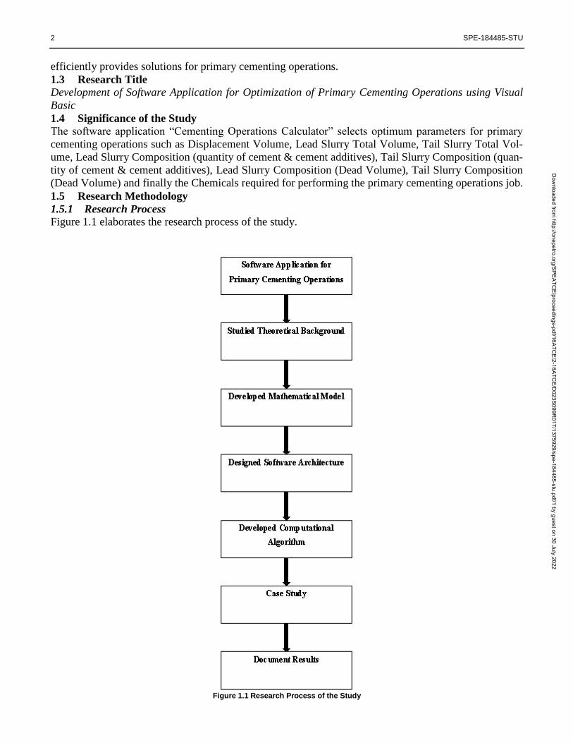
1.5 Research Methodology
1.5.1 Research Process
Figure 1.1 elaborates the research process of the study.
Figure 1.1 Research Process of the Study
Dow
nloaded from http://onepetro.org/SPEATC
E/proceedings-pdf/16ATCE/2-16ATC
E/D023S099R
017/1375929/spe-184485-stu.pdf/1 by guest on 30 July 2022

SPE-184485-STU 3
1.5.2 Classification
The study in hand can be classified into a couple of research areas i.e. longitudinal (Case Study) and ap-
plied research.
1.5.3 Limitations of the Study
This version of the software application “Cementing Operations Calculator” can only be used for
Primary Cementing Operations including Conductor Casing, Surface Casing, Intermediate Cas-
ing and Production Casing
2 Statement of Theory and Definitions
2.1 Terminology
The basic terminology and concepts behind cementing operations, used in this software “Cementing Op-
erations Calculator” are discussed as follows:
2.1.1 Primary Cementing
The placement of cement in the annular space between the casing and the wellbore is known as primary
cementing. Primary cementing is the most important operation performed on a well. The main objective
is to provide zonal isolation. Without complete zonal isolation in the wellbore, the well may never reach
its full producing potential. A faulty cementing job results in lost reserves, low production rates and
hence the revenue is delayed. In order to repair a faulty cementing job, stimulation treatments may be
required. [1]
2.1.2 Classification of Casing Strings
A series of casing strings are essential to complete a well and for the production of the desired fluids ef-
ficiently. The design of the casing program depends on the following:
Drilling objectives
Depth
Sizes of the holes
Formation Pressures
Mud column
Formation Geology
Withstand mechanical stresses and
Chemical stresses
In this section, the functions of the casing strings and the depths to which they are normally set are dis-
cussed. [1]
2.1.2.1 Conductor Pipe
The first and the shortest casing string in the well which helps protect shallow sands from being contam-
inated and help prevent washouts is known as conductor casing. It can be used for attaching a blowout
preventer (BOP). It is used to protect the subsequent casing strings from corrosion and to support some
of the wellhead load. The setting depth is usually less than 300 ft. (9 1 m). [1]
2.1.2.2 Surface Casing
The second string of casing which helps to cordon off aquifers which are found at relatively shallow
depths, unconsolidated formations and to maintain hole integrity is known as surface casing. Diameters
range from 7 to 20 in. (18 to 50 cm) and depths can reach 5,000 ft. (1,520 m). [1]
2.1.2.3 Intermediate Casing
The longest section of casing in the well which is used to maintain the borehole integrity, seal off weak
Dow
nloaded from http://onepetro.org/SPEATC
E/proceedings-pdf/16ATCE/2-16ATC
E/D023S099R
017/1375929/spe-184485-stu.pdf/1 by guest on 30 July 2022
4 SPE-184485-STU
zones and prevent lost circulation is known as intermediate casing. Typical casing sizes range from 65/8
in. (17 cm) to 133/8 in. (34 cm), and the depth can vary from 1,000 to 15,000 ft. (305 to 4,570 m). [1]
2.1.2.4 Production Casing
The last string of casing in the well which is used to isolate the reservoir from undesirable fluids in the
producing formation and from other zones penetrated by the wellbore is known as production casing.
We can say that, the production string is the oil well. Common sizes range from 41/2 to 95/8 in. (11.5 to
24.5 cm). Depths can vary from 1,500 to over 25,000 ft. (460 to over 7,620 m). [1]
2.1.3 Cement Additives
The chemicals which modify the behavior of the cement slurry which allows successful placement of
cement slurry, rapid compressive strength development and zonal isolation during the lifetime of the
well are known as additives. Over 100 additives are available which can be in solid or liquid forms. The
concentrations of most solid cement additives are expressed as a percentage by weight of cement
(BWOC). Liquid additive concentrations are expressed in gallons per sack (GPS) of cement. Eight cate-
gories of additives are generally recognized. [1]
2.1.3.1 Accelerators
The chemicals which reduce the setting time of cement slurry and increase the rate of compressive
strength development are known as accelerators. [1]
2.1.3.2 Retarders
The chemicals which extend the setting time of cement slurry are known as retarders. [1]
2.1.3.3 Extender-s
The materials which lower the density of cement slurry and reduce the quantity of cement
per unit volume of set product are known as extenders. [1]
2.1.3.4 Weighting Agents
The materials which increase the density of cement slurry are known as weighting agents. [1]
2.1.3.5 Dispersants
The chemicals which reduce the viscosity of cement slurry are known as dispersants. [1]
2.1.3.6 Fluid-Loss Control Agents
The materials which control the loss of the aqueous phase of cement slurry to the formation are known
as fluid loss control agents. [1]
2.1.3.7 Lost Circulation Control Agents
The materials which control the loss of cement slurry to weak or vugular formations are known as lost
circulation control agents. [1]
2.1.3.8 Specialty Additives
Miscellaneous additives, e.g., antifoam agents, fibers, etc. [1]
2.1.4 Cement Slurry Properties
2.1.4.1 Slurry Density
The slurry density is calculated by adding the masses of the components of the cement slurry and divid-
ing by the total of the absolute volumes occupied. In other words, to determine the density in lb/gal, di-
vide the total pounds by the total gallons. [1]
Dow
nloaded from http://onepetro.org/SPEATC
E/proceedings-pdf/16ATCE/2-16ATC
E/D023S099R
017/1375929/spe-184485-stu.pdf/1 by guest on 30 July 2022

SPE-184485-STU 5
2.1.4.2 Yield
The volume occupied by one unit of the cement plus all of the additives and mix water is known as
yield. As cement is measured in sacks hence the yield is measured in cubic feet per sack (ft3/sk). This
value is then used to calculate the number of sacks required to achieve the desired fill-up in the annular
space. Most slurry density calculations are performed on the basis of one sack of cement which is equiv-
alent to 94 lb. [1]
2.1.4.3 Mix Water
The amount of water in gallons per sack of dry cement blend before the addition of liquid additives is
known as Mix Water. Water can be Fresh Water or Sea Water. [1]
2.1.4.4 Mix Fluid
The amount of total liquid additives and water in gallons per sack of dry cement blend is known as Mix
Fluid. [1]
2.1.4.5 Displacement Volume
The displacement volume to land the plug is simply a calculation of the capacity of the pipe. [1]
2.1.4.6 Lead Slurry
The low density and high yield slurry which is used to fill and cover the upper section of the annular
space is known as lead slurry. The density of lead slurry is higher than that of the drilling fluid and less
than that of the tail slurry. [1]
2.1.4.7 Tail Slurry
The higher density slurry which is used to cover the lower section of the annular space up from the bot-
tom of the hole is known as tail slurry. The properties of the tail slurry are normally superior to those of
the lead slurry. [1]
3 System Analysis and Design
3.1 Software Architecture
The software architecture of the application “Cementing Operations Calculator” is illustrated in Figure
3.1.
Figure 3.1 Software Architecture
Dow
nloaded from http://onepetro.org/SPEATC
E/proceedings-pdf/16ATCE/2-16ATC
E/D023S099R
017/1375929/spe-184485-stu.pdf/1 by guest on 30 July 2022

6 SPE-184485-STU
3.2 Front End Interface
3.2.1 File
The options that are enlisted under the “File” tab are shown in Figure 3.2.
Figure 3.2 File
3.2.1.1 New Cementing Data
It opens the “Input Data” form and the user has the ability to enter the input data manually into the form
as shown in Figure 3.3.
Figure 3.3 New Cementing Data
3.2.1.2 Open Cementing Data
It allows the user to automatically load the input data into the “Input Data” form, from the saved files
which are in the form of CEM File as shown in Figure 3.4.
Dow
nloaded from http://onepetro.org/SPEATC
E/proceedings-pdf/16ATCE/2-16ATC
E/D023S099R
017/1375929/spe-184485-stu.pdf/1 by guest on 30 July 2022

SPE-184485-STU 7
Figure 3.4 Open Cementing Data
3.2.1.3 Save Cementing Data
It allows the user to save the input data which is entered manually into the “Input Data” form, in the
form of CEM File as shown in Figure 3.5.
Figure 3.5 Save Cementing Data
3.2.1.4 Save Cementing Result
It allows the user to save the results generated in the “Output Data” form, in response to the processes
performed on the input data, in the form of Text Document as shown in Figure 3.6.
Dow
nloaded from http://onepetro.org/SPEATC
E/proceedings-pdf/16ATCE/2-16ATC
E/D023S099R
017/1375929/spe-184485-stu.pdf/1 by guest on 30 July 2022

8 SPE-184485-STU
Figure 3.6 Save Cementing Result
3.2.2 Process
The options that are enlisted under the “Process” tab are shown in Figure 3.7.
Figure 3.7 Process
3.2.2.1 Conductor Casing
It performs all the calculations on the input data for conductor casing and display the results in the “Out-
put Data” form. The results obtained are actually the design of the cementing job for the conductor cas-
ing section of the well as shown in Figure 3.8.
Dow
nloaded from http://onepetro.org/SPEATC
E/proceedings-pdf/16ATCE/2-16ATC
E/D023S099R
017/1375929/spe-184485-stu.pdf/1 by guest on 30 July 2022

SPE-184485-STU 9
Figure 3.8 Conductor Casing
3.2.2.2 Surface Casing
It performs all the calculations on the input data for surface casing and displays the results in the “Out-
put Data” form. The results obtained are actually the design of the cementing job for the surface casing
section of the well as shown in Figure 3.9.
Figure 3.9 Surface Casing
3.2.2.3 Intermediate Casing
It performs all the calculations on the input data for intermediate casing and displays the results in the
“Output Data” form. The results obtained are actually the design of the cementing job for the intermedi-
ate casing section of the well as shown in Figure 3.10.
Dow
nloaded from http://onepetro.org/SPEATC
E/proceedings-pdf/16ATCE/2-16ATC
E/D023S099R
017/1375929/spe-184485-stu.pdf/1 by guest on 30 July 2022

10 SPE-184485-STU
Figure 3.10 Intermediate Casing
3.2.2.4 Production Casing
It performs all the calculations on the input data for production casing and displays the results in the
“Output Data” form. The results obtained are actually the design of the cementing job for the production
casing section of the well as shown in Figure 3.11.
Figure 3.11 Production Casing
3.2.3 Plot
The option that is enlisted under the “Plot” tab is shown in Figure 3.12.
Dow
nloaded from http://onepetro.org/SPEATC
E/proceedings-pdf/16ATCE/2-16ATC
E/D023S099R
017/1375929/spe-184485-stu.pdf/1 by guest on 30 July 2022

SPE-184485-STU 11
Figure 3.12 Plot
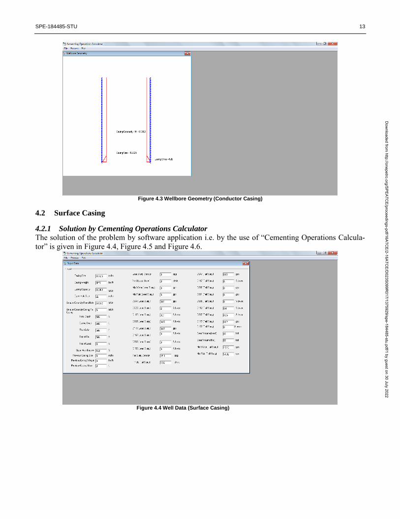
3.2.3.1 Wellbore Geometry
It shows the graphical representation of the well which includes wellbore wall & casing to be cemented
with appropriate labels as shown in Figure 3.13.
Figure 3.13 Wellbore Geometry
4 Case Study The accuracy of the software application “Cementing Operations Calculator” is demonstrated with the
use of real field data examples.
4.1 Conductor Casing
4.1.1 Solution by Cementing Operations Calculator
The solution of the problem by software application i.e. by the use of “Cementing Operations Calcula-
tor” is given in Figure 4.1, Figure 4.2 and Figure 4.3.
Dow
nloaded from http://onepetro.org/SPEATC
E/proceedings-pdf/16ATCE/2-16ATC
E/D023S099R
017/1375929/spe-184485-stu.pdf/1 by guest on 30 July 2022

12 SPE-184485-STU
Figure 4.1 Well Data (Conductor Casing)
Figure 4.2 Results (Conductor Casing)
Dow
nloaded from http://onepetro.org/SPEATC
E/proceedings-pdf/16ATCE/2-16ATC
E/D023S099R
017/1375929/spe-184485-stu.pdf/1 by guest on 30 July 2022
SPE-184485-STU 13
Figure 4.3 Wellbore Geometry (Conductor Casing)
4.2 Surface Casing
4.2.1 Solution by Cementing Operations Calculator
The solution of the problem by software application i.e. by the use of “Cementing Operations Calcula-
tor” is given in Figure 4.4, Figure 4.5 and Figure 4.6.
Figure 4.4 Well Data (Surface Casing)
Dow
nloaded from http://onepetro.org/SPEATC
E/proceedings-pdf/16ATCE/2-16ATC
E/D023S099R
017/1375929/spe-184485-stu.pdf/1 by guest on 30 July 2022

14 SPE-184485-STU
Figure 4.5 Results (Surface Casing)
Figure 4.6 Wellbore Geometry (Surface Casing)
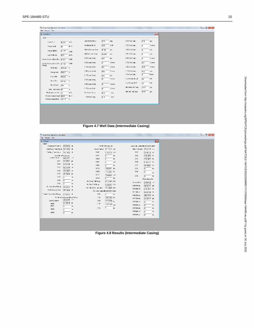
4.3 Intermediate Casing
4.3.1 Solution by Cementing Operations Calculator
The solution of the problem by software application i.e. by the use of “Cementing Operations Calcula-
tor” is given in Figure 4.7, Figure 4.8 and Figure 4.9.
Dow
nloaded from http://onepetro.org/SPEATC
E/proceedings-pdf/16ATCE/2-16ATC
E/D023S099R
017/1375929/spe-184485-stu.pdf/1 by guest on 30 July 2022
SPE-184485-STU 15
Figure 4.7 Well Data (Intermediate Casing)
Figure 4.8 Results (Intermediate Casing)
Dow
nloaded from http://onepetro.org/SPEATC
E/proceedings-pdf/16ATCE/2-16ATC
E/D023S099R
017/1375929/spe-184485-stu.pdf/1 by guest on 30 July 2022

16 SPE-184485-STU
Figure 4.9 Wellbore Geometry (Intermediate Casing)
4.4 Production Casing
4.4.1 Solution by Cementing Operations Calculator
The solution of the problem by software application i.e. by the use of “Cementing Operations Calcula-
tor” is given in Figure 4.10, Figure 4.11 and Figure 4.12.
Figure 4.10 Well Data (Production Casing)
Dow
nloaded from http://onepetro.org/SPEATC
E/proceedings-pdf/16ATCE/2-16ATC
E/D023S099R
017/1375929/spe-184485-stu.pdf/1 by guest on 30 July 2022
SPE-184485-STU 17
Figure 4.11 Results (Production Casing)
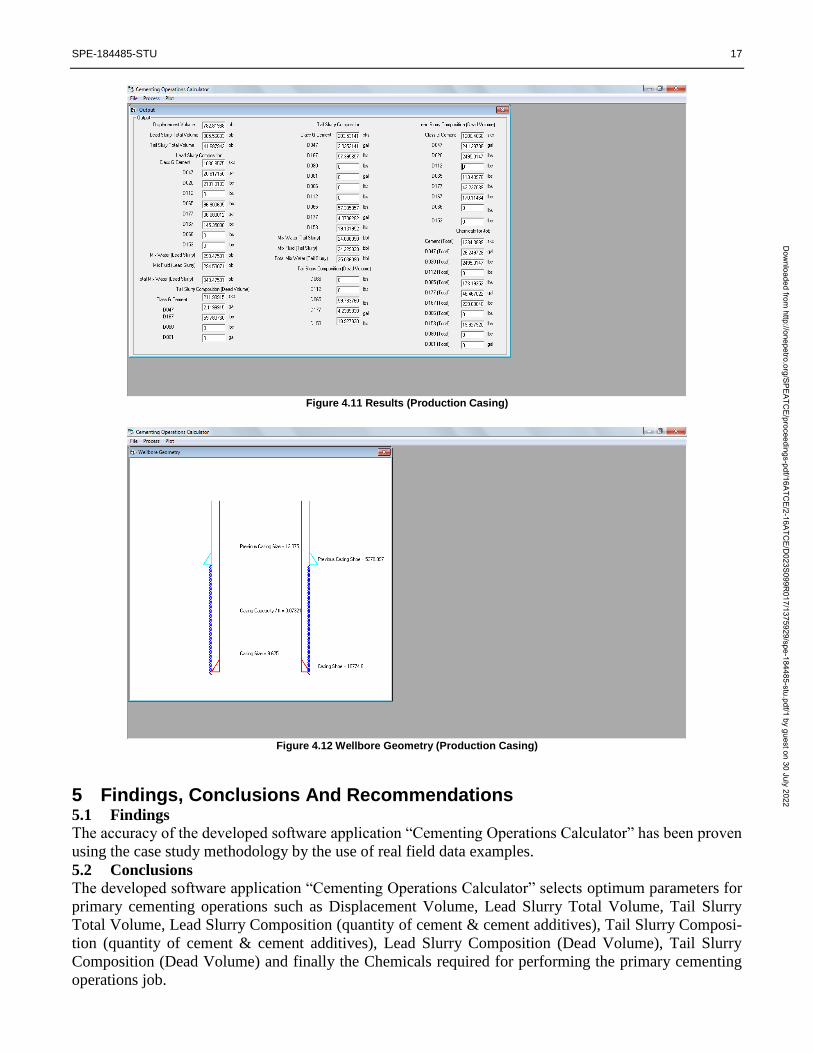
Figure 4.12 Wellbore Geometry (Production Casing)
5 Findings, Conclusions And Recommendations 5.1 Findings
The accuracy of the developed software application “Cementing Operations Calculator” has been proven
using the case study methodology by the use of real field data examples.
5.2 Conclusions
The developed software application “Cementing Operations Calculator” selects optimum parameters for
primary cementing operations such as Displacement Volume, Lead Slurry Total Volume, Tail Slurry
Total Volume, Lead Slurry Composition (quantity of cement & cement additives), Tail Slurry Composi-
tion (quantity of cement & cement additives), Lead Slurry Composition (Dead Volume), Tail Slurry
Composition (Dead Volume) and finally the Chemicals required for performing the primary cementing
operations job.
Dow
nloaded from http://onepetro.org/SPEATC
E/proceedings-pdf/16ATCE/2-16ATC
E/D023S099R
017/1375929/spe-184485-stu.pdf/1 by guest on 30 July 2022

18 SPE-184485-STU
5.3 Recommendations
The following recommendations are suggested regarding the further development of this open source
Cementing Operations software library:
This research work i.e. open source Cementing Operations software library should be continued
in future in the Master’s thesis and Doctoral dissertations by the research students of various
universities and also by the professionals working in this field to make this publicly available li-
brary be the best in the field of Cementing
This research work should be funded by the national Exploration and Production (E&P) compa-
nies in Pakistan to trigger the development of Oil and Gas software’s in Pakistan and which will
help in tremendous cost savings from the expenses that are done in lieu of purchasing and licens-
ing of software’s acquired from the services companies
5.4 Future Work
The future research work in the further development of the software application “Cementing Operations
Calculator” is listed as follows:
Liners: Acquiring results from the services companies for testing the “Liner” cementing jobs on
the already developed version of the software
Remedial Cementing: Development of computational algorithm for “Remedial Cementing” i.e.
Squeeze Cementing techniques
Cement Plugs: Development of computational algorithm for “Cement Plugs” techniques
Horizontal Well Cementing: Development of computational algorithm for “Horizontal Well
Cementing” techniques
Cement Job Evaluation: Development of computational algorithm for “Cement Job Evalua-
tion” i.e. testing and logging techniques
6 Acknowledgements I would like to express my sincere gratitude to my advisor Dr. Khalid Amin Khan for the continuous
support, for his patience, motivation, and immense knowledge. His guidance helped me in all the time of
research and writing of this paper.
7 Nomenclature BWOC = By Weight of Cement
Ft = Foot
ft3 = Cubic Feet
GPS = Gallons per Sack
gal = Gallons
in = Inches
lb = Pounds
m = Meter
sk = Sack
8 References
8.1 End Notes [1] Nelson, Erik B. 1990. Well Cementing. Sugar Land, Texas: Schlumberger Educational Services.
Dow
nloaded from http://onepetro.org/SPEATC
E/proceedings-pdf/16ATCE/2-16ATC
E/D023S099R
017/1375929/spe-184485-stu.pdf/1 by guest on 30 July 2022

SPE-184485-STU 19
8.2 Bibliography
Spoerker, H.F., Real-Time Job Monitoring and Performance Control of Primary Cementing Operations
as a Way to Total Quality Management (TQM), SPE, 1995.
Ravi, K.M., Improve Primary Cementing by Continuous Monitoring of Circulatable Hole, SPE, 1993.
Smith, R.C., Successful Primary Cementing: Fact or Fiction, SPE, 1986.
Smith, R.C., Successful Primary Cementing Can Be a Reality, SPE, 1984.
Carl Haut, Richard, Applications Of A Computer Simulator To Primary Cementing, SPE, 1978.
Dow
nloaded from http://onepetro.org/SPEATC
E/proceedings-pdf/16ATCE/2-16ATC
E/D023S099R
017/1375929/spe-184485-stu.pdf/1 by guest on 30 July 2022
Copyright © 2022 FDOKUMEN