SPE 169578 CO2 Injection for Enhanced Gas Recovery
16
SPE 169578-MS CO 2 Injection for Enhanced Gas Recovery Sumeer Kalra, Xingru Wu, University of Oklahoma Copyright 2014, Society of Petroleum Engineers This paper was prepared for presentation at the SPE Western North American and Rocky Mountain Joint Regional Meeting held in Denver, Colorado, USA, 16–18 April 2014. This paper was selected for presentation by an SPE program committee following review of information contained in an abstract submitted by the author(s). Contents of the paper have not been reviewed by the Society of Petroleum Engineers and are subject to correction by the author(s). The material does not necessarily reflect any position of the Society of Petroleum Engineers, its officers, or members. Electronic reproduction, distribution, or storage of any part of this paper without the written consent of the Society of Petroleum Engineers is prohibited. Permission to reproduce in print is restricted to an abstract of not more than 300 words; illustrations may not be copied. The abstract must contain conspicuous acknowledgment of SPE copyright. Abstract Literature shows that there is a significant amount of natural gas available for enhanced recovery in the depleted reservoirs; at the same time, the depleted gas reservoirs are a proven storage facility for Carbon Dioxide (CO 2 ) storage in terms of reservoir integrity. Conceptually, injecting CO 2 into a depleted gas reservoir will not only potentially rejuvenalize the gas production, but will also store the greenhouse gas in a proven subsurface formation. Study on CO 2 phase behavior in subsurface conditions shows that CO 2 most likely will be in super-critical state which exhibits liquid-like density and gas-like viscosity. These properties are favorable in displacing natural gas reservoirs in volumetric and pore scale sweep efficiency. Using numerical reservoir simulation on a synthetic case with multiple scenarios, this paper identifies the most amenable characteristics of a reservoir for enhancing gas production by injecting CO 2 and analyzes the parameters influencing this secondary recovery process. In the paper, reservoir depth, depletion pressure ratio, aquifer activity, inclination angle, reservoir heterogeneity with various permeability arrangement, injection rate, and producer bottomhole pressure will be studied on the synthetic model. Furthermore, this paper will quantify the amount of natural gas which can be produced and CO 2 that can be stored in an ideal case using economic matrix. From this study, the ideal candidates for enhanced gas recovery by CO 2 injection will be proposed based on simulation results, thus one can screen the available gas reservoirs for CO 2 storage purpose and can quickly quantify the additional gas production from the secondary recovery. Introduction World energy demands are only met by the utilization of fossil fuels but the byproducts of combustion are a major cause of concern. Carbon Dioxide (CO 2 ) sequestration can help in the mitigation of global warming concerns caused by CO 2 emission (Agarwal et al. 2011). CO 2 sequestration is a process of capturing CO 2 and permanently sequestrating it into a reservoir. Major candidates for CO 2 sequestration are deep saline aquifers, depleted oil/gas reservoirs and coal seams. The subsurface storage of CO 2 mechanisms, techniques, and pilot projects have been well documented in literature (Clemens and Wit 2002, Gallo et al. 2002, Oldenburg and Benson 2002, Oldenburg 2003, Jikich et al. 2003). For depleted gas reservoirs, some reservoirs had to be abandoned at high pressures because of a variety of reasons such as formation subsidence, water invasion, and non-economic production rates. In gas reservoir development, high abandoned pressure indicates that there is still a large quantity of natural gas available for further development by pushing the subsurface and technical limits. A technique to repressurize the reservoir is to inject CO 2 to displace the remaining oil/gas present in the formation. As the pressure buildup, cumulative production is increased and also the depleted reservoir can act as an ideal carbon sink for long-term storage. In summary, injecting CO 2 in a depleted gas reservoir will not only potentially rejuvenalize the gas production by pressure buildup but will also store the greenhouse gas in a proven subsurface formation. There are four primary reasons that a depleted gas reservoir be a good candidate for CO 2 storage. First of all, the gas reservoir is a container with a proven integrity. One big concern of CO 2 subsurface storage is that it potentially leaks out to aquifer and surface (Maldal and Tappel 2004, Michael et al. 2010, Klusman 2003, Divison et al. 2010). For a depleted gas reservoir, its integrity has been tested by the original natural gas in geological time scale. Secondly, CO 2 can efficiently displace the remaining natural gas because of gravity segregation. Therefore, natural gas is produced from an upper part of the reservoir and CO 2 is injected at bottom part of the formation for better sweep efficiency and avoiding gas mixing to a better extent.
Transcript of SPE 169578 CO2 Injection for Enhanced Gas Recovery

SPE 169578-MS
CO2 Injection for Enhanced Gas Recovery Sumeer Kalra, Xingru Wu, University of Oklahoma
Copyright 2014, Society of Petroleum Engineers This paper was prepared for presentation at the SPE Western North American and Rocky Mountain Joint Regional Meeting held in Denver, Colorado, USA, 16–18 April 2014. This paper was selected for presentation by an SPE program committee following review of information contained in an abstract submitted by the author(s). Contents of the paper have not been reviewed by the Society of Petroleum Engineers and are subject to correction by the author(s). The material does not necessar ily reflect any position of the Society of Petroleum Engineers, its officers, or members. Electronic reproduction, distribution, or storage of any part of this paper without the written consent of the Society of Petroleum Engineers is prohi bited. Permission to reproduce in print is restricted to an abstract of not more than 300 words; illustrations may not be copied. The abstract must contain conspicuous acknowledgment of SPE copyright.
Abstract Literature shows that there is a significant amount of natural gas available for enhanced recovery in the depleted reservoirs; at
the same time, the depleted gas reservoirs are a proven storage facility for Carbon Dioxide (CO2) storage in terms of reservoir
integrity. Conceptually, injecting CO2 into a depleted gas reservoir will not only potentially rejuvenalize the gas production,
but will also store the greenhouse gas in a proven subsurface formation.
Study on CO2 phase behavior in subsurface conditions shows that CO2 most likely will be in super-critical state which
exhibits liquid-like density and gas-like viscosity. These properties are favorable in displacing natural gas reservoirs in
volumetric and pore scale sweep efficiency. Using numerical reservoir simulation on a synthetic case with multiple scenarios,
this paper identifies the most amenable characteristics of a reservoir for enhancing gas production by injecting CO2 and
analyzes the parameters influencing this secondary recovery process. In the paper, reservoir depth, depletion pressure ratio,
aquifer activity, inclination angle, reservoir heterogeneity with various permeability arrangement, injection rate, and producer
bottomhole pressure will be studied on the synthetic model. Furthermore, this paper will quantify the amount of natural gas
which can be produced and CO2 that can be stored in an ideal case using economic matrix.
From this study, the ideal candidates for enhanced gas recovery by CO2 injection will be proposed based on simulation
results, thus one can screen the available gas reservoirs for CO2 storage purpose and can quickly quantify the additional gas
production from the secondary recovery.
Introduction World energy demands are only met by the utilization of fossil fuels but the byproducts of combustion are a major cause of
concern. Carbon Dioxide (CO2) sequestration can help in the mitigation of global warming concerns caused by CO2 emission
(Agarwal et al. 2011). CO2 sequestration is a process of capturing CO2 and permanently sequestrating it into a reservoir.
Major candidates for CO2 sequestration are deep saline aquifers, depleted oil/gas reservoirs and coal seams. The subsurface
storage of CO2 mechanisms, techniques, and pilot projects have been well documented in literature (Clemens and Wit 2002,
Gallo et al. 2002, Oldenburg and Benson 2002, Oldenburg 2003, Jikich et al. 2003).
For depleted gas reservoirs, some reservoirs had to be abandoned at high pressures because of a variety of reasons such as
formation subsidence, water invasion, and non-economic production rates. In gas reservoir development, high abandoned
pressure indicates that there is still a large quantity of natural gas available for further development by pushing the subsurface
and technical limits. A technique to repressurize the reservoir is to inject CO2 to displace the remaining oil/gas present in the
formation. As the pressure buildup, cumulative production is increased and also the depleted reservoir can act as an ideal
carbon sink for long-term storage. In summary, injecting CO2 in a depleted gas reservoir will not only potentially
rejuvenalize the gas production by pressure buildup but will also store the greenhouse gas in a proven subsurface formation.
There are four primary reasons that a depleted gas reservoir be a good candidate for CO2 storage. First of all, the gas reservoir
is a container with a proven integrity. One big concern of CO2 subsurface storage is that it potentially leaks out to aquifer and
surface (Maldal and Tappel 2004, Michael et al. 2010, Klusman 2003, Divison et al. 2010). For a depleted gas reservoir, its
integrity has been tested by the original natural gas in geological time scale. Secondly, CO2 can efficiently displace the
remaining natural gas because of gravity segregation. Therefore, natural gas is produced from an upper part of the reservoir
and CO2 is injected at bottom part of the formation for better sweep efficiency and avoiding gas mixing to a better extent.
2 SPE 169578-MS
Thirdly, the cost of sequestration and storage of CO2 can be offset by income from additional gas production; verse versa, the
gas production cost will be mitigated via taxes of using CO2. Fourthly, the industry can capitalize on existing wells (previous
producer or injector) rather than drilling new wells, which potentially makes the project more economically viable. Therefore,
we consider depleted gas reservoirs as the target for CO2 storage as well as enhanced gas production.
However, a good candidate does not guarantee a viable engineering project as there are many uncertainties in subsurface
conditions. What are the ideal characteristics for enhancing gas production by injecting CO2 in the formation is the problem
that this paper focuses on. We used numerical simulator as the tool to study some key parameters controlling the subsurface
flow. Our simulation work is based on a synthetic case with an aim to study the generic relationship between CO2 storage and
natural gas recovery with different reservoir descriptions. The purpose is to define the typical characteristics of the formation
for CO2 storage with the highest possible natural gas recovery. We present our results using several dimensionless variables
so that the conclusions drawn from this study can be applied to other reservoirs without scaling issue.
Physical Properties of CO2 and CH4 Knowledge of thermodynamic properties of Carbon Dioxide (CO2) and Methane (CH4) are important as these properties are
responsible to optimize compression, monitor transportation and model mobility of gas in the reservoir conditions. Some key
parameters of Methane and Carbon Dioxide are listed in Table 1. Likely, CO2 at deep reservoir conditions behave as a super
critical fluid which has viscosity of a gas and density of a liquid. The higher density of CO2 means that it will migrate
downward in the reservoir as relative to CH4. Figure 1 describes the density comparison of CH4 and CO2 changes with depth.
Methane density is calculated using Jacobsen and Stewart equation (Angus et al. 1976) and CO2 density is estimated by an
equation developed by Chapela and Rowlinson (Younglove and Ely 1987). The figure clearly signifies that CO2 is highly
denser than CH4 throughout the reservoir pressure range. CO2 will tend to migrate in the downward direction relative to CH4.
Figure 2 shows the viscosity comparison of CO2 and CH4 with respect to formation depth. The mobility ratio of CH4
displacement by CO2 will be very favorable rendered by the highly viscous property of CO2. Figure 3 shows the comparison
of solubilities of CH4 and CO2 in formation brine. Solubility of CO2 is modeled using correlations developed by Chang,
Coats and Nolen (Chang et al. 1996) and CH4 solubility in aqueous phase is modeled using correlation developed by Duan
and Mao (Duan and Mao 2006). The solubility curve shows that CH4 solubility in brine water is negligible as compared with
the solubility of CO2. In these correlations, the solubilities of CO2 and CH4 are a function of temperature, pressure and
salinity. The comparison of solubility at salinity range from 1,000 ppm to 300,000 ppm in Figure 3 indicates that the
solubility decreases with an increase in salinity because of the presence of dissolved solids in the formation water, also
termed as a salting out effect (Bachu et al. 2003).
All above calculations are done considering normal temperature gradient of 0.015°F/ft and hydrostatic pressure gradient of
0.433 Psi/ft. Due to these properties, there are fewer tendencies to finger and intermix between the gases (Oldenburg et al.
2001). From these properties, it can be inferred that the properties of CO2 and CH4 with limited inter mixing, makes depleted
gas reservoirs an ideal candidate for CO2 injection for enhanced gas recovery and storage. Furthermore, from these figures,
we can see that shallow reservoirs below depths of 4,000 ft will provide less storage capacity and can be ignored for carbon
storage and enhanced gas recovery. The density and viscosity contrast between CO2 and CH4 is very high beyond 4,000 ft;
making these reservoirs a suitable candidates for enhanced gas recovery and carbon storage.
Base Case Description A depleted gas reservoir is modeled for this study using a commercial simulator CMG-GEM developed by Computer
Modelling Group Ltd. for general purpose of compositional simulation. The original reservoir pressure was assumed to be
7,000 Psia and after years of production it has depleted to 4,350 Psia which is the initial reservoir pressure for our study. The
reservoir temperature is a constant 200 °F during injection and production. We use 99.9% CH4 and a trace of CO2 to
represent the original gas composition in the reservoir. When we analyze the results, CH4 recovery will be used to represent
the natural gas recovery. Key parameters in the model of reservoir and well properties for the base case are outlined inTable
2. Figure 4 illustrate the relative permeability curve used in the simulation study and Figure 5 depicts the simulation model
for the base case with an injector and a producer well. The reservoir top layer is at a depth of 9,700 ft with 300 ft payzone
thickness and a positive dip of 15°. Water-Gas contact (DWGC) is defined at 9,700 ft signifying the presence of aquifer zone
( =1.0).
Initially, the reservoir is saturated with natural gas and 10% residual water saturation. Injector well has perforations at the
lower most grid block and producer well perforations are in the top layer because of the density contrast to delay CO2
breakthrough during natural gas production. For all simulation modeling, natural gas production is stopped at a time when
mole fraction of CO2 in the producing stream reaches a set value of 50%. For the injector, the injection will stop when
injection bottomhole pressure reaches the original reservoir pressure. For the base case, the reservoir has a uniform
permeability of 100 mD.

SPE 169578-MS 3
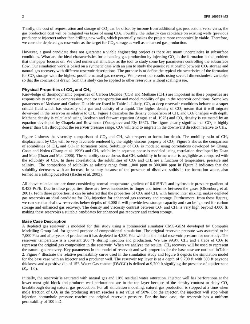
Figure 6 demonstrates the importance of CO2 injection. Three scenarios were simulated: No injection (reservoir blowdown
till the reservoir pressure reaches 2000 psia); No Production case, and using CO2 injection simultaneously with natural gas
production. It shows that the natural gas recovery factor increases from 46.3% to 94.8 % and also the percent hydrocarbon
pore volume (%HCPV) of CO2 injected is increased from 95.8% to 166.6%. The simulated results clearly justify the
importance of CO2 injection to potentially rejuvenalize the gas production and also allow higher quantity of CO2 storage into
the subsurface formation.
Sensitivity Analysis on the Base Model Reservoir Heterogeneity: Reservoir heterogeneity is probably the most important parameter to be considered for numerical
simulation studies because reservoir permeability defines the path for the fluid to flow. For the base case, we considered ideal
situation with uniform permeability of 100 mD. The study evaluated the effects of reservoir heterogeneity in the displacement
process. The method used to quantify reservoir heterogeneity is the Dykstra-Parsons Coefficient (DPC), as elaborated in
Appendix A. The Dykstra-Parsons Coefficient relates standard deviation of permeability profile to the median permeability.
CO2 mixing with the in-situ gas in the reservoir can potentially degrade the gas price. Therefore, it is important to capture the
mixing physics using the numerical simulation. Recovery efficiency depends on how much CO2 “mixes” with the in-situ gas
in the reservoir. In reservoir simulation, physical dispersion is commonly approached by numerical dispersion.
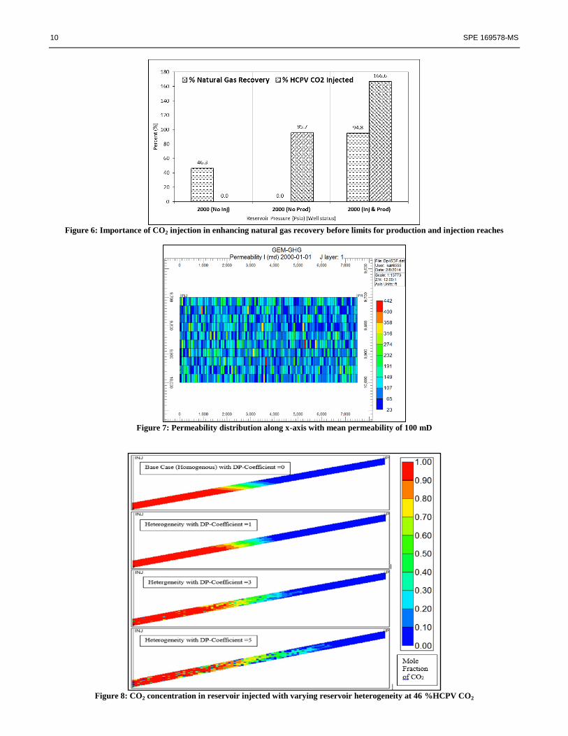
As considering reservoir heterogeneity, the permeability variation within the reservoir applying the Dykstra-Parsons
Coefficient of 0.5 can be observed in Figure 7. The effect of dispersion can be observed in Figure 8 where the profile of mole
fraction of CO2 mixing in the reservoir is described with varying Dykstra-Parson Coefficient. The CO2 mole fraction profile
is observed when 46% HCPV of CO2 is injected into the reservoir. It shows that with zero DPC, no mixing takes place and
CO2 profile is very smooth. With increasing diffusivity, bigger mixing zones are observed and CO2 is displaced all over the
reservoir. Bigger mixing zones leads to early CO2 breakthrough in the producer and results in lower natural gas recovery as
observed in Figure 9. Given that the uniform permeability for analysis also provides best case scenario of the reservoir which
is usually not observed during operations, it is very important to take into account the effect of reservoir heterogeneity in
defining the operational parameters for CO2 sequestration and enhanced gas recovery.
For all the following simulation analysis, we assumed reservoir heterogeneity with Dykstra-Parsons Coefficient of 0.5. Also,
the maximum injection bottomhole pressure is kept constant at 7,000 Psia and minimum production bottomhole pressure is
constant at 1,000 Psia.
Depletion Pressure Ratio: Depletion pressure ratio is defined as the ratio of initial reservoir pressure when EGR starts to the
original reservoir pressure. Depletion pressure provides broader understanding of the present reservoir conditions instead of
analyzing results considering only current reservoir pressure. It will help in the decision making for the time frame in a
reservoir development to be considered for CO2 injection and allow the production from the reservoir through secondary
recovery. Three cases with initial reservoir pressures of 4,500, 3,000 and 2,000 Psia are considered for the study leading to
depletion pressure ratios of 0.65, 0.43 and 0.30. The results shown in Figure 10 indicates that CO2 injection should be started
as late as possible if no other detrimental factors are involved. For example, in the case of active or strong aquifer, starting the
CO2 injection late may indicate that a large quantity of natural gas will be trapped by the water invasion.
Location of Injection Well: As stated before, existing wells (previous producer or injector) are usually considered for CO2
injection rather than drilling new wells. Therefore, the location of injection well is an important parameter in planning for
CO2 injection in a field. A case study was run by changing the location of injection well and moving it towards the producer
well in the reservoir. Three injection well locations were simulated in the cells 1, 20, and 40 in the X-direction. Figure 11
shows the recovery factor of natural gas and %HCPV of CO2 injected in all the three cases. The result shows that perforating
an injection well closer to the producer will lead to a significantly less natural gas recovery and CO2 storage. With early
production well shut-in, the reservoir pressure will build up at a higher rate as compared to an injector well at a farther
location and less amount of CO2 will be sequestered in the reservoir. So, considering all candidate injection wells in a
reservoir, decision can be made to select the well which is very far from the current producer well.
Arrangement of Permeability Layers and Anisotropy: In order to model a very heterogeneous reservoir, we considered 5
layers of permeability throughout the payzone thickness of 300 ft. The reservoir grid block is modified to (100, 1, 5) (NX,
NY, NZ) with each layer in the vertical direction has a different mean permeability and permeability of each grid block in
that layer is calculated using 0.5 Dykstra-Parsons Coefficient. The schematic of different permeability arrangements used for
the simulation study are drawn in Figure 12. Figure 13 shows the natural gas recovery and CO2 storage for different
permeability arrangements when the operational limits are reached. From the simulated results, it can be inferred that the
injection and production well should be perforated in relatively lower mean permeability zones. In case of permeability
arrangement (K3-K5-K1-K2-K4), natural gas recovery is the highest and also more CO2 stored. In this case, the injection
well is perforated in a mean permeability of 5 mD and production well in mean permeability of 1 mD. Perforating the
producer well in a lower permeability zone will delay CO2 breakthrough into the producer well to reach 50% and will allow

4 SPE 169578-MS
more time for the reservoir pressure to reach the injection well pressure and thus higher CO2 can be injected into the
subsurface formation.
In the above study, the permeability is assumed to be isotropic. We also performed sensitivity study on reservoir permeability
contrast between the vertical permeability and the horizontal permeability. Simulation results show that as long as the vertical
equilibrium is satisfied, the natural gas recovery and CO2 storage would be about the same for different permeability
anisotropic contrasts. This is because vertical equilibrium is achieved very quickly and will not affect the production or
injection profile.
Injection Rate: Simulation study was carried out by varying injection rate and keeping other parameters constant. In this
case, four rates of injection are simulated as shown in Figure 14. The figure shows that natural gas recovery does not vary
much by changing the injection rate. But, with increasing the injection rate, the pore volume of CO2 injected into the
reservoir decreases. This happens because the maximum injection bottomhole pressure limitation is kept constant, and with
very high injection rates, the reservoir pressure reaches quickly the maximum pressure i.e. the injection pressure and will
allow less time for CO2 injection.
Production Rate: For this case, simulation study was carried out by varying production rates as shown in Figure 17. The
figure indicates that the recovery of natural gas is not sensitive to the production rate, and about 92% is achieved with all
production rates but the time to achieve the same recovery significantly increases by reducing the production rate. Similarly
the amount of CO2 storage remains relative constant.
Activity of Aquifer: Energy from aquifer is very important in natural gas development. Strong aquifer can sustain high
production rate; however, aquifer invasion also traps a large quantity of gas which cannot be produced, and some producers
close to the aquifer might be watered out. For simulation study, three cases are modeled by varying the aquifer zone
comparative to the reservoir drainage area. It can be observed in Figure 16 that by increasing the presence of aquifer in the
reservoir from no aquifer zone to 30% reservoir being covered by aquifer, we achieve higher natural gas recovery. Also,
effect of well location within or outside the aquifer has an impact of natural gas recovery and CO2 sequestered. By moving
the well away from aquifer, natural gas recovery is reduced. But this may also be an effect of the lesser distance between the
injector and producer well.
Analysis Using Dimensionless Numbers Dimensionless analysis is very important for the purpose of scaling the results from a reservoir to quantify other reservoirs.
Utilization of dimensionless variables will reduce the number of varying parameters in the study and avoid unit conversions.
More importantly, dimensionless analysis for the governing equations of fluid flow in a reservoir can provide insight into the
relative importance of driving forces such as viscous force, gravity force, and capillary force on the displacement
mechanisms. Independent dimensionless groups that control immiscible flow in porous media were derived by Shook, Li and
Lake (Shook et al. 1992) using inspectional analysis of the governing equations and boundary and initial conditions. These
dimensionless groups provided the guidelines for selecting the variables that influence the hydrocarbon recovery process in
EGR by CO2 injection.
Buoyancy Number ( ): In a fluid flow system, buoyancy number is defined as the ratio of gravity force to the viscous
force. Mathematically, the buoyancy number can be expressed as follows.
…………………………………………………………………………………………………… (1)
Buoyancy number typically ranges from 0.01 to 10. In the higher value range of , the flow is mainly controlled by
gravitational forces. This indicates that the flow rate is low and will allow CO2 to drop to the bottom of reservoir. At lower
value range, the flow is controlled by viscous forces indicating a higher rate and providing less time for CO2 to segregate to
the bottom of reservoir.
Effective Aspect Ratio ( ): The effective aspect ratio is defined as a characteristic ratio of time for fluid to cross the
reservoir in the horizontal direction to that in the vertical direction. The effective aspect ratio is defined as follow.
√
…………………………………………………………………………………………………… (2)
If is large, saturation or pressure variations in the vertical direction are much less than those in the horizontal direction.
The effective aspect ratio is mainly used for identifying whether the assumption of vertical equilibrium (VE) for a particular
reservoir is valid or not.
Dip Angle Group ( ): Dip angle group accounts for the geometry of a reservoir. The group considers geometrical effects,
and it does not involve any fluid properties.

SPE 169578-MS 5
…………………………………………………………………………………………………… (3)
Simulation studies were carried out to relative quantify natural gas recovery factor using above dimensionless variables.
Table 3 provides the input parameters for the simulation model. Dimensionless variables were analyzed so that the above
simulation results of sensitivity analysis can be scaled up to be applied for several types of reservoir.
Natural gas recovery was observed with respect to buoyancy number ( ) with varying effective aspect ratio ( ) with
results shown in Figure 17. It is observed that with decreasing , natural gas recovery is also decreasing, as the fluid
movement along vertical direction is more stringent with decreasing effective aspect ratio. A significantly less variation is
being observed in the buoyancy number, which in our study is a function of reservoir dip angle keeping other parameters as
constant. Buoyancy number decreases with increasing dip angle. So, it can be stated that Buoyancy number ( ) is
insensitive to changes in the reservoir parameters. With higher buoyancy number, natural gas recovery is diminishing, which
is due to the increasing gravity effects. Also, as by the understanding of buoyancy number, it is inversely proportional to the
flux velocity (relative to production rate).
Very low values of buoyancy number indicates viscous dominated flow regimes, so the gas displacement is dependent
significantly upon residual phase saturation and relative permeability (Shook et al. 1992). Figure 18 indicates the results of
natural gas recovery with respect to effective aspect ratio ( ) with varying dip angle group ( ). As explained earlier,
natural gas recovery increases with increasing effective aspect ratio. Natural gas recovery increases very rapidly with change
in effective aspect ratio ( < 10) as with higher , fluid movement along vertical direction is less restrictive and not much
effect on natural gas recovery can be observed. Natural gas recovery is further increased by higher dip angle group which is
directly proportional to the reservoir dip angle. Dip angle group analysis is very critical before considering vertical
equilibrium (VE). In reservoirs with consideration of vertical equilibrium, effective aspect ratio is neglected. This
implies that we are considering natural gas recovery factor, saturation profiles and mixing zones to be independent of the
changes in effective aspect ratio. This assumption could lead to major errors in the study and production profile can vary
significantly than as expected. With higher effective aspect ratio, natural gas recovery will increases but it stabilizes after a
certain range, indicating the establishment of vertical equilibrium. The calculations of dip angle group and effective aspect
ratio are shown in Table 3.
Tornado Study based on Sensitivity Analysis Several reservoir parameters and well characteristics were analyzed during this sensitivity study in the paper and
implementing dimensionless variables. A tornado study was applied on the results to have an understanding of very critical
parameters while planning CO2 injection for enhanced gas recovery and sequestrating large volumes of CO2 into the
reservoir. Impact of all the parameters was analyzed to see their effect of natural gas recovery as well as %HCPV of CO2
injection. It can be observed in Figure 19 that effective aspect ratio has the highest positive impact on natural gas recovery.
So, higher aspect ratio leads to higher production. Also, the location of injection well has the highest negative impact on
natural gas recovery indicating that closer the injection well to the producer, less recovery would be achieved. Parameters
increasing towards left have inverse proportional relationship with natural gas recovery. It can be observed that depletion
pressure ratio has very minimal impact on natural gas recovery but as it can also be seen in Figure 20 that depletion pressure
ratio is the most dominating parameters for %HCPV of CO2 injection. Lower the depletion pressure ratio, higher volume of
CO2 can be sequestrated in the reservoir. This study provides clear understanding of the important parameters to be
considered while designing CO2 injection planning for enhanced gas recovery in depleted gas reservoirs.
Conclusion Based on above analysis, the following conclusions can be drawn:
1) The results in the study are represented with dimensionless group governing the displacement of the fluid. These
simulation results can be scaled up for generic reservoirs using these dimensionless groups and the effect of
interaction between parameters on gas recovery can be better analyzed.
2) Physical property study of CO2 and CH4 indicates that the minimum formation depth is of 4,000 ft for enhanced gas
recovery and carbon storage.
3) Injecting CO2 into depleted natural gas reservoir will enhance gas recovery; the recovery factors are highly affected
by the reservoir heterogeneity and anisotropy. For the scenario of no thief zone, an additional 60% or more of gas in
the depleted reservoir can be recovered. However, highly heterogeneous reservoir will lead to lower natural gas
recovery and will further reduce the percentage hydrocarbon pore volume of CO2 being sequestered because of
higher mixing zones in the formation.
4) Strong aquifer can sustain high production rate; however, aquifer invasion also traps a large quantity of gas which
cannot be produced. So, aquifer connectivity with the reservoir should be carefully studied before considering CO2
injection.

6 SPE 169578-MS
5) Gas reservoirs must be depleted as much as possible before being considered for CO2 injection as lower depletion
pressure ratios provided higher natural gas recovery and also more carbon storage.
6) If the reservoir is relative homogeneous, the injector should be as far as possible away from the producer for high
natural gas recovery and more storage of CO2
7) Perforations of producer well should be in lower permeability zone as it will delay CO2 breakthrough into the
production well to reach 50% and will allow more time for the reservoir pressure to reach the injection well pressure
and thus higher CO2 can be injected into the subsurface formation.
Nomenclature
= density difference between the displacing fluids and displaced fluid,
= reservoir dip angle, degree
= end-point mobility of the gas phase
= mean
= standard deviation
= variance
= density,
CDF = cumulative distribution function
DPC = Dykstra-Parsons Coefficient
DWGC = water-gas contact depth,
EGR = enhanced gas recovery
g = gravitational acceleration,
H = reservoir thickness,
HCPV = hydrocarbon pore volume
= reservoir permeability,
= horizontal permeability,
= vertical permeability,
L = reservoir length in the flow direction,
= dip angle group
= buoyancy number
= effective aspect ratio
= water saturation, %
= gas saturation, %
SCF = standard cubic feet
STB = stock tank barrel
= total flux velocity,
= gas compressibility factor
References Agarwal, R., Chusak, L.and Zhang, Z. 2011. Economics of carbon dioxide sequestration and mitigation versus a suite of
alternative renewable energy sources for electricity generation in US. International Journal of Energy Economics and Policy
1 (4): 78-94.
Angus, S., Armstrong, B.and de Reuck, K. M. 1976. International Thermodynamic Tables of the Fluid State - 3 Carbon
Dioxide. Pergamon, New York, Pergamon Press, Oxford (Reprint).
Bachu, S., Michael, K.and Adams, J. 2003. Effects of In Situ Conditions on Aquifer Capacity for CO2 Sequestration in
Solution. Paper presented at the Proceedings of Second National Conference on Carbon Sequestration.
Chang, Y., Coats, B.and Nolen, J. 1996. A Compositional Model for CO2 Floods Including CO2 Solubility in Water. Paper
SPE 35164 presented at the 1996 Permian Basin Oil and Gas Recovery Conference.
Chase, M. W., Jr. 1998. NIST-JANAF Themochemical Tables, Fourth Edition, Vol. Monograph 9 (Reprint).
Clemens, T.and Wit, K. 2002. CO2 enhanced gas recovery studied for an example gas reservoir. Paper SPE 77348-MS
presented at the SPE Annual Technical Conference and Exhibition.
Divison, A. E. M., Grobe, M., Pashin, J. C.and Dodge, R. L. 2010. Carbon Dioxide Sequestration in Geological Media: State
of the Science, AAPG Studies in Geology 59, Vol. 59, AAPG (Reprint).

SPE 169578-MS 7
Duan, Z.and Mao, S. 2006. A thermodynamic model for calculating methane solubility, density and gas phase composition of
methane-bearing aqueous fluids from 273 to 523K and from 1 to 2000bar. Geochimica et Cosmochimica Acta 70 (13): 3369-
3386.
Gallo, Y., Couillens, P.and Manai, T. 2002. CO2 Sequestration in Depleted Oil or Gas Reservoirs. Paper SPE 74104-MS
presented at the SPE International Conference on Health, Safety and Environment in Oil and Gas Exploration and
Production.
Jikich, S., Smith, D., Sams, W.and Bromhal, G. 2003. Enhanced Gas Recovery (EGR) with carbon dioxide sequestration: A
simulation study of effects of injection strategy and operational parameters. Paper SPE 84813-MS presented at the SPE
Eastern Regional Meeting.
Klusman, R. W. 2003. Evaluation of leakage potential from a carbon dioxide EOR/sequestration project. Energy Conversion
and Management 44 (12): 1921-1940.
Maldal, T.and Tappel, I. 2004. CO2 underground storage for Snøhvit gas field development. Energy 29 (9): 1403-1411.
Michael, K., Golab, A., Shulakova, V., Ennis-King, J., Allinson, G., Sharma, S.and Aiken, T. 2010. Geological storage of
CO2 in saline aquifers—A review of the experience from existing storage operations. International Journal of Greenhouse
Gas Control 4 (4): 659-667.
Oldenburg, C.and Benson, S. 2002. CO2 Injection for Enhanced Gas Production and Carbon Sequestration. Paper SPE
74367-MS presented at the SPE International Petroleum Conference and Exhibition, Mexico.
Oldenburg, C., Pruess, K.and Benson, S. M. 2001. Process modeling of CO2 injection into natural gas reservoirs for carbon
sequestration and enhanced gas recovery. Energy & Fuels 15 (2): 293-298.
Oldenburg, C. M. 2003. Carbon dioxide as cushion gas for natural gas storage. Energy & Fuels 17 (1): 240-246.
Shook, M., Li, D.and Lake, L. W. 1992. Scaling immiscible flow through permeable media by inspectional analysis. In Situ;
(United States) 16:4: 311-350.
Younglove, B.and Ely, J. F. 1987. Thermophysical Properties of Fluids: II. Methane, Ethane, Propane, Isobutane, and
Normal Butane, American Chemical Society and the American Institute of Physics for the National Bureau of Standards
(Reprint).
Appendix I: Estimation of Permeabilities for Each Grid Block from Dykstra-Parsons Coefficient
Permeability is usually characterized as log normal distribution in nature. The log-normal distribution has the probability
density function (PDF) as follows:
√ …………………………………………………………………………………………………… (4)
Where and are mean and standard deviation of the variable’s logarithm.
The cumulative distribution function (CDF) is:
[ (
√ )] ………………………………………………………………………………………………… (5)
From this distribution, the median permeability is:
…………………………………………………………………………………………………… (6)
So above equation can be written as:
[ (
√ )] ………………………………………………………………………………………….……… (7)
Define
…………………………………………………………………………………………………… (8)
Dykstra-Parsons coefficient is defined as:

8 SPE 169578-MS
…………………………………………………………………………………………………… (9)
Where is the median of the distribution, and is the permeability at which 84.1% of the distribution has a great
permeability. The permeability, corresponds to . From which we can solve the
By substituting Equation (8) into equation (7), an expression can be derived for the relationship between the permeability
variation and the standard derivation.
…………………………………………………………………………………………..……… (10)
Or the standard derivation can be calculated from the Dykstra-Parsons Coefficient,
………………………………………………………………………………………..………… (11)
And the variance of the permeability distribution is:
[ ] ……………………………………………………………………………………………..…… (12)
For this study, sgsim (sequential gaussian simulation) moldeing in sGEMS software was utilized for generating permeability
for each grid block. Defining the number of grid block and their dimensions, sgsim provides random number distribution
based on cumulative distribution function (CDF) for each grid block, which is characterized through simple kriging system.
Using mean permeability and standard deviation, permeability can be generated for each grid block defining the reservoir.
Figure 7 provides an example of permeability distribution along the grid block using sgsim with mean permeability of 100
mD and standard deviation of 0.50.
Figures
Figure 1: Density comparison of CO2 and CH4 with formation depth
Figure 2: Viscosity comparison of CO2 and CH4 with formation depth

SPE 169578-MS 9
Figure 3: Solubility of CO2 and CH4 with varying formation depth and salinity
Figure 4: Relative permeability curves used in the base case simulation.
Figure 5: 2D gridblocks model for the base case
10 SPE 169578-MS
Figure 6: Importance of CO2 injection in enhancing natural gas recovery before limits for production and injection reaches
Figure 7: Permeability distribution along x-axis with mean permeability of 100 mD
Figure 8: CO2 concentration in reservoir injected with varying reservoir heterogeneity at 46 %HCPV CO2

SPE 169578-MS 11
Figure 9: Effect of reservoir heterogenity with varying Dykstra-Parsons Coefficient (DPC)
Figure 10: Depletion pressure impact on the natural gas recovery and CO2 storage.
Figure 11: Injection well location effect on the natural gas recovery

12 SPE 169578-MS
Figure 12: Arrangement of permeability layers for simulation study
Figure 13: Permeability arrangment impact on natural gas recovery
Figure 14: Effect of injection rate on natural gas recovery and CO2 storage

SPE 169578-MS 13
Figure 15: Natural gas recovery with changing production rate
Figure 16: Effect of aquifer on the recovery of natural gas recovery and CO2 storage
Figure 17: Effect on % natural gas recovery with buoyancy number, NG at varying effective aspect ratio, RL (dimensionless
analysis)

14 SPE 169578-MS
Figure 18: Effect on % natural gas recovery with effective aspect ratio, RL varying dip angle group Nϴ (dimensionless analysis)
Figure 19: Sensitivity study of affecting parameters on natural gas recovery
Figure 20: Sensitivity study of affecting parameters on CO2 storage volume

SPE 169578-MS 15
Tables Table 1: Critical properties of CO2 and CH4 and their properties at reservoir depth of 10,000 ft and 200°F
Physical Property CH4 CO2 Unit Reference
Critical
Parameters
Temperature 116.6 88.0 °F (Chase 1998)
Pressure 667 1075 psia
Density 16.4 57.1
(Angus et al. 1976,
Younglove and Ely 1987)
Viscosity 0.022 0.256 cP
Solubility
(Salinity: 1 mol/kg) 24.4 182 SCF/STB
(Chang et al. 1996)
(Duan and Mao 2006)
Table 2: Reservoir description for base case simulation model
Reservoir Properties
Length 7,500 ft
Width 75 ft
Thickness 300 ft
Reservoir Grid (NX, NY, NZ) (100, 1, 10)
Dip 15° degree
Initial Pressure 4,350 psia
Reference depth 10,000 Ft.
Initial Temperature 200 oF
1
Reservoir Permeability 100 mD
Reservoir Porosity 20 %
Initial Water Saturation 0.1
Well Properties
Injection Rate 4.5 MMSCF/Day
Maximum Injection Bottomhole Pressure Limitation 7,000 psia
Production Rate 3.0 MMSCF/Day
Minimum Production Bottomhole Pressure Limitation 1,000 psia
Simulation Time 10 years
Table 3: Input parameters for dimensionless analysis
Reservoir Parameters
Parameter Field Units SI values
Horizontal Permeabity 100 mD 9.87E-14 m2
Vertical Permeability 100 mD 9.87E-14 m2
Reservoir Thickness 300 ft 91.5 m
Lateral Well Spacing 7,500 ft 2,286 m
CO2 Density 57.1 914 kg/m3
CH4 Density 16.4 263 kg/m
3
CO2 Viscosity 0.26 cP 2.56E-04 Pa.s
CH4 Viscosity 0.02 cP 2.17E-05 Pa.s
End point-Gas relative permeability 0.74
Dimensiosless Variables
Dip
Angle
Dip Angle Group
(Eq. 3)
Effective Aspect Ratio
(Eq. 2)
5° 2.20 1 25.0
15° 6.70 0.1 7.90
30° 14.4 0.01 2.50
45° 25.0 0.001 1.77
60° 43.3 0.005 0.79
0.0001 0.25

16 SPE 169578-MS