
Sole maker : towards ultra-personalised shoe design using ...
11
Sole maker : towards ultra-personalised shoe design using voronoi diagrams and 3D printing Citation for published version (APA): Feijs, L. M. G., Nachtigall, T. R., & Tomico Plasencia, O. (2016). Sole maker : towards ultra-personalised shoe design using voronoi diagrams and 3D printing. In K. Polthier, J. A. Baerentzen, & E. Akleman (Eds.), Proceedings of SMI'2016 Fabrication and Sculpting Event (FASE) (Vol. 2016, pp. 31-40). (Hyperseeing ; Vol. Summer 2016). ISAMA. http://www.geometrysummit.org/proceedings/fase2016/papers/1.pdf Document status and date: Published: 01/06/2016 Document Version: Publisher’s PDF, also known as Version of Record (includes final page, issue and volume numbers) Please check the document version of this publication: • A submitted manuscript is the version of the article upon submission and before peer-review. There can be important differences between the submitted version and the official published version of record. People interested in the research are advised to contact the author for the final version of the publication, or visit the DOI to the publisher's website. • The final author version and the galley proof are versions of the publication after peer review. • The final published version features the final layout of the paper including the volume, issue and page numbers. Link to publication General rights Copyright and moral rights for the publications made accessible in the public portal are retained by the authors and/or other copyright owners and it is a condition of accessing publications that users recognise and abide by the legal requirements associated with these rights. • Users may download and print one copy of any publication from the public portal for the purpose of private study or research. • You may not further distribute the material or use it for any profit-making activity or commercial gain • You may freely distribute the URL identifying the publication in the public portal. If the publication is distributed under the terms of Article 25fa of the Dutch Copyright Act, indicated by the “Taverne” license above, please follow below link for the End User Agreement: www.tue.nl/taverne Take down policy If you believe that this document breaches copyright please contact us at: [email protected] providing details and we will investigate your claim. Download date: 22. Jul. 2022
-
Upload
khangminh22 -
Category
Documents
-
view
1 -
download
0
Transcript of Sole maker : towards ultra-personalised shoe design using ...

Sole maker : towards ultra-personalised shoe design usingvoronoi diagrams and 3D printingCitation for published version (APA):Feijs, L. M. G., Nachtigall, T. R., & Tomico Plasencia, O. (2016). Sole maker : towards ultra-personalised shoedesign using voronoi diagrams and 3D printing. In K. Polthier, J. A. Baerentzen, & E. Akleman (Eds.),Proceedings of SMI'2016 Fabrication and Sculpting Event (FASE) (Vol. 2016, pp. 31-40). (Hyperseeing ; Vol.Summer 2016). ISAMA. http://www.geometrysummit.org/proceedings/fase2016/papers/1.pdf
Document status and date:Published: 01/06/2016
Document Version:Publisher’s PDF, also known as Version of Record (includes final page, issue and volume numbers)
Please check the document version of this publication:
• A submitted manuscript is the version of the article upon submission and before peer-review. There can beimportant differences between the submitted version and the official published version of record. Peopleinterested in the research are advised to contact the author for the final version of the publication, or visit theDOI to the publisher's website.• The final author version and the galley proof are versions of the publication after peer review.• The final published version features the final layout of the paper including the volume, issue and pagenumbers.Link to publication
General rightsCopyright and moral rights for the publications made accessible in the public portal are retained by the authors and/or other copyright ownersand it is a condition of accessing publications that users recognise and abide by the legal requirements associated with these rights.
• Users may download and print one copy of any publication from the public portal for the purpose of private study or research. • You may not further distribute the material or use it for any profit-making activity or commercial gain • You may freely distribute the URL identifying the publication in the public portal.
If the publication is distributed under the terms of Article 25fa of the Dutch Copyright Act, indicated by the “Taverne” license above, pleasefollow below link for the End User Agreement:www.tue.nl/taverne
Take down policyIf you believe that this document breaches copyright please contact us at:[email protected] details and we will investigate your claim.
Download date: 22. Jul. 2022
Sole Maker: Towards Ultra- personalised Shoe Design Using Voronoi
Diagrams and 3D Printing
Loe Feijs, Troy Nachtigall, Oscar Tomico
Department of Industrial Design
Technische Universiteit Eindhoven
{l.m.g.feijs, t.r.nachtigall, o.tomico}@tue.nl
Abstract. In this article, we describe the design of a program that allows users to create their personal shoe
soles. The program has a backend which generates different components of the sole, such as the treads, the sur-
face, the insole pattern and the contour (where the sole will be connected to the rest of the shoe). Instead of the
traditio-nal fixed grids, we use Voronoi diagrams, which have another aesthetic appeal and which allow influ-
encing the dynamic behavior of the sole. This program shows an example of the possibilities of digital fabrica-
tion (3D printing) for the personalization of material properties and behavior when combined with mathematical
algorithms. Moreover, we highlight our approach and interesting algorithmic aspects like intersecting edges and
contours, generating Voronoi diagrams, finding polygons, solving the Chinese postman problem, and solving the
travelling salesman problem.
1 Background and vision
We envision future product service systems where the user has more influence on the products he or she pur-
chases and plays a role in the programming of the material. The primary technological enablers for this change
are twofold: first the advent and widespread application of digital manufacturing equipment which may gradual-
ly replace the traditional manufacturing equipment.
In traditional manufacturing, there is one expensive mold or one machine setup, or one human drill,
which is prepared once and then executed many times. The efficiency of this type of manufacturing demands
that there are large numbers of the same products which are produced in large batches. With digital manufactur-
ing, one machine can produce a huge variety of designs without mold making, training or machine reconfigura-
tion. Examples are digital printers, digital embroidery machines, CNC milling machines, and of course 3D print-
ers. At present, traditional manufacturing can still provide better quality at lower cost, but as additive manufac-
turing improves quickly, the vision of the users personalizing products gains feasibility. The second technologi-
cal enabler is the Internet, which allows any user to create, share and manage digital information. There are other
enablers as well, such as changes in logistics chains. Web shops with online payments and fast delivery services
are getting very common. Consumption is changing (users are now willing to wait days or weeks to get their
products sent to them). The role of the user in programming a material is a research topic in itself, and there are
subtle differences between customization and personalization. In general the difference goes from a predefined
choice (customization) to an adaptive system without explicit choices from the user or made for the individual in
every instance (personalization) [1]. A good example of the approach is the work by Leonie Tenthof van Noor-
den [2].
Algorithms have the power to generate two- and three-dimensional patterns which are carriers of con-
siderable aesthetic and cultural value or which are tools to study or revitalize existing artworks and patterns.
Examples of such efforts are documented in Leonardo [3,4], Bridges [5,6,7,8] and related publications such as
[9,10,11].
In this article, we present one example of a tool which is meant to show the feasibility of the approach
in one specific area: shoe design, in particular the sole. We create new software, solving a variety of technical
hurdles and thus learn about shoe design, 3D printing, software, and algorithms.
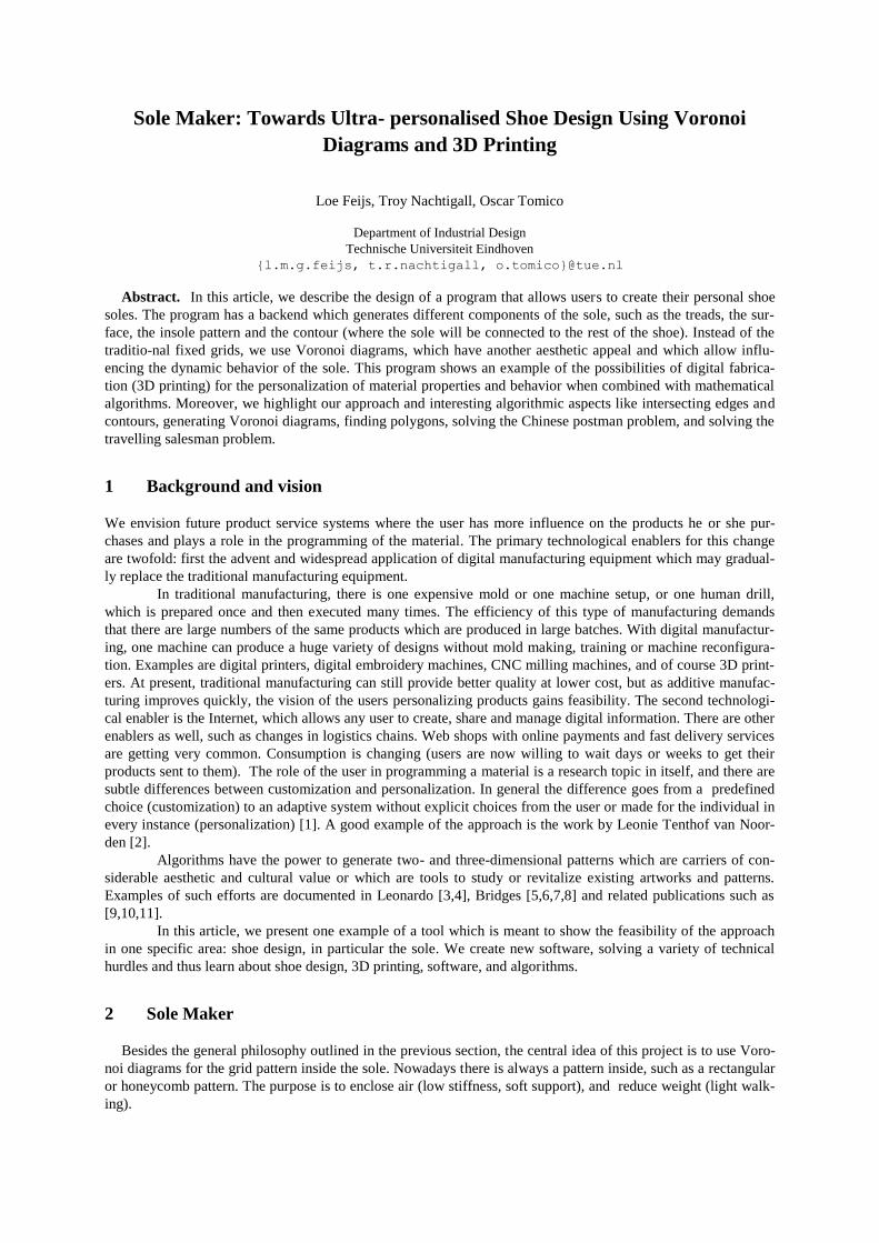
2 Sole Maker
Besides the general philosophy outlined in the previous section, the central idea of this project is to use Voro-
noi diagrams for the grid pattern inside the sole. Nowadays there is always a pattern inside, such as a rectangular
or honeycomb pattern. The purpose is to enclose air (low stiffness, soft support), and reduce weight (light walk-
ing).
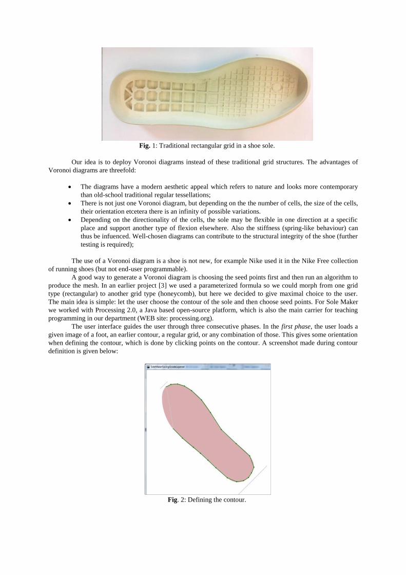
Fig. 1: Traditional rectangular grid in a shoe sole.
Our idea is to deploy Voronoi diagrams instead of these traditional grid structures. The advantages of
Voronoi diagrams are threefold:
The diagrams have a modern aesthetic appeal which refers to nature and looks more contemporary
than old-school traditional regular tessellations;
There is not just one Voronoi diagram, but depending on the the number of cells, the size of the cells,
their orientation etcetera there is an infinity of possible variations.
Depending on the directionality of the cells, the sole may be flexible in one direction at a specific
place and support another type of flexion elsewhere. Also the stiffness (spring-like behaviour) can
thus be infuenced. Well-chosen diagrams can contribute to the structural integrity of the shoe (further
testing is required);
The use of a Voronoi diagram is a shoe is not new, for example Nike used it in the Nike Free collection
of running shoes (but not end-user programmable).
A good way to generate a Voronoi diagram is choosing the seed points first and then run an algorithm to
produce the mesh. In an earlier project [3] we used a parameterized formula so we could morph from one grid
type (rectangular) to another grid type (honeycomb), but here we decided to give maximal choice to the user.
The main idea is simple: let the user choose the contour of the sole and then choose seed points. For Sole Maker
we worked with Processing 2.0, a Java based open-source platform, which is also the main carrier for teaching
programming in our department (WEB site: processing.org).
The user interface guides the user through three consecutive phases. In the first phase, the user loads a
given image of a foot, an earlier contour, a regular grid, or any combination of those. This gives some orientation
when defining the contour, which is done by clicking points on the contour. A screenshot made during contour
definition is given below:
Fig. 2: Defining the contour.
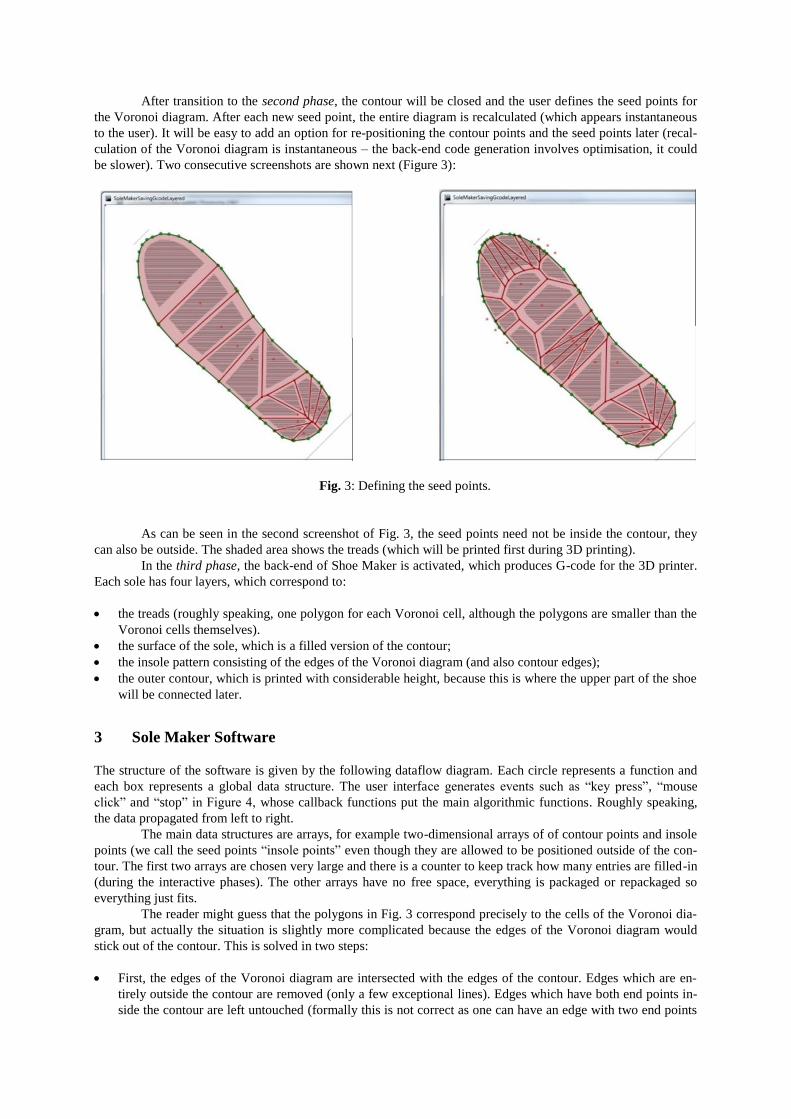
After transition to the second phase, the contour will be closed and the user defines the seed points for
the Voronoi diagram. After each new seed point, the entire diagram is recalculated (which appears instantaneous
to the user). It will be easy to add an option for re-positioning the contour points and the seed points later (recal-
culation of the Voronoi diagram is instantaneous – the back-end code generation involves optimisation, it could
be slower). Two consecutive screenshots are shown next (Figure 3):
Fig. 3: Defining the seed points.
As can be seen in the second screenshot of Fig. 3, the seed points need not be inside the contour, they
can also be outside. The shaded area shows the treads (which will be printed first during 3D printing).
In the third phase, the back-end of Shoe Maker is activated, which produces G-code for the 3D printer.
Each sole has four layers, which correspond to:
the treads (roughly speaking, one polygon for each Voronoi cell, although the polygons are smaller than the
Voronoi cells themselves).
the surface of the sole, which is a filled version of the contour;
the insole pattern consisting of the edges of the Voronoi diagram (and also contour edges);
the outer contour, which is printed with considerable height, because this is where the upper part of the shoe
will be connected later.
3 Sole Maker Software
The structure of the software is given by the following dataflow diagram. Each circle represents a function and
each box represents a global data structure. The user interface generates events such as “key press”, “mouse
click” and “stop” in Figure 4, whose callback functions put the main algorithmic functions. Roughly speaking,
the data propagated from left to right.
The main data structures are arrays, for example two-dimensional arrays of of contour points and insole
points (we call the seed points “insole points” even though they are allowed to be positioned outside of the con-
tour. The first two arrays are chosen very large and there is a counter to keep track how many entries are filled-in
(during the interactive phases). The other arrays have no free space, everything is packaged or repackaged so
everything just fits.
The reader might guess that the polygons in Fig. 3 correspond precisely to the cells of the Voronoi dia-
gram, but actually the situation is slightly more complicated because the edges of the Voronoi diagram would
stick out of the contour. This is solved in two steps:
First, the edges of the Voronoi diagram are intersected with the edges of the contour. Edges which are en-
tirely outside the contour are removed (only a few exceptional lines). Edges which have both end points in-
side the contour are left untouched (formally this is not correct as one can have an edge with two end points

inside the contour but the edge itself will be partially outside, as the contour is not necessarily convex; in
practice this hardly ever happens once there are more than a few seed points). If an edge has one end point
inside the contour and one end point outside the contour, then the latter end point is replaced by the intersec-
tion point of that edge and the contour. This is called “prune Edges” in Fig. 4. Secondly, the intersection points of the pruned edges and the contour have to be added explicitly to the con-
tour (otherwise we cannot find proper polygons in the contour later. This is called “refine Edges” in Fig. 4.
Fig. 4: dataflow diagram of the Sole Maker software.
After these two steps there is no more difference between the edges originating from the contour (“co-
Edges”) and the edges originating from the insole (“inEdges”). They are combined in “allEdges”. From here,
subsequent calculations prepare for printing of the mesh. This amounts to calculating two new data tables.
The first data table to be calculated is called “cppEdges”, where CPP abbreviates Chinese Postman
Problem. The problem is finding an optimal tour along all edges, where each edge is traversed at least once and
with a minimal number of second or third traversals. This is a so-called Chinese postman problem and the func-
tion to prepare a tour thus is indicated as “allPrepChinese” in Figure 4. More details about that function are in the
next section.
The second data table contains the tread polygons, the collection of polygons formed by the combined
contour and insole edges. This called “trPolygons” in Figure 4; the polygons can be seen in Figure 3. Finally
there are four phases of printing, corresponding to the four layers of the shoe sole:
The treads (the face which will touch the ground), which are downsized and filled versions of the
abovementioned tread polygons;
The central sole layer (the closed and thin layer which comes next);
The insole mesh (the printed edges of the polygons);
The contour going up in tapered fashion up to 10 mm.
No external slicer is needed, the software takes care for slicing, which amounts to slicing polygons (easy, just
intersect lines). In total Sole Maker now has 1431 lines of Code in Processing 2.0 (essentially Java).

4 Algorithms
There are five interesting algorithmic aspects we like to mention: (1) intersecting edges and contours, (2) gener-
ating Voronoi diagrams, (3) finding polygons, (4) solving the Chinese postman problem, and (5) solving the
travelling salesman problem. We highlight our approach and interesting aspects for each of them.
4.1 Intersecting edges and contours
In the heart of Sole Maker is the task of intersecting edges (lines) and contours (closed set of connected lines),
finding intersection points and to find out which points are either inside or outside the contour.
Although it is not hard to derive the formulas, we consider Paul Bourke’s geometry website helpful
(paulbourke.net/geometry/pointlineplane/). The following equations are essentially obtained from that website.
If we have four points P1, P2, P3, and P4 whose coordinates are given by (x1,y1), (x2,y2), (x3,y3), (x4,y4) , respec-
tively, then we want to know whether line segments P1P2 and P3P4 intersect. Calculate:
d = (y4 - y3) × (x2 - x1) - (x4 - x3) × (y2 - y1)
f1 = (x4 - x3) × (y1 - y3) - (y4 - y3) × (x1 - x3) / d
f2 = (x2 - x1) × (y1 - y3) - (y2 - y1) × (x1 - x3) / d
then the line segments intersect if and only if 0 < f1 ≤ 1 and 0 < f2 ≤ 1. If they intersect, then the x coordinate of
the intersection point is x1 + f1 × (x2 - x1) and the y coordinate is y1 + f1 × (y2 - y1). If we want to know whether a
point intersects a contour (or polygon) we test all edges of the contour in a for loop. If we want to know whether
a point P is inside or outside a contour we take an edge PQ where Q is very far away, at coordinates x = 0 and y
= 10000 say, and then check whether PQ has an odd or even number of intersection points with the contour.
4.2 Generating Voronoi diagrams
To convert the point set into a set of polygons we used Lee Byron’s Processing Mesh library [12]. The latter
library in turn is based on the QuickHull library since the problem of genating Voronoi diagrams in two dimen-
sions can be reduced the problem of finding convex hulls in three dimensions. We have used the same Mesh
library in an earlier project, Drapely-o-lightment by Marina Toeters and Loe Feijs [4]. The library is reliable and
easy to use in Processing. If nrInPoints equals inPoints.length then the code is simply:
Voronoi myVoronoi;
myVoronoi = new Voronoi( inPoints );
inEdges = myVoronoi.getEdges();
4.3 Finding polygons
The initial vague assumption that the tread polygons are simply the cells of the Voronoi diagram is not generally
true. Particularly near the contour, there is a mix of contour edges and Voronoi edges. So we are faced with a
connected set of edges and the question is how to find the faces of the corresponding graph? This abstract prob-
lem had been discussed already on the forum /mathoverflow.net/questions/23811/ reporting-all-faces-in-a-
planar-graph. The problem was refined, in the forum, by noting that it is about a planar graph together with an
embedding of the graph into the plane. Therefore it is clear what clockwise and counterclockwise mean. An al-
gorithm is described informally by Darsh Ranjan:
I'll assume the graph is connected, and that you have the clockwise or counterclockwise ordering of the edges
around each vertex. Then it's easy, given a directed edge e, to walk around the face whose counterclockwise
boundary contains e. So make a list of all directed edges (i.e., two copies of each undirected edge). Pick one di-
rected edge, walk counterclockwise around its face, and cross off all the directed edges you traverse. That's one
face. Pick a directed edge you haven't crossed off yet and walk around its face the same way. Keep doing that until
you've crossed off all of the edges. (Note that the "counterclockwise" boundary of the exterior unbounded face ac-
tually goes clockwise around the outside of the graph.)
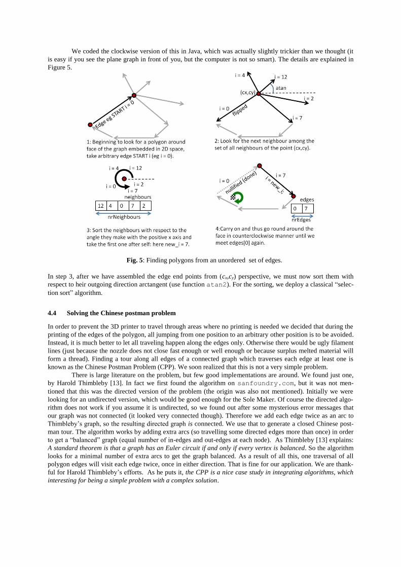
We coded the clockwise version of this in Java, which was actually slightly trickier than we thought (it
is easy if you see the plane graph in front of you, but the computer is not so smart). The details are explained in
Figure 5.
Fig. 5: Finding polygons from an unordered set of edges.
In step 3, after we have assembled the edge end points from (cx,cy) perspective, we must now sort them with
respect to heir outgoing direction arctangent (use function atan2). For the sorting, we deploy a classical “selec-
tion sort” algorithm.
4.4 Solving the Chinese postman problem
In order to prevent the 3D printer to travel through areas where no printing is needed we decided that during the
printing of the edges of the polygon, all jumping from one position to an arbitrary other position is to be avoided.
Instead, it is much better to let all traveling happen along the edges only. Otherwise there would be ugly filament
lines (just because the nozzle does not close fast enough or well enough or because surplus melted material will
form a thread). Finding a tour along all edges of a connected graph which traverses each edge at least one is
known as the Chinese Postman Problem (CPP). We soon realized that this is not a very simple problem.
There is large literature on the problem, but few good implementations are around. We found just one,
by Harold Thimbleby [13]. In fact we first found the algorithm on sanfoundry.com, but it was not men-
tioned that this was the directed version of the problem (the origin was also not mentioned). Initially we were
looking for an undirected version, which would be good enough for the Sole Maker. Of course the directed algo-
rithm does not work if you assume it is undirected, so we found out after some mysterious error messages that
our graph was not connected (it looked very connected though). Therefore we add each edge twice as an arc to
Thimbleby’s graph, so the resulting directed graph is connected. We use that to generate a closed Chinese post-
man tour. The algorithm works by adding extra arcs (so travelling some directed edges more than once) in order
to get a “balanced” graph (equal number of in-edges and out-edges at each node). As Thimbleby [13] explains:
A standard theorem is that a graph has an Euler circuit if and only if every vertex is balanced. So the algorithm
looks for a minimal number of extra arcs to get the graph balanced. As a result of all this, one traversal of all
polygon edges will visit each edge twice, once in either direction. That is fine for our application. We are thank-
ful for Harold Thimbleby’s efforts. As he puts it, the CPP is a nice case study in integrating algorithms, which
interesting for being a simple problem with a complex solution.
4.5 Solving the traveling salesman problem
We tested three Java programs to solve the problem of printing all tread polygons while minimizing the extra
jumps of the nozzle when moving from one tread to the next. This is a typical instance of the famous traveling
salesman problem. We easily wrote a naive solution, which is called either “greedy” or “nearest neighbour”. It
finds a closed tour along the gravity centers of the polygons, although not necessarily the shortest. Later we
started wondering whether the tours would be too inefficient and perhaps we should write a decent algorithm
which finds the optimal solution. So we coded a brute force search, trying all tours. We thus find that in typical
test runs the greedy tour is between 10% and 15% longer than the optimal tour. But we also find that the brute
force algorithm has high runtime for more than 14 polygons. Based on Kevin Buchin’s course notes [14], we
coded a backtracking version using the well-known branch-and-bound technique, which is at least 1000 times
faster. This is the algorithm as given by Buchin [14]:
Algorithm TSP_Backtrack(A, ℓ, lengthSoFar, minCost) 1. n ← length[A] // number of elements in the array A
2. if ℓ = n
3. then minCost ← min(minCost, lengthSoFar + distance[A[n], A[1]])
4. else for i ← ℓ + 1 to n
5. do Swap A[ℓ + 1] and A[i] // select A[i] as the next city
6. newLength ← lengthSoFar + distance[A[ℓ],A[ℓ + 1]]
7. if newLength > minCost // this will never be a better solution
8. then skip // prune
9. else minCost ←
10. min(minCost, TSP_Backtrack(A,ℓ + 1, newLength, minCost))
11. Swap A[ℓ + 1] and A[i] // undo the selection
12. return minCost
Buchin [14] only describes how to calculate tour length; we have to add an extra structure to extract the
tour itself, later.
But sooner or later the problem is hopeless ─ as is to be expected because the travelling salesman prob-
lem is “hard” in the theoretical sense. The effect is obvious in Figure 6.
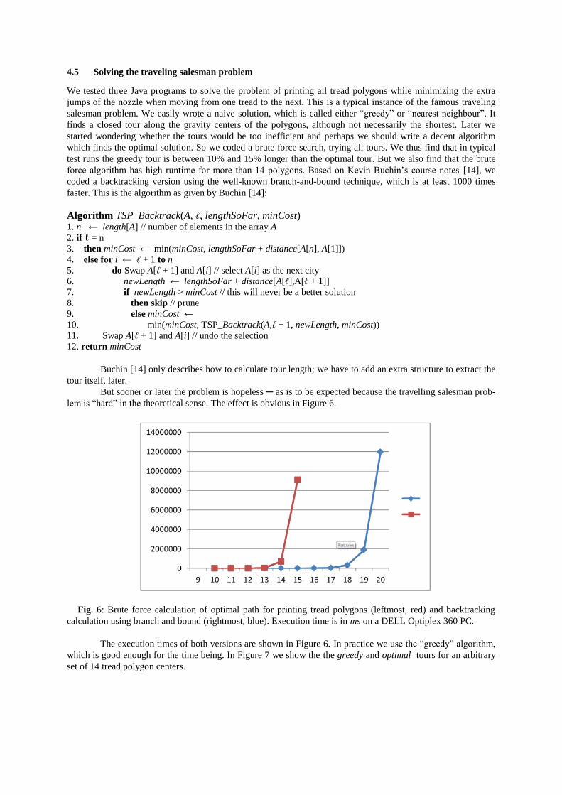
Fig. 6: Brute force calculation of optimal path for printing tread polygons (leftmost, red) and backtracking
calculation using branch and bound (rightmost, blue). Execution time is in ms on a DELL Optiplex 360 PC.
The execution times of both versions are shown in Figure 6. In practice we use the “greedy” algorithm,
which is good enough for the time being. In Figure 7 we show the the greedy and optimal tours for an arbitrary
set of 14 tread polygon centers.
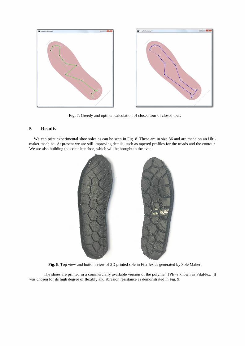
Fig. 7: Greedy and optimal calculation of closed tour of closed tour.
5 Results
We can print experimental shoe soles as can be seen in Fig. 8. These are in size 36 and are made on an Ulti-
maker machine. At present we are still improving details, such as tapered profiles for the treads and the contour.
We are also building the complete shoe, which will be brought to the event.
Fig. 8: Top view and bottom view of 3D printed sole in Filaflex as generated by Sole Maker.
The shoes are printed in a commercially available version of the polymer TPE–s known as FilaFlex. It
was chosen for its high degree of flexibly and abrasion resistance as demonstrated in Fig. 9.

Fig. 9: Demonstration of the Flexibility of the TPE-s material
6 Claims and outlook
We believe that this work is a first step toward implementing the vision of personalized shoes with the end-user
contributing as a co-designer and exploiting the power of digital manufacturing.
We claim that we demonstrate the technical feasibility of the personalized + Voronoi + generative +
3D printing approach. It is interesting that we encountered both “dual” versions of the famous graph traversal
problem in the same project (Chinese postman and traveling salesman). The development of new business prop-
ositions and optimizations to reach economic feasibility is research which will take more time. Troy Nachtigall
and others in TU/e explore this further in the coming years.
We also claim that it is fruitful for designers with different backgrounds to work together. In particular,
the joint efforts of Troy, with his background in fashion and shoe design, and Loe, with his background in math-
ematics and software, is fun and gives extra creative energy. The outcome is probably much more and is
achieved faster than what each of us could do alone.
Finally, we claim that projects such as [4,5,6] and the current project benefit significantly from a variety
of earlier projects, open-source developments, forums and related on-line resources. This is essential. We men-
tion Drapely-O-Lightment with Marina Toeters, Processing, Paul Bourke’s geometry website, Lee Byron’s Mesh
library, the mathoverflow.net forum, Kevin Buchin’s on-line course notes, and last but not least Harold Thim-
bleby’s publication. Although we still have to do serious coding, most of the work is integrating technology
rather than pure invention. Many additional new possibilities arise:
Adjusting the foldability and the torque stiffness of the sole from physical measurements of the user’s foot
and the user’s walking dynamics;
Although we cannot be sure yet how viable the Voronoi solution is in terms of orthopedic support and per-
formance, but we plan to test several variations. Moreover we have shown the work to a podiatrist and an
orthopedist who considered it promising.
Designing for recognizable personal footprints, which can be used for all kinds of aesthetic effects, leaving
footprints in the sand or any other playground (changing forensics too).
Applying a similar approach to the rest of the shoe.
Still the chief designer, company or brand can have a recognizable brand identity by putting limitations on
the seed points or other parameters. BeyondVoronoi diagrams, there is a rich variety of mathematical or cul-
tural principles which can be used as a creative space the user has to work in (e.g. Lissajous curves, Heesch-
Kienzle tessellations and so on).
We leave these as options for future research.
Acknowledgements: We are grateful for the discussion by Gerry Myerson and Darsh Ranjan about the planar
graph algorithm on mathoverflow.net. We thank the anonymous reviewers for their feedback, which we used to
improve the paper. We thank Stephan Wensveen, Nicoline van Enter, Sigridur Helga Hauksdottir and Frank
Delbressine for the useful discussions and SLEM shoe innovation center for their kind support.

References
1. Bhomer, M. ten, Tomico, O., Wensveen, S.A.G. (2015) Designing ultra-personalized embodied smart textile
services for well-being. In: L. van Langenhove (Ed.) Advances in Smart Medical Textiles: Treatments and
Health Monitoring (pp. 155-175). Cambridge: Woodhead Publishing.
2. Tenthof Van Noorden, L. This Fits Me. Bridges Mathematical Art Exposition Seoul. Mathematical Art Gal-
leries. gallery.bridgesmathart.org/exhibitions/2014-bridges-conference (2014).
3. Feijs, L.M.G. Divisions of the plane by computer: another way of looking at Mondrian's non-figurative
compositions. Leonardo, 37(3), 217-222 (2004).
4. Feijs, L.M.G. & Toeters, M.J. Design of Drapely-o-lightment: An Algorithmic Approach to Designing for
Drapability in an E-Textile Garment. Leonardo, 48(3), 226-234 (2015).
5. Feijs, L.M.G. Geometry and computation of Houndstooth (Pied-de-poule). In Robert Bosch, Douglas
McKenna & Reza Sarhangi (Eds.), Conference Paper : Proceedings of the Bridges Towson Conference (pp.
299-306). Baltimore: Bridges Mathart.org. (2012).
6. Feijs, L.M.G. and Hu, J. Turtles for Tessellations. In: (George W. Hart and Reza Sarhangi Eds.) Proceedings
of Bridges, pp. 241—248 (2013).
7. Feijs, L.M.G. & Toeters, M.J. Constructing and applying the fractal pied de poule (houndstooth). In G. Hart
& R. Sarhangi (Eds.), Proceedings of Bridges 2013 : Mathematics, Music, Art, Architecture, Culture, July
27-31, Enschede, pp. 429-432. (2013).
8. Feijs, L.M.G., Toeters, M.J., Hu, J., & Liu, J. Design of a Nature-like Fractal Celebrating Warp-knitting. In:
Bridges 2014: Mathematics, Music, Art, Architecture, Culture, Seoul, Korea, 2014, pp. 369-372 (2014).
9. Feijs, L.M.G. Il linguaggio di Mondrian: Ricerche algoritmiche e assiomatiche. In M. Emmer (Ed.), Ma-
tematica e cultura (pp. 181-194). Berlin: Springer Verlag (2006).
10. Feijs, L.M.G., Bartneck, C. Teaching geometrical principles to design students. Digital Culture & Educa-
tion, 1(2), 104-115 (2009).
11. Van Lankveld, T. Man-shaped figures. Bridges Math Art Exposition Baltimore. Mathematical Art Galleries.
gallery.bridgesmathart.org/exhibitions/2014 -bridges-conference (2014).
12. Byron, L. Mesh – A Processing Library (retrieved january, 2016). Available: www.leebyron.com/else/mesh/
13. Thimbleby, H. (2003). The directed chinese postman problem. Software: Practice and Experience, 33(11),
1081-1096.
14. Buchin, K. Backtracking / Branch-and-Bound. Course notes for Algorithms (2IL15), Technische Universiteit
Eindhoven, www.win.tue.nl/~kbuchin/teaching/ 2IL15/ backtracking.pdf (2014).