Solar Grass Cutter With Linear Blades By Using Scotch Yoke Mechanism
17
www.ijera.com B.Venu et al. Int. Journal of Engineering Research and Applications www.ijera.com ISSN : 2248-9622, Vol. 4, Issue 9( Version 1), September 2014, pp. Solar Grass Cutter With Linear Blades By Using Scotch Yoke Mechanism P.Amrutesh 1 , B.Sagar 2 , B.Venu 3 1 Student,B.Tech(Mechanical Engineering), MeRITS, A.P, India, 2 Student,B.Tech(Mechanical Engineering), MeRITS ,A.P, India, 3 Asst.Professor,Mechanical engineering, MeRITS,A.P,India. ABSTRACT A Solar grass cutter is a machine that uses sliding blades to cut a lawn at an even length. Even more sophisticated devices are there in every field. Power consumption becomes essential for future. Solar grass cutter is a very useful device which is very simple in construction. It is used to maintain and upkeep lawns in gardens, schools, college’s etc. We have made some changes in the existing machine to make its application easier at reduced cost. Our main aim in pollution control is attained through this. Unskilled operation can operate easily and maintain the lawn very fine and uniform surface look. In our project, “Solar grass cutter” is used to cut the different grasses for the different application. Keywords: scotch yoke mechanism, linear blades, I. INTRODUCTION Moving the grass cutters with a standard motor powered grass cutters is an inconvenience, and no one takes pleasure in it. Cutting grass cannot be easily accomplished by elderly, younger, grass cutter moving with engine create noise pollution due to the loud engine, and local air pollution due to the combustion in the engine. Also, a motor powered engine requires periodic maintenance such as RESEARCH ARTICLE
-
Upload
independent -
Category
Documents
-
view
3 -
download
0
Transcript of Solar Grass Cutter With Linear Blades By Using Scotch Yoke Mechanism
www.ijera.com
B.Venu et al. Int. Journal of Engineering Research and Applications www.ijera.comISSN : 2248-9622, Vol. 4, Issue 9( Version 1), September 2014, pp.
Solar Grass Cutter With Linear Blades By Using Scotch Yoke Mechanism
P.Amrutesh1, B.Sagar2, B.Venu3
1Student,B.Tech(Mechanical Engineering), MeRITS, A.P, India,2Student,B.Tech(Mechanical Engineering), MeRITS ,A.P, India, 3Asst.Professor,Mechanical engineering, MeRITS,A.P,India.
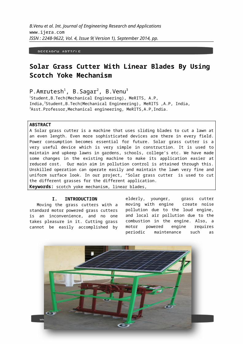
ABSTRACTA Solar grass cutter is a machine that uses sliding blades to cut a lawn atan even length. Even more sophisticated devices are there in every field.Power consumption becomes essential for future. Solar grass cutter is avery useful device which is very simple in construction. It is used tomaintain and upkeep lawns in gardens, schools, college’s etc. We have madesome changes in the existing machine to make its application easier atreduced cost. Our main aim in pollution control is attained through this.Unskilled operation can operate easily and maintain the lawn very fine anduniform surface look. In our project, “Solar grass cutter” is used to cutthe different grasses for the different application.Keywords: scotch yoke mechanism, linear blades,
I. INTRODUCTIONMoving the grass cutters with a
standard motor powered grass cuttersis an inconvenience, and no onetakes pleasure in it. Cutting grasscannot be easily accomplished by
elderly, younger, grass cuttermoving with engine create noisepollution due to the loud engine,and local air pollution due to thecombustion in the engine. Also, amotor powered engine requiresperiodic maintenance such as
RESEARCH ARTICLE

www.ijera.com
B.Venu et al. Int. Journal of Engineering Research and Applications www.ijera.comISSN : 2248-9622, Vol. 4, Issue 9( Version 1), September 2014, pp.
changing the engine oil. Even thoughelectric solar grass areenvironmentally friendly, they toocan be an inconvenience. Along withmotor powered grass cutter, electricgrass cutters are also hazardous andcannot be easily used by all. Also,
if the electric grass cutter iscorded, mowing could prove to beproblematic and dangerous. Theprototype will also be will becharged from sun by using solarpanels.
1.1 SOLAR ENERGY:Solar energy is very large,
inexhaustible source of energy. Thepower from the sun interrupted byearth is approximately 1.8/10MW,which are many thousands of timeslarger than the present consumptionrate on the earth of all energysources. The quantum of energyIndia’s land area receive from sunis equivalent to 15,000 time sitsconsumption requirement (500 billionkWh) as projected for 2004. In
addition to its size, solar energyhas two other factors in its favour.Firstly, unlike fossil fuels andnuclear power, it is anenvironmentally clean source ofenergy. Secondly, it is free andavailable in adequate quantities inalmost all parts of the world peoplelive. But there are some problemsassociated with its. The realchallenge in utilizing solar energyis of and economic concern. One hasto strive for the development ofcheaper methods of collection andstorage so that large initialinvestments required at preset inmost applications are reduced, solarenergy in India:
A large amount of solar radiationfall on India and for most of thecountry very few days are without
sunshine. India lies within thelatitude of 7 N to and 37 N withannual average intensity of solarradiation as500 to 600 cal/cm/daywith more such insulations availablein arid and semi arid regions.Average solar radiation falling onIndia in arid and semiarid regionsis 7.5 K w h/m/day. Solar energy 5×10 K w h/year potential to meetbasic energy needs of teemingmillions who live in rural India.
Solar energy is an important,clean,cheapand
abundantly available renewableenergy. The sun radiates heat andlight. The heat, light received fromthe sun supports the environment onthe earth through the following wellknown natural effects.
Temperature balance on theearth
Photo-synthesis by biologicalplants production of oxygenand organic materials,production of organicchemicals and bio-mass.
Wind due to unequal heating ofwater, land surfaces.
Heating of ocean water: oceanthermal energy (OTEC)
Waves in ocean: ocean waveenergy
Figure 1 solar grass cutter with linear blades

www.ijera.com
B.Venu et al. Int. Journal of Engineering Research and Applications www.ijera.comISSN : 2248-9622, Vol. 4, Issue 9( Version 1), September 2014, pp.
Tides in ocean: ocean tidalenergy (due to gravitationalforces)
The sun produces enormous amount
of energy of heat and light throughsustained nuclear fusion reactions.The solar energy received on the
earth in the form of radiation isused for heating and producing anelectrical energy.Among the non-conventional sourcesof energy solar energy is the mostpromising. Hence our project isbased on the solar energy conversionto mechanical energy to run a normalgrass cutter.
Table1: COMPARISIONSl. No
SOLAR SYSTEM FUEL SYSTEM
1 Totally free from pollution Pollution is a great factor2 No fuel consumption Fuel is the important need3 No. of reciprocating parts
are lessNo. of reciprocating parts are more
4 Friction is greatly reduced Frictions between the parts are high.5 Low cast and maintenance Maintenance is difficult & costly6 Load carrying capacity is
lowLoad carrying capacity is high
7 Continuous ride for hours together is not possible
Continuous ride is possible
8 Ratio of speed reduction more when weight increases very much
Speed reduction ratio is less and it does not vary
1.2. PROBLEMS IDENTIFICATIONEarlier most of the activities
are done by manually. Gradually somany big and small equipments aredeveloped to ease humanactivities ,thus to reduce the humanefforts to do the things . Now aday’s most of the activities whichincluded human efforts are eitherreplaced or automated by the use ofmachines or other kinds ofequipments. Skilled persons arerequired for conventional grasscutter .why because here we usesanimals like bulls .now a days thetechnology is developed in otherhands skilled persons withconvention grass cutter were
decreased. Now we have a need todepend on the technology.Due to the risk involved in aconventional grass cutter, now daysvery few peoples coming forward tograss cutting by conventional grasscutter .moreover, educationalbackground of Indian youth isimproving. So most of peoplehesitate to use conventional grasscutter.
1.3. COMPONENTS USEDThe main components of the solar
powered grass cutter are, Solar panels Batteries Brush less DC motor

www.ijera.com
B.Venu et al. Int. Journal of Engineering Research and Applications www.ijera.comISSN : 2248-9622, Vol. 4, Issue 9( Version 1), September 2014, pp.
Solar charger Mechanism used Circuit breaker Blades
This are explained below one by one
1.3.1SOLAR PANEL: 1.3.1.1Photovoltaic principles:
The photo- voltaic effect can beobserved in nature in a variety ofmaterials that have shown that thebest performance in sunlight is thesemiconductors as stated above. Whenphotons from the sun are absorbed ina semiconductor, that create freeelectrons with higher energies thanthe created there must be anelectric field to induce these
higher energy electrons to flow outof the semi-conductor to do usefulwork. A junction of materials, whichhave different electricalproperties, provides the electricfield in most solar cells for thephoton interaction in asemiconductor.A solar cell consists of
Semi –conductor in which electron hole pairs are createdby the absorption of incident solar radiation.
Region containing a drift fieldfor charge separation.
Charge collecting front and back electrodes.
1.3.1.2 Photovoltaic effectThe photo-voltaic effect can be
described easily for p-n junction ina semi-conductor. In an intrinsicsemi-conductor such as silicon, eachone of the four valence electrons ofthe material atom is tied in achemical bond, and there are no freeelectrons at absolute zero. If apiece of such a material is doped onone side by a five valance electronmaterial, such as arsenic orphosphorus, there will be an excessof electrons in that side, becomingan n-type semi-conductor.
The excess electrons will bepractically free to move in thesemi-conductor lattice. When a threevalance electron material, such as
boron dopes the other side of thesame piece, there will be deficiencyof electrons leading to a p-typesemi-conductor. This deficiency isexpressed in terms of excess ofholes free to move in the lattice.Such a piece of semi-conductor withone side of the p-type and theother, of the n-type is called p-njunction. In this junction after theprotons are absorbed, the freeelectrons of the n-side will tendsto flow to the p-side, and the holesof the p-side will tend to flow tothe n-region to compensate for theirrespective deficiencies. Thisdiffusion will create an electricfield from the n-region to the p-region. This field will increase

www.ijera.com
B.Venu et al. Int. Journal of Engineering Research and Applications www.ijera.comISSN : 2248-9622, Vol. 4, Issue 9( Version 1), September 2014, pp.
until it reaches equilibrium forvoltage, the sum of the diffusionpotentials for holes and electrons.If electrical contacts the connectedthrough an external electricalconductor, the free electrons willflow from the n-type materialthrough the conductor to the p-typematerial as shown in the figure.Here the free electrons will enterthe holes and become bound electronsthus both free electrons and holeswill be removed. The flow ofelectrons through the externalconductor constitutes an electriccurrent, which will continue as longas move free electrons and holes arebeing formed by the solar radiation.This is the basis of photo-voltaicconversion that is the conversion ofsolar energy into electrical energy.The combination of n-type and p-typesemiconductors thus constitutes aphoto-voltaic cell or solar cell.All such cells some rate directcurrent that can be converted intoalternating current it desired.
The photo-voltaic effect can beobserved in almost any junction ofmaterial that have differentelectrical characteristics, but thebest performance to date has beenfrom cells using semiconductormaterial especially all of the solarcells used for both space andterrestrial applications have beenmade of the semiconductor silicon.Future cells may use such materialsas the semiconductors like Galliumarsenate, copper sulphate cadsulphide etc. The device used to
utilize the photovoltaic effectis solar cell.
1.3.1.3 SPECFICATIONS:Array size : 67×60cmMaximum Power : 50WMaximum Voltage : 12VMaximum Current : 2.9ANo of modules : 1Type : Polycrystalline
1.3.2 BATTERY:The batteries are used as a
storage device for solar energywhich can be further converted intoelectrical energy. The onlyexceptions are isolated sunshineload such as irrigation pumps ordrinking water supplies for storage,for small units with output lessthan one kilowatt. Batteries seem tobe the only technically andeconomically available storagemeans. Since both the photo- voltaicsystem and batteries are high incapital costs, it is necessary thatthe overall system be optimized withrespect to available energy andlocal demand pattern. To beeconomically attractive the storageof solar electricity requires abattery with following particularcombination of properties:
(1) Low cost(2) Long life(3) High reliability(4) High overall efficiency

www.ijera.com
B.Venu et al. Int. Journal of Engineering Research and Applications www.ijera.comISSN : 2248-9622, Vol. 4, Issue 9( Version 1), September 2014, pp.
Figure 2 Li-ion batteries
1.3.3 BRUSHLESS D.C MOTOR:This is a relatively new class of motors whose application have been
increasing at a rapid rate each year, due to both declining costs as wellas increasing functionality.
A brushless DC motor is similar to that brush DC motor in that it hasan internal shaft position feedback which tells which windings to switch onat which an exact moment. This internal feedback gives both the brush DCmotor and brushless DC motor their unique characteristics. Linear speed-torque curves which are well suited for speed and position control and highstarting torque. The internal feedback is accomplished in a brush type DCmotor with the mechanical commutator (a series of copper bar which areinsulated from each other) and the mechanical brushes through which thecurrent is fed into the commutator bars and switched sequentially into theappropriate winding in the armature.
Figure 3 brushless DC Motor
1.3.3.1 Theory of DC motor speed control:
The speed controller works byvarying the average voltage sent tothe motor. It could do this by
simply adjusting the voltage sent tothe motor, but this is quiteinefficient to do. A better way isto switch the motor's supply on andoff very quickly. If the switching
www.ijera.com
B.Venu et al. Int. Journal of Engineering Research and Applications www.ijera.comISSN : 2248-9622, Vol. 4, Issue 9( Version 1), September 2014, pp.
is fast enough, the motor doesn'tnotice it, it only notices theaverage effect. When we watch a film in the cinema,or the television, what you areactually seeing is a series of fixedpictures, which change rapidlyenough that your eyes just see theaverage effect - movement. Yourbrain fills in the gaps to give anaverage effect. Now imagine a light bulb with aswitch. When you close the switch,the bulb goes on and is at fullbrightness, say 100 Watts. When youopen the switch it goes off (0Watts). Now if you close the switchfor a fraction of a second, and thenopen it for the same amount of time,the filament won't have time to cooldown and heat up, and you will justget an average glow of 50 Watts.This is how lamp dimmers work, andthe same principle is used by speedcontrollers to drive a motor. When
the switch is closed, the motor sees12 Volts, and when it is open itsees 0 Volts. If the switch is openfor the same amount of time as it isclosed, the motor will see anaverage of 6 Volts, and will runmore slowly accordingly. As the amount of time that thevoltage is time that it is off, theaverage speed of the motorincreases. This on-off switching is performedby power MOSFETs. A MOSFET (Metal-Oxide-Semiconductor Field EffectTransistor) is a device that canturn very large currents on and offunder the control of a low signallevel voltage. The time that it takes a motor tospeed up and slow down underswitching conditions is dependent onthe inertia of the rotor (basicallyhow heavy it is), and how muchfriction and load torque there is.
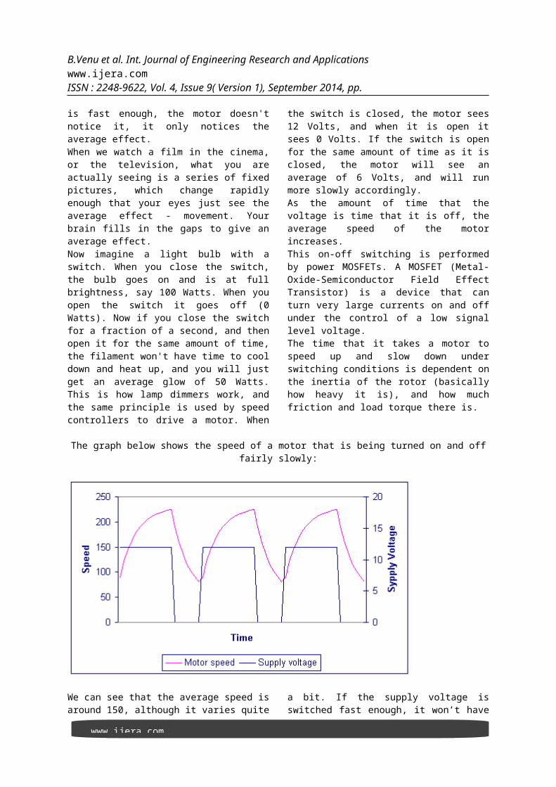
The graph below shows the speed of a motor that is being turned on and offfairly slowly:
We can see that the average speed isaround 150, although it varies quite
a bit. If the supply voltage isswitched fast enough, it won’t have

www.ijera.com
B.Venu et al. Int. Journal of Engineering Research and Applications www.ijera.comISSN : 2248-9622, Vol. 4, Issue 9( Version 1), September 2014, pp.
time to change speed much, and thespeed will be quite steady. This isthe principle of switch mode speedcontrol. Thus the speed is set byPWM – Pulse Width Modulation.
1.3.4 SOLAR CHARGER:The power charge regulator is
also known as charge controller,voltage regulator, charge-dischargecontroller or charge-discharge andload controller. The regulator sitsbetween the array of panels, thebatteries, and the equipment orloads.
By monitoring the voltage ofbattery, the regulator preventsovercharging or over discharging.Regulators used in solarapplications should be connected inseries: they disconnect the array ofpanels from the battery to avoidovercharging, and they disconnectthe battery from the load to avoidover discharging. The connection anddisconnection is done by means ofswitches which can be of two types:electromechanical (relays) or solidstate (bipolar transistor).
Figure 4 Solar charger
Solar chargers should never be connected in parallel. In order toprotect the battery from gasification, the switch opens the chargingcircuit when the voltage in the battery reaches its high voltagedisconnects (HVD) or cut-off set point.
The low voltage disconnects (LVD) prevents the battery from overdischarging by disconnecting the load. The most modern regulators are alsoable to automatically disconnect the panels during the night to avoiddischarging of the battery. They can also periodically overcharge thebattery to improve their life, and they may use a mechanism known as pulsewidth modulation (PWM).
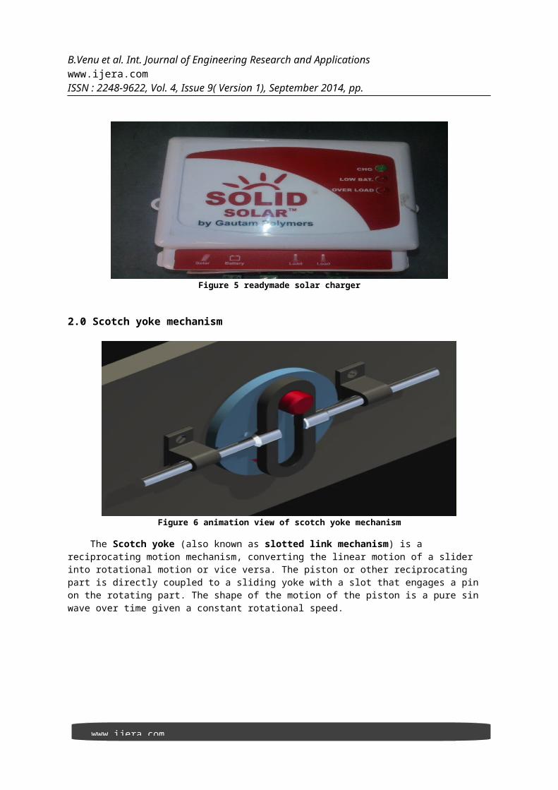
Solar charger has three light indicators. The first light blinks whenthe batteries are charging by using solar energy. The second light glowswhen the charging in the batteries is very low. The third light glows whenthe batteries are fully charged and an extra load (charging) is applied onthe batteries.
www.ijera.com
B.Venu et al. Int. Journal of Engineering Research and Applications www.ijera.comISSN : 2248-9622, Vol. 4, Issue 9( Version 1), September 2014, pp.
Figure 5 readymade solar charger
2.0 Scotch yoke mechanism
Figure 6 animation view of scotch yoke mechanism
The Scotch yoke (also known as slotted link mechanism) is a reciprocating motion mechanism, converting the linear motion of a slider into rotational motion or vice versa. The piston or other reciprocating part is directly coupled to a sliding yoke with a slot that engages a pin on the rotating part. The shape of the motion of the piston is a pure sin wave over time given a constant rotational speed.

www.ijera.com
B.Venu et al. Int. Journal of Engineering Research and Applications www.ijera.comISSN : 2248-9622, Vol. 4, Issue 9( Version 1), September 2014, pp.
Figure 7 scotch yoke mechanism
2.1 Applications:This setup is most commonly used in control valve actuators in highpressure oil and gas pipelines. Although not a common metalworking machinenowadays, crude shapers can use a Scotch yoke. Almost all those use aWhitworth linkage, which gives a slow speed forward cutting stroke and afaster return. It has been used in various internal combustion engines,such as the Bourke engine and many hot air engines and steam engines.The term scotch yoke continues to be used when the slot in the yoke isshorter than the diameter of the circle made by the crank pin. For example,the side rods of a locomotive may have scotch yokes to permit verticalmotion of intermediate driving axles.2.2 Circuit breaker: A circuit breaker is an automaticallyoperated electrical switch designed to protect an electrical circuit fromdamage caused by overload or short circuit. Its basic function is to detecta fault condition and interrupt current flow. Unlike a fuse, which operatesonce and then must be replaced, a circuit breaker can be reset (eithermanually or automatically) to resume normal operation. Circuit breakers aremade in varying sizes, from small devices that protect an individualhousehold appliance up to large switch gear designed to protect highvoltage circuits feeding an entire city.
www.ijera.com
B.Venu et al. Int. Journal of Engineering Research and Applications www.ijera.comISSN : 2248-9622, Vol. 4, Issue 9( Version 1), September 2014, pp.
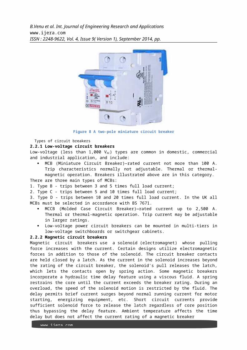
Figure 8 A two-pole miniature circuit breaker
Types of circuit breakers2.2.1 Low-voltage circuit breakersLow-voltage (less than 1,000 VAC) types are common in domestic, commercialand industrial application, and include:
MCB (Miniature Circuit Breaker)—rated current not more than 100 A.Trip characteristics normally not adjustable. Thermal or thermal-magnetic operation. Breakers illustrated above are in this category.
There are three main types of MCBs: 1. Type B - trips between 3 and 5 times full load current; 2. Type C - trips between 5 and 10 times full load current; 3. Type D - trips between 10 and 20 times full load current. In the UK allMCBs must be selected in accordance with BS 7671.
MCCB (Molded Case Circuit Breaker)—rated current up to 2,500 A.Thermal or thermal-magnetic operation. Trip current may be adjustablein larger ratings.
Low-voltage power circuit breakers can be mounted in multi-tiers inlow-voltage switchboards or switchgear cabinets.
2.2.2 Magnetic circuit breakersMagnetic circuit breakers use a solenoid (electromagnet) whose pullingforce increases with the current. Certain designs utilize electromagneticforces in addition to those of the solenoid. The circuit breaker contactsare held closed by a latch. As the current in the solenoid increases beyondthe rating of the circuit breaker, the solenoid's pull releases the latch,which lets the contacts open by spring action. Some magnetic breakersincorporate a hydraulic time delay feature using a viscous fluid. A springrestrains the core until the current exceeds the breaker rating. During anoverload, the speed of the solenoid motion is restricted by the fluid. Thedelay permits brief current surges beyond normal running current for motorstarting, energizing equipment, etc. Short circuit currents providesufficient solenoid force to release the latch regardless of core positionthus bypassing the delay feature. Ambient temperature affects the timedelay but does not affect the current rating of a magnetic breaker

www.ijera.com
B.Venu et al. Int. Journal of Engineering Research and Applications www.ijera.comISSN : 2248-9622, Vol. 4, Issue 9( Version 1), September 2014, pp.
2.3 Blades:A blade is that portion of a tool, weapon, or machine with an edge that isdesigned to cut and/or puncture, stab, slash, chop, slice, thrust, orscrape surfaces or materials. A blade may be made from a flaking stone,such as flint, metal (usually steel), ceramic, or other material.Here we used two blades i.e fixed blade and sliding blade 2.3.1 Fixed blade:-the blade which has no motion is called Fixed blade.This fixed blade is welded to the frame .And this is placed below thesliding blade.2.3.2 Sliding blade:-This blade slide over the moving blade .This bladeis connect to wheel and this is connected to DC motor.
Figure 9 showing sliding and moving blade
3.0 CIRCUIT DIAGRAM:
CONVERTERSolar battery
BATTERIESO O O O
O O O O
DC MOTOR
SOLAR PANEL

www.ijera.com
B.Venu et al. Int. Journal of Engineering Research and Applications www.ijera.comISSN : 2248-9622, Vol. 4, Issue 9( Version 1), September 2014, pp.
S
FIG 10 SHOWING CIRCUIT CONNECTIONS3.1 WORKING OF SOLAR POWERED GRASS CUTTER: Coming to the working of solar powered grass cutter , it has panelsmounted in a particular arrangement at an angle of 45 degrees in such a waythat it can receive solar radiation with high intensity easily from thesun. These solar panels convert solar energy into electrical energy asstudied earlier. Now this electrical energy is stored in batteries by usinga solar charger. The main function of the solar charger is to increase thecurrent from the panels while batteries are charging, it also disconnectsthe solar panels from the batteries when they are fully charged and alsoconnects to the panels when the charging in batteries is low. The motor isconnected to the batteries through connecting wires .Between these twomechanical circuit breaker switch is provided. It starts and stops theworking of the motor. From this motor, the power transmits to the mechanismand this makes the blade to slide on the fixed blade and this makes to cutthe grass.
SWITCH

www.ijera.com
B.Venu et al. Int. Journal of Engineering Research and Applications www.ijera.comISSN : 2248-9622, Vol. 4, Issue 9( Version 1), September 2014, pp.
Figure 10 orthographic view of solar powered grass cutter
4.0 CALCULATIONS AND RESULT
P = 2πNT60
watts
P = powerN = Speed of motorT = TorqueThen P=V*IV=voltageI=current
TORQUE AND POWER OF A MOTOR WITH NO LOAD CONDITIONS :P=V*I =12*25 =300W N= 800 RPM
Then
P = 2πNT60
300=2∗π∗800∗T
6018000=2*π*800*TT=3.58N-m
TORQUE AND POWER OF A MOTOR WITH LOAD CONDITIONS :
www.ijera.com
B.Venu et al. Int. Journal of Engineering Research and Applications www.ijera.comISSN : 2248-9622, Vol. 4, Issue 9( Version 1), September 2014, pp.
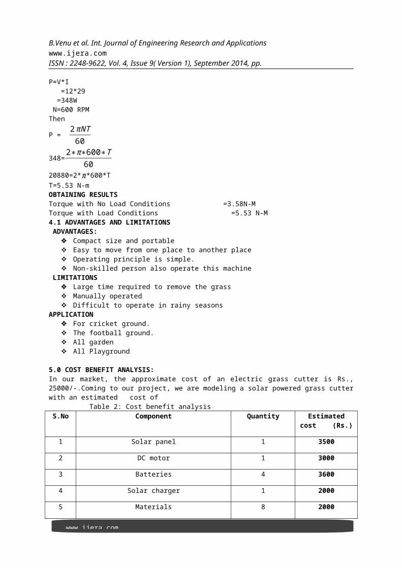
P=V*I =12*29 =348W N=600 RPM Then
P = 2πNT60
348=2∗π∗600∗T
6020880=2*π*600*TT=5.53 N-mOBTAINING RESULTSTorque with No Load Conditions =3.58N-MTorque with Load Conditions =5.53 N-M4.1 ADVANTAGES AND LIMITATIONS ADVANTAGES:
Compact size and portable Easy to move from one place to another place Operating principle is simple. Non-skilled person also operate this machine
LIMITATIONS Large time required to remove the grass Manually operated Difficult to operate in rainy seasons
APPLICATION For cricket ground. The football ground. All garden All Playground
5.0 COST BENEFIT ANALYSIS:In our market, the approximate cost of an electric grass cutter is ₨.,25000/-.Coming to our project, we are modeling a solar powered grass cutterwith an estimated cost of Table 2: Cost benefit analysisS.No Component Quantity Estimated
cost (Rs.)
1 Solar panel 1 3500
2 DC motor 1 3000
3 Batteries 4 3600
4 Solar charger 1 2000
5 Materials 8 2000
www.ijera.com
B.Venu et al. Int. Journal of Engineering Research and Applications www.ijera.comISSN : 2248-9622, Vol. 4, Issue 9( Version 1), September 2014, pp.
a. Square pipe=3
a. L angular =2
a. Flat plate=3
6 Electrical components
a. Mechanical switch = 1
b. Wires = 5Meters
c. Connections pins = 12
18 300
7 Expenses 1 600
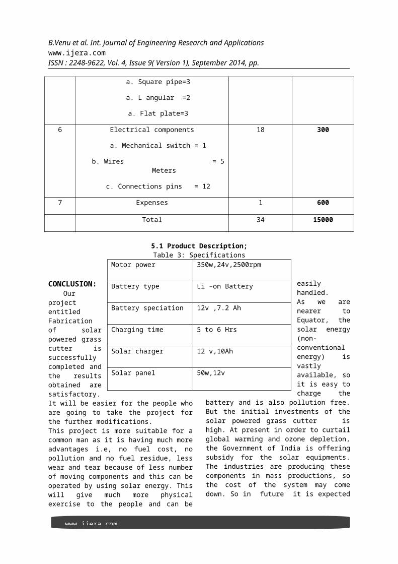
Total 34 15000
5.1 Product Description;Table 3: Specifications
CONCLUSION:Our
projectentitledFabricationof solarpowered grasscutter issuccessfullycompleted andthe resultsobtained aresatisfactory.It will be easier for the people whoare going to take the project forthe further modifications.This project is more suitable for acommon man as it is having much moreadvantages i.e, no fuel cost, nopollution and no fuel residue, lesswear and tear because of less numberof moving components and this can beoperated by using solar energy. Thiswill give much more physicalexercise to the people and can be
easilyhandled.As we arenearer toEquator, thesolar energy(non-conventionalenergy) isvastlyavailable, soit is easy tocharge the
battery and is also pollution free.But the initial investments of thesolar powered grass cutter ishigh. At present in order to curtailglobal warming and ozone depletion,the Government of India is offeringsubsidy for the solar equipments.The industries are producing thesecomponents in mass productions, sothe cost of the system may comedown. So in future it is expected
Motor power 350w,24v,2500rpm
Battery type Li –on Battery
Battery speciation 12v ,7.2 Ah
Charging time 5 to 6 Hrs
Solar charger 12 v,10Ah
Solar panel 50w,12v
www.ijera.com
B.Venu et al. Int. Journal of Engineering Research and Applications www.ijera.comISSN : 2248-9622, Vol. 4, Issue 9( Version 1), September 2014, pp.
to run all equipments by using solarenergy.This system is having facility ofcharging the batteries while thesolar powered grass cutter is inmotion. So it is much more suitablefor grass cutting also. The samething can be operated in night timealso, as there is a facility tocharge these batteries in day light.
FUTURE WORK We completed ourproject successfully with theavailable sources. But the resultsand modifications are not up to theexpectations. This can be furtherimproved by incorporating thefollowing modifications to obtainbetter results. The mechanism which weused ie scotch yoke mechanism doesnot given excepted efficiency. Thisefficiency can be increased by usingsome other mechanism. and speed ofmotor is reduce because we have usedheavy material and this material canbe replaced by using light weightmaterial .and design of bladesshould be done based on types ofgrass is used to cut. The project which wehave done surly reaches the averagefamiles because the grass can betrimmed with minimum cost and withminimum time Finally this projectmay give an inspiration to thepeople who can modify and can obtainbetter results. REFERENCES:
1. The solar entrepreneur’s handbook, Wise publications
2. A project report on “solar tracking system using hydraulic damper” (MeRITS)
3. Non Conventional Energy sources by G.D.RAI, Khanna Publishers
4. A project report on”solar powered bicycle” (MeRITS)
5. WWW.solar grass powered grass cutter.com [on line]
6. www.merits.tech.in