SNMP web card - greenhvac.tech
22
GPRS Card SILA User’s Manual www.sila-ups.ru
-
Upload
khangminh22 -
Category
Documents
-
view
0 -
download
0
Transcript of SNMP web card - greenhvac.tech

GPRS Card SILA
User’s Manual
www.sila-ups.ru

Table of Content
1 Overview ..................................................................................................................... 1 1.1 Introduction ..................................................................................................... 1 1.2 Features ........................................................................................................... 1 1.3 Product overview ............................................................................................. 2
2 Preparation ................................................................................................................. 2 2.1 Prerequisite ....................................................................................................... 2 2.2 Installation ........................................................................................................ 3
3 Monitor ....................................................................................................................... 5 3.1 Registration ....................................................................................................... 5 3.2 Login .................................................................................................................. 6 3.3 Region Manager ................................................................................................ 7 3.4 Device Manager ................................................................................................ 8 3.5 Monitor ............................................................................................................. 8
3.6 User Manager.................................................................................................. 11 4 System Configuration ................................................................................................ 13
4.1 SMS Setting ..................................................................................................... 13 5 SMS Notification ....................................................................................................... 19
5.1 Notification of firmware ................................................................................. 19 5.2 Prompt Alarm Notification .............................................................................. 19
www.sila-ups.ru

1
1 Overview
1.1 Introduction
GPRS Card can collect the data from various device, and transmit data via GPRS to data center. It’s
suitable for places where there is no access to Internet. The HTTP service of data center can
manage and monitor several devices, and can record all data/events with in data center.
Via the SMS of telecommunication companies, GPRS card supports reminder and alarm service.
The users can assign one or multiple numbers to receive the notification. Parameter
configuration and firmware upgrade can be completed via SMS.
Diagram 1-1
1.2 Features
Upload information to data center via GPRS.
Manage and monitor data in the data center through browser at any time
Notification via SMS
Parameter configuration and firmware upgrade through SMS
www.sila-ups.ru

2
1.3 Product overview
Diagram 1-2 System Status LED:
LED Status Description
10ms on , 990ms off 1. GSM CS data in process or established.
2. GSM CS audio call in process or established.
10ms on , 1990ms off GSM PS Data transmitting
10ms on , 3990ms off Online registration succeeded. No call, and no data
transmission.
500ms on , 500ms off Limited Internet service (for example, no SIM card, no
PIN authentication, or searching for Internet)
2 Preparation
2.1 Prerequisite
The following devices are required if you’re using GPRS Card or GPRS Box:
For GPRS Card:
1. GPRS Card (Diagram 1-1)
2. Micro SIM Card (12 x 15 mm) as in Diagram 2-1
3. SMS Device such as cell phone
4. Monitored device
GPRS antenna
System status LED
Golden Fingers: to connect
intelligent slot of connected
device
Micro SIM card slot
www.sila-ups.ru

3
GPRS card Micro SIM card
Diagram 2-1
For GPRS Box:
1. GPRS Card (Diagram 2-1)
2. Micro SIM Card (12 x 15 mm) as in Diagram 2-1
3. GPRS Card Box (Diagram2-2)
4. DB9 to RJ-45 Data Cable (Diagram 2-2)
5. SMS Device such as cell phone
6. Monitored device.
GPRS box DB9 to RJ-45 data cable
Diagram 2-2
2.2 Installation
For GPRS Card:
1. Screw the Antenna to GPRS card. (Diagram 2-3)
www.sila-ups.ru

4
Diagram 2-3
2. Insert SIM card into the slot. Pay attention to the direction of SIM card. (Diagram 2-4)
Diagram 2-4
3. Remove the cover of Intelligent Slot located on Inverter or UPS. Retain the screws for further
use. (Diagram 2-5)
Diagram 2-5 Diagram 2-6
4. Insert SIM Card and fix it with screws.
For GPRS Box:
1. Same Step 1 and 2 as GPRS card.
2. Insert GPRS card into GPRS Box, and fix it with screws. (Diagram 2-6)
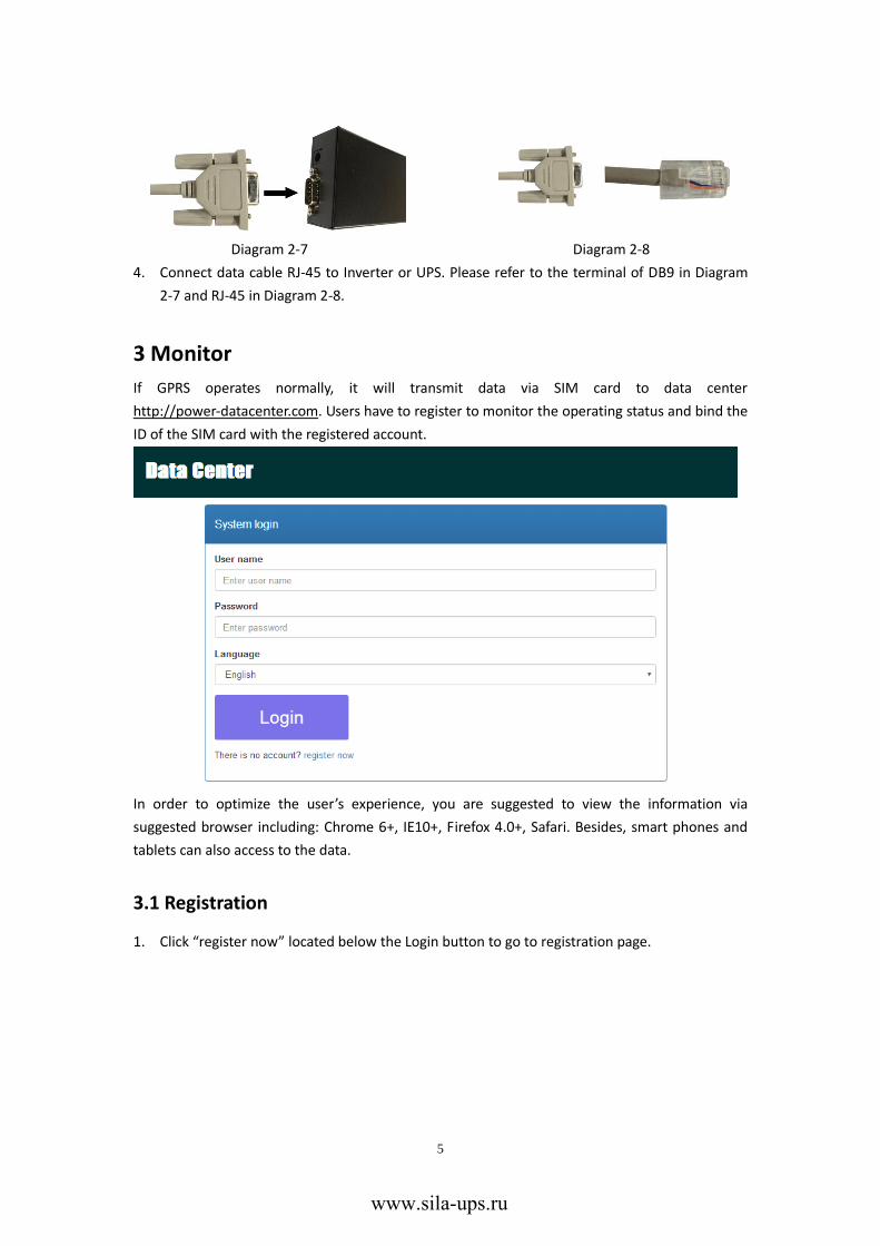
3. Connect DB9 terminal of data cable to GPRS Box. (Diagram 2-7)
www.sila-ups.ru
5
Diagram 2-7 Diagram 2-8
4. Connect data cable RJ-45 to Inverter or UPS. Please refer to the terminal of DB9 in Diagram
2-7 and RJ-45 in Diagram 2-8.
3 Monitor
If GPRS operates normally, it will transmit data via SIM card to data center
http://power-datacenter.com. Users have to register to monitor the operating status and bind the
ID of the SIM card with the registered account.
In order to optimize the user’s experience, you are suggested to view the information via
suggested browser including: Chrome 6+, IE10+, Firefox 4.0+, Safari. Besides, smart phones and
tablets can also access to the data.
3.1 Registration
1. Click “register now” located below the Login button to go to registration page.
www.sila-ups.ru

6
User name:Please enter user name and remember it for further use.
Password:It contains 6 ASCII characters, including number, capital letter and lower case
letters.
Confirm password:Re-enter the password which should be consistent with the one in
Password.
2. Click button to complete the registration
3.2 Login
After registration, you can log in the data center. The login page is shown as follow:
www.sila-ups.ru

7
After logging in, the main page of data center will be shown as below:
Region Manager: The users can monitor all device in the same region (or same location).
Device Manager: The users can bind the device to designated region and assign the
device to users.
Monitor: It is grouped by region, and all device in every region will be listed.
User Manager: The user can create end users.
3.3 Region Manager
1. Users can create new region, delete region, and edit region
2. After registration, the system will assigned the user an “undefined” region, which can be
deleted, and edited.
3. Click and the system will show new created message.
www.sila-ups.ru
8
4. Click to complete the creation.
5. Click to end up the new created message.
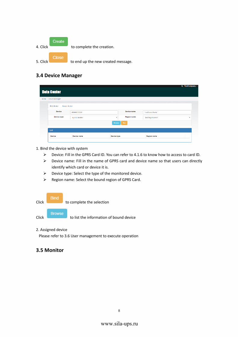
3.4 Device Manager
1. Bind the device with system
Device: Fill in the GPRS Card ID. You can refer to 4.1.6 to know how to access to card ID.
Device name: Fill in the name of GPRS card and device name so that users can directly
identify which card or device it is.
Device type: Select the type of the monitored device.
Region name: Select the bound region of GPRS Card.
Click to complete the selection
Click to list the information of bound device
2. Assigned device
Please refer to 3.6 User management to execute operation
3.5 Monitor
www.sila-ups.ru

9
1. It’s grouped by region, and all device in that region will be listed.
2. The message will be updated once every 5 minutes.
3. Click to show th detailed information in the new page.
Click to end up the page of detailed infrmation.
Status: Current operation status of monitored device.
Status Diagram:
It shows the status diagram of monitored device. The serial number is shown on the
upper left corner of the window and operation status indicator is shown as a dot on the
upper right corner of the window.
a) Basic information:
It shows basic information including the voltage, current, loading, temperature and etc.
www.sila-ups.ru

10
b) Power Information:
It shows the information of generated power in bar chart. You can select displayed
chart in “per hour,” “Daily,” “Monthly,” “Annual” basis to check the power information.
c) Rated information:
It shows the nominal rated information including input voltage, output voltage,
frequency, and battery voltage.
d) Product Information
It shows the product information including model type, Main CPU processor version,
and voltage.
Data: Historical data of currently monitored device
Event log: Historical event record of currently monitored device
www.sila-ups.ru

11
Power generation data log:Power generation data log of currently monitored device.
3.6 User Manager
Users can establish another end-user and assign specific GPRS card to this end-user. The end-user
can monitor the device by logging in the website via assigned GPRS cards.
1. Create User
Click to show the end-user’s information
www.sila-ups.ru

12
After filling in the related information, click to complete the creation
Click to end up the creation page, and it will go back to user list.
Click to remove the established user.
2. Assigned device
The GPRS card will be assigned to specific end-user.
Device type/Region name: The pull-down value might vary depending on different device.
Device: Select Device (GPRS card)
End user: Select one of the end-users.
Click to complete the assignment:
www.sila-ups.ru

13
Click to release the assignment.
4 System Configuration
4.1 SMS Setting
4.1.1 SMS Format
The SMS starts with “GPRS+password” and ends with “APPLY.” The default password is
“12345678,” and it is adjustable through “C^CPWD”. One SMS can include several commands,
and every command should be independently listed in single row. The response message will
start with “GPRS” and its content might vary depending on different commands.
4.1.2 Command Format
Every command starts with “C^” or “C+.” The setting starting with “C^” will be saved and
permanently valid. The setting starting with “C+” is normal command, and will be invalid after
GPRS Card resumes.
Every command has three possible applied methods. “CMD” stands for concrete commands, and
“C_VALUE” stands for current value. “VALUE” represents setting value.
1. “CMD” or “CMD?” means you can search for the current value and trigger command set
as default. For example: “C^CPWD” or “C^PWD?” means you can search for current
passwords for SMS setting. “C^RESTART” or “C^RESTART?” is an executive command
which will restart GPRS Card.
2. Set “CMD=VALUE” as the top of the page.
For example, “C^CPWD=12345678” means the password is “12345678.”
3. “CMD=?” is used to search for the acceptable parameter range.
For example, after placing the command “C^CPWD=?” the system replies
“CPWD:(4-10)” which means the acceptable parameter range is at least 4, and at most
10 ASCII characters. The details of range format and its definition will be introduced
www.sila-ups.ru

14
below.
The special character “*” is to represent all items.
1. “C^*” or “C^*?” can be used to inquire the current value of all commands starting
with “C^.”
2. “C^” can be used to inquire the setting range of all commands starting with “C^”
3. “C^” or “C+*?” can search for which normal command is available to use.
4.1.3 Range format
The value range included in “( ).” If there is any corresponding description, it will be put outside
“( ).” There are four formats in setting value.
1. (A,B,C)
This format indicates the setting value is one of them in the setting range.
2. (A-B)
A and B are numbers, which indicates the length of ASCII character strings ranges from ≥A
to ≤B.
For example, the return value of “C^CID=?” is “C^CID=?” which indicates the acceptable
range is 1 to 100 ASCII characters.
3. (A,B…C)
A and B are numbers, which indicates the setting range is larger than A, but smaller than B.
The interval is a value of arithmetic sequence between B-A.
For example, The return value of “C^UPS=?” is “UPS:(5,10...86400)” which indicates the
initial value is 5, and its maximum is 86400, and the tolerance is 5, so 5, 10, or 15 is
acceptable value, but 16 is unacceptable.
4. (!)
It indicate the value can’t be set by the user manually, but set by system automatically.
For example, the return value is from “C^FWV=?” to “FWV:(!)” which indicates the value is
set by system automatically.
4.1.4 Response Format
1. “CMD” or “CMD ?”
If it’s an inquiry command, the return value is “CMD:C_VALUE.” If it’s an order command, it
replies “OK” for successful execution, or “ERROR” for unsuccessful execution.
2. “CMD=VALUE”
If it’s set successfully, it replies “OK.” If not, it replies “ERROR.”
3. “CMD=?”
According to different command, it indicate the ranges of setting value (Refer to 4.1.3).
www.sila-ups.ru

15
4.1.5 Command List
Command Description CMD/CMD?(Default) CMD=? CMD=VALUE
C^CID ID of GPRS Card CID:- ① CID:(1-100) OK/ERROR
C^SURL IP Address of server
SUR:http://www.power-d
atacenter.com/cmmq/dat
aCenter SRUL:(8-100) OK/ERROR
C^UPS
Duration of data update
(second) SUPS:300 UPS:(5,10...86400) OK/ERROR
C^BURL
IP address of transmitting
update data
BURL:www.power-datace
nter.com:58081 BRUL:(3-100) OK/ERROR
C^BPS
Duration of transmitting data
update (Second) BPS:30 BPS:(5,10...600) OK/ERROR
C^SNTP SNTP Server SNTP:time-a.nist.gov SNTP:(1-100) OK/ERROR
C^DBGL
Adjusted Level. It is not
suggested to adjust. DBGL:0 DBGL:(0,1...10) OK/ERROR
C^FWV Firmware version FWV:- ① FWV:(!) ERROR
C^SMMG
Message Management.
Multiple telephone numbers
can be set to send the alarm
and version update
notification. Different numbers
are separated by “,” . SMMG: SMMG:(0-100) OK/ERROR
C^SMAD
Messages contains added
information. When GPRS Card
automatically sends messages
to Message Management, it
will add extra information. SMAD: SMAD:(0-100) OK/ERROR
C^SMAR Switch of alarm notification SMAR:OFF SMAR:(ON,OFF) OK/ERROR
C^CPWD
Password for message.
When the password is correct,
the message will be read by
GPRS card. CPWD:12345678 CPWD:(4-10) OK/ERROR
C^UURL
Update address of firmware.
After sending C+UPDATE, the
system will get the device’s
firmware and update it.
UURL:http://www.power-
datacenter.com/fw/gprs/
GPRSFW.jad UURL:(10-100) OK/ERROR
C^* C^ Type operation command
Return to all information
above. ERROR ERROR
C+QED
Inquiry of daily generated
power QED:- ①② QED:(!) ERROR
www.sila-ups.ru

16
Note:
①:It indicates the default value is incorrect.
②:The format of return value for QED is “ED,SN,Year,Month,Data00,Data01…,Data31.”
ED: It shows the daily generated power.
SN: Serial Number of monitored device
Year:Current year
Month:Current month
Data00,Data01…,Data31:Generated Power by day. The date you don’t inquire shows “-.”
4.1.6 Examples of SMS
1. Inquire Card ID:
2. Set Card ID:
3. Firmware update:
C+PAT
It shows the process of sending
AT command and it’s only for
adjustment. PAT:OFF PAT:(ON,OFF) OK/ERROR
C+UPDATE
Firmware update. The system
will get the device’s firmware
and update it from the assigned
address of “C^UURL.” UPDATE: OK/ERROR UPDATE:(!) ERROR
C+RESTART GPRS Card restart RESTART: OK/ERROR RESTART:(!) ERROR
www.sila-ups.ru

17
4. Set the interval time of uploading the data.
5. Set the password of SMS
6. Inquiry of daily generated power.
www.sila-ups.ru

18
7. Multiple commands
8. Set the queries upon range.
www.sila-ups.ru

19
5 SMS Notification
5.1 Notification of firmware
Users need to use “C^SMMG” commands to set the SMS management numbers. If there are
more than one number, they should be separated by “,”. If the firmware changes, all the numbers
in the management group will be notified by SMS notification. Please refer to Diagram 5-1 for the
example of SMS notification.
The format of SMS notification for updating firmware.
ID: XXXXXXXXXXXXXX
TOPIC: FW UPDATE
X.X.X->X.X.X
1. ID: GPRS Card ID。
2. TOPIC: Remind the firmware update via SMS notification.
3. The version of firmware is X.X.X。“->” It indicates the alternation of version.
Diagram 5-1
5.2 Prompt Alarm Notification
1. Users have to set the numbers for Management Group through C^SMMG command. If there
are more than one numbers, they should be separated by “,”.
2. Users should turn on prompt alarm notification through C^SMAR=ON command. The prompt
alarm notification is OFF in default. Refer to Diagram 5-2 for the SMS example.
www.sila-ups.ru

20
Format for alarm notification is:
ID: XXXXXXXXXXXXXX
TOPIC: ALARM
SN, CODE,DETAIL
(1.) ID: GPRS Card ID
(2.) TOPIC: Notify the message is an alarm notification
(3.) SN: Serial Number of monitored device
(4.) CODE: There are four formats. WO means there are warnings. FO means there are
faults. WR means the warnings cancel. The code number will follows “WO,” “FO,”
“WR,” and “FR.”
(5.) DETAIL: English description of warning or fault.
Diagram 5-2
www.sila-ups.ru